Article

Synthesis, Microstructure, and Electrical Conductivity of Eutectic Composites in MF2–RF3 (M = Ca, Sr, Ba; R = La–Nd) Systems

by
Irina I. Buchinskaya
,
Natalia A. Arkharova
,
Anna G. Ivanova
,
Nikolay I. Sorokin
and
Denis N. Karimov
*
Shubnikov Institute of Crystallography, Federal Scientific Research Center «Crystallography and Photonics», Russian Academy of Sciences, 59 Leninsky Prospekt, Moscow 119333, Russia
*
Author to whom correspondence should be addressed.
J. Compos. Sci. 2023, 7(8), 330; https://doi.org/10.3390/jcs7080330
Submission received: 14 July 2023 / Revised: 4 August 2023 / Accepted: 11 August 2023 / Published: 15 August 2023
(This article belongs to the Special Issue Dielectric Composite Materials)

Abstract

:
Multiphase fluoride polycrystalline eutectics pRF3 × qMF2 forming in the MF2–RF3 (M = Ca, Sr, Ba; R = La–Nd) binary systems were synthesized by the directional crystallization technique from a melt. The phase composition, morphology, and temperature dependences of fluorine ionic conductivity in fabricated composites were studied in detail. The pRF3 × qMF2 (p and q are the mole percentages of components) eutectic composites consist of both extremely saturated fluorite-type structure M1−xRxF2+x solid solutions and the tysonite-type R1−yMyF3−y ones. Microsized growth blocks with a fine lamellar structure are typical for synthesized composites. The thinnest (from 3 μm) and longest lamellae are observed in the 68LaF3 × 32BaF2 composition. The ionic conductivity values of pRF3 × qMF2 composites are determined by the phase composition, practically do not depend on their morphological features, and reach 10−3–10−2 S/cm at 500 K (with an ion transport activation enthalpy of about 0.5–0.6 eV). Crystallized eutectics are superior to any single-phase M1−xRxF2+x solid solutions and ball-milling R1−yMyF3−y nanoceramics in terms of ion-conducting properties. These fluoride materials represent an alternative to widely applied tysonite-type ceramic composites in various electrochemical devices and require further in-depth studies.

Graphical Abstract

1. Introduction

Alloys of eutectic compositions, being a kind of natural in situ composites, are of scientific interest both from a fundamental and practical point of view. These composite materials are naturally oriented fibrous or lamellar formations produced by a directional crystallization process and are uniform on the macroscale but heterogeneous on the microscale. Interest in eutectic composites is primarily due to the fact that the process of their crystallization is one-stage and that the possibilities for fine control of such microstructure parameters as phase morphology, dispersion, and mutual spatial orientation are quite wide. Eutectic composites are actively used as constructional materials with optimal mechanical properties and functional materials for solid-state ionics (chemical sensors, low-voltage current sources [1,2]), photonics (scintillators, thermal emission materials, and metamaterials [3,4]).
A large number of studies have been devoted to the preparation of eutectics by various methods of solidification and heat treatment. However, only a narrow range of publications is associated with the directional crystallization of eutectic composites from a melt [5,6,7]. Composite materials with a periodic lamellar or rod microstructure can be synthesized by directional solidification of eutectic melts. Directional crystallization makes it possible to control the composite microstructure [8,9]. Composite materials exhibit functional characteristics that are not an additive combination of their constituent phases properties and are not inherent in the original components. The eutectic microstructures morphology depends on the volume fraction of the components, their melting entropy, and the temperature gradient at the crystallization front [6,7]. The period of the eutectic microstructure is largely determined by the movement rate of the interfacial boundary during crystallization [10,11], namely the crucible pulling rate or temperature gradient variation, while other parameters depend on the chemical nature of the substance. Obviously, the possibility of producing extended, controlled periodic eutectic structures is limited.
To date, eutectics of metallic [8,9,12], oxide [3,4,5,13,14,15,16], carbide [17], halide (including fluoride) [16,18,19,20,21,22,23,24,25,26,27,28,29], and some other systems [30] have been fabricated by the directed crystallization technique. Most of these materials were obtained for the purpose of research in the fields of materials science and technology, photonics, and high-energy physics.
In the framework of the search for new promising fluorine-conducting solid electrolytes, researchers are attracted to composite materials based on eutectics in fluoride systems. Conductive fluoride composites were especially widely studied by a scientific group led by Prof. Viera Trnovcova (Slovakia) [16,25,26,31,32]. Fluoride composites (compared to single crystals) have improved mechanophysical properties, and their synthesis is simple and less expensive. The high ionic conductivity of composite (heterophase) electrolytes is due to the formation of a branched spatial network of interphase boundaries containing mobile defects.
The ionic conductivity of fluoride eutectic materials has already been studied in the following binary LiF– NaF, LiF–RF3 (R = La, Nd, Sm, Gd, Er, Y), NaF–CaF2, NaF–RF3 (R = Dy, Ho), CaF2–MgF2, MgF2–ScF3, MgF2–GdF3, MF–PbF2 (M = Li, Na), PbF2–RF3 (R = Ho, Yb, Sc), SrF2–RF3 (R = La, Nd, Sm), BaF2–NdF3, LiF–LiBaF3, LiF–LiRF4 (R = Gd, Lu, Y) [2,14,15,16,18,22,25,26,29,31,32,33,34,35,36,37,38,39,40], and ternary LiF–SrF2–LaF3, NaF–PbF2–CdF2 systems [33,36].
An analysis of the results of electrophysical studies of the above composites shows that highly conductive compounds in the SrF2–RF3 (R = La, Nd, Sm) and BaF2–NdF3 systems can be distinguished among them. The highest ionic conductivity, σdc = 2 × 10⁻³–7 × 10⁻³ S/cm at 500 K, is observed for the eutectic composition 71LaF3 × 29SrF2 [39]. The conductivity values of such pRF3 × qMF2 composites significantly exceed those of widely studied M1−xRxF2+x solid solutions (SSs) with fluorite-type structures (M are Ca, Sr, Ba, and R are the rare earth elements) [41,42,43]. Therefore, the utilization of composite fluoride materials as medium-temperature solid electrolytes is a promising research area. A systematic study of the electrophysical properties of eutectic composites in the family of MF2–RF3 systems (M = Ca, Sr, Ba, and R = La, Ce, Pr, Nd) is especially important due to the high expected performance.
The aim of this study is the synthesis of pRF3 × qMF2 eutectic fluoride composites (M = Ca, Sr, Ba, and R = La–Nd), their complex characterization by X-ray diffraction (XRD) phase analysis, optical and electron microscopy, investigation of the temperature dependences of the ionic conductivity of grown compounds by impedance spectroscopy, and analysis of the influence of the phase, chemical composition, and composite morphology of composites on the ionic conductivity.

2. Materials and Methods

2.1. Composites Synthesis

The MF2–RF3 systems (M = Ca, Sr, Ba; R = La, Ce, Pr, Nd) [44,45,46] are of the simple eutectic type (Figure 1). Wide ranges of fluorite-type and tysonite-type SSs (marked as F and T, respectively) are formed on the basis of the initial components in these systems. The MF2 difluorides belong to the fluorite structural type. The melting points of CaF2, SrF2, and BaF2 are 1691, 1737, and 1627 ± 5 K, respectively. The RF3 belongs to the tysonite structure type (sp. gr. P-3c1) at room temperature. The melting points of LaF3, CeF3, PrF3, and NdF2 do not differ much from MF2 (M = Ca, Sr, and Ba) and are equal to 1773, 1716, 1677, and 1645 ± 10 K, respectively. The compositions and parameters of the eutectics forming phases in these systems are summarized in Table 1.
The composite synthesis was carried out by the technique of vertical directional crystallization with resistive heating in graphite multicell crucibles according to the method described in [47]. Rare-earth trifluorides and strontium difluoride powders (99.99%, LANHIT, Moscow, Russia), CaF2, and BaF2 (99.99%, Sigma-Aldrich, St. Louis, MI, USA) were used as initial components. The reagents were melted in a CF4 atmosphere to remove oxygen-containing impurities. The eutectic melts were kept at 1750 K for 3 h for homogenization. The crucible pulling rate was about 10 mm/h, and the cooling rate was 100 K/h. Composite boules with a diameter of 7 mm and a length of 30–40 mm were synthesized under the above-mentioned technological parameters (Figure 2a). The composite ingots had a large block structure and remained monolithic under mechanical impact without cracking (Figure 2b). The loss of crystallized material for evaporation did not exceed 0.75–1.00 wt.%.

2.2. X-ray Difraction (XRD) Phase Analysis

The XRD Analysis of the eutectic composite was carried out using an X-ray powder diffractometer, the Rigaku MiniFlex 600 (CuKα radiation). The diffraction peaks were recorded within the angle range 2θ from 10 to 140°. The phases were identified using the ICDD PDF-2 (2014). The calculation of unit-cell parameters and the quantitative ratio of detected phases were performed by the Rietveld full-profile fitting (X’Pert HighScore Plus software, PANanalytical, The Netherlands).

2.3. Optical and Scanning Electron Microscopy

The composite’s morphology was studied by optical microscopy and scanning electron microscopy (SEM). An optical microscope was performed on a POLAM RP-1 instrument (Lomo, St. Petersburg, Russia). The morphology of the eutectic sample sections was studied using scanning electron microscopy on a FEI Scios (Hillsboro, OR, USA) operating at a 5 kV accelerating voltage in a secondary and back-scattering electron mode.

2.4. Electrical Conductivity Measurements

Measurements of the direct current electrical conductivity σdc of composites were performed by impedance spectroscopy on a laboratory experimental setup [40]. Eutectic samples cut from the middle parts of the ingots were utilized. The thickness of the samples is h = 4–5 mm, and the area of the silver electrodes (Leitsilber paste) is a circle 6 mm in diameter. An impedance of Ag, composite, and Ag electrochemical cells was measured in the frequency range 5–5 × 10⁵ Hz and resistance range 1–107 Ω (Tesla BM-507 instrument). The temperature measurements of the impedance were carried out in a vacuum ~1 Pa and in the range 296–706 K. The relative measurement error σdc did not exceed 5%. The presence in the impedance spectra of the blocking effect from inert (silver) electrodes at low frequencies indicates the ionic nature of the electrical transport.

3. Results and Discussion

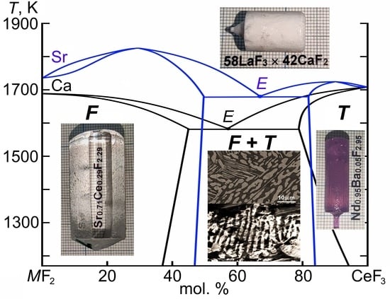
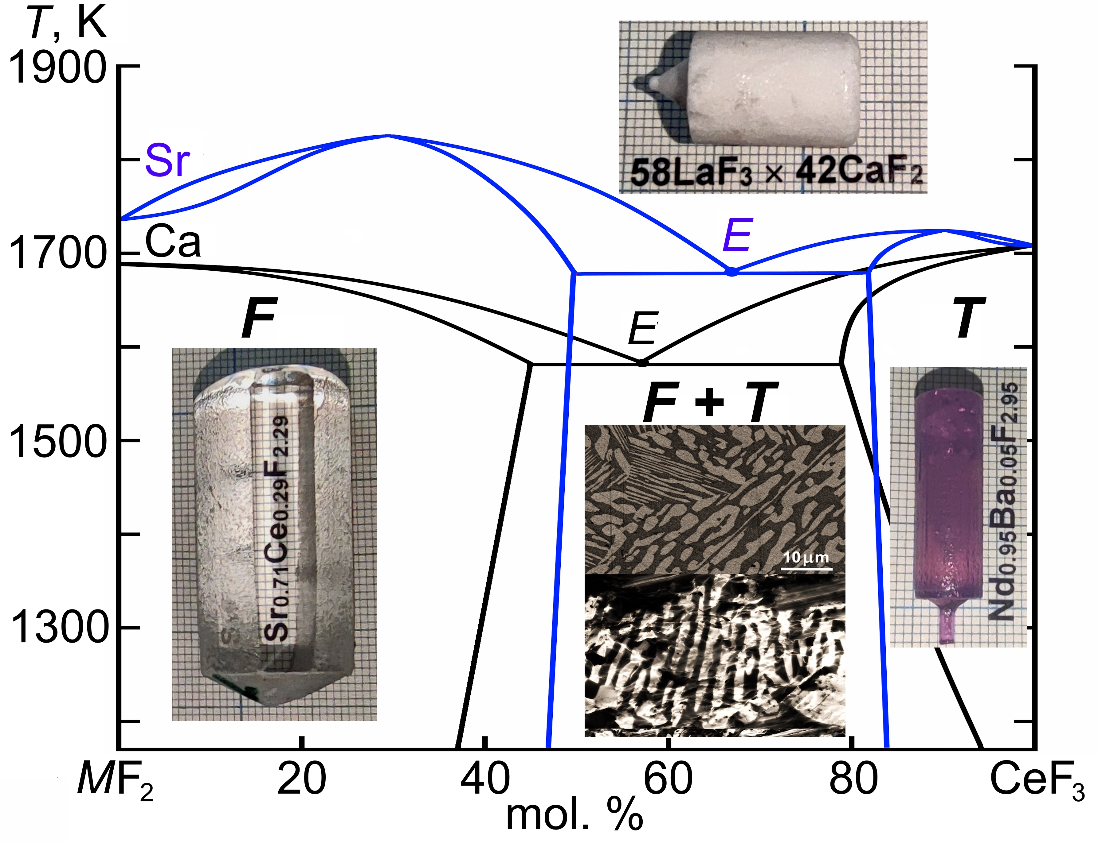
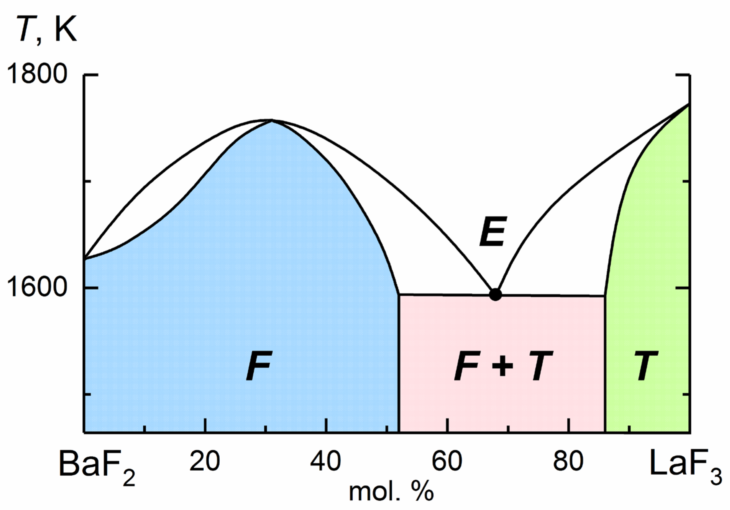
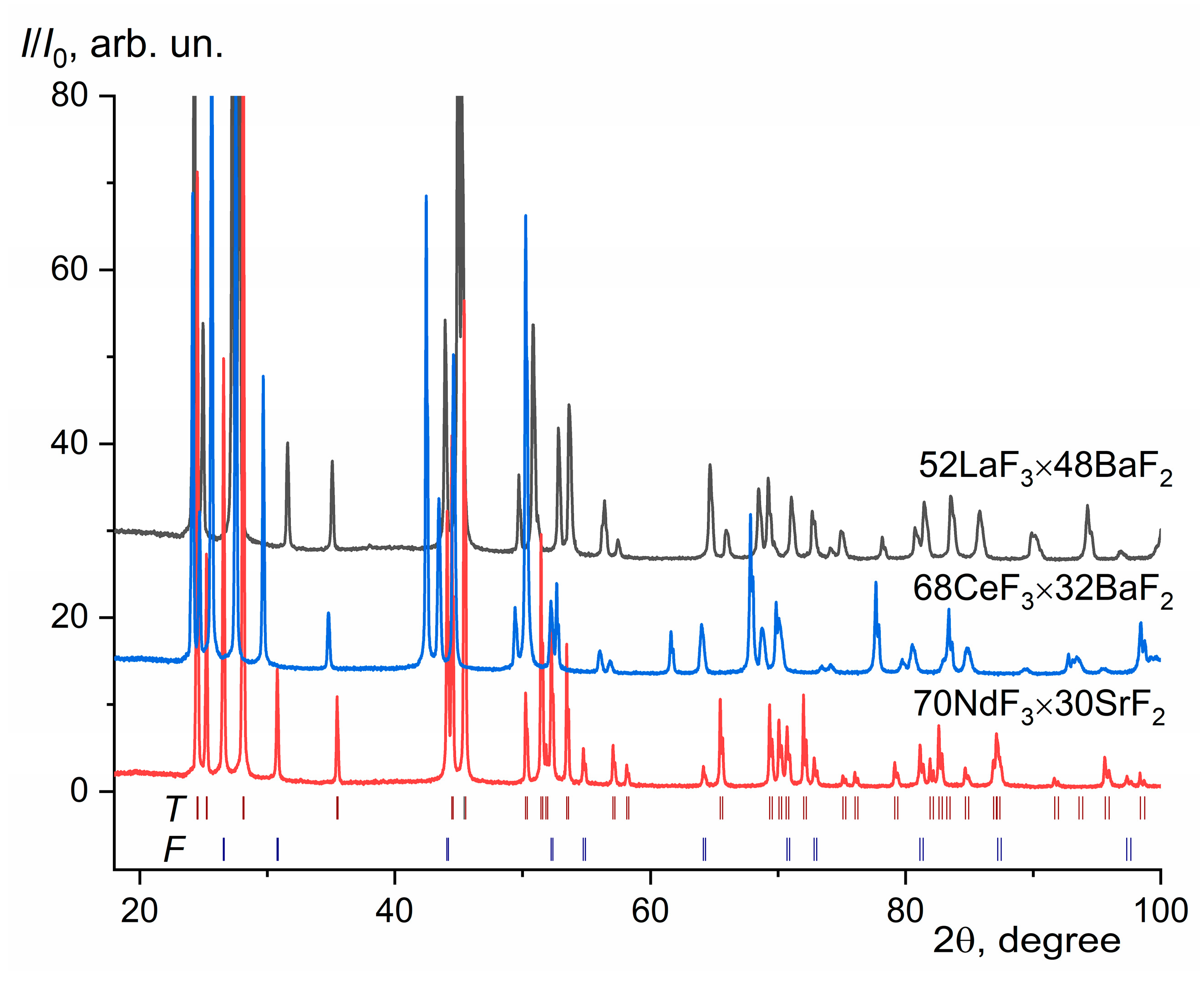
3.1. XRD Characterization of Eutectic Composites

The XRD data reveals two phases in all synthetized composites, consisting of a mixture of nonstoichiometric phases with saturated (at the eutectic temperature TE) compositions for the F (M1−xRxF2+x) and T (R1−yMyF3−y) phases. The unit-cell parameters and the mass ratio of the detected SSs are given in Table 2. The compositions of limiting F and T SSs, given in Table 2, were calculated from analytical concentration dependencies of the form a, c = f(x, y) according to [44,45,46]. Typical XRD patterns of selected composites are shown in Figure 3.
The experimental values of the lattice parameters for crystallized eutectic composites and phase ratios differ greatly from the published data [44,45,46] in terms of the limiting compositions of saturated SSs M1−xRxF2+x and R1−yMyF3−y (see Table 1 for comparison). The best match is observed only for BaF2-based eutectics. Attempts to calculate the values of the limiting compositions of the F- and T-phases for CaF2-based eutectic composites using the analytical concentration dependences of the unit-cell parameters [45] were unsuccessful due to the low accuracy of these data in the areas of limiting phase compositions. The ratio of F- to T-phases based on Rietveld XRD refinement is equimolar or close to it for all composites except 70NdF3 × 30SrF2 and 69NdF3 × 31BaF2 compositions, for which the eutectic molar phase ratio is close to 1:2 (see Table 2). This fact is associated with the accuracy of the determination of the eutectic compositions in the binary phase diagrams MF2–RF3 and, moreover, with the thermodynamic nonequilibrium of the process of directional melt crystallization. Local quasi-eutectic structures can form during nonequilibrium crystallization.
In addition, we should not forget about the role of diffusion processes during the crystallization of such systems. With rapid cooling of the crystallized composite, diffusion processes are inhibited; therefore, a nonequilibrium position of the solidus (the same process is sometimes described by the term “incipient melting”) is realized [49]. This nonequilibrium is associated with the narrowing of the SSs regions (for F- and T-phases simultaneously) based on both components MF2 and RF3 observed in our crystallization experiments (see Table 2) and a significant difference between the calculated lattice parameters and their equilibrium values according to the data [44,45,46].

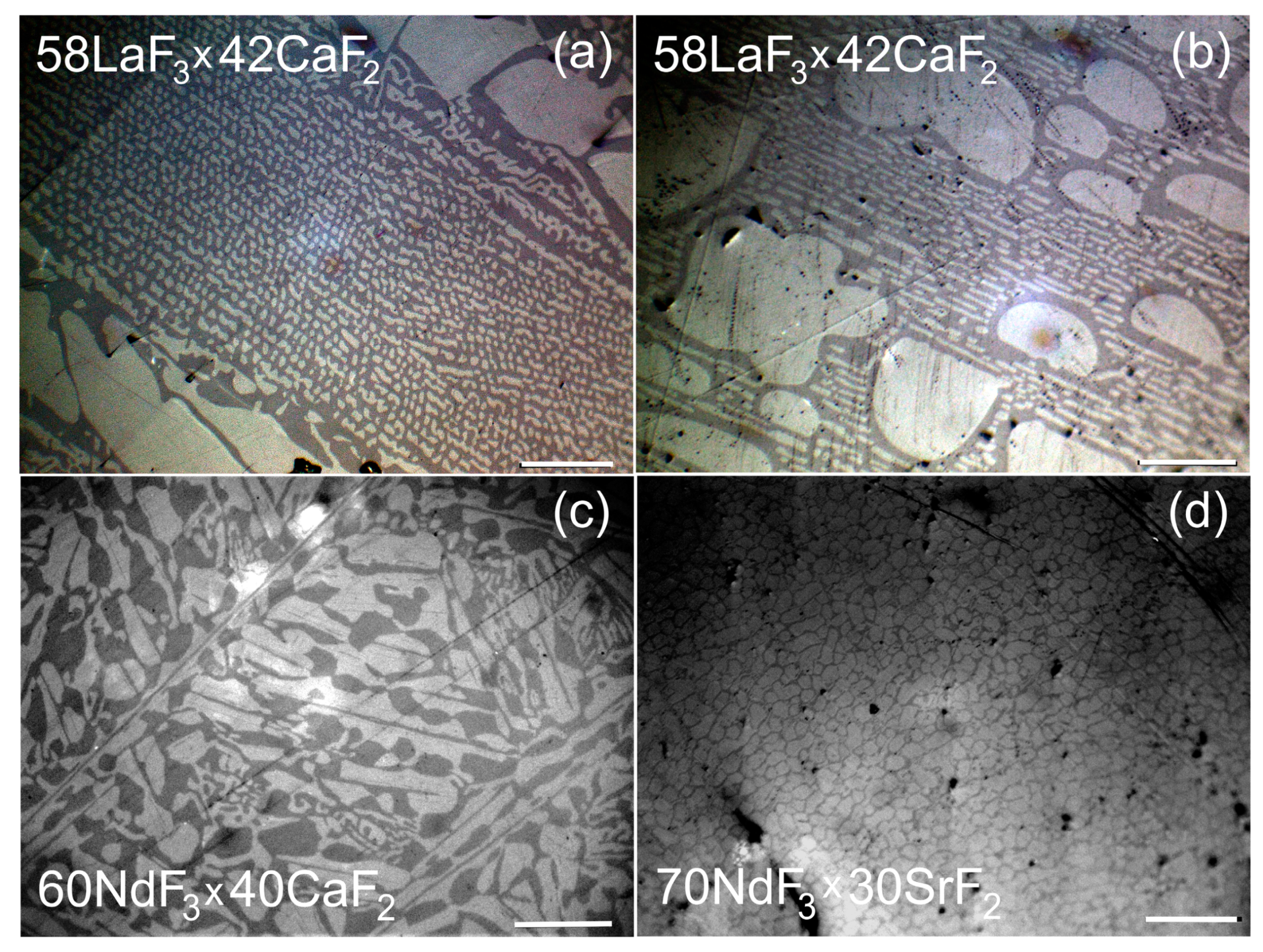
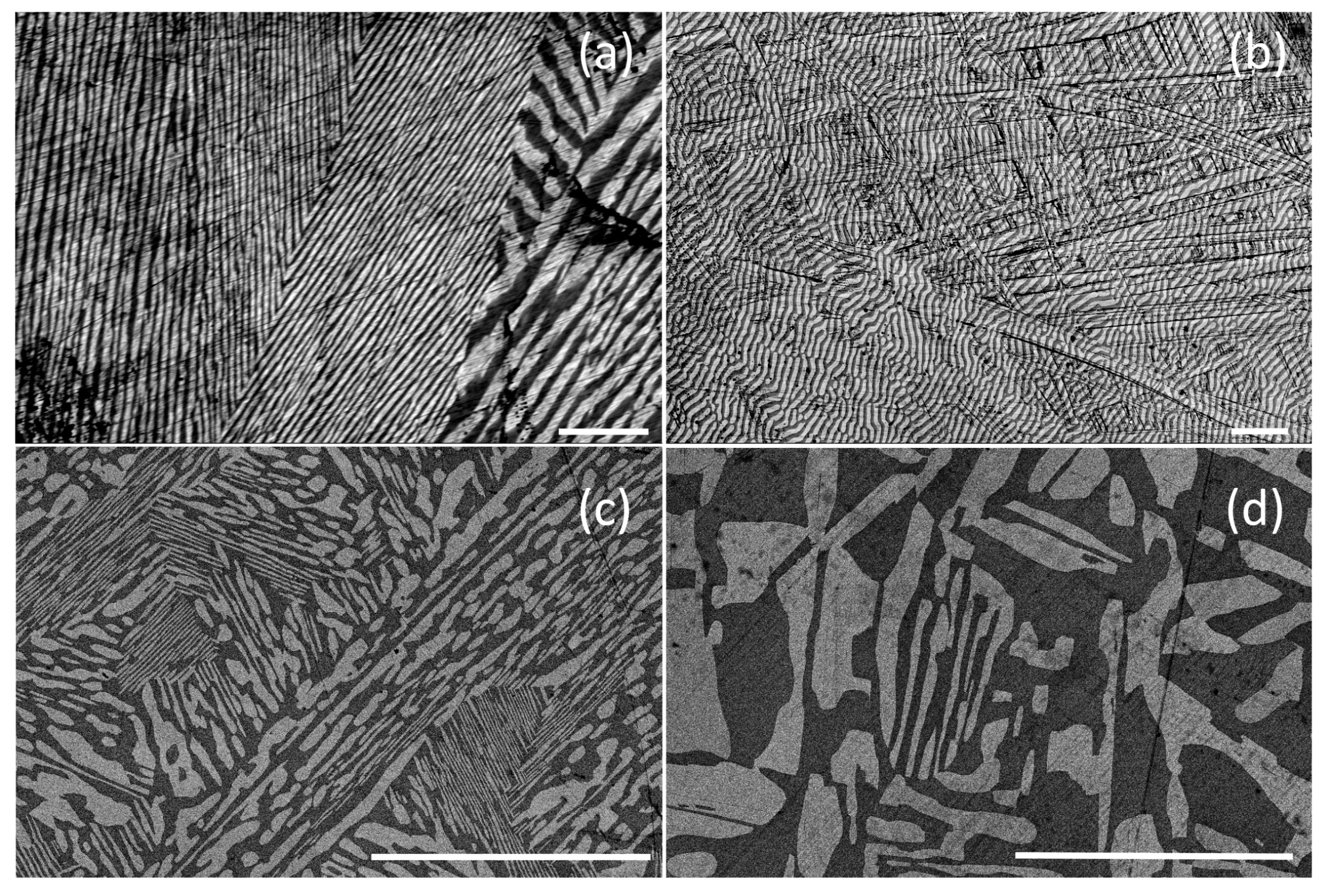
3.2. Characterization of Composites by Optical and SEM Microscopy

Optical and SEM images of some crystalized eutectics are shown in Figure 4 and Figure 5 as examples. A complex block structure is observed with different morphologies of the simultaneous crystallization of the detected phases, which are determined both by the type of components and their ratios and by the accuracy of the coincidence of the initial melt composition with the eutectic point. The low contrast of optical images (Figure 4) is determined by the close values of the refractive indices of the F- and T-phases in the composites [50,51].
Composites with an inhomogeneous fine-grained structure, since two phases (F and T) crystallize and differ greatly in properties (density) and crystal structure, were formed as a result of the directional solidification of an eutectic melt. Within individual crystalline blocks (grains), a directed microstructure of lamellae colonies is visible, between which large single-phase inclusions are located (Figure 4b). The blocks are misoriented in the composite bulks, which may indicate crystallization front instability [6,52]. Interlamellar distances differ significantly for different pRF3 × qMF2 composite materials.
In general, the combination of the lamella and rod microstructures is distributed non-uniformly through the composite bulk (Figure 5). The lamella thickness varies from 3 µm for the 68LaF3 × 32BaF2 samples (Figure 5a,b) to almost 30 µm for the 59PrF3 × 41CaF2 samples (Figure 5c,d). The microstructure of the 68LaF3 × 32BaF2 sample is inhomogeneous and is characterized by the presence of the thinnest lamellae (up to 3 µm). The lamellae tend to stretch along the ingot growth axis (Figure 4a), which correlates with the crystallization direction.
The effect of the melt solidification rate and temperature gradient on the macrostructure of eutectic samples was previously experimentally demonstrated in [21,22], and the LiF–LiYF4 system was used as a model object. Directional crystallization in the rate range of 6–20 mm/h was used in [21], while the micro-pulling-down method with a rate of 6–90 mm/h was applied in [22] to fabricate LiF/LiYF4 eutectic composites. The diameter of the rod-like LiF in the LiYF4 matrix systematically decreased with an increasing growth rate. The relationship between the diameter of the rod-like phase and the growth rate is in accordance with the Hunt-Jackson law [6]. In our experiments, the crystallization of eutectic compositions occurred at a rate of about 10 mm/h.
To fabricate the most homogeneous and anisotropic materials (with a directional and controlled texture), it is necessary to select the optimal conditions by varying the rate of the crucible pulling and the temperature gradient at the crystallization front for each specific eutectic composition. Large axial gradients and growth rates should help solve this problem and stabilize the directional solidification process of polycrystalline eutectics.

3.3. Temperature Dependence of the Ionic Conductivity of Composites

Composite samples for conductometric studies were cut from the middle of crystallized ingots perpendicular to the growth axis. Temperature dependencies of ionic conductivity for pRF3 × qBaF2 composites (R = La, Ce, and Nd) are shown in Figure 6 in comparison with the data [53,54,55]. It is clearly seen that the conductivity of composites with approximately the same quantitative ratio of components increases with an increase in the ionic radius of rare-earth cations R3+. In terms of electrical conductivity, the 68LaF3 × 32BaF2 composite occupies a position between the Ba0.5La0.5F2.5 fluorite-type SS and the tysonite-type La0.95Ba0.05F2.95 one [53,54].
The σdc(T) dependence composites were fitted according to the Arrhenius-type equation:
σdcT = Aexp(−Ha/kT),
where A is a pre-exponential conductivity multiplier, Ha is an activation enthalpy of ion transport, k is the Boltzmann’s constant, and T is a temperature.
The parameters of the Arrhenius equation for the studied composites are given in Table 3, where data are additionally given for previously studied eutectics [39,40]. The values of the activation enthalpy Ha for composites differ little from each other and amount to 0.5–0.6 eV.
The ionic conductivity characteristics of pRF3 × qMFn (n = 1, 2) eutectic composites in systems MF–RF3 and MF2–RF3 according to our measurements and data [2,18,25,26,32,33,34,35,36,37,38,39,40] are summarized in Table 4. It can be clearly concluded that the σdc-values of the pRF3 × qMF2 composites (M = Ca, Sr, Ba; R = La–Sm) are among the highest and reach ~10−2 S/cm at T = 500 K. The La-based pLaF3 × qMF2 (M = Sr, Ba) eutectics demonstrate the maximum fluorine-ionic conductivity among those studied to date. Their electrolytic properties are not inferior to eutectic composites based on the fluorite-type modification of β-PbF2 (25ScF3 × 75PbF2 [33], 31NaF × 69PbF2 [35], 34NaF × 66PbF2 [36,56]).

3.4. Anisotropy of the Ionic Conductivity of Composites

To estimate the anisotropy of the ionic conductivity of the composites synthesized from the melt by the method of directional crystallization, the impedance of the 59PrF3 × 41CaF2 eutectics was measured along and across the direction of crystallization. Practically quasi-isotropic conductivity of this composite was obtained; the σdc-values at 294 K are 4.9 × 10⁻⁷ and 4.5 × 10⁻⁷ S/cm for longitudinal and transverse sections, respectively. The anisotropy factor of the electrical conductivity of the 59PrF3 × 41CaF2 composite is about 10% at room temperature. Therefore, the influence of the directed eutectic microstructure on the electrical conductivity of composites can be neglected in the first approximation. This observation agrees well with the data on the absence of ionic conductivity anisotropy in 35LiF × 65PbF2 [18] and 34NaF × 66PbF2 [36,56] melt-crystallized eutectic composites. The quasi-isotropic nature is determined by the absence of sufficiently large homogeneous grains in the eutectic sample during their directional crystallization. For composites consisting of large, misoriented grains, the anisotropy of conductivity would be more noticeable. The electrical conductivity of NaF-based eutectic composites (NaF × CaF2 and NaF × LiF) exhibits a large anisotropy due to their oriented microstructure [29], and the electrical conductivity measured in the growth direction was about an order of magnitude higher than that measured perpendicular to it.

3.5. The Mechanism of Fluorine-Ionic Conductivity in pRF3 × qMF2 Composites

As already mentioned, binary systems MF2–RF3 (M = Ca, Sr, Ba; R = La–Nd) belong to the simple eutectic type and do not form intermediate stoichiometric compounds. Only limited regions of SSs M1−xRxF2+x (fluorite type) and R1−yMyF3−y (tysonite type) are formed in these systems. The M1−xRxF2+x and R1−yMyF3−y SSs have superionic conductivity and are medium- and low-temperature solid electrolytes, respectively [41,42,43,57,58]. Mobile carriers are interstitial fluorine ions in fluorite-type anion-rich M1−xRxF2+x crystals [59] and fluorine vacancies in tysonite-type anion-deficient R1−yMyF3−y crystals [60]. The eutectic composites pRF3 × qMF2 are two-phase materials consisting of interpenetrating components—extremely saturated SSs M1−xRxF2+x and R1−yMyF3−y. In terms of conductivity, the composites are located between the M1−xRxF2+x [41,42,43,50] and R1−yMyF3−y [41,51,57,58] crystals (see Figure 6) and are superior to ceramics of similar compositions synthesized by mechanochemical (ball milling) synthesis [55,61,62,63,64]. Between the ionic conductivity characteristics of eutectic composites and single phases of fluorite or tysonite-type in the SrF2–RF3 (R = La–Nd) systems, a “conductivity-composition” correlation was found [65]. Some compositions of pRF3 × qMF2 composites with M = Ca, Sr, Ba, and R = La–Nd were recently patented by us as medium-temperature solid electrolytes [66].

4. Conclusions

A series of eutectic composites in the CaF2–RF3 (R = Pr, Nd), SrF2–NdF3, and BaF2–RF3 (R = La, Ce, Nd) systems have been grown by vertical directional crystallization, and their ionic conductivity has been studied. The fabricated composites are characterized by a fine lamellar microstructure for BaF2-based systems and a mixed microstructure for CaF2- and SrF2-based fluoride systems. It was found that the studied composites have almost quasi-isotropic conductivity, which is an important property for practical applications.
The 68LaF3 × 32BaF2 and 58LaF3 × 42CaF2 composites tend to form extended, thin lamellae. The creation of such a given microstructure is a direction for further research. The realization of such a homogeneous columnar microstructure of the eutectic composite can be achieved by significantly reducing the rate of crystallization.
The observed features of the temperature dependence of the ionic conductivity of the studied composites are a consequence of the phase composition and morphology of the crystallizing eutectics. The temperature dependencies σdc(T) satisfy the Arrhenius-type equation with the activation enthalpy Ha = 0.5–0.6 eV. The values of the ionic conductivity of the composites are 10−3–10−2 S/cm at 500 K. The eutectic composites based on LaF3 and MF2 (M = Sr, Ba) demonstrate the maximum electrical conductivity and are promising for further development.
The eutectic composites have improved mechanophysical properties, and their synthesis requires lower energy expenditures in comparison with single crystals of nonstoichiometric M1−xRxF2+x or R1−yMyF3−y phases, so they are of undoubted interest for solid-state ionics and fluoride material science.

Author Contributions

Conceptualization, I.I.B. and D.N.K.; methodology, N.I.S.; validation, N.I.S.; formal analysis, D.N.K.; investigation, I.I.B., N.A.A., A.G.I., N.I.S. and D.N.K.; writing—original draft preparation, I.I.B. and N.I.S.; writing—review and editing, I.I.B. and D.N.K.; supervision, D.N.K. All authors have read and agreed to the published version of the manuscript.

Funding

This research was performed within the State assignment of the Federal Scientific Research Centre “Crystallography and Photonics” of the Russian Academy of Sciences using the equipment of the Shared Research Center of the FSRC «Crystallography and Photonics» RAS in part of the development of approaches to the melt synthesis of composites and was supported by RSF (project # 23-23-00479) in part of the investigation of the ion-conducting properties of composites.

Institutional Review Board Statement

Not applicable.

Informed Consent Statement

Not applicable.

Data Availability Statement

Data sharing is not applicable to this article.

Acknowledgments

The authors are deeply indebted to Boris P. Sobolev for conceptual support of this study and Tatyana O. Teplyakova for their invaluable assistance in research.

Conflicts of Interest

The authors declare no conflict of interest.

References

  1. Uvarov, N.F. Composite solid electrolytes: Resent advances and design strategies. J. Solid State Electrochem. 2011, 15, 367–389. [Google Scholar] [CrossRef]
  2. Sorokin, N.I. Superionic transport in fluoride composites and glasses. Russ. J. Electrochem. 2004, 40, 569–577. [Google Scholar] [CrossRef]
  3. Llorca, J.; Orera, V.M. Directionally solidified eutectic ceramic oxides. Prog. Mater. Sci. 2006, 51, 711–809. [Google Scholar] [CrossRef]
  4. Pawlak, D.A.; Turczynski, S.; Gajc, M.; Kolodziejak, K.; Diduszko, R.; Rozniatowski, K.; Smalc, J.; Vendik, I. Metamaterials: How far are we from making metamaterials by self-organization? The microstructure of highly anisotropic particles with an SSR-like geometry. Adv. Funct. Mater. 2010, 20, 1116–1124. [Google Scholar] [CrossRef]
  5. Ashbrook, R.L. Directionally solidified ceramic eutectics. J. Am. Ceram. Soc. 1977, 60, 428–435. [Google Scholar] [CrossRef]
  6. Hunt, J.D.; Lu, S.Z. Crystallization of eutectics, monotectics and peritectics. In Handbook of Crystal Growth; Hurle, D.T.J., Ed.; North–Holland Elseiver Science: Amsterdam, The Netherlands; New York, NY, USA, 1994; Volume 2, Part B, pp. 1111–1166. [Google Scholar]
  7. Akamatsu, S.; Plapp, M. Eutectic and peritectic solidification patterns. Curr. Opin. Solid State Mater. Sci. 2016, 20, 46–54. [Google Scholar] [CrossRef] [Green Version]
  8. Gao, K.; Zhang, Z.; Zhao, J.; Sun, D.; Wang, F. Orientation and microstructure evolution of Al-Al2Cu regular eutectic lamellar bifurcating in an abruptly changing velocity under directional solidification. Materials 2020, 13, 1004. [Google Scholar] [CrossRef] [Green Version]
  9. Semenenko, V.E.; Kovtun, G.P. Influence of rolling on the stability of the compositional microstructure of eutectic alloys. Voprosy Atomnoy Nauki i Tekhniki 2002, 1, 148–150. (In Russian) [Google Scholar]
  10. Gus’kov, A.P. Stability of the interphase boundary during the crystallization of eutectics. Tech. Phys. Lett. 2001, 27, 480–483. [Google Scholar] [CrossRef]
  11. Gus’kov, A.; Orlov, A. Dependence of period of macrostructures on kinetic parameters under directed crystallization. Comput. Mater. Sci. 2002, 24, 93–98. [Google Scholar] [CrossRef]
  12. Bei, H.; George, E.P. Microstructures and mechanical properties of a directionally solidified NiAl-Mo eutectic alloy. Acta Mater. 2005, 53, 69–77. [Google Scholar] [CrossRef]
  13. Ohashi, Y.; Yasui, N.; Suzuki, T.; Watanabe, M.; Den, T.; Kamada, K.; Yokota, Y.; Yoshikawa, A. Orientation relationships of unidirectionally aligned GdAlO3/Al2O3 eutectic fibers. J. Eur. Ceram. Soc. 2014, 34, 3849–3857. [Google Scholar] [CrossRef]
  14. Orera, V.M.; Merino, R.I.; Pardo, J.A.; Larrea, A.; Pena, J.I.; Gonzalez, C.; Poza, P.; Pastor, J.Y.; Llorca, J. Microstructure and physical properties of some oxide eutectic composites processed by directional solidification. Acta Mater. 2000, 48, 4683–4689. [Google Scholar] [CrossRef]
  15. Cicka, R.; Trnovcova, V.; Starostin, M.Y. Electrical properties of alumina–zirconia eutectic composites. Solid State Ion. 2002, 148, 425–429. [Google Scholar] [CrossRef]
  16. Trnovcova, V.; Starostin, M.Y.; Cicka, R.; Fedorov, P.P.; Barta, C.; Labas, V.; Sobolev, B.P. Microstructure and fast ionic conduction of inorganic fluoride and oxide eutectic composites prepared from the melt. Solid State Ion. 2000, 136–137, 11–17. [Google Scholar] [CrossRef]
  17. Semenenko, V.E.; Pylypenko, M.M. The morphology of carbide phases in eutectic alloys created by unidirectional solidification. Vopr. At. Nauk. Tekhniki 2003, 13, 117–121. (In Russian) [Google Scholar]
  18. Fedorov, P.; Trubitsyn, M.; Trnovtseva, V.; Sobolev, B. Obtaining the eutectic composition in the LiF-PbF2 system. Inorg. Mater. 1992, 28, 1805–1808. [Google Scholar]
  19. Kim, K.J.; Furuya, Y.; Kamada, K.; Murakami, R.; Kochurikhin, V.V.; Yoshino, M.; Chiba, H.; Kurosawa, S.; Yamaji, A.; Shoji, Y.; et al. Growth and Scintillation Properties of Directionally Solidified Ce:LaBr3/AEBr2 (AE = Mg, Ca, Sr, Ba) Eutectic System. Crystals 2020, 10, 584. [Google Scholar] [CrossRef]
  20. Cheng, S.; Hunneke, R.E.; Tian, M.; Lukosi, E.; Zhuravleva, M.; Melcher, C.L.; Wu, Y. Self-assembled natLiCl-CeCl3 directionally solidified eutectics for thermal neutron detection. CrystEngComm 2020, 22, 3269–3273. [Google Scholar] [CrossRef]
  21. Barta, C.; Fendrych, F.; Recker, K.; Triska, A.; Wallrafen, F. On the influence of the crystallization conditions on the microstructure of the directionally solidified eutectic of the LiF-LiYF4 system. Cryst. Res Technol. 1991, 26, 413–424. [Google Scholar] [CrossRef]
  22. Nishimoto, K.; Yokota, Y.; Kurosawa, S.; Fujimoto, Y.; Kawaguchi, N.; Fukuda, K.; Yoshikawa, A. Crystal growth of LiF/LiYF4 eutectic crystals and their luminescent properties. J. Eur. Ceram. Soc. 2014, 34, 2117–2121. [Google Scholar] [CrossRef]
  23. Yanagida, T.; Fukuda, K.; Fujimoto, Y.; Kawaguchi, N.; Kurosawa, S.; Yamazaki, A.; Watanabe, K.; Futami, Y.; Yokota, Y.; Pejchal, J.; et al. Eu-doped 6LiF-SrF2 eutectic scintillators for neutron detection. Opt. Mater. 2012, 34, 868–871. [Google Scholar] [CrossRef]
  24. Hishinuma, K.; Kamada, K.; Kurosawa, S.; Yamaji, A.; Pejchal, J.; Yokoto, Y.; Jhashi, Y.; Yoshikawa, A. LiF/CaF2/LiBaF3 ternary fluoride eutectic scintillator. Jpn. J. Appl. Phys. 2015, 54, 04DH04. [Google Scholar] [CrossRef] [Green Version]
  25. Trnovcova, V.; Fedorov, P.P.; Barta, C.; Labas, C.V.; Meleshina, V.A.; Sobolev, B.P. Microstructure and physical properties of superionic eutectic composites of the LiF-RF3 (R-rare earth element) system. Solid State Ion. 1999, 119, 173–180. [Google Scholar] [CrossRef]
  26. Trnovcova, V.; Fedorov, P.P.; Buchinskaya, I.I.; Smatko, V.; Hanic, F. Fast ionic conductivity of PbF2:MF2 (M = Mg, Ba, Cd) and PbF2:ScF3 single crystals and composites. Solid State Ion. 1999, 119, 181–189. [Google Scholar] [CrossRef]
  27. Wakahara, S.; Furuya, Y.; Yanagida, T.; Yokoto, Y.; Pejchal, J.; Sugiyama, M.; Kawaguchi, N.; Totsuka, D.; Yoshikawa, A. Crystal growth and scintillation properties of Ce-doped sodium calcium lutetium complex fluoride. Opt. Mater. 2012, 34, 729–732. [Google Scholar] [CrossRef]
  28. Karimov, D.N.; Sorokin, N.I.; Grebenev, V.V.; Ivanova, A.G.; Arkharova, N.A.; Orekhov, A.S.; Sobolev, B.P. 75LiF+25SmF3 eutectic composite and ionic conductivity of SmF3 near the polymorphic α-β transition. Crystallogr. Rep. 2020, 65, 468–472. [Google Scholar] [CrossRef]
  29. Hartmann, E.; Peller, V.V.; Rogalski, G.I. Electrical conductivity of fluoride eutectic composites. Solid State Ion. 1988, 28–30, 1098–1101. [Google Scholar] [CrossRef]
  30. Xiang, M.; Zhang, Y.; Lin, H.; Zhu, Y.; Guo, X.; Chen, J.; Li, L. LiBH4-NaX (X = Cl, I) composites with enhanced lithium ionic conductivity. J. Alloys Compd. 2018, 764, 307–313. [Google Scholar] [CrossRef]
  31. Trnovcova, V.; Fedorov, P.P.; Furar, I. Fluoride solid electrolytes. Russ. J. Electrochem. 2009, 45, 630–639. [Google Scholar] [CrossRef]
  32. Trnovcova, V.; Barta, C.; Zibrov, I.P.; Fedorov, P.P. Phase relations, microstructure and physical properties of superionic fluoride composites. Mater. Sci. Forum 1991, 76, 13–18. [Google Scholar] [CrossRef]
  33. Medvedeva, L.V.; Sorokin, N.I.; Vistin’, L.L.; Fedorov, P.P.; Sobolev, B.P. Phase equilibria in the system LiF-SrF2-LaF3 and ionic conductivity of the eutectic electrolyte. Russ. J. Inorg. Chem. 1994, 39, 304–306. [Google Scholar]
  34. Sorokin, N.I.; Buchinskaya, I.I.; Bystrova, A.A.; Konovalova, V.V.; Sobolev, B.P. Eutectic composition systems NaF-DyF3, NaF-HoF3 and MgF2-ScF3 as ionic conductors. Russ. J. Electrochem. 2005, 41, 900–902. [Google Scholar] [CrossRef]
  35. Trnovcova, V.; Fedorov, P.P.; Buchinskaya, I.I.; Sobolev, B.P. Ionic conductivity of the PbF2-NaF eutectic composite and PbF2 single crystals doped with alkali fluorides. Inorg. Mater. 1996, 32, 1104–1107. [Google Scholar]
  36. Buchinskaya, I.I.; Fedorov, P.P.; Sorokin, N.I.; Akchurin, M.S.; Sobolev, B.P. Section Pb0.67Cd0.33F2.00-NaF and the conductivity of the composites. Rus. J. Inorg. Chem. 1996, 41, 166–170. [Google Scholar]
  37. Trnovcova, V.; Garashina, L.S.; Skubla, A.; Fedorov, P.P.; Cicka, R.; Krivandina, E.A.; Sobolev, B.P. Structural aspects of fast ionic conductivity of rare earth fluorides. Solid State Ion. 2003, 157, 195–201. [Google Scholar] [CrossRef]
  38. Fedorov, P.P.; Trnovcova, V.; Meleshina, V.A.; Chugunov, V.D.; Sobolev, B.P. Eutectic alloys in PbF2-RF3 systems (R = Ho, Yb, Sc). Inorg. Mater. 1994, 30, 384–388. [Google Scholar]
  39. Sorokin, N.I.; Sobolev, B.P. Conductivity of a eutectic composite in the SrF2-LaF3 system. Crystallogr. Rep. 1996, 41, 490–493. [Google Scholar]
  40. Sorokin, N.I.; Karimov, D.N.; Samsonova, N.V.; Ivanova, A.G.; Fedorov, V.A.; Sobolev, B.P. Growth of Sm1−ySryF3−y (0 < y ≤ 0.31) crystals and investigation of their properties. Crystallogr. Rep. 2019, 64, 488–495. [Google Scholar] [CrossRef]
  41. Sorokin, N.I. Superionic transport in solid fluoride solutions with a fluorite structure. Russ. J. Electrochem. 2006, 42, 744–759. [Google Scholar] [CrossRef]
  42. Sobolev, B.P.; Sorokin, N.I. Nonstoichiometry in inorganic fluorides: 2. Ionic conductivity of nonstoichiometric M1−xRxF2+x and R1−yMyF3−y crystals (M = Ca, Sr, Ba; R are rare earth elements). Crystallogr. Rep. 2014, 59, 807–830. [Google Scholar] [CrossRef]
  43. Sobolev, B.P.; Sorokin, N.I.; Bolotina, N.B. Nonstoichiometric single crystals M1−xRxF2+x and R1−yMyF3−y (M-Ca, Sr, Ba; R-rare earth elements) as fluorine-conducting solid electrolytes. In Progress in Fluorine Science; Tressaud, A., Poeppelmeier, K., Eds.; Elsevier: Amsterdam, The Netherlands, 2016; Volume 1, Chapter 21; pp. 465–491. [Google Scholar] [CrossRef]
  44. Sobolev, B.P.; Tkachenko, N.L. Phase diagrams of the BaF2-(Y, Ln)F3 systems. J. Less Common Met. 1982, 85, 155–170. [Google Scholar] [CrossRef]
  45. Sobolev, B.P.; Fedorov, P.P. Phase Diagrams of the CaF2-(Y, Ln)F3 systems. I. Experimental. J. Less Common Met. 1978, 60, 33–46. [Google Scholar] [CrossRef]
  46. Sobolev, B.P.; Seiranian, K.B.; Garashina, L.S.; Fedorov, P.P. Phase diagrams of the SrF2-(Y, Ln)F3 Systems. I. X-ray characteristics of phases. J. Solid State Chem. 1979, 28, 51–58. [Google Scholar] [CrossRef]
  47. Buchinskaya, I.I.; Karimov, D.N.; Sorokin, N.I. La1−yBayF3−y Solid Solution Crystals as an Effective Solid Electrolyte: Growth and Properties. Crystals 2021, 11, 629. [Google Scholar] [CrossRef]
  48. Bolotina, N.B.; Chernaya, T.S.; Verin, I.A.; Khrykina, O.N.; Sobolev, B.P. Dimorphism of RF3 (R = La-Nd) crystals based on the data of X-ray diffraction studies. Crystallogr. Rep. 2016, 61, 29–34. [Google Scholar] [CrossRef]
  49. Jackson, K.A.; Hunt, J.D. Lamellar and rod eutectic growth. In Dynamics of Curved Fronts; Pelcé, P., Ed.; Academic Press Inc.: Cambridge, MA, USA, 1988; pp. 363–376. [Google Scholar] [CrossRef]
  50. Konstantinova, A.F.; Krivandina, E.A.; Karimov, D.N.; Sobolev, B.P. Calculation of the Refractive Indices of M1−xRxF2+x Crystals (M = Ca, Sr, Ba, Cd, Pb; R are Rare Earth Elements). Crystallogr. Rep. 2010, 55, 990–994. [Google Scholar] [CrossRef]
  51. Glushkova, T.M.; Karimov, D.N.; Krivandina, E.A.; Zmurova, Z.I.; Sobolev, B.P. Nanostructured crystals of fluorite phases Sr1−xRxF2+x (R = Y, La-Lu) and their ordering: Part III. A study of the refractive indices. Crystallogr. Rep. 2009, 54, 603–608. [Google Scholar] [CrossRef]
  52. Chalmers, B. Principles of Solidification; John Wiley and Sons: Hoboken, NJ, USA; London, UK, 1964; p. 319. [Google Scholar]
  53. Sorokin, N.I.; Breiter, M.W. Anionic conductivity and thermal stability of single crystals of solid solutions based on barium fluoride. Solid State Ion. 1977, 99, 241–250. [Google Scholar] [CrossRef]
  54. Sorokin, N.I.; Fominykh, M.V.; Krivandina, E.A.; Zhmurova, Z.I.; Sobolev, B.P. Ion transport in the anion-deficient nonstoichiometric phases La0.95(Ba1−xSrx)0.05F2.95 (0 ≤ x ≤ 1). Phys. Solid State 1998, 40, 604–607. [Google Scholar] [CrossRef]
  55. Rongeat, C.; Anji Reddy, M.; Witter, R.; Fichtner, M. Nanostructured fluorite-type fluorides as electrolytes for fluoride ion batteries. J. Phys. Chem. C 2013, 117, 4943–4950. [Google Scholar] [CrossRef]
  56. Sorokin, N.I.; Fedorov, P.P.; Sobolev, B.P. Superionic materials based on lead fluoride. Inorg. Mater. 1997, 33, 1–11. [Google Scholar]
  57. Sobolev, B.P.; Sorokin, N.I.; Krivandina, E.A.; Zhmurova, Z.I. 293-K conductivity optimization for single crystals of solid electrolytes with tysonite structure (LaF3): I. Nonstoichiometric phases R1−yCayF3−y (R = La-Lu, Y). Crystallogr. Rep. 2014, 59, 550–562. [Google Scholar] [CrossRef]
  58. Sobolev, B.P.; Sorokin, N.I.; Krivandina, E.A.; Zhmurova, Z.I. Optimization of single crystals of solid electrolytes with tysonite-type structure (LaF3) for conductivity at 293 K: 2. Nonstoichiometric phases R1−yMyF3−y (R = La-Lu, Y.; M = Sr, Ba). Crystallogr. Rep. 2015, 60, 123–129. [Google Scholar] [CrossRef]
  59. Sorokin, N.I. Crystal-physical model of electrotransfer in the superionic conductor Pb1−xScxF2+x (x = 0.1). Phys. Solid State 2018, 60, 714–718. [Google Scholar] [CrossRef]
  60. Sorokin, N.I.; Sobolev, B.P. Frequency response of the low-temperature ionic conductivity of single crystals R1−yMyF3−y (R = La-Er, M = Ca, Sr, Ba, Cd). Phys. Solid State 2008, 50, 416–421. [Google Scholar] [CrossRef]
  61. Breuer, S.; Lunghamer, S.; Kies, A.; Wilkening, M. F anion dynamics in cation-mixed nanocrystalline LaF3: SrF2. J. Mater. Sci. 2018, 53, 13669–13681. [Google Scholar] [CrossRef] [Green Version]
  62. Chable, J.; Martin, A.G.; Bourdin, A.; Body, M.; Legein, C.; Jouanneaux, A.; Crosnier-Lopez, M.-P.; Galven, C.; Dieudonne, B.; Leblanc, M.; et al. Fluoride solid electrolytes: From microcrystalline to nanostructured tysonite-type La0.95Ba0.05F2.95. J. Alloys Compd. 2017, 692, 980–988. [Google Scholar] [CrossRef]
  63. Rongeat, C.; Anji Reddy, M.; Witter, R.; Fichtner, M. Solid electrolytes for fluoride ion batteries: Ionic conductivity in polycrystalline tysonite-type fluorides. ACS Appl. Mater. Interfaces 2014, 6, 2103–2110. [Google Scholar] [CrossRef]
  64. Duvel, A.; Bednarcik, J.; Sepelak, V.; Heitjans, P. Mechanosynthesis of the fast ion conductor Ba1−xLaxF2+x: From the fluorite to the tysonite structure. J. Phys. Chem. C 2014, 118, 7117–7129. [Google Scholar] [CrossRef] [Green Version]
  65. Sorokin, N.I.; Sobolev, B.P. Correlation between the fluorine ion conductivities of Sr1−xRxF2+x (CaF2 type) and R1−ySryF3−y (LaF3 type) crystals in the SrF2-RF3 systems (R = La-Nd). Phys. Solid State 2019, 61, 2034–2040. [Google Scholar] [CrossRef]
  66. Karimov, D.N.; Buchinskaya, I.I.; Sorokin, N.I.; Sobolev, B.P. Fluorine-Conducting Composite Electrolyte and Method for Its Preparation. Patent RU 2702905, 14 October 2019. Bulletin No. 29. [Google Scholar]
Figure 1. A schematic representation of the phase diagram of the BaF2–LaF3 system [44]. Letters F and T denote the regions of SSs with fluorite- and tysonite-type structures, respectively; E is an eutectic point.
Jcs 07 00330 g001
Figure 2. The molar melt compositions and the appearance of the corresponding eutectic ingots synthesized by melt directional crystallization (a) and selected fabricated composite samples (b).
Jcs 07 00330 g002
Figure 3. The XRD patterns of eutectic composites. The positions of the Bragg peaks of the tysonite-type (T) and fluorite-type (F) phases for composite 70NdF3 × 30SrF2 are shown.
Jcs 07 00330 g003
Figure 4. Optical micrographs of longitudinal (a) and transverse (bd) sections of the selected composite ingots. The length of the scale bar is 200 μm.
Jcs 07 00330 g004
Figure 5. SEM images of the typical morphology of longitudinal (a,c) and transverse (b,d) sections of the 68LaF3 × 32BaF2 and 59PrF3 × 41CaF2 eutectic ingots at different magnifications correspondingly. The length of the scale bar is 50 μm. The bright fields correspond to the T-phases.
Jcs 07 00330 g005
Figure 6. Temperature dependence of ionic conductivity of BaF2-based eutectic composites and selected compounds: 1—68LaF3 × 32BaF2, 2—68CeF3 × 32BaF2, 3—69NdF3 × 31BaF2, 4—the fluorite-type Ba0.5La0.5F2.5 single crystal [53], 5—the tysonite-type La0.95Ba0.05F2.95 single crystal [54], 6—the ball-milling fluorite-type Ba0.5La0.5F2.5 nanoceramics [55], and 7—the ball-milling tysonite-type La0.9Ba0.1F2.9 nanoceramics [55].
Jcs 07 00330 g006
Table 1. Compositions, thermal, and phase parameters of eutectics in MF2–RF3 systems according to [44,45,46]. The F- and T-phases denote fluorite (sp. gr. Fm-3m) and tysonite (sp. gr. P-3c1) structure types, respectively.
MF2–RF3 SystemsEutectic
Compositions *
Lattice Parameters *, ÅLimiting Molar Phase Compositions (x, y) at TEMole Phase Ratio (F/T) in Eutectics
mol. % MF2TE, KF-PhaseT-PhaseF-Phase
M1−xRxF2+x
T-Phase
R1−yMyF3−y
aac
CaF2LaF34215845.7097.0547.3140.460.231/0.63
CeF34315815.6767.0357.2500.450.211/0.55
PrF34115735.6506.9827.2170.430.221/0.84
NdF34015575.6386.9567.1930.440.191/0.76
SrF2LaF33017235.8677.1737.3680.490.171/1.61
CeF33416785.8437.1277.3260.500.181/1.10
PrF33416575.8227.0957.2900.490.191/1.28
NdF33016355.8007.0777.2740.500.191/1.81
BaF2LaF33216636.0427.2357.4080.520.141/0.89
CeF33215966.0127.2037.3780.530.161/0.94
PrF33315436.0077.2087.3350.510.181/1.07
NdF33114885.9947.1747.3010.510.181/1.38
* Measurement errors of the phase composition, temperature, and lattice parameters are ±2 mol.%, ±10 K, and ±0.003 Å, respectively.
Table 2. Compositions and parameters of phases forming synthetized eutectic composites based on Rietveld XRD data refinement in the selected binary systems.
Crystallized
Eutectic
Compositions
Lattice Parameters of the Saturated SSs, ÅExperimental Phase Mass Fraction in the
SS Composition
Calculated Limiting Phase Compositions
(x, y)
Mass Phase (F/T) Ratio
F-PhaseT-Phase *F-PhaseT-PhaseF-Phase
M1−xRxF2+x
T-Phase
R1−yMyF3−y
aac
58LaF3 × 42CaF25.662 (1)4.118 (1)7.332 (1)0.43(9)0.57 (10)0.36-1/1.32
59PrF3 × 41CaF25.631 (1)4.053 (1)7.223 (1)0.37 (6)0.63 (9)0.360.151/1.67
60NdF3 × 40CaF25.618 (1)4.028 (1)7.188 (1)0.41 (6)0.59 (10)0.38-1/1.44
70NdF3 × 30SrF25.801 (1)4.069 (1)7.251 (1)0.30 (3)0.70 (5)-0.131/2.33
68LaF3 × 32BaF26.037 (1)4.186 (1)7.419 (1)0.464 (1)0.536 (1)0.540.171/1.16
68CeF3 × 32BaF26.019 (1)4.164 (1)7.372 (1)0.415 (4)0.585 (15)0.510.151/1.41
69NdF3 × 31BaF25.984 (1)4.135 (1)7.310 (1)0.314 (11)0.700 (19)0.530.201/2.23
* T-phase is described within the high-temperature hexagonal tysonite modification (sp. gr. P63/mmc, Z = 2) [48].
Table 3. Fit parameters of temperature dependences of dc conductivity for studied eutectic composite electrolytes in MF2–RF3 systems.
Composites
pRF3 × qMF2
Temperature Range ΔT, KFactor A,
105 S·K/cm
Enthalpy
Ha, eV
References
59PrF3 × 41CaF2297–53710.52this work
60NdF3 × 40CaF2298–5362.90.56
71LaF3 × 29SrF2293–57012–250.57–0.60[39]
70NdF3 × 30SrF2298–5536.40.60this work
69SmF3 × 31SrF2290–541270.65[40]
68LaF3 × 32BaF2296–5350.70.49this work
68CeF3 × 32BaF2298–5360.650.50
69NdF3 × 31BaF2297–7060.40.53
Table 4. The ionic conductivity of selected pRFm × qMFn eutectic composites in the MFn–RFm systems (n, m = 1, 2, 3).
CompositesConductivity σdc, S/cmReferences
293 K500 K
58LaF3 × 42CaF23.5 × 10−7this work
59PrF3 × 41CaF24.2 × 10−71.1 × 10⁻³
60NdF3 × 40CaF21.75 × 10−71.3 × 10⁻³
71LaF3 × 29SrF26 × 10−7–2 × 10−62 × 10−3–7 × 10⁻³[39]
70NdF3 × 30SrF21.8 × 10−71.2 × 10⁻³this work
NdF3 × SrF2~1.6 × 10⁻⁷~2 × 10⁻³[32]
69SmF3 × 31SrF26 × 10−81.5 × 10⁻³[40]
68LaF3 × 32BaF28.2 × 10−71.6 × 10⁻³this work
68CeF3 × 32BaF28.3 × 10−71.2 × 10⁻³
69NdF3 × 31BaF21.3 × 10−74 × 10−4
NdF3 × BaF2~1 ×10⁻⁷~2 × 10⁻⁴[32]
82LaF3 × 18LiF1 × 10−7–2 × 10−72 × 10−5[32]
82LaF3 × 18LiF4 × 10−82.2 × 10⁻⁵[33]
LaF3 × LiF4 × 10−81 × 10−5[25,26]
PrF3 × LiF5 × 10−7~1 × 10⁻⁴[25,26]
82NdF3 × 18LiF1 × 10−7–2 × 10−74 × 10−5[32]
80NdF3 × 20LiF2 × 10−71.2 × 10⁻⁴[2]
NdF3 × LiF6 × 10−78 × 10−5[25,26]
SmF3 × LiF8 × 10−126 × 10−7[25,26]
GdF3 × LiF4 × 10−83 × 10−5[25,26]
ErF3 × LiF~1 × 10−92 × 10−6[32]
YF3 × LiF3 × 10−93 × 10−6[25,26]
75DyF3 × 25NaF2 × 10−7[34]
75HoF3 × 25NaF4 × 10−7[34]
45ScF3 × 55MgF22 × 10−5[34]
52HoF3 × 48PbF27 × 10−92 × 10−5[38]
52YbF3 × 48PbF23 × 10−116 × 10−7[33]
25ScF3 × 75PbF21 × 10−43 × 10−3[33]
38LiF × 62PbF24 × 10−78 × 10−4[18]
31NaF × 69PbF21.5 × 10−44 × 10−3[35]
34NaF × 66PbF26 × 10−55 × 10−3[36,53]
40NaF × 60Pb0.67Cd0.33F24.5 × 10−5[36]
38NaF × 62Pb0.74Cd0.26F22.4 × 10−5[36]
NaF × LiF2 × 10−10–4 × 10⁻⁹[29]
NaF × CaF26 × 10−7–3 × 10⁻⁶[29]
CaF2 × MgF22 × 10−9–1 × 10⁻⁸[16]
LiF × LiBaF3,5 × 10−8–1 × 10⁻⁶[16]
LiF × LiGdF42 × 10−6[25]
LiF × LiYF41 × 10−6–5 × 10⁻⁶[25]
LiF × LiLuF46 × 10−7[25]
Disclaimer/Publisher’s Note: The statements, opinions and data contained in all publications are solely those of the individual author(s) and contributor(s) and not of MDPI and/or the editor(s). MDPI and/or the editor(s) disclaim responsibility for any injury to people or property resulting from any ideas, methods, instructions or products referred to in the content.

