Article

Development of a Bike-Sharing System Based on Pedal-Assisted Electric Bicycles for Bogota City

1
Escuela de Ciencias Exactas e Ingeniería, Universidad Sergio Arboleda, 110221 Bogota, Colombia
2
Department of Electronics, Pontificia Universidad Javeriana, 110231 Bogota, Colombia
*
Author to whom correspondence should be addressed.
Electronics 2018, 7(11), 337; https://doi.org/10.3390/electronics7110337
Submission received: 19 September 2018 / Revised: 9 October 2018 / Accepted: 12 October 2018 / Published: 20 November 2018
(This article belongs to the Special Issue Green Communications in Smart City)

Abstract

:
The lack of sustainable solutions to mobility and transportation is a major problem in Latin American cities and requires prompt solutions. The main issues in Latin America are the high-cost of solutions, no inclusion of renewable energies, poor energy management, the use of foreign systems not adapted to local contexts, ineffective regional legislation and politics, among others. In this paper the main technical issues concerning the implementation of a bike-sharing system using pedaling-assisted (PAS) electric bicycles for Bogota City are discussed and a solution is proposed. To solve such problems, a methodology to design a tailored solution well suited to Bogota citizen’s needs is developed. Such methodology starts with the development of an on-board-computer (OBC) in order to characterize bike-users by collecting a rider’s data in real-time. Furthermore, the proposed solution develops a low-cost middle-drive (mid-drive) propulsion system for the PAS in the electric bike using brushless-DC (BLDC) motors and by implementing a field-oriented controller (FOC). The reported bike-sharing system also includes the development and implementation of two charging-stations that enable charging the battery on the electric bikes exclusively by using photovoltaic energy. Experimental results are presented and discussed.

1. Introduction

Public transportation in Bogota City, Colombia, has critical and almost overwhelming problems (air pollution, traffic-jam, saturation, among others) that negatively impact the citizen’s quality of life [1,2]. Although the problem is particularly dramatic in Bogota, according to [1] it is common in crowded cities and is particularly related to the Andean region due to cultural reasons. Therefore, alternative solutions for transportation and mobility are being promoted by local authorities. Moreover, the beginning of a transition in means of transportation has been witnessed worldwide to address new environmental, social and economic challenges [3].
Vehicles powered by electricity are one of the best alternatives to propulsion with fossil fuels. Among electric vehicles, the electric bicycle is the means of transportation with the highest growth as measured in the number of units sold per year [2,3]. Currently, the largest market for electric bicycles is China, reaching 170 million units in use by 2013. Health, economic and social benefits of bicycles sharing systems are reported in [2].
The commercial success of electric bicycles has increased the popularity of related technologies, promoted low-cost solutions and encouraged innovation in the area.
In Colombia, the electric bicycle as a transportation system is being introduced in markets using a model of “import-marketing”, i.e., sellers buy overseas and re-sell to Colombian users. Therefore, bicycles with no added value to the Colombian traffic scenario are available to the public. The main consequences of this business model are: (i) lack of local support services; (ii) electric bicycles may not be suited to the topography of Colombian cities nor the usage routine of the users; (iii) lack of urban infrastructure available for charging electric bicycles; and (iv) most of imported bicycles lack efficient power systems, since the low cost of batteries overseas means energy efficiency is not a design priority.
The above context highlights the opportunities and challenges to Colombian industries to become developers of solutions and innovations in electric bicycles technologies. Opportunities in the Colombian context are supported since in Colombia there are:
  • A long-standing industry and experience in electric motors (e.g., Siemens), metalworking and machining.
  • Numerous companies dedicated to the design and manufacture of bicycles.
  • A deep-rooted culture of bicycle use.
  • National lawmaking, normativity and regulations encouraging the development, innovation and use of efficient energy solutions and alternative energy sources [4,5].
Therefore, since the year 2015 researchers from the School of Exact Sciences and Engineering (ECEI) from University Sergio Arboleda, in Bogota, have been working on answering the following question:
  • How should be a public transport system based on shared electric bicycles be implemented so that it is sustainable, safe and appropriate to the characteristics of the bike-users of Bogota City?
In order to address this matter, several elements must be considered: (i) the identification and quantification of the Latin American bike-user’s needs, their habits and social context (e.g., high thefts rates and accidents); (ii) the use of assisted pedaling with low-cost sensors; (iii) the need to incorporate more efficient power alternatives, such as middle-drive (mid-drive) propulsion, that not only positively impacts the use of energy resources but also the environment; (iv) the ability to offer warranties and customer service over all the system components; and (v) integration of the electric bicycle system with mobile applications for rental services, among others.
In this paper, the development of a bike-sharing system based on pedal-assisted electric bikes for Bogota City is presented. In the present work are reported: (i) the characterization of Bogota bike-users using an embedded system; (ii) a mid-drive type propulsion system for the electric bicycle using brushless-DC (BLDC) motors and field-oriented controllers (FOC); and (iii) the development of charging stations for electric bikes exclusively using photovoltaic energy.
In the following, basic concepts related to bike-sharing systems, such as pedaling assistance systems (PAS), electric bike powertrains, batteries and Internet of Things (IoT) principles are reported. Then, Section 2 presents a brief outline of related work emphasizing state-of-the-art of information and communications technologies (ICT) for bike-sharing systems, as well as outstanding advances in charging systems for electric bicycles, developments in electric bicycles in Colombia, and some latest developments worldwide. In Section 3, different subsystems, such as the characterization of bike-users using on-board embedded systems, the design and implementation of a low-cost mid-drive propulsion system, and the development of photovoltaic charging stations are explained. In Section 4, several experiments carried out during the project and are reported and discussed. Finally, Section 5 presents concluding remarks are presented.

1.1. Pedaling Assistance Systems for Electric Bicycles

For the propulsion of electric bicycles there are two main schemes [6]: manual acceleration control and PAS. In the former, the electric motor can aid the user without pedaling. In the second, PAS, it is the pedaling action that activates the electric propulsion. The main advantage of PAS propulsion system is that it optimizes the use of the electric energy in the bicycle, in comparison with manual accelerator where energy is wasted, and battery autonomy is reduced. The PAS system is mandatory in electric bicycles in Europe (see Regulation (EU) No 168/2013 [7]), as well as in Colombia [8], so that the electric vehicle can be considered a bicycle. In Europe, electric bicycles with PAS are also called “pedelecs” [3].
The level of assistance of the electric motor in a PAS system is usually a function of the pedaling velocity. In the most efficient systems, the effort or torque applied by the user is measured to “help” the user with a power proportional to the effort the user is making [9]. In this technology, torque is measured with diverse sensors located in the bicycle chain, the pedals, the gears, or the bicycle frame. The main drawback of these sensors is their excessive cost (approximately USD 150–300).
Hereafter, the term “e-bike” will be used to refer to those electric bicycles equipped with PAS where the assistance cuts out when the user ceases to pedal or when the bicycle exceeds 25 km/h, according to Resolution No. 160 of 2 February 2017 [8], issued by the Ministry of Colombian Public Transportation, which regulates bicycles with PAS and their uses in Colombia. Resolution No. 160 also states that an e-bike with PAS should not weigh more than 35 kg and the electric motor in the bicycle should not have power greater than 0.35 kW.

1.2. Electric Motors and Powertrain Systems for E-Bikes

Brushless-DC motors (BLDC) are well suited to be used in e-bikes since they are silent and efficient, have a long-lasting life, work well at low temperatures, and allow precise control of velocity and torque [10]. The efficient use of BLDC motors requires the continuous measurement of the motor windings position as well as the computation of precise control signals [11]. Nevertheless, the benefits of the current state-of-the-art in semiconductor components and the low cost of microprocessors has allowed the development of increasingly reliable and inexpensive controllers. Therefore, BLDC motors have become the most adopted option in the industry for the propulsion of light electric vehicles (LEV) and are usually the first choice for use in propulsion systems of electric bicycles.
The powertrain is the system used to transmit the power of the electric motor to the bicycle. For light electric vehicles (e.g., bicycles, tricycles, two-seater, etc.), powertrain developments with higher energy efficiency found in literature and available in the market are the mid-drive type (see Figure 1). In fact, in comparison with hub-type propulsion (front and rear), which is currently used in the Colombian market, the mid-drive type has many other advantages in addition to energy efficiency. These advantages include more stable behavior, suitability for use with e-bike gears, minimal impact on tire life, facilitation of e-bike maintenance, smaller battery requirement, greater torque, and better performance in rugged geography.
The most advanced mid-drive systems are based on a sensorless motor control scheme that measures the magnetic field produced by the motor in the windings [10,11]. This technique, by avoiding the use of external sensors, such as Hall effect sensors, reduces costs and increases the reliability of the system. Among these schemes, one of the most recent is the InstaSpinTM system [12] developed by Texas Instruments.
Future circuits for the control of motors will be able to reach better levels of efficiency and smaller sizes thanks to modern solid-state switch technologies, such as the MOSFET of Silicon Carbide (SiC) or of Gallium Nitride [13].

1.3. Energy Accumulators and Batteries for E-Bikes and Their Charging Systems

In Colombia, National law 1715 of May 2014 regulates and promotes the use of non-conventional sources of energy, as well as the generation of energy in homes and businesses and its integration with the power grid [4]. This law is an important element to encourage the use of photovoltaic energy in the charging of electric vehicle batteries in Colombia. Most of the technical aspects necessary to efficiently charge batteries from photovoltaic energy are already at a high level of sophistication and diverse solutions are available in the market [14].
In a typical photovoltaic charging system for batteries, the central controller receives energy generated by solar panels and uses several energy conversion circuits to transfer energy to the accumulators or to an external load. To achieve energy efficiency in the system, it is essential that the central controller tracks the maximum power point of the photovoltaic array (maximum power point tracking—MPPT) [15]. In addition, the central controller must provide energy to the batteries following a specific voltage and current profile, to ensure a long battery life. Battery charging voltage and current profiles are related to the battery technology used.
Charging of batteries, whether lead-acid, nickel-metal hydride (NiMH), nickel-cadmium (NiCd), lithium-ion (Li-ion), or less common types, such as nickel-hydrogen (NiH2) or lithium-iron phosphate (LiFePO4), operates according to similar principles regarding charging voltage and current profile [16]. It is common for the charge control circuit and the battery to be integrated.
Batteries for e-bikes must have a high energy density (i.e., to be light), be resistant to vibration and shock, and provide enough energy for the bicycle electric motor. The most commercially used batteries are Li-ion, lead-acid and NiMH [17]. Experimental developments with fuel cells are reported in [9].
Accumulators or stationary batteries are intended to support the solar panels by accumulating energy during photovoltaic production peaks and by supplying this energy to the external load when the panels do not generate enough energy. In the present work, the e-bike battery is the external load. The gel and Absorptive glass mat (AGM) valve-regulated lead-acid batteries (or VRLA batteries) technologies are the best-suited technologies for use as stationary accumulators since they receive large current peaks, have low cost and are maintenance free [16]. Gel and AGM batteries are 99% recyclable [18,19].

1.4. IoT and E-Bikes Sharing Systems

Many authors agree that the ability to obtain information in real time from various processes and activities will lead to the appearance of new kinds of services [20,21]. The so-called “Internet of Things (IoT)” is a concept that was used for the first time at the Massachusetts Institute of Technology (MIT) in 1999 to describe the possibilities of connecting objects (telephones, refrigerators, vehicles, houses, bicycles, etc.) with the web.
Currently, with the exponential growth of devices of different nature connected to the internet, these “objects” are acquiring their own identity and can interact with their environment (users or other devices/objects) through the transmission and reception of information by the network [21]. Moreover, objects connected to the web can not only be controlled remotely but also serve as access stations to Internet services [20]. Recent advances in ICT have allowed inclusion of communication and processing modules in these “objects”, adding to the growing need of systems for greater “intelligence and autonomy”, and making the IoT concept a reality [22].
Bicycles sharing systems are not far from this reality and multiple developments are oriented to traceability on the net [3,6,23].
New challenges associated with the IoT revolution refer to the processing and use of the large volumes of data that are generated. With current technology, most aspects of everyday life can be observed at an elevated level of detail at a low cost [20], which translates into thousands of data of diverse types that travel on the network and are stored. These challenges also impact bike-sharing systems.

2. Related Work

2.1. Information and Communications Technologies for Bike-Sharing Systems

Since several cities around the world have implemented so-called “public bicycle exchange systems” (PBES) or bike-sharing systems (BSS), in which people can temporarily use bicycles anywhere in the city [2], the associated challenges concerning the availability and location of the bikes and the number and location of parking lots, as well as charging stations and its location, have become mayor issues in any bike-sharing scheme [3]. Complex systems of sensors on the bikes and rental points are usually implemented, aimed at understanding bike uses, routes and availability [24]. In 2013, the Mobility Department of Bogota City hired a consultancy that would provide information to promote the use of bicycles in the city. As one of the results of this consultation, a PBES proposal for Bogota City was published, including the incorporation of several ICT tools. Although this study was conducted largely by interviewing citizens, it did not consider the use of electric assisted propulsion (PAS) in bikes. Nevertheless, the statistics and proposals derived from this study do constitute a valuable input for the design of any electric bicycle system in Bogota City. In the following, some of the most recent and innovative ICT solutions for PBES in the world are presented.
In [25], a free-parking-lots prediction system is presented. The prediction system uses data collected from the biking system implemented in the city of Barcelona. The system has about 400 bike stations distributed around the city, each with a fixed number of parking lots that can be free (i.e., without a bike), occupied (with a bike waiting to be rented) or “out of service” (either because the bike or the parking lot itself is damaged). The user releases the bicycle out of the parking station using a radio-frequency identification (RFID) card, uses the bike to travel to his destination and leaves the bike in a parking lot. The system constantly checks the parking stations and provides information on the number of available bikes and free parking lots in real time. With this information the system performs bike users’ trends analysis, recognizes high traffic stations and identifies mobility patterns.
In [24], the bike-sharing system allows the use of smartphones to provide the user with real time information about the availability of rental bikes and available parking spots. The mobile application presented in [24] also has additional features that may be attractive to users, such as calorie consumption and a bike availability prediction system. This work was carried out in the world’s largest PBES system: the “Hangzhou public bicycle sharing system” in China.
Another valuable example of the impact of ICT in bike-sharing systems is the use of IoT in bicycles to determine if the biking routes (or segments of them) are safe and well suited to biking. In [26], the evaluation of a set of roads is carried out using a GPS system incorporated into public bicycles of the “Pedalro” PBES in the city of Ansan in Korea. Using the collected GPS data, the bike users’ velocities, accelerations and stops were mapped to evaluate different routes. Using a classifier based on support vector machines, biking routes were classified as satisfactory or not. Similarly, [27] used a GPS system with braking sensors and a video camera on the bike to characterize the behavior of electric bicycles users in the city of Gothenburg, Sweden, and the possible dangers to which cyclists are exposed were highlighted.
In the following, a brief overview of two notable information and communications technologies that have greatly impacted mobility and, specifically, bike-sharing systems, are presented. These technologies are mobile apps for transportation and data mining from bike users.

2.1.1. Transportation and Mobile Apps

Apps for means of transportation and mobility have proliferated in recent years in parallel with technological advances. Both the web platform and the mobile platform have examples of support apps according to transport needs. Worth mentioning are those apps that handle information regarding public-transportation types of transportation, mass types (e.g., Moovit), personal types (e.g., Uber), private transportation with emphasis on sharing (closed to companies or educational centers), and specialized transportation for a certain group of population, e.g., apps for the visually impaired that are currently in trial versions.
Regarding bike users, mobile apps are being pioneered using a range of different types of technology. Informative apps are standing out with bikes capturing location data, routes, traffic conditions, activities for cyclists, and parking lots locations. These apps are usually specific to the city where they were initiated as academic initiatives (e.g., Buzz Santiago) or as private-sector initiatives (e.g., CityBikes, EcoBici). Other modalities of similar apps are those that create social networks around the bicycle culture, known as participative systems, which allow users to provide feedback on safety issues, routes, times and distances in real time.
Specifically, in Bogota City, there are already apps such as PlanBici for gathering information, and Biko, which is a proposal based on a business model to encourage the responsible use of bicycles. Through the mobile application, distance and velocity (not higher than 30 km/h) are recorded and measured to accumulate a currency called Biko that can be exchanged for commercial products in allied fast-food establishments, cinemas and others. The more it is used, evidencing a responsible use of bicycles, the more commercial incentives are received by the bicycle user.

2.1.2. Bike-Sharing Systems and Data Mining

The large volume of information collected by IoT systems such as PBES can be used in several ways. A current stream uses so-called data mining techniques to discover patterns and trends. In [28], the data of 38 public systems of bicycles in the world, in conjunction with data processing techniques, is used to find common points and improvement opportunities for all PBES. The results obtained serve as a point of reference to future research in the area or for the planning of new PBES systems. Similarly, in [29], data mining techniques are used to determine the potential effect of a public bicycle system in the city of Helsinki.
Smartphones are also a way to track bicycle users without needing to be integrated into PBES systems, providing the possibility of tracing a broader set of bike users. In Travis County, Texas, US, a mobile app was used to store geo-referenced information from several bicycle users who installed the app voluntarily. With the collected information, the most common places and routes for bike sports were identified [30]. In general, increase in the use of smartphones as the main communication and information capture device is evidenced in literature. This phenomenon responds, according to some authors, to the overcrowding and large computational capabilities of current devices. An analysis of apps for mobile devices focused on cyclists can be found in [31].
Other researchers, on the contrary, have developed their own systems for communication and information capture. In [32], an anti-theft system for bicycles was developed where the prototype allows GPS traceability of the cycle using GMS and GPRS as communication protocols.

2.2. Charging Systems for Electric Bicycles

At the University of Naples, wireless charging stations for electric bicycles are proposed [33]. The charging station proposal uses photovoltaic energy and a resonant inductive power transfer system (RITP) to charge the bike battery without wiring. The idea of the wireless system is to reduce the need for significant alterations to parking spots while maintaining the possibility of placing the bike without making a connection. The parking spot is endowed with the primary winding and the secondary winding is on the bike. The inductive charging system transfers the high frequency AC (alternating-current) power signal from the charging station to the secondary winding on the bike to be regulated into the DC (direct-current) signal required to charge the bike´s battery. The photovoltaic generation intends to give the system some autonomy from the grid by including batteries. However, it has a connection to the main grid which requires an electronic system of modular converters for the management of energy flow. Therefore, since it has connections to the main grid, solar panels and batteries, this charging station proposal is, actually, a distributed energy generation system.
In [34], a methodology to verify the design and performance of DC charging stations for electric two-wheelers is presented. This charging station is directly powered by the main grid and does not use renewable energy systems. Nevertheless, it uses an acid lead battery system as backup in order to reduce the impact of the charging operation on the main grid. The batteries taken as a reference for electric vehicles are LiFePO4, 51 V, 40 Ah, which are evaluated as the external load by using a buck-type converter.

2.3. Electric Bicycles in Colombia and Latest Developments Worldwide

2.3.1. Colombia

There are two relevant precursors for the technology of electric bicycles in Colombia that are worth mentioning. The first is related to the company Lucky Lion. This company currently offers franchises for the sale of its electric bicycles in Colombia. Lucky Lion announced plans in 2011 for the assembly of a manufacturing plant for its bicycles in Colombia, which must be carried out.
By contrast, in 2012 the Siemens Company announced an investment of more than USD 1 million for the adaptation of its plant in Tenjo, Cundinamarca, Colombia, for manufacturing a new generation of electric motors. This plant is currently in operation. This verifies that conditions for the development and manufacturing of electric motors in Colombia exist and that the Colombian market is attractive for the development of this technology.
The problem of mobility with electric vehicles in Colombia has been addressed by government initiatives such as the importation of vehicles for pilot tests, as for the case of the fleet of electric taxis currently circulating in Bogota City. Moreover, a number of sellers have now offered electric bicycles for several years. All these companies offer imported products, usually designed in the USA or in China.

2.3.2. Worldwide

Patents related to electric bicycles and similar devices have been registered since about 1880. As a result, many of the inventions are already in the public domain and little has changed in the concept of the electric bicycle since the 1980s.
The most significant evolution in electric bicycles occurred in the late 1990s with the mass production of neodymium magnets (used in motors) and Li-ion batteries. These two technologies allowed electric bicycles to have the power, autonomy and reliability that have made them so popular today. The latest innovations consist of the incorporation of on-board computers that perform a variety of functions.
Many accessories and systems for communication, control, administration and propulsion for electric bicycles are patented every year. In general, these patents are variations or adaptations to systems that already exist.
In particular, the bicycle management system registered in [35] incorporates important elements, such as alarms, bicycle status, load levels, and battery usage planning, which are not designed to increase the security of the user but can be adapted for that purpose. In terms of propulsion, recent patents include devices for the recovery and administration of motor power [36]. From previous research it has been found that in the rugged geography of Colombian mountains the potential energy can be sufficiently high so that a system of this type can be viable. The Optibike Company was a pioneer in high electric bicycles with mid-drive type performance. This company has patents for several developments [37], among which we highlight a system to maintain the battery at low temperatures and thus increase its useful life. Another patent [38], combines sensors with heart rate monitoring to regulate the power supplied to the bicycle engine.

3. Electronic Design and Development of an E-Bike-Sharing System for Bogota City

In this section, each stage and subsystem involved in the development of an e-bike-sharing system for Bogota City will be described. Before delving into the technical details of each stage of the project, an overview of the developed system is presented first.

3.1. System Overview

The design process is described by devising first the functional and technical requirements. The main requirements mainly stem from qualitative characteristics expressed by the users of bicycles in Bogota City and from desirable functionalities, e.g., moving from point A to point B effortlessly. In order to quantify these requirements, an embedded system that can characterize typical bike-users is developed. The embedded system is presented in Section 3.2.
The technical requirements are often derived from quantitative constraints obtained from functional requirements and technologies available in the market. In this section we focus on two main aspects of the technical description of a bike-sharing system: (i) a BLCD motor-based propulsion system for an electric bicycle with PAS, which, together with its electronic design, is reported in Section 3.3, and (ii) a photovoltaic charging station, which is described in Section 3.4. Finally, in Section 4, the implementation results for each of the e-bike-sharing system components are presented and discussed.

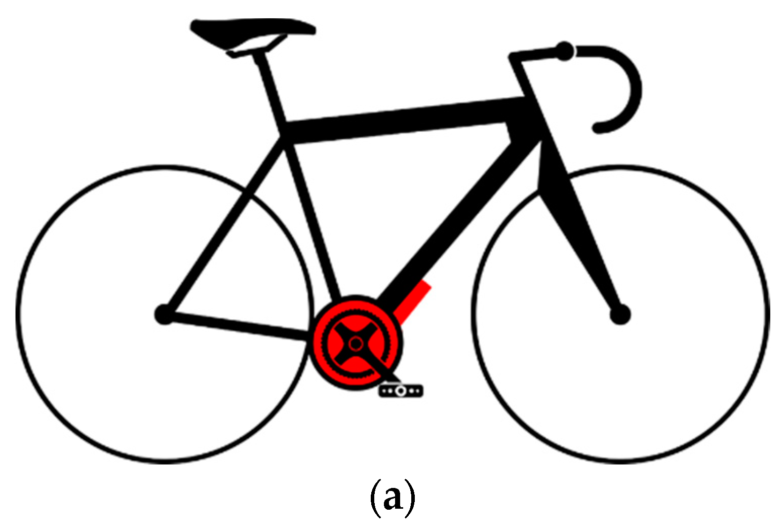
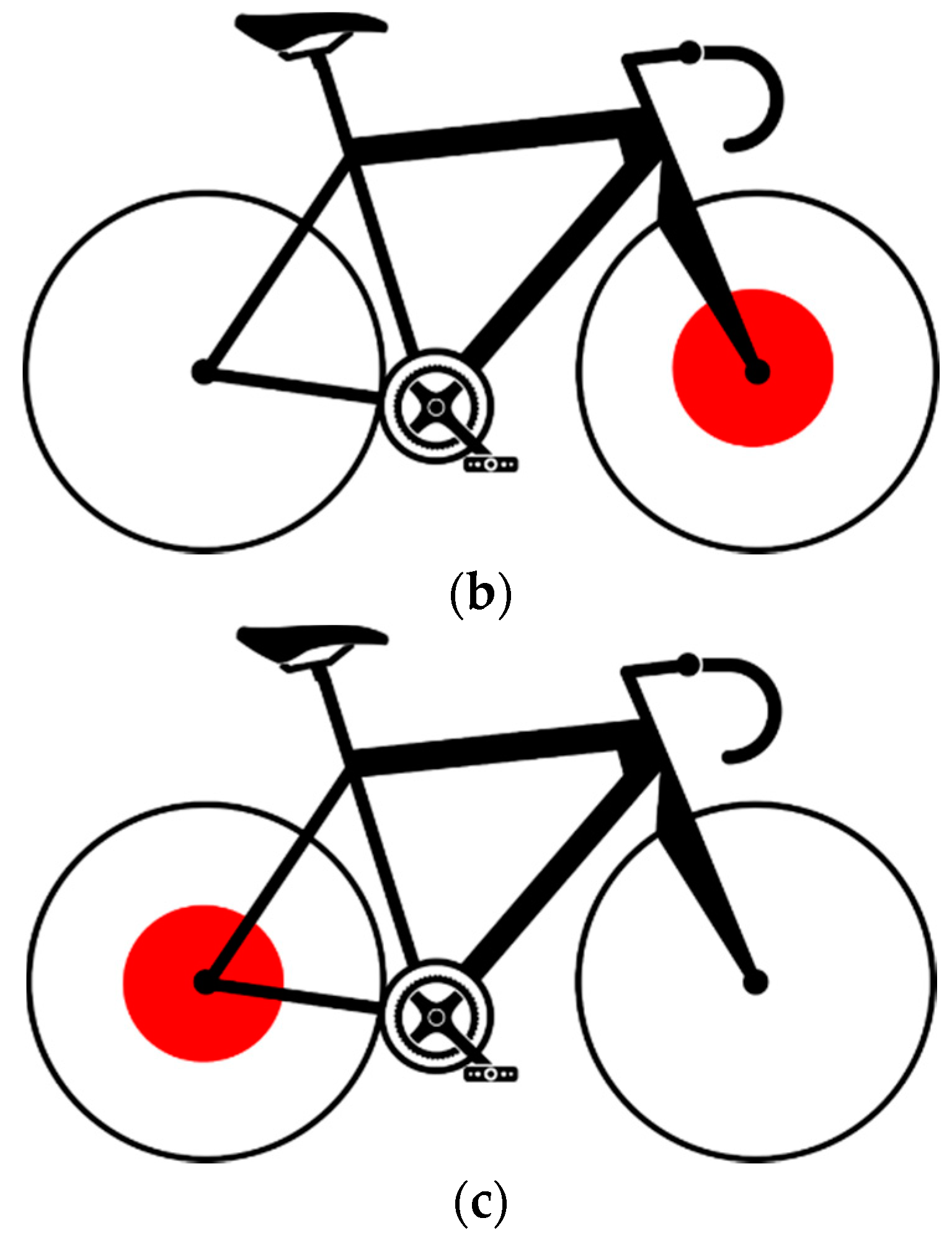
3.2. Embedded System for Bike-Users’ Characterization

With the aim of identifying the characteristics required for an e-bike optimized for Bogota City, a quantitative methodology to study cyclist behavior is developed. This methodology includes the measurement of several parameters, such as velocity, power, gear ratio, etc., obtained from diverse types of cyclists in real scenarios, as well as interviews of bike users. The experimental evidence is used to quantify the minimum performance requirements for the e-bike.
The proposed methodology consists of acquiring and analyzing quantitative data related to the riding behavior of different type of cyclists in Bogota City (Figure 2). The data are gathered trough a custom-made on-board computer (OBC) installed on each bicycle. The OBC records riding data for one week and then the information is downloaded and processed by software specifically developed for this project that returns the average values of ground velocity, pedaling frequency, cyclist power and travel time, the stops along each path, the geographical coordinates of the ride, and the voltage and current of the e-bike battery.
In the following, the OBC and the processing software are described, and in Section 4 some of the obtained results of the cyclist characterization are presented.

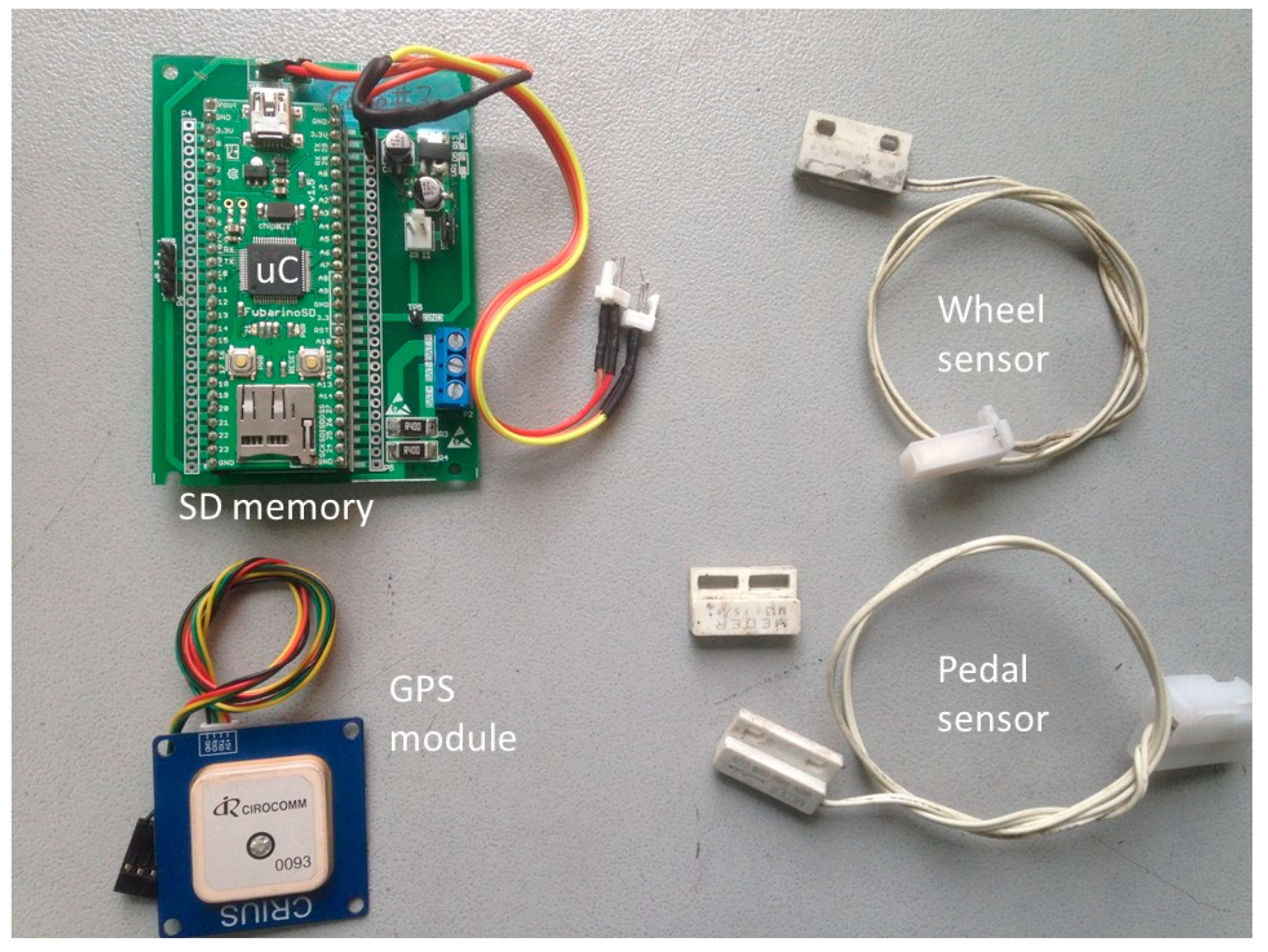
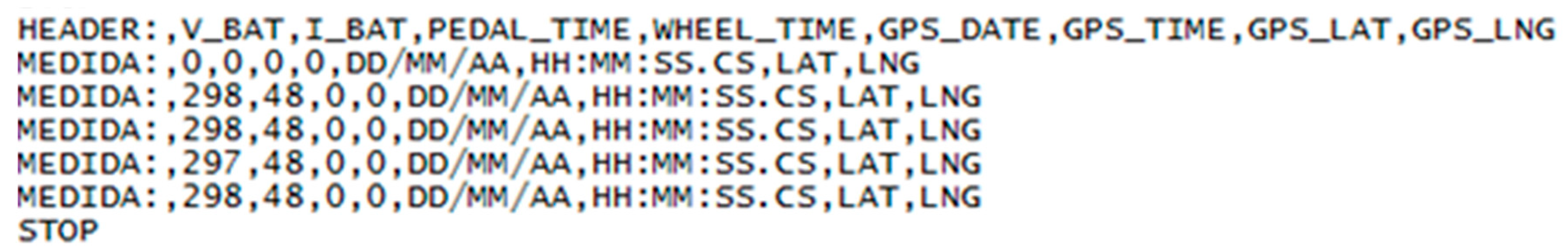
3.2.1. Custom-Made On-Board Computer OBC

The OBC used to capture the data consists of a microprocessor unit, a microSD slot, two reed switches to measure the rotation period on wheels and pedals, a GPS module, a signal conditioning stage for e-bikes’ battery voltage and current, and a battery pack for the device power supply (Figure 3).
Signal conditioning is used to collect the information from the reed switches, the battery voltage and the battery current sensors (shunt resistor). For e-bike battery voltage and current measurement, two operational amplifiers with fixed gains are used, designed to accept a maximum battery voltage and current of 48 V and 10 A, respectively. After the conditioning stage, a 10-bit analog-to-digital converter (ADC) is used to register the battery voltage and current each second during a trip.
All the sensor data are stored in a “txt” file each second with GPS data. Once the trip is finished, the “txt” file is then processed by a custom-made software, which returns the trip information required by the present project. The processing software is presented in the following.

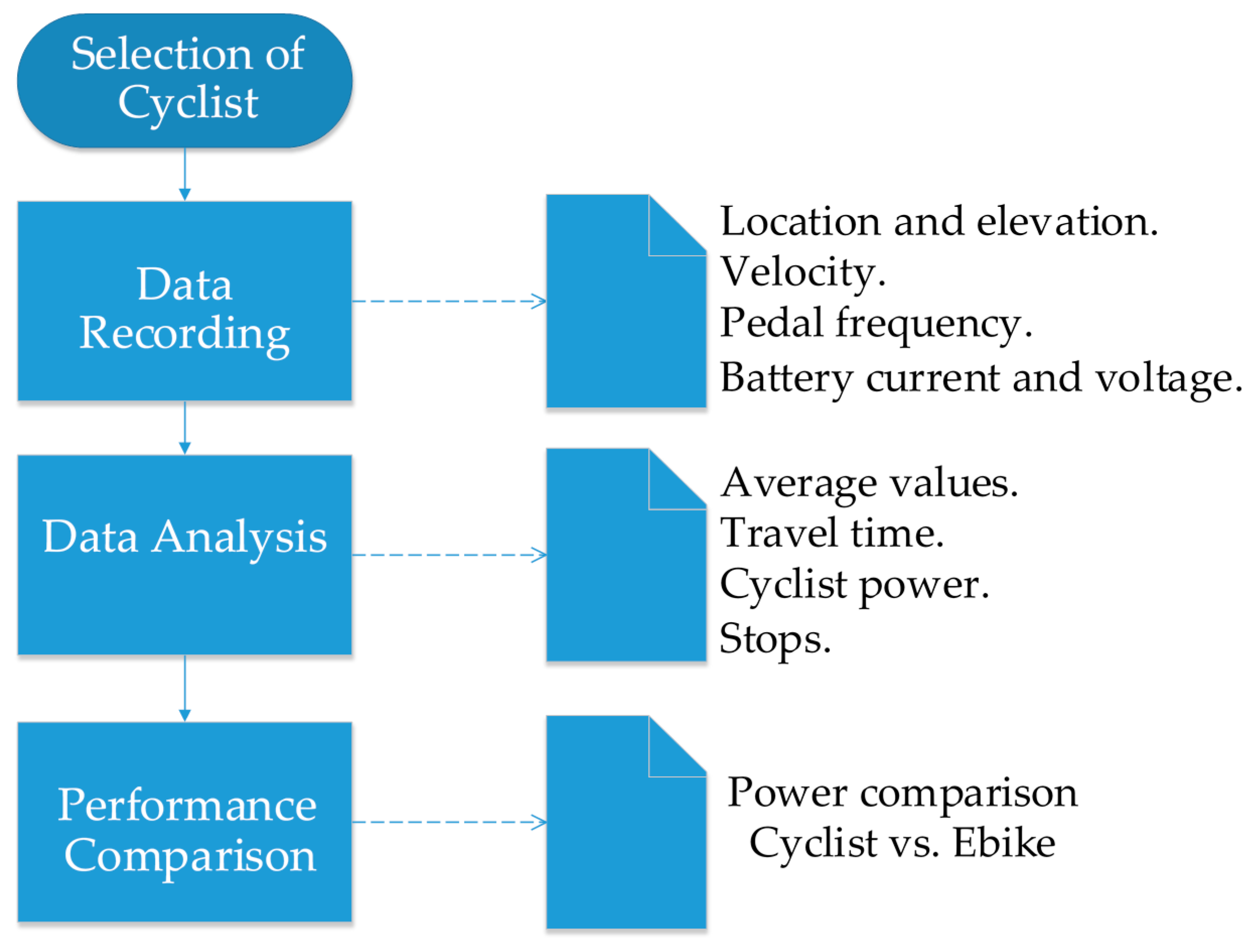
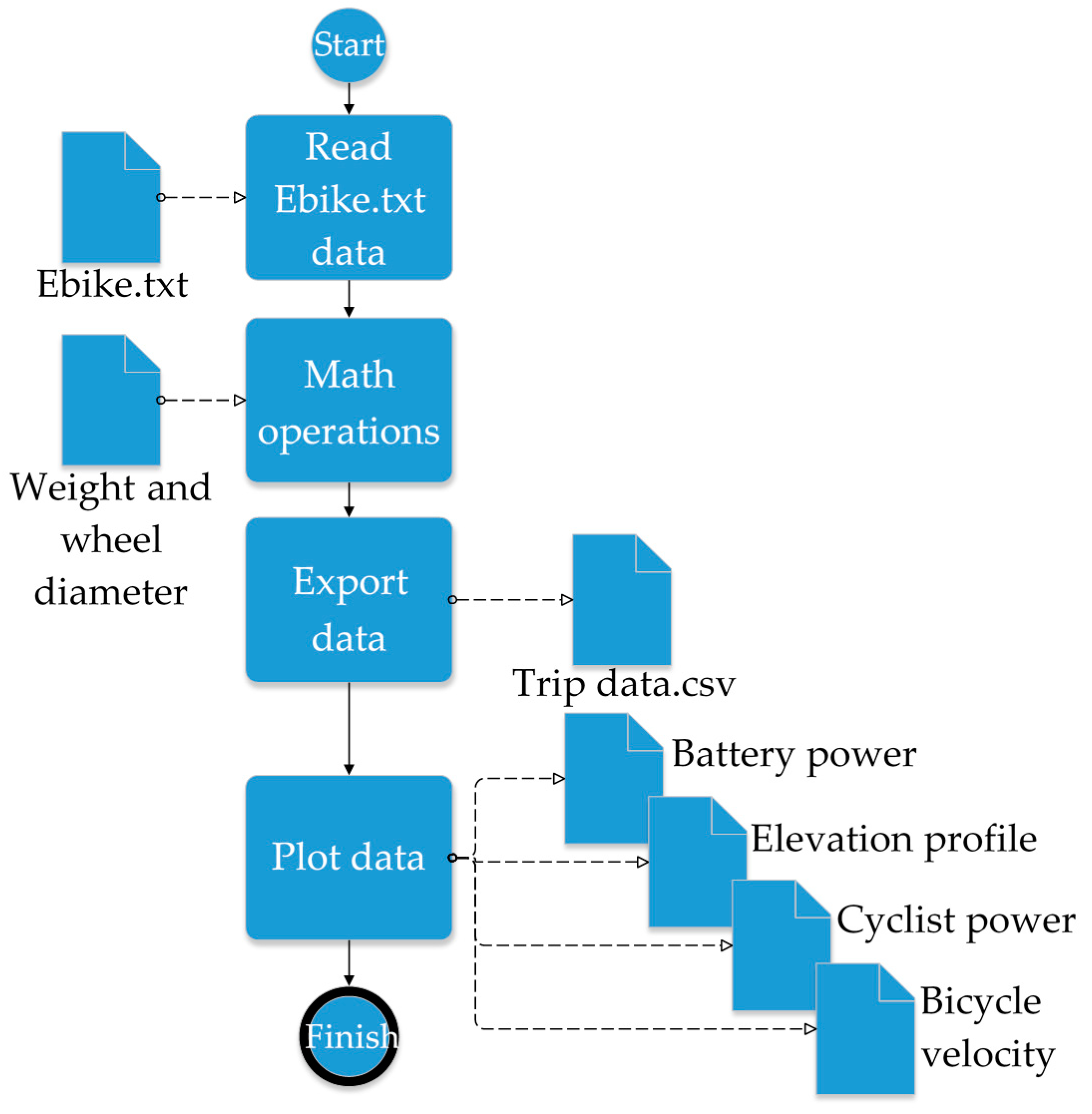
3.2.2. Processing Software

The processing software, designed with Python coding language, asks, in a first stage, for the following set-up parameters: wheel size, cyclist and bike weight, and the location of the “txt” file with the data recorded by the OBC. Then, it initiates the reading and processing algorithm to provide the bicycle velocity, the cyclist pedaling cadence, the e-bike battery power (by processing the e-bike battery voltage and its current), the route map, the elevation profile and the cyclist power. A flowchart of the processing algorithm is depicted in Figure 4.
The cyclist power is estimated using the model described in [9]. The power calculated is the total power required to provide bike and cyclist movement, which in a non-assisted bike is given only by the cyclist, and in pedal-assist e-bikes would be the sum of the power provided by the motor and the power provided by the cyclist.
The pedaling power, P p e d , is equal to the power required to overcome the forces counteracting the movement, P R e s , divided by the efficiency of the drive train system, η , as depicted by Equation (1):
  P P e d ( t ) = P R e s ( t ) · 1 η  
The efficiency factor from the drivetrain to the ground (frictional and elasticity losses) is set to 0.975. As described in Equations (2)–(6) (see Table 1), the resistance power, P R e s , is calculated as the sum of the powers related to: aerodynamic drag, P a i r ; rolling resistance, P r o l l ; bearing resistance, P b e a r i n g ; power due to changes in potential energy, P P e ; and, power due to changes in kinematic energy, P K e .
Parameters used in Equations (2)–(6), such as the rolling resistance coefficient, C R R , the frontal area, A , and the drag coefficient, C D , are not calculated for each cyclist and bike, but included within the averaged values; therefore, results are expected to approximate the real power used by the cyclist. The fixed parameters used in Equations (2)–(6) are given in Table 2.
V A is assumed to be 0 m/s, neglecting its average impact when rolling in urban areas. The wind velocity is assumed to be 0. The time-dependent variables used in Equations (2)–(6) (e.g., V G ( t ) , θ R ( t ) , a (t)) are calculated with a sample time of 1s from the captured data. m T and r values, required in Equations (3), (5) and (6), depend on the current user and may vary between different users. The above parameters are presented in Table 3.

3.3. BLDC Based Motor Propulsion System for an Electric Bicycle

To provide a natural feeling to a cyclist when using a pedaling assistance system (PAS), a common strategy consists of performing an automatic adjustment of assistance level, proportional to the instantaneous power provided by the cyclist [9]. Hence, a method to obtain this cyclist power value must be incorporated in any design of a propulsion system for a bicycle.
Although most of the currently available cyclist power meters are expensive units, which are not viable for a shared bicycles system, different approaches to estimate cyclist power with reduced cost are proposed in the literature [17], and are good candidates for mass production [38]. In particular, in this project a prototype based on an inertial measurement unit (IMU) was validated.
Accordingly, a pedal assistance system motor control was developed assuming that cyclist torque measurement is implemented in the OBC and is operative. Next, the conception, design and experimental validation of this propulsion system control is presented. Torque measurement output is emulated with a signal generator.

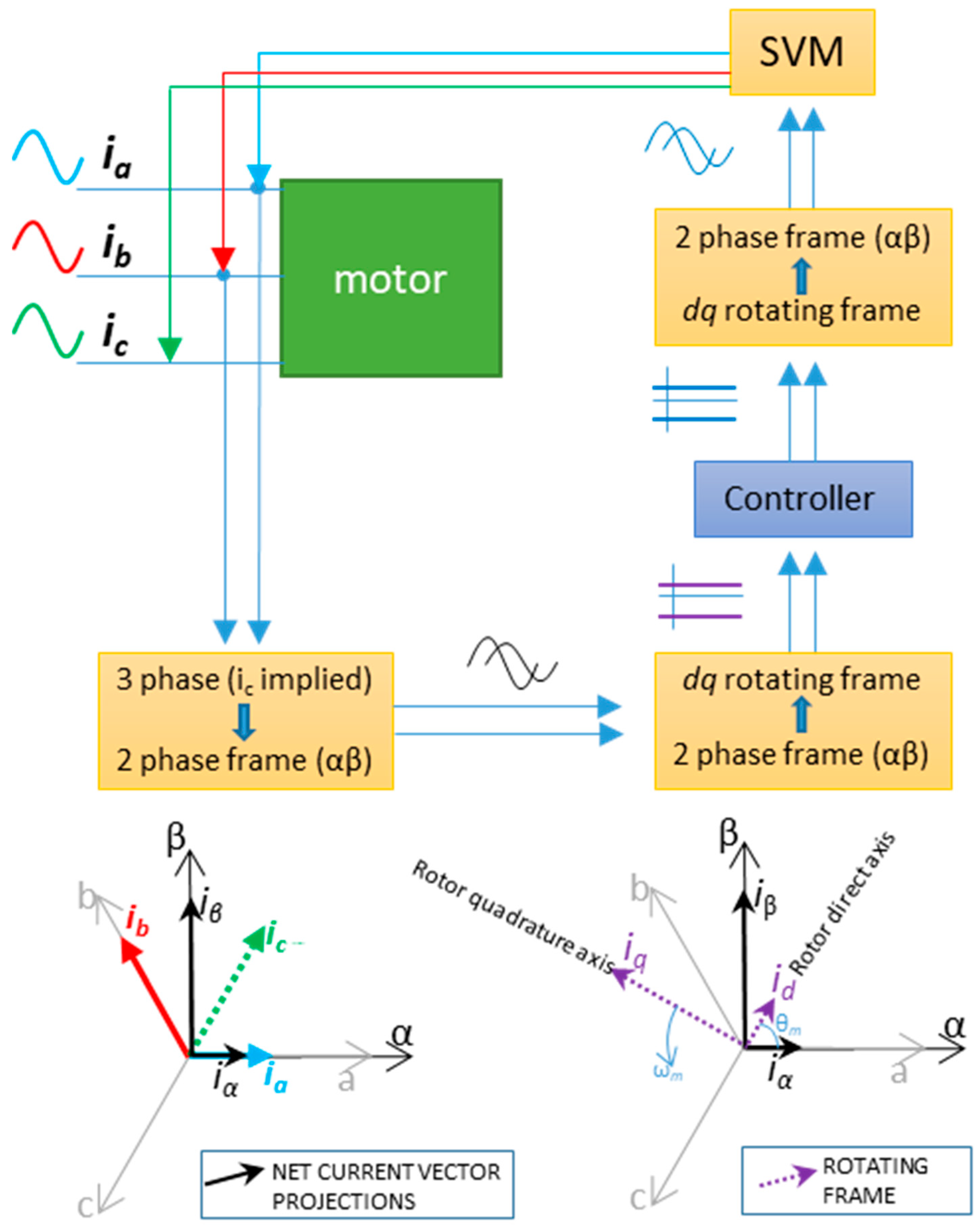
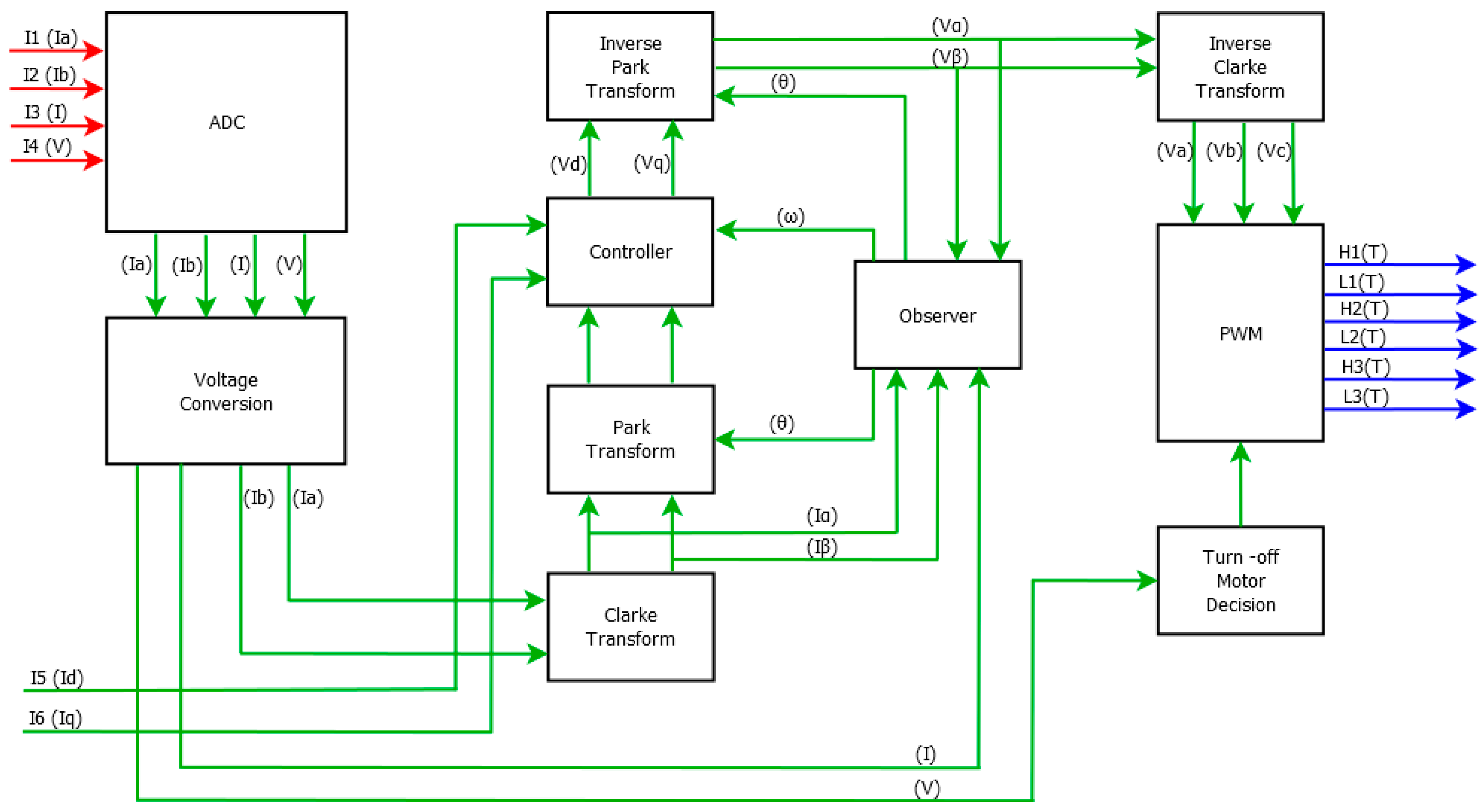
3.3.1. Control Strategy

In general, cyclist power is proportional to the torque applied by the legs over the pedal levers. The shape of this torque waveform over time depends on factors like the type of pedals, cyclist behavior and road conditions.
In order to alleviate the torque input complexity as an entry of the motor controller, a simplified torque waveform is assumed, which represents the pedal torque over time, as shown in Figure 5. This corresponds to the expected output of a power estimator.
The above signal has a specific frequency that depends on the linear velocity at which the rider is pedaling and the bike gear ratio. The pedaling velocity range is expected to be between 60 and 100 RPM (1–3.3 Hz), which is considered the point of maximum efficiency for an average rider [9].
Considering the effect of both pedal strokes and assuming that the PAS mainly operates during the same range of pedaling speed, the frequency range of the signal that emulates the required torque input, f t o r q u e , is chosen to be between 2 and 3.3 Hz.
To control the torque of a BLDC motor, a field-oriented controller (FOC) is a well-adapted and effective technique [12]. From [12], by handling the stator windings the FOC maintains the field produced by the permanent magnets of the rotor orthogonal to the stator field, therefore controlling the field allows torque control.
In order to allow control by FOC, three main tasks are carried out [39]:
  • The currents of each of the three phases in the stators are measured. These are transformed from the static three-phase reference frame to the static two-phase reference frame, in which it passes from having three variables to two, the parameters α, β being from the Clarke transform.
  • From this reference frame, the next step is to move to the rotating two-phase reference frame by means of the Park transform, leaving two variables d, q. These two variables are controlled.
  • The next step is to perform the Park and Clarke inverse transforms remaining in the frame of the static three-phase reference; these are used for pulse-width SVM (space vector modulation) or SVPWM (space-vector pulse-width modulation).
This process is shown in Figure 6.
In Figure 6 it is observed that only the current from two of the motor windings is necessary to obtain the α and β parameters from Kirchhoff’s current law. The detailed position of the rotor is needed to perform the transform to the rotating frame. Measuring the rotor position can be performed by encoder sensor, detection of the zero crossings of the back electromagnetic field, complex sliding mode observers, and with extended Kalman filters [40].
In the next subsection, the FOC controller is developed.

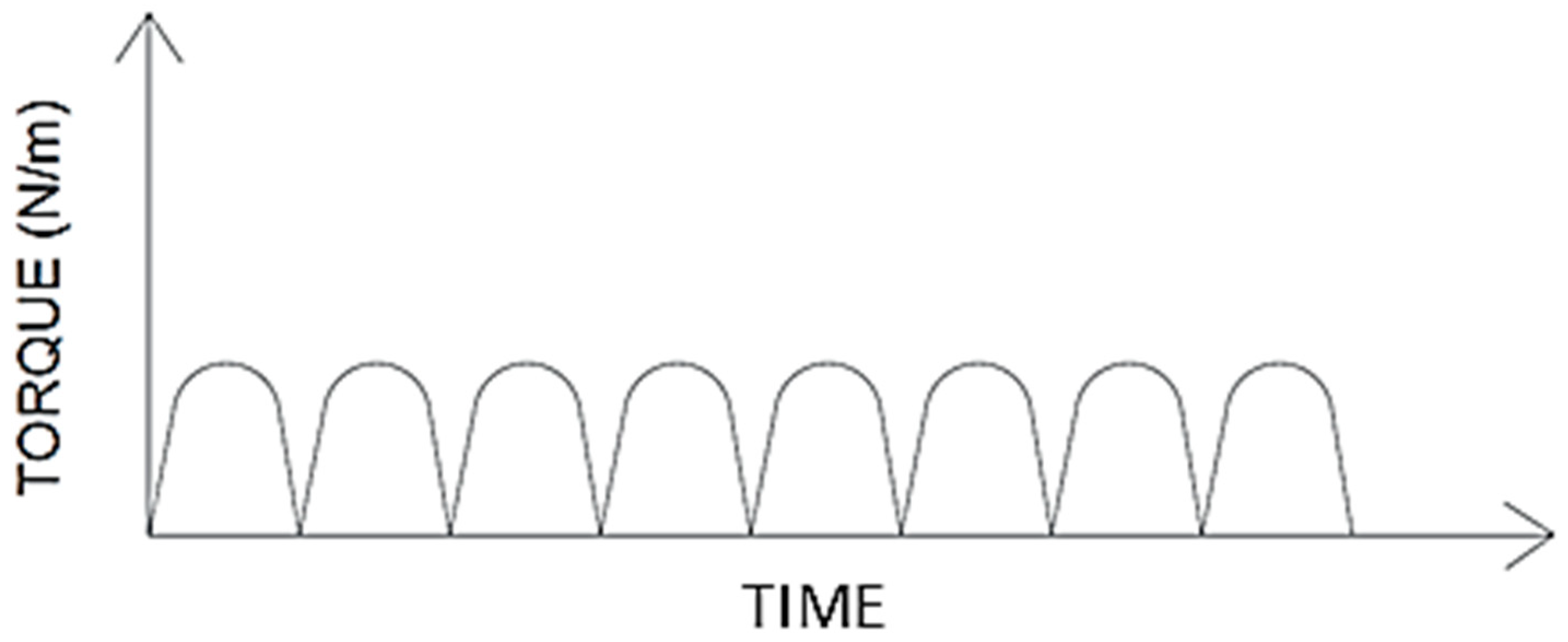
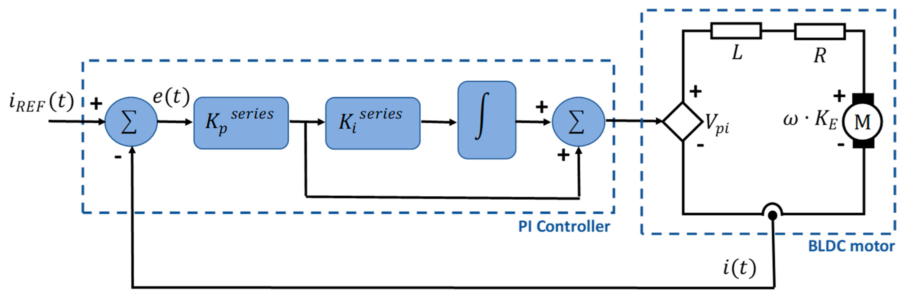
3.3.2. Motor Torque Control

To implement the motor torque controller, a model based on the InstaSPIN™ algorithm [12] is selected. This controller is of the proportional-integral (PI) type and incorporates a first order approximation for the motor model, as illustrated in Figure 7. In this model, if the integral gain, Ki, and the proportional gain, Kp, constants are properly selected, the existence of conjugated poles can be avoided. In particular, Ki can be selected to be equal to the pole of the plant as shown in Equation (7).
  K i s e r i e s = R s L s  
The obtained closed loop transfer function then becomes:
  G ( s ) = 1 L K p s e r i e s s + 1  
Therefore, Kp can be calculated to adjust the desired bandwidth in the frequency response (where ω c o is the G(s) cutoff frequency):
  K p s e r i e s = L s · ω c o  

3.3.3. Motor Control Implementation Details

In this application of bicycle pedal assistance, motor velocity is not controlled, since to guarantee the motor torque to be proportional to the pedal torque, the motor must be free to spin at any velocity (between 60 and 100 RPM, as mentioned before). With the aid of the InstaSPIN™ development platform from Texas Instruments running over the TMS320F28035 processor, the torque controller is implemented as shown in Figure 8.
As shown in Figure 8, the controller receives two set points: Iq and Id. To implement the controller in the micro-processor, the controller digital constants ( K i z ,   K p z ) used in the FOC algorithm, are calculated. K i z is simply determined by Equation (10):
  K i z = K i s e r i e s ·   T i
where Ti is the current controller period (66.6 µs in this platform).
As explained previously, Kp is selected to adjust the controller bandwidth. As a starting point, a bandwidth of 1/20 of the current controller frequency is used [12]. The value of the parameter for the algorithm is computed as:
  K p ( P U ) = K p s e r i e s · I f s V f s  
where I f s and V f s are the full-scale current (A) and voltage (V), defined by the user in the platform.
The controller was implemented and validated using the Texas Instruments development board DRV8301-HC-C2-KIT. Two different BLDC motors are considered in this propulsion system. The first is an Anaheim BLY342S-48V-3200 motor [41]. This model was selected because its operating voltage (48 V) and output power are well suited to the e-bike requirements and because its well-documented technical specifications facilitates the proper design and validation of the controller.
The second is an out-runner type BLDC motor (MTO 5065-170-HA-C, Maytech, Shanghai, China). This motor was selected due to its low cost and the expected possibility (from manufacturer specifications) of operating at high peak power levels for short time periods. However, the datasheet and technical information about this motor is very limited, thus requiring the running of an identification process to achieve a proper implementation of the control strategy. This is a case of evaluating the effectiveness of the identification and controller design processes. Accordingly, in Section 4 a controller is calculated and evaluated for each one of these motors.

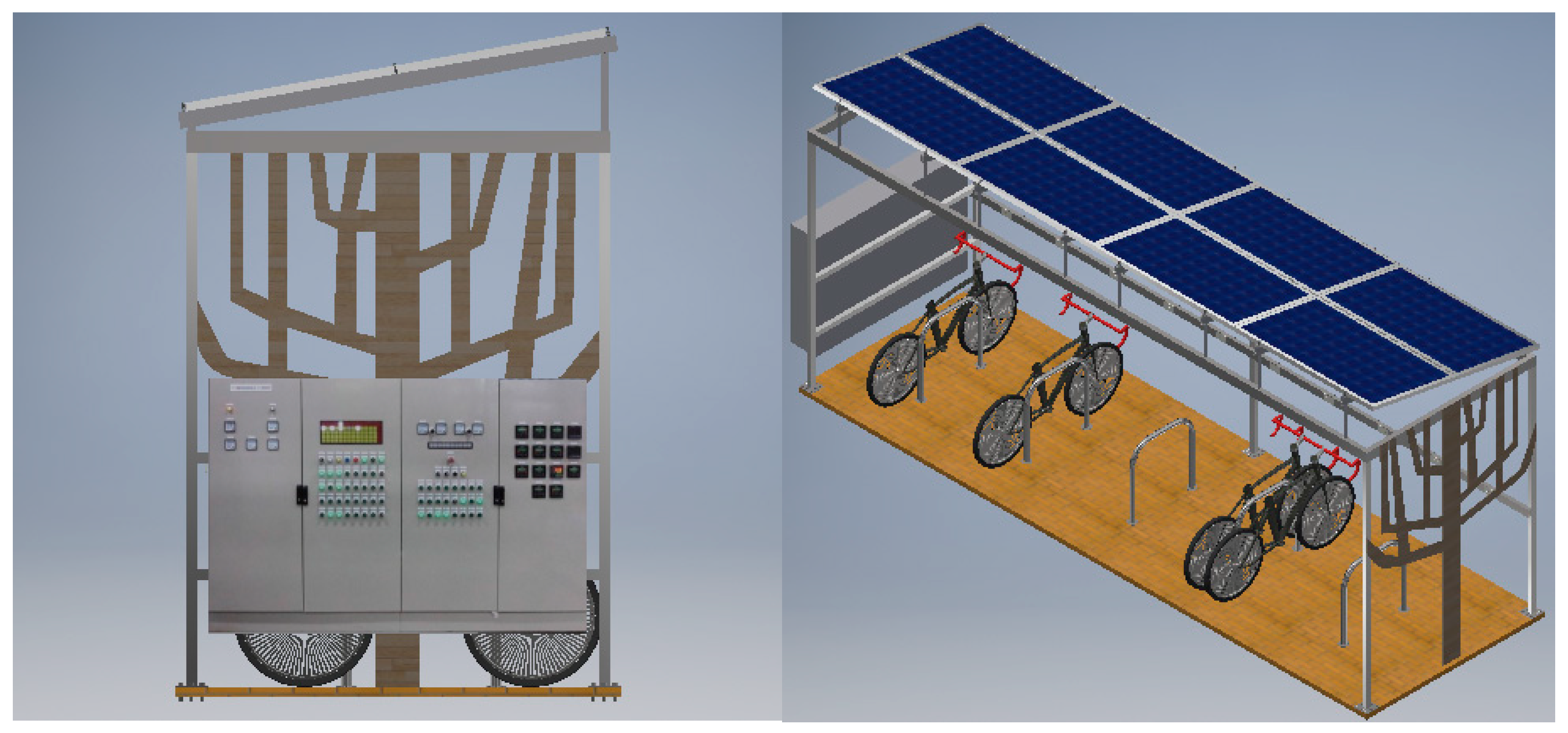
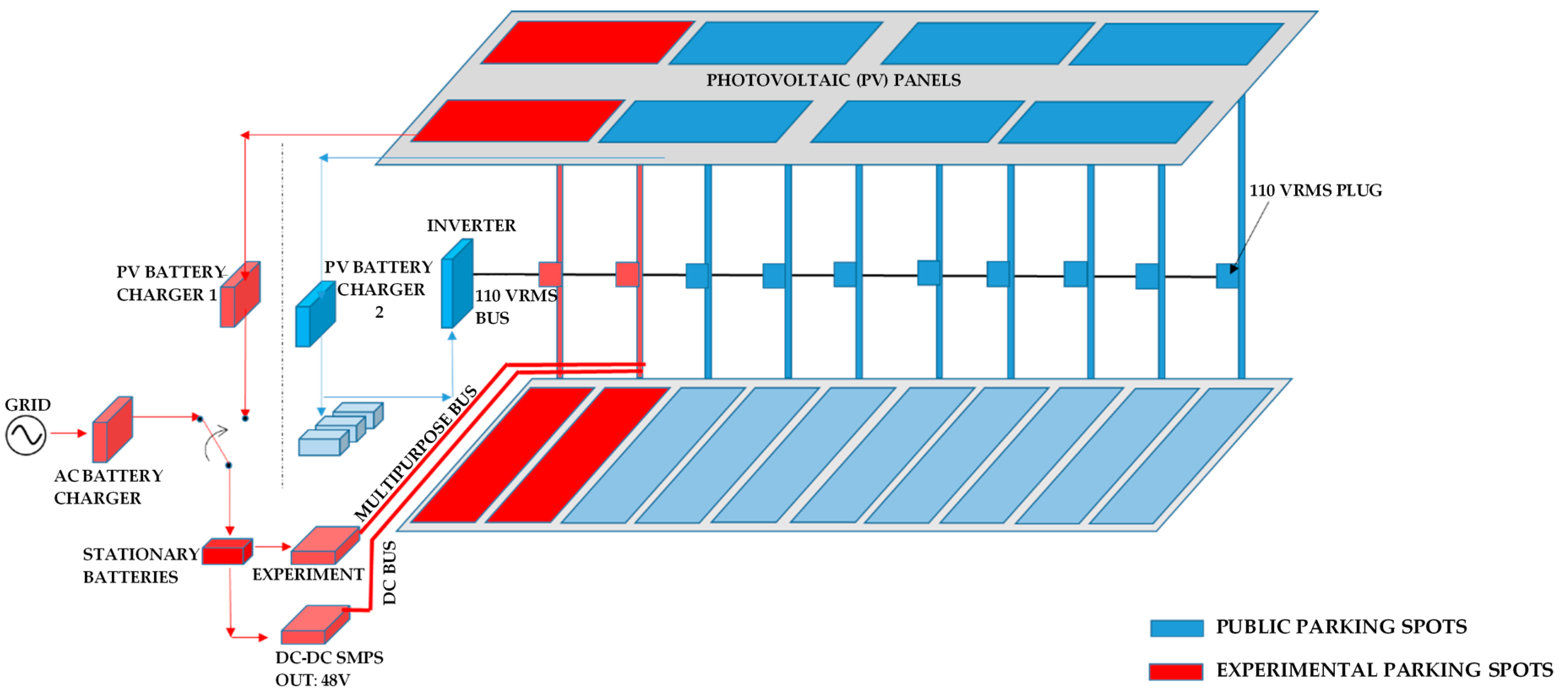
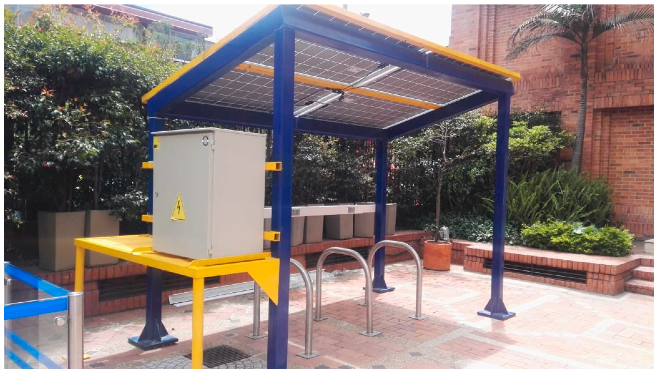
3.4. Charging Station for E-Bike Sharing Systems
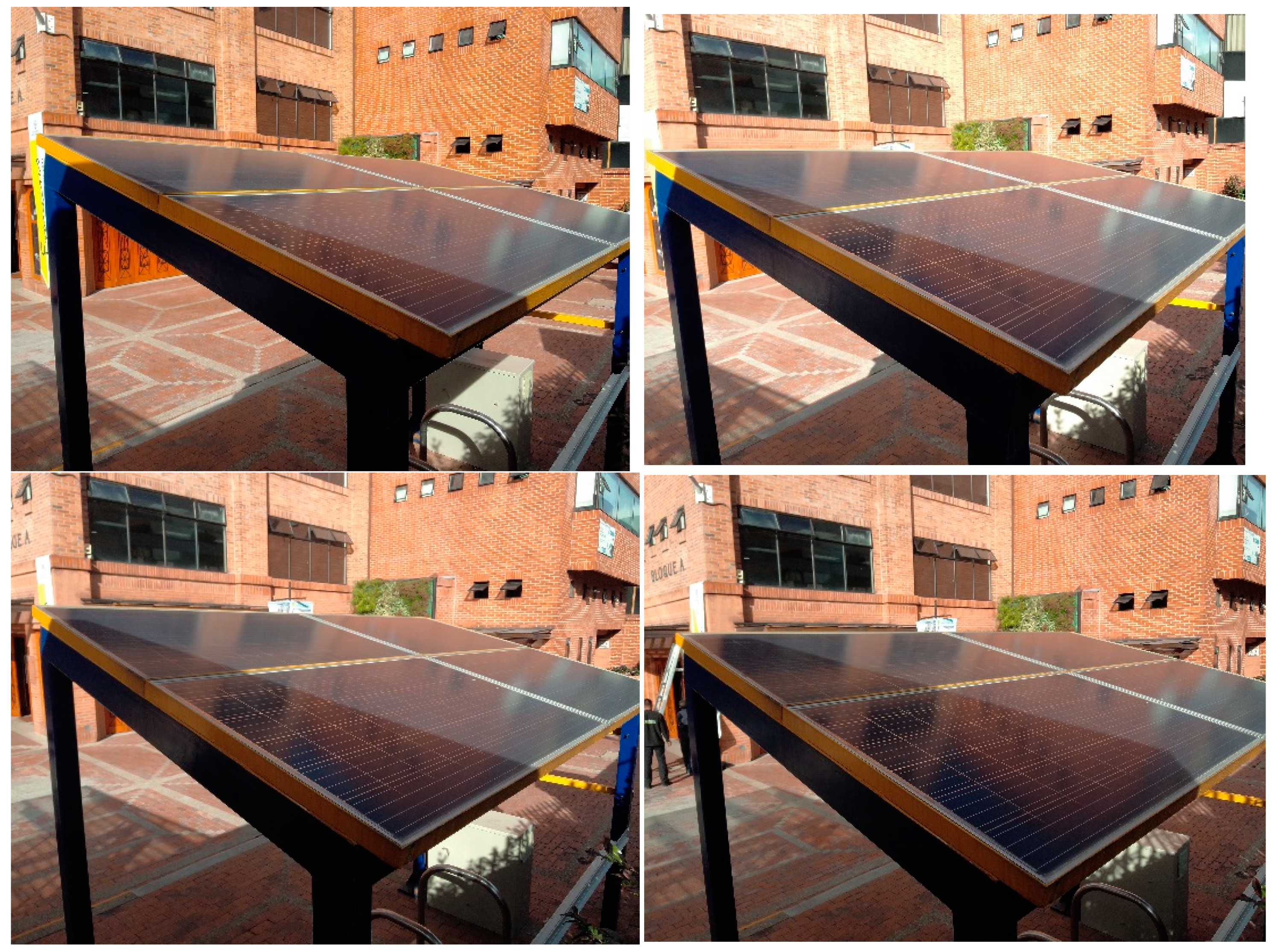
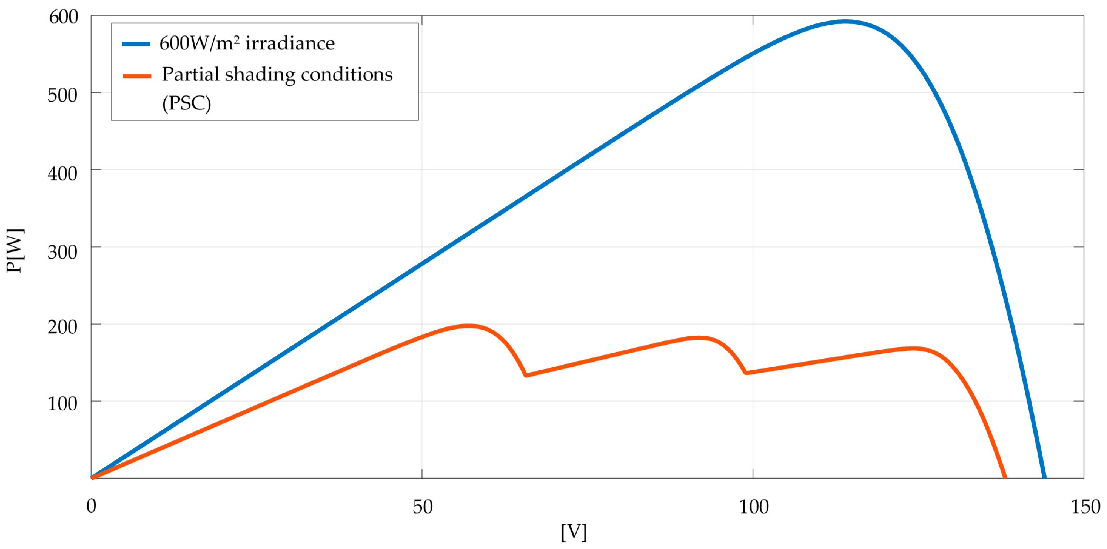
Since e-bikes are equipped with batteries that are required to be charged, bike-sharing systems frequently face mayor challenges regarding charging stations, their design, efficiency, use of renewable energies, and geographical distribution [3].
A solar supply system can be stand-alone or connected to the main grid in a vehicle-to-grid (V2G) configuration to assist the charging process. As described earlier, a typical solar supply system has a central controller that receives energy from the solar panels to transfer to the load.
In 2017, the School of Exact Sciences and Engineering (ECEI) of the Sergio Arboleda University in Bogota, Colombia, placed the BiCiSOLAR Solar Charging station for electric bikes at the disposal of the university community, free of charge. This charging station is powered exclusively by solar energy, in a stand-alone configuration, and can charge up to five e-bikes simultaneously. The BiCiSOLAR charging station has several extra parking spots with a DC charger directly from the main grid reserved for experimental research purposes only. These extra parking spots are not available to the public. Figure 9 shows renders of the mechanical design of the BiCiSOLAR Solar Charging station. In broad terms, the station comprises (i) a control panel that regulates voltage from the panels and outputs a steady 120 VAC for charging bikes, (ii) four solar panels and (iii) five public charging spots for bikes.
Figure 10 depicts a schematic layout of the BiCiSOLAR Solar Charging station. The main components of the BiCiSOLAR Solar Charging station are: (i) solar panels, (ii) solar charge controller and inverter, and (iii) stationary batteries.

3.4.1. Solar Panels

In each module, the photovoltaic (PV) energy is generated by four 250W-24V polycrystalline solar panels in a series configuration.

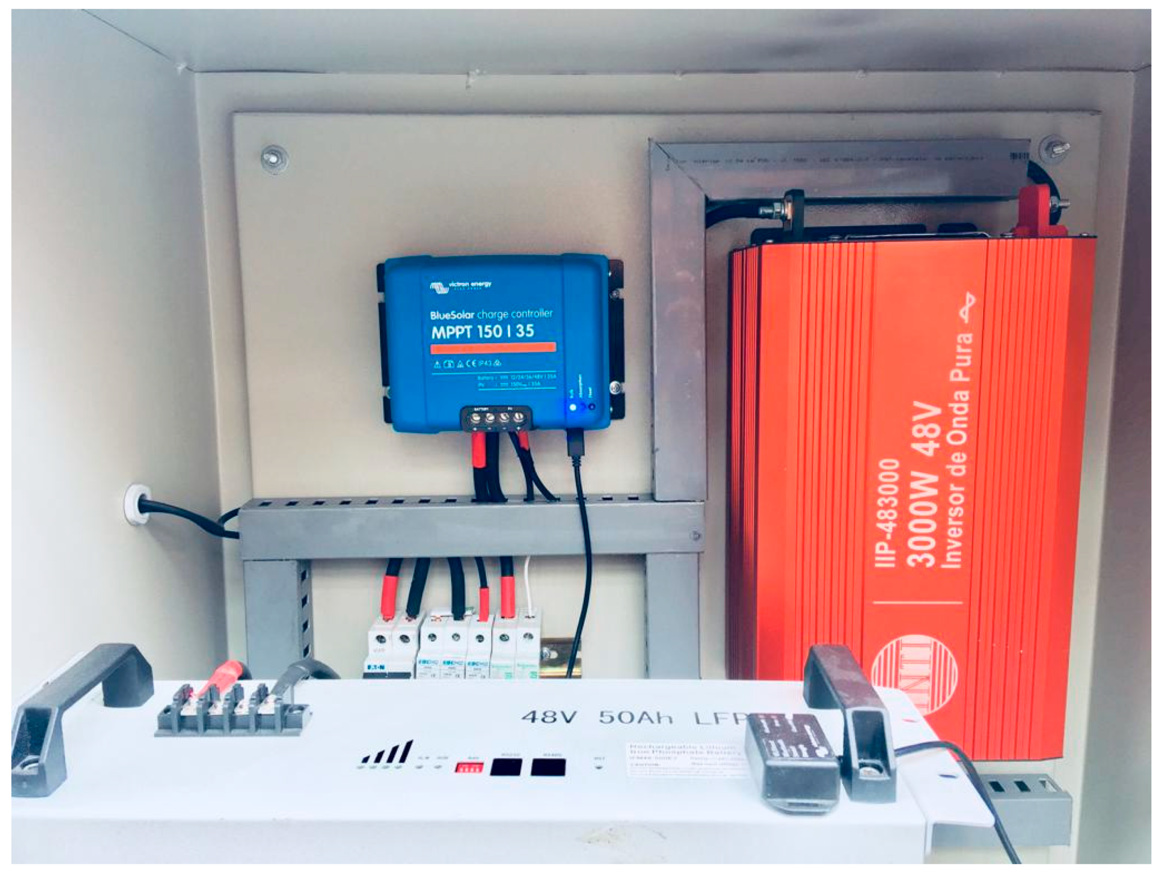
3.4.2. Solar Charge Controller and Inverter

To achieve high efficiency in the system, the central controller must track the maximum power point of the panels array by using a MPPT strategy [15] and provide the required voltage and current profile to properly charge the batteries.
An electronic inverter BlueSolar Charge Controller MPPT 150/35 (see Figure 11) allows the BiCiSOLAR charging station to efficiently convert photovoltaic solar energy into 120VAC power at any time of the day.

3.4.3. Stationary Batteries

In the BiCiSOLAR station, Li-ion batteries of 48VDC@7Ah of the brand IBL are used as accumulators.
The BiCiSOLAR station serves two main purposes: it provides a service to the university community and is also a laboratory for projects in Efficient Conversion of Photovoltaic Solar Energy and its uses. In Section 4 we will show the uses by the university community of the BiCiSOLAR charging station between 12 April 2018 and 11 May 2018.

4. Results

This section presents the main results obtained for the characterization of e-bike users using the designed embedded system; the mid-drive type propulsion system designed for the electric bicycle using BLDC motors and FOC; and, the development of charging stations for electric bikes using photovoltaic energy exclusively. Results are organized as follows: first, in Section 4.1, the results obtained from the OBC regarding the estimation of cyclist power and the e-bike user’s profile are presented. In Section 4.2, the mid-drive benchmark used to test the controller designed for the BLDC motors is described and several controller performance tests results are related. Finally, in Section 4.3, the photovoltaic charging stations are presented and performance results are reported.

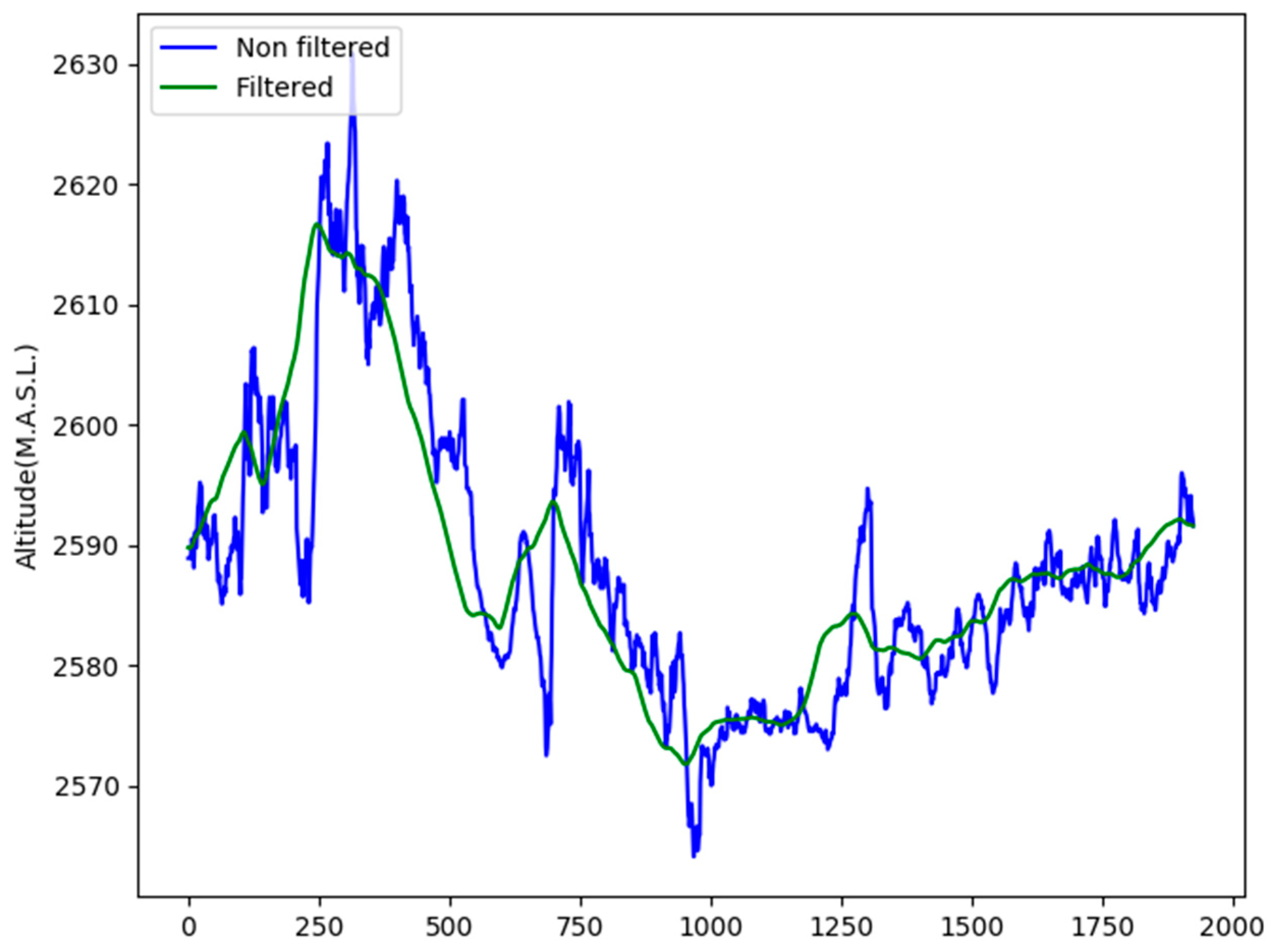
4.1. Embedded System for Bike-Users Characterization

The OBC operation was validated by placing the device on four different bicycles and recording data for one week. The information was processed using the processing software (see Section 3.2.2). Next, the obtained results are analyzed.

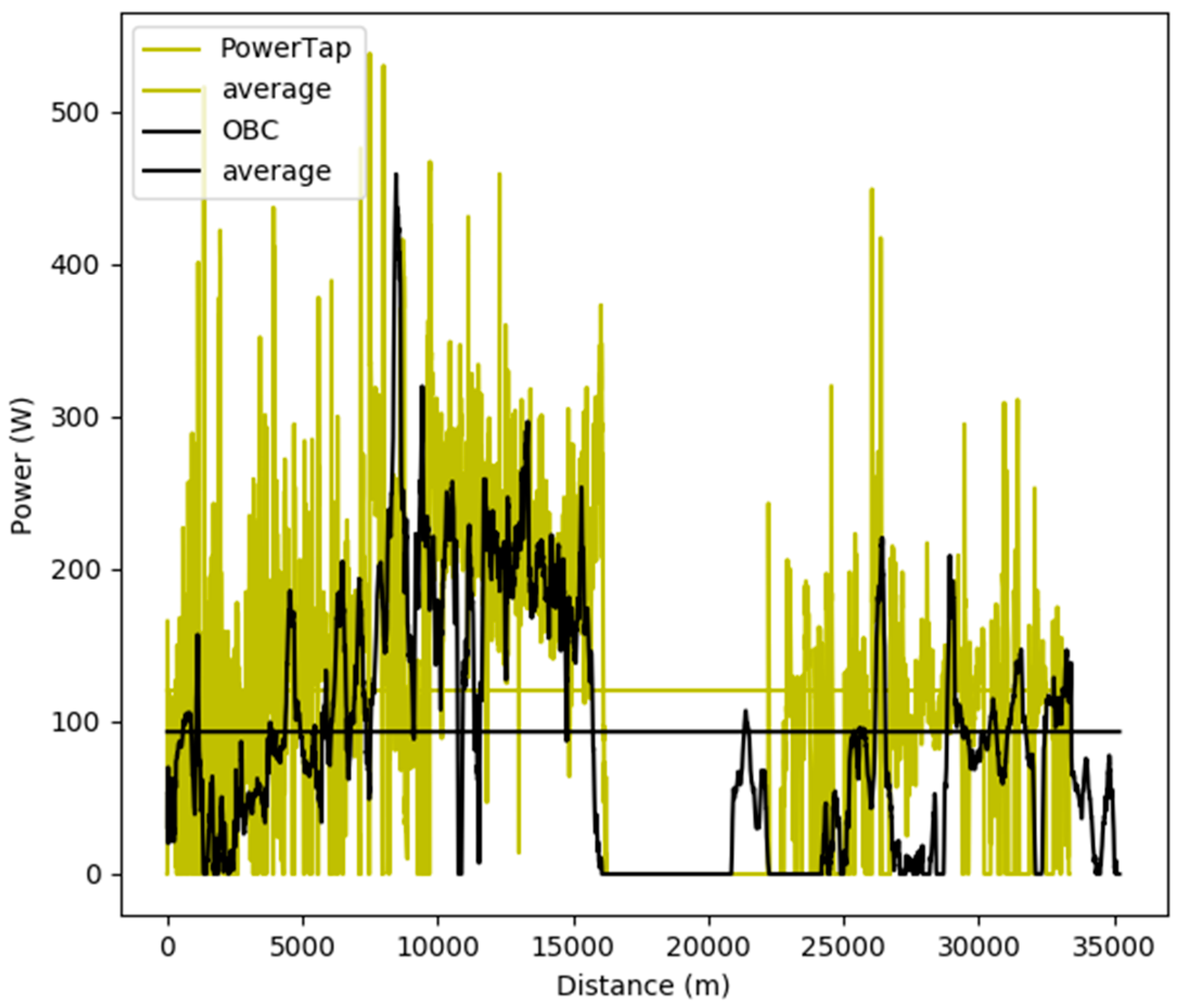
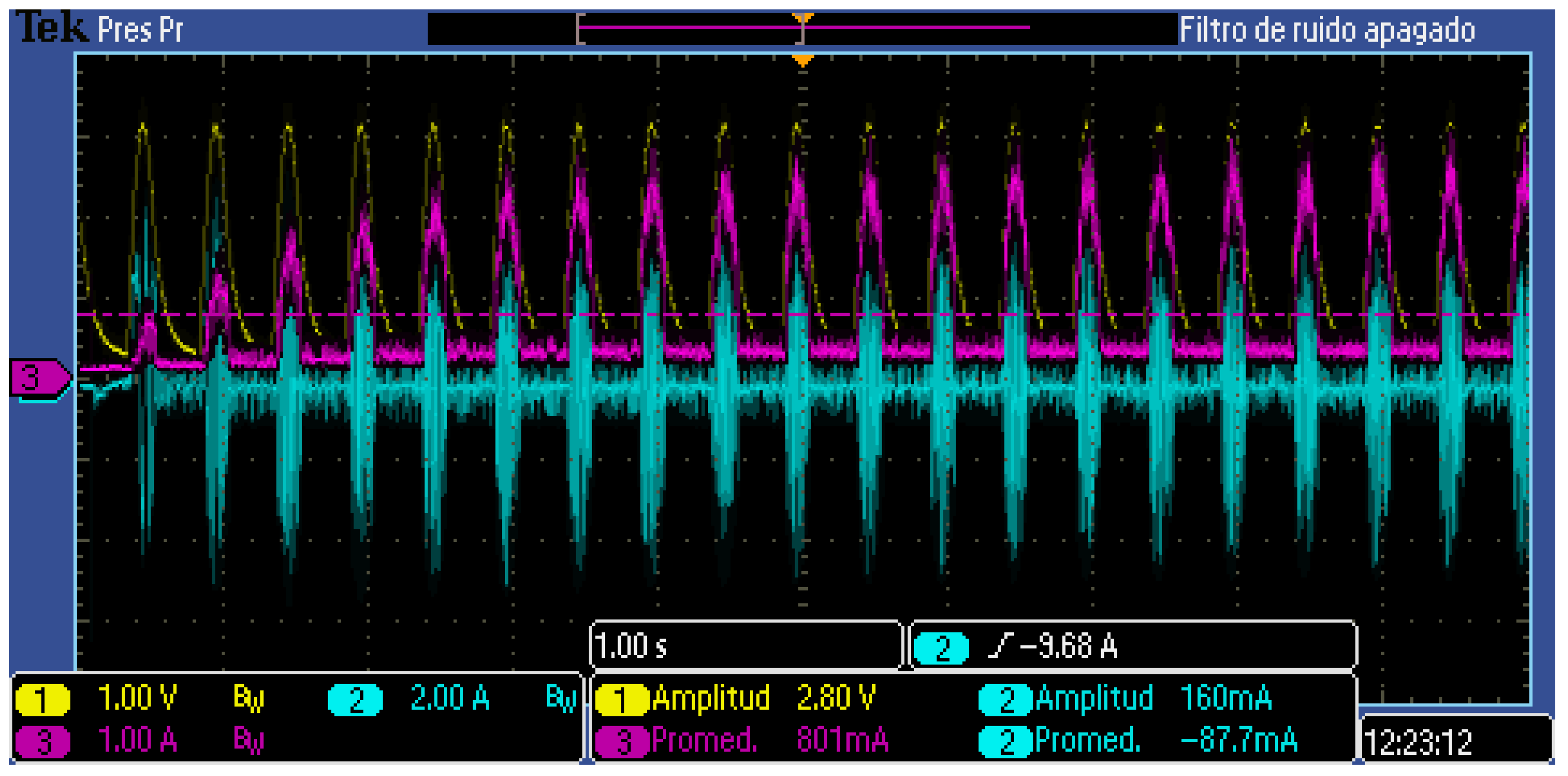
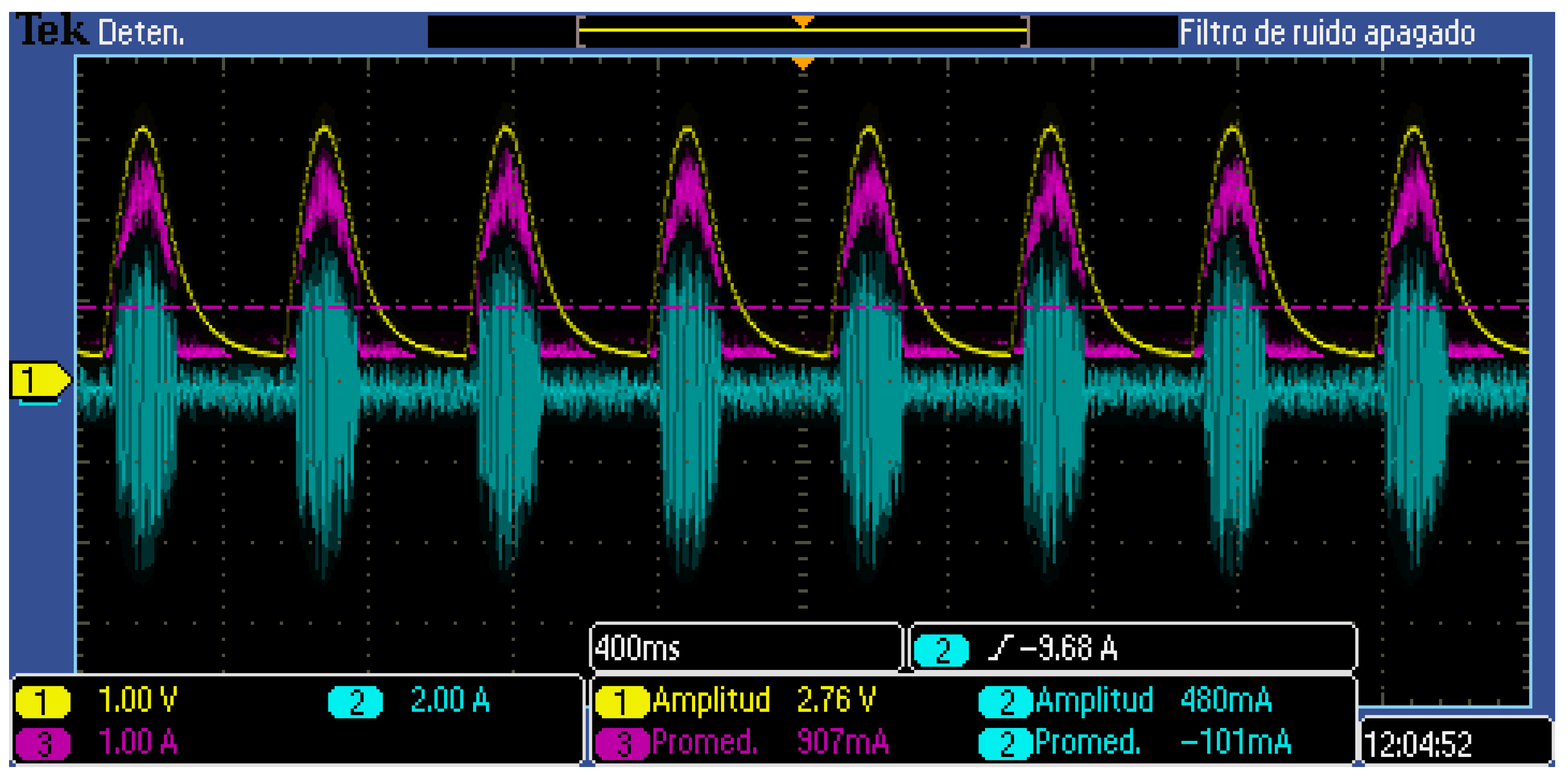
4.1.1. Cyclist Power Estimation

The gradient (θR) is obtained from the GPS unit data. It was found that the obtained elevation value is very noisy (see Figure 12, blue) because of its sensitivity to fluctuations in position data, which is an inherent characteristic of GPS operation. These rapid and erroneous transitions are not acceptable for the power computation.
Accordingly, the elevation profile vector was pre-processed using a low pass filter implemented with a mobile average window of n positions (see Equation (12)). The result of each averaging iteration is placed in a new vector, vf. The process is iterated until vf have the same length of the non-filtered vector (see Figure 12, green). Experimentally a value of n = 100 was selected.
v f [ i ] = x = i n v n f [ x ] n
This Pped power estimator was validated experimentally through comparison against a commercial cyclist power measurement unit (PowerTap P1S). Data are simultaneously recorded by the PowerTap P1S and by the developed OBC for a 33 km flat ride followed by a 7 km climb without stops. The comparison of the two recorded power vectors shows that the power profile recorded on the flat ride and during the climb by both devices, as well as the average power computed (93.27 W for OBC, 120.34 W for PowerTap), are sufficiently close for the study (see Figure 13). Therefore, OBC power estimation can be trusted and used.

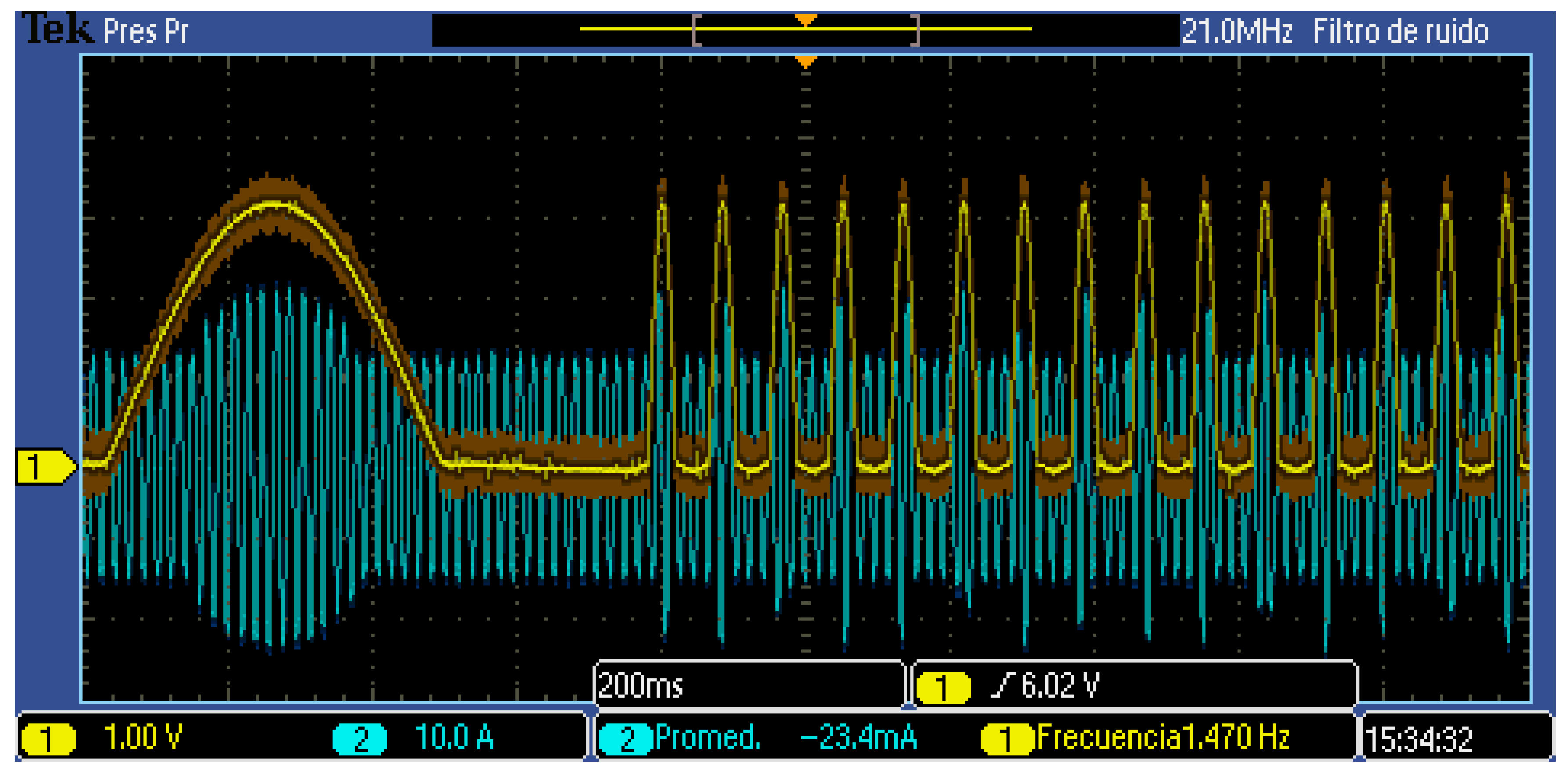
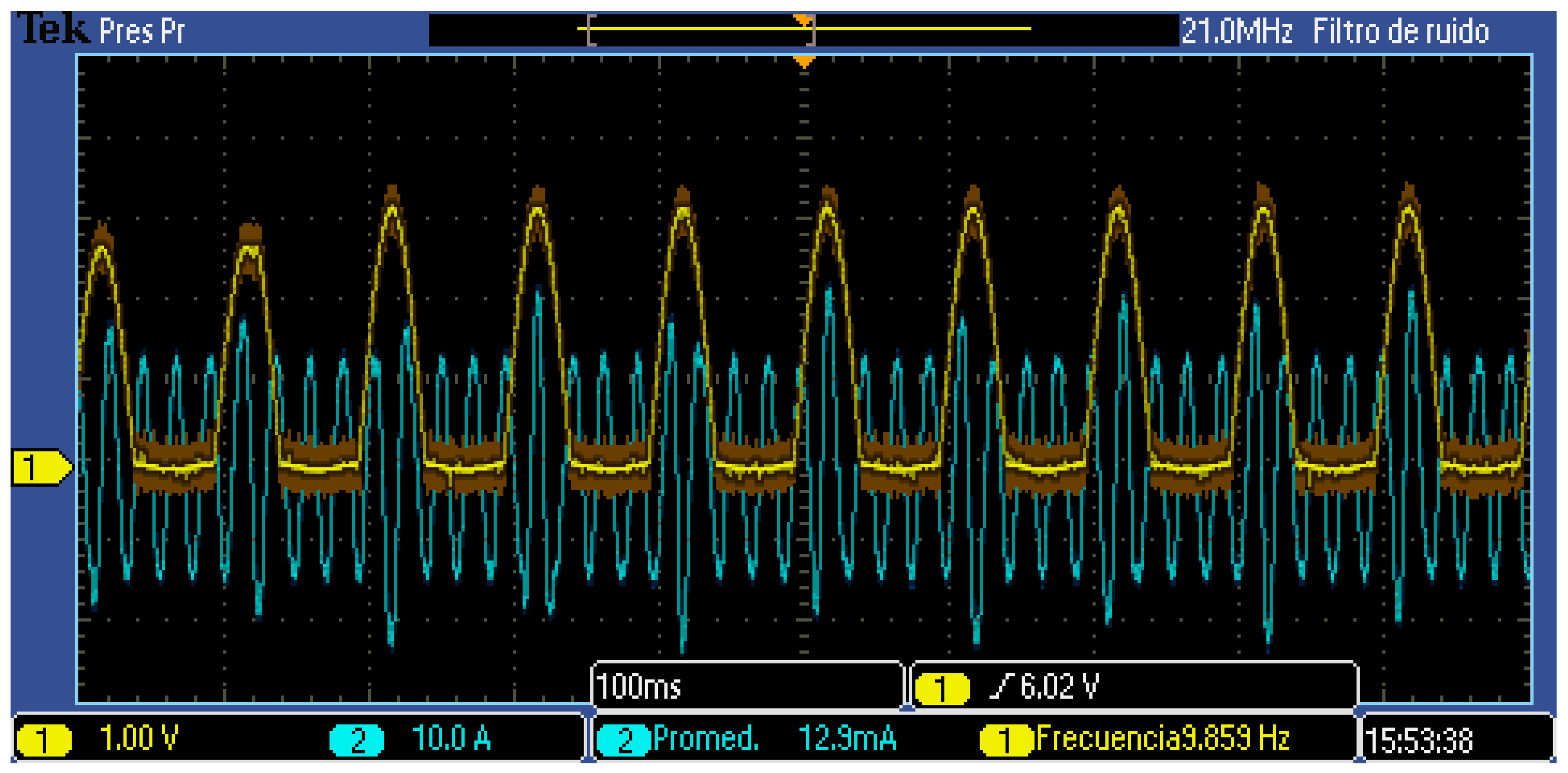
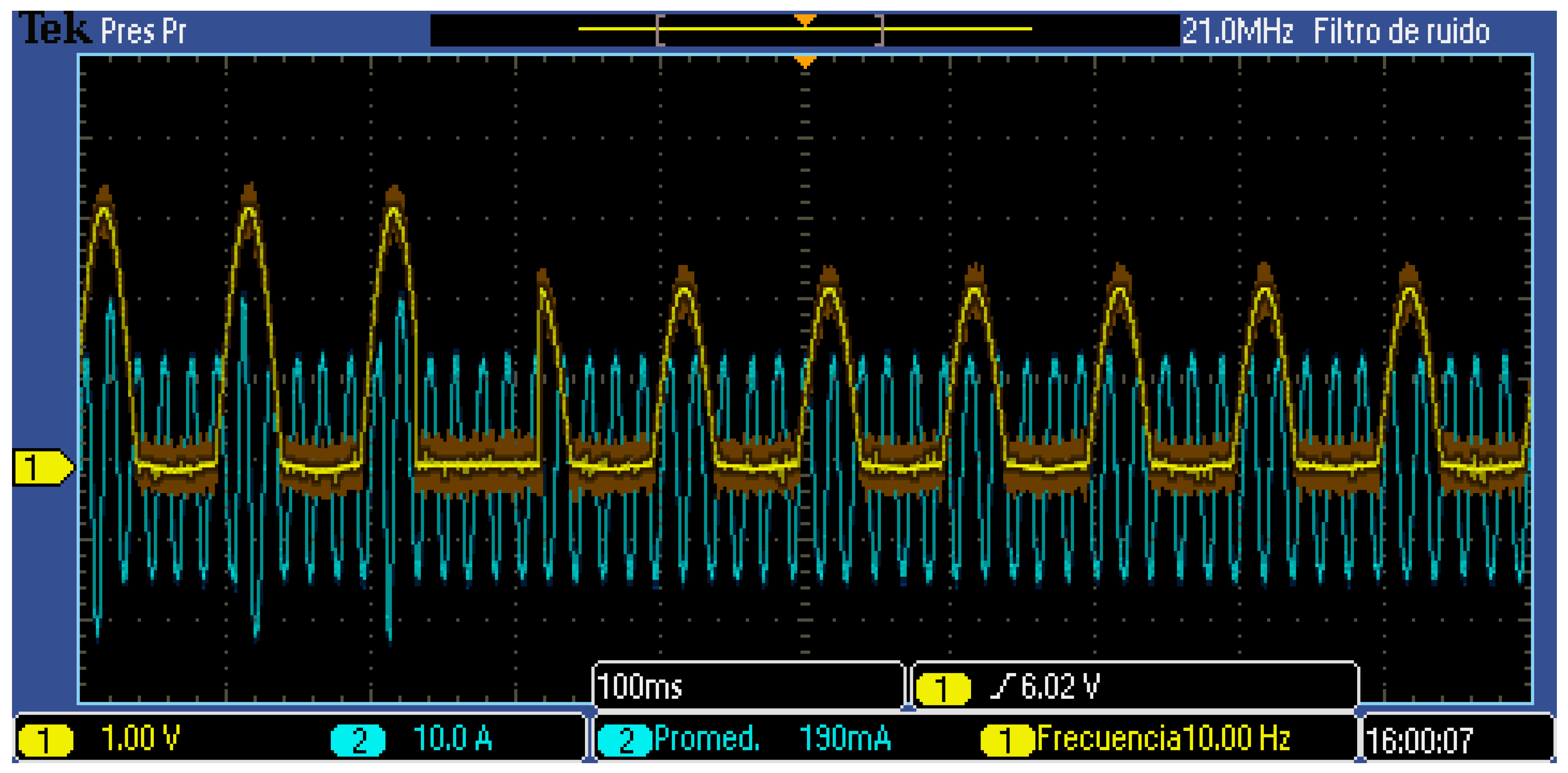
4.1.2. E-Bike Battery Power Measurement

To ensure accurate measurement of the e-bike battery energy and power by the OBC, a calibration process was performed. First, a known voltage over a known load, calibrated with a Fluke 115 multi-meter, is placed at the OBC’s ADC, and compared against the actual battery current and voltage values read by the OBC and saved in the log file (see Figure 14). This procedure was repeated for a range of 0–48 V and 1–3 A, verifying the linear response and stability of the voltage and current acquisition system. Next, the ADC output to voltage and current input gains were calculated. These gains values are subsequently used by the processing software to obtain the battery energy and power values from the log file. The maximum errors were 1.71% and 1.83% for voltage and current respectively.
This battery monitoring feature of the OBC will be exploited in future work for the study of e-bikes on road conditions and for comparison with human-only propelled bicycles. The results will be compared with different approaches, e.g., naturalistic driven studies [42].

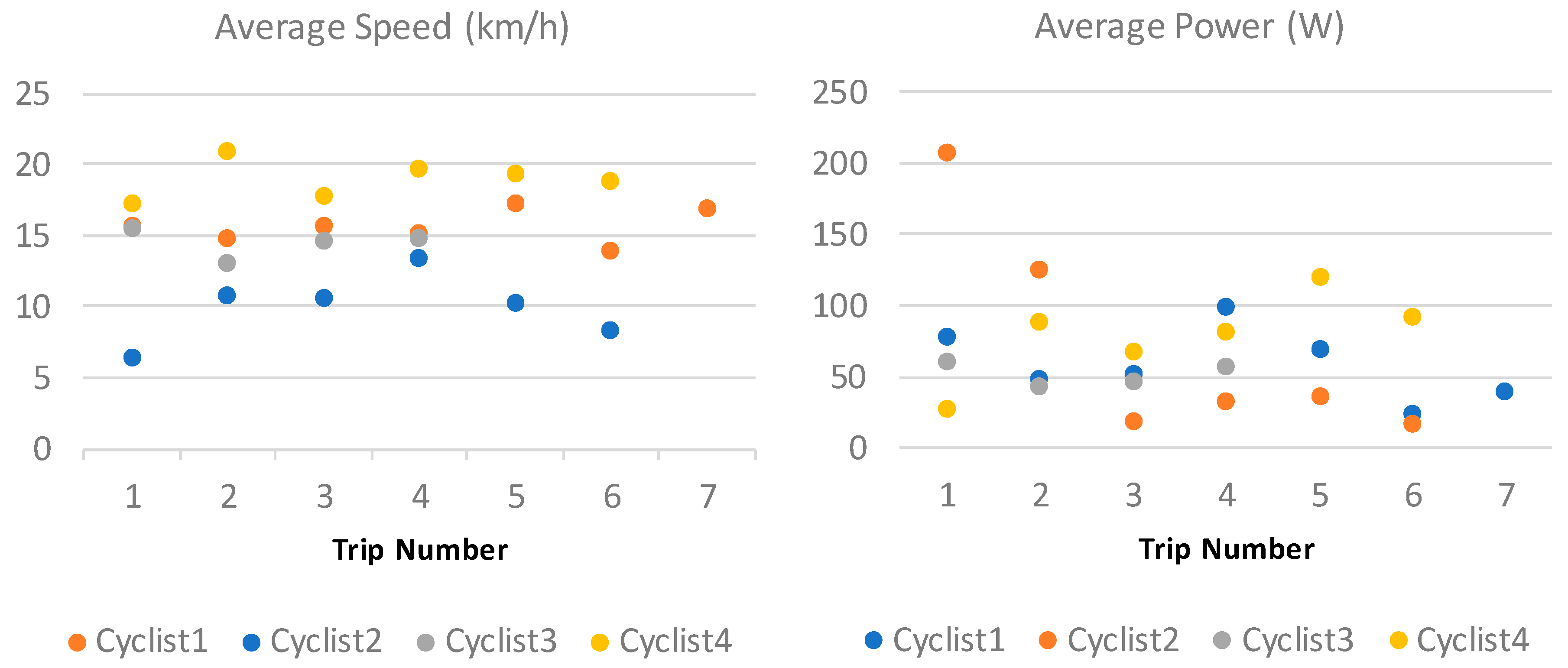
4.1.3. E-Bike User’s Power profiles

In Figure 15, data recorded by the OBC for four different cyclists, performing seven trips each, are reported. The average velocity is always lower than 25 km/h, in line with Resolution No. 160 of 2 February 2017 [8], that regulates bicycles with PAS in Colombia. The average cyclist cadence is between 50 and 70 RPM which, according to [9], is optimum for lower power outputs since a higher cadence might increase fatigue.
The average power of the four cyclists is maintained below 200 W, with most values under 100 W. The overall power registered for all trips is 1600 W; 21% of the maximum power on each trip is over 1000 W, 13% below 100 W, 43% between 100 and 300 W, and 21% between 300 and 1000 W. Analyzing the plots of power and velocity shows that the maximum power peaks are registered just after a stop, when acceleration and power are both at maximums.
While the average time of travel is between 30 and 60 min, one user spent 135 min. This trip consumed 500 kJ from the cyclist, while the other trips consumed below 150 kJ.

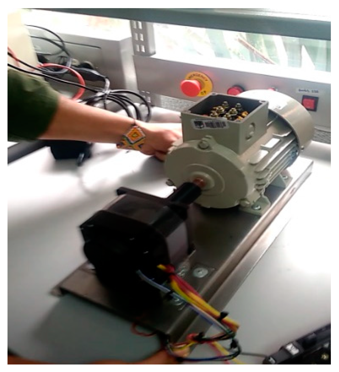
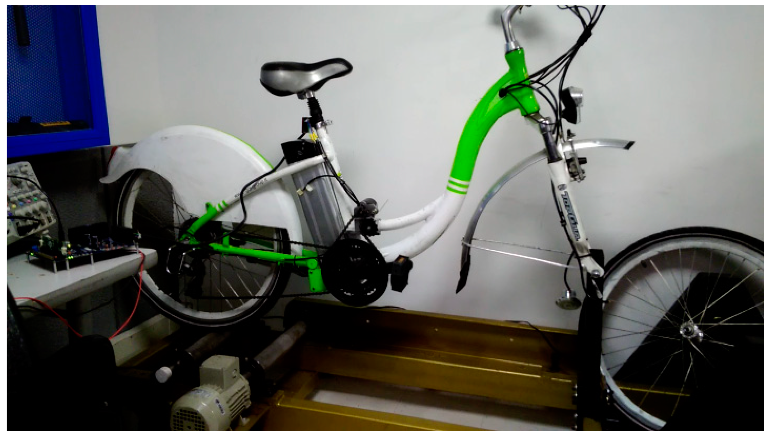
4.2. BLDC Motor-Based Propulsion System for an E-Bike

Two different test benchmarks are used for the assessment of each of the motor torque controllers. The first platform is a stationary bench, which allows easy adjustment of the BLDC motor load. This bench is based on an induction motor directly coupled to the BLDC motor under test as shown in Figure 16. The load (Siemens 1LA7 070-4YC60 motor) is controlled using a Sinamics G120 inverter operating in vector mode to adjust the torque delivered to the BLDC motor.
The second platform used for the test of the out-runner motor is a mid-drive propulsion system integrated onto a bicycle (see Figure 17). This propulsion system is mid-drive type and couples the motor to the pedals through a chain using a 5:32 gear ratio. The bicycle is mounted over a test bench with inertia cylinders, specifically designed for this project. The load applied to the bicycle is kept constant.

4.2.1. Experimental Results

The first step in the experimental validation is the computation of the controller constants. For the motor BLY342S-48V-3200 (Rs = 0.19693256 Ω, Ls = 0.00052149 H), the results obtained are presented in Equations (13)–(16):
  K i s e r i e s = 0.19693256 521.49   ×   10 6 = 377.634  
  K i s e r i e s ( P U ) = 377.634 × 66.666 × 10 6 = 0.0251756  
  K p s e r i e s = 0.00052149 × 3750 = 1.9555875  
  K p s e r i e s ( P U ) = 1.9555875 × 41.45 48 = 1.688731289  
In a similar way, the required parameters for the MTO 5065-170-HA-C motor are found. The obtained results for both motors are summarized in Table 4.

4.2.2. BLY342S-48V-3200 MOTOR

The maximum reference of Iq for the experimental validation is 4 A. It was not possible to increase the Iq reference due to mechanical instability. The torque reference signal comes from a rectifier bridge, whose input is a sine signal. It was also established that the minimum reference point for Iq in the controller is 0.5 A to prevent the engine from totally stopping at some point.
In Figure 18 and Figure 19, the yellow signal corresponds to the signal coming from a diode bridge, which has a frequency of 2 Hz. The blue signal is the current measurement in a motor winding. Finally, the violet signal is the average current of the DC source at 48 V.

4.2.3. MTO 5065-170-HA-C MOTOR

The motor control was tested for different pedaling torque signal frequencies, corresponding to different user scenarios. This signal is generated externally and the pedals are free to spin at the motor spinning frequency.
In Figure 20, a half-wave rectified signal is used as reference for iq (yellow). A motor winding current is observed to follow the reference. The current does not become zero because the algorithm ensures a minimum current to flow through the motor to avoid instability (evidenced experimentally).
In Figure 21, the reference signal frequency increases, consistent with a cyclist pedaling faster. In this case, the period of the motor current and the pedaling frequency became comparable, degrading the ability to track the pedaling torque with precision. This could be solved by increasing the gear ratio between the motor and the pedaling sprockets.
Figure 22 shows the response of the system to rejection of disturbances, in which the bicycle is turning and the pedals are suddenly subjected to braking. In Figure 23, Figure 24, Figure 25 and Figure 26, several responses of the system to the rejection of disturbances are shown. The first two cases refer to a variation in the set-point as the pedaling frequency varies with a fixed amplitude. The last two cases refer to a variation in the set-point amplitude while maintaining the frequency. As shown in all these figures, the system stabilizes either at the initial condition or the new condition.
Considering the results shown in the above figures, Table 5, and the system response settling time when subjected to disturbances, it is established that the system responds quite well to disturbances, with the worst case occurring when the brake was generated intentionally within 0.3 seconds. These response times are practically imperceptible for the user.

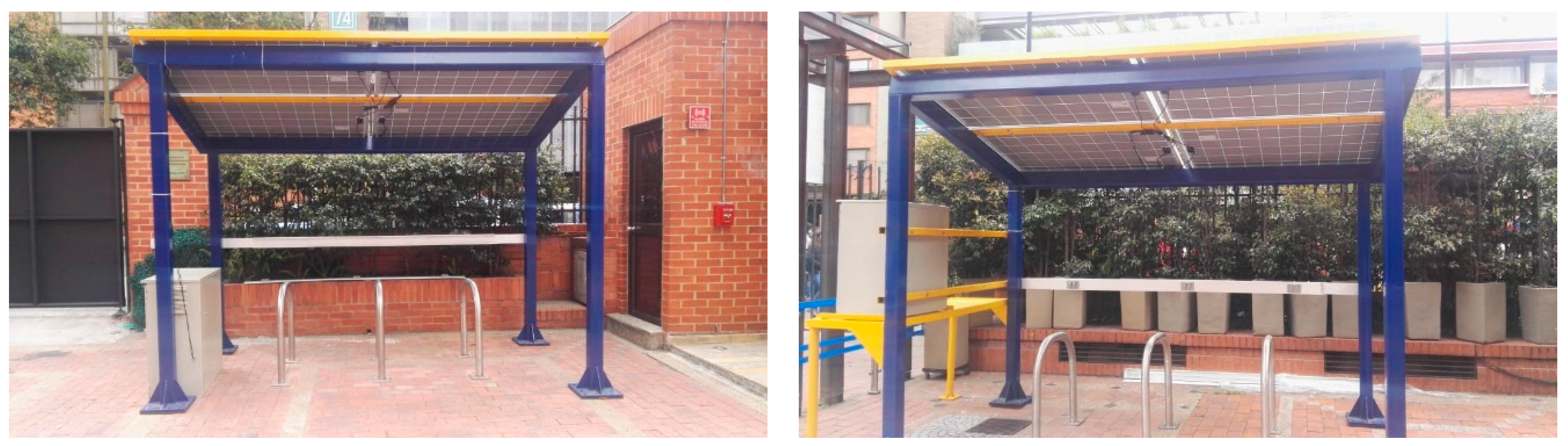
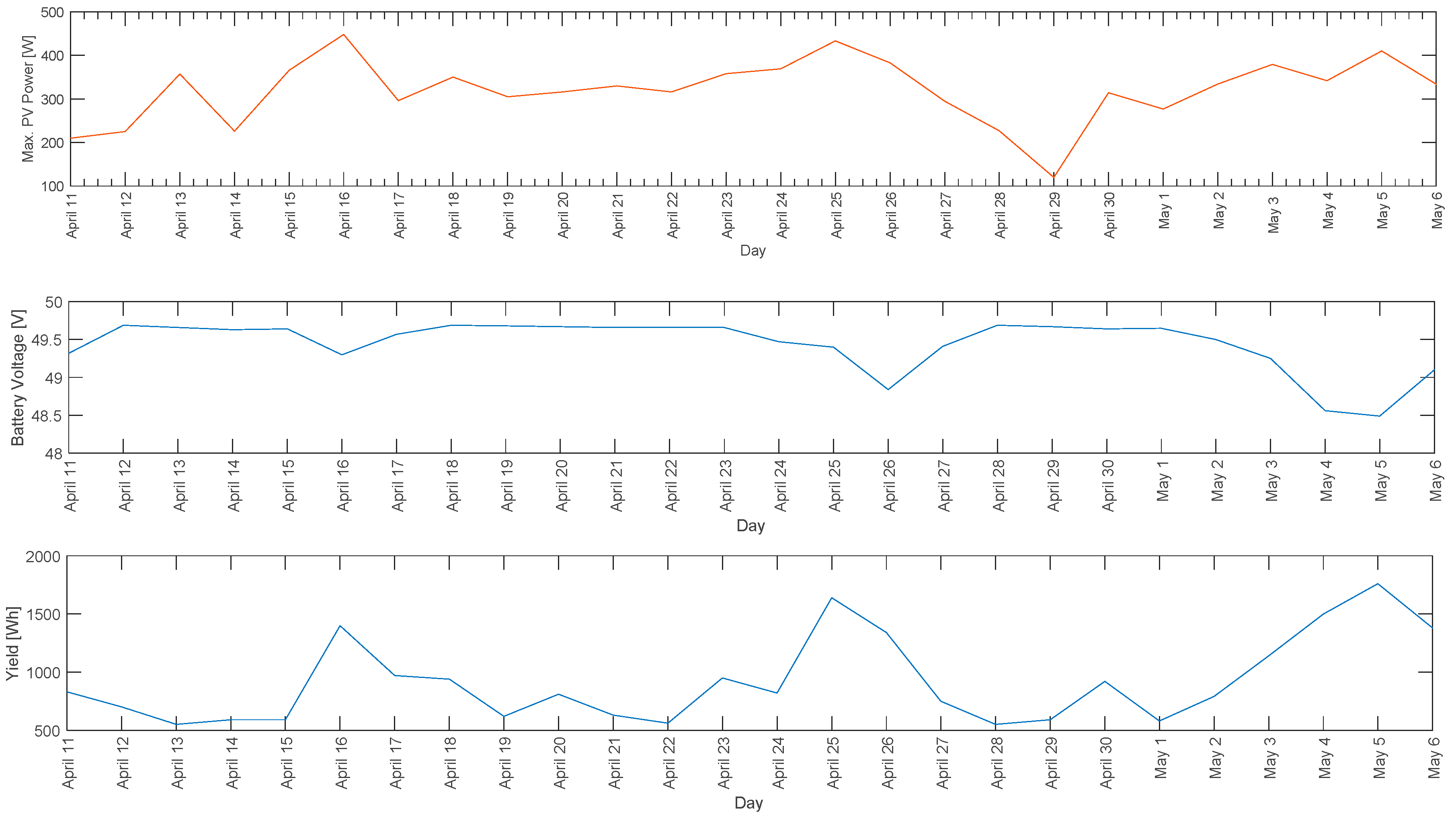
4.3. Charging Station for E-Bike Sharing Systems

In Figure 27 and Figure 28, the BiCiSolar charging stations available at Sergio Arboleda University are shown. Two stations were implemented so that ten e-bikes can be simultaneously charged. Each station is located in the university campus with the solar panels facing south at a fixed 6° angle to the horizontal.
Several phenomena regarding photovoltaic installations have been studied using the BiCiSOLAR charging station, such as partial shading conditions (PSC) [43]. This phenomenon deforms the P-V (power-voltage) curve of the photovoltaic array, reduces its efficiency, and presents major issues for conventional MPPT algorithms due to the presence of multiple maxima in the P-V curve, requiring nonconventional maximum power-point detection techniques [44]. In Figure 29, the PSC phenomenon in the BiCiSOLAR charging stations is presented and in Figure 30 the P-V curve deformation due to such phenomena is depicted.
In Figure 30, it can be seen that the maximum power point is not only lower, reducing the photovoltaic array efficiency, but also that several maxima appear.
As the BiCiSOLAR station also serves as a laboratory for projects in Efficient Conversion of Photovoltaic Solar Energy, the phenomenon presented in Figure 30 is currently under study by the researchers and students at the Sergio Arboleda University. In Figure 31, use by the university community of the BiCiSOLAR charging station between 11 April 2018 and 6 May 2018 is depicted.
Figure 31 shows that despite variations in power generated by the PV array due to irradiance variation and meteorological conditions (cloudy days), battery voltage remains almost constant at around 49.5 V, with small variations of smaller than 2% of the battery charge. Consumption (in Wh) shows that the day the charging station was used most was 5 May. The lowest consumption corresponds with weekends and holidays.

5. Discussion

This paper reported the development of a bike-sharing system for bikes with PAS for Bogota City and experimental results performed at Sergio Arboleda University Campus located in Bogota, Colombia. The system’s main developments include the characterization of bike-users using on-board embedded systems, the design and implementation of a low-cost mid-drive propulsion system, and the development of photovoltaic charging stations for e-bikes.
The exploratory review of state-of-the-art technologies revealed that several solutions are mature enough to be used and adapted to design solutions best adapted to local issues. Encouraging the innovation and development of solutions tailored to local issues, such as economic and social factors, is crucial.
Given that the proposed solutions are designed with consideration of the local context, they are better suited to the bike users of Bogota City than the many existing solutions available in the market.
As reported in the paper, an important corpus of research and development has been carried out in the field of electric bicycles, which has seen them incorporated into the current IoT trend. As an example, the paper reports the development of an on-board-computer (OBC) to characterize bike-users by collecting, in real time, bicycle user’s data, such as bike speed, pedaling frequency, stops, and route lengths, and electric variables from the bicycles, such as battery current and voltage. The data acquired are used to derive cyclist riding profiles in order to design e-bike system controllers that consider the electrical requirements for a bicycle propulsion system.
The study showed that the use of a rectified semi-sinusoidal signal as a motor torque modulator is effective to control power and to ensure that torque follows the average effort made by the bike-user. The rectified semi-sinusoidal signal corresponds to the torque performed by a bike-user when pedaling.
The use of FOC as a control strategy reduced computational burden, thereby reducing the embedded systems cost. In addition, excellent performance was achieved for control of the motor current.
Future security enhancement for the e-bike are pursue in obstacle avoidance systems [45] and place recognition [46] towards autonomous driving.
A major issue in the implementation of e-bike sharing systems is the location and availability of charging stations, as realized by the authors when searching for the right location on the university campus to place the BiCiSolar charging stations. The charging stations also provided information regarding user habits, which can be used to make strategic decisions, such as the placement of additional charging stations or the relocation of existing stations.

Author Contributions

Cyclist characterization system was developed by M.H. and M.C.; The propulsion system conceptualization and design, by D.F., R.G. and S.R.; Charging station design and study by T.M.; Systems test and modeling by H.C. and R.H.-V. Project management and funding acquisition by D.F.

Funding

This work was supported by COLCIENCIAS, Universidad Sergio Arboleda and Energía Movilidad S.A.S under projects 133571552601 and EI.BG.086.15.009.

Acknowledgments

We acknowledge the contributions of undergraduate students Oscar Javier Barragán Becerra, Nicolás Barrantes and Carlos Serrano, and to the mechanical engineer Julian Alvarado.

Conflicts of Interest

The authors declare no conflict of interest.

References

  1. Franco R., J.F. Air pollution in urban centers. Challenge to achieve sustainability: Case study Bogota City. Rev. EAN 2012, 72, 193–204. Available online: https://journal.universidadean.edu.co/index.php/Revista/article/view/576 (accessed on 12 November 2018).
  2. Otero, I.; Nieuwenhuijsen, M.J.; Rojas-Rueda, D. Health impacts of bike sharing systems in Europe. Environ. Int. 2018, 115, 387–394. [Google Scholar] [CrossRef] [PubMed]
  3. Paul, F.; Bogenberger, K. Evaluation-Method for a Station Based Urban-Pedelec Sharing System. Transp. Res. Procedia 2014, 4, 482–493. [Google Scholar] [CrossRef]
  4. Colombian Congress. National Law 1715 of Mai 13th of 2014 issued by Colombian congress, by means of which is regulated the integration of non-conventional renewable energies to the National Energy System. Official Journal of the Republic of Colombia 2014, 49.150, 1–9, ISSN 0122-2112. Available online: https://goo.gl/b8LUCp (accessed on 19 November 2018).
  5. Colombian Congress. National Law 697 of October 3rd of 2001, issued by Colombian Congress, which promotes the rational and efficient use of energy, promotes the use of alternative energies and dictates other provisions. Official Journal of the Republic of Colombia 2001, 44.573, 1–3, ISSN 0122-2112. Available online: https://goo.gl/XgV7He (accessed on 19 November 2018).
  6. Kiefer, C.; Behrendt, F. Smart e-bike monitoring system: Real-time open source and open hardware GPS assistance and sensor data for electrically-assisted bicycles. IET Intell. Transp. Syst. 2016, 10, 79–88. [Google Scholar] [CrossRef]
  7. Regulation (EU) No 168/2013 of the European Parliament and of the Council of 15 January 2013 on the approval and market surveillance of two- or three-wheel vehicles and quadricycles. Official Journal of the European Communities 2013, 56, 52–128, ISSN 1977-0677. Available online: https://eur-lex.europa.eu/legal-content/en/TXT/?uri=CELEX:32013R0168 (accessed on 12 November 2018).
  8. Ministry of Colombian Public Transportation. Resolution Number 160, Ministry of Colombian Public Transportation. Official Journal of the Republic of Colombia 2017, 50.135, 6–9, ISSN 0122-2112. Available online: https://goo.gl/q2ex9r (accessed on 19 November 2018).
  9. Morchin, W.C.; Oman, H. Electric Bicycles: A Guide to Design and Use, 1st ed.; Wiley-IEEE Press: Hoboken, NJ, USA, 2005. [Google Scholar]
  10. Chlebosz, W.; Ombach, G.; Junak, J. Comparison of permanent magnet brushless motor with outer and inner rotor used in e-bike. In Proceedings of the 2010 XIX International Conference on Electrical Machines (ICEM), Rome, Italy, 6–8 September 2010; pp. 1–5. [Google Scholar]
  11. Diga, N.; Ivanov, S.; Diga, S.-M.; Ivanov, V. Considerations on Design and Control Modelling of Permanent Magnet Synchronous Motors for Driving Electric Bicycles. Ann. Univ. Craiova 2013, 37, 16–21. [Google Scholar]
  12. Texas Instruments. InstaSPIN-FOC™ and InstaSPIN-MOTION™ User’s Guide; Texas Instruments: Dallas, TX, USA, 2017. [Google Scholar]
  13. Bindra, A. Wide-Bandgap Power Devices Are Changing the Power Game. IEEE Power Electron. Mag. 2015, 2, 4–6. [Google Scholar] [CrossRef]
  14. Thomas, D.; Klonari, V.; Vallée, F.; Ioakimidis, C.S. Implementation of an e-bike sharing system: The effect on low voltage network using pv and smart charging stations. In Proceedings of the 2015 International Conference on Renewable Energy Research and Applications (ICRERA), Palermo, Italy, 22–25 November 2015; pp. 572–577. [Google Scholar]
  15. Texas Instruments. Test Report of MPPT Charge Controller PMP 7605; Texas Instruments: Dallas, TX, USA, 2013. [Google Scholar]
  16. Reddy, T.B. Linden’s Handbook of Batteries, 4th ed.; McGraw-Hill: New York, NY, USA, 2011. [Google Scholar]
  17. Turner, J. The Electric Bike Book; Oak Creek Publishing: Boulder, CO, USA, 2013. [Google Scholar]
  18. U.S. Environmental Protection Agency. Advancing Sustainable Materials Management: 2014 Fact Sheet; U.S. Environmental Protection Agency (EPA): Washington, DC, USA, 2016. Available online: https://www.epa.gov/sites/production/files/2016-11/documents/2014_smmfactsheet_508.pdf (accessed on 13 November 2018).
  19. SmithBucklin Statistics Group. National Recycling Rate Study; Battery Council International (BCI): Chicago, IL, USA, 2017; Available online: https://cdn.ymaws.com/batterycouncil.org/resource/resmgr/Recycling_Rate/BCI_201212-17_FinalRecycling.pdf (accessed on 13 November 2018).
  20. García Salvatierra, A. The Internet of Things and the New Risks for Privacy. Master’s Thesis, E.U.I.T. Telecomunicación (UPM), Madrid, Spain, 2012. [Google Scholar]
  21. Mattern, F.; Floerkemeier, C. From the internet of computers to the internet of things. In From Active Data Management to Event-Based Systems and More; Springer: Berlin, Germany, 2010; pp. 242–259. [Google Scholar]
  22. O’Leary, D.E. ‘Big Data’, the ‘Internet of Things’ and the ‘Internet of Signs’. Int. J. Intell. Syst. Acc. Financ. Manag. 2013, 20, 53–65. [Google Scholar] [CrossRef]
  23. Aguiari, D.; Delnevo, G.; Monti, L.; Ghini, V.; Mirri, S.; Salomoni, P.; Pau, G.; Im, M.; Tse, R.; Ekpanyapong, M.; et al. Canarin II: Designing a smart e-bike eco-system. In Proceedings of the 2018 15th IEEE Annual Consumer Communications & Networking Conference (CCNC), Las Vegas, NV, USA, 12–15 January 2018; pp. 1–6. [Google Scholar]
  24. Zhao, Y.; Chen, L.; Teng, C.; Li, S.; Pan, G. GreenBicycling: A smartphone-based public bicycle sharing system for healthy life. In Proceedings of the 2013 IEEE and Internet of Things (iThings/CPSCom) and IEEE International Conference on and IEEE Cyber, Physical and Social Computing, Beijing, China, 20–23 August 2013; pp. 1335–1340. [Google Scholar]
  25. Kaltenbrunner, A.; Meza, R.; Grivolla, J.; Codina, J.; Banchs, R. Urban cycles and mobility patterns: Exploring and predicting trends in a bicycle-based public transport system. Pervasive Mob. Comput. 2010, 6, 455–466. [Google Scholar] [CrossRef]
  26. Joo, S.; Oh, C.; Jeong, E.; Lee, G. Categorizing bicycling environments using GPS-based public bicycle velocity data. Transp. Res. Part C Emerg. Technol. 2015, 56, 239–250. [Google Scholar] [CrossRef]
  27. Dozza, M.; Piccinini, G.F.B.; Werneke, J. Using naturalistic data to assess e-cyclist behavior. Transp. Res. Part F Traffic Psychol. Behav. 2016, 41, 217–226. [Google Scholar] [CrossRef]
  28. O’Brien, O.; Cheshire, J.; Batty, M. Mining bicycle sharing data for generating insights into sustainable transport systems. J. Transp. Geogr. 2014, 34, 262–273. [Google Scholar] [CrossRef]
  29. Jäppinen, S.; Toivonen, T.; Salonen, M. Modelling the potential effect of shared bicycles on public transport travel times in Greater Helsinki: An open data approach. Appl. Geogr. 2013, 43, 13–24. [Google Scholar] [CrossRef]
  30. Griffin, G.P.; Jiao, J. Where does Bicycling for Health Happen? Analysing Volunteered Geographic Information through Place and Plexus. J. Transp. Health 2015, 2, 238–247. [Google Scholar] [CrossRef]
  31. Navarro, K.F.; Gay, V.; Golliard, L.; Johnston, B.; Leijdekkers, P.; Vaughan, E.; Wang, X.; Williams, M.A. SocialCycle: What can a mobile app do to encourage cycling? In Proceedings of the 38th IEEE Conference on Local Computer Networks (LCN 2013), Sydney, Australia, 21–24 October 2013; pp. 24–30. [Google Scholar]
  32. Zeng, J.; Li, M.; Liang, J. An Anti-theft Electric Bicycle Tracking System Supporting Large-Scale Users. In Proceedings of the 2014 International Conference on Identification, Information and Knowledge in the Internet of Things, Beijing, China, 17–18 October 2014; pp. 9–16. [Google Scholar]
  33. Iannuzzi, D.; D’Ostilio, R. Inductive charging station for Ebike Clever Mobility: A research project. In Proceedings of the AEIT Annual Conference—From Research to Industry: The Need for a More Effective Technology Transfer (AEIT), Trieste, Italy, 18–19 September 2014; pp. 1–4. [Google Scholar]
  34. Veneri, O.; Capasso, C.; Iannuzzi, D. Experimental evaluation of DC charging architecture for fully-electrified low-power two-wheeler. Appl. Energy 2016, 162, 1428–1438. [Google Scholar] [CrossRef]
  35. Zhang, X.; Mao, W.; Long, Z.; Tang, Z.; Li, Z.; Zheng, X.; Ding, Y.; Tang, C. Electric Bike Management Method and System. CN Patent CN104240031A, 24 December 2014. [Google Scholar]
  36. Tîtu, A.M.; Oprean, C.; Bondrea, I.; Carabulea, I.; Marginean, I.; Moldovan, A.M.; Bogorin-Predescu, A.; Iuonas, I.D. Bicycle with Accentuated Energy Recovery System. EU Patent RO129293A0, 28 March 2014. [Google Scholar]
  37. Turner, J.R. Electric Bicycle and Methods. US Patent US6629574B2, 7 October 2003. [Google Scholar]
  38. Tang, M.; Zhang, B. Intelligent Power Assisting Device of Electric Bicycle. CN Patent CN203186536U, 11 September 2013. [Google Scholar]
  39. Fisher, P. High Performance Brushless DC Motor Control; School of Engineering and Technology CQUniversity Australia: Rockhampton, Australia, 2014. [Google Scholar]
  40. Gamazo-Real, J.C.; Vázquez-Sánchez, E.; Gómez-Gil, J. Position and Speed Control of Brushless DC Motors Using Sensorless Techniques and Application Trends. Sensors 2010, 10, 6901–6947. [Google Scholar] [CrossRef] [PubMed] [Green Version]
  41. Anaheim Automation. BLY34–Brushless DC Motors Specifications Sheet; Anaheim Automation: Anaheim, CA, USA, 2010. [Google Scholar]
  42. Schleinitz, K.; Petzoldt, T.; Franke-Bartholdt, L.; Krems, J.; Gehlert, T. The German naturalistic cycling study—Comparing cycling speed of riders of different e-bikes and conventional bicycles. Saf. Sci. 2017, 92, 290–297. [Google Scholar] [CrossRef]
  43. Seyedmahmoudian, M.; Mekhilef, S.; Rah-mani, R.; Yusof, R.; Renani, E.T. Analytical modeling of partially shaded photovoltaic systems. Energies 2013, 6, 128–144. [Google Scholar] [CrossRef] [Green Version]
  44. Ishaque, K.; Salam, Z. A review of maximum power point tracking techniques of PV system for uniform insolation and partial shading condition. Renew. Sustain. Energy Rev. 2013, 19, 475–488. [Google Scholar] [CrossRef]
  45. Devy, M.; Boizard, J.L.; Galeano, D.B.; Lindado, H.C.; Manzano, M.I.; Irki, Z.; Naoulou, A.; Lacroix, P.; Fillatreau, P.; Fourniols, J.Y.; et al. Stereovision Algorithm to be Executed at 100Hz on a FPGA-Based Architecture. In Advances in Theory and Applications of Stereo Vision; Bhatti, A., Ed.; IntechOpen: London, UK, 2010; p. 17. [Google Scholar]
  46. Carrillo, H.; Latif, Y.; Neira, J.; Castellanos, J.A. Place categorization using sparse and redundant representations. In Proceedings of the 2014 IEEE/RSJ International Conference on Intelligent Robots and Systems, Chicago, IL, USA, 14–18 September 2014; pp. 4950–4957. [Google Scholar]
Figure 1. Mid-drive powertrain and hub-type powertrain. The location of assistance motors indicating where motors power is applied is shown in red. (a) Mid-drive propulsion—motor transfers power directly to the drivetrain; (b) front hub propulsion—motor is placed to spin the front tire; and (c) rear hub propulsion—motor is placed to spin the back tire.
Electronics 07 00337 g001aElectronics 07 00337 g001b
Figure 2. Methodology to quantify Bogota City bike users’ requirements.
Electronics 07 00337 g002
Figure 3. Data acquisition device on-board computer (OBC).
Electronics 07 00337 g003
Figure 4. Developed software flowchart.
Electronics 07 00337 g004
Figure 5. Simplified model of cyclist pedaling torque.
Electronics 07 00337 g005
Figure 6. Domain transformations required for the field-oriented controller (FOC) control using space vector modulation (SVM).
Electronics 07 00337 g006
Figure 7. Current control loop and brushless-DC motor (BLDC) motor first order model.
Electronics 07 00337 g007
Figure 8. Implementation of the FOC algorithm. In red, analog input data. In green, digital signals with 32-bit resolution in floating point. In blue, pulse-width modulation (PWM) output signals.
Electronics 07 00337 g008
Figure 9. BiCiSOLAR charging station renders at Sergio Arboleda University.
Electronics 07 00337 g009
Figure 10. BiCiSOLAR charging station at Sergio Arboleda University.
Electronics 07 00337 g010
Figure 11. BlueSolar Charge Controller MPPT 150/35.
Electronics 07 00337 g011
Figure 12. Filtered and non-filtered elevation profile vectors.
Electronics 07 00337 g012
Figure 13. Power vector comparison and average power comparison.
Electronics 07 00337 g013
Figure 14. Sample of recorded data for 15 V and 1 A test.
Electronics 07 00337 g014
Figure 15. Acquired average velocity and power.
Electronics 07 00337 g015
Figure 16. Test bench for the BLY342S-48V-3200 motor.
Electronics 07 00337 g016
Figure 17. Test bench for the MTO 5065-170-HA-C motor.
Electronics 07 00337 g017
Figure 18. Transient response of the controller.
Electronics 07 00337 g018
Figure 19. Steady state of the controller.
Electronics 07 00337 g019
Figure 20. Motor current under control. Reference signal frequency: 1 Hz.
Electronics 07 00337 g020
Figure 21. Motor current under control. Reference signal frequency: 10 Hz.
Electronics 07 00337 g021
Figure 22. Motor current behavior after locking the motor by means of the brakes.
Electronics 07 00337 g022
Figure 23. Motor current behavior after a sudden change in the pedaling frequency: 5 to 15 Hz.
Electronics 07 00337 g023
Figure 24. Motor current behavior after a sudden change in the pedaling frequency: 1 to 12 Hz.
Electronics 07 00337 g024
Figure 25. Motor current behavior after a step in the peak current reference from 18 A to 21 A. Pedaling frequency, 10 Hz.
Electronics 07 00337 g025
Figure 26. Motor current behavior after a step in the peak current reference from 22 A to 15 A. Pedaling frequency, 10 Hz.
Electronics 07 00337 g026
Figure 27. BiCiSOLAR charging station. East charging station (left) and west charging station (right).
Electronics 07 00337 g027
Figure 28. West BiCiSOLAR charging station.
Electronics 07 00337 g028
Figure 29. Partial shading phenomenon PSC in BiCiSOLAR charging station.
Electronics 07 00337 g029
Figure 30. Power-voltage (P-V) curve with uniform 600 W/m2 irradiance (blue) and P-V curve due to PSC phenomena (red) in BiCiSOLAR charging station.
Electronics 07 00337 g030
Figure 31. Maximum power generated by the PV array in the BiCiSOLAR charging station (top), battery voltage (center) and charging station consumption (bottom).
Electronics 07 00337 g031
Table 1. Resistance power equations.
P a i r (t) 1 2 · ρ · C D · A · V A 2 · V G ( t ) (2)
P r o l l (t) V G ( t ) · cos ( θ R ( t ) ) · C R R · m T · g (3)
P b e a r i n g (t) β 0 · V G ( t ) + β 1 · V G ( t ) 2 (4)
P P e (t) V G ( t ) · m T · g · sin ( θ R ( t ) ) (5)
P K e (t) 1 2 · ( m T + I r 2 ) · a ( t ) 2 · Δ t (6)
Table 2. Average parameter values.
SymbolDescriptionValue
ρ Air density0.8962 kg/m3
C D Drag coefficient1
A Frontal area (bike and cyclist)0.504 m2
C R R Coefficient of rolling resistance0.0032
g Gravitational acceleration9.81 m/s2
β 0 1st coefficient of wheel bearing0.091 N
β 1 2nd coefficient of wheel bearing0.0087 N s/m
I Wheel moment of inertia0.14 kg m2
Δ t Power measurement period1 s
V A Bicycle velocity relative to air0 m/s2
Table 3. Time-variable parameters.
SymbolDescriptionSensor—Method
V G ( t ) Bicycle ground velocityReed switch sensor (m/s)
θ R ( t ) Road—gravity vector angleGPS unit output based (°)
m T Bike and cyclist massBody and hanging scales (kg)
r Wheel radiusClass 2 tape measure (m)
a ( t ) Bicycle linear acceleration V G ( t ) value based computation (m/s2)
Table 4. Motor and controller parameters.
Motor ReferenceMotor Model ParametersController Constants
Rs (Ω)Ls (μH)KiKp
BLY342S-48V-32000.197521.49 0.0251756 1.688731289
MTO 5065-170-HA-C0.09150.80 0.21830827 0.1312173009
Table 5. Average settling time for different perturbations.
Perturbed ParameterSettling Time (s)
Motor load0.3
Frequency0.2
Reference amplitude0.15

