
Influence of Airflow Disturbance on the Uniformity of Spin Coating Film Thickness on Large Area Rectangular Substrates


Key Laboratory for Precision and Non-Traditional Machining Technology of Ministry of Education, Dalian University of Technology, Dalian 116024, China
*
Author to whom correspondence should be addressed.
Coatings 2022, 12(9), 1253; https://doi.org/10.3390/coatings12091253
Submission received: 21 July 2022
/
Revised: 20 August 2022
/
Accepted: 22 August 2022
/
Published: 26 August 2022
Abstract
:Spin coating is widely used to form a uniform film on a solid substrate. Airflow disturbance has been considered as one of the most influential factors of film thickness, especially for spin coating on large area noncircular substrates. However, the exact mechanism of airflow disturbance influence, such as air shear force effect or indirect effects on evaporation, so far, remains ambiguous. In this work, the influence mechanism of airflow disturbance on film uniformity on large rectangular substrates is studied. The experiment with airflow disturbance is artificially introduced and contrasts with the common spin coating conditions. Both numerical simulations and experiments show a causal relationship between airflow disturbances and the uniformity of the spin coating film. The film thickness and airflow field results show that the film uniformity is affected by solvent evaporation and air shear force caused by airflow disturbance. Additionally, evaporation inhibition and airflow disturbance results do not support the proposition that air shear forces can affect film uniformity, but that solvent evaporation is the primary factor affecting film thickness uniformity. These conclusions are beneficial to the understanding of the mechanism of airflow disturbance influence on the film thickness uniformity on large rectangular substrates.

1. Introduction
The spin coating method plays a significant role in the fabrication of Micro-Electro-Mechanical System (MEMS) devices [1], photodetectors [2], and diffraction optical elements [3]. Compared with the sol–gel method [4], vacuum deposition [5], dip-coating [6] and other thin film preparation methods, spin coating is more suitable for the preparation of uniform photoresist thin films due to its simple process, controllability and repeatability. A typical spin coating process includes deposition, spin-off, and drying steps. Studies have proved that film thickness uniformity has a significant correlation with the performance of the photolithography process [7] and thin film devices [8,9]. The non-uniform layer thickness of perovskite photodetectors on the rectangular substrate could cause transverse defects and is indicated to be the major primary cause of poor device performance and reduced device efficiency [10]. As non-uniform film introduces an optical path difference and leads to poor imaging performance, spin-coated polyimide film on a large area Fresnel diffraction element must perform a better uniformity superior ±1.1% [11]. To achieve the performance and efficiency of thin-film devices, film thickness uniformity on large area substrates is increasingly suggested as a basic requirement.
Compared with spin coating on circular substrates, the film thickness nonuniformity on noncircular substrates is generally more significant. Carcano et al. conducted spin coating experiments with high viscosity photoresist on the surface of square substrates (2 × 2 inches) [12]. According to the experimental results, the edge effect and fringe defect were found on the substrate corner, and this non-uniform problem was attributed to the noncircular geometry of the substrate. Later studies focus on the edge bead effect attributed to the air velocity increase in friction at the large radial position [13], and indicate edge defect on the corner was exacerbated by the Bernoulli effect [14]. It is widely recognized that the edge effect leads to poor spin coating uniformity on rectangular substrates [15,16]. When the spin coating experiment is performed in an open chamber, the edges and corners of the substrate cut the air directly at high relative speeds. This phenomenon caused a considerable relative velocity at the air-liquid film interface and velocity fluctuation at the edge of the rectangular substrate. To improve the film uniformity, the rectangular substrate was embedded into a circular chuck plate and limited the volume of the spin coating chamber [17]. These measures weaken the disorder of air velocity field and the Bernoulli effect, but cannot wholly eliminate the airflow disturbance. Especially for the large chamber, small disturbances are easy to develop and intensify, forming local turbulent and irregular airflow fields. For the spin coating process, the change in the airflow field is directly reflected in the flow state of the liquid film.
Liquid flow behavior determines the film thickness and uniformity of the spin-coated film and changes according to the stress in the liquid film and is induced by the external field force. The main stress in the liquid film is caused by surface tension. Various external field forces also act on the liquid film, including frictional force, centrifugal force and gravity. As the spin area is enlarged, the effects of radial position-related forces amplify its influence on liquid flow behavior, such as frictional force. Ma et al. studied the thinning effect of air shear for the spin coating processes in open space and defined air shear as a function of air velocity and radial position [18]. Compared with the classical model of Emslie [19], it has been concluded that air shear accelerates the thinning rate in the initial stage, while the rough surface decreases the thinning rate in the afterward stage. The experimental results of Yanagisawa et al. [20] were used for the verification model of Middleman [21], and found that both the thinning rate and the final film thickness were higher than the predicted one. This means the direct influence of air shear is not as obvious as predicted and other indirect effects of the airflow should be taken into consideration.
Airflow is also an important factor affecting evaporation [22] and the importance of evaporation in spin coating has been widely demonstrated [23]. The solvent evaporation rate is susceptible to airflow, which is positively correlated with velocity and exponentially correlated with turbulence intensity [24]. During the spin coating process, as solvent evaporation increases the volume fraction of solute in the layer, the liquid film viscosity gradually increases and causes poor fluidity [25]. Due to the heterogeneity of viscosity within the global liquid film, the high-viscosity liquid film tends to stop flowing and obstruct low-viscosity fluid flow. The film piled high in the slowly flowing area, exacerbating uneven film thickness distribution defects. In the small-area rectangular substrate spinning experiment, local non-uniform airflow caused by disturbance plate was found to leave its pattern on the surface [26], inferred presumably due to the various viscosity caused by non-uniform evaporation. The increasing spinning size enlarged the evaporation area, and the rectangular shape caused airflow fluctuation at corners. Both make non-uniform evaporation a notability problem when spinning on large rectangular substrates. Therefore, revealing the influence of airflow disturbance on the film thickness distribution is very important for achieving a high uniformity spin coating film on large area rectangular substrates. In this study, a series of experiments on the thickness uniformity of the spin coating on the large area rectangular substrate were conducted. The experiment with airflow disturbance and solvent evaporation inhibition was carried out to contrast with the common spin coating conditions. The characteristic of the spin coating chamber airflow field with disturbance conditions was analyzed by the CFD simulation. The dominant role of the airflow force or solvent evaporation is discussed to clarify the mechanism of influence of airflow disturbance on film thickness uniformity.
2. Experiment and Modeling Methods
2.1. Experiment Method of Spin Coating
For all the experiments in this paper, the AC800 spin coater (LEBO Science Co. Ltd., Wuxi, China) was used. The schematic diagram of the rotating system is shown in Figure 1. The rotating system is the most important part of the spin coater, including the circular barrier plate, side wall and cover plate. The thickness of the substrate was the same as the depth of the circular barrier plate; their upper surfaces lie in the same plane when the rectangular substrate was embedded to suppress the airflow disturbance caused by the edges of the substrate. The whole process of the spin coating was conducted in an airtight chamber. The resin-solvent mixture consists of rzj-304 positive (Suzhou Ruihong Electronic Chemicals Co. Ltd., Suzhou, China) photoresist and PGMEA (Suzhou Ruihong Electronic Chemicals Co. Ltd., Suzhou, China) was used as the diluent. The initial solute volume fraction of the mixed solution was 66.2%. On each experimental sequence, a 100 mL mixture was dispensed on the rectangular quartz substrate. The liquid film was thinned by rotating the substrate at a specified spin speed of 100 rpm for 10 s. Then, the substrate was rapidly accelerated to the maximum spin speed of 300 rpm and rotated for 50 s. A series of experiments were carried out including the reference group, airflow disturbance group and evaporation inhibition group, with the same spinning parameter. In the latter two experiments, the disturbance plate was stuck to the underside of the cover plate above the center of the substrate, as shown in Figure 1. The height of the spinning chamber and disturbance plate is 20 and 5 mm, and the disturbance plate is sufficient to generate a noticeably disturbed airflow field. In the evaporation inhibition group, in addition to the disturbance plate, the solvent (PGMEA) was left to rest on the circular barrier plate for 30 min before spin coating. The solvent in the chamber evaporated so that there was a certain vapor concentration in the airtight chamber. A repeated experiment was conducted to ensure that the data on film thickness uniformity was reliable.
After the spinning process was completed, the substrate with photoresist film was dried in the air for no less than 6 h to ensure the solvent was completely evaporated. Until photoresist film thickness was no longer decreased, thickness error would not be introduced into the thickness test. The OEM-MAP white light interference system (Ellitop Scientific Co., Ltd., Beijing, China) was applied to the film thickness measurement. The interferometer probe was equipped on a two-axis motion platform which could realize single-point measurement and large area mapped scanning measurement. The distance between adjacent points of the map scanning measurement was set as 20 mm. The thickness uniformity εh is defined as:
where hmax, hmin is the maximum and minimum film thickness. In the following text, the film thickness uniformity of the reference group, airflow disturbance group and the evaporation inhibition group are represented as εref, εdisturb and εevap, respectively.
According to the existing research about the characteristics of rectangular spin coating thickness distribution, the thick ridge of a film arising along the periphery of a substrate is called the edge-bead. The average thickness of the edge-bead effect area is significantly thicker than that in the central area. To focus on the overall film thickness uniformity analysis and exclude interference from the edge buildup region, it is necessary to remove the edge-bead effect area. From the regularity of experimental results of large area spin coating in this study, the width of the edge-bead effect is less than 20 mm. To eliminate the influence of edge effects, this paper only focuses on the thickness uniformity in the central area after 30 mm of edge removal.
2.2. Modeling Method of Airflow Field in Spin Chamber
The averaged equations of conservation of mass, energy and Reynolds are:
The mass conservation equation:
Energy Equations:
Reynolds Equations:
The k-ω SST (Shear Stress Transport) model is a hybrid model that retains the original k-ω model near the wall and applies the k-ω model away from the wall. The k-ω SST turbulence model captures the flow properties with higher accuracy than other two-equation turbulence models [27]. For this reason, the k-ω SST turbulence model was selected to simulate the chamber flow field characteristic. The formulation of the two-equation model can be written as:
specific dissipation rate:
the blend function F1 is defined by:
eddy viscosity is given by the following equation:
F2 is a function that is one for boundary-layer flows and zero for free shear layers; the second blending function is defined by:
the model constants are calculated using the mixing function F1:
the values of the model constants are: Cμ = 0.09, α1 = 5/9, α2 = 0.44, β2 = 0.828, σk1 = 0.85, σk2 = 1.0, σω1 = 0.5, σω2 = 0.856.
The flow field in the spin coating chamber was analyzed through finite element simulation. The spin coating chamber was a cylinder with a diameter of 680 mm and a height of 20 mm. The size of the quartz spin coating substrate was 480 mm × 300 mm. There was a gap with a width of 2 mm and a depth of 5 mm surrounding the substrate. There were two groups of chamber models: the reference group and the airflow disturbance group, with the same structure and size. The difference between them was that there was a disturbance plate in the chamber model of the airflow disturbance group. The dynamic area was the air with a density of 1.225 kg/m3 and a viscosity of 1.790 × 10⁻⁵ kg/m·s. The rotational motion of the fluid in the chamber was simulated using a dynamic grid. The rotation diagram of the spin coating chamber was shown in Figure 2. The dynamic area was defined as the fluid area formed by the top wall, side wall and subface of the chamber. The chamber rotation-time function was defined through the profile.
The running time of the acceleration, constant rotation, and deceleration stage is 2, 4 and 2 s, respectively. The airflow field was continuously developing in the acceleration and deceleration stage, so only the stable result of the constant rotation stage was analyzed. The walls of the chamber were all defined as fixed wall boundaries. The walls were set to rotate relative to the rotation region of the chamber without slippage, and the relative speed was zero to remain static.
A boundary layer was added at the substrate surface to ensure the simulation accuracy of the near-wall airflow fluid. The remaining region was divided by tetrahedral mesh. The number of grids was slightly different according to the disturbance plate features in the chamber structure, ranging from 650,000 and 700,000. A smaller time step can resolve a more accurate solution, the calculation time step was set as 0.002 s, which is far less than 1/20 of the rotation period (0.01 s). The number of iterations is 80, and it takes about 80 h to complete the computation for one case.
3. Results and Discussion
3.1. Experimental and Analysis Results
3.1.1. Film Uniformity Results with Airflow Disturbance
The experiments of the reference group and the disturbance group were carried out to study the influence of airflow disturbance on thickness distribution and uniformity. Compared with the reference group, the disturbance plate was set in the spin chamber to form an airflow disturbance in the experimental group. Figure 3 shows the contour map of the thickness distribution of the reference group (Figure 3a) and disturbance group (Figure 3b) with a measuring range of 240 mm × 420 mm. The overall thickness uniformity behaves well, although accompanied by slight thickness fluctuation in the reference group while there is a significant concentration area of larger thicknesses in the airflow disturbance group. Compared with the reference group, the average film thickness increased from 523.0 to 536.3 nm, and the uniformity decreased from εref = ±3.41% to εdisturb = ±6.74%. The average film thickness of the area within the central red circle (diameter 0.15 m) shown in Figure 3b is higher than that of the area outside the circle. Furthermore, even at the same distance from the center of rotation, the film thickness fluctuated obviously, such as the locations along the red circle in Figure 3b. Obvious wind marks with higher thickness defects could be observed near the center area, which also happened to be the area where the disturbance plate was located. In other words, there is a clear correlation between the location of the abnormal film thickness area and the airflow disturbance.
3.1.2. Simulation Results of Disturbed Airflow Field
In this section, the characteristics of the airflow field of the chamber were analyzed when the spin system rotated at a constant speed of 300 rpm. Different from open space spin coating, the cover plate that rotated synchronously with the substrate was used in this experiment. Therefore, there was a lower relative velocity between the air and the substrate. After processing the velocity data by subtracting the local velocity of the reference frame, the relative velocity of the chamber flow field was obtained. Figure 4 and Figure 5 show the velocity and wall shear stress distribution of the flow field in the reference group and the airflow disturbance group. The wall shear stress was collected at the substrate surface, and the velocity value was at 6 mm in height from the substrate surface, respectively.
In the results of the reference group, the velocity and wall shear stress distribution had a similar regularity, and the values increased with the radial distance from the center of the rotation. The velocity increases from 0 to 3.4 m/s, and the shear stress increases from 0 to 0.11 Pa. In the airflow disturbance group, although the maximum and minimum values differed little from the reference group, in the range from −0.1 to 0.1 m, both the velocity and the shear stress were quite different from the reference group. This range was exactly where the disturbance plate was located. The fluctuation of the velocity vs. was about 9.0% at the location around 0.1 m and −17.2% at the location around −0.1 m. The obvious fluctuation range of wall shear stress was within an area of 0.1 m in diameter, and the maximum fluctuation σs increased by 27.2%. The circumferential velocity fluctuation at the disturbance plate position is shown in Figure 4c. The velocity is displayed according to the corresponding angle. Compared with the airflow disturbance group, the circumferential velocity distribution in the reference group was uniform. The velocity of the airflow disturbance group increases sharply over 60% near the plate, compared with the smooth distribution area.
The data showed that in different areas, airflow disturbance could not only have an increase but also a decrease in the air shear stress and velocity, at the same moment. Comparing the above results with the experimental results in Section 3.1.1, the location of the local features of the shear stress and velocity was roughly the same as the location of abnormal film thickness in the airflow disturbance group. It could be preliminarily concluded that the phenomenon of change in film thickness uniformity was related to the fluctuation but not the magnitude of the airflow velocity and the wall shear.
As the existing studies have considered, the film thinning in the spin coating could be divided into three stages [26]. In the first stage, the solution spread out rapidly under the action of centrifugal force. The second stage was a radial outflow of liquid driven by both the centrifugal force of the photoresist layer itself and the air shear force, gradually forming a uniform film layer. Additionally, as for the third stage, the film was so thin that the centrifugal force and the airflow shear force could not continue thinning it down, then the evaporation became the key factor in thinning the film. When the centrifugal force, the shear force, and the evaporation were distributed ideally over the entire substrate plane, the final film thickness was also uniform. However, in practice, as the size of the substrate increased and the edges and corners of the substrate appeared, some local disturbances occurred, leading the distribution of film thickness to demonstrate poor uniformity, as Figure 3 shows. From the above experimental results alone, it was difficult to judge how the disturbance caused by the disturbance plate specifically affected the uniformity of the film thickness distribution. This was because the changes in airflow rates not only changed the air shear but also significantly affected the evaporation rate of the solvent of the photoresist. It was therefore necessary to analyze the contribution of the air shear force, the centrifugal force and the evaporation to the film thickness uniformity in the spin coating process.
3.2. Influence of Airflow Disturbance on Film Uniformity
3.2.1. Shear Stress Induced by the Airflow
The air shear force and the centrifugal force could be analyzed in the form of a net force. As shown in Figure 6, a system of cylindrical coordinates which spins at an angular velocity ω about the z-axis is used. An element volume rdθdr·h in a cylindrical coordinate system is used to analyze the forced condition in the spin-coating process. The centrifugal force Fc on this representative elemental volume was defined as
where h is the height of the film layer. The upper surface of the elemental volume contacts the air and generates a shearing force Fs on the area of rdθdr. According to Middleman’s research [21], the shear stress σs, on the air-liquid surface could be exploited to give the approximation as
where is the kinematic viscosity of the air, and ηair is the viscosity of the air. So the Fs could be written as
It is assumed that the radial velocity of the induced airflow is substantially greater than that of the film layer. Therefore, Fs is in the same direction as Fc. These two forces acting on the representative elemental volume determined the evolution of film thickness. Taking this elemental volume as the object, the relative relation of the two forces should be compared to judge their contribution to the evolution of film thickness. The coefficient Ss-c that indicates the priority of the two forces could be defined by the ratio of Fs to Fc as
Equation (15) shows that the contribution ratio of centrifugal active and shear action Ss-c is independent of r. Based on the three-stage theory concluded by Meyerhofer [28], in the first two stages of the spin coating process, the photoresist liquid flows radially outward. Additionally, this flow was uniform throughout the coating plane, even at different radial positions. Furthermore, the change in Ss-c is only related to the change in film thickness h. What is clear is that as the h decreases, the air shear effect gradually dominates the centrifugation effect. When a disturbance plate caused airflow disturbances in the spin coating chamber, the local air shear intensity changes, as Figure 4b shows. The increase in local flow velocity and wall shear accelerated the thinning rate of the film. The thickness uniformity defect in the experimental results of the airflow disturbance group in Section 3.1.1 could be explained, such as the increase in the outliers and differences in film thickness associated with the radial position. However, although disturbances caused differences in local flow fields, the shearing effects were always the same in the same radial position due to the high-speed rotation during spin coating. It could not be explained that the film thickness fluctuates at the same radial position from the above perspective such as the results along the red line in Figure 3b.
It could be concluded from the discussion above that the air shear effect shows the notable change caused by the disturbance plate, and the thickness uniformity of the corresponding area becomes worse. It is preliminarily speculated that the local non-uniform flow field has the effect of reducing the thickness uniformity. However, in addition to direct air shear in the flow field, studies have also pointed out the obvious effect of flow velocity on the evaporation rate [29,30]. Therefore, it is necessary to consider the possible influence of solvent evaporation in the spinning process and estimate the role in the influence of thickness uniformity.
3.2.2. Evaporation Induced by the Airflow Disturbance
In the process of evaporation of the solvent, the viscosity of the photoresist was constantly increasing, reducing the behavior of liquid flow [21,31,32]. When the liquid flow behavior dropped to a critical value, the centrifugal forces and the air shear forces would not be able to cause the photoresist to flow out. In this case, the evaporation process determined the final deposition thickness of the solute of the photoresist film. Under the assumption that the evaporation was uniform, the thickness of the film theoretically depended only on the mixing ratio of the solute to the solvent. However, in practice, both the rate and degree of evaporation were non-uniform throughout the whole substrate, especially on a large area rectangular substrate.
The inherent corner characteristics of a rectangular substrate would bring airflow turbulence to the spin coating chamber. As the velocity of airflow is one of the most important factors in evaporation rates, local changes in air velocity caused by airflow disturbances can change the evaporation rate. As a result, the film thickness can no longer be predicted according to the law of uniform evaporation in the region affected by airflow disturbance. The stagnant zone due to poor fluidity obstructs the surrounding flow, leading to local liquid accumulation and the formation of high solute concentration zones. Therefore, the film thickness in the higher evaporation rate areas was higher than that of the lower evaporation areas. Due to the high-speed rotation of the substrate, in the treatment of many problems the conditions at the same rotation radius could be approximately treated the same. This was precisely because evaporation was a continuous process in terms of time and the changes in viscosity and fluidity were irreversible, which caused film thicknesses to vary even at a uniform radius of spin rotation. Specifically, the moment when an area of photoresist piled up, the flow of photoresist in adjacent areas began to be blocked. As Figure 3b shows, defects of differences in film thickness between the piling-up area and the surrounding area were formed.
From the above analysis, it could be concluded that the later spin coating process has a greater influence on the uniformity of film thickness. Additionally, this influence was dominated by the evaporation of photoresists. To verify the above conclusions, it was necessary to obtain support from the results using experimental methods.
3.3. Validation Experiment by Inhibiting the Evaporation
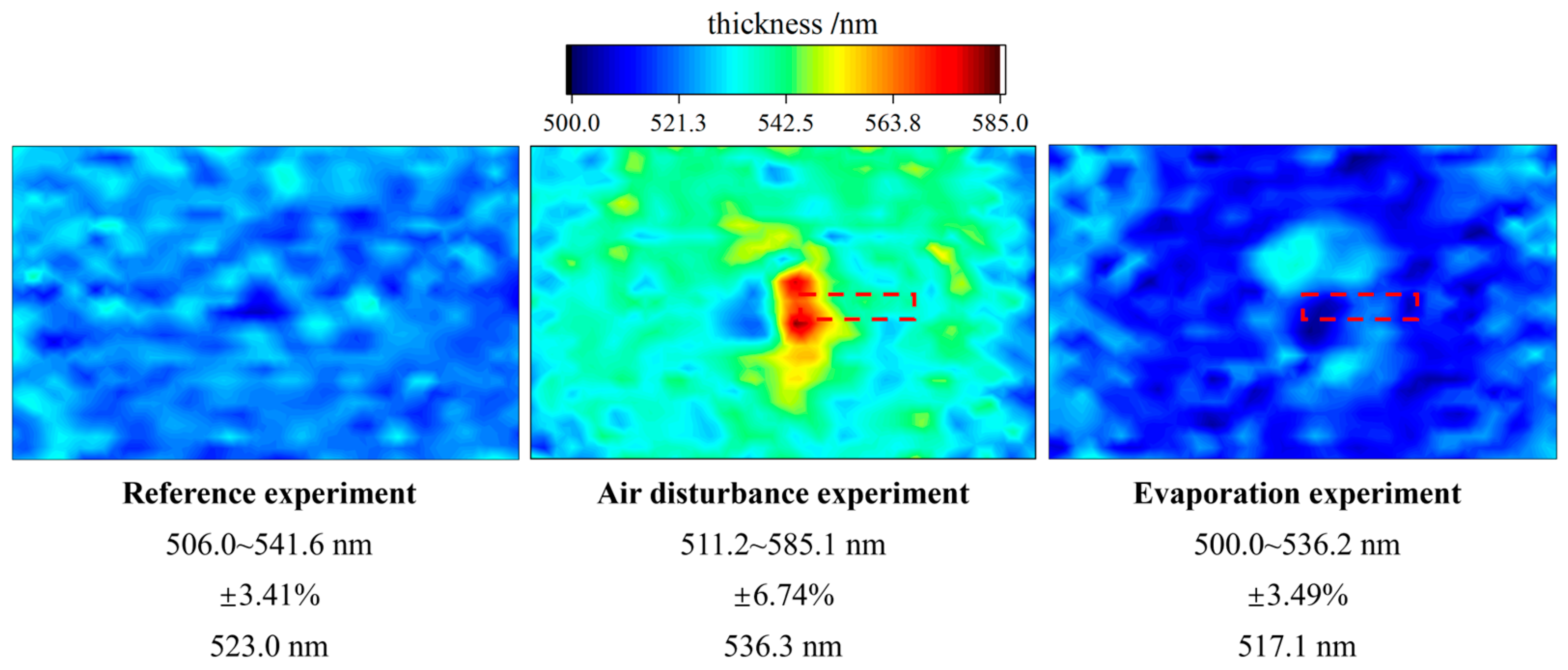
To analyze the influence of solvent evaporation on thickness uniformity, it was necessary to separate the influence of solvent evaporation from flow field disturbance. The evaporation inhibition group constructs a relatively high concentration of solvent vapor in the chamber before starting spin coating. The evaporation inhibition group and the airflow disturbance group had the same chamber and disturbance plate structure, and the solvent evaporation state was the only variable of the two groups. As is shown in Figure 7, the experimental results of the three groups were compared, and the film thickness counters were displayed in the same thickness range. The range of thickness, εh and , is listed below in the thickness distribution chart. The average thickness of the evaporation inhibition group was the lowest, and the uniformity was similar to that of the reference group. It can be seen from the film thickness distribution that the evaporation inhibition group significantly improved the film defect in the central region, which is also reflected in the improvement in εh.
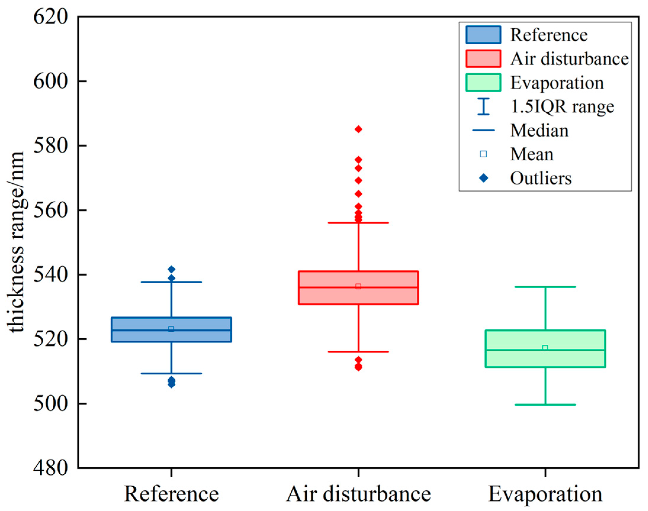
The definition of εh was only calculated from extreme value h and the thickness data around the median area might be not considered. Therefore, we carried out a statistical analysis of the thickness data of the reference group and experimental group, and the results are shown in Figure 8. It can be seen from the boxplot that in each group, the mean value of the film thickness data was close to the median value. Therefore, the mean value could preliminarily measure the central tendency of film thickness distribution. As Figure 8 indicated that , the effect of airflow disturbance would increase the film thickness, and suppressing evaporation during spin coating would reduce the film thickness, which was consistent with previous analyses. In the early stage of spin coating, the photoresist film was cast out and thinned by the centrifugal and the air shear force. As the film thickness becomes thinner, the increase in the viscosity made the centrifugal force and the air shear force unable to thin the film, and evaporation thinning was dominant. However, when the evaporation was inhibited, the rate of increase in viscosity of the solution was slowed down, so that the centrifugal force and the air shear force had a longer time to thin down the film. As a result, it was understandable that the evaporation group obtained the smallest mean value of the film thickness. The box in the figure was bounded by upper and lower quartiles.
Compared with the reference group, the box height of the airflow disturbance group was obviously increased. This meant that the airflow disturbance not only affected the vicinity of the disturbance plate but almost the entire substrate. The height of the evaporation group was close to that of the airflow disturbance group. It could be considered that the suppression of evaporation did not significantly improve the concentration of thickness values in this part of the film. The 1.5IQR range was similar to the case with the height of the box described above. However, regarding the outliers, the most important parameter for evaluating the thickness uniformity of photoresist films, there were significant differences between these three groups. The outliers in the reference group were more evenly distributed on both sides of the 1.51IQR range. In contrast, there was a right-skewed distribution in the airflow disturbance group, which indicated that there were many areas where the film thickness increased abnormally in the airflow disturbance group. Coinciding with the analysis in Section 3.2.2, the acceleration of evaporation caused by the airflow disturbance led the local photoresist to sharply decrease in fluidity and then pile up. The results of the evaporation group showed no outliers, which could support this explanation. The only variable in these two groups was the evaporation condition, and no other effects were introduced during the spin coating process. So, it was the evaporation that led to the appearance of film thickness outliers in the airflow disturbance group, resulting in poor film thickness uniformity.
4. Conclusions
In this paper, an experimental investigation of spin coating and a simulation of the spin chamber flow field were carried out to elucidate the influence mechanism of airflow disturbance on film thickness in spin coating on large area noncircular substrates. The results present a reasonable explanation for the nonuniform film thickness distribution. Furthermore, according to the analysis results, a method for improving the uniformity of the spin coating film thickness is proposed by controlling the evaporation condition of the solvent.
- Regarding spin coating on a large area rectangular substrate, airflow disturbance introduced by a designed disturbance plate significantly deteriorates the uniformity of the film thickness. The experimental results of film thickness distribution show a strong correlation with the simulation results of the airflow field in the spin chamber.
- Airflow disturbance changes the driving force of liquid film thinning on the one hand and the local evaporation rate of the photoresist on the other hand. Additionally, evaporation is the dominant factor affecting the final uniformity of the film thickness.
- The film thickness uniformity was improved significantly by inhibited solvent evaporation, and the uniformity effect of airflow disturbance was almost negligible in the verification experiment. Controlling evaporation is an effective method to suppress film thickness defects caused by airflow field disturbance and improve uniformity.
Author Contributions
Conceptualization, Q.L. and P.Z.; Methodology, Z.Z.; Project administration, P.Z.; Supervision, P.Z.; Validation, Y.Y. and L.M.; Writing—original draft, Q.L. and Z.Z.; Writing—review and editing, Q.L., Y.Y. and L.M. All authors have read and agreed to the published version of the manuscript.
Funding
This research was funded by the National Key Research and Development Program of China No. 2020YFA0714502, 2019YFA0709102, the Fundamental Research Funds for the Central Universities, Grant No. DUT20ZD216.
Institutional Review Board Statement
Not applicable.
Informed Consent Statement
Not applicable.
Data Availability Statement
Data sharing is not applicable to this article.
Conflicts of Interest
The authors declare no conflict of interest.
References
- Tiwary, A.; Rout, S.S. Electrical and Electronic Devices, Circuits and Materials, 1st ed.; CRC Press: Boca Raton, FL, USA, 2021; pp. 245–262. [Google Scholar]
- You, J.; Zhang, Y.; Yang, M. Ultraviolet-visible-near infrared broadband photodetector based on electronspun disorder Zno nanowires/Ge quantum dots hybrid structure. Crystals 2022, 12, 172. [Google Scholar]
- Wang, Y.; Song, Q.; Lin, T. Improved performance of CH3NH3Pbl3 based photodetector with a MoO3 interface layer. Org. Electron 2017, 49, 355–359. [Google Scholar]
- Purcar, V.; Rădițoiu, V.; Rădițoiu, A.; Manea, R.; Raduly, F.M.; Ispas, G.C.; Frone, A.N.; Nicolae, C.A.; Gabor, R.A.; Anastasescu, M.; et al. Preparation and characterization of some sol-gel modified silica coatings deposited on polyvinyl chloride (PVC) substrates. Coatings 2021, 11, 11. [Google Scholar]
- Barajas-Valdes, U.; Suárez, O.M. Nanomechanical properties of thin films manufactured via magnetron sputtering from pure aluminum and aluminum-boron targets. Thin Solid Films 2020, 693, 137670. [Google Scholar]
- Dong, G.; Zhao, J.; Shen, L. Large-area and highly uniform carbon nanotube film for high-performance thin film transistors. Nano Res. 2018, 11, 4356–4367. [Google Scholar]
- Zheng, D.Y.; Chang, M.H.; Pan, C.L. Effects of O2 plasma treatments on the photolithographic patterning of PEDOT: PSS. Coatings 2020, 11, 31. [Google Scholar]
- Naghdi, S.; Rhee, K.Y.; Hui, D.; Park, S.J. A review of conductive metal nanomaterials as conductive, transparent, and flexible coatings, thin films, and conductive fillers: Different deposition methods and applications. Coatings 2018, 8, 278. [Google Scholar]
- Wang, Y.; Yu, J.; Mao, Y. Stable, high-performance sodium-based plasmonic devices in the near infrared. Nature 2020, 581, 401–405. [Google Scholar]
- Wu, Z.; Li, W.; Ye, Y.; Li, X. Recent progress in meniscus coating for large-area perovskite solar cells and solar modules. Sustain. Energy Fuels 2021, 5, 1926–1951. [Google Scholar]
- Liu, X.; Li, M.; Li, B.; Fan, B. Membrane–fresnel diffractive lenses with high-optical quality and high-thermal stability. Polymers 2022, 14, 3056. [Google Scholar] [PubMed]
- Carcano, G.; Ceriani, M.; Soglio, F. Spin coating with high viscosity photoresist on square substrates—Applications in the thin film hybrid microwave integrated circuit field. Microelectron. Int. 1993, 10, 12–20. [Google Scholar]
- Atthi, N.; Nimittrakoolchai, O.; Jeamsaksiri, W. Study of optimization condition for spin coating of the photoresist film on rectangular substrate by Taguchi design of an experiment. Songklanakarin J. Sci. Technol. 2009, 31, 331–335. [Google Scholar]
- Kwon, H.C.; Ma, S.; Yun, S.C. A nanopillar-structured perovskite-based efficient semitransparent solar module for power-generating window applications. J. Mater. Chem. A 2020, 8, 1457–1468. [Google Scholar]
- Manabe, T.; Yamaguchi, I.; Sohma, M.; Kondo, W.; Tsukada, K.; Kamiya, K.; Mizuta, S.; Kumagai, T. Rectangular (1 cm ×12 cm) YBCO films prepared by MOD using spin-coating and wire-bar coating. J. Phys. Conf. Ser. 2006, 43, 366–368. [Google Scholar]
- Öztekin, A.; Bornside, D.E.; Brown, R.A. The connection between hydrodynamic stability of gas flow in spin coating and coated film uniformity. J. Appl. Phys. 1995, 77, 2297–2308. [Google Scholar]
- Luurtsema, G.A. Spin Coating for Rectangular Substrates; University of California Berkeley: Berkeley, CA, USA, 1997. [Google Scholar]
- Ma, F.; Hwang, J.H. The effect of air shear on the flow of a thin liquid film over a rough rotating disk. J. Appl. Phys. 1990, 68, 1265–1271. [Google Scholar]
- Emslie, A.G.; Bonner, F.T.; Peck, L.G. Flow of a viscous liquid on a rotating disk. J. Appl. Phys. 1958, 29, 858–862. [Google Scholar]
- Yanagisawa, M. Slip effect for thin liquid film on a rotating disk. J. Appl. Phys. 1987, 61, 1034–1037. [Google Scholar]
- Middleman, S. The effect of induced air-flow on the spin coating of viscous liquids. J. Appl. Phys. 1987, 62, 2530–2532. [Google Scholar]
- Danglad-Flores, J.; Eickelmann, S.; Riegler, H. Evaporation behavior of a thinning liquid film in a spin coating setup: Comparison between calculation and experiment. Eng. Rep. 2021, 3, e12390. [Google Scholar]
- Yan, Y.; Li, J.; Liu, Q. Evaporation effect on thickness distribution for spin-coated films on rectangular and circular substrates. Coatings 2021, 11, 1322. [Google Scholar] [CrossRef]
- Sutton, G. Micrometeorology; McGraw-Hill: New York, NY, USA, 1953; pp. 121–124. [Google Scholar]
- Rehg, T.J.; Higgins, B.G. Evaporative Convection in Spin Coating; University of California Davis: Davis, CA, USA, 2014. [Google Scholar]
- Yan, Y.; Zhou, P.; Zhang, S. Effect of substrate curvature on thickness distribution of polydimethylsiloxane thin film in spin coating process. Chin. Phys. B 2018, 27, 068104. [Google Scholar] [CrossRef]
- Lacombe, F.; Pelletier, D.; Garon, A. Compatible wall functions and adaptive remeshing for the k-omega SST model. In Proceedings of the AIAA Scitech 2019 Forum, San Diego, CA, USA, 7–11 January 2019. [Google Scholar]
- Meyerhofer, D. Characteristics of resist films produced by spinning. J. Appl. Phys. 1978, 49, 3993–3997. [Google Scholar] [CrossRef]
- Liu, W.; Bai, C.; Liu, Q. Mechanism and experimental study of high volatile liquid mass transfer rate. Acta Armamentarii 2020, 41, 1123–1130. [Google Scholar]
- Shiratori, S.; Kato, D.; Sugasawa, K. Spatio-temporal thickness variation and transient Marangoni number in striations during spin coating. Int. J. Heat Mass Transf. 2020, 154, 119678. [Google Scholar] [CrossRef]
- Chou, F.; Wu, P. Effect of air shear on film planarization during spin coating. J. Electrochem. Soc. 2000, 147, 699. [Google Scholar] [CrossRef]
- Dandapat, B.S.; Maity, S.; Singh, S.K. Two-layer film flow on a rough rotating disk in the presence of air shear. Acta Mech. 2017, 228, 4055–4065. [Google Scholar] [CrossRef]
Figure 1.
Schematic diagram of the rotating system of the spin coater. The cover plate and the side wall are fixed without relative movement and form a closed spin coating chamber.
Figure 1.
Schematic diagram of the rotating system of the spin coater. The cover plate and the side wall are fixed without relative movement and form a closed spin coating chamber.

Figure 2.
Schematic diagram of the spin coating chamber structure. The maximum rotation speed ω is same as the experiment parameter at 300 rpm.
Figure 2.
Schematic diagram of the spin coating chamber structure. The maximum rotation speed ω is same as the experiment parameter at 300 rpm.

Figure 3.
The contour map of the film thickness obtained from the reference group, (a) and airflow disturbance group (b) experiments. The dashed line is the relative position of the disturbance plate in the top view, and the area within the solid line is where the film thickness changes significantly.

Figure 4.
Characteristics of the chamber airflow field in the reference group and the airflow disturbance group. (a) the variety of velocity, (b) the variety of airflow shear stress, (c) the circumferential velocity fluctuation at the disturbance plate position. The height of the velocity field in (a,c) is 6 mm above the substrate. The data of flow velocity and wall shear in (a,b) was taken along the symmetry axis of the long side of the substrate.


Figure 5.
The contour map of the velocity and wall shear distribution in the reference group and the airflow disturbance group. (a) the velocity distribution, (b) the airflow shear stress distribution. Details within the dashed line are magnified in the contour map on the right.
Figure 5.
The contour map of the velocity and wall shear distribution in the reference group and the airflow disturbance group. (a) the velocity distribution, (b) the airflow shear stress distribution. Details within the dashed line are magnified in the contour map on the right.

Figure 6.
Schematic diagram of liquid film representative elemental volume analysis.

Figure 7.
Comparison of the results of the reference group and experimental group. The relative position of the disturbance plate is marked in the distribution chart of the airflow disturbance group and evaporation group, respectively.
Figure 7.
Comparison of the results of the reference group and experimental group. The relative position of the disturbance plate is marked in the distribution chart of the airflow disturbance group and evaporation group, respectively.

Figure 8.
Statistical analysis results of film thickness data of the reference group (in blue), the airflow disturbance group (in red), and the evaporation group (in green). The thickness test data in each group of experiments is about 550.
Figure 8.
Statistical analysis results of film thickness data of the reference group (in blue), the airflow disturbance group (in red), and the evaporation group (in green). The thickness test data in each group of experiments is about 550.

Publisher’s Note: MDPI stays neutral with regard to jurisdictional claims in published maps and institutional affiliations. |
© 2022 by the authors. Licensee MDPI, Basel, Switzerland. This article is an open access article distributed under the terms and conditions of the Creative Commons Attribution (CC BY) license (https://creativecommons.org/licenses/by/4.0/).
Share and Cite
MDPI and ACS Style
Liu, Q.; Yan, Y.; Meng, L.; Zhang, Z.; Zhou, P. Influence of Airflow Disturbance on the Uniformity of Spin Coating Film Thickness on Large Area Rectangular Substrates. Coatings 2022, 12, 1253. https://doi.org/10.3390/coatings12091253
AMA Style
Liu Q, Yan Y, Meng L, Zhang Z, Zhou P. Influence of Airflow Disturbance on the Uniformity of Spin Coating Film Thickness on Large Area Rectangular Substrates. Coatings. 2022; 12(9):1253. https://doi.org/10.3390/coatings12091253
Chicago/Turabian StyleLiu, Qiuyu, Ying Yan, Lei Meng, Zhengyu Zhang, and Ping Zhou. 2022. "Influence of Airflow Disturbance on the Uniformity of Spin Coating Film Thickness on Large Area Rectangular Substrates" Coatings 12, no. 9: 1253. https://doi.org/10.3390/coatings12091253
Note that from the first issue of 2016, this journal uses article numbers instead of page numbers. See further details here.