
Design and Performance Analysis of a Staggered Vernier Generator for Wave Power Generation


1
College of Intelligence Science and Technology, National University of Defense Technology, Changsha 410073, China
2
National Key Laboratory of Human Factors Engineering, China Astronaut Research and Training Center, Beijing 100094, China
*
Author to whom correspondence should be addressed.
J. Mar. Sci. Eng. 2022, 10(8), 1156; https://doi.org/10.3390/jmse10081156
Submission received: 14 July 2022
/
Revised: 18 August 2022
/
Accepted: 19 August 2022
/
Published: 21 August 2022
(This article belongs to the Section Marine Energy)
Abstract
:In this paper, a staggered vernier generator suitable for a counter-rotating self-adaptable WEC is proposed to meet the energy demand of the small-scale engineering equipment in the deep sea. According to the vernier effect of the magnetic gear, the generator modulates the low-order rotating magnetic field generated by the rotation of the low-speed permanent magnet rotor into a high-order magnetic field rotating at a high speed, thereby realizing the acceleration of the generator magnetic field. A staggered structure permanent magnet vernier generator with 18 teeth/28 poles is designed. The main magnetic flux path on the staggered structure in the staggered vernier generator is analyzed, and the air-gap magnetic field distribution of the generator is analyzed with the help of numerical simulation software. The influence of different design parameters on the vernier generator is discussed. The staggered vernier structure can improve the main magnetic flux of the generator, reduce the magnetic flux leakage, and improve the performance of the generator without adding additional structures and materials.
1. Introduction
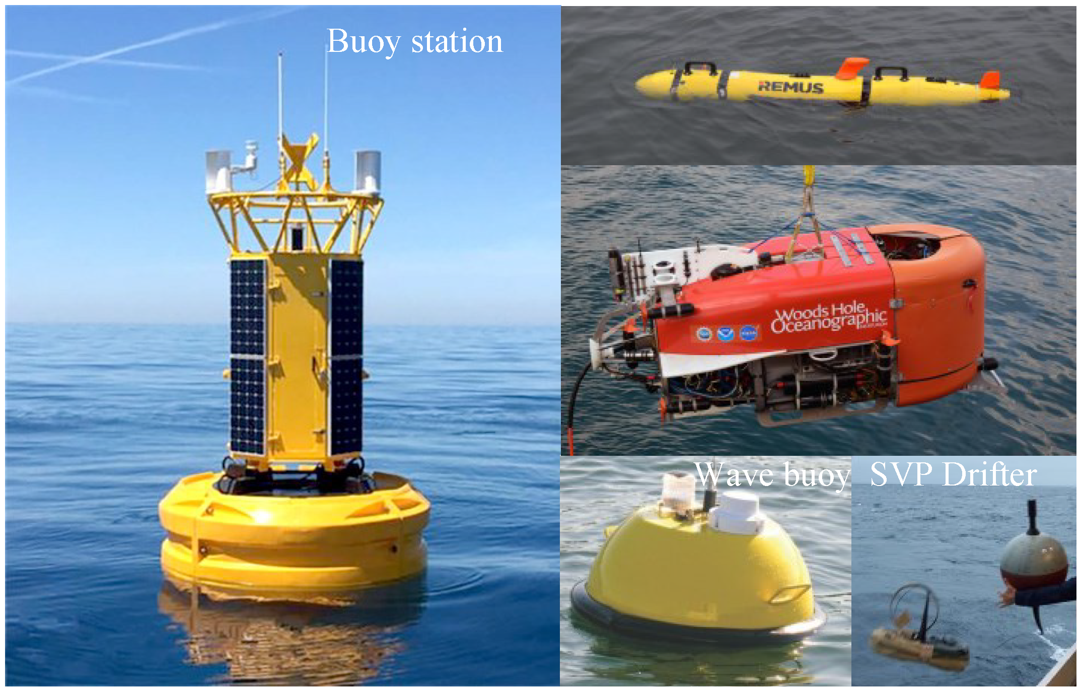
Marine unmanned engineering equipment will become an important means of marine research and resource development [1,2]. In fact, some marine engineering equipment has been used for marine monitoring and development as shown in Figure 1, such as navigation buoys in various oceans, marine unmanned robots, and marine meteorological and hydrological monitoring equipment [3,4,5,6,7].
Table 1 lists the energy supply schemes and performance of some typical marine engineering equipment [8,9,10,11]. Batteries are still the most mature technical means of energy supply for marine equipment, but their low energy density results in very limited battery life and durability. Therefore, the development of marine unmanned equipment inevitably requires vigorous development of renewable energy and internal energy supply technology according to local conditions.
Compared with other ocean energy resources, the wave energy has the following advantages: (1) The wave energy is embodied in the form of mechanical energy, and the energy quality of the wave energy is good. (2) It has high energy density and plentiful supply. (3) The wave energy is widely distributed and can be utilized in most sea areas. If the wave energy in the ocean can be used for power supply of offshore marine engineering equipment nearby, the regular energy re-supply of engineering equipment can be eliminated, the maintenance and guarantee costs will be greatly reduced, and the endurance and reliability of marine engineering equipment can also be greatly improved.
Since the first patent application on wave energy technology in 1799 [12], devices related to wave energy have emerged in an endless stream, and inventors have proposed many different energy devices to develop wave energy to serve human beings [13,14,15]. These devices have different structures and principles. According to different energy absorption principles, wave energy generation devices can be divided into Overtopping Wave Energy Converter (OWEC), Oscillating Water Column (OWC) and Oscillating Body System (OBS) [16,17,18,19,20,21,22,23]. Among them, most of the OWECs and the OWCs are installed on the shore. At the same time, patents and research papers on ocean wave energy conversion are emerging [24,25,26,27]. However, these relatively mature research objects are almost all large-scale wave power generation devices for grid-connected power generation, or small mooring buoys for offshore applications, and almost no offshore wave power generation devices for deep-sea marine engineering equipment.
Compared with the more mature shore-based wave energy power generation technology, the offshore wave technology is more difficult, but it can meet the energy and power security needs of deep sea settings and can provide power support for offshore marine engineering equipment.
1.1. Background
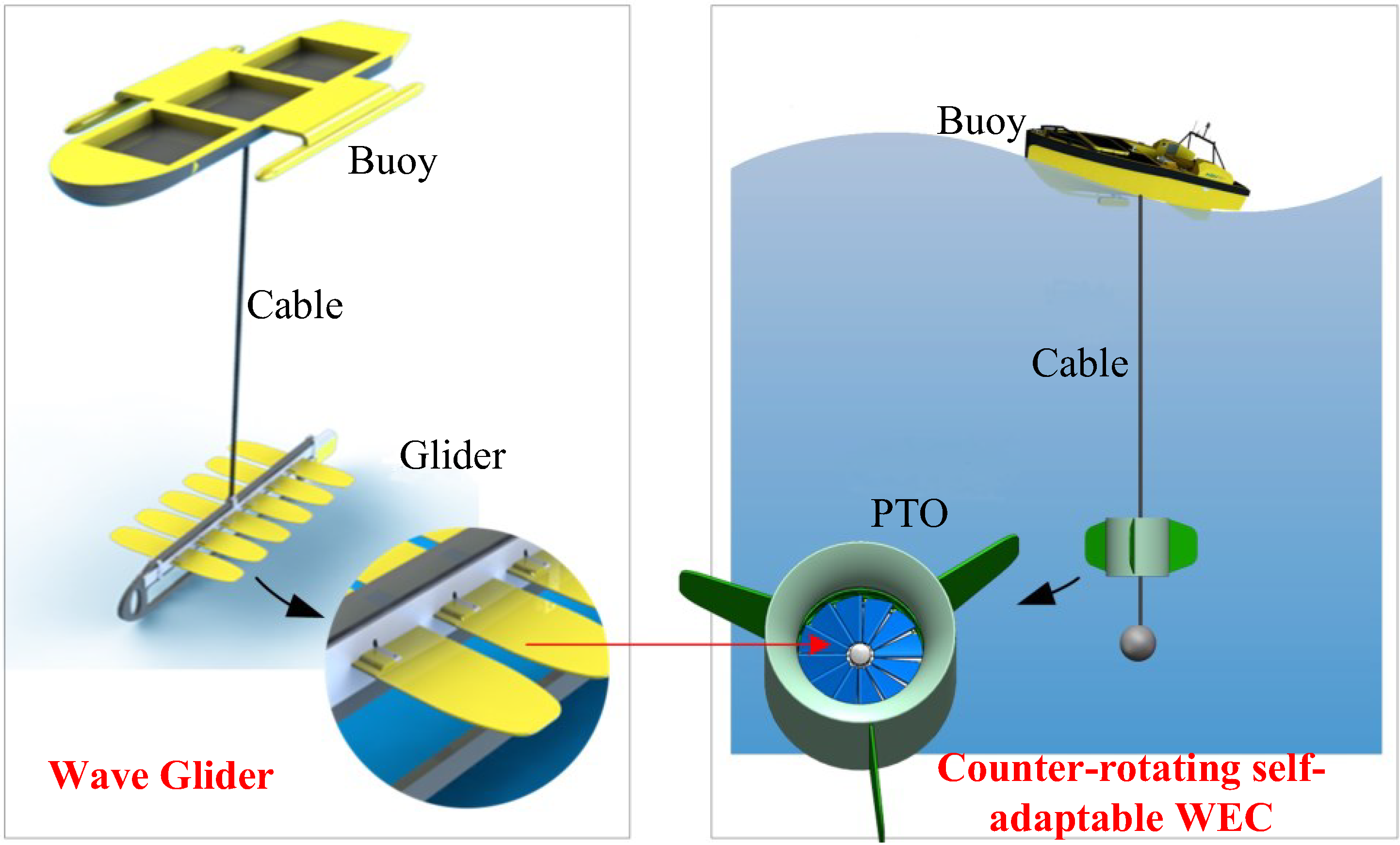
In 2019, based on the idea of wave glider, the research team proposed a counter-rotating self-adaptable WEC [28], whose blades can automatically change the angle under the action of water flow, as shown in Figure 2.
However, this device has the problem that the characteristics of the generator do not match the performance of the whole power generation system, which leads to the low overall power generation efficiency of the system. Therefore, this paper presents the design of a generator for the power generation of the WEC.
1.2. Review of Vernier Generator
The direct-drive generator is the trend of wave power generation technology selection of power generation tools. Its application can greatly reduce the complexity and cost of the power generation system and improve the reliability and transmission efficiency of the power generation device. [29] Permanent magnet generators are the first choice for small wave energy devices. However, there are many types of permanent magnet generators with variable topological structures. How to select and design a low-speed and high-torque generator suitable for small wave power generation devices is an important research challenge, with the aim of realizing high-efficiency power conversion of wave energy power generation devices [30].
International scholars have proposed the application of different topologies in low-speed direct-drive generators [31,32,33,34]. Among them, the permanent magnet vernier generator proposed in the literature [35] is a basic vernier generator mechanism. If the power factor of the vernier generator can be improved, it will be a low-speed high-torque generator well suited for wave power generation.
According to the number of air gaps, vernier generators can be mainly divided into single air gap permanent magnet vernier generators and double air gap permanent magnet vernier generators. The multi-air gap vernier generator with more than three air gaps is not considered in this paper due to the complex structure. Although the structure of the single-air-gap vernier generator is simple, the large magnetic leakage leads to a low power factor, which is not suitable for wave power generation. Professor Ronghai Qu pointed out that the double air gap generator has higher torque density than the traditional single air gap generator [36].
There are many research achievements on double air-gap vernier generators. Professor S. L. Ho proposed a dual-rotor permanent magnet vernier generator combined with a dual-rotor structure and annular windings, which can improve the internal space utilization of the generator [37]. Two dual-rotor vernier generators are also proposed in the literature [38,39]. Prof. B. Kwon, Prof. A. Lipo and Prof. C. T. Liu have successively proved through finite element simulation or experiment that a dual-stator vernier generator has higher torque density than the traditional permanent magnet synchronous generator. Refs. [40,41,42].
The double-stator structure can make full use of the internal space of the generator and improve the torque density and power factor of the wave energy power generation system. In the wave energy absorber studied in this paper, the impeller needs to be placed in the middle of the generator. Therefore, optimizing the topology and design theory of the dual-stator vernier generator is the research aim of this paper.
This paper will propose a low-speed direct-drive permanent magnet vernier generator suitable for a bidirectional point absorption wave energy device, and the main magnetic flux path of the generator will be analyzed. Through derivation and calculation, the magnetic flux modulation principle of the staggered vernier generator will be analyzed, and the principle that the staggered vernier generator can utilize the main harmonic components of the permanent magnet rotor will be explored, so that the low-speed performance of the generator can be improved. The influence of basic parameters such as the number of poles and slots on the performance of the generator will be analyzed, and the combination of slots and poles with excellent low-speed performance will be obtained. The performance parameters such as the magnetic field acceleration principle and electromagnetic load of the vernier generator will be analyzed through numerical simulation. Finally, the low-speed performance of the staggered vernier generator will be tested by a comparative test.
2. Implementation and Principle
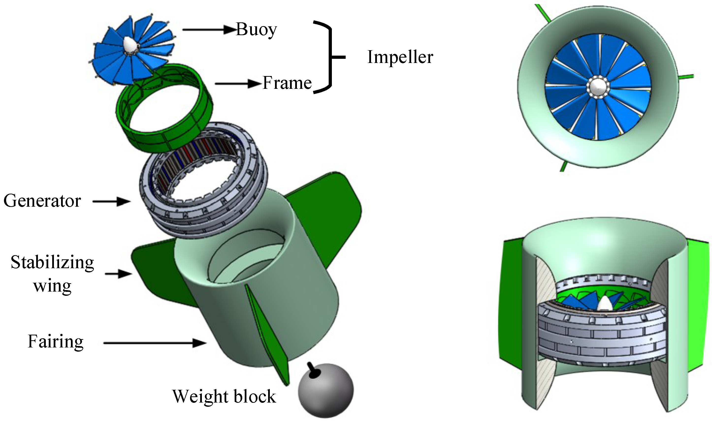
The counter-rotating self-adaptable WEC connects a buoy to the underwater power take-off (PTO) through a cable and arranges the PTO at a certain depth by controlling the length of the cable. The design structure of the PTO system is shown in Figure 3.
The PTO system mainly consists of an impeller, a generator, a fairing and a weight block, all arranged axially. The fairing compresses the flow channel to increase the speed of the water flow, and the impeller converts the kinetic energy of the water flow into torque, which together affect the hydrodynamic characteristics of the PTO. The generator converts the torque obtained by the impeller into electrical energy, and the impeller bracket is directly connected to the rotor of the generator. The stabilizing wing on the fairing is used to enhance the stability of the entire device, and the weight block at the bottom can increase the weight of the entire system, so that when the buoy on the water falls with the waves, there is enough gravitational potential energy to be converted into mechanical energy to drive the generator to generate electricity. The buoy and the underwater PTO are connected by armored cables, so that the mechanical energy electricity is transferred between the buoy and the PTO.
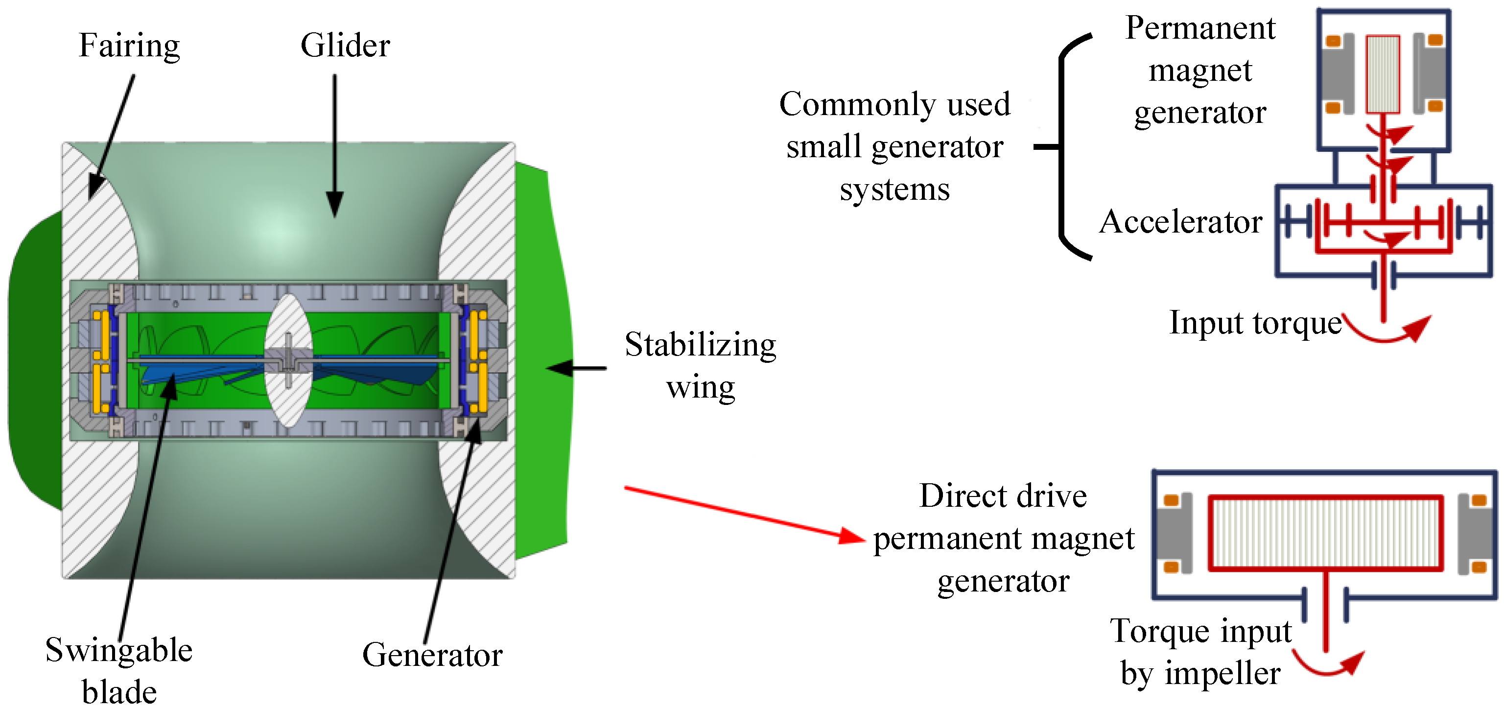
Figure 4 shows the cross-sectional structure of the underwater PTO. Among them, the shape of the fairing is symmetrical up and down, and the generator and the impeller are placed in the middle of the fairing, so that the fairing can effectively compress the water flow and increase the speed of the water flow into the impeller. In order to improve the energy transfer efficiency of the system, differing from the common design scheme of adding an accelerator to the generator, the underwater PTO system designed in this paper adopts a direct drive generator, and it is no longer necessary to install an accelerator in front of the generator. The design of the generator simplifies the mechanical energy conversion process, reduces the energy loss caused by the accelerator, improves the mechanical transmission efficiency, and also improves the starting effect of the impeller.
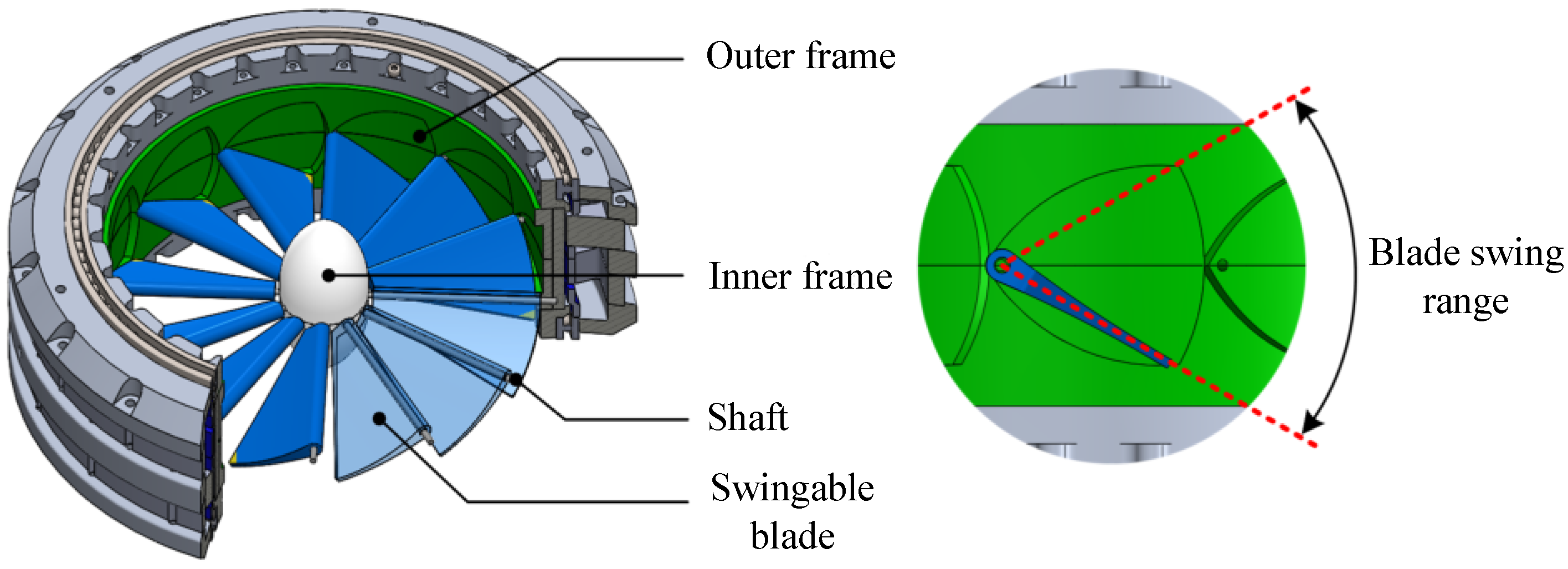
The specific design structure of the impeller is shown in Figure 5. The blades are distributed in a circular array around the central axis of the impeller. The blades are mounted on the impeller through a rotating shaft, and the leading edge of each blade has a rotating shaft passing through the impeller radially. The ends of the rotating shaft are fixed on the outer frame and the inner frame, respectively, and the blades are mounted on the impeller through the rotating shaft. Similar to Wave Glider’s glider blades, the impeller’s blades can also swing around the rotating shaft within a certain symmetrical angle. The swing angle of the blades is limited by the outer frame. The inner and outer frames jointly connect each rotating shaft into a whole to enhance the structural strength and rigidity of the entire impeller and transmit the torque of the impeller to the inner rotor of the generator.
3. Analysis of Key Performance Parameters
3.1. Electromagnetic Load of the New Permanent Magnet Vernier Generator
This section analyzes the generator with the analysis method of the permanent magnet generator. [43,44]. Assuming that the magnetic permeability of the permanent magnet is the same as that of air, ignoring the influence of magnetic flux leakage, and short-circuiting the two poles of the permanent magnet, the magnetomotive force of the permanent magnet satisfies the following equation:
where,
is the magnetic field intensity,
is the length of magnetic path, is the remanence of the permanent magnet, is the vacuum permeability and is the thickness of the permanent magnet.
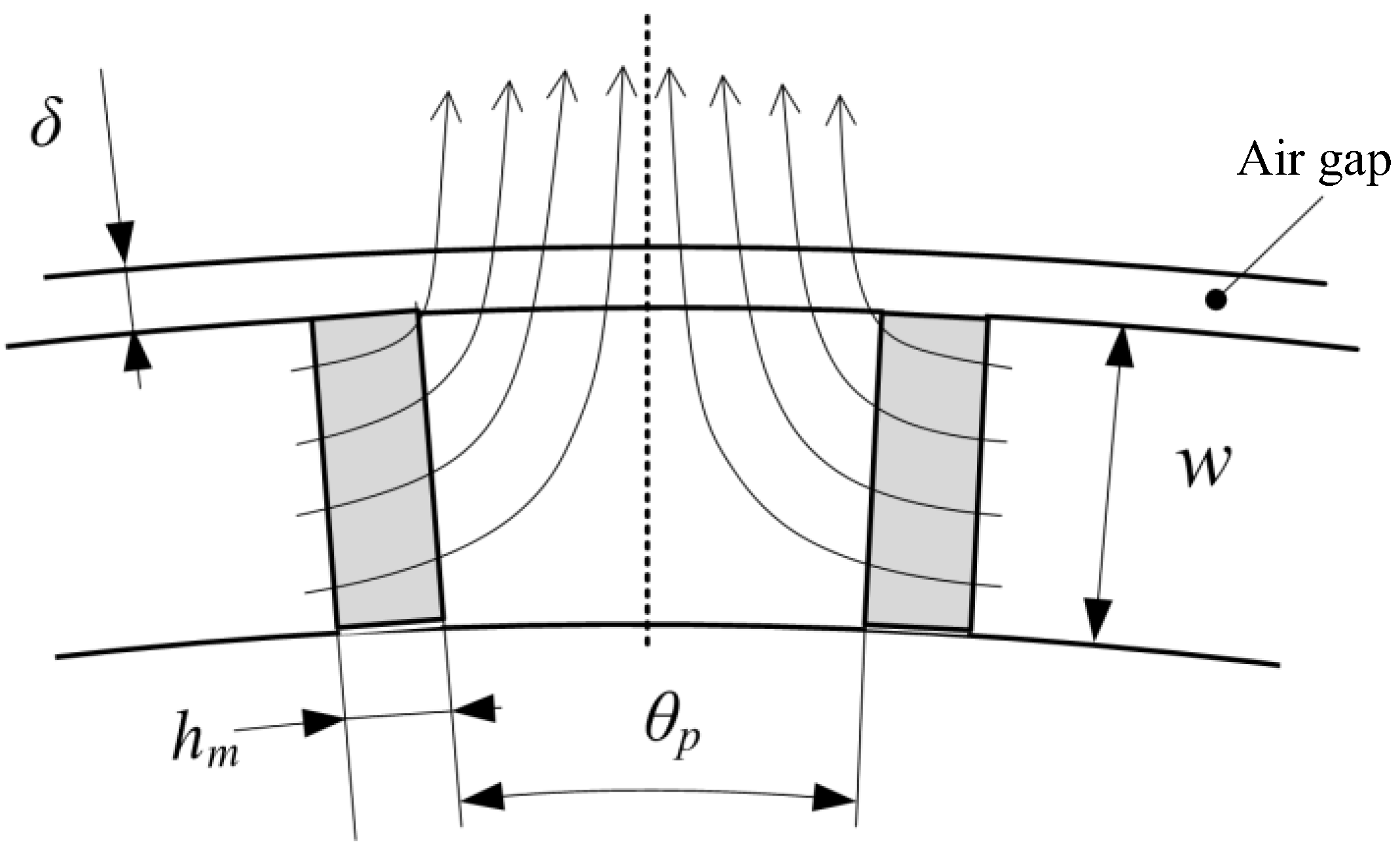
The magnetic circuit of the permanent magnets in the magnetic vernier generator is shown in the Figure 6, where is the thickness of the air gap, is the angle between adjacent permanent magnets, and is the radial dimension of the permanent magnets on the rotor.
The magnetomotive force of a permanent magnet can be regarded as the sum of the magnetomotive force at both ends of the permanent magnet and the magnetomotive force of the two air gaps it passes through, which satisfies the following equation:
If the magnetic flux passing through the permanent magnet and the air gap is the same, then the following two equations are obtained:
where L is the axial dimension of the permanent magnet. According to the above equations, the following equation is obtained:
It can be seen that the parameters of the permanent magnet will affect the electromagnetic load. In order to simplify the analysis process, let , ; then Equation (5) can be expressed as:
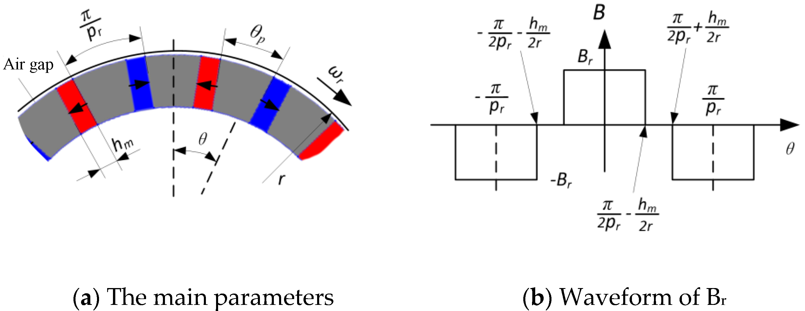
The distribution of along the outside of the rotor is shown in Figure 7.
The waveform of on the rotor is a periodic function and an even function, and so the waveform function can be Fourier decomposed into the sum of different harmonic components:
where, is the Fourier coefficient of each order harmonic component.
From the expression of the Fourier coefficient, it can be known that when , .
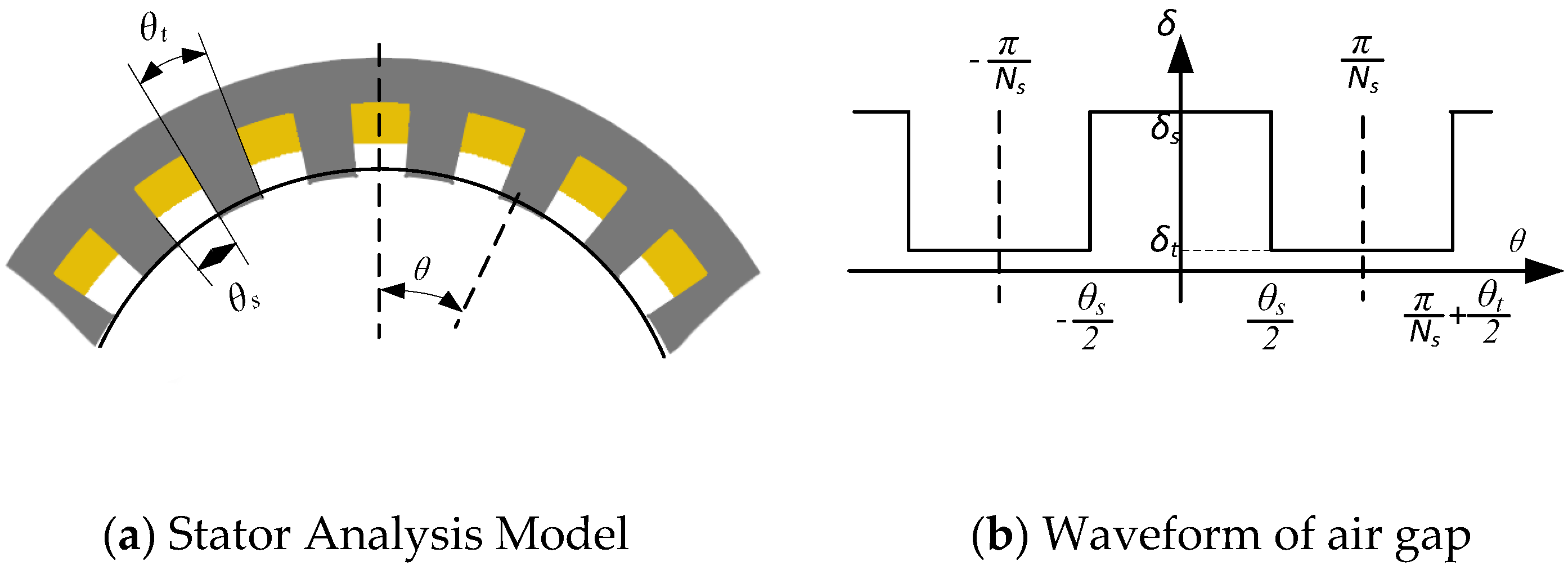
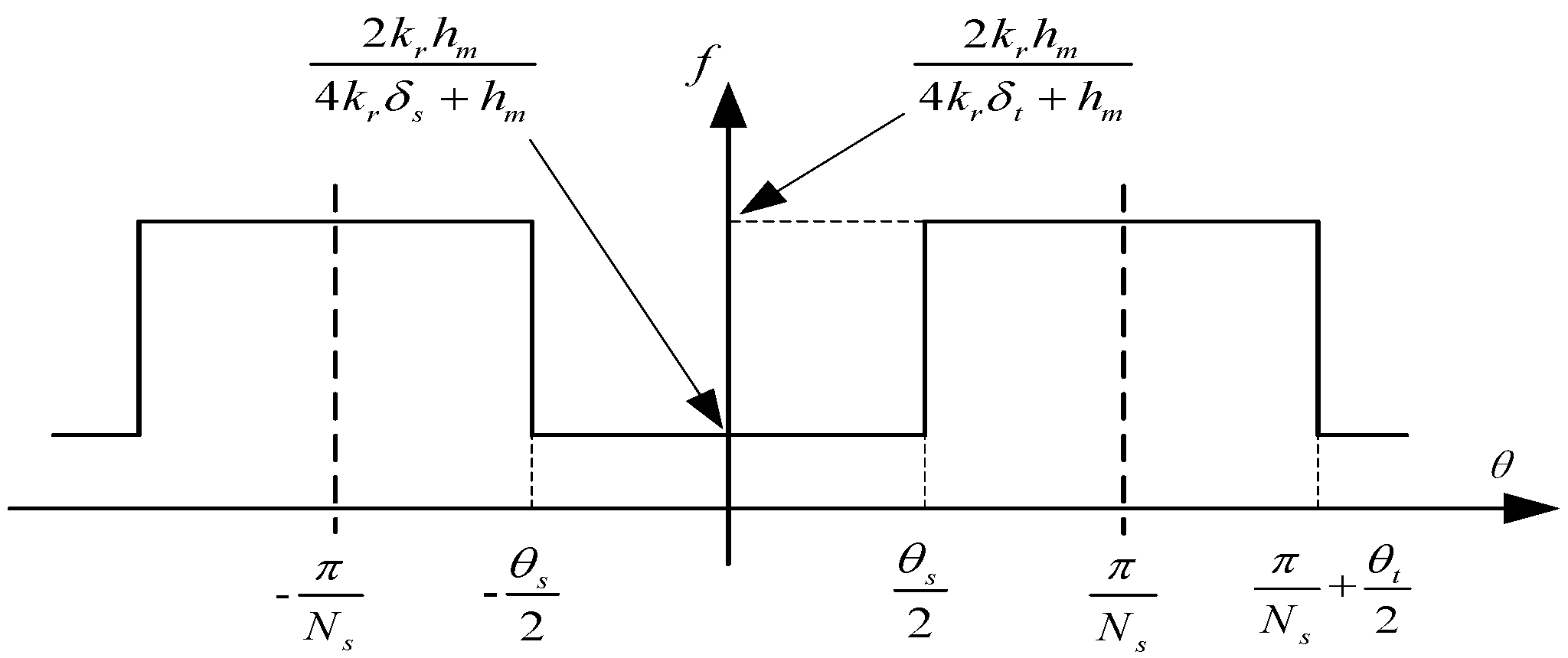
The above is the analysis and simplified calculation of the influence of rotor design parameters on the electromagnetic load. The following considers the influence of the stator cogging distribution on the electromagnetic load for calculation. Figure 8a is the analysis model with the main parameters of the air gap, and Figure 8b is the air gap waveform of the stator slot air gap changing with the angle.
is the angle occupied by a single tooth slot, and is the angle occupied by the width of a single stator tooth. Since the air gap waveform is a periodic function of , the second half of Equation (5) can be defined as the periodic function , and its waveform is shown in Figure 9.
This equation can also be Fourier decomposed into an equation that varies with the position of the circumference:
where, is the DC component, and its equation is:
is the Fourier coefficient of each order harmonic component.
From Equations (10) and (11), it can be known that the DC component , and the amplitude of the fundamental component .
Substituting Equations (7) and (9) into Equation (5), the electromagnetic load can be expressed as follows:
In the equation, represents the high-order harmonic component of the electromagnetic load. Since the high-order harmonic component accounts for a small proportion, its influence is usually not considered in order to simplify the analysis. It can be known from Equation (12) that the distribution function of the electromagnetic load is mainly composed of the fundamental component and two harmonic components. Among them, the order of the fundamental wave component is the same as the number of pole pairs of the rotor permanent magnet. The pole pairs of the two harmonic components are and , respectively. In order to reduce the magnetic flux leakage, usually , then is written as . The harmonic magnetic field with the number of pole pairs has a slower speed, and the harmonic magnetic field with the number of pole pairs has a faster speed.
3.2. Magnetic flux of the New Permanent Magnet Vernier Generator
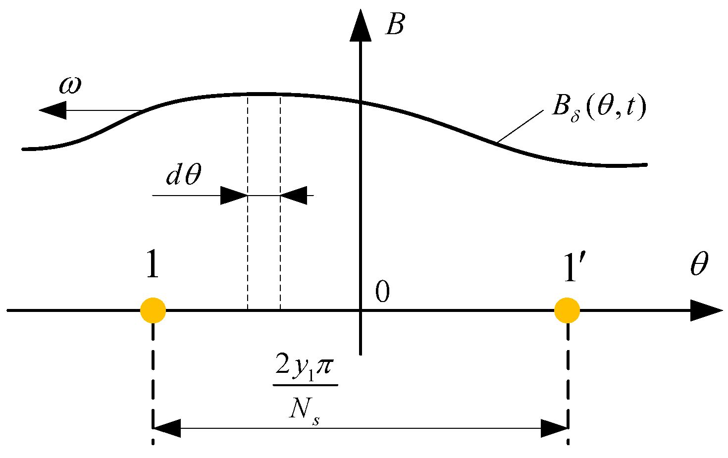
According to the geometric relationship between the single winding and the electromagnetic load and Equation (12), the single winding is integrated to obtain the magnetic flux of the single winding. The geometric relationship between a single winding and the electromagnetic load is shown in Figure 10, where the flux density curve is a schematic representation and does not represent the real electromagnetic load. The magnetic flux of a single winding is:
where is the number of turns of a single winding, is the effective length of the stator axial direction, is the coil span, and is the air gap radius.
Consider the fundamental, harmonic magnetic field fluxes on a single winding with pole pairs and , respectively. The flux of the fundamental wave on a single winding is:
The magnetic flux of a harmonic magnetic field with pole pairs on a single winding is:
The magnetic flux of a harmonic magnetic field with pole pairs on a single winding is:
Therefore, the flux linkage of a single-phase winding can be expressed as:
where, is the distribution coefficient of the phase winding, is the number of slots per pole per phase of the stator winding. The phase-induced electromotive force of a vernier generator with a single-layer winding can be expressed as:
It can be seen that the number of pole pairs of the fundamental wave magnetic density is times of the number of pole pairs of the effective harmonic magnetic density; the electric angular frequency of the induced electromotive force of both is the same.
According to Equation (18), the no-load phase induced electromotive force amplitude can be obtained as:
4. Design of the New Permanent Magnet Vernier Generator
4.1. The Overall Design of the Generator
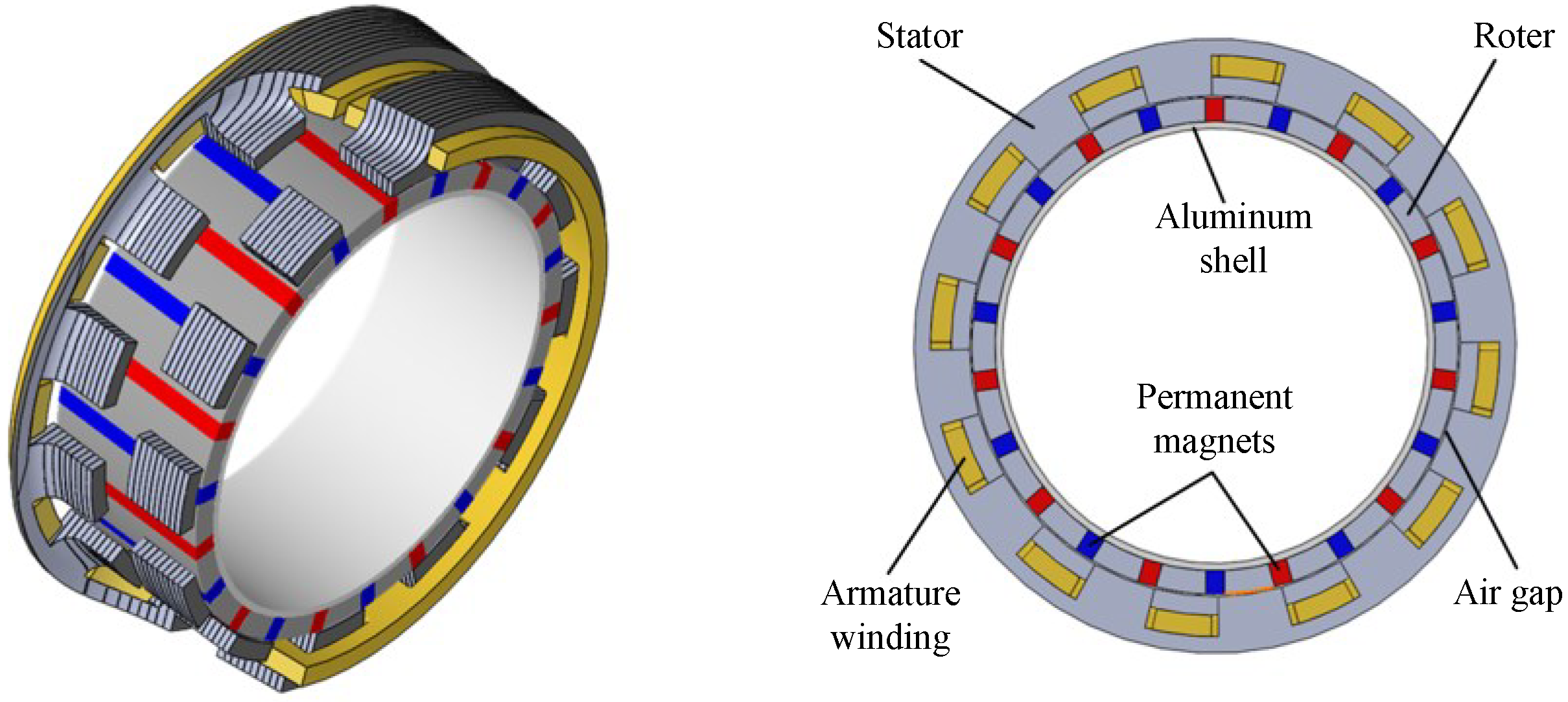
In this paper, a new type of staggered vernier generator is designed. The topology of the generator is shown in Figure 11. The generator is evolved from a double-rotor structure. The middle of the generator is a permanent magnet rotor with a magnetic concentrating structure. Each rotor is composed of several permanent magnets and iron yokes. The outer side is two side-by-side stators. There is an angle difference of the stator teeth on the layout, and the armature windings are arranged in the stator tooth slots. Different from the double stator generator with double air gap, the inner and outer diameters of the staggered vernier generator here are exactly the same. The parallel air gap structure of the two air gaps with the same radius is more like a single air gap structure, which simplifies the complexity of the generator structure and reduces the connection and fixation.
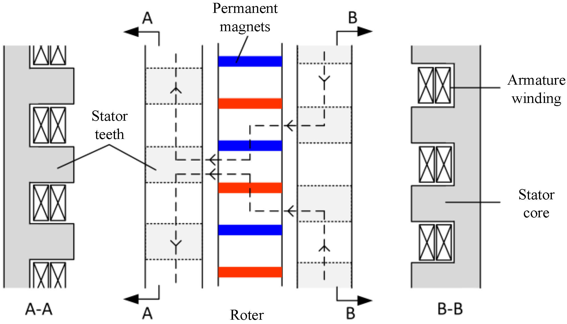
Compared with the single stator single rotor vernier generator, the main magnetic flux path of the staggered double-stator vernier generator is very different, as shown in Figure 12. The main magnetic flux path is not only shuttled between a single stator and rotor, but also can pass through the double stator at the same time, so as to keep the main magnetic flux path unobstructed at all times and reduce the adverse effect of magnetic flux leakage on the generator.
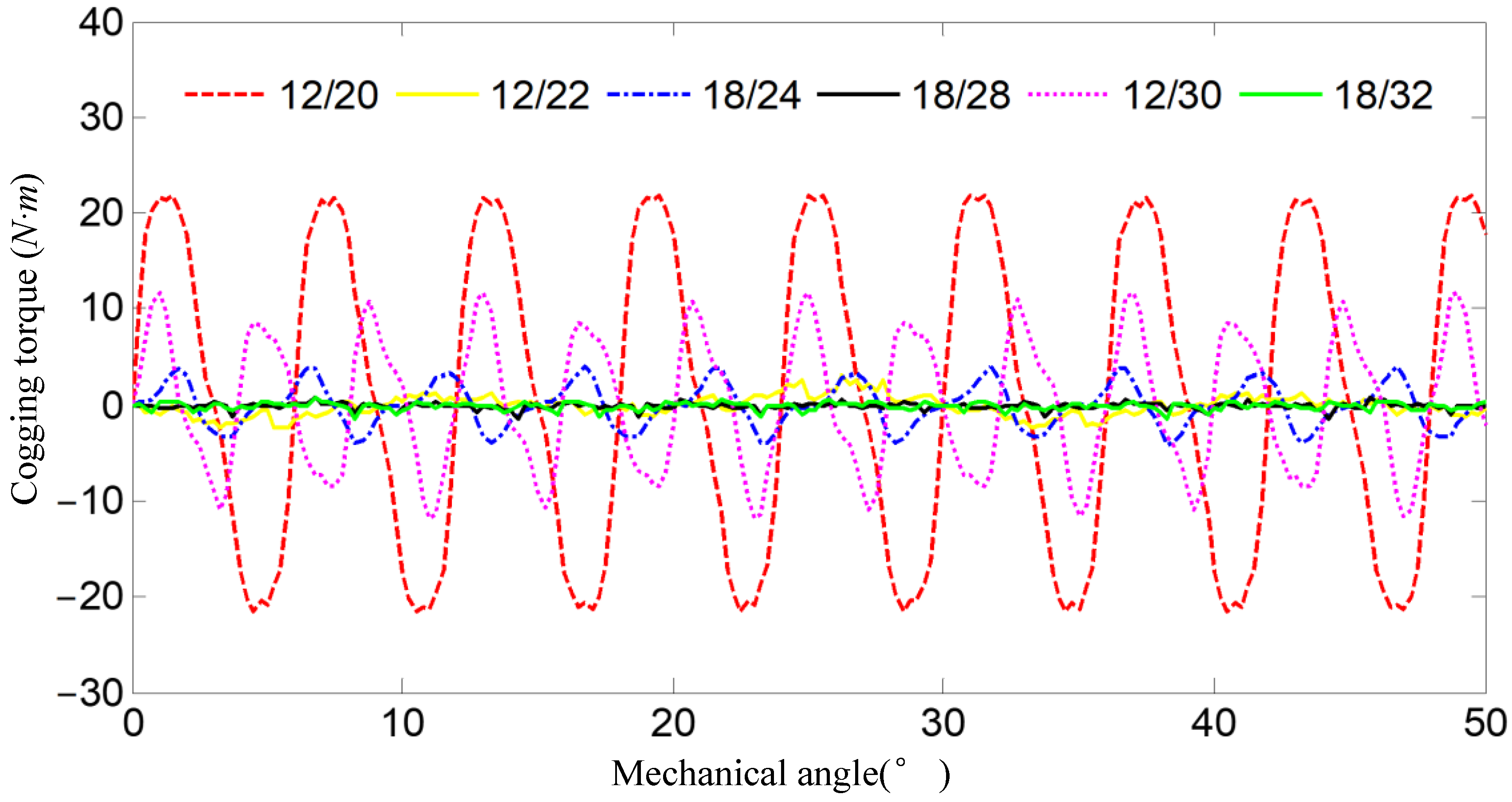
The combination of poles and slots not only affects the air gap magnetic field and the induced electromotive force of the armature, but also determines the complexity of the vernier generator, the relevant parameters of the armature winding, and the cogging torque, etc. The smaller number of poles and slots simplifies machining of the armature windings, thereby reducing the complexity of the generator. The cogging torque is also affected by the number of stator teeth and rotor poles. The larger their least common multiple , the smaller the cogging torque. In addition, the number of stator teeth should be a multiple of 3 to facilitate the arrangement of the three-phase armature windings.
A summary of the 6 possible combinations of poles and slots is shown in Table 2. Here, is the winding coefficient of the armature, which reflects the distribution of the armature windings. If the value is too low, it will affect the torque density of the generator. Its value is generally above 0.85. The winding pitch should select a short pitch to reduce the length of the coil end.
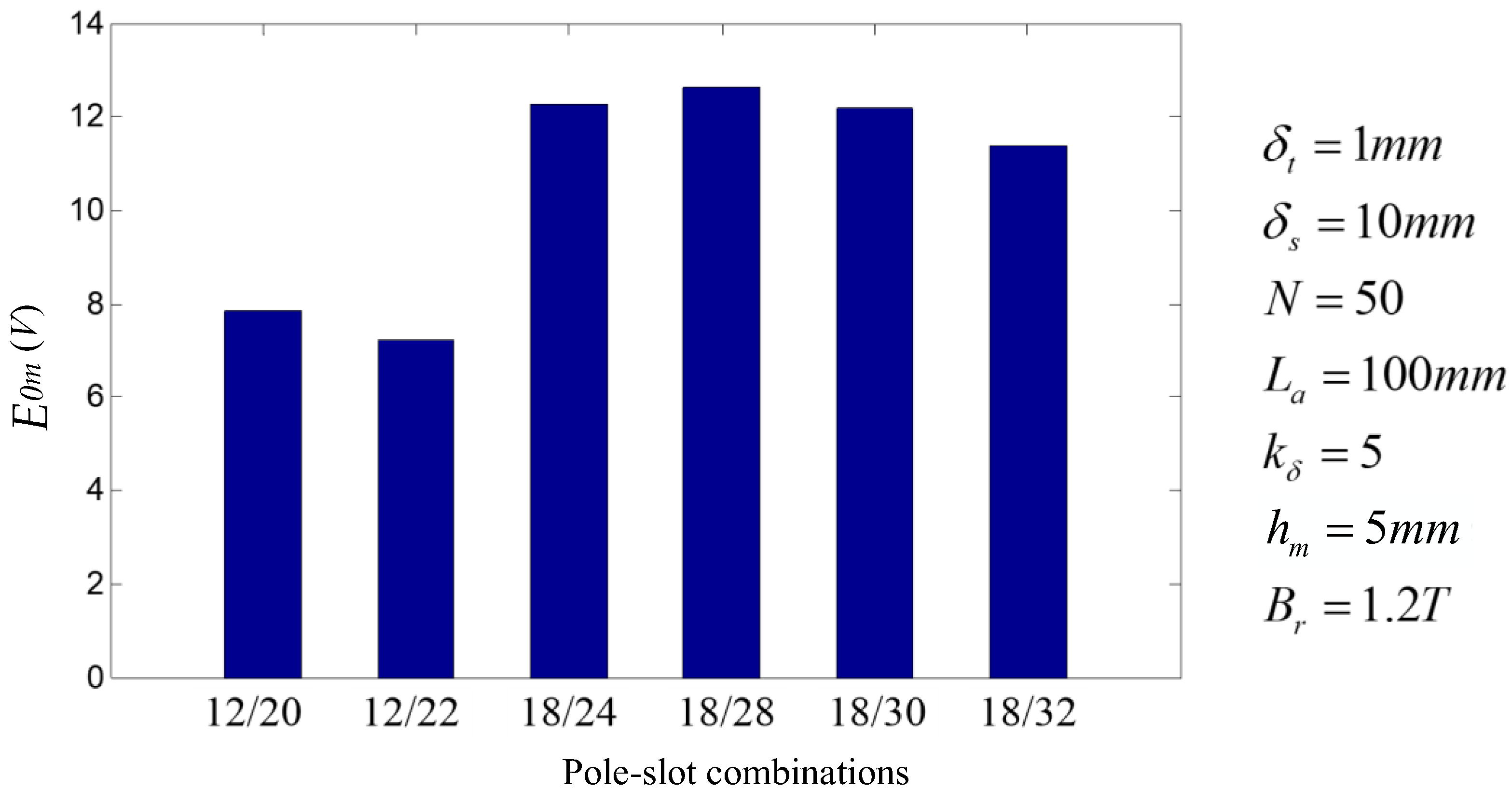
Keeping the air gap size and permanent magnet volume unchanged under different combinations, the induced electromotive force of different combinations can be obtained by substituting combinations in Table 2 into Equation (19), as shown in Figure 13.
Assuming that the permeability of the permanent magnet is the same as that of air, the effective air gap at the stator teeth is , the air gap at the stator slot is , the pole piece coefficient of the stator is 0.5, the number of coil turns . Let , then the permanent magnet thickness , and the stator axial length . The volume of permanent magnets used in different combinations is set to 150 cm3. The permanent magnet is an NdFeB permanent magnet, and its magnetic range is about 1.0~1.4T. The result of in the calculation is shown in Figure 14.
4.2. The Design of the Stator
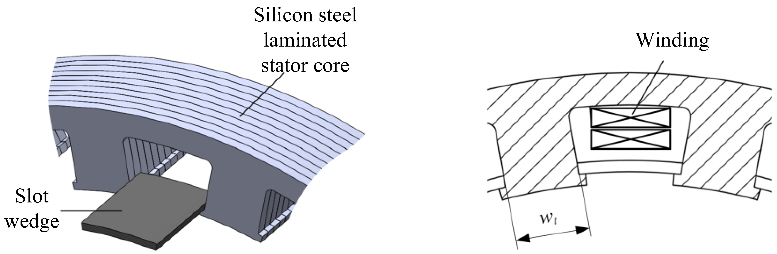
The stator is mainly composed of an iron core and windings, as shown in Figure 15. If the pole piece coefficient of the stator core is too large, the slot opening will be too small, which is inconvenient for wire insertion; if the pole piece coefficient is too small, the magnetic flux at the stator teeth will be saturated, increasing the magnetic flux leakage. Therefore, in the permanent magnet vernier generator, the pole piece coefficient of the stator is generally selected around 0.5. In addition, the design of the stator slot also needs to consider the installation and fixation of the slot wedge.
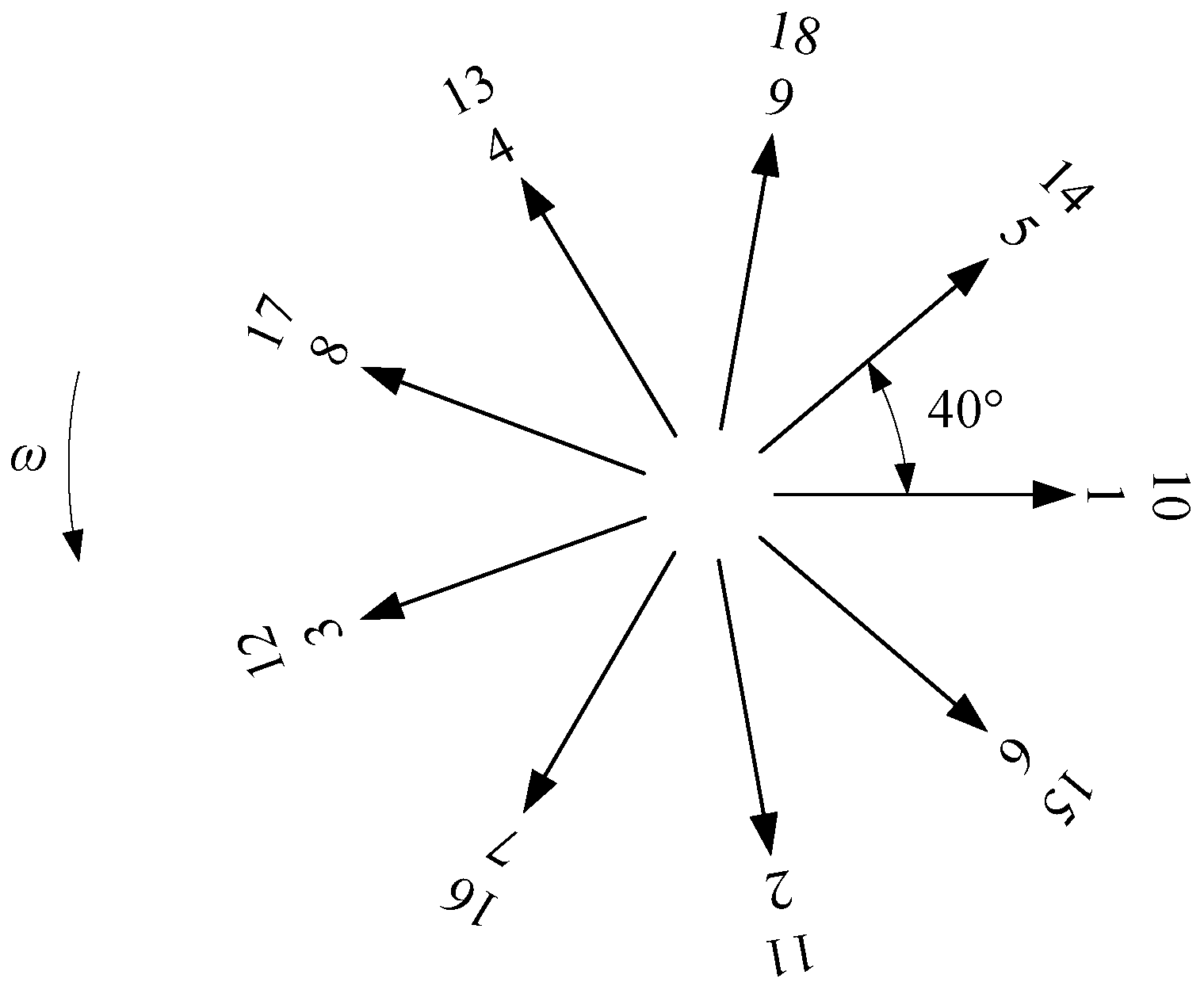
The arrangement of the armature winding is the key point in the stator design. The number of poles and slots adopted by the new vernier generator is 18 slots/28 poles, and the number of pole pairs of the stator winding is . Then the number of stator slots corresponding to each pole is 2.25, and the electrical angle of the slot distance is ; the star diagram of its slot potential is obtained as shown in Figure 16. Since the number of slots per pole and each phase is , the stator winding needs to use double-layer winding, which can reduce the circulating current loss of the winding at the same time.
An arrangement like A Z B X C Y A Z B X C Y A Z B X C Y A Z B X C Y A Z B X C Y A Z B X C Y A Z B X C Y A Z B X C Y A Z B X C Y A Z B X C Y is consistent with the arrangement of the actual coils in the stator slots, i.e., looping in the order A Z B X C Y, where A-Z are two phase bands of the same phase at different poles; the same goes for B-Y and C-Z. When , each phase should occupy a number of slots less than 1 under each pole (such as 3/4). In fact, this is impossible, since the stator slots are indivisible. According to the actual physical principle, the same phase can only occupy 1 slot or 0 slots under a pole [45,46]. The number of slots per pole per phase for a fractional slot winding actually refers to the average value. Since of this generator, the denominator is 4, so in the above A Z B X C Y cycle, count from the beginning, and remove the phase band when a multiple of 4 is encountered. It can be seen that 5 X-phase bands, 5 Y-phase bands, and 5 Z-phase bands have been removed. The winding arrangement order of the stator is obtained as A Z B C Y A B X C A Z B C Y A B X C A Z B C Y A B X C A Z B C Y A B X C A Z B C Y A B X C Y. That is how to cycle through the arrangement of A Z B C Y A B X C.
According to above method of dividing the winding phase band when , the division results of the fractional slot winding phase band of the 18-slots/28-poles generator shown in Table 3 are obtained. According to the star diagram of slot potential, it can be seen that the windings of slots 1 to 9 are exactly the same as those of slots 10 to 18, so this paper only analyzes the division of the winding phase bands of slots 1 to 9.
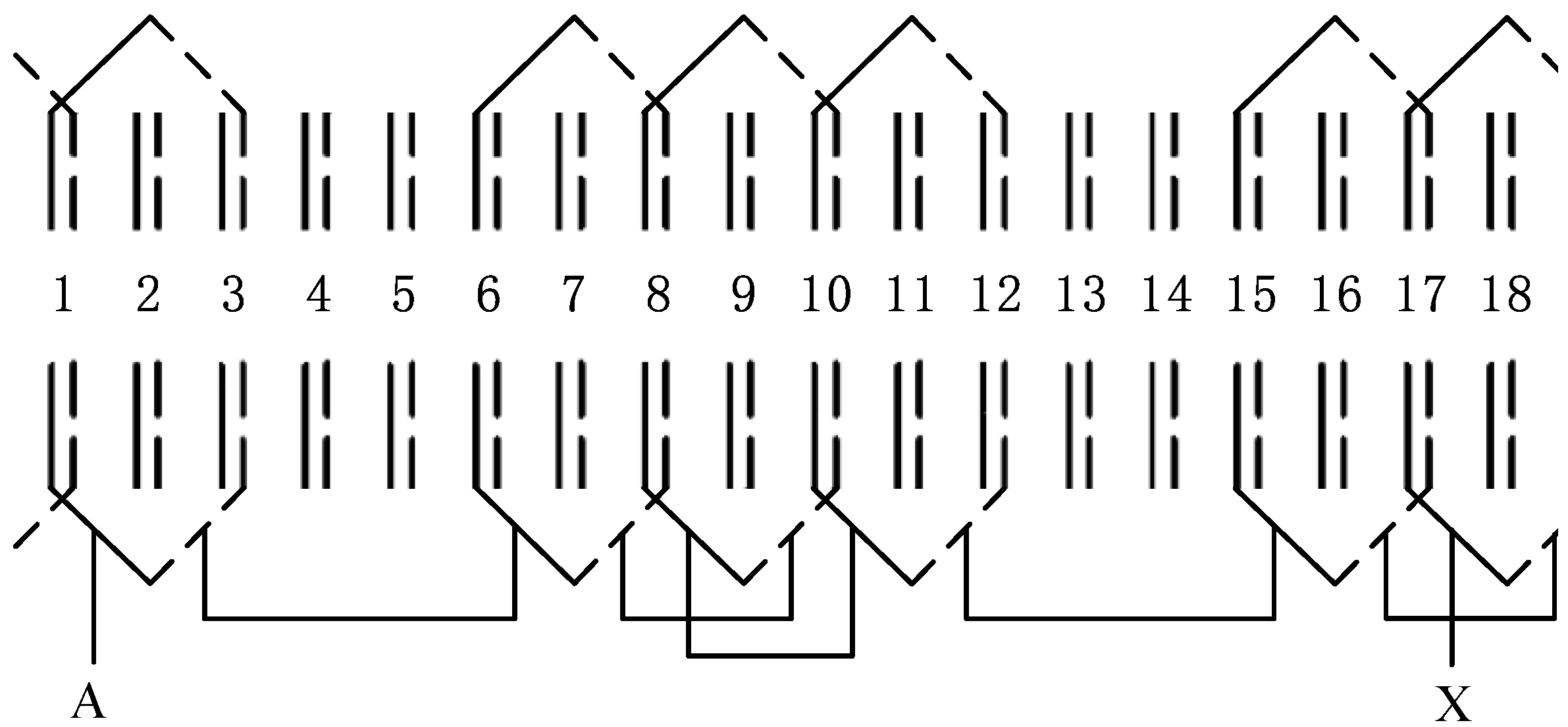
Short-distance winding is used, which can not only reduce the length of the winding, but also improve the flux linkage of the winding. According to Table 3, an expanded view of the connection of the stator windings can be drawn, as shown in Figure 17. A double-layered winding arrangement is adopted, in which the solid line in the slot represents the upper layer side, and the dashed line represents the lower layer side. In order to explain the connection method of the windings more clearly, only the connection expansion diagram of the A-phase windings is drawn; the connection of the other two-phase windings is the same as that of the A-phase windings, but moving the electrical angle backward by 120°.
4.3. The Design of the Rotor
The permanent magnet rotor is the input component of the staggered vernier generator. It needs a stable and reliable structure. At the same time, the rotor needs to provide enough magnetomotive force for the magnetic circuit of the vernier generator. When the number of pole slots of the generator is determined, the permanent magnets on the rotor can affect the electromagnetic load and the magnetic flux linked by the turns of the stator armature windings. Too few permanent magnets on the rotor will cause the electromagnetic load to be low, the torque density of the generator will be too small, and the advantages of the vernier generator cannot be exerted. However, blindly increasing the permanent magnets will cause the magnetic flux of the rotor core to saturate, resulting in excessive flux leakage and an increase in the size and weight of the generator.
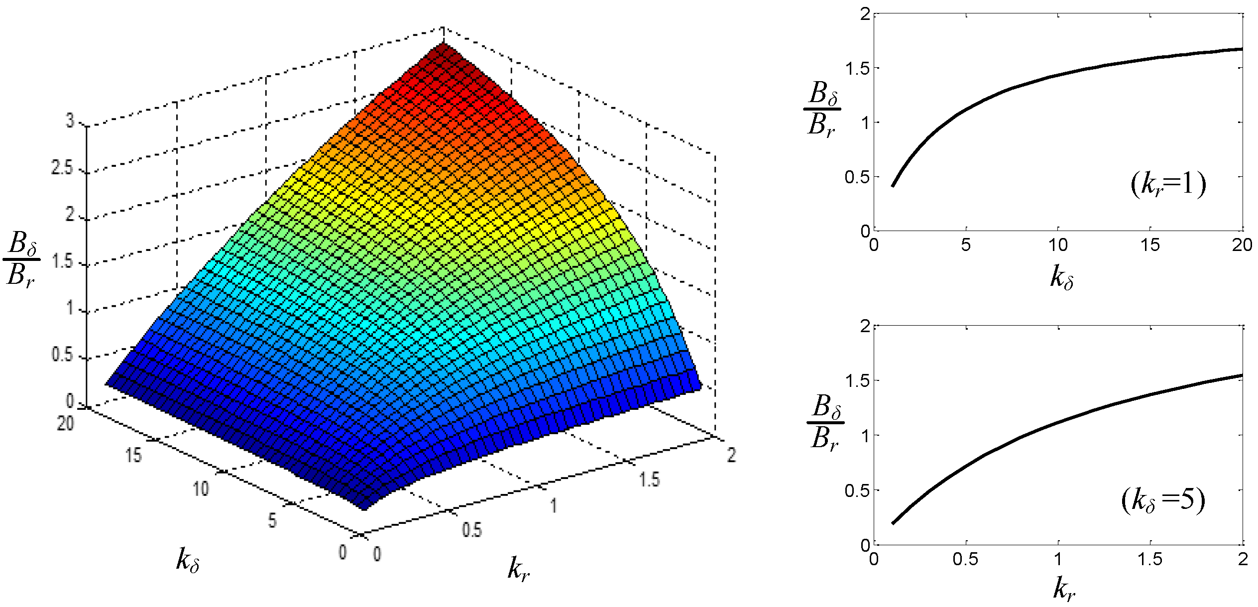
For a rotor with a magnetically concentrated arrangement, the thickness of the permanent magnets and the radial thickness of the rotor will affect the electromagnetic load of the generator. According to Equation (1), the effects of and on the electromagnetic load can be obtained, as shown in Figure 18. It can be seen that increasing the thickness of the permanent magnet can increase the electromagnetic load, but with the increase of the thickness of the permanent magnet, the growth rate of the electromagnetic load will gradually decrease, and finally tend to be flat. In order to take into account the amount of permanent magnets and the torque of the generator, can be selected from 5 to 10. With the increase of the radial thickness of the permanent magnets in the rotor, the electromagnetic load also increases accordingly. Although the growth rate is gradually reduced, it still has strong linearity. The radial thickness of the rotor can be designed according to requirements when there is sufficient space inside the generator.
5. Results and Discussion
5.1. Simulation Results and Analysis
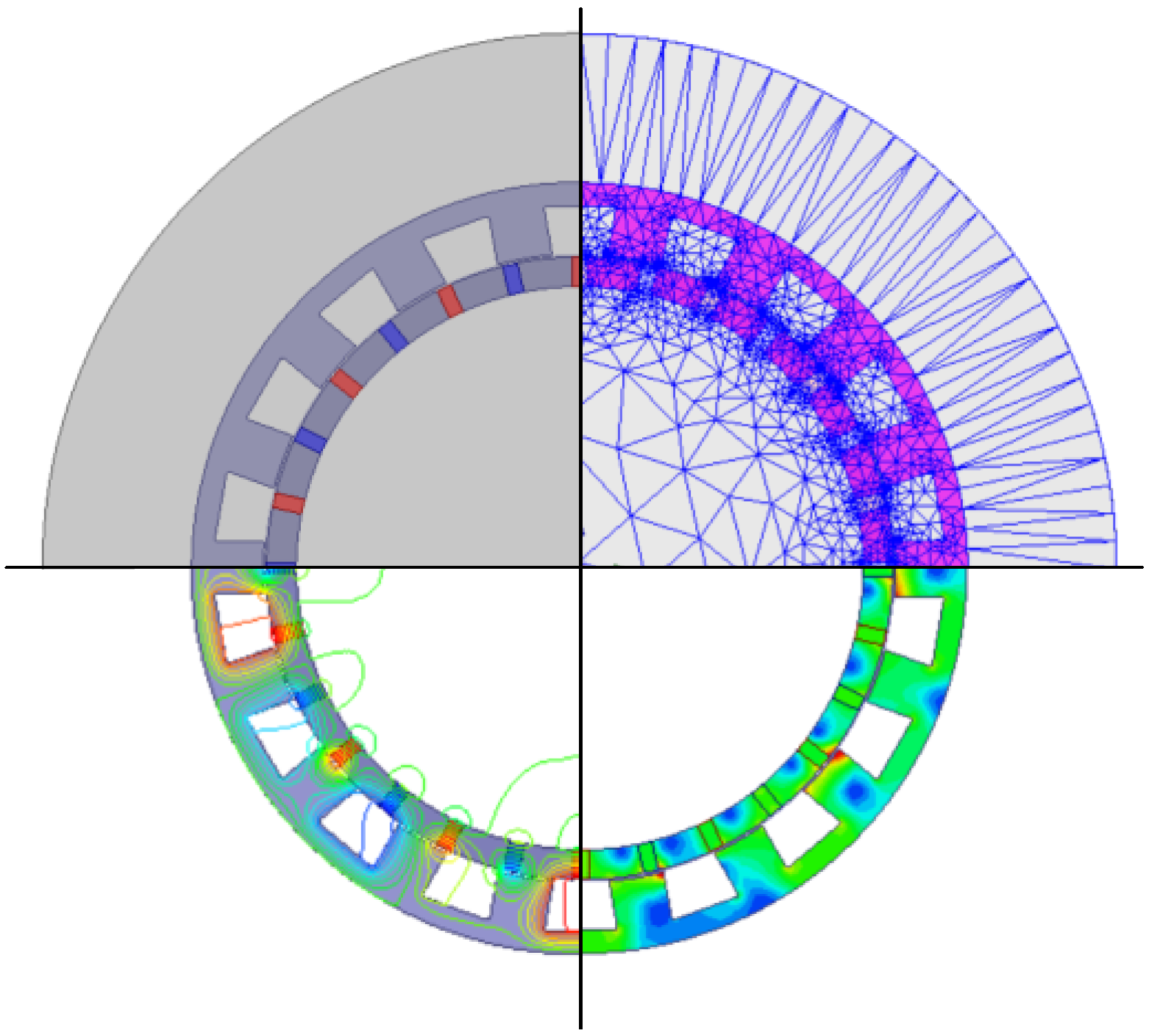
Based on the parameters calculated above, a simplified topology model of the staggered vernier generator is designed, and the model is imported into Maxwell for numerical simulation. Figure 19 shows the general process of generator simulation. The four quadrants in the figure are the simplified model of the generator, the finite element meshing, the distribution of magnetic force and the magnetic density cloud map.
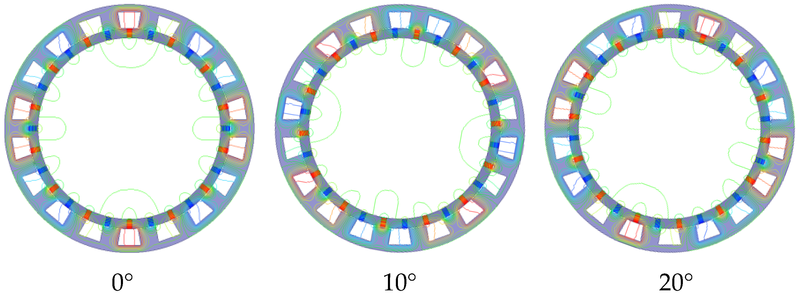
Figure 20 shows the magnetic field acceleration effect of the vernier generator through the magnetic field simulation. Through the modulation of the stator teeth, the low-speed rotating stator magnetic field can be accelerated in the stator yoke. In the figure, the clockwise rotation angle of the rotor is 20°, while the fundamental magnetic field in the stator yoke has reversely rotated by a mechanical angle of 70°, realizing the acceleration of the magnetic field.
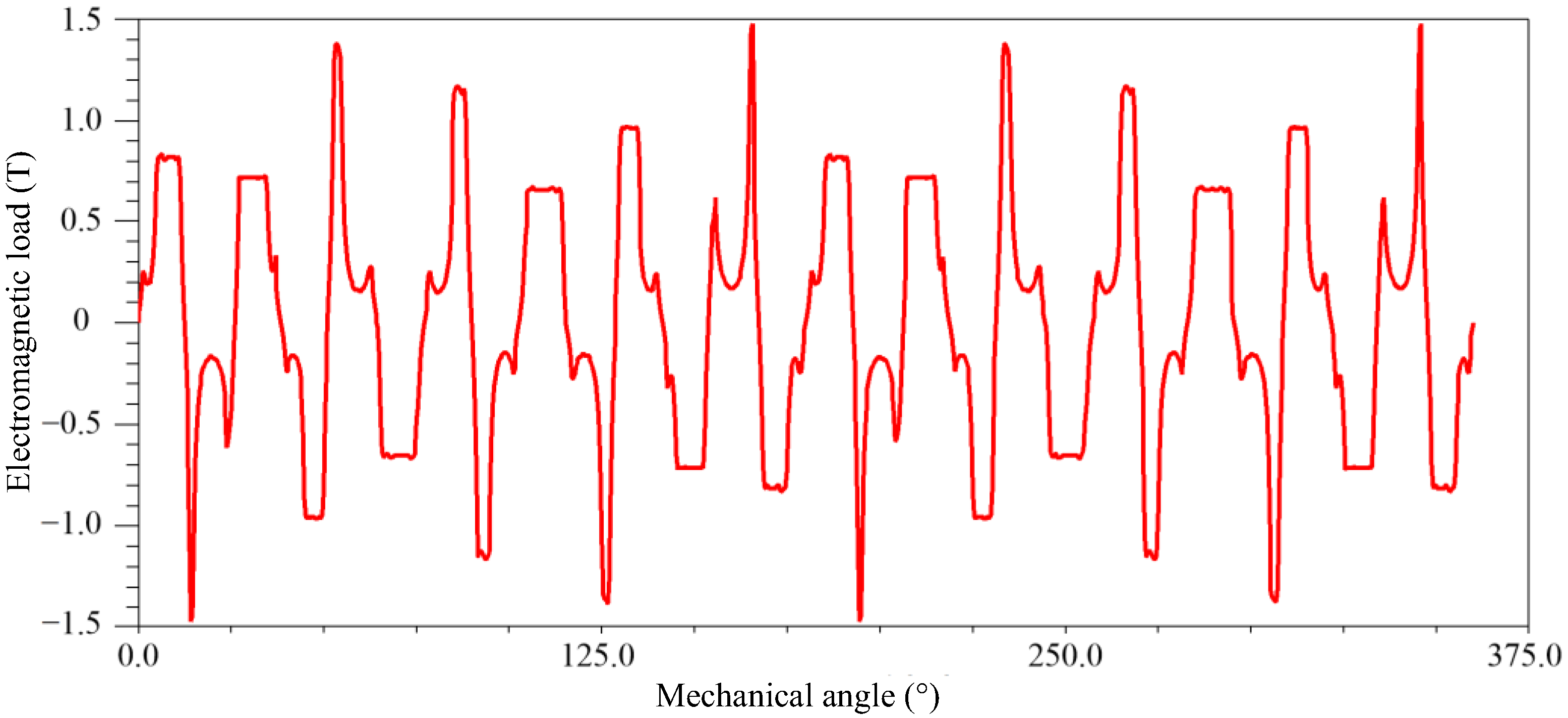
Figure 21 shows the electromagnetic load around the generator. It can be found that the electromagnetic load of the vernier generator is different from the traditional permanent magnet synchronous generator. The waveform is not a simple periodic waveform, but a superimposed periodic waveform. The waveform in the figure has roughly 28 “tips” with different heights, which correspond to the fundamental magnetic field of the permanent magnet rotor. The difference in each “tip” is due to the modulation of the stator teeth.
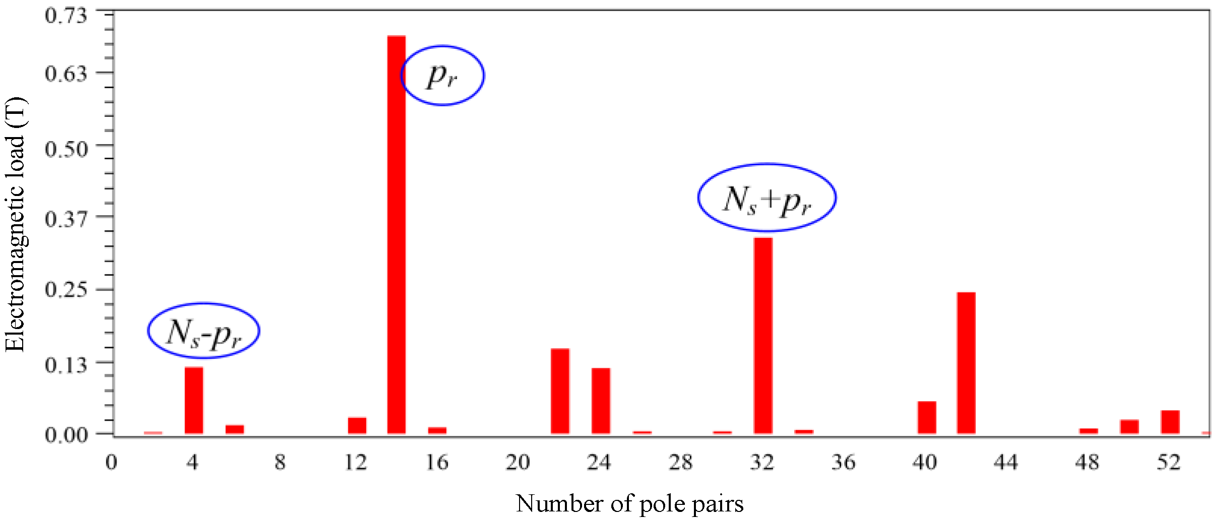
The proportions of the modulated magnetic field components of each order can be obtained by spectral analysis of the electromagnetic load. The spectrum obtained by Fourier transform is shown in Figure 22, in which the amplitude of the fundamental magnetomotive force is the highest, so we can roughly find 28 “tips” in Figure 21. The second highest is the magnetic field component of the 32-pole-pair order, which is the magnetic field component mainly used in the actual magnetic field acceleration effect. The magnetic field component of the order of 4 pole pairs is the smallest order magnetic field component that can be used in the generator. They are all the result of magnetic field modulation.
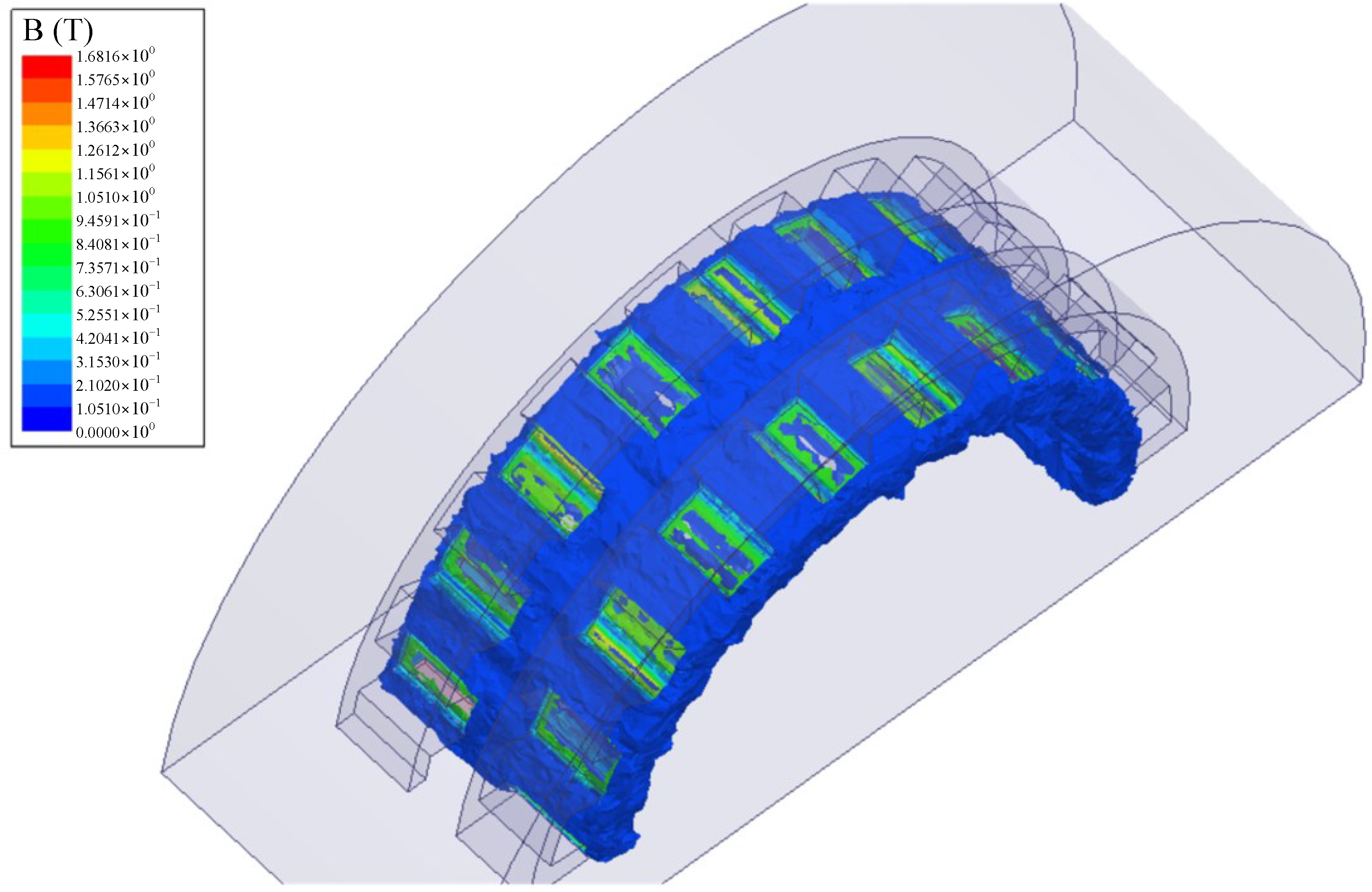
In order to observe the spatial distribution of the magnetic field in the air gap, a three-dimensional simulation of the electromagnetic load of the staggered vernier generator is carried out. The simulation results are shown in Figure 23. From the figure, it can be found that the areas with higher magnetic field strength are mainly concentrated in the stator teeth area, which is the main magnetic flux path of the generator.
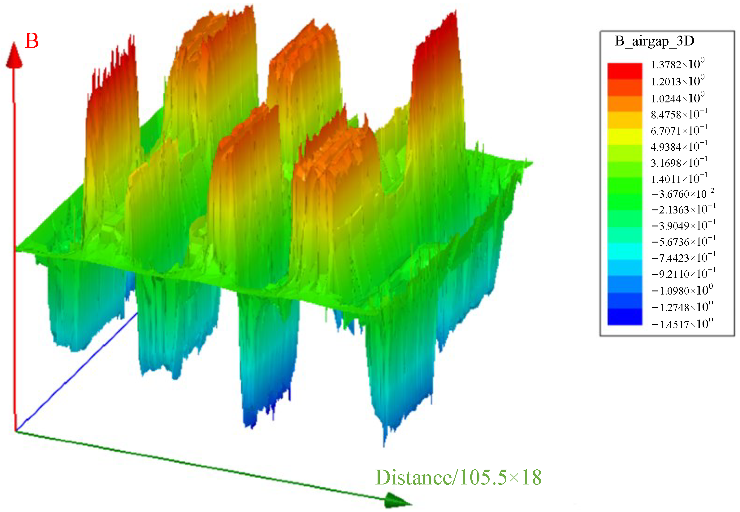
In order to analyze the influence of staggered-teeth on the main magnetic flux path of vernier generators, a comparative analysis of vernier generators with staggered teeth and non-staggered teeth was carried out through simulation. Figure 24 and Figure 25 show the electromagnetic load amplitude surfaces of the vernier generator with the staggered structure and the vernier generator with the non-staggered structure, respectively. It can be found from Figure 24 that due to the staggered teeth structure, the peak values of the electromagnetic load are also staggered, and the peak value of the electromagnetic load at the stator tooth position is about 1.38T. It can be observed from Figure 25 that the electromagnetic load waveform of the non-staggered-teeth structure is relatively simple, and the maximum value of electromagnetic load at the stator teeth position is about 1.4T, but the electromagnetic load at each stator tooth position is quite different.
The comparison of the electromagnetic load is shown in Figure 26, which is obtained by taking a section in Figure 24 and Figure 25. It can be seen from Figure 26 that the overall trend of the electromagnetic load of the two generators is basically the same. The simulation results differ only in the specific details of the waveform, reflecting that the staggered structure has little effect on the electromagnetic load of the vernier generator.
In order to observe the influence of the staggered structure in the stator on the main magnetic flux, the magnetic field strength of the cross-section of the generator was analyzed, and the analysis results are shown in Figure 27 and Figure 28. Through the comparison of the cross-sectional diagrams, it can be found that although the staggered structure has little difference in the electromagnetic load, it has a greater impact on the stator yoke. The magnetic circuit of the staggered vernier generator is smoother and the magnetic flux leakage is smaller, so it has better performance of the main magnetic flux.
5.2. Experimental Results and Analysis
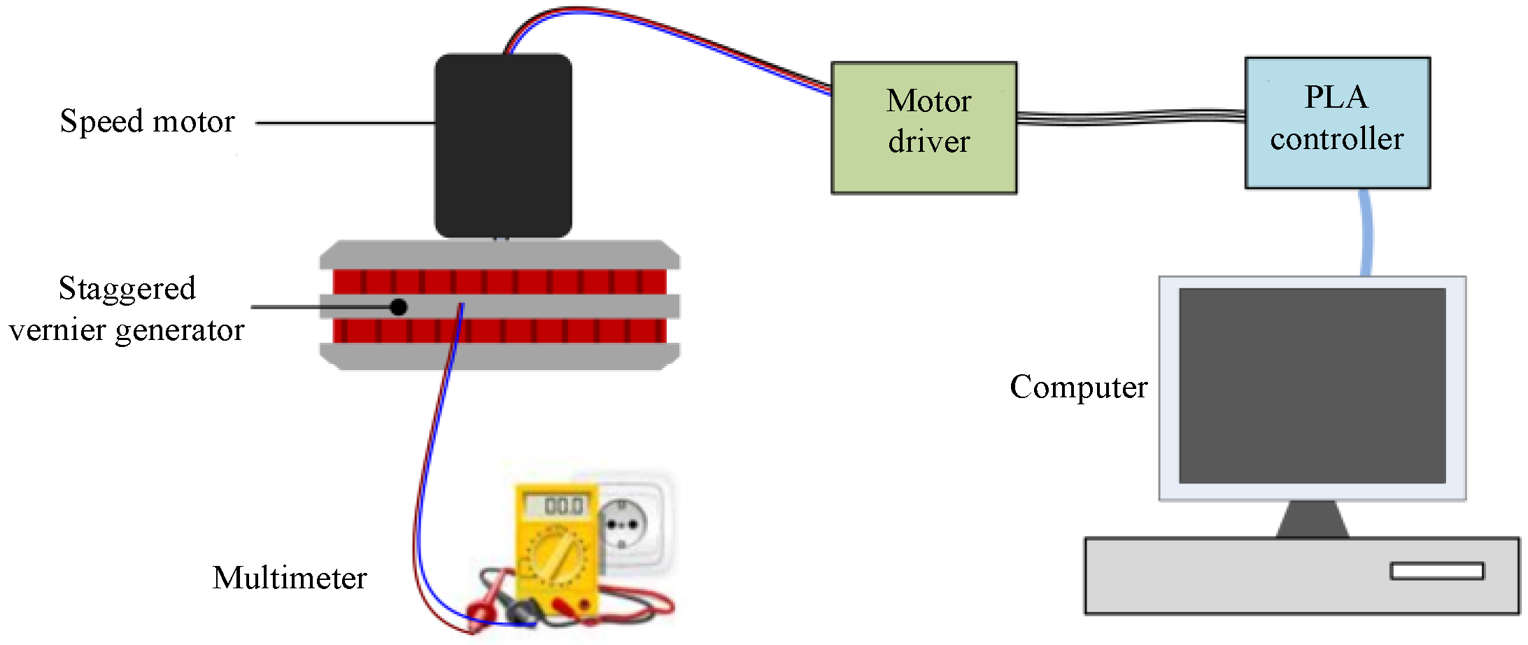
In order to measure the output voltage of the staggered vernier generator at different speeds, the speed-regulating motor is fixed on the rotor of the staggered vernier generator, and the effect of different driving torques on the vernier generator is simulated by controlling the speed of the speed-regulating motor. Figure 29 shows the experiment scheme of the staggered vernier generator. Among them, the driver of the speed regulating motor is DM860H, and the model of the PLA controller is LX3V-1212MT4H-A of Wecon Company.
The input speed of the generator is determined according to the speed of the impeller when the whole WEC is operating under the condition of the third-level sea state (the frequency range of the typical wave spectrum is 0.14–1.0Hz), so the output characteristics of the vernier generator at a speed range of 0.25 r/s~2 r/s were measured in the test. In order to analyze whether the staggered structure can reduce the magnetic flux leakage of the generator and improve the main magnetic flux intensity of the generator, the staggered and non-staggered structure of the generator are compared and analyzed.
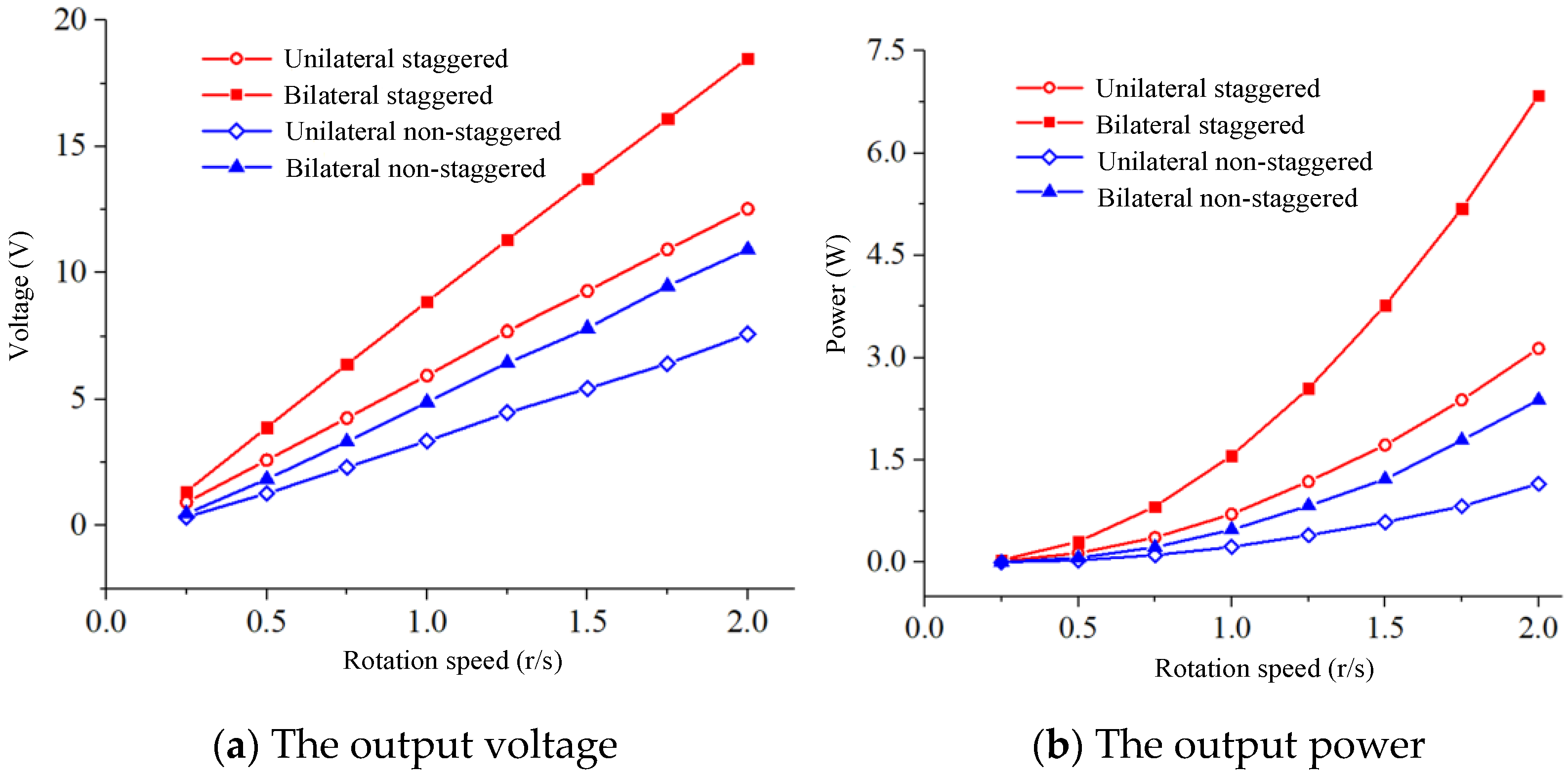
The test measured the output voltage of the unilateral staggered vernier generator, the bilateral staggered vernier generator, the unilateral non-staggered vernier generator and the bilateral non-staggered vernier generator at different speeds. The data obtained from the test are shown in Figure 30. The non-staggered generator is to rotate a stator winding of a staggered vernier generator by a half-tooth angle to obtain two identical stator windings arranged side by side, similar to the superposition of two vernier generators.
It can be seen from Figure 30 that the output voltage of the staggered structure is higher than that of the non-staggered structure, regardless of the unilateral structure or the bilateral structure. For example, when the speed is 2 r/s, the output voltage of the staggered vernier generator is close to 20 V, while the non-staggered structure bilateral generator can only reach about 10 V, which is even lower than the output voltage of the unilateral stator winding with the staggered structure. The stator yoke, winding turns and other parameters of the staggered structure and the non-staggered structure are exactly the same, which means that the main magnetic flux of the staggered vernier generator is much larger than that of the non-staggered structure. The suppression of magnetic flux leakage is realized, and the power density and power factor of the generator are improved.
The comparative result of output power is similar to the comparative result of output voltage, except that the change trend of the power curve is different from that of the voltage curve.
The results show that the staggered vernier structure can improve the main magnetic flux of the vernier generator, reduce the leakage flux, and improve the power factor of the generator. The staggered vernier structure can improve the performance of the generator without adding additional structures and materials.
6. Conclusions
In order to optimize the energy conversion efficiency of the counter-rotating self-adaptable WEC and improve the efficiency of the generator at low speed, a staggered structure vernier generator suitable for the counter-rotating self-adaptable WEC is proposed in this paper. Based on simulation results and experimental data, the following conclusions were drawn:
- A multi-air-gap vernier generator with single rotor and double stator structure was designed. The double stators have the same diameter and thickness, and are arranged side by side, making the generator more like a single air gap structure.
- The principle of magnetic flux modulation of the vernier generator with staggered teeth structure was analyzed by deduction and calculation. It was concluded that the staggered vernier generator can utilize the fundamental magnetic field and the modulated main harmonic components of the permanent magnet rotor at the same time. This makes it possible to reduce flux leakage inside the generator.
- The influence of basic parameters such as the number of poles and slots on performance of the generator was analyzed by means of calculation and numerical simulation, and it was concluded that the combination of 18 slots/28 poles has excellent low-speed performance and almost negligible cogging torque.
- Through numerical simulation, the principle of magnetic field acceleration of the vernier generator, the air-gap magnetic density, the magnetic flux density of the stator yoke and other key characteristic parameters were analyzed, and the design scheme of the staggered vernier generator was confirmed.
- The low-speed performance of the staggered vernier generator was tested, and it was verified that the staggered vernier generator has better performance through comparative experiments.
This paper proposed a vernier generator for a counter-rotating self-adaptable WEC with a staggered tooth structure to solve the problems of magnetic flux leakage and structural complexity of multi-air-gap generators in the permanent magnet vernier generators. The direct-drive generator designed in this paper is a hollow generator, which is often difficult to design. The design places the impeller directly in the generator, which simplifies the construction of the system, but also limits the increase in the diameter of the impeller. Optimizing the combination of impeller and direct drive generator can solve this contradiction. The optimizing and the specific influences of this generator on the power generation performance of the WEC will be discussed in future.
Author Contributions
Conceptualization, Z.L. (Zirong Luo) and Z.L. (Zhongyue Lu); methodology, G.W.; software, Z.L. (Zhongyue Lu); validation, M.W., J.S. and Z.L. (Zhongyue Lu); formal analysis, J.S.; investigation, Z.L. (Zhongyue Lu); resources, J.S.; data curation, Z.L. (Zhongyue Lu); writing—original draft preparation, G.W. and Z.L. (Zhongyue Lu); writing—review and editing, Z.L. (Zhongyue Lu); visualization, G.W.; supervision, J.S.; project administration, Z.L. (Zirong Luo); funding acquisition, Z.L. (Zirong Luo) and J.S. All authors have read and agreed to the published version of the manuscript.
Funding
This research was funded by National Natural Science Foundation of China, grant number 52,075,537; and Guangdong Province Key Field R&D Program, grant number 2020B1111030002.
Institutional Review Board Statement
Not applicable.
Informed Consent Statement
Not applicable.
Data Availability Statement
Not applicable.
Conflicts of Interest
The authors declare no conflict of interest.
Symbols
| Magnetomotive force | Length of magnetic path | ||
| Magnetic field intensity | The thickness of the permanent magnet | ||
| Remanence | The thickness of the air gap | ||
| Vacuum permeability | The radial dimension of the permanent magnets on the generator | ||
| The angle between adjacent permanent magnets | The electromagnetic load | ||
| The magnetic induction intensity of the magnetic poles | The radius of air gap | ||
| The magnetic flux | Effective area of each air gap | ||
| Actual number of pole pairs | The angle occupied by a single stator tooth | ||
| The angle occupied by a single tooth slot | The high-order harmonic component of the electromagnetic load | ||
| Number of conductors per slot | The number of turns of a single winding | ||
| The effective length of the stator axial direction | The coil span | ||
| The winding coefficient of the armature | The distribution coefficient of the phase winding | ||
| The number of slots per pole per phase of the stator winding | The no-load phase induced electromotive force amplitude | ||
| The ratio between the pole pairs of fundamental and effective harmonic flux density |
References
- Heo, J.; Kim, J.; Kwon, Y. Technology Development of Unmanned Underwater Vehicles (UUVs). J. Comput. Commun. 2017, 5, 28–35. [Google Scholar] [CrossRef] [Green Version]
- Zeng, Z.; Lyu, C.; Bi, Y.; Jin, Y.; Di, L.; Lian, L. Review of hybrid aerial underwater vehicle: Cross-domain mobility and transitions control. Ocean Eng. 2022, 248, 110840. [Google Scholar] [CrossRef]
- Molchanov, A.; Breitenmoser, A.; Sukhatme, G.S. Active drifters: Towards a practical multi-robot system for ocean monitoring. In Proceedings of the 2015 IEEE International Conference on Robotics and Automation (ICRA), Seattle, WA, USA, 26–30 May 2015; IEEE: Manhattan, NY, USA, 2015; pp. 545–552. [Google Scholar]
- Neill, S.P.; Vögler, A.; Goward-Brown, A.J.; Baston, S.; Lewis, M.J.; Gillibrand, P.A.; Waldman, S.; Woolf, D.K. The wave and tidal resource of Scotland. Renew. Energy 2017, 114 Part A, 3–17. [Google Scholar] [CrossRef]
- Fenichel, E.P.; Addicott, E.T.; Grimsrud, K.M.; Lange, G.-M.; Porras, I.; Milligan, B. Modifying national accounts for sustainable ocean development. Nat. Sustain. 2020, 3, 889–895. [Google Scholar] [CrossRef]
- Yun, S.-J.; Kim, H.-G.; Park, J.-W.; Lee, H.-J.; Kim, J.-C.; Hwang, J.-H.; Choi, Y.-H.; Lee, S.-J.; Ryu, J.-K.; Suh, J.-H.; et al. Development of a Towed Underwater Platform That Can Operate in a Marine Environment and Explore the Sea Bottom. J. Mar. Sci. Eng. 2022, 10, 66. [Google Scholar] [CrossRef]
- López, A.M.; Imiya, A.; Pajdla, T.; Álvarez, J.M. Exploring the Seafloor with Underwater Robots. In Computer Vision in Vehicle Technology: Land, Sea & Air; John Wiley & Sons, Ltd.: Chichester, UK, 2017. [Google Scholar] [CrossRef]
- Guihen, D.; Brearley, J.A.; Fielding, S. Antarctic krill likely avoid underwater gliders. Deep Sea Res. Part I Oceanogr. Res. Pap. 2022, 179, 103680. [Google Scholar] [CrossRef]
- Buscombe, D.; Carini, R.J.; Harrison, S.R.; Chickadel, C.C.; Warrick, J.A. Optical wave gauging using deep neural networks. Coast. Eng. 2020, 155, 103593. [Google Scholar] [CrossRef]
- Meyer, H.K.; Roberts, E.M.; Rapp, H.T.; Davies, A.J. Spatial patterns of arctic sponge ground fauna and demersal fish are detectable in autonomous underwater vehicle (AUV) imagery. Deep Sea Res. Part I Oceanogr. Res. Pap. 2019, 153, 103137. [Google Scholar] [CrossRef]
- Fiester, C.; Gomez-Ibanez, D.; Stokey, R. A Modular, Compact, and Efficient Next Generation REMUS 600 AUV. In Proceedings of the OCEANS—Marseille Conference, 2019|OCEANS 2019—MARSEILLE, Marseille, France, 17–20 June 2019. [Google Scholar]
- Xu, R.; Wang, H.; Xi, Z.; Wang, W.; Xu, M. Recent Progress on Wave Energy Marine Buoys. J. Mar. Sci. Eng. 2022, 10, 566. [Google Scholar] [CrossRef]
- Teixeira-Duarte, F.; Clemente, D.; Giannini, G.; Rosa-Santos, P.; Taveira-Pinto, F. Review on layout optimization strategies of offshore parks for wave energy converters. Renew. Sustain. Energy Rev. 2022, 163, 112513. [Google Scholar] [CrossRef]
- Khan, M.Z.A.; Khan, H.A.; Aziz, M. Harvesting Energy from Ocean: Technologies and Perspectives. Energies 2022, 15, 3456. [Google Scholar] [CrossRef]
- Clemente, D.; Rosa-Santos, P.; Taveira-Pinto, F. On the potential synergies and applications of wave energy converters: A review. Renew. Sustain. Energy Rev. 2021, 135, 110162. [Google Scholar] [CrossRef]
- Faicao, A. Wave energy utilization: A review of the technologies. Renew. Sustain. Energy Rev. 2010, 14, 899–918. [Google Scholar]
- Trivedi, K.; Koley, S. Mathematical modeling of breakwater-integrated oscillating water column wave energy converter devices under irregular incident waves. Renew. Energy 2021, 178, 403–419. [Google Scholar] [CrossRef]
- Wu, B.; Li, M.; Wu, R.; Chen, T.; Zhang, Y.; Ye, Y. BBDB wave energy conversion technology and perspective in China. Ocean Eng. 2018, 169, 281–291. [Google Scholar] [CrossRef]
- Salter, S.H.; Lin, C.P. Wide tank efficiency measurements on a model of the sloped IPS buoy. In Proceedings of the 3rd European Wave Energy Conference, Patras, Greece, 30 September–2 October 1998; pp. 200–206. [Google Scholar]
- Jusoh, M.A.; Ibrahim, M.Z.; Daud, M.Z.; Albani, A.; Mohd Yusop, Z. Hydraulic Power Take-Off Concepts for Wave Energy Conversion System: A Review. Energies 2019, 12, 4510. [Google Scholar] [CrossRef] [Green Version]
- McCabe, A.P.; Bradshaw, A.; Widden, M.B.; Chaplin, R.V.; French, M.J. Meadow croft JAC. PS Frog Mk5: An offshore point-absorber wave energy converter. In Proceedings of the 5th European Wave Energy Conference, Cork, Ireland, 17–20 September 2003; pp. 31–37. [Google Scholar]
- Rachmayani, R.; Ningsih, N.S.; Ardiansyah, I.; Yani, L.F.; Rizal, A.M.; Kartadikaria, A.R.; Sari, N.T.; Park, H. Utilization and Linkage of Oceanic Energy in Natuna Island: A Review. J. Coast. Res. 2021, 114 (Suppl. 1), 599–603. [Google Scholar] [CrossRef]
- Sheng, W. Wave energy conversion and hydrodynamics modelling technologies: A review. Renew. Sustain. Energy Rev. 2019, 109, 482–498. [Google Scholar] [CrossRef]
- Polinder, H.; Scuotto, M. Wave energy converters and their impact on power systems. In Proceedings of the International Conference on Future Power Systems, Amsterdam, The Netherlands, 16–18 November 2005; pp. 9–18. [Google Scholar]
- Previsic, M. Wave Power Technologies. In Proceedings of the IEEE Power Engineering Society General Meeting, San Francisco, CA, USA, 12–16 June 2005; Volume 2, pp. 2011–2016. [Google Scholar]
- Ringwood, J. The dynamics of wave energy. In Proceedings of the Irish Signals and Systems Conference (ISSC 2006), Dublin, Ireland, 28–30 June 2006. [Google Scholar]
- Markel, P.; Ringwood, J.V. A Review of Wave-to-Wire Models for Wave Energy Converters. Energies 2016, 9, 506. [Google Scholar]
- Wu, G.; Lu, Z.; Luo, Z.; Shang, J.; Sun, C.; Zhu, Y. Experimental Analysis of a Novel Adaptively Counter-Rotating Wave Energy Converter for Powering Drifters. J. Mar. Sci. Eng. 2019, 7, 171. [Google Scholar] [CrossRef] [Green Version]
- Gao, Y.; Qu, R.; Li, D.; Li, J.; Zhou, G. Design of a dual-stator LTS vernier machine for direct-drive wind power generation. IEEE Trans. Appl. Supercond. 2016, 26, 5204505. [Google Scholar] [CrossRef]
- Yin, X.; Fang, Y.; Huang, X.; Pfister, P.D. Analytical modeling of a novel vernier Pseudodirect-drive permanent-magnet machine. IEEE Trans. Magn. 2017, 53, 16914054. [Google Scholar] [CrossRef]
- Wang, L.L.; Shen, J.X.; Luk, P.C.K.; Fei, W.Z.; Wang, C.F.; Hao, H. Development of a magnetic-geared permanent-magnet brushless motor. IEEE Trans. Magn. 2009, 45, 4578–4581. [Google Scholar] [CrossRef] [Green Version]
- Kim, B.; Lipo, T.A. Analysis of a PM vernier motor with spoke structure. In Proceedings of the 2014 IEEE Energy Conversion Congress and Exposition, Pittsburgh, PA, USA, 14–18 September 2014; IEEE: Manhattan, NY, USA, 2014; pp. 2358–2365. [Google Scholar]
- Liu, C.H.; Chau, K.T.; Zhang, Z. Novel design of double-stator single-rotor magnetic-geared machines. IEEE Trans. Magn. 2012, 48, 4180–4183. [Google Scholar] [CrossRef]
- Li, D.; Qu, R.; Li, J. Topologies and analysis of flux-modulation machines. In Proceedings of the 2015 IEEE Energy Conversion Congress and Exposition, Montreal, QC, Canada, 20–24 September 2015; IEEE: Manhattan, NY, USA, 2015. [Google Scholar]
- Toba, A.; Lipo, T.A. Generic torque-maximizing design methodology of permanent magnet Vernier machine. In Proceedings of the International Conference on Electric Machines and Drives, Canterbury, UK, 1–3 September 1999; pp. 522–524. [Google Scholar]
- Qu, R.; Lipo, T.A. Dual-rotor, radial-flux, toroidally wound, permanent-magnet machines. IEEE Trans. Ind. Appl. 2003, 39, 1665–1673. [Google Scholar]
- Niu, S.X.; Ho, S.L.; Fu, W.N. A novel direct-drive dual-structure permanent magnet machine. IEEE Trans. Magn. 2010, 46, 2036–2039. [Google Scholar] [CrossRef]
- Toba, A.; Lipo, T.A. Novel Dual-excitation permanent magnet Vernier machine. In Proceedings of the IEEE Industry Applications Conference, Phoenix, AZ, USA, 3–7 October 1999; IEEE: Manhattan, NY, USA, 1999. [Google Scholar]
- Niu, S.X.; Ho, S.L.; Fu, W.N.; Wang, L.L. Quantitative Comparison of Novel Vernier Permanent Magnet Machines. IEEE Trans. Magn. 2010, 46, 2032–2035. [Google Scholar] [CrossRef]
- Kim, M.S.; Zhao, F.; Kwona, B.; Lipo, T.A. Design and analysis of an axial-flux PM Vernier machine for auto-focusing systems. In Proceedings of the 2015 International Conference on Electrical Machines and Systems, Pattaya, Thailand, 25–28 October 2015; pp. 1792–1796. [Google Scholar]
- Toba, A.; Lipo, T.A. Generic torque-maximizing design methodology of surface permanent-magnet Vernier machine. IEEE Trans. Ind. Appl. 2000, 36, 1539–1546. [Google Scholar]
- Dalal, A.; Nekkalapu, S.; Kumar, P. 2-D Analytical Subdomain Model for Hybrid Dual-Rotor Motor. IEEE Trans. Magn. 2016, 52, 1–9. [Google Scholar] [CrossRef]
- Riba, J.-R.; López-Torres, C.; Romeral, L.; Garcia, A. Rare-earth-free propulsion motors for electric vehicles: A technology review. Renew. Sustain. Energy Rev. 2016, 57, 367–379. [Google Scholar] [CrossRef] [Green Version]
- Shao, L.; Navaratne, R.; Popescu, M.; Liu, G. Design and Construction of Axial-Flux Permanent Magnet Motors for Electric Propulsion Applications—A Review. IEEE Access 2021, 9, 158998–159017. [Google Scholar] [CrossRef]
- Wang, X.; Chen, F.; Zhu, R.; Huang, X.; Sang, N.; Yang, G.; Zhang, C. A Review on Disturbance Analysis and Suppression for Permanent Magnet Linear Synchronous Motor. Actuators 2021, 10, 77. [Google Scholar] [CrossRef]
- Ghabeli, A.; Yazdani-Asrami, M.; Doroudi, A.; Gholamian, S.A. Reduction of Electromagnetic Force in AC Distributed Winding of Fault Current Limiter under Short-Circuit Condition. J. Magn. Korean Magn. Soc. 2015, 20, 400–404. [Google Scholar] [CrossRef] [Green Version]
Figure 1.
Various types of small marine engineering equipment.

Figure 2.
Preliminary scheme of the counter-rotating self-adaptable WEC.

Figure 3.
Composition and structure of the PTO.

Figure 4.
Cross-sectional view and transmission diagram of the PTO.

Figure 5.
Impeller installation structure and swingable blades.

Figure 6.
Magnetic circuit analysis model.

Figure 7.
Rotor analysis model and Br waveform along the rotor.

Figure 8.
Stator Analysis Model and Circumferential Air Gap Waveform.

Figure 9.
Circumferential air gap waveform of function f(θ).

Figure 10.
The geometric relationship between a single winding and the electromagnetic load.

Figure 11.
Sectional view and structural diagram of side-by-side double stator staggered permanent magnet vernier generator.
Figure 11.
Sectional view and structural diagram of side-by-side double stator staggered permanent magnet vernier generator.

Figure 12.
Main magnetic flux path of the staggered vernier generator.

Figure 13.
Comparison of no-load electromotive force of vernier generators with different pole-slot combinations.
Figure 13.
Comparison of no-load electromotive force of vernier generators with different pole-slot combinations.

Figure 14.
Comparison of no-load cogging torque of vernier generators with different pole-slot combinations.
Figure 14.
Comparison of no-load cogging torque of vernier generators with different pole-slot combinations.

Figure 15.
The structure diagram of the stator.

Figure 16.
The star diagram of slot potential.

Figure 17.
The expanded view of A-phase winding connection.

Figure 18.
Variation curve of electromagnetic load with and .

Figure 19.
Simulation of staggered vernier generator at no-load.

Figure 20.
Single winding and waveform of its electromagnetic load.

Figure 21.
Waveform of electromagnetic load variation with mechanical angle of vernier generator.

Figure 22.
Spectrum analysis results of electromagnetic load of vernier generator.

Figure 23.
Spatial distribution of magnetic field in vernier generator.

Figure 24.
Circumferential variation of magnetic field of staggered vernier generator.

Figure 25.
Circumferential variation of magnetic field of non-staggered vernier generator.

Figure 26.
The comparison of the electromagnetic load of staggered and non-staggered vernier generator.
Figure 26.
The comparison of the electromagnetic load of staggered and non-staggered vernier generator.

Figure 27.
Magnetic field intensity distribution in cross section of vernier generator with staggered structure.
Figure 27.
Magnetic field intensity distribution in cross section of vernier generator with staggered structure.

Figure 28.
Magnetic field intensity distribution in cross section of vernier generator with non-staggered structure.
Figure 28.
Magnetic field intensity distribution in cross section of vernier generator with non-staggered structure.

Figure 29.
The experiment scheme of the staggered vernier generator.

Figure 30.
Comparison of output characteristics of different generators at different speeds.


Table 1.
Energy supply scheme and performance of several typical marine engineering equipment.
| Name | Power Type | Battery Life (h) | Cruising Distance (km) |
|---|---|---|---|
| Slocum Battery (US) | Alkaline battery | 480 | 500 |
| MUST (US) | Lead-acid batteries | 24 | \ |
| OEX (US) | Ni-Cr battery | 12 | \ |
| CR-02 (CN) | Silver zinc battery | 25 | \ |
| Remus 1000 (DE) | lithium polymer battery | 24 | \ |
| Urashima (JP) | PEFC fuel cells (main) | \ | 300 |
| HUGIN 3000 (US) | AI/HP Half Fuel Cell | 60 | 432 |
Table 2.
Characteristics of permanent magnet vernier generators with different combinations of poles and slots.
Table 2.
Characteristics of permanent magnet vernier generators with different combinations of poles and slots.
| Parameters | Combinations of Poles and Slots (Ns/2pr) | |||||
|---|---|---|---|---|---|---|
| 12/20 | 12/22 | 18/24 | 18/28 | 18/30 | 18/32 | |
| y1 | 3 | 6 | 1 | 2 | 3 | 4 |
| kw | 1 | 1 | 0.87 | 0.95 | 1 | 0.95 |
| Gr | 5 | 11 | 2 | 3.5 | 5 | 8 |
| Nc | 60 | 132 | 72 | 252 | 90 | 288 |
Table 3.
Division of phase bands of fractional slot windings with .
| Slot Number | Electrical Angle | Phase | Polarity |
|---|---|---|---|
| 1 | 0° | A | N1, S1 |
| 2 | 80° | Z | N1, S1 |
| 3 | 160° | B | N1, S1 |
| 4 | 240° | C | N1, S1 |
| 5 | 320° | Y | N1, S1 |
| 6 | 400° | A | N2, S2 |
| (40°) | |||
| 7 | 480° | B | N2, S2 |
| (120°) | |||
| 8 | 560° | X | N2, S2 |
| (200°) | |||
| 9 | 640° | C | N2, S2 |
| (280°) |
Publisher’s Note: MDPI stays neutral with regard to jurisdictional claims in published maps and institutional affiliations. |
© 2022 by the authors. Licensee MDPI, Basel, Switzerland. This article is an open access article distributed under the terms and conditions of the Creative Commons Attribution (CC BY) license (https://creativecommons.org/licenses/by/4.0/).
Share and Cite
MDPI and ACS Style
Lu, Z.; Wu, G.; Wang, M.; Luo, Z.; Shang, J. Design and Performance Analysis of a Staggered Vernier Generator for Wave Power Generation. J. Mar. Sci. Eng. 2022, 10, 1156. https://doi.org/10.3390/jmse10081156
AMA Style
Lu Z, Wu G, Wang M, Luo Z, Shang J. Design and Performance Analysis of a Staggered Vernier Generator for Wave Power Generation. Journal of Marine Science and Engineering. 2022; 10(8):1156. https://doi.org/10.3390/jmse10081156
Chicago/Turabian StyleLu, Zhongyue, Guoheng Wu, Mangkuan Wang, Zirong Luo, and Jianzhong Shang. 2022. "Design and Performance Analysis of a Staggered Vernier Generator for Wave Power Generation" Journal of Marine Science and Engineering 10, no. 8: 1156. https://doi.org/10.3390/jmse10081156
Note that from the first issue of 2016, this journal uses article numbers instead of page numbers. See further details here.