
The Effect of the Shot Blasting Process on the Dynamic Response of Steel Reinforcement


Laboratory of Technology and Strength of Materials, Department of Mechanical Engineering & Aeronautics, University of Patras, 26054 Patras, Greece
*
Author to whom correspondence should be addressed.
Metals 2022, 12(6), 1048; https://doi.org/10.3390/met12061048
Submission received: 20 May 2022
/
Revised: 11 June 2022
/
Accepted: 16 June 2022
/
Published: 19 June 2022
(This article belongs to the Special Issue Assessment of Corrosion Resistance and Mechanical Properties of Reinforced Concrete)
Abstract
:As it is widely known, corrosion poses a real threat for reinforced concrete structures, especially when they are located in coastal areas. This phenomenon, in conjunction with repeated loads, such as intense seismic events, adversely affect their useful service life. Several experimental studies have presented the magnitude of degradation of steel reinforcement due to corrosion in the presence of fatigue, which affects either the serviceability or durability of steel reinforcement. As a result, the current experimental study presents the results of the shot blasting process of steel reinforcement at various times of exposure to a corrosive environment and the influence on their dynamic response after the execution of low cycle fatigue tests at different constant strain amplitudes. The findings show the beneficial effect of the shot blasting process in terms of percentage mass loss and the improvement of mechanical performance of steel bars in terms of service life and energy dissipation capacity. Moreover, the assessment performed with a quality material index demonstrates the improved mechanical performance of shot blasted specimens vs. bare specimens, in the long term for medium range-imposed deformation.
1. Introduction
As it is widely known, reinforced concrete (RC) comprises the most widely used building material in civil engineering structures, ensuring a satisfying mechanical response in terms of strength and ductility, in combination with its low cost for production. However, the presence of aggressive environmental factors affect RC, triggering steel corrosion that results in non-uniform mass loss of steel reinforcing bars and consequently non-uniform loss of their effective cross-section and drop of their mechanical properties. Due to the increased volume of corrosion oxides, cracks are developed in the surrounding concrete and subsequently spalling of concrete cover. At the elemental level, corrosion significantly degrades both the steel-concrete bond strength and the bearing capacity of RC members. Thus, corrosion of steel reinforcement constitutes an important durability issue in RC structures, as it degrades the entire mechanical performance of RC structures and consequently impairs their strength and their safety. The significant annual budget spent by many countries on maintenance, repair, and rehabilitation of RC structures reflects the severity of a corrosion problem worldwide and the attention attained by researchers [1,2,3].
Especially, in the case of structures located in marine environments or in coastal areas, steel reinforcement demotes due to the intense action of chlorides [4]. Several studies have already demonstrated the negative consequences of chloride induced corrosion on steel reinforcing bars, which causes pits and non-uniform reduction of their cross-section, resulting in a significant degradation of their mechanical response in terms of strength properties, but mainly in ductility [5,6,7,8,9]. Recent studies show the significant loss of bond strength due to corrosion combined with concrete cracking development and spalling of concrete cover, decreasing the service life of RC elements [10,11,12].
The abovementioned consequences are the inciting cause that the scientific community has recently directed toward ways of surface properties’ improvement through the shot blasting process. The shot blasting process is a prominent and broadly used mechanical cleaning method to eliminate rust and dirt from the material’s surface and to improve its finishing. Amid the process, the particles (shots) which indent on the material surface act not only abrasively but they likewise cause compressive deformations. Recent experimental studies have demonstrated that for every type of steel reinforcement, there is an optimal combination of degree of cleanliness and abrasive material that can ameliorate its ductility properties [13,14,15] (Figure 1).
The impact of bombarding the surface of steel reinforcing bars has been widely reported. Drakakaki et al. [13,14] demonstrated the positive impact of shot blasting treatment process of B500c steel, providing corrosion resistance but mainly enhancement of the mechanical response under monotonic loading. Furthermore, a previous study of the authors [15] demonstrated that shot blasting on B500c steel reinforcing bars with corundum can enhance their ductility properties and benefit mechanical behavior in the long term, once again under static loading. Voorwald et al. [16] performed shot blasting for AISI 4340 steel through cast steel shots, and the outcomes indicated the significant improvement of corrosion resistance and the fatigue life of the target material.
Besides the continuous exposure of coastal RC structures in a corrosive environment, earthquakes are another factor that limit the service life, which is the main criterion for the design of a structure. In earthquake-prone areas, where the RC structures are likely subjected to dynamic loads due to intense seismic events, there is an impending need for energy absorption from steel reinforcement. In case of intense earthquake events, steel reinforcement yields and high plastic deformations are developed beyond the elastic area, resulting in a reduced energy capacity of the material. Additionally, in the presence of corrosion, steel reinforcement is presented with degraded ductility, below the minimum requirements imposed by standards, according to existing literature [6,17,18]. Hence, the need to attain a certain level of ductility, as defined by European standards, is at risk, leading to unexpected brittle failure of critical elements for the safety of the structure.
In continuance, previous studies have indicated that the loadings on steel reinforcing bars due to strong earthquake events can be simulated in a laboratory by low-cycle fatigue tests [19]. Furthermore, several researchers have illustrated the drop of the useful service life of reinforcing bars due to low-cycle fatigue [20,21,22,23]. The above mentioned studies have also shown the different mechanical response of the steel reinforcing bars in cyclic toward monotonic loadings. In that manner, the loading history of rebars is capable of appreciably reducing their strength and ductility. Yet, current European and international regulations mainly provide design values from monotonic loading (quasi-static loading), despite the fact that cumulative damage due to fatigue loading is explicitly stated due to seismic events. In actuality, the material’s strain history and especially the inelastic cycles should be considered during the seismic analysis of RC elements since they can be termed significant in cases of intense earthquakes, especially in the presence of corrosion damage; hence, over the recent years, researchers have studied the mechanical behavior of steel reinforcing bars under dynamic (fatigue) loadings considering the corrosive factor focusing on the fatigue damage accumulation in terms of energy absorption [24,25,26].
Hence, the need to offer resistance to reinforcing steel bars against the combined effect of fatigue and corrosion is a matter of urgency and an unceasing challenge to the structural assessment and durability of corroded RC structures. In light of the foregoing issues, this study is an effort to investigate the influence of shot blasting treatment on steel reinforcement under low cycle fatigue loading, taking into account corrosion conditions. A secondary aim is to assess the mechanical behavior of the material, before and after the shot blasting process, with the use of a fatigue damage index QF, introduced by the authors [26], as an attempt to reflect the loading history and the corresponding absorbed energy.
2. Experimental Procedure
The main objective of the current study is to further investigate the effect of shot blasting on the mechanical response of steel reinforcing bars under dynamic loadings (fatigue conditions) in the long term. The experiments were conducted on a B500c class dual-phase steel that has been widely used in the last decades in civil engineering construction—the chemical composition of which is summarized in Table 1—and delivered in the form of ribbed reinforcing bars of nominal diameter equal to 12 mm. With the aim of investigating the dynamic response of steel reinforcing bars, 150 specimens were cut with a total length of 200 mm. Based on the current regulations for high strength and ductility steel, the B500c class steel should provide a minimum value of yield strength of 500 MPa and a minimum value of deformation at a maximum strength of 7.50%. Moreover, the ratio of the maximum strength to the yield strength Rm/Rp should vary from 1.15 to 1.35.
In this particular case, the specimens were divided into two groups, where there were specimens of bare steel reinforcing bars (as delivered) and specimens of shot blasted steel reinforcing bars, which were subjected to an initial pass with olivine pellets and a subsequent use of glass beads. Afterwards, each group was further subdivided into five groups, each of them corresponded to a different corrosion level of specimens; the non-corroded specimens (without corrosion damage) and four corrosion exposure times in laboratory conditions remained in the salt spray chamber for 30, 60, 90, and 120 days, respectively.
After the accelerated corrosion tests, mechanical fatigue tests were conducted in order to study the dynamic behavior of both bare and shot blasted specimens. In this framework, three different cases of imposed strain levels were examined, namely ±0.5%, ±0.75% and ±1.25%.
2.1. Shot Blasting Procedure
The shot blasting process consists of a prominent and a broadly followed mechanical cleaning method to eliminate rust and dirt from the surface of a material. Besides their abrasive action during the shot blasting process, the particles develop local compressive deformations on the material’s surface. The development of surface compressive stresses leading to the desired degree of cleanliness consists the headliner of the protocol correlated to the shot blasting process. The standard grades of cleanliness for abrasive shot blasting, according to NACE (National Association of Corrosion Engineer; Steel Structures Painting Council) and ISO 8501-1 (2007), are presented in Table 2.
The type and the geometry of the abrasive material, the impact angle, the shot velocity, and the flow rate are critical parameters for the optimal shot blasting process. The present manuscript, as part of an extensive experimental research, considering the encouraging results of the mechanical performance of steel reinforcing bars under monotonic loading [13,14], investigates the effect of the shot blasting process on the mechanical performance of steel bars under cyclic (fatigue) loadings.
As detailed below in Table 3 and Table 4, the characteristics of the materials used in the research are:
- Olivine: a magnesium iron silicate that has a sandy structure. It does not contain free silica. It is the industrial mineral with the highest magnesium content;
- Glass beads: a non-metallic mineral abrasive made of soda glass.

Table 3.
Characteristics of abrasive materials.
| Properties | Olivine | Glass Beads |
|---|---|---|
| Shape | sub angular to angular | Spherical |
| Color | pale green | transparent, white |
| Hardness (Mohs) | 6.5–7 | 6 |
| Specific density (kg/dm3) | 3.3 | 2.5 |
| Loose bulk density (kg/dm3) | 1.7 | 1.5–1.6 |
| Grain sizes (microns) | 63–250 | 150–250 |
Table 4.
Chemical composition (in%) of olivine and glass beads.
| Chemical Components (%) | Olivine | Glass Beads |
|---|---|---|
| Al2O3 | 0.40–0.50 | <2.5 |
| Fe2O3 | 7.30–7.60 | <0.5 |
| SiO2 | 41.50–41.90 | 70.0–75.0 |
| CaO | 0.05–0.10 | 7.0–12.0 |
| MgO | 48.80–49.70 | <5.0 |
| K2O | - | <1.5 |
| Cr2O3 | 0.31–0.66 | - |
| MnO | 0.05–0.10 | - |
| NiO | 0.31–0.32 | - |
| Na2O | - | 12.0–15.0 |
| SO3 | - | <0.5 |
The parameters for the shot blasting treatment were set as follows. The specimens underwent the process of abrasive blasting first with olivine natural mineral abrasive to withdraw the mill scale and to achieve a surface cleanliness of Sa 2.5. Subsequently, the specimens underwent persistent shot peening using glass beads. The final degree of cleanliness achieved was Sa 3.0 as per ISO 8501-1 [27] since the glass bead blasting removed the last traces of mill scale. The abrasives used were GL40 olivine with a distribution of 63–250 microns and a soda-type glass bead with a distribution of 150–250 microns. The blasting was performed using a 90° angle of impact, whilst the flow rate of the compressed air was 5200 L per sec at 7 bar. Nozzle pressure was estimated to be 5 bar after losses and decompression at nozzle. Furthermore, the production speed was approximately 20 m per hour blasting with the olivine and 16 m per hour for the glass bead blasting, while blasting distance was maintained at approximately 15 cm. A view of steel reinforcing bars before and after shot blasting is illustrated in Figure 2.
2.2. Accelerated Corrosion Method
Given the fact that the corrosion phenomenon of steel reinforcement takes place slowly in nature, laboratory techniques are followed in order to accelerate the corrosion reactions so as to examine its consequences in a short period of time.
Following the experimental procedure of the authors’ previous studies, the accelerated corrosion method of a salt spray chamber was adopted (Figure 3a), based on the ASTM-B117 standard [28]. In this framework, specimens were exposed to an aggressive corrosion environment, where a sodium chloride solution was sprayed on steel reinforcing bars under wet/dry cycles with specific temperature and pH conditions. Furthermore, in order to simulate the corrosive agents in coastal areas or a marine environment, a sodium chloride solution (5% by weight of water) was imposed in wet cycles per 1.5 h, temperature was set at 35 °C, and the values of pH ranged from 6.5 to 7.2. With the aim of examining different corrosion levels for steel bars, the specimens remained in the chamber for 30, 60, 90 and 120 days, as previously described (Figure 3b).
Before corrosion experiments, the values of initial mass and total length of each specimen were recorded. It is worth mentioning that a certain length in the middle of the steel bars was allowed to corrode during the corrosion experiments and the remaining length was covered with wax in order to ensure that the failure during the following mechanical tests would not occur in the grabs.
After the completion of corrosion tests, all specimens were cleaned following the ASTM G1-72 standard [29] to remove all dirt and corrosion oxides.
Therefore, the corrosion damage of the steel bars, reduced to their corroded length, was estimated in terms of mass loss according to the following expression:
2.3. Mechanical Tests
For the purpose of the present study, a significant number of specimens able to stabilize the results was considered for cyclic (LCF) tests. Bare and shot blasted rebars were tested in the same conditions for comparison. More specifically, a total of 120 corrosion tests and more than 75 of shot blasting applications were carried out, whereas 150 cycle fatigue tests were conducted so as to simulate the seismic response of rebars, as presented in Table 5.
For the mechanical tests, a servohydraulic MTS 250 kN machine was utilized. More specifically, cyclic fatigue tests were carried out under displacement control on non-corroded, and all cases of corroded, reinforcing bars. A protocol for the execution of LCF tests on the selected representative steel reinforcements was elaborated; the testing frequency to use in the mechanical tests was fixed equal to 2.0 Hz, which simulates medium and large scale seismic events, with a stress ratio equal to 1. All tests were run up to failure and the number of cycles was recorded.
3. Experimental Results
3.1. Mass Loss
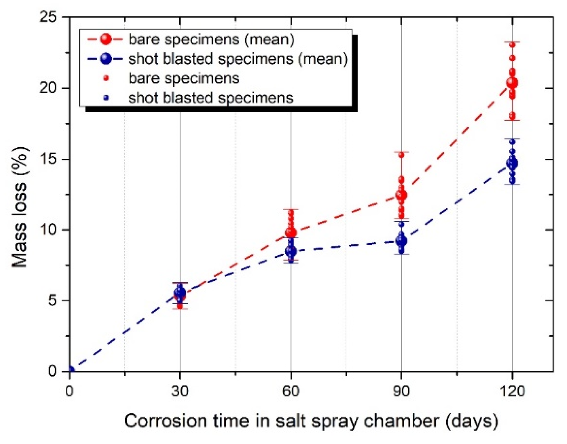
After accelerated corrosion testing was completed, the percentage mass loss of bare and shot blasted specimens was determined; the values of which are summarized in Table 6 and depicted for all cases in Figure 4.
Not surprisingly, corrosive agents act as a reductive factor for the initial mass of the reinforcing bars. Taking into account the given values of percentage mass loss, as illustrated in Figure 4, it is apparent that shot blasted specimens are less sensitive to corrosion, as they demonstrate lower mass loss values than the corresponding bare specimens. Even though both groups of specimens demonstrate a similar percentage mass loss for low levels of corrosion, in greater levels of corrosion exposure time shot blasted specimens demonstrate a lower percentage mass loss compared to the bare specimens. The shot blasted recorded 39% lower percentage mass loss values with respect to the bare, with a 120 d corrosion time, respectively. Hence, by the end of corrosion time for both groups of specimens, bare specimens recorded generally higher values of percentage mass loss toward shot blasted specimens. As it has been already highlighted from previous studies of the authors [13,14], the lower values of percentage mass loss are owed to the plastic compressive deformations of the steel surface, which excluded several corrosion diodes of the material. Hence, as also confirmed by the values in Figure 4 of the current study, the induced plastic deformation on the steel surface due to the shot blasting process provides a deterrent to the growth of surface cracks and subsequent development of corrosion paths on its external surface.
3.2. Results of Fatigue Tests
Several studies have investigated the effect of microstructure on the low cycle fatigue behavior of dual phase steel reinforcement, indicating that a high loading rate and strain amplitudes impose intense stresses, causing local detachment of ferrite and martensite layers, contrary to what occurs in single-phase steel reinforcement [30]. Fatigue damage mechanisms due to repeated loadings have also been a part of the scientific community’s interest. Stolarz and Foct [31] have investigated the onset of fatigue cracks and their further development. Experimental studies [32,33,34,35,36] have also shown that the microstructure of steel plays a key role in the formation of surface cracking under fatigue loading.
The damage of materials, due to fatigue, is directly linked to their surface conditions, which are crucial for mechanical performance since the initial fatigue crack is developed on the outer circumference and, in continuance, microcracks are propagated toward the inner part of the material. In this framework, the influence of the shot blasting method on the fatigue response of steel reinforcing bars is studied. A correlative study in terms of load bearing capacity and energy absorption ability was conducted to assess the impact of loading history on the mechanical performance of steel reinforcement; thus, low cycle fatigue tests were carried out to simulate the consequences of seismic loading on steel rebars, as already indicated by several studies [19,37]. The results are demonstrated in Table 7, Table 8 and Table 9 for each tested group of specimens, along with the corresponding mass loss, where a gradual improvement of shot blasted specimens is clearly recorded in terms of percentage mass loss, service life, dissipated energy density, and the performance of maximum stress.
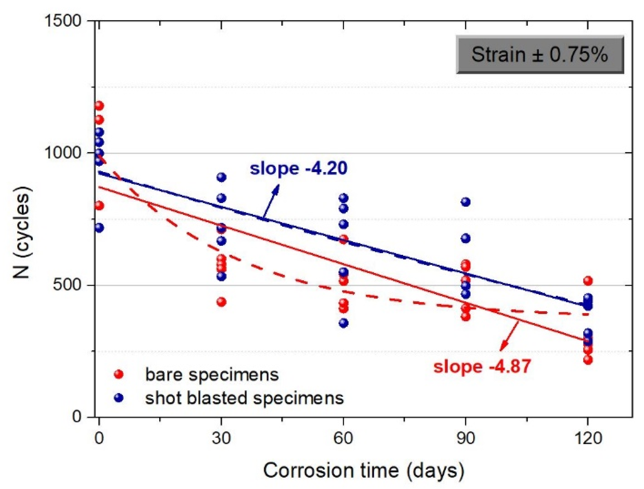
Several studies have already demonstrated that dual steel reinforcement carries defects, such as microcracks and microvoids and imperfections of the material itself, in the outer surface of the martensitic zone [38,39]. These surface microcracks widen by the interaction of chlorides, which is further boosted when corrosion occurs, paving the way for corrosive agents to act. Figure 5, Figure 6 and Figure 7 indicate the significant influence of the shot blasting process on the increase in the service life of steel reinforcing bars—a property that is particularly crucial in case of earthquakes—conveyed by their capacity to deposit energy. In other words, it is that property which is mainly used to determine the emerged damage accretion in monotonic as well as cyclic loadings. Even though the shot blasting treatment does not consist of an anticorrosive method, with the use of abrasive particles the induced plastic deformation seems to assist the closure of microcracks on the steel reinforcement surface, delaying the occurrence of corrosion. In that manner, the contribution of the shot blasting process emerges from the recorded increase in the number of cycles in cyclic loading for all cases of imposed deformation.
In the case of imposed deformation ±0.5%, Figure 5 highlights the contribution of shot blasting from the rise of number of cycles, both in reference (non-corroded) and corroded conditions. More specific, in reference conditions, number of cycles highly increased by 65% and in 120-d corroded conditions by 40%. In a similar manner, in the case of imposed deformation ±0.75%, as depicted in Figure 6, the number of cycles recorded a slight rise of 7% in reference conditions and a rise of approximately 40% and 20%, in 90-d and 120-d corroded conditions, respectively. As in the case of imposed deformation ±1.25%, the number of cycles demonstrated a slim upgrade of 3.5% in reference conditions and a rapid rise of 71% in 60-d corroded conditions as well as a rise of 17% in 120-d corroded conditions.
The abovementioned figures emphasize the similar behavior of energy density of steel reinforcement, bare and shot blasted, for all cases of imposed deformation. For the entire time of corrosion exposure, shot blasted specimens outweigh bare specimens, a fact that is directly linked with the energy dissipation capability and the response of steel reinforcement in earthquake prone areas.
In a similar manner, with an increase in the corrosion degree of steel reinforcement, the recorded maximum stress of the hysteretic curves gradually decreased, as illustrated in Figure 8. Even though in quasi-static loadings the conventional yield strain, namely 0.2%, that corresponds to yield stress equal to 500 MPa is taken into consideration, the recorded maximum stress is below that theoretical value for the cases of imposed deformation ±0.5% and ±0.75% in conditions of high loading rate (dynamic loadings). For example, in the case of imposed cyclic deformation ±0.5%, the maximum stress only reached the value of 400 MPa. When corrosion occurs, the load bearing capacity of steel reinforcement degrades even more. Moreover, by increasing the imposed deformation at ±1.25%, the drop of load bearing capacity is more intense, a fact that seems to be mainly attributed to the occurrence of the buckling phenomena.
4. Fatigue Damage Index
As often followed, damage indices are employed to rank steel grades in terms of their tensile properties. Authors have previously introduced a static damage index QD [40,41,42] to assess the mechanical response of steel grade under monotonic loading, yet, it is seen in one-dimensional terms as the purely tensile behavior of steel reinforcement. Furthermore, the presence of corrosion gave an accumulative index of mechanical performance of steel reinforcement, due to reduced tensile properties. In light of all the above, as a supplement to the research gap, a fatigue damage index is introduced to assess the response to dynamic loadings in contrast with the corresponding factors from monotonic loadings. More specifically, as is already the case for seismic-prone areas, when a structure is forced to absorb energy, a dynamic indicator factor is then introduced so as to attempt to reflect the loading history and the corresponding absorbed energy.
As already mentioned in a previous section, the mechanical performance of a material should be better determined by the compound of its strength and its capacity. Hence, the choice of a steel class based on its enhanced mechanical performance among other steel classes is not a straightforward decision. Therefore, performance indices are the appropriate tool to assist the engineering community in the optimal choice of materials, according to intended application.
In the present manuscript, an effort has been made to evaluate the performance of both types of steel bars, expressed in the form of the quality index QF Equation (2), in a similar manner as the quality indexes proposed in [40,41,42,43]. More specifically, a fatigue damage indicator, QF, is introduced, a detailed description of which follows below. The fatigue damage indicator QF is determined as:
KF is a stress factor representing the bearing capacity of steel reinforcing bars under cyclic loadings and taking into account the mechanical degradation due to corrosion. In particular, K1 factor is expressed as:
where a1 coefficient stands for the fatigue damage accumulation due to cyclic loading and a2 reflects the influence of corrosion on mechanical performance of the material.
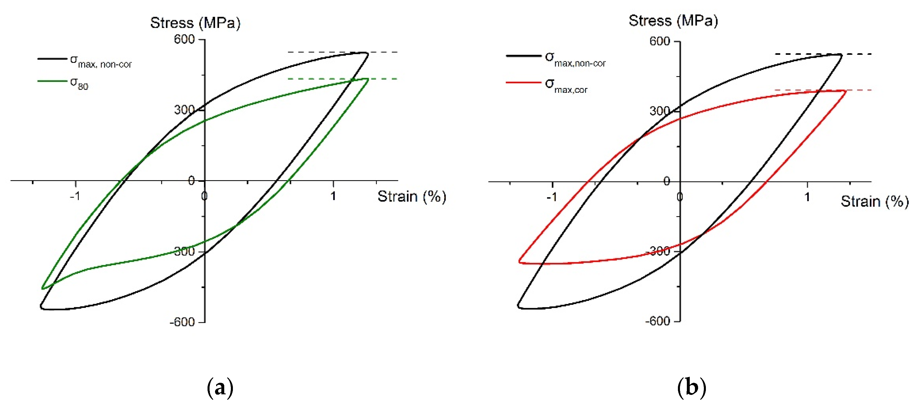
It is well known that a gradual reduction of the maximum stress per loading cycle is depicted due to fatigue. Several studies have indicated that the recorded maximum stress of steel bars in their useful lifetime under cyclic loading is reduced to 80% of their initial strength (Figure 9a). Based on this lower acceptable limit of the material, coefficient a1 reflects the reduced mechanical response of steel bars due to fatigue, and it is expressed as:
The exposure of steel in a corrosive environment causes an overall reduction of bearing capacity. In order to involve the negative consequences of corrosion on the mechanical behavior of steel bars, coefficient a2 takes into account the decrease of maximum stress of corroded bars compared to the corresponding maximum stress in non-corroded (reference) conditions (Figure 9b). Thus, coefficient a2 is expressed as:
In an attempt to determine the influence of shot blasting on steel reinforcing bars under cyclic loading, the fatigue damage indicator QF was determined for both groups of reinforcing steel bars, bare and shot blasted, for each strain amplitude. The values are summarized in Table 10 and presented in Figure 10, Figure 11 and Figure 12, wherein the fitting curves were exported so as to depict the trend of shot blasted specimens vs. bare specimens in a corrosive environment in the long term.
With regard to the obtained quality evaluation, as depicted in Figure 10, for the case of imposed deformation equal to ±0.5%, both indexes showed similar trends since when increasing the corrosion exposure time, the mechanical response and subsequently the service life of the material steadily decreased. It can be also noted that shot blasted specimens demonstrated higher levels of bearing capacity in reference conditions than bare specimens, which points to the beneficiary impact of the shot blasting process. Yet, over the corrosion exposure time, this impact tends to disappear and both groups of specimens denoted low values of energy supplies.
In continuance, in the case of a ±0.75% imposed deformation, the shot blasting process appears prominent, especially for lower corrosion exposure time, namely for a percentage mass loss of approximately 10%, where shot blasted specimens demonstrated higher values of energy reserves in respect to bare specimens. However, the harmful influence of the corrosion phenomenon can be seen in the case of a higher mass loss as both indexes tend to converge, as clearly depicted in the responding curves of Figure 11.
Moreover, in the case of ±1.25% imposed deformation, as reflected by the fitting curves in Figure 12, shot blasted specimens indicated a higher fatigue resistance in contrast to bare reinforcing bars and preserved their capacity to absorb higher energy, for the entire corrosion exposure time. More specifically, shot blasted specimens recorded higher values on the fatigue damage indicator as well as a milder decrease during the corrosion exposure time. The fatigue damage indicator, which takes into account not only the load bearing capacity but the energy supplies of material in terms of energy density and fatigue lifetime, tends to fully assess the mechanical behavior of material under repeated (cyclic) loadings.
The mechanical testing of steel reinforcing bars was imposed up to a ±1.25% deformation since buckling phenomena was expected to occur in the case of higher values of deformation, resulting in rapid damage accumulation in steel bars in both bare and shot blasted specimens. To conclude, the quality assessment of steel reinforcing bars, through the fatigue damage indicator, taking into account both strength and ductility properties, indicated the better mechanical performance of shot blasted specimens vs. bare specimens, in the long term for medium range imposed deformation.
5. Conclusions
In the present experimental study, the mechanical behavior of corroded steel reinforcing bars under fatigue conditions was examined in different imposed strain amplitudes, ±0.5%, ±0.75%, and ±1.25%, taking into account the presence or the absence of shot a blasting process. From the current results, the following outcomes were obtained:
- The loading history degraded the mechanical performance because fatigue damage accumulation reduced the recorded maximum stress and the service life for both steel categories. Accumulative damage due to fatigue loading should be considered in the seismic response of RC structures;
- Increases in the corrosion ratio and the strain amplitude significantly decreased fatigue life;
- The shot blasting process provides a time-log onset of corrosion, since compressive stresses are imposed on the external surface of steel bars, resulting in a limitation of the corrosion paths in the martensitic layer;
- Shot blasting benefits the service life of steel reinforcement, a fact that emerges from the recorded increase of service life in cyclic loading, for all cases of imposed deformation and corrosion exposure time;
- On the basis of the fatigue damage index QF, the outcomes indicated the better mechanical performance of shot blasted specimens vs. bare specimens, in the long term, for medium range imposed deformation.
Author Contributions
Methodology, M.B. and C.A.; investigation, M.B.; writing—original draft preparation, M.B.; writing—review and editing, C.A.; supervision, C.A. All authors have read and agreed to the published version of the manuscript.
Funding
This research received no external funding.
Conflicts of Interest
The authors declare no conflict of interest.
References
- Hou, B.; Li, X.; Ma, X.; Du, C.; Zhang, D.; Zheng, M.; Xu, W.; Lu, D.; Ma, F. The cost of corrosion in China. Mater. Degrad. 2017, 1, 1–10. [Google Scholar] [CrossRef]
- Association for Materials Protection and Performance (AMPP). 2021 IMPACT Canada: International Measures of Prevention, Application, and Economics of Corrosion Technologies Study for Canada; Association for Materials Protection and Performance (AMPP): Houston, TX, USA, 2021. [Google Scholar]
- Marcus, P. Pour un monde durable: Journée mondiale de la corrosion, 24 April 2020. Matér. Tech. 2020, 108, N1. [Google Scholar]
- Apostolopoulos, C.A.; Koulouris, K. Corrosion Effect on Bond Loss between steel and concrete. In Structural Integrity and Failure; Oyguc, R., Tahmasebinia, F., Eds.; IntechOpen: London, UK, 2020. [Google Scholar]
- Zhang, W.; Song, X.; Gu, X.; Li, S. Tensile and fatigue behavior of corroded rebars. Constr. Build. Mater. 2012, 34, 409–417. [Google Scholar] [CrossRef]
- Imperatore, S.; Rinaldi, Z.; Drago, C. Degradation relationships for the mechanical properties of corroded steel rebars. Constr. Build. Mater. 2017, 148, 219–230. [Google Scholar] [CrossRef]
- Caprili, S.; Salvatore, W. Mechanical performance of steel reinforcing bars in uncorroded and corroded conditions. Data Brief 2018, 18, 1677–1695. [Google Scholar] [CrossRef]
- Andisheh, K.; Scott, A.; Palermo, A.; Clucas, D. Influence of chloride corrosion on the effective mechanical properties of steel reinforcement. Struct. Infrastruct. Eng. 2019, 15, 1036–1048. [Google Scholar] [CrossRef]
- Gu, X.; Guo, H.; Zhou, B.; Zhang, W.; Jiang, C. Corrosion non-uniformity of steel bars and reliability of corroded RC beams. Eng. Struct. 2018, 167, 188–202. [Google Scholar] [CrossRef]
- Di Carlo, F.; Meda, A.; Rinaldi, Z. Numerical evaluation of the corrosion influence on the cyclic behaviour of RC columns. Eng. Struct. 2017, 153, 264–278. [Google Scholar] [CrossRef]
- Koulouris, K.; Apostolopoulos, C.A. An Experimental Study on Effects of Corrosion and Stirrups Spacing on Bond Behavior of Reinforced Concrete. Metals 2020, 10, 1327. [Google Scholar] [CrossRef]
- Hanjari, K.Z.; Coronelli, D.; Lundgren, K. Bond capacity of severely corroded bars with corroded stirrups. Mag. Concr. Res. 2011, 63, 953–968. [Google Scholar] [CrossRef] [Green Version]
- Drakakaki, A.; Apostolopoulos, C.A.; Katsaounis, A.; Bjorn, H. Corrosion resistance and mechanical characteristics of dual-phase steel B500c, after shot blasting processes. Int. J. Struct. Integr. 2017, 8, 544–564. [Google Scholar] [CrossRef]
- Drakakaki, A.; Apostolopoulos, C.A. The Mechanical Characteristics of B500c Dual Phase Steel Category, after Two Different Shot Blasting Processes. Mater. Sci. Eng. Adv. Res. Spec. 2017, 45–51. [Google Scholar] [CrossRef]
- Basdeki, M.; Apostolopoulos, C. The Effect of Shot Blasting Process on Mechanical Properties and Anti-Corrosive Behavior of Steel Reinforcement. Metals 2022, 12, 275. [Google Scholar] [CrossRef]
- Voorwald, H.J.C.; Silva, M.P.; Costa, M.Y.P.; Cioffi, M.O.H. Improvement in the fatigue strength of chromium electroplated AISI 4340 steel by shot peening Fatigue Fract. Eng. Mater. Struct. 2009, 32, 97–104. [Google Scholar] [CrossRef]
- Caprili, S.; Moersch, J.; Salvatore, W. Mechanical Performance vs. Corrosion Damage Indicators for corroded steel reinforcing bars. Adv. Mater. Sci. Eng. 2015, 2015, 739625. [Google Scholar] [CrossRef] [Green Version]
- Darwin, D.; Kahrs, J.T.; Locke, C.E., Jr. Evaluation of Corrosion Resistance of Type 304 Stainless Steel Clad Reinforcing Bars; SM Report No. 65; The University of Kansas Center for Research, Inc.: Lawrence, KS, USA, 2001; 76p. [Google Scholar]
- Sheng, G.M.; Gong, S.H. Investigation of low cycle fatigue behavior of building structural steels under earthquake loading. Acta Metall. Sin. Engl. Lett. 1997, 10, 51–55. [Google Scholar]
- Hua, J.; Fan, H.; Yan, W.; Wang, N.; Xue, X.; Huang, L. Seismic resistance of the corroded bimetallic steel bar under different strain amplitudes. Constr. Build. Mater. 2022, 319, 126088. [Google Scholar] [CrossRef]
- Ouyang, X.S.; Luo, X.Y.; Wang, J. The fatigue properties and damage of the corroded steel bars under the constant-amplitude fatigue load. J. Vibroeng. 2019, 21, 988–997. [Google Scholar] [CrossRef]
- Veerman, R.; van Breugel, K.; Koenders, E. Effect of Corrosion on the Fatigue Service-Life on Steel and Reinforced Concrete Beam. In Proceedings of the Fib Symposium, Copenhagen, Denmark, 18–20 May 2015. [Google Scholar]
- Fernandez, I.; Bairán, J.M.; Marí, A.R. Corrosion effects on the mechanical properties of reinforcing steel bars. Fatigue and σ-ε behavior. Constr. Build. Mater. 2015, 101, 772–783. [Google Scholar] [CrossRef]
- Basdeki, M.; Apostolopoulos, C. Mechanical Behavior Evaluation of Tempcore and Hybrid Reinforcing Steel Bars via a Proposed Fatigue Damage Index in Long Terms. Metals 2021, 11, 834. [Google Scholar] [CrossRef]
- Abdalla, J.A.; Hawileh, R.A.; Oudah, F.; Abdelrahman, K. Energy-based prediction of low-cycle fatigue life of BS 460B and BS B500B steel bars. Mater. Des. 2009, 30, 4405–4413. [Google Scholar] [CrossRef]
- Apostolopoulos, C.A.; Pasialis, V.P. Use of quality indices in comparison of corroded technical steel bars B500c and S500s on their mechanical performance basis. Constr. Build. Mater. 2008, 22, 2325–2334. [Google Scholar] [CrossRef]
- ISO 8501-1:2007(en); Preparation of Steel Substrates before Application of Paints and Related Products—Visual Assessment of Surface Cleanliness, Part 1: Rust Grades and Preparation Grades of Uncoated Steel Substrates and of Steel Substrates after Overall Removal of Previous Coatings. ISO: Geneva, Switzerland, 2007.
- ASTM Standard B117; Standard Practice for Operating Salt Spray (Fog) Apparatus. ASTM International: West Conshohocken, PA, USA, 2003.
- ASTM Standard G1; Standard Practice for Preparing, Cleaning, and Evaluating Corrosion Test Specimens. ASTM International: West Conshohocken, PA, USA, 2011.
- Chakraborti, P.C.; Mitra, M.K. Microstructural response on the room temperature low cycle fatigue behaviour of two high strength duplex ferrite–martensite steels and a normalised ferrite–pearlite steel. Int. J. Fatigue 2006, 28, 194–202. [Google Scholar] [CrossRef]
- Stolarz., J.; Foct, J. Specific features of two-phase alloys response to cyclic deformation. Mater. Sci. Eng. A 2001, 319–321, 501–505. [Google Scholar] [CrossRef]
- Nakajima, K.; Urabe, T.; Hosoya, Y.; Kamiishi, S.; Miyata, T.; Takeda, N. Influence of microstructural morphology and prestraining on short fatigue crack propagation in dual phase steels. ISIJ Int. 2001, 41, 298–304. [Google Scholar] [CrossRef] [Green Version]
- Rajabinezhad, M.; Bahrami, A.; Mousavinia, M.; Seyedi, S.J.; Taheri, P. Corrosion-Fatigue Failure of Gas-Turbine Blades in an Oil and Gas Production Plant. Materials 2020, 13, 900. [Google Scholar] [CrossRef] [Green Version]
- Mousavinia, M.; Bahrami, A.; Rafiaei, S.M.; Rajabinezhad, M.; Taghian, M.; Seyedi, S.J. Root cause analysis of failure of bolts in the low pressure section of a gas turbine in an oil and gas production plant. Eng. Fail. Anal. 2020, 115, 104675. [Google Scholar] [CrossRef]
- Rivaz, A.; Mousavi Anijdan, S.H.; Moazami-Goudarzi, M.; Nazari Ghohroudi, A.; Jafarian, H.R. Damage causes and failure analysis of a steam turbine blade made of martensitic stainless steel after 72,000 h of working. Eng. Fail. Anal. 2022, 131, 105801. [Google Scholar] [CrossRef]
- Rivaz, A.; Mousavi Anijdan, S.H.; Moazami-Goudarzi, M. Failure analysis and damage causes of a steam turbine blade of 410 martensitic stainless steel after 165,000 h of working. Eng. Fail. Anal. 2020, 113, 104557. [Google Scholar] [CrossRef]
- Apostolopoulos, C.A.; Konstantopoulos, G.; Koulouris, K. Seismic resistance prediction of corroded S400 (BSt420) reinforcing bars. Int. J. Struct. Integr. 2018, 9, 119–138. [Google Scholar] [CrossRef]
- Kelestemur, O.; Yıldız, S. Effect of various dual-phase heat treatments on the corrosion behavior of reinforcing steel used in the reinforced concrete structures. Constr. Build. Mater. 2009, 23, 78–84. [Google Scholar] [CrossRef] [Green Version]
- Apostolopoulos, C.A.; Drakakaki, A.; Apostolopoulos, A.; Matikas, T.; Rudskoi, A.I.; Kodzhaspirov, G. Characteristic defects Corrosion Damage and Mechanical Behavior of Dual phase rebar. Mater. Phys. Mech. 2017, 30, 1–19. [Google Scholar]
- Alexopoulos, N.D.; Apostolopoulos, C.A.; Papadopoulos, M.P.; Pantelakis, S.G. Mechanical performance of BStIV grade steel bars with regard to the long-term material degradation due to corrosion damage. Constr. Build. Mater. 2007, 21, 1362–1369. [Google Scholar] [CrossRef]
- Papadopoulos, M.P.; Apostolopoulos, C.A.; Alexopoulos, N.D.; Pantelakis, S.G. Effect of salt spray corrosion exposure on the mechanical performance of different technical class reinforcing steel bars. Mater. Des. 2007, 28, 2318–2328. [Google Scholar] [CrossRef]
- Alexopoulos, N.D.; Pantelakis, S.G. A new quality index for characterizing aluminum cast alloys with regard to aircraft structure design requirements. Metall. Mater. Trans. A 2004, 35, 301–308. [Google Scholar] [CrossRef]
- Apostolopoulos, C.A.; Koulouris, K.; Basdeki, M. Damage Parameters of Rebars in Marine Environment and Fatigue Life. In Proceedings of the International Conference on Sustainable Materials, Systems and Structures (SMSS 2019), Rovinj, Croatia, 20–22 March 2019. [Google Scholar]
Figure 1.
Plastic deformation Ag to maximum force, in shot blasted specimens, in non-corroded conditions for different abrasive material in dual-phase steel.
Figure 1.
Plastic deformation Ag to maximum force, in shot blasted specimens, in non-corroded conditions for different abrasive material in dual-phase steel.

Figure 2.
Steel (B500c) reinforcing bars before (left) and after (right) shot blasting process.

Figure 3.
(a) View of salt spray chamber in laboratory and (b) view of the tested steel bars in the salt spray chamber.
Figure 3.
(a) View of salt spray chamber in laboratory and (b) view of the tested steel bars in the salt spray chamber.

Figure 4.
Mass loss vs. corrosion time for fatigue specimens.

Figure 5.
Fitting curves of number of cycles in function with corrosion time for imposed deformation ±0.5%.
Figure 5.
Fitting curves of number of cycles in function with corrosion time for imposed deformation ±0.5%.

Figure 6.
Fitting curves of number of cycles in function with corrosion time for imposed deformation ±0.75%.
Figure 6.
Fitting curves of number of cycles in function with corrosion time for imposed deformation ±0.75%.

Figure 7.
Fitting curves of number of cycles in function with corrosion time for imposed deformation ±1.25%.
Figure 7.
Fitting curves of number of cycles in function with corrosion time for imposed deformation ±1.25%.

Figure 8.
Relation between maximum stress and corrosion ratio for all cases of imposed deformation.

Figure 9.
Definition of (a) maximum stress σmax, non-cor and maximum stress at the lower limit of 80% of the maximum loads σ80 of the non-corroded steel bar and (b) maximum stress σmax,cor of the corroded steel bar.
Figure 9.
Definition of (a) maximum stress σmax, non-cor and maximum stress at the lower limit of 80% of the maximum loads σ80 of the non-corroded steel bar and (b) maximum stress σmax,cor of the corroded steel bar.

Figure 10.
Extracted fitting curves of fatigue damage indicator QF as a function of corrosion exposure for imposed deformation ±0.5% for both groups of specimens.
Figure 10.
Extracted fitting curves of fatigue damage indicator QF as a function of corrosion exposure for imposed deformation ±0.5% for both groups of specimens.

Figure 11.
Extracted fitting curves of fatigue damage indicator QF as a function of corrosion exposure for imposed deformation ±0.75% for both groups of specimens.
Figure 11.
Extracted fitting curves of fatigue damage indicator QF as a function of corrosion exposure for imposed deformation ±0.75% for both groups of specimens.

Figure 12.
Extracted fitting curves of fatigue damage indicator QF as a function of corrosion exposure for imposed deformation ±1.25% for both groups of specimens.
Figure 12.
Extracted fitting curves of fatigue damage indicator QF as a function of corrosion exposure for imposed deformation ±1.25% for both groups of specimens.

Table 1.
Chemical composition of B500c class.
| C (%) | S (%) | P (%) | Cu (%) | N (%) | Ceq (%) |
|---|---|---|---|---|---|
| 0.24 | 0.055 | 0.055 | 0.85 | 0.013 | 0.52 |
Table 2.
Visual standards for grades of cleanliness.
| Description | International ISO 8501 | American SSPC-SP |
|---|---|---|
| White metal | Sa3 | SSPC SP5 |
| Nearly white metal | Sa2.5 | SSPC SP10 |
| Commercial blast | Sa2 | SSPC SP6 |
| Brush-off blast | Sa1 | SSPC SP7 |
Table 5.
Test matrix for bare and shot blasted rebars.
| Corrosion Time | Corrosion Tests | Fatigue Tests | |||||
|---|---|---|---|---|---|---|---|
| Bare | Shot Blasted | ||||||
| ±0.5% | ±0.75% | ±1.25% | ±0.5% | ±0.75% | ±1.25% | ||
| Reference | - | 5 | 5 | 5 | 5 | 5 | 5 |
| 30 d | 30 | 5 | 5 | 5 | 5 | 5 | 5 |
| 60 d | 30 | 5 | 5 | 5 | 5 | 5 | 5 |
| 90 d | 30 | 5 | 5 | 5 | 5 | 5 | 5 |
| 120 d | 30 | 5 | 5 | 5 | 5 | 5 | 5 |
| 75 | 75 | ||||||
| Total | 120 | 150 | |||||
Table 6.
Percentage mass loss toward corrosion time for fatigue specimens.
| Corrosion Time (Days) | Mass Loss (%) | |
|---|---|---|
| Bare | Shot Blasted | |
| 0 | - | - |
| 30 | 5.3 | 5.6 |
| 60 | 9.8 | 8.5 |
| 90 | 12.5 | 9.2 |
| 120 | 20.4 | 14.7 |
Table 7.
Results of LCF tests with free length 6Ø conducted on bare and shot blasted specimens (in non-corroded and corroded conditions) for imposed deformation ±0.5%.
Table 7.
Results of LCF tests with free length 6Ø conducted on bare and shot blasted specimens (in non-corroded and corroded conditions) for imposed deformation ±0.5%.
| Strain | Type of Specimens | Corrosion Time | Mass Loss (%) | Cycles (N) | Energy Density Wd (MPa) | σmax (MPa) |
|---|---|---|---|---|---|---|
| ±0.5% | bare | 0 | - | 8410 | 5390.6 | 491.57 |
| 30 | 4.8 | 7317 | 3171.3 | 487.65 | ||
| 60 | 9.6 | 3720 | 1878.9 | 457.08 | ||
| 90 | 13.3 | 2343 | 1334.0 | 420.60 | ||
| 120 | 20.7 | 1393 | 1060.3 | 415.68 | ||
| Shot blasted | 0 | - | 13,857 | 7118.5 | 486.48 | |
| 30 | 5.2 | 6832 | 3528.7 | 477.33 | ||
| 60 | 8.6 | 3868 | 2143.8 | 465.61 | ||
| 90 | 9.1 | 5064 | 2498.5 | 463.72 | ||
| 120 | 14.8 | 1955 | 1299.8 | 449.59 |
Table 8.
Results of LCF tests with free length 6Ø conducted on bare and shot blasted specimens (in non-corroded and corroded conditions) for imposed deformation ± 0.75%.
Table 8.
Results of LCF tests with free length 6Ø conducted on bare and shot blasted specimens (in non-corroded and corroded conditions) for imposed deformation ± 0.75%.
| Strain | Type of Specimens | Corrosion Time | Mass Loss (%) | Cycles (N) | Energy Density Wd (MPa) | σmax (MPa) |
|---|---|---|---|---|---|---|
| ±0.75% | bare | 0 | - | 956 | 2820.0 | 491.57 |
| 30 | 5.7 | 573 | 1634.4 | 487.65 | ||
| 60 | 10.5 | 541 | 1371.7 | 457.08 | ||
| 90 | 12.2 | 438 | 1326.7 | 420.60 | ||
| 120 | 20.4 | 323 | 904.7 | 415.68 | ||
| Shot blasted | 0 | - | 1023 | 2727.5 | 486.48 | |
| 30 | 5.7 | 732 | 2091.5 | 477.33 | ||
| 60 | 8.2 | 652 | 1777.4 | 465.61 | ||
| 90 | 9.5 | 627 | 1733.8 | 463.72 | ||
| 120 | 14.9 | 384 | 1082.3 | 449.59 |
Table 9.
Results of LCF tests with free length 6Ø conducted on bare and shot blasted specimens (in non-corroded and corroded conditions) for imposed deformation ±1.25%.
Table 9.
Results of LCF tests with free length 6Ø conducted on bare and shot blasted specimens (in non-corroded and corroded conditions) for imposed deformation ±1.25%.
| Strain | Type of Specimens | Corrosion Time | Mass Loss (%) | Cycles (N) | Energy Density Wd (MPa) | σmax (MPa) |
|---|---|---|---|---|---|---|
| ±1.25% | Bare | 0 | - | 172 | 1649.3 | 575.14 |
| 30 | 5.6 | 155 | 1395.0 | 547.19 | ||
| 60 | 9.3 | 123 | 1041.6 | 525.11 | ||
| 90 | 11.9 | 105 | 883.9 | 484.37 | ||
| 120 | 20.0 | 113 | 930.2 | 433.01 | ||
| Shot blasted | 0 | - | 178 | 1659.9 | 568.02 | |
| 30 | 5.7 | 168 | 1510.4 | 552.46 | ||
| 60 | 8.7 | 211 | 1192.0 | 522.58 | ||
| 90 | 9.1 | 155 | 1331.7 | 531.84 | ||
| 120 | 14.4 | 132 | 1093.1 | 472.27 |
Table 10.
Values of fatigue damage indicator QF on bare and shot blasted specimens (in non-corroded and corroded conditions).
Table 10.
Values of fatigue damage indicator QF on bare and shot blasted specimens (in non-corroded and corroded conditions).
| Corrosion Time (Days) | QF (MPa) | |||||
|---|---|---|---|---|---|---|
| Bare | Shot Blasted | |||||
| ±0.5% | ±0.75% | ±1.25% | ±0.5% | ±0.75% | ±1.25% | |
| 0 | 5390.60 | 2819.99 | 1649.29 | 7118.46 | 2727.48 | 1695.92 |
| 30 | 939.37 | 181.86 | 650.11 | 652.01 | 639.31 | 844.60 |
| 60 | 198.13 | 149.88 | 201.32 | 121.06 | 439.27 | 514.68 |
| 90 | 69.95 | 157.53 | 165.19 | 232.98 | 251.99 | 500.37 |
| 120 | 18.58 | 16.54 | 149.05 | 20.90 | 30.43 | 304.18 |
Publisher’s Note: MDPI stays neutral with regard to jurisdictional claims in published maps and institutional affiliations. |
© 2022 by the authors. Licensee MDPI, Basel, Switzerland. This article is an open access article distributed under the terms and conditions of the Creative Commons Attribution (CC BY) license (https://creativecommons.org/licenses/by/4.0/).
Share and Cite
MDPI and ACS Style
Basdeki, M.; Apostolopoulos, C. The Effect of the Shot Blasting Process on the Dynamic Response of Steel Reinforcement. Metals 2022, 12, 1048. https://doi.org/10.3390/met12061048
AMA Style
Basdeki M, Apostolopoulos C. The Effect of the Shot Blasting Process on the Dynamic Response of Steel Reinforcement. Metals. 2022; 12(6):1048. https://doi.org/10.3390/met12061048
Chicago/Turabian StyleBasdeki, Maria, and Charis Apostolopoulos. 2022. "The Effect of the Shot Blasting Process on the Dynamic Response of Steel Reinforcement" Metals 12, no. 6: 1048. https://doi.org/10.3390/met12061048
Note that from the first issue of 2016, this journal uses article numbers instead of page numbers. See further details here.