Review

A Review of Electrode Manufacturing Methods for Electrical Discharge Machining: Current Status and Future Perspectives for Surface Alloying

1
Mechanical Engineering, Universiti Teknologi PETRONAS, Bandar Seri Iskandar 32610, Perak Darul Ridzuan, Malaysia
2
Mechanical Engineering, Bayero University, Kano 700006, Nigeria
3
School of Mechanical and Mining Engineering, The University of Queensland, St. Lucia, QLD 4072, Australia
*
Author to whom correspondence should be addressed.
Machines 2023, 11(9), 906; https://doi.org/10.3390/machines11090906
Submission received: 22 June 2023 / Revised: 18 July 2023 / Accepted: 21 July 2023 / Published: 12 September 2023

Abstract

:
In electrical discharge machining (EDM), the tool electrode is one of the substantial components of the system, and it ensures the success or failure of the EDM process. The electrode’s role is to conduct electrical charges and erode the workpiece to the desired shape. Different electrode materials have different impacts on machining. Certain electrode materials remove metal quickly but wear out rapidly, while others degrade slowly but the material removal is too slow. The choice of the electrode has an influence on both the mechanical properties, such as metal removal rate (MRR), wear rate, surface finish, surface modification and machinability, and the electrical properties, such as sparking initiation, time lag, gap contamination and process stability. There are factors to consider when fabricating an electrode, which include the type of workpiece materials, the metallurgical alloying of the materials, the choice of fabrication techniques, the intended use of the electrode, and material cost. Considerable challenges in EDM electrode fabrication have been reported, which include excessive tool wear for green compact electrodes, high toughness for sintered electrodes, and poor rigidity for additively manufactured electrodes. To address these issues, researchers have explored different manufacturing methods, such as casting, conventional machining, electrodeposition, powder metallurgy and additive manufacturing. In this paper, the various techniques attempted and adopted in EDM electrode manufacturing are analyzed and discussed. This paper also sought to give insight into EDM, its various forms, the dielectric fluid’s properties, EDM electrode’s size and shape, the effects of the electrode on the EDM process, material removal, electrode wear, present technologies for electrode fabrication, and the limitations of these technologies. Finally, directions for future research are highlighted.

1. Introduction

Electrical discharge machining (EDM) is an electro-thermal material erosion process that primarily converts electrical energy into thermal energy through an ongoing cycle of discontinuous electrical discharges between the tool and the workpiece, which are submerged in a dielectric medium. The thermal energy develops a plasma channel between the anode and the cathode at an exceedingly elevated temperature ranging from 8000 °C to up to 20,000 °C and at a pressure of 20 MPa [1]. During the machining process, the materials melt and evaporate in the presence of the dielectric, which fulfills the requirement for cooling, insulation and the flushing of microscopic debris [2,3]. The EDM method possesses dominance over the subtractive machining approach because of its ability to develop geometrically complex shapes and for the efficient machining of ductile, hard and brittle materials because it does not establish a direct contact between the workpiece and the tool, resulting in the omission of chips formation and interactive and vibrational stresses during machining [4,5]. A schematic illustration of EDM is shown in Figure 1.
Notable drawbacks, such as the low material removal rate, inadequate surface quality, long processing time, high cost and restriction to the machining of conductive materials only, have mitigated the employment of EDM [6]. However, EDM has been effectively used in manufacturing mold, dies and components for the automotive, nuclear, aerospace and biomedical industries due to component precision rather than factors of enhanced productivity and surface finish [7,8]. Electrical discharge machines have a variety of applications, such as die-sinker EDM, electrical discharge grinding (EDG), multi-lead and multi-electrode EDM, wire cut EDM (multi-electrode and multi-workpiece), micro-hole EDM drilling and electrical discharge texturing (EDT). Electrical discharge grinding differs from the typical die-sinker EDM since the electrode is stationary as the workpiece travels beneath the revolving electrode [9]. In multi-electrode machining, numerous electrodes are employed instead of using just one electrode. In the multi-electrode approach, only one spark occurs at a time, which can lengthen the spark off time and enhance debris removal. The effectiveness of sparking will rise since the subsequent spark will take place in a space free of debris [10]. The performance of all types of EDM techniques depends on process parameters. Figure 2 depicts the relationship between EDM input parameters and output parameters.
A dielectric, typically kerosene or mineral oil, is typically used to protect both the electrode and the workpiece from damage during machining. The sparking gap is the minimum distance between the tool electrode and the workpiece, which must always be maintained. The potential difference between the electrode and the workpiece can reach around 170 volts when the electrode is brought to within a few millimeters of the closest location between them. The open-circuit voltage refers to this level of potential difference. The dielectric fluid undergoes an ionization transition from the insulator to the conductor when subjected to this waveform voltage at a distance equal to 0.025 mm (about 0.00098 in) [12].
Wire cut EDM is used for contour cutting by discharging sparks from a moving wire against an electrically conducting workpiece as it moves along a path. During its sole use, a tensioned wire is guided from a take-off spool to a take-up spool to create a precise narrow slit. The cutting path is calculated by numerically controlling the horizontal motion of the worktable. To prevent wire breakage from insufficient dielectric flushing, flushing nozzles are placed as near together as possible. Because of its low viscosity, deionized water is the dielectric that is usually used, but wire cut EDM occasionally employs dielectric fluids based on ethylene glycol-based chemicals and lubricants [13]. A tiny hole can be drilled via electrical discharge micro-drilling. The high wear resistance of the pure tungsten wire makes it a popular electrode material, but tungsten carbide is also a viable option for creating holes ranging between 40–200 μm in size. To better flush away residues, the electrode is frequently rotated during cutting [14].
This study presents an overview of EDM methods and their applications, as researched in a myriad of studies. EDM has been used for mold and die production, surface alloying, surface modification, and the development of micro-products, biomedical implants and components for the aerospace, automotive and nuclear industries [15]. However, recent research has laid more emphasis on the application of EDM in developing biomedical implants for better corrosion resistance, osseointegration and biocompatibility. It is worth noting that from the extensive review so far, there is no evidence of studies on the application of EDM for the oil and gas industry, particularly for corrosion control. This could be achieved through powder-mixed electrical discharge machining (PMEDM) or through electrode erosion, such as electrode discharge coating (EDC). This study’s objective is to provide insight into the EDM electrode for surface alloying and surface coating. The remaining parts of the paper are structured as follows: the methodology of the review process is presented in Section 2, while a review of the evolution of EDM based on its applications as well as a review of gap-active EDM, EDM dielectric fluid, additive-mixed EDM, EDM electrodes, electrode materials and the effects of powder metallurgy electrodes on the EDM process are elaborated in Section 3Section 4 presents the primary outcomes of EDM electrode manufacturing methods. The conclusion and the direction for future studies are discussed in Section 5.

2. Methodology

This research focused on previously published research works that provide knowledge on prospective applications of the EDM electrode and demonstrate academic interest in the most significant trends, influential works, and directions for future research. Thus, the authors of the present review paper attempted to create a centralized resource for improving the body of research on this contemporary topic. This project’s scope spans the years 1996 to 2023. The sources for research materials were Google Scholar, Web of Science, Science Direct, Scopus and ResearchGate. Because there is an increasing need for research on the EDM electrode, this research review was basically based on the evaluation of approaches in a variety of high-quality journal articles and conference papers that are all closely related to the concepts and applications of the EDM electrode to achieve the study’s objectives. The articles reviewed were sourced from various journals, such as Materials Today (Elsevier) [16], Precision Engineering (Elsevier) [17], the Journal of Engineering Manufacture (SAGE) [18], Heliyon (Elsevier) [19], Micromachines (MDPI) [20], Materials and Manufacturing Processes (Taylor & Francis Inc.) [21] and Materials (MDPI) [22]. Due to the breadth and diversity of these approaches, it was determined that the papers were dispersed across a variety of sources. The findings of the literature review in this study are presented in Section 3.

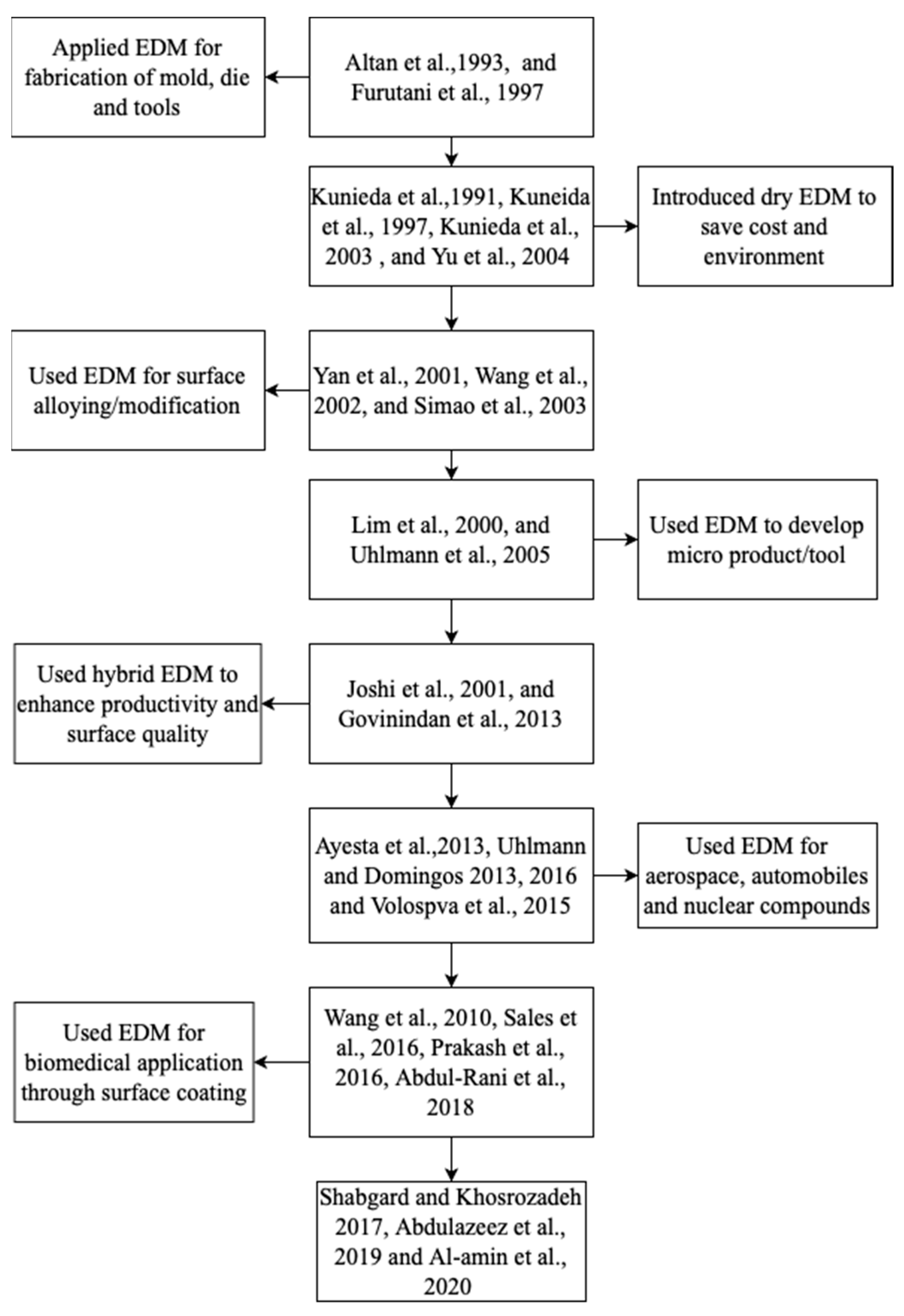
3. Evolution of EDM Applications

EDM has been generally employed for the fabrication of cutting tools, molds and dies for decades [23]. Studies have shown that material migration occurs between the workpiece, the electrode and the dielectric fluid additive during the process [24,25], and therefore, the EDM method is also regarded as a surface modification/alloying technique. EDM has risen to prominence as one of the most often-utilized unconventional machining methods, and hence, the idea of employing EDM to modify workpieces has been explored in recent years. There are two key reasons why EDM is a viable candidate for this type of surface modification: the first is the unavoidable electrode wear, and the other is the recast layer or white layer deposition [25,26].
Dry (air) EDM has been advanced as an alternative to the oil dielectric fluid and is widely employed in the production of cutting tools, molds and dies [7,27]. Dry EDM was developed to lessen the expenses associated with the oil dielectric fluid and the negative effects on the environment. For 3D machining, Kunieda et al. [28] demonstrated that EDM is conceivable in a gas medium. Reduced or eliminated wear on the tool electrode and enhanced surface quality are both possible with dry EDM [29]. The presence of material transfer between the electrode and the dielectric fluid additive during EDM suggests that the process can be used for surface modification/alloying as well as material removal [30]. As the market for miniaturized goods grows, many industries are increasingly using electrical discharge machining to produce microcavities with high appearance ratios [31], as well as micro-molds, micro-dies [32] and rotating micro-components [33]. When a magnetic field is added to dry EDM, the quality of the machined surface has been reported to improve, and production increases significantly [34,35]. Since EDM can produce a polished surface finish with no additional procedure, it has found widespread use in the production of components for the automotive, aerospace and nuclear industries [36,37]. Because of its capacity to create a nano-porous surface that is both biocompatible and exceptionally durable, EDM has recently gained traction in the biomedical sector [38]. Peng et al. [39] offered data demonstrating the formation of a nano-porous biocompatible layer on the surface of an electrical discharge machine. Ti. Sales et al. [40] and Shabgard and Khosrozadeh [41] used calcium and carbon nanotubes, respectively, in a dielectric fluid to modify the surface of Ti-6Al-4V. They also employed PMEDM using zinc powder to improve the surface of a biodegradable magnesium alloy. Abdul-Rani et al. [42,43] employed nano-aluminum in PMEDM to modify a high-grade Ti alloy for biomedical applications. Abdu Aliyu et al. [24,27,44] coated the surface of Zr with hydroxyapatite for biomedical applications. Al-Amin et al. [45] alloyed the surface of 316L steel using a novel hybrid of Hydroxyapatite/carbon nanotubes (HA/CNT) for biomedical applications. Figure 3 provides a summary of how the EDM process has evolved according to its various applications. The concept of using the additive mix will be discussed in the coming subsections.
Gap-active electrical discharge machining (GA-EDM) is a new technique that uses an electrode-retraction system, which is sensitive to the gap between the electrode and the workpiece and adjusts automatically. This system is based on the fundamentals of a parallel-plate photoelectric cell with two dielectric fluids, where the surfaces between the electrodes function as the plates. Kerosene has been employed as the primary dielectric material, while a more viscous layer of bio-oil has been used to serve as the secondary dielectric material [46,47]. The tool arrangement is servo-controlled and synchronized using the flushing mechanism, which enhances the equivalent capacitance of the plasma column and allows for the dissipation of copious amounts of energy during the discharging cycle. This process melts most of the solidification defects and improves the entire texture of the surface compared with normal EDM. Figure 4b depicts the schematic diagram of GA-EDM. Additionally, the study in [42] suggested that the viscous layer of the secondary fluid provided an adhesive grip and a gradual heat rejection process, which helped to prevent the formation of micro-cracks on the workpiece. The electrode retraction system ensures an adequate passage for flushing, which helps to expel debris and control heat dissipation. Das et al. [54] suggested in their study that the gap-active mechanism produced a surface with a better texture and fewer indentations, solidified agglomerates and cracks compared with normal EDM. The use of the secondary dielectric also increased the carbon content in the dielectric and resulted in a surface that was 10–14% harder than that produced using normal EDM. Kerosene and bio-oil were used as the primary and secondary dielectric fluids, respectively, and the result of the study suggested an increase in the MRR, as shown in Figure 5. It has been suggested by researchers that bio-oils are good candidates as the secondary dielectric fluid [55,56]. The properties of the primary and secondary dielectric fluids used are shown in Table 1.

3.1. EDM’s Dielectric Fluid

The dielectric fluid is vital in EDM because it insulates the electrode, provides high pressure to clear the collapsed plasma channel or debris, cools the molten metal, and washes away the solidified particles that have been previously flushed away. Specific types of working fluids are designed for use in some EDM devices [57]. A suitable dielectric fluid must be chosen; however, in certain cases, sinking EDM commonly utilizes mineral lubricants, whereas deionized water is typically used in micro-EDM and wire cut EDM [58,59]. It is important to keep in mind that these fluids’ potential uses are not without their drawbacks. Studies have suggested that deionized water, when used as the dielectric in EDM, increases the corrosion rate of the surface of the implanted material, while carbons released during the combustion of oil-based dielectric fluids react with the alloying elements of the workpiece and the tool electrode to form an extremely hard carbide layer on the substrate [55,60]. Water-based dielectric fluids are predicted to replace oil-based fluids soon, as described by [55,61]. Dry and semi-dry EDM have been developed to mitigate the negative impacts of dielectric fluids on human health and the environment [25,62]. The method involves the use of gases, such as oxygen and nitrogen, as the EDM working fluid [63]. Das et al. used neem oil as the dielectric fluid in their comparative study and suggested that neem oil was 22% better than kerosene oil in terms of MRR and 17% better in terms of surface roughness (SR) [64,65]. It was also concluded in another comparative study on canola oil, neem oil and Jatropha oil as dielectric fluids that the bio-based oils outperformed kerosene in terms of MRR and SR [66,67]. It is suggested by [1] that the laws of energy distribution, field-assisted machining, dry EDM machining and the use of vegetable dielectric reduces the environmental and health concerns posed by the conventional EDM dielectric fluids [68]. A dielectric fluid’s electrical conductivity increases due to debris that have not been drained out of the gap [69,70]. As a result, the process is hard to regulate, leading to unsatisfactory machining results. That is why it is so important to flush the machining gap, even if it is a point of contention [71,72]. Different flushing methods are shown in Figure 6. Several factors have to be considered when selecting a dielectric fluid for a particular purpose, as presented in Table 2. Also, dielectric fluids have several requirements, which are presented in Table 3. Although deionized water seems to meet several requirements, it has been suggested that water accelerates corrosion and hence is not desirable for biomedical applications [73,74].

3.2. Additive-Mixed EDM

Additive-mixed EDM (AM-EDM) refers to EDM with the addition of a substance in the dielectric medium. In industries where an important level of surface tolerance is required, such as the automotive, aerospace and medical industries, conventional EDM using deionized water, oil-based or mineral oil as the dielectric fluid for EDM is inadequate to achieve the desired surface texture [59,76]. There are three categories of substances that are introduced in AM-EDM. Solid additives, such as metal particles, can be used in EDM, while liquid surfactants, urea solutions and calcium aqueous solutions are examples of liquid and gaseous additives [23]. The EDM process can be stabilized, and EDM efficacy and the quality of the machined surface can be improved by adding additives to the dielectric fluid [77,78]. The type, size, concentration and quality of a particular additive influence the performance of the EDM process, the tool life and the surface quality of the machined component [22,45,79,80,81].

3.2.1. Solid Additive-Mixed PMED

This refers to the addition of solid metallic or ceramic powders in the dielectric fluid of PMEDM. The addition of powder particles stabilizes the general EDM process and improves machining efficiency by increasing the discharge gap and decreasing the insulating strength of the dielectric fluid [22,24]. Figure 7 shows the diagram of solid-additive-mixed PMEDM of different powders as indicated in different colours depicted in the figure. The addition of metallic powders of distinct types have been reported in multiple studies. To increase fatigue life and recast layer thickness, Al-Khazraji et al. [82] suggested the incorporation of SiC micro-size powder in the dielectric. The surface roughness and morphology of AISI D2 steel were significantly improved by the inclusion of Ti nano powder in the dielectric fluid, according to a study by [83]. Additionally, Ref. [84] found that adding chromium powder to PMEDM significantly improved the surface quality and hardness of the machined tool steel. Singh et al. [85] investigated the effects of EDM parameters by comparing the results obtained with and without the incorporation of tungsten powder in the dielectric fluid. After undergoing PMEDM, the recast layer thickness of SiC was reduced, and the surface quality was improved. In another commendable assessment of micro- and nano-size powder particles, Bajaj et al. [16] suggested that nanoparticles provided better surface quality and improved MRR than did microparticles. Carbon nanotubes have been also found to be a solid additive that significantly enhances surface quality, MRR and tool wear ratio (TWR) in the PMEDM of various materials [86,87].

3.2.2. Gaseous Additive-Mixed PMEDM

Dry EDM employs a gaseous substance, such as nitrogen, argon or oxygen, instead of a liquid dielectric fluid to mitigate environmental and health hazards as well as the cost of the oil-based fluids [38]. The choice of gas has a significant impact on both the material removal rate and the surface quality. EDM with an oxygen-containing dielectric fluid leads to wider and deeper craters, and high-velocity air is usually blown into the discharge gap to clear debris and ensure uninterrupted cutting. Discontinuous recast layers and a small heat-affected zone have been shown to improve surface quality the most. Oxygen was employed as the working fluid by Yu et al. [24] when milling cemented carbide. The research suggested that the technique was superior to wet machining in terms of time and money spent. Dhakar and Dvivedi [55] discovered that in the machining of high-speed steel, the use of gas in near-dry EDM (a combination of air and liquid) resulted in a smoother surface finish, less tool wear and a thinner deposited layer. With dry EDM, the debris in the machining gap is easily cleared, preventing them from reattaching to the electrode. The surface characteristics of electrical discharge-machined samples using various gases are illustrated in Figure 8 below.
In a similar research work by Saha [88], nitrogen gas was used as the dielectric fluid to modify the surfaces of Ti50Ni50 and Ti50Ni49.5Cr0.5, and the study suggested that TiN and CrN nanostructures were discovered, providing an extremely hard and adhering surface. The diagram of oxygen-mixed EDM is depicted in Figure 9.
It is worth noting that despite the numerous advantages presented by PMEDM, it has some drawbacks, such as the high disposal cost of the EDM dielectric oil after use, the complicated requirements for set-up modification, powder agglomeration, etc.

3.2.3. Liquid Additive-Mixed PMEDM

To improve the efficacy of EDM and enhance the surface characteristics of the machined surface, either pure liquid or liquids combined with powder particles can be used as the dielectric fluid [29]. The addition of a surfactant in the dielectric improves EDM performance by reducing agglomeration and increasing the conductivity of the powder particles, resulting in decreased surface roughness and the deposited layer’s thickness [19,89]. Yan et al. [64] investigated the effects of adding a urea solution to the dielectric (deionized water) in the EDM of titanium and found that, as the urea-based dielectric fluid deteriorated, nitrogen was released and deposited on the surfaces of the electrode and the workpiece. Another study suggested that the addition of a surfactant not only reduced surface roughness and improved the material removal rate, but it also reduced the abnormal discharge conditions, thereby improving the efficiency of the machining process [90]. This is evident in the results showing material removal rate against surfactant concentration, and surface roughness against surfactant concentration shown in Figure 10 and Figure 11 respectively. In the next subsection, the electrode, which is a critical component of EDM, is discussed.

3.3. EDM Electrode

The material used as the electrode in EDM can either be machined from conductive metals or manufactured through various methods. Without a doubt, the qualities of the electrode material will have an impact on surface tolerance, the machining process and surface roughness [50]. With excessive wear on the electrode, a square hole, for instance, may end up looking more like an elliptical hole. Since high-energy ions from the plasma will impinge on the electrode, the first limitation in material choice is that the electrode should not have excessive wear. There is no single electrode material that meets all the requirements [91]. However, the performance of the electrode depends on many factors, as depicted in Figure 12.
However, in general, an electrode material should have the following characteristics, with the caveat that these requirements may change depending on the electrode’s intended use [92,93]:
  • Despite being pummeled by the plasma’s high-energy ions, the electrode should not wear out too quickly, and a rise in temperature should not cause any melting or evaporation.
  • Higher electrical conductivity (lower resistance) is needed to improve cutting efficiency. Otherwise, cold-emission electrons will not easily leave the electrode’s surface, causing bulk heating.
  • When choosing tool properties, the electrode’s melting point should be considered. A higher melting point means an improved electrode wear ratio (electrode wear/workpiece erosion). As EDM uses a lot of tools, the electrode should be cheap.
  • The electrode should exhibit excellent thermal conductivity so that heat may be removed from the heat-affected zone. A high conductivity reduces the rise in local temperature, which benefits the electrode material’s mechanical properties.
  • It is important that the electrode material can be easily machined too. Electrodes can be more challenging to produce because of issues with machinability, stability, burr creation and burr removal. Die-sinker EDM uses a rotary tool to create a negative of the tool geometry. Since the desired form must be established on the tool, it is imperative that the latter be amenable to normal machining methods.
  • Density is also important for the electrode material, as a lower dimensional loss is achieved with higher density. The density of a material is crucial for surface tolerance since higher density results in less dimensional loss for a given amount of weight loss. Hence, it is preferable if the dimensional loss deviation is as small as possible.

EDM Electrode Materials

The features that characterize the appropriateness and suitability of electrode materials are as follows: the electrode should be able to accomplish the maximum material erosion rate, have a low tool wear rate, and be made inexpensively into the required shape and dimension [88]. Brass, copper, copper alloys, copper tungsten, graphite, molybdenum, silver tungsten, tellurium copper and others are some of the various materials used as electrodes [94,95]. Various materials are compared based on economic and technological factors in Table 4.
EDM performance is determined by the geometrical arrangement because the machining creates a mirror of the tool electrode on the workpiece. There is always a minimum clearance between the work cavity to be formed and the electrode because the magnitude of clearance and the material removal rate changes depending on the materials of the tool and the workpiece. Different tools are usually applied for roughing and finishing operations [96]. Table 5 shows how the side clearance, the cutting rate and the finishing type are related.

4. Findings

There are quite a few methods that researchers have used to fabricate EDM electrodes; these are the conventional machining of a metallic material, casting, additive manufacturing, powder metallurgy and electrodeposition. In this section, the methods used for the fabrication of EDM electrodes are discussed in detail. The research works employing each of the methods are categorized in Table 6 based on materials and applications.

4.1. Additive Manufacturing of EDM Electrodes

Additive manufacturing (AM) can be utilized to manufacture EDM electrodes from materials that are either conductive or non-conductive [106,123]. In this subsection, a detailed description of relevant studies concerning conductive materials is provided. Dürr et al. [124] were the first to investigate the application of direct metal laser solidification (DMLS) in EDM electrode manufacturing. Their study suggested that the rate of machining was adequate, while tool wear and surface roughness were unacceptable. Tay and Haider [117] also employed DMLS to produce EDM electrodes. The electrodes were deemed unfit for industrial use due to the variation in copper coating thickness across the entire part. Amorim et al. [106] investigated the selective laser sintering (SLS) method for manufacturing tool electrodes. The materials used in the process were pure copper powder, DS20 steel alloy powder, bronze–nickel (Br–Ni) alloy powder and a mixture consisting of 50% pure copper and 50% standard bronze–nickel alloy powder. In the comparative evaluation, electrodes made of bronze–nickel alloy powder and steel alloy powder exhibited the lowest porosity and the best densification compared with solid copper electrodes. Czelusniak et al. [98] examined how the densification behavior and porosity are affected by material content and SLS variables during the rapid fabrication of electrodes using Cu powder, Cu–Ni and ZrB2. They found that electrodes made of CuNi-ZrB2 outperformed those made of Cu powder, although they were still not as effective as solid copper electrodes.
To make non-conductive parts conductive, the surface of the additively manufactured component is cleaned first, followed by primary metallization [125]. Additional metallization is then applied on the metalized layer in order to increase the coating thickness to enable its application in EDM. Arthur and Dickens [102] employed stereolithography (SLA) to manufacture EDM electrodes. Although the study suggested that the results were satisfactory, the produced electrodes were discovered to be inadequate for the roughing phase. Research has also been conducted on the dissipation of heat in SLA electrodes [126]. The findings showed that shear stress occurred at the interfaces due to the different linear expansion rates of the inner plastic core and the outer metalized layer. The accuracy of copper-electroplated (CE) electrodes was studied by Gillot et al. [127]. The research indicated that the electrodes’ lack of dimensional precision could be problematic. Therefore, CE electrodes are unsuited for industrial use. Equbal et al. [10] investigated spray metal deposition on components produced through SLA. Their research revealed that for metallization, electroforming and electroplating were proven to be better than spraying. Equbal et al. [128] also investigated the application of spray metal deposition for metallization. They concluded that the electrode’s properties were inadequate for EDM. Yin et al. [122] electroformed SLA components using a low-melting-point alloy, and their research suggested that the homogeneity of metallization was unsatisfactory. Arthur et al. [129] used electroforming and backfilling using a negative model to manufacture electrodes. Hsu et al. [101] used copper powders (ZP100) in a Zcorp Z402 3DP rapid prototyping machine. Copper electroforming was used after nickel electroless plating (ELP). When Akula and Karunakaran [130] examined the hybrid adaptive AM approach, they discovered that although precise tools could be produced, their composition and tool life were subpar. Research on additive manufacturing has indicated that using fused deposition modeling (FDM) can effectively produce electrodes that meet the requirements of EDM while also surpassing the constraints of conventional AM methods [129,131]. Singaravel et al. [45] investigated the conductivity of FDM-produced PLA-based EDM electrodes and acrylonitrile butadiene styrene (ABS) electrodes. The conductivity of the materials increased when the deposition time increased, reaching its highest conductivity after 48 h. However, the findings were not validated through real-time machining and therefore need to be further verified.
The first real-time EDM was performed by Fefar and Karajagikar [99] using an electrode made via FDM. They contrasted how well the EN-19 alloy steel electrode could machine pure copper compared with the metalized FDM electrode. The research showed that, under the same machining conditions, the metalized FDM electrode’s performance was like that of a solid copper electrode. In this context, experimental research conducted by Equbal et al. [132] employed an FDM electrode and a solid copper electrode to machine mild steel. Their experiment revealed that the FDM-produced electrode performed better than the solid copper electrode. However, both electrodes had a drawback in terms of dimensional accuracy, as huge holes were produced during machining.
Ilani and Khoshnevisan [133] investigated FDM electrodes’ practicability for the EDM of Ti-6Al-4V alloy. The machining was conducted in two distinct ways: with and without powder addition. The researchers concluded that FDM electrodes utilized in powder-mixed EDM exhibited significant potential for cutting intricate structures when compared with cutting without adding powder to the dielectric [133]. Padhi et al. [98] evaluated the efficiency of an FDM tool electrode produced through copper electroplating. Danade et al. [97] investigated the machining capability of an ABS part fabricated through FDM, which was subsequently electroplated with copper to serve as the EDM electrode. Based on their findings, copper-electroplated electrodes have the advantage of being much lighter than solid electrodes.
FDM is a common manufacturing method that employs a 3D printer to create a part layer by layer using a thermoplastic material that is melted and extruded through a nozzle. The efficacy and quality of FDM manufacturing depend on several variables, including material properties, diameter and height of the nozzle, temperature, bed leveling, support structure, printing speed, flow acceleration and environmental conditions. The thermoplastic material’s properties can impact the quality of the ultimate product. Solidifying temperature, viscosity and tensile strength can all influence the success of the FDM procedure. In addition, the diameter and height of the nozzle used in FDM can impact the accuracy and resolution of the final product. A smaller nozzle diameter can enable more intricate details and a higher resolution, whereas a larger nozzle diameter can accelerate the manufacturing process. The thickness of each layer deposited can also influence the quality of the ultimate product. A thinner layer can result in a smoother surface finish, but it can also lengthen the time required for production. Additionally, temperature control and bed leveling control are crucial to the success of FDM manufacturing. If the temperature is inconsistent or the bed is not level, the layers may not adhere properly, resulting in a botched print.
The FDM process’ printing speed and flow acceleration parameters can affect the quality of the final product. A higher printing speed can reduce production time but may result in printing of inferior quality. Depending on the intricacy of the component being printed, a support structure may be necessary to prevent the component from collapsing during printing. The design and positioning of the support structure can affect the quality of the final product and necessitate additional post-processing. Environmental conditions, such as temperature and humidity, can also influence the efficacy of the FDM process. Elevated temperature or humidity can cause the thermoplastic material to distort or deform, resulting in a ruined part. The process diagram for the FDM method of EDM electrode manufacturing is depicted in Figure 13 below. The specifics may vary depending on the type of FDM printer and software being used, as well as the specific material and electrode design.
Even though selective laser sintering (SLS-EDM) electrodes work well for the removal of a light material, they have higher wear and lower surface quality [124]. Researchers who fabricated and machined FDM-EDM electrodes claimed that the performance of the electrodes is equivalent to or superior to that of solid copper electrodes [101,132].
The study trend discussed above demonstrates that, despite its many benefits, AM has downsides in terms of part quality. The fabricated electrode needs to be extremely accurate in terms of its dimensions and surface quality and be strong enough to withstand the demanding conditions during machining. FDM is the most widely used method among the AM methods, and hence, it is crucial to understand the method’s shortcomings before employing it for industrial use. Some of the challenges of the additive manufacturing methods used for electrode manufacturing are highlighted in Table 7, while Table 8 presents the pros and cons of the FDM method.

Surface Quality Achieved through Additively Manufactured Electrode

The surface quality achievable with additively manufactured EDM electrodes depends on several factors, including the printing technology used, the quality of the printed electrode, and the post-processing steps employed. AM electrodes can achieve a wide range of surface finishes, but the achievable quality may be influenced by factors like layering effects and surface roughness inherent in the printing process. Electrode manufacture through this method gradually wears away due to its lake of rigidity, and its wear affects the surface finish. Table 9 presents a review of additively manufactured electrodes.

4.2. Powder Metallurgy EDM Electrode

The powder metallurgy (P/M) technology for electrode fabrication is a simple and controllable method, offering advantages over other techniques, according to the research in [136]. P/M electrodes can influence both the macro- and micro-variables in EDM, and their properties can be adjusted significantly by modifying the sintering and compacting conditions [137]. The production of electrodes through powder metallurgy is divided into two sub-divisions: green compact and sintered electrodes. A tool made through P/M, either green compact or sintered, can deposit a suitable number of materials into the workpiece [137]. The following steps are used for the powder metallurgy method of producing EDM electrodes:
  • Material selection: Selecting appropriate materials for the EDM electrode is the initial step. The ideal materials for EDM electrodes possess high electrical conductivity, a high melting point and excellent thermal conductivity. Typical materials used include copper, tungsten, and graphite.
  • Powder preparation: The chosen materials are then ground into powder. Milling and atomization techniques are commonly used to create the powders.
  • Blending: The powders are mixed to have the desired composition and properties. This step is critical because the final product’s properties are dependent on the homogeneity of the blend.
  • Pressing: The blended powder is pressed into the required shape and size using a hydraulic press. To ensure that the powder particles are tightly packed, the pressing process is performed under high pressure.
  • Sintering: This occurs when the pressed components are sintered in a high-temperature furnace. The powder particles bond together during sintering, resulting in a solid and dense material. The sintering temperature and sintering time are determined by the material type and the desired properties.
  • Machining: Computer numerical control (CNC) machining is used to machine the sintered part into its final shape and size. The EDM electrode’s surface finish and dimensional accuracy are critical for optimal EDM performance.
  • Polish and coat: The last step is to polish and coat the electrode to improve its surface finish and prevent oxidation.
Powder metallurgy has many advantages over traditional manufacturing methods, including better control over the electrode’s properties, improved performance, and lower costs. The mechanism of material transfer through electrode erosion is shown in Figure 14i,ii below. An electrode is said to be made through green compaction when the process involves only compaction, while the one called sintered is said to involve heating the composition to a sintering state. In this section, the research works conducted using both green compact and sintered electrodes are discussed.
A significant number of research works have been conducted using green compact electrodes for EDM and surface modification. Mathan Kumar et al. [138] attempted to modify the surface of OHNS steel utilizing the Cu-CrB2 composite for the green compact electrode. The electrode was discovered to be responsive to both high levels of discharge current and prolonged pulse duration. A thick layer was also observed, and the presence of foreign materials was discovered using microscopic images. A study by Simao et al. [136] explored surface alloying through the electrical discharge texturing of hardened AISI D2 Sendzimir rolls using a TiC/WC/Co green compact electrode. They discovered that the electrode had similar efficiency to that of a solid copper electrode and suggested that material migration and the carbon transfer from the dielectric to the workpiece were successful. Mazarbhuiya and Rahang [139] used a green compact tool in reverse EDM to generate complex patterns on 6061 aluminum, where the minimum surface roughness of 1.7 μm and the minimum deviation of 13.07 μm were achieved.
Patowari et al. [140] used a P/M green compact tool in EDM to alter the surface of a C-40 steel workpiece. They formed a thick coating of WC and Cu material and increased the surface microhardness of the C-40 steel. Wang et al. [114] used a Ti-powder green compact tool as well as kerosene as the dielectric fluid for surface modification, and the results suggested that a hard ceramic layer with a thickness of 20 μm was formed using the noble process of electrical discharge coating (EDC). Sarmah et al. [141] tried to change the surface properties of Al-7075 alloy by applying a P/M green compact tool in EDM. The study suggested that the deposited layer’s microhardness was 1.5–2.5 times greater than that of the original material, verifying the efficiency of the deposition of Inconel on the surface of the Al workpiece. Gangadhar et al. [142] employed the electrical discharge method and a Cu-Cr P/M green compact tool to deposit bronze onto the surface of a steel workpiece. Ho et al. [30] studied the alloying of Ti-6Al-4V using Cu as a solid electrode and as a P/M green compact tool. The P/M green compact tool transferred 78% more material to the surface of the workpiece than did the solid electrode (29%). Eswara Krishna and Patowari [143] used a W-Cu P/M green compact tool to deposit W and Cu on mild steel.
A study conducted by Misra and Das [144] was able to improve the surface of an aluminum workpiece by using a TiC/Cu green compact tool and by leveraging the EDC technique. They obtained a microhardness value of 1800 HV on the deposited surface, which was significantly higher than the original surface’s microhardness of 155 HV. Additionally, Chakraborty et al. [112] successfully carried out EDC on Al-6351 using a SiC-Cu P/M green compact tool, increasing the hardness of the recast layer by 1.5 to 3 times compared with the hardness of the original metal. Using the EDC technique and a MoS2-Cu P/M green compact tool electrode, Tyagi et al. [69] conducted a study in which they created a self-lubricating surface on mild steel, resulting in a decrease in the microhardness of the deposited layer to 45.49–114 HV from the base metal’s 180 HV and a reduction in average wear to a minimum value of 4.56 μm as opposed to 95.61 μm on the deposited layer. In another study by Tyagi et al. [105], the use of a hBN-Cu P/M tool reduced tool wear from 95.75 µm to 1.52 µm and reduced the coefficient of friction from 0.9 (workpiece) to 0.1 (coating). Nair et al. [145] developed a copper–tungsten P/M electrode to apply a coat on a workpiece’s selected surface. The results demonstrated that the tool material was deposited on the machined surface, thereby increasing the hardness of the workpiece. Siddique et al. [146] produced a P/M electrode by combining varying weight percentages of brass and tungsten disulfide powders. The study suggested that coating was achieved through material migration from the tool to the workpiece.
Sintered electrodes, on the other hand, have been used for both EDM and surface alloying. The process involves the surface tension-driven extension of the powder particles’ contact area under optimum pressure, temperature, and operating condition [147,148]. Green-compact sintering results in a coherent body with regulated microstructure, grain size and porosity. It consolidates green compacts or loose metal powders into the desired composition in a closed environment at a temperature slightly lower than its melting point. This results in corrosion resistance and improved mechanical properties and dimensional tolerance.
It is possible to assess the electrical properties of an EDM electrode by analyzing either its electrical resistivity or electrical conductivity. The attributes are contingent on the quantity and dimensions of the tiny welds that occur between particles that underwent the sintering process. Teng et al. [113] explored the machining properties of a polycrystalline diamond in the EDM employing a Cu-Ni P/M electrode. The study showed an enhancement in the metal removal rate and a decrease in the tool wear rate. Tsai et al. [107] achieved the successful deposition of a hard, corrosion-resistant coating on a workpiece’s surface using a sintered Cu-Cr electrode. Patowari et al. [109] used the artificial neural network to modify the surface of C-40 steel using W-Cu sintered P/M tools to examine layer deposition thickness and material transfer rate. Their study concluded that the wear rates of sintered or partially sintered electrodes were lower than those of green compacts. Beri et al. [100] deposited tungsten and copper on an Inconel 718 workpiece using an 80%W-20%Cu P/M tool electrode. Singh and Banwait [149] employed the EDC method to alter the surface of die steel using a Cu-Cr P/M electrode. The hardness of the recast layer was twice that of the base metal, and it exhibited a substantial increase in wear resistance and corrosion resistance. EDM was also employed to successfully deposit hard intermetallic phases of B4C, FeB and Fe3C onto a steel substrate using a Cu-B4C P/M tool [103]. Compared with the baseline values of the workpiece, the machined surface showed a 4–4.3-fold increase in microhardness and a 65–78% reduction in abrasive wear. Gill and Kumar [150] employed a Cu-Mn P/M electrode on hot die steel. The electrode was said to have improved the microhardness of the workpiece’s surface by 93.7%. In a separate study, Gill and Kumar [151] reported an increase of 96.3% in the microhardness of a machined surface using a Cu-Cr-Ni P/M tool from that of the base material. Murray et al. [152] successfully altered the surface of a 304 stainless steel workpiece by depositing a composite coating through the EDC method and successive coating with a TiC P/M sintered tool and a Si tool. The created coating had a microhardness value of 11.4 GPa, which was significantly higher than the base metal’s 1.9 GPa. The coating was also devoid of any pores or cracks.
Mandal and Mondal [87] leveraged on a 6061Al sintered tool coated with a composite of copper and multiwalled carbon nanotubes, and they concluded that the microhardness of the machined surface increased by 139.48% and that micro-crack development was reduced. Mathan Kumar et al. [12] discovered that the use of a Cu-TiB2 P/M tool in the EDM of a Monel 400TM workpiece led to a reduction in TWR and a slim proliferation in MRR, likely owing to the addition of TiB2 particles in the Cu electrode. M. Kumar et al. [153] used phase diagrams to calculate the percentage of composition for Cu-W, Cu-Mg and Cu-Si to produce a composite electrode. The study suggested that better results were obtained using 0–12% W, while the rise in the percentage of Mg decreased the melting temperature of the electrode.
Surface alloying through material migration from the electrode to the workpiece was achieved by Gangadhar et al. [142] using a powder-compact sintered tool electrode. Their study concluded that reverse polarity enhanced material transfer. Eswara Krishna and Patowari [143] employed the Taguchi analysis to modify the surface of C-40 grade carbon steel using a 75%W-25%Cu sintered P/M tool. The study indicated the influence of the tool material on the workpiece, and it was observed that the surface finish was below the acceptable limit, with values exceeding 10 microns. Sridhar et al. [154] attempted the electrical discharge modification process using a Cu-10Ni-Cr sintered P/M electrode for the surface modification of Strenx 900 steel. Their study suggested that chromium, copper and nickel were deposited on the workpiece. The material transfer rate (MTR) was obtained at 9A, 350A at 6% chromium. The wear loss for the electrode increased linearly with the increase in the sliding speed from 2 m/s to 4 m/s. Mathan Kumar et al. [153] developed a TiB2-Cu sintered P/M electrode to machine Inconel 718 using EDM. Their study confirmed the presence of 0.13% Ti on the workpiece at the optimal run. A critical review of studies on powder metallurgy electrode manufacturing is presented in Table 10 below.

4.2.1. Effects of Powder Metallurgy Electrodes in EDM Applications

The outcomes obtained using electrodes manufactured via powder metallurgy differ from those obtained using traditional electrodes. The reactions of certain P/M electrodes vary based on manufacturing factors. In EDM, P/M electrodes can affect both slight changes (such as how long it takes for the breakdown process to start, etc.) and substantial changes (such as how much metal is removed, how fast the electrode wears out, etc.). There is a substantial mutual influence between these processes, although they are physically distinct and may be easily distinguished. The impacts of P/M processing variables on several crucial process parameters are as follows:
Breakdown process: The way a pure dielectric breaks down is different than that of a contaminated dielectric in many ways. When dealing with EDM, it is not reasonable to expect the dielectric to be completely free of impurities [155]. Field non-uniformity and erosion products are the two variables that induce breakdown. Even a small protrusion on the surface of the electrode has the potential to elevate the field stress [156]. Consequently, an upsurge in the field stress can result from the roughness of P/M electrodes’ surface. When the stress surpasses a specific boundary, particles with superior permittivity tend to migrate towards the area of extreme stress and create a bridge. Large particles preferentially cut out the creation of such a bridge, which lowers the breakdown voltage and can even cause a short circuit. All models of dielectric breakdown accept the role of impurities. This is a crucial aspect to consider when using P/M electrodes in EDM [157,158].
Spark initiation: The provision of electrons for the initiation, sustenance and cessation of electrical discharge is a vital function of electrodes. Certain conduction electrons situated near the surface of metals can obtain adequate energy to surpass their work function and discharge electrons. Research has indicated that the work function of a rough-surfaced electrode decreases when it is subjected to high electric fields, such as those encountered in EDM [159]. Sharp tips, tiny irregularities and even dust particles can be highly efficient in producing localized areas of high field emission. P/M electrodes’ greater surface roughness enhances their propensity for initiating electric sparks and therefore are a good fit for EDM [160].
Time delay: The time gap between the use of a breakdown voltage and the occurrence of the breakdown event is referred to as the time lag, which comprises two factors: statistical time lag and formative time lag. The former is determined by the pre-ionization of the gap, whereas the latter is influenced by the spark generation process. The products of erosion can be utilized to express the time lag (tb) as a mathematical function [37,161], as indicated in the following:
tb = C1 In{C2/mi}
In the given equation, mi refers to the concentration of the particles in the working fluid (dielectric), while C1 and C2 represent the coefficients of the material. The value of C1 varies depending on the size of the particles, and C2 is determined uniquely by the makeup of the degraded material. The erosion rate and particle size can be regulated by adjusting the parameters of the P/M process. Hence, the manufacturing parameters of the electrode have a significant impact on the time lag [153,162].
Gap contamination: Contamination of the EDM spark gap can occur due to the erosion of particles or the breakdown of the dielectric liquid. As there is a direct correlation between gap contamination and the erosion rate, it is apparent that the production variables of P/M electrodes have a substantial impact on gap contamination. Reduced compacting pressure and sintering temperature result in higher electrode tool wear, resulting in increased gap contamination. The cause of this can be ascribed to the weak cohesion between the individual particles that constitute the electrode [163]. The transverse rupture strength, as per Metal Powder Industries Federation (MPIF) standards, is a widely recognized measure used to compare and assess the bonding strength among the particles in P/M electrodes [164].
Stability of process: Consistent results from EDM operations are strongly correlated to the servo’s response characteristics. Even though it is the job of the electro-mechanical servo to keep the spark gap constant, excessive contamination of the gap can occasionally disrupt the process. To enhance the process stability when faced with such circumstances, it is necessary to carry out effective flushing [165]. The phenomenon of excessive contamination of the gap is specific to P/M electrodes produced using low compacting pressure and sintering temperature. The decreased stability of the process observed in electrodes produced at lower pressure and temperature is not unconnected to their low mechanical strength. When the surface of the tool contains holes or cracks, particles become detached and fall into the gap between the electrodes. The low mechanical strength of P/M electrodes manufactured at low compacting pressure and sintering temperature can lead to reduced process stability. Holes or cracks on the electrode surface can cause particles to separate and fall into the gap between electrodes, resulting in short circuits and instability. Moreover, the particle size of P/M electrodes plays a crucial role in process stability. If the particle size surpasses the spark gap dimension, the probability of short circuits increases, leading to decreased stability [18].
Removal rate: Evaluating the efficacy of EDM is contingent on the metal removal rate for a given workpiece arrangement, and the rate of machining is manipulated by the production parameters of the electrode [166]. Lower current and higher frequency settings have been found to result in lower metal removal rates in EDM. The surface structure of P/M electrodes is a contributing factor to this phenomenon. P/M electrodes are more porous than conventional solid electrodes, which results in a greater number of asperities on their working surface. As a result, the input energy is dispersed across multiple asperities, preventing any asperity from generating a breakdown in the dielectric or developing a discharge successfully [167]. Simple metallization techniques have been used, such as electroless plating and electroplating. Conversely, at extreme frequencies, the pulse on-time is inadequate to produce a meaningful discharge [54]. The study in [53] suggested that the pulse on-time was insufficient at higher frequencies to trigger a successful discharge. However, the combination of a high frequency and high current resulted in an increased metal removal rate. An additional noteworthy observation is the occurrence of cathode material deposition on the workpiece in specific circumstances. Research has demonstrated that by appropriately altering the processing variables of the P/M electrode, EDM can be utilized for material deposition.
Electrode wear: The best electrode as an EDM tool should be able to resist self-erosion and be able to remove maximum material from the substrate. It is evident that the resistance of EDM tools to electrical erosion is regulated by a blend of mechanical and thermophysical characteristics. While these features may have some connection, certain factors tend to have a greater impact and therefore overshadow the effects of others [149]. When electrodes are produced at lower pressure and temperature, they tend to exhibit a lower rate of metal removal and a higher level of tool wear [16].
The material removed during EDM from an electrode is denoted by (∂er), while (∂v) denotes the material removed from the vapor, (∂l) denotes the material removed from the liquid, and (∂s) denotes the solid particles resulting from the brittle rupture of the electrode:
(∂er) = ∂v + ∂l + ∂s
The values of ∂v and ∂l are influenced by boiling temperature and melting point, whereas the value of ∂s is determined by mechanical strength. As the cohesion among powder particles intensifies, Top of Form ∂s decreases, and the combination of ∂v and ∂l becomes the primary component of ∂er. It is conjectured that the difference in tool wear is caused by the variation in ∂s, given that the same base material is used for all electrodes. Compacts with insufficient mechanical strength are produced when using a low sintering temperature and compacting pressure [168]. When compared with solid electrodes, the tool wear of P/M electrodes remains constant at various levels of machining current and frequency. Tool wear tends to increase with an increase in pulse current, but it is determined by the combined values of pulse current and pulse length rather than their individual magnitudes. Certain combinations may render the machining process impractical due to wear characteristics [169,170,171]. It has been noted in the scholarly literature that the wear rate of P/M green compact tools is higher than that of solid tools. In addition to surface modification, previous researchers have used P/M green compact tools to deposit material to form various patterns on the workpiece’s surface.

4.2.2. Surface Quality Achieved through Powder Metallurgy

The achievable surface quality through powder metallurgy electrodes can be relatively good. The surface finish is typically influenced by factors such as the size and quality of the powder, compaction process, sintering conditions, and post-processing techniques. Most importantly, surface quality is influenced by process parameters such as the discharge current, gap voltage, pulse duration, pulse frequency, and flushing conditions. Optimal parameter selection can help achieve better surface quality. Powder metallurgy electrodes can provide a range of surface finishes, typically in the range of a few micrometers (µm) Ra. Table 11 presents a review of some selected articles.

4.3. Electrodeposition EDM Electrodes

Electrodeposition is a well-known technique for producing metallic coatings in situ by passing an electric current through a conductive material submerged in a solution containing a salt of the metal to be deposited. This method has a limited number of studies in the literature [172,173]. Mandal and Mondal [87] fabricated an EDM electrode using copper and multiwalled carbon nanotubes (MWCNTs) via electrodeposition. Their study suggested that MWCNTs were induced on the surface of the workpiece. Microhardness increased by 163% from that of the original steel, and the micro-crack formation on the workpiece’s surface diminished. Teng et al. [113], in a similar research work, fabricated a Cu-Ni composite electrode using electrodeposition for machining PCD. Their research suggested that the MRR of PCD was 252% higher than that of the conventional copper electrode, and the SR was 18% lower.
The steps involved in the electrodeposition method of EDM electrode manufacturing are itemized below:
  • Designing the electrode: The first step in electrodeposition is designing the electrode. The design will depend on the shape and size of the workpiece to be machined.
  • Preparation of the substrate: The substrate is the base material on which the electrode will be deposited. It is important to prepare the substrate properly to ensure good adhesion of the deposited material. The substrate is cleaned and pre-treated by degreasing, etching and rinsing.
  • Electroplating: Electroplating is the process of depositing a layer of metal onto the workpiece material using electric current. The metal to be deposited is chosen based on its electrical and mechanical properties, such as conductivity, hardness and resistance to wear. The electrode is usually made of copper or graphite.
  • Post-treatment: Once the electrode has been deposited, it is removed from the plating bath and rinsed thoroughly. The electrode is then treated to improve its surface finish and to remove any surface defects or impurities.
  • Quality control: The finished electrode is inspected for quality to ensure that it meets the required specifications for EDM. This may involve measurement of surface roughness, dimensional accuracy and electrical conductivity.
  • Packaging and storage: The finished electrodes are then packaged and stored in a suitable environment to prevent damage or contamination prior to EDM.
  • Final use: Once the electrode has been prepared, it can be used to machine the workpiece using EDM. The electrode is clamped on the EDM machine and used to erode the workpiece. After machining, the electrode may need to be cleaned and reconditioned for further use.

Surface Quality Achieved through Electrodeposition

The achievable surface quality with electrode deposition-manufactured electrodes can be relatively high. The deposition process and the choice of deposition material can impact the resulting surface finish. With proper control and optimization of the deposition process, electrode deposition-manufactured electrodes can achieve surface finishes in the range of a few micrometers (µm) Ra. Table 12 presents a review of electrodeposition studies.

4.4. Conventional Machining of EDM Electrodes

Conventional machining is a precision manufacturing process that involves the use of an electrically conductive material, typically a metal or alloy, to create EDM electrodes of desired shapes and features. The EDM electrode manufacturing process typically involves several steps, which are design, material selection, machining and finishing [96]. Here is an overview of each step:
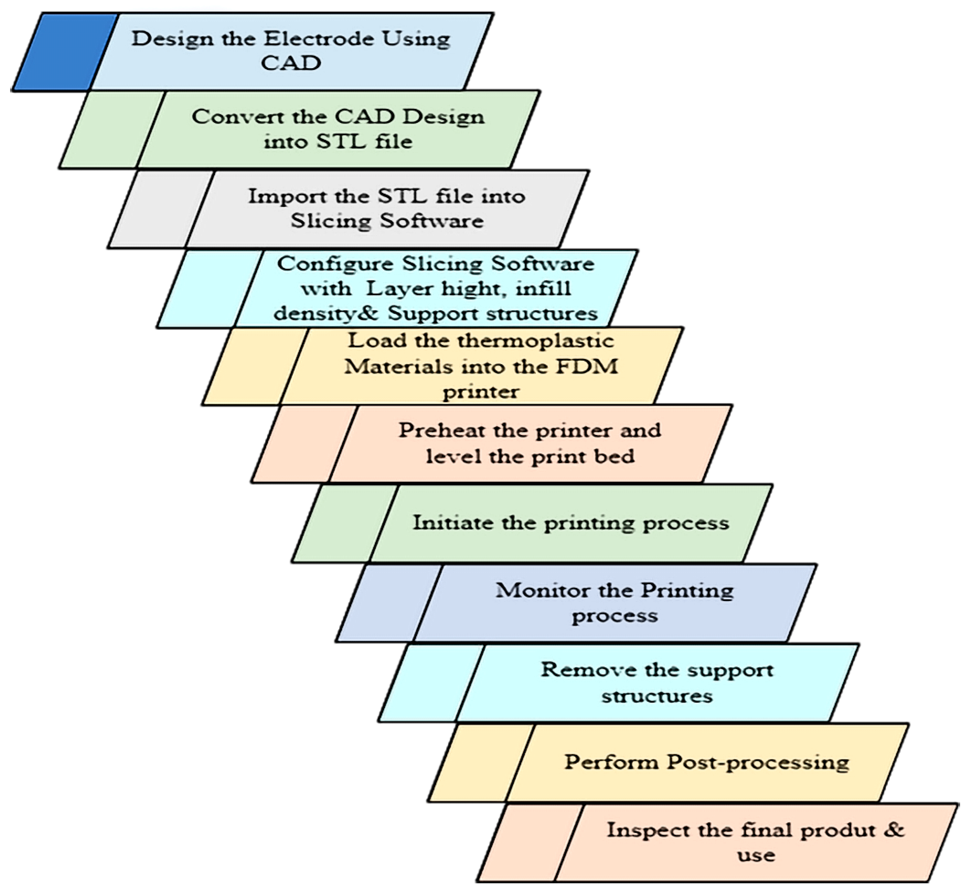
  • Design: The first step in EDM electrode manufacturing is to design the electrode based on the desired shape or feature to be produced. This design is typically carried out using computer-aided design (CAD) software, which allows for the precise and accurate control of the electrode’s geometry.
  • Material selection: Once the design is complete, the next step is to select the appropriate material for the electrode. The material must be highly conductive and capable of withstanding the elevated temperature and stress generated during the EDM process. Common materials used for electrodes include copper, graphite, tungsten and titanium.
  • Machining: The electrode is then machined using specialized equipment, such as the conventional lathe, CNC milling machine or wire EDM machine. This step involves removing the material from the raw product to create the required shape and size of the electrode.
  • Finishing: After machining, the electrode is typically finished to improve its surface finish and dimensional accuracy. This may involve polishing or coating the electrode with a thin layer of material, such as nickel or diamond, to improve its durability and conductivity.

Surface Quality Achieved with Conventional Method

Conventionally manufactured electrodes, typically made from materials such as copper, graphite, or tungsten, can achieve good surface finishes. The achievable surface quality depends on factors like the electrode material, machining techniques, tooling conditions, and surface treatment processes. Surface finishes in the range of a few micrometers (µm) Ra or better are often attainable with conventionally manufactured electrodes. Table 13 presents a review of the conventional method studies.

5. Direction for Future Research

Although EDM has many promising applications, there are still a few challenges that must be addressed before the technique can be safely implemented in biomedical applications, such as the clinical stage, or in industrial applications. The challenges and directions of the EDM approach are as follows:
  • During EDM, materials are melted and then quenched. As a result, there is a high possibility that the material structure will undergo a change into distinct phases. Consequently, the substrate materials’ initial functionality and mechanical qualities could be compromised. Therefore, comprehensive research is needed in this field.
  • Controlling and determining the precise thickness of the layer formed by electrode erosion is highly challenging. A thorough investigation in this direction will be beneficial.
  • Electrode erosion as a means of material deposition is complex enough that its mechanism is not well understood. The monitoring of material deposition during machining is an area that needs to be explored further in future studies.
  • Efforts using the additive manufacturing method without the metallization process would be a breakthrough in electrode production.
  • The parameters used in EDM’s electrode-to-workpiece material transfer are material-specific. As a result, it is difficult to determine the best settings for all material permutations.
  • Experiments using both green compact and sintered electrodes should be explored to ascertain the efficiency of the material transfer of both production processes.
  • From the literature reviewed, there is extremely limited research on surface modification using electrodes for biomedical applications, and hence, future research should consider using biocompatible materials, such as Co-Cr-HA, for electrode production. This will be an alternative to the expensive PMEDM, which requires setting modifications.
  • From the literature reviewed, there is limited research on EDM or PMEDM for oil and gas applications, and hence, there is a need for research in this direction.

6. Conclusions

Based on the extensive literature review on the various production methods of EDM electrodes, it was discovered that the additive manufacturing method involves two stages of production, which are the printing of the electrode itself and the metallization of the electrode to provide conductivity. These methods are viable and can shorten the production time, but they are expensive. The challenge of the two stages of production, which results in a lack of homogeneity and sufficient strength in real EDM applications, remains a drawback for this method. It would be a breakthrough if conductive materials could be printed directly, bypassing the metallization stage.
Several researchers focused on the powder metallurgy approach due to its many advantages over other methods. However, it has some drawbacks that need to be studied further, such as the high tool wear and porosity in green compact electrodes. Low tool wear is evident in the case of sintered electrodes, and hence, there is a need for further studies to establish the most appropriate P/M production balance between the two. Most importantly, some research works suggested surface modification through electrode erosion for material migration, and hence, in-depth research will be needed to establish the best composition for powder metallurgy.
Additionally, there is limited literature on the electrodeposition method. Therefore, this method is not well understood in terms of its viability.
The conventional machining method has been employed for so many years. However, it has some drawbacks, such as the lack of control over the properties of the electrodes. Nevertheless, this method is the most promising method used because it is the easiest and most cost-effective.

Author Contributions

The authors contributed to the entire manuscript. Conceptualization and manuscript writing was performed by E.G.; A.M.A.-R. supervised the work. N.A.Y., A.A.A.A., I.A.G., M.A.-A. and R.A. reviewed and edited the manuscript. All authors have read and agreed to the published version of the manuscript.

Funding

This research was funded by Universiti Teknologi PETRONAS through YUTP-FRG grant through Cost Centre_015LC0-385 and the APC was partly funded by the same grant together with funding from Centre for Graduate Studies, Universiti Teknologi PETRONAS.

Data Availability Statement

Not applicable.

Acknowledgments

On behalf of the institution, the authors articulate their profound appreciation to the Yayasan Universiti Teknologi Petronas-Fundamental Research Grant Scheme (YUTP-FRG Cost center: 015LC0-385) for funding the research. The authors would also like to acknowledge Universiti Teknologi Petronas, Mechanical Engineering Department for providing research facilities.

Conflicts of Interest

The authors declare no conflict of interest.

References

  1. Khan, A.A. Role of heat transfer on process characteristics during electrical discharge machining. Dev. Heat Transf. 2011, 21, 417–435. [Google Scholar]
  2. Ho, K.; Newman, S. State of the art electrical discharge machining (EDM). Int. J. Mach. Tools Manuf. 2003, 43, 1287–1300. [Google Scholar] [CrossRef]
  3. Abdulkareem, S.; Khan, A.A.; Konneh, M. Cooling effect on electrode and process parameters in EDM. Mater. Manuf. Process. 2010, 25, 462–466. [Google Scholar] [CrossRef]
  4. Abu Qudeiri, J.E.; Saleh, A.; Ziout, A.; Mourad, A.-H.I.; Abidi, M.H.; Elkaseer, A. Advanced electric discharge machining of stainless steels: Assessment of the state of the art, gaps and future prospect. Materials 2019, 16, 907. [Google Scholar] [CrossRef]
  5. Gul, I.A.; Abdul-Rani, A.M.; Al-Amin, M.; Garba, E. Elucidating Powder-Mixed Electric Discharge Machining Process, Applicability, Trends and Futuristic Perspectives. Machines 2023, 11, 381. [Google Scholar] [CrossRef]
  6. Razak, M.A.; Abdul-Rani, A.M.; Nanimina, A.M. Improving EDM Efficiency with Silicon Carbide Powder-Mixed Dielectric Fluid. Int. J. Mater. Mech. Manuf. 2015, 3, 40–43. [Google Scholar] [CrossRef]
  7. Schumacher, B.; Krampitz, R.; Kruth, J.-P. Historical phases of EDM development driven by the dual influence of ‘Market Pull’ and ‘Science Push’. Procedia CIRP 2013, 6, 5–12. [Google Scholar] [CrossRef]
  8. Mahajan, A.; Sidhu, S.S. Enhancing biocompatibility of Co-Cr alloy implants via electrical discharge process. Mater. Technol. 2018, 33, 524–531. [Google Scholar] [CrossRef]
  9. Kechagias, J.; Iakovakis, V.; Katsanos, M.; Maropoulos, S. EDM electrode manufacture using rapid tooling: A review EDM electrode manufacture using rapid tooling: A review. J. Mater. Sci. 2008, 43, 2522–2535. [Google Scholar] [CrossRef]
  10. Equbal, A.; Equbal, I.; Badruddin, I.A.; Algahtani, A. A critical insight into the use of FDM for production of EDM electrode. Alex. Eng. J. 2022, 61, 4057–4066. [Google Scholar] [CrossRef]
  11. Kumar, S.; Gupta, T. A review of electrical discharge machining (EDM) and its optimization techniques. Mater. Today Proc. 2023. [Google Scholar] [CrossRef]
  12. Kumar, P.M.; Sivakumar, K.; Jayakumar, N. Multiobjective optimization and analysis of copper–titanium diboride electrode in EDM of monel 400TM alloy. Mater. Manuf. Process. 2018, 33, 1429–1437. [Google Scholar] [CrossRef]
  13. Bin Sapit, A.; Shather, S.K.; Abed, F.N. Parameters analysis in wire electrical discharge machine process of titanium alloys with dielectric alumina. Mater. Today Proc. 2021, 42, 1854–1859. [Google Scholar] [CrossRef]
  14. Prakash, C.; Kansal, H.K.; Pabla, B.S.; Puri, S. Experimental Investigations in Powder Mixed Electric Discharge Machining of Ti-35Nb-7Ta-5Zr β—Titanium Alloy. Mater. Manuf. Process. 2016, 32, 274–285. [Google Scholar] [CrossRef]
  15. Altan, T.; Lilly, B.; Kruth, J.; König, W.; Tönshoff, H.; van Luttervelt, C.; Khairy, A. Advanced Techniques for Die and Mold Manufacturing. CIRP Ann. 1993, 42, 707–716. [Google Scholar] [CrossRef]
  16. Bajaj, R.; Tiwari, A.K.; Dixit, A.R. Current trends in electric discharge machining using micro and nano powder materials- A Review. Mater. Today Proc. 2015, 2, 3302–3307. [Google Scholar] [CrossRef]
  17. Marashi, H.; Jafarlou, D.M.; Sarhan, A.A.; Hamdi, M. State of the art in powder mixed dielectric for EDM applications. Precis. Eng. 2016, 46, 11–33. [Google Scholar] [CrossRef]
  18. Talla, G.; Gangopadhayay, S.; Biswas, C. State of the art in powder-mixed electric discharge machining: A review. Proc. Inst. Mech.Eng. Part B J. Eng. Manuf. 2017, 231, 2511–2526. [Google Scholar] [CrossRef]
  19. Joshi, A.Y.; Joshi, A.Y. A systematic review on powder mixed electrical discharge machining. Heliyon 2019, 5, e02963. [Google Scholar] [CrossRef]
  20. Abdudeen, A.; Abu Qudeiri, J.E.; Kareem, A.; Ahammed, T.; Ziout, A. Recent advances and perceptive insights into powder-mixed dielectric fluid of EDM. Micromachines 2020, 11, 754. [Google Scholar] [CrossRef]
  21. Al-Amin, M.; Rani, A.M.A.; Aliyu, A.A.A.; Razak, M.A.A.; Hastuty, S.; Bryant, M.G. Powder mixed-EDM for potential biomedical applications: A critical review. Mater. Manuf. Process. 2020, 35, 1789–1811. [Google Scholar] [CrossRef]
  22. Al-Amin, M.; Danish, M.; Rubaiee, S. Investigation of Coatings, Corrosion and Wear Characteristics of Machined Biomaterials through Hydroxyapatite Mixed-EDM Process: A Review. Materials 2021, 14, 3597. [Google Scholar] [CrossRef]
  23. Aliyu, A.A.; Abdul-Rani, A.M.; Ginta, T.L.; Prakash, C.; Axinte, E.; Razak, M.A.; Ali, S. A Review of Additive Mixed-Electric Discharge Machining: Current Status and Future Perspectives for Surface Modification of Biomedical Implants. Adv. Mater. Sci. 2017, 2017, 8723239. [Google Scholar] [CrossRef]
  24. Aliyu, A.A.; Abdul-Rani, A.M.; Ginta, T.L.; Rao, T.; Axinte, E.; Ali, S.; Ramli, M. Hydroxyapatite electro discharge coating of Zr-based bulk metallic glass for potential orthopedic application. Key Eng. Mater. 2019, 796, 123–128. [Google Scholar] [CrossRef]
  25. Yu, Z.; Jun, T.; Masanori, K. Dry electrical discharge machining of cemented carbide. J. Mater. Process. Technol. 2004, 149, 353–357. [Google Scholar] [CrossRef]
  26. Patowari, P.K.; Saha, P.; Mishra, P.K. Taguchi analysis of surface modification technique using W-Cu powder metallurgy sintered tools in EDM and characterization of the deposited layer. Int. J. Adv. Manuf. Technol. 2011, 54, 593–604. [Google Scholar] [CrossRef]
  27. Aliyu, A.A.; Abdul-Rani, A.M.; Rao, T.; Axinte, E.; Hastuty, S.; Parameswari, R.; Subramaniam, J.R.; Thyagarajan, S. Characterization, adhesion strength and in-vitro cytotoxicity investigation of hydroxyapatite coating synthesized on Zr-based BMG by electro discharge process. Surf. Coat. Technol. 2019, 370, 213–226. [Google Scholar] [CrossRef]
  28. Kunieda, M.; Yoshida, M.; Taniguchi, N. Electrical Discharge Machining in Gas. RP Ann. 1996, 46, 143–146. [Google Scholar] [CrossRef]
  29. Philip, J.T.; Mathew, J.; Kuriachen, B. Transition from EDM to PMEDM—Impact of suspended particulates in the dielectric on Ti6Al4V and other distinct material surfaces: A review. J. Manuf. Process. 2021, 64, 1105–1142. [Google Scholar] [CrossRef]
  30. Ho, S.; Aspinwall, D.; Voice, W. Use of powder metallurgy (PM) compacted electrodes for electrical discharge surface alloying/modification of Ti-6Al-4V alloy. J. Mater. Process. Technol. 2007, 191, 123–126. [Google Scholar] [CrossRef]
  31. Lim, H.; Wong, Y.; Rahman, M.; Lee, M.E. A study on the machining of high-aspect ratio micro-structures using micro-EDM. J. Mater. Process. Technol. 2003, 140, 318–325. [Google Scholar] [CrossRef]
  32. Uhlmann, E.; Piltz, S.; Doll, U. Machining of micro/miniature dies and moulds by electrical discharge machining—Recent development. J. Mater. Process. Technol. 2005, 167, 488–493. [Google Scholar] [CrossRef]
  33. Uhlmann, E.; Piltz, S.; Oberschmidt, D. Machining of micro rotational parts by wire electrical discharge grinding. Prod. Eng. 2008, 2, 227–233. [Google Scholar] [CrossRef]
  34. Govindan, P.; Gupta, A.; Joshi, S.S.; Malshe, A.; Rajurkar, K. Single-spark analysis of removal phenomenon in magnetic field assisted dry EDM. J. Mater. Process. Technol. 2013, 213, 1048–1058. [Google Scholar] [CrossRef]
  35. Ali, S.; Abdul Rani, A.M.; Ahmad Mufti, R.; Ahmed, S.W.; Baig, Z.; Hastuty, S.; Razak, M.A.H.A.; Abdu, A.A.A. Optimization of sintering parameters of 316L stainless steel for in-situ nitrogen absorption and surface nitriding using response surface methodology. Processes 2020, 8, 297. [Google Scholar] [CrossRef]
  36. Volosova, M.A.; Okunkova, A.A.; Povolotskiy, D.E.; Podrabinnik, P.A. Study of electrical discharge machining for the parts of nuclear industry usage. Mech. Ind. 2015, 16, 706. [Google Scholar] [CrossRef]
  37. Ayesta, I.; Izquierdo, B.; Sánchez, J.; Ramos, J.; Plaza, S.; Pombo, I.; Ortega, N.; Bravo, H.; Fradejas, R.; Zamakona, I. Influence of EDM parameters on slot machining in C1023 aeronautical alloy. Procedia CIRP 2013, 6, 129–134. [Google Scholar] [CrossRef]
  38. Liqing, L.; Yingjie, S. Study of dry EDM with oxygen-mixed and cryogenic cooling approaches. Procedia CIRP 2013, 6, 344–350. [Google Scholar] [CrossRef]
  39. Peng, P.-W.; Ou, K.-L.; Lin, H.-C.; Pan, Y.-N.; Wang, C.-H. Effect of electrical-discharging on formation of nanoporous biocompatible layer on titanium. J. Alloys Compd. 2010, 492, 625–630. [Google Scholar] [CrossRef]
  40. Sales, W.; Oliveira, A.; Raslan, A. Titanium perovskite (CaTiO3) formation in Ti6Al4V alloy using the electrical discharge machining process for biomedical applications. Surf. Coat. Technol. 2016, 307, 1011–1015. [Google Scholar] [CrossRef]
  41. Shabgard, M.; Khosrozadeh, B. Investigation of carbon nanotube added dielectric on the surface characteristics and machining performance of Ti–6Al–4V alloy in EDM process. J. Manuf. Process. 2017, 25, 212–219. [Google Scholar] [CrossRef]
  42. Abdul-Rani, A.; Nanimina, A.; Ginta, T.; Razak, M. Machined Surface Quality in Nano Aluminum Mixed Electrical Discharge Machining. Procedia Manuf. 2017, 7, 510–517. [Google Scholar] [CrossRef]
  43. Aliyu, A.A.A.; Rohani, J.M.; Rani, A.M.A.; Musa, H. Optimization of Electric Discharge Machining Parameters of SiSiC through Response Surface Methodology. J. Teknol. 2017, 1, 119–129. [Google Scholar]
  44. Aliyu, A.A.A.; Abdul-Rani, A.M.; Ginta, T.L.; Rao, T.V.V.L.N.; Selvamurugan, N.; Roy, S. Hydroxyapatite mixed-electro discharge formation of bioceramic Lakargiite (CaZrO3) on Zr—Cu—Ni—Ti—Be for orthopedic application. Mater. Manuf. Process. 2018, 33, 1734–1744. [Google Scholar] [CrossRef]
  45. Amin, A.; Abdul-Rani, A.M.; Rao, T.; Danish, M.; Rubaiee, S.; bin Mahfouz, A.; Parameswari, R.; Wani, M. Investigation of machining and modified surface features of 316L steel through novel hybrid of HA/CNT added-EDM process. Mater. Chem. Phys. 2022, 276, 125320. [Google Scholar] [CrossRef]
  46. Mahamat, A.Z. Synthesizing and Evaluation of new EDM Electrode Materials for Machining Hardened Die-Steel Using Taguchi Technique. Ph.D. Thesis, Universiti Teknologi Petronas, Seri Iskandar, Malaysia, 2012. [Google Scholar]
  47. Ali, S.; Abdul Rani, A.M.; Mufti, R.A.; Hastuty, S.; Hussain, M.; Shehzad, N.; Baig, Z.; Abdu Aliyu, A.A. An Efficient Approach for Nitrogen Diffusion and Surface Nitriding of Boron-Titanium Modified Stainless Steel Alloy for Biomedical Applications. Metals 2019, 9, 755. [Google Scholar] [CrossRef]
  48. Jampana, V.N.R.; Rao, P.S.V.R.; Sampathkumar, A. Experimental and Thermal Investigation on Powder Mixed EDM Using FEM and Artificial Neural Networks. Adv. Mater. Sci. Eng. 2021, 2021, 8138294. [Google Scholar] [CrossRef]
  49. Amin, A.; Abdul-Rani, A.M.; Ahmed, R.; Rao, T.V.V.L.N. Mulatite-added EDM technique for processing of 316L-steeltiple-objective optimization of hydroxyap. Mater. Manuf. Process. 2021, 36, 1134–1145. [Google Scholar] [CrossRef]
  50. Shunmugam, M.; Philip, P.; Gangadhar, A. Improvement of wear resistance by EDM with tungsten carbide P/M electrode. Wear 1994, 171, 1–5. [Google Scholar] [CrossRef]
  51. Tyagi, R.; Pandey, K.; Das, A.K.; Mandal, A. Deposition of hBN+Cu layer through electrical discharge process using green compact electrode. Mater. Manuf. Process. 2019, 34, 1035–1048. [Google Scholar] [CrossRef]
  52. Zhao, X.; Yang, L.; Zuo, Y.; Xiong, J. Hydroxyapatite Coatings on Titanium Prepared by Electrodeposition in a Modified Simulated Body Fluid. Chin. J. Chem. Eng. 2009, 17, 667–671. [Google Scholar] [CrossRef]
  53. Uhlmann, E.; Domingos, D.C. Investigations on Vibration-assisted EDM-machining of Seal Slots in High-Temperature Resistant Materials for Turbine Components -Part II. Procedia CIRP 2016, 42, 334–339. [Google Scholar] [CrossRef]
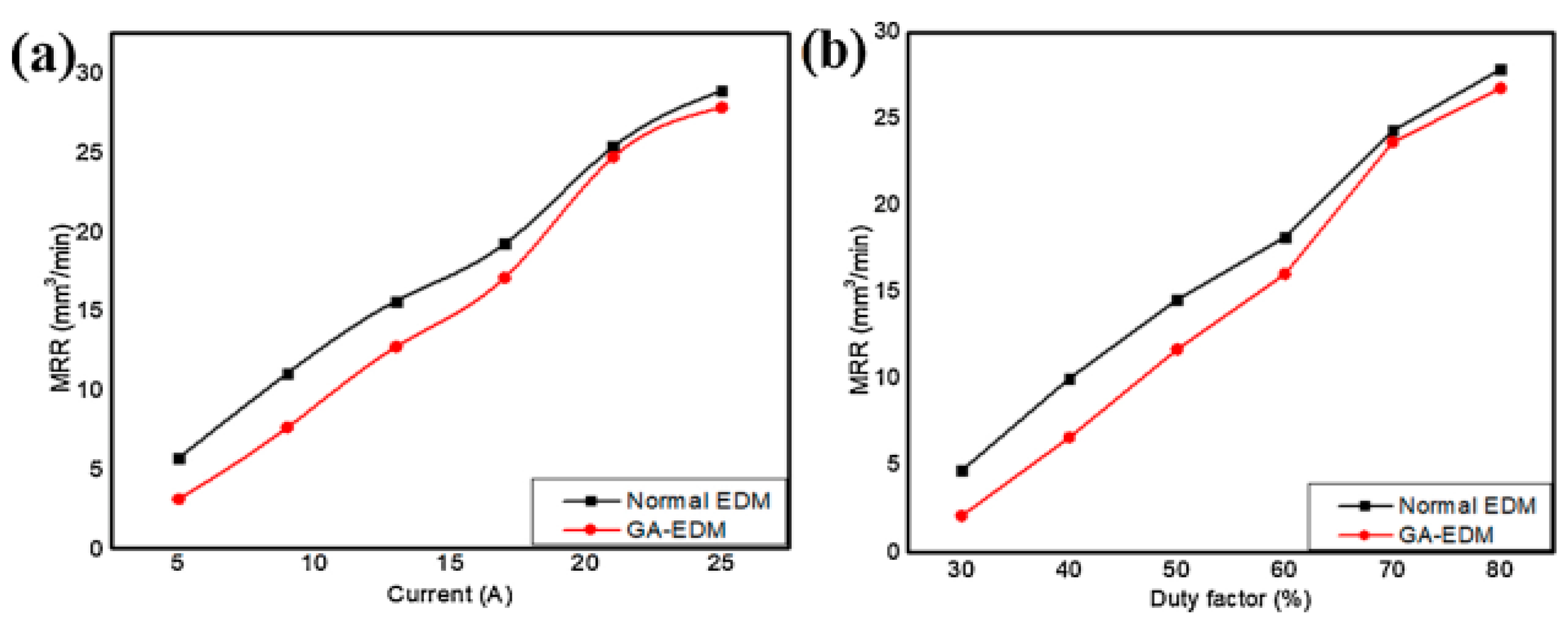
  54. Das, S.; Paul, S.; Doloi, B. A gap-active electrical discharge machining (GA-EDM ) to rectify the textural defects of the processed surface. J. Manuf. Process. 2021, 64, 594–605. [Google Scholar] [CrossRef]
  55. Khan, M.Y.; Rao, P.S.; Pabla, B.S. Characterization of Jatropha Curcas oil based Biodiesel for Utilization as Dielectric media in EDM Process. Mater. Today 2020, 26, 335–340. [Google Scholar] [CrossRef]
  56. Singaravel, B.; Shekar, K.C.; Reddy, G.G.; Prasad, S.D. Experimental investigation of vegetable oil as dielectric fluid in Electric discharge machining of Ti-6Al-4V. Ain Shams Eng. J. 2020, 11, 143–147. [Google Scholar] [CrossRef]
  57. Gupta, V.; Singh, P.; Singh, B.; Mishra, R. Vegetable oil based dielectric fluids for electrical discharge Machining Process: Advancements and challenges. Mater. Today Proc. 2022, 62, 3129–3132. [Google Scholar] [CrossRef]
  58. Kolli, M.; Kumar, A. Effect of dielectric fluid with surfactant and graphite powder on Electrical Discharge Machining of titanium alloy using Taguchi method. Eng. Sci. Technol. Int. J. 2015, 18, 524–535. [Google Scholar] [CrossRef]
  59. Liu, Q.; Zhang, Q.; Zhang, M.; Yang, F. Study on the Discharge Characteristics of Single-Pulse Discharge in Micro-EDM. Micromachines 2020, 11, 55. [Google Scholar] [CrossRef]
  60. Schnakovszky, C.; Herghelegiu, E. Experimental Investigation of Stability of Vegetable Oils Used as Dielectric Fluids for Electrical Discharge Machining. Processes 2020, 8, 1187. [Google Scholar] [CrossRef]
  61. Dhakar, K.; Dvivedi, A. Parametric Evaluation on Near-Dry Electric Discharge Machining. Mater. Manuf. Process. 2016, 31, 413–421. [Google Scholar] [CrossRef]
  62. Kunieda, N.T.M.; Furuoya, S. Improvement of EDM efficiency by supplying oxygene gas into gap. CIRP Ann. Technol. 1991, 40, 215–218. [Google Scholar] [CrossRef]
  63. Yan, B.H.; Tsai, H.C.; Huang, F.Y. The effect in EDM of a dielectric of a urea solution in water on modifying the surface of titanium. Int. J. Mach. Tools Manuf. 2005, 45, 194–200. [Google Scholar] [CrossRef]
  64. Das, S.; Paul, S.; Doloi, B. Feasibility investigation of neem oil as a dielectric for electrical discharge machining. Int. J. Adv. Manuf. Technol. 2020, 106, 1179–1189. [Google Scholar] [CrossRef]
  65. Das, S.; Paul, S.; Doloi, B. Investigation of the Machining Performance of Neem Oil as a Dielectric Medium of EDM: A Sustainable Approach. IOP Conf. Ser. Mater. Sci. Eng. 2019, 653, 012017. [Google Scholar] [CrossRef]
  66. Mohammed, L.; Syed, M.; Bakrutheen, M.W.; Karthik, M. Study on Critical Properties of Vegetable Oil-based Insulating Fluids. In Proceedings of the 2015 Annual IEEE India Conference, New Delhi, India, 17–20 December 2015; pp. 25–28. [Google Scholar]
  67. Khan, M.Y.; Rao, P.S.; Pabla, B.; Kumar, K.A. Journal of King Saud University—Science Feasibility of used cooking oil-based biodiesel (UCOB) as a dielectric for electrical discharge machining. J. King Saud Univ. Sci. 2022, 34, 102305. [Google Scholar] [CrossRef]
  68. Ming, W.; Xie, Z.; Ma, J.; Du, J.; Zhang, G.; Cao, C.; Zhang, Y. Critical review on sustainable techniques in electrical discharge machining. J. Manuf. Process. 2021, 72, 375–399. [Google Scholar] [CrossRef]
  69. Tyagi, R.; Mahto, N.K.; Das, A.K.; Mandal, A. Preparation of MoS2+Cu coating through the EDC process and its analysis. Surf. Eng. 2020, 36, 86–93. [Google Scholar] [CrossRef]
  70. Niranjan, T.; Singaravel, B.; Chakradhar, B.; Kumar, D.S. Investigation of vegetable oil as dielectric fluid in electric discharge machining. Mater. Today Proc. 2023, 10–14. [Google Scholar] [CrossRef]
  71. Aliyu, A.A. Coating of Bulk Metallic Glass Through Electro-Discharge Process for Potential Orthopedic Application. Ph.D. Thesis, Universiti Tekbologi Petronas, Seri Iskandar, Malaysia, 2019. [Google Scholar]
  72. Singh, K.; Agarwal, A.K.; Yadav, R. Effect of Dielectric fluids used on EDM Performance: A Review. Int. J. Emerg. Technol. Eng. Res. 2017, 5, 9–16. [Google Scholar]
  73. Biswal, S.; Tripathy, S.; Tripathy, D. Machining performance analysis for PMEDM of biocompatible material Ti-6Al-7Nb alloy: A machine learning approach. Mater. Lett. 2022, 320, 132337. [Google Scholar] [CrossRef]
  74. Aliyu, A.A.; Abdul-Rani, A.M.; Al-Amin, M.; Hastuty, S.; Razak, M.A.; Ali, S.; Danish, M.; Rubaiee, S.; Bin Mahfouz, A.; Hamza, A.N. Deposition of biomimetic biocompatible oxides on metallic glass surface by electro-discharge coating process. Materwiss. Werksttech. 2023, 54, 129–136. [Google Scholar] [CrossRef]
  75. Viswanth, V.S.; Ramanujam, R.; Rajyalakshmi, G. ScienceDirect A Review of Research Scope on Sustainable and Eco-Friendly Electrical Discharge Machining (E-EDM). Mater. Today Proc. 2018, 5, 12525–12533. [Google Scholar] [CrossRef]
  76. Roughness, S.; Aliyu, A.A.A.; Abdul-Rani, A.M.; Rubaiee, S.; Danish, M.; Bryant, M.; Hastuty, S.; Razak, M.A.H.; Ali, S. Electro-Discharge Machining of Zr67Cu11Ni10Ti9Be3: An Investigation on Hydroxyapatite Deposition and Surface Roughness. Processes 2020, 8, 635. [Google Scholar] [CrossRef]
  77. Prakash, C.; Kansal, H.K.; Pabla, B.; Puri, S.; Aggarwal, A. Electric Discharge Machining—A Potential Choice for Surface Modification of Metallic Implants for Orthopedic Applications: A Review. Proceedings of the Institution of Mechanical Engineers, Part B: Journal of Engineering Manufacture; SAGE Publications Ltd.: New York, NY, USA, 2016; Volume 230, pp. 331–353. [Google Scholar] [CrossRef]
  78. Amin, A.; Abdul-Rani, A.M.; Danish, M.; Thompson, H.M.; Aliyu, A.A.A.; Hastuty, S.; Zohura, F.T.; Bryant, M.G.; Rubaiee, S.; Rao, T. Assessment of PM-EDM cycle factors influence on machining responses and surface properties of biomaterials: A comprehensive review. Precis. Eng. 2020, 66, 531–549. [Google Scholar] [CrossRef]
  79. Nanimina, A.M.; Rani, A.M.A.; Ginta, T.L. Assessment of Powder Mixed EDM: A Review. MATEC Web Conf. 2014, 13, 2–5. [Google Scholar] [CrossRef]
  80. Al-Amin, M.; Abdul-Rani, A.M.; Rana, M.; Hastuty, S.; Danish, M.; Rubaiee, S.; bin Mahfouz, A. Evaluation of modified 316L surface properties through HAp suspended EDM process for biomedical application. Surf. Interfaces 2021, 28, 101600. [Google Scholar] [CrossRef]
  81. Aliyu, A.A.A.; Udomlertpreecha, S.; Medhisuwakul, M.; Panwisawas, C.; Reed, R.; Puncreobutr, C.; Khamwannah, J.; Kuimalee, S.; Yipyintum, C.; Lohwongwatana, B. A new toxic-free Ti40Zr10Co36Pd14 metallic glass with good biocompatibility and surface behaviour comparable to Ti-6Al-4V. Mater. Des. 2022, 218, 110691. [Google Scholar] [CrossRef]
  82. Al-Khazraji, A.; Amin, S.A.; Ali, S.M. The effect of SiC powder mixing electrical discharge machining on white layer thickness, heat flux and fatigue life of AISI D2 die steel. Eng. Sci. Technol. Int. J. 2016, 19, 1400–1415. [Google Scholar] [CrossRef]
  83. Marashi, H.; Sarhan, A.A.; Hamdi, M. Employing Ti nano-powder dielectric to enhance surface characteristics in electrical discharge machining of AISI D2 steel. Appl. Surf. Sci. 2015, 357, 892–907. [Google Scholar] [CrossRef]
  84. Toshimitsu, R.; Okada, A.; Kitada, R.; Okamoto, Y. Improvement in Surface Characteristics by EDM with Chromium Powder Mixed Fluid. Procedia CIRP 2016, 42, 231–235. [Google Scholar] [CrossRef]
  85. Singh, B.; Kumar, J.; Kumar, S. Influences of Process Parameters on MRR Improvement in Simple and Powder-Mixed EDM of AA6061/10%SiC Composite. Mater. Manuf. Process. 2015, 30, 303–312. [Google Scholar] [CrossRef]
  86. Porwal, R.K.; Kumar, V. An overview of CNT based electric discharge machining. Mater. Today Proc. 2021, 44, 1944–1948. [Google Scholar] [CrossRef]
  87. Mandal, P.; Mondal, S.C. Surface characteristics of mild steel using EDM with Cu-MWCNT composite electrode. Mater. Manuf. Process. 2019, 34, 1326–1332. [Google Scholar] [CrossRef]
  88. Saha, S.K. Experimental Investigation of the Dry Electric Discharge Machining (Dry EDM) Process. Indian Institute of Technology Kanpur. 2008. Available online: https://www.researchgate.net/publication/201146222 (accessed on 17 October 2022).
  89. Rehbein, W.; Schulze, H.-P.; Mecke, K.; Wollenberg, G.; Storr, M. Influence of selected groups of additives on breakdown in EDM sinking. J. Mater. Process. Technol. 2004, 149, 58–64. [Google Scholar] [CrossRef]
  90. Kolli, M.; Kumar, A. Surfactant and graphite powder-assisted electrical discharge machining of titanium alloy. Proc. Inst. Mech. Eng. Part B J. Eng. Manuf. 2017, 231, 641–657. [Google Scholar] [CrossRef]
  91. Singh, G.; Samra, P.S.; Kumar, A. Tool electrode considerations in EDM of titanium alloys—A review. Mater. Today Proc. 2022, 56, 3117–3120. [Google Scholar] [CrossRef]
  92. Abdul-Rani, A.M.; Aliyu, A.A.A.; Hastuty, S.; Ginta, T.L.; Rao, T.V.V.L.N.; Ali, S. Enhancing surface quality of Zr-Cu-Ni-Ti-Be through hydroxyapatite mixed EDM for potential orthopedic application. AIP Conf. Proc. 2018, 2035, 080010. [Google Scholar] [CrossRef]
  93. Al Amin, M.; Rani, A.M.A.; Aliyu, A.A.A.; Bryant, M.G.; Danish, M.; Ahmad, A. Bio-ceramic coatings adhesion and roughness of biomaterials through PM-EDM: A comprehensive review. Mater. Manuf. Process. 2020, 35, 1157–1180. [Google Scholar] [CrossRef]
  94. Mahendran, R.; Devarajan, T.; Nagarajan, A. A Review of Micro-EDM. In Proceedings of the International MultiConference of Engineers and Computer Scientists (IMECS 2010), Kowloon, Hong Kong, 17–19 March 2010; p. 2246. [Google Scholar]
  95. Nimmawitt, P.; Aliyu, A.A.A.; Lohwongwatana, B.; Arunjaroensuk, S.; Puncreobutr, C.; Mattheos, N.; Pimkhaokham, A. Understanding the Stress Distribution on Anatomic Customized Root-Analog Dental Implant at Bone-Implant Interface for Different Bone Densities. Materials 2022, 15, 6379. [Google Scholar] [CrossRef]
  96. Jha, B.; Ram, K.; Rao, M. An overview of technology and research in electrode design and manufacturing in sinking electrical discharge machining. J. Eng. Sci. Technol. Rev. 2011, 4, 118–130. Available online: www.jestr.org (accessed on 17 October 2022). [CrossRef]
  97. Danade, U.A.; Londhe, S.D.; Metkar, R.M. Machining performance of 3D-printed ABS electrode coated with copper in EDM. Rapid Prototyp. J. 2019, 25, 1224–1231. [Google Scholar] [CrossRef]
  98. Padhi, S.K.; Mahapatra, S.S.; Padhi, R.; Das, H.C. Performance analysis of a thick copper-electroplated FDM ABS plastic rapid tool EDM electrode. Adv. Manuf. 2018, 6, 442–456. [Google Scholar] [CrossRef]
  99. Fefar, S.D.; Karajagikar, M.J.S. Study and Analysis of Metallized Electrode Fabricated with FDM Rapid Prototyping Technique for Electro Discharge Machining (EDM). In Proceedings of the 5th International & 26th All India Manufacturing Technology Design and Research Conference (AIMTDR 2014), IIT Guwahati, Assam, India, 12–14 December 2014; pp. 37–42. [Google Scholar]
  100. Saxena, P.; Metkar, R.M. Development of electrical discharge machining (EDM) electrode using fused deposition modeling (FDM). In 3D Printing and Additive Manufacturing Technologies; Springer: Singapore, 2018; pp. 257–268. [Google Scholar] [CrossRef]
  101. Hsu, C.Y.; Chen, D.Y.; Lai, M.Y.; Tzou, G.J. EDM electrode manufacturing using RP combining electroless plating with electroforming. Int. J. Adv. Manuf. Technol. 2008, 38, 915–924. [Google Scholar] [CrossRef]
  102. Arthur, A.; Dickens, P. The measurement of heat distribution in stereolithography electrodes during electro-discharge machining. Int. J. Prod. Res. 1998, 36, 2451–2461. [Google Scholar] [CrossRef]
  103. Li, D.; Goodwin, K.; Yang, C.-L. Electroless copper deposition on aluminum-seeded ABS plastics. J. Mater. Sci. 2008, 43, 7121–7131. [Google Scholar] [CrossRef]
  104. Li, D.; Yang, C.-L. Acidic electroless copper deposition on aluminum-seeded ABS plastics. Surf. Coat. Technol. 2009, 203, 3559–3568. [Google Scholar] [CrossRef]
  105. Dechasit, P.; Trakarnpruk, W. Surface Treatment of ABS Using Cobalt and Nickel Solution for Electroless Plating. Ph.D. Thesis, Chulalongkorn University, Bangkok, Thailand, 2011. [Google Scholar]
  106. Czelusniak, T.; Amorim, F.L.; Lohrengel, A.; Higa, C.F. Development and application of copper-nickel zirconium diboride as EDM electrodes manufactured by selective laser sintering. J. Adv. Manuf. Technol. 2014, 72, 905–917. [Google Scholar] [CrossRef]
  107. Tsai, H.; Yan, B.; Huang, F. EDM performance of Cr/Cu-based composite electrodes. Int. J. Mach. Tools Manuf. 2003, 43, 245–252. [Google Scholar] [CrossRef]
  108. Beri, N.; Maheshwari, S.; Sharma, C. Evaluation of surface quality during electrical discharge machining of Inconel 718 with powder metallurgy electrodes. Adv. Mater. Res. 2012, 410, 245–248. [Google Scholar] [CrossRef]
  109. Patowari, P.K.; Saha, P.; Mishra, P.K. Artificial neural network model in surface modification by EDM using tungsten-copper powder metallurgy sintered electrodes. Int. J. Adv. Manuf. Technol. 2010, 51, 627–638. [Google Scholar] [CrossRef]
  110. Aspinwall, D.; Dewes, R.; Lee, H.; Simao, J.; McKeown, P. Electrlcal Dlscharge Surface Alloylng of Ti and Fe Workpiece Materlals Using Refractory Powder Compact Electrodes and Cu Wire. CIRP Ann. Manuf. Technol. 2003, 52, 151–156. [Google Scholar] [CrossRef]
  111. Cogun, C.; Esen, Z.; Genc, A.; Cogun, F.; Akturk, N. Effect of powder metallurgy Cu-B4C electrodes on workpiece surface characteristics and machining performance of electric discharge machining. Proc. Inst. Mech. Eng. Part B J. Eng. Manuf. 2016, 230, 2190–2203. [Google Scholar] [CrossRef]
  112. SChakraborty; Kar, S.; Dey, V.; Ghosh, S.K. Multi Attribute Decision Making for Determining Optimum Process Parameter in EDC with Si and Cu Mixed Powder Green Compact Electrodes. J. Sci. Ind. Res. 2018, 77, 229–236. [Google Scholar]
  113. Teng, Y.L.; Li, L.; Zhang, W.; Wang, N.; Feng, C.C.; Ren, J. Machining characteristics of PCD by EDM with Cu-Ni composite electrode. Mater. Manuf. Process. 2020, 35, 442–448. [Google Scholar] [CrossRef]
  114. Wang, Z.L.; Fang, Y.; Wu, P.N.; Zhao, W.S.; Cheng, K. Surface modi®cation process by electrical discharge machining with a Ti powder green compact electrode. J. Mater. Process. Technol. 2002, 129, 139–142. [Google Scholar] [CrossRef]
  115. Li, L.; Niu, Z.W.; Zheng, G.M. Ultrasonic Electrodeposition of Cu-SiC Electrodes for EDM. Mater. Manuf. Process. 2016, 31, 37–41. [Google Scholar] [CrossRef]
  116. Kar, A.; Raja, K.; Misra, M. Electrodeposition of hydroxyapatite onto nanotubular TiO2 for implant applications. Surf. Coat. Technol. 2006, 201, 3723–3731. [Google Scholar] [CrossRef]
  117. Wang, L.-N.; Luo, J.-L. Preparation of hydroxyapatite coating on CoCrMo implant using an effective electrochemically-assisted deposition pretreatment. Mater. Charact. 2011, 62, 1076–1086. [Google Scholar] [CrossRef]
  118. Shozib, I.A.; Ahmad, A.; Abdul-Rani, A.M.; Beheshti, M.; Aliyu, A.A. A review on the corrosion resistance of electroless Ni-P based composite coatings and electrochemical corrosion testing methods. Corros. Rev. 2022, 40, 1–37. [Google Scholar] [CrossRef]
  119. Gopal, R.; Thirunavukkarasu, K. Effect of ECAP on copper electrode in spark machining. Mater. Today Proc. 2020, 21, 253–256. [Google Scholar] [CrossRef]
  120. Wu, K.L.; Yan, B.H.; Huang, F.Y.; Chen, S.C. Improvement of Surface Finish on SKD Steel using Electro-Discharge Machining with Aluminum and Surfactant added dielectric. Int. J. Mach. Tools Manuf. 2005, 45, 1195–1201. [Google Scholar] [CrossRef]
  121. Fathi, M.; Azam, F. Novel hydroxyapatite/tantalum surface coating for metallic dental implant. Mater. Lett. 2007, 61, 1238–1241. [Google Scholar] [CrossRef]
  122. Yin, H.; Yang, J.; Zhang, Y.; Crilly, L.; Jackson, R.L.; Lou, X. Carbon nanotube (CNT) reinforced 316L stainless steel composites made by laser powder bed fusion: Microstructure and wear response. Wear 2022, 496-497, 204281. [Google Scholar] [CrossRef]
  123. Aliyu, A.A.A.; Panwisawas, C.; Shinjo, J.; Puncreobutr, C.; Reed, R.C.; Poungsiri, K.; Lohwongwatana, B. Laser-based additive manufacturing of bulk metallic glasses: Recent advances and future perspectives for biomedical applications. J. Mater. Res. Technol. 2023, 23, 2956–2990. [Google Scholar] [CrossRef]
  124. Dürr, H.; Pilz, R.; Eleser, N.S. Rapid Tooling of EDM Electrodes by means of Selective Laser Sintering. Comput. Ind. 1999, 39, 35–45. [Google Scholar] [CrossRef]
  125. Tay, F.E.H.; Haider, E.A. The Potential of Plating Techniques in the Development of Rapid EDM Tooling; Springer: London, UK, 2001. [Google Scholar]
  126. Cheah, C.; Chua, C.; Lee, C.; Feng, C.; Totong, K. Rapid prototyping and tooling techniques: A review of applications for rapid investment casting. Int. J. Adv. Manuf. Technol. 2005, 25, 308–320. [Google Scholar] [CrossRef]
  127. Gillot, F.; Mognol, P.; Furet, B. Dimensional accuracy studies of copper shells used for electro-discharge machining electrodes made with rapid prototyping and the electroforming process. J. Mater. Process. Technol. 2005, 159, 33–39. [Google Scholar] [CrossRef]
  128. Equbal, A.; Islamia, J.M.; Sood, A.K. Technology. Rapid prototyping Application in manufacturing of EDM Electrode. Int. J. Sci. Eng. Res. 2013, 4. [Google Scholar]
  129. Arthur, A.; Dickens, P.M.; Cobb, R.C. Using Rapid Prototyping to Produce EDM Electrode. Rapid Prototyp. J. 1996, 2, 4–12. [Google Scholar] [CrossRef]
  130. Akula, S.; Karunakaran, K. Hybrid adaptive layer manufacturing: An Intelligent art of direct metal rapid tooling process. Robot. Comput. Integr. Manuf. 2006, 22, 113–123. [Google Scholar] [CrossRef]
  131. Wang, J.; Zhu, R.; Liu, Y.; Zhang, L. Understanding melt pool characteristics in laser powder bed fusion: An overview of single- and multi-track melt pools for process optimization. Adv. Powder Mater. 2023, 2, 100137. [Google Scholar] [CrossRef]
  132. Equbal, A.; Equbal, I.; Sood, A.K. An investigation on the feasibility of fused deposition modelling process in EDM electrode manufacturing. CIRP J. Manuf. Sci. Technol. 2019, 26, 10–25. [Google Scholar] [CrossRef]
  133. Ilani, M.A.; Khoshnevisan, M. Powder mixed-electrical discharge machining (EDM) with the electrode is made by fused deposition modeling (FDM) at Ti-6Al-4V machining procedure. Multiscale Multidiscip. Model. Exp. Des. 2020, 3, 173–186. [Google Scholar] [CrossRef]
  134. Uhlmann, E.; Bergmann, A.; Bolz, R.; Gridin, W. Application of additive manufactured tungsten carbide tool electrodes in EDM. Procedia CIRP 2018, 68, 86–90. [Google Scholar] [CrossRef]
  135. Pawar, P.; Anasane, S.; Ballav, A.R.; Kumar, A. Experimental Study of Electroless Copper Coated On Abs Material Used For Tooling In EDM Machining Process. J. Prod. Eng. 2016, 19, 27–32. [Google Scholar]
  136. Simão, J.; Aspinwall, D.; El-Menshawy, F.; Meadows, K. Surface alloying using PM composite electrode materials when electrical discharge texturing hardened AISI D2. J. Mater. Process. Technol. 2002, 127, 211–216. [Google Scholar] [CrossRef]
  137. Samueli, M.P.; Philipt, P.K. Powder Metallurgy Tool Electrode for Electrical Discharge Machining. Mech.Tools Manufact. 1997, 37, 1625–1633. [Google Scholar] [CrossRef]
  138. Kumar, P.M.; Sivakumar, K.; Jayakumar, N. Surface Modification on OHNS Steel Using Cu-CrB 2 Green Compact Electrode in EDM. 2018. Available online: www.sciencedirect.comwww.materialstoday.com/proceedings2214-7853 (accessed on 9 January 2023).
  139. Mazarbhuiya, R.M.; Rahang, M. Reverse EDM process for pattern generation using powder metallurgical green compact tool. Mater. Manuf. Process. 2020, 35, 1741–1748. [Google Scholar] [CrossRef]
  140. Patowari, P.K.; Mishra, U.K.; Saha, P.; Mishra, P.K. Surface integrity of C-40 steel processed with WC-Cu powder metallurgy green compact tools in EDM. Mater. Manuf. Process. 2011, 26, 668–676. [Google Scholar] [CrossRef]
  141. Sarmah, A.; Kar, S.; Patowari, P.K. Surface modification of aluminum with green compact powder metallurgy Inconel-aluminum tool in EDM. Mater. Manuf. Process. 2020, 35, 1104–1112. [Google Scholar] [CrossRef]
  142. Gangadhar, A.; Shunmugam, M.; Philip, P. Surface Modification in Electrodischarge Processing with a Powder Compact Tool Electrode. Wear 1991, 143, 45–55. [Google Scholar] [CrossRef]
  143. Krishna, M.E.; Patowari, P.K. Parametric optimisation of electric discharge coating process with powder metallurgy tools using Taguchi analysis. Surf. Eng. 2013, 29, 703–711. [Google Scholar] [CrossRef]
  144. Das, A.; Misra, J.P. Experimental investigation on surface modification of aluminum by electric discharge coating process using TiC/Cu green compact tool-electrode. Mach. Sci. Technol. 2012, 16, 601–623. [Google Scholar] [CrossRef]
  145. Nair, S.; Dutta, A.; Giridharan, A. Investigation on EDM machining of Ti6Al4V with negative polarity brass electrode. Mater. Manuf. Process. 2019, 34, 1824–1831. [Google Scholar] [CrossRef]
  146. Siddique, A.R.; Mohanty, S.; Das, A.K. Micro-electrical discharge coating of Titanium alloy using WS2 and Brass P/M electrode. Mater. Manuf. Process. 2019, 34, 1761–1774. [Google Scholar] [CrossRef]
  147. Ali, S.; Irfan, M.; Niazi, U.M.; Rani, A.M.A.; Shah, I.; Legutko, S.; Rahman, S.; Jalalah, M.; Alsaiari, M.A.; Glowacz, A.; et al. Synthesis, surface nitriding and characterization of ti-nb modified 316l stainless steel alloy using powder metallurgy. Materials 2021, 14, 3270. [Google Scholar] [CrossRef]
  148. Bisaria, H.; Patra, B.B.; Mohanty, S. Surface modification during hydroxyapatite powder mixed electric discharge machining of metallic biomaterials: A review. Surf. Eng. 2022, 38, 680–706. [Google Scholar] [CrossRef]
  149. Singh, H.; Banwait, S.S. Experimental Investigations of Surface Modification of AISI 1045 Die Steel by Electro Discharge Machining Process. Am. J. Mech. Eng. 2016, 4, 131–141. [Google Scholar] [CrossRef]
  150. Gill, A.S.; Kumar, S. Surface Roughness and Microhardness Evaluation for EDM with Cu-Mn Powder Metallurgy Tool. Mater. Manuf. Process. 2016, 31, 514–521. [Google Scholar] [CrossRef]
  151. Gill, A.S.; Kumar, S. Micro-hardness evaluation for surface alloying of H11 die steel with Cu–Cr–Ni powder metallurgy tool in electrical discharge machining. Proc. Inst. Mech. Eng. Part B J. Eng. Manuf. 2018, 232, 438–450. [Google Scholar] [CrossRef]
  152. Murray, J.; Cook, R.; Senin, N.; Algodi, S.; Clare, A. Defect-free TiC/Si multi-layer electrical discharge coatings. Mater. Des. 2018, 155, 352–365. [Google Scholar] [CrossRef]
  153. Kumar, P.M.; Sivakumar, K.; Kumar, S.M.V. Experimental Investigation Of Electrical Discharge Machining Of Inconel 718 Using A Tib2-Cu Sintered Composite Electrode. Mater. Tehnol. 2022, 56, 131–138. [Google Scholar] [CrossRef]
  154. Sridhar, S.; Valeti, S.V.; Koti, V.; Sathish, S.; Chand, R.R.; Sivakumar, N.; Subbiah, R.; Veerappan, G. Surface Modification of Strenx 900 Steel Using Electrical Discharge Alloying Process with Cu-10Ni- CrxPowder Metallurgy Sintered Electrode. Mater. Res. 2022, 25. [Google Scholar] [CrossRef]
  155. Tambuwal, F.R.; Oparanti, S.O.; Abdulkadir, I.; Sadiq, U.; Abdelmalik, A.A. Investigative study on the AC and DC breakdown voltage of nanofluid from Jatropha–Neem oil mixture for use in oil-filled power equipment. Int. J. Adv. Manuf. Technol. 2022, 119, 4375–4383. [Google Scholar] [CrossRef]
  156. Rahul; Mishra, D.K.; Datta, S.; Masanta, M. Effects of Tool Electrode on EDM Performance of Ti-6Al-4V. Silicon 2018, 10, 2263–2277. [Google Scholar] [CrossRef]
  157. Nalwa, H.S. Handbook of Low and High Dielectric Constant Materials and Their Applications; Academic Press: Cambridge, MA, USA, 1999. [Google Scholar]
  158. Peta, K.; Mendak, M.; Bartkowiak, T. Discharge Energy as a Key Contributing Factor Determining Microgeometry of Aluminum Samples Created by Electrical Discharge Machining. Crystals 2021, 11, 1371. [Google Scholar] [CrossRef]
  159. El-Taweel, T.A. Multi-response optimization of EDM with Al-Cu-Si-TiC P/M composite electrode. Int. J. Adv. Manuf. Technol. 2009, 44, 100–113. [Google Scholar] [CrossRef]
  160. Gill, A.S.; Kumar, S. Investigation of Micro-Hardness in Electrical Discharge Alloying of En31 Tool Steel with Cu—W Powder Metallurgy Electrode. Arab. J. Sci. Eng. 2017, 43, 1499–1510. [Google Scholar] [CrossRef]
  161. Amin, A.; Abdul-Rani, A.M.; Danish, M.; Zohura, F.T.; Rubaiee, S.; Ahmed, R.; Ali, S.; Sarikaya, M. Analysis of hybrid HA/CNT suspended-EDM process and multiple-objectives optimization to improve machining responses of 316L steel. J. Mater. Res. Technol. 2021, 15, 2557–2574. [Google Scholar] [CrossRef]
  162. Prakash, C.; Singh, S.; Pruncu, C.I.; Mishra, V.; Królczyk, G.; Pimenov, D.Y.; Pramanik, A. Surface modification of Ti-6Al-4V alloy by electrical discharge coating process using partially sintered Ti-Nb electrode. Materials 2019, 12, 1006. [Google Scholar] [CrossRef]
  163. Amorim, F.L.; Lohrengel, A.; Müller, N.; Schäfer, G.; Czelusniak, T. Performance of sinking EDM electrodes made by selective laser sintering technique. Int. J. Adv. Manuf. Technol. 2013, 65, 1423–1428. [Google Scholar] [CrossRef]
  164. Akhtar, S.; Saad, M.; Misbah, M.R.; Sati, M.C. ScienceDirect Recent Advancements in Powder Metallurgy: A Review. Mater. Today Proc. 2018, 5, 18649–18655. [Google Scholar] [CrossRef]
  165. Jithin, S.; Joshi, S.S. Surface topography generation and simulation in electrical discharge texturing: A review. J. Mater. Process. Technol. 2021, 298, 117297. [Google Scholar] [CrossRef]
  166. Kumar, M.; Gupta, R.K.; Pandey, A. Study of Cu-W, Cu-Mg, Cu-Si phase diagrams to fabricate composite electrode tool for Electrical Discharge machining. Mater. Today Proc. 2022, 63, 422–426. [Google Scholar] [CrossRef]
  167. Hagen, C.; Hognestad, A.; Knudsen, O.; Sørby, K. The effect of surface roughness on corrosion resistance of machined and epoxy coated steel. Prog. Org. Coat. 2019, 130, 17–23. [Google Scholar] [CrossRef]
  168. Simao, J.; Lee, H.; Aspinwall, D.; Dewes, R.; Aspinwall, E. Aspinwall, “Workpiece surface modification using electrical discharge machining. Int. J. Mach. Tools Manuf. 2003, 43, 121–128. [Google Scholar] [CrossRef]
  169. Pandey, S.N.; Alam, S. An Experimental Investigation of Electrode Wear Rate (EWR) on EDM of SS-202 using Different Electrodes. Int. J. Sci. Eng. Res. 2015, 4, 2341–2347. Available online: www.ijsetr.com (accessed on 3 March 2023).
  170. Chunate, H.-T.; Khamwannah, J.; Aliyu, A.A.A.; Tantavisut, S.; Puncreobutr, C.; Khamkongkaeo, A.; Tongyam, C.; Tumkhanon, K.; Phetrattanarangsi, T.; Chanamuangkon, T.; et al. Titania Nanotube Architectures Synthesized on 3D-Printed Ti-6Al-4V Implant and Assessing Vancomycin Release Protocols. Materials 2021, 14, 6576. [Google Scholar] [CrossRef]
  171. Adnan, M.H.; Musa, H. Electrical Discharge Machining of Siliconized Silicon Carbide Using Copper Electrode. Master’s Thesis, Universiti Teknologi Malaysia, Johor, Malaysia, 2014. [Google Scholar]
  172. Peng, P.; Kumar, S.; Voelcker, N.H.; Szili, E.; Smart, R.S.C.; Griesser, H.J. Thin calcium phosphate coatings on titanium by electrochemical deposition in modified simulated body fluid. J. Biomed. Mater. Res. Part A 2006, 76, 347–355. [Google Scholar] [CrossRef]
  173. Aliyu, A.A.; Hamidon, M.; Rohani, J.M. Parametric study of powder mixed Electrical Discharge Machining and Mathematical Modeling of SiSiC using Copper Electrode. Adv. Mater. Res. 2014, 845, 878–882. [Google Scholar] [CrossRef]
  174. Gillani, F.; Zahid, T.; Bibi, S.; Khan, R.S.U.; Bhutta, M.R.; Ghafoor, U. Parametric Optimization for Quality of Electric Discharge Machined Profile by Using Multi-Shape Electrode. Materials 2022, 15, 2205. [Google Scholar] [CrossRef] [PubMed]
  175. Bartkowiak, M.W.T.; Mendak, M.; Mrozek, K. Analysis of Surface Microgeometry Created by Electric Discharge Machining. Materials 2020, 13, 3830. [Google Scholar] [CrossRef] [PubMed]
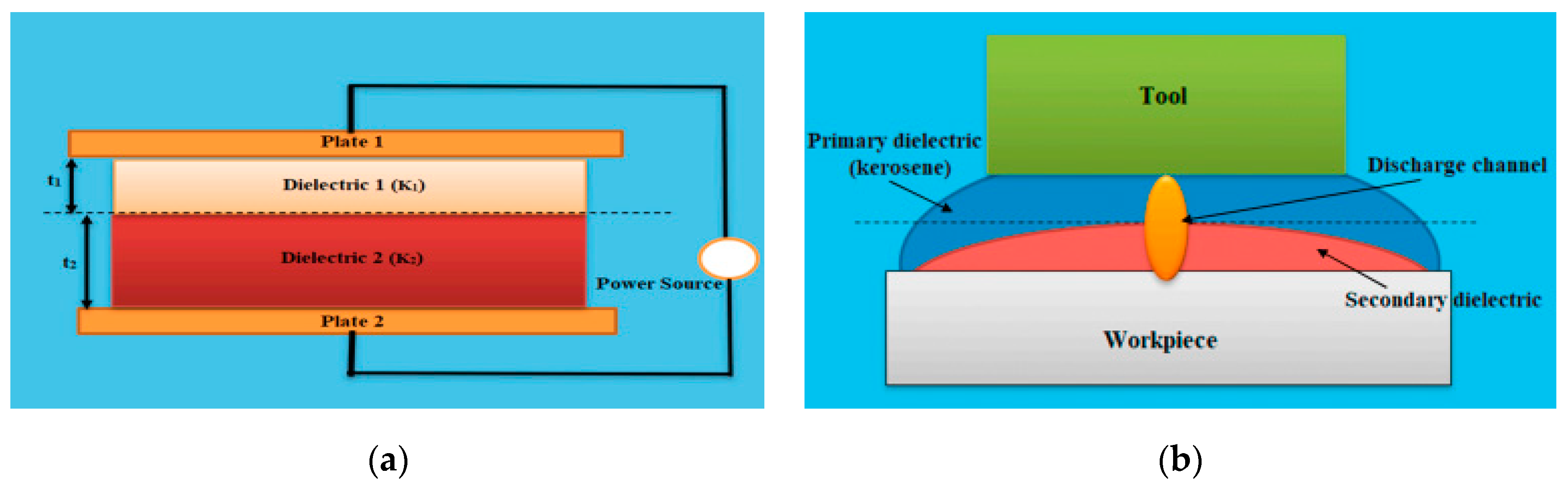
Figure 1. Schematic diagram of EDM.
Machines 11 00906 g001
Figure 2. EDM input and output parameters [11].
Machines 11 00906 g002
Figure 3. Evolution of EDM process based on application [15,23,24,25,27,30,31,32,33,34,35,36,39,40,46,47,48,49,50,51,52,53].
Machines 11 00906 g003
Figure 4. Schematic diagrams of (a) parallel capacitor and (b) gap-active EDM [54].
Machines 11 00906 g004
Figure 5. (a,b) Comparison of MRR for normal EDM and GA EDM [54].
Machines 11 00906 g005
Figure 6. Types of EDM gap flushing.
Machines 11 00906 g006
Figure 7. Solid-additive-mixed PMEDM of different powders as indicated in different colours.
Machines 11 00906 g007
Figure 8. Comparison of dry EDM of carbon steel using various gases in terms of MRR [38].
Machines 11 00906 g008
Figure 9. Schematic diagram of dry EDM.
Machines 11 00906 g009
Figure 10. Effect of surfactant additive on (a) MRR and (b) SR [23].
Machines 11 00906 g010
Figure 11. SEM images of electrical discharge-machined samples using additives at (a) 14 g/L graphite powder and (b) 16 g/L graphite powder [90].
Machines 11 00906 g011
Figure 12. Factors affecting electrode performance.
Machines 11 00906 g012
Figure 13. Stages for FDM method of EDM electrode manufacturing.
Machines 11 00906 g013
Figure 14. (i,ii): Material migration through electrode erosion [23].
Machines 11 00906 g014
Table 1. Properties of primary and secondary dielectric fluids used [54].
S/NPropertyPrimary DielectricSecondary Dielectric
1Density (g/cm3)0.840.92
2Viscosity (ŋ)1.34.2
3Flash point (°C)54135
4Sp. heat (J·kg−1K−1)2.11.8
Table 2. Properties of dielectric materials used in EDM [19].
TypeSpecific Heat
(J·kg−1 K−1)
Thermal Conductivity
(W·m−1 K−1)
Breakdown Strength
(kV/mm)
Flashpoint (°C)
Deionized water42000.62365–70Not Applicable
Kerosine21000.142437–65
Mineral oil18600.1310–15160
Silicon oil15100.1510–15300
Table 3. Requirements of dielectric fluids [75].
Dielectric PropertyDesiredHydrocarbon Mineral OilOil/KeroseneWaterBio-Dielectric
Specific gravityLowHighModerateLowLow
Flash pointHighLowLowLowHigh
Oxygen contentHighLowLowHighHigh
ToxicityLowHighHighLowLow
Breakdown voltageHighLowLowModerateHigh
ViscosityLowHighLowLowLow
VolatilityHighHighHighModerateHigh
Carbon contentLowHighHighNegligibleNegligible
BiodegradabilityModerateLowLowModerateModerate
Table 4. Comparative analysis of electrode materials [19].
MaterialMelting Temperature (°C)Thermal Conductivity (Wm−1·K−1)Density
(g/cm3)
MRRTWRManufacturing DifficultyCost
Copper10844018.96High for roughing LowEasyHigh
Graphite335024–4701.811HighLowDifficultHigh
Brass9301598.73High for finishingHighEasyLow
Tungsten369517319.25LowLowDifficultHigh
Tungsten copper alloy350027.2115.2LowLowDifficultHigh
Cast iron120420–707.13LowLowEasyLow
Carbon steel146051.97.85LowHighEasyLow
Zinc-based alloy6931167.14High for roughing HighEasyHigh
Cu-W225022014.84MediumLowMediumHigh
Cu-Gr25502506.8HighLowEasyHigh
Ag-W98016015.28MediumLowDifficultHigh
W-C287084.0215.7HighLowDifficultHigh
Te-Cu6602102.69LowHighDifficultHigh
Table 5. Influence of operational conditions on side clearance.
Rate of CuttingSurface FinishingSide Clearance (mm)
SlowFine0.03–0.06
MediumMedium0.2–0.3
RapidCourse0.5–0.6
Table 6. General methods used for electrode production.
MethodMaterial UsedApplicationMeritDemeritRemarksRefs.
Additive manufacturingABS (for printing) and copper (for metallization)EDMIntricate shapes can be made;
shorter production time
Expensive; limited number of materials; two stages of productionAchieving high quality surface is challenging due to inherent layer effect[10,97,98,99,100,101,102,103,104,105]
Powder metallurgyAll materialsEDM/surface modificationSimplicity and ability to control other properties of electrodeHigh porosity; high tool wear for green compact tool and low tool wear for sintered toolEnables the production of electrodes with tailored properties[106,107,108,109,110,111,112,113,114]
ElectrodepositionConductive materialsEDM Control over electrode’s propertiesHigh tool wearEnhanced electrical and thermal properties[115,116,117,118]
Conventional machiningConductive materialEDM Simple, fast, and cheapNo control over properties of electrode; surface defectsProvides high level of process control[23,119,120,121,122]
Table 7. Comparison of additive manufacturing methods used for electrode manufacturing.
Method UsedAdvantagesLimitationsRemarksRef.
SLAVariety of materials can be printedRequires curing after printing; cannot print large partsNot suitable for EDM electrode production[9]
FDMMaterial flexibility and cost-effectivenessOnly suitable for small sizes; unstable quality of partsRequires more than one stage of production[10]
DMLSFreedom of design, smoothness, and material reusabilityPorous parts; require post-processingCould be an alternative method of EDM electrode production[126]
SLMOverly complex geometry can be produced. Strong and tough parts can be madeProhibitive cost of machines and materials; elevated temperature gradient (may compromise structural integrity)Good for EDM electrode production[134]
Table 8. Fused deposition modelling method of electrode manufacturing.
Electrode ApplicationAdvantagesLimitationsConclusionRef.
Machinability of FDM electrode electroplated with copperThe researchers’ conclusion was that copper-electroplated electrodes were lighter, with weight that was less than one-third of solid electrodes. This made the plated electrodes more convenient to use.The process of plating a complex electrode profile can be complex, and the accuracy of the resulting plated electrode may be inconsistent.The electrical conductivity of the copper-electroplated electrode was found to be the same as that of the solid electrode for each performance measure studied.[97]
Assess effectiveness of tool electrodes made from FDM samples using copper electroplatingThe electrode can be reused by selectively metalizing it again after the previous layer wears out. The demonstrated process reduced metallization time and material while also reducing tool cost and cycle time.Despite its many benefits, the process still lacked dimensional accuracy in machined holes.The results showed that the MRR and TWR achieved with the copper electroplated FDM electrode were higher than those obtained with the
solid copper electrode.
[98]
Machining of EN-19 alloy steel using metalized FDM electrodesUsing a simple electroless process, a metalized thickness of 70 mm (about 2.76 in) was achieved; metalized FDM electrodes outperformed metal copper electrodes in terms of performanceSurface machining lasted about 35 min and rough machining was absent; requires more than one stage of fabricationFor finished machining operations, FDM-fabricated EDM electrodes were better suited, and they can be used to replace complex metal electrodes that have become worn out.[99]
Capability of FDM electrodes during machining processThe electroless method is an inexpensive and straightforward approach. When complex profiled electrodes became worn out, they were required to be promptly reproduced with FDM electrodes.There was no reference in the literature, and machining dimensions were missing. There were no complete investigations.
It requires more than one stage of fabrication.
In every way, the performance of the FDM electrode did not match that of the conventional copper electrode. FDM electrode manufacturing process can rapidly produce replicas of worn-out electrodes with complex profiles.[100]
EDM using metalized FDM electrodes to check for MRR, TWR, Ra and dimensional accuracy Basic methods of metallization, such as electroplating and electroless plating, were employed. A mathematical equation was suggested for regulating the thickness of the coating during electroplating. The FDM-manufactured electrode coated with metal wore out at a quicker rate than did the solid copper electrode.Various metalized electrodes were used to machine various holes. A single electrode’s full machining capability was not investigated.
It requires more than one stage of fabrication.
During roughing, semi-finishing and finishing operations, FDM electrodes coated with metal were less effective than the solid copper electrodes. An optimal set of machining parameters were suggested to enhance machining efficiency.[132]
Possibility of using FDM electrodes to machine Ti-6Al-4V alloyFDM electrodes demonstrated a high potential in PMEDM application to machine intricate shapes.
There was a marked improvement in the average surface quality.
The researchers did not provide information on the coating method used, and there were no dimensions provided for the machining process.Powder-mixed EDM with both CNC (computer numerical control) and FDM electrodes demonstrated an improvement in TWR, MRR and SR. However, this method has the limitation of the range of materials.[133]
Evaluate effectiveness of electrode produced through electroless plating on ABS materialUsing a simple electroless process, a thickness of 1.5 mm (about 0.06 in) was achieved on FDM fabricated parts after metalized. The result was also deemed satisfactory.The machining was limited to the L9 array and a maximum current of 6 A. Further testing is necessary to determine the effectiveness of the electrode.Compared with voltage and pulse on-time, current had a greater impact. The main effect plot was used to identify the optimal parameter settings for the fabricated electrode.[135]
Table 9. Review on surface quality achieved through additively manufactured electrode.
Materials UsedPrinting Method UsedSurface Quality Achieved (µm)Ref.
ABSFDM11.0–75.33[97]
ABSFDM10[98]
ABSFDM3.22–6.9[99]
ABSFDM1–2[100]
CuSTL10[102]
Gypsum (ZP100)STL4.49–10.5[105]
Tungsten carbide (WC)SLM3.15–23.42[134]
ABSFDM2.62–8.07[135]
Table 10. Powder metallurgy electrode production.
Electrode ApplicationAdvantageLimitationsConclusion Ref.
Surface modification via EDM using Ti-powder green compact electrodeThis study was able to achieve surface modification using a Ti P/M tool.The thickness of the modified layer was uneven, and there was excessive tool wear.A proper assessment should be conducted to improve the process. The study did not give details on the methodology.[114]
Surface alloying using P/M composite electrode through electrical discharge texturing of hardened AISI D2Both green compact and sintered electrodes exhibited comparable results. These methods can be used for both machining and improved roll life and performance through EDT. Excellent sparking was achieved.Due to high porosity in green compact tool, the electrical conductivity was low.
Electrodes produced with low compaction pressure could not withstand mechanical forces during spark discharge.
This study suggested that compaction pressure and sintering temperature are critical, and an equilibrium should be maintained. [136]
Surface modification on OHNS steel using Cu-CrB2 green compact electrodeGreen compact electrode modified the surface through material transfer migration (MTR) with composite layers.The composite electrode was found to be sensitive at high pulse discharge current and pulse on-time, which resulted in thicker layers. Electrode wear needs to be controlled.[138]
Reverse EDM process for pattern generation using P/M green compact tool on aluminum 6061’s surfaceThis method has the ability to combine composite material.
Reverse EDM improves MRR.
The geometric deviation of the size is unavoidable due to the process errors.This method is good for EDM and can be employed for potential surface modification.[139]
Table 11. Review of surface quality achieved through powder metallurgy electrode.
Electrode MaterialsWorkpiece MaterialGreen/SinteredSurface Quality Achieved (µm)Ref.
W-CuC-40-Carbon steelSintered3–15[26]
CuTi-6Al4V (α-β)Green/Sintered1–9[30]
CuW/CuInconel 718Green compacted0.05–0.826[108]
W-CuNillSintered3–15[109]
Cu-B4C/CuSAE 1040 SteelSintered2.5–15[111]
Si-Cu MixedAl 6351Green compacted 2.92[112]
TiCarbon steelGreen Compacted20[114]
CuWAl 6061Green compacted1.7[139]
W-CuC-40 SteelGreen Compacted3.2–12.9[140]
Inconel-718-AlAl-7075Green Compacted 1–5[141]
W-CuMild SteelGreen Compacted2.6[143]
Al 7075Inconel 718Green Compacted1.5–2.5[148]
Cu-MnDie steel-H11Sintered3.11[150]
Cu-10Ni-CrStrenx 900 SteelSintered1–9[153]
Cu-WEn31 SteelSintered8.12[160]
TiB2-CuInconel 718Sintered2.71–4.7[161]
Table 12. Review of studies on surface quality achieved through electrodeposition electrode.
Deposited MaterialsDeposition Process UsedSurface Quality Achieved (µm)Ref.
Cu-AlElectroless10–15[103]
CuElectrolessNill[104]
NiElectroless1.3–2.2[105]
HAAnodizationNill[115]
HAPulsed Electrodeposition2–3[116]
HAEffective Electrochemically assisted depositionNill[117]
Table 13. Review of studies on surface quality achieved through conventional electrode.
Electrode MaterialsApplicationSurface Quality Achieved (µm)Ref.
Cu-TiB2Monel 400TM6–9[12]
Cu-MWCNT-Al6061Mild Steel20–37[87]
Cu-NiPCD2.399–2.857[113]
AlSKD Steel5–8[120]
TiCAl5.35–9.07[144]
Cu3Zn2Ti6Al4V2.38–7.39[152]
CuSiSiC1.7[172]
CuSiSiC1.573–1.701[173]
CuD2 die Steel0.006[174]
Graphite1.2363 tool steel0.70–2.23[175]
Disclaimer/Publisher’s Note: The statements, opinions and data contained in all publications are solely those of the individual author(s) and contributor(s) and not of MDPI and/or the editor(s). MDPI and/or the editor(s) disclaim responsibility for any injury to people or property resulting from any ideas, methods, instructions or products referred to in the content.

