Article

Design and Optimization of an Asymmetric Rotor IPM Motor with High Demagnetization Prevention Capability and Robust Torque Performance

1
Department of Electrical Engineering, Harbin Institute of Technology, Harbin 150080, China
2
Chongqing Research Institute of HIT, Chongqing 401151, China
*
Author to whom correspondence should be addressed.
Energies 2023, 16(9), 3635; https://doi.org/10.3390/en16093635
Submission received: 6 April 2023 / Revised: 17 April 2023 / Accepted: 22 April 2023 / Published: 23 April 2023
(This article belongs to the Special Issue Advanced Permanent-Magnet Machines for Electric Vehicles)

Abstract

:
In this paper, an asymmetric rotor interior permanent magnet (ARIPM) motor with high demagnetization prevention capability and robust torque performance is proposed. The key contribution of this paper lies in two aspects. On the one hand, a novel asymmetric rotor with a shifted magnet axis is proposed to improve the demagnetization prevention capability and torque density. In order to obtain a proper asymmetric rotor topology of the ARIPM motor, the multi-physical performances, especially the PM demagnetization characteristics of five types of PM arrangements, are analyzed. Furthermore, an asymmetric rotor with V- and VV-type PM arrangement is preliminarily designed, considering the multi-physical performance balance and the potentially high anti-demagnetization ability. On the other hand, it is found that the asymmetric rotor structure can not only improve the nominal value of motor performance but also can enhance the resistance to the influence of manufacturing uncertainties. Therefore, multi-objective optimization of the ARIPM motor with rotor notch design is carried out to obtain an optimal motor structure with both high nominal value and robustness of motor performances. By comparing the simulation results with those of a benchmark motor, the superiority and validity of the proposed ARIPM motor are confirmed. Experimental tests will be carried out in the future to further verify the effectiveness of the proposed motor.

1. Introduction

In recent years, interior permanent magnet (IPM) motors have been extensively researched for the advantages of high power density, high efficiency, and wide speed range when driving electric vehicles (EVs) and hybrid electric vehicles (HEVs) [1,2,3]. In order to maximize the power density and efficiency, Nd-Fe-B magnets are usually used in the IPM motor with a strong armature reaction magnetic field and bad temperature. Such a harsh working environment often leads to a high risk of permanent magnet (PM) irreversible demagnetization and results in the torque performance decline of IPM motors [4,5,6]. Moreover, in addition to the harsh operating environment, the manufacturing uncertainties during the manufacturing process also lead to the actual motor performance deviating from the design value, which further deepens the motor torque performance decline and even causes motor operation failure. These problems force motor designers to look for better design schemes to improve the torque performance robustness and the demagnetization prevention capability, especially in large-scale industrial production with strict requirements of performance consistency and safety.
Motor topology development and optimization are two main methods to improve the torque performance and demagnetization ability of IPM motors [7,8]. On the one hand, a variety of multilayer barrier synchronous reluctance motors and PM-assisted synchronous reluctance motors have been proposed to enhance the output torque and the utilization rate of reluctance torque [9,10,11]. Yet, these types of motors suffer from some drawbacks, like high torque ripple, complex rotor structure, and low output power compared with pure Nd-Fe-B PM motors. On the other hand, with the continuous upgrading and iteration of products, the PM arrangement of the IPM motor has been greatly changed. For example, the PM arrangement of the Toyota Prius motor has undergone updates and changes from a Flat-type PM arrangement to V- and U-type PM arrangements [12,13]. In [14], three models and prototypes with different PM arrangements (Flat, V, and double layer) were compared. It was concluded that the Flat-type PM arrangement is most likely to be demagnetized under high torque working conditions, while the V-type PM arrangement is most likely to be demagnetized under short circuit situations, and the double layer PM arrangement has the most robust characteristics on anti-demagnetization ability. However, the magnetic equivalent circuit method was used to design the motor structure, which might not be effective enough to obtain the optimal PM parameters and placement. Moreover, the above-mentioned researches mainly design and optimize the motor with symmetric rotor topology. However, for the symmetric rotor IPM (SRIPM) motors, the maximum current angle difference between the PM torque component and the reluctance torque component is basically 45°, resulting in both a low comprehensive utilization rate of the two torque components and relatively high d-axis demagnetization current.
Recently, the IPM motor with asymmetric rotor topology has received more and more attention [15,16,17,18,19]. Different from the conventional SRIPM motor, the ARIPM motor generates an asymmetric magnetic field, which brings the magnet-axis shift effect to improve the utilization rate of PM torque and reluctance torque, as well as reduce the d-axis demagnetization current. In [20], an ARIPM motor with a mixture of ferrite magnets and Nd-Fe-B magnets was proposed, and the performance comparison was made with the BMW i3 IPM motor. The results show that the proposed ARIPM motor has a better flux weakening ability and higher torque density. However, the authors achieve the asymmetric effect by using both Nd-Fe-B magnets and ferrite magnets. In order to achieve better performance compared to the initial design, additional ferrite PM material was added while maintaining the same amount of rare earth PMs, increasing the motor cost. Moreover, the mixture of ferrite magnets and Nd-Fe-B magnets causes the problem that the ferrite magnets are demagnetized by the Nd-Fe-B magnets when the rotor is manufactured separately. In [21], an ARIPM motor with mixed Spoke- and Flat-type PM arrangements was proposed, and finite element analysis (FEA) was used to verify that the proposed asymmetric rotor structure has better demagnetization prevention capability than the traditional symmetric rotor structure. However, only the nominal values of the motor performances were analyzed, and the effect of asymmetric motor structure on the motor performance robustness was lacking, considering the manufacturing tolerances and material property deviations in the manufacturing process. This makes the motor designers reserve the margin to ensure the safe operation of the motor, which not only limits the range of motor performance but also makes it difficult to ensure the consistency of motor performance in mass production.
The purpose of this paper is to investigate the design and optimization of an ARIPM motor with high demagnetization prevention capability and robust torque performance. The contribution of this paper mainly lies in two aspects. On the one hand, based on the performance comparison of five commonly used PM arrangements, a new asymmetric rotor topology with V- and VV-type PM arrangement is preliminarily designed, with consideration of multi-physical performance balance. The V-type PM arrangement is shifted to reduce the maximum torque current angle to further improve the demagnetization prevention capability. Meanwhile, multi-objective optimization is carried out for the optimal shift angle of V-type poles without sacrificing torque performance. On the other hand, considering the uncertain factors in the manufacturing process, i.e., manufacturing errors and material diversities, the performance robustness of the proposed ARIPM motor is analyzed and compared with a benchmark motor by finite element analysis. The results show that the proposed ARIPM motor not only has a high nominal average torque value and demagnetization prevention capability but also possesses robust torque performance under the influence of manufacturing uncertainties.
The organization of this paper is as follows. The basic model with five commonly used PM arrangements and the evaluation methods of motor performances are illustrated in Section 2. And the multi-physical performances are evaluated and compared for a good design foundation of an ARIPM motor in Section 3. Then, multi-objective design optimization of the ARIPM motor is carried out, and the mechanism of performance improvement is analyzed in Section 4. In Section 5, the superiority and validity of the proposed ARIPM motor are confirmed. Finally, the conclusions are given in Section 6.

2. Basic Models and Evaluation Method of Motor Performance
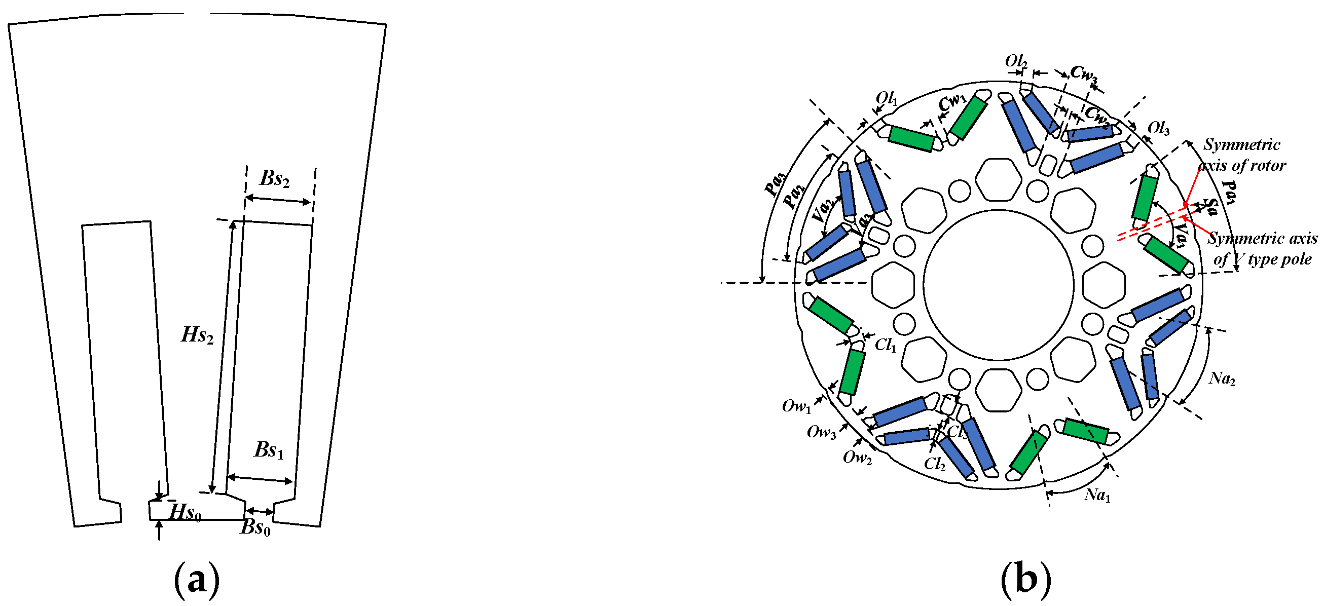
2.1. Basic Models

One effective method to improve the anti-demagnetization ability, torque performance, and other performances is by changing the topology of the IPM motor, especially the PM arrangement. Therefore, five basic models with different PM arrangements in the rotor are compared at first to achieve a proper asymmetric rotor structure with potentially high demagnetization prevention capability and comprehensive good multi-physical performance. The design requirements of the IPM motor are listed in Table 1, and Figure 1 shows the cross-sections of five basic IPM motor models. Each model is optimized to provide the required output torque without violating the design constraints. Moreover, for a fair comparison, only the design variables related to the PM arrangement are varied, and the PM material usage, stator structure, and winding configurations of the investigated five basic models keep the same.

2.2. Evaluation Method of Motor Performance

In this paper, the motor performance analysis is mainly performed by using 2D FEA, and analytical equations are used to interpret the simulation results. As for the evaluation index of PM demagnetization, the ratio of magnet volume that is irreversible demagnetized to the total magnet volume (in %) is regarded as an index to compare the irreversible demagnetization degree. It is calculated as:
δ = 1 B r 1 / B r 0
where Br0 is the initial remanence, Br1 is the demagnetized remanence, as shown in Figure 2a. When δ = 0, the PM behaves without any demagnetization, and when δ = 1, the PM is totally demagnetized. For the PMs used in this study, the knee point appears on the demagnetization curve at high temperatures. This critical temperature used to analyze the PM demagnetization of five basic models is 140 °C, and the criterion for the flux density of irreversible demagnetization is 0.4 T at 140 °C, as shown in Figure 2b.

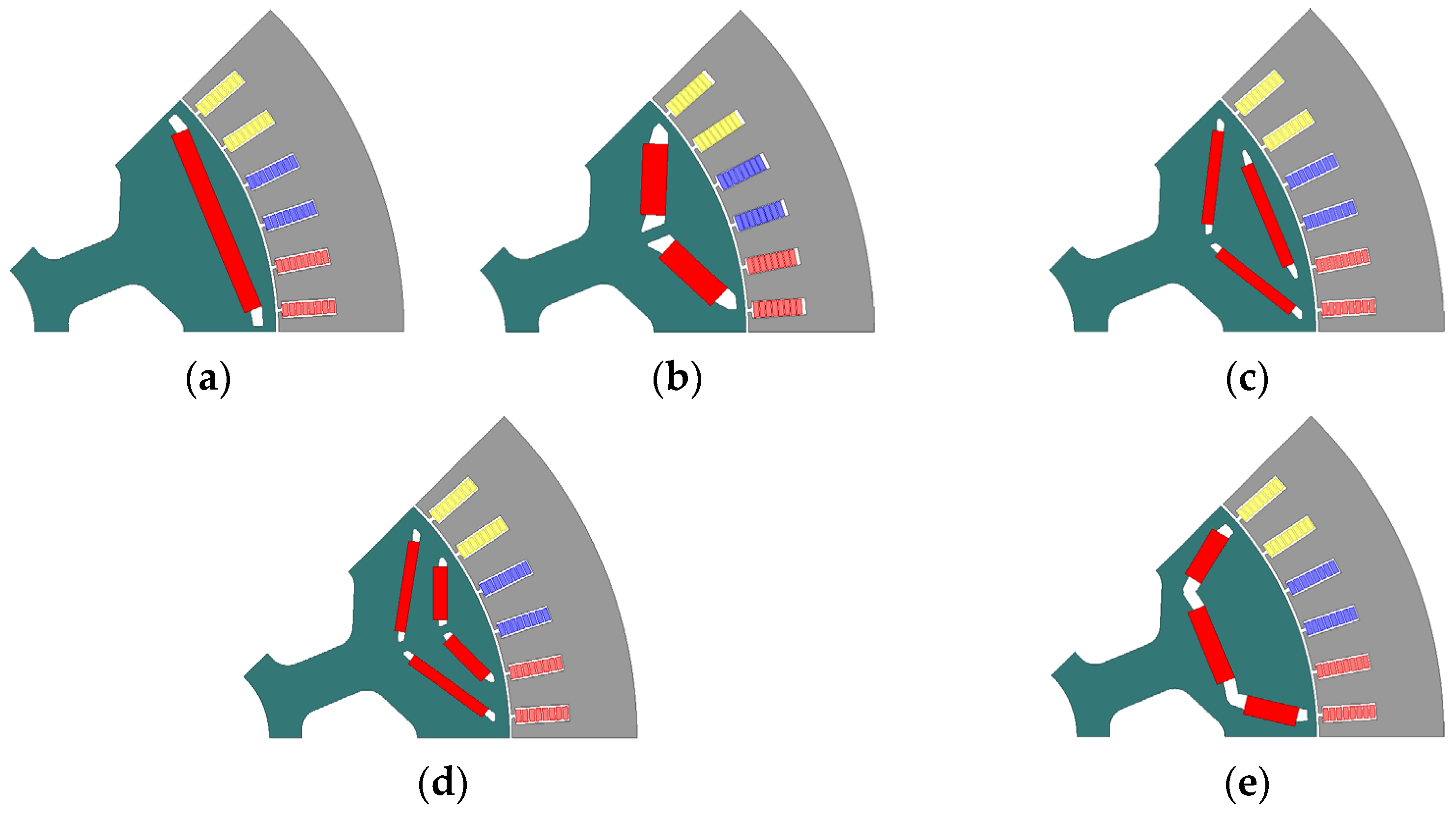
3. Motor Performance Comparison of Five Basic IPM Motors

This section compares the multi-physical performance of five basic IPM motors, including electromagnetic performance (Torque, inductance, and saliency ratio), thermal performance (efficiency and loss), mechanical performance (critical speed), manufacturing (manufacturing difficulty), and robustness (demagnetization ratio and robustness). Special attention has been paid to PM demagnetization performance because it significantly affects the operational safety and other performances of IPM motors. All of the results are compared and summarized to find a good design foundation for the asymmetric rotor structure of the ARIPM motor in Section 3. During the FEA simulation, the same voltage and current constraints are applied to the five basic IPM motors.

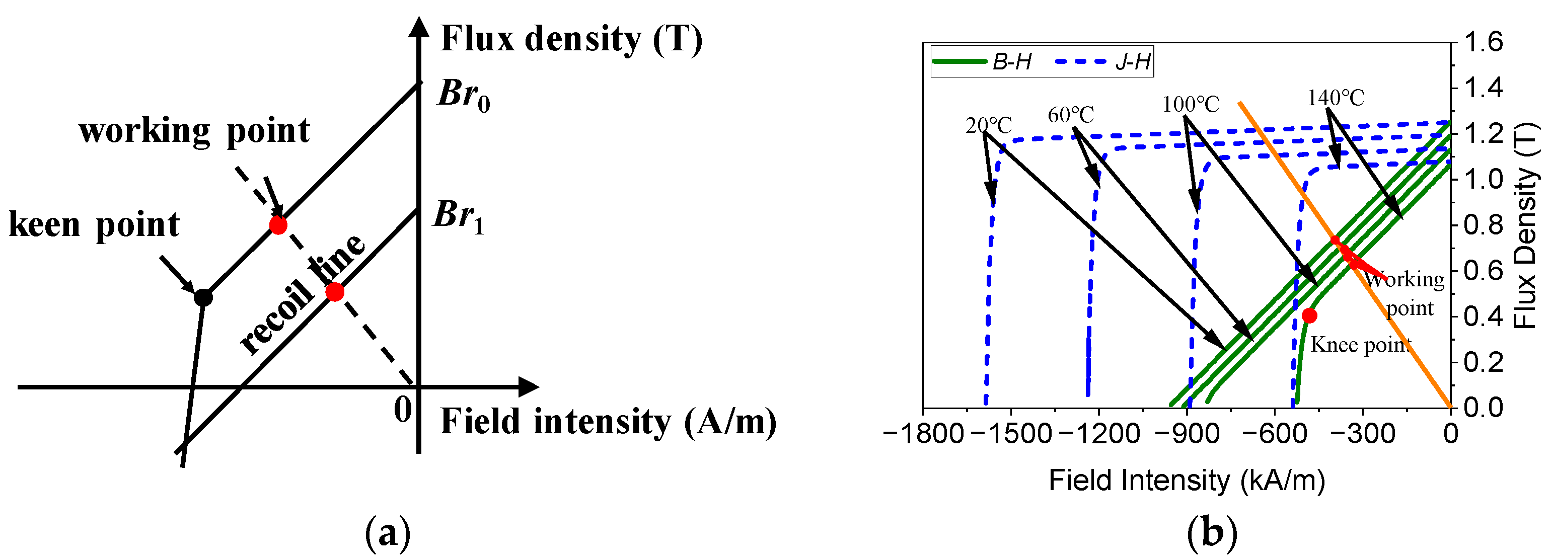
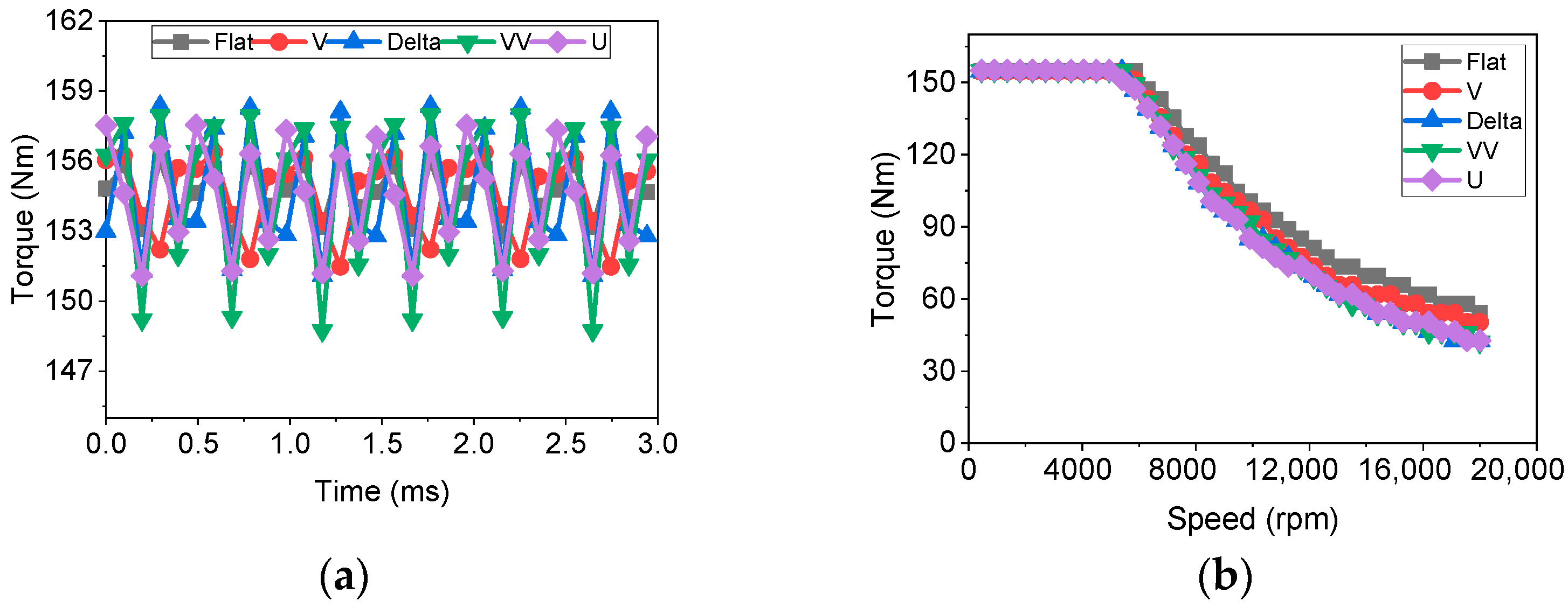
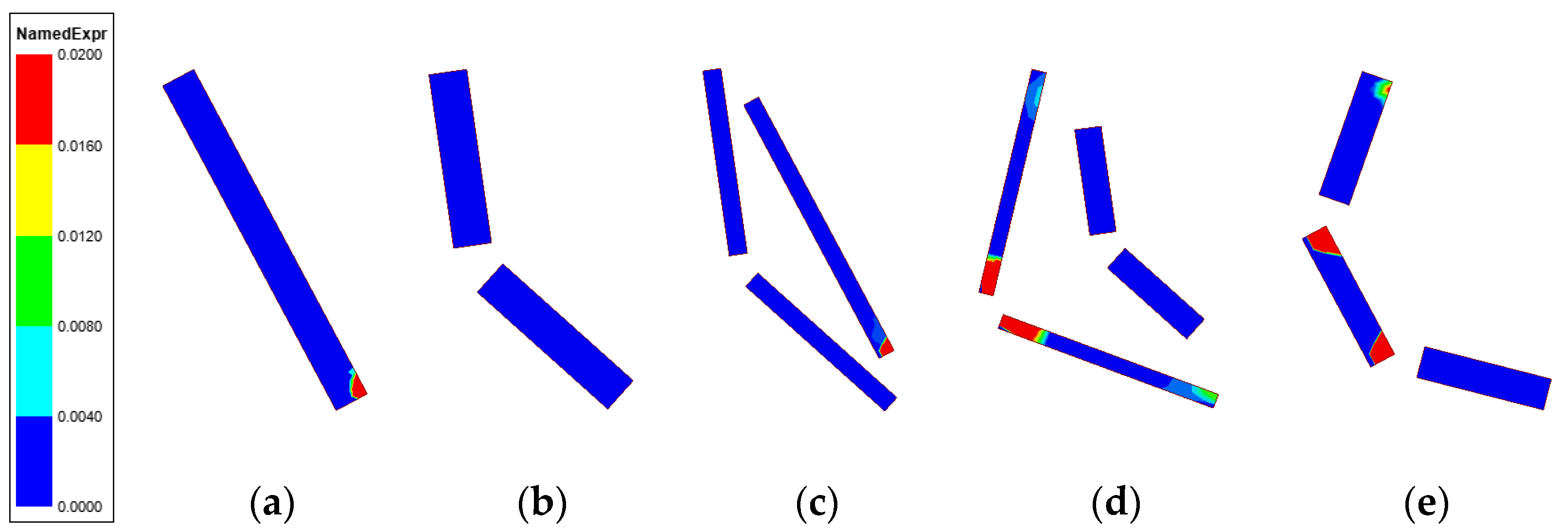
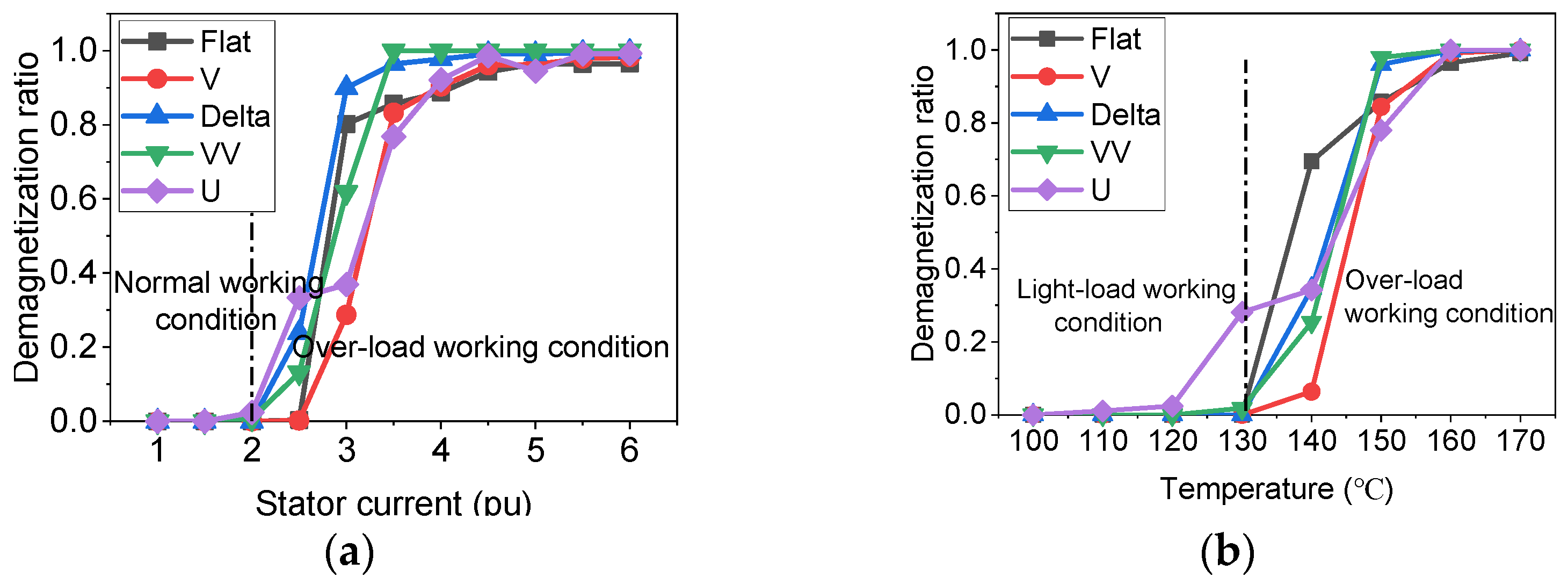
3.1. Torque Characteristics and PM Demagnetization Ratio

For a fair comparison of five basic IPM motors, the motor structures are selected to generate the same average torque with the same maximum current excitation, as shown in Figure 3a. Figure 3b shows the torque-speed curves of the investigated five basic IPM motors, and it can be seen that they provide similar average torque in the maximum torque per ampere (MTPA) region and different torque decrease speeds in the maximum torque per voltage (MTPV) region. Among them, the Flat-type IPM motor possesses the largest flux weakening region, the V-type IPM motor randing the second, and the other three types of IPM motors have basically the same torque-speed curves.
During normal working conditions, the MTPA and MTPV control strategies are adopted. Table 2 lists the maximum d-axis current id and current phase angle β of the investigated five basic IPM motors with MTPA and MTPV control strategies. Figure 4 shows the demagnetization map of the PMs of the investigated five IPM motors. Generally, the motor can still operate safely with the PM demagnetizing ratio of less than 2%. It can be seen that in addition to the V-type PM arrangement, the other four types of PM arrangements have areas with a demagnetization ratio of more than 2%, which leads to operation safety risks. The reasons for the PM demagnetization difference of the investigated five IPM motors are as follows:
In order to obtain the required output torque with limited PM volume, a large pole arc coefficient is needed to achieve the desired air-gap flux density. As a result, (1) for the investigated VV- and Delta-type IPM motors, the PM bodies are thin due to the relatively large number of PM segments, which leads to serious demagnetization. (2) for the investigated Flat and U-type IPM motors, except for the saturated outside magnetic bridges, the magnetic flux generated by the d-axis current can only pass through the magnetic barrier and PM bodies to form a closed loop, which also results in serious PM demagnetization on the PM corner. (3) the V-type IPM motor not only has more magnetic flux path in the rotor but also has relatively thick PM bodies, which result in a high demagnetization prevention capability.
In addition to normal working conditions, the extreme conditions in which the current phase angle β is 90° with the maximum phase current excitation are also analyzed. Figure 5 shows the comparison of the demagnetization ratio of the investigated five PM arrangements under different currents and temperatures. The half value of the maximum phase current 130A is defined as 1 pu in this paper. It can be seen that all of the investigated five IPM motors show good anti-demagnetization ability at the phase currents less than 2 pu or temperatures lower than 120 °C. While at larger currents or higher temperatures, the demagnetization ratio of the investigated motors will increase quickly. Among the investigated five IPM motors, the V-type IPM motor shows the best demagnetization prevention capability with the same amount of PM usage and output torque constraints.

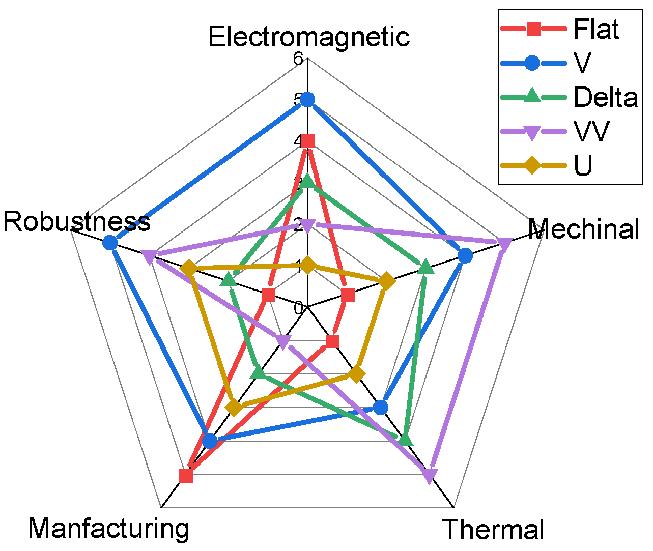
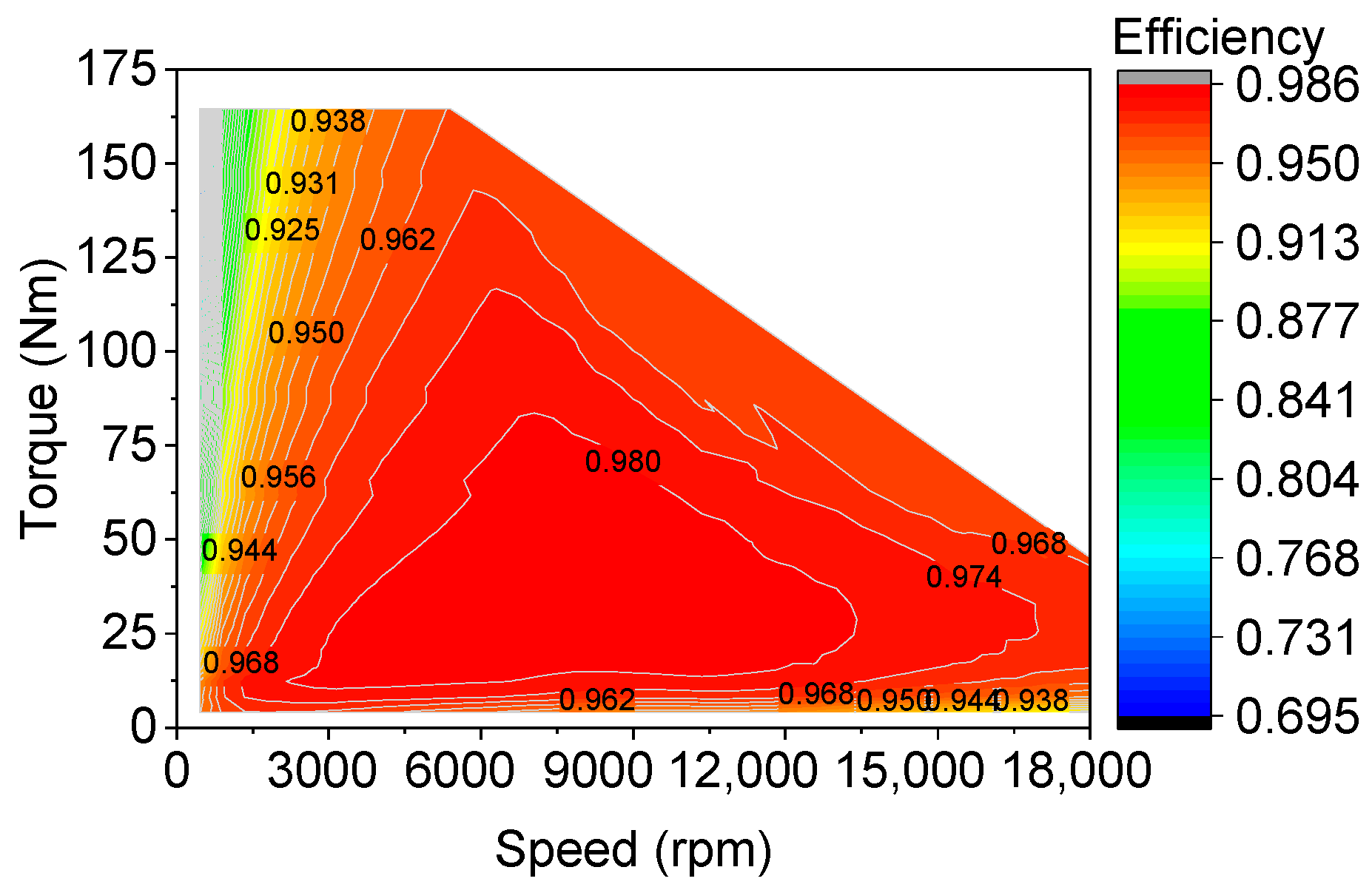
3.2. Multi-Physical Performance Assessment

In addition to the torque characteristics, the other performances, including inductance, saliency ratio, cogging torque, maximum efficiency, core loss, PM loss, the maximum speed within material mechanical stress limitation (critical speed), and manufacturing difficulty, are compared, as listed in Table 2. It can be shown that noticeable differences between the designs exist and that the choice of the PM arrangement plays an important role. The differences mainly result from the different utilization ratios of PM flux and reluctance torque of each investigated PM arrangement. In order to clearly show the advantages and disadvantages of the investigated PM arrangements, an overall assessment represented by a radar map is shown in Figure 6. The investigated performances are divided into five categories, namely electromagnetic (Torque, inductance, and saliency ratio), thermal (efficiency and loss), mechanical (critical speed), manufacturing (manufacturing difficulty), and robustness (indicated by the mean value μ and standard deviation value σ of demagnetization ratio). As for the rating, the best PM arrangement in its class receives a rating of “5 points,” whereas the worst PM arrangement receives “1 point,” and the other PM arrangements receive their rating according to their relative position between the best and the worst value. It should be noted here that a high saliency ratio is considered to be of high importance and have relatively high weight during rating.
It can be seen from Figure 6 that all of the investigated types of PM arrangements have their advantages and disadvantages, without one standing out very much in all disciplines. Additionally, it is worth noting that each of the investigated motors might be further optimized to improve specific performance, but it is not the focus of this paper. Generally, the above studies provide a reference to choose the proper PM arrangement of the IPM motor for the research purpose of this paper. In the overall rating, the V-type PM arrangement slightly leads the ranking. It has the broadest area with comprehensive consideration of the investigated performances. The VV-type PM arrangement ranks second for its visible advantages of mechanical and thermal characteristics, making it better-suitable for high-speed applications. Moreover, the V- and VV-type PM arrangements perform well in terms of PM demagnetization robustness. Therefore, V and VV PM arrangements are selected for the design of the asymmetric rotor IPM motor with the potentially high anti-demagnetization ability and comprehensive good multi-physical performance balance.

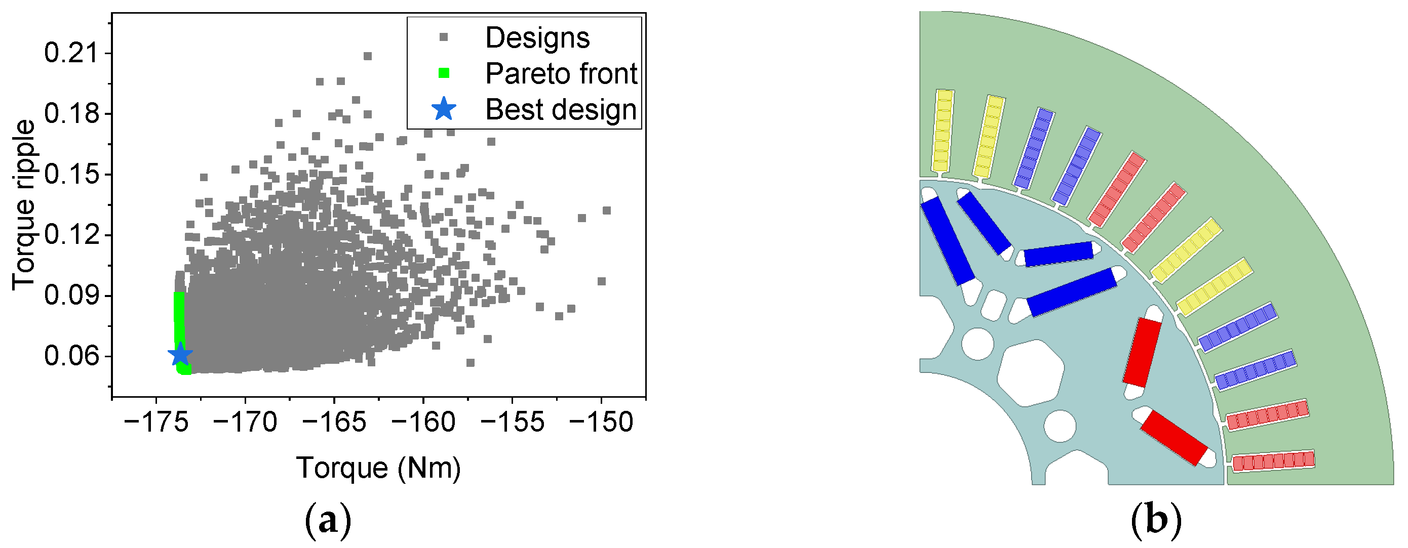
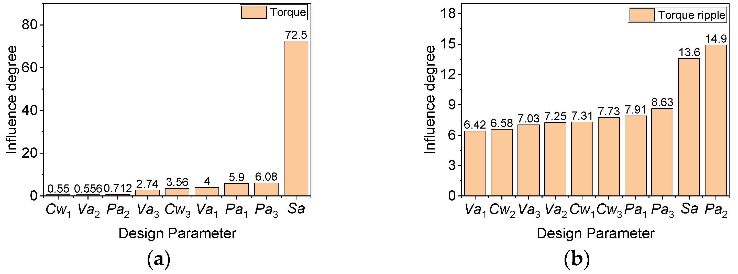
4. Multi-Objective Design Optimization and Performance Improvement Mechanism of ARIPM Motor

4.1. Asymmetric Motor Topologies

Based on the results in Section 3, an ARIPM motor is proposed and optimized. The basic cross-section and parameter definitions of the ARIPM motor are shown in Figure 7. The design procedures of the ARIPM motor are as follows. Firstly, the V- and VV-type PM arrangements are grouped together with 45° spaced intervals. Secondly, the V-type pole is rotated along the circumference direction to improve the torque density and PM demagnetization prevention capability. The rotation angle is defined as the shift angle (Sa) in this paper. Thirdly, in order to reduce the torque ripple with low manufacturing cost, asymmetric rotor notches are also designed to substitute for the rotor step skew. Finally, the multi-objective optimization of the ARIPM motor is carried out by using the non-dominated sorting genetic algorithm II (NSGA II) [22]. The optimization problem of the ARIPM motor is:
min : f 1 x = T r i p f 2 x = T a v e _ p e a k f 3 x = P l o s s s . t . g 1 x = W P M 1 0 g 2 x = T a v e _ p e a k 150 0
where Trip is the torque ripple, Tave_peak is the average value of torque with maximum phase current excitation, WPM is the weight of PM usage, and Ploss is the power loss of the motor, including copper loss, stator/rotor iron loss and PM eddy current loss. Figure 8a shows the Pareto front of the optimization results, and Figure 8b shows the motor structure of the selected best design. It can be seen that after the rotation of the V-type pole, the symmetry axis of the V-type pole no longer coincides with that of the rotor. The value of each design parameter of the ARIPM motor is listed in Table 3.

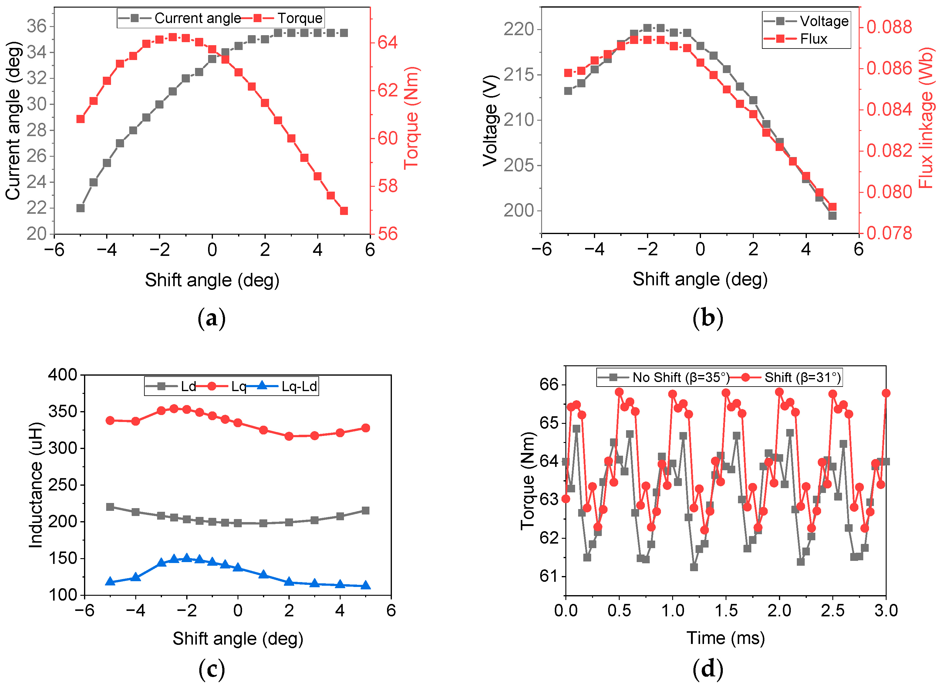
4.2. Effects of V-Type Pole Shift Angle

Figure 9 shows some parameters whose influence degree on torque and torque ripple is greater than 0.5. It is seen that the shift angle (Sa) of the V-type pole has a very significant impact on the torque and torque ripple. Detailly, Figure 10a shows the effect of the shift angle on the current angle and the torque, and Figure 10b shows the effect of the shift angle on the voltage and the flux linkage. It can be seen that with the increase of the shift angle, the current angle increases gradually. However, the torque, voltage, and flux link of the motor increase first and then decrease and reach the maximum value when the shift angle is −1.5 degrees. Therefore, compared with the SRIPM motor, the ARIPM motor can reduce the current angle while retaining the same torque by shifting the V-type pole. Specifically, for the ARIPM motor proposed in this paper, the value of average torque is the same as that of the SRIPM motor when the shift angle is −2 degrees.
Moreover, Figure 10c shows the influence of the shift angle on d-axis inductance Ld and q-axis inductance Lq. It can be seen that with the increase of the shift angle, the value of Lq first increases and then decreases, and the value of Ld first decreases and then increases. The difference between them, LqLd, also shows a trend of first decreases and then increases. The value of LqLd is closely related to reluctance torque and can be expressed as:
T R e l = 3 p 4 L q L d i s 2 sin 2 β
where TRel is the reluctance torque, p is the number of pole pairs, is is the phase current. According to the results shown in Figure 10c, the value of LqLd reaches its maximum at −2 degrees. Therefore, it can be concluded that the utilization ratio of reluctance torque is increased with the asymmetric rotor structure.
Additionally, Figure 10d shows the torque and the maximum torque current angle with and without a shift angle of the V-type pole. It can be seen that the torque of the motor increases while the maximum torque current angle of the motor decreases from 35 degrees to 31 degrees with a shift angle of the V-type pole. The values of the q-axis current, iq, and d-axis current, id, can be expressed as:
β s h i f t = β S a i d _ s h i f t = i s sin β s h i f t = i s sin β S a i q _ s h i f t = i s cos β s h i f t = i s cos β S a
where βshift, id_shift, and iq_shift are the maximum torque current angle, d-axis current, and q-axis current with a shift angle of the rotor pole, respectively. On the one hand, when the maximum torque current angle is reduced, the value of the q-axis current, iq, will increase, and the PM torque of the motor will also increase correspondingly. Therefore, the torque increase of the asymmetric rotor IPM motor also partly comes from the improvement of PM torque utilization. On the other hand, when the maximum torque current angle is reduced, the d-axis current will also decrease. Namely, the demagnetization current used to generate a magnetic field opposite to the rotor field decreases, which potentially increases the anti-demagnetization ability of the motor under the MTPA and MTPV control strategy.

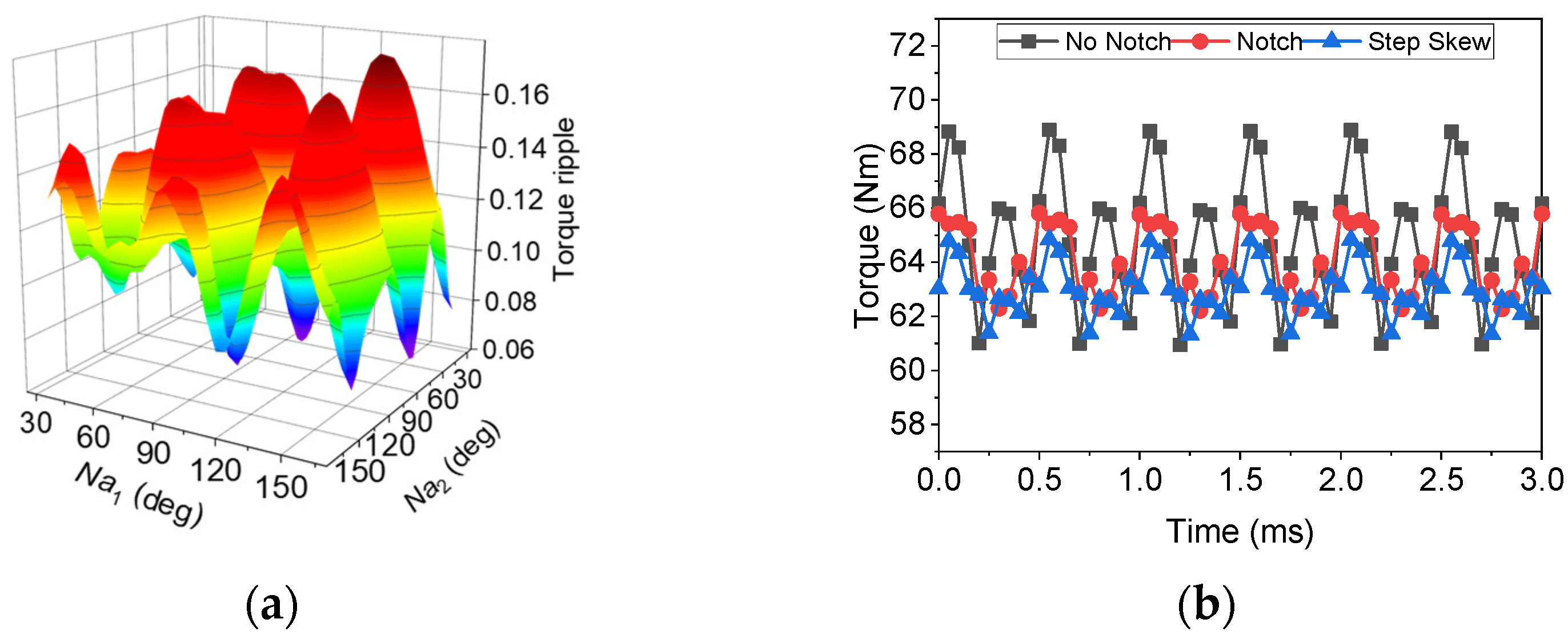
4.3. Effects of Asymmetric Rotor Notch

Figure 11a shows the response surface model (RSM) of the rotor notch angles (Na1, Na2) and torque ripple. It can be seen that the design of the rotor notch can reduce the torque ripple effectively. Figure 11b shows the comparison of torque waveforms with the rotor notch and the rotor step skew method, respectively. It is seen that a similar torque ripple to that of the step skew rotor can be obtained by using the asymmetric rotor notch. At the same time, the manufacturing difficulty and cost of the motor can be greatly reduced by using the asymmetric rotor notch.

5. Performance Superiority Validation of ARIPM Motor

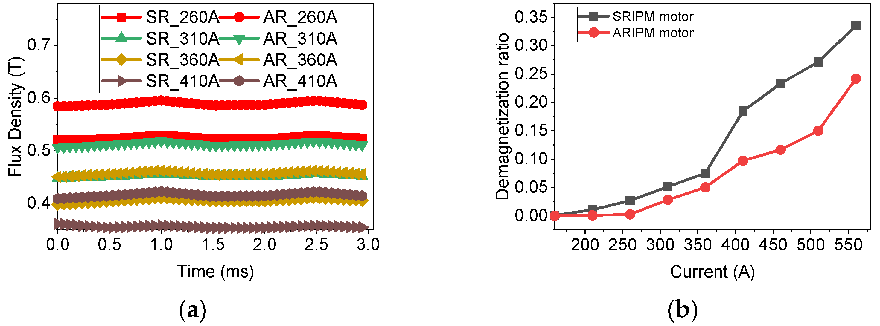
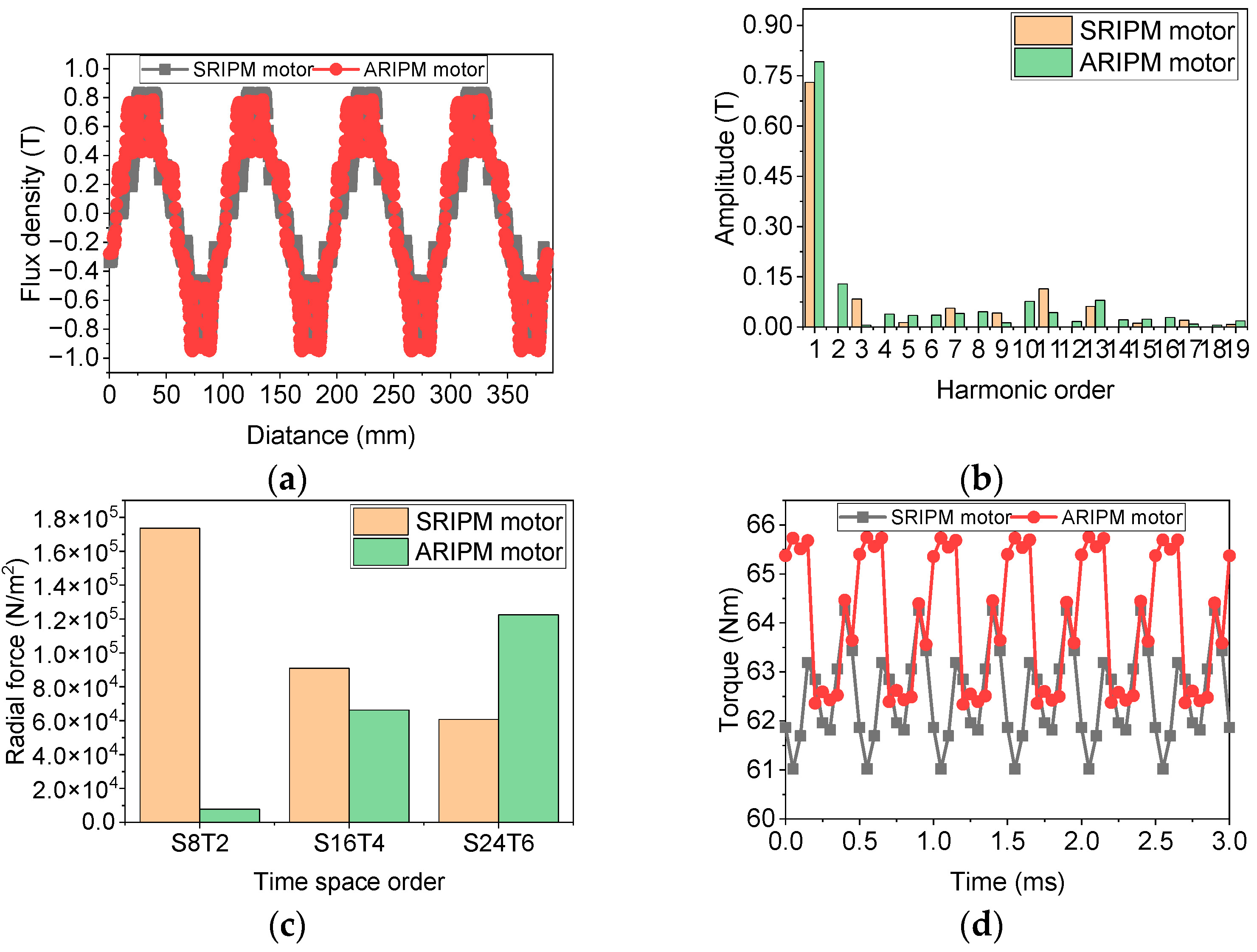
5.1. PM Demagnetization Prevention Capability and Nominal Electromagnetic Characteristics

In order to reveal the effects and advantages of the proposed ARIPM motor, an SRIPM motor, which was designed and prototyped with the same design requirements, is selected as a benchmark motor.
First, the PM demagnetization maps of the symmetric and asymmetric motors are compared, as shown in Figure 12. The PM temperature is set to 140 °C, and the keen point of irreversible demagnetization is 0.4 T. Figure 12b compares the flux density waveforms of a point on the PM corner of the investigated motors under different current excitations. It can be seen that under the excitation of maximum demagnetizing current, irreversible demagnetization will not occur in both motors. Meanwhile, the PM working point of the proposed ARIPM motor is higher than that of the ARIPM motor. In addition, Figure 12b also compares the PM demagnetization ratio of the investigated motors under different current excitations with the same amount of PMs. It can be seen that the proposed ARIPM motor has a lower demagnetization ratio compared with the SRIPM motor, which means that the proposed ARIPM motor has better anti-demagnetization ability. Therefore, the superiority of the PM demagnetization capability of the proposed ASIPM model has been validated.
Second, the electromagnetic characteristics of the SRIPM and ARIPM motors are compared, as shown in Figure 13. It can be seen from Figure 13a that the spatial distribution of the no-load air-gap flux density of the asymmetric rotor IPM motor is also asymmetric about the 0-axis. After the Fourier transformation, it is seen from Figure 13b that the amplitude of the fundamental flux density is improved. Moreover, the values of some low-order radial electromagnetic forces, which have significate effects on the noise and vibration of the investigated motors, are shown in Figure 13c. It can be seen that by the comprehensive use of asymmetric rotor structures and the rotor notch method, the radial electromagnetic force with a space order of eight and a time order of twp (S8T2) and a space order of 16 and a time order of four (S16T4) are reduced, while the radial electromagnetic force with a space order of 24 and a time order of six (S24T6) is increased. According to the law that the lower the order of radial electromagnetic force, the greater the impact on motor noise and vibration, it can be predicted that the proposed motor possesses good noise and vibration performance. This result can be verified by research on motor torque ripple improvement by using asymmetric motor structures in [23,24]. The motor torque waveforms with the same amplitude of phase current are shown in Figure 13d. It can be seen that the average torque of the IPM motor with the proposed asymmetric rotor increases by 2.4% compared with that of the IPM motor with the symmetric rotor.
After the electromagnetic performances and robustness validation of the proposed ARIPM motor, the efficiency map of the proposed ARIPM motor is also investigated, as shown in Figure 14. It can be seen that the maximum efficiency of the proposed ARIPM motor is above 97.4%, and the maximum speed of the MTPA working region is nearly 5000rpm, which fulfills the design requirements listed in Table 1.

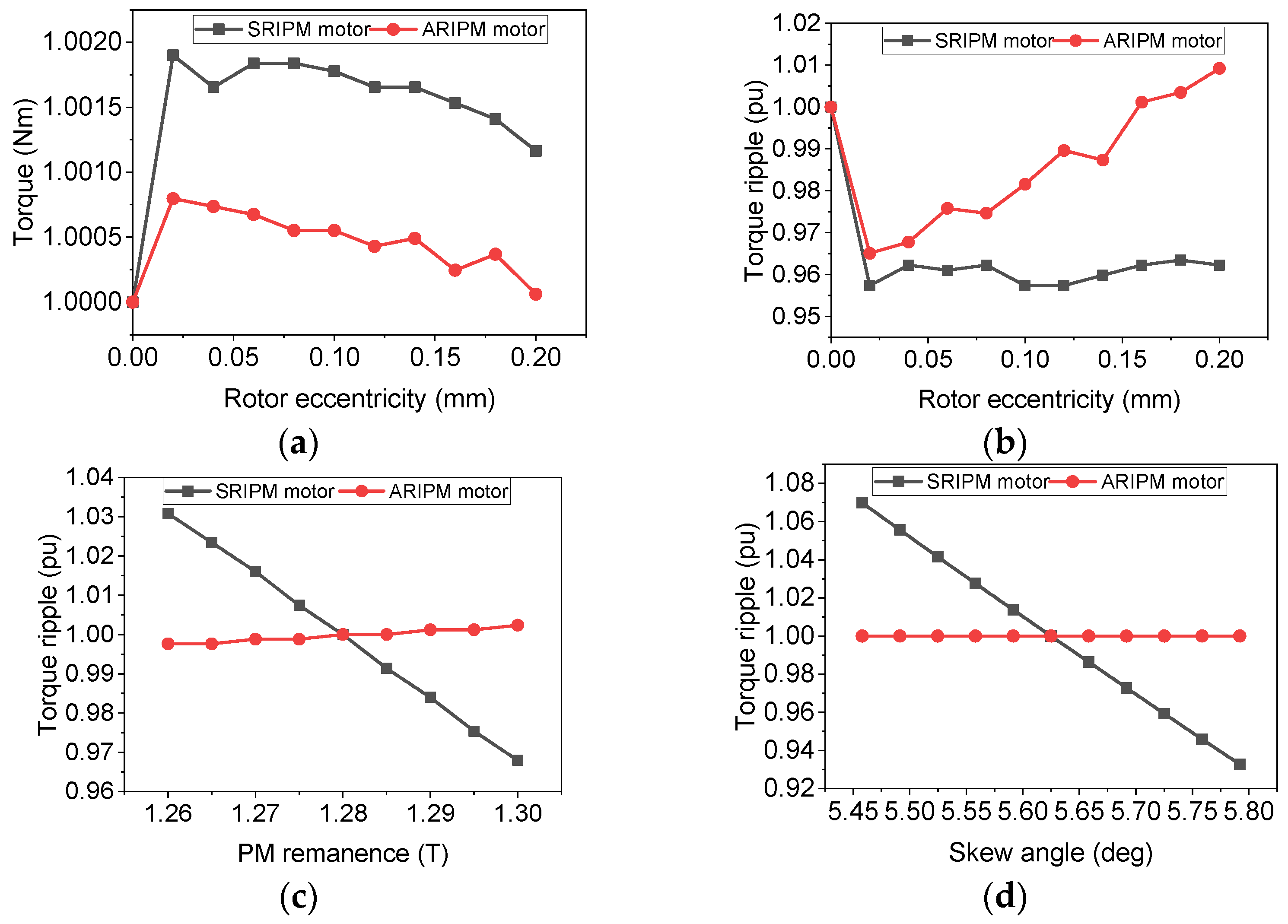
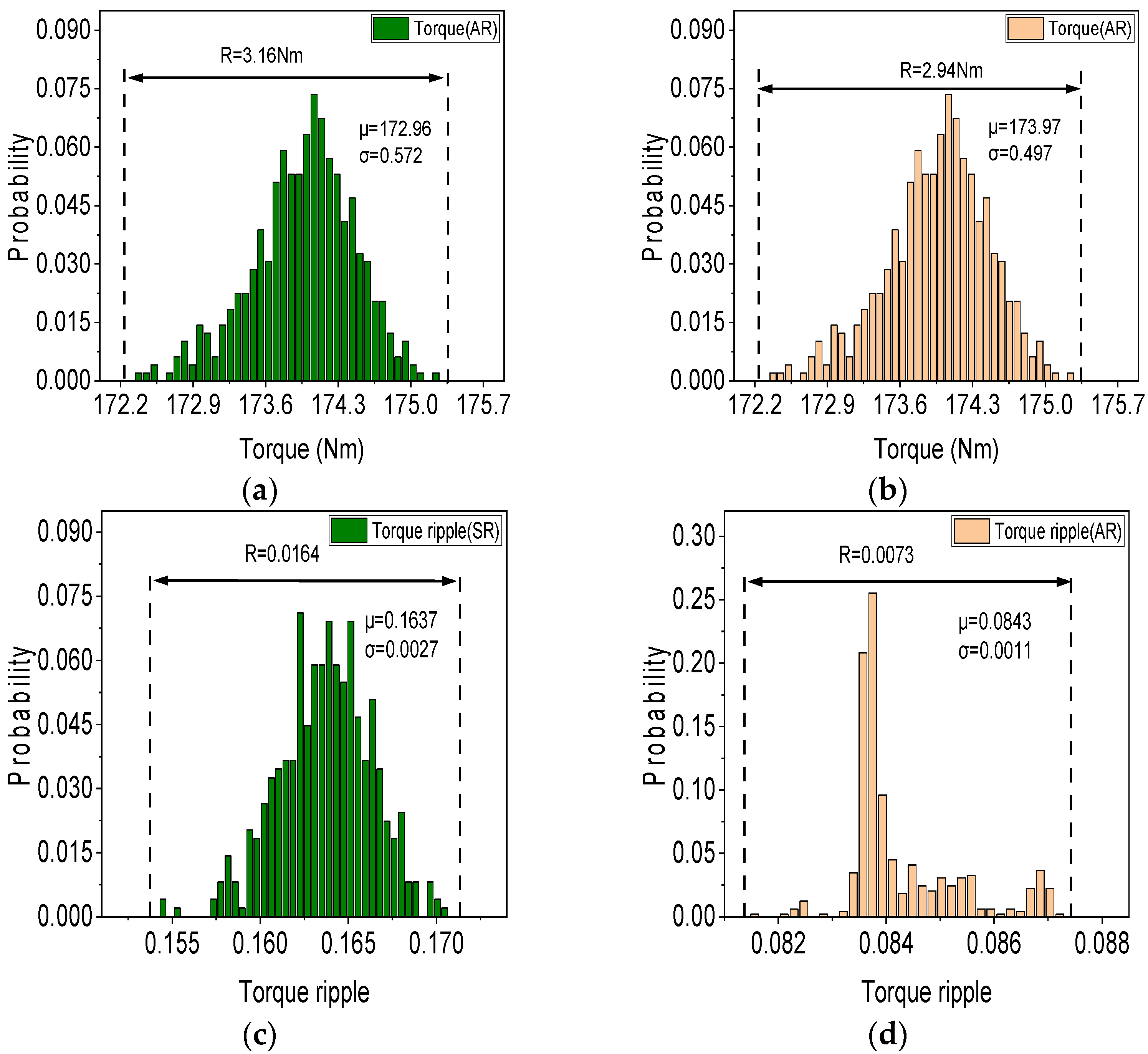
5.2. Torque and Torque Ripple Robustness

Figure 15 shows the performance fluctuations considering the uncertainties of manufacturing tolerance and material deviation. Since the absolute values of the output performance of the two motors are different, the performance of the motors is normalized to ensure the fairness of the comparison. The nominal value, without considering any manufacturing uncertainties, is defined as 1pu. Figure 15a,b show the fluctuations of torque and torque ripple performance considering the manufacturing uncertainties (0, +0.2 mm) of rotor eccentricity. For a motor with robust performance, the fluctuation value after normalization is expected to be close to 1pu. Therefore, it is seen that both the values of torque and torque ripple of the ARIPM motor are closer to 1pu than those of the ARIPM motor. And Figure 15c shows the fluctuations of torque ripple performance considering the material deviation (−0.02 T, +0.02 T) of PM remanence. It also can be seen that compared with the IPM motor with the symmetric rotor, the performance fluctuation of the IPM motor with the proposed asymmetric rotor is much smaller. In this paper, the high-precision laser cutting method is selected for the cutting of the stator and rotor sheets, and the manufacturing uncertainty is ±0.01 mm. Thus, the manufacturing uncertainties of rotor notches can be ignored. Figure 15d shows the fluctuations of torque ripple performance considering the manufacturing uncertainties (−0.15 deg, +0.15 deg) of the skew angle. It can be seen that torque ripple fluctuation can be greatly reduced by using the rotor notch method.
Figure 16 shows the torque and torque ripple robustness considering the comprehensive effects of the investigated manufacturing uncertainties. It can be seen that the performance distributions of torque and torque ripple of the proposed ARIPM motor are more concentrated than those of the SRIPM motor. Meanwhile, the variation range (R), mean value (μ), and standard deviation value (σ) are calculated to indicate the performance robustness. It can also be concluded that the performance of the proposed ARIPM motor is more robust than that of the SRIPM motor.

6. Conclusions

In this paper, the design and optimization of an ARIPM motor with robust torque performance and demagnetization prevention capability are present. The rotor with asymmetric PM arrangements and asymmetric rotor notches is developed to improve the torque and torque ripple performance, as well as demagnetization prevention capability. Both the nominal value of the motor performance and the performance fluctuation considering manufacturing uncertainties are investigated. The results show that the proposed ARIPM motor not only has a high nominal average torque value and demagnetization prevention capability but also possesses robust torque performance under the influence of manufacturing uncertainties. In the future, a prototype will be manufactured to verify the simulation results.

Author Contributions

Conceptualization, Y.C.; Data curation, L.D.; Formal analysis, L.D.; Funding acquisition, Y.C.; Investigation, L.D.; Methodology, L.D.; Project administration, Y.C.; Resources, L.D.; Supervision, Y.C.; Validation, L.D., K.Y. and Y.W.; Writing—original draft, L.D.; Writing—review & editing, Y.C., T.Z. and S.C. All authors have read and agreed to the published version of the manuscript.

Funding

This paper is sponsored by China Heilongjiang Provincial Key R&D Program under Grant JD22A002 and also by the Fundamental Research Funds for the Central Universities under Grant FRFCU5710010719.

Data Availability Statement

The data presented in this study are available on request from the corresponding author.

Conflicts of Interest

The authors declare no conflict of interest.

References

  1. Zhu, X.; Huang, J.; Quan, L.; Xiang, Z.; Shi, B. Comprehensive Sensitivity Analysis and Multiobjective Optimization Research of Permanent Magnet Flux-Intensifying Motors. IEEE Trans. Ind. Electron. 2019, 66, 2613–2627. [Google Scholar] [CrossRef]
  2. Ou, J.; Liu, Y.; Doppelbauer, M. Comparison Study of a Surface-Mounted PM Rotor and an Interior PM Rotor Made From Amorphous Metal of High-Speed Motors. IEEE Trans. Ind. Electron. 2021, 68, 9148–9159. [Google Scholar] [CrossRef]
  3. Sun, X.; Shi, Z.; Lei, G.; Guo, Y.; Zhu, J. Multi-Objective Design Optimization of an IPMSM Based on Multilevel Strategy. IEEE Trans. Ind. Electron. 2021, 68, 139–148. [Google Scholar] [CrossRef]
  4. Choi, G.; Jahns, T.M. Analysis and Design Recommendations to Mitigate Demagnetization Vulnerability in Surface PM Synchronous Machines. IEEE Trans. Ind. Appl. 2018, 54, 1292–1301. [Google Scholar] [CrossRef]
  5. Baranski, M.; Szelag, W.; Lyskawinski, W. Experimental and Simulation Studies of Partial Demagnetization Process of Permanent Magnets in Electric Motors. IEEE Trans. Energy Convers. 2021, 36, 3137–3145. [Google Scholar] [CrossRef]
  6. Chen, H.; Qu, R.; Li, J.; Li, D. Demagnetization Performance of a 7 MW Interior Permanent Magnet Wind Generator with Fractional-Slot Concentrated Windings. IEEE Trans. Magn. 2015, 51, 8205804. [Google Scholar] [CrossRef]
  7. Lim, S.; Min, S.; Hong, J.-P. Optimal Rotor Design of IPM Motor for Improving Torque Performance Considering Thermal Demagnetization of Magnet. IEEE Trans. Magn. 2015, 51, 8202405. [Google Scholar] [CrossRef]
  8. Diao, K.; Sun, X.; Lei, G.; Bramerdorfer, G.; Guo, Y.; Zhu, J. Robust Design Optimization of Switched Reluctance Motor Drive Systems Based on System-Level Sequential Taguchi Method. IEEE Trans. Energy. Convers. 2021, 36, 3199–3207. [Google Scholar] [CrossRef]
  9. Li, W.; Feng, G.; Lai, C.; Li, Z.; Tian, J.; Kar, N.C. Demagnetization Analysis of Interior Permanent Magnet Machines Under Integrated Charging Operation. IEEE Trans. Ind. Appl. 2019, 55, 5204–5213. [Google Scholar] [CrossRef]
  10. Sarikhani, A.; Mohammed, O.A. Demagnetization Control for Reliable Flux Weakening Control in PM Synchronous Machine. IEEE Trans. Energy Convers. 2012, 27, 1046–1055. [Google Scholar] [CrossRef]
  11. Wu, W.; Zhu, X.; Quan, L.; Du, Y.; Xiang, Z.; Zhu, X. Design and Analysis of a Hybrid Permanent Magnet Assisted Synchronous Reluctance Motor Considering Magnetic Saliency and PM Usage. IEEE Trans. Appl. Supercond. 2018, 28, 1–6. [Google Scholar] [CrossRef]
  12. Cao, R.; Mi, C.; Cheng, M. Quantitative Comparison of Flux-Switching Permanent-Magnet Motors With Interior Permanent Magnet Motor for EV, HEV, and PHEV Applications. IEEE Trans. Magn. 2012, 48, 2374–2384. [Google Scholar] [CrossRef]
  13. Liu, X.; Chen, H.; Zhao, J.; Belahcen, A. Research on the Performances and Parameters of Interior PMSM Used for Electric Vehicles. IEEE Trans. Ind. Electron. 2016, 63, 3533–3545. [Google Scholar] [CrossRef]
  14. Ki-Chan, K.; Kwangsoo, K.; Jun, K.H.; Ju, L. Demagnetization Analysis of Permanent Magnets According to Rotor Types of Interior Permanent Magnet Synchronous Motor. IEEE Trans. Magn. 2009, 45, 2799–2802. [Google Scholar] [CrossRef]
  15. Xiao, Y.; Zhu, Z.Q.; Wang, S.S.; Jewell, G.W.; Chen, J.T.; Wu, D.; Gong, L.M. A Novel Asymmetric Interior Permanent Magnet Machine for Electric Vehicles. IEEE Trans. Energy Convers. 2021, 36, 2404–2415. [Google Scholar] [CrossRef]
  16. Xu, G.; Liu, G.; Zhao, W.; Chen, Q.; Du, X. Principle of Torque-Angle Approaching in a Hybrid Rotor Permanent-Magnet Motor. IEEE Trans. Ind. Electron. 2019, 66, 2580–2591. [Google Scholar] [CrossRef]
  17. Li, F.; Wang, K.; Li, J.; Sun, H.Y. Electromagnetic Performance Analysis of Consequent-Pole PM Machine with Asymmetric Magnetic Pole. IEEE Trans. Magn. 2019, 55, 1–5. [Google Scholar] [CrossRef]
  18. Ren, W.; Xu, Q.; Li, Q.; Zhou, L. Reduction of Cogging Torque and Torque Ripple in Interior PM Machines With Asymmetrical V-Type Rotor Design. IEEE Trans. Magn. 2016, 52, 8104105. [Google Scholar] [CrossRef]
  19. Zhao, W.; Zhao, F.; Lipo, T.A.; Kwon, B.-I. Optimal Design of a Novel V-Type Interior Permanent Magnet Motor with Assisted Barriers for the Improvement of Torque Characteristics. IEEE Trans. Magn. 2014, 50, 8104504. [Google Scholar] [CrossRef]
  20. Li, Y.; Yang, H.; Lin, H.; Fang, S.; Wang, W. A Novel Magnet-Axis-Shifted Hybrid Permanent Magnet Machine for Electric Vehicle Applications. Energies 2019, 12, 641. [Google Scholar] [CrossRef] [Green Version]
  21. Zhu, X.; Li, S.; Zheng, S.; Quan, L.; Fan, D.; Zeng, X.; Lee, C.H. Torque Component Redistribution and Enhancement for Hybrid Permanent Magnet Motor With Permanent Magnet Offset Placement. IEEE Trans. Transport. Electrific. 2023, 9, 631–641. [Google Scholar] [CrossRef]
  22. Pang, L.M.; Ishibuchi, H.; Shang, K. NSGA-II With Simple Modification Works Well on a Wide Variety of Many-Objective Problems. IEEE Access 2020, 8, 190240–190250. [Google Scholar] [CrossRef]
  23. Sanada, M.; Hiramoto, K.; Morimoto, S.; Takeda, Y. Torque Ripple Improvement for Synchronous Reluctance Motor Using an Asymmetric Flux Barrier Arrangement. IEEE Trans. Ind. Appl. 2004, 40, 1076–1082. [Google Scholar] [CrossRef]
  24. Ren, W.; Xu, Q.; Li, Q. Asymmetrical V-Shape Rotor Configuration of an Interior Permanent Magnet Machine for Improving Torque Characteristics. IEEE Trans. Magn. 2015, 51, 8113704. [Google Scholar] [CrossRef]
Figure 1. Cross-sections of five basic IPM motor models. (a). Flat-type motor; (b). V-type motor; (c). Delta-type motor; (d). VV-type motor; (e). U-type motor.
Energies 16 03635 g001
Figure 2. Demagnetization ratio definition and PM Demagnetization curve. (a) Demagnetization ratio. (b) PM demagnetization curve.
Energies 16 03635 g002
Figure 3. Torque characteristics of five basic IPM motors. (a) Peak torque waveforms. (b) Torque-speed curves.
Energies 16 03635 g003
Figure 4. Comparison of demagnetization ratio of different PM arrangements. (a) Flat-type PM arrangement. (b) V-type PM arrangement. (c) Delta-type PM arrangement. (d) VV-type PM arrangement. (e) U-type PM arrangement.
Energies 16 03635 g004
Figure 5. Comparison of demagnetization ratio of five PM arrangements under extreme conditions. (a) Effect of stator current. (b) Effect of temperature.
Energies 16 03635 g005
Figure 6. Comprehensive performance evaluation.
Energies 16 03635 g006
Figure 7. Parameter definitions of ARIPM motor. (a) Parameter definitions of the stator. (b) Parameter definitions of the rotor.
Energies 16 03635 g007
Figure 8. Optimization results. (a) Pareto front. (b) Optimal motor structure.
Energies 16 03635 g008
Figure 9. Sensitivity analysis results. (a) Degree of the impact of design parameters on the torque. (b) Degree of the impact of design parameters on the torque ripple.
Energies 16 03635 g009
Figure 10. Effect of shift angle on electromagnetic characteristics. (a) Effect of the shift angle on current angle and torque. (b) Effect of shift angle on voltage and flux. (c) Effect of the shift angle on the inductance. (d) Effect of shift angle on torque and maximum torque current angle.
Energies 16 03635 g010
Figure 11. Effect of asymmetric rotor notch. (a) RSM of the rotor notch on the torque ripple. (b) Comparison of torque with rotor notch and rotor skew.
Energies 16 03635 g011
Figure 12. Comparison of demagnetization of motors. (a) Flux density waveforms of motors. (b) PM demagnetization ratio of SRIPM motor and ARIPM motor under different currents.
Energies 16 03635 g012
Figure 13. Comparison of electromagnetic characteristics of motors. (a) Comparison of no-load air-gap flux density. (b) Comparison of harmonic of no-load air-gap flux density. (c) Comparison of radial electromagnetic force. (d) Comparison of rated torque.
Energies 16 03635 g013
Figure 14. Efficiency map of the proposed ARIPM motor.
Energies 16 03635 g014
Figure 15. Comparison of performance robustness of motors. (a) Torque ripple fluctuation considering rotor eccentricity uncertainty. (b) Torque fluctuation considering rotor eccentricity uncertainty. (c) Torque ripple fluctuation considering PM remanence uncertainty. (d) Torque ripple fluctuation considering skew angle uncertainty.
Energies 16 03635 g015
Figure 16. Torque and torque ripple robustness of motors. (a) Torque robustness of SRIPM motor. (b) Torque robustness of ARIPM motor. (c) Torque ripple robustness of SRIPM motor. (d) Torque ripple robustness of ARIPM motor.
Energies 16 03635 g016
Table 1. Design requirements of the IPM Motor.
RequirementsUnitsTargets
Maximum powerkW70
Maximum speedr/min16,000
Rated speedr/min4500
Maximum torqueNm150
Maximum phase current (rms)A≤260
Efficiency-≥96%
Phase number-3
PM weightkg≤1
PM material-N38SH
Table 2. Multi-physical performance of the IPM Motor.
ItemFlatVDeltaVVU
Maximum d-axis Current (A)358.9360.4357.2360.4338.9
Current angle (deg)77.578.676.378.667.2
Peak torque (Nm)154.9155.0154.9155.1155.1
No load d-axis inductance Ld (mH)1.22361.30581.29081.35291.4815
No load q-axis inductance Lq (mH)2.33842.87292.75182.82552.8385
Saliency ratio LqLd1.11481.56711.4611.447261.357
Cogging torque (mNm) 114.8516.568.7933.83202.13
Maximum efficiency 98.48%98.42%98.52% 98.52%98.32%
Efficiency ratio above 90%0.9510.9710.9720.9750.954
Core loss at rated speed (W)146.271.190.376.7143.2
PM loss at rated speed (mW)29.702.5312.384.8318.65
Critical speed at 400 Map (r/min)73501160010550131508500
Mean value of demagnetization ratio (μ)0.6940.0600.3390.2580.345
Standard deviation value of demagnetization ratio (σ)0.0150.0090.0340.0210.005
Manufacturing cost of rotor sheet ($)1.411.172.252.62.13
Table 3. Design parameters of the ARIPM motor.
ParametersValueParametersValue
Slot depth Hs216.4 mmSlot opening Bs00.9 mm
Slot width Bs13.7 mmSlot bottom width Bs23.7 mm
Tooth tip height Hs00.8 mmV pole angle Pa1115 deg
V opening angle Va1110 degV notch angle Na172 deg
V shift angle Sa−2 degV outer bridge length Ol13.1 mm
V outer bridge width Ow11.4 mmV center bridge length Cl14.7 mm
V center bridge width Cw12 mmVV top pole angle Pa2105 deg
VV top opening angle Va2120 degVV top outer bridge length Ol22.4 mm
VV top outer bridge width Ow21 mmVV top center bridge length Cl24.8 mm
VV top center bridge width Cw21 mmVV low outer bridge length Ol32.4 mn
VV low outer bridge width Ow31.4 mmVV low center bridge length Cl310 mm
VV low center bridge width Cw37 mmVV low pole angle Pa3158 deg
VV low opening angle Va390 degV notch angle Na288 deg
Disclaimer/Publisher’s Note: The statements, opinions and data contained in all publications are solely those of the individual author(s) and contributor(s) and not of MDPI and/or the editor(s). MDPI and/or the editor(s) disclaim responsibility for any injury to people or property resulting from any ideas, methods, instructions or products referred to in the content.

