

A Misalignment Tolerate Integrated S-S-S-Compensated WPT System with Constant Current Output
by
 ,
,
Zhaoyang Yuan
1,
Qingxin Yang
2,*,
Xian Zhang
1,
Xianjie Ma
1,
Ran Wang
1,
Ming Xue
1 and
Pengcheng Zhang
3,* 1
State Key Laboratory of Reliability and Intelligence of Electrical Equipment, Hebei University of Technology, Tianjin 300401, China
2
Tianjin Key Laboratory of New Energy Power Conversion, Transmission and Intelligent Control, Tianjin University of Technology, Tianjin 300384, China
3
Department of Electrical Engineering, State Key Laboratory of Power System, Tsinghua University, Beijing 100083, China
*
Authors to whom correspondence should be addressed.
Energies 2023, 16(6), 2798; https://doi.org/10.3390/en16062798
Submission received: 30 January 2023
/
Revised: 8 March 2023
/
Accepted: 14 March 2023
/
Published: 17 March 2023
(This article belongs to the Special Issue Advances in Wireless Power Transfer System)
Abstract
:This paper proposes a cooperative (Cx) coil design for the series-series-series (S-S-S)-compensated wireless power transfer (WPT) system to improve the horizontal misalignment tolerance and the system efficiency. The Cx coil is formed by four series-connected rectangular coils and integrated into the transmitter (Tx) coil to provide a coupling variation opposite to that of the Tx coil, obtaining the constant equivalent mutual inductance (MI). The design overcomes the problem that the decoupling-designed intermediate coil does not participate in system energy delivery under the well-aligned condition. A misalignment tolerant design with the zero-phase-angle (ZPA) input and load-independent constant current (CC) output conditions is presented based on the Delta-Wye network transform and linear regression. A comparison between the proposed design and a two-coil system using a similar amount of copper, i.e., the Tx coil plus the Cx coil, is made. Finally, a 218.08 W/85.85 kHz scaled-down prototype with the proposed Cx coil is demonstrated to validate the performance and effectiveness of the design. The proposed design can maintain at over 82% efficiency, and offer the ZPA input and load-independent CC output within a misalignment tolerant range of 50% of the length of the receiver coil, as the load varies from 10 to 25 .
1. Introduction
Wireless power transfer (WPT) provides a flexible power supply mode and becomes a promising way to charge electric vehicles (EVs), consumer electronics, biomedical implants, robots, and drones [1,2,3,4]. In a WPT system, energy is transferred through the mutual inductance (MI) of the magnetically coupled transmitter (Tx) and receiver (Rx) coils. Therefore, MI is a critical design parameter to enhance the system’s performance. In practical application, however, the inevitable misalignment between the Tx and Rx coils affects the MI, deteriorating the system power transfer capability, efficiency, and system instability [5]. Moreover, the output voltage/current can be influenced by load variation during the battery charging process [6]. Therefore, more efforts are required to increase the tolerance to load variation and misalignment and enhance MI to improve power transfer efficiency. In addition, to minimize reactive power and improve power transfer efficiency, the zero-phase angle (ZPA) input is desirable.
In recent literature, the additional dc-dc converter [7,8], impedance matching [9], frequency tuning [10], maximum efficiency tracking [11], phase shift control [12,13], duty-cycle control [14,15], load identification [16], etc., have been designed to improve the transferring efficiency and misalignment tolerance. The point to keep in mind here, however, is that this method has limited load adaptability, and the additional control system will increase the system volume, cost, and power loss. In addition, for some control methods, a large number of selection switches and composition components should be introduced for wide misalignment and load variation ranges [17]. Regardless of the extra costs and power losses, reliability issues could be introduced due to the speed and accuracy of the current and voltage sample and the communications [18,19,20]. Furthermore, the switched passive compensation components used in the above methods are mostly nonlinear adjustments with a limited matching range and difficulty guaranteeing matching accuracy.
High-order compensation topology is another way to mitigate the effects of misalignment and load variations on system output, such as inductor-capacitor-capacitor () [21,22], inductor-capacitor-inductor () [23,24], and capacitor-inductor-capacitor () [25] topologies. However, more passive components are introduced, causing a bulky system and extra power losses. Furthermore, the additional high-frequency inductor will cause core loss and thermal issues. The integration design for the high-frequency inductor can solve these issues; nevertheless, the complicated coil design is required to maintain the original input and output profiles.
Recently, to eliminate the drawbacks of additional passive components and control methods, three-coil WPT systems based on an intermediate or a relay coil without control have been studied to improve energy transfer and misalignment tolerance. Based on double-D (DD) coils, an intermediate coil combined with two orthogonal DD coils is proposed in [26]. The intermediate coil is overlapped with the Rx coil. By reconfiguring the intermediate resonant circuit, the constant current (CC) and constant voltage (CV) outputs with ZPA input are achieved under load variation. However, the misalignment tolerance is not discussed in this design. To improve the misalignment tolerance, an intermediate coil-based hybrid inductive power transfer (IPT) system is proposed in [27]. On the reviver side, S and topologies are connected in series based on a bipolar (BP) coil. Due to the intermediate and transmitter coils being formed into a bipolar coil, the y-misalignment tolerance is improved. However, the x-misalignment tolerance is not as good as the y-misalignment tolerance due to the effect of cross-coupling. Due to the overlapped Q and DD coils being naturally decoupled, an intermediate coil with overlapped Q and DD coils is proposed in [28] for a three-coil WPT to maintain the load-independent CV output under misalignment. With a DD-shaped Rx coil, the x-misalignment tolerance is obtained. However, the y-misalignment tolerance is not considered in this design. Furthermore, since the intermediate coil is a decoupling design, it only participates in system energy delivery when the coils are misaligned. In [29], an exciter–quadrature–repeater (EQR) transmitter pad, including one exciter and two repeater coils, is proposed to obtain the load-independent CC charging and ZPA conditions under large lateral misalignment. Due to the two quadrature repeater coils, much larger than the exciter, overlapping to form a BP coil, the y-misalignment tolerance is not improved.
To improve the misalignment tolerance in both x- and y-misalignments, a series-series-parallel (S-S-P)-compensated three-coil WPT system is proposed to tolerate the misalignment and load variations [30]. The load-independent CC and CV outputs with ZPA input are achieved for high system efficiency. Based on sensitivity analysis, a parameter tuning method for the compensation components is proposed, obtaining a mm misalignment tolerance range in both x- and y-misalignments. In [31], two intermediate coils for primary and secondary sides based on S compensation are proposed. The magnetizing impedance between the transmitter and receiver coils without ferrites is improved due to the intermediate coils. Therefore, the core loss is reduced, improving the transfer efficiency. By changing the inverter’s frequency, the CC and CV output are obtained under load variation. However, the misalignment tolerance is poor compared to the coil’s dimension. In [32], a series–series– (S–S-) compensation design with load-independent output voltage is proposed for the three-coil WPT system to tolerate the misalignment and load variations. This design can reduce the voltage stress and increase the power transfer capacity in the entire process of charging. However, the misalignment tolerant range is not presented. In [33], an intermediate coil, which can be switched by an additional inverter between the repeater-aided and power-interactive modes, is designed to enhance the system efficiency and misalignment tolerance. As a result, the CV output with ZPA input is achieved within the 100 cm horizontal misalignment range. However, the additional inverter increases the power loss and requires a control system. In [34], a design method for three-resonator WPT systems with ZPA input and constant power (CP) output is proposed to tolerate coupling variation. The misalignment tolerance of the design outperforms the traditional SS and topologies by sacrificing system efficiency.
In addition, the results of [35,36] have found the intermediate can be placed anywhere between transmitting and receiving coils for different resonant systems. As remarked in [37], its optimal position is mostly determined by the quality factors of resonators. The optimal design guidelines of the resonators are studied in [38]. The intermediate coil can boost the coupling coefficient and output voltage gain, increasing the transfer efficiency. However, the intermediate coil placed in the secondary will cause current stress much higher on the primary [20]. The intermediate coil should be placed on the transmitter to avoid the issue.
To improve the misalignment tolerance in both x- and y-misalignments and improve the system efficiency, a design method for the intermediate coil placed on the primary side based on S-S-S-compensated WPT systems is proposed. The main contributions of this work can be summarized as follows:
- (1)
- A cooperative coil based on a quadruple D-pad is proposed. The cooperative coil is integrated into the primary side to provide a cooperative effect that allows the cooperating coil to participate in system energy transfer under well-aligned and misaligned conditions, thereby improving misalignment tolerance and transfer efficiency. Based on the Delta-Wye network transform, the compensation method to achieve the ZPA input and load-independent CC output is analyzed.
- (2)
- A novel design method for the misalignment tolerance is proposed based on linear regression. The output current and system efficiency can be maintained under both x- and y-misalignments.
The paper is organized as follows: A mathematical description of the cooperative coil is established, and the decoupled equivalent circuit is built to design the cooperative coil in Section 2. The effects of the cooperative coil on power efficiency are analyzed. In addition, the parameters of the compensation topology are designed using the Delta-Wye network transform, considering ZPA input and CC output. In Section 3, to improve the misalignment tolerance, the cooperative coil is optimized based on the minimum variance principle, and the variation is introduced with simulation. In Section 4, the feasibility is verified by experiments. Finally, Section 5 concludes this paper.
2. Analysis and Design of ZPA Input and CC Output of Cooperative Coil
2.1. Analysis and Design of ZPA Input and CC Output
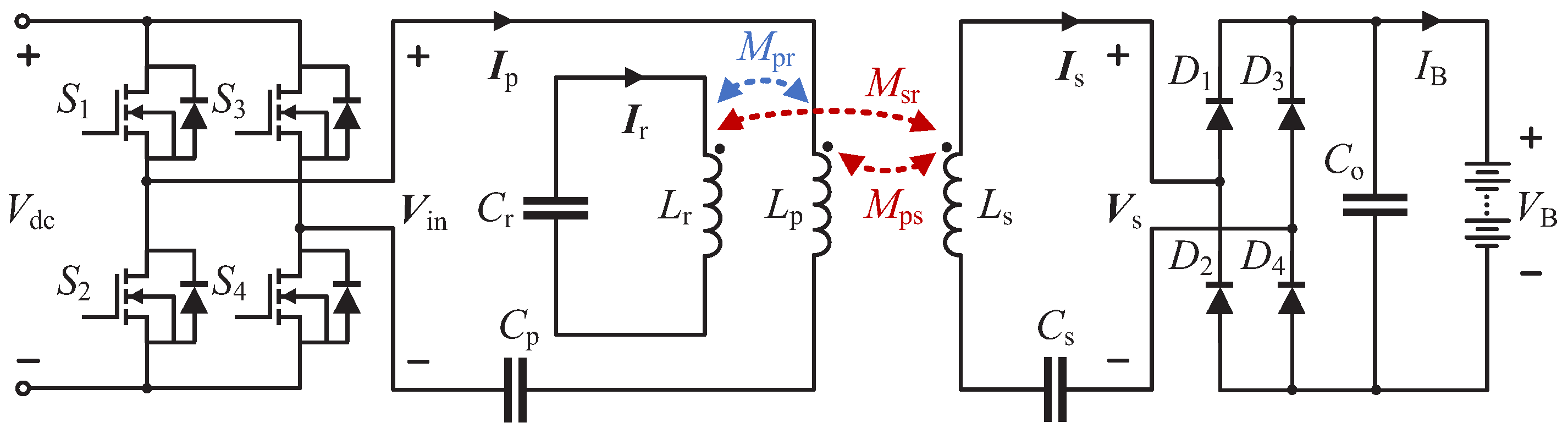
Based on the three-coil WPT system, the separate third coil, named cooperative coil (Cx), is integrated into the primary side to improve transfer efficiency and misalignment tolerance. The proposed WPT system with the cooperative coil using S-S-S compensation topology is shown in Figure 1.
In Figure 1, is the DC input voltage, is the H-bridge inverted output voltage with the nominal operating frequency of 85 kHz. and refer to the inductance and compensation capacitance of the transmitter (Tx) coil. and refer to the inductance and compensation capacitance of the receiver (Rx) coil. and refer to the inductance and compensation capacitance of the Cx coil. , , and are the mutual inductance (MI) between the Tx and Rx coils, the Tx and Cx coils, and the Rx and Cx coils, respectively. is the filtering capacitor. and are the dc charging current and voltage, respectively.
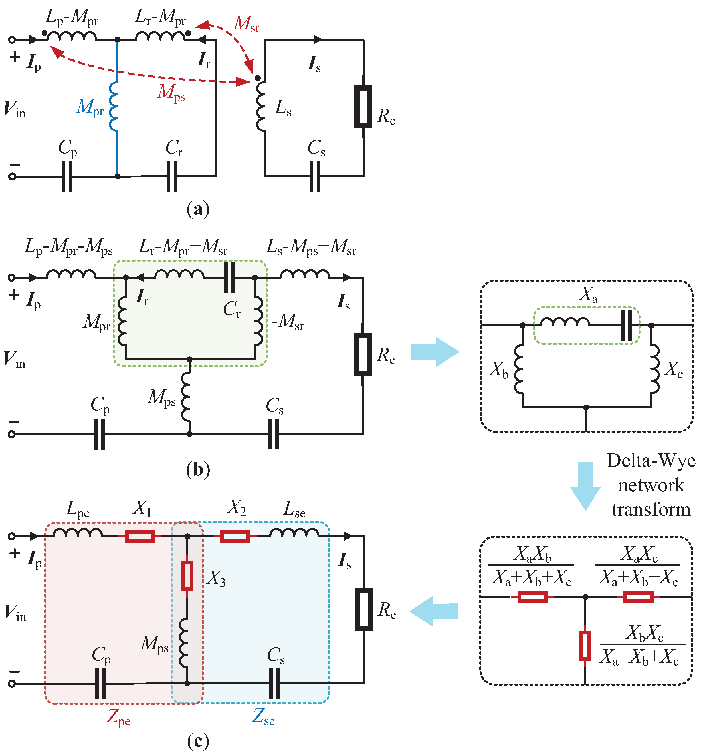
Since the Cx coil is integrated into the primary side, it can be regarded as an auxiliary Tx coil. The circuit in Figure 1 can be simplified to Figure 2a by decoupling the MI based on T model, which is similar to the integrated -S topology. Therefore, the output is the equivalent resistance observed before the rectifier. is the equivalent resistance to model the battery, where . Based on T model, the decoupled equivalent circuit can be obtained when and are decoupled, as shown in Figure 2b. To maintain the polarity of the induced voltage between the Cx and Rx coils, the value of the MI branch in the T model is . Define the following equivalent parameters:
where is the system resonant frequency.
By using the Delta-Wye network transform, the equivalent circuit of Figure 2b can be further simplified as Figure 2c, which is similar to the T-equivalent model of the conventional SS topology. Consequently, the proposed S-S-S topology can offer the ZPA input and CC output. Set the currents in the Tx, Rx, and Cx coils are , , and , respectively. The circuit in Figure 2c can be described by
where
Compared with the conventional SS topology, to obtain the ZPA input and CC output characteristics, the requirements can be concluded as:
which leads to
Under the conditions of (5), the primary current and secondary current can be derived from (2) as:
The current, , flowing in the Cx coil can be derived as:
2.2. Compensation Capacitance of Cooperative Coil
The effects of the Cx coil on transfer efficiency should be analyzed. To investigate the effect, from (2), the equivalent MI between the primary and secondary coils can be expressed as:
Since the transfer efficiency has a positive correlation with the MI, to improve the transfer efficiency of the three-coil WPT system, there should be . In other words, the parameters of Cx coil, i.e., and , should be selected to satisfy the following constraint:
Therefore, based on (7) and (9), the real part of and are in the same direction, and will therefore enhance the main magnetic flux. The efficiency-enhanced three-coil WPT system featuring ZPA input and CC output conditions can thus be obtained based on (5) and (8).
3. Analysis and Design of the Cooperative Coil with High Misalignment Tolerance
3.1. Analysis of Misalignment Tolerance
As shown in (6), the currents will vary with and as misalignment increases. To obtain a stable output within the misalignment tolerant range, there should be a constant difference between and , leading to
where is the resonant angular frequency of Cx coil, as expressed by
Defining the factor p:
the equivalent MI can be expressed as:
Therefore, to improve the transfer efficiency and magnetic coupling, a larger p should be designed. Based on (9), there is , and can be obtained from (11), where p is determined. The design objectives of the coils can be summarized as:
- (1)
- Within a reasonable misalignment range, the trends of and versus the misalignment should be opposite to achieve a stable .
- (2)
- To limit the current and reduce the power loss of the Cx coil and to obtain a larger power transfer efficiency, p should be appropriately large.
- (3)
- To achieve a high misalignment tolerance, the maximum variation of should be minimized within the misalignment range.
Let
to obtain a stable under misalignment conditions, should be maintained as close as possible at a constant value within the range of misalignment tolerance. The variance of is presented as:
where i is the misalignment position, and refers to the position where the primary and secondary sides are well-aligned. n is the number of misalignment positions. is used to limit the current flowing in the Cx coil. At the minimum , stable is achieved.
Subsequently, to look for the minimum point of with respect to p, the first-order derivative of is set to be zero, yielding:
It should be noted here that any multi-coil structure or topology with a similar MI characteristic as in (13) can be designed using the proposed design method.
3.2. Design of Coupler Coils
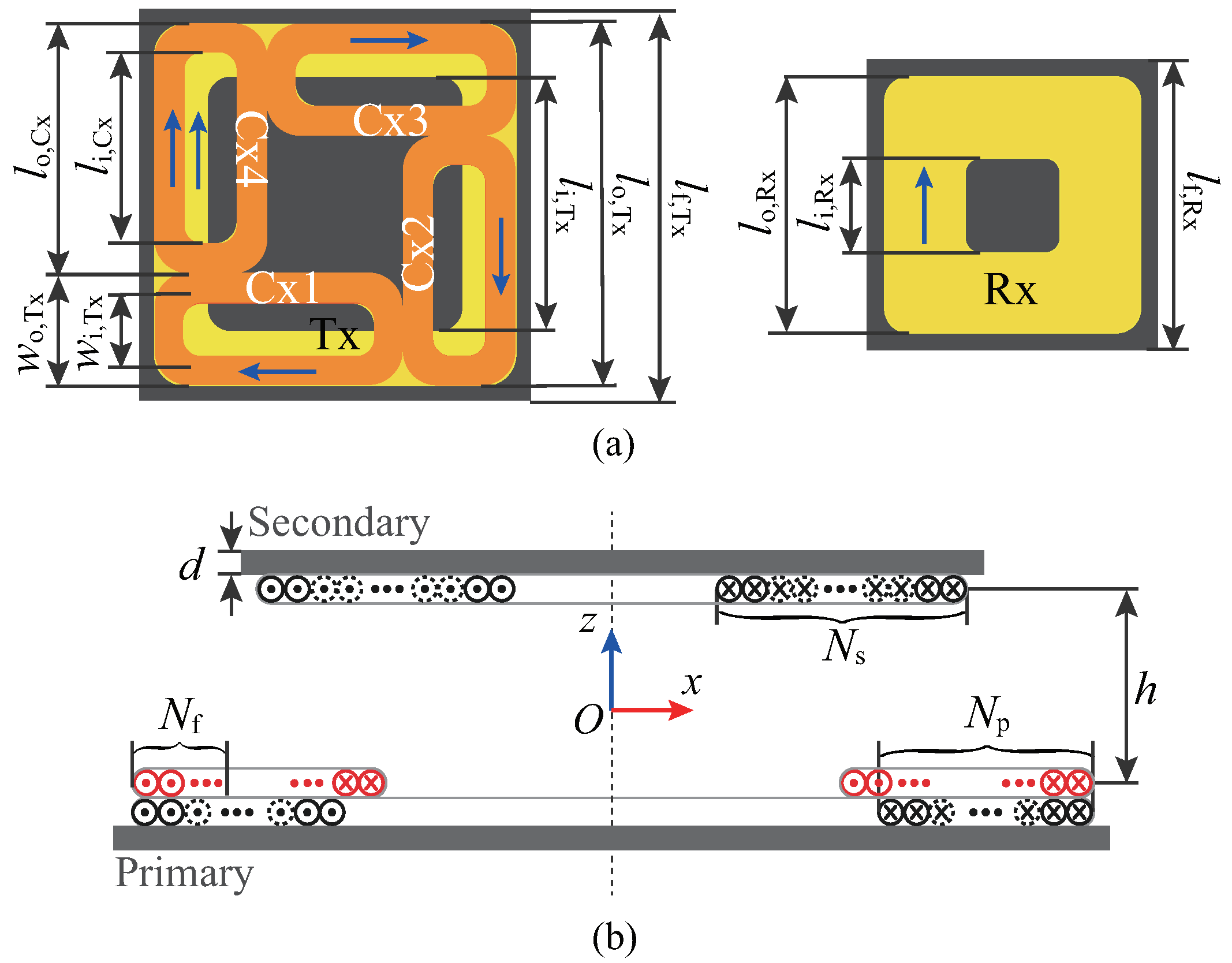
The coil’s structure is proposed in Figure 3. To obtain a larger horizontal misalignment tolerant range, all the coils are designed as square-shaped [39]. Meanwhile, to get identical misalignment tolerant on both x- and y-axes, the Cx coil is a quadruple D-pad, i.e., Cx1, Cx2, Cx3, Cx4, which is identical and symmetrical wounded. To avoid thermal issues caused by coil overlapping and reduce power losses due to the cross-coupling between the four D-pads, the Cx1, Cx2, Cx3, and Cx4 coils are placed end-to-end with the same outer size as the Tx coil. To achieve opposite trends of and under misalignment conditions, Cx1, Cx2, Cx3, and Cx4 coils are placed out of the projection area of the Rx coil, where the centers of the Cx1, Cx2, Cx3, and Tx4 coils are aligned with the outer boundary of the Rx coil, respectively. The blue arrow shows the winding direction of the coils.
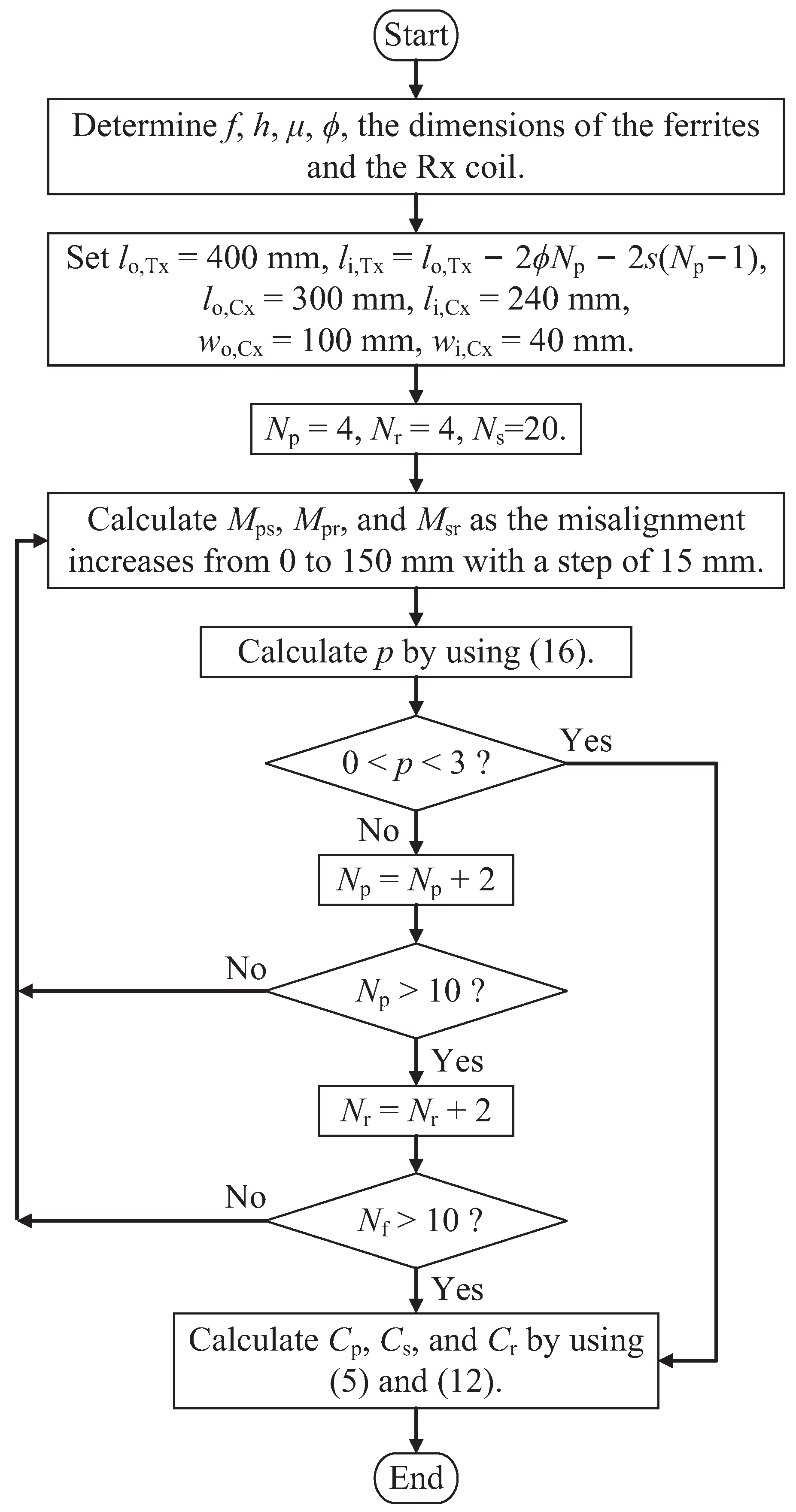
Figure 4 shows the optimization procedure of the coil structures and the compensation capacitors. The outer length, , of the Rx coil is set as 300 mm with turns. Due to the inactive area of the primary coil will increase by designing larger Tx and Cx coils, there will be more magnetic flux leakage, and the outer length of the Tx coil is set to be mm. The Cx1, Cx2, Cx3, and Cx4 coils have the same outer length as the Rx coil, i.e., mm. The out width of the Cx1, Cx2, Cx3, and Cx4 coils is mm. All coils are wound with Litz-wire with a diameter of mm. For the coupling is determined by the active area of coils [40], to achieve a considerably higher p, the inner length of the Rx coil is given as mm, and the inner length and width of the Cx coil are set as mm and mm, respectively. The inner length of Tx coil is · mm is the space between the turns of the Tx coil. and are the number of turns of the Tx and Cx coils, respectively, which both are increased from 4 to 10 with a step of 2 to meet the design objectives. The ferrite layer with a thickness of mm is formed by PC95, which has an initial permeability of 3300, and the outer length of mm, mm. Within the misalignment range, the primary and secondary coils are placed in two perfect parallel planes with mm air gap. At kHz, the optimization procedure as presented in Figure 4 can be summarized as follow:
- (1)
- Within 50% of the length of the Rx coil misalignment, to achieve the increasing as the misalignment increases, the centers of the Cx1, Cx2, Cx3, and Tx4 coils are aligned with the outer boundary of the Rx coil, respectively, i.e., mm, mm.
- (2)
- and combine to a nested parametric sweep, where is the inner sweep increasing from 4 to 10 by a step size of 2. By setting 50% of the length of the Rx coil misalignment tolerant range and increasing from 2 to 10 by a step size of 2, and are obtained to calculate p based on (16). The design outputs all the values of and selected by .
Since the coils are symmetrical, the system has the same output under the x- and y-misalignments. The variations of are calculated and analyzed under the x-misalignment from 0 to 240 mm with a step size of 30 mm, as well as the diagonal misalignment which is composed with equal x- and y-misalignments. By running the flowchart in Figure 4, all possible dimensions of the Cx and Tx coils are listed in Table 1.
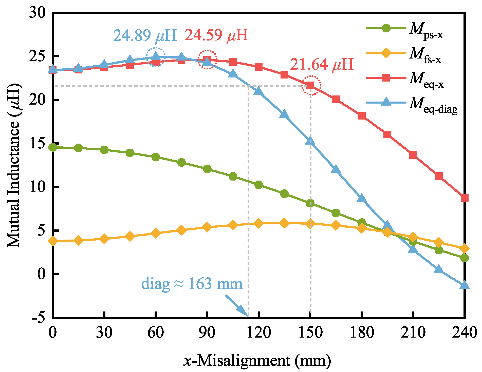
As shown in Table 1, based on an appropriately large p, to improve the coupling between the primary and secondary coils and reduce the magnetic leakage flux, #6 is selected as the optimized design. The variations of , , and the comparison between and versus misalignment under x-misalignment from 0 to 240 mm are shown in Figure 5. The subscripts “−x” and “−diag” refer to the x- and diagonal misalignments, respectively. The diagonal misalignment is composed of equal x- and y-misalignments.
As shown in Figure 5, and have the opposite gain trends versus the misalignment from 0 to 150 mm, which is 50% of the length of the Rx coil. With , the equivalent MI H is obtained under well-aligned condition. Under 150 mm x-misalignment, has an acceptable maximum change of 1.76 H from 23.40 H to 21.64 H. As the x-misalignment increases from 0 to 60 mm, varies from 23.40 H to 24.59 H, which changes only 6.37% compared with the well-aligned position. Considering the same change of 1.76 H to , the diagonal-misalignment tolerant range can reach about 163 mm. Therefore, the proposed design can operate with a stable within 50% of the length of the Rx coil misalignment.
3.3. Comparison between the Two-Coil and the Proposed Three-Coil Systems
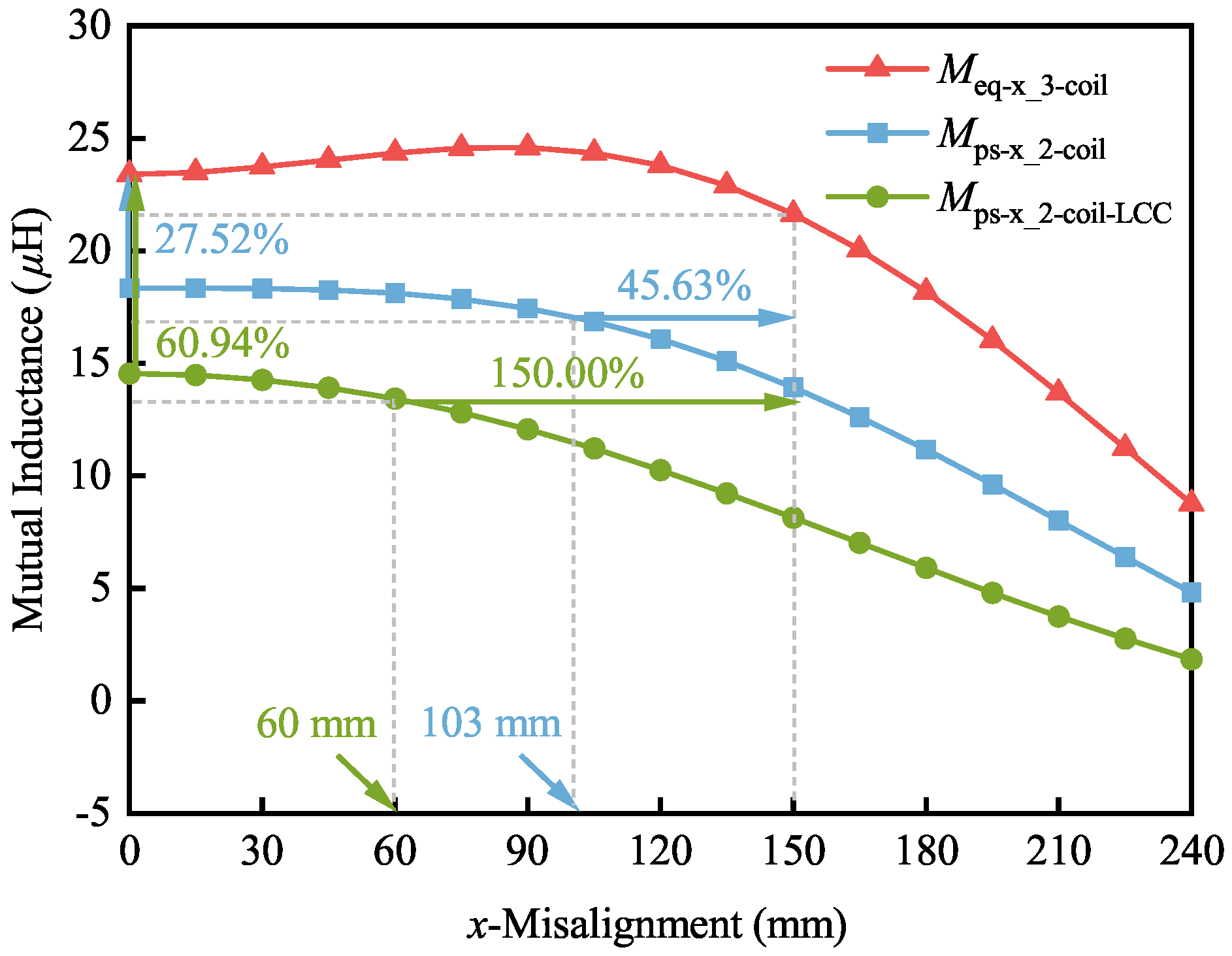
To verify the effectiveness of the improvement of the MI and the misalignment tolerance capability, a comparison between the two-coil and the proposed three-coil WPT system is provided. For the two-coil system, a single primary coil combining both the Tx and Cx coils in series is created. To justify the advantages of the proposed design, an -S-compensated two-coil system is compared. This 2-coil system is created without the Cx coil where the primary coil only consists of the Tx coil. Figure 6 presents the variations of , , and versus x-misalignment from 0 to 240 mm.
As shown in Figure 6, compared with the two-coil system, is improved by 27.52% from 18.35 H to 23.40 H under the well-aligned condition. For the two-coil system, it can be considered as , as shown in (12). Due to the cooperative effect of the Cx coil in the proposed three-coil system, the coupling between the primary and secondary coils is enhanced with . Considering the same maximum change of 7.52%, can be maintained within 103 mm x-misalignment. Compared with the 150 mm x-misalignment tolerant range of the proposed three-coil system, the misalignment tolerant range is improved by 45.63%. Compared with the -S-compensated two-coil system, increases 60.94% from 14.54 H to 23.40 H under the well-aligned condition. Considering the same maximum change of 7.52%, can be maintained within 60 mm x-misalignment. The misalignment tolerant range of the proposed three-coil system is 1.5 times that of the -S-compensated two-coil system.
4. Experimental Study
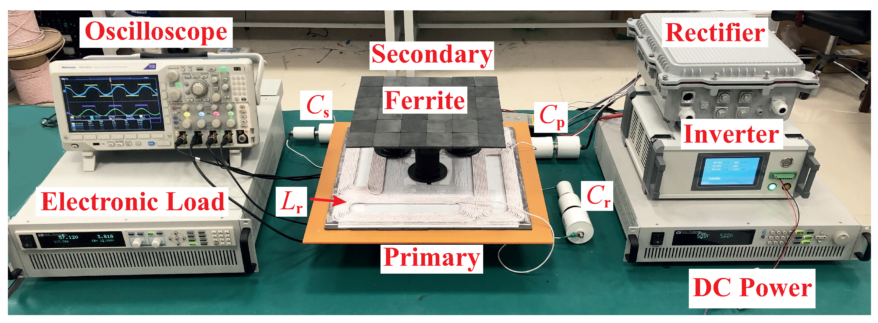
To demonstrate the effectiveness of the proposed design, a 220-W scaled-down experimental prototype is built and tested, as illustrated in Figure 7. The prototype parameters are listed in Table 2.
4.1. Experimental Validation of the Efficiency Improvement
The two types of two-coil WPT systems are built to evaluate the effectiveness of the proposed design, and their system parameters are listed in Table 3 and Table 4, respectively.
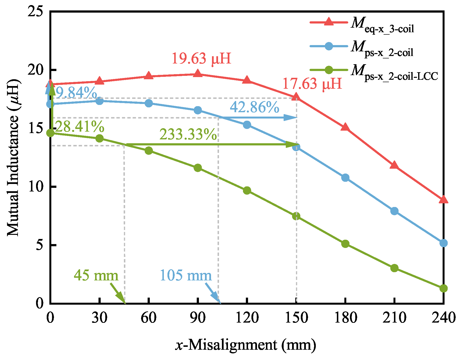
Figure 8 shows the variations of , , and versus x-misalignment from 0 to 240 mm. The results show that the MI between the primary and secondary coils is improved by using the Cx coil. When the primary and secondary coils are well-aligned, is increased 9.84% from H to 18.76 H. Therefore, the system’s efficiency can be improved. Meanwhile, with the same maximum change of 6.02%, the misalignment tolerant range is improved by 42.86% from 105 mm to 150 mm x-misalignment. Compared with , is increased from 14.61 H to 18.76 H, which is improved by 28.41% under the well-aligned condition. Besides, the misalignment tolerant range increases by 233.33% from 45 mm to 150 mm considering the same maximum variation of 6.02%. Regardless of the winding process and the measurement accuracy, the experimental results are consistent with the simulation results.
Under the same rated output power of 220 W condition, when the primary and secondary coils are well-aligned, the DC-DC efficiencies of the two-coil system, the -S-compensated two-coil system, and the proposed three-coil system are 85.23%, 86.04%, and 86.21%, respectively.
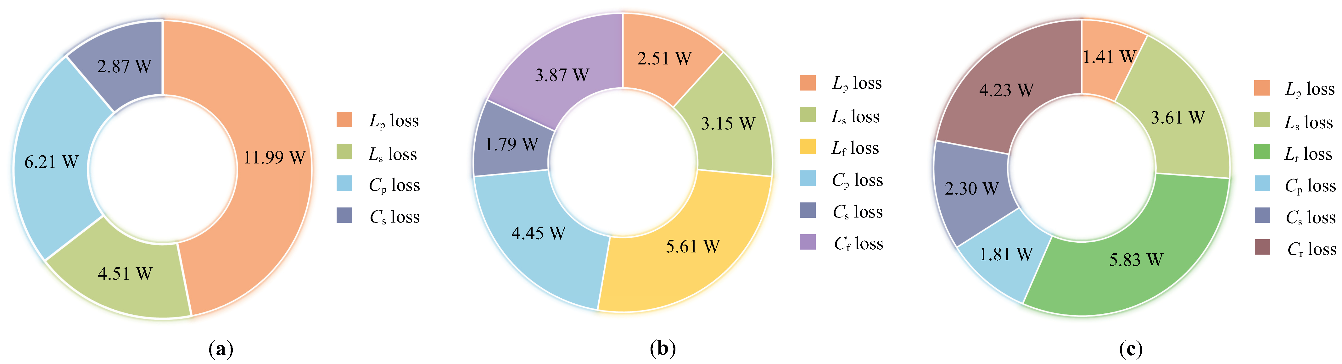
Under the well-aligned condition, the losses of the compensation topologies of the two-coil system, the -S-compensated two-coil system, and the proposed three-coil system are analyzed separately and shown in Figure 9. The losses are mainly coil loss, compensation capacitor loss, and compensation inductor loss. As shown in Figure 9, the total losses of the three systems are 25.58 W, 21.38 W, and 19.28 W, respectively. As shown in Figure 9a, the combination of the Cx and Rx coils will increase the coil resistance leading to a large power loss. Compared with the -S-compensated two-coil system, the power loss of the proposed Cx coil is a little higher than the compensation inductor. Nevertheless, the proposed design has a large MI due to the factor p, which makes the primary current lower than that of the -S-compensated two-coil system to obtain the same output power. Therefore, the additional coil will not cause a significant increase in system losses.
4.2. Experimental Validation of the Misalignment Tolerance
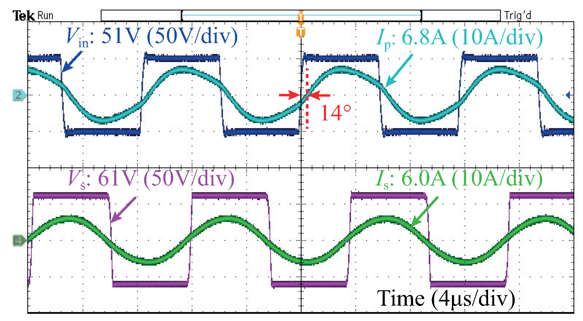
Under the well-aligned condition, the steady-state waveforms of the input voltage and current , and output voltage and current are shown in Figure 10. Under V and , the system has a 218.1 W output power and 6.0 A output current. The phase shift between and is . Considering the value deviation of components and measurement accuracy, the phase shift is acceptable, confirming the ZPA input is achieved.
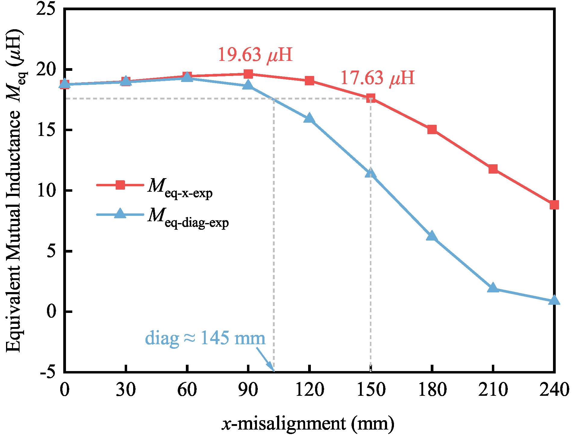
The measured equivalent MI versus the x- and diagonal misalignments are plotted in Figure 11. The subscripts “−x−exp” and “−diag−exp” refer to the x- and diagonal misalignments in the experimental study. It can be found that varies between 19.63 H and 17.63 H within 150 mm x-misalignment, which changes 4.63% and 6.02% compared with the well-aligned condition, respectively. The variations are only 0.87 H and 1.13 H, respectively, which are allowable in practice. With the same maximum change of 6.02%, has about 145 mm tolerant range. Due to the precision of the Litz wire, the winding process, and the measurement accuracy, there will be a difference in and between the experimental and simulation values. In addition, p is obtained based on and under different misalignments, as shown in (13). Therefore, the experimental and simulation values of p will be different. The cumulative measurement errors cause the difference in between the experimental and simulation values. By ignoring the cumulative measurement errors, it can be concluded that the proposed design can maintain the constant output both within 150 mm x- and diagonal misalignments. Therefore, the performance and effectiveness of the misalignment tolerance of the proposed design are only investigated under x-misalignment.
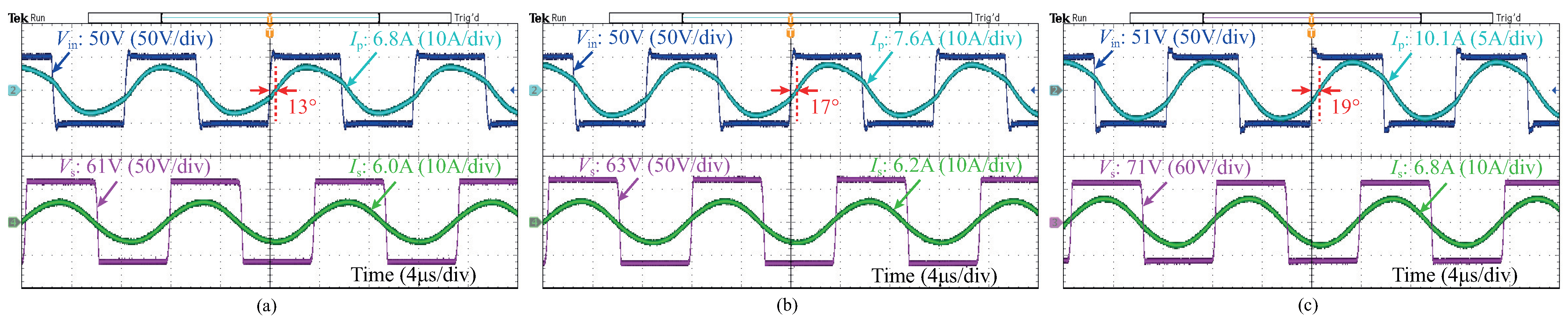
Figure 12 presents the steady-state experimental waveforms of the input voltage and current , and output voltage and current under 50 mm, 100 mm, and 150 mm x-misalignment with Ω. As shown in Figure 11, the phase shifts change from 13 under 50 mm x-misalignment to 19 under 150 mm x-misalignment, which are acceptable in practice considering the measurement errors of the components. Therefore, the system can be considered to achieve the ZPA input. Furthermore, the amplitude of has a maximum change of 13.33% from 6.0 A to 6.8 A under 150 mm x-misalignment compared with the well-aligned condition shown in Figure 10. However, the variation is only 0.8 A, which is allowable and so small that the system can be regarded as CC output. Therefore, the CC output of the proposed design can be maintained within 50% of the length of the Rx coil misalignment range.
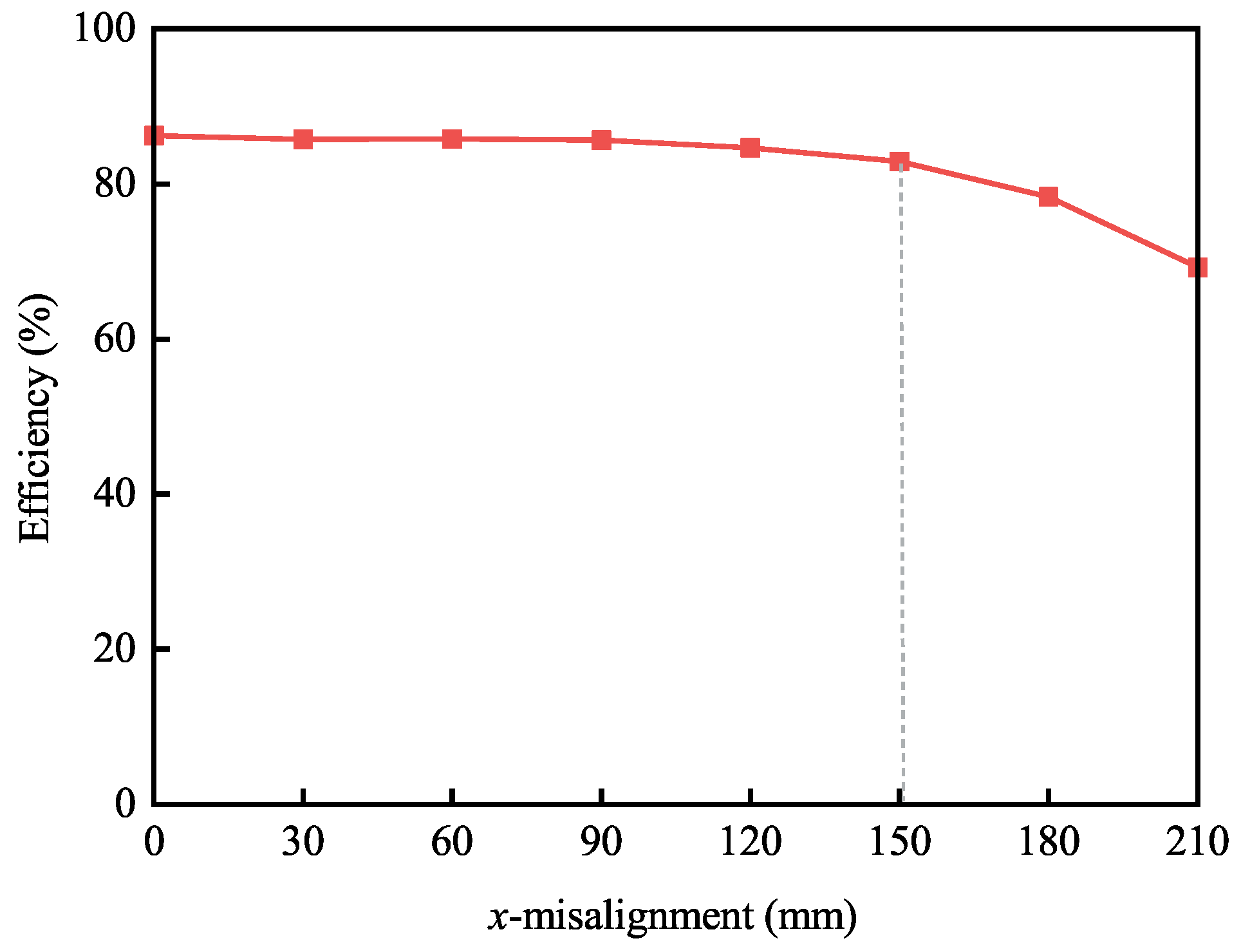
Figure 13 provides the DC-DC efficiency versus the x-misalignment from 0 to 210 mm of the proposed system. Under the well-aligned position, the DC-DC efficiency is 86.21%, which has a maximum variation of 3.33% under 150 mm x-misalignment. The DC-DC efficiency is constant and can be maintained at over 82% within the misalignment tolerant range.
As analyzed, 50% of the length of the Rx coil misalignment tolerance is validated by the experimental results.
4.3. Performance of the WPT System with Load Variation
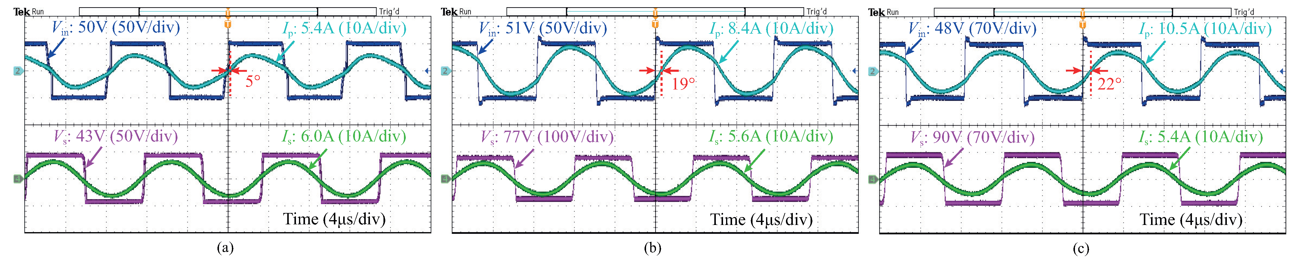
The performance of the proposed design with load variation is analyzed in Figure 14. When the primary and secondary coils are well-aligned, the phase shifts between the input current and the input voltage change from 5 with to 22 with . Compared with the rated power condition with , the maximum change is 9, which means that the load-independent ZPA input is achieved by ignoring the measurement errors of the components and measurement accuracy of the phase shifts. Furthermore, as the electrical DC load changes from 5 to 25 , the amplitude of the output current varies from 6.0 A to 5.4 A, where the maximum variation is 0.6 A. Therefore, the proposed design can offer the load-independent CC output with the ZPA input condition.
4.4. Comparison with Other Methods
A comprehensive performance comparison between the proposed and other misalignment tolerant design methods is given in Table 5. The methods in [26,34] have a larger system efficiency than the proposed design; however, the misalignment tolerance is not designed in [26], and the percentages of the x- and y-misalignments in [34] are smaller than in the proposed design. The method in [27] has a larger percentage of y-misalignment and ∼+60-mm z-misalignment tolerance, yet the x-misalignment tolerance is quite small. Compared with [28], the proposed design method has better system efficiency and larger asymmetrical tolerance in the x- and y-misalignments. Furthermore, the methods in [30,31,33] have a larger system efficiency. Nevertheless, the proposed design method has larger x- and y-misalignments tolerance than [30,31,33], in which the x- and y-misalignments tolerance are asymmetrical. On the other hand, the larger system efficiency in [27,29,32,33] is obtained under a small air-gap in terms of the coil size/diameter. Moreover, the decoupled design for cross-coupling in [26,27,28,29,32] will decrease the degree of design freedom of the coil structure.
5. Conclusions
An integrated S-S-S-compensated WPT system is proposed to improve the system transfer efficiency and the misalignment tolerance. The misalignment tolerant design with ZPA input and load-independent CC output is studied based on Delta–Wye network transform and linear regression. In the proposed design, the Cx coil is formed by four series-connected rectangular coils and integrated into the Tx coil. A cooperative effect, where the MIs between the Tx and Rx coils and between the Cx and Rx coils have opposite gain trends versus the x-misalignment, is achieved to improve the coupling between the primary and secondary coils and misalignment tolerance. A rated at 220 W scaled-down prototype is built to verify the feasibility and effectiveness of the proposed design method. The proposed design method can be used in WPT systems with a similar equivalent MI characteristic to improve output stability under misalignment conditions.
Author Contributions
Writing—original draft preparation, Z.Y.; supervision, Q.Y.; writing—review and editing, Z.Y., X.Z. and P.Z.; validation, Z.Y., X.M. and R.W.; data analysis, M.X., R.W., X.M. and Z.Y. All authors have read and agreed to the published version of the manuscript.
Funding
This research was funded by the National Natural Science Foundation of China Grant numbers 52122701, 52207010, and 52077153.
Institutional Review Board Statement
Not applicable.
Informed Consent Statement
Not applicable.
Data Availability Statement
Not applicable.
Conflicts of Interest
The authors declare no conflict of interest. The funders had no role in the design of the study; in the collection, analyses, or interpretation of data; in the writing of the manuscript; or in the decision to publish the results.
References
- Feng, H.; Tavakoli, R.; Onar, O.C.; Pantic, Z. Advances in High-Power Wireless Charging Systems: Overview and Design Considerations. IEEE Trans. Transp. Electrif. 2020, 6, 886–919. [Google Scholar] [CrossRef]
- Zhang, Z.; Pang, H.L.; Georgiadis, A.; Cecati, C. Wireless Power Transfer-An Overview. IEEE Trans. Ind. Electron. 2019, 66, 1044–1058. [Google Scholar] [CrossRef]
- Wang, J.; Chen, R.; Cai, C.; Zhang, J.; Wang, C. An Onboard Magnetic Integration Based WPT System for UAV Misalignment-Tolerant Charging with Constant Current Output. IEEE Trans. Transp. Electrif. 2022, 9, 1973–1984. [Google Scholar] [CrossRef]
- Yuan, H.; Liang, C.; Zhang, R.; Ruan, Z.; Zhou, Z.; Yang, A.; Wang, X.; Rong, M. A Novel Anti-offset Interdigital Electrode Capacitive Coupler for Mobile Desktop Charging. IEEE Trans. Power Electron 2022, 38, 4140–4151. [Google Scholar] [CrossRef]
- Vu, V.B.; Ramezani, A.; Triviño, A.; González-González, J.M.; Kadandani, N.B.; Dahidah, M.; Pickert, V.; Narimani, M.; Aguado, J. Operation of Inductive Charging Systems under Misalignment Conditions: A Review for Electric Vehicles. IEEE Trans. Transp. Electrif. 2022, 9, 1857–1887. [Google Scholar] [CrossRef]
- Lee, Y.D.; Kim, K.W.; Moon, G.W. A Self-Compensated Planar Coil with Integrated Single-Switch Regulator for Wireless Power Transfer (WPT) Systems. IEEE Trans. Power Electron. 2021, 36, 10954–10958. [Google Scholar] [CrossRef]
- Kim, M.; Joo, D.M.; Lee, B.K. Design and Control of Inductive Power Transfer System for Electric Vehicles Considering Wide Variation of Output Voltage and Coupling Coefficient. IEEE Trans. Power Electron. 2019, 34, 1197–1208. [Google Scholar] [CrossRef]
- Zhang, Q.; Zhang, X.; Li, W.; Hu, T.; Wang, Y.; Shen, S. New Control Method for Receiver-side DC-DC Converter with Large Stability Margin and Fluctuation Suppression Towards DWPT System. IEEE Trans. Ind. Electron. 2022, 1–10. [Google Scholar] [CrossRef]
- Yan, Z.; Yang, B.; Liu, H.; Chen, C.; Waqas, M.; Mai, R.; He, Z. Efficiency Improvement of Wireless Power Transfer Based on Multitransmitter System. IEEE Trans. Power Electron. 2020, 35, 9011–9023. [Google Scholar] [CrossRef]
- Deng, J.; Mao, Q.; Wang, W.; Li, L.; Wang, Z.; Wang, S.; Guidiet, G. Frequency and Parameter Combined Tuning Method of LCC-LCC Compensated Resonant Converter with Wide Coupling Variation for EV Wireless Charger. IEEE Trans. Emerg. Sel. Topics Power Electron. 2022, 10, 956–968. [Google Scholar] [CrossRef]
- Yang, L.; Shi, Y.; Wang, M.; Ren, L. Constant Voltage Charging and Maximum Efficiency Tracking for WPT Systems Employing Dual-Side Control Scheme. IEEE Trans. Emerg. Sel. Top. Power Electron. 2022, 10, 945–955. [Google Scholar] [CrossRef]
- Mai, R.; Liu, Y.; Li, Y.; Yue, P.; Cao, G.; He, Z. An Active-Rectifier-Based Maximum Efficiency Tracking Method Using an Additional Measurement Coil for Wireless Power Transfer. IEEE Trans. Power Electron. 2018, 33, 716–728. [Google Scholar] [CrossRef]
- Jiang, Y.; Wang, L.; Fang, J.; Li, R.; Han, R.; Wang, Y. A High-Efficiency ZVS Wireless Power Transfer System for Electric Vehicle Charging with Variable Angle Phase Shift Control. IEEE Trans. Emerg. Sel. Top. Power Electron. 2021, 9, 2356–2372. [Google Scholar] [CrossRef]
- Liu, Y.; Madawala, U.K.; Mai, R.; He, Z. An Optimal Multivariable Control Strategy for Inductive Power Transfer Systems to Improve Efficiency. IEEE Trans. Power Electron. 2020, 35, 8998–9010. [Google Scholar] [CrossRef]
- Hsieh, H.C.; Nguyen, A.D.; Lai, J.S. Output Regulation With Integrated SR Switch Duty Cycle Control for Wireless Power Transfer Systems. IEEE Trans. Emerg. Sel. Top. Power Electron. 2022, 10, 3161–3169. [Google Scholar] [CrossRef]
- Guo, Y.; Zhang, Y.; Zhang, W.; Wang, L. Battery Parameter Identification Based on Wireless Power Transfer System with Rectifier Load. IEEE Trans. Ind. Electron. 2021, 68, 6893–6904. [Google Scholar] [CrossRef]
- Luo, S.; Yao, Z.; Zhang, Z.; Li, G.; Zhang, X.; Ma, H. A Dual Shunt Inductor Compensated IPT System with Nearly Unity Power Factor for Wide Load Range and Misalignment Tolerance. IEEE Trans. Ind. Electron. 2022, 69, 10001–10013. [Google Scholar] [CrossRef]
- Zhao, L.; Thrimawithana, D.J.; Madawala, U.K.; Hu, A.P.; Mi, C.C. A Misalignment-Tolerant Series-Hybrid Wireless EV Charging System with Integrated Magnetics. IEEE Trans. Power Electron. 2019, 34, 1276–1285. [Google Scholar] [CrossRef]
- Ji, L.; Wang, L.; Liao, C.; Li, S.; Ma, J. Research and design of automatic alternation between constant-current and constant-voltage modes on the secondary side in wireless charging systems. IET Electr. Power Appl. 2020, 14, 1119–1126. [Google Scholar] [CrossRef]
- Liu, S.; Li, X.; Yang, L. Three-coil structure-based WPT system design for electric bike CC and CV charging without communication. IET Electr. Power Appl. 2019, 13, 1318–1327. [Google Scholar] [CrossRef]
- Li, Y.; Hu, J.; Li, X.; Mai, R.; Li, Z.; Liu, M.; He, Z. Efficiency Analysis and Optimization Control for Input-Parallel Output-Series Wireless Power Transfer Systems. IIEEE Trans. Power Electron. 2020, 35, 1074–1085. [Google Scholar] [CrossRef]
- Wang, F.; Zhang, W.; Ye, L.; Guo, J.; Liu, K.; Do, H.T. A Design Method to Implement ZVS for Electric Vehicle Wireless Charging System with Double-Side LCC Compensation. IEEE Trans. Emerg. Sel. Top. Power Electron. 2021, 9, 3791–3801. [Google Scholar] [CrossRef]
- Gao, W.; Jiang, L.; Chen, Q.; Ren, X.; Zhang, Z.; Wong, S. Analysis and Design of an Integrated LCL-S Contactless Resonant Converter. In Proceedings of the IEEE Conference on Applied Power Electronics Conference and Exposition, San Antonio, TX, USA, 4–8 March 2018; pp. 3178–3182. [Google Scholar]
- Yao, Y.; Wang, Y.; Liu, X.; Lin, F.; Xu, D. A Novel Parameter Tuning Method for a Double-Sided LCL Compensated WPT System with Better Comprehensive Performance. IIEEE Trans. Power Electron. 2018, 33, 8525–8536. [Google Scholar] [CrossRef]
- Wang, Y.; Liu, W.; Huangfu, Y. A Primary-Sided CLC Compensated Wireless Power Transfer System Based on the Class D Amplifier. In Proceedings of the IECON 2018—44th Annual Conference of the IEEE Industrial Electronics Society, Washington, DC, USA, 21–23 October 2018; pp. 943–947. [Google Scholar]
- Li, Y.; Hu, J.; Liu, M.; Chen, Y.; Chan, K.W.; He, Z.; Mai, R. Reconfigurable Intermediate Resonant Circuit Based WPT System with Load-Independent Constant Output Current and Voltage for Charging Battery. IEEE Trans. Power Electron. 2019, 34, 1988–1992. [Google Scholar] [CrossRef]
- Li, G.; Yao, Z.; Luo, S.; Ma, H. A Hybrid IPT System Implementing Misalignment Tolerance and Constant Current Output with Primary Intermediate Coil. IEEE Trans. Emerg. Sel. Top. Power Electron. 2022, 10, 7797–7807. [Google Scholar] [CrossRef]
- Wang, H.; Cheng, K.W.E.; Li, X.; Hu, J. A Special Magnetic Coupler Structure for Three-Coil Wireless Power Transfer: Analysis, Design, and Experimental Verification. IEEE Trans. Magn. 2021, 57, 1–8. [Google Scholar] [CrossRef]
- Luo, Z.; Nie, S.; Pathmanathan, M.; Lehn, P.W. Exciter-Quadrature-Repeater Transmitter for Wireless Electric Vehicle Charging with High Lateral Misalignment Tolerance and Low EMF Emission. IEEE Trans. Transp. Electrif. 2021, 7, 2156–2167. [Google Scholar] [CrossRef]
- Yang, L.; Ren, L.; Shi, Y.; Wang, M.; Geng, Z. Analysis and Design of a S/S/P-Compensated Three-coil Structure WPT System with Constant Current and Constant Voltage Output. IEEE Trans. Emerg. Sel. Top. Power Electron. 2022. [Google Scholar] [CrossRef]
- Tran, D.H.; Vu, V.B.; Choi, W. Design of a High-Efficiency Wireless Power Transfer System with Intermediate Coils for the On-Board Chargers of Electric Vehicles. IEEE Trans. Power Electron. 2018, 33, 175–187. [Google Scholar] [CrossRef]
- Darvish, P.; Mekhilef, S.; Illias, H.A.B. A Novel S-S-LCLCC Compensation for Three-Coil WPT to Improve Misalignment and Energy Efficiency Stiffness of Wireless Charging System. IEEE Trans. Power Electron. 2021, 36, 1341–1355. [Google Scholar] [CrossRef]
- Huang, S.J.; Lee, T.S.; Yang, Y.M.; Chen, J.Y. Intermediate Coil-Aided Wireless Charging Via Interactive Power Transmitting With Misalignment-Tolerating Considerations. IEEE Trans. Ind. Electron. 2022, 69, 9972–9983. [Google Scholar] [CrossRef]
- Yao, Y.; Ibrahim, A.U.; Zhong, W. A Three-Resonator Wireless Power Transfer System With Constant-Output Feature Within a Misalignment Range. IEEE Trans. Power Electron. 2022, 37, 15753–15763. [Google Scholar] [CrossRef]
- Zhang, X.; Ho, S.L.; Fu, W.N. Quantitative Design and Analysis of Relay Resonators in Wireless Power Transfer System. IEEE Trans. Magn. 2012, 48, 4026–4029. [Google Scholar] [CrossRef]
- Ahn, D.; Hong, S. A Study on Magnetic Field Repeater in Wireless Power Transfer. IEEE Trans. Ind. Electron. 2013, 60, 360–371. [Google Scholar] [CrossRef]
- Lee, K.; Chae, S.H. Power Transfer Efficiency Analysis of Intermediate-Resonator for Wireless Power Transfer. IEEE Trans. Power Electron. 2018, 33, 2484–2493. [Google Scholar] [CrossRef]
- Oh, K.-K. Design and voltage regulation of inductively coupled wireless power transfer circuits with an intermediate coil. IET Power Electron. 2019, 12, 3488–3498. [Google Scholar] [CrossRef]
- Dalal, A.; Joy, T.P.E.R.; Kumar, P. Mutual inductance computation method for coils of different geometries and misalignments. In Proceedings of the 2015 IEEE Power & Energy Society General Meeting, Denver, CO, USA, 26–30 July 2015; p. 15502306. [Google Scholar]
- Zierhofer, C.M.; Hochmair, E.S. Geometric approach for coupling enhancement of magnetically coupled coils. IEEE. Trans. Biomed. Eng. 1996, 43, 708–714. [Google Scholar] [CrossRef]
Figure 1.
Circuit configuration of the S-S-S-compensated WPT system with cooperative coil.

Figure 2.
Equivalent circuit of the proposed S-S-S-compensated WPT system. (a) is decoupled. (b) and are decoupled. (c) Simplified equivalent circuit by Delta-Wye network transform.
Figure 2.
Equivalent circuit of the proposed S-S-S-compensated WPT system. (a) is decoupled. (b) and are decoupled. (c) Simplified equivalent circuit by Delta-Wye network transform.

Figure 3.
(a) Coil structure, and (b) Cross-section view of the proposed three-coil WPT system.

Figure 4.
Design flowchart of the coil structure and the compensation capacitors.

Figure 5.
Variations of , , and the comparison between and versus misalignment under x-misalignment from 0 to 240 mm.
Figure 5.
Variations of , , and the comparison between and versus misalignment under x-misalignment from 0 to 240 mm.

Figure 6.
Comparison between , , and versus misalignment under x-misalignment from 0 to 240 mm.

Figure 7.
Experimental setup.

Figure 8.
Variations of , , and versus x-misalignment from 0 to 240 mm.

Figure 9.
Power losses of the topology in (a) the 2-coil system, (b) the LCC-S-compensated 2-coil system, and (c) the proposed system.
Figure 9.
Power losses of the topology in (a) the 2-coil system, (b) the LCC-S-compensated 2-coil system, and (c) the proposed system.

Figure 10.
Steady-state experimental waveforms of , , , and under the well-aligned condition with .

Figure 11.
The experimental equivalent MIs under x- and diagonal-misalignments.

Figure 12.
Steady-state experimental waveforms of , , , and with under (a) 50 mm x-misalignment, (b) 100 mm x-misalignment, and (c) 150 mm x-misalignment conditions.
Figure 12.
Steady-state experimental waveforms of , , , and with under (a) 50 mm x-misalignment, (b) 100 mm x-misalignment, and (c) 150 mm x-misalignment conditions.

Figure 13.
The measured DC-DC efficiency versus x-misalignment.

Figure 14.
Steady-state experimental waveforms of , , , and under (a) , (b) , (c) .


Table 1.
Optimization results of the coils.
| Result | p | ||||||
|---|---|---|---|---|---|---|---|
| #1 | 4 | 4 | 358 mm | 2.7605 | 9.49 H | 18.41 H | 1.87 H |
| #2 | 4 | 6 | 358 mm | 2.3904 | 9.49 H | 22.65 H | 2.28 H |
| #3 | 4 | 8 | 358 mm | 1.7928 | 9.49 H | 30.20 H | 3.04 H |
| #4 | 6 | 8 | 334 mm | 2.9131 | 14.54 H | 50.80 H | 3.04 H |
| #5 | 4 | 10 | 358 mm | 1.4342 | 9.49 H | 37.35 H | 3.80 H |
| #6 | 6 | 10 | 334 mm | 2.3304 | 14.54 H | 52.22 H | 3.80 H |
Table 2.
Parameters of the proposed three-coil WPT system.
| Parameter | Description | Value |
|---|---|---|
| DC power supply | 50 V | |
| f | Resonant frequency | 85.85 kHz |
| h | Air gap | 150 mm |
| Load resistance | 15 | |
| p | Factor | 1.8864 |
| Number of turns of the Tx coil | 6 | |
| Number of turns of the Rx coil | 20 | |
| Number of turns of the CX coil | 10 | |
| Outer length of the Tx coil | 400 mm | |
| Inner length of the Tx coil | 334 mm | |
| Outer length of the Rx coil | 300 mm | |
| Inner length of the Rx coil | 120 mm | |
| Outer length of the Cx coil | 300 mm | |
| Inner length of the Cx coil | 240 mm | |
| Outer length of the Cx coil | 100 mm | |
| Inner length of the Cx coil | 40 mm | |
| Outer length of the Rx coil | 424 mm | |
| Inner length of the Rx coil | 318 mm | |
| Inductance of the Tx coil | 50.21 H | |
| Inductance of the Rx coil | 193.04 H | |
| Inductance of the Cx coil | 140.02 H | |
| Mutual inductance between the Tx and Cx coils | 44.44 H | |
| Mutual inductance between the Tx and Rx coils | 14.45 H | |
| Mutual inductance between the Rx and Cx coils | 2.28 H | |
| Equivalent mutual inductance | 18.76 H | |
| Compensation capacitance of the Tx coil | 34.35 nF | |
| Compensation capacitance of the Rx coil | 19.39 nF | |
| Compensation capacitance of the Cx coil | 18.10 nF |
Table 3.
Parameters of the two-coil WPT system.
| Parameter | Description | Value |
|---|---|---|
| DC power supply | 44.5 V | |
| f | Resonant frequency | 83.55 kHz |
| h | Air-gap | 150 mm |
| Load resistance | 15 | |
| Number of turns of the Tx coil | 16 | |
| Number of turns of the Rx coil | 20 | |
| Inductance of the Tx coil | 281.75 H | |
| Inductance of the Rx coil | 193.15 H | |
| Mutual inductance between the Tx and Rx coils | 17.08 H | |
| Compensation capacitance of the Tx coil | 12.44 nF | |
| Compensation capacitance of the Rx coil | 19.39 nF |
Table 4.
Parameters of the -S-compensated two-coil WPT system.
| Parameter | Description | Value |
|---|---|---|
| DC power supply | 45.5 V | |
| f | Resonant frequency | 85.48 kHz |
| h | Air gap | 150 mm |
| Load resistance | 15 | |
| Number of turns of the Tx coil | 6 | |
| Number of turns of the Rx coil | 20 | |
| Inductance of the Tx coil | 50.21 H | |
| Inductance of the Rx coil | 193.15 H | |
| Compensation inductaor in the primary side | 9.83 H | |
| Mutual inductance between the Tx and Rx coils | 14.54 H | |
| Compensation capacitance of the Tx coil | 85.49 nF | |
| Compensation capacitance of the Tx coil | 364.09 nF | |
| Compensation capacitance of the Rx coil | 18.01 nF |
Table 5.
Comparison with other methods.
| Items | Maximum Coil Size/Diameter (mm) | Air-Gap (mm) | Input Characteristic | Output Type | Efficiency | Misalignment Tolerant Range (mm) (% of the Maximum Coil Size) | Cross-Coupling |
|---|---|---|---|---|---|---|---|
| [26] | 150 × 150 | 200 | ZPA | CC/CV | 92.25% | N/A | Decoupled |
| [27] | 600 × 600 | 150 | ZPA | CC | 96.7% | x-misalignment: −80∼+60 (13.3%) y-misalignment: ±300 (50%) z-misalignment: −30∼+60 | Decoupled |
| [28] | 400 × 400 | 140 | ZVS | CV | 83.3% | x-misalignment: ±100 (25%) y-misalignment: N/A z-misalignment: N/A | Decoupled |
| [29] | 645 × 410 | 200 | ZPA | CC | 90.7% coil-to-coil | x-misalignment: ±150 (23.3%) y-misalignment: N/A z-misalignment: N/A | Decoupled |
| [30] | 300 × 300 | 65 | ZPA | CC/CV | 96% | x-misalignment: ±50 (16.7%) y-misalignment: ±50 (16.7%) z-misalignment: N/A | Not decoupled |
| [31] | 720 diameter | 200 | ZPA | CC/CV | 97.08% | x-misalignment: ±200 (27.8%) y-misalignment: ±200 (27.8%) z-misalignment: +100 | Not decoupled |
| [32] | 400 diameter | 200 | ZPA | CC/CV | 91.2% | Not provide | Decoupled |
| [33] | 400 diameter | 100 | ZPA | CV | 90.11% | x-misalignment: ±100 (25%) y-misalignment: ±100 (25%) z-misalignment: −50∼+40 | Not decoupled |
| [34] | 350 diameter | 175 | ZPA | CP | 94.47% | x-misalignment: ±100 (28.6%) y-misalignment: ±100 (28.6%) z-misalignment: N/A | Not decoupled |
| This work | 400 × 400 | 150 | ZPA | CC | 86.21% | x-misalignment: ±150 (37.5%) y-misalignment: ±150 (37.5%) z-misalignment: N/A | Not decoupled |
Disclaimer/Publisher’s Note: The statements, opinions and data contained in all publications are solely those of the individual author(s) and contributor(s) and not of MDPI and/or the editor(s). MDPI and/or the editor(s) disclaim responsibility for any injury to people or property resulting from any ideas, methods, instructions or products referred to in the content. |
© 2023 by the authors. Licensee MDPI, Basel, Switzerland. This article is an open access article distributed under the terms and conditions of the Creative Commons Attribution (CC BY) license (https://creativecommons.org/licenses/by/4.0/).
Share and Cite
MDPI and ACS Style
Yuan, Z.; Yang, Q.; Zhang, X.; Ma, X.; Wang, R.; Xue, M.; Zhang, P. A Misalignment Tolerate Integrated S-S-S-Compensated WPT System with Constant Current Output. Energies 2023, 16, 2798. https://doi.org/10.3390/en16062798
AMA Style
Yuan Z, Yang Q, Zhang X, Ma X, Wang R, Xue M, Zhang P. A Misalignment Tolerate Integrated S-S-S-Compensated WPT System with Constant Current Output. Energies. 2023; 16(6):2798. https://doi.org/10.3390/en16062798
Chicago/Turabian StyleYuan, Zhaoyang, Qingxin Yang, Xian Zhang, Xianjie Ma, Ran Wang, Ming Xue, and Pengcheng Zhang. 2023. "A Misalignment Tolerate Integrated S-S-S-Compensated WPT System with Constant Current Output" Energies 16, no. 6: 2798. https://doi.org/10.3390/en16062798
Note that from the first issue of 2016, this journal uses article numbers instead of page numbers. See further details here.