
Wide-Area Measurement-Based Two-Level Control Design to Tolerate Permanent Communication Failures


Department of Electrical Engineering, Federal University of Rio de Janeiro, Rio de Janeiro 21941909, Brazil
Energies 2023, 16(15), 5646; https://doi.org/10.3390/en16155646
Submission received: 28 June 2023
/
Revised: 21 July 2023
/
Accepted: 25 July 2023
/
Published: 27 July 2023
(This article belongs to the Special Issue Research on Power System Control and Optimization)
Abstract
:The operation of modern power systems must meet stability requirements to guarantee the supply of electrical energy. One of these requirements is to ensure that the low-frequency oscillation modes have high damping ratios to avoid angular instability and future power system blackouts. Advances in phasor measurement units (PMUs) have contributed to the development and improvement of wide-area damping controllers (WADCs) capable of increasing the damping rates of the oscillation modes of the system, especially the inter-area modes. Nevertheless, the operation of WADCs is vulnerable to communication failures and cyber-attacks, and if not properly designed the WADC can affect the stability of the entire system. This research proposes a procedure for designing a WADC robust to permanent communication failures using a linear quadratic regulator (LQR) and genetic algorithms. Case studies conducted on an IEEE 68-bus test power system show the effectiveness of the WADC designed by the proposed procedure even when communication failures are occurring in the system. The use of genetic algorithms improves the convergence and results of the LQR-based method.
1. Introduction
Electric power systems have played a fundamental role in the development of society over the last few years. Human beings increasingly depend on electricity to perform different daily functions for their own benefit or those of other members of society. This dependency motivates the expansion and constant improvement of electrical power systems in terms of transmission and generation of electrical energy [1,2,3,4,5,6,7].
Renewable sources of electricity generation such as wind and solar generation are increasingly expanding around the world, as reported in [8,9,10,11]. Although the benefits of these new electrical energy sources are great, there are challenges in operating electrical systems with these new energy sources as they affect system stability and can even induce system blackout if not properly controlled. Furthermore, the interconnection of large electrical systems makes the systems vulnerable to defects of the most varied types that can also compromise their operation [12,13,14].
Contingencies and disturbances can induce the appearance of low-frequency oscillation modes with large amplitudes and low damping rates in power systems. If these oscillation modes arise in the system in the frequency range of 0.1 to 2 Hz, and if they are not adequately damped, they can induce a blackout in the electrical system. Because of this, small-signal stability studies aim to study these oscillation modes and develop control strategies to increase the damping rates of these modes to acceptable values [15].
Many damping control strategies have been created and refined over the years. The controller widely used today in modern power systems is the power system stabilizer (PSS) incorporated in the excitation loop of the synchronous generator, especially in hydroelectric and thermoelectric plants where an automatic voltage regulator (AVR) is present [15]. If PSS is correctly tuned, it effectively dampens local oscillation modes in the frequency range 0.8 to 2 Hz. As power systems can have many generators in operation, the installation and operation of a PSS can improve the damping of most oscillation modes of the system. However, as the power system expands and interconnects, PSSs are not effective in damping inter-area oscillation modes in the frequency range 0.1 to 0.8 Hz [16]. One of the main factors of this limitation is the fact that the PSS is a local controller and uses local information from the synchronous generator. Inter-area oscillation modes require global system information for effective mitigation [16].
The development and constant improvement and installation of phasor measurement units (PMUs) in buses of transmission and distribution systems of modern power systems provides an effective observability of the entire system [17]. PMUs installed on system buses collect three-phase voltage and current measurements with high sampling rates and time synchronization, thus allowing global system information for the most varied applications. These real data from PMUs have encouraged the scientific community to develop different applications for the improvement of large electrical systems [18,19,20,21,22,23,24,25,26].
In small-signal stability studies, researchers have developed controllers called wide-area damping controllers, using data from PMUs to increase the damping rates of inter-area oscillation modes [27]. Different WADC design techniques have been proposed and the achieved results have been promising [28,29,30]. Methods based on linear matrix inequalities, the linear quadratic regulator, and metaheuristics were proposed for the robust design of a WADC. Metaheuristics in particular have been shown to be able to solve different optimization problems in engineering with great reliability and speed [31,32,33,34]. Due to advances and the development of new metaheuristics to solve optimization problems, different methods based on metaheuristics have been proposed and evaluated for the design of a WADC [35,36,37]. However, the design of a WADC presents challenges that are not found in the design of a PSS, and these additional challenges can be summarized in three items: (i) choice of WADC signals, (ii) presence of time delays in the WADC communication channels, and (iii) vulnerability of the communication channels to communication breakdown and cyber-attacks.
In multi-generator power systems, multiple generator speed signals are candidates for input to a WADC. However, a high number of WADC input and output signals increases the number of WADC parameters to be adjusted in the control design. Most control designs involve solving an optimization problem and a high number of parameters makes this search problem infeasible. Thus, the choices of the WADC output and input signals must be guided towards choosing the minimum number of signals that is sufficient to damp all modes that need their damping ratios to be high. In the literature, methods applying the traditional geometric measures, residuals and heuristics, have been proposed in the scientific community and the results were effective [30,38,39,40].
WADCs use remote signals from different parts of the system and, thus, time delays in the transmission of data packets over protocols or communication channels must be modeled in control designs. Initial work considered models of fixed-time delays that could be represented by transfer functions of different orders and that could be included in the open-loop model of the system. Padé approximation theory proved to be effective in this application [41]. Later, variable time delays were considered in the scientific community using an adaptive delay compensator [42,43,44]. In addition, some authors tried to determine a margin of time delays allowed in the communication channels [45]. The different methods developed showed promise in the treatment of time delays in the WADC channels.
A recent concern in the operation of a WADC in a modern power system is the vulnerability of the communication channels to communication failures or cyber-attacks, such as false data injection attacks. Initial work proposed completely shutting down the WADC when a fault is identified so as not to destabilize the system, but this strategy removes the benefits of operating a WADC [46]. Subsequently, works were proposed to solve temporary failures, but these failures are limited [43]. Some authors have proposed WADC design methods that are robust to one communication failure but the dynamic performance can be compromised [47,48,49]. Some authors have proposed using redundant signals, but such a strategy has limited effects [50]. Although the results so far are promising, some challenges still remain, such as ensuring that the dynamic performance of the power system is not affected due to communication failures or cyber-attacks.
This research proposes a WADC design procedure that is robust to one WADC’s permanent communication failure and multiple system operating conditions. The proposed control design method uses linearized models and it is based on the linear quadratic regulator (LQR) and some of its parameters are adjusted using genetic algorithms (GA). In this research, the time delays are fixed and represented by an approximate second-order model. Case studies through modal analysis and dynamic simulations are performed using the IEEE 68-bus test power system. Comparative analyses are carried out by applying the method presented by the authors previously [51]. Discussions of the results are presented and the advantages and disadvantages of the proposed method are pointed out.
This article has been structured as follows. The model of the modern power system, including the time delays and the WADC-type controller is presented in detail in Section 2. The proposed control design method based on LQR and genetic algorithms is described in Section 3. Applications, results, and evaluations of the proposed method are presented in Section 4 where a discussion is also presented. The research conclusions are described in Section 5 with possible future work.
2. Modeling of the Modern Power System, Time Delay, and WADC
2.1. Modern Power System Model
Modern power systems are one of the most complex types of persistent dynamic systems and can have many elements, such as asynchronous and synchronous machines, transmission lines, transformers, AVRs, PSSs, dynamic and static loads, among other equipment. As a dynamic system, power systems can have their operation represented by a complete set of differential-algebraic equations for each operating point. Usually in damping control projects it is common to linearize this differential-algebraic set of equations for each operating point, resulting in the following system of equations [15]:
where the matrices described above, , , and , are the state, input, and output matrices and , , and represent the vectors of the state, output, and input variables. Each operating point will have a model given by (1) and (2), and in control projects these matrices and vectors are known. Furthermore, modal analyses can be conducted at these operating points to identify low-frequency oscillation modes with low damping ratios and which damping control strategies can be applied. At this stage, it is essential that the designer defines a relevant set of operating points that adequately represent the operating conditions of the system and, thus, correctly identify the typical low-damping modes that are present in the system and need to be effectively damped.
2.2. Time Delay Model
The WADC operates on signals from PMUs at different remote locations and, thus, time delays must be considered in the modeling and design of the WADC-type controller. In this research, the time delay will be modeled by the following Padé approximation [27]:
where the parameter T described above represents the maximum time delay allowed in the communication channels or protocols for this control design. The time delay model represents the maximum time delay that the control design may tolerate during normal operation of the closed-loop control system without considering that there has been a problem in transmitting data from PMUs. As this model (3) is given by a transfer function, a state-space representation can be obtained by using the observable canonical form, resulting in
The WADC receives speed signals from remote locations and sends control signals to remote locations. As the time delay will be fixed, it is important to mention that it can be incorporated in the model that defines the operating points of the system that will also be fixed during the control project. Thus, time delays must be considered in the input and output of the model described in (1) and (2), and because of this, we will use two models: one to represent the time delay in the WADC output (, , ) and the other to represent the time delay in the WADC input (, , ). From all these processes, the following linearized model is obtained:
where the representations of the matrices described in the equations above are
2.3. WADC Model
The WADC will operate with multiple input signals and multiple output signals, as this way it will be effective at increasing the damping rates of all inter-area modes. To achieve this goal, the WADC will be modeled by the following matrix of transfer functions:
where each can be represented by
Applying the observable canonical representation to the transfer function matrix (11) it is possible to obtain
If the WADC controller poles are fixed, the control design problem must determine only the parameters of the numerator of the transfer functions of (11) that meet the performance requirements of the control system. It is important to mention that the definition of the WADC poles reduces the search space of the control problem, but the definition of these poles must be performed carefully to ensure that the control objective is achieved. In this research, it was decided to choose the same poles of the PSSs of the test system.
2.4. Closed-Loop Control System
The control design will be made to meet performance requirements of the power system with the WADC projected in this research. The closed-loop control power system composed by the models (6) and (7) and by the WADC model (13) and (14) can be described as
where the new vector of state variables is and the matrix that will be the object of the controller’s performance evaluation is given by
Another way to represent the closed-loop system is using the following model [52]:
where the new vector of state variables is
If we use the following output feedback law
so
and so the matrix can be obtained in the following new way
If we fix the poles of the WADC in the control design, then the matrices , , , and are fixed. The WADC control project must determine the matrices and or the matrix (22). Therefore, the WADC-type control design ( in (11)) consists of resolving a constant output feedback problem given by (23). It is important to mention that this is a very effective control strategy as it considerably reduces the number of variables in the WADC design.
2.5. Robustness to Communication Failure
The WADC’s resilience to a communication failure can be evaluated by linearized models and included without major difficulties in the design stage. Based on the choice of WADC signals, the input and output matrices are defined. When a WADC input signal is lost, it is similar to zeroing out the line referring to this signal in the matrix , as its effect is nullified. When a WADC output signal is lost, it is similar to zeroing the column referring to this signal in the matrix , as its effect is nullified. Therefore, resilience to communication failures consists of properly zeroing the rows or columns of the matrices and . These communication failures affect the closed-loop matrix , and thus, two additional sets of matrices can be defined: (i) associated with the lost signal at the WADC input (26); and (ii) associated with the lost signal at the WADC output (27).
3. Proposed Method
The control system described in (15) is similar to (17) and (18) with constant output feedback control represented by , where is to be calculated. This problem, to design the feedback control, can be solved using optimal control theories [53]. The WADC project of this research will adopt an optimal control theory where the objective is to minimize a quadratic index that is commonly known as: the linear quadratic regulator (LQR) problem. This index is frequent in control projects and can be formulated as
where the and matrices are defined by the designer and can be fixed or design variables. Matrices and are positive definite and semi-definite, respectively. These and matrices are defined by the designer and affect the desired control performance. The and matrices can have large dimensions and, thus, have many parameters. It is common in control designs for these matrices to be diagonal to facilitate design.
The WADC parameters are obtained from solving the algebraic Riccati equation (ARE) described in (31). The unique optimal solution provided by solving the ARE by the state feedback control law is obtained as [52]:
where the matrix represents the state feedback gain which obeys the following formulation
where is a symmetric and positive definite matrix that is obtained through the Riccatti equation
At the end of all these calculations and processes, the matrix is determined from and as
As already mentioned, , , are known and fixed by the designer in the control problem to find the WADC parameters and is the variable to be determined. In this optimal control design, the designer defines the and matrices and this is an important step because the results of the convergence of the method affect the system performance indices. This appropriate definition of the and matrices motivated the authors to develop an optimization model to seek the values of the and matrices that maximize an objective function, and this optimization model can be solved by any metaheuristic. The next section describes the optimization model and the next section describes the proposed algorithm.
3.1. Optimization Model
The method based on optimal control finds the matrix from a definition of the and matrices. However, the closed-loop matrices , , and need to be evaluated if the damping rate requirements are met. Thus, the objective function of the proposed optimization model consists of maximizing the minimum damping rates of the three matrices (, , and ) for the matrix resulting from the convergence of the method based on the LQR for each and definition. The proposed optimization problem is described in (33).
To facilitate the search process, the and matrices are strictly diagonal and each element has minimum and maximum value restrictions. This optimization model can be solved by any metaheuristic and the authors decided to use genetic algorithms for their simplicity and good results in optimization problems [54,55,56].
3.2. Proposed Algorithm
From what has been exposed so far in the previous sections, the proposed algorithm for the WADC design considering the robustness to the permanent loss of one communication channel is described below.
- Step 01: Linearize the test system around the set of operating points of interest.
- Step 02: Apply a modal analysis to identify low-frequency oscillation modes with low damping ratios.
- Step 03: Define the nominal operating point and choose the signals (speed signals and control signals) for the WADC to be designed.
- Step 04: Define each parameter of the genetic algorithm, such as mutation rate , crossover rate , population size , and the maximum number of epochs .
- Step 05: Set the maximum and minimum values of all diagonal elements of the and matrices: , , , and .
- Step 06: Simulate the proposed method until reaching the maximum limit of epochs.
- Step 07: At the end of the simulation, the best individual will provide the WADC parameters.
4. Results
The proposed method formally presented in Section 2 will be evaluated on the IEEE 68-bus test power system described in detail in reference [57] for angular stability studies. It is the largest test system of this reference and, therefore, is a challenge for the design of damping controllers. A modal analysis was conducted on this test system to identify the modes that have the lowest damping ratios. Table 1 shows these modes for this nominal case (NC). In addition, a second operating point, called C2, was obtained and consisted of increasing the load level of the entire system by 2%. A set of operating points allows an evaluation of the difficulty of the WADC project and the operating uncertainties of the test system. The damping for this second case of operation is described in Table 1. As reported in Table 1, there are modes that have damping rates lower than 5% that can affect the dynamic performance of the entire power system. Thus, the WADC design can be beneficial for improving the dynamic performance of the entire test power system.
The first step consists of properly choosing the input and output signals that are really capable of increasing the damping rates of the oscillation modes described in Table 1. Applying the geometric measures of observability and controllability, the velocity signals chosen for the WADC input signals correspond to generators 12, 13, 14, 15, and 16, and the WADC control output signals will go to the AVRs of generators 5, 9, 10, 11, and 12. The WADC then displays five input signals and five output signals. The WADC of this case study will, therefore, have five input and output signals. Originally, the test system had 16 synchronous generators whose speed signals would be available to be WADC inputs and the test system had 12 AVRs whose WADC control signals would be available to be WADC output signals. Therefore, the application allowed a reduction in the chosen signals and consequently a reduction in the number of WADC parameters that need to be tuned. The WADC will be a matrix of 25 transfer functions that need to have their numerator parameters obtained by the proposed method.
Defining the parameter values of the proposed method is the next step in the WADC project. The time delay in transmitting data on channels has been fixed to 100 ms . The proposed method presents the following parameters: , , , , , , , . The WADC transfer functions will have two poles equal to and so the denominator will be . Applying the proposed method in this test system, the convergence provided the controller is described in Table 2.
In order to evaluate the benefits of the proposed method, the WADC design method presented in [51] was applied to the test system under study and the results were compared with the proposed method. Applying the method in [51] for the same WADC poles of the proposed method, the projected WADC parameters are available in Table 3.
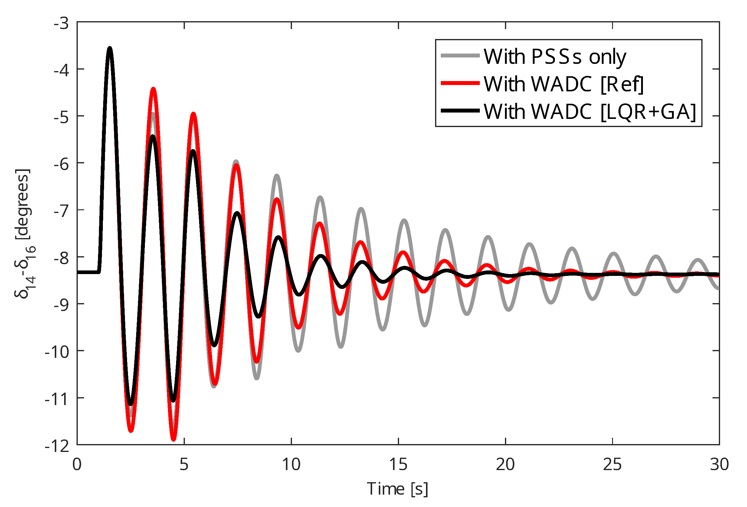
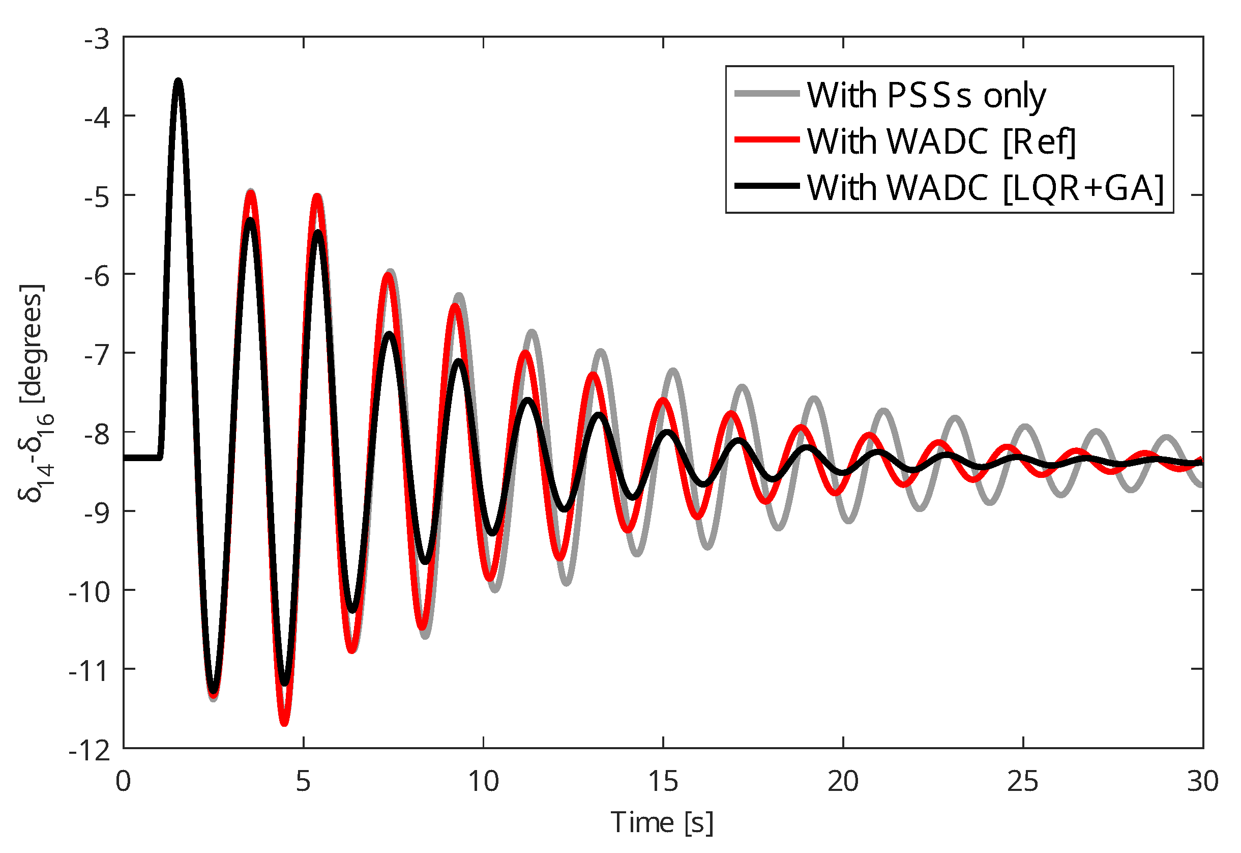
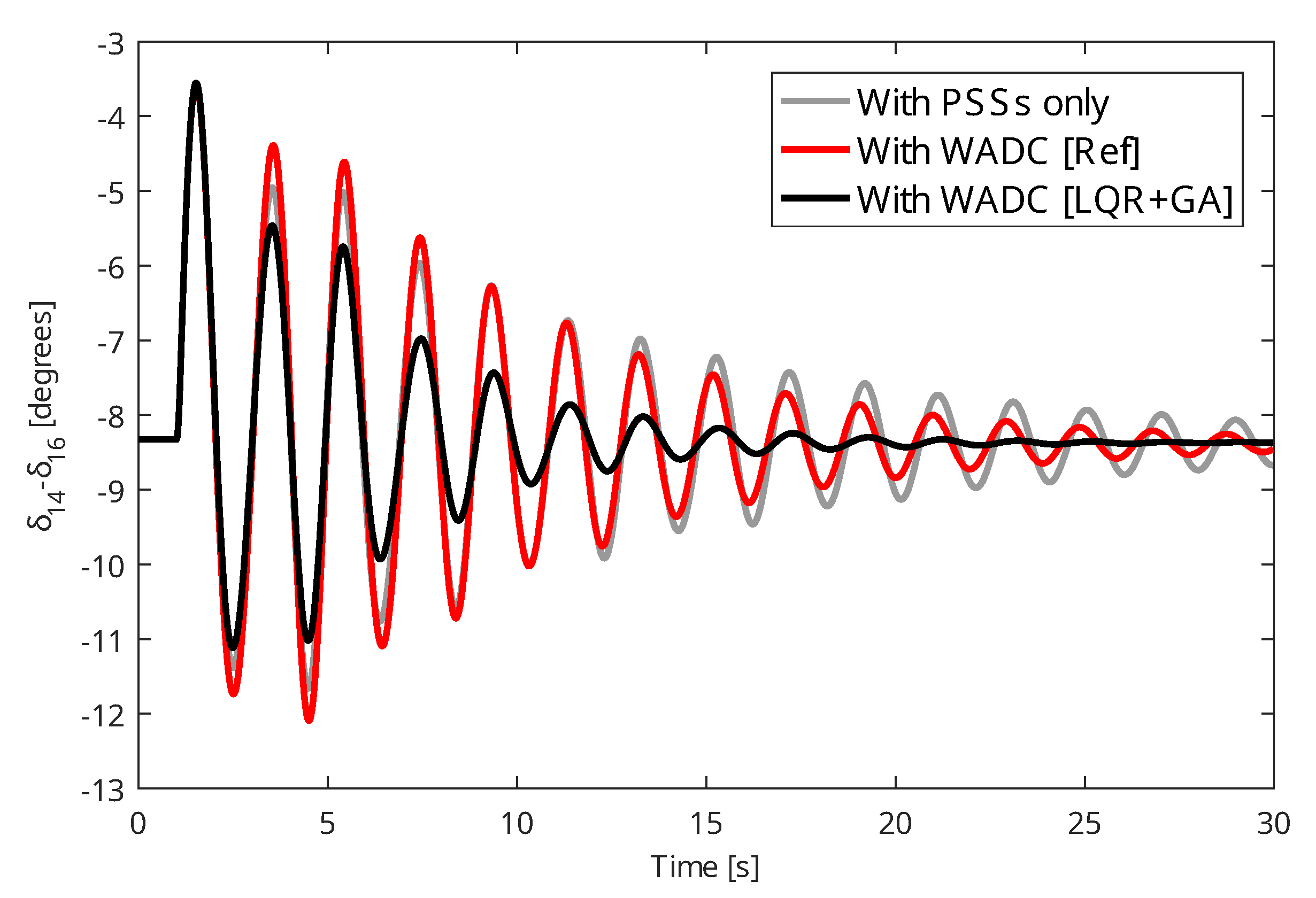
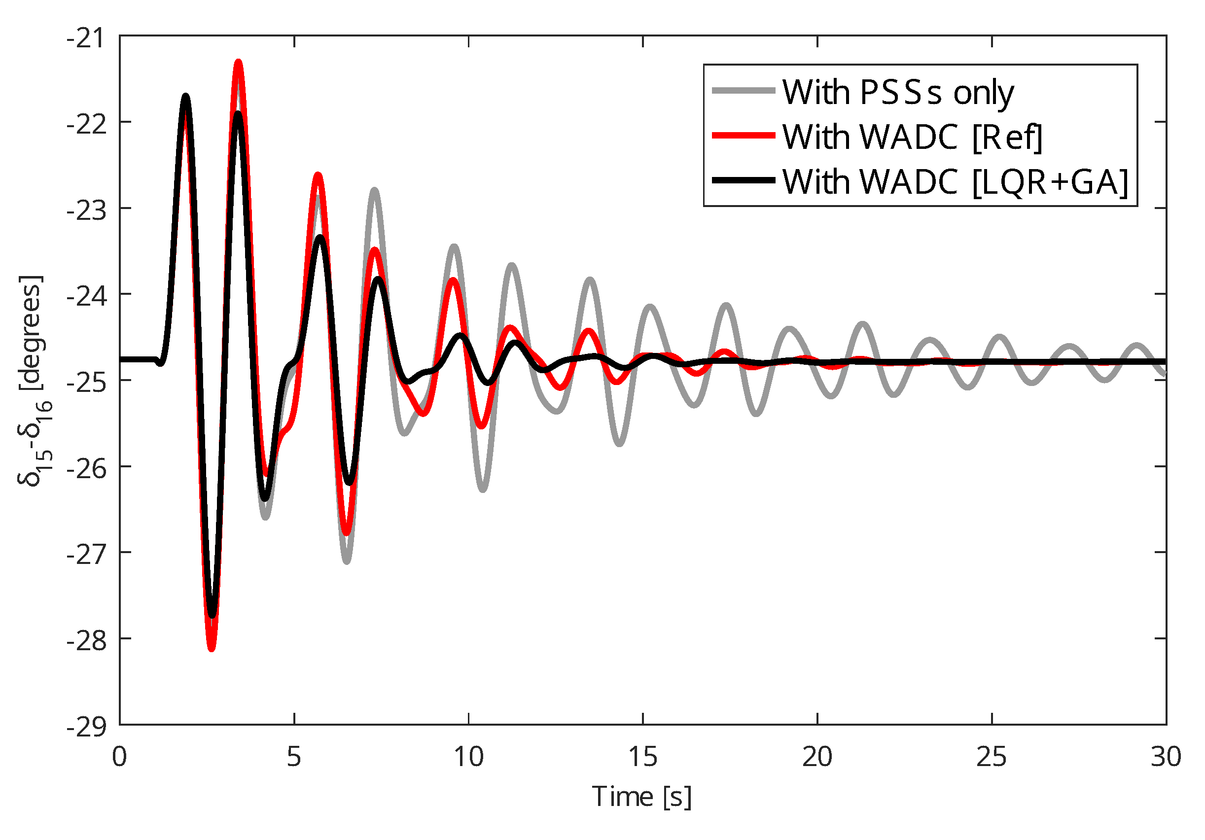
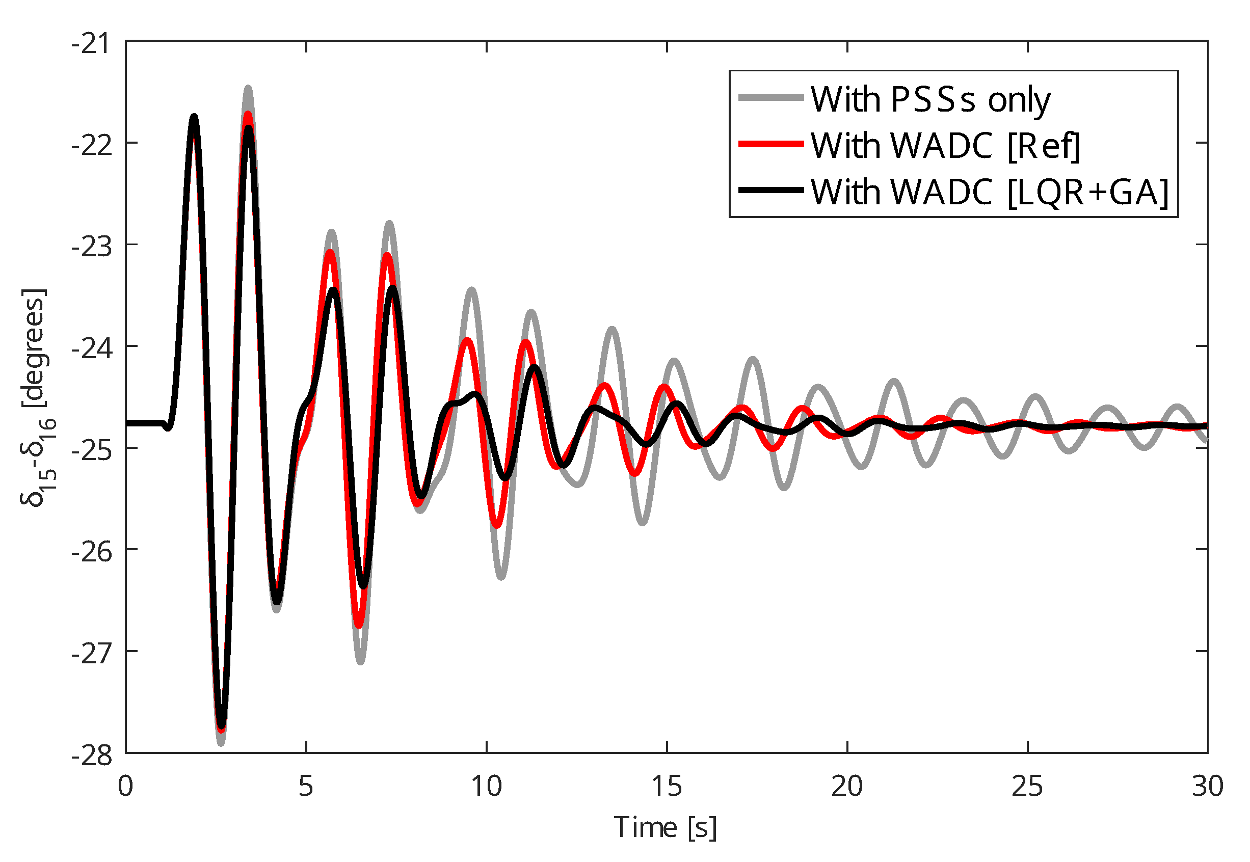
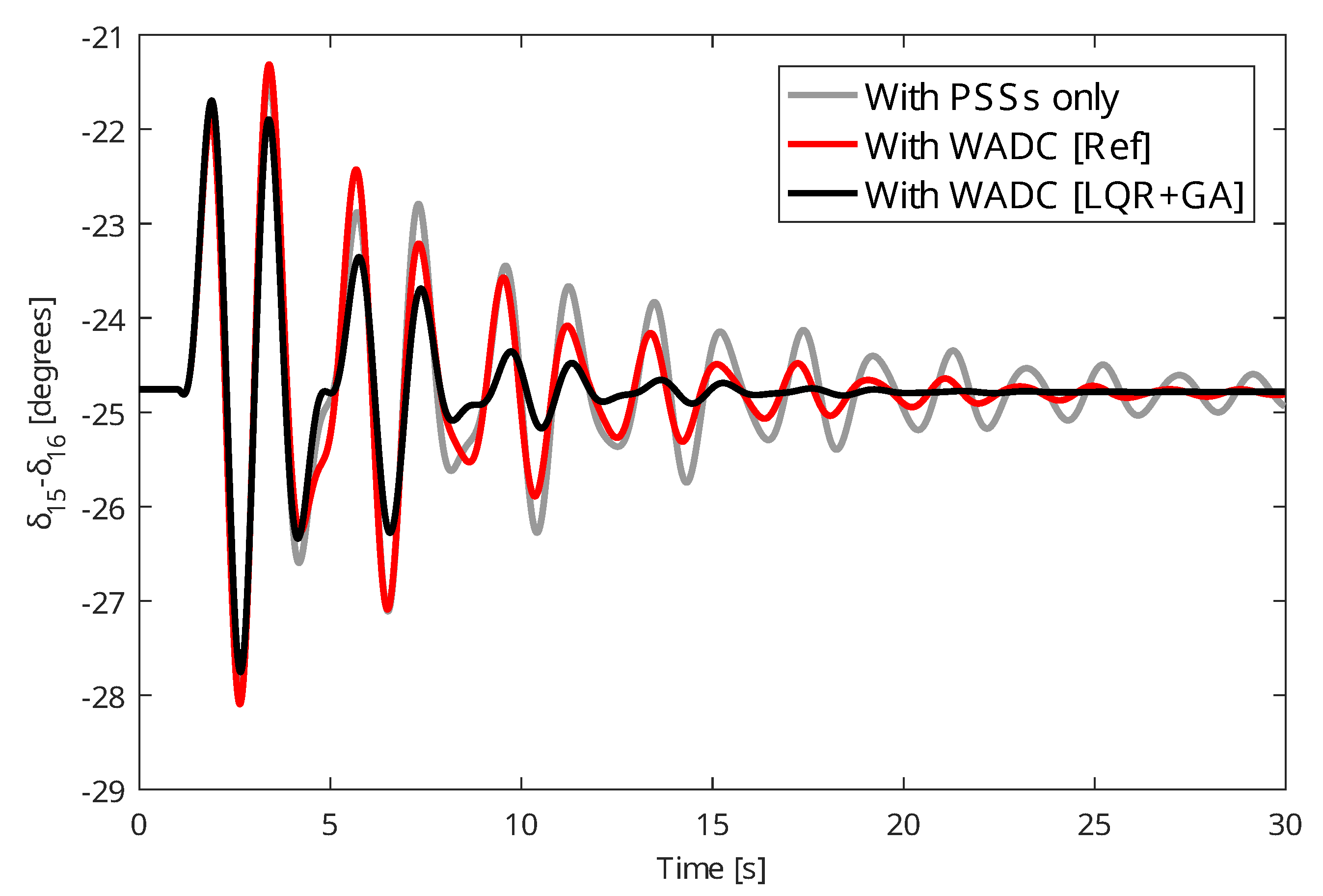
The WADC projected by linearized models will be analyzed through the application of contingencies in the dynamic nonlinear model of the test system. A three-phase fault of 100 ms was applied to bus 14 and the angular responses of the generators were comparatively evaluated without the presence of the WADC, the WADC designed by the proposed method, and the WADC designed by the method in [51]. Figure 1, Figure 2 and Figure 3 present the angular responses of generator 14 for the C2 case (see Table 1) to the WADC operating with all communication channels, the loss of the signal from machine 14, and the loss of the WADC control signal that goes to the comparator of the AVR of machine 5. Figure 4, Figure 5 and Figure 6 present the angular responses of machine 15 for the C3 case (C2 case with the disconnection of transmission lines 31–53) to the WADC working with all communication channels, the loss of the speed signal from machine 14, and the loss of the WADC control signal that goes to the comparator of the AVR of machine 5. In all cases shown, the angular responses of the test system with the WADC (LQR + GA) designed by the proposed method showed a well-damped behavior and with low amplitudes when compared to the method proposed in [51] (WADC (Ref)) and the system operating only with PSSs.
From the results achieved by the modal analysis and nonlinear simulations by applying the proposed method and the method available in [51], some comments can be made.
- The proposed method achieved its objective in providing a WADC capable of increasing the damping rates of the electromechanical modes of the test system and providing well-damped angular responses when the system is subject to contingencies or communication failures.
- The use of genetic algorithms to tune the diagonal elements of the Q and R matrices was effective in improving the convergence of the proposed method. Damping rate indices were greater than 5% as desired. Thus, the appropriate use of a metaheuristic in conjunction with a method based on LQR can be beneficial in obtaining better results of control objectives.
- The strategy adopted in the linearized models to ensure robustness to communication failures was effective, as can be seen in the nonlinear analyses through contingency applications. Furthermore, the use of linearized models facilitates the design of WADC-type controls.
5. Conclusions and Future Work
This research proposes a WADC design method using LQR and genetic algorithms incorporating robustness to communication failures. From the results achieved, the method proposed in this paper was effective in providing a WADC capable of increasing the damping rates of the modes of test systems even if there is a communication failure in the transmission of data from PMUs. The application of genetic algorithms in the LQR-based method was effective in ensuring high damping rates for the modes as the traditional method does not evaluate this. The dynamic simulations of the test system under contingency showed dynamic responses with low amplitudes and were well damped even in the case of a communication failure, as desired for the system operation.
Future research work is the application of the proposed method in power systems with wind and photovoltaic generation sources. In addition, other control devices such as STATCOM can be evaluated in improving the performance of the entire system. Other metaheuristics such as the particle swarm optimization, crow search algorithm, and marine predators algorithm can be applied and compared in place of GA to tune the matrices of the LQR-based method.
Funding
This study was financed in part by the Coordenação de Aperfeiçoamento de Pessoal de Nível Superior—Brasil (CAPES)—Finance Code 001.
Data Availability Statement
Not applicable.
Conflicts of Interest
The author declares no conflict of interest. The funders had no role in the design of the study; in the collection, analyses, or interpretation of data; in the writing of the manuscript; or in the decision to publish the results.
Abbreviations
The following abbreviations are used in this manuscript:
| ARE | Algebraic Riccati equation |
| AVR | Automatic voltage regulator |
| LQR | Linear quadratic regulator |
| PMU | Phasor measurement unit |
| PSS | Power system stabilizer |
| WADC | Wide-area damping controller |
References
- Keokhoungning, T.; Premrudeepreechacharn, S.; Wongsinlatam, W.; Namvong, A.; Remsungnen, T.; Mueanrit, N.; Sorn-in, K.; Kravenkit, S.; Siritaratiwat, A.; Srichan, C.; et al. Transmission Network Expansion Planning with High-Penetration Solar Energy Using Particle Swarm Optimization in Lao PDR toward 2030. Energies 2022, 15, 8359. [Google Scholar] [CrossRef]
- Crozier, C.; Quarton, C.; Mansor, N.; Pagnano, D.; Llewellyn, I. Modelling of the Ability of a Mixed Renewable Generation Electricity System with Storage to Meet Consumer Demand. Electricity 2022, 3, 16–32. [Google Scholar] [CrossRef]
- Bento, M.E.C.; Ramos, R.A. An approach for monitoring and updating the load margin of power systems in dynamic security assessment. Electr. Power Syst. Res. 2021, 198, 107365. [Google Scholar] [CrossRef]
- Puvvada, N.Y.; Mohapatra, A.; Srivastava, S.C. Robust AC Transmission Expansion Planning Using a Novel Dual-Based Bi-Level Approach. IEEE Trans. Power Syst. 2022, 37, 2881–2893. [Google Scholar] [CrossRef]
- Kabirifar, M.; Fotuhi-Firuzabad, M.; Moeini-Aghtaie, M.; Pourghaderi, N.; Dehghanian, P. A Bi-Level Framework for Expansion Planning in Active Power Distribution Networks. IEEE Trans. Power Syst. 2022, 37, 2639–2654. [Google Scholar] [CrossRef]
- Li, Z.; Wu, W.; Tai, X.; Zhang, B. A Reliability-Constrained Expansion Planning Model for Mesh Distribution Networks. IEEE Trans. Power Syst. 2021, 36, 948–960. [Google Scholar] [CrossRef]
- Bento, M.E.C. Monitoring of the power system load margin based on a machine learning technique. Electr. Eng. 2022, 104, 249–258. [Google Scholar] [CrossRef]
- Xie, Y.; Xu, Y. Transmission Expansion Planning Considering Wind Power and Load Uncertainties. Energies 2022, 15, 7140. [Google Scholar] [CrossRef]
- Matos, D.; Lassio, J.G.; Branco, D.C.; Junior, A.O.P. Perspectives for Expansion of Concentrating Solar Power (CSP) Generation Technologies in Brazil. Energies 2022, 15, 9286. [Google Scholar] [CrossRef]
- Amega, K.; Lare, Y.; Bhandari, R.; Moumouni, Y.; Egbendewe, A.; Sawadogo, W.; Madougou, S. Solar Energy Powered Decentralized Smart-Grid for Sustainable Energy Supply in Low-Income Countries: Analysis Considering Climate Change Influences in Togo. Energies 2022, 15, 9532. [Google Scholar] [CrossRef]
- Ndiaye, A.; Moussa, M.S.; Dione, C.; Sawadogo, W.; Bliefernicht, J.; Dungall, L.; Kunstmann, H. Projected Changes in Solar PV and Wind Energy Potential over West Africa: An Analysis of CORDEX-CORE Simulations. Energies 2022, 15, 9602. [Google Scholar] [CrossRef]
- Meegahapola, L.; Sguarezi, A.; Bryant, J.S.; Gu, M.; Conde, D.E.R.; Cunha, R.B.A. Power System Stability with Power-Electronic Converter Interfaced Renewable Power Generation: Present Issues and Future Trends. Energies 2020, 13, 3441. [Google Scholar] [CrossRef]
- Ufa, R.A.; Rudnik, V.E.; Malkova, Y.Y.; Bay, Y.D.; Kosmynina, N.M. Impact of renewable generation unit on stability of power systems. Int. J. Hydrogen Energy 2022, 47, 19947–19954. [Google Scholar] [CrossRef]
- Shah, R.; Mithulananthan, N.; Bansal, R.C.; Ramachandaramurthy, V.K. A review of key power system stability challenges for large-scale PV integration. Renew. Sustain. Energy Rev. 2015, 41, 1423–1436. [Google Scholar] [CrossRef]
- Rogers, G. Power System Oscillations; Springer: Berlin/Heidelberg, Germany, 2000. [Google Scholar] [CrossRef]
- Trudnowski, D.; Kosterev, D.; Undrill, J. PDCI damping control analysis for the western North American power system. In Proceedings of the 2013 IEEE Power & Energy Society General Meeting, Vancouver, BC, Canada, 21–25 July 2013; pp. 1–5. [Google Scholar] [CrossRef]
- Li, F.; Qiao, W.; Sun, H.; Wan, H.; Wang, J.; Xia, Y.; Xu, Z.; Zhang, P. Smart Transmission Grid: Vision and Framework. IEEE Trans. Smart Grid 2010, 1, 168–177. [Google Scholar] [CrossRef]
- Paramo, G.; Bretas, A.; Meyn, S. Research Trends and Applications of PMUs. Energies 2022, 15, 5329. [Google Scholar] [CrossRef]
- Bento, M.E.C. A method for monitoring the load margin of power systems under load growth variations. Sustain. Energy Grids Netw. 2022, 30, 100677. [Google Scholar] [CrossRef]
- Darmis, O.; Karvelis, G.; Korres, G.N. PMU-Based State Estimation for Networks Containing LCC-HVDC Links. IEEE Trans. Power Syst. 2022, 37, 2475–2478. [Google Scholar] [CrossRef]
- Bento, M.E.C. Physics-Guided Neural Network for Load Margin Assessment of Power Systems. IEEE Trans. Power Syst. 2023, 1, 1–12. [Google Scholar] [CrossRef]
- Dobakhshari, A.S.; Abdolmaleki, M.; Terzija, V.; Azizi, S. Robust Hybrid Linear State Estimator Utilizing SCADA and PMU Measurements. IEEE Trans. Power Syst. 2021, 36, 1264–1273. [Google Scholar] [CrossRef]
- Bento, M.E.C. Design of a Wide-Area Power System Stabilizer to Tolerate Multiple Permanent Communication Failures. Electricity 2023, 4, 154–170. [Google Scholar] [CrossRef]
- Elimam, M.; Isbeih, Y.J.; Moursi, M.S.E.; Elbassioni, K.; Hosani, K.H.A. Novel Optimal PMU Placement Approach Based on the Network Parameters for Enhanced System Observability and Wide Area Damping Control Capability. IEEE Trans. Power Syst. 2021, 36, 5345–5358. [Google Scholar] [CrossRef]
- Bento, M.E.C. Resilient Wide-Area Damping Controller Design Using Crow Search Algorithm. IFAC PapersOnLine 2022, 55, 938–943. [Google Scholar] [CrossRef]
- Azhar, I.F.; Putranto, L.M.; Irnawan, R. Development of PMU-Based Transient Stability Detection Methods Using CNN-LSTM Considering Time Series Data Measurement. Energies 2022, 15, 8241. [Google Scholar] [CrossRef]
- Bento, M.E.C. Fixed Low-Order Wide-Area Damping Controller Considering Time Delays and Power System Operation Uncertainties. IEEE Trans. Power Syst. 2020, 35, 3918–3926. [Google Scholar] [CrossRef]
- Darabian, M.; Bagheri, A. Stability improvement of large-scale power systems including offshore wind farms and MTDC grid aiming at compensation of time delay in sending robust damping signals. Int. J. Electr. Power Energy Syst. 2022, 143, 108491. [Google Scholar] [CrossRef]
- Bento, M.E.C.; Ramos, R.A. A Method Based on Linear Matrix Inequalities to Design a Wide-Area Damping Controller Resilient to Permanent Communication Failures. IEEE Syst. J. 2021, 15, 3832–3840. [Google Scholar] [CrossRef]
- Prakash, A.; Singh, P.; Kumar, K.; Parida, S.K. Design of a Reduced-Order WADC for Wind Turbine System-Integrated Power System. IEEE Trans. Ind. Appl. 2022, 58, 3250–3260. [Google Scholar] [CrossRef]
- Gul, F.; Mir, A.; Mir, I.; Mir, S.; Islaam, T.U.; Abualigah, L.; Forestiero, A. A Centralized Strategy for Multi-Agent Exploration. IEEE Access 2022, 10, 126871–126884. [Google Scholar] [CrossRef]
- Abualigah, L.; Elaziz, M.A.; Khodadadi, N.; Forestiero, A.; Jia, H.; Gandomi, A.H. Aquila Optimizer Based PSO Swarm Intelligence for IoT Task Scheduling Application in Cloud Computing. In Studies in Computational Intelligence; Springer International Publishing: Berlin/Heidelberg, Germany, 2022; pp. 481–497. [Google Scholar] [CrossRef]
- Soma, G.G. Optimal Sizing and Placement of Capacitor Banks in Distribution Networks Using a Genetic Algorithm. Electricity 2021, 2, 187–204. [Google Scholar] [CrossRef]
- Abualigah, L.; Diabat, A.; Thanh, C.L.; Khatir, S. Opposition-based Laplacian distribution with Prairie Dog Optimization method for industrial engineering design problems. Comput. Methods Appl. Mech. Eng. 2023, 414, 116097. [Google Scholar] [CrossRef]
- Bento, M.E.C. An Optimization Approach for the Wide-Area Damping Control Design. In Proceedings of the 2018 13th IEEE International Conference on Industry Applications (INDUSCON), Sao Paulo, Brazil, 12–14 November 2018; pp. 269–276. [Google Scholar] [CrossRef]
- Bento, M.E.C.; Dotta, D.; Ramos, R.A. Performance analysis of Wide-Area Damping Control Design methods. In Proceedings of the 2016 IEEE Power and Energy Society General Meeting (PESGM), Boston, MA, USA, 17–21 July 2016; pp. 1–5. [Google Scholar] [CrossRef]
- Bento, M.E.C. Design analysis of wide-area damping controllers using genetic algorithms. In Proceedings of the 2016 12th IEEE International Conference on Industry Applications (INDUSCON), Curitiba, Brazil, 20–23 November 2016; pp. 1–8. [Google Scholar] [CrossRef]
- Bento, M.E.C. A procedure to design wide-area damping controllers for power system oscillations considering promising input–output pairs. Energy Syst. 2019, 10, 911–940. [Google Scholar] [CrossRef]
- Heniche, A.; Kamwa, I. Assessment of Two Methods to Select Wide-Area Signals for Power System Damping Control. IEEE Trans. Power Syst. 2008, 23, 572–581. [Google Scholar] [CrossRef]
- Bento, M.E.C.; Ramos, R.A. Selecting the Input-Output Signals for Fault-Tolerant Wide-Area Damping Control Design. In Proceedings of the 2021 IEEE Texas Power and Energy Conference (TPEC), College Station, TX, USA, 2–5 February 2021; pp. 1–5. [Google Scholar] [CrossRef]
- Bento, M.E.C. Design of a Resilient Wide-Area Damping Controller Using African Vultures Optimization Algorithm. In Proceedings of the 2021 31st Australasian Universities Power Engineering Conference (AUPEC), Perth, Australia, 26–30 September 2021; pp. 1–6. [Google Scholar] [CrossRef]
- Beiraghi, M.; Ranjbar, A.M. Adaptive Delay Compensator for the Robust Wide-Area Damping Controller Design. IEEE Trans. Power Syst. 2016, 31, 4966–4976. [Google Scholar] [CrossRef]
- Padhy, B.P.; Srivastava, S.C.; Verma, N.K. A Wide-Area Damping Controller Considering Network Input and Output Delays and Packet Drop. IEEE Trans. Power Syst. 2017, 32, 166–176. [Google Scholar] [CrossRef]
- Zeng, L.; Yao, W.; Zeng, Q.; Li, D.; Fang, J.; Ai, X.; Wen, J.; He, H. Design and real-time implementation of data-driven adaptive wide-area damping controller for back-to-back VSC-HVDC. Int. J. Electr. Power Energy Syst. 2019, 109, 558–574. [Google Scholar] [CrossRef]
- Bento, M.E.C. Design of a wide-area damping controller to tolerate permanent communication failure and time delay uncertainties. Energy Syst. 2022, 13, 235–264. [Google Scholar] [CrossRef]
- Zhang, S.; Vittal, V. Design of Wide-Area Power System Damping Controllers Resilient to Communication Failures. IEEE Trans. Power Syst. 2013, 28, 4292–4300. [Google Scholar] [CrossRef]
- Bento, M.E.C. A Hybrid Particle Swarm Optimization Algorithm for the Wide-Area Damping Control Design. IEEE Trans. Ind. Informatics 2022, 18, 592–599. [Google Scholar] [CrossRef]
- Bento, M.E.C.; Kuiava, R.; Ramos, R.A. Design of Wide-Area Damping Controllers Incorporating Resiliency to Permanent Failure of Remote Communication Links. J. Control. Autom. Electr. Syst. 2018, 29, 541–550. [Google Scholar] [CrossRef]
- Bento, M.E.C. Bird Swarm Algorithm Applied to the Wide-Area Damping Controller Design. In Proceedings of the 2021 IEEE International Conference on Automation/XXIV Congress of the Chilean Association of Automatic Control (ICA-ACCA), Valparaíso, Chile, 22–26 March 2021. [Google Scholar] [CrossRef]
- Sengupta, A.; Das, D.K. Delay dependent wide area damping controller with actuator saturation and communication failure for wind integrated power system. Sustain. Energy Technol. Assess. 2022, 52, 102123. [Google Scholar] [CrossRef]
- Bento, M.E.C. A hybrid procedure to design a wide-area damping controller robust to permanent failure of the communication channels and power system operation uncertainties. Int. J. Electr. Power Energy Syst. 2019, 110, 118–135. [Google Scholar] [CrossRef]
- Dotta, D.; e Silva, A.S.; Decker, I.C. Wide-Area Measurements-Based Two-Level Control Design Considering Signal Transmission Delay. IEEE Trans. Power Syst. 2009, 24, 208–216. [Google Scholar] [CrossRef]
- Lewis, F.L.; Vrabie, D.L.; Syrmos, V.L. Optimal Control; John Wiley & Sons, Inc.: Hoboken, NJ, USA, 2012. [Google Scholar] [CrossRef]
- Xu, W.; Yu, B.; Song, Q.; Weng, L.; Luo, M.; Zhang, F. Economic and Low-Carbon-Oriented Distribution Network Planning Considering the Uncertainties of Photovoltaic Generation and Load Demand to Achieve Their Reliability. Energies 2022, 15, 9639. [Google Scholar] [CrossRef]
- Khan, A.Y.; Ahmad, Z.; Sultan, T.; Alshahrani, S.; Hayat, K.; Imran, M. Optimization of Photovoltaic Panel Array Configurations to Reduce Lift Force Using Genetic Algorithm and CFD. Energies 2022, 15, 9580. [Google Scholar] [CrossRef]
- Kumar, G.N.; Gundabattini, E. Investigation of Supercritical Power Plant Boiler Combustion Process Optimization through CFD and Genetic Algorithm Methods. Energies 2022, 15, 9076. [Google Scholar] [CrossRef]
- Canizares, C.; Fernandes, T.; Geraldi, E.; Gerin-Lajoie, L.; Gibbard, M.; Hiskens, I.; Kersulis, J.; Kuiava, R.; Lima, L.; DeMarco, F.; et al. Benchmark Models for the Analysis and Control of Small-Signal Oscillatory Dynamics in Power Systems. IEEE Trans. Power Syst. 2017, 32, 715–722. [Google Scholar] [CrossRef]
Figure 1.
Angular response after applying and removing a contingency from generator 14 for C2 case.

Figure 2.
Angular response after applying and removing a contingency from generator 14 for C2 case with the loss of the signal associated with the third input of the WADC.
Figure 2.
Angular response after applying and removing a contingency from generator 14 for C2 case with the loss of the signal associated with the third input of the WADC.

Figure 3.
Angular response from generator 14 for C2 case with the loss of the signal associated with the first output of the WADC.
Figure 3.
Angular response from generator 14 for C2 case with the loss of the signal associated with the first output of the WADC.

Figure 4.
Angular response from generator 15 for C3 case.

Figure 5.
Angular response from generator 15 for C3 case with the loss of the signal associated with the third input of the WADC.
Figure 5.
Angular response from generator 15 for C3 case with the loss of the signal associated with the third input of the WADC.

Figure 6.
Angular response from generator 15 for C3 case with the loss of the signal associated with the first output of the WADC.
Figure 6.
Angular response from generator 15 for C3 case with the loss of the signal associated with the first output of the WADC.


Table 1.
Modes that have the lowest damping ratios in the test system.
| Case | Modes (Eigenvalues) | Damping Ratio (%) |
|---|---|---|
| Nominal Case (NC) [57] | 3.3851 | |
| 3.6236 | ||
| C2 | 2.8919 | |
| 3.3615 |
Table 2.
WADC (LQR + GA) using the proposed method.
Table 3.
WADC (Ref) parameters using the method in [51].
Table 3.
WADC (Ref) parameters using the method in [51].
Disclaimer/Publisher’s Note: The statements, opinions and data contained in all publications are solely those of the individual author(s) and contributor(s) and not of MDPI and/or the editor(s). MDPI and/or the editor(s) disclaim responsibility for any injury to people or property resulting from any ideas, methods, instructions or products referred to in the content. |
© 2023 by the author. Licensee MDPI, Basel, Switzerland. This article is an open access article distributed under the terms and conditions of the Creative Commons Attribution (CC BY) license (https://creativecommons.org/licenses/by/4.0/).
Share and Cite
MDPI and ACS Style
Bento, M.E.C. Wide-Area Measurement-Based Two-Level Control Design to Tolerate Permanent Communication Failures. Energies 2023, 16, 5646. https://doi.org/10.3390/en16155646
AMA Style
Bento MEC. Wide-Area Measurement-Based Two-Level Control Design to Tolerate Permanent Communication Failures. Energies. 2023; 16(15):5646. https://doi.org/10.3390/en16155646
Chicago/Turabian StyleBento, Murilo Eduardo Casteroba. 2023. "Wide-Area Measurement-Based Two-Level Control Design to Tolerate Permanent Communication Failures" Energies 16, no. 15: 5646. https://doi.org/10.3390/en16155646
Note that from the first issue of 2016, this journal uses article numbers instead of page numbers. See further details here.