Article

Electrochemical Evaluation of Nickel Oxide Addition toward Lanthanum Strontium Cobalt Ferrite Cathode for Intermediate Temperature Solid Oxide Fuel Cell (IT-SOFCS)

by
Ahmad Fuzamy Mohd Abd Fatah
1,
Ahmad Zaki Rosli
1,
Ahmad Azmin Mohamad
2,
Andanastuti Muchtar
3,
Muhammed Ali S.A.
3 and
Noorashrina A. Hamid
1,*
1
School of Chemical Engineering, Universiti Sains Malaysia, Nibong Tebal 14300, Pulau Pinang, Malaysia
2
School of Materials & Mineral Resources Engineering, Universiti Sains Malaysia, Nibong Tebal 14300, Pulau Pinang, Malaysia
3
Fuel Cell Institute, Universiti Kebangsaan Malaysia UKM, Bangi 43600, Selangor, Malaysia
*
Author to whom correspondence should be addressed.
Energies 2022, 15(14), 5188; https://doi.org/10.3390/en15145188
Submission received: 17 June 2022 / Revised: 11 July 2022 / Accepted: 14 July 2022 / Published: 18 July 2022
(This article belongs to the Section A4: Bio-Energy)

Abstract

:
A mixture of lanthanum strontium cobalt ferrite (LSCF) and nickel oxide (NiO) makes for a desirable cathode material for an IT-SOFC due to its excellent oxygen reduction capability. This study investigates the effect of NiO addition into LSCF cathode on its physical and electrochemical properties. To optimise the amount of NiO addition, both electrochemical impedance spectra and bode phase were used to examine various weight ratios of nickel oxide and LSCF cathode. Brunauer-Emmett-Teller (BET) and thermal analyses validated the electrochemical observation that the LSCF:NiO ratio yields sensible oxygen reduction reaction and stoichiometric findings. Initial characterisation, comprising of phase and bonding analyses, indicated that LSCF-NiO was successfully synthesised at 800 °C using an improved modified sol gel technique. The addition of 5% nickel oxide to LSCF results in the lowest area specific resistance (ASR) value overall. The Bode phase implies that the addition of 5% nickel oxide to LSCF reduces the impedance at low frequencies by 64.28 percent, indicating that a greater oxygen reduction process happened at the cathode. After the addition of 5 wt% NiO, a single LSCF-NiO cell may function at temperatures as low as 650 °C and the LSCF cathode power density is increased by 25.35%. The surface morphology of the LSCF-NiO cathode reveals that the average particle size is less than 100 nm, and mapping analysis demonstrated a homogenous NiO distribution over the cathode layer. Consequently, the synthesis of LSCF-NiO at intermediate temperatures (800–600 °C) revealed outstanding chemical compatibility, bonding characteristics, and electrochemical performance.

1. Introduction

A solid oxide fuel cell (SOFC) is a device that converts chemical energy into electrical energy and typically consists of a cathode, electrolyte, and anode [1]. The process involved in SOFC is oxygen reduction reaction (ORR), and it is believed to be the main contributor to electrode polarization resistance. LaxSr1−xCoyFe1−yO3−ծ (LSCF), a perovskite type cathode, has received a lot of attention due to its ability to create a bulk pathway for oxygen anion transport and high ionic and electronic conductivity compared to other oxide electrocatalysts [2]. However, the ORR of LSCF cathode is only limited to the surface exchange process, and the addition of another material will enable bulk charge transport, which will theoretically improve the ORR process that occurs in the cathode [3]. Nickel oxide (NiO) is one of the possible candidates to be composited towards LSCF. This is due to the fact that infiltration techniques are capable of dispersing nano-sized particles into a porous oxide backbone to improve the electrochemical activity of cathode materials [4]. Although nickel oxide is widely used in the anode section, it is also used in the cathode section due to its ability to resist carbon dioxide reactions [5,6].
In SOFCs standpoints, the addition of nickel oxide to a lanthanum-based cathode improves its ionic and electronic conductivity [7,8,9,10,11]. Nickle oxide has also been reported to have good chemical compatibility with lanthanum and strontium [9,12]. It is also worth mentioning that the addition of nickel oxide towards the cathode side is expected to induce extra interstitial oxygen transfer rates and oxygen permeation properties, which results in an improvement in ionic conductivity and oxygen reduction catalytic activity of the cell itself [7,11,13,14]. There is an article suggesting the oxygen stoichiometry of nickel-based cathodes decreases as operating temperature increases. However, the reduction is significant in oxygen stoichiometry of nickel-based cathodes value (4.12 at 400 °C and 4.09 at 800 °C), which results in a negligible parameter [15].
Research towards the addition of nickel oxide for LSCF cathodes proved that nickel oxide is indeed able to improve the cathode performance due to its capability for carbon dioxide resistance [3]. It was important to highlight that nickel oxide has good chemical compatibility with LSCF and can operate well in IT-SOFCs. The nickel oxide addition was limited to 5 wt% maximum due to the inactive surface area (which is a result of the abundance of nickel oxide on the cathode composition) [3]. However, it was not justified in the article as the cathode performance dropped after the amount of nickel oxide addition exceeded 5%. Therefore, it can be further researched in terms of specific surface area to further prove that 5 wt% is the optimal value for the addition of nickel oxide towards LSCF cathode. It was also reported to have good chemical compatibility with GDC electrolyte at IT-SOFC since no chemical reaction was detected after being heated at 800 °C [16,17]. Therefore, it was concluded that the addition of nickel oxide towards LSCF is possible due to great affinity among all of the elements, and the nickel oxide-based cathode also works well with GDC electrolyte.
The goal of this study was to see how adding nickel oxide to the LSCF cathode affected chemical compatibility, specific surface area, electrochemical performance, single cell applicability, and surface morphology. This study is a continuation of Rosli et al. [18] with the addition of optimization value for nickel oxide addition that can improve the LSCF cathode that operates in IT-SOFCs (600 °C–800 °C) and further elaboration toward low frequency impedance and high frequency impedance. Thus, a series of cathode materials with varying nickel oxide addition percentages were manufactured.

2. Materials and Methods

2.1. Sample Preparation and Cell Fabrication

The electrode powder La0.6Sr0.4Co0.2Fe0.8 (LSCF) was synthesized via the enhanced modified sol gel (EM-SG) method and was calcined at 800 °C [19]. The Pechini method was used to synthesize Ge0.1Ce0.9O1.95 (GDC) electrolyte, LSCF powder (for XRD comparison method only) and nickel oxide (NiO) powders, followed by calcining the precursor at 600 °C and 800 °C for 3 h, respectively [20]. LSCF and NiO powder were mixed with a weight ratio of 1:1 followed by calcination at 1100 °C for 2 h for chemical compatibility analysis. A fine powder of GDC was pressed at 300 MPa and sintered at 1500 °C for 6 h. LSCF ink was prepared by amalgamation with vehicle ink (95% terpineol as solvent and 5% ethyl cellulose as binder). The LSCF ink was applied to both electrolyte surfaces (1 cm diameter) using a screen-printing technique, and the resulting cell was sintered at 1100 °C for 2 h to form a symmetric cell. To produce a composite LSCF-NiO cathode, the LSCF electrode was mixed with 3 wt%, 5 wt%, 7 wt%, and 9 wt% of nickel oxide, followed by calcination at 1100 °C [21]. The fabrication of the symmetric cell of LSCF-NiO was followed in a similar manner to the LSCF symmetric cell. Single cells of LSCF-NiO were evaluated via electrolyte-supported single cells with NiO-GDC as anode. Screen printing was used to apply a NiO-GDC (40:60 ratio) slurry on one side of the GDC electrolyte surface with a diameter of approximately 1 cm and sintered at 1200 °C for 2 h. The cathode was made in the same way as the symmetric cell.

2.2. Characterization

The phase composition was determined using AXS Bruker GmbH’s X-ray diffraction (XRD) using Cu K radiation from 10° to 90° for the entire sample. After the sintering procedure, Braggs law was used to verify the structure of the composite cathode. Lattice constants a, b, and c were compared to the respective JCPDS card that yielded the highest score during search and match in Xpert-Highscore plus®. Swarts and Shrout’s equation was used to calculate the percentage of perovskite phase [22].
The LSCF-NiO specific surface area was determined using Brunauer-Emmett-Teller (BET) with an average mass of 0.3 gramme per sample. The samples were subjected to a pycnometer test to determine their true density. Equation (1) was used to calculate theoretical particle size [23]. SBET refer to specific surface area, p refers to actual density of material, and dBET is the mean theoretical particle size.
d B E T = 6 ρ × S B E T  
The thermal decomposition behaviour of LSCF-NiO was investigated using a TGA analyser model Pelkin Elmer STA 600® from room temperature to 900 °C with an air flow rate of 50 cm3/min and a heating rate of 5 °C/min in air. The oxygen stoichiometric value of calcined composited cathode powder was calculated using Equation (2) [24]. Δ m / m s refers to weight loss of the material, Msample represent the molecular weight of the sample, Moxygen refers to molecular weight of oxygen.
Δ δ = Δ m M S a m p l e m s M O x y g e n  
LSCF-NiO symmetrical cell scanning electron microscopy (SEM) analysis was performed using Regulus 8220®. The acceleration voltage was 5 kV and the magnification was 30 k using backscattering electron and scattering electron (BSE + SE). For 70 readings, the particle size was measured using the software included with the Regulus 8220®. The same machine was used for energy dispersive x-ray analysis (EDX), but with 500 magnifications for mapping analysis.

2.3. Electrochemical Properties of the Symmetric Cell and Single Cell

The Electrochemical impedance spectra (EIS) analysis was used in conjunction with the furnace system (PGSTAT302N, Metrohm Autolab®, Utrecht, The Netherlands). To measure the cathode resistance, silver wires were attached to the electrode surfaces coated with silver paste. The symmetric cell was measured with a type-K thermocouple and recorded with a Digi-Sense digital thermocouple metre (Eutech Instrument, Paisley, UK). The EIS has a temperature range of 600 °C to 800 °C, a frequency range of 0.1Hz to 1MHz, and a signal amplitude of 10 mV. NOVA®-software (Version 1.10) was used to fit the experimental data to the equivalent circuit, and each data set was plotted using Origin software. The analysis was conducted in open air. The performance of a single cell was evaluated using 10% hydrogen/90% nitrogen as the fuel at the anode side with a flow rate of 25 mL min, while the cathode side was supplied with air at the same flowrate. All single cell impedance spectra were recorded in open circuit with a 10 mV AC signal perturbation. It took one hour to stabilise. Area specific resistance (ASR) for symmetric cells was calculated using Equation (3), where Rp denotes polarisation resistance and S denotes cathode working area [25].
A S R = R p · S 2  

3. Results and Discussions

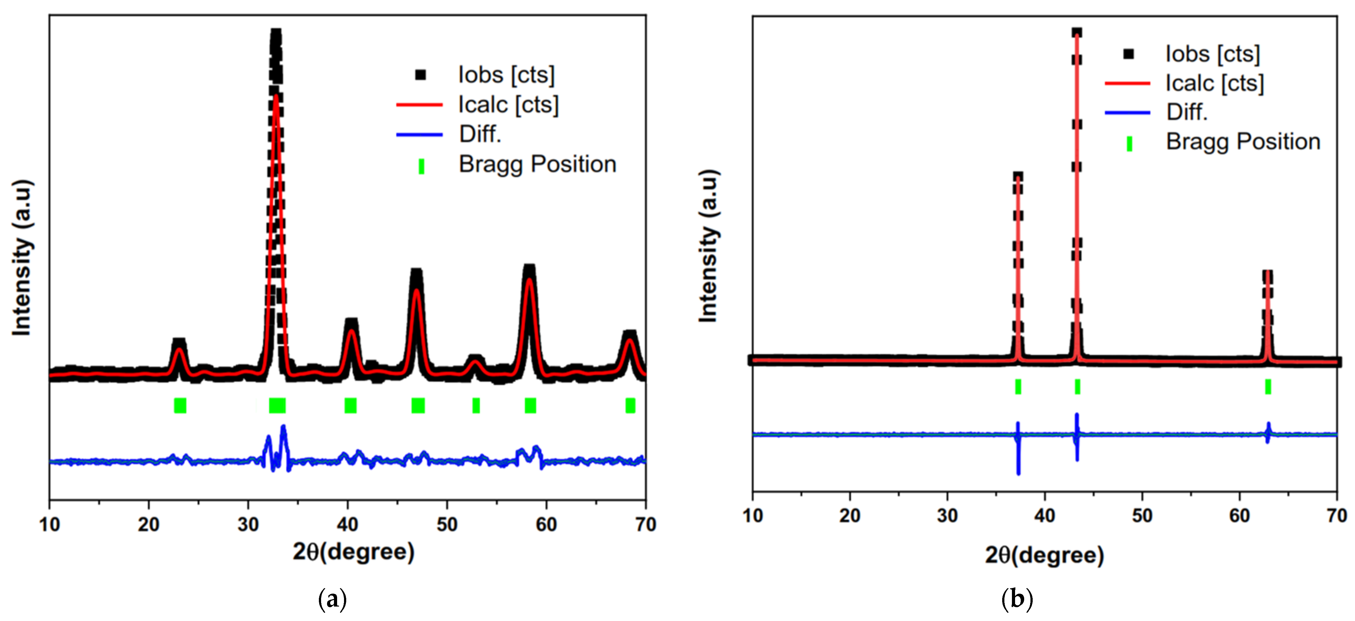
3.1. Powder Characterizations

Figure 1a,b described the Rietveld refinement analysis of LSCF and NiO. Figure 1a shows a single-phase perovskite LSCF with cells factor a = 0.5475 nm, b = 0.5360 nm, c = 0.7848 nm which is orthorhombic structure (JCPDS = 01-089-1268). Figure 1b revealed cubic structure of nickel oxide which bears a cell factor a = b = c = 0.4179 nm (JCPDS = 01-078-0423).
Based on Rietveld refinement analysis described in Figure 1a,b, a comparison peak was taken between LSCF-NiO synthesized with the enhanced modified sol gel method and LSCF-NiO synthesized via the Pechini method from previous research [18]. Previously, Rosli et al. [18] claimed LSCF-NiO was successfully synthesized via the Pechini method at 800 °C. Figure 1c revealed a comparison peak between LSCF-NiO (EM-SG method) and LSCF-NiO (Pechini method) with LSCF (JCPDS = 01-089-1268) and NiO (JCPDS = 01-078-0423). Except for the LSCF and NiO peaks, no tertiary phase is detected using either method. Based on the comparison with the respective Rietveld refinement toward LSCF and nickel oxide, peak position shows no shifting, indicating good compatibility between LSCF and nickel oxide for the EM-SG method under operating conditions. However, the Pechini method shows slight peak shifting at 22.80°, 32.56°, and 46.76°, which can be potentially denoted as insufficient calcination temperature [26].
Further analysis was conducted towards LSCF-NiO (EM-SG method) on the percentage of perovskite phase and average crystal size. The crystal size calculated from Scherrer’s equation showed that LSCF was slightly increased from 28.35 nm to 28.58 nm and the perovskite phase from Swarts and Shrout equation revealed that LSCF-NiO was able to achieve 99.297% perovskite phase. It was expected since nickel has a much smaller ionic size than LSCF, resulting in almost no change in overall crystal size (Nickel = 0.69 Å, LSCF = 1.4 Å) [27]. Further characterization on phase analysis also in-line with XRD result which illustrated in Figure S1. Therefore, it is wise to continue further analysis via LSCF-NiO synthesized with the EM-SG method.

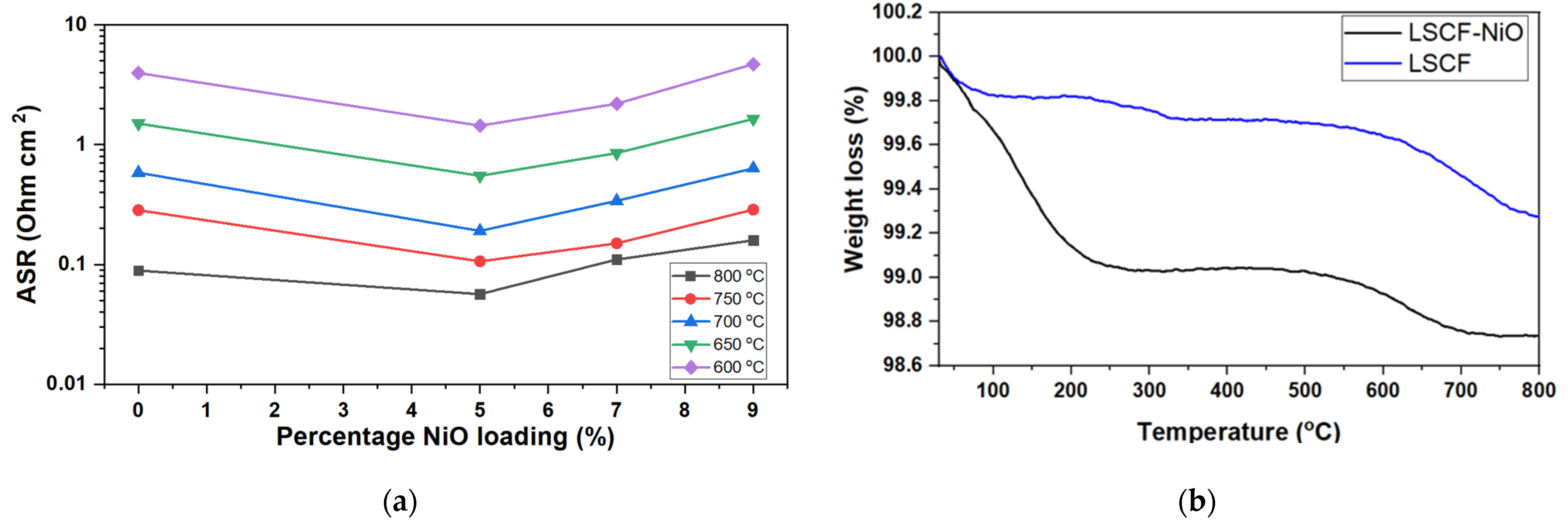
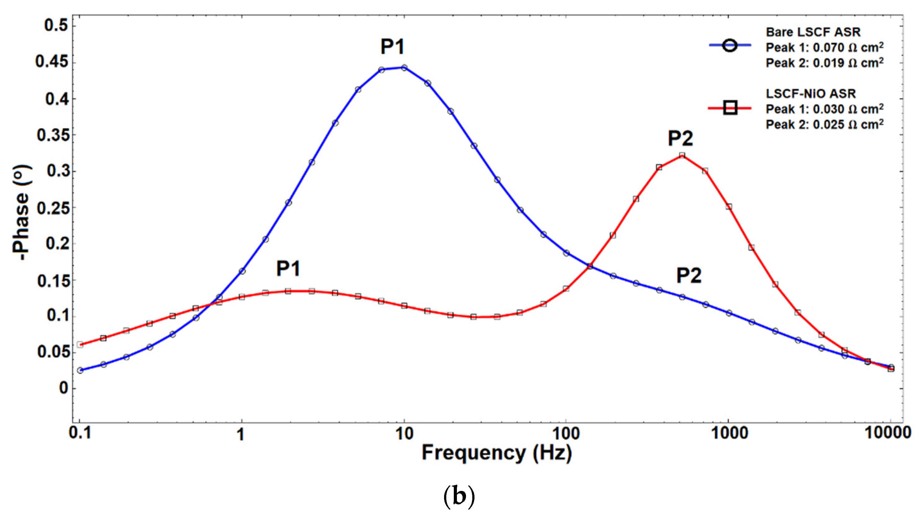
3.2. Electrochemical Properties of the Symmetrical Composite Cathode Pellets

The electrochemical analysis of the LCF-NiO modified electrode was performed using a symmetric cell GDC electrolyte at an operating temperature of 800 °C, as shown in Figure 2a. In the circuit, Ro represents the cathode’s ohmic resistance. R1 indicates the high frequency arc connected with the process of charge transfer, whereas R2 represents the low frequency arc related to the cathode’s oxygen absorption. CPE1 and CPE2 are constant phase elements for the respective arcs. Rp is the sum of the arc at high frequency and the arc at low frequency (Rp = R1 + R2). To facilitate comparison, Ro was subtracted from each arc, and the explanation was provided in terms of the ASR derived by Equation (3).
Area specific resistance (ASR) of LSCF-NiO shows that the addition of 5 wt% nickel oxide can reduce the ASR of the LSCF cathode from 0.09 Ω cm2 to 0.06 Ω cm2. Further addition of nickel oxide up to 7 wt% revealed an increase of ASR up to 0.11 Ω cm2 while it continuously increases to 0.16 Ω cm2 when the nickel oxide content reaches 9 wt%. This result was supported by BET analysis in Figure 2b, where the specific surface area increased from 7.51 m2/g to 10.28 m2/g after the addition of 5 wt% of nickel oxide. A similar trend was observed towards the addition of 7 wt% and 9 wt% of nickel oxide, where the specific surface area decreases by up to 9.46 m2/g and 9.05 m2/g, respectively. This result is coherent with Mubashar et al. [3], which also acquired a similar trend where ASR of LSCF-NiO increased after nickel oxide content at 10 wt% of nickel oxide loading content. The specific surface area of LSCF + 3% NiO is slightly greater than that of bare LSCF. Consequently, it was incorporated to improve the resolution of the trend graph.
Further investigation was carried out at an intermediate temperature range (800 °C–600 °C), as shown in Figure 3a. In detail ASR value was tabulated in Table S1. It was obvious that adding up to 5 wt% nickel oxide to the LSCF cathode reduced the ASR at operating temperatures ranging from 800 °C to 600 °C, showing that nickel oxide particles increased the oxygen reduction rate. Observation towards lower operating temperatures (650 °C and 600 °C) suggested that a major increase in ASR occurred after the addition of 9 wt% nickel oxide, where the ASR of LSCF with 9 wt% of nickel oxide is higher than bare LSCF cathode. Although previous EIS analysis showed the ASR of LSCF with 7 wt% nickel oxide content is higher than bare LSCF, it was observed that the ASR is still lower than bare LSCF when operated at a lower temperature, suggesting the oxygen reduction rate (ORR) of LSCF-NiO is still higher than bare LSCF. Despite this observation, LSCF with 5 wt% NiO outperforms bare LSCF cathode and LSCF (+7 wt% and 9 wt% NiO) for the entire intermediate temperature range, implying that the 5 wt% is an optimized amount of nickel oxide addition to the LSCF cathode.
The TGA experiment was carried out using air flow to replicate fill and empty the oxygen content as shown in Figure 3b toward bare LSCF and LSCF with 5 wt% of nickel oxide powder. The study was conducted at temperatures ranging from room temperature to 800 °C to simulate the oxygen filling and emptying capabilities of the device when utilized at an intermediate temperature range [28,29]. According to the graph’s trend between 30 and 300 °C, the weight loss indicated the evacuation of absorbed water from the surrounding environment [24]. A slight weight increase was observed above 300 °C, implying that Co3+/Fe3+ is thermally oxidized to Co4+/Fe4+. Ionized Co3+/Fe3+ ions are frequently difficult to convert to air, resulting in just a minor weight gain and mass shift. [30]. As a result, the weight reduction from both parts was utilized for the calculation of oxygen nonstoichiometric value. Table 1 summarizes the oxygen nonstoichiometric of LSCF and LSCF-NiO. The oxygen nonstoichiometric value of LSCF-NiO was found to be significantly higher than LSCF, suggesting that more oxygen reduction processes take place on the LSCF-NiO cathode [31]. Further heating of LSCF-NiO at 550 °C shows a reducing weight loss trend, indicating complete oxidation of Co4+/Fe4+, which contributes to suitableness for cathode operation.
Aside from expanding the triple boundary phase, the ORR process was enhanced by adding enough nickel oxide, which in this case was 5 wt% nickel oxide. It is conceivable since the ionic size of nickel is substantially smaller than that of LSCF, allowing nickel to fill up huge blank spots in the LSCF cathode. (Ionic radii nickel = 0.69 Å, LSCF = 1.4 Å) [27,28,32]. To support this assertion, the tolerance factors (t) of LSCF-NiO were assessed via (Equations (4) and (5)) [27,28].
t = r a + r o 2 ( r b + r o )  
t t o t a l = 0.95   t L S C F + 0.05   t N i O  
where ra is the ionic radii of an A-site, rb is the ionic radii of a B-site, and ro is the ionic radii of oxygen. It has been claimed that LSCF tolerance factors should be in the range of 0.97–0.98, corresponding to a good orthorhombic structure, whereas the NiO tolerance factor is 0.80 [27]. As a result, the tolerance factor of LSCF-NiO is 0.96, indicating that the structure is still orthorhombic. As a result, the addition of nickel oxide has no effect on the structural behavior of the LSCF cathode since the structure remains orthorhombic, which is desirable for LSCF-based cathodes [33].
To explain the degradation of ASR which occurred at LSCF with 7 wt% and 9 wt% of NiO, it could be summarized as the abundance of NiO particle presence in the LSCF cathode structure that blocked LSCF pores. The ORR process will be hampered, raising the ASR value. In addition, it was said that optimum cathode porosity should be between 40% and 20% for the ORR process to take place [34,35]. As a result, adding nickel oxide above 7% may potentially inhibit the ORR process due to pore obstruction caused by an excess of nickel oxide particles.
Further research was carried out on the low impedance resistance and high impedance resistance of bare LSCF and LSCF with 5% NiO at an operating temperature of 800 °C. Plot in Figure 4a revealed the polarization resistance with a deduction of resistance related to electrolyte and silver wire for clearer comparison. At an operating temperature of 800 °C, the addition of NiO toward the LSCF cathode can reduce the ASR from 0.09 Ω cm2 to 0.06 Ω cm2. In correlation, the bode phase plot in Figure 4b showed the position peak with the corresponding frequency of bare LSCF and LSCF-NiO. There are two peaks (P1 and P2) in the curve fit that correlate to the frequency of the Nyquist plots. The oxygen reduction reaction is represented by P1 (low frequency) and the charge transfer is represented by P2 (high frequency) during the triple boundary phase of the cathode [21,36,37]. It was observed that P1 (low frequency) reveals a substantial reduction of ASR from 0.07 Ω cm2 to 0.03 Ω cm2, which proves that the addition of 5 wt% nickel oxide improved the oxygen reduction reaction process and the triple boundary phase of the LSCF electrode [21]. In conjunction with this study, the ASR of P2 (high frequency) marginally increased from 0.019 Ω cm2 to 0.025 Ω cm2 after the addition of 5% nickel oxide due to the LSCF pore structure being obstructed by nickel oxide, which hindered charge transfer speed and bulk transport of oxide-ions at the cathode [38]. Despite a modest rise in the high frequency ASR (P2), the addition of nickel oxide massively enhances the ORR process, which reduces the ASR significantly from 0.09 Ω cm2 to 0.06 Ω cm2.

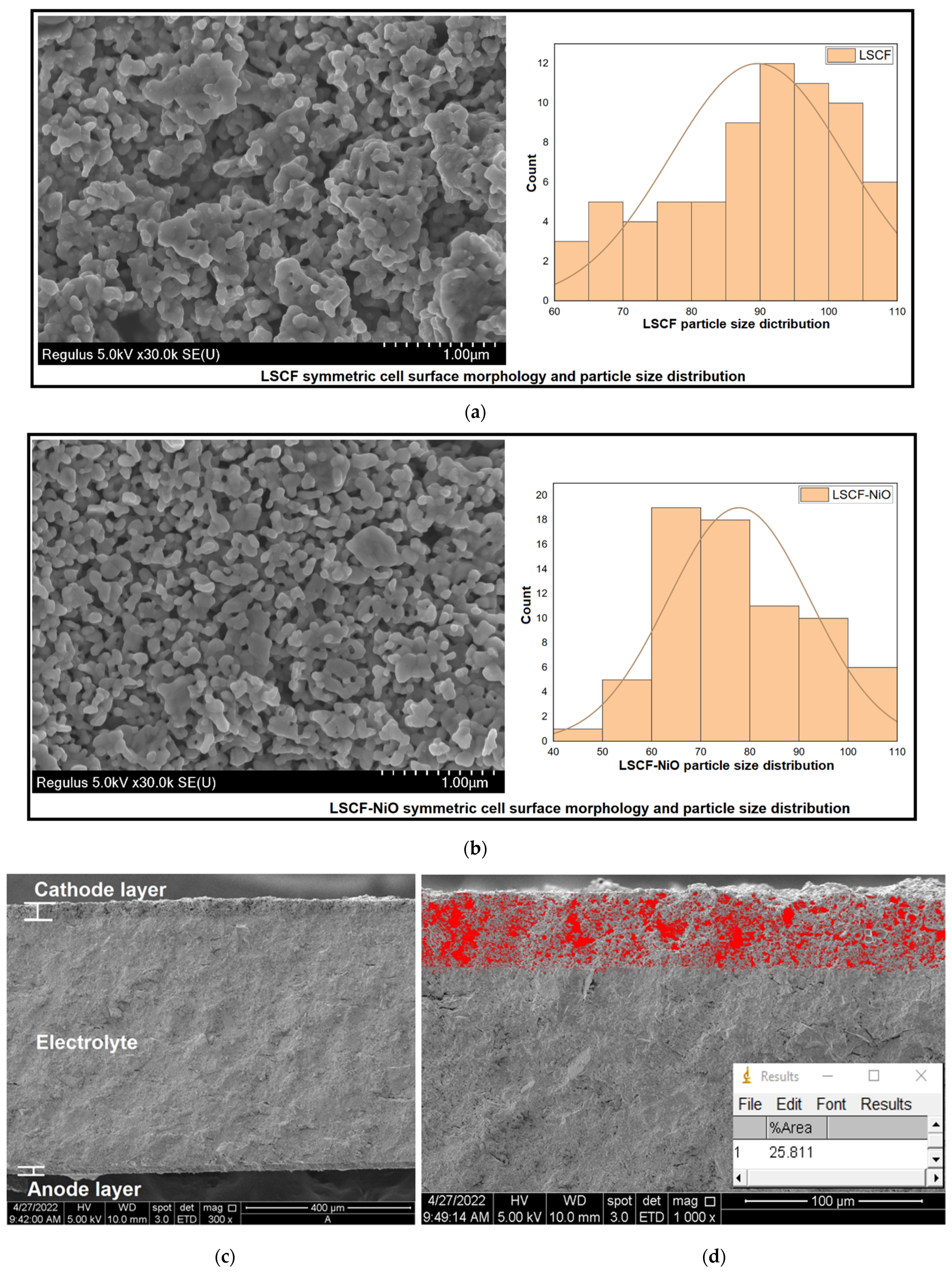
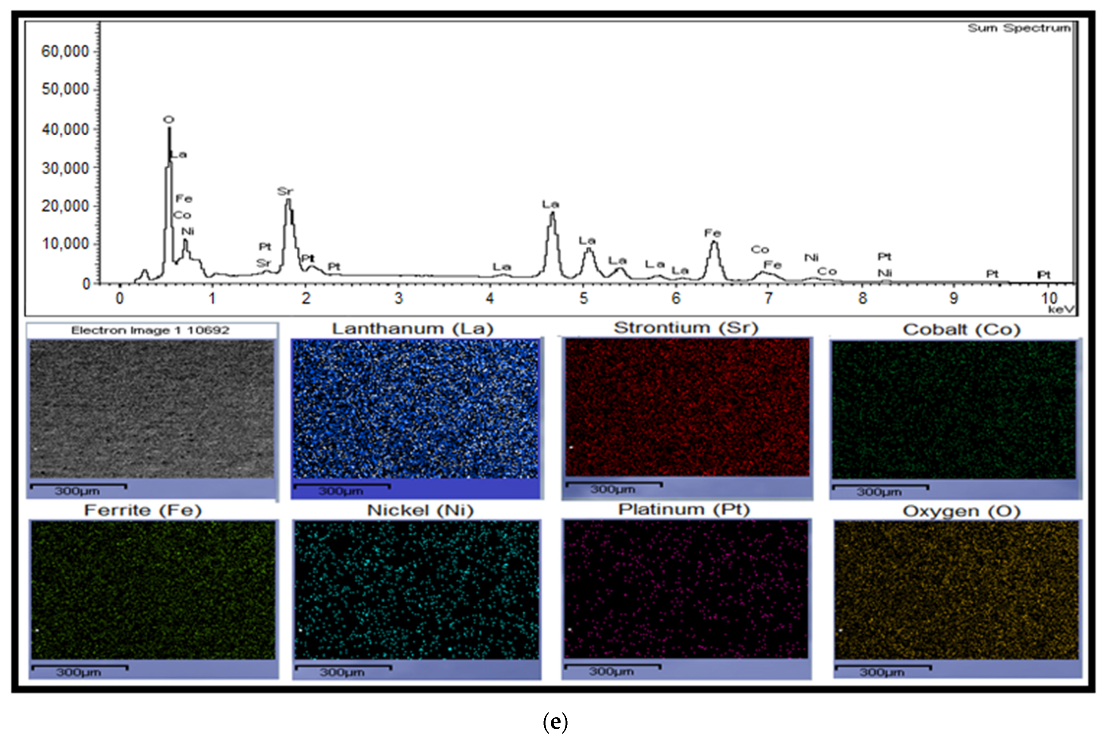
3.3. Microstructure Characterization and Single Cell Performance

Figure 5a,b depict the performance of single-cell bare LSCF and LSCF with 5 wt% NiO at operating temperatures of 650 °C and 600 °C, respectively. Prior ASR research graphs previously demonstrated a significant increase in ASR value between 650 °C and 600 °C, while thermal analysis also confirmed the possibility of operating LSCF-NiO at 600 °C. Therefore, the performance analysis was performed at 650 °C and 600 °C to determine the power density at the lowest operating temperature for the intermediate temperature range. The power density of the LSCF rose from 0.22 Wcm−2 to 0.26 Wcm−2 after the addition of 5% nickel oxide. Single cells of bare LSCF and LSCF with 5 wt% nickel oxide were also conducted at an operating temperature of 600 °C for the purpose of temperature-based performance comparisons. The power density of bare LSCF fell from 0.22 Wcm−2 to 0.09 Wcm−2, resulting in a 59% fall in performance, whereas the LSCF-NiO single cell was reduced from 0.26 Wcm−2 to 0.15 Wcm−2, indicating a 47% performance reduction. This was consistent with the electrochemical data given previously, in which the ASR of bare LSCF increased dramatically at an operating temperature of 600 °C, while LSCF-NiO showed a slight drop in ASR at the same temperature. This demonstrates that LSCF-NiO is capable of operating at temperatures as low as 600 °C and that the addition of nickel oxide to the LSCF structure boosted the ORR process.
The fact that the LSCF-NiO cathode shown an improvement in single cell performance suggests that the inclusion of nickel oxide does, in fact, improve the ORR kinetics of the LSCF cathode. Figure 5c concludes the electrochemical performance investigation in which the activation energy of LSCF without nickel oxide was compared to LSCF with additions of nickel oxide (5 wt%, 7 wt% and 9 wt%). It has been established that the ideal composition for constructing an LSCF-NiO cathode utilizes LSCF that contains 5 wt% of NiO. ASR value of LSCF-NiO (7 wt%) at 600 °C is significantly higher than that of LSCF-NiO (5 wt%), making LSCF-NiO (5 wt%) the optimal choice for this investigation.
Figure 6a,b depict SEM micrographs of LSCF and LSCF-NiO on pellet surfaces. It was observed that LSCF and LSCF-NiO sintered at 1100 °C formed spherical particles that were well coupled to one another, resulting in a porous network [22,33]. It also exhibited a honeycomb-like structure, which is fundamental to the ORR process in a manner similar to that of other articles [39,40]. The concept behind the inclusion of metal oxide is that it will lessen the agglomeration effect, as shown in Figure 6b. Several articles related to the addition of metal oxide to the cathode also published these findings [3,41,42]. As O2− ions travel between the LSCF and NiO without traversing an air gap, the metal oxide will cover the gap and drive the ORR process [43]. It was demonstrated that the particle size distribution of LSCF-NiO is significantly more uniform in the range of 50 nm to 90 nm than that of LSCF, which ranges from 85 nm to 105 nm. This is due to the fact that nickel oxide ionic radii are substantially less than LSCF ionic radii, resulting in a smaller overall particle size (Ionic radii nickel = 0.69 Å, LSCF = 1.4 Å). Table 2 compares the crystal and particle size of bare LSCF and LSCF including 5 wt% nickel oxide.
Further study was conducted towards cross-sectional image on LSCF-NiO/GDC/NiO-GDC single cell. Figure 6c depicts a well separated section of cathode, electrolyte, and anode. There is no delamination occurring between the cathode and electrolyte layer, indicating a sufficient sintering temperature (1100 °C) between the electrolyte and anode layer as well (1200 °C). In depth, the porosity of the cathode has been identified to be 25.81% in Figure 6d, which concludes a good amount of porosity subjected towards the nominal SOFC cathode [34]. As illustrated in Figure 6e, the existence of the element was confirmed by EDX and mapping analysis. The presence of lanthanum, strontium, cobalt, ferrite, nickel, and oxygen peaks on the pellet surface suggested that LSCF-NiO was manufactured using an enhanced modified process that produced a high purity sample. EDX mapping revealed that the element distribution on the cathode surface is uniform across the cathode layer. Platinum is present due to platinum coating for enhancing SEM/EDX resolution. It was also determined that no reaction between the cathode and electrolyte occurred after 1100 °C sintering, indicating that LSCF-NiO is chemically compatible with the GDC electrolyte.

4. Conclusions

It has been demonstrated that the addition of nickel oxide to the LSCF cathode improves the ORR catalytic activity. No solid-state reaction occurred between the two phases during the synthesis of LSCF-NiO using the modified sol gel technique. Then, it was discovered that the addition of 5 wt% nickel oxide to LSCF was able to reduce the ASR value from 0.09 Ω cm2 to 0.05 Ω cm2, and 5 wt% of nickel oxide to LSCF gave the lowest ASR value during the intermediate temperature operation (800 °C–600 °C). Additional investigation demonstrated that the SBet of LSCF-NiO is greater than that of LSCF alone. The bode phase confirms that the ASR value of LSCF-NiO substantially decreased for low frequency resistance, indicating a significant improvement in the ORR process, which in turn improved the triple boundary phase of the cathode. At an operating temperature of 650 °C, the performance of a single LSCF cell containing 5% nickel oxide increased from 0.22 W cm−2 to 0.26 W cm−2. The specific surface area of the LSCF cathode increased from 7.51 m2/g to 10.28 m2/g with the addition of 5% NiO. In accordance with the characterization reported in this article, the cathode’s Bode phase electrochemical analysis revealed a significant decrease in the low frequency ASR (P1) from 0.07 Ω cm2 to 0.03 Ω cm2, proving that nickel oxide can enhance the ORR process.

Supplementary Materials

The following supporting information can be downloaded at: https://www.mdpi.com/article/10.3390/en15145188/s1, Figure S1: FTIR spectra of LSCF powder synthesised via (a) EM-SG method and calcined at 600 °C, 700 °C and 800 °C, LSCF with 5 wt% of NiO powder calcined at 800 °C. (b) Pechini method and calcined at 600 °C, 700 °C and 800 °C, LSCF with 5 wt% of NiO powder calcined at 800 °C; Table S1: ASR tabulated data for LSCF with different NiO loading at different operating temperature. References [44,45,46,47,48] are cited in the supplementary materials.

Author Contributions

A.F.M.A.F. conducted the research, designed, and wrote the manuscript. A.Z.R. assisted on collecting electrochemical impedance spectra data, review and editing the manuscript. A.A.M., M.A.S.A. and A.M. review and editing the manuscript. N.A.H. supervised the analysis of the findings and checked the final manuscript prior to submission. All authors have read and agreed to the published version of the manuscript.

Funding

This research was fully funded by the Ministry of Science, Technology & Innovation (MOSTI) under the Fundamental Research Grant Scheme (FRGS/203/PJKIMIA/6071343).

Institutional Review Board Statement

Not applicable.

Informed Consent Statement

Not applicable.

Data Availability Statement

All datasets used in this study are available on the following website: https://drive.google.com/drive/folders/1oyJlrV2d_OkVqtdE_KngE0pjQcKq5zmo?usp=sharing (accessed on 13 June 2022).

Acknowledgments

The authors are grateful to Ministry of Science, Technology & Innovation (MOSTI) for supporting this research under the Fundamental Research Grant Scheme (FRGS/203/PJKIMIA/6071482).

Conflicts of Interest

The authors declare that they have no competing interest.

References

  1. Golkhatmi, S.Z.; Asghar, M.I.; Lund, P.D. A review on solid oxide fuel cell durability: Latest progress, mechanisms, and study tools. Renew. Sustain. Energy Rev. 2022, 161, 112339. [Google Scholar] [CrossRef]
  2. Ahmad, M.Z.; Ahmad, S.H.; Chen, R.S.; Ismail, A.F.; Hazan, R.; Baharuddin, N.A. Review on recent advancement in cathode material for lower and intermediate temperature solid oxide fuel cells application. Int. J. Hydrogen Energy 2022, 47, 1103–1120. [Google Scholar] [CrossRef]
  3. Nadeem, M.; Hu, B.; Xia, C. Effect of NiO addition on oxygen reduction reaction at lanthanum strontium cobalt ferrite cathode for solid oxide fuel cell. Int. J. Hydrogen Energy 2018, 43, 8079–8087. [Google Scholar] [CrossRef]
  4. Choe, Y.-J.; Seo, J.-U.; Lee, K.-J.; Lee, M.-J.; Hwang, H.-J. Cr-poisoning under open-circuit condition in LaNi0.6Fe0.4O3–δ-based nano composite cathodes for solid oxide fuel cells prepared by infiltration process. Trans. Nonferrous Met. Soc. China 2016, 26, 1367–1372. [Google Scholar] [CrossRef]
  5. Li, J.; Zhang, Q.; Qiu, P.; Jia, L.; Chi, B.; Pu, J.; Li, J. A CO2-tolerant La2NiO4+δ-coated PrBa0.5Sr0.5Co1.5Fe0.5O5+δ cathode for intermediate temperature solid oxide fuel cells. J. Power Source 2017, 342, 623–628. [Google Scholar] [CrossRef]
  6. Aslannejad, H.; Barelli, L.; Babaie, A.; Bozorgmehri, S. Effect of air addition to methane on performance stability and coking over NiO–YSZ anodes of SOFC. Appl. Energy 2016, 177, 179–186. [Google Scholar] [CrossRef]
  7. Yi, S.; Shen, Y.; Zhao, H.; Du, Z.; Chen, N.; Huang, B. Electrochemical Performance of La1.5Sr0.5Ni1-xFexO4+δ Cathode for IT-SOFCs. Electrochim. Acta 2016, 219, 394–400. [Google Scholar] [CrossRef]
  8. Ferkhi, M.; Yahia, H.A. Electrochemical and morphological characterizations of La2−xNiO4±d (x = 0.01, 0.02, 0.03 and 0.05) as new cathodes materials for IT-SOFC. Mater. Res. Bull. 2016, 83, 268–274. [Google Scholar] [CrossRef]
  9. Kolisetty, A.; Fu, Z.; Koc, R. Development of La(CrCoFeNi)O3 system perovskites as interconnect and cathode materials for solid oxide fuel cells. Ceram. Int. 2017, 43, 7647–7652. [Google Scholar] [CrossRef]
  10. Li, P.; Huang, X.; Wei, B.; Wang, Z.; Zhang, Y.; Zhu, X.; Zhang, L.; Zhu, L.; Lü, Z. A novel La2NiO4+δ-La3Ni2O7-δ-Ce0.55La0.45O2-δ ternary composite cathode prepared by the co-synthesis method for IT-SOFCs. Int. J. Hydrogen Energy 2017, 42, 17202–17210. [Google Scholar] [CrossRef]
  11. Li, P.; Wang, Z.; Huang, X.; Zhu, L.; Cao, Z.; Zhang, Y.; Wei, B.; Zhu, X.; Lü, Z. Enhanced electrochemical performance of co-synthesized La2NiO4+δ-Ce0.55La0.45O2-δ composite cathode for IT-SOFCs. J. Alloys Compd. 2017, 705, 105–111. [Google Scholar] [CrossRef]
  12. Liu, X.; Liu, X.; Meng, J.; Yao, C.; Zhang, X.; Wang, J.; Meng, J. Electrochemical property assessment of Sr-doped LaNi0.5Mn0.5O3−δ as cathode for intermediate-temperature solid oxide fuel cells. Int. J. Hydrogen Energy 2016, 41, 22361–22372. [Google Scholar] [CrossRef]
  13. Liu, Z.; Wang, X.; Liu, M.; Liu, J. Enhancing sinterability and electrochemical properties of Ba(Zr0.1Ce0.7Y0.2)O3-δ proton conducting electrolyte for solid oxide fuel cells by addition of NiO. Int. J. Hydrogen Energy 2018, 43, 13501–13511. [Google Scholar] [CrossRef]
  14. Zheng, K.; Świerczek, K. Evaluation of La2Ni0.5Cu0.5O4+δ and Pr 2 Ni 0.5 Cu 0.5 O 4+δ Ruddlesden-Popper-type layered oxides as cathode materials for solid oxide fuel cells. Mater. Res. Bull. 2016, 84, 259–266. [Google Scholar] [CrossRef]
  15. Wang, Y.-P.; Xu, Q.; Huang, D.-P.; Zhao, K.; Chen, M.; Kim, B.-H. Evaluation of La1.8Sr0.2NiO4+δ as cathode for intermediate temperature solid oxide fuel cells. Int. J. Hydrogen Energy 2016, 41, 6476–6485. [Google Scholar] [CrossRef]
  16. Sharma, R.K.; Burriel, M.; Dessemond, L.; Martin, V.; Bassat, J.-M.; Djurado, E. An innovative architectural design to enhance the electrochemical performance of La2NiO4+δ cathodes for solid oxide fuel cell applications. J. Power Source 2016, 316, 17–28. [Google Scholar] [CrossRef]
  17. Wang, H.; Liu, X.; Bi, H.; Yu, S.; Han, F.; Sun, J.; Zhu, L.; Yu, H.; Pei, L. Effects of NiO on the conductivity of Ce0.85Sm0.15O1.925 and on electrochemical properties of the cathode/electrolyte interface. J. Power Source 2016, 320, 86–93. [Google Scholar] [CrossRef]
  18. Rosli, A.Z.; Somalu, M.R.; Osman, N.; Hamid, N.A. Physical characterization of LSCF-NiO as cathode material for intermediate temperature solid oxide fuel cell (IT-SOFCs). Mater. Today Proc. 2021, 46, 1895–1900. [Google Scholar] [CrossRef]
  19. Fatah, A.F.; Mohamad, A.A.; Muchtar, A.; Hamid, N.A. Physical characterization of LSCF-CuO via enhanced modified sol–gel method for intermediate temperature Solid oxide Fuel Cells (IT-SOFCs). Mater. Today Proc. 2021, 46, 2052–2057. [Google Scholar] [CrossRef]
  20. Arabacı, A.; Öksüzömer, M.F. Preparation and characterization of 10mol% Gd doped CeO2 (GDC) electrolyte for SOFC applications. Ceram. Int. 2012, 38, 6509–6515. [Google Scholar] [CrossRef]
  21. Zhang, L.; Hong, T.; Li, Y.; Xia, C. CaO effect on the electrochemical performance of lanthanum strontium cobalt ferrite cathode for intermediate-temperature solid oxide fuel cell. Int. J. Hydrogen Energy 2017, 42, 17242–17250. [Google Scholar] [CrossRef]
  22. Somalu, M.R. Preparation of Lanthanum Strontium Cobalt Oxide Powder by a Modified Sol-Gel Method. Malays. J. Anal. Sci. 2016, 20, 1458–1466. [Google Scholar] [CrossRef]
  23. Xi, X.; Kondo, A.; Kozawa, T.; Naito, M. LSCF–GDC composite particles for solid oxide fuel cells cathodes prepared by facile mechanical method. Adv. Powder Technol. 2016, 27, 646–651. [Google Scholar] [CrossRef]
  24. Samreen, A.; Galvez-Sanchez, M.; Steinberger-Wilckens, R.; Arifin, N.A.; Saher, S.; Ali, S.; Qamar, A. Electrochemical performance of novel NGCO-LSCF composite cathode for intermediate temperature solid oxide fuel cells. Int. J. Hydrogen Energy 2020, 45, 21714–21721. [Google Scholar] [CrossRef]
  25. Dumaisnil, K.; Fasquelle, D.; Mascot, M.; Rolle, A.; Roussel, P.; Minaud, S.; Duponchel, B.; Vannier, R.-N.; Carru, J.-C. Synthesis and characterization of La0.6Sr0.4Co0.8Fe0.2O3 films for solid oxide fuel cell cathodes. Thin Solid Film. 2014, 553, 89–92. [Google Scholar] [CrossRef]
  26. Fatah, A.F.; Hamid, N.A. Physical and chemical properties of LSCF-CuO as potential cathode for intermediate temperature solid oxide fuel cell (IT-SOFC).pdf. Malays. J. Fundam. Appl. Sci. 2018, 14, 391–396. [Google Scholar] [CrossRef] [Green Version]
  27. Kumar, S.A.; Kuppusami, P.; Vengatesh, P. Auto-combustion synthesis and electrochemical studies of La0.6Sr0.4Co0.2Fe0.8O3-δ—Ce0.8Sm0.1Gd0.1O1.90 nanocomposite cathode for intermediate temperature solid oxide fuel cells. Ceram. Int. 2018, 44, 21188–21196. [Google Scholar] [CrossRef]
  28. Lakshminarayanan, N.; Choi, H.; Kuhn, J.N.; Ozkan, U.S. Effect of additional B-site transition metal doping on oxygen transport and activation characteristics in La0.6Sr0.4(Co0.18Fe0.72X0.1)O3−δ (where X = Zn, Ni or Cu) perovskite oxides. Appl. Catal. B Environ. 2011, 103, 318–325. [Google Scholar] [CrossRef]
  29. Basu, P. Chapter 14—Analytical Techniques. In Biomass Gasification, Pyrolysis and Torrefaction, 3rd ed.; Basu, P., Ed.; Academic Press: Cambridge, MA, USA, 2018; pp. 479–495. [Google Scholar]
  30. Deganello, F.; Liotta, L.F.; Marcì, G.; Fabbri, E.; Traversa, E. Strontium and iron-doped barium cobaltite prepared by solution combustion synthesis: Exploring a mixed-fuel approach for tailored intermediate temperature solid oxide fuel cell cathode materials. Mater. Renew. Sustain. Energy 2013, 2, 8. [Google Scholar] [CrossRef] [Green Version]
  31. Wei, W.J.; Huang, D.R.; Wang, D. (Bi,Sr) (Fe1-x,Mx)O3-delta (M = Co, Ni and Mn) Cathode Materials with Mixed Electro-Ionic Conductivity. Materials 2016, 9, 922. [Google Scholar] [CrossRef] [PubMed] [Green Version]
  32. Guo, S.; Wu, H.; Puleo, F.; Liotta, L. B-Site Metal (Pd, Pt, Ag, Cu, Zn, Ni) Promoted La1−xSrxCo1−yFeyO3–δ Perovskite Oxides as Cathodes for IT-SOFCs. Catalysts 2015, 5, 366–391. [Google Scholar] [CrossRef] [Green Version]
  33. Jiang, S.P. Development of lanthanum strontium cobalt ferrite perovskite electrodes of solid oxide fuel cells—A review. Int. J. Hydrogen Energy 2019, 44, 7448–7493. [Google Scholar] [CrossRef]
  34. da Conceição, L.; Silva, A.M.; Ribeiro, N.F.P.; Souza, M.M.V.M. Combustion synthesis of La0.7Sr0.3Co0.5Fe0.5O3 (LSCF) porous materials for application as cathode in IT-SOFC. Mater. Res. Bull. 2011, 46, 308–314. [Google Scholar] [CrossRef]
  35. Lichtner, A.Z.; Jauffrès, D.; Roussel, D.; Charlot, F.; Martin, C.L.; Bordia, R.K. Dispersion, connectivity and tortuosity of hierarchical porosity composite SOFC cathodes prepared by freeze-casting. J. Eur. Ceram. Soc. 2015, 35, 585–595. [Google Scholar] [CrossRef]
  36. Ali, S.A.M.; Anwar, M.; Somalu, M.R.; Muchtar, A. Enhancement of the interfacial polarization resistance of La0.6Sr0.4Co0.2Fe0.8O3-δ cathode by microwave-assisted combustion method. Ceram. Int. 2017, 43, 4647–4654. [Google Scholar] [CrossRef]
  37. Zhang, Y.; Chen, Y.; Chen, F. In-situ quantification of solid oxide fuel cell electrode microstructure by electrochemical impedance spectroscopy. J. Power Source 2015, 277, 277–285. [Google Scholar] [CrossRef]
  38. Loureiro, F.J.A.; Macedo, D.A.; Nascimento, R.M.; Cesário, M.R.; Grilo, J.P.F.; Yaremchenko, A.A.; Fagg, D.P. Cathodic polarisation of composite LSCF-SDC IT-SOFC electrode synthesised by one-step microwave self-assisted combustion. J. Eur. Ceram. Soc. 2019, 39, 1846–1853. [Google Scholar] [CrossRef]
  39. Lee, H.; Park, I.; Park, J.; Lee, G.; Shin, D. Effects of dual porosity honeycomb structure in SSC–SDC composite cathode for SOFCs. Int. J. Hydrogen Energy 2015, 40, 11998–12002. [Google Scholar] [CrossRef]
  40. Sreedhar, I.; Agarwal, B.; Goyal, P.; Singh, S.A. Recent advances in material and performance aspects of solid oxide fuel cells. J. Electroanal. Chem. 2019, 848, 113315. [Google Scholar] [CrossRef]
  41. Santos-Gómez, L.d.; Porras-Vázquez, J.M.; Losilla, E.R.; Martín, F.; Ramos-Barrado, J.R.; Marrero-López, D. LSCF-CGO nanocomposite cathodes deposited in a single step by spray-pyrolysis. J. Eur. Ceram. Soc. 2018, 38, 1647–1653. [Google Scholar] [CrossRef]
  42. Gao, C.; Liu, Y.; Xi, K.; Jiao, S.; Tomov, R.I.; Kumar, R.V. Improve the catalytic property of La0.6Sr0.4Co0.2Fe0.8O3/Ce0.9Gd0.1O2 (LSCF/CGO) cathodes with CuO nanoparticles infiltration. Electrochim. Acta 2017, 246, 148–155. [Google Scholar] [CrossRef]
  43. Baharuddin, N.A.; Muchtar, A.; Somalu, M.R. Short review on cobalt-free cathodes for solid oxide fuel cells. Int. J. Hydrogen Energy 2017, 42, 9149–9155. [Google Scholar] [CrossRef]
  44. Cheng, H.; Wang, P.; Zhao, H.; Li, K.; Lu, X.; Xu, Q. Synthesis, CO2-tolerance and rate-determining step of Nb-doped Ce0.8Gd0.2O2−δ–Pr0.6Sr0.4Co0.5Fe0.5O3−δ ceramic membranes. Ceram. Int. 2017, 43, 6477–6486. [Google Scholar] [CrossRef]
  45. Bermudez, J.M.; Garcia-Fayos, J.; Reina, T.R.; Reed, G.; Persoon, E.S.; Görtz, D.; Schroeder, M.; Millan, M.; Serra, J.M. Thermochemical stability of LaxSr1-xCoyFe1-yO3-δ and NiFe2O4-Ce0.8Tb0.2O2-δ under real conditions for its application in oxygen transport membranes for oxyfuel combustion. J. Membr. Sci. 2018, 562, 26–37. [Google Scholar] [CrossRef]
  46. Tan, K.H.; Rahman, H.A.; Taib, H. Ba0.5Sr0.5Co0.8Fe0.2O3−δ-Sm0.2Ce0.8O1.9 carbonate perovskite coating on ferritic stainless steel interconnect for low temperature solid oxide fuel cells. Mater. Chem. Phys. 2020, 254, 123433. [Google Scholar] [CrossRef]
  47. Rout, S.K.; Pratihar, S.K. Tailoring of properties in the preparation level of nano crystalline Ce0.8Sm0.2O1.9-δ(SDC) for the use of SOFC electrolyte. Mater. Today Proc. 2021, 45, 5764–5768. [Google Scholar] [CrossRef]
  48. Li, L.; Shi, Q.; Huang, L.; Yan, C.; Wu, Y. Green synthesis of faujasite-La0.6Sr0.4Co0.2Fe0.8O3-δ mineral nanocomposite membrane for low temperature advanced fuel cells. Int. J. Hydrogen Energy 2021, 46, 9826–9834. [Google Scholar] [CrossRef]
Figure 1. Rietveld refinement analysis of (a) LSCF powder heated at 800 °C for 6 h (b) Nickel oxide powder formed by heating Ni (NO3)2 at 800 °C for 3 h. (c) XRD pattern for the powder of LSCF-NiO composite powder (EM-SG method) in comparison with LSCF, nickel oxide, and LSCF-NiO (Pechini method from Rosli et al. [18]) pattern.
Energies 15 05188 g001aEnergies 15 05188 g001b
Figure 2. (a) Polarization resistance of bare LSCF and LSCF-NiO with various NiO loading content at operating temperature 800 °C. (b) Specific surface area of various nickel oxide loading towards LSCF powder.
Energies 15 05188 g002
Figure 3. (a) Effect of varies nickel oxide loading content on LSCF cathode towards the area specific resistance (ASR) of the symmetric cell. (b) Thermal analysis of bare LSCF vs. LSCF with 5 wt% NiO powder from room temperature to 800 °C.
Energies 15 05188 g003
Figure 4. (a) Electrochemical impedance spectra measured at 800 °C for a bare LSCF symmetric cell and LSCF with 5 wt% NiO symmetric cell and their respective bode phase results are shown in (b).
Energies 15 05188 g004aEnergies 15 05188 g004b
Figure 5. Cell voltage and power density for a single cell (a) bare LSCF cathode; (b) LSCF cathode with 5 wt% addition of NiO; and (c) activation energy of LSCF and LSCF with varies NiO loading content at intermediate operating temperature.
Energies 15 05188 g005
Figure 6. SEM images for the surface microstructure of (a) surface of bare LSCF cathode; (b) surface of LSCF with 5 wt% of NiO cathode; (c) cross-sectional image of LSCF-NiO single cell; (d) close-up cross-sectional image between LSCF-NiO cathode and GDC electrolyte with the presence of porosity presented in the screen-printed layers (red colour); (e) EDX analysis and mapping of LSCF with 5 wt% of NiO cathode surface.
Energies 15 05188 g006aEnergies 15 05188 g006b
Table 1. Oxygen stoichiometric for LSCF and LSCF-NiO.
SampleMspeciment (g/mol)Moxygen (g/mol)Δm/msΔδ
LSCF222.860.160.00750.104
LSCF-NiO290.530.160.01260.229
Table 2. Crystallite size, specific surface area, mean BET particle size and average particle size from SEM analysis for bare LSCF and LSCF with 5 wt% of NiO, respectively.
SampleScherrer Equation (nm)Specific Surface Area (m2/g)Mean BET Based Sized (nm)Particle Size from FESEM (nm)
LSCF28.357.51131.9589.66
LSCF-NiO28.5810.2893.3978.61
Publisher’s Note: MDPI stays neutral with regard to jurisdictional claims in published maps and institutional affiliations.

