
Multiport Single Element Mimo Antenna Systems: A Review


1
Wireless Communication Center, School of Electrical Engineering, Faculty of Engineering, Universiti Teknologi Malaysia, Johor Bahru 81310, Malaysia
2
Advanced Cyclotron Systems Inc. (ACSI), Richmond, BC V6X 1X5, Canada
3
Faculty of Engineering and Technology, Multimedia University, Melaka 75450, Malaysia
*
Author to whom correspondence should be addressed.
Sensors 2023, 23(2), 747; https://doi.org/10.3390/s23020747
Submission received: 31 August 2022
/
Revised: 30 September 2022
/
Accepted: 4 October 2022
/
Published: 9 January 2023
(This article belongs to the Special Issue Theory and Application of Radio Frequency Identification (RFID) and IoT)
Abstract
:In response to the increasing demand for voice, data, and multimedia applications, the next generation of wireless communication systems is projected to provide faster data rates and better service quality to customers. Techniques such as Multiple-Input–Multiple-Output (MIMO) and diversity are being studied and implemented to meet the needs of next-generation wireless communication systems. Embedding multiple antennas into the same antenna system is seen as a promising solution, which can improve both the system’s channel capacity and the communication link’s quality. However, for small handheld and portable devices, embedding many antennas into a single device in a small area and at the same time providing good isolation becomes a challenge. Hence, designing a shared antenna system with multiple feed ports with equivalent or better performance characteristics as compared to the approach of multiple antennas with multiple feed ports is a promising advantage which can reduce the size and cost of manufacturing. This paper intends to provide an in-depth review of different MIMO antenna designs with common radiators covering various antenna design aspects such as isolation techniques, gain, efficiency, envelope correlation coefficient, and size, etc. There is also a discussion of the mathematical concepts of MIMO and different isolation techniques, as well as a comparative analysis of different shared radiator antenna designs. The literature review shows that only very few antennas’ design with common radiator have been suggested in the available literature at present. Therefore, in this review paper, we have endeavored to study different antennas’ designs with common radiator. A comparison is provided of their performance improvement techniques in a holistic way so that it can lead to further develop the common radiator multiport antenna systems and realize the promising advantages they offer.
1. Introduction
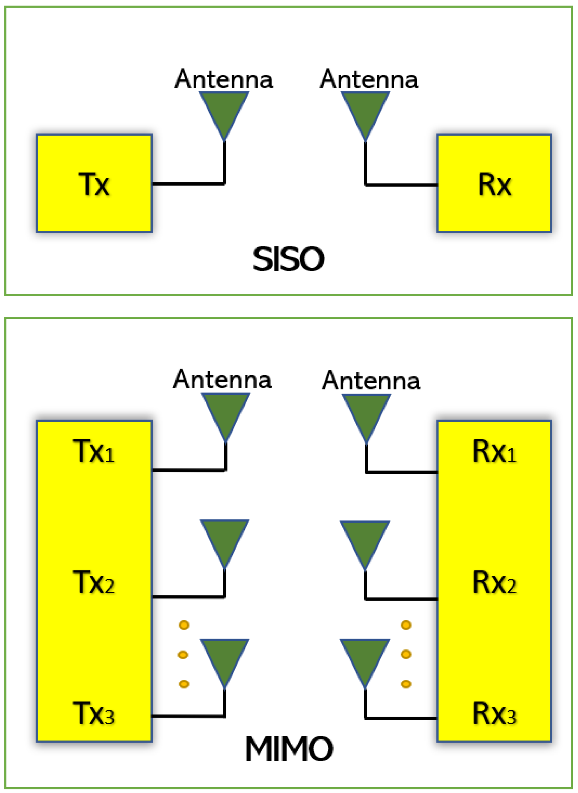
With the explosive growth in users of present and future technology, there is a pressing need to design new compact antenna systems for higher data rate and large bandwidth. Design and implementation of Single-Input Single-Output (SISO) antennas for portable devices are easy and can be easily integrated into the portable systems. However, SISO systems are susceptible to the problems caused by multipath effect and for obtaining higher gain, the size of a SISO antenna should be increased proportionally [1]. For antenna to work efficiently at higher data rates in the existing frequency with an improved channel capacity is a great challenge. With the growing demand, designing Multiple-Input Multiple-Output (MIMO) antenna systems is a significant solution [2,3]. The MIMO systems precisely provide a technique in which multiple independent channels send and receive data concurrently in the same radio channel. The multiple transmit-and-receive antennas used in MIMO technology improve the radio link capacity to attain the multipath propagation. Next-generation wireless communication technology has presented MIMO systems as a feasible solution to solve the data rate limitation problem experienced by SISO systems, due to its multiple antennas’ capability which can also provide better system reliability and increased channel capacity [4,5]. The MIMO antenna system can enhance the signal quality and the gain of an antenna but leads to complexity in design and an increase in size [6]. To attain a required level of signal independence and good isolation in MIMO operation, the multiple antennas should be placed with adequate separation from each other. But for portable devices, this approach would need to be given more space for multiple antennas, as well as additional feedline length [7]. The close placement of the antenna elements for MIMO operations can solve the space issue but results in higher mutual coupling among antenna elements.
In this perspective, various isolation techniques and different types of isolation enhancement techniques are found in literature to improve the isolation in various antenna structures which are discussed in detail in Section 2. Through these techniques, the gain, bandwidth, envelop correlation coefficient (ECC), and efficiency can be enhanced. The antenna diversity technique used in MIMO systems enhances the performance of MIMO systems through multipath fading and co-channel interference reduction [8,9]. Depending on the requirement, the diversity gain is achieved by employing different methods such as spatial, polarization, and pattern diversities.
Several findings regarding the potential antenna designs suitable for portable devices and small handheld terminals for the MIMO applications have been described in the literature. Existing literatures discussed in Section 4 have presented works on numerous MIMO antenna designs. In all these designs, more than one antenna elements are integrated or etched on single substrate to apprehend a compact MIMO antenna. This occupies more space and hence presents a big challenge in the industrial design process.
The shared radiator with multiport arrangement is a good alternative to miniaturizing the overall size of MIMO antennas. However, due to the difficulties in getting high isolation among connected ports, only a countable number of antenna designs having shared radiators with more than one port are available in literature. Compared to the array designs and separated ports, there is much less focus on common radiator designs with multiple feeding ports. To regulate mutual coupling, these coupled ports with the shared radiator require extra effort. Thus, designing an antenna becomes critical while considering the required parameters suitable for portable devices.
Currently, we could not find any related review paper accessible in the literature which can provide us in detail about the shared radiator multiport MIMO antenna systems and their performance improvement techniques. So, in this paper, we have endeavoured to explore all the multiport MIMO antennas with a shared radiator, presented in recent years in a holistic manner considering their performance-enhancing techniques and aims to address the design issues for the further advancement in the MIMO antenna design as per their application. Our main aim in this paper is to provide a comprehensive literature review of multiport MIMO antenna systems having one shared radiator and a comparative study on different multiport-shared radiator antenna designs and the isolation improvement techniques used in these designs. The primary antenna features of shared radiator multiport MIMO antennas such as gain, frequency, mutual coupling, ECC and their applications are reviewed and compared in this paper. In addition, a brief overview of MIMO mathematical concepts and approaches used in these antenna designs for increasing the isolation are also discussed.
The rest of this paper is structured as follows. Section 2 discusses the mathematical concepts of MIMO, whereas a detailed literature review of diverse types of isolation techniques is elaborated in Section 3. The findings of single-element multiport MIMO antenna classification are summarized in Section 4. Section 5 then gives a detailed summary and discussion of the important findings of the paper.
2. Mathematical Concepts of MIMO
In this section, the mathematical concepts for MIMO antenna design are discussed [10]. Since the MIMO antenna system has multiple antennas at the transmit side (Mt) and receive end (Mr) as shown in Figure 1, the MIMO system capacity (C) can be expressed by Equation (1).
where PT—total input power, —noise power, H—channel matrix, HH—Hermitian transpose of channel matrix and IMr—identity matrix.
Mutual coupling occurs when antenna elements are placed in closed proximity, which results in isolation reduction thus affecting performance. The envelope correlation coefficient (ECC) is required because the S-parameters such as S12 or S21 measured in between the ports are inadequate to encompass the effect of all S-parameters. The mutual coupling and return loss at the ports can be used to determine ECC, which helps to find the diversity performance of the MIMO antennas [11]. The acceptable and standard value of ECC should be less than 0.5 for portable devices. However, the ECC calculation through S-parameters is effective only in case of lossless antenna substrates but in case of lossy antenna substrate, the ECC must be calculated/measured from the antennas’ far-field radiation patterns. In Table 1, the acronyms and their meanings are included.
The mean effective gain (MEG) is an important performance parameter and can be defined as the ratio of the mean power received to the mean incident power of the antenna. It is used to calculate the average received signal strength of each antenna [12]. Another performance parameter, which is the total active reflection coefficient (TARC) is the ratio of square root of total reflected powers to the total incident powers [13,14]. The TARC is a function of frequency and is expressed in Equations (2) and (3).
where, [b] = [S][a] and [S] is the antenna’s scattering matrix, vector [a] is the sum of the available incident power at all the ports, vector [b] is the power reflected to the source and an, bn are the nth element of the vector [a] and vector [b] respectively.
Similarly, the antenna Diversity Gain (DG) is a well-known performance parameter used to verify the efficacy of the diversity. It can be defined as the ratio of rise in SNR of mixed signal from a multiple antenna to the SNR from a single antenna in the system. The DG can be calculated using Equation (4).
Like the above parameters, the dielectric substrate permittivity, loss tangent and thickness play an important role in designing the antennas. The efficiency, return loss and gain can also be improved by the proper selection of the dielectric material.
3. Isolation Techniques
Mutual coupling between the antenna elements is the energy absorbed by the antenna element in MIMO system when the nearby antenna is transmitting/receiving. As the energy radiated away from one antenna gets absorbed by a closely placed antenna, it becomes adverse. This affects the efficiency and performance of the antennas in both transmitter and receiver side.
Good isolation between the two antennas would be achieved by placing the antennas in such a way that they have sufficient space between them [15]. However, this required space between the antenna elements will increase the antenna size. Other than space, there are various isolation techniques which have been reported in literature for increasing the isolation among antenna elements.
3.1. Defected Ground Structure
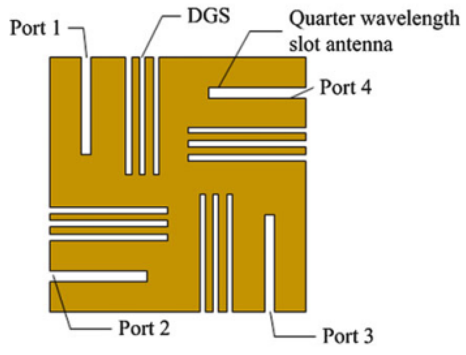
Defected ground (DG) structure is an isolation technique in which the slots or slits are inserted on the antennas ground plane to change its electromagnetic properties. By modifying the ground plane [16] as shown in Figure 2, the isolation is improved. The ground plane modification can be in the form of slits [17,18] or tumble-shaped defects [19,20].
DG structure acts as a band stop filter by disturbing the current flow on the ground plane. The coupled fields generated between the nearby antennas are suppressed. The mutual coupling is reduced between the two antenna-radiating elements by periodic S-shaped-defected ground structure [21]. This disrupts the electromagnetic far-field drastically and the current is induced between patch elements. A square ring-defected structure discussed in [22] is added to the ground plane to act as a resonator. It decreases the cross-polar levels, and the surface waves are decreased by limiting them within the dielectric. The reduction in surface wave further helps to decline in back radiation which results in getting good isolation.
3.2. Decoupling Network
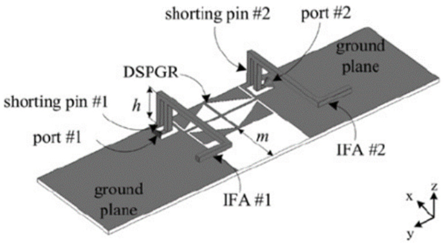
In [23], a decoupling network (DN) also termed decoupling and matching network (DMN) is used. It is a circuit-based approach to achieve good isolation in MIMO antennas. The basic principle of DMN is to reduce the coupling coefficients between the antennas while maintaining a good impedance matching for each antenna [24]. Figure 3 shows two L-shaped Inverted-F antennas which act as radiating elements. The diamond-shaped pattern etched in the ground known as the diamond-shaped pattern ground resonator (DSPRG), acts as a resonator which also works as a decoupling element [25]. This can control the surface current flow in the antenna elements and provides good isolation in the wideband.
In [26], another decoupling method known as a coupled resonator decoupling network (CDRN) is implemented between the two nearby antennas to achieve good isolation. CDRN consists of two similar open-loop square-ring resonators.
3.3. Electromagnetic Bandgap (EBG) Structure
An electromagnetic bandgap (EBG) structure is designed on the ground plane by periodic arrangement of unit cells. This structure acts as a band stop filter and provides high attenuation, which helps in achieving reduction in mutual coupling between the antennas [27,28]. Each cell in an electromagnetic bandgap structure looks like a mushroom inserted between two antenna elements. It can act as a band stop filter at different frequencies by adjusting the unit cell dimensions and its arrangement.
3.4. Neutralization Lines
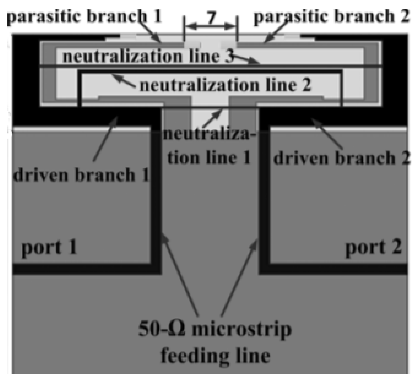
This is a decoupling technique in which a conductive wire or strip is used that links the two antenna radiating elements. The idea of a neutralization line is to minimize the coupling between the two antenna elements by establishing a new coupling path and improves the bandwidth when connected between ground planes [4].
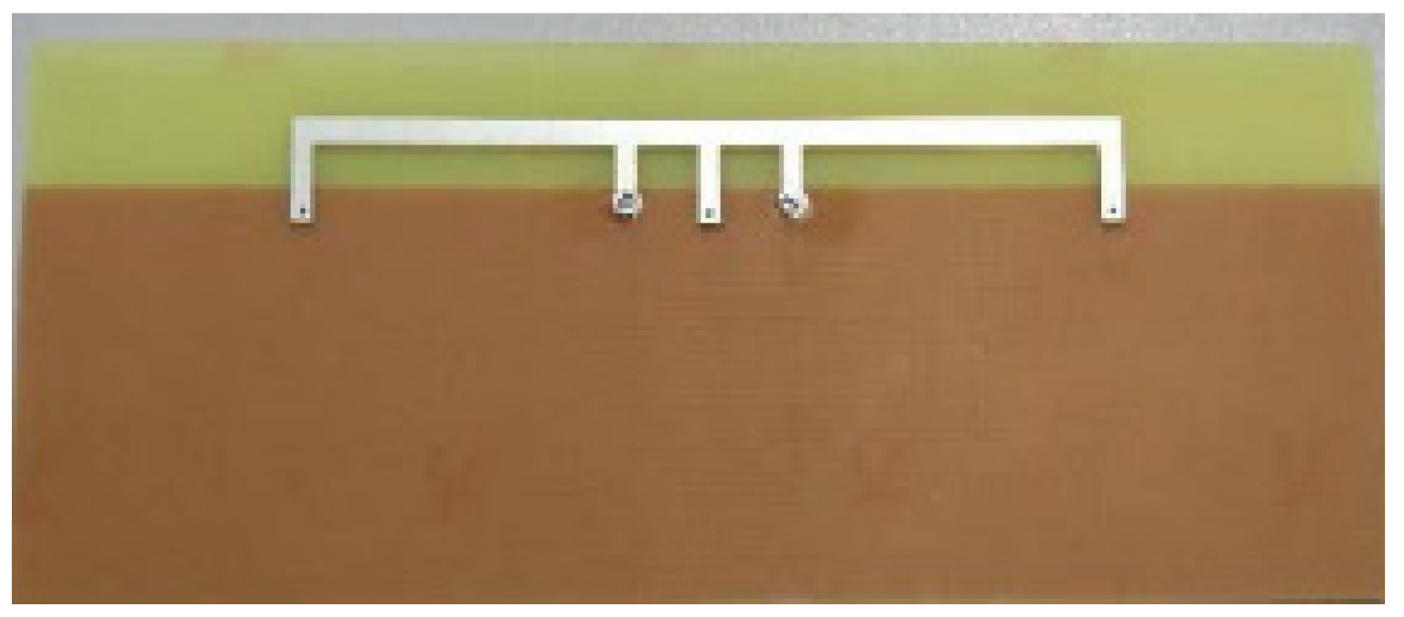
Neutralization lines with various lengths can be utilized for achieving multi-bands or a wide band operation and to obtain high isolation. Good isolation is achieved for frequency from 1.7 GHz to 2.7 GHz using multiple neutralization lines as shown in Figure 4. Three neutralization lines are used with different lengths to achieve multi-band frequency coverage [29].
A neutralization line introduced between two antenna elements creates some current on the line path and generates an extra EM field to cancel the mutual coupling as discussed in [30]. Between the C-shaped radiator antennas, a neutralization line is incorporated in parallel. This line cancels out unnecessary coupling by producing opposite coupling and generates imaginary admittance [31].
3.5. Parasitic Elements
This decoupling technique can be implemented to reduce the mutual coupling by placing the parasitic elements in between the antennas in MIMO configuration by cancelling a segment of the coupled fields through an opposite coupling field, which can reduce the total coupling on the selected antenna. These elements are not coupled to the antennas in any way. The parasitic element can be of any type like a resonator or shorted stubs [32]. Parasitic elements are also used to adjust the bandwidth, isolation range, and coupling quantity [33]. A parasitic decoupling structure of a T-shaped stub with a slot is employed on the backside of the substrate between the two square monopole elements [34]. The antenna matching is improved through the stub and the slot attached to stub reflects the radiation from the elements. Hence, the isolation is improved. Two orthogonal modes [35] used in the parasitic elements creates a impedance bandwidth broader by coupling either in radiating patch or in the ground plane. Mutual coupling is minimized, and a good isolation is achieved by establishing new additional coupling path [36,37]. Additionally, good isolation is achieved by the extra coupling path resisting the signal approaching from the other path.
3.6. Complementary Split Ring Resonators (CSRR)
This method is one of the good solutions for mutual coupling reduction in which magnetic and electric coupling are produced from an LC resonator. This method is useful in filtering and improving isolation [38]. The impedance bandwidth is broadened through the proper placement of CSRRs on the patch at a symmetrical position of the MIMO antenna in which the two printed dipole antennas are perpendicular to each other [39]. Since the CSRRs behaves as negative permittivity band-stop filters, higher-order modes are suppressed. In [40], a slotted CSRR etched in the ground plane between the antennas achieves a good isolation. In this configuration, the length of slotted CSRR etched in ground plane is adjusted to improve the isolation. This technique is also known as space diversity utilization.
3.7. Metamaterials
Metamaterials are useful for the reduction of mutual coupling implemented between adjacent antenna elements and the presence of a band gap in their frequency response [33]. The decoupling component is made of sub-wavelength metal-air layers, which can be treated as a singular medium operating over a broad frequency band [41]. Four element substrate integrated cavity-backed slot antennas distributed orthogonally comprise two-layer mushroom structure and the isolation are improved by placing a wall between each antenna element. MIMO antenna with reversal composite right-left-handed configuration is discussed in [42]. Here, the slit and interdigital capacitors are jointly inverted by cascading the metamaterial transmission line. Hence, by this configuration, the current produced inside the antenna is reversed. This configuration reduces the mutual coupling, and a good isolation is achieved.
The minimum value of mutual coupling achieved in the above-discussed techniques is between −15 dB to −20 dB. The values lower than this can affect the antenna mismatches and embedded radiation efficiencies of the MIMO antenna systems.
4. Multiport Single Element System
MIMO technology offers many benefits, including error-free and faster communication, as well as superior multipath propagation results. MIMO technology, which employs multiple trans-receive systems, also improves transmission and reception quality. The performance metrics required to characterize the behavior of multiport antenna systems is discussed in [34]. The author suggests that existing designs cannot fulfill the needs of future wireless handsets that can cover the 4G and 5G (upper and lower) frequency bands along with WLAN and WiMAX, while considering the wide bandwidth. Hence, novel designs should be implemented to satisfy the requirement.
For 5G MIMO antenna base stations, the 3-D printing technology and metal plating technique are used together to fabricate metal-coated polymer antenna [43]. The fabricated antenna has an isolation of less than −14 dB with antenna dimensions of 27.2 × 27.2 × 17 mm3. Four identical box-folded PIFA MIMO antenna, designed for mobile handsets with a wide operating band of 1.84–2.69 GHz. However, the whole antenna system dimensions are large and not the most suitable for portable devices [43].
A dual-band MIMO antenna for LTE Terminal is presented in [44]. To reduce the mutual coupling, the coupling feed patch and capacitive load patch are used in this system, which reduces the current density on the ground plane and the slotted technology is used to achieve the dual band. In contrast, a two-element four-shaped MIMO printed antenna system designed with defected ground structure and micro-strip matching network is used to enhance the isolation [45]. An eight-port antenna array with each pair of antennas is placed symmetrically on the substrate at the four edges. Each antenna element is autonomously coupled with a feeding strip and a communal square loop is etched at each antenna pair. Good isolation is achieved through this configuration by orthogonal polarization, but the efficiency is compromised because of the non-availability of the external decoupling structure [46,47].
A multiband antenna system for LTE application, discussed in [48], have 3D Inverted-F Antennas folded on a non-metalized section of PCB. A new resonance is created by inserting the parasitic radiating element to IFAs and high port-to-port isolation is achieved via a suspended neutralization line between the two ports. A novel MIMO antenna system with a nature-inspired flower shape is proposed for upcoming 5G communication systems [49], which covers the mmWave frequency band. In [50], a rectangular dielectric resonator antenna (RDRA) with circularly polarized response is designed which covers the frequency band from 4.4–4.8 GHz suitable for 5G NR (New Radio) Sub-6 GHz band applications. Similarly, an eight-element MIMO array structure is presented in [51], which covers the frequency range between 3.4 GHz to 3.6 GHz. This helps to surge the data throughput with intra-band contiguous carrier aggregation. This is a circular-monopole antenna for portable devices with each antenna element consisting of three microstrip transition printed on the top side of substrate and two L-shaped stubs at the ground plane to improve the isolation [52].
An eight-port planar antenna for 5G micro wireless access point applications is designed by integrating three monopole strips with different structures and resonant modes for a wider bandwidth. High isolation and low ECC are obtained through diverse protruded stubs and etched slots loaded on the defected ground plane [53]. In [54], a printed antenna is designed which is capable of multiband operation with coupled-fed monopoles providing good isolation of less than 15 dB over all the frequency bands. A hybrid antenna with 4G and 5G antenna modules combined operating at 3.5 GHz band capable of covering the C-band is designed [55]. Four-port MIMO antenna for sub-6 GHz 5G applications is designed on an FR4 substrate and the overall volume of the circuit board is 50 × 50 × 1.6 mm3 [56]. A compact dual-band 2-port antenna operating at 2.4–2.5 GHz works simultaneously with a 4-port antenna operating at 4.9–5.725 GHz, without using the MEMS switching. Isolation is better than 12 dB achieved through back-to-back slot arrangement [57].
The MIMO antennas discussed in [43,44,45,46,47,48,49,50,51,52,53,54,55,56,57] provides good isolation but their structure is either complex or their total size is larger. Hence, designing a compact MIMO system considering all the performance parameters is a challenging task for portable devices and mobile terminals. The approach of designing common radiator MIMO antenna with multiple feed ports providing better performance could represent a considerable advantage by reducing the size and the manufacturing cost. In the existing literature, it is observed that few studies have been conducted on MIMO multiport single element antenna systems. The following sections will present the recent literature regarding two-port or four-port antenna systems sharing a single radiating element.
4.1. Single Element Two-Ports MIMO Antenna System
In [58], a novel single element MIMO antenna with dual-port based on isolated mode antenna technology (iMAT) was discussed. The phase and magnitude of the signal are changed due to few bends available in the crossover coupling structure connected to the single antenna radiating patch with two ports. To solve this issue and to attain good isolation, an I-shaped slot is etched at the ground plane which behaves as a LC filter. The iMAT concept was introduced in [59] also to achieve enhanced port-to-port isolation in which a U-shaped antenna with common radiator is designed and compared with two elements monopole antenna.
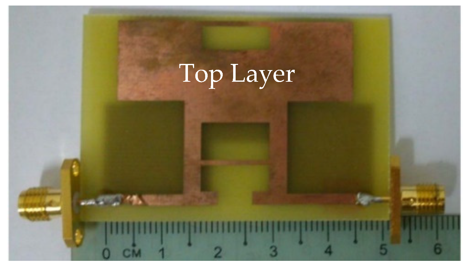
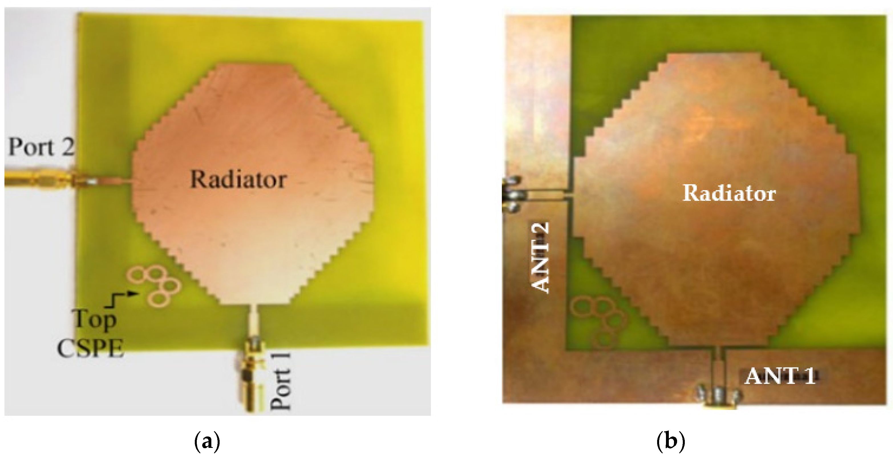
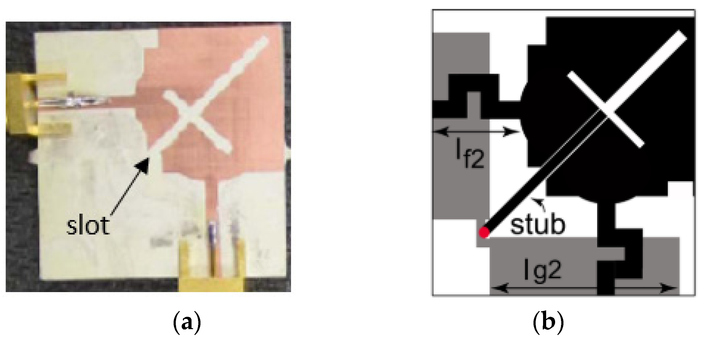
In [60], a common radiator dual port antenna using iMAT for LTE band application was designed. A good isolation was achieved by etching a rectangular slot at the ground plane on the bottom side; which intersects with a T-shaped slot inserted at the radiating patch as shown in the Figure 5. The multiple slots and slits etched on the top patch and the ground layer reduces the mutual coupling and has a good bandwidth covering the LTE 2300; 2.4 GHz WLAN and LTE 2500 frequency bands. This proposed common radiator dual port antenna has a dimension of 48 × 33.8 mm2 suitable for mobile devices. The single element MIMO antenna system presented in [61], consists of two wideband monopole antennas which are orthogonally placed with a shared radiator and L-corner ground plane for the frequency bandwidth of 600 MHz from 2.3 to 2.9 GHz. As shown in Figure 6a; a parasitic element of chain-shaped structure with two sets of rings are etched on the top and bottom layer of the substrate. The position of rings is adjusted in such a way to generate a secondary current path; which can reduce the current distribution effects between the ports. This configuration provides good isolation between the ports and a return loss of less than −10 dB is achieved.
The two-port MIMO antenna system in [61] is presented for wireless access point indoor applications. In this design, two coplanar waveguide-fed ports which are perpendicular to each other are connected to a common radiator. On the same side of the substrate, an L-shaped ground plane is also etched as shown in Figure 6b to excite two orthogonally polarized modes [62]. Good isolation is obtained by introducing the chain-shape parasitic element (CSPE) between the ports. The total dimensions of the antenna structure are 110 × 130 × 1.6 mm3. The stepped-cut technique at four corners is used by adjusting the shape of radiating patch to obtain the required bandwidth. The implemented antenna achieves a good isolation of around 15 dB, providing impedance bandwidth of 1.8 GHz from 0.9 GHz to 2.7 GHz [62].
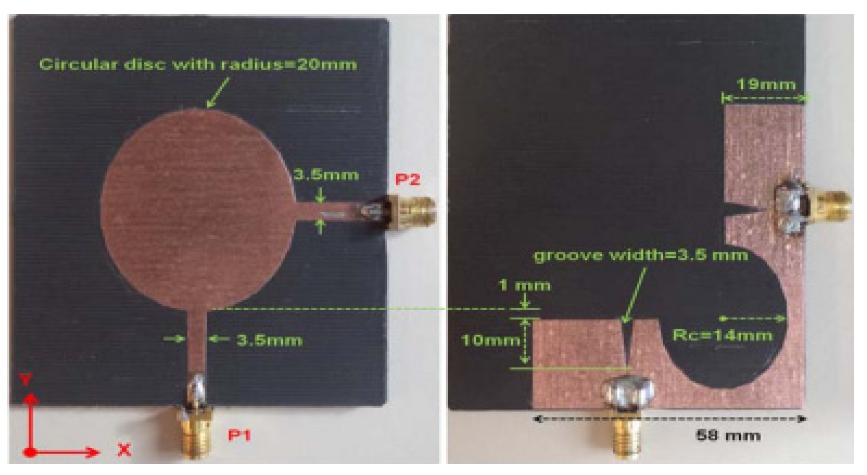
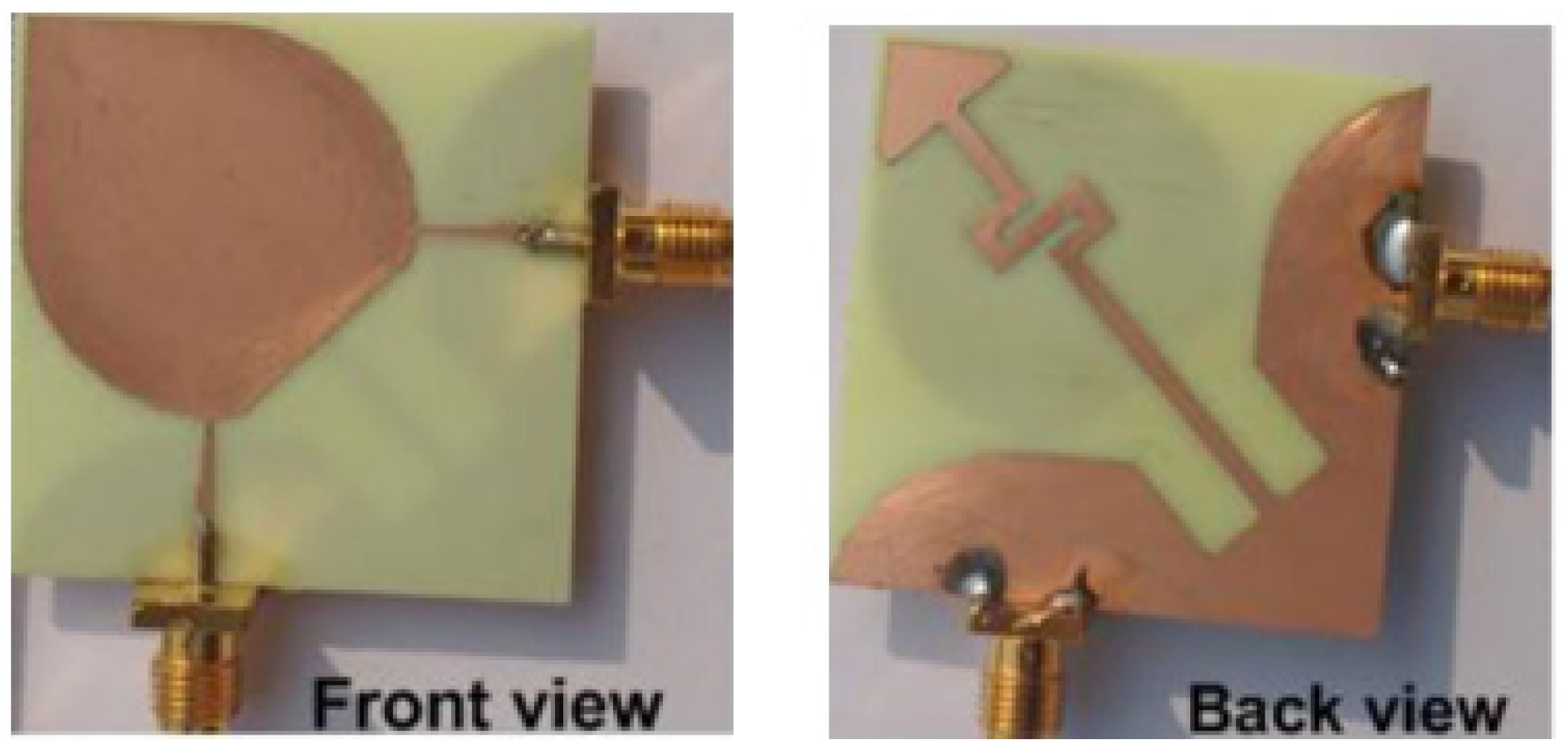
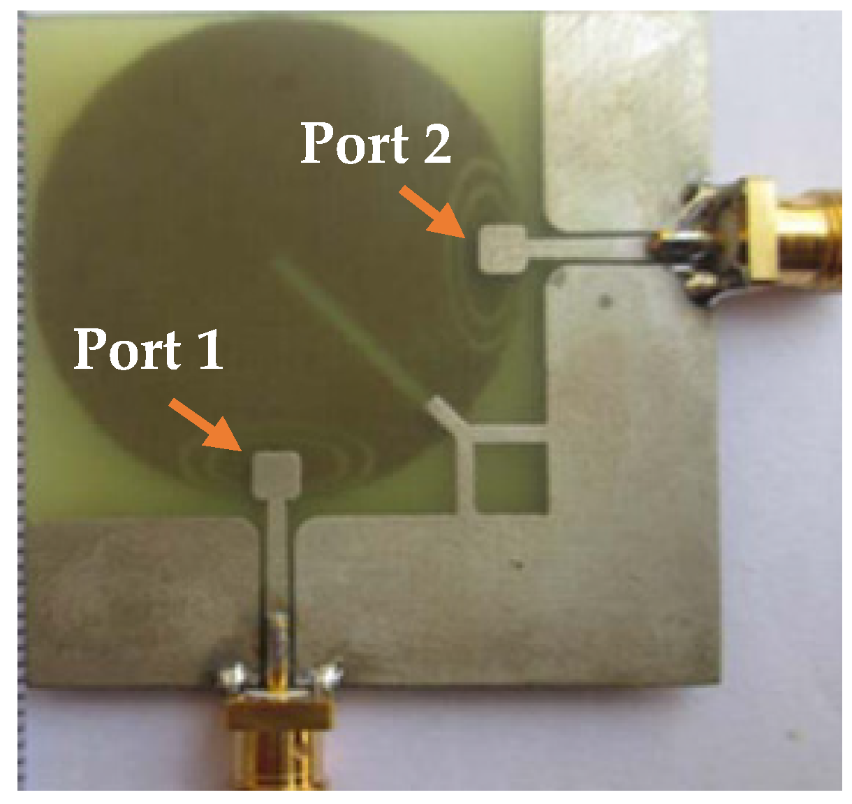
A dual-port monopole antenna (64 × 64 mm2) attached to a common radiator with a shape of circular disc with a radius of 20 mm was implemented in [63]. To excite from each port, a feed line 20 mm long and 3.5 mm wide is connected. To expand 10 dB input impedance bandwidth, a groove is inserted below each feeding line of the antenna as shown in Figure 7. To achieve a good isolation, a circular cut of radius Rc was etched in the ground plane, which restricts the current flowing between the two ports. Wide bandwidth of 2 GHz to 6 GHz is achieved with less than −15 dB port-to-port isolation. Similarly, the dual-port microstrip antenna was presented in [64] which utilizes an external loop to attain good port-to-port isolation. An ACS-fed multiple-input–multiple output antenna presented in [65] operates from a frequency range of 3.1 to 10.6 GHz. A good isolation of more than 15 dB is achieved. The antenna design discussed in [66] is much smaller in size of 26 × 26 mm2 as compared to the antenna structure presented in [65]. This size reduction was achieved by two antenna elements sharing the single radiator and the ground size is reduced using an ACS-fed structure as shown in Figure 8a. The operating bandwidth and the isolation between the two ports are enhanced by attaching a rectangular patch on the bottom side and etching a I-shaped slot in the radiator.
A modified common rectangular radiator connected with two antenna elements is fed by two microstrips placed perpendicular to each other and the ground plane connected by a short strip as shown in Figure 8b [66]. The current flow between the two antenna elements is reduced and the isolation is improved through the insertion of slots in the radiator. This configuration disturbs the coupling by focusing the current flow on the edges of the slots. Good isolation of less than -15 dB is achieved with a reflection coefficient of better than 10 dB from 3 GHz to 11 GHz.
The MIMO antenna design shown in Figure 9b as an ultra-compact size of 22 × 24.3 mm2, which is smaller as compared to the designs presented in [65,66,67]. Figure The design discussed in [68], the single shared radiating element is fed with two perpendicular meandered microstrip lines. Good isolation is obtained for the entire bandwidth through the placement of an open shunt stub on the radiator and a T-shaped slot in the middle of the radiator. The use of meandered slots reduces the total length while maintaining the electrical length of the microstrip lines which helps to achieve compact size of the antenna [69] but increases the energy leakage. Hence, a partial ground plane of small strips is placed on the bottom of the substrate and the stub connected to the ground provides the current a path to the stub providing good isolation between the two ports. The antenna presented in [70] consists of a common radiating element with leaf-shaped structure, shared evenly as shown in Figure 10, using two microstrip lines and a common ground plane with curved shaped slot etched on the bottom side of the substrate. Isolation less than −15 dB is obtained for the operating frequency band (2.4–12.75 GHz) with the help of end-loaded meandered line connected to the ground plane.
The two-port antenna presented in [71] comprises a shared radiator with two shorting strips connected to the ground plane via holes at their end. High isolation is achieved for the impedance bandwidth from 3.3 GHz to 3.7 GHz through appropriate adjustment of the two feeding ports’ distance and by proper placement of shorting strips on the radiator. Compared to [71], the dual-feed MIMO antenna designed with one shared radiator and three shorting pins achieves a good isolation of less than −25 dB for the impedance bandwidth from 3.4 to 3.6 GHz [72]. Due to the insertion of shorting pins between two feeding ports and on the other sides as shown in Figure 11, the current distribution takes place everywhere on the antenna, which leads to good isolation.
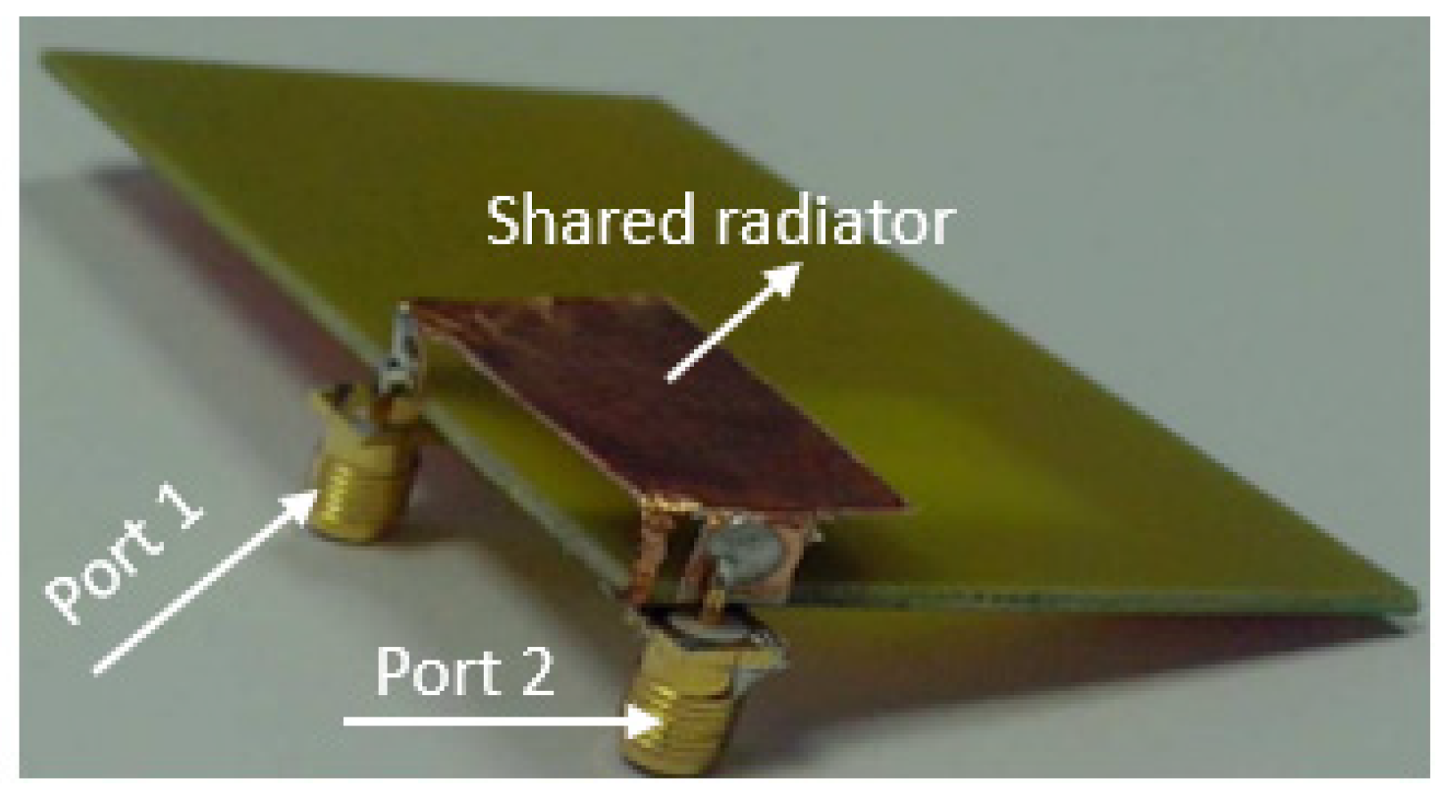
In [73], a two-port PIFA with a common radiator placed at a height of 5 mm from the substrate having two feed plates placed perpendicular to each other as shown in Figure 12. A slot is etched on the ground plane which reduces the current flow between the two ports which results in improved isolation. The impedance bandwidth achieved is around 800 MHz from around 2.1 to 2.9 GHz. The ECC is below 0.005 and the MEG of the two ports is approximately equal to 1.
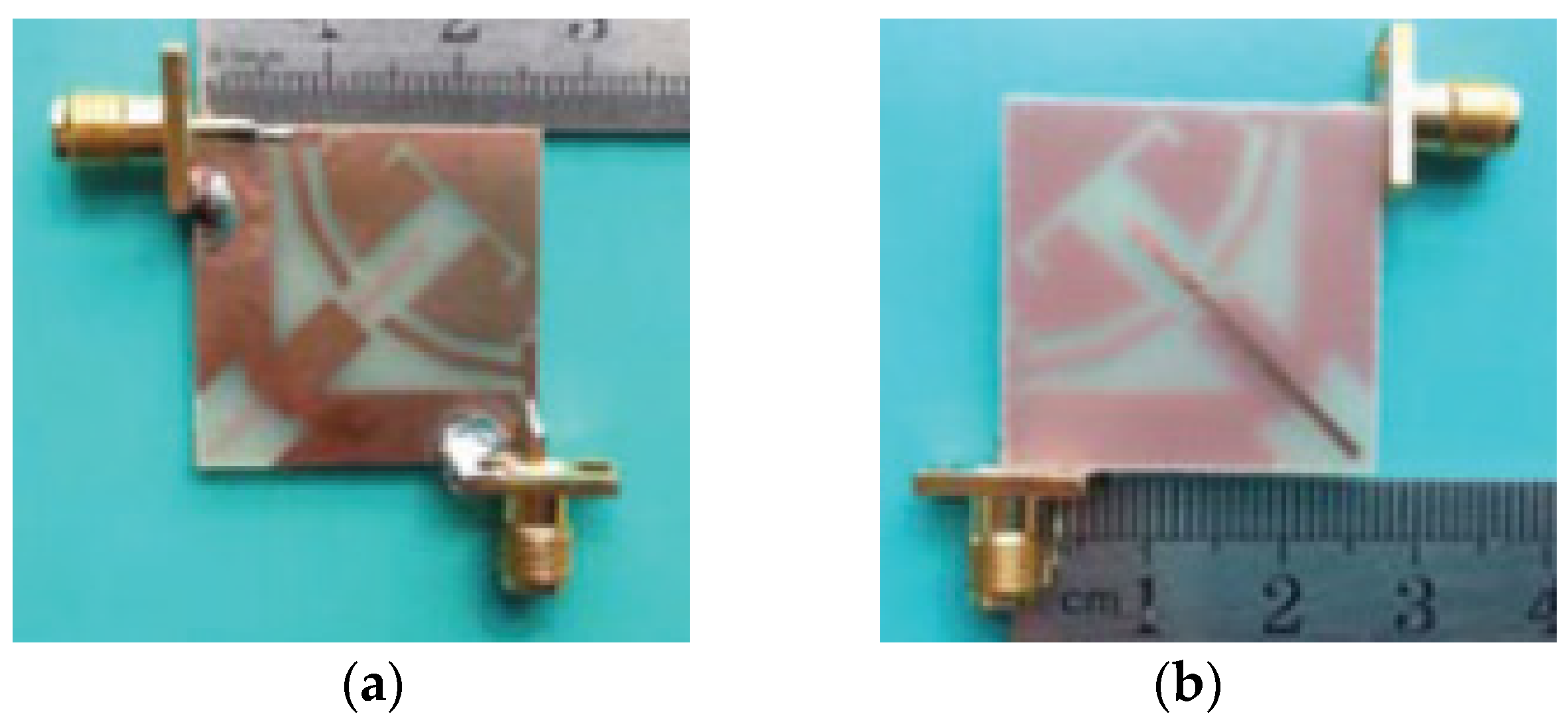
In [74], a common single circular patch radiator designed for UWB application with dimensions of 45 × 45 mm2 was proposed. An edged rectangular slot placed in the radiator increases the isolation between the two ports for the operating frequency range from 3 to 12 GHz. The measured ECC in terms of far field is less than 0.01. In [75], a circular-shaped common radiator is connected by two tapered coplanar waveguide feeding structures as shown in Figure 13. It consists of a ground plane printed on the bottom layer corner of the substrate and the circular radiator placed on the top layer. In this antenna design, the implemented common radiating element decreases the overall size of the antenna to dimensions of 41 mm × 41 mm and supports in creating the band notch elements in the radiator. Good isolation is achieved through the rectangular slot and inverted Y-shaped strip placed in the middle of the radiator and to the ground plane respectively. Wide bandwidth is obtained for UWB applications, which covers the frequency ranging from 2.9 GHz to 12 GHz.
As discussed in this section, a CPW-feed provides easy integration and placement of multiple antennas with shared radiator with existing MMIC technology on a single-sided PCB board. The objective is to have compact antennas, space being the primary concern in most of the applications. Thus, an alternative feeding technique is required, the ACS [65,66] feed antenna currently has been significantly explored and can still facilitate the basic antenna requirements. In [66], through proper placement of an I-shaped slot in the radiator along with a stub and a slot etched on ground plane achieve good isolation. In [67], by using a cross-shaped slot etched in a common radiator, mutual coupling is reduced, but the antenna performance is not identical for both ports due to asymmetrical radiator configuration seen from the two ports. In addition, most of the single element antennas reported in the literature are for UWB-MIMO applications and to achieve ample isolation between antenna ports, slots are used.
The usage of a slot on a shared radiator is one technique for obtaining effective isolation between the antenna ports. To control the effect of mutual coupling, a chain-shaped parasitic isolation structure is used for the common element MIMO antenna and ground plane [61]. Similarly, a circular patch is shared by two co-planar waveguide (CPW) feeds and mutual coupling is reduced with the help of a single slot etched in the patch [74] and by introducing a slot in patch and stub etched to the ground plane. In [75], two band-rejections are also achieved using elliptical split ring slots.
4.2. Single Element Four-Ports MIMO Antenna System
Two compact co-radiators with dual polarization, where each radiator shares two antenna elements, are discussed in [76]. A metal branch, expanded and etched in the two antenna elements at symmetric axis and which can be viewed as a reflector, decreases the current flow on the ground plane and reduces the electromagnetic coupling. The combination of a T-shaped slot on the patch with a pair of slits on the ground plane, and a stub attached to the ground plane results in good isolation. Further, the two slots placed in the ground plane stops the current in the ground from flowing to the other port. Dual polarization is also achieved by exciting the shared radiator with two perpendicular feeds. The four ports’ semi-elliptical monopole antennas with inverted L-shaped ground layer on the same plane are presented. The isolation is improved through polarization diversity and by inserting narrow slits to the degenerated ground plane, improves isolation at low frequencies. By implementation of inverted ‘L’ shaped ground layer, the ground plane acts as a reflector and operates as a directional antenna element as shown in Figure 14.
In [77], asymmetric coplanar strip (ACS)-fed multi-port antenna is designed with four antenna elements and two radiators in which the two antenna elements share a single radiator to provide overall dimensions of 36 × 36 mm2. Good isolation between the antenna elements is achieved and the operating bandwidth is also broadened by placing two I-shaped slots at the middle of the radiator and a rectangular patch attached on the bottom of the substrate, as shown in Figure 15. The surface current flowing between the ports is blocked by the stubs and reduces the mutual coupling. Since the ground plane presented here is asymmetric, the radiation pattern gets weaker at the higher frequency range.
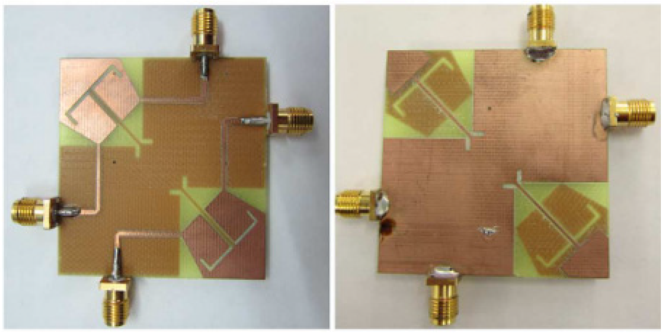
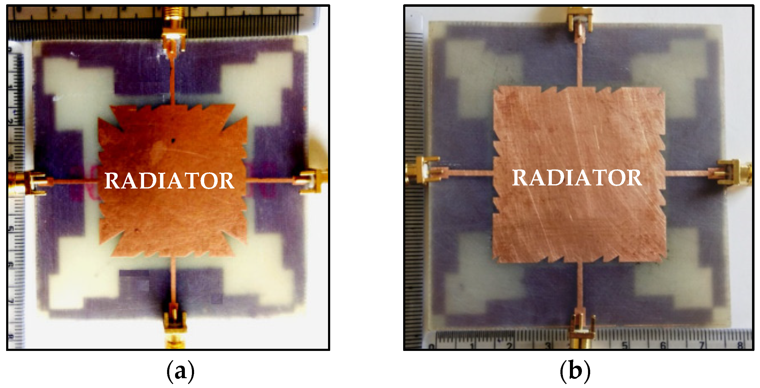
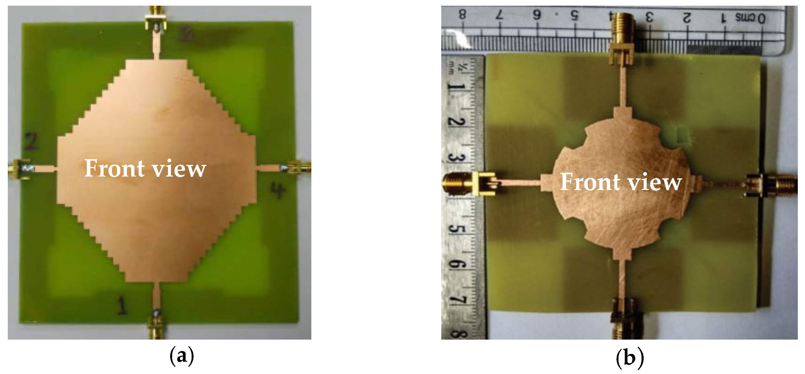
In [78], a microstrip patch antenna having multi-cut design with four ports sharing a common radiator and the stepped ground is considered, as shown in Figure 16a. The energy released as surface current from the ports enters in the undesired directions. This causes mutual coupling and is reduced by etching multiple saw-tooth cuts at the corners of the shared rectangular patch. The overall size of the antenna is 75 × 75 × 1.6 mm3 and covers the frequency range from 4.96 to 5.5 GHz with gain varying between 2.4 and 5.5 dBi in the proposed band. A four-port shared radiator is further improved with better isolation and overall size of the antenna is 75 × 75 × 1.6 mm3 is presented in [79] as shown in Figure 16b. The designed stepped ground and the multi-cuts at the radiator patch controls the surface current direction which subsequently reduces the mutual coupling. The signal to noise ratio and back lobe radiation is also reduced through stepped rectangular design geometry. Good isolation is achieved for the entire frequency range from 4.4 GHz to 6.4 GHz. Low ECC of <0.04 is obtained and the gain of the designed antenna varied between 3.0 and 6.1 dBi.
In [80], four microstrip feedline monopole antenna connected to a shared radiator and ground plane is discussed. To achieve wideband, the rectangular-shaped common radiator is modified with stepped lines at the four corners as shown in the Figure 17a, to provide a better bandwidth of 1100 MHz. The four slots etched in each corner of the modified ground plane disturbs the current flow to achieve good isolation of better than 15 dB at the expected frequency range from 1.8 GHz to 2.9 GHz. The port coupling is also reduced via slot-loaded technique. Low measured ECC of < 0.1 and DG of about 10 dB are achieved.
In [81], the common element MIMO antenna with a notch-loaded circular radiator is fed by four identical modified feedlines, suitable for Wi-Fi applications, is proposed as shown in Figure 17b. The uniformity of the circular shaped radiator reduces the surface current, and the fringing field is formed by choosing the modified circular geometry concept. The surface current direction is further disturbed by the octagonal notches loaded in the circular radiator and thus the mutual coupling is reduced. The parasitic element placed diagonally between the ground plane enhances the inter-port isolation and ECC less than 0.5 is achieved.
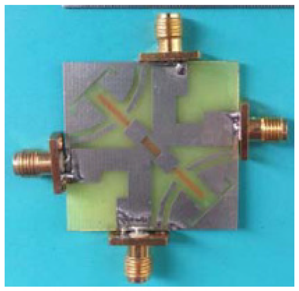
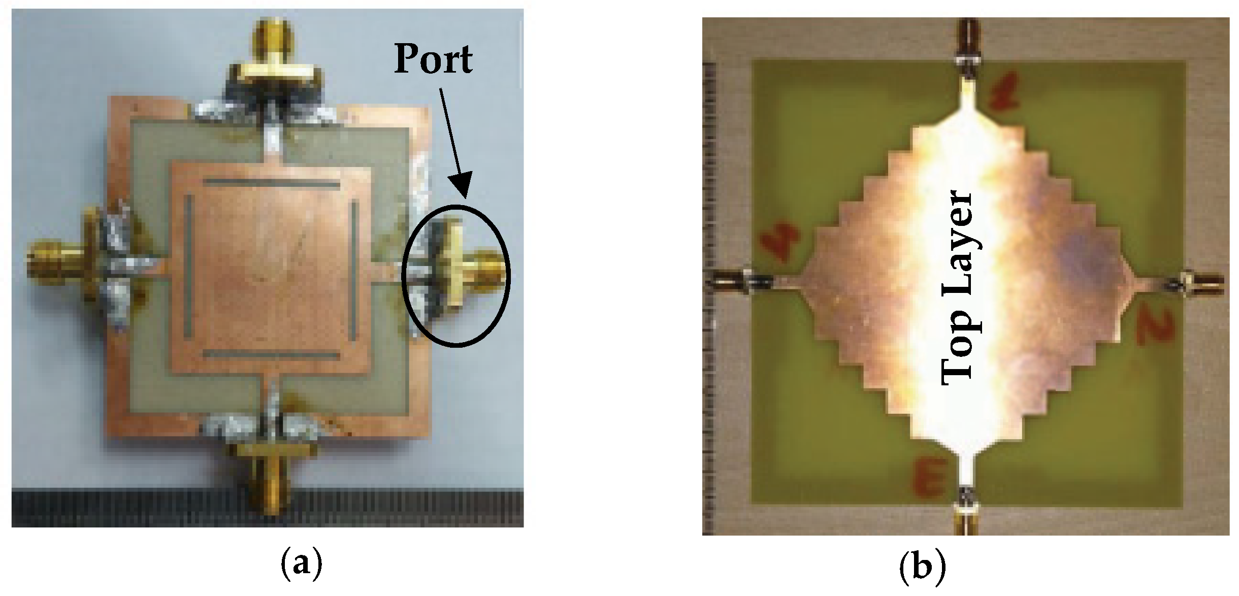
The differentially-fed MIMO antenna with dual-band is discussed in [82]. It consists of four ports sharing a common radiator and a square ring ground, suitable for WiMAX application, as shown in Figure 18a. Four differential ports arranged perpendicular to each other connected to virtual ground provides dual polarization and good isolation is achieved for dual frequency bands from 3.2–3.87 GHz and 5.35–5.83 GHz. Since the designed antenna is CPW differential fed, both the radiating patch and the virtual ground is printed on the same layer of the substrate. This makes the fabrication process easy and suitable for integration with RF front-end circuits. In [83], a monopole antenna with four ports sharing a common radiator and a ground plane with slots on all four edges was proposed covering the frequency ranging from 2 GHz to 3 GHz. The steps-shape common radiator patch placed on the top layer and frame-shape ground plane minimizes the mutual coupling effect among the ports which provides better isolation of less than −12 dB as shown in Figure 18b. With the partial removal of ground plane on the bottom plate, the bandwidth is enhanced and ECC below 0.5 is achieved. The common radiator with four port MIMO antenna, discussed in [84], consists of a common radiating element and a square ring ground plane. Good isolation is achieved through space diversity and by etching the stubs in the ground plane, to achieve isolation of less than −15 dB and measured return loss of −10 dB is achieved for frequency range from 4.5 GHz to 7 GHz.
5. Summary
In this paper, a concise review on different multiport single antenna element systems has been presented. Comparison has been done based on antenna size, substrate, number of ports, ECC, antenna gain, and radiation efficiency, and summarized in Table 2 and Table 3 for the compared MIMO antenna designs.
Designing a compact common radiator MIMO antenna system with strong isolation between antenna ports is important for future wireless communication. Several isolation techniques considered for MIMO antenna design are discussed in this review paper. By implementing DGS and CSRR technique, the MIMO antenna provides wide band with lower ECC values. The simple structure with a significantly improved isolation is achieved through a neutralization line technique and parasitic elements provide size reduction with improved efficiency. Similarly, other mutual coupling reduction techniques discussed in the literature offer better isolation, but maintaining improvement in efficiency and size reduction could be a challenge for shared radiator MIMO antenna design.
The implementation of a slot on a common radiating patch is another technique for obtaining effective isolation between antenna ports but the antenna performance is affected. Similarly, CPW-fed structure provides easy integration but increase in space between the antenna elements leads to less suitability for portable devices. Compared to this CPW-fed structure, ACS structure provides good performance in decreasing the overall size, due to its half-ground identity of antennas. Additionally, the ACS-fed structure provides better performance with additional features such as single lateral ground-plane, wide bandwidth, and easy to integrate with portable devices.
But these antenna configurations suffer minor variations in radiation characteristics behavior due to the asymmetrical nature of the antenna. Therefore, these antennas would be implemented for those applications where the radiation pattern does not substantially affect the performance of the antenna. Besides this, most of the single common element antennas reviewed here are suitable for UWB-MIMO applications.
The shared radiator in a MIMO system is an effective method to retain the compactness of the antenna design for the portable devices as compared to separate antenna elements. This also provides unique radiation pattern characteristics, but to design with good isolation is difficult. Hence this paper presents several antennas designs and mutual coupling reduction techniques which would be helpful in designing antenna for future communication systems and in achieving the required performance parameters of the MIMO antennas. In all the above cases, most of the single element antennas reported in the literature are for UWB-MIMO and Wi-Fi/WLAN applications. Hence, it is important in the future, to consider efficient technique to design MIMO antenna with shared radiator for 5G and portable devices.
Author Contributions
Conceptualization, N.S. and H.T.C.; methodology, N.S. and T.K.G.; software, N.S.; validation, H.T.C. and S.K.A.R.; formal analysis, H.T.C., N.S. and S.K.A.R.; investigation, N.S. and S.K.A.R.; resources, S.K.A.R. and T.K.G.; data curation, N.S. and H.T.C.; writing—original draft preparation, N.S.; writing—review and editing, H.T.C., S.K.A.R. and T.K.G.; visualization, T.K.G.; supervision, H.T.C. and S.K.A.R.; project administration, S.K.A.R. and T.K.G.; funding acquisition, S.K.A.R. and T.K.G. All authors have read and agreed to the published version of the manuscript.
Funding
This work was supported in part by the Telekom Malaysia Berhad under the Grant No. MMUE/220012 and FRGS grant FRGS/1/2018/TK08/MMU/02/1 or MMUE/180033.
Institutional Review Board Statement
Not applicable.
Informed Consent Statement
Not applicable.
Conflicts of Interest
The authors declare no conflict of interest.
References
- Liu, H.; Yang, W.; Zhang, A.; Zhu, S.; Wang, Z.; Huang, T. A Miniaturized Gain-Enhanced Antipodal Vivaldi Antenna and Its Array for 5G Communication Applications. IEEE Access 2018, 6, 76282–76288. [Google Scholar] [CrossRef]
- Takahashi, K.; Arai, H.; Ihara, T.; Ishikawa, Y. A study of antenna configuration and channel capacity about MIMO. In Proceedings of the 2015 IEICE Society Conference, Tokyo, Japan, 16–18 September 2015. [Google Scholar]
- Rohani, B.; Arai, H. Enhancing 4× 4 MIMO channel capacity by dual polarized directional antenna. In Proceedings of the IEICE General Conference, Yokohama, Japan, 28–31 March 2016; p. 181. [Google Scholar]
- Nadeem, I.; Choi, D.-Y. Study on Mutual Coupling Reduction Technique for MIMO Antennas. IEEE Access 2018, 7, 563–586. [Google Scholar] [CrossRef]
- Roy, S.; Ghosh, S.; Chakarborty, U. Compact dual wide-band four/eight elements MIMO antenna for WLAN applications. Int. J. RF Microw. Comput. Eng. 2019, 29, e21749. [Google Scholar] [CrossRef]
- Dixit, A.S.; Kumar, S. A miniaturized antipodal Vivaldi antenna for 5G communication applications. In Proceedings of the 2020 7th International Conference on Signal Processing and Integrated Networks (SPIN), Noida, India, 27–28 February 2020. [Google Scholar]
- Seyyedesfahlan, M.; Uzun, A.; Skrivervik, A.; Tekin, I. Wideband Multiport Antennas. Sensors 2020, 20, 6960. [Google Scholar] [CrossRef] [PubMed]
- Vaughan, R.; Andersen, J. Antenna diversity in mobile communications. IEEE Trans. Veh. Technol. 1987, 36, 149–172. [Google Scholar] [CrossRef]
- Mattheijssen, P.; Herben, M.; Dolmans, G.; Leyten, L. Antenna-Pattern Diversity Versus Space Diversity for Use at Handhelds. IEEE Trans. Veh. Technol. 2004, 53, 1035–1042. [Google Scholar] [CrossRef]
- Chouhan, S.; Panda, D.K.; Gupta, M.; Singhal, S. Multiport MIMO antennas with mutual coupling reduction techniques for modern wireless transreceive operations: A review. Int. J. RF Microw. Comput. Eng. 2017, 28, e21189. [Google Scholar] [CrossRef]
- Votis, C.; Tatsis, G.; Kostarakis, P. Envelope Correlation Parameter Measurements in a MIMO Antenna Array Configuration. Int. J. Commun. Netw. Syst. Sci. 2010, 3, 350–354. [Google Scholar] [CrossRef] [Green Version]
- Glazunov, A.A.; Molisch, A.; Tufvesson, F. Mean effective gain of antennas in a wireless channel. IET Microw. Antennas Propag. 2009, 3, 214–227. [Google Scholar] [CrossRef] [Green Version]
- ho Chae, S.; il Kawk, W.; Park, S.O.; Lee, K. Analysis of mutual coupling in MIMO antenna array by TARC calculation. In Proceedings of the 2006 Asia-Pacific Microwave Conference, Yokohama, Japan, 12–15 December 2006; pp. 2090–2093. [Google Scholar]
- Fritz-Andrade, E.; Jardon-Aguilar, H.; Tirado-Mendez, J.A. The correct application of total active reflection coefficient to evaluate MIMO antenna systems and its generalization to N ports. Int. J. RF Microw. Comput. Eng. 2019, 30, e22113. [Google Scholar] [CrossRef]
- Zhang, Y.; Niu, B. Compact ultrawideband (UWB) slot antenna with wideband and high isolation for MIMO applications. Prog. Electromagn. Res. C 2014, 54, 9–16. [Google Scholar] [CrossRef] [Green Version]
- Li, H.; Xiong, J.; Ying, Z.; He, S. High isolation compact four-port MIMO antenna systems with built-in filters as isolation structure. In Proceedings of the Fourth European Conference on Antennas and Propagation, Barcelona, Spain, 12–16 April 2010. [Google Scholar]
- Wu, Y.; Chu, Q. Dual-band multiple input multiple output antenna with slitted ground. IET Microw. Antennas Propag. 2014, 8, 1007–1013. [Google Scholar] [CrossRef]
- Chiu, C.-Y.; Cheng, C.-H.; Murch, R.D.; Rowell, C.R. Reduction of Mutual Coupling Between Closely-Packed Antenna Elements. IEEE Trans. Antennas Propag. 2007, 55, 1732–1738. [Google Scholar] [CrossRef]
- Ghosh, C.K.; Parui, S.K. Reduction of cross polar radiation of a dual trace omnidirectional microstrip antenna array by using dumbbell-shaped resonator. Microw. Opt. Technol. Lett. 2013, 56, 141–145. [Google Scholar] [CrossRef]
- Salehi, M.; Motevasselian, A.; Tavakoli, A.; Heidari, T. Mutual coupling reduction of microstrip antennas using defected ground structure. In Proceedings of the 2006 10th IEEE Singapore International Conference on Communication Systems, Singapore, 30 October–1 November 2006. [Google Scholar]
- Wei, K.; Li, J.; Wang, L.; Xing, Z.; Xu, R. S-shaped periodic defected ground structures to reduce microstrip antenna array mutual coupling. Electron. Lett. 2016, 52, 1288–1290. [Google Scholar] [CrossRef]
- Anitha, R.; Sarin, V.; Mohanan, P.; Vasudevan, K. Enhanced isolation with defected ground structure in MIMO antenna. Electron. Lett. 2014, 50, 1784–1786. [Google Scholar] [CrossRef]
- Volmer, C.; Stephan, R.; Blau, K.; Hein, M.A. An Eigen-Analysis of Compact Antenna Arrays and Its Application to Port Decoupling. IEEE Trans. Antennas Propag. 2008, 56, 360–370. [Google Scholar] [CrossRef]
- Wallace, J.; Jensen, M. Mutual Coupling in MIMO Wireless Systems: A Rigorous Network Theory Analysis. IEEE Trans. Wirel. Commun. 2004, 3, 1317–1325. [Google Scholar] [CrossRef] [Green Version]
- Wu, D.; Cheung, S.W.; Li, Q.L.; Yuk, T.I. Decoupling using diamond-shaped patterned ground resonator for small MIMO antennas. IET Microw. Antennas Propag. 2017, 11, 177–183. [Google Scholar] [CrossRef]
- Zhao, L.; Wu, K.-L. A Dual-Band Coupled Resonator Decoupling Network for Two Coupled Antennas. IEEE Trans. Antennas Propag. 2015, 63, 2843–2850. [Google Scholar] [CrossRef]
- Yang, F.; Rahmat-Samii, Y. Microstrip antennas integrated with electromagnetic band-gap (EBG) structures: A low mutual coupling design for array applications. IEEE Trans. Antennas Propag. 2003, 51, 2936–2946. [Google Scholar] [CrossRef] [Green Version]
- Inclan-Sanchez, L.; Vazquez-Roy, J.-L.; Rajo-Iglesias, E. High Isolation Proximity Coupled Multilayer Patch Antenna for Dual-Frequency Operation. IEEE Trans. Antennas Propag. 2008, 56, 1180–1183. [Google Scholar] [CrossRef]
- Wang, Y.; Du, Z. A Wideband Printed Dual-Antenna with Three Neutralization Lines for Mobile Terminals. IEEE Trans. Antennas Propag. 2013, 62, 1495–1500. [Google Scholar] [CrossRef]
- Zhang, S.; Lau, B.K.; Tan, Y.; Ying, Z.; He, S. Mutual Coupling Reduction of Two PIFAs with a T-Shape Slot Impedance Transformer for MIMO Mobile Terminals. IEEE Trans. Antennas Propag. 2011, 60, 1521–1531. [Google Scholar] [CrossRef] [Green Version]
- Ou, Y.; Cai, X.; Qian, K. Two-element compact antennas decoupled with a simple neutralization line. Prog. Electromagn. Res. Lett. 2017, 65, 63–68. [Google Scholar] [CrossRef] [Green Version]
- Kakade, A.B.; Kumbhar, M. Wideband circularly polarized conformal strip fed three layer hemispherical dielectric resonator antenna with parasitic patch. Microw. Opt. Technol. Lett. 2014, 56, 72–77. [Google Scholar] [CrossRef]
- Liu, L.; Cheung, S.W.; Yuk, T.I. Compact MIMO Antenna for Portable UWB Applications With Band-Notched Characteristic. IEEE Trans. Antennas Propag. 2015, 63, 1917–1924. [Google Scholar] [CrossRef]
- Sharawi, M.S. Printed Multi-Band MIMO Antenna Systems and Their Performance Metrics [Wireless Corner]. IEEE Antennas Propag. Mag. 2013, 55, 218–232. [Google Scholar] [CrossRef]
- Kahrizi, M.; Sarkar, T.; Maricevic, Z. Analysis of a wide radiating slot in the ground plane of a microstrip line. IEEE Trans. Microw. Theory Tech. 1993, 41, 29–37. [Google Scholar] [CrossRef]
- Fan, S.T.; Yin, Y.Z.; Lee, B.; Hu, W.; Yang, X. Bandwidth Enhancement of a Printed Slot Antenna With a Pair of Parasitic Patches. IEEE Antennas Wirel. Propag. Lett. 2012, 11, 1230–1233. [Google Scholar] [CrossRef]
- Row, J.-S.; Wu, S.-W. Circularly-Polarized Wide Slot Antenna Loaded With a Parasitic Patch. IEEE Trans. Antennas Propag. 2008, 56, 2826–2832. [Google Scholar] [CrossRef]
- Yoo, M.; Lim, S. SRR- and CSRR-loaded ultra-wideband (UWB) antenna with tri-band notch capability. J. Electromagn. Waves Appl. 2013, 27, 2190–2197. [Google Scholar] [CrossRef]
- Ren, Y.-H.; Ding, J.; Guo, C.-J.; Qu, Y.; Song, Y.-C. A Wideband Dual-Polarized Printed Antenna Based on Complementary Split-Ring Resonators. IEEE Antennas Wirel. Propag. Lett. 2014, 14, 410–413. [Google Scholar] [CrossRef]
- Yang, D.-G.; Kim, D.O.; Kim, C.-Y. Design of dual-band MIMO monopole antenna with high isolation using slotted CSRR for WLAN. Microw. Opt. Technol. Lett. 2014, 56, 2252–2257. [Google Scholar] [CrossRef]
- Xu, S.; Zhang, M.; Wen, H.; Wang, J. Deep-subwavelength Decoupling for MIMO Antennas in Mobile Handsets with Singular Medium. Sci. Rep. 2017, 7, 1–9. [Google Scholar] [CrossRef] [PubMed] [Green Version]
- Ibrahim, A.A.; Abdalla, M.A. CRLH MIMO antenna with reversal configuration. AEU-Int. J. Electron. Commun. 2016, 70, 1134–1141. [Google Scholar] [CrossRef]
- Yang, L.; Li, T. Box-folded four-element MIMO antenna system for LTE handsets. Electron. Lett. 2015, 51, 440–441. [Google Scholar] [CrossRef]
- Wang, L.; Wei, C.; Wei, W. Design of a high isolation dual-band MIMO antenna for LTE terminal. In Proceedings of the 2013 International Symposium on Antennas & Propagation, Nanjing, China, 23–25 October 2013. [Google Scholar]
- Sharawi, M.S.; Numan, A.B.; Khan, M.U.; Aloi, D.N. A Dual-Element Dual-Band MIMO Antenna System with Enhanced Isolation for Mobile Terminals. IEEE Antennas Wirel. Propag. Lett. 2012, 11, 1006–1009. [Google Scholar] [CrossRef]
- Li, M.Y.; Xu, Z.Q.; Ban, Y.L.; Sim, C.Y.D.; Yu, Z.F. Eight-port orthogonally dual-polarised MIMO antennas using loop structures for 5G smartphone. IET Microw. Antennas Propag. 2017, 11, 1810–1816. [Google Scholar] [CrossRef]
- Li, Y.; Sim, C.-Y.-D.; Luo, Y.; Yang, G. High-Isolation 3.5 GHz Eight-Antenna MIMO Array Using Balanced Open-Slot Antenna Element for 5G Smartphones. IEEE Trans. Antennas Propag. 2019, 67, 3820–3830. [Google Scholar] [CrossRef]
- Dioum, I.; Diallo, A.; Farssi, S.M.; Luxey, C. A Novel Compact Dual-Band LTE Antenna-System for MIMO Operation. IEEE Trans. Antennas Propag. 2014, 62, 2291–2296. [Google Scholar] [CrossRef]
- Rahman, S.; Ren, X.-C.; Altaf, A.; Irfan, M.; Abdullah, M.; Muhammad, F.; Anjum, M.; Mursal, S.; AlKahtani, F. Nature Inspired MIMO Antenna System for Future mmWave Technologies. Micromachines 2020, 11, 1083. [Google Scholar] [CrossRef] [PubMed]
- Illahi, U.; Iqbal, J.; Irfan, M.; Sulaiman, M.I.; Khan, M.A.; Rauf, A.; Bari, I.; Abdullah, M.; Muhammad, F.; Nowakowski, G.; et al. A Novel Design and Development of a Strip-Fed Circularly Polarized Rectangular Dielectric Resonator Antenna for 5G NR Sub-6 GHz Band Applications. Sensors 2022, 22, 5531. [Google Scholar] [CrossRef] [PubMed]
- Kiani, S.; Altaf, A.; Abdullah, M.; Muhammad, F.; Shoaib, N.; Anjum, M.; Damaševičius, R.; Blažauskas, T. Eight Element Side Edged Framed MIMO Antenna Array for Future 5G Smart Phones. Micromachines 2020, 11, 956. [Google Scholar] [CrossRef]
- Liang, M.; Zhang, F.; Zhang, G.; Li, Q. Broadband dual-polarized antennas with high port isolation for portable devices. In Proceedings of the 2014 3rd Asia-Pacific Conference on Antennas and Propagation, Harbin, China, 26–29 July 2014. [Google Scholar]
- Li, Y.; Yu, B.; Shen, H.; Zhu, L.; Yang, G. An 8-port planar UWB MIMO antenna for future 5G micro wireless access point applications. In Proceedings of the 2017 International Applied Computational Electromagnetics Society Symposium (ACES), Suzhou, China, 1–4 August 2017. [Google Scholar]
- Shoaib, S.; Shoaib, I.; Shoaib, N.; Chen, X.; Parini, C.G. MIMO antennas for mobile handsets. IEEE Antennas Wirel. Propag. Lett. 2014, 14, 799–802. [Google Scholar] [CrossRef]
- Ban, Y.-L.; Li, C.; Sim, C.-Y.-D.; Wu, G.; Wong, K.-L. 4G/5G Multiple Antennas for Future Multi-Mode Smartphone Applications. IEEE Access 2016, 4, 2981–2988. [Google Scholar] [CrossRef]
- Saxena, S.; Kanaujia, B.; Dwari, S.; Kumar, S.; Tiwari, R. MIMO antenna with built-in circular shaped isolator for sub-6 GHz 5G applications. Electron. Lett. 2018, 54, 478–480. [Google Scholar] [CrossRef]
- Soltani, S.; Lotfi, P.; Murch, R.D. A Dual-Band Multiport MIMO Slot Antenna for WLAN Applications. IEEE Antennas Wirel. Propag. Lett. 2016, 16, 529–532. [Google Scholar] [CrossRef]
- Kiem, N.K.; Dinh, D.N.; Viet, H.T.; Dao-Ngoc, C. A novel design of dual-feed single-element antenna for 4G MIMO terminals. In Proceedings of the Progress in Electromagnetics Research Symposium, Kuala Lumpur, Malaysia, 27 March 2012. [Google Scholar]
- Caimi, F.M.; Mongomery, M. Dual Feed, Single Element Antenna for WiMAX MIMO Application. Int. J. Antennas Propag. 2008, 2008, 1–5. [Google Scholar] [CrossRef] [Green Version]
- Shin, W.H.; Kibria, S.; Islam, M.T. Single element MIMO antenna for LTE application with iMAT. In Proceedings of the 2014 IEEE Asia-Pacific Conference on Applied Electromagnetics (APACE), Johor Bahru, Malaysia, 8–10 December 2014. [Google Scholar]
- Moradikordalivand, A.; Leow, C.Y.; Rahman, T.A.; Ebrahimi, S.; Chua, T.H. Wideband MIMO antenna system with dual polarization for WiFi and LTE applications. Int. J. Microw. Wirel. Technol. 2015, 8, 643–650. [Google Scholar] [CrossRef]
- Moradikordalivand, A.; Rahman, T.A.; Leow, C.Y.; Ebrahimi, S. Dual-polarized MIMO antenna system for WiFi and LTE wireless access point applications. Int. J. Commun. Syst. 2014, 30, e2898. [Google Scholar] [CrossRef]
- Nawaz, H.; Tekin, I. Dual port disc monopole antenna for wide-band MIMO-based wireless applications. Microw. Opt. Technol. Lett. 2017, 59, 2942–2949. [Google Scholar] [CrossRef] [Green Version]
- Nawaz, H.; Tekin, I. Dual port single patch antenna with high interport isolation for 2.4 GHz in-band full duplex wireless applications. Microw. Opt. Technol. Lett. 2016, 58, 1756–1759. [Google Scholar] [CrossRef]
- Liu, Y.; Wang, P.; Qin, H. Compact ACS-fed UWB antenna for diversity applications. Electron. Lett. 2014, 50, 1336–1338. [Google Scholar] [CrossRef]
- Zhang, J.Y.; Zhang, F.; Tian, W.P.; Luo, Y.L. ACS-fed UWB-MIMO antenna with shared radiator. Electron. Lett. 2015, 51, 1301–1302. [Google Scholar] [CrossRef]
- Khan, M.S.; Capobianco, A.-D.; Iftikhar, A.; Asif, S.; Braaten, B.D. A compact dual polarized ultrawideband multiple-input- multiple-output antenna. Microw. Opt. Technol. Lett. 2015, 58, 163–166. [Google Scholar] [CrossRef]
- Khan, M.S.; Capobianco, A.; Iftikhar, A.; Shubair, R.M.; Anagnostou, D.E.; Braaten, B.D. Ultra-compact dual-polarised UWB MIMO antenna with meandered feeding lines. IET Microw. Antennas Propag. 2017, 11, 997–1002. [Google Scholar] [CrossRef]
- Kiourti, A.; Nikita, K.S. Miniature Scalp-Implantable Antennas for Telemetry in the MICS and ISM Bands: Design, Safety Considerations and Link Budget Analysis. IEEE Trans. Antennas Propag. 2012, 60, 3568–3575. [Google Scholar] [CrossRef]
- Patre, S.R.; Singh, S.P. Shared radiator MIMO antenna for broadband applications. IET Microw. Antennas Propag. 2018, 12, 1153–1159. [Google Scholar] [CrossRef]
- Chen, A.; Zhang, J.; Zhao, L.; Yin, Y. A dual-feed MIMO antenna pair with one shared radiator and two isolated ports for fifth generation mobile communication band. Int. J. RF Microw. Comput. Eng. 2017, 27, e21146. [Google Scholar] [CrossRef]
- Liu, L.; Zhao, L.; Cai, Y.; Yin, Y. Dual-feed MIMO antennas with one shared radiator for future 5G MIMO systems. In Proceedings of the 2017 Sixth Asia-Pacific Conference on Antennas and Propagation (APCAP), Xi’an, China, 16–19 October 2017. [Google Scholar]
- Chattha, H.T.; Nasir, M.; Abbasi, Q.H.; Huang, Y.; AlJa’Afreh, S.S. Compact Low-Profile Dual-Port Single Wideband Planar Inverted-F MIMO Antenna. IEEE Antennas Wirel. Propag. Lett. 2013, 12, 1673–1675. [Google Scholar] [CrossRef]
- Srivastava, G.; Kanuijia, B.; Paulus, R. UWB MIMO antenna with common radiator. Int. J. Microw. Wirel. Technol. 2017, 9, 573–580. [Google Scholar] [CrossRef]
- Srivastava, G.; Kanuijia, B.K. Compact dual band-notched UWB mimo antenna with shared radiator. Microw. Opt. Technol. Lett. 2015, 57, 2886–2891. [Google Scholar] [CrossRef]
- Mao, C.-X.; Chu, Q.-X. Compact Coradiator UWB-MIMO Antenna With Dual Polarization. IEEE Trans. Antennas Propag. 2014, 62, 4474–4480. [Google Scholar] [CrossRef]
- Zhang, J.-Y.; Zhang, F.; Tian, W.-P. Compact 4-port ACS-fed UWB-MIMO antenna with shared radiators. Prog. Electromagn. Res. Lett. 2015, 55, 81–88. [Google Scholar] [CrossRef] [Green Version]
- Malviya, L.; Chouhan, S. Multi-cut four-port shared radiator with stepped ground and diversity effects for WLAN application. Int. J. Microw. Wirel. Technol. 2019, 11, 1044–1053. [Google Scholar] [CrossRef]
- Chouhan, S.; Malviya, L. Four-port shared rectangular radiator with defected ground for wireless application. Int. J. Commun. Syst. 2020, 33, e4356. [Google Scholar] [CrossRef]
- MoradiKordalivand, A.; Rahman, T.A.; Khalily, M. Common Elements Wideband MIMO Antenna System for WiFi/LTE Access-Point Applications. IEEE Antennas Wirel. Propag. Lett. 2014, 13, 1601–1604. [Google Scholar] [CrossRef]
- Chouhan, S.; Panda, D.K.; Kushwah, V.S. Modified circular common element four-port multiple-input-multiple-output antenna using diagonal parasitic element. Int. J. RF Microw. Comput. Eng. 2018, 29, e21527. [Google Scholar] [CrossRef]
- Li, W.A.; Tu, Z.H.; Liu, Y.Y. High isolation, dual-polarized & dual-band single-layer differential MIMO antenna for WiMAX application. In Proceedings of the 2016 IEEE International Symposium on Antennas and Propagation (APSURSI), Fajardo, PR, USA, 26 June–1 July 2016. [Google Scholar]
- Yussuf, A.A.; Paker, S. Design of wideband MIMO antenna for wireless applications. In Proceedings of the 2017 25th Signal Processing and Communications Applications Conference (SIU), Antalya, Turkey, 15–18 May 2017. [Google Scholar]
- Sun, D.; Wang, P.; Gao, P. Single radiator four-port MIMO antenna for WLAN and WIMAX applications with high isolation. In Proceedings of the 2017 IEEE 5th International Symposium on Electromagnetic Compatibility (EMC-Beijing), Beijing, China, 28–31 October 2017. [Google Scholar]
Figure 1.
SISO and MIMO Antenna system.

Figure 2.
Orthogonally polarized slot antenna DGS [16].
Figure 2.
Orthogonally polarized slot antenna DGS [16].

Figure 3.
Diamond-shaped patterned ground resonator [23].
Figure 3.
Diamond-shaped patterned ground resonator [23].

Figure 4.
Neutralization line technique [29].
Figure 4.
Neutralization line technique [29].

Figure 5.
Fabricated prototype with T-shaped slot [60].
Figure 5.
Fabricated prototype with T-shaped slot [60].


Figure 7.
Shared radiator with circular cut at ground [63].
Figure 7.
Shared radiator with circular cut at ground [63].

Figure 8.
(a) Top layer of ACS-fed structure with common radiator (b) Bottom layer [66].
Figure 8.
(a) Top layer of ACS-fed structure with common radiator (b) Bottom layer [66].

Figure 9.
(a) Slots etched in the common radiator antenna design [67], (b) Open shunt stub placement and etched T-shaped slots in the common radiator antenna design [68].

Figure 10.
Front and bottom view of two port MIMO antenna design with common radiator [70].
Figure 10.
Front and bottom view of two port MIMO antenna design with common radiator [70].

Figure 11.
Fabricated two port shared radiator with shorting pins [72].
Figure 11.
Fabricated two port shared radiator with shorting pins [72].

Figure 12.
Fabricated two port PIFA MIMO antenna design with shared radiator [73].
Figure 12.
Fabricated two port PIFA MIMO antenna design with shared radiator [73].

Figure 13.
Circular patch shared radiator [75].
Figure 13.
Circular patch shared radiator [75].

Figure 14.
Compact co-radiator with dual polarization [76].
Figure 14.
Compact co-radiator with dual polarization [76].

Figure 15.
ACS-fed 4 port antenna [77].
Figure 15.
ACS-fed 4 port antenna [77].

Figure 16.
(a) Four ports multi-cut shared radiator and stepped ground [78], (b) Four ports multi-cut shared radiator and stepped ground [79].

Figure 17.
(a) Stepped line common radiator prototype [80], (b) Notch-loaded circular radiator [81].


Table 1.
Acronyms.
| Acronyms | Meanings |
|---|---|
| SISO | Single Input Single Output |
| MIMO | Multiple Input Multiple Output |
| TARC | Total Active Reflection Coefficient |
| ECC | Envelop Correlation Coefficient |
| DG | Diversity Gain |
| DGS | Defected Ground Structure |
| DMN | Decoupling and matching network |
| CDRN | Coupled Resonator Decoupling Network |
| CSRR | Complementary Split Ring Resonators |
| ACS | Asymmetric Coplanar Strip |
| CPW | Co Planar Waveguide |
| CE | Common Element |
| PIFA | Planar Inverted-F antenna |
| iMAT | Isolated Mode Antenna Technology |
| EBG | Electromagnetic Bandgap |
| MEG | Mean Effective Gain |
| WiFi | Wireless Fidelity |
| UWB | Ultra-Wide Band |
| LTE | Long-Term Evolution |
| WiMax | Worldwide Interoperability for Microwave Access |
Table 2.
Shared radiator antenna with two ports.
| References | Frequency (GHz) | Size/Material (mm2) | Isolation Technique | Isolation (dB) | ECC | Gain (dBi) | No. of Ports/Application |
|---|---|---|---|---|---|---|---|
| [60] | 2.3–2.6 | 48 × 33.8/FR4 | Slots/Ground slot | −16 | 0.1 | 1.2 | 2/WLAN (2.4 GHz) |
| [61] | 2.3–2.9 | 105 × 125/FR4 | CSPE rings | −15 | 0.15 | 5 | 2/WiFi (2.4 GHz) and LTE (2.6 GHz) |
| [62] | 1.2–1.55; 2.3–2.7 | 110 × 130/FR4 | CSPE rings | −15 | 0.15 | 3.3–5.6 | 2/WiFi (2.4 GHz), WiMAX (2.3 and 2.5 GHz), and LTE (1.5, 2.6 GHz) |
| [63] | 2–6 | 64 × 64 mm/RT Duroid 5880 | Ground plane circular slot | −15 | 0.02 | 3.2–6.1 | 2/MIMO applications |
| [66] | 3.1–10.6 | 26 × 26/FR4 | I and U-shaped stub | −15 | 0.02 | 2.2, 3.5, 2 | 2/Ultra-Wide Band |
| [65] | 2.6–11 | 28.5 × 28.5/FR4 | Rectangular stub | −15 | 0.01 | 1.5–3.7 | 2/Ultra-Wide Band |
| [67] | 3–11 | 27 × 27/Rogers TMM4 | Slot | −15 | 0.01 | 3 | 2/Ultra-Wide Band |
| [68] | 3.1–10.6 | 22 × 24.3/Rogers TMM4 | Slots, open shut stub | −15 | 0.02 | 2–5.5 | 2/Ultra-Wide Band |
| [70] | 2.4–12.75 | 39 × 39/FR4 | Stub, meandered line | −15 | 0.02 | 4.92 | 2/Ultra-Wide Band |
| [71] | 3.35–3.65 | 90 × 50/FR4 | Positioning shorting strips | −20 | 0.1 | 3.5 | 2/MIMO applications |
| [72] | 3.4–3.7 | 130 × 50/FR4 | 3 shorting strips | −25 | 0.017 | 4 | 2/MIMO applications |
| [73] | 2.1–2.9 | 45 × 100/FR4 | Slot at ground plane | −14 | 0.005 | 6.4 | 2/2.45-GHz WLAN band and WiMAX band (2.5–2.7 GHz) |
| [74] | 3–12 | 45 × 45 | Slot | −17 | 0.01 | −4 to 2 | 2/Ultra-Wide Band |
| [75] | 3–12 | 41 × 41 | Slot | −14 | 0.01 | 2 | 2/ Ultra-Wide Band |
Table 3.
Shared radiator antenna with four ports.
| References | Frequency (GHz) | Size (mm2) | Isolation Technique | Isolation (dB) | ECC | Gain (dBi) | Number of Ports/Application |
|---|---|---|---|---|---|---|---|
| [76] | 3–11 | 48 × 48 | T shaped slot | −17 | 0.02 | 2–5 | 4/Ultra-Wide Band |
| [77] | 3.1–10.6 | 36 × 36 | Stub at ground plane | −15 | 0.02 | 1.5–4 | 4/Ultra-Wide Band |
| [78] | 4.96–5.5 | 75 × 75 | Defected patch and ground | −12 | 0.03 | 2.4–5.5 | 4/WLAN (5.2) |
| [79] | 4.4–6.4 | 75 × 75 | Defected patch and ground | −13 | 0.04 | 3–6.1 | 4/Sub 6 GHz applications |
| [80] | 1.8–2.9 | 120 × 140 | Slots at ground, DGS | −15 | 0.07 | 6 | 4/LTE (Wireless Access Point), WiFi (2.4) |
| [81] | 2.34–2.56 | 72 × 72 | Diagonal parasitic element | −12 | 0.01 | 2 | 4/WiFi (2.4) |
| [82] | 3.5, 5.5 | 45 × 45 | Slot technique | −35 | 0.02 | 2–5 | 4/WiMAX (3.5,5.5) |
| [83] | 2–3 | 108 × 108 | Slot technique | −12 | 0.02 | 5.9–6.2 | 4/LTE (2.1/2.3/2.6 GHz), Wi-Fi (2.4) |
| [84] | 4.5–7 | 95 × 95 | Ground stub | −20 | 0.01 | 5 | 4/WLAN (5.2,5.8), WiMAX (5.5) |
Publisher’s Note: MDPI stays neutral with regard to jurisdictional claims in published maps and institutional affiliations. |
© 2023 by the authors. Licensee MDPI, Basel, Switzerland. This article is an open access article distributed under the terms and conditions of the Creative Commons Attribution (CC BY) license (https://creativecommons.org/licenses/by/4.0/).
Share and Cite
MDPI and ACS Style
Sheriff, N.; Kamal Abdul Rahim, S.; Tariq Chattha, H.; Kim Geok, T. Multiport Single Element Mimo Antenna Systems: A Review. Sensors 2023, 23, 747. https://doi.org/10.3390/s23020747
AMA Style
Sheriff N, Kamal Abdul Rahim S, Tariq Chattha H, Kim Geok T. Multiport Single Element Mimo Antenna Systems: A Review. Sensors. 2023; 23(2):747. https://doi.org/10.3390/s23020747
Chicago/Turabian StyleSheriff, Nathirulla, Sharul Kamal Abdul Rahim, Hassan Tariq Chattha, and Tan Kim Geok. 2023. "Multiport Single Element Mimo Antenna Systems: A Review" Sensors 23, no. 2: 747. https://doi.org/10.3390/s23020747
Note that from the first issue of 2016, this journal uses article numbers instead of page numbers. See further details here.