
Related Manuals for Liebert GXT3


Summary of Contents for Liebert GXT3
- Page 1 AC Power For Business-Critical Continuity™ Liebert GXT3 UPS 120V/208V 500VA-3000VA ® ™ User Manual...
-
Page 3: Table Of Contents
® 2.6.2 Installing the Optional Liebert IntelliSlot Card and Communication Cables ... 18 ..........19... - Page 4 ..........23 Disconnecting Input Power from the Liebert GXT3....... . 23 .
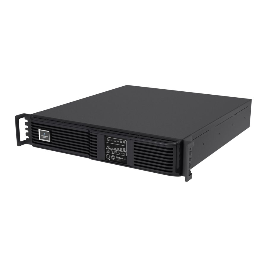
- Page 5 Liebert GXT3 rack/tower models—front view ........
-
Page 7: Important Safety Precautions
When the UPS is connected to an IT power distribution system, a short-circuit protection device must be installed on the neutral line. ® ™ Install and use the Liebert GXT3 in the following environments: • Temperature: 32°F - 104°F (0°C - 40°C), relative humidity: 0% ~ 95% non-condensing •... - Page 8 Operating this device in a residential area is likely to cause harmful interference that users must correct at their own expense. The Liebert GXT3 series complies with the requirements of EMC Directive 2004/108/EC and the published technical standards. Continued compliance requires installation in accordance with these instructions and use of accessories approved by Emerson.
-
Page 9: Glossary Of Symbols
LOSSARY OF YMBOLS Risk of electrical shock Indicates caution followed by important instructions AC input AC output Requests the user to consult the manual Indicates the unit contains a valve-regulated lead acid battery PbH2SO4 Recycle DC voltage Equipment grounding conductor Bonded to ground AC voltage ON/Alarm Silence/Battery Test... -
Page 10: Product Description
GXT3 is a compact, online uninterruptible power system (UPS) that continuously conditions and regulates its output voltage. The Liebert GXT3 is designed to supply microcomputers and other sensitive equipment with clean sine wave input power. Upon generation, AC power is clean and stable. However, during transmission and distribution it is subject to voltage sags, spikes and complete failure that may interrupt computer operations, cause data loss and damage equipment. -
Page 11: Appearance And Components
Liebert GXT3 minitower—front view Operation and Display Panel Ventilation Slots 1.3.2 Rear Panel Features The rear panel of the Liebert GXT3 has these features: • USB port • Cooling fan • Power output receptacles • Input circuit breaker ® • Liebert IntelliSlot port •... -
Page 12: Figure 3 Liebert ® Gxt3 ™ 120V Rack/Tower Models-Rear Panel Components
Product Description ® ™ Figure 3 Liebert GXT3 120V rack/tower models—rear panel components 500VA, 700VA, 1000VA, 1500VA Models Input Power Plug and Cable 5-15P Input Circuit USB Port Breaker Liebert IntelliSlot Port Output Receptacles, 5-15R External Terminal Block Battery Communication... -
Page 13: Figure 4 Liebert ® Gxt3 ™ 208V Rack/Tower Models-Rear Panel Components
Port External Terminal Block Battery Cooling Communication Connector Output Receptacles, L6-15R ™ Figure 5 Liebert GXT3-1000MT120 —rear panel components Input Power Plug and Cable, 5-15P 1000VA Model Terminal Block Input Circuit Communication Breaker Liebert IntelliSlot Port USB Port Cooling Fan... -
Page 14: Major Components
Liebert GXT3. Inverter In normal operation, the Liebert GXT3’s inverter utilizes the DC output of the PFC to produce precise, regulated sine wave AC power. When utility power fails, the inverter receives DC power from the DC-to-DC Converter. In either operation mode, the UPS inverter is online, continuously... -
Page 15: Operating Mode
Manual Bypass Mode occurs when the Standby/Manual bypass button is pressed and held for about 2 seconds while the Liebert GXT3 is in Utility (AC) Mode. Bypass operation is indicated by an audible alarm and illuminated amber bypass indicator (If other indicators are illuminated, refer to 7.0 - Troubleshooting). -
Page 16: Battery Mode
• Auto Sensing - 50Hz or 60Hz – Bypass Disabled • Frequency Converter - 50Hz – Bypass Disabled • Frequency Converter - 60Hz – Bypass Disabled The default for all models of the Liebert GXT3 is “Auto Sensing - 50Hz or 60Hz – Bypass Enabled.”... -
Page 17: Installation
77°F (25°C) reduces battery life. Installation Clearances Maintain at least 4 inches (100mm) clearance in the front and rear of the Liebert GXT3. Do not obstruct the air inlets on the front panel and rear panel of the UPS; blocking the air inlets reduces... -
Page 18: Mechanical Installation
The Liebert GXT3 may be installed as a tower or in a rack, depending on space and use considerations. The Liebert GXT3 may be used alone, as a single UPS, or with up to four battery cabinets. NOTE When installing the UPS or making input and output connections, comply with all relevant safety codes and standards 2.4.1... -
Page 19: Figure 9 Rotate The Operation And Display Panel
90 degrees clockwise, which provides upright viewing for users. 5. Place the Liebert GXT3 and any battery cabinets on the support bases. Each Liebert GXT3 needs two support assemblies, as shown in Figure 10. -
Page 20: Rack Installation
3. Determine the Liebert GXT3’s mounting position inside the racks vertical rails. CAUTION Reduce the risk of tipping the rack by installing the Liebert GXT3 as low as possible in the rack. 4. Attach the rear member of each slide rail assembly to the rack’s rails with two factory-supplied M5 screws (see Figure 12). -
Page 21: Figure 13 Installing Front Member Of Each Slide Rail Assembly
M4 screws provided in this kit. Make sure that the retaining latch is near the rear of the UPS, as shown in Figure 15. Figure 15 Installing inner members Liebert GXT3 UPS Inner Member Retaining Latch M4 screw , 8 pieces... -
Page 22: Figure 16 Installing Rack-Mount Handles
Installation Figure 16 Installing rack-mount handles Liebert GXT3 UPS Rack-Mount Handles, 2 pieces M4 Screw , 8 pieces 9. Insert the UPS, with inner members attached, into slide rail assemblies by inserting top and bottom edges of inner members into the top and bottom, curved tracks of front members and sliding the UPS into rack, as shown in Figure 17. -
Page 23: Cable Connection
GXT3 rear panel has an input cable and plug, output receptacles and output cable(s) (Output cables are on GXT3-3000 models only). Refer to 1.3.2 - Rear Panel Features for details. The battery cables are supplied with the battery cabinet. 2.5.1... -
Page 24: Connecting Communication Cables
Connecting USB Communication Cables 1. Take the USB communication cables out of the accessories box. ® 2. Insert one end of the USB communication cable to the USB port on the rear panel of the Liebert ™ GXT3 (see Figures 3 and 5). -
Page 25: Controls And Indicators
Controls and Indicators ONTROLS AND NDICATORS ® ™ The operation and display panel, shown in Figure 18, is on the front panel of the Liebert GXT3 (see Figures 1 and 2). Figure 18 Operation and display panel Battery Level Indicators... -
Page 26: Indicators
The battery level indicator is composed of five sets of LED bars that illuminate and flash to indicate ® ™ the battery capacity level. The Liebert GXT3 battery capacity level is shown in 20% increments (±5%). The battery level indicators will illuminate as shown in Figure 19. -
Page 27: Ups Status Indicators
Controls and Indicators 3.2.2 UPS Status Indicators UPS status is indicated by five symbols: fault indicator, AC input indicator, battery indicator, inverter indicator and bypass indicator. Table 5 shows the symbols and their meaning. Table 5 UPS status indicators UPS Status Indicator Icon Color... -
Page 28: Operation
3. Once the inverter LED has been illuminated, turn On the connected loads. 4. Check the status indicators to determine whether the Liebert GXT3 is operating normally. 5. Check the load level indicators to verify that the connected load does not exceed the UPS’ rated capacity. -
Page 29: Shut Down The Liebert ® Gxt3
Disconnecting Input Power from the Liebert GXT3 ® ™ 1. Once the UPS has been shut down as detailed in 4.5 - Shut Down the Liebert GXT3 disconnect the input cable plug. 2. Wait 30 seconds and verify that all indicators have turned Off and the fan has stopped; this indicates that the power-off is complete. -
Page 30: Communication
Liebert MultiLink monitors the UPS continuously and can shut down your computer or server in the event of an extended power failure. Liebert MultiLink can also be configured to shut down the UPS. Liebert’s MultiLink can also be configured for use without the USB cable when the Liebert IntelliSlot SNMP Card or Liebert IntelliSlot Web Card is installed in the UPS. -
Page 31: Usb Port Communication
5.2.1 Configuration Program ™ Accessing the Configuration Program via USB is a new feature of the Liebert GXT3 . For most users, the factory default settings will be adequate. This section illustrates the features available for modification, as well as the factory default setting. -
Page 32: Terminal Block Communication
When the Auto-Enable output option is selected and the UPS output is disabled using Pin 1 ® ™ and Pin 2, the Liebert GXT3 ’s output can turn On automatically and without warning if the Pin 1 and Pin 2 connection is changed. -
Page 33: Battery Mode Shutdown
This timer cannot be stopped once triggered. If utility power returns during this countdown, the Liebert GXT3 will still shut down and must remain shut down for 10 seconds. Whether the UPS turns back On when the power is restored depends on the auto-restart setting. -
Page 34: Maintenance
Maintenance AINTENANCE ® This section describes replacing the internal battery pack, precautions, checking the Liebert GXT3’s status and checking UPS functions. WARNING The battery can present a risk of electrical shock and high short circuit current. The following precautions should be observed before replacing the battery pack: •... -
Page 35: Figure 22 Removing The Front Bezel Cover And Battery Door
Maintenance Figure 22 Removing the front bezel cover and battery door Battery Door Screws, 6 Front Bezel 4. Gently pull the battery wire out and disconnect the battery plug and battery receptacle, as shown in Figure 23. Figure 23 Disconnecting the battery plug and battery receptacle (front view) Battery Connector Battery Receptacle 5. -
Page 36: Battery Charging
If the Liebert GXT3 will be stored for a long time, Emerson recommends connecting the UPS to input power for at least 24 hours every four to six months to ensure full recharge of the batteries. -
Page 37: Troubleshooting
B&E Short circuit on the output ™ port) (no C&E UPS shutdown by command from communication (USB port or Liebert IntelliSlot audible) Utility LED flash L-N reverse Battery Indicator Battery not connected (continuous horn); check battery connection, power down and restart... -
Page 38: Audible Alarm
Troubleshooting 7.1.2 Audible Alarm An audible alarm will be used in conjunction with the visual indicators to indicate to the user a change in UPS operating status. The audible alarm will enunciate as given in Table 9. Table 9 Audible alarm description Condition Alarm Battery discharge... - Page 39 When reporting a UPS issue to Emerson, include the UPS model and serial number. These are on the ® ™ top panel of the Liebert GXT3...
-
Page 40: Battery Cabinet
. The battery connectors and input breaker are on the battery cabinet’s rear panel, as shown in Figure 26. For battery cabinet specifications, refer to Table 13. The Liebert GXT3 may be equipped with a maximum of four extension battery packs. -
Page 41: Specifications
Specifications PECIFICATIONS Table 11 Specifications of GXT3-500RT120 - GXT3-1000RT120 and GXT3-1000MT120 UPS Product Model GXT3-500RT120 GXT3-700RT120 GXT3-1000RT120 GXT3-1000MT120 Parameters (500VA/450W) (700VA/630W) (1000VA/900W) (1000VA/900W) Dimensions, D × W × H, in. (mm) 19.7 x 16.9 x 3.4 15.4 x 6.9 x 8.9 Unit (497 ×... -
Page 42: Table 12 Specifications Of Gxt3-1500Rt120 - Gxt3-3000Rt120 And Gxt3-3000Rt208 Ups
Specifications Table 12 Specifications of GXT3-1500RT120 - GXT3-3000RT120 and GXT3-3000RT208 UPS Product Model GXT3-1500RT120 GXT3-2000RT120 GXT3-3000RT120 GXT3-3000RT208 Parameters (1500VA/1350W) (2000VA/1800W) (3000VA/2700W) (3000VA/2700W) Dimensions, D × W × H, in. (mm) 19.7 x 16.9 x 3.4 23.7 x 16.9 x 3.4 Unit (497 ×... -
Page 43: Table 13 Operating Temperature Parameters
Specifications Table 13 Battery cabinet specifications Model Number Parameter GXT3-48VBATT GXT3-72VBATT GXT3-500RT120,GXT3-700RT120 GXT3-1000RT120,GXT3-1500RT120, GXT3-3000RT120 Used w/UPS Model GXT3-2000RT120 GXT3-3000RT208 Dimensions, D × W × H, in (mm) 19.7 x 16.9 x 3.3 23.7 x 16.9 x 3.3 Unit (497 × 430 × 85) (602 ×... -
Page 44: Table 15 Battery Run Times
Specifications Table 15 Battery run times 208 VAC RT 120VAC RT Models Model Load Percent Number of of Capacity 500VA 700VA 1000VA 1500VA 2000VA 3000VA 3000VA Batteries/Cabinets Internal Battery 100% Internal Battery + 1 External Battery Cabinet 100% Internal Battery + 2 External Battery Cabinets 100%... -
Page 45: Product Warranty Registration
77°F (25°C). To increase this time, turn Off non-essential loads (such as idle computers and monitors) or add optional external battery cabinets. Product Warranty Registration ® To register for warranty protection, visit the Quick Links section of the Liebert Web site at: http://www.liebert.com Click on Product Warranty Registration and fill in the form. - Page 46 Specifications...
- Page 48 +39 049 9719 111 Fax: +39 049 5841 257 While every precaution has been taken to ensure the accuracy and completeness of this literature, Liebert Corporation assumes no Asia responsibility and disclaims all liability for damages resulting from use of 29/F, The Orient Square Building this information or for any errors or omissions.