
Related Manuals for CleaverBrooks 4WI


Summary of Contents for CleaverBrooks 4WI
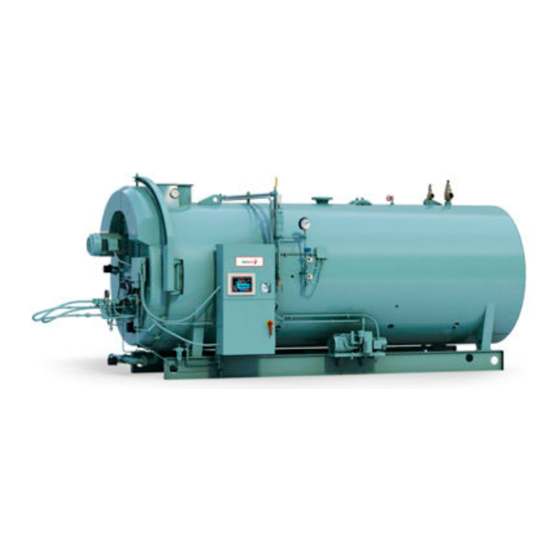
- Page 1 Model 4WI Promethean Boilers 100 to 800 HP Steam and Hot Water Fuel: Light Oil, Gas or Combination Operation, Service, and Parts Manual 750-211 12/09...
- Page 2 WARNING WARNING ! DANGER ! DANGER If the information in this manual is not fol- Improper installation, adjustment, ser- lowed exactly, a fire or explosion may re- vice, or maintenance can cause equip- ment damage, personal injury, or death. sult causing property damage, personal Refer to the Operation and Maintenance injury or loss of life.
- Page 3 ! DANGER WARNING WARNING ! DANGER The boiler and its individual shutoff valve The installation must conform to the re- must be disconnected from the gas sup- quirements of the authority having jurisdic- ply piping system during any pressure tion absence such testing of that system at test pressures in...
- Page 4 TO: Owners, Operators and/or Maintenance Personnel This operating manual presents information that will help to properly operate and care for the equipment. Study its contents care- fully. The unit will provide good service and continued operation if proper operating and maintenance instructions are followed. No attempt should be made to operate the unit until the principles of operation and all of the components are thoroughly under- stood.
- Page 5 CLEAVER-BROOKS Model 4WI, Promethean Boilers Operation and Maintenance Manual Manual Number: 750-211 Release Date: December 2009...
- Page 6 Copyright © 2009 by Cleaver-Brooks All rights reserved. No part of this document may be reproduced, stored in a retrieval system, or transmitted in any form or by any means without the prior writ- ten consent of Cleaver-Brooks. Cleaver-Brooks 11950 West Lake Park Drive Milwaukee, WI 53224 414-359-0600 www.cleaver-brooks.com...
-
Page 7: Table Of Contents
2.1 — The Burner 2-1 2.2 — Controls Common to all Boilers 2-2 2.3 — Control and Component Function 2-3 2.4 — Components Common to all Boilers 2-3 2.5 — Controls for Gas Firing 2-6 750-211 (revised 2009) Promethean Boilers, Model 4WI Manual... - Page 8 3.2.1.8 — Pump Operation 3-5 3.2.1.9 — Pressure 3-5 3.2.2 — Steam Boiler 3-6 3.2.2.1 — Feed Pump Operation 3-6 3.2.2.2 — Water Feeder (optional) Operation 3-6 3.3 — Water Treatment 3-6 750-211 (revised 2009) Promethean Boilers, Model 4WI Manual...
- Page 9 4.4 — Flame Loss Sequence 4-5 Starting and Operating Instructions 5-1 CHAPTER 5 5.1 — General Preparation for Startup: All Fuels 5-1 5.2 — Control Settings: Steam and Hot Water 5-2 5.3 — Gas Pilot 5-4 750-211 (revised 2009) Promethean Boilers, Model 4WI Manual...
- Page 10 6.7 — Operating Limit Pressure Control: Steam 6-8 6.8 — High Limit Pressure Control: Steam 6-9 6.9 — Modulating Temperature Control: Hot Water 6-9 6.10 — High Limit Temperature Control: Hot Water 6-9 750-211 (revised 2009) Promethean Boilers, Model 4WI Manual...
- Page 11 6.26 — Low-Oil-Pressure Switch: Optional 6-26 6.27 — Electric Oil Heater Thermostat: 400 and 600 Series (Steam) 6-26 6.28 — Steam Oil Heater Thermostat: No. 6 Oil, 400 and 600 Series (Steam) 6-27 750-211 (revised 2009) Promethean Boilers, Model 4WI Manual...
- Page 12 8.7.5 — Ignition System 8-13 8.8 — Gas Burner Maintenance 8-14 8.9 — Motorized Gas Valve 8-15 8.10 — Solenoid Valves 8-15 8.11 — Air Control Damper, Linkage and Cam Spring 8-16 750-211 (revised 2009) Promethean Boilers, Model 4WI Manual...
- Page 13 8.20.3 — Solenoid and Motorized Valves 8-34 8.20.4 — IFGR Lubrication 8-34 8.21 — Oil Heaters: Electric, Steam, Hot Water 8-34 8.22 — Combustion 8-35 Parts 9-1 CHAPTER 9 9.1 — Ordering Parts 9-1 750-211 (revised 2009) Promethean Boilers, Model 4WI Manual...
- Page 14 9.2.43 — Water Column Piping: 96”-106”, 500-800 HP 9-58 9.2.44 — Front Door 60”-106” Air Duct Gasket 9-60 9.2.45 — Pressure Vessel Manway Components 9-61 9.2.46 — Pressure Vessel Handhole Components 9-61 9.2.47 — Pressure Vessel Handhole Components 9-62 viii 750-211 (revised 2009) Promethean Boilers, Model 4WI Manual...
-
Page 15: Firetube Operation Basics
800 boiler horsepower for the following fuels: Series 100 Light Oil (No. 2) Series 200 Light Oil (No. 2) or Gas Series 400 Heavy Oil (No. 6) or Gas Series 600 Heavy Oil (No. 6) Series 700 750-211 (revised 2009) Promethean Boilers, Model 4WI Manual... - Page 16 NOx emissions. In this approach, the combustion air fan handles both the combustion air and the recirculated flue gases. Induced Flue Gas Recirculation (IFGR) FIGURE 1-3. 750-211 (revised 2009) Promethean Boilers, Model 4WI Manual...
-
Page 17: The Boiler
The firetube construction provides some characteristics that differentiate it from other boiler types. Because of its vessel size, the firetube contains a large amount of water, allowing it to respond to load changes with minimum variation in steam pressure. 750-211 (revised 2009) Promethean Boilers, Model 4WI Manual... -
Page 18: Construction
Steam boilers designed for operating pressures exceeding 15 psig are constructed in accordance with Section I, Power Boilers, of the ASME Code. Hot water boilers designed for operating temperatures above 250º F or 125 psi are likewise built to Section I of the ASME Code. 750-211 (revised 2009) Promethean Boilers, Model 4WI Manual... -
Page 19: Steam Controls (All Fuels)
(optional equipment) to ring. Code requirements of some models require a manual reset type of low water cutoff. •Starts and stops the feedwater pump (if used) to maintain water at the proper operating level. 750-211 (revised 2009) Promethean Boilers, Model 4WI Manual... -
Page 20: Water Column
Use only flat-jawed wrenches on the flats provided. When installing a flange connected valve, use a new gas- ket and draw the mounting bolts down evenly. Do not install or remove side outlet valves by using a pipe or wrench in the outlet. 750-211 (revised 2009) Promethean Boilers, Model 4WI Manual... -
Page 21: Hot Water Controls (All Fuels)
Operating Limit Temperature Control: Breaks a circuit to stop burner operation on a rise of boiler tempera- ture at a selected setting. It is adjusted to stop or start the burner at a preselected operating temperature. 750-211 (revised 2009) Promethean Boilers, Model 4WI Manual... -
Page 22: Low Water Cutoff And Alwco
Two jackshaft drive arms are provided, one for oil and one for gas. The linkage is manually connected to the appropriate arm, based on the fuel being used. 750-211 (revised 2009) Promethean Boilers, Model 4WI Manual... - Page 23 On dual-fuel boilers with two jackshaft drive arms, as defined above, a proximity switch is used to prove that the correct linkage connection is made. (Refer to the wiring diagram provided with the boiler.) Cross Section of Front Head FIGURE 1-11. Over-Travel Mechanism and Fuel Changeover Linkage FIGURE 1-12. 750-211 (revised 2009) Promethean Boilers, Model 4WI Manual...
- Page 24 Fan/Motor Cassette: The fan and motor assemblies are designed as a cassette so that they can be removed from the front of the boiler, without opening the front door. The front door davit arm can be used to remove the assembly. Fan/Motor Cassette FIGURE 1-13. 1-10 750-211 (revised 2009) Promethean Boilers, Model 4WI Manual...
-
Page 25: Burner Operation And Control
The programming portion of the control provides a pre-purging period, proving of the pilot and main flame, and a period of continued blower operation to post-purge the boiler of all unburned fuel vapor. Other safety controls shut down the burner under low-water conditions, excess steam pressure, or water temperature. 750-211 (revised 2009) Promethean Boilers, Model 4WI Manual... -
Page 26: Controls Common To All Boilers
The devices are wired into the circuitry to provide safe operation and protect against incorrect operating techniques. All Promethean 4WI boilers have the burner assembly integral with the front head. The entire head may be swung open for inspection and maintenance. -
Page 27: Control And Component Function
Drives forced draft fan directly to provide combustion air. Also referred to as a blower motor. 2. Forced Draft Impeller Provides all air, under pressure, for combustion of pilot fuel and main fuel, and for purging. 750-211 (revised 2009) Promethean Boilers, Model 4WI Manual... - Page 28 It consists of two concentric cylinders with openings. The outer is stationary. The inner is rotated, under control of the modulating motor, to vary the effective size of the openings where they overlap. 750-211 (revised 2009) Promethean Boilers, Model 4WI Manual...
- Page 29 An internal checking circuit, effective on every start, prevents burner operation in the event anything causes the flame relay to hold in during this period. 750-211 (revised 2009) Promethean Boilers, Model 4WI Manual...
-
Page 30: Controls For Gas Firing
A second shutoff cock, downstream of the main gas valve(s), is installed to provide a means of shutting off the gas line whenever a test is made for leakage across the main gas valve. 750-211 (revised 2009) Promethean Boilers, Model 4WI Manual... - Page 31 The body of the gas valve has a plugged opening that is used whenever it is neces- sary to conduct a test for possible leakage across the closed valve. Burner Drawer Face and Gas Modulating Cam FIGURE 2-7. 750-211 (revised 2009) Promethean Boilers, Model 4WI Manual...
-
Page 32: Controls Common To Oil-Fired Boilers (Including Combination)
C. Oil Burner Pressure Gauge: Indicates pressure of the fuel oil at the metering valve. D. Oil Pressure Regulator: For adjustment of the pressure of oil at the metering valve. 750-211 (revised 2009) Promethean Boilers, Model 4WI Manual... - Page 33 13. Fuel Oil Pump Transfers fuel oil from the storage tank and delivers it under pressure to the burner system. Fuel Oil Controller and Relief Valve & Terminal Block FIGURE 2-9. 750-211 (revised 2009) Promethean Boilers, Model 4WI Manual...
- Page 34 A fan driven by the air pump motor circulates cooling air over the coil. H. Lube OIl Fill Pipe and Strainer: Used when adding oil to the air-oil receiver tank. Air Pump (Primary Air) FIGURE 2-10. 2-10 750-211 (revised 2009) Promethean Boilers, Model 4WI Manual...
-
Page 35: Additional Controls For Heavy Oil
5. Oil Return to Tank Excess oil returned to the heavy oils supply tank. 6. Oil Inlet from Supply Tank Heavy oil inlet from the supply tank. 750-211 (revised 2009) 2-11 Promethean Boilers, Model 4WI Manual... - Page 36 Provided as a time saver in establishing oil flow. When open, it permits circulation of oil through the supply and return lines. The valve must be closed prior to initial light off. 2-12 750-211 (revised 2009) Promethean Boilers, Model 4WI Manual...
-
Page 37: Controls For Combination Burners Only
The selector switch engages the appropriate interlocks and controls for gas or oil operation. Chapter 4 details the required mechanical functions of each fuel system. Control Panel with Gas-Oil Selector Switch FIGURE 2-13. 750-211 (revised 2009) 2-13 Promethean Boilers, Model 4WI Manual... -
Page 38: Combustion Air
Either pilot serves the same function. At the beginning of the ignition cycle, and governed by the program relay and the Hawk ICS system, the pilot sole- noid valve and ignition transformer are simultaneously energized. 2-14 750-211 (revised 2009) Promethean Boilers, Model 4WI Manual... -
Page 39: Atomizing Air
Some of the primary air is also used to assist the oil pressure reg- ulators of the fuel oil controller. Further explanation is given in Chapter 5. Air-Oil Receiver Tank FIGURE 2-15. 750-211 (revised 2009) 2-15 Promethean Boilers, Model 4WI Manual... -
Page 40: Oil Fuel Flow: Light Oil
Burner Operation and Control 2.12 — Oil Fuel Flow: Light Oil In Figure 2-16 the oil flow is indicated by arrows and the pertinent controls are identified. Diagram for Light Oil Flow FIGURE 2-16. 2-16 750-211 (revised 2009) Promethean Boilers, Model 4WI Manual... -
Page 41: Oil Fuel Flow: Heavy Oil
It cannot be opened (energized) unless the combustion air proving switch, the atomizing air proving switch, and the low oil-temperature and any pressure switches are closed. They 750-211 (revised 2009) 2-17 Promethean Boilers, Model 4WI Manual... - Page 42 Diagram for No. 6 Heavy Oil Flow (Steam-Electric Heater) FIGURE 2-17. 2-18 750-211 (revised 2009) Promethean Boilers, Model 4WI Manual...
-
Page 43: Gas Fuel Flow
The main gas valves cannot be energized (opened) unless the combustion air proving switch is closed to indicate a sufficient supply of combustion air. The low gas pressure and high gas pressure switches must be closed to prove sufficient, but not excessive, gas fuel pressure. 750-211 (revised 2009) 2-19 Promethean Boilers, Model 4WI Manual... -
Page 44: Modulating Firing
A feature designed into the circuitry maintains the modulating motor in the low-fire position during ignition and keeps it there until the main flame is established. A low-fire switch, integral to the motor, is actuated by the rotation 2-20 750-211 (revised 2009) Promethean Boilers, Model 4WI Manual... - Page 45 The second integral switch closes, as high-fire position is approached, to complete an internal circuit in the programmer to allow continuation of the programming cycle. 750-211 (revised 2009) 2-21 Promethean Boilers, Model 4WI Manual...
- Page 46 Burner Operation and Control 2-22 750-211 (revised 2009) Promethean Boilers, Model 4WI Manual...
-
Page 47: Waterside Care And Requirements
NOTE: This manual covers boilers using water. Glycol solutions ave different operating requirements, circulation rates, temperatures, etc. 750-211 (revised 2009) Promethean Boilers, Model 4WI Manual... -
Page 48: Water Requirements
F cannot be completely replaced with 80° F water in a few minutes time without causing thermal stress. The same fact applies to periods of normal operation, as well as during initial startup. 750-211 (revised 2009) Promethean Boilers, Model 4WI Manual... -
Page 49: Continuous Flow Through The Boiler
NOTE: The circulating pumps should be interlocked with the burner so that the burner cannot operate unless the cir- culating pump is running in order to avoid damage to the equipment. 750-211 (revised 2009) Promethean Boilers, Model 4WI Manual... -
Page 50: Water Circulation
In extreme cases, one boiler may be in the high-fire position while the other boiler or boilers may be at low fire. The net result would be that the common header water temperature to the system would not be up to the desired point. 750-211 (revised 2009) Promethean Boilers, Model 4WI Manual... -
Page 51: Pump Location
It is advisable to have a thermometer installed in the return line to indicate return water temperature. Knowing the supply water temperature, the boiler system differential can be established. With knowledge of the pumping rate, the operator can easily detect any excessive load condition and take appropriate corrective action. 750-211 (revised 2009) Promethean Boilers, Model 4WI Manual... -
Page 52: Steam Boiler
Prevent hard scale deposits or soft sludge deposits, which reduce heat transfer and can lead to overheated metal and costly downtime and repairs. Eliminate corrosive gases in the supply or boiler water. 750-211 (revised 2009) Promethean Boilers, Model 4WI Manual... -
Page 53: Cleaning
The installation and operating conditions that the boiler will be subjected to should be considered and cleaning of the waterside of the pressure vessel should be provided during the course of initial start-up. 750-211 (revised 2009) Promethean Boilers, Model 4WI Manual... -
Page 54: Boil-Out Of A New Unit
There are several chemicals suitable for boil-out. One combination often used is soda ash (sodium carbonate) and caustic soda (sodium hydroxide) at the rate of 3 to 5 pounds each per 1,000 pounds of water, along with a small amount of laundry detergent serving as a wetting agent. 750-211 (revised 2009) Promethean Boilers, Model 4WI Manual... - Page 55 (Refer to Chapter 8, Section 8-17 for valve installation instructions.) An overflow pipe should be attached ton one of the top boiler openings and routed to a safe point of discharge. The safety valve tapping is usually used. 750-211 (revised 2009) Promethean Boilers, Model 4WI Manual...
-
Page 56: Washing Out
Upon completion of the inspection, the pressure vessel interior should be flushed out, as required, with a high pressure hose. If deposits are not fully removed by flushing, a consultation may be required with your local Cleaver- 3-10 750-211 (revised 2009) Promethean Boilers, Model 4WI Manual... -
Page 57: Blowdown: Steam Boiler
TDS blowdown is employed. The blowdown tappings are located at the bottom or lowest part of the boiler in order to rid the sludge in the lower part of the vessel. 750-211 (revised 2009) 3-11 Promethean Boilers, Model 4WI Manual... -
Page 58: Continuous Blowdown (Controlling Tds)
A hot water boiler does not normally include openings for surface blowdown and bottom blowdown since blow- downs are not practiced. The need remains to be alert to system water losses and corresponding amount of raw water make-up. A water meter is recommended for water make-up lines. 3-12 750-211 (revised 2009) Promethean Boilers, Model 4WI Manual... -
Page 59: Manual Blowdown Procedure
To avoid the hazard of electrical shock, we recommend the use of a low voltage flashlight during an internal inspection. Preferably, inspectors should work in pairs. Failure to follow these instructions could result in serious injury or death. 750-211 (revised 2009) 3-13 Promethean Boilers, Model 4WI Manual... -
Page 60: Preparation For Extended Layup
3-14 750-211 (revised 2009) Promethean Boilers, Model 4WI Manual... - Page 61 Additional chemicals may be suggested by your local Cleaver- Brooks authorized representative to minimize corrosion. Internal water pressure should be maintained at greater than atmospheric pressure. Nitrogen is often used to pressurize the vessel. 750-211 (revised 2009) 3-15 Promethean Boilers, Model 4WI Manual...
- Page 62 Waterside Care and Requirements 3-16 750-211 (revised 2009) Promethean Boilers, Model 4WI Manual...
-
Page 63: Sequence Of Operation
Air compressor motor starter (if provided). c. Oil heater relay (if provided). d. Oil pump motor starter (if provided). Chapters 6 and 7 contain operating instructions and specific information on setting and adjusting the controls. 750-211 (revised 2009) Promethean Boilers, Model 4WI Manual... -
Page 64: Circuit And Interlock Controls
Auxiliary low-water cutoff (ALWCO) • Low Fire Proving Circuit Low fire switch (LFS) • Pilot Ignition Circuit Gas pilot valve (GPV) • Ignition transformer (IT) • Gas pilot vent valve (GPVV) - if provided • 750-211 (revised 2009) Promethean Boilers, Model 4WI Manual... -
Page 65: Sequence Of Operation: Gas Or Oil
The controls wired into the “running interlock circuit” must be closed within 10 seconds after the start sequence. In the event any of the controls are not closed at this time, or if they subsequently open, the program relay will go into a safety shutdown. 750-211 (revised 2009) Promethean Boilers, Model 4WI Manual... -
Page 66: Ignition Cycle
(MFC) or the modulating control (MC), depending upon the position of the manual-automatic switch (MAS). This allows operation in ranges above low fire. 750-211 (revised 2009) Promethean Boilers, Model 4WI Manual... -
Page 67: Flame Loss Sequence
Lockout will also occur if flame or flame simulating condition occurs during the pre-purge period. 750-211 (revised 2009) Promethean Boilers, Model 4WI Manual... - Page 68 Following a routine may possibly eliminate overlooking an obvious condition, often one that is relatively simple to correct. 750-211 (revised 2009) Promethean Boilers, Model 4WI Manual...
- Page 69 Preventive maintenance and scheduled inspection of all components should be followed. Periodic checking of the relay is recommended to see that a safety lockout will occur under conditions of failure to ignite either pilot or main flame, or from loss of flame. 750-211 (revised 2009) Promethean Boilers, Model 4WI Manual...
- Page 70 Sequence of Operation 750-211 (revised 2009) Promethean Boilers, Model 4WI Manual...
-
Page 71: Starting And Operating Instructions
The boiler should be filled with water to the proper operating level using water of ambient temperature. Be sure that treated feedwater is available and used. In heating applications, the entire system should be filled and vented. 750-211 (revised 2009) Promethean Boilers, Model 4WI Manual... -
Page 72: Control Settings: Steam And Hot Water
5.2 — Control Settings: Steam and Hot Water See Chapter 6 for adjustment instructions for the following controls. Inspect the operating limit control for proper setting as follows: 750-211 (revised 2009) Promethean Boilers, Model 4WI Manual... - Page 73 The importance of proper functioning of low-water controls cannot be over- emphasized. Be sure that the control and the piping are level. The settings of controls relating to fuel, either oil or gas, are covered in subsequent sections. 750-211 (revised 2009) Promethean Boilers, Model 4WI Manual...
-
Page 74: Gas Pilot
“oil.” Turn the burner switch on. The burner will cycle to the low-fire pre-purge position and stop there. 750-211 (revised 2009) Promethean Boilers, Model 4WI Manual... -
Page 75: Firing Preparations For No. 2 Oil (Series 100-200)
“oil.” Insert the burner drawer gun into its most forward position and latch it in place, closing the oil drawer switch. Oil Gun Locked in Firing Position FIGURE 5-5. 750-211 (revised 2009) Promethean Boilers, Model 4WI Manual... - Page 76 A pressure gauge should be installed in the terminal block and the relief valve adjusted to obtain a mini- mum reading of 75 psi when the burner is firing at maximum rate. Oil Terminal Block FIGURE 5-6. 750-211 (revised 2009) Promethean Boilers, Model 4WI Manual...
-
Page 77: Firing Preparation For No. 6 Oil (Series 400-600)
If the boiler is a combination fuel model, be certain that the main gas shutoff cock is closed and set the gas/oil selector to “oil.” Insert the burner drawer gun into its most forward position and latch it in place, depressing the oil drawer switch. 750-211 (revised 2009) Promethean Boilers, Model 4WI Manual... -
Page 78: Oil Flow
The pressure gauges will indicate higher readings when a flame is present. The pressure will increase as the firing rate increases. The pressure reading on the two gauges on the controller will, despite the fluctuation, retain a nearly constant difference of 10 psi. 750-211 (revised 2009) Promethean Boilers, Model 4WI Manual... -
Page 79: Oil Temperature
When all the conditions covered above and in Sections 5.1, 5.2, 5.3, and 5.4 are assured, the burner is ready for fir- ing. Refer to Section 5.8 for further starting and operating information. 750-211 (revised 2009) Promethean Boilers, Model 4WI Manual... -
Page 80: Firing Preparations For Gas (Series 200-400-700)
“bleed” air from the line. Warning Do not repeat unsuccessful lighting attempts without re-checking the burner and pilot adjustments. Failure to follow these instructions could result in serious injury or death. 5-10 750-211 (revised 2009) Promethean Boilers, Model 4WI Manual... -
Page 81: Ifgr Setup
Verify that all the IFGR components are set to the settings recorded on the Start Up report (as noted by the Cleaver-Brooks authorized representative during original setup). Be sure that all linkages are secure. 750-211 (revised 2009) 5-11 Promethean Boilers, Model 4WI Manual... -
Page 82: Startup, Operating, And Shutdown: All Fuels
The fuel selector switch should be, accordingly, set to either oil or gas. Jackshaft Linkage Settings FIGURE 5-13. 5-12 750-211 (revised 2009) Promethean Boilers, Model 4WI Manual... - Page 83 5.9 — Startup, Operating, and Shutdown: All Fuels Overtravel Linkage Settings FIGURE 5-14. Flange Collar and Damper Settings (Top View) FIGURE 5-15. 750-211 (revised 2009) 5-13 Promethean Boilers, Model 4WI Manual...
- Page 84 To properly perform the testing and adjusting, it is necessary that the burner be allowed to fire at a maximum rate long enough to achieve desired results. 5-14 750-211 (revised 2009) Promethean Boilers, Model 4WI Manual...
-
Page 85: Operating
Proper operation of the various controls should be verified and tested when the boiler is initially placed into ser- vice, or whenever a control is replaced. Periodic checks should be made thereafter in accordance with a planned maintenance program. 750-211 (revised 2009) 5-15 Promethean Boilers, Model 4WI Manual... - Page 86 Promptly correct any conditions causing leakage. Failure to follow these instructions could result in seri- ous injury or death. Refer to the adjustment procedures and maintenance instructions given in Chapters 6 and 8. 5-16 750-211 (revised 2009) Promethean Boilers, Model 4WI Manual...
-
Page 87: Adjustment Procedures
(Series 400 or 600) or HTB (Series 100, 200, or 700) burners to avoid damage to the equipment. The burner series is identified on the boiler data plate affixed to the front head of the boiler. For example: 4WI (model), 700 (fuel), 250 (HP), 150 (pressure) 750-211 (revised 2009) -
Page 88: Linkage: Modulating Motor And Air Damper
Complete Linkage Assembly: Combination Gas and Oil FIGURE 6-1. Overtravel linkage, where used, should not be required to extend its spring to the fullest stretch. 750-211 (revised 2009) Promethean Boilers, Model 4WI Manual... - Page 89 Adjustment of linkage connected to a gas butterfly valve is described in Section 6.17. 750-211 (revised 2009) Promethean Boilers, Model 4WI Manual...
-
Page 90: Modulating Motor
Refer to the appropriate boiler Operation and Maintenance manual for specific information on boiler startup and operation. The standard boiler operating control package consists of three separate controls: • Operating Limit Control • High Limit Control • Modulating Control 750-211 (revised 2009) Promethean Boilers, Model 4WI Manual... - Page 91 • The burner will be operating in low-fire position prior to shutdown. • The burner will operate at low-fire for a brief period on each start during normal operation. • Eliminates frequent burner on-off cycling. 750-211 (revised 2009) Promethean Boilers, Model 4WI Manual...
- Page 92 The Firing Graph shows that point B and point C do not coincide. Extreme load conditions could require the points be closely matched. 750-211 (revised 2009) Promethean Boilers, Model 4WI Manual...
- Page 93 (A to B) should be set as wide as conditions permit, since a wide setting will provide less frequent burner cycling. 750-211 (revised 2009) Promethean Boilers, Model 4WI Manual...
-
Page 94: Modulating Pressure Control: Steam
The “cut-in” (burner on) pressure is the cutout pressure minus the differential. The cutout pressure should not exceed 90% of the safety valve setting. 750-211 (revised 2009) Promethean Boilers, Model 4WI Manual... -
Page 95: High Limit Pressure Control: Steam
Set the “cutout” (burner off) temperature on the scale by inserting a screwdriver through the cover opening to engage the slotted head adjusting screw. The “cut-in” (burner on) temperature is the cutout temperature minus the differential. The differential is adjusted from 5º to 30º F. 750-211 (revised 2009) Promethean Boilers, Model 4WI Manual... -
Page 96: Low Water Cutoff Devices: Steam And Hot Water
Recycle the program relay to be sure that normal operation is obtained. Replace the wire on terminal W and re- install the cover. Return the test switch to the “Run” position. 6-10 750-211 (revised 2009) Promethean Boilers, Model 4WI Manual... -
Page 97: Atomizing Air Proving Switch
The correct voltage or micro amp readings can be found in the information supplied with the flame safeguard sys- tem or the Hawk ICS manual 750-197. 750-211 (revised 2009) 6-11 Promethean Boilers, Model 4WI Manual... - Page 98 If the control shuts down, manually reset it. Replace the detector and repeat the process from step 5. Warning When checking the pilot flame, be aware the electrode is energized. Failure to follow these instructions could result in serious injury or death. 6-12 750-211 (revised 2009) Promethean Boilers, Model 4WI Manual...
-
Page 99: Gas Pressure And Flow Information
The pressure requirement varies with boiler size, altitude, and type of gas train. Refer to Table 6.1 for pressure requirements. Minimum Net Regulated Gas Pressure for Rated Boiler Output TABLE 6-1. Pressure Required Boiler HP Std. Pipe Size (inches) (WC) 2-1/2 2-1/2 10.5 750-211 (revised 2009) 6-13 Promethean Boilers, Model 4WI Manual... - Page 100 1.11 4000 1.16 5000 1.21 6000 1.25 7000 1.30 8000 1.35 9000 1.40 NOTE: For undersized or oversized gas trains or altitudes above 9000 feet, contact your local Cleaver-Brooks repre- sentative. 6-14 750-211 (revised 2009) Promethean Boilers, Model 4WI Manual...
-
Page 101: Gas Flow
6.16 — Gas Pressure and Flow Information 4-Pass Wetback Boilers with Integral Burner (4WI) Firing Rates TABLE 6-3. Natural Gas, 1000 Btu/hr No. 2 Oil, GPM Boiler HP Low-Fire High-Fire Low-Fire High-Fire 1021 4082 29.2 1276 5103 36.4 1531 6124 10.9... - Page 102 3 psig. Determine the flow rate by dividing the Btu content of the gas into the burner input, Table 6.3, and “correct” this answer by applying the correction factor for 3 psig, Table 6.4. 6-16 750-211 (revised 2009) Promethean Boilers, Model 4WI Manual...
-
Page 103: Checking Gas Flow
Your gas supplier can, if necessary, furnish exact correction factors that take into consideration Btu content, exact base pressure, specific gravity, temperature, etc., of the gas used. Fuel Modulating Cam FIGURE 6-13. 750-211 (revised 2009) 6-17 Promethean Boilers, Model 4WI Manual... -
Page 104: Gas Fuel Combustion Adjustment
Proper setting of the air/fuel ratios at all rates of firing must be established by the use of a combustion or flue gas analyzer. The appearance or color of the gas flame is not an indication of its efficiency, because an efficient gas flame will vary from transparent blue to translucent yellow. 6-18 750-211 (revised 2009) Promethean Boilers, Model 4WI Manual... - Page 105 Tighten the locknuts on all ball joints. The low-fire setting should be regarded as tentative until the proper gas pressure for high-fire operation is established. Butterfly Gas Valve FIGURE 6-15. 750-211 (revised 2009) 6-19 Promethean Boilers, Model 4WI Manual...
-
Page 106: Burner Low-Fire Adjustment
To ensure that the low-fire position of the gas butterfly valve is always the same, allow a half turn of the stopscrew for overtravel. If the air damper must be reset to meet the low-fire air/fuel requirements, combustion at higher firing rates must be rechecked. 6-20 750-211 (revised 2009) Promethean Boilers, Model 4WI Manual... -
Page 107: Low-Gas-Pressure Switch
Variations in burning characteristics of the fuel oil may occasionally require adjustments to assure highest combus- tion efficiency. The handling and burning characteristics may vary from one delivery of oil to another. Therefore, it 750-211 (revised 2009) 6-21 Promethean Boilers, Model 4WI Manual... - Page 108 Similarly, if an electric, steam, or hot water oil heater is removed for servicing, the tempera- ture of the heater should be reduced by circulating oil until it has cooled. 6-22 750-211 (revised 2009) Promethean Boilers, Model 4WI Manual...
-
Page 109: Fuel Oil Combustion Adjustment
If an adjustment is necessary, turn the cam adjustment screw accordingly to increase or decrease fuel flow. Take a combustion reading to verify input. Repeat as necessary until the desired flow is obtained. Continue this process, stopping at each adjusting screw, until the low-fire position is reached. 750-211 (revised 2009) 6-23 Promethean Boilers, Model 4WI Manual... -
Page 110: Standard Burner Low-Fire Adjustment 100-200 Hp
Check the setting of the ignition electrode(s) for proper gap and position. See Figure 6-19 for the gas pilot elec- trode and Figure 6-20 for the light oil pilot. Be sure that the porcelain insulator is not cracked and that ignition cable connections are tight. 6-24 750-211 (revised 2009) Promethean Boilers, Model 4WI Manual... - Page 111 Check to see that the flame detector sight tube and the gas pilot tube extend through their respective openings in the diffuser face. Gas Pilot Electrode FIGURE 6-19. Light Oil Pilot Settings FIGURE 6-20. 750-211 (revised 2009) 6-25 Promethean Boilers, Model 4WI Manual...
-
Page 112: Oil Drawer Switch
“high” end of the scale. Lower settings are obtained by turning the adjusting knob clockwise using the thermometer in the fuel oil controller as a guide. 6-26 750-211 (revised 2009) Promethean Boilers, Model 4WI Manual... -
Page 113: Steam Oil Heater Thermostat: No. 6 Oil, 400 And 600 Series (Steam)
Such a temperature prevents the electric heater from operation when the water heater is functioning. The electric heater is sized to provide sufficient heated oil for low-fire operation on cold starts before hot water is available. 750-211 (revised 2009) 6-27 Promethean Boilers, Model 4WI Manual... -
Page 114: Revised 2009)
Adjustment Procedures 6-28 750-211 (revised 2009) Promethean Boilers, Model 4WI Manual... -
Page 115: Troubleshooting
Most circuitry checking can be done between appropriate terminals on the terminal boards in the control cabinet or the entrance box. Refer to the schematic wiring diagram for terminal identification. 750-211 (revised 2009) Promethean Boilers, Model 4WI Manual... - Page 116 D. Oil fired unit - burner gun must be in full forward position to close oil drawer switch. E. Heavy oil fired unit - oil temperature below minimum settings. Fuel valve interlock circuit not completed. A. Fuel valve auxiliary switch not closed. 750-211 (revised 2009) Promethean Boilers, Model 4WI Manual...
- Page 117 Insufficient or no voltage at main fuel valve circuit terminal. BURNER STAYS IN LOW- Pressure or temperature above modulating control setting. FIRE Manual-automatic switch in wrong position. Inoperative modulating motor. Defective modulating control. Binding or loose linkage, cams, setscrews, etc. 750-211 (revised 2009) Promethean Boilers, Model 4WI Manual...
- Page 118 C. Damper motor transformer defective. Motor does not operate on demand: A. Manual-automatic switch in wrong position. B. Modulating control improperly set or inoperative. C. Motor defective. D. Loose electrical connection. E.Damper motor transformer defective. 750-211 (revised 2009) Promethean Boilers, Model 4WI Manual...
-
Page 119: Inspection And Maintenance
Any leaks — fuel, water, steam, exhaust gas — should be repaired promptly and under conditions that observe necessary safety precautions. Preventive maintenance measures, such as regularly checking the tightness of connections, locknuts, setscrews, packing glands, etc., should be included in regular maintenance activities. 750-211 (revised 2009) Promethean Boilers, Model 4WI Manual... -
Page 120: Periodic Inspection
NOTE: Replacement spare parts, if not on hand, should be ordered sufficiently prior to shutdown. 750-211 (revised 2009) Promethean Boilers, Model 4WI Manual... -
Page 121: Fireside Cleaning
Any soot, or other deposits, should be removed from the furnace and tube sheets. Refer to Section 8.17 for instructions on properly closing rear heads. Front Head Open FIGURE 8-2. 750-211 (revised 2009) Promethean Boilers, Model 4WI Manual... -
Page 122: Water Level Controls
Replica of Low Water Cutoff Plate FIGURE 8-4. 750-211 (revised 2009) Promethean Boilers, Model 4WI Manual... -
Page 123: Hot Water Boiler
Insert one end of the glass into the upper gauge valve body far enough to allow the lower end to be dropped into the lower body. Slide the packing nuts onto each valve and tighten. 750-211 (revised 2009) Promethean Boilers, Model 4WI Manual... -
Page 124: Electrical Controls
Replacement of the contacts is necessary only if the silver has worn thin. Caution Do not use files or abrasive materials such as sandpaper on the contact points. Failure to follow these instructions could result in equipment damage. 750-211 (revised 2009) Promethean Boilers, Model 4WI Manual... - Page 125 (Fusetrons®) or circuit breakers. Similar fuses should be used in branch circuits. Standard one-shot fuses are not recommended. Information given below is included for guidance to fuse requirements. Entry Box FIGURE 8-8. 750-211 (revised 2009) Promethean Boilers, Model 4WI Manual...
-
Page 126: Flame Safety Control
Also check to see that the amplifier and the program module are tightly inserted. The relay's self-diagnostic ability includes advising when it or its plug-in modules are at fault and require replace- ment. 750-211 (revised 2009) Promethean Boilers, Model 4WI Manual... -
Page 127: Checking Pilot Flame Failure
The ignition circuit will de-energize and the control will lock out on a safety shutdown. The flame failure light (and optional alarm) will be activated. The blower motor will run through the post-purge and stop. 750-211 (revised 2009) Promethean Boilers, Model 4WI Manual... -
Page 128: Checking Failure To Light Main Flame
The flame failure light (and optional alarm) will be activated. The blower motor will run through the post-purge and stop. Turn the burner switch off. Reset the safety switch. Re-establish main fuel supply. 8-10 750-211 (revised 2009) Promethean Boilers, Model 4WI Manual... -
Page 129: Oil Burner Maintenance
Exercise care not to damage the cartridge discs or the cleaner blades. Wash the cartridge in solvent. Do not attempt to disassemble the cartridge. Heavy Oil Cleaner FIGURE 8-13. 750-211 (revised 2009) 8-11 Promethean Boilers, Model 4WI Manual... -
Page 130: Cleaning The Oil Nozzle
Clean the strainer screen carefully to remove any foreign matter. Use suitable solvents in cleaning. Hot water at high velocity is also helpful in cleaning. Replace strainer by screwing it into the nozzle body only finger tight. Do not use an orifice of a size other than originally installed. 8-12 750-211 (revised 2009) Promethean Boilers, Model 4WI Manual... -
Page 131: Ignition System
Periodically remove the access plug from the gas pilot aspirator and clean out any accumulated lint or other foreign material. Gas Pilot Electrode and Diffuser Spacing FIGURE 8-16. 750-211 (revised 2009) 8-13 Promethean Boilers, Model 4WI Manual... -
Page 132: Gas Burner Maintenance
Periodically remove the access plug from the gas pilot aspirator and clean out any accumulated lint or other foreign material. Check the ignition cables for cracks in the insulation. Verify that all connections between the transformer and the electrode are tight. 8-14 750-211 (revised 2009) Promethean Boilers, Model 4WI Manual... -
Page 133: Motorized Gas Valve
Coils may be replaced without removing the valve from the line. Check coil position and make sure that any insulating washers or retaining springs are reinstalled in proper order. 750-211 (revised 2009) 8-15 Promethean Boilers, Model 4WI Manual... -
Page 134: Air Control Damper, Linkage And Cam Spring
Use care to avoid damaging the cam or spring during installation. Front Linkage and Oil Cam FIGURE 8-20. Lubricate occasionally with a non-gumming, dripless, high-temperature lubricant such as graphite or a silicone derivative. 8-16 750-211 (revised 2009) Promethean Boilers, Model 4WI Manual... -
Page 135: Fan/Motor Cassette Removal
When suspending the fan/motor cassette from the davit arm, all equipment used must be of adequate strength to safely support the complete cassette. Failure to follow these instructions could result in serious injury or death. 750-211 (revised 2009) 8-17 Promethean Boilers, Model 4WI Manual... -
Page 136: Inspection And Adjustment
If the impeller clearance is not correct at all points, adjust: A. Loosen the retaining nuts on both sides of the impeller housing. 8-18 750-211 (revised 2009) Promethean Boilers, Model 4WI Manual... -
Page 137: Fan/Motor Cassette Installation
Do not remove the davit arm assembly from the motor/fan cassette without first verifying that the cassette is securely bolted to the boiler. Failure to follow these instructions could result in serious injury or death. 750-211 (revised 2009) 8-19 Promethean Boilers, Model 4WI Manual... -
Page 138: Safety Valves
This will cause the valve to leak and necessitate down time of the boiler for valve repair or replacement. Repair of a valve must be done only by the manufacturer or his authorized representative. Operating Safety Valves FIGURE 8-25. 8-20 750-211 (revised 2009) Promethean Boilers, Model 4WI Manual... -
Page 139: Fuel Oil Metering Valve, Adjusting And Relief Valves
In the event the packing is too high, remove one teflon packing from each side of the middle brass guide as needed. Under no circumstances eliminate the two teflon packings on only one side of the brass guide. Replace the gasket, put the support in place, and secure all fastenings. 750-211 (revised 2009) 8-21 Promethean Boilers, Model 4WI Manual... - Page 140 Clean the slotted stem of the oil metering valve with suitable solvent and blow-dry with dry shop air. Follow the procedure outlined above when removing or re-installing the metering valve stem. Also check all fuel line strainers. 8-22 750-211 (revised 2009) Promethean Boilers, Model 4WI Manual...
-
Page 141: Air Pump And Lubricating System
Oil with proper viscosity must be used. SAE 20 detergent is recommended, although SAE 10 detergent is also per- missible. When adding oil, remove the cover from the fill pipe and add oil through the conical strainer in the pipe with the unit running. 750-211 (revised 2009) 8-23 Promethean Boilers, Model 4WI Manual... -
Page 142: Lubricating Oil Strainer And Cooling Coil
FIGURE 8-29. 8.17.5 — Air Cleaner Never operate the air pump without the air cleaner in place. The cleaner itself must be periodically checked and its element flushed and cleaned semi-annually. 8-24 750-211 (revised 2009) Promethean Boilers, Model 4WI Manual... -
Page 143: Lube Oil Cooling Coil
90º intervals. Shift the pump or motor, as required, so that the ends of the coupling are the same distance apart at all points. The coupling will then have proper angular alignment. 750-211 (revised 2009) 8-25 Promethean Boilers, Model 4WI Manual... -
Page 144: Air Compressor Replacement
Leave the rear pump bracket (coupling end) in place to aid in realignment of the replacement pump. Do this by removing the two capscrews that extend through the bracket into the pump housing. Temporarily leave the front bracket attached to the pump. 8-26 750-211 (revised 2009) Promethean Boilers, Model 4WI Manual... -
Page 145: Reassembly
Re-coating intervals will vary with operating loads and are best determined by the operator when the boiler is opened for inspection. 750-211 (revised 2009) 8-27 Promethean Boilers, Model 4WI Manual... -
Page 146: Furnace Liner
4 o’clock position to the 8 o’clock position with insulating cement. The liner tile should be fitted tightly against the crown of the corrugation. 8-28 750-211 (revised 2009) Promethean Boilers, Model 4WI Manual... -
Page 147: Throat Tile And Liner
Install both pieces of cerafelt to insulate the tile from the corrugation, and begin bottom half of first row of tiles as shown on DETAIL “C” (see note #7 on Figure 8-33). 750-211 (revised 2009) 8-29 Promethean Boilers, Model 4WI Manual... - Page 148 Install both pieces of cerafelt and continue laying furnace tiles to complete the last two rows (see note #7 on Figure 8-33). After joint cement hardens (approximately 2 hours), remove bricking tool, wooden tile supports, and discard cerafelt shims. 8-30 750-211 (revised 2009) Promethean Boilers, Model 4WI Manual...
-
Page 149: Rear Door
After opening either door, check the gaskets and seating sur- faces. Replace the door gaskets if they are hard or brittle. Clean the sealing surfaces of the door and tube sheet. Tighten the Davit Nut FIGURE 8-34. 750-211 (revised 2009) 8-31 Promethean Boilers, Model 4WI Manual... -
Page 150: Rear Access Plug
After the boiler is back in operation, re-tighten the door bolts to compensate for compression of the gasket or movement of the door. Warning Be certain that the davit arm is under tension before opening. Failure to follow these instructions could result in seri- ous injury or death. 8-32 750-211 (revised 2009) Promethean Boilers, Model 4WI Manual... -
Page 151: Lubrication
Apply a non-gumming, dripless, high temperature lubricant, such as graphite or a silicone derivative to all pivot points and moving parts. Work lubricant in well and wipe excess. Repeat application at required intervals to main- tain freedom of motion of parts. 750-211 (revised 2009) 8-33 Promethean Boilers, Model 4WI Manual... -
Page 152: Solenoid And Motorized Valves
The condensate from steam oil heaters must be safely discharged to waste. The waste should be checked periodi- cally for any traces of oil that would indicate leaking tubes within the heater. 8-34 750-211 (revised 2009) Promethean Boilers, Model 4WI Manual... -
Page 153: Combustion
The air-fuel ratio should be checked monthly in order to alert the operator to losses in efficiency, which do not pro- duce visible flame change. Any time maintenance is performed on the burner linkage, the air-fuel ratio should be checked. 750-211 (revised 2009) 8-35 Promethean Boilers, Model 4WI Manual... - Page 154 Readjustment of the burner may be required due to variations in fuel composition. A combustion analyzer should be used to adjust air-fuel ratio for maximum operating efficiency. If your burner requires adjustments, contact your local Cleaver-Brooks authorized representative for assistance. 8-36 750-211 (revised 2009) Promethean Boilers, Model 4WI Manual...
-
Page 155: Parts
Furnish complete information when ordering parts by giving the item number, description, and the quantity of parts desired, together with the complete nameplate data, including all electrical requirements. Repair and replacement parts should be ordered from your local Cleaver-Brooks authorized representative. 750-211 (revised 2009) Promethean Boilers, Model 4WI Manual... -
Page 156: Revised 2009)
FRONT HEAD ASSEMBLY 132-02338 132-02337 60" 132-02427 132-02426 132-02418 132-02417 67" 132-02431 132-02430 132-02404 132-02403 78" 132-02391 132-02390 132-02411 132-02410 85" 132-02308 132-02307 132-02408 132-02407 96" 132-02398 132-02397 132-02316 132-02315 106" 132-02429 132-02428 750-211 (revised 2009) Promethean Boilers, Model 4WI Manual... -
Page 157: Front Door Exterior Insulation Component List
828-00039 CLIP, WELDING ST. STL 872-00443 RIGIDIZER 59.5" 70" 74" 83" 100" 107" 872-00362 BULK, INSULATION BLANKET 797-01813 ADHESIVE 59.5" 70" 74" 83" 100" 107" 904-00012 GASKET, TAPE 930-00135 SCREEN ST. STL 750-211 (revised 2009) Promethean Boilers, Model 4WI Manual... -
Page 158: Rear Door Insulated Assembly
457-03454 WITHOUT COMBUSTION DOOR 457-03447 96" WITH COMBUSTION DOOR 457-03448 WITHOUT COMBUSTION DOOR 457-03451 106" 457-03452 WITH COMBUSTION DOOR NOTE: REAR DOOR INSULATED ACCESS PLUG NOT INCLUDED, FOLLOWIG PAGE FOR PART NUMBER. 750-211 (revised 2009) Promethean Boilers, Model 4WI Manual... -
Page 159: Rear Door Insulation Component List
350" 375" 432" 432" 466" 497" ROPE GASKET 1/2" 872-00651 72" 72" 72" 72" 72" 72" ROPE GASKET 1" 004-00026 BAR, MOUNTING 868-00158 CAPSCREW, HEX 903-00182 PIN, WELDING 828-00039 CLIP, WELD PIN 750-211 (revised 2009) Promethean Boilers, Model 4WI Manual... -
Page 160: Rear Door Insulated Access Plug
Parts 9.2.5 — Rear Door Insulated Access Plug BOILER PLUG ASSEMBLY PART NO. DIAMETER 60" & 67" 465-02389 78" & 85" 465-02372 96" & 106" 465-02380 750-211 (revised 2009) Promethean Boilers, Model 4WI Manual... -
Page 161: Front Head Assembly 60" Diameter
EYEBOLT, DOOR HINGE (LOWER) 914-00147 RING, RETAINING 860-00236 SETSCREW, SOCKET HD 869-00154 NUT, HEX, JAM 056-00002 PIN, HINGE 952-00230 WASHER, SPECIAL 868-00094 CAPSCREW, HEX HD 952-00106 WASHER 869-00030 NUT, HEX 007-00058 EYEBOLT, DOOR HINGE (UPPER) 750-211 (revised 2009) Promethean Boilers, Model 4WI Manual... -
Page 162: Front Davit Assembly
952-00250 WASHER 868-00093 868-00102 CAP SCREW, HEX 952-00194 952-00193 WASHER, FLAT, BRASS 077-00386 077-00386 WASHER, SPACER 841-01594 STUD 67" & 78" 841-01585 STUD 85" & 96" 841-01682 STUD 106" 914-00158 RETAINER RING 750-211 (revised 2009) Promethean Boilers, Model 4WI Manual... -
Page 163: Rear Door Davit Parts List
135-03634 SIZED ROD 066-00573 RING, RETAINER, PEDESTAL PIN, REAR DOOR 807-00439 BEARING, BALL THRUST 807-00438 BEARING, BALL THRUST 807-00440 BEARING, NEEDLE ROLLER 952-00132 WASHER, FLAT, 1" 869-00157 NUT, SELF LOCKING HEX- 1"-8UNC 750-211 (revised 2009) Promethean Boilers, Model 4WI Manual... -
Page 164: Refractory Throat Materials For 60
NUT, HEX, BRASS 1/2"-13 032-00106 GASKET, DRY OVEN 952-00106 WASHER, STD 3/8" 869-00037 NUT, HEX BRASS 3/8"-16 872-00635 3/4" SQ FIBERGLASS ROPE INNER FURNACE 3 4 5 DOOR PLATE TUBE SHEET 9-10 750-211 (revised 2009) Promethean Boilers, Model 4WI Manual... -
Page 165: Refractory Throat Materials 67"-106
STUD 2" LG 67"-78" STUD 2.5" LG 85"-96"-106" 841-00308 30lbs 872-00162 REFRACTORY MIX NOT REQUIRED 67" 872-00657 78"-85" INSULATION 872-00687 96"-106" INSULATION 67" NOT REQUIRED 872-00656 78"-85" INSULATION 872-00690 96"-106" INSULATION 750-211 (revised 2009) 9-11 Promethean Boilers, Model 4WI Manual... -
Page 166: Motor Cartridge Assembly: 60
BASE, MOUNTING 869-00119 NUT, JAMB 841-00410 952-00132 WASHER 2" OD 869-00015 NUT, HEX (125) 952-00094 LOCKWASHER 887-00027 NEVER SEEZ 869-00365 NUT, HEX 13 12 952-00093 LOCKWASHER 869-00101 NUT, COUPLING 952-00106 WASHER, FLAT 9-12 750-211 (revised 2009) Promethean Boilers, Model 4WI Manual... -
Page 167: Motor Cartridge Assembly: 67
BASE, MOUNTING 869-00177 NUT, JAMB 841-01105 952-00225 WASHER 2.5" OD (200) 869-00015 NUT, HEX 952-00094 LOCKWASHER 887-00027 NEVER SEEZ 869-00365 NUT, HEX 952-00093 LOCKWASHER 869-00101 NUT, COUPLING 13 12 952-00106 WASHER, FLAT 750-211 (revised 2009) 9-13 Promethean Boilers, Model 4WI Manual... -
Page 168: Motor Cartridge Assembly: 78
9.2.13 — Motor Cartridge Assembly: 78” BOILER MOTOR DESCRIPTION ITEM PART NO. DIAMETER H.P. THIS IS PICTORIALLY INCORRECT FOR 250HP 60PPM 4WI, THERE HOUSING, IMPELLER 040-00618 ARE ACTUALLY (3) ITEM #8 REQ`D. IMPELLER 192-00080 077-00433 SPACER, 5/8" THK 003-01279 BASE ASSEMBLY... -
Page 169: Motor Cartridge Assembly: 85
TYPE A 952-00106 WASHER, FLAT HOUSING, IMPELLER 040-00618 THIS IS PICTORIALLY INCORRECT 192-00079 IMPELLER (TYPE A) FOR 250HP 60PPM 4WI, THERE ARE ACTUALLY (3) ITEM #8 REQ`D. 077-00445 SPACER, 5/8" THK 003-01280 BASE ASSEMBLY 841-01105 BACK OF ITEM 5 869-00177... -
Page 170: Motor Cartridge Assembly: 96
(600) 841-01105 952-00176 CAP SCREW 869-00015 NUT, HEX 952-00108 WASHER 952-00094 LOCKWASHER 869-00018 NUT, HEX 952-00095 LOCKWASHER 869-00030 NUT, HEX 952-00093 LOCKWASHER 869-00101 NUT, COUPLING 952-00106 WASHER, FLAT 884-00024 NEVER SEEZ 9-16 750-211 (revised 2009) Promethean Boilers, Model 4WI Manual... -
Page 171: Motor Cartridge Assembly: 106
2.45" TYP. SPACE (approx) (adjust to aquire the specified impeller to impeller housing gap) CLEARANCE STD. .010 .040"± 60 PPM .010 30 PPM .050"± .005 9 10 11 12 16 15 750-211 (revised 2009) 9-17 Promethean Boilers, Model 4WI Manual... -
Page 172: Front Head Linkage: 60"-106
9.2.17 — Front Head Linkage: 60”-106” SEE NOTE 4 NOT REQ'D ON 60"-67" FUEL OIL CONTROLLER DAMPER 60" CB ONLY BUTTERFLY VALVE FRONT HEAD ASSEMBLY ON GAS TRAIN DETAIL "A-A" FRONT VIEW RIGHT SIDE VIEW 9-18 750-211 (revised 2009) Promethean Boilers, Model 4WI Manual... - Page 173 002-00310 DRIVE ARM 85"/106" 2" 940-00231 287-00005 ACTUATING ARM 2-1/2" 940-00133 3" 866-00034 940-00134 SCREW 4" 940-00165 860-00082 SET SCREW 859-00021 882-00015 KIT SPRING MTG PLATE SEE TABLE BUTTERFLY GAS VALVE 750-211 (revised 2009) 9-19 Promethean Boilers, Model 4WI Manual...
-
Page 174: Front Head, Fgr Linkage: 60"-85
OF DAMPER SHAFT. FRONT HEAD 14 25 (REF) 14 24 20 21 PLAN VIEW SIDE VIEW FRONT HEAD (REF) PLAN VIEW 14 24 14 25 SIDE VIEW 5 6 7 27 FRONT VIEW 9-20 750-211 (revised 2009) Promethean Boilers, Model 4WI Manual... - Page 175 952-00093 LOCKWASHER 952-00106 WASHER, FLAT 002-00333 DRIVE ARM, JACKSHAFT 002-00334 ARM, JACKSHAFT PROXIMITY SWITCH 836-01031 PROXIMITY SWITCH 032-02555 GASKET, BEARING PLATE 476-00320 CAMFOLLOWER ASSEMBLY 868-00210 CAPSCREW SOCKETHEAD 313-00023 CAM ASSEMBLY L.H. 750-211 (revised 2009) 9-21 Promethean Boilers, Model 4WI Manual...
-
Page 176: Front Head, Fgr Linkage: 96" & 106
3 8 9 10 FRONT HEAD (REF.) PLAN VIEW 14 25 20 21 22 3 8 9 10 FRONT HEAD (REF.) 2 4 5 6 7 12 14 14 24 SIDE VIEW FRONT VIEW 9-22 750-211 (revised 2009) Promethean Boilers, Model 4WI Manual... - Page 177 LINKAGE ASSY DAMPER 883-00078 BALL SCREW FOR QUICK DISCONNECT 869-00022 NUT, HEX 952-00093 LOCKWASHER 952-00106 WASHER, FLAT 002-00333 DRIVE ARM, JACKSHAFT 002-00334 ARM, JACKSHAFT PROXIMITY SWITCH 836-01031 PROXIMITY SWITCH 032-02555 GASKET, BEARING PLATE 750-211 (revised 2009) 9-23 Promethean Boilers, Model 4WI Manual...
-
Page 178: 60" Burner Drawer, Gas Pilot, Models 100-600, 100-125 Hp
DRAWER, PLUGGED HOLE SHOULD BY LOCATED ON BOTTOM C. 3/16" MAX. 3/32" MIN. 1" MIN. 1/4" 41 42 NOTE: 1/4" DIA. HOLE IN IT. 10 SHOULD BE ON BOTTOM C. L 9-24 750-211 (revised 2009) Promethean Boilers, Model 4WI Manual... - Page 179 860-00201 MACHINE SCREW, 10-24 NC RD. H. X 1/8" 860-00161 SET SCREW-SOCKET HD. 5/16"-18 NC X 1/2" 853-00001 O-RING 134-00053 HOLDER-ELECTRODE 860-00244 SET SCREW-SOCKET HD. 6-32 X 1/8" 952-00117 LOCKWASHER #10 750-211 (revised 2009) 9-25 Promethean Boilers, Model 4WI Manual...
-
Page 180: 67" Burner Drawer, Gas Pilot, Models 101-600, 150-200 Hp
DRAWER, PLUGGED HOLE SHOULD BY LOCATED ON BOTTOM C. 1/8" 3/16" MAX. 3/32" MIN. 1/4" 43 44 NOTE: 1/4" DIA. HOLE 16-1/16" IN IT. 10 SHOULD BE ON BOTTOM C. 23-1/16" 23-13/16" 9-26 750-211 (revised 2009) Promethean Boilers, Model 4WI Manual... - Page 181 853-00001 O-RING 134-00053 HOLDER-ELECTRODE 860-00244 SETSCREW-SOCKET HD. 6-32 X 1/8" 090-01897 SCANNER TUBE ASS'Y 900-00002 SPACER, PIPE, 1/8" SCH. 40 X 1" LG. 858-00091 PLUG, PIPE, 1/2" NPT 952-00117 LOCKWASHER #10 750-211 (revised 2009) 9-27 Promethean Boilers, Model 4WI Manual...
-
Page 182: 78" Burner Drawer, Gas Pilot, Hi-Td, 250-300 Hp
GAS SPUD 3/4" (OIL ONLY) 1-1/2" 3/8" APPROX. 7/16" 40 19 1/4" 1" SEE NOTE #2 3/16" MAX. 20 45 3/32" MIN. 1/4" 29 30 27 39 22-1/8" APPROX. SEE NOTE #1 9-28 750-211 (revised 2009) Promethean Boilers, Model 4WI Manual... - Page 183 SETSCREW, SOCKET HD. 1/4"-20 X 5/16"LG. 860-00201 SCREW, MACH. R.H. #10-24 X 3/8"LG. 836-00996 MICRO LIMIT-SWITCH 868-00207 CAPSCREW, SOC HD. #10-24 X 1/2"LG. 134-00053 ELECTRODE HOLDER 860-00244 SETSCREW-SOCKET HEAD-6-32 X 1/8" 034-00007 GALND, PACKING 750-211 (revised 2009) 9-29 Promethean Boilers, Model 4WI Manual...
-
Page 184: 85" Burner Drawer, Gas Pilot, Models 100-200, 350-400 Hp
HOLE SHOULD BE LOCATED ON BOTTOM C L 3/4" (OIL ONLY) 1-1/2" 3/8" APPROX. 1" 1/4" 3/16" SEE NOTE #2 MAX. 3/32" MIN. 1/4" 10 11 27 39 44 43 25-3/8" APPROX. SEE NOTE #1 9-30 750-211 (revised 2009) Promethean Boilers, Model 4WI Manual... - Page 185 860-00201 SCREW, MACH. R.H. #10-24 x 3/8" LG. 836-00996 MICRO LIMIT-SWITCH 868-00207 CAPSCREW, SOC HD. #10-24 x 1/2" LG. 134-00053 ELECTRODE HOLDER 860-00244 SETSCREW-SOCKET HEAD-6-32 x 1/8" LG. 034-00007 GLAND, PACKING 750-211 (revised 2009) 9-31 Promethean Boilers, Model 4WI Manual...
-
Page 186: 96"-106" Burner Drawer, Gas Pilot, Models 101 & 200, 500-800 Hp
MUST THEN BE ADJUSTED TO DIM. SHOWN RELATIVE TO DIFFUSER. 15/16" (OIL ONLY) 42 12 SEE NOTE #2 2" 1/8" 28 27 3/16" MAX. 3/32" MIN. SEE NOTE #1 1/4" 35 36 11 31 25" APPROX. SEE NOTE #4 9-32 750-211 (revised 2009) Promethean Boilers, Model 4WI Manual... - Page 187 ADAPTER-GAS PILOT 073-00032 SEAL-RING, GAS PILOT 108-00134 DAMPER (108 00133) 022-00133 DIFFUSER-AIR STABILIZER, FRONT 860-00088 MACH. SCREW RD. HD., 1/4"-20 X 3/8" LG. 073-00041 SEAL-RING DAMPER 022-00132 DIFFUSER-AIR STABILIZER, REAR 134-00050 SPIDER-DIFFUSER 750-211 (revised 2009) 9-33 Promethean Boilers, Model 4WI Manual...
-
Page 188: Burner Housing Support: 60
MANUAL PARTS SECTION GAS AND COMBINATION TUBE SHEET BAFFLE SEAL DOOR 3" NPT PLUG BAFFLE ATTACHMENT FRONT HEAD SEE REFRACTORY THROAT MATERIALS PAGE OF O & M MANUAL PARTS SECTION OIL ONLY 9-34 750-211 (revised 2009) Promethean Boilers, Model 4WI Manual... - Page 189 BURNER BOILER HP PPM NOX SERIES DRAWER P/N 100 - 125 429-01494 429-01495 (OIL PILOT) 429-01494 100 - 125 429-01492 100-600 429-01493 (GAS PILOT) 429-01492 100 - 125 429-01363 429-01386 429-01363 750-211 (revised 2009) 9-35 Promethean Boilers, Model 4WI Manual...
-
Page 190: Burner Housing Support: 67"-106
FRONT HEAD TOWARD I.D. SIDE OF SHELL 5" DIA. HOLE FRONT HEAD GASKET ATTACHMENT 5" GAS AND COMBINATION FURNACE BURNER DRAWER TUBE SHEET BAFFLE SEAL DOOR BAFFLE ATTACHMENT FRONT HEAD OIL ONLY 9-36 750-211 (revised 2009) Promethean Boilers, Model 4WI Manual... - Page 191 67", 78", 85", 96", & 106" GASKET, INNER DOOR TO BURNER HOUSING 032-02619 67" GASKET, INNER DOOR TO BURNER HOUSING 032-00898 78" GASKET, INNER DOOR TO BURNER HOUSING 032-00993 85", 96", & 106" 750-211 (revised 2009) 9-37 Promethean Boilers, Model 4WI Manual...
-
Page 192: General Control Panel: 60"-106", 100-800 Hp
Parts 9.2.27 — General Control Panel: 60”-106”, 100-800 HP 9-38 750-211 (revised 2009) Promethean Boilers, Model 4WI Manual... -
Page 193: Entrance Box & Fuses: 60"-1-6", 100-800 Hp
** QTY IS AS REQ`D. MAIN POWER TERMINAL BLOCK PART NO.S AMPS PART NO. 832-780 832-781 832-782 832-964 832-1902 L C OF BOILER 2300 ENTRANCE CABINET FRONT VIEW FRONT FLANGE SIDE VIEW 750-211 (revised 2009) 9-39 Promethean Boilers, Model 4WI Manual... - Page 194 346-416V 440-480V 550-660V CONSULT CLEAVER-BROOKS PARTS DEPT. FOR FUSE SIZING 4-1/2 3-2/10 ON POWER SYSTEMS WITH VOLTAGE, FREQUENCY OR PHASE 6-1/4 5-6/10 4-1/2 NOT LISTED ON THIS SHEET. 6-1/4 7-1/2 17-1/2 9-40 750-211 (revised 2009) Promethean Boilers, Model 4WI Manual...
- Page 195 ALLOWS 61-100 AMP FUSE TO 832-01037 832-00136 832-0145 61-100 832-01124 FIT IN 101-200 AMP BLOCK 832-01038 832-00481 832-0471 NOTE: 2 REDUCERS REQUIRED PER FUSE. 832-01039 832-00347 832-0146 17.5 832-00137 832-0448 832-00298 832-0147 832-00461 832-0148 750-211 (revised 2009) 9-41 Promethean Boilers, Model 4WI Manual...
-
Page 196: Main Gas Train: 60"-106", 100-800 Hp
Parts 9.2.29 — Main Gas Train: 60”-106”, 100-800 HP 9-42 750-211 (revised 2009) Promethean Boilers, Model 4WI Manual... -
Page 197: Pilot Gas Train: 60"-106", 100-800 Hp
507-01348 507-01348 507-01348 PILOT TUBING 507-01015 250-350 HP 507-01015 507-01015 507-01299 400-800 HP 507-01299 507-01299 100 HP 845-00314 845-00314 845-00314 ELBOW, FLARED 125-800 HP 845-00194 845-00194 845-00194 VALVE, VENT, 3/4" 948-00002 750-211 (revised 2009) 9-43 Promethean Boilers, Model 4WI Manual... -
Page 198: Front Head #2 Oil/Air Piping: 60"-67", 100-200 Hp
REPLACED W/ MOTORIZED VALVES FOR 60"-67" DIA. BOILERS. FRONT HEAD RETURN STANDARD W/ HOPS DETAIL "A" TOP VIEW DETAIL "B-B" SEE DETAIL"A" PILOT IRI INS. ONLY FM INS. ONLY "B" BURNER "B" FRONT HEAD SIDE VIEW FRONT VIEW 9-44 750-211 (revised 2009) Promethean Boilers, Model 4WI Manual... -
Page 199: Front Head #2 Oil/Air Piping: 78"-85", 250-400 Hp
MDL. 100 - #2 OIL W/ OIL PILOT TO PILOT MDL. 101 - #2 OIL W/ GAS PILOT MDL. 200 - #2 OIL & GAS COM - COMBINATION FUEL, #2 OIL & GAS INS. - INSURANCE DETAIL "A-A" 750-211 (revised 2009) 9-45 Promethean Boilers, Model 4WI Manual... -
Page 200: Front Head #2 Oil/Air Piping: 96"-106", 500-800 Hp
COM - COMBINATION FUEL, #2 OIL & GAS SUPPLY FRONT HEAD INS. - INSURANCE RETURN "A" "A" TOP VIEW DETAIL "A-A" FM INS. ONLY TO PILOT IRI INS. ONLY BURNER FRONT VIEW FRONT HEAD SIDE VIEW 9-46 750-211 (revised 2009) Promethean Boilers, Model 4WI Manual... -
Page 201: Air Compressor Piping: 60"-106", 100-800 Hp
60"-85", 100-400 HP 819-00158 819-00158 819-00158 7.5HP ODP 894-03657 894-03655 894-03386 7.5HP TEFC 894-03672 894-03673 894-04020 96"-106", 500-800 HP 819-00227 819-00227 819-00227 60"-67", 100-200 HP ONLY FRONT HEAD FRONT VIEW SIDE VIEW 750-211 (revised 2009) 9-47 Promethean Boilers, Model 4WI Manual... -
Page 202: Air Compressor: 60"-85", 100-400 Hp
1/16" MIN. 3/32" MAX. ROTOR SHAFT 7/8" MIN. 15/16" MAX. 1" NPT COMPRESSED AIR OUTLET DETAIL "C" SEE VIEW "A-A" SEE AIR COMPRESSOR PIPING SHEET FOR MOTOR SELECTION FLOW SEE VIEW "B-B" 9-48 750-211 (revised 2009) Promethean Boilers, Model 4WI Manual... -
Page 203: Air Compressor: 96"-106", 500-800 Hp
TO MEET EXISTING TUBE. SEE VIEW "A-A" 49 50 SEE AIR COMPRESSOR PIPING SHEET FOR MOTOR SELECTION AIR FLOW SHIM ITEMS 7 & 12 3/4"-ALIGN COMP. SEE VIEW "B-B" 7 WITH MOTOR AS NORMAL 750-211 (revised 2009) 9-49 Promethean Boilers, Model 4WI Manual... -
Page 204: Light Oil Piping: 78"-106", 250-800 Hp
NIPPLE 857-00167 833-00776 STARTER 857-00174 NIPPLE SEE TABLE STRAINER SEE TABLE OIL PUMP HOPS REFER TO FRONT HEAD SEE TABLE STARTER (IF APPLICABLE) AIR-OIL PIPING SHEET LOPS "A" OIL RETURN "A" 9-50 750-211 (revised 2009) Promethean Boilers, Model 4WI Manual... -
Page 205: Light Oil Piping: 60"-67", 100-200 Hp
905-01342 OIL PUMP 125-200 HP 60 HZ 506-00507 OIL PUMP 100 HP 50 HZ OIL PUMP 125-200 HP 50 HZ 506-00508 833-00494 STARTER 529-00011 STRAINER OIL INLET OIL RETURN TYP. TYP. 750-211 (revised 2009) 9-51 Promethean Boilers, Model 4WI Manual... -
Page 206: Hot Water Temperature Controls: 60"-106", 100-800 Hp
BUSHING, REDUCING, 3/4" x 1/2", F.S. 860-00004 MACH. SCR. #10-32 x 3/4" 869-00009 NUT, MACH. SCR. #10-32 841-00571 SHT. MTL. SCR. #10-32 x 5/8" 928-00039 STRAP, PIPE 24 FT 950-00414 WIRE, THERMOCOUPLE, TYPE-J 9-52 750-211 (revised 2009) Promethean Boilers, Model 4WI Manual... -
Page 207: Steam Pressure Controls: 60"-106", 100-800 Hp
CONTROL PRESSURE (OLC) 817-00900 817-00900 817-00109 817-00415 SEE TABLE CONTROL PRESSURE (HLC) 817-00234 817-00234 817-00204 817-00251 SEE TABLE CONTROL PRESSURE (MC) 880-00605 SEE TABLE LIMIT STOP ASSEMBLY UL & / OR CSD-1 750-211 (revised 2009) 9-53 Promethean Boilers, Model 4WI Manual... -
Page 208: Water Column Piping: 60"-67", 100-200 Hp
A.L.W.C.O. M D. M. SEE DETAIL HW ONLY L.W.C.O. CASTING MARK "A-A" L.W.C.O. ABOVE A.L.W.C.O. MAGNETROL L C C L & WARRICK 3K A.L.W.C.O. "B" A.L.W.C.O. WARRICK 3C HW ONLY BOILER A.L.W.C.O. M.M. #750 9-54 750-211 (revised 2009) Promethean Boilers, Model 4WI Manual... - Page 209 IF REFLEX GAUGE GLASS IS REQ`D REPLACE LWCO P/N 289-154 W/ OPTIONAL REPLACEMENT FOR ITEM 2 289-155 AND USE P/N 851-389 AND 825-369. 2. FOR ALL OTHER TRIM REFER TO STANDARD BOM 750-211 (revised 2009) 9-55 Promethean Boilers, Model 4WI Manual...
-
Page 210: Water Column Piping: 78"-85", 250-400 Hp
25" 31" A.L.W.C.O. M D. M. HW ONLY SEE DETAIL L.W.C.O. CASTING MARK "A-A" L.W.C.O. A.L.W.C.O. MAGNETROL & WARRICK 3K A.L.W.C.O. A.L.W.C.O. WARRICK 3C "B" REF. HW ONLY A.L.W.C.O. M.M. #750 9-56 750-211 (revised 2009) Promethean Boilers, Model 4WI Manual... - Page 211 158, 193, & 194 BUSHING 1-1/4" x 1" 200-300# 847-472 15# ST 817-1161 847-431 BUSHING 1-1/4" x 3/4" 15-150# BUSHING 1-1/4" x 3/4" 200-300# 847-471 150# ST 817-1155 200-250# ST 817-304 750-211 (revised 2009) 9-57 Promethean Boilers, Model 4WI Manual...
-
Page 212: Water Column Piping: 96"-106", 500-800 Hp
300# ST 30-3/8" 33-3/8" A.L.W.C.O. M D. M. "C" HW ONLY SEE DETAIL "A-A" L.W.C.O. A.L.W.C.O. MAGNETROL & WARRICK 3K "C" A.L.W.C.O. L.W.C.O. CASTING MARK A.L.W.C.O. WARRICK 3C "B" A.L.W.C.O. M.M. #750 9-58 750-211 (revised 2009) Promethean Boilers, Model 4WI Manual... - Page 213 BUSHING 1-1/4" x 1" 15-150# 847-432 847-472 BUSHING 1-1/4" x 1" 200-300# BUSHING 1-1/4" x 3/4" 15-150# 847-431 847-471 BUSHING 1-1/4" x 3/4" 200-300# * - 9FT. ON 78", 12FT. ON 96" 750-211 (revised 2009) 9-59 Promethean Boilers, Model 4WI Manual...
-
Page 214: Front Door 60"-106" Air Duct Gasket
2.) THIS DIMENSION MUST BE HELD TO ±1/16" 15° THROUGHOUT ENTIRE CIRCUMFERENCE OF OPENING TO ASSURE PROPER GASKET SEAL TO IMPELLER HOUSING. 3.) 96" BOILER SHOWN (REF.) RETAINER SEAM 15° GASKET SEAM 7-1/2° "A" "A" 9-60 750-211 (revised 2009) Promethean Boilers, Model 4WI Manual... -
Page 215: Pressure Vessel Manway Components
9.2.46 — Pressure Vessel Handhole Components 15#-150# D.P. 200# & 250# D.P. DESCRIPTION PART NO. PART NO. HANDHOLE COVER 258-00011 258-00011 HANDHOLE YOKE 104-00449 104-00449 HANDHOLE GASKET 853-00935 853-01042 869-00017 869-00017 WASHER 952-00101 952-00101 750-211 (revised 2009) 9-61 Promethean Boilers, Model 4WI Manual... - Page 216 9.2.47 — Pressure Vessel Handhole Components 15#-150# D.P. 200# & 250# D.P. DESCRIPTION PART NO. PART NO. HANDHOLE COVER 258-00011 258-00011 HANDHOLE YOKE 104-00449 104-00449 HANDHOLE GASKET 853-00935 853-01042 869-00017 869-00017 WASHER 952-00101 952-00101 9-62 750-211 (revised 2009) Promethean Boilers, Model 4WI Manual...