
Related Manuals for Broadcom G610


Summary of Contents for Broadcom G610
- Page 1 ® Brocade G610 Switch Hardware Installation Guide Installation Guide 8 February 2021 Broadcom 53-1004408-11 8 February 2021...
-
Page 2: Table Of Contents
® 53-1004408-11 Installation Guide Brocade G610 Switch Hardware Installation Guide Table of Contents Copyright Statement..........................5 Introduction............................6 About This Document..............................6 Supported Hardware and Software..........................6 Notes, Cautions, and Danger Notices........................... 6 ® Contacting Technical Support for Your Brocade Product..................7 Document Feedback................................ - Page 3 ® 53-1004408-11 Installation Guide Brocade G610 Switch Hardware Installation Guide Parts List................................... 25 Attaching the Front Brackets............................ 27 Installing the Device in the Rack..........................29 Attaching the Rear Brackets to the Front Brackets....................30 Attaching the Rear Brackets to the Rack Posts.......................31 Installing the 1U and 2U Nonport-Side Fixed-Mount Rack Kit (15 in.–20 in.) for Four-Post Racks (XNA-000072...
- Page 4 Management Port LEDs............................54 FC Port Status LEDs..............................55 Interpreting POST Results............................55 Interpreting Boot Results.............................. 56 Running Diagnostic Tests............................. 56 Brocade G610 Switch Technical Specifications................57 Regulatory Statements........................61 BSMI Statement (Taiwan)...............................61 Canadian Requirements..............................61 CE Statement.................................. 61 China CCC Statement..............................62 China ROHS..................................
-
Page 5: Copyright Statement
2018–2021 Broadcom. All Rights Reserved. Broadcom, the pulse logo, Brocade, the stylized B logo, and Fabric OS are among the trademarks of Broadcom in the United States, the EU, and/or other countries. The term “Broadcom” refers to Broadcom Inc. and/or its subsidiaries Broadcom reserves the right to make changes without further notice to any products or data herein to improve reliability, function, or design. -
Page 6: Introduction
Supported Hardware and Software ® This document is applicable to the Brocade G610 FC Switch running Fabric OS (FOS) 8.1.0 or later. The following table lists the rack mount kits that are supported with this device. -
Page 7: Contacting Technical Support For Your Brocade ® Product
• Other Resources: Licensing Portal (top), SAN Health (top and bottom), Communities (top), Education (top). If you purchased Brocade product support from a Broadcom OEM/solution provider, contact your OEM/solution provider for all your product support needs. • OEM/solution providers are trained and certified by Broadcom to support Brocade products. -
Page 8: Device Overview
Brocade G610 Switch Hardware Installation Guide Device Overview Hardware Features The Brocade G610 Switch offers the following features and capabilities: • Up to 24 autosensing ports supporting 32G SFP+ technology in a single domain. • Dynamic Ports on Demand (Dynamic-POD) scaling from a base configuration of 8 ports to 24 ports (two 8-port SFP+ POD). -
Page 9: License Options
License Options The Brocade G610 uses a capacity-based Dynamic-POD license method and can be purchased with 8, 16, or 24 licensed ports. The first eight ports (0-7) are enabled by default. To enable the remaining sixteen ports, you need to purchase and install two 8-port POD license keys. -
Page 10: Nonport-Side View
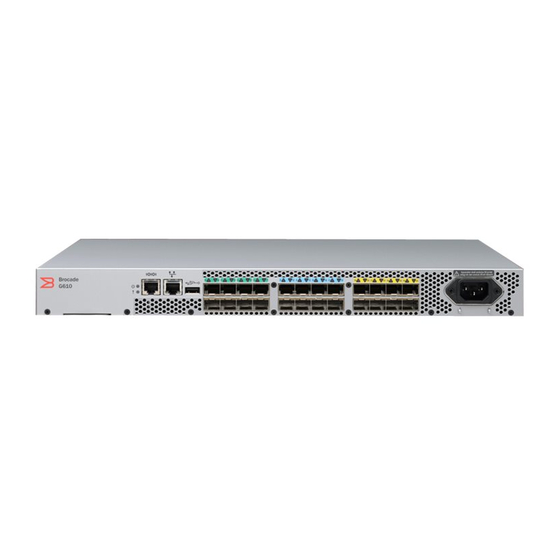
® 53-1004408-11 Installation Guide Brocade G610 Switch Hardware Installation Guide Figure 1: Port-Side View 1. Switch ID Pull-Out Tab 2. System Status LED 3. System Power LED 4. System RS-232 Console Port (RJ-45) 5. Ethernet Port with Two Ethernet Status LEDs 6. - Page 11 ® 53-1004408-11 Installation Guide Brocade G610 Switch Hardware Installation Guide Table 2: Management Options for the Device Management Tool Out-of-Band Support Reference Documents Command-line interface (CLI) Ethernet or serial connection Brocade Fabric OS Administration Guide Up to two admin sessions and four user Brocade Fabric OS Command Reference Manual sessions simultaneously.
-
Page 12: Preparing For Installation
® 53-1004408-11 Installation Guide Brocade G610 Switch Hardware Installation Guide Preparing for Installation Safety Precautions When using this product, observe all danger, caution, and attention notices in this manual. The safety notices are accompanied by symbols that represent the severity of the safety condition. -
Page 13: Power Precautions
® 53-1004408-11 Installation Guide Brocade G610 Switch Hardware Installation Guide NOTE Wear a wrist grounding strap connected to the chassis ground (if the device is plugged in) or to a bench ground. Power Precautions DANGER Make sure that the power source circuits are properly grounded, and then use the power cord supplied with the device to connect it to the power source. -
Page 14: Laser Precautions
All fiber-optic interfaces use Class 1 lasers. DANGER Use only optical transceivers that are qualified by Broadcom and comply with the FDA Class 1 radiation performance requirements defined in 21 CFR Subchapter I, and with IEC 60825 and EN60825. Optical products that do not comply with these standards might emit light that is hazardous to the eyes. - Page 15 ® 53-1004408-11 Installation Guide Brocade G610 Switch Hardware Installation Guide Table 4: Installation Prerequisites Task Task Details or Additional Information Completed Unpack the device. Take an inventory of the hardware components included in your shipment. See Shipping Carton Contents. Gather the necessary components and Review the time and items required information at the beginning of each chapter required tools.
-
Page 16: Shipping Carton Contents
® 53-1004408-11 Installation Guide Brocade G610 Switch Hardware Installation Guide Task Task Details or Additional Information Completed Provide power to the device. Providing Power to the Device. Attach a management station, Establishing a First-Time Serial Connection. After completing this task, log establish a serial connection, and on to the serial port to configure the device. - Page 17 ® 53-1004408-11 Installation Guide Brocade G610 Switch Hardware Installation Guide – A serial cable – One 6-ft. power cord – Power cord retainer clip – China-RoHS Hazardous/Toxic Substance statement – Network Advisor web pointer card. – EZSwitch web pointer card –...
-
Page 18: Mounting The Device
® 53-1004408-11 Installation Guide Brocade G610 Switch Hardware Installation Guide Mounting the Device Mounting Options You can install the device in several ways: • As a stand-alone unit on a flat surface, for example, a table top. No other equipment is required for desktop installation. -
Page 19: Installing The 1U And 2U Mid-Mount Kit For Two-Post Racks (Xbr-000165 And Xbr-R000292)
® 53-1004408-11 Installation Guide Brocade G610 Switch Hardware Installation Guide Installing the 1U and 2U Mid-Mount Kit for Two-Post Racks (XBR-000165 and XBR-R000292) Use the following instructions to install a fixed-port device in a mid-mount configuration in a two-post rack using the 1U and 2U Mid-Mount Kit for Two-Post Racks (XBR-000165 and XBR-R000292). -
Page 20: Attaching The Front Brackets To The Device
® 53-1004408-11 Installation Guide Brocade G610 Switch Hardware Installation Guide Figure 3: Rack Kit Parts 1. Bracket, Front Right and Back Left 2. Bracket, Front Left and Back Right 3. Screw, 8-32 x 5/16-in. Panhead Phillips (12) 4. Screw, 6-32 x 1/4-in. Flathead Phillips (8) 5. - Page 21 53-1004408-11 Installation Guide Brocade G610 Switch Hardware Installation Guide Complete the following steps to attach the front brackets to the device. 1. Position the right front bracket with the flat side against the right side of the device as shown in the following figure.
-
Page 22: Attaching The Device To A Rack
® 53-1004408-11 Installation Guide Brocade G610 Switch Hardware Installation Guide Attaching the Device to a Rack Complete the following steps to install the device in the rack. 1. Position the device in the rack as shown in the following figure, providing temporary support under the device until the rail kit is secured to the rack. - Page 23 53-1004408-11 Installation Guide Brocade G610 Switch Hardware Installation Guide Complete the following steps to attach the rear brackets to the rack. 1. Position the right rear bracket in the right rear of the device as shown in the following figure.
-
Page 24: Attaching The Rear Brackets To The Device
® 53-1004408-11 Installation Guide Brocade G610 Switch Hardware Installation Guide Attaching the Rear Brackets to the Device Complete the following steps to attach the rear brackets to the device. 1. Align the right rear bracket to the right rear of the device and use two 8-32 x 5/16-in. screws to attach the bracket to the device as shown in the following figure. -
Page 25: Parts List
® 53-1004408-11 Installation Guide Brocade G610 Switch Hardware Installation Guide • No. 2 Phillips torque screwdriver • 1/4-in. slotted-blade torque screwdriver NOTE You may need two people to install the device, one to support the device, while the other secures it into the rack. - Page 26 ® 53-1004408-11 Installation Guide Brocade G610 Switch Hardware Installation Guide Figure 8: Rack Kit Parts 1. Bracket, Front Right 2. Bracket, Front Left 3. Bracket, Rear Left 4. Bracket, Rear Right 5. Screw, 8-32 x 5/16-in. Panhead Phillips (12) 6. Screw, 6-32 x 1/4-in. Flathead Phillips (8) 7.
-
Page 27: Attaching The Front Brackets
® 53-1004408-11 Installation Guide Brocade G610 Switch Hardware Installation Guide 8. Retainer Nut, 10-32 (8) NOTE Not all parts may be used with certain installations depending on the device type. NOTE Although this document describes how to install single-height (1U) and double-height (2U) devices, the illustrations show a single-height device as a typical installation. - Page 28 ® 53-1004408-11 Installation Guide Brocade G610 Switch Hardware Installation Guide Figure 9: Attaching the Front Brackets 1. Bracket, Front Right 2. Screw, 8-32 x 5/16-in. Panhead Phillips Broadcom 53-1004408-11...
-
Page 29: Installing The Device In The Rack
® 53-1004408-11 Installation Guide Brocade G610 Switch Hardware Installation Guide Installing the Device in the Rack Complete the following steps to install the device in the rack. 1. Position the device in the rack, as shown in the following figure. Provide temporary support under the device as you secure it to the rack. -
Page 30: Attaching The Rear Brackets To The Front Brackets
® 53-1004408-11 Installation Guide Brocade G610 Switch Hardware Installation Guide Attaching the Rear Brackets to the Front Brackets Complete the following steps to attach the rear brackets to the front brackets. 1. Position the right rear bracket inside the right front bracket, as shown in the following figure. -
Page 31: Attaching The Rear Brackets To The Rack Posts
® 53-1004408-11 Installation Guide Brocade G610 Switch Hardware Installation Guide Attaching the Rear Brackets to the Rack Posts Complete the following steps to attach the rear brackets to the rack posts. 1. Attach the right rear bracket to the right rear rack post using two 10-32 x 5/8-in. screws and two retainer nuts, as shown in the following figure. -
Page 32: Time And Items Required
® 53-1004408-11 Installation Guide Brocade G610 Switch Hardware Installation Guide • Use Electronic Industries Association (EIA) standard racks. Provide space in a 19-inch (48.3 cm) EIA rack, as required for the device type, with a minimum distance of 24 in. (60.96 cm) and a maximum distance of 32 in. (81.28 cm) between the front and back posts. -
Page 33: Attaching The Front Brackets
® 53-1004408-11 Installation Guide Brocade G610 Switch Hardware Installation Guide Figure 13: Rack Kit Parts 1. Brackets, Front (2) 2. Brackets, Rear Short (2) 3. Screws, 8-32 x 5/16-in. Panhead Phillips with Patchlock (10) 4. Screws, 6-32 x 1/4-in. Panhead Phillips with Patchlock (8) 5. - Page 34 There are four pairs of vertically aligned holes in the brackets. Each pair is labeled with a letter as are few single holes along the length of the bracket. Each letter corresponds to a specific device's mounting holes. For the Brocade G610, use the holes that are marked with the letter ‘A.’...
- Page 35 53-1004408-11 Installation Guide Brocade G610 Switch Hardware Installation Guide Figure 14: Enlarged View of the Front Right Bracket Showing Labels 1. Position the right front bracket with the flat side against the right side of the device as shown in the following figure. Be sure that the arrowhead is pointing upward when mounted.
-
Page 36: Installing The Device In The Rack
® 53-1004408-11 Installation Guide Brocade G610 Switch Hardware Installation Guide Installing the Device in the Rack NOTE Two people are required to install the device in a rack. One person must hold the device while the other attaches it to the rack. - Page 37 ® 53-1004408-11 Installation Guide Brocade G610 Switch Hardware Installation Guide Complete the following steps to attach the rear brackets to the front brackets. 1. Position the right rear bracket inside the right front bracket. 2. Attach the brackets using four 6-32 x 1/4-in. screws as shown in the following figure.
-
Page 38: Attaching Rear Brackets To The Rack Posts
® 53-1004408-11 Installation Guide Brocade G610 Switch Hardware Installation Guide Attaching Rear Brackets to the Rack Posts Complete the following steps to attach the rear brackets to the rack posts. 1. Attach the right rear bracket to the right rear rack post using two 10-32 x 5/8-in. screws and two retainer nuts as shown in the following figure. -
Page 39: Initial Setup And Verification
PNY Attache 3.0 4 USB 32GB Flash Drive • PNY Attache 3.0 4 USB 16GB Flash Drive These drives are not orderable from Broadcom but are generically-branded and can be purchased from other suppliers. Providing Power to the Device Perform the following steps to provide power to the device. -
Page 40: Configuring The Ip Address
53-1004408-11 Installation Guide Brocade G610 Switch Hardware Installation Guide 2. Disable any serial communication programs running on the workstation, such as synchronization programs. 3. Open a terminal emulator application, such as PuTTY, XShell, or SecureCRT on a Windows PC, or TERM, TIP, or C- Kermit in a Linux environment, and configure the application as follows: •... -
Page 41: Using Dhcp To Set The Ip Address
® 53-1004408-11 Installation Guide Brocade G610 Switch Hardware Installation Guide Using DHCP to Set the IP Address When using DHCP, the switch obtains its IP address, subnet mask, and default gateway address from the DHCP server. The DHCP client can connect only to a DHCP server that is on the same subnet as the switch. If your DHCP server is not on the same subnet as the switch, use a static IP address. -
Page 42: Setting The Time Zone
® 53-1004408-11 Installation Guide Brocade G610 Switch Hardware Installation Guide device:admin> date Thu Dec 22 14:05:10 UTC 2016 device:admin> date "1222150617" Thu Dec 22 15:06:00 UTC 2017 Setting the Time Zone The default time zone is Coordinated Universal Time (UTC). The time zone must be set only once because the value is stored in nonvolatile memory. -
Page 43: Customizing The Chassis Name And Switch Name
® 53-1004408-11 Installation Guide Brocade G610 Switch Hardware Installation Guide Updating Clock Server configuration...done. Updated with the NTP servers Customizing the Chassis Name and Switch Name Changing the chassis and switch names is important for uniquely distinguishing and identifying the device and for accurate tracking of logs and errors. -
Page 44: Verifying Correct Operation
® 53-1004408-11 Installation Guide Brocade G610 Switch Hardware Installation Guide Perform the following steps to modify the domain ID. a) Disable the switch by entering the switchDisable command. b) Enter the configure command. The command prompts display sequentially; enter a new value or press Enter to accept each default value. -
Page 45: Backing Up The Configuration
® 53-1004408-11 Installation Guide Brocade G610 Switch Hardware Installation Guide Index Port Address Media Speed State Proto ================================================== 460000 Online F-Port 20:05:00:11:0d:a8:01:00 460100 Online F-Port 20:01:00:11:0d:bb:01:00 460200 Online F-Port 20:03:00:11:0d:84:01:00 460300 Online F-Port 20:07:00:11:0d:26:01:00 460400 Online F-Port 10:00:8c:7c:ff:5c:c5:01 460500 Online... -
Page 46: Powering Down The Device
® 53-1004408-11 Installation Guide Brocade G610 Switch Hardware Installation Guide Powering Down the Device Complete the following steps to power down the device. 1. Shut down the Fabric OS software using the sysShutdown command. 2. Unplug the power cable from the power source before servicing the device. -
Page 47: Installing Transceivers And Cables
Matrix and Brocade Transceiver Modules webpage on www.broadcom.com. DANGER Use only optical transceivers that are qualified by Broadcom and comply with the FDA Class 1 radiation performance requirements defined in 21 CFR Subchapter I, and with IEC 60825 and EN60825. Optical products that do not comply with these standards might emit light that is hazardous to the eyes. -
Page 48: Cleaning The Fiber-Optic Connectors
Brocade Transceiver Support Matrix and Brocade Transceiver Modules webpage on www.broadcom.com. If you use an unqualified transceiver, the switchshow command output shows the port in a Mod_Inv state. The issue is also logged in the system error log. - Page 49 ® 53-1004408-11 Installation Guide Brocade G610 Switch Hardware Installation Guide Figure 20: Installing a 32G SFP+ Transceiver into a Port 1. Pull Tab 2. Transceiver Broadcom 53-1004408-11...
-
Page 50: Replacing An Sfp+ Transceiver
® 53-1004408-11 Installation Guide Brocade G610 Switch Hardware Installation Guide Figure 21: Closeup of Installing a 32G SFP+ Transceiver into an Upper Port 1. Pull Tab 2. Transceiver 2. Position a cable so that the key (the ridge on one side of the cable connector) is aligned with the slot in the transceiver. -
Page 51: Verifying The Operation Of New Transceivers
® 53-1004408-11 Installation Guide Brocade G610 Switch Hardware Installation Guide NOTE 16G and 32G SFP+ transceivers have pull tabs instead of bails. Always use the pull tab to insert or remove the SFP+ transceivers, since the SFP might be hot. - Page 52 ® 53-1004408-11 Installation Guide Brocade G610 Switch Hardware Installation Guide • errDump • fabricShow • sfpShow • switchShow Refer to the Brocade Fabric OS Command Reference Manual for output examples and descriptions. Broadcom 53-1004408-11...
-
Page 53: Monitoring The Device
5. Eth Port Link/Speed LED 6. Eth Port Activity LED NOTE There are four built-in fans in Brocade G610. The device continues to run even if two fans fail. However, if the third fan fails, the device will shut down. NOTE The condition of the Status LED is independent of MAPS "Current Switch Policy Status."... -
Page 54: System Status Led
® 53-1004408-11 Installation Guide Brocade G610 Switch Hardware Installation Guide Table 7: System Power LED Patterns during Normal Operation LED Color Status of Hardware Recommended Action No light System is off or there is an internal power Verify that system is powered on, the power supply failure. -
Page 55: Fc Port Status Leds
® 53-1004408-11 Installation Guide Brocade G610 Switch Hardware Installation Guide FC Port Status LEDs See the following table to interpret the FC port status LEDs. Table 10: FC SFP+ Port Status LED Patterns during Normal Operation LED Color Status of Hardware Recommended Action •... -
Page 56: Interpreting Boot Results
® 53-1004408-11 Installation Guide Brocade G610 Switch Hardware Installation Guide Perform the following steps to determine whether the POST completed successfully and whether any errors were detected. 1. Verify that the LEDs on the device indicate that all components are healthy. If one or more LEDs do not display a healthy state: a) Verify that the LEDs are not set to "beacon"... -
Page 57: Brocade G610 Switch Technical Specifications
® 53-1004408-11 Installation Guide Brocade G610 Switch Hardware Installation Guide Brocade G610 Switch Technical Specifications The following tables highlight the features and specifications for the Brocade G610 Switch. System Specifications System Component Description Enclosure 1U, nonport-side intake airflow, port-side power inlet. - Page 58 ® 53-1004408-11 Installation Guide Brocade G610 Switch Hardware Installation Guide LEDs System Component Description System power LED One green system power status LED (upper) on the left side. System status LED One bicolor (green/amber) system status LED (lower) on the left side.
- Page 59 ® 53-1004408-11 Installation Guide Brocade G610 Switch Hardware Installation Guide Data Port Specifications (Fibre Channel) Port Numbers Media Type Description 0 to 23 16G or 32G SFP+ optical ports Switch mode (default): 8-, 16-, and 24-port configurations (8-port increments through Ports on Demand [PoD] licenses); can be an F_Port, an N_Port, or an E_Port.
- Page 60 ® 53-1004408-11 Installation Guide Brocade G610 Switch Hardware Installation Guide Signal Description Not supported Not supported Serial Port Specifications (Protocol) Parameter Value Baud 9600 Data bits Parity None Flow control None (must be disabled at the host) Stop bits Broadcom...
-
Page 61: Regulatory Statements
® 53-1004408-11 Installation Guide Brocade G610 Switch Hardware Installation Guide Regulatory Statements BSMI Statement (Taiwan) Warning: This is Class A product. In a domestic environment, this product may cause radio interference, in which case the user may be required to take adequate measures. -
Page 62: China Ccc Statement
® 53-1004408-11 Installation Guide Brocade G610 Switch Hardware Installation Guide China CCC Statement Broadcom 53-1004408-11... -
Page 63: China Rohs
® 53-1004408-11 Installation Guide Brocade G610 Switch Hardware Installation Guide China ROHS FCC Warning (U.S. Only) This equipment has been tested and complies with the limits for a Class A computing device pursuant to Part 15 of the FCC rules. These limits are designed to provide reasonable protection against harmful interference when the equipment is operated in a commercial environment. -
Page 64: Vcci Statement
® 53-1004408-11 Installation Guide Brocade G610 Switch Hardware Installation Guide VCCI Statement This is a Class A product based on the standard of the Voluntary Control Council for Interference by Information Technology Equipment (VCCI). If this equipment is used in a domestic environment, radio disturbance might arise. When such trouble occurs, the user might be required to take corrective actions. - Page 65 ® 53-1004408-11 Installation Guide Brocade G610 Switch Hardware Installation Guide Regulatory Compliance (Environmental) • 1907/2006 of the European Parliament and of the Council of 18 December 2006 concerning the Registration, Evaluation, Authorisation, and Restriction of Chemicals (EU REACH). • 2006/66/EC – Batteries and accumulators and waste batteries and accumulators (EU battery directive).
-
Page 66: Cautions And Danger Notices
® 53-1004408-11 Installation Guide Brocade G610 Switch Hardware Installation Guide Cautions and Danger Notices Danger Notices A Danger statement indicates conditions or situations that can be potentially lethal or extremely hazardous to you. Safety labels are also attached directly to products to warn of these conditions or situations. - Page 67 ® 53-1004408-11 Installation Guide Brocade G610 Switch Hardware Installation Guide DANGER Make sure that the power source circuits are properly grounded, and then use the power cord supplied with the device to connect it to the power source. GEFAHR Stellen Sie sicher, dass die Stromkreise ordnungsgemäß geerdet sind. Benutzen Sie dann das mit dem Gerät gelieferte Stromkabel, um es an die Srromquelle anzuschließen.
-
Page 68: Cautions
Todas las interfaces de fibra óptica utilizan láser de clase 1. DANGER Use only optical transceivers that are qualified by Broadcom and comply with the FDA Class 1 radiation performance requirements defined in 21 CFR Subchapter I, and with IEC 60825 and EN60825. Optical products that do not comply with these standards might emit light that is hazardous to the eyes. - Page 69 ® 53-1004408-11 Installation Guide Brocade G610 Switch Hardware Installation Guide Un mensaje de precaución le alerta de situaciones que pueden resultar peligrosas para usted o causar daños en el hardware, el firmware, el software o los datos. General Cautions CAUTION Changes or modifications made to this device that are not expressly approved by the party responsible for compliance could void the user's authority to operate the equipment.
- Page 70 ® 53-1004408-11 Installation Guide Brocade G610 Switch Hardware Installation Guide CAUTION Static electricity can damage the chassis and other electronic devices. To avoid damage, keep static-sensitive devices in their static-protective packages until you are ready to install them. VORSICHT Statische Elektrizität kann das System und andere elektronische Geräte beschädigen. Um Schäden zu vermeiden, entnehmen Sie elektrostatisch empfindliche Geräte erst aus deren antistatischer Schutzhülle, wenn...
- Page 71 ® 53-1004408-11 Installation Guide Brocade G610 Switch Hardware Installation Guide a special tool, lock and key, or other means of security, and is controlled by the authority responsible for the location. VORSICHT Alle Geräte mit DC-Netzteil sind nur für die Installation in Bereichen mit beschränktem Zugang gedacht.
- Page 72 ® 53-1004408-11 Installation Guide Brocade G610 Switch Hardware Installation Guide CAUTION The DC return shall be isolated from the chassis ground (DC-I) when connections to the power supply are made. VORSICHT Der Gleichstromrücklauf soll von der Gehäuseerdung isoliert werden (DC-I), wenn Verbindungen zur Stromversorgung hergestellt werden.
-
Page 73: Revision History
® 53-1004408-11 Installation Guide Brocade G610 Switch Hardware Installation Guide Revision History 53-1004408-11; 8 February 2021 • Updated the Supported Hardware and Software section. • Updated the Mounting Options section. • Updated the Installing the 1U and 2U Mid-Mount Kit for Two-Post Racks (XBR-000165 and XBR-R000292) section.