
Related Manuals for Basler DGC-2020


Summary of Contents for Basler DGC-2020
- Page 1 INSTRUCTION MANUAL DIGITAL GENSET CONTROLLER DGC-2020 Publication: 9400200990 Revision: I 07/08...
- Page 3 INTRODUCTION This instruction manual provides information about the operation and installation of the DGC-2020 Digital Genset Controller. To accomplish this, the following information is provided: • General Information and Specifications • Controls and Indicators • Functional Description • Graphical User Interface Operation •...
- Page 4 July 2008 CONFIDENTIAL INFORMATION of Basler Electric, Highland Illinois, USA. It is loaned for confidential use, subject to return on request, and with the mutual understanding that it will not be used in any manner detrimental to the interest of Basler Electric.
- Page 5 REVISION HISTORY The following information provides a historical summary of the changes made to this instruction manual (9400200990), BESTCOMSPlus software, firmware package, and hardware of the DGC-2020, LSM- 2020, and CEM-2020. Manual Revision and Date Change • I, 07/08 Changed Output Contacts 13 through 24 rating from 2 Adc to 1 Adc.
- Page 6 Added Spanish language support. • 1.00.08, 03/07 Minor firmware improvements. • 1.00.07, 01/07 Added Chinese language support. • 1.00.06, 11/06 Initial release DGC-2020 Hardware Version and Date Change • —, 11/06 Initial release LSM-2020 Hardware Version and Date Change •...
-
Page 7: Table Of Contents
SECTION 7 • MAINTENANCE AND TROUBLESHOOTING..............7-1 SECTION 8 • LSM-2020 (LOAD SHARE MODULE) ................8-1 SECTION 9 • CEM-2020 (CONTACT EXPANSION MODULE) ............... 9-1 APPENDIX A • TIME OVERCURRENT CHARACTERISTIC CURVES ........... A-1 APPENDIX B • MODBUS™ COMMUNICATION ..................B-1 9400200990 Rev I DGC-2020 Introduction... - Page 8 This page intentionally left blank. DGC-2020 Introduction 9400200990 Rev I...
- Page 9 Type Tests............................1-10 Environment ............................. 1-10 UL/CSA Approvals ........................... 1-10 NFPA Compliance..........................1-11 CE Compliance ..........................1-11 Physical ............................1-11 Figures Figure 1-1. DGC-2020 Style Chart ......................1-3 Tables Table 1-1. Special-Order DGC-2020 Controllers ..................1-4 9400200990 Rev I DGC-2020 General Information...
- Page 10 This page intentionally left blank. DGC-2020 General Information 9400200990 Rev I...
-
Page 11: Auto-Synchronizer
Overcurrent and phase imbalance protection is available as an option. Each generator protection function has an adjustable pickup and time delay setting. Sixteen inverse time curves enable the DGC-2020 to offer overcurrent protection in a variety of applications. -
Page 12: Contact Inputs And Output Contacts
• Bus voltage unstable due to overfrequency or underfrequency At this time, the DGC-2020 will start the genset and when ready, apply power to the load via the genset. The DGC-2020 implements open transitions to and from the mains. When the mains returns and is considered stable, the DGC-2020 will transfer the load back to the mains. -
Page 13: Lsm-2020 (Load Share Module)
The optional LSM-2020 in conjunction with the DGC-2020 provides load sharing between governors through an analog load share line. The LSM-2020 communicates through an ethernet port and provides access to the DGC-2020 via ethernet. Refer to Section 8, LSM-2020 (Load Share Module), for more information. -
Page 14: Specifications
Table 1-1. Special-Order DGC-2020 Controllers Part Number Style Number Special Features 9400200105 51ANBNSNH001 cURus recognized for use in hazardous locations. 9400200106 11ANBNSNH001 SPECIFICATIONS Operating Power Nominal: 12 or 24 Vdc Range: 6 to 32 Vdc (Withstands cranking ride-through down to 6 Vdc for 500 ms.) -
Page 15: Engine System Inputs
START – NO, COM Programmable Relays (12) Rating: 2 Adc at 30 Vdc—make, break, and carry Terminals† Output 1: 52, 51 (common) Output 2: 53, 51 (common) Output 3: 54, 51 (common) Output 4: 56, 55 (common) 9400200990 Rev I DGC-2020 General Information... - Page 16 The number of programmable output contacts provided is determined by the output contacts character of the DGC-2020 style number. Controllers with output contacts option A have 4 program- mable outputs (Outputs 1, 2, 3, and 4). Controllers with output contacts option B have 12 programmable outputs.
- Page 17 0 to 5,000 h Update Interval: 6 min ±1% or actual indication or ±12 min Accuracy: Display Resolution: 1/10 hour Fuel Level Metering Range: 0 to 100% ±2% (subject to accuracy of sender) Accuracy: Display Resolution: 1.0% 9400200990 Rev I DGC-2020 General Information...
-
Page 18: Generator Protection Functions
0 to 30 s Activation Delay Increment: 0.1 s Logic Timers Range: 0 to 10 s Increment: 0.1 s ±15 ms Accuracy: Communication Interface Specification Compatibility: USB 2.0 Data Transfer Speed: 9600 baud Connector Type: Mini-B jack DGC-2020 General Information 9400200990 Rev I... -
Page 19: Real-Time Clock
Terminals: 48 (low), 49 (high), and 50 (shield) NOTES 1.) If the DGC-2020 is providing one end of the J1939 backbone, a 120 Ω terminating resistor should be installed across terminals 48 (CANL) and 49 (CANH). 2.) If the DGC-2020 is not part of the J1939 backbone, the stub connecting the DGC-2020 to the backbone should not exceed 914 mm (3 ft) in length. -
Page 20: Type Tests
HALT subjects the device to extremes in temperature, shock, and vibration to simulate years of operation, but in a much shorter period span. HALT allows Basler Electric to evaluate all possible design elements that will add to the life of this device. As an example of some of the extreme testing conditions, the DGC-2020 was subjected to temperature tests (tested over a temperature range of -100°C... -
Page 21: Nfpa Compliance
• EN 61000-6-4:2001 - Electromagnetic Compatibility (EMC), Generic Standards, Emission Standard for Industrial Environments • EN 61000-6-2:2001 - Electromagnetic Compatibility (EMC), Generic Standards, Immunity for Industrial Environments Physical Weight: 2 kg (4.4 lb) Dimensions: See Section 6, Installation. 9400200990 Rev I DGC-2020 General Information 1-11... - Page 22 This page intentionally left blank. 1-12 DGC-2020 General Information 9400200990 Rev I...
-
Page 23: Section 2 • Human-Machine Interface
Figure 2-1. Front Panel HMI ........................2-1 Figure 2-2. Metering Screen Branches ..................... 2-4 Figure 2-3. Settings Screen Branches ...................... 2-5 Figure 2-4. DGC-2020 Rear Panel HMI ....................2-12 Tables Table 2-1. Front Panel HMI Descriptions ....................2-2 Table 2-2. General Settings Screen Branches..................2-5 Table 2-3. - Page 24 This page intentionally left blank. DGC-2020 Human-Machine Interface 9400200990 Rev I...
-
Page 25: Section 2 • Human-Machine Interface
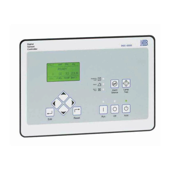
HMI components are located on the front panel (controls and indicators) and the rear panel (terminals and connectors). FRONT PANEL Figure 2-1 illustrates the front panel HMI of the DGC-2020. Table 2-1 lists the call-outs of Figure 2-1 along with a description of each HMI component. Figure 2-1. Front Panel HMI... -
Page 26: Display Operation
Display operation is maintained at -40°C. Not in Auto Indicator. This red LED lights when the DGC-2020 is not operating in Auto mode. Alarm Indicator. This red LED lights continuously during alarm conditions and flashes during pre-alarm conditions. -
Page 27: Summary Screen And Configurable Metering
Sleep Mode Sleep mode serves as a power saving feature. If the DGC-2020 is in Off mode or Auto mode not running and a key is not pressed for more than 15 minutes, the front panel LCD backlight and LCD heater are turned off. -
Page 28: Front Panel Display Structure
Figure 2-2. The SETTINGS screen branches are shown in Figure 2-3. Details of the SETTINGS screen branches are listed in Tables 2-2 through 2-9. Figure 2-2. Metering Screen Branches DGC-2020 Human-Machine Interface 9400200990 Rev I... -
Page 29: Communication
CONFIGURABLE METERING • CONFIGURE DATE/TIME YEAR MONTH HOURS MINUTES SECONDS UTC OFFSET DST ENABLED • VIEW DATE/TIME • VERSION INFO FIRMWARE VERSION BOOT CODE SERIAL NUMBER PART NUMBER MODEL NUMBER LANGUAGE VERSION LANGUAGE PART NUM 9400200990 Rev I DGC-2020 Human-Machine Interface... - Page 30 FUEL LVL TYP SYSTEM UNITS BATTERY VOLT FLYWHL TEETH SPEED SOURCE MAINT RESET NFPA LEVEL HORN 1 PHASE O-RIDE RATED PF POWER UP DELAY • CRANK SETTINGS DISCNCT LMIT PRECRNK DELY PRESTRT CNTCT STYLE # CYCLES DGC-2020 Human-Machine Interface 9400200990 Rev I...
- Page 31 THRESHOLD LOW OIL PRESSURE ENABLE THRESHOLD LOW FUEL LEVEL ENABLE THRESHOLD ENGINE OVERLOAD ENABLE THRESHOLD MAINTENANCE INTERVAL ENABLE THRESHOLD BATTERY OVERVOLTAGE ENABLE THRESHOLD LOW BATTERY VOLTAGE ENABLE THRESHOLD ACTIVATN DLY WEAK BATTERY VOLTAGE ENABLE 9400200990 Rev I DGC-2020 Human-Machine Interface...
- Page 32 The HIGH COOLANT TEMP and LOW OIL PRESSURE alarms have an ARMING DLY setting that disables the alarm for the specified time after engine startup. • SENDER FAIL COOL TEMP SENDR FAIL CONFIG TYPE ACTIVATN DLY DGC-2020 Human-Machine Interface 9400200990 Rev I...
- Page 33 51-1 / 51-2 LOW LINE OVERRIDE • SCALE FACTOR 3 / 1 PHASE SETTINGS • PICKUP • TIME DIAL • CURVE • ALARM CONFIG • 32 REVERSE POWER 3 / 1 PHASE SETTINGS PICKUP 9400200990 Rev I DGC-2020 Human-Machine Interface...
- Page 34 TIME DELAY BUS DEAD THRESHOLD TIME DELAY BUS STABLE OV PICKUP OV DROPOUT UV PICKUP UV DROPOUT OF PICKUP OF DROPOUT UF PICKUP UF DROPOUT TIME DELAY BUS FAILED TIME DELAY • SYNCHRONIZER TYPE 2-10 DGC-2020 Human-Machine Interface 9400200990 Rev I...
- Page 35 Table 2-9. Multigen Management Screen Branches • AVR ANALOG OUTPUT OUTPUT TYPE MIN OUTPUT MAX OUTPUT VOLT RESPONSE • GOV ANALOG OUTPUT OUTPUT TYPE MIN OUTPUT MAX OUTPUT SPD RESPONSE • LOAD SHARE LINE MIN VOLTAGE MAX VOLTAGE 9400200990 Rev I DGC-2020 Human-Machine Interface 2-11...
-
Page 36: Rear Panel
All DGC-2020 terminals and connectors are located on the rear panel. Rear panel terminals and connectors are illustrated in Figure 2-4. (To show the terminals and connectors, Figure 2-4 shows the DGC-2020 with the rear cover removed.) Table 2-10 lists the call-outs of Figure 2-4 along with a description of each connector type. - Page 37 DGC-2020 controllers with an optional, internal, dial-out modem connect to a telephone line through a USOC RJ-11 jack. Connections to the DGC-2020 Start (starter), Run (fuel solenoid), and Pre (glow plug) output contacts are made directly to each relay through quarter-inch, male, quick-connect terminals.
- Page 38 This page intentionally left blank. 2-14 DGC-2020 Human-Machine Interface 9400200990 Rev I...
-
Page 39: Section 3 • Functional Description
SECTION 3 • FUNCTIONAL DESCRIPTION TABLE OF CONTENTS SECTION 3 • FUNCTIONAL DESCRIPTION ................... 3-1 INTRODUCTION............................ 3-1 DGC-2020 FUNCTION BLOCKS......................3-1 Power Supply ............................. 3-1 Microprocessor ........................... 3-1 Generator Voltage Sensing Inputs ..................... 3-2 Bus Voltage Sensing Inputs ....................... 3-2 Current Sensing Inputs........................ - Page 40 This page intentionally left blank. DGC-2020 Functional Description 9400200990 Rev I...
-
Page 41: Section 3 • Functional Description
The internal, switch-mode power supply uses the applied battery voltage to generate operating power for the internal circuitry of the DGC-2020. The power supply accepts a nominal battery voltage of 12 or 24 Vdc and has an operating range of 6 to 32 Vdc. Battery voltage is applied to terminals 2 (–) and 3 (+). -
Page 42: Generator Voltage Sensing Inputs
An open circuit or short circuit across the oil pressure sender terminals will cause the DGC-2020 to indicate a failed sender. Oil pressure senders that are compatible with the DGC-2020 include Datcon model 02505-00, Isspro model R8919, and Stewart-Warner models 411K and 411M. -
Page 43: Speed Signal Inputs
Generator Voltage Sensing Input The generator voltage sensed by the DGC-2020 is used to measure frequency and can be used to measure machine speed. Sensing voltage is applied to terminals 41 (A-phase), 39 (B-phase), 37 (C-phase), and 35 (Neutral). -
Page 44: Front Panel Hmi
• Engine sender unit failure ∗ Can be configured in the DGC-2020 as None, Alarm, or Pre-Alarm. See Section 4, BESTCOMSPlus, Programmable Inputs, Programmable Functions, for more information. The light on the RDP-110 will turn on when the input that is assigned to the programmable function is closed, whether the function is configured as None, Alarm, or Pre-Alarm. - Page 45 The rear-panel, mini-B USB socket enables local communication with a PC running BESTCOMSPlus software. The DGC-2020 is connected to a PC using a standard USB cable. BESTCOMSPlus is a ® Windows based communication software package that is supplied with the DGC-2020. A detailed description of BESTCOMSPlus is provided in Section 4, BESTCOMSPlus Software.
- Page 46 Previously active DTCs are available upon request. Active and previously active DTCs can be cleared on request. Table 3-3 lists the diagnostic information that the DGC-2020 obtains over the CAN interface. DTCs are reported in coded diagnostic information that includes the Suspect Parameter Number (SPN), Failure Mode Identifier (FMI), and Occurrence Count (OC).
- Page 47 METERING, ALARMS-STATUS, MDEC FAULT CODES. Each fault code is displayed with a fault description and the fault number. If the DGC-2020 does not have descriptive information about a fault number that was received, the fault description will display as “NO TEXT AVAILABLE”.
-
Page 48: Output Contacts
When equipped with the optional, internal, dial-out modem, the DGC-2020 can be connected to a standard telephone line through its RJ-11 jack. The modem enables the DGC-2020 to dial up to four pager telephone numbers and annunciate conditions selected by the user. These conditions include any DGC-2020 alarm or pre-alarm, closure of any programmable contact input, and an active cooldown timer. -
Page 49: Determining Breaker Status
BESTCOMSPlus Control screen. Breaker Operation The DGC-2020 will attempt to close a breaker only after verifying that it can be closed. If the breaker cannot be closed, the close request will be ignored. Only one breaker can be closed at a time. -
Page 50: Event Recording
99 occurrences each are retained in memory, a history of nearly 3,000 specific events are retained in the DGC-2020. Detailed occurrence information is retained for the most recent 30 occurrences of each event record, and there are 30 event records; thus the time, date, and engine hours details for up to 900 specific event occurrences are retained in the event log. - Page 51 1 to 40) INPUT_N_P (where N is a number User Configurable Input N (where N is a Pre-Alarm in the range of 1 to 40) number in the range of 1 to 40) 9400200990 Rev I DGC-2020 Functional Description 3-11...
- Page 52 Oil Pressure Sender Fail Alarm OIL PRESS SENDR FAIL_P Oil Pressure Sender Fail Pre-Alarm OVERCRANK_A Overcrank Alarm PROT_SHUTDOWN Protective Shutdown Status SPD_SNDR_FAIL Speed Sender Fail Status SPD_SNDR_FAIL_A Speed Sender Fail Alarm WEAK_BATTERY_P Weak Battery Pre-Alarm 3-12 DGC-2020 Functional Description 9400200990 Rev I...
-
Page 53: Section 4 • Bestcomsplus Software
INSTALLATION............................4-1 Installing BESTCOMSPlus ......................... 4-2 STARTUP AND ACTIVATION ....................... 4-2 Starting BESTCOMSPlus........................4-2 Activating the DGC-2020 Plug-In ....................... 4-3 COMMUNICATION..........................4-4 Connecting the DGC-2020 and PC....................4-4 Configuring Communication ....................... 4-4 Installing the USB Driver if Automatic Installation Fails ..............4-5 Establishing Communication ...................... - Page 54 Figure 4-6. DGC-2020 Connection......................4-5 Figure 4-7. Processing, Please Wait…...................... 4-5 Figure 4-8. Front Panel HMI Settings ......................4-8 Figure 4-9. DGC-2020 Style Chart Selections and Definitions ..............4-8 Figure 4-10. Device Info Values and Settings ................... 4-9 Figure 4-11. Device Security Setup......................4-11 Figure 4-12.
- Page 55 Figure 4-49. Programmable Senders Settings ..................4-53 Figure 4-50. BESTCOMSPlus Settings Compare Setup................. 4-54 Figure 4-51. BESTCOMSPlus Settings Compare ................... 4-55 Figure 4-52. Basler Electric Device Package Uploader ................4-56 Figure 4-53. DGC-2020 Selection ......................4-56 Figure 4-54. Processing, Please Wait… ....................4-56 Figure 4-55.
- Page 56 This page intentionally left blank. DGC-2020 BESTCOMSPlus Software 9400200990 Rev I...
-
Page 57: Section 4 • Bestcomsplus Software
The DGC-2020 plug-in opens inside the BESTCOMSPlus main shell with the same default logic scheme that is shipped with the DGC-2020. This gives the user the option of developing a custom setting file by modifying the default logic scheme or by building a unique scheme from scratch. -
Page 58: Installing Bestcomsplus
When BESTCOMSPlus installation is complete, a Basler Electric folder is added to the Windows programs menu. This folder is accessed by clicking the Windows Start button and then accessing the Basler Electric folder in the Programs menu. The Basler Electric folder contains an icon that, when clicked, starts BESTCOMSPlus. -
Page 59: Activating The Dgc-2020 Plug-In
If a DGC-2020 is not connected, select New from the File pull-down and select DGC-2020. Activating the DGC-2020 Plug-In The DGC-2020 plug-in must be activated before it can be used to set up a DGC-2020 product. If the DGC-2020 plug-in has already been activated, skip to Communication. -
Page 60: Communication
Click on the Activate button when you are ready to enter the activation key you received from Basler Electric. The Device Needs Activated pop-up will appear. Refer to Figure 4-5. Entering an Activation Key Select the device from the Device pull-down menu. Enter your Email Address and Activation Key provided by Basler Electric. -
Page 61: Installing The Usb Driver If Automatic Installation Fails
1. Apply operating power to the DGC-2020 and wait for the boot sequence to complete. 2. Plug the proper end of the USB cable into the PC and the other end into the DGC-2020. 3. The Found New Hardware Wizard dialog box pops up. -
Page 62: Menu Bars
• Check For Updates ........Check for BESTCOMSPlus updates via the internet • Select Language ........... Select BESTCOMSPlus language • Activate Device ..........Activate the product instance (DGC-2020 plug-in) • Set File Password ......... Password protect a settings file • Compare Settings Files......... Compare settings files •... -
Page 63: Lower Menu Bar (Dgc-2020 Plug-In)
Open File This clickable icon is used to open a saved settings file. Connect/Disconnect Opens the DGC-2020 Connection screen allowing the user to connect via USB or a modem. Also used to disconnect from the device. Preview Metering Clicking on this icon will bring up the Print Preview screen where a preview of the Metering printout is shown. -
Page 64: Front Panel Hmi
, will turn the front panel LCD backlight and LCD heater off when the DGC-2020 is in Off mode or Auto mode (not in Run mode) and a key is not pressed for more than 15 minutes. Normal display operation is resumed when any front panel button is pressed or the genset is started remotely via the ATS. - Page 65 , Language Module Version , and Language Module Part Number Site-specific information for the DGC-2020 can be assigned by the user. This label includes a device name Load Share Module Information about an LSM-2020 communicating with BESTCOMSPlus can also be obtained on the Device Info tab of BESTCOMSPlus.
-
Page 66: Device Security Setup
Application Version: When configuring DGC-2020 settings off-line, the application version for the unit to be configured must be selected. Select <1.00.07, <=1.00.07 & >1.01.00, >=1.01.00 & <1.02.00, or >=1.02.00. Application Version: Read-only value obtained when BESTCOMSPlus is communicating with the DGC- 2020. -
Page 67: Clock Setup
All controls on the Control screen available via the Metering Explorer in BESTCOMSPlus Changing Passwords Passwords can be changed only after communication between the PC and DGC-2020 is established. Changes to passwords are made through the Device Security Setup screen. Use the Settings Explorer in BESTCOMSPlus to open the General Settings, Device Security Setup screen. -
Page 68: Communications
DGC-2020 will ignore the analog coolant temperature, oil pressure, and engine speed inputs and rely upon the ECU for these parameters. The DGC-2020 will also stop calculating engine run time and begin using the run time recorded by the ECU. - Page 69 In applications where the ECU is not continuously powered, the DGC-2020 has provisions for applying power to the ECU and pulsing the ECU to update its engine monitoring data. Either the DGC-2020 Fuel Solenoid or Pre-Start relay output can be used to apply power to the ECU .
-
Page 70: Modem Setup (Optional)
Modem Setup (Optional) DGC-2020 controllers with style number xxxxxMxxx are equipped with an internal telephone modem that has dial-in and dial-out capability. The modem gives the DGC-2020 the ability to dial up to four telephone numbers and annunciate user-selected conditions to specified pagers . - Page 71 • Overspeed Alarm • Reserved • Scheduled Maintenance Pre-Alarm • Switch Not in Auto • Transfer Fail Alarm • Virtual Output x Status (x = 1 to 8) • Weak Battery Voltage Pre-Alarm 9400200990 Rev I DGC-2020 BESTCOMSPlus Software 4-15...
-
Page 72: Setup (Optional)
The message string sent by the DGC-2020 can be limited to a length supported by the receiving pagers If a message to be transmitted by the DGC-2020 exceeds the pager message limit, the DGC-2020 will make multiple calls to transmit the complete message. -
Page 73: System Parameters
2020 will automatically switch to the genset frequency as the engine speed source. When the CAN interface is used, the speed signal source settings must be set at MPU or MPU_Gen. This allows the DGC-2020 to receive the engine speed data sent by the ECU via the SAE J1939 protocol. Engine Cooldown After a genset’s load is removed, the DGC-2020 can ensure proper engine and turbocharger cooldown by... - Page 74 The value of the scale factor setting serves as a multiplier for the threshold settings. For example, if a scale factor contact input is received bye the DGC-2020 and the scale factor setting is 2.000, the threshold setting will be doubled (2.000 x PU).
-
Page 75: Crank Settings
Continuous cranking provides a single, extended engine-starting attempt. The DGC-2020 uses the engine speed signal (supplied by a magnetic pickup (MPU) or the generator frequency) and the Crank Disconnect Limit setting to detect engine startup (and determine when engine cranking can be stopped). -
Page 76: Automatic Restart
Crank Disconnect Pressure (psi): Adjustable from 3 to 150 psi in increments of 1 psi. Automatic Restart If the DGC-2020 has shut down due to an alarm condition, the automatic restart, when enabled , will automatically clear alarms. An attempt to restart the engine is made after a predetermined time delay the ATS contact input is closed. -
Page 77: Exercise Timer
RUN time. Contact inputs and outputs can be assigned to the function. Refer to Section 5, BESTlogic+ Programmable Logic, for more information. BESTCOMSPlus exercise timer settings (DGC-2020, System Parameters, Exercise Timer) are illustrated in Figure 4-19. Figure 4-19. Exercise Timer Settings Mode: Monthly, Weekly, or Daily. -
Page 78: Sensing Transformers
The secondary value of the generator CT is dictated by the style number of the controller. A DGC-2020 with a style number of 1xxxxxxxx uses a nominal CT secondary rating of 1 Aac. A DGC-2020 with a style number of 5xxxxxxxx uses a nominal CT secondary rating of 5 Aac. -
Page 79: Programmable Functions
Contacts can be recognized always or while the engine is running only. BESTCOMSPlus settings for the configurable contact inputs (DGC-2020, Programmable Inputs, Configurable Local Inputs) are illustrated in Figure 4-21. Figure 4-21. Configurable Inputs Settings Alarm Configuration: None, Prealarm, or Alarm. -
Page 80: Configurable Remote Inputs
Contacts can be recognized always or only while the engine is running. BESTCOMSPlus settings for the configurable contact inputs (DGC-2020, Programmable Inputs, Configurable Remote Inputs) are illustrated in Figure 4-23. 4-24 DGC-2020 BESTCOMSPlus Software... -
Page 81: Programmable Outputs
Contact Recognition: Always or While Engine Running Only. PROGRAMMABLE OUTPUTS DGC-2020 output contacts include four user-programmable output contacts if the style number is xxAxxxxxx. If the style number is xxBxxxxxx, twelve output contacts are provided. An additional 24 output contacts are provided with an optional CEM-2020 (Contact Expansion Module). -
Page 82: Configurable Remote Outputs
To make identifying the element easier, each of the elements can be given a user-assigned name Elements can be recognized always or while the engine is running only. BESTCOMSPlus settings for the elements (DGC-2020, Programmable Outputs, Configurable Elements) are illustrated in Figure 4-25. Figure 4-25. Configurable Elements Settings Alarm Configuration: None, Prealarm, or Alarm. -
Page 83: Alarm Configuration
ALARM CONFIGURATION DGC-2020 alarms and pre-alarms can be used to annunciate system, genset, and engine sender conditions. The description of the alarm configuration settings is organized as follows: • Pre-Alarms • Alarms • Sender Failure Pre-Alarms A pre-alarm is annunciated when a condition programmed to trigger a pre-alarm is met. When a pre-alarm... - Page 84 If CAN and DTC support are both enabled, an “active DTC” pre-alarm may be enabled to announce the presence of a condition that is causing a DTC to be sent from the ECU to the DGC-2020. AVR Bias Output Limit AVR bias output limit settings consist of an enable/disable setting and an activation delay setting.
- Page 85 LSM-2020 communication failure pre-alarm settings consist of a single enable/disable setting. If enabled, an LSM-2020 communication failure pre-alarm is annunciated when communication between an optional LSM-2020 and DGC-2020 is lost. ID Missing ID missing pre-alarm settings consist of a single enable/disable setting .
- Page 86 Engine kW Overload: Enable or Disable, threshold is adjustable from 95 to 140% of Genset kW Rating in 1% increments. Low Fuel Level: Enable or Disable, threshold is adjustable from 10 to 100% in 1 % increments. 4-30 DGC-2020 BESTCOMSPlus Software 9400200990 Rev I...
-
Page 87: Alarms
LCD. An alarm condition stops the engine by opening the Fuel output contact. Alarms are reset when the DGC-2020 is set to Off mode. Each DGC-2020 alarm is described in the following paragraphs. Alarms may be enabled and adjusted in BESTCOMSPlus or through the front panel HMI. -
Page 88: Sender Fail
Low Coolant Level: Enable or Disable, threshold is adjustable from 1 to 99% in 1% increments. Sender Fail The DGC-2020 can be configured to annunciate a pre-alarm or alarm when a loss of signal is detected at the coolant temperature... -
Page 89: Generator Protection
Speed Sender Fail: Time delay adjustable from 0 to 300 s in 1 s increments. GENERATOR PROTECTION Two tiers of generator protection are offered. DGC-2020 controllers with style number xxxxxxSxx offer standard protection consisting of undervoltage (27), overvoltage (59), overfrequency (81O), underfrequency (81U), reverse power (32), and loss of excitation (40) elements. - Page 90 The value of the scale factor setting serves as a multiplier for the pickup settings. For example, if a scale factor contact input is received by the DGC-2020 and the scale factor setting is 2.000, the pickup setting will be doubled (2.000 × PU).
- Page 91 The pickup setting entered is based on the VT secondary side (DGC-2020). A phase imbalance condition is annunciated when the difference between any of the three phases of generator voltage increases above the 47 pickup setting for the duration of the 47 activation delay setting .
-
Page 92: Frequency Protection (81O/U)
Two sets of reverse power settings are provided: one for three-phase generator connections and one for single-phase generator connections. The pickup setting entered is based on the CT secondary side (DGC-2020). When a single-phase override contact input is received by the DGC-2020, the reverse 4-36... -
Page 93: Loss Of Excitation Protection (40Q)
The pickup setting entered is based on the CT secondary side (DGC-2020). When a single-phase override contact input is received by the DGC-2020, the loss of excitation protection settings automatically switch from the three-phase settings to the single-phase loss of excitation protection settings. -
Page 94: Overcurrent Protection (51-1, 51-2)
(warning) or alarm (shutdown). A loss of excitation annunciation can also be user- configured to close a programmable output. The calculation used in the DGC-2020 for the approximate tripping region is given by: Tripping Region = 40Q Pickup + (1/8) ∗ ((Actual Watts ∗ 100)/Rated var) where the units of the Tripping Region and the 40Q Pickup setting are percent of rated var. - Page 95 The value of the scale factor setting serves as a multiplier for the pickup settings. For example, if a scale factor contact input is received by the DGC-2020 and the scale factor setting is 2.000, the pickup setting will be doubled (2.000 × PU).
-
Page 96: Breaker Management
. Separate settings for each breaker’s open and close pulse widths are provided. During synchronization of the generator with the bus (Anticipatory mode only), the DGC-2020 uses the breaker closing time to calculate the optimum time to close the breaker. 4-40... - Page 97 When a close command is issued, the DGC-2020 monitors the breaker status and annunciates a breaker failure if the breaker does not close within the time defined by the breaker-close wait-time delay Typically, this parameter is set to be longer than twice the breaker closing time.
- Page 98 Breaker Close Wait Time: Adjustable from 0.1 to 600 s in 0.1 s increments. Dead Bus Close Enable: Enable or Disable. Bus Condition Detection DGC-2020 detection of dead bus voltages (for dead bus breaker closure) is controlled by a Dead Bus Threshold setting and a Dead Bus Activation Delay setting .
-
Page 99: Automatic Synchronizer (Optional)
If this is the case, the DGC-2020 will drive the generator frequency higher than the bus frequency before closing the breaker. The breaker closing angle setting defines the maximum allowable phase angle difference between the generator and the bus. -
Page 100: Bias Control Settings
LSM-2020. The DGC-2020 adjusts the generator voltage and frequency by issuing voltage correction signals to the generator AVR (automatic voltage regulator). Correction signals are issued in the form of DGC-2020 output contact closures. -
Page 101: Governor Bias Control Settings
LSM-2020. The DGC-2020 adjusts the generator voltage and frequency by issuing speed correction signals to the generator governor. Correction signals are issued in the form of DGC-2020 output contact closures. - Page 102 BESTlogic+ must be driven by logic or a contact input. If parallel to utility operation is undertaken and the Parallel to Mains logic element is not implemented, the DGC-2020 will remain in kW load share and will either move toward operation at 100% of capacity or 0 capacity resulting in damage to the machine or system.
-
Page 103: Pid Controller
4. Introduce transients to the system being tuned and observe “ringing” in response to the transients. 5. Slowly increase Kd until the ringing is adequately dampened. 6. Slowly increase Ki until the steady state error in the system being tuned is eliminated. 9400200990 Rev I DGC-2020 BESTCOMSPlus Software 4-47... -
Page 104: Multigen Management
MULTIGEN MANAGEMENT This group of settings is used when an optional LSM-2020 (Load Share Module) is connected to the DGC-2020. Multigen management settings consist of settings for AVR output, governor output, load share output, demand start/stop, generator sequencing, and network configuration. -
Page 105: Load Share Output
Settings are provided for maximum voltage and minimum voltage BESTCOMSPlus load share output settings (DGC-2020, Multigen Management, Load Share Output are illustrated in Figure 4-45. Figure 4-45. Load Share Output Max Voltage: Adjustable from -10 to 10 V in 0.1 V increments. -
Page 106: Generator Sequencing
If a unit fails to sequence on, the next generator in the sequence will be requested. The generator that previously failed will be requested again in the next sequence cycle. BESTCOMSPlus generator sequencing settings (DGC-2020, Multigen Management) are illustrated in Figure 4-47. -
Page 107: Network Configuration
HMI and BESTCOMSPlus metering screen. If an expected sequence ID is detected on two or more units and the ID Repeat pre-alarm is enabled, an ID Repeat pre-alarm appears on the front panel HMI and the BESTCOMSPlus metering screen. 9400200990 Rev I DGC-2020 BESTCOMSPlus Software 4-51... -
Page 108: Programmable Senders
Expected Seq Id: Adjustable from 0 to 255. PROGRAMMABLE SENDERS The sender inputs of the DGC-2020 can be customized to obtain maximum accuracy from the coolant temperature, oil pressure, and fuel level senders. The characteristic curve of each sender input can be configured with up to 11 points . -
Page 109: Bestlogic+ Programmable Logic
BESTlogic+ settings, refer to Section 5, BESTlogic+ Programmable Logic. A settings file conversion is required when DGC-2020 firmware has been changed so that the settings file is compatible with the firmware. For information on converting settings files, see Converting Settings Files, later in this section. - Page 110 Uploading a Settings File To upload a settings file to the DGC-2020, you must first open the file through BESTCOMSPlus or create the file using BESTCOMSPlus. Then pull down the Communication menu and select Upload Settings. You are prompted to enter the password. If the password is correct, the upload begins and the progress bar is shown.
-
Page 111: Uploading Device Packages (Firmware/Language Module)
1. Place the DGC-2020 in Off mode. This can be accomplished by clicking the Off button on the Control screen inside the Metering Explorer or by pressing the Off button on the DGC-2020 front panel. - Page 112 5. Click on the Upload button and the Proceed with Device Upload screen will appear. Select Yes or 6. After selecting Yes, the DGC-2020 Selection screen will appear. Select the communication port to begin upload. Firmware updating is only possible locally through the USB port. Refer to Figure 4-53.
-
Page 113: Metering Explorer
8. After file(s) have been uploaded, click the Close button on the Basler Electric Device Package Uploader screen. METERING EXPLORER The Metering Explorer is a convenient tool within BESTCOMSPlus used to navigate through the following metering screens of the DGC-2020 plug-in. - Page 114 This floating screen can later be closed by clicking on the in the upper right corner. It may also be dragged to one of the arrow boxes used for docking. 4-58 DGC-2020 BESTCOMSPlus Software 9400200990 Rev I...
-
Page 115: Engine
This screen provides metering of generator voltages and currents. Refer to Figure 4-57. Figure 4-57. Metering, Generator Power This screen provides metering of generator power and power factor. Refer to Figure 4-58. Figure 4-58. Metering, Power 9400200990 Rev I DGC-2020 BESTCOMSPlus Software 4-59... -
Page 116: Run Statistics
Figure 4-59. The maintenance interval can be reset through this screen. Figure 4-59. Metering, Run Statistics Status This screen indicates status of breakers, modes, and switches. A green LED indicates that the status is TRUE. Refer to Figure 4-60. Figure 4-60. Metering, Status 4-60 DGC-2020 BESTCOMSPlus Software 9400200990 Rev I... -
Page 117: Inputs
A red LED indicates that the status is TRUE. Refer to Figure 4-62. Figure 4-62. Metering, Inputs, Configurable Remote Inputs 9400200990 Rev I DGC-2020 BESTCOMSPlus Software 4-61... -
Page 118: Outputs
This screen indicates the status of configurable elements. It also indicates alarms and pre-alarms of configurable elements. A red LED indicates that the status is TRUE. Refer to Figure 4-64. Figure 4-64. Metering, Outputs, Configurable Elements 4-62 DGC-2020 BESTCOMSPlus Software 9400200990 Rev I... - Page 119 When an optional CEM-2020 (Contact Expansion Module) is connected, the status of the configurable remote outputs are shown on this screen. A red LED indicates that the status is TRUE. Refer to Figure 4-65. Figure 4-65. Metering, Outputs, Configurable Remote Outputs 9400200990 Rev I DGC-2020 BESTCOMSPlus Software 4-63...
-
Page 120: Alarms
This screen indicates the status of Alarms, Pre-Alarms, Sender Fail, and Generator Protection. A green LED indicates that the status is TRUE. Alarms and pre-alarms are reset when the DGC-2020 is set to the Off mode. The Sync Fail at Gen Breaker, Gen Breaker Fail to Open, Gen Breaker Fail to Close, Sync Fail at Mains Breaker, Mains Breaker Fail to Open, and Mains Breaker Fail to Close pre-alarms can be reset by pressing the Reset key on the front panel HMI. - Page 121 Options->Copy Selection feature. The Download button refreshes the event log list by performing a fresh download of the list from the DGC-2020. The Clear button gives the user the option of clearing selected or all event logs. Refer to Figure 4-67.
-
Page 122: J1939 Ecu
Figure 4-68. Metering, Event Log, Sorted by Event ID J1939 ECU The ECU reports operating information to the DGC-2020 through the CAN interface when the ECU is configured for Volvo Penta. Operating parameters and diagnostic information, if supported by the ECU, are decoded and displayed on these screens. - Page 123 Figure 4-70. Metering, Engine Configuration Active DTC and Previously Active DTC This screen is used for viewing, downloading, and clearing DTC (Diagnostic Trouble Codes). Refer to Figure 4-71. Figure 4-71. Metering, Download DTC 9400200990 Rev I DGC-2020 BESTCOMSPlus Software 4-67...
-
Page 124: Mtu Mdec
MTU MDEC The MTU MDEC reports operating information to the DGC-2020 through the CAN interface when the ECU is configured for MTU MDEC. Operating parameters and diagnostic information, if supported by the MTU MDEC, are decoded and displayed on these screens. -
Page 125: Summary
Summary This screen displays a metering summary. Refer to Figure 4-74. Figure 4-74. Metering, Summary 9400200990 Rev I DGC-2020 BESTCOMSPlus Software 4-69... -
Page 126: Control
Open or Close buttons. A red LED indicates that a switch is closed. When running BESTCOMSPlus in Live mode, these buttons will interact with the DGC-2020 in real time. Figure 4-75. Metering, Control Real Time Clock Settings for Date and Time are made here. -
Page 127: Generator Network Status
(http://www.basler.com). An outline form can be completed to obtain a password for downloading the software from the Basler Electric web site. BESTCOMSPlus also has a built in tool that will check for program updates if you are connected to the World Wide Web. The Check for Updates tool is located in the Tools drop-down menu. - Page 128 This page intentionally left blank. 4-72 DGC-2020 BESTCOMSPlus Software 9400200990 Rev I...
-
Page 129: Section 5 • Bestlogic+ Programmable Logic
The Active Logic Scheme......................... 5-11 Copying and Renaming Preprogrammed Logic Schemes............... 5-12 Sending and Retrieving Logic Schemes ..................5-12 Retrieving a Logic Scheme from the DGC-2020 ................5-12 Sending a Logic Scheme to the DGC-2020 ................. 5-12 PROGRAMMING BESTlogic+ ......................5-12 I/O.............................. - Page 130 Tables Table 5-1. I/O Group, Names and Descriptions ..................5-2 Table 5-2. Components Group, Names and Descriptions................. 5-7 Table 5-3. Elements Group, Names and Descriptions ................5-9 Table 5-4. Status LEDs ........................... 5-13 DGC-2020 BESTlogic+ Programmable Logic 9400200990 Rev I...
-
Page 131: Section 5 • Bestlogic+ Programmable Logic
DGC-2020 is called a logic scheme. One default active logic scheme is pre-loaded into the DGC-2020. This scheme is configured for a typical protection and control application and virtually eliminates the need for "start-from-scratch" programming. -
Page 132: Bestlogic+ Composition
TRUE. ATS Input Status Input TRUE when the Audible Horn is active. Audible Horn Status Input TRUE when the DGC-2020 is in Auto Mode. Auto Mode Status Input TRUE when the Automatic Restart function is active. Auto Restart Status Input TRUE when the Battery Charger Fail input is TRUE. - Page 133 Module Governor Output Limit Status Input TRUE when the Low Line Override input is TRUE. Low Line Override Status Input TRUE when the DGC-2020 is in Off Mode. Off Mode 9400200990 Rev I DGC-2020 BESTlogic+ Programmable Logic...
- Page 134 Single Phase TRUE when the Single Phase Override input is TRUE. Connection Override Status Input TRUE when the DGC-2020 is not in Auto Mode. Switch not in Auto Output Objects Physical Outputs Physical Outputs 1 through 7 (style xxAxxxxx) or 1 through 15 (style xxBxxxxx).
- Page 135 Contact Expansion TRUE when communication from the CEM-2020 to the Module Comm Fail DGC-2020 has been lost. Coolant Temp TRUE when the Coolant Temp Sender Fail is configured Sender Fail as a Pre-Alarm and the activation delay has expired.
- Page 136 Fail connection. Load Share TRUE when communication from the LSM-2020 to the Module Comm Fail DGC-2020 has been lost. Low Battery TRUE when the Low Battery Voltage Pre-Alarm settings Voltage have been exceeded. TRUE when the Low Coolant Level function is...
-
Page 137: Components
This group contains Logic Gates, Pickup and Dropout Timers, Latches, and Comment Blocks. Table 5-2 lists the names and descriptions of the objects in the Components group. Table 5-2. Components Group, Names and Descriptions Name Description Symbol Logic Gates Input Output Input Output NAND 9400200990 Rev I DGC-2020 BESTlogic+ Programmable Logic... - Page 138 Pickup and Dropout Timers Drop Out Timer Used to set a delay in the logic. Pickup Up Timer Used to set a delay in the logic. Latches Reset Priority Latch Resets latch. Set Priority Latch Sets latch. DGC-2020 BESTlogic+ Programmable 9400200990 Rev I...
-
Page 139: Elements
TRUE when the 51-2 overcurrent is in a TRIP condition. Connect to another logic block input. (Optional) TRUE when the 59-1 overvoltage is in a TRIP condition. Connect to 59-1TRIP another logic block input. 9400200990 Rev I DGC-2020 BESTlogic+ Programmable Logic... - Page 140 81TRIP another logic block input. Other Element Objects When this input is TRUE, and the DGC-2020 is in OFF mode, the AUTOMODE DGC-2020 will switch to AUTO mode. This is a pulsed input. It does not need to be held after the desired mode switch has occurred.
-
Page 141: Logic Schemes
The Active Logic Scheme Digital Genset Controllers must have an active logic scheme in order to function. All Basler Electric DGC- 2020’s are delivered with a default, active logic scheme pre-loaded in memory. If the function block configuration and output logic of the default logic scheme meets the requirements of your application, then only the operating settings (power system parameters and threshold settings) need to be adjusted before placing the DGC-2020 in service. -
Page 142: Copying And Renaming Preprogrammed Logic Schemes
Sending and Retrieving Logic Schemes Retrieving a Logic Scheme from the DGC-2020 To retrieve settings from the DGC-2020, the DGC-2020 must be connected to a computer through a communications port. Once the necessary connections are made, settings can be downloaded from the DGC-2020 by selecting Download Settings on the Communication pull-down menu. -
Page 143: I/O
Output objects can be logically connected to any logic block output. Alarms There is a variety of alarms available in the DGC-2020. Use the drag and drop method to logically connect an alarm to a logic input. More information on alarms is available in Section 3, Functional Description. -
Page 144: Logic Comment Block
TRIP output to another logic block input. Control Elements AUTOMODE is used to switch the DGC-2020 to AUTO mode. AVR is used to raise and lower the AVR setpoint. GENBRK is used to control the generator breaker. Connect the inputs and outputs of the GENBRK logic block to inputs and outputs of other logic blocks. -
Page 145: Logic Alarm Elements
If used for alarm or pre-alarm, the user's text is what will appear in the alarm or pre-alarm annunciation and in the DGC-2020 event log. In addition, the configurable element status can be used to generate modem dial outs which display the user's text on modem equipped DGC-2020's. -
Page 146: Printing A Bestlogic+ File
Output 5 will become TRUE when the 27TRIP is TRUE. Output 7 will become TRUE when the Cool Temp Sender Fail is TRUE. Output 1 will become TRUE when the DGC-2020 is in RUN mode (RUN Mode TRUE). Refer to Figure 5-7. 5-16... - Page 147 Figure 5-7. Example 3 - Multiple Logic Connections 9400200990 Rev I DGC-2020 BESTlogic+ Programmable Logic 5-17...
- Page 148 This page intentionally left blank. 5-18 DGC-2020 BESTlogic+ Programmable 9400200990 Rev I...
-
Page 149: Section 6 • Installation
Figure 6-9. Single-Phase A-B Connections for Volvo Penta EDC III Applications........6-15 Figure 6-10. Single-Phase A-C Connections for Volvo Penta EDC III Applications ....... 6-16 Figure 6-11. DGC-2020, LSM-2020, CEM-2020 CANBus Connections ..........6-17 Tables Table 6-1. Operating Power Terminals ..................... 6-3 Table 6-2. - Page 150 This page intentionally left blank. DGC-2020 Installation 9400200990 Rev I...
- Page 151 Inspect for damage, and if there is evidence of such, immediately file a claim with the carrier and notify the Basler Electric regional sales office, your sales representative, or a sales representative at Basler Electric, Highland, Illinois USA.
- Page 152 Figure 6-2. Overall Dimensions DGC-2020 Installation 9400200990 Rev I...
- Page 153 The DGC-2020 has sensing inputs for A-phase, B-phase, and C-phase generator current. Depending on the style number, a DGC-2020 will have a nominal sensing current rating of 1 Aac or 5 Aac. A style number of 1xxxxxxxx indicates 1 Aac nominal current sensing and a style number of 5xxxxxxxx indicates 5 Aac nominal current sensing.
- Page 154 The DGC-2020 accepts either line-to-line or line-to-neutral generator sensing voltage over the range of 12 to 576 volts, rms line-to-line. Depending on the style number, a DGC-2020 will have a nominal generator frequency rating of 50/60 hertz or 400 hertz. A style number of x1xxxxxxxx indicates 50/60 hertz generator voltage and a style number of x2xxxxxxxx indicates 400-hertz generator voltage.
- Page 155 27 (INPUT 4) Programmable contact input 4 28 (INPUT 3) Programmable contact input 3 29 (INPUT 2) Programmable contact input 2 30 (INPUT 1) Programmable contact input 1 46 (ESTOP) Emergency stop contact input 47 (ESTOP) 9400200990 Rev I DGC-2020 Installation...
-
Page 156: Output Contacts
A mini-B USB socket enables local communication with a PC running BESTCOMSPlus software. The DGC-2020 is connected to a PC using a standard USB cable equipped with a type A plug on one end (PC termination) and a mini-B plug on the other end (DGC-2020 termination). - Page 157 50 (SHIELD) CAN drain connection NOTES 1.) If the DGC-2020 is providing one end of the J1939 backbone, a 120 Ω terminating resistor should be installed across terminals 48 (CANL) and 49 (CANH). 2.) If the DGC-2020 is not part of the J1939 backbone, the stub connecting the DGC-2020 to the backbone should not exceed 914 mm (3 ft) in length.
- Page 158 3-Phase Wye Connections for Typical Applications Figure 6-3. 3-Phase Wye Connections for Typical Applications DGC-2020 Installation 9400200990 Rev I...
- Page 159 3-Phase Delta Connections for Typical Applications Figure 6-4. 3-Phase Delta Connections for Typical Applications 9400200990 Rev I DGC-2020 Installation...
- Page 160 Single-Phase A-B Connections for Typical Applications Figure 6-5. Single-Phase A-B Connections for Typical Applications 6-10 DGC-2020 Installation 9400200990 Rev I...
- Page 161 Single-Phase A-C Connections for Typical Applications Figure 6-6. Single-Phase A-C Connections for Typical Applications 9400200990 Rev I DGC-2020 Installation 6-11...
- Page 162 Wake-up of the EDC III is initiated by using the DGC-2020 RUN output contacts to apply battery power to the EDC. To stop the engine, the DGC-2020 sends a sleep command through the J1939 interface to the EDC III and opens the RUN output contacts. This causes the EDC to stop the engine and enter the sleep mode.
- Page 163 3-Phase Wye Connections for Volvo Penta EDC III Applications Figure 6-7. 3-Phase Wye Connections for Volvo Penta EDC III Applications 9400200990 Rev I DGC-2020 Installation 6-13...
- Page 164 3-Phase Delta Connections for Volvo Penta EDC III Applications Figure 6-8. 3-Phase Delta Connections for Volvo Penta EDC III Applications 6-14 DGC-2020 Installation 9400200990 Rev I...
- Page 165 Single-Phase A-B Connections for Volvo Penta EDC III Applications Figure 6-9. Single-Phase A-B Connections for Volvo Penta EDC III Applications 9400200990 Rev I DGC-2020 Installation 6-15...
- Page 166 Single-Phase A-C Connections for Volvo Penta EDC III Applications Figure 6-10. Single-Phase A-C Connections for Volvo Penta EDC III Applications 6-16 DGC-2020 Installation 9400200990 Rev I...
- Page 167 INSTALLATION IN A SALT FOG ENVIRONMENT If the DGC-2020 will be installed in a salt-fog environment, it is recommended that the backup battery for the real-time clock be removed. Salt fog is known to be conductive and may short-circuit the battery.
- Page 168 This page intentionally left blank. 6-18 DGC-2020 Installation 9400200990 Rev I...
-
Page 169: Section 7 • Maintenance And Troubleshooting
Incorrect Measurement or Display of Generator Current..............7-2 Incorrect Display of Engine RPM ....................... 7-2 Programmable Inputs Do Not Operate as Expected................7-2 Programmable Outputs Do Not Operate as Expected ............... 7-2 Communication Port Does Not Operate Properly ................7-2 9400200990 Rev I DGC-2020 Maintenance and Troubleshooting... - Page 170 This page intentionally left blank. DGC-2020 Maintenance and Troubleshooting 9400200990 Rev I...
- Page 171 TROUBLESHOOTING If you do not get the results that you expect from the DGC-2020, first check the programmable settings for the appropriate function. Use the following troubleshooting procedures when difficulties are encountered in the operation of your genset control system.
- Page 172 Step 1. Verify that all wiring is properly connected. Refer to Figures 6-3 through 6-10. Step 2. Ensure that the proper voltage is present at the DGC-2020 voltage sensing inputs (41, 39, 37, and 35). Step 3. Verify that the voltage transformer ratio and sensing configuration is correct.
-
Page 173: Section 8 • Lsm-2020 (Load Share Module)
Figure 8-3. LSM-2020 Overall Dimensions ....................8-6 Figure 8-4. CANBus Interface with LSM-2020 providing One End of the Backbone ........ 8-8 Figure 8-5. CANBus Interface with DGC-2020 providing One End of the Backbone ....... 8-9 Figure 8-6. Typical LSM-2020 Connections ....................8-9 Figure 8-7. - Page 174 This page intentionally left blank. DGC-2020 LSM-2020 (Load Share Module) 9400200990 Rev I...
-
Page 175: Section 8 • Lsm-2020 (Load Share Module)
SECTION 8 • LSM-2020 (LOAD SHARE MODULE) GENERAL INFORMATION The LSM-2020 is a remote auxiliary device that interfaces to the DGC-2020 and provides analog outputs to the power system in the form of analog bias signals to the voltage regulator and speed governor. When the breaker is closed and Load Sharing is enabled, the LSM-2020 will share real power load proportionally with the other generators on the Analog Load Share Line. -
Page 176: Type Tests
HALT subjects the device to extremes in temperature, shock, and vibration to simulate years of operation, but in a much shorter period span. HALT allows Basler Electric to evaluate all possible design elements that will add to the life of this device. As an example of some of the extreme testing conditions, the LSM-2020 was subjected to temperature tests (tested over a temperature range of -80°C... -
Page 177: Functional Description
Firmware updates to the LSM-2020 are made through the ethernet port. Firmware updates to the DGC-2020 are only available through the USB port of the DGC-2020. Refer to Section 4, BESTCOMSPlus, for information on updating firmware in the DGC-2020. -
Page 178: Bestcomsplus Software
The LSM-2020 plugin is used to set device security and view device information such as firmware version and serial number. LSM-2020 operational settings are found in the DGC-2020 plugin for BESTCOMSPlus. Refer to Section 4, BESTCOMSPlus Software, for a detailed description of each setting. -
Page 179: Installation
Inspect for damage, and if there is evidence of such, immediately file a claim with the carrier and notify the Basler Electric regional sales office, your sales representative, or a sales representative at Basler Electric, Highland, Illinois USA. -
Page 180: Connections
The RJ-45 socket mates with a standard ethernet cable and provides local communication between the LSM-2020 and a PC running BESTCOMSPlus software. This allows for setting of the LSM-2020 and for the DGC-2020 that the module is connected to. LSM-2020 connections are made with an 18-position connector with screw-down compression terminals. - Page 181 These inputs do not have functionality at this time. They are for future enhancement. Analog input terminals are listed in Table 8-3. Table 8-3. Analog Input Terminals Terminal Description P2-9 (V+) Future enhancement. P2-8 (IN–) Future enhancement. P2-7 (I+) Future enhancement. 9400200990 Rev I DGC-2020 LSM-2020 (Load Share Module)
- Page 182 These terminals provide communication using the SAE J1939 protocol and provide high-speed communication between the LSM-2020 and the DGC-2020. Connections between the LSM-2020 and DGC-2020 should be made with twisted-pair, shielded cable. CAN interface terminals are listed in Table 8-4. Refer to Figure 8-4 and Figure 8-5.
-
Page 183: Connections For Typical Applications
Other CEM-2020 Devices (Optional) Figure 8-5. CANBus Interface with DGC-2020 providing One End of the Backbone Ethernet Port The LSM-2020 has Ethernet capability. The LSM-2020 connects to a PC through a RJ-45 jack (J3). Connections for Typical Applications Figure 8-6 illustrates typical LSM-2020 connections. -
Page 184: Connections Using Avr', Gov', And Ls
Preventive maintenance consists of periodically checking that the connections between the LSM-2020 and the system are clean and tight. LSM-2020’s are manufactured using state-of-the-art surface-mount technology. As such, Basler Electric recommends that no repair procedures be attempted by anyone other than Basler Electric personnel. -
Page 185: Section 9 • Cem-2020 (Contact Expansion Module)
Figure 9-2. Input Contact and Output Contact Terminals................9-5 Figure 9-3. CANBus Interface with CEM-2020 providing One End of the Backbone ....... 9-6 Figure 9-4. CANBus Interface with DGC-2020 providing One End of the Backbone ....... 9-6 Tables Table 9-1. Operating Power Terminals ..................... 9-4 Table 9-2. - Page 186 This page intentionally left blank. DGC-2020 CEM-2020 (Contact Expansion Module) 9400200990 Rev I...
-
Page 187: Section 9 • Cem-2020 (Contact Expansion Module)
The CEM-2020 contains 10 programmable inputs that accept normally open and normally closed, dry contacts. Time from a CEM-2020 input going high to: Shutdown the generator via an alarm: 245 ms max Close a relay on board the DGC-2020: 245 ms max Output Contacts Ratings Outputs 13 through 24:... -
Page 188: Environment
DGC-2020. Output Contacts The CEM-2020 provides 24 programmable output contacts with the same functionality as the output contacts on the DGC-2020. Outputs 13 through 24 can carry 1 A. Outputs 25 through 36 can carry 4 A. Communications CANBus A Control Area Network (CAN) is a standard interface that enables communication between the CEM- 2020 and the DGC-2020. -
Page 189: Bestcomsplus Software
Inspect for damage, and if there is evidence of such, immediately file a claim with the carrier and notify the Basler Electric regional sales office, your sales representative, or a sales representative at Basler Electric, Highland, Illinois USA. -
Page 190: Connections
The Contact Expansion Module has 10 contact inputs. Contact input terminals are shown in Figure 9-2. Output Contacts The Contact Expansion Module has 24 output contacts. Output contact terminals are shown in Figure 9-2. DGC-2020 CEM-2020 (Contact Expansion Module) 9400200990 Rev I... - Page 191 These terminals provide communication using the SAE J1939 protocol and provide high-speed communication between the Contact Expansion Module and the DGC-2020. Connections between the CEM-2020 and DGC-2020 should be made with twisted-pair, shielded cable. CAN interface terminals are listed in Table 9-2. Refer to Figure 9-3 and Figure 9-4.
-
Page 192: Maintenance
LSM-2020 Devices (Optional) Figure 9-4. CANBus Interface with DGC-2020 providing One End of the Backbone MAINTENANCE Preventive maintenance consists of periodically checking that the connections between the CEM-2020 and the system are clean and tight. Contact Expansion Modules are manufactured using state-of-the-art surface-mount technology. -
Page 193: Appendix A • Time Overcurrent Characteristic Curves
Figure A-15. Time Characteristic Curve C, Extremely Inverse ...............A-19 Figure A-16. Time Characteristic Curve G, Long Time Inverse ..............A-20 Tables Table A-1. 51 Time Characteristic Curve Constants.................A-2 Table A-2. Characteristic Curve Cross-Reference..................A-3 Table A-3 .Time Dial Setting Cross-Reference ..................A-4 9400200990 Rev I DGC-2020 Time Overcurrent Characteristic Curves... - Page 194 This page intentionally left blank. DGC-2020 Time Overcurrent Characteristic Curves 9400200990 Rev I...
- Page 195 APPENDIX A • TIME OVERCURRENT CHARACTERISTIC CURVES INTRODUCTION The inverse time overcurrent characteristic curves provided by the DGC-2020 (style xxxxxxExx only) closely emulate most of the common electromechanical, induction-disk, overcurrent relays sold in North America. CURVE SPECIFICATIONS Timing Accuracy: Within ±500 milliseconds of indicated operating point.
- Page 196 ∗ Curve F has a fixed delay of one second times the Time Dial setting. TIME OVERCURRENT CHARACTERISTIC CURVE GRAPHS Figures A-1 through A-16 illustrate the characteristic curves of the DGC-2020. Table A-2 cross- references each curve to existing electromechanical relay characteristics. Equivalent time dial settings were calculated at a value of five times pickup.
- Page 197 (estimate the correct intermediate value) between the electromechanical setting and the Basler Electric setting. The DGC-2020 has a maximum time dial setting of 9.9. The Basler Electric equivalent time dial setting for the electromechanical maximum setting is provided in the cross-reference table even if it exceeds 9.9.
- Page 198 Table A-3 .Time Dial Setting Cross-Reference Electromechanical Relay Time Dial Setting Equivalent Curve 10.0 11.0 Basler Electric Equivalent Time Dial Setting S, S1 ABB CO-2 L, L1 ABB CO-5 ABB CO-6 10.1 ABB CO-7 I, I1 ABB CO-8 10.0 V, V1...
- Page 199 Figure A-1. Time Characteristic Curve S, S1, Short Inverse (Similar to ABB CO-2) 9400200990 Rev I DGC-2020 Time Overcurrent Characteristic Curves...
- Page 200 Figure A-2. Time Characteristic Curve S2, Short Inverse (Similar To GE IAC-55) DGC-2020 Time Overcurrent Characteristic Curves 9400200990 Rev I...
- Page 201 Figure A-3. Time Characteristic Curve L, L1, Long Inverse (Similar to ABB CO-5) 9400200990 Rev I DGC-2020 Time Overcurrent Characteristic Curves...
- Page 202 Figure A-4. Time Characteristic Curve L2, Long Inverse (Similar To GE IAC-66) DGC-2020 Time Overcurrent Characteristic Curves 9400200990 Rev I...
- Page 203 Figure A-5. Time Characteristic Curve D, Definite Time (Similar To ABB CO-6) 9400200990 Rev I DGC-2020 Time Overcurrent Characteristic Curves...
- Page 204 Figure A-6. Time Characteristic Curve M, Moderately Inverse (Similar to ABB CO-7) A-10 DGC-2020 Time Overcurrent Characteristic Curves 9400200990 Rev I...
- Page 205 Figure A-7. Time Characteristic Curve I, I1, Inverse Time (Similar to ABB CO-8) 9400200990 Rev I DGC-2020 Time Overcurrent Characteristic Curves A-11...
- Page 206 Figure A-8. Time Characteristic Curve I2, Inverse Time (Similar to GE IAC-51) A-12 DGC-2020 Time Overcurrent Characteristic Curves 9400200990 Rev I...
- Page 207 Figure A-9. Time Characteristic Curve V, V1, Very Inverse (Similar to ABB CO-9) 9400200990 Rev I DGC-2020 Time Overcurrent Characteristic Curves A-13...
- Page 208 Figure A-10. Time Characteristic Curve V2, Very Inverse (Similar to GE IAC-53) A-14 DGC-2020 Time Overcurrent Characteristic Curves 9400200990 Rev I...
- Page 209 Figure A-11. Time Characteristic Curve E, E1, Extremely Inverse (Similar to ABB CO-11) 9400200990 Rev I DGC-2020 Time Overcurrent Characteristic Curves A-15...
- Page 210 Figure A-12. Time Characteristic Curve E2, Extremely Inverse (Similar to GE IAC-77) A-16 DGC-2020 Time Overcurrent Characteristic Curves 9400200990 Rev I...
- Page 211 Figure A-13. Time Characteristic Curve A, Standard Inverse 9400200990 Rev I DGC-2020 Time Overcurrent Characteristic Curves A-17...
- Page 212 Figure A-14. Time Characteristic Curve B, Very Inverse A-18 DGC-2020 Time Overcurrent Characteristic Curves 9400200990 Rev I...
- Page 213 Figure A-15. Time Characteristic Curve C, Extremely Inverse 9400200990 Rev I DGC-2020 Time Overcurrent Characteristic Curves A-19...
- Page 214 Figure A-16. Time Characteristic Curve G, Long Time Inverse A-20 DGC-2020 Time Overcurrent Characteristic Curves 9400200990 Rev I...
- Page 215 TABLE OF CONTENTS INTRODUCTION .......................... B-1 General Overview ........................B-1 Intended Use of the Communications Protocol ..............B-1 DETAILED DESCRIPTION OF DGC-2020 MODBUS PROTOCOL..........B-1 Modbus Protocol Overview ....................B-1 Serial Transmission Details ....................B-2 Message Framing / Timing Considerations ................B-2 Error Handling and Exception Responses................
- Page 216 This page intentionally left blank. DGC-2020 Modbus™ Communication 9400200990 Rev I...
-
Page 217: Appendix B • Modbus™ Communication
40XXX registers are identical to the data that was present in the DGC-500 and DGC-1000 products. This allows the DGC-2020 to work seamlessly in Modbus applications where it is replacing a DGC-500 or DGC-1000. The 42XXX registers contain all information included in the DGC-2020 and should be used for any new Modbus applications. -
Page 218: Serial Transmission Details
DETAILED DGC-2020 MESSAGE DEFINITION Device Address The DGC-2020 Device Address can be any value in the Modbus protocol Device Address range (1 - 247). A query with a Device Address of 0 signifies a Broadcast message to all slaves - the connected DGC- 2020s will not respond to the broadcast query. - Page 219 • Function 08, Subfunction 00 - Diagnostics: Return Query Data • Function 16 - Preset Multiple Registers, Non-Broadcast & Broadcast The only Broadcast query supported by the DGC-2020 is the Preset Multiple Registers query. Read Holding Registers Read Holding Registers - General QUERY: This query message requests a register or block of registers to be read.
- Page 220 • There are several instances of registers that are grouped together (signified as DP or TP) to collectively represent a single numerical (vs. ASCII string) DGC-2020 parameter value. A query to write a subset of such a register group will result in an error response with Exception Code “Illegal Data Address”.
-
Page 221: Data Formats
• There are several instances of registers that are grouped together (signified as DP or TP) to collectively represent a single numerical (vs. ASCII string) DGC-2020 parameter value. A query to write a subset of such a register group will result in an error response with Exception Code “Illegal Data Address”. - Page 222 Holding Register Value (Hi Byte) hex 1C (Lo Byte) hex 00 K+1 (Hi Byte) hex 47 K+1 (Lo Byte) hex BB The same byte alignments are required to write. DGC-2020 Modbus™ Communication 9400200990 Rev I...
-
Page 223: Double Precision Data Format (Dp
This field contains a 2-byte CRC value for transmission error detection. The master first calculates the CRC and appends it to the query message. The DGC-2020 recalculates the CRC value for the received query and performs a comparison to the query CRC value to determine if a transmission error has occurred. -
Page 224: Mapping - Dgc 2020 Parameters Into Modicon Address Space
Legacy Parameter Table The DGC-2020 maps all legacy parameters previously associated with the DGC-500 and DGC-1000 into the Holding Register address space (40000 to 41999). Query address N will access the Holding Register N+1. The Data Format is Integer type data unless identified otherwise in the Data Format column. - Page 225 Enable 1 =On 40045 Threshold 95-140 % of Rated HIGH COOLANT TEMP PRE-ALARM 0 =Off 40046 Enable 1 =On 40047 Threshold 100-280 Degrees F LOW OIL PRESSURE PRE-ALARM 0 =Off 40048 Enable 1 =On 9400200990 Rev I DGC-2020 Modbus™ Communication...
- Page 226 Active Speed Signal Sources 3=GEN 4=NONE b0=High Coolant Temperature b1=Oil Pressure individual bits b2 Fuel Level 40081 Sender Failure Alarm Code are 0 or 1 b3=Generator Voltage Sensing b4=Magnetic Pick-up b5-b7 not used B-10 DGC-2020 Modbus™ Communication 9400200990 Rev I...
- Page 227 RMS Volt RMS Volt x 40106 Phase b-n RMS Voltage(a) 10000 40107 Phase b-n RMS Voltage(b) RMS Volt RMS Volt x 40108 Phase c-n RMS Voltage(a) 10000 40109 Phase c-n RMS Voltage(b) RMS Volt 9400200990 Rev I DGC-2020 Modbus™ Communication B-11...
- Page 228 = button #1, b1 = button #2, BESTCOMS Test Buttons individual bits 40274 b2 = button #3, States are 0 or 1 b3 = button #4, b4-b7 are not used. 40275-80 RESERVED B-12 DGC-2020 Modbus™ Communication 9400200990 Rev I...
- Page 229 Half of a set of DTC data as defined in 40317 0-65535 Two Bytes SAE J1939-73 Active DTC Number 7 – Lower Half of a set of DTC data as defined in 40318 0-65535 Two Bytes SAE J1939-73 9400200990 Rev I DGC-2020 Modbus™ Communication B-13...
- Page 230 Half of a set of DTC data as defined in 40349 0-65535 Two Bytes SAE J1939-73 Previous DTC Number 10 – Lower Half of a set of DTC data as defined in 40350 0-65535 Two Bytes SAE J1939-73 B-14 DGC-2020 Modbus™ Communication 9400200990 Rev I...
- Page 231 40370 CAN Bus Results Register are 0 or 1 b4 = CAN Hardware Test Pass, b5 = UNASSIGNED, b6 = UNASSIGNED, b7 = UNASSIGNED, CAN Related Parameter: Percent 40371 0-100 Percent Coolant Level 9400200990 Rev I DGC-2020 Modbus™ Communication B-15...
- Page 232 Volvo Accelerator Pedal Position 40385 0-100 50 = Rated speed; (Trim) 100 = Rated speed + 120rpm. 0 = Primary, 40386 Volvo Engine RPM Select 1 = Secondary. 40387 J1939 source address for this unit 0-253 B-16 DGC-2020 Modbus™ Communication 9400200990 Rev I...
- Page 233 0 to +125 kPa 0.5 kPa/bit gain, 0 kPa offset 40446 Barometric Pressure (0 to +18.1 psi) -273 to +1735.0 0.03125 °C/bit gain, -273 °C offset 40447 Ambient Air Temperature °C (-459.4 to 3155.0 °F) 9400200990 Rev I DGC-2020 Modbus™ Communication B-17...
- Page 234 2 kPa/bit gain, 0 offset 40477-82 FUTURE USE 40493-99 FUTURE USE 2020 40500 DGC-2020 product series identifier Firmware Part Number - 2nd most 0 - 9 significant digit. NOTE: The most 40501 significant digit is always 9, but is not mapped.
- Page 235 27 Pick-up – 1-phase 70-576 Volts AC 40621 27 Time Delay – 1-phase 0-300 0.0-30.0 seconds 40622 27 Inhibit Frequency – 1-ph. 20-400 Hertz 40623 27 Alarm Config. – 1-phase 0=None, 1=Pre-Alarm, 2=Alarm 9400200990 Rev I DGC-2020 Modbus™ Communication B-19...
- Page 236 Month 1-12 40704 1-31 40705 Year 0 = Off 40706 Daylight Savings Time Enable 1 = On 40707-33 RESERVED RUN STATISTICS 40734 Maintenance Interval Hours 0-5000 hours 40735 Hours Until Maintenance 0-5000 hours B-20 DGC-2020 Modbus™ Communication 9400200990 Rev I...
- Page 237 UNASSIGNED Current Parameter Table The DGC-2020 maps all non-legacy parameters into the Holding Register address space (42000 and above). Query address N will access the Holding Register N+1. Data Format is Long Integer type data unless identified otherwise in the Data Format column. See Table B-4.
- Page 238 BUS CONDITION DETECTION 42750 Gen Sensing Dead Bus Pickup 0-4800 (Volts / 10) in increments of 10 42752 Gen Sensing Dead Bus Time Delay 1-6000 (milliseconds * 100) in increments of 1 42754 RESERVED B-22 DGC-2020 Modbus™ Communication 9400200990 Rev I...
- Page 239 Seconds in increments of 1 Delay 0 = None Voltage Sensing Fail Configuration 43446 -1, 0, 1 1 = Alarm Type 2 = Pre-Alarm Voltage Sensing Fail Activation 43448 0-300 Seconds in increments of 1 Delay 9400200990 Rev I DGC-2020 Modbus™ Communication B-23...
- Page 240 Switch A value of 1 will close the Virtual Input 3 43782 Virtual Input 3 Close Switch A value of 1 will open the Virtual Input 3 43784 Virtual Input 3 Open Switch B-24 DGC-2020 Modbus™ Communication 9400200990 Rev I...
- Page 241 15 = G Curve 16 = F Curve 0 = None 1 Phase Overcurrent Alarm 44264 1 = Alarm Configuration (51-1) 2 = Pre-Alarm 44266 Phase Imbalance Pickup 5-100 Volts in increments of 1 9400200990 Rev I DGC-2020 Modbus™ Communication B-25...
- Page 242 18-118 1A 44320 3 Phase Overcurrent Pickup (51-2) (Sec Amps / 100) in increments of 1 90-7750 5A 3 Phase Overcurrent Time Dial (51- 44322 0-99 (Units / 10) in increments of 1 B-26 DGC-2020 Modbus™ Communication 9400200990 Rev I...
- Page 243 1 = Alarm Configuration (27-2) 2 = Pre-Alarm 44352 3 Phase Overvoltage Pickup (59-2) 70-576 Volts in increments of 1 3 Phase Overvoltage Activation 44354 0-300 (Seconds / 10) in increments of 1 Delay (59-2) 9400200990 Rev I DGC-2020 Modbus™ Communication B-27...
- Page 244 Deci-percent in increments of 1 1 Phase Loss of Excitation 44418 0-300 Deci-second in increments of 1 Activation Delay 0 = None 1 Phase Loss of Excitation Alarm 44420 1 = Alarm Configuration 2 = Pre-Alarm B-28 DGC-2020 Modbus™ Communication 9400200990 Rev I...
- Page 245 (Volts DC / 10) in increments of 1 40-80 for 12V Weak Battery Pre-Alarm Activation 44560 1-10 Seconds in increments of 1 Delay 0 = Disable Battery Overvoltage Pre-Alarm 44562 Enable 1 = Enable 9400200990 Rev I DGC-2020 Modbus™ Communication B-29...
- Page 246 Increments of 0.001 1 Phase Low Line Scale Factor 0 = Disable LSM Comm Failure Pre-alarm 44626 Enable 1 = Enable 0 = Disable Intergenset Comm Failure Pre- 44628 alarm Enable 1 = Enable B-30 DGC-2020 Modbus™ Communication 9400200990 Rev I...
-
Page 247: Metering
(Volts / 10) in increments of 1 44806 Fuel Level Metering 0-100 % in increments of 1 44808 ECU Coolant Level Metering 0-100 % in increments of 1 44810 Cool Down Time Remaining 0-60 Minutes in increments of 1 9400200990 Rev I DGC-2020 Modbus™ Communication B-31... - Page 248 Bit 1 = 47 Phase Imbalance Bit 2 = 27 Undervoltage 44822 Protection Alarm Metering 0 - 4294967295 Bit 3 = 59 Overvoltage Bit 4 = 81 Overfrequency Bit 5 = 81 Underfrequency 44824-26 FUTURE USE B-32 DGC-2020 Modbus™ Communication 9400200990 Rev I...
- Page 249 Session Start Date Month 1-12 Month in increments of 1 44876 Session Start Date Day 1-31 Day in increments of 1 44878 Session Start Date Year 0 - 4294967295 Year in increments of 1 9400200990 Rev I DGC-2020 Modbus™ Communication B-33...
- Page 250 Bit 24 = Malfunction Bit 27 = Stop 45000 ECU Lamp Status 0 - 4294967295 Bit 28 = Warning Bit 31 = Protect Quantity in increments of 1 45002 Number of DTC’s 0 - 4294967295 B-34 DGC-2020 Modbus™ Communication 9400200990 Rev I...
- Page 251 Route 143, Box 269, Highland, Illinois U.S.A. 62249 Suzhou, Jiangsu Province - P .R. China 215200 Tel +33 3.88.87.1010 Fax +33 3.88.87.0808 Tel +1 618.654.2341 Fax +1 618.654.2351 e-mail: beifrance@basler.com e-mail: info@basler.com Tel +86(0)512 6346 1730 Fax +86(0)512 6346 1760 www.basler.com...