
Related Manuals for Xilinx EH600 A Series

Summary of Contents for Xilinx EH600 A Series
- Page 1 EH600 A Series Inverter User's manual V2.3 SHENZHEN XILIN ELECTRIC TECHNOLOGIES CO., LTD.
-
Page 2: Preface
Preface series of inverters, presented by ShenZhen xilin Electrical Technology EH600A Limited Corporation , is a new generation of high performance. It is a revolutionary product integrated with general , personal and professional demand of customers. 、 、paramter It has practical PI , simple PLC flexible input and output terminals save selection when power-off , main/auxiliary reference control, frequency swing control , innovative exact stop mode(length/counter/time control) ,... -
Page 3: Table Of Contents
Contents Preface Chapter 5 Function Parameters …… … … … … … … … … … … … … … … … … … … … … … … Chapter 1 Safety and Cautions Chapter 6 Parameter Description Safety Cautions Group : Basic Function Group …... -
Page 4: Chapter 1 Safety And Cautions
Chapter 1 Safety and Cautions Chapter 1 Safety and Cautions Safety Definition: 、 To make sure your body equipment and property are safe , please read this chapter thoroughly before using the inverters made in our company . These are two kinds of safety cautions in the manual : Danger : Operations which are not performed according to the requirements may cause severe !... -
Page 5: Cautions
Chapter 1 Safety and Cautions 1.1.4 Before Power-on Danger ! Please confirm the mains voltage level is consistent with that of the inverter and input and output wirings are correct , and check if there is any short circuit in peripheral circuit and if the wiring is fixed and fast , otherwise the inverter may be damaged !... - Page 6 Chapter 1 Safety and Cautions 1.2.2 Thermal Protection of Motor If the selected inverter is not matching the r ated capacity of the motor , especially when the rated power of the inverter is higher than that of the motor ,make sure to adjust the parameters for motor protection in the inverter or to install thermal relay to protect the motor .
-
Page 7: Chapter 2 Product Information
Chapter 2 Product Information Chapter 2 Product Information 2.1 Name Designation Rules 7. 5 G Inverter Series Mark Brake Unit Null None Mark Voltage Level Including brake Single phase 220V unit and brake resistance Three-phase 220V only brake unit Three-phase 380V Mark Function Type General... -
Page 8: Eh600A Series Of Inverters
Chapter 2 Product Information 2.3 EH600A Series of Inverter Power Capacity Input Current Output Current Adaptable Motor Model Input Voltage ( ) ( ) ( ) EH620A.04 Single - phase 0.75 EH620A0.7 220V range: EH620A1.5 14.0 -15% to 20% EH620A2.2 10.0 23.0 0.75... -
Page 9: Technical Specification
Chapter 2 Product Information 2.4 Technical Specification Item Specification 650Hz Maximum output frequency Carrier frequency 1.0K to 15KHz ;According to the load characteristics, carrier frequency can be adjusted automatically Input frequency resolution Digital setting : 0.01Hz Analog setting : Maximum frequency x 0.1% Overload capability Type G : 150% rated current for 60s ;... -
Page 10: Operation Panel
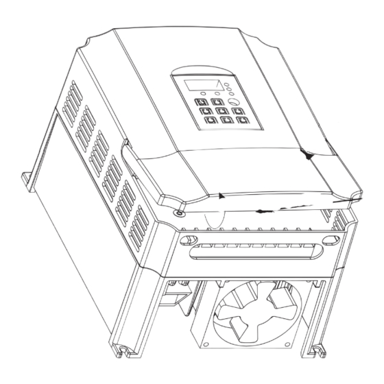
Chapter 2 Product Information 2.5 Product Appearance and Dimension of Installation Holes Operation panel 1) Product Appearance Cabinet-cover Small cover Input/Output hole Bottom installation holes Fig. 2-1 Appea ance C o m p l e m e n t : There are two types of height in the EH640A 132G/160P and... -
Page 11: Inverter Model
Chapter 2 Product Information 2) Dimension of Inverter Installation Holes Diameter Gross weight Inverter Model (mm) (mm) (mm) ( ) (mm) (mm) (mm) Ф4 EH620A.04G Ф4 EH620A0.7G Ф4 EH620A1.5G EH620A2.2G Ф4 EH640A0.7G/1.5P Ф4 Ф4 EH640A1.5G/2.2P EH640A2.2G/3.7P EH623A0.7G Ф4 EH640A3.7G/5.5P Ф5 EH623A1.5G EH640A5.5G/7.5P EH623A2.2G... -
Page 12: Optional Parts
Chapter 2 Product Information 3) Dimension of Extra operation Panel Installation Holes EH60-KE1: 74.2 +0.3 74.2 74.7 +0.3 54.7 Small operation panel Small operation panel install 19.5 structure size diagram opening hole size diagram 54.4 EH60-KE2: +0.3 76.4 +0.3 145.6 145.6 146.3 Big operation panel install... -
Page 13: Daily Maintenance Of Inverter
Chapter 2 Product Information 2.7 Daily Maintenance of Inverter 1) Daily Maintenance Since the influence of ambient temperature , humidity , dust and vibration , the components in inverter may for aging and wearing ,which will give rise to the occurrence of potential faults and reduce the life of inverter . -
Page 14: Warranty
Chapter 2 Product Information a Cooling fan 、 Possible damage causes : shaft bearing attrition and blade aging . Judging criteria : no crack on fan blade , and no abnormal vibration noise at start . b Filtering electrolytic capacitor 、... -
Page 15: Selection Braking Units
Chapter 2 Product Information 2.10 Selection Braking Units The data in this table is instructional , user can select different resistance value and power according to actual situation .(Resistance values can not be lower than the recommended ones , the power can be higher than recommended ones). -
Page 16: Chapter 3 Mechanical And Electrical Installation
Chapter 3 Mechanical and Electrical Installation Chapter 3 Mechanical and Electrical Installation 3.1 Mechanical Installation 1、Insatallation Environment 1) Ambient temperature : ambient temperature influences the life of inverters greatly , so it should be within the range of -10 ℃ to 50 ℃... - Page 17 Chapter 3 Mechanical and Electrical Installation Heat sink should be taken into account during the mechanical installation . Due attention should be paid to the following items : 1) Install the inverter vertically so that the heat may be expelled from the top , but do not install the inverter upside down .
-
Page 18: Electrical Installation
Chapter 3 Mechanical and Electrical Installation 3.2 Electrical Installation 1、Guide to the external electrical parts : Circuit breaker Contact Input cables Output cables Control cables Inverter model (MCCB) ( ) (mm) (mm) (mm) ( ) EH620A0.4G EH620A0.7G EH623A0.7G EH620A1.5G EH623A1.5G EH620A2.2G EH623A2.2G EH640A0.7G/1.5P... - Page 19 Chapter 3 Mechanical and Electrical Installation 1) Improve the input power factor ; 2) Eliminate the higher harmonics of the input effectively and prevent other equipment AC input reactor Inverter input from damaging due to distortion of voltage wave ; 3) Eliminate the input current unbalance due to the unbalance between the power phases .
- Page 20 Chapter 3 Mechanical and Electrical Installation 4、Main circuit terminal and wiring The left diagram is suitable for all of the EH620 series equipment . Ground DC brake Single phase resistance source input Electromotor The left diagram is suitable for EH640A 15G(18.5P) and the inverter with lower level power , besides , Ground EH623A 3.7G and the inverter with...
- Page 21 Chapter 3 Mechanical and Electrical Installation over current protection of the inverter .When the length of motor cable is longer than 30m , it needs to reduce carrier wave so so that to decrease leakage current .When the length of motor cable is longer than 50m, it needs to install AC output reactor . D Earth terminal E : The terminal should be earthed reliably , the diameter of earth cable should be more than 10mm , with 、...
- Page 22 Chapter 3 Mechanical and Electrical Installation 3) Description of connection of control terminals : A、Analog input terminal Since the weak analog voltage signal is easy to suffer external interferences , generally it needs to employ shielded cable and the length should be no longer than 20m ,as shown in Fig.3-4 . In case the analog signal is subject to severe interference , and analog signal source side should be installed with filter capacitor or ferrite magnectic core , as shown in fig.3-5 .
- Page 23 Chapter 3 Mechanical and Electrical Installation 2 Electromagnetic interference and handing 、 1) There are two kinds of electromagnetic interferences , one is interference of electromagnetice noise in the surrounding environment to the inverter ,it maybe cause error action ,however, the impact is usually small, because the inverter has internal handling when it is designed , so it has strong anti-interference capability for itself ;...
- Page 24 Chapter 3 Mechanical and Electrical Installation C The surrounding equipment is separately earthed , which can avoid the interference caused by the 、 leakage current of the inverter’s earth wire when common earth mode is adopted . 3 Leakage current and handling 、...
-
Page 25: Chapter 4 Operation And Display
Chapter 4 Operation and Display Chapter 4 Operation and Display Introduction to operation and display interface The operation panel can perform such operations on the inverter as function parameter modification , inverter working status monitoring and inverter runnign control (startup and stop) .Refer to Fig.4-1 for the physical appearance and functional zone of the operation panel . -
Page 26: Check And Modify The Function Codes
Chapter 4 Operation and Display Keyboard button description 、 Button Name Function Program key Entry and exit of primary menu FUNC Confirmation key Enter the menu interfaces level by level ,and confirm the set parameters . ENTER Increase of the data or function code Increase key Decrease key Decrease of the data or function code... -
Page 27: Method Of Viewing Status Parameter
Chapter 4 Operation and Display In the third menu ,if the parameter has no flashing bit ,it indicates that the function code cannot be modified . The reasons could be: ) 1 The function code is an unchangeable parameter , such as actual detection parameter(FV parameter) , running record parameter , etc . -
Page 28: Suggestive Information
Chapter 4 Operation and Display Suggestive information When operating the inverter , the operation panel provides full suggestive information . P.LU: Suggest lack of voltage when upon power and shutdown . CE : Since vibration or other casual factor lead to deyboard communication abnormity , you can retry non-success operation after exceptional factor solution. -
Page 29: Chapter 5 Function Parameters
Chapter 5 Function Parameter Table Chapter 5 Function Parameter Table Function parameters grouping according to their function , they are from F0 to FD and FV , There are fifteen groups of my company inverter . Every function group contains some function codes , which adopt the mark of function code group number add function code number . - Page 30 Chapter 5 Function Parameter Table Function Parameter Table Modif- Factory default Function Setup range Minimum unit Name code ication value Group F0 Basic Function Group F0.00 Software version number Model dependent 0 9999 ~ : F0.01 V / F Control mode :...
- Page 31 Chapter 5 Function Parameter Table Modif- Function Factory default Setup range Minimum unit Name code ication value : F0.07 Frequency source main frequency source X selection 1 auxiliary frequency source Y : : main frequency source X plus auxiliary frequency source Y :...
- Page 32 Chapter 5 Function Parameter Table Modif- Factory default Function Name Setup range Minimum unit code value ication Group V/F Control Parameters V/F curve setup 0 straight V/F curve : F2.00 1 multiple-point V/F curve : 2 square V/F curve 1 1.5 time power :...
- Page 33 Chapter 5 Function Parameter Table Modif- Factory default Function Name Minimum unit Setup range code ication value Group F3 Input Terminal X1 terminal function F3.00 0 no function : selection 0-30 ( ) : 1 MS speed terminal 1 F3.01 X2 terminal function 2 MS speed terminal 2 :...
- Page 34 Chapter 5 Function Parameter Table Modif- Factory default Function Name Minimum unit Setup range code ication value F3.07 Change rate of 0.01 100.0Hz/s ~ 0.01Hz/S 1.00Hz/S ○ terminals UP / DW ○ F3.08 0.00V 10.00V ~ 0.01V 0.00V AI1 Minimum input F3.09 I A 1 Minimum input -100.0 100.0%...
- Page 35 Chapter 5 Function Parameter Table Modif- Factory default Function Name Minimum unit Setup range code ication value 18: Running command indication 19: Limitative time output terminal X1 20: Dormant 21: Ready for running 22: Three-line running mode 1 start to trigger information output by itself .
- Page 36 Chapter 5 Function Parameter Table Modif- Factory default Function Name Minimum unit Setup range code ication value : Stop mode 0 deceleration to stop ○ F5.05 1 coast to stop : ~ F5.06 DC brake beginning 0.0Hz upper limit frequency F0.11 ○...
- Page 37 Chapter 5 Function Parameter Table Modif- Factory default Function Name Minimum unit Setup range code ication value Jog action selection ○ F7.03 0: Active on running status 1: Disabled It is avoid to lead jog command for error operation by setting it as 1 in the inverter running .
- Page 38 Chapter 5 Function Parameter Table Modif- Factory default Function Name Minimum unit Setup range code ication value Stall protection ~ F8.04 110% 200% 150% ○ coefficient over current Stall protection ~ ○ F8.05 120 150% 130% voltage over voltage : Restart setup after 0 no action F8.06...
- Page 39 Chapter 5 Function Parameter Table Modif- Factory default Function Name Setup range Minimum unit code value ication Group F 9 PID Function PID control mode F9.00 The third part ot LED: PID action direction setup 0 positive action : 1 reverse action :...
- Page 40 Chapter 5 Function Parameter Table Modif- Factory default Function Name Minimum unit Setup range code ication value : 2 keep current running frequency The first part of LED detection mode : : 0 no detection 1 detection according to PID feedback :...
- Page 41 Chapter 5 Function Parameter Table Modif- Factory default Function Name Setup range Minimum unit code value ication Group F MS S pee d / PLC MS speed 0 0.0Hz upper limit frequency ~ FB.00 0.01Hz 0.0Hz ○ ~ FB.01 MS speed 1 0.0Hz upper limit frequency 0.01Hz 0.0Hz...
- Page 42 Chapter 5 Function Parameter Table Modif- Factory default Function Name Minimum unit Setup range code ication value 0000 ○ FB.23 Phase 2/3 running The forth part of LED phase 3 acceleration : / deceleration time selection : 0-3 mode The third part of LED phase 3 direction :...
- Page 43 Chapter 5 Function Parameter Table Modif- Factory default Function Name Setup range Minimum unit code value ication 0.0 6553.5s(h) ~ 0.0s ○ Phase 10 running time 0.1s FB.33 ○ ~ 0.1s 0.0s FB.34 Phase 11 running time 0.0 6553.5s(h) Phase 10 /11 running The forth part of LED phase 11 acceleration :...
- Page 44 Chapter 5 Function Parameter Table Modif- Factory default Function Name Minimum unit Setup range code ication value ○ FC.01 The second part of LED : data frames check Data format mode selection 0: CRC16 1: accumlate sum (16 bit ) The first part of LED: byte check mode selection 0: No parity check (8,N,2) Note:Two stop bit...
- Page 45 Chapter 5 Function Parameter Table Modif- Factory default Function Name Setup range Minimum unit code value ication Grpup F Status Parameter ~ FV . 0 0 Output frequency 0.0Hz upper limit frequency 0.01Hz ~ FV . 0 1 Setup frequency 0.0Hz upper limit frequency 0.01Hz (flashes)
-
Page 46: Group F0 : Basic Function Group
Chapter 6 Parameter Description Chapter 6 Parameter Description Group Basic Function Main frequency Model Factory F0.03 source X selection default value dependent Factory Model F0.00 Software version number default value dependent Panel potentiometer Setup range Digital setup by UP and DW adjustment Display the software version of the machine Setup range (panel or external terminal) - Page 47 Chapter 6 Parameter Description When the frequency source selection is auxiliary frequency 、 8 Communication reference source Y F0.07 is set to 1 and F0.05 is set to 1 , simple ( ) It means that the main frequency source is given by the host and convenient synchronous control can be realized through...
-
Page 48: Group F1 Motor Parameters
Chapter 6 Parameter Description Output Frequency When F0.09 is selected as “ Without memory when power ” failure , it means that the setup frequency value is Fmax recovered to the value of F0.08 “ Digital setup preset Setup frequency ”... -
Page 49: Group F2 : V/F Control Parameters
Chapter 6 Parameter Description Group F2 V/F Control Parameters Factory Model F2.07 Torque boost default value dependent ~ Factory 0.0 20.0% Setup range F2.00 V/F curse setup default value Cutoff frequency of Factory 50.00Hz F2.08 torque boost default value Setup range Straight V/F curve rated frequency Hz~... -
Page 50: Group F3 Input Terminal
Chapter 6 Parameter Description Carrier frequency Automatic Voltage Model Factory F2.10 F2.13 dependent Regulation (AVR) Selection adjustment selection default value Disabled Setup range Setup range , Fixed PWM and carrier frequency Enabled temperature adjustment disabled . Disabled only at the time of Random PWM and carrier frequency ,... - Page 51 Chapter 6 Parameter Description When the frequency reference Forward rotation For details regarding frequency UP/DOWN setup is digital frequency reference , Jog JOGF ( ) and Jog acceleration / clear (terminal this terminal can be used to deceleration time during the and keyboard) Reverse rotation clear the frequency value...
- Page 52 Chapter 6 Parameter Description 1 Two-line running mode 2 : : When this mode is adopted , Frequency Corresponding REV is enabled terminal . The direction is determined by the setup parameter status of FWD . MS speed 0 FB.00 Running Command MS speed 1 FB.01...
- Page 53 Chapter 6 Parameter Description Prompt: Steer Stick mode: The above parameters are set in reason , Xn is multifunctional input terminals . In this way , it can realize the forward/reverse rotation of the motor through corresponding terminal function should be defined as NO.5 changing the analog input ,this mode usually called JOYST “...
-
Page 54: Group F4 Output Terminal
Chapter 6 Parameter Description Prompt The above several settinh examples are typical Prompt: The above cutlines are typical application settings. Setup Function Description application setting , for detailed setting need adjustment and As for the setting details, the adjustment should be made to value The output terminals does not according to client demand . - Page 55 Chapter 6 Parameter Description Limitative time When terminal X1 enabled , the Output channel Factory F4.08 default value selection output terminal output terminal enabled at once The first part of LED AO1 output : , then after the setup time of F4.05, Setup range selection...
-
Page 56: Group F5 : Start And Stop Control
Chapter 6 Parameter Description : 1 Perform braking prior to start 20kHz 、 Perform DC braking prior to start (refer to F5.04 F5.05) . 。 It is applicable to the applications where reverse rotation is likely to occur when small loads are started . :... - Page 57 Chapter 6 Parameter Description The process of DC brake is shown as the following figure: Inverter has no output during the DC brake waiting time at stop. for high-power motor, the setup time can prevent the Output over-high current at the brake beginning moment. frequency The setup of DC brake current at stop is relative to the percentage of rated current of inverter .
-
Page 58: Group F6 : Keyboard And Display
Chapter 6 Parameter Description Frequency In stop or running status ,when the status parameter(FV) needs to be inquired again and again, by setting running parameter (F6.01 to F6.02) and stop parameter (F6.03 to F6.04) , and realizing the common-using status parameter by controlling the Fmax shift key( ) to display in turns . - Page 59 Chapter 6 Parameter Description Corresponding relationship LED running display parameter 1 F6.01 between binary and decimal ~ FV.00 : Output frequency Setup range 1 8191 FV.01 : Setup frequency (flashes) FV.02 : Output current FV.03 : Running rev FV.04 : Setup rev (flashes) FV.05 : Running load speed FV.06 : Setup load speed (flashes) FV.07 : Output voltage...
-
Page 60: Group F7 Auxiliary Function
Chapter 6 Parameter Description Copy keyboard Factory Factory F6.09 F7.07 Deceleration time 3 20.0s function selection default value default value Setup range ~ 0.0 6553.5s Please refer to the copy keyboard description of our Factory company . Acceleration time 4 F7.08 20.0s default value... - Page 61 Chapter 6 Parameter Description Frequency detection Forward/reverse Factory F7.12 Factory 0.0s 2.00Hz F7.18 hysteresis default value rotation dead-zone time default value ( FDT2 hysteresis ) ~ 0.0 3000.0s Setup range Setup range 0.0Hz the maximum frequency F0.11 ~ During the setting of forward/reverse rotation of the inverter , the transition time at the output zero frequency position.
-
Page 62: Group F8 Fault And Protection
Chapter 6 Parameter Description Group F8 Fault and Protection Restart waiting time Factory F8.07 1.0S default value after power-off Setup range 0.1 10.0s ~ Inverter overload Factory F8.00 110% default value When restart after power-off is enabled ,inverter is on the pre-warning running state before power cut. -
Page 63: Group F9 Pid Function
Chapter 6 Parameter Description Output frequency 5 Max{AI1 AI2} : , F8.13 Display the state parameter on fault : ( ) 6 Pulse setup DI upon fault for the latest time . Output current 7 Communication setup : F8.14 on fault The first part of LED: F8.15 Bus voltage on fault... - Page 64 Chapter 6 Parameter Description PID reference Factory Factory F9.07 F9.01 1000 Integration time I 2.0S feedback range default value default value Setup range 0 9999 ~ Setup range 0.1 100.0s ~ 100.0s : close I PID reference feedback range is a nondimensional unit , it is used Proportional gain P:...
- Page 65 Chapter 6 Parameter Description Output frequency PID feedback Factory F9.16 disconnection default value detection preset frequency The second part of LED action mode : : 0 enter PID feedback disconnetcion fault state display E.6 ( ) :stop in term of F5.05 setup stop mode preset frequency keep time :...
-
Page 66: Group Fa : Swing Frequency 、 Fixed-Length Count And
Chapter 6 Parameter Description Group FA Swing Frequency ,Fixed Length and Count Setup frequency(Hz) Frequency amplitude Aw=Fset FA.01 Frequency upper limit FH Cetnter frequency Fset Frequency lower limit FL Textile kick frequency =AW FA.02 Triangular wave Time (t) Accelerate by Decelerate by =FA.03 FA.04 acceleration time... - Page 67 Chapter 6 Parameter Description The function is shown the following figure: Factory FA.05 Setup length 1.000km default value Counting Pulse Setup range 0 65.535km ~ Setting Count Factory FA.06 Designed length 1.000km default value Designated Count 0 65.535km ~ Setup range Fig.
- Page 68 Chapter 6 Parameter Description increase unceasingly, on base of modified value, along with Factory 0.0Hz FB.00 MS speed 0 the signal input. default value When it switches into display setup length , you can modify 0.00 upper limit frequency F0.11 ~...
-
Page 69: Group Fc Communication Parameter
Chapter 6 Parameter Description When the frequency source selections F0.07 , F0.03 and F0.04 2 Constant circulation : are determined as PLC running mode , FB.00 to FB.15,FB.16, The inverter will automatically start next one cycle upon FB.17 and FB.18 to FB.41should be set to determine its the completion of one cycle , and will not stop until stop characteristics . - Page 70 Chapter 6 Parameter Description Factory Factory Automatic energy FD.08 Inner fan control FD.01 default value default value conservation running automatic Setup range 0 no action 1 action : : Setup range when select automatic energy conservation constant open running , the inverter will be able to adjust 0 automatic :...
-
Page 71: Group Fv Status Parameter
Chapter 6 Parameter Description Group FV Status Parameter Modif- Factory default Function Name Minimum unit Setup range code value ication ~ Output frequency 0.0Hz upper limit frequency V . 0.01Hz Setup frequency 0.0Hz upper limit frequency ~ V . 0.01Hz (flashes) Output current V .... -
Page 72: Chapter 7 Eh600 Communication Protocol And Description Of Communication
Chapter 7 EH600 Communication Protocol and Description of Communication Chapter 7 EH600 Communication Protocol and Description of Communication Communication protocol of EH600 is completely compatible with standard communication protocol of Modbus , meanwhile , according to the applied requests from client, the protocol added accumulation 、... - Page 73 Chapter 7 EH600 Communication Protocol and Description of Communication And then a new message will startup after that time . The whole message frame must be transferred as a continuous data stream. If there is pause time exceeds 1.5-byte internal time before the frame finished , the receive equipment will refresh the non-integrated message and assume the next byte to be a address field of the new message.
- Page 74 Chapter 7 EH600 Communication Protocol and Description of Communication Check Mode ——CRC check mode:CRC(Cyclical Redundancy Check): By using RTU frame format , the message contains error detect field that bases on CRC method . CRC field detects the whole message data. It is two bytes and includes 16-byte binary value, it is calculated by transmission equipment and then added to the message, the receive equipment calculates CRC over again after receiving the message and compares it to the...
- Page 75 Chapter 7 EH600 Communication Protocol and Description of Communication definition of Communication parameter add.: This part is the content of communication, it is used to control the running of inverter and inverter status and the correlative parameter setting . Read-write function code parameter: Add.rule:...
- Page 76 EH600 Chapter 7 Communication Protocol and Description of Communication Fault description (EH600 current fault information): Fault Add. information 8000H 0000H:no fault(- -) 0001H:Inverter unit protection(E.1) 0002H:Acceleration over current(E.OC1) 0003H:Deceleration over current(E.OC2) 0004H:Constant speed over current(E.OC3) 0005H:Acceleration over voltage(E.OU1) 0006H:Deceleration over voltage(E.OU2) 0007H:Constant speed over voltage(E.OU3) 0008H:Stop over voltage(E.OU4) 0009H:Running under voltage(E.LU)
- Page 77 EH600 Chapter 7 Communication Protocol and Description of Communication Host inquiry Slave responding Execptional code Register Add. high-order Register Add. low-order CRC low-order Register number high-order CRC high-order Register number low-order CRC low-order CRC high-order Note:Since F0.00 parameter is only-read parameter , the modification of response parameter disabled .
- Page 78 Chapter 7 EH600 Communication Protocol and Description of Communication The setup data format both host and inverter must be the same, or else, the communication can not be carried out. As for users whose programmable check mode is accumulate sum , the communication protocol of XILIN company is compatible with this mode, it is realized by setting the second part of FC.01 to 1.
- Page 79 Chapter 7 EH600 Communication Protocol and Description of Communication 8. Common communication command examples Note: The following slave computer response is used as example to help user understanding protocol, but it might have some differences with the actual response. A. CRC check mode Read :...
- Page 80 Chapter 7 EH600 Communication Protocol and Description of Communication Write : Register Register Register Register Add. Add. data data low-order high-order high-order low-order high-order low-order Send forward rotation command to No.1 slave computer: Send deceleration stop to No.1 slave computer: All slaves’...
- Page 81 Chapter 7 EH600 Communication Protocol and Description of Communication The followings take the accumulate sum check mode as an example to explain complex command protocol. Note: The following slave computer response is used as example to help user understanding protocol, but it might have some differences with the actual response.
-
Page 82: Description Of Communication Card
Chapter 7 EH600 Communication Protocol and Description of Communication Description of Communication Card Communication card of SHENZHEN XILIN ELECTRIC THECHNOLOGIES CO.,LTD is specially designed for the EH600 series inverter to provide long-distance serial port communication function . : For the EH600M , EH600S series and EH600A 11G/15P above power level inverters of our company, the NOTE communication correlative hardware interface is provided by special communication CPU, please give a clear indication... -
Page 83: Chapter 8 Troubleshooting And Countermeasures
Chapter 8 Troubleshooting and Countermeasures Chapter 8 Troubleshooting and Countermeasures 8.1 Fault Alarm and Countermeasures Inverters of our company has 22 pieces of warning information and protection function. In case of abnormal fault, the protection function will be invoked , the inverter will stop output , and the faulty relay contact of the inverter will start , the fault code will be displayed on the display panel of the inverter . - Page 84 Chapter 8 Troubleshooting and Countermeasures Acceleration over current E. OC 1 Check if the output loop of the Perform troubleshooting inverter is grounding or short circuited Whether the acceleration time is too short Prolong the acceleration time Whether the manual boost torque Adjust the manual boost or V/F curve is proper torque or V/F curve...
- Page 85 Chapter 8 Troubleshooting and Countermeasures Constant speed over current E. O C 3 Check if the output loop of the Perform troubleshooting , inverter is short circuited or has and install output reactor leakage current if the cable is too long Whether the load is added suddenly Remove the added load during the running...
- Page 86 Chapter 8 Troubleshooting and Countermeasures Constant over voltage Adjust the voltage Whether the input voltage is too high to normal range Whether there are external forces Remove the external driving the motor to run during the forces or install brake unit and resistor running process Ask for technical support...
- Page 87 Chapter 8 Troubleshooting and Countermeasures Motor overload Inverter overload Whether the motor overload protection Set it properly parameter F8.03 is set properly Reduce the load and Whether the load is too heavy or check the motor and the motor does not rotate the machine Adjust the input Whether the voltage of power net is too low...
- Page 88 Chapter 8 Troubleshooting and Countermeasures Inverter overheat E. O H Reduce the ambient Whether the ambient temperature is too high temperature Whether the air duct is blocked Clean the air duct Whether the fan is broken Replace the fan Ask for technical support Replace the main Check Whether...
- Page 89 Chapter 8 Troubleshooting and Countermeasures Output grounding E.GF Replace cable Check Whether the output is short circuited or motor Ask for technical support Replace the drive board CPU interference Ask for technical support Whether it works normally after The main control board is faulty replacing the main control board Current detect fault...
-
Page 90: Common Faults And The Resolution
Chapter 8 Troubleshooting and Countermeasures Phase loss at the input side Check and resolve the problems in the Check Whether three-phase input external lines to ensure that the three -phase power input to the inverter is power supply is normal Ask for technical support normal Replace the... - Page 91 Warranty Agreement 1. The warranty period of the product is 18 months (refer to the bar code on the equipment body). During the warranty period , if the product fails or it is damaged under the condition of normal use by following the instruction, our company will be responsible for free maintenance .
- Page 92 Product Warranty Card Add. of corporation: Customer Name of corporation: Contact person: information P.C.: Tel.: Product model: Product Body bar code: information Name of agent: ( maintenance time and content) : Failure information Maintenance personnel:...