Table of Contents
Advertisement
Advertisement
Table of Contents
Troubleshooting

Related Manuals for Allied Telesis AT-2911SX/ST


Summary of Contents for Allied Telesis AT-2911SX/ST
- Page 1 2911 Series Gigabit Ethernet Network Interface Cards AT-2911SX/ST AT-2911STX/LC AT-2911SX/SC AT-2911LTX/SC AT-2911SX/LC AT-2911LTX/LC AT-2911LX/SC AT-2911SX/2LC AT-2911LX/LC AT-2911LX/2LC AT-2911SFP AT-2911SFP/2 AT-2911STX/SC AT-2911T/2 Installation and User’s Guide 613-001705 Rev. B...
- Page 2 Telesis, Inc. be liable for any incidental, special, indirect, or consequential damages whatsoever, including but not limited to lost profits, arising out of or related to this manual or the information contained herein, even if Allied Telesis, Inc. has been...
- Page 3 Declaration of Conformity Manufacturer Name: Allied Telesis, Inc. Declares that the product: Gigabit Ethernet Network Interface Cards Model Numbers: AT-2911SX/ST, AT-2911SX/SC, AT-2911SX/LC, AT-2911LX/SC, AT-2911LX/LC, AT-2911SFP, AT-2911STX/SC, AT-2911STX/LC, AT-2911LTX/SC, AT-2911LTX/LC, AT-2911SX/2LC, AT-2911LX/2LC, AT-2911SFP/2, and AT-2911T/2 This device complies with Part 15 of the FCC Rules. Operation is subject to the following two conditions: (1) This device may not cause harmful interference, and (2) this device must accept any interference received, including interference that may cause undesired operation.
-
Page 4: Radiation Exposure Statement
European Union Restriction of the Use of Certain Hazardous Substances (RoHS) in Electrical and Electronic Equipment This Allied Telesis RoHS-compliant product conforms to the European Union Restriction of the Use of Certain Hazardous Substances (RoHS) in Electrical and Electronic Equipment. Allied Telesis ensures RoHS conformance by requiring supplier Declarations of Conformity, monitoring incoming materials, and maintaining manufacturing process controls. - Page 5 Safety EN 60950-1 TUV-T UL 60950-1 Translated Safety Statements Important: The indicates that a translation of the safety statement is available in a PDF document titled “Translated Safety Statements” on the Allied Telesis website at www.alliedtelesis.com/support.
-
Page 7: Table Of Contents
Contents Preface ....................................13 Safety Symbols Used in this Document ........................14 Contacting Allied Telesis ...............................15 Chapter 1: Overview ................................17 Physical Description ..............................18 AT-2911 Series Single Port Adapters ........................18 AT-2911 Series Dual Port Adapters ........................19 ST Fiber Optic Connector ............................19 SC Fiber Optic Connector ............................20 LC Fiber Optic Connector ............................20... - Page 8 Contents Large Send Offload v2 (IPv4) ............................58 Large Send Offload v2 (IPv6) ............................60 Network Address ................................61 NS Offload ..................................63 Priority & VLAN................................64 Receive Buffers ................................66 Receive Side Scaling..............................67 RSS Queues..................................68 Speed & Duplex................................70 TCP/UDP Checksum Offload (IPv4)..........................72 TCP/UDP Checksum Offload (IPv6)..........................74 Virtual Machine Queues ..............................76 VLAN ID..................................77 VMQ Lookahead Split..............................78...
- Page 9 Figures Figure 1: AT-2911SX/SC Adapter ............................18 Figure 2: AT-2911LTX/LC Adapter ............................19 Figure 3: ST Fiber Optic Connector............................19 Figure 4: SC Fiber Optic Connector .............................20 Figure 5: LC Fiber Optic Connector............................20 Figure 6: Twisted Pair Cable Port............................20 Figure 7: Pin and RJ-45 Connector Pin Layout ........................21 Figure 8: SFP Slot ................................21 Figure 9: AT-2911 Model Naming Conventions........................22 Figure 10: Removing the Low-Profile Bracket ........................33...
- Page 10 Figures Figure 51: Update Device Software Window on Windows Server 2008 R2, Server 2008, Vista, and 7.......91 Figure 52: Update Device Software Window on Windows Server 2008 R2, Server 2008, Vista, and 7.......92 Figure 53: Ethernet Controller on Windows Server 2003 and XP..................93 Figure 54: Hardware Update Wizard 1 ..........................93 Figure 55: Hardware Update Wizard 2 ..........................94 Figure 56: Hardware Update Wizard 3 ..........................95...
- Page 11 Tables Table 1: LED Status ................................21 Table 2: AT-2911 Model Naming Conventions ........................22 Table 3: 1000BASE-X Fiber Optic Cable Specifications .....................39 Table 4: Physical Specifications ............................112 Table 5: Environmental Specifications ..........................113 Table 6: Power Specifications ............................114 Table 7: MTBF Specifications ............................115 Table 8: Optical Specifications ............................116...
- Page 12 Tables...
-
Page 13: Preface
The instructions in this guide explain how to install the network adapter on a desktop computer, install and uninstall the driver software, and configure the driver software. This preface contains the following sections: “Safety Symbols Used in this Document” on page 14 “Contacting Allied Telesis” on page 15... -
Page 14: Safety Symbols Used In This Document
Preface Safety Symbols Used in this Document This document uses the following conventions: Note Notes provide additional information. Caution Cautions inform you that performing or omitting a specific action may result in equipment damage or loss of data. Warning Warnings inform you that performing or omitting a specific action may result in bodily injury. -
Page 15: Contacting Allied Telesis
AT-2911 Series Gigabit Ethernet Network Adapters Installation and User’s Guide Contacting Allied Telesis If you need assistance with this product, you may contact Allied Telesis technical support by going to the Support & Services section of the Allied Telesis web site at www.alliedtelesis.com/support. You can find links for the following services on this page: ... - Page 16 Preface...
-
Page 17: Chapter 1: Overview
Chapter 1 Overview This chapter contains an overview for the AT-2911 Series Gigabit Ethernet Network Adapters and includes the following sections: “Physical Description” on page 18 “Model Naming Conventions” on page 22 “Supported Operating Systems” on page 23 ... -
Page 18: Physical Description
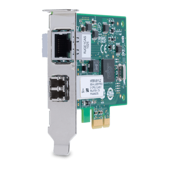
PCI Express (PCIe) x1 version 2 interface. The AT-2911 series adapter connects a PCIe compliant computer to a Gigabit Ethernet network. Allied Telesis offers models equipped with a single port interface or dual port interface in the AT-2911 series. The AT-2911 adapter is equipped with single or dual fiber optic connector, copper connector, SFP slot, or a combination of these connectors. -
Page 19: At-2911 Series Dual Port Adapters
The AT-2911LTX/LC adapter is shown in Figure 2. Figure 2. AT-2911LTX/LC Adapter ST Fiber Optic The AT-2911SX/ST adapter is equipped with a 1000BASE-SX ST fiber optic connector for attaching to a compatible link partner. Connector The ST fiber optic connector is shown in Figure 3. -
Page 20: Sc Fiber Optic Connector
Chapter 1: Overview SC Fiber Optic The AT-2911SX/SC, AT-2911LX/SC, AT-2911STX/SC, and AT-2911LTX/SC, adapters are equipped with a 1000BASE-SX or Connector 1000BASE-LX SC fiber optic connector. The SC fiber optic connector is shown in Figure 4. Figure 4. SC Fiber Optic Connector To connect the adapter to a network cable, you must have a fiber optic network cable with the SC connector. -
Page 21: Sfp Slot
The AT-2911SFP/2 adapter has two SFP slots. Note An SFP transceiver must be purchased separately. For a list of supported transceivers, contact your Allied Telesis distributor or reseller. The SFP slot is shown in Figure 8. Figure 8. SFP Slot LEDs The AT-2911 series adapter has an LED per port. -
Page 22: Model Naming Conventions
Chapter 1: Overview Model Naming Conventions The hardware features of the AT-2911 adapters are represented by the letters and numbers in the model names. The conventions for the AT-2911 adapters are identified in Figure 9. Figure 9. AT-2911 Model Naming Conventions The conventions are defined in Table 2. -
Page 23: Supported Operating Systems
AT-2911 Series Gigabit Ethernet Network Adapters Installation and User’s Guide Supported Operating Systems The following list shows the supported operating systems for the AT-2911 series adapters: Windows XP 32-bit Windows XP 64-bit Windows Server 2003 32-bit Windows Server 2003 64-bit ... -
Page 24: Features
Chapter 1: Overview Features The AT-2911 adapter supports the following features: One or two interfaces x1 PCI Express v2.0 PXE 2.0 remote boot support Flow control (IEEE 802.3x) VLAN tag support (IEEE 802.1Q) Jumbo packet (9K) ... -
Page 25: Broadcom Utilities
To install BASP and BACS, download the Broadcom Management Application Installer on the Allied Telesis website as described in “Installing Broadcom Utilities” on page 26. For more information about teaming and how to install BASP and BACS, see the Broadcom NetXtreme®... -
Page 26: User Diagnostics
1. Open a web browser, such as Internet Explorer or FireFox, on your Utilities system and enter the following: http://www.alliedtelesis.com/support/software The Allied Telesis Software Download page is displayed. 2. Enter “2911” in the search box and press the enter key. 3. Select the Broadcom Management Applications Installer or User Diagnostics. -
Page 27: Contents Of Your Shipment
Note The AT-2911 adapter is not shipped with a software driver CD. You must download the driver software from the Allied Telesis website. See Chapter 4, “Downloading the Driver Software” on page 83. Inform your network supplier of any missing or damaged items. If you need to return the module, you must pack it in the original (or equivalent) packing material or the warranty will be voided. -
Page 28: Warranty Registration
Warranty Registration Allied Telesis hardware products are covered under limited warranties. All Allied Telesis warranties are subject to and provided only on the terms and conditions set out in the Allied Telesis Limited Warranties listed on the Allied Telesis website at www.alliedtelesis.com/support/warranty. -
Page 29: Chapter 2: Installing The Hardware
Chapter 2 Installing the Hardware This chapter contains the following sections: “Reviewing Safety Precautions” on page 30 “Pre-Installation Checklist” on page 32 “Replacing the Bracket” on page 33 “Installing the AT-2911 Series Adapter Card” on page 35 ... -
Page 30: Reviewing Safety Precautions
Note indicates that a translation of the safety statement is available in a PDF document titled “Translated Safety Statements” posted on the Allied Telesis website at www.alliedtelesis.com/ support. Warning This is a “Class 1 LED product”. Warning Do not stare into the laser beam. - Page 31 AT-2911 Series Gigabit Ethernet Network Adapters Installation and User’s Guide Warning The module is being installed in a system that operates with voltages that can be lethal. Before you remove the cover of your system, you must observe the following precautions to protect yourself and to prevent damage to the system components.
-
Page 32: Pre-Installation Checklist
1. Check that your computer has an appropriate open PCIe slot. 2. Verify that your computer is using the latest BIOS. 3. When you download the driver software from the Allied Telesis website, record the path to where the driver file resides on your system. -
Page 33: Replacing The Bracket
AT-2911 Series Gigabit Ethernet Network Adapters Installation and User’s Guide Replacing the Bracket The AT-2911 series adapter is shipped with the low-profile bracket attached to the adapter. Depending on your PC, you may need to replace the bracket attached to your adapter. The following procedure describes how to remove the low-profile bracket from the adapter and replace it with the standard bracket. -
Page 34: Figure 11: Fastening Screws Onto Standard Bracket
Chapter 2: Installing the Hardware Figure 11. Fastening Screws onto Standard Bracket... -
Page 35: Installing The At-2911 Series Adapter Card
AT-2911 Series Gigabit Ethernet Network Adapters Installation and User’s Guide Installing the AT-2911 Series Adapter Card The following instructions describe how to install an AT-2911 series adapter in most systems. Refer to the manuals that were supplied with your system for details about performing these tasks on your particular system. -
Page 36: Figure 13: Removing The Faceplate From Pcie Slot
Chapter 2: Installing the Hardware 4. Remove the faceplate that is directly in line with the PCIe slot you selected. See Figure 13. Keep the faceplate in a safe place. You may need it for future use. Figure 13. Removing the Faceplate From PCIe Slot Note If you cannot locate or know how to find an appropriate PCIe slot, refer to the documentation that came with your system. -
Page 37: Figure 14: Inserting The Network Adapter Card
AT-2911 Series Gigabit Ethernet Network Adapters Installation and User’s Guide Figure 14. Inserting the Network Adapter Card Caution Do not use excessive force when seating the module, because this may damage the system or the module. If the module resists ... - Page 38 Chapter 2: Installing the Hardware Note When you installed the adapter in a Windows Operating system before installing the driver software, the Found New Hardware Wizard launches automatically except Windows 7 and Windows Server 2008 R2 systems. For installing the driver software, refer to the section for your Windows Operating system.
-
Page 39: Connecting The Network Cables
SC and LC connectors. For optical characteristics of the AT-2911 adapter, see Appendix A, “Specifications” on page 111. In addition, the AT-2911 data sheet is available on the Allied Telesis website: www.alliedtelesis.com. To connect a fiber optic network cable to the adapter, perform the following procedure: 1. -
Page 40: Twisted Pair Copper Cable
Chapter 2: Installing the Hardware 4. Connect the other end of the fiber optic cable to the appropriate Ethernet network port or fiber optic port. After connecting the system to the network and power is supplied, the adapter performs auto-negotiation and attempts to establish the connection at 1000 Mbps full-duplex only. -
Page 41: Chapter 3: Modifying Advanced Properties
Chapter 3 Modifying Advanced Properties This chapter includes the following topics: “Overview” on page 42 “Accessing Advanced Properties” on page 43 “802.3az EEE” on page 45 “ARP Offload” on page 47 “EEE Control” on page 48 ... -
Page 42: Overview
Chapter 3: Modifying Advanced Properties Overview To modify the advanced properties of the AT-2911 adapter, you must access Device Manager on your operating system, then go to each advanced property page. Guidelines Here are the guidelines to modifying the advanced properties: ... -
Page 43: Accessing Advanced Properties
“Accessing Device Manager on Windows Server 2003 and XP” on page 86 2. In the Device Manager window, double-click Allied Telesis AT-2911xx Gigabit Fiber Ethernet. The properties window pops up as shown in Figure 16. Figure 16. Properties Window... -
Page 44: Figure 17: Advanced Properties Window
Chapter 3: Modifying Advanced Properties 3. Click the Advanced tab. The Advanced Properties window opens as shown in Figure 17. Figure 17. Advanced Properties Window... -
Page 45: Az Eee
AT-2911 Series Gigabit Ethernet Network Adapters Installation and User’s Guide 802.3az EEE The 802.3az EEE (Energy-Efficient Ethernet) feature allows you to reduce power consumption when the network link is idle. Note This feature is valid only for copper ports. For fiber connectors, the setting is always disabled. - Page 46 Chapter 3: Modifying Advanced Properties 3. Select one of the following options: Disable — The Energy-Efficient Ethernet feature is off. This is the default setting. Note For fiber connectors, the setting is always disabled. Enable — The adapter saves energy consumption when the link is idle.
-
Page 47: Arp Offload
AT-2911 Series Gigabit Ethernet Network Adapters Installation and User’s Guide ARP Offload The ARP Offload feature, one of the network power management features, allows the adapter to respond to an ARP request without waking up the computer. To enable or disable the ARP Offload feature, do the following: 1. -
Page 48: Eee Control
Chapter 3: Modifying Advanced Properties EEE Control The EEE (Energy-Efficient Ethernet) Control feature allows you prioritize power saving, performance, optimal power, and performance. To change the setting of the EEE Control feature, do the following: 1. Access the Advanced Properties. See “Accessing Advanced Properties”... -
Page 49: Ethernet@Wirespeed
AT-2911 Series Gigabit Ethernet Network Adapters Installation and User’s Guide Ethernet@WireSpeed The Ethernet@WireSpeed feature enables the adapter with a twisted pair copper interface to establish a link at a lower speed when only two pairs of wires are available in the connected cable. Note This feature is valid only for copper ports. - Page 50 Chapter 3: Modifying Advanced Properties 3. Select one of the following options: Disabled — The adapter tries to establish a link at 1000 Mbps. Note For fiber connectors, the setting is always disabled. Enabled — The adapter establishes a link at a lower speed when only two pairs of wires are available in the connected cable.
-
Page 51: Flow Control
AT-2911 Series Gigabit Ethernet Network Adapters Installation and User’s Guide Flow Control The Flow Control feature allows you to control the flow between the AT-2911 adapter and its link partner. You can enable or disable the adapter to process received PAUSE frames and transmit PAUSE frames. To enable or disable the Flow Control feature, do the following: 1. - Page 52 Chapter 3: Modifying Advanced Properties 3. Select one of the following options: Auto — Receiving and transmitting PAUSE frames are optimized. This is the default setting. Disabled — The adapter ignores PAUSE frames. Tx & Rx Enabled — The adapter processes PAUSE frames when receiving and transmits PAUSE frames.
-
Page 53: Interrupt Moderation
AT-2911 Series Gigabit Ethernet Network Adapters Installation and User’s Guide Interrupt Moderation The Interrupt Moderation feature allows you to limit the rate of interrupts to the CPU during packet transmission and packet reception. When this feature is enabled, interrupts are handled as a group so that the CPU utilization decreases;... -
Page 54: Ipv4 Checksum Offload
Chapter 3: Modifying Advanced Properties IPv4 Checksum Offload The IPv4 Checksum Offload feature allows the adapter to verify the IPv4 checksum to enhance IPv4 receive and transmit performance and reduce CPU utilization. To enable or disable the IPv4 Checksum Offload feature, do the following: 1. -
Page 55: Jumbo Mtu
AT-2911 Series Gigabit Ethernet Network Adapters Installation and User’s Guide Jumbo Mtu The Jumbo Mtu (Maximum transmission unit) feature allows you to specify the size of the Ethernet frame that the adapter supports. The network performance usually improves when the larger frame size is specified: however, the network must be capable of supporting the oversized Ethernet frames. -
Page 56: Large Send Offload (Ipv4)
Chapter 3: Modifying Advanced Properties Large Send Offload (IPv4) The Large Send Offload (IPv4) feature allows you to control the load of sending out large packets. When this feature is enabled, the AT-2911 adapter segments large packets and reduces the CPU load. The Large Send Offload (IPv4) feature supports large packets up to 64kb. - Page 57 AT-2911 Series Gigabit Ethernet Network Adapters Installation and User’s Guide 3. Select one of the following options: Disabled — This feature is disabled. Enabled — The adapter segments large packets up to 64kb for IPv4 traffic before sending them out. This is the default setting. 4.
-
Page 58: Large Send Offload V2 (Ipv4)
Chapter 3: Modifying Advanced Properties Large Send Offload v2 (IPv4) The Large Send Offload v2 (IPv4) feature allows you to control the load of sending out large packets. When this feature is enabled, the AT-2911 adapter segments large packets for IPv4 traffic and reduces the CPU load. This feature, which supports large packets up to 256kb, overrides the Large Send Offload (IPv4) feature if both features are enabled. - Page 59 AT-2911 Series Gigabit Ethernet Network Adapters Installation and User’s Guide 3. Select one of the following options: Disabled — The feature is disabled. Enabled — The adapter segments large packets up to 256kb for IPv4 traffic before sending them out. This is the default setting. 4.
-
Page 60: Large Send Offload V2 (Ipv6)
Chapter 3: Modifying Advanced Properties Large Send Offload v2 (IPv6) The Large Send Offload v2 (IPv6) feature allows you to control the load of sending out large packets. When this feature is enabled, the AT-2911 adapter segments large packets for IPv6 traffic and reduces the CPU load. To enable or disable the Large Send Offload v2 (IPv6) feature, do the following: 1. -
Page 61: Network Address
AT-2911 Series Gigabit Ethernet Network Adapters Installation and User’s Guide Network Address The Network Address allows you to replace the MAC address originally assigned to the adapter with a user-defined address. The user-defined address that you assign to the adapter is called a locally administered address. - Page 62 Chapter 3: Modifying Advanced Properties 3. In the Value text box, enter a locally administered address for the AT-2911 adapter. By default, no network address is assigned. Here are guidelines to assigning a locally administered address: The address must be unique. ...
-
Page 63: Ns Offload
AT-2911 Series Gigabit Ethernet Network Adapters Installation and User’s Guide NS Offload The NS (Neighbor Solicitation) Offload feature, one of the network power management features, allows the adapter to respond to a Neighbor Solicitation request without waking up the computer. To enable or disable the NS Offload feature, do the following: 1. -
Page 64: Priority & Vlan
Chapter 3: Modifying Advanced Properties Priority & VLAN The Priority & VLAN feature allows you to control sending and receiving tagged frames of QoS and VLAN. When the property is set to Priority & VLAN Enabled, the adapter sends and receives QoS and VLAN tagged frames; with Priority Enabled, the adapter sends and receives QoS tagged frames;... - Page 65 AT-2911 Series Gigabit Ethernet Network Adapters Installation and User’s Guide 3. Select one of the following options: Priority & VLAN Enabled — The adapter sends and receives QoS and VLAN tagged frames. This is the default setting. Priority Enabled — The adapter sends and receives QoS tagged frames.
-
Page 66: Receive Buffers
Chapter 3: Modifying Advanced Properties Receive Buffers The Receive Buffers property specifies the number of receive buffers allocated for the adapter. Increasing this value may enhance performance in receiving traffic, but consumes more system memory. To change the Receive Buffers value, do the following: 1. -
Page 67: Receive Side Scaling
AT-2911 Series Gigabit Ethernet Network Adapters Installation and User’s Guide Receive Side Scaling The Receive Side Scaling (RSS) feature allows the adapter to efficiently distribute receive processing across multiple CPU and to prevent from overloading a single CPU. To make this feature effective, the computer must have multiple CPUs in a multiprocessor system. -
Page 68: Rss Queues
Chapter 3: Modifying Advanced Properties RSS Queues The RSS Queues feature allocates queue space between the adapter and processor, and allows you to specify the number of RSS queues that the adapter assigns receiving data to. To Specify the RSS Queues value, do the following: 1. - Page 69 AT-2911 Series Gigabit Ethernet Network Adapters Installation and User’s Guide 3. Select one of the following options: Note The supported number of RSS queues and default setting depend on the adapter and operating system. You might not see all options listed below.
-
Page 70: Speed & Duplex
Chapter 3: Modifying Advanced Properties Speed & Duplex The Speed & Duplex feature sets the link speed and duplex mode of the adapter with a twisted pair copper interface. Note This feature is valid only for copper ports. For fiber connectors, the setting is always Auto. - Page 71 AT-2911 Series Gigabit Ethernet Network Adapters Installation and User’s Guide 3. Select one of the following options: Auto — Auto-negotiation. This is the default setting. Note For fiber connectors, the setting is always Auto. 10 Mbps Half Duplex — 10 Mbps speed in the half duplex mode. ...
-
Page 72: Tcp/Udp Checksum Offload (Ipv4)
Chapter 3: Modifying Advanced Properties TCP/UDP Checksum Offload (IPv4) The TCP/UDP Checksum Offload (IPv4) function enables the adapter to compute the checksum of transmitting IPv4 packets and verify the checksum of receiving IPv4 packets, taking load off from the CPU. To modify the TCP/UDP Checksum Offload (IPv4) setting, do the following: 1. - Page 73 AT-2911 Series Gigabit Ethernet Network Adapters Installation and User’s Guide 3. Select one of the following options: Rx & Tx Enabled — Enables the TCP/UDP Checksum Offload (IPv4) function for both receiving and transmitting IPv4 packets. This is the default setting. ...
-
Page 74: Tcp/Udp Checksum Offload (Ipv6)
Chapter 3: Modifying Advanced Properties TCP/UDP Checksum Offload (IPv6) The TCP/UDP Checksum Offload (IPv6) function enables the adapter to compute the checksum of transmitting IPv6 packets and verify the checksum of receiving IPv6 packets, taking load off from the CPU. To enable or disable the TCP/UDP Checksum Offload (IPv6) feature, do the following: 1. - Page 75 AT-2911 Series Gigabit Ethernet Network Adapters Installation and User’s Guide 3. Select one of the following options: Rx & Tx Enabled — Enables the TCP/UDP Checksum Offload (IPv6) function for both receiving and transmitting IPv6 packets. This is the default setting. ...
-
Page 76: Virtual Machine Queues
Chapter 3: Modifying Advanced Properties Virtual Machine Queues The Virtual Machine Queues feature allows you to control the load of sorting data packets. When this feature is enabled, the adapter sorts data packets to improve networking performance and reduce CPU utilization. This feature applies to host computers with Windows Server 2008 R2 or Windows 7 64 bit operating systems only. -
Page 77: Vlan Id
AT-2911 Series Gigabit Ethernet Network Adapters Installation and User’s Guide VLAN ID The VLAN ID property allows you to specify a VLAN ID on your network to the adapter. The adapter adds the value of the VLAN ID to a frame in the VLAN tag before transmitting the frame. -
Page 78: Vmq Lookahead Split
Chapter 3: Modifying Advanced Properties VMQ Lookahead Split The VMQ Lookahead Split feature allows the adapter to split receive buffers into two separate buffers. This feature applies to host computers with Windows Server 2008 R2 or Windows 7 64 bit operating systems only. -
Page 79: Vmq Vlan Filtering
AT-2911 Series Gigabit Ethernet Network Adapters Installation and User’s Guide VMQ VLAN Filtering The VMQ VLAN Filtering feature allows the adapter to filter data packets using the VLAN ID in the media access control (MAC) header to improve networking performance and reduce CPU utilization. This feature applies to host computers with Windows Server 2008 R2 or Windows 7 64 bit operating systems only. - Page 80 Chapter 3: Modifying Advanced Properties...
-
Page 81: Chapter 4: Installing The Driver Software
Chapter 4 Installing the Driver Software This chapter describes how to install driver software for the AT-2911 adapter onto your operating system. It contains the following topics: “Overview” on page 82 “Downloading the Driver Software” on page 83 ... -
Page 82: Overview
“Downloading the Driver Software” on page 83 and “Updating the Driver Software” on page 97. Installing Linux Allied Telesis supports Linux systems for the AT-2911 series adapter. To install driver software, see the Broadcom NetXtreme® 57XX User Guide. Driver... -
Page 83: Downloading The Driver Software
Downloading the Driver Software The AT-2911 series adapter is not shipped with a software driver CD. You must download driver software from the Allied Telesis website. To download driver software, do the following: 1. Open a web browser, such as Internet Explorer or FireFox, on your system and enter the following: http://www.alliedtelesis.com/support/software... -
Page 84: Figure 43: Specifying The Folder For Unzipped Files
Chapter 4: Installing the Driver Software A window as shown in Figure 43 pops up and prompts you to specify the location of a folder that you want to place unzipped files in. Figure 43. Specifying the Folder for Unzipped Files 7. -
Page 85: Accessing The Device Manager
AT-2911 Series Gigabit Ethernet Network Adapters Installation and User’s Guide Accessing the Device Manager When you install or update the driver software for AT-2911 series adapter, you must first access Device Manager. The procedures for accessing Device Manager are slightly different among Windows Server 2008 R2, Server 2008, Vista, 7, Server 2003, and XP. -
Page 86: Accessing Device Manager On Windows Server 2003 And Xp
Chapter 4: Installing the Driver Software The Device Manager window opens. Your AT-2911 series adapter is detected as Ethernet Controller as shown in Figure 45. Figure 45. Device Manager Window on Windows Server 2008 R2, Sever 2008, Vista, and 7 Accessing Device To access Device Manager on Windows Server 2003 or Windows XP, do the following:... -
Page 87: Figure 46: System Properties Window On Windows Server 2003 And Xp
AT-2911 Series Gigabit Ethernet Network Adapters Installation and User’s Guide Figure 46. System Properties Window on Windows Server 2003 and XP 2. Select the Hardware Tab. The Hardware page is shown in Figure 47. Figure 47. Hardware Page on Windows Server 2003 and XP... -
Page 88: Figure 48: Device Manager Window On Windows Server 2003 And Xp
Chapter 4: Installing the Driver Software 3. Click Device Manager. The Device Manager window opens as shown in Figure 48. Figure 48. Device Manager Window on Windows Server 2003 and XP... -
Page 89: Installing The Driver Software
AT-2911 Series Gigabit Ethernet Network Adapters Installation and User’s Guide Installing the Driver Software Once you physically install the AT-2911 series adapter, the system detects the new hardware and creates an entry in Device Manger when the Windows operating system first boots up. Shortly after you log in, you need to install the driver software for your adapter. -
Page 90: Figure 49: Ethernet Controller On Windows Server 2008 R2, Server 2008, Vista, And 7
Chapter 4: Installing the Driver Software Figure 49. Ethernet Controller on Windows Server 2008 R2, Server 2008, Vista, and 7 3. Select Update Driver Software. The Update Driver Software window pops up as shown in Figure 50. Figure 50. Update Driver Software Window on Windows Server 2008 R2, Server 2008, Vista, and 7... -
Page 91: Figure 51: Update Device Software Window On Windows Server 2008 R2, Server 2008, Vista, And 7
AT-2911 Series Gigabit Ethernet Network Adapters Installation and User’s Guide 4. Select Browse my computer for driver software. The Update Device Software window prompts you to enter the location of the driver folder as shown in Figure 51. Figure 51. Update Device Software Window on Windows Server 2008 R2, Server 2008, Vista, and 7 5. -
Page 92: Installing The Driver Software On Windows Server 2003 And Xp
Chapter 4: Installing the Driver Software Figure 52. Update Device Software Window on Windows Server 2008 R2, Server 2008, Vista, and 7 7. Click Close. Installing the To install the driver software onto Windows Server 2003 and Windows XP, do the following: Driver Software on Windows 1. -
Page 93: Figure 53: Ethernet Controller On Windows Server 2003 And Xp
AT-2911 Series Gigabit Ethernet Network Adapters Installation and User’s Guide Figure 53. Ethernet Controller on Windows Server 2003 and XP 3. Select Update Driver. The Hardware Update Wizard window pops up as shown in Figure 54. Figure 54. Hardware Update Wizard 1 4. -
Page 94: Figure 55: Hardware Update Wizard 2
Chapter 4: Installing the Driver Software 5. Click Next. The Hardware Update Wizard prompts you to select one of two options as shown in Figure 55 Figure 55. Hardware Update Wizard 2 6. Select Install from a list or specific location (Advanced). 7. -
Page 95: Figure 56: Hardware Update Wizard 3
AT-2911 Series Gigabit Ethernet Network Adapters Installation and User’s Guide Figure 56. Hardware Update Wizard 3 8. Specify the location of the driver software. 9. Click Next. The confirmation message is displayed as shown in Figure 57. Figure 57. Hardware Update Wizard 4... - Page 96 Chapter 4: Installing the Driver Software 10. Click Finish.
-
Page 97: Updating The Driver Software
If your operating system detects an adapter and installs a default driver, you need to update the driver software with the driver that you downloaded from the Allied Telesis website. To obtain the latest version of the AT-2911 series adapter driver, see “Downloading the Driver Software” on page 83. -
Page 98: Updating The Driver On Windows Server 2003 And Xp
Chapter 4: Installing the Driver Software Figure 58. Device Manager with an Expanded List on Windows Server 2008 R2, Server 2008, Vista and 7 3. Select Update Driver Software. The Update Driver Software window pops up as shown in Figure 50 on page 90. -
Page 99: Figure 59: Network Adapters On Windows Server 2003 & Xp
AT-2911 Series Gigabit Ethernet Network Adapters Installation and User’s Guide 2. In the Device Manager window, right-click the device you wish to update. It may be listed as Allied Telesis AT-2911xx Gigabit Fiber Ethernet or as a Broadcom Device. The shortcut menu appears as shown in Figure 59. - Page 100 Chapter 4: Installing the Driver Software 9. Click Next. The confirmation message is displayed as shown in Figure 57 on page 10. Click Finish.
-
Page 101: Chapter 5: Uninstalling The Driver Software
Chapter 5 Uninstalling the Driver Software This chapter describes how to uninstall the driver software for the AT-2911 adapter. This chapter contains the following topics: “Overview” on page 102 “Uninstalling the Driver Software” on page 103... -
Page 102: Overview
Here are the guidelines to uninstalling the driver software from your system: You must have Administrator privileges to remove the driver software. Before uninstalling the Allied Telesis device, capture all of the Advanced Property settings for later use. The properties are lost during the uninstall process. -
Page 103: Uninstalling The Driver Software
Network Adapters folder to expand the Network Adapter folder. The selection expands to show the list of installed network adapter cards. 4. Right-click Allied Telesis AT-2911xx Gigabit Fiber Ethernet. The shortcut menu appears. See Figure 58 on page 98. 5. Select Uninstall. - Page 104 Chapter 5: Uninstalling the Driver Software 7. Click OK to complete the uninstall.
-
Page 105: Chapter 6: Troubleshooting
Chapter 6 Troubleshooting This chapter describes troubleshooting procedures and contains the following sections: “Troubleshooting Checklist” on page 106 “Checking a Port LED on the Adapter” on page 107 “Testing Network Connectivity” on page 108 “Software Problems and Solutions” on page 109... -
Page 106: Troubleshooting Checklist
Chapter 6: Troubleshooting Troubleshooting Checklist The following checklist provides recommended actions to resolve problems installing the Allied Telesis AT-2911 Series Gigabit Ethernet Network Adapters or running them in your system. Note Before opening the cabinet of your system for removing or inserting the adapter, review all precautions outlined under “Reviewing Safety... -
Page 107: Checking A Port Led On The Adapter
AT-2911 Series Gigabit Ethernet Network Adapters Installation and User’s Guide Checking a Port LED on the Adapter Each port has an LED that indicates the link status. The LED functions once the driver is installed and the cables are connected properly. The LED is lit solid if data traffic is present. -
Page 108: Testing Network Connectivity
Chapter 6: Troubleshooting Testing Network Connectivity To test network connectivity for Windows, perform the following procedure: Note When using forced link speeds, make sure that both the adapter and the switch, or link partner are forced to the same speed. Or, make sure the adapter and the link partner are configured for Auto- Negotiation. -
Page 109: Software Problems And Solutions
AT-2911 Series Gigabit Ethernet Network Adapters Installation and User’s Guide Software Problems and Solutions Microsoft Remote Problem: Microsoft Remote Installation Service (RIS) installation fails for Windows XP. Installation Service (RIS) Solution: Refer to Microsoft Article Q246184, “How to Add Third-Party Instructions OEM Network Adapters to RIS Installations.”... - Page 110 Chapter 6: Troubleshooting...
-
Page 111: Appendix A: Specifications
Appendix A Specifications This appendix contains the following specifications: “Physical and Power Specifications” on page 112 “Environmental Specifications” on page 113 “Power Specifications” on page 114 “Performance Specification” on page 115 “Optical Specifications” on page 116... -
Page 112: Physical And Power Specifications
Physical and Power Specifications Table 4 provides the dimensions and weight specifications of the AT-2911 series adapters: Table 4. Physical Specifications Length Height Weight Model (cm) (inch) (cm) (inch) (oz) AT-2911SX/ST 56.7 AT-2911SX/SC 56.7 AT-2911SX/LC 56.7 AT-2911LX/SC 56.7 AT-2911LX/LC 56.7 AT-2911SFP 45.4 AT-2911STX/SC 59.5... -
Page 113: Environmental Specifications
AT-2911 Series Gigabit Ethernet Network Adapters Installation and User’s Guide Environmental Specifications The following environmental specifications apply to the AT-2911 adapter: Table 5. Environmental Specifications 0°C to 45°C (+32°F to +113°F) Operating Temperature -20°C to +70°C (-4°F to +158°F) Storage Temperature 5% to 90% (non-condensing) Operating Humidity 5% to 95% (non-condensing) -
Page 114: Power Specifications
Appendix A: Specifications Power Specifications The following power specifications apply to the AT-2911 adapter: Table 6. Power Specifications Model Power (Watts) AT-2911SX/ST 1.5 @ +3.3V AT-2911SX/SC 1.5 @ +3.3V AT-2911SX/LC 1.5 @ +3.3V AT-2911LX/SC 1.5 @ +3.3V AT-2911LX/LC 1.5 @ +3.3V AT-2911SFP 1.5 @ +3.3V... -
Page 115: Performance Specification
AT-2911 Series Gigabit Ethernet Network Adapters Installation and User’s Guide Performance Specification The following MTBF (Mean Time Between Failure) specifications apply to all of the AT-29xx Series adapters: Table 7. MTBF Specifications Model MTBF@30C AT-2911SX/ST 860,000 AT-2911SX/SC 1,960,000 AT-2911SX/LC 1,550,000 AT-2911LX/SC... -
Page 116: Optical Specifications
Appendix A: Specifications Optical Specifications The following optical specifications apply to the AT-2911 series adapters: Table 8. Optical Specifications Output Optical Optical Wavelength Sensitivity Power 1000SX/ST Connector -17 dBm -9.5/-4 dBm 850 nm 1000SX/SC Connector -17 dBm -9.5/-4 dBm 850 nm 1000SX/LC Connector -17 dBm -9.5/-1.5 dBm... -
Page 117: Appendix B: Cleaning Fiber Optic Connectors
Appendix B Cleaning Fiber Optic Connectors This appendix explains how to clean fiber optic connectors and includes the following topics: “Overview” on page 118 “Cleaning Fiber Optic Connectors Using a Cartridge-Type Cleaner” on page 119 “Cleaning Fiber Optic Connector Using a Swab” on page 121... -
Page 118: Overview
Appendix A: Cleaning Fiber Optic Connectors Overview The fiber optic connector consists of a fiber optic plug and its adapter. The end of the fiber optic cable is held in the core of the ferrule in the plug. Light signals are transmitted through the core of the fiber. Even minor smudges or dirt on the end face of the fiber, completely invisible to the naked eye, can disrupt light transmission and lead to failure of the component or of the entire system. -
Page 119: Cleaning Fiber Optic Connectors Using A Cartridge-Type Cleaner
AT-2911 Series Gigabit Ethernet Network Adapters Installation and User’s Guide Cleaning Fiber Optic Connectors Using a Cartridge-Type Cleaner Fiber optic cartridge-type cleaners are available from many vendors and typically called “cartridge cleaners.” See Figure 64. Figure 64. Cartridge Cleaner Note Do not use compressed air or aerosol air to clean a fiber optic connector. - Page 120 Appendix A: Cleaning Fiber Optic Connectors Note Rub the ferrule tip on the cleaning surface in one direction only. 3. When you reach the end of the cleaning surface, pick up the ferrule tip, rotate and place it at the top and rub downwards at least 2 times. Caution Failing to pick up the ferrule tip when you reach the bottom of the cleaning surface can result in static electricity that can damage the...
-
Page 121: Cleaning Fiber Optic Connector Using A Swab
AT-2911 Series Gigabit Ethernet Network Adapters Installation and User’s Guide Cleaning Fiber Optic Connector Using a Swab Specially treated swabs (stick cleaners) are available for cleaning inside connector adapters or hard-to-reach ferrule tips. These swabs, often referred to as “lint free” or “alcohol free” swabs, are available from many vendors. - Page 122 Appendix A: Cleaning Fiber Optic Connectors 3. If a fiber inspection scope is available, use the scope to inspect the connector to make sure that it is clean and to check for scratches, pits, or other problems that may affect performance. Note Always keep a dust cap on a fiber optic cable when it is not in use.