Coordinated Control Strategy of DC Fault Ride-through for the WF Connected to the Grid Through the MMC-HVDC
 Bo Zhu1
  Hongying Li
 Yechun Xin
- 1Guangzhou Bureau of EHV Transmission Company of China Southern Power Grid Co, Ltd, Guangzhou, China
- 2School of Electric Power Engineering, Northeast Electric Power Univer, Jilin, China
Aiming at the problems of DC fault isolation and power surplus in the HVDC system with large-scale wind farm (WF) integration after single-pole grounding fault, this article designs a modified current transfer modular multilevel converter (M-CT-MMC) topology with DC fault isolation and power dissipation functions. The DC fault current can be isolated through the coordination of each branch of the M-CT-MMC. In terms of surplus power consumption, the control mode switching strategy of the M-CT-MMC is designed to improve the power transmission capability of the non-fault pole and enable it to absorb surplus power independently. Furthermore, a coordinated control strategy of wind turbines and dissipation resistors is designed to absorb surplus power. With the advantages of fast response speed of wind turbines and reliable dissipation resistance, DC fault ride-through under different working conditions is realized. Finally, the effectiveness and feasibility of the coordinated control strategy for DC fault ride-through are verified.
Introduction
In the HVDC system with large-scale WF integration, when a short-circuit fault occurs at the DC side, the fault current will rise rapidly, and power surplus will occur (Lin et al., 2016; Song et al., 2018; Nian et al., 2020), which will lead to the overload of the converter station. Therefore, how to quickly isolate the fault current and dissipate the surplus power is the key issue to be resolved urgently to realize DC fault ride-through (Xue and Xu, 2014; Moawwad et al., 2016; Rizk-Allah et al., 2021).
At present, AC and DC circuit breakers are mainly used to isolate fault currents. However, the development of a hybrid DC circuit breaker is difficult and expensive (Liu et al., 2017; Xiaoguang et al., 2017). AC circuit breakers have poor speed (Li et al., 2017). Guo et al. (2017) designed asymmetric full-bridge submodules and relied on diode freewheeling to make partial capacitors reversible to achieve fault current suppression. The full-bridge submodules, clamped dual sub-modules, and hybrid sub-modules all can isolate DC fault (Li et al., 2016; Tao et al., 2016; Li et al., 2019; Li et al., 2021), but they have respective problems of high cost or complex control and voltage sharing, or the investment benefit is not clear. In addition, there are combined DC fault current isolating schemes (Song et al., 2017; Ahmed et al., 2018). Wang et al. (2018) proposed a current-transfer MMC topology with DC fault clearing capability. The topology works well in a pseudo bipolar system, but there is a DC bias problem in the bipolar system, which will improve the withstand voltage of the grounding switch and increase the number of devices.
To deal with the problem of surplus power dissipation after failure, He et al. (2017) proposed a power transfer control strategy for a bipolar connection system, which can balance the surplus power after a fault, but it still needs to cut off the machine and load in the face of extreme conditions. Li et al. (2020) used the coordinated control between the WF and the MMC to actively reduce the output power of the WF by a fast communication method, but the influence of communication delay on response speed should be considered. Cao et al. (2019) designed an accurate switching dissipative resistance control strategy for the multiterminal bipolar system to absorb the surplus power after a fault and effectively improve the fault ride-through capability under the condition of excess power. At present, there is still not enough information to study the cooperative control strategy of wind turbine load-shedding and dissipation resistors absorbing surplus power based on the new topology.
The M-CT-MMC topology is designed for bipolar HVDC connected with the WF to realize DC fault isolation and power dissipation. Under the condition of giving full play to the active load-shedding capacity of wind turbines, a complete coordinated control strategy for DC fault ride-through is designed for self-absorption and non–self-absorption conditions. The bipolar M-CT-MMC control mode switching strategy, wind turbine load-shedding control strategy, and dissipation resistors are used to realize the surplus power consumption, which can meet the needs of different surplus power consumption to realize DC fault ride-through. Finally, the effectiveness and feasibility of the coordinated control strategy for DC fault ride-through are verified.
Coordinated Control Strategy of DC Fault Ride-through for the WF Connected to the Grid Through the MMC-HVDC
The DC System With WF Integration and M-CT-MMC Topology
The DC System With WF Integration
The system is shown in Figure 1. The M-CT-MMC is connected with a symmetrical bipolar metal return line. The DC line is the overhead line. The M-CT-MMC at the WF (WFMMC) side adopts constant frequency/AC voltage control to ensure voltage quality and frequency stability of the WF parallel point. The M-CT-MMC at the grid side adopts constant DC voltage/reactive power control to ensure voltage stability at the DC side and provide reactive power support for the AC grid at the receiving end.
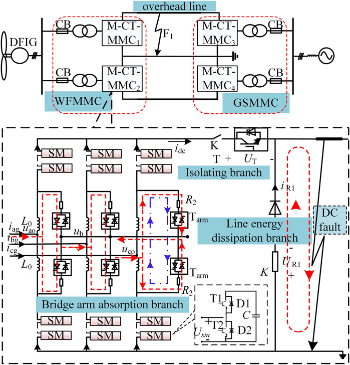
FIGURE 1. DC system with wind power integration and M-CT-MMC topology.
M-CT-MMC Topology
The M-CT-MMC topology is shown in Figure 1. The normal working state of the M-CT-MMC is the same as that of the half-bridge MMC; only three auxiliary branches are added, which can isolate the fault current and dissipate the surplus power. The components of each branch are described below.
1) Isolating branch: It is composed of the isolating switch T composed of several diodes and IGBTs in series after an antiparallel connection and an ultrafast mechanical switch K.
2) Line power dissipation branch: It is composed of freewheeling diodes D and an absorption resistor R1.
3) Bridge arm absorption branch: All bridge arm inductors of the MMC are equipped with an absorption branch at both ends, which is composed of the dissipation resistor R2 and bridge arm switch Tarm composed of n antiparallel thyristors in series. The leads between the two switches of each phase are connected to construct the AC flow path.
Fault Current Isolating Control Strategy for the M-CT-MMC Topology
For Figure 1 system, the isolating process of the M-CT-MMC fault current is introduced by taking mono-pole grounding fault as an example:
1) The fault occurs at t0, the capacitor of the fault pole M-CT-MMC discharges rapidly, and the fault current rises sharply. With a delay of 1 ms, the fault pole M-CT-MMC is locked at t1, and Tarm is triggered. All dissipative resistors are put into operation to reduce the fault current flowing through the converter valve, and the voltage after T is disconnected.
2) T is turned off at t2, and the fault current is transferred to the line power dissipation branch and the bridge arm absorption branch.
3) After a short delay, the current flowing through submodules of the bridge arm and the isolating branch is reduced to zero, and K is turned off. After about 2 ms, at t3, the ultrafast mechanical switch action is completed to achieve physical isolation of the M-CT-MMC and fault point.
4) At t4, Tarm has switched to the dissipation resistor adaptive switching control mode.
The M-CT-MMC can reduce the current stress of the bridge arm converter valve and can also provide breaking conditions for T to achieve effective isolation of DC faults. The three-phase neutral point scheme is constructed by the interconnection of bridge arm absorption branch outgoing lines, which saves the grounding investment and does not have the problem of bearing DC bias.
Coordinated Control Strategy of Surplus Power Consumption
After fault isolation, the output power of the WF will be completely borne by the non-fault pole, which may lead to non-fault pole overload. The problem of power surplus must be solved.
Control Mode Switching Strategy of the M-CT-MMC
To improve the power transfer capability of the non-faulty pole M-CT-MMC of the WFMMC, the control mode switching strategy is designed as follows:
1) The faulty pole M-CT-MMC control is switched to constant DC voltage/AC voltage control and put into operation again to maintain the voltage stability of the grid-connected bus of the WF.
2) The non-fault pole M-CT-MMC control is switched to the constant frequency/reactive power—voltage droop control (The reactive power reference value is set to 0 to improve the power transfer capability.)—to absorb the power of the fault pole and maintain the frequency stability of the WF side.
Under the condition that the surplus power can be completely transferred from the non-fault pole M-CT-MMC (self-absorbing condition), the WF and the receiving end system can quickly return to the normal state based on this method.
Control Strategy of Load-Shedding for Wind Turbines
When the non-fault pole M-CT-MMC cannot fully transfer surplus power (the non-self-absorption condition), it should be operated at full capacity. Surplus power is absorbed by wind turbine load-shedding and the dissipation resistors of the bridge arm.
The load shedding control strategy of the wind turbine is a coordinated control strategy between the M-CT-MMC and WF based on the idea of frequency control. Using the frequency control capability of the non-fault pole M-CT-MMC, we improve the frequency of the wind farm side accurately during fault crossing. Then, using the frequency response ability of the wind turbine, the accurate load shedding of the wind turbine is realized. The load-shedding power ∆PWF of the WF should meet the following equation:
where PWF is the output power of WF and SN is the rated capacity of the non-fault pole M-CT-MMC.
According to the principle of primary frequency regulation of the synchronous generator, the equivalent adjustment coefficient K doubly fed induction generator (DFIG) is defined as follows:
where ∆f is the frequency variation of the sending end system.
The expression of the maximum operating power P1 of the WF in the steady state and the output power Pmin when the rotor speed of the unit reaches the upper limit is shown in Eq. 3.
where kmppt and kmin are the tracking coefficients of the corresponding power curve, ω1 is the current rotor speed, ω2 is the upper limit of rotor speed, and ωN is the rated rotor speed; usually ω2 = 1.2ωN.
DFIG operates at a maximum power point in the steady state. When the system frequency fluctuates, the output power of the wind turbine meets the following relationship:
When the speed adjustment range is not large, it can be considered that ω1>>∆ω. (4) is simplified:
where fmax is the peak value of the system’s allowable operating frequency, the maximum is 50.5Hz; ∆Pmax is the limit frequency modulation power at the current wind speed, which can be expressed as the difference between P1 and Pmin at the wind speed.
Substituting ∆Pmax into (6) and sorting it out, we can get
When the system finally runs to a new steady-state point, ∆Pe is the load shedding power of WF ∆PWF, which satisfies ∆ω∝∆PWF∝∆f within the frequency adjustment range. The K value of the corresponding wind speed can be determined by using the current speed and relevant tracking coefficient of the wind turbine. Finally, combined with the frequency control of the non-fault pole M-CT-MMC, the precise load shedding of the WF can be realized. The specific implementation methods are as follows:
1) The non-fault pole M-CT-MMC determines ∆f according to ∆PWF and K. By adding ∆f to the frequency reference value fN of the non-fault pole M-CT-MMC, the system frequency on the WF side is controlled to reach the new steady-state value fN+∆f.
2) The WF monitors the system frequency f in real time. When f > fN, it immediately enters the overspeeding load-shedding control mode. According to Eq. 1, the frequency modulation ∆PWF can be calculated. Combined with the functional relationship F(x) between the output power of the WF and the speed of the WF in Eq. 5, ∆ω is obtained. ∆ω is superimposed on ω1 to obtain a new rotational speed control command ωref to realize the accurate load-shedding control of the WF. As shown in Figure 2, when f < fN, ∆ω = 0, it does not participate in the system power regulation. The WF continues to work in the maximum power tracking mode to improve the efficiency of wind energy utilization. In this process, the inherent delay of communication between the WF and M-CT-MMC is eliminated, and the load shedding response speed of the WF after the fault is improved.
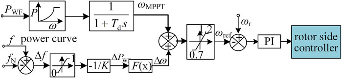
FIGURE 2. Overspeed load reduction control strategy of the WF.
This method does not require communication, which improves the response speed of the wind turbine load-shedding. And it can achieve accurate load-shedding and maximum power transmission, but the frequency threshold is small and the load-shedding capacity is small, which cannot meet the power dissipation demand of the WF under full-power operation.
Control Strategy of Dissipative Resistors Absorbing Surplus Power
The input capacity Phs (neglecting loss) of dissipation resistors can be expressed as follows:
where PN and λ (0 ≤ λ ≤ 1), respectively, represent the rated power and output coefficient of the WF.
For bipolar HVDC connected by the WF, the rated capacity of the unipolar M-CT-MMC is usually half of the rated capacity of the WF. Therefore, according to Eq. 9, if λ ≤ 0.5, the non-fault pole is used to transmit surplus power. If 0.5<λ ≤ 1, the input capacity of dissipation resistors shall be greater than and close to PHS to eliminate surplus power and reduce the influence on AC voltage and DC transmission power. Input dissipative resistance Req2 can be calculated by Eq. 10. When λ = 1, Req2 is minimum, dissipative resistance R2 (Req2|λ=1) is designed as M RSM2 (dissipation resistance of each group) in parallel, as shown in Eq. 11.
where UL is the effective value of line voltage borne by dissipation resistors.
The dissipation resistors of the fault pole M-CT-MMC are cut adaptively according to the actual output coefficient of the WF to maintain power balance, as given in the formula Eq. 12.
where Mout is the number of dissipation resistor groups to be removed after fault isolation;
Coordinated Control Strategy of Load-Shedding for Wind Turbine and Dissipative Resistors Absorbing Surplus Power
The basic idea of the coordinated control strategy based on wind turbine load-shedding and dissipation resistor absorbing surplus power is as follows: first, fault isolation shall be carried out according to the working process of the M-CT-MMC described in Fault Current Isolating Control Strategy for the M-CT-MMC Topology section. After the fault is isolated, the M-CT-MMC control strategy is switched, and the bridge arm absorption branch is switched to the adaptive cutoff mode. At the same time, the WF will also operate under load-shedding. The two strategies are carried out at the same time. With the increase of load-shedding power, the number of groups of dissipative resistance is increased to achieve power balance and fault ride-through. The flow block diagram of fault ride-through is shown in Figure 3.
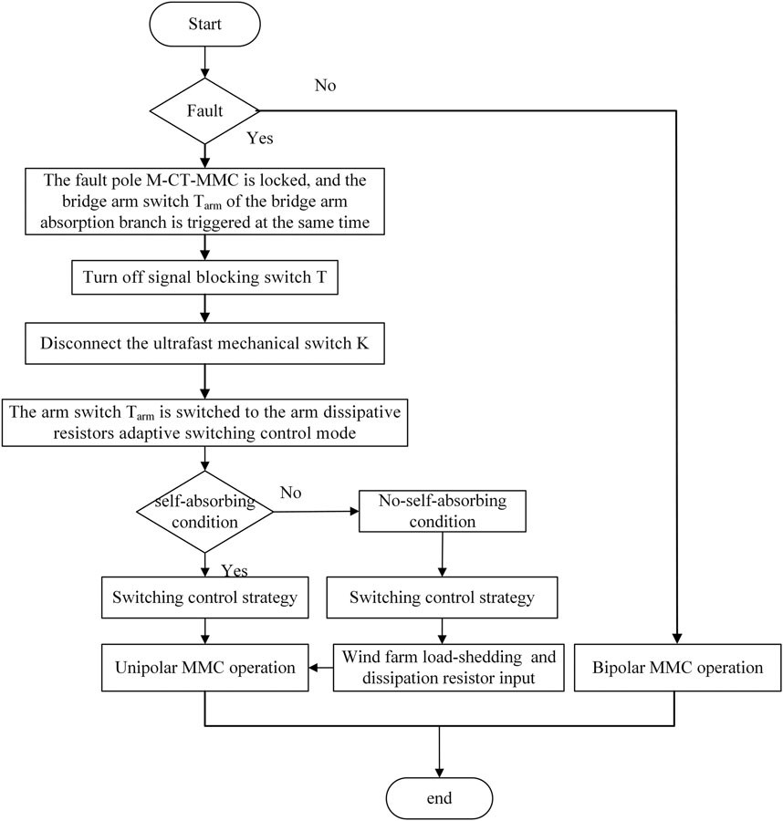
FIGURE 3. Fault ride-through flow block diagram.
Simulation Verification
Based on the Matlab/Simulink simulation platform, the simulation model as shown in Figure 1 is built. The WF is paralleled by two 500 MV A-rated DFIGs. The main parameters of the M-CT-MMC can be found in the study by Li et al. (2021), where RSM2 = 550Ω, M = 5. The effectiveness of the abovementioned strategy is verified by simulation. Figure 4 shows the simulation results of the DC fault ride-through–coordinated control strategy.
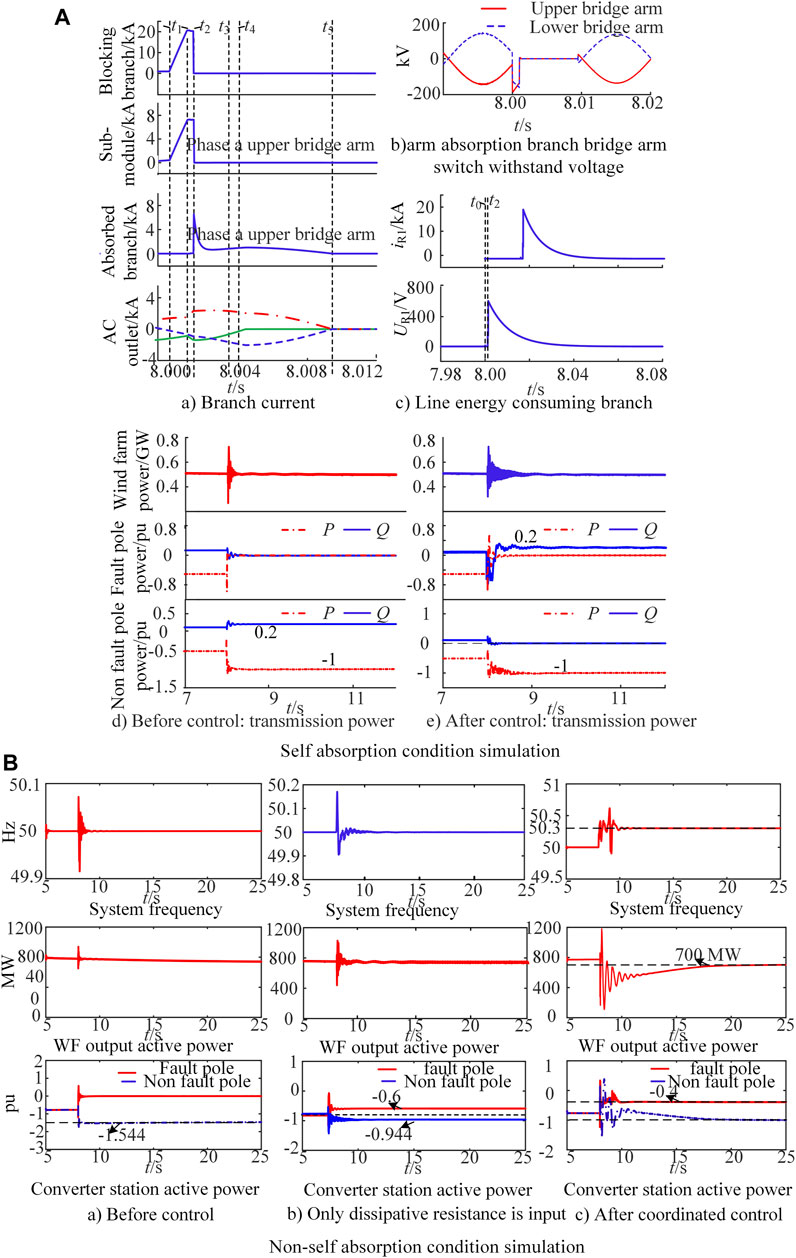
FIGURE 4. Simulation verification of the DC fault ride-through coordinated control strategy.
Simulation Verification of Self-Absorption Condition
The output power of the WF is set to 500 MW, and the positive and negative pole of the converter station shall bear 250 MW active power and 50MVar reactive power, respectively. At 8.0s, a unipolar metallic short-circuit grounding fault occurred at the DC outlet of the WF side. At t1, the fault pole M-CT-MMC is isolated and triggers Tarm; t1-t2 = 0.4 ms; t2-t3 = 2 ms; and t3-t4 = 0.6 ms. When t = 8.0035s, the control mode of the M-CT-MMC is switched.
After the fault occurs, the submodule current and isolating branch current increase rapidly. After adopting the fault current isolating control, the fault current drops rapidly and transfers to the bridge arm absorption branch and the line energy dissipation branch. The branch current decays to 0 after 1.09 ms and within 50 ms, respectively. As shown in Figure 4A,a,c., the M-CT-MMC can effectively isolate the DC side fault. Figure 4A,b shows the voltage of Tarm without DC voltage bias, which verifies the effectiveness of the proposed three-phase neutral point scheme.
After the fault is isolated, the power output of the WF remains unchanged. WF output active power (500 MW) and system reactive power (100MVar) can only be borne by the non-faulty pole M-CT-MMC, which leads to its overload operation. After switching the M-CT-MMC control, the faulty pole M-CT-MMC provides 0.2p.u. reactive power support for the system. It can avoid overload operation of the non-fault pole and ensure maximum transmission of active power at the same time, as shown in Figure 4A,d,e.
Simulation Verification of the Non–self-absorption Condition
The output power of the WF is 772 MW. Under this condition, the proposed coordinated control strategy is compared with the method of only using dissipative resistance to absorb surplus power, and the simulation results are shown in Figure 4B. When the wind turbine load is reduced from 72 to 100 MW (maximum), the input capacity of dissipation resistors is 200 MW. Therefore, to reduce the frequency change of the sending end, the non-fault pole M-CT-MMC frequency reference value adopts 50.3 Hz.
Before control, all output power of the WF is injected into the non-fault pole to enable its active power reach 1.544pu. The non-fault pole overload is shown in Figure 4B,a. After control, the system frequency finally stabilizes from 50 to 50.3 Hz; load-shedding of the wind turbine is reduced by 72 MW; 200 MW dissipation resistors are put into operation. The remaining 500 MW power is borne by the non-faulty pole M-CT-MMC to ensure the maximum transmission of active power and reduce the impact of the fault on the receiving end AC system, as shown in Figure 4B,c. When only dissipative resistors are put into operation, the output power of the WF is not changed; when three groups of dissipative resistors are put into operation, 300 MW active power is consumed, and the loss increases. The non-fault pole transmits 472 MW power and cannot operate at full load, as shown in Figure 4B,b, which increases the probability of load rejection. By comparison, the proposed coordinated control method has obvious advantages.
Conclusion
Aiming at the problem of DC fault ride-through in the bipolar DC system with WF integration, the M-CT-MMC with fault isolation and power dissipation is designed, and the coordinated control strategy of surplus power consumption is proposed. The following conclusions are obtained through simulation:
1) In terms of fault isolation, the M-CT-MMC can effectively isolate the fault current and avoid DC voltage bias, which can also dissipate surplus power, transfer fault current, and provide a new discharge path for the bridge arm inductance current.
2) In terms of surplus power consumption, the bipolar M-CT-MMC control mode switching strategy, wind turbine load shedding control strategy, and dissipation resistors are used to absorb the surplus power, which can comprehensively play the rapidity of wind turbine load-shedding and the reliability of dissipation resistors to meet the demand of surplus power dissipation under different conditions, and effectively reduce the fault influence range and improve the ability of safe and stable operation of the system.
Data Availability Statement
The original contributions presented in the study are included in the article/Supplementary Material; further inquiries can be directed to the corresponding author.
Author Contributions
BZ: conceptualization. HL: methodology. PX: software. SJ: validation. LZ: formal analysis. YX: data curation. All authors contributed to the article and approved the submitted version.
Funding
This research was financially supported by the National Natural Science Foundation of China (Grant No. U2066208).
Conflict of Interest
BZ, PX, and SJ were employed by Guangzhou Bureau of EHV Transmission Company of China Southern Power Grid Co, Ltd.
The remaining authors declare that the research was conducted in the absence of any commercial or financial relationships that could be construed as a potential conflict of interest.
Publisher’s Note
All claims expressed in this article are solely those of the authors and do not necessarily represent those of their affiliated organizations, or those of the publisher, the editors, and the reviewers. Any product that may be evaluated in this article, or claim that may be made by its manufacturer, is not guaranteed or endorsed by the publisher.
References
Ahmed, K. H., Adam, G. P., Abdelsalam, I. A., and Aboushady, A. A. (2018). Modular Multilevel Converter with Modified Half-Bridge Submodule and Arm Filter for Dc Transmission Systems with Dc Fault Isolating Capability[J]. IET Power Electron. 11 (14), 2253–2262. (in Chinese). doi:10.1049/iet-pel.2018.5081
Cao, S., Wang, X., Lin, W., and Win, J. (2019). Fault Ride-Through and Energy Dissipation Control of Bipolar Hybrid MMC-MTDC Integrating Wind Farms[J]. Power Syst. Prot. Control. 47 (07), 39–48. (in Chinese).
Guo, X., Cui, X., and Qi, L. (2017). DC Short-Circuit Fault Analysis and protection for the Overhead Line Bipolar MMC-HVDC System[J]. Proc. CSEE 37 (8), 2177–2184. (in Chinese). doi:10.13334/j.0258-8013.pcsee.162229
He, Y., Zhou, L., Li, Y., Gu, W., Zhao, B., and Wang, S. (2017). Power Conversion Strategy of VSC-MTDC System Based on Real Bipolar Wiring Mode[J]. Automation Electric Power Syst. 41 (19), 95–101. (in Chinese). doi:10.7500/AEPS20170327009
Li, G., Jiang, S., Xin, Y., and Wang, L. (2020). Coordinated Control Strategies for DC Fault Ride-Through of Wind Power Integration via Bipolar MMC-HVDC Overhead Lines[J]. Proc. CSEE 40 (11), 3516–3527. (in Chinese). doi:10.13334/j.0258-8013.pcsee.190724
Li, G., Song, Z., and Wang, G. (2019). Asymmetric Full-Bridge Sub-module Topology of MMC with DC Fault Isolation Capability[J]. High Voltage Eng. 45 (1), 12–20. (in Chinese). doi:10.13336/j.1003-6520.hve.20181229001
Li, G., Zhang, L., Jiang, S., and Xin, Y. (2021). Coordinated Control Strategies for DC Fault Ride-Through of Wind Power Integration via Bipolar Hybrid MMC-HVDC Overhead Lines [J]. Power Syst. Prot. Control. 49 (10), 27–36. (in Chinese). doi:10.19783/j.cnki.pspc.200880
Li, S., Guo, C., Zhao, C., and Xu, J. (2017). Novel MMC Topology with Lower Power Loss and DC Fault Ride-Through Capability[J]. Proc. CSEE 37 (23), 6801–6810. (in Chinese). doi:10.13334/j.0258-8013.pcsee.162109
Li, S., Wang, X., Tai, L., and Peng, Z. (2016). Optimal Design for Hybrid MMC and its DC Fault Ride-Through Strategy[J]. Proc. CSEE 36 (7), 1849–1858. (in Chinese). doi:10.13334/j.0258-8013.pcsee.162109
Lin, W., Jovcic, D., Nguefeu, S., and Saad, H. (2016). Full-Bridge MMC Converter Optimal Design to HVDC Operational Requirements. IEEE Trans. Power Deliv. 31 (3), 1342–1350. doi:10.1109/tpwrd.2015.2475130
Liu, G., Xu, F., Xu, Z., Zhang, Z., and Tang, G. (2017). Assembly HVDC Breaker for HVDC Grids with Modular Multilevel Converters. IEEE Trans. Power Electron. 32 (2), 931–941. doi:10.1109/tpel.2016.2540808
Moawwad, A., El Moursi, M. S., and Xiao, W. (2016). Advanced Fault Ride-Through Management Scheme for VSC-HVDC Connecting Offshore Wind Farms. IEEE Trans. Power Syst. 31 (6), 4923–4934. doi:10.1109/tpwrs.2016.2535389
Nian, M., Zhou, Y., Tan, L., and Yuan, B. (2020). Energy Consumption Method for Power Surplus in Zhangbei VSC-Based DC Grid[J]. Power Syst. Technol. 44 (05), 1991–1999. doi:10.13335/j.1000-3673.pst.2019.1946
Rizk-Allah, R. M., Hassanien, A. E., and Song, D. (2021). Chaos-Opposition-Enhanced Slime Mould Algorithm for Minimizing the Cost of Energy for the Wind Turbines on High-Altitude Sites. ISA Trans. (15). doi:10.1016/j.isatra.2021.04.011
Song, Q., Yang, W., Li, X., Li, J., Zeng, W., Huang, Y., et al. (2017). A Modular Multilevel Converter Integrated with DC Circuit Breaker [J]. Proc. CSEE 37 (20), 6004–6013. (in Chinese). doi:10.13334/j.0258-8013.pcsee.171497
Song, Q., Zeng, R., Yu, Z., Liu, W., Huang, Y., Yang, W., et al. (2018). A Modular Multilevel Converter Integrated with DC Circuit Breaker. IEEE Trans. Power Deliv. 33 (5), 2502–2512. doi:10.1109/tpwrd.2018.2815550
Tao, F., Xie, Z. J., Cheng, J., Li, C., Zhao, L., and Wen, J. (2016). Fast Valve Power Loss Evaluation Method for Modular Multi-Level Converter Operating at High-Frequency. Prot. Control. Mod. Power Syst. 1 (1), 2. doi:10.1186/s41601-016-0015-z
Wang, Z., Liu, J., and Zhuang, X. (2018). A Current Transferring MMC Topology with DC Fault Clearance Capability[J]. Proc. CSEE 38 (19), 5795–5803. (in Chinese).
Xiaoguang, W., Yang, B., and Tang, G. (2017). Technical Development and Engineering Applications of HVDC Circuit Breaker[J]. Power Syst. Technol. 41 (10), 3180–3188. (in Chinese).
Keywords: modular multilevel converter, fault isolating, power dissipation, DC fault ride-through, coordinated control strategy
Citation: Zhu B, Li H, Xu P, Jiao S, Zhang L and Xin Y (2021) Coordinated Control Strategy of DC Fault Ride-through for the WF Connected to the Grid Through the MMC-HVDC. Front. Energy Res. 9:743465. doi: 10.3389/fenrg.2021.743465
Received: 18 July 2021; Accepted: 13 September 2021;
Published: 20 October 2021.
Edited by:
Dongran Song, Central South University, ChinaCopyright © 2021 Zhu, Li, Xu, Jiao, Zhang and Xin. This is an open-access article distributed under the terms of the Creative Commons Attribution License (CC BY). The use, distribution or reproduction in other forums is permitted, provided the original author(s) and the copyright owner(s) are credited and that the original publication in this journal is cited, in accordance with accepted academic practice. No use, distribution or reproduction is permitted which does not comply with these terms.
*Correspondence: Hongying Li, 732392093@qq.com