IBSync: Intra-body synchronization and implicit contextualization of wearable devices using artificial ECG landmarks
 Florian Wolling
 Kristof Van Laerhoven
- Ubiquitous Computing, Department of Electrical Engineering and Computer Science, University of Siegen, Siegen, Germany
With a smaller form factor and a larger set of applications, body-worn devices have evolved into a collection of simultaneously deployed hardware units, rather than into a single all-round wearable. The sensor data, logged by such devices across the user's body, contains a wealth of information but is often difficult to synchronize. Especially the application of machine learning techniques, e.g., for activity recognition, suffers from the inaccuracy of the devices' internal clocks. In recent years, intra-body communication emerged as a promising alternative to the traditional wired and wireless communication techniques. Distributed wearable systems will notably benefit from its advantages, such as a superior energy efficiency. However, due to the absence of commercially available platforms, applications using this innovative technique remain rare and underinvestigated. With IBSync, we present a novel concept in which artificial landmark signals are received by body-worn devices on touching, approaching, or passing certain areas, surfaces, or objects with embedded transmitter beacons. The landmark signals enable both the wearables' intentional or incidental synchronization as well as the implicit contextualization using supplementary information about the beacons' situational context. For the detection of the landmarks, we propose to repurpose the on-board ECG sensor front-end available in recent commercial wearable devices. Evaluated on a total of 215 min of recordings from two devices, we demonstrate the concept's feasibility and a promising synchronization error of 0.80±1.79 samples or 6.25±14.00 ms at a device's sampling rate of 128 Hz.
1. Introduction
The last two decades showed numerous wearable devices entering the market and targeting the wearer's continuous ambulatory and non-invasive monitoring. With a smaller form factor and a larger set of applications, these body-worn devices have, however, evolved into a collection of simultaneously deployed hardware units, rather than into a single all-round wearable. Worn close or even directly attached to the body surface, the devices log sensor data which contains a wealth of information. The synchronization of such distributed, multi-device systems is, however, often difficult. As stated by Ohmura et al. (2006) and Wang et al. (2019), traditional signal processing but especially the application of cutting-edge machine learning techniques, e.g., for activity recognition, suffer from the inaccuracy of the devices' internal clocks and the recordings' unmatched time. Most commercial, off-the-shelf devices do not support the online synchronization during operation by default because it would require specific hardware and interfaces, which would exceed their small energy budget. As detailed by Barth et al. (2008), Mare and Kotz (2010), and Naganawa et al. (2015), the available methods, based on Bluetooth and other popular wireless protocols, suffer from the general inefficiency of radio transmission due to a lossy air channel and, particularly in wireless body area networks (WBAN), a vicinity to the water-rich tissue. Originated in research on human activity recognition by Bannach et al. (2009), the existing methods of Bennett et al. (2015a), Bennett et al. (2015b), Wang et al. (2019), and Ahmed et al. (2020) allow for the alignment of measurements offline, after the recording. However, the performed synchronization actions, i.e., gestures and motion patterns, are not incidental but rather tend to be cumbersome and obtrusive. As discussed in Lu et al. (2020) and our previous work in Wolling et al. (2021b), they furthermore suffer from inaccuracies due to soft tissue deformation as well as delays in the motion sequences and inertia of the body parts. The achieved accuracy is typically in the range of 250 ms in Wang et al. (2019) down to 46 ms in Ahmed et al. (2020).
In general, accelerometers and inertial measurement units (IMU) became very popular instruments and are commonly used for the signal classification in human activity recognition. However, to distinguish motion patterns which result in similar signals, the data is often not rich enough. Supplementary material about the context could help to improve the inference. With the term implicit HCI, Schmidt et al. (2000) described “a shift [...] from explicit interaction [...] toward a more implicit interaction based on situational context.” According to Schmidt (2000) and Berlin et al. (2010), the knowledge of the object grasped can, therefore, help to also interpret interactions and the user's intention. To detect objects, equipped with passive RFID tags, the prototypes of Schmidt (2000), Philipose et al. (2004), Fishkin et al. (2005), and Berlin et al. (2010) use wrist-worn RFID readers. In this way, the combination of inertial sensor data and the context information of the object grasped improve the classification of activities and help to minimize the labeling efforts, as presented by Wang et al. (2007). The wearable RFID readers tend, however, to be obtrusive and the large coils require a certain quality to achieve a sufficient range to reach the tags.
In recent years, a novel yet promising approach emerged that makes use of the limited volume of the human body as a transmission medium: intra-body communication (IBC). It is somewhat located between traditional wired and wireless communication techniques. The fundamentals were first described in the dissertation (Zimmerman, 1995) and the ensuing publication (Zimmerman, 1996). Since then, many researchers developed optimal electrode settings and modulation schemes, and the developed prototypes range from an implementation on experimental PCBs, such as in Große-Puppendahl et al. (2014), Moralis-Pegios et al. (2015), and Wolling et al. (2017), to the use of own chip-casted, high-level ASICs as in Song (2007), Chung et al. (2015), and Cho et al. (2016). High data rates of up to 2 MBit/s at 0.2 mW in Song (2007) or even 80 MBit/s at 8.9 mW in Cho et al. (2016) have been reported. As discussed in Große-Puppendahl et al. (2017), the accompanied grounding issues limit, however, the reliability of the presented solutions outside the laboratory environment. Moreover, these approaches often remain closed-source and, besides the discontinued attempt BodyCom from Microchip1, they are not made commercially available. Consequently, academic research still focuses rather on the development of transceiver circuits, accompanied with advances in reliability, energy efficiency, and data throughput. Applications benefiting from this novel technique have, however, not yet been thoroughly explored. From our previous research in Wolling et al. (2021a) aside, to our knowledge, two very essential, possible applications of IBC have not yet been investigated: the synchronization and the contextualization of wearables and their measurements.
In this paper, we propose to repurpose the single-lead ECG sensors, integrated in recent off-the-shelf wearables, to detect artificial landmark signals. Those are either consciously or implicitly and incidentally induced into the user's skin by touching, approaching, or passing certain areas, surfaces, or objects with embedded beacons. In close proximity, the signals are capacitively induced into the skin and propagate in the tissue as harmless displacement currents. In this way, landmarks are made available throughout the entire body surface, which serves as a limited transmission channel that is hence more efficient than air. Considering the limitations of the utilized analog ECG front-end, we present a suitable modulation scheme and evaluate the proposed signal processing pipeline for the landmark detection and demodulation. We demonstrate the method's general feasibility on the base of two possible applications as examples in which the landmark signal is used to either synchronize two devices or to provide the context of measurements.
With our presented contributions, we do not intend to compete with cutting-edge research in IBC, especially not in terms of data throughput and efficiency. Instead, we aim for the use of accessible, commercially available devices to pave the way for applications that, when finally made available, can directly be translated to future single-chip solutions, specifically designed for IBC.
2. Related work
According to their domain, the following related work is split up into four sections. First, the state of the art in electrocardiography (ECG), synchronization techniques, and contextualization for wearable devices are presented. Then, the relevant research in wireless body area networks (WBAN) and intra-body communication (IBC) are summarized. Each section closes with the statements most relevant for this work.
2.1. Electrocardiography
Electrocardiography (ECG) is the gold standard to monitor a patient's heart activity and to diagnose heart diseases in clinical settings. Every contraction of the heart is initiated through electrical action potentials which polarize the myocardal muscle. Its electric field accumulates, spreads in the tissue, and is therefore detectable at the skin surface. The typical ECG waveform with its prominent QRS complex is monitored applying traditional lead systems, introduced by Einthoven et al. (1950) and Holter (1961), and summarized by AlGhatrif and Lindsay (2012), with up to 12 wired wet gel electrodes that capture the electric potential differences across the limbs or torso. The progress in miniaturization does not only enable more convenient but also more energy efficient mobile devices, as surveyed in Zheng et al. (2014). Nevertheless, the conventional ECG leads remain inapplicable and too uncomfortable for the continuous monitoring in long-term ambulatory assessments. The first wearable ECG devices, such as in Karvonen et al. (1984), had the shape of a chest strap and used dry electrodes to resemble lead I across the heart. Starting with the crowdfunded Mio Alpha and the Scosche Rhythm in 2013, elaborated in Kyriacou and Allen (2021), these devices were then successively replaced by more convenient, wrist-worn devices that primarily apply the cheap and easy-to-implement optical photoplethysmography (PPG). However, according to Castaneda et al. (2018), PPG cannot yet compete with ECG in terms of accuracy. As a result, wrist-worn devices gradually offer the special feature of a supplementary single-lead ECG sensor to enable the monitoring of heart activity at the medical grade. As described in Beach et al. (2018) and Avila (2019), the user has to touch an electrode with a finger from the opposite arm to form the lead I with potentials from either side of the heart. However, as described in Chi et al. (2010), the use of dry electrodes inevitably results in a considerably weaker signal that, according to Casson (2014) and Ha et al. (2014), typically ranges from tens to hundreds of μV. According to Harland et al. (2002), the used differential amplifier thus requires a high input impedance in the order of several MΩ to not load the fragile signal. Introduced by Neuman and Webster (1978), detailed in Winter and Webster (1983), and reviewed in Sun and Yu (2016), a common technique to improve the common-mode rejection ratio (CMRR) is an actively driven electrode, often termed as driven-right-leg (DRL) circuit or body bias, that allows to suppress common-mode interference such as 50/60 Hz humming noise from the power line. Nevertheless, the single-spot measurement of ECG at the wrist, without closing the wide lead I, remains a challenge. With the front-ends available today, according to Beach et al. (2018), the signal-to-noise ratio (SNR) at the wrist quickly drops to less than 0 dB, which makes the differentiation of the desired signal from the noise floor de facto impossible. However, advances by Harland et al. (2002), Chi et al. (2011), and Rachim and Chung (2016), present promising circuits, with a very high input impedance beyond several GΩ, that might be a first step toward solving this issue. In the next few years, the required ECG sensor front-end will hence become standard in wearables and therefore inherently enable the methods presented.
2.2. Synchronization
The network time protocol (NTP) of Mills (1991) and the precision time protocol (PTP) of Lee and Eldson (2004) have established as popular and reliable methods to obtain a precise universal time base in both wired and wireless distributed systems. In contrast to large computer networks, body-attached distributed systems often require only a local synchronization, relative between the nodes. As stated by Elson et al. (2002), referring to Lamport (1978), in most applications the “causality is more important than absolute time.” The available synchronization techniques can be grouped into the two classes of online and offline methods. The online synchronization at runtime requires the continuous coordination and tuning of the devices' local clocks.
Advances in conductive textiles, such as in Poupyrev and Gong (2016), would, of course, easily enable sharing a master clock. Nevertheless, wireless radio communication still remains the preferred technology in wearable applications. Not only the methods applied in wireless sensor networks (WSN), as surveyed in Sundararaman et al. (2005) and Lasassmeh and Conrad (2010), but in particular those running on wearable devices, as discussed in Zheng et al. (2014), primarily focus on energy efficiency. As discussed in Barth et al. (2008), Mare and Kotz (2010), and Naganawa et al. (2015), radio transmission, applying e.g., the popular Bluetooth in Roberto Casas (2005), Ringwald and Romer (2007), and Pflugradt et al. (2014), suffers largely from a variable path loss, shadowing effects due to the devices' direct attachment to the water-rich human body. Offline synchronization methods, in contrast, use external events to align recorded signals in a post-processing step.
Originated in research on activity recognition, Bannach et al. (2009) established the idea of aligning time series through the correlation of synchronization actions such as clapping, shaking, or jumping. It already achieved a synchronization error of about 0.3 s for more than 80 % of the data. Based on this fundamental concept, more sophisticated approaches use specific motion patterns, e.g., in Bennett et al. (2015a), Bennett et al. (2015b), Wang et al. (2019), and Lu et al. (2020), or even cough events as in Ahmed et al. (2020). These achieved typical synchronization errors ranging from 250 ms down to 46 ms. Beyond that, Vaz et al. (2015) proposed the correlation and alignment of physiological signal channels by means of the inherently present white noise. The achieved sub-ms accuracy is, however, bought dearly through high sampling rates of 2 and 20 kHz. More signal-specific, Li and Tan (2010) used the “naturally synchronized” rhythm of the heartbeat to schedule the time slots in a time division multiple access (TDMA) protocol for medium-access control (MAC). In our previous research on PulSync, in Wolling et al. (2021b), we used the uniqueness of the heart rate variability (HRV) interval function as a fingerprint to correlate and align sensor recordings from multiple wearable devices. In this way, we achieved a synchronization error of 0.71 ± 3.44 samples or 2.86±11.43 ms at 250 Hz.
2.3. Contextualization
In the late twentieth century, research in human-computer interaction (HCI), such as by Want et al. (1999), aimed at “seamlessly bridging the gulf between physical and virtual worlds.” At that time, also the interest of psychologists in experience sampling motivated computer-assisted methods to replace the traditional pen-and-paper procedures and to get a “window into [a user's] daily experience and behavior,” as detailed by Barrett and Barrett (2001). Such approaches require, however, the reliable classification of activities of daily living (ADL) and the unobtrusive detection of interactions with objects, as described by Philipose et al. (2004). With the emergence of microelectromechanical systems (MEMS), accelerometers became affordable and wearable sensing devices enable since then the recognition of activities of limited sets. However, the obtained information is often not rich enough to distinguish similar activities that show confusable signal patterns. According to Berlin et al. (2010), the knowledge of the object grasped can, however, help to classify activities, to interpret interactions, and to “reason on the intention of the user,” as stated by Schmidt (2000). As presented by Wang et al. (2007), this knowledge allows the interpretation of the way objects are used, and can, moreover, help to minimize the labeling efforts. In course of this development, Schmidt et al. (2000) introduced the term implicit HCI which describes “a shift [...] from explicit interaction [...] toward a more implicit interaction based on situational context.” Accordingly, not only the location but especially the awareness of the situational context brings advantages in the interpretation of observations and the inference of sensor signals. Toward this concept, different projects aimed to identify the objects grasped to support the more reliable and precise classification of activities. First approaches, such as by Smith et al. (2003), used barcodes to tag objects. Following research used radio-frequency identification (RFID) tags instead, attached to certain objects, tools, or even the environment, e.g., at a doorknob in Berlin et al. (2010). Different wearable setups then combined inertial sensors for activity recognition and RFID readers to simultaneously detect the objects' tags. The yet wired and bulky prototype of Schmidt (2000) allowed to trigger different applications by handling tagged objects, read through a coil sewn into a work glove. The lighter iGlove in Philipose et al. (2004) used a reader coil in the palm while the iBracelet in Fishkin et al. (2005) as well as the prototype of Berlin et al. (2010) applied a PCB coil worn around the wrist instead. Most RFID tags are passive and receive the energy, required for data transmission, from the reader coil through electromagnetic induction, so no battery is needed. The reader requires, however, a coil with a certain quality for a long range, which is not available in commercial devices. The proposed use of ECG sensors for the detection of object identifiers, broadcasted as landmark signals by long-lasting active beacons, might hence be a promising alternative.
2.4. Intra-body communication
Due to a considerable amount of fully developed, standardized, small, and affordable modules, conventional radio communication, using protocols such as Bluetooth, ZigBee, and Wi-Fi, remains the most popular technique applied in research prototypes as well as commercial wearable devices. In most applications, fixed cable joints but also wires embedded and woven into clothing, such as presented in Poupyrev and Gong (2016), are not yet a serious alternative since the attachment and linking of devices tends to be interference-prone, inflexible, and uncomfortable. As discussed in Donker (2009) and Antonescu and Basagni (2013), the nodes of wireless body area networks (WBAN) are thereby usually attached to or at least worn close to the skin and their radio modules suffer considerably from the immediate vicinity to the water-rich body, shadowing, and motion.
A novel alternative has been presented first in the dissertation (Zimmerman, 1995) and the ensuing publication (Zimmerman, 1996), introducing the term intra-body communication (IBC). In following research, it is also referred to as body-coupled or body channel communication (BCC) and, designated as human body communication (HBC), it is included in the IEEE 802.15.6 of the IEEE Standards Association (2012) for WBAN since 2012. As an intermediate principle between the traditional wired and wireless techniques, it uses the human body as an alternative transmission medium to provide information throughout the user's skin surface, and thus shows advantages over both. In contrast to the busy air, Donker (2009) and Kibret et al. (2014) state that the body channel is free, its limited distribution volume improves the energy efficiency of signal propagation, and the abruptly decaying near-field outside the body is less susceptible to eavesdropping. As surveyed by Naranjo-Hernández et al. (2018), there exist two primary principles for the signal induction: the original capacitive coupling and galvanic coupling. Reviewed by Tomlinson et al. (2019), other approaches using electromagnetic fields, e.g., Koshiji et al. (2012) or Park and Mercier (2015), and transdermal ultrasound, as discussed in Galluccio et al. (2012), remained exotic and rather unpopular. Since the applicable principle is inherently given by the wearable devices used in this work, only the relevant capacitive coupling approach is elaborated in the following.
For capacitive coupling, two stacked electrodes form a parallel plate capacitor of which one faces the skin and couples to the body while the other one provides a delicate return path through the environment and earth ground, as detailed in Große-Puppendahl et al. (2017). To emit a signal, the transmitter changes the potential difference among its electrodes and hence modulates the quasi-electrostatic field of the user's body. This variation induces a tiny current flow, spreading in the tissue, and in turn causes a small potential difference among the electrodes of the receiver, which can be detected using a sensitive circuit. As discussed in Tomlinson et al. (2019), the slight displacement current in the order of pA does not pose a health risk to the user. Besides the applied coupling principle, the channel characteristics, robustness, and efficiency largely depend on the selected frequency band. The electrical properties of the tissues, conductivity and dielectric permittivity, respectively, exhibit a considerable frequency dependency which results in the human body showing a transmission behavior similar to the one of a high-pass filter. The effect of different tissue compositions on the transmission characteristics have been investigated, modeled, and simulated in diverse studies, surveyed in Naranjo-Hernández et al. (2018). As stated by Mazloum (2008), also the electrode size and distance play an important role while “using an electrode with a larger area specifically at TX will result in less propagation loss.” Furthermore, Mazloum (2008) and Kibret et al. (2014) discussed that the most suitable frequency band ranges from 100 kHz up to 50 MHz, limited through the resonance of the human body or parts of it. Research of Bae et al. (2012) also explains the three frequency-dependent transmission mechanisms: quasi-static near-field coupling (predominating below 40 MHz), reactive induction-field radiation (maximal at 40 MHz), and surface wave far-field propagation (predominating beyond 40 MHz).
An important aspect for this research is stated by Harikumar et al. (2012): “Low frequencies in the range of few Hz are susceptible to electromagnetic interferrence and demand very high input impedance amplifiers.”
As already mentioned by Zimmerman (1995) and elaborated in Große-Puppendahl et al. (2017), capacitive coupling suffers primarily from the delicate return path through earth ground, the environment which is susceptible to changes and provides a highly variable loss. If both devices are floating, the transmitter as well as the receiver, and do not share a common potential, the SNR, associated with signal amplitude and quality, decreases significantly. However, a stationary transmitter with a link to earth ground consequently results in a significantly higher SNR and less complex circuits that, as stated in Donker (2009), “can be done by graduate students with limited budgets” as presented in Moralis-Pegios et al. (2015) and our previous work of Wolling et al. (2017).
There has also been prior research in repurposing off-the-shelf devices for applications similar to ours. On the one hand, fingerprint sensors of smartphones and touchpads of laptops have been utilized as transmitters in Hessar et al. (2016), achieving a data rate of up to 50 bps by triggering the active sensors' operation, and hence the generation of electromagnetic interference (EMI). On the other hand, touchscreens of tablet computers have been used as receivers to distinguish users at 4 bps in Vu et al. (2012) and for the continuous user authentication at 12 bps in Holz and Knaust (2015) by means of wrist-worn transmitters.
In our prior work (Wolling et al., 2021a), we have first demonstrated that the analog front-ends of conventional, wearable ECG sensors can be repurposed to detect and decode artificial landmark signals. In this article, we do not only present more details but also new findings and advanced evaluation results.
3. System implementation
The exemplary scenario, applied in scope of this paper, is illustrated in Figure 1. It consists of a transmitter beacon, embedded into a desktop, and two off-the-shelf wearable devices with integrated ECG sensor front-end, repurposed as the receiver for the artificial landmark signals. In the following sections, the used hardware, modulation scheme, signal processing pipeline, and proposed applications are explained.
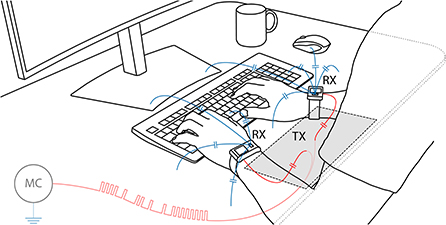
Figure 1. Exemplary scenario of IBSync for the synchronization and contextualization of wearable devices: microcontroller (MC) with transmitter electrode (TX) embedded into a desktop; information implicitly and incidentally provided to two sensing devices (RX) worn at the wrists; artificial landmark signal (), capacitively induced into the human body; detection by means of repurposed analog ECG sensor front-ends; weak return paths () to close the circuit; MC is grounded via environment, the earth ground.
3.1. Stationary transmitter beacon
In order to easily assemble and deploy beacons at a larger scale, the transmitter circuit is kept simple. The general-purpose input/output (GPIO) pin of a conventional MSP430FR5969 microcontroller2 from Texas Instruments directly drives the signal electrode and hence modulates its surrounding quasi-static electric field. Unlike for antennas in radio frequency (RF), there are no special requirements on the electrode since rather low frequencies are applied. It is made from metal foil and has a relatively large size of 16 × 32 cm2 to provide a sufficiently wide contact face.
As illustrated in Figure 1, the investigated scenario shows the electrode fixed under the front edge of a conventional desktop. It is intended to couple to the user's arms through a 1.5 cm plate of wood and plastic. A second ground electrode, to close the circuit, is not required since the beacon is supplied by and hence grounded through a USB link to a computer, in turn connected to mains. In this way, the environment serves as a large, virtual ground electrode and only a single transmitter electrode is required. As previously mentioned in Section 2.4, cutting the beacon's link to earth ground would largely affect the simplified setting, considerably attenuate the signal amplitude, and hence degrade the SNR at the receiver. Keeping the transmitter grounded, therefore, has the advantage that no additional power amplification stage is required, to boost the transmitter's output amplitude to tens of V as originally done by Zimmerman (1995). To ensure a precise timing, the computer is also employed to regularly, every 2.5 s, instruct the microcontroller to send a landmark signal. In future scenarios, however, this task could independently be performed by the microcontroller itself. Precise timing could then be obtained from a high-quality real-time clock, or even absolute time from the internet. To generate the landmark signal, a pulse train is generated by switching the pin between 0 and 3.3 V. As reasoned below in Section 4.1, the applied modulation frequency f0 is tuned to 20 Hz.
3.1.1. Signal modulation
By toggling the GPIO pin, the beacon generates a pulse train of a certain pattern to encode the information to be transmitted. Figure 2 illustrates the applied scheme for a single landmark packet. Each packet consists of eight pulses as a preamble, one gap and one pulse as delimiter, eight pulses or gaps as symbols to represent the 8 bit of data, again one pulse and one gap as delimiter, and finally four pulses as a terminator. The preamble, terminator, and two delimiters form a constant packet frame which embraces the variable data segment. As common, the data byte is transferred with the most significant bit (MSB) first. Figure 3 illustrates that the generation and transmission of rectangular waves is not ideal in terms of bandwidth and efficiency since the energy spreads in a wide frequency band and the effective signal magnitude within the desired band decreases considerably. Nevertheless, the on-off-keying (OOK) modulation scheme is reasonable since it is simple and easy to implement with a conventional, cheap, and low-power microcontroller. When coupling to the user's body, the beacon capacitively modulates the quasi-electrostatic field and, as discussed in Tomlinson et al. (2019), induces a harmless displacement current in the order of pA. Due to the human body's transmission characteristics and the applied preprocessing at the receivers, described below in Section 3.2.1, the rectangular wave is detrended and smoothed. As shown in Figure 9 later on, it resembles a rounded, quasi-sinusoidal wave, centered at the baseline.
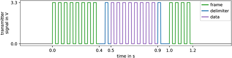
Figure 2. Simulated, synthetic illustration of the signals at the transmitter: 8 pulses preamble (), gap and pulse as delimiter (), 8 pulses or gaps to encode the data in OOK scheme () with the MSB first, pulse and gap as delimiter (), and 4 pulses terminator (). Modulation frequency f0 of 20 Hz.
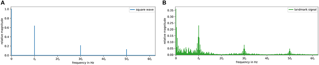
Figure 3. Simulated, synthetic frequency spectra of an ideal, continuous square wave with f0 of 20 Hz and 50 % duty cycle [(A), blue] and of a landmark signal with 2.5 s intervals, 1.2 s active period, and an incrementing 8 bit data segment [(B), green]. In both cases, the even harmonics of f0 are zero. For the discontinuous landmark signal, the spectrum spreads around the odd multiples of f0. The energy contained in the DC component at 0 as well as in f0 and its harmonics decreases considerably (note the y axes).
3.2. Wearable receiver
There exist no commercial IBC transceiver modules yet. Therefore, we propose the use of the analog front-ends (AFE) from the emerging single-lead ECG sensors available in recent wearable devices such as smartwatches or fitness trackers. The AFEs offer themselves to be repurposed for the detection of artificial landmark signals since they are carefully designed with regard to both energy efficiency and the sensitive detection of tiny potential differences.
In the experiments, two off-the-shelf MAXREFDES101#3 devices from Maxim Integrated, which is since 2021 a subsidiary of Analog Devices, have been used. The reference designs have the shape of a wristwatch and, besides IMU, PPG, and body temperature sensors, they include an AFE for bio-impedance and biopotential measurements, enabling the ECG monitoring. The devices grant access to the sensor configuration, the source code of their firmware, and the raw measurements. The on-board MAX300014 AFE consumes only 95 μA at 1.8 V while providing both, a very high input impedance >1 GΩ and a CMRR >100 dB. In this way, it enables the unloaded detection of the tiny voltage drop that is caused by the displacement current between the electrodes. Sampled at a rate fs of 128 Hz, the raw measurements can directly be recorded to the 32 MB flash memory. As depicted in Figure 4, the devices' casing shows three electrodes of which two virtually form the parallel plate capacitor required for capacitive coupling in the proposed application. The positive input (ECGP) at the front is kept floating and is intended to couple to the environment. The negative input (ECGN) directly couples to the body and enables the measurement of the potential difference in reference to ECGP at the front. Labeled in the datasheet as body bias, the third electrode (VCM) serves as a DRL circuit to improve the CMRR. Its activation connects the body through a 499 kΩ resistor5 to the device's internal common-mode voltage VCM of 0.650 V.
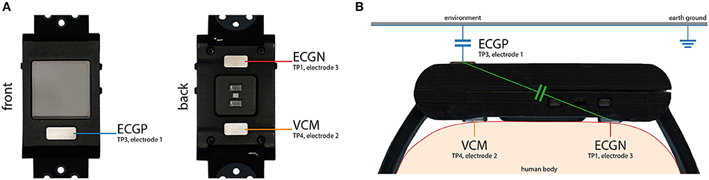
Figure 4. The ECG sensing device MAXREFDES101# has three electrodes on its casing (A) a positive input (ECGP) at the front, a negative input (ECGN) and a body bias (VCM) at the back. Detection of the artificial landmarks according to the capacitive coupling principle for IBC (B) ECGP and ECGN resemble a parallel plate capacitor (); ECGN directly couples to the human body (); ECGP is floating, weakly coupling to the environment to close the circuit (); VCM to improve CMRR ().
3.2.1. Signal demodulation
To detect the landmarks, to determine their positions in local time t′, and to decode the contained data d, the signal processing pipeline, illustrated in Figure 5, is applied. It starts with three 2nd order (2 × 1st) infinite impulse response (IIR) filter stages to extract the weak, desired signal. The use of zero-phase forward-backward filters is expedient to preserve the signal's phase, which is important for the proposed synchronization application. In Python, this filter type is well-known as filtfilt filter from the scipy.signal library. First, an anti-aliasing low-pass filter (LP) with a cutoff frequency fc of 63Hz<fs/2 below the Nyquist frequency is applied. Then, the power line's humming noise at 50/60 Hz is suppressed using a band-stop notch filter (BS), to provide an interference-reduced signal (IRS). Centered at the carrier's fundamental frequency f0 of 20 Hz, the desired frequency band is finally extracted using a band-pass filter (BP).
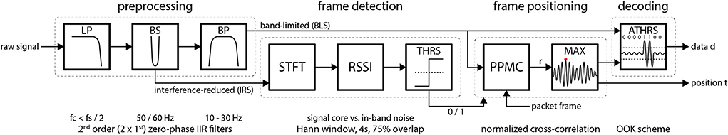
Figure 5. The processing pipeline consists of four blocks: signal preprocessing, frame detection, frame positioning, and data decoding. First, the raw, noisy signal is filtered. While the band-limited signal (BLS) is forwarded to the frame positioning, the less preprocessed, interference-reduced signal (IRS) is provided to the frame detection block. It inspects the frequency components using a short-time Fourier transform (STFT) and assesses the signal quality applying the received signal strength indicator (RSSI). If the RSSI metric exceeds a certain threshold (THRS), the landmarks' temporal position t is determined within the relevant interval using a Pearson product-moment correlation (PPMC). The data d is decoded according to an on-off-keying (OOK) modulation scheme applying an adaptive threshold (ATHRS) mechanism.
As evaluated in Section 4.2, the wide bandwidth B = fc, high−fc, low of 20 Hz, i.e., from 10 to 30 Hz, is required to cover the sidebands of the OOK modulation. After preprocessing, the short-time Fourier transform (STFT) is applied to the IRS, yet before band-pass filtering, using a von Hann window with a size of 4 s (512 samples) and 75 % overlap (384 samples). Then, analog to the determination of the signal-to-noise ratio (SNR), the received signal strength indicator (RSSI) of each window interval S is derived from the STFT. It is computed according to Equation (1) by averaging the bins associated with the signal core with bs∈ ❬17.5, …, f0, …, 22.5Hz❭ and the adjacent bins of in-band noise with bn∈ ❬10, …, 17.5Hz❬⋂❭22.5, …, 30Hz❭:
The RSSI is a measure of the desired signal's predominance over the noise floor. It is applied as a metric to identify the characteristic frequency components around f0, which are associated with the presence of a landmark frame (Figures 2, 3B).
The subsequent steps are only continued if the RSSI exceeds a significance threshold (THRS), i.e., at least the minimum of 0 dB. Next, a universal frame template F with empty data segment d = 0 is shifted along the relevant window interval S and inspected using the Pearson product-moment correlation (PPMC) coefficient r(S, F) by Pearson (1895), given in Equation (2):
The significant and maximum correlation (MAX) between the template F and S unveils the frame's temporal position t′. The data d are finally extracted by decoding the interval according to the OOK scheme using an adaptive threshold (ATHRS). Its level orientates on the amplitude of the frame's preamble and terminator, to distinguish the pulses from the gaps and, therefore, to assign the symbols to the binary values 0 and 1. Depending on the target application, elaborated below in Section 3.3, the frame position t′ and the contained data d are then used to either synchronize devices or to contextualize their measurements.
3.3. Proposed applications
With IBSync, we present a novel concept that makes use of the human body as a unidirectional communication channel between stationary transmitters and body-attached devices. In this way, the body tissue enables the wearables to receive landmark signals by simply touching, approaching, or passing beacons, embedded into certain areas, surfaces, or objects. These landmarks can be enriched with temporal information to enable the alignment and synchronization of recordings (Section 3.3.1) or can be enhanced with information about the situational context (Section 3.3.2), e.g., the type of object touched. The fundamental principle of capacitive coupling for intra-body communication (Section 2.4) hence enables either the intentional and continuous, or the implicit and incidental reception of temporal or contextual information by means of the obtained landmarks. Motivated through Figure 1, the scenario to be evaluated and discussed uses a transmitter beacon, embedded into a desktop, and two wrist-worn receivers.
3.3.1. Synchronization
The changes in the modulated quasi-electrostatic field are virtually instantaneously detectable throughout the entire body surface, which enables the use of IBC for synchronization purposes. The simultaneous reception of significant landmark signals by multiple devices allows the precise offline alignment of recordings and the devices' local times. Moreover, even the exact temporal allocation of landmarks and, therefore, the online synchronization of a single or multiple devices in respect to absolute time is possible.
A landmark Li is defined as the ith packet frame at position ti in absolute time t, transporting the data di:
Generated by the transmitter at ti, a landmark is captured by the receiver at the local time . Its deviation from t is given through the initial offset , interpreted as the start time of a device, and the drift rate δ:
Therefore, the received landmark is given as , with the data naturally remaining the same. After the detection of landmarks at different devices, those could be assigned to each other by aligning their closest temporal occurance. The devices' start times and drift rate δ are, however, unknown. Furthermore, due to a continuous repetition every 2.5 s, the pure packet frames would be interchangeable and confusable. For any arbitrary but constant data x, all landmarks at two devices A and B are therefore prone to temporal displacement, ambiguous, and cannot uniquely be assigned to each other. Consequently, the following condition of an arbitrary assignment has to be avoided:
As illustrated in Figure 6, to actually match the coincident landmarks, the information contained in the data segment di between the delimiters is used. The data can transport a landmark identifier such as an incrementing packet counter (Figure 6A). To minimize the probability of a disrupted data packet, e.g., through motion during a transmission at the relatively slow symbol rate of 20 Hz, the amount of carried data per packet is limited to 8 bit. The identifier would, therefore, be unique as long as the measurement time of 28×2.5s = 640s (10 min 40 s) is not exceeded. If two landmarks, detected at the devices A and B, then contain the identical data da = db, these must be originated in the same moment ta = tb, generated by the transmitter at the same absolute time t. In this way, the data enables the landmarks to be uniquely assigned and aligned despite their different local times :
To enhance the uniqueness beyond the aforementioned time limit, and to furthermore improve the Hamming distance between subsequent packets according to Hamming (1950), the data can also contain a random number as a unique landmark identifier (Figure 6B). Consequently, the probability of two random numbers following each other in subsequent landmark packets is very small, and of three or more ones in a row even infinitesimal. Theoretically, the landmarks and their order would remain unique for 28! repetition-free permutations, resulting in a recurrence interval of 6.8 × 10499 years.
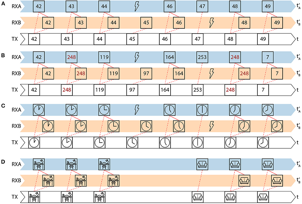
Figure 6. Proposed applications using the data segment of the landmark packet for synchronization (A–C) and contextualization (D): incrementing packet counter as identifier for a limited recurrence interval of 28 × 2.5 s = 640 s, 10 min 40 s, respectively (A); sequences of random numbers as unique identifier patterns for a quasi-infinite recurrence interval of ideally 28! landmarks, lasting for 6.8 × 10499 years (B); information related to absolute time, preferentially with larger data segments of four bytes, unsigned long for ms-accurate timestamps (C); unique location or object identifier to provide the situational context (D).
The data could also be related to the absolute time, which, however, is again constrained to the 8 bit of the proposed packet scheme (Figure 6C). A longer data segment of two, three, or even four bytes for an unsigned long ms-accurate timestamp would significantly upgrade this concept, however at cost of robustness against disruption through motion.
3.3.2. Contextualization
Instead of temporal information, the landmark's data segment could also contain context information, as illustrated in Figure 6D. In this way, the 8 bit of data can serve as a context identifier and be associated with up to 256 areas, surfaces, or objects. The exemplary scenario in Figure 1 shows the beacon transmitter embedded into a desktop. Consequently, the receiving wearable devices would get aware of the user being close to and probably sitting at the desktop, likely to work on the computer. The motion and the user's vital signs, and hence e.g., inferable arousal and stress, could now be interpreted in the context of work. In contrast, e.g., sitting on the couch would indicate the user's leisure and intention to relax.
4. Evaluation
Three experiments have been conducted to first optimize the filter parameters as well as to evaluate the performance and to demonstrate the applicability of IBSync. The first experiment (Section 4.1) aims to determine the characteristic noise floor, caught from a typical environment, to dimension carrier frequency f0, and to identify the applicable frequency band. The second experiment (Section 4.2) concentrates on the technical aspects of optimal bandwidth B, the metrics RSSI and PPMC r, the packet error rate (PER), as well as the synchronization error ϵ. Finally, the third experiment (Section 4.3) demonstrates the applicability in an everyday life usage scenario. Due to the persistent pandemic, the evaluation is based on a single subject (male, 33yr., 198 cm, 102 kg) only, however with 215 min recordings from two wearable devices, attached to the left and right wrist, in a typical scenario with a desk in an ordinary living space.
4.1. Noise floor characterization
The normal use of the wearables' AFE according to its original purpose, i.e., the measurement of the natural ECG signal, requires a finger from the opposite arm to form the traditional lead I (Figure 7A). Without closing this circuit, the floating sensor predominantly catches noise from the environment and the ECG signal vanishes (Figure 7B). For the new purpose of detecting the artificial landmark signals, the most suitable carrier frequency f0 and possible bandwidth B had to be determined first.
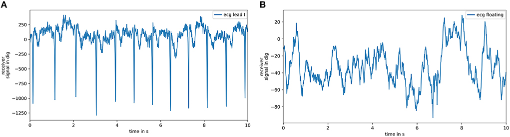
Figure 7. Excerpts from raw measurements of the analog ECG front-end of the MAXREFDES101# device: touching the electrode at the front closes the traditional lead I and results in visible, distinct ECG pulses (A); for a floating electrode, the pulses vanish into the noise floor and the heart beat can only be guessed (B).
To estimate the present noise floor, measurements in an ordinary living space have been recorded, performing seven different activities such as sitting, working on a computer, walking, and doing different gymnastics for 60 s each. The respective periodograms, determined using the method of Welch (1967) for power spectral density (PSD) estimation, are shown in Figure 8A. The spectra indicate that the frequency band from about 10 to 45 Hz would be applicable.
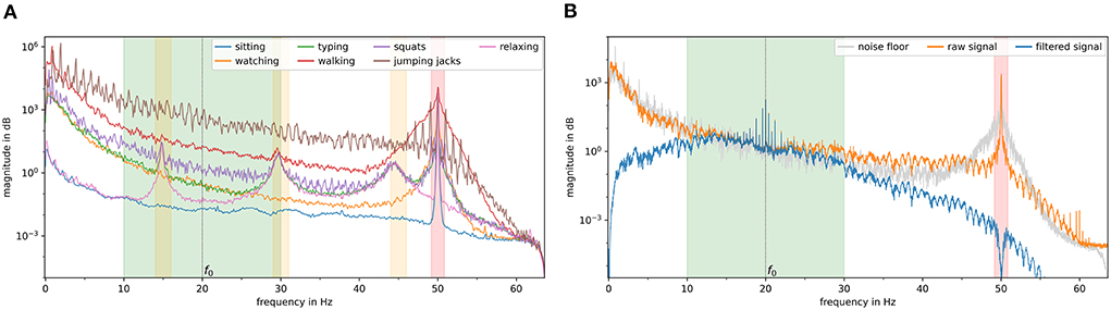
Figure 8. Analysis of the frequency spectra (PSD) of the noise floor (A): interference generated by seven activities; 50 Hz power line noise ( band); unknown interference source, oscillation at 15 Hz with its first and second harmonics (orange bands). Analysis of the frequency spectra (PSD) of the desired signal extracted from the raw measurements (B): noise floor, overall average of the activities (); raw signal (); filtered signal (); selected bandwidth B of 20 Hz, pass-band from 10 to 30 Hz ( band).
Unfortunately, the possible band is sporadically interfered by oscillations at about 15 Hz, accompanied by harmonics at 30 and 45 Hz. The origin of this interference is not evident but might either be induced from the environment or the device itself. Because it is very specific to the device worn on the right wrist, it could even come from resonance due to filter instability and the absence of the ECG signal sought. While the high-pass characteristic of the body channel favors a higher f0 in the order of a few MHz, the sensor's sampling rate fs of 128 Hz, and hence a Nyquist frequency of 64 Hz, demands for a lower f0 to increase the sample coverage Ns = fs/f0 of a unit pulse period T0 = 1/f0. Therefore, as shown in Figure 8B, a trade-off is made on f0 of 20 Hz, resulting in 6.4 samples scanning a 50 ms pulse period. The determination of the optimal B is detailed below in Section 4.2.
4.2. Controlled setting
To evaluate IBSync from a technical perspective, three specific ways of coupling between the user and the transmitter have been investigated: a) directly touching the transmitter electrode, b) touching the desktop surface above the electrode with both hands, and c) sitting at the desktop without touching the electrode and leaning back in the office chair. Those have been recorded consecutively, with each interval spanning at least 15 min. The interval of a) covers 379 landmarks (15.8 min) with 6.585 pulses and 2.511 gaps, b) covers 377 landmarks (15.7 min) with 6.619 pulses and 2.429 gaps, and c) covers 389 landmarks (16.2 min) with 6.811 pulses and 2.525 gaps. For each interval, the pulses and gaps have semi-automatically been annotated in the IRS and manually been revised and validated. All results of this section are summarized in Table 1.
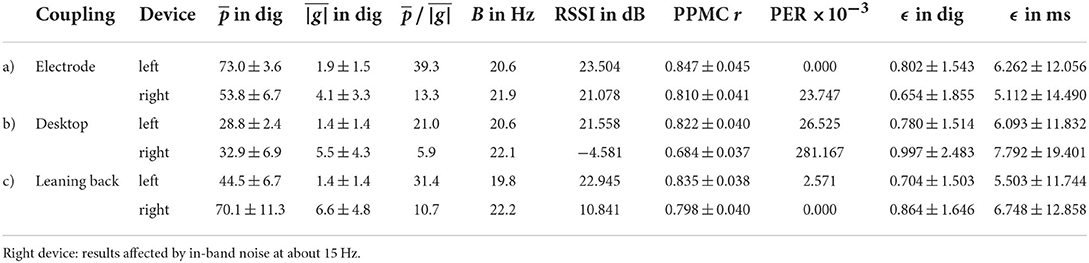
Table 1. Results of the evaluation.
4.2.1. Optimal filter bandwidth
To be able to adequately reconstruct the discontinuous pulse wave, the filter pass-band is required to cover the sidebands of the modulation, adjacent to the carrier f0. These frequency components allow for a fast transient response, the change between the two symbols pulse and gap representing the binary values 1 and 0. As shown in Figure 9, the filter bandwidth B considerably affects not only the shape of the particular pulses but also the signal's envelope contour and the remaining ripple within the gaps. Therefore, the optimal B has been discovered through 399 filter configurations, by applying the bandwidths {0.1HZ, …, 39.9HZ} at steps of, centered at the previously specified f0 of 20HZ. Since the right wrist's recordings are considerably interfered from an unknown noise source (Section 4.1), only the results from the left wrist are further evaluated here. For each way of coupling and each configuration, the pulse heights p and the gap ripple |g|, the absolute distance to the baseline, have been determined for the labeled positions. After calculating their mean and standard deviation, the ratio of mean pulse amplitude and mean gap ripple magnitude has been computed. As illustrated in Figure 10, along with a minimal standard deviation among the pulses and gaps, the pulse-to-gap ratio unveils the optimal filter bandwidth B by reaching its maximum at about 20 Hz for all three couplings. In the optimal configuration, a) showed the best coupling with a pulse-to-gap ratio of 39.3, b) showed the weakest coupling with a ratio of 21.0, and c) is in between with a ratio of 31.4.
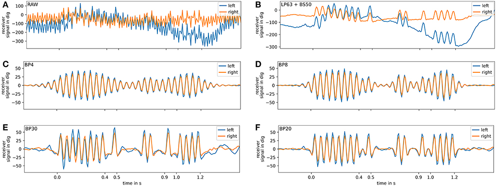
Figure 9. Matched landmark packets of two receivers worn at the left () and right wrist (). Raw, unfiltered measurements (A). Interference-reduced signal (IRS) after anti-alias filtering (LP) and power line noise rejection (BS) with contained data 000011002 (MSB first) visible (B). Applied filter bandwidths B of 4 Hz (C), 8 Hz (D), 20 Hz (E), 30 Hz (F). Best result regarding fast transient response, pulse-to-gap ratio, as well as minimal interference and baseline wander for a B of 20 Hz (E).
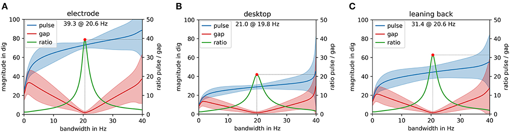
Figure 10. Determination of the optimal filter bandwidth B, centered at f0, for the scenario's three ways of coupling. From 0.1to39.9 Hz in steps of 0.1 Hz, 399 iterations each, considering the mean and standard deviation of the pulse amplitudes p (), the mean and standard deviation of the absolute gap magnitudes |g| (), the remaining ripple, respectively, and the ratio of the means () with the maximum marked ( dot). Best ratio 39.3 dig for 20.6 Hz by directly touching the electrode (A), second best 31.4 dig for 20.6 Hz by leaning back (C), and lowest 21.0 dig for 19.8 Hz by touching the desktop (B). The filter bandwidth B of 20 Hz is, therefore, selected as optimal. Based on signals from the left wrist only.
4.2.2. Processing pipeline
Applying the determined optimal bandwidth B of 20 Hz, the processing pipeline and its discrete metrics have been evaluated. Figure 11 visualizes the output of the consecutive stages. It shows the generated STFT, the derived RSSI, the PPMC correlation coefficient r, and the decoded data d along the entire recording of both devices with the relevant intervals a), b), and c). While the STFT of the device at the left wrist shows a clearly distinguishable signal core, the right sensor also caught the aforementioned oscillation at 15 Hz. Starting at about 900 s it unintentionally demonstrates the effect of in-band noise on the metrics. While the average RSSI at the left wrist is a) 23.504 dB, (b) 21.558 dB, and c) 22.945 dB, the signal strength at the right wrist significantly decreases on occurrence of the interference to values of a) 21.078 dB (semi-affected), b) -4.581 dB, and c) 10.841 dB. Nevertheless, the normalized cross-correlation coefficient r significantly indicates the presence of the landmark signal with an average of 0.835 at the left and a marginally lower one of 0.764 at the right wrist. Despite the presence of noise, the data is successfully decoded for most landmark packets, even though the RSSI was partly below 0 dB. The detection of erroneous landmarks and the relation to the RSSI is evaluated in the following.
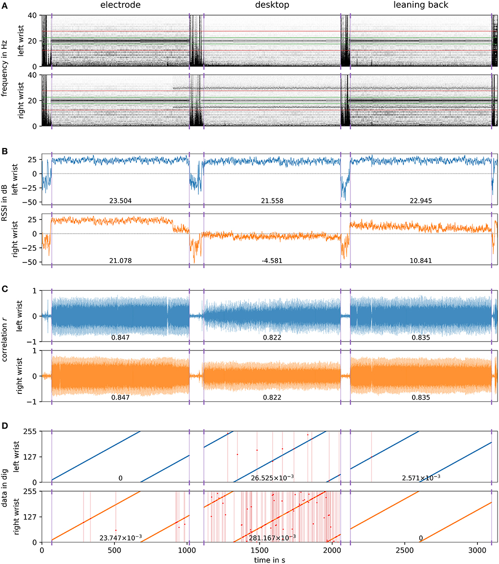
Figure 11. Output of the processing pipeline for the desktop experiment: (A) short-time Fourier transform (STFT) with a window length of 4 s (512 samples) and 75 % overlap, presence of the signal core in 17.5–22.5 Hz ( lines) and in-band noise in 12.5–17.5 Hz and 22.5–27.5 Hz ( lines); (B) received signal strength indicator (RSSI) derived from the signal core and the adjacent in-band noise, resulting in average RSSI of the segments; (C) Pearson's r, normalized cross-correlation, maxima of the detected landmarks resulting in mean of the segments; (D) decoded data d and damaged information () due to erroneously detected pulses, resulting in PER of the segments.
4.2.3. Packet error rate
The packet error rate (PER) is a measure of the number of landmark packets that have not successfully been detected due to at least one symbol being interfered and hence erroneous. It is the quotient Nerror/Nsent of erroneous packets Nerror per total packets sent Nsent. For the device at the left wrist, the PER of a) is virtually 0 since all packets have been decoded correctly. Interval b) shows the largest PER of 26.525 × 10⁻³ with ten errors occurred: five erroneously detected pulses and one missed pulse in the data segment, two times a excessive fifth pulse and once a missed pulse in the terminator, and once an undetected pulse in the preamble. The PER of c) is 2.571 × 10⁻³, only one packet was erroneous due to a glitch in the data segment. The noise present at the right wrist largely interferes with the landmark signals and hence results not only in considerably decreased RSSI and r but also in a significantly higher PER of a) 23.747 × 10⁻³ and b) 281.167 × 10⁻³. However, the coupling of interval c) showed with a PER of 0 to be more robust against the noise. In general, there is a manifest link between the RSSI and the PER. However, a low RSSI, even below 0 dB, does not inevitably result in a large PER. The RSSI is, nevertheless, a suitable metric and helpful to indicate whether a signal interval likely contains the desired landmark signal and should be further analyzed, or not.
4.2.4. Synchronization error
To evaluate the synchronization accuracy achievable by means of IBSync, the deviation of the landmark positions from ground truth has been evaluated for both devices. The ground truth positions are given through the labels that were set in context of the bandwidth determination before. Despite of the interference at the right wrist, the mean synchronization error ϵ of 0.761±1.521 samples at the left and of 0.838±2.027 samples at the right wrist are close. Consequently, the overall mean ϵ is 0.800±1.792 samples or 6.249±14.004 ms. Most determined landmark positions distribute evenly with an error ϵ of either 0 or 1 sample, which is originated in the quantization. In a few cases (161 landmarks or 7.03 %), however, the cross-correlation did not maximize at the position of the first pulse of the preamble but matched the position of the second one instead. This effect is caused by ripple artifacts, remaining from filtering, and the correlation template being non-ideal and edgy due to sampling with a low sample coverage Ns = fs/f0 of 6.4. Consequently, the determined landmark position skips one unit pulse period T0 or its respective sample count Ns, resulting in a deviation of 7 samples. This alignment error can, however, easily be detected and corrected by algorithmically validating the number of detected preamble and terminator pulses. By solving this issue, the synchronization error further decreases to even 0.360±0.482 samples or 2.811±3.765 ms which now is in the order of the inevitable quantization error of ±3.9 ms.
4.3. Application in-the-wild
To finally demonstrate the concept's feasibility and its applicability in the wild, the two devices have been worn for about 23 min while performing activities of daily living which includes partly working at the desk, equipped with an IBSync beacon. In this way, the recording does neither contain only the desired landmark signal nor the ambient noise but both varying in an uncontrolled setting. As in the previous experiment (Section 4.2), the landmarks transport a continuously incrementing 8 bit packet counter which overruns every 640 s. In this way, discontinuities in the decoded values indicate packet errors. Figure 12 visualizes the output of the processing pipeline. Again, as in the previous experiment, the oscillation at 15 Hz is visible and starts at about 900 s, immediately decreasing both RSSI and PPMC r. Nevertheless, the landmarks can successfully be decoded when the subject is at the desk and either the arms or the thighs are in proximity to the desktop and couple sufficiently to the beacon's electrode. There are periods in which the landmark signal is present at both wrists, as intended. Interestingly, in other periods it is only present at a single wrist. Therefore, we have to conclude that the IBC signal does not always propagate well throughout the entire body surface under all conditions. The observations showed that the signal propagates better, and is hence available at both wrists, when induced through the thighs. When induced at one hand, the signal might, however, not be detectable at the other one. One reason might be the larger distance between the wrists, compared to the shorter one from the thighs to both wrists. The presumably major reason, however, has already been mentioned by Zimmerman (1995), the “feet are the best location for [IBC] devices” since the coupling to both the body and the environment is the strongest.
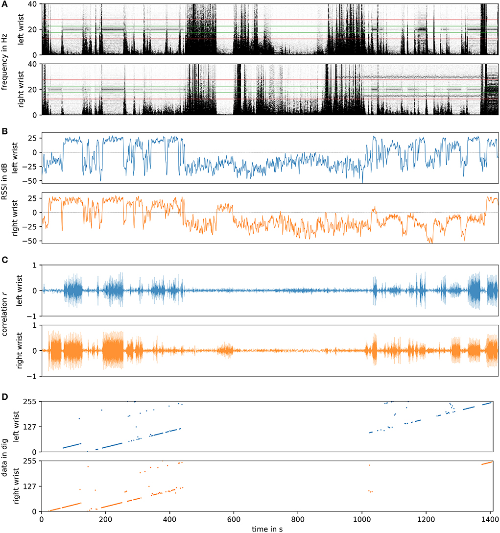
Figure 12. Output of the processing pipeline for the in-the-wild experiment: (A) short-time Fourier transform (STFT) with a window length of 4 s (512 samples) and 75 % overlap, presence of the signal core in 17.5–22.5 Hz ( lines) and in-band noise in 12.5–17.5 Hz and 22.5–27.5 Hz ( lines); (B) received signal strength indicator (RSSI) derived from the signal core and the adjacent in-band noise; (C) Pearson's r, normalized cross-correlation, maxima of the detected landmarks; (D) decoded data d, partly damaged information, erroneously detected pulses within the data segment, considerable disruption through motion. Correlation excecuted if RSSI > 0 dB, data decoded if r ≥ 0.65 and preamble amplitude ≥ 5.
5. Results and discussion
In three experiments, we successfully demonstrated the use of analog ECG front-ends, available in commercial wearable devices, for the detection of artificial landmarks. We further showcased the general feasibility of applying IBSync for the synchronization and implicit contextualization of wearable devices. The evaluation is based on an exemplary scenario in which a transmitter beacon is embedded into a desktop and two sensing devices record the ECG signal captured at the user's left and right wrist. In a controlled setting, the coupling between the user's body and the transmitter has been evaluated in three different ways: a) directly touching the electrode, b) touching the desktop, and c) leaning back in the office chair and primarily coupling through the thighs. The results are summarized in Table 1. Unfortunately, the recordings at the right wrist are considerably affected by oscillations at about 15 Hz, unintentionally demonstrating the effect of in-band noise on the proposed metrics. The proposed RSSI metric successfully indicates the presence of a landmark signal with values ranging from 21.6 to 23.5 dB. The maxima of the normalized cross-correlation coefficient r, ranging from 0.845 to 0.863, then provide the positions of the landmark packets in time and enable the decoding of the data segments. In all three coupling cases, the reception of landmarks was successful and resulted in a low PER of 0 to 26.5 × 10⁻³. Based on the manually revised and validated ground truth labels, the achieved synchronization is promising with a mean error ϵ of 0.800±1.792 samples (6.249±14.004 ms). In 92.97 % of the landmarks, the position error was just in the order of a single sample, resulting in an ϵ of 0.360±0.482 samples or 2.811±3.765 ms, which is in the order of the quantization error of ±3.9 ms. The larger deviations of 7 samples are caused by erroneous matching, due to filter ripple and a non-ideal, edgy correlation template, but are easily solvable by validating the number of detected preamble and terminator pulses. Due to the interference, all measurements at the right wrist are weaker and show a lower RSSI and r as well as higher PER and ϵ. In general, the coupling a) apparently showed the best results, but c) was somewhat unexpectedly good and even better than b) which constantly showed the lowest yet sufficient performance.
The ECG AFE's low sampling rate of 128 Hz limits the realizable carrier frequency to 20 Hz which is multiple orders below the optimal frequency band of capacitive coupling IBC. In combination with the discovered optimal bandwidth of 20 Hz, the filtered signal shows, however, a good ratio between the pulse amplitude and the remaining gap ripple, in the range of 21.0 and 39.3. The relatively wide bandwidth is required to cover the modulated sidebands and to adequately reconstruct the discontinuous pulse wave, allowing for a fast transient response between the symbols, representing the binary values 0 and 1. However, the comparably slow carrier frequency results in a slow symbol rate, and a landmark packet with in total 24 pulse periods takes 1.2 s. Therefore, the achievable data throughput is apparently not sufficient for the transmission of larger data, not even of four bytes for an unsigned long ms-accurate timestamp. To improve the noise immunity, future implementations should consider the implementation of error-checking and -correction techniques since redundancy can significantly improve the PER. For the proposed applications, the 8 bit of data are sufficient to either serve as a unique landmark for the temporal allocation and synchronization, or to transport a unique object identifier for contextualization. The strength of the coupling to the environment but also the devices themselves and the tightness of their attachment have large influence on the signal quality. Also the user's tissue composition has an influence on the signal amplitude, however the propagation velocity is less affected. Consequently, the distance-related delay can be neglected and landmarks are assumed to be immediately and without any delay present throughout the entire body surface. This assumption is particularly valid, considering that the ECG AFE's low sampling rate inherently limits the achievable accuracy to a quantization error of ±3.9 ms. So of course, the ECG AFEs are neither originally intended nor optimal for the use in IBC and the proposed applications. Since the AFEs are designed for the sensitive detection of tiny potential differences in energy-efficient wearable applications, the circuits allow, however, to be repurposed.
6. Conclusions
With IBSync we have presented a novel method for the intentional or incidental synchronization as well as the implicit contextualization of wearable devices by touching, approaching, or passing certain areas, surfaces, or objects. The demonstrated scenario shows a desktop, equipped with an embedded transmitter beacon that capacitively induces artificial landmark signals into the user's body. Because no off-the-shelf IBC transceivers are available, the analog ECG front-ends of commercial wearable devices have been repurposed. Those are carefully designed regarding their energy efficiency and the sensitive detection of tiny signals on the human skin. The evaluation is based on three experiments. First, the ambient noise captured by the ECG AFEs has been characterized. Second, the optimal parameters and the system's performance have been evaluated in a controlled setting, investigating the coupling between the user's body and the transmitter beacon in three different ways: a) directly touching the electrode, b) touching the desktop, and c) leaning back in the office chair and primarily coupling with the thighs. Third, the concept has been tested in an everyday life setting, demonstrating its feasibility and applicability in-the-wild.
The signal quality primarily depends on the coupling strength between the transmitter's electrode and the user's body. Of course, also the attachment of the devices has a large influence on the captured signal. The deployment in-the-wild discovered that, moreover, the induced signal does not always propagate throughout the entire body surface. When picking up the signal through one hand, it tends to be available only at the respective wrist. However, leaning back and coupling through the thighs showed somewhat unexpectedly good signal quality at both wrists. One reason might be that the distance between the wrists is larger than the ones from the thighs to the wrists. Another reason might be the extremely low carrier frequency that is several orders below the optimal frequency range of IBC. Moreover, as already mentioned by Zimmerman (1995), the presumably main reason is that the “feet are the best location for [IBC] devices” since the coupling to both the body and the environment is the strongest.
Our proposed method IBSync enables both the synchronization and implicit contextualization of wearable devices using their on-board ECG sensor. With a synchronization error of 0.80±1.79 samples, or 6.25±14.00 ms at a sampling rate of 128 Hz, we outperformed the motion-based offline synchronization methods, e.g., the methods of Wang et al. (2019) and Ahmed et al. (2020) with a typical error in the order of 250 down to 46 ms. Moreover, the research of Hessar et al. (2016) demonstrated the use of commodity devices and their fingerprint or touch sensors to transmit signals confined to the human body. With IBSync, we now provide the receiver side, as well. The concepts' combination would therefore enable wearable devices, such as wristwatches, to transmit signals via a fingerprint sensor or touchscreen, and to receive these signals using their analog ECG front-end.
Data availability statement
The raw data supporting the conclusions of this article is available at the following link: https://ubicomp.eti.uni-siegen.de/home/datasets/fcs22.
Ethics statement
Ethical review and approval was not required for the study on human participants in accordance with the local legislation and institutional requirements. Written informed consent for participation was not required for this study in accordance with the national legislation and the institutional requirements.
Author contributions
FW has developed the concept, implemented the study, and visualized the results. KV helped in the search of the related work and assisted in the methodologies. Both authors contributed to the article and approved the submitted version.
Acknowledgments
We are thankful to Cong Dat Huynh who investigated the method's fundamentals in his Master's thesis. Supported by the Publication Fund of the University of Siegen.
Conflict of interest
The authors declare that the research was conducted in the absence of any commercial or financial relationships that could be construed as a potential conflict of interest.
Publisher's note
All claims expressed in this article are solely those of the authors and do not necessarily represent those of their affiliated organizations, or those of the publisher, the editors and the reviewers. Any product that may be evaluated in this article, or claim that may be made by its manufacturer, is not guaranteed or endorsed by the publisher.
Footnotes
1. ^Application Note AN1391 of BodyCom from Microchip Technologies, Inc.: http://ww1.microchip.com/downloads/en/AppNotes/00001391C.pdf (2022-02-28).
2. ^Datasheet of the MSP430FR5969 from Texas Instruments, Inc.: https://www.ti.com/product/MSP430FR5969 (2021-06-16).
3. ^Product website of the MAXREFDES101# from Maxim Integrated, Inc.: https://www.maximintegrated.com/en/design/reference-design-center/system-board/6779.html (2021-06-16).
4. ^Product website of the MAX30001 from Maxim Integrated, Inc.: https://www.maximintegrated.com/en/products/analog/data-converters/analog-front-end-ics/MAX30001.html (2021-06-16).
5. ^The datasheet of the MAX30001 (p. 31) mentions a 200 kΩ resistor while the schematic files of the MAXREFDES101# specify a value for R7 of 499 kΩ.
References
Ahmed, T., Ahmed, M. Y., Rahman, M. M., Nemati, E., Islam, B., Vatanparvar, K., et al. (2020). “Automated time synchronization of cough events from multimodal sensors in mobile devices,” in International Conference on Multimodal Interaction (ACM), 614–619.
AlGhatrif, M., and Lindsay, J. (2012). A brief review: history to understand fundamentals of electrocardiography. J. Commun. Hospit. Internal Med. Perspect. 2, 14383. doi: 10.3402/jchimp.v2i1.14383
Antonescu, B., and Basagni, S. (2013). “Wireless body area networks: challenges, trends and emerging technologies,” in BodyNets '13 (Boston, MA: ICST), 1–7.
Avila, C. O. (2019). Novel use of apple watch 4 to obtain 3-lead electrocardiogram and detect cardiac ischemia. Perm J. 23, 19-025. doi: 10.7812/TPP/19-025
Bae, J., Cho, H., Song, K., Lee, H., and Yoo, H. J. (2012). The signal transmission mechanism on the surface of human body for body channel communication. IEEE Trans. Microw Theory Tech. 60, 582–593. doi: 10.1109/TMTT.2011.2178857
Bannach, D., Amft, O., and Lukowicz, P. (2009). “Automatic event-based synchronization of multimodal data streams from wearable and ambient sensors,” in Smart Sensing and Context, EuroSSC'09 (Springer), 135–148.
Barrett, L. F., and Barrett, D. J. (2001). An introduction to computerized experience sampling in psychology. Soc. Sci. Comput. Rev. 19, 175–185. doi: 10.1177/089443930101900204
Barth, A. T., Hanson, M. A., Powell, H., Unluer, D., Wilson, S. G., and Lach, J. (2008). “Body-coupled communication for body sensor networks,” in Proceedings of the 3rd International ICST Conference on Body Area Networks, ed S. Panchanathan (Tempe, AZ: ICST).
Beach, C., Krachunov, S., Pope, J., Fafoutis, X., Piechocki, R. J., and Crad, I. (2018). An ultra low power personalizable wrist worn ECG monitor integrated with iot infrastructure. IEEE Access 6, 44010–44021. doi: 10.1109/ACCESS.2018.2864675
Bennett, T. R., Gans, N., and Jafari, R. (2015a). “A data-driven synchronization technique for cyber-physical systems,” in Proceedings of the Second International Workshop on the Swarm at the Edge of the Cloud (Osaka: ACM), 49–54.
Bennett, T. R., Gans, N., and Jafari, R. (2015b). “Multi-sensor data-driven synchronization using wearable sensors,” in Proceedings of the 2015 ACM International Symposium on Waerable Computers (Seattle, WA: ACM), 113–116.
Berlin, E., Liu, J., van Laerhoven, K., and Schiele, B. (2010). “Coming to grips with the objects we grasp,” in Proceedings of the Fourth International Conference on Tangible, Embedded, and Embodied Interaction-TEI '10, eds H. Ishii, R'. J. Jacob, P. Maes, M. Coelho, J. Zigelbaum, T. Pederson, O. Shaer, and R. Wakkary (New York, NY: ACM Press).
Casson, A. J. (2014). “Performance of wrist based electrocardiography with conventional ECG analysis algorithms,” in 2014 8th Conference of the European Study Group on Cardiovascoular Oscillations (ESGCO 2014) (Piscataway, NJ: IEEE), 11–12.
Castaneda, D., Esparza, A., Ghamari, M., Soltanpur, C., and Nazeran, H. (2018). A review on wearable photoplethysmography sensors and their potential future applications in health care. Int. J. Biosens Bioelectron. 4, 195–202. doi: 10.15406/ijbsbe.2018.04.00125
Chi, Y. M., Jung, T.-P., and Cauwenberghs, G. (2010). Dry-contact and noncontact biopotential electrodes: methodological review. IEEE Rev. Biomed. Eng. 3, 106–119. doi: 10.1109/RBME.2010.2084078
Chi, Y. M., Maier, C., and Cauwenberghs, G. (2011). Ultra-high input impedance, low noise integrated amplifier for noncontact biopotential sensing. IEEE J. Emerg. Select. Top. Circ. Syst. 1, 526–535. doi: 10.1109/JETCAS.2011.2179419
Cho, H., Kim, H., Kim, M., Jang, J., Lee, Y., Lee, K. J., et al. (2016). A 79 pJ/b 80 Mb/s full-duplex transceiver and a 100 kb/s super-regenerative transceiver for body channel communication. IEEE J. Solid State Circ. 51, 310–317. doi: 10.1109/JSSC.2015.2498761
Chung, C.-C., Chang, C.-T., and Lin, C.-Y. (2015). “A 1 Mb/s-40 Mb/s human body channel communication transceiver,” in VLSI Design, Automation and Test(VLSI-DAT) (Hsinchu: IEEE), 1–4.
Donker, J. H. (2009). “The body as a communication medium,” in Department of EMCS, University of Twente, 11th Twente Student Conference on IT (Enschede).
Einthoven, W., Fahr, G., and de Waart, A. (1950). On the direction and manifest size of the variations of potential in the human heart and on the influence of the position of the heart on the form of the electrocardiogram. Am. Heart J. 40, 163–211. doi: 10.1016/0002-8703(50)90165-7
Elson, J., Girod, L., and Estrin, D. (2002). Fine-grained network time synchronization using reference broadcasts. ACM SIGOPS Operat. Syst. Rev. 36, 147. doi: 10.1145/844128.844143
Fishkin, K. P., Philipose, M., and Rea, A. (2005). “Hands-on rfid: Wireless wearables for detecting use of objects,” in Ninth IEEE International Symposium on Wearable Computers (ISWC'05) (Osaka: IEEE), 38–43.
Galluccio, L., Melodia, T., Palazzo, S., and Santagati, G. E. (2012). “Challenges and implications of using ultrasonic communications in intra-body area networks,” in 2012 9th Annual Conference on Wireless On-Demand Network Systems and Services (WONS) (Courmayeur: IEEE), 182–189.
Große-Puppendahl, T., Herber, S., Wimmer, R., Englert, F., Beck, S., von Wilmsdorff, J., Wichert, R., et al. (2014). “Capacitive near-field communication for ubiquitous interaction and perception,” in UbiComp '14: Proceedings of the 2014 ACM International Joint Conference on Pervasive and Ubiquitous Computing (ACM), 231–242.
Große-Puppendahl, T., Holz, C., Cohn, G., Wimmer, R., Bechtold, O., Hodges, S., et al. (2017). “Finding common ground: a survey of capacitive sensing in human-computer interaction,” in Conference: Proceedings of the SIGCHI Conference on Human Factors in Computing Systems (CHI '17) (Denver, CO).
Ha, S., Kim, C., Chi, Y. M., and Cauwenberghs, G. (2014). “Low-power integrated circuit design for wearable biopotential sensing,” in Wearable Sensors, eds E. Sazonov and M. R. Neuman (Amsterdam: AP Academic Press is an imprint of Elsevier), 323–352.
Hamming, R. W. (1950). Error detecting and error correcting codes. Bell. Syst. Techn. J. 29, 147–160. doi: 10.1002/j.1538-7305.1950.tb00463.x
Harikumar, P., Kazim, M. I., and Wikner, J. J. (2012). “An analog receiver front-end for capacitive body-coupled communication,” in NORCHIP, 2012 (Copenhagen: IEEE), 1–4.
Harland, C. J., Clark, T. D., and Prance, R. J. (2002). Electric potential probes - new directions in the remote sensing of the human body. Meas. Sci. Technol. 13, 163–169. doi: 10.1088/0957-0233/13/2/304
Hessar, M., Iyer, V., and Gollakota, S. (2016). “Enabling on-body transmissions with commodity devices,” in UbiComp '16: Proceedings of the 2016 ACM International Joint Conference on Pervasive and Ubiquitous Computing (Heidelberg: ACM), 1100–1111.
Holter, N. J. (1961). New method for heart studies. Science 134, 1214–1220. doi: 10.1126/science.134.3486.1214
Holz, C., and Knaust, M. (2015). “Biometric touch sensing: Seamlessly augmenting each touch with continuous authentication,” in UIST'15, eds C. Latulipe, B. Hartmann, and T. Grossman (New York, NY: ACM), 303–312.
IEEE Standards Association (2012). IEEE 802.15.6-2012 - Wireless Body Area Networks. IEEE Standards Association. Available online at: https://standards.ieee.org/standard/802_15_6-2012.html
Karvonen, J., Chwalbinska-Moneta, J., and Saynajakangas, S. (1984). Comparison of heart rates measured by ECG and microcomputer. Phys. Sportsmed. 12, 65–69. doi: 10.1080/00913847.1984.11701872
Kibret, B., Teshome, A. K., and Lai, D. T. H. (2014). Human body as antenna and its effect on human body communications. Progr. Electromagn. Re. 148, 193–207. doi: 10.2528/PIER14061207
Koshiji, F., Yuyama, N., and Koshiji, K. (2012). “Wireless body area communication using electromagnetic resonance coupling,” in 2012 2nd IEEE CPMT Symposium Japan (Kyoto: IEEE), 1–4.
Kyriacou, P. A., and Allen, J. (2021). “Photoplethysmography,” in Technology, Signal Analysis and Applications, 1st Edn, eds J. Allen and P. Kyriacou (Academic Press). doi: 10.1016/C2020-0-00098-88
Lamport, L. (1978). Time, clocks, and the ordering of events in a distributed system. Commun. ACM. 21, 558–565. doi: 10.1145/359545.359563
Lasassmeh, S. M., and Conrad, J. M. (2010). “Time synchronization in wireless sensor networks: a survey,” in IEEE SoutheastCon 2010 (Concord, NC: IEEE), 242–245.
Lee, K. B., and Eldson, J. (2004). “Standard for a precision clock synchronization protocol for networked measurement and control systems,” in 2nd ISA/IEEE Sensors for Industry Conference (Houston, TX: IEEE), 98–105.
Li, H., and Tan, J. (2010). Heartbeat-driven medium-access control for body sensor networks. IEEE Eng. Med. Biol. Soc. 14, 44–51. doi: 10.1109/TITB.2009.2028136
Lu, Y., Huang, B., Yu, C., Liu, G., and Shi, Y. (2020). Designing and evaluating hand-to-hand gestures with dual commodity wrist-worn devices. Proc. ACM Interact. Mobile Wearable Ubiquit. Technol. 4, 1–27. doi: 10.1145/3380984
Mare, S., and Kotz, D. (2010). “Is bluetooth the right technology for mhealth?,” in USENIX Workshop on Health Security (HealthSec). Available online at: https://digitalcommons.dartmouth.edu/facoa/3336
Mazloum, N. S. (2008). Body-coupled communications: Experimental characterization, channel modeling and physical layer design (Master's thesis).
Mills, D. L. (1991). Internet time synchronization: the network time protocol. IEEE Trans. Commun. 39, 1482–1493. doi: 10.1109/26.103043
Moralis-Pegios, M., Alexandridou, P., and Koukourlis, C. (2015). Applying pulse width modulation in body coupled communication. J. Electr. Comput Eng. 2015, 1–6. doi: 10.1155/2015/378054
Naganawa, J.-I., Wangchuk, K., Kim, M., Aoyagi, T, and Takada, J. i. (2015). Simulation-based scenario-specific channel modeling for WBAN cooperative transmission schemes. IEEE J. Biomed. Health Inform. 19, 559–570. doi: 10.1109/JBHI.2014.2326424
Naranjo-Hernández, D., Callejón-Leblic, A., Vasić, Ž. L., Seyedi, M., and Gao, Y. -M. (2018). Past results, present trends, and future challenges in intrabody communication. Wireless Commun. Mobile Comput. 2018, 1–39. doi: 10.1155/2018/9026847
Neuman, M. R., and Webster, J. G. (1978). “Biopotential amplifiers,” in Medical Instrumentation: Application and Design, 273–335.
Ohmura, R., Naya, F., Noma, H., and Kogure, K. (2006). “B-pack: a bluetooth-based wearable sensing device for nursing activity recognition,” in Wireless Pervasive Computing (ISWPC) (Phuket: IEEE), 1–6.
Park, J., and Mercier, P. P. (2015). Magnetic human body communication. Annu. Int. Conf. IEEE Eng. Med. Biol. Soc. 2015, 1841–1844. doi: 10.1109/EMBC.2015.7318739
Pearson, K. (1895). Note on regression and inheritance in the case of two parents. Proc. R. Soc. Lond. 58, 240–242.
Pflugradt, M., Fritzsch, I., Mann, S., Tigges, T., and Orglmeister, R. (2014). “A novel pulseoximeter for bluetooth synchronized measurements in a body sensor network,” in 2014 6th European Embedded Design in Education and Research Conference (EDERC) (Milan: IEEE), 21–25.
Philipose, M., Fishkin, K. P., Perkowitz, M., Patterson, D. J., Fox, D., Kautz, H., et al. (2004). Inferring activities from interactions with objects. IEEE Pervasive Comput. 3, 50–57. doi: 10.1109/MPRV.2004.7
Poupyrev, I., Gong, N.-W., Fukuhara, S., Karagozler, M. E., Schwesig, C., and Robinson, K. E. (2016). Project jacquard: Interactive digital textiles at scale. in CHI '16: Proceedings of the 2016 CHI Conference on Human Factors in Computing Systems (San Jose, CA), 4216–4227.
Rachim, V. P., and Chung, W.-Y. (2016). Wearable noncontact armband for mobile ECG monitoring system. IEEE Trans. Biomed. Circ. Syst. 10, 1112–1118. doi: 10.1109/TBCAS.2016.2519523
Ringwald, M., and Romer, K. (2007). “Practical time synchronization for Bluetooth Scatternets,” in 4th International Conference on Broadband Communications, Networks and Systems 2007 (Raleigh, NC), 337–345.
Roberto Casas, H. J. G. (2005). “Synchronization in wireless sensor networks using bluetooth,” in 3rd International Workshop on Intelligent Solutions in Embedded Systems (Hamburg: IEEE), 79–88.
Schmidt, A. (2000). Implicit human computer interaction through context. Pers. Technol. 4, 191–199. doi: 10.1007/BF01324126
Schmidt, A., Gellersen, H.-W., and Merz, C. (2000). “Enabling implicit human computer interaction: a wearable rfid-tag reader,” in The Fourth International Symposium on Wearable Computers (Atlanta, GA: IEEE), 193–194.
Smith, M., Davenport, D., and Hwa, H. (2003). Aura: A Mobile Platform for Object and Location Annotation. Microsoft Research.
Song, S.-J. E. A. (2007). A 0.2-mW 2-Mb/s digital transceiver based on wideband signaling for human body communications. IEEE J. Solid-State Circuits. 42, 2021–2033. doi: 10.1109/JSSC.2007.903080
Sun, Y., and Yu, X. B. (2016). Capacitive biopotential measurement for electrophysiological signal acquisition: a review. IEEE Sens. J. 16, 2832–2853. doi: 10.1109/JSEN.2016.2519392
Sundararaman, B., Buy, U., and Kshemkalyani, A. D. (2005). Clock synchronization for wireless sensor networks: a survey. Adv. Hoc. Networks 3, 281–323. doi: 10.1016/j.adhoc.2005.01.002
Tomlinson, W. J., Banou, S., Yu, C., Stojanovic, M., and Chowdhury, K. R. (2019). Comprehensive survey of galvanic coupling and alternative intra-body communication technologies. IEEE Commun. Surveys Tutorials 21, 1145–1164. doi: 10.1109/COMST.2018.2879643
Vaz, P.Almeida, V., et al. (2015). Signal (Stream) synchronization with White noise sources, in biomedical applications. Biomed. Signal Process Control 18, 394–400. doi: 10.1016/j.bspc.2015.02.015
Vu, T., Baid, A., Gao, S., Gruteser, M., Howard, R., Lindqvist, J., et al. (2012). “Distinguishing users with capacitive touch communication,” in MobiCom'12, eds Ö. B. Akan, E. Ekici, L. Qiu, and A. C. Snoeren (New York, NY: Association for Computing Machinery), 197.
Wang, C., Sarsenbayeva, Z., Luo, C., Goncalves, J., and Kostakos, V. (2019). “Improving wearable sensor data quality using context markers,” in UbiComp/ISWC '19 (London: ACM).
Wang, S., Pentney, W., Popescu, A.-M., Choudhury, T., and Philipose, M. (2007). “Common sense based joint training of human activity recognizers,” in IJCAI (Hyderabad).
Want, R., Fishkin, K. P., Gujar, A., and Harrison, B. L. (1999). “Bridging physical and virtual worlds with electronic tags,” in CHI 99, Conference on Human Factors in Computing Systems, eds M. G. Williams and S. Pemberton (New York, NY: ACM Press and Harlow : Pearson Education), 370–377.
Welch, P. D. (1967). The use of fast fourier transform for the estimation of power spectra: a method based on time averaging over short, modified periodograms. IEEE Trans. Audio Electr. 15, 70–73. doi: 10.1109/TAU.1967.1161901
Winter, B. B., and Webster, J. G. (1983). Driven-right-leg circuit design. IEEE Trans. Biomed. Eng. 30, 62–66. doi: 10.1109/TBME.1983.325168
Wolling, F., Huynh, C. D., and van Laerhoven, K. (2021a). “IBSync: intra-body synchronization of wearable devices using artificial ECG landmarks,” in 2021 International Symposium on Wearable Computers (New York, NY: ACM), 102–107.
Wolling, F., Scholl, P. M., and Reindl, L. M. Van Laerhoven, K. (2017). “Combining capacitive coupling with conductive clothes: towards resource-efficient wearable communication,” in ISWC '17: Proceedings of the 2017 ACM International Symposium on Wearable Computers (Maui, HI: ACM).
Wolling, F., Van Laerhoven, K., Siirtola, P., and Röning, J. (2021b). “PulSync: the heart rate variability as a unique fingerprint for the alignment of sensor data across multiple wearable devices,” in 2021 IEEE International Conference on Pervasive Computing, PerCom Workshops (Kassel: IEEE), 188–193.
Zheng, Y.-L., Ding, X.-R., Poon, C. C. Y., Lo, B. P. L., Zhang, H., Zhou, X.-L., et al. (2014). unobtrusive sensing and wearable devices for health informatics. IEEE Trans. Biomed. Eng. 61, 1538–1554. doi: 10.1109/TBME.2014.2309951
Zimmerman, T. G. (1995). Personal Area Networks (PAN): Near-Field Intra-Body Communication (Ph.D. thesis). Massachusetts Institute of Technology.
Keywords: intra-body communication (IBC), synchronization, context awareness, electrocardiography (ECG), wearable devices
Citation: Wolling F and Van Laerhoven K (2022) IBSync: Intra-body synchronization and implicit contextualization of wearable devices using artificial ECG landmarks. Front. Comput. Sci. 4:915448. doi: 10.3389/fcomp.2022.915448
Received: 08 April 2022; Accepted: 25 July 2022;
Published: 08 September 2022.
Edited by:
Katia Vega, University of California, Davis, United StatesReviewed by:
Sizhen Bian, ETH Zürich, SwitzerlandLin Wang, Queen Mary University of London, United Kingdom
Copyright © 2022 Wolling and Van Laerhoven. This is an open-access article distributed under the terms of the Creative Commons Attribution License (CC BY). The use, distribution or reproduction in other forums is permitted, provided the original author(s) and the copyright owner(s) are credited and that the original publication in this journal is cited, in accordance with accepted academic practice. No use, distribution or reproduction is permitted which does not comply with these terms.
*Correspondence: Florian Wolling, florian.wolling@uni-siegen.de