3.4 GNSS Signals
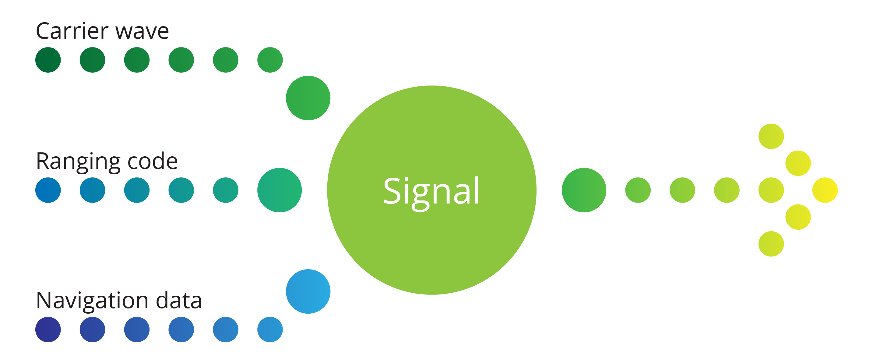
GNSS satellites transmit information by radio waves, and there are three main components to the radio wave signals they transmit; the carrier wave, ranging code and navigation data.
The basics
While this chapter will not go into great depth on how radio waves function, enough of the basics are included for you to understand how GNSS signals are created and what information they contain.
General signal structure
Radio waves are three dimensional, however, they are generally depicted in two dimensions. Radio waves are described by five main physical quantities, as outlined in Table 3.4(a).
Table 3.4(a): Physical quantities used to describe radio waves
| Quantity | Symbol | Dimension |
|---|---|---|
| Circular frequency | f | Cycles per second |
| Phase |  |
cycle |
| Wavelength |  |
Metres per second |
| Period | P | Seconds |
| Speed of light | c | Metres per second |
Carrier waves and modulation
A carrier wave is simply a wave of a constant frequency, like a sine wave. Carrier waves are kind of like a blank piece of paper, on their own they’re not particularly interesting. But like drawing something on a piece of paper, adding an input signal to a carrier wave makes it a lot more interesting. The process of adding an input signal to a carrier wave is called modulation, and in most GNSS, we modulate a carrier wave with a code. This is called Code-division multiple access (CDMA). GLONASS is the exception to this – it uses a process called FDMA, however, its newer satellites include signals that use the CDMA technique.
Ranging codes
Ranging codes are binary, meaning they are a string of zeros and ones that represent different messages depending on the sequence of numbers and method of encoding that is used. An example of a ranging code is shown in Figure 3.4(b).

Ranging codes in GNSS are also known as pseudo-random noise (PRN) ranging codes, even though they’re not random, they appear to lack any definite pattern. PRN ranging codes repeat after a period of time.
Fundamental frequencies
Each GNSS satellite has a number of atomic clocks on board, and these have a fundamental frequency. The fundamental frequency is used to generate carrier waves, the PRN ranging code and the navigation message.
Navigation messages
The navigation message is a critical component in any GNSS signal and is unique to each satellite in a constellation. A navigation message contains information about:
- satellite health
- GPS week number
- the atomic clock data and corrections
- orbital data parameters (this is the ephemeris data)
- ionospheric data
- almanac data
Algorithms are inbuilt into most GNSS receivers to use the information in the navigation message to improve the accuracy of their position. The navigation message is maintained and managed by the control segment, who are constantly checking the satellite parameters of operation against the antenna, signal, time clocks, atmospherics, communications and power level information data held by the master station.
Different GNSS measurement processing techniques require the information in the navigation message to deal with different errors – this will be discussed in more depth in Chapters, 4, 5 and 6 when we discuss different observation techniques.
Almanac
As briefly covered in Chapter 1, the almanac is like a group calendar for all the satellites in a constellation. It contains the approximate orbital parameters of each satellite, and all satellites have the almanac in their navigation message. It is useful for the rapid acquisition of satellites by GNSS receivers.
Ephemeris
The broadcast ephemeris is like a personal calendar for each satellite – it provides the orbital parameters of individual satellites. Each satellite has its own ephemeris, which is broadcast in the navigation message, however, each satellite only broadcasts its own ephemeris. The ephemeris contains information including:
- age of ephemeris data
- satellite PRN number
- satellite health status
- current GPS week
- reference epoch
- five of the orbital parameters:
- semi major axis
- eccentricity
- argument of perigee
- longitude of ascending node at weekly epoch
- the Mean anomaly at reference epoch
- clock phase bias
- clock frequency bias
The orbits of satellites in a GNSS are constantly monitored by the control segment, and once a satellite has finished its orbit, the ephemeris data and other tracking information can be used to produce a final or precise ephemeris. These ephemerides (plural of ephemeris) are produced by organisations like the International GNSS Service, and can be used to correct GNSS data to gain very accurate positioning results, and are usually available between 1-2 weeks after the observations are taken.
GNSS signal recipes
So how do all of these things add up to be a GNSS signal?
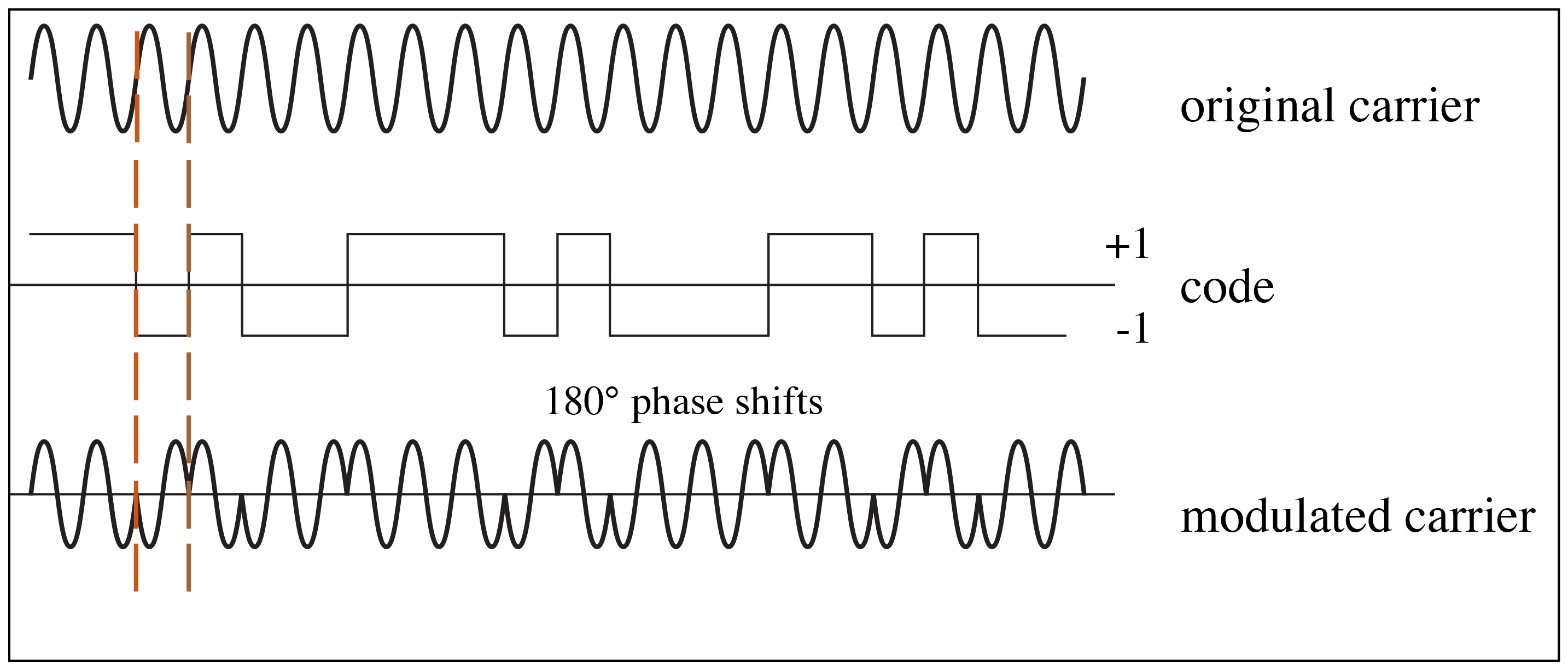
Each of the global systems have their own set of signals, but essentially they work in the same way. GPS and Galileo, (and some of the newer GLONASS signals) have a fundamental frequency, which generates a carrier wave of a specified frequency, and then a PRN ranging code and a navigation message are modulated on to the carrier wave to create a modulated carrier wave. When a change in the code value happens, the carrier wave phase is shifted 180°, as shown in Figure 3.4(c).
For GPS and Galileo, the fundamental frequency is 10.23MHz, and this is used to generate several different signals. Each satellite has its own unique PRN number, and this is how GNSS receivers are able to determine that data being received is coming from a specific satellite.
GPS signals
GPS has three main signals, L1, L2 and L5.
L1
L1 is the signal used by almost every GNSS receiver chip in existence. It is the GPS signal that contains the PRN ranging code called the coarse acquisition code, known as C/A code, which is accessible by civilian GNSS receivers. L1 is one of the two original signals.
L1 contains a military code called the precise code, known as the P(Y) code, which is only accessibly by the US military. It is actually the P code encrypted with the W code to make the Y code, however, it’s most commonly known as the P(Y) code.
L1 uses the Civilian navigation data message, known as CNAVDATA, which is a code that is transmitted at 50 bits per second (BPS).
L1C is a newer version of the L1 signal, but it broadcast on the same frequency as L1. It contains the C/A code and the P(Y) code, and 3 new components:
- L1C code – the updated version of the C/A code
- M code – Military code, the new military code
- CNAV-2 – the new navigation data message format for GPS, transmitted at 100BPS
L2
L2 was one of the original signals along with L1, however, it was largely a military signal to begin with, only having the P(Y) code and the NAVDATA message (the precursor to CNAVDATA). People quickly figured out that by using information in the L2 NAVDATA and components of the P(Y) code that using L2 with L1 allowed significantly more accurate positions to be determine. It is on this basis that the majority of high-level accuracy GNSS surveying is able to be undertaken.
L2C is an updated version of L2, and like L1 & L1C, is broadcast on the same frequency as L2. It now contains a civilian code, L2C (made up of CM and CL codes), as well as the M, P(Y) and CNAVDATA codes.
L5
L5 is what is referred to as a safety of life signal, as it is broadcast in the section of the radio spectrum that is used by aviation safety services, however, it is available for all civilian users. It contains the I5, Q5 and the CNAVDATA codes.
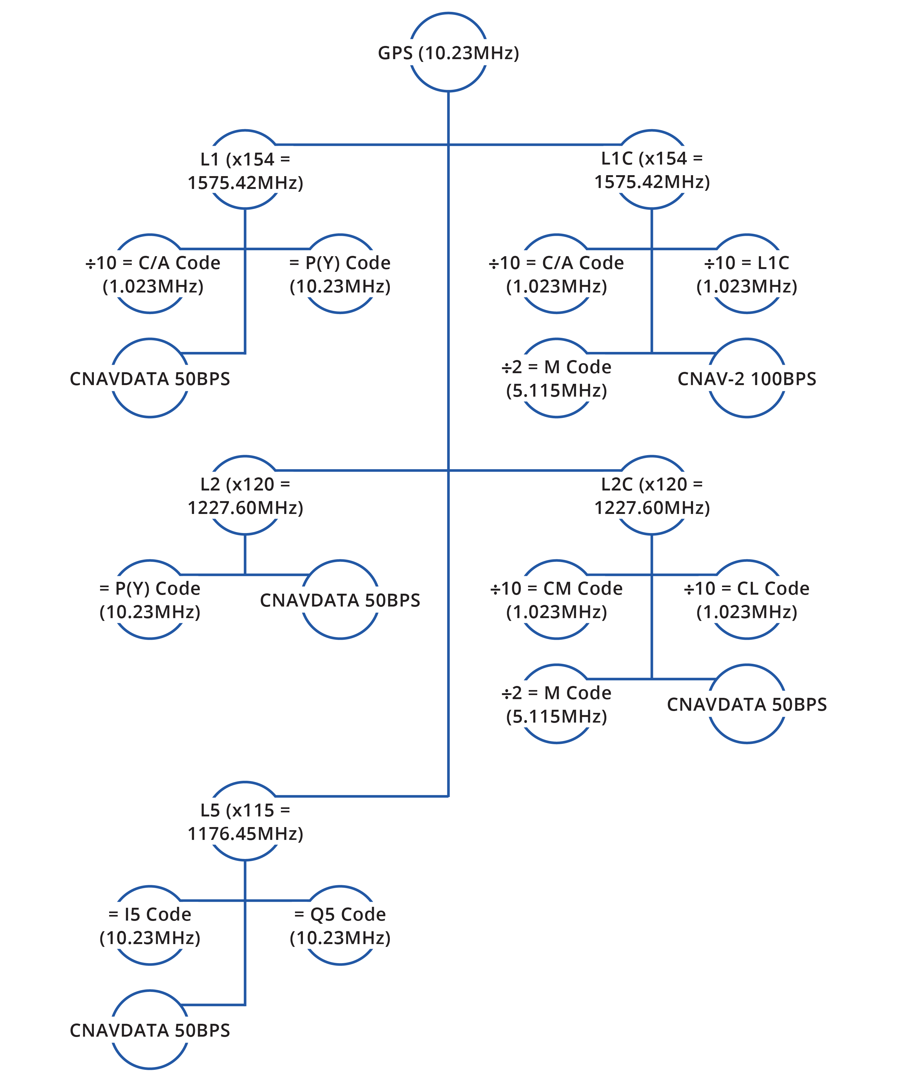
The process of generating the 5 GPS signals from the fundamental frequency is shown in Figure 3.4(d), showing the frequency multipliers and dividers as well as the factors. A summary table is also provided in Table 3.4(b).
Table 3.4(b): Summary of GPS signals
| Signal | L1 | L1C* | L2 | L2C* | L5 |
|---|---|---|---|---|---|
| Fundamental Frequency factor | X154 | X154 | X120 | X120 | X115 |
| Frequency (MHzs) | 1575.42 | 1575.42 | 1227.60 | 1227.60 | 1176.45 |
| Wavelength | 19cm | 19cm | 24cm | 24cm | 25cm |
| Code Info | L1 | L1C* | L2 | L2C* | L5 |
| Civilian | C/A Code | C/A Code L1C |
CM Code CL Code (L2C Code) |
I5 Code Q5 Code |
|
| Military | P(Y) Code | M Code | P(Y) Code | M Code | |
| Navigation Message | CNAVDATA | CNAV-2 | CNAVDATA | CNAVDATA | CNAVDATA |
| *L1C and L2C broadcast on the same frequencies as L1 and L2 respectively | |||||
Galileo signals
Galileo has four signals E1, E6, E5a and E5b. Because it is a civilian operated system, has no military codes, however, it has a Public Regulated Service (PRS) code that is encrypted for governmental authorised users and sensitive applications.
The E1 and E5a signals overlap with the GPS L1 and L5 signals.
The E1 signal has two codes, the E1 Open Service code, and the PRS code.
The E6 signal has the Commercial Service code that is only accessible through paid services.
The E5a signal is similar to the L5 signal – it is primarily considered a safety of life signal.
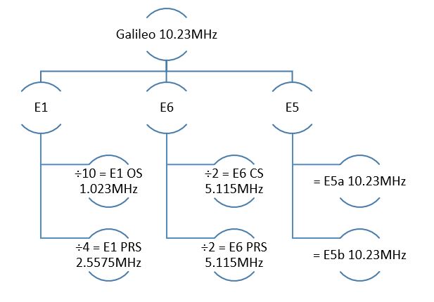
The process of generating the four Galileo signals from the fundamental frequency for is shown in Figure 3.4(e), showing the frequency multipliers and dividers as well as the factors.
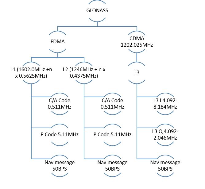
GLONASS signals
As mentioned previously, GLONASS signals are a combination of CDMA and FDMA signals. An outline of the main signals in each type is provided in Figure 3.4(f).
GNSS Time
All GNSS relies on accurate measurement of the distance between a GNSS receiver and satellites, which requires incredibly accurate measurements of the time it takes a signal to travel from a satellite to a receiver – remember that GNSS satellites are orbiting at approximately 20 000 km, and radio waves travel at the speed of light, which is 299 792 458 metres per second! This means GNSS signals take between 60 and 90 milliseconds to reach Earth. For any GNSS to work properly, all the satellites must have their atomic clocks synchronised.
Coordinated Universal Time (UTC) is the standard the world uses to regulate time, and GNSS link their timing systems to UTC at different epochs.
GNSS Time is generally expressed in seconds, for example GPS time is expressed as a week number and then the number of seconds into the week it is.
The different global systems use different types of atomic clocks, and most satellites will have multiple types of clocks on board. Rubidium and Caesium are standard on GPS SVs, Galileo has Hydrogen maser and Rubidium.
