WO2011055643A1 - Liquid crystal display element, liquid crystal composition, aligning agent, method for producing liquid crystal display element, and use of liquid crystal composition - Google Patents
Liquid crystal display element, liquid crystal composition, aligning agent, method for producing liquid crystal display element, and use of liquid crystal composition Download PDFInfo
- Publication number
- WO2011055643A1 WO2011055643A1 PCT/JP2010/068775 JP2010068775W WO2011055643A1 WO 2011055643 A1 WO2011055643 A1 WO 2011055643A1 JP 2010068775 W JP2010068775 W JP 2010068775W WO 2011055643 A1 WO2011055643 A1 WO 2011055643A1
- Authority
- WO
- WIPO (PCT)
- Prior art keywords
- liquid crystal
- formula
- crystal display
- group
- display element
- Prior art date
Links
- 239000004973 liquid crystal related substance Substances 0.000 title claims abstract description 391
- 239000000203 mixture Substances 0.000 title claims abstract description 232
- 239000003795 chemical substances by application Substances 0.000 title claims abstract description 145
- 238000004519 manufacturing process Methods 0.000 title claims abstract description 14
- 150000001875 compounds Chemical class 0.000 claims abstract description 377
- 239000000178 monomer Substances 0.000 claims abstract description 120
- 239000000758 substrate Substances 0.000 claims abstract description 54
- 125000001997 phenyl group Chemical group [H]C1=C([H])C([H])=C(*)C([H])=C1[H] 0.000 claims abstract description 53
- 229910052731 fluorine Inorganic materials 0.000 claims abstract description 29
- 125000001153 fluoro group Chemical group F* 0.000 claims abstract description 13
- 230000000379 polymerizing effect Effects 0.000 claims abstract description 8
- 125000005843 halogen group Chemical group 0.000 claims abstract description 5
- -1 tetrahydropyran-2,5-diyl Chemical group 0.000 claims description 98
- 125000000217 alkyl group Chemical group 0.000 claims description 96
- 150000004985 diamines Chemical class 0.000 claims description 79
- 229910052739 hydrogen Inorganic materials 0.000 claims description 76
- 239000001257 hydrogen Substances 0.000 claims description 76
- 238000000034 method Methods 0.000 claims description 60
- UFHFLCQGNIYNRP-UHFFFAOYSA-N Hydrogen Chemical compound [H][H] UFHFLCQGNIYNRP-UHFFFAOYSA-N 0.000 claims description 51
- 125000004432 carbon atom Chemical group C* 0.000 claims description 50
- 229920005575 poly(amic acid) Polymers 0.000 claims description 47
- GTDPSWPPOUPBNX-UHFFFAOYSA-N ac1mqpva Chemical compound CC12C(=O)OC(=O)C1(C)C1(C)C2(C)C(=O)OC1=O GTDPSWPPOUPBNX-UHFFFAOYSA-N 0.000 claims description 31
- 125000003342 alkenyl group Chemical group 0.000 claims description 28
- 125000003545 alkoxy group Chemical group 0.000 claims description 27
- 229920001721 polyimide Polymers 0.000 claims description 26
- 125000006158 tetracarboxylic acid group Chemical group 0.000 claims description 26
- 125000004955 1,4-cyclohexylene group Chemical group [H]C1([H])C([H])([H])C([H])([*:1])C([H])([H])C([H])([H])C1([H])[*:2] 0.000 claims description 25
- 239000004642 Polyimide Substances 0.000 claims description 25
- 150000002431 hydrogen Chemical group 0.000 claims description 25
- 239000011737 fluorine Substances 0.000 claims description 24
- 125000000113 cyclohexyl group Chemical group [H]C1([H])C([H])([H])C([H])([H])C([H])(*)C([H])([H])C1([H])[H] 0.000 claims description 22
- 239000007787 solid Substances 0.000 claims description 22
- 238000006116 polymerization reaction Methods 0.000 claims description 21
- 125000002947 alkylene group Chemical group 0.000 claims description 20
- 229910052799 carbon Inorganic materials 0.000 claims description 18
- 229910052736 halogen Inorganic materials 0.000 claims description 18
- 150000002367 halogens Chemical class 0.000 claims description 18
- 125000001140 1,4-phenylene group Chemical group [H]C1=C([H])C([*:2])=C([H])C([H])=C1[*:1] 0.000 claims description 16
- OKTJSMMVPCPJKN-UHFFFAOYSA-N Carbon Chemical compound [C] OKTJSMMVPCPJKN-UHFFFAOYSA-N 0.000 claims description 14
- 125000002496 methyl group Chemical group [H]C([H])([H])* 0.000 claims description 13
- 125000001495 ethyl group Chemical group [H]C([H])([H])C([H])([H])* 0.000 claims description 11
- 239000003112 inhibitor Substances 0.000 claims description 11
- 125000004093 cyano group Chemical group *C#N 0.000 claims description 10
- 239000003999 initiator Substances 0.000 claims description 7
- 239000002243 precursor Substances 0.000 claims description 6
- 125000000843 phenylene group Chemical class C1(=C(C=CC=C1)*)* 0.000 claims description 5
- 125000005714 2,5- (1,3-dioxanylene) group Chemical group [H]C1([H])OC([H])([*:1])OC([H])([H])C1([H])[*:2] 0.000 claims description 4
- PPBRXRYQALVLMV-UHFFFAOYSA-N Styrene Chemical compound C=CC1=CC=CC=C1 PPBRXRYQALVLMV-UHFFFAOYSA-N 0.000 claims description 4
- 125000005647 linker group Chemical group 0.000 claims description 4
- 125000000962 organic group Chemical group 0.000 claims description 4
- 125000003277 amino group Chemical group 0.000 claims description 3
- 150000001721 carbon Chemical group 0.000 claims description 3
- 125000000596 cyclohexenyl group Chemical group C1(=CCCCC1)* 0.000 claims description 3
- 125000001181 organosilyl group Chemical group [SiH3]* 0.000 claims description 3
- 229920006395 saturated elastomer Polymers 0.000 claims description 3
- 238000012719 thermal polymerization Methods 0.000 claims description 3
- HRPVXLWXLXDGHG-UHFFFAOYSA-N Acrylamide Chemical compound NC(=O)C=C HRPVXLWXLXDGHG-UHFFFAOYSA-N 0.000 claims description 2
- 230000008878 coupling Effects 0.000 claims description 2
- 238000010168 coupling process Methods 0.000 claims description 2
- 238000005859 coupling reaction Methods 0.000 claims description 2
- 238000010304 firing Methods 0.000 claims description 2
- FQPSGWSUVKBHSU-UHFFFAOYSA-N methacrylamide Chemical compound CC(=C)C(N)=O FQPSGWSUVKBHSU-UHFFFAOYSA-N 0.000 claims description 2
- PXGOKWXKJXAPGV-UHFFFAOYSA-N Fluorine Chemical compound FF PXGOKWXKJXAPGV-UHFFFAOYSA-N 0.000 claims 5
- NIXOWILDQLNWCW-UHFFFAOYSA-M Acrylate Chemical compound [O-]C(=O)C=C NIXOWILDQLNWCW-UHFFFAOYSA-M 0.000 claims 1
- CERQOIWHTDAKMF-UHFFFAOYSA-M Methacrylate Chemical compound CC(=C)C([O-])=O CERQOIWHTDAKMF-UHFFFAOYSA-M 0.000 claims 1
- 238000004090 dissolution Methods 0.000 abstract description 14
- 238000011156 evaluation Methods 0.000 description 65
- 230000004044 response Effects 0.000 description 40
- 0 CC(C)(*)N(C(*)=O)C(*(C(N1C)=O)C1=O)=O Chemical compound CC(C)(*)N(C(*)=O)C(*(C(N1C)=O)C1=O)=O 0.000 description 33
- 239000010408 film Substances 0.000 description 25
- 238000005259 measurement Methods 0.000 description 24
- 125000001424 substituent group Chemical group 0.000 description 23
- 239000002904 solvent Substances 0.000 description 20
- 229920000642 polymer Polymers 0.000 description 19
- 230000003247 decreasing effect Effects 0.000 description 18
- 238000010828 elution Methods 0.000 description 17
- 239000011521 glass Substances 0.000 description 15
- 230000001965 increasing effect Effects 0.000 description 15
- 239000000126 substance Substances 0.000 description 15
- SECXISVLQFMRJM-UHFFFAOYSA-N N-Methylpyrrolidone Chemical compound CN1CCCC1=O SECXISVLQFMRJM-UHFFFAOYSA-N 0.000 description 13
- 238000000576 coating method Methods 0.000 description 13
- 230000000694 effects Effects 0.000 description 13
- 239000003505 polymerization initiator Substances 0.000 description 13
- 230000003287 optical effect Effects 0.000 description 12
- 229920000728 polyester Polymers 0.000 description 11
- 239000000243 solution Substances 0.000 description 11
- 239000000654 additive Substances 0.000 description 10
- 210000004027 cell Anatomy 0.000 description 10
- 239000011248 coating agent Substances 0.000 description 10
- 238000010438 heat treatment Methods 0.000 description 10
- 239000012535 impurity Substances 0.000 description 10
- 238000003786 synthesis reaction Methods 0.000 description 10
- WEVYAHXRMPXWCK-UHFFFAOYSA-N Acetonitrile Chemical compound CC#N WEVYAHXRMPXWCK-UHFFFAOYSA-N 0.000 description 9
- YCKRFDGAMUMZLT-UHFFFAOYSA-N Fluorine atom Chemical compound [F] YCKRFDGAMUMZLT-UHFFFAOYSA-N 0.000 description 9
- ZMXDDKWLCZADIW-UHFFFAOYSA-N N,N-Dimethylformamide Chemical compound CN(C)C=O ZMXDDKWLCZADIW-UHFFFAOYSA-N 0.000 description 9
- 150000002500 ions Chemical class 0.000 description 9
- 239000004593 Epoxy Substances 0.000 description 8
- 230000015572 biosynthetic process Effects 0.000 description 8
- 238000004140 cleaning Methods 0.000 description 8
- 238000002834 transmittance Methods 0.000 description 8
- ISSYGWIDLYOJEN-UHFFFAOYSA-N [3-methyl-4-[4-(3-prop-2-enoyloxypropoxy)benzoyl]oxyphenyl] 4-(3-prop-2-enoyloxypropoxy)benzoate Chemical compound C=1C=C(OC(=O)C=2C=CC(OCCCOC(=O)C=C)=CC=2)C(C)=CC=1OC(=O)C1=CC=C(OCCCOC(=O)C=C)C=C1 ISSYGWIDLYOJEN-UHFFFAOYSA-N 0.000 description 7
- 238000004458 analytical method Methods 0.000 description 7
- 239000003963 antioxidant agent Substances 0.000 description 7
- 238000006243 chemical reaction Methods 0.000 description 7
- 230000000052 comparative effect Effects 0.000 description 7
- 230000007423 decrease Effects 0.000 description 7
- 230000005684 electric field Effects 0.000 description 7
- 150000003254 radicals Chemical class 0.000 description 7
- 239000007788 liquid Substances 0.000 description 6
- QSHDDOUJBYECFT-UHFFFAOYSA-N mercury Chemical compound [Hg] QSHDDOUJBYECFT-UHFFFAOYSA-N 0.000 description 6
- 229910052753 mercury Inorganic materials 0.000 description 6
- 239000000047 product Substances 0.000 description 6
- IJGRMHOSHXDMSA-UHFFFAOYSA-N Atomic nitrogen Chemical compound N#N IJGRMHOSHXDMSA-UHFFFAOYSA-N 0.000 description 5
- LFQSCWFLJHTTHZ-UHFFFAOYSA-N Ethanol Chemical compound CCO LFQSCWFLJHTTHZ-UHFFFAOYSA-N 0.000 description 5
- 239000002518 antifoaming agent Substances 0.000 description 5
- LYCAIKOWRPUZTN-UHFFFAOYSA-N ethylene glycol Natural products OCCO LYCAIKOWRPUZTN-UHFFFAOYSA-N 0.000 description 5
- 238000004128 high performance liquid chromatography Methods 0.000 description 5
- 239000000463 material Substances 0.000 description 5
- 238000002156 mixing Methods 0.000 description 5
- 229920000647 polyepoxide Polymers 0.000 description 5
- 238000007639 printing Methods 0.000 description 5
- 230000008569 process Effects 0.000 description 5
- 239000002994 raw material Substances 0.000 description 5
- 125000002345 steroid group Chemical group 0.000 description 5
- POAOYUHQDCAZBD-UHFFFAOYSA-N 2-butoxyethanol Chemical compound CCCCOCCO POAOYUHQDCAZBD-UHFFFAOYSA-N 0.000 description 4
- YEJRWHAVMIAJKC-UHFFFAOYSA-N 4-Butyrolactone Chemical compound O=C1CCCO1 YEJRWHAVMIAJKC-UHFFFAOYSA-N 0.000 description 4
- YMWUJEATGCHHMB-UHFFFAOYSA-N Dichloromethane Chemical compound ClCCl YMWUJEATGCHHMB-UHFFFAOYSA-N 0.000 description 4
- QIGBRXMKCJKVMJ-UHFFFAOYSA-N Hydroquinone Chemical compound OC1=CC=C(O)C=C1 QIGBRXMKCJKVMJ-UHFFFAOYSA-N 0.000 description 4
- 239000000853 adhesive Substances 0.000 description 4
- 230000001070 adhesive effect Effects 0.000 description 4
- 230000003078 antioxidant effect Effects 0.000 description 4
- 230000008859 change Effects 0.000 description 4
- 239000007795 chemical reaction product Substances 0.000 description 4
- 238000012937 correction Methods 0.000 description 4
- 239000007822 coupling agent Substances 0.000 description 4
- 230000007547 defect Effects 0.000 description 4
- 238000001035 drying Methods 0.000 description 4
- 239000000975 dye Substances 0.000 description 4
- 239000003822 epoxy resin Substances 0.000 description 4
- DNIAPMSPPWPWGF-UHFFFAOYSA-N monopropylene glycol Natural products CC(O)CO DNIAPMSPPWPWGF-UHFFFAOYSA-N 0.000 description 4
- 238000012360 testing method Methods 0.000 description 4
- 125000006017 1-propenyl group Chemical group 0.000 description 3
- 238000005160 1H NMR spectroscopy Methods 0.000 description 3
- KWVGIHKZDCUPEU-UHFFFAOYSA-N 2,2-dimethoxy-2-phenylacetophenone Chemical compound C=1C=CC=CC=1C(OC)(OC)C(=O)C1=CC=CC=C1 KWVGIHKZDCUPEU-UHFFFAOYSA-N 0.000 description 3
- 125000005450 2,3-difluoro-1,4-phenylene group Chemical group [H]C1=C([*:2])C(F)=C(F)C([*:1])=C1[H] 0.000 description 3
- ZWEHNKRNPOVVGH-UHFFFAOYSA-N 2-Butanone Chemical compound CCC(C)=O ZWEHNKRNPOVVGH-UHFFFAOYSA-N 0.000 description 3
- 229920003319 Araldite® Polymers 0.000 description 3
- UHOVQNZJYSORNB-UHFFFAOYSA-N Benzene Chemical compound C1=CC=CC=C1 UHOVQNZJYSORNB-UHFFFAOYSA-N 0.000 description 3
- KFZMGEQAYNKOFK-UHFFFAOYSA-N Isopropanol Chemical compound CC(C)O KFZMGEQAYNKOFK-UHFFFAOYSA-N 0.000 description 3
- OKKJLVBELUTLKV-UHFFFAOYSA-N Methanol Chemical compound OC OKKJLVBELUTLKV-UHFFFAOYSA-N 0.000 description 3
- 239000004990 Smectic liquid crystal Substances 0.000 description 3
- HEMHJVSKTPXQMS-UHFFFAOYSA-M Sodium hydroxide Chemical compound [OH-].[Na+] HEMHJVSKTPXQMS-UHFFFAOYSA-M 0.000 description 3
- YXFVVABEGXRONW-UHFFFAOYSA-N Toluene Chemical compound CC1=CC=CC=C1 YXFVVABEGXRONW-UHFFFAOYSA-N 0.000 description 3
- RWCCWEUUXYIKHB-UHFFFAOYSA-N benzophenone Chemical compound C=1C=CC=CC=1C(=O)C1=CC=CC=C1 RWCCWEUUXYIKHB-UHFFFAOYSA-N 0.000 description 3
- 239000012965 benzophenone Substances 0.000 description 3
- 238000000113 differential scanning calorimetry Methods 0.000 description 3
- 235000019441 ethanol Nutrition 0.000 description 3
- ANSXAPJVJOKRDJ-UHFFFAOYSA-N furo[3,4-f][2]benzofuran-1,3,5,7-tetrone Chemical compound C1=C2C(=O)OC(=O)C2=CC2=C1C(=O)OC2=O ANSXAPJVJOKRDJ-UHFFFAOYSA-N 0.000 description 3
- 238000005227 gel permeation chromatography Methods 0.000 description 3
- 230000001678 irradiating effect Effects 0.000 description 3
- 230000014759 maintenance of location Effects 0.000 description 3
- 239000011159 matrix material Substances 0.000 description 3
- 238000002844 melting Methods 0.000 description 3
- 230000008018 melting Effects 0.000 description 3
- 229910052757 nitrogen Inorganic materials 0.000 description 3
- 125000001436 propyl group Chemical group [H]C([*])([H])C([H])([H])C([H])([H])[H] 0.000 description 3
- 239000012925 reference material Substances 0.000 description 3
- 239000013558 reference substance Substances 0.000 description 3
- 229910052717 sulfur Inorganic materials 0.000 description 3
- 230000002194 synthesizing effect Effects 0.000 description 3
- CXWXQJXEFPUFDZ-UHFFFAOYSA-N tetralin Chemical compound C1=CC=C2CCCCC2=C1 CXWXQJXEFPUFDZ-UHFFFAOYSA-N 0.000 description 3
- 229910052724 xenon Inorganic materials 0.000 description 3
- FHNFHKCVQCLJFQ-UHFFFAOYSA-N xenon atom Chemical compound [Xe] FHNFHKCVQCLJFQ-UHFFFAOYSA-N 0.000 description 3
- AQAGCHUHSHTBLP-AFBJXSTISA-N (4z,8z,13z)-11-hexyl-1-oxacyclopentadeca-4,8,13-trien-2-one Chemical compound CCCCCCC1C\C=C/CC\C=C/CC(=O)OC\C=C/C1 AQAGCHUHSHTBLP-AFBJXSTISA-N 0.000 description 2
- CYSGHNMQYZDMIA-UHFFFAOYSA-N 1,3-Dimethyl-2-imidazolidinon Chemical compound CN1CCN(C)C1=O CYSGHNMQYZDMIA-UHFFFAOYSA-N 0.000 description 2
- 125000004973 1-butenyl group Chemical group C(=CCC)* 0.000 description 2
- RWNUSVWFHDHRCJ-UHFFFAOYSA-N 1-butoxypropan-2-ol Chemical compound CCCCOCC(C)O RWNUSVWFHDHRCJ-UHFFFAOYSA-N 0.000 description 2
- 125000006039 1-hexenyl group Chemical group 0.000 description 2
- 125000006023 1-pentenyl group Chemical group 0.000 description 2
- HZAXFHJVJLSVMW-UHFFFAOYSA-N 2-Aminoethan-1-ol Chemical compound NCCO HZAXFHJVJLSVMW-UHFFFAOYSA-N 0.000 description 2
- 125000004974 2-butenyl group Chemical group C(C=CC)* 0.000 description 2
- 125000006040 2-hexenyl group Chemical group 0.000 description 2
- 125000006024 2-pentenyl group Chemical group 0.000 description 2
- QCAHUFWKIQLBNB-UHFFFAOYSA-N 3-(3-methoxypropoxy)propan-1-ol Chemical compound COCCCOCCCO QCAHUFWKIQLBNB-UHFFFAOYSA-N 0.000 description 2
- 125000004975 3-butenyl group Chemical group C(CC=C)* 0.000 description 2
- 125000006041 3-hexenyl group Chemical group 0.000 description 2
- VVBLNCFGVYUYGU-UHFFFAOYSA-N 4,4'-Bis(dimethylamino)benzophenone Chemical compound C1=CC(N(C)C)=CC=C1C(=O)C1=CC=C(N(C)C)C=C1 VVBLNCFGVYUYGU-UHFFFAOYSA-N 0.000 description 2
- LKVFCSWBKOVHAH-UHFFFAOYSA-N 4-Ethoxyphenol Chemical compound CCOC1=CC=C(O)C=C1 LKVFCSWBKOVHAH-UHFFFAOYSA-N 0.000 description 2
- FAUAZXVRLVIARB-UHFFFAOYSA-N 4-[[4-[bis(oxiran-2-ylmethyl)amino]phenyl]methyl]-n,n-bis(oxiran-2-ylmethyl)aniline Chemical compound C1OC1CN(C=1C=CC(CC=2C=CC(=CC=2)N(CC2OC2)CC2OC2)=CC=1)CC1CO1 FAUAZXVRLVIARB-UHFFFAOYSA-N 0.000 description 2
- DLFVBJFMPXGRIB-UHFFFAOYSA-N Acetamide Chemical compound CC(N)=O DLFVBJFMPXGRIB-UHFFFAOYSA-N 0.000 description 2
- CSCPPACGZOOCGX-UHFFFAOYSA-N Acetone Chemical compound CC(C)=O CSCPPACGZOOCGX-UHFFFAOYSA-N 0.000 description 2
- 101100132433 Arabidopsis thaliana VIII-1 gene Proteins 0.000 description 2
- 101500000959 Bacillus anthracis Protective antigen PA-20 Proteins 0.000 description 2
- NLZUEZXRPGMBCV-UHFFFAOYSA-N Butylhydroxytoluene Chemical compound CC1=CC(C(C)(C)C)=C(O)C(C(C)(C)C)=C1 NLZUEZXRPGMBCV-UHFFFAOYSA-N 0.000 description 2
- WVOLTBSCXRRQFR-SJORKVTESA-N Cannabidiolic acid Natural products OC1=C(C(O)=O)C(CCCCC)=CC(O)=C1[C@@H]1[C@@H](C(C)=C)CCC(C)=C1 WVOLTBSCXRRQFR-SJORKVTESA-N 0.000 description 2
- IAZDPXIOMUYVGZ-UHFFFAOYSA-N Dimethylsulphoxide Chemical compound CS(C)=O IAZDPXIOMUYVGZ-UHFFFAOYSA-N 0.000 description 2
- OFOBLEOULBTSOW-UHFFFAOYSA-N Malonic acid Chemical compound OC(=O)CC(O)=O OFOBLEOULBTSOW-UHFFFAOYSA-N 0.000 description 2
- 238000005481 NMR spectroscopy Methods 0.000 description 2
- UFWIBTONFRDIAS-UHFFFAOYSA-N Naphthalene Chemical compound C1=CC=CC2=CC=CC=C21 UFWIBTONFRDIAS-UHFFFAOYSA-N 0.000 description 2
- NBIIXXVUZAFLBC-UHFFFAOYSA-N Phosphoric acid Chemical compound OP(O)(O)=O NBIIXXVUZAFLBC-UHFFFAOYSA-N 0.000 description 2
- 238000002835 absorbance Methods 0.000 description 2
- 239000006096 absorbing agent Substances 0.000 description 2
- 125000000304 alkynyl group Chemical group 0.000 description 2
- MTHSVFCYNBDYFN-UHFFFAOYSA-N anhydrous diethylene glycol Natural products OCCOCCO MTHSVFCYNBDYFN-UHFFFAOYSA-N 0.000 description 2
- 239000012298 atmosphere Substances 0.000 description 2
- 230000002238 attenuated effect Effects 0.000 description 2
- IISBACLAFKSPIT-UHFFFAOYSA-N bisphenol A Chemical compound C=1C=C(O)C=CC=1C(C)(C)C1=CC=C(O)C=C1 IISBACLAFKSPIT-UHFFFAOYSA-N 0.000 description 2
- 125000000484 butyl group Chemical group [H]C([*])([H])C([H])([H])C([H])([H])C([H])([H])[H] 0.000 description 2
- WVOLTBSCXRRQFR-DLBZAZTESA-M cannabidiolate Chemical compound OC1=C(C([O-])=O)C(CCCCC)=CC(O)=C1[C@H]1[C@H](C(C)=C)CCC(C)=C1 WVOLTBSCXRRQFR-DLBZAZTESA-M 0.000 description 2
- 239000013078 crystal Substances 0.000 description 2
- 238000001514 detection method Methods 0.000 description 2
- XXJWXESWEXIICW-UHFFFAOYSA-N diethylene glycol monoethyl ether Chemical compound CCOCCOCCO XXJWXESWEXIICW-UHFFFAOYSA-N 0.000 description 2
- 229940075557 diethylene glycol monoethyl ether Drugs 0.000 description 2
- 238000007598 dipping method Methods 0.000 description 2
- 238000013213 extrapolation Methods 0.000 description 2
- 125000003187 heptyl group Chemical group [H]C([*])([H])C([H])([H])C([H])([H])C([H])([H])C([H])([H])C([H])([H])C([H])([H])[H] 0.000 description 2
- 150000002430 hydrocarbons Chemical group 0.000 description 2
- 230000001976 improved effect Effects 0.000 description 2
- HJOVHMDZYOCNQW-UHFFFAOYSA-N isophorone Chemical compound CC1=CC(=O)CC(C)(C)C1 HJOVHMDZYOCNQW-UHFFFAOYSA-N 0.000 description 2
- 229910052751 metal Inorganic materials 0.000 description 2
- 239000002184 metal Substances 0.000 description 2
- 229910001507 metal halide Inorganic materials 0.000 description 2
- 150000005309 metal halides Chemical class 0.000 description 2
- 239000011259 mixed solution Substances 0.000 description 2
- 239000012046 mixed solvent Substances 0.000 description 2
- 239000003960 organic solvent Substances 0.000 description 2
- 125000001147 pentyl group Chemical group C(CCCC)* 0.000 description 2
- 125000003884 phenylalkyl group Chemical group 0.000 description 2
- 238000000016 photochemical curing Methods 0.000 description 2
- 230000010287 polarization Effects 0.000 description 2
- 238000002360 preparation method Methods 0.000 description 2
- 238000010526 radical polymerization reaction Methods 0.000 description 2
- 239000003381 stabilizer Substances 0.000 description 2
- 238000001308 synthesis method Methods 0.000 description 2
- 239000006097 ultraviolet radiation absorber Substances 0.000 description 2
- 125000000391 vinyl group Chemical group [H]C([*])=C([H])[H] 0.000 description 2
- 229920002554 vinyl polymer Polymers 0.000 description 2
- XLYOFNOQVPJJNP-UHFFFAOYSA-N water Substances O XLYOFNOQVPJJNP-UHFFFAOYSA-N 0.000 description 2
- 239000003643 water by type Substances 0.000 description 2
- QNODIIQQMGDSEF-UHFFFAOYSA-N (1-hydroxycyclohexyl)-phenylmethanone Chemical compound C=1C=CC=CC=1C(=O)C1(O)CCCCC1 QNODIIQQMGDSEF-UHFFFAOYSA-N 0.000 description 1
- NQJAUIYRHFRPNO-UHFFFAOYSA-N (3,5-diaminophenyl)-(4-tetradecylphenyl)methanone Chemical compound C1=CC(CCCCCCCCCCCCCC)=CC=C1C(=O)C1=CC(N)=CC(N)=C1 NQJAUIYRHFRPNO-UHFFFAOYSA-N 0.000 description 1
- WYTZZXDRDKSJID-UHFFFAOYSA-N (3-aminopropyl)triethoxysilane Chemical compound CCO[Si](OCC)(OCC)CCCN WYTZZXDRDKSJID-UHFFFAOYSA-N 0.000 description 1
- OLQWMCSSZKNOLQ-ZXZARUISSA-N (3s)-3-[(3r)-2,5-dioxooxolan-3-yl]oxolane-2,5-dione Chemical compound O=C1OC(=O)C[C@H]1[C@@H]1C(=O)OC(=O)C1 OLQWMCSSZKNOLQ-ZXZARUISSA-N 0.000 description 1
- JWXYMBDCGNXXRO-UHFFFAOYSA-N (4-methoxyphenyl) 4-(6-prop-2-enoyloxyhexoxy)benzoate Chemical compound C1=CC(OC)=CC=C1OC(=O)C1=CC=C(OCCCCCCOC(=O)C=C)C=C1 JWXYMBDCGNXXRO-UHFFFAOYSA-N 0.000 description 1
- JDGFELYPUWNNGR-UHFFFAOYSA-N 1,2,3,3a,4,5,6,6a-octahydropentalene-1,3,4,6-tetracarboxylic acid Chemical compound OC(=O)C1CC(C(O)=O)C2C(C(=O)O)CC(C(O)=O)C21 JDGFELYPUWNNGR-UHFFFAOYSA-N 0.000 description 1
- YHMYGUUIMTVXNW-UHFFFAOYSA-N 1,3-dihydrobenzimidazole-2-thione Chemical compound C1=CC=C2NC(S)=NC2=C1 YHMYGUUIMTVXNW-UHFFFAOYSA-N 0.000 description 1
- LTMRRSWNXVJMBA-UHFFFAOYSA-L 2,2-diethylpropanedioate Chemical compound CCC(CC)(C([O-])=O)C([O-])=O LTMRRSWNXVJMBA-UHFFFAOYSA-L 0.000 description 1
- KODNTHAUOGOFJY-UHFFFAOYSA-N 2,4-diethylxanthen-9-one Chemical compound C1=CC=C2C(=O)C3=CC(CC)=CC(CC)=C3OC2=C1 KODNTHAUOGOFJY-UHFFFAOYSA-N 0.000 description 1
- BRAXACIBZBWDGG-UHFFFAOYSA-N 2-(2,5-dioxo-3-phenylpyrrol-1-yl)ethyl 3,5-diaminobenzoate Chemical compound NC1=CC(N)=CC(C(=O)OCCN2C(C(=CC2=O)C=2C=CC=CC=2)=O)=C1 BRAXACIBZBWDGG-UHFFFAOYSA-N 0.000 description 1
- JECYNCQXXKQDJN-UHFFFAOYSA-N 2-(2-methylhexan-2-yloxymethyl)oxirane Chemical compound CCCCC(C)(C)OCC1CO1 JECYNCQXXKQDJN-UHFFFAOYSA-N 0.000 description 1
- IJXPXNZUSXLSTF-UHFFFAOYSA-N 2-[2-(4-butoxyphenyl)ethenyl]-5-(trichloromethyl)-1,3,4-oxadiazole Chemical compound C1=CC(OCCCC)=CC=C1C=CC1=NN=C(C(Cl)(Cl)Cl)O1 IJXPXNZUSXLSTF-UHFFFAOYSA-N 0.000 description 1
- CQZQMQQAHUDRMC-UHFFFAOYSA-N 2-[[3-[4-(4-pentylcyclohexyl)cyclohexyl]phenyl]methyl]benzene-1,3-diamine Chemical compound C1CC(CCCCC)CCC1C1CCC(C=2C=C(CC=3C(=CC=CC=3N)N)C=CC=2)CC1 CQZQMQQAHUDRMC-UHFFFAOYSA-N 0.000 description 1
- QVEMWYGBLHQEAK-UHFFFAOYSA-N 2-ethylbutanamide Chemical compound CCC(CC)C(N)=O QVEMWYGBLHQEAK-UHFFFAOYSA-N 0.000 description 1
- 125000005449 2-fluoro-1,4-phenylene group Chemical group [H]C1=C([*:2])C([H])=C(F)C([*:1])=C1[H] 0.000 description 1
- QPXVRLXJHPTCPW-UHFFFAOYSA-N 2-hydroxy-2-methyl-1-(4-propan-2-ylphenyl)propan-1-one Chemical compound CC(C)C1=CC=C(C(=O)C(C)(C)O)C=C1 QPXVRLXJHPTCPW-UHFFFAOYSA-N 0.000 description 1
- XMLYCEVDHLAQEL-UHFFFAOYSA-N 2-hydroxy-2-methyl-1-phenylpropan-1-one Chemical compound CC(C)(O)C(=O)C1=CC=CC=C1 XMLYCEVDHLAQEL-UHFFFAOYSA-N 0.000 description 1
- LWRBVKNFOYUCNP-UHFFFAOYSA-N 2-methyl-1-(4-methylsulfanylphenyl)-2-morpholin-4-ylpropan-1-one Chemical compound C1=CC(SC)=CC=C1C(=O)C(C)(C)N1CCOCC1 LWRBVKNFOYUCNP-UHFFFAOYSA-N 0.000 description 1
- HLYCTXRRGDDBOW-UHFFFAOYSA-N 2-methylpiperazine-1-carbodithioic acid Chemical compound CC1CNCCN1C(S)=S HLYCTXRRGDDBOW-UHFFFAOYSA-N 0.000 description 1
- 125000003903 2-propenyl group Chemical group [H]C([*])([H])C([H])=C([H])[H] 0.000 description 1
- CDVWEQJFWZJVKC-JLHYYAGUSA-N 3,5-diamino-2-[(E)-7-(4-hexoxyphenyl)-5-oxohept-6-enyl]benzoic acid Chemical compound C1=CC(OCCCCCC)=CC=C1\C=C\C(=O)CCCCC1=C(N)C=C(N)C=C1C(O)=O CDVWEQJFWZJVKC-JLHYYAGUSA-N 0.000 description 1
- RHRNYXVSZLSRRP-UHFFFAOYSA-N 3-(carboxymethyl)cyclopentane-1,2,4-tricarboxylic acid Chemical compound OC(=O)CC1C(C(O)=O)CC(C(O)=O)C1C(O)=O RHRNYXVSZLSRRP-UHFFFAOYSA-N 0.000 description 1
- MFKRHJVUCZRDTF-UHFFFAOYSA-N 3-methoxy-3-methylbutan-1-ol Chemical compound COC(C)(C)CCO MFKRHJVUCZRDTF-UHFFFAOYSA-N 0.000 description 1
- SJECZPVISLOESU-UHFFFAOYSA-N 3-trimethoxysilylpropan-1-amine Chemical compound CO[Si](OC)(OC)CCCN SJECZPVISLOESU-UHFFFAOYSA-N 0.000 description 1
- LJMPOXUWPWEILS-UHFFFAOYSA-N 3a,4,4a,7a,8,8a-hexahydrofuro[3,4-f][2]benzofuran-1,3,5,7-tetrone Chemical compound C1C2C(=O)OC(=O)C2CC2C(=O)OC(=O)C21 LJMPOXUWPWEILS-UHFFFAOYSA-N 0.000 description 1
- PLCLIPCLSAAXDR-UHFFFAOYSA-N 4-[4-[1-[4-(4-aminophenoxy)phenyl]-4-[2-(4-heptylcyclohexyl)ethyl]cyclohexyl]phenoxy]aniline Chemical compound C1CC(CCCCCCC)CCC1CCC1CCC(C=2C=CC(OC=3C=CC(N)=CC=3)=CC=2)(C=2C=CC(OC=3C=CC(N)=CC=3)=CC=2)CC1 PLCLIPCLSAAXDR-UHFFFAOYSA-N 0.000 description 1
- ZHVBBDVBERFGCH-UHFFFAOYSA-N 4-[[4-[1-[4-[(4-aminophenyl)methyl]phenyl]-4-heptylcyclohexyl]phenyl]methyl]aniline Chemical compound C1CC(CCCCCCC)CCC1(C=1C=CC(CC=2C=CC(N)=CC=2)=CC=1)C(C=C1)=CC=C1CC1=CC=C(N)C=C1 ZHVBBDVBERFGCH-UHFFFAOYSA-N 0.000 description 1
- 125000006042 4-hexenyl group Chemical group 0.000 description 1
- YGYCECQIOXZODZ-UHFFFAOYSA-N 4415-87-6 Chemical compound O=C1OC(=O)C2C1C1C(=O)OC(=O)C12 YGYCECQIOXZODZ-UHFFFAOYSA-N 0.000 description 1
- VQVIHDPBMFABCQ-UHFFFAOYSA-N 5-(1,3-dioxo-2-benzofuran-5-carbonyl)-2-benzofuran-1,3-dione Chemical compound C1=C2C(=O)OC(=O)C2=CC(C(C=2C=C3C(=O)OC(=O)C3=CC=2)=O)=C1 VQVIHDPBMFABCQ-UHFFFAOYSA-N 0.000 description 1
- 125000006043 5-hexenyl group Chemical group 0.000 description 1
- KDDDBOTWRRILGO-UHFFFAOYSA-N 6-[4-[4-(6-prop-2-enoyloxyhexoxy)phenyl]phenoxy]hexyl prop-2-enoate Chemical group C1=CC(OCCCCCCOC(=O)C=C)=CC=C1C1=CC=C(OCCCCCCOC(=O)C=C)C=C1 KDDDBOTWRRILGO-UHFFFAOYSA-N 0.000 description 1
- MTRFEWTWIPAXLG-UHFFFAOYSA-N 9-phenylacridine Chemical compound C1=CC=CC=C1C1=C(C=CC=C2)C2=NC2=CC=CC=C12 MTRFEWTWIPAXLG-UHFFFAOYSA-N 0.000 description 1
- PKHJLMKSEAXHIZ-UYGPNLQVSA-N CC(C)CCCC(C)C(CC1)C(C)(CC2)C1C(C1)C2C(C)(CCC(C2)OC(C(C=CC3)=C[C@@H]3N)=O)C2C1OC(C(CCC=C1)CC1N)=O Chemical compound CC(C)CCCC(C)C(CC1)C(C)(CC2)C1C(C1)C2C(C)(CCC(C2)OC(C(C=CC3)=C[C@@H]3N)=O)C2C1OC(C(CCC=C1)CC1N)=O PKHJLMKSEAXHIZ-UYGPNLQVSA-N 0.000 description 1
- SIEHPQBFGFLGPR-UHFFFAOYSA-N CC(C1C(C(CCC23)C(C4)C2C(O)OC4=O)C3C2CC1)C2C([O]=O)=O Chemical compound CC(C1C(C(CCC23)C(C4)C2C(O)OC4=O)C3C2CC1)C2C([O]=O)=O SIEHPQBFGFLGPR-UHFFFAOYSA-N 0.000 description 1
- BEWUGRITXXCIDC-UHFFFAOYSA-N CCC(CCC(C)C(CC1)C(C)(CC2)C1C(CC1)C2C2(C)C1CC(C)CC2)C(C)C Chemical compound CCC(CCC(C)C(CC1)C(C)(CC2)C1C(CC1)C2C2(C)C1CC(C)CC2)C(C)C BEWUGRITXXCIDC-UHFFFAOYSA-N 0.000 description 1
- DIJCWEAQRJWIQM-UHFFFAOYSA-N COC1=CC=C(C=C1)C=1C(=NN(NC1)C(Cl)(Cl)Cl)C(Cl)(Cl)Cl Chemical compound COC1=CC=C(C=C1)C=1C(=NN(NC1)C(Cl)(Cl)Cl)C(Cl)(Cl)Cl DIJCWEAQRJWIQM-UHFFFAOYSA-N 0.000 description 1
- 229920000742 Cotton Polymers 0.000 description 1
- IAYPIBMASNFSPL-UHFFFAOYSA-N Ethylene oxide Chemical compound C1CO1 IAYPIBMASNFSPL-UHFFFAOYSA-N 0.000 description 1
- OWYWGLHRNBIFJP-UHFFFAOYSA-N Ipazine Chemical compound CCN(CC)C1=NC(Cl)=NC(NC(C)C)=N1 OWYWGLHRNBIFJP-UHFFFAOYSA-N 0.000 description 1
- PEEHTFAAVSWFBL-UHFFFAOYSA-N Maleimide Chemical compound O=C1NC(=O)C=C1 PEEHTFAAVSWFBL-UHFFFAOYSA-N 0.000 description 1
- OFOBLEOULBTSOW-UHFFFAOYSA-L Malonate Chemical compound [O-]C(=O)CC([O-])=O OFOBLEOULBTSOW-UHFFFAOYSA-L 0.000 description 1
- SUAKHGWARZSWIH-UHFFFAOYSA-N N,N‐diethylformamide Chemical compound CCN(CC)C=O SUAKHGWARZSWIH-UHFFFAOYSA-N 0.000 description 1
- ZWXPDGCFMMFNRW-UHFFFAOYSA-N N-methylcaprolactam Chemical compound CN1CCCCCC1=O ZWXPDGCFMMFNRW-UHFFFAOYSA-N 0.000 description 1
- IGDOUJFVKGUAOZ-YVUCDPHTSA-N N/C(/C=C\CC(C(CC1)=CC=C1N)O)=C/C=O Chemical compound N/C(/C=C\CC(C(CC1)=CC=C1N)O)=C/C=O IGDOUJFVKGUAOZ-YVUCDPHTSA-N 0.000 description 1
- NXJOWPCSMRUVTB-UHFFFAOYSA-N NC(C=C1)=CCC1S Chemical compound NC(C=C1)=CCC1S NXJOWPCSMRUVTB-UHFFFAOYSA-N 0.000 description 1
- QVOXHDOPZVYFMU-UHFFFAOYSA-N NC(CC1)C=CC1SCCSC(C=C1)=CCC1N Chemical compound NC(CC1)C=CC1SCCSC(C=C1)=CCC1N QVOXHDOPZVYFMU-UHFFFAOYSA-N 0.000 description 1
- LPIMEXAFOJPGGU-GDVGLLTNSA-N NC(CC1)C=C[C@@H]1S Chemical compound NC(CC1)C=C[C@@H]1S LPIMEXAFOJPGGU-GDVGLLTNSA-N 0.000 description 1
- CTQNGGLPUBDAKN-UHFFFAOYSA-N O-Xylene Chemical compound CC1=CC=CC=C1C CTQNGGLPUBDAKN-UHFFFAOYSA-N 0.000 description 1
- 239000004952 Polyamide Substances 0.000 description 1
- 239000004962 Polyamide-imide Substances 0.000 description 1
- 239000004793 Polystyrene Substances 0.000 description 1
- 101000701286 Pseudomonas aeruginosa (strain ATCC 15692 / DSM 22644 / CIP 104116 / JCM 14847 / LMG 12228 / 1C / PRS 101 / PAO1) Alkanesulfonate monooxygenase Proteins 0.000 description 1
- 229920000297 Rayon Polymers 0.000 description 1
- 239000006087 Silane Coupling Agent Substances 0.000 description 1
- 229920002125 Sokalan® Polymers 0.000 description 1
- 101000983349 Solanum commersonii Osmotin-like protein OSML13 Proteins 0.000 description 1
- 101000983338 Solanum commersonii Osmotin-like protein OSML15 Proteins 0.000 description 1
- RTAQQCXQSZGOHL-UHFFFAOYSA-N Titanium Chemical compound [Ti] RTAQQCXQSZGOHL-UHFFFAOYSA-N 0.000 description 1
- FQCKIWWAEIOPSD-UHFFFAOYSA-N [3-methyl-4-[4-(6-prop-2-enoyloxyhexoxy)benzoyl]oxyphenyl] 4-(6-prop-2-enoyloxyhexoxy)benzoate Chemical compound C=1C=C(OC(=O)C=2C=CC(OCCCCCCOC(=O)C=C)=CC=2)C(C)=CC=1OC(=O)C1=CC=C(OCCCCCCOC(=O)C=C)C=C1 FQCKIWWAEIOPSD-UHFFFAOYSA-N 0.000 description 1
- HVTJQICZTQZLSK-UHFFFAOYSA-N [4-[4-(2-methylprop-2-enoyloxy)phenyl]phenyl] 2-methylprop-2-enoate Chemical group C1=CC(OC(=O)C(=C)C)=CC=C1C1=CC=C(OC(=O)C(C)=C)C=C1 HVTJQICZTQZLSK-UHFFFAOYSA-N 0.000 description 1
- 239000002250 absorbent Substances 0.000 description 1
- 230000002745 absorbent Effects 0.000 description 1
- 150000001242 acetic acid derivatives Chemical class 0.000 description 1
- IPBVNPXQWQGGJP-UHFFFAOYSA-N acetic acid phenyl ester Natural products CC(=O)OC1=CC=CC=C1 IPBVNPXQWQGGJP-UHFFFAOYSA-N 0.000 description 1
- 150000001252 acrylic acid derivatives Chemical class 0.000 description 1
- 150000001298 alcohols Chemical class 0.000 description 1
- 125000002723 alicyclic group Chemical group 0.000 description 1
- 239000003513 alkali Substances 0.000 description 1
- 125000005089 alkenylaminocarbonyl group Chemical group 0.000 description 1
- 125000005090 alkenylcarbonyl group Chemical group 0.000 description 1
- 125000005193 alkenylcarbonyloxy group Chemical group 0.000 description 1
- 125000003302 alkenyloxy group Chemical group 0.000 description 1
- 125000005092 alkenyloxycarbonyl group Chemical group 0.000 description 1
- 125000004183 alkoxy alkyl group Chemical group 0.000 description 1
- 125000004453 alkoxycarbonyl group Chemical group 0.000 description 1
- 125000004457 alkyl amino carbonyl group Chemical group 0.000 description 1
- 125000004448 alkyl carbonyl group Chemical group 0.000 description 1
- 125000005196 alkyl carbonyloxy group Chemical group 0.000 description 1
- 150000001350 alkyl halides Chemical class 0.000 description 1
- 125000005095 alkynylaminocarbonyl group Chemical group 0.000 description 1
- 125000005087 alkynylcarbonyl group Chemical group 0.000 description 1
- 125000005198 alkynylcarbonyloxy group Chemical group 0.000 description 1
- 125000005133 alkynyloxy group Chemical group 0.000 description 1
- 125000005225 alkynyloxycarbonyl group Chemical group 0.000 description 1
- 229910000147 aluminium phosphate Inorganic materials 0.000 description 1
- 150000001408 amides Chemical class 0.000 description 1
- 150000001412 amines Chemical class 0.000 description 1
- 229910021417 amorphous silicon Inorganic materials 0.000 description 1
- 239000001000 anthraquinone dye Substances 0.000 description 1
- 239000002216 antistatic agent Substances 0.000 description 1
- 239000007864 aqueous solution Substances 0.000 description 1
- 150000004945 aromatic hydrocarbons Chemical class 0.000 description 1
- 239000000987 azo dye Substances 0.000 description 1
- 150000001555 benzenes Chemical class 0.000 description 1
- 150000001558 benzoic acid derivatives Chemical class 0.000 description 1
- 150000008366 benzophenones Chemical class 0.000 description 1
- 125000003236 benzoyl group Chemical group [H]C1=C([H])C([H])=C(C([H])=C1[H])C(*)=O 0.000 description 1
- 230000005540 biological transmission Effects 0.000 description 1
- ZLSMCQSGRWNEGX-UHFFFAOYSA-N bis(4-aminophenyl)methanone Chemical compound C1=CC(N)=CC=C1C(=O)C1=CC=C(N)C=C1 ZLSMCQSGRWNEGX-UHFFFAOYSA-N 0.000 description 1
- 230000001680 brushing effect Effects 0.000 description 1
- 150000001244 carboxylic acid anhydrides Chemical class 0.000 description 1
- 229920001577 copolymer Polymers 0.000 description 1
- 210000002858 crystal cell Anatomy 0.000 description 1
- 238000001723 curing Methods 0.000 description 1
- 125000001316 cycloalkyl alkyl group Chemical group 0.000 description 1
- 125000004956 cyclohexylene group Chemical group 0.000 description 1
- 125000002933 cyclohexyloxy group Chemical group C1(CCCCC1)O* 0.000 description 1
- OCDXZFSOHJRGIL-UHFFFAOYSA-N cyclohexyloxycyclohexane Chemical group C1CCCCC1OC1CCCCC1 OCDXZFSOHJRGIL-UHFFFAOYSA-N 0.000 description 1
- 230000018044 dehydration Effects 0.000 description 1
- 238000006297 dehydration reaction Methods 0.000 description 1
- 239000011903 deuterated solvents Substances 0.000 description 1
- 238000011161 development Methods 0.000 description 1
- 239000010432 diamond Substances 0.000 description 1
- 238000007865 diluting Methods 0.000 description 1
- 238000010790 dilution Methods 0.000 description 1
- 239000012895 dilution Substances 0.000 description 1
- 125000000118 dimethyl group Chemical group [H]C([H])([H])* 0.000 description 1
- 229910001873 dinitrogen Inorganic materials 0.000 description 1
- 238000010891 electric arc Methods 0.000 description 1
- 239000003480 eluent Substances 0.000 description 1
- 238000005516 engineering process Methods 0.000 description 1
- 125000001301 ethoxy group Chemical group [H]C([H])([H])C([H])([H])O* 0.000 description 1
- 239000004744 fabric Substances 0.000 description 1
- 238000001914 filtration Methods 0.000 description 1
- 125000003983 fluorenyl group Chemical group C1(=CC=CC=2C3=CC=CC=C3CC12)* 0.000 description 1
- 238000005187 foaming Methods 0.000 description 1
- 238000002290 gas chromatography-mass spectrometry Methods 0.000 description 1
- 125000005446 heptyloxy group Chemical group [H]C([H])([H])C([H])([H])C([H])([H])C([H])([H])C([H])([H])C([H])([H])C([H])([H])O* 0.000 description 1
- 125000004051 hexyl group Chemical group [H]C([H])([H])C([H])([H])C([H])([H])C([H])([H])C([H])([H])C([H])([H])* 0.000 description 1
- 230000001771 impaired effect Effects 0.000 description 1
- AMGQUBHHOARCQH-UHFFFAOYSA-N indium;oxotin Chemical compound [In].[Sn]=O AMGQUBHHOARCQH-UHFFFAOYSA-N 0.000 description 1
- 230000001939 inductive effect Effects 0.000 description 1
- 230000000977 initiatory effect Effects 0.000 description 1
- 238000002347 injection Methods 0.000 description 1
- 239000007924 injection Substances 0.000 description 1
- 238000003780 insertion Methods 0.000 description 1
- 230000037431 insertion Effects 0.000 description 1
- 239000012212 insulator Substances 0.000 description 1
- 230000010354 integration Effects 0.000 description 1
- 238000010813 internal standard method Methods 0.000 description 1
- 150000002576 ketones Chemical class 0.000 description 1
- 150000002596 lactones Chemical class 0.000 description 1
- 239000004611 light stabiliser Substances 0.000 description 1
- 238000010297 mechanical methods and process Methods 0.000 description 1
- 239000012528 membrane Substances 0.000 description 1
- 150000002734 metacrylic acid derivatives Chemical class 0.000 description 1
- 125000000956 methoxy group Chemical group [H]C([H])([H])O* 0.000 description 1
- QJQAMHYHNCADNR-UHFFFAOYSA-N n-methylpropanamide Chemical compound CCC(=O)NC QJQAMHYHNCADNR-UHFFFAOYSA-N 0.000 description 1
- NGAVKPIEGZEJAO-UHFFFAOYSA-N naphtho[1,2-g]phthalazine Chemical compound N1=NC=C2C=C3C4=CC=CC=C4C=CC3=CC2=C1 NGAVKPIEGZEJAO-UHFFFAOYSA-N 0.000 description 1
- 230000007935 neutral effect Effects 0.000 description 1
- 125000000449 nitro group Chemical group [O-][N+](*)=O 0.000 description 1
- 238000000655 nuclear magnetic resonance spectrum Methods 0.000 description 1
- 125000002347 octyl group Chemical group [H]C([*])([H])C([H])([H])C([H])([H])C([H])([H])C([H])([H])C([H])([H])C([H])([H])C([H])([H])[H] 0.000 description 1
- 238000006053 organic reaction Methods 0.000 description 1
- 150000002924 oxiranes Chemical class 0.000 description 1
- 229910052760 oxygen Inorganic materials 0.000 description 1
- 239000002245 particle Substances 0.000 description 1
- 125000000951 phenoxy group Chemical group [H]C1=C([H])C([H])=C(O*)C([H])=C1[H] 0.000 description 1
- WLJVXDMOQOGPHL-UHFFFAOYSA-M phenylacetate Chemical compound [O-]C(=O)CC1=CC=CC=C1 WLJVXDMOQOGPHL-UHFFFAOYSA-M 0.000 description 1
- 229940049953 phenylacetate Drugs 0.000 description 1
- 230000000704 physical effect Effects 0.000 description 1
- 239000003495 polar organic solvent Substances 0.000 description 1
- 239000002798 polar solvent Substances 0.000 description 1
- 229920003216 poly(methylphenylsiloxane) Polymers 0.000 description 1
- 229920000058 polyacrylate Polymers 0.000 description 1
- 229920002647 polyamide Polymers 0.000 description 1
- 229920002312 polyamide-imide Polymers 0.000 description 1
- 229910021420 polycrystalline silicon Inorganic materials 0.000 description 1
- 229920002959 polymer blend Polymers 0.000 description 1
- 229920002223 polystyrene Polymers 0.000 description 1
- 239000002244 precipitate Substances 0.000 description 1
- 230000001376 precipitating effect Effects 0.000 description 1
- 125000002924 primary amino group Chemical group [H]N([H])* 0.000 description 1
- 239000010453 quartz Substances 0.000 description 1
- 239000002964 rayon Substances 0.000 description 1
- 230000009467 reduction Effects 0.000 description 1
- 238000007363 ring formation reaction Methods 0.000 description 1
- 238000000926 separation method Methods 0.000 description 1
- 238000004904 shortening Methods 0.000 description 1
- VYPSYNLAJGMNEJ-UHFFFAOYSA-N silicon dioxide Inorganic materials O=[Si]=O VYPSYNLAJGMNEJ-UHFFFAOYSA-N 0.000 description 1
- 229920002545 silicone oil Polymers 0.000 description 1
- 125000006850 spacer group Chemical group 0.000 description 1
- 238000004528 spin coating Methods 0.000 description 1
- 239000007921 spray Substances 0.000 description 1
- 230000003068 static effect Effects 0.000 description 1
- 238000013020 steam cleaning Methods 0.000 description 1
- 230000001954 sterilising effect Effects 0.000 description 1
- 238000004659 sterilization and disinfection Methods 0.000 description 1
- 238000003756 stirring Methods 0.000 description 1
- 239000004094 surface-active agent Substances 0.000 description 1
- 230000002459 sustained effect Effects 0.000 description 1
- 229940042055 systemic antimycotics triazole derivative Drugs 0.000 description 1
- 150000000000 tetracarboxylic acids Chemical class 0.000 description 1
- CZDYPVPMEAXLPK-UHFFFAOYSA-N tetramethylsilane Chemical compound C[Si](C)(C)C CZDYPVPMEAXLPK-UHFFFAOYSA-N 0.000 description 1
- 239000010409 thin film Substances 0.000 description 1
- 239000010936 titanium Substances 0.000 description 1
- 229910052719 titanium Inorganic materials 0.000 description 1
- WBYWAXJHAXSJNI-VOTSOKGWSA-M trans-cinnamate Chemical group [O-]C(=O)\C=C\C1=CC=CC=C1 WBYWAXJHAXSJNI-VOTSOKGWSA-M 0.000 description 1
- FZMJEGJVKFTGMU-UHFFFAOYSA-N triethoxy(octadecyl)silane Chemical compound CCCCCCCCCCCCCCCCCC[Si](OCC)(OCC)OCC FZMJEGJVKFTGMU-UHFFFAOYSA-N 0.000 description 1
- 238000004506 ultrasonic cleaning Methods 0.000 description 1
- 238000000870 ultraviolet spectroscopy Methods 0.000 description 1
- ABDKAPXRBAPSQN-UHFFFAOYSA-N veratrole Chemical compound COC1=CC=CC=C1OC ABDKAPXRBAPSQN-UHFFFAOYSA-N 0.000 description 1
- 239000008096 xylene Substances 0.000 description 1
Images


Classifications
-
- G—PHYSICS
- G02—OPTICS
- G02F—OPTICAL DEVICES OR ARRANGEMENTS FOR THE CONTROL OF LIGHT BY MODIFICATION OF THE OPTICAL PROPERTIES OF THE MEDIA OF THE ELEMENTS INVOLVED THEREIN; NON-LINEAR OPTICS; FREQUENCY-CHANGING OF LIGHT; OPTICAL LOGIC ELEMENTS; OPTICAL ANALOGUE/DIGITAL CONVERTERS
- G02F1/00—Devices or arrangements for the control of the intensity, colour, phase, polarisation or direction of light arriving from an independent light source, e.g. switching, gating or modulating; Non-linear optics
- G02F1/01—Devices or arrangements for the control of the intensity, colour, phase, polarisation or direction of light arriving from an independent light source, e.g. switching, gating or modulating; Non-linear optics for the control of the intensity, phase, polarisation or colour
- G02F1/13—Devices or arrangements for the control of the intensity, colour, phase, polarisation or direction of light arriving from an independent light source, e.g. switching, gating or modulating; Non-linear optics for the control of the intensity, phase, polarisation or colour based on liquid crystals, e.g. single liquid crystal display cells
- G02F1/133—Constructional arrangements; Operation of liquid crystal cells; Circuit arrangements
- G02F1/1333—Constructional arrangements; Manufacturing methods
- G02F1/1337—Surface-induced orientation of the liquid crystal molecules, e.g. by alignment layers
- G02F1/133711—Surface-induced orientation of the liquid crystal molecules, e.g. by alignment layers by organic films, e.g. polymeric films
-
- C—CHEMISTRY; METALLURGY
- C08—ORGANIC MACROMOLECULAR COMPOUNDS; THEIR PREPARATION OR CHEMICAL WORKING-UP; COMPOSITIONS BASED THEREON
- C08F—MACROMOLECULAR COMPOUNDS OBTAINED BY REACTIONS ONLY INVOLVING CARBON-TO-CARBON UNSATURATED BONDS
- C08F2/00—Processes of polymerisation
- C08F2/46—Polymerisation initiated by wave energy or particle radiation
- C08F2/48—Polymerisation initiated by wave energy or particle radiation by ultraviolet or visible light
- C08F2/50—Polymerisation initiated by wave energy or particle radiation by ultraviolet or visible light with sensitising agents
-
- C—CHEMISTRY; METALLURGY
- C08—ORGANIC MACROMOLECULAR COMPOUNDS; THEIR PREPARATION OR CHEMICAL WORKING-UP; COMPOSITIONS BASED THEREON
- C08G—MACROMOLECULAR COMPOUNDS OBTAINED OTHERWISE THAN BY REACTIONS ONLY INVOLVING UNSATURATED CARBON-TO-CARBON BONDS
- C08G73/00—Macromolecular compounds obtained by reactions forming a linkage containing nitrogen with or without oxygen or carbon in the main chain of the macromolecule, not provided for in groups C08G12/00 - C08G71/00
- C08G73/06—Polycondensates having nitrogen-containing heterocyclic rings in the main chain of the macromolecule
- C08G73/10—Polyimides; Polyester-imides; Polyamide-imides; Polyamide acids or similar polyimide precursors
-
- C—CHEMISTRY; METALLURGY
- C09—DYES; PAINTS; POLISHES; NATURAL RESINS; ADHESIVES; COMPOSITIONS NOT OTHERWISE PROVIDED FOR; APPLICATIONS OF MATERIALS NOT OTHERWISE PROVIDED FOR
- C09K—MATERIALS FOR MISCELLANEOUS APPLICATIONS, NOT PROVIDED FOR ELSEWHERE
- C09K19/00—Liquid crystal materials
- C09K19/04—Liquid crystal materials characterised by the chemical structure of the liquid crystal components, e.g. by a specific unit
- C09K19/06—Non-steroidal liquid crystal compounds
- C09K19/08—Non-steroidal liquid crystal compounds containing at least two non-condensed rings
- C09K19/10—Non-steroidal liquid crystal compounds containing at least two non-condensed rings containing at least two benzene rings
- C09K19/12—Non-steroidal liquid crystal compounds containing at least two non-condensed rings containing at least two benzene rings at least two benzene rings directly linked, e.g. biphenyls
-
- C—CHEMISTRY; METALLURGY
- C09—DYES; PAINTS; POLISHES; NATURAL RESINS; ADHESIVES; COMPOSITIONS NOT OTHERWISE PROVIDED FOR; APPLICATIONS OF MATERIALS NOT OTHERWISE PROVIDED FOR
- C09K—MATERIALS FOR MISCELLANEOUS APPLICATIONS, NOT PROVIDED FOR ELSEWHERE
- C09K19/00—Liquid crystal materials
- C09K19/04—Liquid crystal materials characterised by the chemical structure of the liquid crystal components, e.g. by a specific unit
- C09K19/06—Non-steroidal liquid crystal compounds
- C09K19/08—Non-steroidal liquid crystal compounds containing at least two non-condensed rings
- C09K19/30—Non-steroidal liquid crystal compounds containing at least two non-condensed rings containing saturated or unsaturated non-aromatic rings, e.g. cyclohexane rings
- C09K19/3001—Cyclohexane rings
- C09K19/3003—Compounds containing at least two rings in which the different rings are directly linked (covalent bond)
-
- C—CHEMISTRY; METALLURGY
- C09—DYES; PAINTS; POLISHES; NATURAL RESINS; ADHESIVES; COMPOSITIONS NOT OTHERWISE PROVIDED FOR; APPLICATIONS OF MATERIALS NOT OTHERWISE PROVIDED FOR
- C09K—MATERIALS FOR MISCELLANEOUS APPLICATIONS, NOT PROVIDED FOR ELSEWHERE
- C09K19/00—Liquid crystal materials
- C09K19/04—Liquid crystal materials characterised by the chemical structure of the liquid crystal components, e.g. by a specific unit
- C09K19/06—Non-steroidal liquid crystal compounds
- C09K19/08—Non-steroidal liquid crystal compounds containing at least two non-condensed rings
- C09K19/30—Non-steroidal liquid crystal compounds containing at least two non-condensed rings containing saturated or unsaturated non-aromatic rings, e.g. cyclohexane rings
- C09K19/3001—Cyclohexane rings
- C09K19/3028—Cyclohexane rings in which at least two rings are linked by a carbon chain containing carbon to carbon single bonds
-
- C—CHEMISTRY; METALLURGY
- C09—DYES; PAINTS; POLISHES; NATURAL RESINS; ADHESIVES; COMPOSITIONS NOT OTHERWISE PROVIDED FOR; APPLICATIONS OF MATERIALS NOT OTHERWISE PROVIDED FOR
- C09K—MATERIALS FOR MISCELLANEOUS APPLICATIONS, NOT PROVIDED FOR ELSEWHERE
- C09K19/00—Liquid crystal materials
- C09K19/04—Liquid crystal materials characterised by the chemical structure of the liquid crystal components, e.g. by a specific unit
- C09K19/06—Non-steroidal liquid crystal compounds
- C09K19/08—Non-steroidal liquid crystal compounds containing at least two non-condensed rings
- C09K19/30—Non-steroidal liquid crystal compounds containing at least two non-condensed rings containing saturated or unsaturated non-aromatic rings, e.g. cyclohexane rings
- C09K19/3001—Cyclohexane rings
- C09K19/3066—Cyclohexane rings in which the rings are linked by a chain containing carbon and oxygen atoms, e.g. esters or ethers
-
- C—CHEMISTRY; METALLURGY
- C09—DYES; PAINTS; POLISHES; NATURAL RESINS; ADHESIVES; COMPOSITIONS NOT OTHERWISE PROVIDED FOR; APPLICATIONS OF MATERIALS NOT OTHERWISE PROVIDED FOR
- C09K—MATERIALS FOR MISCELLANEOUS APPLICATIONS, NOT PROVIDED FOR ELSEWHERE
- C09K19/00—Liquid crystal materials
- C09K19/04—Liquid crystal materials characterised by the chemical structure of the liquid crystal components, e.g. by a specific unit
- C09K19/06—Non-steroidal liquid crystal compounds
- C09K19/34—Non-steroidal liquid crystal compounds containing at least one heterocyclic ring
- C09K19/3402—Non-steroidal liquid crystal compounds containing at least one heterocyclic ring having oxygen as hetero atom
-
- C—CHEMISTRY; METALLURGY
- C09—DYES; PAINTS; POLISHES; NATURAL RESINS; ADHESIVES; COMPOSITIONS NOT OTHERWISE PROVIDED FOR; APPLICATIONS OF MATERIALS NOT OTHERWISE PROVIDED FOR
- C09K—MATERIALS FOR MISCELLANEOUS APPLICATIONS, NOT PROVIDED FOR ELSEWHERE
- C09K19/00—Liquid crystal materials
- C09K19/52—Liquid crystal materials characterised by components which are not liquid crystals, e.g. additives with special physical aspect: solvents, solid particles
- C09K19/54—Additives having no specific mesophase characterised by their chemical composition
- C09K19/56—Aligning agents
-
- G—PHYSICS
- G02—OPTICS
- G02F—OPTICAL DEVICES OR ARRANGEMENTS FOR THE CONTROL OF LIGHT BY MODIFICATION OF THE OPTICAL PROPERTIES OF THE MEDIA OF THE ELEMENTS INVOLVED THEREIN; NON-LINEAR OPTICS; FREQUENCY-CHANGING OF LIGHT; OPTICAL LOGIC ELEMENTS; OPTICAL ANALOGUE/DIGITAL CONVERTERS
- G02F1/00—Devices or arrangements for the control of the intensity, colour, phase, polarisation or direction of light arriving from an independent light source, e.g. switching, gating or modulating; Non-linear optics
- G02F1/01—Devices or arrangements for the control of the intensity, colour, phase, polarisation or direction of light arriving from an independent light source, e.g. switching, gating or modulating; Non-linear optics for the control of the intensity, phase, polarisation or colour
- G02F1/13—Devices or arrangements for the control of the intensity, colour, phase, polarisation or direction of light arriving from an independent light source, e.g. switching, gating or modulating; Non-linear optics for the control of the intensity, phase, polarisation or colour based on liquid crystals, e.g. single liquid crystal display cells
- G02F1/133—Constructional arrangements; Operation of liquid crystal cells; Circuit arrangements
- G02F1/1333—Constructional arrangements; Manufacturing methods
- G02F1/1337—Surface-induced orientation of the liquid crystal molecules, e.g. by alignment layers
- G02F1/133711—Surface-induced orientation of the liquid crystal molecules, e.g. by alignment layers by organic films, e.g. polymeric films
- G02F1/133715—Surface-induced orientation of the liquid crystal molecules, e.g. by alignment layers by organic films, e.g. polymeric films by first depositing a monomer
-
- G—PHYSICS
- G02—OPTICS
- G02F—OPTICAL DEVICES OR ARRANGEMENTS FOR THE CONTROL OF LIGHT BY MODIFICATION OF THE OPTICAL PROPERTIES OF THE MEDIA OF THE ELEMENTS INVOLVED THEREIN; NON-LINEAR OPTICS; FREQUENCY-CHANGING OF LIGHT; OPTICAL LOGIC ELEMENTS; OPTICAL ANALOGUE/DIGITAL CONVERTERS
- G02F1/00—Devices or arrangements for the control of the intensity, colour, phase, polarisation or direction of light arriving from an independent light source, e.g. switching, gating or modulating; Non-linear optics
- G02F1/01—Devices or arrangements for the control of the intensity, colour, phase, polarisation or direction of light arriving from an independent light source, e.g. switching, gating or modulating; Non-linear optics for the control of the intensity, phase, polarisation or colour
- G02F1/13—Devices or arrangements for the control of the intensity, colour, phase, polarisation or direction of light arriving from an independent light source, e.g. switching, gating or modulating; Non-linear optics for the control of the intensity, phase, polarisation or colour based on liquid crystals, e.g. single liquid crystal display cells
- G02F1/137—Devices or arrangements for the control of the intensity, colour, phase, polarisation or direction of light arriving from an independent light source, e.g. switching, gating or modulating; Non-linear optics for the control of the intensity, phase, polarisation or colour based on liquid crystals, e.g. single liquid crystal display cells characterised by the electro-optical or magneto-optical effect, e.g. field-induced phase transition, orientation effect, guest-host interaction or dynamic scattering
- G02F1/139—Devices or arrangements for the control of the intensity, colour, phase, polarisation or direction of light arriving from an independent light source, e.g. switching, gating or modulating; Non-linear optics for the control of the intensity, phase, polarisation or colour based on liquid crystals, e.g. single liquid crystal display cells characterised by the electro-optical or magneto-optical effect, e.g. field-induced phase transition, orientation effect, guest-host interaction or dynamic scattering based on orientation effects in which the liquid crystal remains transparent
- G02F1/1393—Devices or arrangements for the control of the intensity, colour, phase, polarisation or direction of light arriving from an independent light source, e.g. switching, gating or modulating; Non-linear optics for the control of the intensity, phase, polarisation or colour based on liquid crystals, e.g. single liquid crystal display cells characterised by the electro-optical or magneto-optical effect, e.g. field-induced phase transition, orientation effect, guest-host interaction or dynamic scattering based on orientation effects in which the liquid crystal remains transparent the birefringence of the liquid crystal being electrically controlled, e.g. ECB-, DAP-, HAN-, PI-LC cells
-
- C—CHEMISTRY; METALLURGY
- C09—DYES; PAINTS; POLISHES; NATURAL RESINS; ADHESIVES; COMPOSITIONS NOT OTHERWISE PROVIDED FOR; APPLICATIONS OF MATERIALS NOT OTHERWISE PROVIDED FOR
- C09K—MATERIALS FOR MISCELLANEOUS APPLICATIONS, NOT PROVIDED FOR ELSEWHERE
- C09K19/00—Liquid crystal materials
- C09K19/04—Liquid crystal materials characterised by the chemical structure of the liquid crystal components, e.g. by a specific unit
- C09K19/0403—Liquid crystal materials characterised by the chemical structure of the liquid crystal components, e.g. by a specific unit the structure containing one or more specific, optionally substituted ring or ring systems
- C09K2019/0407—Liquid crystal materials characterised by the chemical structure of the liquid crystal components, e.g. by a specific unit the structure containing one or more specific, optionally substituted ring or ring systems containing a carbocyclic ring, e.g. dicyano-benzene, chlorofluoro-benzene or cyclohexanone
-
- C—CHEMISTRY; METALLURGY
- C09—DYES; PAINTS; POLISHES; NATURAL RESINS; ADHESIVES; COMPOSITIONS NOT OTHERWISE PROVIDED FOR; APPLICATIONS OF MATERIALS NOT OTHERWISE PROVIDED FOR
- C09K—MATERIALS FOR MISCELLANEOUS APPLICATIONS, NOT PROVIDED FOR ELSEWHERE
- C09K19/00—Liquid crystal materials
- C09K19/04—Liquid crystal materials characterised by the chemical structure of the liquid crystal components, e.g. by a specific unit
- C09K19/0403—Liquid crystal materials characterised by the chemical structure of the liquid crystal components, e.g. by a specific unit the structure containing one or more specific, optionally substituted ring or ring systems
- C09K2019/0411—Liquid crystal materials characterised by the chemical structure of the liquid crystal components, e.g. by a specific unit the structure containing one or more specific, optionally substituted ring or ring systems containing a chlorofluoro-benzene, e.g. 2-chloro-3-fluoro-phenylene-1,4-diyl
-
- C—CHEMISTRY; METALLURGY
- C09—DYES; PAINTS; POLISHES; NATURAL RESINS; ADHESIVES; COMPOSITIONS NOT OTHERWISE PROVIDED FOR; APPLICATIONS OF MATERIALS NOT OTHERWISE PROVIDED FOR
- C09K—MATERIALS FOR MISCELLANEOUS APPLICATIONS, NOT PROVIDED FOR ELSEWHERE
- C09K19/00—Liquid crystal materials
- C09K19/04—Liquid crystal materials characterised by the chemical structure of the liquid crystal components, e.g. by a specific unit
- C09K19/06—Non-steroidal liquid crystal compounds
- C09K19/34—Non-steroidal liquid crystal compounds containing at least one heterocyclic ring
- C09K19/3402—Non-steroidal liquid crystal compounds containing at least one heterocyclic ring having oxygen as hetero atom
- C09K2019/3422—Non-steroidal liquid crystal compounds containing at least one heterocyclic ring having oxygen as hetero atom the heterocyclic ring being a six-membered ring
- C09K2019/3425—Six-membered ring with oxygen(s) in fused, bridged or spiro ring systems
-
- C—CHEMISTRY; METALLURGY
- C09—DYES; PAINTS; POLISHES; NATURAL RESINS; ADHESIVES; COMPOSITIONS NOT OTHERWISE PROVIDED FOR; APPLICATIONS OF MATERIALS NOT OTHERWISE PROVIDED FOR
- C09K—MATERIALS FOR MISCELLANEOUS APPLICATIONS, NOT PROVIDED FOR ELSEWHERE
- C09K2323/00—Functional layers of liquid crystal optical display excluding electroactive liquid crystal layer characterised by chemical composition
- C09K2323/02—Alignment layer characterised by chemical composition
- C09K2323/023—Organic silicon compound, e.g. organosilicon
-
- C—CHEMISTRY; METALLURGY
- C09—DYES; PAINTS; POLISHES; NATURAL RESINS; ADHESIVES; COMPOSITIONS NOT OTHERWISE PROVIDED FOR; APPLICATIONS OF MATERIALS NOT OTHERWISE PROVIDED FOR
- C09K—MATERIALS FOR MISCELLANEOUS APPLICATIONS, NOT PROVIDED FOR ELSEWHERE
- C09K2323/00—Functional layers of liquid crystal optical display excluding electroactive liquid crystal layer characterised by chemical composition
- C09K2323/02—Alignment layer characterised by chemical composition
- C09K2323/025—Polyamide
-
- C—CHEMISTRY; METALLURGY
- C09—DYES; PAINTS; POLISHES; NATURAL RESINS; ADHESIVES; COMPOSITIONS NOT OTHERWISE PROVIDED FOR; APPLICATIONS OF MATERIALS NOT OTHERWISE PROVIDED FOR
- C09K—MATERIALS FOR MISCELLANEOUS APPLICATIONS, NOT PROVIDED FOR ELSEWHERE
- C09K2323/00—Functional layers of liquid crystal optical display excluding electroactive liquid crystal layer characterised by chemical composition
- C09K2323/02—Alignment layer characterised by chemical composition
- C09K2323/027—Polyimide
Definitions
- the present invention relates to a liquid crystal display element, a liquid crystal composition used for the liquid crystal display element, and an alignment agent, and in particular, the liquid crystal display element polymerizes a reactive monomer or oligomer contained in the alignment agent to form an alignment layer, mainly a liquid crystal projector,
- the present invention relates to an AM (active matrix) liquid crystal display element suitable for a liquid crystal television and the like, a liquid crystal composition and an alignment agent, a method for producing the liquid crystal display element, and use thereof.
- the classification based on the operation mode of the liquid crystal includes PC (phase change), TN (twisted nematic), ECB (electrically controlled birefringence), IPS (in-plane). switching), VA (vertical alignment), and the like.
- the classification based on the driving method of the element is PM (passive matrix) and AM (active matrix). PM is classified into static and multiplex, and AM is classified into TFT (thin film transistor), MIM (metal insulator metal), and the like.
- the TFTs are classified into amorphous silicon and polycrystalline silicon. The latter is classified into a high temperature type and a low temperature type according to the manufacturing process.
- the classification based on the light source includes a reflection type using natural light, a transmission type using backlight, and a semi-transmission type using both natural light and backlight.
- a liquid crystal composition having a nematic phase having appropriate characteristics is used for these elements, and in order to obtain an AM element having good characteristics, it is necessary to improve the general characteristics of the liquid crystal composition.
- the relationship in the general characteristics of the AM device and the liquid crystal composition is shown in Table 1 below.
- the temperature range of the nematic phase is related to the temperature range in which the device can be used, and the preferable upper limit temperature of the nematic phase is 70 ° C. or higher and the lower limit temperature is ⁇ 10 ° C. or lower. Since the viscosity and rotational viscosity of the liquid crystal composition are related to the response time of the device, a short response time is preferable for displaying a moving image. Therefore, it is preferable that the viscosity of the liquid crystal composition is small. Furthermore, it is more preferable that the viscosity is small even at a low temperature.
- the optical anisotropy of the liquid crystal composition is related to the contrast ratio of the device
- the product ( ⁇ n ⁇ d) of the optical anisotropy ( ⁇ n) of the composition and the cell gap (d) of the device is the contrast ratio.
- the appropriate product value depends on the type of operation mode, but is in the range of 0.30 ⁇ m to 0.40 ⁇ m in the VA mode, and in the range of 0.20 ⁇ m to 0.30 ⁇ m in the IPS mode element.
- a composition having a large optical anisotropy is preferable for a device having a small cell gap.
- the larger the absolute value of the dielectric anisotropy of the liquid crystal composition the lower the threshold voltage, the smaller power consumption, and the greater the contrast ratio in the device. Therefore, a dielectric anisotropy having a large absolute value is preferable.
- the specific resistance in the composition increases, it contributes to a larger voltage holding ratio and a larger contrast ratio in the device. Therefore, a composition having a large specific resistance not only at room temperature but also at a high temperature in the initial stage is preferable. Further, a composition having a large specific resistance at room temperature and high temperature even after being used for a long time is preferable.
- the stability of the composition against ultraviolet rays and heat relates to the lifetime of the liquid crystal display element. When their stability is high, the lifetime of the device is long. Such characteristics are preferable for an AM device used in a liquid crystal projector, a liquid crystal television, and the like.
- a composition having a positive dielectric anisotropy is used for an AM device having a TN mode.
- a composition having negative dielectric anisotropy is used for an AM device having a VA mode.
- a composition having positive or negative dielectric anisotropy is used in an AM device having an IPS mode.
- a composition having positive or negative dielectric anisotropy is used in an AM device to which a polymer support alignment (PSA) technique is applied.
- PSA polymer support alignment
- the AM element has characteristics such as a wide usable temperature range, a short response time, a large contrast ratio, a low threshold voltage, a large voltage holding ratio, and a long life. .
- the response time is as short as 1 ms, and further an AM element that is less prone to display defects such as unevenness or burn-in.
- the liquid crystal display element usually has an alignment layer for aligning the liquid crystal composition in the liquid crystal layer in a specific direction.
- the alignment layer is one of the important elements related to the display quality of the liquid crystal display element, and the role of the alignment layer is becoming important year after year as the quality of the liquid crystal display element is improved.
- the alignment layer is prepared from an alignment agent.
- the alignment agent mainly used is a solution in which polyamic acid or soluble polyimide is dissolved in an organic solvent.
- the alignment layer is formed by applying such a solution to a substrate and then forming the film by means such as heating.
- the formed alignment layer exhibits anisotropy by applying a rubbing method of rubbing in a specific direction with a cloth such as rayon or cotton, and the liquid crystal is arranged in a predetermined direction.
- the alignment control method by rubbing has the following problems.
- the rubbing method is a mechanical method, it is difficult to precisely adjust the initial alignment state of the liquid crystal, and it is difficult to express different alignment directions in a fine region. 2) Scratches and scratches generated during rubbing cause a decrease in yield. 3)
- the driving voltage is applied to the liquid crystal display device to complete the alignment of the liquid crystal molecules and then the driving voltage is turned off and the driving voltage is applied again, the final alignment state of the liquid crystal molecules is different from the previous driving voltage application. For this reason, every time a driving voltage is applied, the final alignment state of the liquid crystal molecules changes irregularly, and thus it takes a long time for the liquid crystal molecules to reach the final alignment state. Therefore, the response time of the liquid crystal becomes long.
- the viewing angle is deteriorated by using the orientation in a single direction.
- Non-patent Document 1 a method in which a reactive monomer is contained in an aligning agent and a voltage is applied to perform polymerization.
- Non-Patent Document 1 The manufacturing method of the liquid crystal display device disclosed in Non-Patent Document 1 is considered to improve the above-described drawbacks due to the PSA technique. However, mainly focusing on shortening the response time, display burn-in, Other necessary characteristics as the liquid crystal display element such as dissolution of the unreacted monomer into the liquid crystal layer are not taken into consideration.
- the liquid crystal display element is required to improve not only the response time but also other characteristics.
- the present invention has been made in order to solve the above-mentioned problems.
- a liquid crystal display element obtained by polymerizing a reactive monomer contained in an aligning agent and applying a voltage the specific aligning agent and the liquid crystal composition, or those
- the above-mentioned various characteristics, in particular, display burn-in, and excellent liquid crystal display elements, liquid crystal compositions and alignment agents, and liquid crystal display elements with little unreacted monomer dissolved in the liquid crystal layer in the alignment agent are obtained. It aims to provide a manufacturing method and its use.
- a liquid crystal display device comprises a pair of transparent substrates at least one substrate, and includes a transparent electrode sandwiched between the pair of substrates, at least a reactive monomer or oligomer.
- An alignment agent and a liquid crystal layer are provided, and a reactive monomer or oligomer contained in the alignment agent is polymerized to form an alignment layer, and the liquid crystal layer has at least one benzene ring disubstituted with a halogen atom containing at least one fluorine atom.
- a liquid crystal display device comprising a liquid crystal composition comprising a compound contained in a molecule.
- the liquid crystal display element according to the present invention has an excellent effect that display burn-in is small and unreacted monomers in the alignment agent are not dissolved into the liquid crystal layer.
- the alignment agent of the present invention contains a reactive monomer or oligomer before the start of polymerization, a polyimide obtained by reacting a diamine and tetracarboxylic dianhydride, a mixture of the precursor polyamic acid and polyamic acid derivative
- the alignment layer is a layer obtained by polymerizing a reactive monomer or oligomer and having a molecular alignment ability in the liquid crystal display device.
- the liquid crystal composition of the present invention or the liquid crystal display device of the present invention may be abbreviated as “composition” or “device”, respectively.
- the liquid crystal layer of the present invention is a layer made of a liquid crystal composition in the liquid crystal display element.
- a liquid crystal display element is a general term for a liquid crystal display panel, a liquid crystal display module, and a liquid crystal display device.
- “Liquid crystal compound” means a compound having a liquid crystal phase such as a nematic phase or a smectic phase, or a compound having no liquid crystal phase but useful as a component of a composition. This useful compound contains a six-membered ring such as 1,4-cyclohexylene and 1,4-phenylene and has a rod-like molecular structure. Polymerizable compounds other than the optically active compound and the compound of formula (1) may be added to the composition. Even if these compounds are liquid crystal compounds, they are classified as additives here.
- At least one compound selected from the group of compounds represented by formula (1) may be abbreviated as “compound (1)”.
- “Compound (1)” means one compound or two or more compounds represented by formula (1). The same applies to compounds represented by other formulas.
- “Arbitrary” indicates that not only the position but also the number is arbitrary, but the case where the number is 0 is not included.
- the upper limit temperature of the nematic phase may be abbreviated as “upper limit temperature”.
- the lower limit temperature of the nematic phase may be abbreviated as “lower limit temperature”.
- “High specific resistance” means that the composition has a large specific resistance not only at room temperature in the initial stage but also at a temperature close to the upper limit temperature of the nematic phase. It means having a large specific resistance even at a close temperature.
- “High voltage holding ratio” means that the device has a large voltage holding ratio not only at room temperature but also at a high temperature in the initial stage, and a large voltage not only at room temperature but also at a temperature close to the upper limit temperature of the nematic phase after a long period of use. It means having a retention rate.
- characteristics such as optical anisotropy values measured by the methods described in the examples are used.
- Each component such as the first component provided in the composition is one compound or two or more compounds.
- R 1 is used for a plurality of compounds. In any two of these compounds, the meaning of R 1 may be the same or different. For example, there is a case where R 1 of the compound (1) is ethyl and R 1 of the compound (1-1) is ethyl. In some cases, R 1 of compound (1) is ethyl and R 1 of compound (1-1) is propyl. This rule also applies to R 2 , Z 1 , etc.
- Z 1 , Z 2 , Z 11 and Z 12 which are divalent groups are not limited to the orientation of the described definition.
- —CH 2 O— —OCH 2 — may even, -COO- may be -OCO-, -CF 2 O- is -OCF 2 - may be.
- Rings A to D and rings A 11 to A 15 that are disubstituted rings in the chemical formulas of the component compounds are not limited to the orientation of the described definition.
- 2-fluoro-1,4-phenylene May be 3-fluoro-1,4-phenyleneoxymethylene.
- a plurality of divalent groups or disubstituted rings are represented. These can be selected, but they may be the same or different.
- ring A may be two 2,3-difluoro-1,4-phenylene, or 1,4-cyclohexylene and 2,3-difluoro-1 , 4-phenylene may be used.
- Z 1 for example, a single bond and a single bond may be selected, or a single bond and —COO— may be selected.
- a reactive monomer comprising at least one substrate comprising a pair of transparent substrates, a transparent electrode sandwiched between the pair of substrates, an alignment agent containing at least a reactive monomer or oligomer, and a liquid crystal layer, and being included in the alignment agent
- a liquid crystal display element which is a liquid crystal composition comprising a compound having at least one benzene ring in the molecule, wherein the oligomer is polymerized to form an alignment layer and the liquid crystal layer is disubstituted by a halogen atom containing at least one fluorine atom .
- Item 2 The liquid crystal display element according to Item 1, wherein each of the pair of substrates is transparent.
- Item 3 The liquid crystal display element according to item 1 or 2, wherein the alignment of the liquid crystal molecules of the liquid crystal composition constituting the liquid crystal layer is perpendicular to the substrate surface.
- Item 4 The liquid crystal display element according to any one of Items 1 to 3, wherein the liquid crystal composition of the liquid crystal composition constituting the liquid crystal layer has a plurality of pixels in which the alignment of the liquid crystal molecules is perpendicular to the substrate surface and is divided by the alignment layer.
- Item 5 The liquid crystal display element according to any one of Items 1 to 4, wherein the alignment layer is formed by aligning liquid crystal molecules with a reactive monomer or oligomer at a predetermined voltage and then polymerizing by ultraviolet irradiation.
- Item 6 The liquid crystal according to any one of Items 1 to 5, wherein the liquid crystal layer contains a liquid crystal composition comprising at least one compound selected from the group of compounds represented by a liquid crystal compound having a negative dielectric anisotropy. Display element.
- Item 7 The liquid crystal display element according to item 6, wherein the liquid crystal composition contains at least one liquid crystal compound selected from the group of liquid crystal compounds represented by formula (1) as the first component.
- R 1 and R 2 are independently alkyl having 1 to 12 carbons, alkoxy having 1 to 12 carbons, alkenyl having 2 to 12 carbons, or carbon number 2 in which any hydrogen is replaced with fluorine.
- Ring A and ring B are independently 1,4-cyclohexylene, tetrahydropyran-2,5-diyl, 1,3-dioxane-2,5-diyl, 1,4-phenylene.
- Item 8 The liquid crystal display element according to item 7, wherein the liquid crystal composition is at least one liquid crystal compound selected from the group of liquid crystal compounds represented by formulas (1-1) to (1-31) as a first component.
- R 1 and R 2 are independently alkyl having 1 to 12 carbons, alkoxy having 1 to 12 carbons, alkenyl having 2 to 12 carbons, or carbon number 2 in which any hydrogen is replaced with fluorine.
- Ring A 1 , ring A 2 , ring A 3 , ring B 1 , and ring B 2 are independently 1,4-cyclohexylene or 1,4-phenylene; Z 11 and Z 12 is independently a single bond, — (CH 2 ) 2 —, —CH 2 O—, or —COO—.
- Item 9 The liquid crystal display device according to item 8, wherein the liquid crystal composition is at least one compound selected from the group of compounds represented by formula (1-1) as a first component.
- the first component is selected from at least one compound selected from the group of compounds represented by formula (1-1) and from the group of compounds represented by formula (1-4) Item 9.
- the first component is selected from at least one compound selected from the group of compounds represented by formula (1-1) and from the group of compounds represented by formula (1-7) Item 9.
- the first component is selected from at least one compound selected from the group of compounds represented by formula (1-2) and from the group of compounds represented by formula (1-4) Item 9.
- the first component is selected from at least one compound selected from the group of compounds represented by formula (1-2) and from the group of compounds represented by formula (1-7) Item 9.
- the first component is selected from at least one compound selected from the group of compounds represented by formula (1-1) and from the group of compounds represented by formula (1-12) Item 9.
- Item 19 The liquid crystal display device according to any one of Items 7 to 18, wherein the liquid crystal composition further contains a liquid crystal compound represented by the formula (2) as a second component.
- R 3 and R 4 are independently alkyl having 1 to 12 carbons, alkoxy having 1 to 12 carbons, alkenyl having 2 to 12 carbons, or carbon 2 having any hydrogen substituted with fluorine.
- Ring C and ring D are independently 1,4-cyclohexylene, tetrahydropyran-2,5-diyl, 1,3-dioxanediyl, 1,4-phenylene, 2-fluoro- 1,4-phenylene, 2,5-difluoro-1,4-phenylene, or 2,6-naphthalenediyl;
- Z 2 is independently a single bond, — (CH 2 ) 2 —, —CH 2 O— , —COO—, or —CF 2 O—;
- k is 1, 2, or 3.
- Item 20 The liquid crystal display element according to item 19, wherein the liquid crystal composition is at least one liquid crystal compound selected from the group of liquid crystal compounds represented by formulas (2-1) to (2-13) as the second component. .
- R 3 and R 4 are independently alkyl having 1 to 12 carbons, alkoxy having 1 to 12 carbons, alkenyl having 2 to 12 carbons, or carbon 2 having any hydrogen substituted with fluorine. To 12 alkenyl.
- the second component is selected from at least one compound selected from the group of compounds represented by formula (2-1) and from the group of compounds represented by formula (2-5) Item 21.
- the second component is selected from at least one compound selected from the group of compounds represented by formula (2-1) and from the group of compounds represented by formula (2-7) Item 21.
- Item 27 The liquid crystal composition according to any one of Items 19 to 26, wherein the ratio of the first component is in the range of 20 wt% to 80 wt%, and the ratio of the second component is in the range of 20 wt% to 80 wt%.
- An alignment agent is an alignment agent for display elements that develops anisotropy on the surface and is fixed by light irradiation, and is a polyimide obtained by reacting diamine and tetracarboxylic dianhydride, and its precursor. It contains at least one selected from polyamic acid and polyamic acid derivative (solid content A), a photopolymerizable monomer and / or a photopolymerizable oligomer (solid content B), and is a photopolymerizable monomer and / or photopolymerizable.
- Item 28 The liquid crystal display device according to any one of Items 1 to 27, wherein the content ratio of the oligomer (solid content B) is 10% by weight or more based on 100% by weight of the alignment agent solid content (solid content A + solid content B).
- Item 29 The liquid crystal display device according to item 28, wherein the content of the photopolymerizable monomer and / or photopolymerizable oligomer is 20% by weight or more.
- Item 29 The liquid crystal display element according to item 28, wherein the alignment agent is a polyimide composed of a combination of diamine and tetracarboxylic dianhydride or a polyamic acid that is a precursor thereof, represented by the following structure (I) or (II): Alignment agent used for Here, n is an integer of 10 or more; R 11 is a divalent organic group; R 12 is a tetravalent organic group, and these may be different for each structural unit; R 13 is 1 R ′ is independently hydrogen or alkyl of 1 to 4 carbons.
- the alignment agent is a polyimide composed of a combination of diamine and tetracarboxylic dianhydride or a polyamic acid that is a precursor thereof, represented by the following structure (I) or (II): Alignment agent used for Here, n is an integer of 10 or more; R 11 is a divalent organic group; R 12 is a tetravalent organic group, and these may be different for each structural unit
- the alignment agent is at least one diamine selected from the group of compounds represented by formulas (III-1) to (III-14), or a mixture of this (these) diamine and other diamines Item 30.
- G 1 is independently a single bond, —O—, —S—, —S—S—, —SO 2 —, —CO—, —CONH. -, - NHCO -, - C (CH 3) 2 -, - C (CF 3) 2 -, - (CH 2) m -, - O- (CH 2) m -O-, or -S- (CH 2) m -S- and and; G 2 is independently a single bond, -O -, - S -, - CO -, - C (CH 3) 2 -, - C (CF 3) 2 - or the number of carbon atoms 1 to 3 alkylene; any hydrogen of the cyclohexane ring and the benzene ring may be replaced by fluorine or —CH 3 , and the bonding position of the NH 2 group to the cyclohexane ring or the benzene
- G 3 is a single bond, —O—, —COO—, —OCO—, —CO—, —CONH— or — (CH 2 ) m —, and m is from 1
- R 14 is an alkyl having 3 to 20 carbon atoms, a phenyl group or a group represented by the formula (III-8-a), and in this alkyl, any hydrogen may be replaced by fluorine.
- any —CH 2 — may be replaced by —O—, —CH ⁇ CH— or —C ⁇ C—, and the hydrogen of this phenyl may be —F, —CH 3 , —OCH 3 , — OCH 2 F, —OCHF 2 or —OCF 3 may be substituted; the bonding position of the NH 2 group to the benzene ring is arbitrary.
- R 15 is hydrogen, fluorine, alkyl having 1 to 20 carbons, fluorine-substituted alkyl having 1 to 20 carbons, alkoxy having 1 to 20 carbons, —CN, —OCH 2 F, —OCHF 2 or —OCF. be 3;
- a 11 , A 12 and A 13 are rings, and these are independently 1,4-phenylene, 1,4-cyclohexylene, 1,3-dioxane-2,5.
- a, b and c are each independently an integer from 0 to 2 and their sum is from 1 to 5, and a, b or c is 2
- the two linking groups may be the same or different, and the two rings may be the same or different.
- R 18 is hydrogen or alkyl having 1 to 20 carbons, and any —CH 2 — in the alkyl is —O—, —CH ⁇ CH— or —C ⁇ C— may be substituted;
- R 19 is alkyl having 6 to 22 carbons;
- R 20 is hydrogen or alkyl having 1 to 22 carbons; and
- G 8 is —O—.
- a 14 is 1,4-phenylene or 1,4-cyclohexylene;
- G 9 is a single bond or alkylene having 1 to 3 carbon atoms;
- d is 0 or 1
- the bonding position of the amino group to the benzene ring is arbitrary.
- R 21 and R 22 are each independently alkyl or phenyl having 1 to 3 carbon atoms;
- G 10 is methylene, phenylene or alkyl-substituted phenylene;
- j 1 is 1 To k;
- k 1 is an integer from 1 to 10.
- R 16 is independently hydrogen or —CH 3 ;
- R 17 is independently hydrogen, alkyl having 1 to 20 carbons, or carbon.
- G 7 is independently a single bond, —CO— or —CH 2 —;
- one hydrogen of the benzene ring in Formula (III-13) is an alkenyl having 2 to 20 carbon atoms; Alkyl or phenyl may be substituted; and a group in which the bonding position is not fixed to any carbon atom constituting the ring is arbitrary.
- G 3a is a single bond, —O—, —COO—, —OCO—, —CO—, —CONH—, or — (CH 2 ) m —, and m is 1 to R 4a is a group represented by any one of formulas (III-14-a) to (III-14-d).
- Item 32 The alignment agent according to item 31, wherein the alignment agent is at least one compound selected from the group of compounds represented by formula (III-12) to formula (III-14).
- the aligning agent is selected from the group of compounds represented by the following formulas (IV-1) to (IV-12) in the formula (I) or (II): Item 31.
- G 11 is a single bond, alkylene having 1 to 12 carbons, 1,4-phenylene, or 1,4-cyclohexylene;
- X 1 is each independently a single bond or -CH 2 - is.
- R 23 , R 24 , R 25 , and R 26 are independently hydrogen, methyl, ethyl, or phenyl.
- ring A 15 is a cyclohexane ring or a benzene ring.
- G 12 is a single bond, —CH 2 —, —CH 2 CH 2 —, —O—, —CO—, —S—, —C (CH 3 ) 2 —, — SO-, or -C (CF 3 ) 2- ; each ring A 15 is independently a cyclohexane ring or a benzene ring.
- R 27 is hydrogen or methyl.
- each X 1 is independently a single bond or —CH 2 —; v is 1 or 2.
- X 1 is a single bond or —CH 2 —.
- R 28 is hydrogen, methyl, ethyl, or phenyl; Ring A 16 is a cyclohexane ring or a cyclohexene ring.
- w1 and w2 are 0 or 1.
- each ring A 15 is independently a cyclohexane ring or a benzene ring.
- X 2 is independently alkyl having 2 to 6 carbons.
- Item 30 The liquid crystal display element according to any one of items 6 to 29, wherein the reactive monomer is a photopolymerizable monomer that is at least one compound selected from the group of compounds represented by formula (3).
- R a1 is independently a polymerizable group represented by the following formulas (3-1-1) to (3-1-6), hydrogen, halogen, cyano, —CF 3 , —CF 2 H, — CFH 2 , —OCF 3 , —OCF 2 H, —N ⁇ C ⁇ O, —N ⁇ C ⁇ S, or alkyl having 1 to 20 carbons, in which any —CH 2 — is —O —, —S—, —SO 2 —, —CO—, —COO—, —OCO—, —CH ⁇ CH—, —CF ⁇ CF— or —C ⁇ C— may be replaced by any hydrogen May be replaced by halogen or cyano, and at least one of R a1 is a polymerizable group represented by formulas (3-1-1) to (3-1-6); A saturated or unsaturated independent, condensed, or spirocyclic divalent group having 3 to 10 carbon atoms, Any —CH 2 — may be replaced
- —CH 2 — may be replaced by —O—, —CO—, —COO—, —OCO—, —OCOO—, —CH ⁇ CH— or —C ⁇ C—;
- m1 is an integer from 1 to 6; When m1 is an integer of 2 to 6, a plurality of EZs in parentheses may be the same or different.
- R b is hydrogen, halogen, —CF 3, or alkyl having 1 to 5 carbons.
- R a1 is independently in the photopolymerizable monomer has the formula (3), acrylates, methacrylates, styrene, acrylamide or a liquid crystal display device of claim 36, wherein methacrylamide.
- Item 38 The liquid crystal display element according to any one of Items 6 to 29, 36, or 37, wherein the alignment agent or the liquid crystal layer further contains an initiator or a polymerization inhibitor.
- Item 30 The liquid crystal display device according to any one of Items 1 to 29, wherein the reactive monomer or oligomer is a photopolymerizable monomer or oligomer, or a thermally polymerizable monomer or oligomer.
- Item 38 The liquid crystal display element according to item 36 or 37, wherein the photopolymerizable monomer or oligomer is photopolymerized by ultraviolet irradiation at 1,000 to 100,000 mJ / cm 2 .
- Item 45 The liquid crystal display element according to item 40, wherein the photopolymerizable monomer or oligomer is left as a monomer or oligomer without thermal polymerization at 50% by weight or more at a baking temperature of 100 to 230 ° C. before the photopolymerization. .
- Item 42 The liquid crystal display element according to item 41, wherein the firing temperature is 180 to 230 ° C.
- Item 28 A liquid crystal composition in a liquid crystal display device according to any one of items 6 to 27.
- Item 44 The method for producing a liquid crystal display element according to any one of Items 1 to 29 or 36 to 42.
- Item 28 Use of a liquid crystal composition in a liquid crystal display device according to any one of items 6 to 27.
- the present invention includes the following items. 1) Device using the above composition further containing an optically active compound, 2) Device using the above composition further containing additives such as an antioxidant, an ultraviolet absorber, and an antifoaming agent, 3 ) An AM device containing the above composition, 4) a device containing the above composition and having a mode of TN, ECB, IPS, or VA, 5) a transmissive device containing the above composition, 6) Use as a liquid crystal composition having a nematic phase in the above device, 7) Use as an optically active composition by adding an optically active compound to the above composition.
- the liquid crystal composition used in the present invention has a high maximum temperature of the nematic phase, a low minimum temperature of the nematic phase, a small viscosity, a suitable optical anisotropy, a large negative dielectric anisotropy or It is a composition having characteristics such as a large dielectric anisotropy, a large specific resistance, a high stability to heat and ultraviolet rays, and a small amount of impurities, and a liquid crystal composition having an appropriate balance regarding at least two characteristics.
- the reactive monomer or oligomer used in the present invention has a solubility in an aligning agent and a high ability to align liquid crystal molecules.
- the reactive monomer or oligomer of the present invention it becomes possible to deal with a wide range of cell manufacturing processes, and since there are few impurities such as unreacted monomer or oligomer in the liquid crystal composition, there are fewer display defects, It became possible to manufacture high-quality liquid crystal display elements.
- the composition used for the device of the present invention will be described in the following order. First, the constitution of component compounds in the composition will be described. Second, the main characteristics of the component compounds and the main effects of the compounds on the composition will be explained. Third, the combination of components in the composition, the preferred ratio of the component compounds, and the basis thereof will be described. Fourth, a preferred form of the component compound will be described. Fifth, specific examples of component compounds are shown. Sixth, additives that may be mixed into the composition will be described. Seventh, a method for synthesizing the component compounds will be described. Finally, the use of the composition will be described.
- the composition of the present invention is classified into Composition A and Composition B.
- the composition A may further contain other liquid crystal compounds, additives, impurities and the like.
- the “other liquid crystal compound” is a liquid crystal compound different from the compound (1) and the compound (2). Such compounds are mixed into the composition for the purpose of further adjusting the properties.
- a smaller amount of cyano compound is preferable from the viewpoint of stability to heat or ultraviolet light.
- a more desirable ratio of the cyano compound is 0% by weight.
- Additives include optically active compounds, antioxidants, ultraviolet absorbers, dyes, antifoaming agents, polymerizable compounds, polymerization initiators, and the like. Impurities are compounds mixed in a process such as synthesis of component compounds. Even if this compound is a liquid crystal compound, it is classified as an impurity here.
- Composition B consists essentially of compound (1) and compound (2). “Substantially” means that the composition does not contain a liquid crystal compound different from these compounds, except for additives and impurities. Composition B has fewer components than composition A. From the viewpoint of reducing the cost, the composition B is preferable to the composition A. The composition A is preferable to the composition B from the viewpoint that the physical properties can be further adjusted by mixing other liquid crystal compounds.
- the main characteristics of the component compounds are summarized in Table 2 based on the characteristics of the liquid crystal compound of the present invention.
- L means large or high
- M means moderate
- S means small or low.
- L, M, and S are classifications based on a qualitative comparison among the component compounds.
- the main effects of the component compound on the characteristics of the liquid crystal composition are as follows.
- Compound (1) increases the absolute value of dielectric anisotropy and decreases the minimum temperature.
- Compound (2) decreases the viscosity and increases the maximum temperature.
- the combination of the components in the composition is the first component, the first component + the second component.
- a desirable ratio of the first component is 20% by weight or more for increasing the absolute value of the dielectric anisotropy, and 80% by weight or less for decreasing the minimum temperature.
- a more desirable ratio is in the range of 30% to 70% by weight.
- a particularly desirable ratio is in the range of 40% to 60% by weight.
- a desirable ratio of the second component is 20% by weight or more for decreasing the viscosity or increasing the maximum temperature, and is 80% by weight or less for increasing the absolute value of the dielectric anisotropy.
- a more desirable ratio is in the range of 30% to 75% by weight.
- a particularly desirable ratio is in the range of 40% by weight to 70% by weight.
- R 1 , R 2 , R 3 and R 4 are independently alkyl having 1 to 12 carbons, alkoxy having 1 to 12 carbons, alkenyl having 2 to 12 carbons, or any hydrogen replaced with fluorine Alkenyl having 2 to 12 carbons.
- Desirable R 1 or R 2 is alkyl having 1 to 12 carbons for increasing the stability to ultraviolet light or heat, or alkoxy having 1 to 12 carbons for increasing the absolute value of dielectric anisotropy.
- Desirable R 3 or R 4 is alkyl having 1 to 12 carbons for increasing the stability to ultraviolet light or heat, or alkenyl having 2 to 12 carbons for decreasing the viscosity.
- Preferred alkyl is methyl, ethyl, propyl, butyl, pentyl, hexyl, heptyl or octyl. More desirable alkyl is ethyl, propyl, butyl, pentyl, or heptyl for decreasing the viscosity.
- Preferred alkoxy is methoxy, ethoxy, propoxy, butoxy, pentyloxy, hexyloxy, or heptyloxy. More desirable alkoxy is methoxy or ethoxy for decreasing the viscosity.
- Preferred alkenyl is vinyl, 1-propenyl, 2-propenyl, 1-butenyl, 2-butenyl, 3-butenyl, 1-pentenyl, 2-pentenyl, 3-pentenyl, 4-pentenyl, 1-hexenyl, 2-hexenyl, 3-hexenyl, 4-hexenyl, or 5-hexenyl. More desirable alkenyl is vinyl, 1-propenyl, 3-butenyl or 3-pentenyl for decreasing the viscosity.
- the preferred configuration of —CH ⁇ CH— in these alkenyls depends on the position of the double bond.
- Trans is preferable in alkenyl such as 1-propenyl, 1-butenyl, 1-pentenyl, 1-hexenyl, 3-pentenyl and 3-hexenyl for decreasing the viscosity.
- Cis is preferable in alkenyl such as 2-butenyl, 2-pentenyl and 2-hexenyl.
- linear alkenyl is preferable to branching.
- alkenyl in which any hydrogen is replaced by fluorine include 2,2-difluorovinyl, 3,3-difluoro-2-propenyl, 4,4-difluoro-3-butenyl, 5,5-difluoro-4- Pentenyl, and 6,6-difluoro-5-hexenyl. Further preferred examples are 2,2-difluorovinyl and 4,4-difluoro-3-butenyl for decreasing the viscosity.
- Ring A and Ring B are independently 1,4-cyclohexylene, tetrahydropyran-2,5-diyl, 1,3-dioxane-2,5-diyl, 1,4-phenylene, 2-fluoro-1, 4-phenylene, 2,5-difluoro-1,4-phenylene, 2,3-difluoro-1,4-phenylene, 2-fluoro-3-chloro-1,4-phenylene, 2,3-difluoro-6 Methyl-1,4-phenylene, 2,6-naphthalenediyl, 7,8-difluorochroman-2,6-diyl, wherein at least one of ring A and ring B is 2,3-difluoro-1 , 4-phenylene, 2-fluoro-3-chloro-1,4-phenylene, 2,3-difluoro-6-methyl-1,4-phenylene, 7,8-difluorochroman-2,6-diyl
- Preferred ring A and ring B are 2,3-difluoro-1,4-phenylene or tetrahydropyran-2,5-diyl for increasing the dielectric anisotropy, respectively, and 1,4-for decreasing the viscosity. Cyclohexylene.
- Ring A 1 , Ring A 2 , Ring A 3 , Ring B 1 , and Ring B 2 are independently 1,4-cyclohexylene or 1,4-phenylene.
- Preferred ring A 1 , ring A 2 , ring A 3 , ring B 1 , and ring B 2 are each 1,4-cyclohexylene for decreasing the viscosity.
- Ring C and Ring D are independently 1,4-cyclohexylene, tetrahydropyran-2,5-diyl, 1,3-dioxanediyl, 1,4-phenylene, 2-fluoro-1,4-phenylene, 2 , 5-difluoro-1,4-phenylene, or 2,6-naphthalenediyl, and when k is 2 or 3, any two rings C may be the same or different.
- Preferred ring C and ring D are 1,4-phenylene for increasing the optical anisotropy and 1,4-cyclohexylene for decreasing the viscosity, respectively.
- Z 1 and Z 2 are each independently a single bond, — (CH 2 ) 2 —, —CH 2 O—, —COO—, —CF 2 O—, and when j is 2 or 3, any Two Z 1 may be the same or different, and when k is 2 or 3, any two Z 2 may be the same or different, and preferred Z 1 and Z 2 are dielectric constants It is —CH 2 O— for increasing anisotropy and a single bond for decreasing the viscosity.
- Z 11 and Z 12 are each independently a single bond, — (CH 2 ) 2 —, —CH 2 O—, or —COO—. Desirable Z 11 and Z 12 are —CH 2 O— for increasing the dielectric anisotropy, and a single bond for decreasing the viscosity.
- J is 1, 2, or 3.
- Preferred j is 1 for decreasing the minimum temperature, and 2 for increasing the maximum temperature.
- k is 1, 2 or 3.
- Preferred k is 1 for decreasing the viscosity, and 3 for increasing the maximum temperature.
- R 5 and R 6 are each linear alkyl having 1 to 12 carbons, linear alkoxy having 1 to 12 carbons, or linear alkenyl having 2 to 12 carbons It is.
- R 7 is straight-chain alkyl having 1 to 12 carbons or straight-chain alkenyl having 2 to 12 carbons.
- R 8 is straight-chain alkyl having 1 to 12 carbons, straight-chain alkenyl having 2 to 12 carbons, or straight-chain alkoxy having 1 to 12 carbons.
- the configuration of 1,4-cyclohexylene is preferably trans rather than cis for increasing the maximum temperature.
- Desirable compounds (1) are from the compound (1-1-1) to the compound (1-31-1). More desirable compounds (1) are the compound (1-1-1) to the compound (1-18-1), and the compound (1-21-3). Particularly preferred compounds (1) include compound (1-1-1) to compound (1-7-1), compound (1-11-1) to compound (1-17-1), and compound (1-21). 3).
- Desirable compounds (2) are from the compound (2-1-1) to the compound (2-13-1). More desirable compounds (2) are the compound (2-1-1) to the compound (2-3-1) and the compound (2-5-1) to the compound (2-13-1). Particularly preferred compounds (2) are the compound (2-1-1), the compound (2-5-1), the compound (2-7-1), the compound (2-8-1), and the compound (2-13). -1).
- the alignment agent is an alignment agent for a display element that develops anisotropy on the surface and is fixed by light irradiation, and is a polyimide obtained by reacting diamine and tetracarboxylic dianhydride, and its precursor. It comprises at least one selected from a polyamic acid and a polyamic acid derivative and an aligning agent containing a photopolymerizable monomer and / or a photopolymerizable oligomer as components.
- Preferred examples of the diamine are compounds selected from the group of compounds represented by formulas (III-1) to (III-7). Then, at least one of these diamines may be selected and used, or these (these) diamines and other diamines (diamines other than compound (III-1) to compound (III-7)). And may be used in combination.
- m is an integer of 1 to 12;
- G 1 is independently a single bond, —O—, —S—, —S—S—, — SO 2 -, - CO -, - CONH -, - NHCO -, - C (CH 3) 2 -, - C (CF 3) 2 -, - (CH 2) m -, - O- (CH 2) m -O-, or -S- (CH 2) a m -S-, m is an integer from 1 to 12;
- G 2 is independently a single bond, -O -, - S -, - CO- , —C (CH 3 ) 2 —, —C (CF 3 ) 2 — or alkylene having 1 to 3 carbon atoms; any hydrogen in the cyclohexane ring and the benzene ring is replaced by fluorine or —CH 3
- the binding position of the NH 2 is independently a single bond,
- compound (III-1) to compound (III-7) more preferred examples are compound (III-4-1) to compound (III-4-5), compound (III-5-1).
- compound (III-5-12), compound (III-5-26), compound (III-5-27), compound (III-6-1), compound (III-6-2), compound (III -6-6), and compound (III-7-1) to compound (III-7-5) particularly preferred examples include compound (III-4-1), compound (III-4-2), and From Compound (III-5-1) to Compound (III-5-12).
- the ratio of the compound (III-1) to the compound (III-7) with respect to the total amount of the diamine used depends on the structure of the selected diamine. , Adjusted according to the desired voltage holding ratio and residual DC reduction effect.
- the preferable ratio is 20 to 100 mol%, the more preferable ratio is 50 to 100 mol%, and the still more preferable ratio is 70 to 100 mol%.
- a diamine having a side chain structure means a diamine having a substituent located on the side of the main chain when a chain connecting two amino groups is the main chain. That is, a diamine having a side chain structure reacts with tetracarboxylic dianhydride to provide a polyamic acid or polyimide (branched polyamic acid or branched polyimide) having a substituent in the side orientation with respect to the polymer main chain. can do.
- An alignment layer formed from such an alignment agent containing polyamic acid or polyimide can increase the pretilt angle in the liquid crystal display element.
- the side substituents in the diamine having a side chain structure may be appropriately selected according to the required pretilt angle.
- this lateral substituent is preferably a group having 3 or more carbon atoms.
- substituents examples include alkyl, fluorine-substituted alkyl, alkoxy, and alkoxyalkyl.
- alkyl used without particular explanation indicates that either a straight-chain alkyl or a branched-chain alkyl may be used.
- alkenyl and “alkynyl”.
- Preferred examples of the diamine having a side chain structure are selected from the group of compounds represented by formula (III-8) to formula (III-10), formula (III-12) and formula (III-13), respectively. It is a compound.
- G 3 is a single bond, —O—, —COO—, —OCO—, —CO—, —CONH— or — (CH 2 ) m —, and m is an integer of 1 to 12.
- R 14 is an alkyl having 3 to 20 carbon atoms, phenyl, a group having a steroid skeleton, or a group represented by the following formula (III-8-a). In this alkyl, any hydrogen may be replaced with fluorine, and any —CH 2 — may be replaced with —O—, —CH ⁇ CH— or —C ⁇ C—.
- Hydrogen which phenyl, -F, -CH 3, -OCH 3 , -OCH 2 F, may be replaced by -OCHF 2 or -OCF 3.
- the bonding position of the NH 2 group to the benzene ring is arbitrary, but the bonding position relationship between the two NH 2 groups is preferably meta or para. That is, when the bonding position of the group “R 14 -G 3 —” is the 1-position, the two NH 2 groups are preferably bonded to the 3-position and 5-position, or the 2-position and 5-position, respectively.
- R 15 is hydrogen, fluorine, alkyl having 1 to 20 carbons, fluorine-substituted alkyl having 1 to 20 carbons, alkoxy having 1 to 20 carbons, —CN, —OCH 2 F, —OCHF 2 or —OCF 3
- G 4 , G 5 and G 6 are a linking group, and these are independently a single bond, —O—, —COO—, —OCO—, —CONH—, —CH ⁇ CH— or a carbon number of 1 to 12;
- a 11 , A 12 and A 13 are rings, which are independently 1,4-phenylene, 1,4-cyclohexylene, 1,3-dioxane-2,5-diyl, pyrimidine 2,5-diyl, pyridine-2,5-diyl, naphthalene-1,5-diyl, naphthalene-2,7-diyl or
- R 18 is hydrogen or alkyl having 1 to 20 carbon atoms, and any —CH 2 — in the alkyl having 2 to 20 carbon atoms is —O—, —CH ⁇ CH—, or —C ⁇ C. It may be replaced with-.
- R 19 is alkyl having 6 to 22 carbon atoms
- R 20 is hydrogen or alkyl having 1 to 22 carbon atoms.
- G 8 is —O— or alkylene having 1 to 6 carbons.
- a 14 is 1,4-phenylene or 1,4-cyclohexylene
- G 9 is a single bond or alkylene having 1 to 3 carbon atoms
- d is 0 or 1.
- the bonding position of the NH 2 group to the benzene ring is arbitrary, it is preferably a meta position or a para position with respect to the bonding position of G 8 .
- R 16 is independently hydrogen or —CH 3 .
- R 17 is independently hydrogen, alkyl having 1 to 20 carbons, or alkenyl having 2 to 20 carbons.
- G 7 is independently a single bond, —CO— or —CH 2 —.
- One hydrogen of the benzene ring in formula (III-13) may be replaced with alkyl having 1 to 20 carbons or phenyl.
- a group whose bonding position is not fixed to any carbon atom constituting the ring indicates that the bonding position in the ring is arbitrary.
- Formula (III-13) in two groups - bonded to the benzene rings "NH 2 phenylene -G 7 -O-" is that with respect to the binding position of the steroid nucleus, are each meta or para position preferable.
- the NH 2 group is preferably bonded to the benzene ring at the meta position or the para position relative to the bonding position of G 7 .
- compound (III-8) to compound (III-13) when compound (III-8) to compound (III-13) are used as a diamine raw material, at least one of these diamines may be selected and used, or these (these) diamines and Other diamines (a diamine other than the compound (III-8) to the compound (III-13)) may be mixed and used.
- the selection range of other diamines includes the compound (III-1) to the compound (III-7).
- R 29 is alkyl having 3 to 20 carbons or alkoxy having 3 to 20 carbons, preferably alkyl having 5 to 20 carbons or alkoxy having 5 to 20 carbons.
- R 30 is alkyl having 1 to 18 carbons or alkoxy having 1 to 18 carbons, preferably alkyl having 3 to 18 carbons or alkoxy having 3 to 18 carbons.
- R 31 is alkyl having 4 to 16 carbons, preferably alkyl having 6 to 16 carbons.
- R 32 is alkyl having 6 to 20 carbons, preferably alkyl having 8 to 20 carbons.
- R 33 is alkyl having 1 to 20 carbons or alkoxy having 1 to 20 carbons, preferably alkyl having 3 to 20 carbons or alkoxy having 3 to 20 carbons.
- R 34 is hydrogen, fluorine, alkyl having 1 to 20 carbons, alkoxy having 1 to 20 carbons, —CN, —OCH 2 F, —OCHF 2 or —OCF 3 , preferably alkyl having 3 to 20 carbons. Or alkoxy having 3 to 20 carbon atoms.
- G 14 is alkylene having 1 to 20 carbon atoms.
- R 35 is hydrogen or alkyl having 1 to 20 carbons, preferably hydrogen or alkyl having 1 to 10 carbons, and R 36 is hydrogen or alkyl having 1 to 10 carbons.
- R 37 is alkyl having 6 to 20 carbon atoms
- R 38 is hydrogen or alkyl having 1 to 10 carbon atoms.
- diamines More specifically, the following diamines are used. Particularly preferred diamines represented by the general formula (III-10) include the formulas (III-10-4), (III-10-6), (III-10-7), (III-10-8), (III-10-15) and (III-10-16) are mentioned.
- the ratio of the compound (III-8) to the compound (III-13) with respect to the total amount of the diamine used depends on the selected side chain structure. It is adjusted according to the structure of the diamine it has and the desired pretilt angle. The proportion is 1 to 100 mol%, and a preferred proportion is 5 to 80 mol%.
- a diamine that is not compound (III-1) to compound (III-7), nor compound (III-8) to compound (III-10), formula (III-12), or formula (III-13) can be used.
- diamines are naphthalene-based diamines, diamines having a fluorene ring, diamines having a siloxane bond, and the like, and examples include diamines having side chain structures other than compound (III-8) to compound (III-13).
- diamine having a siloxane bond is a diamine represented by the following formula (III-11).
- R 21 and R 22 are independently alkyl or phenyl having 1 to 3 carbon atoms
- G 10 is methylene, phenylene or alkyl-substituted phenylene.
- j 1 represents an integer of 1 to 6
- k 1 represents an integer of 1 to 10.
- Examples of diamines having a side chain structure other than compound (III-1) to compound (III-13) are shown below.
- R 39 and R 40 are independently alkyl having 3 to 20 carbon atoms.
- Examples of the tetracarboxylic dianhydride used in the present invention include tetracarboxylic dianhydrides represented by the general formulas (IV-1) to (IV-12).
- G 11 represents a single bond, an alkylene having 1 to 12 carbon atoms, a 1,4-phenylene ring, or a 1,4-cyclohexylene ring, and X 1 each independently represents a single bond.
- CH 2 is represented, for example, tetracarboxylic dianhydride represented by the following structural formula.
- R 23 , R 24 , R 25 , and R 26 represent hydrogen, methyl, ethyl, or phenyl, and examples thereof include tetracarboxylic dianhydrides represented by the following structural formula.
- ring A 15 represents a cyclohexane ring or a benzene ring, tetracarboxylic acid dianhydride represented e.g. by the following structural formulas.
- G 12 represents a single bond, CH 2, CH 2 CH 2 , O, S, C (CH 3) 2, SO, or C (CF 3) represents a 2
- ring A 15 is Each independently represents a cyclohexane ring or a benzene ring, and examples thereof include tetracarboxylic dianhydride represented by the following structural formula.
- R 27 represents hydrogen, or represents methyl, tetracarboxylic acid dianhydride represented e.g. by the following structural formulas.
- X 1 each independently represents a single bond or CH 2
- v represents 1 or 2
- examples thereof include tetracarboxylic dianhydrides represented by the following structural formula.
- X 1 represents a single bond or CH 2 , and examples thereof include a tetracarboxylic dianhydride represented by the following structural formula.
- R 28 represents hydrogen, methyl, ethyl, or phenyl
- ring A 16 represents a cyclohexane ring or a cyclohexene ring, and for example, tetracarboxylic dianhydride represented by the following structural formula is Can be mentioned.
- w1 and w2 are 0 or 1.
- tetracarboxylic dianhydride represented by the following structural formula is mentioned.
- each ring A 15 independently represents a cyclohexane ring or a benzene ring.
- the tetracarboxylic dianhydride represented by the following structural formula is mentioned.
- X 2 represents an alkylene having 2 to 6 carbon atoms, and examples thereof include tetracarboxylic dianhydrides represented by the following structural formula.
- Preferred tetracarboxylic dianhydrides include the following structures.
- the photopolymerizable monomer or oligomer used in the present invention is at least one compound represented by the general formula (3).
- R a1 is independently a polymerizable group represented by the following formulas (3-1-1) to (3-1-6), hydrogen, halogen, cyano, —CF 3 , —CF 2 H, —CFH 2 , —OCF 3 , —OCF 2 H, —N ⁇ C ⁇ O, —N ⁇ C ⁇ S, or alkyl having 1 to 20 carbons, in which any —CH 2 — is —O—, — S—, —SO 2 —, —CO—, —COO—, —OCO—, —CH ⁇ CH—, —CF ⁇ CF— or —C ⁇ C— may be substituted, Or may be replaced by cyano, and at least one of R a1 is a polymerizable group represented by formulas
- any —CH ⁇ may be replaced by —N ⁇ , and any hydrogen may be a halogen, cyano, nitro, isocyano, isothiocyanato, silyl substituted with 1 to 3 alkyls with 1 to 4 carbons
- R b is hydrogen, halogen, —CF 3, or alkyl having 1 to 5 carbons.
- R a1 is the formula (3-1-1), (3-1-2) or (3-1-3).
- E is 1,4-cyclohexylene, 1,4-cyclohexenylene, 1,4-phenylene, naphthalene-2,6-diyl, tetrahydronaphthalene-2,6-diyl, fluorene-2 , 7-diyl, bicyclo [2.2.2] octane-1,4-diyl, bicyclo [3.1.0] hexane-3,6-diyl, and these rings
- any —CH 2 — may be replaced by —O—
- any —CH ⁇ may be replaced by —N ⁇
- any hydrogen may be halogen, cyano, nitro, isocyano, isothiocyanato, It may be replaced by alkyl having 1 to 4 carbon atoms or silyl substituted by 1 to 3 with phenyl, linear or branched alkyl having 1 to 10 carbon atoms or alkyl halide having 1 to 10 carbon atoms
- E is preferably the following formulas (3-2-1) to (3-2-21).
- L represents a halogen atom or an alkyl having 1 to 3 carbon atoms.
- More preferable structures of the photopolymerizable monomer or oligomer include the following structures.
- R c represents hydrogen or methyl
- m2 represents an integer of 1 to 6
- m3 represents an integer of 1 to 6.
- More preferable structures of the photopolymerizable monomer or oligomer include the following structures.
- the photopolymerizable monomer or oligomer contained in the polyimide or polyamic acid can be mixed in an amount of 0.01 to 30% by weight of the solid content concentration of the polyimide or polyamic acid.
- the photopolymerizable monomer or oligomer is desirably 0.01% by weight or more in order to exhibit the effect of determining the tilt direction of the liquid crystal after polymerization. Further, in order to make the orientation effect of the polymer after polymerization appropriate, or in order to avoid the unreacted monomer or oligomer from eluting into the liquid crystal after ultraviolet irradiation, the content is preferably 30% by weight or less.
- polyimide or polyamic acid having a group capable of generating a radical by light at R 11 , R 12 , or R 13 in a proportion of 0.05 to 0.5 in the structural unit May be included.
- R 11 , R 12 , or R 13 the following divalent, tetravalent, or monovalent groups (VI-1) to (VI-5), ( VII-1), (VIII-1) to (VIII-2).
- R 35 is hydrogen or a hydrocarbon group having 1 to 25 carbon atoms, and any hydrogen of the hydrocarbon group may be replaced by F
- R 36 is hydrogen, methyl, or phenyl
- X 3 , X 4 is a single bond, —COO—, or —O—
- X 5 is —COO—, or —O—
- G 13 represents alkylene having 2 to 6 carbon atoms.
- R 37 is hydrogen, methyl, or phenyl.
- (VI-1) to (VI-5), (VII-1), (VIII-1) to (VIII-2) are preferably the following compounds.
- R 38 is hydrogen or alkyl having 1 to 25 carbon atoms.
- the molecular weight of the polyimide or polyamic acid is, for example, a polystyrene-equivalent weight average molecular weight (Mw) by gel permeation chromatography (GPC), preferably 10,000 to 500,000, more preferably 20,000 to 200, 000.
- Mw polystyrene-equivalent weight average molecular weight
- the polyimide or polyamic acid can be produced in the same manner as the known polyimide or polyamic acid used for forming a polyimide film, except that the above-described tetracarboxylic dianhydride and diamine are used.
- a reaction vessel equipped with a raw material inlet, a nitrogen inlet, a thermometer, a stirrer and a condenser, with one or more diamines represented by the general formulas (III-1) to (III-5), Is charged with one or more diamines selected from other diamines and, if necessary, the desired amount of monoamines.
- a solvent for example, N-methyl-2-pyrrolidone and dimethylformamide which are amide polar solvents
- tetracarboxylic dianhydride tetracarboxylic dianhydride
- carboxylic anhydride as necessary are added.
- the total amount of tetracarboxylic dianhydride is preferably approximately equimolar (molar ratio of about 0.9 to 1.1) with the total number of moles of diamine.
- the photopolymerizable monomer or oligomer may be added simultaneously when the tetracarboxylic dianhydride and the diamine are mixed, or may be added after mixing the tetracarboxylic dianhydride and the diamine.
- the structure represented by the general formula (I) or (II) in the polyimide or polyamic acid can be specified by an ordinary technique in specifying the structure of the polymer, and more specifically, specified by IR or NMR. be able to.
- the polyamic acid or derivative thereof in the present invention can be identified by precipitating with a large amount of a poor solvent, completely separating the solid content and the solvent by filtration or the like, and analyzing by IR or NMR. Furthermore, after decomposing solid polyamic acid or its derivative with an aqueous solution of strong alkali such as KOH or NaOH, it is extracted with an organic solvent, and analyzed by GC, HPLC or GC-MS, and used monomers. Can be identified.
- the concentration of the polymer component containing the polyamic acid or derivative thereof in the alignment agent is not particularly limited, but is preferably 0.1 to 40% by weight.
- the aligning agent When the aligning agent is applied to the substrate, an operation of diluting the polymer component contained therein with a solvent in advance may be required for film thickness adjustment.
- the concentration of the polymer component is 40% by weight or less, when it is necessary to dilute the aligning agent for adjusting the film thickness, the viscosity is suitable for easily mixing the solvent with the aligning agent. It is preferable from the viewpoint of adjusting the viscosity of the alignment agent.
- the concentration of the polymer component in the aligning agent may be adjusted by the method of applying the aligning agent.
- the concentration of the polymer component is usually 10% by weight or less in order to keep the film thickness good.
- Other coating methods such as a dipping method or an ink jet method may further reduce the concentration.
- the concentration of the polymer component is 0.1% by weight or more, preferably 0.5 to 10% by weight in the usual spinner method or printing method.
- it may be used at a dilute concentration.
- the viscosity of the orientation agent of this invention can be determined according to the means and method which form the film
- it is preferably 5 mPa ⁇ s or more from the viewpoint of obtaining a sufficient film thickness, and 100 mPa ⁇ s or less from the viewpoint of suppressing printing unevenness. Is more preferable, and 10 to 80 mPa ⁇ s is more preferable.
- it is preferably 5 to 200 mPa ⁇ s, more preferably 10 to 100 mPa ⁇ s, from the same viewpoint.
- the viscosity of the alignment agent can be reduced by curing with dilution or stirring with a solvent.
- the alignment agent used in the element of the present invention may be in the form of a so-called polymer blend.
- Such an alignment agent includes a polyamic acid or a derivative A thereof, which is a reaction product of tetracarboxylic dianhydride A and diamine A, and a reaction product of tetracarboxylic dianhydride B and diamine B.
- the diamine A includes diamines represented by the general formulas (III-1) to (III-13), and the diamine B is represented by the general formula (III-1) To (III-13) and a diamine-free aligning agent.
- the polyamic acid or its derivative A is the same as the polyamic acid or its derivative used for the element in the present invention described above.
- the polyamic acid or its derivative B is the above-mentioned book except that the diamine does not contain the diamine represented by the general formulas (III-1) to (III-13), that is, the diamine is used as the diamine. It is the same as the polyamic acid or derivative thereof in the invention.
- the above-described tetracarboxylic acids can be used.
- the diamine A only needs to contain diamines represented by general formulas (III-1) to (III-13), and may further contain other diamines described above.
- As the diamine B other diamines other than the diamines represented by the general formulas (III-1) to (III-13) can be used.
- the content of the polyamic acid or its derivative B in the alignment agent used in the element of the present invention is not particularly limited as long as the effect of the present invention is expressed, but is 1 for the total amount of the polymer in the alignment agent. From the viewpoint of achieving both the expression of the effects of the present invention and the adjustment of the orientation, 2 to 30% by weight is more preferable.
- the alignment layer used in the element of the present invention is obtained from the alignment agent of the present invention described above.
- the alignment layer of the present invention comprises a step of forming a coating film of the alignment agent of the present invention, a step of heating and baking the coating, a liquid crystal is injected to adjust the liquid crystal display element, and then the alignment agent liquid crystal is applied by an electric field. It can be obtained by a step of developing anisotropy at the interface and fixing it by light irradiation.
- the coating film can be formed by applying the aligning agent of the present invention to a substrate in a liquid crystal display element in the same manner as in the preparation of a normal alignment layer.
- the substrate include a glass substrate on which an electrode such as an ITO (Indium Tin Oxide) electrode, a color filter, or the like may be provided.
- ITO Indium Tin Oxide
- a spinner method As a method for applying the aligning agent to the substrate, a spinner method, a printing method, a dipping method, a dropping method, an ink jet method and the like are generally known. These methods are similarly applicable in the present invention.
- the coating film can be baked under conditions necessary for the polyamic acid or its derivative to exhibit a dehydration / ring-closure reaction.
- a method of heat treatment in an oven or an infrared furnace, a method of heat treatment on a hot plate, and the like are generally known. These methods are equally applicable in the present invention. In general, it is preferably performed at a temperature of about 100 to 300 ° C. for 1 minute to 3 hours, and by baking at 100 ° C. to 230 ° C., 50% by weight or more of the photopolymerizable monomer or oligomer may remain as it is without thermal polymerization. More preferably, by baking at 180 to 230 ° C., it is more preferable that 50% by weight or more of the photopolymerizable monomer or oligomer remains without being thermally polymerized.
- the alignment layer of the present invention can be suitably obtained by a method further including other steps than the steps described above.
- Examples of such other processes include a process of drying the coating film and a process of cleaning the film with a cleaning liquid.
- the drying step a method of heat treatment in an oven or an infrared furnace, a method of heat treatment on a hot plate, and the like are generally known as in the baking step. These methods are also applicable to the drying step.
- the drying step is preferably performed at a temperature within a range where the solvent can be evaporated, and more preferably at a temperature relatively lower than the temperature in the baking step.
- Examples of the cleaning method of the alignment layer with the cleaning liquid include brushing, jet spray, steam cleaning, and ultrasonic cleaning. These methods may be performed alone or in combination.
- the cleaning liquid is pure water or various alcohols such as methyl alcohol, ethyl alcohol and isopropyl alcohol, aromatic hydrocarbons such as benzene, toluene and xylene, halogen solvents such as methylene chloride, and ketones such as acetone and methyl ethyl ketone. Although it can be used, it is not limited to these. Of course, these cleaning liquids are sufficiently purified and have few impurities. Such a cleaning method can also be applied to the cleaning step in forming the alignment layer of the present invention.
- the thickness of the alignment layer of the present invention is not particularly limited, but is preferably 10 to 300 nm, and more preferably 30 to 150 nm.
- the film thickness of the alignment layer of the present invention can be measured by a known film thickness measuring device such as a step meter or an ellipsometer.
- the liquid crystal display element of the present invention includes a pair of substrates, a liquid crystal layer containing liquid crystal molecules, formed between the pair of substrates, an electrode for applying a voltage to the liquid crystal layer, and the liquid crystal molecules in a predetermined direction. And an orientation layer to be oriented.
- the alignment layer of the present invention described above is used for the alignment layer.
- the glass substrate described above in the alignment layer of the present invention can be used for the substrate, and the ITO electrode formed on the glass substrate as described above in the alignment layer of the present invention is used for the electrode. be able to.
- the liquid crystal layer is formed of a liquid crystal composition that is sealed in a gap between a pair of substrates facing each other such that a surface on which an alignment layer of one of the pair of substrates is formed faces the other substrate.
- the liquid crystal display element of the present invention is formed between the substrates by forming the alignment layer of the present invention on at least one of the pair of substrates, with the obtained pair of substrates facing the alignment layer inward via a spacer. It is obtained by enclosing a liquid crystal composition in the gaps to form a liquid crystal layer.
- the production of the liquid crystal display element of the present invention may include additional steps such as attaching a polarizing film to the substrate as necessary.
- ultraviolet rays or visible rays are usually used.
- the wavelength of light used for light irradiation is in the range of 150 to 500 nm, preferably 250 to 450 nm, more preferably 300 to 400 nm.
- a light source for light irradiation for example, a low-pressure mercury lamp (sterilization lamp, fluorescent chemical lamp, black light), a high-pressure discharge lamp (high-pressure mercury lamp, metal halide lamp), and a short arc discharge lamp (ultra-high pressure mercury lamp, xenon lamp, mercury) Xenon lamp).
- a metal halide lamp, a xenon lamp, and a high-pressure mercury lamp are preferable.
- the wavelength region of the irradiation light source may be selected by passing only a specific wavelength region by installing a filter or the like.
- the amount of light radiated from a light source 100,000mJ / cm 2 1,000, preferably 50,000mJ / cm 2, more preferably from 5,000 30,000mJ / cm 2 2,000.
- the liquid crystal display element of the present invention can form liquid crystal display elements for various electric field systems.
- Such an electric field mode liquid crystal display element includes a horizontal electric field mode liquid crystal display element in which a voltage is applied to the liquid crystal layer in a horizontal direction with respect to the substrate surface, and a vertical direction with respect to the substrate surface.
- Examples thereof include a liquid crystal display element for a vertical electric field mode in which an electrode applies a voltage to a liquid crystal layer.
- an alignment layer made of the alignment agent of the present invention obtained from a diamine not containing a diamine having a side chain is suitably used.
- the liquid crystal display element for the vertical electric field system requires a relatively large pretilt angle
- the liquid crystal display element is obtained from a diamine containing a diamine having a side chain, or the diamine B contains a diamine having a side chain.
- An alignment layer made of the above aligning agent is preferably used.
- the alignment layer produced using the alignment agent of the present invention as a raw material can be applied to liquid crystal display elements of various display drive systems by appropriately selecting the polymer as the raw material.
- additives that may be mixed will be described.
- additives that may be mixed in the liquid crystal composition are optically active compounds, antioxidants, ultraviolet absorbers, dyes, antifoaming agents, polymerization initiators, polymerization inhibitors, and the like.
- An optically active compound is mixed with the composition for the purpose of inducing a helical structure of the liquid crystal to give a twist angle. Examples of such a compound are the compound (4-1) to the compound (4-4).
- a desirable ratio of the optically active compound is 5% by weight or less. A more desirable ratio is in the range of 0.01% to 2% by weight.
- an antioxidant is added to the liquid crystal composition. Mixed.
- a preferred example of the antioxidant is a compound (5) in which w is an integer of 1 to 9.
- preferred w is 1, 3, 5, 7, or 9. Further preferred w is 1 or 7. Since the compound (5) in which w is 1 has high volatility, it is effective in preventing a decrease in specific resistance due to heating in the atmosphere. Since the compound (5) in which w is 7 has low volatility, it is effective for maintaining a large voltage holding ratio not only at room temperature but also at a high temperature after the device has been used for a long time.
- a desirable ratio of the antioxidant is 50 ppm or more for achieving its effect, and is 600 ppm or less for avoiding a decrease in the maximum temperature or avoiding an increase in the minimum temperature. A more desirable ratio is in the range of 100 ppm to 300 ppm.
- the ultraviolet absorber examples include benzophenone derivatives, benzoate derivatives, triazole derivatives and the like. Also preferred are light stabilizers such as sterically hindered amines.
- a desirable ratio in these absorbents and stabilizers is 50 ppm or more for obtaining the effect thereof, and 10,000 ppm or less for avoiding a decrease in the maximum temperature or avoiding an increase in the minimum temperature. A more desirable ratio is in the range of 100 ppm to 10,000 ppm.
- a dichroic dye such as an azo dye or an anthraquinone dye is mixed with the composition in order to adapt to a GH (Guest host) mode element.
- a preferred ratio of the dye is in the range of 0.01% by weight to 10% by weight.
- an antifoaming agent such as dimethyl silicone oil or methylphenyl silicone oil is mixed with the composition.
- a desirable ratio of the antifoaming agent is 1 ppm or more for obtaining the effect thereof, and 1000 ppm or less for preventing a poor display.
- a more desirable ratio is in the range of 1 ppm to 500 ppm.
- a radical or ion is easily generated, and a polymerization initiator is mixed as a substance necessary for initiating the chain polymerization reaction.
- a polymerization initiator is mixed as a substance necessary for initiating the chain polymerization reaction.
- Irgacure 651 registered trademark
- Irgacure 184 registered trademark
- Darocure 1173 registered trademark
- the polymerizable compound preferably contains a photopolymerization initiator in the range of 0.1% to 5% by weight.
- the photopolymerization initiator is contained in the range of 1% by weight to 3% by weight.
- a polymerization inhibitor is mixed for the purpose of stopping the polymerization reaction by quickly reacting with a radical generated from a polymerization initiator or monomer to change to a stable radical or neutral compound.
- Polymerization inhibitors are classified into several structures. One is a radical that is itself stable, such as tri-p-nitrophenylmethyl, di-p-fluorophenylamine, and the other is a stable radical that reacts readily with radicals present in the polymerization system. Typical examples include nitro, nitriso, amino, and polyhydroxy compounds. Representative examples of the latter include hydroquinone and dimethoxybenzene.
- a desirable ratio of the polymerization inhibitor is 5 ppm or more for obtaining the effect thereof, and 1000 ppm or less for preventing a poor display. A more desirable ratio is in the range of 5 ppm to 500 ppm.
- the alignment agent of the present invention may further contain components other than the polyimide or polyamic acid and the photopolymerizable monomer or oligomer. Other components may be one kind or two or more kinds.
- a polymerization initiator or a polymerization inhibitor can be added to the polyimide or polyamic acid and the photopolymerizable monomer or oligomer.
- a polymerization initiator it is not always necessary to add a polymerization initiator, the polymerization can be carried out quickly by adding a polymerization initiator.
- the polymerization initiator is not particularly limited, and known ones can be used.
- Examples of commercially available products include “Darocur Series 1173, 4265” and “Irgacure Series 184, 369, 500, 651, 784, 819, 907, 1300, 1700, 1800, 1850, manufactured by Ciba Specialty Co., Ltd. , 2959 ", etc., may be used alone, or may be used by being mixed appropriately.
- the addition amount of the polymerization initiator is desirably 10% by weight or less with respect to the photopolymerizable monomer or oligomer. If it is added more than 10% by weight, the polymerization initiator may act as an impurity, and the display quality of the display element may deteriorate.
- a polymerization inhibitor is not necessarily added, but the photopolymerizable monomer or oligomer has high polymerizability, and therefore a polymerization inhibitor may be added for easy handling.
- a stabilizer known ones can be used without limitation, and examples thereof include hydroquinone, 4-ethoxyphenol and 3,5-di-t-butyl-4-hydroxytoluene (BHT). You may use, and may mix and use it appropriately.
- the addition amount of the polymerization inhibitor is preferably 10% by weight or less based on the photopolymerizable monomer or oligomer. When added in excess of 10% by weight, the polymerization inhibitor may act as an impurity.
- the aligning agent used in the element of the present invention may further contain an epoxy compound from the viewpoint of improving durability in the alignment layer, for example.
- the epoxy compound is not particularly limited as long as it has an epoxy, but a compound having two or more oxiranes is preferable.
- the epoxy compound may be a kind of compound or two or more kinds of compounds.
- the content of the epoxy compound in the alignment agent is not particularly limited, but it is 0.1 to 40% by weight with respect to the alignment agent, and the alignment layer formed from the alignment agent has good durability. It is preferable from a viewpoint of making it, and it is further more preferable that it is 0.2 to 30 weight%.
- Examples of the epoxy compound include a bisphenol A type epoxy resin, a glycidyl ester type epoxy resin, an alicyclic epoxy resin, a polymer of a monomer having an oxirane, a copolymer of a monomer having an oxirane and another monomer, and the following structure: Examples thereof include compounds represented by formulas (E1) to (E3) and (E5), compounds represented by the following general formula (E4), and the like. In general formula (E4), n represents an integer of 0 to 10.
- examples of the epoxy resin include trade names “Epicoat 807”, “Epicoat 815”, “Epicoat 825”, and “Epicoat 827”.
- Examples of the compound represented by the structural formula (E1) include trade name “Araldite CY184” (manufactured by Ciba Japan Co., Ltd.).
- Examples of the compound represented by the structural formula (E2) include trade names “Celoxide 2021P” and “EHPE-3150” (manufactured by Daicel Chemical Industries, Ltd.).
- Examples of the compound represented by the structural formula (E3) include trade name “Techmore VG3101L” (manufactured by Mitsui Chemicals, Inc.).
- Examples of the compound represented by the structural formula (E5) include “4,4′-methylenebis (N, N-diglycidylaniline)” (manufactured by Sigma-Aldrich).
- Araldite CY184 (manufactured by Ciba Geigy Japan), trade name” Celoxide 2021P "(manufactured by Daicel Chemical Industries), a compound represented by structural formula (E2), compound represented by structural formula (E3)
- the product name “Techmore VG3101L” manufactured by Mitsui Chemicals
- the compound “4,4′-methylenebis (N, N-diglycidylaniline)” represented by the structural formula (E5) (Sigma-Aldrich) From the viewpoint of improving the transparency and flatness of the alignment layer.
- the alignment agent of the present invention may further contain a coupling agent such as a silane coupling agent, a titanium-based coupling agent, and an aminosilicon compound from the viewpoint of improving adhesion to the substrate.
- a coupling agent such as a silane coupling agent, a titanium-based coupling agent, and an aminosilicon compound from the viewpoint of improving adhesion to the substrate.
- the coupling agent may be a single compound or two or more compounds.
- aminosilicon compound examples include paraaminophenyltrimethoxysilane, paraaminophenyltriethoxysilane, metaaminophenyltrimethoxysilane, metaaminophenyltriethoxysilane, aminopropyltrimethoxysilane, aminopropyltriethoxysilane, and the like.
- the content of the coupling agent is preferably 0.01 to 6% by weight in the alignment agent.
- the aligning agent of the present invention further contains a polymer component such as polyester, acrylic acid polymer, acrylate polymer or the like within a range that does not impair the characteristics of the present invention (preferably within 20% by weight of the polyamic acid or its derivative). You may do it.
- a polymer component such as polyester, acrylic acid polymer, acrylate polymer or the like within a range that does not impair the characteristics of the present invention (preferably within 20% by weight of the polyamic acid or its derivative). You may do it.
- the alignment agent of the present invention is a polyamide which is a reaction product of a dicarboxylic acid or a derivative thereof and a diamine, or a polyamideimide which is a reaction product of a tetracarboxylic dianhydride, a dicarboxylic acid or a derivative thereof and a diamine.
- a polyamide which is a reaction product of a dicarboxylic acid or a derivative thereof and a diamine
- a polyamideimide which is a reaction product of a tetracarboxylic dianhydride, a dicarboxylic acid or a derivative thereof and a diamine.
- Such other polymer components may be further contained as long as the object of the present invention is not impaired.
- the alignment agent of the present invention may further contain a surfactant according to the purpose from the viewpoint of improving the coating property of the alignment agent, or from the viewpoint of improving the antistatic property of the alignment agent. It may further contain an antistatic agent.
- the aligning agent of the present invention may further contain a solvent from the viewpoint of the coating property of the aligning agent and the adjustment of the concentration of the polyamic acid or its derivative.
- the solvent can be applied without particular limitation as long as it has a capability of dissolving the polymer component.
- the said solvent contains the solvent normally used in the manufacturing process and use surface of polymer components, such as a polyamic acid and a soluble polyimide, and can be suitably selected according to the intended purpose.
- the solvent may be one kind or a mixed solvent of two or more kinds. Examples of the solvent include a parent solvent for the polyamic acid or a derivative thereof, and other solvents for the purpose of improving coatability.
- lactones such as acetamide, dimethyl sulfoxide, N, N-dimethylformamide, N, N-diethylformamide, diethylacetamide, and ⁇ -butyrolactone.
- Examples of other solvents for the purpose of improving coating properties include alkyl lactate, 3-methyl-3-methoxybutanol, tetralin, isophorone, ethylene glycol monoalkyl ethers such as ethylene glycol monobutyl ether, diethylene glycol monoethyl ether, etc. Diethylene glycol monoalkyl ether, ethylene glycol monoalkyl or phenyl acetate, triethylene glycol monoalkyl ether, propylene glycol monoalkyl ether such as propylene glycol monobutyl ether, dialkyl malonate such as diethyl malonate, dipropylene glycol monomethyl ether, etc. Examples include propylene glycol monoalkyl ether and ester compounds such as these acetates.
- the solvent particularly includes N-methyl-2-pyrrolidone, dimethylimidazolidinone, ⁇ -butyrolactone, ethylene glycol monobutyl ether, diethylene glycol monoethyl ether, propylene glycol monobutyl ether, dipropylene glycol monomethyl ether, and the like. It can be preferably used.
- a method for synthesizing the component compounds will be described.
- a method for synthesizing a liquid crystal compound will be described. These compounds can be synthesized by known methods. The synthesis method is illustrated.
- Compound (1-1-1), compound (1-2-1) and compound (1-4-1) are synthesized by the method described in JP-T-2-503441.
- Compound (2-1-1) is synthesized by the method described in JP-A-59-70624.
- Compound (2-6-1) is synthesized by the method described in JP-A-59-176221.
- Antioxidants are commercially available.
- a compound of formula (5) where w is 1 is available from Sigma-Aldrich Corporation.
- Compound (5) or the like in which w is 7 is synthesized by the method described in US Pat. No. 3,660,505.
- the reactive monomer or oligomer is polymerized or cross-linked by polymerizing an aligning agent in the alignment layer in a state where a voltage is applied.
- a preferred polymerization method is, for example, heat or photopolymerization, preferably photopolymerization. If necessary, one or more polymerization initiators can be added here. Polymerization conditions and suitable types of initiators are known to those skilled in the art.
- the reactive monomer or oligomer of the present invention is excellent in that it reacts quickly without using an initiator. As a result, it is possible to reduce display defects due to the photoinitiator remaining in the system or its residue and to prolong the product life.
- the reactive monomer or oligomer of the present invention may be used alone or in combination with other reactive monomers or oligomers.
- Examples of reactive monomers or oligomers that can be used in combination include commercially available or known monomers, such as existing monofunctional or polyfunctional liquid crystalline monomers suitable for liquid crystal display elements described in JP-A No. 2004-123829, etc. Is mentioned.
- the liquid crystal display element of the present invention has two substrates provided with a transparent electrode and an alignment layer for aligning liquid crystal molecules, and the alignment layer includes an alignment agent containing a reactive monomer or oligomer between the substrate and the liquid crystal layer.
- the alignment layer includes an alignment agent containing a reactive monomer or oligomer between the substrate and the liquid crystal layer.
- each transparent electrode provided on the pair of upper and lower substrates has a discontinuous part and a continuous part, and the discontinuous part of one transparent electrode faces the continuous part of the other transparent electrode.
- a VA type display element formed in a plurality of pixels by dividing a liquid crystal layer in the facing portion, and is particularly preferred for a VA element using a slit type electrode.
- the element structure suitable and preferable for the present invention is, of course, applied to the element structures listed in the prior art, for example, but the present invention is not limited by these structures, and is applicable to various VA type display elements. Is possible.
- compositions have a minimum temperature of ⁇ 10 ° C. or lower, a maximum temperature of 70 ° C. or higher, and an optical anisotropy in the range of 0.07 to 0.20.
- a device containing this composition has a large voltage holding ratio.
- This composition is suitable for an AM device.
- This composition is particularly suitable for a transmissive AM device.
- a composition having an optical anisotropy in the range of 0.08 to 0.25 may be prepared by controlling the ratio of the component compounds or by mixing other liquid crystal compounds.
- This composition can be used as a composition having a nematic phase, or can be used as an optically active composition by adding an optically active compound.
- This composition can be used for an AM device. Further, it can be used for PM elements. This composition can be used for an AM device and a PM device having modes such as PC, TN, ECB, IPS, and VA. These elements may be reflective, transmissive, or transflective. Use in a transmissive element is preferred. It can also be used for an amorphous silicon-TFT device or a polycrystalline silicon-TFT device.
- the compound obtained by the synthesis was identified by proton nuclear magnetic resonance spectroscopy ( 1 H-NMR), high performance liquid chromatography (HPLC), ultraviolet / visible spectroscopy (UV / Vis) and the like.
- the melting point of the compound was determined by differential scanning calorimetry (DSC).
- DSC differential scanning calorimetry
- the composition ratio of the specific substance in the liquid crystal composition was determined by IR measurement.
- HPLC analysis Prominence (LC-20AD; SPD-20A) manufactured by Shimadzu Corporation was used as a measuring apparatus.
- the column used was YMC-Pack ODS-A (length 150 mm, inner diameter 4.6 mm, particle diameter 5 ⁇ m) manufactured by YMC.
- the eluent was acetonitrile / water (volume ratio: 80/20), and the flow rate was adjusted to 1 mL / min.
- a UV detector, an RI detector, a CORONA detector, or the like was appropriately used. When a UV detector was used, the detection wavelength was 254 nm.
- the sample was dissolved in acetonitrile to prepare a 0.1 wt% solution, and 1 ⁇ L of the obtained solution was introduced into the sample chamber.
- a recorder C-R7 Plus manufactured by Shimadzu Corporation was used.
- the obtained chromatogram shows the peak retention time and peak area value corresponding to the component compounds.
- the peak area ratio in the chromatogram obtained from HPLC corresponds to the ratio of the component compounds.
- the weight% of the component compound of the analysis sample is not completely the same as the area% of each peak of the analysis sample.
- the correction factor is substantially 1. Therefore, the weight% of the component compound in the analysis sample substantially corresponds to the area% of each peak in the analysis sample. This is because there is no significant difference in the correction coefficients of the component liquid crystal compounds.
- an internal standard method based on the chromatogram is used.
- test component Each liquid crystal compound component (test component) and a reference liquid crystal compound (reference material) weighed accurately by a certain amount are simultaneously measured by HPLC, and the peak of the obtained test component and the peak of the reference material are measured.
- the relative intensity of the area ratio is calculated in advance.
- the composition ratio of the liquid crystal compound in the liquid crystal composition can be accurately determined from the chromatogram.
- UV / Vis analysis PharmaSpec UV-1700 manufactured by Shimadzu Corporation was used as a measuring apparatus. The detection wavelength was 190 nm to 700 nm. The sample was dissolved in acetonitrile to prepare a 0.01 mmol / L solution, and the sample was placed in a quartz cell (optical path length 1 cm) and measured.
- DSC measurement Using a scanning calorimeter DSC-7 system manufactured by PerkinElmer or Diamond DSC system, the temperature is increased and decreased at a rate of 3 ° C / min. Calculated by insertion (on set), the melting point was determined.
- the measurement apparatus used was Nicolet 6700FT-IR manufactured by Thermo Fisher Scientific, and also used Nicolet Continuum Infrared Microscope, which is a microscopic IR system.
- the detected wave number was 750 to 4000 cm-1.
- the presence or absence of a specific substance is known from the peak position of the obtained test component.
- the relative intensity of absorbance at the peak of the test component and the peak of the reference substance is calculated in advance.
- the composition ratio of the specific substance in the liquid crystal composition can be accurately obtained.
- the composition and this compound are used as measurement objects.
- the object to be measured was a composition
- the measurement object was a compound
- a sample for measurement was prepared by mixing this compound (15% by weight) with mother liquid crystals (85% by weight).
- the ratio of the compound and the mother liquid crystal is 10% by weight: 90% by weight, 5% by weight: 95% by weight, 1% by weight: 99% by weight in this order. changed.
- the maximum temperature, optical anisotropy, viscosity and dielectric anisotropy values for the compound were determined.
- composition of the mother liquid crystals is as follows.
- the characteristic value was measured according to the following method. Many of them are the standards of the Japan Electronic Machinery Manufacturers Association (Standard). of Electric Industries Association of Japan), a method described in EIAJ ED-2521A or a modified method thereof.
- NI nematic phase
- T C Minimum temperature of nematic phase
- Viscosity ( ⁇ ; measured at 20 ° C .; mPa ⁇ s): An E-type rotational viscometer was used for measurement.
- Threshold voltage (Vth; measured at 25 ° C .; V): An LCD5100 luminance meter manufactured by Otsuka Electronics Co., Ltd. was used for measurement.
- the light source is a halogen lamp.
- the voltage (60 Hz, rectangular wave) applied to the VA element described in this application example was increased stepwise from 0V to 10V by 0.02V.
- the device was irradiated with light from the vertical direction, and the amount of light transmitted through the device was measured.
- a voltage-transmittance curve was created in which the transmittance was 100% when the light amount reached the maximum and the transmittance was 0% when the light amount was the minimum.
- the threshold voltage is a voltage when the transmittance reaches 10%.
- Voltage holding ratio (VHR-1; 25 ° C .;%):
- the TN device used for the measurement has a polyimide alignment film, and the distance between two glass substrates (cell gap) is 5 ⁇ m. This element was sealed with an adhesive that was cured with ultraviolet rays after the sample was placed.
- the TN device was charged by applying a pulse voltage (60 microseconds at 5 V).
- the decaying voltage was measured for 16.7 ms with a high-speed voltmeter, and the area A between the voltage curve and the horizontal axis in a unit cycle was determined.
- the area B is an area when it is not attenuated.
- the voltage holding ratio is a percentage of the area A with respect to the area B.
- Voltage holding ratio (VHR-2; 80 ° C .;%):
- the TN device used for the measurement has a polyimide alignment film, and the distance between two glass substrates (cell gap) is 5 ⁇ m. This element was sealed with an adhesive that was cured with ultraviolet rays after the sample was placed.
- the TN device was charged by applying a pulse voltage (60 microseconds at 5 V).
- the decaying voltage was measured for 16.7 ms with a high-speed voltmeter, and the area A between the voltage curve and the horizontal axis in a unit cycle was determined.
- the area B is an area when it is not attenuated.
- the voltage holding ratio is a percentage of the area A with respect to the area B.
- VHR-3 Voltage holding ratio
- the TN device used for measurement has a polyimide alignment film, and the cell gap is 5 ⁇ m.
- a sample was injected into this element and irradiated with light for 20 minutes.
- the light source is an ultra high pressure mercury lamp USH-500D (manufactured by USHIO), and the distance between the element and the light source is 20 cm.
- the decreasing voltage was measured for 16.7 ms.
- VHR-3 is preferably 90% or more, and more preferably 95% or more.
- VHR-4 Voltage holding ratio
- the TN device injected with the sample was heated in a constant temperature bath at 80 ° C. for 500 hours, and then the voltage holding ratio was measured to evaluate the stability against heat.
- a composition having a large VHR-4 has a large stability to heat.
- the decreasing voltage was measured for 16.7 ms.
- Response time ( ⁇ ; measured at 25 ° C .; ms): An LCD5100 luminance meter manufactured by Otsuka Electronics Co., Ltd. was used for measurement.
- the light source is a halogen lamp.
- the low-pass filter was set to 5 kHz.
- the VA device described in the example of the present application was manufactured. A rectangular wave (60 Hz, 10 V, 0.5 seconds) was applied to this element. At this time, the device was irradiated with light from the vertical direction, and the amount of light transmitted through the device was measured.
- the transmittance is 100% when the light amount is maximum, and the transmittance is 0% when the light amount is minimum.
- the rise time ( ⁇ r: rise time) is the time required for the transmittance to change from 10% to 90%.
- Fall time ( ⁇ f: fall time) is the time required to change the transmittance from 90% to 10%.
- the response time is the rise time thus obtained.
- Ion density (measured at 25 ° C .; pC / cm 2 ): An MTR-1 type liquid crystal cell ion density measuring system manufactured by Toyo Corporation was used for measurement. A ⁇ 10 V triangular wave of 0.05 Hz was applied to the device, and the Lissajous waveform of the current / voltage signal was analyzed to determine the ion density in the device. The ion density increases as the amount of reactive monomer dissolved out increases, causing seizure. A small ion density results in less seizure and good seizure evaluation.
- Br represents the amount of light in the reference portion
- Bs represents the amount of light in the portion where a voltage is applied to the element to give a load.
- Small ISLs show little seizure and good seizure evaluation.
- the abbreviations and substance names of the compounds used in the examples are as follows.
- BMB 4,4′-bis (methacryloyloxy) biphenyl (3-3-1-1-1)
- RM-257 1,4-bis- (4- (3-acryloyloxypropyl) oxybenzoyloxy) -2-methylbenzene (3-3-2-3)
- MLC-1026 1,4-bis [4- (6-acryloyloxyhexyl) oxybenzoyloxy] -2-methylbenzene (3-3-2-6)
- BAB6 4,4′-bis (6-acryloyloxyhexyl) oxybiphenyl (3-3-3-6)
- CPh 4-cyanophenyl-4 ′-(6-acryloyloxyhexyl) oxybenzoate (3-3-4-6)
- 9Cl 4-methoxyphenyl-4- [6- (acryloyloxy) hexyloxy] benzoate (3-3-5-6)
- NMP N-methyl-2-pyrrolidone
- BC Butyl cellosolve (ethylene glycol monobutyl ether)
- Liquid crystal composition The liquid crystal compounds in Comparative Examples and Examples were represented by symbols based on the definitions in Table 3 below.
- the configuration regarding 1,4-cyclohexylene is trans
- the configuration of the 2,5-tetrahydropyran ring is a mixture of (R, R) and (S, S).
- the number in parentheses after the symbol corresponds to the number of the preferred compound.
- the symbol ( ⁇ ) means other liquid crystal compounds.
- the ratio (percentage) of the liquid crystal compound is a weight percentage (% by weight) based on the total weight of the liquid crystal composition, and the liquid crystal composition contains impurities in addition to this.
- phosphoric acid / DMF 0.6 / 100: weight ratio
- the above mixed solution was measured by a GPC method using a developing agent, and was calculated by polystyrene conversion.
- the column was HSPgel RT MB-M (manufactured by Waters), and measurement was performed under conditions of a column temperature of 40 ° C. and a flow rate of 0.35 mL / min.
- the alignment agent was applied to two glass substrates with an ITO electrode by a spinner to form a film having a thickness of 100 nm. After coating, the film was heated and dried at 80 ° C. for about 10 minutes, and then heat-treated at 180 ° C. for 60 minutes to form an alignment film.
- One glass substrate was sprayed with a 4.25 ⁇ m gap material, and the other substrate was sealed with an epoxy-based adhesive leaving the liquid crystal injection port, and bonded with the surface on which the alignment film was formed facing inward. It was.
- the liquid crystal composition shown in [Liquid crystal composition of Example 1] was vacuum-injected into the cell, the inlet was sealed with a photocuring agent, and the photocuring agent was cured by irradiation with ultraviolet rays. Next, a heat treatment was performed at 110 ° C. for 30 minutes to manufacture a liquid crystal display element. (See Figure 1)
- a rectangular wave of ⁇ 2.8V is applied to the manufactured liquid crystal display element for 5 minutes, then a rectangular wave of ⁇ 5.6V is applied for 5 minutes, and then 10,000 mJ / W while applying a rectangular wave of ⁇ 5.6V.
- the liquid crystal display element was finally obtained by irradiating ultraviolet rays of cm 2.
- ISL is less than 2%
- ⁇ ISL is 2% or more and less than 5%
- X ISL is 5% or more.
- ion density is less than 500pC / cm 2
- ⁇ ion density is less than 500 or more 1,000pC / cm 2
- ⁇ shows the ion density 1,000pC / cm 2 or more.
- a liquid crystal display device using an alignment layer obtained from the liquid crystal composition of the present application and an alignment agent containing a polyamic acid containing the photopolymerizable monomer of the present application is photopolymerized by irradiating ultraviolet light while applying a voltage.
- the monomers were reacted, the improved effects of seizure and monomer dissolution were remarkably exhibited.
- Liquid Crystal Composition of Comparative Example 1 Using the same alignment agent PA1 and photopolymerizable monomer RM-257 (10% by weight) as in the present application, a VA device was prepared with voltage application and ultraviolet irradiation.
- the components and characteristics of the liquid crystal composition are as follows.
- Liquid Crystal Composition of Example 1 Using this orientation agent PA1 and a photopolymerizable monomer RM-257 (10% by weight), a VA device was prepared with voltage application and ultraviolet irradiation.
- the components and characteristics of the liquid crystal composition are as follows.
- Example 2 Using this orientation agent PA1 and a photopolymerizable monomer RM-257 (10% by weight), a VA device was prepared with voltage application and ultraviolet irradiation.
- the components and characteristics of the liquid crystal composition are as follows.
- Example 3 Using this orientation agent PA1 and the photopolymerizable monomer BMB (10% by weight), a VA device was prepared with voltage application and ultraviolet irradiation.
- the components and characteristics of the liquid crystal composition are as follows.
- Example 4 Using this orientation agent PA1 and a photopolymerizable monomer RM-257 (10% by weight), a VA device was prepared with voltage application and ultraviolet irradiation.
- the components and characteristics of the liquid crystal composition are as follows.
- V-HB (2F, 3F) -O2 (1-1-1) 13%
- V-HB (2F, 3F) -O4 (1-1-1) 13%
- 3-HBB (2F, 3F) -O2 (1-7-1) 10%
- 4-HBB (2F, 3F) -O2 (1-7-1) 6%
- 5-HBB (2F, 3F) -O2 (1-7-1) 8%
- 2-HH-5 (2-1-1) 3-HH-4 (2-1-1) 14% 5-HB-O2 (2-2-1) 8%
- 3-HHB-1 (2-5-1) 3% 3-HHB-3
- 4% 3-HHB-O1 (2-5-1) 2% 3-HHEBH-3 (2-10-1) 2% 3-HHEBH-5 (2-10-1) 2% 5-HBB (F) B-2 (2-13-1)
- Example 5 A VA device was formed by applying voltage and applying ultraviolet rays using the alignment agent PA1 and photopolymerizable monomer MLC-1026 (10% by weight).
- the components and characteristics of the liquid crystal composition are as follows.
- V-HB (2F, 3F) -O2 (1-1-1) 10% V-HB (2F, 3F) -O4 (1-1-1) 10% 3-H2B (2F, 3F) -O2 (1-2-1) 13% 5-H2B (2F, 3F) -O2 (1-2-1) 12% 3-HBB (2F, 3F) -O2 (1-7-1) 11% 4-HBB (2F, 3F) -O2 (1-7-1) 4% 5-HBB (2F, 3F) -O2 (1-7-1) 9% 3-HH-4 (2-1-1) 2% 3-HHEH-3 (2-4-1) 2% 3-HHEH-5 (2-4-1) 2% 4-HHEH-3 (2-4-1) 2% 4-HHEH-5 (2-4-1) 2% 3-HHB-1 (2-5-1) 4% 3-HHB-3 (2-5-1) 7% 3-HHB-O1 (2-5-1) 4% 3-HHEBH-3 (2-10-1) 3% 3-HHEBH-5 (2-10-1) 3% NI 90.9 ° C .; Tc ⁇
- Example 6 Using this orientation agent PA1 and the photopolymerizable monomer BAB6 (10% by weight), a VA device was prepared with voltage application and ultraviolet irradiation.
- the components and characteristics of the liquid crystal composition are as follows.
- Example 7 Using this orientation agent PA1 and the photopolymerizable monomer CPh (10% by weight), a VA device was prepared with voltage application and ultraviolet irradiation.
- the components and characteristics of the liquid crystal composition are as follows.
- Example 8 Using this orientation agent PA4 and a photopolymerizable monomer 9Cl (10% by weight), a VA device was prepared with voltage application and ultraviolet irradiation.
- the components and characteristics of the liquid crystal composition are as follows.
- V-HB (2F, 3F) -O2 (1-1-1) 14% V-HB (2F, 3F) -O4 (1-1-1) 13% 3-HBB (2F, 3F) -O2 (1-7-1) 10%
- 4-HBB (2F, 3F) -O2 (1-7-1) 4% 5-HBB (2F, 3F) -O2 (1-7-1) 5%
- 3-HH1OCro (7F, 8F) -5 (1-21-3) 7% 2-HH-3 (2-1-1) 26%
- Example 9 Using the alignment material PA2 of the present application, the photopolymerizable monomer BMB (10% by weight), and the polymerization initiator Irgacure 651 (10% by weight with respect to the photopolymerizable monomer), a VA device was formed with voltage application and ultraviolet irradiation. .
- the components and characteristics of the liquid crystal composition are as follows.
- Example 10 Using this orientation agent PA3 and the photopolymerizable monomer BMB (10% by weight), a VA device was prepared with voltage application and ultraviolet irradiation.
- the components and characteristics of the liquid crystal composition are as follows.
- Example 11 A VA device was prepared by applying voltage and applying ultraviolet rays using the alignment agent PA4 of the present application and the photopolymerizable monomer BMB (10% by weight).
- the components and characteristics of the liquid crystal composition are as follows.
- Example 12 Using this orientation agent PA5 and a photopolymerizable monomer BMB (10% by weight), a VA device was prepared with voltage application and ultraviolet irradiation.
- the components and characteristics of the liquid crystal composition are as follows.
- the response time in the PVA element described in the present application was
- Example 13 Using this orientation agent PA6 and photopolymerizable monomer BMB (10% by weight), a VA device was prepared with voltage application and ultraviolet irradiation.
- the components and characteristics of the liquid crystal composition are as follows.
- Example 14 Using this orientation agent PA7 and photopolymerizable monomer BMB (10% by weight), a VA device was prepared with voltage application and ultraviolet irradiation.
- the components and characteristics of the liquid crystal composition are as follows.
- Example 15 Using this application orientation agent PA8 and a photopolymerizable monomer BMB (10% by weight), a VA device was prepared with voltage application and ultraviolet irradiation.
- the components and characteristics of the liquid crystal composition are as follows.
- V-HB (2F, 3F) -O2 (1-1-1) 16% 1V-HB (2F, 3F) -O4 (1-1-1) 6% 3-H2B (2F, 3F) -O2 (1-2-1) 3% 3-HHB (2F, 3F) -O2 (1-4-1) 3% V-HHB (2F, 3F) -O2 (1-4-1) 10% V2-HHB (2F, 3F) -O2 (1-4-1) 7% V-HBB (2F, 3F) -O2 (1-7-1) 10% 3-HH2Cro (7F, 8F) -3 (1-21-2) 3% 3-HH2Cro (7F, 8F) -5 (1-21-2) 4% 3-Cro (7F, 8F) 2HH-5 (1-22-2) 3% V-HH-3 (2-1-1) 20% 1V-HH-3 (2-1-1) 7% 5-HHEBH-3 (2-10-1) 4% 5-HB (F) BH-3 (2-12-1) 4% NI 90.1 ° C .; Tc ⁇
- Example 16 Using this orientation agent PA9 and photopolymerizable monomer BMB (10% by weight), a VA device was prepared with voltage application and ultraviolet irradiation.
- the components and characteristics of the liquid crystal composition are as follows.
- Example 17 Using this orientation agent PA10 and the photopolymerizable monomer BMB (15% by weight), a VA device was prepared with voltage application and ultraviolet irradiation.
- the components and characteristics of the liquid crystal composition are as follows.
- Example 18 Using this orientation agent PA11 and the photopolymerizable monomer BMB (20% by weight), a VA device was prepared with voltage application and ultraviolet irradiation.
- the components and characteristics of the liquid crystal composition are as follows.
- Example 19 Using this orientation agent PA12 and a photopolymerizable monomer BMB (20% by weight), a VA device was prepared with voltage application and ultraviolet irradiation.
- the components and characteristics of the liquid crystal composition are as follows.
- Example 20 Using this orientation agent PA13 and the photopolymerizable monomer BMB (15% by weight), a VA device was prepared with voltage application and ultraviolet irradiation.
- the components and characteristics of the liquid crystal composition are as follows.
- Example 21 Using this orientation agent PA14 and the photopolymerizable monomer BMB (15% by weight), a VA device was prepared with voltage application and ultraviolet irradiation.
- the components and characteristics of the liquid crystal composition are as follows.
- Example 22 Using this orientation agent PA15 and the photopolymerizable monomer BMB (10% by weight), a VA device was prepared with voltage application and ultraviolet irradiation.
- the components and characteristics of the liquid crystal composition are as follows.
- Example 23 A VA device was prepared by applying voltage and applying ultraviolet rays using the alignment agent PA16 of the present application and the photopolymerizable monomer BMB (10% by weight).
- the components and characteristics of the liquid crystal composition are as follows.
- Example 24 Using this orientation agent PA17 and photopolymerizable monomer BMB (10% by weight), a VA device was prepared with voltage application and ultraviolet irradiation.
- the components and characteristics of the liquid crystal composition are as follows.
- Example 25 A VA device was prepared by applying voltage and applying ultraviolet rays using the alignment agent PA18 of the present application and the photopolymerizable monomer BMB (10% by weight).
- the components and characteristics of the liquid crystal composition are as follows.
- Example 26 A VA device was prepared by applying voltage and irradiating ultraviolet rays using the alignment agent PA19 and photopolymerizable monomer BMB (20% by weight).
- the components and characteristics of the liquid crystal composition are as follows.
- Example 27 A VA device was formed by applying voltage and applying ultraviolet rays using the alignment agent PA20 of the present application and the photopolymerizable monomer BMB (10% by weight).
- the components and characteristics of the liquid crystal composition are as follows.
- Example 28 Using this orientation agent PA9 and photopolymerizable monomer BMB (10% by weight), a VA device was prepared with voltage application and ultraviolet irradiation.
- the components and characteristics of the liquid crystal composition are as follows.
- compositions of Examples 1 to 28 have a shorter response time than those of Comparative Example 1, and are excellent in seizure evaluation and dissolution evaluation. Therefore, the liquid crystal display element according to the present invention has more excellent characteristics than the liquid crystal display element shown in Comparative Example 1.
Abstract
Description
switching)、VA(vertical alignment)などである。素子の駆動方式に基づいた分類は、PM(passive matrix)とAM(active matrix)である。PMはスタティック(static)とマルチプレックス(multiplex)などに分類され、AMはTFT(thin film transistor)、MIM(metal insulator metal)などに分類される。TFTの分類は非晶質シリコン(amorphous silicon)および多結晶シリコン(polycrystal silicon)である。後者は製造工程によって高温型と低温型とに分類される。光源に基づいた分類は、自然光を利用する反射型、バックライトを利用する透過型、そして自然光とバックライトの両方を利用する半透過型である。 In the liquid crystal display element, the classification based on the operation mode of the liquid crystal includes PC (phase change), TN (twisted nematic), ECB (electrically controlled birefringence), IPS (in-plane).
switching), VA (vertical alignment), and the like. The classification based on the driving method of the element is PM (passive matrix) and AM (active matrix). PM is classified into static and multiplex, and AM is classified into TFT (thin film transistor), MIM (metal insulator metal), and the like. The TFTs are classified into amorphous silicon and polycrystalline silicon. The latter is classified into a high temperature type and a low temperature type according to the manufacturing process. The classification based on the light source includes a reflection type using natural light, a transmission type using backlight, and a semi-transmission type using both natural light and backlight.

液晶表示素子は、通常は、液晶層中の液晶組成物を特定の方向に配向させるための配向層を有する。配向層は、液晶表示素子の表示品位に係わる重要な要素の一つであり、液晶表示素子の高品質化に伴って配向層の役割が年々重要になってきている。 On the other hand, the development of the technology of the liquid crystal display element has been achieved not only by improving the driving method of the liquid crystal display element and the structure of the liquid crystal display element, but also by improving the components used for the liquid crystal display element.
The liquid crystal display element usually has an alignment layer for aligning the liquid crystal composition in the liquid crystal layer in a specific direction. The alignment layer is one of the important elements related to the display quality of the liquid crystal display element, and the role of the alignment layer is becoming important year after year as the quality of the liquid crystal display element is improved.
しかしながら、ラビングによる配向制御の方法には以下に示す問題点がある。 The formed alignment layer exhibits anisotropy by applying a rubbing method of rubbing in a specific direction with a cloth such as rayon or cotton, and the liquid crystal is arranged in a predetermined direction.
However, the alignment control method by rubbing has the following problems.
2)ラビング時に発生するスクラッチや傷は、歩留まり低下の原因となる。
3)液晶表示装置に駆動電圧を印加して液晶分子の配向が完了した後に駆動電圧を切り、再度駆動電圧を印加した場合、液晶分子の最終配向状態が前回の駆動電圧印加時と異なる。そのため、駆動電圧を印加する度に液晶分子の最終配向状態が不規則に変化するため、液晶分子が最終配向状態になるまでに長い時間がかかる。従って、液晶の応答時間が長くなる。
4)VA方式の場合、単一方向の配向を用いることによって視野角が悪くなる。 1) Since the rubbing method is a mechanical method, it is difficult to precisely adjust the initial alignment state of the liquid crystal, and it is difficult to express different alignment directions in a fine region.
2) Scratches and scratches generated during rubbing cause a decrease in yield.
3) When the driving voltage is applied to the liquid crystal display device to complete the alignment of the liquid crystal molecules and then the driving voltage is turned off and the driving voltage is applied again, the final alignment state of the liquid crystal molecules is different from the previous driving voltage application. For this reason, every time a driving voltage is applied, the final alignment state of the liquid crystal molecules changes irregularly, and thus it takes a long time for the liquid crystal molecules to reach the final alignment state. Therefore, the response time of the liquid crystal becomes long.
4) In the case of the VA system, the viewing angle is deteriorated by using the orientation in a single direction.
sustained alignment)技術を用いることによって応答速度とコントラストを改善する方法が提案されている。 In order to solve the problems of the rubbing method described above, a PSA (polymer)
A method for improving the response speed and the contrast by using a sustained alignment technique has been proposed.
光学活性な化合物および式(1)の化合物以外の重合可能な化合物は組成物に添加されることがある。これらの化合物が液晶性化合物であったとしても、ここでは添加物として分類される。式(1)で表される化合物の群から選択された少なくとも1つの化合物を「化合物(1)」と略すことがある。「化合物(1)」は、式(1)で表される1つの化合物または2つ以上の化合物を意味する。他の式で表される化合物についても同様である。「任意の」は、位置だけでなく個数についても任意であることを示すが、個数が0である場合を含まない。 Terms used in this specification are as follows. The alignment agent of the present invention contains a reactive monomer or oligomer before the start of polymerization, a polyimide obtained by reacting a diamine and tetracarboxylic dianhydride, a mixture of the precursor polyamic acid and polyamic acid derivative The alignment layer is a layer obtained by polymerizing a reactive monomer or oligomer and having a molecular alignment ability in the liquid crystal display device. The liquid crystal composition of the present invention or the liquid crystal display device of the present invention may be abbreviated as “composition” or “device”, respectively. The liquid crystal layer of the present invention is a layer made of a liquid crystal composition in the liquid crystal display element. A liquid crystal display element is a general term for a liquid crystal display panel, a liquid crystal display module, and a liquid crystal display device. “Liquid crystal compound” means a compound having a liquid crystal phase such as a nematic phase or a smectic phase, or a compound having no liquid crystal phase but useful as a component of a composition. This useful compound contains a six-membered ring such as 1,4-cyclohexylene and 1,4-phenylene and has a rod-like molecular structure.
Polymerizable compounds other than the optically active compound and the compound of formula (1) may be added to the composition. Even if these compounds are liquid crystal compounds, they are classified as additives here. At least one compound selected from the group of compounds represented by formula (1) may be abbreviated as “compound (1)”. “Compound (1)” means one compound or two or more compounds represented by formula (1). The same applies to compounds represented by other formulas. “Arbitrary” indicates that not only the position but also the number is arbitrary, but the case where the number is 0 is not included.
1. 少なくとも一方の基板が透明な一対の基板からなり、該一対の基板間に挟持された透明電極、少なくとも反応性モノマーまたはオリゴマーを含む配向剤、および液晶層を備え、配向剤に含まれる反応性モノマーまたはオリゴマーを重合して配向層とし、液晶層が少なくとも1つのフッ素原子を含むハロゲン原子で二置換されたベンゼン環を少なくとも1つ分子中に有する化合物を含んでなる液晶組成物である液晶表示素子。 The present invention includes the following items.
1. A reactive monomer comprising at least one substrate comprising a pair of transparent substrates, a transparent electrode sandwiched between the pair of substrates, an alignment agent containing at least a reactive monomer or oligomer, and a liquid crystal layer, and being included in the alignment agent Alternatively, a liquid crystal display element which is a liquid crystal composition comprising a compound having at least one benzene ring in the molecule, wherein the oligomer is polymerized to form an alignment layer and the liquid crystal layer is disubstituted by a halogen atom containing at least one fluorine atom .


Ra1−Z−(E−Z)m1−Ra1 (3) 36. Item 30. The liquid crystal display element according to any one of items 6 to 29, wherein the reactive monomer is a photopolymerizable monomer that is at least one compound selected from the group of compounds represented by formula (3).
R a1 -Z- (E-Z) m1 -R a1 (3)

第五に、成分化合物の具体的な例を示す。第六に、組成物に混合してもよい添加物を説明する。第七に、成分化合物の合成法を説明する。最後に、組成物の用途を説明する。 The composition used for the device of the present invention will be described in the following order. First, the constitution of component compounds in the composition will be described. Second, the main characteristics of the component compounds and the main effects of the compounds on the composition will be explained. Third, the combination of components in the composition, the preferred ratio of the component compounds, and the basis thereof will be described. Fourth, a preferred form of the component compound will be described.
Fifth, specific examples of component compounds are shown. Sixth, additives that may be mixed into the composition will be described. Seventh, a method for synthesizing the component compounds will be described. Finally, the use of the composition will be described.
添加物は、光学活性な化合物、酸化防止剤、紫外線吸収剤、色素、消泡剤、重合可能な化合物、重合開始剤などである。不純物は成分化合物の合成などの工程において混入した化合物などである。この化合物が液晶性化合物であったとしても、ここでは不純物として分類される。 First, the constitution of component compounds in the composition will be described. The composition of the present invention is classified into Composition A and Composition B. The composition A may further contain other liquid crystal compounds, additives, impurities and the like. The “other liquid crystal compound” is a liquid crystal compound different from the compound (1) and the compound (2). Such compounds are mixed into the composition for the purpose of further adjusting the properties. Among the other liquid crystal compounds, a smaller amount of cyano compound is preferable from the viewpoint of stability to heat or ultraviolet light. A more desirable ratio of the cyano compound is 0% by weight.
Additives include optically active compounds, antioxidants, ultraviolet absorbers, dyes, antifoaming agents, polymerizable compounds, polymerization initiators, and the like. Impurities are compounds mixed in a process such as synthesis of component compounds. Even if this compound is a liquid crystal compound, it is classified as an impurity here.

R1、R2、R3およびR4は独立して、炭素数1から12のアルキル、炭素数1から12のアルコキシ、炭素数2から12のアルケニル、または任意の水素がフッ素で置き換えられた炭素数2から12のアルケニルである。好ましいR1またはR2は、紫外線または熱に対する安定性などを上げるために炭素数1から12のアルキル、または誘電率異方性の絶対値を上げるために炭素数1から12のアルコキシである。好ましいR3またはR4は、紫外線または熱に対する安定性などを上げるために炭素数1から12のアルキル、または粘度を下げるために炭素数2から12のアルケニルである。 Fourth, a preferred form of the component compound will be described.
R 1 , R 2 , R 3 and R 4 are independently alkyl having 1 to 12 carbons, alkoxy having 1 to 12 carbons, alkenyl having 2 to 12 carbons, or any hydrogen replaced with fluorine Alkenyl having 2 to 12 carbons. Desirable R 1 or R 2 is alkyl having 1 to 12 carbons for increasing the stability to ultraviolet light or heat, or alkoxy having 1 to 12 carbons for increasing the absolute value of dielectric anisotropy. Desirable R 3 or R 4 is alkyl having 1 to 12 carbons for increasing the stability to ultraviolet light or heat, or alkenyl having 2 to 12 carbons for decreasing the viscosity.
好ましい環Cおよび環Dはそれぞれ、光学的異方性を上げるために1,4−フェニレンであり、粘度を下げるために1,4−シクロヘキシレンである。 Ring C and Ring D are independently 1,4-cyclohexylene, tetrahydropyran-2,5-diyl, 1,3-dioxanediyl, 1,4-phenylene, 2-fluoro-1,4-phenylene, 2 , 5-difluoro-1,4-phenylene, or 2,6-naphthalenediyl, and when k is 2 or 3, any two rings C may be the same or different.
Preferred ring C and ring D are 1,4-phenylene for increasing the optical anisotropy and 1,4-cyclohexylene for decreasing the viscosity, respectively.
さらに好ましい化合物(1)は、化合物(1−1−1)から化合物(1−18−1)、および化合物(1−21−3)である。特に好ましい化合物(1)は、化合物(1−1−1)から化合物(1−7−1)、化合物(1−11−1)から化合物(1−17−1)および化合物(1−21−3)である。 Desirable compounds (1) are from the compound (1-1-1) to the compound (1-31-1).
More desirable compounds (1) are the compound (1-1-1) to the compound (1-18-1), and the compound (1-21-3). Particularly preferred compounds (1) include compound (1-1-1) to compound (1-7-1), compound (1-11-1) to compound (1-17-1), and compound (1-21). 3).
さらに好ましい化合物(2)は、化合物(2−1−1)から化合物(2−3−1)、化合物(2−5−1)から化合物(2−13−1)である。特に好ましい化合物(2)は、化合物(2−1−1)、化合物(2−5−1)、化合物(2−7−1)、化合物(2−8−1)、および化合物(2−13−1)である。 Desirable compounds (2) are from the compound (2-1-1) to the compound (2-13-1).
More desirable compounds (2) are the compound (2-1-1) to the compound (2-3-1) and the compound (2-5-1) to the compound (2-13-1). Particularly preferred compounds (2) are the compound (2-1-1), the compound (2-5-1), the compound (2-7-1), the compound (2-8-1), and the compound (2-13). -1).


1)置換基を有していてもよいフェニル、置換基を有していてもよいシクロヘキシル、置換基を有していてもよいシクロヘキシルフェニル、置換基を有していてもよいビス(シクロヘキシル)フェニル、または炭素数3以上のアルキル、アルケニルもしくはアルキニル、
2)置換基を有していてもよいフェニルオキシ、置換基を有していてもよいシクロヘキシルオキシ、置換基を有していてもよいビス(シクロヘキシル)オキシ、置換基を有していてもよいフェニルシクロヘキシルオキシ、置換基を有していてもよいシクロヘキシルフェニルオキシ、または炭素数3以上のアルキルオキシ、アルケニルオキシもしくはアルキニルオキシ、
3)フェニルカルボニル、または炭素数3以上のアルキルカルボニル、アルケニルカルボニルもしくはアルキニルカルボニル、
4)フェニルカルボニルオキシ、または炭素数3以上のアルキルカルボニルオキシ、アルケニルカルボニルオキシもしくはアルキニルカルボニルオキシ、
5)置換基を有していてもよいフェニルオキシカルボニル、置換基を有していてもよいシクロヘキシルオキシカルボニル、置換基を有していてもよいビス(シクロヘキシル)オキシカルボニル、置換基を有していてもよいビス(シクロヘキシル)フェニルオキシカルボニル、置換基を有していてもよいシクロヘキシルビス(フェニル)オキシカルボニル、または炭素数3以上のアルキルオキシカルボニル、アルケニルオキシカルボニルもしくはアルキニルオキシカルボニル、
6)フェニルアミノカルボニル、または炭素数3以上のアルキルアミノカルボニル、アルケニルアミノカルボニルもしくはアルキニルアミノカルボニル、
7)炭素数3以上の環状アルキル、
8)置換基を有していてもよいシクロヘキシルアルキル、置換基を有していてもよいフェニルアルキル、置換基を有していてもよいビス(シクロヘキシル)アルキル、置換基を有していてもよいシクロヘキシルフェニルアルキル、置換基を有していてもよいビス(シクロヘキシル)フェニルアルキル、置換基を有していてもよいフェニルアルキルオキシ、アルキルフェニルオキシカルボニル、またはアルキルビフェニリルオキシカルボニル、
9)置換基を有してもよいベンゼン環および/または置換基を有してもよいシクロヘキサン環が、単結合、−O−、−COO−、−OCO−、−CONH−若しくは炭素数1から3のアルキレンを介して結合した、2個以上の環を有する基、あるいはステロイド骨格を有する基などが挙げられるが、これらに限定されない。 Therefore, the side substituents in the diamine having a side chain structure may be appropriately selected according to the required pretilt angle. For example, this lateral substituent is preferably a group having 3 or more carbon atoms. In particular,
1) phenyl which may have a substituent, cyclohexyl which may have a substituent, cyclohexyl phenyl which may have a substituent, bis (cyclohexyl) phenyl which may have a substituent Or an alkyl, alkenyl or alkynyl having 3 or more carbon atoms,
2) phenyloxy which may have a substituent, cyclohexyloxy which may have a substituent, bis (cyclohexyl) oxy which may have a substituent, which may have a substituent Phenylcyclohexyloxy, cyclohexylphenyloxy which may have a substituent, or alkyloxy, alkenyloxy or alkynyloxy having 3 or more carbon atoms,
3) phenylcarbonyl, or alkylcarbonyl, alkenylcarbonyl or alkynylcarbonyl having 3 or more carbon atoms,
4) Phenylcarbonyloxy, or alkylcarbonyloxy, alkenylcarbonyloxy or alkynylcarbonyloxy having 3 or more carbon atoms,
5) phenyloxycarbonyl which may have a substituent, cyclohexyloxycarbonyl which may have a substituent, bis (cyclohexyl) oxycarbonyl which may have a substituent, which has a substituent Optionally bis (cyclohexyl) phenyloxycarbonyl, optionally substituted cyclohexylbis (phenyl) oxycarbonyl, or alkyloxycarbonyl, alkenyloxycarbonyl or alkynyloxycarbonyl having 3 or more carbon atoms,
6) phenylaminocarbonyl, or alkylaminocarbonyl having 3 or more carbon atoms, alkenylaminocarbonyl or alkynylaminocarbonyl,
7) cyclic alkyl having 3 or more carbon atoms,
8) Cycloalkylalkyl optionally having substituent (s), phenylalkyl optionally having substituent (s), bis (cyclohexyl) alkyl optionally having substituent (s), optionally having substituent (s) Cyclohexylphenylalkyl, optionally substituted bis (cyclohexyl) phenylalkyl, optionally substituted phenylalkyloxy, alkylphenyloxycarbonyl, or alkylbiphenylyloxycarbonyl,
9) The benzene ring which may have a substituent and / or the cyclohexane ring which may have a substituent may be a single bond, —O—, —COO—, —OCO—, —CONH— or a carbon number of 1 Examples thereof include, but are not limited to, a group having two or more rings or a group having a steroid skeleton bonded via 3 alkylene.


化合物(III−1)から化合物(III−13)以外の側鎖構造を有するジアミンの例を次に示す。 An example of a diamine having a siloxane bond is a diamine represented by the following formula (III-11).
Examples of diamines having a side chain structure other than compound (III-1) to compound (III-13) are shown below.


Ra1−Z−(E−Z)m1−Ra1 (3)
式(3)中、
Ra1は、独立に下記式(3−1−1)から(3−1−6)で表される重合性基、水素、ハロゲン、シアノ、−CF3、−CF2H、−CFH2、−OCF3、−OCF2H、−N=C=O、−N=C=Sまたは炭素数1から20のアルキルであり、該アルキルにおいて、任意の−CH2−は、−O−、−S−、−SO2−、−CO−、−COO−、−OCO−、−CH=CH−、−CF=CF−または−C≡C−で置き換えられてもよく、任意の水素は、ハロゲンまたはシアノで置き換えられてもよく、Ra1の少なくとも1つは、式(3−1−1)から(3−1−6)で表される重合性基であり;
環Eは、炭素数3から10の飽和または不飽和の独立環、縮合環、またはスピロ環式の二価基であり、これらの環において、任意の−CH2−は−O−で置き換えられてもよく、任意の−CH=は−N=で置き換えられてもよく、任意の水素は、ハロゲン、シアノ、ニトロ、イソシアノ、イソチオシアナト、炭素数1から4のアルキルで1から3置換されたシリル、炭素数1から10の直鎖または分岐のアルキルまたは炭素数1から10のハロゲン化アルキルで置き換えられてもよく、該アルキルにおいて、任意の−CH2−は、−O−、−CO−、−COO−、−OCO−、−OCOO−、−CH=CH−または−C≡C−で置き換えられてもよく;
Zは、独立に単結合または炭素数1から20のアルキレンであり、該アルキレンにおいて、任意の−CH2−は、−O−、−S−、−CO−、−COO−、−OCO−、−OCOO−、−CH=CH−、−CF=CF−、−CH=N−、−N=CH−、−N=N−、−N(O)=N−または−C≡C−で置き換えられてもよく、任意の水素はハロゲンで置き換えられてもよく;
m1は1から6の整数である。 The photopolymerizable monomer or oligomer used in the present invention is at least one compound represented by the general formula (3).
R a1 -Z- (E-Z) m1 -R a1 (3)
In formula (3),
R a1 is independently a polymerizable group represented by the following formulas (3-1-1) to (3-1-6), hydrogen, halogen, cyano, —CF 3 , —CF 2 H, —CFH 2 , —OCF 3 , —OCF 2 H, —N═C═O, —N═C═S, or alkyl having 1 to 20 carbons, in which any —CH 2 — is —O—, — S—, —SO 2 —, —CO—, —COO—, —OCO—, —CH═CH—, —CF═CF— or —C≡C— may be substituted, Or may be replaced by cyano, and at least one of R a1 is a polymerizable group represented by formulas (3-1-1) to (3-1-6);
Ring E is a saturated or unsaturated independent ring, condensed ring, or spirocyclic divalent group having 3 to 10 carbon atoms, in which any —CH 2 — is replaced by —O—. Any —CH═ may be replaced by —N═, and any hydrogen may be a halogen, cyano, nitro, isocyano, isothiocyanato, silyl substituted with 1 to 3 alkyls with 1 to 4 carbons A linear or branched alkyl group having 1 to 10 carbon atoms or a halogenated alkyl group having 1 to 10 carbon atoms, in which any —CH 2 — represents —O—, —CO—, May be replaced by —COO—, —OCO—, —OCOO—, —CH═CH— or —C≡C—;
Z is independently a single bond or alkylene having 1 to 20 carbon atoms, and in the alkylene, arbitrary —CH 2 — is —O—, —S—, —CO—, —COO—, —OCO—, -OCOO-, -CH = CH-, -CF = CF-, -CH = N-, -N = CH-, -N = N-, -N (O) = N- or -C≡C- Any hydrogen may be replaced with a halogen;
m1 is an integer of 1 to 6.


これらの中では、メタルハライドランプ、キセノンランプおよび高圧水銀ランプが好ましい。 When polymerizing a photopolymerizable monomer or oligomer, ultraviolet rays or visible rays are usually used. The wavelength of light used for light irradiation is in the range of 150 to 500 nm, preferably 250 to 450 nm, more preferably 300 to 400 nm. As a light source for light irradiation, for example, a low-pressure mercury lamp (sterilization lamp, fluorescent chemical lamp, black light), a high-pressure discharge lamp (high-pressure mercury lamp, metal halide lamp), and a short arc discharge lamp (ultra-high pressure mercury lamp, xenon lamp, mercury) Xenon lamp).
Among these, a metal halide lamp, a xenon lamp, and a high-pressure mercury lamp are preferable.
このような電界方式用の液晶表示素子には、基板の表面に対して水平方向に電極が液晶層に電圧を印加する横電界方式用の液晶表示素子や、基板の表面に対して垂直方向に電極が液晶層に電圧を印加する縦電界方式用の液晶表示素子が挙げられる。 The liquid crystal display element of the present invention can form liquid crystal display elements for various electric field systems.
Such an electric field mode liquid crystal display element includes a horizontal electric field mode liquid crystal display element in which a voltage is applied to the liquid crystal layer in a horizontal direction with respect to the substrate surface, and a vertical direction with respect to the substrate surface. Examples thereof include a liquid crystal display element for a vertical electric field mode in which an electrode applies a voltage to a liquid crystal layer.


重合開始剤は必ずしも添加させる必要はないが、重合開始剤を添加することで、重合を速やかに行うことができる。 For example, a polymerization initiator or a polymerization inhibitor can be added to the polyimide or polyamic acid and the photopolymerizable monomer or oligomer.
Although it is not always necessary to add a polymerization initiator, the polymerization can be carried out quickly by adding a polymerization initiator.

一般式(E4)で表される化合物としては、商品名「エピコート828」、「エピコート190P」、「エピコート191P」、商品名「エピコート1004」、「エピコート1256」(以上、ジャパンエポキシレジン(株)製)、商品名「アラルダイトCY177」が挙げられる。 More specifically, examples of the epoxy resin include trade names “Epicoat 807”, “Epicoat 815”, “Epicoat 825”, and “Epicoat 827”.
As the compound represented by the general formula (E4), trade names “Epicoat 828”, “Epicoat 190P”, “Epicoat 191P”, trade names “Epicoat 1004”, “Epicoat 1256” (above, Japan Epoxy Resins Co., Ltd.) Product name) “Araldite CY177”.
構造式(E2)で表される化合物としては、商品名「セロキサイド2021P」、「EHPE−3150」(ダイセル化学工業(株)製)が挙げられる。 Examples of the compound represented by the structural formula (E1) include trade name “Araldite CY184” (manufactured by Ciba Japan Co., Ltd.).
Examples of the compound represented by the structural formula (E2) include trade names “Celoxide 2021P” and “EHPE-3150” (manufactured by Daicel Chemical Industries, Ltd.).
構造式(E5)で表される化合物としては、「4,4’−メチレンビス(N,N−ジグリシジルアニリン)」(シグマ・アルドリッチ社製)が挙げられる。 Examples of the compound represented by the structural formula (E3) include trade name “Techmore VG3101L” (manufactured by Mitsui Chemicals, Inc.).
Examples of the compound represented by the structural formula (E5) include “4,4′-methylenebis (N, N-diglycidylaniline)” (manufactured by Sigma-Aldrich).
前記カップリング剤の含有率は、配向剤中、0.01から6重量%であることが好ましい。 Examples of the aminosilicon compound include paraaminophenyltrimethoxysilane, paraaminophenyltriethoxysilane, metaaminophenyltrimethoxysilane, metaaminophenyltriethoxysilane, aminopropyltrimethoxysilane, aminopropyltriethoxysilane, and the like.
The content of the coupling agent is preferably 0.01 to 6% by weight in the alignment agent.
前記溶剤としては、前記ポリアミック酸又はその誘導体の親溶剤や、塗布性改善を目的とした他の溶剤が挙げられる。 Further, for example, the aligning agent of the present invention may further contain a solvent from the viewpoint of the coating property of the aligning agent and the adjustment of the concentration of the polyamic acid or its derivative. The solvent can be applied without particular limitation as long as it has a capability of dissolving the polymer component. The said solvent contains the solvent normally used in the manufacturing process and use surface of polymer components, such as a polyamic acid and a soluble polyimide, and can be suitably selected according to the intended purpose. The solvent may be one kind or a mixed solvent of two or more kinds.
Examples of the solvent include a parent solvent for the polyamic acid or a derivative thereof, and other solvents for the purpose of improving coatability.
液晶性化合物の合成法を説明する。これらの化合物は既知の方法によって合成できる。
合成法を例示する。化合物(1−1−1)、化合物(1−2−1)および化合物(1−4−1)は、特表平2−503441号公報に掲載された方法で合成する。化合物(2−1−1)は、特開昭59−70624号公報に記載された方法で合成する。化合物(2−6−1)は、特開昭59−176221号公報に記載された方法で合成する。酸化防止剤は市販されている。式(5)のwが1である化合物は、アルドリッチ(Sigma−Aldrich Corporation)から入手できる。wが7である化合物(5)などは、米国特許3660505号明細書に記載された方法によって合成する。 Seventh, a method for synthesizing the component compounds will be described.
A method for synthesizing a liquid crystal compound will be described. These compounds can be synthesized by known methods.
The synthesis method is illustrated. Compound (1-1-1), compound (1-2-1) and compound (1-4-1) are synthesized by the method described in JP-T-2-503441. Compound (2-1-1) is synthesized by the method described in JP-A-59-70624. Compound (2-6-1) is synthesized by the method described in JP-A-59-176221. Antioxidants are commercially available. A compound of formula (5) where w is 1 is available from Sigma-Aldrich Corporation. Compound (5) or the like in which w is 7 is synthesized by the method described in US Pat. No. 3,660,505.
Reactions,John Wiley & Sons,Inc)、コンプリヘンシブ・オーガニック・シンセシス(Comprehensive Organic Synthesis,Pergamon Press)、新実験化学講座(丸善)などの成書に記載された方法によって合成できる。組成物は、このようにして得た化合物から公知の方法によって調製される。例えば、成分化合物を混合し、そして加熱によって互いに溶解させる。 Compounds for which no synthesis method was described are Organic Synthesis (John Wiley & Sons, Inc.), Organic Reactions (Organic).
It can be synthesized by the methods described in books such as Reactions, John Wiley & Sons, Inc), Comprehensive Organic Synthesis, Pergamon Press, and New Experimental Chemistry Course (Maruzen). The composition is prepared from the compound thus obtained by known methods. For example, the component compounds are mixed and dissolved in each other by heating.
本発明に適切で好ましい素子の構造は、例えば前記先行技術に挙げた素子構造に適用されることはもちろんであるが、本発明はこれらの構造によって制限されず、様々なVA型表示素子に適用可能である。 In the liquid crystal display element of the present invention, each transparent electrode provided on the pair of upper and lower substrates has a discontinuous part and a continuous part, and the discontinuous part of one transparent electrode faces the continuous part of the other transparent electrode. In addition, it is suitable for a VA type display element formed in a plurality of pixels by dividing a liquid crystal layer in the facing portion, and is particularly preferred for a VA element using a slit type electrode.
The element structure suitable and preferable for the present invention is, of course, applied to the element structures listed in the prior art, for example, but the present invention is not limited by these structures, and is applicable to various VA type display elements. Is possible.
この組成物は、PC、TN、ECB、IPS、VAなどのモードを有するAM素子およびPM素子への使用が可能である。これらの素子が反射型、透過型または半透過型であってもよい。透過型の素子への使用は好ましい。非結晶シリコン−TFT素子または多結晶シリコン−TFT素子への使用も可能である。 This composition can be used for an AM device. Further, it can be used for PM elements.
This composition can be used for an AM device and a PM device having modes such as PC, TN, ECB, IPS, and VA. These elements may be reflective, transmissive, or transflective. Use in a transmissive element is preferred. It can also be used for an amorphous silicon-TFT device or a polycrystalline silicon-TFT device.
以下、実施例により本発明をさらに詳しく説明するが、本発明はこれら実施例によっては制限されない。なお特に断りのない限り、「%」は「重量%」を意味する。 [Example]
EXAMPLES Hereinafter, although an Example demonstrates this invention further in detail, this invention is not restrict | limited by these Examples. Unless otherwise specified, “%” means “% by weight”.
1H−NMR分析:測定装置は、DRX−500(ブルカーバイオスピン製)を用いた。測定は、実施例などで製造したサンプルを、CDCl3などのサンプルが可溶な重水素化溶媒に溶解し、室温で、500MHz、積算回数24回などの条件で行った。なお、得られた核磁気共鳴スペクトルの説明において、sはシングレット、dはダブレット、tはトリプレット、qはカルテット、mはマルチプレットであることを意味する。また、化学シフトδ値のゼロ点の基準物質としてはテトラメチルシラン(TMS)を用いた。 First, each analysis method will be described.
1 H-NMR analysis: DRX-500 (manufactured by Bruker Biospin) was used as a measurement apparatus. The measurement was carried out by dissolving the sample produced in Examples and the like in a deuterated solvent in which a sample such as CDCl 3 is soluble, and at room temperature under conditions of 500 MHz and 24 times of integration. In the description of the obtained nuclear magnetic resonance spectrum, s is a singlet, d is a doublet, t is a triplet, q is a quartet, and m is a multiplet. Tetramethylsilane (TMS) was used as a reference material for the zero point of the chemical shift δ value.
記録計としては島津製作所製のC−R7Aplusを用いた。得られたクロマトグラムには成分化合物に対応するピークの保持時間およびピークの面積値が示されている。 The sample was dissolved in acetonitrile to prepare a 0.1 wt% solution, and 1 μL of the obtained solution was introduced into the sample chamber.
As a recorder, C-R7 Plus manufactured by Shimadzu Corporation was used. The obtained chromatogram shows the peak retention time and peak area value corresponding to the component compounds.
試料はアセトニトリルに溶解して、0.01mmol/Lの溶液となるように調製し、石英セル(光路長1cm)に入れて測定した。 UV / Vis analysis: PharmaSpec UV-1700 manufactured by Shimadzu Corporation was used as a measuring apparatus. The detection wavelength was 190 nm to 700 nm.
The sample was dissolved in acetonitrile to prepare a 0.01 mmol / L solution, and the sample was placed in a quartz cell (optical path length 1 cm) and measured.
set)、融点を決定した。 DSC measurement: Using a scanning calorimeter DSC-7 system manufactured by PerkinElmer or Diamond DSC system, the temperature is increased and decreased at a rate of 3 ° C / min. Calculated by insertion (on
set), the melting point was determined.
組成物および組成物に含有させる化合物の特性を評価するために、組成物およびこの化合物を測定目的物とする。測定目的物が組成物のときはそのままを試料として測定し、得られた値を記載した。測定目的物が化合物のときは、この化合物(15重量%)を母液晶(85重量%)に混合することによって測定用試料を調製した。測定によって得られた値から外挿法によって化合物の特性値を算出した。(外挿値)={(測定用試料の測定値)−0.85×(母液晶の測定値)}/0.15。この割合でスメクチック相(または結晶)が25℃で析出するときは、化合物と母液晶の割合を10重量%:90重量%、5重量%:95重量%、1重量%:99重量%の順に変更した。この外挿法によって化合物に関する上限温度、光学異方性、粘度および誘電率異方性の値を求めた。 Next, a method for measuring each characteristic value will be described.
In order to evaluate the properties of the composition and the compound contained in the composition, the composition and this compound are used as measurement objects. When the object to be measured was a composition, it was measured as it was as a sample, and the obtained value was described. When the measurement object was a compound, a sample for measurement was prepared by mixing this compound (15% by weight) with mother liquid crystals (85% by weight). The characteristic value of the compound was calculated by extrapolation from the value obtained by the measurement. (Extrapolated value) = {(Measured value of measurement sample) −0.85 × (Measured value of mother liquid crystal)} / 0.15. When the smectic phase (or crystal) precipitates at 25 ° C. at this ratio, the ratio of the compound and the mother liquid crystal is 10% by weight: 90% by weight, 5% by weight: 95% by weight, 1% by weight: 99% by weight in this order. changed. By this extrapolation method, the maximum temperature, optical anisotropy, viscosity and dielectric anisotropy values for the compound were determined.

of Electric Industries Association of Japan)EIAJ・ED−2521Aに記載された方法、またはこれを修飾した方法である。 The characteristic value was measured according to the following method. Many of them are the standards of the Japan Electronic Machinery Manufacturers Association (Standard).
of Electric Industries Association of Japan), a method described in EIAJ ED-2521A or a modified method thereof.
この素子にサイン波(0.5V、1kHz)を印加し、2秒後に液晶分子の長軸方向における誘電率(ε‖)を測定した。 1) Measurement of dielectric constant (ε‖): A solution of octadecyltriethoxysilane (0.16 mL) in ethanol (20 mL) was applied to a well-cleaned glass substrate. The glass substrate was rotated with a spinner and then heated at 150 ° C. for 1 hour. A sample was put in a VA element in which the distance between two glass substrates (cell gap) was 4 μm, and the element was sealed with an adhesive that was cured with ultraviolet rays.
Sine waves (0.5 V, 1 kHz) were applied to the device, and after 2 seconds, the dielectric constant (ε‖) in the major axis direction of the liquid crystal molecules was measured.
ISL=|Bs−Br|/Br×100 Image sticking evaluation (ISL; measured at 25 ° C .;%): A predetermined AC and DC voltage was applied to the device to display a checker pattern. Image sticking level (ISL) was evaluated from the light intensity transmitted through the device after a certain time by the following equation.
ISL = | Bs−Br | / Br × 100
実施例において用いる化合物の略号および物質名は次の通りである。 Here, Br represents the amount of light in the reference portion, and Bs represents the amount of light in the portion where a voltage is applied to the element to give a load. Small ISLs show little seizure and good seizure evaluation.
The abbreviations and substance names of the compounds used in the examples are as follows.
PMDA:ピロメリット酸無水物(IV−3−2)
CBDA:1,2,3,4−シクロブタンテトラカルボン酸二無水物(IV−2−1)
BTDA:1,2,3,4−ブタンテトラカルボン酸二無水物(IV−1−1)
CHDA:1,2,4,5−シクロヘキサンテトラカルボン酸二無水物(IV−3−1)TCMP:2,3,5−トリカルボキシシクロペンチル酢酸二無水物(IV−7−2)
BCODA:ビシクロ[3.3.0]オクタン−2,4,6,8−テトラカルボン酸二無水物(IV−10)
PSQ1:18,21−ビス(3−(2,5−ジオキソテトラヒドロフラン−3−イル)プロピル)−18,21−ジメチル−1,3,5,7,9,11,13,15−オクタフェニル−ペンタシクロ[10.5.1.25,13.17,11.19,15]デカシロキサン(IV−12−1)
BPhDA:ベンゾフェノン−3,3’,4,4’−テトラカルボン酸二無水物(VII−1−1) <Tetracarboxylic dianhydride>
PMDA: pyromellitic anhydride (IV-3-2)
CBDA: 1,2,3,4-cyclobutanetetracarboxylic dianhydride (IV-2-1)
BTDA: 1,2,3,4-butanetetracarboxylic dianhydride (IV-1-1)
CHDA: 1,2,4,5-cyclohexanetetracarboxylic dianhydride (IV-3-1) TCMP: 2,3,5-tricarboxycyclopentylacetic acid dianhydride (IV-7-2)
BCODA: Bicyclo [3.3.0] octane-2,4,6,8-tetracarboxylic dianhydride (IV-10)
PSQ1: 18,21-bis (3- (2,5-dioxotetrahydrofuran-3-yl) propyl) -18,21-dimethyl-1,3,5,7,9,11,13,15-octaphenyl -Pentacyclo [10.5.1.25, 13.17, 11.19,15] decasiloxane (IV-12-1)
BPhDA: Benzophenone-3,3 ′, 4,4′-tetracarboxylic dianhydride (VII-1-1)
5HHP1PDA:5−[4−(4−n−ペンチルシクロヘキシル)シクロヘキシル]フェニルメチル−1,3−ジアミノベンゼン(III−8−5)
7H2HBA:1,1−ビス[4−(4−アミノフェノキシ)フェニル]−4−[(4−ヘプチルシクロヘキシル)エチル]シクロヘキサン(III−9−7)
7HBZ:1,1−ビス[4−(4−アミノフェニル)メチルフェニル]−4−n−ヘプチルシクロヘキサン(III−9−2)
ChDA:コレステリル 3,5−ジアミノベンゾエート(III−8−40)
5HHPOPDA:4−[4−(4’−ペンチル−(1−1’)−ビシクロヘキサン−4−イル)フェノキシ]−1,3−ジアミノベンゼン(III−8−39)
DBPh:4,4’−ジアミノベンゾフェノン(VI−1−1)
14DBPh:(3,5−ジアミノフェニル)(4−テトラデシルフェニル)メタノン(VI−2−1:R38=−C14H29)
PhMI2EPDA:N−(2−(3,5−ジアミノベンゾイル)オキシエチル)−α−フェニルマレイミド(VI−3−1)
5CIDA:(E)−6−(3−(4−ペンチルフェニル)アクリロイルオキシ)ヘキシル−3,5−ジアミノベンゾアート(VI−4−5)
6CIDA:(E)−7−(4−ヘキシルオキシフェニル)−5−オキソヘプト−6−エニル−3,5−ジアミノベンゾアート(VI−5−1) <Diamine>
5HHP1PDA: 5- [4- (4-n-pentylcyclohexyl) cyclohexyl] phenylmethyl-1,3-diaminobenzene (III-8-5)
7H2HBA: 1,1-bis [4- (4-aminophenoxy) phenyl] -4-[(4-heptylcyclohexyl) ethyl] cyclohexane (III-9-7)
7HBZ: 1,1-bis [4- (4-aminophenyl) methylphenyl] -4-n-heptylcyclohexane (III-9-2)
ChDA:
5HHPOPDA: 4- [4- (4′-pentyl- (1-1 ′)-bicyclohexane-4-yl) phenoxy] -1,3-diaminobenzene (III-8-39)
DBPh: 4,4′-diaminobenzophenone (VI-1-1)
14DBPh: (3,5- diamino-phenyl) (4-tetradecylphenyl) methanone (VI-2-1: R 38 = -C 14 H 29)
PhMI2EPDA: N- (2- (3,5-diaminobenzoyl) oxyethyl) -α-phenylmaleimide (VI-3-1)
5CIDA: (E) -6- (3- (4-pentylphenyl) acryloyloxy) hexyl-3,5-diaminobenzoate (VI-4-5)
6CIDA: (E) -7- (4-hexyloxyphenyl) -5-oxohept-6-enyl-3,5-diaminobenzoate (VI-5-1)
BMB:4,4’−ビス(メタクリロイルオキシ)ビフェニル(3−3−1−1)
RM−257:1,4−ビス−(4−(3−アクリロイルオキシプロピル)オキシベンゾイルオキシ)−2−メチルベンゼン(3−3−2−3)
MLC−1026:1,4−ビス[4−(6−アクリロイルオキシヘキシル)オキシベンゾイルオキシ]−2−メチルベンゼン(3−3−2−6)
BAB6:4,4’−ビス(6−アクリロイルオキシヘキシル)オキシビフェニル(3−3−3−6)
CPh:4−シアノフェニル−4’−(6−アクリロイルオキシヘキシル)オキシベンゾエート(3−3−4−6)
9Cl:4−メトキシフェニル−4−[6−(アクリロイルオキシ)ヘキシルオキシ]ベンゾアート(3−3−5−6) <Photopolymerizable monomer>
BMB: 4,4′-bis (methacryloyloxy) biphenyl (3-3-1-1-1)
RM-257: 1,4-bis- (4- (3-acryloyloxypropyl) oxybenzoyloxy) -2-methylbenzene (3-3-2-3)
MLC-1026: 1,4-bis [4- (6-acryloyloxyhexyl) oxybenzoyloxy] -2-methylbenzene (3-3-2-6)
BAB6: 4,4′-bis (6-acryloyloxyhexyl) oxybiphenyl (3-3-3-6)
CPh: 4-cyanophenyl-4 ′-(6-acryloyloxyhexyl) oxybenzoate (3-3-4-6)
9Cl: 4-methoxyphenyl-4- [6- (acryloyloxy) hexyloxy] benzoate (3-3-5-6)
チバ・スペシャリティー(株)製イルガキュア651 <Polymerization initiator>
Ciba Specialty Co., Ltd. Irgacure 651
NMP:N−メチル−2−ピロリドン
BC:ブチルセロソルブ(エチレングリコールモノブチルエーテル) <Solvent>
NMP: N-methyl-2-pyrrolidone BC: Butyl cellosolve (ethylene glycol monobutyl ether)
比較例および実施例における液晶性化合物は、下記の表3の定義に基づいて記号により表した。 <Liquid crystal composition>
The liquid crystal compounds in Comparative Examples and Examples were represented by symbols based on the definitions in Table 3 below.

[合成例1]
温度計、攪拌機、原料投入仕込み口及び窒素ガス導入口を備えた100mLの四つ口フラスコに5HHP1PDAを4.0577g、および脱水NMPを80.0g入れ、乾燥窒素気流下で攪拌溶解した。次いでCBDAを0.9196gとPMDAを1.0227g入れ、室温環境下で30時間反応させた。反応中に反応温度が上昇する場合は、反応温度を約70℃以下に抑えて反応させた。得られた溶液に、BCを14.0g加えて、濃度が6重量%のポリアミック酸溶液(PA1)を得た。尚、PA1の重量平均分子量は65,000であった。 <1. Synthesis of polyamic acid>
[Synthesis Example 1]
In a 100 mL four-necked flask equipped with a thermometer, a stirrer, a raw material charging inlet, and a nitrogen gas inlet, 4.0577 g of 5HHP1PDA and 80.0 g of dehydrated NMP were stirred and dissolved under a dry nitrogen stream. Next, 0.9196 g of CBDA and 1.0227 g of PMDA were added and reacted for 30 hours in a room temperature environment. When the reaction temperature rose during the reaction, the reaction temperature was kept at about 70 ° C. or lower for the reaction. 14.0 g of BC was added to the obtained solution to obtain a polyamic acid solution (PA1) having a concentration of 6% by weight. The weight average molecular weight of PA1 was 65,000.
表4に示したようにテトラカルボン酸二無水物及びジアミンを変更した以外は、合成例1に準拠してポリアミック酸溶液(PA2)から(PA20)を調製した。合成例1を含めて、結果を表4にまとめた。 [Synthesis Examples 2 to 20]
(PA20) was prepared from the polyamic acid solution (PA2) according to Synthesis Example 1 except that the tetracarboxylic dianhydride and diamine were changed as shown in Table 4. The results are summarized in Table 4 including Synthesis Example 1.

[実施例1]
合成例1で合成したポリアミック酸(固形分A)溶液(PA1)に、RM−257(固形分B)をPA1の固形分濃度の10重量%、つまり、光重合性モノマー(固形分B)の含有割合が配向剤固形分(固形分A+固形分B)を100重量%として10重量%含有するよう添加し、NMP/BC=1/1(重量比)の混合溶媒を加えて全体を4重量%に希釈して配向剤とした。 <2. Production of liquid crystal display element>
[Example 1]
In the polyamic acid (solid content A) solution (PA1) synthesized in Synthesis Example 1, RM-257 (solid content B) is 10% by weight of the solid content concentration of PA1, that is, the photopolymerizable monomer (solid content B). The content ratio is 10% by weight with respect to the solid content of the alignment agent (solid content A + solid content B) being 100% by weight, and a mixed solvent of NMP / BC = 1/1 (weight ratio) is added to give a total weight of 4%. % To obtain an aligning agent.
比較例1の液晶表示素子を実施例1に準拠して作製した。液晶組成物は下記の[比較例1の液晶組成物]で示す液晶組成物を用いた。結果を表5にまとめた。 [Comparative Example 1]
The liquid crystal display element of Comparative Example 1 was produced according to Example 1. The liquid crystal composition shown in the following [Liquid crystal composition of Comparative Example 1] was used as the liquid crystal composition. The results are summarized in Table 5.

本願と同じ配向剤PA1と光重合性モノマーRM−257(10重量%)を用いて、電圧印加と紫外線照射有りでVA素子を作成した。
液晶組成物の成分および特性は下記のとおりである。 [Liquid Crystal Composition of Comparative Example 1]
Using the same alignment agent PA1 and photopolymerizable monomer RM-257 (10% by weight) as in the present application, a VA device was prepared with voltage application and ultraviolet irradiation.
The components and characteristics of the liquid crystal composition are as follows.
4−HB(2Cl,3Cl)−O2 (−) 15%
5−HB(2Cl,3Cl)−O2 (−) 20%
3−HHEB(2Cl,3Cl)−3 (−) 7%
5−HHEB(2Cl,3Cl)−3 (−) 10%
5−HHEB(2Cl,3Cl)−5 (−) 10%
V−HH−3 (2−1−1) 5%
V−HHB−1 (2−5−1) 6%
2−BB(F)B−3 (2−7−1) 2%
5−HBB(F)B−2 (2−13−1) 10%
NI=78.0℃;Tc≦−20℃;Δn=0.100;Δε=−3.1.
本願記載のVA素子における応答時間はτ=16.0ms、焼付き評価及び溶け出し評価は×であった。 3-HB (2Cl, 3Cl) -O2 (-) 15%
4-HB (2Cl, 3Cl) -O2 (-) 15%
5-HB (2Cl, 3Cl) -O2 (-) 20%
3-HHEB (2Cl, 3Cl) -3 (-) 7%
5-HHEB (2Cl, 3Cl) -3 (-) 10%
5-HHEB (2Cl, 3Cl) -5 (-) 10%
V-HH-3 (2-1-1) 5%
V-HHB-1 (2-5-1) 6%
2-BB (F) B-3 (2-7-1) 2%
5-HBB (F) B-2 (2-13-1) 10%
NI = 78.0 ° C .; Tc ≦ −20 ° C .; Δn = 0.100; Δε = −3.1.
The response time in the VA device described in the present application was τ = 16.0 ms, and the seizure evaluation and the elution evaluation were x.
本願配向剤PA1と光重合性モノマーRM−257(10重量%)を用いて、電圧印加と紫外線照射有りでVA素子を作成した。液晶組成物の成分および特性は下記のとおりである。 [Liquid Crystal Composition of Example 1]
Using this orientation agent PA1 and a photopolymerizable monomer RM-257 (10% by weight), a VA device was prepared with voltage application and ultraviolet irradiation. The components and characteristics of the liquid crystal composition are as follows.
V−HB(2F,3F)−O4 (1−1−1) 10%
2−HBB(2F,3F)−O2 (1−7−1) 1%
3−HBB(2F,3F)−O2 (1−7−1) 10%
5−HBB(2F,3F)−O2 (1−7−1) 10%
2−HHB(2F,3Cl)−O2 (1−17−1) 2%
3−HHB(2F,3Cl)−O2 (1−17−1) 3%
4−HHB(2F,3Cl)−O2 (1−17−1) 3%
5−HHB(2F,3Cl)−O2 (1−17−1) 3%
2−HH−3 (2−1−1) 27%
3−HB−O2 (2−2−1) 2%
3−HHB−1 (2−5−1) 6%
3−HHB−3 (2−5−1) 5%
3−HHB−O1 (2−5−1) 3%
NI=74.7℃;Tc≦−20℃;Δn=0.090;Δε=−2.9;VHR−1=99.1%;VHR−2=98.1%;VHR−3=98.1%.
本願記載のVA素子における応答時間はτ=3.9ms、焼付き評価及び溶け出し評価は○であった。 V-HB (2F, 3F) -O2 (1-1-1) 15%
V-HB (2F, 3F) -O4 (1-1-1) 10%
2-HBB (2F, 3F) -O2 (1-7-1) 1%
3-HBB (2F, 3F) -O2 (1-7-1) 10%
5-HBB (2F, 3F) -O2 (1-7-1) 10%
2-HHB (2F, 3Cl) -O2 (1-17-1) 2%
3-HHB (2F, 3Cl) -O2 (1-17-1) 3%
4-HHB (2F, 3Cl) -O2 (1-17-1) 3%
5-HHB (2F, 3Cl) -O2 (1-17-1) 3%
2-HH-3 (2-1-1) 27%
3-HB-O2 (2-2-1) 2%
3-HHB-1 (2-5-1) 6%
3-HHB-3 (2-5-1) 5%
3-HHB-O1 (2-5-1) 3%
NI = 74.7 ° C .; Tc ≦ −20 ° C .; Δn = 0.090; Δε = −2.9; VHR-1 = 99.1%; VHR-2 = 98.1%; VHR-3 = 98. 1%.
The response time in the VA device described in the present application was τ = 3.9 ms, and the seizure evaluation and the elution evaluation were ◯.
[実施例2]
本願配向剤PA1と光重合性モノマーRM−257(10重量%)を用いて、電圧印加と紫外線照射有りでVA素子を作成した。液晶組成物の成分および特性は下記のとおりである。 In the same manner as in Example 1, Examples 2 to 28 were performed as follows.
[Example 2]
Using this orientation agent PA1 and a photopolymerizable monomer RM-257 (10% by weight), a VA device was prepared with voltage application and ultraviolet irradiation. The components and characteristics of the liquid crystal composition are as follows.
5−H2B(2F,3F)−O2 (1−2−1) 16%
3−HBB(2F,3F)−O2 (1−7−1) 12%
4−HBB(2F,3F)−O2 (1−7−1) 6%
5−HBB(2F,3F)−O2 (1−7−1) 10%
2−HH−3 (2−1−1) 20%
3−HH−4 (2−1−1) 4%
5−HB−O2 (2−2−1) 4%
3−HHB−1 (2−5−1) 4%
5−HBB(F)B−2 (2−13−1) 7%
NI=78.2℃;Tc≦−20℃;Δn=0.101;Δε=−3.1;VHR−1=99.2%;VHR−2=98.6%;VHR−3=98.8%.
本願記載のVA素子における応答時間はτ=4.1ms、焼付き評価及び溶け出し評価は○であった。 3-H2B (2F, 3F) -O2 (1-2-1) 17%
5-H2B (2F, 3F) -O2 (1-2-1) 16%
3-HBB (2F, 3F) -O2 (1-7-1) 12%
4-HBB (2F, 3F) -O2 (1-7-1) 6%
5-HBB (2F, 3F) -O2 (1-7-1) 10%
2-HH-3 (2-1-1) 20%
3-HH-4 (2-1-1) 4%
5-HB-O2 (2-2-1) 4%
3-HHB-1 (2-5-1) 4%
5-HBB (F) B-2 (2-13-1) 7%
NI = 78.2 ° C .; Tc ≦ −20 ° C .; Δn = 0.101; Δε = −3.1; VHR-1 = 99.2%; VHR-2 = 98.6%; VHR-3 = 98. 8%.
The response time in the VA device described in the present application was τ = 4.1 ms, and the seizure evaluation and the dissolution evaluation were ◯.
本願配向剤PA1と光重合性モノマーBMB(10重量%)を用いて、電圧印加と紫外線照射有りでVA素子を作成した。液晶組成物の成分および特性は下記のとおりである。 [Example 3]
Using this orientation agent PA1 and the photopolymerizable monomer BMB (10% by weight), a VA device was prepared with voltage application and ultraviolet irradiation. The components and characteristics of the liquid crystal composition are as follows.
V−HB(2F,3F)−O4 (1−1−1) 10%
3−H2B(2F,3F)−O2 (1−2−1) 15%
5−H2B(2F,3F)−O2 (1−2−1) 5%
3−HBB(2F,3F)−O2 (1−7−1) 10%
4−HBB(2F,3F)−O2 (1−7−1) 6%
5−HBB(2F,3F)−O2 (1−7−1) 6%
3−HH−4 (2−1−1) 14%
3−HHB−1 (2−5−1) 4%
3−HHB−3 (2−5−1) 5%
3−HHB−O1 (2−5−1) 3%
5−HBB(F)B−2 (2−13−1) 6%
5−HBB(F)B−3 (2−13−1) 5%
NI=86.0℃;Tc≦−20℃;Δn=0.118;Δε=−3.6;VHR−1=99.0%;VHR−2=98.6%;VHR−3=98.8%.
本願記載のVA素子における応答時間はτ=5.3ms、焼付き評価及び溶け出し評価は○であった。 V-HB (2F, 3F) -O2 (1-1-1) 11%
V-HB (2F, 3F) -O4 (1-1-1) 10%
3-H2B (2F, 3F) -O2 (1-2-1) 15%
5-H2B (2F, 3F) -O2 (1-2-1) 5%
3-HBB (2F, 3F) -O2 (1-7-1) 10%
4-HBB (2F, 3F) -O2 (1-7-1) 6%
5-HBB (2F, 3F) -O2 (1-7-1) 6%
3-HH-4 (2-1-1) 14%
3-HHB-1 (2-5-1) 4%
3-HHB-3 (2-5-1) 5%
3-HHB-O1 (2-5-1) 3%
5-HBB (F) B-2 (2-13-1) 6%
5-HBB (F) B-3 (2-13-1) 5%
NI = 86.0 ° C .; Tc ≦ −20 ° C .; Δn = 0.118; Δε = −3.6; VHR-1 = 99.0%; VHR-2 = 98.6%; VHR-3 = 98. 8%.
The response time in the VA device described in the present application was τ = 5.3 ms, and the seizure evaluation and the elution evaluation were ◯.
本願配向剤PA1と光重合性モノマーRM−257(10重量%)を用いて、電圧印加と紫外線照射有りでVA素子を作成した。液晶組成物の成分および特性は下記のとおりである。 [Example 4]
Using this orientation agent PA1 and a photopolymerizable monomer RM-257 (10% by weight), a VA device was prepared with voltage application and ultraviolet irradiation. The components and characteristics of the liquid crystal composition are as follows.
V−HB(2F,3F)−O4 (1−1−1) 13%
3−HBB(2F,3F)−O2 (1−7−1) 10%
4−HBB(2F,3F)−O2 (1−7−1) 6%
5−HBB(2F,3F)−O2 (1−7−1) 8%
3−HH1OCro(7F,8F)−5 (1−21−3) 5%
2−HH−5 (2−1−1) 8%
3−HH−4 (2−1−1) 14%
5−HB−O2 (2−2−1) 8%
3−HHB−1 (2−5−1) 3%
3−HHB−3 (2−5−1) 4%
3−HHB−O1 (2−5−1) 2%
3−HHEBH−3 (2−10−1) 2%
3−HHEBH−5 (2−10−1) 2%
5−HBB(F)B−2 (2−13−1) 2%
NI=85.4℃;Tc≦−20℃;Δn=0.100;Δε=−3.2;VHR−1=99.2%;VHR−2=98.6%;VHR−3=98.8%.
本願記載のVA素子における応答時間はτ=5.2ms、焼付き評価及び溶け出し評価は○であった。 V-HB (2F, 3F) -O2 (1-1-1) 13%
V-HB (2F, 3F) -O4 (1-1-1) 13%
3-HBB (2F, 3F) -O2 (1-7-1) 10%
4-HBB (2F, 3F) -O2 (1-7-1) 6%
5-HBB (2F, 3F) -O2 (1-7-1) 8%
3-HH1OCro (7F, 8F) -5 (1-21-3) 5%
2-HH-5 (2-1-1) 8%
3-HH-4 (2-1-1) 14%
5-HB-O2 (2-2-1) 8%
3-HHB-1 (2-5-1) 3%
3-HHB-3 (2-5-1) 4%
3-HHB-O1 (2-5-1) 2%
3-HHEBH-3 (2-10-1) 2%
3-HHEBH-5 (2-10-1) 2%
5-HBB (F) B-2 (2-13-1) 2%
NI = 85.4 ° C .; Tc ≦ −20 ° C .; Δn = 0.100; Δε = −3.2; VHR-1 = 99.2%; VHR-2 = 98.6%; VHR-3 = 98. 8%.
The response time in the VA device described in the present application was τ = 5.2 ms, and the seizure evaluation and the melt-out evaluation were ◯.
本願配向剤PA1と光重合性モノマーMLC−1026(10重量%)を用いて、電圧印加と紫外線照射有りでVA素子を作成した。液晶組成物の成分および特性は下記のとおりである。 [Example 5]
A VA device was formed by applying voltage and applying ultraviolet rays using the alignment agent PA1 and photopolymerizable monomer MLC-1026 (10% by weight). The components and characteristics of the liquid crystal composition are as follows.
V−HB(2F,3F)−O4 (1−1−1) 10%
3−H2B(2F,3F)−O2 (1−2−1) 13%
5−H2B(2F,3F)−O2 (1−2−1) 12%
3−HBB(2F,3F)−O2 (1−7−1) 11%
4−HBB(2F,3F)−O2 (1−7−1) 4%
5−HBB(2F,3F)−O2 (1−7−1) 9%
3−HH−4 (2−1−1) 2%
3−HHEH−3 (2−4−1) 2%
3−HHEH−5 (2−4−1) 2%
4−HHEH−3 (2−4−1) 2%
4−HHEH−5 (2−4−1) 2%
3−HHB−1 (2−5−1) 4%
3−HHB−3 (2−5−1) 7%
3−HHB−O1 (2−5−1) 4%
3−HHEBH−3 (2−10−1) 3%
3−HHEBH−5 (2−10−1) 3%
NI=90.9℃;Tc≦−20℃;Δn=0.105;Δε=−4.4;VHR−1=99.3%;VHR−2=98.6%;VHR−3=98.9%
本願記載のVA素子における応答時間はτ=5.6ms、焼付き評価及び溶け出し評価は○であった。 V-HB (2F, 3F) -O2 (1-1-1) 10%
V-HB (2F, 3F) -O4 (1-1-1) 10%
3-H2B (2F, 3F) -O2 (1-2-1) 13%
5-H2B (2F, 3F) -O2 (1-2-1) 12%
3-HBB (2F, 3F) -O2 (1-7-1) 11%
4-HBB (2F, 3F) -O2 (1-7-1) 4%
5-HBB (2F, 3F) -O2 (1-7-1) 9%
3-HH-4 (2-1-1) 2%
3-HHEH-3 (2-4-1) 2%
3-HHEH-5 (2-4-1) 2%
4-HHEH-3 (2-4-1) 2%
4-HHEH-5 (2-4-1) 2%
3-HHB-1 (2-5-1) 4%
3-HHB-3 (2-5-1) 7%
3-HHB-O1 (2-5-1) 4%
3-HHEBH-3 (2-10-1) 3%
3-HHEBH-5 (2-10-1) 3%
NI = 90.9 ° C .; Tc ≦ −20 ° C .; Δn = 0.105; Δε = −4.4; VHR-1 = 99.3%; VHR-2 = 98.6%; VHR-3 = 98. 9%
The response time in the VA device described in the present application was τ = 5.6 ms, and the seizure evaluation and the elution evaluation were ◯.
本願配向剤PA1と光重合性モノマーBAB6(10重量%)を用いて、電圧印加と紫外線照射有りでVA素子を作成した。液晶組成物の成分および特性は下記のとおりである。 [Example 6]
Using this orientation agent PA1 and the photopolymerizable monomer BAB6 (10% by weight), a VA device was prepared with voltage application and ultraviolet irradiation. The components and characteristics of the liquid crystal composition are as follows.
V−HB(2F,3F)−O4 (1−1−1) 10%
3−HBB(2F,3F)−O2 (1−7−1) 11%
4−HBB(2F,3F)−O2 (1−7−1) 4%
5−HBB(2F,3F)−O2 (1−7−1) 7%
3−HH1OCro(7F,8F)−5 (1−21−3) 8%
2−HH−3 (2−1−1) 17%
3−HH−4 (2−1−1) 8%
3−HH−5 (2−1−1) 4%
5−HB−O2 (2−2−1) 6%
3−HHB−1 (2−5−1) 5%
3−HHB−3 (2−5−1) 6%
3−HHB−O1 (2−5−1) 3%
NI=79.2℃;Tc≦−20℃;Δn=0.092;Δε=−2.9;VHR−1=99.3%;VHR−2=98.5%;VHR−3=98.5%.
本願記載のVA素子における応答時間はτ=3.9ms、焼付き評価及び溶け出し評価は○であった。 V-HB (2F, 3F) -O2 (1-1-1) 11%
V-HB (2F, 3F) -O4 (1-1-1) 10%
3-HBB (2F, 3F) -O2 (1-7-1) 11%
4-HBB (2F, 3F) -O2 (1-7-1) 4%
5-HBB (2F, 3F) -O2 (1-7-1) 7%
3-HH1OCro (7F, 8F) -5 (1-21-3) 8%
2-HH-3 (2-1-1) 17%
3-HH-4 (2-1-1) 8%
3-HH-5 (2-1-1) 4%
5-HB-O2 (2-2-1) 6%
3-HHB-1 (2-5-1) 5%
3-HHB-3 (2-5-1) 6%
3-HHB-O1 (2-5-1) 3%
NI = 79.2 ° C .; Tc ≦ −20 ° C .; Δn = 0.092; Δε = −2.9; VHR-1 = 99.3%; VHR-2 = 98.5%; VHR-3 = 98. 5%.
The response time in the VA device described in the present application was τ = 3.9 ms, and the seizure evaluation and the elution evaluation were ◯.
本願配向剤PA1と光重合性モノマーCPh(10重量%)を用いて、電圧印加と紫外線照射有りでVA素子を作成した。液晶組成物の成分および特性は下記のとおりである。 [Example 7]
Using this orientation agent PA1 and the photopolymerizable monomer CPh (10% by weight), a VA device was prepared with voltage application and ultraviolet irradiation. The components and characteristics of the liquid crystal composition are as follows.
V−HB(2F,3F)−O4 (1−1−1) 13%
3−HBB(2F,3F)−O2 (1−7−1) 6%
4−HBB(2F,3F)−O2 (1−7−1) 6%
5−HBB(2F,3F)−O2 (1−7−1) 6%
3−HH1OCro(7F,8F)−5 (1−21−3) 5%
2−HH−3 (2−1−1) 26%
5−HB−O2 (2−2−1) 5%
3−HHB−1 (2−5−1) 4%
3−HHB−3 (2−5−1) 7%
3−HHB−O1 (2−5−1) 4%
5−HBB(F)B−2 (2−13−1) 5%
NI=75.0℃;Tc≦−20℃;Δn=0.095;Δε=−2.7;VHR−1=99.3%;VHR−2=98.5%;VHR−2=98.5%.
本願記載のVA素子における応答時間はτ=3.6ms、焼付き評価及び溶け出し評価は○であった。 V-HB (2F, 3F) -O2 (1-1-1) 13%
V-HB (2F, 3F) -O4 (1-1-1) 13%
3-HBB (2F, 3F) -O2 (1-7-1) 6%
4-HBB (2F, 3F) -O2 (1-7-1) 6%
5-HBB (2F, 3F) -O2 (1-7-1) 6%
3-HH1OCro (7F, 8F) -5 (1-21-3) 5%
2-HH-3 (2-1-1) 26%
5-HB-O2 (2-2-1) 5%
3-HHB-1 (2-5-1) 4%
3-HHB-3 (2-5-1) 7%
3-HHB-O1 (2-5-1) 4%
5-HBB (F) B-2 (2-13-1) 5%
NI = 75.0 ° C .; Tc ≦ −20 ° C .; Δn = 0.095; Δε = −2.7; VHR-1 = 99.3%; VHR-2 = 98.5%; VHR-2 = 98. 5%.
The response time in the VA device described in the present application was τ = 3.6 ms, and the seizure evaluation and the elution evaluation were ◯.
本願配向剤PA4と光重合性モノマー9Cl(10重量%)を用いて、電圧印加と紫外線照射有りでVA素子を作成した。液晶組成物の成分および特性は下記のとおりである。 [Example 8]
Using this orientation agent PA4 and a photopolymerizable monomer 9Cl (10% by weight), a VA device was prepared with voltage application and ultraviolet irradiation. The components and characteristics of the liquid crystal composition are as follows.
V−HB(2F,3F)−O4 (1−1−1) 13%
3−HBB(2F,3F)−O2 (1−7−1) 10%
4−HBB(2F,3F)−O2 (1−7−1) 4%
5−HBB(2F,3F)−O2 (1−7−1) 5%
3−HH1OCro(7F,8F)−5 (1−21−3) 7%
2−HH−3 (2−1−1) 26%
4−HHEH−3 (2−4−1) 3%
4−HHEH−5 (2−4−1) 3%
3−HHB−1 (2−5−1) 6%
3−HHB−3 (2−5−1) 6%
3−HHB−O1 (2−5−1) 3%
NI=75.6℃;Δn=0.090;Δε=−3.1;Vth=2.07V;VHR−1=99.2%;VHR−2=98.5%;VHR−3=98.5%.
本願記載のVA素子における応答時間はτ=4.2msで、焼付き評価及び溶け出し評価は○であった。 V-HB (2F, 3F) -O2 (1-1-1) 14%
V-HB (2F, 3F) -O4 (1-1-1) 13%
3-HBB (2F, 3F) -O2 (1-7-1) 10%
4-HBB (2F, 3F) -O2 (1-7-1) 4%
5-HBB (2F, 3F) -O2 (1-7-1) 5%
3-HH1OCro (7F, 8F) -5 (1-21-3) 7%
2-HH-3 (2-1-1) 26%
4-HHEH-3 (2-4-1) 3%
4-HHEH-5 (2-4-1) 3%
3-HHB-1 (2-5-1) 6%
3-HHB-3 (2-5-1) 6%
3-HHB-O1 (2-5-1) 3%
NI = 75.6 ° C .; Δn = 0.090; Δε = −3.1; Vth = 2.07 V; VHR-1 = 99.2%; VHR-2 = 98.5%; VHR-3 = 98. 5%.
The response time in the VA device described in the present application was τ = 4.2 ms, and the seizure evaluation and the elution evaluation were “good”.
本願配向剤PA2と光重合性モノマーBMB(10重量%)、および重合開始剤イルガキュア651(光重合性モノマーに対して10重量%)を用いて、電圧印加と紫外線照射有りでVA素子を作成した。液晶組成物の成分および特性は下記のとおりである。 [Example 9]
Using the alignment material PA2 of the present application, the photopolymerizable monomer BMB (10% by weight), and the polymerization initiator Irgacure 651 (10% by weight with respect to the photopolymerizable monomer), a VA device was formed with voltage application and ultraviolet irradiation. . The components and characteristics of the liquid crystal composition are as follows.
5−H2B(2F,3F)−O2 (1−2−1) 15%
2−HBB(2F,3F)−O2 (1−7−1) 3%
3−HBB(2F,3F)−O2 (1−7−1) 9%
5−HBB(2F,3F)−O2 (1−7−1) 9%
3−HHB(2F,3Cl)−O2 (1−17−1) 5%
2−HH−5 (2−1−1) 3%
3−HH−4 (2−1−1) 15%
3−HH−5 (2−1−1) 4%
3−HB−O2 (2−2−1) 12%
3−HHB−1 (2−5−1) 3%
3−HHB−3 (2−5−1) 4%
3−HHB−O1 (2−5−1) 3%
NI=76.1℃;Δn=0.098;Δε=−2.8;Vth=2.39V;VHR−1=99.2%;VHR−2=98.5%;VHR−3=98.5%.
本願記載のVA素子における応答時間はτ=4.3ms、焼付き評価及び溶け出し評価は○であった。 3-H2B (2F, 3F) -O2 (1-2-1) 15%
5-H2B (2F, 3F) -O2 (1-2-1) 15%
2-HBB (2F, 3F) -O2 (1-7-1) 3%
3-HBB (2F, 3F) -O2 (1-7-1) 9%
5-HBB (2F, 3F) -O2 (1-7-1) 9%
3-HHB (2F, 3Cl) -O2 (1-17-1) 5%
2-HH-5 (2-1-1) 3%
3-HH-4 (2-1-1) 15%
3-HH-5 (2-1-1) 4%
3-HB-O2 (2-2-1) 12%
3-HHB-1 (2-5-1) 3%
3-HHB-3 (2-5-1) 4%
3-HHB-O1 (2-5-1) 3%
NI = 76.1 ° C .; Δn = 0.098; Δε = −2.8; Vth = 2.39 V; VHR-1 = 99.2%; VHR-2 = 98.5%; VHR-3 = 98. 5%.
The response time in the VA device described in the present application was τ = 4.3 ms, and the seizure evaluation and the elution evaluation were ◯.
本願配向剤PA3と光重合性モノマーBMB(10重量%)を用いて、電圧印加と紫外線照射有りでVA素子を作成した。液晶組成物の成分および特性は下記のとおりである。 [Example 10]
Using this orientation agent PA3 and the photopolymerizable monomer BMB (10% by weight), a VA device was prepared with voltage application and ultraviolet irradiation. The components and characteristics of the liquid crystal composition are as follows.
5−H2B(2F,3F)−O2 (1−2−1) 17%
3−HHB(2F,3Cl)−O2 (1−17−1) 4%
4−HHB(2F,3Cl)−O2 (1−17−1) 3%
5−HHB(2F,3Cl)−O2 (1−17−1) 3%
3−HBB(2F,3Cl)−O2 (1−18−1) 8%
5−HBB(2F,3Cl)−O2 (1−18−1) 9%
V−HH−3 (2−1−1) 27%
V−HHB−1 (2−5−1) 10%
2−BB(F)B−3 (2−7−1) 2%
NI=70.3℃;Δn=0.095;Δε=−2.8;Vth=2.34V;VHR−1=99.2%;VHR−2=98.6%;VHR−3=98.6%.
本願記載のVA素子における応答時間はτ=4.2ms、焼付き評価及び溶け出し評価は○であった。 3-H2B (2F, 3F) -O2 (1-2-1) 17%
5-H2B (2F, 3F) -O2 (1-2-1) 17%
3-HHB (2F, 3Cl) -O2 (1-17-1) 4%
4-HHB (2F, 3Cl) -O2 (1-17-1) 3%
5-HHB (2F, 3Cl) -O2 (1-17-1) 3%
3-HBB (2F, 3Cl) -O2 (1-18-1) 8%
5-HBB (2F, 3Cl) -O2 (1-18-1) 9%
V-HH-3 (2-1-1) 27%
V-HHB-1 (2-5-1) 10%
2-BB (F) B-3 (2-7-1) 2%
NI = 70.3 ° C .; Δn = 0.095; Δε = −2.8; Vth = 2.34 V; VHR-1 = 99.2%; VHR-2 = 98.6%; VHR-3 = 98. 6%.
The response time in the VA device described in the present application was τ = 4.2 ms, and the seizure evaluation and the dissolution evaluation were ◯.
本願配向剤PA4と光重合性モノマーBMB(10重量%)を用いて、電圧印加と紫外線照射有りでVA素子を作成した。液晶組成物の成分および特性は下記のとおりである。 [Example 11]
A VA device was prepared by applying voltage and applying ultraviolet rays using the alignment agent PA4 of the present application and the photopolymerizable monomer BMB (10% by weight). The components and characteristics of the liquid crystal composition are as follows.
V−HHB(2F,3F)−O2 (1−4−1) 15%
V2−HHB(2F,3F)−O2 (1−4−1) 15%
3−HCro(7F,8F)−5 (1−19−1) 3%
2O−Cro(7F,8F)H−3 (1−20−1) 3%
3−HHCro(7F,8F)−5 (1−21−1) 3%
2O−Cro(7F,8F)HH−5 (1−22−1) 3%
V−HH−3 (2−1−1) 25%
1V−HH−3 (2−1−1) 8%
V−HHB−1 (2−5−1) 5%
2−BB(F)B−3 (2−7−1) 10%
NI=76.3℃;Tc≦−20℃;Δn=0.096;Δε=−3.1;VHR−1=99.1%;VHR−2=98.5%;VHR−3=98.6%.
本願記載のVA素子における応答時間はτ=5.7ms、焼付き評価及び溶け出し評価は○であった。 V-HB (2F, 3F) -O2 (1-1-1) 10%
V-HHB (2F, 3F) -O2 (1-4-1) 15%
V2-HHB (2F, 3F) -O2 (1-4-1) 15%
3-HCro (7F, 8F) -5 (1-19-1) 3%
2O-Cro (7F, 8F) H-3 (1-20-1) 3%
3-HHCro (7F, 8F) -5 (1-21-1) 3%
2O-Cro (7F, 8F) HH-5 (1-22-1) 3%
V-HH-3 (2-1-1) 25%
1V-HH-3 (2-1-1) 8%
V-HHB-1 (2-5-1) 5%
2-BB (F) B-3 (2-7-1) 10%
NI = 76.3 ° C .; Tc ≦ −20 ° C .; Δn = 0.096; Δε = −3.1; VHR-1 = 99.1%; VHR-2 = 98.5%; VHR-3 = 98. 6%.
The response time in the VA device described in the present application was τ = 5.7 ms, and the seizure evaluation and the dissolution evaluation were ◯.
本願配向剤PA5と光重合性モノマーBMB(10重量%)を用いて、電圧印加と紫外線照射有りでVA素子を作成した。液晶組成物の成分および特性は下記のとおりである。 [Example 12]
Using this orientation agent PA5 and a photopolymerizable monomer BMB (10% by weight), a VA device was prepared with voltage application and ultraviolet irradiation. The components and characteristics of the liquid crystal composition are as follows.
V−HBB(2F,3F)−O2 (1−7−1) 12%
3−H1OCro(7F,8F)−5 (1−19−3) 5%
5−H1OCro(7F,8F)−4 (1−19−3) 5%
3−HH1OCro(7F,8F)−5 (1−21−3) 4%
5−HH1OCro(7F,8F)−5 (1−21−3) 6%
3−BBCro(7F,8F)−5 (1−21−5) 5%
V−HH−3 (2−1−1) 30%
V2−HHB−1 (2−5−1) 10%
3−BB(F)B−2V (2−7−1) 8%
NI=78.3℃;Tc≦−20℃;Δn=0.111;Δε=−3.0;VHR−1=99.2%;VHR−2=98.5%;VHR−3=98.6%.
本願記載のPVA素子における応答時間はτ=5.8ms、焼付き評価及び溶け出し評価は○であった。 V2-HB (2F, 3F) -O2 (1-1-1) 15%
V-HBB (2F, 3F) -O2 (1-7-1) 12%
3-H1OCro (7F, 8F) -5 (1-19-3) 5%
5-H1OCro (7F, 8F) -4 (1-19-3) 5%
3-HH1OCro (7F, 8F) -5 (1-21-3) 4%
5-HH1OCro (7F, 8F) -5 (1-21-3) 6%
3-BBCro (7F, 8F) -5 (1-21-5) 5%
V-HH-3 (2-1-1) 30%
V2-HHB-1 (2-5-1) 10%
3-BB (F) B-2V (2-7-1) 8%
NI = 78.3 ° C .; Tc ≦ −20 ° C .; Δn = 0.111; Δε = −3.0; VHR-1 = 99.2%; VHR-2 = 98.5%; VHR-3 = 98. 6%.
The response time in the PVA element described in the present application was τ = 5.8 ms, and the seizure evaluation and the dissolution evaluation were ◯.
本願配向剤PA6と光重合性モノマーBMB(10重量%)を用いて、電圧印加と紫外線照射有りでVA素子を作成した。液晶組成物の成分および特性は下記のとおりである。 [Example 13]
Using this orientation agent PA6 and photopolymerizable monomer BMB (10% by weight), a VA device was prepared with voltage application and ultraviolet irradiation. The components and characteristics of the liquid crystal composition are as follows.
V−HHB(2F,3F)−O2 (1−4−1) 10%
1V−HHB(2F,3F)−O2 (1−4−1) 5%
1V2−HHB(2F,3F)−O2 (1−4−1) 5%
V2−HBB(2F,3F)−O2 (1−7−1) 10%
3−H2Cro(7F,8F)−5 (1−19−2) 5%
2−Cro(7F,8F)2H−3 (1−20−2) 5%
2−HH−3 (2−1−1) 22%
3−HH−O1 (2−1−1) 3%
7−HB−1 (2−2−1) 5%
3−HHEH−5 (2−4−1) 3%
V−HHB−1 (2−5−1) 7%
V2−BB(F)B−1 (2−7−1) 5%
5−HBB(F)B−3 (2−13−1) 5%
NI=81.1℃;Tc≦−20℃;Δn=0.100;Δε=−2.7;VHR−1=99.3%;VHR−2=98.4%;VHR−2=98.6%.
本願記載のPVA素子における応答時間はτ=4.1ms、焼付き評価及び溶け出し評価は○であった。 V-HB (2F, 3F) -O2 (1-1-1) 10%
V-HHB (2F, 3F) -O2 (1-4-1) 10%
1V-HHB (2F, 3F) -O2 (1-4-1) 5%
1V2-HHB (2F, 3F) -O2 (1-4-1) 5%
V2-HBB (2F, 3F) -O2 (1-7-1) 10%
3-H2Cro (7F, 8F) -5 (1-19-2) 5%
2-Cro (7F, 8F) 2H-3 (1-20-2) 5%
2-HH-3 (2-1-1) 22%
3-HH-O1 (2-1-1) 3%
7-HB-1 (2-2-1) 5%
3-HHEH-5 (2-4-1) 3%
V-HHB-1 (2-5-1) 7%
V2-BB (F) B-1 (2-7-1) 5%
5-HBB (F) B-3 (2-13-1) 5%
NI = 81.1 ° C .; Tc ≦ −20 ° C .; Δn = 0.100; Δε = −2.7; VHR-1 = 99.3%; VHR-2 = 98.4%; VHR-2 = 98. 6%.
The response time in the PVA element described in the present application was τ = 4.1 ms, and the seizure evaluation and the dissolution evaluation were ◯.
本願配向剤PA7と光重合性モノマーBMB(10重量%)を用いて、電圧印加と紫外線照射有りでVA素子を作成した。液晶組成物の成分および特性は下記のとおりである。 [Example 14]
Using this orientation agent PA7 and photopolymerizable monomer BMB (10% by weight), a VA device was prepared with voltage application and ultraviolet irradiation. The components and characteristics of the liquid crystal composition are as follows.
V−HB(2F,3F)−O2 (1−1−1) 11%
V−HB(2F,3F)−O4 (1−1−1) 12%
V−HHB(2F,3F)−O2 (1−4−1) 10%
V−HHB(2F,3F)−O4 (1−4−1) 10%
3−HBB(2F,3F)−O2 (1−7−1) 5%
3−BCro(7F,8F)−5 (1−19−4) 3%
3−HBCro(7F,8F)−5 (1−21−4) 4%
V−HH−3 (2−1−1) 25%
V2−BB−1 (2−3−1) 6%
1V−HBB−2 (2−6−1) 4%
5−HBBH−3 (2−11−1) 5%
NI=70.1℃;Tc≦−20℃;Δn=0.100;Δε=−3.1;VHR−1=99.3%;VHR−2=98.5%;VHR−2=98.5%.
本願記載のVA素子における応答時間はτ=3.9ms、焼付き評価及び溶け出し評価は○であった。 3-HB (2F, 3F) -O2 (1-1-1) 5%
V-HB (2F, 3F) -O2 (1-1-1) 11%
V-HB (2F, 3F) -O4 (1-1-1) 12%
V-HHB (2F, 3F) -O2 (1-4-1) 10%
V-HHB (2F, 3F) -O4 (1-4-1) 10%
3-HBB (2F, 3F) -O2 (1-7-1) 5%
3-BCro (7F, 8F) -5 (1-19-4) 3%
3-HBCro (7F, 8F) -5 (1-21-4) 4%
V-HH-3 (2-1-1) 25%
V2-BB-1 (2-3-1) 6%
1V-HBB-2 (2-6-1) 4%
5-HBBH-3 (2-11-1) 5%
NI = 70.1 ° C .; Tc ≦ −20 ° C .; Δn = 0.100; Δε = −3.1; VHR-1 = 99.3%; VHR-2 = 98.5%; VHR-2 = 98. 5%.
The response time in the VA device described in the present application was τ = 3.9 ms, and the seizure evaluation and the elution evaluation were ◯.
本願配向剤PA8と光重合性モノマーBMB(10重量%)を用いて、電圧印加と紫外線照射有りでVA素子を作成した。液晶組成物の成分および特性は下記のとおりである。 [Example 15]
Using this application orientation agent PA8 and a photopolymerizable monomer BMB (10% by weight), a VA device was prepared with voltage application and ultraviolet irradiation. The components and characteristics of the liquid crystal composition are as follows.
1V−HB(2F,3F)−O4 (1−1−1) 6%
3−H2B(2F,3F)−O2 (1−2−1) 3%
3−HHB(2F,3F)−O2 (1−4−1) 3%
V−HHB(2F,3F)−O2 (1−4−1) 10%
V2−HHB(2F,3F)−O2 (1−4−1) 7%
V−HBB(2F,3F)−O2 (1−7−1) 10%
3−HH2Cro(7F,8F)−3 (1−21−2) 3%
3−HH2Cro(7F,8F)−5 (1−21−2) 4%
3−Cro(7F,8F)2HH−5 (1−22−2) 3%
V−HH−3 (2−1−1) 20%
1V−HH−3 (2−1−1) 7%
5−HHEBH−3 (2−10−1) 4%
5−HB(F)BH−3 (2−12−1) 4%
NI=90.1℃;Tc≦−20℃;Δn=0.095;Δε=−3.6;VHR−1=99.2%;VHR−2=98.5%;VHR−3=98.6%.
本願記載のVA素子における応答時間はτ=3.9ms、焼付き評価及び溶け出し評価は○であった。 V-HB (2F, 3F) -O2 (1-1-1) 16%
1V-HB (2F, 3F) -O4 (1-1-1) 6%
3-H2B (2F, 3F) -O2 (1-2-1) 3%
3-HHB (2F, 3F) -O2 (1-4-1) 3%
V-HHB (2F, 3F) -O2 (1-4-1) 10%
V2-HHB (2F, 3F) -O2 (1-4-1) 7%
V-HBB (2F, 3F) -O2 (1-7-1) 10%
3-HH2Cro (7F, 8F) -3 (1-21-2) 3%
3-HH2Cro (7F, 8F) -5 (1-21-2) 4%
3-Cro (7F, 8F) 2HH-5 (1-22-2) 3%
V-HH-3 (2-1-1) 20%
1V-HH-3 (2-1-1) 7%
5-HHEBH-3 (2-10-1) 4%
5-HB (F) BH-3 (2-12-1) 4%
NI = 90.1 ° C .; Tc ≦ −20 ° C .; Δn = 0.095; Δε = −3.6; VHR-1 = 99.2%; VHR-2 = 98.5%; VHR-3 = 98. 6%.
The response time in the VA device described in the present application was τ = 3.9 ms, and the seizure evaluation and the elution evaluation were ◯.
本願配向剤PA9と光重合性モノマーBMB(10重量%)を用いて、電圧印加と紫外線照射有りでVA素子を作成した。液晶組成物の成分および特性は下記のとおりである。 [Example 16]
Using this orientation agent PA9 and photopolymerizable monomer BMB (10% by weight), a VA device was prepared with voltage application and ultraviolet irradiation. The components and characteristics of the liquid crystal composition are as follows.
V−HB(2F,3F)−O4 (1−1−1) 7%
3−HBB(2F,3F)−O2 (1−7−1) 3%
V−HBB(2F,3F)−O2 (1−7−1) 10%
V2−HBB(2F,3F)−O2 (1−7−1) 10%
3−HH1OCro(7F,8F)−5 (1−21−3) 8%
2−HH−3 (2−1−1) 29%
3−HHB−1 (2−5−1) 6%
3−HHB−3 (2−5−1) 6%
3−HHB−O1 (2−5−1) 6%
NI=81.0℃;Tc≦−20℃;Δn=0.094;Δε=−3.1;VHR−1=99.3%;VHR−2=98.5%;VHR−3=98.6%.
本願記載のVA素子における応答時間はτ=4.4ms、焼付き評価及び溶け出し評価は○であった。 V-HB (2F, 3F) -O2 (1-1-1) 15%
V-HB (2F, 3F) -O4 (1-1-1) 7%
3-HBB (2F, 3F) -O2 (1-7-1) 3%
V-HBB (2F, 3F) -O2 (1-7-1) 10%
V2-HBB (2F, 3F) -O2 (1-7-1) 10%
3-HH1OCro (7F, 8F) -5 (1-21-3) 8%
2-HH-3 (2-1-1) 29%
3-HHB-1 (2-5-1) 6%
3-HHB-3 (2-5-1) 6%
3-HHB-O1 (2-5-1) 6%
NI = 81.0 ° C .; Tc ≦ −20 ° C .; Δn = 0.094; Δε = −3.1; VHR-1 = 99.3%; VHR-2 = 98.5%; VHR-3 = 98. 6%.
The response time in the VA device described in the present application was τ = 4.4 ms, and the seizure evaluation and the dissolution evaluation were ◯.
本願配向剤PA10と光重合性モノマーBMB(15重量%)を用いて、電圧印加と紫外線照射有りでVA素子を作成した。液晶組成物の成分および特性は下記のとおりである。 [Example 17]
Using this orientation agent PA10 and the photopolymerizable monomer BMB (15% by weight), a VA device was prepared with voltage application and ultraviolet irradiation. The components and characteristics of the liquid crystal composition are as follows.
5−DhBB(2F,3F)−O2 (1) 4%
3−HB(2F,3F)−O2 (1−1−1) 5%
5−HB(2F,3F)−O2 (1−1−1) 5%
3−HHB(2F,3F)−O2 (1−4−1) 5%
3−HH2B(2F,3F)−O2 (1−5−1) 7%
3−DhB(2F,3F)−O2 (1−8−1) 6%
5−DhB(2F,3F)−O2 (1−8−1) 6%
3−Dh1OB(2F,3F)−O2 (1−10−1) 5%
5−HBB(2F,3Cl)−O2 (1−18−1) 5%
3−HH−VFF (2−1) 3%
V−HH−3 (2−1−1) 28%
1V2−BB−1 (2−3−1) 4%
3−HHEH−3 (2−4−1) 3%
V2−BB(F)B−1 (2−7−1) 4%
3−HB(F)HH−5 (2−9−1) 5%
NI=72.2℃;Tc≦−20℃;Δn=0.096;Δε=−2.4;VHR−1=99.1%;VHR−2=98.4%;VHR−3=98.5%.
本願記載のVA素子における応答時間はτ=3.5ms、焼付き評価及び溶け出し評価は○であった。 3-DhBB (2F, 3F) -O2 (1) 5%
5-DhBB (2F, 3F) -O2 (1) 4%
3-HB (2F, 3F) -O2 (1-1-1) 5%
5-HB (2F, 3F) -O2 (1-1-1) 5%
3-HHB (2F, 3F) -O2 (1-4-1) 5%
3-HH2B (2F, 3F) -O2 (1-5-1) 7%
3-DhB (2F, 3F) -O2 (1-8-1) 6%
5-DhB (2F, 3F) -O2 (1-8-1) 6%
3-Dh1OB (2F, 3F) -O2 (1-10-1) 5%
5-HBB (2F, 3Cl) -O2 (1-18-1) 5%
3-HH-VFF (2-1) 3%
V-HH-3 (2-1-1) 28%
1V2-BB-1 (2-3-1) 4%
3-HHEH-3 (2-4-1) 3%
V2-BB (F) B-1 (2-7-1) 4%
3-HB (F) HH-5 (2-9-1) 5%
NI = 72.2 ° C .; Tc ≦ −20 ° C .; Δn = 0.096; Δε = −2.4; VHR-1 = 99.1%; VHR-2 = 98.4%; VHR-3 = 98. 5%.
The response time in the VA device described in the present application was τ = 3.5 ms, and the seizure evaluation and the elution evaluation were ◯.
本願配向剤PA11と光重合性モノマーBMB(20重量%)を用いて、電圧印加と紫外線照射有りでVA素子を作成した。液晶組成物の成分および特性は下記のとおりである。 [Example 18]
Using this orientation agent PA11 and the photopolymerizable monomer BMB (20% by weight), a VA device was prepared with voltage application and ultraviolet irradiation. The components and characteristics of the liquid crystal composition are as follows.
5−H1OB(2F,3F)−O2 (1−3−1) 5%
3−HH1OB(2F,3F)−O2 (1−6−1) 5%
5−HH1OB(2F,3F)−O2 (1−6−1) 5%
5−HBB(2F,3Cl)−O2 (1−18−1) 6%
3−DhHB(2F,3F)−O2 (1−11−1) 6%
3−HDhB(2F,3F)−O2 (1−12−1) 10%
3−BB(2F,5F)B−2 (2) 3%
V−HH−3 (2−1−1) 37%
1V−HH−3 (2−1−1) 6%
3−HHB−1 (2−5−1) 4%
3−HHB−O1 (2−5−1) 4%
1O1−HBBH−5 (−) 4%
NI=92.1℃;Tc≦−20℃;Δn=0.085;Δε=−2.4;VHR−1=99.2%;VHR−2=98.5%;VHR−3=98.5%.
本願記載のVA素子における応答時間はτ=3.2ms、焼付き評価及び溶け出し評価は○であった。 3-H1OB (2F, 3F) -O2 (1-3-1) 5%
5-H1OB (2F, 3F) -O2 (1-3-1) 5%
3-HH1OB (2F, 3F) -O2 (1-6-1) 5%
5-HH1OB (2F, 3F) -O2 (1-6-1) 5%
5-HBB (2F, 3Cl) -O2 (1-18-1) 6%
3-DhHB (2F, 3F) -O2 (1-11-1) 6%
3-HDhB (2F, 3F) -O2 (1-12-1) 10%
3-BB (2F, 5F) B-2 (2) 3%
V-HH-3 (2-1-1) 37%
1V-HH-3 (2-1-1) 6%
3-HHB-1 (2-5-1) 4%
3-HHB-O1 (2-5-1) 4%
1O1-HBBH-5 (-) 4%
NI = 92.1 ° C .; Tc ≦ −20 ° C .; Δn = 0.085; Δε = −2.4; VHR-1 = 99.2%; VHR-2 = 98.5%; VHR-3 = 98. 5%.
The response time in the VA device described in the present application was τ = 3.2 ms, and the seizure evaluation and the dissolution evaluation were ◯.
本願配向剤PA12と光重合性モノマーBMB(20重量%)を用いて、電圧印加と紫外線照射有りでVA素子を作成した。液晶組成物の成分および特性は下記のとおりである。 [Example 19]
Using this orientation agent PA12 and a photopolymerizable monomer BMB (20% by weight), a VA device was prepared with voltage application and ultraviolet irradiation. The components and characteristics of the liquid crystal composition are as follows.
3−HBB(2F,3F)−O2 (1−7−1) 6%
5−HBB(2F,3F)−O2 (1−7−1) 6%
3−Dh2B(2F,3F)−O2 (1−9−1) 9%
3−Dh1OB(2F,3F)−O2 (1−10−1) 6%
3−DhH1OB(2F,3F)−O2 (1−13−1) 6%
3−H2Cro(7F,8F)−5 (1−19−2) 3%
3−H1OCro(7F,8F)−5 (1−19−3) 4%
3−HHCro(7F,8F)−5 (1−21−1) 3%
V−HH−3 (2−1−1) 32%
1V−HH−3 (2−1−1) 7%
3−HB−O2 (2−2−1) 3%
1V−HBB−2 (2−6−1) 4%
2−BB(F)B−3 (2−7−1) 5%
NI=72.0℃;Tc≦−20℃;Δn=0.092;Δε=−2.9;VHR−1=99.2%;VHR−2=98.5%;VHR−3=98.6%.
本願記載のVA素子における応答時間はτ=3.3ms、焼付き評価及び溶け出し評価は○であった。 3-HH1OB (2F, 3F) -O2 (1-6-1) 6%
3-HBB (2F, 3F) -O2 (1-7-1) 6%
5-HBB (2F, 3F) -O2 (1-7-1) 6%
3-Dh2B (2F, 3F) -O2 (1-9-1) 9%
3-Dh1OB (2F, 3F) -O2 (1-10-1) 6%
3-DhH1OB (2F, 3F) -O2 (1-13-1) 6%
3-H2Cro (7F, 8F) -5 (1-19-2) 3%
3-H1OCro (7F, 8F) -5 (1-19-3) 4%
3-HHCro (7F, 8F) -5 (1-21-1) 3%
V-HH-3 (2-1-1) 32%
1V-HH-3 (2-1-1) 7%
3-HB-O2 (2-2-1) 3%
1V-HBB-2 (2-6-1) 4%
2-BB (F) B-3 (2-7-1) 5%
NI = 72.0 ° C .; Tc ≦ −20 ° C .; Δn = 0.092; Δε = −2.9; VHR-1 = 99.2%; VHR-2 = 98.5%; VHR-3 = 98. 6%.
The response time in the VA device described in the present application was τ = 3.3 ms, and the seizure evaluation and the elution evaluation were ◯.
本願配向剤PA13と光重合性モノマーBMB(15重量%)を用いて、電圧印加と紫外線照射有りでVA素子を作成した。液晶組成物の成分および特性は下記のとおりである。 [Example 20]
Using this orientation agent PA13 and the photopolymerizable monomer BMB (15% by weight), a VA device was prepared with voltage application and ultraviolet irradiation. The components and characteristics of the liquid crystal composition are as follows.
5−HB(2F,3F)−O2 (1−1−1) 5%
V−H1OB(2F,3F)−O2 (1−3−1) 4%
V2−H1OB(2F,3F)−O2 (1−3−1) 4%
V−HH2B(2F,3F)−O2 (1−5−1) 5%
V2−HH2B(2F,3F)−O2 (1−5−1) 5%
3−HH1OB(2F,3F)−O2 (1−6−1) 5%
4−HH1OB(2F,3F)−O2 (1−6−1) 3%
5−HH1OB(2F,3F)−O2 (1−6−1) 5%
3−HB(2F,3Cl)−O2 (1−16−1) 5%
3−HBB(2F,3Cl)−O2 (1−18−1) 2%
5−HBB(2F,3Cl)−O2 (1−18−1) 3%
V−HH−3 (2−1−1) 28%
3−HH−4 (2−1−1) 10%
V2−BB−1 (2−3−1) 4%
5−HBB(F)B−2 (2−13−1) 4%
5−HBB(F)B−3 (2−13−1) 3%
NI=74.5℃;Tc≦−20℃;Δn=0.087;Δε=−3.4;VHR−1=99.2%;VHR−2=98.6%;VHR−3=98.6%.
本願記載のVA素子における応答時間はτ=3.7ms、焼付き評価及び溶け出し評価は○であった。 3-HB (2F, 3F) -O2 (1-1-1) 5%
5-HB (2F, 3F) -O2 (1-1-1) 5%
V-H1OB (2F, 3F) -O2 (1-3-1) 4%
V2-H1OB (2F, 3F) -O2 (1-3-1) 4%
V-HH2B (2F, 3F) -O2 (1-5-1) 5%
V2-HH2B (2F, 3F) -O2 (1-5-1) 5%
3-HH1OB (2F, 3F) -O2 (1-6-1) 5%
4-HH1OB (2F, 3F) -O2 (1-6-1) 3%
5-HH1OB (2F, 3F) -O2 (1-6-1) 5%
3-HB (2F, 3Cl) -O2 (1-16-1) 5%
3-HBB (2F, 3Cl) -O2 (1-18-1) 2%
5-HBB (2F, 3Cl) -O2 (1-18-1) 3%
V-HH-3 (2-1-1) 28%
3-HH-4 (2-1-1) 10%
V2-BB-1 (2-3-1) 4%
5-HBB (F) B-2 (2-13-1) 4%
5-HBB (F) B-3 (2-13-1) 3%
NI = 74.5 ° C .; Tc ≦ −20 ° C .; Δn = 0.087; Δε = −3.4; VHR-1 = 99.2%; VHR-2 = 98.6%; VHR-3 = 98. 6%.
The response time in the VA device described in the present application was τ = 3.7 ms, and the seizure evaluation and the elution evaluation were ◯.
本願配向剤PA14と光重合性モノマーBMB(15重量%)を用いて、電圧印加と紫外線照射有りでVA素子を作成した。液晶組成物の成分および特性は下記のとおりである。 [Example 21]
Using this orientation agent PA14 and the photopolymerizable monomer BMB (15% by weight), a VA device was prepared with voltage application and ultraviolet irradiation. The components and characteristics of the liquid crystal composition are as follows.
5−HHB(2F,3F)−O2 (1−4−1) 8%
V−HHB(2F,3F)−O2 (1−4−1) 10%
V−HHB(2F,3F)−O4 (1−4−1) 4%
3−H1OB(2F,3F,6Me)−O2 (1−25−1) 5%
5−H1OB(2F,3F,6Me)−O2 (1−25−1) 5%
3−HH1OB(2F,3F,6Me)−O2 (1−28−1) 5%
5−HH1OB(2F,3F,6Me)−O2 (1−28−1) 5%
3−HBB(2F,3F,6Me)−O2 (1−29−1) 5%
V−HH−5 (2−1−1) 20%
1V2−BB−1 (2−3−1) 10%
V−HHB−1 (2−5−1) 5%
V2−BB(F)B−1 (2−7−1) 3%
V2−BB(F)B−2 (2−7−1) 7%
5−HBB(F)B−2 (2−13−1) 5%
NI=90.5℃;Tc≦−30℃;Δn=0.129;Δε=−3.0;VHR−1=99.2%;VHR−2=98.5%;VHR−3=98.5%.
本願記載のVA素子における応答時間はτ=3.7ms、焼付き評価及び溶け出し評価は○であった。 V-HB (2F, 3F) -O2 (1-1-1) 3%
5-HHB (2F, 3F) -O2 (1-4-1) 8%
V-HHB (2F, 3F) -O2 (1-4-1) 10%
V-HHB (2F, 3F) -O4 (1-4-1) 4%
3-H1OB (2F, 3F, 6Me) -O2 (1-25-1) 5%
5-H1OB (2F, 3F, 6Me) -O2 (1-25-1) 5%
3-HH1OB (2F, 3F, 6Me) -O2 (1-28-1) 5%
5-HH1OB (2F, 3F, 6Me) -O2 (1-28-1) 5%
3-HBB (2F, 3F, 6Me) -O2 (1-29-1) 5%
V-HH-5 (2-1-1) 20%
1V2-BB-1 (2-3-1) 10%
V-HHB-1 (2-5-1) 5%
V2-BB (F) B-1 (2-7-1) 3%
V2-BB (F) B-2 (2-7-1) 7%
5-HBB (F) B-2 (2-13-1) 5%
NI = 90.5 ° C .; Tc ≦ −30 ° C .; Δn = 0.129; Δε = −3.0; VHR-1 = 99.2%; VHR-2 = 98.5%; VHR-3 = 98. 5%.
The response time in the VA device described in the present application was τ = 3.7 ms, and the seizure evaluation and the elution evaluation were ◯.
本願配向剤PA15と光重合性モノマーBMB(10重量%)を用いて、電圧印加と紫外線照射有りでVA素子を作成した。液晶組成物の成分および特性は下記のとおりである。 [Example 22]
Using this orientation agent PA15 and the photopolymerizable monomer BMB (10% by weight), a VA device was prepared with voltage application and ultraviolet irradiation. The components and characteristics of the liquid crystal composition are as follows.
3−HBB(2F,3F)−O2 (1−7−1) 12%
5−HBB(2F,3F)−O2 (1−7−1) 4%
3−H2B(2F,3F,6Me)−O2 (1−24−1) 4%
3−H1OB(2F,3F,6Me)−O2 (1−25−1) 5%
5−H1OB(2F,3F,6Me)−O2 (1−25−1) 3%
3−HH2B(2F,3F,6Me)−O2 (1−27−1) 5%
3−HH1OB(2F,3F,6Me)−O2 (1−28−1) 6%
3−HH1OCro(7F,8F)−5 (1−21−3) 4%
V−HH−4 (2−1−1) 15%
V−HH−5 (2−1−1) 23%
1V−HH−3 (2−1−1) 6%
V−HHB−1 (2−5−1) 5%
V2−HHB−1 (2−5−1) 3%
NI=85.4℃;Tc≦−20℃;Δn=0.092;Δε=−2.8;VHR−1=99.3%;VHR−2=98.6%;VHR−3=98.6%.
本願記載のVA素子における応答時間はτ=5.1ms、焼付き評価及び溶け出し評価は○であった。 2-HBB (2F, 3F) -O2 (1-7-1) 5%
3-HBB (2F, 3F) -O2 (1-7-1) 12%
5-HBB (2F, 3F) -O2 (1-7-1) 4%
3-H2B (2F, 3F, 6Me) -O2 (1-24-1) 4%
3-H1OB (2F, 3F, 6Me) -O2 (1-25-1) 5%
5-H1OB (2F, 3F, 6Me) -O2 (1-25-1) 3%
3-HH2B (2F, 3F, 6Me) -O2 (1-27-1) 5%
3-HH1OB (2F, 3F, 6Me) -O2 (1-28-1) 6%
3-HH1OCro (7F, 8F) -5 (1-21-3) 4%
V-HH-4 (2-1-1) 15%
V-HH-5 (2-1-1) 23%
1V-HH-3 (2-1-1) 6%
V-HHB-1 (2-5-1) 5%
V2-HHB-1 (2-5-1) 3%
NI = 85.4 ° C .; Tc ≦ −20 ° C .; Δn = 0.092; Δε = −2.8; VHR-1 = 99.3%; VHR-2 = 98.6%; VHR-3 = 98. 6%.
The response time in the VA device described in the present application was τ = 5.1 ms, and the seizure evaluation and the dissolution evaluation were ◯.
本願配向剤PA16と光重合性モノマーBMB(10重量%)を用いて、電圧印加と紫外線照射有りでVA素子を作成した。液晶組成物の成分および特性は下記のとおりである。 [Example 23]
A VA device was prepared by applying voltage and applying ultraviolet rays using the alignment agent PA16 of the present application and the photopolymerizable monomer BMB (10% by weight). The components and characteristics of the liquid crystal composition are as follows.
3−HHB(2F,3F)−O2 (1−4−1) 10%
3−HBB(2F,3F)−O2 (1−7−1) 11%
5−HBB(2F,3E)−O2 (1−7−1) 5%
3−HB(2F,3F,6Me)−O2 (1−23−1) 4%
3−H2B(2F,3F,6Me)−O2 (1−24−1) 4%
3−HHB(2F,3F,6Me)−O2 (1−26−1) 5%
3−HH1OB(2F,3F,6Me)−O2 (1−28−1) 6%
V−HH−3 (2−1−1) 40%
3−HHEBH−3 (2−10−1) 4%
3−HHEBH−4 (2−10−1) 3%
NI=82.9℃;Δn=0.088;Δε=−3.0;VHR−1=99.1%;VHR−2=98.6%;VHR−3=98.6%.
本願記載のPVA素子における応答時間はτ=3.9ms、焼付き評価及び溶け出し評価は○であった。 3-HB (2F, 3F) -O2 (1-1-1) 8%
3-HHB (2F, 3F) -O2 (1-4-1) 10%
3-HBB (2F, 3F) -O2 (1-7-1) 11%
5-HBB (2F, 3E) -O2 (1-7-1) 5%
3-HB (2F, 3F, 6Me) -O2 (1-23-1) 4%
3-H2B (2F, 3F, 6Me) -O2 (1-24-1) 4%
3-HHB (2F, 3F, 6Me) -O2 (1-26-1) 5%
3-HH1OB (2F, 3F, 6Me) -O2 (1-28-1) 6%
V-HH-3 (2-1-1) 40%
3-HHEBH-3 (2-10-1) 4%
3-HHEBH-4 (2-10-1) 3%
NI = 82.9 ° C .; Δn = 0.088; Δε = −3.0; VHR-1 = 99.1%; VHR-2 = 98.6%; VHR-3 = 98.6%.
The response time in the PVA element described in the present application was τ = 3.9 ms, and the seizure evaluation and the elution evaluation were ◯.
本願配向剤PA17と光重合性モノマーBMB(10重量%)を用いて、電圧印加と紫外線照射有りでVA素子を作成した。液晶組成物の成分および特性は下記のとおりである。 [Example 24]
Using this orientation agent PA17 and photopolymerizable monomer BMB (10% by weight), a VA device was prepared with voltage application and ultraviolet irradiation. The components and characteristics of the liquid crystal composition are as follows.
V−HB(2F,3F)−O4 (1−1−1) 10%
3−H2B(2F,3F)−O2 (1−2−1) 15%
3−HBB(2F,3F)−O2 (1−7−1) 7%
4−HBB(2F,3F)−O2 (1−7−1) 6%
5−HBB(2F,3F)−O2 (1−7−1) 6%
2−BB(2F,3F)B−4 (1−15−1) 3%
4O−B(2F,3F)B(2F,3F)−O6(1−30−1) 4%
3−HH−4 (2−1−1) 14%
3−HHB−1 (2−5−1) 4%
3−HHB−3 (2−5−1) 5%
3−HHB−O1 (2−5−1) 3%
5−HBB(F)B−2 (2−13−1) 6%
5−HBB(F)B−3 (2−13−1) 5%
NI=83.9℃;Tc≦−20℃;Δn=0.120;Δε=−3.7;VHR−1=99.1%;VHR−2=98.6%;VHR−2=98.6%.
本願記載のVA素子における応答時間はτ=5.2ms、焼付き評価及び溶け出し評価は○であった。 V-HB (2F, 3F) -O2 (1-1-1) 12%
V-HB (2F, 3F) -O4 (1-1-1) 10%
3-H2B (2F, 3F) -O2 (1-2-1) 15%
3-HBB (2F, 3F) -O2 (1-7-1) 7%
4-HBB (2F, 3F) -O2 (1-7-1) 6%
5-HBB (2F, 3F) -O2 (1-7-1) 6%
2-BB (2F, 3F) B-4 (1-15-1) 3%
4O-B (2F, 3F) B (2F, 3F) -O6 (1-30-1) 4%
3-HH-4 (2-1-1) 14%
3-HHB-1 (2-5-1) 4%
3-HHB-3 (2-5-1) 5%
3-HHB-O1 (2-5-1) 3%
5-HBB (F) B-2 (2-13-1) 6%
5-HBB (F) B-3 (2-13-1) 5%
NI = 83.9 ° C .; Tc ≦ −20 ° C .; Δn = 0.120; Δε = −3.7; VHR-1 = 99.1%; VHR-2 = 98.6%; VHR-2 = 98. 6%.
The response time in the VA device described in the present application was τ = 5.2 ms, and the seizure evaluation and the melt-out evaluation were ◯.
本願配向剤PA18と光重合性モノマーBMB(10重量%)を用いて、電圧印加と紫外線照射有りでVA素子を作成した。液晶組成物の成分および特性は下記のとおりである。 [Example 25]
A VA device was prepared by applying voltage and applying ultraviolet rays using the alignment agent PA18 of the present application and the photopolymerizable monomer BMB (10% by weight). The components and characteristics of the liquid crystal composition are as follows.
5−H2B(2F,3F)−O2 (1−2−1) 15%
2−HBB(2F,3F)−O2 (1−7−1) 3%
3−HBB(2F,3F)−O2 (1−7−1) 9%
4−HBB(2F,3F)−O2 (1−7−1) 5%
5−HBB(2F,3F)−O2 (1−7−1) 9%
2−HH−5 (2−1−1) 3%
3−HH−4 (2−1−1) 15%
3−HH−5 (2−1−1) 4%
3−HB−O2 (2−2−1) 12%
3−HHB−1 (2−5−1) 3%
3−HHB−3 (2−5−1) 4%
3−HHB−O1 (2−5−1) 3%
NI=76.0℃;Δn=0.101;Δε=−2.8;VHR−1=99.3%;VHR−2=98.6%;VHR−3=98.7%.
本願記載のVA素子における応答時間はτ=4.0ms、焼付き評価及び溶け出し評価は○であった。 3-H2B (2F, 3F) -O2 (1-2-1) 15%
5-H2B (2F, 3F) -O2 (1-2-1) 15%
2-HBB (2F, 3F) -O2 (1-7-1) 3%
3-HBB (2F, 3F) -O2 (1-7-1) 9%
4-HBB (2F, 3F) -O2 (1-7-1) 5%
5-HBB (2F, 3F) -O2 (1-7-1) 9%
2-HH-5 (2-1-1) 3%
3-HH-4 (2-1-1) 15%
3-HH-5 (2-1-1) 4%
3-HB-O2 (2-2-1) 12%
3-HHB-1 (2-5-1) 3%
3-HHB-3 (2-5-1) 4%
3-HHB-O1 (2-5-1) 3%
NI = 76.0 ° C .; Δn = 0.101; Δε = −2.8; VHR-1 = 99.3%; VHR-2 = 98.6%; VHR-3 = 98.7%.
The response time in the VA device described in the present application was τ = 4.0 ms, and the seizure evaluation and the dissolution evaluation were ◯.
本願配向剤PA19と光重合性モノマーBMB(20重量%)を用いて、電圧印加と紫外線照射有りでVA素子を作成した。液晶組成物の成分および特性は下記のとおりである。 [Example 26]
A VA device was prepared by applying voltage and irradiating ultraviolet rays using the alignment agent PA19 and photopolymerizable monomer BMB (20% by weight). The components and characteristics of the liquid crystal composition are as follows.
3−HB(2F,3F)−O2 (1−1−1) 5%
5−HB(2F,3F)−O2 (1−1−1) 5%
3−HHB(2F,3F)−O2 (1−4−1) 5%
3−HH2B(2F,3F)−O2 (1−5−1) 7%
3−DhB(2F,3F)−O2 (1−8−1) 6%
5−DhB(2F,3F)−O2 (1−8−1) 6%
3−Dh1OB(2F,3F)−O2 (1−10−1) 5%
3−dhBB(2F,3F)−O2 (1−14−1) 5%
5−HBB(2F,3Cl)−O2 (1−17−1) 5%
3−HH−VFF (2−1) 3%
V−HH−3 (2−1−1) 28%
1V2−BB−1 (2−3−1) 4%
3−HHEH−3 (2−4−1) 3%
V2−BB(F)B−1 (2−7−1) 4%
3−HB(F)HH−5 (2−9−1) 5%
NI=73.1℃;Tc≦−20℃;Δn=0.097;Δε=−2.5;VHR−1=99.1%;VHR−2=98.3%;VHR−3=98.5%.
本願記載のVA素子における応答時間はτ=3.4ms、焼付き評価及び溶け出し評価は○であった。 5-DhBB (2F, 3F) -O2 (1) 4%
3-HB (2F, 3F) -O2 (1-1-1) 5%
5-HB (2F, 3F) -O2 (1-1-1) 5%
3-HHB (2F, 3F) -O2 (1-4-1) 5%
3-HH2B (2F, 3F) -O2 (1-5-1) 7%
3-DhB (2F, 3F) -O2 (1-8-1) 6%
5-DhB (2F, 3F) -O2 (1-8-1) 6%
3-Dh1OB (2F, 3F) -O2 (1-10-1) 5%
3-dhBB (2F, 3F) -O2 (1-14-1) 5%
5-HBB (2F, 3Cl) -O2 (1-17-1) 5%
3-HH-VFF (2-1) 3%
V-HH-3 (2-1-1) 28%
1V2-BB-1 (2-3-1) 4%
3-HHEH-3 (2-4-1) 3%
V2-BB (F) B-1 (2-7-1) 4%
3-HB (F) HH-5 (2-9-1) 5%
NI = 73.1 ° C .; Tc ≦ −20 ° C .; Δn = 0.097; Δε = −2.5; VHR-1 = 99.1%; VHR-2 = 98.3%; VHR-3 = 98. 5%.
The response time in the VA device described in the present application was τ = 3.4 ms, and the seizure evaluation and the elution evaluation were ◯.
本願配向剤PA20と光重合性モノマーBMB(10重量%)を用いて、電圧印加と紫外線照射有りでVA素子を作成した。液晶組成物の成分および特性は下記のとおりである。 [Example 27]
A VA device was formed by applying voltage and applying ultraviolet rays using the alignment agent PA20 of the present application and the photopolymerizable monomer BMB (10% by weight). The components and characteristics of the liquid crystal composition are as follows.
V−HB(2F,3F)−O4 (1−1−1) 7%
3−HBB(2F,3F)−O2 (1−7−1) 3%
V−HBB(2F,3F)−O2 (1−7−1) 10%
V2−HBB(2F,3F)−O2 (1−7−1) 10%
3−HH1OCro(7F,8F)−5 (1−21−3) 8%
V−HH−3 (2−1−1) 29%
3−HHB−1 (2−5−1) 6%
3−HHB−3 (2−5−1) 6%
3−HHB−O1 (2−5−1) 6%
NI=85.5℃;Tc≦−20℃;Δn=0.100;Δε=−3.2;VHR−1=99.5%;VHR−2=98.8%;VHR−3=98.8%.
本願記載のVA素子における応答時間はτ=4.1ms、焼付き評価及び溶け出し評価は○であった。 V-HB (2F, 3F) -O2 (1-1-1) 15%
V-HB (2F, 3F) -O4 (1-1-1) 7%
3-HBB (2F, 3F) -O2 (1-7-1) 3%
V-HBB (2F, 3F) -O2 (1-7-1) 10%
V2-HBB (2F, 3F) -O2 (1-7-1) 10%
3-HH1OCro (7F, 8F) -5 (1-21-3) 8%
V-HH-3 (2-1-1) 29%
3-HHB-1 (2-5-1) 6%
3-HHB-3 (2-5-1) 6%
3-HHB-O1 (2-5-1) 6%
NI = 85.5 ° C .; Tc ≦ −20 ° C .; Δn = 0.100; Δε = −3.2; VHR-1 = 99.5%; VHR-2 = 98.8%; VHR-3 = 98. 8%.
The response time in the VA device described in the present application was τ = 4.1 ms, and the seizure evaluation and the dissolution evaluation were ◯.
本願配向剤PA9と光重合性モノマーBMB(10重量%)を用いて、電圧印加と紫外線照射有りでVA素子を作成した。液晶組成物の成分および特性は下記のとおりである。 [Example 28]
Using this orientation agent PA9 and photopolymerizable monomer BMB (10% by weight), a VA device was prepared with voltage application and ultraviolet irradiation. The components and characteristics of the liquid crystal composition are as follows.
3−H2B(2F,3F)−O2 (1−2−1) 7%
3−HHB(2F,3F)−O2 (1−4−1) 5%
3−HBB(2F,3F)−O2 (1−7−1) 3%
V2−HBB(2F,3F)−O2 (1−7−1) 10%
3−HDhB(2F,3F)−O2 (1−12−1) 5%
3−HH1OCro(7F,8F)−5 (1−21−3) 8%
2−HH−3 (2−1−1) 29%
3−HHB−1 (2−5−1) 6%
3−HHB−3 (2−5−1) 6%
3−HHB−O1 (2−5−1) 6%
NI=81.9℃;Tc≦−20℃;Δn=0.087;Δε=−3.2;VHR−1=99.2%;VHR−2=98.5%;VHR−3=98.3%.
本願記載のVA素子における応答時間はτ=4.3ms、焼付き評価及び溶け出し評価は○であった。 V-HB (2F, 3F) -O2 (1-1-1) 15%
3-H2B (2F, 3F) -O2 (1-2-1) 7%
3-HHB (2F, 3F) -O2 (1-4-1) 5%
3-HBB (2F, 3F) -O2 (1-7-1) 3%
V2-HBB (2F, 3F) -O2 (1-7-1) 10%
3-HDhB (2F, 3F) -O2 (1-12-1) 5%
3-HH1OCro (7F, 8F) -5 (1-21-3) 8%
2-HH-3 (2-1-1) 29%
3-HHB-1 (2-5-1) 6%
3-HHB-3 (2-5-1) 6%
3-HHB-O1 (2-5-1) 6%
NI = 81.9 ° C .; Tc ≦ −20 ° C .; Δn = 0.087; Δε = −3.2; VHR-1 = 99.2%; VHR-2 = 98.5%; VHR-3 = 98. 3%.
The response time in the VA device described in the present application was τ = 4.3 ms, and the seizure evaluation and the elution evaluation were ◯.
Claims (45)
- 少なくとも一方の基板が透明な一対の基板からなり、該一対の基板間に挟持された透明電極、少なくとも反応性モノマーまたはオリゴマーを含む配向剤、および液晶層を備え、配向剤に含まれる反応性モノマーまたはオリゴマーを重合して配向層とし、液晶層が少なくとも1つのフッ素原子を含むハロゲン原子で二置換されたベンゼン環を少なくとも1つ分子中に有する化合物を含んでなる液晶組成物である液晶表示素子。 A reactive monomer comprising at least one substrate comprising a pair of transparent substrates, a transparent electrode sandwiched between the pair of substrates, an alignment agent containing at least a reactive monomer or oligomer, and a liquid crystal layer, and being included in the alignment agent Alternatively, a liquid crystal display element which is a liquid crystal composition comprising a compound having at least one benzene ring in the molecule, wherein the oligomer is polymerized to form an alignment layer and the liquid crystal layer is disubstituted by a halogen atom containing at least one fluorine atom .
- 一対の基板がいずれも透明である請求項1記載の液晶表示素子。 The liquid crystal display element according to claim 1, wherein each of the pair of substrates is transparent.
- 液晶層を構成する液晶組成物の液晶分子の配向が基板面に対して垂直配向である請求項1または2に記載の液晶表示素子。 The liquid crystal display element according to claim 1, wherein the liquid crystal molecules of the liquid crystal composition constituting the liquid crystal layer are aligned vertically to the substrate surface.
- 液晶層を構成する液晶組成物の液晶分子の配向が基板面に対して垂直配向であり、配向層により配向分割された複数の画素を有する請求項1から3のいずれかに記載の液晶表示素子。 4. The liquid crystal display element according to claim 1, wherein the liquid crystal composition of the liquid crystal composition constituting the liquid crystal layer has a plurality of pixels in which the alignment of the liquid crystal molecules is perpendicular to the substrate surface and is divided by the alignment layer. .
- 配向層が、所定の電圧で液晶分子が反応性モノマーまたはオリゴマーによって配向され、その後紫外線照射により重合されることにより形成した請求項1から4のいずれかに記載の液晶表示素子。 The liquid crystal display element according to claim 1, wherein the alignment layer is formed by aligning liquid crystal molecules with a reactive monomer or oligomer at a predetermined voltage, and then polymerizing by ultraviolet irradiation.
- 液晶層が、誘電率異方性が負の液晶化合物で表される化合物の群から選択された少なくとも1つの化合物を含んでなる液晶組成物を含有する請求項1から5のいずれかに記載の液晶表示素子。 6. The liquid crystal composition according to claim 1, wherein the liquid crystal layer contains a liquid crystal composition comprising at least one compound selected from the group of compounds represented by liquid crystal compounds having a negative dielectric anisotropy. Liquid crystal display element.
- 液晶組成物が、第一成分として式(1)で表される液晶化合物の群から選択された少なくとも1つの液晶化合物を含有する請求項6記載の液晶表示素子。

- 液晶組成物が、第一成分が式(1−1)から式(1−31)で表される液晶化合物の群から選択された少なくとも1つの液晶化合物である、請求項7に記載の液晶表示素子。


- 液晶組成物が、第一成分が式(1−1)で表される化合物の群から選択された少なくとも1つの化合物である、請求項8記載の液晶表示素子。 The liquid crystal display element according to claim 8, wherein the liquid crystal composition is at least one compound selected from the group of compounds represented by formula (1-1) as a first component.
- 液晶組成物が、第一成分が式(1−2)で表される化合物の群から選択された少なくとも1つの化合物である、請求項8記載の液晶表示素子。 The liquid crystal display element according to claim 8, wherein the liquid crystal composition is at least one compound selected from the group of compounds represented by formula (1-2) as a first component.
- 液晶組成物が、第一成分が式(1−4)で表される化合物の群から選択された少なくとも1つの化合物である、請求項8記載の液晶表示素子。 The liquid crystal display element according to claim 8, wherein the liquid crystal composition is at least one compound selected from the group of compounds represented by formula (1-4) as a first component.
- 液晶組成物が、第一成分が式(1−6)で表される化合物の群から選択された少なくとも1つの化合物である、請求項8記載の液晶表示素子。 The liquid crystal display element according to claim 8, wherein the liquid crystal composition is at least one compound selected from the group of compounds represented by formula (1-6) as a first component.
- 液晶組成物が、第一成分が式(1−7)で表される化合物の群から選択された少なくとも1つの化合物である、請求項8記載の液晶表示素子。 The liquid crystal display element according to claim 8, wherein the liquid crystal composition is at least one compound selected from the group of compounds represented by formula (1-7) as a first component.
- 液晶組成物が、第一成分が、式(1−1)で表される化合物の群から選択された少なくとも1つの化合物、および式(1−4)で表される化合物の群から選択された少なくとも1つの化合物の混合物である、請求項8記載の液晶表示素子。 In the liquid crystal composition, the first component is selected from at least one compound selected from the group of compounds represented by formula (1-1) and from the group of compounds represented by formula (1-4) The liquid crystal display element according to claim 8, which is a mixture of at least one compound.
- 液晶組成物が、第一成分が、式(1−1)で表される化合物の群から選択された少なくとも1つの化合物、および式(1−7)で表される化合物の群から選択された少なくとも1つの化合物の混合物である、請求項8記載の液晶表示素子。 In the liquid crystal composition, the first component is selected from at least one compound selected from the group of compounds represented by formula (1-1) and from the group of compounds represented by formula (1-7) The liquid crystal display element according to claim 8, which is a mixture of at least one compound.
- 液晶組成物が、第一成分が、式(1−2)で表される化合物の群から選択された少なくとも1つの化合物、および式(1−4)で表される化合物の群から選択された少なくとも1つの化合物の混合物である、請求項8記載の液晶表示素子。 In the liquid crystal composition, the first component is selected from at least one compound selected from the group of compounds represented by formula (1-2) and from the group of compounds represented by formula (1-4) The liquid crystal display element according to claim 8, which is a mixture of at least one compound.
- 液晶組成物が、第一成分が、式(1−2)で表される化合物の群から選択された少なくとも1つの化合物、および式(1−7)で表される化合物の群から選択された少なくとも1つの化合物の混合物である、請求項8記載の液晶表示素子。 In the liquid crystal composition, the first component is selected from at least one compound selected from the group of compounds represented by formula (1-2) and from the group of compounds represented by formula (1-7) The liquid crystal display element according to claim 8, which is a mixture of at least one compound.
- 液晶組成物が、第一成分が、式(1−1)で表される化合物の群から選択された少なくとも1つの化合物、および式(1−12)で表される化合物の群から選択された少なくとも1つの化合物の混合物である、請求項8記載の液晶表示素子。 In the liquid crystal composition, the first component is selected from at least one compound selected from the group of compounds represented by formula (1-1) and from the group of compounds represented by formula (1-12) The liquid crystal display element according to claim 8, which is a mixture of at least one compound.
- 液晶組成物が、第二成分として式(2)で表される液晶化合物をさらに含有した請求項7から18のいずれかに記載の液晶表示素子。

- 液晶組成物が、第二成分が式(2−1)から式(2−13)で表される液晶化合物の群から選択された少なくとも1つの液晶化合物である、請求項19に記載の液晶表示素子。

- 液晶組成物が、第二成分が式(2−1)で表される化合物の群から選択された少なくとも1つの化合物である、請求項20記載の液晶表示素子。 The liquid crystal display element according to claim 20, wherein the liquid crystal composition is at least one compound selected from the group of compounds wherein the second component is represented by formula (2-1).
- 液晶組成物が、第二成分が式(2−7)で表される化合物の群から選択された少なくとも1つの化合物である、請求項20記載の液晶表示素子。 21. The liquid crystal display element according to claim 20, wherein the liquid crystal composition is at least one compound selected from the group of compounds wherein the second component is represented by formula (2-7).
- 液晶組成物が、第二成分が式(2−8)で表される化合物の群から選択された少なくとも1つの化合物である、請求項20記載の液晶表示素子。 21. The liquid crystal display element according to claim 20, wherein the liquid crystal composition is at least one compound selected from the group of compounds wherein the second component is represented by formula (2-8).
- 液晶組成物が、第二成分が式(2−13)で表される化合物の群から選択された少なくとも1つの化合物である、請求項20記載の液晶表示素子。 The liquid crystal display element according to claim 20, wherein the liquid crystal composition is at least one compound selected from the group of compounds represented by formula (2-13).
- 液晶組成物が、第二成分が、式(2−1)で表される化合物の群から選択された少なくとも1つの化合物、および式(2−5)で表される化合物の群から選択された少なくとも1つの化合物の混合物である、請求項20記載の液晶表示素子。 In the liquid crystal composition, the second component is selected from at least one compound selected from the group of compounds represented by formula (2-1) and from the group of compounds represented by formula (2-5) The liquid crystal display element according to claim 20, which is a mixture of at least one compound.
- 液晶組成物が、第二成分が、式(2−1)で表される化合物の群から選択された少なくとも1つの化合物、および式(2−7)で表される化合物の群から選択された少なくとも1つの化合物の混合物である、請求項20記載の液晶表示素子。 In the liquid crystal composition, the second component is selected from at least one compound selected from the group of compounds represented by formula (2-1) and from the group of compounds represented by formula (2-7) The liquid crystal display element according to claim 20, which is a mixture of at least one compound.
- 液晶組成物が、第一成分の割合が20重量%から80重量%の範囲であり、第二成分の割合が20重量%から80重量%の範囲である、請求項19から26のいずれか1項に記載の液晶表示素子。 27. The liquid crystal composition according to claim 19, wherein the ratio of the first component is in the range of 20% by weight to 80% by weight and the ratio of the second component is in the range of 20% by weight to 80% by weight. A liquid crystal display element according to item.
- 配向剤が、表面に異方性を発現させ、光照射により固定化させる表示素子用の配向剤であって、ジアミンとテトラカルボン酸二無水物を反応させて得られるポリイミド、その前駆体であるポリアミック酸およびポリアミック酸誘導体から選択される少なくとも1つ(固形分A)と、光重合性モノマーおよび/または光重合性オリゴマー(固形分B)を含有し、光重合性モノマーおよび/または光重合性オリゴマー(固形分B)の含有割合が配向剤固形分(固形分A+固形分B)を100重量%として10重量%以上である請求項1から27のいずれかに記載の液晶表示素子。 An alignment agent is an alignment agent for display elements that develops anisotropy on the surface and is fixed by light irradiation, and is a polyimide obtained by reacting diamine and tetracarboxylic dianhydride, and its precursor. It contains at least one selected from polyamic acid and polyamic acid derivative (solid content A), a photopolymerizable monomer and / or a photopolymerizable oligomer (solid content B), and is a photopolymerizable monomer and / or photopolymerizable. The liquid crystal display element according to any one of claims 1 to 27, wherein a content ratio of the oligomer (solid content B) is 10% by weight or more with respect to 100% by weight of the alignment agent solid content (solid content A + solid content B).
- 光重合性モノマーおよび/または光重合性オリゴマーの含有量が、20重量%以上である請求項28記載の液晶表示素子。 The liquid crystal display element according to claim 28, wherein the content of the photopolymerizable monomer and / or photopolymerizable oligomer is 20% by weight or more.
- 配向剤が、ジアミンとテトラカルボン酸二無水物の組合せから成るポリイミドまたはその前駆体であるポリアミック酸が、以下の構造(I)または(II)で表される、請求項28に記載の液晶表示素子に用いられる配向剤。

- 配向剤が、ジアミンが、式(III−1)から式(III−14)で表される化合物の群から選択される少なくとも1つのジアミン、またはこの(これらの)ジアミンとその他のジアミンとの混合物である、請求項30に記載の配向剤。


- 配向剤が、ジアミンが式(III−1)から式(III−11)で表される化合物の群から選択された少なくとも1つの化合物である請求項31に記載の配向剤。 The aligning agent according to claim 31, wherein the aligning agent is at least one compound selected from the group of compounds represented by formulas (III-1) to (III-11).
- 配向剤が、ジアミンが式(III−12)から式(III−14)で表される化合物の群から選択された少なくとも1つの化合物である請求項31に記載の配向剤。 32. The aligning agent according to claim 31, wherein the aligning agent is at least one compound selected from the group of compounds wherein the diamine is represented by formula (III-12) to formula (III-14).
- 配向剤が、式(I)または(II)において、テトラカルボン酸二無水物の残基が下記式(IV−1)から(IV−12)のそれぞれで表される化合物の群から選択される少なくとも1つのテトカラルボン酸酸二無水物、またはこの(これらの)テトラカルボン酸二無水物とその他のテトラカルボン酸二無水物との混合物である、請求項30に記載の配向剤。


- 配向剤が、式(I)または式(II)において、テトラカルボン酸二無水物の残基が以下の式(IV−1−1)から(IV−12−1)で表される化合物の群から選択された少なくとも1つの化合物である請求項30に記載の配向剤。
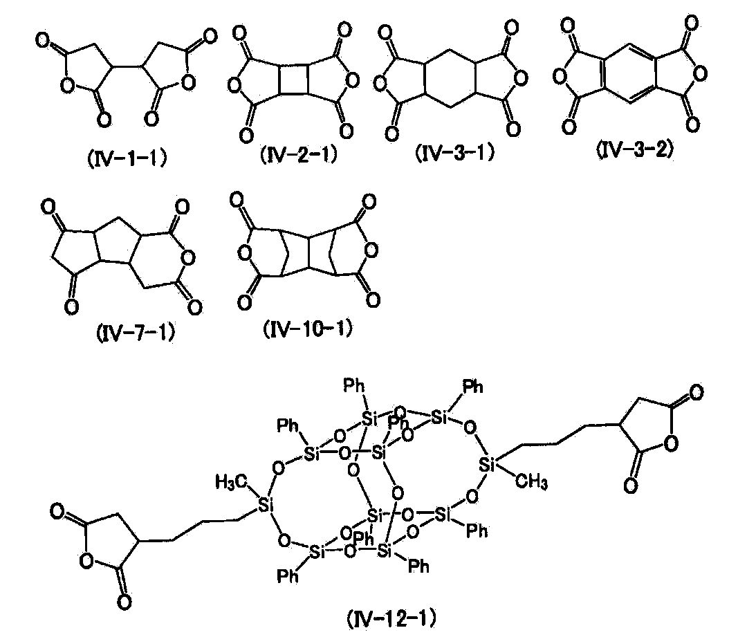
- 反応性モノマーが、式(3)で表される化合物の群から選択された少なくとも1つの化合物である光重合性モノマーである請求項6から29のいずれかに記載の液晶表示素子。
Ra1−Z−(E−Z)m1−Ra1 (3)
ここで、Ra1は、独立に下記式(3−1−1)から(3−1−6)で表される重合性基、水素、ハロゲン、シアノ、−CF3、−CF2H、−CFH2、−OCF3、−OCF2H、−N=C=O、−N=C=Sまたは炭素数1から20のアルキルであり、該アルキルにおいて、任意の−CH2−は、−O−、−S−、−SO2−、−CO−、−COO−、−OCO−、−CH=CH−、−CF=CF−または−C≡C−で置き換えられてもよく、任意の水素は、ハロゲンまたはシアノで置き換えられてもよく、Ra1の少なくとも1つは、式(3−1−1)から(3−1−6)で表される重合性基であり;環Eは、炭素数3から10の飽和または不飽和の独立環、縮合環、またはスピロ環式の二価基であり、これらの環において、任意の−CH2−は−O−で置き換えられてもよく、任意の−CH=は−N=で置き換えられてもよく、任意の水素は、ハロゲン、シアノ、ニトロ、イソシアノ、イソチオシアナト、炭素数1から4のアルキルで1から3置換されたシリル、炭素数1から10の直鎖または分岐のアルキルまたは炭素数1から10のハロゲン化アルキルで置き換えられてもよく、該アルキルにおいて、任意の−CH2−は、−O−、−CO−、−COO−、−OCO−、−OCOO−、−CH=CH−または−C≡C−で置き換えられてもよく;Zは、独立に単結合または炭素数1から20のアルキレンであり、該アルキレンにおいて、任意の−CH2−は、−O−、−S−、−CO−、−COO−、−OCO−、−OCOO−、−CH=CH−、−CF=CF−、−CH=N−、−N=CH−、−N=N−、−N(O)=N−または−C≡C−で置き換えられてもよく、任意の水素はハロゲンで置き換えられてもよく;m1は1から6の整数である。m1が2から6の整数であるとき、括弧内の複数のE−Zは同じであっても異なってもよい。
R a1 -Z- (E-Z) m1 -R a1 (3)
Here, R a1 is independently a polymerizable group represented by the following formulas (3-1-1) to (3-1-6), hydrogen, halogen, cyano, —CF 3 , —CF 2 H, — CFH 2 , —OCF 3 , —OCF 2 H, —N═C═O, —N═C═S, or alkyl having 1 to 20 carbons, in which any —CH 2 — is —O —, —S—, —SO 2 —, —CO—, —COO—, —OCO—, —CH═CH—, —CF═CF— or —C≡C— may be replaced by any hydrogen May be replaced by halogen or cyano, and at least one of R a1 is a polymerizable group represented by formulas (3-1-1) to (3-1-6); A saturated or unsaturated independent, condensed, or spirocyclic divalent group having 3 to 10 carbon atoms, Any —CH 2 — may be replaced by —O—, any —CH═ may be replaced by —N═, and any hydrogen may be halogen, cyano, nitro, isocyano, isothiocyanato, It may be substituted with silyl substituted with 1 to 3 alkyl with alkyl having 1 to 4 carbons, linear or branched alkyl with 1 to 10 carbons or halogenated alkyl with 1 to 10 carbons. —CH 2 — may be replaced by —O—, —CO—, —COO—, —OCO—, —OCOO—, —CH═CH— or —C≡C—; Z is independently A single bond or alkylene having 1 to 20 carbon atoms, in which the arbitrary —CH 2 — represents —O—, —S—, —CO—, —COO—, —OCO—, —OCOO—, — CH = CH-,- F = CF-, -CH = N-, -N = CH-, -N = N-, -N (O) = N- or -C≡C- may be substituted, and any hydrogen is a halogen May be replaced; m1 is an integer from 1 to 6; When m1 is an integer of 2 to 6, a plurality of EZs in parentheses may be the same or different.
- 光重合性モノマーが式(3)においてRa1が独立に、アクリレート、メタクリレート、スチレン、アクリルアミド、またはメタクリルアミドである請求項36記載の液晶表示素子。 37. The liquid crystal display element according to claim 36, wherein the photopolymerizable monomer in formula (3), R a1 is independently acrylate, methacrylate, styrene, acrylamide, or methacrylamide.
- 配向剤または液晶層が、さらに開始剤や重合禁止剤を含有している、請求項6から29、36、または37のいずれかに記載の液晶表示素子。 The liquid crystal display element according to any one of claims 6 to 29, 36, or 37, wherein the alignment agent or the liquid crystal layer further contains an initiator or a polymerization inhibitor.
- 反応性モノマーまたはオリゴマーが、光重合性モノマーまたはオリゴマー、または熱重合性モノマーまたはオリゴマーである、請求項1から29のいずれかに記載の液晶表示素子。 The liquid crystal display element according to any one of claims 1 to 29, wherein the reactive monomer or oligomer is a photopolymerizable monomer or oligomer, or a thermopolymerizable monomer or oligomer.
- 光重合性モノマーまたはオリゴマーが、1,000~100,000mJ/cm2の紫外線照射により光重合化させる、請求項36または37に記載の液晶表示素子。 The liquid crystal display element according to claim 36 or 37, wherein the photopolymerizable monomer or oligomer is photopolymerized by ultraviolet irradiation of 1,000 to 100,000 mJ / cm 2 .
- 光重合性モノマーまたはオリゴマーが、光重合化する前に、100~230℃の焼成温度により、50重量%以上が熱重合せずにモノマーまたはオリゴマーのまま残存させる、請求項40に記載の液晶表示素子。 41. The liquid crystal display according to claim 40, wherein the photopolymerizable monomer or oligomer is left as a monomer or oligomer without thermal polymerization at 50% by weight or more at a baking temperature of 100 to 230 ° C. before photopolymerization. element.
- 焼成温度が180~230℃である、請求項41に記載の液晶表示素子。 The liquid crystal display element according to claim 41, wherein the firing temperature is 180 to 230 ° C.
- 請求項6から27のいずれかに記載の液晶表示素子における液晶組成物。 28. A liquid crystal composition in a liquid crystal display element according to any one of claims 6 to 27.
- 請求項1から29、36から42のいずれかに記載の液晶表示素子の製造方法。 A method for manufacturing a liquid crystal display element according to any one of claims 1 to 29 and 36 to 42.
- 請求項6から27のいずれかに記載の液晶表示素子における液晶組成物の使用。 Use of the liquid crystal composition in the liquid crystal display element according to any one of claims 6 to 27.
Priority Applications (3)
| Application Number | Priority Date | Filing Date | Title |
|---|---|---|---|
| KR1020127010417A KR101734600B1 (en) | 2009-11-09 | 2010-10-18 | Liquid crystal display element, liquid crystal composition, aligning agent, and method for producing liquid crystal display element |
| JP2011539335A JP5903890B2 (en) | 2009-11-09 | 2010-10-18 | Liquid crystal display element, liquid crystal composition, alignment agent, method for producing liquid crystal display element and use thereof |
| US13/502,141 US8741397B2 (en) | 2009-11-09 | 2010-10-18 | Liquid crystal display element, liquid crystal composition, aligning agent, method for producing liquid crystal display element, and use of liquid crystal composition |
Applications Claiming Priority (2)
| Application Number | Priority Date | Filing Date | Title |
|---|---|---|---|
| JP2009255891 | 2009-11-09 | ||
| JP2009-255891 | 2009-11-09 |
Publications (1)
| Publication Number | Publication Date |
|---|---|
| WO2011055643A1 true WO2011055643A1 (en) | 2011-05-12 |
Family
ID=43969883
Family Applications (1)
| Application Number | Title | Priority Date | Filing Date |
|---|---|---|---|
| PCT/JP2010/068775 WO2011055643A1 (en) | 2009-11-09 | 2010-10-18 | Liquid crystal display element, liquid crystal composition, aligning agent, method for producing liquid crystal display element, and use of liquid crystal composition |
Country Status (5)
| Country | Link |
|---|---|
| US (1) | US8741397B2 (en) |
| JP (1) | JP5903890B2 (en) |
| KR (1) | KR101734600B1 (en) |
| TW (1) | TWI516575B (en) |
| WO (1) | WO2011055643A1 (en) |
Cited By (39)
| Publication number | Priority date | Publication date | Assignee | Title |
|---|---|---|---|---|
| JP2013054187A (en) * | 2011-09-02 | 2013-03-21 | Jsr Corp | Method for manufacturing liquid crystal display element |
| JP2013068749A (en) * | 2011-09-21 | 2013-04-18 | Jsr Corp | Color filter, liquid crystal display element, and manufacturing method of color filter |
| JP2013080140A (en) * | 2011-10-05 | 2013-05-02 | Jsr Corp | Method for manufacturing liquid crystal display device |
| WO2013080850A1 (en) * | 2011-11-28 | 2013-06-06 | Jnc株式会社 | Liquid crystal composition and liquid crystal display element |
| JP2013147599A (en) * | 2012-01-20 | 2013-08-01 | Ube Industries Ltd | Polyimide precursor and polyimide |
| WO2013125088A1 (en) * | 2012-02-24 | 2013-08-29 | Dic株式会社 | Liquid crystal composition |
| CN103364996A (en) * | 2012-03-30 | 2013-10-23 | 索尼公司 | Liquid crystal display apparatus and manufacturing method thereof |
| US20130341565A1 (en) * | 2012-05-18 | 2013-12-26 | Shenzhen China Star Optoelectronics Technology Co. Ltd. | Liquid crystal molecule having flexible structure and mixture for the same |
| CN103484132A (en) * | 2013-09-25 | 2014-01-01 | 深圳市华星光电技术有限公司 | Alignment film material and manufacturing method for liquid crystal display panel |
| WO2014057945A1 (en) * | 2012-10-09 | 2014-04-17 | 日産化学工業株式会社 | Liquid crystal alignment agent, liquid crystal alignment film, and liquid crystal display element |
| WO2014119682A1 (en) * | 2013-02-01 | 2014-08-07 | 日産化学工業株式会社 | Liquid crystal aligning agent, liquid crystal alignment film, and liquid crystal display element |
| JP5585745B1 (en) * | 2013-03-06 | 2014-09-10 | Dic株式会社 | Nematic liquid crystal composition and liquid crystal display device using the same |
| WO2014136770A1 (en) * | 2013-03-06 | 2014-09-12 | Dic株式会社 | Nematic liquid crystal composition, and liquid crystal display element incorporating same |
| JP2014181293A (en) * | 2013-03-19 | 2014-09-29 | Jnc Corp | Liquid crystal composition and liquid crystal display element |
| JP5633661B2 (en) * | 2012-09-11 | 2014-12-03 | Dic株式会社 | Nematic liquid crystal composition and liquid crystal display device using the same |
| WO2015052948A1 (en) * | 2013-10-08 | 2015-04-16 | Dic株式会社 | Nematic liquid crystal composition and liquid crystal display element using same |
| WO2015087775A1 (en) * | 2013-12-11 | 2015-06-18 | Dic株式会社 | Liquid crystal display element and method for producing same |
| CN104845643A (en) * | 2014-02-14 | 2015-08-19 | 奇美实业股份有限公司 | Liquid crystal alignment agent, liquid crystal alignment film and liquid crystal display element |
| CN104946269A (en) * | 2014-03-28 | 2015-09-30 | 奇美实业股份有限公司 | Liquid crystal alignment agent and application thereof |
| WO2015159656A1 (en) * | 2014-04-15 | 2015-10-22 | Jnc株式会社 | Liquid crystal display element |
| JP2015199900A (en) * | 2014-04-02 | 2015-11-12 | Jnc株式会社 | Liquid crystal composition and liquid crystal display element |
| WO2015198960A1 (en) * | 2014-06-25 | 2015-12-30 | Dic株式会社 | Liquid crystal display element and method for producing same |
| WO2016093141A1 (en) * | 2014-12-12 | 2016-06-16 | Dic株式会社 | Liquid crystal display element and method of manufacturing the same |
| WO2016093142A1 (en) * | 2014-12-12 | 2016-06-16 | Dic株式会社 | Liquid crystal display element and method of manufacturing the same |
| WO2016125870A1 (en) * | 2015-02-06 | 2016-08-11 | 日産化学工業株式会社 | Liquid crystal orienting agent, liquid crystal display element, and method for producing liquid crystal display element |
| JPWO2014073537A1 (en) * | 2012-11-06 | 2016-09-08 | 日産化学工業株式会社 | Liquid crystal alignment agent, liquid crystal alignment film, and liquid crystal display element |
| CN103911163B (en) * | 2012-12-28 | 2017-03-01 | Jsr株式会社 | Aligning agent for liquid crystal, liquid crystal orientation film and liquid crystal display cells |
| US9593281B2 (en) | 2012-07-04 | 2017-03-14 | Dic Corporation | Nematic liquid crystal composition and liquid crystal display device |
| WO2017054274A1 (en) * | 2015-09-29 | 2017-04-06 | 深圳市华星光电技术有限公司 | Alignment film, manufacturing method and liquid crystal panel thereof |
| WO2017134841A1 (en) * | 2016-02-02 | 2017-08-10 | Dic株式会社 | Liquid crystal display element and method for producing same |
| CN108018048A (en) * | 2017-12-15 | 2018-05-11 | 石家庄诚志永华显示材料有限公司 | A kind of negative dielectric anisotropic liquid-crystal composition |
| JP2018087343A (en) * | 2013-02-28 | 2018-06-07 | 日産化学工業株式会社 | Polymer |
| US10113115B2 (en) | 2014-09-05 | 2018-10-30 | DIC Corporation (Tokyo) | Nematic liquid crystal composition and liquid crystal display device using the same |
| US10119075B2 (en) | 2013-09-20 | 2018-11-06 | Dic Corporation | Liquid crystal display device and method for manufacturing the same |
| KR101928350B1 (en) * | 2011-11-16 | 2018-12-12 | 제이에스알 가부시끼가이샤 | Liquid crystal aligning agent, liquid crystal alignment film and liquid crystal display device |
| US10308873B2 (en) | 2010-12-24 | 2019-06-04 | Dic Corporation | Polymerizable compound-containing liquid crystal composition and liquid crystal display device using the same |
| US10323186B2 (en) | 2014-12-25 | 2019-06-18 | Dic Corporation | Nematic liquid crystal composition and liquid crystal display element using the same |
| US10351772B2 (en) | 2014-05-13 | 2019-07-16 | Dic Corporation | Nematic liquid crystal composition and liquid crystal display element using same |
| WO2023276880A1 (en) * | 2021-06-29 | 2023-01-05 | 東洋紡株式会社 | Polyamic acid, polyimide, and use thereof |
Families Citing this family (35)
| Publication number | Priority date | Publication date | Assignee | Title |
|---|---|---|---|---|
| TWI480363B (en) * | 2009-08-19 | 2015-04-11 | Jnc Corp | Tetrahydropyran compound, liquid crystal composition and liquid crystal display device |
| WO2013031371A1 (en) * | 2011-08-31 | 2013-03-07 | Jsr株式会社 | Liquid-crystal-display-element manufacturing method, liquid-crystal alignment agent, and liquid-crystal display element |
| WO2013047693A1 (en) * | 2011-09-30 | 2013-04-04 | 日産化学工業株式会社 | Liquid crystal orientation treatment agent, liquid crystal orientation membrane, and liquid crystal display element |
| CN103460120B (en) * | 2012-03-30 | 2014-12-31 | Dic株式会社 | Liquid crystal display element and method for manufacturing same |
| CN103827739B (en) * | 2012-09-20 | 2016-08-17 | Dic株式会社 | Liquid crystal indicator |
| EP2733529B1 (en) * | 2012-10-03 | 2016-09-21 | DIC Corporation | Liquid crystal display device |
| CN103013533B (en) * | 2012-12-12 | 2014-12-17 | 深圳市华星光电技术有限公司 | Liquid crystal composition, liquid crystal oriented mixture and liquid crystal panel |
| KR102470287B1 (en) * | 2013-02-28 | 2022-11-23 | 닛산 가가쿠 가부시키가이샤 | Liquid crystal alignment agent, liquid crystal alignment film, and liquid crystal display element |
| KR20140127641A (en) * | 2013-04-25 | 2014-11-04 | 삼성디스플레이 주식회사 | Liquid crystal display device and manufacturing method of the same |
| KR20140147354A (en) * | 2013-06-19 | 2014-12-30 | 삼성디스플레이 주식회사 | Method of forming alignment layer and fabrication method of liquid crystal display using the same |
| TWI490321B (en) | 2013-08-30 | 2015-07-01 | Chunghwa Picture Tubes Ltd | Liquid crystal composition |
| WO2015045441A1 (en) | 2013-09-24 | 2015-04-02 | Dic株式会社 | Liquid-crystal display |
| TWI525130B (en) * | 2013-12-23 | 2016-03-11 | 奇美實業股份有限公司 | Liquid crystal alignment agent, liquid crystal alignment film and liquid crystal display element having thereof |
| DE112014006109B4 (en) * | 2014-01-06 | 2018-09-20 | Dic Corporation | A nematic liquid crystal composition and its use for producing a liquid crystal display element |
| KR102074956B1 (en) | 2014-01-10 | 2020-02-10 | 삼성디스플레이 주식회사 | Liquid crystal display |
| KR20150118659A (en) | 2014-04-14 | 2015-10-23 | 삼성디스플레이 주식회사 | Liquid crystal display |
| KR102224841B1 (en) * | 2014-06-11 | 2021-03-10 | 삼성디스플레이 주식회사 | Liquid crystal display device and method for manufacturing the same |
| TWI529242B (en) * | 2014-06-12 | 2016-04-11 | 奇美實業股份有限公司 | Liquid crystal alignment agent, liquid crystal alignment film, and liquid crystal display device |
| KR102160489B1 (en) * | 2014-07-25 | 2020-09-29 | 삼성디스플레이 주식회사 | Fabrication method of display device and display device |
| TWI693277B (en) * | 2014-11-07 | 2020-05-11 | 日商日產化學工業股份有限公司 | Liquid crystal display element |
| EP3219776B1 (en) * | 2014-11-12 | 2019-07-24 | JNC Corporation | Liquid crystal composition and liquid crystal display device |
| WO2016148042A1 (en) * | 2015-03-18 | 2016-09-22 | シャープ株式会社 | Liquid crystal display device |
| WO2016153044A1 (en) * | 2015-03-26 | 2016-09-29 | 東京応化工業株式会社 | Negative photosensitive composition and pattern formation method |
| TWI564346B (en) * | 2015-03-27 | 2017-01-01 | 奇美實業股份有限公司 | Liquid crystal alignment agent, liquid crystal alignment film, and liquid crystal display element |
| KR102323244B1 (en) | 2015-04-29 | 2021-11-08 | 삼성디스플레이 주식회사 | Liquid crystal display and method of manufacturing the same |
| CN106019668A (en) * | 2015-08-06 | 2016-10-12 | 友达光电股份有限公司 | Display panel and method for manufacturing the same |
| KR102457205B1 (en) * | 2015-08-31 | 2022-10-20 | 엘지디스플레이 주식회사 | Polarizing Control Panel, Method for Manufacturing the Same, and Stereoscopic Display Device Using the Same |
| US20180258348A1 (en) * | 2015-09-25 | 2018-09-13 | Jnc Corporation | Liquid crystal display device |
| KR102431140B1 (en) * | 2015-11-02 | 2022-08-12 | 티씨엘 차이나 스타 옵토일렉트로닉스 테크놀로지 컴퍼니 리미티드 | Liquid crystal photo alinement agent and method of manufacturing liquid crystal display device using the same |
| KR102581446B1 (en) * | 2016-04-05 | 2023-09-21 | 삼성디스플레이 주식회사 | Alignment film composition, liquid crystal display device and manufacturing method of the liquid crystal display device |
| KR101856727B1 (en) * | 2016-06-21 | 2018-05-10 | 주식회사 엘지화학 | Liquid crystal alignment composition, method of preparing liquid crystal alignment film, and liquid crystal alignment film using the same |
| JP2018054761A (en) * | 2016-09-27 | 2018-04-05 | Jsr株式会社 | Liquid crystal element and method for manufacturing the same |
| CN110192148B (en) * | 2016-11-22 | 2022-07-19 | 日产化学株式会社 | Method for manufacturing liquid crystal display element, substrate for liquid crystal display element, and liquid crystal display element assembly |
| JP7193782B2 (en) * | 2017-11-30 | 2022-12-21 | 日産化学株式会社 | Liquid crystal alignment agent, liquid crystal alignment film and liquid crystal display element |
| CN111778040B (en) * | 2019-04-03 | 2022-03-22 | 北京八亿时空液晶科技股份有限公司 | Liquid crystal compound and preparation method and application thereof |
Citations (3)
| Publication number | Priority date | Publication date | Assignee | Title |
|---|---|---|---|---|
| JP2006099038A (en) * | 2004-01-15 | 2006-04-13 | Sharp Corp | Display element and display device |
| WO2008114821A1 (en) * | 2007-03-22 | 2008-09-25 | Chisso Corporation | Liquid-crystal composition and liquid-crystal display element |
| JP2010230759A (en) * | 2009-03-26 | 2010-10-14 | Sekisui Chem Co Ltd | Liquid crystal sheet |
Family Cites Families (9)
| Publication number | Priority date | Publication date | Assignee | Title |
|---|---|---|---|---|
| JP3395877B2 (en) | 1996-12-20 | 2003-04-14 | シャープ株式会社 | Liquid crystal display device and manufacturing method thereof |
| JP4175826B2 (en) | 2002-04-16 | 2008-11-05 | シャープ株式会社 | Liquid crystal display |
| US6919404B2 (en) * | 2002-05-31 | 2005-07-19 | Elsicon, Inc. | Hybrid polymer materials for liquid crystal alignment layers |
| ATE354623T1 (en) | 2002-07-06 | 2007-03-15 | Merck Patent Gmbh | LIQUID CRYSTALLINE MEDIUM |
| JP2006133619A (en) | 2004-11-08 | 2006-05-25 | Sharp Corp | Liquid crystal display device and method for manufacturing the same |
| DE102007030730A1 (en) | 2006-07-25 | 2008-01-31 | Merck Patent Gmbh | Liquid crystal medium, useful in electro-optical displays, comprises a polymerizable compound and a phenyl-cyclohexane compound |
| EP1911828B1 (en) * | 2006-10-12 | 2010-09-01 | Merck Patent GmbH | Liquid crystal display |
| JP2008174717A (en) * | 2006-12-18 | 2008-07-31 | Fujifilm Corp | Liquid crystal composition and liquid crystal element |
| KR101492656B1 (en) * | 2007-03-23 | 2015-02-12 | 닛산 가가쿠 고교 가부시키 가이샤 | Diamine compound, polyamic acid, polyimide and liquid crystal aligning agent |
-
2010
- 2010-10-18 KR KR1020127010417A patent/KR101734600B1/en active IP Right Grant
- 2010-10-18 WO PCT/JP2010/068775 patent/WO2011055643A1/en active Application Filing
- 2010-10-18 US US13/502,141 patent/US8741397B2/en not_active Expired - Fee Related
- 2010-10-18 JP JP2011539335A patent/JP5903890B2/en active Active
- 2010-11-03 TW TW099137794A patent/TWI516575B/en not_active IP Right Cessation
Patent Citations (3)
| Publication number | Priority date | Publication date | Assignee | Title |
|---|---|---|---|---|
| JP2006099038A (en) * | 2004-01-15 | 2006-04-13 | Sharp Corp | Display element and display device |
| WO2008114821A1 (en) * | 2007-03-22 | 2008-09-25 | Chisso Corporation | Liquid-crystal composition and liquid-crystal display element |
| JP2010230759A (en) * | 2009-03-26 | 2010-10-14 | Sekisui Chem Co Ltd | Liquid crystal sheet |
Non-Patent Citations (1)
| Title |
|---|
| YOU-JIN LEE ET AL.: "Surface-controlled patterned vertical alignment mode with reactive mesogen", OPTICS EXPRESS, vol. 17, no. 12, 8 June 2009 (2009-06-08), pages 10298 - 10303 * |
Cited By (84)
| Publication number | Priority date | Publication date | Assignee | Title |
|---|---|---|---|---|
| US10934488B2 (en) | 2010-12-24 | 2021-03-02 | Dic Corporation | Polymerizable compound-containing liquid crystal composition and liquid crystal display device using the same |
| US10308873B2 (en) | 2010-12-24 | 2019-06-04 | Dic Corporation | Polymerizable compound-containing liquid crystal composition and liquid crystal display device using the same |
| KR101908964B1 (en) * | 2011-09-02 | 2018-10-17 | 제이에스알 가부시끼가이샤 | Manufacturing method for liquid crystal display device, polymer composition, and the liquid crystal display device |
| JP2013054187A (en) * | 2011-09-02 | 2013-03-21 | Jsr Corp | Method for manufacturing liquid crystal display element |
| JP2013068749A (en) * | 2011-09-21 | 2013-04-18 | Jsr Corp | Color filter, liquid crystal display element, and manufacturing method of color filter |
| JP2013080140A (en) * | 2011-10-05 | 2013-05-02 | Jsr Corp | Method for manufacturing liquid crystal display device |
| KR101928350B1 (en) * | 2011-11-16 | 2018-12-12 | 제이에스알 가부시끼가이샤 | Liquid crystal aligning agent, liquid crystal alignment film and liquid crystal display device |
| WO2013080850A1 (en) * | 2011-11-28 | 2013-06-06 | Jnc株式会社 | Liquid crystal composition and liquid crystal display element |
| JPWO2013080850A1 (en) * | 2011-11-28 | 2015-04-27 | Jnc株式会社 | Liquid crystal composition and liquid crystal display element |
| JP2013147599A (en) * | 2012-01-20 | 2013-08-01 | Ube Industries Ltd | Polyimide precursor and polyimide |
| JP5288224B1 (en) * | 2012-02-24 | 2013-09-11 | Dic株式会社 | Liquid crystal composition |
| WO2013125088A1 (en) * | 2012-02-24 | 2013-08-29 | Dic株式会社 | Liquid crystal composition |
| US9062249B2 (en) | 2012-02-24 | 2015-06-23 | Dic Corporation | Liquid crystal composition |
| KR101477210B1 (en) | 2012-02-24 | 2014-12-29 | 디아이씨 가부시끼가이샤 | Liquid crystal composition |
| EP2725084B1 (en) | 2012-02-24 | 2016-11-30 | DIC Corporation | Liquid crystal composition |
| CN103364996A (en) * | 2012-03-30 | 2013-10-23 | 索尼公司 | Liquid crystal display apparatus and manufacturing method thereof |
| US20130341565A1 (en) * | 2012-05-18 | 2013-12-26 | Shenzhen China Star Optoelectronics Technology Co. Ltd. | Liquid crystal molecule having flexible structure and mixture for the same |
| US9593281B2 (en) | 2012-07-04 | 2017-03-14 | Dic Corporation | Nematic liquid crystal composition and liquid crystal display device |
| US9650571B2 (en) | 2012-09-11 | 2017-05-16 | Dic Corporation | Nematic liquid crystal composition and liquid crystal display device |
| KR101574157B1 (en) | 2012-09-11 | 2015-12-03 | 디아이씨 가부시끼가이샤 | Nematic liquid crystal composition and liquid crystal display element using same |
| JP5633661B2 (en) * | 2012-09-11 | 2014-12-03 | Dic株式会社 | Nematic liquid crystal composition and liquid crystal display device using the same |
| WO2014057945A1 (en) * | 2012-10-09 | 2014-04-17 | 日産化学工業株式会社 | Liquid crystal alignment agent, liquid crystal alignment film, and liquid crystal display element |
| KR20150068445A (en) * | 2012-10-09 | 2015-06-19 | 닛산 가가쿠 고교 가부시키 가이샤 | Liquid crystal alignment agent, liquid crystal alignment film, and liquid crystal display element |
| JPWO2014057945A1 (en) * | 2012-10-09 | 2016-09-05 | 日産化学工業株式会社 | Liquid crystal alignment agent, liquid crystal alignment film, and liquid crystal display element |
| KR102118762B1 (en) * | 2012-10-09 | 2020-06-03 | 닛산 가가쿠 가부시키가이샤 | Liquid crystal alignment agent, liquid crystal alignment film, and liquid crystal display element |
| JPWO2014073537A1 (en) * | 2012-11-06 | 2016-09-08 | 日産化学工業株式会社 | Liquid crystal alignment agent, liquid crystal alignment film, and liquid crystal display element |
| CN103911163B (en) * | 2012-12-28 | 2017-03-01 | Jsr株式会社 | Aligning agent for liquid crystal, liquid crystal orientation film and liquid crystal display cells |
| WO2014119682A1 (en) * | 2013-02-01 | 2014-08-07 | 日産化学工業株式会社 | Liquid crystal aligning agent, liquid crystal alignment film, and liquid crystal display element |
| JPWO2014119682A1 (en) * | 2013-02-01 | 2017-01-26 | 日産化学工業株式会社 | Liquid crystal alignment agent, liquid crystal alignment film, and liquid crystal display element |
| JP2018087343A (en) * | 2013-02-28 | 2018-06-07 | 日産化学工業株式会社 | Polymer |
| JP2014208842A (en) * | 2013-03-06 | 2014-11-06 | Dic株式会社 | Nematic liquid crystal composition and liquid crystal display element using the same |
| WO2014136315A1 (en) * | 2013-03-06 | 2014-09-12 | Dic株式会社 | Nematic liquid-crystal composition and liquid-crystal display element obtained using same |
| JP2014196474A (en) * | 2013-03-06 | 2014-10-16 | Dic株式会社 | Nematic liquid-crystal composition and liquid-crystal display element using the same |
| CN104284962A (en) * | 2013-03-06 | 2015-01-14 | Dic株式会社 | Nematic liquid-crystal composition and liquid-crystal display element obtained using same |
| CN105121597A (en) * | 2013-03-06 | 2015-12-02 | Dic株式会社 | Nematic liquid crystal composition, and liquid crystal display element incorporating same |
| JP2015180727A (en) * | 2013-03-06 | 2015-10-15 | Dic株式会社 | Nematic liquid crystal composition and liquid crystal display element using the same |
| US10316251B2 (en) | 2013-03-06 | 2019-06-11 | Dic Corporation | Nematic liquid crystal composition and liquid crystal display device using same |
| WO2014136770A1 (en) * | 2013-03-06 | 2014-09-12 | Dic株式会社 | Nematic liquid crystal composition, and liquid crystal display element incorporating same |
| CN104284962B (en) * | 2013-03-06 | 2016-02-24 | Dic株式会社 | Nematic liquid-crystal composition and the liquid crystal display device using it |
| JP2019014893A (en) * | 2013-03-06 | 2019-01-31 | Dic株式会社 | Nematic liquid crystal composition and liquid crystal display element prepared therewith |
| JP5585745B1 (en) * | 2013-03-06 | 2014-09-10 | Dic株式会社 | Nematic liquid crystal composition and liquid crystal display device using the same |
| JP2015157948A (en) * | 2013-03-06 | 2015-09-03 | Dic株式会社 | Nematic liquid crystal composition and liquid crystal display element using the same |
| US9745513B2 (en) | 2013-03-06 | 2017-08-29 | Dic Corporation | Nematic liquid crystal composition and liquid crystal display device using same |
| JP5761468B2 (en) * | 2013-03-06 | 2015-08-12 | Dic株式会社 | Nematic liquid crystal composition and liquid crystal display device using the same |
| JP2014181293A (en) * | 2013-03-19 | 2014-09-29 | Jnc Corp | Liquid crystal composition and liquid crystal display element |
| US10119075B2 (en) | 2013-09-20 | 2018-11-06 | Dic Corporation | Liquid crystal display device and method for manufacturing the same |
| CN103484132B (en) * | 2013-09-25 | 2016-01-06 | 深圳市华星光电技术有限公司 | The making method of a kind of alignment film material and display panels |
| CN103484132A (en) * | 2013-09-25 | 2014-01-01 | 深圳市华星光电技术有限公司 | Alignment film material and manufacturing method for liquid crystal display panel |
| JP2015180728A (en) * | 2013-10-08 | 2015-10-15 | Dic株式会社 | Nematic liquid crystal composition and liquid crystal display element using the same |
| WO2015052948A1 (en) * | 2013-10-08 | 2015-04-16 | Dic株式会社 | Nematic liquid crystal composition and liquid crystal display element using same |
| US10093857B2 (en) | 2013-10-08 | 2018-10-09 | Dic Corporation | Nematic liquid crystal composition and liquid crystal display device using the same |
| JP5930134B2 (en) * | 2013-12-11 | 2016-06-08 | Dic株式会社 | Liquid crystal display element and manufacturing method thereof |
| JPWO2015087775A1 (en) * | 2013-12-11 | 2017-03-16 | Dic株式会社 | Liquid crystal display element and manufacturing method thereof |
| WO2015087775A1 (en) * | 2013-12-11 | 2015-06-18 | Dic株式会社 | Liquid crystal display element and method for producing same |
| CN104845643A (en) * | 2014-02-14 | 2015-08-19 | 奇美实业股份有限公司 | Liquid crystal alignment agent, liquid crystal alignment film and liquid crystal display element |
| CN104946269A (en) * | 2014-03-28 | 2015-09-30 | 奇美实业股份有限公司 | Liquid crystal alignment agent and application thereof |
| JP2015199900A (en) * | 2014-04-02 | 2015-11-12 | Jnc株式会社 | Liquid crystal composition and liquid crystal display element |
| CN106164220A (en) * | 2014-04-15 | 2016-11-23 | 捷恩智株式会社 | Liquid crystal display cells |
| US10435627B2 (en) | 2014-04-15 | 2019-10-08 | Jnc Corporation | Liquid crystal display device |
| WO2015159656A1 (en) * | 2014-04-15 | 2015-10-22 | Jnc株式会社 | Liquid crystal display element |
| US10351772B2 (en) | 2014-05-13 | 2019-07-16 | Dic Corporation | Nematic liquid crystal composition and liquid crystal display element using same |
| JPWO2015198960A1 (en) * | 2014-06-25 | 2017-04-20 | Dic株式会社 | Liquid crystal display element and manufacturing method thereof |
| WO2015198960A1 (en) * | 2014-06-25 | 2015-12-30 | Dic株式会社 | Liquid crystal display element and method for producing same |
| US10113115B2 (en) | 2014-09-05 | 2018-10-30 | DIC Corporation (Tokyo) | Nematic liquid crystal composition and liquid crystal display device using the same |
| WO2016093142A1 (en) * | 2014-12-12 | 2016-06-16 | Dic株式会社 | Liquid crystal display element and method of manufacturing the same |
| WO2016093141A1 (en) * | 2014-12-12 | 2016-06-16 | Dic株式会社 | Liquid crystal display element and method of manufacturing the same |
| KR102450332B1 (en) | 2014-12-12 | 2022-10-04 | 디아이씨 가부시끼가이샤 | Liquid crystal display element and method of manufacturing the same |
| JP6011903B1 (en) * | 2014-12-12 | 2016-10-25 | Dic株式会社 | Liquid crystal display element and manufacturing method thereof |
| JP6011904B1 (en) * | 2014-12-12 | 2016-10-25 | Dic株式会社 | Liquid crystal display element and manufacturing method thereof |
| CN107209421A (en) * | 2014-12-12 | 2017-09-26 | Dic株式会社 | Liquid crystal display cells and its manufacture method |
| KR20170094331A (en) * | 2014-12-12 | 2017-08-17 | 디아이씨 가부시끼가이샤 | Liquid crystal display element and method of manufacturing the same |
| US10323186B2 (en) | 2014-12-25 | 2019-06-18 | Dic Corporation | Nematic liquid crystal composition and liquid crystal display element using the same |
| KR102502321B1 (en) * | 2015-02-06 | 2023-02-21 | 닛산 가가쿠 가부시키가이샤 | Liquid crystal orienting agent, liquid crystal display element, and method for producing liquid crystal display element |
| KR20170109604A (en) * | 2015-02-06 | 2017-09-29 | 닛산 가가쿠 고교 가부시키 가이샤 | Liquid crystal orienting agent, liquid crystal display element, and method for producing liquid crystal display element |
| JPWO2016125870A1 (en) * | 2015-02-06 | 2017-11-16 | 日産化学工業株式会社 | Liquid crystal aligning agent, liquid crystal display element, and manufacturing method of liquid crystal display element |
| WO2016125870A1 (en) * | 2015-02-06 | 2016-08-11 | 日産化学工業株式会社 | Liquid crystal orienting agent, liquid crystal display element, and method for producing liquid crystal display element |
| KR102607979B1 (en) * | 2015-02-06 | 2023-11-30 | 닛산 가가쿠 가부시키가이샤 | Liquid crystal orienting agent, liquid crystal display element, and method for producing liquid crystal display element |
| KR20230027326A (en) * | 2015-02-06 | 2023-02-27 | 닛산 가가쿠 가부시키가이샤 | Liquid crystal orienting agent, liquid crystal display element, and method for producing liquid crystal display element |
| WO2017054274A1 (en) * | 2015-09-29 | 2017-04-06 | 深圳市华星光电技术有限公司 | Alignment film, manufacturing method and liquid crystal panel thereof |
| WO2017134841A1 (en) * | 2016-02-02 | 2017-08-10 | Dic株式会社 | Liquid crystal display element and method for producing same |
| JPWO2017134841A1 (en) * | 2016-02-02 | 2018-04-12 | Dic株式会社 | Liquid crystal display element and manufacturing method thereof |
| CN108018048A (en) * | 2017-12-15 | 2018-05-11 | 石家庄诚志永华显示材料有限公司 | A kind of negative dielectric anisotropic liquid-crystal composition |
| CN108018048B (en) * | 2017-12-15 | 2021-11-05 | 石家庄诚志永华显示材料有限公司 | Negative dielectric anisotropy liquid crystal composition |
| WO2023276880A1 (en) * | 2021-06-29 | 2023-01-05 | 東洋紡株式会社 | Polyamic acid, polyimide, and use thereof |
Also Published As
| Publication number | Publication date |
|---|---|
| TWI516575B (en) | 2016-01-11 |
| KR101734600B1 (en) | 2017-05-11 |
| US8741397B2 (en) | 2014-06-03 |
| US20120229744A1 (en) | 2012-09-13 |
| TW201124512A (en) | 2011-07-16 |
| KR20120099652A (en) | 2012-09-11 |
| JP5903890B2 (en) | 2016-04-13 |
| JPWO2011055643A1 (en) | 2013-03-28 |
Similar Documents
| Publication | Publication Date | Title |
|---|---|---|
| JP5903890B2 (en) | Liquid crystal display element, liquid crystal composition, alignment agent, method for producing liquid crystal display element and use thereof | |
| JP6186974B2 (en) | Liquid crystal composition, antioxidant and liquid crystal display element | |
| EP3133136B1 (en) | Liquid crystal display device | |
| JP6893784B2 (en) | Liquid crystal display element | |
| JP6337335B2 (en) | Liquid crystal composition and liquid crystal display element | |
| EP3163368B1 (en) | Liquid crystal display element | |
| JP5983393B2 (en) | Liquid crystal composition and liquid crystal display element | |
| WO2014024648A1 (en) | Liquid crystal composition and liquid crystal display element | |
| EP3179303B1 (en) | Liquid crystal display element | |
| EP3355107B1 (en) | Liquid crystal display element | |
| WO2020095499A1 (en) | Liquid crystal composition and liquid crystal display element | |
| JP2019168612A (en) | Liquid crystal display element | |
| JP2023034229A (en) | liquid crystal display element |
Legal Events
| Date | Code | Title | Description |
|---|---|---|---|
| 121 | Ep: the epo has been informed by wipo that ep was designated in this application |
Ref document number: 10828203 Country of ref document: EP Kind code of ref document: A1 |
|
| WWE | Wipo information: entry into national phase |
Ref document number: 2011539335 Country of ref document: JP |
|
| WWE | Wipo information: entry into national phase |
Ref document number: 13502141 Country of ref document: US |
|
| ENP | Entry into the national phase |
Ref document number: 20127010417 Country of ref document: KR Kind code of ref document: A |
|
| NENP | Non-entry into the national phase |
Ref country code: DE |
|
| 122 | Ep: pct application non-entry in european phase |
Ref document number: 10828203 Country of ref document: EP Kind code of ref document: A1 |