
ViewSonic LDS135-151 All-in-One Direct View LED
Display Solution kit User Guide

This device complies with part 15 of FCC Rules. Operation is subject to the following two conditions: (1) this device may not cause harmful interference, and (2) this device must accept any interference received, including interference that may cause undesired operation.
Industry Canada ICES-003 Compliance: CAN ICES-003(B) / NMB-003(B)
CE Conformity for European Countries
The device complies with the EMC Directive 2014/30/EU and Low Voltage Directive 2014/35/EU and Radio Equipment Directive 2014/53/EU. The full Declaration of Conformity can be found at the following website:
Declaration of RoHS2 Compliance
This product has been designed and manufactured in compliance with Directive 2011/65/EU of the European Parliament and the Council on restriction of the use of certain hazardous substances in electrical and electronic equipment (RoHS2 Directive) and is
deemed to comply with the maximum concentration values issued by the European Technical Adaptation Committee (TAC).

Package Contents


NOTE:
- This product is packed in an air transport box.
- Due to the size and weight, it is recommended that two or more people handle it.
Physical Dimensions for LDS135-151

Product Overview
Front Panel

Rear Panel

Control Panel for Motorized Trolley Cart

- Instructions on Preset Lifting Height
• Initial preset lifting height: Three groups of preset data. The 1/2/3 keys (. , .. , …) correspond to 0 cm / 25 cm / 65 cm height respectively.
• Erasing of preset height data: Height data can be stored for more than 10 years. When new parameters are set, old parameters will be automatically erased.
• How to preset height: at any height (unavailable under the reset and error status), the current height parameters can be preset into keys 1/2/3.For example, set 25 cm on the 2 key:
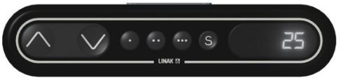
Press the S key to display “SET”.
 Within 2 seconds, before “SET” disappears, press the 2 (..) key .

When “S-2” is displayed, the setting is over and will return to the previous display.
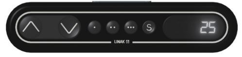
- How to Use Preset Height
At any height (unavailable under the reset and error status), keys 1/2/3 may be used to quickly reach the preset height. If the current height has reached such preset height, no actions will be performed. - How to Change the Height
• Use the “Up” key to lift the display. The lift will automatically stop upon reaching the height limit. Please note, the “Up” key is a “click to act” key, i.e., upon releasing the key the lift will not immediately stop. Instead, it will slow down for a short distance then stop.
• Use the “Down” key to lower the display. The lift will automatically stop upon reaching the height limit. Please note, the “Down” key is a “click to act” key, i.e., upon releasing the key the lift will not immediately stop. Instead, it will slow down for a short distance then stop.
Schematic Diagram of Components

I. Handling and Moving Flight Cases
![]() Note: During moving, handling, placing and transporting of flight cases, always keep the specified position up, no reversing, in order to prevent bumping and damage to the structure of the equipment and the display components.
Note: During moving, handling, placing and transporting of flight cases, always keep the specified position up, no reversing, in order to prevent bumping and damage to the structure of the equipment and the display components.
- Before moving any flight case, pull up the brake locks of the six rollers at the bottom, guaranteeing the release of the brake status.

- Ensure that the group is level, with the height difference less than 1.5 cm, and the ground can comfortably hold more than the weight of the entire equipment.
- During moving, at least two adults are needed.
II. Unboxing Operation
- After the flight case is moved to the designated location, open the flight case according to the sequence of Front Cover, Back Cover, Movable Plate and Bottom Plate. To distinguish the Front cover and Back cover, refer to the following diagram.

- As shown below, pull the handle of the lock-ups, and rotate the handle counterclockwise to unlock the 9 lock-ups connecting the Front Cover with the Bottom Plate and the Back Cover, ensuring that each lock-up will not be interlocked.

- Two people will need to grip the handles, as indicated by the red circles below, and pull. While lifting, keep the Front Cover level as it is moved to another location.

- As shown below, pull the handle of the lock-ups, and rotate the handle counterclockwise to unlock the 5 lock-ups connecting the Back Cover with the Bottom Plate, ensuring that each lock-up will not be interlocked. Two people will need to grip the handles, as indicated by the red circles below, and pull. While lifting, lift off the Back Cover to another location, ensuring to keep the cover level.

- As shown in the red circles below, open the 4 lock-ups of the Movable plate at the bottom of the flight case. Lift the Movable plate while holding up the bottom of it. Pull out the Movable plate from behind to separate.

- Take the power cord out of the accessory box. Insert the flight plug into the female socket at the right of the base control box of the screen and rotate the plug 90° clockwise (as shown below). Ensure the plug is connected securely (a click should be heard). Insert the other end of the plug into a power socket. Ensure that the power socket meets the specifications and standards of the LED display screen (30A socket for 110V area, and 16A socket for 220V area).

- After the power cord is properly connected, the green light and digits on the control lifting plate of the base of the screen will be ON. Press the 2 key (..) on the control box at the base, or continuously hold the “Up” key, to raise the screen and lift it from the cabinet.

- After the screen is raised to a certain height, pull out the Bottom Plate of the flight case from the front.

- Unlock the 2 bottom buckles, and open both side cabinets of the display.

III. Packing and Handling Operation
- Close both side cabinets of the display, and lock the 2 buckles.

- Ensure that the display is OFF, and the Accessories box is placed in the grid corresponding to the Bottom Plate of the flight case. The Bottom Plate of the flight case, which shall be close to the ground, is clipped into the base of the display from the front as shown below.

- Power On the display and press the 1 key (.) on the control box at the base, or continuously hold the “Down” key, to lower the screen to the lowest position until it is inside the cart slot, as shown below:

- Insert the Movable Plate from behind, as shown below, and tighten the 4 lock-ups connecting with the Bottom Plate. Ensure that the clips are engaged.

- . Ensure the display is Powered Off, then unplug the power cord from the power socket. Next, remove the flight plug by rotating it 90° counterclockwise. Finally, place the power cord into the Backup Box on the Bottom plate.

- Two people will need to lift the Back Cover of the flight case, aligning the Back Cover with the position of the lock-ups of the Bottom Plate. When aligned, rotate the 5 lock-ups clockwise to secure the connection with the Bottom Plate. Next, lift the Front Cover of the flight case onto the Bottom Plate, aligning the Front Cover with the position of the lock-ups. When aligned, rotate the 9 lock-ups clockwise to secure the connection between the Front Cover, the Bottom Plate, and Back Cover. Ensure that the lock-ups are engaged in place, and there are no obvious gaps.

- After the flight case is closed, at least two people will be needed to move the case to its storage or transport location. Ensure the brake locks are engaged on all six rollers upon reaching the case’s storage or transport location.

![]() Note: When storing the flight case, ensure the ground is level and that all six rollers are locked.
Note: When storing the flight case, ensure the ground is level and that all six rollers are locked.
![]() Note: For the detailed instructions on the equipment, please see the user manual, which can be found at the following links:
Note: For the detailed instructions on the equipment, please see the user manual, which can be found at the following links:
https://www.viewsonic.com/us/ld108-121.html#downloads
https://www.viewsonic.com/us/ld135-151.html#downloads
Specifications


NOTE: Product specifications are subject to change without notice.
![]()
Documents / Resources
 |
ViewSonic LDS135-151 All-in-One Direct View LED Display Solution kit [pdf] User Guide LDS135-151 All-in-One Direct View LED Display Solution kit, LDS135-151, All-in-One Direct View LED Display Solution kit, LED Display Solution kit, LED Display, Display |
References
-
 108" Premium All-in-One Direct View LED Commercial Display
-
ViewSonic LD135-151, 135" Premium All-in-One Direct View LED Commercial Display
- User Manual


