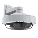
FS IPC201-2M-T Turret Network Cameras
Introduction
Thank you for choosing turret network cameras. This guide is designed to familiarize you with the structure of the camera and describes how to deploy the camera in your network.
Accessories
NOTE:
There is no wrench in the accessories of IPC201-2M-T. The installation position map varies according to the different models of cameras.
Hardware Overview Ports
- Power Interface
- Ethernet Interface
- Connect DC 12V power
- Connect to Ethernet cable
Installation Requirements
- Installation and removal of the device and its accessories must be carried out by qualified personnel.
- Store or use the device in a proper environment that meets environmental requirements, including and not limited to temperature, humidity, dust, corrosive gases, electromagnetic radiation, etc.
- Make sure the device is securely installed or placed on a flat surface to prevent falling.
- Unless otherwise specified, do not stack devices.
- Ensure good ventilation in the operating environment. Do not cover the vents on the device. Allow adequate space for ventilation.
- Protect the device from liquid of any kind.
- Make sure the power supply provides a stable voltage that meets the power requirements of the device. Make sure the power supply’s output power exceeds the total maximum power of all the connected devices.
- Take proper waterproof measures in accordance with requirements before using the device outdoors.
- Using the device may involve the collection of personal information such as face, fingerprint, license plate number, email, phone number, GPS. Please abide by your local laws and regulations while using the device.
Mounting the Camera
Installing Micro SD Card (Optional)
- Insert the Micro SD card (purchased separately) into the camera.
- Do not hot plug the Micro SD card after it is inserted. Otherwise the camera or the Micro SD card might be damaged.
Installing Waterproof Connector (Optional)
Install the supplied waterproof components to the Ethernet cable in sequence.
NOTE:
Please use self-adhesive waterproof tape (purchased separately) to protect the cables.
Ceiling Mount
- Locate the positions of the holes by pasting installation position map on the ceiling, and lead the cables through the hole on the ceiling.
- Drill holes with a diameter of 6 – 6.5 mm and the depth of 30 mm in the marked locations.

- Knock the plastic rivets of self-tapping screws into the guide holes and ensure that they are tightened up.

- Connect all cables of the ceiling and the camera.
- Secure the camera to the ceilingl by leading the self-tapping screws through the guide holes in the base and fix them by using a screwdriver.
- Loosen the screw on the base and detach the housing from the base plate with the marks aligned.

NOTE:
The installation process above is concealed installation, during which holes are drilled in the ceiling and tail cable is led out from the top of the camera. Cables are connected and frapped at the ceiling side to prevent messy cables from affecting camera mounting. If open installation is adopted, tail cable is led out from one side of the camera and can be routed from the side groove of the camera.
Mount the housing with install mark aligned.
Adjust the monitoring direction by rotating the camera, tighten the screws.
Connecting the Power PoE Device 
Use an Ethernet cable to connect the network interface of the camera to the PoE port on a PoE device, such as a PoE switch.
Power Adapter
Use the power adapter (purchased separately) to connect the power interface of the camera to the local power source.
Configuring the Camera
Step 1: Connect the computer to the camera on the same LAN. Step
2: Set the IP address of the computer to 192.168.1.x. (“x” is any number from 2 to 254.)
Step 3: Open a browser, type http://192.168.1.13 , and enter the default username and password, admin/admin.
Step 4: Click Login to display the web-based configuration page.
NOTE:
You may need to install a plug-in at your first login. Please follow the on-screen instructions to complete the installation and then open the browser again to log in.
Support and Other Resources
- Download https://www.fs.com/download.html
- Help Center https://www.fs.com/service/help_center.html
- Contact Us https://www.fs.com/contact_us.html
Product Warranty
FS ensures our customers that any damage or faulty items due to our workmanship, we will offer a free return within 30 Days from the day you receive your goods. This excludes any custom made items or tailored solutions.
- Warranty: Turret network cameras enjoy 2 years limited warranty against defect in materials or workmanship. For more details about warranty, please check at
- https://www.fs.com/policies/warranty.html Return: If you want to return item(s), information on how to return can be found at
- https://www.fs.com/policies/day_return_policy.html
Documents / Resources
 |
FS IPC201-2M-T Turret Network Cameras [pdf] User Guide IPC201-2M-T, Turret Network Cameras, IPC201-2M-T Turret Network Cameras |
References
-
 FS.com - HPC, Data Center, Enterprise, Telecom
-
 HPC, Data Centre, Enterprise, Telecom - FS.com United Kingdom
-
HPC, Rechenzentrum, Unternehmen, Telekom - FS.com Deutschland
-
Fournisseur leader de solutions et matériels de connectivité à haut débit - FS France
-
FS.com - Data Center, Enterprise, Telecom
-
Contact Us - FS.com
-
Kontakt - FS.com Deutschland
-
Technische Dokumente - FS.com Deutschland
-
Rückgaberecht - FS.com Deutschland
-
HPC, Rechenzentrum, Unternehmen, Telekom - FS.com Deutschland
-
Hilfezentrum - FS.com Deutschland
-
Technical Documents - FS.com
-
Comment Nous Contacter - FS.com France
-
Documents techniques - FS.com France
-
Politique de retour - FS.com France
-
HPC, Datacenter, Enterprise, Télécom - FS.com France
-
Centre d'aide - FS.com France
-
Return Policy - FS.com
-
Products Warranty - FS.com
- User Manual