

page 28 page 12 page 18 page 30 page 102 page 40 page 136 page 112 page 87 page 94 page 90 page 150

Electrical safety measurements Temperature measurements High voltage measurements Low resistance measurements Location of hidden infrastructure and faults Illuminance measurements Safety of electrical equipment SMT and THT assembly Laboratory Multi-task equipment Multi-function instruments NEW! Sonel MPI-536 Residual current device measurements PV installation measurements NEW! Sonel PVM-1020, IRM-1 Accessories Insulation resistance measurements NEW! Sonel MIC-2511 NEW! Sonel MIC-5 EarthAccessoriesFaultAccessoriesloopmeasurements(ground)measurements Sonel Reports Plus software Accessories Sonel ThermoAnalyze software Sonel PAT Analysis software Sonel PAT Server software Clamp meters NEW! Sonel CMP-1015-PV Standard programmable resistors Decade resistors Phase sequence testers Leakage current alarm signaller Demonstration boards AccessoriesMultimeters Thermal imagers, pyrometers Accessories Partial discharges meters High voltage insulation testers Low resistance meters Accessories Cable and underground infrastructure locators AccessoriesReflectometers Illuminance meters Accessories Safety of electrical equipment Accessories10093776106116 17213117129-3610-2837-5153-6162-7688 168-170144-151139162164165-166153-158102-10594-9581-92108-115117 133-141 Voltage testers 160-161 Leak and electrical discharge detection 163 Power quality analysis Sonel Analysis software Power quality analyzers Accessories 120-127130118 143 Laboratory equipment 167 Distance meter NEW! Sonel LMW-100 161
2010 Thermal imagers added to offer
has allowed us to gain experience. We are
2015 Start of cooperation with Lincoln Electric and acquisition of Lower Silesian Economic Certificate
1994 The production plant in Świdnica is opened
2013 Foxytech founded
1989 The beginning of activity as the Innovation Implementation Centre in Wrocław

2016 Won gold medal at the ENERGETAB trade fair in Bielsko-Biała - the largest electrotechnics and energy exhibition in Poland for PQM-711: power quality analyzer
1998 Change of company name and legal entity

Time a the
2019 We are celebrating 25 years on the market
2008 Debut on the Warsaw Stock Exchange
2018 Won gold medal at the ENERGETAB trade fair for MPI-540: multi-function meter of electrical system parameters
1997 Start-up of surface mounting process in an automated line, and the creation of the first Polish microprocessor-based fault loop impedance meter
2008 Over 200 employees barrier exceeded
2012 Implementation of SPS production management system

2013 Expansion into new markets
2006 Sales in over 20 countries around the world
1995 The first Polish microprocessor-based insulation resistance meter is created
1996 Export sales of meters are initiated
2004 First multi-function meter
2017 Acquisition of accreditation of Polish Centre for Accreditation
2001 Implementation and certification of quality management system

4
2008 Relocation to new headquarters and purchase of the most modern SMT assembly line in the world

1990 The first digital fault loop tester is created
Our products have achieved a high position on the market thanks to the continuous development of the technologies and functions of the products we offer and their adaptation to market requirements. This has been confirmed by the following international certificates: Quality Management System ISO 9001:2015, Environmental Management Sys tem ISO 14001:2015, and Occupational Health and Safety Management System ISO 45001:2018. Manufactured instru ments are compliant with standards EN 61557, EN 61010 as well as the electromagnetic compatibility directive, which al lows us to bear the full responsibility that comes with the CE mark that we place on our products.

market! for the latest news, visit: Be up to date with updates. Visit us online! Complete product support is available on our websiteincluding current: meter firmware, drivers, instruction manuals, technical specifications and practical articles that help to expand knowledge about the theory and practice of taking measurements.www.sonel facebook.com/.comsonel.measurement.instruments youtube.com/sonelsafilm
Quality and safety
1999 The first Polish microprocessor-based earth resistance meter is manufactured
leader on
2011 Creation of the first Polish safety tester of electrical equipment
Modern technologies for you
Our offer is not limited to measuring instruments only. We also provide calibration and rating services in our accredited Calibra tion and Research Laboratory. The calibration offer applies to all electrical safety meters. Besides such instruments, we also test many other meters of electrical values, including thermal imag ers, pyrometers, illuminance meters and similar instruments.
Weworld.aroundcountriesthecareaboutourcustomers.
Grow with us!
5
We offer SMT surface mounting assembly services on a profes sional, automated assembly line manufactured by FUJI. We have two SMT surface assembly lines, a THT through-hole assembly line and inspection stations. All Assembly process are fulfill in accordance to IPC-A-610D standard.


Excellent products, good logistical support, efficient guarantee and post-guarantee service as well as customer support after purchase are the most important elements of our success.

We are also preparing increasingly interesting training formulas. Over the course of training seminars and conferences, our specialists present the latest technological solutions, supported by an interpretation of currently applicable regulations and standards, and conduct practical demonstrations of measurement techniques.

We sincerely invite you to cooperate with us!
To satisfy these needs, we create new designs of measuring in struments that are fully adapted to users’ expectations.
During numerous trainings, conferences and meetings organized by us, we systematically analyze the current needs of our clients
Products from SONEL S.A. are sold in nearly 50

One of measures for electric shock protection is a protection against indirect con tact in circuits equipped with overcurrent protection - it is based on automatic dis connection of power supply in case of a dangerous touch voltage on the exposed conductive elements. In such case, the current will flow in the circuit of phase-pro tective conductor, and it is called the short-circuit current which should trip the over current switch and power supply. As the exposed elements cannot remain too long under dangerous touch voltage, the protection has to trip in a sufficient time, which is specified in binding standards. The condition for correct protection is specified by the following formula:
» polarization (absorption) current (3) - the result of charges and dipoles moved by electric field,
Due to the nature of the current flowing through the insulation, the measured in sulation resistance value is affected by the time of measurement as well as by humidity, temperature, measurement voltage and surface cleanliness of the insu lating material.
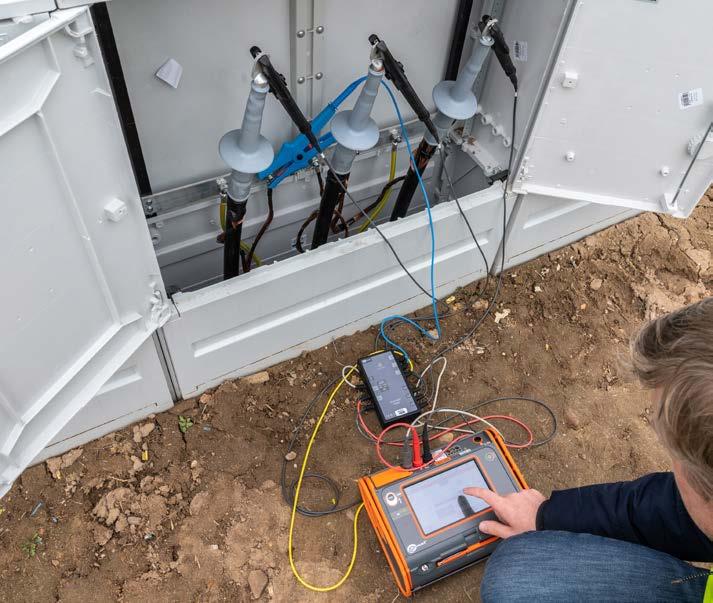
The impedance value ZS (needed to determine whether the protection is correct) shall be measured. During fault loop measurement performed by the technical "method, an "artificial short circuit" is generated. The instrument measures the volt age without load and after that during a short-term load from short-circuit resistor. Fault loop impedance is calculated based on the difference in voltage drops. This measurement may be performed using the following fault loop impedance meters: MZC-304, MZC-306, MZC-310S, MZC-320S and MZC-330S and MPI multifunctional meters - all of them indicate also components of the impedance, resistance and reactance.
» insulation leakage current (4) - the sum of currents flowing through the material and on its surface.
0,1 10 100 I t 4 1 3 2 min
LLL321 Rr N(PEN) RU 100101
RZ X
Fault loop impedance meters (except MZC-310S, MZC-320S and MZC-330S) pro vide also the measurement in L-PE circuits in systems protected by RCDs without any interference in the circuit. This measurement is carried out with current lower than 15 mA and it is extended in time, while the resolution of the result, is the same as for other measurements, i.e. 0.01 Ω. High current meters MZC-310S, MZC-320S and MZC-330S provide measurements with a result resolution of 0.1 mΩ (supply points, switchgear centres, transformer stations) applying the test current up to 300 A, which provides measurements in accordance with EN 61557 standard, even for circuits where the value of the fault loop impedance is in milli-ohm order.
Current regulations require the measurements of electrical systems both during commissioning (after completing the installation, after any change or extension of the system), as well as regularly during the operation. The scope of acceptance or periodic inspection is specified in standard HD 60364-6. Requirements for measur ing instruments are defined in standard EN 61557. Protective measures include, depending on needs, the measurement of fault loop impedance, insulation resis tance, continuity of protection and equipotential bonding, earthing resistance and parameters of residual current devices. Devices used for this type of measurement shall have a document confirming their technical efficiency. Pursuant to the Metrol ogy Act, this document shall be a calibration certificate. The period between checks of the instrument, recommended by the manufacturer is 12 months.
Measurement of fault loop impedance
where: ZS - fault loop impedance, lA - current triggering overcurrent protection in required time (depending on the time-current characteristic of applied protection and required disconnection time), Un - rated voltage of the network in relation to the earth.
Zs = UnIA
Fault loop impedance meters may be used for measuring the earth resis tance by using an auxiliary voltage source (phase conductor of the net work). The measured value is then overstated - the measurement result is the sum of resistance of the measured earth electrode, operational earthing system, source and phase conductor.
MZC-306 offers the measurements
PE Measuring device LLLN321 V RL R0
R(M )Ω T(s) R(M )Ω T(oC) R(M )Ω U(V)
» for any AC voltages » up to 750 V – also in industrial systems.
» capacitance charging current (2) - it depends on the capacitance (e.g. on the length of the tested cable),
Electrical safety measurements
6
Measurement of insulation resistance
Z = R2 + X2
The insulation condition is crucial for the operational safety and proper functioning of the system and electric appliances, guaranteeing also protection against direct contact. Systematic inspection of the insulation is necessary to detect its deterio ration and it is a permanent element of measurement and control works. In case of measurements on industrial equipment it is crucial to determine the tendency of changes in the resistance, which may indicate a gradual deterioration of the in sulation. The basic factors causing the insulation degradation include: electrical and mechanical exposures, chemical attack, thermal exposure and environmental pollution; their impact during normal operation of electrical system causes insula tion wear and tear. Insulation resistance measurements are performed with direct current (DC), to eliminate the impact of capacitance on the results. The method of measuring insulation resistance and the required test voltages are specified in standards: PN-HD 60364-6; PN-E-04700; EN 61557-2. During the measurements, after applying the voltage, the insulation conducts electricity. During the resistance measurement, the current flowing through the insulation (1) consists of the follow ing components:
The RCD will trip (disconnecting power supply) if the measured dif ference of currents I and l2 exceeds a certain characteristic for the RCD value. When a fault current flows, UB voltage will appear on the housing of the protected device, which in accordance with Ohm's law is:
soil type soil surfaceresistivityofthe earth electrode surface resistances
UB= IΔ• RE
IΔn < ULRE
The main function of the Residual Current Device (RCD) is an additional protection against electric shock by disconnecting the protected circuit from power supply, when the circuit is subject to earth overcurrent.
Rating current of the circuit breaker I∆n should be selected in a way ensuring that the contact voltage generated during fault current flow does not exceed the allowable long-term voltage UL:
Earthing systems may be called differently depending on their destination. e.g.: » protective, » functional (working), » lightning protection, » Checkingauxiliary.the
Meters MIC-10k1, MIC-5050, MIC-5010, MIC-5005, MIC-5001, MIC-2511, MIC-2501, MIC-30 as well as MPI-525 multifunctional meter, perform measure ments at a specified time and provide readouts in intervals set by the user. The obtained results are used to calculate one or two absorption coefficients, providing information about the condition of the insulation. Before the measurements, make sure that the tested object is disconnected from the mains. Upon detection of volt age on the object (or when voltage appears during the measurements), the device stops the measurement signals the anomaly. During the measurement, the device displays the current, instantaneous value of the resistance or the current value of the leakage current. After completing the measurement, the devices save the val ues measured at the end of periods sets by the user (the range from 1 to 600 s) and the tested object is discharged by the device.
Conductor Metal foil wrapped around the conductor insulationCablesheath R( ) COME R( ) COMEor 7
During each measurement procedure (except AC voltage measurements), the me ter controls whether the resulting contact voltage does not exceed the predeter mined voltage allowable for longer periods. If this value is exceeded, the measure ment will be automatically interrupted (i.e. the differential test current is switched off). The value of the long-term allowable touch voltage can be set to 25 V or 50 V and for selective switches additionally at 12.5 V. The tripping time of RCD is mea sured from the start of differential current flow until the tripping of RCD - the user may select the initial phase (or polarity) as positive or negative. The maximum mea sured value of the triggering time is 300 ms, and with selected measurement of selective switches it is 500 ms. Tripping current of RCD is measured after enforcing a differential current increasing linearly in the tested circuit. The increases from approx. 30% of I∆n until RCD is tripped or I∆n exceeded for AC breakers (140% and 200% for A and B respectively).
With the touch electrode installed in the devices, instruments for RCD measure ments may check the correctness of connections in the socket. When the voltage between the touch electrode and the protective conductor (PE) connected to the socket exceeds 50 V, the device will inform the user about it.
A system equipped with RCD must have, for safety reasons, a protective earthing conductor (PE). Therefore, the RCDs cannot be installed in networks without a ded icated protective conductor. RCD does not limit the fault current value, but only the time of its flow. However, as the criterion for tripping the RCD is the fault current exceeding the rated current of the RCD, it must be chosen appropriately to the type of protected devices. Due to the response time, the residual circuit devices are di vided into: normal, short-time delay G - intended for receivers and circuits, where momentarily, small leakage currents and selective may occur. S - having a de layed triggering time, which is the minimum time, during which the device does not trip, despite the difference between the current flowing in and flowing out to/from the circuit. Depending on the shape of the fault current that causes tripping, the switches may be divided into: AC circuit breakers marked with , responding to a differential sinusoidal current, type A, marked with responding to the sinusoi dal, unidirectional pulsating current and pulsating current with constant component up to 6 mA, and B type switches marked with responding to the sinusoidal, uni directional pulsating current and pulsating current with constant component and to
NL L I1I2IPEN RE UB I RCD LLLNPE321 RB RCD
Earthing is an essential element of any electrical system regardless of its rated voltage. The efficient earthing system is important for: » human safety during the operation of electrical devices, » proper operation of electrical equipment, » elimination or significant reduction of the impact of lightning.
effectiveness of earthing, i.e. measuring its resistance or impedance, is carried out to determine whether the received value will effectively drain fault current. Term "effectiveness" means that the resistance does not exceed the max imum value allowed for the particular case and the type of the earth electrode.
The 3-wire method, used in all advanced instruments, allows user to eliminate the impact of surface leakage current. In case of cables, wrap the core insulation with metal foil, which is connected to the shield terminal of the meter - only leakage current flowing through the insulation is measured. The measurement by 3-wire method is recommended for large areas exposed to pollutants (cables of large diameter, HV bushings, transformers, HV switches):
Earthing system is subject to periodic checks, during the operation in order to as sess whether corrosion or changes in soil resistivity do not significantly affect its performance.
direct current Measurements on RCDs may be performed with MRP-201 meter or by multifunctional meters MPI.
Measurements of resistance-to-earth
earthing system
Measurements of RCD parameters
When the circuit protected by the RCD is free from damage (differen tial current I∆ = 0), the inflow current I1 is equal to outflow current l2. In case of any damage (e.g. punctured insulation) fault current I∆ starts to flow and value of l2 current is lower than l1
Using the 3-wire method is important in the case of measurements of ob jects with very large resistance values (100 M)
The surge impedance specified in the standard is a theoretical value, as generally peaks of voltage and current do not occur simultaneously. The surge impedance is considered an indicator of the effectiveness of earthing systems in the conditions of stricter or special protection.
voltage electrode is driven into the ground between the measured earth electrode and the current electrode in the area of the so-called zero potential. In practice, it is recommended to perform three measurements, changing the position of the voltage electrode by 1-2 meters in a direction from and to the tested earthing. If the results are identical, the place of driving the electrode into the ground has been chosen correctly. The measurement is performed with a current at a frequency that allows to avoid interference and distortion having the frequency of the network (50 Hz or 60 Hz) and its harmonics. Advanced earth resistance/resistivity meters of MRU series check and indicate the size of interference voltages before starting the measurement In addition, these meters calculate the additional error related with too high resistance of probes.
The 2-clamp method is used for measurements of systems with multiple earthing electrodes not connected with each other underground. If the earthing electrodes are also connected underground, this method allows user to measure only the con tinuity of the circuit.
The 3-pole method with additional clamp has one more variation. Instead of using a directly connected current clamp with a split core, this method uses a special ERP-1 adapter. ERP-1 works with MRU meters with a measuring current of 200 mA. With use of a flexible clamp, it is possible to measure the total value of the current flowing through the earthing points of objects such as high and medium voltage pylons with a lattice structure or prestressed concrete spun transmission poles of medium and low voltage lines. The measurement procedure consists in wrapping the entire pole with the earthing with flexible clamp, thanks to which we measure the entire current flowing in the circuit to the ground.
The two-clamp method (MRU-30, MRU-120, MRU-120HD, MRU-200, MRU-200-GPS, MPI-530, MPI-535, MPI-540, MPI-540-PV) allows the user to measure the resistance of multiple earthing systems, without the need to drive auxiliary probes into the ground. During this measurement, the current generated by transmission clamps is closed within the following circuit: tested earthing system + parallel connection of other earthing probes and it is measured by the receiving clamps to provide data for calculating the circuit resistance. As the parallel connection of a few resistances generates the resultant resistance of much lower value, the result is higher than the tested resistance. The difference is the smaller, the more earthing electrodes is within the tested object.
Methods of performing measurements are described in detail at www.sonel.com
Earthing measurements may be carried out with multifunctional meters having the appropriate function and with specialist meters of MRU series. The method most commonly used for measuring earth resistance is the technical method, where the meter calculates the resistance by measuring the voltage across its terminals after applying test current. For measurements of individual earthing systems, the most commonly used is 3-pole method of potential drop, which enforces current flow in the following circuit: the meter - tested earthing system - current electrode - the meter. Distances between the electrodes should be as large as possible; the current electrode should be at the distance of least 10-fold greater than the physical length of the measured earthing; In practice, the distance is approx. 40 m between the tested earth electrode and the current electrode.
Nuisance arising from the need to disconnect individual earth electrodes when testing the systems with multiple electrodes may be eliminated by using the tech nical method with additional clamps (MRU-30, MRU-120, MRU-120HD, MRU-200, MRU-200-GPS). Current and voltage electrodes are arranged similarly to the 3-pole method, but the current is measured with clamps attached to the tested earthing. The meter calculates the resistance knowing that part of the current which flows through the tested earth electrode. The method of measurement with clamps can not be used in multiple systems, which have individual earth electrodes connected to each other underground.
Parameters of the test pulse (which simulates the shape of the lightning) are de fined by two numbers: the pulse leading edge duration t1 and a time to half-peak t2 The MRU-200 / MRU-200-GPS meter provides a selection of three pulse shapes: 10/350 μs, 8/20 μs and 4/10 μs. Pursuant to EN 62305, the pulse with a shape of 10/350 μs is typical for the first stroke of the lightning current. The same pulse is specified as a reference pulse in EN62305-1 standard. Pulse 4/10 μs has parame ters resulting from PN-92/E-04060.
Advanced devices have the ability to perform measurements using 4-lead method, eliminating the impact of the resistance of cable used to connect the meter with tested earthing system.
In the earthing system assessed for electric shock protection, it is important to maintain currents of low frequency (50, 60 Hz). The task of the lightning protec tion earthing systems is to discharge lightning strikes into the ground. The pulsed nature of such discharge makes the inductive component of the earth electrode quite important, as the lightning current is effectively discharged only by a part of the earth electrode, located in the immediate vicinity of the discharge. There fore an earth electrode with low static resistance, which provides good basic pro tection does not ensure adequate lightning protection parameters - especially in the case of extensive earthing systems, having low static resistance, but several times higher dynamic impedance. The measurement using the impulse method (MRU-200, MRU-200-GPS), in accordance with: EN 62305 and withdrawn, but still applied PN-86/E-05003, enables user to diagnose the parameters of dynamic light ning protection earthing systems. The pulsed nature of the measurement does not require the disconnection of the earthing in case of multiple earthing probes or live objects, as the test current pulse, similarly to lightning stroke, operates only within a limited distance. The measurement is carried out in accordance with the descrip tion specified in EN 62305 standard. This method allows to determine the theoretical value of the surge impedance (Zd), which is the ratio of peak voltage to peak current.
V A E1U UH0% 52% 62% 72% S52% S62% S72% RE H S ES E H S E Distribution of voltage during the flow of the test current Measurement of resistance to earth - the 4-lead method Measurement of resistance to earth - the 3P method + clamps N-1 UI C-3 R RE1 RE3 RE4 RE5RE6 C-3N-1RE2 RE1 RE3RE4RE5RE6 RE = RE1 + 1 RE21 RE31+ RE41+ RE51+ RE61+ I U Connection of the meter in the 2-clamp method Equivalent circuit of multiple earthing system in the 2-clamp method 10% T1 T2 t t = current amplitude T1 = pulse leading edge duration T2 = time to semi-spike 90% 50% The shape of test pulse in the impulse method 8
Measuring devices are supplied in appropriate casings or suitcases fitted to their sizes with inner compartments for transporting measuring accessories.
are
Sonel offers also long probes (80 cm) with a suitable cover, clamps of high sensitiv ity and accuracy (C-3, N-1) for earthing measurements without the need to discon nect the test connections or for current measurements, as well as special terminals guaranteeing adequate contact.
Knowing the cross-section of the soil, the user may select the appropriate type of earthing system - e.g. for low resistivity values occurring only at a certain depth, the single earth electrode may be designed as deeply immersed, whereas for soil with low resistivity at the shallower area; or rock base with a greater depth - it will be a set of shorter earthing electrodes connected by a vertical metal band.
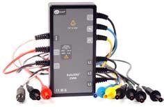
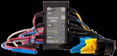
AutolSO-2500 and AutoISO-2511 adapter allows user to perform tests on cables under 2500 V voltage. In other hand, for AutolSO-5000 adapter the test voltage is as high as 5000 .

Facilitating the measurements
During measurements carried out under voltage (earth fault loop impedance, RCD parameters, voltage, sequence of phases) conductors ended with blade probes or crocodile clips may be used (of adequate measuring categories with a shape prevent slipping or disconnecting), as well as adapters suitable for measuring ter Metersminals/sockets.connected to the system equipped with sockets by a cable terminated with a mains plug, or by wires, automatically check the correctness of connections and signal any abnormalities. Measurements in single-phase sockets may be carried out using adapters ended with Uni-Schuko plug; the measurements are performed also in the case of exchanging the phase conductor with neutral conductor (without comply with European directives on electromagnetic compatibility and safety and marked
When the impulse method is used for measurements on multiple earth ing systems, connected both above and under the ground, the test pulse operates only in the close proximity of tested earthing electrode, which allows user to carry out the measure ment without the need to disconnect testing terminals and equipotential bondings - i.e. without the need to disconnect the power supply of the object.
Family of AutolSO adapters facilitate the insulation measurements carried out with suitable devices on insulation of 3-, 4- and 5-wire cables, without the need of man ual selection of pairs and combinations of the measured wires. Adapter cables ended with crocodile clips (depending on the position 3, 4 or all 5) are attached to the tested cable cores; when the measurement is started, the adapter connected with the meters, performs the sequence of all required tests.
of HV pole earthing AutoISO-5000 TWR-1J AutoISO-1000 AutoISO-2500 AutoISO-2511 9
for measuring earth resistance are delivered with many ergonomic ac cessories that simplify measurements. Cables used for testing earthing systems, due to their length (50, 30, 25,15 meters) are wound on drums made of a material resistant to frost and strokes, allowing fast winding and unwinding by the user.
TWR-1J adapter enables user to check RCD parameters before installing it within the syste Instrumentsm.

All devices
the need for manual switching or using additional adapters). In addition, WS-01 and WS-03 adapters have buttons for triggering measurements and saving recorded values. For the measurements in three-phase or HV sockets, one of the following adapters may be optionally used: for three-phase sockets AGT-16P, AGT-32P, AGT63P AGT--16C, AGT-32C and for HV sockets AGT-16T and AGT-32T.
with H S ES E V H S E1 d1 d1 = 0,7d E2 E3 E4 I I I ES E A ES = 1,5 kV RS R 60 E Earthing impedance measurement system (4P impulse method)

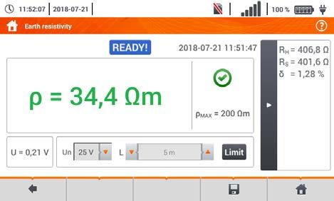
Knowledge of the soil resistivity value (MRU-30, MRU-120, MRU-120HD, MRU-200, MRU-200-GPS) is important at the stage of designing the earthing system.
Soil resistivity measurement is performed using four electrodes arranged linearly at equal distances (Wenner method). The soil resistivity is measured at the depth equal to 0.7 of the distance between the probes.
Measurements
The impulse method may also be used to measure the impedance of earthing used for HV poles; it allows also to determine the earthing imped ance of the entire pole, including both ground band systems as well as the re sistance of pole legs, and it may be used without the need to disconnect the tested HV line or to remove components of the earthing system.
Detailed lists of standard and optional accessories can be found at the end of prod uct groups.
Multi-function meters of electrical system parameters MPI-535MPI-536MPI-540MPI-540-PV MPI-530-ITMPI-530MPI-525MPI-520 PVM-1020MRP-201EVSE-01MPI-502MPI-506MPI-507 KIT / PVM-1020 / IRM-1


MPI-540-PV
Autotests
Measurement voltages [V] 95…440 95…440 95…440 95…440 180…460 180…460
Measurement voltages [V] MPI-536 | 10 50, 100, 250, 500, 1000 MPI-536 | 1500, 2500 50, 100, 250, 500, 1000 50, 100, 250, 500, 1000, 2500 50, 100, 250, 500, 1000 100, 250, 500
Measurement of tripping current IA with rising current 10, 30, 100, 300, 500, 1000 10, 30, 100, 300, 500, 1000 10, 30, 100, 300, 500, 1000 10, 30, 100, 300, 500, 1000 10, 15, 30, 100, 300, 500 10, 30, 100, 300, 500
Simultaneous measurement of IA and tA in one RCD trip √ √ √ √ √ √
Automatic measurement of multi-core cables with AutoISO-2500 adapter — / — / √ √
Low-voltage resistance
Earth resistance measurement of setting
Display
Measuring range [Ω] 5G / 5G / 5G / 10G 10G 10G 3G 600M
3p, 4p, 3p+clamps, double-clamp 3p, 4p, 3p+clamps, double-clamp 3p 3p 3p / — Capability
Fault loop impedance resolution [Ω] 0…1999 0…1999 0…1999 0…1999 0…1999 0…1999


Sound signalling of time intervals for characteristics √ √ √ √ Calculation of absorption coefficients √ Continuity testing with current ≥ 200mA √ √ √ √ √
Resolution of fault loop impedance measurement without RCD tripping [Ω] 0,01 0,01 0,01 0,01 0.01 0,01
measurement √ √ √ √ √ √
Measurement of touch voltage UB √ √ √ √ √ √ Detection of L and N swapping √ √ √ √ √ √
Protection against appearance of voltage √ √ √ √ √
7" LCD touchscreen LCD graphic LCD graphic LCD graphic segmented LCD segmented LCD


√ √ √ √ √ √
√ √ √ √ √ √
Measurement of tripping time for factor of rated current 1/2, 1, 2, 5 1/2, 1, 2, 5 1/2, 1, 2, 5 1/2, 1, 2, 5 1/2, 1, 2, 5 1/2, 1, 2, 5
limit for every function √ √ Quick check of PE connection √ √ √ √ √ √ Voltage measurement [V] 0…500 0…500 0…500 0…500 0…500 0…500 Frequency measurement [Hz] √ √ √ √ √ √ Alternating current measurement [A] optionally 0…3000 optionally 0…3000 optionally 0…400 Power and cosφ measurement √ / √ / — / — √ √ Measurement of U harmonics: I up to the 40th √ / √ / — / — √ THD measurement for U and I √ / √ / — / — √ Phase sequence check [V] 95…500 95…500 95…500 95…500 100...440 Memory (records) unlimited 10 000 for measurementeverytype 990 990 990 990 Power supply rechargeable battery rechargeable battery / batteries rechargeable battery / batteries batteries / rechargeable battery batteries / rechargeable batteries batteries / rechargeable batteries Built-in quick charger √ √ √ √ Data transmission USB, Bluetooth, Wi-Fi USB, Bluetooth USB USB Bluetooth Bluetooth Dimensions [mm] 288 x 223 x 75 288 x 223 x 75 288 x 223 x 75 288 x 223 x 75 220x98x58 220x98x58 Weight [kg] 2.5 2.2 2.2 2.2 0.8 0.6 11
Residual current device measurements AC, A, F, B, B+, EV G S AC, A, F, B, B+ G S AC, A, F, B, B+ G S AC, A, F, B, B+ G S AC, A G S AC, A G S
√
√ √ √ √ √
/ MPI-540 / MPI-536 / MPI-535 MPI-530-IT / MPI-530 MPI-525 MPI-520 MPI-507 / MPI-506 MPI-502
Automatic discharging of object after measurement √ √ √ √ √
Measurement of insulation resistance √ √ √ √ √
Calculation of fault current according to measured voltage
Automatic measurement in socket
Automatic measurement of the full set of RCD parameters - RCD Auto √ √ √ √ √ √

Automatic measurement of multi-core cords with AutoISO-1000C adapter √ / √ / — √ √ √
Energy losses calculator √ / √ / — / —
√
Maximum resolution of fault loop impedance measurement [Ω] 0.001 0.001 0.01 0.01 0.01 0.01
Network parameters recorder three-phase / three-phase / — / — single-phase
Calculation of fault current according to rated voltage
Comparison of multi-function meters
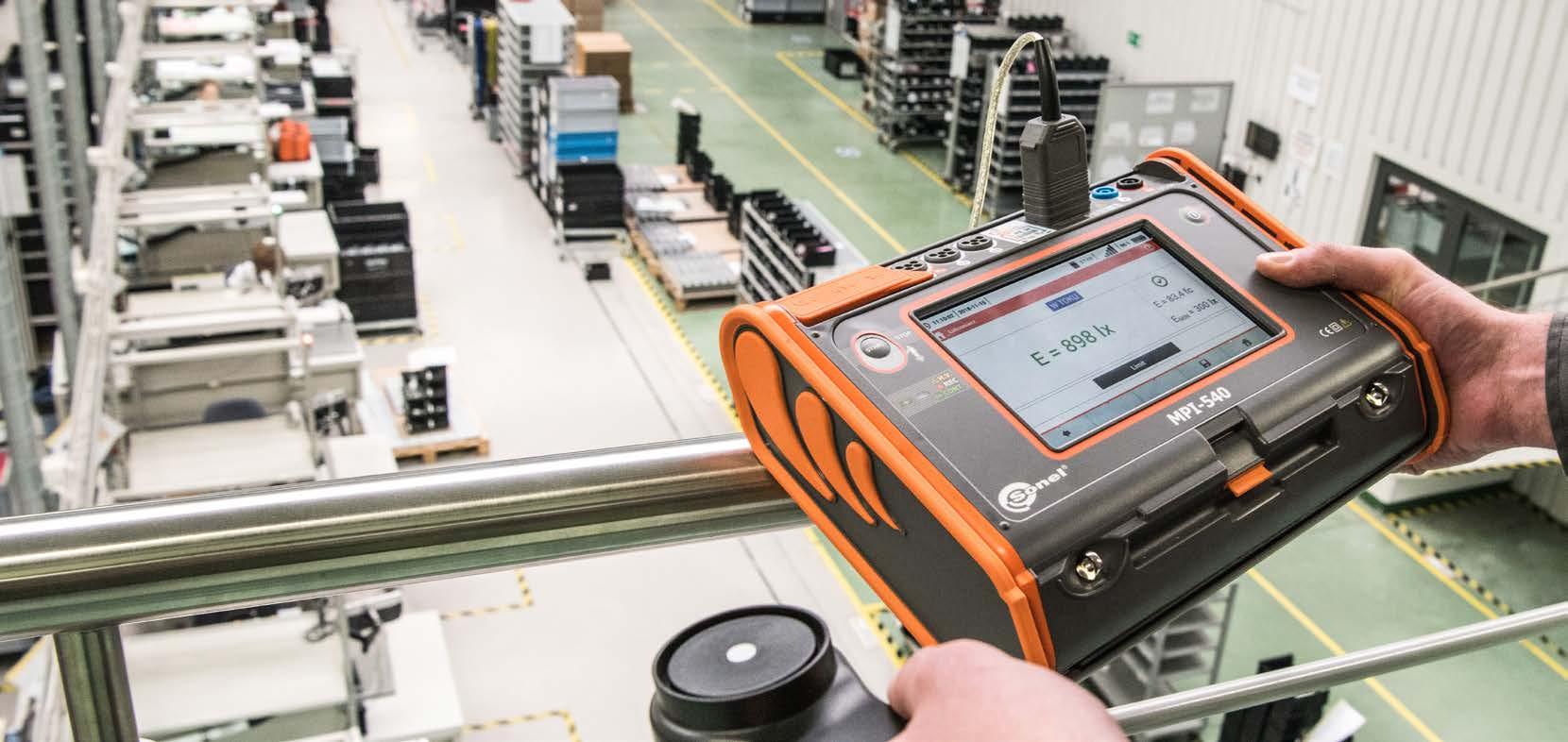
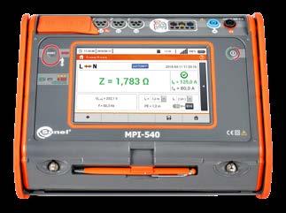
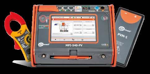
SONEL MPI-540 / MPI-540-PV Multi-function meter of electrical system parameters 7” screentouch power3-phasequalityrecorder measurementscomplex of installations ρ RISO ZS RE RCONTE measurement of PV installations MPI-540-PV Features » The largest touch screen on the market (7”) – remarkable ergonomics and ease of use » Removable microSD memory card – easy increase of memory capacity » Li-Ion battery – longer operation of the meter » MPI-540-PV: measurement of photovoltaic installations according to EN 62446 standard » MPI-540-PV: photovoltaic installation test report with Sonel Reports PLUS software » Three-phase power recorder – advanced power quality diagnostics » Real time display of network parameters – immediate evaluation of the test site conditions » Parameters measured in accordance to class S of EN 61000-4-30 standard – high accuracy of measurements » Energy cost calculator – quick evaluation of potential savings » Measurement of all parameters related to earthing and protection against electric shock – one device instead of several » Quick measurement of the fault loop impedance in networks secured with RCD without triggering (up to several seconds) – time saver » Auto measurements – the ability to perform automatic measurements in sequence –simplified measurements » Fast path from measurements to report – time saver
• active (P), reactive (Q) and apparent (S) power,
» The MPI-540-PV instrument can measure photovoltaic installations in accordance with the EN 62446 standard:
• total harmonic distortion (THD) for current and voltage.
• short circuit current ISC,

• continuity of protective and equipotential bondings,
• power factor (PF), cosφ,
» MPI-540 / MPI-540-PV can record 50/60 Hz power quality parameters in accordance to S class of EN 61000-4-30:


• insulation resistance on the DC side,
• phase sequence test,
Multi-function meter of electrical and PV system parameters with flexible coils index: WMGBMPI540PV
• work currents and powers on both DC and AC side,
• continuity of protective and equipotential bondings,
• light intensity measurement,
Multi-function meter of electrical and PV system parameters without flexible coils index: WMGBMPI540PVNC

• L1, L2, L3 currents, – average values, current measurement in the range up to 3 kA (depending on the current probes used),
• insulation resistance,

Multi-function meter of electrical and PV system parameters with flexible coils and solar radiation measurement set index: WMGBMPI540PVIRM1
MPI-540
• harmonics (up to 40th for voltage and current),
• RCD parameters,

MPI-540-PV MPI-540-PV Solar
12
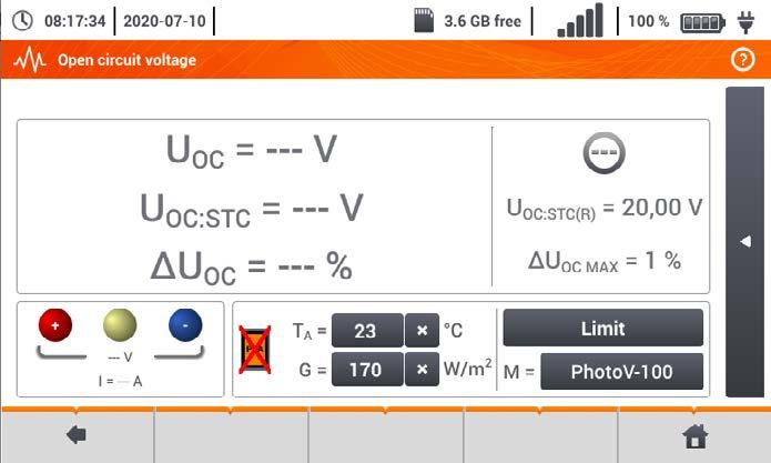
• open circuit voltage UOC,
• frequency in the range of 40 Hz – 70 Hz,

Capabilities
• inverter efficiency.
MPI-540-PV Start
MPI-540-PV Solar
MPI-540 Start
• earth resistance (4 measurement methods + soil resistivity measurement),
• voltage L1, L2, L3, – average values in the range up to 500 V,


» MPI-540 / MPI-540-PV can be used for all measurements for commissioning of electrical installations in accordance with applicable regulations:


• short circuit loop impedance (also in circuits secured with RCDs),

• motor rotation direction test.
Choose the best set for your needs
MPI-540-PV
The meter has above-average functionality. It combines the measuring capabilities of several devices, while ensuring equally good accuracy.
Multi-function meter of electrical system parameters with flexible coils index: WMGBMPI540
Multi-function meter of electrical system parameters without flexible coils index: WMGBMPI540NC
• earth resistance,
»
» measuring range: 0.5 Ωm…9.99 kΩm,
Illuminance measurement:
» measurement of general, short-time delay and selective RCDs with rated residual currents of 10, 30, 100, 300, 500 and 1000 mA,
» selection of installation protections and automatic evaluation of measurement results.
» detection of L and N phase swapping in a socket; does not affect measurements, » capability of measuring tripping current IA as well as actual tripping time tA with just one RCD trip, » voltage measurements within the range of 95…270 V.
Insulation resistance measurement:
» MPI-540 / MPI-540-PV also enables measurements in IT networks,
» internal power source with frequency appropriate for 50 Hz or 60 Hz power network.
Fault loop impedance measurements:
» measurement of touch voltage UB and protective conductor resistance RE without tripping the RCD,
MPI-540 / MPI-540-PV allow safety control of residential, commercial and industrial electrical installations Measurements can be easily automated with:

Photovoltaics under supervision
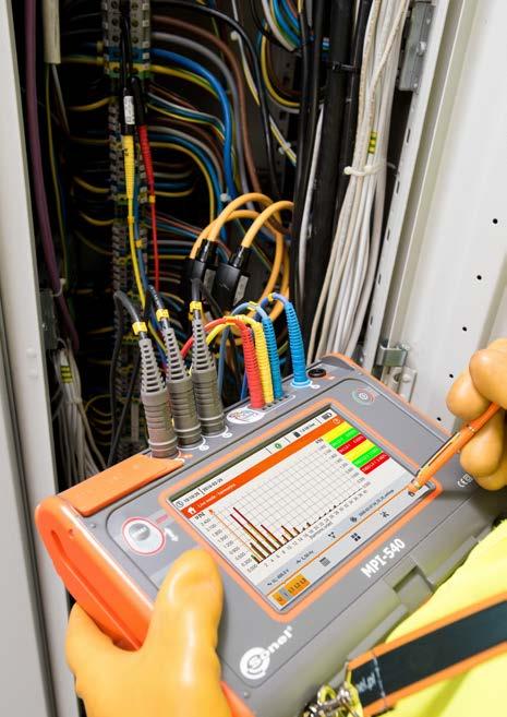
The device has a three-phase power quality recorder with the LIVE mode view and the possibility to register electrical network parameters such as voltage, current, power, harmonics and THD. The meter enables reading of selected parameters and their graphic presentation on the screen in real time. These parameters are measured and displayed concurrently with the recording on the memory card. In the LIVE mode, the user can see:
Low-voltage continuity testing of protective conductors and equipotential bonding:
» AutoISO-1000C adapter for automatic insulation resistance test of 3-, 4- and 5-conductor cables, without switching.
Soil resistivity measurements according to the Wenner method:
» automatic calculation of fault current on the basis of nominal or measured voltage; differentiation of phase-to-neutral and phase-to-phase voltage,
Earth resistance measurements:
» impedance measurement with 23 A current (40 A for phase-to-phase voltage), max. resolution 0.001 Ω,
» function of automatic measurement of all RCD parameters (after pressing the “START” button once, the meter performs the entire defined cycle of measurements, including the capability of earth fault loop impedance measurement with 15 mA current),
Additional functions of the meter:
» type of insulation double, as per EN 61010-1 and EN 61557 » power supply Li-Ion battery 11.1 V 3.4 Ah 37.7 Wh » operating temperature range 0…+50°C
» fast fault loop impedance measurement with resolution up to 0.01 Ω in systems protected with RCDs not tripping at IΔn ≥ 30 mA,
» auto mode of residual current devices (RCD) tests,
» sound signalling of five-second time intervals, facilitating capture of time characteristics, meter protected against the presence of voltage on the object and the appearance of voltage during measurement,
» real time display of network parameters, » autotests - pre-programmed measurement sequences, » quick check of correct connection of PE conductor by means of contact electrode, » check of phase sequence and direction of motor rotation, » tree-like memory structure with dynamic management » data transmission to PC via USB or Bluetooth®, » replaceable microSD memory card, » power supply from rechargeable battery, built-in quick charger, » capability of charging from the power grid or 12 V car lighter socket.
» measurement voltages: 50 V, 100 V, 250 V, 500 V, 1000 V, » measurement of insulation resistance up to 10 GΩ, » capability measurement in-socket by means of UNI-Schuko adapter,
» fault current-limiting resistor: 10 Ω,
» automatic discharge of the measured object's capacitance after completion of measurement,
Testing of AC, A, F, B, B+ and EV residual current devices:
Three-phase power quality recorder
» voltage and current waveforms (oscilloscope), » voltage and current timeplots, » a phasor graph, » display of multiple parameters in tabular form, » spectrum graph of current and voltage harmonics.
» measuring range according to EN 61557-4: 0.12…400 Ω, max. resolution 0.01 Ω, » measurement of protective conductor continuity with current ≥200 mA in two directions, » low-current measurement with sound signaling, » voltage on open terminals: 4…9 V, » automatic calibration of test leads - leads of any length can be used.
» measurements using UNI-Schuko plug with measurement triggering button (including case with swapped L and N leads) or 1.2 m, 5 m, 10 m, 20 m test leads, with optional use of three-phase socket adapters (AGT),
» according to 3- or 4-lead technical method with 2 auxiliary electrodes, » according to 3-lead method with additional clamp, » according to double-clamp method,
Measuring parameters related to the photovoltaic installation, the instrument will automatically convert them to the STC (Standard Test Conditions) reference conditions. Measurements of voltage, current and power on the AC and DC side of the inverter allow to verify its efficiency. Sonel Reports PLUS software enables creating PV installation test report with measurement results saved meter’s in memory..
» automatic measurement of all resistance combinations of 3-, 4- and 5-core cords by means of the optional AutoISO-1000C adapter.
» distances between electrodes can be set in meters (1…30 m) or feet (1…90 ft).
MPI-540-PV is an extremely universal meter, designed in particular for testing photovoltaic installations. The device allows a complete set of tests on the DC and AC side – in accordance with the guidelines of EN 62446 standard.
» display range: 0.001/0.01/0.1 lx…399.9 klx, » measurement in lux (lx) or foot-candles (fc), » measurement by means of external photodetectors (optional)
13
» shape of the input leakage current selected by the user: sinusoidal (start from rising or falling edge), unidirectional pulsating (positive or negative), unidirectional pulsating with direct current offset (positive or negative), constant (positive or negative), » measurement of tripping current IA with rising current, » measurement of tripping time tA with currents 0.5 I∆n, 1 I∆n, 2 I∆n and 5 I∆n,
» auto measurements – freely configurable measuring sequences,
» range of measurement voltages: 95…440 V, frequencies 45…65 Hz,
Other technical specifications:
Automatic installation safety test
MPI-540 Start does not include flexible coils
Choose the best set for your needs
MPI-540-PV includes flexible coils

MPI-540-PV Start does not include flexible coils
MPI-540 includes flexible coils

MPI-540-PV Solar includes flexible coils and solar radiation measurement set


F-3A flexible coils solar measurementradiationset


14
C-PV clamp WACEGCPVOKR √ √ √
Test lead 1.2 m, yellow, 1 kV (banana plugs) WAPRZ1X2YEBB √ √ √ √ √
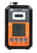
Standard accessories: solar radiation and temperature meter WMGBIRM1 mounting&measuring
Cable for battery charging from car cigarette lighter socket (12 V) WAPRZLAD12SAM √ √ √ √ √
Pin probe, red 1 kV (banana socket) WASONREOGB1 √ √ √ √ √
F-3A flexible coil (Ø120 mm) WACEGF3AOKR √ √ √
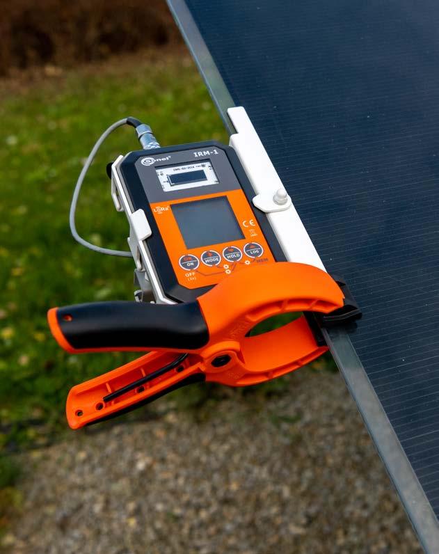
» Built-in compass and inclination sensor. recorder that can be used to record solar radiation before constructing PV systems, well as to measure the shading of existing systems. measurement memory: 999 cache memory cells and 5000 recorder records available (one-time recording) with the option of overwriting them (continuous recording).
WAPOZUCHPV power supply with USB 2.0 output and a detachable micro-USB WASONTPVCKPL
LORA-S1 USB adapter for data transmission
WAADAWS03 √ √ √ √ √
WAPRZ015BUBBSZ √ √ √ √ √
Test lead 1.2 m, red, 1 kV (banana plugs) WAPRZ1X2REBB √ √ √ √ √
Test lead 15 m, blue (on a reel)
MC4-banana sockets adapter (set of 2 pcs.) WAADAMC4 √ √ √
Crocodile clip, red, 1 kV, 20 A
IRM-1
WAADAUSBLORA carrying case
Crocodile clip, yellow, 1 kV, 20 A WAKROYE20K02 √ √ √ √ √
Adapter for C-PV clamp WAADACPV √ √ √
WS-03 adapter with START button with UNI-Schuko plug
IRM-1
as
» Inclination
Factory calibration certificate √ √ √ √ √
Li-Ion battery 11.1 V 3.4 Ah WAAKU15 √ √ √ √ √
» Large
» PV
WAFUTM14 calibration certificate
» Solar
» The LoRa interface for communication with the meter - offers a larger range than the Bluetooth technology!
Test lead 30 m, red (banana plugs, on a reel) WAPRZ030REBBSZ √ √ √ √ √
set
WAKRORE20K02 √ √ √ √ √
M14
5 V
Z7 power supply WAZASZ7 √ √ √ √ √
index: WMGBIRM1MPI
Standard accessories:
panels » Orientation
» Automatic data synchronization with the meter.
Measured parameters radiation intensity (irradiance) in W/m2 or BTU/ft2h. panel temperature in °C or °F. temperature in °C or °F. angle of of the panels with the built-in compass.
MicroSD card √ √ √ √ √
PVM-1 adapter WAADAPVM1 √ √ √
USB cable WAPRZUSB √ √ √ √ √
WAPRZ1X2BLBBN √ √ √ √ √
2x earth contact test probe (rod), 30 cm WASONG30 √ √ √ √ √
Voltage adapter with M4/M6 thread (5 pcs.) WAADAM4M6 √ √ √ √ √
Crocodile clip, blue, 1 kV, 20 A WAKROBU20K02 √ √ √ √ √
Features
15
MPI-540-PV Solar MPI-540-PV MPI-540-PV Start MPI-540 MPI-540 Start WMGBMPI540PVIRM1 WMGBMPI540PV WMGBMPI540PVNC WMGBMPI540 WMGBMPI540NC
L2 carrying case WAFUTL2 √ √ √ √ √ L2 hanging straps (set) WAPOZSZEKPL √ √ √ √ √
Solar radiation measurement set WMGBIRM1MPI √
cable
Pin probe, yellow 1 kV (banana socket) WASONYEOGB1 √ √ √ √ √
Factory
Pin probe, blue 1 kV (banana socket) WASONBUOGB1 √ √ √ √ √
Test lead 1.2 m, blue, 1 kV (banana plugs) WAPRZ1X2BUBB √ √ √ √ √
Carrying case M13 WAFUTM13 √ √ √
Test lead 1.2 m, black, 1 kV (banana plugs)
Mains cable with IEC C7 plug WAPRZLAD230 √ √ √ √ √
Crocodile clip, black, 1 kV, 20 A WAKROBL20K01 √ √ √ √ √
» Built-in
» Measurement of solar radiation and temperature.
» Ambient
Solar radiation measurement set
Measurement of RCD trip current IA for sinusoidal residual current (AC type)
• AC module in EV type
Nominal current Measuring range Resolution Measurementcurrent Accuracy
0.35 IΔn…1.4 IΔn 100 mA 35…140 mA 1 mA300 mA 105…420 mA 500 mA 175…700 mA
10 IΔn 0…300 ms 1 ms33 IΔn 0…100 ms
for RCD of IΔn= 10 mA of the measurement with 0,5 IΔn accuracy: ±(2% m.v. + 3 digits)
10 mA 3.0…10.0 mA 0.1 mA
30 mA 9.0…30.0 mA 100 mA 30…100 mA 1 mA 300 mA 90…300 mA 500 mA 150…500 mA 1000 mA 300…1000 mA
10 mA 3.5…20.0 mA 0.1 mA 0.35 IΔn…2.0 IΔn ±10% IΔn 30 mA 10.5…42.0 mA
» I∆n - nominal value of residual current Measurement of RE earth resistance using 3-lead, 4-lead, or 3-lead + clamp technical method
Display range Resolution Accuracy 0.00…19.999 Ω 0.001 Ω ±(5% m.v. + 0.03 Ω) 20.00…199.99 Ω 0.01 Ω ±(5% m.v. + 0.3 Ω) 200.00…1999.9 Ω 0.1 Ω ±(5% m.v. + 3 Ω)
The instrument meets the requirements set forth in the standards:
Selective 0.5 IΔn 0…500 ms
0.5 IΔn 0…300 ms
» Nominal voltage: 95…270 V
• EV 6 mA DC
1 ms ±(2% m.v. + 2 digits)
RCD type Factor Range Resolution Accuracy
50 IΔn 0…40 ms
» PN-E 04700 (performance of measurements - commissioning tests)
Earthing resistance measurement with two clamps
» for U n = 50 V: 50 kΩ…250 MΩ
Indication of phase sequence
C-6A
5 IΔn 0…40 ms
» Indication of phase sequence: compliant, non-compliant, display of phase-tophase voltages
Measuring range according to EN 61557-2:
0.00…19.99 Ω 0.01 Ω ±(6% m.v. + 10 digits) 20.00…199.99 Ω 0.1 Ω ±(6% m.v. + 5 digits)200…1999 Ω 1 Ω
1 IΔn2 IΔn 0…200 ms
» Frequency: 45…65 Hz
Nominal current Measuring range Resolution
» EN 61010-1 (general and particular requirements related to safety)
» EN 61557 (requirements for measurement instruments)
F-1A,F-3AF-2A, 0…3000 A (10 kAp-p @ 50Hz) 0.01% I nom ±0.1%
Measurement of RCD trip current IA for uni-directional residual current and uni-directional current with 6 mA direct current offset (type A)
» Measurement is possible for positive or negative input leakage current
Measuring range according to EN 61557-5: 0.50 Ω…1.99 kΩ for U = 50 V (3-lead, 4-lead): Display range Resolution Accuracy 3p, 4p Accuracy 3-lead with clamp 0.00…9.99 Ω 0.01 Ω ±(2% m.v. + 4 digits) ±(8% m.v. + 4 digits)10.0…99.9 Ω 0.1 Ω ±(2% m.v. + 3 digits)100…999 Ω 1 Ω 1.00…1.99 kΩ 0.01 kΩ “m.v.” = “measured value”
» for U n = 250 V: 250 kΩ…99 MΩ
• Short-time delay
» EN 62446 (testing of PV panels) (MPI-540-PV only)
C-7A
» HD 60364-4-41 (performance of measurements - shock protection)
0.2 IΔn…2.0 IΔn ±10% IΔn 30 mA 6…60 mA 1 mA 100 mA 20…200 mA 300 mA 60…600 mA 500 mA 100…1000 mA
» Measurement can be started from the positive or negative half-period of the input leakage current (AC) Measurement of RCD trip current IA for residual direct current (type B)
• RCM
» Measurement can be started from the positive or negative half-period of the input leakage current (AC)
Measurement of insulation resistance
Measurement of fault loop impedance ZL-PE, ZL-N, ZL-L in 23/40 A mode Measurement with 23/40 A current - measuring range according to EN 61557: 0.130 …1999 Ω (for 1.2 m test lead):
Measurements of RCD parameters (working voltage range 95…270V): RCD trip test and measurement of tripping time tA (for tA measurement function)
Measurement of the ZL-PE fault loop impedance in the RCD mode Measurement with 15 mA current - measuring range according to EN 61557: 0.50…1999 Ω
Display range Resolution Accuracy
AC current measurement (True RMS) with clamp
Illuminance measurement* Display range [lx] Resolution [lx] Spectral uncertainty Accuracy 0…3.999 0.001 f1
Clamp Display range Resolution Accuracy
C-5A 0…1000 A (3600 Ap-p) 0.01% I nom 0.5…100 A: ≤(1.5%+1 A) 100…800 A: ≤2.5% 800…1000 A AC: ≤4% 800…1400 A DC: ≤4% 0…10 A (36 Ap-p) 0.01% I nom 0.01…0.1 A: ±(3%+ 1 mA) 0.1…1 A: ±2.5% 1…12 A: ±1% 0…100 A (360 Ap-p) 0.01% I nom 0…100 A: ± (0.5% + 0.02 A) (45…65 Hz) 0…100 A: ± (1.0% + 0.04 A) (40…1000 Hz) < 2% ±(2% m.v. + 5 digits)
» EN 61326 (electromagnetic compatibility)
0.3 IΔn…1.0 IΔn ± 5% IΔn
Display range Resolution Accuracy 0…1999 kΩ 1 kΩ ±(3% m.v. + 8 digits) 2.00…19.99 MΩ 0.01 MΩ 20.0…199.9 MΩ 200…999 MΩ 1 MΩ 1.00…4.99 GΩ 0.01 GΩ ±(4% m.v. + 6 digits) 5…9.99 GΩ 0.01 GΩ (non-specified)
Nominal current Measuring range Resolution Measurementcurrent Accuracy
1 IΔn 0.0…10.0 s 0.1 s ±(2% m.v. + 3 digits)
» HD 60364-6 (performance of measurements - checking)
» for U n = 100 V: 100 kΩ…500 MΩ
» for U n = 500 V: 500 kΩ…2 GΩ » for U n = 1000 V: 1000 MΩ…9.99 GΩ
» EN 12464 (lighting workplaces)
» Nominal voltage: 95…270 V (for ZL-PE and ZL-N) or 95…440 V (for ZL-L - only mode 23/40 A). Frequency: 45…65 Hz.
1 IΔn2 IΔn 0…150 ms
Measurementcurrent Accuracy
• General
» Residual current input accuracy: for 0.5 I∆n 8...0% for 1 I∆n, 2 I∆n, 5 I∆n 0...8%
» EN 61010-031 (general and particular requirements related to safety)
» UL-L power system voltage range: 95…500 V (45…65 Hz)
C-4A 0…1000 A (3600 Ap-p) 0.01% I nom 0.1…10 A: ±(3% + 0.1 A) 10 A: ±3% 50 A: ±1.5% 200 A: 1000…1200±0.75%A:±0.5%
4.00…39.99 0.01 40.0…399.9 0.1 400…3999 1 4.00 k…39.99 k 0.01 k 40.0 k…399.9 k 0.1 k *) for the LP-10A measuring probe 16
5 IΔn 0…150 ms
Display range Resolution Accuracy 0.00…9.99 Ω 0.01 Ω ±(10% m.v. + 4 digits)10.0…19.9 Ω 0.1 Ω 20.0…99.9 Ω ±(20% m.v. + 4 digits)
6 mA 1.0…6,0 mA 0.1 mA 1.0...6.0 mA ± 6% IΔn 10 mA 2.0…20.0 mA 0.1 mA
Harmonics voltage as for alternating voltage True RMS as for alternating voltage True RMS ±5% m.v. if m.v. ≥ 3% U nom ±0.15% U nom if m.v. < 3% U nom
• active energy (EP), reactive energy (EQ), apparent energy (ES),
Current as for alternating voltage True RMS as for alternating voltage True RMS ±5% m.v. if m.v. ≥ 10% I nom ±0.5% I nom if m.v. < 10% I nom
• harmonics up to the 40th in voltage and current, total harmonic distortion THD for current and voltage,
Alternating voltage TRMS depending on clamp* 0.01% I nom ±2% m.v. if m.v. ≥ 10% I nom ±2% I nom if m.v. < 10% I nom error does not account for clamp error)
• currents L1, L2, L3 (three measurement inputs), average, minimum and maximum values, current measurement within the range up to 3 kA (depends on used clamps), interoperability with current transformers,
cosφ and power factor (PF) 0.00…1.00 0.01 ±0.03

» Measured parameters:
up to four places after the decimal point depending on configuration (instrument transformers, clamp)
*Clamp F-1A, F-2A, F-3A: 0…3000 A AC (10 000 Ap-p) • Clamp C-4A: 0…1000 A AC (3600 Ap-p) • Clamp C-5A: 0…1000 A AC/DC (3600 Ap-p) • Clamp C-6A: 0…10 A AC (36 Ap-p) • Clamp C-7A: 0…100 A AC (360 Ap-p)
Fault loop impedance measurement Network parameters recorder Selected features of the Sonel MPI-540 / MPI-540-PV meter Ground resistivity measurement MPI-540-PV | Specifications – photovoltaic installation parameters Open circuit voltage UOC measurement Display range Resolution Accuracy 0.0 V...299.9 V 0.1 V ±(3% m.v. + 5 digits) 300 V…1000 V 1 V ±(3% m.v. + 2 digits) Short circuit current ISC measurement Display range Resolution Accuracy 0.00 A...20.00 A 0.01 A ±(3% m.v. + 0.10 A)
Active, reactive apparent energy depending on configuration (instrument transformers, clamp)
• single-phase, • two-phase with common N, • three-phase - star with and without N conductor, • three-phase - delta.
Parameter
• energy losses calculator.
» Supported network configurations:
Active, reactive, apparent and distortion power depending on configuration (instrument transformers, clamp)
• unbalance of voltages (in compliance with IEC 61000-4-30 class S) and currents,
Three-phase power network data logger
Measuring range Max. resolution Accuracy
17
» The instrument is intended for operation in networks:
MPI-540 / MPI-540-PV meter enables estimation of power losses and related costs of poor power quality, through built-in energy loss calculator.
• with rated frequency 50/60 Hz,
• with rated voltages: 64/110 V;110/190 V; 115/200 V; 127/220 V; 220/380 V; 230/400 V; 240/415 V; 254/440 V; 290/500 V, • with direct current.
Alternating voltage (TRMS) 0.0…500 V 0.01% U nom ±0.5% U nom
Frequency: 40.00…70.00 Hz 0.01 Hz ±0.05 Hz
up to four places after the decimal point as power error
• frequency within the range of 40 Hz…70 Hz,
• active power (P), reactive power (Q), apparent power (S), inactive power Sn
Recorder parameters

• power factor (PF), cosφ,
• energy cost calculator,
• power registration: IEEE 1459,
THD voltage (relative0.0…100.0%toRMSvalue) 0.1% ±5% Current Unbalance factor andvoltagecurrent 0.0…10.0% 0.1% ±0.15% (absolute error)
• voltages L1, L2, L3, N (four measurement inputs), minimum and maximum values within the range up to 550 V, interoperability with voltage transformers,
» measurement of touch voltage UB and protective conductor resistance RE without tripping the RCD,
WAPRZ015BUBBSZ 1 1
» autotests - pre-programmed measurement sequences,
» meter protected against the presence of voltage on the object and the appearance of voltage during measurement, automatic discharge of the measured object's capacitance after completion of measurement, automatic measurement of all resistance combinations of 3-, 4- and 5-core cords by means of the optional adapter:
» impedance measurement with 23 A current (40 A for phase-to-phase voltage), max. resolution 0.001 Ω,
Illuminance measurement:
» measurement in lux (lx) or foot-candles (fc),
» measurement by means of external photodetectors (optional)
»
» distances between electrodes can be set in meters (1…30 m) or feet (1…90 ft).
WASONG30 2 2
WS-03 adapter with START button with UNI-Schuko plug
» voltage measurements within the range of 95…270 V.
»
Multi-function meter of electrical system parameters
WAADAWS03 1 1
Low-voltage continuity testing of protective conductors and equipotential bonding:
» type of insulation double, as per EN 61010-1 and EN 61557
WAPRZ1X2REBB 1 1
» operating temperature range 0…+50°C
»
» measurement voltages:

Cable for battery charging from car cigarette lighter socket (12 V) WAPRZLAD12SAM 1
» voltage on open terminals: 4…9 V,
» range of measurement voltages: 95…440 V, frequencies 45…65 Hz,
WAPRZ1X2YEBB 1 1
Crocodile clip, blue, 1 kV, 20 A WAKROBU20K02 1 1
Test lead 1.8 m, black, 5 kV (banana plugs)
» capability of measuring tripping current IA as well as actual tripping time tAI with just one RCD trip,
» function of automatic measurement of all RCD parameters (after pressing the “START” button once, the meter performs the entire defined cycle of measurements, including the capability of earth fault loop impedance measurement with 15 mA current),
WAPRZ1X8REBB 1
» measurements using UNI-Schuko plug with measurement triggering button (including for swapped L and N leads) or 1.2 m, 5 m, 10 m, 20 m test leads, with optional use of three-phase socket adapters (AGT),
» measurement of general, short-time delay and selective RCDs with rated residual currents of 10, 30, 100, 300, 500 and 1000 mA,

» data transmission to PC via USB or Bluetooth®,


Pin probe, red 1 kV (banana socket)
Pin probe, blue 1 kV (banana socket) WASONBUOGB1 1 1
Pin probe, yellow 1 kV (banana socket) WASONYEOGB1 1 1
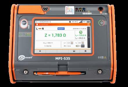
MPI-535 MPI-536 18
2.5 kV maximum RISO voltagemeasuring MPI-536 7” screentouch
» automatic calculation of fault current on the basis of nominal or measured voltage; differentiation of phase-to-neutral and phase-to-phase voltage,
» shape of the input leakage current selected by the user: sinusoidal (start from rising or falling edge), unidirectional pulsating (positive or negative), unidirectional pulsating with direct current offset (positive or negative), constant (positive or negative),
Fault loop impedance measurements:
» measurement of protective conductor continuity with current ≥200 mA in two directions,
» display range: 0.001/0.01/0.1 lx…399.9 klx,
» quick check of correct connection of PE conductor by means of contact electrode,
» automatic calibration of test leads - leads of any length can be used.
• MPI-535 | 50 V, 100 V, 250 V, 500 V, 1000 V,
» tree-like memory structure with dynamic management
» power supply from rechargeable battery, built-in quick charger, » capability of charging from the power grid or 12 V car lighter socket.
Standard accessories: MPI-536 MPI-535
Test lead 1.2 m, blue, 1 kV (banana plugs)
WAPRZ1X2BUBB 1 1
Test lead 1.8 m, red, 5 kV (banana plugs)
SONEL MPI-536 / MPI-535 index: WMGBMPI536 / WMGBMPI535
Test lead 15 m, blue (on a reel)
Crocodile clip, yellow, 1 kV, 20 A WAKROYE20K02 1 1
Mains cable with IEC C7 plug WAPRZLAD230 1 1
» measurement of tripping time tA with currents 0.5 I∆n, 1 I∆n, 2 I∆n and 5 I∆n,
Test lead 1.2 m, red, 1 kV (banana plugs)
USB cable
L2 carrying case WAFUTL2 1 1 L2 hanging straps (set) WAPOZSZEKPL 1 1
Testing of AC, A, F, B, B+ and EV residual current devices:
Soil resistivity measurements according to the Wenner method:
»
WAPRZ030REBBSZ 1 1
» fast fault loop impedance measurement with resolution up to 0.01 Ω in systems protected with RCDs not tripping at IΔn ≥ 30 mA,
• MPI-536 | AutoISO-2500
Test lead 30 m, red (banana plugs, on a reel)
»
» check of phase sequence and direction of motor rotation,
» detection of L and N phase swapping in a socket; does not affect measurements,
Other technical specifications:
»
» low-current measurement with sound signalling,
Additional functions of the meter:
»
• MPI-535 | AutoISO-1000C,
» replaceable microSD memory card,
» selection of installation protections and automatic evaluation of measurement results.
Insulation resistance measurement:
Crocodile clip, black, 11 kV, 32 A WAKROBL32K09 1
WASONYEOGB2 1
• MPI-535 | 5 GΩ,
» according to 3- or 4-lead technical method with 2 auxiliary electrodes, according to 3-lead method with additional clamp, according to double-clamp method, » internal power source with frequency appropriate for 50 Hz or 60 Hz power network.
» measuring range according to EN 61557-4: 0.12…400 Ω, max. resolution 0.01 Ω,
Crocodile clip, red, 1 kV, 20 A WAKRORE20K02 1 1
Earth contact test probe (rod), 30 cm
» measurement of tripping current IA with rising current,
» fault current-limiting resistor: 10 Ω,
WAPRZUSB 1 1
WASONREOGB1 1 1
• MPI-536 | 10 V, 50 V, 100 V, 250 V, 500 V, 1000 V, 1500 V, 2500 V, measurement of insulation resistance up to:
Z7 Power supply WAZASZ7 1 1
» measuring range: 0.5 Ωm…9.99 kΩm,
• MPI-536 | 10 GΩ, capability measurement in-socket by means of UNI-Schuko adapter, sound signalling of five-second time intervals, facilitating capture of time characteristics,
Test lead 1.2 m, yellow, 1 kV (banana plugs)
Pin probe, red 5 kV (banana socket)
Li-Ion battery 11.1 V 3.4 Ah WAAKU15 1 1 Factory calibration certificate 1 1
» power supply Li-Ion rechargeable battery 11.1 V 3.4 Ah 37.7 Wh

WAPRZ1X8BLBB 1
Earth resistance measurements:
10 mA 3.5…20.0 mA 0.1 mA 0.35 IΔn …2.0 IΔn ±10% IΔn 30 mA 10.5…42.0 mA 0.35 IΔn …1.4 IΔn 100 mA 35…140 mA 1 mA300 mA 105…420 mA 500 mA 175…700 mA
» MPI-536 | for U n = 1500 V: 1500 kΩ…5.00 GΩ
0.00…19.99 Ω 0.01 Ω ±(6% m.v. + 10 digits) 20.00…199.99 Ω 0.1 Ω ±(6% m.v. + 5 digits)200…1999 Ω 1 Ω
» MPI-536 | for U n = 10 V: 10 kΩ…99.9 MΩ
0.3 IΔn…1.0 IΔn ±5% IΔn
» Nominal voltage: 95…270 V
Earthing resistance measurement with two clamps
Display range Resolution Accuracy3p,4p Accuracy 3-lead with clamp 0.00…9.99 Ω 0.01 Ω ±(2% m.v. + 4 digits) ±(8% m.v. + 4 digits)10.0…99.9 Ω 0.1 Ω ±(2% m.v. + 3 digits)100…999 Ω 1 Ω 1.00…1.99 kΩ 0.01 kΩ “m.v.” = “measured value” The instrument meets the requirements set forth in the standards:
» EN 61010-1 (general and particular requirements related to safety)
Display range Resolution Accuracy
10 mA 2.0…20.0 mA 0.1 mA 0.2 IΔn …2.0 IΔn ±10% IΔn 30 mA 6…60 mA 1 mA 100 mA 20…200 mA 300 mA 60…600 mA 500 mA 100…1000 mA
Measuring range according to EN 61557-5: 0.50 Ω…1.99 kΩ for U = 50 V (3-lead, 4-lead):
Measurementcurrent Accuracy
» Nominal voltage: 95…270 V (for ZL-PE and ZL-N) or 95…440 V (for ZL-L - only mode 23/40 A). Frequency: 45…65 Hz.
» EN 61557 (requirements for measurement instruments)
Measurement of RCD trip current IA for residual direct current (type B)
Measurement of insulation resistance
» Frequency: 45…65 Hz
» EN 61010-031 (general and particular requirements related to safety)
30 mA 9.0…30.0 mA 100 mA 30…100 mA
» EN 12464 (lighting workplaces)
6 mA 1.0…6,0 mA 0.1 mA 1.0...6.0 mA ± 6% IΔn
» MPI-536 | for U n = 2500 V: 2500 kΩ…9.99 GΩ
» Measurement can be started from the positive or negative half-period of the input leakage current (AC)
» HD 60364-4-41 (performance of measurements - shock protection)
» for U n = 250 V: 250 kΩ…999 MΩ
» MPI-536 | for U n = 1000 V: 1000 kΩ…3.00 GΩ
Measurement with 15 mA current - measuring range according to EN 61557: 0.50…1999 Ω
» for U n = 500 V: 500 kΩ…2.00 GΩ
Measurement of fault loop impedance ZL-PE, ZL-N, ZL-L in 23/40 A mode Measurement with 23/40 A current - measuring range according to EN 61557: 0.130 …1999 Ω (for 1.2 m test lead):
0.00…9.99 Ω 0.01 Ω ±(10% m.v. + 4 digits)10.0…19.9 Ω 0.1 Ω 20.0…99.9 Ω ±(20% m.v. + 4 digits)
» for U n = 100 V: 100 kΩ…500 MΩ
1 mA 300 mA 90…300 mA 500 mA 150…500 mA 1000 mA 300…1000 mA
» Measurement can be started from the positive or negative half-period of the input leakage current (AC)
» MPI-535 | for U n = 1000 V: 1000 kΩ…4.99 GΩ
Nominal current Measuring range Resolution
Measurementcurrent Accuracy
19
» EN 61326 (electromagnetic compatibility)
Nominal current Measuring range Resolution
MPI-535 | 1.00…4.99 GΩ MPI-536 | 1.00…9.99 GΩ 0.01 GΩ digits)
» HD 60364-6 (performance of measurements - checking)
±(4% m.v. + 6
Display range Resolution Accuracy
Display range Resolution Accuracy 0.00…19.999 Ω 0.001 Ω ±(5% m.v. + 0.03 Ω) 20.00…199.99 Ω 0.01 Ω ±(5% m.v. + 0.3 Ω) 200.00…1999.9 Ω 0.1 Ω ±(5% m.v. + 3 Ω)
» Measurement is possible for positive or negative input leakage current
Indication of phase sequence » Indication of phase sequence: compliant, non-compliant, display of phase-tophase voltages » UL-L power system voltage range: 95…500 V (45…65 Hz) Measurements of RCD parameters (operating voltage range 95…270 V): RCD trip test and measurement of tripping time tA (for tA measurement function) RCD type Factor Range Resolution Accuracy • General • Short-time delay • AC module in EV type 0.5 IΔn 0…300 ms 1 ms ±(2% m.v. + 2 digits) for RCD of IΔn= 10 mA of the measurement with 0,5 IΔn accuracy: ±(2% m.v. + 3 digits) 1 IΔn2 IΔn 0…150 ms 5 IΔn 0…40 ms Selective 0.5 IΔn 0…500 ms 1 IΔn2 IΔn 0…200 ms 5 IΔn 0…150 ms • EV 6 mA DC • RCM 1 IΔn 0.0…10.0 s 0.1 s ±(2% m.v. + 3 digits)10 IΔn 0…300 ms 1 ms33 IΔn 0…100 ms 50 IΔn 0…40 ms » Residual current input accuracy: for 0.5 I∆n 8...0% for 1 I∆n, 2 I∆n, 5 I∆n 0...8%
» PN-E 04700 (performance of measurements - commissioning tests)
» I∆n - nominal value of residual current Measurement of RE earth resistance using 3-lead, 4-lead or 3-lead + clamp technical method
Measurementcurrent Accuracy
Nominal current Measuring range Resolution
Measurement of the ZL-PE fault loop impedance in the RCD mode
» for U n = 50 V: 50 kΩ…250 MΩ
Display range Resolution Accuracy 0…1999 kΩ 1 kΩ ±(3% m.v. + 8 digits) 2.00…19.99 MΩ 0.01 MΩ 20.0…199.9 MΩ 200…999 MΩ 1 MΩ
Measurement of RCD trip current IA for uni-directional residual current and uni-directional current with 6 mA direct current offset (type A)
Measuring range according to EN 61557-2:
Measurement of RCD trip current IA for sinusoidal residual current (AC type)
10 mA 3.0…10.0 mA 0.1 mA
» Quick check of correct connection of PE conductor by means of contact electrode,
» automatic calibration of test leads - leads of any length can be used.
Mini Bluetooth keyboard
» automatic calculation of fault current on the basis of nominal or measured voltage; differentiation of phase-to-neutral and phase-to-phase voltage,
Standard accessories:
WAPRZUSB
Factory calibration certificate
» power supply of the meter Ni-MH rechargeable battery LR14 alkaline batteries (4 pcs.) (optional)
Mains cable with IEC C7 plug WAPRZLAD230
» measurement in lux (lx) or foot-candles (fc),
Test lead 1.2 m, yellow, 1 kV (banana plugs) WAPRZ1X2YEBB
» shape of the input leakage current selected by the user: sinusoidal (start from rising or falling edge), unidirectional pulsating (positive or negative), unidirectional pulsating with direct current offset (positive or negative), constant (positive or negative),
Testing of AC, A, F, B and B+ residual current devices:
» according to 3- or 4-lead technical method with 2 auxiliary electrodes,

Crocodile clip, yellow, 1 kV, 20 A WAKROYE20K02
2x earth contact test probe (rod), 30 cm WASONG30
» automatic discharge of the measured object's capacitance after completion of measurement,
» display range: 0.001/0.01/1 lx…399.9 klx,
» Analysis and registration of single-phase network parameters (U, I, cosφ, P, PF, Q, S, Sn),

» low-current measurement with sound signaling,
Pin probe, yellow 1 kV (banana socket) WASONYEOGB1
» Power supply from rechargeable battery or batteries (optional), built-in quick charger,
Earth resistance measurements:
SONEL MPI-530 / MPI-530-IT index: WMGBMPI530 / WMGBMPI530IT
Other technical specifications:
Multi-function meter of electrical system parameters
» measurements using UNI-Schuko plug with measurement triggering button (including for swapped L and N leads) or 1.2 m, 5 m, 10 m or 20 m test leads, with optional use of three-phase socket adapters (AGT),
Crocodile clip, red, 1 kV, 20 A WAKRORE20K02
Soil resistivity measurements according to the Wenner method:
» Capability of charging from the power grid or 12 V car lighter socket,
Test lead 1.2 m, blue, 1 kV (banana plugs) WAPRZ1X2BUBB
Low-voltage continuity testing of protective conductors and equipotential bonding:
» according to double-clamp method,
» Check of phase sequence and direction of motor rotation,
» voltage measurements within the range of 95…270 V.
» measurement of general, short-time delay and selective RCDs with rated residual currents of 10, 30, 100, 300, 500 and 1000 mA,
Test lead 1.2 m, red, 1 kV (banana plugs) WAPRZ1X2REBB
» THD of voltage and current harmonics up to the 40th,
» range of measurement voltages: 95…440 V, frequencies 45…65 Hz,
Fault loop impedance measurements:
» Tree-structure memory with dynamic management (max. 10,000 entries for each type of measurement),
» measurement of tripping current IA with rising current,
» automatic measurement of all resistance combinations of 3-, 4- and 5-core cords by means of the optional AutoISO-1000C adapter
Pin probe, blue 1 kV (banana socket) WASONBUOGB1
» measuring range according to EN 61557-4: 0.12…400 Ω, max. resolution 0.01 Ω,
SONEL MPI MOBILE
» function of automatic measurement of all RCD parameters (after pressing the “START” button once, the meter performs the entire defined cycle of measurements, including the capability of earth fault loop impedance measurement with 15 mA current),
A mobile version of the program cooperating with a multifunctional Sonel instrument: MPI-530-IT / MPI-530 meters of electrical system parameters. It can be downloaded from Google Play
» MPI-530-IT also enables measurements in IT networks,


» fault loop impedance measurement with resolution up to 0.01 Ω in systems protected with RCDs not tripping at IΔn ≥ 30 mA,
» measurement of insulation resistance up to 10 GΩ,
L2 carrying case WAFUTL2
Pin probe, red 1 kV (banana socket) WASONREOGB1
Illuminance measurement:
WAADAMK
» capability of measuring tripping current IA as well as actual tripping time tAI with just one RCD trip,
» meter protected against the presence of voltage on the object and the appearance of voltage during measurement,
Cable for battery charging from car cigarette lighter socket (12 V) WAPRZLAD12SAM
Insulation resistance measurement:
» measurement voltages: 50 V, 100 V, 250 V, 500 V, 1000 V,

» impedance measurement with 23 A current (40 A for phase-to-phase voltage), max. resolution 0.001 Ω,
» Data transmission to PC via USB or Bluetooth®.
» measuring range: 0.5 Ωm…9.99 kΩm, » distances between electrodes can be set in meters (1…30 m) or feet (1…90 ft).
Z7 Power supply WAZASZ7
MPI-530-IT
» measurement of tripping time tA with currents 0.5 I∆n, 1 I∆n, 2 I∆n and 5 I∆n,
» voltage on open terminals: 4…9 V,
» type of insulation double, as per EN 61010-1 and EN 61557
» selection of installation protections and automatic evaluation of measurement results.
NiMH battery 4.8 V 4.2 Ah WAAKU07
USB cable
» measurement of protective conductor continuity with current ≥200 mA in two directions,
» according to 3-lead method with additional clamp,
Crocodile clip, blue, 1 kV, 20 A WAKROBU20K02
WS-03 adapter with START button with UNISCHUKO plug WAADAWS03
» capability measurement in-socket by means of UNI-Schuko adapter, » sound signaling of five-second time intervals, facilitating capture of time characteristics,
Test lead 15 m, blue (on a reel) WAPRZ015BUBBSZ
L2 hanging straps (set) WAPOZSZEKPL
» operating temperature range 0…+50°C
» measurement of touch voltage UB and protective conductor resistance RE without tripping the RCD,
» internal power source with frequency appropriate for 50 Hz or 60 Hz power network.
» measurement by means of external photodetectors (optional).
20
Test lead 30 m, red (banana plugs, on a reel) WAPRZ030REBBSZ
» fault current-limiting resistor: 10 Ω,
» detection of L and N phase swapping in a socket; does not affect measurements,
Additional functions of the meter:
10 mA 3.5…20.0 mA 0.1 mA 0.35 IΔn…2.0 IΔn ±10% IΔn 30 mA 10.5…42.0 mA 0.35 IΔn…1.4 IΔn 100 mA 35…140 mA 1 mA300 mA 105…420 mA 500 mA 175…700 mA
Display range Resolution Accuracy 0…1999 kΩ 1 kΩ ±(3% m.v. + 8 digits)
0.3 IΔn…1.0 IΔn ±5% IΔn 30 mA 9.0…30.0 mA 100 mA 33…100 mA 1 mA 300 mA 90…300 mA 500 mA 150…500 mA 1000 mA 330…1000 mA
» Residual current input accuracy: for 0.5 I∆n 8...0%, for 1 I∆n, 2 I∆n, 5 I∆n 0...8% Measurement of RCD trip current IA for sinusoidal residual current (AC type)
Measurements of RCD parameters (working voltage range 95…270 V): RCD trip test and measurement of tripping time tA (for tA measurement function)
300
The instrument meets the requirements set forth in the standards:
Measurement of insulation resistance
» Indication of phase sequence: compliant, non-compliant, display of phase-tophase voltages
Nominal current Measuring range Resolution Measurementcurrent Accuracy
» for Un = 250 V: 250 kΩ…99 MΩ
10 mA 2.0…20.0 mA 0.1 mA
Analysis and recording of single-phase system
General, shorttime delay selectiveand
» Nominal voltage: 95…270 V (for ZL-PE and ZL-N) or 95…440 V (for ZL-L - only mode 23/40 A). Frequency: 45…65 Hz.
MPI-530 / MPI-530-IT meters enable automatic insulation resistance measurement of 3-, 4- and 5-core cords with optional AutoISO-1000C adapter.
Display range Resolution 3-lead,Accuracy4-lead Accuracy 3-lead with clamp 0.00…9.99 Ω 0.01 Ω ±(2% m.v. + 4 digits) ±(8% m.v. + 4 digits)10.0…99.9 Ω 0.1 Ω ±(2% m.v. + 3 digits)100…999 Ω 1 Ω 1.00…1.99 kΩ 0.01 kΩ “m.v.” = “measured value”
» cosφ measurement: 0.00…1.00 (resolution 0.01).
» Measurement can be started from the positive or negative half-period of the input leakage current (AC)
» AC current measurement (True RMS) with clamp:
Nominal current Measuring range Resolution Measurementcurrent Accuracy
» Measurement of voltage UL-N: 0…500 V, power measurement P, Q, S: 0…1.5 M (W, var, VA).
Measurement of RCD trip current IA for uni-directional residual current and uni-directional current with 6mA direct current offset (type A)
» PN-E 04700 (performance of measurements - commissioning tests)
Measuring range according to EN 61557-2:
2 I1 IΔnΔn 0…150 ms 0…200 ms 5 IΔn 0…40 ms 0…150 ms
0.2 IΔn …2.0 IΔn ±10% IΔn 30 mA 6…60 mA 1 mA mA 20…200 mA mA 60…600 mA mA 100…1000 mA
100
» EN 12464 (lighting workplaces)
2.00…19.99 MΩ 0.01 MΩ 20.0…199.9 MΩ 200…999 MΩ 1 MΩ 1.00…9.99 GΩ 0.01 GΩ ±(4% m.v. + 6 digits)
» UL-L power system voltage range: 95…500 V (45…65 Hz)
» for Un = 500 V: 500 kΩ…2 GΩ
» for Un = 50 V: 50 kΩ…250 MΩ
» for Un = 100 V: 100 kΩ…500 MΩ
MPI-530 / MPI-530-IT meters enable measurement of the actual tripping time and trip current of an RCD with just one trip.
21
0.5 IΔn 0…300 ms 0…500 ms 1 ms ±(2% m.v. + 2 digits) (for RCD of IΔn= 10 mA and the measurement with 0.5 IΔn error: ±(2% m.v. + 3 digits)
» HD 60364-4-41 (performance of measurements - shock protection)
RCD type Factor (generalRangeandshort-timedelay) (selective)Range Resolution Accuracy
10 mA 3.3…10.0 mA 0.1 mA
» THD measurement relative to first harmonic (for U and I).
Nominal current Measuring range Resolution Measurementcurrent Accuracy
» EN 61326 (electromagnetic compatibility)
Clamp Display range Resolution Accuracy C-3, C-6 0.0…99.9 mA 0.1 mA ±(5% m.v. + 3 digits)100…999 mA 1 mA
Display range Resolution Accuracy 0.00…19.999 Ω 0.001 Ω ±(5% m.v. + 0.03 Ω) 20.00…199.99 Ω 0.01 Ω ±(5% m.v. + 0.3 Ω) 20.00…1999.9 Ω 0.1 Ω ±(5% m.v. + 3 Ω)
» HD 60364-6 (performance of measurements - checking)
MPI-530 / MPI-530-IT meters enable accurate measurement of fault loop impedance, including in L-PE loops in networks equipped with RCDs, as well as measurements in sockets with swapped L and N conductors.
Measurement of fault loop impedance ZL-PE, ZL-N, ZL-L in 23/40A mode Measurement with 23/40 A current - measuring range according to EN 61557: 0.130 …1999 Ω (for 1.2 m lead):
500
» EN 61557 (requirements for measurement instruments)
»
Measurement of RCD trip current IA for residual direct current (type B)
» EN 61010-1 (general and particular requirements related to safety)
» for Un = 1000 V: 1000 MΩ…9.99 GΩ
» Frequency measurement within range 45.0…65.0 Hz for voltages 50…500 V (Accuracy within a maximum of ±0.1% m.v. + 1 digit).
Measurement of the ZL-PE fault loop impedance in the RCD mode Measurement with 15 mA current - measuring range acc. to EN 61557: 0.50…1999 Ω
» Rated voltage: 95…270 V; frequency: 45…65 Hz
» EN 61010-031 (general and particular requirements related to safety)
C-3, C-6, F-2, F-3 1.00…9.99 A 0.01 A ±(5% m.v. + 5 digits) (C-3, C-6)10.0…99.9 A 0.1 A 100…999 A 1 A ±(0,1% In + 2 digits) (F-1, F-2, F-3)F-1, F-2, F-3 1.00…3.00 kA 0.01 kA
Illuminance measurement*
Earthing resistance measurement with two clamps
Indication of phase sequence
Display range Resolution Accuracy 0.00…9.99 Ω 0.01 Ω ±(10% m.v. + 4 digits)10.0…19.9 Ω 0.1 Ω 20.0…99.9 Ω ±(20% m.v. + 4 digits)
» Frequency range of measured voltages: 45…65 Hz.
» Measurement of current and voltage harmonics (up to the 40th).
Measuring range according to EN 61557-5: 0.50 Ω…1.99 kΩ for U = 50 V (3-lead, 4-lead):
Display range [lx] Resolution [lx] uncertaintySpectral Accuracy 0…3.999 0.001 f1 < 2% ±(2% + 5 digits) 4.00…39.99 0.01 40.0…399.9 0.1 400…3999 1 4.00 k…39.99 k 0.01 k 40.0 k…399.9 k 0.1 k *) for LP-10A measuring probe.
» Measurement is possible for positive or negative input leakage current I∆n - nominal value of residual current Measurement of RE earth resistance using 3-lead, 4-lead, or 3-lead + clamp technical method
» Measurement can be started from a positive or negative half-period of the input leakage current
Display range Resolution Accuracy 0.00…19.99 Ω 0.01 Ω ±(6% m.v. + 10 digits) 20.00…199.9 Ω 0.1 Ω ±(6% m.v. + 5 digits)200…1999 Ω 1 Ω
» meter protected against the presence of voltage on the object and the appearance of voltage during measurement,
» Power supply from rechargeable battery or battery (optional), builtin quick charger,
» measurement of general, short-time delay and selective RCDs with rated residual currents of 10, 30, 100, 300, 500 and 1000 mA,
Factory calibration certificate
NiMH battery 4.8 V 4.2 Ah WAAKU07
» low-current measurement with sound and light signaling,
» fault current-limiting resistor: 10 Ω,
» measurement of tripping time tA for currents: 0.5I∆n, 1 I∆n, 2I∆n and 5I∆n,
Pin probe, red 1 kV (banana socket) WASONREOGB1
Pin probe, blue 1 kV (banana socket) WASONBUOGB1
Crocodile clip, black, 11 kV, 32 A WAKROBL32K09
L2 hanging straps (set) WAPOZSZEKPL
Mains cable with IEC C7 plug WAPRZLAD230
Crocodile clip, yellow, 1 kV, 20 A WAKROYE20K02
» type of insulation double, as per EN 61010-1 and EN 61557
Test lead 1.2 m, blue, 1 kV (banana plugs) WAPRZ1X2BUBB
» range of measurement voltages: 95…440 V, frequencies 45…65 Hz,
Insulation resistance measurement:
» sound signaling of five-second time intervals, facilitating capture of time characteristics,
» automatic discharge of the measured object's capacitance after completion of measurement,
Standard accessories:
» automatic measurement of all resistance combinations of 3-, 4- and 5-core cords and power cords by means of the optional AutoISO-2500 adapter.
» measurement according to 3- or 4-lead technical method with 2 auxiliary electrodes, » internal power source with frequency appropriate for 50 Hz or 60 Hz power network (selected in the meter).
SONEL MPI-525
MPI-525 enables measurements in sockets with swapped L and N conductors.
2.5 kV maximum RISO voltagemeasuring
22
» measurement of tripping current IA with rising current,
WS-03 adapter with START button with UNISCHUKO plug WAADAWS03
Test lead 1.2 m, yellow, 1 kV (banana plugs) WAPRZ1X2YEBB
» measurement of touch voltage UB and protective conductor resistance RE without tripping the RCD,
Other technical specifications:
Test lead 30 m, red (banana plugs, on a reel) WAPRZ030REBBSZ
» impedance measurement with 23 A current (40 A for phase-to-phase voltage),
Z7 Power supply WAZASZ7
Low-voltage resistance measurement of protective conductors and equipotential bonding:
Additional functions of the meter:
» voltage measurements within the range of 95…270 V.
» automatic calibration of test leads - leads of any length can be used.
» timing of T1, T2, T3 within the range of 1…600 s,
Multi-function meter of electrical system parameters
» Memory storing up to 990 records (57,500 individual results), data transmission to PC via USB,
» operating temperature range 0…+50°C
» power supply of the meter
Test lead 1.8 m, black, 5 kV (banana plugs, shielded) WAPRZ1X8BLBB
Earth resistance measurements:
The MPI-525 meter is one of the few multifunction meters capable of measuring insulation resistance with 2500 V voltage.
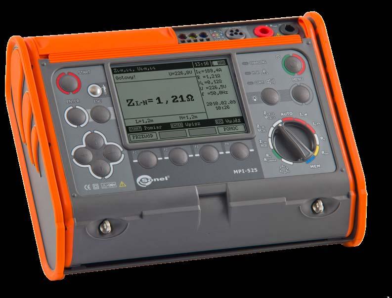
» Real-time clock (RTC) - time of measurement saved to memory.
L2 carrying case WAFUTL2
Pin probe, red 5 kV (banana socket) WASONREOGB2
» shape of the input leakage current selected by the user: sinusoidal (start from rising or falling edge), unidirectional pulsating (positive or negative), unidirectional pulsating with direct current offset (positive or negative), constant (positive or negative),
Test lead 1.2 m, red, 1 kV (banana plugs) WAPRZ1X2REBB
» measurement of protective conductor continuity with current ≥200 mA in two directions (according to standard EN 61557-4),
Pin probe, yellow 1 kV (banana socket) WASONYEOGB1
Fault loop impedance measurements:
» detection of L and N phase swapping in a socket; does not affect measurements, » capability of measuring tripping current IA as well as actual tripping time tA with just one RCD trip,
index: WMGBMPI525
» measurement of insulation resistance up to 10 GΩ,
Test lead 1.8 m, red, 5 kV (banana plugs) WAPRZ1X8REBB
» Check of phase sequence,
» function of automatic measurement of all RCD parameters (after pressing the “START” button once, the meter performs the entire defined cycle of measurements, including the capability of earth fault loop impedance measurement with 15 mA current),
» automatic fault current calculation; differentiation of phase and phase-to-phase voltage,
» Quick check of correct connection of PE conductor by means of contact electrode,
» measurement voltages: 50 V, 100 V, 250 V, 500 V, 1000 V and 2500 V,
2x earth contact test probe (rod), 30 cm WASONG30
» fault loop impedance measurement with resolution up to 0.01 Ω in systems protected with RCDs not tripping at IΔn ≥ 30 mA,
» measurements using UNI-Schuko plug with measurement triggering button (including for swapped L and N leads) or 1.2 m, 5 m, 10 m, 20 m test leads, with optional use of three-phase socket adapters (AGT).
» measurement of 2 absorption coefficients (DAR, PI or Ab1, Ab2)
Crocodile clip, black, 1 kV, 20 A WAKROBL20K01
USB cable WAPRZUSB
Testing of AC, A, F, B and B+ residual current devices:
Test lead 15 m, blue (on a reel) WAPRZ015BUBBSZ
Ni-MH battery or LR14 alkaline batteries (4 pcs. - optional)
RCD type Factor Range Resolution Accuracy
Nominal current Measuringrange Resolution Measurementcurrent Accuracy
» EN 61010-1 (general and particular requirements related to safety)
The instrument meets the requirements set forth in the standards:
**) no greater than the measuring range for a given voltage.
10 mA 2.0…20.0 mA 0.1 mA
The MPI-525 meter enables measurement of the actual tripping time and trip current of an RCD with just one trip.
±(3% m.v. + 8 digits)2.00…19.99 MΩ 0.01 kΩ 20.0…199.9 MΩ 0.1 kΩ 200…999 MΩ 1 kΩ 1.00…9.99 GΩ 0.01 GΩ ±(4% m.v. + 6 digits)
1 ms ±(2% m.v. + 2 digits) (for RCD of IΔn=10mA and the measurement 0.5 IΔn error: ±(2% m.v. + 3 digits)
Measurements of RCD parameters (working voltage range 95…270 V): RCD trip test and measurement of tripping time tA (for tA measurement function)
Nominal current Measuringrange Resolution Measurementcurrent Accuracy
0.3 IΔn…1.0 IΔn ±5% IΔn
Display range Resolution Accuracy 0.00…19.99 Ω 0.01 Ω ±(6% m.v. + 10 digits) 20.0…199.9 Ω 0.1 Ω ±(6% m.v. + 5 digits)200…1999 Ω 1 Ω
The MPI-525 meter is one of the few meters capable of accurately measuring fault loop impedance, including in L-PE loops, in networks equipped with residual current devices (measurement with 15 mA current).
» Measurement can be started from a positive or negative half-period of the input leakage current Measurement of RCD trip current IA for residual direct current (type B, B+)
Measurement of fault loop impedance ZL-PE, ZL-N, ZL-L
Indication of phase sequence
» Measurements for both current polarities
» EN 61010-031 (general and particular requirements related to safety)
Nominal current Measuringrange Resolution Measurementcurrent Accuracy
» Frequency: 45…65Hz
Measuring range according to EN 61557-2: for Un = 50 V: 50 kΩ…250 MΩ for Un = 500 V: 500 kΩ…2.00 GΩ for Un = 100 V: 100 kΩ…500 MΩ for Un = 1000 V: 1000 kΩ…3.00 GΩ for Un = 250 V: 250 kΩ…999 MΩ for Un = 2500 V: 2.50 MΩ…9.99 GΩ
The MPI-525 meter enables automatic insulation resistance measurement of cables and 3-, 4- and 5-core cords by means of the optional AutoISO-2500 adapter.
Measurement with 23 / 40 A current - measuring range according to EN 61557-3: 0.13…1999 Ω (for 1.2 m test lead):
Display range *) Resolution Accuracy 0…1999 kΩ 1 kΩ
0.2 IΔn …2.0 IΔn ±10% IΔn 30 mA 6…60 mA 1 mA 100 mA 20…200 mA 300 mA 60…600 mA 500 mA 100…1000 mA
Measurement of insulation resistance
2 I1 IΔnΔn 0…150 ms 5 IΔn 0…40 ms Selective 0.5 IΔn 0…500 ms
Measurement of RCD trip current IA for uni-directional residual current and uni-directional current with 6 mA direct current offset (type A, F)
» Rated voltage: 95…270 V
» Indication of phase sequence: compliant, non-compliant
General short-timeanddelay 0.5 IΔn 0…300 ms
» Residual current input accuracy: for 0.5 I∆n 8...0% for 1 I∆n, 2 I∆n, 5 I∆n 0...8%
Display range Resolution Accuracy 0.00…19.99 Ω 0.01 Ω ±(5% m.v. + 3 digits)20.0…199.9 Ω 0.1 Ω 200…1999 Ω 1 Ω
» PN-E 04700 (performance of measurements - commissioning tests)
Measurement of the ZL-PE fault loop impedance in the RCD mode
10 mA 3.5…20.0 mA 0.1 mA 0.35 IΔn …2.0 IΔn ±10% IΔn 30 mA 10.5…42.0 mA
Measurement with 15 mA current, measuring range according to EN 61557-3: 0.50…1999 Ω
» Frequency: 45…65 Hz
» Measurement can be started from the positive or negative half-period of the input leakage current (AC)
» Automatic calibration of test leads
10 mA 3.3…10.0 mA 0.1 mA
» Measurement is possible for both a positive or negative input leakage current » I∆n - nominal value of residual current “m.v.” = “measured value”
Display range Resolution Accuracy 0.00…9.99 Ω 0.01 Ω ±(2% m.v. + 4 digits) 10.0…99.9 Ω 0.1 Ω ±(2% m.v. + 3 digits)100…999 Ω 1 Ω 1.00…1.99 kΩ 0.01 kΩ
» HD 60364-4-41 (performance of measurements - shock protection)
» EN 61326 (electromagnetic compatibility)
Earth resistance RE measurement Measuring range according to EN 61557-5: 0.50 Ω…1.99 kΩ for 50 V measurement voltage 0.56 Ω…1.99 kΩ for 25 V measurement voltage
» Nominal voltage: 95…270V (for ZL-PE and ZL-N) or 95…440 V (for ZL-L)
Measurement of RCD trip current IA for sinusoidal residual current (AC type)
» voltage on open terminals: 4…9 V
» EN 61557 (requirements for measurement instruments)
» HD 60364-6 (performance of measurements - checking)
0.35 IΔn …1.4 IΔn 100 mA 35…140 mA 1 mA300 mA 105…420 mA 500 mA 175…700 mA
1 IΔn2 IΔn 0…200 ms 5 IΔn 0…150 ms
» UL-L power system voltage range: 95…500 V (45…65 Hz)
Display range Resolution Accuracy 0.00…19.99 Ω 0.01 Ω ±(2% m.v. + 3 digits)20.0…199.9 Ω 0.1 Ω 200…400 Ω 1 Ω
30 mA 9.0…30.0 mA 100 mA 30…100 mA 1 mA 300 mA 90…300 mA 500 mA 150…500 mA 1000 mA 300…1000 mA
» Output current at R<2 Ω: min. 200 mA
23
» Display of phase-to-phase voltage values
Low-voltage measurement of circuit continuity and resistance Testing of protective conductor continuity with ±200 mA current measuring range according to EN 61557-4: 0.12…400 Ω
» automatic fault current calculation; differentiation of phase and phase-to-phase voltage,
Other technical specifications:
» fault loop impedance measurement with resolution up to 0.01 Ω in systems protected with RCDs not tripping at IΔn≥ 30 mA,
Standard accessories:
Test probe with banana socket; 1 kV; red WASONREOGB1
Earth resistance measurements:
» internal power source with frequency appropriate for 50 Hz or 60 Hz power network (selected in the meter).
MPI-520
» impedance measurement with 23 A current (40 A for phase-to-phase voltage),
Fault loop impedance measurements:
» capability of in-socket measurement by means of UNI-Schuko adapter,
» measurement according to 3-lead technical method with 2 auxiliary electrodes,
» measurement of protective conductor continuity with current ≥200 mA in two directions (according to standard EN 61557-4),
Test lead with banana plugs; 1 kV; 1.2 m; red WAPRZ1X2REBB
WAPRZ030REBBSZ
» low-current measurement with sound signaling,
» type of insulation double, as per EN 61010-1 and EN 61557
» fault current-limiting resistor: 10 Ω,
Test lead with banana plugs; 1 kV; 1.2 m; yellow WAPRZ1X2YEBB
WAFUTL4
Test probe with banana socket; 1 kV; blue WASONBUOGB1
» detection of L and N phase swapping in a socket; does not affect measurements,
» automatic discharge of the measured object's capacitance after completion of measurement,
» automatic calibration of test leads - leads of any length can be used.
» measurements using UNI-Schuko plug with measurement triggering button (including for swapped L and N leads) or 1.2 m, 5 m, 10 m, 20 m test leads, with optional use of three-phase socket adapters (AGT).
» memory storing up to 990 records (57,500 individual results), data transmission to PC via USB,
» function of automatic measurement of all RCD parameters (after pressing the “START” button once, the meter performs the entire defined cycle of measurements, including the capability of earth fault loop impedance measurement with 15 mA current),
Red "crocodile" clip 1 kV 20 A WAKRORE20K02
SONEL MPI-520
WAPRZ015BUBBSZ
» operating temperature range 0…+50°C
WAPRZUSB 2x earth contact test probe (30 cm) (only MPI-520)
WAADAWS03
Earthing measurement test lead with banana plugs on reel; 30 m; red (only MPI-520)
» automatic measurement of all resistance combinations of 3-, 4- and 5-core cords by means of the optional AutoISO-1000C adapter.
» check of phase sequence.
Multi-function meter of electrical system parameters
Choose the best set for your needs
» measurement of touch voltage UB and protective conductor resistance RE without tripping the RCD,
Additional functions of the meters:
» capability of measuring tripping current IA as well as actual tripping time tA with just one RCD trip,
Yellow "crocodile" clip 1 kV 20 A WAKROYE20K02
» power supply of the meter alkaline batteries (4 pcs.) or Ni-MH rechargeable battery (optional)
» measurement of tripping time tA for currents: 0.5 IΔn, 1 IΔn, 2 IΔn and 5 IΔn,
» measurement of insulation resistance up to 3 GΩ,
Testing of AC, A, F, B and B+ residual current devices:
WAPOZSZEKPL
Low-voltage resistance measurement of protective conductors and equipotential bonding:
MPI-520 Start
Factory calibration certificate
WS-03 adapter for triggering measurement (UNI-Schuko plug)
» quick check of correct connection of PE conductor by means of contact electrode.
» shape of the input leakage current selected by the user: sinusoidal (start from rising or falling edge), unidirectional pulsating (positive or negative), unidirectional pulsating with direct current offset (positive or negative), constant (positive or negative),
» measurement of tripping current IA with rising current,
» measurement of general, short-time delay and selective RCDs with rated residual currents of 10, 30, 100, 300, 500 and 1000 mA,
Insulation resistance measurement:
» power supply from batteries or rechargeable batteries (optional), built-in quick charger.
» meter protected against the presence of voltage on the object and the appearance of voltage during measurement,
WAFUTL2
Earthing measurement test lead with banana plugs on reel; 15 m; blue (only MPI-520)
Multi-function meter of electrical system parameters without accessories for earth resistance measurement index: WMGBMPI520S
» range of measurement voltages: 95…440 V, frequencies 45…65 Hz,
» sound signaling of five-second time intervals, facilitating capture of time characteristics,
Test probe with banana socket; 1 kV; yellow WASONYEOGB1 Meter strap (type L-2)
WASONG30
» voltage measurements within the range of 95…270 V.
24
Test lead with banana plugs; 1 kV; 1.2 m; blue WAPRZ1X2BUBB
MPI-520 and MPI-520 Start enable measurements in sockets with swapped L and N conductors.
USB data transmission cable
» measurement voltages: 50 V, 100 V, 250 V, 500 V, 1000 V,
Battery container WAPOJ1
» measurement of voltage, frequency and - additionally with a clamp - alternating current, cosφ and power (active, reactive, apparent).
L-4 carrying case (only MPI-520 Start)
Multi-function meter of electrical system parameters index: WMGBMPI520
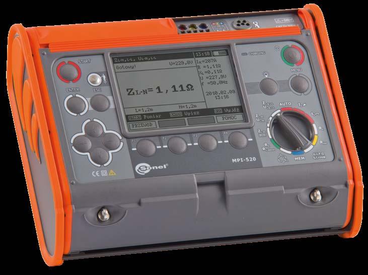
The MPI-520 and MPI-520 Start meters enable automatic insulation resistance measurement of 3-, 4- and 5-core cords with optional AutoISO1000C adapter.
L-2 carrying case (only MPI-520)
Display range Resolution Accuracy 0.00…19.99 Ω 0.01 Ω ±(6% m.v. + 10 digits) 20.0…199.9 Ω 0.1 Ω ±(6% m.v. + 5 digits)200…1999 Ω 1 Ω
Low-voltage measurement of circuit continuity and resistance
» Measurement is possible for both a positive or negative input leakage current » IΔn - nominal value of residual current “m.v.” = “measured value”
» EN 61010-1 (general and particular requirements related to safety)
» Measurement of voltage UL-N: 0…500 V
±(2% m.v. + 3 digits)20.0…199.9 Ω 0.1 Ω 200…400 Ω 1 Ω
0.00…19.99 Ω 0.01 Ω
Measurement of RCD trip current IA for sinusoidal residual current (AC type)
» Frequency measurement for voltages 50…500 V within the range of 45.0…65.0 Hz (Accuracy to a maximum of ± 0.1% m.v. + 1 digit)
Selective 0.5 IΔn 0…500 ms
10 mA 2.0…20.0 mA 0.1 mA
Display range * Resolution Accuracy 0…1999 kΩ 1 kΩ ±(3% m.v. + 8 digits)2.00…19.99 MΩ 0.01 MΩ 20.0…199.9 MΩ 0.1 MΩ 200…999 MΩ 1 MΩ 1.00…3.00 GΩ 0.01 GΩ ±(4% m.v. + 6 digits) **) no greater than the measuring range for a given voltage. **) an additional error of ±2% is present in measurements when the UNISchuko plug is used.
Measurement of RCD trip current IA for uni-directional residual current and uni-directional current with 6 mA direct current offset (type A, F)
» Rated voltage: 95…270 V
» Frequency: 45…65 Hz
Measurements of RCD parameters (working voltage range 95…270 V): RCD trip test and measurement of tripping time tA (for tA measurement function)
0.3 IΔn…1.0 IΔn ±5% IΔn
» Measurements for both current polarities Indication of phase sequence
0.2 IΔn …2.0 IΔn ±10% IΔn 30 mA 6…60 mA 1 mA 100 mA 20…200 mA 300 mA 60…600 mA 500 mA 100…1000 mA
Nominal current Measuringrange Resolution Measurementcurrent Accuracy
10 mA 3.5…20.0 mA 0.1 mA 0.35 IΔn …2.0 IΔn ±10% IΔn 30 mA 10.5…42.0 mA 0.35 IΔn …1.4 IΔn 100 mA 35…140 mA 1 mA300 mA 105…420 mA 500 mA 175…700 mA
30 mA 9.0…30.0 mA 100 mA 30…100 mA 1 mA 300 mA 90…300 mA 500 mA 150…500 mA 1000 mA 300…1000 mA
» Frequency range of measured voltages: 45.0…65.0 Hz
» HD 60364-6 (performance of measurements - checking)
» Voltage on open terminals: 4…9 V
Measuring range according to EN 61557-5: 0.50 Ω…1.99 kΩ for 50 V measurement voltage 0.56 Ω…1.99 kΩ for 25 V measurement voltage
Display range Resolution Accuracy 0.00…19.99 Ω 0.01 Ω ±(5% m.v. + 3 digits)20.0…199.9 Ω 0.1 Ω 200…1999 Ω 1 Ω
» Display of phase-to-phase voltage values Measurement of alternating voltage and current, cosφ and power
» EN 61010-031 (general and particular requirements related to safety)
» Output current at R<2 Ω: min. 200 mA
» Nominal voltage: 95…270 V (for ZL-PE and ZL-N) or 95…440 V (for ZL-L)
Display range Resolution Accuracy 0.00…9.99 Ω 0.01 Ω ±(2% m.v. + 4 digits) 10.0…99.9 Ω 0.1 Ω ±(2% m.v. + 3 digits)100…999 Ω 1 Ω 1.00…1.99 kΩ 0.01 kΩ
Measurement of insulation resistance
» UL-L power system voltage range: 95…500 V (45…65 Hz)
» HD 60364-4-41 (performance of measurements - shock protection)
The MPI-520 and MPI-520 Start meters are two of the few meters capable of accurately measuring fault loop impedance, including in L-PE loops, in networks equipped with residual current devices (measurement with 15 mA current).
The MPI-520 and MPI-520 Start meters enable measurement of the actual tripping time and trip current of an RCD with just one trip.
» Measurement can be started from the positive or negative half-period of the input leakage current (AC)
» Measurement can be started from a positive or negative half-period of the input leakage current
25
Nominal current Measuringrange Resolution Measurementcurrent Accuracy
Measurement of fault loop impedance ZL-PE, ZL-N, ZL-L
Display range Resolution Accuracy
» Power measurement P, Q, S: 0…200k (W, var, VA).
Testing of protective conductor continuity with ±200 mA current measuring range according to EN 61557-4: 0.12…400 Ω
1 IΔn2 IΔn 0…200 ms 5 IΔn 0…150 ms
» Residual current input accuracy: for 0.5 I∆n 8...0% for 1 I∆n, 2 I∆n, 5 I∆n 0...8%
The instrument meets the requirements set forth in the standards:
» EN 61326 (electromagnetic compatibility)
General short-timeanddelay 0.5 IΔn 0…300 ms 1 ms ±(2% m.v. + 2 digits) (for RCD of IΔn=10 mA and the measurement 0.5 IΔn error: ±(2% m.v. + 3 digits)
Earth resistance RE measurement
» Measurement of alternating current (True RMS) using clamp (0…400 A), max. resolution 0.1 mA
Measuring range according to EN 61557-2: for Un = 50 V: 50 kΩ…250 MΩ for Un = 500 V: 500 kΩ…2.00 GΩ for Un = 100 V: 100 kΩ…500 MΩ for Un = 1000 V: 1000 kΩ…3.00 GΩ for Un = 250 V: 250 kΩ…999 kΩ
» EN 61557 (requirements for measurement instruments)
» PN-E 04700 (performance of measurements - commissioning tests)
» Frequency: 45…65 Hz Measurement of the ZL-PE fault loop impedance in the RCD mode Measurement with 15 mA current, measuring range according to EN 61557-3: 0.50…1999 Ω
RCD type Factor Range Resolution Accuracy
» cosφ measurement: 0.00…1.00 (resolution 0.01)
Measurement of RCD trip current IA for residual direct current (type B, B+)
Measurement with 23/40 A current - measuring range according to EN 61557-3: 0.13…1999 Ω (for 1.2 m test lead):
10 mA 3.3…10.0 mA 0.1 mA
» Indication of phase sequence: compliant, non-compliant
2 I1 IΔnΔn 0…150 ms 5 IΔn 0…40 ms
Nominal current Measuringrange Resolution Measurementcurrent Accuracy
» Automatic calibration of test leads
» extended AUTO function of RCD measurement, with the possibility of measuring ZL-PE with low current,
WAPRZ015BUBBN
Multi-function meter of electrical system parameters
The instrument meets the requirements set forth in the standards:
WS-03 adapter with START button with UNI-Schuko plug (only MPI-506, MPI-507)
WAADAWS05
WAPRZ030REBBN
MPI-506 • MPI-507 | Phase sequence indication:
» measurement of IA trip current and tripping time tA for currents 0.5 I∆n, 1 I∆n, 2 I∆n, 5 I∆n,
» Power supply from LR6 batteries, NiMH rechargeable batteries can optionally be applied.
index: WMGBMPI507
MPI-507 | Earth resistance measurements:
Test probe with banana socket; 1 kV; yellow (only MPI-506, MPI-507)
Measurement of short circuit loop parameters:
» Backlit keyboard.
» Detection of L and N phase swapping in a socket and automatic unswapping.
2x earth contact test probe (rod), 25 cm (only MPI-507)
WASONG25
» EN 61010-031 (general and particular requirements related to safety)
» RE and UB measurement without RCD tripping,
26
Factory calibration certificate
» internal power source with frequency appropriate for 50 Hz or 60 Hz power network (selected in the meter).
Test lead with banana plugs; 1 kV; 1.2 m; red WAPRZ1X2REBB
Test probe with banana socket; 1 kV; red WASONREOGB1
» Memory storing up to 990 results, wireless data transmission to computer.
» measurements of short circuit loop impedance with 15 mA current, without tripping the RCD circuit breaker
Test lead with banana plugs; 1 kV; 1.2 m; blue WAPRZ1X2BUBB
» test voltage 100 V, 250 V, 500 V.
Test lead 30 m, red (banana plugs, on H-frame reel) (only MPI-507)
WASONYEOGB1
Standard accessories:
WAADAWS03
» indication of short circuit loop resistance R and short circuit loop reactance X
Testing RCD breakers of AC, A types:
Meter strap (type M-1) WAPOZSZE4
» EN 61326 (electromagnetic compatibility)
4x LR6 1,5 V battery
/ WMGBMPI506 / WMGBMPI502
WS-05 adapter (UNI-Schuko angle plug) (only MPI-502)
» Check of correct connection of PE conductor by means of contact electrode.
WAFUTM6
Red "crocodile" clip 1 kV 20 A (only MPI-506, MPI-507)
MPI-506 • MPI-507 | Insulation resistance measurement:
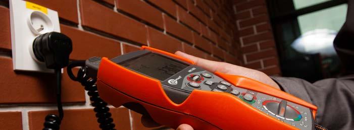
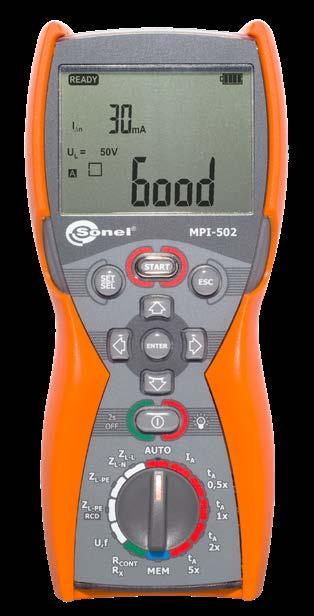
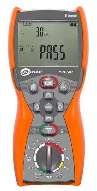

» autocalibration of test leads - any leads can be used,
» testing of prompt, short-delay and selective RCDs with rated current values : • 10 mA,

» maximum test current: 7.6 A (at 230 V), 13.3 A (at 400 V).

» Measurement of network voltage (0…500 V) and frequency.
M-1 housing holder - hanger WAPOZUCH1
WAKRORE20K02
» phase sequence indication: compliant, not compliant,
» HD 60364-4-41 (performance of measurements - shock protection)
» network voltage range: 100…440 V,
» measurement of short circuit loop impedance in networks with rated voltage: 220/380 V, 230 V/400 V, 240/415 V and frequency 45…65 Hz, operating voltage range: 180…460 V
Measurement of resistance of earth connection and equipotential bondings:
» displaying the values of phase-to-phase voltages.
M-6 carrying case
» PN-E 04700 (performance of measurements - commissioning tests)
» measurement of protective connections continuity with a ±200 mA current in accordance with EN 61557-4,
» HD 60364-6 (performance of measurements - checking)
Additional functions of the meter:
Test lead with banana plugs; 1 kV; 1.2 m; yellow WAPRZ1X2YEBB
» measurement according to 3-lead technical method with 2 auxiliary electrodes,
» EN 61010-1 (general and particular requirements related to safety)
» EN 61557 (requirements for measurement instruments)
Yellow "crocodile" clip 1 kV 20 A WAKROYE20K02
Test probe with banana socket; 1 kV; blue WASONBUOGB1
SONEL MPI-507 / MPI-506 / MPI-502
» low current resistance measurement with sound signaling.
Test lead 15 m, blue (banana plugs, on H-frame reel) (only MPI-507)
» measurement of IA and tA during one RCD tripping.
• MPI-506, MPI-507 | 15 mA, • 30, 100, 300, 500 mA,
» Measurements for both current polarities MPI-506 • MPI-507 | Indication of phase sequence
» Automatic calibration of test leads
MPI-506 • MPI-507 | Insulation resistance measurement Test range according to IEC 61557-2: UISO = 100 V: 100 kΩ...99.9 MΩ UISO = 250 V: 250 kΩ...199.9 MΩ UISO = 500 V: 500 kΩ...599.9 MΩ
Measurement of fault loop impedance ZL-PE, ZL-N, ZL-L Measurement with 7.6/13.3 A current - measuring range according to EN 61557-3: 0.13...1999 Ω:

Display range Resolution Accuracy 0,00...19,99 Ω 0,01 Ω ±(2% m.v. + 3 digits)20,0...199,9 Ω 0,1 Ω 200...400 Ω 1 Ω
Measuring range according to EN 61557-5: 0,63 Ω…1999 Ω for 50 V measurement voltage
» Voltage on open terminals: 4…20 V
» UL-L power system voltage range: 100...440 V (45...65 Hz)
Measurement of earth fault loop impedance ZL-PE in RCD mode
» Indication of phase sequence: compliant, non-compliant
RCD
Display range Resolution Accuracy 0,00...19,99 Ω 0,01 Ω ±(3% m.v. + 5 digits) 20,0...199,9 Ω 0,1 Ω ±5% m.v. 200...1999 Ω 1 Ω
Display range Resolution Accuracy 0.00...19.99 Ω 0.01 Ω ±(6% m.v. + 10 digits) 20.0...199.9 Ω 0.1 Ω ±(6% m.v. + 5 digits)200...1999 Ω 1 Ω
General type 0.5 IΔn 0...300 ms 1 ms ±(2% m.v. + 2 digits) 1 IΔn2 IΔn 0...150 ms 5 IΔn 0...40 ms Selective 0.5 IΔn 0...500 ms 1 IΔn2 IΔn 0...200 ms 5 IΔn 0...150 ms Measurement of RCD trip current IA for sinusoidal residual current Nominal current Measuring range Resolution Measurementcurrent Accuracy 10 mA 3.0...10.0 mA 0.1 mA 0.3 IΔn...1.0 IΔn ±5% IΔn 15 mA (MPI-506, MPI-507) 4.5...15.0 mA 30 mA 9.0...30.0 mA 100 mA 30...100 mA 1 mA300 mA 90...300 mA 500 mA 150...500 mA » Measurement can be started from the positive or negative half-period of the input current Measurement of RCD trip current IA for uni-directional pulsating residual current Nominal current Measuring range Resolution Measurementcurrent Accuracy 10 mA 3.5...20.0 mA 0.1 mA 0.35 IΔn...2.0 IΔn ±10% IΔn 15 mA (MPI-506, MPI-507) 5.3...21.0 mA 0.35 IΔn...1.4 IΔn30 mA 10.5...42.0 mA (MPI-506, MPI-507) 12.0...42.0 mA (MPI-502) 100 mA 35...140 mA 1 mA 300 mA 105...420 mA » Measurement for positive or negative half-periods of the input leakage current
MPI-507 | Earth resistance RE measurement
» Output current at R<2 Ω: min. 200 mA
» Display of phase-to-phase voltage values
27
Measurement with 15 mA current, measuring range according to EN 61557-3: 0.50...1999 Ω
Low-voltage measurement of circuit continuity and resistance Testing of protective conductor continuity with ±200 mA current measuring range according to EN 61557-4: 0,12...400 Ω
Display range Resolution Accuracy 0.00...19.99 Ω 0.01 Ω ±(5% m.v. + 3 digits)20.0...199.9 Ω 0.1 Ω 200...1999 Ω 1 Ω
Measurements of RCD parameters (operating voltage range 180…270 V): RCD trip test and measurement of tripping time tA (for tA measurement function) type Factor Range Resolution Accuracy
To facilitate diagnostics, one of the EVSE-01 sockets is provided with pulse width modula tion signal (PWM)
» type of insulation according to EN 61010-1 double
SONEL EVSE-01
»
» socket types measuring sockets L1, L2, L3, N, PE 1-phase socket CP signal socket - PWM communication test lead (length)
»
Works with*
» pollution degree 2
» ingress protection according to EN 60529 IP40

» measurement category according to EN 61010-1 CAT II 300 V

» input voltage 400 V (3-phase)
» frequency 50 Hz, 60 Hz
»
Application
Adapter allows to perform comprehensive measurements of electric vehicle charging sta tions - quickly and in accordance with applicable regulations. Simulating the charging cable (proximity pilot line - PP) and vehicle connection status (control pilot line - CP), it will bring the station into different operating states. This will enable measurements in the field of electric shock protection: ZS fault loop impedance, RISO insulation resistance and checking the parameters of RCD residual current devices.
The EVSE-01 adapter enables measurements of AC electric vehicle charging stations with type 2 connector. Tests for 1-phase and 3-phase stations are available - both with and with out ventilation.


» vehicle connection simulation CP state A vehicle not connected state B vehicle connected, not charging state C vehicle connected, charging without ventilation state D vehicle connected, charging with ventilation state E error - CP short to PE
»
Adapter for testing vehicle charging stations
index: WAADAEVSE01
»
Capabilities
» simulation of charging cable PP open circuit, 13 A, 20 A, 32 A, 63 A
MPI-540-PVMPI-540MPI-536MPI-535 MPI-530-ITMPI-530MPI-525MPI-520 MPI-506MPI-507 MPI-502 measurementsauto √ measurementthree-phaseautomaticviamultiplug √ visual inspection √ fault loop ZL-PE, ZL-Nmeasurementparameters √ √ √ √ 6 mA RCD test √ RCD test AC, A, F, B, B+, EV AC, A, F, B, B+ AC, A AC, A resistanceinsulationRISO measurement √ √ √ measurementsreport √ √ √ √ MPI-540-PVMPI-540MPI-536MPI-535 MPI-530-ITMPI-530MPI-525MPI-520 MPI-502MPI-506MPI-507

Standard accessories: Carrying case WAFUTM6
Functional comparison
Technical specifications
EVSE 1 m MPI 0.5 m operating temperature -5...+45°C storage temperature -20...+60°C dimensions 220 x 100 x 60 mm weight 1.4 kg the product meets EMC requirements acc. to standards EN 61326-1 and EN 61326-2-2
»
* the scope of measurements depends on the capabilities and technical parameters of each model. 28

index: WMGBMRP201
» memory of measurement results (990 cells, 10 000 entries),
» EN 61326 (electromagnetic compatibility)
» EN 61010-031 (general and particular requirements related to safety)
ratedSelectedRCDcurrent
»
= 50,0 Hz max. 14 710 ms RCD tripping current IA for the residual DC current Measurement range acc. to IEC 61557-6: (0.2…2)IΔn ratedSelectedRCDcurrent Range Resolution Measuring current Accuracy 10 mA 2.0…20.0 mA 0.1 mA 0.2 I∆n …2.0 I∆n ±10% I∆n 30 mA 6…60 mA 1 mA100 mA 20…200 mA 300 mA 60…600 mA » Measurement possible for positive or negative residual current » test current flow time at f=50,0 Hz max. 4500 ms. RCD Meter MRP-201 measures all kinds of RCDs (general, short delay, selective - type AC, A, B). MRP-201 has two kinds of automatic measurement mode, especially useful when measuring type A and B circuit breakers. 29
» start of the measurement from the positive or negative half sine period of the test current test current flow time at f
» simultaneous measurement of triggering current IA and trip time tA,
» measurement of RE and UB without RCD tripping,
» operating temperature -10…+50°C
0.5 I∆n 0…300 ms
double, as per EN 61010-1 and EN 61557
» checking the correctness of the connection of PE conductor,
» EN 61010-1 (general and particular requirements related to safety)
SONEL MRP-201
General or short delay
10 mA 3.0…10.0 mA 0.1 mA 0.3 I∆n …1.0 I∆n ±5% I∆n 30 mA 9.0…30.0 mA 100 mA 30…100 mA 1 mA300 mA 90…300 mA 500 mA 150…500 mA start of the measurement from the positive or negative half sine period of the test current » test current flow time at f = 50.0 Hz max. 7510 ms
Test lead 1.2 m, blue, 1 kV (banana plugs) WAPRZ1X2BUBB
The instrument meets the requirements set forth in the standards:
Range Resolution Measuring current Accuracy
Δ
Crocodile clip, yellow, 1 kV, 20 A WAKROYE20K02
»
» residual current setting accuracy: for 1 I∆n, 2 I∆n and 5 I∆n : 0…8%; for 0.5 I∆n: -8…0%, » operating voltage range: 180…270 V » operating frequency range: 45…65 Hz RCD tripping current IA for sine AC current Measurement range acc. to IEC 61557-6: (0.3…1.0)I n
10 mA 1.5…20.0 mA 0.1 mA 0.15 I∆n …2.0 I∆n ± 10% I∆n 30 mA 4.5…42.0 mA 0.15 I∆n …1.4 I∆n ± 10% I∆n 100 mA 15…140 mA 1 mA 300 mA 45…420 mA
WS-05 adapter with UNI-SCHUKO angular plug WAADAWS05 M6 carrying case WAFUTM6
Range Resolution Accuracy
RCD trigger test and response time measurement tA Measurement range according to IEC 61557: 0 ms…to the upper limit of the displayed value
» power supply alkaline batteries (AA, 4 pcs) or rechargeable batteries set (option)
» storage temperature -20…+70°C
Other technical specifications:
RCD type Rated multiplicationcurrentfactor
» weight 0.7 kg
» HD 60364-6 (performance of measurements - checking)
» testing of general, short delay and selective RCDs for the rated current values I∆n =10, 30, 100, 300, 500 mA,
Standard accessories:
Test lead 1.2 m, yellow, 1 kV (banana plugs) WAPRZ1X2YEBB
Pin probe, red 1 kV (banana socket) WASONREOGB1
Additional functions of the meter:
» measurement of AC voltage and frequency,
1 ms ±(2% m.v. + 2 digits) 1 I∆n 2 I∆n 0…150 ms 5 I∆n 0…40 ms
Test lead 1.2 m, red, 1 kV (banana plugs) WAPRZ1X2REBB
» AUTO RCD test function (automatic measurement of subsequent selected parameters without triggering),
Selective 0.5 I∆n 0…500 ms 1 I∆n 2 I∆n 0…200 ms 5 I∆n 0…150 ms
» PN-E 04700 (performance of measurements - commissioning tests)
» EN 61557 (requirements for measurement instruments)
ratedSelectedRCDcurrent
» type of insulation
» automatic measurement for all current shapes for RCDs of type AC, A and B.
» communication with PC using Bluetooth interface, » backlit keyboard.
Pin probe, blue 1 kV (banana socket) WASONBUOGB1 M1 hanging straps WAPOZSZE4 4x R6 Factorybatterycalibration certificate
» HD 60364-4-41 (performance of measurements - shock protection)
Range Resolution Measuringcurrent Accuracy
» measurement of triggering current IA and trip time tA for currents 0,5 I∆n, 1 I∆n, 2 I∆n, 5 I∆n,
Nominal operating conditions:
Testing RCD breakers of AC, A and B types:
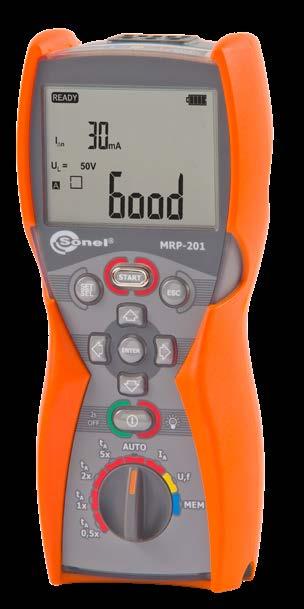
» dimensions 220 x 98 x 58 mm
Measurement range acc. to IEC 61557-6: (0.15…1,4)IΔn for IΔn>30 mA (0.15…2)IΔn for IΔn=10 mA
Measurement of RCD tripping current IA for unidirectional pulsed residual current and unidirectional pulsed current with a 6 mA DC offset
PVM-1020
» Automatic data synchronization with the PVM-1020 meter.
Features
Photovoltaic meters
PVM-1020: trouble? reSYNC!
» Large measurement memory: 999 cache memory cells and 5000 recorder records available (one-time recording) with the option of overwriting them (continuous recording).
IRM-1
PVM-1020
PVM-1020
» Short circuit current of a PV panel or chain of panels - up to 20 A DC.
Low-current resistance measurement, audible and visual signalling.
Measurement data from the PVM-1020 can be transferred to a computer via Bluetooth wireless communication. Saving the downloaded data to popular formats and printing ensured by Sonel Reader. In order to gen erate a report on electric shock protection use the optional software: Sonel Reports PLUS
Light meters perform well in harsh environmental conditions. Protection against the ingress of dust and water is provided by the housing rated at IP65. This is especially important for measurements on photovoltaic systems, which are outdoor installations.
» RMS voltage of the AC network up to 600 V with frequency measurement.
Solar radiation and temperature meter index: WMGBIRM1
PVM-1020
» Insulation resistance of PV panels - measuring voltage of 250, 500 or 1000 V, simultaneous measurement of two values: RISO+ and RISO-
» Measurement of solar radiation and temperature.
» The built-in LoRa radio interface ensures cooperation with the IRM-1 meter over long distances.

IRM-1
» Inclination angle of panels
PVM-1020: great capabilities in a small casing
» It converts measured parameters into STC conditions according to IEC 60891 by cooperation with the IRM-1 solar radiation and temperature meter.
Photovoltaic meter and solar radiation and temperature meter index: WMGBPVM1020KIT
SONEL PVM-1020 KIT / PVM-1020 / IRM-1
» Built-in recorder that can be used to record solar radiation before constructing PV systems, as well as to measure the shading of existing systems.
» Resistance of protective conductors and equipotential bonding with ± 200 mA current.
» Built-in Bluetooth module for communication with a computer.

Tightness and durability
Photovoltaic meter index: WMGBPVM1020
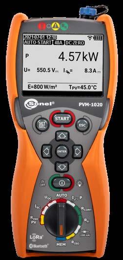

» Built-in compass and inclination sensor.
» Ambient temperature in °C or °F.
Measurement data from the IRM-1 can be transferred to a computer via the USB port. In addition, the device has a built-in wireless LoRa inter face (Long Range) for automatic data exchange with the PVM-1020 me ter - even over long distances.
PVM-1020 KIT
Choose the best set for your needs
» The open circuit voltage of the PV panel or a chain of panels, up to 1000V DC.
Measured parameters
» AC/DC power Measurement.
30
PVM-1020 meter is probably the world’s smallest photovoltaic system meter with such a substantial number of measurement functions. The functions are selected with a rotary switch. Additional parameters are set with buttons located on the housing. All buttons and the graphic display are backlit, which greatly facilitates operation in shaded places, e.g. when taking measurements under ground-mounted PV systems. Large memory significantly shortens preparation of documents after the measurement.
IRM-1, small, but indispensable for testing PV systems. By measuring solar radiation values, as well as panel and ambient temperatures, it provides the necessary data to convert the results into STC conditions. A built-in recorder with a memory of 5000 records enables the instru ment to be used as a tool in the PV plant design process, as well as to diagnose panel shading problems.
» AUTO mode for performing a sequence of measurements after one press of the START button.
» The LoRa interface for communication with the PVM-1020 meter - offers a larger range than the Bluetooth technology!

» Orientation of the panels with the built-in compass.
» Measurement of PV panels operating current and AC current - all with external clamp.
» Large measurement memory: 100 objects with 40 cells each.
IRM-1
» Solar radiation intensity (irradiance) in W/m2 or BTU/ft2h.
» reSYNC function – automatic completion of results with environmental parameters and their conversion to STC conditions after restoring connection with IRM-1.
» Insulation resistance of AC circuits - measuring voltage 250, 500 or 1000 V.
» PV panel temperature in °C or °F.
» Diode test with 200 mA current, automatic polarity detection. Test of blocking diodes with 1000V DC voltage.
IRM-1
IRM-1: simple and compact
It may happen that in the course of measurements the PVM-1020 moves away from the IRM-1 so far, that communication between them is lost. If the measurements are continued, then after the connection is restored, the results will be automatically supplemented with environmental pa rameters, which in the meantime were recorded by the IRM-1 in its tem porary memory, and converted into STC conditions.
» It can be used for category 1 measurements according to IEC 62446-1.


» Backlit display and buttons.
PVM-1020 KIT
Communication and software
√ √
DC voltage measurement
WAKROYE20K02 √
UISO = 250 V: 250 kΩ...2.000 GΩ
PVM-1020 KIT PVM-1020 IRM-1 WMGBPVM1020KIT WMGBPVM1020 WMGBIRM1
Low-voltage measurement of circuit continuity and resistance Testing of protective conductor continuity with ±200 mA current Measuring range according to EN 61557-4: 0.10...1999 Ω
IRM-1 mounting&measuring set
√ √
Measuring range: 100 W/m2…1400 W/m2, 32 BTU/ft2h…444 BTU/ft2h
WAPRZ1X2YEBB √ √
UISO = 1000 V: 500 kΩ...9.999 GΩ
UISO = 500 V: 250 kΩ...5.00 GΩ
Display range Resolution Accuracy 0.0…100.0 kW 0.1 kW ±(6% m.v. + 5 digits)
» Output current at R<2 Ω: min. 200 mA
» Measurements for both current polarities
Display range Resolution Accuracy 0.00…20.00 A 0.01 A ±(1% m.v. + 2 digits)
PV and ambient temperature measurement
WAKRORE20K02 √ √
√
Red "crocodile" clip kV 20 A Yellow "crocodile" clip kV 20 A
Active power measurement – AC and DC voltage
WAPRZ1X2BLBB
Short circuit current ISC measurement
1
Standard accessories:
Display range Resolution Accuracy -20.0…100.0°C 0.1°C ±(1% m.v. + 5 digits)-4.0…212.0°F 0.1°F
1
√ √
WAKROBL20K01 √ √
Factory calibration certificate - IRM-1
IRM-1 | Specifications
» Automatic calibration of test leads
L4 carrying case WAFUTL4 √
Meter strap (type M-1) WAPOZSZE4 √ √
Factory calibration certificate - PVM-1020
WASONTPVCKPL √
Inclination angle measurement
Test range according to IEC 61557-2:
m, red,
Test lead 1.2 1 kV (banana plugs)
√
Test lead 1.2 1 kV (banana plugs)
PVM-1020 photovoltaic meter
m, yellow,
Irradiance measurement
5 V power supply with USB 2.0 output and a detachable micro-USB cable WAZASZ24 √
Test lead 1.2 m, black, 1 kV (banana plugs)
Black "crocodile" clip kV 20 A
Test range according to IEC 61557-2:
MC4-banana sockets adapter (set of 2 pcs.)
M6 carrying case WAFUTM6 √
WAADAMC4 √ √
Insulation resistance measurement - PV module / PV installation
√ √
M14 carrying case WAFUTM14
Insulation resistance measurement

Display range Resolution Accuracy 0.0…600.0 V 0.1 V ±(2% m.v. + 6 digits)
WAPRZ1X2REBB √ √
UISO = 250 V / 500 V / 1000 V: 250 kΩ...1.000 GΩ
WACEGCPVOKR √ √
AC voltage measurement - True RMS
PVM-1020 | Specifications
Display range Resolution Accuracy -90…+90° 1° ±2°
» Voltage on open terminals: 4 V < UOC < 8 V
√
1
Display range Resolution Accuracy 0.00...19.99 Ω 0.01 Ω ±(2% m.v. + 3 digits)20.0...199.9 Ω 0.1 Ω 200...1999 Ω 1 Ω ±(4% m.v. + 3 digits)
IRM-1 solar radiation and temperature meter √
2x AAA 1.5 V battery
C-PV clamp
√ √
√
√ √ 31
WASONREOGB1 √ √
Determination of position direction - compass Display range Resolution Accuracy 0…360° 1° ±5°
Test probe with banana socket; 1 kV; red
√
4x AA 1.5 V battery
Display range Resolution Accuracy 0…1400 W/m2 1 W/m2 ±(0.5% m.v. + 2 digits)0…444 BTU/ft2h 1 BTU/ft2h
Display range Resolution Accuracy 0.0…1000.0 V 0.1 V ±(0.5% m.v. + 2 digits)
WAADAAGT32T
SolarMPI-540-PV
• • • • • • • • • • • • • • • • •
Set of standard and optional accessories
AutoISO-1000C adapter
adapter WAADAAISO25 • • EVSE-01 adapter WAADAEVSE01 • • • • • • • • • • • • • • PVM-1 adapter WAADAPVM1 1 1 1 IRM-1 mounting&measuring set (solar radiation meter mounting kit for PV panels + probe for measuring the temperature of PV panels and the ambient temperature) WASONTPVCKPL • • • 1 1 Solar radiation measurement set (IRM-1 solar radiation and temperature meter + IRM-1 mounting&measuring set + Z24 power supply + LORA-S1 adapter for data transmission + M14 carrying case) WMGBIRM1MPI 1 • • TWR-1J - RCD breaker testing adapter WAADATWR1J • • • • • • • • • • • • • • • WS-01 adapter with START button with UNI-Schuko plug WAADAWS01 • • WS-03 adapter with START button with UNI-Schuko plug WAADAWS03 1 1 1 1 1 1 1 1 1 1 1 1 1 WS-04 adapter with UNI-Schuko plug WAADAWS04 • • • • • • • • • • • • • WS-05 adapter with UNI-Schuko plug WAADAWS05 1 1 WS-06 adapter (miniDIN-4P plug) WAADAWS06 • • • • • • • • 32


• • • • • • • • • • • • • • • • •
• • • • • • • • •
•
AGT-16C three-phase socket adapter 16 A WAADAAGT16C


WAADAAISO10C
• • • • • • • • • • • • • • • • •
AGT-32P three-phase socket adapter 32 A

StartMPI-540-PV MPI-540 StartMPI-540 MPI-536 MPI-535 MPI-530/530-IT MPI-525 MPI-520 StartMPI-520 MPI-507 MPI-506 MPI-502 MRP-201 KITPVM-1020 PVM-1020 IRM-1
1, 2, 4 - number of standard accessories - optional accessories
WMGBPVM1020 1 1 •
• • • • • • • • • • • • • • • • •
AutoISO-2500
MPI / MRP / PVM
AC-16 line splitter


AGT-63P three-phase socket adapter 63 A
• • • • • • • • • •
WAADAAGT16T
• • • • • • • • • • • • • • • • •
• • •
MPI-540-PV
AGT-32T industrial socket adapter 32 A
WAADAAGT63P
AGT-16P three-phase socket adapter 16 A WAADAAGT16P

AGT-16T industrial socket adapter 16 A
AGT-32C three-phase socket adapter 32 A WAADAAGT32C


WAADAAGT32P • • • • • • • • • • • • • • • • •
• • • • • • • • • • • • • • • • •
IRM-1 solar radiation and temperature meter


WAADAAC16
Photo Name Index
WMGBIRM1 1 • 1
PVM-1020 photovoltaic meter
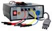

Crocodile clip, yellow, 1 kV, 20 A


C-PV clamp
•
WACEGN1BB
Crocodile clip, red, 1 kV, 20 A


Test lead 1.2 m, black, 1 kV (banana plugs)

• • • • • •
MC4 splitter for power measurement in PV systems - set of 2 pcs.


WS-09 adapter (pin probe)

MPI-540-PV
Voltage adapters with M4/M6 thread (set of 4 pcs.)
Set of standard and optional accessories
Double-wire test lead 2 m, for N-1 clamps (banana plugs)


C-5A current clamp (Ø39 mm)
• • • • •
MPI / MRP / PVM
F-2A flexible coil (Ø235 mm)
WAKROBL20K01 1 1 1 1 1 1 1 1
Test lead 1.2 m, black, 1 kV with markers (banana plugs) WAPRZ1X2BLBBN 1 1 1 1 1


F-3A flexible coil (Ø120 mm)
WAADAMC4 1 1 1 1 1
WACEGC6AOKR
• • • • • • • • • •
WAPRZ002DZBB
• • • • • •
WACEGC4AOKR
WAADAWS09
C-3 current clamp (Ø52 mm)
Photo Name Index
WAKROYE20K02 1 1 1 1 1 1 1 1 1 1 1 1 1 1 1 1 1
Crocodile clip, black, 1 kV, 20 A


F-1A flexible coil (Ø360 mm)
• • • • • • •
• • • • •
WAPRZ1X2BLBB 1 1
• • • • •
WAADACPV 1 1 1
Crocodile clip, black, 11 kV, 32 A WAKROBL32K09 1 1

SolarMPI-540-PV
• • • • •
WACEGC7AOKR
N-1 transmitting clamp (Ø52 mm)
• • • • • • • •
33
Crocodile clip, blue, 1 kV, 20 A WAKROBU20K02 1 1 1 1 1 1 1 1

WACEGF1AOKR
• •
• • • • • • •
WACEGC5AOKR
WACEGC3OKR
1, 2, 4 - number of standard accessories • - optional accessories
• • • • • •
C-4A current clamp (Ø52 mm)
WAKRORE20K02 1 1 1 1 1 1 1 1 • 1 1 1 1 • • 1 1
• • • • • • • •
WACEGF2AOKR
C-7A current clamp (Ø24 mm)
StartMPI-540-PV MPI-540 StartMPI-540 MPI-536 MPI-535 MPI-530/530-IT MPI-525 MPI-520 StartMPI-520 MPI-507 MPI-506 MPI-502 MRP-201 KITPVM-1020 PVM-1020 IRM-1
WAADAMC4SKPL
WACEGCPVOKR 1 1 1 1 1
MC4-banana sockets adapter (set od 2 pcs.)
Adapter for C-PV clamp
WACEGF3AOKR 3 3 3
WAADAM4M64 1 1 1 1 1
• •
Crocodile clip, red, 11 kV, 32 A WAKRORE32K09
C-6A current clamp (Ø20 mm)
WAADALP10AKPL • • • • • • • •
WAPRZ025REBBSZ
Test lead 25 m, red (banana plugs, on a reel)
Test lead 15 m, blue (on a reel)

• • • • • • • •
WAPRZ1X8REBB 1 1
MPI / MRP / PVM
• • • • • • • • • • • •
Test lead 25 m, blue (banana plugs, on a reel)
• • • • • • • • • • • •
PRS-1 resistance test probe
SolarMPI-540-PV MPI-540-PV StartMPI-540-PV MPI-540 StartMPI-540 MPI-536 MPI-535 MPI-530/530-IT MPI-525 MPI-520 StartMPI-520 MPI-507 MPI-506 MPI-502 MRP-201 KITPVM-1020 PVM-1020 IRM-1


Photo Name Index
Foldable pin probe, 1 kV, 2 m (banana socket)
WAPRZ1X2REBB 1 1 1 1 1 1 1 1 1 1 1 1 1 1 1 1 1
• • 34
Test lead 1.2 m, yellow, 1 kV (banana plugs)

WASONSP2M
• • • • • • • • • • • • • • •
• • • • • • • • • • • • • • •
Test lead 30 m, red, 1 kV (banana plugs)


WAPRZ1X8BLBB 1 1
Test lead 50 m, yellow (banana plugs, on a reel)
LP-10A light meter probe for MPI (set, WS-06 plug)
Set of standard and optional accessories

• • • • • • • • LP-1
WAPRZ005REBB
Test lead 1.2 m, red, 1 kV (banana plugs)
LP-10A light meter probe (miniDIN-4P plug)
WAPRZ020REBB
WAPRZ025BUBBSZ
• • • • • • • • • • • • • • •
Pin probe, black 1 kV (banana socket)
WAADALP10B
WAADALP1 light meter probe for MPI (set, WS-06 plug)


Test lead 15 m, blue, 1 kV (banana plugs)

• • • • • • • • • • •
LP-10B light meter probe (miniDIN-4P plug)
WAPRZ030REBBN 1
WAADALP10BKPL • • • • • • • •
WAPRZ1X2BUBB 1 1 1 1 1 1 1 1 1 1 1 1 1 1 1
LP-10B light meter probe (set, WS-06 plug)


WAPRZ1X2YEBB 1 1 1 1 1 1 1 1 1 1 1 1 1 1 1 1 1
Test lead 10 m, red, 1 kV (banana plugs)
WAPRZ050YEBBSZ
Test lead 30 m, red (banana plugs, on a reel)
• • • • • • • • • • • •
WAADALP1KPL • • • • • • • •
WAPRZ010REBB
Test lead 1.8 m, red, 5 kV (banana plugs)
Test lead 5 m, red, 1 kV (banana plugs)
• •
WAPRZ015BUBBSZ 1 1 1 1 1 1 1 1 1 1
Test lead 20 m red 1 kV (banana plugs)


WASONBLOGB1
• •
Test lead 1.8 m, black, 5 kV (banana plugs, shielded)
Test lead 1.2 m, blue, 1 kV (banana plugs)

WAPRZ030REBBSZ 1 1 1 1 1 1 1 1 1 1
WAPRZ015BUBBN 1
• • • • • • • • • • • • • • •
1, 2, 4 - number of standard accessories • - optional accessories
LP-1 light meter probe (miniDIN-4P plug)
WASONPRS1GB
WAADALP10A
• • • • • • • •
for measuring the temperature of PV panels and the ambient temperature WASONTPVC • • • • •

Earth contact test probe (rod), 25 cm WASONG25 2


1,
•
Pin probe, black 5 kV (banana socket)


Earth contact test probe (rod), 30 cm WASONG30 2 2 2 2 2


WASONBUOGB1 1 1 1 1 1 1 1 1 1 1 1 1 1 1 •
• •
MPI / MRP / PVM
Pin probe, red 5 kV (banana socket)
2 2 2 2 2 • •
•
contact test probe (rod), 80 cm WASONG80V2 • • • • • • • • • • • • Cramp (banana socket) WAZACIMA1 • • • • • • • • • • • • CS-1 cable simulator WAADACS1 • • • • • • • • • • • CS-5kV calibration box WAADACS5KV • • NiMH battery 4.8 V 4.2 Ah WAAKU07 1 1 • • Li-Ion battery 11.1 V 3.4 Ah WAAKU15 1 1 1 1 1 1 1 Battery container WAPOJ1 • • 1 1 Z7 power supply WAZASZ7 1 1 1 1 1 1 1 1 1 • • Z24 5 V power supply with USB 2.0 output and a detachable micro-USB cable WAZASZ24 1 1 Mains cable with IEC C7 plug WAPRZLAD230 1 1 1 1 1 1 1 1 1 • • MPI charging set (charger + battery) WAKPLLADMPI520 • • • • AZ-2 power supply adapter (IEC C7 plug/banana connectors) WAADAAZ2 • • • • • • • Cable for battery charging from car cigarette lighter socket (12 V) WAPRZLAD12SAM 1 1 1 1 1 1 1 1 • • • Test wire reel WAPOZSZP1 • • • • • • • • • • • L2 hanging straps (set) WAPOZSZEKPL 1 1 1 1 1 1 1 1 1 1 1 M1 hanging straps WAPOZSZE4 1 1 1 1 1 1 35
WASONBLOGB2
optional
Photo Name Index
Pin probe, red 1 kV (banana socket)

Pin probe, blue 1 kV (banana socket)
Set of standard and accessories 2, 4 - number of standard accessories - accessories


WASONREOGB1 1 1 1 1 1 1 1 1 1 1 1 1 1 1 1 1 1
WASONYEOGB1 1 1 1 1 1 1 1 1 1 1 1 1
SolarMPI-540-PV MPI-540-PV StartMPI-540-PV MPI-540 StartMPI-540 MPI-536 MPI-535 MPI-530/530-IT MPI-525 MPI-520 StartMPI-520 MPI-507 MPI-506 MPI-502 MRP-201 KITPVM-1020 PVM-1020 IRM-1

Pin probe, yellow 1 kV (banana socket)

• • • •
Earth
optional
Probe
WASONREOGB2 1 1
SONEL MPI MOBILE


A mobile version of the program cooperating with a multifunctional Sonel instrument: MPI-530-IT / MPI-530 meters of electrical system parameters. It can be downloaded from Google Play With the application you can connect directly to the device via Bluetooth and down load the measurement data from the meter. After reading the measurements from the instrument, they can be easily and quickly viewed, but also sent from the meas urement place to a person who can help interpret the data or perform a measure ments documentation. To each measurement we can add, voice memo, note, GPS data, or photo. From the application level we also have access to the meter's user manual 36
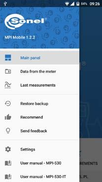

MPI / MRP / PVM Set of standard and optional accessories 1, 2, 4 - number of standard accessories • - optional accessories Photo Name Index


SolarMPI-540-PV
MPI-540-PV StartMPI-540-PV MPI-540 StartMPI-540 MPI-536 MPI-535 MPI-530/530-IT MPI-525 MPI-520 StartMPI-520 MPI-507 MPI-506 MPI-502 MRP-201 KITPVM-1020 PVM-1020 IRM-1 M1 hanging hook straps WAPOZUCH1 1 1 1 • • • Solar radiation meter mounting kit for PV panels WAPOZUCHPV • • • 1 1 Clamp for mounting the solar radiation meter to the solar panels WAZACPV • • • • • L2 carrying case WAFUTL2 1 1 1 1 1 1 1 1 1 1 • L3 carrying case for a 80 cm rods WAFUTL3 • • • • • • • • • • • • L4 carrying case WAFUTL4 • 1 1 M6 carrying case WAFUTM6 1 1 1 1 1 M13 carrying case WAFUTM13 1 1 1 M14 carrying case WAFUTM14 1 XL12 hard carrying case WAWALXL12 • • • • • • • XL13 hard carrying case WAWALXL13 • Mini Bluetooth keyboard WAADAMK 1 S4 armband case for mini Bluetooth keyboard WAFUTS4 • Mini Bluetooth keyboard with S-4 armband case WAADAMKZ • USB cable WAPRZUSB 1 1 1 1 1 1 1 1 1 1 1 LORA-S1 USB adapter for data transmission WAADAUSBLORA • • • OR-1 USB wireless receiver WAADAUSBOR1 • • • 1 PC software: Sonel Reports PLUS WAPROREPORTSPLUS • • • • • • • • • • • • • • • • • PC software: Sonel Reader WAPROREADER 1 1 1 1 1 1 • • • • • • • • • • •


MIC-5001MIC-5005MIC-5010 MIC-5 MIC-10MIC-30 MIC-2501MIC-2511MIC-15k1MIC-10k1MIC-5050 Insulation resistance meters
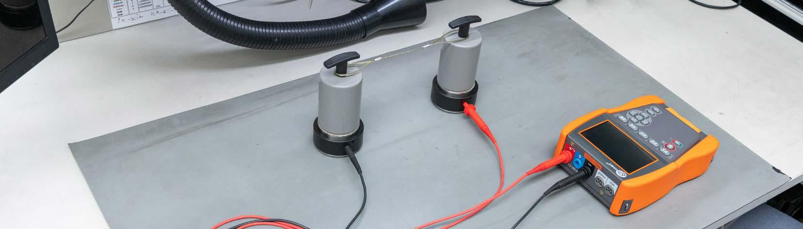

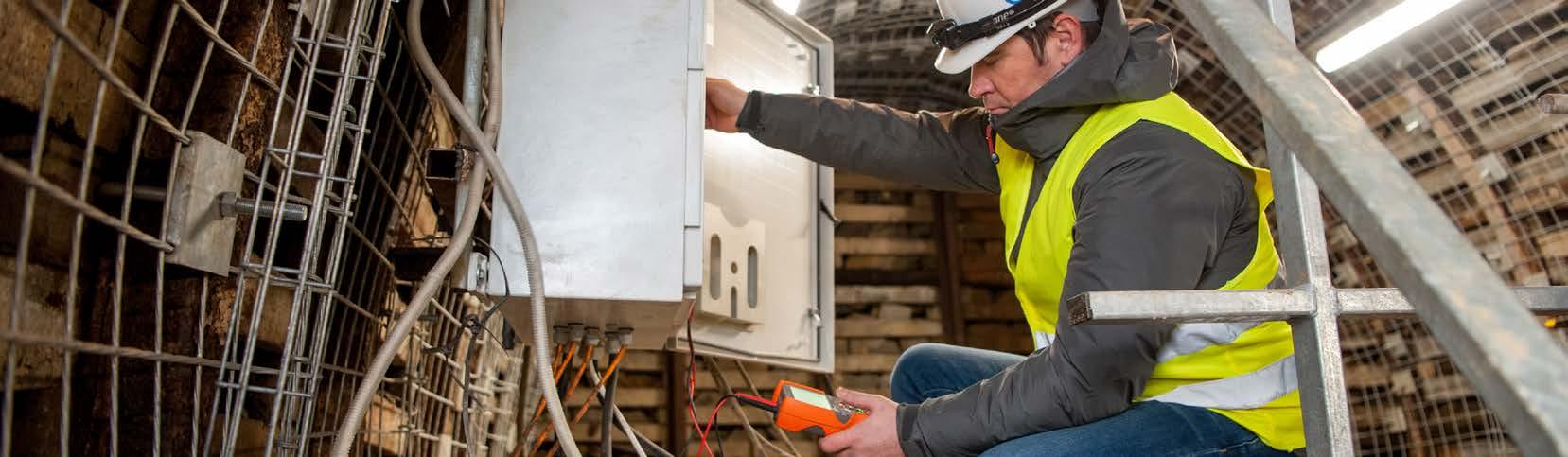
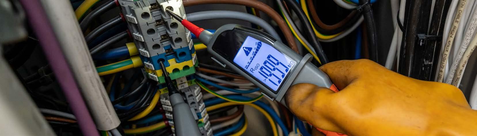
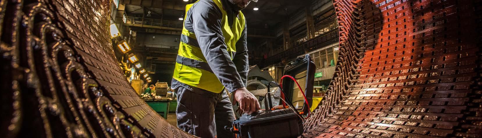
Automatic measurement of 3-, of AutoISO measurement

Low-voltage resistance measurement test with


and leakage current


Measurement of insulation resistance using the three-terminal method
current ≥200mA (resolution 0.01Ω) √ √ √
√ √ √ √ √ √ √ √
Automatic discharging of object after measurement Built-in quick charger
√ √ √ √ √ √ √ √
Power supply
rechargeable battery rechargeable battery rechargeable battery rechargeable battery rechargeable battery rechargeable battery rechargeable battery rechargeable battery
√ √ √ √ √ √ √ √
√ √ √ √ √ √ √ √
4- and 5-core cords by means
adapters AutoISO-5000 AutoISO-5000 AutoISO-2511 Voltage measurement 0…600 V 0…750 V 0…750 V 0…600 V 0…600 V 0…750 V 0…1500 V 0…750 V Temperature

Plotting of insulation resistance characteristics in-socket measurement Capacitance measurement (number of records) [mm] [kg] calculation of Ab1,
autosave990 10 000 10 000 990 990 990 9999 990 Data transmission USB, Bluetooth USB, Bluetooth USB, Bluetooth USB, Bluetooth USB, Bluetooth USB USB, Bluetooth USB Dimensions
390 x 308 x 172 390 x 308 x 172 390 x 308 x 172 390 x 308 x 172 390 x 308 x 172 200 x 180 x 77 234 x 169 x 70 200 x 180 x 77 Weight
Measurement of 2 absorption coefficients
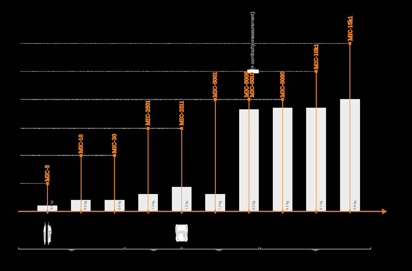
in mobile application √ √ in mobile application in mobile application √ √ √ Automatic
√ √ √
6.6 6.1 6.1 6.0 6.0 1.0 1.3 1.0 * - for
Ab2, PI, DAR 38
Measurement of leakage current during insulation resistance measurement

√ √ √ √ √ √ √ √
√ Continuity
√ √ √ √ √ √ Memory
Comparison of insulation resistance meters MIC-15k1 MIC-10k1 MIC-5050 MIC-5010 MIC-5005 MIC-5001 MIC-2511 MIC-2501 Measurement voltage [V] 50…15 000 50…10 000 50…5000 50…5000 50…5000 50…5000 50…2500 100…2500 Measuring range 50 kΩ…40 TΩ 10 kΩ…40 TΩ 20 kΩ…20 TΩ 20 kΩ…15 TΩ 20 kΩ…15 TΩ 50 kΩ…5 TΩ 50 kΩ...2 TΩ 50 kΩ…2 TΩ Short-circuit current ISC 1.2 / 3 / 5 / 7 mA 1.2 / 3 / 6 mA 1.2 / 3 / 6 mA 1.2 / 3 mA 1.2 / 3 mA 1.5 mA <2 mA 1 mA Setting of 3 measurement times * 1…600 s 1…600 s 1…600 s 1…600 s 1…600 s 1…600 s 1…600 s 1…600 s Maximum setting of measurement time 99'59'’ 99'59'’ 99'59'’ 99'59'’ 99'59'’ 10' 60' 10'
» insulation measurement of 3- , 4- and 5-wire cables and wires using test voltage up to 2.5 kV optional for MPI-536, MPI-525
AutoISO-2500 AutoISO-2500
Maximum setting of measurement time
Continuity test with current ≥200mA (resolution 0.01Ω)
Automatic measurement of 3-, by means of AutoISO L-7 carrying case optional for MIC-2511 set: PRS-1 + PRS-2 KIT optional for MIC-2511
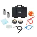

√
Built-in quick charger
»
»
index: WAADAAISO50
Setting of 3 measurement times *
»
SONEL AutoISO-5000
Adapter for measuring insulation resistance Insulation measurements:resistance


Low-voltage resistance measurement

√ √ √ √ √ √ √ √ √
Measurement of 2 absorption coefficients
Measurement of leakage current during insulation resistance measurement


adapters 0…600 V 0…600 V 0…600 V 0…500 V 0…500 V 0…500 V 0…500 V 0…500 V 0…500 V Voltage Temperaturemeasurementmeasurement √ Plotting of insulation resistance and leakage current characteristics √ √ √ √ √ Automatic in-socket measurement √ √ Capacitance measurement 990 UNLIMITED UNLIMITED 10 000 990 990 990 Memory (number of records) Bluetooth USB, Bluetooth USB, Bluetooth USB, Bluetooth USB, Bluetooth USB, Bluetooth USB, Bluetooth Data transmission 200 x 150 x 60 220 x 100 x 60 275 x 82 x 36 288 x 223 x 75 288 x 223 x 75 295 x 223 x 75 288 x 223 x 75 288 x 223 x 75 220 x 98 x 58 mm Dimensions [mm] 0.6 0.6 0.3 2.5 2.5 2.2 2.2 2.2 0,8 Weight [kg] In addition to specific meters you can also purchase: SONEL PRS-1 SONEL PRS-2 / PRS-2 KIT SONEL PRZ-2 index: WASONPRS1GB index: WASONPRS2 / WASONPRS2KIT index: WASONPRZ2 Probe for measurement of floor and wall resistances Probe for measuring resistance in zones with ESD protection Set for measuring resistance in zones with ESD protection » Sonel PRS-1 tripod measuring probe, with the shape of an equilateral triangle, has been manufactured according to the guidelines given in standards HD 60364-6 and EN 1081 » optional for MIC and MPI meters » 2x double-sized ring-shape measurement probe (counterelectrode) » circular probe (counter-electrode) » 2x pressure weight » insulating plate » 3x test lead 1.2 m » test lead 10 m on a reel » distance line 25 cm » PRS-2 KIT |
39
√ √
» insulation measurement of 3- , 4- and 5-wire cables and wires using test voltage up to 2.5 kV optional for MIC-2511

Measurement of insulation resistance using the three-terminal method
»
AA batteries or rechargeablebatteries AA batteries or rechargeablebatteries AAA batteries or rechargeablebatteries rechargeable battery rechargeable battery rechargeable battery or batteries rechargeable battery or batteries batteries rechargeableorbatteries batteries rechargeableorbatteries


index: WAADAAISO25
Adapter for measuring insulation resistance Adapter for measuring insulation resistance
Insulation measurements:resistance
»
Automatic discharging of object after measurement
√ √ √ √ √
SONEL AutoISO-2500 SONEL AutoISO-2511
10' 5' 5'
√ √ √ √ √ √ √ √
√ √ √ √ √ √ √ √ √
Insulation measurements:resistance
Power supply
»
√ √ √
MIC-30 MIC-10 MIC-5 MPI-540-PVMPI-540MPI-535 MPI-536 MPI-530-ITMPI-530 MPI-525 MPI-520 MPI-506MPI-507 50…1000 50, 100, 250, 500, 1000 250, 500 50, 100, 250, 500, 1000 10, 50, 100, 250, 500, 1500,1000,2500 50, 100, 250, 500, 1000 50, 100, 250, 500, 1000, 2500 50, 100, 250, 500, 1000 100, 250, 500 Measurement voltage [V] 50 kΩ…100 GΩ 50 kΩ…10 GΩ 250 kΩ...1.999 GΩ 50 kΩ…9,99 GΩ 10 kΩ...9.99 GΩ 50 kΩ…9,99 GΩ 50 kΩ…9,99 GΩ 50 kΩ…3 GΩ 100 kΩ...600 MΩ Measuring range 1 mA 1 mA <1.4 mA <2 mA <2 mA <2 mA <2 mA <2 mA <2 mA Short-circuit current ISC 1…600 s 1...600 s 1…600 s

4- and 5-core cords
index: WAADAAISO2511
» insulation measurement of 3- , 4- and 5-wire cables and wires using test voltage up to 5 kV optional for MIC-10k1, MIC-5050
» timing of measurement times T1, T2 and T3 for measurement of one or two absorption coefficients (Ab1, Ab2 or DAR, PI) within the range of 1…600 s,
» damage location (burning function, current of 11 mA),
Insulation Quality Analyzer
»
Additional functions of the meters:
USB
Bluetooth® VIRTUAL INSTRUMENTS We invite you to use the virtual instruments application. Thanks to it you can familiar ize yourself with features of a selected device, its interface and capabilities. The application gives you the opportunity to change the selected meter's configura tion and perform measurements in a way you would in reality. www.sonel.com › Knowledge Centre › Virtual instrument applications 15 kV measuringmaximumvoltage 40 TΩ measurementmaximumrange dischargespartialindicator bycontrolremotephone PDC measurements (Sonel MIC Mobile) 40
» protection against measurement of live object, » two- or three-lead method of insulation resistance measurement,
»
»
» digital filters for measurements with strong disturbances (10 s, 30 s, 60 s, 100 s, 200 s).
» partial discharges indicator,

»
CAT IV 600 V (operating altitude ≤3000 m) acc. to EN 61010-1 housing protection rating acc. to EN 60529 IP40 (IP67 with closed housing cover)


»
» supports external wireless Bluetooth® keyboard (optional),

»
» measurement time setting - up to 99’59’’,
» dielectric discharge (DD) test,
»
» high immunity to disturbances - in compliance with standard EN 61326, » setting the limits of minimal insulation resistance, » measurement of leakage current during insulation resistance measurement,
» autosaving the measurement results to the dynamic memory of the device, » 990-cell memory (11,880 entries)
» power supply from rechargeable battery packs or power grid, » charging during measurement,
» measurement voltages selected within the range of 50…5000 V,


Display range
L4 carrying case
» the instrument meets the requirements laid down by standard EN 61557.
Nominal operating conditions: operating temperature range -20…+50°C storage temperature -25…+70°C humidity 20…90% elevation above sea level ≤3000 m reference temperature +23°C ± 2°C reference humidity 40…60%

» up to 40 TΩ,
» measurement with RampTest (RT) method,
» sound signaling of five-second time intervals, facilitating capture of time characteristics,
» measurements with lead lengths up to 20 m,
»
Measurement of insulation resistance:
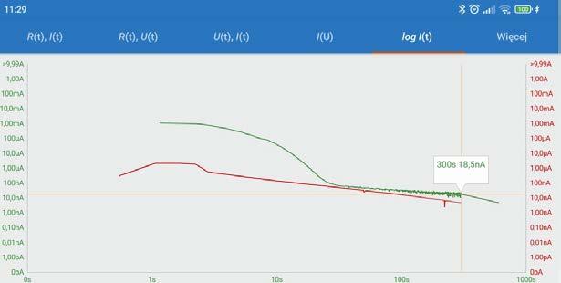
»
» capacitance measurement during measurement of RISO, » measurement with step voltage (SV),
index: WMGBMIC15k1
W1 hanging straps
SONEL MIC-15k1
» backlit keyboard and display,
»
Measuring range 50 V 200 GΩ 100 V 400 GΩ 250 V 1.00 TΩ 500 V 2.00 TΩ 1000 V 4.00 TΩ 2500 V 10.0 TΩ 5000 V 20.0 TΩ 10000 V 40.0 TΩ 15000 V 40.0 TΩ
» measurement of direct and alternating voltages within the range of 0…600 V,
» sound signaling of five-second time intervals, facilitating capture of time characteristics,
» remote start and stop of the measurement via Sonel MIC Mobile application, » continuous readings of measured insulation resistance and leakage current,
» reading of actual measurement voltage during measurement, » measurement current 1.2 mA, 3 mA, 5 mA or 7 mA,
Measurement of insulation resistance Measuring range in compliance with EN 61557-2: RISOmin =UISOnom /IISOmax= 50 kΩ...40 TΩ (IISOmax =1.2 mA, 3 mA, 5 mA, 7 mA)
Test lead 15 kV 3 m CAT IV 1000 V with crocodile clip, red WAPRZ003REKRO15KV Test lead 15 kV 3 m CAT IV 1000 V with crocodile clip, shielded, black WAPRZ003BLKROE15KV Test lead 15 kV 3 m CAT IV 1000 V with crocodile clip, blue WAPRZ003BUKRO15KV USB cable WAPRZUSB Mains cable with IEC C13 plug WAPRZ1X8BLIEC Factory calibration certificate
WAFUTL4
Values of measured resistance depending on measuring voltage
Electrical safety:
Standard accessories:
WAPOZSZE5
» dimensions 390
Display range Resolution Accuracy 0...999 kΩ 1 kΩ ±(3% w.m. + 10 digits) 1.00..9.99 MΩ 0.01 MΩ 10.0...99.9 MΩ 0.1 MΩ 100..999 MΩ 1 MΩ 1.00...9.99 GΩ 0.01 GΩ 10.0...99.9 GΩ 0.1 GΩ 100...999 GΩ 1 GΩ ±(3.5% w.m. + 10 digits) 1.00...9.99 TΩ 0.01 TΩ ±(7.5% w.m. + 10 digits) 10.0...20.0 TΩ 0.1 TΩ ±(12.5% w.m. + 10 digits)10.0...40.0 TΩ
Other technical specifications: power supply built-in Li-FePO4 battery 13.2 V 5.0 Ah network: 90 V ÷ 260 V 50/60 Hz weight approx. 6.6 kg x 308 x 172 transmission of results link or
» type of insulation double, as per EN 61010-1 and EN 61557 measurement category CAT IV 1000 V (operating altitude ≤2000 m) acc. to EN 61010-1
rechargeable
» data transmission to PC via USB connection or Bluetooth®,
»
from
» PDC measurements,

*The measuring voltage equals 15 kV ± 10%, which gives max. 16,5 kV.
» capacitors, switches and other devices installed in power stations.
Highly efficient HV inverter, with test voltage of 15 kV and current up to 10 mA,
For all
» single- and multicore cables,
Capabilities of the device
» SV method ensures that a dielectric in good condition will provide the same results, regardless of the applied voltage.
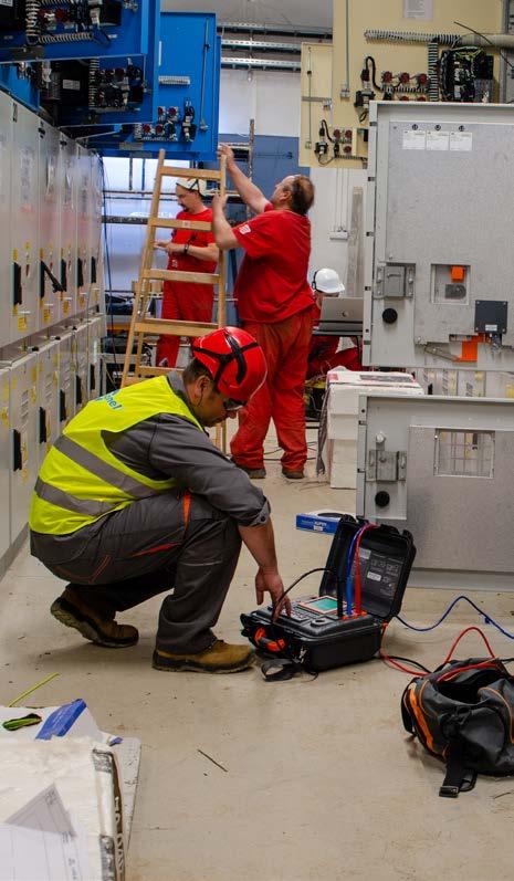
The device automatically saves the measurement results. The number of autosave points depends on the amount of data, which is saved within the main memory.
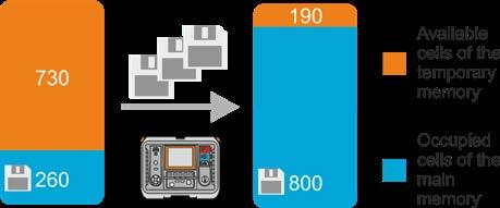
The meter indicates the Dielectric Absorption Ratio DAR, Polarization Index PI and the value of Dielectric Dis charge DD (measurement time 60...5999 s).
The device allows user to assess the condition of the insulation, by applying the test voltage incrementally in steps (SV - Step Volatge) or smoothly (RampTest - RT).
Static and dynamic memory of measurements operating conditions
A very useful solution is the function that allows to Burnout the damaged object. In case of exposed cables, it enables visual identification of the fault location. In the case of shielded cables, the method allows to generate a seismic-acoustic wave from the place of damage.
The option of remote start and stop of the measurement is particularly useful. Thanks to it, the tests can be carried out remotely, eg. from a different room or inside the car, when there are difficult weather conditions for the user. Using the phone GPS, it is possible to precisely determine the place of measurement.
With the application, you can connect directly to the device via Bluetooth and download measurement data from the meter. After reading the measurements from the device, they can be easily and quickly viewed, and also sent from the place of measurement to the person who can help in the interpretation of data or make a measurement report. Additional functionalities will be useful: assigning a photo, text or voice note to a given measurement.
In special conditions, an energetic discharge will appear cyclically. By using the geophone it will be possible to precisely pinpoint the place where such a discharge occurs.
» motors and generators,
Application
Autosaving the measurement results
The Sonel MIC Mobile mobile app allows to observe the results during the measurement. The application can generate real-time graphs in various configurations. This allows to evaluate the condition of the object already during the tests.

SONEL MIC MOBILE
suitable for measuring the insulation resistance up to 40 TΩ. Achieving such a result makes these meters unri valled devices. Three-wire resistance measurement, performed using a "GUARD" wire, eliminates surface leak age currents caused by contaminated insulation, thereby increasing the reliability of obtained results.
It is especially recommended for measurements in areas with very high electromagnetic disturbances, e.g. elec trical substations with 1200 kV AC and 500 kV DC. Thanks to the 15 kV* measuring voltage (in accordance with ANSI / NETA ATS-2009 TABLES 100.1) the meter can be used for measuring objects with a nominal voltage above 34.5 kV.
There is a possibility to start and stop the measurement remotely. You can also convert the k20 temperature coefficient. The application can be downloaded from Google Play
Burnout feature allows also locating transient faults (appearing, for example, only during rainfall) with the sup port of reflectometry, and in case of a short circuit (of a screen or return wire) to the ground - applying the method of measuring voltage drop (the A-frame).
» RT method allows to determine the characteristics of the insulating material. The meter smoothly increases the measuring voltage without exposing the object to so-called electrical stress. It records the time and voltage value at which the electrical breakdown of the insulation took place.
Built-in digital filters, with averaging time of 10, 30, 60, 100, 200 sec. guarantee stable measurement results in areas of strong electromagnetic interference.
Supported by a mobile application

41
Thanks to the mobile application and the Sonel Reader software, the user can store previous measurements data and compare them with current results transferred from the meter's extensive memory. This solution allows to prepare a measurement report, track the progress of insulation degradation and plan renovation works.

» transformers,
MIC-15k1 meter is designed to measure insulation resistance of power objects, i.e.:
Mobile version of the program cooperating with insulation resistance meters: MIC-15k1, MIC-10k1, MIC-5050, MIC-5010, MIC-5005

Data analysis
Burnout
» timing of measurement times T1, T2 and T3 for measurement of one or two absorption coefficients (Ab1, Ab2 or DAR, PI) within the range of 1…600 s,
Display range Resolution Accuracy 0…999 kΩ 1 kΩ ±(3% m.v. + 10 digits)
» stable measurement in 765 kV substations
» measurement with step voltage (SV),
»
» charts plotted on display during measurements,
Measuring range in compliance with EN 61557-2: RISOmin =UISOnom /IISOmax=5 MΩ…40 TΩ (IISOmax =1.2 mA, 3 mA or (6 ± 15%) mA)
» measurements with lead lengths up to 20 m,
values of measured resistance depending on measuring voltage Display range Measuring range Measuring range for AutoISO-5000 50 V 200 GΩ 20.0 GΩ 100 V 400 GΩ 40.0 GΩ 250 V 1.00 TΩ 100 GΩ 500 V 2.00 TΩ 200 GΩ 1000 V 4.00 TΩ 400 GΩ 2500 V 10.0 TΩ 400 GΩ 5000 V 20.0 TΩ 400 GΩ MIC-10k1 | 10000 V 40.0 TΩ
» temperature measurement (with the use of the optional ST-1 temperature probe),
Measurement of insulation resistance:
» supports external wireless Bluetooth® keyboard (optional),
»
» dielectric discharge (DD) test,
» measurement of leakage current during measurement of RISO,
»
» automatic discharge of the measured object's capacitance upon completion of insulation resistance measurement,
» data transmission to PC via USB connection, Bluetooth® or capability of data transfer via USB flash drives,
index: WMGBMIC10K1 / WMGBMIC5050

»
»
» high immunity to disturbances - in compliance with standard EN 61326,
» backlit keyboard,
Additional functions of the meters:
Factory calibration certificate
Nominal operating conditions: operating temperature range -20…+50°C storage temperature -25…+70°C humidity 20…90% elevation above sea level ≤3000 m reference temperature +23°C ± 2°C reference humidity 40…60%
»
» the instrument meets the requirements laid down by standard EN 61557.
» sound signaling of five-second time intervals, facilitating capture of time characteristics,
»
» MIC-5050 | up to 20 TΩ,
»
SONEL MIC-10k1 / MIC-5050
INSTRUMENTS We invite you to use the virtual instruments application. Thanks to it you can familiar ize yourself with features of a selected device, its interface and capabilities. The application gives you the opportunity to change the selected meter's configura tion and perform measurements in a way you would in reality. www.sonel.com › Knowledge Centre › Virtual instrument applications 42
» damage location (burning function, current of 6 mA),
MIC-5050 | 10.0…20.0 TΩ 0.1 TΩ ±(12.5% m.v. + 10 digits)MIC-10k1 | 10.0…40.0 TΩ
40
VIRTUAL
WAPRZUSB
» remote start and stop of the measurement via Sonel MIC Mobile application,
» MIC-10k1 | up to 40 TΩ,
• MIC-10k1 | 50…10000 V: 50…1000 V in steps of 10 V, 1…10 kV in steps of 25 V,
» automatic measurement of all resistance combinations of 3-, 4- and 5-core cords and power cords by means of the optional AutoISO-5000 adapter (for MIC-10k1 at voltage up to 5 kV),
• MIC-5050 | 50…5000 V: 50…1000 V in steps of 10 V, 1…5 kV in steps of 25 V,
» reading of actual measurement voltage during measurement, » measurement current 1.2 mA, 3 mA or 6 mA,
» protection against measurement of live object, » two- or three-lead method of insulation resistance measurement,
» measurement time setting - up to 99’59’’,
» capacitance measurement during measurement of RISO,
Standard accessories: L4 carrying case WAFUTL4
Mains cable with IEC C13 plug WAPRZ1X8BLIEC
»
»
Measurement of insulation resistance
Test lead 15 kV 3 m CAT IV 1000 V with crocodile clip, red WAPRZ003REKRO15KV
Test lead 15 kV 3 m CAT IV 1000 V with crocodile clip, shielded, black WAPRZ003BLKROE15KV
» power supply from rechargeable battery packs or power grid,
»
» type of insulation double, as per EN 61010-1 and EN 61557 measurement category CAT IV 600 V (CAT III 1000 V) according to EN 61010-1 housing protection rating according to EN 60529 IP40 (IP67 with closed housing cover)

» continuous readings of measured insulation resistance and leakage current,
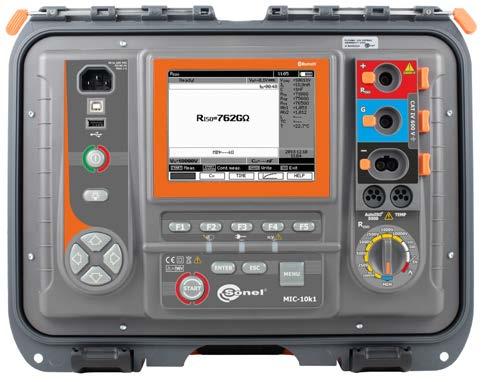
»
USB cable
»
MIC-10k1
Other technical specifications: power supply built-in LiFePO4 rechargeable battery 13.2 V 5.0 Ah from network: 90 V ÷ 260 V 50/60 Hz weight approx. 6.1 kg dimensions 390 x 308 x 172 mm display graphic LCD 5.6’’ transmission of results USB link or Bluetooth® TΩ measurementmaximumrange
» digital filters for measurements with strong disturbances (10 s, 30 s, 60 s).
Insulation resistance meters
Electrical safety:
» memory storing up to 10,000 results of each type of measurement, including descriptions of measurement points, objects, client names,
1.00…9.99 MΩ 0.01 MΩ 10.0…99.9 MΩ 0.1 MΩ 100…999 MΩ 1 MΩ 1.00…9.99 GΩ 0.01 GΩ 10.0…99.9 GΩ 0.1 GΩ 100…999 GΩ 1 GΩ ±(3.5% m.v. + 10 digits) 1.00…9.99 TΩ 0.01 TΩ ±(7.5% m.v. + 10 digits)
» easy-to-read, backlit 5.6’’ LCD graphic display,
Test lead 15 kV 3 m CAT IV 1000 V with crocodile clip, blue WAPRZ003BUKRO15KV
» measurement of direct and alternating voltages within the range of 0…750 V,
» measurement voltages selected within the range of:
» charging during measurement,
MIC-10k1 has the unique ability to perform measurements on multi-core cables, within one connection step, using the AutoISO-5000 adapter. This solution reduces the duration of measurements on repetitive of objects, such as cables of street lighting systems. Inverter with a power of almost 60 W is able to intensify the point of cable damage, which facilitates finding the location of the fault using a reflectometric method e.g. with TDR-420
Built-indevice.
The meter measures temperature of tested object, which is necessary to determine the temperature correction factor for RISO. In addition, it indicates the absorption coefficient (DAR - Dielectric Absorption Ratio), Polarization Index (PI) and the value of Dielectric Discharge (DD). The device allows user to assess the condition of the in sulation, by applying the test voltage incrementally in steps (SV). This solution ensures that a dielectric in good condition will provide the same results, regardless of the applied voltage. Deviations in obtained resistance values of approx. 25%, observed on the chart in the individual steps, may indicate the potential insulation defects.
digital filters, with averaging time of 10, 30, 60, 100, 200 sec. and "smart" solution guarantee stable meas urement results in areas of strong electromagnetic interference.
MIC-10k1 meter is designed to measure the insulation resistance of electro-power objects, i.e. single- and mul ti-core cables, transformers, motors and generators, capacitors, switches and other devices installed in power stations. Furthermore, it is dedicated for measurements in areas with very high electromagnetic disturbances, e.g. electrical substations with 765 kV voltage or higher.
Data analysis
Highly efficient HV inverter, with test voltage of 10 kV and current of 6 mA, suitable for measuring the insulation resistance up to 40 TΩ. Achieving such a result makes these meters unrivalled devices. Three-wire resistance measurement, performed using a "GUARD" wire, eliminates surface leakage currents caused by contaminated insulation, thereby increasing the reliability of obtained results.
Features of the device
After installing mobile application or Sonel Reader software, the user can collect historical data and compare it with current results, transferred from the extensive memory of the meter. This solution helps user to prepare a measurements report, track the insulation degradation and plan the maintenance / repair works.

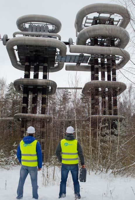
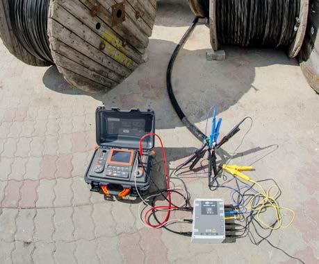
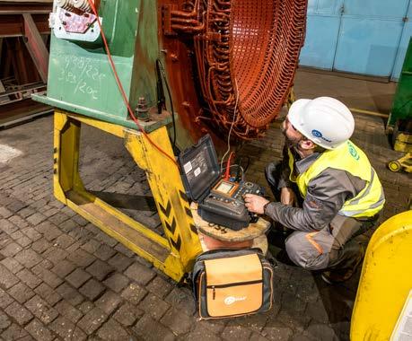
Application
The device, with its backlight graphical screen may display a waveform of insulation resistance, voltage and current as a function of time. The operator, basing on the trend shown by the waveform, may quickly assess the insulation condition right after starting the measurement. This provides full control over the tested object and clear image of the tested insulation. In addition, with movable tags, the operator may trace the course of the measurement and check resistance values obtained for any time of the current measurement and of measure ments made in the past.
Professional diagnostic tool Several measurements in one connection Graphic interpretation of results Comparison of meters MIC-10k1 MIC-5050 maximum measuring voltage 10 000 V 5000 V maximum measuring range 40 TΩ 20 TΩ resistance to external interference voltages up to 1550 V up to 1550 V advanced, digital interference filtration 10 / 30 / 60 / 100 / 200 seconds and SMART 10 / 30 / 60 / 100 / 200 seconds and SMART test leads lock √ √ Designed for the most demanding objects 43

» backlit keyboard and display,
» EN 61557 (requirements for measurement instruments)
MIC-5010 | Continuity test of protective conductors and equipotential bonding:
» type of insulation double, as per EN 61010-1 and EN 61557
Test lead 1.8 m, blue, 11 kV (banana plugs) WAPRZ1X8BUBB10K
V »
» display segmented LCD
» remote start and stop of the measurement via Sonel MIC Mobile application,
WAFUTL4
Crocodile clip, black, 11 kV, 32 A WAKROBL32K09
20.0…199.9 Ω 0.1 Ω 200…999 Ω 1 Ω ±(4%
Pin probe, red 11 kV (banana socket) WASONREOGB11
Standard accessories:
Display range Resolution Accuracy 0…999 kΩ 1 kΩ ±(3% m.v. + 10 digits) 1.00…9.99 MΩ 0.01 MΩ 10.0…99.9 MΩ 0.1 MΩ 100…999 MΩ 1 MΩ 1.00…9.99 GΩ 0.01 GΩ 10.0…99.9 GΩ 0.1 GΩ 100…999 GΩ 1 GΩ ±(3.5% m.v. + 10 digits) 1.00…9.99 TΩ 0.01 TΩ ±(7.5% m.v. + 10 digits) 10.0…15.0 TΩ 0.1 TΩ ±(10% m.v. + 10 digits)
» EN 61010-1 (general and particular requirements related to safety)
WAPOZSZE5
»
» PN-E 04700 (performance of measurements - commissioning tests)
» power supply from rechargeable battery packs, built-in quick charger,
Ω Display
» housing protection rating according to EN 60529 IP40 (IP67 with closed housing cover)
Measurement of insulation resistance:
» power supply of the meter built-in LiFePO4 rechargeable battery 13.2 V 5.0 Ah
Instruments meet the requirements set forth in the standards:
» HD 60364-4-41 (performance of measurements - shock protection)
Nominal operating conditions:
» weight approx. 6.0 kg
» measurements with lead lengths up to 20 m,
Mains cable with IEC C13 plug WAPRZ1X8BLIEC
values of measured resistance depending on measuring voltage Voltage Measured resistance 250 V 500 GΩ 500 V 1.00 TΩ 1000 V 2.00 TΩ 2500 V 5.00 TΩ 5000 V 15.0 TΩ
Electrical safety:
» operating temperature range -20…+50°C
» sound signaling of five-second time intervals, facilitating capture of time characteristics,
Test lead 1.8 m, red, 11 kV (banana plugs) WAPRZ1X8REBB10K
» dimensions 390 x 308 x 172 mm
» storage temperature -25…+70°C
» automatic discharge of the measured object's capacitance upon completion of insulation resistance measurement,
» humidity 20%…90%
Measuring range in compliance with EN 61557-2:
Ω: Imin
» reference temperature +23°C ± 2°C
» Voltage on open terminals: 4…24 Output current at R < 15 > 200 mA (ISC: 200…250 mA) Compensation of test lead resistance Current flows in two
» reference humidity 40…60%
Insulation
The MIC-10k1, MIC-5050, MIC-5010 and MIC-5005 meters are capable of operating in the presence of very large disturbances at substations and switching stations.
» configurable limits of minimum and maximum insulation resistance RCONT
» measurement of leakage current during measurement of RISO,
Other technical specifications:
» 990-cell memory (11,880 entries) with the capability of wireless data transmission to a PC (via Bluetooth® or via USB cable),
MIC-5010 | Test of the continuity of protective conductors and equipotential bonding with current >200 mA Measuring range according to EN 61557-4: 0.12…999 range Resolution m.v. + 3 digits) m.v. + 3 digits)
44
Measurement of insulation resistance
» Temperature stability of voltage better than 0.2% /°C
» measurement of capacitance during measurement of RISO,
Crocodile clip, blue, 11 kV, 32 A WAKROBU32K09
» transmission of results USB link or Bluetooth®
» measurement current 1.2 mA or 3 mA,
directions, mean resistance value displayed Capacitance measurement Display range Resolution Accuracy 1…999 nF 1 nF ±(5% m.v. + 5 digits)1.00…49.99 µF 0.01 µF » Capacitance measurement result displayed after measurement of RISO “m.v.” = “measured value”
» continuous reading of measured insulation resistance or leakage current,
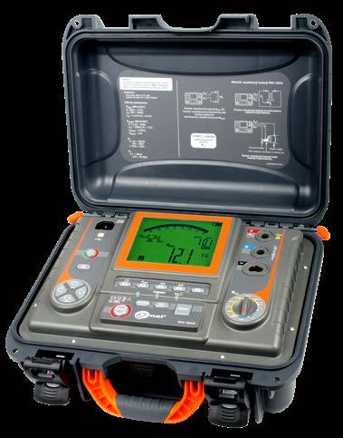
» protection against measurement of live objects,
» measurement time setting - up to 99’59’’,
Accuracy 0.00…19.99 Ω 0.01 Ω ±(2%
Additional functions of the meters:
» elevation above sea level ≤3000 m
15 TΩ measurementmaximumrange
Test lead 1.8 m, black, 11 kV (banana plugs, shielded) WAPRZ1X8BLBBE10K
» EN 61326 (electromagnetic compatibility)
» EN 61010-031 (general and particular requirements related to safety)
Crocodile clip, red, 11 kV, 32 A WAKRORE32K09
SONEL MIC-5010 / MIC-5005
» dielectric discharge (DD) test.
» with current ≥200 mA flowing in two directions in compliance with EN 61557-4,
» measurement voltage selected within the range of 50…1000 V: 50…1000 V selected in steps of 10 V, 1000 V…5000 V selected in steps of 25 V,
resistance meters
W1 hanging straps
» timing of measurement times T1, T2 and T3 for measurement of one or two absorption coefficients (Ab1, Ab2 or DAR, PI) within the range of 1…600 s,
L4 carrying case
» two- or three-lead method of insulation resistance measurement,
USB cable WAPRZUSB
RISOmin = UISOnom /IISOmax= 50 kΩ…15 TΩ (IISOmax =1.2 mA or 3 mA)
»
index: WMGBMIC5010 / WMGBMIC5005
» digital filters for measurements with strong disturbances (10 s, 30 s, 60 s).
» high immunity to disturbances - in compliance with standard EN 61326,
» instruments meet the requirements laid down by standard EN 61557.
Factory calibration certificate
» measurement with step voltage (SV),
Pin probe, black 11 kV (banana socket) WASONBLOGB11
» HD 60364-6 (performance of measurements - checking)
» measurement of direct and alternating voltages within the range of 0…600 V,
» measurement category CAT IV 600 V (CAT III 1000 V) according to EN 61010-1
» reading of actual measurement voltage during measurement,
±(5%
Breakdown voltage measurement
Other technical specifications:
Factory calibration certificate
» dimensions 200 x 180 x 77 mm
double, as per EN 61010-1 and IEC 61557
» housing protection rating according to EN 60529 IP65
» continuous reading of measured insulation resistance or leakage current,
Test probe with banana socket; 5 kV; red WASONREOGB2 Meter power adapter (type Z7) WAZASZ7
Measuring range according to IEC 61557-2: RISOmin=UISOnom/IISOmax ≤ 5 TΩ (IISOmax = 1 mA)
WAKROBL32K09
Black "crocodile" clip 11 kV 32 A
M-8 carrying case
Insulation resistance measurement in Ramp Test mode
Display range Resolution Accuracy
index:
Insulation resistance measurement (two-lead)
» type of insulation
» measurement voltage within the range of 50…1000 V: 50…500 V selected in steps of 50 V, 500…5000 V selected in steps of 100 V,
» measurement category CAT IV 600 V (CAT III 1000 V) according to EN 61010-1
V 5000 GΩ
Ramp Test mode Range Resolution Selected UISO Accuracy 25.0 …99.0 V 0.1 V ≤600 V ±(5% m.v. + 10 digits) 100 … 600 V 1 V ≤600 V ±(5% m.v. + 4 digits) 25 … 999 V 1 V >600 V ±(5% m.v. + 5 digits) 1.00 … 5.00 kV 10V >600 V ±(5% m.v. + 4 digits) Measurement of direct and alternating voltage Range Resolution Accuracy 0…299.9 V 0.1 V ±(3% m.v. + 2 digits)300…750 V 1 V » frequency range: 45…65 Hz 45
0.0…999.9 kΩ 0.1 kΩ ±(3% m.v. + 20 digits)
230 V power cord (IEC C7 plug) WAPRZLAD230
» protection against measurement of live objects, » two- or three-lead method of insulation resistance measurement,
Display range Resolution 0.0…999.9 kΩ 0.1 kΩ m.v. + 40 digits) 1.000…9.999 MΩ 0.001 MΩ 10.00…99.99 MΩ 0.01 MΩ 100.0…999.9 MΩ 0.1 MΩ 1.000…9.999 GΩ 0.001 GΩ 10.00…99.99 GΩ 0.01 GΩ 100.0…999.9 GΩ 0.1 GΩ 1.000…4.999 TΩ 0.001 TΩ in
WMGBMIC5001 Insulation resistance meter
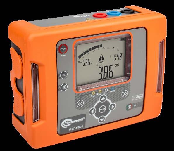
1.000…9.999 MΩ 0.001 MΩ 10.00…99.99 MΩ 0.01 MΩ 100.0…999.9 MΩ 0.1 MΩ 1.000…9.999 GΩ 0.001 GΩ 10.00…99.99 GΩ 0.01 GΩ 100.0…999.9 GΩ 0.1 GΩ 1.000…5.000 TΩ 1 GΩ ±(4% m.v. + 50 digits)
WAPRZUSB
Voltage UISO Measuring range up to 100 V 50 GΩ 200…400 V 100 GΩ 500…900 V 250 GΩ 1000…2400 V 500 GΩ 2500 V 2500 GΩ 5000
» measurement of direct and alternating voltages within the range of 0…750 V, » 990-cell memory (11,880 entries), data transmission to PC via USB cable, » power supplied by rechargeable battery, » the meter can be powered and charged from an external power adapter or from a car lighter socket, » backlit display, » instruments meet the requirements laid down by standard EN 61557.
Blue "crocodile" clip 11 kV 32 A WAKROBU32K09
» measurement current 1.5 mA,
» memory 990 cells, 11,880 entries
Test probe with banana socket; 5 kV; black WASONBLOGB2
SONEL NiMH LSD 9.6 V 2 Ah rechargeable battery pack 12 V, 2.5 A external power supply
» operating humidity 20…90%
» automatic discharge of the measured object's capacitance upon completion of insulation resistance measurement,
Additional functions of the meter:
Test lead with banana plugs; 5 kV; 1.8 m; red WAPRZ1X8REBB
Test lead with banana plugs; 5 kV; 1.8 m; blue WAPRZ1X8BUBB
Red "crocodile" clip 11 kV 32 A WAKRORE32K09
Electrical safety:
WAFUTM8
» timing of measurement times T1, T2 and T3 for measurement of one or two absorption coefficients (Ab1, Ab2 or DAR, PI) within the range of 1… 600 s,
» reading of actual measurement voltage during measurement,
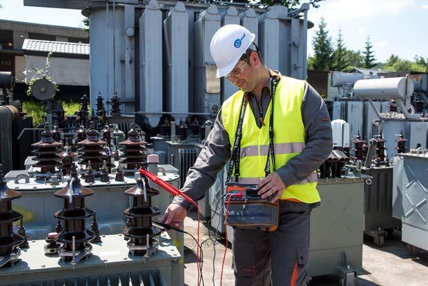
» meter weight approx. 0.9 kg
» sound signaling of five-second time intervals, facilitating capture of time characteristics,
» transmission of results insulated USB cable
Measured resistance values depending on measurement voltage
Shielded test lead with banana plugs; 5 kV; 1.8 m; black WAPRZ1X8BLBB
SONEL MIC-5001
» insulation resistance measurement according to the RampTest method and breakdown voltage measurement with ramping rate up to ~1 kV/s.
» display segmented LCD
Accuracy
USB data transmission cable
Measurement of insulation resistance:
» power supply of the meter
Standard accessories:
» memory 9999 entries
Li-Ion 10.8 V 3.5 Ah rechargeable battery WAAKU29 M-6 carrying case WAFUTM6

»
Li-Ion 10.8 V 3.5 Ah rechargeable battery
» display LCD TFT 5,6" 800 x 480
Ω 0.1 Ω 200...999 Ω 1 Ω ±(4% m.v. + 3 digits) Measurement of direct and alternating voltage Display range Resolution Accuracy 0...1500 V 1 V ±(3% m.v. + 2 digits) » frequency range: 45…65 Hz Insulation resistance meter 5.6” screentouch 46
»
»
» dimensions 234 x 169 x 70 mm
Measurement of insulation resistance:

» measurement of leakage current during measurement of RISO, » capacitance measurement during measurement of RISO, » low-voltage measurement of circuit continuity and resistance, temperature measurement (with the use of the optional ST-1 temperature probe), measurement of direct and alternating voltages within the range of 0...1500 V, 9999-entry memory, data transmission to PC via USB cable, power supplied by rechargeable battery, backlit keyboard, the instrument meets the requirements laid down by standard EN 61557.
»
double, as per EN 61010-1 and EN 61557 measurement category CAT IV 600 V (CAT III 1000 V) according to EN 61010-1 housing protection rating according to EN 60529 IP65


» protection against measurement of live objects, » two- or three-lead method of insulation resistance measurement.
Electrical safety:
» with current ≥200 mA flowing in two directions in compliance with EN 61557-4.
» automatic measurement of all resistance combinations of 3-, 4- and 5-core cords and power cords by means of the optional AutoISO-2511 adapter, » reading of actual measurement voltage during measurement, » measurement current <2 mA,
»
Other technical specifications:
»
» type of insulation
» weight ca. 1.3 kg
» transmission of results USB
SONEL MIC-2511
Black "crocodile" clip 11 kV 32 A WAKROBL32K09
Blue "crocodile" clip 11 kV 32 A WAKROBU32K09
Shielded test lead with banana plugs; 5 kV; 1.8 m; black WAPRZ1X8BLBB
» measurement voltage within the range of 50…2500 V: selected from 100 V, 250 V, 500 V, 1000 V, 2500 V or 50…2500 V selected in steps of 10 V, » charts plotted on display during measurements, » EPA measurements,
Continuity test of protective conductors and equipotential bonding:
»
Test lead with banana plugs; 5 kV; 1.8 m; red WAPRZ1X8REBB
USB data transmission cable WAPRZUSB 230 V power cord (IEC C7 plug) WAPRZLAD230
Test probe with banana socket; 5 kV; black WASONBLOGB2
Red "crocodile" clip 11 kV 32 A WAKRORE32K09
Type C USB cable WAPRZUSBC Meter power adapter (type Z32) WAZASZ32 Factory calibration certificate
Measurement of insulation resistance Measuring range acc. to EN 61557-2 for RISOmin = UISOnom/IISOmax≤ 2 TΩ (IISOmax = 1.6 mA)
Maximum measured resistance values depending on measurement voltage Voltage Measured resistance 50 V 50 GΩ 100 V 100 GΩ 250 V 250 GΩ 500 V 500 GΩ 1000 V 1,00 TΩ 2500 V 2,00 TΩ
Capacitance measurement Display range Resolution Accuracy 0...999 nF 1 nF ±(5% m.v. + 5 digits)1.00...9.99 µF 0.01 µF

Test of the continuity of protective conductors and equipotential bonding with 200 mA current Measuring range according to EN 61557-4:: 0.10...999 Ω range Resolution Accuracy 0.00...19.99 0.01 + 3 digits)20.0...199.9
Display
Ω ±(2% m.v.
Test lead with banana plugs; 5 kV; 1.8 m; blue WAPRZ1X8BUBB
Additional functions of the meter:
Display range Resolution Accuracy 0.0...999.9 kΩ 0.1 kΩ ±(3% m.v. + 20 digits) 1.000...9.999 MΩ 0.001 MΩ 10.00...99.99 MΩ 0.01 MΩ 100.0...999.9 MΩ 0.1 MΩ 1.000...9.999 GΩ 0.001 GΩ 10.00...99.99 GΩ 0.01 GΩ 100.0...999.9 GΩ 0.1 GΩ 1.000...2.000 TΩ 0.001 TΩ
Standard accessories:
» power supply of the meter
»
index: WMGBMIC2511
» continuous reading of measured insulation resistance or leakage current, » automatic discharge of the measured object's capacitance upon completion of insulation resistance measurement, » sound signaling of five-second time intervals, facilitating capture of time characteristics, » timing of measurement times T1, T2 and T3 for measurement of one or two absorption coefficients (Ab1, Ab2 or DAR, PI) within the range of 1… 600 s,
Test probe with banana socket; 5 kV; red WASONREOGB2 Hanging strap WAPOZPAS6
Ω
» measurement current 1 mA,
You can charge the meter during the measurement using any Power Bank 12 V / 2 Ah with a 5.5 mm / 2.1 mm power supply.
Black "crocodile" clip 11 kV 32 A WAKROBL32K09
Blue "crocodile" clip 11 kV 32 A WAKROBU32K09
» power supply of the meter
USB data transmission cable WAPRZUSB
SONEL MIC-2501
» measurement of direct and alternating voltages within the range of 0…750 V,
» reading of actual measurement voltage during measurement,
» Voltage on open terminals: 4…24 V
Red "crocodile" clip 11 kV 32 A WAKRORE32K09
Measuring range according to EN 61557-4: 0.10…999 Ω
Measuring range acc. to EN 61557-2 for RISOmin = UISOnom/IISOmax ≤ 1 TΩ (IISOnom = 1 mA)
index: WMGBMIC2501
» dimensions 200 x 180 x 77 mm
» measurement category CAT IV 600 V (CAT III 1000 V) according to EN 61010-1
» memory 990 cells, 11,880 entries
» housing protection rating according to EN 60529 IP65
» Current flows in two directions, mean resistance value displayed
Additional functions of the meter:
double, as per EN 61010-1 and EN 61557
Other technical specifications:
» display segmented LCD
» protection against measurement of live objects, » two- or three-lead method of insulation resistance measurement.
Test probe with banana socket; 5 kV; black WASONBLOGB2
» type of insulation
» sound signaling of five-second time intervals, facilitating capture of time characteristics,
Maximum measured resistance values depending on measurement voltage Voltage Measured resistance up to 100 V 50 GΩ 200…400 V 100 GΩ 500…900 V 250 GΩ 1000…2400 V 500 GΩ 2500 V 1000 GΩ
» timing of measurement times T1, T2 and T3 for measurement of one or two absorption coefficients (Ab1, Ab2 or DAR, PI) within the range of 1… 600 s,
Test of the continuity of protective conductors and equipotential bonding with 200 mA current
Measurement of insulation resistance
» continuous reading of measured insulation resistance or leakage current,
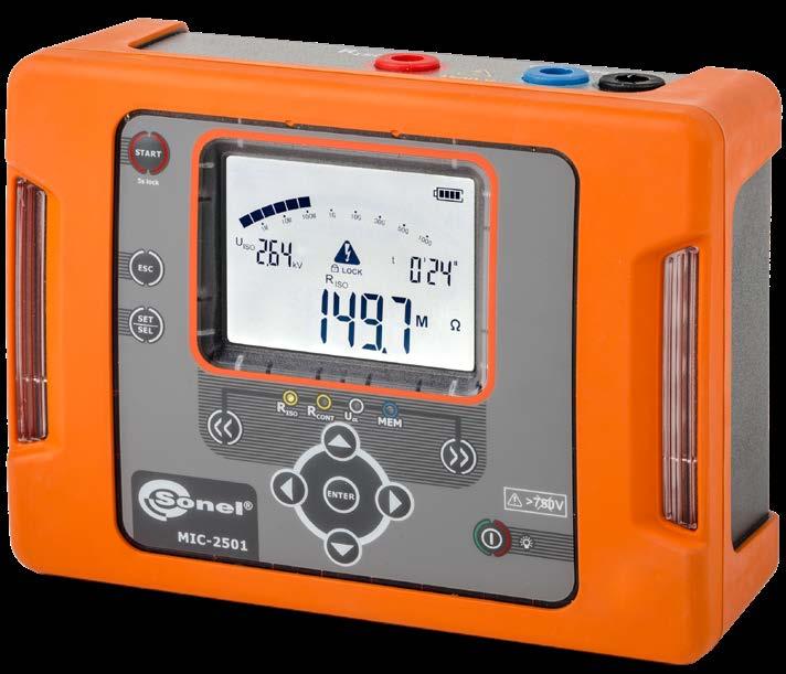
» Compensation of test lead resistance
» with current ≥200 mA flowing in two directions in compliance with EN 61557-4.
» automatic discharge of the measured object's capacitance upon completion of insulation resistance measurement,
Display range Resolution Accuracy 0.00…19.99 Ω 0.01 Ω ±(2% m.v. + 3 digits)20.0…199.9 Ω 0.1 Ω 200…999 Ω 1 Ω ±(4% m.v. + 3 digits)
Factory calibration certificate
» power supplied by rechargeable battery,
Insulation resistance meter
» the meter can be powered and charged from an external power adapter or from a car lighter socket,
Display range Resolution Accuracy 0…299.9 V 0.1 V ±(3% m.v. + 2 digits)300…750 V 1 V
“m.v.” = “measured value” UISO - measurement voltage.
Standard accessories: M-8 carrying case WAFUTM8
Electrical safety:
Continuity test of protective conductors and equipotential bonding:
SONEL NiMH LSD 9.6 V rechargeable battery pack external power supply 12 V, 2.5 A
Test lead with banana plugs; 5 kV; 1.8 m; blue WAPRZ1X8BUBB
» low-voltage measurement of circuit continuity and resistance,
» 990-cell memory (11,880 entries), data transmission to PC via USB cable,
» measurement voltage within the range of 100…2500 V: 100…2500 V selected in steps of 100 V,
230 V power cord (IEC C7 plug) WAPRZLAD230
» Output current at R<2 Ω: ISC >200 mA
» meter weight approx. 0.9 kg
» measurement of leakage current during RISO measurement,
» transmission of results USB
Measurement of direct and alternating voltage
» frequency range: 45…65 Hz
Measurement of insulation resistance:
47
Test lead with banana plugs; 5 kV; 1.8 m; red WAPRZ1X8REBB
Display range Resolution Accuracy 0.0…999.9 kΩ 0.1 kΩ ±(3% m.v. + 20 digits) 1.000…9.999 MΩ 0.001 kΩ 10.00…99.99 MΩ 0.01 kΩ 100.0…999.9 MΩ 0.1 kΩ 1.000…9.999 GΩ 0.001 GΩ 10.00…99.99 GΩ 0.01 GΩ 100.0…999.9 GΩ 0.1 GΩ
» backlit display,
Test probe with banana socket; 5 kV; red WASONREOGB2 Meter power adapter (type Z7) WAZASZ7
» the instrument meets the requirements laid down by standard EN 61557.
Shielded test lead with banana plugs; 5 kV; 1.8 m; black WAPRZ1X8BLBB
» measurement voltage within the range of 50…1000 V: selected from 50, 100, 250, 500, 1000 V or 50…1000 V selected in steps of 10 V,
Measurement of insulation resistance
» measurement current 1 mA,
» with current ≥200 mA flowing in two directions in compliance with EN 61557-4.
Measuring range according to EN 61557-2 for
» Un=250V: 250 kΩ…2.000 GΩ
= 1000 V 100.0 GΩ | Un = 1000 V 0.1 GΩ *for WS-04 adapter **for WS-04 adapter, range up to 10 GΩ » measurements with voltage up to 500 V for WS-04 lead Capacitance measurement Display range Resolution Accuracy 1…999 nF 1 nF ±(5% m.v. + 10 digits)1.00…9.99 µF 0.01 µF » Capacitance measurement result displayed after measurement of RISO » For measurement voltages below 100 V and measured resistance of less than 10 MΩ, the error of capacitance measurement is unspecified Test of the continuity of protective conductors and equipotential bonding with 200 mA current Measuring range according to EN
0.10…1999 Ω Display range Resolution Accuracy 0.00…19.99 Ω 0.01 Ω ±(2% m.v. + 3
» EN 61010-1 (general and particular requirements related to safety)
» automatic discharge of the measured object's capacitance upon completion of insulation resistance measurement,
» display segmented LCD
Shielded test lead with banana plugs; 1 kV; 1.2 m; black WAPRZ1X2BLBBE
Test lead with banana plugs; 1 kV; 1.2 m; blue WAPRZ1X2BUBB
double, as per EN 61010-1 and EN 61557
» readings of actual measurement voltage during measurement,
» HD 60364-6 (performance of measurements - checking)
» continuous reading of measured insulation resistance or leakage current,
» protection against measurement of live objects,
» two- or three-lead method of insulation resistance measurement.
Additional functions of the meter:
» power supply of the meter 4 LR6 batteries or Ni-MH AA rechargeable batteries
» EN 61010-031 (general and particular requirements related to safety)
index: WMGBMIC30
Blue "crocodile" clip 1 kV 20 A WAKROBU20K02
Test lead with banana plugs; 1 kV; 1.2 m; red WAPRZ1X2REBB
» Un=1000V: 1000 kΩ…100.0 GΩ
±(3% m.v. + 8 digits) [±(5% m.v. + 8 digits)]* 1.000...9.999 MΩ 0.001 MΩ 10.00...99.99 MΩ 0.01 MΩ 100.0...250.0 MΩ | Un = 50 V 0.1 MΩ100.0...500.0 MΩ | Un = 100 V 100.0...999.9 MΩ | Un ≥ 250 V 1.000...2.000 GΩ | Un =250 V 0.001 GΩ 1.000...9.999 GΩ | Un ≥ 500 V 0.001 GΩ ±(4% m.v. + 6 digits) [±(6% m.v. + 6 digits)]* 10.00...20.00 GΩ | Un ≥ 500 V ** 0.01 GΩ10.00...99.99 GΩ | Un 61557-4: digits) digits)
20.0…199.9 Ω 0.1 Ω 2000…1999 Ω 1 Ω ±(4% m.v. + 3
» Un=100V: 100 kΩ…500.0 MΩ
Insulation resistance meter MIC-30 makes it possible to perform automatic resistance measurement for all combinations or for any pair of conductors in the socket. 48
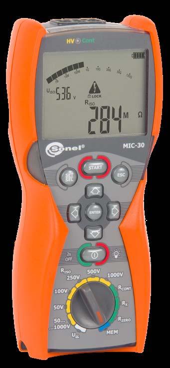
» Un=50V: 50 kΩ…250.0 MΩ
» automatic measurement in sockets by means of UNI-Schuko adapter with the capability of configuring pairs of measured conductors,
SONEL MIC-30
» Un=500V: 500 kΩ…20.00 GΩ
Display range Resolution Accuracy 0.0...999.9 kΩ 0.1 kΩ
» EN 61557 (requirements for measurement instruments)
Continuity test of protective conductors and equipotential bonding:
» measurement of direct and alternating voltages within the range of 0…600 V, » 990-cell memory (11,880 entries) with the capability of wireless data transmission to a PC via Bluetooth®,
Other technical specifications:
The instrument meets the requirements set forth in the standards:
» EN 61326 (electromagnetic compatibility)
Test probe with banana socket; 1 kV; red WASONREOGB1 Meter strap (type M-1) WAPOZSZE4
Test probe with banana socket; 1 kV; black WASONBLOGB1
WAFUTM6
Factory calibration certificate
» measurement of leakage current during measurement of RISO, » capacitance measurement during measurement of RISO, » low-voltage measurement of circuit continuity and resistance,
» sound signaling of five-second time intervals, facilitating capture of time characteristics,
Measurement of insulation resistance:
» timing of measurement times T1, T2 and T3 for measurement of one or two absorption coefficients (Ab1, Ab2 or DAR, PI) within the range of 1… 600 s,
» HD 60364-4-41 (performance of measurements - shock protection)
Standard accessories: M-6 carrying case
M-1 housing holder - hanger WAPOZUCH1
» backlit keyboard and display, » the instrument meets the requirements laid down by standard EN 61557.
» type of insulation
» PN-E 04700 (performance of measurements - commissioning tests)
» Un=100 V: 100 kΩ…500.0 MΩ
V
Capacitance measurement
» capacitance measurement during measurement of RISO,
index: WMGBMIC10
» continuous reading of measured insulation resistance,
» the instrument meets the requirements laid down by standard EN 61557.
» PN-E 04700 (performance of measurements - commissioning tests)
Test probe with banana socket; 1 kV; red WASONREOGB1 Meter strap (type M-1) WAPOZSZE4
Accuracy 1…999 nF 1 nF ±(5%
» measurement of direct and alternating voltages within the range of 0…600 V,
» Un=1000 V: 1000 kΩ…10.00 GΩ
» measurement voltage within the range of 50…1000 V: selected from 50, 100, 250, 500, 1000 V,
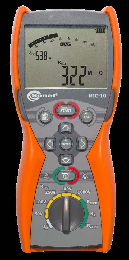
Additional functions of the meter:
Display range Resolution m.v. + 10 digits) measurement result displayed after measurement of RISO measurement voltages below 100 and measured resistance of less than 10 the error of capacitance measurement is unspecified. of the continuity of protective conductors and equipotential bonding with 200 mA current range according to EN 61557-4: 0.10…1999
Other technical specifications:
Black "crocodile" clip 1 kV 20 A WAKROBL20K01
Measurement of insulation resistance Measuring range according to EN 61557-2 for
» EN 61557 (requirements for measurement instruments)
Standard accessories:
Test lead with banana plugs; 1 kV; 1.2 m; black WAPRZ1X2BLBB Test lead with banana plugs; 1 kV; 1.2 m; red WAPRZ1X2REBB
Test probe with banana socket; 1 kV; black WASONBLOGB1
» Un=500 V: 500 kΩ…5.000 GΩ
20.0…199.9 Ω 0.1 Ω 2000…1999 Ω 1 Ω ±(4%
M-6 carrying case
» Un=50 V: 50 kΩ…250.0 MΩ
standard EN 61557. 49
SONEL MIC-10
Insulation resistance meter Besides measuring insulation resistance, MIC-10 is capable of performing continuity tests of protective conductors and equipotential bonding in accordance
» Un=250 V: 250 kΩ…2.000 GΩ
» EN 61010-031 (general and particular requirements related to safety)
The instrument meets the requirements set forth in the standards:
0.00…19.99 Ω 0.01 Ω ±(2%
» low-voltage measurement of circuit continuity and resistance,
| Un = 500 V 0.001 GΩ ±(4% m.v. + 6 digits)1.000...9.999 GΩ | Un = 1000 V 10.00 GΩ | Un = 1000 V 0.01 GΩ
» protection against measurement of live objects, » two- or three-lead method of insulation resistance measurement.
Continuity test of protective conductors and equipotential bonding:
» EN 61326 (electromagnetic compatibility)
Measurement of insulation resistance:
» For
» sound signaling of five-second time intervals, facilitating capture of time characteristics,
WAFUTM6
» backlit keyboard and display,
» display segmented LCD
1.00…9.99 µF 0.01 µF » Capacitance
Ω
double, as per EN 61010-1 and EN 61557
» EN 61010-1 (general and particular requirements related to safety)
Display range Resolution Accuracy 0.0...999.9 kΩ 0.1 kΩ ±(3% m.v. + 8 digits) 1.000...9.999 MΩ 0.001 MΩ 10.00...99.99 MΩ 0.01 MΩ 100.0...250.0 MΩ | Un = 50 V 0.1 MΩ100.0...500.0 MΩ | Un = 100 V 100.0...999.9 MΩ | Un ≥ 250 V 1.000...2.000 GΩ | Un = 250 V 0.001 GΩ 1.000...5.000 GΩ
» HD 60364-6 (performance of measurements - checking)
M-1 housing holder - hanger WAPOZUCH1 Factory calibration certificate
» with current ≥200 mA flowing in two directions in compliance with EN 61557-4.
Measuring
Test
» type of insulation
MΩ,
» HD 60364-4-41 (performance of measurements - shock protection)
» automatic discharge of the measured object's capacitance upon completion of insulation resistance measurement,
» power supply of the meter 4 alkaline batteries or Ni-MH rechargeable batteries - size AA
» readings of actual measurement voltage during measurement, » measurement current 1 mA,
Display range Resolution Accuracy m.v. + 3 digits) m.v. + 3 digits) with
» EN 61557 (requirements for measurement instruments)
Measurement of insulation resistance:
» the instrument meets the requirements laid down by standard EN 61557.
» HD 60364-6 (performance of measurements - checking)
» measurement voltage within the range of 250…500 V: selected from 250, 500 V,
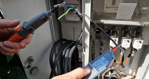
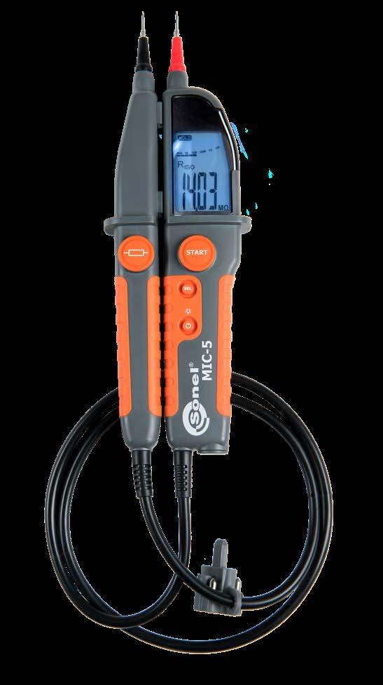
» measurement current up to 1.4 mA,
» low-voltage measurement of circuit continuity and resistance,

»
» PN-E 04700 (performance of measurements - commissioning tests)
SONEL
» HD 60364-4-41 (performance of measurements - shock protection)
» continuous indication of measured resistance,
» backlit display,
» sound signaling of five-second time intervals, facilitating capture of time characteristics,
» EN 61010-1 (general and particular requirements related to safety)
Other technical specifications:
» type of insulation
double, as per EN 61010-1 and EN 61557 power supply of the meter 2 LR03
alkaline batteries or Ni-MH rechargeable batteries - size AAA » display segmented LCD Standard accessories: Φ4 mm screw tip (set of 4 pcs.) WAPOZN4MMK 4 mm applied tip (set of 2 pcs.) WAPOZO4MMK 2x AAA / LR03 alkaline battery Declaration of verification Measurement of insulation resistance Measuring range according to EN 61557-2 for » Un=250 V: 250 kΩ...1.000 GΩ » Un=500 V: 500 kΩ...1.999 GΩ Display range Resolution Accuracy 1...249 kΩ | Un = 250 V 1...499 kΩ | Un = 500 V 1 kΩ not defined 250...1999 kΩ | Un = 250 V 500...1999 kΩ | Un = 500 V 1 kΩ ±(3% m.v. + 8 digits)2.00...19,99 MΩ 0.01 MΩ 20.0...199,9 MΩ 0.1 MΩ 200...1000 MΩ | Un = 250 V 200...1999 MΩ | Un = 500 V 1 MΩ Insulation resistance meter 50
» protection against measurement of live objects.
» EN 61010-031 (general and particular requirements related to safety)
» EN 61326 (electromagnetic compatibility)
MIC-5 index: WMGBMIC5
» measurement of direct and alternating voltages within the range of 0…600 V,

» automatic discharge of tested object’s capacitance after measurement of insulation resistance,
Additional functions of the meter:
The instrument meets the requirements set forth in the standards:
• •
•
Test lead 1 kV (banana plugs) blue 1.2 m WAPRZ1X2BUBB 1

• •
•
Crocodile clip, black, 11 kV, 32 A WAKROBL32K09 1 1 1 1 1


Test lead 1 kV (banana plugs, shielded) black 5 m WAPRZ005BLBBE


AGT-32T industrial socket adapter 32 A WAADAAGT32T
• •
Crocodile clip, black, 1 kV, 20 A WAKROBL20K01
AGT-63P three-phase socket adapter 63 A WAADAAGT63P
Test lead 5 kV (banana plugs) blue 1.8 m


AGT-16P three-phase socket adapter 16 A WAADAAGT16P

1
• •
Test lead 5 kV (banana plugs) red 1.8 m WAPRZ1X8REBB
•
• • • 1 1 1
Test lead 11 kV (banana plugs, shielded) black 1.8 m
• •
Test lead 11 kV (banana plugs) red 3 / 5 / 10 / 20 m
WS-04 adapter with UNI-Schuko angular plug WAADAWS04
Crocodile clip, red, 1 kV, 20 A WAKRORE20K02
Test lead 1 kV (banana plugs) red 1.2 m WAPRZ1X2REBB 1


WAPRZ010BUBB5KWAPRZ005BUBB5K
1 •
Test lead 1 kV (banana plugs) blue 5 m WAPRZ005BUBB


Test lead 11 kV (bananablueplugs) 3 / 5
• •
AGT-32C three-phase socket adapter 32 A (PEN) WAADAAGT32C
•
• • • 1 1 1
• • • • • •
WAPRZ010BLBBE5KWAPRZ005BLBBE5K
WAPRZ1X8BUBB
AutoISO-5000 adapter WAADAAISO50
AGT-16T industrial socket adapter 16 A WAADAAGT16T
Test lead 1 kV (banana plugs) red 5 m WAPRZ005REBB


• •
• •
Crocodile clip, blue, 11 kV, 32 A WAKROBU32K09 1 1 1 1 1


Test lead 5 kV (banana plugs, shielded) black 5 / 10 m
• • • • •
Crocodile clip, red, 11 kV, 32 A WAKRORE32K09 • 1 1 1 1 1


WAPRZ020BLBBE10KWAPRZ010BLBBE10KWAPRZ005BLBBE10KWAPRZ003BLBBE10K
Test lead 5 kV (banana plugs) blue 5 / 10 m
Photo Name Index MIC-15k1 MIC-10k1 MIC-5050 MIC-5010 MIC-5005 MIC-5001 MIC-2511 MIC-2501 MIC-30 MIC-10 MIC-5
• • • •
WAPRZ1X8BLBBE10K
1
• • • •
AGT-16Csocketthree-phaseadapter 16 A (PEN) WAADAAGT16C

AutoISO-2511 adapter WAADAAISO2511
• •
WAPRZ020REBB10KWAPRZ010REBB10KWAPRZ005REBB10KWAPRZ003REBB10K


Test lead 5 kV (banana plugs, shielded) black 1.8 m WAPRZ1X8BLBB
• • • • •
• •
/ 10 / 20 m WAPRZ020BUBB10KWAPRZ010BUBB10KWAPRZ005BUBB10KWAPRZ003BUBB10K • • • • Test lead 15 kV with crocodile clip, shielded, black 1.8 m WAPRZ1X8BLKROE15KV • • • • • Test lead 15 kV with crocodile clip, shielded, black 3 m WAPRZ003BLKROE15KV 1 1 1 • • Test lead 15 kV with crocodile clip, shielded, black 5 / 10 / 20 m WAPRZ020BLKROE15KVWAPRZ010BLKROE15KVWAPRZ005BLKROE15KV • • • • • Test lead 15 kV with crocodile clip, red 1.8 m WAPRZ1X8REKRO15KV • • • • • test lead 15 kV with crocodile clip, red 3 m WAPRZ003REKRO15KV 1 1 1 • • MIC Set of standard and optional accessories 1, 2, 4 - number of standard accessories - optional accessories 51
• • • 1 1 1
Photo Name Index
Test lead 1 kV (banana plugs, shielded) black 1.2 m WAPRZ1X2BLBBE
WAPRZ010REBB5KWAPRZ005REBB5K
AGT-32P three-phase socket adapter 32 A WAADAAGT32P
Test lead 1 kV (banana plugs) black 1.2 m WAPRZ1X2BLBB
• •
Test lead 11 kV (banana plugs) red 1.8 m WAPRZ1X8REBB10K • • 1 1
• 1
•
Test lead 11 kV (banana plugs, shielded) black 3 / 5 / 10 / 20 m
•
Test lead 11 kV (banana plugs) blue 1.8 m WAPRZ1X8BUBB10K • • 1 1
MIC-15k1 MIC-10k1 MIC-5050 MIC-5010 MIC-5005 MIC-5001 MIC-2511 MIC-2501 MIC-30 MIC-10 MIC-5
1 •
Test lead 5 kV (banana plugs) red 5 / 10 m


• •
Crocodile clip, blue, 1 kV, 20 A WAKROBU20K02
• •
• •
• • 1 1
1 1 Z32 power supply
•
WASONPRS2KIT
Pin probe, blue 1 kV (banana socket) WASONBUOGB1


• • •
•
•
of standard and optional accessories 1, 2, 4 - number of standard accessories - optional accessories Photo Name Index MIC-15k1 MIC-10k1 MIC-5050 MIC-5010 MIC-5005 MIC-5001 MIC-2511 MIC-2501 MIC-30 MIC-10 MIC-5
test lead kV
WAPRZ020BUKRO15KVWAPRZ010BUKRO15KVWAPRZ005BUKRO15KV • • • • •
Test lead 15 kV with crocodile clip, blue 5 / 10 / 20 m
MIC
1 • •
Test lead 15 kV with crocodile clip, blue 1.8
Set for withresistancemeasuringinzonesESDprotection(kitwithacaseandPRS-1 probe)


•
Pin probe, black 5 kV (banana socket) WASONBLOGB2 1 1 1
15
Pin probe, red 11 kV (banana socket) WASONREOGB11 1 1 (set of 4 pcs.) (set of 2 pcs.) WAPOZO4MMK WAZASZ7 WAZASZ32

Pin probe, red 5 kV (banana socket) WASONREOGB2 1 1 1
Pin probe, black 11 kV (banana socket) WASONBLOGB11 1 1
WAPOZN4MMK 1 4 mm applied tip
Φ4 mm screw tip
Probe for measuring resistance in zones with ESD protection (kit with a case)


PRS-1 resistance test probe

Pin probe, red 1 kV (banana socket) WASONREOGB1 1 1
Set
• • •
m WAPRZ1X8BUKRO15KV • • • • •
•
Pin probe, black 1 kV (banana socket) WASONBLOGB1 1 1


with crocodile clip, red 5 / 10 / 20 m WAPRZ020REKRO15KVWAPRZ010REKRO15KVWAPRZ005REKRO15KV • • • • •
Test lead 15 kV with crocodile clip, blue 3 m WAPRZ003BUKRO15KV 1 1
WASONPRS2

WASONPRZ2
WASONPRS1GB

1 CS-1 cable simulator WAADACS1 • • • • • • • • • • • CS-5kV calibration box WAADACS5KV • • • • • • • • • • • SRP-10G0-10T0 resistance calibrator WMGBSRP10G010T0 • • • • • Li-Ion 10.8 V 3.5 Ah rechargeable battery WAAKU29 1 Photo Name Index MIC-15k1 MIC-10k1 MIC-5050 MIC-5010 MIC-5005 MIC-5001 MIC-2511 MIC-2501 MIC-30 MIC-10 MIC-5 Z7 power supply
1 Mains cable with IEC C7 plug WAPRZLAD230 1 1 Mains cable with IEC C13 plug WAPRZ1X8BLIEC 1 1 1 1 1 Cable for battery charging from car cigarette lighter socket (12 V) WAPRZLAD12SAM • • Hanging strap WAPOZPAS6 1 M1 hanging straps WAPOZSZE4 1 1 W1 hanging straps WAPOZSZE5 1 • • 1 1 • M1 hanging hook straps WAPOZUCH1 1 1 L4 carrying case WAFUTL4 1 1 1 1 1 M6 carrying case WAFUTM6 1 1 1 M8 carrying case WAFUTM8 1 1 M15 carrying case WAFUTM15 • S2 carrying case WAFUTS2 • Mini Bluetooth keyboard WAADAMK • • S4 armband case for Mini Bluetooth keyboard WAFUTS4 • • Mini Bluetooth keyboard with S4 armband case WAADAMKZ • • USB cable WAPRZUSB 1 1 1 1 1 1 1 Type C USB cable WAPRZUSBC 1 PC software: Sonel Reports PLUS WAPROREPORTSPLUS • • • • • • • • • PC Sonelsoftware:Reader WAPROREADER • • • • • • • • • 52


Temperature probe ST-1 WASONT1
• • • • • • • • • •
Probe for measuring resistance in zones with ESD protection (2 pcs.)


Fault loop impedance meters MZC-310SMZC-320SMZC-330S MZC-306 MZC-20EMZC-304
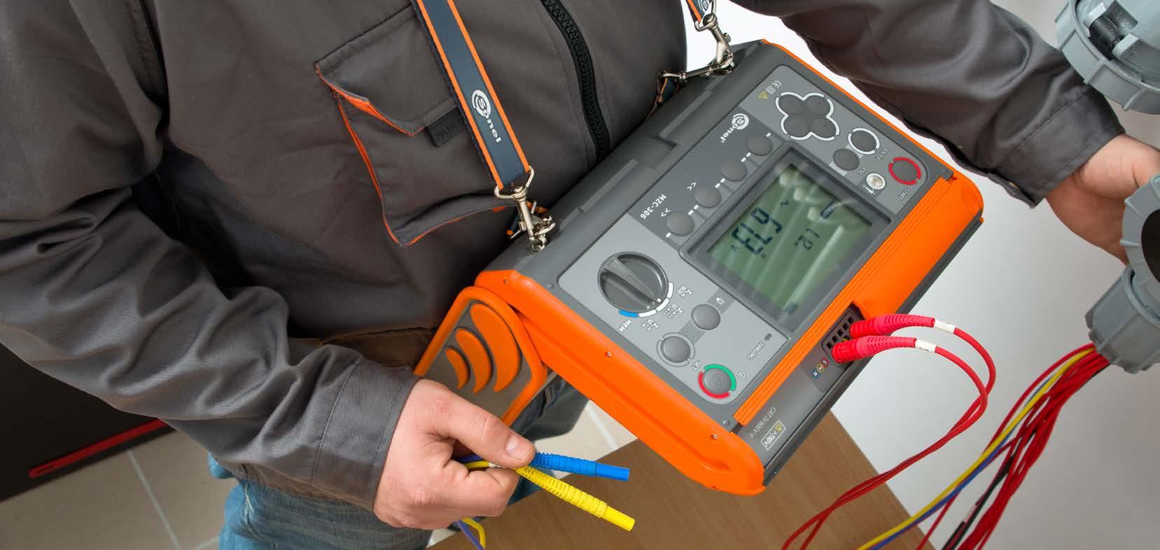
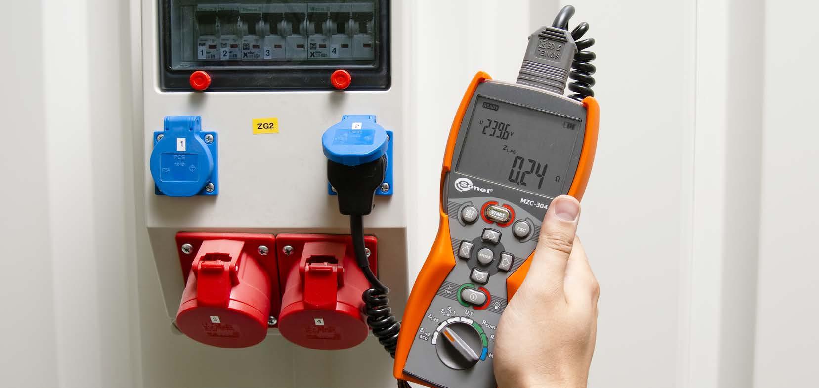

Comparison of fault loop impedance meters MZC-330S MZC-320S MZC-310S MZC-306 MZC-304 MZC-20E MPI-540-PVMPI-540MPI-536MPI-535 MPI-530-ITMPI-530 MPI-520MPI-525 MPI-502MPI-506MPI-507 Rated voltage [V] 290/500240/415230/400220/380127/220115/200110/190400/690 290/500240/415230/400220/380127/220115/200110/190 230/400220/380 400/690290/500240/415230/400220/380127/220115/200110/190 240/415230/400220/380 240/415230/400220/380 240/415230/400220/380127/220115/200110/190 240/415230/400220/380127/220115/200110/190 240/415230/400220/380127/220115/200110/190 240/415230/400220/380 Operating voltage range [V] 100…750 100…550 187…440 100…750 180…460 180…440 95…440 95…440 95…440 180…460 Display range [Ω] 0…1999 0…1999 0…199.9 0…1999 0…1999 0…200 0…1999.9 0…1999 0…1999 0…1999 Maximum resolution [Ω] 0.001 0.001 0.001 0.01 0.01 0.01 0.001 0.001 0.01 0.01 Maximum resolution for measurement with 15 mA current [Ω] 0.01 0.01 0.01 0.01 0.01 0.01 0.01 Max. measurement current [A] 130/280 130/280 160/280 12.2…36.7 7.6/13.3 15.3/26.7 23/44 23/44 23/44 7.6/13.3 Measuring range according to EN 61557 [Ω] 0.0072…1999 0.0072…1999 0.0072…199.9 0.13…1999 0.13…1999 0.24…200 0.50…1999 0.13…1999 0.13…1999 0.13…1999 Display of fault loop resistance and reactance √ √ √ √ √ √ √ √ √ √ Calculation of prospective fault current on the basis of rated voltage √ √ √ √ √ √ √ √ √ √ Calculation of prospective fault current on the basis of measured voltage √ √ √ Memory (number of each type of measurement) 990 990 990 990 990 UNLIMITED 10 000 990 990 4-lead method √ √ √ Measurement of prospective touch and shock voltage √ √ √ Selection of test lead length √ √ √ √ √ √ √ √ √ √ In-socket measurement by means of adapter - plug Option √ √ √ √ √ Triggeringbyof measurementsadapter Option Option √ √ √ Option Alternating voltage measurement √ √ √ √ √ √ √ √ √ √ Dimensions [mm] 390 x 308 x 172 390 x 308 x 172 295 x 222 x 95 288 x 223 x 75 220 x 98 x 58 220 x 98 x 58 288 x 223 x 75 288 x 223 x 75 288 x 223 x 75 220 x 98 x 58 Weight [kg] 6.5 6.5 2.2 2.2 0.6 0.5 2.5 2.2 2.2 0.6 54


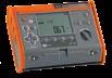

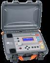
Short circuit loop parameters measurement using standards current (2p, Imax=37 A)
Test lead 1.2 m, black, 1 kV (banana plugs) WAPRZ1X2BLBB
» operating temperature range -10…+40°C
Display range Resolution Accuracy 0…199.9 mΩ 0.1 mΩ ±(2% m.v. + 2 mΩ)200…1999 mΩ 1 mΩ
Additional functions of the meter:
Pin probe, black 1 kV (banana socket) WASONBLOGB1 Pin probe, yellow 1 kV (banana socket) WASONYEOGB1
» differentiation between the phase voltage and the inter-phase voltage while calculating the short circuit current,
» dimensions 390 x 308 x 172 mm
Test lead 1.2 m, yellow, 1 kV (banana plugs) WAPRZ1X2YEBB
» ability to perform measurements in short circuit system: phase-phase, phase-PE, phase-N,
double, according to EN 61010-1 and IEC 61557
Calculated on the basis of error for fault loop 200…1999 A 1 A 2.00…19.99 kA 0.01 kA 20.0…199.9 kA 0.1 kA 200 kA… * 1 kA *max 690 kA for MZC-330S, max 500 kA for MZC-320S
Standard accessories:
» measurement of very low short circuit loop impedances (with resolution 0,1 mΩ) with a current of 130 A at 230 V; maximum 300 A at 690 V (500 V in MZC-320S),
» touch voltage and touch shock voltage measurement with resistor 1 kΩ),
» power supply: rechargeable battery,
» frequency measurement 45.0...65.0 Hz,
» measurement with a current of 24 A at 230 V, maximum 37 A at 690 V (maximum 27 A at 500 V in MZC-320S) with resolution 0,01 Ω,
Electric security:
» temperature coefficient ±0,1% of measured value/°C
Doble-wire test lead 3 m (10 A / 25 A) U1/I1 WAPRZ003DZBBU1I1
» memory of 990 measurement results, ability to transfer the data to a PC via USB and Bluetooth,
meters are the only meters on the market that also enable touch voltage or shock voltage measurement, which can be employed during safety assessment of a tested system. 750 V maximumnetworkvoltage MZC-330S 0.1 mΩ maximumresolution 55

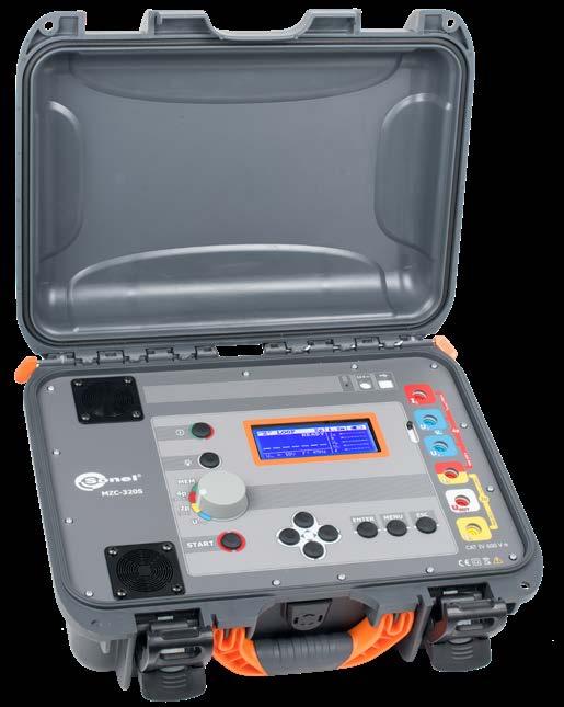
» 4p (four-pole) method, test leads do not require calibration (measurement with current up to 300 A),
Display range Resolution Accuracy 0…100 V 1 V ±(10% m.v. + 2 digits)
» measurements in installations with rated voltages: 110/190 V, 115/200 V, 127/220 V, 220/380 V, 230/400 V, 240/415 V, 290/500 V and 400/690 V (MZC-330S only) and frequencies 45…65 Hz,
L-14 carrying case WAFUTL14 USB cable WAPRZUSB Factory calibration certificate
Measuring range according to IEC61557: 0,13 Ω…199,9 Ω for test leads length 1,2 m
High-current fault loop impedance meters
The MZC-310S, 320S 330S
Other technical specifications:
» AC voltage measurement in range 0…750 V (0...550 V in MZC-320S),
and
» ability to change the length of test lead (measurement with 2p method),
SONEL MZC-330S / MZC-320S
» resistor limiting the current: for 4 pole method (4p) 1.8 Ω for U≤550 V 2.5 Ω for U>550 V (MZC-330S) for two pole method (2p) 9.4 Ω for U≤253 V 19 Ω for U>253 V
2x high-current pin probe 1 kV (banana sockets) WASONSPGB1 Mains cable with IEC C7 plug WAPRZLAD230
4x crocodile clip, black, 1 kV, 32 A WAKROBL30K03
2x Kelvin clamp, 1 kV, 25 A WAKROKELK06
» protection class acc. EN 60529 IP67 (IP20 with front cover open)
Doble-wire test lead 3 m (10 A / 25 A) U2/I2 WAPRZ003DZBBU2I2
index: WMGBMZC330 / WMGBMZC320
» power supply built in Li-Ion 7.2 V / 8.8 Ah rechargeable battery
Display range Resolution Accuracy 115.0…199.9 A 0.1 A
» weight 6.5 kg
» measurement of resistance (RS) and reactance (XS) components.
» number of short circuit loop measurements min. 4000 (2/min)
Nominal operating conditions:
Power supply adaptor Z19 WAZASZ19
» measurement category IV 600 V acc. to EN 61010-1
» type of insulation
Touch voltage measurements UST and shock voltage UT
High-current measurement of fault loop impedance ZS: measuring range according to EN 61557-3: 7.2 mΩ…1999 mΩ
Fault loop impedance measurement:
Display range Resolution Accuracy 0.00…19.99 Ω 0.01 Ω ±(2% m.v. + 3 digits) 20.0…199.9 Ω 0.1 Ω ±(3% m.v. + 3 digits)
» the device meets the requirements of EN 61557 standard.
High-current measurement of fault loop parameters (4-lead Imax = 300 A)
Short circuit current indication Measuring range according to IEC 61557 for Un = 230 V 115.0 A…32.9 kA for Un = 400 V 200 A…55.5 kA for Un = 500 V 250 A…69.4 kA for Un = 690 V 345 A…95.8 kA (MZC-330S)
» memory of 990 measurement results, ability to transfer the data to a PC via RS-232,
» EN 61010-031 (general and particular requirements related to safety)
Pin probe, yellow 1 kV (banana socket) WASONYEOGB1
Measurement of fault loop impedance ZS with standard current (2-lead, Imax=42 A) measuring range for 1.2 m test leads according to EN 61557: 0.13 Ω…199.9 Ω
Additional functions of the meter:
Calculated on the basis of error for fault loop 200…1999 A 1 A 2.00…19.99 kA 0.01 kA 20.0…199.9 kA 0.1 kA 200kA… * 1 kA *230 kA for UL-N 400 kA for UL-L
» ability to perform measurements in short circuit system: phase-phase, phase-PE, phase-N,


UNI-SONEL hanging straps WAPOZSZE1
» EN 61557 (requirements for measurement instruments)
» measurements in installations with rated voltages: 220/380 V and 230/400 V and frequencies 45…65 Hz,
» differentiation between the phase voltage and the inter-phase voltage while calculating the short circuit current,
RS-232 serial transmission cable WAPRZRS232
Standard accessories:
WMGBMZC310
Measurement of touch voltage UST and shock voltage UT Display range Resolution Accuracy 0…100 V 1 V ±(10% m.v. + 2 digits)
L1 carrying case
» measurement with a current of 23 A at 230 V, maximum 42 A at 440 V with resolution 0,01 Ω,
Pin probe, black 1 kV (banana socket) WASONBLOGB1
» EN 61326 (electromagnetic compatibility)
» 4p (four-pole) method, test leads do not require calibration (measurement with current up to 280 A),
The instrument meets the requirements set forth in the standards:
» power supply: rechargeable battery (5x LR14).
2x high-current pin probe 1 kV (banana sockets) WASONSPGB1
0.1 mΩ maximumresolution 56
» type of insulation
High-current measurement of fault loop impedance ZS: measuring range according to EN 61557-3: 7.2 mΩ…1999 mΩ
Fault current readings Measuring range according to EN 61557- 3: for Un = 230 V 115.0 A…32.0 kA for Un = 400 V 200 A…55.7 kA
» HD 60364-6 (performance of measurements - checking)
» operating temperature range 0…+40°C
» temperature coefficient ±0,1% of measured value/°C
High-current measurement of fault loop parameters (4-lead, Imax = 280 A)
double, as per EN 61010-1 and EN 61557
» number of fault loop measurements (alkaline batteries) at least 4000 (2/min.)
» power supply of the meter LR14 alkaline batteries (size C) (5 pcs.)
Fault loop impedance measurement:
Nominal operating conditions:
» AC voltage measurement in range 0…440 V,
Display range Resolution Accuracy 0.00…19.99 Ω 0.01 Ω ±(2% m.v. + 3 digits) 20.0…199.9 Ω 0.1 Ω ±(3% m.v. + 3 digits)
High-current fault loop impedance meter
SONEL MZC-310S
Double-wire test lead 3 m (10 A / 25 A) U2/I2 WAPRZ003DZBBU2I2
» EN 61010-1 (general and particular requirements related to safety)
» touch voltage and touch shock voltage measurement with resistor 1 kΩ),
» measurement of very low short circuit loop impedances (with resolution 0,1 mΩ) with a current of 150 A at 230 V; maximum 280 A at 440 V,
2x Kelvin clamp, 1 kV, 25 A WAKROKELK06
Test lead 1.2 m, black, 1 kV (banana plugs) WAPRZ1X2BLBB
Display range Resolution Accuracy 115.0…199.9 A 0.1 A
» frequency measurement 45.0...65.0 Hz,
Double-wire test lead 3 m (10 A / 25 A) U1/I1 WAPRZ003DZBBU1I1
» measurement of resistance (RS) and reactance (XS) components.
The MZC-310S, 320S and 330S meters are the only meters on the market that also enable touch voltage or shock voltage measurement, which can be used during safety assessment of a tested system.
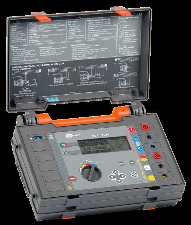
» ability to change the length of test lead (measurement with 2p method),
» current-limiting resistor for 4-lead measurement: 1.5 Ω, for 2-lead measurement: 10 Ω
index:
» HD 60364-4-41 (performance of measurements - shock protection)
Other technical specifications:
Test lead 1.2 m, yellow, 1 kV (banana plugs) WAPRZ1X2YEBB
WAFUTL1
4x crocodile clip, black, 1 kV, 32 A WAKROBL30K03
» PN-E 04700 (performance of measurements - commissioning tests)
Display range Resolution Accuracy 0…199.9 mΩ 0.1 mΩ ±(2% m.v. + 2 mΩ)200…1999 mΩ 1 mΩ
Factory calibration certificate
Pin probe, red 1 kV (banana socket) WASONREOGB1
Electrical safety:
Measurement of earth fault loop impedance ZL-PE in RCD mode
Pin probe, blue 1 kV (banana socket) WASONBUOGB1
WAPOZSZEKPL
Other technical specifications:
Test lead 1.2 m, blue, 1 kV (banana plugs) WAPRZ1X2BUBB
Instruments meet the requirements set forth in the standards:
Display range Resolution Accuracy 0.00…19.99 Ω 0.01 Ω ±(5% m.v. + 3 digits) 20.0…199.9 Ω 0.1 Ω ±(4% m.v. + 3 digits)200…1999 Ω 1 Ω
L4 carrying case
» EN 61326 (electromagnetic compatibility)
Nominal operating conditions:
» EN 61010-1 (general and particular requirements related to safety)
WS-05 adapter with UNI-SCHUKO angular plug WAADAWS05
Factory calibration certificate
» voltage measurement 0...750 V AC (0...250 V with resolution of 0,1 V),
Additional functions of the meter:
» humidity 20…80%
index: WMGBMZC306
L2 hanging straps (set)
Test lead 1.2 m, yellow, 1 kV (banana plugs)
fault loop impedance measurements in industrial networks of any voltage up to 750 V. 750 V maximumnetworkvoltage IΔn measurementswithouttrippingRCDs 57
» HD 60364-6 (performance of measurements - checking)
NiMH battery 4.8 V 4.2 Ah
» measurement of resistance (RS) and reactance (XS) components.
» EN 61557 (requirements for measurement instruments)
Display range Resolution Accuracy 0.00…19.99 Ω 0.01 Ω ±(6% m.v. + 10 digits) 20.0…199.9 Ω 0.1 Ω ±(6% m.v. + 5 digits)200…1999 Ω 1 Ω
WAZASZ7
Meter calculates
» type of insulation
double, as per EN 61010-1 and EN 61557
» EN 61010-031 (general and particular requirements related to safety)
Pin probe, yellow 1 kV (banana socket) WASONYEOGB1
Measuring range acc. to EN 61557-3 for 1.2 m test leads: 0.13…1999 Ω
Mains cable with IEC C7 plug WAPRZLAD230
» measurement with swapped L and N conductors,
Fault loop impedance meter

» HD 60364-4-41 (performance of measurements - shock protection)
Standard accessories:
Fault loop impedance measurement:
» calculation of Ik fault current,
» power supply: batteries (4 x LR14) or rechargeable batteries.
the value of prospective fault current in compliance with standard HD 60364-6.
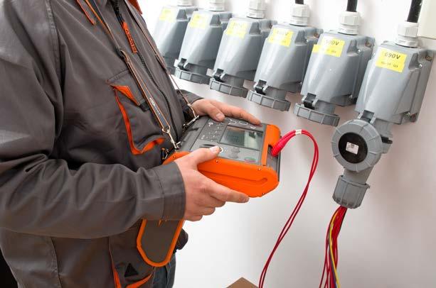
MZC-306 meter performs
» possibility of applying an adapter terminated by a power network plug or 1.2, 5, 10, 20 m test leads,
» operating frequency 45…65 Hz,
WAFUTL4
USB cable
SONEL MZC-306
Z7 Power supply
Crocodile clip, red, 1 kV, 20 A WAKRORE20K02
WAAKU07
Test lead 1.2 m, red, 1 kV (banana plugs) WAPRZ1X2REBB
» low-current impedance measurement in circuits protected by RCD ≥ 30mA with 0.01 Ω resolution (range of 100…440 V),
» operating temperature range 0…+45°C
» contact electrode - quick testing of proper connection of PE conductor,
» rechargeable battery or alkaline battery performance at least 5000 measurements (2/min)
» display backlit LED
WAPRZUSB
» automatic differentiation between phase and phase-to-phase voltage,
» test leads EN 61010-2-031
» operates in networks with voltages 110/190 V, 115/200 V, 127/220 V, 220/380 V, 230/400 V, 240/415 V, 290/500 V and 400/690 V (operating range 100…750 V),
Crocodile clip, blue, 1 kV, 20 A WAKROBU20K02
» fault loop impedance measurement with 0.01 Ω resolution,
» PN-E 04700 (performance of measurements - commissioning tests)
Measurement of fault loop impedance ZL-PE, ZL-N, ZL-L
» memory of 990 measurement results, ability to transfer the data to a PC via USB,
Measuring range according to EN 61557-3 for 1,2 m leads: 0.43…1999 Ω
WAPRZ1X2YEBB
Nominal voltage: 100…440 V (for ZL-PE and ZL-N) or 100…750 V (for ZL-L)
» meter power supply rechargeable battery pack or (optional) alkaline batteries
» operates in networks with voltages 220/380 V, 230 V/400 V, 240/415 V (operating range 180...460 V),
» calculation of Ik fault current,
double, as per EN 61010-1 and EN 61557
Factory calibration certificate
The MZC-304 meter calculates the value of prospective fault current in compliance with standard HD 60364-6.

» test leads EN 61010-2-031
Measuring range for 1.2 m leads according to EN 61557-3: 0.51 Ω…1999 Ω
Nominal operating conditions:
» operating voltage range: 180…270 V (for ZL-PE and ZL-N) and 180…460 V (for ZL-L),
» power supply of the meter pack of rechargeable batteries or alkaline batteries (size AA, 4 pcs.)
Measurement of fault loop impedance ZL-PE, ZL-N, ZL-L, fault loop resistance and reactance
Test lead 1,2 m, red, 1 kV (banana plugs) WAPRZ1X2REBB
Electrical safety:
index: WMGBMZC304
» type of insulation
» operating frequency 45…65 Hz,
» operating temperature range 0…+50°C humidity 20…80%
»
» power supply: batteries (4 x LR14) or rechargeable batteries (4 x NiMH).
Crocodile clip, yellow, 1 kV, 20 A WAKROYE20K02
» measurement of resistance (RS) and reactance (XS) components,
Test lead 1,2 m, yellow, 1 kV (banana plugs) WAPRZ1X2YEBB
» EN 61010-1 (general and particular requirements related to safety)
» PN-E 04700 (performance of measurements - commissioning tests)
» rechargeable battery life at least 5000 measurements (2/min)
58
IΔn
» HD 60364-6 (performance of measurements - checking)
» low-current impedance measurement in circuits protected by RCD ≥ 30mA with 0.01 Ω resolution (range of 180...270 V),
WS-05 adapter with UNI-Schuko angular plug WAADAWS05
» measurement with swapped L and N conductors,
Measuring range for 1.2 m test leads according to EN 61557-3: 0.13 Ω…1999 Ω
M1 hanging straps WAPOZSZE4
SONEL MZC-304
Other technical specifications:
Pin probe, blue 1 kV (banana socket) WASONBUOGB1
» voltage measurement 0...500 V,
» EN 61010-031 (general and particular requirements related to safety)
» fault loop impedance measurement with 0.01 Ω resolution,
Test lead 1,2 m, blue, 1 kV (banana plugs) WAPRZ1X2BUBB
» EN 61557 (requirements for measurement instruments)
Fault loop impedance meter
The MZC-304 meter measures fault loop impedance with 0.01 Ω resolution, including in circuits protected by RCDs, without tripping them.
Standard accessories:
Pin probe, red 1 kV (banana socket) WASONREOGB1
» maximum measuring current: 7.6 A for 230 V (3x10 ms), 13.3 A for 400 V (3x10 ms),
» does not trip RCDs with I∆n ≥ 30 mA
Display range Resolution Accuracy 0.00…19.99 Ω 0.01 Ω ±(5% m.v. + 3 digits)20.0…199.9 Ω 0.1 Ω 200…1999 Ω 1 Ω
Display range Resolution Accuracy 0.00…19.99 Ω 0.01 Ω ±(6% m.v. + 10 digits) 20.0…199.9 Ω 0.1 Ω ±(6% m.v. + 5 digits)200…1999 Ω 1 Ω
» frequency measurement 45.0...65.0 Hz,
» EN 61326 (electromagnetic compatibility)
» measurement category CAT III 600 V (CAT IV 300 V) according to EN 61010-1
Measurement of earth fault loop impedance ZL-PE in RCD mode (without tripping RCD)
» HD 60364-4-41 (performance of measurements - shock protection)
Additional functions of the meter:
» housing protection rating according to EN 60529 IP67
» memory of 990 measurement results, ability to transfer the data to a PC via Bluetooth,
» low-voltage measurement of continuity of circuit and resistance.
MZC-304 always measures total fault loop impedance as well as its components –resistance and reactance – regardless of the phase shift value. measurementswithouttrippingRCDs
» contact electrode - quick testing of proper connection of PE conductor,
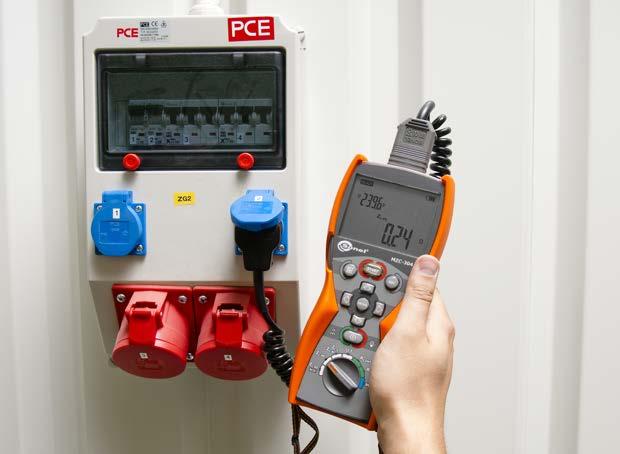
M6 carrying case WAFUTM6
Fault loop impedance measurement:
The instrument meets the requirements set forth in the standards:
» measurement category CAT III 300 V according to EN 61010-1

Ω 59
» the instrument is compliant with standards EN 61326-1 and EN 61326-2-2
Test lead 1,2 m, red, 1 kV (banana plugs) WAPRZ1X2REBB
SONEL MZC-20E
M1 hanging hook straps WAPOZUCH1
Measurement of fault loop impedance ZS Test lead ZS measuring range 1.2 m 0.24…200 Ω 5 m 0.26…200 10 m 0.28…200 20 m 0.35…200
» measurement of resistance (RS) and reactance (XS) components.
Fault loop impedance meter
Ω
double, as per EN 61010-1 and IEC 61557
Ω
» Maximum measurement current: 15.3 A for 230 V (10 ms) and 26.7 A for 400 V (10 ms) Readings of fault loop resistance RS and fault loop reactance ZS: Display range Resolution Accuracy 0.00…9.99 Ω 0.01 Ω ±(5% m.v. + 5 digits) of ZS value
» time until Auto-OFF max. 900 seconds
» power supply: batteries (4 x LR6) or rechargeable batteries (4 x NiMH).
» reference humidity 40…60%
Pin probe, red 1 kV (banana socket) WASONREOGB1
» measurement with swapped L and N conductors,
» calculation of Ik fault current,
» Operating frequency range: 45…65 Hz
» humidity 20…80%
» operating frequency 45…65 Hz,
Fault current IK: 0.115÷1769 A (Un=230 V)
» operates in networks with voltages 220/380 V, 230/400 V, 240/415 V (operating range 180…440 V),
» quality standard development, design and production in compliance with ISO 9001
» elevation above sea level <2000 m
Factory calibration certificate
AC voltage measurement: 0÷440 V Display range Resolution Accuracy 0.00…19.99 Ω 0.01 Ω ±(2.5% m.v. + 5 digits) 20.0…99.9 Ω 0.1 Ω ±(2.5% m.v. + 3 digits) 100…200 Ω 1 Ω ±(3% m.v. + 3 digits)
» operating temperature range -10…+50 oC
» storage temperature -20…+70 oC
Test lead 1,2 m, blue, 1 kV (banana plugs) WAPRZ1X2BUBB
» the instrument meets the requirements set forth in the standards IEC 61557
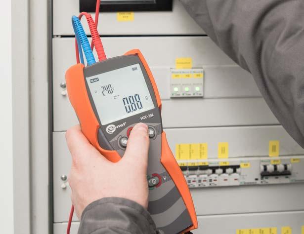
» reference temperature +23…± 2 oC
» display segmented LCD
Standard accessories:
» housing protection rating according to EN 60529 IP67
Measurement of fault loop impedance ZS within the range of 0.24…200 Ω
» meter weight with battery pack 509 g
» Nominal network frequency fn: 50 Hz, 60 Hz
Display range Resolution Accuracy 0…440 V 1 V ±(2.5% m.v. + 3 digits)
» dimensions 220 x 98 x 58 mm
» possibility of applying test leads: 1.2 m, 5 m and longer,
Crocodile clip, red, 1 kV, 20 A WAKRORE20K02
Pin probe, blue 1 kV (banana socket) WASONBUOGB1
» Nominal operating voltage UnL-N/UnL-L : 220/380 V, 230/400 V, 240/415 V
M1 hanging straps WAPOZSZE4
Additional functions of the meter:
Calculated on the basis of uncertainty for fault loop 10.0…99.9 A 0.1 A 100…999 A 1 A 1.00…9.99 kA 0.01 kA 10.0…40.0 kA 0.1 kA
M13 carrying case WAFUTM13
» fault loop impedance measurement with 0.01 Ω resolution,
» Operating voltage range: 180…270 V (for ZL-PE and ZL-N) and 180…440 V (for ZL-L)
» automatic differentiation between phase and phase-to-phase voltage,
» type of insulation
Voltage measurement
» Calculated and displayed for ZS < 10 Ω Readings of fault current IK Measuring ranges according to EN 61557 can be calculated on the basis of ZS measurement ranges and nominal voltages
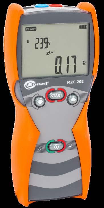
Fault loop impedance measurement:
Other technical specifications:
Other technical specifications:
Display range Resolution Accuracy 1.15…9.99 A 0.01 A
» power supply of the meter LR6 alkaline batteries or AA Ni-MH rechargeable batteries (4 pcs.)
» number of Z measurements (for rechargeable batteries) >5000 (2 measurements/minute)
» voltage measurement 0...440 V AC,
index: WMGBMZC20E
MZC-310S
High-current pin probe 1 kV (banana sockets) WASONSPGB1 2 2 2
Test lead 1.2 m, red, 1 kV (banana plugs) WAPRZ1X2REBB 1 1 1
Pin probe, blue 1 kV (banana socket) WASONBUOGB1 1 1 1
Doble-wire test lead 6 m (10 A / 25 A) U1/I1 WAPRZ006DZBBU1I1

AGT-16Csocketthree-phaseadapter 16 A (PEN) WAADAAGT16C


Test lead 1.2 m, yellow, 1 kV (banana plugs)
MZC-330S
Foldable pin probe, 1 kV, 2 m (banana socket) WASONSP2M
Doble-wire test lead 3 m (10 A / 25 A) U2/I2 WAPRZ003DZBBU2I2 1 1 1
AGT-63P three-phase socket adapter 63 A WAADAAGT63P
Doble-wire test lead 3 m (10 A / 25 A) U1/I1 WAPRZ003DZBBU1I1 1 1 1
Pin probe, yellow 1 kV (banana socket) WASONYEOGB1 1 1 1 1
• •
Battery container WAPOJ1
• • • •
• • •
Test lead 1.2 m, blue, 1 kV (banana plugs) WAPRZ1X2BUBB 1 1 1

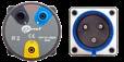
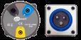
•
• • • •
WAPRZ1X2YEBB 1 1 1 1 1

• •
AGT-16P three-phase socket adapter 16 A WAADAAGT16P
AGT-32P three-phase socket adapter 32 A WAADAAGT32P
Test lead 5 m, red, 1 kV (banana plugs) WAPRZ005REBB
• •
WS-01 adapter with START button with UNI-SCHUKO plug WAADAWS01
Doble-wire test lead 6 m (10 A / 25 A) U2/I2 WAPRZ006DZBBU2I2
Crocodile clip, blue, 1 kV, 20 A WAKROBU20K02 1

1, 2, 4 - number of standard
• • • •
AGT-16T industrial socket adapter 16 A WAADAAGT16T
• • •
Test lead 5 m, yellow, 1 kV (banana plugs) WAPRZ005YEBB
•
• • •
Pin probe, black 1 kV (banana socket) WASONBLOGB1 1 1 1
NiMH battery 4.8 V 4.2 Ah WAAKU07 1
Crocodile clip, yellow, 1 kV, 20 A WAKROYE20K02 1


MZC-306 MZC-304 MZC-20E
Pin probe, red 1 kV (banana socket) WASONREOGB1 1 1 1


Test lead 10 m, yellow, 1 kV (banana plugs) WAPRZ010YEBB
Crocodile clip, red, 1 kV, 20 A WAKRORE20K02 1 1


Pin probe, red 11 kV (banana socket) WASONREOGB11
•
• • •
•
Crocodile clip, black, 1 kV, 32 A WAKROBL30K03 4 4 4
MZC
Test lead 20 m, red, 1 kV (banana plugs) WAPRZ020REBB


Set
WS-07 adapter for measuring Z(L-N) WAADAWS07
of standard and optional accessories
• • • •
Test lead 1.2 m, black, 1 kV (banana plugs) WAPRZ1X2BLBB 1 1 1
• • •
• •
• • •
Photo Name Index MZC-330S MZC-320S MZC-310S MZC-306 MZC-304 MZC-20E
• • • •
AGT-32Csocketthree-phaseadapter 32 A (PEN) WAADAAGT32C


•
AGT-32T industrial socket adapter 32 A WAADAAGT32T
WS-05 adapter with UNI-SCHUKO angular plug WAADAWS05 1 1
MZC-320S
• • • •
• Kelvin clamp, 1 kV, 25 A WAKROKELK06 2 2 2
Test lead 20 m, yellow, 1 kV (banana plugs) WAPRZ020YEBB
• • • •
Photo Name Index
accessories • - optional accessories 60
Test lead 10 m, red, 1 kV (banana plugs) WAPRZ010REBB

• • •
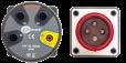
MZC Set of standard and optional accessories 1, 2, 4 - number of standard accessories • - optional accessories Photo Name Index MZC-330S MZC-320S MZC-310S MZC-306 MZC-304 MZC-20E Mains cable with IEC C7 plug WAPRZLAD230 1 Z7 Power supply WAZASZ7 1 Power adaptorsupplyZ19 WAZASZ19 1 1 Cable for battery charging from car cigarette lighter socket (12 V) WAPRZLAD12SAM • Reel for long test lead WAPOZSZP1 • UNI-SONEL hanging straps WAPOZSZE1 1 L2 hanging(short)straps WAPOZSZE2 M1 hanging straps WAPOZSZE4 • 1 1 L2 hanging straps (set) WAPOZSZEKPL 1 M1 hanging hook straps WAPOZUCH1 1 L1 carrying case WAFUTL1 1 L2 carrying case WAFUTL2 • Photo Name Index MZC-330S MZC-320S MZC-310S MZC-306 MZC-304 MZC-20E L4 carrying case WAFUTL4 • • 1 L14 carrying case WAFUTL14 1 1 M6 carrying case WAFUTM6 1 M13 carrying case WAFUTM13 1 USB cable WAPRZUSB 1 1 1 RS-232 serial transmission cable WAPRZRS232 1 USB/RS-232 converter WAADAUSBRS232 • OR-1 USB wireless receiver WAADAUSBOR1 • PC Sonelsoftware:Reader WAPROREADER • • • • • 61
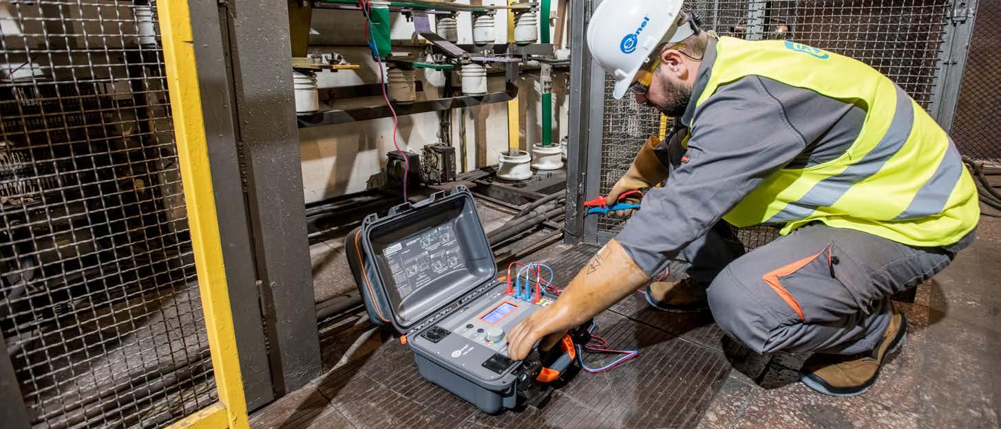


Earth resistance meters MRU-120MRU-120HDMRU-200MRU-200-GPS MRU-30 MRU-10MRU-11MRU-21
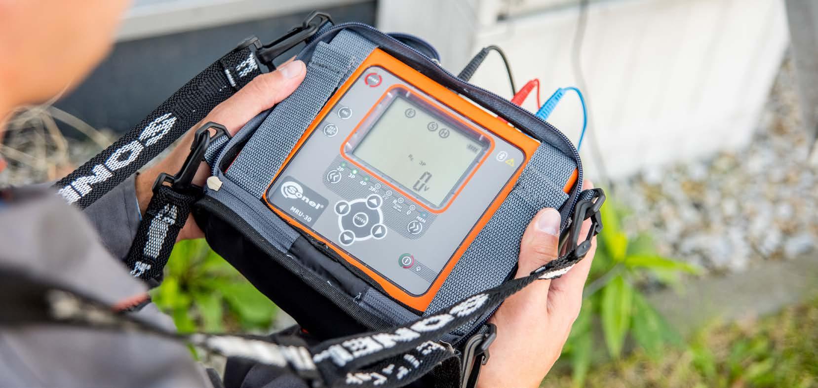
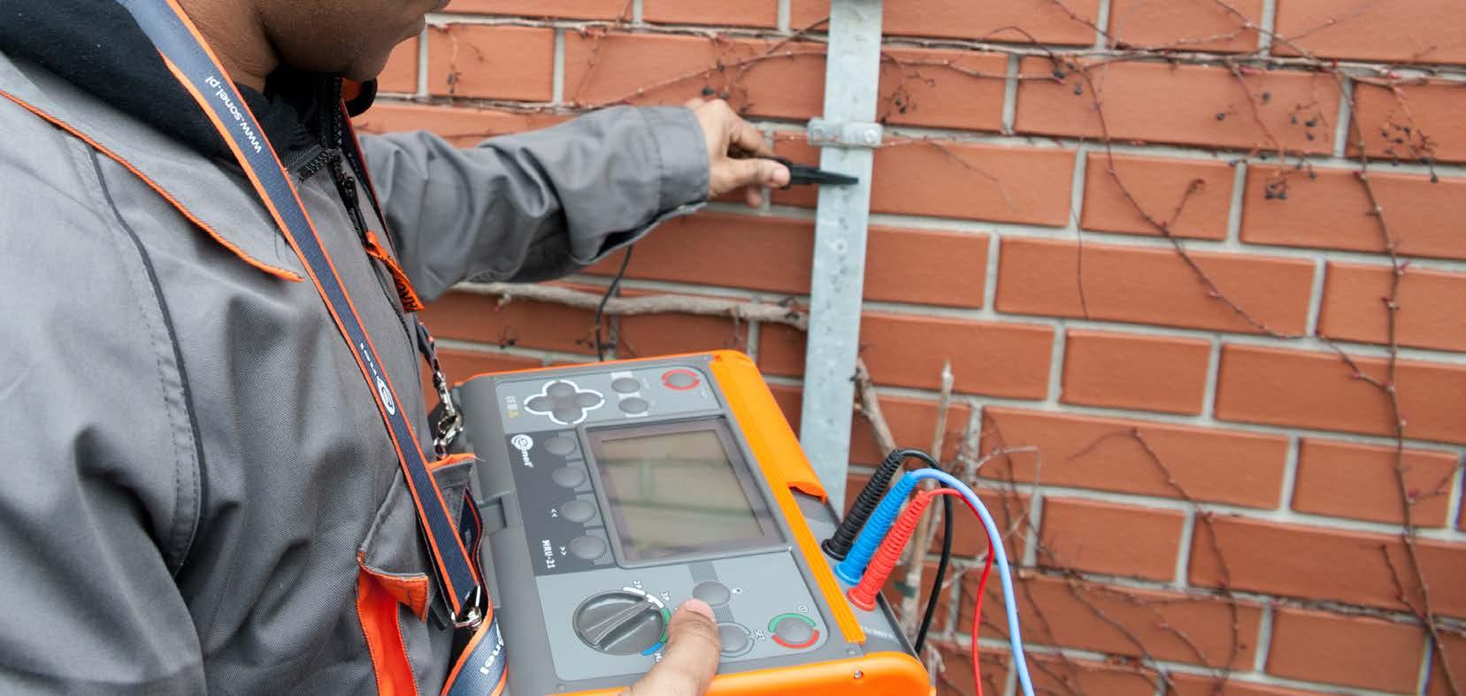

√ √ √ √
Earth impedance measurement according to impulse method
√ √ √ √ √ √
»
The adapter is compatible with MRU-200-GPS MRU-200 MRU-120HD MRU-120
index: WAADAERP1 / WAADAERP1V2 / WAADAERP1V3
√ √ √ √
»
Power supply rechargeablebattery/bateries rechargeablebattery rechargeablebattery/bateries rechargeablebattery rechargeablebattery/bateries rechargeablebatteries/bateries rechargeablebatteries/bateries rechargeablebattery rechargeablebattery/bateries rechargeablebattery/bateries
Charging from car lighter socket √ OPTIONAL Memory (records) 990 990 990 990 990 UNLIMITED 10 000 990
Measurement current in measurements of earthing resistance [mA] resolution
Earth resistance measurement according to 3-pole method with additional clamp
SONEL ERP-1
»
Leakage current measurement with flexible coil
»
Set of instruments for earth measurements MRU-200-GPSMRU-200 MRU-120HD MRU-120 MRU-30 MRU-21 MRU-11 MRU-10 MPI-540-PVMPI-540MPI-536MPI-535 MPI-530-ITMPI-530 MPI-520MPI-525
√ √ √ √ √
√ √ √ √ √ √ √ √ √ √
Ergonomic design of the adapter, its convenient housing and simple operation make earth resistance measurements on transmission towers and pylons quick and problem-free. The protection degree of the adapter is IP67, which makes it suitable for operation in muddy and rain conditions.
Electrical specifications:
146
»
meters: »
2 4 2 1.1 1.4 0.7 0.7 2.5 2.2 2.2
Earth resistance measurement according to 2-lead method
»
»
» measuring range up to 5 A operating frequency 125 Hz (in 50 Hz networks) 150 Hz (in 60 Hz networks)
√ √ √ √ √ √
√
Other specifications: protection rating IP67 storage temperature -20…+80°C relative humidity of storage 20…90% operating temperature range -10…+50°C operating humidity 20…85% exterior dimensions x 88 x 33 with batteries without
√ √ √ √ √ √ √
√ √ √ √ √ √
√ √ √ √ √ √ √ √ √ √
200 200 200 20 20 20 20 20 20 20 Maximum
Earth resistance measurement according to 3-pole method
Leakage current measurement with hard clamp MPI-520
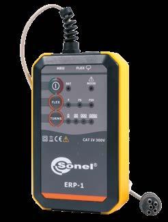

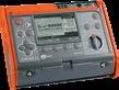


mm » weight
x 223 x 75 Weight
»
Earth
»
Measurement of disturbance voltages
x 223 x 75
» power supply 3 x LR6 1.5 V battery or 3 x Ni-MH LR6 1.2 V rech. battery measurement category CAT IV 300 V according to EN 61010-1
batteries 340 g / 270 g
/
»
√ √ √ √ √ √ √ √
Measurement of resistance of earth connection and equipotential bonding according to standard EN 61557-4
Soil resistivity measurement
The SONEL ERP-1 adapter, in combination with meters that can generate meas urement current of 200 mA, serves for measuring of resistance of multiple groundings without disconnecting control connection clamps. The flexible, big diameter coil allows to measure earth resistance of e.g. transmission towers - in cluding lattice poles - without shutting down the power line
Earth resistance measurement according to 4-lead method
»
resistance measurements adapter Standard accessories: WAADAERP1 WAADAERP1V2 WAADAERP1V3 FS-2 flexible coil (Ø 1260 mm) WACEGFS2OKR √ FSX-3 flexible coil (Ø 630 mm) WACEGFSX3OKR √ M6 carrying case WAFUTM6 √ √ 3x AA (LR6) 1.5 V battery √ √ √ Factory calibration certificate √ √ √ Optional accessories: XL8 hard carrying case WAWALXL8 63
[Ω] 0.001 0.01 0.01 0.01 0.01 0.01 0.01 0.01 0.01 0.01
Resistance measurement of auxiliary electrodes Dimensions [mm] 288 x 223 x 75 390 x 310 x 180 288 x 223 x 75 200 x 180 x 74 288 x 223 x 75 221 x 102 x 62 221 x 102 x 62 288 x 223 x 75 288 288 [kg]
√ √ √ √
Earth resistance measurement according to two-clamp method
√ √ √ √ √ √ √ √ √ √
Hard-to-reach measuring points cataloguing
Residential buildings foundation earth electrodes vertical earth electrode systems measuring conditions
• dust in the air • rain, snow Casing resistant to weather conditions and damagemechanical √ MRU-200-GPS MRU-200 MRU-120HD MRU-120 MRU-30 MRU-21 MRU-11 MRU-10 Measurement current 200 mA 64
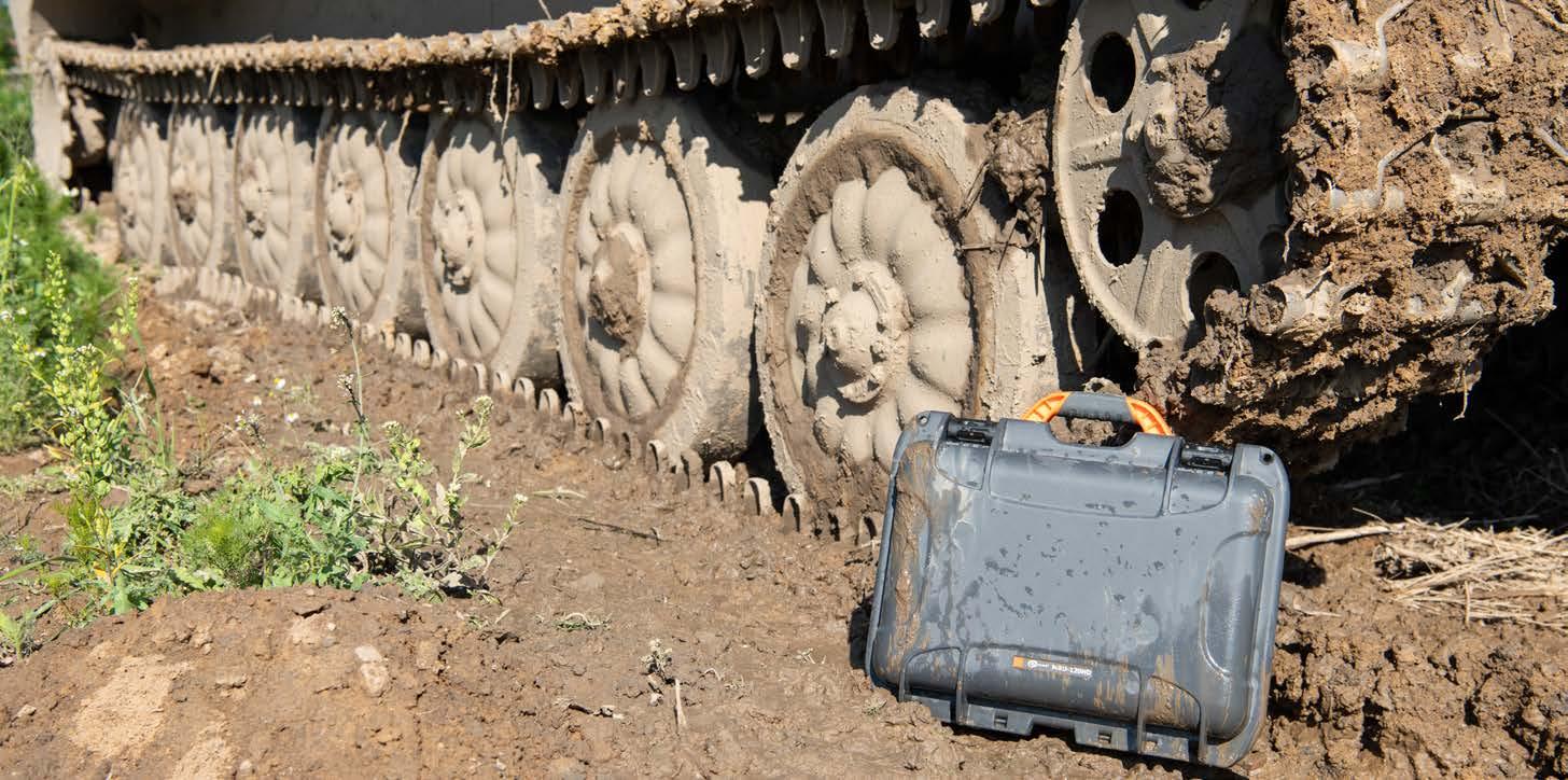
• earthingmeasurementsimpedance • other
measurementsimpedance Impulse method √ √ Gas
points • pole base measurements • Measurement current: 200 mA • Using ERP-1 √ √ √ √ Power
•
measurements Impulse method √ √
Commercial buildings ring, latticefoundation,earthing
• high
Railway electric traction comprehensive poles multiple earthing stations disruptions areas system consisting
• multiple lattice earthing Measurement current: 200 mA √ √ √ √ Urban
•
•
of horizontal and vertical earth electrodes • impossible to insert auxiliary electrodes 2-clamp method √ √ √ √ √ Soil tests • earthing design Soil resistivity √ √ √ √ √ √
•
the coordinates of measurement locations Coordinates of the measurement points added to the measurement results √
Operation in 400 Hz networks √ √
•
• ring,
3-pole method √ √ √ √ √ √ √ √
measurements for all types of earthing Operation in 16 2/3 Hz networks √ √ Power


3-pole method √ √ √ √ √ √ √ √ Difficult
Operation in 400 Hz networks √ √
Airport areas comprehensive measurements
•
•
Lightning protection earthing stations earthing


•
Military facilities comprehensive measurements
•
Application Distinguishing feature
WAZACIMA1
» 4-lead method,
NiMH battery 4.8 V 4.2 Ah
» measurement of voltage and frequency of interference signal, » measurement in the presence of disturbance voltages in networks with frequency 16 2/3 Hz, 50 Hz and 60 Hz as well as 400 Hz (with automatic or manual selection of relevant measurement signal frequency),
WAAKU07
WAPRZLAD12SAM
WAPRZUSB
Z7 Power supply
The instrument meets the requirements set forth in standards:
» HD 60364-6 (performance of measurements - checking)
Measurement of resistance of earth connection and equipotential bonding:
Test lead 50 m, yellow (banana plugs, on a reel, shielded) WAPRZ050YEBBSZE
Standard accessories:
» 3-pole method with ERP-1 adapter,


ground resistance and ground resistivity meters MRU-200 and MRU-200-GPS It can be downloaded from Google Play GPSbuilt-inreceiver MRU-200-GPS soil withoutresistivitymanualconversion ρΩ R Ωm200 mA measurementcurrent MRU-200-GPS is the only earthing resistance and impedance meter with the function of determining the geographical coordinates of the location of measurement. 65
Earthing resistance measurement - 3-pole and 4-lead method measuring range according to EN 61557-5: 0.100 Ω…19.99 kΩ
» measurement category CAT IV 300 V (CAT III 600 V) acc. to EN 61010-1 number of measurements provided by set of batteries >1500

Earthing resistance and soil resistivity meters
SONEL MRU MOBILE
» impulse method (without the need to disconnect measured earth electrodes) - three types of measurement impulse (4/10 µs, 8/20 µs, 10/350 µs),
» reading of battery charge state, built-in quick charger.
» EN 61010-031 (general and particular requirements related to safety)
»
Cramp (banana socket)
WMGBMRU200XL3 (with XL3 case) / WMGBMRU200GPSXL3 (with XL3 case)
Display range Resolution Accuracy 0.000…3.999 Ω 0.001 Ω ±(2% m.v. + 4 digits) 4.00…39.99 Ω 0.01 Ω ±(2% m.v. + 2 digits)40.0…399.9 Ω 0.1 Ω 400…3999 Ω 1 Ω 4.00 kΩ…19.99 kΩ 0.01 kΩ ±(5% m.v. + 2 digits)
» EN 61326 (electromagnetic compatibility)
»
» 3-pole method,
Test lead 1.2 m, red, 1 kV (banana plugs) WAPRZ1X2REBB
Measurement of multiple earthing systems - two-clamp method
»
» selection of maximum measurement voltage (25 V and 50 V), calibration of applied clamp, full interoperability with ERP-1 adapter, memory storing 990 measurements (10 banks with 99 cells each),
» MRU-200-GPS | built-in GPS receiver, real-time clock (RTC), data transmission to computer (USB, Bluetooth).
»
» measurement of auxiliary electrode resistances RS and RH,
Other technical specifications:
Display range Resolution Accuracy 0.0…99.9 Ω 0.1 Ω ±(2.5% m.v. + 3 digits)100…199 Ω 1 Ω
» displaying the soil resistivity value in Ωm or Ωft.
Display range Resolution Accuracy 0.00…19.99 Ω 0.01 Ω ±(10% m.v. + 3 digits) 20.0…149.9 Ω 0.1 Ω ±(20% m.v. + 3 digits)
»
»
» EN 61010-1 (general and particular requirements related to safety)
» EN 62305-1 (lightning protection)
»
USB cable
Resistance measurement of multiple earthing systems - 3-pole method with additional clamp
Nominal operating conditions: operating temperature range -10…+50°C storage temperature -20…+80°C humidity 20…90%
» EN 61557 (requirements for measurement instruments)
Test lead 25 m, red (banana plugs, on a reel) WAPRZ025REBBSZ
Crocodile clip, black, 1 kV, 20 A WAKROBL20K01
» HD 60364-4-41 (performance of measurements - shock protection)
»
Crocodile clip, red, 1 kV, 20 A WAKRORE20K02
» with auto-zeroing function - with current ≥200 mA, » according to EN 61557-4.
L2 carrying case (only WMGBMRU200, WMGBMRU200GPS) WAFUTL2
4x earth contact test probe (rod), 30 cm WASONG30
Test lead 25 m, blue (banana plugs, on a reel) WAPRZ025BUBBSZ
Measurement of earthing impedance - impulse method
L2 hanging straps (set) WAPOZSZEKPL
Earthing resistance measurements:
index: WMGBMRU200 (with L2 case) / WMGBMRU200GPS (with L2 case)
» two-clamp method.
Additional functions of the meter:
Cable for battery charging from car cigarette lighter socket (12 V)
» distances between electrodes can be input in meters (m) or feet (ft),
» type of insulation double, as per EN 61010-1 and EN 61557
Mobile version of the program supports
SONEL MRU-200 / MRU-200-GPS
» 3-pole method with additional clamp,
Display range Resolution Accuracy 0.000…3.999 Ω 0.001 Ω ±(8% m.v. + 4 digits) 4.00…39.99 Ω 0.01 Ω ±(8% m.v. +3 digits)40.0…399.9 Ω 0.1 Ω 400…1999 Ω 1 Ω
XL3 carrying case (only WMGBMRU200XL3, WMGBMRU200GPSXL3) WAWALXL3
Test lead 2.2 m, black, 1 kV (banana plugs) WAPRZ2X2BLBB
Mains cable with IEC C7 plug WAPRZLAD230
» PN-E 04700 (performance of measurements - commissioning tests)
Soil resistivity measurements (Wenner method):
»
WAZASZ7
Factory calibration certificate
» measurement in the presence of disturbance voltages in networks with frequencies of 50 Hz and 60 Hz,
Soil resistivity measurements (Wenner method):
» real-time clock (RTC),
» two-clamp method.
Resistance measurement of multiple earthing systems - 3-pole method with additional clamp Display range Resolution Accuracy 0.00…19.99 Ω 0.01 Ω ±(8% m.v. +3 digits)20.0…199.9 Ω 0.1 Ω 200…1999 Ω 1 Ω
WAPRZUSB
Mains cable with IEC C7 plug
» HD 60364-6 (performance of measurements - checking)
Earthing resistance and soil resistivity meter MRU-120HD makes it possible to measure earthings, even without the use of auxiliary probes, by means of the double-clamp method. MRU-120HD allows for measurements of multiple earthing systems without disconnection of test connections, by means of the 3-pole method with additional clamp or two-clamp method. closed cover open cover soil withoutresistivitymanualconversion ρΩ R Ωm 200 mA measurementcurrent 66
index: WMGBMRU120HD
» interoperability with ERP-1 adapter,


Test lead 4 m blue 1 kV (banana plugs) WAPRZ4X0BUBB
» 4-lead method,
» measurement of voltage and frequency of interference signal,
» distances between electrodes can be input in meters (m) or feet (ft),
Nominal operating conditions:
2x cramp (banana socket) WAZACIMA1
» number of measurements provided by set of batteries >1100
» memory storing 990 measurements (10 banks with 99 cells each),
Earthing resistance measurement - 3-pole and 4-lead method measuring range according to EN 61557-5: 0.30 Ω…19.9 kΩ
» type of insulation
» EN 61326 (electromagnetic compatibility)
Display range Resolution Accuracy 0.00…19.99 Ω 0.01 Ω ±(2% m.v. + 2 digits)20.0…199.9 Ω 0.1 Ω 200…1999 Ω 1 Ω 2.0…9.99 kΩ 0.01 kΩ ±(5% m.v. + 2 digits)10.0…19.9 kΩ 0.1 kΩ
double, as per EN 61010-1 and EN 61557
Standard accessories:
» EN 61010-031 (general and particular requirements related to safety)
» reading of battery charge status, built-in quick charger.
» PN-E 04700 (performance of measurements - commissioning tests)
WAFUTL4
Other technical specifications:
» storage temperature -20…+80°C
» with auto-zeroing function - with current ≥200 mA
» 3-pole method,
» measurement of auxiliary electrode resistances RS and RH,
» EN 61557 (requirements for measurement instruments)
» data transmission to computer (USB),
» selection of maximum measurement voltage (25 V or 50 V),
The instrument meets the requirements set forth in the standards:
Factory calibration certificate
W1 hanging straps WAPOZSZE5
Additional functions of the meter:
4x earth contact test probe (rod), 30 cm WASONG30
Test lead 25 m, red (banana plugs, on a reel) WAPRZ025REBBSZ
Earthing resistance measurements:
» in compliance with EN 61557-4.
L4 carrying case
Test lead 4 m black 1 kV (banana plugs) WAPRZ4X0BLBB
» measurement category CAT IV 300 V (CAT III 600 V) acc. to EN 61010-1
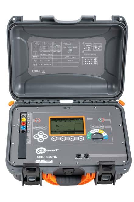
» humidity 20…85%

WAZASZ7
» 3-pole method with additional clamp,
» operating temperature range -10…+50°C
Test lead 50 m, yellow (banana plugs, on a reel) WAPRZ050YEBBSZ
» displaying the soil resistivity value in Ωm or Ωft.
USB cable
WAPRZLAD230
SONEL MRU-120HD
» HD 60364-4-41 (performance of measurements - shock protection)
Measurement of resistance of earth connection and equipotential bonding:
Test lead 25 m, blue (banana plugs, on a reel) WAPRZ025BUBBSZ
Z7 Power supply
Measurement of multiple earthing systems - two-clamp method Display range Resolution Accuracy 0.00…19.99 Ω 0.01 Ω ±(10% m.v. + 3 digits) 20.0…149.9 Ω 0.1 Ω ±(20% m.v. + 3 digits)
» EN 61010-1 (general and particular requirements related to safety)
» two-clamp method.
» EN 61010-031 (general and particular requirements related to safety)
» EN 61557 (requirements for measurement instruments)
» operating temperature range -10…+50°C
» memory storing 990 measurements (10 banks with 99 cells each),
WAZACIMA1
Earthing resistance measurements:
WAFUTL2
The instrument meets the requirements set forth in the standards:
measuring range according to EN 61557-5: 0.30 Ω…19.9 kΩ
Crocodile clip, black, 1 kV, 20 A WAKROBL20K01
» HD 60364-6 (performance of measurements - checking)
» with auto-zeroing function - with current ≥200 mA
4x earth contact test probe (rod), 30 cm WASONG30
SONEL MRU-120
» measurement in the presence of disturbance voltages in networks with frequencies of 50 Hz and 60 Hz,
Nominal operating conditions:
WAPRZUSB
Test lead 2.2 m, black, 1 kV (banana plugs) WAPRZ2X2BLBB
» real-time clock (RTC),
Other technical specifications:
XL3 carrying case (only WMGBMRU120XL3) WAWALXL3
Additional functions of the meter:
» measurement of auxiliary electrode resistances RS and RH,
Measurement of resistance of earth connection and equipotential bonding:
» in compliance with EN 61557-4.
» PN-E 04700 (performance of measurements - commissioning tests)
» type of insulation
» storage temperature -20…+80°C
» 4-lead method,
index:
L2 carrying case (only WMGBMRU120)
» humidity 20…85%
» displaying the soil resistivity value in Ωm.
Test lead 1.2 m, red, 1 kV (banana plugs) WAPRZ1X2REBB
» EN 61010-1 (general and particular requirements related to safety)
» distances between electrodes can be input in meters (m) or feet (ft),
Pin probe, red 1 kV (banana socket) WASONREOGB1
» data transmission to computer (USB),
WAAKU08
Display range Resolution Accuracy 0.00…19.99 Ω 0.01 Ω ±(2% m.v. + 2 digits)20.0…199.9 Ω 0.1 Ω 200…1999 Ω 1 Ω 2.0…9.99 kΩ 0.01 kΩ ±(5% m.v. + 2 digits)10.0…19.9 kΩ 0.1 kΩ
Soil resistivity measurements (Wenner method):
Z7 Power supply WAZASZ7
» reading of battery charge status, built-in quick charger.
Earthing resistance measurement - 3-pole and 4-lead method
Factory calibration certificate
Earthing resistance and soil resistivity meter MRU-120 allows for measurements of multiple earthing systems without disconnection of test connections, by means of the 3-pole method with additional clamp or two-clamp method. soil withoutresistivitymanualconversion ρΩ R Ωm200 mA measurementcurrent MRU-120 makes it possible to measure earthings, even without the use of auxiliary probes, by means of the double-clamp method. 67
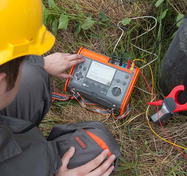
Test lead 25 m, red (banana plugs, on a reel) WAPRZ025REBBSZ
Cramp (banana socket)
Measurement of multiple earthing systems - two-clamp method Display range Resolution Accuracy 0.00…19.99 Ω 0.01 Ω ±(10% m.v. + 3 digits) 20.0…149.9 Ω 0.1 Ω ±(20% m.v. + 3 digits)
NiMH battery 4.8 V 3.2 Ah
Test lead 50 m, yellow (banana plugs, on a reel) WAPRZ050YEBBSZ
» interoperability with ERP-1 adapter,
» measurement of voltage and frequency of interference signal,
WMGBMRU120 (with L2 case) / WMGBMRU120XL3 (with XL3 case)
» selection of maximum measurement voltage (25 V or 50 V),

Test lead 25 m, blue (banana plugs, on a reel) WAPRZ025BUBBSZ
Resistance measurement of multiple earthing systems - 3-pole method with additional clamp Display range Resolution Accuracy 0.00…19.99 Ω 0.01 Ω ±(8% m.v. +3 digits)20.0…199.9 Ω 0.1 Ω 200…1999 Ω 1 Ω
double, as per EN 61010-1 and EN 61557
» 3-pole method with additional clamp,
Standard accessories:
» EN 61326 (electromagnetic compatibility)
» measurement category CAT IV 300 V (CAT III 600 V) acc. to EN 61010-1
L2 hanging straps (set) WAPOZSZEKPL
» HD 60364-4-41 (performance of measurements - shock protection)
Mains cable with IEC C7 plug WAPRZLAD230
» number of measurements provided by set of batteries >1100
USB cable
» 3-pole method,
WAFUTM9
» measurement of auxiliary electrode resistances RS and RH, » measurement of interference voltage, » measurement in the presence of disturbance voltages in networks with frequencies of 50 Hz and 60 Hz,
USB cable
» with auto-zeroing function - with current ≥200 mA
» measurement category CAT III 300V according to EN 61010-1

» dimensions 200 x 150 x 73 mm
double, as per EN 61010-1 and EN 61557
of multiple earthing systems - two-clamp method Display range Resolution Accuracy 0.00…19.99 Ω 0.01 Ω ±(10% m.v. + 8
ρΩ R Ωm
Earthing resistance measurement - 3-pole and 4-lead method measuring range according to EN 61557-5:2007: 0.53 Ω…9999 Ω for 50 V
68
WAFUTL10
» housing protection rating according to EN 60529 IP65
» type of insulation
» memory storing 990 measurements (10 banks with 99 cells each),
Test lead 1.2 m, red, 1 kV (banana plugs) WAPRZ1X2REBB
WAPRZUSB
Pin probe, red 1 kV (banana socket) WASONREOGB1
» data transmission to computer (USB),
2000…9999 Ω 1 Ω
Ω
Crocodile clip, black, 1 kV, 20 A WAKROBL20K01
Other technical specifications:
Cramp WAZACIMA1
20.0…99.9 Ω 0.1 Ω ±(20% m.v. + 3
» storage temperature -20…+60°C withoutresistivitymanualconversion
» 3-pole method with additional clamp, » two-clamp method.
Additional functions of the meter:
» operating temperature range -10…+50°C
» distances between electrodes can be input in meters (m) or feet (ft),
L10 carrying case
Ω 200…1999 Ω 1 Ω ±5%
Soil resistivity measurements (Wenner method):
Display range Resolution Accuracy 0.00…19.99 0.01 Ω ±(3% m.v. + 3 digits)20.0…199.9 0.1 m.v. ±8% m.v.
» humidity 20…90% Earthing resistance and soil resistivity meter soil
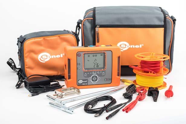


Accuracy 0.00…19.99 Ω 0.01 Ω ±(3% m.v.
20.0…199.9 Ω 0.1 Ω 200…1999 Ω 1 Ω ±5% m.v. 2000…9999 Ω 1 Ω ±8% m.v.
2x earth contact test probe (rod), 30 cm WASONG30
Resistance measurement of multiple earthing systems - 3-pole method with additional clamp range Resolution + 3 digits)
» reading of battery charge status.
» 3-pole method, » 4-lead method,
Ω
Test lead 2.2 m, black, 1 kV (banana plugs) WAPRZ2X2BLBB
Measurement of resistance of earth connection and equipotential bonding:
Mains cable with IEC C7 plug WAPRZLAD230
» selection of maximum measurement voltage (25 V or 50 V),
» displaying the soil resistivity value in Ωm or Ωft.
SONEL MRU-30
» in compliance with EN 61557-4.
Nominal operating conditions:
Standard accessories:
Z7 Power supply WAZASZ7
index: WMGBMRU30
Test lead 25 m, red (banana plugs, on a reel) WAPRZ025REBBSZ
Display
Earthing resistance measurements:
M9 carrying case
Test lead 50 m, yellow (banana plugs, on a reel) WAPRZ050YEBBSZ
Factory calibration certificate
Measurement digits) digits)
» LCD display segmented, with backlit
» EN 61010-1 (general and particular requirements related to safety)
» EN 61326 (electromagnetic compatibility)
Other technical specifications:
» type of insulation
2x earth contact test probe (rod), 30 cm WASONG30
» measurement of auxiliary electrode resistances RS and RH, » measurement of interference voltage, » measurement in the presence of disturbance voltages in the network, » selection of maximum measurement voltage (25 V or 50 V),
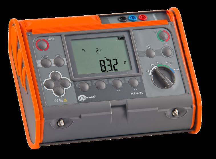
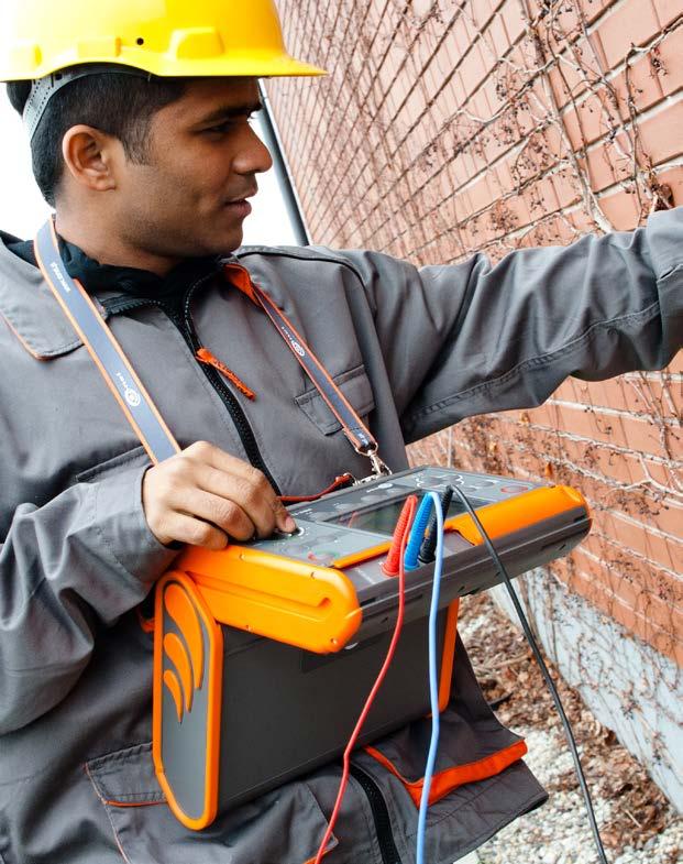
» number of measurements provided by set of alkaline batteries >1000 (5 Ω, 2/min)
Factory calibration certificate
» storage temperature -20…+70°C
double, as per EN 61010-1 and EN 61557
USB cable WAPRZUSB
» HD 60364-6 (performance of measurements - checking)
Standard accessories:
» 3-pole method, » 2-pole method.
» measurement category CAT IV 300V according to EN 61010-1
» weight including batteries 1.4 kg
SONEL MRU-21
» HD 60364-4-41 (performance of measurements - shock protection)
Resistance measurement - 2-pole method:
Test lead 2.2 m, black, 1 kV (banana plugs) WAPRZ2X2BLBB
» EN 61557 (requirements for measurement instruments)
» LCD display segmented, with backlit
Nominal operating conditions:
WAFUTL4
Display range Resolution Accuracy 0.00…9.99 Ω 0.01 Ω ±(2% m.v. + 3 digits)10.0…99.9 Ω 0.1 Ω 100…199 Ω 1 Ω
Additional functions of the meter:
Earthing resistance measurement:
Crocodile clip, black, 1 kV, 20 A WAKROBL20K01
» power supply of the meter 4 x 1.5 V batteries or type C rechargeable batteries
69
» humidity 20…90%
L2 hanging straps (set) WAPOZSZEKPL
Crocodile clip, blue, 1 kV, 20 A WAKROBU20K02
Battery container WAPOJ1
The instrument meets the requirements set forth in the standards:
Earthing resistance measurement - 3-pole method measuring range according to EN 61557-5: 0.50 Ω…1.99 kΩ for 50 V; 0.68 Ω…1.99 kΩ for 25 V
Display range Resolution Accuracy 0.00…9.99 Ω 0.01 Ω ±(2% m.v. + 3 digits)10.0…99.9 Ω 0.1 Ω 100…999 Ω 1 Ω 1.00…1.99 kΩ 0.01 kΩ
Earthing resistance meter
» memory storing up to 990 results, data transmission to computer via USB cable, » reading of battery or rechargeable battery charge status,
» dimensions 260 x 190 x 60 mm
» this product meets EMC requirements in compliance with standards EN 61326-1 and EN 61326-2-2
Test lead 1.2 m, blue, 1 kV (banana plugs) WAPRZ1X2BUBB
Measurement of resistance of earth connection and equipotential bonding: measuring range according to EN 61557-4: 0.13 Ω…199 Ω
» PN-E 04700 (performance of measurements - commissioning tests)
» operating temperature range -10…+55°C
» measurement current: >20 mA upon closing of circuit » frequency of measurement current: 125 Hz
» auto-zeroing of test leads
L4 carrying case
Test lead 15 m, blue (on a reel) WAPRZ015BUBBSZ
Test lead 30 m, red, (banana plugs, on a reel) WAPRZ030REBBSZ
index: WMGBMRU21
» meeting the requirements of EN 61557-4, with auto-zeroing function - with ≥200 mA current.
Measurement of resistance of earth connection and equipotential bonding:
» power supply from batteries or rechargeable batteries,
» automatic power down.
» EN 61010-031 (general and particular requirements related to safety)
Test lead 15 m, blue (banana plugs, on H-frame reel) WAPRZ015BUBBN
M1 hanging hook straps WAPOZUCH1
» Measurement current: under short circuit >20 mA, frequency 125 Hz or 150 Hz, voltage selectable 25 V or 50 V.
» reading of battery or rechargeable battery charge status,
» measurement of interference voltage, » selection of maximum measurement voltage (25 V or 50 V),
70
Nominal operating conditions:
» measurement of auxiliary electrode resistances RS and RH,
Other technical specifications:
» measurement category CAT IV 150 V (III 300 V) according to EN 61010-1

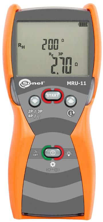
Crocodile clip, blue, 1 kV, 20 A WAKROBU20K02
Test lead 2,2 m, blue, 1 kV (banana plugs) WAPRZ2X2BUBB
Factory calibration certificate
M6 carrying case
Additional functions of the meter:
M1 hanging straps WAPOZSZE4
SONEL MRU-11
Test lead 15 m, red (banana plugs, on H-frame reel) WAPRZ015REBBN
» Maximum interference voltage, at which RE measurement is performed, equals 24 V.
» automatic power down.
» displaying the soil resistivity value in Ωm or Ωft.
» reference temperature +23±2°C
Earthing resistance measurement - 2-pole method
» weight with batteries approx. 660 g
Earthing resistance measurement:
» dimensions 221 x 102 x 62 mm
» humidity 20…90%
» power supply of the meter alkaline batteries or NiMH AA rechargeable batteries (4 pcs.)
WAFUTM6
Display range Resolution Accuracy 0.00…19.99 Ω 0.01 Ω ±(3% m.v. + 3 digits)20.0…199.9 Ω 0.1 Ω 200…1999 Ω 1 Ω ±5% m.v. 2000…9999 Ω 1 Ω ±8% m.v.
» type of insulation double, as per EN 61010-1 and EN 61557
Test lead 2,2 m, black, 1 kV (banana plugs) WAPRZ2X2BLBB
soil withoutresistivitymanualconversion
» storage temperature -20…+60°C
Earthing resistance measurement - 3-pole and 4-lead method measurement range to IEC 61557-5:2007: 0.53 Ω…9999 Ω for 50 V
» Measurement current: under short circuit >20 mA, frequency 125 Hz or 150 Hz, voltage selectable 25 V or 50 V.
» Maximum interference voltage, at which RE measurement is performed, equals 24 V.
Soil resistivity measurements (Wenner method):
WAKROBL20K01
4x AA battery, LR6
» operating temperature -10…+50°C
» housing protection rating according to EN 60529 IP67
ρΩ R Ωm
» LCD display segment, backlit
Display range Resolution Accuracy 0.00…19.99 Ω 0.01 Ω ±(3% m.v. + 3 digits)20.0…199.9 Ω 0.1 Ω 200…1999 Ω 1 Ω ±5% m.v. 2000…9999 Ω 1 Ω ±8% m.v.
» distances between electrodes can be input in meters (m) or feet (ft),
index: WMGBMRU11 Earthing resistance and soil resistivity meter
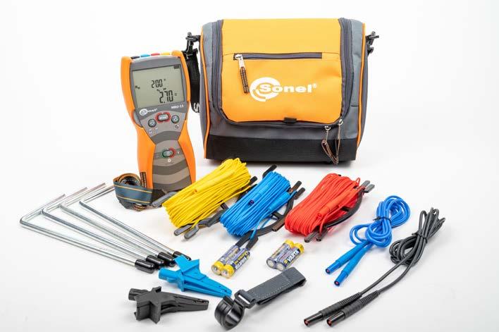
Standard accessories:
Crocodile clip, black, 1 kV, 20 A
Test lead 30 m, yellow (banana plugs, on H-frame reel) WAPRZ030YEBBN
4x earth contact test probe (rod), 25 cm WASONG25
» 3-pole method, » 4-lead method, » 2-pole method.
» the meter meets the EMC requirements acc. to standards EN 61326-1 and EN 61326-2-2
» 2-pole method.
» the meter meets the EMC requirements acc. to standards EN 61326-1 and EN 61326-2-2
Earthing resistance measurement - 3-pole method measurement range to IEC 61557-5:2007: 0.53 Ω…9999 Ω for 50 V
» reference temperature +23±2°C
» Maximum interference voltage, at which RE measurement is performed, equals 24 V.
» type of insulation double, as per EN 61010-1 and EN 61557
» housing protection rating according to EN 60529 IP67
index: WMGBMRU10
» weight with batteries approx. 660 g
» power supply of the meter alkaline batteries or NiMH AA rechargeable batteries (4 pcs.)
Other technical specifications:
Standard accessories:
2x earth contact test probe (rod), 25 cm WASONG25
4x AA battery, LR6
M1 hanging hook straps
» measurement of auxiliary electrode resistances RS and RH,
M1 hanging straps WAPOZSZE4
» Measurement current: under short circuit >20 mA, frequency 125 Hz or 150 Hz, voltage selectable 25 V or 50 V.
» measurement of interference voltage,
» LCD display segment, backlit
SONEL MRU-10
» reading of battery or rechargeable battery charge status, » automatic power down.
» 3-pole method,
» measurement category CAT IV 150 V (III 300 V) according to EN 61010-1
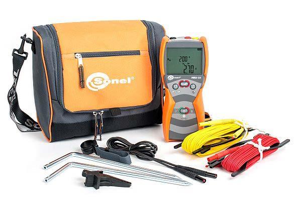
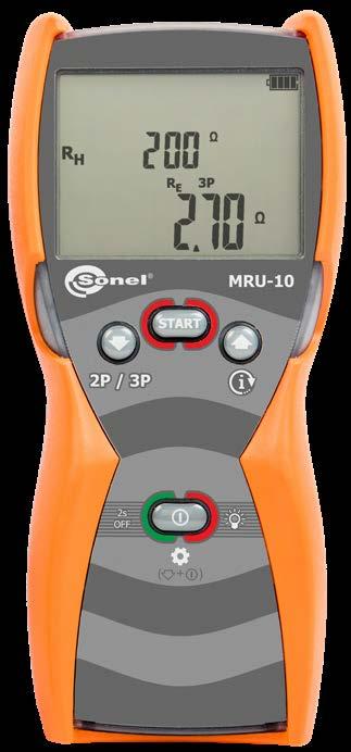
Crocodile clip, black, 1 kV, 20 A
» operating temperature -10…+50°C
Earthing resistance measurement:
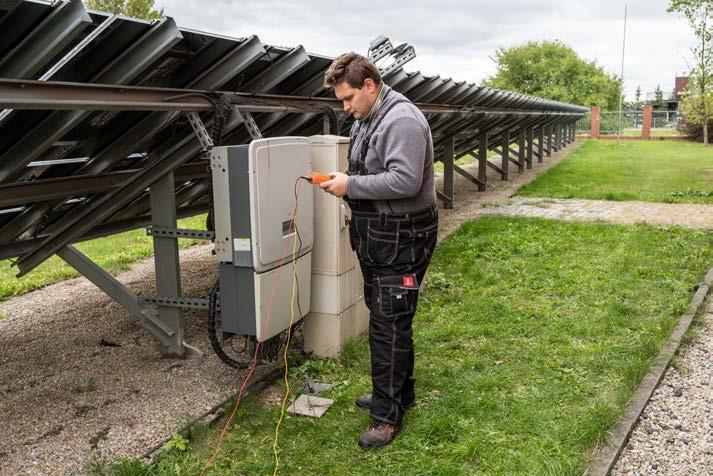
WAPOZUCH1
Earthing resistance meter
M6 carrying case
» selection of maximum measurement voltage (25 V or 50 V),
Test lead 15 m, red (banana plugs, on H-frame reel) WAPRZ015REBBN
Earthing resistance measurement - 2-pole method
» Maximum interference voltage, at which RE measurement is performed, equals 24 V.
» humidity 20…90%
» dimensions 221 x 102 x 62 mm
Test lead 30 m, yellow (banana plugs, on H-frame reel) WAPRZ030YEBBN
Factory calibration certificate
Display range Resolution Accuracy 0.00…19.99 Ω 0.01 Ω ±(3% m.v. + 3 digits)20.0…199.9 Ω 0.1 Ω 200…1999 Ω 1 Ω ±5% m.v. 2000…9999 Ω 1 Ω ±8% m.v.
Display range Resolution Accuracy 0.00…19.99 Ω 0.01 Ω ±(3% m.v. + 3 digits)20.0…199.9 Ω 0.1 Ω 200…1999 Ω 1 Ω ±5% m.v. 2000…9999 Ω 1 Ω ±8% m.v.
WAFUTM6
» storage temperature -20…+60°C
WAKROBL20K01
Test lead 2,2 m, black, 1 kV (banana plugs) WAPRZ2X2BLBB
» Measurement current: under short circuit >20 mA, frequency 125 Hz or 150 Hz, voltage selectable 25 V or 50 V.
71
Additional functions of the meter:
Nominal operating conditions:
• • • • •
WACEGF1AOKR
(L2)MRU-200-GPS (XL3)MRU-200-GPS (L2)MRU-200 (XL3)MRU-200 MRU-120HD (L2)MRU-120 (XL3)MRU-120 MRU-30 MRU-21 MRU-11 MRU-10 ERP-1
• • • • • • •
• • • • •
• • • • •
ERP-1 adapter for earth resistance measurements WAADAERP1

WACEGN1BB
F-4A flexible coil (Ø630 mm)
F-3A flexible coil (Ø120 mm)
• • • • • • • •
N-1 transmitting clamp (Ø52 mm)
WACEGF2AOKR
• • • • •
WACEGFS2OKR
• • • • •
FSX-3 flexible coil (Ø630 mm) WACEGFSX3OKR


• • • • •
ERP-1 adapter for earth resistance measurements with FS-2 flexible coil WAADAERP1V2


Photo Name Index
WACEGF3AOKR
FS-2 flexible coil (Ø1260 mm)
C-3 current clamp (Ø52 mm)
• • • • • • •
F-1A flexible coil (Ø360 mm)
F-2A flexible coil (Ø235 mm)
• • • • • • •
ERP-1 adapter for earth resistance measurements with FSX-3 flexible coil WAADAERP1V3

• • • • • • • • Crocodile clip, black, 1 kV, 20 A WAKROBL20K01 1 1 1 1 1 1 1 1 1 1 Crocodile clip, red, 1 kV, 20 A WAKRORE20K02 1 1 1 1 • • • • • • • Crocodile clip, blue, 1 kV, 20 A WAKROBU20K02 1 1 Crocodile clip, yellow, 1 kV, 20 A WAKROYE20K02 • • • • • • • • • • • Test lead 1.2 m, black, 1 kV (banana plugs) WAPRZ1X2BLBB • • • • • • • • • • • Test lead 1.2 m, red, 1 kV (banana plugs) WAPRZ1X2REBB 1 1 1 1 • 1 1 1 • • • MRU Set of standard and optional accessories 1, 2, 4 - number of standard accessories • - optional accessories 72


WACEGC3OKR
WACEGF4OKR
• • • • • • • • • • •
Test lead 2.2 m, blue, 1 kV (banana plugs) WAPRZ2X2BUBB 1
1, 2, 4 - number of standard accessories - optional accessories
Double-wire test lead 2 m, for N-1 clamps (banana plugs) WAPRZ002DZBB


Test lead 2.2 m, yellow, 1 kV (banana plugs) WAPRZ2X2YEBB
•
Test lead 15 m, blue (on a reel) WAPRZ015BUBBSZ 1
Test lead 25 m, red (banana plugs, on a reel) WAPRZ025REBBSZ 1 1 1 1 1 1 1

1
1 • • • 73
Photo Name Index
• • • •
Test lead 4 m blue 1 kV (banana plugs) WAPRZ4X0BUBB 1
• • • • • • • •
Test lead with banana plug; 15 m; blue WAPRZ015BUBBN 1

(L2)MRU-200-GPS (XL3)MRU-200-GPS (L2)MRU-200 (XL3)MRU-200 MRU-120HD (L2)MRU-120 (XL3)MRU-120 MRU-30 MRU-21 MRU-11 MRU-10 ERP-1

Test lead 1.2 m, yellow, 1 kV (banana plugs) WAPRZ1X2YEBB
Test lead 2.2 m, red, 1 kV (banana plugs) WAPRZ2X2REBB
• • • • • • • •
Test lead 2.2 m, black, 1 kV (banana plugs) WAPRZ2X2BLBB 1 1 1 1 1 1 1 1 1 1
Test lead with banana plug; 15 m; red WAPRZ015REBBN 1 1


•
Test lead 4 m black 1 kV (banana plugs) WAPRZ4X0BLBB 1
Test lead 25 m, blue (banana plugs, on a reel) WAPRZ025BUBBSZ 1 1 1 1 1 1 1
• •
• • • •
Test lead 30 m, red (banana plugs, on a reel) WAPRZ030REBBSZ
• • • • • • • • • • •
MRU
• • • • • • • • •
Test lead 1.2 m, blue, 1 kV (banana plugs) WAPRZ1X2BUBB 1
Set of standard and optional accessories
• • • • • •
• • • •
Test lead with banana plugs; 30 m; yellow WAPRZ030YEBBN 1 1

• • • • • • • • •
• •
• • • • • •
Test lead 50 m, yellow (banana plugs, on a reel) WAPRZ050YEBBSZ 1 1 1
• • • • • • • •
• • • •
• • • • • • • • • • •
• • • • • • • • • • •
Pin probe, red 1 kV (banana socket) 1

Pin probe, blue 1 kV (banana socket)


• • • • • • • • • • •
Test lead 100 m, yellow (banana plugs, on a reel) WAPRZ100YEBBSZ
Test lead 200 m, blue, (banana plugs, on a reel)
1 1 • • •
MRU
WASONBUOGB1 • • • • • • • • • • •
• • • • • • • • • • •
Photo Name Index
• • • •
WASONBLOGB1
WAPRZ050YEBBSZE 1 1 1 1
WASONYEOGB1 • • • • • • • • • • •
74
Test lead 75 m, yellow (banana plugs, on a reel) WAPRZ075YEBBSZ
• • • • • • • • • • •
Test lead 100 m, yellow (banana plugs, on a reel, shielded)
Test lead 200 m, red, (banana plugs, on a reel) WAPRZ200REBBSZ
Test lead 50 m, yellow (banana plugs, on a reel, shielded)
• • • •
Pin probe, black 1 kV (banana socket)
Test lead 100 m, blue (banana plugs, on a reel) WAPRZ100BUBBSZ
Test lead 100 m, red (banana plugs, on a reel) WAPRZ100REBBSZ
(L2)MRU-200-GPS (XL3)MRU-200-GPS (L2)MRU-200 (XL3)MRU-200 MRU-120HD (L2)MRU-120 (XL3)MRU-120 MRU-30 MRU-21 MRU-11 MRU-10 ERP-1
1, 2, 4 - number of standard accessories - optional accessories
Test lead 75 m, red (banana plugs, on a reel) WAPRZ075REBBSZ

•
WAPRZ200YEBBSZE
Test lead 75 m, blue (banana plugs, on a reel) WAPRZ075BUBBSZ


• • • • • • • • • • •
WAPRZ100YEBBSZE
WASONREOGB1 • • • • •
Test lead 75 m, yellow (banana plugs, on a reel, shielded) WAPRZ075YEBBSZE


Set of standard and optional accessories
Test lead 200 m, yellow (banana plugs, on a reel, shielded)
Test lead 200 m, yellow (banana plugs, on a reel) WAPRZ200YEBBSZ
Pin probe, yellow 1 kV (banana socket)
WAPRZ200BUBBSZ
Photo Name Index (L2)MRU-200-GPS (XL3)MRU-200-GPS (L2)MRU-200 (XL3)MRU-200 MRU-120HD (L2)MRU-120 (XL3)MRU-120 MRU-30 MRU-21 MRU-11 MRU-10 ERP-1 Earth contact test probe (rod), 25 cm WASONG25 4 2 Earth contact test probe (rod), 30 cm WASONG30 4 4 4 4 4 4 4 2 2 • • Earth contact test probe (rod), 80 cm WASONG80V2 Cramp WAZACIMA1 1 1 1 1 2 1 1 1 • • • NiMH battery 4.8 V 4.2 Ah WAAKU07 1 1 1 1 • • NiMH battery 4.8 V 3.2 Ah WAAKU08 1 1 NiMH battery 4.8 V 4.2 Ah (replaceable in the SONEL S.A. service) WAAKU28 1 Battery pack WAPOJ1 • • • • • • 1 Z7 power supply WAZASZ7 1 1 1 1 1 1 1 1 Mains cable with IEC C7 plug WAPRZLAD230 1 1 1 1 1 1 1 1 Cable for battery charging from car cigarette lighter socket (12 V) WAPRZLAD12SAM 1 1 1 1 • • • • Test wire reel WAPOZSZP1 L2 hanging straps (set) WAPOZSZEKPL 1 1 1 1 1 1 1 M1 hanging straps WAPOZSZE4 1 1 W1 hanging straps WAPOZSZE5 1 M1 hanging hook straps WAPOZUCH1 1 1 L2 carrying case WAFUTL2 1 • 1 • 1 • MRU Set of standard and optional accessories 1, 2, 4 - number of standard accessories • - optional accessories 75


Mobile version of the program cooperating with ground resistance and ground re sistivity meters MRU-200 and MRU-200-GPS. It can be downloaded from Google Play
» For every room user can create separate table with test results.
» Tree structure presents a clear picture of the tested building and its rooms.
» User can print labels for test points.
Test structure can be uploaded to the meter and downloaded from it together with test results.
SONEL REPORTS

PLUS MRU Set of standard and optional accessories 1, 2, 4 - number of standard accessories • - optional accessories Photo Name Index (L2)MRU-200-GPS (XL3)MRU-200-GPS (L2)MRU-200 (XL3)MRU-200 MRU-120HD (L2)MRU-120 (XL3)MRU-120 MRU-30 MRU-21 MRU-11 MRU-10 ERP-1 L3 carrying case for a 80 cm rods WAFUTL3 • • • • • • • • • • • L4 carrying case WAFUTL4 1 1 L10 carrying case WAFUTL10 1 M6 carrying case WAFUTM6 1 1 M9 carrying case WAFUTM9 1 XL3 carrying case (accessories not included) WAWALXL3 • 1 • 1 • 1 XL8 carrying case WAWALXL8 • USB cable WAPRZUSB 1 1 1 1 1 1 1 1 1 PC software: Sonel Reports PLUS WAPROREPORTSPLUS PC Sonelsoftware:Reader WAPROREADER • • • • • • • • • 76


» For every room user can add picture or scheme of electrical installation.

SONEL MRU MOBILE

Thanks to the application, you can connect directly to the device via Bluetooth and download measurement data from the meter. After reading the measurements from the device, they can be easily and quickly viewed, and also sent from the place of measurement to a person who can help in interpretation of data or make a measurement report.
Thanks to the application, you can enrich the measurement with a photo, com ments or voice memo. From the application level, we also have access to the me ter's manual and help regarding various measurement methods.
Users who do not have a meter can use the set of sample data implemented in demo mode.
Sonel Reports Plus supports creation of documentation after testing of electrical installation. The software communicates with Sonel test instruments, downloads data from memory of the devices and creates necessary documentation. Many useful functions are included in order to help creating documentation of the meas urements. Sonel Reports Plus supports MPI-540 and MPI-530 by reading, down loading and uploading test structure from/to test instrument.
» Software contains library of fuses.
» Every report can contain description page.
Industry KT-560KT-650KT-670KT-400KT-200KT-320KT-250KT-165KT-128DIT-500DIT-200DIT-130DIT-120 Temperature measurements Fever detection KT-120MKT-560MKT-800M
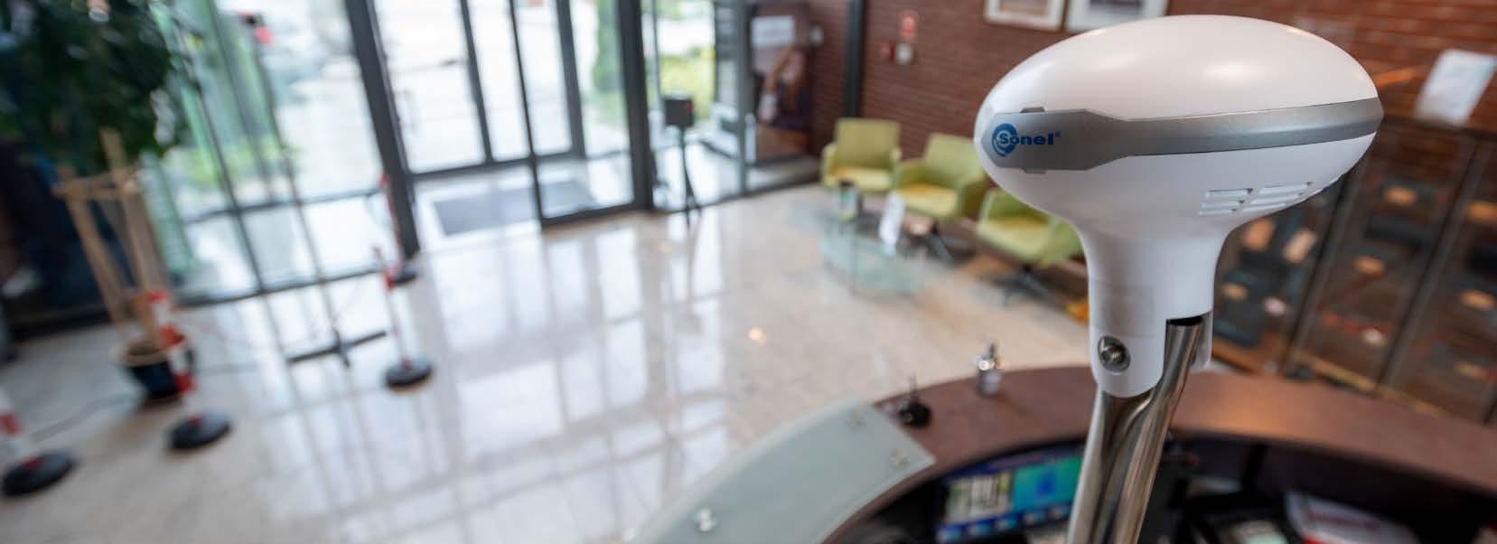
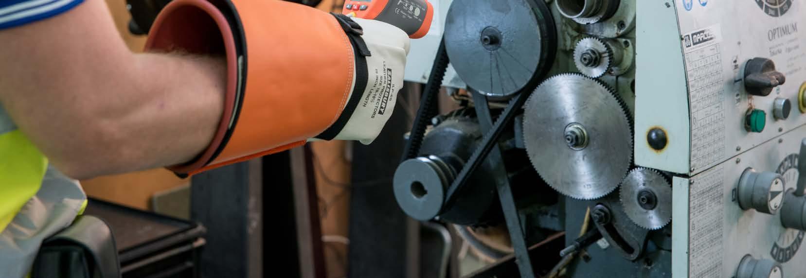


78
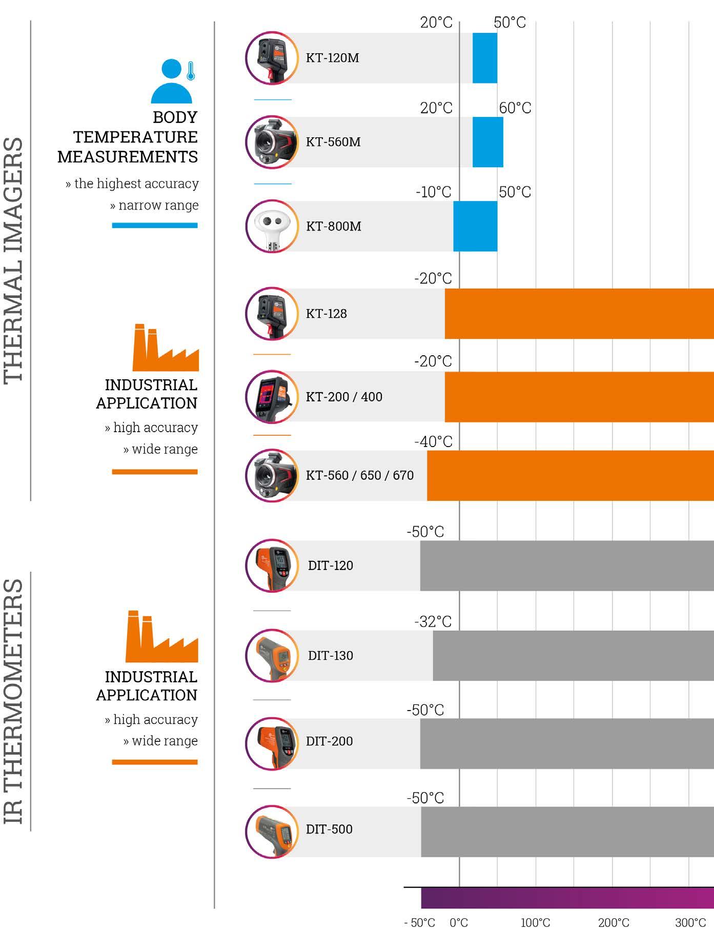
79

Professional radiometric thermal imaging cameras register temperature separately for each point of the image. For example, in the case of a camera with a 640 x 480 resolution, temperature is registered simultaneously for each of the 307200 points. This makes it possible to conduct detailed analysis of saved thermal images, which display different temperatures as different colors.


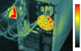

80
A thermal image is presented on-screen in the color palette selected by the user that best represents individual temperature ranges:
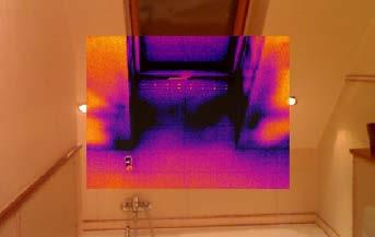

camera, which makes it possible to precisely locate places with a specific tempera ture, and the color palette can be changed arbitrarily to best represent the tempera ture distribution.
All information saved in a thermogram can be used by specialized software deliv ered with the thermal imaging camera. During analysis of a thermogram, points with maximum or minimum temperature can be determined, the emissivity coef ficient of the whole thermogram or a part of it can be corrected, temperature can be read at any point of the thermogram, mean temperature can be calculated, tem perature distribution can be presented in the form of histograms or isotherms, the thermal image can be combined with the real image, just as on the screen of the
In thermographic analysis, contactless measurement in the infrared spectrum is used to determine the temperature of a surface from a distance. Since all objects with a temperature above absolute zero emit thermal radiation of similar character istics (called black-body radiation), by measuring the radiation and with knowledge of the emissivity coefficient of a given object, its temperature can be determined.
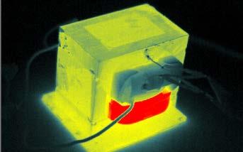
Contactless measurementstemperature
One useful function of thermal imaging cameras is the capability of taking real-life photographs as well as combined image modes enabling combination of the re al-life image with the thermal image and displaying an image in which the thermal image overlaps with the real-life image.
Thermal imaging is a process based on processing infrared radiation, that is the heat emitted by objects, into a visible image, making possible to assess tempera ture distribution on the surface of the observed object without contact.
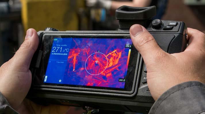
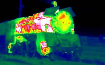

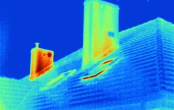
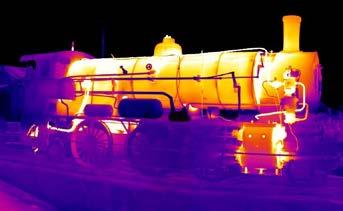
This is important wherever it is necessary to measure temperature at inaccessible or hazardous locations and also allows for: » quick temperature measurement on surfaces of any size, » or lightning-fast location of heat escape points invisible to the naked eye related to failures in buildings’ insulation and construction errors (thermal bridges for example).
The main parameters characterizing an infrared thermometer are: measured temperature ranges, accuracy and D:S ratio, which is the ratio of the distance from the object to the diam eter of the field for which the measurement is made.

Thanks to their design, pyrometers allow to measure tem perature of small objects, also from great distance. The big ger D:S ratio is, the smaller objects can be measured from big distance.
Infrared thermometers are also devices that serve for con tactless temperature measurement, and the operate on the basis of analysis of the thermal radiation emitted by the test ed object. These devices are applied whenever it is required to measure wide range of temperatures.
Storage temperature -20...+60°C
Camera head interface
Sonel KT-800M is equipped with various powerful functions. Multi-tar get tracking ensures that no target is missed. Custom warning zones and high-temperature shielding settings help avoiding interference from other high-temperature objects. When a feverish person is detected, the system supports automatic warning, tracking and photo taking for stor age. It also supports video recording. Convenient for query and classify management.
index: WMGBKT800M
Supported. The software needs to be upgraded to V1.1.0.9, and equipped with NVR (NVR standard 4T hard disk). Supports GB28181 protocol to access third-party platforms
Operating temperature -10...+50°C (ambient temperature 16...32°C)
Video recording
WAZESTAWKOMPKT800M
Network communication protocol HTTP, RTSP
Visual camera Resolution 2 MPix
SONEL KT-800M
Functions
Real-time preview of visible and thermal image
Overview
Face tracking
Humidity <90% (non-condensing)
Vibration 10 Hz ~ 150 Hz ~ 10 Hz 0.15 mm, IEC60068-2-6
» Real-time temperature calibration with blackbody ensures high accuracy
Cable set
Temperature stability ≤ ±0.2°C (single point)
Support query, classification and deletion of historical warning screenshots
Frame rate 25 Hz
38° x 28° / 9.7 mm
Features
Input power ≤12 W
Blackbody target surface uniformity ≤0.1°C
» 400 x 300 px infrared uncooled Vox detector

Standard accessories:
» Automatic focus on a person's face
Frame rate 25 Hz
Input voltage DC 12 V
Sensitivity ≤40 mK
Calibration
Accuracy ≤ ±0.3°C (ambient temperature 16...32°C)
Built-in shutter and external black body, automatic calibration mode
Two-way, visible light 100M, infrared 1000M
400 x 300 / 17 μm
Lens (field of view / focal distance)
Tripod WAADASTATYWKT800M
Large-scale temperature screening at airports, railway stations, subway stations, hospitals, supermarkets, factories, schools and other places with large flow of people to control and reduce the spread of diseases and viruses with fever symptoms.
Support automatic tracking for elevated temperatures
Network interface
Warning switch and warning threshold value, number of warning targets,
Factory calibration certificate
Automatic tracking
Environmental conditions
Fever detection | Fever warning system
Intelligent face tracking
Parameter settings
» AI deep learning algorithm based on neural network provides more accurate temperature detection and lower false warning rate
Automatic tracking, warning and photo capturing for storage when person with fever is detected. Warning while the blackbody is blocked
Black Body WAADABBKT800M
Historical records
Camera head size 173 x 184 x 212 mm
Sonel KT-800M IR Fever Warning System can be applied to mass fever screening in crowded public places, which helps detect people with potential fever. It may contain or limit the spread of diseases through identification of infected individuals showing fever symptoms. Sonel KT800M combines advanced technology such as thermographic human temperature detection and AI intelligent face tracking which makes the equipment accurate and easy to use.
Black body
Application
Computer set
Measurement range -10...+50°C
Automatic warning
Real-time spot temperature detection
» Warning sound alarm when a person with fever is detected
» Stand-type, easy to deploy, equipped with PC with powerful analysis software
Camera head power
Detector resolution
Total height (incl. stand) 2200 mm
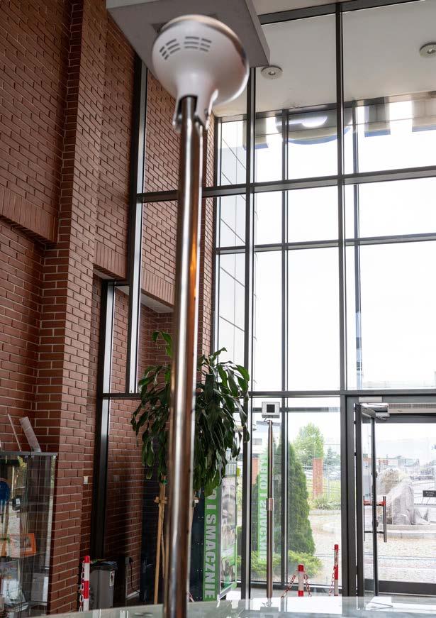
Shock 30g 11 ms, IEC 60068-2-27
» Accurate single-point and multi-point high temperature tracking and warning
Real-time preview
Real-time temperature monitoring at any point in the field of view
81
WAPRZKPLKT800M
warning photos automatic clearing, shielding fixed high temperature objects
Thermal imager
384 x 288 / 25 µm VOx
Temperature range 20°C...60°C
IR / Visual / Infrafusion MIF/ PiP
Shoulder strap WAPOZPAS3
Interfaces
Li-Ion rechargeable battery (operating time >4 hours), sleep mode, built-in charger, AC 110-230 V temperature 15°C...35°C -40°C...+70°C
5 Mpix visual photo camera, LED flashlight, GPS, laser pointer, microphone, speaker, digital compass, lighting sensor Wireless communication Wi-Fi
Spectral range 7.5~14 μm
The camera allows to identify people with fever in the crowd (e.g. caused by viral or bacterial infection). Ideally suited for sanitary-epide miological monitoring of groups or individual people. In addition, it can be widely used in medicine (neurosurgery, neurology, vascular surgery, dentistry, otolaryngology, pulmonology, endocrinology and mammology) and in veterinary medicine.
» saving IR images and videos to SD card or directly to a PC
Auto tracking Max. or Min.
Built-in functions
Storage temperature
Isotherm Upper / Lower Temperature alarm Visual and voice
The camera is a useful tool when detecting:
Zoom 1.1...4
Factory calibration certificate
Lens (field of vision / focal distance) 21.7° x 16.4°/25 mm/F1.0
index: WMGBKT560M
50/60 Hz power supply Operating
Power adapter WAZASZ13
16 GB SD memory card WAPOZSD16
Reports module PDF reports, report printing via Wi-Fi
Spatial resolution (IFOV) 0.99 mrad
Palettes 8
SD card port, LAN 1 Gb/s, mini HDMI, microUSB 2.0 Memory 16 GB SD card (max. 32 GB)
» fever
Sonel KT-560M is dedicated for body temperature measurements. If the temperature exceeds a set threshold (i.e. fever), setting off an alarm is possible. This way, one can detect risk groups during extensive ex aminations. The imager can also be used to detect various diseases in individual patients and animals.
Humidity 10%...95% Resistance to shocks / vibrations 25g, IEC 60068-2-29 / 2g, IEC 60068-2-6 Housing IP54 Weight approx. 1.3 kg (with battery) 82
Frame rate 25 Hz / 9 Hz
Fever detection | Thermal imager
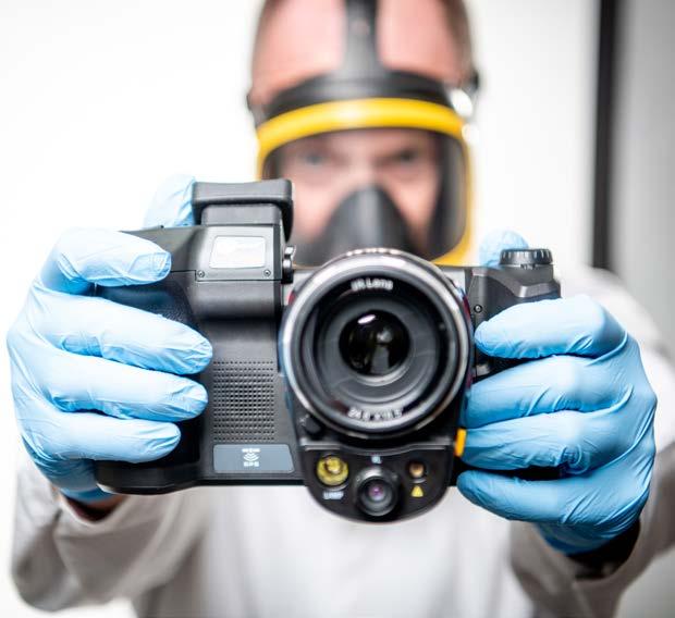
Accuracy ±0.4°C (32°C...38°C) ±0.6°C (20°C …32°C or 38°C…60°C)
Rechargeable Li-Ion battery WAAKU18
» removable Li-Ion battery with 4-hour working time
Focus Motor-drive / Auto Display 5", 1280 x 720, touch-screen LCD
RJ45 cable WAPRZRJ45
SONEL KT-560M
Sensitivity 40 mK
Image mode
Image analysis mode 5 points, 5 lines, 5 areas
Analysis info storage Saved with image (point, line, areas)
Application
» 5 Mpix visual camera
HDMI cable WAPRZHDMI
» add voice and text notes, draw graphical symbols on images
Image file format
» malignant tumours of breast, skin, lymph nodes, facial skeleton and their relapses, » inflammation and adenocarcinoma (ovary and fallopian tube),
Detector resolution
» thyroid dysfunction and disease, » inflammatory and functional diseases of the kidneys, as well as the digestive system and liver,
Examine through image
USB cable (A to Micro B Type) WAPRZUSBMICRO
Video internal storage Manual
Viewfinder 1280 x 960 LCOS
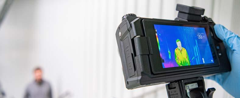
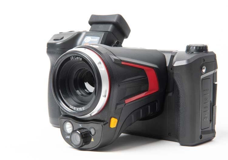
» GPS, digital compass, LED flashlight and laser pointer
» measuring range 20°C...60°C, accuracy ≤ ±0.4°C
» built-in report module for complete thermal analysis
» inflammatory diseases of the joints and spine, » diseases of the vessels and nerves of the extremities,
Video file format H.264 (with temperature data)
Standard accessories:
Power supply
Features
» adjustable brightness of the display, facilitating work at high ambient light and dark places
» 5’’ large rotating touchscreen

» inflammation and diseases in animals.
» interfaces: microUSB 2.0, Wi-Fi, Gigabit Ethernet, MiniHDMI, SD slot
Hard carrying case WAWALXL9
» ear, throat and nose inflammation,
» imaging modes: IR, visual, PIP (picture in picture), MIF (combined visual and IR)
JPG or raw data
»
WAZASZ20
Spectral
50°
»
»
Simple thermography
WMGBKT120M
16 GB microSD card
WAPOZPAS1
Lens
Spatial
7.6 mrad Display 2.4", 240 x 320, LCD Image mode IR Temperature range 20°C...50°C Accuracy ≤0.5°C (ambient temperature 23°C ± 2°C, humidity ≤80%, target distance 0.8 m, target temperature 32°C...42°C) Image analysis mode Temperature indication, temperature alarm Image file format JPG Interfaces microSD card slot (max. 32 GB), USB type C, tripod Memory SD card (max. 32 GB) Power supply Li-Ion battery (operating time >8 hours), built-in charger (charging time <2.5 hour), AC adapter 110-230 V, 50/60 Hz Operating temperature -10°C...+50°C Storage temperature -40°C...+70°C Housing IP54 Weight ca. 0.35 kg 83
WAPOZMSD16
»
Fever detection | Thermal imager

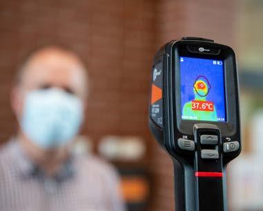

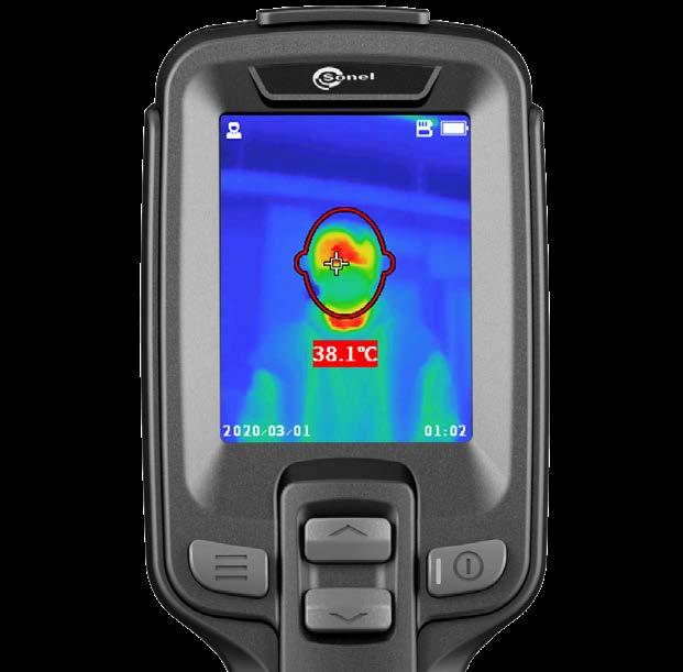
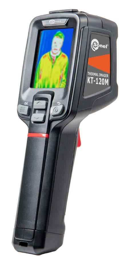
»
»
» measuring range 20°C...50°C accuracy up to ±0.5°C fast temperature measurement automatic signalling of fever detection saving IR images to SD card built-in Li-Ion battery with 8-hour working time interfaces: USB type C, SD slot can be set up on a tripod
Features
Declaration of verification
KT-120M is used wherever many people need to be tested for body tem perature. Particularly useful in: factories, schools, shopping malls, office buildings.
»
KT-120M is a special camera. Economical, practical and handy, it is a powerful tool in preventing or limiting epidemics. The user can meas ure the temperature with 0.5°C accuracy. The exceeding of the threshold value is signalled by an alarm. All this in order to quickly and efficiently detect people with fever - e.g. infected with a virus giving such symp toms.
Wristband
WAPRZUSBC
»
Type C USB cable
SONEL KT-120M
»
»
index:
Application
»
Standard accessories: USB charger
Detector resolution 120 x 90 / 17 µm range 7.5~14 µm Frame rate 25 Hz Sensitivity 60 mK (field of vision / focal distance) x 38°/2.28 mm resolution (IFOV)
Isotherms. Temp. alarm. Smart stroke
Industry | Thermal imagers KT-560 KT-650 KT-670
Micro HDMI cable WAPRZMIKROHDMI √ √ √ SD card 64 GB WAPOZSD64 √ √ √
view
» interchangeable lenses that do not require calibration by the manufacturer
» recording of IR videos (on SD memory card or computer hard disk)
Emissivity coefficient Set from 0.01 to 1.00
Image file format
Behold the highest class of thermal imagers that offers temperature measurements of substantial accuracy. Robustly designed and con structed, they are ideally suited for:

» locating hidden heat sources (of people, animals, objects) in dark or low-light conditions.
Housing IP54 Weight approx. 1.4 kg (with battery)
84
» MIF image combining mode
Notes on IR images Additional visual photos, voice, text recognition, text typing Reports module PDF reports Video file format MP4 (without temp. information), IRGD
index: WMGBKT6701 / WMGBKT6501 / WMGBKT5601

• macro 23.3 mm x 17.5 mm / 67 mm / - / 60.7 μm 23.3 mm x 17.5 mm / 67 mm / - / 37.5 μm
Panoramic images √
Humidity ≤95% Resistance to shocks / vibrations 30g 11 ms (IEC 60068-2-27)
Shoulder harness WAPOZPAS3 √ √ √
» digital zoom
Storage temperature -40oC…+70oC
Interfaces
correctionMeasurement
standard 24.9° x 18.7° / 15 mm / 1.13 mrad / 0.4 m 24.6° x 18.5° / 25 mm / 0.68 mrad / 0.3 m
Image mode IR / Visual / Infrafusion MIF/ PiP Zoom 1…10 1…35
Features
Overview
» built-in camera for capturing images within the visible light spectrum
Imagers have built-in tools for analysis and generating reports on-site.
» identifying overheating of mechanical and electro-mechanical components,
Range 1: -40°C…150°C Range 2: 100°C…800°C Optional: 700°C…2000°C

• wide angle 48.1° x 35.9° / 7.78 mm / 2.19 mrad / 0.15 m 45.4° x 34.8° / 13 mm / 1.31 mrad / 0.15 m
• telephoto 11.2° x 8.4° / 33 mm / 0.52 mrad / 2 m 11.3° x 8.5° / 55 mm / 0.31 mrad / 1.5 m
• ultra-telephoto 7.3° x 5.5° / 50.7 mm / 0.34 mrad / 4 m 7.3° x 5.5° / 85 mm / 0.2 mrad / 4 m
• high temp 24.9° x 18.7° / - / - 24.6° x 18.5° / - / - / -
Super-resolution 4x, 768 x 576 4x, 1280 x 960
temp. information) Built-in functions Visual camera 13 MPix, LED flashlight, GPS, laser pointer, laser rangefinder, microphone, speaker, digital compass, light sensor.
Wireless Wi-Fi, Bluetooth Built-in memory (64 GB), SD card, cloud service SD card slot (max. 64 GB), LAN 1 Gb/s, micro HDMI, USB type C (data transfer only), tripod
Storage
» built-in reports module

Power supply Li-ion battery (4 h of continuous operation), built-in charger, AC adapter 110-230 V, 50/60 Hz
» troubleshooting electrical installations, wiring, panels, motors, breakers, transformers, switchgear, and electrical equipment,
XL9 carrying case WAWALXL9 √ √ √
» built-in: GPS, digital compass, LED flashlight, laser pointer, laser rangefinder
LAN cable (RJ45) WAPRZRJ45 √ √ √
External battery charger Z14 WAZASZ14 √
640
Temperature range
communication
Palettes 8 10 12
Power adaptorsupplyZ13 WAZASZ13 √ √ √
Operating temperature range -15oC…+50oC
Auto-adjustable distance, relative humidity, ambient temperature (reflected) JPG (including
» monitoring the thermal performance of industrial manufacturing processes,
KT-670
Detector type 384 x 288 / μm x 480 / μm
17
17
SONEL / KT-650 / KT-560
Sensitivity 45 mK (field of view / focal length / instantaneous field of / min. focus distance)
mK 40
Standard accessories: KT-560 KT-650 KT-670 2x Li-Ion battery 10.8 V 3.35 Ah WAAKU18 √ √ √
Factory calibration certificate √ √ √
Display 5”, 1280 x 720 high brightness, LCD touchscreen Viewfinder 1280 x 960 LCOS


» inspecting buildings for insulation leaks, energy audits, HVAC/R equipment, water damage, and pests,
» extensive image analysis tools
Type C USB cable WAPRZUSBC √ √ √
» image files saved in JPG format (complete image data)
Spectral range 7.5~14 μm
Accuracy ±2°C or 2% of reading ±1°C or ±1% of reading
» interfaces: USB type C, Wi-Fi, Gigabit Ethernet, micro HDMI, SD memory card slot, Bluetooth
The touchscreen as well as the lens swivel independently to view objects of interest that are difficult to access from any angle. The large number of functions, intuitive handling and excellent ergonomics make the KT560/650/670 imagers perfect for every advanced thermographer
35 mK Lens
Image analysis mode 12 points, 12 lines, 12 areas. Temperature readings: min., max., average. Isotherms. Temp. alarm. Smart stroke 16 points, 16 lines, 16 Temperatureareas.readings:min.,max.,average.
2x
» built-in report module
Storage temperature -40°C…+70°C
» built-in visual camera: 5 Mpix
SONEL KT-400 /
WAADAO19 √ IR 19 mm tele lens for KT-400 (28.4°x21.5°)
More to see, less to hold
Spectral range 7.5~14 µm Frame rate 25 Hz
Interfaces
» comprehensive image analysis tools
Thermal sensitivity 50 mK 45 mK
» interfaces: Micro USB 2.0, Wi-Fi, microHDMI, microSD slot
» high sensitivity of detectors and a wide temperature range
The picture is just the beginning
28.4°*21.5°/19 mm optional: 57.0° x 45.0°/8.8 mm 13.7° x 10.3°/40 mm
Image analysis mode 5 points, 2 lines, 5 areas. Temp. readings: min., max., mean. Isotherms. Temp. difference Alarm temp. Dew point.
Photo image format JPG
Temperature range range 1: -20°C…150°C range 2: 150°C…650°C range 3: 650°C…1500°C (optional)
Shock/vibration resistance 30g 11 ms (IEC 60068-2-27) / 10 Hz~150 Hz~10 Hz 0.15 mm (IEC 60068-2-6)
Focusing manual IFOV (standard lens) 3.45 mrad 1.29 mrad
rechargeable
Characteristic
» IR video recording (on the SD card or computer disc)
Thanks to state-of-the-art technologies and solutions, the cameras ensure full control and flexibility in various situations, and are an ideal tool for both novice users and professional thermographic inspectors.
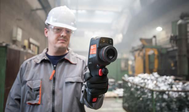
Wireless communication Wi-Fi
Lens (field of view/focal length) 37.8° x 28.8°/7 mm optional: 14.4° x 10.8°/19 mm
Power supply
Thermal imaging is not everything
Features
Standard accessories: KT-200 KT-400 IR 19 mm tele lens for KT-200 (14.4°x10.8°)
Regardless of whether you take photos or record videos, the newest cameras supplied by Sonel, equipped with modern detectors, a wide range of temperature measurement and high-quality lenses, ensure highly detailed images and accurate measurements. The cameras are available in several versions, thus enabling the appropriate configuration for the user’s needs.
Measurement correction settable distance, relative humidity, ambient temperature (reflected)
Palettes 8
» intuitive user interface
Video file format AVI, IRV (including information on temperature)
Detector resolution 192 x 144 / 25 µm VOx 384 x 288 / 25 µm VOx
Notes to IR photos audio (60 seconds), text, graphic, photo Report module PDF reports, report printing through Wi-Fi
» panoramic photos (only KT-400)
Imaging mode IR / Visual / Infrafusion MIF / PiP Zoom 1.1…4
Accuracy ±2°C or 2% of reading (for ambient temperatures between 15°C and 35°C and object temperature above 0°C)
KT-200 index: WMGBKT400V19 / WMGBKT200V19 Industry | Thermal imagers

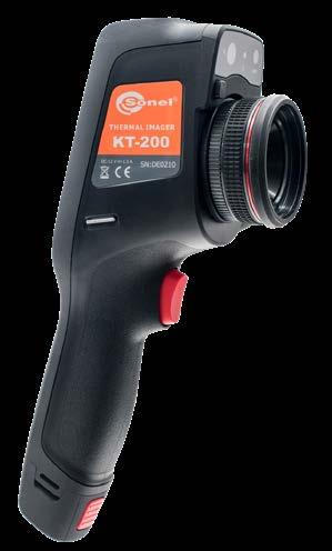
microSD card port, microHDMI, microUSB 2.0
Display 4", 480 x 800 px, high-quality LCD touchscreen
Operating temperature -10°C…+50°C
Li-Ion battery (operating time >4 hours), built-in charger, AC 110-230 V (50/60 Hz) / 12V power supply adapter
Cameras are additionally equipped with visual lenses and related image mixing technologies: PIP, MIF. Support from the built-in LED torch and laser improves operational quality by facilitating photography and then image interpretation.
Emissivity coefficient adjustable from 0.01 to 1.00 or taken from material list
Dimensions (with standard lens and battery) 274 x 106 x 78 mm 274 x 110 x 78 mm
» photos in increased resolution (only KT-400)
Humidity 10%…95%
KT-200 KT-400
Built-in functions visual camera 5 MPix, LED torch, laser pointer, microphone, speaker.
Housing IP54 Weight approx. 0.84 kg (with battery)
WAAKU24 √ √ Micro-USB data transfer cable WAPRZUSBMICRO √ √ Wrist strap WAPOZPAS4 √ √ MicroHDMI cable WAPRZMIKROHDMI √ √ Touchscreen work gloves WAREK1 √ √ MicroSD 16 GB card WAPOZMSD16 √ √ Z13 battery charger WAZASZ13 √ √ Hard carrying case WAWALL6 √ Stiffened case WAFUTL16 √ Factory calibration certificate √ √ 85
WAADAO19V400 √ 7.4 V 3.2 Ah Li-Ion battery
The built-in report module allows for the preparation and printing out of reports directly from the camera. Built-in communication interfaces ensure constant communication between the camera and the computer or mobile device, also over a wireless network.
» different imaging modes: IR, Visual, PIP, MIF
A large display combined with innovative data processing electronics is placed in a compact housing, thus ensuring a perfect balance between high performance and small dimensions – the best choice for everyday use. Moreover, due to the centrally located navigation button supported by a menu on the touchscreen, this model ensures simple and intuitive operation.
» built-in: LED torch, laser pointer
Zoom x2 / x4
» different imaging modes: IR, Visual, PIP, MIF

Palettes 6
Video Sending images via USB or Wi-Fi (option)
» solid and portable tool, intuitive user interface
Solid and portable tool for daily tasks. This is the main goal when de signing a line of budget cameras with a visible spectrum lens.

» high-capacity, replaceable Li-Ion battery
Detector resolution 160 x 120 / 12 μm 256 x 192 / 12 μm 320 x 240 / 17 μm
Description
Minimum focus distance (standard lens) 0.5 m
Despite the low price, the camera has been equipped with a set of essen tial, but necessary tools for analysing and correcting images/measure ments. The results of the work can be saved on an SD card or sent via USB or Wi-Fi for further processing. Professional software for thermo gram analysis completes the unit. This makes the camera an ideal tool for maintenance personnel, electricians, the construction industry and others, in their daily tasks.
Display 3.5", high-quality LCD
Imaging mode IR / Visual / MIF / PiP
Housing IP43 Weight approx. 0.72 kg (with battery)
Standard accessories: KT-165 KT-250 KT-320 Rechargeable Li-Ion battery 7.4 V 2.3 Ah WAAKU26 1 2 2 micro-USB data transfer cable WAPRZUSBMICRO 1 1 1
Wrist strap WAPOZPAS1 1 1 1 8 GB SD card WAPOZSD1 1 16 GB SD card WAPOZSD16 1 1 Z20 battery charger WAZASZ20 1 1 1 M-11 camera case WAFUTM11 1 1 1 Factory calibration certificate 1 1 1
Humidity -10°C…+50°C
Various imaging modes
» 1-hand operation,
Image analysis mode
Measurement correction Settable distance, relative humidity, ambient (reflected) temperature
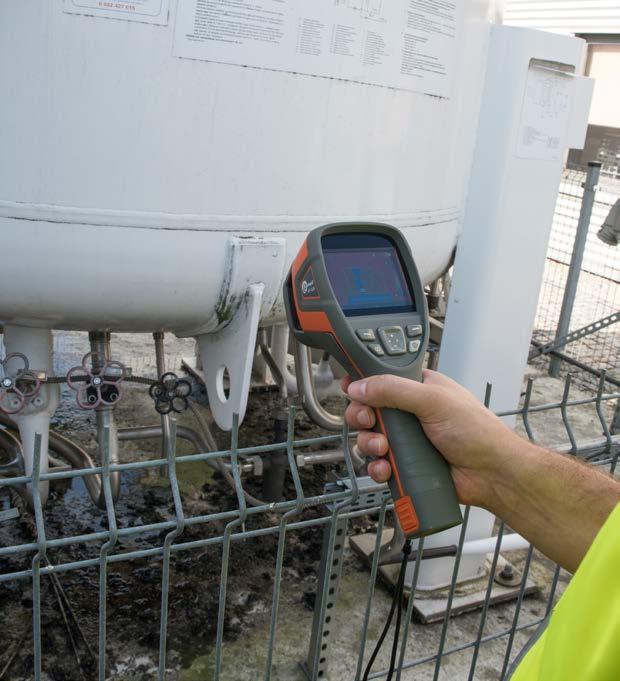
Wireless communication Wi-Fi
Spectral range 7.5~14 µm
Temp. readings: min., max. temp. alarm
index: WMGBKT320 / WMGBKT250 / WMGBKT165 Industry | Thermal imagers

Power supply Li-Ion battery (operating time >4 hours), built-in charger,AC 110-230 V (50/60 Hz) power supply adapter
IFOV (standard lens) 3.30 mrad 2.36 mrad 2.33 mrad
Interfaces SD card port, microUSB 2.0
Thanks to state-of-the-art technologies and solutions, the cameras of the Sonel company ensure full control and flexibility in various situa tions, and are an ideal tool for both novice users and professional ther mographic inspectors.
» built-in visual camera: 5 Mpx
86
Features
Photo image format JPG
Accuracy ±2°C or 2% of reading(for ambient temperatures between 15°C and 35°C and an objecttemperature of above 0°C)
Lens (field of view/focal length) 30.0° x 22.0°/3.7 mm 35.0° x 26.0°/5 mm 42.5° x 32.5°/7 mm
Built-in thermoanalysis essentials
Thermal sensitivity ≤50 mK
Focusing Fixed focal
Storage temperature -20°C…+60°C
Modern IR sensors available in three resolution versions are supported with the visible spectrum lens, which allows operation in four modes: IR, Visual, PIP (picture in picture) and MIF (contours visible on IR image). A high-quality image is presented on a clear display with backlighting adjustment.
KT-320 / KT-250 / KT-165
»
Dimensions (with standard lens and battery) 258 x 98 x 90 mm
Shock/vibration resistance 30g 11 ms (IEC 60068-2-27) / 10 HZ~150 HZ~10 HZ 0.15 mm(IEC 60068-2-6)
KT-165 KT-250 KT-320
Emissivity coefficient Adjustable from 0.01 to 1.00 or taken from the material list.
Built-in functions Visual camera 5 MPix
Humidity 10%…95%
Temperature range -20°C…650°C
Li-Ion battery (operating time >5 hours), built-in charger (charging time <2.5 hour), AC adapter 110-230 V, 50/60 Hz temperature -10°C...+50°C Storage temperature -40°C...+70°C IP54 Weight ca. 0.35 kg
Operating
Housing
87
Measurement adjustment
Declaration of verification
» quick start fast temperature measurement
»
Accuracy ±2°C or ±2% of reading (for ambient temperature 15°C…30°C, object temp. ≥0°C)
WMGBKT128
Palettes 6
Wristband
Spectral range 7.5~14 µm
Standard accessories: USB charger WAZASZ20
Type C USB cable WAPRZUSBC
Features
» built-in Li-Ion battery with 5-hour working time
SONEL KT-128
» interfaces: USB type C, SD slot
WAPOZMSD16
» automatic signalling of exceeded alarm threshold

WAPOZPAS1
Simple thermography
Detector resolution 120 x 90 / 17 µm
» saving IR images to SD card
» can be set up on a tripod
KT-128 is a special camera. Economical, practical and handy, it is a pow erful tool in everyday work. The camera is used for basic diagnostics. It is equipped with a matrix having a resolution of 120 x 90 pixels, supported by visual camera, laser pointer and additional features to fully meet the needs of users.
Application
Frame rate 25 Hz
Industry | Thermal imager
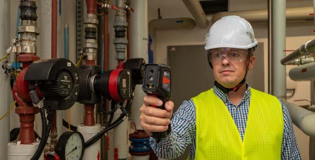

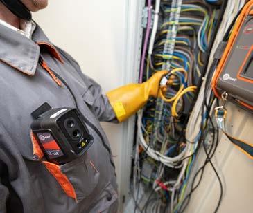
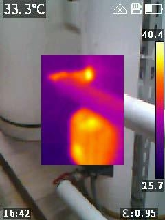

Spatial resolution (IFOV) 7.6 mrad
Display 2.4", 240 x 320, LCD
Sensitivity 60 mK
»
Point. 3 areas. Temperature indication: min, max. Temp. alarm
Image mode IR / Visual / PiP
index:
Selectable from 0.01 to 1.00 or from the list
Built-in features
Visual camera 5 MPix, LED flashlight, laser pointer Interfaces microSD card slot (max. 32 GB), USB type C, tripod

» measuring range -20°C...400°C
Temperature range Range 1: -20°C...+150°C Range 2: 100°C...+400°C
Power supply
»
»
16 GB microSD card
KT-128 is used always when the temperature of objects is important and may affect the operation of the equipment. Particularly useful in: power engineering, construction sector, industry » HVAC.
Lens (field of vision / focal distance) 50° x 38°/2.28 mm
Image analysis mode
Emissivity
Adjustable distance, ambient temperature (reflected) Image file format JPG
creation, “drag-and-drop” desired elements into the report – thermo grams and the visible images corresponding to them.
SONEL THERMOANALYZE 3
SONEL KT MOBILE
Software index: WAPROTHERMOANALYZE3 88
Analyzed areas selection – drawing of a rectangular area, oval area, area of any
Temperatureshape.
Capability of correcting the emissivity coefficient throughout the entire thermogram or part of it – the coefficient can be corrected individually for each selected area.
Easypolyline).report
reading at any point – after scrolling the cursor over to the “Informa tion” window, temperature readouts are displayed continuously along with current coordinates, and other recorded information is also available (maximum tempera ture, humidity, emissivity).

Infra Fusion technology – a thermogram is superimposed onto a part of the visi ble image, in any palette selected by the user. The thermogram is applied with the selected transparency, making it possible to optimally display and mark areas of in terest, particularly when it is difficult to visually compare points on the thermogram with details on the visible image of the observed object.

A mobile version of the program supporting Sonel thermal imaging cameras. With the application, you can get a preview of the actual image on your phone, and remote ly perform a series of other activities by managing the camera from a mobile device. It can be downloaded from Google Play

All corrections applied and characteristic points are saved for further analysis at a later time. Selection of the visually optimal color palette (among 9 available in the application) for the best visualization of temperature changes. Configuration of the temperature range for the best imaging of temperature distribution (manual or automatic mode available).
The software has an unlimited license - it can be used simultaneously on multiple Thedevices.software is available on the website: www.sonel.com

Software for analyses and reports, included with the set of thermal imagers.

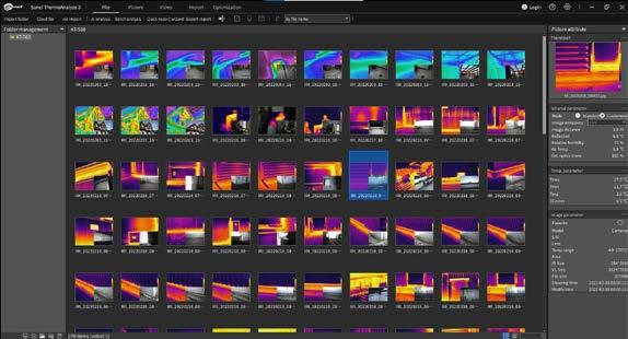
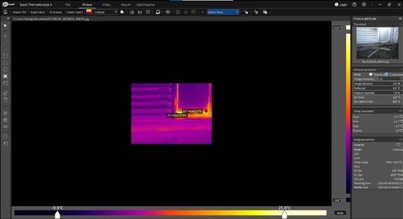
Determination and reading of minimum, maximum and mean temperature for the entire area and in every marked area of interest. Selection of segment (straight line or

» D:S ratio of 13:1
Special features
LCD display
» Displaying MAX, MIN, AVG, DIF temperatures.
Professional and compact infrared (IR) thermometers are a solution for problems in every area where specific thermal conditions are required. The intuitive one-hand operation of the devices and the ergonomically designed gun-type housing allow for trouble-free daily work.
» Precise non-contact temperature measurement.
» Single laser pointer (marking the measurement area).
» Automatic Data Hold
DIT-500
» Temperature measurements in the range of -50°C...1600°C
index:
laserSemi-conductordiode output power <1 mW wavelength 630~670 nm class class 2 (II) laser
» Transmission of current readings to computer via USB cable.
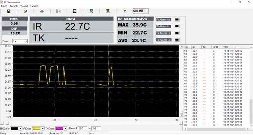
» Resolution from 0.1°C and 0.1°F.
• DIT-500 | double.
» Backlit LCD display.
Standard accessories - DIT-500: Mini-USB data transmission cable WAPRZUSBMNIB5 Temperature measurement probe (type K) WASONTEMK Mini tripod WAPOZSTATYW Carrying case 9 V Factorybatterycalibration certificate
A program dedicated for the PC. It is used to download results from the memory of the DIT-500 pyrometer and to supervise continuous temperature measurements by down loading the results in real time.
Additional functions
DIT-500 DIT-130
Standard accessories - DIT-130: Temperature measurement probe (type K) WASONTEMK Holster WAFUTS5 9 V Factorybatterycalibration certificate
» Temperature measurements in the range of -32°C...380°C
» High and Low alarm.
» Double laser pointer (marking the measurement area).

Technical specification
Measurements
» Input for type K temperature probe.
» Mechanical areas.
89
SONEL DIT-500 / DIT-130
» A specially designed holster for storing the equipment with the possibility of attaching it to the belt in standard.
WMGBDIT500 / WMGBDIT130 Industry | Infrared thermometers
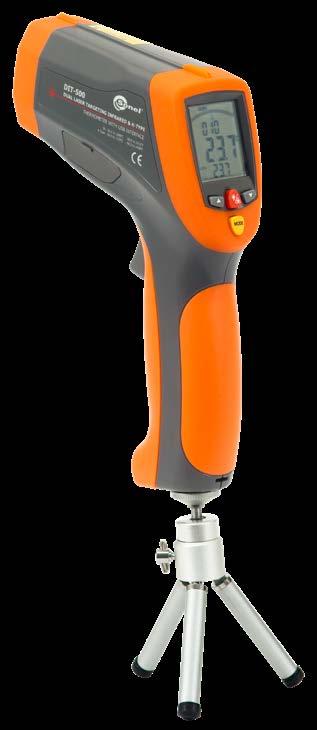
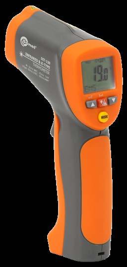
» Electrical areas.
DIT-130
All measurementsadvancedinindustrialenvironments Basic measurements in plants, andmechanicalelectrical,HVACareas
» Temperature unit selection: °C / °F.
» Auto power off.
Description
» D:S ratio of 50:1
segmented, with backlight Spectral sensitivity 8~14 μm
» Industry areas.
» Data memory (LOG) for 100 measurements
Applications
Emissivity digitally adjusted from 0.10 to 1.00
» HVACR areas.
» Operation with an external temperature probe - temperature measurement range -50°C...1370°C.
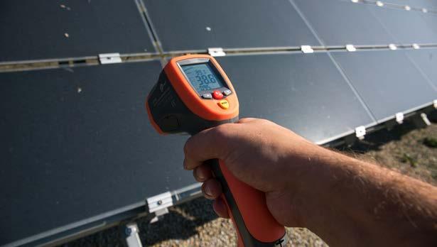
» Emissivity digitally adjustable from 0.10 to 1.00.
» Data memory (LOG) for 20 measurements
Power supply 9 V alkaline battery NEDA 1604A or IEC 6LR61 Operating temperature range 32...122°F0...50°C Storage temperature -20...+60°C-4...+140°F Humidity 10...90% Indication of range overflow symbol “----” symbols “-0L”, “0L” Response time 150 ms <1 s Weight 350 g 290 g Dimensions 230 x 155 x 54 mm 190 x 111 x 48 mm
» Laser pointer:
SONEL IR THERMOMETER
• DIT-130 | single,
» Circular laser pointer (marking the measurement area).
Indication of range overflow symbol “----” Response time 150 ms Weight 242 g 231 g Dimensions 170 x 50 x 95 mm 170 x 50 x 85 mm
» D:S ratio of 12:1
LCD display segmented, with backlight
» High and Low alarm.
» DIT-200 | Input for type K temperature probe.
Standard accessories - DIT-120: Holster WAFUTS5 2x AAA 1.5 V battery Factory calibration certificate
» Automatic Data Hold
Applications
» Temperature measurements in the range of -50°C...650°C
SONEL DIT-200 / DIT-120
» Resolution from 0.1°C and 0.1°F.
» Displaying MAX, MIN, AVG, DIF temperatures.
Power supply 2x AAA 1.5 V battery
Emissivity digitally adjusted from 0.10 to 1.00
index:
» Laser pointer:
» Temperature control of busbars and connections.
» Auto power off.
» D:S ratio of 20:1
Operating temperature range 32...122°F0...50°C
» Precise non-contact temperature measurement.
» Temperature measurement of transformers.
Storage temperature 14...+140°F-10...+60°C
90
DIT-200 DIT-120
» Temperature control of materials in metallurgical processes.
DIT-120 and DIT-200 are pyrometers for professionals. Durable housing, ergonomic grip, but tons accessible with one finger - all this contributes to the comfort of the user. Technical parameters speak for themselves. The advanced laser pointer will precisely and unambigu ously indicate the area of the performed measurement.
» Temperature measurements in the range of -50°C...1000°C
Special features
DIT-120
» Temperature unit selection: °C / °F.
» Monitoring the condition of heating and cooling devices.
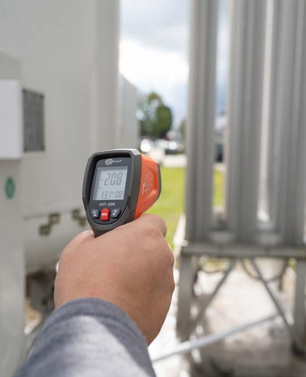
DIT-200
» Operation with an external temperature probe - temperature measurement range -50°C...1370°C.
Additional functions
Spectral sensitivity 8~14 μm
laserSemi-conductordiode
» Double laser pointer (marking the measurement area).
• DIT-200 | circular, • DIT-120 | dual.
» Checking the heating of rollers and bearings in transport conveyors.
» ...and many others.
Measurements
WMGBDIT200 / WMGBDIT120 Industry | Infrared thermometers


» Emissivity digitally adjustable from 0.10 to 1.00.
» Backlit LCD display.
Description
Technical specification
output power <1 mW wavelength 630~670 nm class class 2 (II) laser
Humidity 10...90%
Standard accessories - DIT-200: Temperature measurement probe (type K) WASONTEMK Holster WAFUTS5 2x AAA 1.5 V battery Factory calibration certificate
•
IR lens 7 mm (37.8°x28.8°) WAADAO7
Tele IR lens 33 mm (11.2°x8.4°) WAADAO33V560
Tele IR lens 55 mm (11.3°x8.5°) WAADAO55V6701
Wristband WAPOZPAS1 1 1 1 1 harness WAPOZPAS3 1 1


1 1
• • •
• Tele IR lens 19 mm (14.4°x10.8°) WAADAO19 1


Wide-angle IR lens 8.8 mm (57.0°x45.0°) WAADAO8X8
Tele IR lens 19 mm (28.4°x21.5°) WAADAO19V400 1

•
High temperature filter (up to 1500°C) WAADAOF2

High temperature filter (up to 2000°C) WAADAOF1


•
• •
Shoulder
1 1
•
Wide-angle IR lens 7.78 mm (48.1°x35.9°) WAADAO8V560

Wide-angle IR lens 13 mm (45.4°×34.8°) WAADAO13V6701


• •
Wristband WAPOZPAS4
1 MicroUSB cable WAPRZUSBMICRO 1 1 1 1 1 1 KT / DIT Set of standard and optional accessories 1, 2, 4 - number of standard accessories • - optional accessories 91


•
•
Photo Name Index KT-800M KT-560M KT-120M KT-670 KT-650 KT-560 KT-400 KT-200 KT-320 KT-250 KT-165 KT-128 DIT-500 DIT-130 DIT-200 DIT-120 Adapter – converter HDMI / RCA WAADAHDMIXRCP • • • • Li-Ion battery 10.8 V 3.35 Ah WAAKU18 2 2 2 2 Rechargeable Li-Ion battery 7.2 V 3.2 Ah WAAKU24 2 2 Rechargeable Li-Ion battery 7.4 V 2.3 Ah WAAKU26 2 2 1 Black body WAADABBKT800M 1 MicroSD card 16 GB WAPOZMSD16 1 1 1 1 SD card 8 GB WAPOZSD1 1 SD card 16 GB WAPOZSD16 1 1 1 SD card 64 GB WAPOZSD64 1 1 1 Wi-Fi SD card 4 GB WAPOZSDWIFI4 • • • Wi-Fi SD card 8 GB WAPOZSDWIFI8 • • •
Tele IR lens 40 mm (13.7°x10.3°) WAADAO40

KT / DIT Set of standard and optional accessories 1, 2, 4 - number of standard accessories • - optional accessories Photo Name Index KT-800M KT-560M KT-120M KT-670 KT-650 KT-560 KT-400 KT-200 KT-320 KT-250 KT-165 KT-128 DIT-500 DIT-130 DIT-200 DIT-120 Type C USB cable WAPRZUSBC 1 1 1 1 1 USB cable MINI-B 5 WAPRZUSBMNIB5 1 HDMI cable WAPRZHDMI 1 MicroHDMI cable WAPRZMIKROHDMI 1 1 1 1 1 LAN cable (RJ45) WAPRZRJ45 1 1 1 1 Cable set WAPRZKPLKT800M 1 Type K Temperature Probe WASONTEMK 1 1 1 Temperature probe (type K, metal) WASONTEMK2 • • • Additional Pin Probe with banana plugs WASONTEMP • • • L16 stiffened case WAFUTL16 • 1 M11 carrying case WAFUTM11 • • • • • • 1 1 1 M13 carrying case WAFUTM13 • S1 carrying case WAFUTS1 • • • L6 hard carrying case WAWALL6 1 • XL9 carrying case WAWALXL9 1 1 1 1 Power supply adaptor Z13 WAZASZ13 1 1 1 1 1 1 Power supply adaptor Z20 WAZASZ20 1 1 1 1 1 External battery charger Z12 WAZASZ12 • • • External battery charger Z14 WAZASZ14 • 1 • • External battery charger Z18 WAZASZ18 • • Mini tripod WAPOZSTATYW 1 Tripod WAADASTATYWKT800M 2 Protective gloves (for operating the touchscreen) WAREK1 1 1 Computer set WAZESTAWKOMPKT800M 1 92
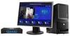


voltage measurements

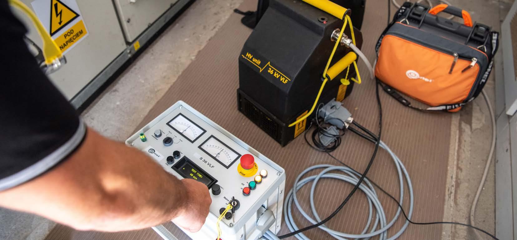

Test PD
High
» measured temperature range -40…+120°C
» measured pulse dynamic range: 80 dB 60 dB 60 dB
Wskaźnik stanu połączeń i kabli wysokiego napięcia
High voltage cables and joints tester
See the video tutorials available on YouTube.
» weight 0.3 kg
» Industrial current frequency sensor for synchronization of measurements (N).
» humidity 95%
АС
» Electromagnetic high-frequency sensor for partial discharge measurement (HF, 0.1…2 MHz).
» partial discharge frequency range: 40 kHz 0.1…2 MHz 2…100 MHz
» dimensions 205 x 85 x 75 mm
» Acoustic ultrasonic sensor for partial dis-charge measurement (AC, 40 kHz).
VHF
The device is easy to use thanks to the advanced system integrated into its software, which allows the user to quickly evaluate the condition of the analysed object. This makes the device user-friendly for service personnel, not requiring a special training.
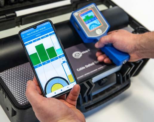
Sensors
dischargespartialindicator
UDI-M6 adapter for connecting an insulating stick WAADAAUDIM6
94
Features
Standard accessories: Transportation case
HF
» operating temperature -20…+40°C
SONEL TEST PD

Other technical specifications:
HF
АС
» Non-contact pyrometer (-40°C…+120°C).
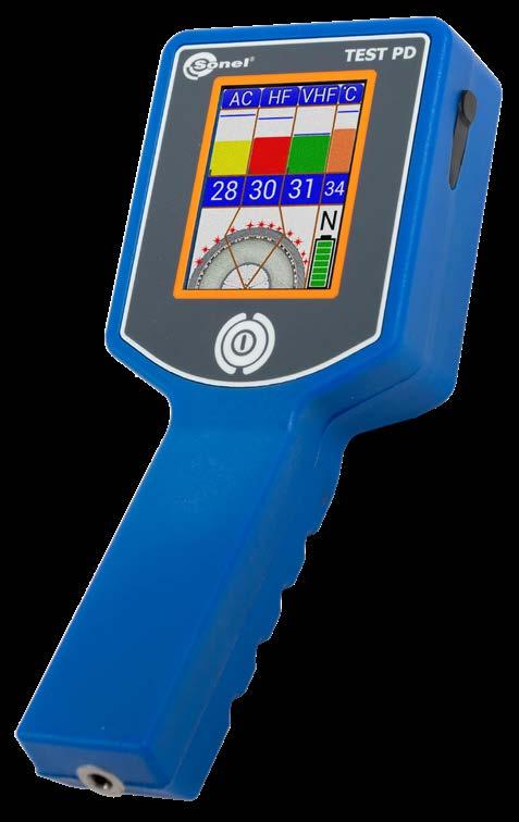
» data transmission Bluetooth 4.1
Test PD is a compact, portable device designed for the effective testing of cable heads and cable joints that are live – voltage at least 6 kV.

VHF
Euro-M6 adapter for connecting an insulating stick WAADAEUROM6 Charger with USB port USB-microUSB cable
» Capacitive VHF sensor for partial discharge measurement (VHF, 2…100 MHz).
To test a cable joint, switch on Test PD, install it on a insulating stick and bring it close to the tested object. The information about the current joint condition will be immediately displayed in the form of 4-colour histograms and a cross-section of the high voltage cable. The Sonel TestPD mobile application for Android devices allows for remote reading of the instrument’s indications.
index: WMGBTESTPD
» battery Li-Ion 18650 battery
Sonel TestPD application for cooperation with the Test PD meter to measure partial discharges. The application receives and displays on-line information from the PD test meter about the level and intensity of partial discharges in couplings and voltage cables terminations. It can be down loaded from Google Play
SONEL TESTPD
Detector
RCA/RCA video cable WAPRZVIDRCA
Headphone set with microphone WAPOZSLU2
Hard briefcase WAWALXL11
Description of the device:
Specifications of visible spectrum section Full color
» 5.7” touch LCD,
»
Accuracy of UV/visible image superposition
Better than 1 milliradian 0.1 optical and 12x 5.7" VGA PAL/NTSC
Image type
Frequency:
Standard accessories:
»
Additional features:
» high UV sensitivity,
External battery charger WAADALB220
digital Display Type Unfolding
touch LCD Video standard

» precise location of discharge sources, recording and playback of videos and images,

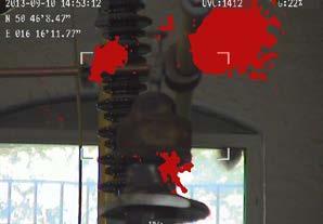
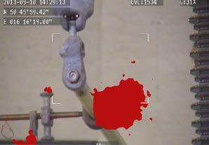
» no sensitivity to sunlight during operation in full daylight, additional LED alarm in the event of UV radiation detection, built-in GPS, PC software for data transmission and generating reports.
»
Minimum UV sensitivity 2.2 x 10⁻¹⁸ W/cm2
»
Specifications of UV section type Monochromatic
Sharpness range
UV-260 is an innovative solution in the field of UV radiation detection!
Corona discharge camera


Spectral range
95
Sharpness setting Automatic and manual (UV and visible spectrum) 2 m … ∞ life Non-consumable 50 Hz
Imaging modes Combined (UV & visible) / only UV / only visible Discharge color White, red, blue Processing and communication Video standard H.264 Alarm Audio, LED Operation Buttons and touch LCD Audio module Microphone input for audio notes GPS module √ Data storage Memory type SD memory card Image file format JPG Video file format AVI Memory capacity 8000 images or >4 hours of video (for 2 GB card) File transfer USB, card reader Power supply Power consumption 10 W Battery type Li-Ion (2 pcs. in set) Operating time on battery power 2 hours Charging External or internal charger External power supply 9-12 V, 10 VA Power adapter 110-240 V AC, 50/60 Hz / 12 V DC 3.8 A Other specifications Operating temperature range -10°C … +50°C Storage temperature -25°C … +60°C Relative Humidity 95% without condensation Dimensions 238 x 165 x 91 mm Weight 2.5 kg Power input √ SD card slot √ Video output CVBS Audio input / output Microphone / headphones
SD memory card
Field of vision (WxS) 5.5°x 4.0°
» automatic noise reduction,
Battery charging cable for 12 V car sockets WAPRZLAD12SAM1
Image
Minimum detectable discharge pC from a distance of 10 meters UV 240 … 280 nm
index: WMGBV260
SONEL UV-260
2x Li-Ion rechargeable battery 7.2 V 2.2 Ah WAAKU22
Minimum sensitivity
Power supply
Camera strap WAPOZSZEUV260
The UV-260 is a high-class, professional, and simultaneously lightweight and intuitive device enabling quick and simple remote diagnostics of a system without interfering in its operation. Its design, placing em phasis on high functionality, allows for detection and monitoring of co rona, arc and surface discharges in power engineering. This is a way to continuously analyze the technical condition of equipment, e.g. an HV power line, and locate problems before damage or serious failure occurs.
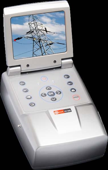
1
» automatic sharpness for UV and visible image,
lux Zoom 25x

• S-50 / 80 / 110 / 120 DC | external ground-discharge rod
Standard accessories - S-50 DC / S-80 DC / S-110 DC / S-120 DC: Protective bag Discharge rod
» Testing of electrical equipment
» Easy operation
» Testing at recommissioning of cable systems after maintenance and repair
WAWALXXL1
» Protective ground connection
» Discharge device:
• S-25 DC | integrated (S-25 DC),
» S-50 DC / 80 DC / 110 DC / 120 DC | Regular preventive cable testing
High voltage insulation testers
• S-50 / 80 / 110 / 120 DC | max. 60 min (option)
Overview
96
SONEL S-120 DC / S-110 DC / S-80 DC / S-50 DC / S-25 DC
S-25 DC
» Short-circuit-proof output:
Protective bag Power Connectioncablecables for external DC power supply
» S-25 DC | Voltage testing at cable sheath
» Robust construction, low weight
High voltage connecting cable, 2 m Service pack Start keys
Optional accessories - S-50 DC / S-80 DC / S-110 DC / S-120 DC: Transport case
Features
index: WMGBS25DC / WMGBS50DC / WMGBS80DC / WMGBS110DC / WMGBS120DC
S-50 DC / S-80 DC / S-110 DC / S-120 DC
» S-25 DC | Mains-independent by internal rechargeable battery
Protective ground cable, 3 m Operation ground cable, 3 m
» Integrated timer:
Capacitive loads, such as shielded power cables, will be properly and automatically discharged in case of an error or at the end of testing time by the integrated discharge device. Key switch, switch-on interlock and a protective ground circuit ensure maximum safety. S-25 DC stands out in particular. Not just with modest dimensions. Thanks to an internal rechargeable battery it enables mains-independent testing.
Transport case with wheels
• S-25 DC | max. 30 min (standard)
• S-25 DC | electronically limited output current
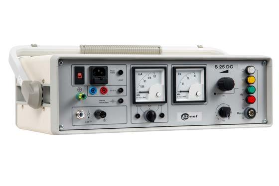
The S-xx DC series devices are universal high voltage testers. They are extremely robust, but also lightweight, compact and easily portable thanks to a transport case on wheels (only for S-50 / 80 / 110 / 120 DC).

» Voltage measurement direct at HV output

» Testing of newly installed cables an cable joints before commissioning
Fields of application
» S-25 DC | Internal battery charger with deep discharge protection
Standard accessories - S-25 DC:
Protective ground cable, 3 m Operation ground cable, 3 m High voltage connecting cable (shielded), 3 m Service pack Start keys
WAWALXXL2
Optional accessories - S-25 DC: Transport case Transport case with wheels
• S-50 / 80 / 110 / 120 DC | protection by overcurrent tripping
S-25 DC S-50 DC S-80 DC S-110 DC S-120 DC Power supply internalmains,batteryrechargeableswitchable 115 / 230 V, 50-60 Hz external DC voltage source 11…15 V DC 230mainsV/50 Hz (optional: 115 V / 60 Hz) Power consumption max. 120 VA max. 900 VA Output voltage 0…25 kV DC infinitely adjustable negative polarity ripple < 0,25% 0…50 kV DC infinitely adjustable negative polarity 0…80 kV DC infinitely adjustable negative polarity 0…110 kV DC infinitely adjustable negative polarity 0…120 kV DC infinitely adjustable negative polarity Rated output current at max. output voltage 1.5 electronicallymAlimited 6 mA 5 mA 4 mA 3.5 mA Battery operation at full load 45 min Discharge - integrated automatic discharge device 3000 J 9.6 µF at 25 kV 7500 J 6 µF at 50 kV 12 250 J 4 µF at 75 kV 3.5 µF at 80 kV 15 000 J 3 µF at 100 kV 2.5 µF at 110 kV 18 750 J 2.4 µF at 125 kV 2.6 µF at 120 kV Voltage measuring range 0…30 kV 0…50 kV 0…80 kV 0…110 kV 0…130 kV Current measuring ranges 0…200 µA / 0…2 mA manual or automatic switching between ranges 0…100 μA / 1 mA / 10 mA manual switching between ranges Operating temperature -25…+55°C Storage temperature -40…+70°C Weight Operating unit 13.5 kg 13 kg High voltage unit 17 kg 18.5 kg 20 kg 20.5 kg Dimensions Operating unit 473 x 152 x 275 mm 370 x 200 x 280 mm High voltage unit 210 x 380 x 310 mm 210 x 400 x 310 mm 210 x 420 x 310 mm 210 x 430 x 310 mm 97

» Integrated fault time detection
» High voltage start key interlock
Bridging cables
High voltage connecting cable (shielded) 5 m
index: WMGBS57VLF / WMGBS44VLF (230 V) / WMPAS44VLF (110 V) / WMGBS36VLF / WMGBS24VLF
Optional accessories:
» Integrated timer 1-300 min with automatic tripping
Overview
» Extremely compact high-power VLF test device
High voltage insulation testers
Features
» Leakage current measurement during VLF test
Connecting cable between high voltage unit and station ground
» Fully automatic test sequence
SONEL S-57 VLF / S-44 VLF / S-36 VLF / S-24 VLF
Case with wheels WAWALVLF2 Frequency extension 0.05 Hz + 0.02 Hz WAADAHVVLFFE
Optional features
» Easily portable for 1-2 people
» Frequency extension: 0.05 + 0.02 Hz
Connecting cable between operation unit and protective ground Service pack Start keys
» Protective ground connection
» Integrated breakdown detection
The compact, robust and portable S VLF cable test sets are used for testing of medium voltage cables in accordance to the standards IEEE400, IEC 60502-2, CENELEC HD 620 & 621 and DIN VDE 0276/620 & 621. The test is carried out with a low strain practice with VLF (very low frequency) test voltage at 0.1 Hz frequency.

» Customized test cables
» Simple operation: menu-assisted control with industrial class OLED display
USB stick for data logging WAADAHVVLFDL Case WAWALVLF
98
VLF test enables detection of damages of the insulation within shortest test time. The S VLF series device can test cables with extruded insulation (XLPE-, PE-, EPR-insulation) as well as cables with paper-oil insulation (PILC). Cable sheath testing with direct voltage is also possible.
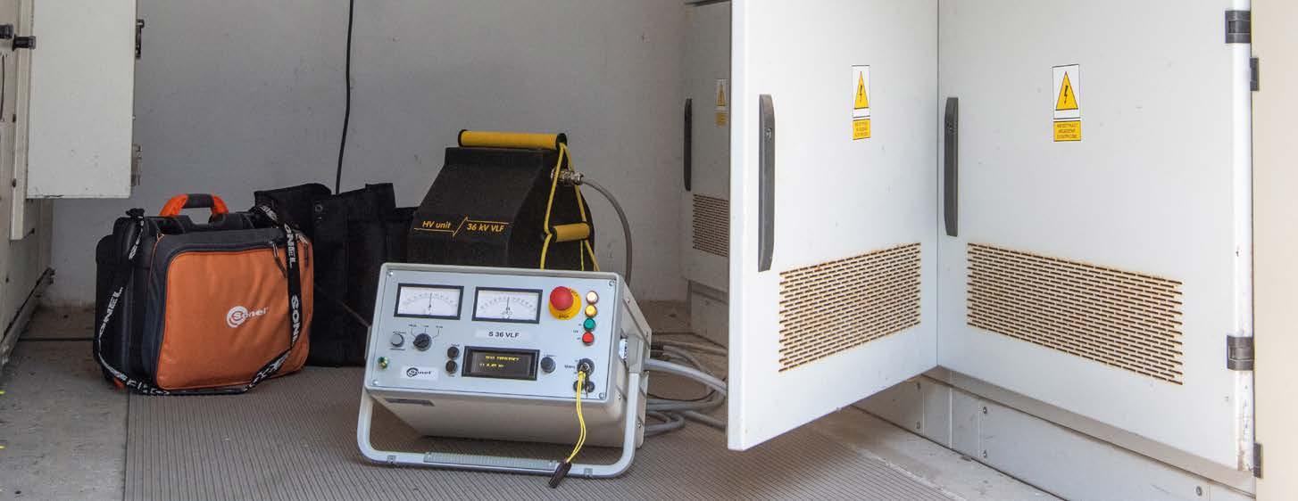
» Protective circuit / indication in accord. with EN 50191
Standard accessories:
» Voltage measurement direct at HV output
» Transport case
» Data logging (USB stick) for VLF test sets
Power supply 230 V (±10%) 10 A, 50/60 Hz 230 V (±10%) 10 A, 50/60 Hz 230 V (±10%) 10 A, 50/60 Hz 110 V (100 V...127 V) 15 A, 50/60 Hz 230 V (±10%) 10 A, 50/60 Hz
PC USB stick in two parts: and
S-44(110VLFV) S-57 VLF
up to 60 km (15.0 µF at 18 kVRMS, 0.02 Hz)*
up to 60 km (15 µF at 18 kVRMS, 0.02 Hz)*
Operating temperature -20…+45°C
0…44 kVRMS VLF 0.1 Hz (option: 0.05 Hz + 0.02 Hz) ± 0…62 kV DC
DC direct voltage, negative and positive polarity
interface
S-24 VLF S-36 VLF (230VLFV)
0…44 kVRMS VLF 0.1 Hz (option: 0.05 Hz + 0.02 Hz) ± 0…62 kV DC
Duty continuous operation
operation unit
up to 60 km (15.0 µF at 18 kVRMS, 0.02 Hz)*
Construction
Overcurrent trip (DC) 10 mA
5
Discharge - integrated automatic discharge device max. 9000 J max. 12500 J max. 12500 J max. 12500 J max. 12500 J
Voltage measuring range -40…0…40 kV accuracy ±1% -60…0…60 kV accuracy ±1% -70…0…70 kV accuracy ±1% -70…0…70 kV accuracy ±1% -70…0…70 kV accuracy ±1%

0…24 kVRMS VLF 0.1 Hz (option: 0.05 Hz + 0.02 Hz) ± 0…34 kV DC 0…36 kVRMS VLF 0.1 Hz (option: 0.05 Hz + 0.02 Hz) ± 0…52 kV DC
*at a cable capacitance of approx. 0.25 µF/km
up to 60 km (15 µF at 24 kVRMS, 0.02 Hz)*
Current measuring ranges ±0…100 µA / 1 mA / 10 mA
S-44
up to 60 km (15.0 µF at 6 kVRMS, 0.02 Hz)*
Storage temperature -25…+70°C
high voltage unit Dimensions and weight Operation unit 37 x 34 x 20 cm 17 kg High voltage unit 40 x 41 x 24 cm 38 kg 40 x 44 x 24 cm 48 kg 40 x 44 x 24 cm 49 kg 40 x 44 x 24 cm 49 kg 40 x 44 x 24 cm 49 kg 99
waveshapeVoltage
VLF similar sine-wave, symmetrical, with True RMS measurement
Max. testable cable length, max. capacitance (VLF)
Output voltage
0…57 kVRMS VLF 0.1 Hz (option: 0.05 Hz + 0.02 Hz) ± 0…62 kV DC
Max. load at max. output voltage (VLF) and 0.1 Hz µF at 24 kVRMS 2.4 µF at 36 kVRMS 1.6 µF at 44 kVRMS 1.0 µF at 44 kVRMS 0.55 µF at 57 kVRMS
When using the automatic and continuous mode, exceeding the pre-set range limits will interrupt a series of measurements and the meter will wait for a reaction of the user.
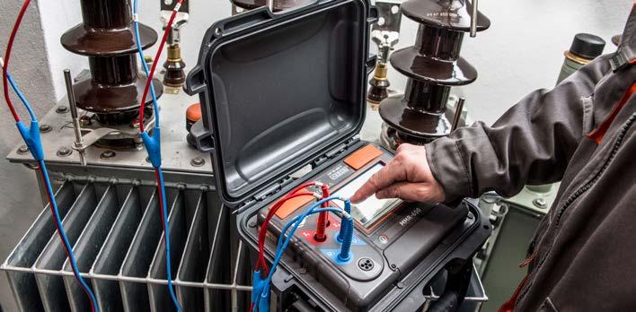
For small resistance values (microohms), the wiring and contact resistances in connection points are of significant importance. Therefore, the design of the bridge provides separate current and voltage terminals at the R and R resistors. It is rec ommended that all other resistors have a resistivity 1000 times greater than the resistance of the leads.
U x - voltage drop in tested object, I - intensity of flowing current, Rx - measured resistance.
Before starting the measurement, select the maximum measurement current (range: from 0.1 mA to 10 A). The measuring range (and thus the current) is select ed manually or automatically. In some cases (e.g. exceeding the allowable power generated at the object), it may be desirable to limit the maximum current flowing through the tested object. MMR devices have a lock that allows user to set the upper limit of the measuring current.
operation mode is the window mode, which allows the user to set the up per and lower limits for the measurement result. Results outside this range are additionally signalled by the meter.
The limits of the acceptable range of variability of results are determined by the user.
The user selects the measurement method in one of available modes: » in manual mode, each measurement must be triggered by the operator by pressing "Start" button; » in automatic mode, the measurement starts at the moment of connecting the last measurement terminal » for the continuous mode, measurements are performed every three seconds (resistive mode) or continuously (inductive mode).
The normal duration of the measurement is 3 seconds. In order to measure an in ductive object, the extended measurement time may be selected. For objects with a high inductance, the measurement time is extended to a few minutes and after completed measurement, the tested object is discharged.
Operating mode
I v - current flowing through the voltmeter.
Circuit diagram of Thomson bridge
Low resistance measurements may be performed by several methods. The most popular is the technical method
Due to very low values of the measured resistance, the four-wire method is used, which allows user to perform accurate measurements without taking into account the impact of the resistance of test leads. Therefore, the manual calibration of the meter and test leads is not necessary, but it is possible (e.g. when using other type of test probes). In addition, it is always possible to restore the factory calibration settings of the device.
The circuit with correctly measured voltage is used for small resistances, when the current flowing through the tested object is several times greater than the current of the voltmeter, which measures the voltage drop on the object. The resistance obtained by the measurement is calculated from the formula:
Rx RRp1 R2 =
Low resistance measurements are made when testing the resistance of the follow ing connections: welded, equipotential, contacts, cable connections and coils of low resistance. Meters for low resistance measurement are also used to test motor and transformer windings. These tests also include testing the quality of solder joints or continuity of earthing cables.
Rx Ux I - Iv =
Measurements with MMR-650
The measurements may be performed using the current: » flowing only in one direction or » flowing in two opposite directions.
Testing with unidirectional current makes the measurements faster, whereas using bidirectional current eliminates errors resulting caused by the presence of internal voltages and electrothermal forces in the tested object. The main result of meas urements using the bidirectional current is the average of two measurements of the resistance with the currents flowing in opposite directions. In addition, sup plemental results are displayed, i.e. RF resistance with the current flowing in theo retical "forward" direction and RR resistance with the current flowing in theoretical "backward" direction.
At the balanced state of the bridge, the current flowing in the branch of the galva nometer is equal to zero. The formula for the measured resistance is as follows:
The accuracy of the measurement with Thomson bridge is affected insensitivity deviation, which for low resistances of Rx = 10-6...10-5 Ω order is particularly evident. The accuracy also depends on the error in recreating the model, which is related to the quality of particular elements of the bridge. During the measurement, there may be additional errors due to current overloads of the tested and reference resistors, temperature changes and the presence of additional electromotive forces in the Duesystem.todefectiveness and limitations of traditional technical bridges, currently we witness a tendency to construct electronic meters for the measurement of low re sistances in the range from single micro-ohms to several hundred ohms. Instru ments can measure very small resistances even with a resolution of 0.1 μΩ. An im portant feature of modern micro-ohm meters is ease of use, application of different measurement modes and the option to cooperate with a computer. These devices measure the resistance using the technical method. Any conductive element may be described by the formula according to Ohm's law:
Resistance measurement using technical method (circuit with correctly measured voltage)
101
There is an option of using fast measurement mode for inductive devices/objects (FAST mode), which at a slightly lower accuracy accelerates the measurement pro Anothercedure.
Rx Ux I =
The device measures the resistance by causing a current to flow through the tested object (using current leads), at the same time controlling the voltage drop across the terminals of the voltage lines. A break in any circuit will be adequately signalled and the resistance measurement will not be possible.
Low resistance measurements
With a voltmeter of very high resistance, the current flowing in its circuit is negligi bly low, so the measurement result is not affected by the resistance of test leads. This is so called 4-pole method This type of measurement, which eliminates the impact of the resistance of wires, is used in low resistance meters of MMR series.
» work with a printer and a 2D barcode reader
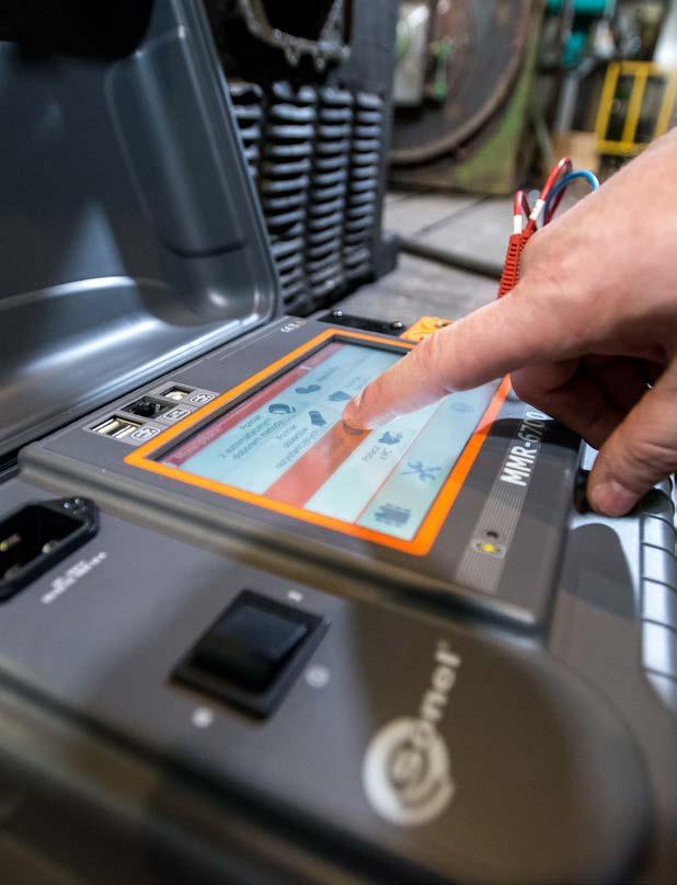
2x crocodile clip, black, 1 kV, 32 A WAKROBL30K03
Doble-wire test lead 3 m (10 A / 25 A) U1/I1 WAPRZ003DZBBU1I1
Product features
» high immunity to outside interference
Contact
Sonel microohmeter MMR-6xxx series thanks to the use of special algorithms, measuring functions and a stabilized, non-pulsing measurement current allow user to work in difficult conditions. Possibility of use measurement current up to 200 A and a high power source allows you to measure the contacts of the HV switch with basic uncertainty from 0.25%.
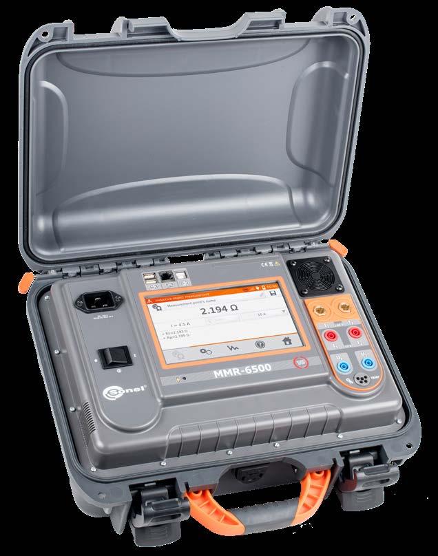
» measurements of resistive objects with current up to 100/200 A
Mains cable with IEC C19 plug WAPRZZAS1
ST-3 temperature probe WASONT3 Case L12 WAFUTL12
Current carrying test lead 3 m black I1 (200 A, 25 mm2) WAPRZ003BLI1
Current carrying test lead 3 m black I2 (200 A, 25 mm2) WAPRZ003BLI2
index:
» automatic compensation temperature of objects measured
» measurements of induction objects up to 10 A
Measurements of contact resistance using high current
» a state of the art interface with a touch screen and expanded memory

102
Test lead 3 m blue 1 kV U2 (banana plug) WAPRZ003BUBBU2
2x Kelvin clamp, 1 kV, 25 A WAKROKELK06
resistance meters closed cover
Standard accessories:
Doble-wire test lead 3 m (10 A / 25 A) U2/I2 WAPRZ003DZBBU2I2 USB cable WAPRZUSB
The MMR-6700 microcontroller is equipped with readable, touch screen, 5 inch color display with a resolution of 800x480 pixels for convenience of readings measurement results.
» measurement with one- or both-way current flow
Factory calibration certificate
WMGBMMR6700 / WMGBMMR6500
Device capabilities
» measurements temperature of windings
Simplicity of readings
The use of a large, readable display allowed for use helpful appetent drawings how to use the meter.
Help system
» measurements of objects earthed on both sides (i.e. main joints of HV switches)
Test lead 3 m blue 1 kV U1 (banana plug) WAPRZ003BUBBU1
Range Resolution Accuracy Test current 0.0…999.9 μΩ 0.1 μΩ ±(0.25% + 2 digits) 100 A < I ≤ 200 A* 0.0…999.9 μΩ 0.1 μΩ 50 A < I ≤ 100 A 1.0000…1.9999 mΩ 0.0001 mΩ 0.0…999.9 μΩ 0.1 μΩ 20 A < I ≤ 50 A 1.0000…3.9999 mΩ 0.0001 mΩ 0.0…999.9 μΩ 0.1 μΩ 10 A < I ≤ 20 A 1.0000…7.9999 mΩ 0.0001 mΩ * MMR-6700 only
MMR-6xxx micrometers series are devices with a state of art design with unprecedented approach to measuring small resistances. The instruments allow to measure resistive ob jects with a high current and have a unique in his measurement class module for inductive current objects up to 10 A
Application
SONEL MMR-6700 / MMR-6500

» Wi-Fi, USB and LAN communication
» IP67
Measurements of resistance and inductive objects using low current Range Resolution Accuracy Test current 0…999.9 μΩ 0.1 μΩ ±(0.25% + 2 digits) 10 A 1.0000…1.9999 mΩ 0.0001 mΩ 2.000…19.999 mΩ 0.001 mΩ 10 A 20.00…199.99 mΩ 0.01 mΩ 10 A / 1 A 200.0…999.9 mΩ 0.1 mΩ 1 A / 0.1 A 1.0000…1.9999 Ω 0.0001 Ω 2.000…19.999 Ω 0.001 Ω 0.1 A 20.00…199.99 Ω 0.01 Ω 10 mA 200.0…1999.9 Ω 0.1 Ω 1 mA
» earthing conductors, equipotential bondings,
Device capabilities
2x Kelvin clamp, 1 kV, 25 A WAKROKELK06
Li-Ion 7.2 V rechargeable battery WAAKU27
The MMR-650 winding resistance and low resistance meter is equipped with a readable col our touchscreen that, due to its 800 x 480 pixel resolution, provides both high comfort of interacting with the interface and high readability of the measurement results.
MMR-650 can be also utilized on production lines (eg. at the final production control stage).
103
L11 carrying case WAFUTL11
Doble-wire test lead 3 m (10 A / 25 A) U2/I2 WAPRZ003DZBBU2I2
1.0000…1.9999 m 0.0001 m 2.000…19.999 m 0.001 m 10A 20.00…199.9 m 0.01 m 10 A/1 A 200.0…999.9 m 0.1 m 1 A/0.1 A 1.0000…1.9999 0.0001 2.000…19.999 0.001 0.1 A 20.00…199.99 0.01 10 mA 200.0…1999.9 0.1 1 mA
Standard accessories:
USB cable WAPRZUSB
» function of determining the temperature of a motor under load
» windings of power transformers and motors,
» welded and soldered connections,
Resistance measurement
±(0.25% + 2 digits) 10 A
ST-3 temperature probe WASONT3
Easy readout
» measurement of winding resistance (including amorphous core transformers)
» and other resistive and inductive objects.
» measurement of resistant objects using bipolar current

2x double-tip Kelvin probe (banana sockets) WASONKEL20GB
Application
Product features
The MMR-650 winding resistance and low resistance meter provides an innovative combina tion of a high-performance measuring device with a modern user interface and advanced data management system. Wireless data transmission, enhanced system of 2D codes and ability to print labels to identify test items, all contribute to bringing new quality of work and allow the user to perform a wide range of measurements.
» high immunity to disturbances
Range [Ω] Resolution [Ω] Accuracy* Test current 0…999.9 μ 0.1 μ

*for resistive objects
Mains cable with IEC C13 plug WAPRZ1X8BLIEC
Winding and low resistance meter
open closedcovercover
Durable and practical casing
In response to the customers needs the MMR-650 microohmmeter has been designed to op erate in difficult environmental conditions. A unique casing with the IP67 ingress protection rating ensures that the device is both waterproof and dustproof.

SONEL MMR-650
» transformer core demagnetization function
index: WMGBMMR650
» breakers, contacts,
Factory calibration certificate
The MMR-650 winding resistance and low resistance meter is designed to measure very low very low resistance of both windings - including amorphous core transformers - and resistive objects. This product is made to be used in power plants, railways and maintenance companies to measure:
» bolted connections,
The MMR-650 allows single-channel measurement resistance of transformer windings with amorphous cores.
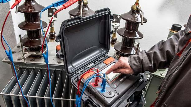
Doble-wire test lead 3 m (10 A / 25 A) U1/I1 WAPRZ003DZBBU1I1
» automatic temperature compensation function (temperature probe)
Measurements of objects resistive in nature:
» fast measurement (3 seconds) for measurement of objects of a resistive nature, » extended measurement for testing of objects of an inductive nature (accelerated mode, with slightly worse accuracy, available); with automatic discharging of the object after measurement.
» makes possible to set an upper and lower limit within the measurement result should remain; sound signal triggered when the result is beyond set range,
Two-core cord; 3 m (10 / 25 A) U1/I1 WAPRZ003DZBBU1I1
» measurement in continuous mode - the meter repeats successive measurement cycles with breaks every 3 seconds (for objects of a resistive nature) or performs measurement continuously (for objects of an inductive nature).
Selection of measurement mode according to the type of measured object:
» welded and soldered connections, equipotential bondings, earthing conductors, » contacts, welds of rails, conductors and cables, » measurement according to the four-lead method.
» capability of performing measurements even under disturbances of a value five times greater than the measured signal.
» EN 61010-1 (general and particular requirements related to safety)
» EN 61326 (electromagnetic compatibility)
» HD 60364-4-41 (performance of measurements - shock protection) meters
» time until auto-OFF 120 seconds
SONEL MMR-630 / MMR-620
RS-232 serial transmission cable WAPRZRS232
L-1 carrying case WAFUTL1
NiMH rechargeable battery 4.8 V 3 Ah WAAKU03
» time of resistance measurement: ▪ resistance mode, with two-directional current flow 3 seconds ▪ induction mode max 10 min (depends on R and L of the object)
Measurements of objects inductive in nature:
» dimensions 295 x 222 x 95 mm
» operating temperature range 0…+40°C
4x black "crocodile" clip 1 kV 32 A WAKROBL30K03
Resistance measurement MMR-620 MMR-630
» maximum lead resistance for 10A current 100 mΩ
Other technical specifications:
Additional functions of the meters:
» meter power supply SONEL/Ni-MH 4.8 V rechargeable battery pack
Automatic or manual selection of measuring range (measurement of objects of an inductive nature).
Factory calibration certificate
» measurement in normal mode - triggered when the “START” button is pressed,
» measurement in automatic mode - the instrument awaits connection of all four test leads to the object, after which it automatically start measurement in one or both directions and calculates the mean resistance value,
2x Kelvin clamp 1 kV 25 A WAKROKELK06
» battery charging time approx. 2.5 hours
» measurement current input accuracy ±10%
Instruments meet the requirements set forth in the standards:
» EN 61010-031 (general and particular requirements related to safety)
» HD 60364-6 (performance of measurements - checking)
Window mode:
index: WMGBMMR630 / WMGBMMR620
Low resistance
» type of insulation double, as per EN 61010-1 and IEC 61557
230 V power cord (IEC C7 plug) (MMR-630) WAPRZLAD230
» electric hum immunity additional error ≤1% for 50 Hz voltage ≤100 mV RMS
» meter weight approx. 1.7 kg
Accuracy ±(0.25% m.v. + 2 digits) “m.v.” = “measured value”
Selection of measurement mode depending on application (including control of product series):
MMR-630/620 microohmmeters enable accurate measurements of both connections resistance (welded, soldered, bolted) and winding resistance of electrical motors and power transformers.

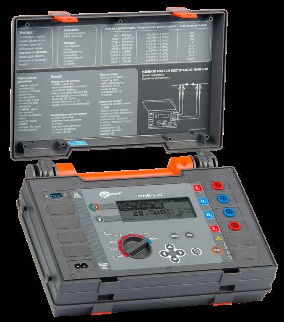
104
» charger built-in
Two-core cord; 3 m (10 / 25 A) U2/I2 WAPRZ003DZBBU2I2
» number of measurements with 10 A current 300
Standard accessories:
Test currentRange [Ω] Resolution [Ω] Range [Ω] Resolution [Ω] 0…999 μ* 1 μ 0…999.9 μ* 0.1 μ 10 A1.000…1.999 m 0.001 m 1.0000…1.9999 m 0.0001 m 2.00…19.99 m 0.01 m 2.000…19.999 m 0.001 m 20.0…199.9 m 0.1 m 20.00…199.99 m 0.01 m 1 A 200…999 m 1 m 200.0…999.9 m 0.1 m 0.1 A 1.000…1.999 0.001 1.0000…1.9999 0.0001 2.00…19.99 0.01 2.000…19.999 0.001 10 mA 20.0…199.9 0.1 20.00…199.99 0.01 1 mA 200…1999 1 200.0…1999.9 0.1 0.1 mA
» motor windings, » low-resistance coils.
2x double-tip Kelvin probe (banana sockets) WASONKEL20GB Meter strap (Unisonel type) WAPOZSZE1
Photo Name Index MMR-6700 MMR-6500 MMR-650 MMR-630 MMR-620 Adapter - converter USB / RS-232 WAADAUSBRS232 • • C-5A current clamps (Φ39 mm) WACEGC5AOKR • • Barcode scanner 2D (USB) WAADACK2D • • • • • D2 portable USB report / barcode printer (Sato) WAADAD2 • • • • • L1 carrying case WAFUTL1 1 1 L11 carrying case WAFUTL11 1 L12 carrying case WAFUTL12 1 1 Crocodile clip, black, 1 kV, 32 A WAKROBL30K03 2 2 4 4 Kelvin clamp, 1 kV, 25 A WAKROKELK06 2 2 2 2 2 PC software: Sonel Reader WAPROREADER • • • Double-wire test lead 10 m (Kelvin crocodile clip / banana plug) WAPRZ010DZBKEL • Double-wire test lead 25 m (Kelvin crocodile clip / banana plug) WAPRZ025DZBKEL • Doble-wire test lead 3 m (10 A / 25 A) U1/I1 WAPRZ003DZBBU1I1 1 1 1 1 1 Doble-wire test lead 3 m (10 A / 25 A) U2/I2 WAPRZ003DZBBU2I2 1 1 1 1 1
• •
MMR-6700 MMR-6500 MMR-650 MMR-630 MMR-620


Current carrying test lead black I1 6 m / 10 m / 15 m WAPRZ015BLI1WAPRZ010BLI1WAPRZ006BLI1


Current carrying test lead black I2 6 m / 10 m / 15 m WAPRZ015BLI2WAPRZ010BLI2WAPRZ006BLI2 Index


Current carrying test lead 3 m black I1 (200 A, 25 mm2) WAPRZ003BLI1 1 1
Test lead 3 m blue 1 kV U2 (banana plug) WAPRZ003BUBBU2 1 1
Test lead blue 1 kV U1 (banana plug) 6 m / 10 m / 15 m WAPRZ015BUBBU1WAPRZ010BUBBU1WAPRZ006BUBBU1
Current carrying test lead 3 m black I2 (200 A, 25 mm2) WAPRZ003BLI2 1 1
• • Test lead 3 m blue 1 kV U1 (banana plug) WAPRZ003BUBBU1 1 1 Photo Name


• • Test lead blue 1 kV U2 (banana plug) 6 m / 10 m / 15 m WAPRZ015BUBBU2WAPRZ010BUBBU2WAPRZ006BUBBU2 • • USB cable WAPRZUSB 1 1 1 RS-232 serial transmission cable WAPRZRS232 1 1 Mains cable with IEC C13 plug WAPRZ1X8BLIEC 1 Mains cable with IEC C19 plug WAPRZZAS1 1 1 Mains cable with IEC C7 plug WAPRZLAD230 1 LAN cable (RJ45) WAPRZRJ45 • • • Protective gloves (for operating the touchscreen) WAREK1 • • Temperature probe ST-1 WASONT1 • • • ST-3 temperature probe WASONT3 1 1 1 Double pin Kelvin probe with banana connector WASONKEL20GB • • 2 2 2 UNI-SONEL hanging straps WAPOZSZE1 1 1 Label Roll – Black on White for D2 printer (SATO) WANAKD2 • • • • • Ribbon for D2 printer (SATO) WANAKD2BAR • • • • • Kelvin vice with cables WAZACKEL1 • • • • • NiMH battery 4.8 V 3.2 Ah for MMR-620/630 WAAKU03 1 1 Li-Ion battery Li-Ion 7.2 V WAAKU27 1 MMR Set of standard and optional accessories 1, 2, 4 - number of standard accessories • - optional accessories 105

Location of hidden infrastructure and faults LKZ-2000 LKZ-1500-LITELKZ-1500 TDR-410TDR-420LKZ-1000 LKZ-720


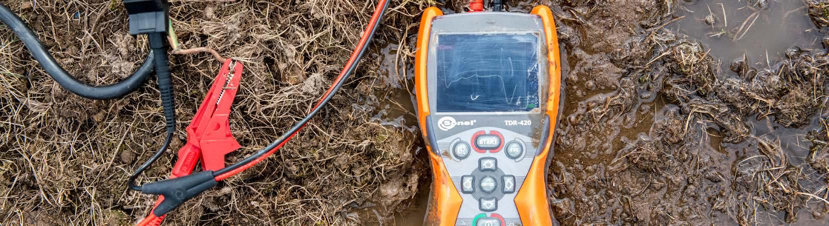

Power - used to locate electric cables. It is a passive mode, where the transmitter is not required: the signal is generated by the live cable itself.
LKZ-1000 is a set for locating wires and pipes, which precisely determine the depth and direction of conductive systems (power and telecommunications cables, met al pipes) and with additional probes it is able to detect plastic and concrete pipes.
Location and tracking underground infrastructure elements is performed in a wide range of conditions. LKZ-1000 can operate in several different modes, adapted to different situations:
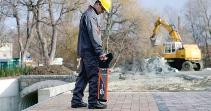
Earthworks that include various types of excavation, but also installation of sewer and water pipes or cables - are associated with a high risk of damage to under ground systems, which could lead to a dangerous accident. European Union law requires from the contractor of such works to ensure safety to employees, third parties and private property. In order to reduce the risk of accidents, a number of activities are carried out, including the mandatory detection of existing under ground installations ad systems. The contractors are never absolutely sure whether all underground utilities are shown on the maps. Therefore, in order to identify all potentially hazardous installations and systems, additional checks are necessary, which may be performed with cable locators.
Radio - used to locate metal objects (pipes, reinforcement elements), which re-emit radio signals. It is also a passive method: the signal is present in the tested object, which re-emits radio waves.
min. 10 m
In metal systems, the signal may be generated without wires by induction or by direct connection of test leads or by using transmitting clamps. In non-conductive systems, the signal may be generated by introducing a transmitting probe (in the form of a coiled cable or "floating" probe) directly to the detected system (plastic, concrete pipes etc.). In addition to determining the direction and depth of pipes, the user may also locate their blockages by using additional probes.
LKN-1000 generator (transmitter) generates a signal which is tracked in the detect ed system. Depending on the situation, in active modes, the transmitter may be connected as shown in one of the following images.
With the intuitive menu and transparent graphic display, LKO-1000 receiver is very user-friendly. It also has a number of options and features designed to improve safety and comfortable use.
Auto Mode combines the advantages of Radio and Power mode. It is very conven ient for initial screening of the area. Additionally, LKZ-1000 set allows the user to precisely determine the depth of a par ticular system within 3 meters. In such detection, the device must operate in active modes of 8 kHz or 33 kHz, which use the transmitter and receiver.
107
Detecting cables and underground infrastructures
8 kHz - used for precise location of a particular type of systems (cables, pipes, etc.). The frequency of the generated signal (8 kHz) has better range than 33 kHz and lower tendency to transfer the signal to other objects. This is an active method, because it requires the use of a signal generator.
Earthworks are carried out in difficult conditions (moisture, dirt), so both devices meet the requirements of IP54, while the transmitter with closed cover provides ingress protection of IP67.
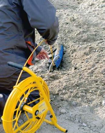
33 kHz - used for location of a particular type of systems (cables, pipes, etc.). This frequency is most often used to locate underground installations. It ensures the highest efficiency, but it has a greater tendency to transfer the signal to other sys tems/installations. This method also requires the use of a signal generator (active method).

»
LKN-2000 transmitter:
»
RADIO passive mode: 15 kHz to 60 kHz
Active mode (with transmitter): 512 Hz, 3140 Hz, 8192 Hz, 32768 Hz, 83.1 kHz
» Operating time with battery power for LKO: up to 60 hours (at 20°C)
» Operating frequencies: 512 Hz, 3140 Hz, 8192 Hz, 32768 Hz, 83,1 kHz, 200 kHz
»
LKO-2000 receiver
» operating temperature -20...+50°C dimensions 700 x 325 x 122 mm weight ca. 2.2 kg
»
»
LKO-2000 receiver:
Standard accessories: LKN-2000 transmitter WMGBLKN2000 LKO-2000 receiver WMGBLKO2000 L9 carrying case WAFUTL9 12x 1.5 V Declarationbatteryofverification LKN-2000 LKO-2000 LKO-2000receiver LKZ-2000LKN-2000transmitter 108
LKO-2000 enables remote control and configuration of the transmitter.
» Auto-OFF: Capability of selecting auto-OFF time, after 1, 2, 3, 4, 5, 6, 7, 8 hours
The Sonel LKZ-2000 locator set has a series of unique functions that assist in selecting the appropriate location mode. The most important feature distinguishing this instrument from the competition is its capability of analyzing disturbances present at the place where loca tion is performed, facilitating selection of the best frequency under difficult conditions. This makes it possible to avoid selection of an ineffective frequency, significantly accelerating and facilitating work with the locator.
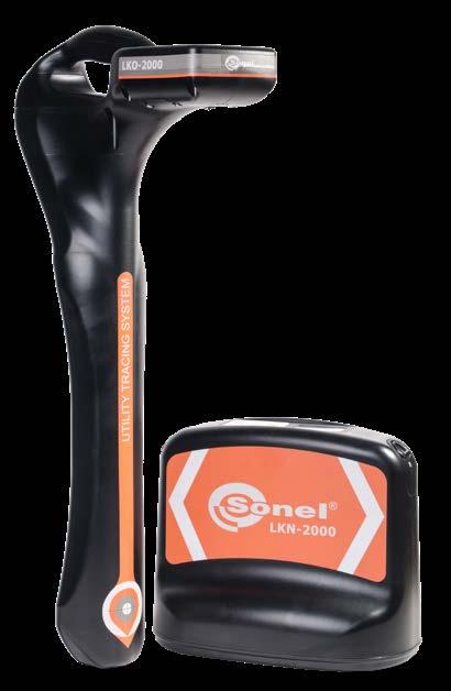
» operating temperature -20...+50°C
»
»
index: WMGBLKZ2000
LKN-2000 transmitter
» Batteries: up to 100 hours (level 2 output power at 20°C)
10% depth in probe mode (from 4.6 m to 6 m)
SONEL LKZ-2000
» Accuracy of measurement (error):
» dimensions 255 x 190 x 305 mm
» power engineering construction railway telecommunications refineries sanitary infrastructure heat distribution networks transmission pipelines
» ingress protection IP65
» weight ca. 3.5 kg
» power supply 2x LR20 battery
» ingress protection IP65
» power supply
• POWER passive mode: 50 Hz, 100 Hz, 450 Hz / 60 Hz, 120 Hz, 540 Hz
» Power in induction mode (max): 3 W
Cable and underground infrastructure locator
» Antenna configuration: Single peak value, double peak value, neutral point, full field
Li-Ion rechargeable battery pack
» Power for galvanic connection (max): 12 W (for impedance of connected object: 100 Ω)
» Output power control: 5 levels
5% depth in linear or probe mode (from 0.2 m to 4.6 m)
» Depth measurement range: POWER mode up to 3 m RADIO mode up to 2 m modes with active transmitter up to 4.6 m probe mode up to 6 m
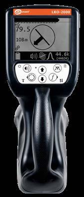
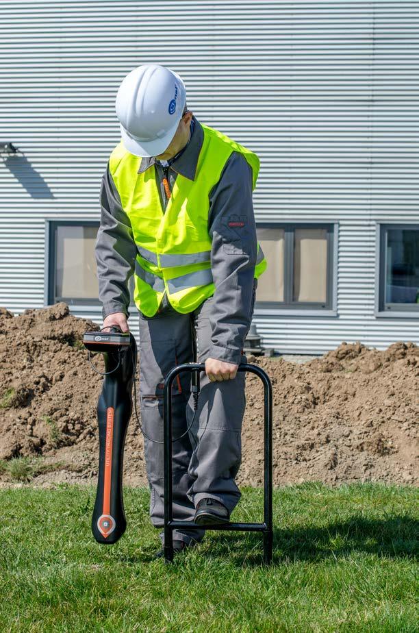
The best system under the most demanding conditions:
»
The diversity and concentration of underground infrastructure are still growing. Identifying underground systems was never as difficult and important a task as it is today. Location allows us to infer the actual position of an underground system and determine the proper location for current works, as well as to prevent accidents caused by damage to the under ground objects.
»
10x LR20 battery
» Bluetooth: for remote transmitter control
» Auto-OFF: Capability of selecting auto-OFF time after 5, 10, 20 or 30 minutes
» Mode / Frequency:
Using the A-frame, a cable earth fault can be located.
» Passive mode – work at the frequencies of: 50 RADIOHz, (10...36 kHz), SB (48 Hz...14 kHz).
SONEL LKZ TERMINAL
LKO-1500-LITELKN-1500LKO-1500LKO-1500
Crocodile clip, blue, 1 kV, 20 A
» Case housing.
• LKO-1500-LITE ca. 1.7 kg
Test lead 5 m, red, 1 kV (banana plugs) WAPRZ005REBB
Bag L13 WAFUTL13
LKO-1500-LITE / LKO-1500 receiver:
» power supply
Test lead 5 m, blue, 1 kV (banana plugs)
LKO-1500-LITE receiver is designed according to “intuitive and user-friendly” principle and it is an ideal solution for users entering the world of cable location and routing. LKO-1500 receiver is a level higher: it facilitates the work of the user to with many features, including visualization of the cable routing in the tested object or a greater number of frequencies to choose from. It is also distinguished by the option of tracing cable short-to-earth faults with the use of additional accessories.
WAZASZ16
» Active mode: work with LKN-1500 transmitter at the frequencies of 273 Hz, 526 Hz, 1024 Hz, 8928 Hz, 33 kHz, work with transmitters other than LKN-1500 at the frequencies of 491 Hz, 512 Hz, 982 Hz, 2000 Hz, 2048, Hz 8440 Hz, 9828 Hz, 10000 Hz.
Battery charger Z17 (receiver)
Battery charger Z16 (transmitter)
» Operation with external probes.
» dimensions 700 x 300 x 140 mm
WAZASZ17
Sun - protecting cover (only LKZ-1500)
WASONG23
The application additionally enables: » live positioning preview, » measuring the distance to a specific point on the route, » export of routes saved in LKO-1500 to the phone's memory, » reading routes from the phone's memory, » preview of the saved values of all parameters, » data export to PC.
The sets of LKZ series are an invaluable support in earthworks carried out for various in dustries, including energy, installation, construction, railway, telecommunications, water and sanitary, heating, geodetic and many others.
» power supply
» weight
SONEL LKZ-1500 / LKZ-1500-LITE
WMGBLKZ1500 / WMGBLKZ1500LITE
SONEL LKO TERMINAL
» operating temperature -20...+55°C
LKZ-1500LKO-1500receiverLKN-1500LKZ-1500-LITEtransmitterLKO-1500-LITEreceiver
Cable and underground infrastructure locator

» Location depth up to 10 m
» weight ca. 4.9 kg

WMGBLKN1500
WAPOZOSL4
» Transmission of double frequency signals.
» The mode of limiting the voltage of the transmitted signal.
Ground probe 23 cm
WMGBLKO1500
VRLA (AMG) lead-acid 12 V / 7 Аh
» Active mode work with LKN-1500 transmitter at the frequencies of 1024 Hz, 8928 Hz, 33 kHz.
• LKO-1500 ca. 1.8 kg
» Location depth up to 6 m
LKO-1500 receiver (only LKZ-1500)
» Compatible with transmitting clamps.
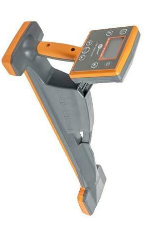
WAKROBU20K02
WAPRZ005BUBB
» ingress protection IP54
index:
LKN-1500 transmitter:
» Transmitter power: 1 W, 2 W, 5 W, 10 W.
LKO-1500-LITE receiver
LKO-1500-LITE receiver (only LKZ-1500-LITE)
LKN-1500 transmitter introduces a specific signal to the tracked objects, enabling LKO re ceivers to route in the active mode. The receivers operate also in a passive mode that uses the network frequencies and telecommunications signals present in the facility.
The application works with the Sonel LKZ-1500 wire and ca ble locator. By replacing the external GPS module, it allowing the user to define and record the geographic coordinates of the cable route.
WMGBLKO1500LITE
» Operation in direct galvanic or inductive connection modeinternal transmitting antenna.
» Continuous or interval mode of operation that extends battery life.
» dimensions 275 х 250 х 180 mm
5x Ni-MH 1.2 V rechargeable battery
» fuel transmission systems (pipelines, gas pipelines)
A dedicated PC program for handling data stored in LKO1500. It allows you to map a route from your location and read the data stored in the receiver. The data includes: » coordinates of the place of measurement according to GPS information, » reading the depth of the object and value of current flowing in it, » the direction of the forced current, » operating frequency, » date and local time at the time of measurement according to GPS information, » export of route data to a file.
109
» underground elements of lightning protection systems, cathodic protection systems,

LKN-1500 transmitter
LKN-1500 transmitter
Declaration of verification
» ingress protection IP54
» heating systems and pre-insulated pipes.
» power cords and cables, control cables, telecommunications cables,
» Passive mode – work at the frequencies of: 50 Hz, 60 Hz, 100 Hz, 300 Hz, 550 Hz, 1450 Hz, RADIO (10...36 kHz), • SB (48 Hz...14 kHz).
Crocodile clip, red, 1 kV, 20 A WAKRORE20K02
The LKZ locator set consists of a LKN transmitter and LKO receiver. It allows for location, identification and tracking of the route of objects buried in the earth. The user will be able to trace:
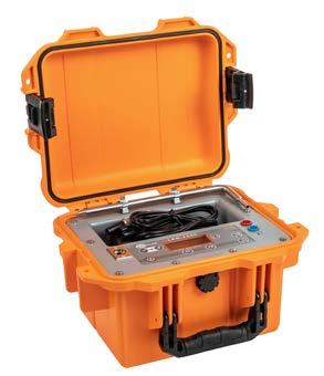
» operating temperature -20...+55°C
Rechargeable battery NiMH 6 V, 2 Ah WAAKU23
LKO-1500 receiver
5x AA 1.5 V battery
» water and sewage systems,
Ni-MH 6 V/2000 mAh battery pack
Standard accessories:
Battery compartment WAPOJ3 Neck straps (only LKZ-1500) WAPOZSZE6
» active (with transmitter) (8 kHz and 33 kHz) enables:
The improved LKN-1000 transmitter generates a signal that is 10 times stronger than in the previous model, allowing for:
» shallow cable warning,
» weight ca. 2.9 kg
» dimensions 180 x 280 x 260 mm
Declarationbatteryofverification
» additional built-in test function enabling independent checking of all functions before starting work,
» tracing of non-conducting pipelines by means of “floating” probe,
» automatic detection sensitivity regulation,
» cable depth measurement up to 3 m,
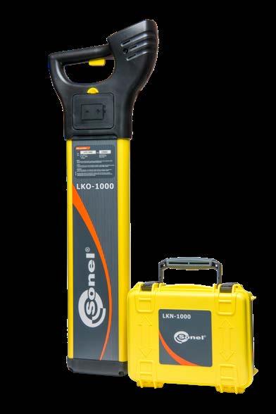
Earth contact pin probe
» detection of live underground cables,
Index: WMGBLKZ1000
SONEL LKZ-1000
LKN-1000 transmitter
» passive RADIO (15…30 kHz) - enables quick, non-selective location of underground infrastructure of a minimum length of 100 m (metal installations)
Functions of the set:
» ingress protection IP54
» Automatic display backlighting – the installed lighting sensor automatically activates display backlighting when it is necessary.
Cable and underground infrastructure locator
LKO-1000 receiver
» detection of underground cables not carrying current using the transmitter (galvanic or inductive connection, or by means of clamp),
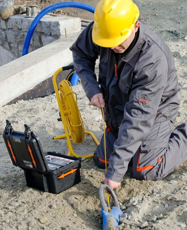
» durable, water-resistant housing with IP65 protection rating, more compact and lightweight, designed for work under difficult conditions,
10x 1.5 V
» better detection of underground systems under adverse conditions with strong disturbances,
» Automatic mode - combines the benefits of simultaneous detection in Power and Radio mode. Makes it possible to confirm the presence of underground infrastructure in the initial phase of location, making detection easier and safer.
» better detectability of multiple underground systems simultaneously,
» passive or active tracing modes,
• location in induction mode (it is enough to place the transmitter above the located object) location by means of direct connection of the transmitter to an object not carrying electrical current location by means of transmission clamp (the clamp is to be fastened onto the tested object) location with the use of a transmission lead or transmission probes (enables location of non-metal objects) location by means of splitting adapter (direct connection of LKN1000 transmitter to a 230 V network socket).
» weight ca. 2.4 kg
» power supply 6x LR6 battery
» three operating modes to choose from: passive, active, automatic (passive+active),
LKN-1000 transmitter:
» determination of direction of cable route,
» contrast display, automatic LCD backlit.
» passive 50 Hz and 60 Hz - enables location of live conductors and cables (POWER)
» control buttons found on the housing's exterior, allowing for control while the housing is closed, affording better protection against mechanical and water damage.
Automatic mode - combines the benefits of simultaneous detection in power and radio mode, making it possible to confirm the presence of underground infrastructure in the initial location phase.
» power supply 4x LR20 battery
» operating temperature -20...+50°C
» four adjustable output signal power levels, up to 1 W,
» tracing of a specific cable,
» tracking of underground systems over longer distances,
Standard accessories:
» Digital signal strength reading – this function additionally activates digital reading of signal strength on the display, facilitating location of underground installations.
» 5 operating modes,
» operating temperature -20...+50°C
WASONG15
» easier depth determination,
WAFUTL6
L6 carrying case
Work modes:
» Auto-test – allows for independent receiver control. After the test is passed, the receiver’s display will read PAS, if the test is not passed, ERR will be displayed.
» determination of cable depth,
LKO-1000 receiver:
» dimensions 760 x 250 x 85 mm
» Hazard zone – this function generates an alarm signal indicating the proximity (within a radius of approx. 30 cm) of cables being located. It works in Power, 8 kHz or 33 kHz operating modes, as well as in automatic mode.
» ingress protection IP54
» easy-to-read visual and sound signals facilitating operation,
» tracing of metal or non-conducting pipes by means of additional probe,
LKN-1000 LKO-1000 LKO-1000receiver LKZ-1000 LKN-1000transmitter 110
The set also has a series of options and functions that improve safety and convenience of work:
WMGBLKN1000
» detection of underground cables not carrying current (radio mode),
WMGBLKO1000
... and cables immediately before installation
Detecting cables and wires
SONEL S.A., due to its continuous contact with installers and contractors, thorough ly recognizes the problems faced by specialists repairing electrical installations. This resulted in designing and producing LKZ-720 a locator of wires and pipes, intended mainly for detecting cables in buildings with various construction envi ronments (concrete, brick, wood). Apart from tracking cables in ceilings, walls and floors, detecting interrupted and shorted circuits, LKZ-720 has the ability to detect 50/60 Hz electric field (non-contact voltage tester) and identify system safety de vices such as circuit breakers, differential switches. The device is equipped with a special 3D spatial antenna, which significantly facilitates detection and provides transfer of many useful information.

In order to determine the routing of wires and to locate their damages, the device uses physical phenomena, especially the propagation of the electromagnetic field. After connecting an open circuit to the transmitter, which emits a modulated signal of AC voltage, this circuit acts as an antenna emitting an electric field. When the transmitter is connected to a closed circuit, or a circuit under voltage, a magnet ic field will be generated. The receiver is designed to present the received signal strength in numerical and graphical form. Changes in presented indications allow user determine the position of an object that emits electromagnetic field.
Due to its features, LKZ-720 set (LKN-720 transmitter and LKO-720 receiver) ena bles user to easily, fast and precisely locate cable and wire routes, as well as their potential defects. Definitely, the easiest method is to use a two-step technique: » quickly and roughly locate the searched object using the 2D method, and then » use the 3D method to precisely determine the position of the object or location of the defect.
111
See the manual in im ages and video tutorials that are available on the product website and on YouTube.
Recommended areas for laying cables in residential premises...

Manual in images
Video tutorials


Another problem often encountered after completed finishing works is the diffi culty in finding termination of cables and pipes, which disappeared from eyesight after plastering. Inventorying old systems (often installed in a surprising way), iden tification of safety devices, finding short-circuits and interrupted electrical circuits are difficult tasks, even for experienced professionals.
This is particularly useful, when dealing with the effect of work that does not match the documentation of the system. During the tracking process, the receiver informs the user about the direction from which the signal is transmitted, i.e. the place of connecting the transmitter. In addition, the indicators on the display show the direction and position of the localized conductor in relation to the receiver. With this information, determining the location is quick, efficient and very intuitive.
Works on detecting underground cables and wires and their routes are always chal lenging and quite difficult for people performing this task. Despite good practice and guidelines included in standards and recommendations, which define places for routing cables in the walls, contractors often perform their tasks inconsist ently and negligently. In result electric wires are found often in at least expect ed places. Naturally, floors and ceilings are also areas used for installing cables. Therefore, electrical systems can be found in many locations, causing problems during renovation and finishing works. Performing works without prior routing of cables and wires may cause their damage by drilling, puncture, or short-circuit by a metal screw.
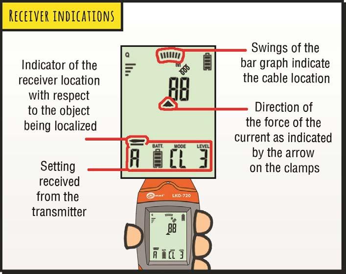
WAPRZ020REBBSZ 1 1 1
index:
» A LED torch.
» maximum depth of the analysed object ("I" mode) 2 m
WAPOZSZE4 1 1 1 1
1.5 V battery 4 16 4 12
WASONG25 1 2 1 1
LKN-720 transmitter:
WASONBDOT 1 1 1
» Five modes of wire tracer operation: voltage, current, currentvoltage, power and clamp.

» Measurement of voltage at the object to 500 V RMS.
» Screen backlight for work in dark.
» power supply 4x 1.5 AA alkaline battery or 4x 1.2 Ni-MH rechargeable battery
L2 carrying case WAFUTL2 1 1 M6 carrying case WAFUTM6 1 1
Pin probe, red 1 kV (banana socket)
SONEL LKZ-720 / LKZ-720 KIT
» dimensions 221 x 102 x 62 mm
Earth contact test probe (rod), 25 cm
» ingress protection IP40
» Receiving status information from the LKN-720 transmitter.
Test lead 1.2 m, blue, 1 kV (banana plugs)
LKZ-720 LKZ-720 KIT LKO-720 LKN-720 LKN-720 KIT WMGBLKZ720 WMGBLKZ720KIT WMGBLKO720 WMGBLKN720 WMGBLKN720KIT
Description
WAKROBU20K02 1 4 1 3
The Sonel LKZ-720 cable and wire locator is a device consisting of the LKN-720 transmitter and the LKO-720 receiver. This instrument is dedicated to finding cables and other underground infrastructures. The LKZ-720 allows the location of both metallic objects (cables) and non-conductive objects (PVC pipes, concrete, etc.). The locator is main ly dedicated to use in the energy and installation industry, among others.

» The function 3D - detecting the direction of current.
» measurement category CAT III 600 V according to EN 61010-1
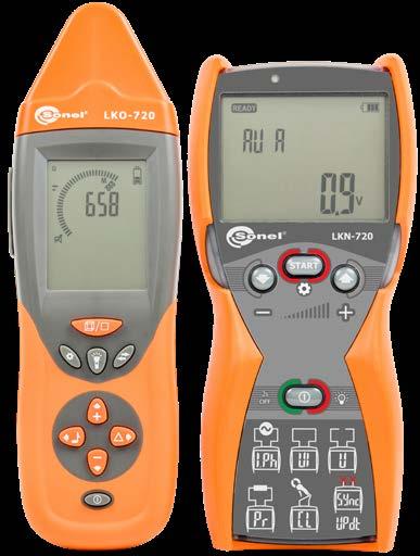
LKN-720 transmitter WMGBLKN720 1 4 1 3
» Detection of wires and cables (live or not).
» Flow and accurate locating the object.
Declaration of verification 1 1 1 1 1
» operating temperature -10...+50°C
» power supply 9 V 6LR61 alkaline battery
M1 hanging straps
Features
» ingress protection IP67

» dimensions 245 x 77 x 52 mm
» maximum range of contactless neon probe 50 cm (in air) 5 cm (in concrete)
LKO-720
» Additional accessories enable precise localization - such as contact or non-contact probes and measurement clamp.
LKN-720
» 4 codes of the transmitted signal.
» Tracing conductive water and heating pipelines.
» type of insulation double, as per EN 61010-1
» weight ca. 0.7 kg
WAPRZ1X2REBB 1 4 1 3
Crocodile clip, blue, 1 kV, 20 A
Mini-USB cable
Non-contact probe
WMGBLKZ720 / WMGBLKZ720KIT Wire tracer
Special features
» Headphone socket.
LKN-720 receiver WMGBLKO720 1 1 1
» Software upgrade via USB.
» Transmission of information about the transmitter settings and battery charge level.
WASONBUOGB1 1 4 1 3
» operating temperature -10...+50°C
LKO-720 receiver:
Test lead 1.2 m, red, 1 kV (banana plugs)
» weight ca. 0.4 kg
» Receiver operation with max. 4 transmitters at the same time to locate interruptions or distinguish wires.
WASONREOGB1 1 4 1 3
Crocodile clip, red, 1 kV, 20 A
LKN-720LKN-720LKO-720LKO-720 LKO-720receiverLKZ-720LKZ-720 KIT LKN-720transmitter LKN-720 KIT set of transmitters See the videoavailabletutorialson YouTube. 112
WAPRZ1X2BUBB 1 4 1 3
WAKRORE20K02 1 5 1 4
» Three levels of amplification.
Standard accessories:
» Tracing underground cables.
9 V battery 1 1 1
» Operation in wide range of rated voltage, up to 500 V RMS.

» Screen backlight for work in dark.
Pin probe, blue 1 kV (banana socket)
Test lead 20 m, red, 1 kV (on a reel, banana plugs)
WAPRZUSBMNIB5 1 1 1
» maximum operating voltage 500 V (RMS)
» Phase detection mode.
» Automatic or manual selection of operation modes.
Photo Name Index LKZ-2000 LKZ-1500 LKZ-1500-LITE LKZ-1000 KITLKZ-720 LKZ-720 LKN-720 transmitter WMGBLKN720 4 1 LKO-720 receiver WMGBLKO720 1 1 LKN-1000 transmitter WMGBLKN1000 1 LKO-1000 receiver WMGBLKO1000 1 LKN-1500 transmitter WMGBLKN1500 1 1 LKO-1500-LITE receiver WMGBLKO1500LITE 1 LKO-1500 receiver WMGBLKO1500 1 LKN-2000 transmitter WMGBLKN2000 1 LKO-2000 receiver WMGBLKO2000 1 A-frame WAADALKZRA • A-frame WAADALKZRA2 • C-3 clamp adapter WAADALKOC8 • • Magnetic voltage adapter, black WAADAUMAGKBL • • • • Magnetic voltage adapter, blue WAADAUMAGKBU • • • • AS-1 Separating adapter WAADAAS1PL • Photo Name Index LKZ-2000 LKZ-1500 LKZ-1500-LITE LKZ-1000 KITLKZ-720 LKZ-720 Rechargeable battery NiMH 6 V, 2 Ah WAAKU23 1 1 N-1 transmitting clamps (Ø52 mm) WACEGN1BB • • N-2 transmitting clamps (Ø100 mm) WACEGN2XLR • N-3 transmitting clamps (Ø125 mm) WACEGN3 • C-8 clamp probe (Ø52 mm) WASONCEGC8 • • L2 carrying case WAFUTL2 1 L6 carrying case WAFUTL6 1 L9 carrying case WAFUTL9 1 L13 carrying case WAFUTL13 1 1 M6 carrying case WAFUTM6 1 Li-Ion battery 3.6 V 4.5 Ah WAAKU14 • Crocodile clip, red, 1 kV, 20 A WAKRORE20K02 1 1 5 1 Crocodile clip, blue, 1 kV, 20 A WAKROBU20K02 1 1 4 1 Sun-protecting cover WAPOZOSL4 1 Battery compartment WAPOJ3 1 1 LKZ Set of standard and optional accessories 1, 2, 4 - number of standard accessories • - optional accessories 113


Test lead 1.2 m, red, 1 kV (banana plugs)
CAT IV 1000 V (banana plugs with 10 A fuse) WAPRZ002GRBBF10
Photo Name Index LKZ-2000 LKZ-1500 LKZ-1500-LITE LKZ-1000 KITLKZ-720 LKZ-720
BIK probe for wireless identification of cables WASONBIK
BT-Q1000XT GPS adapter WAADAQ1000XT

Pin probe, red 1 kV (banana socket) WASONREOGB1 4 1

• • • USB
Test lead 2,0 m green

•
• • • •
• Contact
Pin probe, blue 1 kV (banana socket) WASONBUOGB1 4 1
WAPRZ002YEBBF10
Photo Name Index LKZ-2000 LKZ-1500 LKZ-1500-LITE LKZ-1000 KITLKZ-720 LKZ-720
Test lead 5 m, blue, 1 kV (banana plugs) WAPRZ005BUBB 1 1


locate nonmetallic installations 80 m
Test lead 2,0 m black CAT IV 1000 V (banana plugs with 10 A fuse) WAPRZ002BLBBF10
LKZ
Test lead 2,0 m red CAT IV 1000 V (banana plugs with 10 A fuse) WAPRZ002REBBF10
Set of standard and optional accessories
•
WAPRZ002DZBB
Test lead 2,0m yellow CAT IV 1000 V (banana plugs with 10 A fuse)
5 WAPRZUSBMNIB5 1 1
1 1
Ground probe 23 cm WASONG23 1 1

WAPRZ1X2REBB 4 1
•
• • • •
NAD-1 Transmission probe WASONNAD1
• •
PN-30 wire to locate nonmetallic installations 30 m WAPRZPN30
Test lead 5 m, red, 1 kV (banana plugs) WAPRZ005REBB 1 1


• • • •
Non-contact probe WASONBDOT

Test lead 2,0 m blue CAT IV 1000 V (banana plugs with 10 A fuse) WAPRZ002BUBBF10
• • •
Test lead 20 m, red, 1 kV (on a reel, banana plugs) WAPRZ020REBBSZ 1 1
•
• •
Pin probe, black 11 kV (banana socket) WASONBLOGB11

• • • •
• •
Test lead 1.2 m, blue, 1 kV (banana plugs) WAPRZ1X2BUBB 4 1
PN-50 wire to locate nonmetallic installations 50 m WAPRZPN50

Earth contact test probe (rod), 15 cm WASONG15 1
PN-80 to WAPRZPN80 cable MINI-B

• • • •
M1 hanging hook straps WAPOZUCH1 • • hangingMagneticstrap WAPOZUCH6 • • M1 hanging straps WAPOZSZE4 1 1 Neck straps WAPOZSZE6 1 Battery charger (transmitter)Z16 WAZASZ16 1 1 Battery charger Z17 (receiver) WAZASZ17 1 1 114


1, 2, 4 - number of standard accessories - optional accessories
wire
• • •
Double-wire test lead 2 m, for N-1 clamps (banana plugs)

Earth contact test probe (rod), 25 cm WASONG25 2 1 probe WASONDKI probe WASONDOT


DKI
• • • •
The TDR-420 reflectometer is equipped with a readable colour display that, due to its 320 x 240 pixel resolution, allows the fault location to be indicated even more accurately.
√ √
Device capabilities
Crocodile clip, black 1 kV 20 A WAKROBL20K01 1 1

• •
•
accuracy 1% of selected range resolution approx. 1% of range minimum cable length 4 m velocity of propagation within 10…99% or 15…148.5 m/μs within 1…99% or 1…148 m/μs output impulse 5 Vp-p for an open circuit output impedance 25, 50, 75, 100, 125, 200 Ω 25, 50, 75, 100 Ω impulse width 3 ns…3 μs (depending on the range) scanning type up to 3 scans/s or a single scan (ONCE mode) 2 scans/s or a single scan
• •
M1 hanging straps WAPOZSZE4 1
Test lead 2,0 m red CAT IV 1000 V (banana plugs with 10 A fuse) WAPRZ002REBBF10

auto-off function 1, 3, 5, 10, 15 minutes or deactivated 1, 2, 3, 5 minutes or deactivated display colour 3.5” LCD TFT, 320 x 240 pixels graphical, backlit, 128 x 64 pixels
Easy readout
• •
In response to the customers needs the new model of TDR-420 has been designed to operate in difficult environmental conditions. A unique casing with the IP67 in gress protection rating ensures that the device is both waterproof and dustproof. An additional advantage is the elastomer coating of the casing that prevents the de vice from slipping out of the hands and provides protection if accidentally dropped.
M6 carrying case WAFUTM6
Application
√ √
Integrated Help
Crocodile clip, red 1 kV 20 A WAKRORE20K02 1 1

Magnetic adapter, blue WAADAUMAGKBU
» detection of breaks, short-circuits, damage caused by moisture and other changes in cable impedance

TDR-410 and TDR-420 time-domain reflectometers are designed for faults locating in metal wires. These products are designed for electrical wholesalers and cable dealers, electrical installation companies, maintenance personnel at manufactur ing plants and building personnel. These devices meet the expectations of all those who have to accurately locate a fault and wire end in either power or telecommu nications cables.
Voltage adapter with M4 / M6 thread, blue WAADAM4M6BU
Test lead 2,0 m blue CAT IV 1000 V (banana plugs with 10 A fuse) WAPRZ002BUBBF10

1, 2, 4 - number of standard accessories • - optional accessories
1 kV,
TDR
» graphic presentation of cable faults with an indication of the distance to the fault on the display
SONEL TDR-420 / TDR-410
TDR-420 TDR-410
SONEL reflectometers are distinguished for their long operating range (up to 6,000 m for TDR-420), very low margin of error in measurement (in the order of 1%) and the ability to adjust both the velocity of propagation and the impedance of the cable which is under investigation. By using two cursors there should be no prob lem with determining both the distance to two faults and the distance between them.
Test lead 2,0 m black CAT IV 1000 V (banana plugs with 10 A fuse) WAPRZ002BLBBF10
In the TDR-420 device a handy help function has been added to facilitate the in terpretation of the result obtained during measurement. Thanks to this function, a user can quickly determine the type of anomaly that is present in the cable seg ment which is being examined, by comparing the displayed reflectogram with typ ical fault shapes.
A
index: WMGBTDR420 / WMGBTDR410 Reflectometers
M6 carrying case WAFUTM6 1
power supply 4 x alkaline batteries 1.5 V AA type or 4 x NiMH AA rechargeable batteries 4 x alkaline batteries 1.5 V AA type
0.6 m
Set of standard and optional accessories
» TDR-420 | trace hold and compare feature allows displaying and comparing two traces
tone generator 810 – 1100 Hz operating time on a full battery up to 8 hours of continuous scanning up to 30 hours of continuous scanning
Parameters TDR-420 Advanced reflectometric measurements in all fields TDR-410 Basic cable faults measurements
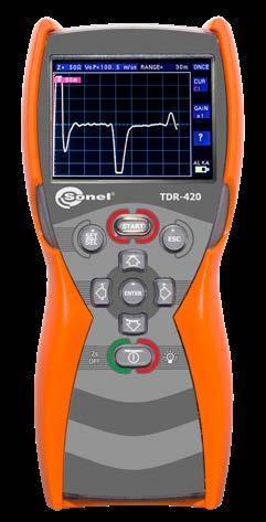
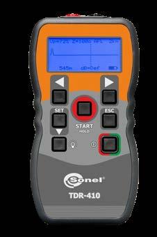
Voltage adapter with M4 / M6 thread, black WAADAM4M6BL
» fault location in power and telecommunication cables
√
• •
Standard accessories: TDR-420 TDR-410
» fault location in infrastructure cables
√
√
1.5 V AA battery √ √ Declaration
M13 carrying case WAFUTM13
Diagnose faults with instruments from the TDR series
Magnetic adapter, black WAADAUMAGKBL

A
4x alkaline of
» fault location in coaxial cables
overvoltage protection 400 V DC / 250 V AC operating temperature -20…+70°C -10…+50°C storage temperature -30…+80°C -20…+70°C dimensions 220 x 98 x 58 mm 165 x 90 x 37 mm weight 487 g 350 g electromagnetic compatibility standards (EMC) EN 61326-1 ingress protection IP67 IP54
» TDR-420 | two independent cursors to indicate two fault locations and the distance between them
Durable and practical casing
√ √
Double-wire test lead WAPRZ0X6DZBB

Crocodile clip, red, 1 20 WAKRORE20K02
kV,
M13 carrying case WAFUTM13 1
Crocodile clip, black, 20 WAKROBL20K01
7 m, 15 m, 30 m, 60 m, 120 m, 250 m, 500 m, 1 km, 2 km, 3 km, 4 km 20, 45, 90, 180, 360, 750, 1500, 3000, 6000, 10000, 14000 [ft]
• •
Photo Name Index
Double-wire test lead 0.6 m WAPRZ0X6DZBB 1 1

• •
measuring ranges 7 m, 15 m, 30 m, 60 m, 120 m, 250 m, 500 m, 1 km, 2 km, 3 km, 6 km 20, 45, 90, 180, 360, 750, 1500, 3000, 6000, 10000, 20000 [ft]
• •
M1 hanging straps WAPOZSZE4
verification √ √ 115
Magnetic hanging strap WAPOZUCH6
The light colour is another factor that has a significant impact on the well-being of people present in the room. For a man the most optimal lighting has the spectral composition most similar to daylight. Light sources are classified according to the colour temperature into warm, cool and neutral light. The colour temperature may be determined based on colour rendering index Ra, which reflects the difference between the colour of object illuminated by natural light and the object illuminated by tested light. Light sources with relatively high Ra index include standard bulbs, halogen bulbs or LEDs. Sources with Ra below 70 include sodium and mercury lamps. Measurements of parameters that help to assess lighting conditions should be carried out during the acceptance of new lighting devices and during the mod ernization of existing devices or periodically every 5 years. It is recommended to carry out the tests at least every two years. The tests shall be carried out:
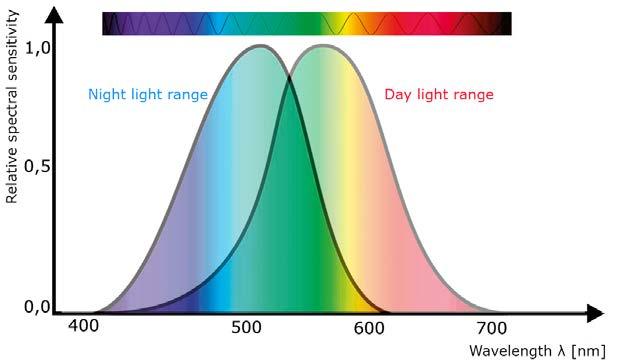
In order to determine the measuring points of all three areas, create grid with a mesh of approximately square shape. The ratio of length to width of the mesh should be between 0.5 and 2. The measurement points should be located inside the mesh of the lighting grid. The maximum grid size shall be:
116
Fig. 1. Visible range of electromagnetic waves during the day and night
Despite the adaptability of the eye to changing light intensity, the measurements require to set the measuring at device to have a sensitivity similar to an eye adapted to bright daylight. Spectral curve that corresponds to this sensitivity is called the photopic curve V(λ). It is useful to calculate photometric values. In determining the criteria for proper lighting parameters, consider the following:
» local regulations (i.e. GB 50034, JIES-008, CIE S 008/E-2001, SNiP 23-05-95, AS 1680.1-2006).
Luminaires with discharge lamps must be switched on at least 30 minutes before testing. Other types of light sources such as halogen bulbs or LEDs, may be ex amined directly after switching on. Discharge lamps must not be new; they should operate at least 100 hours before measurements; in case light bulbs and halogen lighting this operation period is only one hour. The person performing the measure ments can not affect the results. Therefore, it is advisable to wear dark clothing, and the distance from the measuring device should be as large as possible. Meas
p = 0,2 • 5 log10d
» recommendations of the International Commission on Illumination (CIE) (determination of optimal conditions for the illumination of rooms, depending on their use)
Basing on the measurements, lighting uniformity U0 may be calculated for a given workplace.
When selecting the measuring instrument, attention should be paid to a valid calibration certificate, which confirms its efficiency and the fact that it meets declared levels of basic and spectral uncertainty. The photoelectric cell, which is used as a sensor, is ageing over time, so it should be subject to metrological periodic checks.
To measure lighting in interiors with daylight, carry out the measurements that determine the daylight index. For this purpose, use two luxmeters to perform meas urements simultaneously outside and inside the rooms lit via windows or skylights. On the other hand, when measuring emergency lighting the illuminance values are very low. The requirements in this matter are defined in standard EN 1838:2013. It should be mentioned that for escape routes with a width of 2 meters, the minimum value of illuminance measured at the floor is 1 lux, which affects the selection of an appropriate measuring device. In recent years, LED illumination sources become more and more popular. Their measurements are currently based on the same re quirements as other types of light sources. In case of measurements on white LED light, consider the guidelines of CIE concerning parameter f1', i.e. the size of mis match between luxmeter sensitivity and curve V(λ). The Commission recommends the use of luxmeter with f‘ not exceeding 3%
» in operating conditions - the test area shall not be specially prepared (creating unrealistic conditions) for the tests.
Our perceptive capability and psychophysical condition depend to a very large ex tent on the surrounding environment. Light stimuli are decisive factors in the psy chological comfort. Prolonged exposure to artificial light may accelerate fatigue and contribute to eyesight defects and other diseases. Negative impact of improp er lighting on people is particularly important in terms of safety and work efficien cy. The perception of light stimuli, although dependent on the individual character istics of a person, is in general similar for majority of people. Therefore, regulations have been defined to define values and types of lighting in places where people live and work. The light visible to humans is an electromagnetic wave with a length from approx. 380 nm to approx. 780 nm. The sensitivity of a human eye is not the same in all conditions - it results from its structure and location of receptors, as well as from the nature of the light. In daylight conditions the eye is most sensitive to green colour, whereas at night or in poor lighting, the eye sensitivity shifts to blue colour - this is why we have a subjective impression that at night everything is grey.
urements should be performed in the plane of the task (e.g. desk surface) with the photometer head set in parallel and directly on the test surface.
EN 12464-1:2012 introduces a new term: illuminance of the immediate surround ing area. It depends on illuminance in the task area ono and it shall provide an even distribution of luminance in the field of view. This standard recommends minimum dimensions of the task area and related dimensions of the immediate surrounding area (a strip with a width of at least 0.5 m around the task area) and a background area (a strip with a width of at least 3 m adjacent to immediate surrounding area).
pwhere:-maximum dimension of the grid [m], d - longer dimension of the calculated area [m].
For testing workplace lighting, it is recommended to observe guidelines defined in binding standard EN 12464. When discussing illuminance measurements, it is use ful to define the illuminance. It is the ratio of luminous flux on a specified area and the surface of this area. The unit of illuminance is lux (lx) [ lm/m2 ] In addition, CIE provides recommended illuminance uniformity Em in the field of view, i.e. the way of lighting the workplace. High irregularity of illumination (e.g. exposed light sources in the field of view) creates a risk of glare which may reduce the ability to recognize details or cause a discomfort. In addition, due to the time needed for eyes to adapt to changes, the illumination uniformity should be maintained over time. Therefore, the level of ripple is important and this relates to flicker.
Fig. 2. Visual task, immediate surrounding area and background area

» after dark or with curtains drawn
Sonel LXP-10A light meter of Class A meets this condition. In case of light meters LXP-10B and LXP-2 of Class B, having the declared error value of spectral correc tion f1'< 6%, the error value f1 must be also taken into account, which results from differences in spectral distribution of the measured and calibration light source. The illuminance measurement formula requires taking into account the correction factors for the LED light. As in luxmeters of Class A and B, the correction factors k take values close to 1, they do not have a significant impact on the measured illu minance value.
Illuminance measurements
»
» meter dimensions 170 × 80 × 40 mm
Factory calibration certificate plug)

Light meter probe holder (trolley) WAPOZUCH10

1, 2, 4 - number of standard accessories - optional accessories
Product functions » data HOLD » PEAK HOLD »
»
» memory of recorder 16,000 results
Light meter probe holder (stick) WAPOZUCH9

» power source 9 V battery or 8.4 V rechargeable battery
LP-10B light meter probe (miniDIN-4P) (only LXP-10B)
•
• • •
WAADAUSBOR1 • • Free
Device of the highest class A thanks to cooperation with LP-10A measuring probe. LXP-10A has all advantages that can be found in LXP-10B. Furthermore, it allows to make the most accurate measurements in industrial zones and public facilities. In addition, the instrument has the ability to wirelessly send data to Sonel Reader PC software.
»
WAADALP10A
meters WAPROREADER • • •
LXP-10B
Model with resolution 0.01 lx allows to accurate lighting measurements in workplaces and emergency lighting in escape routes. It works with LP-10B measuring probe (class B). The device has internal memory of 999 measurements and additional logger for recording data with a selectable sampling rate.

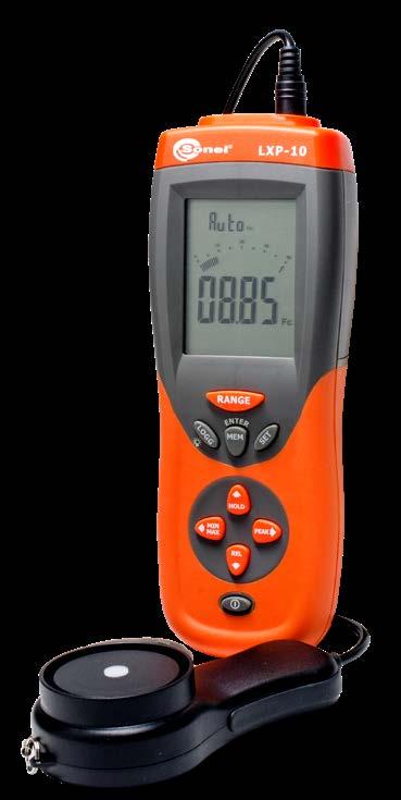
»
LXP-10A LXP-10B LXP-2 the forrecommendedmostprofessionals measurementsfor of emergency lighting basic measurements of workplaces class A B B measurement range 0.000…399.9k lx 0.000…39.99k fc 0.00…399.9k lx 0.000…39.99k fc 0.0…19.99k lx 0.00…1999 fc resolution (lx/fc) up to 0.001 up to 0.01 / 0.001 up to 0.1 / 0.01 accuracy ±(2% + 5 digits) ±(5% + 5 digits) spectral uncertainty f1' <2% <6% cosine matching error f2 ±3% number of ranges 6 5 3 sampling rate 1.3 Hz spectral sensitivity CIE spectral sensitivity (CIE human eye sensitivity) photodetector one silicon photodiode and spectral sensitivity filter
» memory 99 results (LXP-2), 999 results (LXP-10)
» operating temperature 0…50°C
LP-1 light meter probe (miniDIN-4P plug)
» photodetector lead length approx. 150 cm
» exceeding of range „OL” symbol
»
• • •
SONEL LXP-10A / LXP-10B / LXP-2 index: WMGBLXP10A / WMGBLXP10B / WMGBLXP2 Illuminance meter LXP-10B and LXP-10A enable wireless data transfer to a PC via the OR-1 adapter Photo Name Index LXP-10A LXP-10B LXP-2 LP-1 light meter probe (miniDIN-4P
»
WAADALP1
Other technical specifications:
WAADALP1 1
Main features measurements of all types of light - also LED lighting no need to using correction factors displaying results in lux and foot-candle measurements of emergency lighting MAX and MIN results save measurements of relative (REL) values data logger with memory auto power off
USB cable MINI-B 5
Basic technical specifications:
LP-10B light meter probe (miniDIN-4P plug)
»
WAADALP10B
» weight 390 g
» communication interface USB and radio link (only LXP-10B, LXP-10A)

117
Standard accessories:
» display 3¾ digits, LCD with 40-segment bar indicator
WAADALP10B 1
LXP-2
Model for everyone who makes basic lighting measurements of indoor and outdoor work places. The device works with LP-1 measuring probe (class B) which allows to proceed with measurements in a reliable way. The non-integrated probe eliminates the influence of the user to the measurement result.
LP-1 light meter probe (miniDIN-4P) (only LXP-2)

LXP
OR-1 USB wireless receiver software to transfer data from
» photodetector dimensions 115 × 60 × 20 mm
WAPRZUSBMNIB5
LP-10A light meter probe (miniDIN-4P) (only LXP-10A)
» storage relative humidity 0…70%
WAADALP10A 1 •
LXP-10A
» relative humidity 0…80%
» storage temperature -20…+70°C
WAPRZUSBMNIB5 1 1 1
LP-10A light meter probe (miniDIN-4P plug)
Set of standard and optional accessories

Top class of mains network analyzer with transients capture Class A high accuracy mains network analyzer Stand alone Class S mains network analyzer for fast diagnosis Portable Class S analyzer for basic and long term analysis PQM-711 PQM-710 PQM-707 PQM-700


Diagnosis of harmonics based on the behaviour of voltage, current and power har monics, which enables the user to evaluate the effects of power supply to non-line devices and their impact on the parameters of the power grid and power quality. High level of harmonics causes additional heat losses of the energy system ele ments, endangering the operation of these devices and generating additional costs. It is also possible to assess these risks for other power equipment supplied from the network that increase the risk of unexpected failure.
Diagnosis of active and reactive power helps to select parameters of the compen sator that eliminate penalties for exceeding the reactive power limits and to verify the effectiveness and conditions of operating the battery compensating the reactive power, ensuring trouble-free operation.
Electricity produced in electric power industry is a typical commercial product. Therefore, it is subject to the same rules as all goods available on the market, tak ing into account the fact that both the provider and the receiver use the same power grid, which affects the final quality of the power supply. The industry clearly defined power quality parameters, criteria and conditions for their evaluation and rules of distribution and control. Power distribution requires the control of power quality pa rameters, conditions of receiving process and recording all incidents of exceeded tolerance values. Data gathered in the control process is used for statistical eval uation of the compliance of recorded parameters with applicable standards, legal requirements and contracts. The final result is a confirmation of correctness which ends the assessment or a non-compliance statement, which is related to further analysis of the problem to indicate the responsibility for exceeding limits, which may result in financial consequences.
Instruments for analysing and diagnosing power quality are required to provide two basic functionalities. The first one is to assess the conformity or non-conformity of power supply parameters with binding standards and law requirements. This function is provided by all instruments offered on the market. The second functionality is to capture the phenomena that dete riorate power quality and those, which disturb proper and efficient operation of power equipment, provid ing flexibility to diagnose different types of networks with different nominal voltages. Presence of this feature in offered devices depends mainly on the initiative of producers of measuring equipment.
Diagnosis and identification of voltage dips to indicate their cause. Basing on si multaneous recording of average and limit values, as well as RMS (1/2) of voltages and currents, it is possible to indicate whether the dips were caused by out side factors or by own op eration of devices. Record ing the oscillograms helps to capture transients dur ing power outages, returns or high voltage surges.
Wide availability of electricity means that the public networks supply industrial fa cilities, public buildings, and the vast majority of households. Rapid technological progress resulted in a situation, where typical electric line machines, such as mo tors, light bulbs, resistive heaters are provided with additional power electronics that ensure easy control of the energy flow, power control and improved efficiency. The consequences of this progress, supported by the need to minimize costs, are significantly simpler solutions that cause higher levels of current and voltage dis tortion and interference. Power networks are now exposed to new types of impacts that deteriorate power quality, causing additional losses, which is particularly visi ble with increasing use of new devices.
» Class S: PQM-700, PQM-707,
» Class A: PQM-710, PQM-711
Example of the deformed current waveform
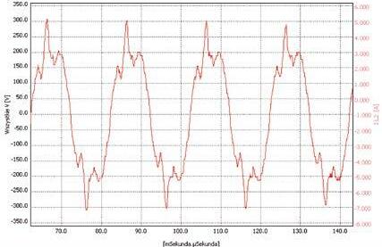
Examplefailure
of exceeded PLT indicator
Assessment of the quality of power supply in relation to the regulations binding in Poland or to EN 50160 standard. The conformity assessment report indicates which parameters are exceeded in relation to their threshold values, showing per centage values on the observation period scale. The assessment covers average values of voltages and frequencies, asymmetry, flicker factor PLT, THD U, voltage harmonics and additionally the maximum average active power of 15 min and tg, when necessary.
The measurement results provided by PQM analyzers may be used for the follow ing purposes:
119
Power electronics in industry is related to much higher values of active and pas sive power, systematically repeated changes of load and type of reactive power, asymmetries of single-phase and two-phase loads, current distortion, voltage dips caused by temporary network overloads and equipment failures. Therefore, the in dustry supply networks experience troublesome voltage fluctuations causing light flickering lights, short voltage dips, higher levels of harmonic voltages and currents as well as dangerous resonance phenomena. Other adverse incidents include dis continuities and interruptions of power supply that cause losses in production or even hazards to the life of employees. The increased amount of negative impacts causes faster and unpredictable wear of machine parts, making it difficult to plan maintenance activities. Moreover, the risk of losses due to unforeseen failures also significantly increases.
For close communication, the analyzers use USB connection and some types have built-in Wi-Fi module.
Diagnosis of voltages and currents, used for assessing the operational conditions for electrical machines with rotating field, basing on the behaviour of symmetrical com ponents of voltages and currents. Uneven operation of three-phase motors powered directly from the network, interferences in the work of transformers with the risk of ferro-resonances may be identified basing on the interdependence of the various parameters in combination with the waveforms of symmet rical components. The detection of these phe nomena may reduce the risk of failure, increasing operational reliability of machines.
Example of asymmetry caused by connection process
Diagnosis of interharmonics allows user to identify transients and dangerous be haviour of the grid that may threaten the operation of other devices. These phenom ena may occur at any frequency. Interharmonics complement the harmonics in the analysis of 0 - 2500 Hz band.
Diagnosis of voltage fluc tuations and flicker that presents the levels of volt age fluctuations and the degree of flicker nuisance, indicating the relation with the turbulent operation of own devices. Relating the high level of changes in active and reactive power to the waveform of the PST factor and propagation of changes with synchronous record ing in several points of the network allows identifying the direction leading to the source of disturbed loads.
Consumer electronics involves small power devices, but a very large number of them may significantly affect the quality of power supply in public networks.
The offer of our company includes a wide range of products tailored to the needs of users:
The main tasks of PQM-7xx analyzers, equipped with a wide range of accessories, include the use of a high-speed memory to simultaneously record up to 4500 net work parameters, including: average values, MIN and MAX values, waveforms of voltages and currents at the end of each averaging cycle. Monitored parameters in clude voltage increases, dips and interruptions with recorded waveforms and RMS (1/2) graphs. In addition, instruments check for exceeding tolerance values, ac ceptable levels or other parameters. PQM-711 analysers offer also quick waveform recording of transient currents up to 8000 V. Smart solutions used in the analyzers enable them to operate continuously with power supply from the tested network, up to 1000 V AC for CAT IV 600 V of overvoltage resistance over a wide temper ature range. The analyzers also maintain full functionality for a few hours on their own battery power. Class A devices have a built-in GPS, which provides high time accuracy and a GSM modem for distant remote communication.
Power quality analysis

Example of power supply
Diagnosis of transients based on high-speed re cording of voltage, sam pled at a frequency up to 10 MHz in the voltage range of +/- 8000 V. It is possible to detect quick surges threatening the power electronics devices, and insulating elements. Their presence may indi cate the absence or fail ure of surge protection or device malfunction, which in turn can lead to break downs and unnecessary loss.
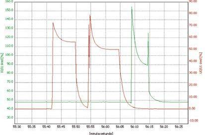

Crest factor I √ √ √ √
Number of current inputs 4 4 4 4 GPS input 1 1

Short term flicker √ √ √ √
TRMS current √ √ √ √
PQM-710
Current TID and interharmonics √ √
Number of voltage inputs 5 5 5 4
GOST 32144 √ √ √ √ AS 61000.3.100 √ √ √ √
MEASUREMENT INPUTS
analyzers
efficiency √ Maximal number of parameters measurements at the same time 3655 3655 1300 1200 Maximal recording time 100 years 100 years 18 years 18 years Integration period half cycle … 120 min half cycle … 120 min 1 s … 30 min half cycle … 30 min SAFETY Measurement category CAT IV 600 V CAT III 1000 V CAT IV 600 V CAT III 1000 V CAT IV 600 V CAT III 760 V CAT IV 300 V CAT III 600 V EN 61010 √ √ √ √ EN 61326 √ √ √ √ Anti-theft function √ √ ENVIRONMENTAL CONDITIONS Working temperature [ºC] -20..+55 -20..+55 -10..+50 -20..+55 Built-in heater √ √ √ Ingress protection IP65 IP65 IP51 IP65 All-weather measurements √ √ √ Pole mounting √ √ √ DIN rail mounting √ √ √ 120
Inrush √ √ √ √
Long term flicker √ √ √ √
1-phase, spilt-phase, 3-phase system √ √ √ √ Frequency √ √ √ √
PQM-707 PQM-700 STANDARDS
Angles between harmonics √ √ K-factor √ √
Harmonic power √ √ √
PQM-711
Crest factor U √ √ √ √
Mains signalling √ √ Power (P, Q, D, S) acc. to IEEE 1459 or Budeanu method √ √ √ √


of power
MEASUREMENTS
voltage THD and harmonics √ √ √ √ voltage TID and interharmonics √ √ voltage unbalance √ √ √ √ voltage transients (10 MHz sampling) √
TRMS voltage √ √ √ √
Current THD and harmonics √ √ √ √
Current unbalance √ √ √ √
Power factor √ √ √ √ Cos(φ) √ √ √ √ Tan(φ) √ √ √ √ Energy (EP, EQ, ES) √ √ √ √ 4-quadrants energy measurements √ √ √ PV inverter
Comparison quality
Compliance class acc. IEC 61000-4-30 A A S S Certificate from independent laboratory √ √ √ EN 50160 √ √ √ √
PQM-711 PQM-710 PQM-707 PQM-700 MEMORY AND COMMUNICATION Memory 8 GB (max. 32 GB) 8 GB (max. 32 GB) 4 GB (max. 32 GB) 4 GB (max. 32 GB) Replaceable memory card √ √ USB √ √ USB 2.0 High Speed √ √ Wi-Fi √ √ GSM (UMTS) modem √ √ POWER SUPPLY Built-in Li-Ion battery √ √ √ Replaceable Li-Ion battery √ Battery operating time min. 2 h min. 2 h min. 6 h min. 6 h Battery charger internal internal external internal USB charging √ GENERAL LCD display √ √ LCD touch screen √ GPS time synchronisation √ √ Multilanguage Sonel Analysis software √ √ √ √ Paper and PDF user manual √ √ √ √ Weight 1.6 kg 1.6 kg 1.75 kg 1.6 kg Dimensions 200x175x75 mm 200x175x75 mm 216x111x45 mm 200x175x75 mm ClassPortableSanalyzer for basic and long term analysis Stand alone Class S mains network analyzer for fast diagnosis Class A high accuracy mains network analyzer Top class of mains network analyzer with transients capture PQM-711 PQM-700 PQM-707 PQM-710 121

» harmonics up to the 50th in voltage and current, interharmonics measured as groups,
Voltage adapter with M4/M6 thread (5 pcs.) WAADAM4M6
• single-phase,
WAADAAZ1
» IEC 61000-4-15 (class A) (light flicker)
» power factor (PF), cosφ, tgφ,

• two-phase with common N,
WAPROANALIZA4 Factory calibration certificate
» IEC 61000-4-7 (class I) (measurements of harmonics)
» IEC 61010-1 (safety of measuring instruments)
» registration of current and voltage oscillograms after every averaging period,
» registration of overvoltages, voltage dips and breaks along with oscillograms,

• three-phase - star with and without N conductor,
» IEC 50160 (supply voltage measurements)
»
» calculation of reactive power using the:
» sampling frequency: 10.24 kHz,
»
Crocodile clip, blue, 1 kV, 20 A WAKROBU20K02
The instrument is intended for operation in networks:
» with rated frequency 50/60 Hz,

Crocodile clip, yellow, 1 kV, 20 A WAKROYE20K02
SONEL ANALYSIS MOBILE

» K factor (transformer overload due to harmonics),
is possible to wirelessly configure the measurements and analyze measurement data using Sonel Analysis PC software.
Mobile version of the program supports PQM-711 and PQM-710 power quality analyzers. It can be downloaded from Google Play
XL-2 hard case WAWALXL2 USB cable WAPRZUSB Sonel Analysis 4 PC software
» frequency within the range of 40 Hz – 70 Hz,
» total harmonic distortion THD for current and voltage, short-term (PST) and long-term (PLT) light flicker index (in compliance with IEC 61000-415 class A),
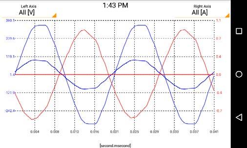
» unbalance of voltages and currents,
» active power (P), reactive power (Q), distortion power (D), apparent power (S) with identification of the nature of reactive power (capacitive, inductive),
Standard accessories:
Magnetic voltage adapter (set - 4 pcs) WAADAUMAGKPL
» measurement of control signals up to 3000 Hz,
PQM-711/710 have an independent power source, making them particularly suited for measurements with voltage transducers.
AC-16 line splitter WAADAAC16
• three-phase - delta.
» voltages L1, L2, L3, N-PE (five measurement inputs) – mean, minimum and maximum values, instant values within the range up to 1000 V, interoperability with voltage transformers,
AZ-1 power supply adapter (mains plug/ banana inputs)
122
2x crocodile clip, red, 1 kV, 20 A WAKRORE20K02
» all parameters in compilance with Class A of IEC 61000-4-30.

• Budeanu method,
Straps for mounting on the pole for PQM (set) WAPOZOPAKPL
3x crocodile clip, black, 1 kV, 20 A WAKROBL20K01
» event logging for current along with oscillograms (up to 1 s) as well as 10 ms RMS charts with maximum registration time of 30 s,
SONEL PQM-711 / PQM-710 index: WMGBPQM711BTW / WMGBPQM710BTW Power quality analyzers
DIN rail mounting bracket with positioning catches WAPOZUCH3
It
» with rated voltages: 64/110 V, 110/190 V, 115/200 V, 120/208 V, 127/220 V, 220/380 V, 230/400 V, 240/415 V, 254/440 V 277/480 V, 290/500 V, 400/690 V, 480/830 V (for systems with N conductor),
The instrument meets the requirements set forth in the standards:
» with direct current,
» currents L1, L2, L3, N (four measurement inputs) - mean, minimum and maximum values, instant values, direct current measurement within the range up to 6 kA (depending on applied current clamp), interoperability with current transformers,

PQM-711 enables measurement of transients up to ±8000 V with maximum sampling frequency of 10 MHz.
• IEEE 1459,
» measurement of transients up to ±8000 V with maximum sampling frequency of 10 MHz. The minimum transient time that can be registered is 650 ns (only PQM-711),
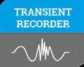
» crest factors for current (CFI) and voltage (CFU),
Measured parameters:
» active energy (EP), reactive energy (Eq), apparent energy (ES),
2x fasteners and bands for mounting the analyzer on a pole WAPOZUCH4
» in the following configurations:
» IEC 61000-4-30 (class A) (electromagnetic compatibilitymeasurement methods)
» A built-in rechargeable battery allows for max. two hours of operation in the event of a power failure.
Crest factor Voltage 1.00…10.00 (≤1.65 for 690 V voltage) 0.01 ±5% Current 1.00…10.00 (≤3.6 Inom) 0.01 ±5%
Active, reactive, apparent and distortion power depending on configuration (instrument transformers, clamp)
• C-5A
| Measurement
Active, reactive apparent energy depending on configuration (instrument transformers, clamp) 4 significant digits as power error cosφ and power factor (PF) -1.00...1.00 0.01 ±0.03
• F-1A6, F-2A6, F-3A6
PQM-711 of transients ±8000 V 4 significant digits ±(5% + 25 V) clamp: 0…1500 A AC (10 000 Ap-p) clamp: A AC (10 000 Ap-p) clamp: 0…6000 A AC (10 000 Ap-p) clamp: 0…1000 A AC (3600 Ap-p) clamp: 0…1000 A AC/DC (3600 Ap-p) C-6A clamp: 0…10 A AC (36 Ap-p) clamp: 0…100 A AC(360 Ap-p)
123
C-4A
Angle between current and voltage harmonics -180.0…+180.0° 0.1° ±(n x 1°) K-Factor 1.0…50.0 ±10% index ±5% unbalance andVoltagecurrent ±0.15% (absolute error)
0.20…10.00 0.01
4 significant digits ±0.1% U nom
tgφ -10.00...10.00 0.01 depends on error of active and reactive power
*F-1A1, F-2A1 F-3A1
THD Voltage (relative0.0…100.0%toRMSvalue) 0.1% ±5% Current ±5%
Measuring range
Flicker
Voltage
Alternating voltage (TRMS) 0.0…1000.0 V
• C-7A
• F-1A, F-2A F-3A
Max. resolution Accuracy
4 significant digits depending on configuration (instrument transformers, clamp)
0…3000
unspecified for <1% Unom ±0.15% for 1...3% U nom ±5% for 3...15% U nom
0.0…20.0% 0.1%
Current DC, 1...50 as for currentalternatingTrueRMS ±0.15% I nom for m.v. < 3% I nom ±5% m.v. for m.v. ≥ 3% I nom
Parameter
Parameters of PQM-711, PQM-710 analyzers
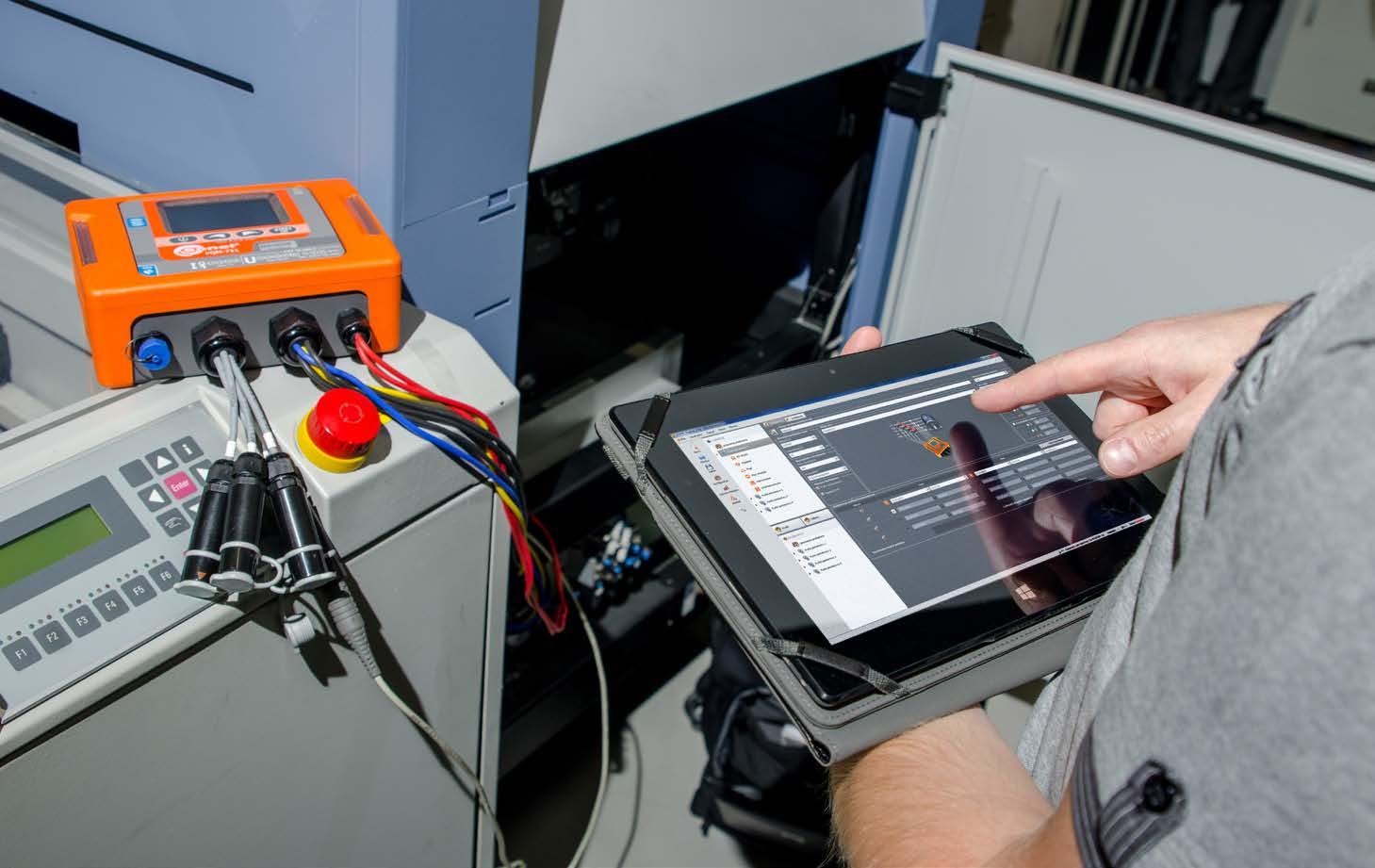
Voltage
Active and reactive power of harmonics depending on configuration (instrument transformers, clamp) depends on minimum current and voltage values
0.1
Measurement of control signals up to 15% Unom at 5.00...3000.00 Hz 4 significant digits
•
Voltage
Voltage DC, 1...50 as for voltagealternatingTrueRMS ±0.05% U nom for m.v. < 1% U nom ±5% m.v. for m.v. ≥ 1% U nom
Frequency 40.00…70.00 Hz 0.01 Hz ±0.01 Hz
Alternating current (TRMS) depending on clamp* 4 significant digits ±0.1% I nom (error does not account for clamp error)
Harmonics and inter-harmonics
transformers, clamp) Active, reactive apparent energy depending on configuration (instrument transformers, clamp) 4
and reactive power Harmonics Voltage DC, 1...50 as for voltagealternatingTrueRMS ±0.15% U nom for m.v. < 3% U nom±5% m.v. for m.v. ≥ 3% U nom Current DC, 1...50 as for currentalternatingTrueRMS ±0.5% I nom for m.v. < 10% I nom±5% m.v. for m.v. ≥10% I nom THD Voltage (relative0.0…100.0%toRMSvalue) 0.1% ±5% Current ±5% Flicker index 0.40…10.00 0.01 ±10% Unbalance factor andVoltagecurrent 0.0…10.0% 0.1% ±0.15% (absolute error) Inrush current Current depending on clamp* 0.01% I nom ±4% m.v. for m.v ≥ 10% I nom ±4% I nom for m.v < 10% I nom (RMS1/2) *F-1A1 F-2A1 F-3A1 clamp: 0…1500 A AC (10 000 Ap-p) • F-1A F-2A F-3A clamp: 0…3000 A AC (10 000 Ap-p) • F-1A6 F-2A6 F-3A6 clamp: 0…6000 A AC (10 000 Ap-p) C-4A clamp: 0…1000 A AC (3600 Ap-p) • C-5A clamp: 0…1000 A AC/DC (3600 Ap-p) • C-6A clamp: 0…10 A AC (36 Ap-p) • C-7A clamp: 0…100 A AC(360 Ap-p) 124
» Frequency within the range of 40 Hz – 70 Hz,

WAPRZLAD230
3x crocodile clip, black, 1 kV, 20 A WAKROBL20K01
» Testing the efficiency of PV inverters,
» Crest factors for current (CFI) and voltage (CFU),
» Active power (P), reactive power (Q), distortion power (D), apparent power (S) with identification of the nature of reactive power (capacitive, inductive),
Test lead 2.2 m, blue, 1 kV (banana plugs) WAPRZ2X2BUBB
±0.5% U nom Crest factor Voltage 1.00…10.00 (≤1.65 for 690 V voltage) 0.01 ±5% Current 1.00…10.00 (≤3.6 Inom) 0.01 ±5% Alternating current TRMS depending on clamp* 0.01% I nom ±0.2% I nom (error
USB cable
4x F-3A flexible coil (Ø120 mm) WACEGF3AOKR
WAPRZ2X2BLBBL1
» Unbalance of voltages (in compliance with IEC 61000-4-30 class S) and currents,
WAPRZLAD12SAM
Supported network configurations:
» Active energy (EP), reactive energy (Eq), apparent energy (ES),
Test lead 2.2 m, black, 1 kV with L1 marker (banana plugs)
Test lead 2.2 m, black, 1 kV with L3 marker (banana plugs) WAPRZ2X2BLBBL3
AZ-2 power supply adapter (IEC C7 plug/ banana connectors) WAADAAZ2
WAPROANALIZA4
Mains cable with IEC C7 plug
Test lead 2.2 m, yellow / green, 1 kV (banana plugs) WAPRZ2X2YEBB
depending
» Currents L1, L2, L3, N (four measurement inputs) - mean, minimum and maximum values, current measurement within the range up to 6 kA (depending on applied current clamp), interoperability with current transformers,
Cable for battery charging from car cigarette lighter socket (12 V)
Factory calibration certificate
Measured parameters:
» Short-term (PST) and long-term (PLT) light flicker index (in compliance with IEC 61000-4-15 class S),
Crocodile clip, yellow, 1 kV, 20 A WAKROYE20K02
Sonel Analysis PC software
WAFUTL4
WAPRZUSB
Magnetic voltage adapter (set - 4 pcs) WAADAUMAGKPL
Hz Active, reactive, apparent and distortion power depending on configuration (instrument transformers, clamp) 4
configuration
» Harmonics up to the 50th in voltage and current,
» Energy cost calculator,
L4 carrying case
2x crocodile clip, red, 1 kV, 20 A WAKRORE20K02
» Event logging for current and voltage along with oscillograms and half-period RMS charts,
as power error cosφ and power factor (PF) 0.00…1.00 0.01
» single-phase, » two-phase with common N, » three-phase - star with and without N conductor, » three-phase - triangle. significant digits does not Hz ±0.05 significant digits on (instrument significant digits ±0.03 of active
» voltages L1, L2, L3, N-PE (five measurement inputs) – mean, minimum and maximum values within the range up to 760 V, interoperability with voltage transformers,
WAZASZ7
AC-16 line splitter
tg φ 0.00…10.00 0.01 depends on error
Test lead 2.2 m, black, 1 kV with L2 marker (banana plugs) WAPRZ2X2BLBBL2
» Inrush current,
Standard accessories:
L2 hanging straps (set)
Crocodile clip, blue, 1 kV, 20 A WAKROBU20K02
Li-Ion battery 11.1 V 3.4 Ah WAAKU15
» sampling frequency: 10.24 kHz,
WAPOZSZEKPL
WAADAAC16
The instrument is intended for operation in networks: » with rated frequency 50/60 Hz, » with rated voltages: 58/100 V, 64/110 V;110/190 V; 115/200 V; 120/208 V, 127/220 V; 133/230 V, 220/380 V; 230/400 V; 240/415 V; 254/440 V; 290/500 V, 400/690 V, » with direct current.
Z7 Power supply
» Power factor (PF), cosφ, tgφ,
account for clamp error) Frequency 40.00…70.00 Hz 0.01
SONEL PQM-707 index: WMGBPQM707 / WMGBPQM707NC (without F-3A coils) Power quality analyzers Parameters of PQM-707 Parameter Measuring range Max. resolution Accuracy Alternating voltage (TRMS) 0.0…760.0 V 4
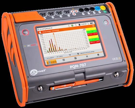
» Power registration: Budeanu method, IEEE 1459,
» All parameters are registered in compliance with class S acc. to standard IEC 61000-4-30.

» Total harmonic distortion THD for current and voltage,
» all parameters are registered in compliance with class S according to standard EN 61000-4-30
Parameters of PQM-700
» IEC 61326 (electromagnetic compatibility - electrical equipment for measurement)
3x crocodile clip, black, 1 kV, 20 A WAKROBL20K01
» unbalance of voltages (in compliance with EN 61000-4-30 class S) and currents,
Harmonics DC, 1...40 for alternating voltage True RMS ±0.15% U nom for m.v. < 3% U ±5% m.v. for m.v. ≥ 3% U DC, 1...40 for alternating current True RMS ±0.5% I nom for A AC (10 000 Ap-p) clamp: 0…6000 A AC (10 000 Ap-p) A AC (3600 Ap-p) 0…1000 A AC/DC (3600 clamp: 0…10 A AC (36 Ap-p) C-7A clamp: 0…100 A AC(360 Ap-p)
4 significant digits ±0.2% I nom(error does not account for clamp error) Hz 0.01 Hz ±0.05 Hz
m.v. < 10% I nom±5% m.v. for m.v. ≥ 10% I nom THD Voltage (relative0.0…100.0%toRMSvalue) 0.1% ±5% Current ±5% Flicker index 0.40…10.00 0.01 ±10% Unbalance factor andVoltagecurrent 0.0…10.0% 0.1% ±0.3% (absolute error) *F-1A1, F-2A1 F-3A1 clamp: 0…1500 A AC (10 000 Ap-p) • F-1A, F-2A F-3A clamp: 0…3000
• IEEE 1459,
index:
L5 carrying case
The device conforms to class S according to IEC 61000-4-30
• Budeanu method,
Max. resolution Accuracy
2x crocodile clip, red, 1 kV, 20 A WAKRORE20K02
4
WMGBPQM700 Power quality analyzer
Factory calibration certificate
» power factor (PF), cosφ, tgφ,
» IEC 61000-4-30 (electromagnetic compatibility - measurement methods)
» IEC 50160 (supply voltage measurements)
cosφ and power factor
» short-term (PST) and long-term (PLT) light flicker index (in compliance with EN 61000-4-15 class S),
reactive, apparent and distortion power
WAADAAZ1
» crest factors for current (CFI) and voltage (CFU),
Alternating voltage (TRMS) 0.0…760.0 V
4x magnetic voltage adapter (set - 4 pcs) WAADAUMAGKPL
125
0.00…1.00 0.01
» harmonics up to the 40th in voltage and current,
» IEC 61010-1 (safety of measuring instruments)
» IEC 61000-4-15 (light flicker)
Measured parameters (EN 50160-4-30, class S):
» currents L1, L2, L3, N (four measurement inputs) - mean, minimum and maximum values, instant values, current measurement within the range up to 6 kA (depending on applied current clamp), interoperability with current transformers,
nom
•
» sampling frequency: 10.24 kHz,
» IEC 61000-4-7 (measurements of harmonics)
C-4A clamp: 0…1000
» voltages L1, L2, L3 (four measurement inputs) – mean, minimum and maximum values, instant values within the range up to 760 V, interoperability with voltage transformers,
2x fasteners and bands for mounting the analyzer on a pole
Sonel Analysis 4 software WAPROANALIZA4
Active, depending on configuration (instrument transformers, clamp) significant digits depending on configuration (instrument transformers, clamp) depending on configuration (instrument transformers, clamp) significant digits as power error (PF) ±0.03 depends on error of active and reactive power
SONEL PQM-700
• C-5A clamp:
» active energy (EP), reactive energy (EQ), apparent energy (ES),
as
WAFUTL5
» event logging for current and voltage along with oscillograms and half-period RMS charts,
Current
USB cable WAPRZUSB
Frequency 40.00…70.00
DIN rail mounting bracket with positioning catches WAPOZUCH3
Ap-p) • C-6A
The instrument is intended for operation in networks:
Alternating current TRMS depending on clamp*
Active, reactive apparent energy
Straps for mounting on the pole for PQM (set) WAPOZOPAKPL
» calculation of reactive power using the:
Voltage
» frequency within the range of 40 Hz – 70 Hz,
PQM-700 has an independent power source, making it particularly suited for measurements with voltage transducers.
WAPOZUCH4
Voltage 1.00…10.00 (≤1.65 for 690 V voltage) 0.01 ±5% 1.00…10.00 (≤3.6 Inom) 0.01 ±5%
Crocodile clip, blue, 1 kV, 20 A WAKROBU20K02
» active power (P), reactive power (Q), distortion power (D), apparent power (S) with identification of the nature of reactive power (capacitive, inductive),
tg φ 0.00…10.00 0.01
» with rated frequency 50/60 Hz, » with rated voltages: 64/110 V; 110/190 V; 115/200 V; 120/208 V; 127/220 V; 220/380 V; 230/400 V; 240/415 V; 254/440 V; 277/480 V, 290/500 V, 400/690 V, » with direct current, » in the following three-phasetwo-phasesingle-phase,configurations:withcommonN,-starwithandwithout N conductor, three-phase - triangle.
4
• F-1A6, F-2A6, F-3A6
Standard accessories:
Crest factor
» total harmonic distortion THD for current and voltage,
4 significant digits ±0.5% U nom
Parameter
as
nom Current
Measuring range
AZ-1 power supply adapter (mains plug/ banana inputs)
Optional accessories for analyzers C-4A C-5A C-6A C-7A F-1A1 / F-1A / F-1A6 F-2A1 / F-2A / F-2A6 F-3A1 / F-3A / F-3A6 WACEGC4AOKR WACEGC5AOKR WACEGC6AOKR WACEGC7AOKR WACEGF1AOKRWACEGF1A1OKRWACEGF1A6OKR WACEGF2AOKRWACEGF2A1OKRWACEGF2A6OKR WACEGF3AOKRWACEGF3A1OKRWACEGF3A6OKR Rated current 1000 A AC 1000 A AC 1400 A DC 10 A AC 100 A AC 1500 / 3000 / 6000 A AC 1500 / 3000 / 6000 A AC 1500 / 3000 / 6000 A AC Frequency 30 Hz…10 kHz DC…5 kHz 40 Hz…10 kHz 40 Hz…1 kHz 40 Hz…10 kHz Max. diameter of measured conductor 52 mm 39 mm 20 mm 24 mm 380 mm 250 mm 140 mm Minimum accuracy ≤0.5% ≤1.5% ≤1% 0,5% 1% Battery power √ Lead length 2.2 m 2.2 m 2.2 m 3 m 2.5 m Measurement category IV 300 V IV 300 V IV 300 V III 300 V IV 600 V Ingress protection IP40 IP67 126
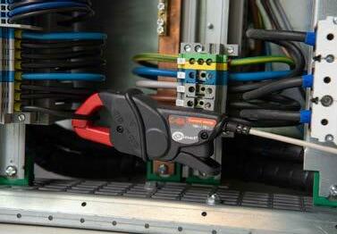

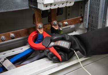
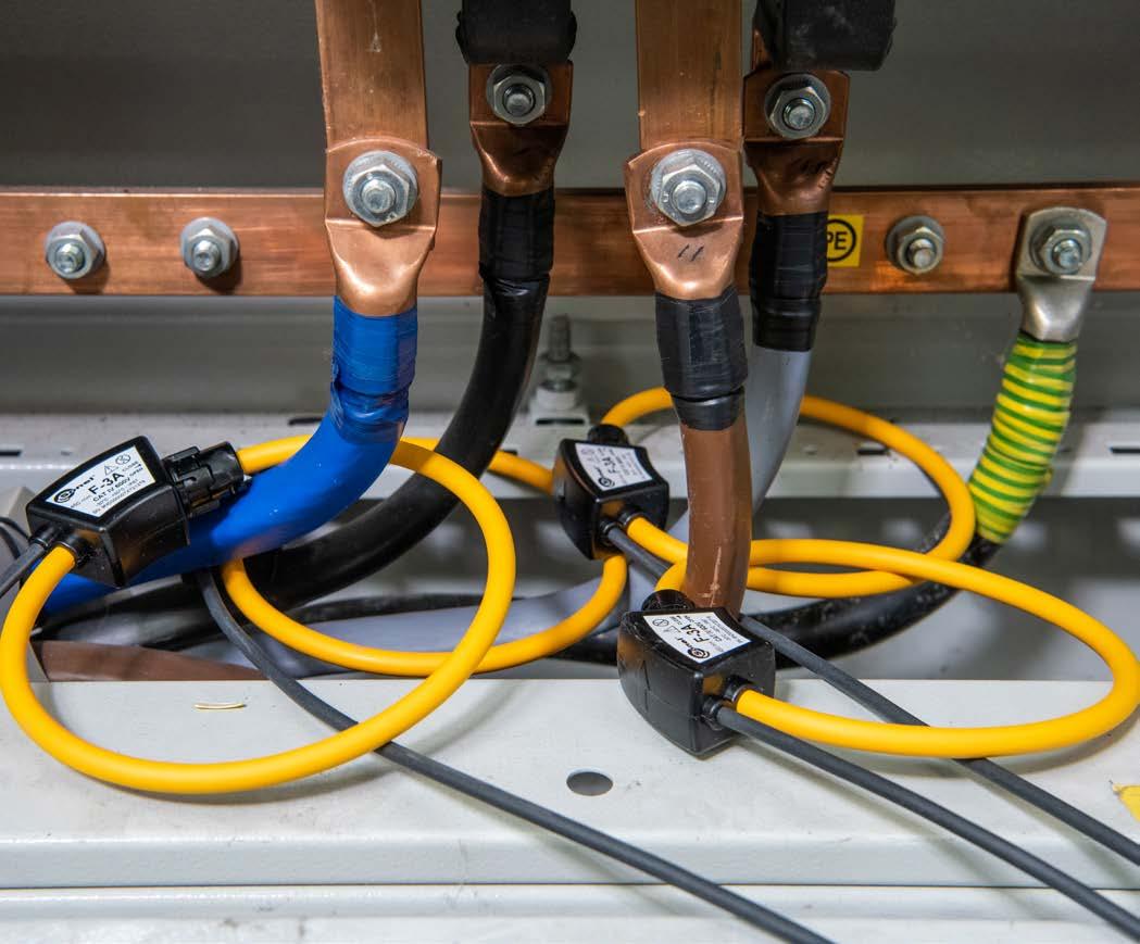


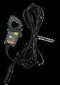
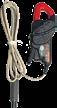


• • • •
AGT-16T adapter (for industrial outlets)

AGT-32T adapter (for industrial outlets)
WAAKU11 1 1 1
• • • •
PQM-707 PQM-700
Magnetic adapter, black
WAADAAZ1 1 1 1
WAADAAC16
AGT-16P adapter (for 3-phase outlets)
WAADAUMAGKBU
WACEGF1A6OKRWACEGF1A1OKR • • • •
Voltage adapter with M4 / M6 thread
PQM
WAADAUMAGKBL
AGT-32P adapter (for 3-phase outlets)
• • • •
• • • •
WAADAAGT32C
WAADAAGT16P
AGT-16C adapter (for 3-phase outlets)
• • • •
AC-16 line splitter adapter 1 1 1 power supply adapter (mains plug / banana sockets)
Magnetic adapter, blue

• • • •
• • • •
Magnetic adapter (4 pcs.)
WAADAPRZKPL1
WAADAAGT16C
WAADAM4M6 1 1
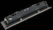
GPS
WAADAAGT16T
• • 4 •
Flexible clamp F-2A (Ø 255 mm) 3 kA
PQM-711
AZ-2 power supply adapter (IEC C7 plug / banana sockets)
Flexible clamp F-1A1 (Ø 380 mm) 1.5 kA F-1A6 (Ø 380 mm) 6 kA
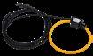

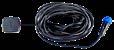


Set of standard and optional accessories 2, 4 - number of standard accessories
1,
WACEGF1AOKR
• - optional accessories 127
AGT-63P adapter (for 3-phase outlets)
• • • •
• • • •
Voltage adapter for energy measuring terminal block (5 pcs)
PQM-710
WAADAAGT63P
WAAKU15
WAPOZANT10GPS • • GSM
WACEGF3AOKR
Li-Ion 3.6 V 4.5 Ah battery (replaceable in the SONEL S.A. service)

Li-Ion 11.1 V 3.4 Ah battery 1 antenna signal repeater
WAADASKA
WACEGF2AOKR
WAADAUMAGKPL 1 1 1 1
Flexible clamp F-3A (Ø 140 mm) 3 kA
AGT-32C adapter (for 3-phase outlets)
• •
WAPOZANTREPEATER • •
Cable adapter for control terminals CAT II / 1000 V (5 pcs.)


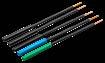
• • • •
WAADAAGT32T
• • • •
WAADAAGT32P
Photo Name Index
• • • •
• AZ-1
WAADAAZ2 1
Flexible clamp F-1A (Ø 380 mm) 3 kA
• • • •
WACEGC4AOKR
WAPRZ2X2YEBB 1
• •
WAFUTL5 1
WAPRZUSB 1 1 1 1
Flat test clip for busbars (5 pcs.)

WACEGC5AOKR
WAPRZ2X2BLBBL2 1
WAPRZ2X2BLBBL1 1
• • •
Crocodile clip, black 1 kV 20 A

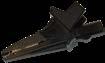
WAPRZ2X2BLBBL3 1
• • •
Flexible clamp F-3A1 (Ø 140 mm) 1.5 kA F-3A6 (Ø 140 mm) 6 kA


Set
WAPRZ2X2BUBB 1
• •
•
PQM-707
•
Pin probe, blue 1 kV (banana socket)
Voltage probe with grasper (5 pcs.)

Flexible clamp F-2A1 (Ø 250 mm) 1.5 kA F-2A6 (Ø 250 mm) 6 kA
WAKROBU20K02 1 1 1 1
WACEGC7AOKR
Lead 2.2 m, black 1 kV with L1 marker (banana plugs)
Crocodile clip, red 1 kV 20 A


L-5 carrying case

• • • •
1, 2, 4 - number of standard accessories - optional accessories
Photo Name Index
Crocodile clip, blue 1 kV 20 A

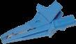
USB data transmission cable
• •
WASONKGB1KPL
Lead 2.2 m, yellow-green 1 kV (banana plugs)
• • • •
Lead 2.2 m, blue 1 kV (banana plugs)

C-5A current clamp (Ø 39 mm) 1000 A AC/DC
Pin probe, black 1 kV (banana socket)


WACEGF3A6OKRWACEGF3A1OKR
Lead 2.2 m, black 1 kV with L2 marker (banana plugs)
• • • •
WAKRORE20K02 2 2 2 2
WASONREOGB1
• •
•
Lead 2.2 m, black 1 kV with L3 marker (banana plugs)
WASONBLOGB1
WAFUTL4 1
•
PQM-700
L-4 carrying case

•
Pin probe, yellow 1 kV (banana socket)
C-4A current clamp (Ø 52 mm) 1000 A AC
PQM-710
C-6A current clamp (Ø 20 mm) 10 A AC
WACEGF2A6OKRWACEGF2A1OKR
WASONBUOGB1
PQM
Pin probe, red 1 kV (banana socket)
•
PQM-711
WAKROYE20K02 1 1 1
WACEGC6AOKR
of standard and optional accessories 128
•
• • • •
WAKROBL20K01 3 3 3 3
WASONYEOGB1
WASONCGB1KPL
Crocodile clip, yellow 1 kV 20 A

C-7A current clamp (Ø 24 mm) 100 A AC
PQM Set of standard and optional accessories Photo Name Index PQM-711 PQM-710 PQM-707 PQM-700 Flat test clip for busbars black WASONBLCGB1 • • • • Flat test clip for busbars blue WASONBUCGB1 • • • • Flat test clip for busbars green WASONGRCGB1 • • • • Voltage probe for internal hex screws M6 with banana socket (5 pcs.) WASONVG6GBKPL • • • • ASX-1 piercing adapter (4 pcs.) WAADAPRZASX1KPL • • • • Hanging straps (type L-2) WAPOZSZEKPL 1 Strap for mounting on the pole (set) WAPOZOPAKPL 1 1 1 DIN rail mounting bracket with positioning catches WAPOZUCH3 1 1 1 Plates for pole mounting WAPOZUCH4 2 2 2 Magnetic holder for mounting the meter (2 pcs.) WAPOZUCH5 • • • Case for hanging with a magnetic strap (universal) WAPOZUCH8 • Hard carrying case for clamps WAWALL2 • • • • XL-2 hard case WAWALXL2 1 1 • XL-12 hard case WAWALXL12 • Cable for battery charging from the car lighter socket 12 V WAPRZLAD12SAM 1 Mains cable 230 V (IEC C7 plug) WAPRZLAD230 1 Z7 power supply adaptor WAZASZ7 1 1, 2, 4 - number of standard accessories • - optional accessories 129
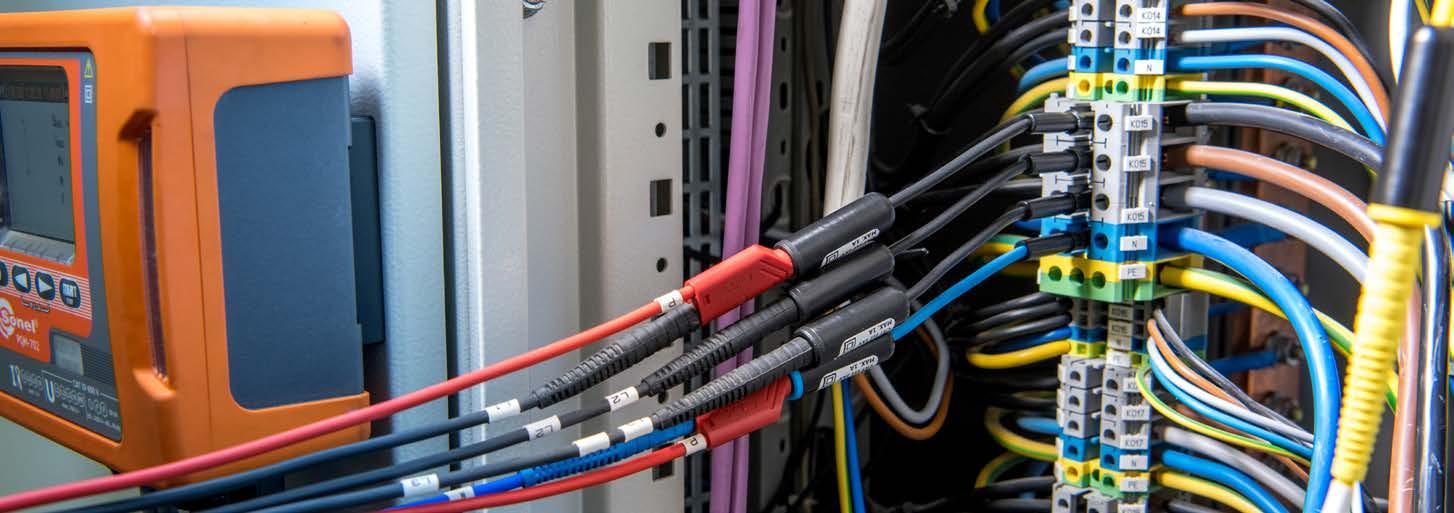


» Events – all types of detected events are displayed in the form of dots (dips, overvoltages, breaks, etc.),
“SONEL Analysis” software - application delivered as standard accessory, indis pensable for working with PQM-series analyzers. It enables:
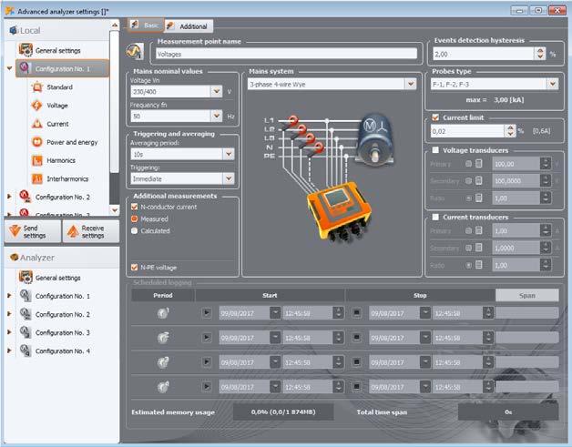
» configurable analyzer time,
» the user may define whether the logger will save instant, mean, maximum or minimum values for each parameter,
» data reading from logger,
Readout of current data
» analyzer firmware updates.
Mobile version of the program cooperating with PQM-711 and PQM-710 from Sonel company. With the application, you can connect directly to your device via the Wi-Fi interface and check of current readings of network param eters to which the analyzer is connected.
» independent support of multiple analyzers,
SONEL ANALYSIS
» PIN code protection against unauthorized access by third parties,

» configurable averaging time,
The application enables configuration of, among other things:
» selection of triggering mode (instant after an event occurs or according to set time schedule),
» charts of voltage and current progression (oscilloscope),
» charts of voltage and current over time,
» selection of measurement points and arbitrary memory assignment to individual measurement points,
The analyzer has four, mutually independent measurement points. Each measure ment point can be configured separately so that four different registrations can be performed later without the need for reprogramming the analyzer in each instance.
Analyzer configuration
The following can be configured for each measurement point:
» phasor diagrams,
» data analysis and generating reports in compliance with standard EN 50160 (reports) and other user defined reference conditions - also for PV microinstallations up to 50 kW, a breakdown for active power states P>0, P<0 and P=0 and taking into account the graphs Q1=f(U1/Un) and cosφ=f(P/Pn),
Sonel Analysis software enables readout of selected parameters and their visualization on the computer screen in real time. These parameters are measured independently from the registration saved on the memory card.
» harmonics and harmonic powers (estimating the direction of harmonics),
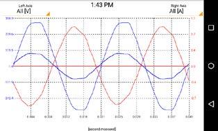
» limits can be defined for most parameters, and the analyzer will log an event if these limits are crossed.
» preview of network parameters in real time (with capability of reading via GSM modem),
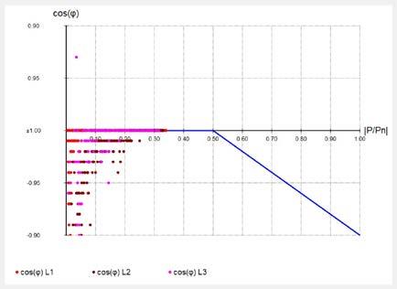
» whether the analyzer is to perform registration in terms of compliance with standard EN 50160 and/or according to user-defined parameters,
» measurements of multiple parameters,
» interharmonics.
SONEL ANALYSIS MOBILE
» analyzer configuration,
The application enables configuration of all analyzer settings. Configuration is per formed on a computer and then sent to the analyzer. A configuration can also be saved on a hard disk or other data carriers for later use.
» selection of current and voltage transformers,
The user can view:
Data analysis
Useful for users can be remotely start/stop recording, and to change the measure ment point (configuration) in the analyzer.
Using the application, the user can read and analyze data saved on the memory card. Read data can also be saved on the computer's hard disk for later processing. Thanks to this, archiving of data from successive registrations is possible.
After data reading, the user can conduct analysis. There are three windows to choose from:
» data presentation in charts,
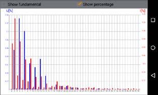
» General – all individual types of data are displayed in the form of dots (Measurements, Events and Oscillograms),
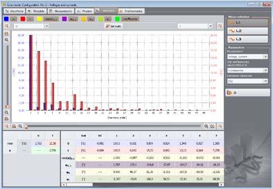
» Measurements – all measurement types registered are displayed in the form of dots according to averaging time (voltage, frequency, etc.),

» selection of the network type for which the analyzer will register all parameters set by the user.
» Configuration – all settings with which data was registered are displayed. Various types of charts are available in the application, enabling the user to view data registered by the analyzer in a simple way:
» deletion of data in the analyzer,
» button blockade,
» Oscillogram – instant progressions of voltages and currents during events or at the end of an averaging cycle,
» Harmonics chart – bar graph presenting the level of harmonics of orders 1…50, » value/Time chart – displays events in the form of dots as a function of the duration of these events.
User-defined reports can be generated using data read from the analyzer, which can then be saved to a hard disk in PDF, HTML, CSV or TXT file format. The appli cation enables generation of a report on compliance with standard EN 50160 and the systems regulation.
» selection of clamp type, selection of additional parameters to be registered in N and PE conductors,
» data presentation in tables,
Software index: WAPROANALIZA4 130
» Time chart – displays the progressions of selected parameters over time,
PAT-2EPAT-10PAT-2PAT-86PAT-85PAT-80 PAT-820 Portable appliance testers
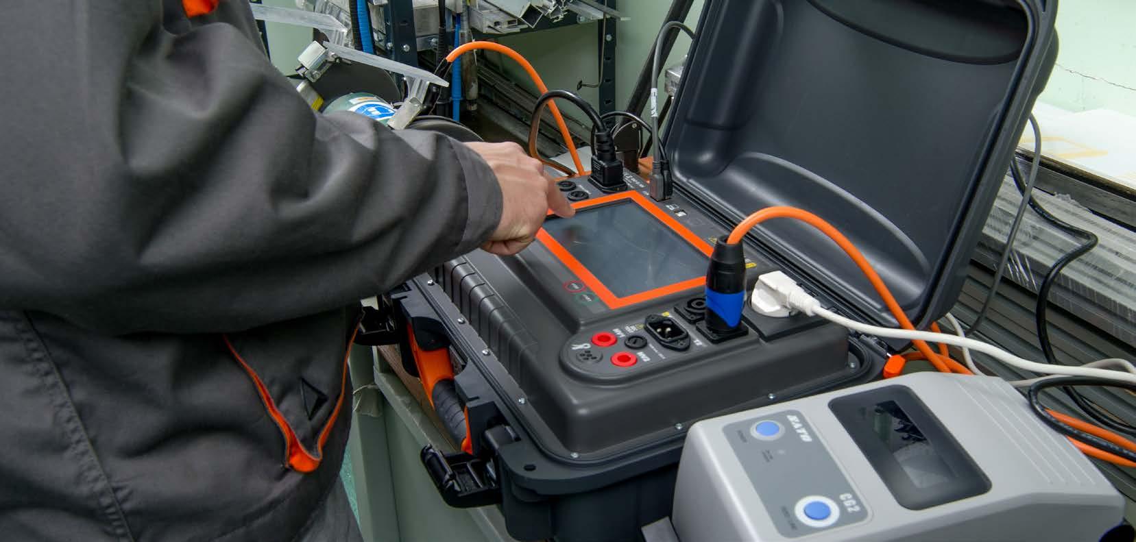
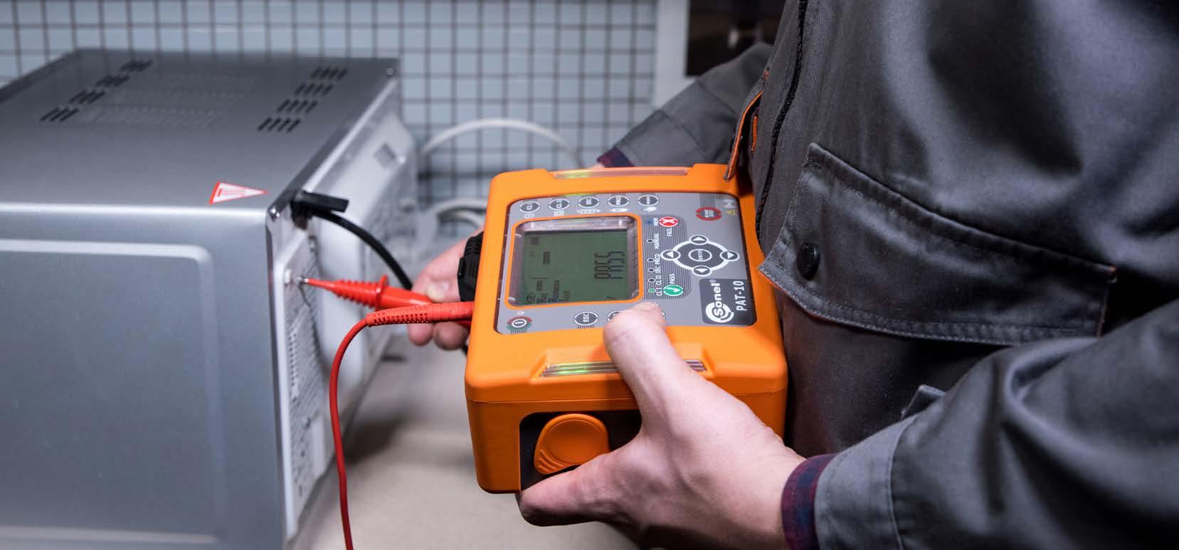

» condition of the housing, » operation of switches, » power cord and mains plug, » mechanical components, » condition of warning and safety elements.
Type tests procedural/tests
Functional test – consists in measuring the parameters of power supply while the tested device is activated. The following parameters are measured/tested: power values, voltage, current, factors of cosφ PF and THD.
» measurement of PE core resistance (continuity),
0751:2001VDEDIN 0701-0702VDEDIN 0751:2001VDEDIN 62353EN 60601IEC 50678:2020EN 0701-0702VDEDIN E-08400:1988 0751:2001VDEDIN standardsBritish 62353EN 60601IEC 60974-4EN 50699EN 60950/50116ENDIN 61010EN 60335/50106ENDIN 60745-1EN 60601IEC
In 2020, CENELEC (European Committee for Electrotechnical Standardization) published EN 50678 standard on the protective measures of electrical equipment after repair and EN 50699 standard on periodic testing. Both standards (EN 50678 and EN 50699) have been implemented as national standards in many countries –e.g. In Germany and Slovakia – whereas other countries are planning to implement theses standards in the near future.
Voltage-generating equipment
The rules and obligations concerning use of various types of electrical equipment, in both private and professional life, are defined by a broad range of regulations, which, besides imposing the obligation of creating products compliant with the rel evant standards on the manufacturer, also impose responsibility for the technical condition of this equipment and tools on their owners. These regulations addition ally define proper performance of regular tests and inspections as well as checks of equipment after repairs. Therefore, it is worth inspecting the technical condition of owned electrical equipment in the proper manner and with the appropriate fre quency. Defective equipment, often damaged without the user’s knowledge, poses a great threat to the user, but it can also be the cause of serious financial loss, e.g. in the event of a fire. In such a case, if it is proven that equipment was not fully op erational (e.g. damaged insulation), the manufacturer’s liability for the incident is transferred to the owner. In addition, this may constitute grounds for the insurer's refusal to pay damages.
Test of IEC cables and extension cords – automatic check of basic parameters of IEC cables and additionally (when a suitable adapter is used) tests on exten sion cords and cables with IEC 60320-C5 plug. The measurement sequence is per formed automatically, and consists of:
» measurement of PE core insulation resistance,
» continuity test of L and N conductors and a check for short circuit between them,
» smooth data management and transfer in real time, » work in a web browser, » work in the task ordering mode, » protection of staff and fleet, » and many more.
PC software Sonel PAT Analysis allows user to read and store data from PAT me ters, including the settings of devices. Basing on measurement data, the device generates test reports and a measurement schedule is kept, whereas a cloudbased solution provides:
Measurement of leakage currents – the ability to measure equivalent leakage current, differential leakage current, touch leakage current and PE leakage current. The device should provide testing in a wide frequency band.
Equipment tested in compliance with standards
Insulation resistance measurement – typically required measuring voltage is 500 V DC, but some of the equipment (especially IT) requires a reduced voltage of 250 V or even 100 V. In contrast, industrial machinery and equipment may be tested in some cases with a higher voltage – up to 1000 V.
Equipment with electrical drive Lighting lamps Multimedia devicestelecommunicationsand Cable reels, extension cords, connector cables Data processing devices and office appliances Electrical equipment for componentsapplications,medical of applications Welding equipment
Every tester who uses a safety meter for electrical equipment assumes great re sponsibility for the both the health and life of users, as well as for their property, when making the decision on whether or not to approve tested equipment for use. Such a person should have a professional meter at their disposal, guaranteeing high accuracy and correct results.
Testsrepairafter
» automatic mode – with configuration of custom measurement sequences of parameters selected by the user, » manual mode l – due to the diversity of tests and standards for different equipment.
Laboratory instruments instrumentsandMeasuringinspection
After setting the measurement duration, programming limit values and completing the measurement, the meter is able to assess the condition of the tested device. With the option of creating measurement sequences, the meter may automatically perform measurements and asses the test results (a positive/negative).
Electric tools
Heating equipment
Preliminary test (visual) – the meter checks the continuity of L-N conductor and then it shows on the screen the moment when the (visual) inspection the device should take place. Then the tested object should be checked for:
» polarity check.
Measurement of protective conductor (PE) resistance – it is carried out with 200 mA current, 10 A or 25 A depending on the requirements and regulations. Re sistance of the measurement cable must not affect the measurement result, there fore autozeroing should be performed on the wire measurement cable using the four-wire method.
A very important safety element is the documentation and records of tested de vices. The system of QR codes that may be printed immediately after the meas urements, helps in keeping the records. Data stored in the code, by referring to the device and performed test, will accelerate the operational tests and facilitate the maintenance work.
Periodical tests
Safety equipmentof electrical
andstart-upFirstmodi fications
132
The functions and technical specifications of testers for electrical equipment should allow for complete inspection of the technical condition of electrical equip ment and tools, including checks of basic parameters of three-phase equipment. In addition, to ensure the user’s work safety and proper measurement results, in struments should be capable of measuring the parameters of the power network (i.e. voltage, frequency, continuity resistance and voltage on protective conductor) immediately after start-up. The capability of performing tests is very useful con sidering:
MEASUREMENTS OF WELDING APPLIANCES
•
• • • • • • •
• • •
• • • •
•
•
• • • •
• • • • • • •
• • •
PAT-820
• •
• • • • • • •
• • • • • •
function of automatic measurement of RCD and PRCD parameters
in mobile application in mobile application in mobile application operation in Sonel QR system
• • •
• • • • • •
measurement of resistance of protective conductor (PE) using test current of 200 mA measurement of resistance of protective conductor (PE) using test current of 10 A measurement of resistance of protective conductor (PE) using test current of 25 A measurement of insulation resistance using test voltage of 100 V measurement of insulation resistance using test voltage of 250 V measurement of insulation resistance using test voltage of 500 V measurement of insulation resistance using test voltage of 1000 V measurement of substitute leakage current measurement of PE leakage current measurement of differential leakage current measurement of touch leakage current power test test of IEC power cord checking the resistance of L-N circuit measurement of voltage and frequency in networks measurement of current consumption autoranging autotests autotests with the option of describing them with the name of the standards or name set by user
• • •
• • • • • •
• • • •
• • • •
• • • • • • •
• • •
measurement of rated voltage of welding appliances in unloaded state measurement of leakage current of welding circuit IL measurement of primary leakage current IP automatic three-lead insulation resistance measurement
• • • • • • •
• • •
•
MEMORY
internal memory cooperation with USB memory stick saving to memory along with initial description of examined appliances, location of measurements and data of client, assigning serial number and index to the measured appliance, capability of adding notes to the tested appliance, damage description
• • • • • • •
• • • •
• • • • • • •
• • • •
• • • •
• • • • • • •
• • • •
• • • •
• • • • • • •
RCD PRCD PRCD measurement of current using clamps high voltage insulation test (flash test) SELV/PELV measurement


• • • •
• • • • • • •
• • • • • •
•
• • •
• • • •
operating of QWERTY keyboard on a big and readable touchscreen with backlit possibility of adding several PAT users with the option of logging in help available on the screen - containing instructions on how to connect the tested appliance and perform the measurement cooperation with barcode scanner cooperation with printer operation using internal battery
• • • • • • 133
• • • • • • •
• • • • • • •
• • • • • • •
USABLE FUNCTIONS
• • • •
COMMUNICATION WITH COMPUTER communication with computer via USB cooperation with software: Sonel Reader and Sonel PAT Analysis (optional) configuration of measurements and meter settings using computer and the meter's interface Wi-Fi Bluetooth LAN
MEASUREMENT FUNCTIONS
PAT-86 PAT-85 PAT-80 PAT-10 PAT-2E PAT-2

Resistance measurement of protective earth conductor I=10 A (protection class I)
Display range Resolution Accuracy 0.00…2.5 mA 0.01 mA ±(5% m.v. + 5 digits)
MΩ »
» measurement of equivalent leakage current,
» measurement time: configurable within the range of: 2…180 s Measurement of insulation resistance
» technical method of measurement ensuring high accuracy of obtained results
» resistance measurement of protective conductor with current: 200 mA, 10 A and 25 A (protection class I),
» humidity 20…80%
Factory calibration certificate
0…999 mΩ 1 mΩ ±(3% m.v. + 4 digits)1.00…1.99 Ω 0.01 Ω
» meter weight approx. 5.7 kg
» automatic selection of measuring range, » professional software for data processing and report generation, » supports barcode reader and printer, » supports USB flash drive storage devices, » large, easy-to-read touch display, » ergonomic operation.
» measurement of touch leakage current,
» type of insulation CAT II 300 V according to EN 61010-1

Basic functions of the tester:
» measurement current: ≥10 A for R ≤ 0.5 Ω
Resistance measurement of protective earth conductor I=25 A (protection class I)
Un=100
» measurement of electricity consumption, » IEC cable test,

index:
Mains cable with IEC C19 plug WAPRZZAS1
U n displayed Display range Resolution Accuracy 100 V 0…1999 kΩ 1 kΩ ±(5%
» this product meets EMC requirements in compliance with standard EN 61326-1 and EN 61326-2-2

» configurable measurement time 1…60 s with resolution of 1 s
» measurement of differential leakage current,

SONEL PAT-820
Flash test / high-voltage test
» measurement voltage: 1500 V AC, 3000 V AC
»
Measuring range according to IEC 61557-2 for: V: 100 kΩ…99.9 MΩ V: 250 kΩ…199.9 MΩ V: 500 kΩ…599.9 MΩ m.v. +8 digits) 0.1 automatic discharge of the measured object's capacitance upon completion of measurement protection against measurement of live objects max. output current 1.4 mA
WMGBPAT820 Safety tester for electrical equipment 134
»
» measurement current: ≥200 mA for R<0.2…1.99 Ω
Un=250
» power measurement,
Un=500
Display range Resolution Accuracy
USB cable WAPRZUSB
» insulation resistance measurement - three measurement voltages: 100 V, 250 V, 500 V,
Nominal operating conditions:
» operating temperature range -10…+50°C
» load current max. 16 A (230 V)
Fuse 0314 015.VXP 15 A 250 V AC 6.3 x 32 mm Littlefuse (2 pcs.) WAPOZB15PAT
» current measurement with clamp, » flash test / high-voltage test.

Electrical safety:
Other technical specifications:
» elevation above sea level <2000 m
» technical method of measurement ensuring high accuracy of obtained results
» display LCD TFT 7’’ 800 x 480
» data transmission to PC computer USB 2.0 cable
» storage temperature -20…+70°C
195…265 V, 50 Hz
Display range Resolution Accuracy
Resistance measurement of protective earth conductor I=200 mA (protection class I)
» measurement current: ≥25 A for R ≤ 0.2 Ω
» configurable upper limit within the range: 10 mΩ …1.99 Ω with resolution of 0.01 Ω
Display range Resolution Accuracy
» power supply of the meter
0…999 mΩ 1 mΩ ±(3% m.v. + 4 digits)1.00…1.99 Ω 0.01 Ω
Additional features:
2x test lead 1.8 m, red, 5 kV (banana plugs) WAPRZ1X8REBB Test lead 1.8 m, orange, (10 A / 25 A, terminated in a crocodile clip) WAPRZ1X8ORKS
2.0…19.99 MΩ 0.01 MΩ 20.0…99.9 MΩ 0.1 MΩ 250 V 0…1999 kΩ 1 kΩ 2.00…19.99 MΩ 0.01 MΩ 20.0…199.9 MΩ 0.1 MΩ 500 V 0…1999 kΩ 1 kΩ 2…19.99 MΩ 0.01 MΩ 20.0…599.9 MΩ
Standard accessories:
» dimensions 390 x 308 x 172 mm
2x pin probe, red 5 kV (banana socket) WASONREOGB2
0.00…0.99 Ω 0.01 Ω ±(4% m.v. + 2 digits) 1.00…19.99 Ω ±(4% m.v. + 3 digits)
» measurement of network voltage and frequency, » testing of RCD parameters,
» housing protection rating according to EN 60529 IP40 (IP67 when case is closed)
Measurement of PE leakage current and differential leakage current Display range Resolution Accuracy 0.00…3.99 mA 0.01 mA ±(5% m.v. + 2 digits)4.0…19.9 mA 0.1 mA
*for RCD of IΔn = 10 mA and the measurement 0.5 IΔn error: ± (2% m.v. + 3 digits)
» EN 60950 Safety of information technology equipment.
0.00…3.99 mA 0.01 mA ±(5% m.v. + 2 digits)4.0…19.9 mA 0.1 mA
n
Active power measurement Display range Resolution Accuracy 0…999 W 1 VA ±(5% m.v. + 3 digits)1.00…3.99 kW 0.01 kW
» configurable measurement time: continuous measurement (Cont) or 1…60s with resolution of 1 s
Measurement of touch leakage current Display range Resolution Accuracy
» EN 61029 Safety of transportable motor-operated electric tools. General requirements.
» EN 60335-1 Household and similar electrical appliances. Safety. General requirements.
of the input leakage current » max. measurement current flow time 3200 ms
Display range Resolution Accuracy 0…999 VA 1 VA ±(5% m.v. + 3 digits)1…3.99 kVA 0.01 kVA
Display range Resolution Accuracy 0.00…1.00 0.01 ±(10% m.v. + 5 digits)
RCD trip test and measurement of tripping time tA
RCD type Factor Range Resolution Accuracy General 0.5 IΔn 0…300 ms 1 ms ±(2% m.v. + 2 digits)* 1 IΔn 2 IΔn 0…150 ms 5 IΔn 0…40 ms
» measurement can be started from a positive or negative half-period
» VDE 0701-0702 Prüfung nach Instandsetzung, Änderung elektrischer Geräte. Wiederholungsprüfung elektrischer Geräte. Allgemeine Anforderungen für die elektrische Sicherheit.
The instruments enable measurements in compliance with:
Power factor PF
Apparent power measurement
» configurable measurement time: continuous measurement (Cont) or 1…60 s with resolution of 1 s
Current measurement with clamp during power measurement
Testing of RCD parameters
» AS/NZS 3760:2010 In-service safety inspection and testing of electrical equipment.
» EN 60745-1 Hand-held motor-operated electric tools. Safety. Part 1: General requirements.
n
» configurable measurement limit within the range: 0.01…19.9 mA with resolution 0.01mA/0.1 mA
» configurable measurement limit within the range: 0.01…19.9 mA with resolution 0.01 mA/0.1 mA
Δn
Measurement of RCD trip current IA for sinusoidal residual current Measuring range according to IEC 61557: (0.3…1.0)I
» configurable measurement time: continuous measurement (Cont) or 1…60 s with resolution of 1 s
Display range Resolution Accuracy
0.1
Display range Resolution Accuracy 0.00…15.99 A 0.01 A ±(2% m.v. + 3 digits)
» VDE 0404-2 Prüf- und Messeinrichtungen zum Prüfen der elektrischen Sicherheit von elektrischen Geräten. Teil 2: Prüfeinrichtungen für Prüfungen nach Instandsetzung, Änderung oder für Wiederholungsprüfungen.
Nominal current Measuring range Resolution Accuracy 10 mA 3.0…10.0 mA mA 0.3 IΔ …1.0 IΔn ±5% IΔ15 mA 4.5…15.0 mA 30 mA 9.0…30.0 mA
» configurable measurement limit within the range: 0.01…1.99 mA with resolution of 0.01 mA
Display range Resolution Accuracy 100…999 mA 1 mA ±(5% m.v. + 5 digits)1.00…9.99 A 0.01 A 10.0…24.9 A 0.1 A
Measurementcurrent
» at half of the measurement time, the meter automatically changes the polarity of the measuring network socket and displays a greater value
» configurable measurement time: continuous measurement (Cont) or 1…60 s with resolution of 1 s
» configurable measurement time: continuous measurement (Cont) or 1…60 s with resolution of 1 s
» open-circuit voltage: 25…50 V
Measurement of equivalent leakage current
0.000…4.999 mA 0.001 mA ±(5% m.v. + 3 digits)
Current measurement during power measurement
» The accuracy given in the table does not account for the accuracy of the measuring clamp
» EN 61557-6 Electrical safety in low voltage distribution systems up to 1000 V a.c. and 1500 V d.c. - Equipment for testing, measuring or monitoring of protective measures - Part 6: Effectiveness of residual current devices (RCD) in TT, TN and IT systems.

» VDE 0404-1 Prüf- und Messeinrichtungen zum Prüfen der elektrischen Sicherheit von elektrischen Geräten. Teil 1: Allgemeine Anforderungen.
135
Basic functions of the tester:
Resistance measurement of protective earth conductor I=200 mA (protection class I)
» meter weight approx. 5 kg
» housing protection rating according to EN 60529 IP40
» storage temperature -20…+70°C
» measurement current: ≥10 A for R ≤ 0.5 Ω
» measurement of differential leakage current,

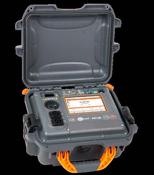
» current measurement with clamp.
Other technical specifications:
SONEL PAT-86 / PAT-85 / PAT-80 index: WMGBPAT86 / WMGBPAT85 / WMGBPAT80 Safety testers for electrical equipment 136
WAPRZ1X5DZBB
» IEC cable test,
PAT-86 | Safety measurements of welding equipment
» this product meets EMC requirements in compliance with standard EN 61326-1 and EN 61326-2-2
Display range Resolution Accuracy 0.00...0.99 Ω 0.01 Ω ±(4% w.m. + 2 digits) 1.00...19.99 Ω ±(4% w.m. + 3 digits)
» battery operation up to 1 hour.

» operating temperature range -10…+50°C
» automatic measurement procedures,
• PAT-80 | 200 mA,
» remote measurement enabling ordering the measurement sequence via computer and re-sending the result,

» humidity 20…80%
» measurement meets the requirements of EN 60974-4
» voltage root mean square URMS measurement
» voltage peak value UPEAK measurement
USB cable WAPRZUSB Mains cable with IEC C19 plug WAPRZZAS1 L-11 carrying case WAFUTL11 Factory calibration certificate
» measurement of electricity consumption,
» PAT-86 | safety measurements of welding equipment
» type of insulation CAT II 300 V according to EN 61010-1
Electrical safety:
» data transmission to PC computer Wi-Fi, LAN, USB
Display range Resolution Accuracy 0.00...14.99 mA 0.01 mA ±(5% w.m. + 5 digits)
Measurement of welding circuit voltage in a no-load state U0 Display range Resolution Accuracy 5.0...240.0 V 0.1 V ±(2.5% w.m. + 5 digits)
• PAT-80 | 250 V, 500 V,
Test lead 1.8 m, orange (10 A / 25 A, terminated in a crocodile clip)
» technical method of measurement ensuring high accuracy of obtained results
Measurement of primary circuit leakage current IP
» elevation above sea level <2000 m
» supports barcode reader and printer,
» display LCD TFT 5.6’’ 800 x 480
Standard accessories: Fuse 16 A, 250 V AC, 5 x 20 mm (2 pcs.) WAPOZB16PAT Crocodile clip, red, 1 kV, 20 A (only PAT-86) WAKRORE20K02 Crocodile clip, blue, 1 kV, 20 A (only PAT-86) WAKROBU20K02
» load current max. 16 A (230 V)
» testing of RCD / PRCD parameters,
Nominal operating conditions:
» measurement current: ≥25 A for R ≤ 0.2 Ω
Resistance measurement of protective earth conductor I=25 A (protection class I)
» resistance measurement of protective conductor (protection class I) with current:
» measurement of equivalent leakage current,
» professional software for data processing and report generation,


» measurement meets the requirements of EN 60974-4
» dimensions 318 x 257 x 152 mm
» supports USB flash drive storage devices, » ergonomic operation,
» insulation resistance measurement - four measurement voltages:
» technical method of measurement ensuring high accuracy of obtained results
Measurement of welding circuit leakage current IL Display range Resolution Accuracy 0.00...14.99 mA 0.01 mA ±(5% w.m. + 2 digits)
Display range Resolution Accuracy 0...999 mΩ 1 mΩ ±(3% w.m. + 4 digits)1.00...1.99 Ω 0.01 Ω
• PAT-85 • PAT-86 | 100 V, 250 V, 500 V, 1000 V,
network: 195...265 V, 50 Hz battery: 7.2 V 2 Ah
• PAT-85 • PAT-86 | 200 mA, 10 A, 25 A,
» power measurement,
» measurement of touch leakage current,
Additional features:
» measurement current: ≥200 mA for R = 0.2...1.99 Ω
Resistance measurement of protective earth conductor I=10 A (protection class I)
WAPRZ1X8ORKS Double-wire test lead 1.5 m (PAT/banana plug) (only PAT-86)
» power supply of the meter
» measurement of network voltage and frequency,
Display range Resolution Accuracy 0...999 mΩ 1 mΩ ±(3% w.m. + 4 digits)1.00...1.99 Ω 0.01 Ω
U n displayed Display range Resolution Accuracy
250 V 0...1999 kΩ 1 kΩ 2.00...19.99 MΩ 0.01 MΩ 20.0...199.9 MΩ 0.1 MΩ
Voltage measurement Display range Resolution Accuracy 195.0...265.0 V 0.1 V ±(2% w.m. + 2 digits)
Current measurement
Current measurement with clamp
» EN 60335-1 Household and similar electrical appliances. Safety. General requirements.
» VDE 0404-2 Prüf- und Messeinrichtungen zum Prüfen der elektrischen Sicherheit von elektrischen Geräten. Teil 2: Prüfeinrichtungen für Prüfungen nach Instandsetzung, Änderung oder für Wiederholungsprüfungen.
» max. output current 1.4 mA
» EN 60745-1 Hand-held motor-operated electric tools. Safety. Part 1: General requirements.
» EN 61557-6 Electrical safety in low voltage distribution systems up to 1000 V a.c. and 1500 V d.c. - Equipment for testing, measuring or monitoring of protective measures - Part 6: Effectiveness of residual current devices (RCD) in TT, TN and IT systems.
Measurement of leakage current PE leakage current and differential leakage current
500 V 0...1999 kΩ 1 kΩ 2.00...19.99 MΩ 0.01 MΩ 20.0...599.9 MΩ 0.1 MΩ
» at half of the measurement time, the meter automatically changes the polarity of the measuring network socket and displays a greater value
Measurement of insulation resistance
Display range Resolution Accuracy 0.000...4.999 mA 0.001 mA ±(5% w.m. + 3 digits)
RCD type Factor Range Resolution Accuracy General 0.5 IΔn 0...300 ms 1 ms ±(2% w.m. + 2 digits)* 1 IΔn 2 IΔn 0...150 ms 5 IΔn 0...40 ms
The instruments enable measurements in compliance with:
» protection against measurement of live objects
*for RCD of IΔn = 10 mA and the measurement 0.5 IΔn error: ± (2% m.v. + 3 digits)
Display range Resolution Accuracy 0...999 VA 1 VA ±(5% w.m. + 3 digits)1...3.99 kVA 0.01 kVA
Testing of RCD / PRCD parameters
±(5% w.m. +8 digits) 2.00...19.99 MΩ 0.01 MΩ 20.0...99.9 MΩ 0.1 MΩ
Display range Resolution Accuracy 100 mA...999 mA 1 mA ±(5% w.m. + 5 digits)1.00 A...9.99 A 0.01 A 10.0 A...24.9 A 0.1 A
Equivalent leakage current
0...1999 kΩ 1 kΩ
Display range Resolution Accuracy 0.00...1.00 0.01 ±(10% w.m. + 5 digits)
Touch leakage current
THD of voltage and current Display range Resolution Accuracy 0.0...99.9% 0.1% ±(5% w.m. + 5 digits)
» EN 61029 Safety of transportable motor-operated electric tools. General requirements.
Reactive power Q measurement Display range Resolution Accuracy 0...999 Var 1 Var ±(5% w.m. + 3 digits)1.00 k...3.99 kvar 0.01 kvar
» The accuracy given in the table does not account for the accuracy of the measuring clamp
RCD trip test and measurement of tripping time tA
» VDE 0404-1 Prüf- und Messeinrichtungen zum Prüfen der elektrischen Sicherheit von elektrischen Geräten. Teil 1: Allgemeine Anforderungen.
» VDE 0701-0702 Prüfung nach Instandsetzung, Änderung elektrischer Geräte. Wiederholungsprüfung elektrischer Geräte. Allgemeine Anforderungen für die elektrische Sicherheit.
» AS/NZS 3760:2010 In-service safety inspection and testing of electrical equipment.
Active power P measurement Display range Resolution Accuracy 0...999 W 1 W ±(5% w.m. + 3 digits)1.00 k...3.99 kW 0.01 kW
Display range Resolution Accuracy 0.00...3.99 mA 0.01 mA ±(5% w.m. + 2 digits)4.0...19.9 mA 0.1 mA
Display range Resolution Accuracy 0.00...3.99 mA 0.01 mA ±(5% w.m. + 2 digits)4.0...19.9 mA 0.1 mA
» EN 60950 Safety of information technology equipment.
Un=250 V: 250 kΩ...199.9 MΩ
5% IΔn 15 mA 4.5...15.0 mA 30 mA 9.0...30.0 mA » measurement can be started from a positive or negative half-period of the input leakage current » max. measurement current flow time 3200 ms
100 V
137
Measuring range according to IEC 61557-2 for:
Power Apparenttestpower S measurement
» automatic discharge of the measured object's capacitance upon completion of measurement
PF power factor
Cosφ factor Display range Resolution Accuracy 0.00i...1.00i 0.01 ±(5% w.m. + 5 digits)0.00c...1.00c
Un=100 V: 100 kΩ...99.9 MΩ (only PAT-85, PAT-86)
Display range Resolution Accuracy 0.00..15.99 A 0.01 A ±(2% w.m. + 3 digits)
Un=500 V: 500 kΩ...599.9 MΩ
1000 V 0...1999 kΩ 1 kΩ 2.00...19.99 MΩ 0.01 MΩ 20.0...599.9 MΩ 0.1 MΩ
» open-circuit voltage: 25…50 V
Measurement of RCD trip current IA for sinusoidal residual current Measuring range according to IEC 61557: (0.3…1.0)IΔn
Nominal current Measuring range Resolution Measurementcurrent Accuracy 10 mA 3.0...10.0 mA 0.1 mA 0.3 IΔn ...1.0 IΔn ±
Un=1000 V: 1 MΩ...599.9 MΩ
Basic functions of the PAT-10 instrument
Features
» cooperation with the Sonel PAT Analysis Mobile application.
» measurement of equivalent, differential and touch leakage current, » IEC cable test,
A 0.01…1.99 Ω
Insulation resistance =
» measurement of insulation resistance.
measurement U
WAPRZ1X2REBK
» EN 60745 - 1: Hand-held motor-operated electric tools. Safety. Part 1: General requirements.
The instrument can be used for tests of equipment, including tests compliant with standards:
All meters in this series additionally enable performance of basic measurements without an external power source, in emergency situations where there is no network power, simplified test sets can be initiatied in battery operating mode.

» EN 60335 - 1: Household and similar electrical appliances. General requirements.
leakage current 0.10…19.9 mA 0.10…19.9 mA IEC
Small overall dimensions, light weight and a specially designed carrying case for the meter and accessories provide convenience of use and high mobility of the instrument. Wireless communication with a printer allows for organization of the location where measurements are performed without a tangle of unnecessary cables. Saving of results to memory and inte gration of results in PC software additionally broaden the instrument's functionality.
» EN 60950: Safety of information technology equipment.
220 V; 230 V; 240 V 50/60 Hz Built-in rechargeable battery Built-in rechargeable battery (measurements can be performed during charging) Measurement category CAT II 300V √ √ √ Weight approx. 1.40 kg approx. 1.40 kg approx. 1.40 kg Dimensions 200 x 180 x 77 mm 200 x 180 x 77 mm 200 x 180 x 77 mm 138
0.01…19.9 mA 0.01…19.9 mA
WAFUTM12
WAPOZB16PAT M12 carrying case
WAPRZUSB Mains cable with IEC C19 plug
Complete set of tests performed after just one press of the START button. The meter's con figuration capabilities allow for modification of the method of the instrument’s operation, which makes it even better adapted to the user's needs. In situations where it is necessary to perform unit measurements without the need to perform the entire, complex measurement procedure, PATs from Sonel enable operation in single measurement mode (of a given type - so-called manual measurements).
» saving of results to memory,
Innovative combination of small overall dimensions (and the transportability of the device related to this) with advanced measurement systems allowing for complete performance of automatic measurements for electrical devices as well as IEC cables and extension cords (including those with PRCD).
SONEL PAT-10 / PAT-2E / PAT-2 index: WMGBPAT10 / WMGBPAT2E / WMGBPAT2 Safety testers for electrical equipment Model PAT-10 PAT-2E PAT-2 Visual assessment √ √ √ Resistance measurement of protective earth conductor I = 200 mA 0.01…19.99 Ω 0.01…19.99 Ω 0.01…19.99 Ω Resistance
Measurement of substitute leakage current 0.01…19.9 of touch leakage
test (Riso, Rpe, polarity) √ √ √ PRCD test
printer √ √ √ Meter configuration from computer √ √ √ Power supply Network
Fuse 16 A, 250 V AC, 5 x 20 mm (2 pcs.) (only PAT-10, PAT-2E)
» resistance measurement of protective conductor with current: 200 mA, 10 A.
mA Measurement
I =
current 0.001…4.999 mA 0.001…4.999 mA
250 V 0.25…99.9 MΩ 0.25…99.9 MΩ Insulation resistance measurement U = 500 V 0.50…99.9 MΩ 0.50…99.9 MΩ 0.50…99.9 MΩ
for IΔn: x1/x5; 0° and 180°) 10 mA, 30 mA 10 mA, 30 mA Built-in memory for results / transmission to computer √ √ √ Wi-Fi √ √ √ Compatible
battery Network power
» quick access to measurement procedures, » compact housing, ergonomic carrying case, » automatic selection of measuring ranges,
Measurement of differential cable (tripping time with power supply: rechargeable supply:
» compatibility with Sonel Reader and Sonel PAT Analysis software (optional),

» EN 61557-6 Electrical safety in low voltage distribution systems up to 1000 V a.c. and 1500 V d.c. - Equipment for testing, measuring or monitoring of protective measures - Part 6: Effectiveness of residual current devices (RCD) in TT, TN and IT systems.
» diode indicating result assessment,
» VDE 0701-0702 Prüfung nach Instandsetzung, Änderung elektrischer Geräte. Wiederholungsprüfung elektrischer Geräte. Allgemeine Anforderungen für die elektrische Sicherheit. measurement of protective earth conductor 10
Test lead 1.2 m, red, 1 kV (terminated in a crocodile clip)
WAPRZZAS1 Factory calibration certificate
» measurement of PRCD trip time.
220 V; 230 V; 240 V 50/60 Hz Built-in
USB cable
Standard accessories
» EN 61029: Safety of transportable motor-operated electric tools. General requirements.
SONEL PAT ANALYSIS
» Recommended resolution: 1920x1080
» Operating system: Windows 10
index: WAPROSONPAT3
Software SONEL PAT ANALYSIS MOBILE


» Perfect for production plants, electrical tool rental services, repair and maintenance services, etc.
» Hierarchical data entry structure - a device is assigned to a specific company or department.
» connects wirelessly to the selected tester
VDE 0701:1, VDE 0701:200, VDE 0701:240, VDE 0701:260, DIN VDE 0702, EN 61010, EN 60335, EN 60950, IEC 60601, EN62353
The mobile application extends the capabilities of Sonel PAT-10, PAT-2E, PAT-2 testers series. Sonel PAT Mobile is available on Android system.
» Capability of creating a custom measurement standard using the report editor.
» Label printing on standard adhesive papers.
» downloads measurement results,
Available report forms:
» test history for device - all measurement results are printed according to defined criteria (from a given period),
» Capability of scheduling measurements - every device contains a “Measurement cycle” list - the application automatically displays devices whose testing deadline is approaching or has expired.
Report printing according to the following standards:
System requirements:
This software is intended for companies that perform safety measurements of electrical Applicationsequipment.arecompatible with Sonel PAT-series testers. Data saved by the meter is entered into the test report for the selected item of equipment.
» full report on one test - on an A4 page, with complete data about the device and a complete series of tests,
» ensures full compatibility with the Sonel QR code system and the object-oriented memory structure
» Capability of advanced meter configuration via software.
139
Sonel PAT Analysis Mobile:
» Capability of gathering information about a given piece of equipment.
» Minimum resolution: 1024x768
» It enables remote sending a measurement procedure to the PAT-8x meter.
» sends data via internet.
» information about the device and information on approval for use.
» prints reports,
» abbreviated report/record sheet - prints the test history with basic
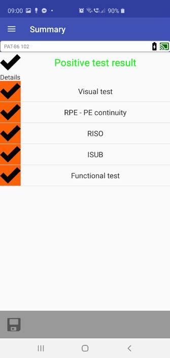
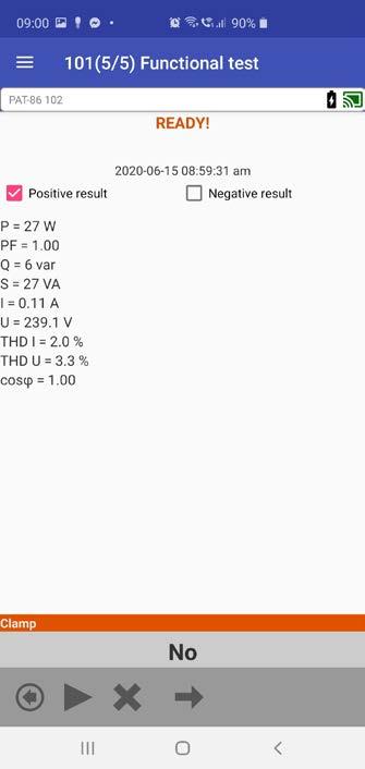
» saves results to PAT structure (client, appliances and measurement data),
» reads QR codes of the PAT system,
In addition, the application allows you to read QR codes, analogously to the PAT-820 testers.
» Tracking the test history of a device.
RISORPER
RISO
After
EPRESIUBIP
The user receives a list of devices with guidelines, and then disconnects from the Internet. After measurements are taken, it connects to the network and sends the test results to a server with the cloud function. the work is done, the user can upload data to the cloud.
MEASUREMENTTASKSABOUTINFORMATIONDATAMETERS PAT Ser verMEASUREMENTRESULTS LKSATIST EDRORS TASKLIST MEASUREMENTRESULTSTASKLISTORDERS Software SONEL PAT SERVER 140
The user works on a device that is permanently connected to the network. In this mode, data, orders and information are sent continuously.
This software: » allows for smooth data management, » enables work through a web browser, » enables work in the task ordering mode, » stores a copy of data on the server.
Using PAT Server, the user may: » work with a permanent connection to the system, » have unlimited access to the software, » have immediate access to reporting, » look after the crew and fleet, » control access.
RISO
PREIPEISUBIO PERFORMING MEASUREMENTS PERFORMING MEASUREMENTS PERFORMING MEASUREMENTS 2 MODE: IMPLEMENTATIONTASK MODE: DATA TRANSMISSION AFTER MEASUREMENT MODE ONLINE MODE OFFLINE MODE OFFLINE 31 MODE: DATA TRANSMISSION IN REAL TIME
• • • • • • •
• • • • • • • Battery for Brother printer WAAKU19 • • • • • • Fuse 6.3 x 32 mm, 15 A (2 pcs.) WAPOZB15PAT 1 Fuse 5 x 20 mm, 16 A (2 pcs.) WAPOZB16PAT 1 1 1 1 1 C-3 current clamp (Ø52 mm) WACEGC3OKR • • • • Barcode scanner 2D (USB) WAADACK2D • • • • PAT Set of standard and optional accessories 1, 2, 4 - number of standard accessories - optional accessories Photo Name Index PAT-820 PAT-86 PAT-85 PAT-80 PAT-10 PAT-2E PAT-2 D2 portable USB report / barcode printer (Sato) WAADAD2 • • • • D3 portable Wi-Fi / USB report / barcode printer (Brother) WAADAD3 • • • • • • L11 carrying case WAFUTL11 1 1 1 M12 carrying case WAFUTM12 1 1 1 Crocodile clip red 1 kV 20 A WAKRORE20K02 • 1 • • • • • Crocodile clip blue 1 kV 20 A WAKROBU20K02 • 1 • • Kelvin clamp 1 kV, 25 A WAKROKELK06 • • • • PC software: Sonel PAT Analysis WAPROSONPAT3 • • • • • • • PC Sonelsoftware:Reader WAPROREADER 1 1 1 1 1 1 1 IEC Test adapter (Shuko) WAADAPATIEC1 • • • • • • • IEC C6 to C13 adapter WAADAPATIEC2 • • • • • • • Test lead 1.2 m, red, 1 kV (2.5 mm2, banana plugs) WAPRZ1X2REBB2X5 • • • Test lead 1.2 m, red, 1 kV (terminated in a crocodile clip) WAPRZ1X2REBK 1 1 1 Test lead 1.8 m, red, 5 kV (banana plugs) WAPRZ1X8REBB 2 Test lead 1.8 m, orange, (10 A / 25 A, terminated in a crocodile clip) WAPRZ1X8ORKS 1 1 1 1 141


Adapter for three-phase socket 16 A Switchable (5P) WAADAPAT16PR


Adapter for an industrial socket 32 A WAADAPAT32F1
Adapter for three-phase socket 32 A (4P) WAADAPAT32C
Adapter for three-phase socket 32 A (5P) WAADAPAT32P
Adapter for an industrial socket 16 A WAADAPAT16F1


Photo Name Index PAT-820 PAT-86 PAT-85 PAT-80 PAT-10 PAT-2E PAT-2


• • • • • • •
Adapter for three-phase socket 32 A switchable (5P) WAADAPAT32PR

Adapter for three-phase socket 16 A switchable (4P) WAADAPAT16CPR

• • • • • • •
• • • • • • •
Adapter for three-phase socket 16 A (4P) WAADAPAT16C
• • • • • • •
Adapter for three-phase socket 16 A (5P) WAADAPAT16P


• • • • • • •
• • • • • • •
Adapter for three-phase socket 32 A switchable (4P) WAADAPAT32CPR
• • • • • • •
• • • • • • •
PAT Set of standard and optional accessories 1, 2, 4 - number of standard accessories - optional accessories Photo Name Index PAT-820 PAT-86 PAT-85 PAT-80 PAT-10 PAT-2E PAT-2 Double-wire test lead 2.1 m (IEC C13 / banana plug) WAPRZ2X1DZIECB • 1 • • Double-wire test lead 1.5 m (PAT/banana plug) WAPRZ1X5DZBB • 1 • • USB cable WAPRZUSB 1 1 1 1 1 1 1 Mains cable with IEC C19 plug WAPRZZAS1 1 1 1 1 1 1 1 Pin probe, red 1 kV (banana socket) WASONREOGB1 • • • • • • • Pin probe, blue 1 kV (banana socket) WASONBUOGB1 • • • Pin probe, red 5 kV (banana socket) WASONREOGB2 2 Brush probe WASONSZ1 • • • High-current pin probe 1 kV (banana sockets) WASONSPGB1 • • • • Ribbon for printer Brother D1 (with glue) WANAKD1 • • • Label Roll – Black on White for D2 printer SATO (with glue) WANAKD2 • • • • Label Roll – Black on White for Brother D3 (with glue) WANAKD3 • • • • • • Ribbon for D2 printer (SATO) WANAKD2BAR • • • • PAT-3F-PE adapter for leakage current testing WAADAPAT3FPE • • • 142
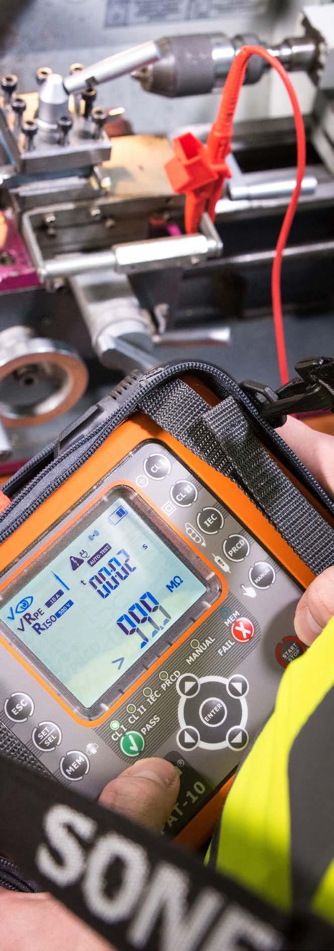


Digital multimeters CMM-10CMM-11CMM-30CMM-40CMM-60 Voltage testers VT-2VT-3P-4P-5P-6 ...and much more phase rotation leakageultrasonicdistancetestersmeterdetectioncurrentdetectiondemonstrationboards CMP-200CMP-200FCMP-3kRCMP-400
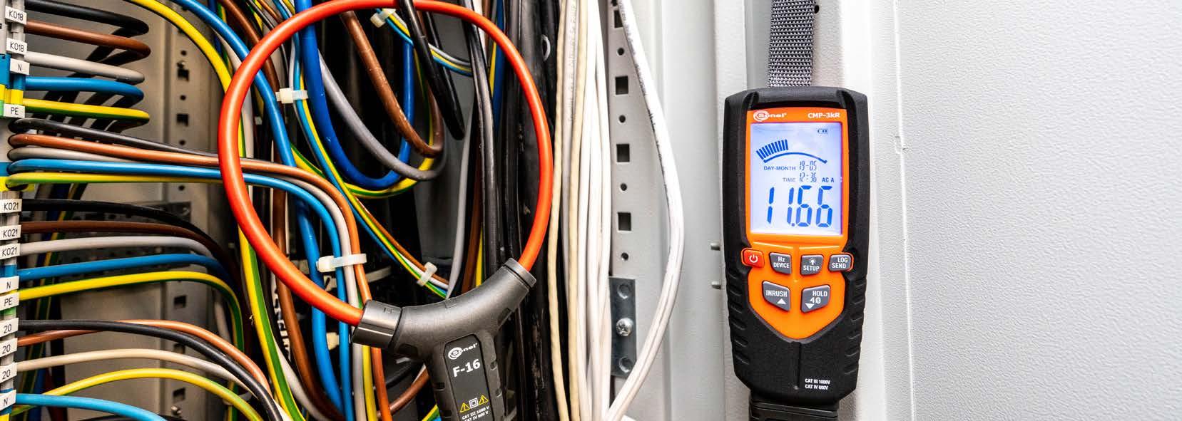
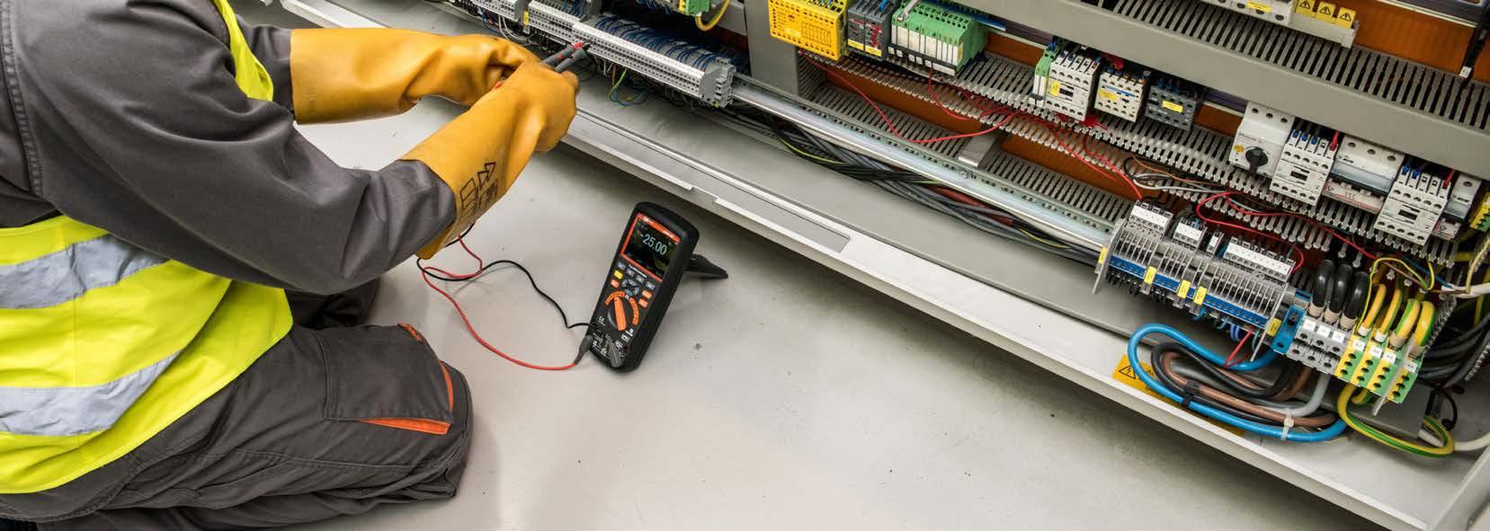

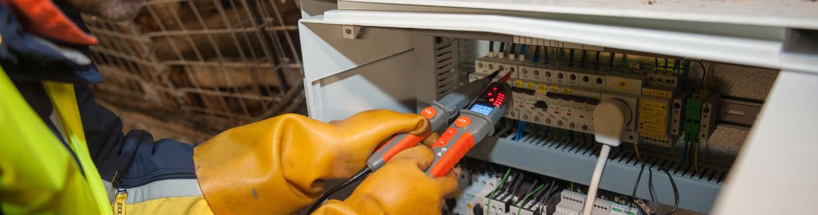
AC/DC voltage current 200.0 50.000
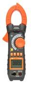
High-end model for industry area High-end model for industry area High-end model for andphotovoltaicsindustryarea Various applications in industry For general use For general use Recording currents For general use Leakage current
voltage indication √ √ √ √ √ Duty cycle (%) √ √ √ √ √ √
voltage measurements downstream the inverter, frequency converter or in the VFD system √

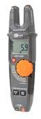
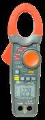
High
Continuity
MΩ (DC) 10 MΩ 10 MΩ 10 MΩ 10 MΩ
√
√ / √ √ / √ √ / √ √
3000 A / 1000 A 1500 A / 2000 A 1000 A / 1000 A 1000 A / 1000 A 400.0 A / 400.0 A 400.0 A / - 3000 A / -
Comparison of clamp multimeters
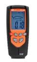
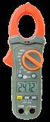
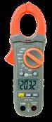
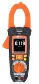
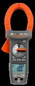
Input impedance 10 MΩ 10 MΩ 9 MΩ (AC) 10
√
CMP-3000 CMP-2000 CMP-1015-PV CMP-1006 CMP-401 CMP-400 CMP-3kR CMP-200F CMP-200
voltage DC (HVDC)measurement √ Inrush current √ √ √ √ √ Low Z √ √
√
Measurement functions
/ diode test √ / √ √ / √ √ / √ √ / √ √ / √ √ / √ √ / √
Basic √ √ √ √ √
MAX / MIN / AVG measurement √ / √ / - √ / √ / - √ / √ / - √ / √ / - - / - / - - / - / - - / - / - √ / √ / - √ / - /HOLD √ √ √ √ √ √ √ √ √ PEAK HOLD √ AC+DC √ Relative measurement √ √ √ √ √ √ Recorder √ √ Memory in mobile app √ √ Bluetooth √ √ √ Sonel Multimeter Mobile √ √ √ Other features Automatic power down √ √ √ √ √ √ √ √ √ Battery indicator √ √ √ √ √ √ √ √ √ Beeper √ √ √ √ √ √ √ Dimensions 230 x 76 x 40 mm 281 x 108 x 53 mm 273 x 96 x 48 mm 229 x 80 x 49 mm 197 x 70 x 40 mm 197 x 70 x 40 mm 150 x 65 x 35 mm 230 x 44 x 66 mm 182 x 61 x 34 mm Weight 501 g 570 g 490 g 303 g 183 g 183 g 240 g 270 g 225 g Display Graphical √ Segmented √ √ √ √ √ √ √ √ Counting 50000, 4 4/5 digits 6600, 3 4/5 digits 6000 6600, 3 4/5 digits 4000, 3 3/4 digits 4000, 3 3/4 digits 33000,digits 6000, 3 4/5 digits 1999, 3 1/2 digits Screen backlit √ √ √ √ √ √ √ √ √ Safety and conditions of use Measurement category (EN 61010) CAT IV 600 V CAT III 1000 V CAT IV 600 V CAT III 1000 V CAT IV 600 V CAT III 1000 V CAT IV 300 V CAT III 600 V CAT IV 300 V CAT III 600 V CAT IV 300 V CAT III 600 V CAT IV 600 V CAT III 1000 V CAT IV 600 V CAT III 1000 V CAT II 600 V Ingress protection IP40 IP20 IP40 IP40 IP40 IP40 IP40 IP40 IP40 Operating temperature 5…40°C 0…50°C 5…40°C 5…40°C 5…40°C 5…40°C 5…40°C 5…40°C 0…50°C 144
A / - 200 A /Resistance 40.000 MΩ 60.00 MΩ 60.00 MΩ 66.00 MΩ 40.00 MΩ 40.00 MΩ 60.00 MΩ Frequency
Advanced features
MHz 1.000 MHz 10.00 MHz 15.00 kHz 10 kHz 10 kHz 100.0 Hz
Automatic / manual range selection √ / √ √ / √ / √ / √ √ / √ - /
5.0000 mF 6.599 mF 100.0 mF 100.0 μF 4000 μF Temperature 1000°C 1000°C 1000°C 760°C 760°C 760°C
Non-contact
Capacitance
Maximum diameter of measured conductor hard clamp: 48 mm flexible clamp: 160 mm 57 mm (conductor) 70 x 18 mm (bus bar) 48 mm 34 mm 30 mm 30 mm flexible clamp: 160 mm 16 mm 30 mm
1000 V / 1000 V 750 V / 1000 V 1000 V / 1500 V 600.0 V / 600.0 V 600 V / 600 V 600 V / 600 V 1000 V / 1000 V - /AC/DC
features True RMS measurement
Current and
±(0.1% m.v. + 9 digits) 0.5001...5.0000 V 0.0001 V 5.001...50.000 V 0.001 V 50.01...500.00 V 0.01 V 500.1...1000.0 V 0.1 V
Display
Direct voltage measurement range Resolution Accuracy 0.01 mV ±(0.1% m.v. + digits)
±(0.3% m.v. + 2 digits) 50.01...500.00 Hz 0.01 Hz 0.5001...5.0000 kHz 0.0001 kHz 5.001...50.000 kHz 0.001 kHz 50.01...500.00 kHz 0.01 kHz 0.5001...5.0000 MHz 0.0001 MHz 5.001...50.000 MHz 0.001 MHz
0.0...400.00 Ω 0.01 Ω ±(1.0% m.v. + 9 digits) 0.4001...4.0000 kΩ 0.0001 kΩ ±(1.0% m.v. + 4 digits)4.001...40.000 kΩ 0.001 kΩ 40.01...400.00 kΩ 0.01 kΩ 0.4001...4.0000 MΩ 0.0001 MΩ ±(2.0% m.v. + 9 digits) 4.001...40.000 MΩ 0.001 MΩ ±(3.0% m.v. + 10 digits)
Standard accessories:
0.0...3000.0 A* *measurement
Display range Resolution Accuracy 5...95% 0.1% ±(1.0% m.v. + 2 digits)
»
Temperature measurement
»
»
»
Direct
»
Display range Resolution Accuracy 10...50.000 Hz 0.001 Hz
“m.v.” = “measured value”
» auto-off timeout 30 min
» dimensions 230 x 76 x 40 mm
»
Display range Resolution Accuracy -100.0...+1000°C 1°C or 1°F ±(1.0% m.v. + 2°C) -148...+1832°F 1°C or 1°F ±(1.0% m.v. + 3.6°F)
» quality standard ISO 9001

Capacitance measurement
WACEGF16
Type K temperature probe adapter WAADATEMK Temperature measurement probe (type K) WASONTEMK 9 V
» frequency range: 10 Hz...10 kHz.
» display segment LCD, readout of 50000 readings, 4 4/5 digits, backlit power supply 9 V battery, type 6LR61 indication of range overflow ‘OL’ symbol is displayed
0.0...1000.0 A 0.1 A ±(2.8%
0.000...500.00 mV 0.01 mV
Frequency measurement
Set of test leads (CAT IV, M)
»
» measurement category CAT III 1000 V (CAT IV 600 V)


»
» flexible clamp dimensions 140 x 180 mm


Alternating voltage measurement (True RMS)
Display range Resolution Accuracy
»
Display range Resolution Accuracy 0.0...500.00 nF 0.01 nF ±(3.5% m.v. + 40 digits) 0.5001...5.0000 µF 0.0001 µF ±(3.5% m.v. + 9 digits)5.001...50.000 µF 0.001 µF 50.01...500.00 µF 0.01 µF 0.5001...5.0000 mF 0.0001 mF ±(5.0% m.v. + 9 digits)
Display
»
» operating temperature 5...40°C
0.000...500.00 mV
MULTIMETERSONEL MOBILE
» storage temperature -20...+60°C
4
Sonel Multimeter Mobile application is intended for reading measurement values in live mode, as well as for transferring and storing measurement results in the memory of mobile devices based on the Android system. It can be downloaded from Google Play
» compliance with standards EN 61010-1, EN 61010-2-032
WAPRZCMM2
Alternating
» INRUSH function for measuring current drawn by an electrical device when first turned on flexible clamp allow the measurement of conductors up to 160 mm in diameter large clamp allows the measurement of conductors up to 48 mm in diameter current measurement up to 1000 A DC and 3000 A AC temperature measurement in Fahrenheit and Celsius automatic selection of measuring ranges HOLD function, allowing for freezing the result on the display holding of MAX/MIN results auto-off function current measurement range Resolution Accuracy m.v. + 5 digits) current (TRUE RMS) range Resolution Accuracy m.v. + 8 digits) for 50...400 Hz with the use of flexible clamp

» sampling rate nominal: 2 Hz
Flexible clamp F-16
» maximal wire diameter 160 mm maximal busbar diameter 500 mm continuity test threshold 50 Ω
0.0...1000.0 A 0.1 A ±(2.5%
»
0.5001...5.0000 V 0.0001 V 5.001...50.000 V 0.001 V 50.01...500.00 V 0.01 V 500.1...1000.0 V 0.1 V ±(0.2% m.v. + 5 digits)
Display
index: WMGBCMP3000
» True RMS AC voltage and current measurement for accurate and reliable readings of non-sinusoidal signals
»
Other technical specifications:
» input impedance approx. 10 MΩ
145
SONEL CMP-3000
Resistance measurement
Display range Resolution Accuracy
Product features
» storage humidity <80%
» weight 501 g
FactoryCarryingbatterycasecalibration certificate
» diode test I = 0.3 mA, U0 = 2.8 V DC
Clamp meter

measurement
Duty cycle measurement
index: WMGBCMP2000
Resistance measurement
» holding of MAX/MIN results
» indication of range overflow ‘OL’ symbol is displayed
Display range Resolution Accuracy 10.00…65.99 Hz 0.01 Hz ±(0.1% m.v. + 5 digits) 66.0…659.9 Hz 0.1 Hz 0.660…6.599 kHz 0.001 kHz 6.60…65.99 kHz 0.01 kHz 66.0…659.9 kHz 0.1 kHz 0.660…1.000 MHz 0.001 MHz
» display segment LCD, readout of 6600 readings, 3 4/5 digits, backlit
» dimensions 281 x 108 x 53 mm
Display range Resolution Accuracy 0.0…6.599 nF 0.001 nF ±(3.0% m.v. + 30 digits) 6.60…65.99 nF 0.01 nF ±(3.0% m.v. + 10 digits) 66.0…659.9 nF 0.1 nF ±(3.0% m.v. + 30 digits) 6.660…6.599 µF 0.001 µF ±(3.0% m.v. + 10 digits)6.60…65.99 µF 0.01 µF 66.0…659.9 µF 0.1 µF 0.660…6.599 mF 0.001 mF ±(5% m.v. + 10 digits)
» auto-off function
» large clamps allow the measurement of conductors up to 57 mm in diameter
» diode test I = 0.8 mA, U0 = 3.2 V DC
Set of test leads for CMM/CMP WAPRZCMP1 Temperature measurement probe (type K) WASONTEMK 9 V
» maximal wire diameter 57 mm
Direct voltage measurement
Display range Resolution Accuracy 0.000…6.599 V 0.001 V ±(1.5% m.v. + 8 digits) for 50…500 Hz 6.60…65.99 V 0.01 V 66.0…659.9 V 0.1 V 660…750 V 1 V
Duty cycle measurement
Display range Resolution Accuracy 0.0…659.9 Ω 0.1 Ω ±(1.0% m.v. + 5 digits)0.660…6.599 kΩ 0.001 kΩ 6.60…65.99 kΩ 0.01 kΩ 66.0…659.9 kΩ 0.1 kΩ 0.660…6.599 MΩ 0.001 MΩ ±(2.0% m.v. + 5 digits) 6.60…66.00 MΩ 0.01 MΩ ±(3.5% m.v. + 5 digits)
Temperature measurement
SONEL CMP-2000
» temperature measurement in Fahrenheit and Celsius
Product features
» storage humidity <80%
» automatic selection of measuring ranges
Alternating current measurement (TRUE RMS)
» True RMS AC voltage and current measurement for accurate and reliable readings of non-sinusoidal signals
Display range Resolution Accuracy
Display range Resolution Accuracy 5…95% 0.1% ±(3.0% m.v. + 30 digits)
Clamp meter
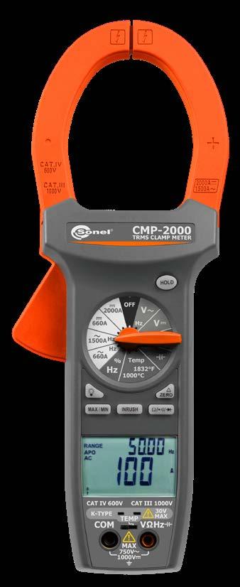
» weight with battery 570 g
“m.v.” = “measured value”
» compliance with standards EN 61010-1, EN 61010-2-032
Display range Resolution Accuracy 0...400°C 1°C ±(1.0% m.v. + 2°C) -20...0°C, 400...1000°C 1°C ±(2.0% m.v. + 3°C) 32...750°F 1°F ±(1.0% m.v. + 4°F) -4...32°F, 750...1832°F 1°F ±(2.0% m.v. + 6°F)
Display range Resolution Accuracy 0.000…6.599 V 0.001 V ±(0.5% m.v. + 2 digits)6.60…65.99 V 0.01 V 66.0…659.9 V 0.1 V 660…1000 V 1 V
» storage temperature -20…+60°C
Frequency measurement
» continuity test threshold 30 Ω
Other technical specifications:
» current measurement up to 2000 A DC and 1500 A AC
» HOLD function, allowing for freezing the result on the display
Display range Resolution Accuracy (AC) 0.0…659.9 A 0.1 A ±(2.0% m.v. + 5 digits) 660…2000 A 1 A (3.0% m.v. + 5 digits) for 660…1000 A ±(5.0% m.v. + 5 digits) for 1000…2000 A
Capacitance measurement
FactoryCarryingbatterycasecalibration certificate
» INRUSH function for measuring current drawn by an electrical device when first turned on
0.0…659.9 A 0.1 A ±(2.0% m.v. + 10 digits) for 50…60 Hz ±(3.0% m.v. + 10 digits) for 61…400 Hz 660…1500 A 1 A ±(2.5% m.v. + 10 digits) for 50…60 Hz and 660…1000 A ±(3.5% m.v. + 10 digits) for 61…400 Hz and 660…1000 A ±(5.0% m.v. + 10 digits) for 50…400 Hz and 1000…1500 A
» operating temperature range 0…+50°C
» quality standard ISO 9001
146
» frequency range: 40 Hz…20 kHz.
Standard accessories:
» Delta ZERO function, relative measurement mode for direct current - capability of zeroing the instrument at any time and returning to measurement in absolute mode
Direct current measurement
» sampling rate nominal: 2.8 Hz analog bar graph: 28 Hz
» power supply 9 V battery, type 6LR61
» double LCD to display more than one value at the same time
» maximal busbar dimensions 70 x 18 mm
Alternating voltage measurement (True RMS)
» input impedance approx. 10 MΩ
» auto-off timeout 30 minutes
Battery charger power supply WAZASZ26 M-3 carrying case WAWALM3
Battery charger WAZASZ25
6.01…60.00 V 0.01 V 60.1…600.0 V 0.1 V 601…1000 V 1 V
147Play
Resistance measurement
» sampling rate nominal: 3 Hz
» INRUSH function for measuring current drawn by an electrical device when first turned on

Set of test leads (CAT IV, M) WAPRZCMM2
Display range Resolution Accuracy 10...90% 0.1% ±(1.2% m.v. + 8 digits)
» HOLD function, allowing for freezing the result on the display
» measurement category CAT III 1000 V (CAT IV 600 V)


Display range Resolution Accuracy 60.00 A 0.01 A ±(2.5% m.v. + 5 digits)600.0 A 1000 A 1 A
Frequency measurement
WMGBCMP1015PV Clamp meter
» large clamp allows the measurement of conductors up to 48 mm in diameter
Duty cycle measurement
» recorder, possibility of continuous recording
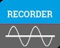
» temperature measurement in Fahrenheit and Celsius
Standard accessories:
Alternating current measurement (TRUE RMS)
“m.v.” = “measured value”
100 000 samples sampling frequency from 1 Hz
Capacitance measurement
index:
Type K temperature probe adapter WAADATEMK
» holding of MAX/MIN results
» diode test I = 1.5 mA, U0 < 3.3 V DC
Other technical specifications:
Alternating voltage measurement (True RMS)
Temperature measurement
Display range Resolution Accuracy 0.000…6.000 V 0.001 V f = 50…60 Hz ±(1.2% m.v. + 5 digits)
SONEL CMP-1015-PV
» elimination of interference and induced voltages - Low Z
Display range Resolution Accuracy 0.00…60.00 nF 0.01 nF ±(3.0% m.v. + 20 digits) 60.1…600.0 nF 0.1 nF ±(3.0% m.v. + 8 digits)0.601…6.000 µF 0.001 µF 6.01…60.00 µF 0.01 µF 60.1…600.0 µF 0.1 µF 601…6000 µF 1 µF ±(3.5% m.v. + 20 digits) 6.01…60.00 mF 0.01 mF unspecified60.1…100.0 mF 0.1 mF
» display graphical LCD, backlit
» storage temperature -20...+60°C
Product features
» current measurement up to 1000 A DC and 1000 A AC
» frequency range: 40 Hz...10 kHz.
» power supply Li-Pol 7.4 V 1200 mAh rechargeable battery
» auto-off timeout 15...60 min
» High voltage DC measurement (HVDC)

Display range Resolution Accuracy 0.00…60.00 Hz 0.01 Hz ±(0.2% m.v. + 5 digits) 60.1…600.0 Hz 0.1 Hz 0.601…6.000 kHz 0.001 kHz 6.01…60.00 kHz 0.01 kHz 60.1…600.0 kHz 0.1 kHz 0.601…6.000 MHz 0.001 MHz 6.01…10.00 MHz 0.01 MHz
» indication of range overflow “0L” symbol
» weight 490 g with battery
» quality standard ISO 9001


» auto-off function
f = 61…1000 Hz ±(2.5% m.v. + 5 digits)
» compliance with standards EN 61010-1, EN 61010-2-032
» built-in Bluetooth module for sending data to mobile devices with Android system

» storage humidity <80%
» Current and voltage measurements downstream the inverter, frequency converter or in the VFD system
Sonel Multimeter Mobile application is intended for reading measurement values in live mode, as well as for transferring and storing measurement results in the memory of mobile devices based on the Android system. It can be downloaded from Google
Direct voltage measurement
Display range Resolution Accuracy 600.0 mV 0.1 mV ± (0.8% m.v. + 8 digits) 6.000 V 0.001 V ± (0.5% m.v. + 5 digits)60.00 V 0.01 V 600.0 V 0.1 V ± (0.8% m.v. + 5 digits)V 1 V
Temperature measurement probe (type K) WASONTEMK Li-Pol battery 7.4 V 1200 mAh WAAKU30
» maximal wire diameter 48 mm
» automatic selection of measuring ranges
» input impedance 9 MΩ (V AC), 10 MΩ (V DC)
» continuity test threshold 50 Ω
» recordercapacitymemory
» True RMS AC voltage and current measurement for accurate and reliable readings of non-sinusoidal signals
1500
Display range Resolution Accuracy 0.0…600.0 Ω 0.1 Ω ±(1.0% m.v. + 10 digits) 0.601…6.000 kΩ 0.001 kΩ ±(0.8% m.v. + 5 digits)6.01…60.00 kΩ 0.01 kΩ 60.1…600.0 kΩ 0.1 kΩ 0.601…6.000 MΩ 0.001 MΩ 6.01…60.00 MΩ 0.01 MΩ ±(2.5% m.v. + 10 digits)
Display range Resolution Accuracy 60.00 A 0.01 A ±(2.0% m.v. + 8 digits)600.0 A 0.1 A 1000 A 1 A
» dimensions 230 x 76 x 40 mm
Factory calibration certificate
» operating temperature 5...40°C
Display range Resolution Accuracy -40.0...+1000°C 1°C or 1°F ±(1.5% m.v. + 3°C) -40.0...+1832°F 1°C or 1°F ±(1.0% m.v. + 5.4°F)
SONEL MULTIMETER MOBILE
Direct current measurement
WASONTEMK
Set of test leads for CMM/CMP
WAPRZCMP1
Display range Resolution Accuracy -20...760°C 1°C ±(3% m.v. + 5°C) -4...1400°F 1°F ±(3% m.v. + 9°F) “m.v.” = “measured value”
» sampling rate 2 Hz
148
9 V certificate RMS INRUSH function clamps
Standard accessories:
10 MΩ (V DC and V AC)
» dimensions 229 x 80 x 49 mm
Clamp meter
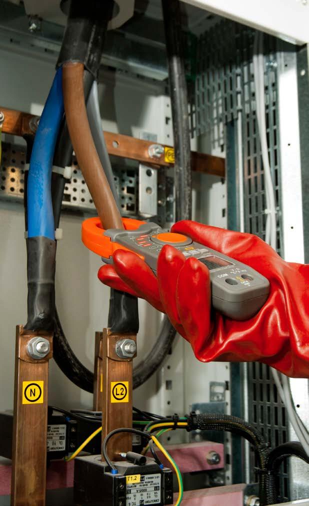
SONEL CMP-1006 index: WMGBCMP1006
» display segment LCD, readout of 6600 readings, 3 4/5 digits, backlit
» auto-off timeout 25 min
AC voltage and current measurement for accurate and reliable readings of non-sinusoidal signals »
Temperature measurement
9 V battery, type 6LR61
» operating temperature +5…+40°C
» power supply of the meter
» weight 303 g
Temperature measurement probe (type K)
0.0…659.9 Ω 0.1 Ω ±(1.0% m.v. + 4 digits) 0.660…6.599 kΩ 0.001 kΩ ±(1.5% m.v. + 2 digits)6.60…65.99 kΩ 0.01 kΩ 66.0…659.9 kΩ 0.1 kΩ 0.660…6.599 MΩ 0.001 MΩ ±(2.5% m.v. + 3 digits) 6.6…66.0 MΩ 0.1 MΩ ±(3.5% m.v. + 5 digits)
for measuring current drawn by an electrical device when first turned on »
» diode test I = 0.3 mA, U0 < 3 V DC
» quality standard ISO 9001
Resistance measurement
» maximal wire diameter 34 mm
» storage temperature -20...+60°C
» indication of range overflow ‘OL’ symbol
» storage humidity <80%
» continuity test threshold 40 Ω; measurement current < 0.5 mA
Display range Resolution Accuracy
Other technical specifications
» measuring category CAT III 600 V (CAT IV 300 V)

» input impedance
FactoryCarryingbatterycasecalibration
Product features » True
allow the measurement of conductors up to 34 mm in diameter » current measurement up to 1000 A AC/DC » temperature measurement in Fahrenheit and Celsius » automatic selection of measuring ranges » HOLD function, allowing for freezing the result on the display » holding of MAX/MIN values » relative measurement mode for direct current - DCA ZERO function » automatic power down » shock resistant rugged case Direct and alternating (TRUE RMS) current measurement Display range Resolution Accuracy (DC) Accuracy (AC) 0…659.9 A 0.1 A ±(2.5% m.v. +5 digits) ±(2.5% m.v. + 8 digits) for f = 45…65 Hz 660…1000 A 1 A ±(2.8% m.v. +8 digits) ±(2.8% m.v. + 8 digits) for f = 45…65 Hz Direct and alternating (TRUE RMS) voltage measurement Display range Resolution Accuracy (DC) Accuracy (AC) 0…6.599 V 0.001 V ±(1.5% m.v. + 3 digits) ±(1.8% m.v. + 5 digits) for f = 45…65 Hz6.60…65.99 V 0.01 V 66.0…600.0 V 0.1 V Frequency measurement Display range Resolution Accuracy 30.0…659.9 Hz 0.1 Hz ±(1.2% m.v. + 2 digits)0.660…6.599 kHz 0.001 kHz 6.60…15.00 kHz 0.01 kHz » sensitivity: • 30…5 kHz:10 V RMS min. • 5 kHz…15 kHz:40 V RMS min. for 20%…80% of duty cycle
» compliance with standards EN 61010-1, EN 61010-2-032
Set of test leads for CMM/CMP measurement probe (type K)
»
» frequency range: 50 Hz…60 Hz
» clamps allow the measurement of conductors up to 30 mm in diameter
Direct and alternating voltage measurement
» HOLD function, allowing for freezing the result on the display
Other technical specifications:
400.0 mV 0.1 mV ±(1.5% m.v. + 30 digits) ±(1.5% m.v. + 30 digits) ±(0.8% m.v. + 2 digits) 4.000 V 0.001 V ±(1.8% m.v. + 8 digits) ±(1.5% m.v. + 5 digits) ±(1.5% m.v. + 2 digits)40.00 V 0.01 V 400.0 V 0.1 V 600.0 V 1 V ±(2.5% m.v. + 8 digits) ±(2% m.v. + 5 digits) ±(2% m.v. + 2 digits)
» relative measurement function
» automatic and manual selection of measuring ranges
» automatic power down - Auto-OFF function shock resistant rugged case
Product features
» frequency range: 50 Hz…400 Hz
» indication of range overflow ‘OL’ symbol is displayed
» power supply of the meter 9 V battery, type 6LR61
»
»
Display range Resolution Accuracy Accuracy CMP-400 (AC) CMP-401 (AC) CMP-400,-401 (DC)
Alternating current measurement
Direct current measurement (only CMP-401)
Display range Resolution Accuracy 4.00 A 0.01 A ±(2.5% m.v. + 5 digits) 400.0 A 0.1 A ±(2.8% m.v. + 5 digits)
» measuring category CAT III 600 V (CAT IV 300 V) compliance with standards EN 61010-1, EN 61010-2-032 quality standard ISO 9001
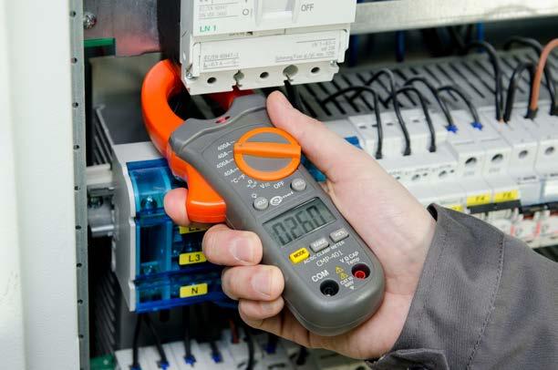
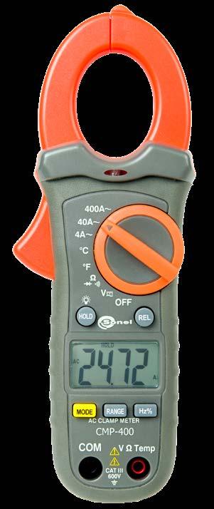
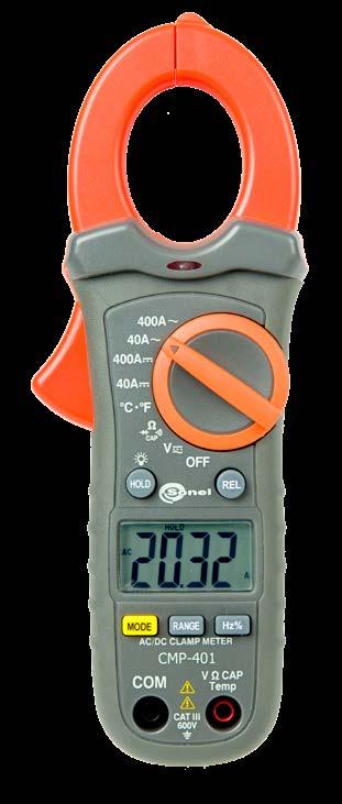
» current measurement: CMP-401 | up to 400 A AC and DC CMP-400 | up to 400 A AC
» temperature measurement in Fahrenheit and Celsius
»
»
WAPRZCMP1 Temperature
Temperature measurement Display range Resolution Accuracy -20.0...760.0°C 0.1°C ±(3% m.v. + 5°C) -4.0...1400°F 0.1°F ±(3% m.v. + 9°F) “m.v.” = “measured value” SONEL CMP-401 / CMP-400 index: WMGBCMP401 / WMGBCMP400 Clamp meters 149
Display range Resolution Accuracy CMP-400 Accuracy CMP-401 4.000 A 0.001 A ±(2.5% m.v. +12 digits) no range 40.00 A 0.01 A ±(2.5% m.v. + 8 digits) ±(2.5% m.v. + 8 digits) 400.0 A 0.1 A ±(2.8% m.v. + 8 digits) ±(2.8% m.v. + 5 digits)
» weight 183 g
»
WASONTEMK 9 V FactoryCarryingbatterycasecalibration certificate
»
»
Standard accessories:
Resistance measurement
» maximal wire diameter 30 mm continuity test threshold 50 Ω, measuring current <0.5 mA diode test I = 0.3 mA, U0 = 1.5 V DC sampling rate 2 Hz input impedance 10 MΩ auto-off timeout approx. 30 minutes operating temperature range +5…+40°C storage temperature -20…+60°C storage humidity <80% dimensions 197 x 70 x 40 mm
»
»
» display segment LCD, readout of 4000 readings, 3 3/4 digits, backlit
»
Display range Resolution Accuracy 400.0 Ω 0.1 Ω ±(1% m.v. + 4 digits) 4.000 kΩ 0.001 kΩ ±(1.5% m.v. + 2 digits)40.00 kΩ 0.01 kΩ 400.0 kΩ 0.1 kΩ 4.000 MΩ 0.001 MΩ ±(2.5% m.v. + 3 digits) 40.00 MΩ 0.01 MΩ ±(3.5% m.v. + 5 digits)
»
» non-contact voltage indication
» current measurement up to 3000 A AC
» real-time clock that allows adding date and time of measurement to each stored result
» HOLD function, allowing for freezing the result on the display
»
Flexible clamp F-16 WACEGF16
Carrying case
is
» recorder with sampling every 1 s, possibility of continuous recording for 24 hours
» True RMS AC current measurement for accurate and reliable readings of nonsinusoidal signals
» flexible clamp allow the measurement of conductors up to 160 mm in diameter
Other technical specifications:
Standard accessories:
» display segment LCD, readout of 3000, 4 digits, backlit
» dimensions 150 x 65 x 35 mm
Sonel Multimeter Mobile
» maximal wire diameter 160 mm
devices based on the
» INRUSH function for measuring current drawn by an electrical device when first turned on
g » measurement category CAT III 1000 V (CAT IV 600 V) » compliance with standards EN 61010-1, EN 61010-2-032 » quality standard ISO 9001 SONEL CMP-3kR index: WMGBCMP3KR AC digital clamp meter with data logger
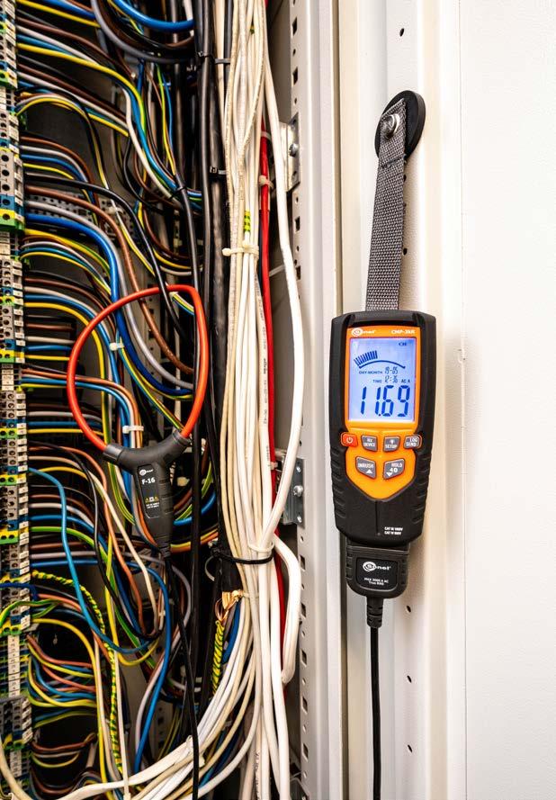
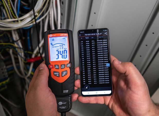
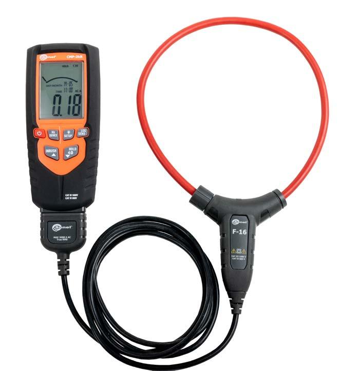
» storage temperature -20...+60°C
» indication of range overflow ‘OL’ symbol is displayed
for reading measurement values in live
Product features
» auto-off function
2x AA 1,5 V battery
» automatic selection of measuring ranges
Display range Resolution Accuracy 0.0...30.00 A 0.01 A ±(3.0% m.v. + 8 digits) for 50...400 Hz 30.1...300.0 A 0.1 A ±(3.0% m.v. + 5 digits) for 50...400 Hz301...3000 A 1 A Frequency measurement Display range Resolution Accuracy 0.0...400.0 Hz 0.1 Hz ±(0.5% m.v. + 5 digits) “m.v.” = “measured value” 150
86
» data export to the Sonel Multimeter Mobile application, viewing the recording results in the application, data export to external files for reading on a PC
» operating temperature 5...40°C
It can
» weight 240
from
» storage humidity <80%
as well as for transferring and storing measurement results in the
» auto-off timeout 15 min
MULTIMETERSONEL MOBILE application intended mode, memory of mobile Android system. be downloaded Google
Alternating current measurement (TRUE RMS)
» power supply 2x 1.5 V battery, type LR6
Factory calibration certificate
» maximal busbar diameter 500 mm
» sampling rate nominal: 3 Hz recordercapacitymemory 400 samples sampling frequency 1 Hz maximum recording time 24 h
» flexible clamp dimensions 140 x 180 mm
Play
»
» DC voltage measurement
SONEL CMP-200
Display range Resolution Accuracy 199.9 mA 0.1 mA ±(5% m.v. + 8 digits) 1.999 A 0.001 A ±(5% m.v. + 10 digits) 199.9 A 0.1 A ±(2.5% m.v. + 10 digits)
Display range Resolution Accuracy AC Accuracy DC 6,000 V 0,001 V ±(1,2% m.v. + 5 digits) ±(0,9% m.v. + 5 digits) 60,00 V 0,01 V ±(1,2% m.v. + 2 digits) ±(1,0% m.v. + 2 digits)600,0 V 0,1 V 1000 V 1 V ±(1,5% m.v. + 2 digits) ±(1,2% m.v. + 2 digits)
current
Display range Resolution Accuracy 200,0 A 0,1 A ±(3% m.v. + 5 digits)
» fork-style clamp

Low Z measurement
» HOLD function, allowing for freezing the result on the display
Resistance measurement
Alternating current measurement (TRUE RMS)
»
Display range Resolution Accuracy 6,000 V 0,001 V ±(3,0% m.v. + 40 digits)60,00 V 0,01 V 600,0 V 0,1 V
kΩ 0,1 kΩ 6,000 MΩ 0,001 MΩ ±(2,5% m.v. + 4 digits) 60,00 MΩ 0,01 MΩ ±(3,5% m.v. + 4 digits) Capacitance measurement Display range Resolution Accuracy 60,00 nF 0,01 nF ±(3,0% m.v. + 5 digits)600,0 nF 0,1 nF 6,000 µF 0,001 µF 60,00 µF 0,01 µF 600,0 µF 0,1 µF ±(3,5% m.v. + 10 digits) 4000 µF 1 µF ±(5,0% m.v. + 10 digits) “m.v.” = “measured value” Standard accessories: Set of test leads (CAT IV, M)
» automatic selection of measuring ranges
Display range Resolution Accuracy 600,0 Ω 0,1 Ω ±(1,0% m.v. + 4 digits) 6,000 kΩ 0,001 kΩ ±(1,5% m.v. + 4 digits)60,00 kΩ 0,01 kΩ 600,0
WAPRZCMM2
»
index: WMGBCMP200
Product features
Measurement of alternating up to 200 A: high resolution (0.1 mA), 3 measuring subranges: 200 mA, 2 A, 200 A. functions of the meter: segment LCD, readout of 1999 readings, 3 1/2 digits, backlit, maximal wire diameter 30 mm, HOLD function, allowing for freezing the measurement result on the display, MAX function, freezing of maximum values, automatic power down of instrument when not in use, reinforced, impact resistant enclosure.
Additional
Current measurement
» current measurement up to 200 A AC

» Auto-OFF function
Alternating and direct voltage measurement
»
» frequency range: 50 Hz...1000 Hz
Leakage current clamp meter
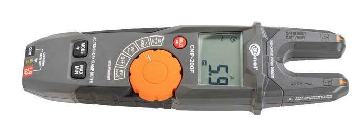
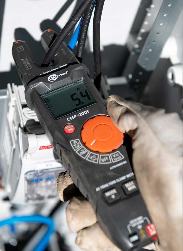
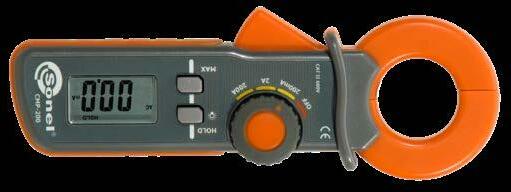
» AC current and AC voltage measurement
»
» function MAX MIN for displaying extreme values
»
»
» low-impedance voltage measurement - Low Z
2x 1,5 V battery Carrying case Factory calibration certificate 151
» frequency range: 50...1000 Hz
»
Comparison of multimeters CMM-60 CMM-40 CMM-30 CMM-11 CMM-10 High-endmeterindustrial Industrial area meter Meter for industry Compact meter for general purpose Pocket meter for basic measurements Measurement functions AC/DC voltage 1000.0 V 1000.0 V 1000.0 V 600 V 600 V AC/DC current 10.000 A 10.000 A 10.00 A 10.00 A 10.00 A Resistance 50.000 MΩ 40.000 MΩ 60.00 MΩ 40.00 MΩ 40.00 MΩ Frequency 10.000 MHz 100.00 MHz 10 kHz 100.0 kHz 10.00 MHz Capacitance 10.00 mF 40.000 mF 6000 µF 4000 µF 100.0 µF Temperature 1000.0°C 1200.0°C 760°C 760°C dB √ Duty cycle (%)/ impulse width (ms) √ / √ √ / - √ / - √ / - √ /Continuity / diode test √ / √ √ / √ √ / √ √ / √ √ / √ 4-20 mA% current loop measurement √ √ Low Z √ Low-pass filter √ Basic features True RMS measurement √ √ √ √ Automatic / manual range selection √ / √ √ / √ √ / √ √ / √ √ / √ Advanced features MAX / MIN / AVG measurement √ / √ / √ √ / √ / - √ / √ / √ √ / √ / - - / - /HOLD √ √ √ √ √ PEAK HOLD √ √ √ Crest factor √ AC + DC √ √ √ Relative measurement √ √ √ √ Recorder √ Trend capture function √ Memory √ √ in mobile app in mobile app Bluetooth √ √ √ Sonel Multimeter Mobile √ √ √ Other features Clock √ Easy access to fuses A / mA - / √ - / - √ / √ √ / √ √ / √ Automatic shutdown √ √ √ √ √ Battery indicator √ √ √ √ √ Built-in flashlight √ √ Beeper √ √ √ √ √ Display Graphical √ Segmented √ √ √ √ Counting 50.000 40.000 6.000 4.000 4.000 Backlit √ √ √ / auto √ √ Safety and conditions of use Measurement category (EN 61010) CAT IV 600 V CAT III 1000 V CAT IV 600 V CAT III 1000 V CAT IV 600 V CAT III 1000 V CAT III 600 V CAT II 600 V Ingress protection IP67 IP67 IP67 IP65 IP40 Operating temperature 5…40°C 0…40°C 0…40°C 5…40°C 0…50°C 152


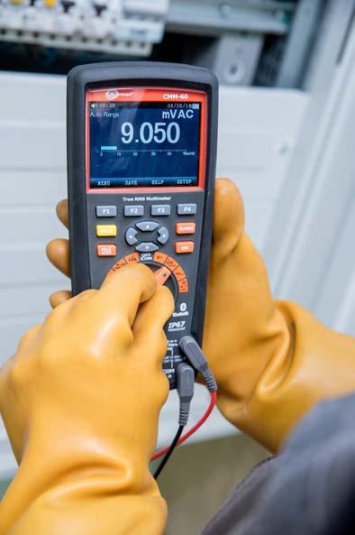


» crest factor ≤3 for full 500 V range decreasing linearly to ≤1.5 at 1000 V
» compliance with standards EN 61010-1, EN 61010-2-032
» integrated HELP function
» freezing the measurement result thanks to HOLD and Auto HOLD function
153Play
f < 5 kHz ±(3% m.v. + 25 digits) ±(0.15% m.v. + 20 digits) ±(0.3% m.v. + 20 digits) 30 seconds with reduced accuracy
» frequency
Display range Resolution Accuracy -50.0...1000°C 0.1°C ±(1.0% m.v. + 2.5°C) -58...1832°F 0.1°F ±(1.0% m.v. + 4.5°F)
Measurements
» the relative REL measurement
V
» input impedance >10 MΩ (V DC), >9 MΩ (V AC)
» indication of range overflow “0L” symbol
» recordercapacitymemory
500.00 μA 0.01 μA
Capacitance measurement
» duty cycle & impulse width
Resolution
» resistance
20 A maximum
CMM-RR radio receiver WAADACMMRR
» storage temperature -20…+60°C
Other technical specifications
10.000 A 0.001 A
» real-time clock that allows adding date and time of measurement to each stored result
Charging adapter WAADALAD1
2x socket protective plug Factory calibration certificate
Temperature measurement
» display 3.5” colour TFT LCD 320 x 240 pixels
» auto-off timeout 15 min
Display range Accuracy (DC) Accuracy (AC) ±(0.1% m.v. + 20 digits)
» registration of maximum and minimum values and calculation of the average of current measurements
» built-in low-pass filter, thanks to which the voltage measurements will be more accurate by eliminating the influence of interference generated by machines and electronic devices
f < 1 kHz ±(1.5% m.v. + 25 digits)
Type K temperature probe adapter WAADATEMK Battery charger WAZASZ21
» fusesmA, µA range 0.8 A/1000 V fast-acting ceramic A range 10 A/1000 V fast-acting ceramic
» operating temperature range +5…+40°C
» weight 342 g
SONEL MULTIMETER MOBILE

Direct and alternating (TRUE RMS) voltage measurement
10 000 samples sampling frequency from 1 Hz
Display range Resolution Accuracy 50.000 Hz 0.001 Hz ±(0.01% m.v. + 10 digits) 500.00 Hz 0.01 Hz 5.0000 kHz 0.0001 kHz 50.000 kHz 0.001 kHz 500.00 kHz 0.01 kHz 5.0000 MHz 0.0001 MHz 10.000 MHz 0.001 MHz
Sonel Multimeter Mobile application is intended for reading measurement values in live mode, as well as for transferring and storing measurement results in the memory of mobile devices based on the Android system. It can be downloaded from Google
Display range Resolution Accuracy
f < 5 kHz ±(3% m.v. + 25 digits) 500.00 mV 0.01 mV ±(0.025% m.v. + 5 digits)5.0000 0.0001 V 50.000 0.001 500.00 0.01 V ±(0.05% m.v. + 5 digits) 1000.0 V 0.1 V ±(0.1% m.v. + digits)
5
index: WMGBCMM60
» built-in memory for 2000 measurements
50.000
V
» measurement category CAT III 1000 V (CAT IV 600 V)
f = 50/60 Hz ±(0.3% m.v. + 25 digits)
Standard accessories:
» auto power-off thanks to Auto-OFF function after selecting of a specific idle period
» manual and automatic range selection
» extremely hermetic (IP67) and reinforced, shock-protected housing covered with elastomer
Temperature probe (type K, metal) WASONTEMK2
» temperature
V
» fast and easy reading is provided by a colour display with a resolution 320 x 240 pixels and a diagonal of 3.5", enabling reading the result under wide angle and in dark locations
0.001
» diode test I = 0.9 mA, U0 = 3.2 V DC
Display range Resolution Accuracy 5.000 nF 0.001 nF ±(2% m.v. + 40 digits) 50.00 nF 0.01 nF 500.0 nF 0.1 nF 5.000 μF 0.001 μF 50.00 μF 0.01 μF 500.0 μF 0.1 μF ±(5% m.v. + 40 digits)10.00 mF 0.01 mF
Li-Pol battery 7.4 V, 2400 mAh WAAKU25
» power supply Li-Pol 7.2 V 2400 mAh rechargeable battery
» sampling rate 20 Hz
» AC & DC current
SONEL CMM-60
Additional functions
» capacitance
» the AC + DC function allows you to simultaneously display the value of the constant and variable component or the sum of both components during voltage measurement
» True RMS for AC voltage and current for measuring the effective value of distorted waveforms
» displaying PEAK values
» built-in Bluetooth module for sending live measurement results to Android mobile devices and - for PCs - CMM-60 Multimeter Software
» current loop 4-20 mA%
f = 50/60 Hz ±(0.6% m.v. + 25 digits)
Advanced industrial multimeter
Display range Resolution Accuracy (DC) Accuracy (AC) mV mV ±(0.05% m.v. + 20 digits)
» 4~20 mA function used for, among others, measurement of the analogue control circuits of temperature, pressure, pH or flow sensors
» possibility of quick detection of irregularities due to the registration of measurement results in graphical form of the trend, thanks to the Trend Capture function and the builtin recorder with the possibility of recording up to 10,000 samples
» AC & DC voltage
» dimensions 220 x 97 x 58 mm
f < 1 kHz ±(0.5% m.v. + 25 digits)
Test leads set (CAT IV, M)
» ...and much more
V
50.000 Ω 0.001 Ω ±(0.5% m.v. + 20 digits) 500.00 Ω 0.01 kΩ ±(0.05% m.v. + 10 digits)5.0000 kΩ 0.0001 kΩ 50.000 kΩ 0.001 kΩ 500.00 kΩ 0.01 kΩ ±(0.1% m.v. + 10 digits) 5.0000 MΩ 0.0001 MΩ ±(0.2% m.v. + 20 digits) 50.000 MΩ 0.001 MΩ ±(2% m.v. + 20 digits)
WAPRZCMM2
Electronic frequency measurement
» continuity test I < 0.35 mA, sound signal for R < 25 Ω
Resistance measurement
» frequency range 50…10 kHz Direct and alternating (TRUE RMS) current measurement
5000.0 μA 0.1 μA 50.000 mA 0.001 mA 500.00 mA 0.01 mA
»
»
»
»
Measurements AC & DC voltage AC & DC current resistance capacitance temperature duty cycle frequency current loop 4-20 mA% diode test and continuity
Temperature measurement
»
Display range Resolution Accuracy 40.000 nF 0.001 nF ±(3.5% m.v. + 40 digits)400.00 nF 0.01 nF 4.0000 μF 0.0001 μF ±(3.5% m.v. + 10 digits)40.000 μF 0.001 μF 400.00 μF 0.01 μF 4000.0 μF 0.1 μF ±(5.0% m.v. + 10 digits)40.000 mF 0.001 mF
index: WMGBCMM40 Industrial multimeter


»
»
Display range Resolution Accuracy -50.0...1200°C 0.1°C ±(1.0% m.v. + 2.5°C) -58...2192°F 0.1°F ±(1.0% m.v. + 4.5°F)
Additional functions the AC + DC function allows you to simultaneously display the value of the constant and variable component or the sum of both components during voltage measurement True RMS for AC voltage and current allows to measure the effective value of distorted waveforms the 4~20 mA function used for, among others, measurement of the control circuits of temperature, pressure, pH or flow sensors displaying PEAK values the relative REL measurement function dual display to show several results at the same time built-in memory for 2000 measurements registration of maximum and minimum automatic and range selection HOLD
» display segment LCD, readout of 40,000 readings, 4 4/5 digits, backlit power supply of the meter 9 V battery, type 6LR61 indication of range overflow “0L” symbol crest factor ≤ 3 for full 500 V range decreasing linearly to ≤ 1.5 at 1000 V continuity test threshold 35 Ω , measuring current <0.35 mA
»
»
»
»
»
manual
Capacitance measurement
» diode test I=0.9 mA, U0=2.8 V DC sampling rate 2 Hz
»
»
Electronic frequency measurement
9 V Factorybatterycalibration certificate
» input impedance >10 MΩ (V DC), >9 MΩ (V AC)
»
Resistance measurement
»
mA, µA range: 0.5 A / 1000 V fast-acting ceramic A range: 10 A / 1000 V fast-acting ceramic operating temperature range 0…+40°C storage temperature -20…+60°C dimensions 187 x 81 x 55 mm weight 342 g measurement category CAT III 1000 V (CAT IV 600 V) type of insulation double, as per EN 61010-1, EN 61010-2-032
»
Display range Resolution Accuracy 40.000 Hz 0.001 Hz ±(0.1% m.v. + 1 digit) 400.00 Hz 0.01 Hz 4.0000 kHz 0.0001 kHz 40.000 kHz 0.001 kHz 400.00 kHz 0.01 kHz 4.0000 MHz 0.0001 MHz 40.000 MHz 0.001 MHz 100.00 MHz 0.01 MHz unspecified value
»
SONEL CMM-40
»
»
»
»
»
Type K temperature probe adapter WAADATEMK
values »
»
»
function » auto power-off thanks to Auto-OFF function after selecting of a specific idle period » extremely hermetic (IP67) and reinforced, shock-protected housing covered with elastomer Direct and alternating (TRUE RMS) voltage measurement Display range Resolution Accuracy (DC) Accuracy (AC) 400.00 mV 0.01 mV ±(0.06% m.v. + 4 digits) ±(1% m.v. + 40 digits) 4.0000 V 0.0001 V ±(1% m.v. + 30 digits) 40.000 V 0.001 V 400.00 V 0.01 V 1000.0 V 0.1 V ±(0.1% m.v. + 5 digits) » frequency range 50…1000Hz. Direct and alternating (TRUE RMS) current measurement Display range Resolution Accuracy (DC) Accuracy (AC) 400.00 μA 0.01 μA ±(1.0% m.v. + 3 digits) ±(1.5% m.v. + 30 digits) 4000.0 μA 0.1 μA 40.000 mA 0.001 mA 400.00 mA 0.01 mA 10.000 A 0.001 A 20 A maximum 30 seconds with reduced accuracy.
Other technical specifications:
»
» auto-off timeout 15 min fuses
»
»
2x socket protective plug Carrying case
»
154
»
Temperature measurement probe (type K) WASONTEMK
Display range Resolution Accuracy 400.00 Ω 0.01 Ω ±(0.3% m.v. + 9 digits) 4.0000 kΩ 0.0001 kΩ ±(0.3% m.v. + 4 digits)40.000 kΩ 0.001 kΩ 400.00 kΩ 0.01 kΩ 4.0000 MΩ 0.0001 MΩ 40.000 MΩ 0.001 MΩ ±(2.0% m.v. + 10 digits)
Standard accessories: Test leads set (CAT IV, M) WAPRZCMM2
» indication of range overflow „0L” symbol
Type K temperature probe adapter WAADATEMK
»
Temperature measurement
» weight 418 g
Measurements AC & DC voltage AC & DC current resistance capacitance duty cycle frequency diode and continuity test Low Z
Display range Resolution Accuracy 20.0...80.0% 0.1% ±(1.2% m.v. + 2 digits)
»
» input impedance 10 MΩ (V AC/DC)
(IP67) and reinforced housing resistant to shocks, covered with elastomer Direct and alternating (TRUE RMS) voltage measurement Display range Resolution Accuracy (DC) Accuracy (AC) 600.0 mV 0.1 mV ±(0.5% m.v. + 8 digits) 6.000 V 0.001 V ±(0.8% m.v. + 5 digits) ±(1.0% m.v. + 5 digits)60.00 V 0.01 V 600.0 V 0.1 V 1000 V 1 V ±(1.0% m.v. + 3 digits) ±(1.2% m.v. + 5 digits) » input impedance: 10 MΩ » frequency range: 45...1000 Hz Direct and alternating (TRUE RMS) current measurement Display range Resolution Accuracy (DC) Accuracy (AC) 600.0 μA 0.1 μA ±(1.0% m.v. + 3 digits) ±(1.0% m.v. + 3 digits)6000 μA 1 μA 60.00 mA 0.01 mA 600.0 mA 0.1 mA 10.00 A 0.01 A ±(1.5% m.v. + 3 digits) ±(2.0% m.v. + 8 digits) SONEL CMM-30 index: WMGBCMM30 Industrial multimeter
Display range Resolution Accuracy 9.999 Hz 0.001 Hz ±(1.0% m.v. + 5 digits) 99.99 Hz 0.01 Hz 999.9 Hz 0.1 Hz 9.999 kHz 0.001 kHz
»
Standard accessories:
»
» sampling rate 3 Hz
» measurement category CAT III 1000 V (CAT IV 600 V)
» diode test I=1 mA, U0<3 V DC
average value »
» auto-off timeout 15 min
» storage temperature -20...+60°C at humidity <80%
to mobile devices with Android system » automatic

»
Sonel Multimeter Mobile application is intended for reading measurement values in live mode, as well as for transferring and storing measurement results in the memory of mobile devices based on the Android system. It can be downloaded from Google Play
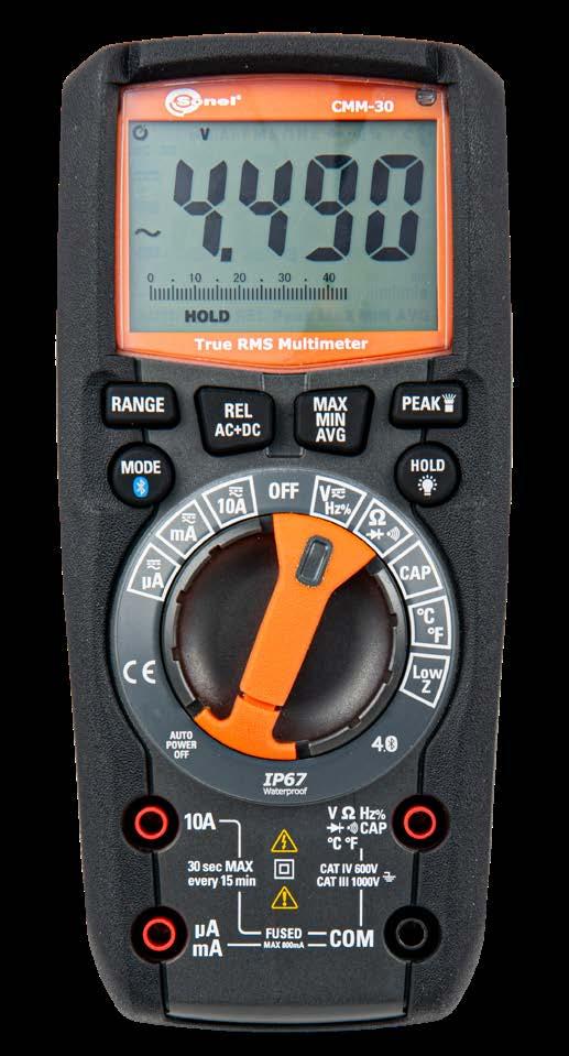
Display range Resolution Accuracy -20...760°C 0.1°C or 1°C ±(1.0% m.v. + 5°C) -4...1400°F 0.1°F or 1°F ±(1.0% m.v. + 9°F)
» continuity test threshold 30 Ω, measuring current <0.35 mA
»
measurement »
» display segment LCD, readout of 6000, 4 digits, backlit
»
155
of the display, buttons and rotary switch » built-in flashlight for illuminating dark measurement places » Auto-OFF function »
» dimensions 170 x 75 x 48 mm
selection »
Frequency measurement
Temperature probe (type K) WASONTEMK
Display range Resolution Accuracy 60.00 nF 0.01 nF ±(5.0% m.v. + 35 digits) 600.0 nF 0.1 nF ±(3.0% m.v. + 5 digits)6.000 μF 0.001 μF 60.00 μF 0.01 μF 600.0 μF 0.1 μF 6000 μF 1 μF ±(5.0% m.v. + 5 digits)
» power supply 4 x AAA 1.5 V battery or 4x AAA NiMH 1.2 V rechargeable battery
Factory calibration certificate
Display range Resolution Accuracy 600.0 Ω 0.1 Ω ±(1.5% m.v. + 5 digits) 6.000 kΩ 0.001 kΩ 60.00 kΩ 0.01 kΩ 600.0 kΩ 0.1 kΩ 6.000 MΩ 0.001 MΩ 60.00 MΩ 0.01 MΩ ±(2.0% m.v. + 10 digits)
A range: 10 A / 1000 V fast-acting
»
Additional functions the AC + DC function allows you to simultaneously display the value of the constant and variable component or the sum of both components during voltage measurement True RMS for AC voltage and current allows to measure the effective value of distorted waveforms function MAX MIN for displaying extreme function AVG for displaying the relative REL automatic and manual range HOLD function built-in Bluetooth module for data backlight hermetic
Capacitance measurement
» fuses mA, µA range: 0,8 A / 1000 V fast-acting
Duty cycle measurement
MULTIMETERSONEL MOBILE
sending
»
Test leads set (CAT IV, M) WAPRZCMM2
values »
4x AAA 1.5 V battery
» operating temperature range 0...+40°C at humidity <75%
Resistance measurement
»
»
» compliance with standards EN 61010-1 EN 61010-2-031, EN 61010-2-033 EN 61326-1, EN 61326-2-2
Other technical specifications:
»
range Resolution Accuracy
Display range Resolution Accuracy 400.0 Ω 0.1 Ω ±(1.0% m.v. + 4 digits) 4.000 kΩ 0.001 kΩ ±(1.5% m.v. + 5 digits) 40.00 kΩ 0.01 kΩ 400.0 kΩ 0.1 kΩ 4.000 MΩ 0.001 MΩ 40.00 MΩ 0.01 MΩ
Display range Resolution Accuracy 40.00 nF 0.01 nF ±(5.0% m.v. + 35 digits) 400.0 nF 0.1 nF ±(3.0% m.v. + 5 digits)4.000 μF 0.001 μF 40.00 μF 0.01 μF 400.0 μF 0.1 μF ±(4.0% m.v. + 5 digits) 4000 μF 1 μF ±(5.0% m.v. + 5 digits)
Sonel Multimeter Mobile application is intended for reading measurement values in live mode, as well as for transferring and storing measurement results in the memory of mobile devices based on the Android system. It can be downloaded from Google Play
Other technical specifications:
» display segment LCD, readout of 9999 readings, 4 digits, backlit
Factory calibration certificate
index:
Resistance measurement
Capacitance measurement
» auto-off timeout 15 min
» fuses mA, µA range: 0.5 A/600 V fast-acting
Electronic frequency measurement
» power supply 2 x AAA 1.5 V battery or 2 x AAA NiMH 1.2 V rechargeable battery
A range: 10 A/600 V fast-acting
» operating temperature range +5…+40°C at humidity <80%
400.0 μA 0.1 μA
Display range Resolution Accuracy 9.999 Hz 0.001 Hz ±(1.0% m.v. + 5 digits) 99.99 Hz 0.01 Hz 999.9 Hz 0.1 Hz 9.999 kHz 0.001 kHz 99.99 kHz 0.01 kHz
Display range Resolution Accuracy 0.1…99.9% 0.1% ±(1.2% m.v. + 2 digits)
» dimensions 121 x 67 x 45 mm
2 LATA GWARANCJI156
3
Duty cycle measurement
Display (DC) (AC) ±(1.0% m.v. + 3 digits) ±(2.0% m.v. + 5 digits) m.v. + digits) ±(2.5% m.v. + 5 digits) m.v. + 5 digits) ±(3.0% m.v. + 7 digits)
WMGBCMM11 Digital multimeter
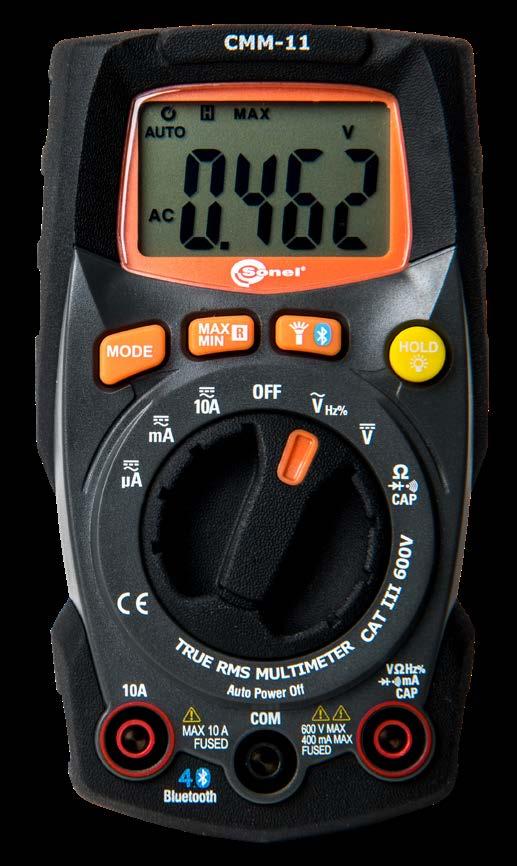
V battery
» input impedance 10 MΩ (V AC/DC)
SONEL CMM-11
Measurements » AC & DC voltage » AC & DC current » resistance » capacitance » duty cycle » frequency » diode and continuity test Additional functions » True RMS for AC voltage and current allows to measure the effective value of distorted waveforms » function MAX MIN for displaying extreme values » automatic and manual range selection » HOLD function » built-in Bluetooth module for sending data to mobile devices with Android system » built-in flashlight for illuminating dark measurement places » Auto-OFF function » hermetic (IP65) and reinforced housing resistant to shocks, covered with elastomer Direct and alternating (TRUE RMS) voltage measurement Display range Resolution Accuracy (DC) Accuracy (AC) 400.0 mV 0.1 mV ±(1.0% m.v. + 8 digits) 4.000 V 0.001 V ±(1.0% m.v. + 3 digits) ±(1.0% m.v. + 5 digits)40.00 V 0.01 V 400.0 V 0.1 V 600 V 1 V ±(1.2% m.v. + 3 digits) ±(1.2% m.v. + 5 digits) » input impedance: 10 MΩ » frequency range: 50…60 Hz Direct and alternating (TRUE RMS) current measurement
» continuity test threshold 50 Ω, measuring current <0.5 mA
meter
WAPRZCMM1
4000 μA 1 μA ±(1.5%
40.00 mA 0.01 mA 400.0 mA 0.1 mA 10.00 A 0.01 A ±(2.5%
2x AAA 1.5
» indication of range overflow “0L” symbol
» sampling rate 2 Hz
» storage temperature -20…+60°C at humidity <80%
» measurement category CAT III 600 V
» compliance with standards EN 61010-1 EN 61010-2-031, EN 61010-2-033 EN 61326-1, EN 61326-2-2
Set of test leads for CMM (CAT IV, S)
Accuracy
» diode test I=0.3 mA, U0<3.3 V DC
» weight 204 g
Standard accessories:
MULTIMETERSONEL MOBILE
»
»
Measurements
»
Direct
400.0 mV 0.1 mV
»
»
»
»
40.00 V 0.01 V

400.0
4000
Capacitance measurement
40.00 mA 0.01 mA 400.0 mA 0.1 mA 4.000 A 0.001 A
4.000 V 0.001 V
Standard accessories: Set of test leads for CMM/CMP WAPRZCMP1 Temperature measurement probe (type K) WASONTEMK Type K temperature probe adapter WAADATEMK 9 V Declarationbattery of verification
»
» AC & DC voltage AC & DC current resistance capacitance temperature duty cycle frequency diode and continuity test
Other technical specifications:
» measurement
SONEL CMM-10
Resistance measurement
»
»
Additional functions automatic and manual range selection freezing the measurement result thanks to HOLD function REL function enabling performance of relative measurement Auto-OFF function resistant to impacts strengthened housing, covered with elastomer and alternating voltage
» sensitivity: minimum effective voltage value 8 V. Duty cycle measurement Display range Resolution Accuracy 0.1…99.9% 0.1% ±(1.2% m.v. + 2 digits)
»
current measurement
10.00 A 0.01 A
Resolution
»
»
Display range Resolution Accuracy (DC) Accuracy (AC) μA 0.1 μA ±(1.0% m.v. + 3 digits) ±(1.5% m.v. + 30 digits) μA 1 μA ±(1.5% m.v. + 3 digits) ±(1.8% m.v. + 5 digits) ±(1.5% m.v. + 2 digits) ±(3.0% m.v. + 7 digits)
Display range Resolution Accuracy 400.0 Ω 0.1 Ω ±(1.2% m.v. + 4 digits) 4.000 kΩ 0.001 kΩ ±(1.0% m.v. + 2 digits) 40.00 kΩ 0.01 kΩ ±(1.2% m.v. + 2 digits)400.0 kΩ 0.1 kΩ 4.000 MΩ 0.001 MΩ 40.00 MΩ 0.01 MΩ ±(2.0% m.v. + 3 digits)
Display range Resolution Accuracy 40.00 nF 0.01 nF ±(5.0% m.v. + 7 digits) 400.0 nF 0.1 nF ±(3.0% m.v. + 5 digits)4.000 μF 0.001 μF 40.00 μF 0.01 μF 100.0 μF 0.1 μF ±(5.0% m.v. + 5 digits)
index: WMGBCMM10
Display range Resolution Accuracy 5.000 Hz 0.001 Hz ±(1.5% m.v. + 5 digits)50.00 Hz 0.01 Hz 500.0 Hz 0.1 Hz ±(1.2% m.v. + 3 digits) 5.000 kHz 0.001 kHz 50.00 kHz 0.01 kHz 500.0 kHz 0.1 kHz 5.000 MHz 0.001 MHz ±(1.5% m.v. + 4 digits) 10.00 MHz 0.01 MHz
Display range Accuracy (DC) Accuracy (AC) ±(0.5% m.v. + 2 digits) ±(1.5% m.v. + 70 digits) ±(1.2% m.v. + 2 digits) ±(1.2% m.v. + 3 digits) ±(1.5% m.v. + 3 digits) ±(1.5% m.v. + 2 digits) ±(2.0% m.v. + 4 digits) input impedance: 7.8 MΩ frequency range: 50…400 Hz and alternating
»
measurement
»
»
Direct
Display range Resolution Accuracy -20...760°C 1°C ±(3% m.v. + 5°C) -4...1400°F 1°F ±(3% m.v. + 9°F)
» display segment LCD, readout of 5000 readings, 3 5/6 digits, backlit power supply of the meter 9 V battery, type 6LR61 indication of range overflow “0L” symbol continuity test threshold 50 Ω, measuring current <0.3 mA diode test I=0.3 mA, U0=1.5 V DC sampling rate 2 Hz input impedance 7.8 MΩ (V AC/DC)
»
Temperature measurement
»
»
»
400.0 V 0.1 V 600 V 1 V
»
»
2 LATA 157GWARANCJI
Digital multimeter

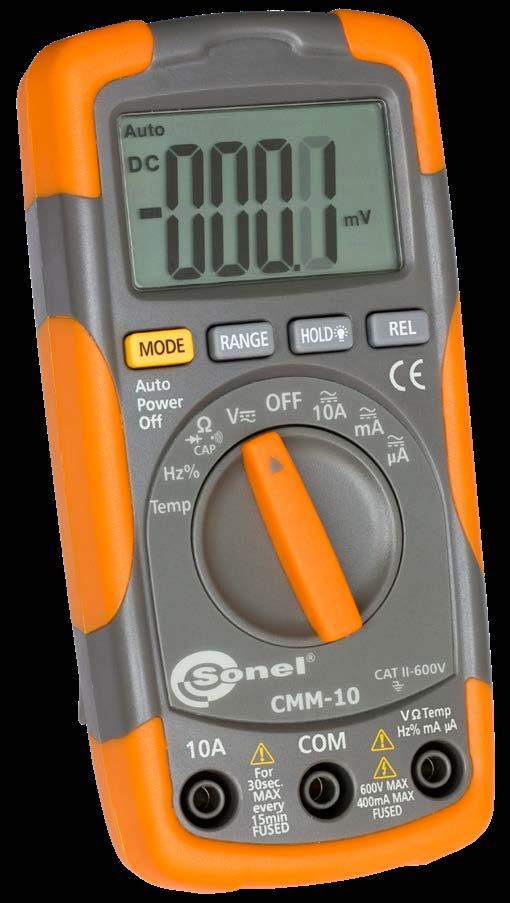
»
»
»
» auto-off timeout 30 min fuses mA, µA range: 0.5 A/1000 V fast-acting arange: 10 A/1000 V fast-acting operating temperature 0…+50°C at humidity <70% storage temperature -20…+60°C at humidity <80% dimensions 138 x 68 x 37 mm weight 210 g category CAT II 600 V compliance with standards EN 61010-1, EN 61010-2-032
Electronic frequency measurement
»
clip mini,

The adapter can be applied with any type of clamp meter.


• • • 1 • • • • • •
Test lead with probe for CMM/CMP (set)

CMP
WAPRZCMP1 • • • • 1 • • 1 1 1
Test lead with probe for CMM/CMP (set) WAPRZCMP2
Test leads set for CMM (CAT IV, M) WAPRZCMM2
WAPRZ002BUBBF10
• • • • • • • • • • •
Set
• • • • • • 1 • • • •
Test leads set for CMM (CAT IV, S) WAPRZCMM1


Test lead 2,0 m blue CAT IV 1000 V (banana plugs with 10 A fuse)

Test lead 2,0 m red CAT IV 1000 V (banana plugs with 10 A fuse)

clamp WACEGF16 1 1
• • • • • • • • • • •
• • • • • • • • • • Type temperatureK probe adapter WAADATEMK 1 1 1 1 1 1 1 1 Temperature probe (type K) WASONTEMK • 1 1 1 1 1 1 1 1 Photo Name Index CMM-60 CMM-40 CMM-30 CMM-11 CMM-10 CMP-3000 CMP-1015-PV CMP-2000 CMP-1006 CMP-401/400 CMP-3kR CMP-200F CMP-200 Temperature probe (type K, metal) WASONTEMK2 1 • • • • • • • • Temperature probe (type K, bayonet) WASONTEMP • • • • • • • • • M1 hanging hook straps WAPOZUCH1 • • hangingMagneticstrap WAPOZUCH6 • • • Battery charger WAZASZ21 1 Battery charger WAZASZ25 1 Battery charger power supply WAZASZ26 1 Charging adapter WAADALAD1 1 CMM-RRreceiverradio WAADACMMRR 1 Li-Pol battery 7.4 V, 2400 mAh WAAKU25 1 Li-Pol battery 7.4 V, 1200 mAh WAAKU30 1 M13 carrying case WAFUTM13 S1 carrying case WAFUTS1 • • • • • M3 carrying case WAWALM3 1 158
WAPRZ002YEBBF10
1 1 1 • • 1 • • • • 1
• • • • • • • • • • •
Crocodile 1 kV 10 A (set)
• • • • • • • • • • •
Test lead 2,0 m green CAT IV 1000 V (banana plugs with 10 A fuse)
WAPRZ002BLBBF10
WAKROKPL10MINI
of standard and optional accessories 1, 2, 4 - number of standard accessories • - optional accessories Photo Name Index CMM-60 CMM-40 CMM-30 CMM-11 CMM-10 CMP-3000 CMP-1015-PV CMP-2000 CMP-1006 CMP-401/400 CMP-3kR CMP-200F CMP-200 AC-16 line splitter WAADAAC16 • • • • • • •

F-16 flexible
WAPRZ002REBBF10
Test lead 2,0 m yellow CAT IV 1000 V (banana plugs with 10 A fuse)

WAPRZ002GRBBF10
Test lead 2,0 m black CAT IV 1000 V (banana plugs with 10 A fuse)


/ CMM

» reading the multimeter’s measurement results in live mode, thanks to Bluetooth wireless data transfer,
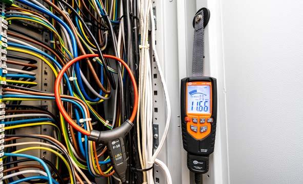
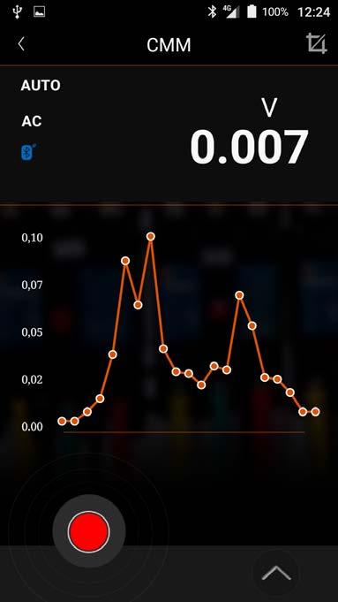
Sonel Multimeter Mobile application is intended for reading measurement values in live mode, as well as for trans ferring and storing measurement results in the memory of mobile devices based on the Android system. Currently the application supports CMP-3000, CMP-1015-PV, CMP-3kR, CMM-60, CMM-30 and CMM-11 multimeters. It can be downloaded from Google Play
The application enables:
» maximum current: 16 A
Universal magnetic hanging strap
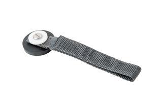
Additional application features i.a.:
Universal magnetic holder for mounting the meter to metal surfaces, e.g. switchgear doors.

» possibility of saving data to .csv file.
» sending data via e-mail,
» setting sampling rate and duration of the measurement,
index: WAPOZUCH6
» fast access to the instrument’s website,
» reading saved results in two forms: list with date and hour of the measurement, as well as in form of a chart for easier analysis of changes and distortions.
Crocodile clip mini, set, 1 kV 10 A

index: WAADAAC16
» saving results as a project and complete it with notes and photos from measurement places,
index: WAKROKPL10MINI
» controlling measurement subfunctions, i.e. MAX/MIN, REL or RANGE,
SONEL AC-16
Line splitter
» ratio x1, x10
» maximum voltage: 230 V AC
Crocodile clips for mounting on the probe's blades with a diameter of 2 mm, used in CMM and CMP multimeters.
» the adapter can be applied with any type of clamp meter
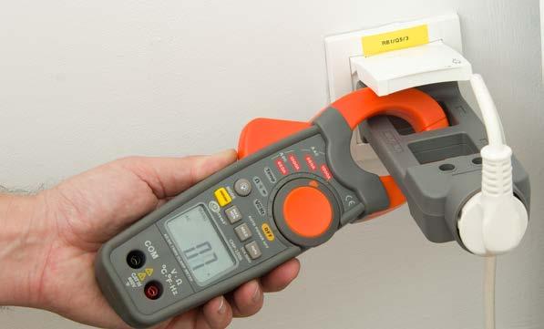
» setting upper and lower limit with acoustic signal in case of exceeding the set limits,
159
SONEL MULTIMETER MOBILE
index: WMGBP6 / WMGBP5 / WMGBP4
» RCD trip test with switchable load

Sonel P-6, P-5 and P-4 are reliable, particularly durable and safe 2-pole testers, which enable testing voltage, circuit continuity and phase sequence. They have been designed for use in extreme conditions both in industry and commercial applications. Advanced technology, a high level of safety and user-friendliness are the key features of the P-line voltage testers.
» robust, two-component housing protecting from mechanical damages and impacts
» continuity test: light and sound signal for R ≤ 400 kΩ
» P-6 • P-5 | optical indication by an additional LCD display
» operating / storage temperature -15…+55oC / -20…+70oC
» P-6 • P-5 | integrated torch light and backlit display for tests in poorly lit areas
» conformance with the requirements of standards EN 61010-1, EN 61243-3
» P-6 • P-5 | resistance measurement up to 1999 Ω
» minimum activation voltage ±6 V AC/DC
» display LCD, 3½ digits, 1999 read-out with function indicators
» single-pole indication of 100 V presence
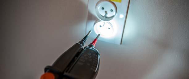
» sound indication when dangerous voltage levels of 50 V AC and 120 V DC are exceeded

double-insulation, class II
» automatic continuity test upon connection to the object
» auto-off time 10 s / 30 s (HOLD mode)
» protection class acc. to EN 60529 IP65
» input impedance approx. 300 kΩ
» HOLD function for freezing the measurement results
» P-6 • P-5 | range of resistance measurement 1…1999 Ω
Durability and comfort of use
» range for single-pole phase indicator 100…1000 V
voltage testers are provided with a set of test probes. The probes reduce metal exposure to 4 mm length, which eliminates the risk of accidental contact with the wrong conductor when performing measurements on a wire harness. Additional screw-on metal adapters are used for applications where tips with 4 mm diameter are required. It is particularly important for tests in electrical sockets, where the user must be sure that contact between the probe and the conductor is kept. All elements of the set are stored in a special case so the probe tips can be replaced when needed. The case also includes an adapter that is helpful for unlocking the UK-type sockets.
Versatility and safety
» electromagnetic compatibility in accordance with standards EN 61326-1, EN 61326-2-2
Parameter P-6 P-5 P-4 measurement category CAT III 1000 V / IV 600 V range of voltage 6.0 … 1000 V AC/DC 12 … ≥690 V AC/DC LED bar 7 segments backlit LCD display √ √ continuity test √ √ √ 10 mA / 30 mA RCD trip test √ √ √ built-in torch light √ √ √ single-pole phase tester √ √ √ 2-pole phase rotation tester √ √ √ IP65 protection class √ √ √ resistance test √ √ freeze display √ √ phase identification √ Standard accessories: Φ4 mm screw tip (set of 4 pcs.) WAPOZN4MMK 4 mm applied tip (set of 2 pcs.) WAPOZO4MMK 2x AAA / LR03 alkaline battery Declaration of verification Optional accessories: S2 case WAFUTS2 160
Product description
» automatic voltage test up to 1000 V AC/DC
» 2-pole test of phase rotation direction
Residual-current device trip testing
Technical specifications:
» insulation type acc. to EN 61010-1
SONEL P-6 / P-5 / P-4
» weight incl. batteries / excl. batteries 291 g / 267 g
» P-6 | phase identification - unique feature in voltage indicators worldwide
» IP65 ingress protection guarantees protection against dust and water
The housing has been designed for use in harsh industrial environments, where the application of personal protection equipment, such as voltage insulation safety gloves, is required. At the same time, the instrument's ergonomic shape allows for one hand use.
» dimensions 275 x 82 x 36 mm
» measurement category acc. to EN 61010-1 III 1000 V / IV 600 V
» operating frequency range 16…400 Hz
Main functions and attributes of the P-line instruments
Two-pole voltage testers
» optical indication by a LED bar
» safety provided by measuring class compliant with CAT IV 600 V and CAT III 1000 V standards

» instrument power supply 2 x LR03 AAA 1.5 V (recommended alkaline cells)
In response to the needs of clients, our new P-line voltage testers allow to check the RCD in a fully controllable way. With buttons on both probes, the user can reduce the internal impedance of the instrument, which makes it possible to trip the RCD. Additionally, pressing both buttons activates an additional loadpoint - a vibration motor. In this way, voltage can be measured in a tested circuit with no impact of stray currents on the result.


»
30…50% »
V
»
Durable
index: WMGBLMW100 Distance meter Standard accessories: Screwdriver WAPOZSRU1 S6 carrying case WAFUTS6 2x AAA 1,5 V battery Declaration of verification Optional accessories: S1 carrying case WAFUTS1
» power
-20…60°C »
Measurement functions Single
» measurement
Non-contact AC voltage and sound range: 90~1000 V AC (50/60 Hz) category: 1000 (LR03) light and sound range: 12~1000 V AC (50/60 Hz) category: IV 1000 V supply: 2x 1.5 V (LR03)
»
»
III
SONEL VT-2
detectorNon-contact AC voltage detector » signaling: light
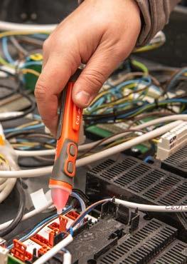

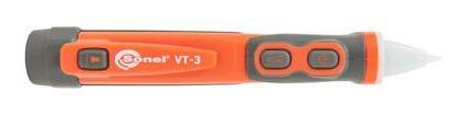

This compact device is equipped with the latest technologies to operate in challenging con ditions. The rubberised housing protects the device against damage.
»
The rangefinder has a range of up to 100 m. With the built-in algorithms, the device helps the user by calculating the area, cubature and - on the basis of 2 or 3 indirect measure ments - height
A pocket device with a handy shape.
0.5
»
»
»
Advanced
SONEL VT-3 WMGBVT2
3
»
index:
»
Features
Technical specifications: degree of housing protection acc. to EN 60529 IP54 range 0.05…100 m measurement accuracy at a distance of ≤10 m from ±1.5 mm unit of measurement meters / inches / feet memory of measurement results 20 records operating temperature -10…50°C storage temperature operating humidity storage humidity power supply AAA 1.5 battery inactivity time for triggering Auto-Off function laser min device min weight 100
2x
»
<95% »
index: WMGBVT3
» voltage
V » power supply: 2x 1.5 V
battery
The 100-meter range facilitates the work in many industry branches. Functions for calculat ing the area, volume and height, help the user to accelerate the execution of tasks.
SONEL LMW-100
mode measurements » Continuous measurements » Automatic continuous determination of extreme values » Summing up the results » Surface measurement » Volume measurement » Determining the distance with 2 measurements » Determining the distance with 3 measurements
g » dimensions 110 x 46 x 28 mm 161
» measurement
»
»
» voltage
battery » signaling:
Handy
The LMW-100 is an invaluable measurement assistant for users working in the construction industry, but also for electricians. It will help you to determine: the measurement grid for illuminance measurements, the distance to the probes when measuring earth resistance, the distance to cable damage indicated by the reflectometer.
Description

Test lead 2,0 m black CAT IV 1000 V (banana plugs, fused 10 A)
TKF-12L with motor model for rotation for rotation data phase-to-phase
Thanks to the innovative technology in the TKF-12L, we have achieved a record range of nominal phase-to-phase voltages: indication of voltage presence is displayed from 29 V AC.
Pin probe, black 1 kV (banana socket) WASONBLOGB1
Non-contact check of motor shaft rotation direction
Test lead 1.2 m, black, 1 kV (banana plugs) WAPRZ1X2BLBB
Prevention
AGT-63P three-phase socket adapter 63 A WAADAAGT63P
Application
WAPRZ002BUBBF10
Crocodile clip, yellow, 1 kV, 20 A WAKROYE20K02
»
nominal
Measure easily and accurately 16-, 32- and 63-amps industrial sockets with optional AGT-16, AGT-32 and AGT-63 adapters.
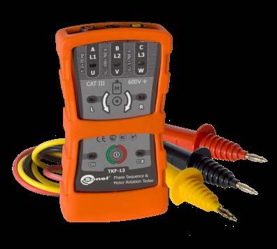
Test lead 1.2 m, yellow, 1 kV (banana plugs) WAPRZ1X2YEBB
The unique TKF-12, TKF-12L and TKF-13 testers are designed to control 3-phase electrical installations in a wide range of phase-to-phase voltages (35… 690 V, frequency up to 70 Hz) in distribution circuits. The indication of the rotating field and the direction of motor shaft rotation is performed, among others, with a non-contact method.
Test lead 2,0 m green CAT IV 1000 V (banana plugs, fused 10 A) WAPRZ002GRBBF10
Non-contact verification of motor shaft rotation direction is possible only in the TKF-13, which includes a function dedicated to this type of measurement.
TKF-12
Standard accessories:
Intuitive, trouble-free connection
Crocodile clip, red, 1 kV, 20 A WAKRORE20K02
Purpose
Declaration of verification
field measurement TKF-12L Basic model
Parameter TKF-13 Professional model
Features indication of phase sequence in networks with voltage 35...690 V AC operation in networks with 2...70 Hz frequency voltage indication light wired and wireless indication of motor rotation magnetic field detection
»
Test lead 1.2 m, red, 1 kV (banana plugs) WAPRZ1X2REBB
TKF-13
Pin probe, red 1 kV (banana socket) WASONREOGB1
AGT-32P three-phase socket adapter 32 A WAADAAGT32P
Various colored cables, crocodile clips and test probes allow you to connect the device to the tested object - quickly and without any problems.


Pin probe, yellow 1 kV (banana socket) WASONYEOGB1
Versality
SONEL TKF-13 / TKF-12 / TKF-12L index: WMGBTKF13 / WMGBTKF12 / WMGBTKF12L
Crocodile clip, black, 1 kV, 20 A WAKROBL20K01
AGT-16C three-phase socket adapter 16 A (PEN) WAADAAGT16C
Sensitive indication
testing TKF-12 Basic
voltage range 120...690 V AC 160...690 V AC 35...690 V AC maximum phase-to-phase operating voltage 760 V AC range of motor electromotive force voltages 1...760 V AC frequency range 2...70 Hz 10...70 Hz Other data work temperature -10...+45°C storage temperature -20...+60°C work humidity 20...80% power supply 6LR61 alkaline battery (9 V) from the tested network up to 15 min for maximum voltage battery status LED blinking period ca. 1 s automatic shutdown time ca. 5 min dimensions (with holster and without test leads) 130 x 72 x 31 mm weight without test leads ca. 150 g ca. 200 g measurement category in accordance with EN 61010 and EN 61557 CAT III 600 V insulation type double in accordance with EN 61010-1
AGT-16P three-phase socket adapter 16 A WAADAAGT16P

Test lead 2,0 m red CAT IV 1000 V (banana plugs, fused 10 A) WAPRZ002REBBF10
Optional accessories:
162
»
field measurement Basic technical
WAFUTS3
S3 carrying case
Phase sequence testers
WAPRZ002BLBBF10
»
AGT-32C three-phase socket adapter 32 A (PEN) WAADAAGT32C
Test lead 2,0 m blue CAT IV 1000 V (banana plugs, fused 10 A)
Test lead 2,0 m yellow CAT IV 1000 V (banana plugs, fused 10 A) WAPRZ002YEBBF10
»
Standard accessories, included in the kits, allow for quick verification whether the shaft rotates in the correct direction after the motor is connected. Otherwise, the engine or the equipment driven by it may be damaged.
» storage temperature -20…+60ºC
» assess unpressurized tanks,
Sonel TUD-1 is a professional, portable device that allows:
Acoustic probe type 3 WASONAKU3
Standard accessories - TG-1:
» centre frequency of the detection range (40±1) kHz
MicroUSB cable
» time of continuous operations ≥20 h
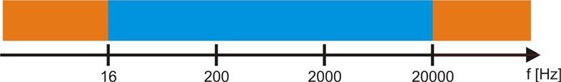
WAPOZSLU1
TUD-1
» detect cracks and holes.
» operating temperature -20ºС…+45ºС
» max. relative humidity of storage 80% at temp. up to 31ºC linearly decreasing to 50% with temp. increasing to 40ºC
TUD-1 ultrasonic detector WMGBTUD1 GUD-1 ultrasonic generator WMGBGUD1
» Stepless adjustment of gain
Acoustic probe type 1 WASONAKU1
» Identification of acoustic-wave defects in the range of ultrasounds (40±1) kHz
Additionally, the unit strengthens the waves and presents the signals via the LED scale and via sounds in the earphone set.
SONEL TUD-1 / GUD-1 / TG-1
» sources of electrical discharge that can be located on such elements as power grid lines, insulators, generators, transformers,
Infrasound
Headphones
163
Acoustic
Features
» Additional probes selected for different methods of analyzing the leakage spot
» maximum operating altitude 2000 m
TG-1
Cap protecting the ultrasonic sensor М6 carrying case WAFUTM6 6LR61 9 V battery (MN1604)
Other technical specifications:
Standard accessories - TUD-1:
» power supply 9 V battery (6LR61 / MN1604)
WAPRZUSBMICRO
» power consumption ≤0.35 W
» searching for leaks in pneumatic and hydraulic systems

Ultrasound
Acoustic probe type 3 WASONAKU3
Cap protecting the ultrasonic sensor М6 carrying case
» relative operating humidity 80% at +20ºС
MicroUSB cable
index: WMGBTUD1 / WMGBGUD1 / WMGBTG1
Standard accessories - GUD-1: GUD-1 ultrasonic generator WMGBGUD1 6LR61 9 V battery (MN1604)
GUD-1
Sonel GUD-1 as support
It can generate ultrasonic signals in places, where gas or air leak does not have enough pressure to generate ultrasonic sound. GUD-1 allows to:
WAFUTM6 2 x 6LR61 9 V battery (MN1604)
WAPRZUSBMICRO
Description of the product
» leak checks on systems that supply water and gas, such as pipelines, taps, valves, hydraulic components, pumps, compressors,
» diagnostics of the condition of mechanical components, including bearings, gears, drive shafts, pumps, compressors, generators.
TUD-1 ultrasonic detector WMGBTUD1

Declaration of verification
» weight with battery installed ≤0.22 kg
» Easy and clear interpretation of results visually on the LED scale and acoustically via earphones
Sonel TUD-1 is a compact, portable device that receives ultrasonic waves and transforms them into acoustic waves in a range that is audible for the human ear.
Acoustic probe type 2 WASONAKU2
Ultrasonic leak and electrical discharge detector
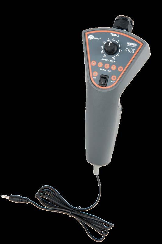
Declaration of verification
Declaration of verification
Acoustic probe type 1 WASONAKU1 Acoustic probe type 2 WASONAKU2
Headphones WAPOZSLU1
» dynamic range ≥60 dB
» dimensions 190 x 60 x 70 mm
F-4 flexible coil (Ø630 mm) WACEGF4OKR
Display
» operating temperature range -10…+50°C
» measurements in low- and medium-voltage networks with frequency of 50 Hz or 60 Hz,
Straps for mounting on the pole for PQM (set) WAPOZOPAKPL Mains cable with IEC C7 plug WAPRZLAD230 L5 carrying case for MPU-1 WAWALL5
» storage temperature -20…+80°C
Resolution
» measurement on one or two clamps simultaneously, in the case of measurement using two clamps, the current value is summed, and this provides the capability of measuring spun poles with independent clamps for each component pole,
The standard kit includes a transport briefcase for the signaler, standard and additional accessories.

» charger operating temperature range +10…+35°C
Cable for battery charging from car cigarette lighter socket (12 V) WAPRZLAD12V2
Technical data:
» elevation above sea level <2000 m
» this product meets EMC requirements in compliance with standards EN 613261 and EN 61326-2-2
SONEL MPU-1

» nominal relative humidity 40…60%
index: WMGBMPU1
Factory calibration certificate
Optional accessories:
» monitoring of battery level,
» instrument power supply rechargeable battery pack SONEL NiMH 9.4 V 2.1 Ah
Leakage current alarm signaler
0.1…9.9 A 0.1 A ±(5% m.v. + 2 digits)10…299 A 1 A » frequency range: 50 Hz or 60 Hz » flexible current coil – F-1A Operation in medium-voltage mode - the display reads the value of the set alarm threshold and indicates the battery charge status. Operation in low-voltage mode - the display reads the value of the measured current flowing through the clamp and indicates the battery charge state.
» operating time for standby mode >18 h
F-3A flexible coil (Ø120 mm) WACEGF3AOKR
» housing protection rating according to EN 60529 IP67
» weight of instrument with rechargeable batteries approx. 1.1 kg
164
» dimensions 125 x 150 x 95 mm
Standard accessories:
» alarm in the event of flow of current higher than the alarm threshold (factory setting 1 A), sound and visual alarm (speaker built into the housing),
» qualitydevelopment,standard design and production in compliance with ISO 9001
» diode indicator of operating mode,

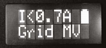
F-1A flexible coil (Ø360 mm) WACEGF1AOKR
» parameters of battery charger power adapter 100…240 V 50…60 Hz
The most important features of the MPU-1 instrument include:
MPU-1 is intended for monitoring (measurement) of leakage current in power networks of alternating current, low and medium voltage, and serves for performing measurements whose results determine the safety status of the monitored system from the perspective of flowing leakage current. The instrument enables setting of the safe threshold value of flowing leakage current, above which a visual and sound alarm is activated.
» continuous monitoring of alternating current flowing through earthing,

» automatic selection of measuring range,
» ergonomic operation.
Power supply adaptor Z11 WAZASZ11
» operating time for alarm mode 3 h
F-2A flexible coil (Ø235 mm) WACEGF2AOKR
Features:
» alarm threshold setting range 0.5 … 9.9 A
Measurement of leakage currents flowing through clamp: range Accuracy
» reference temperature 23 ± 2°C
» measurement with flexible Sonel F-series coil (Rogowski coil) with a max. length of 2 m,
» relative humidity 20…90%
The DB-1 board makes it possible to demonstrate the method of performing the following tests:
Technical specifications of DB-1 board and features of individual functions:
• touch voltage measurement.
SONEL DB-1
» Continuitymeasurementof connections:of equipotential bonding and connections of accessible parts.
• safe voltage exceeded during RCD measurement (UB),
• measurement of RCD trip time,
» 230 V network socket.
The of earth electrode (ZW RE1 of equipotential bonding of H20 pipe (ZW
» fault loop impedance for assessment of the automatic power cutoff condition,
RE1
» earthing resistance,
» Simulation of irregularities: no continuity of earth conductor (RE),
• insufficient L-N insulation resistance (RISO(L-N)),
WMGBDB1 Demonstration board
• excessive fault loop impedance (ZL).
• measurement of L-N short-circuit with impulse currents up to 25 A and 60 ms,
» Soil resistivity:
• resistivity measurement for three soil types (31 Ωm, 295 Ωm, 5.9 kΩm).
» soil resistivity,
Measurements
) 9) Socket
• earth resistance measurement,
• measurement of L-PE earth fault loop with impulse currents up to 20 mA.
» insulation resistance,

» RCD parameters (30 mA RCD):
• measurement of RCD trip current,
index:
» Voltagevoltagemeasurement:measurement in power socket.
» Fault loop impedance:
DB-1 demonstration board makes it possible to simulate various faults and irregularities in an electrical network. 1 2 3 4 6 11 10 7 11 14 13 9 8 11 11 12 11 5 15 16 1) Power socket 230 V 2) Additional PE socket 3) 230 V power indicator lamp 4) Residual current device (RCD) 5) Measurement socket 6) TN network cramp 7) TT network cramp 8) Socket
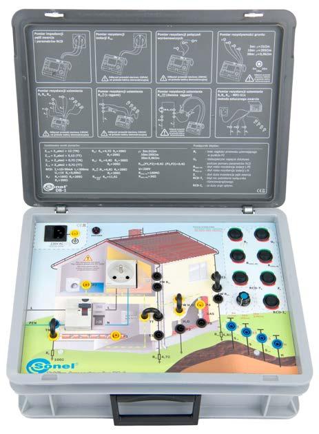
H2O) 10) Socket of earth electrode RE2 (ZW RE2) 11) Measurement points P1, P2, P3, P4, P5 12) Measurement point of earth electrode RE1 (E1) 13) Measurement point of earth electrode RE2 (E2) 14) Measuring electrode sockets 15) Irregularity selection switches 16) Soil type switch for soil resistivity measurements Basic technical data: » RCD type 30 mA type AC » power supply from network 230 V » power consumption approx. 15 mW » protection 2 x T3 14A 250 V or 2 x F 4 A 250 V Safety and work conditions: » measuring category according to EN 61010 II 300 V » ingress protection IP40 » type of insulation according to EN 61010-1 and IEC 61557 single » operating temperature 10…+40°C » storage temperature -20…+60°C » humidity 20…80% » dimensions 405 x 300 x 140 mm » weight ca. 3.6 kg Other information » Quality standard – development, design and production ISO 9001 Standard accessories: Test lead 0.7 m, black (banana plugs) WAPRZ0X7BLBB Mains cable with IEC C13 plug WAPRZ1X8BLIEC 4x configuration jumper WAPOZZW1 Declaration of verification 165
• permissible RCD tripping time (tA) exceeded,
• permissible RCD tripping current (IA) exceeded,
• 2-pole method,
» power network voltage.
• insufficient L-PE insulation resistance (RISO(L-PE)),
» Insulationmeasurementresistance:of L-N insulation, measurement of L-PE insulation, measurement of N-PE insulation.
» continuity test of equipotential bonding,
• 4-wire method, 3-pole method with clamp, two-clamp method, with the use of fault loop meter.
It is possible to simulate typical failures and irregularities in the electrical network.
» RCD parameters,
» Earthing Measurementresistance.by:
Features
• 3-pole method,
DB-THERMO has a heating panel with an emissivity of 0.98 as well as plates made of various typical materials, with matte and polished surfaces. A programmable controller keeps watch over the temperature of the heating panel. The user may select a temperature from within the range of 40...60°C. The LED display reads the current panel temperature.
Power supply 24 V DC / 4 A WAZASZ31
» Quality standard – development, design and production ISO 9001
WAPOZOSL3
» type of insulation according to EN 61010-1 CAT II 300 V
» ingress protection IP20
Polycarbonate 0.88 0.91 Glass 0.84 0.90
Stainless steel 0.12 0.39
» resolution of temperature readings 0.1°C
» hysteresis ±1.5°C
» dimensions 330 x 260 x 140 mm
» operating temperature 10…+40°C
Demonstration board
» weight of device ca. 0.5 kg
Aluminium 0.10 0.30 Brass 0.04 0.33
Safety and work conditions:
The device is enclosed in a solid briefcase housing with a detachable cover.
Standard accessories:
Emissivity of main plate (110 x 110 mm)
» thermal protection 85°C
» resolution of temperature settings 1°C
» power supply 24 V DC
The DB-THERMO board is an indispensable device during any training on contactless temperature measurements and thermal imaging with the use of thermographic cameras. DB-THERMO helps to understand the phenomena related to the emissivity of different materials and the influence of surface type on temperature measurement.
Heating panel protective plate
» display LED
The DB-THERMO demonstration board has a builtin programmable controller that stands vigil over the temperature of the heating panel.
» plate temperature regulation range 40°C...60°C
» power consumption max. 100 W
» storage temperature -20…+70°C
166
SONEL DB-THERMO
» plate temperature reading accuracy ±2%
The DB-THERMO set includes instructions describing all topics concerning thermal imaging.
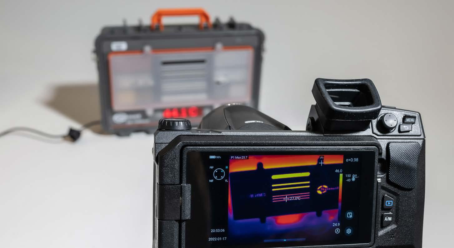

Other information
Material Polished Matte Copper 0.03 0.20
index: WMGBDBTHERMO
Emissivity of materials (70 x 30 mm plates):
» heating panel dimensions 275 x 110 mm
» temperature stabilization time <5 min
Basic technical data:
Material Polished Matte Blackened aluminium 0.98
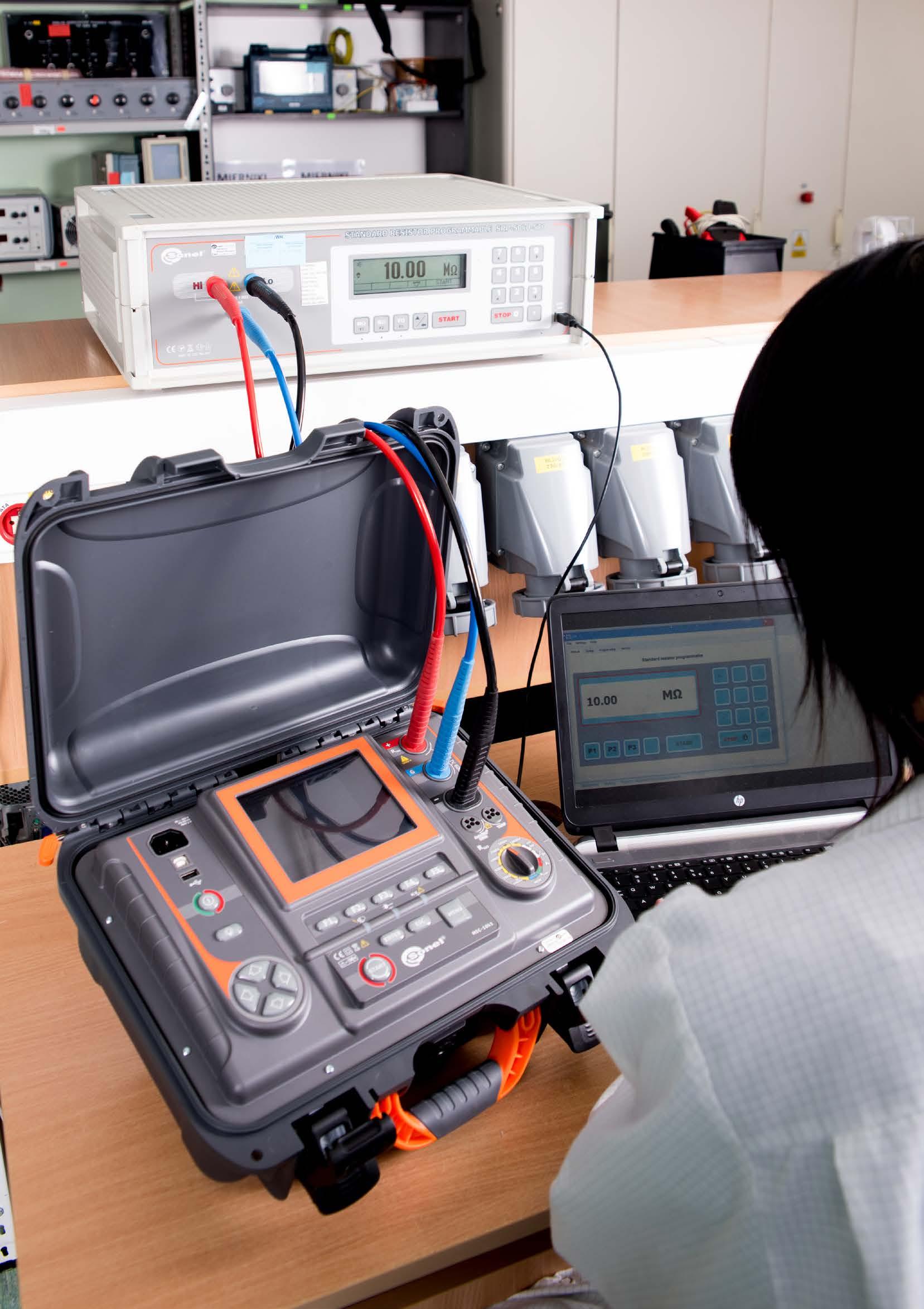
The resistance obtained thanks to these resistors can be kept for a long time under external direct voltage:
SRP Control Software (only SRP-50k0-5T0, SRP-50k0-10G0, SRP-50k0-100G0)
Technical specifications of SRP-10G0-10T0: Umax = 10 000 V DC Display range Resolution Accuracy 10…990 GΩ 10 GΩ 1% s.v. 1.0…10.0 TΩ 0.1 TΩ 1.5% s.v. Technical specifications of SRP-50k0-5T0: Umax = 5000 V DC Display range Resolution Accuracy 0.05…999.95 MΩ 0.05 MΩ 1.5% s.v.0.001…999.999 GΩ 0.001 GΩ 0.0001…5.0000 TΩ 0.0001 TΩ Technical specifications of SRP-50k0-100G0: Umax = 2500 V DC Display range Resolution Accuracy 50…950 kΩ 50 kΩ 0.05% s.v. 1.00…99.95 MΩ 0.05 MΩ 0.1% s.v. 100.0…999.9 MΩ 0.1 MΩ 0.5% s.v. 1.00…100.00 GΩ 0.01 GΩ Technical specifications of SRP-50k0-10G0: Umax = 2500 V DC Display range Resolution Accuracy 50…950 kΩ 50 kΩ 0.1% s.v. 1.00…99.95 MΩ 0.05 MΩ 0.2% s.v. 100.0…999.9 MΩ 0.1 MΩ 1% s.v. 1.00…10.00 GΩ 0.01 GΩ 1% s.v. “s.v.” = “set value” Standard programmable resistors are intended for operation at ambient temperatures within the range from 10 to 30°С, relative humidity of air from 25 to 60%, and atmospheric pressure from 630 to 800 mm Hg. Standard programmable resistors
» maximum current in measuring circuit 3 mA
The SRP application serves for inter-operation between SRP-50k0-5T0, SRP-50k0-10G0 and SRP-50k0-100G0 resistance calibrators and a com puter. The calibrator connects to a computer via USB port.
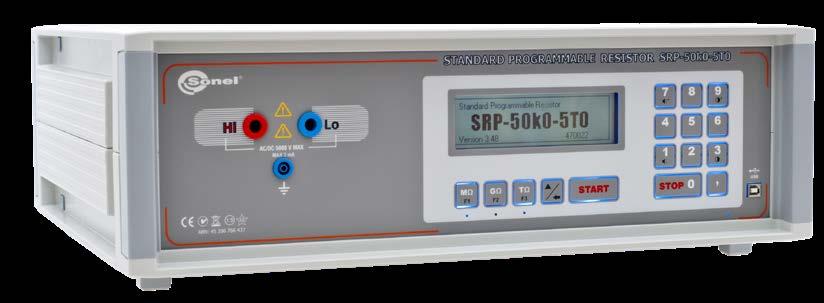
Other technical specifications:
The required resistance is set by the user by means of the standard resistor’s keypad and - for SRP-50k0-5T0 / SRP-50k0-10G0 / SRP-50k0-100G0 - PC application SRP Control Software

WAPRZ1X8BUBB
SRP calibration software

Standard programmable resistors are a source of high resistances used as standard equip ment for calibration and testing of analog and digital insulation resistance meters.
» remote calibrator control,
Test lead 1.8 m, blue, 5 kV (banana plugs)
» resistor settings include a keyboard lock and time until switching to sleep mode,
The application is easy to use and a useful tool in the process of testing devices by means of a calibrator.
» max. operating elevation 2000 m
» SRP-10G0-10T0 | up to 10 kV
Setting of the required value is automatic thanks to commutation of a precision resistance matrix. The control processor calculates the required combination of resistors providing the proper precision of the resultant resistance.
» firmware update from computer via USB interface.
» long-term resistor stability <1%
» dimensions 540 x 450 x 200 mm
WAPRZUSB
» SRP-50k0-5T0 | up to 5000 V,
Test lead 1.8 m, black, 5 kV (banana plugs, shielded) WAPRZ1X8BLBB
» change of display brightness and keyboard response sounds,
» supply voltage 100…240 V AC (50/60 Hz)
» operating temperature range +10…+30°C
» SRP-50k0-10G0 • SRP-50k0-100G0 | up to 2500 V,
» software upgrade from a computer via a USB interface.
» maximum operating voltage
Mains cable with IEC C13 plug
The SRP-50k0-5T0 programmable resistor allows to set any resistance from range 50 kΩ…5 TΩ for 5 kV DC voltage.
SRP-10G0-10T0 / SRP-50k0-5T0 / SRP-50k0-10G0 / SRP-50k0-100G0 index: WMGBSRP10G010T0 / WMGBSRP50K05T0 / WMGBSRP50K010G0 / WMGBSRP50K0100G0 168
» language selection in application,
WAPRZ1X8BLIEC USB cable (only SRP-50k0-5T0, SRP-50k0-10G0, SRP-50k0-100G0)
SRP-50k0-10G0 2500 V DC
» creation and saving of automatic programs for testing of equipment,
Test lead 1.8 m, red, 5 kV (banana plugs)
Capabilities of the application:
WAPRZ1X8REBB
» maximum power consumption 75 VА
SRP-50k0-5T0 5000 V DC
Standard accessories:
SRP-10G0-10T0 10 000 V DC
SRP-50k0-100G0 2500 V DC
» weight approx.15 kg
SRM-3
SRM-3-100
SRM-3-01/1 WMGBSRM3011 3 0.1 Ω…111 Ω 1
6 0.1 Ω…111 111 kΩ 2
SRM-3-01/3 WMGBSRM3013 3 0.1 Ω…111 Ω 3
SRM-3-100/1 WMGBSRM31001 3 100 Ω…111 kΩ 1
SRM-6-100/1 WMGBSRM61001
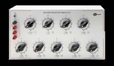
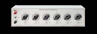

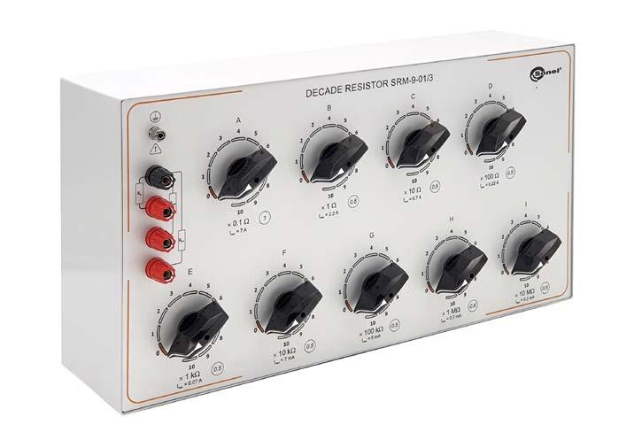
6 100 Ω…111 111 MΩ 2 SRM-6-100/3 WMGBSRM61003 6 100 Ω…111 111 MΩ 3 SRM-9
»
»
6 0.1 Ω…111 111 kΩ 3
SRM-3-100k
A metal housing effectively protects the instrument against mechanical damage. The housing has rubber legs that stabilize the instrument's po sition on the measurement table.
SRM-9-01/1
ca. 6 kg SRM-9 ca. 9 kg
SRM-3-100k/1 WMGBSRM3100K1 3 100 kΩ…111 MΩ 1
SRM-3-100k/2 WMGBSRM3100K2 3 100 kΩ…111 MΩ 2
6 100 Ω…111 111 MΩ 1
WMGBSRM9011 9 0.1 Ω…111 111 111 MΩ 1 SRM-9-01/2 WMGBSRM9012 9 0.1 Ω…111 111 111 MΩ 2 SRM-9-01/3 WMGBSRM9013 9 0.1 Ω…111 111 111 MΩ 3 SRM-6SRM-3 SRM-9
SRM series resistance decade boxes have been developed with labo ratories and institutions requiring the most accurate readings in mind. High-precision decade boxes meet the expectations of even the most demanding customers. Applied resistors are characterized by excellent accuracy and long-term stability
» high accuracy, up to 0.05%, ranges from 0.1 Ω to 111 111 111 MΩ, easy-to-read and comprehensive graphical description of the instrument, functional test jacks, durable and resistant design, available in variants with 3, 6 and 9 sections.
SRM-3 / SRM-6 / SRM-9 Manual decade resistor index: WMGBSRM3... / WMGBSRM6... / WMGBSRM9... Other technical specifications: » initial resistance ≤ (0.025 ± 0.0025) Ω » maximum operating voltage 2000 V » insulation resistance >10 GΩ » operating temperature 10…35°C » storage temperature -20...+60°C » humidity 25…80% » dimensions:SRM-3 215 x 147 x 160 mm SRM-6 540 x 147 x 160 mm SRM-9 472 x 260 x 160 mm » weight:SRM-3 ca. 3 kg
SRM-6-01/1 WMGBSRM6011 SRM-6-01/2 WMGBSRM6012 SRM-6-01/3 WMGBSRM6013
»
SRM-3-100k/3 WMGBSRM3100K3 3 100 kΩ…111 MΩ 3
Index Number of decades Range Accuracy class
Features:
»
x - number of decades (3, 6 or 9) y - minimum resistance range: 01 - (0.1 Ω; 3, 6, 9 decades) 100 - (100 Ω; 3, 6 decades) 100k - (100 kΩ; 3 decades) z - accuracy class: 1 - high (0.05%) 2 - medium (0.2%) 3 - low (0.5%) Comparison of relative errors according to measuring ranges of SRM resistance decade boxes relativeerror R [Ω] 0.050.10.20.51 0.1 1 10 100 1K 10K 100K 1M 10M 100M SRM-x-y/2 SRM-x-y/1SRM-x-y/3 Comparison of simulated resistance and maximum acceptable current ranges R[Ω] 7 max.A 2.2max.A 1 max.A 0.22max.A 0.07max.A 7max.mA 5max.mA 0.7max.mA 0.2max.mA 1 10 100 1K 10K 100K 1M 10M 100M SRM-3-01/z SRM-3-100/z SRM-3-100k/z SRM-6-01/z SRM-9-01/z SRM-6-100/z SRM decade resistors are used as standards in the calibration of resistance meters - including Sonel MPI, MRP, MRU, MIC and others - according to the parameters of grounding resistance, touch voltage, DC resistance. 169
SRM-6-100/2 WMGBSRM61002
»
6 0.1 Ω…111 111 kΩ 1
SRM-3-01/2 WMGBSRM3012 3 0.1 Ω…111 Ω 2
SRM-6-01
SRM-6
SRM-3-100/2 WMGBSRM31002 3 100 Ω…111 kΩ 2
SRM-3-100/3 WMGBSRM31003 3 100 Ω…111 kΩ 3
SRM-6
SRM-3-01
SRM-6-100
Descriptions on the housing clearly inform the user of the set resistance value. Test jacks make it possible to connect the instrument by means of a banana plug, spade plug and insulated lead terminations.
Model
»
45 2nd decade 1 / 2 / 3 / 4 / 5 / 6 / 7 / 8 / 9 / 10 ±0.0005
170
»
Features: high accuracy - up to 0.05%, ranges from 0.1 Ω to 4111 Ω, built-in cooling system - enables high power dissipation, easy-to-read and comprehensive descriptions of the device, functional test jacks, durable and resistant design. R R 35
»
Other technical specifications: initial resistance R0 ≤ (0.025 ± 0.0025) Ω maximum operating voltage 450 V insulation resistance ≥100 MΩ measurement cycle time Тmeas ≤30-40 ms cooling time (pause) Тmeas ≥20 s | Umeas ≤ 230 V ≥25 s | Umeas ≤ 450 V operating temperature 10 30°C storage temperature -20...+60°C humidity 25 60% dimensions 500 x 340 x 170 mm weight ca. 12 kg
»
»
»
Decade No. of the device Nominal resistance values [Ω] Maximummeasurementpermissibleerror Maximum surge current (30...40 ms) [A] 1st decade 0,1 / 0,2 / 0,3 / 0,4 / 0,5 / 0,6 / 0,7 / 0,8 / 0,9 / 1,0 ±0.001
»
»
High-current decade resistor index: WMGBSRM0R14K1
»
3rd decade 10 / 20 / 30 / 40 / 50 / 60 / 70 / 80 / 90 / 100 ±0.0005 R 15 4th decade 100 / 200 / 300 / 400 / 500 / 600 / 700 / 800 / 900 / 1000 ±0.0005 R 2 5th decade 1000 / 2000 / 3000 ±0.0005 R 0,3
The SRM-0R1-4k1 decade resistor simulates the fault loop resistance with mains voltage. It is used as reference equipment for calibration and certification tests of Sonel MZC, MRP, MPI and other instruments according to the fault loop parameters.
The SRM-0R1-4k1 decade uses a built-in cooling system powered from 230 V AC 50 Hz mains.


»
»
»
SRM-0R1-4k1 is a high precision decade resistor designed for laborato ries and institutions that require highly accurate readings. This device will meet the expectations of the most demanding customers.
»
»
»
SONEL SRM-0R1-4k1
»
Built-in resistors provide excellent accuracy and long-term stability Markings and symbols on the housing of the device clearly inform the user about resistance settings. Measuring connectors allow user to con nect the device with a banana plug, spade plug and bare wire terminals. The metal housing efficiently protects the device against mechanical damage. It has rubber feet that stabilize device position on the test bench.
Designing
THT: » ERSA-WAVE 330 wave soldering system (soldering in nitrogen atmosphere). » 70 stations of manual and supplementary assembly. » Inspection and testing » AOI ORBOTECH S-22 automatic optical tester, equipped with nine cameras, » electrical testing of printed circuits, » AOI (Automatic Optical Inspection), » ionic cleanliness test (Ionograph), » function tests.
We perform every order with the appropriate accuracy in the proper environment (ionic
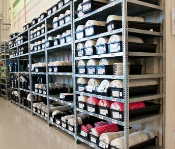
Our meters are manufactured based on the latest SMT and THT electronics assem bly technologies. Besides manufacturing measuring also comprehensive surface mounting and through-hole
who
SMT AND THT ASSEMBLY
tests), and thus, we ensure that your product is of the highest quality. 171


Quality and environment cleanliness
assembly.
The creation of a new product depends on the designing process. For this purpose, have picked a specialized team of designers, will create the perfect solution for needs through their determination and potential.
Programmable selective casting (capability of selecting any area on a circuit board’s surface) with lacquer or resin protective coating is performed automatically. Because of this, we achieve better productivity and save valuable time in the entire production process.


Repair andmaintenance
you
enormous
In order to dispel all doubts as to the proper functioning of our electronic systems, they undergo tests individually designed by us.


Production
We understand production to be the process of product creation. In our book, production means quality, precision, time, and above all, a perfectly filled order, in which we apply modern technology combined with a vast pool of knowledge. Production line SMT: » MPM MOMENTUM screen printer, » FUJI NXT automatic mounter, 6 modules, » ERSA HOTFLOW 2/20 reflow soldering furnace (soldering in nitrogen atmosphere with residual oxygen analyzer), » ASYS conveyor line, » DEK 265 screen printer, » FUJI GL2 dispenser, » FUJI FCP-III-4000 high speed chip placer, » FUJI FIP-III universal automatic chip placer (additionally featuring a coplanarity check).
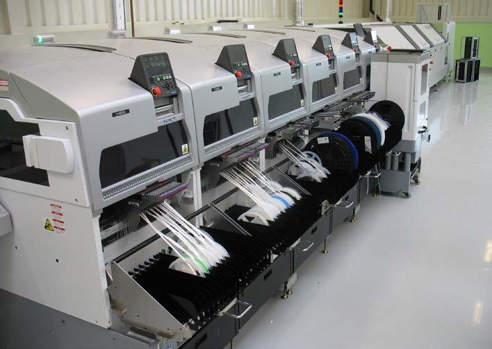
We offer assembly and disassembly, repair and maintenance of elements as an additional service.
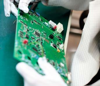
instruments, we
Protective coatings
we
Tester construction
render
»
According to ILAC-G24 „Guidelines for determination of calibration intervals of measuring instruments”, SONEL S.A. recommends periodical metrological in spection of the instruments it manufactures no less frequently than once every 12 Formonths.newinstruments provided with the Calibration Certificate or Validation Certifi cate at the factory, re-calibration should be performed within 12 months from the date of purchase, however, no later than 24 months from the date of purchase.
The person performing the measurements should be absolutely sure about the efficiency of the device being used. Measurements made with an inefficient meter can contribute to an incorrect assessment of the effectiveness of health protec tion and even human life.
172
»
»
»
» pyrometers, » lux meters, thermo-imaging cameras.
LABORATORY
METERS FOR MEASUREMENTS OF NON-ELECTRICAL PARAMETERS
ATTENTION!
» voltage meters, current meters (including clamp meters), resistance meters, insulation resistance meters, earth resistance and resistivity meters, RCD meters, short-circuit loop impedance meters, power quality analyzers, portable appliance testers (PAT), power meters, multimeters, multifunction meters covering the functions of the above-mentioned instruments,
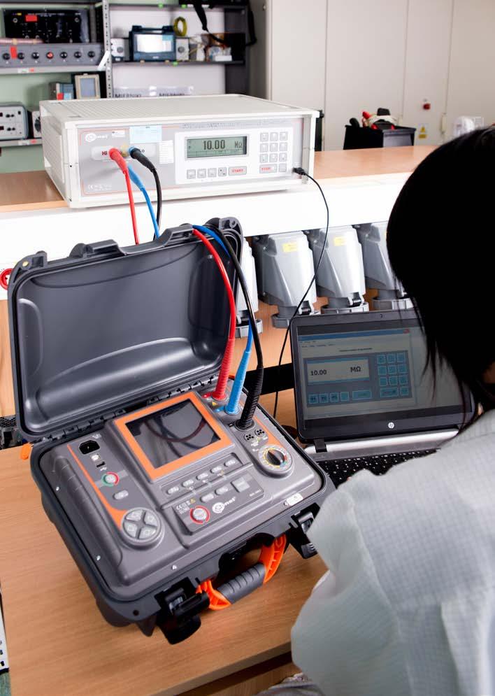
METERS FOR MEASUREMENTS OF ELECTRICAL PARAMETERS
»
Laboratory offers calibration for the following instruments that are used for mea suring electrical and non-electrical parameters.

»
»
»
»
»
SONEL Testing and Calibration Laboratory has been accredited by the Polish Center for Accreditation (PCA) - certificate no. AP 173.

» calibrators, resistance standards,
»
»
»
ELECTRICAL STANDARDS
The Calibration Certificate is a document that presents a relation between the cal ibration standard of known accuracy and meter indications with associated mea surement uncertainties. The calibration standards are normally traceable to the national standard held by the National Metrological Institute.
173
174
175
v1.12 | 29.08.2022
