
Big Switch’s Big Cloud fabric decouples the logical topology from the physical.
The constructs are familiar – the implementation nuances are easily assimilated, once adequate exposure and time has been invested into understanding the Solution.
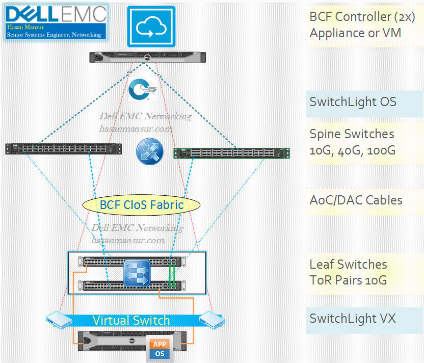
Physical Topology:
So, at a high level –
- A Couple of Controllers (for HA) which could be appliances or VMs,
- A Spine & Leaf CloS fabric with the requisite footprint for bandwidth & Edge ports – All the switches running SwitchLight OS,
- Requisite Cables – AoC etc.
- In case of P+V fabric (OpenStack use case), potentially Switchlight VX Virtual Switches as well.
Logical Topology:
The logical Constructs are as follows:
Within the fabric, you have:
- Tenants: VRFs – Layer 3 Boundary.
- Segments: VLANs. Layer 2/broadcast domain boundary.
- Interface Segment: VLAN Interface/Gateway
- Interface Groups: LAGs
- Logical ports are assigned membership based on VLAN IDs.
- End-points use these logical ports as attachment points.
The Tenant/VRF acts as the demarcation of a Layer 3 boundary, via a logical router. Contained within a Tenant/VRF, are VLANs/Segments which establish a Layer 2 boundary.
So a Tenant space of 172.16.0.0/16 could be made up of segments/VLANs/Subnets as follows:
- Tenant Space: Alpha Quadrant
- Klingon VLAN: 172.16.10.0
- Romulan VLAN: 172.16.20.0
- Vulcan VLAN: 172.16.30.0
Next, we have the Logical Routers. These can be Tenant (automatically assigned to each tenant when it is defined), and system.
- Tenant Logical Router: It routes traffic inside the tenant. For traffic that needs to be routed outside the tenant, the tenant logical router would forward it to the System Tenant‘s logical router.
- It logically resides on leaf.
- At the time of writing, it supports BGP (internal + external) and Static Routes.
- System Tenant Logical Router: System Tenant functions as a special, Internal Only Tenant within the fabric. It is used to interconnect different tenants, provide Multi-Tenancy and External Routing. It has a logical router that provides a tenant interface for each tenant configured in the fabric.
- It logically resides on spine
- At the time of writing, it supports Static Routes only. It can also redistribute routes to tenants.
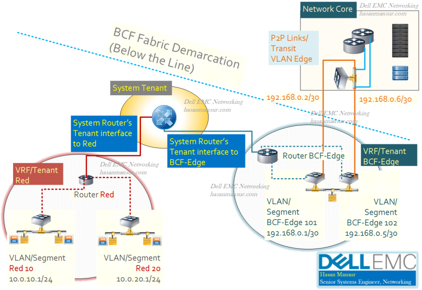
Next, Lets have a look at the interfaces contained within a Tenant’s logical Router. A tenant has two types of interfaces:
- Tenant interfaces
- Segment interfaces
Before describing these, let us look first at the configuration of Segment/VLAN and its interfaces, within the VRF. In configuration, it looks like as follows:
Tenant Alpha Quadrant
logical-router
interface segment Klingon
ip address 172.16.10.1/24
segment Klingon
member interface-group Rack5-Host2 vlan untagged
The “interface segment” is the “interface VLAN” definition. The end-points existing within the Segment/VLAN, will use this interface as the gateway. Inter-VLAN Routing/Inter-Segment Routing within a VRF, will happen here.
Each Tenant would also have (What i like to imagine as a Northbound) interface to System Tenant. While the “User” Tenant resides on the Leaf Switches, the System Tenant resides on the Spine. In case the traffic received on the Segment interface needs routing to other tenants, the Segment interface will forward the traffic, via the Tenant Logical router, to the system tenant.
Typically, we might have default routes on Tenant logical router, pointing to teh system router as the next hop for all destinations outside of Tenant. However, it is also possible we may have external connectivity via a segment, internal to the Tenant. in which case, the routing will be setup accordingly.
Typical Configuration on a Tenant for this interface to the system, may look like:
Tenant Alpha Quadrant
logical-router
interface segment System
route 0.0.0.0/0 next-hop tenant system
So, the logical Router for a given Tenant – will have southbound interfaces for respective VLANs, and Northbound interfaces that link/connect that Tenant’s logical router, to the System Logical Router.
Just like our Tenant “Alpha Quadrant” above had Northbound interfaces to the System Tenant, similarly, the System Tenant will have Corresponding (What i like to imagine as South Bound) interfaces to different User Tenants. These interfaces are called Tenant Interfaces, and are the construct that enables inter-tenant routing. The corresponding Configuration snippet would look like the following:
Tenant System
logical-router
interface tenant Alpha Quadrant
interface tenant Delta Quadrant
————-

very helpful- thanks for the post