gallery
- 4 Sep 2023: UC1628 256x128
- 13 Aug 2023: T6963 128x128 with I2C Converter Board
- 16 Jul 2023: T6963 240x128 with I2C Converter Board
- 4 Jul 2023: ST7586S JLX320160
- 18 Jun 2023: MUI Shield with Rotary Encoder and SH1106 OLED
- 4 Mar 2023: ST7567 128x64
- 3 Jan 2023: SSD1362 256x64 and 206x36
- 18 Apr 2022: SSD1320 160x80
- 3 Oct 2021: UC1609 192x64
- 30 Jul 2021: HD44102 LM234
- 23 Jun 2021: SSD1329 96x96
- 20 Jun 2021: UC1638 LG196962
- 27 Dec 2020: ST7571 JLX128128
- 28 Oct 2020: ST7528 ERC16064
- 19 Apr 2020: UC1617 JLX128128
- 29 Mar 2020: SSD1309 128x64 1.56 Transparent OLED
- 3 Dec 2019: SSD1306 72x40 0.42" OLED
- 10 Jul 2019: MAX32620FTHR with SSD1306
- 15 Jun 2019: ST75320 JLX320240 LCD
- 19 May 2019: ESP8266 Hardware SPI and ST7920 Display
- 22 Apr 2019: SH1107 128x128 Seeed Studio OLED
- 9 June 2018: Step by Step Instructions for Atmel Studio 7
- 19 May 2018: ST7657 Transparent LCD ENH DG128064
- 13 Apr 2018: SH1122 256x64 OLED
- 2 Feb 2018: HX1230 96x68
- 11 Dec 2017: ESP32 and SSD1306 OLED
- 21 Oct 2017: ST75256 JLX25664
- 11 Oct 2017: ST75256 JLX256128
- 11 Oct 2017: ST75256 JLX172104
- 27 Aug 2017: IL3820 WaveShare 296x128 e Ink
- 11 Aug 2017: SED1520 122x32 LCD
- 28 May 2017: MAX7219 32x8 LED Matrix
- 01 Apr 2017: SSD1306 & LPC824
- 24 Mar 2017: WEMOS OLED Shield
- 5 Feb 2017: SSD1607 200x200 eInk
- 17 Jan 2017: ST7588 JLX12864
- 13 Jan 2017: SSD1309 128x64
- 7 Jan 2017: ST7565 DOGM132
- 6 Jan 2017: SSD1305 128x32
- 2 Jan 2017: SSD1306 128x32
- 5 Jan 2017: SSD1327 96x96
- 4 Jan 2017: NT7534 TG12864R
- 2 Jan 2017: ST7567 132x64
- 31 Dec 2016: LC7981 160x80
- 30 Dec 2016: SSD1606 GDE021A1 172x72 eInk
- 18 Dec 2016: UC1604 JLX19264
- 16 Dec 2016: ST7565 128x64 LCD
- 15 Dec 2016: PCD8544 84x48 (Nokia 5110) LCD
- 15 Dec 2016: KS0108 128x64 LCD
- 26 Nov 2016: ST7920 128x64 LCD in 8080 parallel mode
- 22 Nov 2016: UC1608 240x64 LCD
- 20 Nov 2016: SSD1306 64x48 OLED (EastRising 0.66")
- 13 Nov 2016: UC1611 (EA DOGXL240 Display)
- 6 Nov 2016: SSD1306 Mirror Option
- 15 Oct 2016: UC1610 160x104 DOGXL160
- 2 Oct 2016: SSD1322 256x64 NHD Display
- 2 Oct 2016: SSD1325 128x64 NHD Display
- 24 Sep 2016: RA8835 240x128 NHD Display
- 20 Aug 2016: SH1106 display
- 27 Jul 2016: A2 Micro Panel Thermal Printer
- 16 Jul 2016: T6963 240x128 LCD
- 25 Jun 2016: ST7920 128x64 LCD
- 23 Jun 2016: LD7032 60x32 OLED
- 23 Jun 2016: Arduboy (SSD1306 controller)
- 3 Dec 2015: DOGS102 (UC1701 controller)
- 3 Dec 2015: SSD1306 Test board
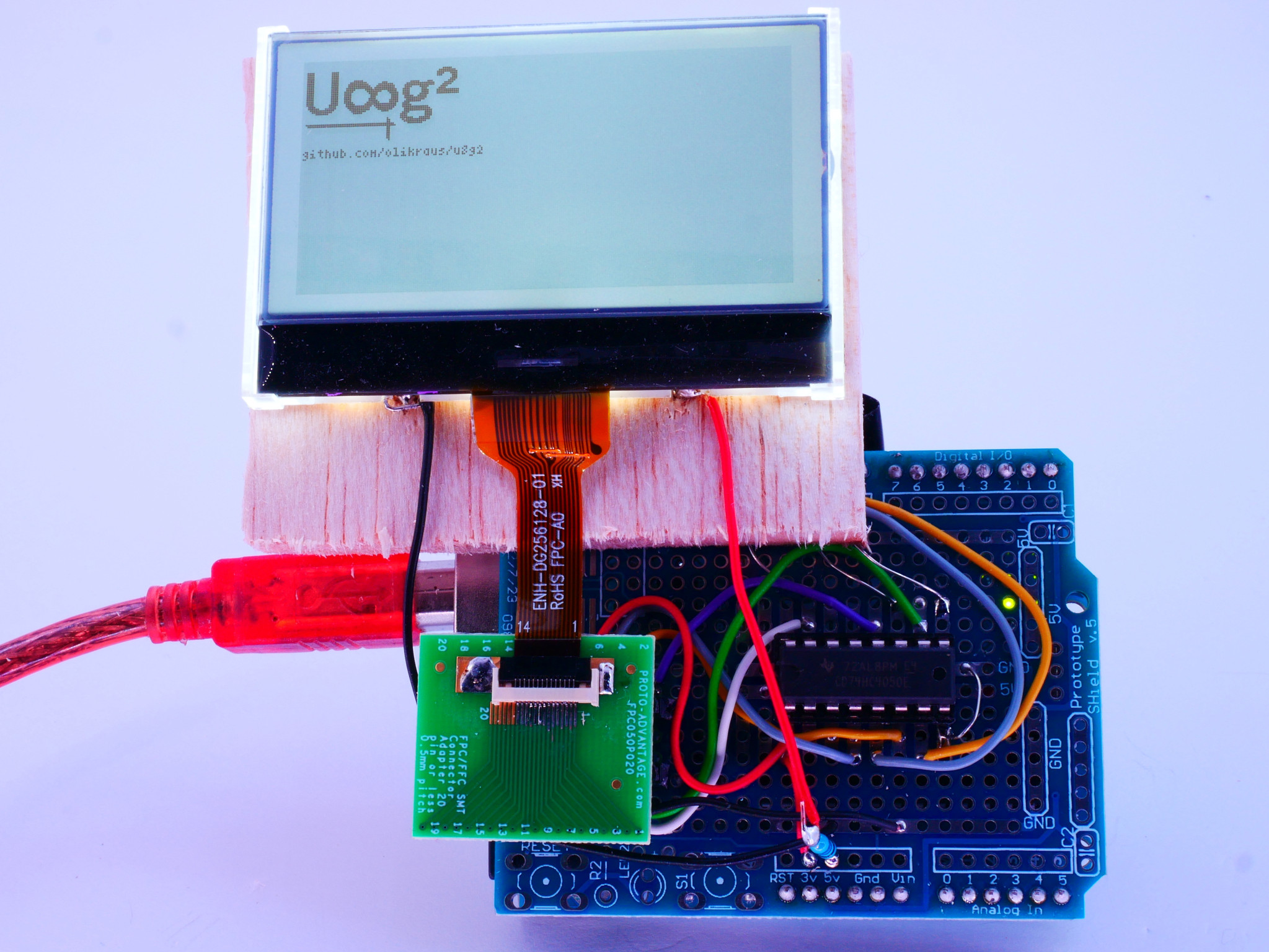
The UC1628 controller is a pure monochrome 163x256 controller which drives a 256x128 LCD (ENH-DG256128-01) in this case.
The max backlight current is unknown, I have applied 50mA for the above picture, but I assume it can be up to 100mA or even 200mA.
The pin description of the flex cable is provided here: https://github.com/olikraus/u8g2/issues/2260
Constructor will be added in u8g2 v2.35.
U8G2_UC1628_256X128_1_4W_SW_SPI u8g2(U8G2_R0, /* clock=*/ 13, /* data=*/ 11, /* cs=*/ 10, /* dc=*/ 9, /* reset=*/ 8);
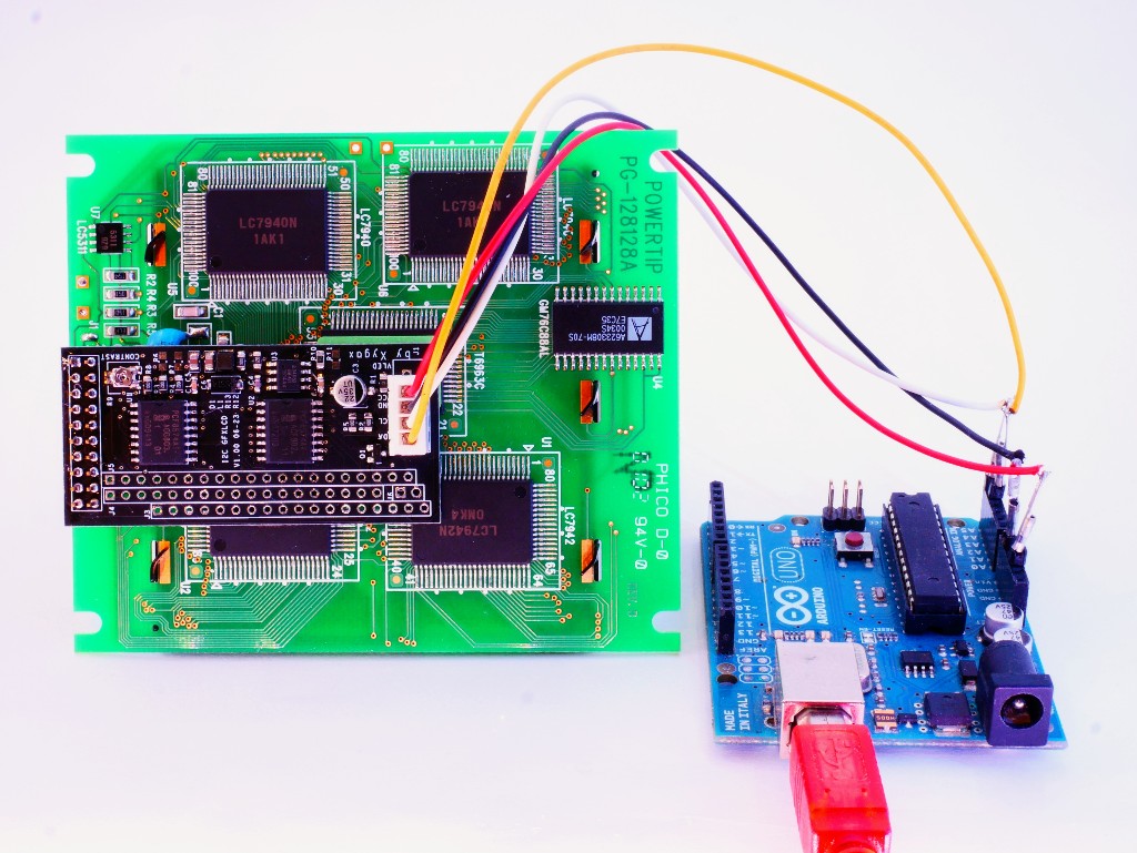
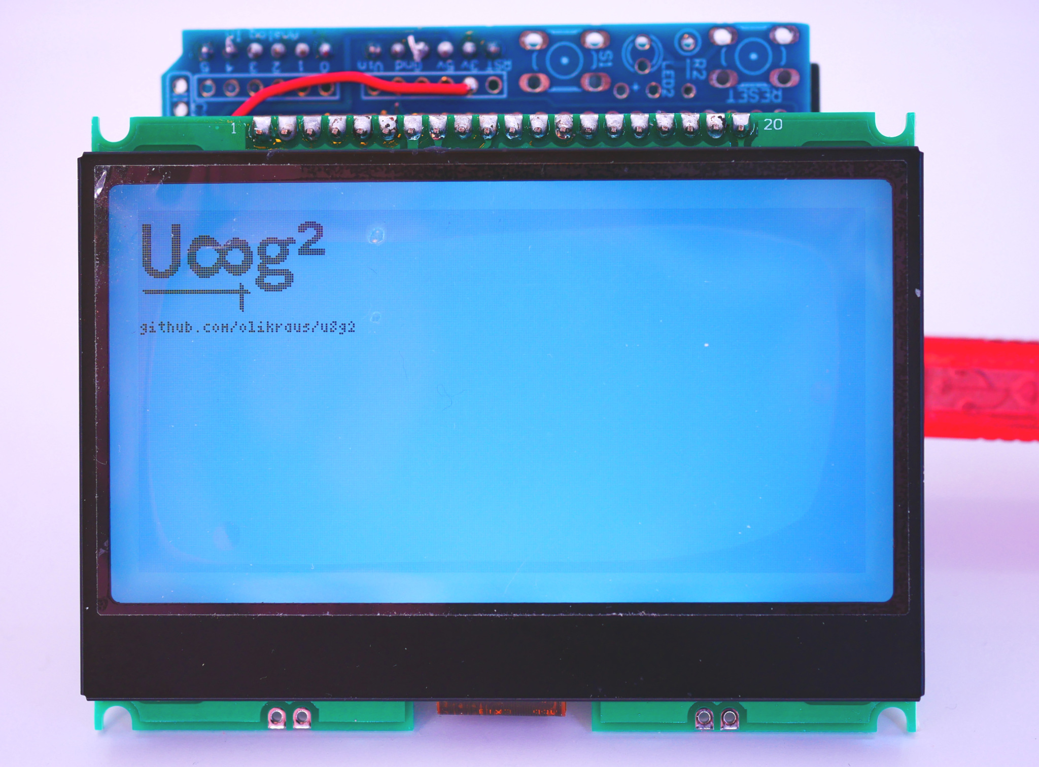
Front and back side of another T6963 display (128x128), which is supported by the I2C converter board, see also the next gallery entry below.
The u8g2 code fror this display is here:
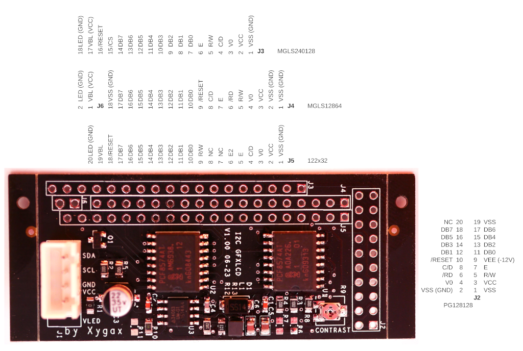
User xygax has created a nice I2C converter board to connect 5V 8-Bit parallel displays. The above picture shows my old T6963 display, which is driven by the I2C converter (below the display) and an Adafruit Feather M0 board (left). The power input for the I2C converter board is connected to the USB power (5V) of the Adafruit Feather board.
- Less wires, just requires a I2C bus connection (5V or 3.3V voltage level for I2C bus)
- Works with 5V and 3.3V Arduino boards (connect the I2C board always to 5V power supply)
- I2C Pull-Up resistors included
- Adjustable negative voltage generator
- Fits to many existing 5V displays
- Support for T6963, LC7981, SBN1661 and SED1520
- Example Code: https://github.com/olikraus/u8g2/blob/master/sys/arduino/u8g2_page_buffer/I2CLCDBoard/I2CLCDBoard.ino
- Issue: https://github.com/olikraus/u8g2/issues/2191
Leave a comment at issue 2191 for further questions. I think xygax has some of the I2C GFX covnerter boards (and also some displays) available for sale. Either contact xygax directly or drop a note at issue 2191.
Top view of the I2C LCD converter board:
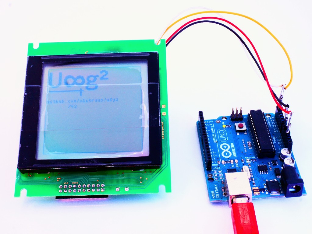
The ST7586 controller has a very unusual internal memory architecture. As a consequence, there is no support for u8x8 and hardware flip mode (use u8g2 rotation instead).
The above image shows the display with reduced backlight. It is probably much brighter if driven with the full 200mA. The protection foil is still attached. Constructor will be there with u8g2 v2.35.
U8G2_ST7586S_JLX320160_1_4W_HW_SPI u8g2(U8G2_R0, /* cs=*/ 10, /* dc=*/ 9, /* reset=*/ 8); // Uno: Enable U8g2 16 bit mode for this display


MUI (Monochrome Minimal User Interface) is part of U8g2:
- MUI Manual: https://github.com/olikraus/u8g2/wiki/muimanual
- MUI Reference: https://github.com/olikraus/u8g2/wiki/muiref
The above test shield includes a SH1106 OLED with some buttons and the KY-040 rotary encoder. The KY-040 is connected to the Arduino board with an additional low pass filter (10K ohm resistor and 10nF capacitor). Any external button and rotary encoder library can be combined with MUI and U8g2:
- Bounce2 Lib: https://github.com/olikraus/u8g2/blob/master/sys/arduino/u8g2_page_buffer/MUIInput3BtnBounce2/MUIInput3BtnBounce2.ino
- Simple Rotary Lib: https://github.com/olikraus/u8g2/blob/master/sys/arduino/u8g2_page_buffer/MUIInputSimpleRotary/MUIInputSimpleRotary.ino
- Versatile Rotary Lib: https://github.com/olikraus/u8g2/blob/master/sys/arduino/u8g2_page_buffer/MUIInputVersatileRotaryEncoder/MUIInputVersatileRotaryEncoder.ino

A nice and inexpensive 128x64 LCD, see here: https://github.com/olikraus/u8g2/issues/2125
Constructor:
U8G2_ST7567_ENH_DG128064I_F_4W_HW_SPI u8g2(U8G2_MIRROR, /* cs=/ 10, / dc=/ 9, / reset=*/ 8);


Both nice and clear OLED displays. Both had been ordered as "white" displays, however the bigger display appears a little bit more as blue compared to the smaller display.
Constructors:
U8G2_SSD1362_256X64_1_4W_HW_SPI u8g2(U8G2_R0, /* cs=*/ 10, /* dc=*/ 9, /* reset=*/ 8);
U8G2_SSD1362_206X36_1_4W_HW_SPI u8g2(U8G2_R0, /* cs=*/ 10, /* dc=*/ 9, /* reset=*/ 8);
Support for this display will be available with v2.34.

Bright SSD1320 OLED with an unusual reflecting (mirror-like) background. This background appears as orange grid on the image, but looks very cool (and not at all orange) in reality.
Constructor:
U8G2_SSD1320_160X80_1_4W_HW_SPI u8g2(U8G2_R0, /* cs=*/ 10, /* dc=*/ 9, /* reset=*/ 8);
Support for this display will be available with v2.33.

This 192x64 display includes the UC1609 controller. Currently this display is available in the Asia market stores in three different colors including the unusual (and cool) white on black option. In the picture above the white appears a little bit as blue. In reality the text is almost white and the black is almost black.
The display was shipped without protection foil and already had a scratch on the display glass (see picture above).
Constructor:
U8G2_UC1609_SLG19264_1_4W_HW_SPI u8g2(U8G2_R0, /* cs=*/ 10, /* dc=*/ 9, /* reset=*/ 8);
Support for this display will be available with v2.32.

This is a HD44102 based LCD with 100x63 usable pixel. The LM234 display is desinged as a 5x7 character display, controlled by four HD44102.
- 5V display, manual constrast, 8-bit interface
- The required negative voltage (about -5V) is derived from 4x AA batteries
- One HD44102 handles 50x32 pixel
- 4x HD44102 are used in the LM234 display
- The lowest row is not visible, every 8th row is trippeled
- Every 6th column can not be controlled (and will be blank)
- Trippled and blank pixel make the LM234 almost unusable as graphics display
- With U8g2, the R/W input of the display can be set to GND
- Example code together with a special font is available here
- Issue 1492
Support for this HD44102 and the compatible T7932 will be added with v2.29.
Constructor:
U8G2_HD44102_100X64_1 u8g2(U8G2_R0, 4, 5, 6, 7, 8, 9, 10, 11, /*enable=*/ 2, /*dc=*/ 3, /*cs0=*/ A0, /*cs1=*/ A1, /*cs2=*/ A2, /* reset=*/ U8X8_PIN_NONE);

96x96 SSD1329 based OLED with SPI interface. Reset line is not available but is also not required. In the picture, the OLED is connected to a Feather 32u4 3.3V board.
The OLED has some horizontal brightness issues (see the uppercase U). The diagonal brightness change on the 8 is caused by the camera.
The brightness problem can be reduced with a large cap at the output stage of the boost converter (see https://github.com/olikraus/u8g2/issues/1511), but it is still visible a little bit.
Constructor for this setup:
U8G2_SSD1329_96X96_NONAME_1_4W_HW_SPI u8g2(U8G2_R0, /* cs=*/ A4, /* dc=*/ A2, /* reset=*/ U8X8_PIN_NONE); // Adafruit Feather 32u4 Basic Proto

 .
.
After more than three years there is now support for the UC1638 (issue 371) The UC1638 is a 4 level monochrome display, but also includes a black/white mode which is used by U8g2.
The LG192962 display in the picture above is preconfigured for the 8080 mode. A solder bridge has to be moved from J7 to J8 (see right picture) to put the display into serial mode. Within serial mode, the value of D1 defines SPI or I2C protocol. With I2C , the input level of the chip select input defines the I2C (U8g2) address (0x78 for CS=0 and 0x7c for CS=1).
My test board for this display includes a small switch (left picture, upper part) to change the com interface (SPI / I2C). The address of the I2C bus can be changed by setting the logic level of the CS signal at pin 10. The default I2C address for the UC1638 is 0x78 (CS=0).
Constructor:
U8G2_UC1638_192X96_1_4W_HW_SPI u8g2(U8G2_R0, /* cs=*/ A4, /* dc=*/ A2, /* reset=*/ U8X8_PIN_NONE); // Adafruit Feather 32u4 Basic Proto
Support for this display will be available with v2.29.

The ST7571 is a 4-level grayscale controller with black and white mode. In black and white mode, the ST7571 behaves like a ST7565 with similar data transfer speed but higher pixel size (128x128 pixel for this display). Will be added in U8g2 v2.28.
Constructor:
U8G2_ST7571_128X128_1_4W_HW_SPI u8g2(U8G2_R0, /* cs=*/ 10, /* dc=*/ 9, /* reset=*/ 8)

The ST7528 is another 4-level grayscale device and as ususal, u8g2 will only use black&white. Memory architecture is a little bit strange: Pixel value is distributed over several bytes. Backlight is actually "white", but is displayed in light blue due to camera and light conditions. Support will be there with v2.28.
Constructor:
U8G2_ST7528_ERC16064_1_4W_SW_SPI u8g2(U8G2_R0, /* clock=*/ 13, /* data=*/ 11, /* cs=*/ 10, /* dc=*/ 9, /* reset=*/ 8);

The UC1617 actually is a 4-level grayscale device, but u8g2 will only use black&white. The display has 128x128 pixel and is rotated by 90 degree, so better use U8G2_R1. Contrast is good, but appears a little bit bad on the above picture due to the camera angle and light conditions in my lab. Support will be there with v2.28.
Constructor:
U8G2_UC1617_JLX128128_1_4W_SW_SPI u8g2(U8G2_R0, /* clock=*/ 13, /* data=*/ 11, /* cs=*/ 10, /* dc=*/ 9, /* reset=*/ 8);
sparkfun Transparent OLED (SSD1309) is OK. Transparent Graphical OLED Breakout (Qwiic=I2C) RedBoard Turbo(SAMD21)
Constructor for this picture: U8G2_SSD1309_128X64_NONAME0_F_HW_I2C u8g2(U8G2_R0, /* reset=/U8X8_PIN_NONE, / clock=/21, / data=*/20);

Added support for the "East Rising" 0.42" OLED. This display is very small but still very bright.
Constructor for this picture:
U8G2_SSD1306_72X40_ER_1_HW_I2C u8g2(U8G2_R0, /* reset=*/ U8X8_PIN_NONE);

Maxim supports the MAX32620FTHR controller with a suitable Arduino Board Software (https://github.com/MaximIntegratedMicros/arduino-max326xx). The Arduino HAL for this controller works with U8g2 as seen in the picture above (thanks to MagSem for the picture).

There is now support for the ST75320 controller. This JLX 320x240 display has a huge resolution: The usual u8g2 logo seems to be very small in the upper left corner. In the picture, the display is driven by an Arduino Uno: I had to reduce the backlight so that the Uno is still able to drive the LCD Backlight.
Constructor:
U8G2_ST75320_JLX320240_1_4W_HW_SPI u8g2(U8G2_R0, /* cs=*/ 10, /* dc=*/ 9, /* reset=*/ 8);
Remember to activate U8g2 16 bit mode.

A long pending issue is now resolved in the latest version of the ESP8266 board software. The correct SPI modes are now supported and the ST7920 display finally works out of the box in hardware SPI mode (https://github.com/olikraus/u8g2/issues/53).
In the picture a Adafruit Feather ESP8266 board drives a ST7920 128x64 display (via 74HC07 level shifter).
U8G2_ST7920_128X64_1_HW_SPI u8g2(U8G2_R0, /* CS=*/ 15, /* reset=*/ 16);
Corresponding SW SPI setup is this:
U8G2_ST7920_128X64_1_SW_SPI u8g2(U8G2_R0, /* clock=*/ 14, /* data=*/ 13, /* CS=*/ 15, /* reset=*/ 16);

This is the newer version (128x128 instead of 96x96 pixel) of the quadratic Grove OLED. Although the pixel size is bigger, the performance is still more than doubled compared to the older 96x96 display.
This is the U8g2 constructor for this display. Support will be available with v2.26:
U8G2_SH1107_SEEED_128X128_1_HW_I2C u8g2(U8G2_R0, /* reset=*/ U8X8_PIN_NONE);
Thanks to seeedstudio.com for supporting this project.

I have created a step by step guideline for the use of U8g2 with Atmel Studio 7: https://github.com/olikraus/u8g2/wiki/u8g2as7

The ENH-DG128064 is one of the rare transparent LCDs available for the Maker community (http://www.geekdisplay.com/arduino-lcd-display/9-128x64-transparent-lcd-module.html).
- The LCD came with a protective film on both sides of the display. The film is still attached to the LCD on the above image (The LCD will be even more transparent after removing the film).
- The description is limited, but I got all the required information from the friendly shop owner: The pins on the flex cable are 1: CS, 2: Reset, 3: DC, 4: Clock, 5: Data, 6: 3.0V (!), 7: Ground, 8: V0, 9: XV0, 10: VG, 11 & 12: Not connected.
- The pins on the flex cable have a distance of 0.8mm to each other.
- The display requires 3.0V, I added a linear voltage regulator to get the 3.0V out of the 5V from the Arduino board.
- The HC4050 level shifter is also driven by the 3.0V (lower part of the picture)
- The voltage generator of the ST7657 can work without external caps, but to avoid ghost lines, I strongly recommend 2x 0.1uF caps between VG and Ground and between XV0 and V0 pins.
Support for U8g2 will be added with v2.23.
This is the constructor for the above picture (FlipMode is set to 1):
U8G2_ST7567_ENH_DG128064_1_4W_SW_SPI u8g2(U8G2_R0, /* clock=*/ 13, /* data=*/ 11, /* cs=*/ 10, /* dc=*/ 9, /* reset=*/ 8);
If you look through the LCD from the back side, use either U8G2_MIRROR or the special "inverse" constructor:
U8G2_ST7567_ENH_DG128064I_1_4W_SW_SPI u8g2(U8G2_R0, /* clock=*/ 13, /* data=*/ 11, /* cs=*/ 10, /* dc=*/ 9, /* reset=*/ 8);

The SH1122 OLED is a small display with a high resolution. The SH1122 is a gray level controller without monochrome mode. This will make the display refresh a little bit slow.
The U8x8 API is not supported due to a different memory architecture.
This is the U8g2 constructor for this display will be available with v2.22:
U8G2_SH1122_256X64_1_4W_HW_SPI u8g2(U8G2_R0, /* cs=*/ 10, /* dc=*/ 9, /* reset=*/ 8); // Enable U8G2_16BIT in u8g2.h

Recently I received this little and inexpense LCD with a HX1230 controller. The display module is configured as 3-wire SPI. There is no proper specification for the backlight, but it works when connected to 3.3V power supply directly.
In my picture the HX1230 is connected to an Uno Board (SMD Version). The display module is powered by 5V, the backlight by 3.3V. Use 3W_SW_SPI constructor:
U8G2_HX1230_96X68_1_3W_SW_SPI u8g2(U8G2_R0, /* clock=*/ 13, /* data=*/ 11, /* cs=*/ 10, /* reset=*/ 8);

I just made a picture of the ESP32 Thing with a SSD1306 OLED. Some OLEDs fit directly into the pinheader of the ESP32 board.
SW I2C and HW I2C with pin-remapping will work:
U8G2_SSD1306_128X64_NONAME_1_SW_I2C u8g2(U8G2_R2, /* clock=*/ 16, /* data=*/ 17, /* reset=*/ U8X8_PIN_NONE);   // ESP32 Thing, pure SW emulated I2C
U8G2_SSD1306_128X64_NONAME_1_HW_I2C u8g2(U8G2_R2, /* reset=*/ U8X8_PIN_NONE, /* clock=*/ 16, /* data=*/ 17);   // ESP32 Thing, HW I2C with pin remapping

Another display with ST75256 controller, mounted on a proto shield for the Arduino Due. This 256x64 display is configured for I2C bus. 16 Bit mode must be enabled for U8g2.
U8G2_ST75256_JLX25664_1_2ND_HW_I2C u8g2(U8G2_R0, /* reset=*/ 8);

There are several display types with the ST75256 controller avaiilable. This is the 256x128 variant. Support will be added with version 2.9.
Remember to enable 16 Bit mode for U8g2.
U8G2_ST75256_JLX256128_1_4W_HW_SPI u8g2(U8G2_R0, /* cs=*/ 10, /* dc=*/ 9, /* reset=*/ 8);

Version 2.9 will include support for the ST75256 controller. It took me almost one year to figure out the right init sequence for this controller.
I placed the display module JLX172104 on an Arduino Shield (together with a 5V - 3.3V level shifter). Everything is driven by an Uno board.
U8G2_ST75256_JLX172104_1_4W_HW_SPI u8g2(U8G2_R0, /* cs=*/ 10, /* dc=*/ 9, /* reset=*/ 8);

Version 2.7 will include support for the WaveShare 2.9" 296x128 e-Ink display. For U8g2 the same restrictions apply as described below. On the picture above, the display is driven by an Arduino Uno (The Protoboard includes the required level converter).
There are two constructors:
-
U8G2_IL3820_296X128...: Slow, lot of screen flicker, init code from vendor -
U8G2_IL3820_V2_296X128...: Faster, lesser screen flicker, maybe little bit lesser display quality
For both devices, the power save command controlls the charge pump of the e-paper controller. For minimal power consumption, enable power save mode. Disable power save mode only for screen updates:
void setup(void) {
  u8g2.begin();			// e-paper is cleared, charge pump is active
    // charge pump still active after .begin()
  u8g2.setPowerSave(1);	// set power save mode: disable charge pump
}

...

  u8g2.setPowerSave(0);	// before drawing, enable charge pump (req. 300ms)
  u8g2.firstPage();
  do {
    draw();
  } while ( u8g2.nextPage() );
  u8g2.setPowerSave(1);	// disable charge pump
The above picture was generated with this constructor:
U8G2_IL3820_296X128_1_4W_SW_SPI u8g2(U8G2_R0, /* clock=*/ 13, /* data=*/ 11, /* cs=*/ 10, /* dc=*/ 9, /* reset=*/ 8); // WaveShare 2.9 inch eInk/ePaper Display, enable 16 bit mode for this display!

The SED1520 has a 8 bit parallel interface. U8g2 will configure this display in 6800 mode: The R/W input pin has to be tied to GND (0 volt).
U8x8 and hardware flip are not supported.
U8G2_SED1520_122X32_1 u8g2(U8G2_R0, 8, 9, 10, 11, 4, 5, 6, 7, /*dc=*/ A0, /*e1=*/ A3, /*e2=*/ A2, /* reset=*/ A4);

The MAX7219 is a LED driver for one 8x8 LED matrix. Multiple 8x8 blocks can be connected together. I have added support for a 32x8 LED matrix.
U8x8 API is not supported, but the U8x8 fonts are also available for U8g2.
The MAX7219 does not require a dc input signal, it has to be set to
U8X8_PIN_NONE. The LOAD input line of the MAX7219 has to be connected
as cs.
U8G2_MAX7219_32X8_F_4W_SW_SPI u8g2(U8G2_R0, /* clock=*/ 11, /* data=*/ 12, /* cs=*/ 10, /* dc=*/ U8X8_PIN_NONE, /* reset=*/ U8X8_PIN_NONE);
Support will be added with U8g2 v2.16.

This is a port of u8g2 to the LPC824 controller. The complete project is located here:
https://github.com/olikraus/u8g2/tree/master/sys/arm/lpc824
The project also includes the upload tool for the LPC824 (hex2lpc).

The 64x48 OLED Shield for the WEMOS ESP8266 boards. It features a SSD1306 driver and works with no special modification using the I2C bus (hardware or software):
U8G2_SSD1306_64X48_ER_F_HW_I2C u8g2(U8G2_R0); // hardware
U8G2_SSD1306_64X48_ER_F_SW_I2C u8g2(U8G2_R0, D1, D2); // software

Several weeks back, I ordered this little 200x200 pixel e-paper device from embedded adventures. It includes a breakout board, which makes it very easy to connect the display to Arduino boards (of course 3.3V level shift is still required for 5V boards). The e-paper itself seems to be the CFAP200200A0-0154 display module from Crystalfontz America, Inc. The code for U8g2 is mainly based on the original library from embedded adventures.
The original library requires a lot of RAM. This restriction is not there for U8g2 (page mode or U8x8 API).
Notes:
- A special refresh command is required to copy the content of the RAM cells to the display. This command is automatically executed in U8g2.
- The refresh command and the automatic buffer switch makes U8x8 difficult to use. In U8x8 the refresh command (u8x8::refreshDisplay()) has to be called manually. Additionally, after each such call, the screen has to be erased manually, because the last to last content is still inside the RAM.
- There will be a black/white flicker for each refresh. This is intended and required for best contrast.
- It requires a long time to change the color of a pixel. For this display, this is more than one second. Any kind of animation will be very slow.
- The busy line is not required. Instead I measured the timing and added delays into U8g2.
- U8g2 constrast setting is not available: There is no such command in the display controller (except for reprogramming the display LUT memory).
- Hardware flip is not implemented. Use the U8g2 software rotation instead.
- U8g2 power down/up function is not required. Instead the display is powered up and down by the refresh command sequence.
Conclusion:
U8g2 supports SSD1607 except for the hardware flip option in v2.13.x
U8G2_SSD1607_200X200_1_4W_SW_SPI u8g2(U8G2_R0, /* clock=*/ 13, /* data=*/ 11, /* cs=*/ 10, /* dc=*/ 9, /* reset=*/ 8); // eInk/ePaper Display

The JLX12864 comes with a white backlight and has a I2C interface.
- ST7588 display controller.
- Driven by a "feather 32u4 basic" to avoid level shifter for the I2C interface.
- SW I2C will work without resistors, but HW I2C will require 10K pullups.
- The backlight can be connected to the 3.3V power source without resistor.
- Support will be added with U8g2 2.13.x
Because of the I2C 5V to 3.3V level shift problem, this display is a little bit less suitable for 5V Arduino boards.
U8G2_ST7588_JLX12864_1_HW_I2C u8g2(U8G2_R0, /* reset=*/ 5);

A 2.42" SSD1309 OLED. I had to reduce bightness a little bit, otherwise it might be too much current consumption for the 3.3V power pin of the Arduino Uno. Support will be there with U8g2 v2.12
U8G2_SSD1309_128X64_NONAME_1_4W_HW_SPI u8g2(U8G2_R0, /* cs=*/ 10, /* dc=*/ 9, /* reset=*/ 8)

The EA DOGM132 has 132x32 pixel. Support will be added with v2.11.x.
U8G2_ST7565_EA_DOGM132_1_4W_HW_SPI u8g2(U8G2_R0, /* cs=*/ 10, /* dc=*/ 9, /* reset=*/ U8X8_PIN_NONE);

This is a very small SSD1305 128x32 OLED. I am not sure whether this is really a SSD1305: I have not encountered any difference to the SSD1306.
- There is no chip select input, but it still works.
- The interface was preconfigured as I2C. The DC input is the lowest bit of the I2C client address. However, there is a solder bridge on the back for the selection of I2C and SPI (see below).
- Support will be added with v2.11.x.
U8G2_SSD1305_128X32_NONAME_1_4W_HW_SPI u8g2(U8G2_R0, /* cs=*/ 10, /* dc=*/ 9, /* reset=*/ 8);
 Solder bridge at S1 at the back side of the SSD1305 128x32 OLED:
- 0: SPI
- 1: I2C

- Used u8x8 on a I2C 128x32 OLED display based on SSD1306 drivers, which I bought on eBay.
- Used Arduino Uno R3, programmed on Atom IDE with PlatformIO.
- Used custom made icons.
U8X8_SSD1306_128X32_UNIVISION_SW_I2C u8x8(/* clock=A5*/ 19, /* data=A4*/ 18);
u8x8 example on Arduino UNO R3 with a 128x32 I2C OLED Display
All credit goes to olikraus and his u8g2 project.

96x96 OLED from "seeedstudio.com". It accepts 5V input, but is a little bit slow compared to SSD1306 OLEDs. Support will be added with v2.11.x.
U8G2_SSD1327_SEEED_96X96_1_HW_I2C u8g2(U8G2_R0, /* reset=*/ U8X8_PIN_NONE);

This 128x64 display (TG12864R) looks like a COB (chip on board) display similar to ST7920/KS0108 boards, however it is a NT7534 based COG (chip on glass) display (like the UC16xx family of displays).
- The TG12864R requires a 5V power supply and 5V logic levels (although the
NT7534 is a 3.3V chip). - The backlight LED does not require any resistor: It must be connected directly to the 5V power supply.
- The NT7534 is almost identical to the ST7565, it shares the same fast SPI interface (at least compared to the ST7920).
- Support will be added with v2.11.x.
U8G2_NT7534_TG12864R_1_4W_HW_SPI u8g2(U8G2_R0, /* cs=*/ 10, /* dc=*/ 9, /* reset=*/ 8);

Today morning I received a nice GLCD shield from Pax Instruments. It includes a 132x64 GLCD (ST7567), six buttons and a micro SD card slot. Support for this controller will be there with v2.11.x.
The white backlight is not controlled by u8g2 and has to be activated manually with
digitalWrite(6, LOW).
I took the picture above with activated flip mode (u8g2.setFlipMode(1)).
U8G2_ST7567_PI_132X64_1_4W_HW_SPI u8g2(U8G2_R0, /* cs=*/ 7, /* dc=*/ 9, /* reset=*/ 8);

This is a quick port of the LC7981 code from u8glib to u8g2. I did not spent much time on performance, but it works as expected.
- The RW input of the display must be connected to GND.
- U8x8, contrast and hardware flip are not supported.
- Support for this display will be included into U8g2 v2.11.x
U8G2_LC7981_160X80_1_6800 u8g2(U8G2_R0, 8, 9, 10, 11, 4, 5, 6, 7, /*enable=*/ 18, /*cs=*/ 14, /*dc=*/ 15, /*reset=*/ 16);
Display Pin Header Description
| Pin | Name | Function |
|---|---|---|
| 1 | VSS | Ground |
| 2 | VDD | 5V |
| 3 | V0 | Contrast adjustment |
| 4 | RS | Register Select, Data/Command Input |
| 5 | R/W | H=Read, L=Write |
| 6 | E | Data Latch |
| 7 - 14 | DB0-DB7 | Data Bus |
| 15 | /CS | Chip Select |
| 16 | /RES | Reset input |
| 17 | VEE | Negative power output (-10) |
| 18 | /DISPOFF | Display off signal |
| 19 | LEDA | LED Supply (5V) |
| 20 | LEDK | LED Supply (GND) |

This is a GDE021A1 eInk/ePaper display mounted on a breakout board from "Smart-Prototyping". It has a very high contrast and keeps the display content without power supply.
Notes:
- A special refresh command is required to copy the content of the RAM cells to the display. This command is automatically executed in U8g2.
- The SSD1606 has two RAM framebuffer areas for the display content. The framebuffer is switched after the execution of the refresh command. This buffer switch can not be avoided (according to my current knowledge).
- The refresh command and the automatic buffer switch makes U8x8 difficult to use. In U8x8 the refresh command (u8x8::refreshDisplay()) has to be called manually. Additionally, after each such call, the screen has to be erased manually, because the last to last content is still inside the RAM.
- It requires a long time to change the color of a pixel. For this display, this is one second. Any kind of animation will be very slow.
- The busy line is not required. Instead I measured the timing and added delays into U8g2.
- U8g2 constrast setting is not available: There is no such command in the display controller (except for reprogramming the display LUT memory).
- Hardware flip is not implemented: It seems that this is not supported by the SSD1606 controller. Use the U8g2 software rotation instead.
- U8g2 power down/up function is not required. Instead the display is powered up and down by the refresh command sequence.
Conclusion:
U8g2 supports SSD1606 except for the hardware flip option in v2.10.x
U8G2_SSD1606_172X72_1_4W_SW_SPI u8g2(U8G2_R0, /* clock=*/ 13, /* data=*/ 11, /* cs=*/ 10, /* dc=*/ 9, /* reset=*/ 8); // eInk/ePaper Display

Another LCD which I received recently: JLX19264G-333. Support for the UC1604 controller will be there with v2.9.x
U8G2_UC1604_JLX19264_1_4W_SW_SPI u8g2(U8G2_R0, /* clock=*/ 13, /* data=*/ 11, /* cs=*/ 10, /* dc=*/ 9, /* reset=*/ 8);

Long time back I ordered this 128x64 LCD from somewhere in the internet. I think it is from zolentech.com. The protection foil is still on top of the LCD, which causes some artefacts on the picture above. Also pixel are not square, so that the U8g2 logo appears a little bit taller. However u8x8 will look very nice with this LCD.
U8G2_ST7565_ZOLEN_128X64_1_4W_SW_SPI u8g2(U8G2_R0, /* clock=*/ 13, /* data=*/ 11, /* cs=*/ 10, /* dc=*/ 9, /* reset=*/ 8);

... the classic PCD8544 84x48 (Nokia) display. I have not enabled the LCD backlight..
U8G2_PCD8544_84X48_1_4W_SW_SPI u8g2(U8G2_R0, /* clock=*/ 13, /* data=*/ 11, /* cs=*/ 10, /* dc=*/ 9, /* reset=*/ 8); // Nokia 5110 Display

There are more faster Arduino libs for KS0108 LCDs, but due to some user requests, I also ported the KS0108 driver from U8glib. When porting from U8glib, please note that the U8g2 constructur does not include the R/W pin any more. Connect the R/W pin to ground either directly or via digitalWrite().
U8G2_KS0108_128X64_1 u8g2(U8G2_R0, 8, 9, 10, 11, 4, 5, 6, 7, /*enable=*/ 18, /*dc=*/ 17, /*cs0=*/ 14, /*cs1=*/ 15, /*cs2=*/ U8X8_PIN_NONE, /* reset=*/ U8X8_PIN_NONE); // Set R/W to low!

I did some more testing and speed improvements for the ST7920.
- If configured as parallel mode (PSB pin set to high), then the ST7920 will only work in u8g2 8080 mode.
- It is required to connect the "RW (SID)" to ground: U8g2 will only write, but not read from the ST7920 display.
- There is no "chip select" in parallel mode of the ST7920, so the corresponding
pin has to be configured as
U8X8_PIN_NONEin U8g2. - The DC (data command) pin is called RS (register select) in the documentation for the ST7920.
U8G2_ST7920_128X64_1_8080 u8g2(U8G2_R0, 8, 9, 10, 11, 4, 5, 6, 7, /*enable=*/ 18 /* A4 */, /*cs=*/ U8X8_PIN_NONE, /*dc/rs=*/ 17 /* A3 */, /*reset=*/ 15 /* A1 */); // Remember to set R/W to 0

U8g2 (v2.7.1): This is my old ERC24064 (UC1608) test setup. Also ported to u8g2.
U8G2_UC1608_ERC24064_1_4W_SW_SPI u8g2(U8G2_R0, /* clock=*/ 13, /* data=*/ 11, /* cs=*/ 10, /* dc=*/ 9, /* reset=*/ 8); // SW SPI, Due ERC24064-1 Test Setup

U8g2 (v2.7.0): This is the port of the 64x48 0.66" OLED from U8glib.
U8G2_SSD1306_64X48_ER_1_HW_I2C u8g2(U8G2_R0, /* reset=*/ U8X8_PIN_NONE);

Today I finished code for the UC1611 controller and tested everything with a 240x128 display. Constructor is this:
U8G2_UC1611_EA_DOGXL240_1_4W_SW_SPI u8g2(U8G2_R0, /* clock=*/ 13, /* data=*/ 11, /* cs=*/ 10, /* dc=*/ 9, /* reset=*/ 8);
Thanks to Electronic Assembly for supporting this project.

Version 2.6.x will have a mirror option (u8g2 library only). Instead of the rotation, apply U8G2_MIRROR as first option to the constructor (see below). Rotation by 180 degree is still possible with the hardware flip function.
U8G2_SSD1306_128X64_NONAME_1_4W_SW_SPI u8g2(U8G2_MIRROR, /* clock=*/ 13, /* data=*/ 11, /* cs=*/ 10, /* dc=*/ 9, /* reset=*/ 8);

This is my old DOGXL160 test environment. I rewrote the old u8glib code to support U8x8 and flip modes. Graylevels are not supported (U8g2 only knows black and white).
U8G2_UC1610_EA_DOGXL160_1_4W_SW_SPI u8g2(U8G2_R0, /* clock=*/ 13, /* data=*/ 11, /* cs=*/ 10, /* dc=*/ 9, /* reset=*/ U8X8_PIN_NONE);

There was never a test board for the SSD1322 controller and u8glib v1.
Finally, I found some
time to create a proper test board for u8g2.
Display is a 256x64 blue OLED from NHD.
Please turn on 16 bit mode for u8g2 by uncommenting U8G2_16BIT in u8g2.h.
Because of the width of this display, 8 bit mode will not be sufficient.
U8G2_SSD1322_NHD_256X64_1_4W_SW_SPI u8g2(U8G2_R0, /* clock=*/ 13, /* data=*/ 11, /* cs=*/ 10, /* dc=*/ 9, /* reset=*/ 8);

SSD1325 support has been ported to u8g2. This picture shows the existing old test board for U8glib.
U8G2_SSD1325_NHD_128X64_1_4W_SW_SPI u8g2(U8G2_R0, /* clock=*/ 13, /* data=*/ 11, /* cs=*/ 10, /* dc=*/ 9, /* reset=*/ 8);

I recently ordered this NHD display from Luna Displays. The actual contrast is much better than on the picture. Some small flicker may happen during write operation to the display memory (this is a RA8835 problem I guess).
U8G2_RA8835_NHD_240X128_1_6800 u8g2(U8G2_R0, 8, 9, 10, 11, 4, 5, 6, 7, /*enable=*/ 17, /*cs=*/ 14, /*dc=*/ 15, /*reset=*/ 16); // A0 is dc pin, /WR = RW = GND, enable is /RD = E

SH1106 display tested with HW SPI and an Arduino Due board.
U8G2_SH1106_128X64_NONAME_1_4W_HW_SPI u8g2(U8G2_R0, /* cs=*/ 10, /* dc=*/ 9, /* reset=*/ 8);

Today I finished the port of the A2 Micro Panel Thermal Printer (RS232 serial interface). Printing is optimized for low peak power consumption, it includes dynamic timing depending on the black level of the content and simulates a 384x240 display. The setup differs a little bit from the other displays.
class U8G2 u8g2;
void setup(void) {

  u8g2_Setup_a2printer_384x240_1(		/* several different a2 printer procs exist... */
    u8g2.getU8g2(), 						/* this is a c call, so use the u8g2 struct instead of the class */
    U8G2_R0, 							/* this defines the usual rotation of the bitmap */
    u8x8_byte_arduino_serial, 				/* this is the new procedure from above */
    u8x8_gpio_and_delay_arduino);			/* standard arduino low level proc, used only for delay */
  u8g2.beginSimple();				/* Do not clear the display, wake is not required */
}
Additionally the function u8x8_byte_arduino_serial has to be implemented (see the A2 Printer example).
Also remember to activate U8g2 16 Bit mode (U8G2_16BIT) in u8g2.h.

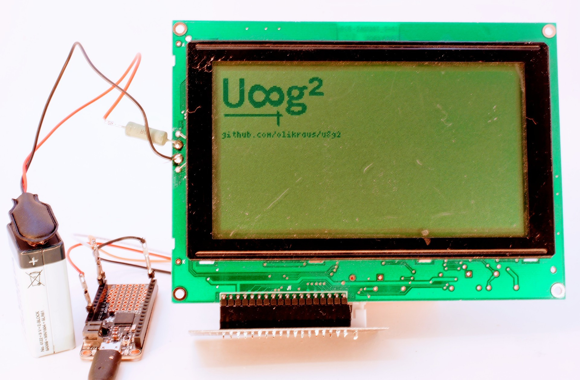
I reactivated my old T6963 for testing with u8g2. The black box at the upper right is the negative voltage generater. The 9V battery is used for the backlight LED.
U8G2_T6963_240X128_1_8080 u8g2(U8G2_R0, 8, 9, 10, 11, 4, 5, 6, 7, /*enable=*/ 17, /*cs=*/ 14, /*dc=*/ 15, /*reset=*/ 16); // Connect RD with +5V, FS0 and FS1 with GND
Display Pin Header Description
| Pin | Name | Function |
|---|---|---|
| 1 | FG | Frame Ground |
| 2 | VSS | Ground |
| 3 | VDD | 5V |
| 4 | V0 | Contrast adjustment |
| 5 | /WR | Write |
| 6 | /RD | Read (U8g2: Connect to 5V) |
| 7 | /CE | Chip Select |
| 8 | C/D | Command/Data Input |
| 9 | /RST | Reset |
| 10-17 | DB0-DB7 | Data Bus |
| 18 | FS | Font Select (U8g2: Connect to 0V) |

This is one of the common ST7920 based LCDs.
U8G2_ST7920_128X64_1_SW_SPI u8g2(U8G2_R0, /* clock=*/ 13, /* data=*/ 11, /* CS=*/ 10, /* reset=*/ 8);

A very small OLED with the LD7032 controller. Unfortunately, u8x8 API is not supported, but the normal u8g2 procedures work fine.
U8G2_LD7032_60X32_1_4W_SW_SPI u8g2(U8G2_R0, /* clock=*/ 11, /* data=*/ 12, /* cs=*/ 9, /* dc=*/ 10, /* reset=*/ 8); // SW SPI Nano Board

I finally received my own Arduboy. Of course I ported U8g2 to the Arduboy environment. There is also a special edition of "Little Rook Chess" included in the examples: Buttons and display of the Arduboy are supported.
This is the Arduboy 1.0 (Kickstarter Edition) constructor for U8g2:
U8G2_SSD1306_128X64_NONAME_1_4W_HW_SPI u8g2(U8G2_R0, /* cs=*/ 12, /* dc=*/ 4, /* reset=*/ 6); // Arduboy (Production, Kickstarter Edition)


A picture of the EA DOGS102 display with UC1701 controller. Probably one of my oldest displays in my lab.

First picture of U8g2 library on a real display. The board is my test board for the different communication protocols. The display module is modified (blue wires), so that I can use the switches to activate the different protocols.
![]()