I'm going to assume you know how to connect your Raspberry Pi, Power supply, Monitor, keyboard/mouse and Wifi or Wired Ethernet.
What follows is the details of various optional hardware you can add to your Raspi to add features or make your clock cooler.
If you want to experiment and learn about the various hardware, and possibly breadboard them first, I've included some decent guides for that. However, you can just skip to the picture showing the hookup for the PiClock.
This hardware guide directly supports the following
- Raspsbery Pi Revision 2 Model B
- Raspberry Pi Revision 2 Model B
- Raspberry Pi Model B+
- Raspberry Pi 2 Model B
Changes can be made, alternate pins (grounds/gpios) can be used to support other models, but this is left as an exercise for the reader.
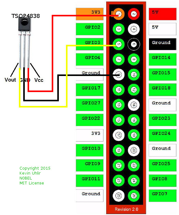
There are many guides showing how to connect an IR receiver (and IR LEDs) to a Raspberry Pi. Here's one: http://www.raspberry-pi-geek.com/Archive/2014/03/Controlling-your-Pi-with-an-infrared-remote
One thing to note is that most of these use GPIO18 (header pin 12). The Install instructions I've provided require the use of GPIO3 (header pin 5). I've found this more convenient, usually sharing the connector with the DS18B20 temperature probe on GPIO4 (header pin 7).
Raspi Header Pin           TSOP4838 Pin
3.3V  Pin 1                  Pin 2
Gnd   Pin 9                  Pin 1
GPIO3 Pin 5                  Pin 3
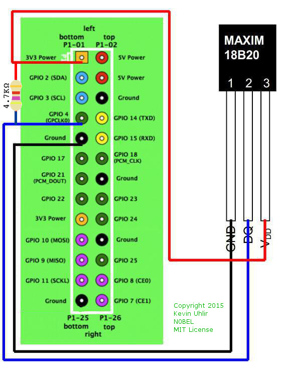
There are many guides showing how to connect and check one or more DS18B20s to a Raspberry Pi. Here's one: http://www.modmypi.com/blog/ds18b20-one-wire-digital-temperature-sensor-and-the-raspberry-pi
Raspi Header Pin           DS18B20 Pin
3.3V  Pin 1                  Pin 3
Gnd   Pin 9                  Pin 1
GPIO4 Pin 7                  Pin 2
A good background guide about how WS2818b connects to the Raspberry Pi can be found here: https://learn.adafruit.com/neopixels-on-raspberry-pi/overview
You might be tempted to connect the LED strip power to the 5V header pin of the Pi -- just don't! That pin can't pass enough current. With all the lights on full you may need an extra 2A to power a 30 LED string (NeoPixels for example come in 30, 60 and 144 LEDs per meter), so size your power supply accordingly.
Everyone seems to recommend a level shift (3.3V to 5V) to drive the LEDs. I've found this to be unnecessary. It also seems that Adafruit recommends a 1000uF cap on the power supply, with the dubious explaination that it protects the LEDs from inrush surges. Again I don't botther. Meh... Your milage may vary. The data pin of the WS2818b string should be connected to GPIO18, header pin 12. Note the markings on the LED strip since they all are not pinned the same.
![]()
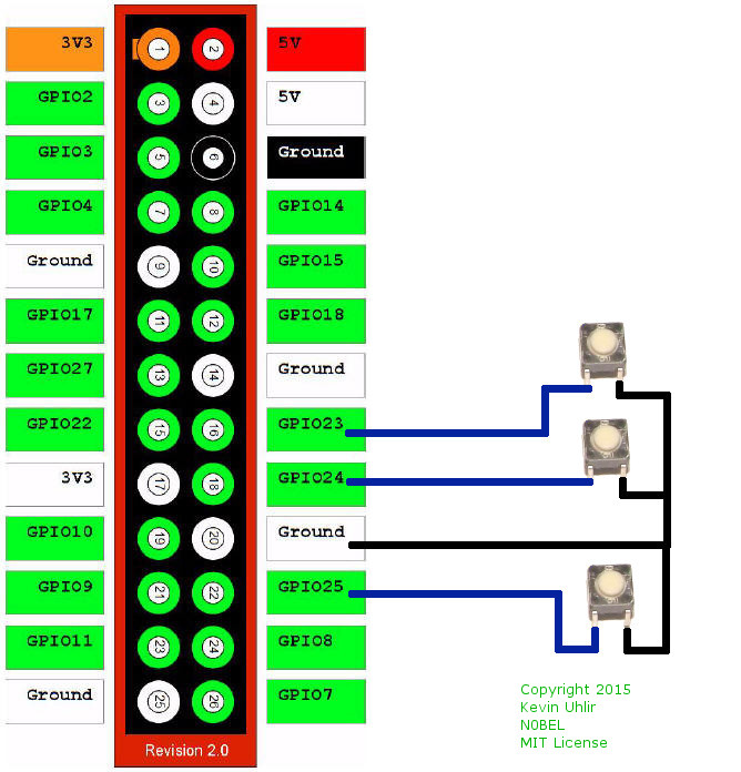
Up to 3 simple push button switches come preconfigured in the software. The switches are wired simply to connect a gpio pin to ground when pushed. The following line in startup.sh configure their function, and which GPIO they are located on.
sudo Button/gpio-keys 23:KEY_SPACE 24:KEY_F2 25:KEY_UP &
- GPIO23 (header pin 16) is mapped to a space (which flips pages on the clock.
- GPIO24 (header pin 18) is mapped to F2 (which toggles the NOAA stream)
- GPIO25 (header pin 22) is mapped to UP (which does nothing yet)
- A convinient ground is on header pin 20.
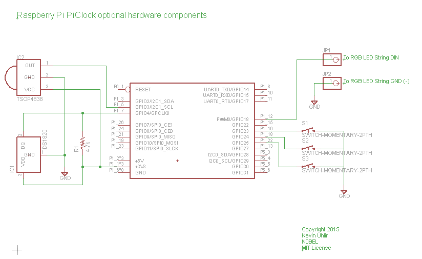
For those that want to work from a schematic, I threw together a simple one