
CW9163E Installation Guide
About this Guide
This guide provides instructions on installing and configuring your CW9163E access point. This guide also provides mounting instructions and limited troubleshooting procedures. For more wireless installation guides, refer to our documentation website's wireless installation guides section.
Product Overview
The Cisco Wireless CW9163E is an outdoor-rated, enterprise-class 802.11ax cloud-managed access point. The AP is equipped with tri-band concurrent radios geared towards low/medium density applications. It will work with different external antennas for required directivity.
It features 2x2 tri-band traffic radios (2x2 2.4 GHz + 2x2 5 GHz + 2x2 6 GHz), 1x1 tri-band scanning radio, and a 2.4 GHz and 802.15.4 radio. It also has an inbuilt GNSS receiver for 6 GHz AFC compliance.
Physical Specifications
|
Dimensions and Weight Interfaces
Antennas
|
|
Power
Note: Actual power consumption may vary depending on the AP usage. Note: The power injector provides DC voltage to the AP over the Ethernet cable and supports a total end-to-end Ethernet cable length of 100 m (328 ft) from the switch to the AP |
|
Environment
|
|
Security
|
Package Contents
The CW9163E package contains the following:
-
Quick install guide
-
Regulatory compliance and safety information
-
CW9163E Cloud-Managed Access Point
-
Mount Plate, MA-MNT-MR-16
-
Support bracket
-
Gift Box
-
Mounting straps
-
Ground lug
-
RJ-45 Field termination gland
-
Waterproof cap
-
Oxide inhibitor paste
-
Product View and Physical Features
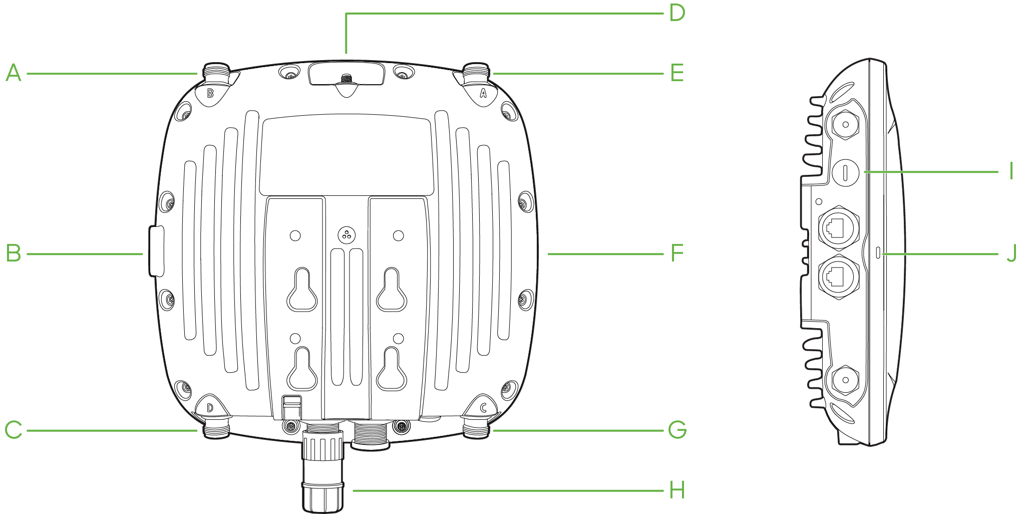
Your CW9163E has the following physical features:
The mount cradle has the following physical features:
A, C, E, G- Antenna ports
B- Grounding post
D- GPS Antenna port
F- Mounting slots
H- Ethernet port
I- Positive reset cap (Covers access to rest button)
J- LED indicator
LED Indicator
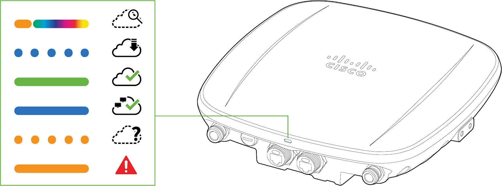
The CW9163E is equipped with a multi-color LED on the bottom edge of the unit to convey information about system functionality and performance:
-
Orange - AP is booting (permanent Orange suggests hardware issue)
-
Rainbow - AP is initializing/scanning
-
Blinking Blue - AP is upgrading
-
Green - AP in Gateway mode with no clients
-
Blue - AP in Gateway mode with clients
-
Blinking Orange - AP can't find uplink
The CW9163E may be operated in “Run Dark” mode for additional security and to reduce the visibility of the access point. In this mode, the LED will not be illuminated. This mode may be enabled through the Meraki Dashboard.
Ethernet Port 
The CW9163E features one PoE 2.5 Gbps Ethernet port which can be sealed with a cable gland for outdoor operation.
The ethernet port accepts 802.3at power and should be used as the primary uplink to your LAN/WAN.
Note: The CW9163E will operate utilizing 802.3af in degraded mode. Please reference the power table below for the expected performance.
Powering Options:
|
Power mode |
PoE Class |
Eth0 |
2.4GHz |
5GHz |
6GHz |
max RF power ch0/ch1 |
Scan |
BLE |
GNSS (tracking) |
|
1 |
AF |
1 Gbps |
1x1 |
1x1 |
off
|
22 dBm |
off |
off |
on |
|
2 |
AT |
2.5 Gbps |
2x2 |
2x2 |
2x2 |
21 dBm |
on |
on |
on |
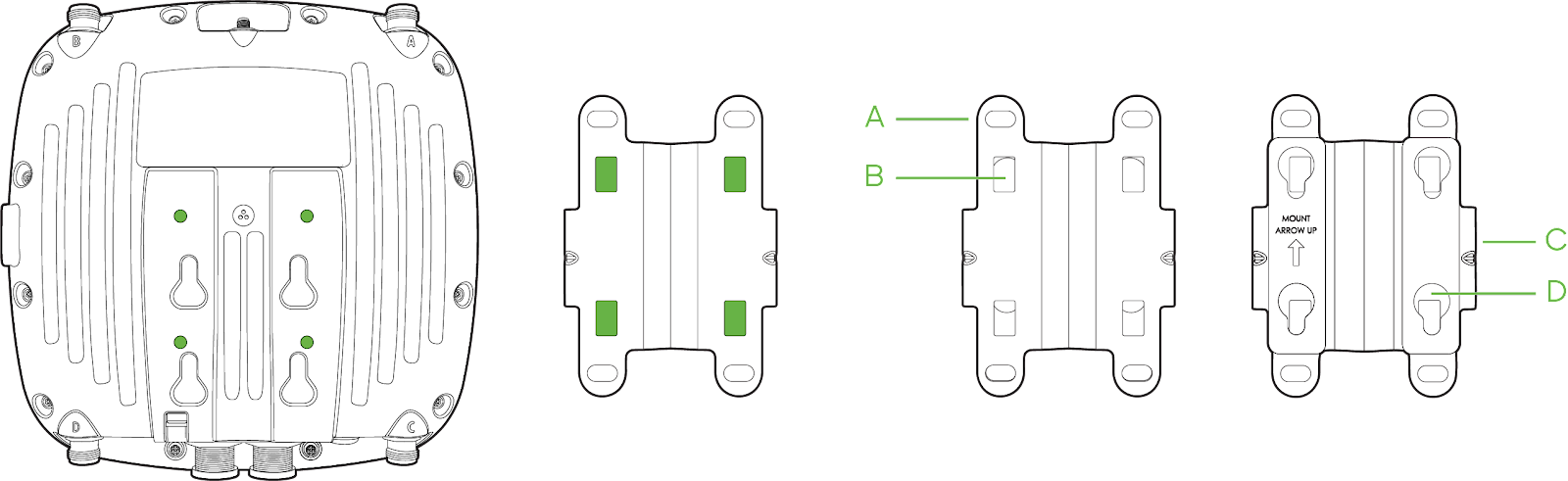
Mount plate attachment slots
The mounting slots located on the rear shell of the CW9163E marry to the 4 mounting posts on the mounting plate, securely fastening the CW9163E to the mounting plate.
Grounding post
The grounding post is located on the left side of the CW9163E unit. Using the included grounding lug, ground the unit to mitigate lightning and other adverse electrical events.
Factory reset button
Using a flathead screwdriver, remove the reset cap to access the reset pinhole. If the pinhole push button is pressed and held for at least five seconds and then released, the CW9163E will reboot and be restored to its original factory settings by deleting all configuration information stored on the unit.
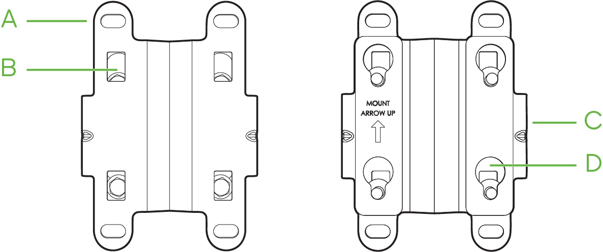
Understanding the CW9163E mount plate
The MA-MNT-MR-16 mount plate will ship with the installation kit.
MA-MNT-MR-16
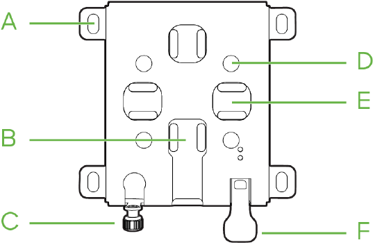
A- Wall mount slots
B- Vertical pole strap slots
C- Mount plate security screw
D- Mount plate attachment posts
E- Horizontal pole strap slots
F- Release tab
AIR-MNT-VERT1
Note: The CW9163E is compatible with the AIR-MNT-VERT1 mounting plate. Refer to the below diagrams on mounting plate specifications.
A- Wall mount slots
B- Mount plate attachment screw
C- Release tab
D- Mounting posts
Mounting holes A (4x)
The mounting holes located on the 4 outermost corners of the MA-MNT-MR-16 mounting plate allow secure installation of the mounting plate to a surface such as a wall.
Vertical orientation mounting strap slots B (2x)
The vertical orientation mounting strap slots located in the middle of the mounting plate secure the mounting plate to a vertical pole using the included mounting straps.
Mount plate attachment screw C
The mount plate attachment screw is located at the bottom of the MA-MNT-MR-16 mounting plate. It securely attaches the AP to the mounting plate.
Mounting posts D (4x)
The mounting posts are located in the middle of the MA-MNT-MR-16 mounting plate, secure the CW9163E to the mounting plate via mounting slots on the AP.
Horizontal orientation mounting strap slots E (2x)
The horizontal orientation mounting strap slots located in the middle of the MA-MNT-MR-16 mounting plate secure the mounting plate to a horizontal pole using the included mounting straps.
Release tab F
The release tab is located at the bottom of the MA-MNT-MR-16 mounting plate. Press down the release tab to when detaching the AP to unlock.
Safety and Warnings
These operations are to be taken with respect to all local laws. Please consider the following for safe operation:
-
Power off the unit before you begin. Read the installation instructions before connecting the system to the power source.
-
Before you work on any equipment, be aware of the hazards involved with electrical circuitry and be familiar with standard practices for preventing accidents.
-
Read the wall-mounting instructions carefully before beginning installation. Failure to use the correct hardware or to follow the correct procedures could result in a hazardous situation to people and damage to the system.
-
This product relies on the building’s installation for short-circuit (overcurrent) protection. Ensure that the protective device is rated not greater than 15 A, 125 Vac, or 10A, 240 Vac.
-
Please only power the device with the provided power cables or standard PoE to ensure regulatory compliance.
Pre-Install Preparation
You should complete the following steps before going on-site to perform an installation.
Configure Your Network in Dashboard
The following is a brief overview of the steps required to add a CW9163E to your network. For detailed instructions about creating, configuring, and managing wireless networks, refer to the online documentation (documentation.meraki.com/mr).
-
Login to http://dashboard.meraki.com. If this is your first time, create a new account.
-
Find the network to which you plan to add your APs or create a new network.
-
Add your APs to your network. You will need your Cisco Wireless order number (found on your invoice) or the serial number of each AP, which looks like Qxxx-xxxx-xxxx, and is found on the bottom of the unit. You will also need your Enterprise license key, which you should have received via email.
-
Go to the map / floor plan view and place each AP on the map by clicking and dragging it to the location where you plan to mount it.
Check and Upgrade Firmware
To ensure your CW9163E performs optimally immediately following installation, it is recommended that you facilitate a firmware upgrade prior to mounting your CW9163E.
Note: Minimum firmware for the CW9163E is MR 30.
-
Attach your CW9163E to PoE-enabled wired Internet connection. See the "Power the CW9163E" section for details.
-
The CW9163E will turn on, and the LED will glow solid orange. If the unit does not require a firmware upgrade, the LED will turn either green (no clients associated) or blue (clients associated) within thirty seconds.
* If the unit requires an upgrade, the LED will begin blinking blue until the upgrade is complete, at which point the LED will turn solid green or blue. You should allow at least a few minutes for the firmware upgrade to complete, depending on the speed of your internet connection.
Check and Configure Firewall Settings
If a firewall is in place, it must allow outgoing connections on particular ports to particular IP addresses. The most current list of outbound ports and IP addresses for your particular organization can be found here.
Assigning IP Addresses to CW9163E
All gateway CW9163E (CW9163E with Ethernet connections to the LAN) must be assigned routable IP addresses. These IP addresses can be dynamically assigned via DHCP or statically assigned.
Dynamic Assignment (Recommended)
When using DHCP, the DHCP server should be configured to assign a static IP address for each MAC address belonging to an AP. Other wireless network features, such as 802.1X authentication, may rely on the property that the APs have static IP addresses.
Static Assignment
Static IPs are assigned using the local web server on each AP. The following procedure describes how to set the static IP:
-
Using a client machine (e.g., a laptop), connect to the AP wirelessly (by associating to any SSID broadcast by the AP) or over a wired connection.
-
If using a wired connection, connect the client machine to the CW9163E either through a PoE switch or a PoE Injector. If using a PoE switch, plug an Ethernet cable into the CW9163E’s Ethernet jack and the other end into a PoE switch. Then connect the client machine over the Ethernet cable to the PoE switch. If using a PoE Injector, connect the CW9163E to the “PoE” port of the Injector and the client machine to the “LAN” port.
-
Using a web browser on the client machine, access the AP’s built-in web server by browsing to http://my.meraki.com. Alternatively, browse to http://10.128.128.128.
-
Click on the “Uplink Configuration” tab. Log in. The default login is the serial number (e.g. Qxxx-xxxx-xxxx), with no password (e.g., Q2DD-551C-ZYW3).
-
Configure the static IP address, netmask, gateway IP address, and DNS servers that this AP will use on its wired connection.
-
If necessary, reconnect the AP to the LAN.
Static IP via DHCP Reservations
Instead of associating each CW AP individually to configure static IP addresses, an administrator can assign static IP addresses on the upstream DHCP server. Through “DHCP reservations,” IP addresses are “reserved” for the MAC addresses of the CW APs. Please consult the documentation for the DHCP server to configure DHCP reservations.
Collect Tools
You will need the following tools to efficiently install the CW9163E.
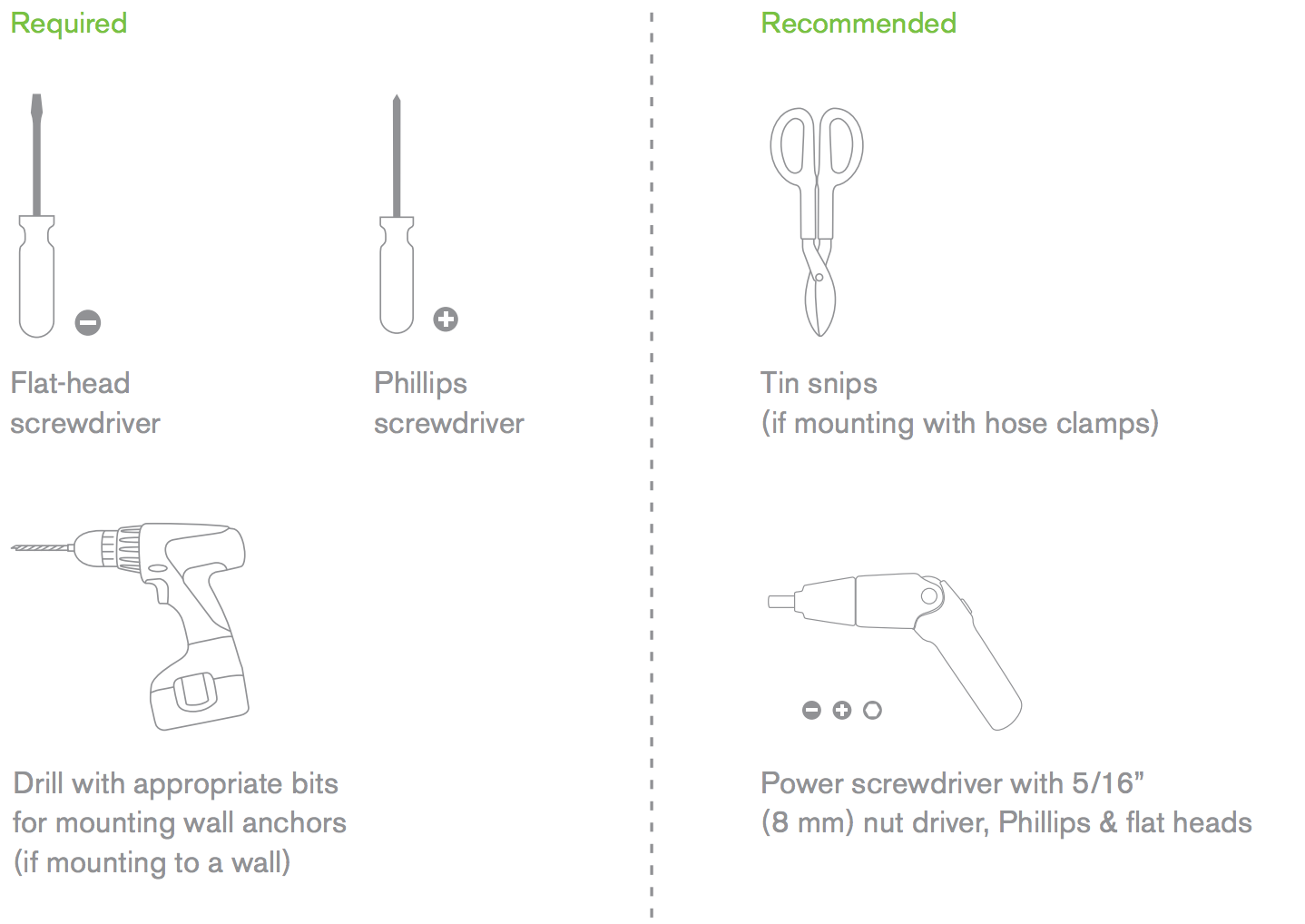
Required Hardware for Installation
You will need the following tools to perform an installation:
-
Shielded outdoor-rated Ethernet (CAT5e) cable of 0.14 to 0.26 inch (3.5 to 6.5 mm) diameter or CAT6/6A
cable of 0.2 to 0.35 inch (5 to 9 mm) diameter. Ethernet RJ-45 connector -
802.3at PoE power source (either PoE switch or PoE Injector)
-
Connection to the Internet (if you are setting up your CW9163E as a gateway to the Internet)
-
Appropriately sized metal straps (if mounting to a pole larger than 3.9” in diameter)
-
Screws- should be up to 6 mm in diameter and at least 1 - 1/4 inch length
-
Mounting anchors appropriate for installation surface
-
6-AWG copper ground wire
Installation Instructions
For most mounting scenarios, the MA-MNT-MR-16 provides a quick, simple, and flexible means of mounting the CW9163E. The installation should be done in two steps. First, install the mount plate to your selected location. Then, attach the CW9163E to the mount plate.
Warning: Due to the heat dissipation in the back of APs during normal operation, please do not stack powered-on APs on top of each other during pre-installation to avoid heat damage.
Choosing a mounting location
A good mounting location is important to get the best performance out of your CW9163E access point. Keep the following in mind:
-
The device should have an unobstructed line of sight to most coverage areas.
-
Power over Ethernet supports a maximum cable length of 300 ft (100 m).
-
If used in a mesh deployment, the CW9163E should have a line of sight to at least two other Meraki devices.
-
The antennas should be as unobstructed as possible. Ensure there is clearance around the CW9163E to install selected antennas.
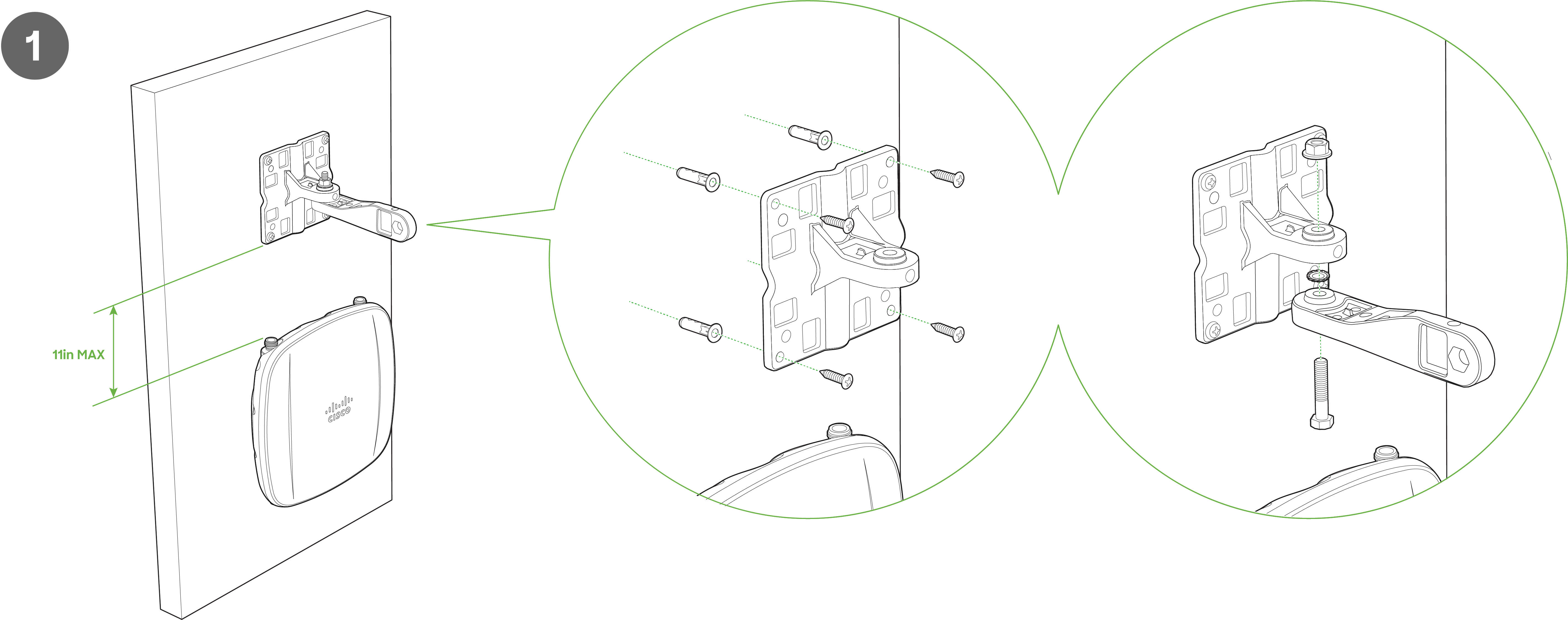
Attach the mounting plate
The CW9163E mounting plate can be used to attach the AP to wall or solid ceiling mount installations.
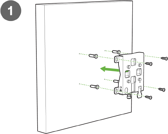
1. To mount the AP on the wall, use the mounting bracket as a template to mark the locations of the mounting holes on the bracket.
2. Use a 0.1360-in. [3.4772 mm] bit to drill a pilot hole at the mounting hole locations you marked.
3. Locate the pilot holes, insert a anchors(not included) into each mounting hole, and tighten.
4. Place the mounting bracket over the faster holes and then use screws up to 6 mm in diameter and at least 1 - 1/4 inch length (not included) to tighten it flush to the wall
The AP is now ready to be mounted on the wall.
Note: It is recommended that the CW9163E be mounted to a wall or solid ceiling using the mounting plate for physical security reasons.
Attaching the AP to the mounting plate
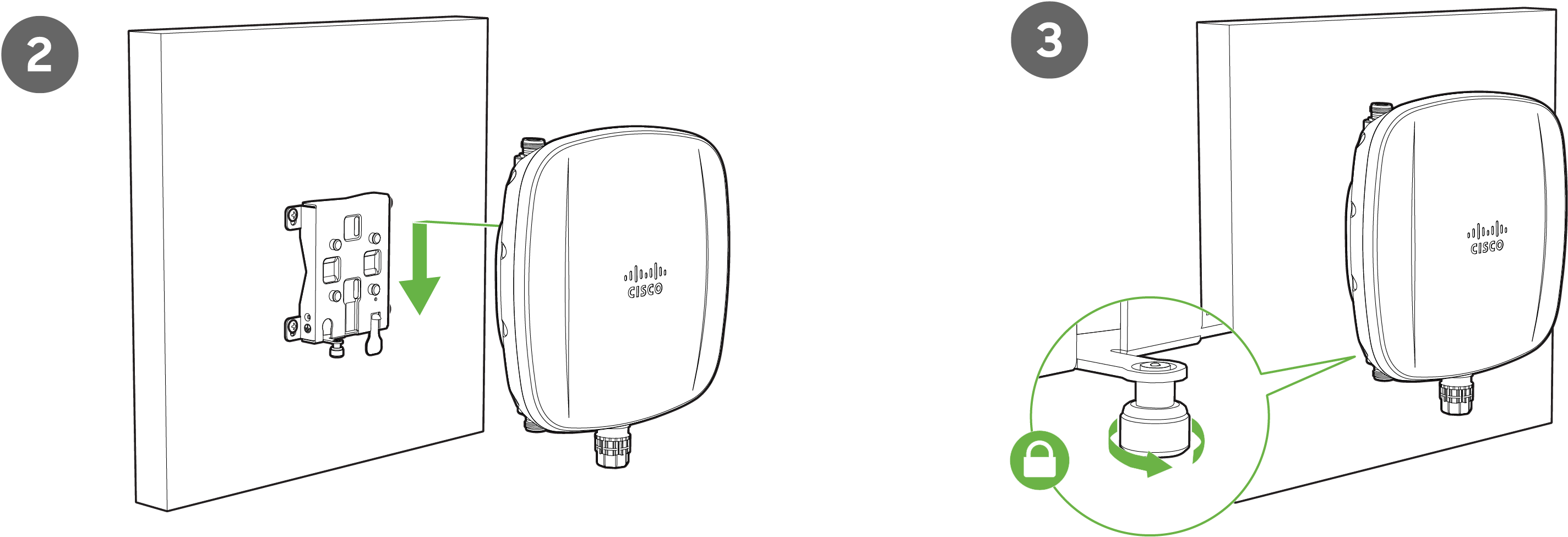
- Align the Mount Plate attachment posts with the mounting holes on the back of the AP.
- Slide the mounting slots on the back of the AP over the mounting posts on the mounting plate. The AP is securely attached when an audible click is heard.
- Tighten the mount plate security screw.
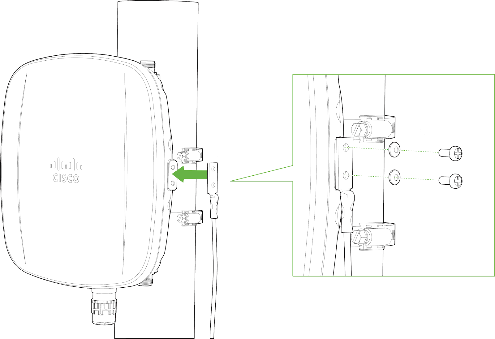
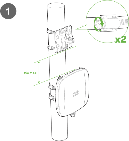
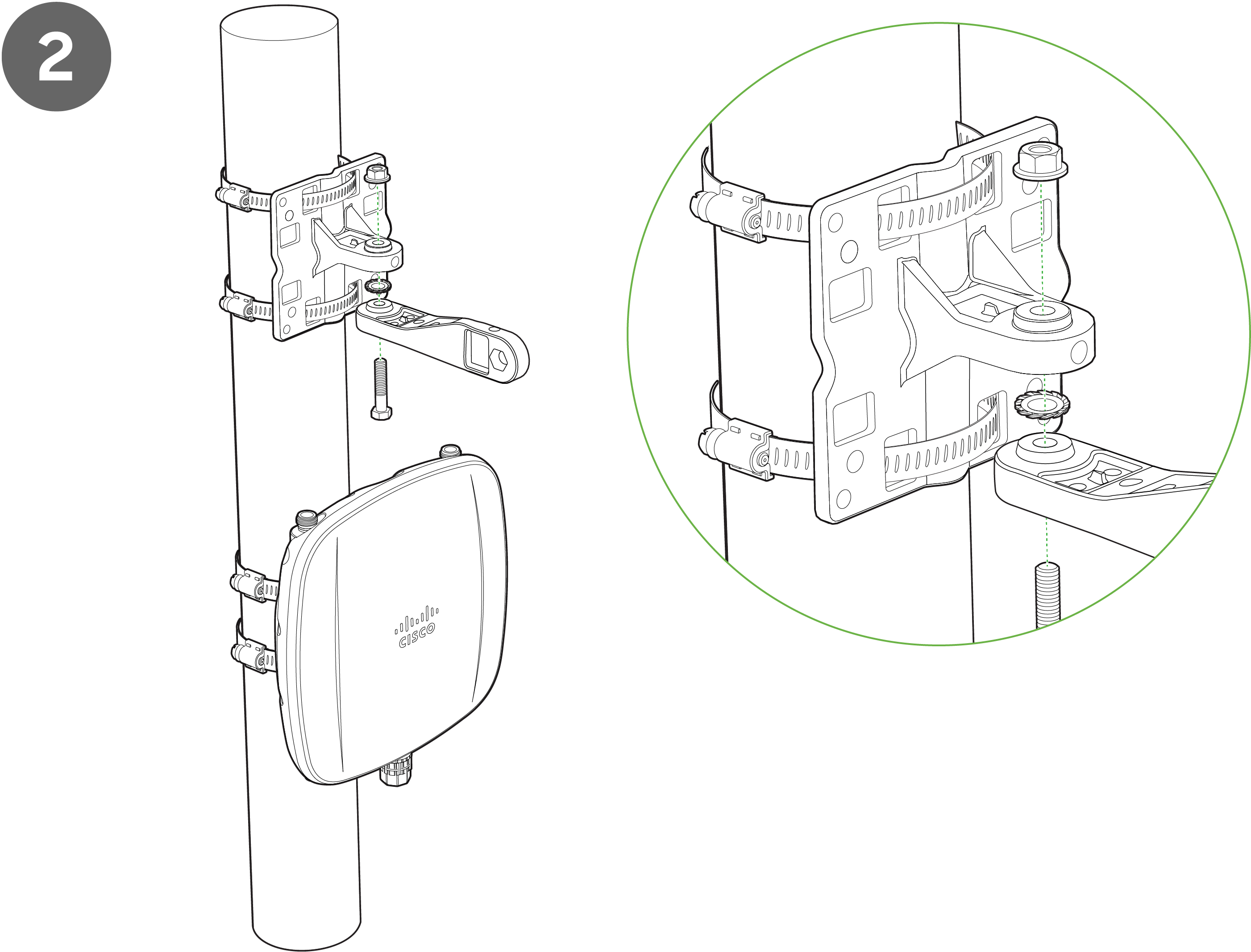
Pole mount installation
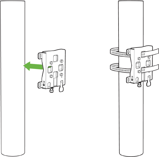
- Use the included mounting straps to mount the AP to a pole 2.5 to 3.9 inches in diameter.
- Thread the mounting straps through the mounting strap slots to secure the mounting plate horizontally or vertically.
- Secure the mounting bracket by tightening the screws of the mounting straps. To tighten, use a flathead screwdriver.
Attaching the AP to the mount bracket
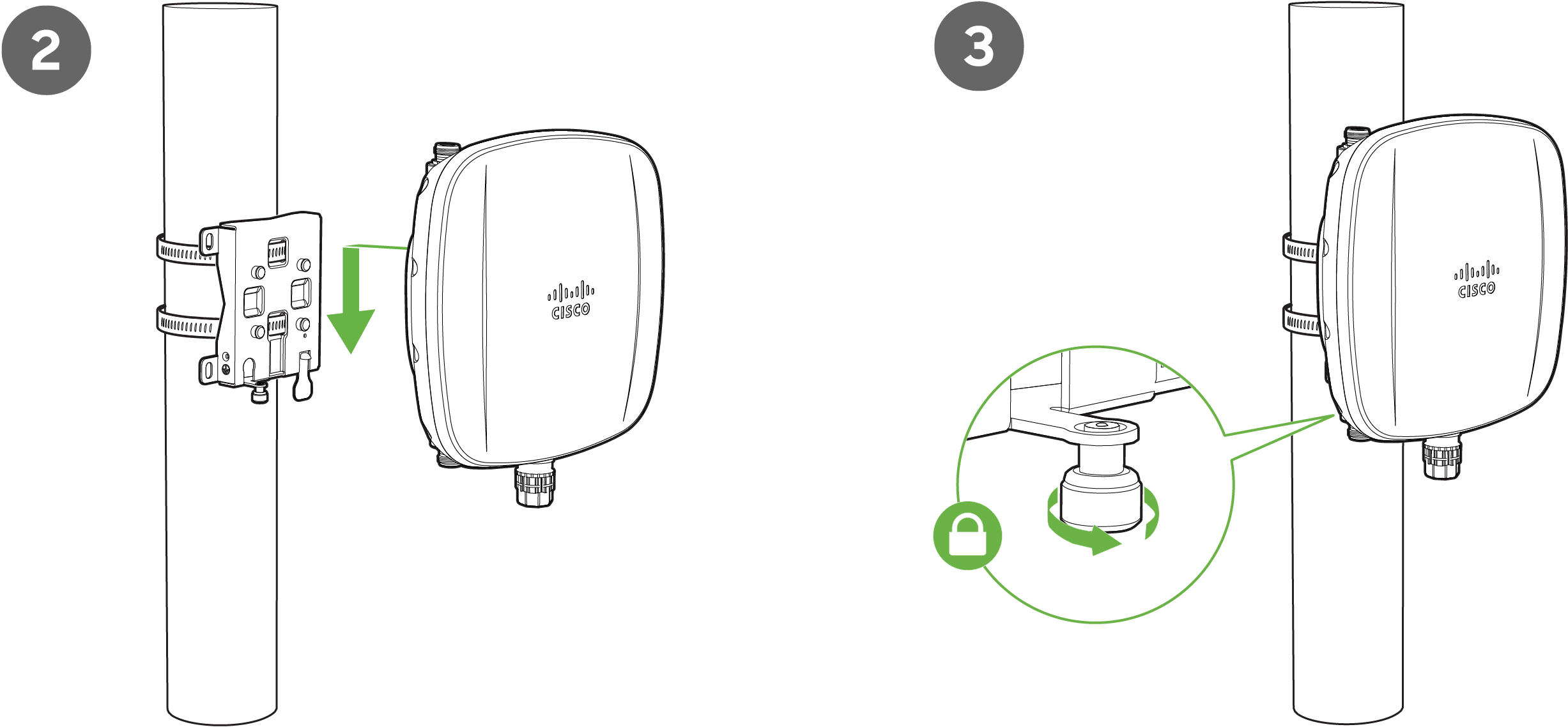
4. Slide the mounting slots on the back of the AP over the mounting posts on the mounting plate. The AP is securely attached when an audible click is heard.
5. Tighten the mount plate security screw.
Attaching grounding strap
If the AP is installed outdoors and exposed to the elements, it should be properly grounded to prevent damage to the unit, connected networking equipment, and the mounting structure.
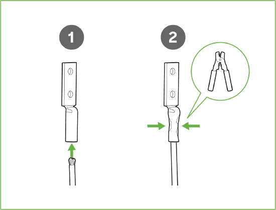
- Thread grounding wire into the grounding strap saddle
- Using a crimper attach the ground wire to the grounding strap
3. Connect one end of the grounding strap to the grounding post with included screw and washer. Securely attach the other end to a nearby metal structure.
Note: For more information on how power plays a big role in the performance of outdoor access points, refer to the following: https://documentation.meraki.com/MR/Wi-Fi_Basics_and_Best_Practices/Grounding_Overview_for_Outdoor_Access_Points
Antenna Selection
Cisco Wireless offers new Wi-Fi and GNSS outdoor-rated antennas to work with CW9163E and future outdoor Wi-Fi APs that work in the 6 GHz band. Choose the antenna based on the install location and designed area of coverage.
The datasheet includes a list of certified antennas. The CW9163E features tri-band antenna ports; thus, tri-band antennas should be paired with the AP. Below is a highlight of the different antenna types and their applications. It is always best practice to consult with a Cisco SE or partner to select the best antenna for the unique design.
Note: The AP is locked to approved antennas. Third-party antennas will not operate if inserted into the 2.4, 5 or 6 GHz ports.
|
PID |
Type |
Connector |
Cable length |
|
CW-ANT-O1-NS-00 |
Direct Attach Omni Directional Antenna, tri-band |
N-type Male |
NA |
|
CW-ANT-D1-NS-00 |
Wall/Pole mount, wide-beam Directional Antenna, tri-band |
N-type Male |
2ft |
|
CW-ANT-GPS2-S-00 |
L1/L5 GNSS patch + SAW + combo-LNA, active |
SMA Male |
10 ft |
Omni Directional
Omni-directional antennas are best for pole mount applications and mesh networks. Use omnidirectional antennas when designing to cover 360 degrees around the Access Point.
Sector Antenna
Sector antennas are ideal for building mounts as they direct the signal away from the interior spaces of the building and focus the energy to the larger outdoor space. This antenna type is ideal for outdoor use but may also be used for some mesh network designs.
Patch Antenna
Patch antennas are ideal for APs mounted on a high ceiling and are intended to cover a large space. This antenna type is ideal for warehouses.
Stadium Patch Antenna
A stadium patch antenna is ideal for high-density AP deployments with an expected high user traffic. Examples are in stadiums where 1 AP is designed to cover a section and an event center with a high user per sqft.
Self-Identifying Antenna Circuitry (SIA)
With Self-identifying antenna circuitry, the CW9163E can automatically detect and configure antenna details like the type of antenna connected and the antenna’s gain values without user intervention.
Note: Please select the right antenna in dashboard when adding the CW9163E to a network. Maximum TX power will depend on the antenna selection made.
Aim Antennas
If using directional antennas, aim them appropriately to ensure optimal performance for your network topography. Omnidirectional antennas perform best in a mesh network when oriented vertically. Patch and sector antennas should be angled in the direction of the desired coverage area.
Note: CW9163E only supports mesh at 2.4 and 5 GHz.
Note: For more information on Cisco Wireless access point antennas, refer to the following: https://documentation.meraki.com/MR/...eraki_Antennas
Antenna Ports
2x N-Type antenna ports are located at the top of the CW9163E and 2x are located at the bottom of the AP. The 4 antenna ports are connected to 2.4 GHz, 5 GHz, 6 Ghz client-serving radios, respectively. Please see the markings on the connectors located on the AP to verify the respective 2.4 GHz, 5 GHz, and 6 GHz ports. In order to ensure the highest performance, ensure antennas connected to the 4 ports have overlapping coverage areas.
|
Port Identification Coloring |
Port colorings on the N-type male should attach the AP side
|
Attaching Antennas
CW-ANT-O1-NS-00
- Remove protective plastic covers from all four N-type RF connectors.
- Ensure a secure connection between antennas and AP by securing fastening into connectors.
- Use the markings on the connectors located on the AP to verify the respective 2.4 GHz, 5 GHz, and 6 GHz ports. To ensure the highest performance, ensure antennas connected to the 4 ports have overlapping coverage areas.
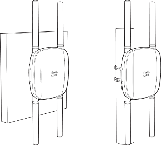
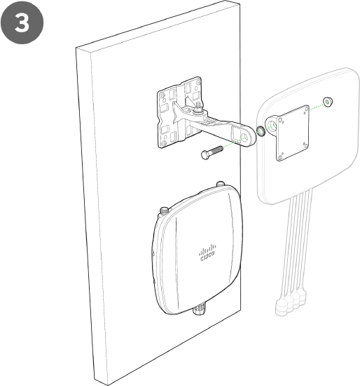
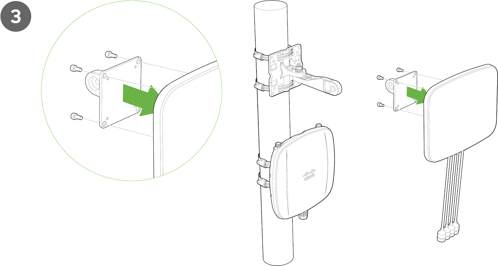
CW-ANT-D1-NS-00 Wall Mount Installation
Note: Installation of the large arm base plate should be done first. The rest of the articulating arm mount should be assembled separately before attaching to the base plate.
-
Determine the desired placement of the antenna.
-
Using the large arm base plate, mark the locations of the mounting holes.
-
Use a 0.1360-in. [3.4772 mm] bit to drill a pilot hole at the mounting hole locations you marked.
-
Locate the pilot holes, insert anchors into each mounting hole, and tighten.
-
Place the large arm base plate over the faster holes and then use screws up to 6 mm in diameter and at least 1 - 1/4 inch length (not included) to tighten it flush to the wall.
- Attach the vertical tilt joint of the small antenna plate to the articulating arm segment using the provided bolt and nut.
![Determine the desired placement of the antenna. Using the large arm base plate, mark the locations of the mounting holes. Use a 0.1360-in. [3.4772 mm] bit to drill a pilot hole at the mounting hole locations you marked. Locate the pilot holes, insert anchors into each mounting hole, and tighten.](https://documentation.meraki.com/@api/deki/files/26441/CW-ANT-D1-NS-00_WallMount2.png?revision=1&size=bestfit&width=753&height=416)
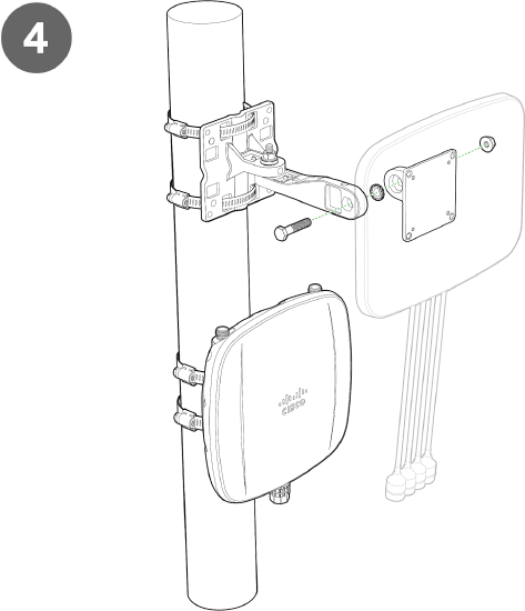
7. Attach the articulating arm segment to the large arm base plate using the provided joint bolt and nut.
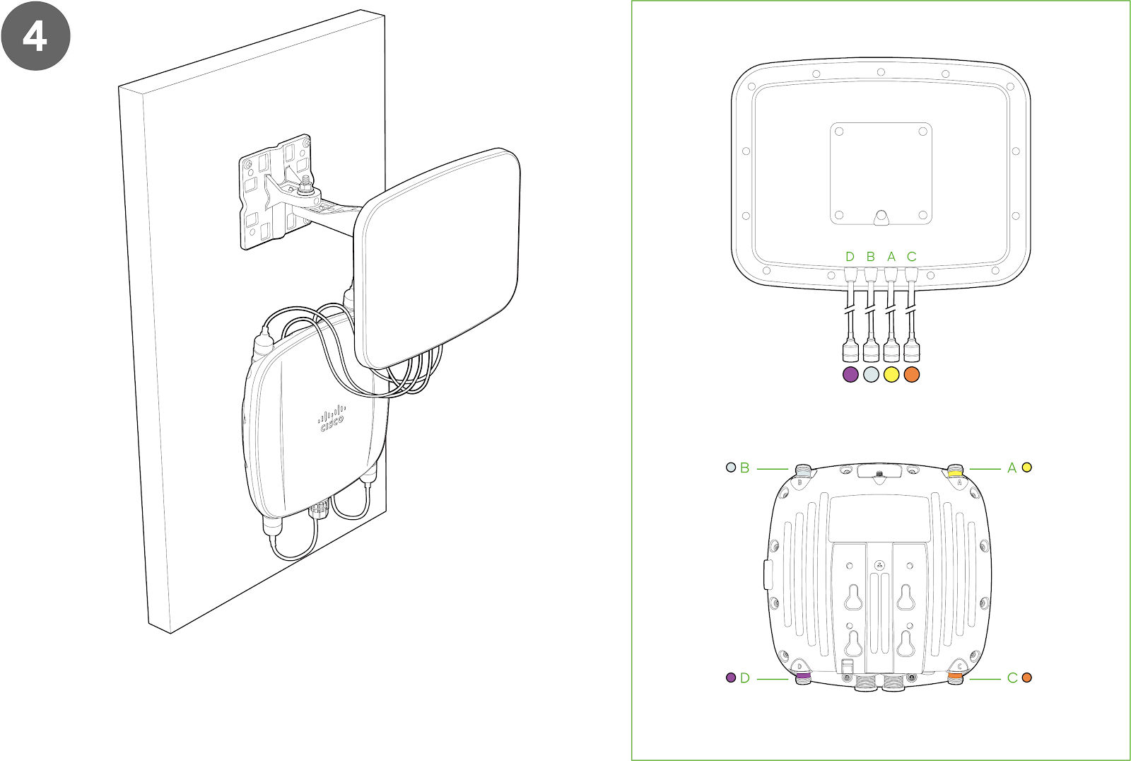
8. Attach the CW9163E to the small antenna plate and secure using the provided screws
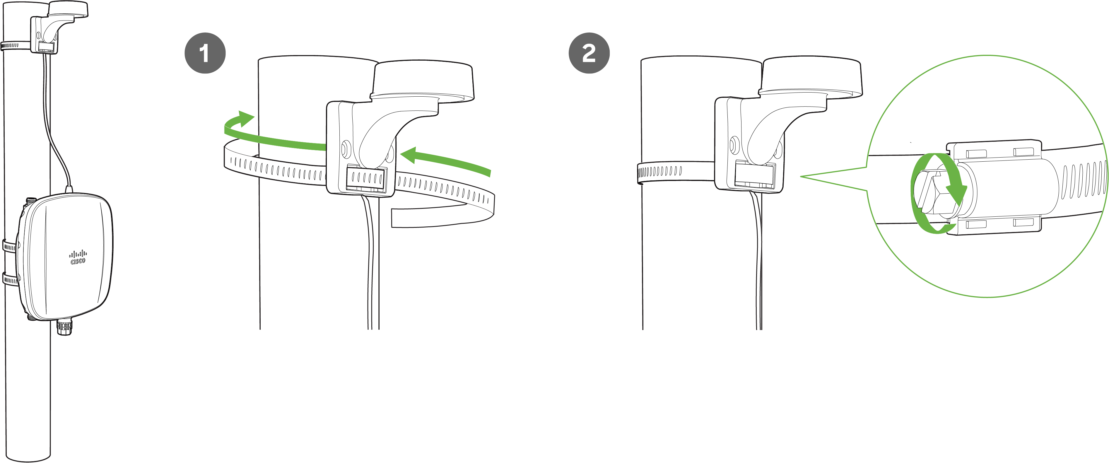
CW-ANT-D1-NS-00 Pole Mount Installation
-
Use the included mounting straps to mount the large arm plate to a pole less than 3.9” in diameter. Thread the mounting straps through the mounting strap slots to secure the arm plate.
-
Attach the antenna arm to the large arm base plate using the provided joint bolt and nut.
-
Attach the small antenna plate securing to the middle arm using the provided bolt and nut
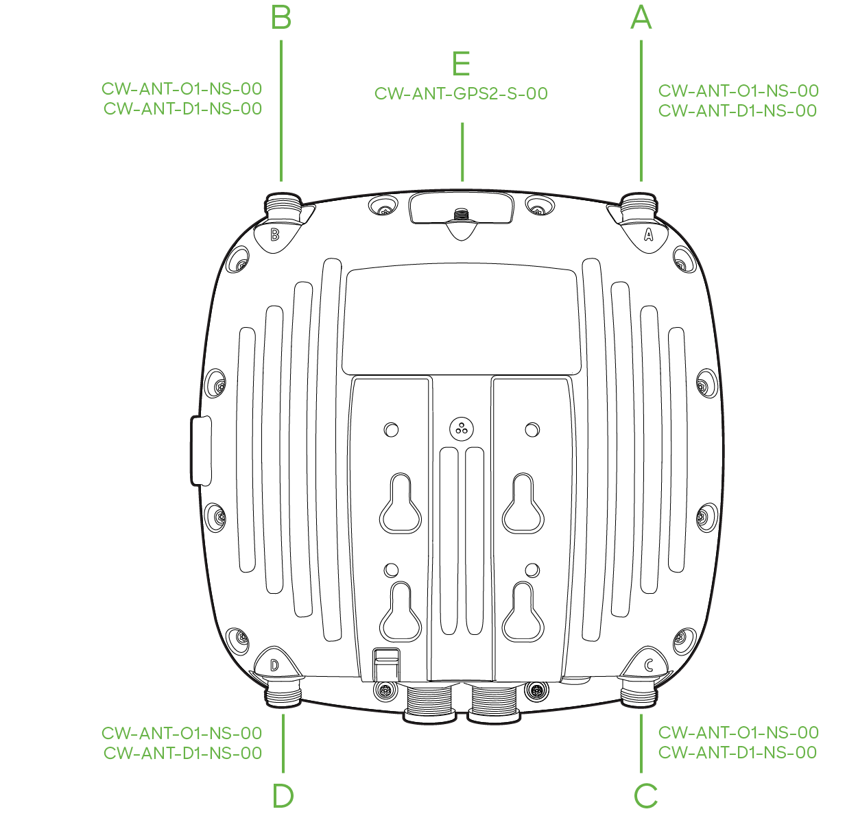
Using the diagram below to attach the antennas to their respective ports on CW9163E.
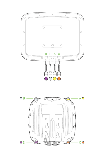
A - 6 GHz
B - 6 GHz
C - 2.4/ 5 GHz
D - 2.4/ 5 GHz
ANT-GPS2-1 Wall Mount Installation
![Determine the desired placement of the antenna. Mark the locations of the mounting holes. Use a 0.1360-in. [3.4772 mm] bit to drill a pilot hole at the mounting hole locations you marked. Locate the pilot holes, insert anchors into each mounting hole, and tighten.](https://documentation.meraki.com/@api/deki/files/26449/ANT-GPS2-1_WallMount.png?revision=1&size=bestfit&width=310&height=295)
For a wall mount installation of the ANT-GPS2-00:
-
Determine the desired placement of the antenna.
-
Mark the locations of the mounting holes.
-
Use a 0.1360-in. [3.4772 mm] bit to drill a pilot hole at the mounting hole locations you marked.
-
Locate the pilot holes, insert anchors into each mounting hole, and tighten.
CW-ANT-GPS2-00 Pole Mount Installation
For a pole mount installation of the CW-ANT-GPS2-00:
- Thread the included pole straps through the horizontal antenna slots.
-
Secure the mounting bracket by tightening the screws of the mounting straps.
-
To tighten pole straps, use a flathead screwdriver.
4. Remove the protective cap and connect the antenna to the GPS port on top of the CW9163E.
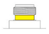
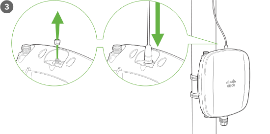
Attaching Cable Gland
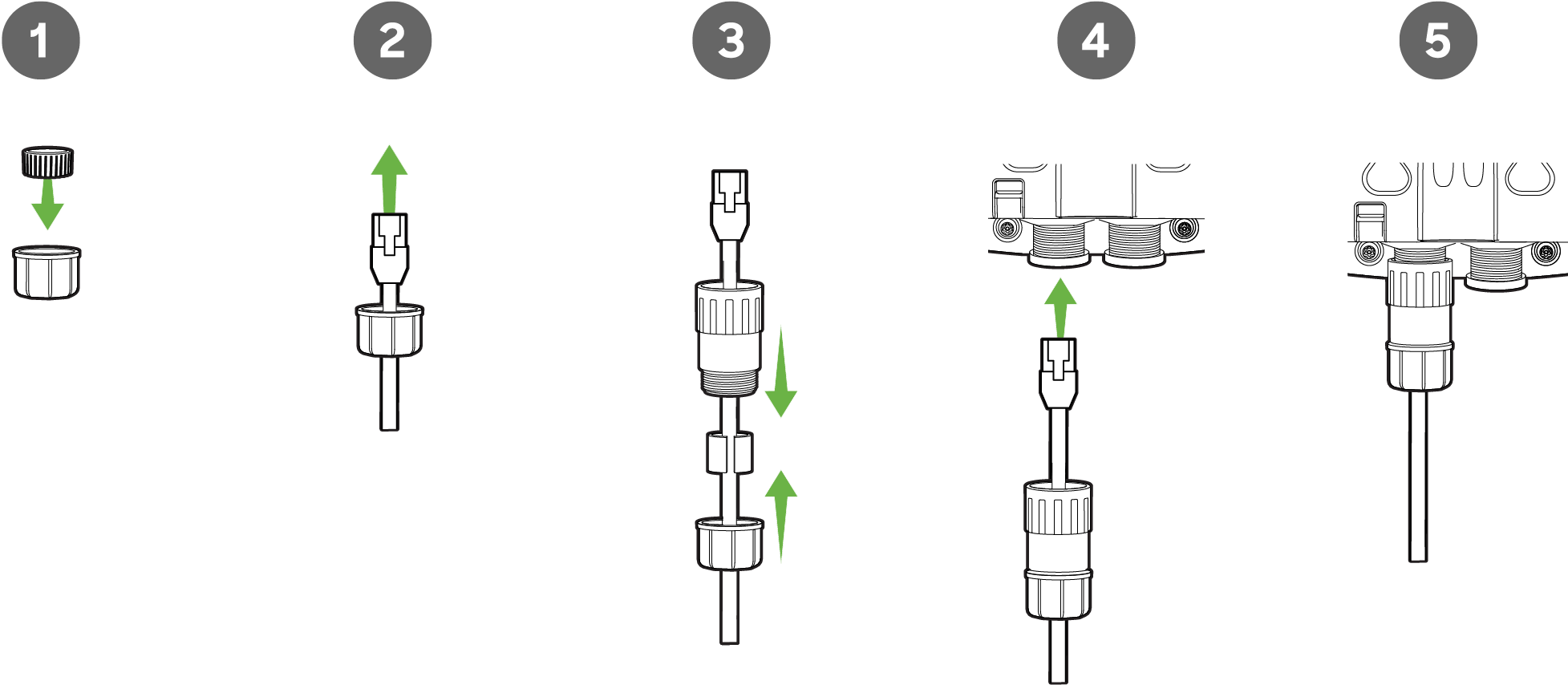
Note: If using molded ethernet connectors, the silicon boot will need to be removed before threading the connector through the cable gland cap.
-
As shown above, insert the included split ring gasket into the gland cap on the CW9163E's end of the cable.
-
Thread the cable connector through the gland cap.
-
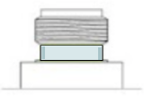
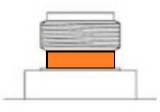
Attach the rubber seal to the cable and sit within the threaded end of the gland body. Hand tighten the gland cap to the gland body.
The installation kit includes two rubber seals. Choose the appropriate size for the ethernet cable.
4. Plug the cable into the ethernet port of the AP.
5. Screw the gland body to the threaded mount surrounding the ethernet port of the AP.
6. Ensure a secure connection between the cable gland and AP.
Powering the CW9163E with 802.3at Power over Ethernet Injector (sold separately)
1. Plug the power cord into the PoE Injector and the other end into wall power.
2. Plug an Ethernet cable that is connected to an active Ethernet connection into the “IN“ port on the injector.
3. Route the ethernet cable from the “OUT“ port on the injector to the PoE labeled port in the cable bay of the CW9163E.
Note: The CW9163E requires at least 802.3at power to operate in normal mode.
Verify Device Functionality and Test Network Coverage
1. Check LEDs
- The Power LED should be solid green (or blue if clients are connected). If it is flashing blue, the firmware is automatically upgrading and the LED should turn green when the upgrade is completed (generally within a few minutes). See the "LED Indicators" section for more details.
Note: Your CW9163E must have an active route to the Internet to check and upgrade its firmware.
2. Verify access point connectivity
- Use any 802.11 client device to connect to the CW9163E and verify proper connectivity using the client’s web browser.
3. Check network coverage
- Confirm that you have good signal strength throughout your coverage area. You can use the signal strength meter on a laptop, smartphone, or other wireless device.
Basic Troubleshooting
The following steps can be used for troubleshooting basic connectivity issues with your access point.
• Reset the access point
• Try switching cables, or testing your cable on another device
If your access point still does not connect, the following instructions may be useful, depending on your issue.
Check Ethernet Port Functionality by Connecting to the AP
1. Disable the Wireless adapter on your computer.
2. Make sure the Ethernet adapter on your device is set to obtain an IP address automatically via DHCP.
3. Connect your computer to the Ethernet port on the AP with an Ethernet cable.
4. The Ethernet LED on the AP should turn solid green or blue.
5. If the Ethernet LED does not turn solid green or blue, try swapping the cable. If the Ethernet port still does not turn green or blue, try the second Ethernet port, if the AP has one.
6. If the Ethernet LED does not turn solid green or blue, you may have a bad port on the AP. If this is the case, the AP signal LEDs will continue to scan.
7. Once the Ethernet LED turns solid green or blue, your computer should obtain an IP address from the AP via DHCP.
Check Static IP Address Configuration
1. If the AP has a static IP address, the green signal LEDs will begin to flash on and off and you will not receive an IP address via DHCP.
2. Disconnect the Ethernet cable from the AP.
3. Associate to the SSID being broadcasted by the AP. If no other APs are within range in the network, the SSID may be appended with "-scanning".
4. Go to my.meraki.com in your web browser.
5. The MAC address on the back of the access point should match the physical address value on the my.meraki.com Overview page.
6. Once you have verified that the MAC address is correct on the overview tab, click the tab Static IP configuration.
7. Enter the username (serial number on the back of the AP) which is case-sensitive and must include the dashes. (There is no password).
8. Make sure your AP is set to obtain a correct DHCP or static IP address configuration from your network.
Reference https://documentation.meraki.com/MR for additional information and troubleshooting tips.
If you are still experiencing hardware issues, please contact Cisco Meraki support by logging in to the Dashboard and using the Help option near the top of the page, then opening an email case or calling using the contact information on that page.
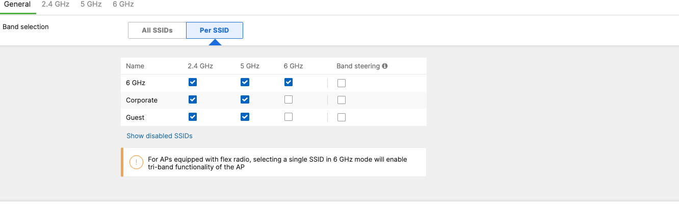
6 GHz Configuration
Broadcasting an outdoor wireless signal in the 6 GHz spectrum is not yet configurable on dashboard. This operation requires AFC feature implementation that provides outdoor 6E APs with unlicensed access to the 6 GHz band by coordinating spectrum sharing with 6 GHz incumbents.
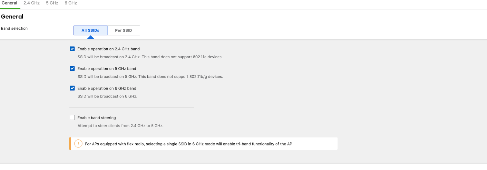
Options to enable the 6 GHz frequencies will be available in Radio Settings, for the regulatory domains that support 6 GHz.
- Navigate Wireless > Configure > Radio Settings > RF Profiles
-
Under RF Profiles, the existing outdoor profile can be modified or new profile can be created.
-
6 GHz capability can be enabled for all SSIDs in the WLAN or enabled for select SSIDs.
WPA3 Support
WiFi 6E in the 6 GHz frequency band requires the clients to support WPA3 as a mandatory mode of operation. WPA2-WPA3 transition mode is not supported in the 6 GHz frequency. If an SSID is configured to operate across all three frequency bands, then the SSID should be configured to be WPA3 only
Note: If an SSID is configured to support WPA3 transition mode across all three frequency bands, then the 2.4 GHz and the 5 GHz frequency will broadcast the SSID with transition mode support. The SSID will not be broadcasted in the 6 GHz mode.
Preferred Scanning Channels
The 6 GHz frequency band introduces 59 20 MHz channels. Due to a large number of channels, the standard implements a new efficient process for clients to discover nearby access points. This is called Preferred Scanning Channels (PSC). PSCs are a set of 20-MHz channels that are spaced every 80 MHz. In order to support the PSC-based clients and effectively onboard the clients in the least possible time, the 6 GHz channel selection in the RF profile for CW9162 Auto RF configuration will be restricted to a set of PSC capable channels.
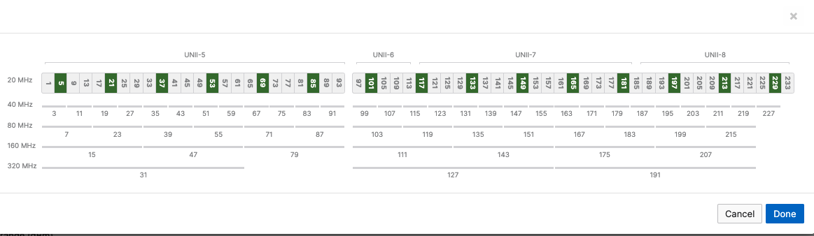
The list of the PSC channels is indicated above in green. Auto RF will choose a channel that is a PSC-supported channel for 20, 40, 80, and 160 MHz frequencies.
Note: When disabling a channel that is being used by Auto Channel configuration settings, the system will make sure to disable all 80 MHz of the closest PSC channel.
Warning: Please make sure to assign a PSC-supported channel when allocating a channel manually. There could be a substantial delay in the client connecting to the Access Point if a non-PSC supported channel is selected during manual allocation.
Management Mode Conversion
CW9163E access point is a converged hardware platform -i.e. One SKU for Catalyst on-prem based wireless network and Meraki Cloud-based wireless network. These access points have the flexibility to change their management mode from Catalyst to Meraki and vice-versa to provide flexibility and full investment protection. If you are interested in migrating from Meraki management to Catalyst mode, please review this document.
Warranty
Additional warranty information can be found on the CW9163E Datasheet or on the Warranty Returns (RMA) page of the Cisco Wireless website.
If your Cisco Wireless device fails and the problem cannot be resolved by troubleshooting, contact support to address the issue. Once support determines that the device is in a failed state, they can process an RMA and send out a replacement device free of charge. In most circumstances, the RMA will include a pre-paid shipping label so the faulty equipment can be returned.
In order to initiate a hardware replacement for non-functioning hardware that is under warranty, you must have access to the original packaging the hardware was shipped in. The original hardware packaging includes the device serial number and order information and may be required for return shipping.
CW9163E has been tested and found to comply with the limits for a Class B digital device, pursuant to part 15 of the FCC rules. These limits are designed to provide reasonable protection against harmful interference in a residential installation. This equipment generates, uses and can radiate radio frequency energy and, if not installed and used in accordance with the instructions, may cause harmful interference to radio communications. However, there is no guarantee that interference will not occur in a particular installation.
Support and Additional Information
If issues are encountered with device installation or additional help is required, contact Meraki Support by logging in to dashboard.meraki.com and opening a case by visiting the Get Help section.
-
The equipment is intended for industrial or other commercial activities.
-
The equipment is used in areas without exposure to harmful and dangerous production factors unless otherwise specified in the operational documentation and/or on the equipment labeling.
-
The equipment is not for domestic use. The equipment is intended for operation without the constant presence of maintenance personnel.
-
The equipment is subject to installation and maintenance by specialists with the appropriate qualifications, sufficient specialized knowledge, and skills.
-
Rules and conditions for the sale of equipment are determined by the terms of contracts concluded by Cisco or authorized Cisco partners with equipment buyers.
-
Disposal of a technical device at the end of its service life should be carried out in accordance with the requirements of all state regulations and laws.
-
Do not throw in the device with household waste. The technical equipment is subject to storage and disposal in accordance with the organization's disposal procedure.
-
The equipment should be stored in its original packaging in a room protected from atmospheric precipitation. The permissible temperature and humidity ranges during storage are specified in the Operation (Installation) Manual.
-
Transportation of equipment should be carried out in the original packaging in covered vehicles by any means of transport. The temperature and humidity during transportation must comply with the permissible established temperature and humidity ranges during storage (in the off state) specified in the Operation Manual (Installation).
For additional information on Meraki hardware and other installation guides, please refer to documentation.meraki.com.