


 Station AJ8MH - Marquette, Michigan")
Notebook Series - Adding the PDC-1 Peak Reading Adapter
Here are a few short tutorials about adding the PDC-1 Peak Reading Adapter from HI-RES Communications to the
MFJ-993B, MFJ-998, MFJ-949E and 962D Tuners. The latest project is presented first followed by earlier
projects.
The PDC-1 is a reasonably priced kit that can be easily installed in your tuner or wattmeter. I am
unsure of current availability as it's been several years since I've ordered one. Here is the last
contact information I have:
Floyd Soo (W8RO)
HI-RES COMMUNICATIONS, INC.
8232 WOODVIEW DR.
CLARKSTON, MI 48348-4058
w8ro AT hotmail DOT com
 [ Marquette, MI - April 2022 ] Notes on installing the PDC-1 Peak Reading Adapter in
the MFJ-993B Auto-Tuner...
[ Marquette, MI - April 2022 ] Notes on installing the PDC-1 Peak Reading Adapter in
the MFJ-993B Auto-Tuner...
The latest tuner added to my collection is the MFJ-993B. It's a low power (150/300 watt) auto tuner
that's similar to its big brother the MFJ-998.
The PDC-1 for this project was removed from an old MFJ-949E that has been retired and wired back to its
original design. Returning these tuners to their original specifications is very easy.
Installation in the MFJ-993B is quite simple, because I finally decided not to use any 9 vdc voltage
regulation as referenced in notes for earlier projects. I powered the PDC-1 directly from the tuner's
13.8 vdc line.
The PDC-1 is mounted horizontally off the Control and Display board by adding a solder lug under one of the
mounting screws, and simply soldering the PDC-1 to the lug. (See photo.) This mount also doubles
as the board ground. All of the connections you need to make are clearly labeled on the end of the
Control and Display board next to the analog SWR meter, so before mounting the board, make your output, input
and power connections.
Unsolder the forward-power wire from the Control and Display board and solder it to the PDC-1 output.
Next, solder a wire to the PDC-1 input and run it to the Control and Display board forward-power
connection. Yes, it's where the wire you just removed was soldered. Now, solder a wire from A+ on
the PDC-1 to the 13.8 vdc line on the Control and Display board. This is the same location that
supplies 13.8 vdc to the analog SWR meter LED.
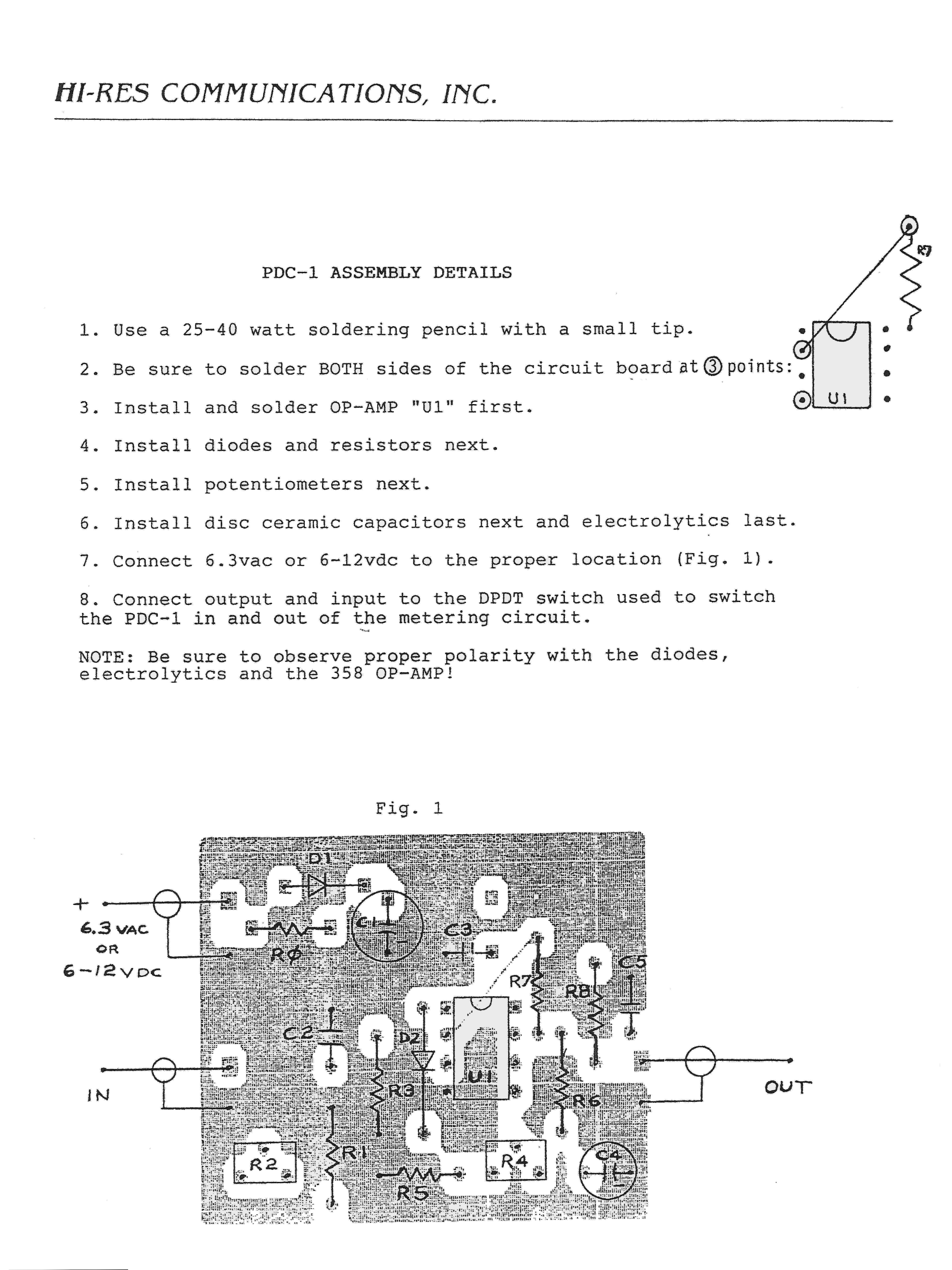
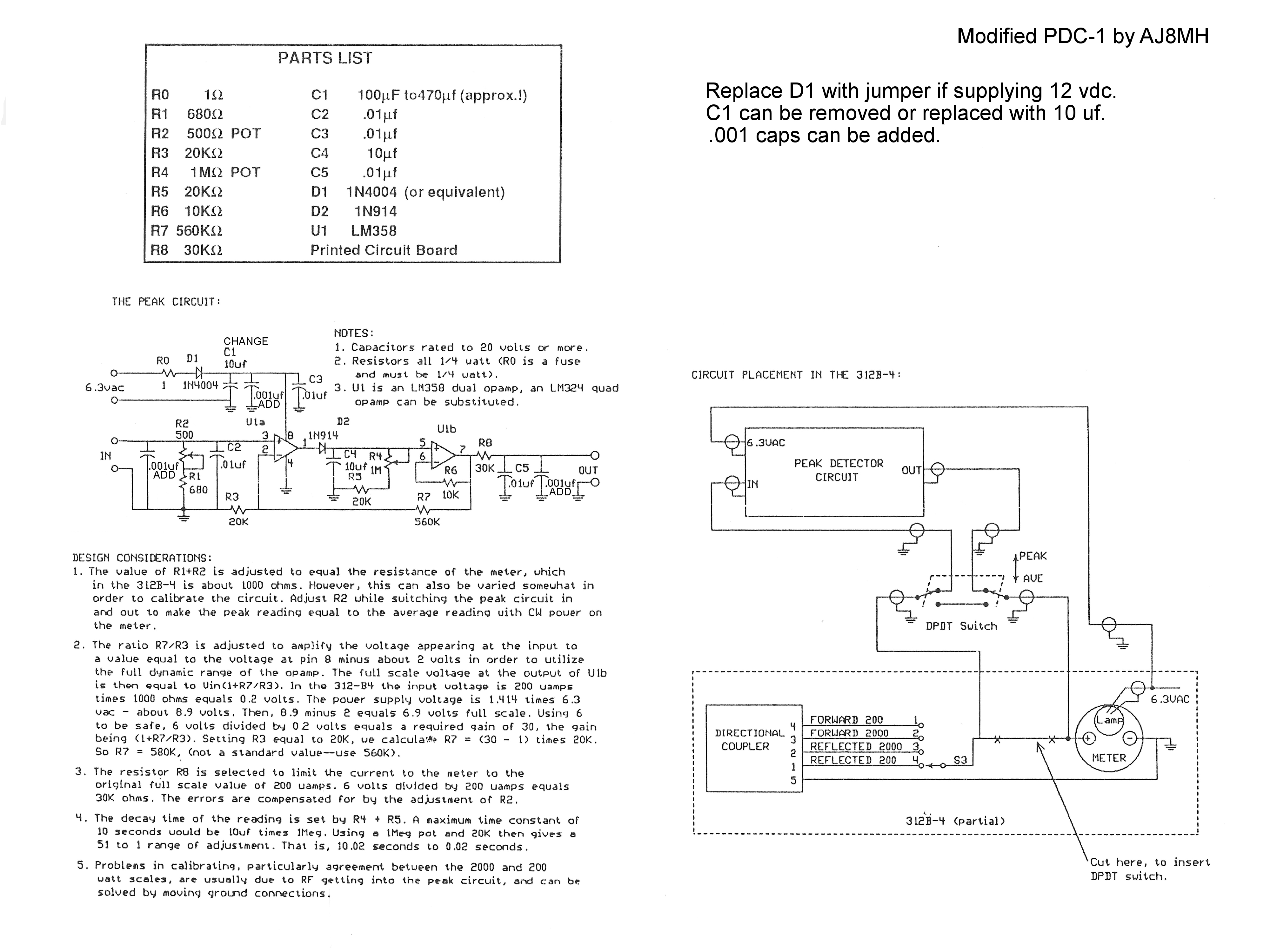
(The PDC-1 was designed for a Collins wattmeter, so the PDC-1 circuit is looking for 6.3 vac. The PDC-1
has a diode and 470-uF-filter capacitor for rectifying and smoothing the AC input, so these components can be
removed or not installed on the board. You can add a jumper wire at the appropriate board locations and
connect your 13.8 vdc from the tuner.)
The alignment should be done next. It's easy and covered below. It's also covered in the PDC-1
manual.
( PDC-1 Manual: Page 1 Page 2 )
73,
Joe (AJ8MH)
ex: WPE8EUM, WN8AQL, WB5FCO and WJ5MH
 [ Marquette, MI - April 2012 ] Notes on installing the PDC-1 Peak Reading Adapter in
the MFJ-998 1.5KW Auto-Tuner...
[ Marquette, MI - April 2012 ] Notes on installing the PDC-1 Peak Reading Adapter in
the MFJ-998 1.5KW Auto-Tuner...
MFJ has been making tuners for a long time, but it's only been in the last few years they've offered an
active peak-reading circuit design and dumped their "switch in a capacitor" design. However, as of
April 2012, the MFJ-998 1.5KW auto-tuner's analog meter still has not been upgraded. In fact, the old
"switch in a capacitor" gimmick isn't an option, either. Hence, HI-RES Communications to the rescue
once again with their PDC-1 Peak Reading Adapter.
Nothing has changed to the HI-RES Communications PDC-1 since I was first introduced to the board in
2001. It was designed for use in the Collins 312B-4/5 station console, so it looks for 6.3 volts
AC. I write about it in detail below in my original article, so I won't cover it again.
Even though the manual says the PDC-1 will work with any voltage between 6 and 13.8 vdc, I feed 13.8 vdc to
an LM317T regulator and adjust it for around 9 volts. This is also covered in the article below.
You may want to save time and components, and just use 13.8 volts for your project.
 Adding the PDC-1 to the
MFJ-998 is easy. First, temporarily remove the aluminum shield that's between the main circuit board
and the front panel. It's held in place by two screws.
Adding the PDC-1 to the
MFJ-998 is easy. First, temporarily remove the aluminum shield that's between the main circuit board
and the front panel. It's held in place by two screws.
I elected to mount the PDC-1 circuit board to the back of the Control and Display board by adding a solder
lug under one of the mounting screws, and simply soldering the PDC-1 to the lug. This connection
doubles as the ground for the PDC-1. 13.8 volts and the "forward" voltage for the meter also come from
the Control and Display board.
Before mounting the PDC-1, connect 13.8 volts. Unsolder the "forward" voltage lead from the Control and
Display board (which runs to the meter), and solder it to the output of the PDC-1. Solder a new wire
from the "forward" voltage point on the Control and Display board and run it to the input of the PDC-1.
Now, mount the board, but be sure you leave clearance for the aluminum shield, which will be reinstalled
after the PDC-1 is adjusted. Also, make sure you have clearance between the PDC-1 and the MFJ-998
Control and Display board.
Connect your rig and dummy load. Transmit a low power CW carrier and set your PDC-1 so the MFJ-998
analog meter reads the power level showing on the MFJ-998 digital display. Next, adjust the hold time
of the PDC-1 to whatever you're comfortable with. After the adjustments are made, remove power and
reinstall the aluminum shield.
 This installation doesn't
allow for switching the analog meter between average and peak. I found no need to switch between the
two readings, but if you do, you can simply add a switch to accomplish the task.
This installation doesn't
allow for switching the analog meter between average and peak. I found no need to switch between the
two readings, but if you do, you can simply add a switch to accomplish the task.
Important. Since acquiring an amplifier, one issue I've noticed needs to be addressed. When the
tuner "METER RANGE" is set to "AUTO" and you're using SSB, the meter will not automatically switch to the
high power scale when using high power. This is because the MFJ power sense circuit does not read voice
peaks. If you change the menu to "METER RANGE 3000", the meter will read SSB voice peaks as
expected. You may find this inconvenient, but I haven't. Remember, the digital display will read
low power just fine.
I haven't experienced any RFI issues with the PDC-1 while running 500 watts or less through the tuner.
However, additional filtering or shielding may be needed with higher power levels. I have always used a
snap-on choke on the power leads to the MFJ-998.
For more information, search for HI-RES Communications and/or PDC-1.
73,
Joe (AJ8MH)
ex: WPE8EUM, WN8AQL, WB5FCO and WJ5MH
[ Austin, TX - September 2001 ] Notes on installing the PDC-1 Peak
Reading Adapter in the MFJ-949E and MFJ-962D... (This document describes my 949E installation, but I
also installed a second PDC-1 in the 962D. Installation in the 962D is somewhat easier, since I didn't
have to move any tuner components. My aluminum box fit nicely between the variable inductor and one of
the capacitors.)
HI-RES Communications, Inc. offers the PDC-1 Peak Reading Adapter for the Collins 312B-X wattmeter, and
according to Chuck Hawely, KE9UW, the adapter will work on any average reading wattmeter, so I decided to
give it a try on the MFJ-949E. After reading the literature that came with the kit, I was concerned
that components would have to be changed to get it to work with the MFJ, but such was not the case. The
internal meter resistance of the 400-084A dual-meter used in the MFJ-949E and 962D is well within the
adjustment range of the PDC-1.
Components that come with the PDC-1 are for use with internal meter resistances between 680 and 1.18K
ohms. The PDC-1 is adjustable within this range. (The reason the wattmeter internal meter
resistance is important is because the PDC-1 must duplicate, or mimic, this internal meter resistance when
the PDC-1 is switched inline.)
Since the PDC-1 is designed for the Collins wattmeter, the circuit is looking for 6.3 volts AC. (The
PDC-1 has a diode and 470-uF-filter capacitor for rectifying and smoothing the AC input. The circuit
would normally supply about 8.9 volts DC to the LM358 OP-AMP.) Since the MFJ-949E uses 13.8 volts for
the meter lamp, I decided to use this voltage and run it through an LM317T adjustable voltage regulator, and
set it to approximately 9 volts.
The LM317T normally uses a variable resistor to set the operating voltage, but I wanted to eliminate the
POT. This is easy to do. I set the variable resistor for 9 volts DC, and measured the
resistance. I replaced the POT with a fixed resistor that was close to the value of the variable
resistor setting.
 (CAUTION: In the past, the
Radio Shack packaging that comes with the LM317T incorrectly labeled the pins. The correct pin-out is
as follows: Pin 1, which is clearly shown on the IC with a small dot (sometimes), is the "adjustment" pin,
and NOT the input. Pin 2 is the output, and pin 3 is the input. Placing the IC in the circuit
backwards will not damage the IC. It just won't regulate at the set voltage. Please see LM317T
diagram.)
(CAUTION: In the past, the
Radio Shack packaging that comes with the LM317T incorrectly labeled the pins. The correct pin-out is
as follows: Pin 1, which is clearly shown on the IC with a small dot (sometimes), is the "adjustment" pin,
and NOT the input. Pin 2 is the output, and pin 3 is the input. Placing the IC in the circuit
backwards will not damage the IC. It just won't regulate at the set voltage. Please see LM317T
diagram.)
I followed standard suggestions on adding capacitors to the input and output of the regulator IC, and made
sure it worked properly before connecting the PDC-1. (With 9 volts DC being supplied to the PDC-1, you
can replace the rectifying diode [D1] with a jumper wire.) To insure some additional RFI protection, I
installed the regulator and PDC-1 in a small aluminum box.
Since the MFJ-949E is a little short on internal space, I had to move the dummy-load resistor and the balun
to the back panel of the tuner. Care must be taken when mounting the 50-ohm resister, because it has to
be mounted low enough that it clears the top cover. To do this, I had to cut one corner off a coax
connector. This allowed me to lower the ceramic standoff on the positive side of the load
resistor. There was not a problem with mounting the ground side of the resistor or the balun.
That was all that I had to change in the tuner to give me enough room to install the small aluminum box
containing the regulator and the PDC-1.
After some thought, I decided not to modify any of the existing switching arrangements on the MFJ-949E.
I wanted to keep it simple, and I wanted the MFJ-949E to act as designed with the power switch off, so I
wired the PDC-1 to come on when power is applied. Normally, the power switch only turns on the meter
lamp. It's important to note that I not only supply 13.8 volts to the regulator IC, but I also us this
voltage to turn on a small relay. I use the relay to change the input connection for the selection of
peak or average readings. (The output of the PDC-1 can be left connected to the plus side of the meter
along with the average reading connection with no side effects.)
[ Update April 2022 ] This modification for the MFJ-949E and MFJ-962D
seems to be overly complicated when it doesn't have to be. After installing a couple PDC-1 boards in
my auto tuners, I've learned that you can save yourself some time and effort and just run 13.8 volts
directly to the PDC-1, avoiding the use of any 9 vdc regulation as talked about above. Just add a
jumper in place of the PDC-1 diode, remove the 470 uf filter cap or replace it with a 10 uf cap.
Also, the use of a shielded box is overkill, and just isn't needed.
All that you have to do to get your PDC-1 up and running is to remove the wire connected to the forward
reading meter. Run this wire to the PDC-1 input. Next, run a wire from the PDC-1 output to the
foward reading point on the meter. It's the same spot you just removed a wire from. Run 13.8
vdc and ground and you're good for an alignment. A good spot to get 13.8 vdc and ground is the same
spot that powers the meter lamp or LED.
Set your transmitter for 100 watts and adjust R2 on the PDC-1 board so the meter reads 100 watts.
Next, adjust R4 for a comfortable decay time.
With this easy installation, your PDC-1 will always be in-circuit and on. No need for a switching
relay.
You'll have to find a spot to mount the PDC-1 board. Just remember to keep the wires short.
73,
Joe (AJ8MH)
ex: WPE8EUM, WN8AQL, WB5FCO and WJ5MH


")


