Virtua Tennis 2 / Power Smash 2 - Arcade - Manual - gamesdbase ...
Virtua Tennis 2 / Power Smash 2 - Arcade - Manual - gamesdbase ...
Virtua Tennis 2 / Power Smash 2 - Arcade - Manual - gamesdbase ...

You also want an ePaper? Increase the reach of your titles
YUMPU automatically turns print PDFs into web optimized ePapers that Google loves.
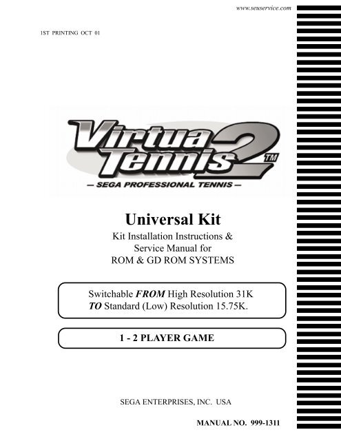
1ST PRINTING OCT 01<br />
Universal Kit<br />
Kit Installation Instructions &<br />
Service <strong>Manual</strong> for<br />
ROM & GD ROM SYSTEMS<br />
Switchable FROM High Resolution 31K<br />
TO Standard (Low) Resolution 15.75K.<br />
1 - 2 PLAYER GAME<br />
SEGA ENTERPRISES, INC. USA<br />
www.seuservice.com<br />
MANUAL NO. 999-1311
VISIT OUR WEBSITE!
Part #<br />
400-5397-01<br />
838-13616<br />
560-5407-UL<br />
838-13683-93CV1<br />
600-7141-200<br />
600-7009-2500<br />
840-0080D-01<br />
600-7247-500<br />
999-1348<br />
999-1326<br />
999-1325<br />
999-1329<br />
999-1327<br />
999-1341<br />
<strong>Virtua</strong> <strong>Tennis</strong> 2<br />
Sega Naomi System<br />
Kit Contains List<br />
Desc<br />
NAOMI POWER SUPPLY<br />
AUDIO POWER AMP 2 CH<br />
AUDIO XFORMER 120V<br />
JAMMA I/O BD (NAOMI)<br />
USB CABLE<br />
VGA VIDEO CABLE<br />
ASSY CASE PC1 DIMM BD<br />
CABLE SCSI TYPE 2 500MM<br />
SERVICE SWT BRKT ASSY<br />
JOYSTICK, COMP. BLUE<br />
BUTTON, COMP. GREEN<br />
SWITCH, PB LARGE<br />
BUTTON, COMP. BLUE<br />
CNTRL PNL (METAL PLT)<br />
Qty<br />
1 www.seuservice.com<br />
1<br />
1<br />
1<br />
1<br />
1<br />
1<br />
1<br />
1<br />
1<br />
2<br />
2<br />
2<br />
2<br />
1
www.seuservice.com<br />
<strong>Virtua</strong> <strong>Tennis</strong> 2<br />
Sega Naomi System<br />
Kit Contains List<br />
Part # Desc<br />
Qty<br />
999-1343<br />
999-1344<br />
999-1347<br />
999-1345<br />
999-1346<br />
999-1342<br />
999-1349<br />
999-1350<br />
999-1351<br />
CNTRL PANEL (NAOMI)<br />
CNTRL PANEL (STANDARD)<br />
DECAL SIDE ART<br />
INSTRUCTION SHT (PLAYER)<br />
INSTRUCTION SHT (BUTTON)<br />
MARQUEE ART<br />
DECALS (BTTNS -TOP SPIN)BL<br />
DECALS (BTTNS-SLICE SPN)GR<br />
DECALS (BTTNS-LOB SHT)WHT<br />
2<br />
1<br />
1<br />
2<br />
1<br />
1<br />
1<br />
2<br />
2<br />
2
DESIGNED RELATED PARTS<br />
Marquee Art ---- 999-1342<br />
Instruction Sheet (Player) ---- 999-1345<br />
Instruction Sheet (Button Controls) ---- 999-1346<br />
Control Panel Overlay ---- 999-1344<br />
3 www.seuservice.com
Decals Side Art ---- 999- 1347<br />
Control Panel Overlay ----- 999-1343<br />
Decals-Buttons -Top Spin (Blue) 999-1349<br />
Decals-Buttons - Slice Spin (Green) 999-1350<br />
Decals-Buttons - Lob Shot (White) 999-1351<br />
www.seuservice.com<br />
4<br />
NOT PICTURED
Feb 9. 2000<br />
SERVICE BULLETIN<br />
SEGA Service Department http://www.seuservice.com<br />
45133 Industrial Drive Phone: 415.701.6580<br />
Fremont, Ca. 94538 Fax: 415.701.6594<br />
SPECIAL NOTICE FOR<br />
ALL SEGA NAOMI KITS<br />
PROBLEM:<br />
The SEGA Naomi Game kits are actually ‘JAMMA Dependent’. What this means exactly is they will only<br />
install into existing JAMMA Cabinets. If an operator tries to install these kits into a Non-JAMMA cabinet,<br />
they will first have to bring the wiring up to JAMMA Standards.<br />
SOLUTION:<br />
° Step 1 Disconnect the games original DC <strong>Power</strong> Supply. You may only use the power supply provided<br />
with your kit. Be sure to set the voltages going to your Game BD to 5.1 and 3.3 volts DC to assure proper<br />
operation ( Measure on Square Connector at Game BD. Yellow = 5vdc / Brown = 3.3vdc / White = Gnd )<br />
° Step 2You MUST USE THE COIN METER SUPPLIED WITH YOUR KIT to assure proper Coin<br />
acceptance. A minimum 18 Gauge wire should be used from the Coin Meter 1 output line on your<br />
JAMMA Harness. The 5vdc ( Yellow ) wire found in the wiring bag of your kit MUST BE USED for the<br />
supply voltage to the meter.<br />
Not following the directions provided herein may cause your game to malfunction.<br />
All electrical work should be performed by the site’s Serviceman or Technician.<br />
In order to prevent an electric shock and short circuit, be sure to turn power off before performing<br />
work or touching the interior parts of the product.<br />
Be careful so as not to damage wirings. Damaged wiring can cause an electric shock or short circuit<br />
accident.<br />
Do not touch places other than those specified. Touching places not specified can cause an electric<br />
shock or short circuit accident.<br />
If you have any questions please contact the SEGA Service Department at the numbers given above.<br />
5 www.seuservice.com<br />
120
www.seuservice.com<br />
INSTALLATION INSTRUCTIONS<br />
1) First. Remove all access panels from the game. Locate the original game Logic PCB’s & <strong>Power</strong><br />
Supply and remove from the Cabinet by first disconnecting all harnesses from the boards. (You need<br />
only to splice in the Main <strong>Power</strong> (110v AC) into the 3-Pin Connector (GRN/WHT/BLK).)<br />
2) Remove all existing game harnesses (we suggest using New Jamma Harnesses (NOT contained in the<br />
kit) to ensure reliability).<br />
3) Locate the most convenient and open area of the cabinet to mount the <strong>Virtua</strong> <strong>Tennis</strong> 2 Naomi System<br />
Assembly. Make sure this area is free and clear of all cable harnesses and grounds, cable clamps, etc.<br />
Vacuum out or clean bottom of cabinet of dirt & miscellaneous parts (e.g.<br />
screws, loose coins / tokens, etc.).<br />
Remove all exterior decals and repair any cabinet damage. Repaint<br />
cabinet if necessary. Remove the Monitor Plexi or if your game plexi has<br />
Silk-screened artwork, you will need to strip it off.<br />
4) Connect the JAMMA Harnesses to the JVS-JAMMA Interface Boards. Separate the wires from each<br />
other (i.e. Control Panel, Video, Speaker, <strong>Power</strong> Supply). Run the various harnesses to the part of the<br />
cabinet they go to ensuring they are dressed properly & secured to the cabinet. Locate the Volume/<br />
Speaker/Coin Meter Cable and connect to your existing Switch Bracket or use the new one included<br />
with the kit. Note: If you are using a VGA Compatible Monitor you can run your VGA Cable directly<br />
to the monitor or connect it to your JVS JAMMA Interface for RGB Conversion to your JAMMA<br />
Cables.<br />
5) Remove Marquee from cabinet and cut to fit the new <strong>Virtua</strong> <strong>Tennis</strong> 2 Marquee in place.<br />
REPLACE old Joysticks & Buttons with the NEW ones supplied in Kit.<br />
6) First remove all Joystick and Button assemblies from the Control Panel. Remove Lexan and Control<br />
Panel Overlay. Proceed to clean surface of the Control Panel by removing all adhesive and dirt. Fill<br />
in or plug up existing button holes to set up a blank work area for your new controls.<br />
7) Install the new Control Panel Overlay by carefully peeling off the paper backing and laying down on<br />
the panel. Smooth it out, starting in the center and working your way to the edges (removing all of<br />
the trapped air pockets). If necessary, cut the edges of the overlay excess and fold under panel.<br />
8) Cut out the button and Joystick Holes. Install Joystick and buttons from kit into the Control Panel<br />
and tighten down. Connect all game harness wires to switches and buttons.<br />
6
INSTALLATION INSTRUCTIONS<br />
9) Proceed to place new decals on the sides of the cabinet. Locate a new monitor bezel, if needed, and<br />
replace glass, if required (due scratches). Install Instruction Placard to the back of the Monitor Glass.<br />
NOTE: As a precaution, disconnect the JAMMA Harness from the I/O Boards and turn power on. With a<br />
Multi-Meter, measure the 5v and 3.3v. Adjust if necessary to 5.15v DCand 3.3vDC. Measure the +12 to<br />
ensure the wires and voltages are in the correct position. Turn power off. Plug in the JAMMA Harness once<br />
again to the I/O Boards. The Attract Mode should appear on the screen.<br />
Adjust the SIZE, CONTRAST, BRIGHTNESS, and COLORS on the<br />
Monitor for optimum appearance. Adjust VERTICAL/HORIZONTAL<br />
Hold to get a stable picture, if required.<br />
Enter DIAGNOSTICS and adjust the Volume Level, test all Buttons &<br />
Joystick for proper operation & wiring. Adjust Pricing. Coin-Up and<br />
test out a game to ensure proper play functions are as they should be.<br />
7 www.seuservice.com
www.seuservice.com<br />
To CN1 of<br />
Amplifier Board<br />
Pin 5<br />
Pin 4<br />
Pin 1<br />
YEL/RED<br />
GRN/RED<br />
WHT/RED<br />
Volume<br />
Sega Naomi System Switch<br />
Bracket and Speaker<br />
Installation Diagrams<br />
(Figure 3)<br />
From CN2 of<br />
Amplifier Board<br />
From CN4 of<br />
Amplifier Board<br />
_<br />
+<br />
Coin Meter<br />
Test Service<br />
GRY/RED<br />
ORG/RED<br />
GRY/BLUE<br />
ORG/BLUE<br />
8<br />
JAMMA Pin 8<br />
Yellow Wire from Extra<br />
Harness (+5v)<br />
JAMMA Pin R<br />
JAMMA Pin 1<br />
JAMMA Pin 15<br />
Left<br />
Speaker<br />
Right<br />
Speaker
Sega Naomi System<br />
JAMMA Harness Wiring<br />
(JAMMA I/O BD)<br />
(Figure 4)<br />
Ground 1 A<br />
Ground<br />
Ground 2 B<br />
Ground<br />
+5v (Not Used) 3 C +5v (Not Used)<br />
+5v (Not Used) 4 D +5v (Not Used)<br />
(Not Used)<br />
5 E (Not Used)<br />
+12v (Not Used) 6 F +12v (Not Used)<br />
Key 7 H Key<br />
Coin Meter 1 8 J Coin Meter 2<br />
(Not Used) 9 K (Not Used)<br />
(Not Used) 10 L (Not Used)<br />
(Not Used) 11 M (Not Used)<br />
Video Red 12 N Video Green<br />
Video Blue 13 P Video Sync<br />
Video Ground 14 R Service<br />
Test 15 S (Not Used)<br />
Coin 1 16 T<br />
Coin 2<br />
1P Start 17 U 2P Start<br />
1P UP 18 V 2P UP<br />
1P Down 19 W 2P Down<br />
1P Left 20 X 2P Left<br />
1P Right<br />
21 Y 2P Right<br />
Attack 1P (1P SW1) 22 Z Attack 2P (2P SW1)<br />
Grapple 1P (1P SW2) 23 a Grapple 2P (2P SW2)<br />
Support 1P (1P SW3) 24 b<br />
Support 2P (2P SW3)<br />
(Not Used)<br />
(Not Used)<br />
Ground<br />
Ground<br />
25 c<br />
26<br />
27<br />
d<br />
e<br />
28 4 f<br />
(Not Used)<br />
(Not Used)<br />
Ground<br />
Ground<br />
9 www.seuservice.com
Service<br />
Switch<br />
www.seuservice.com<br />
PSW2 PSW1<br />
Test<br />
Switch<br />
Sega Naomi System<br />
Filter Board Information<br />
Connector Description etc.<br />
1<br />
1<br />
DIPSW1<br />
2<br />
2<br />
3<br />
3<br />
4<br />
10<br />
CN4<br />
Preamp Level<br />
Audio Out<br />
CN3<br />
VGA Level<br />
Video Out<br />
Setting for High<br />
Resolution 31KHZ<br />
1 -4 off<br />
Setting for Standard<br />
Resolution 15KHZ<br />
1 on 2-4 off.<br />
CN2 CN1<br />
<strong>Power</strong> Connectors
1. HANDLING PRECAUTIONS<br />
STOP<br />
IMPORTANT<br />
� To prevent electric shock or IC Board malfunctioning, be sure to turn<br />
off the power for the cabinet when installing or removing the IC Board.<br />
� Extraneous matter such as dust on the IC Board can cause the IC Board<br />
to generate heat and result in a fire due to short circuit, etc. Ensure the<br />
IC Board surfaces are always kept clean.<br />
� Use NAOMI for the cabinets compatible with JVS. Using NAOMI for<br />
the cabinet other than those compatible with JVS can cause generation<br />
of heat and a fire.<br />
� Be sure to connect the IC Board and connectors completely.<br />
Insufficient insertion can damage IC Board, etc.<br />
� For the IC Board circuit inspection, only the use of Logic Tester is<br />
permitted.<br />
The use of ordinary testers is not permitted as these can damage the IC<br />
Board.<br />
� Do not subject the IC Board to static electricity when installing the IC<br />
Board in the cabinet or when connecting wire harness connectors to the<br />
IC Board.<br />
� When soldering buttons, etc. to the wire harnesses, be sure to remove<br />
the wire harnesses from the IC Board so as not to subject the IC Board<br />
to heat.<br />
� Using NAOMI without the Shield Case can cause electric wave trouble.<br />
Be sure to use NAOMI together with the accessory Shield Case.<br />
� The monitor frequency corresponding to NAOMI is 15kHz or 31kHz.<br />
NAOMI can not be used for the cabinet incorporating a monitor or<br />
projector not corresponding to 15kHz or 31kHz.<br />
� Concerning the display of JAMMA VIDEO STANDARD:<br />
JAMMA VIDEO STANDARD adopted by NAOMI is referred to as JVS. As against this<br />
Standard, the conventional JAMMA STANDARD which employs 56P Edge Connectors adopted<br />
by ST-V, etc. is displayed as Old JAMMA STANDARD.<br />
The specific <strong>Manual</strong> attached to each game sometimes displays JVS as JV STANDARD, New<br />
JAMMA STANDARD, or JAMMA 2 STANDARD AGAINST OLD JAMMA STANDARD as<br />
JAMMA STANDARD, JS, etc.<br />
� The contents herein described are subject to change without notice.<br />
11 www.seuservice.com
2. SPECIFICATIONS<br />
1<br />
2<br />
www.seuservice.com<br />
ON-SCREEN DISPLAY<br />
Monitor Position<br />
CONTROL PANEL<br />
8WAYS<br />
SW1<br />
HORIZONTAL<br />
SW2<br />
PLAYER 1 PLAYER 2<br />
LEVER TOP SPIN<br />
BUTTON<br />
(SW1)<br />
1P 2P<br />
START SW<br />
LOB SHOT BUTTON<br />
(Press both buttons at once)<br />
12<br />
8WAYS<br />
SLICE SPIN<br />
BUTTON<br />
(SW2)<br />
Horizontal Synchronous Frequency<br />
15/31 kHz<br />
� LEVER: Character movement or shot direction<br />
� TOP SPIN BUTTON: Top spin shot (ground stroke or volley automatically<br />
chosen by CPU)<br />
� SLICE SPIN BUTTON: Slice spin shot (ground stroke or volley automatically<br />
chosen by CPU)<br />
� LOB SHOT BUTTON: Lob shot (Hits a ball highly.)<br />
(Note 1) Top spin is the shot that applied order rotation (vertical rotation) to the ball. A<br />
ball flies quickly and bounds highly; an orbit is high.<br />
(Note 2) Slice spin is the shot that applied reverse rotation to the ball. A ball flies late as<br />
it floated and bounds low; an orbit is low.<br />
(Note 3) Lob is the shot of a high arch that passes over a partner's head.<br />
It's effective when passing the head top of the partner approaching the net.<br />
SW1<br />
SW2
3<br />
Minimum DIMM Memory Capacity<br />
256 MB<br />
13 www.seuservice.com
GAME SUMMARY<br />
HOW TO PLAY<br />
GAME SCREEN<br />
Score<br />
1<br />
2<br />
3<br />
4<br />
1P Rafter<br />
GAME<br />
www.seuservice.com<br />
A versus type tennis game featuring the 16 actual professional tennis players.<br />
The type of game played is men's/women's singles and also men's/women's/mixed<br />
doubles.<br />
Max two players can play this game in versus competition singles (SINGLES: VERSUS),<br />
or collaborated doubles (DOUBLES: TEAM PLAY).<br />
Insert a coin(s), and the credit display on the monitor counts up.<br />
When the one credit equivalent coins are inserted, the display changes to "PRESS<br />
START BUTTON" from "INSERT COIN (S)".<br />
Press the START Button while "PRESS START BUTTON" is displayed, and the<br />
character selection screen appears. Bring the arrow to the desired character and press Top<br />
Spin Button (SW1) or Slice Spin Button (SW2) to decide the character being selected.<br />
To win the game, you have got to take first the number of games that have been set in the<br />
GAME ASSIGNMENT (default setting is 2 games). If you win, you can proceed to the<br />
next stage. There are a total of 5 stages in this game, and wining the game results in<br />
proceeding to the ending screen and game over.<br />
When you wish to intrude into a versus game, insert coin(s) and press the START Button<br />
anytime in the game play. If the DOUBLES setting is ON, the select screen of versus<br />
competition singles (SINGLES: VERSUS) or collaborated doubles (DOUBLES: TEAM<br />
PLAY) appears.<br />
14<br />
COM Henman<br />
GAME<br />
1P 30<br />
COM 40 200km/h<br />
Player's Name<br />
Number of games taken<br />
Serve speed
CHARACTERS AND STAGES<br />
VENUES<br />
Male pro tennis players:<br />
� Patrick Rafter (Australia)<br />
� Tim Henman (Germany)<br />
� Cedric Pioline (France)<br />
� Yevgeny Kafelnikov (Russia)<br />
Female pro tennis players:<br />
� Venus Williams (U.S.A.)<br />
� Serena Williams (U.S.A.)<br />
� Lindsay Davenport (U.S.A.)<br />
� Monica Seles (U.S.A.)<br />
SINGLES: A total of 5 stages (CPU randomly selects stage from 1 to 4, and the final stage is<br />
fixed.)<br />
DOUBLES: A total of 3 stages (CPU randomly selects stage from 1 to 2, and the final stage is<br />
fixed.)<br />
VERSUS COMPETITION (VS): CPU randomly selects stages.<br />
Australia Stage (Hard court)<br />
France Stage (Clay court)<br />
U.S.A. Stage (Hard court)<br />
England Stage (Grass court)<br />
Tokyo Stage (Carpet court/Final stage)<br />
� Tommy Haas (Germany)<br />
� Thomas Enqvist (Sweden)<br />
� Magnus Norman (Sweden)<br />
� Carlos Moya (Spain)<br />
� Mary Pierce (France)<br />
� Arantxa Sanchez-Vicario (Spain)<br />
� Jelena Dokic (Yugoslavia)<br />
� Alexandra Stevenson (U.S.A.)<br />
15 www.seuservice.com
3. TEST MODE<br />
A. SYSTEM MENU<br />
STOP<br />
IMPORTANT<br />
SYSTEM MENU<br />
www.seuservice.com<br />
When settings are changed in SYSTEM ASSIGNMENTS, COIN<br />
ASSIGNMENTS, and GAME ASSIGNMENTS of GAME TEST MODE,<br />
be sure to exit from the test mode of SYSTEM MENU screen. The contents<br />
of setting changes are stored in the IC on the BOARD when exiting from the<br />
Test Mode. If the power is turned off in the Test Mode (before exiting), the<br />
contents of setting changes are ineffective. In this case, the settings remain<br />
unchanged.<br />
This test mode mainly allows the IC Board to be checked for accurate functioning, monitor color<br />
to be adjusted as well as COIN ASSIGNMENTS and GAME ASSIGNMENTS to be adjusted.<br />
1) After turning power on, press the TEST Button to have the following SYSTEM MENU<br />
displayed.<br />
RAM TEST<br />
JVS TEST<br />
SOUND TEST<br />
C.R.T. TEST<br />
SYSTEM ASSIGNMENTS<br />
COIN ASSIGNMENTS<br />
BOOKKEEPING<br />
BACKUP DATA CLEAR<br />
CLOCK SETTING<br />
DIMM BOARD TEST<br />
GAME TEST MODE<br />
[ X X X X X X X X X ]<br />
-> EXIT<br />
SELECT WITH SERVICE<br />
BUTTON<br />
AND<br />
PRESS TEST BUTTON<br />
1 2 3 1 4 4 4 2 4 4 4 4 4 4 3 1 2 4 4 3<br />
In the SYSTEM ASSIGNMENTS,<br />
CABINET TYPE is set to 2 PLAYER(S),<br />
MONITOR TYPE is set to HORIZONTAL,<br />
and SERVICE TYPE is set to COMMON.<br />
COIN ASSIGNMENTS initial settings as follows:<br />
COIN CHUTE TYPE: COMMON<br />
COIN/CREDTI SETTING: #1<br />
COIN CHUTE #1 (#2): 1 COIN 1 CREDIT<br />
SEQUENCE SETTING of COIN ASSIGNMENTS functions<br />
as follows:<br />
SEQUENCE 1: Number of credits required for game start<br />
(initial value = 1 CREDIT).<br />
SEQUENCE 2: Number of credits required for CON-<br />
TINUE<br />
(initial value = 1 CREDIT)<br />
SEQUENCE 3 ~ 8: NOT USED.<br />
MEANING OF DISPLAY IN BOOKKEEPING 2/2<br />
P1 (P2) SEQ 1: Play frequency of Player 1 (Player 2)<br />
P1 (P2) SEQ 2: Frequency of CONTINUE by Player 1<br />
(Player 2).<br />
P1 (P2) SEQ 3 ~ 8: NOT USED.<br />
2) Press the SERVICE Button to move the arrow. Bring the arrow to the desired item and press<br />
the TEST Button.<br />
3) Press the TEST Button in the GAME TEST MODE to display the GAME TEST MODE<br />
peculiar to this game. See the next page onward.<br />
4) Upon finishing the test, bring the arrow to EXIT and press the TEST Button to return to the<br />
Game mode.<br />
For detailed explanations as regards the SYSTEM TEST MODE, refer to NAOMI SERVICE<br />
MANUAL (420-6620-01).<br />
16
B. GAME TEST MODE<br />
Bring the arrow to the GAME TEST MODE in the SYSTEM MENU and press the TEST<br />
Button to display the TEST MENU screen peculiar to <strong>Virtua</strong> <strong>Tennis</strong> 2.<br />
TEST MENU<br />
<br />
INPUT TEST<br />
OUTPUT TEST<br />
GAME ASSIGNMENTS<br />
BOOKKEEPING<br />
BACKUP DATA CLEAR<br />
-> EXIT<br />
SELECT WITH SERVICE BUTTON<br />
AND PRESS TEST BUTTON<br />
• Bring the arrow to the desired item with the SERVICE Button and press the TEST<br />
Button to confirm.<br />
• Bring the arrow to EXIT and press the TEST Button to return to the SYSTEM MENU<br />
screen.<br />
17 www.seuservice.com
a. INPUT TEST<br />
www.seuservice.com<br />
This test displays the state of each switch & button. If the display goes ON when the<br />
switch or button is activated, the connection is satisfactory.<br />
LEFT<br />
UP<br />
DOWN<br />
RIGHT<br />
<br />
PLAYER 1P 2P<br />
UP OFF OFF<br />
DOWN OFF OFF<br />
RIGHT OFF OFF<br />
LEFT OFF OFF<br />
SHOT1 OFF OFF<br />
SHOT2OFF OFF<br />
START OFF OFF<br />
PRESS TEST BUTTON TO EXIT<br />
� UP: Changes to ON when inclining the LEVER towards the monitor.<br />
� DOWN: Changes to ON when inclining the LEVER towards you.<br />
� RIGHT: Changes to ON when inclining the LEVER towards the right.<br />
� LEFT: Changes to ON when inclining the LEVER towards the left.<br />
� SHOT 1: Changes to ON when pressing the SHOT1 (TOP SPIN) Button.<br />
� SHOT 2: Changes to ON when pressing the SHOT2 (SLICE SPIN) Button.<br />
� START: Changes to ON when pressing the START Button.<br />
Press the TEST Button to return to the TEST MENU screen.<br />
SHOT2<br />
SHOT1<br />
1P 2P<br />
START<br />
CONTROL PANEL<br />
18<br />
LEFT<br />
UP<br />
DOWN<br />
RIGHT<br />
SHOT2<br />
SHOT1
. OUTPUT TEST<br />
In this test, each winner lamp of 1P/2P and 7 SEG display in the Sega versus cabinet's<br />
billboard can be checked.<br />
<br />
1P SIDE CHECK<br />
2P SIDE CHECK<br />
CLEAR CHECK<br />
-> EXIT<br />
SELECT WITH SERVICE BUTTON<br />
AND PRESS TEST BUTTON<br />
• Bring the arrow to the desired item with the SERVICE Button and press the TEST<br />
Button to have the selected item checked.<br />
• When "1P (2P) SIDE CHECK" is selected, various messages are indicated in the 7<br />
SEG display while the Winner Lamp of 1P/2P is flashing. To stop the test, bring the<br />
arrow to "CLEAR CHECK" and press the TEST Button.<br />
• Bring the arrow to EXIT and press the TEST Button to return to the TEST MENU<br />
screen.<br />
19 www.seuservice.com
c. GAME ASSIGNMENTS<br />
www.seuservice.com<br />
In this test mode, setting for the difficulty, the number of games to take first, etc. can be<br />
changed. Select the item with the SERVICE Button and press the TEST Button to change<br />
the setting.<br />
<br />
DOUBLES [ ON ]<br />
DIFFICULTY [NORMAL]<br />
MATCH COUNT(CPU) [ 2 ]<br />
MATCH COUNT(V S) [ 2 ]<br />
MATCH COUNT(DBL) [ 2 ]<br />
TIE BREAK (V S) [ OFF ]<br />
DEUCE [ ON ]<br />
-> EXIT<br />
SELECT WITH SERVICE BUTTON<br />
AND PRESS TEST BUTTON<br />
� DOUBLES: Can be set to play the collaborated doubles game. If it is set<br />
to ON, you can select versus competition singles (SINGLES:<br />
VERSUS) or collaborated doubles (DOUBLES: TEAM<br />
PLAY) when you intruding into the game. When Sega<br />
versus cabinets such as VERSUS CITY etc. are used, it<br />
recommends to be set to OFF.<br />
� DIFFICULTY: Game difficulty setting for CPU versus mode. Selects from<br />
EASY, NORMAL, HARD and VERY HARD.<br />
� MATCH COUNT (CPU): Sets the number of games to win when playing in 1P<br />
mode against the CPU. Range is from 1 to 6.<br />
� MATCH COUNT (VS):Sets the number of games to win when playing in versus<br />
mode against another player. Range is from 1 to 6.<br />
� MATCH COUNT (DBL): Sets the number of games to win when playing in<br />
doubles mode. Range is from 1 to 6.<br />
20
� TIE BREAK (VS): It is the rule which attaches last one game when the difference<br />
of two or more games does not appear within the number of<br />
setting games, one game is added and a score is in a line, last<br />
one game is decided by the tie-break system.<br />
The tie-break system counts numerically (5-6 etc.), and the<br />
player, which gains seven points or more and two points or<br />
more separated, serves as a winner. In addition, two serves at a<br />
time by turns. Although this rule differs from an actual tennis<br />
rule a little, it recommends using it in convention events as a<br />
fairer judgment rule.<br />
� DEUCE: Selects from ON, 9TIMES and OFF. If it is set to "9 TIMES",<br />
DEUCE will continue to 9 times, and will be displayed on the<br />
10th time as "40-40", and the next point scored wins the game.<br />
If set to "OFF", even if it becomes the score of 40-40, it will not<br />
be set to DEUCE, the next point scored wins the game.<br />
� EXIT: Returns to the TEST MENU screen.<br />
21 www.seuservice.com
d. BOOKKEEPING<br />
www.seuservice.com<br />
PLAY DATA (PAGE 1/3)<br />
This mode displays the playtime related data.<br />
PAGE1/3<br />
PLAY DATA<br />
PLAY TIME **D **H **M **S<br />
AVERAGE TIME **H **M **S<br />
LONGEST TIME **H **M **S<br />
SHORTEST TIME **H **M **S<br />
VS AVERAGE TIME **H **M **S<br />
VS LONGEST TIME **H **M **S<br />
VS SHORTEST TIME **H **M **S<br />
DBL AVERAGE TIME **H **M **S<br />
DBL LONGEST TIME **H **M **S<br />
DBL SHORTEST TIME **H **M **S<br />
PRESS TEST BUTTON TO CONTINUE<br />
� PLAY TIME: Displays game playtime.<br />
� AVERAGE TIME: Displays the average game time.<br />
� LONGEST TIME: Displays the longest game time.<br />
� SHORTEST TIME: Displays the shortest game time.<br />
� VS AVERAGETIME: Displays the average versus game time.<br />
� VS LONGEST TIME: Displays the longest versus game time.<br />
� VS SHORTEST TIME: Displays the shortest versus game time.<br />
� DBL AVERAGE TIME: Displays the average doubles game time.<br />
� DBL LONGEST TIME: Displays the longest doubles game time.<br />
� DBL SHORTEST TIME: Displays the shortest doubles game time.<br />
• Press the TEST Button to migrate to the next page (2/3).<br />
22
TIME HISTOGRAM (PAGE 2/3)<br />
By-playtime play frequency is displayed.<br />
PAGE2/3<br />
TIME HISTOGRAM<br />
00M00S - 00M29S ***<br />
00M30S - 00M59S ***<br />
01M00S - 01M29S ***<br />
01M30S - 01M59S ***<br />
02M00S - 02M29S ***<br />
02M30S - 02M59S ***<br />
03M00S - 03M29S ***<br />
03M30S - 03M59S ***<br />
04M00S - 04M29S ***<br />
04M30S - 04M59S ***<br />
05M00S - 05M29S ***<br />
05M30S - 05M59S ***<br />
06M00S - 06M29S ***<br />
06M30S - 06M59S ***<br />
07M00S - 07M29S ***<br />
07M30S - 07M59S ***<br />
08M00S - 08M29S ***<br />
08M30S - 08M59S ***<br />
09M00S - 09M29S ***<br />
09M30S - 09M59S ***<br />
OVER 10M00S ***<br />
PRESS TEST BUTTON TO CONTINUE<br />
• Press the TEST Button to migrate to the next page (3/3).<br />
CHARACTER DATA (PAGE 3/3)<br />
By-character select frequency, and the number of wins/loses in versus mode are displayed.<br />
PAGE3/3<br />
CHARACTER DATA<br />
SELECT VS WIN VS LOSE<br />
RAFTER (AUS) *** *** ***<br />
HENMAN (GBR) *** *** ***<br />
PIOLINE(FRA) *** *** ***<br />
KAFELNIKOV(RUS) *** *** ***<br />
HAAS(GER) *** *** ***<br />
ENQVIST(SWE) *** *** ***<br />
NORMAN(SWE) *** *** ***<br />
MOYA(ESP) *** *** ***<br />
V WILLIAMS (USA) *** *** ***<br />
S WILLIAMS (USA) *** *** ***<br />
DAVENPORT(USA) *** *** ***<br />
SELES(USA) *** *** ***<br />
PIERCE(FRA) *** *** ***<br />
SANCHEZ(ESP) *** *** ***<br />
DOKIC(YUG) *** *** ***<br />
STEVENSON(USA) *** *** ***<br />
PRESS TEST BUTTON TO EXIT<br />
• Press the TEST Button to return to the TEST MENU screen.<br />
23 www.seuservice.com
e. BACKUP DATA CLEAR<br />
www.seuservice.com<br />
This allows the contents of BOOKKEEPING to be cleared.<br />
<br />
ALL CLEAR<br />
-> EXIT(CANCEL)<br />
SELECT WITH SERVICE BUTTON<br />
AND PRESS TEST BUTTON<br />
• When clearing, bring the arrow to "ALL CLEAR" with the SERVICE Button and<br />
press the TEST Button. When the data has been cleared, "COMPLETED" is displayed.<br />
• Bring the arrow to "EXIT" and press the TEST Button to return to the TEST MENU.<br />
24
According to your DIMM BD type, attach the correct sticker as follows.<br />
1<br />
1<br />
25 www.seuservice.com<br />
2<br />
442-00084B-01 (STICKER 840-0084B-01)<br />
Attached place<br />
PART NO. DESCRIPTION<br />
1 840-0001F ASSY CASE NAO DIMM BD COM<br />
2KEY CHIP<br />
1 + 2840-0084B-01 DIMM BD NAO VT2<br />
2<br />
442-00084B-02 (STICKER 840-0084B-02)<br />
Attached place<br />
PART NO. DESCRIPTION<br />
1 840-0004F ASSY CASE NAO DIMM BD COM RTOS<br />
2KEY CHIP<br />
1 + 2840-0084B-02RT DIMM BD NAO VT2
4. SOFT KIT<br />
STOP<br />
IMPORTANT<br />
www.seuservice.com<br />
Handling the GD-ROM Disc<br />
� Do not contaminate the discs with your<br />
fingerprints or dust particles. Contaminated<br />
discs may lower audio and video quality.<br />
� When cleaning the discs, do not use volatile<br />
chemicals (benzine, thinner, etc.), cleaning<br />
sprays, and antistatic agents.<br />
� Do not use cracked, warped, or damaged discs.<br />
Do not attach papers or seals onto the discs; do<br />
not scratch the discs.<br />
Do not use the discs with a sign of peeled seals,<br />
tapes, etc.<br />
Observing these instructions, do not insert such a non-usable disc into<br />
the GD-ROM drive. Otherwise the inserted disc can not be ejected.<br />
� When cleaning a heavily contaminated disc, use clean cloth that has<br />
been soaked in water and squeezed. Then remove moisture with dry<br />
cloth.<br />
� When holding a disc, be careful not to contaminate it with your<br />
fingerprints.<br />
How to Hold a Disc<br />
With both hands:<br />
Put your thumbs and forefingers of both<br />
hands on the disc's 4 circumference tips.<br />
26<br />
Use clean cloth to wipe<br />
the disc gently and into a<br />
radial direction.<br />
With one hand:<br />
Insert your forefinger into a central<br />
hole and at the same time put your<br />
thumb and middle finger on the<br />
disc's 2 circumference tips.<br />
How to Handle the Key Chip<br />
� The key chip is a precision device. Handle it carefully because it may be<br />
damaged by heat, shock, and static electricity.<br />
� Use the key chip with the GD-ROM disc of the corresponding game that<br />
has been shipped together with the key chip.
4<br />
1<br />
When you order the GD-ROM disc only, please mention the Part No. 610-0625- **** .<br />
2<br />
PART NO. DESCRIPTION<br />
1 + 2 + 3 + 4 610-0630-0015 GD SOFT KIT VT2 ENG<br />
1 NAOMI GDROM VT2<br />
2KEY CHIP<br />
3 420-6621-0015E SERVICE MANUAL VT2 ENG<br />
4 253-5507 DISC CASE WITH IC HOLDER<br />
1 + 4 610-0625-0015 GD SOFT VT2<br />
3<br />
27 www.seuservice.com
5. GAME BOARD<br />
www.seuservice.com<br />
� Do not expose the Game Board so as to avoid causing an accident or<br />
malfunctioning.<br />
� Static electricity discharge can damage electronic parts on the IC Board.<br />
Before starting work by opening the Shield Case Lid, be sure to touch<br />
grounded metallic surfaces to discharge physically charged static electricity.<br />
� When replacing the Game Board, refer to the CVT <strong>Manual</strong> and Instruction<br />
<strong>Manual</strong>.<br />
PART NO. DESCRIPTION<br />
ASSY CASE ( 1 + 2 ) 840-0084D-01 ASSY CASE NAO VT2 USA :USA<br />
840-0084D-02ASSY CASE NAO VT2 EXP :OTHERS<br />
840-0084D-03 ASSY CASE NAO VT2 KOR :KOREA<br />
840-0084D-04 ASSY CASE NAO VT2 AUS :AUSTRALIA<br />
1 ASSY CASE NAOMI 840-0001A-01 ASSY CASE NAOMI MAIN BD USA :USA<br />
MAIN BOARD 840-0001A-02ASSY CASE NAOMI MAIN BD EXP :OTHERS<br />
840-0001A-03 ASSY CASE NAOMI MAIN BD KOR :KOREA<br />
840-0001A-04 ASSY CASE NAOMI MAIN BD AUS :AUSTRALIA<br />
2ROM CASE 840-0084C ROM CASE NAO VT2<br />
28
838-13616<br />
AUDIO POWER AMP 2CH<br />
80<br />
50<br />
P C<br />
1<br />
2<br />
3<br />
JST VH 4P<br />
TRANSFORMER<br />
0V<br />
17V<br />
0V<br />
120V<br />
0V<br />
17V<br />
560-5407<br />
120 Vac Input<br />
WHITE(U/P)<br />
[GD ROM DRIVE]<br />
[Extra]<br />
P C<br />
50<br />
50<br />
10<br />
30<br />
50<br />
50<br />
10<br />
30<br />
51<br />
41<br />
50<br />
50<br />
31<br />
5k pot<br />
2 3 4 5 6<br />
1<br />
92<br />
72<br />
91<br />
71<br />
Phono<br />
plugs<br />
3<br />
1<br />
2<br />
SPEAKER OUTPUTS<br />
CN3<br />
MUST BE SET TO "IN"<br />
TO USE INPUTS ON CN3<br />
OUT IN<br />
1 VCC<br />
2 VCC<br />
3 NC<br />
4 1P SW6<br />
5 1P SW7<br />
6 1P SW8<br />
7 NC<br />
8 2P SW6<br />
9 2P SW7<br />
10 2P SW8<br />
11 NC<br />
12 NC<br />
13 GND<br />
14 GND<br />
JST VL<br />
P C<br />
JST VL<br />
P C<br />
GND<br />
GND<br />
+3.3V<br />
+5V<br />
GND<br />
GND<br />
GND<br />
+3.3V<br />
+5V<br />
+12V<br />
To Extra<br />
Yellow Wire<br />
COIN COUNTER<br />
JP1<br />
400-5397<br />
SW REGU FOR JVS<br />
50 50 10 10 30 30<br />
6 1<br />
CN6<br />
838-13683-91<br />
To PIN 8<br />
of Jamma<br />
600-6743-050<br />
600-7155<br />
29 www.seuservice.com<br />
600-7141-050<br />
JAMMA CONNECTIONS USED ARE:<br />
° VIDEO OUT<br />
° SWITCH INPUTS<br />
° SWITCH GROUND RETURNS<br />
° COIN COUNTER OUTPUT<br />
C<br />
D<br />
E<br />
60<br />
70<br />
80<br />
A<br />
B<br />
10<br />
20<br />
30<br />
40<br />
50<br />
NOTE: THERE ARE TO BE NO<br />
CONNECTIONS MADE TO THE<br />
JAMMA INTERFACE OTHER THAN<br />
THE ABOVE FOREMENTIONED.<br />
NAOMI KIT UNIVERSAL<br />
WIRING DIAGRAM (1/1)
Warranty<br />
Your new Sega Product is covered for a period of 90 days from the date of shipment. This certifies<br />
that the Printed Circuit Boards, <strong>Power</strong> Supplies and Monitor are to be free of defects in workmanship<br />
or materials under normal operating conditions. This also certifies that all Interactive Control<br />
Assemblies are to be free from defects in workmanship and materials under normal operating conditions.<br />
No other product in this machine is hereby covered.<br />
Sellers sole liability in the event a warranted part described above fails shall be, at its option, to<br />
replace or repair the defective part during the warranty period. For Warranty claims, contact your<br />
Sega Distributor.<br />
Should the Seller determine, by inspection that the product was caused by Accident, Misuse, Neglect,<br />
Alteration, Improper Repair, Installation or Testing, the warranty offered will be null and void.<br />
Under no circumstances is the Seller responsible for any loss of profits, loss of use, or other damages.<br />
This shall be the exclusive written Warranty of the original purchaser expressed in lieu of all other<br />
warranties expressed or implied. Under no circumstance shall it extend beyond the period of time<br />
listed above.