ET-7000/PET-7000 DIO Series User Manual - ICP DAS
ET-7000/PET-7000 DIO Series User Manual - ICP DAS
ET-7000/PET-7000 DIO Series User Manual - ICP DAS

Create successful ePaper yourself
Turn your PDF publications into a flip-book with our unique Google optimized e-Paper software.
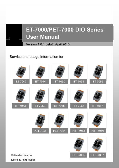
Service and usage information for<br />
Written by Liam Lin<br />
Edited by Anna Huang<br />
<strong>ET</strong>-<strong>7000</strong>/P<strong>ET</strong>-<strong>7000</strong> <strong>DIO</strong> <strong>Series</strong><br />
<strong>User</strong> <strong>Manual</strong><br />
Version 1.0.1 beta2, April 2010<br />
<strong>ET</strong>-7042 <strong>ET</strong>-7044 <strong>ET</strong>-7050 <strong>ET</strong>-7051 <strong>ET</strong>-7052<br />
<strong>ET</strong>-7053 <strong>ET</strong>-7060 <strong>ET</strong>-7065 <strong>ET</strong>-7066 <strong>ET</strong>-7067<br />
P<strong>ET</strong>-7044 P<strong>ET</strong>-7051 P<strong>ET</strong>-7052<br />
P<strong>ET</strong>-7060<br />
P<strong>ET</strong>-7065 P<strong>ET</strong>-7067
Warranty<br />
All products manufactured by <strong>ICP</strong> <strong>DAS</strong> are under warranty regarding defective<br />
materials for a period of one year, beginning from the date of delivery to the original<br />
purchaser.<br />
Warning<br />
<strong>ICP</strong> <strong>DAS</strong> assumes no liability for any damage resulting from the use of this<br />
product.<strong>ICP</strong> <strong>DAS</strong> reserves the right to change this manual at any time without notice.<br />
The information furnished by <strong>ICP</strong> <strong>DAS</strong> is believed to be accurate and reliable.<br />
However, no responsibility is assumed by <strong>ICP</strong> <strong>DAS</strong> for its use, not for any<br />
infringements of patents or other rights of third parties resulting from its use.<br />
Copyright<br />
Copyright @ 2009 by <strong>ICP</strong> <strong>DAS</strong> Co., Ltd. All rights are reserved.<br />
Trademark<br />
The names used for identification only may be registered trademarks of their<br />
respective companies.<br />
Contact US<br />
If you have any problem, please feel free to contact us.<br />
You can count on us for quick response.<br />
Email: service@icpdas.com<br />
<strong>ET</strong>-<strong>7000</strong>/P<strong>ET</strong>-<strong>7000</strong> <strong>DIO</strong> <strong>Series</strong> <strong>User</strong> <strong>Manual</strong>, version 1.0.1 beta2 Page: 2<br />
Copyright © 2009 <strong>ICP</strong> <strong>DAS</strong> Co., Ltd. All Rights Reserved. E-mail: service@icpdas.com
Table of Contents<br />
1. Introduction ....................................................................................... 7<br />
1.1. Product Information ...................................................................................... 8<br />
1.1.1. <strong>ET</strong>-<strong>7000</strong>/P<strong>ET</strong>-<strong>7000</strong> AIO <strong>Series</strong> Release Module ................................ 8<br />
1.1.2. <strong>ET</strong>-<strong>7000</strong>/P<strong>ET</strong>-<strong>7000</strong> Module Naming Convention ................................ 9<br />
1.1.3. <strong>ET</strong>-<strong>7000</strong>/P<strong>ET</strong>-<strong>7000</strong> Comparison ....................................................... 10<br />
1.2. Features ..................................................................................................... 12<br />
1.3. Specification ............................................................................................... 15<br />
1.3.1. System Specification ........................................................................ 15<br />
1.3.2. I/O Specification ............................................................................... 17<br />
1.3.2.1. <strong>ET</strong>-7042 .................................................................................. 17<br />
1.3.2.2. <strong>ET</strong>-7044/P<strong>ET</strong>-7044 ................................................................. 19<br />
1.3.2.3. <strong>ET</strong>-7050 .................................................................................. 21<br />
1.3.2.4. <strong>ET</strong>-7051/P<strong>ET</strong>-7051 ................................................................. 23<br />
1.3.2.5. <strong>ET</strong>-7052/P<strong>ET</strong>-7052 ................................................................. 25<br />
1.3.2.6. <strong>ET</strong>-7053 .................................................................................. 27<br />
1.3.2.7. <strong>ET</strong>-7060/P<strong>ET</strong>-7060 ................................................................. 29<br />
1.3.2.8. <strong>ET</strong>-7065/P<strong>ET</strong>-7065 ................................................................. 31<br />
1.3.2.9. <strong>ET</strong>-7066 .................................................................................. 33<br />
1.3.2.10. <strong>ET</strong>-7067/P<strong>ET</strong>-7067 ............................................................... 35<br />
1.4. Wiring Connection ...................................................................................... 37<br />
1.4.1. <strong>ET</strong>-7042/<strong>ET</strong>-7044/<strong>ET</strong>-7050/P<strong>ET</strong>-7044 .............................................. 37<br />
1.4.2. <strong>ET</strong>-7044/<strong>ET</strong>-7050/<strong>ET</strong>-7051/P<strong>ET</strong>-7044/P<strong>ET</strong>-7051 ............................. 37<br />
1.4.3. <strong>ET</strong>-7052/P<strong>ET</strong>-7052 ........................................................................... 38<br />
1.4.4. <strong>ET</strong>-7053 ............................................................................................ 39<br />
1.4.5. <strong>ET</strong>-7060/P<strong>ET</strong>-7060 ........................................................................... 39<br />
1.4.6. <strong>ET</strong>-7065/P<strong>ET</strong>-7065 ........................................................................... 40<br />
1.4.7. <strong>ET</strong>-7065/<strong>ET</strong>-7066/P<strong>ET</strong>-7065 ............................................................ 40<br />
<strong>ET</strong>-<strong>7000</strong>/P<strong>ET</strong>-<strong>7000</strong> <strong>DIO</strong> <strong>Series</strong> <strong>User</strong> <strong>Manual</strong>, version 1.0.1 beta2 Page: 3<br />
Copyright © 2009 <strong>ICP</strong> <strong>DAS</strong> Co., Ltd. All Rights Reserved. E-mail: service@icpdas.com
1.4.8. <strong>ET</strong>-7067/P<strong>ET</strong>-7067 ........................................................................... 41<br />
1.5. Overview .................................................................................................... 42<br />
1.5.1. Front Panel ....................................................................................... 42<br />
1.5.2. Back Panel ....................................................................................... 45<br />
1.6. Dimensions ................................................................................................. 47<br />
1.7. Companion CD ........................................................................................... 48<br />
2. Getting Started ................................................................................ 49<br />
2.1. Mounting the Hardware .............................................................................. 49<br />
2.2. Configuring the Boot Mode ......................................................................... 51<br />
2.3. Connecting to Network, PC and Power ...................................................... 52<br />
2.4. Installing the MiniOS7 Utility ....................................................................... 53<br />
2.5. Using MiniOS7 Utility to Assign a new IP ................................................... 54<br />
2.6. Enabling Adobe Flash Player in Browser .................................................... 58<br />
3. Web Applications ............................................................................ 60<br />
3.1. Overview .................................................................................................... 63<br />
3.2. Configuration .............................................................................................. 65<br />
3.2.1. Network Settings .............................................................................. 66<br />
3.2.1.1. Configure the Network Settings .............................................. 67<br />
3.2.1.2. Check the software information .............................................. 69<br />
3.2.2. Basic Settings ................................................................................... 70<br />
3.2.2.1. Configure the Module Information .......................................... 71<br />
3.2.2.2. Configure the Web site Information ........................................ 72<br />
3.2.2.3. Reset All Settings to Default ................................................... 75<br />
3.2.3. Module I/O Settings .......................................................................... 79<br />
3.3. Authentication ............................................................................................. 80<br />
3.3.1. Account Management ....................................................................... 81<br />
3.3.1.1. Configure the user accounts .................................................. 82<br />
3.3.1.2. Load the factory default user accounts................................... 83<br />
3.3.2. Accessible IP Settings ...................................................................... 84<br />
<strong>ET</strong>-<strong>7000</strong>/P<strong>ET</strong>-<strong>7000</strong> <strong>DIO</strong> <strong>Series</strong> <strong>User</strong> <strong>Manual</strong>, version 1.0.1 beta2 Page: 4<br />
Copyright © 2009 <strong>ICP</strong> <strong>DAS</strong> Co., Ltd. All Rights Reserved. E-mail: service@icpdas.com
3.3.2.1. Configuring IP filter ................................................................. 85<br />
3.4. Web HMI .................................................................................................... 87<br />
3.4.1. Web HMI .......................................................................................... 88<br />
3.4.2. Web Edit ........................................................................................... 89<br />
3.5. Pair Connection .......................................................................................... 97<br />
3.6. More Information ........................................................................................ 98<br />
4. Modbus Applications ...................................................................... 99<br />
4.1. What is Modbus TCP/IP? ......................................................................... 100<br />
4.2. Modbus Message Structure ...................................................................... 101<br />
4.2.1. Address .......................................................................................... 102<br />
4.2.2. Function Codes .............................................................................. 103<br />
4.2.3. Data Field ....................................................................................... 103<br />
4.2.4. Error Check .................................................................................... 103<br />
4.3. Modbus Register Map .............................................................................. 104<br />
4.3.1. Common Function .......................................................................... 104<br />
4.3.2. Particular Function ......................................................................... 106<br />
4.3.2.1. <strong>ET</strong>-7042 I/O Address Mapping ............................................. 107<br />
4.3.2.2. <strong>ET</strong>-7044/P<strong>ET</strong>-7044 I/O Address Mapping ............................ 109<br />
4.3.2.3. <strong>ET</strong>-7050 I/O and Counter Address Mapping .......................... 111<br />
4.3.2.4. <strong>ET</strong>-7051/P<strong>ET</strong>-7051 I/O and Counter Address Mapping ......... 115<br />
4.3.2.5. <strong>ET</strong>-7052/P<strong>ET</strong>-7052 I/O and Counter Address Mapping ......... 119<br />
4.3.2.6. <strong>ET</strong>-7053 I/O and Counter Address Mapping ......................... 123<br />
4.3.2.7. <strong>ET</strong>-7060/P<strong>ET</strong>-7060 I/O and Counter Address Mapping ........ 127<br />
4.3.2.8. <strong>ET</strong>-7065/P<strong>ET</strong>-7065 I/O and Counter Address Mapping ........ 131<br />
4.3.2.9. <strong>ET</strong>-7066/P<strong>ET</strong>-7066 I/O Address Mapping ............................ 135<br />
4.3.2.10. <strong>ET</strong>-7067/P<strong>ET</strong>-7067 I/O Address Mapping .......................... 137<br />
5. MiniOS7 Utility Tool ....................................................................... 139<br />
5.1. Establishing a Connection ........................................................................ 139<br />
5.2. Exchanging the Protocol (TCP/IP to UDP) ............................................... 142<br />
<strong>ET</strong>-<strong>7000</strong>/P<strong>ET</strong>-<strong>7000</strong> <strong>DIO</strong> <strong>Series</strong> <strong>User</strong> <strong>Manual</strong>, version 1.0.1 beta2 Page: 5<br />
Copyright © 2009 <strong>ICP</strong> <strong>DAS</strong> Co., Ltd. All Rights Reserved. E-mail: service@icpdas.com
5.3. Updating the <strong>ET</strong>-<strong>7000</strong>/P<strong>ET</strong>-<strong>7000</strong> OS........................................................ 144<br />
5.4. Uploading the <strong>ET</strong>-<strong>7000</strong>/P<strong>ET</strong>-<strong>7000</strong> Firmware ............................................ 149<br />
6. External Tools and Tasks .............................................................. 154<br />
6.1. LabVIEW .................................................................................................. 154<br />
6.2. OPC Server .............................................................................................. 155<br />
6.3. SCADA ..................................................................................................... 156<br />
6.3.1. InduSoft .......................................................................................... 157<br />
6.3.2. Citect .............................................................................................. 158<br />
6.3.3. iFix .................................................................................................. 159<br />
Appendix A. Node Information Area ................................................ 160<br />
Appendix B. Modbus Application Notes .......................................... 161<br />
B.1. Dual Watchdog ......................................................................................... 161<br />
B.2. Power ON Value ....................................................................................... 162<br />
B.3. Safe Value ................................................................................................ 163<br />
B.4. AI High/Low Alarm .................................................................................... 164<br />
B.5. AI High/Low Latch .................................................................................... 169<br />
Appendix C. Troubleshooting .......................................................... 173<br />
<strong>ET</strong>-<strong>7000</strong>/P<strong>ET</strong>-<strong>7000</strong> <strong>DIO</strong> <strong>Series</strong> <strong>User</strong> <strong>Manual</strong>, version 1.0.1 beta2 Page: 6<br />
Copyright © 2009 <strong>ICP</strong> <strong>DAS</strong> Co., Ltd. All Rights Reserved. E-mail: service@icpdas.com
1. Introduction<br />
The <strong>ET</strong>-<strong>7000</strong>/P<strong>ET</strong>-<strong>7000</strong>, a web-based Ethernet I/O module, features a built-in web<br />
server, which allows configuration, I/O monitoring and I/O control by simply using a<br />
regular web browser. Besides, with the web HMI function, no more programming or<br />
HTML skills are needed; creating dynamic and attractive web pages for I/O monitoring<br />
and I/O control would be fun to engineers ever after. The <strong>ET</strong>-<strong>7000</strong>/P<strong>ET</strong>-<strong>7000</strong> offers<br />
easily and safely access for users from anytime and anywhere! In addition,<br />
<strong>ET</strong>-<strong>7000</strong>/P<strong>ET</strong>-<strong>7000</strong> also supports Modbus/TCP protocol that makes perfect<br />
integration to SCADA software.<br />
<strong>ET</strong>-<strong>7000</strong>/P<strong>ET</strong>-<strong>7000</strong> <strong>DIO</strong> <strong>Series</strong> <strong>User</strong> <strong>Manual</strong>, version 1.0.1 beta2 Page: 7<br />
Copyright © 2009 <strong>ICP</strong> <strong>DAS</strong> Co., Ltd. All Rights Reserved. E-mail: service@icpdas.com
1.1. Product Information<br />
1.1.1. <strong>ET</strong>-<strong>7000</strong>/P<strong>ET</strong>-<strong>7000</strong> AIO <strong>Series</strong> Release Module<br />
Either <strong>ET</strong>-<strong>7000</strong> or P<strong>ET</strong>-<strong>7000</strong> has released three different types of analog series<br />
modules, which provides a variety of analog module choice, listed in the following<br />
table.<br />
Type Model Description<br />
DC Digital Output<br />
(Open Collector)<br />
DC Digital Input<br />
DC Digital Input<br />
and Output<br />
Power Relay<br />
Output<br />
Photomos Relay<br />
Output<br />
<strong>ET</strong>-7042<br />
<strong>ET</strong>-7051/<br />
P<strong>ET</strong>-7051<br />
<strong>ET</strong>-7053<br />
<strong>ET</strong>-7044/<br />
P<strong>ET</strong>-7044<br />
<strong>ET</strong>-7050<br />
<strong>ET</strong>-7052/<br />
P<strong>ET</strong>-7052<br />
<strong>ET</strong>-7060/<br />
P<strong>ET</strong>-7060<br />
16-channel Sink Type Open Collector Isolated<br />
DO Module<br />
16-channel Isolated DI Module with 32-bit<br />
Counters<br />
16-channel Isolated DI Module with 32-bit<br />
Counters<br />
8-channel Isolated Sink Type Open Collector<br />
Output<br />
8-channel Isolated DI Module with 32-bit<br />
Counters<br />
6-channel Isolated Sink Type Open Collector<br />
Output<br />
12-channel Isolated DI Module with 32-bit<br />
Counters<br />
8-channel Isolated Source Type Open<br />
Collector Output<br />
8-channel Isolated DI Module with 32-bit<br />
Counters<br />
6-channel Power Relay Output<br />
6-channel Isolation DI module<br />
<strong>ET</strong>-7067 8-channel Power Relay Output<br />
<strong>ET</strong>-7065/<br />
P<strong>ET</strong>-7065<br />
6-channel PhotoMos Relay Output Module<br />
6-channel Isolated DI Module with 32-bit<br />
Counters<br />
<strong>ET</strong>-7066 8-channel PhotoMos Relay Output Module<br />
<strong>ET</strong>-<strong>7000</strong>/P<strong>ET</strong>-<strong>7000</strong> <strong>DIO</strong> <strong>Series</strong> <strong>User</strong> <strong>Manual</strong>, version 1.0.1 beta2 Page: 8<br />
Copyright © 2009 <strong>ICP</strong> <strong>DAS</strong> Co., Ltd. All Rights Reserved. E-mail: service@icpdas.com
1.1.2. <strong>ET</strong>-<strong>7000</strong>/P<strong>ET</strong>-<strong>7000</strong> Module Naming Convention<br />
As you examine this manual, you‘ll notice there are many different products available.<br />
Sometimes it is difficult to remember the specifications for any given product. However,<br />
if you take a few minutes to understand the module naming conventions, it may save<br />
you some time and confusion. The figure below shows how the module naming<br />
conventions work for each <strong>ET</strong>-<strong>7000</strong>/P<strong>ET</strong>-<strong>7000</strong> product.<br />
<strong>ET</strong><br />
P<strong>ET</strong><br />
-7 X Y Z<br />
Z: Extension function code<br />
Y: Function code<br />
X: Number of the variance<br />
7: Seventh Generation<br />
<strong>ET</strong>: Ethernet communication interface without PoE<br />
P<strong>ET</strong>: Ethernet communication interface with PoE<br />
X Y Z<br />
Number of variance 1. AI module 4. Transmitter<br />
5. RTD<br />
6. Strain Gauge<br />
7. Analog Input<br />
8. Thermocouple<br />
2. AO module 1. Voltage output<br />
3. Reserved<br />
2. Current output<br />
4. <strong>DIO</strong> module Number of variance<br />
5. <strong>DIO</strong> module Number of variance<br />
6. <strong>DIO</strong> module with relay Number of variance<br />
7. Multi-function 1. General purpose<br />
8. Counter/Frequency Number of variance<br />
9. Motion N: Number of axes<br />
<strong>ET</strong>-<strong>7000</strong>/P<strong>ET</strong>-<strong>7000</strong> <strong>DIO</strong> <strong>Series</strong> <strong>User</strong> <strong>Manual</strong>, version 1.0.1 beta2 Page: 9<br />
Copyright © 2009 <strong>ICP</strong> <strong>DAS</strong> Co., Ltd. All Rights Reserved. E-mail: service@icpdas.com
1.1.3. <strong>ET</strong>-<strong>7000</strong>/P<strong>ET</strong>-<strong>7000</strong> Comparison<br />
The features of the P<strong>ET</strong>-<strong>7000</strong> differ from the <strong>ET</strong>-<strong>7000</strong><br />
Power over Ethernet + <strong>ET</strong>-<strong>7000</strong> = P<strong>ET</strong>-<strong>7000</strong><br />
P<strong>ET</strong>-<strong>7000</strong> features ―PoE‖ and many other advantages in <strong>ET</strong>-<strong>7000</strong>. Now, not only data<br />
but power is carried through an Ethernet cable. This feature makes installation of<br />
P<strong>ET</strong>-<strong>7000</strong> a piece of cake. Imagine that no more unnecessary wires, only an Ethernet<br />
cable takes care of everything in the field.<br />
P<strong>ET</strong>-<strong>7000</strong> also features a built-in web server and the web HMI function. A built-in web<br />
server allows basic setting configuration, I/O monitoring and I/O control by simply<br />
using a regular web browser. Remote control is as easy as you surf the internet.<br />
As to the web HMI function, no programming or HTML skills are required; creating<br />
dynamic and attractive web pages for I/O monitoring and I/O control would be fun for<br />
engineers ever after.<br />
P<strong>ET</strong>-<strong>7000</strong> also supports Modbus/TCP protocol that makes perfect integration for<br />
P<strong>ET</strong>-<strong>7000</strong> to SCADA software.<br />
Industrial PoE Solution<br />
When using PoE devices like P<strong>ET</strong>-<strong>7000</strong>, you can choose <strong>ICP</strong> <strong>DAS</strong> ―PoE‖<br />
switch —‖NS-205PSE‖ as the power source, NS-205PSE automatically detects the<br />
connected devices whether they are PoE devices or not. This mechanism ensures<br />
NS-205PSE to work with both PoE and non-PoE devices coordinately at the same<br />
time.<br />
Being as a power source for PoE devices, NS-205PSE requires its power input<br />
ranging from +46 ~ +55VDC.<br />
<strong>ET</strong>-<strong>7000</strong>/P<strong>ET</strong>-<strong>7000</strong> <strong>DIO</strong> <strong>Series</strong> <strong>User</strong> <strong>Manual</strong>, version 1.0.1 beta2 Page: 10<br />
Copyright © 2009 <strong>ICP</strong> <strong>DAS</strong> Co., Ltd. All Rights Reserved. E-mail: service@icpdas.com
More information about P<strong>ET</strong>-<strong>7000</strong><br />
There are two ways for P<strong>ET</strong>-<strong>7000</strong> getting the power. One is through Ethernet by a<br />
PoE switch; the other is as usual through wiring by an external power. External power<br />
should range from +12 ~ 48 VDC. The reason we keep the second way is because it<br />
might be useful if someday or somehow you have different applications.<br />
There is a LED on P<strong>ET</strong>-<strong>7000</strong>. The LED indicates whether the power comes from the<br />
PoE switch or not.<br />
<strong>ET</strong>-<strong>7000</strong>/P<strong>ET</strong>-<strong>7000</strong> <strong>DIO</strong> <strong>Series</strong> <strong>User</strong> <strong>Manual</strong>, version 1.0.1 beta2 Page: 11<br />
Copyright © 2009 <strong>ICP</strong> <strong>DAS</strong> Co., Ltd. All Rights Reserved. E-mail: service@icpdas.com
1.2. Features<br />
� Built in Web Server<br />
Each <strong>ET</strong>-<strong>7000</strong>/P<strong>ET</strong>-<strong>7000</strong> module has a built-in web server that allows users to<br />
easily configure, monitor and control the module from a remote location using a<br />
regular web browser.<br />
� Web HMI<br />
The Web HMI function allows the users to create dynamic and attractive web<br />
pages to monitor and control the I/O points. <strong>User</strong>s can upload specific I/O layout<br />
pictures (bmp, jpg, gif format) and define a description for each I/O point. No<br />
HTML or Java skills are needed to create the web pages.<br />
<strong>ET</strong>-<strong>7000</strong>/P<strong>ET</strong>-<strong>7000</strong> <strong>DIO</strong> <strong>Series</strong> <strong>User</strong> <strong>Manual</strong>, version 1.0.1 beta2 Page: 12<br />
Copyright © 2009 <strong>ICP</strong> <strong>DAS</strong> Co., Ltd. All Rights Reserved. E-mail: service@icpdas.com
� Communication Security<br />
Account and password are required when logging into the <strong>ET</strong>-<strong>7000</strong>/P<strong>ET</strong>-<strong>7000</strong><br />
web server. An IP address filter is also included, which can be used to allow or<br />
deny connections with specific IP addresses.<br />
� Modbus Protocol<br />
The Modbus/TCP slave function on the Ethernet port can be used to provide<br />
data to remote SCADA software.<br />
� Built-in Multi-function I/O<br />
All Digital Output modules provide:<br />
Power on value (On boot up, the DO status is set to the Power-on value)<br />
Safe value (If Modbus/TCP communication is lost for a certain period, the DO<br />
status will be set to the user defined safe value)<br />
All Digital Input modules provide:<br />
High/Low latched status<br />
DI channels can also be used as DI status and 32-bit low speed (100Hz)<br />
counters.<br />
� All-in-one Module<br />
Various I/O components are mixed with multiple channels in a single module,<br />
which provides the most cost effective I/O usage and enhances performance of<br />
the I/O operations<br />
<strong>ET</strong>-<strong>7000</strong>/P<strong>ET</strong>-<strong>7000</strong> <strong>DIO</strong> <strong>Series</strong> <strong>User</strong> <strong>Manual</strong>, version 1.0.1 beta2 Page: 13<br />
Copyright © 2009 <strong>ICP</strong> <strong>DAS</strong> Co., Ltd. All Rights Reserved. E-mail: service@icpdas.com
� Automatic MDI / MDI-X Crossover for Plug-and-play<br />
RJ-45 port supports automatic MDI/MDI-x that can automatically detect the type<br />
of connection to the Ethernet device without requiring special straight or<br />
crossover cables.<br />
� Built-in Dual Watchdog<br />
The Dual Watchdog consists of a Module Watchdog and a Host Watchdog.<br />
Module Watchdog is a built-in hardware circuit that can be used to monitor the<br />
operation of the module and will reset the CPU module if a failure occurs in the<br />
hardware or the software.<br />
Host Watchdog is a software function that can be used to monitor the operating<br />
status of the host, and is used to prevent network communication problems or<br />
host failures.<br />
� Ventilated Housing Designed to Operate Between -25 °C to +75 °C<br />
<strong>ET</strong>-<strong>7000</strong>/P<strong>ET</strong>-<strong>7000</strong> is housed in a plastic-based shell/case with a column-like<br />
ventilator that helps to cool the working environment inside the shell/case and<br />
allows <strong>ET</strong>-<strong>7000</strong>/P<strong>ET</strong>-<strong>7000</strong> to operate at temperatures ranging from -25 °C to<br />
+75 °C.<br />
� I/O Pair Connection<br />
This function is used to<br />
create a DI to DO pair<br />
through the Ethernet.<br />
Once the configuration is<br />
completed,<br />
<strong>ET</strong>-<strong>7000</strong>/P<strong>ET</strong>-<strong>7000</strong><br />
module can to<br />
continuously poll the<br />
status of remote DI<br />
device using the Modbus/TCP protocol and then write to<br />
local DO channels in the background.<br />
<strong>ET</strong>-<strong>7000</strong>/P<strong>ET</strong>-<strong>7000</strong> <strong>DIO</strong> <strong>Series</strong> <strong>User</strong> <strong>Manual</strong>, version 1.0.1 beta2 Page: 14<br />
Copyright © 2009 <strong>ICP</strong> <strong>DAS</strong> Co., Ltd. All Rights Reserved. E-mail: service@icpdas.com
1.3. Specification<br />
1.3.1. System Specification<br />
System<br />
CPU 80186 CPU (80 MHz)<br />
SRAM 512 KB<br />
Flash Memory 512 KB<br />
EEPROM 16 KB<br />
Dual Watchdog Yes<br />
Communication<br />
Ethernet Port 10/100 Base-TX (With Link, Activity LED Indicator)<br />
Isolation<br />
Ethernet -<br />
I/O 2500 VDC<br />
LED Display<br />
Automatic MDI/MDI-X<br />
PoE PoE On (for P<strong>ET</strong>-<strong>7000</strong> series only)<br />
L1 Run indicator<br />
L2 Link/Act indicator<br />
L3 10/100M indicator<br />
Mechanical<br />
Dimensions (W x H x D) 123 mm x 72 mm x 35 mm<br />
Installation DIN Rail or Wall mounting<br />
Environment<br />
Operating Temperature -25 ˚C ~ +75 ˚C<br />
Storage Temperature -30 ˚C ~ +80 ˚C<br />
Humidity 5 ~ 90 % RH, non-condensing<br />
<strong>ET</strong>-<strong>7000</strong>/P<strong>ET</strong>-<strong>7000</strong> <strong>DIO</strong> <strong>Series</strong> <strong>User</strong> <strong>Manual</strong>, version 1.0.1 beta2 Page: 15<br />
Copyright © 2009 <strong>ICP</strong> <strong>DAS</strong> Co., Ltd. All Rights Reserved. E-mail: service@icpdas.com
Power Requirements (for <strong>ET</strong>-<strong>7000</strong> series only)<br />
Protection Power reverse polarity protection<br />
Required Supply Voltage +10 VDC ~ +30 VDC (non-regulated)<br />
Power Consumption 0.10 A @ 24 VDC Max.<br />
Power Requirements (for P<strong>ET</strong>-<strong>7000</strong> series only)<br />
IEEE 802.3af Class 1<br />
Required Supply Voltage Powered by Power-Over-Ethernet (PoE) or external<br />
LED Indicator Yes<br />
+12~ 48 VDC (non-regulated)<br />
Power consumption 0.08 A @ 24 VDC Max<br />
<strong>ET</strong>-<strong>7000</strong>/P<strong>ET</strong>-<strong>7000</strong> <strong>DIO</strong> <strong>Series</strong> <strong>User</strong> <strong>Manual</strong>, version 1.0.1 beta2 Page: 16<br />
Copyright © 2009 <strong>ICP</strong> <strong>DAS</strong> Co., Ltd. All Rights Reserved. E-mail: service@icpdas.com
1.3.2. I/O Specification<br />
1.3.2.1. <strong>ET</strong>-7042<br />
<strong>ET</strong>-<strong>7000</strong>/P<strong>ET</strong>-<strong>7000</strong> <strong>DIO</strong> <strong>Series</strong> <strong>User</strong> <strong>Manual</strong>, version 1.0.1 beta2 Page: 17<br />
Copyright © 2009 <strong>ICP</strong> <strong>DAS</strong> Co., Ltd. All Rights Reserved. E-mail: service@icpdas.com
Digital Output<br />
Output Channels 16<br />
Output Type Sink, Open Collector<br />
Output Voltage +5 VDC ~ +30 VDC<br />
Max. Load Current 100 mA/channel at 25 °C<br />
Output Isolation 3750 Vrms<br />
Power Requirements<br />
Direct drive power relay module<br />
Power Consumption 0.1 A @ 24 VDC Max.<br />
<strong>ET</strong>-<strong>7000</strong>/P<strong>ET</strong>-<strong>7000</strong> <strong>DIO</strong> <strong>Series</strong> <strong>User</strong> <strong>Manual</strong>, version 1.0.1 beta2 Page: 18<br />
Copyright © 2009 <strong>ICP</strong> <strong>DAS</strong> Co., Ltd. All Rights Reserved. E-mail: service@icpdas.com
1.3.2.2. <strong>ET</strong>-7044/P<strong>ET</strong>-7044<br />
<strong>ET</strong>-<strong>7000</strong>/P<strong>ET</strong>-<strong>7000</strong> <strong>DIO</strong> <strong>Series</strong> <strong>User</strong> <strong>Manual</strong>, version 1.0.1 beta2 Page: 19<br />
Copyright © 2009 <strong>ICP</strong> <strong>DAS</strong> Co., Ltd. All Rights Reserved. E-mail: service@icpdas.com
Digital Input<br />
Input Channels 8<br />
Input Type Wet Contact (Sink, Source)<br />
On Voltage Level +10 VDC ~ 50 VDC<br />
Off Voltage Level +4 VDC max.<br />
Input Impedance 10 kOhm<br />
Max. Count: 4,294,967,285 (32 bits)<br />
Counters Max. Input Frequency: 500 Hz<br />
Overvoltage Protection +70 VDC<br />
Intra-module Isolation 3750 Vrms<br />
Digital Output<br />
Output Channels 8<br />
Min. Pulse Width: 1ms<br />
Output Type Sink, Open Collector<br />
Output Voltage +10 VDC ~ 40 VDC<br />
Max. Load Current 300 mA/channel at 25 °C<br />
Short Circuit Protection Yes<br />
Output Isolation 3750 Vrms<br />
Power Requirements<br />
Direct drive power relay module<br />
Power Consumption 0.08A @ 24 VDC Max.<br />
<strong>ET</strong>-<strong>7000</strong>/P<strong>ET</strong>-<strong>7000</strong> <strong>DIO</strong> <strong>Series</strong> <strong>User</strong> <strong>Manual</strong>, version 1.0.1 beta2 Page: 20<br />
Copyright © 2009 <strong>ICP</strong> <strong>DAS</strong> Co., Ltd. All Rights Reserved. E-mail: service@icpdas.com
1.3.2.3. <strong>ET</strong>-7050<br />
Digital Input<br />
<strong>ET</strong>-<strong>7000</strong>/P<strong>ET</strong>-<strong>7000</strong> <strong>DIO</strong> <strong>Series</strong> <strong>User</strong> <strong>Manual</strong>, version 1.0.1 beta2 Page: 21<br />
Copyright © 2009 <strong>ICP</strong> <strong>DAS</strong> Co., Ltd. All Rights Reserved. E-mail: service@icpdas.com
Input Channels 12<br />
Input Type Wet Contact (Sink, Source)<br />
On Voltage Level +10 VDC ~ 50 VDC<br />
Off Voltage Level +4 VDC max.<br />
Input Impedance 10 kOhm<br />
Max. Count: 4,294,967,285 (32 bits)<br />
Counters Max. Input Frequency: 500 Hz<br />
Overvoltage Protection +70 VDC<br />
Intra-module Isolation 3750 Vrms<br />
Digital Output<br />
Output Channels 6<br />
Min. Pulse Width: 1ms<br />
Output Type Sink, Open Collector<br />
Output Voltage +5 VDC ~ 30 VDC<br />
Max. Load Current 100 mA/channel at 25 °C<br />
Output Isolation 3750 Vrms<br />
Power Requirements<br />
Direct drive power relay module<br />
Power Consumption 0.13A @ 24 VDC Max.<br />
<strong>ET</strong>-<strong>7000</strong>/P<strong>ET</strong>-<strong>7000</strong> <strong>DIO</strong> <strong>Series</strong> <strong>User</strong> <strong>Manual</strong>, version 1.0.1 beta2 Page: 22<br />
Copyright © 2009 <strong>ICP</strong> <strong>DAS</strong> Co., Ltd. All Rights Reserved. E-mail: service@icpdas.com
1.3.2.4. <strong>ET</strong>-7051/P<strong>ET</strong>-7051<br />
<strong>ET</strong>-<strong>7000</strong>/P<strong>ET</strong>-<strong>7000</strong> <strong>DIO</strong> <strong>Series</strong> <strong>User</strong> <strong>Manual</strong>, version 1.0.1 beta2 Page: 23<br />
Copyright © 2009 <strong>ICP</strong> <strong>DAS</strong> Co., Ltd. All Rights Reserved. E-mail: service@icpdas.com
Digital Input<br />
Input Channels 16<br />
Input Type Wet Contact (Sink, Source)<br />
On Voltage Level +10 VDC ~ 50 VDC<br />
Off Voltage Level +4 VDC max.<br />
Input Impedance 10 kOhm<br />
Max. Count: 4,294,967,285 (32 bits)<br />
Counters Max. Input Frequency: 500 Hz<br />
Overvoltage Protection +70 VDC<br />
Intra-module Isolation 3750 Vrms<br />
Power Requirements<br />
Min. Pulse Width: 1ms<br />
Power Consumption 0.11A @ 24 VDC Max.<br />
<strong>ET</strong>-<strong>7000</strong>/P<strong>ET</strong>-<strong>7000</strong> <strong>DIO</strong> <strong>Series</strong> <strong>User</strong> <strong>Manual</strong>, version 1.0.1 beta2 Page: 24<br />
Copyright © 2009 <strong>ICP</strong> <strong>DAS</strong> Co., Ltd. All Rights Reserved. E-mail: service@icpdas.com
1.3.2.5. <strong>ET</strong>-7052/P<strong>ET</strong>-7052<br />
<strong>ET</strong>-<strong>7000</strong>/P<strong>ET</strong>-<strong>7000</strong> <strong>DIO</strong> <strong>Series</strong> <strong>User</strong> <strong>Manual</strong>, version 1.0.1 beta2 Page: 25<br />
Copyright © 2009 <strong>ICP</strong> <strong>DAS</strong> Co., Ltd. All Rights Reserved. E-mail: service@icpdas.com
Digital Input<br />
Input Channels 8<br />
Input Type Wet Contact (Sink, Source)<br />
On Voltage Level +10 VDC ~ 50 VDC<br />
Off Voltage Level +4 VDC max.<br />
Input Impedance 10 kOhm<br />
Max. Count: 4,294,967,285 (32 bits)<br />
Counters Max. Input Frequency: 500 Hz<br />
Overvoltage Protection +70 VDC<br />
Intra-module Isolation 3750 Vrms<br />
Digital Output<br />
Output Channels 8<br />
Min. Pulse Width: 1ms<br />
Output Type Sink, Open Collector<br />
Output Voltage +10 VDC ~ 40 VDC<br />
Max. Load Current 650 mA/channel at 25 °C<br />
Over-Voltage Protection +48 VDC<br />
Output Isolation 3750 Vrms<br />
Power Requirements<br />
Power Consumption 0.08A @ 24 VDC Max.<br />
<strong>ET</strong>-<strong>7000</strong>/P<strong>ET</strong>-<strong>7000</strong> <strong>DIO</strong> <strong>Series</strong> <strong>User</strong> <strong>Manual</strong>, version 1.0.1 beta2 Page: 26<br />
Copyright © 2009 <strong>ICP</strong> <strong>DAS</strong> Co., Ltd. All Rights Reserved. E-mail: service@icpdas.com
1.3.2.6. <strong>ET</strong>-7053<br />
<strong>ET</strong>-<strong>7000</strong>/P<strong>ET</strong>-<strong>7000</strong> <strong>DIO</strong> <strong>Series</strong> <strong>User</strong> <strong>Manual</strong>, version 1.0.1 beta2 Page: 27<br />
Copyright © 2009 <strong>ICP</strong> <strong>DAS</strong> Co., Ltd. All Rights Reserved. E-mail: service@icpdas.com
Digital Input<br />
Input Channels 16<br />
Input Type Dry Contact<br />
On Voltage Level Open<br />
Off Voltage Level Close to GND<br />
Input Impedance 10 kOhm<br />
Max. Count: 4,294,967,285 (32 bits)<br />
Counters Max. Input Frequency: 500 Hz<br />
Min. Pulse Width: 1ms<br />
Effective Distance 500 m max.<br />
Intra-module Isolation 3750 Vrms<br />
Power Requirements<br />
Power Consumption 0.13A @ 24 VDC Max.<br />
<strong>ET</strong>-<strong>7000</strong>/P<strong>ET</strong>-<strong>7000</strong> <strong>DIO</strong> <strong>Series</strong> <strong>User</strong> <strong>Manual</strong>, version 1.0.1 beta2 Page: 28<br />
Copyright © 2009 <strong>ICP</strong> <strong>DAS</strong> Co., Ltd. All Rights Reserved. E-mail: service@icpdas.com
1.3.2.7. <strong>ET</strong>-7060/P<strong>ET</strong>-7060<br />
<strong>ET</strong>-<strong>7000</strong>/P<strong>ET</strong>-<strong>7000</strong> <strong>DIO</strong> <strong>Series</strong> <strong>User</strong> <strong>Manual</strong>, version 1.0.1 beta2 Page: 29<br />
Copyright © 2009 <strong>ICP</strong> <strong>DAS</strong> Co., Ltd. All Rights Reserved. E-mail: service@icpdas.com
Digital Input<br />
Input Channels 6<br />
Input Type Wet Contact (Sink, Source)<br />
On Voltage Level +10 VDC ~ +50 VDC<br />
Off Voltage Level +4 VDC max.<br />
Input Impedance 10 kOhm<br />
Max. Count: 4,294,967,285 (32 bits)<br />
Counters Max. Input Frequency: 500 Hz<br />
Overvoltage Protection +70 VDC<br />
Intra-module Isolation 3750 Vrms<br />
Digital Output<br />
Output Channels 6<br />
Min. Pulse Width: 1ms<br />
Output Type Power Relay, Form A (SPST N.O.)<br />
Operating Voltage Range 250 VAC/30 VDC<br />
Max. Load Current 5.0 A/channel at 25 °C<br />
Operating Time 6 ms<br />
Release Time 3 ms<br />
VDE 5 A 250 VAC 30,000 ops (10 ops/minute) at 75 °C<br />
Electrical Life 5 A 30 VDC 70,000 ops (10 ops/minute) at 75 °C<br />
(Resistive load) UL 5 A 250 VAC/30 VDC 6,000 ops<br />
3 A 250 VAC/30 VDC 100,000 ops<br />
Mechanical Life 20,000,000 ops. At no load (300 ops./minute)<br />
Relay Output Isolation 3000 Vrms<br />
Power Requirements<br />
Power Consumption 0.12A @ 24 VDC Max.<br />
<strong>ET</strong>-<strong>7000</strong>/P<strong>ET</strong>-<strong>7000</strong> <strong>DIO</strong> <strong>Series</strong> <strong>User</strong> <strong>Manual</strong>, version 1.0.1 beta2 Page: 30<br />
Copyright © 2009 <strong>ICP</strong> <strong>DAS</strong> Co., Ltd. All Rights Reserved. E-mail: service@icpdas.com
1.3.2.8. <strong>ET</strong>-7065/P<strong>ET</strong>-7065<br />
<strong>ET</strong>-<strong>7000</strong>/P<strong>ET</strong>-<strong>7000</strong> <strong>DIO</strong> <strong>Series</strong> <strong>User</strong> <strong>Manual</strong>, version 1.0.1 beta2 Page: 31<br />
Copyright © 2009 <strong>ICP</strong> <strong>DAS</strong> Co., Ltd. All Rights Reserved. E-mail: service@icpdas.com
Digital Input<br />
Input Channels 6<br />
Input Type Wet Contact (Sink, Source)<br />
On Voltage Level +10 VDC ~ +50 VDC<br />
Off Voltage Level +4 VDC max.<br />
Input Impedance 10 kOhm<br />
Max. Count: 4,294,967,285 (32 bits)<br />
Counters Max. Input Frequency: 500 Hz<br />
Overvoltage Protection +70 VDC<br />
Intra-module Isolation 3750 Vrms<br />
Digital Output<br />
Output Channels 6<br />
Min. Pulse Width: 1ms<br />
Output Type PhotoMOS Relay, Form A<br />
Load Voltage 60 VDC/VAC<br />
60 V/1.0A (Operating Temperature -25 °C ~ -40 °C)<br />
Load Current 60 V/0.8A (Operating Temperature +40 °C ~ +60 °C)<br />
Turn On Time 1.3 ms (Typical)<br />
Turn Off Time 0.1 ms (Typical)<br />
Relay Output Isolation 1500 Vrms<br />
Power Requirements<br />
Power Consumption 0.1A @ 24 VDC Max.<br />
60 V/0.7A (Operating Temperature +60 °C ~ +75 °C)<br />
<strong>ET</strong>-<strong>7000</strong>/P<strong>ET</strong>-<strong>7000</strong> <strong>DIO</strong> <strong>Series</strong> <strong>User</strong> <strong>Manual</strong>, version 1.0.1 beta2 Page: 32<br />
Copyright © 2009 <strong>ICP</strong> <strong>DAS</strong> Co., Ltd. All Rights Reserved. E-mail: service@icpdas.com
1.3.2.9. <strong>ET</strong>-7066<br />
<strong>ET</strong>-<strong>7000</strong>/P<strong>ET</strong>-<strong>7000</strong> <strong>DIO</strong> <strong>Series</strong> <strong>User</strong> <strong>Manual</strong>, version 1.0.1 beta2 Page: 33<br />
Copyright © 2009 <strong>ICP</strong> <strong>DAS</strong> Co., Ltd. All Rights Reserved. E-mail: service@icpdas.com
Digital Output<br />
Output Channels 8<br />
Output Type PhotoMOS Relay, Form A<br />
Load Voltage 60 VDC/VAC<br />
60 V/1.0A (Operating Temperature -25 °C ~ -40 °C)<br />
Load Current 60 V/0.8A (Operating Temperature +40 °C ~ +60 °C)<br />
Turn On Time 1.3 ms (Typical)<br />
Turn Off Time 0.1 ms (Typical)<br />
Relay Output Isolation 1500 Vrms<br />
Power Requirements<br />
Power Consumption 0.1A @ 24 VDC Max.<br />
60 V/0.7A (Operating Temperature +60 °C ~ +75 °C)<br />
<strong>ET</strong>-<strong>7000</strong>/P<strong>ET</strong>-<strong>7000</strong> <strong>DIO</strong> <strong>Series</strong> <strong>User</strong> <strong>Manual</strong>, version 1.0.1 beta2 Page: 34<br />
Copyright © 2009 <strong>ICP</strong> <strong>DAS</strong> Co., Ltd. All Rights Reserved. E-mail: service@icpdas.com
1.3.2.10. <strong>ET</strong>-7067/P<strong>ET</strong>-7067<br />
<strong>ET</strong>-<strong>7000</strong>/P<strong>ET</strong>-<strong>7000</strong> <strong>DIO</strong> <strong>Series</strong> <strong>User</strong> <strong>Manual</strong>, version 1.0.1 beta2 Page: 35<br />
Copyright © 2009 <strong>ICP</strong> <strong>DAS</strong> Co., Ltd. All Rights Reserved. E-mail: service@icpdas.com
Digital Output<br />
Output Channels 8<br />
Output Type Power Relay, Form A (SPST N.O.)<br />
Operating Voltage Range 250 VAC/30 VDC<br />
Max. Load Current 5.0 A/channel at 25 °C<br />
Operating Time 6 ms<br />
Release Time 3 ms<br />
VDE 5 A 250 VAC 30,000 ops (10 ops/minute) at 75 °C<br />
Electrical Life 5 A 30 VDC 70,000 ops (10 ops/minute) at 75 °C<br />
(Resistive load) UL 5 A 250 VAC/30 VDC 6,000 ops<br />
3 A 250 VAC/30 VDC 100,000 ops<br />
Mechanical Life 20,000,000 ops. At no load (300 ops./minute)<br />
Relay Output Isolation 3000 Vrms<br />
Power Requirements<br />
Power Consumption 0.14A @ 24 VDC Max.<br />
<strong>ET</strong>-<strong>7000</strong>/P<strong>ET</strong>-<strong>7000</strong> <strong>DIO</strong> <strong>Series</strong> <strong>User</strong> <strong>Manual</strong>, version 1.0.1 beta2 Page: 36<br />
Copyright © 2009 <strong>ICP</strong> <strong>DAS</strong> Co., Ltd. All Rights Reserved. E-mail: service@icpdas.com
1.4. Wiring Connection<br />
1.4.1. <strong>ET</strong>-7042/<strong>ET</strong>-7044/<strong>ET</strong>-7050/P<strong>ET</strong>-7044<br />
1.4.2. <strong>ET</strong>-7044/<strong>ET</strong>-7050/<strong>ET</strong>-7051/P<strong>ET</strong>-7044/P<strong>ET</strong>-7051<br />
<strong>ET</strong>-<strong>7000</strong>/P<strong>ET</strong>-<strong>7000</strong> <strong>DIO</strong> <strong>Series</strong> <strong>User</strong> <strong>Manual</strong>, version 1.0.1 beta2 Page: 37<br />
Copyright © 2009 <strong>ICP</strong> <strong>DAS</strong> Co., Ltd. All Rights Reserved. E-mail: service@icpdas.com
1.4.3. <strong>ET</strong>-7052/P<strong>ET</strong>-7052<br />
<strong>ET</strong>-<strong>7000</strong>/P<strong>ET</strong>-<strong>7000</strong> <strong>DIO</strong> <strong>Series</strong> <strong>User</strong> <strong>Manual</strong>, version 1.0.1 beta2 Page: 38<br />
Copyright © 2009 <strong>ICP</strong> <strong>DAS</strong> Co., Ltd. All Rights Reserved. E-mail: service@icpdas.com
1.4.4. <strong>ET</strong>-7053<br />
1.4.5. <strong>ET</strong>-7060/P<strong>ET</strong>-7060<br />
<strong>ET</strong>-<strong>7000</strong>/P<strong>ET</strong>-<strong>7000</strong> <strong>DIO</strong> <strong>Series</strong> <strong>User</strong> <strong>Manual</strong>, version 1.0.1 beta2 Page: 39<br />
Copyright © 2009 <strong>ICP</strong> <strong>DAS</strong> Co., Ltd. All Rights Reserved. E-mail: service@icpdas.com
1.4.6. <strong>ET</strong>-7065/P<strong>ET</strong>-7065<br />
1.4.7. <strong>ET</strong>-7065/<strong>ET</strong>-7066/P<strong>ET</strong>-7065<br />
<strong>ET</strong>-<strong>7000</strong>/P<strong>ET</strong>-<strong>7000</strong> <strong>DIO</strong> <strong>Series</strong> <strong>User</strong> <strong>Manual</strong>, version 1.0.1 beta2 Page: 40<br />
Copyright © 2009 <strong>ICP</strong> <strong>DAS</strong> Co., Ltd. All Rights Reserved. E-mail: service@icpdas.com
1.4.8. <strong>ET</strong>-7067/P<strong>ET</strong>-7067<br />
<strong>ET</strong>-<strong>7000</strong>/P<strong>ET</strong>-<strong>7000</strong> <strong>DIO</strong> <strong>Series</strong> <strong>User</strong> <strong>Manual</strong>, version 1.0.1 beta2 Page: 41<br />
Copyright © 2009 <strong>ICP</strong> <strong>DAS</strong> Co., Ltd. All Rights Reserved. E-mail: service@icpdas.com
1.5. Overview<br />
Here is a brief overview of the components and its descriptions for module status.<br />
1.5.1. Front Panel<br />
The <strong>ET</strong>-<strong>7000</strong>/P<strong>ET</strong>-<strong>7000</strong> front panel contains the Ethernet port, connectors and LEDs.<br />
Ethernet Port<br />
J1 Connector<br />
(Pin 1 ~ 9)<br />
LED Indicators<br />
PoE LED Indicator<br />
(for PoE series only)<br />
J2 Connector<br />
(Pin 10 ~ 23)<br />
<strong>ET</strong>-<strong>7000</strong>/P<strong>ET</strong>-<strong>7000</strong> <strong>DIO</strong> <strong>Series</strong> <strong>User</strong> <strong>Manual</strong>, version 1.0.1 beta2 Page: 42<br />
Copyright © 2009 <strong>ICP</strong> <strong>DAS</strong> Co., Ltd. All Rights Reserved. E-mail: service@icpdas.com
� J1 Connector<br />
Depending on the types of the <strong>ET</strong>-<strong>7000</strong>/P<strong>ET</strong>-<strong>7000</strong> modules.<br />
For more detailed information regarding the pin assignments of the J1<br />
Connector, please refer to ―1.3.2. I/O Specification‖<br />
� J2 Connector<br />
Depending on the types of the <strong>ET</strong>-<strong>7000</strong>/P<strong>ET</strong>-<strong>7000</strong> modules.<br />
For more detailed information regarding the pin assignments of the J2<br />
Connector, please refer to ―1.3.2. I/O Specification‖<br />
Tips & Warnings<br />
The definition of pin 8 and pin 0 applies to all types of the<br />
<strong>ET</strong>-<strong>7000</strong>/P<strong>ET</strong>-<strong>7000</strong> modules. The definition of the other pins is<br />
dependent on the particular <strong>ET</strong>-<strong>7000</strong>/P<strong>ET</strong>-<strong>7000</strong> modules.<br />
Pin number Name Function<br />
8 +VS 10 ~ 30 VDC power input<br />
9 GND Ground connection<br />
<strong>ET</strong>-<strong>7000</strong>/P<strong>ET</strong>-<strong>7000</strong> <strong>DIO</strong> <strong>Series</strong> <strong>User</strong> <strong>Manual</strong>, version 1.0.1 beta2 Page: 43<br />
Copyright © 2009 <strong>ICP</strong> <strong>DAS</strong> Co., Ltd. All Rights Reserved. E-mail: service@icpdas.com
� LED Indicators<br />
Name LED Action Function<br />
Run Flashing Firmware is running<br />
Link/ACT<br />
10/100M<br />
Tips & Warnings<br />
� Poe LED Indicator<br />
ON Ethernet link detected<br />
OFF No Ethernet link detected<br />
Flashing Green Ethernet packet received<br />
OFF Speed 10 Mbps<br />
Orange Speed 100 Mbps<br />
If the Run LED does not display the information as above, the<br />
following steps should be taken:<br />
Step 1: Switch the power off<br />
Step 2: Check that the Init/Normal switch is in the Normal position<br />
(Refer to ―1.5.2. Back Panel‖)<br />
Step 3: Switch the power on and double-check the LED indicators<br />
When unit power is supplied via PoE (Power-over-Ethernet), the PoE indicator<br />
will be on.<br />
� Ethernet Port<br />
An Ethernet port is an opening on <strong>ET</strong>-<strong>7000</strong>/P<strong>ET</strong>-<strong>7000</strong> network equipment that<br />
Ethernet cables plug into. Ethernet ports accept cables with RJ-45 connectors.<br />
<strong>ET</strong>-<strong>7000</strong>/P<strong>ET</strong>-<strong>7000</strong> <strong>DIO</strong> <strong>Series</strong> <strong>User</strong> <strong>Manual</strong>, version 1.0.1 beta2 Page: 44<br />
Copyright © 2009 <strong>ICP</strong> <strong>DAS</strong> Co., Ltd. All Rights Reserved. E-mail: service@icpdas.com
1.5.2. Back Panel<br />
The <strong>ET</strong>-<strong>7000</strong>/P<strong>ET</strong>-<strong>7000</strong> back panel contains the frame ground and<br />
Frame Ground<br />
Operating Mode<br />
Selector Switch<br />
<strong>ET</strong>-<strong>7000</strong>/P<strong>ET</strong>-<strong>7000</strong> <strong>DIO</strong> <strong>Series</strong> <strong>User</strong> <strong>Manual</strong>, version 1.0.1 beta2 Page: 45<br />
Copyright © 2009 <strong>ICP</strong> <strong>DAS</strong> Co., Ltd. All Rights Reserved. E-mail: service@icpdas.com
� Operating Mode Selector Switch<br />
Init mode: MiniOS7 configuration mode<br />
Normal mode: Firmware running mode<br />
In the <strong>ET</strong>-<strong>7000</strong>/P<strong>ET</strong>-<strong>7000</strong> series, the Switch is always in the Normal position.<br />
Only when updating the <strong>ET</strong>-<strong>7000</strong>/P<strong>ET</strong>-<strong>7000</strong> firmware or OS, the switch can be<br />
moved from the Normal position to the Init position.<br />
Move the Switch to the Normal position after the update is complete.<br />
� Frame Ground<br />
Electronic circuits are constantly vulnerable to Electro-Static Discharge (ESD),<br />
which become worse in a continental climate area. <strong>ET</strong>-<strong>7000</strong>/P<strong>ET</strong>-<strong>7000</strong> series<br />
modules feature a new design for the frame ground, which provides a path for<br />
bypassing ESD, allowing enhanced static protection (ESD) capability and<br />
ensures that the module is more reliable.<br />
The following options will provide a better protection for the module:<br />
The <strong>ET</strong>-<strong>7000</strong>/P<strong>ET</strong>-<strong>7000</strong> controller has a metallic board attached to the back of<br />
the plastic basket as shown in the figure below, point 1.<br />
When mounted to the DIN rail, connect the DIN rail to the earth ground because<br />
the DIN rail is in contact with the upper frame ground as shown in the figure<br />
below, point 2.<br />
2<br />
1<br />
Frame Ground<br />
Frame Ground<br />
<strong>ET</strong>-<strong>7000</strong>/P<strong>ET</strong>-<strong>7000</strong> <strong>DIO</strong> <strong>Series</strong> <strong>User</strong> <strong>Manual</strong>, version 1.0.1 beta2 Page: 46<br />
Copyright © 2009 <strong>ICP</strong> <strong>DAS</strong> Co., Ltd. All Rights Reserved. E-mail: service@icpdas.com
1.6. Dimensions<br />
All dimensions are in millimeters.<br />
<strong>ET</strong>-<strong>7000</strong>/P<strong>ET</strong>-<strong>7000</strong> <strong>DIO</strong> <strong>Series</strong> <strong>User</strong> <strong>Manual</strong>, version 1.0.1 beta2 Page: 47<br />
Copyright © 2009 <strong>ICP</strong> <strong>DAS</strong> Co., Ltd. All Rights Reserved. E-mail: service@icpdas.com
1.7. Companion CD<br />
This package comes with a CD that provides drivers, software utility, all of the required<br />
documentations…, etc. All of them are listed below.<br />
CD:\Napdos<br />
P<strong>ET</strong><strong>7000</strong>_<strong>ET</strong><strong>7000</strong><br />
Demo<br />
Document<br />
PC_Client<br />
Modbus_TCP<br />
Application<br />
Data_Sheet<br />
ns_205pse<br />
previous_manual_backup<br />
firmware<br />
OS_image<br />
Tools<br />
Readme.txt<br />
quick_start<br />
EZ_Data_Logger<br />
Napopcsvr<br />
Tools for MiniOS7<br />
<strong>ET</strong>-<strong>7000</strong>/P<strong>ET</strong>-<strong>7000</strong> <strong>DIO</strong> <strong>Series</strong> <strong>User</strong> <strong>Manual</strong>, version 1.0.1 beta2 Page: 48<br />
Copyright © 2009 <strong>ICP</strong> <strong>DAS</strong> Co., Ltd. All Rights Reserved. E-mail: service@icpdas.com
2. Getting Started<br />
If you are a new user, begin with this chapter, it includes a guided tour that provides a<br />
basic overview of installing, configuring and using the <strong>ET</strong>-<strong>7000</strong>/P<strong>ET</strong>-<strong>7000</strong>.<br />
2.1. Mounting the Hardware<br />
The <strong>ET</strong>-<strong>7000</strong>/P<strong>ET</strong>-<strong>7000</strong> can be mounted with the bottom of the chassis on the DIN rail,<br />
the wall or piggyback.<br />
� DIN Rail mounting<br />
The <strong>ET</strong>-<strong>7000</strong>/P<strong>ET</strong>-<strong>7000</strong> has<br />
simple rail clips for mounting reliably on a<br />
standard 35 mm DIN rail.<br />
Mounting on DIN Rail Remounting from DIN Rail<br />
1<br />
3<br />
2<br />
<strong>ET</strong>-<strong>7000</strong>/P<strong>ET</strong>-<strong>7000</strong> <strong>DIO</strong> <strong>Series</strong> <strong>User</strong> <strong>Manual</strong>, version 1.0.1 beta2 Page: 49<br />
Copyright © 2009 <strong>ICP</strong> <strong>DAS</strong> Co., Ltd. All Rights Reserved. E-mail: service@icpdas.com<br />
3<br />
1<br />
2
Din Rail Mountable Model<br />
Three Din rail mountable models<br />
are available to mount a variety<br />
of <strong>ICP</strong> <strong>DAS</strong> devices. Each is<br />
made of stainless steel and has<br />
a ground wire at the end.<br />
Part number Maximum number of modules Dimensions<br />
DRS-125 2 125 mm x 35 mm<br />
DRS-240 3 240 mm x 35 mm<br />
DRS-360 5 360 mm x 35 mm<br />
� Piggyback Mounting<br />
The <strong>ET</strong>-<strong>7000</strong>/P<strong>ET</strong>-<strong>7000</strong> has two holes<br />
on both sides for piggyback mounting<br />
<strong>ET</strong>-<strong>7000</strong>/P<strong>ET</strong>-<strong>7000</strong> <strong>DIO</strong> <strong>Series</strong> <strong>User</strong> <strong>Manual</strong>, version 1.0.1 beta2 Page: 50<br />
Copyright © 2009 <strong>ICP</strong> <strong>DAS</strong> Co., Ltd. All Rights Reserved. E-mail: service@icpdas.com
2.2. Configuring the Boot Mode<br />
The <strong>ET</strong>-<strong>7000</strong>/P<strong>ET</strong>-<strong>7000</strong> has two operating modes that can be determined by the<br />
switch mechanism on the chassis.<br />
� Init Mode<br />
Init mode is a way to use MiniOS7<br />
configuration mode.<br />
Init<br />
Normal<br />
� Normal Mode<br />
Normal mode is the default mode of operation and the one you will use most of<br />
the time. Use this mode for more tasks and configurations. Programs also are<br />
executed in this mode.<br />
Init<br />
Normal<br />
Normal mode is the default mode of operation and the one you will use most of the<br />
time. Use this mode for more tasks and configurations. Programs also are executed in<br />
this mode.<br />
Move the switch to the Normal position after the update is complete<br />
<strong>ET</strong>-<strong>7000</strong>/P<strong>ET</strong>-<strong>7000</strong> <strong>DIO</strong> <strong>Series</strong> <strong>User</strong> <strong>Manual</strong>, version 1.0.1 beta2 Page: 51<br />
Copyright © 2009 <strong>ICP</strong> <strong>DAS</strong> Co., Ltd. All Rights Reserved. E-mail: service@icpdas.com
2.3. Connecting to Network, PC and Power<br />
The <strong>ET</strong>-<strong>7000</strong>/P<strong>ET</strong>-<strong>7000</strong> is equipped with an RJ-45 Ethernet port for connection to an<br />
Ethernet hub/switch and PC<br />
Non-PoE<br />
PoE<br />
<strong>ET</strong>-<strong>7000</strong>/P<strong>ET</strong>-<strong>7000</strong> <strong>DIO</strong> <strong>Series</strong> <strong>User</strong> <strong>Manual</strong>, version 1.0.1 beta2 Page: 52<br />
Copyright © 2009 <strong>ICP</strong> <strong>DAS</strong> Co., Ltd. All Rights Reserved. E-mail: service@icpdas.com
2.4. Installing the MiniOS7 Utility<br />
The MiniOS7 Utility is a useful tool that provides a quick and easy way to update OS<br />
image or firmware, configure Ethernet settings, and download files to<br />
<strong>ET</strong>-<strong>7000</strong>/P<strong>ET</strong>-<strong>7000</strong> from PC.<br />
Step 1: Get the MiniOS7 Utility tool<br />
The MiniOS7 Utility can be obtained from companion CD or our FTP site:<br />
CD:\Napdos\minios7\utility\minios7_utility\<br />
ftp://ftp.icpdas.com/pub/cd/8000cd/napdos/minios7/utility/minios7_utility/<br />
Step 2: Follow the prompts to complete the installation<br />
After the installation has been<br />
completed, there will be a new<br />
short-cut for MiniOS7 Utility on<br />
the desktop.<br />
<strong>ET</strong>-<strong>7000</strong>/P<strong>ET</strong>-<strong>7000</strong> <strong>DIO</strong> <strong>Series</strong> <strong>User</strong> <strong>Manual</strong>, version 1.0.1 beta2 Page: 53<br />
Copyright © 2009 <strong>ICP</strong> <strong>DAS</strong> Co., Ltd. All Rights Reserved. E-mail: service@icpdas.com
2.5. Using MiniOS7 Utility to Assign a new IP<br />
The <strong>ET</strong>-<strong>7000</strong>/P<strong>ET</strong>-<strong>7000</strong> are web-based devices, which comes with a default IP<br />
address, therefore, you must first assign a new IP address to the <strong>ET</strong>-<strong>7000</strong>/P<strong>ET</strong>-<strong>7000</strong>.<br />
The factory default IP settings are as follows:<br />
Item Default<br />
IP Address 192.168.255.1<br />
Subnet Mask 255.255.0.0<br />
Gateway 192.168.0.1<br />
Step 1: Run the MiniOS7 Utility<br />
Double-click the MiniOS7 Utility shortcut on your desktop.<br />
<strong>ET</strong>-<strong>7000</strong>/P<strong>ET</strong>-<strong>7000</strong> <strong>DIO</strong> <strong>Series</strong> <strong>User</strong> <strong>Manual</strong>, version 1.0.1 beta2 Page: 54<br />
Copyright © 2009 <strong>ICP</strong> <strong>DAS</strong> Co., Ltd. All Rights Reserved. E-mail: service@icpdas.com
Step 2: Press “F12” or choose “Search” from the “Connection”<br />
menu<br />
After pressing F12 or choosing Search from Connection menu, that will<br />
search all of the MiniOS7 modules on your network.<br />
See the status tip, waiting<br />
for the search to be done.<br />
Step 3: Choose the field “192.168.255.1” and then choose “IP<br />
setting” from the toolbar<br />
Choose default value ―192.168.255.1‖ for fields in the list, and then choose IP<br />
setting from the toolbar.<br />
<strong>ET</strong>-<strong>7000</strong>/P<strong>ET</strong>-<strong>7000</strong> <strong>DIO</strong> <strong>Series</strong> <strong>User</strong> <strong>Manual</strong>, version 1.0.1 beta2 Page: 55<br />
Copyright © 2009 <strong>ICP</strong> <strong>DAS</strong> Co., Ltd. All Rights Reserved. E-mail: service@icpdas.com
Step 4: Assign a new IP address and then choose “Set” button<br />
You can manually assign an IP address or use DHCP to dynamically assign IP<br />
addresses<br />
Step 5: Choose “Yes” button<br />
After completing the settings, the Confirm dialog box will appear, and then<br />
choose the Yes button to exit the procedure.<br />
<strong>ET</strong>-<strong>7000</strong>/P<strong>ET</strong>-<strong>7000</strong> <strong>DIO</strong> <strong>Series</strong> <strong>User</strong> <strong>Manual</strong>, version 1.0.1 beta2 Page: 56<br />
Copyright © 2009 <strong>ICP</strong> <strong>DAS</strong> Co., Ltd. All Rights Reserved. E-mail: service@icpdas.com
Step 6: Reboot the module and then press “F12” or choose “Search”<br />
from the “Connection” menu to check the IP setting<br />
After completing the settings, you can reboot the module and then using<br />
MiniOS7 to search module again for making sure that your IP settings are<br />
correct.<br />
<strong>ET</strong>-<strong>7000</strong>/P<strong>ET</strong>-<strong>7000</strong> <strong>DIO</strong> <strong>Series</strong> <strong>User</strong> <strong>Manual</strong>, version 1.0.1 beta2 Page: 57<br />
Copyright © 2009 <strong>ICP</strong> <strong>DAS</strong> Co., Ltd. All Rights Reserved. E-mail: service@icpdas.com
2.6. Enabling Adobe Flash Player in Browser<br />
Your browser must support the Adobe Flash Player in order to view the<br />
<strong>ET</strong>-<strong>7000</strong>/P<strong>ET</strong>-<strong>7000</strong> web site.<br />
If you do not have it installed, please follow the instructions below.<br />
Step 1: Go to the Adobe Flash Player Download Center<br />
The Adobe Flash Player Download Center:<br />
http://get.adobe.com/flashplayer/<br />
Step 2: Follow the prompts to download the installation file<br />
Step<br />
Click the Agree and install now button and follow the instructions to download<br />
the installation file<br />
3: Verify that the Adobe Flash Player has been installed<br />
<strong>ET</strong>-<strong>7000</strong>/P<strong>ET</strong>-<strong>7000</strong> <strong>DIO</strong> <strong>Series</strong> <strong>User</strong> <strong>Manual</strong>, version 1.0.1 beta2 Page: 58<br />
Copyright © 2009 <strong>ICP</strong> <strong>DAS</strong> Co., Ltd. All Rights Reserved. E-mail: service@icpdas.com
You can verify that it has been installed correctly by clicking the link below.<br />
http://get.adobe.com/flashplayer/completion/dlm/<br />
<strong>ET</strong>-<strong>7000</strong>/P<strong>ET</strong>-<strong>7000</strong> <strong>DIO</strong> <strong>Series</strong> <strong>User</strong> <strong>Manual</strong>, version 1.0.1 beta2 Page: 59<br />
Copyright © 2009 <strong>ICP</strong> <strong>DAS</strong> Co., Ltd. All Rights Reserved. E-mail: service@icpdas.com
3. Web Applications<br />
The <strong>ET</strong>-<strong>7000</strong>/P<strong>ET</strong>-<strong>7000</strong> contains an advanced web configuration system that<br />
provides users with access <strong>ET</strong>-<strong>7000</strong>/P<strong>ET</strong>-<strong>7000</strong> applications through a standard web<br />
browser.<br />
Logging in to the <strong>ET</strong>-<strong>7000</strong>/P<strong>ET</strong>-<strong>7000</strong> Web site<br />
You can log in to the <strong>ET</strong>-<strong>7000</strong>/P<strong>ET</strong>-<strong>7000</strong> web site from any computer that has<br />
Internet access.<br />
Step 1: Open a browser<br />
In several browsers, Mozilla Firefox and Internet Explorer are both reliable<br />
and popular internet browsers.<br />
Step 2: Type the URL address of the <strong>ET</strong>-<strong>7000</strong>/P<strong>ET</strong>-<strong>7000</strong><br />
If you haven‘t changed the default IP address of the <strong>ET</strong>-<strong>7000</strong>/P<strong>ET</strong>-<strong>7000</strong>,<br />
please refer section ―2.5. Using MiniOS7 Utility to Assign a new IP‖ to<br />
configure it.<br />
<strong>ET</strong>-<strong>7000</strong>/P<strong>ET</strong>-<strong>7000</strong> <strong>DIO</strong> <strong>Series</strong> <strong>User</strong> <strong>Manual</strong>, version 1.0.1 beta2 Page: 60<br />
Copyright © 2009 <strong>ICP</strong> <strong>DAS</strong> Co., Ltd. All Rights Reserved. E-mail: service@icpdas.com
Step 3: Fill out the <strong>User</strong> name and Password<br />
After entering the IP<br />
address, the login dialog<br />
box will appear and prompt<br />
you to enter your<br />
username and password.<br />
The factory default user<br />
name and password are as<br />
follows:<br />
Item Default<br />
<strong>User</strong> name Admin<br />
Password Admin<br />
<strong>ET</strong>-<strong>7000</strong>/P<strong>ET</strong>-<strong>7000</strong> <strong>DIO</strong> <strong>Series</strong> <strong>User</strong> <strong>Manual</strong>, version 1.0.1 beta2 Page: 61<br />
Copyright © 2009 <strong>ICP</strong> <strong>DAS</strong> Co., Ltd. All Rights Reserved. E-mail: service@icpdas.com
Step 4: Welcome to <strong>ET</strong>-<strong>7000</strong>/P<strong>ET</strong>-<strong>7000</strong> web site<br />
After logging into the <strong>ET</strong>-<strong>7000</strong>/P<strong>ET</strong>-<strong>7000</strong> web site, the welcome page will<br />
appear.<br />
This site serves several functions. You can<br />
easily access these functions through the<br />
menu on the left side.<br />
The Overview of the Main menu provides a<br />
brief introduction and explanation of this<br />
site.<br />
<strong>ET</strong>-<strong>7000</strong>/P<strong>ET</strong>-<strong>7000</strong> <strong>DIO</strong> <strong>Series</strong> <strong>User</strong> <strong>Manual</strong>, version 1.0.1 beta2 Page: 62<br />
Copyright © 2009 <strong>ICP</strong> <strong>DAS</strong> Co., Ltd. All Rights Reserved. E-mail: service@icpdas.com
3.1. Overview<br />
The Overview links to the welcome page that determines two message body parts.<br />
<strong>ET</strong>-<strong>7000</strong>/P<strong>ET</strong>-<strong>7000</strong> <strong>DIO</strong> <strong>Series</strong> <strong>User</strong> <strong>Manual</strong>, version 1.0.1 beta2 Page: 63<br />
Copyright © 2009 <strong>ICP</strong> <strong>DAS</strong> Co., Ltd. All Rights Reserved. E-mail: service@icpdas.com
The first part of this page provides basic information about the <strong>ET</strong>-<strong>7000</strong>/P<strong>ET</strong>-<strong>7000</strong><br />
hardware and software.<br />
The second part of this page provides a brief introduction of this web site.<br />
<strong>ET</strong>-<strong>7000</strong>/P<strong>ET</strong>-<strong>7000</strong> <strong>DIO</strong> <strong>Series</strong> <strong>User</strong> <strong>Manual</strong>, version 1.0.1 beta2 Page: 64<br />
Copyright © 2009 <strong>ICP</strong> <strong>DAS</strong> Co., Ltd. All Rights Reserved. E-mail: service@icpdas.com
3.2. Configuration<br />
All items below are located under the Configuration menu:<br />
Network Settings: Links to the Ethernet<br />
Settings page that allows you to access<br />
the IP settings and check the software<br />
version.<br />
Basic Settings: Links to the Basic<br />
Settings page that allows you to configure<br />
the basic information of this site.<br />
Module I/O Settings: Links to the<br />
Common Functions page that allows you<br />
to configure the settings of the Modbus<br />
<strong>ET</strong>-<strong>7000</strong>/P<strong>ET</strong>-<strong>7000</strong> <strong>DIO</strong> <strong>Series</strong> <strong>User</strong> <strong>Manual</strong>, version 1.0.1 beta2 Page: 65<br />
Copyright © 2009 <strong>ICP</strong> <strong>DAS</strong> Co., Ltd. All Rights Reserved. E-mail: service@icpdas.com
3.2.1. Network Settings<br />
The Ethernet Settings page provides the following functions:<br />
� Configure the network settings<br />
� Check the software information<br />
<strong>ET</strong>-<strong>7000</strong>/P<strong>ET</strong>-<strong>7000</strong> <strong>DIO</strong> <strong>Series</strong> <strong>User</strong> <strong>Manual</strong>, version 1.0.1 beta2 Page: 66<br />
Copyright © 2009 <strong>ICP</strong> <strong>DAS</strong> Co., Ltd. All Rights Reserved. E-mail: service@icpdas.com
3.2.1.1. Configure the Network Settings<br />
A generally network setting includes the following parameters:<br />
� An IP address: Each <strong>ET</strong>-<strong>7000</strong>/P<strong>ET</strong>-<strong>7000</strong> on the network must have a unique IP<br />
address. It is used to assign an IP address.<br />
� A default gateway: A gateway (or router) is a system that is used to connect a<br />
network with one or more other networks.<br />
� A subnet mask: The subnet mask indicates which portion of the IP address that<br />
is used to identify the local network or subnet.<br />
There are two ways to configure the network settings:<br />
� Dynamic configuration: Dynamic Host Configuration Protocol (DHCP) is a<br />
network application protocol that automatically assigns IP address to devices.<br />
� <strong>Manual</strong>ly configuration: If you don‘t have a DHCP server in your network, you<br />
can configure network settings manually.<br />
Dynamic Configuration<br />
Dynamic configuration is very easy to configure. If you have a DHCP server, network<br />
address can be configured dynamically by following steps:<br />
Step 1: Enable the DHCP<br />
Step 2: Click MODIFY_S<strong>ET</strong>TING to finished configuring the network settings<br />
<strong>ET</strong>-<strong>7000</strong>/P<strong>ET</strong>-<strong>7000</strong> <strong>DIO</strong> <strong>Series</strong> <strong>User</strong> <strong>Manual</strong>, version 1.0.1 beta2 Page: 67<br />
Copyright © 2009 <strong>ICP</strong> <strong>DAS</strong> Co., Ltd. All Rights Reserved. E-mail: service@icpdas.com
<strong>Manual</strong>ly Configuration<br />
In manual configuration, you have to assign all the network settings manually. To<br />
configure network settings manually, follow the following steps:<br />
Step 1: Disable the DHCP<br />
Step 2: Enter the network settings<br />
Step 3: Click MODIFY_S<strong>ET</strong>TING to finished configuring the network settings<br />
<strong>ET</strong>-<strong>7000</strong>/P<strong>ET</strong>-<strong>7000</strong> <strong>DIO</strong> <strong>Series</strong> <strong>User</strong> <strong>Manual</strong>, version 1.0.1 beta2 Page: 68<br />
Copyright © 2009 <strong>ICP</strong> <strong>DAS</strong> Co., Ltd. All Rights Reserved. E-mail: service@icpdas.com
3.2.1.2. Check the software information<br />
The software information includes the following data items:<br />
� Web Server Lib Ver.: The version of the web server library. The web server<br />
library is a collection of web development solutions.<br />
� MiniOS7 Ver.: The version of the MiniOS7 OS image. The MiniOS7 is an<br />
embedded OS designed for <strong>ICP</strong> <strong>DAS</strong> controller.<br />
After updating the <strong>ET</strong>-<strong>7000</strong>/P<strong>ET</strong>-<strong>7000</strong> firmware, you can check the version of the<br />
<strong>ET</strong>-<strong>7000</strong>/P<strong>ET</strong>-<strong>7000</strong> software information.<br />
<strong>ET</strong>-<strong>7000</strong>/P<strong>ET</strong>-<strong>7000</strong> <strong>DIO</strong> <strong>Series</strong> <strong>User</strong> <strong>Manual</strong>, version 1.0.1 beta2 Page: 69<br />
Copyright © 2009 <strong>ICP</strong> <strong>DAS</strong> Co., Ltd. All Rights Reserved. E-mail: service@icpdas.com
3.2.2. Basic Settings<br />
The Basic Settings page provides the following functions:<br />
� Configure the module information<br />
� Configure the web site information<br />
� Reset all settings to default<br />
<strong>ET</strong>-<strong>7000</strong>/P<strong>ET</strong>-<strong>7000</strong> <strong>DIO</strong> <strong>Series</strong> <strong>User</strong> <strong>Manual</strong>, version 1.0.1 beta2 Page: 70<br />
Copyright © 2009 <strong>ICP</strong> <strong>DAS</strong> Co., Ltd. All Rights Reserved. E-mail: service@icpdas.com
3.2.2.1. Configure the Module Information<br />
The module information includes the following data items:<br />
� Module Name: The name of the module that can be modified. It has an initial<br />
value depending on the name of the module.<br />
� Module Information: The module information indicates the name of the alias<br />
that is used to identify the module.<br />
To configure the module information, follow the following steps:<br />
Step 1: Enter the module information<br />
Step 2: Click Submit to finished configuring the module information<br />
<strong>ET</strong>-<strong>7000</strong>/P<strong>ET</strong>-<strong>7000</strong> <strong>DIO</strong> <strong>Series</strong> <strong>User</strong> <strong>Manual</strong>, version 1.0.1 beta2 Page: 71<br />
Copyright © 2009 <strong>ICP</strong> <strong>DAS</strong> Co., Ltd. All Rights Reserved. E-mail: service@icpdas.com
3.2.2.2. Configure the Web site Information<br />
The module information includes the following data items:<br />
� Top page Information (First line) and Top page Information (Second line):<br />
�<br />
The title of the website that can be modified, you can view the title information<br />
in the top-left corner. The title information can be determined as follows:<br />
<strong>ET</strong>-<strong>7000</strong>/P<strong>ET</strong>-<strong>7000</strong> <strong>DIO</strong> <strong>Series</strong> <strong>User</strong> <strong>Manual</strong>, version 1.0.1 beta2 Page: 72<br />
Copyright © 2009 <strong>ICP</strong> <strong>DAS</strong> Co., Ltd. All Rights Reserved. E-mail: service@icpdas.com
� More Information URL: The URL of the more information menu that can be<br />
modified, you can specify the <strong>ET</strong>-<strong>7000</strong>/P<strong>ET</strong>-<strong>7000</strong> URL for getting additional<br />
<strong>ET</strong>-<strong>7000</strong>/P<strong>ET</strong>-<strong>7000</strong> supports.<br />
� Web Server TCP Port: A port number of the TCP/IP port. A port number is a<br />
16-bit unsigned integer. By default, TCP/IP uses port 80.<br />
<strong>ET</strong>-<strong>7000</strong>/P<strong>ET</strong>-<strong>7000</strong> <strong>DIO</strong> <strong>Series</strong> <strong>User</strong> <strong>Manual</strong>, version 1.0.1 beta2 Page: 73<br />
Copyright © 2009 <strong>ICP</strong> <strong>DAS</strong> Co., Ltd. All Rights Reserved. E-mail: service@icpdas.com
To configure the web site information, follow the following steps:<br />
Step 1: Enter the web site information<br />
Step 2: Click Submit to finished configuring the module information<br />
<strong>ET</strong>-<strong>7000</strong>/P<strong>ET</strong>-<strong>7000</strong> <strong>DIO</strong> <strong>Series</strong> <strong>User</strong> <strong>Manual</strong>, version 1.0.1 beta2 Page: 74<br />
Copyright © 2009 <strong>ICP</strong> <strong>DAS</strong> Co., Ltd. All Rights Reserved. E-mail: service@icpdas.com
3.2.2.3. Reset All Settings to Default<br />
According to the menu selection of this web, the reset function can be divided into<br />
the following categories. You can use this function to reset the settings to their<br />
factory default.<br />
� Configuration<br />
� Authentication<br />
� Web HMI<br />
� Pair Connection<br />
� All<br />
To reset the settings to their factory default, follow the following steps:<br />
Step 1: Enable the reset selection<br />
Step 2: Click Submit to finished resetting the settings to their factory default<br />
<strong>ET</strong>-<strong>7000</strong>/P<strong>ET</strong>-<strong>7000</strong> <strong>DIO</strong> <strong>Series</strong> <strong>User</strong> <strong>Manual</strong>, version 1.0.1 beta2 Page: 75<br />
Copyright © 2009 <strong>ICP</strong> <strong>DAS</strong> Co., Ltd. All Rights Reserved. E-mail: service@icpdas.com
3.2.2.3.1. Factory Default Settings for Configuration Menu Service<br />
The table below lists the factory default settings of the configuration menu.<br />
Network Settings<br />
Data Item Factory Default Settings<br />
IP 192.168.255.1<br />
Gateway 192.168.0.1<br />
Mask 255.255.0.0<br />
DHCP Disable<br />
Basic Settings<br />
Data Item Factory Default Setting<br />
Module Name Depending on the module name<br />
Module Information Empty<br />
Top page Information (First line) <strong>ICP</strong> <strong>DAS</strong><br />
Top page Information (Second line) http://www.icpdas.com<br />
More Information URL<br />
Web Server TCP Port 80<br />
Configuration Disable<br />
Authentication Disable<br />
Web HMI Disable<br />
Pair Disable<br />
All Disable<br />
http://www.icpdas.com/products/Remote<br />
_IO/et-<strong>7000</strong>/et-<strong>7000</strong>_introduction.htm<br />
<strong>ET</strong>-<strong>7000</strong>/P<strong>ET</strong>-<strong>7000</strong> <strong>DIO</strong> <strong>Series</strong> <strong>User</strong> <strong>Manual</strong>, version 1.0.1 beta2 Page: 76<br />
Copyright © 2009 <strong>ICP</strong> <strong>DAS</strong> Co., Ltd. All Rights Reserved. E-mail: service@icpdas.com
Module I/O Settings<br />
The default settings of the I/O modules depending on the Modbus function of the<br />
<strong>ET</strong>-<strong>7000</strong>/P<strong>ET</strong>-<strong>7000</strong> module.<br />
For a more detailed description of these Modbus function, please refer to section ―4.3.<br />
Modbus Register Map‖.<br />
<strong>ET</strong>-<strong>7000</strong>/P<strong>ET</strong>-<strong>7000</strong> <strong>DIO</strong> <strong>Series</strong> <strong>User</strong> <strong>Manual</strong>, version 1.0.1 beta2 Page: 77<br />
Copyright © 2009 <strong>ICP</strong> <strong>DAS</strong> Co., Ltd. All Rights Reserved. E-mail: service@icpdas.com
3.2.2.3.2. Factory Default Settings for Authentication Menu Service<br />
The table below lists the factory default settings of the Authentication menu.<br />
Account Management<br />
Factory Default Setting<br />
A default user account consists of a account name “Admin” and a password<br />
“Admin”.<br />
Accessible IP Settings<br />
Factory Default Setting<br />
Empty, there is no limit to allow any outgoing access.<br />
3.2.2.3.3. Factory Default Settings for Web HMI Menu Service<br />
The table below lists the factory default settings of the Web HMI menu.<br />
Web HMI<br />
Factory Default Setting<br />
Depending on the Modbus setting function of the <strong>ET</strong>-<strong>7000</strong>/P<strong>ET</strong>-<strong>7000</strong>.<br />
Web Editing<br />
Factory Default Setting<br />
0 Page<br />
3.2.2.3.4. Factory Default Settings for Pair Connection Menu Service<br />
The table below lists the factory default settings of the Web HMI menu.<br />
Pair Connection<br />
Factory Default Setting<br />
Empty<br />
<strong>ET</strong>-<strong>7000</strong>/P<strong>ET</strong>-<strong>7000</strong> <strong>DIO</strong> <strong>Series</strong> <strong>User</strong> <strong>Manual</strong>, version 1.0.1 beta2 Page: 78<br />
Copyright © 2009 <strong>ICP</strong> <strong>DAS</strong> Co., Ltd. All Rights Reserved. E-mail: service@icpdas.com
3.2.3. Module I/O Settings<br />
The Common Function page provides options to configure the settings of the<br />
Modbus functions. Modbus setting functions differently depending on the type of<br />
<strong>ET</strong>-<strong>7000</strong>/P<strong>ET</strong>-<strong>7000</strong> module, all settings can be divided into either common, DI, DO,<br />
AI and AO settings.<br />
The illustration below shows the Modbus settings for the <strong>ET</strong>-7019 module<br />
This page display different contents depending on the Modbus function of the<br />
<strong>ET</strong>-<strong>7000</strong>/P<strong>ET</strong>-<strong>7000</strong> module.<br />
For a more detailed description of these Modbus function, please refer to section ―4.3.<br />
Modbus Register Map‖.<br />
<strong>ET</strong>-<strong>7000</strong>/P<strong>ET</strong>-<strong>7000</strong> <strong>DIO</strong> <strong>Series</strong> <strong>User</strong> <strong>Manual</strong>, version 1.0.1 beta2 Page: 79<br />
Copyright © 2009 <strong>ICP</strong> <strong>DAS</strong> Co., Ltd. All Rights Reserved. E-mail: service@icpdas.com
3.3. Authentication<br />
All items below are located under the Authentication menu:<br />
Account Management: Links to the<br />
Privilege management page that allows<br />
you to manage the user accounts and<br />
their privileges.<br />
Accessible IP Settings: Links to the IP<br />
filter Settings page that allow you to<br />
control access to the web site<br />
<strong>ET</strong>-<strong>7000</strong>/P<strong>ET</strong>-<strong>7000</strong> <strong>DIO</strong> <strong>Series</strong> <strong>User</strong> <strong>Manual</strong>, version 1.0.1 beta2 Page: 80<br />
Copyright © 2009 <strong>ICP</strong> <strong>DAS</strong> Co., Ltd. All Rights Reserved. E-mail: service@icpdas.com
3.3.1. Account Management<br />
The Basic Settings page provides the following functions:<br />
� Configure the user accounts<br />
� Load the factory default user account<br />
<strong>ET</strong>-<strong>7000</strong>/P<strong>ET</strong>-<strong>7000</strong> <strong>DIO</strong> <strong>Series</strong> <strong>User</strong> <strong>Manual</strong>, version 1.0.1 beta2 Page: 81<br />
Copyright © 2009 <strong>ICP</strong> <strong>DAS</strong> Co., Ltd. All Rights Reserved. E-mail: service@icpdas.com
3.3.1.1. Configure the user accounts<br />
The <strong>ET</strong>-<strong>7000</strong>/P<strong>ET</strong>-<strong>7000</strong> web site supports up to 5 user accounts.<br />
� A built-in administrator account<br />
The built-in Administrator is basically a setup and disaster recovery account<br />
that can be deleted. You can change the administrator account‘s password.<br />
� Four user-defined account<br />
Each user account consists of<br />
� An account name: Specifies the name of This can be your name or another<br />
alias<br />
� A password: The system will ask you to type this in twice to ensure it is correct.<br />
� The authority: that determines what operations the user is allowed to perform.<br />
The authority has the following roles to determine what operations the user is<br />
allowed to perform.<br />
� Admin: Enables access to all <strong>ET</strong>-<strong>7000</strong>/P<strong>ET</strong>-<strong>7000</strong> website features, functions, and<br />
commands.<br />
� <strong>User</strong>: Enables limited access to <strong>ET</strong>-<strong>7000</strong>/P<strong>ET</strong>-<strong>7000</strong> website features, functions,<br />
and commands. In general, operators cannot change configuration settings.<br />
When you create user accounts, you can Enable or Disable user accounts.<br />
Step 1: Enter the user account information, and then select the enable checkbox<br />
Step 2: Click Submit to finished configuring the user accounts<br />
<strong>ET</strong>-<strong>7000</strong>/P<strong>ET</strong>-<strong>7000</strong> <strong>DIO</strong> <strong>Series</strong> <strong>User</strong> <strong>Manual</strong>, version 1.0.1 beta2 Page: 82<br />
Copyright © 2009 <strong>ICP</strong> <strong>DAS</strong> Co., Ltd. All Rights Reserved. E-mail: service@icpdas.com
3.3.1.2. Load the factory default user accounts<br />
The <strong>ET</strong>-<strong>7000</strong>/P<strong>ET</strong>-<strong>7000</strong> has a built-in administrator account named Admin which is<br />
created when it is installed by default. The default account cannot be deleted.<br />
Step 1: Select the Load Setup Default checkbox<br />
Step 2: Click Submit to finished configuring the user accounts<br />
<strong>ET</strong>-<strong>7000</strong>/P<strong>ET</strong>-<strong>7000</strong> <strong>DIO</strong> <strong>Series</strong> <strong>User</strong> <strong>Manual</strong>, version 1.0.1 beta2 Page: 83<br />
Copyright © 2009 <strong>ICP</strong> <strong>DAS</strong> Co., Ltd. All Rights Reserved. E-mail: service@icpdas.com
3.3.2. Accessible IP Settings<br />
The IP filter Settings page provides the following functions:<br />
� Configure connection filtering<br />
<strong>ET</strong>-<strong>7000</strong>/P<strong>ET</strong>-<strong>7000</strong> <strong>DIO</strong> <strong>Series</strong> <strong>User</strong> <strong>Manual</strong>, version 1.0.1 beta2 Page: 84<br />
Copyright © 2009 <strong>ICP</strong> <strong>DAS</strong> Co., Ltd. All Rights Reserved. E-mail: service@icpdas.com
3.3.2.1. Configuring IP filter<br />
The <strong>ET</strong>-<strong>7000</strong>/P<strong>ET</strong>-<strong>7000</strong> with an IP filter that enables you to restrict or grant user<br />
access based an IP filter list you create.<br />
The filter can be enabled or disable by selecting the Enable the IP filter table<br />
checkbox<br />
Tips & Warnings<br />
By default, there is no limit to allow any outgoing access.<br />
Each list entry can be active or inactive by clicking its Active the rule<br />
� Configure the user accounts<br />
Here we provide two basic methods for configuring the IP filter.<br />
<strong>ET</strong>-<strong>7000</strong>/P<strong>ET</strong>-<strong>7000</strong> <strong>DIO</strong> <strong>Series</strong> <strong>User</strong> <strong>Manual</strong>, version 1.0.1 beta2 Page: 85<br />
Copyright © 2009 <strong>ICP</strong> <strong>DAS</strong> Co., Ltd. All Rights Reserved. E-mail: service@icpdas.com
Method 1: Allows access from a single IP address<br />
Step 1: Select the Enable the IP filter table checkbox<br />
Step 2: Enter the same IP address in the From (IP Address) and To (IP Address)<br />
Step 3: Select the Active the rule checkbox<br />
Step 4: Click Submit to finished configuring the IP filter list<br />
Method 2: Allow access from a group of IP addresses<br />
Step 1: Select the Enable the IP filter table checkbox<br />
Step 2: Enter a range of IP addresses in the From (IP Address) and To (IP Address)<br />
Step 3: Select the Active the rule checkbox<br />
Step 4: Click Submit to finished configuring the IP filter list<br />
<strong>ET</strong>-<strong>7000</strong>/P<strong>ET</strong>-<strong>7000</strong> <strong>DIO</strong> <strong>Series</strong> <strong>User</strong> <strong>Manual</strong>, version 1.0.1 beta2 Page: 86<br />
Copyright © 2009 <strong>ICP</strong> <strong>DAS</strong> Co., Ltd. All Rights Reserved. E-mail: service@icpdas.com
3.4. Web HMI<br />
All items below are located under the Web HMI menu:<br />
Web HMI: Links to the I/O monitor page<br />
that allows you to monitor the<br />
Web Edit: Links to the Web Page<br />
Configuration page that allows you to<br />
<strong>ET</strong>-<strong>7000</strong>/P<strong>ET</strong>-<strong>7000</strong> <strong>DIO</strong> <strong>Series</strong> <strong>User</strong> <strong>Manual</strong>, version 1.0.1 beta2 Page: 87<br />
Copyright © 2009 <strong>ICP</strong> <strong>DAS</strong> Co., Ltd. All Rights Reserved. E-mail: service@icpdas.com
3.4.1. Web HMI<br />
By default, this page displays summary information about I/O channels which are<br />
classified according to the module type.<br />
Here you can add more tabs and set the starting tab by editing the web edit page, for<br />
more details, please refer to 3.4.2. Web Edit.<br />
<strong>ET</strong>-<strong>7000</strong>/P<strong>ET</strong>-<strong>7000</strong> <strong>DIO</strong> <strong>Series</strong> <strong>User</strong> <strong>Manual</strong>, version 1.0.1 beta2 Page: 88<br />
Copyright © 2009 <strong>ICP</strong> <strong>DAS</strong> Co., Ltd. All Rights Reserved. E-mail: service@icpdas.com
3.4.2. Web Edit<br />
The Web Editing page provides functions to create the user-defined web pages<br />
which are displayed on the Web HMI page.<br />
Web HMI page<br />
<strong>ET</strong>-<strong>7000</strong>/P<strong>ET</strong>-<strong>7000</strong> <strong>DIO</strong> <strong>Series</strong> <strong>User</strong> <strong>Manual</strong>, version 1.0.1 beta2 Page: 89<br />
Copyright © 2009 <strong>ICP</strong> <strong>DAS</strong> Co., Ltd. All Rights Reserved. E-mail: service@icpdas.com
By default, there are no pages to be listed in the Web Page Configuration form.<br />
The <strong>ET</strong>-<strong>7000</strong>/P<strong>ET</strong>-<strong>7000</strong> supports up to 10 user-defined web pages<br />
A maximum of 10 pages can be created.<br />
<strong>ET</strong>-<strong>7000</strong>/P<strong>ET</strong>-<strong>7000</strong> <strong>DIO</strong> <strong>Series</strong> <strong>User</strong> <strong>Manual</strong>, version 1.0.1 beta2 Page: 90<br />
Copyright © 2009 <strong>ICP</strong> <strong>DAS</strong> Co., Ltd. All Rights Reserved. E-mail: service@icpdas.com
Below is an example of how to create your own page.<br />
Example:<br />
Create a Web page to monitor the I/O of the conveyer system shown below. The I/O<br />
system contains a sensor that are used to detect the products, and a switch that are<br />
used to turn the conveyer motor on and off.<br />
Step 1: Add a new page<br />
Click Add new Page<br />
<strong>ET</strong>-<strong>7000</strong>/P<strong>ET</strong>-<strong>7000</strong> <strong>DIO</strong> <strong>Series</strong> <strong>User</strong> <strong>Manual</strong>, version 1.0.1 beta2 Page: 91<br />
Copyright © 2009 <strong>ICP</strong> <strong>DAS</strong> Co., Ltd. All Rights Reserved. E-mail: service@icpdas.com
Step 2: Upload a diagram<br />
Click Browse… to select an image, and then click Upload to upload images to the<br />
<strong>ET</strong>-<strong>7000</strong>/P<strong>ET</strong>-<strong>7000</strong> module.<br />
Tips & Warnings<br />
The file type of images can be either of .jpg, .gif, or .bmp. The<br />
recommended resolution for the image to be displayed on the<br />
editing Web page is 340 * 250 pixels.<br />
After the upload is completed, the image information will be displayed and the image<br />
will be added in the Image list box as below shown.<br />
Image information<br />
1. Click Browse… to select an image<br />
2. Click Upload to upload the image<br />
Added in the Image list box<br />
<strong>ET</strong>-<strong>7000</strong>/P<strong>ET</strong>-<strong>7000</strong> <strong>DIO</strong> <strong>Series</strong> <strong>User</strong> <strong>Manual</strong>, version 1.0.1 beta2 Page: 92<br />
Copyright © 2009 <strong>ICP</strong> <strong>DAS</strong> Co., Ltd. All Rights Reserved. E-mail: service@icpdas.com
Step 3: Set the page name and select the diagram<br />
Type the page name in the Page Name field and then select the diagram from the<br />
Image list box. (After selecting the diagram, the diagram will be shown in the Preview<br />
window)<br />
Step 4: Add the register item for reading selected sensor input<br />
Click Edit in the first row of the Group table and then the Edit Group Register window<br />
will be displayed.<br />
Set the page name and select the diagram<br />
Click Edit to edit the register item<br />
<strong>ET</strong>-<strong>7000</strong>/P<strong>ET</strong>-<strong>7000</strong> <strong>DIO</strong> <strong>Series</strong> <strong>User</strong> <strong>Manual</strong>, version 1.0.1 beta2 Page: 93<br />
Copyright © 2009 <strong>ICP</strong> <strong>DAS</strong> Co., Ltd. All Rights Reserved. E-mail: service@icpdas.com
Step 5: Add a DI for reading PHS1 input<br />
Set PHS1 to be an input, you can<br />
using the Modbus Register 1,<br />
then select Discrete Input as the<br />
Register Type and type PHS as<br />
the Alias.<br />
Step 6: Save selected sensor settings<br />
Click Save button to complete set up<br />
Step 7: Add the register item for writing selected motor output to turn/<br />
After save the register settings, the new register item will be displayed in the Group<br />
table.<br />
Click Edit in the second row of the Group table and then the Edit Group Register<br />
window will be displayed.<br />
Click Edit to edit the register item<br />
<strong>ET</strong>-<strong>7000</strong>/P<strong>ET</strong>-<strong>7000</strong> <strong>DIO</strong> <strong>Series</strong> <strong>User</strong> <strong>Manual</strong>, version 1.0.1 beta2 Page: 94<br />
Copyright © 2009 <strong>ICP</strong> <strong>DAS</strong> Co., Ltd. All Rights Reserved. E-mail: service@icpdas.com
Step 8: Add a DO for writing Motor1 output to<br />
turn the conveyer motor on and off<br />
Set Motor to be an output, you can<br />
using the Modbus Register 1, then<br />
select Coil as the Register Type and<br />
type Motor as the Alias.<br />
Step 9: Save selected sensor settings<br />
Click Save button to complete set up<br />
Step 10: Save the editing page.<br />
Click Save button to complete set up<br />
<strong>ET</strong>-<strong>7000</strong>/P<strong>ET</strong>-<strong>7000</strong> <strong>DIO</strong> <strong>Series</strong> <strong>User</strong> <strong>Manual</strong>, version 1.0.1 beta2 Page: 95<br />
Copyright © 2009 <strong>ICP</strong> <strong>DAS</strong> Co., Ltd. All Rights Reserved. E-mail: service@icpdas.com
Step 11: Browse the Conveyer web page.<br />
After saving the editing page, the editing page named as Conveyer has<br />
been added to the list box on the top-left hand side of the Web Page<br />
Configuration window. Then select the Conveyer item and click Go to<br />
browse to the Conveyer web page.<br />
The conveyer image file and all register items will be displayed on the Conveyer<br />
web page.<br />
<strong>ET</strong>-<strong>7000</strong>/P<strong>ET</strong>-<strong>7000</strong> <strong>DIO</strong> <strong>Series</strong> <strong>User</strong> <strong>Manual</strong>, version 1.0.1 beta2 Page: 96<br />
Copyright © 2009 <strong>ICP</strong> <strong>DAS</strong> Co., Ltd. All Rights Reserved. E-mail: service@icpdas.com
3.5. Pair Connection<br />
The Pair Connection links to the configuration page of the pair connection function.<br />
This pair connection function is a particular<br />
feature of <strong>ET</strong>-<strong>7000</strong>/P<strong>ET</strong>-<strong>7000</strong> that can<br />
enable a pair of DI-to-DO via Modbus/TCP<br />
(Ethernet).<br />
<strong>ET</strong>-<strong>7000</strong>/P<strong>ET</strong>-<strong>7000</strong> <strong>DIO</strong> <strong>Series</strong> <strong>User</strong> <strong>Manual</strong>, version 1.0.1 beta2 Page: 97<br />
Copyright © 2009 <strong>ICP</strong> <strong>DAS</strong> Co., Ltd. All Rights Reserved. E-mail: service@icpdas.com
3.6. More Information<br />
The More Information links to the <strong>ET</strong>-<strong>7000</strong>/P<strong>ET</strong>-<strong>7000</strong> web site that provides more<br />
detailed information related to <strong>ET</strong>-<strong>7000</strong>/P<strong>ET</strong>-<strong>7000</strong> series products.<br />
The default URL of the More Information item is:<br />
You can change the URL of this link by<br />
simply editing the URL, for more details,<br />
please refer to section ―3.2.2.2.<br />
Configure the Web site Information‖<br />
http://www.icpdas.com/products/Remote_IO/et-<strong>7000</strong>/et-<strong>7000</strong>_introduction.htm<br />
<strong>ET</strong>-<strong>7000</strong>/P<strong>ET</strong>-<strong>7000</strong> <strong>DIO</strong> <strong>Series</strong> <strong>User</strong> <strong>Manual</strong>, version 1.0.1 beta2 Page: 98<br />
Copyright © 2009 <strong>ICP</strong> <strong>DAS</strong> Co., Ltd. All Rights Reserved. E-mail: service@icpdas.com
4. Modbus Applications<br />
The <strong>ET</strong>-<strong>7000</strong>/P<strong>ET</strong>-<strong>7000</strong> is a Modbus device that allows you to access terminals data<br />
via Ethernet and communicates using a master-slave technique in which only one<br />
device (the master) can initiate transactions (called queries). The other devices<br />
(slaves) respond by supplying the requested data to the master, or by taking the<br />
action requested in the query.<br />
Most SCADA Supervisor Control And Data Acquisition and HMI software can easily<br />
integrate serial devices via the Modbus protocol, such as Citect, ICONICS, iFIX,<br />
InduSoft, Intouch, Entivity Studio, Entivity Live, Entivity VLC, Trace Mode, Wizcon,<br />
Wonderware, etc.<br />
<strong>ET</strong>-<strong>7000</strong>/P<strong>ET</strong>-<strong>7000</strong> <strong>DIO</strong> <strong>Series</strong> <strong>User</strong> <strong>Manual</strong>, version 1.0.1 beta2 Page: 99<br />
Copyright © 2009 <strong>ICP</strong> <strong>DAS</strong> Co., Ltd. All Rights Reserved. E-mail: service@icpdas.com
4.1. What is Modbus TCP/IP?<br />
Modbus is a communication protocol developed by Modicon in 1979.<br />
Different versions of Modbus used today include Modbus RTU (based on serial<br />
communication like RS485 and RS232), Modbus ASCII and Modbus TCP, which is<br />
the Modbus RTU protocol embedded into TCP packets.<br />
Modbus TCP is an internet protocol. The protocol embeds a Modbus frame into a TCP<br />
frame so that a connection oriented approach is obtained thereby making it reliable.<br />
The master query‘s the slave and the slave responds with the reply. The protocol is<br />
open and hence highly scalable.<br />
<strong>ET</strong>-<strong>7000</strong>/P<strong>ET</strong>-<strong>7000</strong> <strong>DIO</strong> <strong>Series</strong> <strong>User</strong> <strong>Manual</strong>, version 1.0.1 beta2 Page: 100<br />
Copyright © 2009 <strong>ICP</strong> <strong>DAS</strong> Co., Ltd. All Rights Reserved. E-mail: service@icpdas.com
4.2. Modbus Message Structure<br />
Modbus devices communicate using a master-slave (client-server) technique in which<br />
only one device (the master/client) can initiate transactions (called queries). The other<br />
devices (slaves/servers) respond by supplying the requested data to the master, or by<br />
taking the action requested in the query.<br />
A master‘s query will consist of a slave address (or broadcast address), a function<br />
code defining the requested action, any required data, and an error checking field. A<br />
slave‘s response consists of fields confirming the action taken, any data to be<br />
returned, and an error checking field.<br />
Address<br />
(1 byte)<br />
Function Code<br />
(1 byte)<br />
Data<br />
Address specifies the address of the receiver.<br />
Function Code specifies the message type.<br />
Data is the data block.<br />
(0 to 252 bytes)<br />
Checksum<br />
(2 bytes)<br />
Checksum specifies the numerical check value for testing the validity of the<br />
protocol.<br />
<strong>ET</strong>-<strong>7000</strong>/P<strong>ET</strong>-<strong>7000</strong> <strong>DIO</strong> <strong>Series</strong> <strong>User</strong> <strong>Manual</strong>, version 1.0.1 beta2 Page: 101<br />
Copyright © 2009 <strong>ICP</strong> <strong>DAS</strong> Co., Ltd. All Rights Reserved. E-mail: service@icpdas.com
4.2.1. Address<br />
The first byte of information in the message structure of Modbus is the receiver‘s<br />
address. The valid addresses are in the range of 0 to 247. Addresses from 1 to 247<br />
are given to individual Modbus devices and 0 is used for broadcast.<br />
Reference Description<br />
0xxxx<br />
1xxxx<br />
3xxxx<br />
4xxxx<br />
Read/Write Discrete Outputs or Coils. A 0x reference<br />
address is used to device output data to a digital output<br />
channel.<br />
Read Discrete Inputs. The ON/OFF status of a 1x reference<br />
address is controlled by the corresponding digital input<br />
channel.<br />
Read Input Registers. A reference register contains a 16-bit<br />
number received from an external source --- e.g. an analog<br />
signal.<br />
Read/Write Output or Holding Registers. A 4x register is<br />
used to store 16-bits of numerical dada (binary or decimal),<br />
or to send the data from the CPU to an output channel.<br />
<strong>ET</strong>-<strong>7000</strong>/P<strong>ET</strong>-<strong>7000</strong> <strong>DIO</strong> <strong>Series</strong> <strong>User</strong> <strong>Manual</strong>, version 1.0.1 beta2 Page: 102<br />
Copyright © 2009 <strong>ICP</strong> <strong>DAS</strong> Co., Ltd. All Rights Reserved. E-mail: service@icpdas.com
4.2.2. Function Codes<br />
The second byte in the frame structure is the function code. The function code<br />
describes what the slave is required to do. Valid function codes are between 1 and<br />
255. The slave uses the same function code as the request to answer it. Only when<br />
error occurs in the system, the highest bit of the function code will be made ‗1‘. Hence<br />
the master will know if the message has been transmitted correctly or not.<br />
Code Function Reference<br />
01 (01H) Read Coils (Output) Status 0xxxx<br />
02 (02H) Read Input Status 1xxxx<br />
03 (03H) Read Holding Registers 4xxxx<br />
04 (04H) Read Input Registers 3xxxx<br />
05 (05H) Force Single Coil (Output) 0xxxx<br />
06 (06H) Preset Single Register 4xxxx<br />
15 (0FH) Force Multiple Coils (Outputs) 0xxxx<br />
16 (10H) Preset multiple Registers 4xxxx<br />
4.2.3. Data Field<br />
The data field consists of messages sent between master and slave. The messages<br />
contain additional information about the action to be taken by the slave or any<br />
information requested by the slave. When the slave does not require this information<br />
the data field can be nonexistent.<br />
4.2.4. Error Check<br />
The error check performed in Modbus/RTU is Cyclic Redundancy Check (CRC). Both<br />
the transmitting device and the receiver compute CRC. Two bytes are used for this<br />
purpose and generally one bit errors are detected by this method.<br />
<strong>ET</strong>-<strong>7000</strong>/P<strong>ET</strong>-<strong>7000</strong> <strong>DIO</strong> <strong>Series</strong> <strong>User</strong> <strong>Manual</strong>, version 1.0.1 beta2 Page: 103<br />
Copyright © 2009 <strong>ICP</strong> <strong>DAS</strong> Co., Ltd. All Rights Reserved. E-mail: service@icpdas.com
4.3. Modbus Register Map<br />
4.3.1. Common Function<br />
� (0xxxx) DO address<br />
Begin<br />
address<br />
Points Description Registers<br />
126 1 Recover all I/O default<br />
settings<br />
127 1 Recover all web default<br />
settings<br />
per Point<br />
Range Access<br />
<strong>ET</strong>-<strong>7000</strong>/P<strong>ET</strong>-<strong>7000</strong> <strong>DIO</strong> <strong>Series</strong> <strong>User</strong> <strong>Manual</strong>, version 1.0.1 beta2 Page: 104<br />
Copyright © 2009 <strong>ICP</strong> <strong>DAS</strong> Co., Ltd. All Rights Reserved. E-mail: service@icpdas.com<br />
Type<br />
1 1=recover W<br />
(Pulse)<br />
1 1=recover W<br />
(Pulse)<br />
128 1 ID default settings 1 1=recover W<br />
(Pulse)<br />
129 1 Web Enable/Disable 1 1=recover W<br />
(Pulse)<br />
133 1 Reboot <strong>ET</strong>-<strong>7000</strong> 1 1=reboot W<br />
� (3xxxx) AI address<br />
Begin<br />
address<br />
Points Description Registers<br />
per Point<br />
150 1 OS image version 1 123 means<br />
version=1.2.3<br />
151 1 Total Firmware version 1 123 means<br />
158 1 Modbus communication<br />
status<br />
version=1.2.3<br />
1 0= No Error<br />
-1= CRC error<br />
-2= Timeout<br />
160 1 Pair Connection 1 0=Normal<br />
1=Timeout<br />
(Pulse)<br />
Range Access<br />
2=Disconnected<br />
Type<br />
R<br />
R<br />
R<br />
R
� (4xxxx) AO address<br />
Begin<br />
address<br />
Points Description Registers<br />
per Point<br />
255 1 CPU reset status 1 1= by power on<br />
Range Access<br />
2= by 0.8 second<br />
WDT<br />
3= by Reset<br />
command<br />
256 1 CPU reset events 1 How many CPU reset<br />
events has<br />
happened?<br />
When CPU is reset by<br />
one of the situations<br />
described in register<br />
555, the event<br />
increases one count.<br />
257 1 Set host watch dog timer 1
4.3.2. Particular Function<br />
<strong>ET</strong>-<strong>7000</strong>/P<strong>ET</strong>-<strong>7000</strong> <strong>DIO</strong> <strong>Series</strong> <strong>User</strong> <strong>Manual</strong>, version 1.0.1 beta2 Page: 106<br />
Copyright © 2009 <strong>ICP</strong> <strong>DAS</strong> Co., Ltd. All Rights Reserved. E-mail: service@icpdas.com
4.3.2.1. <strong>ET</strong>-7042 I/O Address Mapping<br />
Modbus Address<br />
(Base 0)<br />
00000<br />
00001<br />
00002<br />
00003<br />
00004<br />
00005<br />
00006<br />
00007<br />
00008<br />
00009<br />
00010<br />
00011<br />
DO Channel<br />
(Base 0)<br />
00012<br />
00013<br />
00014<br />
00015<br />
11 10 9 8 7 6 5 4 3 2 1 0<br />
13<br />
14<br />
<strong>ET</strong>-<strong>7000</strong>/P<strong>ET</strong>-<strong>7000</strong> <strong>DIO</strong> <strong>Series</strong> <strong>User</strong> <strong>Manual</strong>, version 1.0.1 beta2 Page: 107<br />
Copyright © 2009 <strong>ICP</strong> <strong>DAS</strong> Co., Ltd. All Rights Reserved. E-mail: service@icpdas.com<br />
12<br />
15<br />
DO Channel<br />
(Base 0)
Detailed Modbus Address Table for <strong>ET</strong>-7042<br />
� (0xxxx) DO address<br />
Begin<br />
address<br />
Points Description Registers<br />
per Point<br />
Range Access<br />
<strong>ET</strong>-<strong>7000</strong>/P<strong>ET</strong>-<strong>7000</strong> <strong>DIO</strong> <strong>Series</strong> <strong>User</strong> <strong>Manual</strong>, version 1.0.1 beta2 Page: 108<br />
Copyright © 2009 <strong>ICP</strong> <strong>DAS</strong> Co., Ltd. All Rights Reserved. E-mail: service@icpdas.com<br />
Type<br />
0 0~15 Digital Output 1 0=Off 1=On R/W<br />
231 1 Write DO Power on value to<br />
EEPROM<br />
232 1 Write DO Safe value to<br />
EEPROM<br />
235 0~15 Power on value for DO 1 0=Off<br />
1 1=Write W<br />
(Pulse)<br />
1 1=Write W<br />
1=On<br />
267 0~15 Safe value for DO 1 0=Off<br />
� (3xxxx) AI address<br />
Begin<br />
address<br />
Points Description Registers<br />
per Point<br />
(Default=0)<br />
1=On<br />
(Default=0)<br />
(Pulse)<br />
R/W/E<br />
R/W/E<br />
Value Access<br />
110 1 DO (channel number) 1 16 R<br />
111 1 Power on value for DO<br />
(channel number)<br />
112 1 Safe value for DO (channel<br />
number)<br />
Type<br />
1 16 R<br />
1 16 R
4.3.2.2. <strong>ET</strong>-7044/P<strong>ET</strong>-7044 I/O Address Mapping<br />
Modbus Address<br />
(Base 0)<br />
00000<br />
00001<br />
00002<br />
00003<br />
00004<br />
00005<br />
00006<br />
00007<br />
10000<br />
10001<br />
10002<br />
DI Channel<br />
(Base 0)<br />
10003<br />
10004<br />
10005<br />
10006<br />
10007<br />
DI Channel<br />
(Base 0)<br />
2 1 0 7 6 5 4 3 2 1 0<br />
3 4 5 6 7<br />
DO Channel<br />
(Base 0)<br />
<strong>ET</strong>-<strong>7000</strong>/P<strong>ET</strong>-<strong>7000</strong> <strong>DIO</strong> <strong>Series</strong> <strong>User</strong> <strong>Manual</strong>, version 1.0.1 beta2 Page: 109<br />
Copyright © 2009 <strong>ICP</strong> <strong>DAS</strong> Co., Ltd. All Rights Reserved. E-mail: service@icpdas.com
Detailed Modbus Address Table for <strong>ET</strong>-7044/P<strong>ET</strong>-7044<br />
� (0xxxx) DO address<br />
Begin<br />
address<br />
Points Description Registers<br />
per Point<br />
Range Access<br />
<strong>ET</strong>-<strong>7000</strong>/P<strong>ET</strong>-<strong>7000</strong> <strong>DIO</strong> <strong>Series</strong> <strong>User</strong> <strong>Manual</strong>, version 1.0.1 beta2 Page: 110<br />
Copyright © 2009 <strong>ICP</strong> <strong>DAS</strong> Co., Ltd. All Rights Reserved. E-mail: service@icpdas.com<br />
Type<br />
0 0~15 Digital Output 1 0=Off 1=On R/W<br />
231 1 Write DO Power on value to<br />
EEPROM<br />
232 1 Write DO Safe value to<br />
EEPROM<br />
235 0~15 Power on value for DO 1 0=Off<br />
1 1=Write W<br />
(Pulse)<br />
1 1=Write W<br />
1=On<br />
267 0~15 Safe value for DO 1 0=Off<br />
� (3xxxx) AI address<br />
Begin<br />
address<br />
Points Description Registers<br />
per Point<br />
(Default=0)<br />
1=On<br />
(Default=0)<br />
(Pulse)<br />
R/W/E<br />
R/W/E<br />
Value Access<br />
110 1 DO (channel number) 1 16 R<br />
111 1 Power on value for DO<br />
(channel number)<br />
112 1 Safe value for DO (channel<br />
number)<br />
Type<br />
1 16 R<br />
1 16 R
4.3.2.3. <strong>ET</strong>-7050 I/O and Counter Address Mapping<br />
� <strong>ET</strong>-7050 I/O Address Mapping<br />
Modbus Address<br />
(Base 0)<br />
00000<br />
00001<br />
00002<br />
00003<br />
00004<br />
00005<br />
10000<br />
10001<br />
10002<br />
10003<br />
10004<br />
10005<br />
DI Channel<br />
(Base 0)<br />
DI Channel<br />
(Base 0)<br />
10006<br />
10007<br />
10008<br />
10009<br />
10010<br />
10011<br />
543210 543210<br />
6 7 8 9<br />
1011<br />
DO Channel<br />
(Base 0)<br />
<strong>ET</strong>-<strong>7000</strong>/P<strong>ET</strong>-<strong>7000</strong> <strong>DIO</strong> <strong>Series</strong> <strong>User</strong> <strong>Manual</strong>, version 1.0.1 beta2 Page: 111<br />
Copyright © 2009 <strong>ICP</strong> <strong>DAS</strong> Co., Ltd. All Rights Reserved. E-mail: service@icpdas.com
� <strong>ET</strong>-7050 Counter Address Mapping<br />
Modbus Address<br />
(Base 0)<br />
30016<br />
30018<br />
30020<br />
30022<br />
30024<br />
30026<br />
Counter Channel<br />
(Base 0)<br />
Counter Channel<br />
30028<br />
30030<br />
30032<br />
30034<br />
30036<br />
30038<br />
(Base 0)<br />
543210<br />
6 7 8 9<br />
1011<br />
<strong>ET</strong>-<strong>7000</strong>/P<strong>ET</strong>-<strong>7000</strong> <strong>DIO</strong> <strong>Series</strong> <strong>User</strong> <strong>Manual</strong>, version 1.0.1 beta2 Page: 112<br />
Copyright © 2009 <strong>ICP</strong> <strong>DAS</strong> Co., Ltd. All Rights Reserved. E-mail: service@icpdas.com
Detailed Modbus Address Table for <strong>ET</strong>-7050<br />
� (0xxxx) DO address<br />
Begin<br />
address<br />
Points Description Registers<br />
per Point<br />
Range Access<br />
<strong>ET</strong>-<strong>7000</strong>/P<strong>ET</strong>-<strong>7000</strong> <strong>DIO</strong> <strong>Series</strong> <strong>User</strong> <strong>Manual</strong>, version 1.0.1 beta2 Page: 113<br />
Copyright © 2009 <strong>ICP</strong> <strong>DAS</strong> Co., Ltd. All Rights Reserved. E-mail: service@icpdas.com<br />
Type<br />
0 0~5 Digital Output 1 0=Off 1=On R/W<br />
32 1 Clear all DI latched status (high) 1 1=Clear W (Pulse)<br />
33 1 Clear all DI latched status (low) 1 1=Clear W (Pulse)<br />
34 0~5 Clear low speed (500Hz) digital<br />
counter<br />
150 1 Enable all DI latched status<br />
(high/low)<br />
151 0~5 Enable low speed (500Hz) digital<br />
counter<br />
231 1 Write DO Power on value to<br />
EEPROM<br />
1 1=Clear W (Pulse)<br />
1 0=Disable<br />
1=Enable<br />
(Default=0)<br />
1 0=Disable<br />
1=Enable<br />
(Default=0)<br />
R/W/E<br />
R/W/E<br />
1 1=Write W (Pulse)<br />
232 1 Write DO Safe value to EEPROM 1 1=Write W (Pulse)<br />
235 0~5 Power on value for DO 1 0=Off<br />
1=On<br />
267 0~5 Safe value for DO 1 0=Off<br />
(Default=0)<br />
1=On<br />
(Default=0)<br />
R/W/E<br />
R/W/E
� (1xxxx) DI address<br />
Begin<br />
address<br />
Points Description Registers<br />
per Point<br />
0 0~11 Digital Input 1 0=Off<br />
Range Access<br />
1=On<br />
32 0~11 Digital latched status (high) 1 0=no<br />
1=latched<br />
64 0~11 Digital latched status (low) 1 0=no<br />
� (3xxxx) AI address<br />
Begin<br />
address<br />
16 0~11<br />
Points Description<br />
Low speed (500Hz) digital<br />
counter<br />
Registers<br />
per Point<br />
� (3xxxx) AI address (Static Channel Number Value)<br />
Begin<br />
address<br />
Points Description<br />
1=latched<br />
Range<br />
<strong>ET</strong>-<strong>7000</strong>/P<strong>ET</strong>-<strong>7000</strong> <strong>DIO</strong> <strong>Series</strong> <strong>User</strong> <strong>Manual</strong>, version 1.0.1 beta2 Page: 114<br />
Copyright © 2009 <strong>ICP</strong> <strong>DAS</strong> Co., Ltd. All Rights Reserved. E-mail: service@icpdas.com<br />
Type<br />
R<br />
R<br />
R<br />
Access<br />
Type<br />
2 0~4294967296 R<br />
Registers<br />
per Point<br />
Value<br />
100 1 DI (channel number) 1 12 R<br />
101 1 DI high/low latch (channel number) 1 12 R<br />
110 1 DO (channel number) 1 6 R<br />
111 1<br />
Power on value for DO (channel<br />
number)<br />
Access<br />
Type<br />
1 6 R<br />
112 1 Safe value for DO (channel number) 1 6 R<br />
121 1<br />
� (4xxxx) AO address<br />
Begin<br />
address<br />
Low speed counter (500Hz)<br />
(channel number)<br />
Points Description<br />
50 0~11<br />
Preset value for low speed (500Hz)<br />
digital counter<br />
Registers<br />
per Point<br />
2<br />
1 12 R<br />
Range<br />
0~429496729<br />
6 (Default=0)<br />
Access<br />
Type<br />
R/W/E
4.3.2.4. <strong>ET</strong>-7051/P<strong>ET</strong>-7051 I/O and Counter Address Mapping<br />
� <strong>ET</strong>-7051/P<strong>ET</strong>-7051 I/O Address Mapping<br />
Modbus Address<br />
(Base 0)<br />
00008<br />
00009<br />
00010<br />
00011<br />
00012<br />
DI Channel<br />
(Base 0)<br />
00000<br />
00001<br />
00002<br />
00003<br />
00004<br />
00005<br />
00006<br />
00007<br />
9 8<br />
10<br />
11<br />
12<br />
7 6 5 4 3 2 1 0<br />
00013<br />
00014<br />
00015<br />
13<br />
14<br />
15<br />
DI Channel<br />
(Base 0)<br />
<strong>ET</strong>-<strong>7000</strong>/P<strong>ET</strong>-<strong>7000</strong> <strong>DIO</strong> <strong>Series</strong> <strong>User</strong> <strong>Manual</strong>, version 1.0.1 beta2 Page: 115<br />
Copyright © 2009 <strong>ICP</strong> <strong>DAS</strong> Co., Ltd. All Rights Reserved. E-mail: service@icpdas.com
� <strong>ET</strong>-7051/P<strong>ET</strong>-7051 Counter Address Mapping<br />
Modbus Address<br />
(Base 0)<br />
Counter Channel<br />
(Base 0)<br />
30016<br />
30018<br />
30020<br />
30022<br />
30024<br />
30026<br />
30028<br />
30030<br />
30032<br />
30034<br />
30036<br />
30038<br />
30040<br />
30042<br />
30044<br />
30046<br />
9 8<br />
10<br />
11<br />
12<br />
7 6 5 4 3 2 1 0<br />
14<br />
15<br />
16<br />
Counter Channel<br />
(Base 0)<br />
<strong>ET</strong>-<strong>7000</strong>/P<strong>ET</strong>-<strong>7000</strong> <strong>DIO</strong> <strong>Series</strong> <strong>User</strong> <strong>Manual</strong>, version 1.0.1 beta2 Page: 116<br />
Copyright © 2009 <strong>ICP</strong> <strong>DAS</strong> Co., Ltd. All Rights Reserved. E-mail: service@icpdas.com
Detailed Modbus Address Table for <strong>ET</strong>-7051/P<strong>ET</strong>-7051<br />
� (0xxxx) DO address<br />
Begin<br />
address<br />
Points Description<br />
Registers<br />
per Point<br />
Range<br />
<strong>ET</strong>-<strong>7000</strong>/P<strong>ET</strong>-<strong>7000</strong> <strong>DIO</strong> <strong>Series</strong> <strong>User</strong> <strong>Manual</strong>, version 1.0.1 beta2 Page: 117<br />
Copyright © 2009 <strong>ICP</strong> <strong>DAS</strong> Co., Ltd. All Rights Reserved. E-mail: service@icpdas.com<br />
Access<br />
Type<br />
32 1 Clear all DI latched status (high) 1 1=Clear W (Pulse)<br />
33 1 Clear all DI latched status (low) 1 1=Clear W (Pulse)<br />
34 0~15<br />
150 1<br />
151 0~15<br />
Clear low speed (500Hz) digital<br />
counter<br />
Enable all DI latched status<br />
(high/low)<br />
Enable low speed (500Hz) digital<br />
counter<br />
� (1xxxx) DI address<br />
Begin<br />
address<br />
Points Description<br />
Registers<br />
per Point<br />
1 1=Clear W (Pulse)<br />
1<br />
1<br />
0=Disable<br />
1=Enable<br />
(Default=0)<br />
0=Disable<br />
1=Enable<br />
(Default=0)<br />
Range<br />
R/W/E<br />
R/W/E<br />
Access<br />
0 0~15 Digital Input 1 0=Off 1=On R<br />
32 0~15 Digital latched status (high) 1 0=no 1=latched R<br />
64 0~15 Digital latched status (low) 1 0=no 1=latched R<br />
Type
� (3xxxx) AI address<br />
Begin<br />
address<br />
16 0~15<br />
Points Description<br />
Low speed (500Hz) digital<br />
counter<br />
Registers<br />
per Point<br />
� (3xxxx) AI address (Static Channel Number Value)<br />
Begin<br />
address<br />
Points Description<br />
Range<br />
<strong>ET</strong>-<strong>7000</strong>/P<strong>ET</strong>-<strong>7000</strong> <strong>DIO</strong> <strong>Series</strong> <strong>User</strong> <strong>Manual</strong>, version 1.0.1 beta2 Page: 118<br />
Copyright © 2009 <strong>ICP</strong> <strong>DAS</strong> Co., Ltd. All Rights Reserved. E-mail: service@icpdas.com<br />
Access<br />
Type<br />
2 0~4294967296 R<br />
Registers<br />
per Point<br />
Value<br />
Access<br />
100 1 DI (channel number) 1 16 R<br />
101 1<br />
121 1<br />
DI high/low latch (channel<br />
number)<br />
� (4xxxx) AO address<br />
Begin<br />
address<br />
50 0~15<br />
Low speed counter (500Hz)<br />
(channel number)<br />
Points Description<br />
Preset value for low<br />
speed (500Hz) digital<br />
counter<br />
Registers<br />
per Point<br />
2<br />
Type<br />
1 16 R<br />
1 16 R<br />
Range<br />
0~4294967296<br />
(Default=0)<br />
Access<br />
Type<br />
R/W/E
4.3.2.5. <strong>ET</strong>-7052/P<strong>ET</strong>-7052 I/O and Counter Address Mapping<br />
� <strong>ET</strong>-7052/P<strong>ET</strong>-7052 I/O Address Mapping<br />
Modbus Address<br />
(Base 0)<br />
00000<br />
00001<br />
00002<br />
00003<br />
00004<br />
00005<br />
00006<br />
00007<br />
10000<br />
10001<br />
10002<br />
DI Channel<br />
(Base 0)<br />
10003<br />
10004<br />
10005<br />
10006<br />
10007<br />
DI Channel<br />
(Base 0)<br />
2 1 0 7 6 5 4 3 2 1 0<br />
3 4 5 6 7<br />
DO Channel<br />
(Base 0)<br />
<strong>ET</strong>-<strong>7000</strong>/P<strong>ET</strong>-<strong>7000</strong> <strong>DIO</strong> <strong>Series</strong> <strong>User</strong> <strong>Manual</strong>, version 1.0.1 beta2 Page: 119<br />
Copyright © 2009 <strong>ICP</strong> <strong>DAS</strong> Co., Ltd. All Rights Reserved. E-mail: service@icpdas.com
� <strong>ET</strong>-7052/P<strong>ET</strong>-7052 Counter Address Mapping<br />
Modbus Address<br />
(Base 0)<br />
30016<br />
30018<br />
30020<br />
Counter Channel<br />
(Base 0)<br />
2 1 0<br />
Counter Channel<br />
30022<br />
30024<br />
30026<br />
30028<br />
30030<br />
(Base 0)<br />
3 4 5 6 7<br />
<strong>ET</strong>-<strong>7000</strong>/P<strong>ET</strong>-<strong>7000</strong> <strong>DIO</strong> <strong>Series</strong> <strong>User</strong> <strong>Manual</strong>, version 1.0.1 beta2 Page: 120<br />
Copyright © 2009 <strong>ICP</strong> <strong>DAS</strong> Co., Ltd. All Rights Reserved. E-mail: service@icpdas.com
Detailed Modbus Address Table for <strong>ET</strong>-7052/P<strong>ET</strong>-7052<br />
� (0xxxx) DO address<br />
Begin<br />
address<br />
Points Description<br />
Registe<br />
rs per<br />
Point<br />
0 0~7 Digital Output 1<br />
Range<br />
0=Off<br />
1=On<br />
<strong>ET</strong>-<strong>7000</strong>/P<strong>ET</strong>-<strong>7000</strong> <strong>DIO</strong> <strong>Series</strong> <strong>User</strong> <strong>Manual</strong>, version 1.0.1 beta2 Page: 121<br />
Copyright © 2009 <strong>ICP</strong> <strong>DAS</strong> Co., Ltd. All Rights Reserved. E-mail: service@icpdas.com<br />
Access<br />
Type<br />
32 1 Clear all DI latched status (high) 1 1=Clear W (Pulse)<br />
33 1 Clear all DI latched status (low) 1 1=Clear W (Pulse)<br />
34 0~7<br />
Clear low speed (500Hz) digital<br />
counter<br />
150 1 Enable all DI latched status (high/low) 1<br />
151 0~7<br />
Enable low speed (500Hz) digital<br />
counter<br />
R/W<br />
1 1=Clear W (Pulse)<br />
1<br />
0=Disable<br />
1=Enable<br />
(Default=0)<br />
0=Disable<br />
1=Enable<br />
(Default=0)<br />
R/W/E<br />
R/W/E<br />
231 1 Write DO Power on value to EEPROM 1 1=Write W (Pulse)<br />
232 1 Write DO Safe value to EEPROM 1 1=Write W (Pulse)<br />
235 0~7 Power on value for DO 1<br />
267 0~7 Safe value for DO 1<br />
0=Off<br />
1=On<br />
(Default=0)<br />
0=Off<br />
1=On<br />
(Default=0)<br />
R/W/E<br />
R/W/E
� (1xxxx) DI address<br />
Begin<br />
address<br />
Points Description<br />
Registers<br />
per Point<br />
0 0~7 Digital Input 1<br />
32 0~7 Digital latched status (high) 1<br />
64 0~7 Digital latched status (low) 1<br />
� (3xxxx) AI address<br />
Begin<br />
address<br />
16 0~7<br />
Points Description<br />
Low speed (500Hz) digital<br />
counter<br />
Registers<br />
per Point<br />
� (3xxxx) AI address (Static Channel Number Value)<br />
Begin<br />
address<br />
Points Description<br />
0=off<br />
1=on<br />
0=no<br />
Range<br />
1=latched<br />
0=no<br />
1=latched<br />
Range<br />
<strong>ET</strong>-<strong>7000</strong>/P<strong>ET</strong>-<strong>7000</strong> <strong>DIO</strong> <strong>Series</strong> <strong>User</strong> <strong>Manual</strong>, version 1.0.1 beta2 Page: 122<br />
Copyright © 2009 <strong>ICP</strong> <strong>DAS</strong> Co., Ltd. All Rights Reserved. E-mail: service@icpdas.com<br />
Access<br />
Type<br />
R<br />
R<br />
R<br />
Access<br />
Type<br />
2 0~4294967296 R<br />
Registers<br />
per Point<br />
Value<br />
Access<br />
100 1 DI (channel number) 1 8 R<br />
101 1<br />
DI high/low latch (channel<br />
number)<br />
Type<br />
1 8 R<br />
110 1 DO (channel number) 1 8 R<br />
111 1<br />
112 1<br />
121 1<br />
Power on value for DO<br />
(channel number)<br />
Safe value for DO (channel<br />
number)<br />
� (4xxxx) AO address<br />
Begin<br />
address<br />
50 0~7<br />
Low speed counter (500Hz)<br />
(channel number)<br />
Points Description<br />
Preset value for low<br />
speed (500Hz) digital<br />
counter<br />
Registers<br />
per Point<br />
2<br />
1 8 R<br />
1 8 R<br />
1 8 R<br />
Range<br />
0~4294967296<br />
(default=0)<br />
Access<br />
Type<br />
R/W/E
4.3.2.6. <strong>ET</strong>-7053 I/O and Counter Address Mapping<br />
� <strong>ET</strong>-7053 I/O Address Mapping<br />
Modbus Address<br />
(Base 0)<br />
10000<br />
10001<br />
10002<br />
10003<br />
10004<br />
10005<br />
10006<br />
10007<br />
10008<br />
10009<br />
10010<br />
10011<br />
10012<br />
DI Channel<br />
(Base 0)<br />
DI Channel<br />
(Base 0)<br />
00013<br />
00014<br />
00015<br />
12<br />
11 10 9 8 7 6 5 4 3 2 1 0<br />
14<br />
15<br />
<strong>ET</strong>-<strong>7000</strong>/P<strong>ET</strong>-<strong>7000</strong> <strong>DIO</strong> <strong>Series</strong> <strong>User</strong> <strong>Manual</strong>, version 1.0.1 beta2 Page: 123<br />
Copyright © 2009 <strong>ICP</strong> <strong>DAS</strong> Co., Ltd. All Rights Reserved. E-mail: service@icpdas.com<br />
13
� <strong>ET</strong>-7053 Counter Address Mapping<br />
Modbus Address<br />
(Base 0)<br />
30016<br />
30018<br />
30020<br />
30022<br />
30024<br />
30026<br />
30028<br />
30030<br />
30032<br />
30034<br />
30036<br />
30038<br />
30040<br />
Counter Channel<br />
(Base 0)<br />
Counter Channel<br />
(Base 0)<br />
30042<br />
30044<br />
30046<br />
12<br />
11 10 9 8 7 6 5 4 3 2 1 0<br />
14<br />
15<br />
<strong>ET</strong>-<strong>7000</strong>/P<strong>ET</strong>-<strong>7000</strong> <strong>DIO</strong> <strong>Series</strong> <strong>User</strong> <strong>Manual</strong>, version 1.0.1 beta2 Page: 124<br />
Copyright © 2009 <strong>ICP</strong> <strong>DAS</strong> Co., Ltd. All Rights Reserved. E-mail: service@icpdas.com<br />
13
Detailed Modbus Address Table for <strong>ET</strong>-7053<br />
� (0xxxx) DO address<br />
Begin<br />
address<br />
Points Description<br />
Registers<br />
per Point<br />
32 1 Clear all DI latched status (high) 1 1=clear<br />
33 1 Clear all DI latched status (low) 1 1=clear<br />
34 0~15<br />
150 1<br />
151 0~15<br />
Clear low speed (500Hz) digital<br />
counter<br />
Enable all DI latched status<br />
(high/low)<br />
Enable low speed (500Hz) digital<br />
counter<br />
� (1xxxx) DI address<br />
Begin<br />
address<br />
Points Description<br />
1 1=clear<br />
Range<br />
<strong>ET</strong>-<strong>7000</strong>/P<strong>ET</strong>-<strong>7000</strong> <strong>DIO</strong> <strong>Series</strong> <strong>User</strong> <strong>Manual</strong>, version 1.0.1 beta2 Page: 125<br />
Copyright © 2009 <strong>ICP</strong> <strong>DAS</strong> Co., Ltd. All Rights Reserved. E-mail: service@icpdas.com<br />
1<br />
1<br />
Registers<br />
per Point<br />
0=disable<br />
1=enable<br />
(default=0)<br />
0=disable<br />
1=enable<br />
(default=0)<br />
Range<br />
Access<br />
Type<br />
W<br />
(Pulse)<br />
W<br />
(Pulse)<br />
W<br />
(Pulse)<br />
R/W/E<br />
R/W/E<br />
Access<br />
0 0~15 Digital Input 1 0=off 1=on R<br />
32 0~15 Digital latched status (high) 1 0=no 1=latched R<br />
64 0~15 Digital latched status (low) 1 0=no 1=latched R<br />
� (3xxxx) AI address<br />
Begin<br />
address<br />
16 0~15<br />
Points Description<br />
Low speed (500Hz) digital<br />
counter<br />
Registers<br />
per Point<br />
Range<br />
Type<br />
Access<br />
Type<br />
2 0~4294967296 R
� (3xxxx) AI address (Static Channel Number Value)<br />
Begin<br />
address<br />
Points Description<br />
Registers<br />
per Point<br />
Value<br />
100 1 DI (channel number) 1 16 R<br />
101 1<br />
121 1<br />
DI high/low latch (channel<br />
number)<br />
� (4xxxx) AO address<br />
Begin<br />
address<br />
50 0~15<br />
Low speed counter (500Hz)<br />
(channel number)<br />
Points Description<br />
Preset value for low speed<br />
(500Hz) digital counter<br />
<strong>ET</strong>-<strong>7000</strong>/P<strong>ET</strong>-<strong>7000</strong> <strong>DIO</strong> <strong>Series</strong> <strong>User</strong> <strong>Manual</strong>, version 1.0.1 beta2 Page: 126<br />
Copyright © 2009 <strong>ICP</strong> <strong>DAS</strong> Co., Ltd. All Rights Reserved. E-mail: service@icpdas.com<br />
Access<br />
Type<br />
1 16 R<br />
1 16 R<br />
Registers<br />
per Point<br />
2<br />
Range<br />
0~4294967296<br />
(default=0)<br />
Access<br />
Type<br />
R/W/E
4.3.2.7. <strong>ET</strong>-7060/P<strong>ET</strong>-7060 I/O and Counter Address Mapping<br />
� <strong>ET</strong>-7060/P<strong>ET</strong>-7060 I/O Address Mapping<br />
Modbus Address<br />
(Base 0)<br />
00000<br />
00001<br />
00002<br />
00003<br />
00004<br />
00005<br />
DO Channel<br />
(Base 0)<br />
10005<br />
10004<br />
10003<br />
10002<br />
10001<br />
10000<br />
5 4 3 2 1 0<br />
5 4 3 2 1 0<br />
DI Channel<br />
(Base 0)<br />
<strong>ET</strong>-<strong>7000</strong>/P<strong>ET</strong>-<strong>7000</strong> <strong>DIO</strong> <strong>Series</strong> <strong>User</strong> <strong>Manual</strong>, version 1.0.1 beta2 Page: 127<br />
Copyright © 2009 <strong>ICP</strong> <strong>DAS</strong> Co., Ltd. All Rights Reserved. E-mail: service@icpdas.com
� <strong>ET</strong>-7060/P<strong>ET</strong>-7060 Counter Address Mapping<br />
Counter Channel<br />
(Base 0)<br />
30026<br />
30024<br />
30022<br />
30020<br />
30018<br />
30016<br />
5 4 3 2 1 0<br />
<strong>ET</strong>-<strong>7000</strong>/P<strong>ET</strong>-<strong>7000</strong> <strong>DIO</strong> <strong>Series</strong> <strong>User</strong> <strong>Manual</strong>, version 1.0.1 beta2 Page: 128<br />
Copyright © 2009 <strong>ICP</strong> <strong>DAS</strong> Co., Ltd. All Rights Reserved. E-mail: service@icpdas.com
Detailed Modbus Address Table for <strong>ET</strong>-7060<br />
� (0xxxx) DO address<br />
Begin<br />
address<br />
Points Description<br />
Registers<br />
per Point<br />
Range<br />
<strong>ET</strong>-<strong>7000</strong>/P<strong>ET</strong>-<strong>7000</strong> <strong>DIO</strong> <strong>Series</strong> <strong>User</strong> <strong>Manual</strong>, version 1.0.1 beta2 Page: 129<br />
Copyright © 2009 <strong>ICP</strong> <strong>DAS</strong> Co., Ltd. All Rights Reserved. E-mail: service@icpdas.com<br />
Access<br />
Type<br />
0 0~5 Digital Output 1 0=off 1=on R/W<br />
32 1 Clear all DI latched status (high) 1 1=clear<br />
33 1 Clear all DI latched status (low) 1 1=clear<br />
34 0~5<br />
150 1<br />
151 0~5<br />
231 1<br />
Clear low speed (500Hz) digital<br />
counter<br />
Enable all DI latched status<br />
(high/low)<br />
Enable low speed (500Hz) digital<br />
counter<br />
Write DO Power on value to<br />
EEPROM<br />
1 1=clear<br />
1<br />
1<br />
0=disable<br />
1=enable<br />
(default=0)<br />
0=disable<br />
1=enable<br />
(default=0)<br />
1 1=write<br />
232 1 Write DO Safe value to EEPROM 1 1=write<br />
235 0~5 Power on value for DO 1<br />
267 0~5 Safe value for DO 1<br />
� (1xxx) DI address<br />
Begin<br />
address<br />
Points Description<br />
Registers<br />
per Point<br />
0 0~5 Digital Input 1<br />
32 0~5 Digital latched status (high) 1<br />
64 0~5 Digital latched status (low) 1<br />
0=off<br />
1=on<br />
(default=0)<br />
0=off<br />
1=on<br />
(default=0)<br />
0=off<br />
1=on<br />
0=no<br />
Range<br />
1=latched<br />
0=no<br />
1=latched<br />
W<br />
(Pulse)<br />
W<br />
(Pulse)<br />
W<br />
(Pulse)<br />
R/W/E<br />
R/W/E<br />
W<br />
(Pulse)<br />
W<br />
(Pulse)<br />
R/W/E<br />
R/W/E<br />
Access<br />
Type<br />
R<br />
R<br />
R
� (3xxx) AI address<br />
Begin<br />
address<br />
16 0~5<br />
Points Description<br />
Low speed (500Hz) digital<br />
counter<br />
Registers<br />
per Point<br />
� (3xxx) AI address (Static Channel Number Value)<br />
Begin<br />
address<br />
Points Description<br />
Range<br />
<strong>ET</strong>-<strong>7000</strong>/P<strong>ET</strong>-<strong>7000</strong> <strong>DIO</strong> <strong>Series</strong> <strong>User</strong> <strong>Manual</strong>, version 1.0.1 beta2 Page: 130<br />
Copyright © 2009 <strong>ICP</strong> <strong>DAS</strong> Co., Ltd. All Rights Reserved. E-mail: service@icpdas.com<br />
Access<br />
Type<br />
2 0~4294967296 R<br />
Registers<br />
per Point<br />
Value<br />
Access<br />
100 1 DI (channel number) 1 6 R<br />
101 1<br />
DI high/low latch (channel<br />
number)<br />
Type<br />
1 6 R<br />
110 1 DO (channel number) 1 6 R<br />
111 1<br />
112 1<br />
121 1<br />
Power on value for DO<br />
(channel number)<br />
Safe value for DO (channel<br />
number)<br />
� (4xxx) AO address<br />
Begin<br />
address<br />
50 0~5<br />
Low speed counter (500Hz)<br />
(channel number)<br />
Points Description<br />
Preset value for low speed<br />
(500Hz) digital counter<br />
1 6 R<br />
1 6 R<br />
1 6 R<br />
Registers<br />
per Point<br />
2<br />
Range<br />
0~4294967296<br />
(default=0)<br />
Access<br />
Type<br />
R/W/E
4.3.2.8. <strong>ET</strong>-7065/P<strong>ET</strong>-7065 I/O and Counter Address Mapping<br />
� <strong>ET</strong>-7065/P<strong>ET</strong>-7065 I/O Address Mapping<br />
Modbus Address<br />
(Base 0)<br />
00000<br />
00001<br />
00002<br />
00003<br />
00004<br />
00005<br />
DO Channel<br />
(Base 0)<br />
DI Channel<br />
(Base 0)<br />
10005<br />
10004<br />
10003<br />
10002<br />
10001<br />
10000<br />
5 4 3 2 1 0<br />
5 4 3 2 1 0<br />
<strong>ET</strong>-<strong>7000</strong>/P<strong>ET</strong>-<strong>7000</strong> <strong>DIO</strong> <strong>Series</strong> <strong>User</strong> <strong>Manual</strong>, version 1.0.1 beta2 Page: 131<br />
Copyright © 2009 <strong>ICP</strong> <strong>DAS</strong> Co., Ltd. All Rights Reserved. E-mail: service@icpdas.com
� <strong>ET</strong>-7065/P<strong>ET</strong>-7065 Counter Address Mapping<br />
Counter Channel<br />
(Base 0)<br />
30016<br />
30018<br />
30020<br />
30022<br />
30024<br />
30026<br />
5 4 3 2 1 0<br />
<strong>ET</strong>-<strong>7000</strong>/P<strong>ET</strong>-<strong>7000</strong> <strong>DIO</strong> <strong>Series</strong> <strong>User</strong> <strong>Manual</strong>, version 1.0.1 beta2 Page: 132<br />
Copyright © 2009 <strong>ICP</strong> <strong>DAS</strong> Co., Ltd. All Rights Reserved. E-mail: service@icpdas.com
Detailed Modbus Address Table for <strong>ET</strong>-7065/P<strong>ET</strong>-7065<br />
� (0xxxx) DO address<br />
Begin<br />
addres<br />
s<br />
Points Description Register<br />
s per<br />
Point<br />
0 0~5 Digital Output 1 0=off<br />
1=on<br />
32 1 Clear all DI latched status<br />
(high)<br />
33 1 Clear all DI latched status<br />
(low)<br />
34 0~5 Clear low speed (500Hz)<br />
digital counter<br />
150 1 Enable all DI latched status<br />
(high/low)<br />
151 0~5 Enable low speed (500Hz)<br />
digital counter<br />
231 1 Write DO Power on value to<br />
EEPROM<br />
232 1 Write DO Safe value to<br />
EEPROM<br />
Range Access<br />
Type<br />
<strong>ET</strong>-<strong>7000</strong>/P<strong>ET</strong>-<strong>7000</strong> <strong>DIO</strong> <strong>Series</strong> <strong>User</strong> <strong>Manual</strong>, version 1.0.1 beta2 Page: 133<br />
Copyright © 2009 <strong>ICP</strong> <strong>DAS</strong> Co., Ltd. All Rights Reserved. E-mail: service@icpdas.com<br />
R/W<br />
1 1=clear W<br />
(Pulse)<br />
1 1=clear W<br />
(Pulse)<br />
1 1=clear W<br />
(Pulse)<br />
1 0=disable<br />
1=enable<br />
R/W/E<br />
(default=0)<br />
1 0=disable<br />
1=enable<br />
(default=0)<br />
R/W/E<br />
1 1=write W<br />
(Pulse)<br />
1 1=write W<br />
(Pulse)<br />
235 0~5 Power on value for DO 1 0=off<br />
1=on<br />
(default=0)<br />
267 0~5 Safe value for DO 1 0=off<br />
1=on<br />
� (1xxxx) DI address<br />
Begin<br />
addres<br />
s<br />
Points Description<br />
Registers<br />
per Point<br />
(default=0)<br />
Range<br />
R/W/E<br />
R/W/E<br />
Access<br />
Type<br />
0 0~5 Digital Input 1 0=off 1=on R<br />
32 0~5<br />
Digital latched status<br />
(high)<br />
1<br />
0=no<br />
1=latched<br />
R
64 0~5 Digital latched status (low) 1<br />
� (3xxxx) AI address<br />
Begin<br />
addres<br />
s<br />
Points Description Registers<br />
per Point<br />
16 0~5 Low speed (500Hz)<br />
digital counter<br />
� (3xxxx) AI address (Static Channel Number Value)<br />
Begin<br />
address<br />
Points Description<br />
0=no<br />
1=latched<br />
<strong>ET</strong>-<strong>7000</strong>/P<strong>ET</strong>-<strong>7000</strong> <strong>DIO</strong> <strong>Series</strong> <strong>User</strong> <strong>Manual</strong>, version 1.0.1 beta2 Page: 134<br />
Copyright © 2009 <strong>ICP</strong> <strong>DAS</strong> Co., Ltd. All Rights Reserved. E-mail: service@icpdas.com<br />
R<br />
Range Access<br />
Type<br />
2 0~4294967296 R<br />
Registers<br />
per Point<br />
Value<br />
Access<br />
100 1 DI (channel number) 1 8 R<br />
101 1<br />
DI high/low latch (channel<br />
number)<br />
Type<br />
1 8 R<br />
110 1 DO (channel number) 1 8 R<br />
111 1<br />
112 1<br />
121 1<br />
Power on value for DO<br />
(channel number)<br />
Safe value for DO (channel<br />
number)<br />
� (4xxxx) AO address<br />
Begin<br />
address<br />
50 0~5<br />
Low speed counter (500Hz)<br />
(channel number)<br />
Points Description<br />
Preset value for low<br />
speed (500Hz) digital<br />
counter<br />
Registers<br />
per Point<br />
2<br />
1 8 R<br />
1 8 R<br />
1 8 R<br />
Range<br />
0~4294967296<br />
(default=0)<br />
Access<br />
Type<br />
R/W/E
4.3.2.9. <strong>ET</strong>-7066/P<strong>ET</strong>-7066 I/O Address Mapping<br />
Modbus Address<br />
(Base 0)<br />
00000<br />
00001<br />
00002<br />
00003<br />
00004<br />
00005<br />
DO Channel<br />
(Base 0)<br />
DO Channel<br />
(Base 0)<br />
10006<br />
10007<br />
5 4 3 2 1 0<br />
6 7<br />
<strong>ET</strong>-<strong>7000</strong>/P<strong>ET</strong>-<strong>7000</strong> <strong>DIO</strong> <strong>Series</strong> <strong>User</strong> <strong>Manual</strong>, version 1.0.1 beta2 Page: 135<br />
Copyright © 2009 <strong>ICP</strong> <strong>DAS</strong> Co., Ltd. All Rights Reserved. E-mail: service@icpdas.com
Detailed Modbus Address Table for <strong>ET</strong>-7066/P<strong>ET</strong>-7066<br />
� (0xxxx) DO address<br />
Begin<br />
address<br />
Points Description<br />
Registers<br />
per Point<br />
Range<br />
<strong>ET</strong>-<strong>7000</strong>/P<strong>ET</strong>-<strong>7000</strong> <strong>DIO</strong> <strong>Series</strong> <strong>User</strong> <strong>Manual</strong>, version 1.0.1 beta2 Page: 136<br />
Copyright © 2009 <strong>ICP</strong> <strong>DAS</strong> Co., Ltd. All Rights Reserved. E-mail: service@icpdas.com<br />
Access<br />
Type<br />
0 0~7 Digital Output 1 0=off 1=on R/W<br />
231 1<br />
232 1<br />
Write DO Power on value to<br />
EEPROM<br />
Write DO Safe value to<br />
EEPROM<br />
235 0~7 Power on value for DO 1<br />
267 0~7 Safe value for DO 1<br />
� (3xxxx) AI address (Static Channel Number Value)<br />
Begin<br />
address<br />
Points Description<br />
1 1=write W (Pulse)<br />
1 1=write W (Pulse)<br />
Registers<br />
per Point<br />
0=off<br />
1=on<br />
(default=0)<br />
0=off<br />
1=on<br />
(default=0)<br />
Value<br />
R/W/E<br />
R/W/E<br />
Access<br />
110 1 DO (channel number) 1 8 R<br />
111 1<br />
112 1<br />
Power on value for DO<br />
(channel number)<br />
Safe value for DO (channel<br />
number)<br />
Type<br />
1 8 R<br />
1 8 R
4.3.2.10. <strong>ET</strong>-7067/P<strong>ET</strong>-7067 I/O Address Mapping<br />
Modbus Address<br />
(Base 0)<br />
00000<br />
00001<br />
00002<br />
00003<br />
00004<br />
00005<br />
DO Channel<br />
(Base 0)<br />
DO Channel<br />
(Base 0)<br />
10006<br />
10007<br />
5 4 3 2 1 0<br />
6 7<br />
<strong>ET</strong>-<strong>7000</strong>/P<strong>ET</strong>-<strong>7000</strong> <strong>DIO</strong> <strong>Series</strong> <strong>User</strong> <strong>Manual</strong>, version 1.0.1 beta2 Page: 137<br />
Copyright © 2009 <strong>ICP</strong> <strong>DAS</strong> Co., Ltd. All Rights Reserved. E-mail: service@icpdas.com
Detailed Modbus Address Table for <strong>ET</strong>-7067/P<strong>ET</strong>-7067<br />
� (0xxxx) DO address<br />
Begin<br />
address<br />
Points Description<br />
Registers<br />
per Point<br />
Range<br />
<strong>ET</strong>-<strong>7000</strong>/P<strong>ET</strong>-<strong>7000</strong> <strong>DIO</strong> <strong>Series</strong> <strong>User</strong> <strong>Manual</strong>, version 1.0.1 beta2 Page: 138<br />
Copyright © 2009 <strong>ICP</strong> <strong>DAS</strong> Co., Ltd. All Rights Reserved. E-mail: service@icpdas.com<br />
Access<br />
Type<br />
0 0~7 Digital Output 1 0=off 1=on R/W<br />
231 1<br />
232 1<br />
Write DO Power on value to<br />
EEPROM<br />
Write DO Safe value to<br />
EEPROM<br />
235 0~7 Power on value for DO 1<br />
267 0~7 Safe value for DO 1<br />
� (3xxxx) AI address (Static Channel Number Value)<br />
Begin<br />
address<br />
Points Description<br />
1 1=write W (Pulse)<br />
1 1=write W (Pulse)<br />
Registers<br />
per Point<br />
0=off<br />
1=on<br />
(default=0)<br />
0=off<br />
1=on<br />
(default=0)<br />
Value<br />
R/W/E<br />
R/W/E<br />
Access<br />
110 1 DO (channel number) 1 8 R<br />
111 1<br />
112 1<br />
Power on value for DO<br />
(channel number)<br />
Safe value for DO (channel<br />
number)<br />
Type<br />
1 8 R<br />
1 8 R
5. MiniOS7 Utility Tool<br />
MiniOS7 Utility is a tool for uploading firmware to flash memory and updating the OS<br />
to <strong>ET</strong>-<strong>7000</strong>/P<strong>ET</strong>-<strong>7000</strong> module embedded with <strong>ICP</strong> <strong>DAS</strong> MiniOS7 with easiness and<br />
quickness.<br />
If you don‘t have the MiniOS7 Utility installed on your system, installation of the<br />
MiniOS7 Utility should be the first step. Please refer to section ―2.4. Installing the<br />
MiniOS7 Utility‖ to install it.<br />
5.1. Establishing a Connection<br />
To upload firmware or update the OS to <strong>ET</strong>-<strong>7000</strong>/P<strong>ET</strong>-<strong>7000</strong> module, you must first<br />
establish a connection between PC and the <strong>ET</strong>-<strong>7000</strong>/P<strong>ET</strong>-<strong>7000</strong> module.<br />
Step 1: Run the MiniOS7 Utility<br />
Double-click the MiniOS7 Utility shortcut on your desktop.<br />
<strong>ET</strong>-<strong>7000</strong>/P<strong>ET</strong>-<strong>7000</strong> <strong>DIO</strong> <strong>Series</strong> <strong>User</strong> <strong>Manual</strong>, version 1.0.1 beta2 Page: 139<br />
Copyright © 2009 <strong>ICP</strong> <strong>DAS</strong> Co., Ltd. All Rights Reserved. E-mail: service@icpdas.com
Step 2: Press “F12” or choose “Search” from the “Connection”<br />
menu<br />
After pressing F12 or choosing Search from Connection menu, that will<br />
search all of the MiniOS7 modules on your network.<br />
See the status tip, waiting<br />
for the search to be done.<br />
Step 3: Double-Click the field of your <strong>ET</strong>-<strong>7000</strong>/P<strong>ET</strong>-<strong>7000</strong> module<br />
Double-Click the field of<br />
your <strong>ET</strong>-<strong>7000</strong>/P<strong>ET</strong>-<strong>7000</strong><br />
module in the list to connect<br />
to your <strong>ET</strong>-<strong>7000</strong>/P<strong>ET</strong>-<strong>7000</strong>.<br />
<strong>ET</strong>-<strong>7000</strong>/P<strong>ET</strong>-<strong>7000</strong> <strong>DIO</strong> <strong>Series</strong> <strong>User</strong> <strong>Manual</strong>, version 1.0.1 beta2 Page: 140<br />
Copyright © 2009 <strong>ICP</strong> <strong>DAS</strong> Co., Ltd. All Rights Reserved. E-mail: service@icpdas.com
Step 4: The connection has ready been established<br />
Check the connection status in the top right side to make sure the connection<br />
has been established<br />
Connection Status<br />
Disconnected<br />
Connected<br />
<strong>ET</strong>-<strong>7000</strong>/P<strong>ET</strong>-<strong>7000</strong> <strong>DIO</strong> <strong>Series</strong> <strong>User</strong> <strong>Manual</strong>, version 1.0.1 beta2 Page: 141<br />
Copyright © 2009 <strong>ICP</strong> <strong>DAS</strong> Co., Ltd. All Rights Reserved. E-mail: service@icpdas.com
5.2. Exchanging the Protocol (TCP/IP to UDP)<br />
MiniOS7 Utility supports both UDP and TCP protocols.<br />
For MiniOS7 Utility, the TCP/IP is the default protocol for communicating with<br />
<strong>ET</strong>-<strong>7000</strong>/P<strong>ET</strong>-<strong>7000</strong>, and the UDP is used to update the OS. Therefore, if you want to<br />
update the OS, you might need to change protocols to support them.<br />
Step 1: Establish a connection to <strong>ET</strong>-<strong>7000</strong>/P<strong>ET</strong>-<strong>7000</strong><br />
For more detailed about this process, please refer to section ―5.1. Establishing<br />
a Connection‖ to establish a connection.<br />
Step 2: Right Click the file list of the right side window, and then<br />
choose “Quit Firmware” to stop the firmware running<br />
Right click the file list of the right side windows, and then choose Quit<br />
Firmware to stop the firmware running and exchange TCP/IP protocol to UDP<br />
protocol.<br />
Right Click the file list<br />
Step 3:<br />
Click “Yes” to continue<br />
<strong>ET</strong>-<strong>7000</strong>/P<strong>ET</strong>-<strong>7000</strong> <strong>DIO</strong> <strong>Series</strong> <strong>User</strong> <strong>Manual</strong>, version 1.0.1 beta2 Page: 142<br />
Copyright © 2009 <strong>ICP</strong> <strong>DAS</strong> Co., Ltd. All Rights Reserved. E-mail: service@icpdas.com
After executing the Quick Firmware command, the Confirm dialog will appear,<br />
and then click Yes button to continue and stop the firmware running.<br />
Step 4: Click “Yes” to continue<br />
After confirming the command, the Confirm dialog will appear, and then click<br />
Yes button to exchange UDP protocol for TCP protocol.<br />
Step 5: The changes have been affected<br />
<strong>ET</strong>-<strong>7000</strong>/P<strong>ET</strong>-<strong>7000</strong> <strong>DIO</strong> <strong>Series</strong> <strong>User</strong> <strong>Manual</strong>, version 1.0.1 beta2 Page: 143<br />
Copyright © 2009 <strong>ICP</strong> <strong>DAS</strong> Co., Ltd. All Rights Reserved. E-mail: service@icpdas.com
5.3. Updating the <strong>ET</strong>-<strong>7000</strong>/P<strong>ET</strong>-<strong>7000</strong> OS<br />
<strong>ICP</strong> <strong>DAS</strong> will continue to add additional features to <strong>ET</strong>-<strong>7000</strong>/P<strong>ET</strong>-<strong>7000</strong> OS in the<br />
future, so we advise you to periodically check the <strong>ICP</strong> <strong>DAS</strong> web site for the latest<br />
updates.<br />
Step 1: Get the latest version of the MiniOS7 OS image<br />
The latest version of the MiniOS7 OS image can be obtained from:<br />
CD:\NAPDOS\<strong>ET</strong><strong>7000</strong>\OS_image\<br />
<strong>ET</strong>7K_UDP_YYYYMMDD.img<br />
http://ftp.icpdas.com/pub/cd/6000cd/napdos/et<strong>7000</strong>/os_image/<br />
<strong>ET</strong>-<strong>7000</strong>/P<strong>ET</strong>-<strong>7000</strong> <strong>DIO</strong> <strong>Series</strong> <strong>User</strong> <strong>Manual</strong>, version 1.0.1 beta2 Page: 144<br />
Copyright © 2009 <strong>ICP</strong> <strong>DAS</strong> Co., Ltd. All Rights Reserved. E-mail: service@icpdas.com
Step 2: Turn the switch to “Init” position<br />
Turn the Init/Normal switch to Init position.<br />
Step 3: Establish a connection to <strong>ET</strong>-<strong>7000</strong>/P<strong>ET</strong>-<strong>7000</strong><br />
For more detailed about this process, please refer to section ―5.1. Establishing<br />
a Connection‖ to establish a connection.<br />
Step 4: Exchange the protocol<br />
For more detailed about this process, please refer to section ―5.2. Exchanging<br />
the Protocol (TCP/IP to UDP)‖ to exchange the protocol.<br />
Init<br />
<strong>ET</strong>-<strong>7000</strong>/P<strong>ET</strong>-<strong>7000</strong> <strong>DIO</strong> <strong>Series</strong> <strong>User</strong> <strong>Manual</strong>, version 1.0.1 beta2 Page: 145<br />
Copyright © 2009 <strong>ICP</strong> <strong>DAS</strong> Co., Ltd. All Rights Reserved. E-mail: service@icpdas.com
Step 5: Choose “Update MiniOS7 Image” from the “File” menu<br />
After exchanging the protocol, then choose Update MiniOS7 Image from File<br />
menu to start the update procedure.<br />
<strong>ET</strong>-<strong>7000</strong>/P<strong>ET</strong>-<strong>7000</strong> <strong>DIO</strong> <strong>Series</strong> <strong>User</strong> <strong>Manual</strong>, version 1.0.1 beta2 Page: 146<br />
Copyright © 2009 <strong>ICP</strong> <strong>DAS</strong> Co., Ltd. All Rights Reserved. E-mail: service@icpdas.com
Step 6: Select the latest version of the MiniOS7 OS image<br />
After choosing the update MiniOS7 Image command, the Select MiniOS7<br />
Image file will appear, and then select the latest version of the MiniOS7 OS<br />
image.<br />
Step 7: Click “OK” to finish the procedure<br />
After confirming the command, you just need to wait awhile until the following<br />
dialog appear, and then click OK button to finish the procedure.<br />
<strong>ET</strong>-<strong>7000</strong>/P<strong>ET</strong>-<strong>7000</strong> <strong>DIO</strong> <strong>Series</strong> <strong>User</strong> <strong>Manual</strong>, version 1.0.1 beta2 Page: 147<br />
Copyright © 2009 <strong>ICP</strong> <strong>DAS</strong> Co., Ltd. All Rights Reserved. E-mail: service@icpdas.com
Step 8: Restart the MiniOS7 Utility, and then exchange the protocol<br />
to UDP<br />
You may need to restart the MiniOS7 Utility for refreshing the settings, and<br />
then exchanging the protocol to UPD<br />
For more detailed about this process, please refer to section ―5.2. Exchanging<br />
the Protocol (TCP/IP to UDP)‖ to exchange the protocol.<br />
Step 9: Press “F7” or choose “Info” from the “Command” menu to<br />
check the OS version<br />
After pressing F7 or choosing info from Command menu to check the OS<br />
version.<br />
Check the Build item<br />
<strong>ET</strong>-<strong>7000</strong>/P<strong>ET</strong>-<strong>7000</strong> <strong>DIO</strong> <strong>Series</strong> <strong>User</strong> <strong>Manual</strong>, version 1.0.1 beta2 Page: 148<br />
Copyright © 2009 <strong>ICP</strong> <strong>DAS</strong> Co., Ltd. All Rights Reserved. E-mail: service@icpdas.com
5.4. Uploading the <strong>ET</strong>-<strong>7000</strong>/P<strong>ET</strong>-<strong>7000</strong> Firmware<br />
The firmware is stored in flash memory and can be updated to fix functionality issues<br />
or add additional features, so we advise you to periodically check the <strong>ICP</strong> <strong>DAS</strong> web<br />
site for the latest updates.<br />
Step 1: Get the latest version of the MiniOS7 firmware and the<br />
autoexec.bat file<br />
The latest version of the MiniOS7 firmware and autoexec.bat file can be<br />
obtained from:<br />
CD:\NAPDOS\<strong>ET</strong><strong>7000</strong>\Firmware\<br />
<strong>ET</strong>7026_VXXX.HEX<br />
http://ftp.icpdas.com/pub/cd/6000cd/napdos/et<strong>7000</strong>/Firmware/<br />
<strong>ET</strong>-<strong>7000</strong>/P<strong>ET</strong>-<strong>7000</strong> <strong>DIO</strong> <strong>Series</strong> <strong>User</strong> <strong>Manual</strong>, version 1.0.1 beta2 Page: 149<br />
Copyright © 2009 <strong>ICP</strong> <strong>DAS</strong> Co., Ltd. All Rights Reserved. E-mail: service@icpdas.com
Step 2: Turn the switch to “Init” position<br />
Turn the Init/Normal switch to Init position.<br />
Step 3: Establish a connection to <strong>ET</strong>-<strong>7000</strong>/P<strong>ET</strong>-<strong>7000</strong><br />
For more detailed about this process, please refer to section ―5.1. Establishing<br />
a Connection‖ to establish a connection.<br />
Init<br />
<strong>ET</strong>-<strong>7000</strong>/P<strong>ET</strong>-<strong>7000</strong> <strong>DIO</strong> <strong>Series</strong> <strong>User</strong> <strong>Manual</strong>, version 1.0.1 beta2 Page: 150<br />
Copyright © 2009 <strong>ICP</strong> <strong>DAS</strong> Co., Ltd. All Rights Reserved. E-mail: service@icpdas.com
Step 4: Choose “Erase Disk” from the “Command” menu<br />
After establishing a connection, then choose Erase Disk from Command<br />
menu to erase the contents of the flash memory.<br />
Tips & Warnings<br />
You have to delete all files existed on the <strong>ET</strong>-<strong>7000</strong>/P<strong>ET</strong>-<strong>7000</strong> before<br />
uploading the firmware.<br />
<strong>ET</strong>-<strong>7000</strong>/P<strong>ET</strong>-<strong>7000</strong> <strong>DIO</strong> <strong>Series</strong> <strong>User</strong> <strong>Manual</strong>, version 1.0.1 beta2 Page: 151<br />
Copyright © 2009 <strong>ICP</strong> <strong>DAS</strong> Co., Ltd. All Rights Reserved. E-mail: service@icpdas.com
Step 5: Click “Yes” to continue<br />
After executing the Erase Disk command, the Confirm dialog will appear, and<br />
then click Yes button to continue erasing the memory contents.<br />
Step 6: Select the latest version of the MiniOS7 firmware and<br />
autoexec.bat file<br />
After confirming the command, all files of the <strong>ET</strong>-<strong>7000</strong>/P<strong>ET</strong>-<strong>7000</strong> will be<br />
deleted Select MiniOS7 Image file will appear, and then select the latest<br />
version of the MiniOS7 OS image.<br />
Drag-and-Drop<br />
Step 7: Click OK to finish and restart the MiniOS7 Utility<br />
<strong>ET</strong>-<strong>7000</strong>/P<strong>ET</strong>-<strong>7000</strong> <strong>DIO</strong> <strong>Series</strong> <strong>User</strong> <strong>Manual</strong>, version 1.0.1 beta2 Page: 152<br />
Copyright © 2009 <strong>ICP</strong> <strong>DAS</strong> Co., Ltd. All Rights Reserved. E-mail: service@icpdas.com
After confirming the command, you just need to wait awhile until the following<br />
dialog appear, and then click OK button to finish the procedure.<br />
<strong>ET</strong>-<strong>7000</strong>/P<strong>ET</strong>-<strong>7000</strong> <strong>DIO</strong> <strong>Series</strong> <strong>User</strong> <strong>Manual</strong>, version 1.0.1 beta2 Page: 153<br />
Copyright © 2009 <strong>ICP</strong> <strong>DAS</strong> Co., Ltd. All Rights Reserved. E-mail: service@icpdas.com
6. External Tools and Tasks<br />
6.1. LabVIEW<br />
LabVIEW is the best way to acquire, analyze, and present data. LabVIEW delivers a<br />
graphical development environment that can be used to quickly build data acquisition<br />
quickly, instrumentation and control systems, boosting productivity and saving<br />
development time. With LabVIEW, it is possible to quickly create user interfaces that<br />
enable interactive control of software systems. To specify your system functionality,<br />
simply assemble block diagram – a natural design notation for scientists and<br />
engineers.<br />
The document containing the detailed instructions for linking to the<br />
<strong>ET</strong>-<strong>7000</strong>/P<strong>ET</strong>-<strong>7000</strong> using the Modbus protocol is located on the shipped<br />
CD:\NAPDOS\P<strong>ET</strong><strong>7000</strong>_<strong>ET</strong><strong>7000</strong>\Document\Application\LabVIEW\ or<br />
ftp://ftp.icpdas.com/pub/cd/6000cd/napdos/pet<strong>7000</strong>_et<strong>7000</strong>/document/application/lab<br />
view/<br />
<strong>ET</strong>-<strong>7000</strong>/P<strong>ET</strong>-<strong>7000</strong> <strong>DIO</strong> <strong>Series</strong> <strong>User</strong> <strong>Manual</strong>, version 1.0.1 beta2 Page: 154<br />
Copyright © 2009 <strong>ICP</strong> <strong>DAS</strong> Co., Ltd. All Rights Reserved. E-mail: service@icpdas.com
6.2. OPC Server<br />
OPC (OLE for Process Control) is the first standard resulting from the collaboration of<br />
a number of leading worldwide automation suppliers working in cooperation with<br />
Microsoft. Originally based on Microsoft's OLE COM (Component Object Model) and<br />
DCOM (Distributed Component Object Model) technologies, the specification defines<br />
a standard set of objects, interfaces and methods for use in process control and<br />
manufacturing automation applications to facilitate interoperability.<br />
There are many different mechanisms provided by various vendors that allow access<br />
to a variety of devices via specific applications. However, if an OPC server is provided<br />
for the device, other applications will be able to access the OPC Server via the OPC<br />
interface.<br />
<strong>ET</strong>-<strong>7000</strong>/P<strong>ET</strong>-<strong>7000</strong> <strong>DIO</strong> <strong>Series</strong> <strong>User</strong> <strong>Manual</strong>, version 1.0.1 beta2 Page: 155<br />
Copyright © 2009 <strong>ICP</strong> <strong>DAS</strong> Co., Ltd. All Rights Reserved. E-mail: service@icpdas.com
6.3. SCADA<br />
SCADA stands for Supervisor Control and Data Acquisition. It is a production<br />
automation and control system based on PCs<br />
SCADA is wildly used in many fields e.g. power generation, water systems, the oil<br />
industry, chemistry, the automobile industry. Different fields require different functions,<br />
but they all have the common features:<br />
� Graphic interface<br />
� Process mimicking<br />
� Real time and historic trend data<br />
� Alarm system<br />
� Data acquisition and recording<br />
� Data analysis<br />
� Report generator<br />
� Accessing <strong>ET</strong>-<strong>7000</strong>/P<strong>ET</strong>-<strong>7000</strong> module<br />
SCADA software is able to access <strong>ET</strong>-<strong>7000</strong>/P<strong>ET</strong>-<strong>7000</strong> devices using Modbus<br />
communication protocols, and can communicate without the need for other<br />
software drivers.<br />
� Famous SCADA software<br />
Citect, ICONICS, iFIX, InduSoft, Intouch, Entivity Studio, Entivity Live, Entivity<br />
VLC, Trace Mode, Wizcon, Wonderware ... etc<br />
In the following sections 3 popular brands of SCADA software are introduced<br />
together with the detailed instructions in how use them to communicate with<br />
<strong>ET</strong>-<strong>7000</strong>/P<strong>ET</strong>-<strong>7000</strong> series module using the Modbus/TCP protocol.<br />
<strong>ET</strong>-<strong>7000</strong>/P<strong>ET</strong>-<strong>7000</strong> <strong>DIO</strong> <strong>Series</strong> <strong>User</strong> <strong>Manual</strong>, version 1.0.1 beta2 Page: 156<br />
Copyright © 2009 <strong>ICP</strong> <strong>DAS</strong> Co., Ltd. All Rights Reserved. E-mail: service@icpdas.com
6.3.1. InduSoft<br />
InduSoft Web Studio is a powerful, integrated<br />
collection of automation tools that includes all<br />
the building blocks needed to develop modern<br />
Human Machine Interfaces (HMI), Supervisory<br />
Control and Data Acquisition (SCADA)<br />
systems, and embedded instrumentation and<br />
control applications. InduSoft Web<br />
Studio‘s application runs in native<br />
Windows NT, 2000, XP, CE and<br />
CE .N<strong>ET</strong> environments and<br />
conforms to industry standards<br />
such as Microsoft .N<strong>ET</strong>, OPC, DDE,<br />
ODBC, XML, and ActiveX.<br />
The document containing detailed instructions for linking to the <strong>ET</strong>-<strong>7000</strong>/P<strong>ET</strong>-<strong>7000</strong><br />
module using the Modbus protocol is located on the shipped<br />
CD:\NAPDOS\P<strong>ET</strong><strong>7000</strong>_<strong>ET</strong><strong>7000</strong>\Document\Application\InduSoft\<br />
ftp://ftp.icpdas.com/pub/cd/6000cd/napdos/pet<strong>7000</strong>_et<strong>7000</strong>/document/application/ind<br />
usoft/<br />
<strong>ET</strong>-<strong>7000</strong>/P<strong>ET</strong>-<strong>7000</strong> <strong>DIO</strong> <strong>Series</strong> <strong>User</strong> <strong>Manual</strong>, version 1.0.1 beta2 Page: 157<br />
Copyright © 2009 <strong>ICP</strong> <strong>DAS</strong> Co., Ltd. All Rights Reserved. E-mail: service@icpdas.com
6.3.2. Citect<br />
CitectSCADA is a fully integrated<br />
Human Machine Interface (HMI) /<br />
SCADA solution that enables<br />
users to increase return on assets<br />
by delivering a highly scalable,<br />
reliable control and monitoring<br />
system. Easy-to-use configuration<br />
tools and powerful features enable<br />
rapid development and<br />
deployment of solutions for any<br />
size application.<br />
The document containing detailed instructions for linking to the <strong>ET</strong>-<strong>7000</strong>/P<strong>ET</strong>-<strong>7000</strong><br />
module using the Modbus protocol is located on the shipped<br />
CD:\NAPDOS\P<strong>ET</strong><strong>7000</strong>_<strong>ET</strong><strong>7000</strong>\Document\Application\Citect\<br />
ftp://ftp.icpdas.com/pub/cd/6000cd/napdos/pet-<strong>7000</strong>_et<strong>7000</strong>/document/application/cit<br />
ect/<br />
<strong>ET</strong>-<strong>7000</strong>/P<strong>ET</strong>-<strong>7000</strong> <strong>DIO</strong> <strong>Series</strong> <strong>User</strong> <strong>Manual</strong>, version 1.0.1 beta2 Page: 158<br />
Copyright © 2009 <strong>ICP</strong> <strong>DAS</strong> Co., Ltd. All Rights Reserved. E-mail: service@icpdas.com
6.3.3. iFix<br />
The document containing detailed instructions for linking to the <strong>ET</strong>-<strong>7000</strong>/P<strong>ET</strong>-<strong>7000</strong><br />
module using the Modbus protocol is located on the shipped<br />
CD:\NAPDOS\P<strong>ET</strong><strong>7000</strong>_<strong>ET</strong><strong>7000</strong>\Document\Application\iFix\<br />
ftp://ftp.icpdas.com/pub/cd/6000cd/napdos/pet<strong>7000</strong>_et<strong>7000</strong>/document/application/ifix<br />
/<br />
<strong>ET</strong>-<strong>7000</strong>/P<strong>ET</strong>-<strong>7000</strong> <strong>DIO</strong> <strong>Series</strong> <strong>User</strong> <strong>Manual</strong>, version 1.0.1 beta2 Page: 159<br />
Copyright © 2009 <strong>ICP</strong> <strong>DAS</strong> Co., Ltd. All Rights Reserved. E-mail: service@icpdas.com
Appendix A. Node Information Area<br />
Each <strong>ET</strong>-<strong>7000</strong>/P<strong>ET</strong>-<strong>7000</strong> module has a built-in EEPROM to store configuration<br />
information such as IP address, type code, etc. One minor drawback is that there are<br />
no visual indications of the configuration of the module. New <strong>ET</strong>-<strong>7000</strong>/P<strong>ET</strong>-<strong>7000</strong><br />
modules include node information areas that are protected by a cover, as shown<br />
below, and can be used to make a written record of the node information, such as IP<br />
address, etc. To access the node information areas, first slide the covers outward, as<br />
shown in the figure below.<br />
<strong>ET</strong>-<strong>7000</strong>/P<strong>ET</strong>-<strong>7000</strong> <strong>DIO</strong> <strong>Series</strong> <strong>User</strong> <strong>Manual</strong>, version 1.0.1 beta2 Page: 160<br />
Copyright © 2009 <strong>ICP</strong> <strong>DAS</strong> Co., Ltd. All Rights Reserved. E-mail: service@icpdas.com
Appendix B. Modbus Application Notes<br />
B.1. Dual Watchdog<br />
Dual Watchdog consists of Module Watchdog and Host Watchdog.<br />
1. The Module Watchdog is a built-in hardware circuit that will reset the CPU module if<br />
a failure occurs in either the hardware or the software. If the application does not<br />
refresh the watchdog timer within 0.8 seconds, the watchdog circuit will initiate a<br />
reset of the CPU.<br />
2. The Host Watchdog is a<br />
software function that can<br />
be used to monitor the<br />
operating status of the<br />
host. Its purpose is to<br />
prevent network<br />
communication problems<br />
or a host failure. If the<br />
Watchdog timeout interval<br />
expires, the module will<br />
return all outputs to a<br />
predefined Safe value<br />
(Refer to the Safe Value<br />
application note), which<br />
can prevent the controlled<br />
target from unexpected<br />
situation.<br />
AO address 40557 of the <strong>ET</strong>-<strong>7000</strong>/P<strong>ET</strong>-<strong>7000</strong> series Modbus register is the address of<br />
the Host Watchdog timer, and will be stored into EEPROM. The WDT function will be<br />
disabled if the value is set to less than 5 seconds.<br />
<strong>ET</strong>-<strong>7000</strong>/P<strong>ET</strong>-<strong>7000</strong> <strong>DIO</strong> <strong>Series</strong> <strong>User</strong> <strong>Manual</strong>, version 1.0.1 beta2 Page: 161<br />
Copyright © 2009 <strong>ICP</strong> <strong>DAS</strong> Co., Ltd. All Rights Reserved. E-mail: service@icpdas.com
B.2. Power ON Value<br />
If the <strong>ET</strong>-<strong>7000</strong>/P<strong>ET</strong>-<strong>7000</strong> series module is reset, the output of the module is set to the<br />
predefined Power ON Value for the DO and AO channels. DO address 00435 of the<br />
<strong>ET</strong>-<strong>7000</strong>/P<strong>ET</strong>-<strong>7000</strong> series Modbus register is the first address of the Power ON value,<br />
and the total number of channels depend on the type of module.<br />
For example:<br />
Addresses 00435 to 00438 records the Power ON value for the 4-Channel<br />
<strong>ET</strong>-7017/P<strong>ET</strong>-7017.<br />
Be careful to set the ON value to DO address 00431 to write the DO Power ON value<br />
to the EEPROM of the <strong>ET</strong>-<strong>7000</strong>/P<strong>ET</strong>-<strong>7000</strong> DO module after using Modbus commands<br />
(05 or 15) to change the Power ON value.<br />
Configuration via Web page<br />
Browse to the homepage of the <strong>ET</strong>-<strong>7000</strong>/P<strong>ET</strong>-<strong>7000</strong>, and click the ―Modbus I/O<br />
Settings‖ link in the Configuration Section of the Main Menu tree.<br />
Click the ON/OFF radio box to set the power ON/OFF value and then click the button<br />
to enable the settings to take effect.<br />
<strong>ET</strong>-<strong>7000</strong>/P<strong>ET</strong>-<strong>7000</strong> <strong>DIO</strong> <strong>Series</strong> <strong>User</strong> <strong>Manual</strong>, version 1.0.1 beta2 Page: 162<br />
Copyright © 2009 <strong>ICP</strong> <strong>DAS</strong> Co., Ltd. All Rights Reserved. E-mail: service@icpdas.com
B.3. Safe Value<br />
If the time of the Host PC losing Modbus/TCP communication with the module is<br />
greater than the host WatchDog timer setting (called WDT timeout), the output of the<br />
Digital and Analog channels is set to the Safe Value, and the count of the host WDT<br />
events is increased by one.<br />
AO address 40558 is the address of the Host WDT events. The value of the WDT<br />
events will be not stored into EEPROM, and will return to 0 after the module is<br />
rebooted. DO address 00515 is the first address of the Safe value and the total<br />
number of channels depends on the type of module.<br />
For example:<br />
Address 00515 to 00518 records the Safe value for the 4-Channel<br />
<strong>ET</strong>-7017/P<strong>ET</strong>-7017.<br />
Be careful to set the ON value to DO address 00432 to write the DO Safe value to the<br />
EEPROM of the <strong>ET</strong>-<strong>7000</strong>/P<strong>ET</strong>-<strong>7000</strong> DO module after using Modbus commands (05 or<br />
15) to change the Power ON value.<br />
While the WDT timeout is set, the module can also receive the Modbus/TCP<br />
commands (05, 06, 15 and 16) to change the DO or AO value without needing to clear<br />
the host watchdog timeout value.<br />
Configuration via Web page<br />
Browse to the homepage of the <strong>ET</strong>-<strong>7000</strong>/P<strong>ET</strong>-<strong>7000</strong>, and click the ―Modbus I/O<br />
Settings‖ link in the Configuration Section of the Main Menu tree.<br />
Click the ON/OFF radio box to set the Safe value and then click the button<br />
to enable the settings to take effect.<br />
<strong>ET</strong>-<strong>7000</strong>/P<strong>ET</strong>-<strong>7000</strong> <strong>DIO</strong> <strong>Series</strong> <strong>User</strong> <strong>Manual</strong>, version 1.0.1 beta2 Page: 163<br />
Copyright © 2009 <strong>ICP</strong> <strong>DAS</strong> Co., Ltd. All Rights Reserved. E-mail: service@icpdas.com
B.4. AI High/Low Alarm<br />
<strong>ET</strong>-7017/P<strong>ET</strong>-7017 and <strong>ET</strong>-7017-10 module equip with the High/Low Alarm function.<br />
When the alarm function is enabled, the specified registers are the alarm indicator.<br />
The alarm function is to compare the analog input value with given high alarm value<br />
and low alarm value.<br />
Address 00636 to 00667 can be used to enable/disable the AI High Alarm function.<br />
Address 00668 to 00699 can be used enable/disable the AI Low Alarm function.<br />
� <strong>ET</strong>-7017/P<strong>ET</strong>-7017 AI High/Low Alarm Switch Table<br />
Channel<br />
Number<br />
AI High Alarm AI Low Alarm<br />
Register Description Register Description<br />
AI0 00636 0: Disable/1: Enable 00668 0: Disable/1: Enable<br />
AI1 00637 0: Disable/1: Enable 00669 0: Disable/1: Enable<br />
AI2 00638 0: Disable/1: Enable 00670 0: Disable/1: Enable<br />
AI3 00639 0: Disable/1: Enable 00671 0: Disable/1: Enable<br />
AI4 00640 0: Disable/1: Enable 00672 0: Disable/1: Enable<br />
AI5 00641 0: Disable/1: Enable 00673 0: Disable/1: Enable<br />
AI6 00642 0: Disable/1: Enable 00674 0: Disable/1: Enable<br />
AI7 00643 0: Disable/1: Enable 00675 0: Disable/1: Enable<br />
AI8 00644 0: Disable/1: Enable 00676 0: Disable/1: Enable<br />
AI9 00645 0: Disable/1: Enable 00677 0: Disable/1: Enable<br />
<strong>ET</strong>-<strong>7000</strong>/P<strong>ET</strong>-<strong>7000</strong> <strong>DIO</strong> <strong>Series</strong> <strong>User</strong> <strong>Manual</strong>, version 1.0.1 beta2 Page: 164<br />
Copyright © 2009 <strong>ICP</strong> <strong>DAS</strong> Co., Ltd. All Rights Reserved. E-mail: service@icpdas.com
Address 40296 to 40327 records the High Alarm value. Address 40328 to 40359<br />
records the Low Alarm value. By the default, the High Alarm value is 32767 and the<br />
Low Alarm value is -32768.<br />
� <strong>ET</strong>-7017/P<strong>ET</strong>-7017 AI High/Low Alarm Value Table<br />
Channel<br />
Number<br />
High Alarm Value of AI Low Alarm Value of AI<br />
Register Description Register Description<br />
AI0 40296 -32768 ~ 32767 40328 -32768 ~ 32767<br />
AI1 40297 -32768 ~ 32767 40329 -32768 ~ 32767<br />
AI2 40298 -32768 ~ 32767 40330 -32768 ~ 32767<br />
AI3 40299 -32768 ~ 32767 40331 -32768 ~ 32767<br />
AI4 40270 -32768 ~ 32767 40332 -32768 ~ 32767<br />
AI5 40271 -32768 ~ 32767 40333 -32768 ~ 32767<br />
AI6 40272 -32768 ~ 32767 40334 -32768 ~ 32767<br />
AI7 40273 -32768 ~ 32767 40335 -32768 ~ 32767<br />
AI8 40274 -32768 ~ 32767 40336 -32768 ~ 32767<br />
AI9 40275 -32768 ~ 32767 40337 -32768 ~ 32767<br />
<strong>ET</strong>-<strong>7000</strong>/P<strong>ET</strong>-<strong>7000</strong> <strong>DIO</strong> <strong>Series</strong> <strong>User</strong> <strong>Manual</strong>, version 1.0.1 beta2 Page: 165<br />
Copyright © 2009 <strong>ICP</strong> <strong>DAS</strong> Co., Ltd. All Rights Reserved. E-mail: service@icpdas.com
The analog input High/Low Alarm contains two alarm types, Momentary Alarm and<br />
Latch Alarm. Address 00700 of Modbus register can be used to set the High Alarm<br />
type of channel 0 and the total number of channels depends on the type of module.<br />
Address 00732 of Modbus register can be used to set the Low Alarm type of channel<br />
0.<br />
� <strong>ET</strong>-7017/P<strong>ET</strong>-7017 AI High/Low Type Value Table<br />
Channel<br />
Number<br />
AI0 00700<br />
AI1 00701<br />
AI2 00702<br />
AI3 00703<br />
AI4 00704<br />
AI5 00705<br />
AI6 00706<br />
AI7 00707<br />
AI8 00708<br />
AI9 00709<br />
AI High Alarm Type AI Low Alarm Type<br />
Register Description Register Description<br />
0: Momentary Alarm<br />
1: Latch Alarm<br />
0: Momentary Alarm<br />
1: Latch Alarm<br />
0: Momentary Alarm<br />
1: Latch Alarm<br />
0: Momentary Alarm<br />
1: Latch Alarm<br />
0: Momentary Alarm<br />
1: Latch Alarm<br />
0: Momentary Alarm<br />
1: Latch Alarm<br />
0: Momentary Alarm<br />
1: Latch Alarm<br />
0: Momentary Alarm<br />
1: Latch Alarm<br />
0: Momentary Alarm<br />
1: Latch Alarm<br />
0: Momentary Alarm<br />
1: Latch Alarm<br />
00732<br />
The following are the descriptions for two alarm types.<br />
00733<br />
00734<br />
00735<br />
00736<br />
00737<br />
00738<br />
00739<br />
00740<br />
00741<br />
0: Momentary Alarm<br />
1: Latch Alarm<br />
0: Momentary Alarm<br />
1: Latch Alarm<br />
0: Momentary Alarm<br />
1: Latch Alarm<br />
0: Momentary Alarm<br />
1: Latch Alarm<br />
0: Momentary Alarm<br />
1: Latch Alarm<br />
0: Momentary Alarm<br />
1: Latch Alarm<br />
0: Momentary Alarm<br />
1: Latch Alarm<br />
0: Momentary Alarm<br />
1: Latch Alarm<br />
0: Momentary Alarm<br />
1: Latch Alarm<br />
0: Momentary Alarm<br />
1: Latch Alarm<br />
<strong>ET</strong>-<strong>7000</strong>/P<strong>ET</strong>-<strong>7000</strong> <strong>DIO</strong> <strong>Series</strong> <strong>User</strong> <strong>Manual</strong>, version 1.0.1 beta2 Page: 166<br />
Copyright © 2009 <strong>ICP</strong> <strong>DAS</strong> Co., Ltd. All Rights Reserved. E-mail: service@icpdas.com
� Momentary Alarm<br />
The alarm status is cleared while the analog input is not exceeding the alarm value.<br />
For example:<br />
If analog input value of channel 0 (30001) > High Alarm value (40296), the address<br />
00764 is 1, else it is 0.<br />
If analog input Value of channel 0 (30001) < Low Alarm value (40328), the address<br />
00796 is 1, else it is 0.<br />
The address 00764 to 00795 is the High alarm indicator. If a High alarm occurred,<br />
the value of register is 1. In normal condition, it will be 0. The address 00796 to<br />
00827 is the Low alarm indicator. If a Low alarm occurred, the value of register is 1.<br />
In normal condition, it will be 0.<br />
� Latch Alarm<br />
When the Latch Alarm mode is enabled, the register stays latched until the specified<br />
registers are cleared.<br />
For example:<br />
If analog input value of channel 0 (30001) > High Alarm value (40296), the address<br />
00764 is 1, else if analog input value of channel 0 (30001) < Low Alarm value<br />
(40328), the address 00796 is 1.<br />
The address 00764 to 00795 is the High alarm indicator. In normal condition, the<br />
value of register is 0. If a High alarm occurred, the value of register stays 1 until the<br />
address 00764 to 00795 is cleared. The address 00796 to 00827 is the Low alarm<br />
indicator. In normal condition, the value of register is 0. If a Low alarm occurred, the<br />
value of register stays 1 until the address 00796 to 00827 is cleared.<br />
The address 00764 to 00795 can be used to clear the High Latch Alarm. The<br />
address 00796 to 00827 can be used to clear the Low Latch Alarm.<br />
<strong>ET</strong>-<strong>7000</strong>/P<strong>ET</strong>-<strong>7000</strong> <strong>DIO</strong> <strong>Series</strong> <strong>User</strong> <strong>Manual</strong>, version 1.0.1 beta2 Page: 167<br />
Copyright © 2009 <strong>ICP</strong> <strong>DAS</strong> Co., Ltd. All Rights Reserved. E-mail: service@icpdas.com
Configuration via Web page<br />
Browse to the homepage of the <strong>ET</strong>-<strong>7000</strong>/P<strong>ET</strong>-<strong>7000</strong>, and click the ―Modbus I/O<br />
Settings‖ link in the Configuration Section of the Main Menu tree.<br />
View the Power ON/Safe Value via Web page<br />
Click the ―Web HMI‖ link in the Web HMI Section of the Main Menu tree.<br />
<strong>ET</strong>-<strong>7000</strong>/P<strong>ET</strong>-<strong>7000</strong> <strong>DIO</strong> <strong>Series</strong> <strong>User</strong> <strong>Manual</strong>, version 1.0.1 beta2 Page: 168<br />
Copyright © 2009 <strong>ICP</strong> <strong>DAS</strong> Co., Ltd. All Rights Reserved. E-mail: service@icpdas.com
B.5. AI High/Low Latch<br />
The address 30236 to 30267 records the maximum value of analog inputs and stays<br />
the value until another maximum input enters. The address 30268 to 30299 records<br />
the minimum value of analog inputs and stays the value until another minimum input<br />
enters.<br />
View the Power ON/Safe Value via Web page<br />
Click the ―Web HMI‖ link in the Web HMI Section of the Main Menu tree.<br />
Moving average value of one AI channel<br />
AI<br />
VAve_n=(Vn+Vn-1+Vn-1+Vn-3+…+Vn-6) / 7 (7: 7 records)<br />
The average value of each AI can be reached on a regular interval when the moving<br />
average function is enabled.<br />
For example, a five-item simple moving average would be the sum of the reading<br />
value of the five most recent reading value, divided by five; a 20-item moving average<br />
would be the sum of the 20 most recent reading value divided by 20, and so on. Each<br />
item the most recent reading value is added to the equation and the most distant item<br />
is dropped off.<br />
Vn-6 Vn-5 Vn-4<br />
Vn-3 Vn-2 Vn-1<br />
Tn-6 Tn-5 Tn-4 Tn-3 Tn-2 Tn-1 Tn<br />
<strong>ET</strong>-<strong>7000</strong>/P<strong>ET</strong>-<strong>7000</strong> <strong>DIO</strong> <strong>Series</strong> <strong>User</strong> <strong>Manual</strong>, version 1.0.1 beta2 Page: 169<br />
Copyright © 2009 <strong>ICP</strong> <strong>DAS</strong> Co., Ltd. All Rights Reserved. E-mail: service@icpdas.com<br />
Vn<br />
Time
Register Description<br />
00347<br />
40059<br />
Enable the moving value of the AI channels<br />
0=Disabled<br />
1=Enabled<br />
(Default=0)<br />
Average times for each AI channel<br />
0 ~ 40<br />
Address 30144 to 30153 recodes the average value of each AI channel.<br />
� <strong>ET</strong>-7017/P<strong>ET</strong>-7017 Average value of one channel Table<br />
Channel<br />
Number<br />
Register Description<br />
AI0 30144 0 ~65535 or –32768 ~ +32767<br />
AI1 30145 0 ~65535 or –32768 ~ +32767<br />
AI2 30146 0 ~65535 or –32768 ~ +32767<br />
AI3 30147 0 ~65535 or –32768 ~ +32767<br />
AI4 30148 0 ~65535 or –32768 ~ +32767<br />
AI5 30149 0 ~65535 or –32768 ~ +32767<br />
AI6 30150 0 ~65535 or –32768 ~ +32767<br />
AI7 30151 0 ~65535 or –32768 ~ +32767<br />
AI8 30152 0 ~65535 or –32768 ~ +32767<br />
AI9 30153 0 ~65535 or –32768 ~ +32767<br />
<strong>ET</strong>-<strong>7000</strong>/P<strong>ET</strong>-<strong>7000</strong> <strong>DIO</strong> <strong>Series</strong> <strong>User</strong> <strong>Manual</strong>, version 1.0.1 beta2 Page: 170<br />
Copyright © 2009 <strong>ICP</strong> <strong>DAS</strong> Co., Ltd. All Rights Reserved. E-mail: service@icpdas.com
Average value of all AI channel<br />
The value of all AI channel is obtained on a regular interval. The average of AI<br />
channels can be reached and then stored in the specified registers.<br />
Register Description<br />
00348<br />
30176<br />
AI0<br />
AI1<br />
AI2<br />
AIn<br />
Enable the average value of all enabled channels, High/Low Alarm<br />
value of all AI average value and Average Latched values.<br />
0=Disabled<br />
1=Enabled<br />
(Default=0)<br />
Average value of all enabled AI channel. Address 00595~00626 is<br />
used to enable/disable the AI channel.<br />
0 ~ 65535 or –32768 ~ +32767<br />
V0<br />
T0<br />
V1<br />
V2<br />
Vn<br />
VAve_all=(V0+V1+V2+V3+…+Vn) / n (n: n records)<br />
<strong>ET</strong>-<strong>7000</strong>/P<strong>ET</strong>-<strong>7000</strong> <strong>DIO</strong> <strong>Series</strong> <strong>User</strong> <strong>Manual</strong>, version 1.0.1 beta2 Page: 171<br />
Copyright © 2009 <strong>ICP</strong> <strong>DAS</strong> Co., Ltd. All Rights Reserved. E-mail: service@icpdas.com<br />
Time<br />
Time<br />
Time<br />
Time
High/Low Alarm of the average value of all AI channels<br />
The average value of all AI channels also can equip with the alarm function like the AI<br />
High/Low Alarm. For the detailed description, please refer the AI High/Low Alarm.<br />
Register Description<br />
10336<br />
10337<br />
40198<br />
40199<br />
High alarm for the average value of all AI registers<br />
0=normal<br />
1=alarm<br />
Low alarm for the average value of all AI registers<br />
0=normal<br />
1=alarm<br />
High alarm value for Average value of all AI channels<br />
0 ~ 65535 or –32768 ~ +32767<br />
Low alarm value for Average value of all AI channels<br />
0 ~ 65535 or –32768 ~ +32767<br />
<strong>ET</strong>-<strong>7000</strong>/P<strong>ET</strong>-<strong>7000</strong> <strong>DIO</strong> <strong>Series</strong> <strong>User</strong> <strong>Manual</strong>, version 1.0.1 beta2 Page: 172<br />
Copyright © 2009 <strong>ICP</strong> <strong>DAS</strong> Co., Ltd. All Rights Reserved. E-mail: service@icpdas.com
Appendix C. Troubleshooting<br />
A number of common problems are easy to diagnose and fix if you know the cause.<br />
Symptom/Problem Possible cause Solution<br />
The Run LED doesn‘t light Internal power has failed Return the module for repair.<br />
The Run LED indicator is<br />
ON (light), but not flashing.<br />
Cannot communicate via<br />
the Ethernet port, but the<br />
<strong>ET</strong>-<strong>7000</strong>/P<strong>ET</strong>-<strong>7000</strong> is still<br />
operating.<br />
Able to explore the web<br />
page through port 80 using<br />
a web browser, but the Web<br />
HMI and Modbus/TCP<br />
program cannot access the<br />
module through port 502.<br />
The Web HMI and<br />
Modbus/TCP program can<br />
access the module through<br />
port 502, but Web browser<br />
cannot explore the web<br />
page through port 80 using<br />
a web browser.<br />
The module has possibly<br />
crashed.<br />
The IP/Mask/Gateway<br />
address isn‘t within the IP<br />
address range of the<br />
LAN.<br />
The IP address has<br />
restricted by the IP filter<br />
settings<br />
There are more than 30<br />
TCP/IP connections.<br />
Port 502 has been<br />
restricted by the firewall.<br />
The Port 502 has<br />
restricted by the firewall.<br />
The Web Configuration<br />
function has been<br />
disabled. (Shown on the<br />
Basic Settings page)<br />
The Web server TCP port<br />
has been changed from<br />
port 80 (Shown on the<br />
Basic Settings page)<br />
Reboot the module<br />
Change the<br />
IP/Mask/Gateway address to<br />
match the LAN, or ask the<br />
MIS administrator for<br />
assistance.<br />
Check the IP filter setting<br />
using the Web configuration.<br />
Reboot the module.<br />
Consult your MIS<br />
administrator for assistance.<br />
Consult your MIS<br />
administrator for assistance.<br />
Enable the Web<br />
Configuration function using<br />
either the SMMI or the<br />
console.<br />
Change the TCP port to 80<br />
or reconnect the<br />
<strong>ET</strong>-<strong>7000</strong>/P<strong>ET</strong>-<strong>7000</strong> using the<br />
specific TCP port.<br />
<strong>ET</strong>-<strong>7000</strong>/P<strong>ET</strong>-<strong>7000</strong> <strong>DIO</strong> <strong>Series</strong> <strong>User</strong> <strong>Manual</strong>, version 1.0.1 beta2 Page: 173<br />
Copyright © 2009 <strong>ICP</strong> <strong>DAS</strong> Co., Ltd. All Rights Reserved. E-mail: service@icpdas.com