

TM9-2330-202-14&P - JATONKAM35s HOME ON THE WEB
TM9-2330-202-14&P - JATONKAM35s HOME ON THE WEB
TM9-2330-202-14&P - JATONKAM35s HOME ON THE WEB

You also want an ePaper? Increase the reach of your titles
YUMPU automatically turns print PDFs into web optimized ePapers that Google loves.
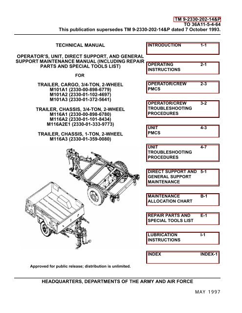
TM 9-<strong>2330</strong>-<strong>202</strong>-14&PTO 36A11-5-4-64This publication supersedes TM 9-<strong>2330</strong>-<strong>202</strong>-14&P dated 7 October 1993.TECHNICAL MANUALINTRODUCTI<strong>ON</strong> 1-1OPERATOR’S, UNIT, DIRECT SUPPORT, AND GENERALSUPPORT MAINTENANCE MANUAL (INCLUDING REPAIRPARTS AND SPECIAL TOOLS LIST)FORTRAILER, CARGO, 3/4-T<strong>ON</strong>, 2-WHEELM101A1 (<strong>2330</strong>-00-898-6779)M101A2 (<strong>2330</strong>-01-102-4697)M101A3 (<strong>2330</strong>-01-372-5641)TRAILER, CHASSIS, 3/4-T<strong>ON</strong>, 2-WHEELM116A1 (<strong>2330</strong>-00-898-6780)M116A2 (<strong>2330</strong>-01-101-8434)M116A2E1 (<strong>2330</strong>-01-333-9773)TRAILER, CHASSIS, 1-T<strong>ON</strong>, 2-WHEELM116A3 (<strong>2330</strong>-01-359-0080)OPERATINGINSTRUCTI<strong>ON</strong>SOPERATOR/CREWPMCSOPERATOR/CREWTROUBLESHOOTINGPROCEDURESUNITPMCSUNITTROUBLESHOOTINGPROCEDURES2-12-33-24-34-7DIRECT SUPPORT ANDGENERAL SUPPORTMAINTENANCE5-1MAINTENANCEALLOCATI<strong>ON</strong> CHARTB-1REPAIR PARTS ANDSPECIAL TOOLS LISTE-1LUBRICATI<strong>ON</strong>INSTRUCTI<strong>ON</strong>SI-1INDEXINDEX-1Approved for public release; distribution is unlimited.HEADQUARTERS, DEPARTMENTS OF <strong>THE</strong> ARMY AND AIR FORCEMAY 1997
TM 9-<strong>2330</strong>-<strong>202</strong>-14&PFOR INFORMATI<strong>ON</strong> <strong>ON</strong> FIRST AID, REFER TO FM 4-25.11.WARNINGASBESTOSDO NOT handle brakeshoes, brakedrums, or other brake components unless the area hasbeen properly cleaned. Asbestos dust, which can be dangerous if you touch it or breathe it,may be on these components. Wear an approved filter mask and gloves. NEVER use compressedair or a dry brush to clean brake components. Dust may be removed using anindustrial-type vacuum cleaner. Clean dust or mud away from brake components with waterand a wet, soft brush or cloth. Failure to follow this warning may result in serious illness ordeath to personnel.WARNINGBRAKE SYSTEM• Do not allow grease to contact brakeshoe linings. Wipe excess lubricant from the areaof brakeshoe linings to prevent grease from soaking the linings. Brakeshoe linings canabsorb grease and oil, causing early glazing of linings and very poor braking action. Ifbrakeshoe linings become soaked, Unit maintenance must replace them. Failure to followthis warning may cause brakes to malfunction, resulting in serious injury or deathto personnel or damage to equipment.• If a brakeshoe lining is replaced, replace all brakeshoe linings on axle. A combinationof old brakeshoes with new brakeshoes will cause uneven braking. Accidents causingserious injury or death to personnel or damage to equipment may result.• When performing maintenance on brake system, make sure wheels are chockedsecurely. Failure to follow this warning may cause trailer to roll, resulting in seriousinjury or death to personnel or damage to equipment.• Brake hub (grease cap)/wheel assembly areas may become hot during operations thatrequire frequent or continuous braking. Use caution when performing hub and brakedrumPMCS checks. Serious burns may result from contact with hot metal.Change 2 1
TM 9-<strong>2330</strong>-<strong>202</strong>-14&PWARNINGCOMPRESSED AIRCompressed air used for cleaning or drying purposes, or for clearing restrictions, shouldnever exceed 30 psi (207 kPa). Wear protective clothing (e.g., goggles/shield, gloves) anduse caution, to avoid injury to personnel.WARNINGCOUPLING AND UNCOUPLING• All personnel must stand clear of towing vehicle and trailer during coupling and uncouplingoperations. Failure to follow this warning may result in serious injury or death topersonnel.• If trailer is not coupled to towing vehicle, make sure handbrakes are applied or wheelsare securely chocked and rear stabilizer is down. Failure to follow this warning maycause trailer to roll, resulting in serious injury or death to personnel or damage toequipment.• DO NOT move the trailer laterally (push/pull) using the landing leg/caster as a thirdwheel or trailer dolly. Mounting bracket or landing leg/caster failure may cause trailerdamage or injury to personnel.• Use ground guides and back prime mover to the trailer lunette, NOT vice versa. Failureto follow this warning may result in injury or death to personnel.• DO NOT use landing leg/caster as a third wheel to pivot/turn trailer around to face theprime mover. Remove the load from the trailer if it must be turned around. Failure to followthis warning may result in serious injury to personnel or damage to equipment.WARNINGDRAWBAR AND LUNETTE RING• Drawbar is heavy - up to 280 lb (127 kg) loaded tongue weight. Use front support (landing)leg crank to raise and lower trailer drawbar. If support leg assembly is inoperative,use suitable lifting device to lift the drawbar. If a suitable lifting device is not available,remove load from trailer and use four or more persons to lift drawbar. Failure to followthis warning may result in serious injury to personnel or damage to equipment.• Keep hands away from lunette ring during coupling/uncoupling operations. Use thelanding leg crank to lower/raise lunette. Realign prime mover tow pintle with lunette asnecessary. Failure to follow this warning may result in injury to personnel.2 Change 2
TM 9-<strong>2330</strong>-<strong>202</strong>-14&PWARNINGDRYCLEANING SOLVENT• Drycleaning solvent P-D-680 is TOXIC and flammable. Wear protective goggles andgloves; use only in a well-ventilated area; avoid contact with skin, eyes, and clothes;and DO NOT breathe vapors. Keep away from heat or flame. Never smoke when usingdrycleaning solvent; the flashpoint for type I drycleaning solvent is 100°F (38°C) and fortype II it is 138°F (50°C). Failure to follow this warning may result in injury or death topersonnel.• If personnel become dizzy while using drycleaning solvent, immediately get fresh airand medical help. If solvent contacts skin or clothes, flush with cold water. If solventcontacts eyes, immediately flush them with water and get immediate medical attention.• When drycleaning solvent is used, notify the local medical authority (preventive medicine)and environmental coordinator concerning medical surveillance, respiratory protection,and disposal requirements.WARNINGIMPROPER CLEANING AGENTSImproper cleaning methods and the use of unauthorized cleaning agents can injure personneland damage equipment. To prevent this, refer to TM 9-247 for instructions.WARNINGSTEAMAvoid contact with steam. Steam can cause burns, blindness, and other serious injuries. Besure to wear protective apron, gloves, and safety goggles when using live steam.WARNINGRIVETS/DRIVE SCREWSWear eye protection when driving heads off rivets or drive screws. Failure to follow thiswarning may result in eye injury or loss of vision.Change 2 3
TM 9-<strong>2330</strong>-<strong>202</strong>-14&PWARNINGHEAVY COMP<strong>ON</strong>ENTSUse extreme caution when handling heavy parts. A lifting device is required when partsweigh over 50 pounds (23 kg) for a single-person lift, over 100 pounds (45 kg) for a two-personlift, and over 150 pounds (68 kg) for a three-person or more lift. Keep clear of heavyparts supported only by lifting device. Failure to follow this warning may cause seriousinjury or death to personnel.WARNINGHOT COMP<strong>ON</strong>ENTSWhen checking for improperly adjusted brakes or dry wheel bearings, cautiously feel eachwheel hub and brakedrum. Serious burns will result from touching an overheated wheelhub and brakedrum.WARNINGINTERVEHICULAR CABLEMake sure intervehicular cable is disconnected from towing vehicle before performingmaintenance on electrical system. Failure to follow this warning may result in electricshock or burns.WARNINGREAR STABILIZER• Rear stabilizer must be used if trailer is carrying generator sets. Failure to follow thiswarning may cause trailer to tip, resulting in serious injury to personnel or damage toequipment.• Rear stabilizer MUST be used during loading and unloading when trailer is not coupledto towing vehicle. Failure to follow this warning may cause trailer to tip, resulting ininjury to personnel or damage to equipment.• Make sure that weight of trailer is on front support (landing) leg or trailer is coupled totowing vehicle before raising rear stabilizer. Failure to follow this warning may causetrailer to tip, resulting in injury to personnel or damage to equipment.WARNINGTAILGATE (CARGO TRAILER)Hold tailgate in place before removing straight-headed pins. If tailgate is not properly supportedit may fall, resulting in injury to personnel.4 Change 2
TM 9-<strong>2330</strong>-<strong>202</strong>-14&PWARNINGTIRES• DO NOT break tire bead and split lockring until certain that no air pressure remains intire. Failure to follow this warning may cause lockring to fly off, resulting in seriousinjury or death to personnel.• An improperly seated lockring may fly off, resulting in serious injury or death to anyperson in its path. A bent or twisted lockring may be difficult to install and, if used, is asafety hazard. Before applying any air pressure to tire, make sure lockring is seatedagainst rim of wheel in its entirety. DO NOT inflate more than 3 psi (21 kPa). Tap lockringcarefully with a mallet to check its seating.• Inflate tire in an inflation safety cage using an extension hose of a least 10 feet (3 m)with an on/off pressure control valve and pressure gage. DO NOT stand on lockringside of wheel and tire assembly. Failure to follow this warning may result in severeinjury or death to personnel.Change 25/(f Blank)
TM 9-<strong>2330</strong>-<strong>202</strong>-14&PTO 36A115-4-64TECHNICAL MANUALHEADQUARTERSNO. 9-<strong>2330</strong>-<strong>202</strong>-14&P DEPARTMENTS OF <strong>THE</strong> ARMYAND AIR FORCECH No. 2Washington D.C., 10 November 2006OPERATOR’S, UNIT, DIRECT SUPPORT, AND GENERAL SUPPORTMAINTENANCE MANUAL (INCLUDING REPAIR PARTSAND SPECIAL TOOLS LIST)FORTRAILER, CARGO, 3/4-T<strong>ON</strong>, 2-WHEELM101A1 (<strong>2330</strong>-00-898-6779)M101A2 (<strong>2330</strong>-01-102-4697)M101A3 (<strong>2330</strong>-01-372-5641)TRAILER, CHASSIS, 3/4-T<strong>ON</strong>, 2-WHEELM116A1 (<strong>2330</strong>-00-898-6730)M116A2 (<strong>2330</strong>-01-101-8434)M116A2E1 (<strong>2330</strong>-01-333-9773)TRAILER, CHASSIS, 1-T<strong>ON</strong>, 2-WHEELM116A3 (<strong>2330</strong>-01-359-0080)TM 9-<strong>2330</strong>-<strong>202</strong>-14&P, 12 May 1997, is changed as follows:1. Remove old pages and insert new pages.2. New or changed material is indicated by a vertical bar in the margin of the page.Remove PagesInsert Pagesa thru da thru e/(f Blank)i thru vii/(viii blank)i thru vii/(viii blank)1-1 thru 1-4 1-1 thru 1-41-11 thru 1-14 1-11 thru 1-141-17 and 1-18 1-17 and 1-18.22-1 thru 2-6 2-1 thru 2-62-11 and 2-12 2-11 and 2-122-15 thru 2-22 2-15 thru 2-224-3 thru 4-6 4-3 thru 4-64-35 and 4-36 4-35 and 4-364-39 and 4-40 4-39 and 4-404-42.1 thru 4-42.104-49 and 4-50 4-49 and 4-504-53 and 4-54 4-53 and 4-544-59 and 4-60 4-59 and 4-604-60.1 thru 4-60.64-63 thru 4-66 4-63 thru 4-664-69 thru 4-72 4-69 thru 4-724-83 thru 4-92 4-83 thru 4-924-99 thru 4-102 4-99 thru 4-1024-102.1 and 4-102.25-3 thru 5-6 5-3 thru 5-6Appendix BAppendix BApproved for public release; distribution is unlimited. 1
TM 9-<strong>2330</strong>-<strong>202</strong>-14&PRemove PagesInsert PagesAppendix DAppendix DAppendix EAppendix EG-3 thru G-8 G-3 thru G-8Appendix IAppendix IIndex-1 thru Index-10Index-1 thru Index-10Front CoverFront Cover3. File this change sheet in front of the publication for reference purpose.By Order of the Secretary of the Army:Official:PETER J. SCHOOMAKERGeneral, United States ArmyChief of Staff0630507By Order of the Secretary of the Air Force:Official:JOHN P. JUMPERGeneral, United States Air ForceChief of StaffGREGORY S. MARTINGeneral, United States Air ForceCommander, Air Force Materiel CommandDISTRIBUTI<strong>ON</strong>: To be distributed in accordance with the initial distribution requirements for IDN: 390560,requirements for TM 9-<strong>2330</strong>-<strong>202</strong>-14&P.2 Approved for public release; distribution is unlimited.
CHANGE NO. 1 TM 9-<strong>2330</strong>-<strong>202</strong>-14&PC 1TECHNICAL MANUAL HEADQUARTERSNO. 9-<strong>2330</strong>-<strong>202</strong>-14&P DEPARTMENT OF <strong>THE</strong> ARMYWashington, D.C., 28 May 1999OPERATORS UNIT, DIRECT SUPPORT, AND GENERAL SUPPORTMAINTENANCE MANUAL (INCLUDING REPAIR PARTSAND SPECIAL TOOLS LIST)FORTRAILER. CARGO, 3/4-T<strong>ON</strong>, 2-WHEELM101A2 (<strong>2330</strong>-01-102-4697)M101A3 (<strong>2330</strong>-01-372-5641)TRAILER, CHASSIS 3/4-T<strong>ON</strong>, 2-WHEELM116A2 (<strong>2330</strong>-01-101-8434)M116A2E1 (<strong>2330</strong>-01-333-9773)TRAILER, CHASSIS, 1-T<strong>ON</strong>, 2-WHEELM116A3 (<strong>2330</strong>-01-359-0080)TM 9-<strong>2330</strong>-<strong>202</strong>-14&P, 12 May 1997, is changed as follows:1. Remove old pages and insert new pages.2. New or changed material is indicated by a vertical bar in the margin of the page.Remove Pages Insert Pages4-101 and 4-102 4-101 and 4-1024-119 and 4-120 4-119 and 4-120B-5 and B-6 B-5 and B-616-1 through Figure 18 16-1 through Figure 1823-1 through BULK-1 23-1 through BULK-1I-1 through I-10 I-1 through 1-103. File this change sheet in front of the publication for reference purpose.Approvedfor public release;distribution is unlimited
By Order of the Secretaryof the Army:DENNIS J. REIMERGeneral, United States ArmyChief of StaffOfficial:Ajo 46 X4-jAdministrative Assistant to theSecretary of the ArmyDISTRIBUTI<strong>ON</strong>:number (IDN) 390560, re-To be distributed in accordance with the initial distributuionquirements for TM 9-<strong>2330</strong>-<strong>202</strong>-14&P
TM 9-<strong>2330</strong>-<strong>202</strong>-14&PLIST OF EFFECTIVE PAGESDate of issue for original manual is:Original . . . . . . . 12 May 1997Change 1 . . . . . . 28 May 1999Change 2 . . . . . . 10 November 2006Total number of pages for front and rear matter is 40 and total number of pages is 418 consisting of the following:PageNo.*ChangeNo.PageNo.Cover 2 4-42.1 to 4-42.10 2a to e/(f Blank) 2 4-43 to 4-48 0i to v 2 4-49 to 4-50 2vi to vii/(viii Blank) 0 4-51 to 4-52 01-1 2 4-53 21-2 to 1-3 0 4-54 to 4-59 01-4 2 4-60 01-5 to 1-10 0 4-60.1 to 4-60.5 21-11 to 1-12 2 4-60.6 21-13 0 4-61 to 4-63 01-14 2 4-64 to 4-65 21-15 to 1-16 0 4-66 to 4-69 01-17 to 1-18 2 4-70 to 4-71 22-1 to 2-3 2 4-72 to 4-82 02-4 to 2-5 0 4-83 to 4-87 22-6 2 4-88 to 4-90 02-7 to 2-10 0 4-90.1 to 4-90.5 22-11 2 4-90.6 02-12 to 2-15 0 4-91 to 4-92 22-16 to 2-18 2 4-93 to 4-98 0(2-18.1 Blank)/2-18.2 2 4-99 to 4-102 22-19 2 4-102.1 to 4-102.2 22-20 0 4-103 to 4-118 02-21 to 2-22 2 4-119 to 4-120 12-23 to 2-28 0 4-121 to 4-126 03-1 to 3-8 0 5-1 to 5-2 04-1 to 4-2 0 5-3 to 5-5 24-3 2 5-6 04-4 0 A-1 to A-3/(A-4 Blank) 04-5 2 B-1 24-6 to 4-34 0 B-2 04-35 2 B-3 to B-6 24-36 to 4-38 0 B-7/(B-8 Blank) 04-39 to 4-40 2 C-1/(C-2 Blank) 04-41 to 4-42 0 D-1 to D-2 2* Zero in this column indicates an original page. E-1 to I-10 2*ChangeNo.A
TM 9-<strong>2330</strong>-<strong>202</strong>-14&PPageNo.F-1 to F-4 0G-1 to G-2 0G-3 to G-8 2G-9/(G-10 Blank) 0H-1 to H-5/(H-6 Blank) 0I-1 to I-6 2Index-1 to Index-10 2*ChangeNo.PageNo.*ChangeNo.B
TM 9-<strong>2330</strong>-<strong>202</strong>-14&PTO 36A11-5-4-64TECHNICAL MANUALHEADQUARTERSNO. 9-<strong>2330</strong>-<strong>202</strong>-14&P DEPARTMENTS OF <strong>THE</strong> ARMYAND AIR FORCEWashington D.C., 12 May 1997OPERATOR’S, UNIT, DIRECT SUPPORT, AND GENERAL SUPPORTMAINTENANCE MANUAL (INCLUDING REPAIR PARTSAND SPECIAL TOOLS LIST)FORTRAILER, CARGO, 3/4-T<strong>ON</strong>, 2-WHEELM101A1 (<strong>2330</strong>-00-898-6779)M101A2 (<strong>2330</strong>-01-102-4697)M101A3 (<strong>2330</strong>-01-372-5641)TRAILER, CHASSIS, 3/4-T<strong>ON</strong>, 2-WHEELM116A1 (<strong>2330</strong>-00-898-6780)M116A2 (<strong>2330</strong>-01-101-8434)M116A2E1 (<strong>2330</strong>-01-333-9773)TRAILER, CHASSIS, 1-T<strong>ON</strong>, 2-WHEELM116A3 (<strong>2330</strong>-01-359-0080)REPORTING ERRORS AND RECOMMENDING IMPROVEMENTSYou can help improve this publication. If you find any mistakes or if you know of a way to improve the procedures,please let us know. Submit your DA Form <strong>202</strong>8 (Recommended Changes to Publications and Blank Forms), through theInternet, on the Army Electronic Product Support (AEPS) website. The Internet address is https://aeps.ria.army.mil/.The DA Form <strong>202</strong>8 is located under the Public Applications section in the AEPS Public Home Page. Fill out the formand click on SUBMIT. Using this form on the AEPS will enable us to respond quicker to your comments and better managethe DA Form <strong>202</strong>8 program. You may also mail, fax or e-mail your letter or DA Form <strong>202</strong>8 direct to: AMSTA-LC-LPIT/TECH PUBS, TACOM-RI, 1 Rock Island Arsenal, Rock Island, IL 61299-7630. The e-mail address is: ROCK-TACOM-TECH-PUBS@conus.army.mil. The fax number is DSN 793-0726 or Commercial (309) 782-0726.Approved for public release; distribution is unlimited.TABLE OF C<strong>ON</strong>TENTSPageHOW TO USE THIS MANUAL . . . . . . . . . . . . . . . . . . . . . . . . . . . . . . . . . . . . . . . . . . . . . . . . . . ivCHAPTER 1INTRODUCTI<strong>ON</strong>Section I. General Information . . . . . . . . . . . . . . . . . . . . . . . . . . . . . . . . . . . . . . . . . . . . . 1-1*This publication supersedes TM 9-<strong>2330</strong>-<strong>202</strong>-14&P dated 7 October 1993.Change 2i
TM 9-<strong>2330</strong>-<strong>202</strong>-14&PTABLE OF C<strong>ON</strong>TENTS (continued)PageCHAPTER 1 INTRODUCTI<strong>ON</strong> (C<strong>ON</strong>TINUED)Section II. Equipment Description and Data. . . . . . . . . . . . . . . . . . . . . . . . . . . . . . . . . . . . 1-4Section III. Principles of Operation . . . . . . . . . . . . . . . . . . . . . . . . . . . . . . . . . . . . . . . . . . 1-17CHAPTER 2 OPERATING INSTRUCTI<strong>ON</strong>SSection I. Description and Use of Operator’s Controls and Indicators . . . . . . . . . . . . . . . 2-1Section II. Operator/Crew Preventive Maintenance Checks and Services (PMCS). . . . . . 2-3Section III. Operation Under Usual Conditions . . . . . . . . . . . . . . . . . . . . . . . . . . . . . . . . . 2-11Section IV. Operation Under Unusual Conditions . . . . . . . . . . . . . . . . . . . . . . . . . . . . . . . 2-26CHAPTER 3 OPERATOR/CREW MAINTENANCE INSTRUCTI<strong>ON</strong>SSection I. Lubrication Instructions . . . . . . . . . . . . . . . . . . . . . . . . . . . . . . . . . . . . . . . . . . . 3-1Section II. Operator/Crew Troubleshooting Procedures. . . . . . . . . . . . . . . . . . . . . . . . . . . 3-2CHAPTER 4 UNIT MAINTENANCESection I.Repair Parts; Tools; Special Tools; Test, Measurement, and DiagnosticEquipment (TMDE); and Support Equipment . . . . . . . . . . . . . . . . . . . . . . . . . . 4-1Section II. Service upon Receipt . . . . . . . . . . . . . . . . . . . . . . . . . . . . . . . . . . . . . . . . . . . . 4-2Section III. Unit Preventive Maintenance Checks and Services (PMCS) . . . . . . . . . . . . . . 4-3Section IV. Unit Troubleshooting Procedures . . . . . . . . . . . . . . . . . . . . . . . . . . . . . . . . . . . 4-7Section V. General Maintenance Instructions. . . . . . . . . . . . . . . . . . . . . . . . . . . . . . . . . . 4-34Section VI. Electrical System Maintenance . . . . . . . . . . . . . . . . . . . . . . . . . . . . . . . . . . . . 4-39Section VII. Brake System Maintenance . . . . . . . . . . . . . . . . . . . . . . . . . . . . . . . . . . . . . . 4-49Section VIII. Wheels, Hubs, and Brakedrums Maintenance . . . . . . . . . . . . . . . . . . . . . . . . 4-83Section IX. Frame and Towing Attachments Maintenance . . . . . . . . . . . . . . . . . . . . . . . . 4-92Section X. Springs and Shock Absorbers Maintenance . . . . . . . . . . . . . . . . . . . . . . . . . 4-104Section XI. Body Maintenance. . . . . . . . . . . . . . . . . . . . . . . . . . . . . . . . . . . . . . . . . . . . . 4-110Section XII. Accessory Items Maintenance . . . . . . . . . . . . . . . . . . . . . . . . . . . . . . . . . . . 4-116Section XIII. Special Purpose Kits Maintenance . . . . . . . . . . . . . . . . . . . . . . . . . . . . . . . . 4-119Section XIV. Painting and Identification Marking . . . . . . . . . . . . . . . . . . . . . . . . . . . . . . . . 4-121Section XV. Preparation for Storage and Shipment . . . . . . . . . . . . . . . . . . . . . . . . . . . . . 4-122ii
TM 9-<strong>2330</strong>-<strong>202</strong>-14&PTABLE OF C<strong>ON</strong>TENTS (continued)PageCHAPTER 5DIRECT SUPPORT AND GENERAL SUPPORT MAINTENANCESection I. Axle Maintenance . . . . . . . . . . . . . . . . . . . . . . . . . . . . . . . . . . . . . . . . . . . . . . . 5-1Section II. DELETED . . . . . . . . . . . . . . . . . . . . . . . . . . . . . . . . . . . . . . . . . . . . . . . . . . . . . . . .Section III. Frame Assembly Maintenance . . . . . . . . . . . . . . . . . . . . . . . . . . . . . . . . . . . . . 5-6Section IV. Accessory Items Maintenance . . . . . . . . . . . . . . . . . . . . . . . . . . . . . . . . . . . . . 5-7APPENDIX A REFERENCES . . . . . . . . . . . . . . . . . . . . . . . . . . . . . . . . . . . . . . . . . . . . . . . . . . . . . . . A-1APPENDIX BMAINTENANCE ALLOCATI<strong>ON</strong> CHARTSection I. Introduction . . . . . . . . . . . . . . . . . . . . . . . . . . . . . . . . . . . . . . . . . . . . . . . . . . . . B-1Section II. Maintenance Allocation Chart for M101 and M116 Series Trailers. . . . . . . . . . B-4Section III. Tool and Test Equipment Requirements . . . . . . . . . . . . . . . . . . . . . . . . . . . . . B-7Section IV. Remarks . . . . . . . . . . . . . . . . . . . . . . . . . . . . . . . . . . . . . . . . . . . . . . . . . . . . . . B-7APPENDIX C COMP<strong>ON</strong>ENTS OF END ITEM AND BASIC ISSUE ITEMS LISTS . . . . . . . . . . . . . . . C-1APPENDIX DADDITI<strong>ON</strong>AL AUTHORIZATI<strong>ON</strong> LISTSection I. Introduction . . . . . . . . . . . . . . . . . . . . . . . . . . . . . . . . . . . . . . . . . . . . . . . . . . . . D-1Section II. Additional Authorization List (AAL) . . . . . . . . . . . . . . . . . . . . . . . . . . . . . . . . . . D-2APPENDIX EREPAIR PARTS AND SPECIAL TOOLS LISTSection I. Introduction . . . . . . . . . . . . . . . . . . . . . . . . . . . . . . . . . . . . . . . . . . . . . . . . . . . . E-1Section II.Repair Parts ListIllus/FigPageGROUP 06ELECTRICAL SYSTEM0609 - LIGHTS ........................................................................................................ 1-1COMPOSITE STOPLIGHT-TAILLIGHT....................................................... 1 1-10613 - HULL OR CHASSIS WIRING HARNESS .................................................... 2-1CHASSIS WIRING HARNESS (COMPOSITE STOPLIGHT-TAILLIGHT)... 2 2-1INTERVEHICULAR CABLE ......................................................................... 3 3-1WIRING HARNESS AND INTERVEHICULAR CABLE ATTACHMENTS.... 4 4-1Change 2iii
TM 9-<strong>2330</strong>-<strong>202</strong>-14&PTABLE OF C<strong>ON</strong>TENTS (continued)GROUP 11REAR AXLE1100 - REAR AXLE ASSEMBLY ............................................................................ 5-1REAR AXLE ASSEMBLY ............................................................................ 5 5-1GROUP 12BRAKES1201 - HANDBRAKES ............................................................................................ 6-1CABLE AND C<strong>ON</strong>DUIT ASSEMBLY........................................................... 6 6-1HANDBRAKE LEVER.................................................................................. 7 7-11<strong>202</strong> - SERVICE BRAKES ..................................................................................... 8-1BRAKE ASSEMBLY .................................................................................... 8 8-11204 - HYDRAULIC BRAKE SYSTEM ................................................................... 9-1WHEEL CYLINDER..................................................................................... 9 9-1HYDRAULIC BRAKE ACTUATOR ASSEMBLY, SURGE........................... 10 10-1HYDRAULIC BRAKE LINES ....................................................................... 11 11-1GROUP 13WHEELS AND TRACKS1311 - WHEEL ASSEMBLY.................................................................................... 12-1WHEEL AND HUB ASSEMBLY .................................................................. 12 12-1WHEEL AND RUNFLAT ASSEMBLY (M101A3 AND M1016A3)................ 13 13-11313 - TIRES, TUBES, AND TIRE CHAINS........................................................... 14-1TIRE AND VALVE ....................................................................................... 14 14-1GROUP 15FRAME, TOWING ATTACHMENTS, DRAWBARS, AND ARTICULATI<strong>ON</strong>SYSTEMS1501 - FRAME ASSEMBLY.................................................................................... 15-1CHASSIS FRAME ASSEMBLY ................................................................... 15 15-11503 - PINTLES AND TWOING ATTACHMENTS ................................................. 16-1DRAWBAR ASSEMBLY AND SAFETY CHAINS........................................ 16 16-11507 - LANDING GEAR, LEVELING JACKS ......................................................... 17-1FR<strong>ON</strong>T SUPPORT LEG.............................................................................. 17 17-1GROUP 16SPRINGS AND SHOCK ABSORBERS1601 - SPRINGS..................................................................................................... 18-1SPRING ASSEMBLY................................................................................... 18 18-11604 - SHOCK ABSORBER EQUIPMENT............................................................. 19-1SHOCK ABSORBER ................................................................................... 19 19-1GROUP 18BODY, CAB, HOOD, AND HULL1810 - CARGO BODY ............................................................................................ 20-1CARGO BODY, RACK, AND TAILGATE ASSEMBLY ................................ 20 20-1GROUP 22BODY, CHASSIS, AND HULL ACCESSORY ITEMS2201 - CANVAS, RUBBER, OR PLASTIC ITEMS.................................................. 21-1CANVAS COVER ASSEMBLY AND BOWS ............................................... 21 21-1iv
TM 9-<strong>2330</strong>-<strong>202</strong>-14&PTABLE OF C<strong>ON</strong>TENTS (continued)2<strong>202</strong> - ACCESSORY ITEMS................................................................................... 22-1REFLECTOR (M101A1, M101A2, M101A3, AND M116A1)........................ 22 22-12210 - DATA PLATES AND INSTRUCTI<strong>ON</strong>S HOLDERS...................................... 23-1DATA PLATES............................................................................................. 23 23-1GROUP 33SPECIAL PURPOSE KITS3307 - SPECIAL PURPOSE KITS .......................................................................... 24-1REAR STABILIZER KIT ............................................................................... 24 24-1GROUP 95GENERAL USE STANDARDIZED PARTSSection IIISection IV9501 - BULK MATERIAL......................................................................................... BULK-1BULK............................................................................................................ BULK BULK-1Special Tools List (If Applicable)Cross-Reference IndexesNSN INDEX.................................................................................................. I-1PART NUMBER INDEX ............................................................................... I-6APPENDIX FEXPENDABLE AND DURABLE ITEMS LISTSection I. Introduction . . . . . . . . . . . . . . . . . . . . . . . . . . . . . . . . . . . . . . . . . . . . . . . . . . . . F-1Section II. Expendable and Durable Items List . . . . . . . . . . . . . . . . . . . . . . . . . . . . . . . . . F-2APPENDIX GILLUSTRATED LIST OF MANUFACTURED ITEMSSection I. Introduction . . . . . . . . . . . . . . . . . . . . . . . . . . . . . . . . . . . . . . . . . . . . . . . . . . . . G-1Section II. Manufacturing Instructions . . . . . . . . . . . . . . . . . . . . . . . . . . . . . . . . . . . . . . . . G-3APPENDIX H TORQUE VALUES FOR THREADED FASTENERS . . . . . . . . . . . . . . . . . . . . . . . . . . H-1APPENDIX I LUBRICATI<strong>ON</strong> INSTRUCTI<strong>ON</strong>S . . . . . . . . . . . . . . . . . . . . . . . . . . . . . . . . . . . . . . . . . . I-1INDEX. . . . . . . . . . . . . . . . . . . . . . . . . . . . . . . . . . . . . . . . . . . . . . . . . . . . . . . . . . . . . . . . INDEX-1Change 2v
TM 9-<strong>2330</strong>-<strong>202</strong>-14&PHOW TO USE THIS MANUALSCOPE.This technical manual provides you with the information you will need to operate and maintain the M101 Series andM116 Series trailers.The information contained in this manual is presented in five chapters and nine appendixes, one of which is arepair parts and special tools list (RPSTL). Each chapter is divided into sections covering operating proceduresand/or other information for specific systems or components.Note that Appendix A of this manual gives the full title of every manual, form, pamphlet, or other document referencedin this manual.INDEXING.Four indexing procedures are used to help you locate information quickly:• Cover index. Lists chapter titles and important parts of the manual, with correspondingpage numbers. Each chapter or part listed is boxed in, with a black outer edge that isin line with the first page of that chapter or part.• Table of contents. The table of contents, which follows the summary of warnings, listsall chapters and sections numerically, with corresponding page numbers.• Section indexes. Each section starts with a numerical listing of all paragraphs in thatsection.• Alphabetical index. The alphabetically arranged subject index starts on page Index-1.WARNINGS, CAUTI<strong>ON</strong>S, AND NOTES.You must read and understand this manual BEFORE operating the M101 Series and M116 Series trailers.Throughout this manual you will see WARNING, CAUTI<strong>ON</strong>, and NOTE headings. There are good reasons forevery one of these notices.WARNINGA WARNING is used to alert the user to hazardous operating and maintenanceprocedures, practices, or conditions that could result in injury ordeath. WARNINGs must be strictly observed.CAUTI<strong>ON</strong>A CAUTI<strong>ON</strong> is used to alert the user to hazardous operating and maintenance procedures,practices, or conditions that could result in damage to, or destruction of,equipment or mission effectiveness. Captions must be strictly observed.vi
TM 9-<strong>2330</strong>-<strong>202</strong>-14&PWARNINGS, CAUTI<strong>ON</strong>S, AND NOTES (C<strong>ON</strong>TINUED).NOTEA NOTE highlights an essential operating or maintenance procedure, condition, orstatement.WARNINGs and CAUTI<strong>ON</strong>s appear immediately preceding the step to which they pertain. It is important to readand thoroughly understand the WARNINGs and/or CAUTI<strong>ON</strong>s before beginning maintenance.NOTES may precede or follow the steps to which they pertain, depending on what makes the most sense.vii/(viii Blank)
TM 9-<strong>2330</strong>-<strong>202</strong>-14&PCHAPTER 1INTRODUCTI<strong>ON</strong>Section I.GENERAL INFORMATI<strong>ON</strong>ParagraphPageNumber Paragraph Title NumberNOTEChange 2 adds the M101A1. Specific M101A1 information is contained in thischapter and designated in the chapter and section indexes.1-1 Scope . . . . . . . . . . . . . . . . . . . . . . . . . . . . . . . . . . . . . . . . . . . . . . . . . . . . . . . . . . . . . . . . . . 1-11-2 Maintenance Forms, Records, and Reports. . . . . . . . . . . . . . . . . . . . . . . . . . . . . . . . . . . . . 1-11-3 Destruction of Army Materiel To Prevent Enemy Use . . . . . . . . . . . . . . . . . . . . . . . . . . . . . 1-11-4 Preparation for Storage or Shipment . . . . . . . . . . . . . . . . . . . . . . . . . . . . . . . . . . . . . . . . . . 1-11-5 Quality Assurance . . . . . . . . . . . . . . . . . . . . . . . . . . . . . . . . . . . . . . . . . . . . . . . . . . . . . . . . 1-21-6 Reporting Equipment Improvement Recommendations (EIRs) . . . . . . . . . . . . . . . . . . . . . . 1-21-7 List of Abbreviations and Acronyms . . . . . . . . . . . . . . . . . . . . . . . . . . . . . . . . . . . . . . . . . . . 1-21-8 Warranty Information . . . . . . . . . . . . . . . . . . . . . . . . . . . . . . . . . . . . . . . . . . . . . . . . . . . . . . 1-31-9 Safety, Care, and Handling . . . . . . . . . . . . . . . . . . . . . . . . . . . . . . . . . . . . . . . . . . . . . . . . . 1-31-10 Corrosion Prevention and Control . . . . . . . . . . . . . . . . . . . . . . . . . . . . . . . . . . . . . . . . . . . . 1-31-1. SCOPE.a. This manual describes Operator’s, Unit, Direct Support, and General Support maintenance and containsthe repair parts and special tools list for the following:• Trailer, Cargo: 3/4-Ton, 2-Wheel, M101A1, M101A2 and M101A3;• Trailer, Chassis: 3/4-Ton, 2-Wheel, M116A1, M116A2 and M116A2E1; and• Trailer, Chassis: 1-Ton, 2-Wheel, M116A3.b. All M101 Series cargo trailers use the M116 Series chassis.c. Throughout this manual, the terms “curb side” and “road side” are used to describe views of the trailer. Asviewed from the rear, curb side is the right side and road side is the left side.d. The trailers are used to carry payloads over highway or cross-country.1-2. MAINTENANCE FORMS, RECORDS, AND REPORTS.Department of the Army forms and procedures used for equipment maintenance will be those prescribed by DAPam 750-8, The Army Maintenance Management System (TAMMS).1-3. DESTRUCTI<strong>ON</strong> OF ARMY MATERIEL TO PREVENT ENEMY USE.Refer to TM 750-244-6 for procedures on the destruction of military vehicles to prevent enemy use.1-4. PREPARATI<strong>ON</strong> FOR STORAGE OR SHIPMENT.For information on preparing the trailers for storage or shipment, refer to Chapter 4, Section XV.Change 2 1-1
TM 9-<strong>2330</strong>-<strong>202</strong>-14&P1-5. QUALITY ASSURANCE.a. No specific quality assurance manual pertains to the M101 or M116 Series of trailers.b. Defective material received through the supply system should be reported on an SF Form 368 (ProductQuality Deficiency Report). Instructions for preparing the reports are provided in AR 702-7, Reporting ofProduct Quality Deficiencies Across Component Lines. Mail your completed form directly to:CommanderU.S. Army Tank-automotive and Armaments CommandATTN: AMSTA-TR-E/MPAWarren, Ml 48397-50001-6. REPORTING EQUIPMENT IMPROVEMENT RECOMMENDATI<strong>ON</strong>S (EIR’S).If your trailer needs improvement, let us know. Send us an EIR. You, the user, are the only one who can tell us whatyou don’t like about the equipment. Let us know why you don’t like the design or performance. Put it on an SF Form368 and mail it to:CommanderU.S. Army Tank-automotive and Armaments CommandATTN: AMSTA-TR-E/MPAWarren, MI 48397-50001-7. LIST OF ABBREVIATI<strong>ON</strong>S AND ACR<strong>ON</strong>YMS.AAL . . . . . . . . . . . . . . . . . additional authorization listBII . . . . . . . . . . . . . . . . . . . . . . . . . . basic issue itemsBOI . . . . . . . . . . . . . . . . . . . . . . . . . . . .basis of issueCAGEC . . . .commercial and government entity codeCARC . . . . . . . . . . . chemical agent resistant coatingCOEI . . . . . . . . . . . . . . . . . . components of end itemCPC . . . . . . . . . . . . corrosion prevention and controlCTA . . . . . . . . . . . . . . . Common Table of AllowancesCUCV . . . . . . . . . . . .commercial utility cargo vehicleDA . . . . . . . . . . . . . . . . . . . . . . . Department of ArmyDoD . . . . . . . . . . . . . . . . . . . . Department of DefenseE . . . . . . . . . . . . . . . . . . . . . . . . . . . . . . . . . . . .emptyEIR . . . . . equipment improvement recommendationGAA . . . . . . . . . . . . grease, automotive and artilleryHMMWV high-mobility multipurpose wheeled vehiclehr . . . . . . . . . . . . . . . . . . . . . . . . . . . . . . . . . . . . . hourIAW . . . . . . . . . . . . . . . . . . . . . . . .in accordance withJTA . . . . . . . . . . . . . . . . . . Joint Table of Allowanceskph . . . . . . . . . . . . . . . . . . . . . . . kilometers per hourL . . . . . . . . . . . . . . . . . . . . . . . . . . . . . . . . . . . . . .literLED . . . . . . . . . . . . . . . . . . . . . . . light-emitting diodeMAC . . . . . . . . . . . . . . .maintenance allocation chartMOS . . . . . . . . . . . . . . military occupational specialtyMTOE Modified Table of Organization and EquipmentMWO . . . . . . . . . . . . . . . . . . . modification work orderNm . . . . . . . . . . . . . . . . . . . . . . . . . . . .newton meterNBC . . . . . . . . . . . . . nuclear, biological and chemicalNIIN . . . . . . . . . . . national item identification numberNSN . . . . . . . . . . . . . . . . . . . . . national stock numberOC . . . . . . . . . . . . . . . . . . . . . . . . . . . . . . on conditionp. . . . . . . . . . . . . . . . . . . . . . . . . . . . . . . . . . . . . Pagepara . . . . . . . . . . . . . . . . . . . . . . . . . . . . . . paragraphPMCS .preventive maintenance checks and servicesqty. . . . . . . . . . . . . . . . . . . . . . . . . . . . . . . . . . quantityQty. Recm. . . . . . . . . . . . . . . quantity recommendedQty. Rqr. . . . . . . . . . . . . . . . . . . . . . quantity requiredRPSTL . . . . . . . . . . . repair parts and special tools listSMR . . . . . .source, maintenance, and recoverabilitySN . . . . . . . . . . . . . . . . . . . . . . . . . . . . .serial numberSOP . . . . . . . . . . . . . . . standard operating procedureSRA . . . . . . . . . . . . . . . . . . specialized repair activityTAMMS The Army Maintenance Management SystemTB . . . . . . . . . . . . . . . . . . . . . . . . . . technical bulletinTDA . . . . . . . . . .Table of Distribution and AllowancesTM . . . . . . . . . . . . . . . . . . . . . . . . . . technical manualTMDE test, measurement, and diagnostic equipmentTOE . . . . . . . . . Table of Organization and EquipmentU/M . . . . . . . . . . . . . . . . . . . . . . . . . . unit of measureUOC . . . . . . . . . . . . . . . . . . . . . . . . . usable-on codeV dc . . . . . . . . . . . . . . . . . . . . . . . volts, direct currentW/ . . . . . . . . . . . . . . . . . . . . . . . . . . . . . . . . . . . . withW/O . . . . . . . . . . . . . . . . . . . . . . . . . . . . . . . . . without1-2
TM 9-<strong>2330</strong>-<strong>202</strong>-14&P1-8. WARRANTY INFORMATI<strong>ON</strong>.The M101 and M116 Series trailers are not warranted.1-9. SAFETY, CARE, AND HANDLING.For information on general safety precautions and regulations, review the warning summary at the front of thismanual preceding the table of contents. Observe all WARNINGs and CAUTI<strong>ON</strong>s that appear in the maintenanceprocedures.1-10. CORROSI<strong>ON</strong> PREVENTI<strong>ON</strong> AND C<strong>ON</strong>TROL.a. Corrosion prevention and control (CPC) of Army materiel is a continuing concern. It is important that anycorrosion problem with this item be reported so the problem can be corrected and improvements can bemade to prevent the problem in future items.b. While corrosion is typically associated with the rusting of metals, it can also include deterioration of othermaterials, such as rubber and plastic. Unusual cracking, softening, swelling, or breaking of these materialsmay be a corrosion problem.c. If a corrosion problem is identified, it can be reported using an SF Form 368. The use of key words, suchas “corrosion,” “rust,” “deterioration,” and “cracking,” will ensure that the information is identified as a CPCproblem. The form should be submitted to the address specified in DA Pam 750-8.1-3
TM 9-<strong>2330</strong>-<strong>202</strong>-14&PSection II.EQUIPMENT DESCRIPTI<strong>ON</strong> AND DATAParagraphPageNumber Paragraph Title NumberNOTEChange 2 adds the M101A1. Specific M101A1 information is contained in thischapter and designated in the chapter and section indexes.1-11 Equipment Characteristics, Capabilities, and Features . . . . . . . . . . . . . . . . . . . . . . . . . . . . 1-41-12 Location and Description of Major Components. . . . . . . . . . . . . . . . . . . . . . . . . . . . . . . . . . 1-51-13 Location and Contents of Data Plates . . . . . . . . . . . . . . . . . . . . . . . . . . . . . . . . . . . . . . . . . 1-101-14 Differences Between Models . . . . . . . . . . . . . . . . . . . . . . . . . . . . . . . . . . . . . . . . . . . . . . . . 1-121-15 Equipment Data . . . . . . . . . . . . . . . . . . . . . . . . . . . . . . . . . . . . . . . . . . . . . . . . . . . . . . . . . . 1-141-11. EQUIPMENT CHARACTERISTICS, CAPABILITIES, AND FEATURES.a. CHARACTERISTICS1. All trailers are designed to be towed by a towing vehicle without airbrake connections. A handbrakelever and cable assembly located on each side of the trailer activates a handbrake at each wheel.Control of each handbrake is independent.2. In addition to handbrake lever-activated handbrakes, the trailers are equipped with an inertia-actuatedhydraulic brake system. For principles of operation of this system, refer to Section III of thischapter.3. All trailers have a single axle with two wheels.4. The trailer suspension consists of two leaf spring assemblies and shock absorbers.5. The M116A2E1 and M116A3 are equipped with a dropped axle, frame, and spring assemblies thatallow for a greater payload than the other models. M101A1 is equipped with tube type, bias ply tireswith 5 lug mounted wheels. A2 and A3 models are equipped with surge brakes. A2 models use the 8lug CUCV style tubeless wheels and tires. A3 models use run flat tires.6. The cargo body, which is a feature of M101 Series trailers, can be easily removed. The old-stylecargo body is being phased out. The new-style cargo body adds reinforcements and U-bolt lift pointsto ensure that the cargo body can be lifted without danger and without using spreader bars.7. A rear stabilizer may be added to provide greater stability when the trailer is carrying generator sets.Use of the stabilizer is optional for all other applications.b. CAPABILITIES AND FEATURES1. Maximum towing speeds with maximum payload evenly distributed are: highway, 50 miles per hour(80 kph); and cross-country, 6 miles per hour (10 kph).2. Maximum payload varies with model designation. Refer to paragraph 1-15.3. The cargo capacity of the M101 Series trailers may be increased by installing a rack and tailgateassembly. A canvas cover assembly may be used to protect cargo from the weather.1-4 Change 2
TM 9-<strong>2330</strong>-<strong>202</strong>-14&P1-12. LOCATI<strong>ON</strong> AND DESCRIPTI<strong>ON</strong> OF MAJOR COMP<strong>ON</strong>ENTS.Key Component Description1 Drawbar Coupler Couples trailer to towing vehicle pintle.2 Breakaway Chain Provides for emergency braking of trailer. Attaches totowing vehicle and applies brakes in the event trailerbreaks away from towing vehicle.3 Hydraulic Brake Actuator Assembly Transmits braking forces from towing vehicle to trailerand service brakes by means of a drawbar coupler,master cylinder, hydraulic brake tubes and hose, andwheel cylinders.4 Intervehicular Cable Provides electrical connection between trailer andtowing vehicle.5 Composite Light Indicates trailer presence to vehicles traveling behind.Consists of blackout light, service light, turn signal,and stoplight. Located at each side of trailer rear.6 Tiedown Shackles Secures trailer during shipment. Located at each frontand rear corner of chassis.7 Chassis Provides mounting for cargo body of M101 Seriestrailers. Frame assembly common to all models.1-5
TM 9-<strong>2330</strong>-<strong>202</strong>-14&P1-12. LOCATI<strong>ON</strong> AND DESCRIPTI<strong>ON</strong> OF MAJOR COMP<strong>ON</strong>ENTS (continued).Key Component Description8 Axle Carries wheels and allows wheels to rotate. Tubularweldment on which trailer wheels and suspensioncomponents are mounted.9 Shock Absorber Dampens spring action. Located on each end of axle.10 Wheel and Tire Assembly Supports trailer load. Attached to each end of axle.11 Spring Assembly Supports trailer load and absorbs road shock. Locatedon each side of frame.12 Handbrake Lever Applies handbrake when trailer is stopped or parked.Located on each side of chassis.13 Front Support Leg Supports trailer when uncoupled from towing vehicle.All trailers have an adjustable front support leg.14 Safety Chain Prevents trailer from fully breaking away. Hooks totowing vehicle shackles. Located on each side ofdrawbar assembly.1-6
TM 9-<strong>2330</strong>-<strong>202</strong>-14&P1-12. LOCATI<strong>ON</strong> AND DESCRIPTI<strong>ON</strong> OF MAJOR COMP<strong>ON</strong>ENTS (continued).Key Component Description15 U-bolt (M101 A2 and M 101A3) Provides lift points for new-style cargo body. Locatedat each of four lower corners of cargo body.16 Cargo Body (M101A2 and M101A3) Carries cargo. A welded box assembly attached toframe.17 Reflector (M101A2 and M101A3) Indicates trailer presence to vehicles traveling behind.Located at lower corners of all sides of cargo body.18 Rear Stabilizer Prevents trailer from tipping over when loading andunloading cargo. Required when trailer is carryinggenerator sets.1-7
TM 9-<strong>2330</strong>-<strong>202</strong>-14&P1-12. LOCATI<strong>ON</strong> AND DESCRIPTI<strong>ON</strong> OF MAJOR COMP<strong>ON</strong>ENTS (continued).Key Component Description19 Canvas Cover Assembly Protects cargo from weather.(M101A2 and M101A3)20 Rack Assembly Increases cargo volume capacity. Consists of one(M101A2 and M101A3)front rack assembly, two side rack assemblies, and atwo-section tailgate assembly. Earlier-model rackassemblies are wooden. Newer-model rack assembliesare made of composite material.21 Tailgate Assembly Opens outward from center for ease in loading and(M101A2 and M101A3)unloading cargo. This two-section hinged tailgateassembly is a component of the rack assembly. Earliermodeltailgate assemblies are wooden. Newer-modeltailgate assemblies are made of composite material.22 Tailgate (M101 A2 and M101 A3) Swings down for ease in loading and unloading cargo.This one-piece tailgate is secured in position by twochain and pin assemblies.1-8
TM 9-<strong>2330</strong>-<strong>202</strong>-14&P1-12. LOCATI<strong>ON</strong> AND DESCRIPTI<strong>ON</strong> OF MAJOR COMP<strong>ON</strong>ENTS (continued).Key Component Description23 Cargo Hook (M101A2 and M101A3) Secures canvas cover assembly to the cargo body.Located on all four sides of cargo body (six on front andrear, eight on left and right sides).24 Chain and Pin Assembly Secures cargo body tailgate in position. Located at(M101A2 and M101A3)both upper rear corners of cargo body.25 Bow Clip (M101A2 and M101A3) Stows bow assemblies. Located on front corner ofeach side rack assembly.26 Bow Assembly (M101A2 and Ml01A3) Supports canvas cover assembly. Five bow assembliesfit across rack assembly. Earlier-model bow assembliesare wooden. Newer-model bow assemblies are madeof steel.1-9
TM 9-<strong>2330</strong>-<strong>202</strong>-14&P1-13. LOCATI<strong>ON</strong> AND C<strong>ON</strong>TENTS OF DATA PLATES.M101A2 and M101A3 Cargo Trailers1-10
TM 9-<strong>2330</strong>-<strong>202</strong>-14&P1-13. LOCATI<strong>ON</strong> AND C<strong>ON</strong>TENTS OF DATA PLATES (C<strong>ON</strong>TINUED).M116A1, M116A2, M116A2E1, and M116A3 Chassis Trailers438-035Change 2 1-11
TM 9-<strong>2330</strong>-<strong>202</strong>-14&P1-14. DIFFERENCES BETWEEN MODELS.a. GENERAL1. Differences between trailers consist of configuration variations in the electrical system, axle, brakes,wheels, frame, and suspension.2. The major trailer differences are summarized In Table 1-1.Table 1-1. Differences Between ModelsModelAxleInertiaBrakeSystem Wheels/Tires FrameSpringLeavesM101A1 Straight No Tubeless/Radial 3 in. (7.62 cm) 5M101A2 Straight Yes Tubeless/Radial 3 in. (7.62 cm) 5M101A3 Offset Yes Tubeless/Runflat/Radial 4 in. (10.16 cm) 6M116A1 Straight No Tubeless/Radial 3 in. (7.62 cm) 5M116A2 Straight Yes Tubeless/Radial 3 in. (7.62 cm) 5M116A2E1 Straight Yes Tubeless 4 in. (10.16 cm) 6M116A3 Offset Yes Tubeless/ Runflat/Radial 4 in. (10.16 cm) 6b. ELECTRICAL SYSTEM1. Trailers are equipped with a chassis wiring harness (1) that terminates at a covered junction box (2)on the roadside drawbar. The intervehicular cable (3) is fixed to the trailer.2. Trailers are equipped with a two-light composite stoplight-taillight configuration that may have standardlamps or LEDs.438-0361-12 Change 2
TM 9-<strong>2330</strong>-<strong>202</strong>-14&P1-14. DIFFERENCES BETWEEN MODELS (C<strong>ON</strong>TINUED).c. BRAKE SYSTEM1. The handbrake levers (4) are located at the front corners of the frame. Adjustment of one of theselevers is made at the lever itself.2. The trailers have both handbrakes and an inertia-actuated hydraulic brake system (5) (para 1-16).d. AXLE, FRAME, AND SUSPENSI<strong>ON</strong>The M116A2E1 and M116A3 are variants of the M116A2. Heavy-duty axles, four-inch frames, and spring assembliesallow for a greater payload than the M116A2 (para 1-15). In addition, the M116A3 uses the HMMWV radialrunflat wheel and tire assemblies.1-13
TM 9-<strong>2330</strong>-<strong>202</strong>-14&P1-15. EQUIPMENT DATA.Components Common to All ModelsELECTRICAL SYSTEM . . . . . . . . . . . . . . . . . . . . . . . . . . . . . . . . . . . . . . . . . . . . . . . . . . . . . . . . . . 24 V dcAXLE. . . . . . . . . . . . . . . . . . . . . . . . . . . . . . . . . . . . . . . . . . . . . . . . . . . . . . . . . . . . . . . . . Tubular WeldmentTIRESQuantity. . . . . . . . . . . . . . . . . . . . . . . . . . . . . . . . . . . . . . . . . . . . . . . . . . . . . . . . . . . . . . . . . . . . . . . . . . . . 2Ply . . . . . . . . . . . . . . . . . . . . . . . . . . . . . . . . . . . . . . . . . . . . . . . . . . . . . . . . . . . . . . . . . . . . . . . . . . . . . . . . 8Size . . . . . . . . . . . . . . . . . . . . . . . . . . . . . . . . . . . . . . . . . . . . . . . . . . . . . . . . . . . . . . .9 x 16 in. (23 x 41 cm)Inflation Pressure Sand and Highway:M101A1, M101A2, M116A1, M116A2 (Tubeless/Radial) . . . . . . . . . . . . . . . . . . . . . . . 30 psi (207 kPa)M101A3, M116A3 (Runflat) . . . . . . . . . . . . . . . . . . . . . . . . . . . . . . . . . . . . . . . . . . . . . 35 psi (241 kPa)WHEELSRim Size . . . . . . . . . . . . . . . . . . . . . . . . . . . . . . . . . . . . . . . . . . . . . . . . . . . . . . . . . 16 x 6.5 in. (43 x 16 cm)SUSPENSI<strong>ON</strong>Spring Assemblies . . . . . . . . . . . . . . . . . . . . . . . . . . . . . . . . . . . . . . . . . . . . . . . . . . . . . . . . . Semi-ellipticalShock Absorbers. . . . . . . . . . . . . . . . . . . . . . . . . . . . . . . . . . . . . . . . . . . . . . . . . . . Hydraulic, Double-actingHANDBRAKESActuation . . . . . . . . . . . . . . . . . . . . . . . . . . . . . . . . . . . . . . . . . . . . . . . . . . . . . . . . . . . . . . . . . . . MechanicalLocation. . . . . . . . . . . . . . . . . . . . . . . . . . . . . . . . . . . . . . . . . . . . . . . . . . . . . . . . . . . . . . . . . .Front of FrameQuantity. . . . . . . . . . . . . . . . . . . . . . . . . . . . . . . . . . . . . . . . . . . . . . . . . . . . . . . . . . . . . . . . . . . . . . . . . . . . 2TOWING SPEEDSHighway . . . . . . . . . . . . . . . . . . . . . . . . . . . . . . . . . . . . . . . . . . . . . . . . . . . . . . . . . . . . . . . 50 mph (80 kph)Cross-country . . . . . . . . . . . . . . . . . . . . . . . . . . . . . . . . . . . . . . . . . . . . . . . . . . . . . . . . . . . . 6 mph (10 kph)M101A1, M101A2, M101A3, M116A1, AND M116A2GENERALAngle of Departure . . . . . . . . . . . . . . . . . . . . . . . . . . . . . . . . . . . . . . . . . . . . . . . . . . . . . . . . . . . . . . . . . .30°Center of Gravity (Measured from Center of Rear Axle):Empty . . . . . . . . . . . . . . . . . . . . . . . . . . . . . . . . . . . . . . . . . . . . . . . . . . . . . . . . . . 45 3/4 in. (116.21 cm)Loaded . . . . . . . . . . . . . . . . . . . . . . . . . . . . . . . . . . . . . . . . . . . . . . . . . . . . . . . . . . 36 1/4 in. (92.08 cm)Shipping Volume of Chassis Trailer . . . . . . . . . . . . . . . . . . . . . . . . . . . . . . . . . . . . 213 cu ft (5.96 cu m)Shipping Volume of Cargo Trailer. . . . . . . . . . . . . . . . . . . . . . . . . . . . . . . . . . . . . 520 cu ft (14.56 cu m)DIMENSI<strong>ON</strong>SOverall:Length. . . . . . . . . . . . . . . . . . . . . . . . . . . . . . . . . . . . . . . . . . . . . . . . . . . . . . . . . . . . 147 in. (373.38 cm)Width . . . . . . . . . . . . . . . . . . . . . . . . . . . . . . . . . . . . . . . . . . . . . . . . . . . . . . . . . . . 73.5 in. (186.69 cm)Height of Chassis . . . . . . . . . . . . . . . . . . . . . . . . . . . . . . . . . . . . . . . . . . . . . . . . . . . . . . 35 in. (88.9 cm)Height of Cargo Trailer (M101A1, M101A2 and M101A3):Empty . . . . . . . . . . . . . . . . . . . . . . . . . . . . . . . . . . . . . . . . . . . . . . . . . . . . . . . . . . . . . 83 in. (210.82 cm)Loaded . . . . . . . . . . . . . . . . . . . . . . . . . . . . . . . . . . . . . . . . . . . . . . . . . . . . . . . . . . . 79 in. (200.66 cm)1-14 Change 2
TM 9-<strong>2330</strong>-<strong>202</strong>-14&P1-15. EQUIPMENT DATA (continued).M116A2E1Cargo Body (Old Style):Length.........................................................................................................................76 in. (193.04 cm)Width ..........................................................................................................................65.5 in. (166.37 cm)Height .........................................................................................................................18 in. (45.72 cm)Tread ..........................................................................................................................72 in. (182.88 cm)Cargo Body (New Style) (M101A2 and M101A3):Length.........................................................................................................................100 in. (254 cm)Width ..........................................................................................................................73.5 in. (186.69 cm)Height .........................................................................................................................19.84 in. (50.39 cm)TOWING INFORMATI<strong>ON</strong>Towing Attachment ............................................................................................................Drawbar CouplerTowing Vehicle ...................................................................................................................CUCV Series, HMMWVSeries, 2-1/2 Ton series,5 Ton seriesWEIGHTSPayload (Maximum):Cross-country .............................................................................................................1500 lb (681 kg)Highway .....................................................................................................................2250 lb (1021.5 kg)Empty:Wheels .......................................................................................................................1225 lb (556.15 kg)Front Support Leg.......................................................................................................115 lb (52.21 kg)Total 1340 lb (608.36 kg)With Payload:WheelsCross-country.....................................................................................................2640 lb (1198.56 kg)Highway .............................................................................................................3360 lb (1525.44 kg)Front Support LegCross-country.....................................................................................................200 lb (90.8 kg)Highway .............................................................................................................230 lb (104.42 kg)TotalCross-country.....................................................................................................2840 lb (1289.36 kg)Highway ............................................................................................................3590 lb (1629.86 kg)GENERALAngle of Departure ............................................................................................................30°Center of Gravity:Empty .........................................................................................................................15.3 in. (38.86 cm)Loaded........................................................................................................................8.3 in. (21.08 cm)Shipping Volume of Chassis Trailer .................................................................................189 cu ft (5.29 cu m)DIMENSI<strong>ON</strong>SLength ...........................................................................................................................145.7 in. (370.08 cm)Width ...........................................................................................................................71.3 in. (181.1 cm)Height of Chassis ...............................................................................................................30 in. (76.2 cm)Tread ...........................................................................................................................71.3 in. (181.1 cm)1-15
TM 9-<strong>2330</strong>-<strong>202</strong>-14&P1-15. EQUIPMENT DATA (continued).M116A3TOWING INFORMATI<strong>ON</strong>Towing Attachment ............................................................................................................Drawbar CouplerTowing Vehicle ...................................................................................................................CUCV Series, HMMWVSeries, 2-1/2 Ton series,5 Ton seriesWEIGHTSPayload (Maximum) ...........................................................................................................2380 lb (1080.52 kg)Empty:Wheels ......................................................................................................................661 lb (300.09 kg)Lunette........................................................................................................................119 lb (54.03 kg)Total ...........................................................................................................................780 lb (354.12 kg)Loaded:Wheels .......................................................................................................................2899 lb (1316.15 kg)Lunette .......................................................................................................................261 lb (118.49 kg)Total ...........................................................................................................................3160 lb (1434.64 kg)GENERALAngle of Departure ............................................................................................................30Center of Gravity:Empty..........................................................................................................................16 in. (40.64 cm)Loaded........................................................................................................................8.2 in. (20.83 cm)Shipping Volume of Chassis Trailer .................................................................................189 cu ft (5.29 cu m)DIMENSI<strong>ON</strong>SLength ...........................................................................................................................145.7 in. (370.08 cm)Width ...........................................................................................................................81.5 in. (207.01 cm)Height of Chassis ...............................................................................................................36 in. (91.44 cm)Tread ...........................................................................................................................81.5 in. (207.01 cm)TOWING INFORMATI<strong>ON</strong>Towing Attachment ............................................................................................................Drawbar CouplerTowing Vehicle ...................................................................................................................CUCV Series, HMMWVSeries, 2 1/2 ton series,5 ton seriesWEIGHTSPayload (Maximum) ........................................................................................................... 2360 lb (1071.44 kg)Empty:Wheels ......................................................................................................................675 lb (306.45 kg)Lunette .......................................................................................................................125 lb (56.75 kg)Total 800 lb (363.2 kg)Loaded:Wheels ......................................................................................................................2905 lb (1 318.87 kg)Lunette .......................................................................................................................255 lb (115.77 kg)Total ...........................................................................................................................3160 lb (1434.64 kg)1-16
TM 9-<strong>2330</strong>-<strong>202</strong>-14&PSection III.PRINCIPLES OF OPERATI<strong>ON</strong>NOTEChange 2 adds the M101A1. Specific M101A1 information is contained in thischapter and designated in the chapter and section indexes.1-16. HYDRAULIC BRAKE SYSTEM (M101A2, M101A3, M116A2,M116A2E1, AND M116A3).a. Brakes are applied automatically by the hydraulic brake system when the towing vehicle slows or stops, orwhen the trailer breaks away from the towing vehicle.b. The major components of the hydraulic brake system and their functions are as follows:1. Hydraulic Brake Actuator Assembly. This assembly transmits the braking forces of the towing vehicleto the trailer by inertia. It consists of a drawbar coupler, master cylinder, breakaway chain and lever,and leaf spring.2. Drawbar Coupler. The drawbar coupler attaches to the towing vehicle and controls the master cylinder.When the towing vehicle goes forward, the drawbar coupler is pulled and the brakes arereleased. When the towing vehicle slows down, the trailer pushes the drawbar ring into the towingvehicle and applies the brakes.3. Master Cylinder. The master cylinder changes the mechanical motion of the drawbar coupler andbreakaway lever into hydraulic pressure. It has a built-in shock absorber to prevent jerky drawbarcoupler movement. The shock absorber prevents hydraulic pressure from building up when the towingvehicle backs up.4. Breakaway Chain. The breakaway chain is attached to the towing vehicle. If the trailer breaks awayfrom the towing vehicle, the breakaway chain will pull up on the breakaway lever and apply thebrakes.438-038Change 2 1-17
TM 9-<strong>2330</strong>-<strong>202</strong>-14&P1-16. HYDRAULIC BRAKE SYSTEM (M101A2, M101A3, M116A2,M116A2E1, AND M116A3) (C<strong>ON</strong>TINUED).5. Breakaway Lever. The breakaway lever is activated by the breakaway chain and controls the mastercylinder. When the breakaway lever is up, the brakes are applied. When the breakaway lever isdown, the drawbar coupler movement controls the master cylinder.6. Leaf Spring. The leaf spring holds the breakaway lever up The breakaway lever must be reset anytime it has been pulled up.7. Hydraulic Brake Tube Assemblies and Hose Assembly. These components transfer hydraulic pressurefrom the master cylinder to the wheel cylinders.8. Wheel Cylinders. One wheel cylinder is located at each wheel. The wheel cylinder changes hydraulicpressure into mechanical motion. When the wheel cylinder is pressurized, it pushes the primary andsecondary brakeshoes against the brakedrum.9. Primary Brakeshoe. The primary brakeshoe is pushed against the brakedrum by the wheel cylinder.The brakedrum pushes the primary brakeshoe down and into the secondary brakeshoe.10. Secondary Brakeshoe. The secondary brakeshoe provides braking action. It is pushed into thebrakedrum by the primary brakeshoe.438-0391-18 Change 2
TM 9-<strong>2330</strong>-<strong>202</strong>-14&PCHAPTER 2OPERATING INSTRUCTI<strong>ON</strong>SSection I.DESCRIPTI<strong>ON</strong> AND USE OF OPERATOR’SC<strong>ON</strong>TROLS AND INDICATORSParagraphPageNumber Paragraph Title NumberNOTEChange 2 adds the M101A1. Specific M101A1 information is contained in thischapter and designated in the chapter and section indexes.2-1. General. . . . . . . . . . . . . . . . . . . . . . . . . . . . . . . . . . . . . . . . . . . . . . . . . . . . . . . . . . . . . . . . . . . . .2-12-2. Controls and Indicators. . . . . . . . . . . . . . . . . . . . . . . . . . . . . . . . . . . . . . . . . . . . . . . . . . . . . . . .2-12-1. GENERAL.This section shows the location and describes the function of all controls and indicators. Review this section thoroughlybefore operating the trailer.2-2. C<strong>ON</strong>TROLS AND INDICATORS.438-040KEY C<strong>ON</strong>TROL OR INDICATOR FUNCTI<strong>ON</strong>1 Handbrake Levers Apply and release handbrakes.2 Breakaway Lever (M101A2, M101A3,M116A2, M116A2E1, and M116A3)Applies brakes in emergency situations. May be reset torelease brakes.Change 2 2-1
TM 9-<strong>2330</strong>-<strong>202</strong>-14&P2-2. C<strong>ON</strong>TROLS AND INDICATORS (C<strong>ON</strong>TINUED).438-041KEY C<strong>ON</strong>TROL OR INDICATOR FUNCTI<strong>ON</strong>3 Release Lever Holds or locks adjustable front support leg in raised orlowered position.4 Handcrank Rotates to adjust height of adjustable front support leg.5 Release Handle Holds or locks rear stabilizer in raised or lowered position.2-2 Change 2
TM 9-<strong>2330</strong>-<strong>202</strong>-14&PSection II.OPERATOR/CREW PREVENTIVE MAINTENANCE CHECKS ANDSERVICES (PMCS)ParagraphPageNumber Paragraph Title NumberNOTEChange 2 adds the M101A1. Specific M101A1 information is contained in thischapter and designated in the chapter and section indexes.2-3. General. . . . . . . . . . . . . . . . . . . . . . . . . . . . . . . . . . . . . . . . . . . . . . . . . . . . . . . . . . . . . . . . . . . . .2-32-4. Service Intervals. . . . . . . . . . . . . . . . . . . . . . . . . . . . . . . . . . . . . . . . . . . . . . . . . . . . . . . . . . . . . .2-32-5. Reporting Repairs. . . . . . . . . . . . . . . . . . . . . . . . . . . . . . . . . . . . . . . . . . . . . . . . . . . . . . . . . . . .2-32-6. General PMCS Procedures. . . . . . . . . . . . . . . . . . . . . . . . . . . . . . . . . . . . . . . . . . . . . . . . . . . . .2-42-7. Specific PMCS Procedures. . . . . . . . . . . . . . . . . . . . . . . . . . . . . . . . . . . . . . . . . . . . . . . . . . . . . .2-42-8. Leakage Definitions. . . . . . . . . . . . . . . . . . . . . . . . . . . . . . . . . . . . . . . . . . . . . . . . . . . . . . . . . . .2-5Table 2-1. Operator/Crew Preventive Maintenance Checks and Services (PMCS)for the M101 and M116 Series Trailers . . . . . . . . . . . . . . . . . . . . . . . . . . . . . . . . . . . . . . . . . . .2-62-3. GENERAL.a. To ensure that the M101 and M116 Series trailers are ready for operation at all times, they must beinspected on a regular basis so that defects may be found before they result in serious damage, equipmentfailure, or injury to personnel. This section contains systematic instructions on inspections, adjustments,and corrections to be performed by the operator/crew.b. While performing preventive maintenance checks and services (PMCS), read and follow all safety instructionsfound in the warning summary at the beginning of this manual. Keep in mind all WARNINGs andCAUTI<strong>ON</strong>s.2-4. SERVICE INTERVALS.Perform the PMCS procedures listed in Table 2-1 at the following intervals:• Perform Before PMCS just before operating the trailer.• Perform During PMCS while operating the trailer.• Perform Weekly PMCS once each week.• Perform Monthly PMCS once each month.2-5. REPORTING REPAIRS.All defects that the operator cannot fix must be reported on a DA Form 2404, Equipment Inspection and MaintenanceWorksheet, immediately after completing PMCS. If a serious problem is found, IMMEDIATELY report it toyour supervisor.Change 2 2-3
TM 9-<strong>2330</strong>-<strong>202</strong>-14&P2-6. GENERAL PMCS PROCEDURES.WARNINGDry cleaning solvent P-D-680 is toxic and flammable. Always wear protectivegoggles and gloves, and use only in a well-ventilated area. Avoid contactwith skin, eyes, and clothes, and DO NOT breathe vapors. DO NOT usenear open flame or excessive heat.a. Keep equipment clean. Dirt, oil, and debris may cover up a serious problem. Clean as you work and asneeded. Use dry cleaning solvent (Item 15, Appendix F) on all metal surfaces. Use detergent (Item 5,Appendix F) and water on rubber, plastic, and painted surfaces.b. While performing specific PMCS procedures, inspect the following components:Bolts, Nuts, and Screws. Make sure they are not loose, missing, bent, or broken. Report loose or missingbolts, nuts, and screws to Unit maintenance.Welds. Inspect for gaps where parts are welded together. Check for loose or chipped paint, rust, andcracks. Report bad welds to Unit maintenance.Wiring Harness, Wires, and Connectors. Inspect for cracked or broken wiring harness insulation, barewires, and loose or broken connectors. Report loose connections and faulty wiring to Unit maintenance.Hydraulic Brake Lines and Fittings. Inspect for wear, damage, and leaks. Make sure fittings are tight.Report any damage, leaks, or loose fittings to Unit maintenance.c. Check to see that components are adequately lubricated in accordance with Appendix I.2-7. SPECIFIC PMCS PROCEDURES.a. Operator/Crew PMCS procedures are provided in Table 2-1. Always perform PMCS procedures in theorder listed. Once the procedures become routine, problems can be easily recognized.b. Before performing PMCS, read all the checks required for the applicable interval and prepare all the toolsneeded for the task. Have several clean rags (Item 13, Appendix F) ready for use. Perform ALL inspectionsat the applicable intervals.c. If any problems are discovered through PMCS, perform the appropriate troubleshooting task as describedin Chapter 3. If any component or system is not serviceable, or if a given service does not correct the problem,notify your supervisor.d. Explanations of the column headings in Table 2-1 are as follows:Item No. The item number column of your PMCS table is to be used for reference. When completing DAForm 2404, include the item number for the check/service indicating a fault. Item numbers also appear Inthe order that you must do checks and services for the interval listed.Interval. This column of your PMCS table tells you when to do a certain check or service.Item To Be Inspected. This column names the item to be checked or serviced.2-4
TM 9-<strong>2330</strong>-<strong>202</strong>-14&P2-7. SPECIFIC PMCS PROCEDURES (Continued).Procedure. This column tells you how to do the required checks and services. Follow these instructionscarefully. If tools are not available or if the procedure says to, have Unit maintenance do the work.NOTEThe term “mission capable” refers to equipment being on hand and able to performits combat mission (refer to AR 700-138).Not Fully Mission Capable If: This column explains when and why your equipment cannot be used.2-8. LEAKAGE DEFINITI<strong>ON</strong>S.a. It is important to know how fluid leakage affects the status of the trailer. The following are types/classes ofleakage an operator must know to determine if the trailer is mission capable. Learn these leakage definitions.When in doubt, notify your supervisor.Class I Seepage of fluid (as indicated by wetness or discoloration) not great enough to form drops.Class II Leakage of fluid great enough to form drops, but not great enough to cause drops to drip fromitem being inspected.Class III Leakage of fluid great enough to form drops that fall from the item being inspected.CAUTI<strong>ON</strong>• Equipment operation is allowable with minor leakages (Class I or II). Of course,you must consider the fluid capacity in the item/system being checked/inspected. When in doubt, notify your supervisor. When operating with Class Ior Class II leaks, continue to check fluid levels as required in your PMCS.• Class Ill leaks should be reported immediately to your supervisor or Unit maintenance.b. Equipment operation is allowed with minor (Class I or II) leakage. Fluid levels in an item/system affectedwith such leakage must be checked more frequently than required in PMCS. When in doubt, notify yoursupervisor.c. Report Class III leaks IMMEDIATELY to your supervisor or Unit maintenance.2-5
TM 9-<strong>2330</strong>-<strong>202</strong>-14&PTable 2-1. Operator/Crew Preventive Maintenance Checks and Services (PMCS)for the M101 and M116 Series TrailersITEMNO.INTERVALITEM TO BEINSPECTEDPROCEDURENOT FULLY MISSI<strong>ON</strong>CAPABLE IF:1 Before Wheel and TireAssembly2 Before Drawbar Coupler,Intervehicular Cable,and Safety ChainsNOTEPerform Weekly as well asBefore PMCS if you are theassigned operator but have notoperated the trailer since thelast Weekly PMCS, or if you areoperating the trailer for the firsttime.NOTELug nuts are turned clockwiseto tighten and counterclockwiseto loosen.a. Check wheels for damage andloose or missing lug nuts.b. Check tires for cuts, foreignobjects, or unusual tread wear.Remove any stones from betweentreads.a. Check drawbar coupler (1) forsecure mounting, obvious damage,and proper torque of mountingbolts.b. Check intervehicular cable (2) forcuts and breaks.c. Check safety chains (3) forsecure mounting and obvious damage.a. One wheel is damaged.One lug nut is loose or missing.b. One tire is flat, missing, orunserviceable.a. Drawbar coupler is looseor bent; missing nuts/bolts ormounting hardware.c. Safety chains are missingor unsecured.438-0422-6 Change 2
TM 9-<strong>2330</strong>-<strong>202</strong>-14&PTable 2-1. OPERATOR/CREW PREVENTIVE MAINTENANCE CHECKS AND SERVICES (PMCS)FOR <strong>THE</strong> M101 AND M116 SERIES TRAILERS (continued)Item Item to be Not Fully MissionNo. Interval inspected Procedure Capable If:3 Before Brake System a. Test brake system by coupling trailer a. Service brakes fail toto towing vehicle (para 2-13).operate.b. Check for brake fluid leakage from b. Any leaks are found.master cylinder, hydraulic brake tubeassemblies, hydraulic brake hose,and fittings.4 Before Handbrakes With trailer coupled to towing vehicle,apply handbrakes (para 2-10). Movetrailer slightly to see if handbrakes holdthe wheels.5 Before Canvas Cover a. Check for missing or unserviceableAssembly tiedown straps and snap fasteners (1).(M101A2 andM101A3)b. Check for missing or unserviceableropes (2).c. Check for missing or unserviceablestraps and buckles (3).d. Check for ripped seams and tears.2-7
TM 9-<strong>2330</strong>-<strong>202</strong>-14&PTable 2-1. OPERATOR/CREW PREVENTIVE MAINTENANCE CHECKS AND SERVICES (PMCS)FOR <strong>THE</strong> M101 AND M116 SERIES TRAILERS (continued)Item Item to be Not Fully MissionNo. Interval inspected Procedure Capable If:6 Before Tailgate a. Check for unserviceable slats (1).Assemby(M101A2 andb. Check for missing or unserviceableM101A3) strap hinge assemblies (2).c. Check for missing or unserviceablestrap latch assemblies (3).7 Before Front Rack a. Check for unserviceable slats (1).Assembly(M101A2 andb. Check for missing or unserviceableM101A3) strap hinge assemblies (2).8 Before Bow Assembly Inspect for unserviceable bow assemblies(M101A2 (4)and M101A3)2-8
TM 9-<strong>2330</strong>-<strong>202</strong>-14&PTable 2-1. OPERATOR/CREW PREVENTIVE MAINTENANCE CHECKS AND SERVICES (PMCS)FOR <strong>THE</strong> M101 AND M116 SERIES TRAILERS (continued)Item Item to be Not Fully MissionNo. Interval inspected Procedure Capable If:9 Before Side Rack a. Check for missing or unserviceableAssemby bow clips (1).(M101A2 andM101A3) b. Check for unserviceable stakes (2).c. Check for unserviceable slats (3).d. Check for missing or unserviceablestrap hinge assemblies (4).10 During Front Support With trailer coupled to towing vehicle, Front support leg will notLeg check front support leg (1) for ease of secure in stowed positionoperation.or will not support trailer.2-9
TM 9-<strong>2330</strong>-<strong>202</strong>-14&PTable 2-1. OPERATOR/CREW PREVENTIVE MAINTENANCE CHECKS AND SERVICES (PMCS)FOR <strong>THE</strong> M101 AND M116 SERIES TRAILERS (continued)Item Item to be Not Fully MissionNo. Interval inspected Procedure Capable If:11 During Stoplight- NOTETaillightsAn assistant is required while checkingstoplight-taillights.a. Connect intervehicular cable totowing vehicle (para 2-13).b. Operate towing vehicle light switchthrough all settings and check stoplighttaillights.12 During Trailer a. Be alert for any unusual noise whileOperationtowing trailer. Stop and investigate anyunusual noises.b. Make sure trailer is tracking correctlybehind towing vehicle, with no side pull.13 Weekly Wheel and Tire Check for proper tire pressure when tires One tire is flat, missing,Assembly are cool (para 1-15). or unserviceable.14 Weekly Reflectors On cargo trailers, check for damage andpresence of reflectors.15 Monthly Frame When trailer is loaded, inspect entire Frame is broken or cracked.Chassis frame (1) for damage, cracks,and broken welds.2-10
TM 9-<strong>2330</strong>-<strong>202</strong>-14&PSection III.OPERATI<strong>ON</strong> UNDER USUAL C<strong>ON</strong>DITI<strong>ON</strong>SParagraphPageNumber Paragraph Title NumberNOTEChange 2 adds the M101A1. Specific M101A1 information is contained in thischapter and designated in the chapter and section indexes.2-9. General. . . . . . . . . . . . . . . . . . . . . . . . . . . . . . . . . . . . . . . . . . . . . . . . . . . . . . . . . . . . . . . . . . . . 2-112-10. Operating Handbrakes. . . . . . . . . . . . . . . . . . . . . . . . . . . . . . . . . . . . . . . . . . . . . . . . . . . . . . . . 2-112-11. Installing Rack, Tailgate, and Canvas Cover Assemblies (M101A1, M101A2 and M101A3). . .2-122-12. Loading the Trailer.. . . . . . . . . . . . . . . . . . . . . . . . . . . . . . . . . . . . . . . . . . . . . . . . . . . . . . . . . . .2-152-13. Coupling Trailer To Towing Vehicle. . . . . . . . . . . . . . . . . . . . . . . . . . . . . . . . . . . . . . . . . . . . . . .2-162-14. Towing Instructions. . . . . . . . . . . . . . . . . . . . . . . . . . . . . . . . . . . . . . . . . . . . . . . . . . . . . . . . . . .2-<strong>202</strong>-15. Uncoupling Trailer From Towing Vehicle. . . . . . . . . . . . . . . . . . . . . . . . . . . . . . . . . . . . . . . . . . .2-222-16. Removing Canvas Cover, Tailgate, and Rack Assemblies (M101A1, M101A2, and M101A3). 2-252-9. GENERAL.a. This section contains instructions for safely operating the M101 and M116 Series trailers under usual conditions.Unusual operating conditions are defined and described in Section IV of this chapter.b. Before operating a trailer, make sure Unit maintenance services the vehicle.c. Perform all Before PMCS listed in Table 2-1 before operating the trailer.d. Before coupling and uncoupling the trailer, review all towing instructions in the operator’s manual for thetowing vehicle.2-10. OPERATING HANDBRAKES.a. Pull handbrake levers (1) forward and down to apply handbrakes.b. Push handbrake levers (1) to an upright position to release handbrakes.438-046Change 2 2-11
TM 9-<strong>2330</strong>-<strong>202</strong>-14&P2-11. INSTALLING RACK, TAILGATE, AND CANVAS COVER ASSEMBLIES (M101A2AND M101A3).WARNINGSide rack assembly is heavy and awkward to handle. To prevent injury topersonnel, use extreme caution and get assistance when handling.a. Apply handbrakes (para 2-10).b. Lift road-side side rack assembly (1) into positionabove cargo body (2), with bow clips (3)toward front of trailer.c. Align five stakes (4) with five stake pockets (5)in cargo body (2). Push stakes (4) evenly intostake pockets (5) until road-side side rackassembly (1) is fully installed in cargo body (2).d. Repeat steps b and c to install curb-side siderack assembly (1).e. Position front rack assembly (6) between roadsideand curb-side side rack assemblies (1).NOTETwo persons are required when performing this task.438-047f. At road-side corner, align two strap hinge assemblies (7) on front rack assembly (6) with two hinges (8) onroadside side rack assembly (1).g. Install two straight headed pins (9), with heads facing up, in two strap hinge assemblies (7) and hinges (8).Install two cotter pins (10) in straight headed pins (9).h. At curb-side corner, repeat steps f and g to install front rack assembly (6) on curb-side side rack assembly(1).438-1192-12
TM 9-<strong>2330</strong>-<strong>202</strong>-14&P2-11. INSTALLING RACK, TAILGATE, AND CANVAS COVER ASSEMBLIES (M101 A2 AND M101A3) (continued).i. At rear of trailer, align two strap hinge assemblies (11) on tailgate assembly (12) with two hinges (13) on road- sideside rack assembly (1).j. Install two straight headed pins (14), with heads facing up, in two strap hinge assemblies (11) and hinges (13).Install two cotter pins (15) in two straight-headed pins (14).k. At curb side, repeat steps i and j to install curb-side tailgate assembly (16) on curb-side side rack assembly (1).I. Close both tailgate assemblies (12 and 16).m. Install connecting link (17) in two top strap latch assemblies (18) of both tailgate assemblies (12 and 16).n. Install two connecting links (19) in two bottom strap latch assemblies (20) on both tailgate assemblies (12 and 16)and two holes in cargo body (2).oAlign one of five bow assemblies (21) with twostakes (4) in both side rack assemblies (1)Push bow assembly (21) evenly into stakes(4) until fully installed in side rack assemblies(1).p. Repeat step o to install remaining four bowassemblies (21).2-13
TM 9-<strong>2330</strong>-<strong>202</strong>-14&P2-11. INSTALLING RACK, TAILGATE, AND CANVAS COVER ASSEMBLIES (M101A2 AND M101A3) (continued).NOTECanvas cover assembly should be positioned so that the side marked "FR<strong>ON</strong>T" faces the front of thetrailer.q. Spread canvas cover assembly (22) over five bow assemblies (21).r. Unfold front curtain (23) and two side curtains (24).s. From inside, attach top of canvas cover assembly (22) to five bow assemblies (21) by securing 10 tiedown straps(25) using 10 snap fasteners (26).t. Unfold back curtain (27).u. Attach 14 ropes (28) to 14 cargo hooks (29) on cargo body (2). Fasten eight straps (30) on canvas coverassembly (22).2-14
TM 9-<strong>2330</strong>-<strong>202</strong>-14&P2-12. LOADING <strong>THE</strong> TRAILER.WARNINGIf trailer is not coupled to towing vehicle, make sure handbrakes are appliedand wheels are chocked securely. Failure to follow this warning may causetrailer to roll, resulting in serious injury or death to personnel or damage toequipment.a. Operate handbrake levers (1) to apply handbrakes (para 2-10).WARNINGRear stabilizer must be used if trailer is carrying generator sets. Failure tofollow this warning may cause trailer to tip, resulting in serious injury topersonnel or damage to equipment.b. If equipped with rear stabilizer (2), pull out on release handle (3) and lower rear stabilizer (2). Turn footassembly (4) until it firmly contacts ground.WARNINGMake sure weight of load is evenly distributed. Too much weight at the frontwill make trailer difficult to lift. Too much weight at the rear will cause trailerto tip backward. Serious injury to personnel or damage to equipment mayresult.c. Distribute load evenly over trailer. Do not exceed maximum allowable payload (para 1-15).2-15
TM 9-<strong>2330</strong>-<strong>202</strong>-14&P2-13. COUPLING TRAILER TO TOWING VEHICLE.NOTEMake sure towing vehicle and trailer are on level ground before coupling.a. Apply handbrakes (para 2-10).WARNING• Rear stabilizer MUST be used during loading and unloading when trailer is notcoupled to towing vehicle. Failure to follow this warning may cause trailer to tip,resulting in injury to personnel or damage to equipment.• Make sure that weight of trailer is on front support (landing) leg or trailer is coupledto towing vehicle before raising rear stabilizer. Failure to follow this warningmay cause trailer to tip, resulting in serious injury to personnel or damageto equipment.b. If equipped with rear stabilizer (1), turn foot assembly (2) as far as it will go into rear stabilizer (1). Swingrear stabilizer (1) up until latch hook (3) hooks onto up-latch pin (4).438-050c. Remove safety pin (5) from pintle hook (6) of towing vehicle.d. Pull up on locking latch (7) to open pintle hook (6).438-0512-16 Change 2
TM 9-<strong>2330</strong>-<strong>202</strong>-14&P2-13. COUPLING TRAILER TO TOWING VEHICLE (C<strong>ON</strong>TINUED).WARNING• All personnel must stand clear of towing vehicle and trailer during couplingoperation. Failure to follow this warning may result in serious injury or death topersonnel.• DO NOT move the trailer laterally (push/pull) using the landing leg/caster as athird wheel or trailer dolly. Mounting bracket or landing leg/cast or failure maycause trailer damage or injury to personnel.• Use ground guides and back prime mover to the trailer lunette, NOT vice versa.Failure to follow this warning may result in injury or death to personnel.• DO NOT use landing leg/caster as a third wheel to pivot/turn trailer around toface the prime mover. Remove the load from the trailer if it must be turnedaround. Failure to follow this warning may result in serious injury to personnelor damage to equipment.e. Back towing vehicle in front of drawbar coupler (8).WARNING• Drawbar is heavy - up to 280 lb (127 kg) loaded tongue weight. Use front support(landing) leg crank to raise and lower trailer drawbar. If support leg assembly isinoperative, use suitable lifting deice to lift the drawbar. If a suitable liftingdevice is not available, remove load from trailer and use four or more personsto lift drawbar. Failure to follow this warning may result in serious injury to personnelor damage to equipment.• Keep hands away from lunette ring during coupling operations. Use the landingleg crank to lower or raise lunette. Realign prime mover tow pintle with lunetteas necessary. Failure to follow this warning may result in injury to personnel.f. Use handcrank to adjust height of drawbar coupler (8). Place drawbar coupler (8) in pintle hook (6).g. Close pintle hook (6). Check to see that locking latch (7) is locked by pulling up on pintle hook (6). Pintlehook (6) should not come up. Install safety pin (5) in pintle hook (6).h. Cross two safety chains (9) under drawbar coupler (8) and hook to two towing vehicle eyebolts (10).Change 2 2-17
TM 9-<strong>2330</strong>-<strong>202</strong>-14&P2-13. COUPLING TRAILER TO TOWING VEHICLE (C<strong>ON</strong>TINUED).438-0522-17.0/(2-17.1 Blank) Change 2
TM 9-<strong>2330</strong>-<strong>202</strong>-14&P2-13. COUPLING TRAILER TO TOWING VEHICLE (C<strong>ON</strong>TINUED).438-0522-18 Change 2
TM 9-<strong>2330</strong>-<strong>202</strong>-14&P2-13. COUPLING TRAILER TO TOWING VEHICLE (C<strong>ON</strong>TINUED).NOTEStep i. does not apply to Models M101A1 and M116A1.i. Attach breakaway chain (11) to towing vehicle. Make sure there is enough slack in breakaway chain (11) toallow trailer to make full turns.CAUTI<strong>ON</strong>Make sure breakaway lever is fully released. If breakaway lever is not fully releasedtrailer brakes will drag, heat up, and burn out.NOTEStep j. does not apply to Models M101A1 and M116A1.j. Make sure breakaway lever (12) is pushed all the way back toward trailer and that ratchet teeth (13) arenot engaged in leaf spring (14). If ratchet teeth (13) are engaged in leaf spring (14), lift leaf spring (14) andpush breakaway lever (12) all the way back toward trailer.BRAKES RELEASEDBRAKES APPLIEDk. Open latch cover (15) of intervehicular cable (16) and push latch (17) to hold latch cover (15) open.l. Lift receptacle cover (18) of towing vehicle. Push plug (19) of intervehicular cable (16) all the way into towingvehicle receptacle (20). Release receptacle cover (18). Make sure tab (21) rests in slot (22).438-053438-054(2-18.1 Blank)/2-18.2 Change 2
TM 9-<strong>2330</strong>-<strong>202</strong>-14&P2-13. COUPLING TRAILER TO TOWING VEHICLE (C<strong>ON</strong>TINUED).m. Pull out on release lever (23) and raise front support leg (24). Lock front support leg (24) in raised positionby pushing in release lever (23) all the way.n. Stow handcrank (25) on front support leg (24) with chain and cotter pin (26).o. Release handbrakes (para 2-10).438-0552-14. TOWING INSTRUCTI<strong>ON</strong>S.a. DRIVING.WARNINGDo not stand between towing vehicle and trailer when backing towingvehicle. Serious injury can result if personnel are caught between vehicles.NOTERefer to FM 21-305 for further information on proper towing practices.CAUTI<strong>ON</strong>Sudden stops may cause drawbar to bend or buckle and may cause damage tohydraulic brake actuator assembly.1. When trailer is coupled, always start and stop towing vehicle slowly and gradually. Do this whether ornot trailer is loaded.2. Sudden and fast acceleration will cause hydraulic brakes to apply.3. Never exceed maximum speed of 50 miles per hour (80 kph) highway and 6 miles per hour (10 kph)cross-country.Change 2 2-19
TM 9-<strong>2330</strong>-<strong>202</strong>-14&P2-14. TOWING INSTRUCTI<strong>ON</strong>S (C<strong>ON</strong>TINUED).4. When diving towing vehicle and trailer, overall length of unit must be kept in mind when turning andpassing other vehicles. Because unit is hinged In the middle, turning and backing are also affected.Heavier payloads will increase stopping distance and decrease off-road maneuverability.b. TURNINGCAUTI<strong>ON</strong>Tight turns may cause damage to hydraulic brake actuator assembly.1. When turning corners, allow for the fact that trailer wheels turn inside the turning radius of towingvehicle.2. To make a right turn at an intersection, drive towing vehicle partway into intersection, then cut sharplyto the night. This will allow for turning radius of trailer keep trailer wheels off the curb.c. BACKINGCAUTI<strong>ON</strong>Jackknifing when backing may cause damage to hydraulic brake actuator assembly.1. Always back towing vehicle slowly and gradually.2. Whenever possible, have an assistant driver or another person act as a ground guide.3. Adjust all towing vehicle rearview mirrors before backing.4. When backing, rear of trailer will move in opposite direction in which towing vehicle is turned. Whentowing vehicle Is turned to the right, rear of trailer will go left. When towing vehicle has turned andbacking in a straight line is required, turn towing vehicle in direction trailer is moving. This will slowlybring towing vehicle and trailer Into a straight line.d. STOPPINGCAUTI<strong>ON</strong>Sudden stops may cause drawbar to bend or buckle and may cause damage tohydraulic brake actuator assembly.Always stop towing vehicle by applying brakes gradually and smoothly. Do this whether or not trailer isloaded.e. PARKING1. When towing vehicle and trailer are to be left unattended, set towing vehicle parking brakes, turn offengine, and set wheel chocks.2. Apply handbrakes (para 2-10).2-20
TM 9-<strong>2330</strong>-<strong>202</strong>-14&P2-15. UNCOUPLING TRAILER FROM TOWING VEHICLE.a. Apply handbrakes (para 2-10).b. Pull out on release lever (1) and lower front support leg (2). Lock front support leg (2) in lowered positionby pushing in release lever (1) all the way.c. Lift receptacle cover (3) of towing vehicle from slot (4), and disconnect plug (5) of intervehicular cable (6)from towing vehicle receptacle (7).NOTEModels M101A1 and M116A1 do not have a breakaway chain.d. Pull back latch (8). Latch cover (9) of intervehicular cable (6) is spring-loaded to close. Remove breakawaychain (10) from towing vehicle.438-056438-057e. Remove two safety chains (11) from two towing vehicle eyebolts (12).438-058Change 2 2-21
TM 9-<strong>2330</strong>-<strong>202</strong>-14&P2-15. UNCOUPLING TRAILER FROM TOWING VEHICLE (C<strong>ON</strong>TINUED).WARNINGIf load has shifted, make sure it is evenly distributed before removing drawbarcoupler from pintle hook. Failure to follow this warning may causetrailer to tip, resulting in injury to personnel or damage to equipment.f. Remove safety pin (13) from pintle hook (14).g. Pull up on locking latch (15) and open pintle hook (14).WARNING• Drawbar is heavy - up to 280 lb (127 kg) loaded tongue weight. Use front support(landing) leg crank to raise and lower trailer drawbar. If support leg assembly isinoperative, use suitable lifting device to lift the drawbar. If a suitable liftingdevice is not available, remove load from trailer and use four or more personsto lift drawbar. Failure to follow this warning may result in serious injury to personnelor damage to equipment.• Keep hands away from lunette ring during coupling operations. Use the landingleg crank to lower or raise lunette. Realign prime mover tow pintle with lunetteas necessary. Failure to follow this warning may result in injury to personnel.h. Use handcrank to adjust height of drawbar coupler (16). Remove drawbar coupler (16) from pintle hook(14).i. Close pintle hook (14). Pull up on pintle hook (14) to ensure that locking latch (15) is engaged. Installsafety pin (13) in pintle hook (14).j. Pull out on release handle (17), and lower rear stabilizer (18). Turn foot assembly (19) until it firmly contactsground.438-0592-22 Change 2
2-16. REMOVING CANVAS COVER, TAILGATE, AND RACK ASSEMBLIES (M101A2 AND M101A3).a. Apply handbrakes (para 2-10).b. Remove 14 ropes (1) from 14 cargo hooks (2)on cargo body (3).c. Unfasten eight straps (4) on canvas coverassembly (5).d. Fold back curtain (6) over top of canvas coverassembly (5).e. From Inside trailer, unsnap 10 snap fasteners (7)and remove 10 tiedown straps (8) from five bowassemblies (9).f. Remove canvas cover assembly (5) from five bowassemblies (9). Fold canvas cover assembly (5) andstow.NOTEAssistance is required for performing this task.TM 9-<strong>2330</strong>-<strong>202</strong>-14&P9. Remove five bow assemblies (9) from 10 stakes(10).NOTESkip step h if rack and tailgate assemblies are beingremoved. Bow assemblies are stowed in bow clips onlyif rack and tailgate assemblies are not removed.h. Stow five bow assemblies (9) in 10 bow clips(11).2-23
TM 9-<strong>2330</strong>-<strong>202</strong>-14&P2-16. REMOVING CANVAS COVER, TAILGATE, AND RACK ASSEMBLIES (M101A2 AND M101A3) (continued).i. Remove connecting link (12) from two top strap latch assemblies (13) of road-side and curb-side tailgateassemblies (14 and 15).j. Remove two connecting links (16) from two bottom strap latch assemblies (17) and holes in cargo body (3).k. At road-side tailgate assembly (14), remove two cotter pins (18) and headed straight pins (19) from two straphinge assemblies (20) and hinges (21). Remove road-side tailgate assembly (14) from curb-side tailgateassembly (15).I. At curb side, repeat step k to remove curb-side tailgate assembly (15).m. At road-side front rack assembly (22), remove two cotter pins (23) and headed straight pins (24) from two straphinge assemblies (25) and hinges (26) on road-side side rack assembly (27).n. Repeat step m at curb-side front rack assembly (22).o. Remove front rack assembly (22) from road-side and curb-side rack assemblies (27 and 28).2-24
TM 9-<strong>2330</strong>-<strong>202</strong>-14&P2-16. REMOVING CANVAS COVER, TAILGATE, AND RACK ASSEMBLIES (M101A2 AND M101A3) (continued).WARNINGSide rack assembly is heavy and awkward to handle. To prevent injury to personnel, use extreme cautionand get assistance when handling.p. Lift road-side side rack assembly (27) from five stake pockets (29) in cargo body (3).q. Repeat step p for curb-side side rack assembly (28).2-25
TM 9-<strong>2330</strong>-<strong>202</strong>-14&PSection IV. OPERATI<strong>ON</strong> UNDER UNUSUAL C<strong>ON</strong>DITI<strong>ON</strong>SParagraphPageNumber Paragraph Title Number2-17 General 2-262-18 Operation in Extreme Cold ......................................................................................................... 2-262-19 Operation in Extreme Heat ......................................................................................................... 2-262-20 Operation in High Humidity and Saltwater Areas ....................................................................... 2-272-21 Operation in Mud and Snow....................................................................................................... 2-272-22 Operation in Dusty or Sandy Areas............................................................................................ 2-272-23 Operation in Rocky Terrain......................................................................................................... 2-272-24 At Halt/Parking............................................................................................................................ 2-282-25 Fording .................................................................................................................................... 2-282-17. GENERAL.a. This section contains instructions for safely operating the M101 and M116 Series trailers under unusualconditions.b. In addition to normal preventive maintenance, special care must be taken in regard to cleaning and lubrication tokeep the trailers operational in extreme temperatures and humidity. Proper cleaning, lubrication, storage, andhandling ensure proper operation and function and also guard against excessive wear.c. Chronic failure of materiel resulting from exposure to extreme conditions must be reported in accordance with DAPam 750-8.2-18. OPERATI<strong>ON</strong> IN EXTREME COLD.a. Refer to the lubrication instructions in Appendix I for proper lubricants to use in extreme cold weather conditions.b. Refer to FM 9-207 and FM 21-305 for special instructions on driving hazards that may be encountered duringextreme cold weather conditions.c. Extreme cold can cause insulation material on electrical harnesses and wires to crack, causing short circuits.Other materials can become hard, brittle, and easily damaged or broken.d. Make sure tires are properly inflated (para 1-15). Tires may freeze to the ground or have flat spots if underinflated.e. Brakeshoes may freeze to the brakedrum and will require preheating to prevent damage (FM 9-207).2-19. OPERATI<strong>ON</strong> IN EXTREME HEAT.a. Refer to Appendix I for proper lubrication during extreme heat conditions. Adequate lubrication is essential.Extreme heat will cause oil films to evaporate, resulting in inadequate lubrication.b. Keep tires covered from direct sunlight to prevent increases in air pressure and deterioration of rubber.2-26
TM 9-<strong>2330</strong>-<strong>202</strong>-14&P2-20. OPERATI<strong>ON</strong> IN HIGH HUMIDITY AND SALTWATER AREAS.a. Moist and salty areas can destroy the rust preventative qualities of oils and greases. When equipment is active,exposed surfaces should be cleaned and lubricated daily. Refer to Appendix I for proper lubrication in highhumidity and saltwater areas.b. When equipment is inactive, unpainted parts should be coated with grease (Item 7, Appendix F). All covers andcaps should be in place.2-21. OPERATI<strong>ON</strong> IN MUD AND SNOW.a. After operation in mud or snow, have Unit maintenance pack wheel bearings as required (refer to Appendix I).b. Refer to FM 21-305 for special instructions on driving hazards in snow. For better traction, reduce air pressure to25 psi (174 kPa).c. If one or more tires sink into mud or snow, it may be necessary to raise the tire and insert planking or mattingbeneath it.d. Immediately after operation in mud and snow, thoroughly clean, inspect, and lubricate if tactical situation permits.Refer to Appendix I for proper lubrication instructions.2-22. OPERATI<strong>ON</strong> IN DUSTY OR SANDY AREAS.a. Inspect, clean, and lubricate frequently when operating in sandy or dusty areas. Refer to Appendix I for properlubrication instructions.b. Make sure no dust or sand enters exposed mechanisms or lubrication fittings during inspections and repairoperations. Cover exposed parts with tarpaulins or other suitable cover during disassembly and assembly.c. When beginning operation in dusty or sandy areas, remove lubricants from exposed components, such as landinggear, if tactical situation permits. Grease and oil will cause dust and sand to accumulate and act as an abrasive,which will cause rapid wear.d. Reduce tire pressure to 30 psi (207 kPa) for emergency use on beach or desert sand. Return tire pressure tonormal after emergency operation (para 1-15).2-23. OPERATI<strong>ON</strong> IN ROCKY TERRAIN.Use extreme caution when operating in rocky terrain. Make sure tires are fully inflated to minimize damage to tiresand tubes (para 1-15).2-27
TM 9-<strong>2330</strong>-<strong>202</strong>-14&P2-24. AT HALT/PARKING.a. For short shutdown periods, park in a sheltered spot out of the wind. For long shutdown periods, prepare a footingof planks or brush if high, dry ground is not available.b. Remove all buildup of ice and snow as soon as possible after shutdown.c. Cover trailer with canvas cover assembly or tarpaulin, keeping the ends of the canvas off the ground to preventfreezing.2-25. FORDING.a. Refer to operating instructions in towing vehicle technical manual for information about fording operations.b. Fording depth of the M101 and M116 Series trailers is limited to 30 inches (76.2 cm).c. If tactical situation permits, perform the following services immediately after fording the trailer:WARNINGDrycleaning solvent P-D-680 is toxic and flammable. Always wear protective goggles and gloves, and useonly in a well-ventilated area. Avoid contact with skin, eyes, and clothes, and DO NOT breathe vapors.DO NOT use near open flame or excessive heat.(1) Notify Unit maintenance to remove wheel and rim assemblies and clean them thoroughly with drycleaningsolvent (Item 15, Appendix F). Dry all working components of handbrakes and wheel bearings. Lubricatehandbrakes and underbody (Appendix I).(2) Immersion in saltwater greatly increases rusting and corrosion, especially on unpainted surfaces. Remove alltraces of saltwater and salt deposits from all areas of the trailer. Apply grease (Item 7, Appendix F) to exposedareas of trailer. Notify Unit maintenance that complete disassembly and assembly may be needed.2-28
TM 9-<strong>2330</strong>-<strong>202</strong>-14&P3-1. LUBRICATI<strong>ON</strong> INSTRUCTI<strong>ON</strong>S.CHAPTER 3OPERATOR/CREW MAINTENANCE INSTRUCTI<strong>ON</strong>SSection I. LUBRICATI<strong>ON</strong> INSTRUCTI<strong>ON</strong>SLubrication instructions are in Appendix I of this manual. All lubrication instructions are mandatory.3-1
TM 9-<strong>2330</strong>-<strong>202</strong>-14&PSection II. OPERATOR/CREW TROUBLESHOOTING PROCEDURESParagraphPageNumber Paragraph Title Number3-2 General 3-23-3 Electrical Troubleshooting 3-23-4 Quick Guide to Troubleshooting 3-33-5 Troubleshooting Chart 3-43-2. GENERAL.a. This section provides information for identifying and correcting malfunctions that may develop while operating ormaintaining your trailer.b. The Quick Guide to Troubleshooting (para 3-4) lists common symptoms you may find during operation ormaintenance of your trailer or its components, and refers you to the Troubleshooting Chart (para 3-5) for theappropriate troubleshooting procedures. You should perform the tests/inspections and corrective actions in theorder listed.c. If you are unsure of the location of an item mentioned in troubleshooting, refer to paragraph 1-12 or to themaintenance task where the item is replaced.d. Before performing troubleshooting, read and follow all safety instructions found in the warning summary at thebeginning of this manual.e. This section cannot list all malfunctions that may occur, nor all tests or inspections and corrective actions. If amalfunction is not listed or is not corrected by the corrective actions listed, notify your supervisor or Unitmaintenance.f. When troubleshooting a malfunction:1. Locate the symptom(s) in the Quick Guide to Troubleshooting (para 3-4) that best describes the malfunction.2. Turn to the page in the Troubleshooting Chart (para 3-5) where the troubleshooting procedures for the symptom(s)in question are described.3. Perform each step in the order listed until the malfunction is corrected. DO NOT perform any maintenance taskunless the troubleshooting procedure tells you to do so.3-3. ELECTRICAL TROUBLESHOOTING.a. Paragraph 4-31 provides a wiring diagram for troubleshooting the chassis wiring harness.b. When troubleshooting any electrical system or component, exercise care in order to prevent electrical shock.3-2
TM 9-<strong>2330</strong>-<strong>202</strong>-14&P3-4. QUICK GUIDE TO TROUBLESHOOTING.ITEM SYMPTOM PARAGRAPHELECTRICAL SYSTEM <strong>ON</strong>E OR BOTH TAILLIGHTS DO NOT WORK. para 3-5a(1)BRAKES BRAKES WILL NOT RELEASE. para 3-5b(1)WHEELS AND TIRES TIRE WEAR IS ABNORMAL OR UNEVEN. para 3-5c(1)SUSPENSI<strong>ON</strong> FRAME HITS SPRING ASSEMBLY OR RESTS para 3-5d(1)<strong>ON</strong> SPRING BUMPER.TRAILER RIDES HARD OR SWAYS.para 3-5d(2)3-3
TM 9-<strong>2330</strong>-<strong>202</strong>-14&P3-5. TROUBLESHOOTING CHART.a. ELECTRICAL SYSTEM (1) <strong>ON</strong>E OR BOTH TAILLIGHTS DO NOT WORK.3-4
TM 9-<strong>2330</strong>-<strong>202</strong>-14&P3-5. TROUBLESHOOTING CHART (continued).b. BRAKES (1) BRAKES WILL NOT RELEASE.3-5
TM 9-<strong>2330</strong>-<strong>202</strong>-14&P3-5. TROUBLESHOOTING CHART (continued).c. WHEELS AND TIRES (1) TIRE WEAR IS ABNORMAL OR UNEVEN.END OF TASK3-6
TM 9-<strong>2330</strong>-<strong>202</strong>-14&P3-5. TROUBLESHOOTING CHART (continued).d. SUSPENSI<strong>ON</strong> (1) FRAME HITS SPRING ASSEMBLY OR RESTS <strong>ON</strong>SPRING BUMPER.END OF TASK3-7
TM 9-<strong>2330</strong>-<strong>202</strong>-14&P3-5. TROUBLESHOOTING CHART (continued).d. SUSPENSI<strong>ON</strong> (2) TRAILER RIDES HARD OR SWAYS.END OF TASK3-8
TM 9-<strong>2330</strong>-<strong>202</strong>-14&PCHAPTER 4UNIT MAINTENANCESection I. REPAIR PARTS; TOOLS; SPECIAL TOOLS; TEST, MEASUREMENT,AND DIAGNOSTIC EQUIPMENT (TMDE);AND SUPPORT EQUIPMENTParagraphPageNumber Paragraph Title Number4-1 General............................................................................................................................................... 4-14-2 Common Tools and Equipment.......................................................................................................... 4-14-3 Special Tools, TMDE, and Support Equipment.................................................................................. 4-14-4 Repair Parts ....................................................................................................................................... 4-14-1. GENERAL.This chapter describes the Unit maintenance tasks to be performed on the M101 Series and M116 Series trailers.4-2. COMM<strong>ON</strong> TOOLS AND EQUIPMENT.Common tools and equipment are issued to Unit maintenance personnel for maintaining the M101 Series and M116Series trailers. Common tools and equipment should not be used for purposes other than those prescribed and should beproperly stored when not in use. For authorized common tools and equipment applicable to your unit, refer to the ModifiedTable of Organization and Equipment (MTOE).4-3. SPECIAL TOOLS, TMDE, AND SUPPORT EQUIPMENT.No special tools, TMDE, or support equipment is required to maintain the trailers.4-4. REPAIR PARTS.Repair parts are listed and illustrated in Appendix E of this manual.4-1
TM 9-<strong>2330</strong>-<strong>202</strong>-14&PSection II. SERVICE UP<strong>ON</strong> RECEIPTParagraphPageNumber Paragraph Title Number4-5 General............................................................................................................................................... 4-24-6 Inspection Instructions........................................................................................................................ 4-24-7 Servicing Instructions ......................................................................................................................... 4-24-5. GENERAL.When a new, used, or reconditioned trailer is received, determine whether it has been properly prepared for service and iscapable of performing Its mission by following the inspection instructions in paragraph 4-6 and the servicing instructions inparagraph 4-7.4-6. INSPECTI<strong>ON</strong> INSTRUCTI<strong>ON</strong>S.a. Refer to DD Form 1397 for procedures on unpacking the trailer.b. Remove all straps, plywood, tape, seals, and wrappings.WARNINGDrycleaning solvent P-D-680 is toxic and flammable. Always wearprotective goggles and gloves, and use only in a well-ventilatedarea. Avoid contact with skin, eyes, and clothes, and DO NOTbreathe vapors. DO NOT use near open flame or excessive heat.c. Remove rust preventive compound from coated exterior parts of the trailer using drycleaning solvent (Item 15,Appendix F) and a clean rag (Item 13, Appendix F).d. Inspect the trailer for damage incurred during shipment. Check also to see if the equipment has been modified.e. Check the equipment against the packing list to see if shipment is complete. Report any discrepancies inaccordance with Instructions in DA Pam 750-8.4-7. SERVICING INSTRUCTI<strong>ON</strong>S.a. Perform all Operator/Crew and Unit preventive maintenance checks and services (PMCS) listed in Tables 2-1 and4-1. Schedule the next Unit PMCS on DD Form 314.b. Lubricate all lubrication points as described in Appendix I, regardless of interval.c. If any system of the trailer does not operate properly, refer to the troubleshooting instructions in Chapter 3, SectionI (Operator/Crew), or Chapter 4, Section IV (Unit).d. Perform a break-in road test of 25 miles (40 km) at a maximum speed of 50 miles per hour (80 kph).e. Report all problems on DA Form 2407.4-2
TM 9-<strong>2330</strong>-<strong>202</strong>-14&PSection III. UNIT PREVENTIVE MAINTENANCECHECKS AND SERVICES (PMCS)ParagraphPageNumber Paragraph Title NumberNOTEChange 2 adds the M101A1. Specific M101A1 information is contained in thischapter and designated in the chapter and section indexes.4-8 General. . . . . . . . . . . . . . . . . . . . . . . . . . . . . . . . . . . . . . . . . . . . . . . . . . . . . . . . . . . . . . . . . . . . .4-34-9 Service Intervals. . . . . . . . . . . . . . . . . . . . . . . . . . . . . . . . . . . . . . . . . . . . . . . . . . . . . . . . . . . . . .4-34-10 Reporting Repairs . . . . . . . . . . . . . . . . . . . . . . . . . . . . . . . . . . . . . . . . . . . . . . . . . . . . . . . . . . . .4-34-11 General PMCS Procedures . . . . . . . . . . . . . . . . . . . . . . . . . . . . . . . . . . . . . . . . . . . . . . . . . . . . .4-34-12 Specific PMCS Procedures . . . . . . . . . . . . . . . . . . . . . . . . . . . . . . . . . . . . . . . . . . . . . . . . . . . . .4-4Table 4-1 Unit Preventive Maintenance Checks and Services (PMCS)for the M101 and M116 Series Trailers . . . . . . . . . . . . . . . . . . . . . . . . . . . . . . . . . . . . . . . . . . .4-54-8. GENERAL.To ensure that the M101 Series and M116 Series trailers are ready for operation at all times, they must beinspected on a regular basis so that defects may be detected and corrected before they result in serious damage,equipment failure, or injury to personnel. Table 4-1 (p. 4-5) contains a tabulated listing of preventive maintenancechecks and services (PMCS) to be performed by Unit maintenance personnel.4-9. SERVICE INTERVALS.Perform the PMCS procedures listed in Table 4-1 at the following intervals:• Perform Semiannual PMCS procedures once every six months.• Perform Annual PMCS procedures once each year.4-10. REPORTING REPAIRS.Report all defects and corrective actions on DA Form 2404. If a serious problem is found, report it to your supervisorimmediately.4-11. GENERAL PMCS PROCEDURES.WARNINGDrycleaning solvent P-D-680 is toxic and flammable. Always wear protectivegoggles and gloves, and use only in a well-ventilated area. Avoid contactwith skin, eyes, and clothes, and DO NOT breathe vapors. DO NOT use nearopen flame or excessive heat.a. Keep equipment clean. Dirt, oil, and debris may cover up a serious problem. Clean as you work and asneeded. Use drycleaning solvent (Item 15, Appendix F) on all metal surfaces. Use detergent (Item 5,Appendix F) and water on rubber, plastic, and painted surfaces.b. While performing PMCS, inspect the following components:Change 2 4-3
TM 9-<strong>2330</strong>-<strong>202</strong>-14&P4-11. GENERAL PMCS PROCEDURES (C<strong>ON</strong>TINUED).Bolts, Nuts, and Screws. Make sure they are not loose, missing, bent, or broken. Tighten any that are loose.Welds. Inspect for gaps where parts are welded together. Report bad welds to your supervisor.Wiring Harnesses, Wires, and Connectors. Inspect for cracked or broken insulation, bare wires, and loose orbroken connectors. Repair or replace as necessary.Hydraulic Brake Lines and Fittings. Inspect for wear, damage, and leaks. Make sure fittings are tight. If a leakoriginates from a loose fitting, tighten it. If a component is broken or worn, correct the problem if authorized by theMaintenance Allocation Chart (MAC) (Appendix B). If not authorized, report it to your supervisor.4-12. SPECIFIC PMCS PROCEDURES.a. Unit PMCS procedures are provided in Table 4-1. Always perform PMCS in the order listed. Once PMCSbecomes a routine, problems can be spotted quickly. If anything wrong is discovered through PMCS, performthe appropriate troubleshooting task listed in Section IV of this chapter. If any component or system isnot serviceable or if the service given does not correct the problem, notify your supervisor.b. The PMCS procedures listed in Table 4-1 are to be performed at two intervals: semiannual and annual.Before performing PMCS, read all the checks required for the applicable interval and prepare the toolsneeded to make all checks. Have several clean rags (Item 13, Appendix F) handy. Perform ALL inspectionsat the applicable interval.c. Explanations of the column headings in Table 4-1 are as follows:Item No. The Item number column of the PMCS table is used for reference. When completing DA Form 2404,include the item number for the check/service indicating a fault. Item numbers also appear in the order that youmust do checks and services for the intervals listed.Interval This column tells you when to do a specific check or service.Item To Check/Service This column names the item to be checked or serviced.Procedure This column tells you how to do the required checks and services. Carefully follow these instructions. Ifyou do not have the tools, or if the procedure tells you to, have Unit maintenance do the work.Not Fully Mission Capable If: Information in this column tells you what faults will keep the equipment from beingcapable of performing its mission. If PMCS reveals faults listed in this column, do not operate the equipment. Followstandard operating procedures for maintaining the equipment or reporting equipment failures.4-4
TM 9-<strong>2330</strong>-<strong>202</strong>-14&PTable 4-1. UNIT PREVENTIVE MAINTENANCE CHECKS AND SERVICES (PMCS) FOR<strong>THE</strong> M101 AND M116 SERIES TRAILERSITEMNO.INTERVALITEM TO CHECK/SERVICEPROCEDURENOT FULLY MISSI<strong>ON</strong>CAPABLE IF:1 Semiannual Composite Stoplight-Taillights2 Semiannual IntervehicularCableNOTEPerform Operator/Crew PMCS prior to or along with UnitPMCS.Check for broken or cracked lensesor damaged composite stoplighttaillightsand replace as required(para 4-28).Check for cuts, breaks, frayedwires, or damaged plug. Replacedefective components as required.3 Semiannual Drawbar Coupler Check for security of mounting.Make sure drawbar coupler is notexcessively worn at the end. Checkfor proper mounting hardware.4 Semiannual Safety Chains Check to make sure safety chainsare there and have no broken links.5 Semiannual Reflectors(M101A2 andM101A3)6 Semiannual Front SupportLeg7 Semiannual Hydraulic BrakeSystemCheck for cracked or broken reflectorsand replace as required (para4-62).Inspect brackets and front supportleg for bent or broken parts.Service master cylinder (AppendixI).8 Annual Data Plates Make sure data plates can be readand are firmly attached. Replace ifdamaged or disfigured (para 4-63).9 Annual SuspensionAssembliesa. Inspect shackles, bushings,shackle pins, and spring eyes fordamage or broken parts.b. Inspect spring assemblies forcracked or shifted leaves.c. Inspect spring hangers for obviousdamage.d. Inspect shock absorbers fordamage and security of mounting.Loose or missing nuts andbolts.Loose or missing chains.Change 2 4-5
TM 9-<strong>2330</strong>-<strong>202</strong>-14&PTable 4-1. UNIT PREVENTIVE MAINTENANCE CHECKS AND SERVICES (PMCS) FOR<strong>THE</strong> M101 AND M116 SERIES TRAILERS (Continued)ITEMNO.INTERVALITEM TO CHECK/SERVICEPROCEDURENOT FULLY MISSI<strong>ON</strong>CAPABLE IF:10 Annual Axle a. Check for damaged axle tube.b. Check for loose or missing U-bolts or self-locking nuts.11 Annual Wheel and TireAssembliesa. Inspect tires for wear and damage.Check tread depth (TM 9-2610-200-14).b. Check tire pressure when tiresare cool (para 1-15).NOTE• Turn lug nuts clockwise to tighten and counterclockwiseto loosen.• If vehicle is equipped with runflat tires, torque lugnuts between 112 and 138 lb-ft (152 and 187 Nm). Forother tire configurations, torque lug nuts between 110and 120 Ib-ft (149 and 163 Nm).c. Check wheels for damage andlug nuts for tightness and presence.12 Annual Wheel Bearings Clean, inspect, and pack wheelbearings (para 4-43).13 Annual Service Brakesystem14 Annual Hydraulic BrakeSystema. Perform service brake maintenance(para 4-35).b. Adjust service brakes (para 4-36).a. Inspect wheel cylinders forleaks.b. Check hydraulic brake actuatorassembly for damage and securityof mounting.c. Check hydraulic brake lines andfittings for dents, cracks, loose connections,and leaks.15 Annual Frame Inspect frame for cracks, bentmembers, and broken welds.16 Annual Road Test Perform road test. Give specialattention to items that wererepaired or adjusted. Be alert forunusual or excessive noises thatmay indicate damage, looseness,defects, or deficient lubrication inattachments or wheels.Any leaks are found.Any leaks are found.4-6
TM 9-<strong>2330</strong>-<strong>202</strong>-14&PSection IV. UNIT TROUBLESHOOTING PROCEDURESParagraphPageNumber Paragraph Title Number4-13 General............................................................................................................................................... 4-74-14 Electrical Troubleshooting.................................................................................................................. 4-74-15 Quick Guide to Troubleshooting......................................................................................................... 4-94-16 Troubleshooting Chart........................................................................................................................ 4-104-13. GENERAL.a. This section provides information for identifying and correcting malfunctions that may develop while operating ormaintaining the trailers.b. The Quick Guide to Troubleshooting (para 4-15) lists common malfunctions of the trailer or its components andrefers you to the Troubleshooting Chart (para 4-16) for the appropriate troubleshooting procedures. You shouldperform the tests/inspections and corrective actions in the order listed.c. If you are unsure of the location of an item mentioned in troubleshooting, refer to paragraph 1-12 or to themaintenance task where the item is replaced.d. Before performing troubleshooting, read and follow all safety instructions listed in the warning summary at thebeginning of this manual.e. This section cannot list all malfunctions that may occur, nor all tests or inspections and corrective actions. If amalfunction is not listed or is not corrected by the corrective actions listed, notify your supervisor.f. When troubleshooting a malfunction:• Locate the symptom(s) in the Quick Guide to Troubleshooting (para 4-15) that best describes themalfunction.• Turn to the page in the Troubleshooting Chart (para 4-16) where the troubleshooting procedures for thesymptom(s) in question are described.• Perform each step in the order listed until the malfunction is corrected. DO NOT perform any maintenancetask unless the troubleshooting procedure tells you to do so.4-14. ELECTRICAL TROUBLESHOOTING.a. Paragraph 4-31 provides a schematic diagram for troubleshooting the chassis wiring harness.b. When troubleshooting any electrical system or component, exercise care in order to prevent electrical shock.WARNINGWhen troubleshooting electrical system or electrical components,be certain MASTER switch is OFF between every step unlessotherwise directed. To prevent injury due to electrical shock,remove all jewelry and metal objects when working on electricalsystem.4-7
TM 9-<strong>2330</strong>-<strong>202</strong>-14&P4-14. ELECTRICAL TROUBLESHOOTING (continued).c. The multimeter is used throughout electrical troubleshooting. When using the multimeter, make sure it is usedwith a probe kit.d. When performing a continuity test, make sure all connectors and/or leads are disconnected from theircomponents. Probe the pins (or sockets) with a multimeter.e. When probing has been completed, place the red lead on the second pin (or connector) and probe with the blacklead in the same order. Do this until every pin has been probed with the red lead of the multimeter. Then placethe black lead of the multimeter on the connector and place the red lead on each pin (or socket) on the connector.f. If continuity is present between any two points, a short exists. Shorts must be repaired in order to continue anyoperation.g. If instructed in a procedure to skip a pin (or socket) during a continuity test, it is because the pin (or socket) is notused or is shielded.h. When a repair or replacement of a lead or wiring harness has been done, do the continuity test again to makesure the problem has been corrected.I. When performing a continuity check, connect the meter probes to both terminals of the circuit you are testing.Read the meter. Interpret the results. If the needle swings over to near 0 on the top scale, the circuit hascontinuity. If the needle does not move, the circuit is open. If the needle jumps or flickers, there is a looseconnection.j. Check light bulbs for cracks or discoloration. Check the continuity of a light bulb by placing one probe of the meterto the metal button base connection of the bulb and one probe to the metal side of the base. If the meter needleswings over to 0 on the top scale, the circuit has continuity. If the meter needle does not move, the circuit is open,indicating a defect.4-8
TM 9-<strong>2330</strong>-<strong>202</strong>-14&P4-15. QUICK GUIDE TO TROUBLESHOOTING.ITEM SYMPTOM PARAGRAPHELECTRICAL SYSTEM NEI<strong>THE</strong>R TAILLIGHT WORKS. para 4-16a(1)<strong>ON</strong>E TAILLIGHT DOES NOT WORK.LAMPS/LED’S ARE DIM OR FLICKERING.para 4-16a(2)para 4-16a(3)AXLE AXLE IS LOOSE OR OUT OF ALIGNMENT. para 4-16b(1)BRAKES HANDBRAKES WILL NOT OPERATE. para 4-16c(1)BRAKES WILL NOT RELEASE.BRAKES DO NOT HOLD TRAILER AT HALT.HYDRAULIC BRAKE SYSTEM WILL NOT OPERATE.para 4-16c(2)para 4-16c(3)para 4-16c(4)WHEELS AND TIRES TIRE WEAR IS ABNORMAL OR UNEVEN. para 4-16d(1)FR<strong>ON</strong>T SUPPORT LEGWHEEL IS WOBBLY.FR<strong>ON</strong>T SUPPORT LEG WILL NOT SWING UPOR DOWN.para 4-16d(2)para 4-16e(1)REAR STABILIZER REAR STABILIZER WILL NOT OPERATE. para 4-16f(1)SUSPENSI<strong>ON</strong>FRAME HITS SPRING ASSEMBLY OR RESTS<strong>ON</strong> SPRING BUMPER.para 4-16g(1)TRAILER RIDES HARD OR SWAYS. para 4-169(2)SPRING ASSEMBLY IS NOISY. para 4-169(3)4-9
TM 9-<strong>2330</strong>-<strong>202</strong>-14&P4-16. TROUBLESHOOTING CHART.a. ELECTRICAL SYSTEM (1) NEI<strong>THE</strong>R TAILLIGHT WORKS.4-10
TM 9-<strong>2330</strong>-<strong>202</strong>-14&P4-16. TROUBLESHOOTING CHART (continued).a. ELECTRICAL SYSTEM (continued) (1) NEI<strong>THE</strong>R TAILLIGHT WORKS (continued).4-11
TM 9-<strong>2330</strong>-<strong>202</strong>-14&P4-16. TROUBLESHOOTING CHART (continued).a. ELECTRICAL SYSTEM (continued) (2) <strong>ON</strong>E TAILLIGHT DOES NOT WORK.4-12
TM 9-<strong>2330</strong>-<strong>202</strong>-14&P4-16. TROUBLESHOOTING CHART (continued).a. ELECTRICAL SYSTEM (continued) (3) LAMPS/LED’S ARE DIM OR FLICKERING.continued on next page4-13
TM 9-<strong>2330</strong>-<strong>202</strong>-14&P4-16. TROUBLESHOOTING CHART (continued).a. ELECTRICAL SYSTEM (continued) (3) LAMPS/LED’S ARE DIM OR FLICKERING(continued).C<strong>ON</strong>TINUED FROM D4-14
TM 9-<strong>2330</strong>-<strong>202</strong>-14&P4-16. TROUBLESHOOTING CHART (continued).a. ELECTRICAL SYSTEM (continued) (3) LAMPS/LED’S ARE DIM OR FLICKERING(continued).C<strong>ON</strong>TINUED FROM GEND OF TASK4-15
TM 9-<strong>2330</strong>-<strong>202</strong>-14&P4-16. TROUBLESHOOTING CHART (continued).b. AXLE (1) AXLE IS LOOSE OR OUT OF ALIGNMENT.continued on next page4-16
TM 9-<strong>2330</strong>-<strong>202</strong>-14&P4-16. TROUBLESHOOTING CHART (continued).b. AXLE (continued) (1) AXLE IS LOOSE OR OUT OF ALIGNMENT(continued).C<strong>ON</strong>TINUED FROM DEND OF TASK4-17
TM 9-<strong>2330</strong>-<strong>202</strong>-14&P4-16. TROUBLESHOOTING CHART (continued).c. BRAKES (1) HANDBRAKES WILL NOT OPERATE.continued on next page4-18
TM 9-<strong>2330</strong>-<strong>202</strong>-14&P4-16. TROUBLESHOOTING CHART (continued).c. BRAKES (continued) (1) HANDBRAKES WILL NOT OPERATE (continued).C<strong>ON</strong>TINUED FROM DEND OF TASK4-19
TM 9-<strong>2330</strong>-<strong>202</strong>-14&P4-16. TROUBLESHOOTING CHART (continued).c. BRAKES (continued) (2) BRAKES WILL NOT RELEASE.continued on next page4-20
TM 9-<strong>2330</strong>-<strong>202</strong>-14&P4-16. TROUBLESHOOTING CHART (continued).c. BRAKES (continued) (2) BRAKES WILL NOT RELEASE.C<strong>ON</strong>TINUED FROM DEND OF TASK4-21
TM 9-<strong>2330</strong>-<strong>202</strong>-14&P4-16. TROUBLESHOOTING CHART (continued).c. BRAKES (continued) (3) BRAKES DO NOT HOLD TRAILER AT HALT.END OF TASK4-22
TM 9-<strong>2330</strong>-<strong>202</strong>-14&P4-16. TROUBLESHOOTING CHART (continued).c. BRAKES (continued) (4) HYDRAULIC BRAKE SYSTEM WILL NOT OPERATE.END OF TASK4-23
TM 9-<strong>2330</strong>-<strong>202</strong>-14&P4-16. TROUBLESHOOTING CHART (continued).d. WHEELS AND TIRES (1) TIRE WEAR IS ABNORMAL OR UNEVEN.continued on next page4-24
TM 9-<strong>2330</strong>-<strong>202</strong>-14&P4-16. TROUBLESHOOTING CHART (continued).d. WHEELS AND TIRES (continued) (1) TIRE WEAR IS ABNORMAL OR UNEVEN (continued).END OF TASK4-25
TM 9-<strong>2330</strong>-<strong>202</strong>-14&P4-16. TROUBLESHOOTING CHART (continued).d. WHEELS AND TIRES (continued) (1) WHEEL IS WOBBLY.continued on next page4-26
TM 9-<strong>2330</strong>-<strong>202</strong>-14&P4-16. TROUBLESHOOTING CHART (continued).d. WHEELS AND TIRES (continued) (2) WHEEL IS WOBBLY (continued).END OF TASK4-27
TM 9-<strong>2330</strong>-<strong>202</strong>-14&P4-16. TROUBLESHOOTING CHART (continued).e. FR<strong>ON</strong>T SUPPORT LEG (1) FR<strong>ON</strong>T SUPPORT LEG WILL NOT SWING UP ORDOWN.END OF TASK4-28
TM 9-<strong>2330</strong>-<strong>202</strong>-14&P4-16. TROUBLESHOOTING CHART (continued).f. REAR STABILIZER (1) REAR STABLILIZER WILL NOT OPERATE.END OF TASK4-29
TM 9-<strong>2330</strong>-<strong>202</strong>-14&P4-16. TROUBLESHOOTING CHART (continued).g. SUSPENSI<strong>ON</strong> (1) FRAME HITS SPRING ASSEMBLY OR RESTS <strong>ON</strong>SPRING BUMPEREND OF TASK4-30
TM 9-<strong>2330</strong>-<strong>202</strong>-14&P4-16. TROUBLESHOOTING CHART (continued).g. SUSPENSI<strong>ON</strong> (continued) (2) TRAILER RIDES HARD OR SWAYS.continued on next page4-31
TM 9-<strong>2330</strong>-<strong>202</strong>-14&P4-16. TROUBLESHOOTING CHART (continued).g. SUSPENSI<strong>ON</strong> (continued) (2) TRAILER RIDES HARD OR SWAYS (continued).END OF TASK4-32
TM 9-<strong>2330</strong>-<strong>202</strong>-14&P4-16. TROUBLESHOOTING CHART (continued).g. SUSPENSI<strong>ON</strong> (continued) (3) SPRING ASSEMBLY IS NOISY.END OF TASK4-33
TM 9-<strong>2330</strong>-<strong>202</strong>-14&PSection V. GENERAL MAINTENANCE INSTRUCTI<strong>ON</strong>SParagraphPageNumber Paragraph Title Number4-17 General.................................................................................................................................... 4-344-18 Work Safety............................................................................................................................. 4-344-19 Cleaning Instructions...............................................................................................................4-354-20 Inspection Instructions.............................................................................................................4-364-21 Tagging Parts ..........................................................................................................................4-374-22 Preservation of Parts...............................................................................................................4-374-23 Painting....................................................................................................................................4-374-24 Electrical Ground Points..........................................................................................................4-384-25 Hydraulic Brake Lines and Ports.............................................................................................4-384-26 Fluid Disposal..........................................................................................................................4-384-17. GENERAL.a. These general maintenance instructions contain general shop practices and specific procedures you must befamiliar with to properly maintain your M101 and M116 Series trailers. You should read and understand thesepractices and procedures before performing any maintenance task.b. Before beginning a task find out how much repair, modification, or replacement is needed to fix the equipment.Sometimes the reason for equipment failure can be seen right away and complete teardown is not necessary.Disassemble equipment only as far as necessary to repair or replace damaged parts.c. The following "Initial Setup" information applies to all procedures:1. Resources are not listed unless they apply to the procedure.2. "Personnel Required" is listed only if more than one technician is required to complete the task.d. All tags and forms attached to equipment must be checked to learn the reason for removal of equipment fromservice. Modification work orders and technical bulletins must also be checked for equipment changes andupdates.e. In some cases, a part may be damaged by removal. If the part appears to be good and other parts behind it arenot defective, leave it on and continue with the procedure. Here are a few simple rules:1. Do not remove dowel pins or studs unless loose, bent, broken, or otherwise damaged.2. Do not remove bearings or bushings unless damaged. If you need to remove them to access parts, carefullypull out bearings and bushings.3. Replace all gaskets, lockwashers, self-locking nuts, seals, cotter pins, preformed packings, and other lockinghardware.4-18. WORK SAFETY.a. Before beginning a procedure, think about the safety risks and hazards to yourself and others. Wear protectivegear, such as safety goggles or lenses, safety shoes, rubber apron, and gloves.4-34
TM 9-<strong>2330</strong>-<strong>202</strong>-14&P4-18. WORK SAFETY (C<strong>ON</strong>TINUED).b. Observe all WARNINGs and CAUTI<strong>ON</strong>s.c. Clean up spilled fluids immediately, to avoid slipping.d. When lifting a heavy part, have someone help you. Make sure that lifting/jacking equipment is workingproperly, meets the weight requirement of the part being lifted, and is securely fastened to the part.e. Always use power tools carefully.f. All maintenance should be performed with• Trailer parking brake engaged;• Rear stabilizer extended as required;• Towing vehicle in neutral with parking brake engaged, if attached; and• Towing vehicle engine stopped, if attached.4-19. CLEANING INSTRUCTI<strong>ON</strong>S.WARNINGImproper cleaning methods and the use of unauthorized cleaning agentscan injure personnel and damage equipment. To prevent this, refer to <strong>TM9</strong>247 for instructions.a. General. Cleaning instructions will be the same for the majority of parts and components that make up thetrailer. The following applies to all cleaning operations:1. Clean all parts before inspection, after repair, and before assembly.2. Keep hands free of grease, which can collect dust, dirt, and grit.3. After cleaning, cover or wrap all parts to protect them from dust and dirt. Parts that are subject to rustshould be lightly oiled.b. Steam Cleaning.WARNINGAvoid contact with live steam, which can burn skin, cause blindness, andcause other serious injury. Be sure to wear protective apron, gloves, andsafety goggles around live steam.1. Before steam cleaning trailer, protect all electrical components that could be damaged by steam ormoisture.2. Place disassembled parts in a suitable container to steam-clean. Parts that are subject to rust shouldbe dried and lightly oiled after cleaning.Change 2 4-35
TM 9-<strong>2330</strong>-<strong>202</strong>-14&P4-19. CLEANING INSTRUCTI<strong>ON</strong>S (C<strong>ON</strong>TINUED).c. Castings, Forgings, and Machined Metal Parts.WARNINGDrycleaning solvent P-D-680 is toxic and flammable. Always wear protectivegoggles and gloves and use only in a well-ventilated area. Avoid contactwith skin, eyes, and clothes, and DO NOT breathe vapors. DO NOT use nearopen flame or excessive heat.1. Clean inner and outer surfaces with drycleaning solvent (Item 15, Appendix F).2. Remove grease and accumulated deposits with a scrub brush (Item 1, Appendix F).WARNINGCompressed air used for cleaning or drying purposes, or for clearingrestrictions, should never exceed 30 psi (207 kPa). Wear protective clothing(goggles/shield, gloves, etc.) and use caution to avoid injury to personnel.3. Clear out all threaded holes with compressed air to remove dirt and cleaning fluids.CAUTI<strong>ON</strong>DO NOT wash oil seals, electrical cables, and flexible hoses with drycleaning solventor mineral spirits. Serious damage or destruction of material will result.d. Oil Seals, Electrical Cables, and Flexible Hoses. Wash electrical cables and flexible hoses with a solutionof detergent (Item 5, Appendix F) and water and wipe dry.e. Bearings. Clean bearings in accordance with TM 9-214.4-20. INSPECTI<strong>ON</strong> INSTRUCTI<strong>ON</strong>S.NOTEAll damaged areas should be marked for repair or replacement.a. All components and parts must be carefully checked to determine if they are serviceable, can be repaired,or must be scrapped.b. Inspect drilled and tapped (threaded) holes for the following:1. In or around holes-wear, distortion (stretching), cracks, and any other damage.2. Threaded areas-wear, distortion (stretching), and evidence of cross-threading.4-36
TM 9-<strong>2330</strong>-<strong>202</strong>-14&P4-20. INSPECTI<strong>ON</strong> INSTRUCTI<strong>ON</strong>S (continued).c. Inspect metal lines, flexible lines (hoses), and metal fittings and connectors for the following:1. Metal lines-sharp kinks, cracks, bad bends, and dents.2. Flexible lines-fraying, evidence of leakage, and loose metal fittings or connectors.3. Metal fittings and connectors-thread damage and worn or rounded hex heads.d. Inspect castings, forgings, and machined metal parts for the following:1. Machined surfaces-nicks, burrs, raised metal, wear, and other damage.2. Inner and outer surfaces-breaks and cracks.e. Inspect fittings and connectors for leaks by coating fittings and connectors with solution of detergent (Item 5,Appendix F) and water. No leakage is permissible.f. Inspect bearings in accordance with TM 9-214.4-21. TAGGING PARTS.a. Use marker tags (Item 16, Appendix F) to identify all electrical wires, hydraulic lines, and any other parts that maybe hard to identify or replace later. Fasten a tag to the part during removal by wrapping a wire fastener around orthrough the part and twisting the ends together. Position tags to be out of the way during cleaning, inspection,and repair. Mark tags with a pencil, pen, or marker.b. Whenever possible, identify each electrical wire with the number of the terminal or wire to which it connects. If nomarkings can be found, tag both wires or wire and terminal using the same identifying mark for both. If you cannottag a wire because it must fit through a small hole or you cannot reach it, write down a description of the wire andthe point at which it connects or draw a simple diagram on paper. Be sure to write down enough information soyou will be able to properly connect wires (or wire and terminal) during assembly. If you need to identify a loosewire, look for identifying numbers near the end of the wire, stamped on a permanent metal tag. Compare thisnumber to the wire numbers on the wiring diagram (para 4-31).c. Identify and tag other parts as required by name and location.d. Remove all tags when finished.4-22. PRESERVATI<strong>ON</strong> OF PARTS.Unpainted metal parts that will not be installed immediately after cleaning should be covered with a thin coat of lubricatingoil (Item 12, Appendix F).4-37
TM 9-<strong>2330</strong>-<strong>202</strong>-14&P4-23. PAINTING.On areas where paint has been removed, paint in accordance with the procedures outlined In TM 43-0139 and TB 43-0209. For camouflage painting instructions, refer to FM 20-3.4-24. ELECTRICAL GROUND POINTS.Many electrical problems are the result of poor ground connections. You can ensure that ground connections are good byperforming the following steps:a. Remove hardware connecting ground cable terminal lug to ground point.WARNINGDrycleaning solvent P-D-680 is toxic and flammable. Always wear protective goggles and glovesand use only in a well-ventilated area. Avoid contact with skin, eyes, and clothes, and DO NOTbreathe vapors. DO NOT use near open flame or excessive heat.b. Clean mounting hardware, mounting surfaces, ground terminal lug, and ground point with drycleaning solvent(Item 15, Appendix F) and scrub brush (Item 1, Appendix F).c. Remove any rust with wire brush (Item 2, Appendix F) and abrasive cloth (Item 3, Appendix F).d. Look for cracks, loose terminal lugs, and stripped threads. Replace any defective parts.e. Install hardware connecting ground cable terminal lug to ground point. Make sure all hardware is tight.4-25. HYDRAULIC BRAKE LINES AND PORTS.To keep dirt from contaminating the hydraulic brake system when removing and installing hydraulic brake lines, performthe following steps:a. Clean fittings and surrounding area before disconnecting lines.b. Cover lines and ports after disconnecting lines. Use hand-carved wooden plugs, clean rags (Item 13,Appendix F), duct tape (Item 18, Appendix F), or other similar materials to prevent dirt from entering system.c. Make sure new and used parts are clean before connecting.d. Wait to uncover lines and ports until just before connecting lines.4-26. FLUID DISPOSAL.Dispose of contaminated drained fluids in accordance with the SOP of your Unit.4-38
TM 9-<strong>2330</strong>-<strong>202</strong>-14&PSection VI.ELECTRICAL SYSTEM MAINTENANCEParagraphPageNumber Paragraph Title NumberNOTEChange 2 adds the M101A1. Specific M101A1 information is contained in thischapter and designated in the chapter and section indexes.4-27 General. . . . . . . . . . . . . . . . . . . . . . . . . . . . . . . . . . . . . . . . . . . . . . . . . . . . . . . . . . . . . . . . . . . .4-394-28 Composite Stoplight-Taillight Maintenance. . . . . . . . . . . . . . . . . . . . . . . . . . . . . . . . . . . . . . . . .4-394-28.1 Blackout Stoplight Maintenance (M101A1 and M116A1) . . . . . . . . . . . . . . . . . . . . . . . . . . . . 4-42.14-28.2 Stoplight Maintenance (M101A1 and M116A1) . . . . . . . . . . . . . . . . . . . . . . . . . . . . . . . . . . . 4-42.64-29 Chassis Wiring Harness Replacement. . . . . . . . . . . . . . . . . . . . . . . . . . . . . . . . . . . . . . . . . . . .4-434-30 Intervehicular Cable Replacement . . . . . . . . . . . . . . . . . . . . . . . . . . . . . . . . . . . . . . . . . . . . . . .4-464-31 Wiring Diagram. . . . . . . . . . . . . . . . . . . . . . . . . . . . . . . . . . . . . . . . . . . . . . . . . . . . . . . . . . . . . .4-484-27. GENERAL.This section describes and illustrates removal and installation procedures for the composite stoplight-taillight,chassis wiring harness, and Intervehicular cable.4-28. COMPOSITE STOPLIGHT-TAILLIGHT MAINTENANCE.This task covers:a. Lamp/LED Removalb. Lamp/LED InstallationInitial Setup:Tools/Test Equipment:• General mechanic's tool kit (Item 1, Appendix B)Materials/Parts:• Tag, marker (as needed) (Item 16, Appendix F)• Lockwasher (2), MS35338-46c. Composite Stoplight-Taillight Removald. Composite Stoplight-Taillight Installation• Starwasher (2), MS45904-76Equipment Conditions:• Intervehicular cable disconnected from towingvehicle (para 2-15).a. LAMP/LED REMOVALNOTEBoth 12 V dc and 24 V dc lamps areavailable. If towing vehicle is aCUCV, 12 V dc lamps should beused.1. Loosen six captive screws (1), andremove lens (2) from body (3).2. Inspect preformed packing (4) for damage.If damaged, remove preformedpacking (4) and discard.3. Remove two lamps (5 and 6) from sockets(7) by pushing in and turning counterclockwise.438-066Change 2 4-39
TM 9-<strong>2330</strong>-<strong>202</strong>-14&P4-28. COMPOSITE STOPLIGHT-TAILLIGHT MAINTENANCE (C<strong>ON</strong>TINUED).• If lamps are present, perform step 4.NOTE• If LEDs are present, perform steps 5 and 6.4. Remove two lamps (8) from sockets (9) by pushing in and turning counterclockwise.5. Insert small flat-tipped screwdriver into slot inside center hole in LED (10). Push in firmly, turn counterclockwise,and remove LED (10) from socket (9).6. Insert small flat-tipped screwdriver into slot on left side of LED (11) and open LED cover, allowingaccess to inside slot in center hole. Push in firmly with screwdriver in center hole slot, turn counterclockwiseslightly, and remove LED (11) from socket (9).NOTE• LEDs can be used to replace lamps that were removed.• To install LEDs, perform step 1.• To install lamps, perform step 2.4-40 Change 2
TM 9-<strong>2330</strong>-<strong>202</strong>-14&P4-28. COMPOSITE STOPLIGHT-TAILLIGHT MAINTENANCE (continued).b. LAMP/LED INSTALLATI<strong>ON</strong>1. Install two LEDs (10 and 11) in sockets (9) by snapping into place by hand.2. Install two lamps (8) in sockets (9) by pushing in and turning clockwise.3. Install two lamps (5 and 6) in sockets (7) by pushing in and turning clockwise.4. If removed, install new preformed packing (4) in lens (2).5. Install lens (2) on body (3) and tighten six captive screws (1).c. COMPOSITE STOPLIGHT-TAILLIGHT REMOVALNOTEIf marker bands are missing or illegible, tag wires for installation purposes (para 4-21).1. Remove four composite stoplight-taillight connectors (12) and chassis wiring harness connectors (13) from clip(14) and disconnect connectors (12 and 13).2. Remove grommet (15) from hole (16) in frame.3. Pull four wires (17) of composite stoplight-taillight (18) through hole (16) in frame.4. Remove two capscrews (19), lockwashers (20), and washers (21) and composite stoplight-taillight (18) frombracket (22). Discard lockwashers and washers.5. If bracket (22) is damaged, remove two self-locking nuts (23) and capscrews (24) and bracket (22) from frame.Discard self-locking nuts.4-41
TM 9-<strong>2330</strong>-<strong>202</strong>-14&P4-28. COMPOSITE STOPLIGHT-TAILLIGHT MAINTENANCE (continued).d. COMPOSITE STOPLIGHT-TAILLIGHT INSTALLATI<strong>ON</strong>1. If bracket (22) is removed, install bracket (22) on frame with two capscrews (24) and new self-locking nuts (23).2. Install composite stoplight-taillight (18) on bracket (22) with two new washers (21), new lockwashers (20), andcapscrews (19).3. Feed four wires (17) of composite stoplight-taillight (18) through hole (16) in frame.4. Position grommet (15) around four wires (17), and install grommet (15) through hole (16) in frame.5. Connect four composite stoplight-taillight connectors (12) on four chassis wiring harness connectors (13). Placeconnectors (12 and 13) in clip (14).FOLLOW-<strong>ON</strong> TASKS:• Connect intervehicular cable to towing vehicle (para 2-13).4-42
TM 9-<strong>2330</strong>-<strong>202</strong>-14&P4-28.1 BLACKOUT STOPLIGHT MAINTENANCE (M101A1 AND M116A1)This task covers:a. Lamp Replacementc. Blackout Stoplight Disassemblye. Blackout Stoplight AssemblyInitial Setup:Tools/Test Equipment:• General mechanic's tool kit (Item 1, Appendix B)Materials/Parts:• Cloth (Item 4, Appendix F)• Detergent (Item 5, Appendix F)• Rag (Item 13, Appendix F)• Solvent, drycleaning (Item 15, Appendix F)• Tag, marker (as needed) (Item 16, Appendix F)b. Blackout Stoplight Removald. Cleaning and Inspectionf. Blackout Stoplight Installation• Gasket, 8694464• Lockwasher, 7410217Equipment Conditions:• Intervehicular cable disconnected from towingvehicle (para 2-15).References:• TM 43-0139a. LAMP REPLACEMENT1. Remove two screws (1), lens retainer (2), and gasket (3). Discard gasket.2. Remove lamp (4) from socket (5) by pushing in and turning counterclockwise.3. Install lamp (4) in socket (5) by pushing in and turning clockwise.4. Install new gasket (3), lens retainer (2), and two screws (1).438-009Change 2 4-42.1
TM 9-<strong>2330</strong>-<strong>202</strong>-14&P4-28.1. BLACKOUT STOPLIGHT MAINTENANCE (M101A1 and M116A1) (C<strong>ON</strong>TINUED).b. BLACKOUT STOPLIGHT REMOVAL1. Disconnect connector (6) from connector (7) in blackout stoplight (8).2. Remove bolt (9), lockwasher (10), and blackout stoplight (8). Discard lockwasher.438-010c. BLACKOUT STOPLIGHT DISASSEMBLY1. Remove two screws (1), lens retainer (2), and gasket (3). Discard gasket.2. Remove lamp (4) from socket (5) by pushing in and turning counterclockwise.3. Remove two screws (11), disconnect terminal (12), and remove socket (5) from housing (13).4. Remove two grommets (14) from housing (13).4-42.2 Change 2
TM 9-<strong>2330</strong>-<strong>202</strong>-14&P4-28.1. BLACKOUT STOPLIGHT MAINTENANCE (M101A1 and M116A1) (C<strong>ON</strong>TINUED).d. CLEANING AND INSPECTI<strong>ON</strong>438-011WARNINGDrycleaning solvent P-D-680 is toxic and flammable. Always wear protectivegoggles and gloves, and use only in a well-ventilated area. Avoid contactwith skin, eyes, and clothes, and DO NOT breathe vapors. DO NOT use nearopen flame or excessive heat.1. Use drycleaning solvent to clean lens, lens retainer, and outside of housing. Dry thoroughly.2. Use detergent and water to clean inside of housing. Dry thoroughly.3. Use abrasive cloth to remove corrosion.4. Touch up paint (refer to TM 43-0139).5. Inspect lens retainer for signs of moisture leakage, cracks, and warpage. Inspect lens for cracks orbreaks. Replace lens retainer if lens retainer or lens is damaged.6. Inspect housing for cracks and dents. Inspect connector for being electrically and mechanically good.Replace housing if damged.7. Inspect grommets for damage and deterioration. Replace grommets if damaged.8. Inspect socket assembly for good electrical and mechanical connections; cracked or deterioratedinsulation; broken wires; and corroded lug, terminal, or socket. Replace socket assembly if damaged.Change 2 4-42.3
TM 9-<strong>2330</strong>-<strong>202</strong>-14&P4-28.1. BLACKOUT STOPLIGHT MAINTENANCE (M101A1 and M116A1) (C<strong>ON</strong>TINUED).e. BLACKOUT STOPLIGHT ASSEMBLY1. Install two grommets (14) in housing (13).2. Install socket (5), connect terminal (12), and install two screws (11) in housing (13).3. Install lamp (4) in socket (5) by pushing in and turning clockwise.4. Install new gasket (3), lens retainer (2), and two screws (1).f. BLACKOUT STOPLIGHT INSTALLATI<strong>ON</strong>1. Install blackout stoplight (8), new lockwasher (10), and bolt (9).2. Push connector (6) into connector (7) of blackout stoplight (8) until they lock.438-0114-42.4 Change 2
TM 9-<strong>2330</strong>-<strong>202</strong>-14&P4-28.1. BLACKOUT STOPLIGHT MAINTENANCE (M101A1 and M116A1) (C<strong>ON</strong>TINUED).438-010FOLLOW-<strong>ON</strong> TASKS:• Connect intervehicular cable to towing vehicle (para 2-13).Change 2 4-42.5
TM 9-<strong>2330</strong>-<strong>202</strong>-14&P4-28.2 STOPLIGHT MAINTENANCE (M101A1 AND M116A1).This task covers:a. Lamp Replacementb. Stoplight Removalc. Stoplight DisassemblyInitial Setup:Tools/Test Equipment:• General mechanic's tool kit (Item 1, Appendix B)Materials/Parts:• Cloth (Item 4, Appendix F)• Detergent (Item 5, Appendix F)• Rag (Item 13, Appendix F)• Solvent, drycleaning (Item 15, Appendix F)d. Cleaning and Inspectione. Stoplight Assemblyf. Stoplight Installation• Tag, marker (as needed) (Item 16, Appendix F)• Lockwasher (2), MS35338-42• Packing, preformed, 7320658• Starwasher (2), 23E06Equipment Conditions:• Intervehicular cable disconnected from towingvehicle (para 2-15).References:• TM 43-0139a. LAMP REPLACEMENTNOTEScrews (1) are held in lens retainer (2) by retainers (3).1. Loosen six screws (1) and remove lens retainer (2) and preformed packing (4). Discard preformedpacking.2. Remove lamp (5) and two lamps (6) from sockets (7) by pushing in and turning counterclockwise.3. Install two lamps (6) and lamp (5) in sockets (7) by pushing in and turning clockwise.4. Install new preformed packing (4) and lens retainer (2) and tighten six screws (1).438-0124-42.6 Change 2
TM 9-<strong>2330</strong>-<strong>202</strong>-14&P4-28.2. STOPLIGHT MAINTENANCE (M101A1 AND M116A1) (C<strong>ON</strong>TINUED).b. STOPLIGHT REMOVAL1. Pull connectors (8 and 9) from support clip (10).2. Pull apart connectors (8 and 9).3. Remove grommet (11) and pull cable (12) through hole in chassis.4. Remove two nuts (13), capscrews (14), and stoplight (15).5. Remove two capscrews (16), starwashers (17), and bracket (18). Discard starwashers.438-013Change 2 4-42.7
TM 9-<strong>2330</strong>-<strong>202</strong>-14&P4-28.2. STOPLIGHT MAINTENANCE (M101A1 AND M116A1) (C<strong>ON</strong>TINUED).c. STOPLIGHT DISASSEMBLY1. Push back three shells (19) and remove slotted washers (20) and shells off wire.NOTEScrews (1) are held in lens retainer (2) by retainers (3).2. Loosen six screws (1), remove lens retainer (2), and preformed packing (4). Discard preformed packing.3. Remove lamp (5) and two lamps (6) from sockets (7) by pushing in and turning counterclockwise.4. Remove two screws (21) and lockwashers (22). Discard lockwashers.5. Remove three screws (23) and pull socket and wiring assembly (24), retaining plate (25), and grommet(26) out of housing (27).438-014d. CLEANING AND INSPECTI<strong>ON</strong>WARNINGDrycleaning solvent P-D-680 is toxic and flammable. Always wear protectivegoggles and gloves, and use only in a well-ventilated area. Avoid contactwith skin, eyes, and clothes, and DO NOT breathe vapors. DO NOT use nearopen flame or excessive heat.1. Use drycleaning solvent to clean lens, lens retainer, and outside of housing. Dry thoroughly.2. Use detergent and water to clean inside of housing. Dry thoroughly.3. Use abrasive cloth to remove corrosion from lens retainer and housing.4-42.8 Change 2
TM 9-<strong>2330</strong>-<strong>202</strong>-14&P4-28.2. STOPLIGHT MAINTENANCE (M101A1 AND M116A1) (C<strong>ON</strong>TINUED).4. Touch up paint (refer to TM 43-0139).5. Inspect lens retainer for signs of moisture leakage, cracks, warpage, and damaged screwdriver slotsor threads on screws. Inspect lenses for cracks or breaks. Replace lens retainer if lens retainer orlenses are damaged.6. Inspect housing for cracks and dents. Replace housing if damaged.7. Inspect grommet for damage. Inspect retaining plate for cracks and distortion. Inspect socket andwiring assembly for good electrical and mechanical connections, cracked or bad insulation, brokenwires, corroded sockets or terminals, and cracked isolators. Replace socket and wiring assembly,retaining plate, and grommet as an assembly if grommet, retaining plate, or socket and wiringassembly is damaged.e. STOPLIGHT ASSEMBLY1. Slip wires through hole in housing (27).2. Position grommet (26), retaining plate (25), and socket and wiring assembly (24) inside housing (27)with double socket at top. Install three screws (23).3. Install two new lockwashers (22) and screws (21).4. Install lamp (6) in top-left socket (7) and lamp (6) in bottom socket (7) by pushing in and turningclockwise.5. Install lamp (5) in top-right socket (7) by pushing in and turning clockwise.6. Slip three shells (19) over electrical contacts and wires. Install three slotted washers (20) in back ofelectrical contacts and pull shells over slotted washers and electrical contacts.Change 2 4-42.9
TM 9-<strong>2330</strong>-<strong>202</strong>-14&P4-28.2. STOPLIGHT MAINTENANCE (M101A1 AND M116A1) (C<strong>ON</strong>TINUED).f. STOPLIGHT INSTALLATI<strong>ON</strong>1. Install bracket (18), two new starwashers (17), and capscrews (16).2. Install stoplight (15), two capscrews (14), and nuts (13).3. Push cable (12) through hole in chassis and install grommet (11).4. Push together connectors (9 and 8) until they lock.5. Push connectors (9 and 8) into support clip (10).438-013-1FOLLOW-<strong>ON</strong> TASKS:• Connect intervehicular cable to towing vehicle (para 2-13).4-42.10 Change 2
TM 9-<strong>2330</strong>-<strong>202</strong>-14&P4-29. CHASSIS WIRING HARNESS REPLACEMENT.This Task Covers:a. Removal b.InstallationInitial Setup:Tools/Test Equipment:• Lockwasher (15), MS45904-64 (M101A2, M101A3,• General mechanic's tool kit (Item 1, Appendix B) and M116A2)• Strap, tiedown, electrical (2), MS3367-1-9Materials/Parts:• Tag, marker (as needed) (Item 16, Appendix F) Equipment Conditions:• Lockwasher, MS35338-43 • Intervehicular cable disconnected from towing• Lockwasher (5), MS45904-64 (M116A2E1 and vehicle (para 2-15).M 116A3)NOTEConfiguration of chassis wiring harness varies slightly with model. The M116A2 chassis trailer is shown.a. REMOVAL1. Remove four screws (1) and lockwashers (2)and cover (3) from junction box (4) at road-sidedrawbar (5). Discard lockwashers.4-43
4-29. CHASSIS WIRING HARNESS REPLACEMENT (continued).TM 9-<strong>2330</strong>-<strong>202</strong>-14&PNOTEIf marker bands are missing or illegible, tag wires for installation purposes (para 4-21).2. At junction box at road-side drawbar (5), removechassis wiring harness connectors (6) andintervehicular cable connectors (7) from clips (8)and disconnect connectors (6 and 7).3. At curb-side and road-side rear of trailer, removechassis wiring harness connectors (9) and lightconnectors (10) from clips (11) and disconnectconnectors (9 and 10).4. Remove electrical tiedown straps (12) fromchassis wiring harness (13). Discard tiedownstraps.NOTEThe M116A2E1 and the M116A3 haveno lockwashers at loop clamp mountingson rear crossmember and road- sideframe. A lockwasher is used at loopclamp mounting on road-side drawbar.5. Remove 11 screws (14) and lockwashers (15)from 11 loop clamps (16) securing chassis wiringharness (13) to rear crossmember, road-sideframe, and road-side drawbar (5). Discardlockwashers.4-44
TM 9-<strong>2330</strong>-<strong>202</strong>-14&P4-29. CHASSIS WIRING HARNESS REPLACEMENT (continued).6. At front road-side corner of frame, remove nut (17), screw (18), and lockwasher (19) from loop clamp (20) andframe. Discard lockwasher.7. Remove chassis wiring harness (13) from frame. Remove 11 loop clamps (16) and loop clamp (20) from chassiswiring harness (13).b. INSTALLATI<strong>ON</strong>1. Position chassis wiring harness (13) along rear crossmember, road-side frame, and road-side drawbar (5). Makesure chassis wiring harness connectors (6 and 9) reach their points of connection. 2.At front road-side corner offrame, install loop clamp (20) on frame with new lockwasher (19), screw (18), and nut (17).NOTEThe M116A2E1 and the M116A3 have no lockwashers at loop clamp mountings on rear crossmemberand road-side frame. A lockwasher is used at loop clamp mounting on road-side drawbar.3. Install 11 loop clamps (16) securing chassis wiring harness (13) to rear crossmember, road-side frame, and roadsidedrawbar (5) with 11 new lockwashers (15) and screws (14).4. Loop excess chassis wiring harness (13) and secure with new electrical tiedown straps (12).5. At curb-side and road-side rear of trailer, connect chassis wiring harness connectors (9) to light connectors (10).Place connectors (9 and 10) in clips (11).6. At junction box (4) at road-side drawbar (5), connect chassis wiring harness connectors (6) to intervehicular cableconnectors (7). Place connectors (6 and 7) in clips (8).7. Install cover (3) on road-side drawbar (5) with four new lockwashers (2) and screws (1).FOLLOW-<strong>ON</strong> TASKS:• Connect intervehicular cable to towing vehicle (para 2-13).4-45
4-30. INTERVEHICULAR CABLE REPLACEMENT.TM 9-<strong>2330</strong>-<strong>202</strong>-14&PThis Task Covers:a. Removal b.InstallationInitial Setup:Tools/Test Equipment:• General mechanic's tool kit (Item 1, Appendix B)• Self-locking nut, MS51922-21Equipment Conditions:• Intervehicular cable disconnected fromMaterials/Parts:• Tag, marker (as needed) (Item 16, Appendix F) towing vehicle (para 2-15).• Lockwasher (7), MS45904-64a. REMOVALNOTEConfiguration of intervehicular cable and mounting varies slightly with model.1. Remove four screws (1) and lockwashers (2) and cover (3) from junction box (4) at road-side drawbar (5).Discard lockwashers.NOTEIf marker bands are missing or illegible, tag wires for installation purposes (para 4-21).2. At junction box (4) at road-side drawbar (5), remove chassis wiring harness connectors (6) and intervehicularcable connectors (7) from clips (8) and disconnect connectors (6 and 7).3. Remove screw (9), lockwasher (10), and ground terminal (11) from road-side drawbar (5). Discard lockwasher.4. Remove two screws (12) and lockwashers (13) and retaining strap (14) from intervehicular cable (15) and roadsidedrawbar (5). Discard lockwashers.4-46
TM 9-<strong>2330</strong>-<strong>202</strong>-14&P4-30. INTERVEHICULAR CABLE REPLACEMENT (continued).5. Remove self-locking nut (16) and loop clamp (17) from hydraulic brake actuator assembly (18). Remove loopclamp (17) from intervehicular cable (15). Discard self-locking nut.b. INSTALLATI<strong>ON</strong>1. Position intervehicular cable (15) along road-side drawbar (5).2. Install ground terminal (11) on drawbar (5) with new lockwasher (10) and screw (9).3. Connect chassis wiring harness connectors (6) to intervehicular cable connectors (7). Place connectors (6 and 7)in clips (8).4. Install retaining strap (14) on intervehicular cable (15) and road-side drawbar (5) with two new lockwashers (13)and screws (12).5. Install loop clamp (17) on intervehicular cable (15). Install loop clamp (17) on hydraulic brake actuator assembly(18) with new self-locking nut (16).6. Install cover (3) on junction box (4) at road-side drawbar (5) with four new lockwashers (2) and screws (1).FOLLOW-<strong>ON</strong> TASKS:• Connect intervehicular cable to towing vehicle (para 2-13).4-47
TM 9-<strong>2330</strong>-<strong>202</strong>-14&P4-31. WIRING DIAGRAM.This wiring diagram is for the chassis wiring harness. Refer to this wiring diagram when performing troubleshooting ormaintenance on the electrical system of the M101 and M116 Series trailers.Curb-Side CircuitsRoad-Side Circuits22-460 Service Stoplight and Turn Signal 22-461 Service Stoplight and Turn Signal23 Blackout Stoplight 23 Blackout Stoplight24-483 Blackout Taillight and Turn Signal 24-484 Blackout Taillight and Turn Signal21 Service Taillight 21 Service Taillight4-48
TM 9-<strong>2330</strong>-<strong>202</strong>-14&PSection VII.BRAKE SYSTEM MAINTENANCEParagraphPageNumber Paragraph Title NumberNOTEChange 2 adds the M101A1. Specific M101A1 information is contained in thischapter and designated in the chapter and section indexes.4-32 General. . . . . . . . . . . . . . . . . . . . . . . . . . . . . . . . . . . . . . . . . . . . . . . . . . . . . . . . . . . . . . . . . . . .4-494-33 Handbrake Lever and Linkage Replacement . . . . . . . . . . . . . . . . . . . . . . . . . . . . . . . . . . . . . . .4-494-34 Handbrake Adjustment. . . . . . . . . . . . . . . . . . . . . . . . . . . . . . . . . . . . . . . . . . . . . . . . . . . . . . . .4-544-35 Service Brake Maintenance (M101A2, M101A3, M116A2, M116A2E1, and M116A3) . . . . . . .4-554-35.1 Service Brake Maintenance (M101A1 and M116A1) . . . . . . . . . . . . . . . . . . . . . . . . . . . . . . . 4-604-36 Service Brake Adjustment (M101A2, M101A3, M116A2, M116A2E1, and M116A3) . . . . . . . 4-60.54-36.1 Service Brake Adjustment (M101A1 and M116A1) . . . . . . . . . . . . . . . . . . . . . . . . . . . . . . . 4-60.64-37 Wheel Cylinder Replacement (M101A2, M101A3, M116A2, M116A2E1, and M116A3) . . . . . .4-614-38 Hydraulic Brake Actuator Assembly Replacement (M101A2, M101A3, M116A2M116A2E1, and M116A3). . . . . . . . . . . . . . . . . . . . . . . . . . . . . . . . . . . . . . . . . . . . . . . . . . . .4-634-39 Master Cylinder Replacement (M101A2, M101A3, M116A2, M116A2E1, and M116A3) . . . . . .4-734-40 Hydraulic Brake Lines Replacement (M101A2, M101A3, M116A2,M116A2E1, and M116A3) . . . . . . . . . . . . . . . . . . . . . . . . . . . . . . . . . . . . . . . . . . . . . . . . . . . .4-764-41 Bleeding Hydraulic Brake System (M101A2, M101A3, M116A2, M116A2E1,and M116A3) . . . . . . . . . . . . . . . . . . . . . . . . . . . . . . . . . . . . . . . . . . . . . . . . . . . . . . . . . . . . . .4-814-32. GENERAL.This section describes and illustrates replacement, adjustment, and maintenance of the handbrake and hydraulicbrake system.4-33. HANDBRAKE LEVER AND LINKAGE REPLACEMENT.This Task Covers:a. Removalb. Cleaning and InspectionInitial Setup:Tools/Test Equipment:• General mechanic's tool kit (Item 1, Appendix B)Materials/Parts:• Rag (Item 13, Appendix F)• Solvent, drycleaning (Item 15, Appendix F)• Lockwasher (2), MS35338-45c. Installation• Self-locking nut (3), MS21042-5• Self-locking nut, MS21042-6Equipment Conditions:• Handbrakes released (para 2-10).• Hub and brakedrum removed (para 4-43).WARNINGWhen performing maintenance on brake system, make sure wheels aresecurely chocked. Failure to follow this warning may cause trailer to roll,resulting in serious injury or death to personnel or damage to equipment.Change 2 4-49
TM 9-<strong>2330</strong>-<strong>202</strong>-14&P4-33. HANDBRAKE LEVER AND LINKAGE REPLACEMENT (C<strong>ON</strong>TINUED).a. REMOVAL1. At wheel brake, pull spring (1) away from swaged sleeve (2) and unhook swaged sleeve (2) of cableassembly (3) from handbrake lever (4).438-0682. Compress lock tangs (5).3. Remove cable assembly (3) from handbrake lever (4) through backing plate (6).NOTEConfiguration varies. Perform step 4 or 4.1 as applicable.4. Remove two self-locking nuts (7) and machine screws (8), retaining strap (9), cable assembly (3),and spacer plate (10) from frame (11). Discard self-locking nuts.4.1. Remove two nuts (11.1), lockwashers (11.2), and U-bolt (11.3). Discard lockwashers.438-0154-50 Change 2
TM 9-<strong>2330</strong>-<strong>202</strong>-14&P4-33. HANDBRAKE LEVER AND LINKAGE REPLACEMENT (continued).5. Remove two self-locking nuts (12), capscrews(13), and spacers (14), handbrake lever (15),and two washers (16) from frame (11). Discardself-locking nuts.6. Disconnect cable assembly (3) from handbrakelever (15).7. Repeat steps 1 through 6 for removal of otherhandbrake lever and linkage.b. CLEANING AND INSPECTI<strong>ON</strong>WARNINGDrycleaning solvent P-D-680 is toxic and flammable. Always wear protective goggles and gloves,and use only in a well-ventilated area. Avoid contact with skin, eyes, and clothes, and DO NOTbreathe vapors. DO NOT use near open flame or excessive heat.1. Clean all removed components with drycleaning solvent and rag and allow to dry.2. Inspect handbrake lever for bends, breaks, corrosion, and freedom of action. Replace handbrake lever ifdamaged.3. Inspect cable assembly for frays, cracks, distortion, corrosion, and freedom of movement in conduit. Replacecable assembly if damaged.4. Inspect all mounting hardware for damage. Replace if damaged.4-51
TM 9-<strong>2330</strong>-<strong>202</strong>-14&P4-33. HANDBRAKE LEVER AND LINKAGE REPLACEMENT (continued).c. INSTALLATI<strong>ON</strong>1. Connect cable assembly (3) to handbrake lever(15).2. Position two washers (16) at frame (11) andinstall handbrake lever (15) with two spacers(14), capscrews (13), and new self-locking nuts(12).CAUTI<strong>ON</strong>Cable must be positioned below top spacer. To do otherwise causes cable to jump off pulley,resulting in damage to cable.3. Feed cable assembly (3) through backing plate (6) and position at handbrake lever (4).4. Make sure lock tangs (5) are spread and hold cable assembly (3) in backing plate (6).5. Pull spring (1) away from swaged sleeve (2), and hook swaged sleeve (2) to handbrake lever (4).4-52
TM 9-<strong>2330</strong>-<strong>202</strong>-14&P4-33. HANDBRAKE LEVER AND LINKAGE REPLACEMENT (C<strong>ON</strong>TINUED).438-069NOTEConfiguration varies. If installing new cable and U-bolt, perform steps 5.1 and 5.2.5.1. Drill two new 5/16 inch holes (11.4) 1 inch apart and 1 inch behind existing mounting holes in frameside.NOTEAlign U-bolt in groove of cable end.5.2. Install U-bolt (11.3), two new lockwashers (11.2), and nuts (11.1).6. Install spacer plate (10), cable assembly (3), and retaining strap (9) on frame (11) with two machinescrews (8) and new self-locking nuts (7).7. Repeat steps 1 through 6 for installation of other handbrake lever and linkage.438-015FOLLOW-<strong>ON</strong> TASKS:• Install hub and brakedrum (para 4-43).• Install wheel and tire assembly (para 4-44).• Lubricate handbrake lever and linkage (Appendix I).• Adjust handbrakes (para 4-34).Change 2 4-53
TM 9-<strong>2330</strong>-<strong>202</strong>-14&P4-34. HANDBRAKE ADJUSTMENT.This Task Covers:AdjustmentInitial Setup:Tools/Test Equipment:• General mechanic's tool kit (Item 1, Appendix B)• Common No. 1 tool set (Item 2, Appendix B)ADJUSTMENTWARNINGWhen performing maintenance on brake system, make sure wheels aresecurely chocked. Failure to follow this warning may cause trailer to roll,resulting in serious injury or death to personnel or damage to equipment.1. Chock wheels on side of trailer opposite side being adjusted.2. Place floor jack under axle (1) on side where handbrake is to be adjusted. Raise axle (1) until wheeland tire assembly (2) is off the ground.3. Release handbrake lever (3) on side to be adjusted.4. Loosen lockscrew (4) at adjusting knob (5).5. Turn adjusting knob (5) clockwise until wheel and tire assembly (2) locks when handbrake lever (3) isno more than two-thirds applied.6. Release handbrake lever (3) and make sure wheel and tire assembly (2) turns freely.7. Fully tighten lockscrew (4) at adjusting knob (5).8. Lower axle (1).9. Repeat steps 1 through 8 for other side.FOLLOW-<strong>ON</strong> TASKS:• None4-54
TM 9-<strong>2330</strong>-<strong>202</strong>-14&P4-35. SERVICE BRAKE MAINTENANCE.This Task Covers:a. Removal b. Disassemblyc. Cleaning and Inspection d. Assemblye. InstallationInitial Setup:Tools/Test Equipment: • Clamp, 11686281• General mechanic’s tool kit (Item 1, Appendix B) • Lockwasher, MS35335-34• Common No. 1 tool set (Item 2, Appendix B) • Lockwasher (5), MS35338-46Materials/Parts:Equipment Conditions:• Rag (Item 13, Appendix F) • Hub and brakedrum removed (para 4-43).• Solvent, drycleaning (Item 15, Appendix F)a. REMOVALWARNINGDO NOT handle brakeshoes, brakedrums, or other brake components unless area has beenproperly cleaned. Asbestos dust, which can be dangerous if you touch it or breathe it, may be onthese components. Wear an approved filter mask and gloves. NEVER use compressed air or adry brush to clean brake components. Dust may be removed using an industrial-type vacuumcleaner. Clean dust or mud away from brake components with water and a wet, soft brush orcloth. Failure to follow this warning may result in serious illness or death to personnel.NOTEIt is not necessary to remove backing plate and service brake assembly from axle in order to disassembleservice brake assembly. Disassembly may be performed with service brake assembly on axle or on workbench.4-55
4-35. SERVICE BRAKE MAINTENANCE (continued).TM 9-<strong>2330</strong>-<strong>202</strong>-14&P1. At wheel brake, pull spring (1) away from swaged sleeve(2) and unhook swaged sleeve (2) of handbrake cableassembly (3) from lever (4).2. Compress lock tangs (5).3. Remove handbrake cable assembly (3) from lever (4)through backing plate (6).NOTEUse a suitable container to catch any draining brakefluid. Make sure all spills are cleaned up.4. Disconnect hydraulic tube assembly (7) from wheel cylinder (8) at backingplate (6).5. Remove five nuts (9), lockwashers (10), and capscrews (11) and backingplate (6) from axle (12). Discard lockwashers.4-56
TM 9-<strong>2330</strong>-<strong>202</strong>-14&P4-35. SERVICE BRAKE MAINTENANCE (continued).b. DISASSEMBLY1. Remove two springs (13) from two brakeshoes (14 and 15) and anchor pin (16). Remove plate (17) from anchor pin(16).2. Remove spring (18) and adjusting screw (19) from two brakeshoes (14 and 15).3. Remove two retainers (20), springs (21), and pins (22) from two brakeshoes (14 and 15) and backing plate (6).4. Remove two brakeshoes (14 and 15), strut (23), and spring (24) from backing plate (6).5. Remove clamp (25), spring tension washer (26), and lever (4) from brakeshoe (15). Discard clamp.6. Remove bolt (27), lockwasher (28), and wheel cylinder (29) from backing plate (6). Discard lockwasher.c. CLEANING AND INSPECTI<strong>ON</strong>WARNINGDrycleaning solvent P-D-680 is toxic and flammable. Always wear protective gogglesand gloves, and use only in a well-ventilated area. Avoid contact with skin, eyes, andclothes, and DO NOT breathe vapors. DO NOT use near open flame or excessive heat.1. Clean all removed components with drycleaningsolvent and rag and allow to dry.4-57
TM 9-<strong>2330</strong>-<strong>202</strong>-14&P4-35. SERVICE BRAKE MAINTENANCE (continued).2. Inspect backing plate for cracks, breaks, corrosion, or other damage. Replace backing plate if damaged.WARNINGIf one brakeshoe is being replaced, replace all brakeshoes on axle. Combination of oldbrakeshoes with new brakeshoes will cause uneven braking. Accidents causing serious injury ordeath to personnel or damage to equipment may result.3. Inspect brakeshoe linings for cracks or grease. Measure lining thickness. Lining thickness must be at least 1/8 inch(3.18 mm). Replace brakeshoes if damaged, grease soaked, or worn.4. Inspect strut and lever for cracks and wear. Replace if damaged.5. Inspect adjusting screw for corrosion or wear on teeth. Replace adjusting screw if corroded or worn.6. Inspect wheel cylinder for leakage and corrosion. Replace if damaged.7. Inspect all other removed components for cracks, breaks, distortion, corrosion, or other damage. Replace anydamaged components.d. ASSEMBLY1. Install wheel cylinder (29) on backing plate (6) with newlockwasher (28) and bolt (27). Torque bolt between 130 and230 lb-in (15-26 N-m).2. Install lever (4) on brakeshoe (15) with spring tension washer(26) and new clamp (25). Pinch ends of clamp (25) to retain itsecurely in place.4-58
TM 9-<strong>2330</strong>-<strong>202</strong>-14&P4-35. SERVICE BRAKE MAINTENANCE (C<strong>ON</strong>TINUED).3. Install two brakeshoes (14 and 15), pins (22), and springs (21) on backing plate (6). Install two retainers(20), spring (24), and strut (23) on backing plate (6).4. Turn in adjusting screw (19) fully. Install adjusting screw (19) and spring (18) between two brakeshoes(14 and 15).5. Install plate (17) on anchor pin (16).6. Install two springs (13) on anchor pin (16)and brakeshoes (14 and 15).e. INSTALLATI<strong>ON</strong>1. Install backing plate (6) and service brakeassembly on axle (12) with five capscrews(11), new lockwashers (10), and nuts (9).2. Connect hydraulic tube assembly (7) towheel cylinder (8) at backing plate (6).3. Feed handbrake cable assembly (3)through backing plate (6) and position atlever (4). Make sure lock tangs (5) arespread and hold handbrake cable assembly(3) securely in backing plate (6).4. Pull spring (1) away from swaged sleeve(2), and hook swaged sleeve (1) to lever(4).FOLLOW-<strong>ON</strong> TASKS:• Install hub and brakedrum (para 4-43).• Install wheel and tire assembly (para 4-44).• Bleed hydraulic brake system (para 4-41).• Adjust service brakes (para 4-36).• Adjust handbrakes (para 4-34).4-59
TM 9-<strong>2330</strong>-<strong>202</strong>-14&P4-35.1 SERVICE BRAKE MAINTENANCE (M101A1 AND M116A1).This Task Covers:a. Removalc. Cleaning and Inspectionb. Disassemblyd. Installatione. AssemblyInitial Setup:Tools/Test Equipment:• General mechanic’s tool kit (Item 1, Appendix B)• Common No. 1 tool set (Item 2, Appendix B)Materials/Parts:• Rag (Item 13, Appendix F)• Solvent, drycleaning (Item 15, Appendix F)• Clip (3), 10911060Equipment Conditions:• Wheel and tire assembly removed (para 4-44)• Hub and brakedrum removed (para 4-43.1)a. REMOVALWARNINGDO NOT handle brakeshoes, brakedrums, or other components unless area hasbeen properly cleaned. Asbestos dust, which can be dangerous if you touch it orbreathe it, may be on these components. Wear an approved filter mask and gloves.NEVER use compressed air or a dry brush to clean brake components. Dust may beremoved using an industrial-type vacuum cleaner. Clean dust or mud away frombrake components with water and a wet, soft brush or cloth. Failure to follow thiswarning may result in serious illness or death to personnel.NOTEIt is not necessary to remove backing plate and service brake assembly from axle inorder to disassemble service brake assembly. Disassembly may be performed withservice brake assembly on axle or on work bench.1. Unhook swaged sleeve (1) from parking brake lever (2).2. Remove five nuts (3), capscrews (4), and backing plate (5) from axle (6).4-60 Change 2
TM 9-<strong>2330</strong>-<strong>202</strong>-14&P4-35.1. SERVICE BRAKE MAINTENANCE (M101A1 AND M116A1) (C<strong>ON</strong>TINUED).438-001Change 2 4-60.1
TM 9-<strong>2330</strong>-<strong>202</strong>-14&P4-35.1. SERVICE BRAKE MAINTENANCE (M101A1 AND M116A1) (C<strong>ON</strong>TINUED).b. DISASSEMBLY1. Remove two spring clips (7) and springs (8).2. Remove cap (9), nut (10), washer (11), pin (12), and brake lever (2).3. Remove clip (13), washer (14), and brakeshoe (15). Discard clip.4. Remove clip (16) and strut (17). Discard clip.5. Remove clip (18), washer (19), and brakeshoe (20). Discard clip.6. Remove four capscrews (21) and brake guide (22).7. Remove two brake guide washers (23).438-002c. CLEANING AND INSPECTI<strong>ON</strong>WARNINGDrycleaning solvent P-D-680 is toxic and flammable. Always wear protective gogglesand gloves, and use only in a well-ventilated area. Avoid contact with skin,eyes, and clothes, and DO NOT breathe vapors. DO NOT use near open flame orexcessive heat.1. Clean all removed components with drycleaning solvent and rag and allow to dry.2. Inspect backing plate for cracks, breaks, corrosion, or other damage. Replace backing plate if damaged.4-60.2 Change 2
TM 9-<strong>2330</strong>-<strong>202</strong>-14&P4-35.1. SERVICE BRAKE MAINTENANCE (M101A1 AND M116A1) (C<strong>ON</strong>TINUED).WARNINGIf one brakeshoe is being replaced, replace all brakeshoes on axle. Combination ofold brakeshoes with new brakeshoes will cause uneven braking. Accidents causingserious injury or death to personnel or damage to equipment may result.3. Inspect brakeshoe linings for cracks or grease. Measure lining thickness. Lining thickness must be atleast 1/8 inch (3.18 mm). Replace brakeshoes if damaged, grease soaked, or worn.4. Inspect parking brake lever, strut, and brake guide for cracks or wear.5. Inspect all other removed components for cracks, breaks, distortion, corrosion, or other damage.Replace any damaged components.d. ASSEMBLY1. Install two brake guide washers (23).2. Install brake guide (22) and four capscrews (21).3. Install brakeshoe (20), washer (19), and new clip (18).4. Install strut (17) and new clip (16).5. Install brakeshoe (15), washer (14), and new clip (13).6. Install brake lever (2), pin (12), washer (11), nut (10), and cap (9).7. Install two springs (8) and spring clips (7).Change 2 4-60.3
TM 9-<strong>2330</strong>-<strong>202</strong>-14&P4-35.1. SERVICE BRAKE MAINTENANCE (M101A1 AND M116A1) (C<strong>ON</strong>TINUED).e. INSTALLATI<strong>ON</strong>1. Install backing plate (5), five capscrews (4), and nuts (3) on axle (6).2. Route swaged sleeve (1) through backing plate (5).3. Pull spring away from swaged sleeve (1) and hook swaged sleeve on parking brake lever (2).438-001FOLLOW-<strong>ON</strong> TASKS:• Install hub and brakedrum (para 4-43.1).• Install wheel and tire assembly (para 4-44).• Adjust service brakes (para 4-36.1).• Adjust handbrakes (para 4-34).4-60.4 Change 2
TM 9-<strong>2330</strong>-<strong>202</strong>-14&P(4-36. SERVICE BRAKE ADJUSTMENT.This Task Covers:AdjustmentInitial Setup:Tools/Test Equipment:• General mechanic’s tool kit (Item 1, Appendix B)• Common No. 1 tool set (Item 2, Appendix B)ADJUSTMENTNOTEThe procedure for adjusting service brake is the same for left side and right side.1. Apply handbrake (para 2-10). Chock wheel and tire assembly (1) opposite side of service brakebeing adjusted.2. Raise axle (2) on side being adjusted until wheel and tire assembly (1) is off the ground.3. Release handbrake on side being adjusted (para 2-10).4. Remove cover (3) from backing plate (4).5. While turning wheel and tire assembly (1), turn adjusting screw (5) until brakes drag lightly. Then turnadjusting screw (5) in opposite direction one click.6. Install cover (3) in backing plate (4).7. Lower axle (2). Apply handbrake on adjusted side (para 2-10).438-076FOLLOW-<strong>ON</strong> TASKS:• Adjust handbrakes (para 4-34).4-60.5
TM 9-<strong>2330</strong>-<strong>202</strong>-14&P4-36.1 SERVICE BRAKE ADJUSTMENT (M101A1 AND M116A1).This Task Covers:AdjustmentInitial Setup:Tools/Test Equipment:• General mechanic’s tool kit (Item 1, Appendix B)• Common No. 1 tool set (Item 2, Appendix B)ADJUSTMENTNOTEThe procedure for adjusting the service brake is the same for the left side and theright side.1. Apply handbrakes (para 2-10). Chock wheel and tire assembly (1) opposite side of service brakebeing adjusted.2. Raise axle (2) on side being adjusted until wheel and tire assembly (1) is off the ground.3. Release handbrake on side being adjusted (para 2-10).4. While turning wheel and tire assembly (1), turn cam stud (3) until brake drags. Turn cam stud inopposite direction just enough to remove drag.5. Repeat step 4 for other cam stud (4).6. Remove button plug (5).7. Loosen nut (6) and turn eccentric pin (7) until it binds. Tighten nut.8. Install button plug (5).9. Lower axle (2). Apply handbrake on adjusted side (para 2-10).438-003FOLLOW-<strong>ON</strong> TASKS:• Adjust handbrakes (para 4-34).4-60.6 Change 2.
TM 9-<strong>2330</strong>-<strong>202</strong>-14&P4-37. WHEEL CYLINDER REPLACEMENT.This Task Covers:a. Removal b. Cleaning and Inspectionc. InstallationInitial Setup:Tools/Test Equipment: • Solvent, drycleaning (Item 15, Appendix F)• General mechanic’s tool kit (Item 1, Appendix B) • Lockwasher, MS35335-34• Common No. 1 tool set (Item 2, Appendix B)Equipment Conditions:Materials/Parts:· • Hub and brakedrum removed (para 4-43).• Rag (Item 13, Appendix F)a. REMOVALNOTE• Use a suitable container to catch any draining brake fluid. Make sure all spills are cleaned up.• If removing or replacing wheel cylinder, do steps 1 and 2 only. If removing or replacing bleeder valveonly, do step 3 only.1. Disconnect hydraulic brake tube assembly (1) at inlet to wheel cylinder (2).2. Remove bolt (3), lockwasher (4), wheel cylinder (2), and link (5) from backing plate (6). Discard lockwasher.3. Remove bleeder valve (7) from wheel cylinder (2).4-61
TM 9-<strong>2330</strong>-<strong>202</strong>-14&P4-37. WHEEL CYLINDER REPLACEMENT (continued).b. CLEANING AND INSPECTI<strong>ON</strong>WARNINGDrycleaning solvent P-D-680 is toxic and flammable. Always wear protective goggles and gloves,and use only in a well-ventilated area. Avoid contact with skin, eyes, and clothes, and DO NOTbreathe vapors. DO NOT use near open flame or excessive heat.1. Clean all removed components, except wheel cylinder, with drycleaning solvent and rag and allow to dry. Wipe wheelcylinder with a clean rag.2. Inspect components for cracks, breaks, corrosion, or damaged threads. Replace if damaged.c. INSTALLATI<strong>ON</strong>1. If removed, install bleeder valve (7) on wheel cylinder (2).CAUTI<strong>ON</strong>Make sure boot of wheel cylinder is dry before installing wheel cylinder. Failure to follow thiscaution may cause brake fluid to damage brakeshoe linings.2. Assemble wheel cylinder (2) and link (5) at backing plate (6), with link engaged in primary brakeshoe (8). Install newlockwasher (4) and bolt (3) on wheel cylinder (2). Torque bolt between 130 and 280 lb-in (15-26 Nom).3. Connect hydraulic brake tube assembly (1) to inlet of wheel cylinder (2).FOLLOW-<strong>ON</strong> TASKS:• Install hub and brakedrum (para 4-43).• Install wheel and tire assembly (para 4-44).• Bleed hydraulic brake system (para 4-41).• Adjust service brake (para 4-36).• Adjust handbrakes (para 4-34).4-62
TM 9-<strong>2330</strong>-<strong>202</strong>-14&P4-38. HYDRAULIC BRAKE ACTUATOR ASSEMBLY REPLACEMENT.This Task Covers:a. Removalc. Cleaning and Inspectione. InstallationInitial Setup:Tools/Test Equipment:• General mechanic’s tool kit (Item 1, Appendix B)• Common No. 1 tool set (Item 2, Appendix B)Materials/Parts:• Brush, wire (Item 2, Appendix F)• Detergent (Item 5, Appendix F)• Rag (Item 13, Appendix F)b. Disassemblyd. Assembly• Solvent, drycleaning (Item 15, Appendix F)• Lockwasher (4), 210104-8S• Self-locking nut (8), MS21044N8• Self-locking nut, MS21083-C7• Self-locking nut (3), MS51922-21• Self-locking nut (6), MS51922-29• Self-locking nut (3), MS51922-61a. REMOVAL1. Place jackstand under drawbar (1) at each front corner of frame.2. Remove self-locking nut (2) and loop clamp (3), with intervehicular cable (4) from hydraulic brakeactuator assembly (5). Discard self-locking nut.NOTEUse a suitable container to catch any draining brake fluid. Make sure all spills arecleaned up.438-0794-63
TM 9-<strong>2330</strong>-<strong>202</strong>-14&P4-38. HYDRAULIC BRAKE ACTUATOR ASSEMBLY REPLACEMENT (C<strong>ON</strong>TINUED).7. Remove fluid passage bolt (18), washer (19), connector (20), and washer (21) from mastercylinder (8).8. Remove four self-locking nuts (22) andcapscrews (23) from hydraulic brakeactuator assembly (5), drawbar bracketassembly (15), and two drawbars (1).Discard self-locking nuts.9. Remove drawbar bracket assembly (15),with hydraulic brake actuator assembly(5), from two drawbars (1).10. Remove two nuts (24), lockwashers (25),and capscrews (26) from drawbarbracket assembly (15) and hydraulicbrake actuator assembly (5). Discardlockwashers.11. Remove two capscrews (27) and lockwashers (28) from drawbar bracket assembly (15), andseparate hydraulic brake actuator assembly (5) from drawbar bracket assembly (15). Discardlockwashers.b. DISASSEMBLY1. Remove self-locking nut (29) and capscrew(30) from channel (31). Discardself-locking nut.NOTEOn newer-model trailers, spacersare welded to inside of channel.2. Remove two self-locking nuts (32), capscrews(33), four spacers (34), and mastercylinder (8) from channel (31).Discard self-locking nuts.438-081438-082438-086Change 2 4-65
TM 9-<strong>2330</strong>-<strong>202</strong>-14&P4-38. HYDRAULIC BRAKE ACTUATOR ASSEMBLY REPLACEMENT (C<strong>ON</strong>TINUED).3. Remove eight self-locking nuts (35), four links (36) and shafts (37), eight bearings (38), and drawbarcoupler (39) from channel (31). Discard self-locking nuts.4. Remove self-locking nut (40), capscrew (41), and shock absorber (42) from drawbar coupler (39).Discard self-locking nut.NOTEBoot may be in master cylinder.5. Remove self-locking nut (43) and socket head screw (44) from drawbar coupler (39) and pushrod(45). Remove washer (46), spring (47), pushrod (45), and boot (48) from drawbar coupler (39).Discard self-locking nut.6. Remove self-locking nut (49), capscrew (50), and breakaway lever (51), with chain (52) from channel(31). Discard self-locking nut.7. If damaged, remove chain (52) from breakaway lever (51).438-0834-66
TM 9-<strong>2330</strong>-<strong>202</strong>-14&P4-38. HYDRAULIC BRAKE ACTUATOR ASSEMBLY REPLACEMENT (continued).NOTEFor trailers with master cylinder cap, do step 8. For trailers with drain hose, do steps 9 and 10.8. Remove cap (53) and gasket (54) from master cylinder (8). Discard gasket if damaged.9. Loosen clamp (55) and remove drain hose (56) from vent tube (57).10. Remove vent tube (57), filler cap (58), baffle (59), and gasket (60) from master cylinder (8). Discard gasket ifdamaged.c. CLEANING AND INSPECTI<strong>ON</strong>WARNINGDrycleaning solvent P-D-680 is toxic and flammable. Always wear protective goggles andgloves, and use only in a well-ventilated area. Avoid contact with skin, eyes, and clothes, andDO NOT breathe vapors. DO NOT use near open flame or excessive heat.1. Clean all removed components with drycleaning solvent and rag and allow to dry. Clean boot with detergent andwater.2. Inspect all removed components for wear, breaks, cracks, damaged welds, corrosion, or other damage. Replace ifdamaged.3. Inspect breakaway lever for worn ratchet teeth. Replace if damaged.4. Remove any corrosion with a wire brush.5. Inspect for a worn slot in pushrod. Replace pushrod if slot is worn.6. Inspect for a weak or broken spring. Replace if damaged.7. Inspect shock absorber for leaks or bad rubber bushings. Replace if damaged.8. Inspect master cylinder for leaks. Replace if damaged.4-67
TM 9-<strong>2330</strong>-<strong>202</strong>-14&P4-38. HYDRAULIC BRAKE ACTUATOR ASSEMBLY REPLACEMENT (continued).9.Inspect channel for broken leaf spring (61). If leaf spring (61) is damaged, replace hydraulic brake actuator assembly(5).d. ASSEMBLYNOTEFor trailers with master cylinder cap, do step 1.For trailers with drain hose, do steps 2 and 3.1. Install gasket (54) and cap (53) on master cylinder (8) and finger-tighten.2. Install gasket (60), baffle (59), filler cap (58), and vent tube (57) on master cylinder (8).3. Install drain hose (56) on vent tube (57) and tighten clamp (55).4. If removed, install chain (52) on breakaway lever (51).5. Position breakaway lever (51) in channel (31) with ratchet teeth facing leaf spring (61). Install capscrew (50) and newself-locking nut (49) on breakaway lever (51). Torque self-locking nut between 10 and 15 Ib-ft (14-20 N•m)6. If removed. attach boot (48) to rod end of pushrod (45). Assemble spring (47) and washer (46) on slot end ofpushrod (45). Install slot end of pushrod (45) on drawbar coupler (39) with socket head screw (44) and new selflockingnut (43). Torque self-locking nut between 20 and 25 Ib-ft (27-34 N•m).7. Install piston rod end of shock absorber (42) on drawbar coupler (39) with capscrew (41) and new self-locking nut(40). Torque self-locking nut between 20 and 25 Ib-ft (27-34 N•m).8. Install drawbar coupler (39) on channel (31) with eight bearings (38), four shafts (37) and links (36), and eight newself-locking nuts (35). Torque self-locking nuts between 35 and 40 Ib-ft (47-54 N•m).9. Install other end of shock absorber (42) on channel (31) with capscrew (30) and new self-locking nut (29). Torqueself-locking nut between 20 and 25 Ib-ft (27-34 N•m).4-68
TM 9-<strong>2330</strong>-<strong>202</strong>-14&P4-38. HYDRAULIC BRAKE ACTUATOR ASSEMBLY REPLACEMENT (C<strong>ON</strong>TINUED).438-0834-69
TM 9-<strong>2330</strong>-<strong>202</strong>-14&P4-38. HYDRAULIC BRAKE ACTUATOR ASSEMBLY REPLACEMENT (C<strong>ON</strong>TINUED).NOTEOn newer-model trailers, spacers arewelded to inside of channel.10. Position master cylinder (8) and fourspacers (34) in channel (31) with boot(48) engaged in pushrod (45). Install twocapscrews (33) and new self-lockingnuts (32) on master cylinder (8). Torqueself-locking nuts between 10 and 15 Ib-ft(14-20 Nm).e. INSTALLATI<strong>ON</strong>1. Install hydraulic brake actuator assembly (5) on drawbar bracket assembly (15) with two new lockwashers(28) and capscrews (27). Torque capscrews between 44 and 54 lb-ft (60-73 Nm). Install twocapscrews (26), new lockwashers (25), and nuts (24) on drawbar bracket assembly (15). Torquenuts between 106 and 120 lb-ft (144-163 Nm).438-086438-0824-70 Change 2
TM 9-<strong>2330</strong>-<strong>202</strong>-14&P4-38. HYDRAULIC BRAKE ACTUATOR ASSEMBLY REPLACEMENT (C<strong>ON</strong>TINUED).2. Position hydraulic brake actuator assembly (5) with drawbar bracket assembly (15) at two drawbars(1).3. Install four capscrews (23) and new self-locking nuts (22) on hydraulic brake actuator assembly (5),drawbar bracket assembly (15), and two drawbars (1). Torque self-locking nuts between 44 and 54Ib-ft (60-73 Nm).4. Install washer (21), connector (20), washer(19), and fluid passage bolt (18) on mastercylinder (8). Torque fluid passage boltbetween 35 and 40 Ib-ft (47-54 Nm).5. Install hydraulic line (17) on curb-side drawbar(1) with two screws (16).NOTEBracket and adjustable front support legis a one-piece welded assembly.6. Install bracket with front support leg (14) ondrawbar bracket assembly (15) with capscrew(13) and new self-locking nut (12).7. Install two safety chains (11) on hydraulicbrake actuator assembly (5), drawbarbracket assembly (15), and two drawbars(1) with two capscrews (10) and new selflockingnuts (9). Torque self-locking nutbetween 165 and 175 Ib-ft (224-237 Nm).438-087438-081438-088Change 2 4-71
TM 9-<strong>2330</strong>-<strong>202</strong>-14&P4-38. HYDRAULIC BRAKE ACTUATOR ASSEMBLY REPLACEMENT (C<strong>ON</strong>TINUED).8. Connect hydraulic brake front tube assembly (6) to connector (7) at master cylinder (8).9. Install loop clamp (3), with intervehicular cable (4) on hydraulic brake actuator assembly (5) with newself-locking nut (2).10. Make sure front support leg (14) is locked in lowered position. Remove jackstands from under twodrawbars (1).11. If a new hydraulic brake actuator assembly (5) was installed, install new brake fluid caution decal tohydraulic brake actuator assembly (5) (para 1-13).438-079FOLLOW-<strong>ON</strong> TASKS:• Lubricate hydraulic brake actuator assembly and service master cylinder as required(Appendix I).• Bleed hydraulic brake system (para 4-41).4-72
TM 9-<strong>2330</strong>-<strong>202</strong>-14&P4-39. MASTER CYLINDER REPLACEMENT.This Task Covers:a. Removal b. Cleaning and Inspectionc. InstallationInitial Setup:Tools/Test Equipment: • Rag (Item 13, Appendix F)• General mechanic’s tool kit (Item 1, Appendix B) • Solvent, drycleaning (Item 15, Appendix F)• Common No. 1 tool set (Item 2, Appendix B) • Self-locking nut (2), MS51922-21Materials/Parts:• Detergent (Item 5, Appendix F)a. REMOVALNOTEUse a suitable container to catch any draining brake fluid. Make sure all spills are cleaned up.1. Disconnect hydraulic brake front tube assembly (1) from connector (2) at master cylinder (3).NOTEOn newer-model trailers, spacers are welded to inside of channel.2. Remove two self-locking nuts (4) and capscrews (5), four spacers (6),and master cylinder (3) from channel (7). Discard self-locking nuts.4-73
TM 9-<strong>2330</strong>-<strong>202</strong>-14&P4-39. MASTER CYLINDER REPLACEMENT (continued).NOTEThe boot may be inside hydraulic brake acuator assembly.3. Remove boot (8) from master cylinder (3) or from inside hydraulic brake actuator assembly (9).4. Remove fluid passage bolt (10), washer (11), connector (2), and washer (12) from master cylinder (3).NOTEFor trailers with master cylinder cap, do step 5. For trailers with drain hose, do step 6.5. Remove cap (13) and gasket (14) from master cylinder (3). Discard gasket If damaged.6. Loosen clamp (15) and remove drain hose (16) from vent tube (17).7. Remove vent tube (17), filler cap (18), baffle (19), and gasket (20) from master cylinder (3). Discard gasket ifdamaged.b. CLEANING AND INSPECTI<strong>ON</strong>WARNINGDrycleaning solvent P-D-680 is toxic and flammable. Always wear protective goggles andgloves, and use only in a well-ventilated area. Avoid contact with skin, eyes, and clothes, andDO NOT breathe vapors. DO NOT use near open flame or excessive heat.1. Clean all removed components except boot with drycleaning solvent and allow to dry. Clean boot with detergent andwater.4-74
TM 9-<strong>2330</strong>-<strong>202</strong>-14&P4-39. MASTER CYLINDER REPLACEMENT (continued).2. Inspect boot for tears. Replace if damaged.3. Inspect master cylinder and mounting hardware for cracks, damaged threads, or other damage. Replace if damaged.c. INSTALLATI<strong>ON</strong>NOTEFor trailers with master cylinder cap, do steps 1 and 2. For trailers with drain hose, do steps 3 and 4.1. Install gasket (14) and cap (13) on master cylinder (3).2. Install fluid passage bolt (10), washer (11), connector (2), and washer (12) on master cylinder (3).3. Install gasket (20), baffle (19), filler cap (18), and vent tube (17) on master cylinder (3).4. Install drain hose (16) on vent tube (17) and tighten clamp (15).NOTEOn newer-model trailers, spacers are welded to inside of channel.5. Position boot (8), master cylinder (3), and four spacers (6) in channel (7) with boot (8) engaged inside hydraulic brakeactuator assembly (9). Install two capscrews (5) and new self-locking nuts (4) on master cylinder (3). Torque selflockingnuts between 10 and 15 Ib-ft (14-20 Nom).6.Connect hydraulic brake front tube assembly (1) to connector (2) at master cylinder (3).FOLLOW-<strong>ON</strong> TASKS:• Service master cylinder (Appendix I).• Bleed hydraulic brake system (para 4-41).4-75
TM 9-<strong>2330</strong>-<strong>202</strong>-14&P4-40. HYDRAULIC BRAKE LINES REPLACEMENT.This Task Covers:a. Front Tube Assembly Removal b. Front Tube Assembly Installationc. Rear Tube Assembly Removal d. Rear Tube Assembly Installatione. Hose Assembly Removal f. Hose Assembly Installationg. Left and Right Tube Assemblies Removal h. Left and Right Tube Assemblies InstallationInitial Setup:Tools/Test Equipment:• Lockwasher, MS35338-44• General mechanic’s tool kit (Item 1, Appendix B) • Self-locking nut, MS51922-6 (M101A2, M101A3,• Common No. 1 tool set (Item 2, Appendix B) M116A2, and M116A3)Materials/Parts:• Rag (Item 13, Appendix F)NOTE• Use a suitable container to catch any draining brake fluid. Make sure all spills are cleaned up.• Quantity of mounting hardware varies slightly with model. Quantities indicated in task are for theM101A3 and the M116A3.• For information on manufacturing tube assemblies, refer to Appendix G.a. FR<strong>ON</strong>T TUBE ASSEMBLY REMOVAL1. Remove five screws (1) from five loop clamps (2) along curb-side drawbar (3).2. Disconnect front tube assembly (4) from connector (5) at master cylinder (6).3. Disconnect front tube assembly (4) from coupling (70. Remove front tube assembly from curb-side drawbar.4. Remove five loop clamps (2) from front tube assembly (4).4-76
TM 9-<strong>2330</strong>-<strong>202</strong>-14&P4-40. HYDRAULIC BRAKE LINES REPLACEMENT (continued).b. FR<strong>ON</strong>T TUBE ASSEMBLY INSTALLATI<strong>ON</strong>1. Install five loop clamps (2) on front tube assembly (4).2. Position front tube assembly (4) along curb-side drawbar (3) and connect to coupling (7).3. Connect front tube assembly (4) to connector (5) at master cylinder (6).4. Install five loop clamps (2) on curb-side drawbar (3) with five screws (1).c. REAR TUBE ASSEMBLY REMOVAL1. Remove two screws (8) from two loop clamps (9) along curb-side frame (10).2. Disconnect rear tube assembly (11) from coupling (7).3. On the M101A2 and M116A2, remove self-locking nut (12) and screw (13) from loop clamp (14) along crossmember.Disconnect rear tube assembly (11 ) from hose assembly (15) and remove. Discard self-locking nut.4. On the M101A3, M116A2E1, and M116A3, remove rear tube assembly (11) from hose assembly (15) at retaining ring(16).5.On the M101A2 and M 116A2, remove two loop clamps (9) and loop clamp (14) from rear tube assembly (11).4-77
TM 9-<strong>2330</strong>-<strong>202</strong>-14&P4-40. HYDRAULIC BRAKE LINES REPLACEMENT (continued).d. REAR TUBE ASSEMBLY INSTALLATI<strong>ON</strong>1. On the M101 A2 and M116A2, install two loop clamps (9) and loop clamp (14) on rear tube assembly (11).2. Position rear tube assembly (11) along curb-side frame (10) and crossmember.3. On the M101 A3, Ml 16A2E1, and Ml 16A3, connect rear tube assembly (11) to hose assembly (15) at retaining ring(16).4. On the M101 A2 and Ml 16A2, connect rear tube assembly (11) to hose assembly (15). Secure loop clamp (14) tocrossmember with screw (13) and new self-locking nut (12).5. Connect rear tube assembly (11) to coupling (7).6. Install two loop clamps (9) on curb-side frame (10) with two screws (8).4-78
TM 9-<strong>2330</strong>-<strong>202</strong>-14&P4-40. HYDRAULIC BRAKE LINES REPLACEMENT (continued).e. HOSE ASSEMBLY REMOVAL1. Disconnect hose assembly (15) from tee (17) at axle.2. Remove copper gasket (18), if present, from hose assembly (15).3. On the M101A3, M116A2E1, and M116A3, remove retaining ring (16) from hose assembly (15) and release hoseassembly (15) from bracket (19) on crossmember.4. Remove hose assembly (15) from rear tube assembly (11).f. HOSE ASSEMBLY INSTALLATI<strong>ON</strong>1. Connect hose assembly (15) to rear tube assembly (11).2. On the M101A3, M116A2E1, and M116A3, secure hose assembly (15) to bracket (19) on crossmember with retainingring (16).3. Install copper gasket (18), if present, on hose assembly (15).4. Connect hose assembly (15) to tee (17) at axle.4-79
TM 9-<strong>2330</strong>-<strong>202</strong>-14&P4-40. HYDRAULIC BRAKE LINES REPLACEMENT (continued).g. LEFT AND RIGHT TUBE ASSEMBLIES REMOVAL1. Disconnect tube assembly (20) from wheel cylinder (21).2. Disconnect tube assembly (20) from tee (17) and remove from axle.NOTEDo steps 3 and 4 to remove tee from axle.3. Disconnect hose assembly (15) from tee (17). Remove copper gasket (18), if present, from hose assembly (15).4. Remove capscrew (22), washer (23), tee (17), and lockwasher (24) from axle. Discard lockwasher.h. LEFT AND RIGHT TUBE ASSEMBLIES INSTALLATI<strong>ON</strong>NOTE• Do steps 1 and 2 to install tee on axle.• The procedure for installing assemblies is the same for left side and right side.1. Install new lockwasher (24), tee (17), washer (23), and capscrew (22) on axle.2. Install copper gasket (18), if present, on hose assembly (15). Connect hose assembly (15) to tee (17).3. Position tube assembly (20) along axle and connect to tee (17).4. Connect tube assembly (20) to wheel cylinder (21).FOLLOW-<strong>ON</strong> TASKS:• Bleed hydraulic brake system (para 4-41).4-80
TM 9-<strong>2330</strong>-<strong>202</strong>-14&P4-41. BLEEDING HYDRAULIC BRAKE SYSTEM.This Task Covers:BleedingInitial Setup:Tools/Test Equipment: • Rag (Item 13, Appendix F)• General mechanic’s tool kit (Item 1, Appendix B) • Tubing, plastic (Item 20, Appendix F)Materials/Parts:Equipment Conditions:• Fluid, brake (Item 6, Appendix F) • Handbrakes applied (para 2-10).• Jar (Item 8, Appendix F)BLEEDINGWARNINGWhen performing maintenance on brake system, make sure wheels are securely chocked.Failure to follow this warning may cause trailer to roll, resulting in serious injury or death topersonnel or damage to equipment.1. Release breakaway lever (1) by pulling up on leaf spring (2) and pushing down on breakaway lever (1). Release leafspring (2).2. Remove cap (3) and gasket (4) from master cylinder (5).3. Fill master cylinder (5) with brake fluid to within 1/4 inch (6.35 mm) of top. Install gasket (4) and cap (3) on mastercylinder (5) and finger-tighten.4-81
TM 9-<strong>2330</strong>-<strong>202</strong>-14&P4-41. BLEEDING HYDRAULIC BRAKE SYSTEM (continued).4. Install one end of hose (6) over bleeder valve (7) at wheel cylinder (8). Place free end of hose (6) in clean jar (9).5. Fill jar (9) half full with brake fluid. Make sure free end of hose (6) is below the level of brake fluid.NOTEMake sure master cylinder is keptfull of brake fluid at all times duringbleeding or air will enter the system,making it necessary to bleed thesystem again.6. Apply and release breakaway lever (1) four to five times, to applypressure to brake system.7. Leave breakaway lever (1) in applied position.8. Open bleeder valve (7) to release air from brake system. Air isbeing released if there are air bubbles in jar (9).9. Close bleeder valve (7). Remove hose (6) from bleeder valve (7)10. Repeat steps 6 through 9 until fluid in jar (9) is free of air bubbles.11. Release breakaway lever (1).12. Remove cap (3) and gasket (4) from master cylinder (5). Discard gasket if damaged.13. Fill master cylinder (5) with brake fluid.14. Install gasket (4) and cap (3) on mastercylinder (5).FOLLOW-<strong>ON</strong> TASKS:• None4-82
TM 9-<strong>2330</strong>-<strong>202</strong>-14&PSection VIII.WHEELS, HUBS, AND BRAKEDRUMS MAINTENANCEParagraphPageNumber Paragraph Title NumberNOTEChange 2 adds the M101A1. Specific M101A1 information is contained in thischapter and designated in the chapter and section indexes.4-42 General. . . . . . . . . . . . . . . . . . . . . . . . . . . . . . . . . . . . . . . . . . . . . . . . . . . . . . . . . . . . . . . . . . . .4-834-43 Hub, Brakedrum, and Wheel Bearings Maintenance (M101A2, M101A3,M116A2, M116A2E1, and M116A3). . . . . . . . . . . . . . . . . . . . . . . . . . . . . . . . . . . . . . . . . . . . .4-834-43.1 Hub, Brakedrum, and Wheel Bearings Maintenance (M101A1 and M116A1) . . . . . . . . . . . . 4-904-44 Wheel and Tire Assembly Replacement . . . . . . . . . . . . . . . . . . . . . . . . . . . . . . . . . . . . . . . . 4-90.64-45 Tire and Tube Maintenance . . . . . . . . . . . . . . . . . . . . . . . . . . . . . . . . . . . . . . . . . . . . . . . . . . . .4-914-42. GENERAL.This section describes and illustrates maintenance procedures for hubs, brakedrums, wheel bearings, wheel andtire assembly, tires, and tubes.4-43. HUB, BRAKEDRUM, AND WHEEL BEARINGS MAINTENANCE (M101A2, M101A3,M116A2, M116A2E1, AND M116A3).This Task Covers:a. Removalc. Cleaning and Inspectione. InstallationInitial Setup:Tools/Test Equipment:• General mechanic’s tool kit (Item 1, Appendix B)• Common No. 1 tool set (Item 2, Appendix B)Materials/Parts:• Cloth, abrasive (Item 3, Appendix F)• Grease (Item 7, Appendix F)• Rag (Item 13, Appendix F)• Solvent, drycleaning (Item 15, Appendix F)b. Disassemblyd. Assemblyf. Wheel Bearing Adjustment• Cotter pin, MS24665-425• Seal, 12313027Equipment Conditions:• Wheel and tire assembly removed (para 4-44).• Handbrakes released (para 2-10).References:• TM 9-214WARNINGDO NOT handle brakeshoes, brakedrums, or other brake componentsunless area has been properly cleaned. Asbestos dust, which can be dangerousif you touch it or breathe it, may be on these components. Failure tofollow this warning may result in serious illness or death to personnel.a. REMOVAL1. Support vehicle with suitable jackstands at front and rear corners on side being maintained.Change 2 4-83
TM 9-<strong>2330</strong>-<strong>202</strong>-14&P4-43. HUB, BRAKEDRUM, AND WHEEL BEARINGS MAINTENANCE (M101A2, M101A3,M116A2, M116A2E1, AND M116A3) (C<strong>ON</strong>TINUED).2. Remove grease cap (1) from hub (2).3. Remove cotter pin (3) from spindle (4). Discard cotter pin.NOTEConfigurations may vary. If trailer has key washers, do step 4. If trailer is equippedwith retainers and washers, do step 5.4. Remove nut (5), key washer (6), and outer bearing (7) from spindle (4).438-0974-84 Change 2
TM 9-<strong>2330</strong>-<strong>202</strong>-14&P4-43. HUB, BRAKEDRUM, AND WHEEL BEARINGS MAINTENANCE (M101A2, M101A3,M116A2, M116A2E1, AND M116A3) (C<strong>ON</strong>TINUED).5. Remove retainer (8), nut (9), washer (10), and outer bearing (7) from spindle (4).6. Remove hub (2) and brakedrum (11), as an assembly, from spindle (4).438-098b. DISASSEMBLY1. Remove seal (12) and inner bearing (13) from hub (2). Discard seal.2. Remove two machine screws (14) from hub (2) and brakedrum (1). Separate hub (2) and brakedrum(11).3. Remove outer and inner cups (15 and 16) from hub (2).4. If damaged, drive out eight shoulder bolts (17) from hub (2) and discard.438-099Change 2 4-85
TM 9-<strong>2330</strong>-<strong>202</strong>-14&P4-43. HUB, BRAKEDRUM, AND WHEEL BEARINGS MAINTENANCE (M101A2, M101A3,M116A2, M116A2E1, AND M116A3) (C<strong>ON</strong>TINUED).c. CLEANING AND INSPECTI<strong>ON</strong>WARNING• Wear an approved filter mask and gloves. NEVER use compressed air or a drybrush to clean brake components. Dust may be removed using an industrialtypevacuum cleaner. Clean dust or mud away from brake components withwater and a wet, soft brush or cloth.• Drycleaning solvent P-D-680 is toxic and flammable. Always wear protectivegoggles and gloves, and use only in a well-ventilated area. Avoid contact withskin, eyes, and clothes, and DO NOT breathe vapors. DO NOT use near openflame or excessive heat.1. Clean and inspect inner and outer bearings and cups in accordance with TM 9-214. If any bearing orcup needs replacing, all bearings and cups must be replaced.2. Clean all other removed components with drycleaning solvent and rag and allow to dry.3. Wipe spindle clean with drycleaning solvent and rag. Inspect spindle for cracks, bends, and scoredor discolored bearing surfaces. If threads are damaged, restore. Notify Direct Support maintenance ifspindle is damaged beyond repair.4. Inspect hub for cracks, breaks, and burrs. Remove burrs with abrasive cloth. Replace hub if damaged.5. Inspect stud holes of brakedrum for cracks. Discard brakedrum if stud holes are cracked.WARNINGDO NOT use a brakedrum that exceeds maximum wear specifications. Failureto follow this warning may result in brake failure and injury or death topersonnel6. Measure inside diameter of brakedrum. Discard and replace brakedrum if inside diameter exceeds12.065 inches (30.65 cm).7. Inspect braking surface of brakedrum for cracks, hot spots, and scoring. Discard and replace brakedrumif damaged.8. Inspect braking surface for out-of-round at 45-degree intervals. Out-of-round should not exceed0.015 inch (0.38 mm). If runout exceeds 0.015 inch (0.38 mm), replace brakedrum.9. Inspect all remaining components for damage. Replace if damaged.d. ASSEMBLY1. If removed, drive eight new shoulder bolts (17) into hub (2).2. Install outer and inner cups (15 and 16)in hub (2).3. Align holes in brakedrum (11) with holesin hub (2). Loosely install two machinescrews (14) in brakedrum (11).4. Tap brakedrum (11) against hub (2) withsoft-faced hammer. Fully tighten twomachine screws (14).5. Pack inner bearing (13) with grease andinstall in hub (2).6. Install new seal (12) in hub (2).438-0994-86 Change 2
TM 9-<strong>2330</strong>-<strong>202</strong>-14&P4-43. HUB, BRAKEDRUM, AND WHEEL BEARINGS MAINTENANCE (C<strong>ON</strong>TINUED).e. INSTALLATI<strong>ON</strong>1. Lightly coat spindle (4) with grease.2. Install hub (2) and brakedrum (11), as an assembly, on spindle (4).3. Pack outer bearing (7) with grease and install on spindle (4).NOTEConfigurations may vary. If trailer has key washer, do step 4. If trailer is equippedwith retainers and washers, do step 5.4. Install key washer (6) and nut (5) on spindle (4).438-097Change 2 4-87
TM 9-<strong>2330</strong>-<strong>202</strong>-14&P4-43. HUB, BRAKEDRUM, AND WHEEL BEARINGS MAINTENANCE (C<strong>ON</strong>TINUED).5. Install washer (10), nut (9), and retainer (8) on spindle (4).6. Perform wheel bearing adjustment (subpara f).f. WHEEL BEARING ADJUSTMENTNOTE• If performing wheel bearing adjustment as part of troubleshooting when wheeland tire assembly has not been removed, perform steps 1 through 12.• If performing wheel bearing adjustment as a follow-on to hub, brakedrum, andwheel bearings maintenance, perform steps 5 through 12 only.1. Apply handbrakes (para 2-10). Chock wheel and tire assembly opposite the side being adjusted.Raise vehicle at front and rear corners of side being maintained until wheel and tire assembly is clearof ground. Support vehicle with suitable jackstand.2. Release handbrake on side being adjusted (para 2-10).3. Remove grease cap (1) from hub (2).4. Remove cotter pin (3) from spindle (4). Discard cotter pin.4-88
TM 9-<strong>2330</strong>-<strong>202</strong>-14&P4-43. HUB, BRAKEDRUM, AND WHEEL BEARINGS MAINTENANCE (C<strong>ON</strong>TINUED).5. Loosen nut (5) on spindle (4) until hub (2) and brakedrum (11) turn freely.6. Torque nut (5) to 30 Ib-ft (41 Nm) while turning hub (2) and brakedrum (11), to seat bearings.7. Back off nut (5) 1/16 turn. Finger-tighten nut.8. Install new cotter pin (3) in spindle (4) and bend back ends. Make sure hub (2) and brakedrum (11)turn freely.9. Install grease cup (1) on hub (2).10. Apply handbrakes (para 2-10).11. If removed, install wheel and tire assembly (para 4-44).12. Remove jackstands and lower vehicle.FOLLOW-<strong>ON</strong> TASKS:• None4-89
TM 9-<strong>2330</strong>-<strong>202</strong>-14&P4-43.1. HUB, BRAKEDRUM, AND WHEEL BEARINGS MAINTENANCE (M101A1 ANDM116A1).This Task Covers:a. Removal b. Disassemblyc. Cleaning and Inspection d. Installatione. Assembly f. Wheel Bearing AdjustmentInitial Setup:Tools/Test Equipment:• General mechanic’s tool kit (Item 1, Appendix B)• Common No. 1 tool set (Item 2, Appendix B)Materials/Parts:• Cloth, abrasive (Item 3, Appendix F)• Grease (Item 7, Appendix F)• Rag (Item 13, Appendix F)• Solvent, drycleaning (Item 15, Appendix F)• Gasket, 7339403• Lockwasher (6), MS35338-47• Seal, 2310Equipment Conditions:• Wheel and tire assembly removed (para 4-44)• Handbrakes released (para 2-10)References:• TM 9-214a. REMOVALWARNINGDO NOT handle brakeshoes, brakedrums, or other components unless areahas been properly cleaned. Asbestos dust, which can be dangerous if youtouch it or breathe it, may be on these components. Failure to follow thiswarning may result in serious illness or death to personnel.1. Raise trailer with jack. Position a suitable jackstand under axle. Lower and remove jack.2. Remove six cap screws (1), lockwashers (2), access cover (3), and paper gasket (4). Discard lockwashersand paper gasket.3. Remove outer bearing sleeve nut (5), key washer (6), adjusting nut (7), outer bearing hub cone androller (8), and wheel hub and brakedrum assembly (9).4-90 Change 2
TM 9-<strong>2330</strong>-<strong>202</strong>-14&P4-43.1. HUB, BRAKEDRUM, AND WHEEL BEARINGS MAINTENANCE (M101A1 ANDM116A1) (C<strong>ON</strong>TINUED).438-004b. DISASSEMBLY1. Remove retaining ring (10), seal (11), andinner bearing hub cone and roller (12).Discard seal.438-005Change 2 4-90.1
TM 9-<strong>2330</strong>-<strong>202</strong>-14&P4-43.1. HUB, BRAKEDRUM, AND WHEEL BEARINGS MAINTENANCE (M101A1 ANDM116A1) (C<strong>ON</strong>TINUED).2. Place wheel hub and brakedrum assembly (9) on work bench.3. Remove three screws (13).4. Screw three retaining cap screws (14) evenly into tapped holes (15) to drive out wheel hub (16) frombrakedrum (17).5. Place wheel hub (16) on work bench. If damaged, drive out five shoulder bolts (18) and discard.438-006c. CLEANING AND INSPECTI<strong>ON</strong>WARNING• Wear an approved filter mask and gloves. NEVER use compressed air or a drybrush to clean brake components. Dust may be removed using an industrialtypevacuum cleaner. Clean dust or mud away from brake components withwater and a wet, soft brush or cloth. Failure to follow this warning may result inserious illness or death to personnel.• Drycleaning solvent P-D-680 is toxic and flammable. Always wear protectivegoggles and gloves, and use only in a well-ventilated area. Avoid contact withskin, eyes, and clothes, and DO NOT breathe vapors. DO NOT use near openflame or excessive heat.1. Clean and inspect inner and outer bearing hub cones and rollers in accordance withTM 9-214. If any cone or roller needs replacing, all cones and rollers must be replaced.2. Clean all other removed components with drycleaning solvent and rag and allow to dry.4-90.2 Change 2
TM 9-<strong>2330</strong>-<strong>202</strong>-14&P4-43.1. HUB, BRAKEDRUM, AND WHEEL BEARINGS MAINTENANCE (M101A1 ANDM116A1) (C<strong>ON</strong>TINUED).3. Wipe spindle clean with drycleaning solvent and rag. Inspect spindle for cracks, bends, and scoredor discolored bearing surfaces. If threads are damaged, restore. Notify Direct Support maintenance ifspindle is damaged beyond repair.4. Inspect wheel hub for cracks, breaks, and burrs. Remove burrs with abrasive cloth. Replace wheelhub if damaged.5. Inspect brakedrum for cracks, scoring, pitting, and grooves. Notify Direct Support maintenance ifbrakedrum is damaged.6. Inspect all remaining components for damage. Replace if damaged.d. ASSEMBLYNOTE• Use left shoulder bolts on left wheel hub and right shoulder bolts on right wheelhub.• Align flat on shoulder bolt with flat on wheel hub flange.1. If removed, drive five shoulder bolts (18) into wheel hub (16).2. Coat mating surface (19) of wheel hub (16) and mating surface (20) of brakedrum (17) with clean oil.3. Align countersunk holes (21) in brakedrum (17) with tapped holes (15) in wheel hub (16).NOTEDo not tighten screws at this time.4. Install three screws (13) loosely.5. Using soft-face mallet, tap brakedrum (17) against wheel hub (16).6. Tighten three screws (13).438-007Change 2 4-90.3
TM 9-<strong>2330</strong>-<strong>202</strong>-14&P4-43.1. HUB, BRAKEDRUM, AND WHEEL BEARINGS MAINTENANCE (M101A1 ANDM116A1) (C<strong>ON</strong>TINUED).7. Pack inner bearing hub cone and roller(12) with grease and install.8. Install new seal (11) and retaining ring(10).438-005e. INSTALLATI<strong>ON</strong>1. Lightly coat spindle with grease and install wheel hub and brakedrum assembly (9).2. Pack outer bearing hub cone and roller (8) with grease and install on spindle.3. Install adjusting nut (7), key washer (6), and outer bearing sleeve nut (5) on wheel hub and brakedrumassembly (9).4. Install new paper gasket (4), access cover (3), six new lockwashers (2), and cap screws (1) on wheelhub and brakedrum assembly (9).438-004438-0864-90.4 Change 2
TM 9-<strong>2330</strong>-<strong>202</strong>-14&P4-43.1. HUB, BRAKEDRUM, AND WHEEL BEARINGS MAINTENANCE (M101A1 ANDM116A1) (C<strong>ON</strong>TINUED).f. WHEEL BEARING ADJUSTMENT1. Install wheel and tire assembly (para 4-44) but leave jackstand under axle.2. Remove six capscrews (1), lockwashers (2), access cover (3), and paper gasket (4). Discard lockwashersand paper gasket.3. Remove outer bearing sleeve nut (5) and key washer (6).4. Loosen adjusting nut (7). Turn wheel and tire assembly (22) until wheel and tire assembly binds.Loosen adjusting nut 1/6 turn or until wheel and tire assembly does not bind.5. Try to move wheel and tire assembly (22) by rocking. Wheel and tire assembly should not move. If itdoes move, repeat step 4 above.6. Mate key washer (9) and spindle. Slide key washer against adjusting nut (7). Dowel pin (23) shouldenter one of the holes in key washer. If dowel pin does not enter hole in key washer, perform step 7below.7. Remove key washer (9). Turn it over and reinstall. If dowel pin (23) does not enter hole in keywasher, perform step 8 below.8. Loosen adjusting nut (7) and repeat steps 4 thru 7 above.9. Install outer bearing sleeve nut (5), new paper gasket (4), access cover (3), six new lockwashers (2),and cap screws (1).10. Raise trailer with jack and remove jackstand. Lower trailer to ground.438-008FOLLOW-<strong>ON</strong> TASKS:• None.Change 2 4-90.5
TM 9-<strong>2330</strong>-<strong>202</strong>-14&P4-44. WHEEL AND TIRE ASSEMBLY REPLACEMENT.This Task Covers:a. Removal b. InstallationInitial Setup:Tools/Test Equipment:• General mechanic’s tool kit (Item 1, Appendix B)• Common No. 1 tool set (Item 2, Appendix B)Equipment Conditions:• Handbrakes applied (para 2-10).NOTEThis procedure shows replacement of the M116A2 or M116A2E1 wheel and tireassembly.a. REMOVAL1. Chock wheel and tire assembly (1) opposite side being removed.2. Loosen eight nuts (2) on wheel and tire assembly (1).3. Raise and support axle (3) on side where wheel and tire assembly (1) is being removed.4. Remove eight nuts (2) from wheel and tire assembly (1). Remove wheel and tire assembly (1) fromshoulder bolts (4).b. INSTALLATI<strong>ON</strong>1. Install wheel and tire assembly (1)on shoulder bolts (4).2. Install eight nuts (2) on wheel andtire assembly (1) and tighten alternatelyand evenly.3. Remove support from axle (3) andlower wheel and tire assembly (1)to the ground.4. Torque eight nuts (2) alternatelyand evenly between 110 and 120Ib-ft (149-163 Nm).FOLLOW-<strong>ON</strong> TASKS:• None4-90.6
TM 9-<strong>2330</strong>-<strong>202</strong>-14&P4-45. TIRE AND TUBE MAINTENANCE.To remove tire from wheel, to repair tire, or to repair wheel and run flat assembly (M101A3 and M116A3), refer toTM 9-2610-200-14.Change 2 4-91
TM 9-<strong>2330</strong>-<strong>202</strong>-14&PSection IX.FRAME AND TOWING ATTACHMENTS MAINTENANCEParagraphPageNumber Paragraph Title NumberNOTEChange 2 adds the M101A1. Specific M101A1 information is contained in thischapter and designated in the chapter and section indexes.4-46 General. . . . . . . . . . . . . . . . . . . . . . . . . . . . . . . . . . . . . . . . . . . . . . . . . . . . . . . . . . . . . . . . . . . .4-924-47 Spring Hanger Replacement . . . . . . . . . . . . . . . . . . . . . . . . . . . . . . . . . . . . . . . . . . . . . . . . . . .4-924-48 Lift Shackle Replacement. . . . . . . . . . . . . . . . . . . . . . . . . . . . . . . . . . . . . . . . . . . . . . . . . . . . . .4-974-49 Eyebolt Replacement . . . . . . . . . . . . . . . . . . . . . . . . . . . . . . . . . . . . . . . . . . . . . . . . . . . . . . . . .4-984-50 Drawbar Replacement . . . . . . . . . . . . . . . . . . . . . . . . . . . . . . . . . . . . . . . . . . . . . . . . . . . . . . . .4-994-51 Adjustable Front Support Leg Replacement. . . . . . . . . . . . . . . . . . . . . . . . . . . . . . . . . . . . . . .4-1014-52 Safety Chains Replacement . . . . . . . . . . . . . . . . . . . . . . . . . . . . . . . . . . . . . . . . . . . . . . . . . . .4-1034-46. GENERAL.This section describes and illustrates removal and installation procedures for spring hangers, lift shackles, eyebolts,drawbars, the adjustable front support leg, and safety chains.4-47. SPRING HANGER REPLACEMENT.This Task Covers:a. Front Spring Hanger Removal b. Rear Spring Hanger Removalc. Cleaning and Inspection d. Rear Spring Hanger Installatione. Front Spring Hanger InstallationInitial Setup:Tools/Test Equipment:• General mechanic’s tool kit (Item 1, Appendix B)• Common No. 1 tool set (Item 2, Appendix B)Materials/Parts:• Rag (Item 13, Appendix F)• Solvent, drycleaning (Item 15, Appendix F)• Cotter pin (2), MS24665-633 (M101A1,M101A3, M116A1, M116A2)• Cotter pin (2), MS24665-357 (M116A2E1 andM116A3)• Lubrication fitting (2), MS15001-1• Self-locking nut (8), MS17829-6F (4 for rearspring hanger, 4 for front spring hanger)• Self-locking nut, MS51922-49 (front springhanger)4-92 Change 2
TM 9-<strong>2330</strong>-<strong>202</strong>-14&P4-47. SPRING HANGER REPLACEMENT (continued).a. FR<strong>ON</strong>T SPRING HANGER REMOVAL1. Place floor jack under vehicle on side where front spring hanger (1) is being removed. Use floor jack to raise trailer.Place suitable support under front corner of vehicle.2. Lower vehicle until weight of trailer rests on support at the front corner. Some weight will be on floor jack.3. Remove cotter pin (2), slotted nut (3), and shacklepin (4) from spring (5) and front spring hanger (1).Remove lubrication fitting (6) from shackle pin (4).Discard cotter pin and lubrication fitting.4. Lower floor jack until spring (5) is clear of front springhanger (1).5. Remove self-locking nut (7) and capscrew (8) fromdrawbar (9) and front spring hanger (1). Discardself-locking nut.6. Remove four self-locking nuts (10), washers (11),and capscrews (12) and front spring hanger (1) fromframe (13). Discard self-locking nuts.4-93
TM 9-<strong>2330</strong>-<strong>202</strong>-14&P4-47. SPRING HANGER REPLACEMENT (continued).b. REAR SPRING HANGER REMOVAL1. Place floor jack under vehicle on side where rear spring hanger (14) is being removed. Use floor jack to raise trailer.Place suitable support under rear corner of vehicle.2. Lower vehicle until weight of trailer rests on support at the rear corner. Some weight will be on floor jack.3. Remove cotter pin (15), slotted nut (16), and shackle pin (17) from shackle (18) and rear spring hanger (14). Removelubrication fitting (19) from shackle pin (17). Discard cotter pin and lubrication fitting.4. Lower floor jack until shackle (18) is clear of rear spring hanger (14).5. Remove four self-locking nuts (20), washers (21), and capscrews (22) and rear spring hanger (14) from frame4-94
TM 9-<strong>2330</strong>-<strong>202</strong>-14&P447. SPRING HANGER REPLACEMENT (continued).6. Remove bushing (23) from rear spring hanger (14).c. CLEANING AND INSPECTI<strong>ON</strong>NOTERemove bushing only if damaged.c. CLEANING AND INSPECTI<strong>ON</strong>WARNINGDrycleaning solvent P-D-680 is toxic and flammable. Always wear protective goggles and gloves,and use only in a well-ventilated area. Avoid contact with skin, eyes, and clothes, and DO NOTbreathe vapors. DO NOT use near open flame or excessive heat.1. Clean all removed components with drycleaning solvent and rag and allow to dry. Make sure lubrication passages inshackle pins are free of grease.2. Inspect all removed components for cracks, breaks, corrosion, and damaged threads. Replace if damaged.d. REAR SPRING HANGER INSTALLATI<strong>ON</strong>1. If removed, install bushing (23) in rear spring hanger (14).2. Install rear spring hanger (14) on frame (13) with four capscrews (22), washers (21), and new self-locking nuts (20).Torque self-locking nuts to 30 Ib-ft (41 N•m).3. Use floor jack to raise vehicle until shackle (18) is aligned with rear spring hanger (14).4. Install shackle pin (17) through shackle (18) and rear spring hanger (14).5. Install slotted nut (16) on shackle (18) and tighten. Install new cotter pin (15) on shackle (18).6. Install new lubrication fitting (19) in shackle pin (17).7. Remove support from rear comer of vehicle. Remove floor jack from under vehicle.4-95
TM 9-<strong>2330</strong>-<strong>202</strong>-14&P4-47. SPRING HANGER REPLACEMENT (continued).e. FR<strong>ON</strong>T SPRING HANGER INSTALLATI<strong>ON</strong>1. Install front spring hanger (1) on frame (13) with four capscrews (12), washers (11 ), and new self-locking nuts (10).Torque self-locking nuts to 30 Ib-ft (41 N•m).2. Install drawbar (9) on front spring hanger (1) with capscrew (8) and new self-locking nut (7). Torque self-locking nutbetween 140 and 150 Ib-ft (190-203 Nom).3. Use floor jack to raise vehicle until spring (5) is aligned with front spring hanger (1).4. Install shackle pin (4) through spring (5) and front spring hanger (1).5. Install slotted nut (3) on shackle pin (4) and tighten. Install new cotter pin (2) on shackle pin (4).6. Install new lubrication fitting (6) in shackle pin (4).7. Remove support from front corner of vehicle. Remove floor jack from under vehicle.4-96
TM 9-<strong>2330</strong>-<strong>202</strong>-14&P4-48. LIFT SHACKLE REPLACEMENT.This Task Covers:a. Removal b. InstallationInitial Setup:Tools/Test Equipment:Materials/Parts:General mechanic’s tool kit (Item 1, • Cotter pin, MS24665-355Appendix B) • Self-locking nut, MS51922-57a. REMOVAL1. On the M101A2 and M116A2, remove cotter pin (1), straight headed pin (2), and lift shackle (3) from bracket (4).Discard cotter pin.2. On the M101A3, M116A2E1, and M1 16A3, remove self-locking nut (5), capscrew (6), and lift shackle (3) from bracket(4). Discard self-locking nut.b. INSTALLATI<strong>ON</strong>1. On the M101A2 and M116A2, install lift shackle (3) on bracket (4) with straight headed pin (2) and new cotter pin (1).2. On the M101A3, M116A2E1, and M116A3, install lift shackle (3) on bracket (4) with capscrew (6) and new self-lockingnut (5).4-97
TM 9-<strong>2330</strong>-<strong>202</strong>-14&P4-49. EYEBOLT REPLACEMENT.This Task Covers:a. Removal b. InstallationInitial Setup:Tools/Test Equipment:Materials/Parts:• General mechanic’s tool kit (Item 1, Appendix B) •Self-locking nut (2), MS21044-N8a. REMOVAL1. Remove self-locking nut (1), capscrew (2), and spacer (3) from eyebolt (4) and drawbar (5). Discard self-locking nut.2. Remove self-locking nut (6) and eyebolt (4) from frame (7). Discard self-locking nut.b. INSTALLATI<strong>ON</strong>1. Install eyebolt (4) on frame (7) with new self-locking nut (6).2. Install spacer (3), capscrew (2), and new self-locking nut (1) on eyebolt (4) and drawbar (5).4-98
TM 9-<strong>2330</strong>-<strong>202</strong>-14&P4-50. DRAWBAR REPLACEMENT.This Task Covers:a. Removal b. InstallationInitial Setup:Tools/Test Equipment:• General mechanic’s tool kit (Item 1, Appendix B)• Common No. 1 tool set (Item 2, Appendix B)Materials/Parts:• Self-locking nut, MS21044-N8• Self-locking nut, MS51922-49Equipment Conditions:• Hydraulic brake actuator assembly removed (asapplicable) (para 4-38).• Fixed front support leg removed (as applicable)(para 4-51.1).• Intervehicular cable removed from road-sidedrawbar (para 4-30).• Chassis wiring harness removed from roadsidedrawbar, if removing road-side drawbar(para 4-29).• Hydraulic brake lines removed from curb-sidedrawbar, if removing curb-side drawbar (para4-40).NOTEThe procedure for removing and installing drawbars is the same for left side andright side.a. REMOVAL1. Raise trailer and place suitable supportat rear corners and at midpoint ofvehicle.2. Place jackstand under drawbar (1)being removed.3. Remove self-locking nut (2) and capscrew(3) from drawbar (1) and frontspring hanger (4). Discard self-lockingnut.4. Remove self-locking nut (5), capscrew(6), and spacer (7) from drawbar (1)and two eyebolts (8). Discard selflockingnut.438-104Change 2 4-99
TM 9-<strong>2330</strong>-<strong>202</strong>-14&P4-50. DRAWBAR REPLACEMENT (C<strong>ON</strong>TINUED).5. Pull drawbar (1) forward, away from vehicle, and remove.6. If replacing drawbar (1), remove data plate (para 4-63).b. INSTALLATI<strong>ON</strong>1. If removed, install data plate (para 4-63).2. Position drawbar (1) under frame and support with jackstand.3. Loosely install drawbar (1) on two eyebolts (8) with spacer (7), capscrew (6), and new self-locking nut(5). Torque self-locking nut (5) between 35 and 40 Ib-ft (47-54 Nm).4. Loosely install drawbar (1) on front spring hanger (4) with capscrew (3) and new self-locking nut (2).Torque self-locking nut (2) between 140 and 150 Ib-ft (190-203 Nm).5. Remove supports from rear of vehicle.438-104FOLLOW-<strong>ON</strong> TASKS:• Install hydraulic brake lines on curb-side drawbar, if installing curb-side drawbar (para4-40).• Install chassis wiring harness on road-side drawbar, if installing road-side drawbar(para 4-29).• Install intervehicular cable on road-side drawbar (para 4-30).• Install hydraulic brake actuator assembly if removed (para 4-38).• Install fixed front support leg if removed (para 4-51.1).4-100 Change 2
TM 9-<strong>2330</strong>-<strong>202</strong>-14&P4-51. ADJUSTABLE FR<strong>ON</strong>T SUPPORT LEG REPLACEMENT.This Task Covers:a. Removal b. Cleaning and Inspectionc. InstallationInitial Setup:Tools/Test Equipment:• General mechanic’s tool kit (Item 1, Appendix B)• Common No. 1 tool set (Item 2, Appendix B)Materials/Parts:• Grease (Item 7, Appendix F)• Rag (Item 13, Appendix F)• Solvent, drycleaning (Item 15, Appendix F)• Self-locking nut, MS51922-61a. REMOVAL1. Place jackstand under both drawbars(1) to support front of trailer.2. Remove self-locking nut (2) andcapscrew (3) from adjustablefront support leg (4) and drawbarbracket assembly (5). Discardself-locking nut.3. Pull out release lever (6) andremove adjustable front supportleg (4) from drawbar bracketassembly (5).4. Remove handcrank (7) fromstowage bracket (8) by removingcotter pin (9) from stowagebracket (8).5. If damaged, remove cotter pin (9)from chain (10). Discard cotterpin.6. Remove two screws (11) and cap(12) from adjustable front supportleg (4).438-105Change 2 4-101
TM 9-<strong>2330</strong>-<strong>202</strong>-14&P4-51. ADJUSTABLE FR<strong>ON</strong>T SUPPPORT LEG REPLACEMENT (C<strong>ON</strong>TINUED).b. CLEANING AND INSPECTI<strong>ON</strong>WARNINGDrycleaning solvent P-D-680 is toxic and flammable. Wear protective gogglesand gloves, and use only in a well-ventilated area. Avoid contact withskin, eyes, and clothes, and DO NOT breathe vapors. DO NOT use near openflame or excessive heat.1. Clean all removed components with drycleaning solvent and rag and allow to dry.2. Inspect all components for wear, cracks, broken welds, or corrosion. Replace if damaged.c. INSTALLATI<strong>ON</strong>1. Fill cavity of adjustable front support leg (4) with grease. Install cap (12) on adjustable front supportleg (4) with two screws (11).2. If removed, install new cotter pin(9) on chain (10).3. Pull out release lever (6) andposition adjustable front supportleg (4) at drawbar bracket assembly(5). Push in release lever tohold leg.4. Install capscrew (3) and new selflockingnut (2) on adjustable frontsupport leg (4) and drawbarbracket assembly (5).5. Use handcrank (7) to make sureadjustable front support leg (4) isin fully lowered position. Push inrelease lever (6) to lock it in position.6. Stow handcrank (7) on stowagebracket (8) with cotter pin (9).7. Remove jackstands from bothdrawbars (1).438-105FOLLOW-<strong>ON</strong> TASKS:• None4-102 Change 2
TM 9-<strong>2330</strong>-<strong>202</strong>-14&P4-51.1 FIXED FR<strong>ON</strong>T SUPPORT LEG REPLACEMENT.This Task Covers:a. Removal b. Cleaning and Inspectionc. InstallationInitial Setup:Tools/Test Equipment:• General mechanic’s tool kit (Item 1, Appendix B)• Common No. 1 tool set (Item 2, Appendix B)Materials/Parts:• Brush, wire (Item 2, Appendix F)• Oil, lubricating (Item 12, Appendix F)• Rag (Item 13, Appendix F)• Solvent, drycleaning (Item 15, Appendix F)• Nut, self-locking (2), MS21044N8• Nut, self-locking (4), MS51922-25• Nut, self-locking, MS51922-61• Pin, cotter, MS24665-497References:• TM 43-0139a. REMOVAL1. Raise trailer with jack. Position jackstands (1) under both drawbars (2). Lower and remove jack.2. Remove cotter pin (3), nut (4), and drawbar ring (5). Discard cotter pin.3. Remove two self-locking nuts (6), capscrews (7), and support leg (8). Discard self-locking nuts.4. Remove self-locking nut (9), bolt (10), and bracket (11). Discard self-locking nut.5. Remove self-locking nut (12), capscrew (13), and safety chains (14 and 15). Discard self-locking nut.6. Remove four self-locking nuts (16), capscrews (17), and drawbar bracket assembly (18). Discardself-locking nuts.438-016Change 2 4-102.1
TM 9-<strong>2330</strong>-<strong>202</strong>-14&P4-51.1 FIXED FR<strong>ON</strong>T SUPPORT LEG REPLACEMENT (C<strong>ON</strong>TINUED).b. CLEANING AND INSPECTI<strong>ON</strong>WARNINGDrycleaning solvent P-D-680 is toxic and flammable. Always wear protectivegoggles and gloves, and use only in a well-ventilated area. Avoid contactwith skin, eyes, and clothes, and DO NOT breathe vapors. DO NOT use nearopen flame or excessive heat.1. Use wire brush to remove all corrosion.2. Clean all components with drycleaning solvent and rag and allow to dry.3. Touch up paint (refer to TM 43-0139).4. Use lubricating oil to coat mating surfaces of drawbars, drawbar ring, and drawbar bracket assembly.5. Inspect all components for wear, cracks, broken welds, and other damage. Replace if damaged.c. INSTALLATI<strong>ON</strong>1. Install drawbar bracket assembly (18), four capscrews (17), and new self-locking nuts (16).2. Install safety chains (15 and 14), capscrew (13), and new self-locking nut (12).3. Install bracket (11), bolt (10), and new self-locking nut (9).4. Install support leg (8), two capscrews (7), and new self-locking nuts (6).5. Install drawbar ring (5), nut (4), and new cotter pin (3).6. Raise trailer with jack and remove jackstands (1) from drawbars (2). Lower trailer to ground.438-016FOLLOW-<strong>ON</strong> TASKS:• None.4-102.2 Change 2
TM 9-<strong>2330</strong>-<strong>202</strong>-14&P4-52. SAFETY CHAINS REPLACEMENT.This Task Covers:a. Removal b. InstallationInitial Setup:Tools/Test Equipment:Materials/Parts:• General mechanic’s tool kit (Item 1, Appendix B) •Self-locking nut, MS51922-61• Common No. 1 tool set (Item 2, Appendix B)NOTEMounting capscrew for safety chains passes through hydraulic brake actuator assembly components.a. REMOVALRemove self-locking nut (1), capscrew (2), and two safety chains (3) from two drawbars (4) and drawbar bracket assembly(5). Discard self-locking nut.b. INSTALLATI<strong>ON</strong>Install two safety chains (3) on two drawbars (4) and drawbar bracket assembly (5) with capscrew (2) and new self-lockingnut (1). Torque self-locking nut between 165 and 175 Ib-ft (224-237 N•m).4-103
TM 9-<strong>2330</strong>-<strong>202</strong>-14&PSection X. SPRINGS AND SHOCK ABSORBERS MAINTENANCEParagraphPageNumber Paragraph Title Number4-53 General ................................................................................................................................... 4-1044-54 Spring Assembly Replacement............................................................................................... 4-1044-55 Shock Absorbers Replacement .............................................................................................. 4-1084-53. GENERAL.This section describes and illustrates removal and installation procedures for the spring assemblies and shock absorbers.4-54. SPRING ASSEMBLY REPLACEMENT.This Task Covers:a. Removal b. Cleaning and Inspectionc. InstallationInitial Setup:Tools/Test Equipment: • Cotter pin (3), MS24665-633 (M101A2 and M116A2)General mechanic’s tool kit (Item 1, Appendix B) • Lubrication fitting (3), MS15001-1Common No. 1 tool set (Item 2, Appendix B) • Self-locking nut (4), MS21044-N8Materials/Parts:Equipment Conditions:• Rag (Item 13, Appendix F)•Wheel and tire assemblyremoved (para 4-44).• Solvent, drycleaning (Item 15, Appendix F)• Cotter pin (3), MS24665-357 (M101A3, M116A2E1,•Personnel Required: Two and M116A3)WARNINGUse extreme caution when handling heavy parts. Lifting device is required whenparts weigh over 50 pounds (23 kg) for a single-person lift, over 100 pounds (45kg) for a two-person lift, and over 150 pounds (68 kg) for a three-person or morelift. Keep clear of heavy parts supported only by lifting device. Failure to followthis warning may cause serious injury or death to personnel.a. REMOVAL1. Place floor jack under axle (1), raise trailer, and place suitable support at rear of trailer.2. Lower axle (1) until weight of trailer rests on support at rear of trailer. Some weight will be on floor jack.3. Remove four self-locking nuts (2) and washers (3), two U-bolts (4), and bumper (5) from axle (1) and spring assembly(6). Discard self-locking nuts.4. Remove screw (7) from handbrake cable clip (8) on frame (9).4-104
TM 9-<strong>2330</strong>-<strong>202</strong>-14&P4-54. SPRING ASSEMBLY REPLACEMENT (continued).5. Lower axle (1) approximately 4 inches (10 cm) to take weight off spring assembly (6).6. At rear spring hanger (10), remove cotter pin (11), slotted nut (12), and shackle pin (13) from two shackles (14 and 15)and, with the aid of an assistant, remove spring assembly (6). Discard cotter pin.7. At front spring hanger (16), remove cotter pin (17), slotted nut (18), and shackle pin (19) from front spring hanger (16)and spring assembly (6). Discard cotter pin.8. Remove spring assembly (6) from frame (9).NOTEShackle pin should fit in rear spring hanger with slight resistance.9. At rear spring hanger (10), check play between shackle pin (20) and rear spring hanger (10). Looseness indicates adamaged shackle pin (20) inside rear spring hanger (step 11).10. Remove cotter pin (21), slotted nut (22), shackle pin (20), and two shackles (14 and 15) from rearspring hanger (10).Discard cotter pin.4-105
TM 9-<strong>2330</strong>-<strong>202</strong>-14&P4-54. SPRING ASSEMBLY REPLACEMENT (continued).11. Remove lubrication fitting (23) from each of three shackle pins (19, 20, and 13) and discard.b. CLEANING AND INSPECTI<strong>ON</strong>WARNINGDrycleaning solvent P-D-680 is toxic and flammable. Always wear protective goggles and gloves,and use only in a well-ventilated area. Avoid contact with skin, eyes, and clothes, and DO NOTbreathe vapors. DO NOT use near open flame or excessive heat.1. Clean all removed components with drycleaning solvent and rag and allow to dry. Make sure lubrication passages inshackle pins are clear.2. Inspect all removed components for cracks, breaks, corrosion, or damaged threads. Replace if damaged.c. INSTALLATI<strong>ON</strong>1. Loosely install two shackles (14and 15) on rear spring hanger (10)with shackle pin (20) and slottednut (22).2. Position spring assembly (6) aboveaxle (1).3. At front spring hanger (16), looselyinstall spring assembly (6) on frame(9) with shackle pin (19) and slottednut (18).4. At rear spring hanger (10), looselyinstall spring assembly (6) on twoshackles (14 and 15) with shacklepin (13) and slotted nut (12).5. Use floor jack to raise axle (1) untilit contacts underside of springassembly 6). Engage springassembly center bolt head (24) withhole in spring mounting pad (25).4-106
TM 9-<strong>2330</strong>-<strong>202</strong>-14&P4-54. SPRING ASSEMBLY REPLACEMENT (continued).6. Install bumper (5) on spring assembly (6). Install two U-bolts (4) into grooves of bumper (5) and through holes inspring plate (26).7. Install four washers (3) and new self-locking nuts (2) on two U-bolts (4).8. Tighten slotted nuts (22, 12, and 18).9. Align holes for three cotter pins (17, 21, and 11 ) with slots in slotted nuts (22, 12, and 18) and install three new cotterpins (17, 21, and 11).10. Install new lubrication fitting (23) in each of three shackle pins (19, 20, and 13).11. Install screw (7) into handbrake cable clip (8) on frame (9) and tighten.FOLLOW-<strong>ON</strong> TASKS:•Lubricate shackle pins (Appendix I).•Install wheel and tire assembly (para 4-44).4-107
TM 9-<strong>2330</strong>-<strong>202</strong>-14&P4-55. SHOCK ABSORBERS REPLACEMENT.This Task Covers:a. Removal b. Cleaning and Inspectionc. InstallationInitial Setup:Tools/Test Equipment: •Rag (Item 13, Appendix F)• General mechanic’s tool kit (Item 1, Appendix B) •Solvent, drycleaning (Item 15, Appendix F)• Common No. 1 tool set (Item 2, Appendix B) •Self-locking nut (2), MS21044N10 (M101A2, M101A3,and M116A2)Materials/Parts:•Self-locking nut (2), MS51922-53 (M116A2E1Detergent (Item 5, Appendix F)and M116A3)a. REMOVAL1. Remove two self-locking nuts (1) from upper and lower mounting studs (2 and 3). Discard self-locking nuts.2. Remove two recessed washers (4) and bushings (5), shock absorber (6), and two bushings (7) from upper and lowermounting studs (2 and 3).b. CLEANING AND INSPECTI<strong>ON</strong>WARNINGDrycleaning solvent P-D-680 is toxic and flammable. Always wear protectivegoggles and gloves, and use only in a well-ventilated area. Avoid contact withskin, eyes, and clothes, and DO NOT breathe vapors. DO NOT use near openflame or excessive heat.1. Clean upper and lower mounting studs and all mounting hardware except bushings with drycleaning solvent and ragand allow to dry.2. Clean bushings with detergent and water solution.4-108
TM 9-<strong>2330</strong>-<strong>202</strong>-14&P4-55. SHOCK ABSORBERS REPLACEMENT (continued).3. Inspect upper and lower mounting studs for cracks, bends, or bad threads. Notify Direct Support maintenance ifdamaged.4. Replace all damaged components.c. INSTALLATI<strong>ON</strong>1. Install two bushings (7), shock absorber (6) with thicker dust shield end at top, and two bushings (5) on upper andlower mounting studs (2 and 3).2. Install two recessed washers (4) and new self-locking nuts (1) on upper and lower mounting studs (2 and 3). Torqueself-locking nuts between 20 and 25 Ib-ft (27-34 N•m).4-109
TM 9-<strong>2330</strong>-<strong>202</strong>-14&PSection XI. BODY MAINTENANCEParagraphPageNumber Paragraph Title Number4-56 General................................................................................................................................... 4-1104-57 Cargo Body Replacement (M101A2 and M101A3)................................................................. 4-1104-58 Tailgate Replacement (M101A2 and M101A3)....................................................................... 4-1134-59 U-Bolt Replacement (M101A2 and M101A3).......................................................................... 4-1154-56. GENERAL.This section describes and illustrates removal and installation procedures for the cargo body, tailgate, and U-bolts.4-57. CARGO BODY REPLACEMENT (M101A2 AND M101A3).This Task Covers:a. Removal b. InstallationInitial Setup:Tools/Test Equipment:• General mechanic's tool kit (Item 1, Appendix B)• Common No. 1 tool set (Item 2, Appendix B)Personnel Required: TwoMaterials/Parts:• Self-locking nut (18), MS51922-17WARNINGUse extreme caution when handling heavy parts. Lifting device is required whenparts weigh over 50 pounds (23 kg) for a single-person lift, over 1 00 pounds (45kg) for a two-person lift, and over 150 pounds (68 kg) for a three-person or morelift. Keep clear of heavy parts supported only by lifting device. Failure to followthis warning may cause serious injury or death to personnel.a. REMOVAL1. Attach a suitable lifting device to cargo body (1).4-110
TM 9-<strong>2330</strong>-<strong>202</strong>-14&P4-57. CARGO BODY REPLACEMENT (M101A2 AND M101A3) (continued).2. Remove eight self-locking nuts (2), square neck bolts (3), and clamps (4) securing cargo body (1) to frame (5).Discard self-locking nuts.3. At each of two rear corner mounting brackets (6), remove two self-locking nuts (7) and capscrews (8) from mountingbracket (6). Discard self-locking nuts.4. At rear chassis sill, remove self-locking nut (9) and capscrew (10) from cargo body (1) and frame (5). Discard selflockingnut.5. At each of two midchassis mounting brackets (11), remove self-locking nut (12) and capscrew (13) from mountingbrackets (11). Discard self-locking nuts.6. At front chassis sill, remove three self-locking nuts (14) and capscrews (15) from cargo body (1) and frame (5).Discard self-locking nuts.7. With the aid of an assistant, lift cargo body (1) from frame (5). Remove lifting device from cargo body (1).4-111
TM 9-<strong>2330</strong>-<strong>202</strong>-14&P4-57. CARGO BODY REPLACEMENT (M101A2 AND M101A3) (continued).b. INSTALLATI<strong>ON</strong>1. Attach a suitable lifting device to cargo body (1).2. With the aid of an assistant, lift cargo body (1) onto frame (5) and align mounting holes.3. At front chassis sill, loosely install three capscrews (15) and new self-locking nuts (14) on cargo body (1) and frame (5).4. At each of two midchassis mounting brackets (11 ), loosely install capscrew (13) and new self-locking nut (12) onmounting brackets (11).5. At rear chassis sill, loosely install capscrew (10) and new self-locking nut (9) on cargo body (1) and frame (5).6. At each of two rear corner mounting brackets (6), loosely Install two capscrews (8) and new self-locking nuts (7) onmounting brackets (6).7. Insert eight square neck bolts (3), clamps (4), and new self-locking nuts (2) into cargo body (1).8. Torque 18 self-locking nuts (14, 2, 9, 7, and 12) between 26 and 31 Ib-ft (35-42 N•m).9. Remove lifting device from cargo body (1).4-112
TM 9-<strong>2330</strong>-<strong>202</strong>-14&P4-58. TAILGATE REPLACEMENT (M101A2 AND M101A3).This Task Covers:a. Removal b. InstallationInitial Setup:Tools/Test Equipment:• General mechanic’s tool kit (Item 1, Appendix B)Materials/Parts:• Cotter pin (4), MS24665-353Personnel Required: TwoWARNINGUse extreme caution when handling heavy parts. Lifting device is required whenparts weigh over 50 pounds (23 kg) for a single-person lift, over 100 pounds (45kg) for a two-person lift, and over 150 pounds (68 kg) for a three-person or morelift. Keep clear of heavy parts supported only by lifting device. Failure to followthis warning may cause serious injury or death to personnel.a. REMOVAL1. Remove two latch pins (1) from cargo body (2) and release top corners of tailgate (3) from cargo body (2).2. Open and lower tailgate (3) and support it with wood blocks.4-113
TM 9-<strong>2330</strong>-<strong>202</strong>-14&P4-58. TAILGATE REPLACEMENT (M101A2 AND M101A3) (continued).WARNINGHold tailgate in place before removing straight headed pins. If tailgate is not properly supported itmay fall, causing injury to personnel.3. With the aid of an assistant, remove four cotter pins (4) and straight headed pins (5) from four hinges (6) and eyebolts(7). Discard cotter pins.4. With the aid of an assistant, remove tailgate (3) from cargo body (2).b. INSTALLATI<strong>ON</strong>1. With the aid of an assistant, position tailgate (3) at cargo body (2) and support tailgate (3) with wood blocks.2. With the aid of an assistant, align four hinges (6) with eyebolts (7) and install four straight headed pins (5) throughhinges (6) with heads facing away from center of tailgate (3).3. With the aid of an assistant, install four new cotter pins (4) in four straight headed pins (5).4. Raise tailgate (3) and secure to top corners of cargo body (2) with two latch pins (1).4-114
TM 9-<strong>2330</strong>-<strong>202</strong>-14&P4-59. U-BOLT REPLACEMENT (M101A2 AND M101A3).This Task Covers:a. Removal b. InstallationInitial Setup:Tools/Test Equipment:• General mechanic's tool kit (Item 1, Appendix B)Materials/Parts:• Lockwasher (2), MS35338-48a. REMOVALRemove two nuts (1), lockwashers (2), and washers (3), plate (4), and U-bolt (5) from cargo body (6). Discardlockwashers.b. INSTALLATI<strong>ON</strong>Install U-bolt (5) on cargo body (6) with plate (4) and two washers (3), new lockwashers (2), and nuts (1).FOLLOW-<strong>ON</strong> TASKS:• None4-115
TM 9-<strong>2330</strong>-<strong>202</strong>-14&PSection XII. ACCESSORY ITEMS MAINTENANCEParagraphPageNumber Paragraph Title Number4-60 General.................................................................................................................................................... 4-1164-61 Canvas Cover Assembly Grommet and Rope Replacement (M101A2 and M101A3)............................ 4-1164-62 Reflector Replacement (M101A2 and M101A3) ..................................................................................... 4-1174-63 Data Plate Replacement ......................................................................................................................... 4-1184-60. GENERAL.This section describes and illustrates removal and installation procedures for the canvas cover assembly grommet andrope, reflectors, and data plates.4-61. CANVAS COVER ASSEMBLY GROMMET AND ROPE REPLACEMENT (M101A2 AND M101A3).This Task Covers:a. Removal b. InstallationInitial Setup:Tools/Test Equipment:• General mechanic's tool kit (Item 1, Appendix B)a. REMOVAL1. Cut rope (1) from canvas cover assembly (2).Discard rope.2. Remove two grommets (3) from canvas coverassembly (2).b. INSTALLATI<strong>ON</strong>1. Install two grommets (3) on canvas coverassembly (2).2. Feed new rope (1) through two grommets (3)and loop securely around grommets (3). Installclip (4) on rope (1) and crimp.3. Install end clip (5) on end of rope (1) and crimp.FOLLOW-<strong>ON</strong> TASKS:• None4-116
TM 9-<strong>2330</strong>-<strong>202</strong>-14&P4-62. REFLECTOR REPLACEMENT (M101A2 AND M101A3).This Task Covers:a. Removal b. installationInitial Setup:Tools/Test Equipment:• General mechanic's tool kit (Item 1, Appendix B)Materials/Parts:• Lockwasher (2), MS35338-44a. REMOVALRemove two nuts (1), lockwashers (2), and screws (3) and reflector (4) from cargo body (5). Discard lockwashers.b. INSTALLATI<strong>ON</strong>NOTEReflector should be installed on cargo body with heads of screws on inside of cargo body.Install reflector (4) on cargo body (5) with two screws (3), new lockwashers (2), and nuts (1).FOLLOW-<strong>ON</strong> TASKS:• None4-117
TM 9-<strong>2330</strong>-<strong>202</strong>-14&P4-63. DATA PLATE REPLACEMENT.This Task Covers:a. Removal b. InstallationInitial Setup:Tools/Test Equipment:• General mechanic's tool kit (Item 1, Appendix B)• Common No. 1 tool set (Item 2, Appendix B)Materials/Parts:• Drive screw (6), MS21318-35a. REMOVALWARNINGWear eye protection when driving heads off drive screws or rivets. Failure to follow this warning mayresult in eye injury or loss of vision.NOTENewer-model trailers may use rivets instead of drive screws.Drive heads off six drive screws (1) or rivets. Remove drive screws (1) or rivets and data plate (2) from cargo body orframe. Discard drive screws or rivets.b. INSTALLATI<strong>ON</strong>1. If serial number is missing, add to data plate (2).2. Install data plate (2) on cargo body or frame with six new drive screws (1).FOLLOW-<strong>ON</strong> TASLS”• None4-118
<strong>TM9</strong>-<strong>2330</strong>-<strong>202</strong>-14&PSectionXIII.SPECIALPURPOSEKITSMAINTENANCE4-64. REAR STABILIZER REPLACEMENT.ThisTaskCovers:a. Removal b. InstallationInitial Setup:Tools/Test Equipment: Materials/Parts:General mechanic's tool kit (Item 1, Appendix B) - Lockwasher (4), 20-14-5• Self-locking nut, MS51922-53• Cotter pin, MS24665-353a. REMOVAL1 Release latch hook (1) from up-latch pin (2). Lower rear stabilizer (3) to the ground.22. Remove self-locking nut (4), shoulderbolt (5), and rear stabilizer (3) from43.bracket (6). Discard self-locking nut.Remove cotter pin (7), straight pin (8),6and latch hook (1) from rear stabilizer(3). Discard cotter pin.-e>4. Remove spring (9) and latch hook (1)from rear stabilizer (3).5. Remove lubrication fitting (10) from 3rear stabilizer (3).5Change1 4-119
TM 9-<strong>2330</strong>-<strong>202</strong>-14&P4-64. REAR STABILIZER REPLACEMENT(continued).6. Remove two nuts (11), capscrews (12), lockwashers (13), and bracket (6) from frame (14) and bracket (15).Discard lockwashers.7. Remove two nuts (16), capscrews (17), lockwashers (18), and brackets (15) and (19) from frame (14). Discardlockwashers.b. INSTALLATI<strong>ON</strong>1. Install brackets (15) and (19) on frame (14) with two capscrews (17), new lockwashers (18), and nuts (16).2. Install bracket (6) on frame (14) and bracket (15) with two capscrews (12), new lockwashers (13), andnuts (11).3. Install lubrication fitting (10) on rear stabilizer (3).4. Install spring (9) and latch hook (1) on rear stabilizer (3).5. Install latch hook (1) on rear stabilizer (3) with straight pin (8) and new cotter pin (7).6. Install rear stabilizer (3) on bracket (6) with shoulder bolt (5) and new self-locking nut (4).7. Swing rear stabilizer (3) up until latch hook (1) hooks onto up-latch pin (2).16 9144 j9@181731>13 61232FOLLOW-<strong>ON</strong> TASK:Lubricate rear stabilizer (Appendix 1).4-120 Change 1
TM 9-<strong>2330</strong>-<strong>202</strong>-14&PSection XIV. PAINTING AND IDENTIFICATI<strong>ON</strong> MARKINGParagraphPageNumber Paragraph Title Number4-65 General.......................................................................................................................................... 4-1214-66 Painting.......................................................................................................................................... 4-1214-67 Stenciling....................................................................................................................................... 4-1214-65. GENERAL.This section gives instruction references for painting and stenciling the M101 and M116 Series trailers.4-66. PAINTING.a. Instructions for the preparation of materiel for painting, methods of painting, and materials to be used arecontained in TM 43-0139.b. Instructions for camouflage painting are contained in FM 20-3 and TB 43-0209.4-67. STENCILING.Refer to TB 43-0209 for instructions on the application of stencils.4-121
TM 9-<strong>2330</strong>-<strong>202</strong>-14&PSection XV. PREPARATI<strong>ON</strong> FOR STORAGE AND SHIPMENTParagraphPageNumber Paragraph Title Number4-68 General.......................................................................................................................................... 4-1224-69 Definition of Administrative Storage .............................................................................................. 4-1224-70 Preparation of Equipment for Administrative Storage ................................................................... 4-1234-71 Care of Equipment in Administrative Storage ............................................................................... 4-124Table 4-2 Exercise Schedule......................................................................................................................... 4-1254-72 Procedures for Common Components and Miscellaneous Items ................................................. 4-1254-73 Removal of Equipment from Administrative Storage .................................................................... 4-1264-74 Preparation of Equipment for Shipment ........................................................................................ 4-1264-68. GENERAL.a. This section contains requirements and procedures for the administrative storage of equipment that is issued toand in use by Army activities worldwide.b. The requirements specified herein are necessary to maintain equipment in administrative storage in such a way asto achieve maximum readiness condition.c. Equipment that is placed in administrative storage should be capable of being readied to perform its mission withina 24-hour period, or as otherwise prescribed by the approving authority. Before equipment is placed inadministrative storage, current PMCS procedures should be completed and deficiencies corrected.d. Report equipment in administrative storage as prescribed for all reportable equipment (refer to AR 200-1).e. Perform inspections, maintenance services, and lubrication as specified herein.f. Records and reports to be maintained for equipment in administrative storage are those prescribed by DA Pam750-8 for equipment in use.g. A 10 percent variance is acceptable on time, running hours, or mileage used to determine the requiredmaintenance actions.h. Accomplishment of applicable PMCS, as mentioned throughout this section, will be on a semiannual basis.4-69. DEFINITI<strong>ON</strong> OF ADMINISTRATIVE STORAGE.The placement of equipment in administrative storage can be for short periods of time when a shortage of maintenanceeffort exists. Items should be ready for use within the time factors determined by the directing authority. During thestorage period, appropriate maintenance records will be kept.4-122
TM 9-<strong>2330</strong>-<strong>202</strong>-14&P4-70. PREPARATI<strong>ON</strong> OF EQUIPMENT FOR ADMINISTRATIVE STORAGE.Storage Sitea. Select the best available site for administrative storage. Separate stored equipment from equipment in use.Conspicuously mark the area "Administrative Storage."b. Covered space is preferred.c. Open sites should be improved hardstand, if available. Unimproved sites should be firm, well drained, and free ofexcessive vegetation.Storage Plana. Store equipment so as to provide maximum protection from the elements and access for inspection, maintenance,and exercising. Anticipate removal or deployment problems and take suitable precautions.b. Take into consideration environmental conditions, such as extreme heat and cold; high humidity; blowing sand,dust, or loose debris; soft ground; mud; heavy snows; or any combination thereof. Take adequate precautions inregard to environmental conditions.c. Establish a fire plan and provide for adequate fire-fighting equipment and personnel.NOTESteps d and e apply to the M101A2 and M101A3 trailers.d. Remove, fold, and stow the canvas cover assembly (para 2-16).e. Remove and stow the rack and tailgate assembly (para 2-16).Maintenance Services and Inspectiona. Prior to storage, perform the next scheduled Unit PMCS.b. Inspect and approve the equipment prior to storage. Do not place in storage equipment that is not missioncapable.Auxiliary Equipment and Basic Issue Itemsa. Process auxiliary equipment and basic issue items (Bll) simultaneously with the major item to which they areassigned.b. If possible, store auxiliary equipment and BII with the major item.c. If stored apart from the major item, mark auxiliary equipment and BII with tags indicating the major item and itsregistration or serial number and location, and store in protective-type enclosures. In addition, place a tag or listindicating the location of the removed items in a conspicuous place on the major item.Correction of Shortcomings and DeficienciesCorrect all shortcomings and deficiencies prior to storage, or obtain a deferment from the approving authority.4-123
TM 9-<strong>2330</strong>-<strong>202</strong>-14&P4-70. PREPARATI<strong>ON</strong> OF EQUIPMENT FOR ADMINISTRATIVE STORAGE.LubricationLubricate equipment in accordance with instructions in Appendix I.General Cleaning, Painting, and PreservationCAUTI<strong>ON</strong>Do not direct water or steam, under pressure, against unsealed electrical systems or any exterior opening.Failure to follow this caution may result in damage to equipment.a. Clean dirt, grease, and other contaminants from the equipment, but do not use vapor degreasing.b. Remove rust and damaged paint by scraping, wire brushing, sanding, or buffing. Sand to a smooth finish andspot-paint as necessary (refer to TB 43-0209).c. After cleaning and drying, immediately coat unpainted metal surfaces with oil or grease, as appropriate (AppendixI). For information on the proper preservation of M101A2 and M101A3 trailers, refer to SB 740-98-1.4-71. CARE OF EQUIPMENT IN ADMINISTRATIVE STORAGE.Maintenance ServicesAfter equipment has been placed in administrative storage, inspect, service, and exercise as specified in this paragraph.InspectionInspection will usually be visual and must consist of at least a walk-around examination of all equipment to detect anydeficiencies. Inspect equipment in open storage weekly, and inspect equipment in covered storage monthly. Inspect allequipment immediately after any severe storm or environmental change. The following are examples of things to look forduring a visual inspection:a. Low or flat tires.b. Condition of preservatives, seals, and wraps.c. Corrosion or other deterioration.d. Missing or damaged parts.e. Water in compartments.f. Any other readily recognizable shortcomings or deficiencies.Repair During Administrative StorageKeep equipment in an optimum state of readiness. Accomplish the required services and repairs as quickly as possible.Whenever possible, perform all maintenance on-site.4-124
TM 9-<strong>2330</strong>-<strong>202</strong>-14&P4-71. CARE OF EQUIPMENT IN ADMINISTRATIVE STORAGE (continued).ExercisingExercise equipment in accordance with Table 4-2 and the following instructions:a. Depreserve equipment by removing only that material restricting exercise. Remove blocks and perform all beforeoperationchecks. Couple trailer to towing vehicle and drive for at least 25 miles (40 km). Make several right andleft 90-degree turns. Make several hard braking stops without skidding. During exercise when it is convenient andsafe, operate all other functional components and perform all during- and after-operation checks.b. Scheduled services will include inspection per the "Inspection" paragraph (p. 4-124) and will be conducted inaccordance with Table 4-2. Lubricate in accordance with the instructions in Appendix I.c. Immediately take action to correct shortcomings and deficiencies noted. Record inspection and exercise resultson DA Form 2404. Record and report all maintenance actions on DA Form 2407. After exercising, restore thepreservation to the original condition. Replenish lubricants used during exercising and note the amount on DAForm 2408.Table 4-2. Exercise ScheduleRotationRotate items in accordance with any rotational plan that will keep the equipment in operational condition and reduce themaintenance effort.4-72. PROCEDURES FOR COMM<strong>ON</strong> COMP<strong>ON</strong>ENTS AND MISCELLANEOUS ITEMS.TiresVisually inspect tires during each walk-around inspection. This inspection includes checking tires with a tire gage. Inflate,repair, or replace as necessary those tires found to be low, damaged, or excessively worn. Mark inflated and repairedtires with a crayon for checking at the next inspection.SealsSeals may develop leaks during storage or shortly thereafter. If leaking persists, refer to the applicable maintenancesection in this manual for corrective maintenance procedures.4-125
TM 9-<strong>2330</strong>-<strong>202</strong>-14&P4-73. REMOVAL OF EQUIPMENT FROM ADMINISTRATIVE STORAGE.ActivationRestore equipment to normal operating condition in accordance with the instructions contained in Chapter 4, Section II.ServicingResume the maintenance service schedule in effect at the commencement of storage, or service the equipment before thescheduled dates in order to produce a staggered workload.4-74. PREPARATI<strong>ON</strong> OF EQUIPMENT FOR SHIPMENT.a. Refer to FM 55-21, TM 55-601, and TM 743-200-1 for additional instructions on processing, storage, and shipmentof materiel.b. Trailers shipped on flatcars require wheel blocking in accordance with the Association of American Railroads’ rulesgoverning the loading of commodities on "open top" cars.c. Trailers that have been removed from storage for shipment do not have to be reprocessed if they will reach theirdestination within the administrative storage period. Reprocess only if inspection reveals any corrosion or if intransitweather conditions make it necessary.d. When a trailer is received and has already been processed for domestic shipment, as indicated on DD Form 1397,the trailer does not have to be reprocessed for storage unless corrosion and deterioration are found during theinspection upon receipt. List, on SF Form 364, all discrepancies found because of poor preservation, packaging,packing, marking, handling, loading, storage, or excessive preservation. Repairs that cannot be handled by thereceiving unit must have tags attached listing needed repairs. A report of these conditions will be submitted by theUnit commander for action by an ordnance maintenance Unit.4-126
TM 9-<strong>2330</strong>-<strong>202</strong>-14&P5-1. AXLE REPLACEMENT.This Task Covers:CHAPTER 5DIRECT SUPPORT AND GENERAL SUPPORT MAINTENANCESection I. AXLE MAINTENANCEa. Removal b. InstallationInitial Setup:Tools/Test Equipment:Equipment Conditions:• General mechanic's tool kit (Item 1, Appendix B) • Shock absorbers removed (para 4-54).• Field maintenance tool set (Item 5, Appendix B) • Hydraulic brake lines removed from axle (para 4-39).• Service brakes removed (para 4-34).Materials/Parts:• Self-locking nut (8), MS21044-N8Personnel Required: TwoWARNINGUse extreme caution when handling heavy parts. Lifting device is required when parts weighover 50 pounds (23 kg) for a single-person lift, over 100 pounds (45 kg) for a two-person lift,and over 150 pounds (68 kg) for a three-person or more lift. Keep clear of heavy partssupported only by lifting device. Failure to follow this warning may result in serious injury ordeath to personnel.NOTEReplacement of axle is the same for all models. This procedure shows replacement of the M116A2 axle.a. REMOVAL1. Block and support frame securely, front and rear.5-1
TM 9-<strong>2330</strong>-<strong>202</strong>-14&P5-1. AXLE REPLACEMENT (continued).2. Place floor jack under midpoint of axle (1) to provide a balanced support.3. At each end of axle (1), remove four self-locking nuts (2) and washers (3), two U-bolts (4), and bumper (5) fromspring assembly (6) and spring plate (7). Discard self-locking nuts.4. Remove axle (1) from under trailer and from floor jack.b. INSTALLATI<strong>ON</strong>1. Place midpoint of axle (1) on floor jack and position axle (1) under trailer.2. Raise axle (1) until it contacts underside of spring assembly (6). At each end of axle (1), engage spring assemblycenter bolt head (8) with hole in pad on bumper (5).3. Install bumper (5) on each spring assembly (6).4. At each end of axle (1), install two U-bolts (4) into grooves of bumper (5) and through holes in spring plate (7).5. At each end of axle (1), install four washers (3) and new self-locking nuts (2) on two U-bolts (4).6. Remove floor jack from under axle (1).FOLLOW-<strong>ON</strong> TASKS:• Install service brakes (para 4-34).• Install hydraulic brake lines on axle (para 4-39).• Install shock absorbers (para 4-54).5-2
TM 9-<strong>2330</strong>-<strong>202</strong>-14&PSection III.FRAME ASSEMBLY MAINTENANCE5-5. FRAME ASSEMBLY REPAIR.Refer to TB 9-2300-247-40 for instructions on frame assembly repair.(5-5 Blank) 5-6 All data on pages 5-3 through 5-5 has been deleted.
TM 9-<strong>2330</strong>-<strong>202</strong>-14&PSection IV. ACCESSORY ITEMS MAINTENANCE5-6. CANVAS COVER ASSEMBLY REPAIR (M101A2 AND M101A3).Refer to FM 10-16 for instructions on canvas cover assembly repair.5-7/(5-8 blank)
TM 9-<strong>2330</strong>-<strong>202</strong>-14&PAPPENDIX AREFERENCESParagraphPageNumber Paragraph Title NumberA-1 General.......................................................................................................................................... A-1A-2 Forms ............................................................................................................................................ A-1A-3 Field Manuals ................................................................................................................................ A-1A-4 Technical Manuals ........................................................................................................................ A-2A-5 Pamphlets and Bulletins................................................................................................................ A-2A-6 Other Publications ......................................................................................................................... A-3A-1.GENERAL.This appendix lists all forms, manuals, pamphlets, bulletins, and other publications that are referenced in this manualand/or apply to the operation and maintenance of the M101 and M116 Series trailers. DA Pam 25-30, Consolidated Indexof Army Publications and Blank Forms, should be consulted frequently for the latest changes or revisions and for newpublications relevant to material covered in this technical manual.A-2.FORMS.Refer to DA Pam 750-8, The Army Maintenance Management System (TAMMS), for instructions on the use ofmaintenance forms.Recommended Changes to Publications and Blank Forms.....................................................DA Form <strong>202</strong>8Recommended Changes to Equipment Technical Publications .......................................... DA Form <strong>202</strong>8-2Organization Control Record for Equipment ............................................................................DA Form 2401Equipment Inspection and Maintenance Worksheet................................................................DA Form 2404Maintenance Request ..............................................................................................................DA Form 2407Equipment Log Assembly (Records)........................................................................................DA Form 2408Equipment Control Record................................................................................................... DA Form 2408-9Serial/Registration Number Record...................................................................................... DA Form 3328-1Preventive Maintenance Schedule and Record ........................................................................ DD Form 314Processing and Deprocessing Record for Shipment, Storage andIssue of Vehicles and Spare Engines ............................................................................... DD Form 1397Report of Discrepancy (ROD) .................................................................................................... SF Form 364Product Quality Deficiency Report.............................................................................................. SF Form 368A-3.FIELD MANUALS.NBC Contamination Avoidance............................................................................................................FM 3-3NBC Protection.....................................................................................................................................FM 3-4NBC Decontamination..........................................................................................................................FM 3-5Operation and Maintenance of Ordnance Materielin Cold Weather (O Degrees F to Minus 65 Degrees F) ...........................................................FM 9-207A-1
TM 9-<strong>2330</strong>-<strong>202</strong>-14&PA-3.FIELD MANUALS (continued).General Fabric Repair ......................................................................................................................FM 10-16Camouflage ........................................................................................................................................FM 20-3First Aid for Soldiers ..................................................................................................................... FM 4-25.11Manual for the Wheeled Vehicle Driver..........................................................................................FM 21-305Basic Cold Weather Manual.............................................................................................................FM 31-70Northern Operations.........................................................................................................................FM 31-71Railway Operating and Safety Rules................................................................................................FM 55-21Army Motor Transport Units and Operations ...................................................................................FM 55-30Desert Operations (How To Fight) .....................................................................................................FM 90-3Mountain Operations ..........................................................................................................................FM 90-6A-4.TECHNICAL MANUALS.Inspection, Care and Maintenance of Antifriction Bearings..............................................................TM 9-214Operator’s Manual for Welding Theory and Application...................................................................TM 9-237Deepwater Fording of Ordnance Materiel ........................................................................................TM 9-238Materials Used for Cleaning, Preserving, Abrading and CementingOrdnance Materiel and Related Materials, Including Chemicals...............................................TM 9-247Operator’s, Unit, Direct Support and General Support Maintenance Manualfor Care, Maintenance Repair and Inspection of PneumaticTires and Inner Tubes ....................................................................................................... TM 9-2610-200-14Painting Instructions for Army Materiel.........................................................................................TM 43-0139Railcar Loading Procedures...........................................................................................................TM 55-601Storage and Materials Handling............................................................................................... TM 743-200-1Procedures for Destruction of Tank-Automotive Equipmentto Prevent Enemy Use....................................................................................................... TM 750-244-6A-5.PAMPHLETS AND BULLETINS.Consolidated Index of Army Publications and Blank Forms ................................................... DA Pam 25-30Using Unit Supply System (Manual Procedures) ................................................................. DA Pam 710-2-1The Army Maintenance Management System (TAMMS).................................................... DA Pam 750-8Storage and Serviceability Standard: Tracked Vehicles, WheeledVehicles, and Component Parts.................................................................................................. SB 740-98-1Description, Use, Bonding Techniques, and Properties of Adhesive....................................... TB ORD 1032Tactical Wheeled Vehicles: Repair of Frames ...................................................................TB 9-2300-247-40Equipment Improvement Report and Maintenance Digest(U.S. Army Tank-automotive and Armaments Command).Tank and Automotive Equipment...........................................................................TB 43-0001-39 SeriesColor, Marking, and Camouflage Painting of Military Vehicles,Construction Equipment and Materials Handling Equipment ................................................ TB 43-0209Maintenance in the Desert ........................................................................................................... TB 43-0239A-2
TM 9-<strong>2330</strong>-<strong>202</strong>-14&PA-6.O<strong>THE</strong>R PUBLICATI<strong>ON</strong>S.Environmental Protection and Enhancement...................................................................................AR 200-1Army Logistics Readiness and Sustainability...............................................................................AR 700-138Reporting of Product Quality Deficiencies Across Component Lines . ............................................AR 702-7Army Medical Department Expendable/Durable Items ..................................................................CTA 8-100Expendable/Durable Items (Except Medical, Class V,Repair Parts and Heraldic Items)...........................................................................................CTA 50-970Abbreviations for Use on Drawings, Specifications, Standards, andin Technical Documents ....................................................................................................... MIL-STD-12A-3/(A-4 blank)
TM 9-<strong>2330</strong>-<strong>202</strong>-14&PAPPENDIX BMAINTENANCE ALLOCATI<strong>ON</strong> CHARTSection I.INTRODUCTI<strong>ON</strong>ParagraphPageNumber Paragraph Title NumberB-1 General. . . . . . . . . . . . . . . . . . . . . . . . . . . . . . . . . . . . . . . . . . . . . . . . . . . . . . . . . . . . . . . . . . . . .B-1B-2 Maintenance Functions . . . . . . . . . . . . . . . . . . . . . . . . . . . . . . . . . . . . . . . . . . . . . . . . . . . . . . . .B-1B-3 Explanation of Columns in Section II, Maintenance Allocation Chartfor M101 and M116 Series Trailers . . . . . . . . . . . . . . . . . . . . . . . . . . . . . . . . . . . . . . . . . . . . . .B-2B-4 Explanation of Columns in Section III, Tool and Test Equipment Requirements . . . . . . . . . . . . .B-3B-5 Explanation of Columns in Section IV, Remarks . . . . . . . . . . . . . . . . . . . . . . . . . . . . . . . . . . . . .B-3B-1.GENERAL.Appendix B consists of four sections:a. Section I provides a general explanation of all maintenance and repair functions authorized at the twomaintenance levels under the Two-Level Maintenance System concept.b. Section II, the maintenance allocation chart (MAC), designates overall authority and responsibility for theperformance of maintenance functions on the identified end item or component. The application of themaintenance functions to the end item or component will be consistent with the capacities and capabilitiesof the designated maintenance levels.c. Section III lists the tools and test equipment (both special tools and common tool sets) required for eachmaintenance function as referenced from Section II.d. Section IV contains supplemental instructions and explanatory notes for some maintenance functions.B-2.MAINTENANCE FUNCTI<strong>ON</strong>S.Maintenance functions are limited to and defined as follows:a. Inspect. To determine the serviceability of an item by comparing its physical, mechanical, and/or electricalcharacteristics with established standards through examination (e.g., by sight, sound, or feel).b. Test. To verify serviceability by measuring the mechanical, pneumatic, hydraulic, or electrical characteristicsof an item and comparing those characteristics with prescribed standards.c. Service. To keep an item in proper operating condition by periodically cleaning (including decontaminating,when required), preserving, draining, painting, or replenishing fuel, lubricants, chemical fluids, or gases.d. Adjust. To maintain or regulate, within prescribed limits, by bringing into proper or exact position or by settingthe operating characteristics to specified parameters.e. Align. To adjust specified variable elements of an item to bring about optimum or desired performance.Change 2 B-1
TM 9-<strong>2330</strong>-<strong>202</strong>-14&PB-2.MAINTENANCE FUNCTI<strong>ON</strong>S (C<strong>ON</strong>TINUED).f. Calibrate. To determine the accuracy of and cause corrections or adjustments to be made on instrumentsor test, measuring, and diagnostic equipment (TMDE) used in precision measurement. Calibration consistsof comparisons of two instruments, one of which is a certified standard of known accuracy, to detect andadjust any discrepancy in the accuracy of the instrument being compared.g. Remove/Install. To remove and install the same item when required to perform service or other maintenancefunctions “Install”’ may be the act of emplacing, seating, or fixing into position a spare, repair part, ormodule (component or assembly) in a manner to allow the proper functioning of an equipment or system.h. Replace. To remove an unserviceable item and install a serviceable counterpart in its place. “Replace” isauthorized by the MAC and is shown as the third position of the source, maintenance, and recoverability(SMR) code.i. Repair. To apply maintenance services--including fault location/troubleshooting, removal/installation, anddisassembly/assembly procedures--and maintenance actions to identify troubles and restore serviceabilityto an item by correcting any specific damage, fault, malfunction, or failure in a part, subassembly, module(component or assembly), end item, or system.j. Overhaul. To perform that maintenance effort (service/action) required to restore an item to a completelyserviceable/operational condition as required by maintenance standards in an appropriate technical publication(e.g., depot maintenance work requirement). Overhaul is normally the highest degree of maintenanceperformed by the Army. Overhaul does not normally return an item to like-new condition.k. Rebuild. To perform those services/actions necessary for the restoration of unserviceable equipment to alike-new condition in accordance with original manufacturing standards. Rebuild is the highest degree ofmateriel maintenance applied to Army equipment. The rebuild operation includes the act of returning tozero those age measurements (hours, miles, etc.) considered in classifying Army equipment/components.B-3.EXPLANATI<strong>ON</strong> OF COLUMNS IN SECTI<strong>ON</strong> II, MAINTENANCE ALLOCATI<strong>ON</strong>CHART FOR M101 AND M116 SERIES TRAILERS.a. (1) Group Number. Column 1 lists functional group code numbers, whose purpose is to identify maintenancesignificant components, assemblies, subassemblies, and modules with the next higher assembly.The end item group number is “00.”b. (2) Component/Assembly. Column 2 contains the names of components, assemblies, subassemblies,and modules for which maintenance is authorized.c. (3) Maintenance Function. Column 3 lists the functions to be performed on the item listed in Column 2.(For a detailed explanation of these functions, refer to para B-2.)d. (4) Maintenance Level. Column 4 specifies, by the listing of a work-time figure in the appropriate subcolumn(s),the level of maintenance authorized to perform the function listed in Column 3. This figure representsthe active time required to perform that maintenance function at the indicated level of maintenance. Ifthe number or complexity of the tasks within the listed maintenance function varies at different maintenancelevels, appropriate work-time figures will be shown for each level. The work-time figure representsthe average time required to restore an item (assembly, subassembly, component, module, end item, orsystem) to a serviceable condition under typical field operating conditions. This time includes preparationtime (includingB-2
TM 9-<strong>2330</strong>-<strong>202</strong>-14&PB-3.EXPLANATI<strong>ON</strong> OF COLUMNS IN SECTI<strong>ON</strong> II, MAINTENANCE ALLOCATI<strong>ON</strong>CHART FOR M101 AND M116 SERIES TRAILERS (C<strong>ON</strong>TINUED).any necessary disassembly/assembly time), troubleshooting/fault location time, and quality assurance/quality control time in addition to the time required to perform the specific tasks identified for the maintenancefunctions authorized in the MAC. The symbol designations for the various maintenance levels areas follows:Field:C . . . . . . . . . . . . . . . . . Operator/CrewO . . . . . . . . . . . . . . . . . UnitF. . . . . . . . . . . . . . . . . . Direct SupportSustainment:H . . . . . . . . . . . . . . . . . General SupportD . . . . . . . . . . . . . . . . . Depote. (5) Tools and Equipment Reference Code. Column 5 specifies, by code, those common tool sets (notindividual tools), common TMDE, special tools, special TMDE, and special support equipment required toperform the designated maintenance function. Codes are keyed to tools and test equipment listed in SectionIll.f. (6) Remarks. When applicable, this column contains a letter code, in alphabetical order, which is keyed toremarks contained in Section IV. If there is nothing in the Remarks column, there is no Section IV.B-4.EXPLANATI<strong>ON</strong> OF COLUMNS IN SECTI<strong>ON</strong> III, TOOL AND TEST EQUIPMENTREQUIREMENTS.a. Column 1, Tool or Test Equipment Reference Code. This code correlates with the code used in SectionII, Column 5.b. Column 2, Maintenance Level. The symbol designation shown indicates the lowest level of maintenanceauthorized to use the tool or test equipment.c. Column 3, Nomenclature. This is the name or identification of the tool or test equipment.d. Column 4, National Stock Number. This is the national stock number of the tool or test equipment.e. Column 5, Tool Number. This is the manufacturer’s part number.B-5.EXPLANATI<strong>ON</strong> OF COLUMNS IN SECTI<strong>ON</strong> IV, REMARKS.a. Column 1, Remarks Code. This column contains the code letter recorded in Column 6 of Section II, theMAC.b. Column 2, Remarks. This column provides information pertinent to the maintenance function being performedas indicated in Section II, the MAC.Change 2 B-3
TM 9-<strong>2330</strong>-<strong>202</strong>-14&PSection II. MAINTENANCE ALLOCATI<strong>ON</strong> CHARTFOR M101 AND M116 SERIES TRAILERS(1)(2)(3)(4)MAINTENANCE LEVEL(5)(6)GROUPNUMBERCOMP<strong>ON</strong>ENT/ASSEMBLY06 ELECTRICALSYSTEMMAINTENANCEFUNCTI<strong>ON</strong>0609 Lights ReplaceRepairFIELDSUSTAINMENTUNIT DS GS DEPOTC O F H D0.50.5TOOLS ANDEQUIPMENTREF CODELamps Replace 0.5 10613 Hull or Chassis WiringHarnessWiring Harness, Replace 0.5 1BranchedCable, Intervehicular Replace 0.3 111 REAR AXLE1100 Rear Axle Assembly Inspect1.0Replace5.5 1,512 BRAKES1201 Handbrakes1<strong>202</strong> Handbrake Levers andLinkageService BrakesAdjustReplace1204 Brake Assemblies AdjustReplaceRepairHydraulic BrakeSystemCylinder Assembly,WheelActuator Assembly,BrakeCylinder Assembly,MasterBrake Lines,Hydraulic0.12.00.52.01.5REMARKSCODE11 A1,211,21,25Replace 1.5 1,2ReplaceRepairServiceReplaceInspectReplace2.02.01,21,20.11.0 1,20.11.0 1,2B-4 Change 2
TM 9-<strong>2330</strong>-<strong>202</strong>-14&P(1)(2)(3)(4)MAINTENANCE LEVEL(5)(6)FIELDSUSTAINMENTGROUPNUMBERCOMP<strong>ON</strong>ENT/ASSEMBLYMAINTENANCEFUNCTI<strong>ON</strong>UNIT DS GS DEPOTC O F H DTOOLS ANDEQUIPMENTREF CODEREMARKSCODE13 WHEEL AND TRACK1311 Wheel AssemblyBrakedrumInspectReplace0.51.0 1,2Hub Bearings, Wheel ServiceAdjustReplaceWheelInspectReplace1313 Tires, Tubes, TireChainsTireInspectReplaceRepair0.10.11.00.21.01,21,21,22.0 1,2Tube, Inner Replace 1.0 1,21.02.01,21,5 B15 FRAME, TOWING,AND ATTACHMENTS1501 Frame Assembly Repair 1.0 4.0 1,2,5,6,7 C1503 Pintles and TowingAttachmentsDrawbar Replace 2.0 1,2Bracket Assembly, Replace 2.0 1,2DrawbarChains, Safety Replace 0.5 1,21507 Landing Gear,Leveling JacksLeg, Support, Front,(Adjustable)16 SPRINGS ANDSHOCKABSORBERSReplaceService1601 Springs Replace 2.0 1,21604 Shock AbsorberEquipmentAbsorber, Shock Replace 1.0 1,22.00.51,21,2Change 2 B-5
TM 9-<strong>2330</strong>-<strong>202</strong>-14&P(1)(2)(3)(4)MAINTENANCE LEVEL(5)(6)GROUPNUMBERCOMP<strong>ON</strong>ENT/ASSEMBLY18 BODY, CAB, HOOD,AND HULL1810 Cargo Body Replace 4.0 1,222 BODY, CHASSIS,AND HULLACCESSORY ITEMS2201 Canvas, Rubber, orPlastic ItemsCover Assembly,Canvas2<strong>202</strong> Accessory ItemsMAINTENANCEFUNCTI<strong>ON</strong>ReplaceRepairFIELD0.5SUSTAINMENTUNIT DS GS DEPOTC O F H DTOOLS ANDEQUIPMENTREF CODE1.0 1,5Reflector Replace 0.5 12210 Data Plates andInstruction HoldersPlate, Identification Replace 1.0 1,2,3,433 SPECIAL PURPOSEKIT3307 Special Purpose KitStabilizer Kit, Rear ReplaceRepair1.00.511REMARKSCODEB-6 Change 2
TM 9-<strong>2330</strong>-<strong>202</strong>-14&PSection III.TOOL AND TEST EQUIPMENT REQUIREMENTS(1)TOOL OR TESTEQUIPMENTREF CODE(2 )MAINTENANCELEVEL(3)NOMENCLATURE(4)NATI<strong>ON</strong>AL STOCKNUMBER(5)TOOLNUMBER1 0 Tool Kit, General Mechanic’s: Automotive 5180-00-177-70332 0 Shop Equipment, Automotive Maintenanceand Repair: Organizational Maintenance,Common No. 1, Less Power3 0 Die Set, Metal Stamping, Hand: With 1/4-In.Numbers4 0 Die Set, Metal Stamping, Hand: With 1/4-In.Upper Case Letters, Ampersand, andPeriod5 F Shop Equipment, Automotive Maintenanceand Repair: Field Maintenance, Basic, LessPower6 F Shop Equipment, Welding, FieldMaintenance4910-00-754-06545110-00-289-00035110-00-289-00074910-00-754-07053470-00-357-72687 F Tool Kit, Welder’s 5810-00-754-0661Section IV.REMARKS(1)Remarks CodeABC(2)RemarksStoplight-taillight and composite stoplight-taillight repair is limited to lens,preformed packing, and lamp or LED replacement.Refer to TM 9-2610-200-14 for information on tire and tube repair.Refer to TB 9-2300-247-40 for information on frame repair.B-7/(B-8 Blank)
TM 9-<strong>2330</strong>-<strong>202</strong>-14&PAPPENDIX CCOMP<strong>ON</strong>ENTS OF END ITEM AND BASIC ISSUE ITEMS LISTSThe M101 and M1 16 Series trailers currently do not have any assigned components of end item or basic issue items.C-1/(C-2 blank)
TM 9-<strong>2330</strong>-<strong>202</strong>-14&PAPPENDIX DADDITI<strong>ON</strong>AL AUTHORIZATI<strong>ON</strong> LISTSection I.INTRODUCTI<strong>ON</strong>ParagraphPageNumber Paragraph Title NumberD-1 Scope . . . . . . . . . . . . . . . . . . . . . . . . . . . . . . . . . . . . . . . . . . . . . . . . . . . . . . . . . . . . . . . . . . . . . D-1D-2 General. . . . . . . . . . . . . . . . . . . . . . . . . . . . . . . . . . . . . . . . . . . . . . . . . . . . . . . . . . . . . . . . . . . . D-1D-3 Explanation of Columns . . . . . . . . . . . . . . . . . . . . . . . . . . . . . . . . . . . . . . . . . . . . . . . . . . . . . . . D-1D-1.SCOPEThis appendix lists additional items you are authorized for support of the M101 and M116 Series trailers.D-2.GENERAL.This list identifies items that do not have to accompany the trailers and do not have to be turned in with them.These items are all authorized to you by CTA or MTOE.D-3.EXPLANATI<strong>ON</strong> OF COLUMNS.a. In Section II (Additional Authorization List), the national stock number, description, Commercial and GovernmentEntity Code (CAGEC) and part number, unit of measure (U/M), and quantity recommended (Qty.Recm.) are provided for each item to help you identify and request the items you need to support thisequipment.b. The items are listed in alphabetical sequence by item name under the type of document (CTA or MTOE)that authorizes the item(s) to you.c. If the item required differs for different models of this equipment, see the “Used-On Code” entries for theapplicable model. These codes are as follows:Used-On CodeModel257 M101A1263 M101A2TC1M101A3646 M116A1258 M116A2SPRM116A2E1CT1M116A3Change 2 D-1
TM 9-<strong>2330</strong>-<strong>202</strong>-14&PSection II.ADDITI<strong>ON</strong>AL AUTHORIZATI<strong>ON</strong> LIST (AAL)(1)NATI<strong>ON</strong>AL STOCKNUMBER(2)DESCRIPTI<strong>ON</strong> CAGEC AND PART NUMBERUSABLE<strong>ON</strong> CODE(3)U/M(4)QTYAUTH2590-01-279-7918 Blackout Lights (LED Kit)(19207) 57K0556MTOE Authorized Items5120-00-243-2419 Bar, Socket Wrench Handle: 3/4-Inch Diameter,30 Inches Long(19207) 61961475120-00-293-2452 Wrench, Double Socket, Hexagon:1 1/2 and 1 1/16-Inch Openings, 10 Inches Long(19207) 70832935120-01-156-7296 Wrench, Wheel Lug: CUCV(11862)14009303263, CT1 EA 1EA 1263 EA 1263 EA 1D-2 Change 2
TM 9-<strong>2330</strong>-<strong>202</strong>-14&PAPPENDIX EREPAIR PARTS AND SPECIAL TOOLS LISTS (RPSTL)Section I.INTRODUCTI<strong>ON</strong>ParagraphPageNumber Paragraph Title NumberE-1. Scope. . . . . . . . . . . . . . . . . . . . . . . . . . . . . . . . . . . . . . . . . . . . . . . . . . . . . . . . . . . . . . . . . . . . . E-1E-2. General. . . . . . . . . . . . . . . . . . . . . . . . . . . . . . . . . . . . . . . . . . . . . . . . . . . . . . . . . . . . . . . . . . . . E-1E-3. Explanation of Columns (Sections II and III). . . . . . . . . . . . . . . . . . . . . . . . . . . . . . . . . . . . . . . . E-2E-4. Explanation of Columns (Section IV).. . . . . . . . . . . . . . . . . . . . . . . . . . . . . . . . . . . . . . . . . . . . . E-5E-5. Special Information. . . . . . . . . . . . . . . . . . . . . . . . . . . . . . . . . . . . . . . . . . . . . . . . . . . . . . . . . . . E-6E-6. How to Locate Repair Parts.. . . . . . . . . . . . . . . . . . . . . . . . . . . . . . . . . . . . . . . . . . . . . . . . . . . . E-7E-7. Abbreviations.. . . . . . . . . . . . . . . . . . . . . . . . . . . . . . . . . . . . . . . . . . . . . . . . . . . . . . . . . . . . . . . E-7E-1.SCOPE.This Repair Parts and Special Tools Lists (RPSTL) lists and authorizes spares and repair parts; special tools; specialtest, measurement, and diagnostic equipment (TMDE); and other special support equipment required for performanceof Unit, Direct Support, and General Support Maintenance of the M101 and M116 series trailers. Itauthorizes the requisitioning, issue, and disposition of spares, repair parts, and special tools as indicated by theSource, Maintenance and Recoverability (SMR) codes.E-2.GENERAL.In addition to Section I, Introduction, this RPSTL is divided into the following sections:a. Section II, Repair Parts List. A list of spares and repair parts authorized by this RPSTL for use in the performanceof maintenance. The list also includes parts that must be removed for replacement of the authorizedparts. Parts lists are composed of functional groups in ascending alphanumeric sequence, with theparts in each group listed in ascending figure and item number sequence. Bulk materials are listed by itemname sequence at the end of the section. Repair part kits are listed separately in their own functional groupwithin Section II. Repair parts for reparable special tools are also listed in this section. Items listed areshown on the associated illustration(s)/figure(s).b. Section III, Special Tools List. A list of special tools, special TMDE, and other special support equipmentauthorized by this RPSTL [as indicated by Basis of Issue (BOI) information in the DESCRIPTI<strong>ON</strong> ANDUSABLE <strong>ON</strong> CODE (UOC) column] for the performance of maintenance.c. Section IV, Cross-Reference Indexes. A list, in National Item Identification Number (NIIN) sequence, ofall National stock numbered items appearing in the listing, followed by a list in alphanumeric sequence ofall part numbers appearing in the listings. National Stock Numbers (NSN) and part numbers are cross-referencedto each illustration/figure and item number appearance.E-1
TM 9-<strong>2330</strong>-<strong>202</strong>-14&PE-3.EXPLANATI<strong>ON</strong> OF COLUMNS (SECTI<strong>ON</strong>S II AND III).a. ITEM NO - Column (1). Indicates the number used to identify items called out in the illustration.b. SMR CODE - Column (2). The SMR code is a five-position code containing supply/requisitioning information,maintenance category authorization criteria, and disposition instruction, as shown in the followingbreakout:Source Code Maintenance Code Recoverability CodeXXxxx xxXXx xxxxX1st two positions 3rd position 4th position 5th positionHow you get an item.Who can install, replace oruse the item.Who can do completerepair* on the item.Who determines dispositionaction on an unserviceable item.* Complete Repair: Maintenance capacity, capability, and authority to perform all corrective maintenance tasks of the “Repair” function in ause/user environment in order to restore serviceability to a failed item.(1) Source Code. The source code tells you how to get an item needed for maintenance,repair, or overhaul of an end item/equipment. Explanations of source codes follow:CodeApplication/ExplanationPAPBPC**PDPEPFPGKDKFKBMO-MF-MH-ML-MD-AO-AF-AH-ALADMade at UM/AVUMLevelMade at DS/AVUMLevelMade at GS LevelMade at SpecializedRepair Activity (SRA)Made at DepotAssembled byUM/AVUM LevelAssembled byDS/AVUM LevelAssembled by GSLevelAssembled by SRAAssembled at DepotStocked items; use the applicable NSN to request/requisition items with thesesource codes. They are authorized to the maintenance category indicated bythe code entered in the third position of the SMR code.**Items coded PC are subject to deterioration.. . . . . . . . . . . . . . . . . . . . . . . . . . . . . . . . . . . . . . . . . . . . . . . . . . . . . . . . . . .Items with these codes are not to be requested/requisitioned individually. Theyare part of a kit which is authorized to the maintenance category indicated inthe third position of the SMR code. The complete kit must be requisitioned andapplied.. . . . . . . . . . . . . . . . . . . . . . . . . . . . . . . . . . . . . . . . . . . . . . . . . . . . . . . . . . .Items with these codes are not to be requested/requisitioned individually. Theymust be made from bulk materiel which is identified by the part number in theDESCRIPTI<strong>ON</strong> AND USABLE <strong>ON</strong> CODE (UOC) column and listed in the bulkmateriel group of the repair parts list in this RPSTL. If the item is authorized toyou by the third position of the SMR code, but the source code indicates it ismade at a higher level, order the item from the higher level of maintenance.. . . . . . . . . . . . . . . . . . . . . . . . . . . . . . . . . . . . . . . . . . . . . . . . . . . . . . . . . . .Items with these codes are not to be requested/requisitioned individually. Theparts that make up the assembled item must be requisitioned or fabricatedand assembled at the level of maintenance indicated by the source code. Ifthe third position code of the SMR code authorizes you to replace the items,but the source code indicates that the item is assembled at a higher level,order the item from the higher level of maintenance.E-2
TM 9-<strong>2330</strong>-<strong>202</strong>-14&PE-3.EXPLANATI<strong>ON</strong> OF COLUMNS (SECTI<strong>ON</strong>S II AND III) (C<strong>ON</strong>TINUED).NOTECannibalization of controlled exchange, when authorized, may be used as a sourceof supply for items with the following source codes, except for those source coded"XA".CodeApplication/ExplanationXA. . . . . . . . . . . . . .DO NOT requisition an "XA"-coded item. Order its next higher assembly.XB. . . . . . . . . . . . . .If an "XB" item is not available from salvage, order it using the CAGECand part number given.XC. . . . . . . . . . . . . .Installation drawing, diagram, instruction sheet or field service drawingthat is identified by manufacturer's part number.XD. . . . . . . . . . . . . .Item is not stocked. Order an "XD"-coded item through normal supplychannels using the CAGEC and part number given, if no NSN is available.(2) Maintenance Code. Maintenance codes tell you the level(s) of maintenance authorized touse and repair support items. The maintenance codes are entered in the third and fourth positions of the SMRcode as follows:(a) The maintenance code entered in the third position tells you the lowest maintenancelevel authorized to remove, replace, and use an item. The maintenance code entered in the third position will indicateauthorization to one of the following levels of maintenance:CodeApplication/ExplanationC . . . . . . . . . . . . . . .Operator or Crew Maintenance done within Unit Maintenance or aviationunit maintenance.O. . . . . . . . . . . . . . .Unit Maintenance or aviation unit can remove, replace, and use the item.F . . . . . . . . . . . . . . .Direct Support Maintenance or aviation intermediate maintenance canremove, replace, and use the item.H . . . . . . . . . . . . . . .General Support Maintenance can remove, replace, and use the item.L . . . . . . . . . . . . . . .Specialized Repair Activity (SRA) can remove, replace, and use the item.D . . . . . . . . . . . . . . .Depot Maintenance can remove, replace, and use the item.NOTESome limited repair may be done on the item at a lower level of maintenance, ifauthorized by the Maintenance Allocation Chart (MAC) and SMR codes.(b) The maintenance code entered in the fourth position tells whether or not the item is tobe repaired and identifies the lowest maintenance level with the capability to do complete repair (i.e., perform allauthorized “Repair” functions). The maintenance code in the fourth position will indicate authorization to one of thefollowing levels of maintenance:CodeApplication/ExplanationO. . . . . . . . . . . . . . .Unit Maintenance or aviation unit maintenance is the lowest level that cando complete repair of the item.F . . . . . . . . . . . . . . .Direct Support Maintenance or aviation intermediate maintenance is thelowest level that can do complete repair of the item.E-3
TM 9-<strong>2330</strong>-<strong>202</strong>-14&PE-3.EXPLANATI<strong>ON</strong> OF COLUMNS (SECTI<strong>ON</strong>S II AND III) (C<strong>ON</strong>TINUED).CodeApplication/ExplanationH . . . . . . . . . . . . . . .General Support Maintenance is the lowest level that can do completerepair of the item.L . . . . . . . . . . . . . . .Specialized Repair Activity (SRA) is the lowest level that can do completerepair of the item.D . . . . . . . . . . . . . . .Depot Maintenance is the lowest level that can do complete repair of theitem.Z . . . . . . . . . . . . . . .Nonreparable. No repair is authorized.B . . . . . . . . . . . . . . .No repair is authorized. (No parts or special tools are authorized for themaintenance of a "B"-coded item.) However, the item may be reconditionedby adjusting, lubricating, etc., at the user level.(3) Recoverability Code. Recoverability codes are assigned to items to indicate the dispositionaction on unserviceable items. The recoverability code is entered in the fifth position of the SMR code as follows:CodeApplication/ExplanationZ . . . . . . . . . . . . . . .Nonreparable item. When unserviceable, condemn and dispose of theitem at the level of maintenance shown in the third position of the SMRcode.O. . . . . . . . . . . . . . .Reparable item. When uneconomically reparable, condemn and disposeof the item at Unit Maintenance or aviation unit maintenance.F . . . . . . . . . . . . . . .Reparable item. When uneconomically reparable, condemn and disposeof the item at Direct Support Maintenance or aviation intermediate maintenance.H . . . . . . . . . . . . . . .Reparable item. When uneconomically reparable, condemn and disposeof the item at General Support Maintenance.D . . . . . . . . . . . . . . .Reparable item. When beyond lower level repair capability, return toDepot Maintenance. Condemnation and disposal of item not authorizedbelow Depot Maintenance.L . . . . . . . . . . . . . . .Reparable item. Condemnation and disposal of item not authorized belowSpecialized Repair Activity (SRA).A . . . . . . . . . . . . . . .Item requires special handling or condemnation procedures because ofspecific reasons (e.g., precious metal content, high dollar value, criticalmaterial, or hazardous material). Refer to appropriate manuals/directivesfor specific instructions.c. NSN - Column (3). Lists the National Stock Number assigned to the item. Use the NSN for requests/requisitions.d. CAGEC - Column (4). The Commercial and Government Entity (CAGE) Code (C) is a five-digit alphanumericcode which is used to identify the manufacturer, distributor, or Government agency, etc., that suppliesthe item.E-4
TM 9-<strong>2330</strong>-<strong>202</strong>-14&PE-3.EXPLANATI<strong>ON</strong> OF COLUMNS (SECTI<strong>ON</strong>S II AND III) (C<strong>ON</strong>TINUED).NOTEWhen you use an NSN to requisition an item, the item you receive may have a differentpart number from the part ordered.e. PART NUMBER - Column (5). Indicates the primary number used by the manufacturer (individual, company,firm, corporation, or Government activity) which controls the design and characteristics of the item bymeans of its engineering drawings, specifications standards, and inspection requirements to identify anitem or range of items.f. DESCRIPTI<strong>ON</strong> AND USABLE <strong>ON</strong> CODE (UOC) - Column (6). This column includes the following information:(1) The Federal item name and, when required, a minimum description to identify the item.(2) Physical security classification. Not applicable.(3) Items that are included in kits and sets are listed below the name of the kit or set.(4) Spare/repair parts that make up an assembled item are listed immediately following theassembled item line entry.(5) Part numbers for bulk materiels are referenced in this column in the line item entry for theitem to be manufactured/fabricated.(6) When the item is not used with all serial numbers of the same model, the effective serialnumbers are shown on the last line(s) of the description (before UOC). Not Applicable.(7) The Usable On Code, when applicable (see paragraph 5, Special Information).(8) In the Special Tools List section, the BOI appears as the last line(s) in the entry for eachspecial tool, special TMDE, and other special support equipment. When density of equipment supported exceedsdensity spread indicated in the BOI, the total authorization is increased proportionately.(9) The statement "END OF FIGURE" appears just below the last item description in Column 6for a given figure in both Section II and Section III.g. QTY - Column (7). The QTY (quantity per figure) column indicates the quantity of the item used in thebreakout shown on the illustration/figure, which is prepared for a functional group, subfunctional group,group or an assembly. A "V" appearing in this column in lieu of a quantity indicates that the quantity is variableand the quantity may vary from application to application.E-4.EXPLANATI<strong>ON</strong> OF COLUMNS (SECTI<strong>ON</strong> IV).a. National Stock Number (NSN) Index.(1) STOCK NUMBER Column. This column lists the NSN by National Item Identification Number(NIIN) sequence. The NIIN consists of the last nine digits of the NSN (i.e., NSN 5305-01-674-1467). Whenusing this column to locate an item, ignore the first four digits of the NSN. However, the complete NSN should beused when ordering items by stock number.(2) FIG. Column. This column lists the number of the figure where the item is identified/located. The figures are in numerical order in Section II and Section III.(3) ITEM Column. The item number identifies the item associated with the figure listed in theadjacent FIG. column. This item is also identified by the NSN listed on the same line.b. Part Number Index. Part numbers in this index are listed by part number in ascending alphanumericsequence (i.e., vertical arrangement of letter and number combination which places the first letter or digitof each group in order A through Z, followed by the numbers 0 through 9 and each following letter or digitin like order).E-5
TM 9-<strong>2330</strong>-<strong>202</strong>-14&PE-4.EXPLANATI<strong>ON</strong> OF COLUMNS (SECTI<strong>ON</strong> IV) (C<strong>ON</strong>TINUED).(1) CAGEC Column. The Commercial and Government Entity (CAGE) Code (C) is a five-digitalphanumeric code used to identify the manufacturer, distributor, or Government agency, etc., that supplies theitem.(2) PART NUMBER Column. Indicates the primary number used by the manufacturer (individual,firm, corporation, or Government activity) which controls the design and characteristics of the item by means ofits engineering drawings, specifications, standards, and inspection requirements to identify an item or range ofitems.(3) STOCK NUMBER Column. This column lists the NSN for the associated part number andmanufacturer identified in the PART NUMBER and CAGEC columns to the left.(4) FIG. Column. This column lists the number of the figure where the item is identified/locatedin Section II and Section III.(5) ITEM Column. The item number assigned to the item as it appears in the figure referencedin the FIG. column.E-5.SPECIAL INFORMATI<strong>ON</strong>.a. Usable On Code. The Usable On Code appears in the lower left corner of the DESCRIPTI<strong>ON</strong> columnheading. Usable on codes are:257 M101A1263 M101A2TC1M101A3646 M116A1258 M116A2SPRCT1M116A2E1M116A3b. Fabrication Instructions. Bulk materiels required to manufacture items are listed in the bulk materielfunctional group of this RPSTL. Part numbers for bulk materiels are also referenced in the Description columnof the line item entry for the item to be manufactured/fabricated. Detailed fabrication instructions foritems source coded to be manufactured or fabricated are found in Appendix G.c. Assembly Instructions. Detailed assembly instructions for items source coded to be assembled fromcomponent spare/repair parts are found in Chapters 4 and 5. Items that make up the assembly are listedimmediately following the assembly item entry or reference is made to an applicable figure.d. Kits. Line item entries for repair kits appear in Group 9401 in Section II.e. Index Numbers. Items which have the word BULK in the FIG. column will have an index number shown inthe item column. This index number is a cross-reference between the National Stock Number Index, thePart Number Index, and the bulk materiel list in Section II.f. Associated Publications. N/AE-6
TM 9-<strong>2330</strong>-<strong>202</strong>-14&PE-6.HOW TO LOCATE REPAIR PARTS.a. When National Stock Number or Part Number is Not Known:(1) First. Using the Table of Contents, determine the assembly group or subassembly group towhich the item belongs. This is necessary since figures are prepared for assembly groups and subassemblygroups, and listings are divided into the same groups.(2) Second. Find the figure covering the assembly group or subassembly group to which theitem belongs.b. When National Stock Number or Part Number is Known:(1) First. Using the National Stock Number Index or Part Number Index, find the pertinentNSN or part number. The NSN Index is in National Item Identification Number (NIIN) sequence [paragraph E-4.a.(1)]. The part numbers in the Part Number Index are listed in ascending alphanumeric sequence (paragraph E-4.b.). Both indexes cross-reference you to the illustration/figure and item number of the item you are looking for.(2) Second. Turn to the figure and item number, verify that the item is the one you're lookingfor, then locate the item number in the repair parts list for the figure.E-7.ABBREVIATI<strong>ON</strong>S.For standard abbreviations see MIL-STD-12D, Military Standard Abbreviations for Use on Drawings, Specifications,Standards, and in Technical Documents.AbbreviationsExplanationNIIN . . . . . . . . . . . . . . . . . . . . . . . . . . . . National Item Identification Number (consists of the last 9digits of the NSN)RPSTL . . . . . . . . . . . . . . . . . . . . . . . . . . Repair Parts and Special Tools ListsE-7
SECTI<strong>ON</strong> IITM 9-<strong>2330</strong>-<strong>202</strong>-14&P12-11Figure 1. Composite Stoplight - Taillight (Sheet 1 of 3)
SECTI<strong>ON</strong> IITM 9-<strong>2330</strong>-<strong>202</strong>-14&P1213-23Models M101A1 and M116A1 OnlyFigure 1. Composite Stoplight - Taillight (Sheet 2 of 3)
SECTI<strong>ON</strong> IITM 9-<strong>2330</strong>-<strong>202</strong>-14&P2425-34Figure 1. Composite Stoplight - Taillight (Sheet 3 of 3)Model M101A1 and M116A1 Only
SECTI<strong>ON</strong> IITM 9-<strong>2330</strong>-<strong>202</strong>-14&P(1) (2) (3) (4) (5) (6) (7)ITEM SMR PARTNO CODE NSN CAGEC NUMBER DESCRIPTI<strong>ON</strong> AND USABLE <strong>ON</strong> CODES(UOC) QTYGROUP 06 ELECTRICAL SYSTEMGROUP 0609 LIGHTSFIG. 1 COMPOSITE STOPLIGHT-TAILLIGHT1 PAOOO 6220013723883 19207 12375837 TAILLIGHT,VEHICULAR COMPOSITE 1MARKER..............................UOC:CT1,SPR,TC1,258,2632 PAOZZ 6220013592870 19207 12375841 .LENS,LIGHT......................... 1UOC:CT1,SPR,TC1,258,2633 PAOZZ 5331004620907 19207 11639519-2 .O-RING............................. 1UOC:CT1,SPR,TC1,258,2634 PAOZZ 5310006379541 96906 MS35338-46 .WASHER,LOCK........................ 2UOC:CT1,SPR,TC1,258,2635 PAOZZ 5305011409118 80204 B1821BH038C088N .SCREW,CAP,HEXAG<strong>ON</strong> H................ 2UOC:CT1,SPR,TC1,258,2636 XAOZZ 19207 12375838 .BODY ASSEMBLY...................... 1UOC:CT1,SPR,TC1,258,2637 PAOZZ 6220012932627 19207 12360870-1 .STOP LIGHT,VEHICULA 12V........... 1UOC:CT1,SPR,TC1,258,2637 PAOZZ 6220012973217 19207 12360870-2 .STOP LIGHT,VEHICULA 24V........... 1UOC:CT1,SPR,TC1,258,2638 PAOZZ 6240000190877 58536 A52463-1-08 .LAMP,INCANDESCENT 24V............. 2UOC:CT1,SPR,TC1,258,2638 PAOZZ 6240001558717 81348 W-L-00111/60 .LAMP,INCANDESCENT 12V............. 2UOC:CT1,258,2639 PAOZZ 6220012842709 19207 12360850-1 .LIGHT,MARKER,CLEARA 24V........... 1UOC:CT1,SPR,TC1,258,26310 PAOZZ 6240000446914 96906 MS35478-1683 .LAMP,INCANDESCENT 24V............. 1UOC:CT1,SPR,TC1,258,26310 PAOZZ 6240006170991 58536 A52463-2-13 .LAMP,INCANDESCENT 12V............. 1UOC:CT1,SPR,258,26311 PAOZZ 6240000193093 58536 A52463-1-09 .LAMP,INCANDESCENT 24V............. 1UOC:CT1,SPR,TC1,258,26311 PAOZZ 6240001433159 96906 MS15570-89 .LAMP,INCANDESCENT 12V............. 1UOC:CT1,SPR,258,26312 PAOZZ 6220006695623 19207 8378785 STOP LIGHT-TAILLIGH LEFT HAND...... 1UOC:257,64612 PAOZZ 6220003376471 96906 MS51330-1 STOP LIGHT-TAILLIGH RIGHT HAND..... 1UOC:257,64613 PAOZZ 6220005000437 96906 MS53047-1 .LIGHT,PARKING...................... 1UOC:257,64614 PAOZZ 5310006379541 12603 23E06 .WASHER,LOCK........................ 4UOC:257,64615 PAOZZ 5305009847350 96906 MS35191-308 .SCREW,MACHINE...................... 2UOC:257,64616 PAOZZ 6150006933452 5A910 8378661 .WIRING HARNESS..................... 1UOC:257,64617 PAOZZ 5310000453299 80205 MS35338-42 .WASHER,LOCK........................ 1UOC:257,64618 PAOZZ 5305008893002 96906 MS35206-242 .SCREW,MACHINE...................... 11-1
SECTI<strong>ON</strong> IITM 9-<strong>2330</strong>-<strong>202</strong>-14&P(1) (2) (3) (4) (5) (6) (7)ITEM SMR PARTNO CODE NSN CAGEC NUMBER DESCRIPTI<strong>ON</strong> AND USABLE <strong>ON</strong> CODES(UOC) QTYUOC:257,64619 PAOZZ 6240000190877 58536 AA52463-A08 .LAMP,INCANDESCENT 24V............. 2UOC:257,64619 PAOZZ 6240001558717 58536 AA52463-A04 .LAMP,INCANDESCENT 12V............. 2UOC:257,64620 PAOZZ 6240000446914 80204 1683 .LAMP,INCANDESCENT 24V............. 1UOC:257,64620 PAOZZ 6240006170991 58536 A52463-2-13 .LAMP, INCANDESCENT 12V............ 1UOC:257,64621 PAOZZ 5331002977106 19207 7320658 .O-RING............................. 1UOC:257,258,263,64622 PAOZZ 6220007526020 19207 7526020 .RETAINER,LENS LEFT................ 1UOC:257,64622 PAOZZ 6220007526018 19207 7526018 .RETAINER,LENS RIGHT............... 1UOC:257,64623 PAOZZ 5305009846191 80205 MS35206-243 .SCREW,MACHINE...................... 1UOC:257,64624 PAOOZ 6220008469745 96906 MS51302-1 STOP LIGHT,VEHICULA BLACKOUT....... 1UOC:257,64625 PAOZZ 6220004335966 19207 8741650 .HOUSING,LIGHT...................... 1UOC:257,64626 PAOZZ 5310004079566 19207 7410218 .WASHER,LOCK........................ 1UOC:257,64627 PAOZZ 5306002259084 80205 MS90726-29 .BOLT, MACHINE...................... 1UOC:257,64628 PAOZZ 5305006330785 19207 8335233 .SCREW,SHOULDER..................... 2UOC:257,64629 PAOZZ 5325006230928 56161 10511558 .GROMMET,N<strong>ON</strong>METALLIC................ 2UOC:257,64630 PAOZZ 6250007415451 19207 8741651 .LAMPHOLDER......................... 1UOC:257,64631 PAOZZ 5330006789047 73331 5942528 .GASKET............................. 1UOC:257,64632 PAOZZ 6220007752384 19207 8741646 .RETAINER,LENS...................... 1UOC:257,64633 PAOZZ 5305007640070 80205 MS51959-46 .SCREW,MACHINE...................... 2UOC:257,64634 PAOZZ 6240000190877 58536 AA52463-A08 .LAMP,INCANDESCENT 24V............. 1UOC:257,64634 PAOZZ 6240001558717 58536 AA52463-A04 .LAMP,INCANDESCENT 12V............. 1UOC:257,646END OF FIGURE1-2
SECTI<strong>ON</strong> IITM 9-<strong>2330</strong>-<strong>202</strong>-14&P89-179 1410-12 15-17Figure 2. Chassis Wiring Harness (Composite Stoplight - Taillight)
SECTI<strong>ON</strong> IITM 9-<strong>2330</strong>-<strong>202</strong>-14&P(1) (2) (3) (4) (5) (6) (7)ITEM SMR PARTNO CODE NSN CAGEC NUMBER DESCRIPTI<strong>ON</strong> AND USABLE <strong>ON</strong> CODES(UOC) QTYGROUP 0613 HULL OR CHASSIS WIRINGHARNESSFIG.2 CHASSIS WIRING HARNESS(COMPOSITE STOPLIGHT-TAILLIGHT)1 PAOOO 19207 11652180-2 WIRING HARNESS USED <strong>ON</strong> VEHICLES W/ 1COMPOSIT STOPLIGHT-TAILLIGHT, 94"...UOC:CT1,SPR,TC11 PAOOO 6150011671827 19207 11652180 WIRING HARNESS USED <strong>ON</strong> VEHICLES W/ 1COMPOSITE STOPLIGHT-TAILLIGHT, 118INCHES L<strong>ON</strong>G.........................UOC:258,2632 PAOZZ 5342000402364 19207 8347212 CLIP ASSEMBLY....................... 1UOC:258,2632 PAOZZ 2590008329976 19207 8722943 CLIP ASSEMBLY,C<strong>ON</strong>NE................. 2UOC:CT1,SPR,TC12 PAOZZ 5340008600555 19207 8722870 CLIP,SPRING TENSI<strong>ON</strong>................. 2UOC:CT1,SPR,TC12 PAOZZ 5342000402364 19207 8347212 CLIP ASSEMBLY....................... 1UOC:257,6463 PAOZZ 5305008813824 19207 171591 SCREW,TAPPING....................... 4UOC:258,2633 PAOZZ 5305009846210 96906 MS35206-263 SCREW,MACHINE....................... 4UOC:CT1,SPR,TC13 PAOZZ 5305008813824 19207 171591 SCREW,TAPPING....................... 4UOC:2574 PAOZZ 5310002857037 96906 MS122031 WASHER,LOCK......................... 4UOC:258,2634 PAOZZ 5310000453296 96906 MS35338-43 WASHER,LOCK......................... 4UOC:CT1,SPR,TC14 PAOZZ 5310002857037 96906 MS122031 WASHER,LOCK......................... 4UOC:257,6465 PAOZZ 5340000402365 19207 8347213 CLIP,SPRING TENSI<strong>ON</strong>................. 1UOC:258,2636 PAOZZ 5310009349758 96906 MS35649-<strong>202</strong> NUT,PLAIN,HEXAG<strong>ON</strong>................... 4UOC:CT1,SPR,TC17 PAOZZ 5340000402365 19207 8347213 CLIP,SPRING TENSI<strong>ON</strong>................. 1UOC:257,6468 PAOOO 2590008306673 19207 8722819 WIRING HARNESS,BRAN USE <strong>ON</strong> 1VEHICLES W/BLACKOUT STOPLIGHT NSN6220008469745.......................UOC:257,6469 PAOOO 5935004626603 96906 MS27142-2 .C<strong>ON</strong>NECTOR,PLUG,ELEC................ 6UOC:257,64610 PAOZZ 5935005729180 19207 8338566 ..SHELL,ELECTRICAL CO............... 1UOC:257,64611 PAOZZ 5310008338567 19207 8338567 ..WASHER,SLOTTED.................... 1UOC:257,64612 PAOZZ 5999000572929 19204 572929 ..C<strong>ON</strong>TACT,ELECTRICAL................ 1UOC:257,64613 MOOZZ 19207 7720853-1 ..WIRE,ELECTRICAL MAKE FROM WIRE... 72-1
SECTI<strong>ON</strong> IITM 9-<strong>2330</strong>-<strong>202</strong>-14&P(1) (2) (3) (4) (5) (6) (7)ITEM SMR PARTNO CODE NSN CAGEC NUMBER DESCRIPTI<strong>ON</strong> AND USABLE <strong>ON</strong> CODES(UOC) QTYP/N MILC13488/1-5...................UOC:257,64614 PAOOO 5935001677775 96906 MS27144-1 .C<strong>ON</strong>NECTOR,PLUG,ELEC................ 7UOC:257,64615 PAOZZ 5940003996676 19207 8338564 ..TERMINAL SET,QUICK................ 1UOC:257,64616 PAOZZ 5970008338562 19207 8338562 ..INSULATOR,BUSHING................. 1UOC:257,64617 PAOZZ 5935008338561 19207 8338561 ..SHELL,ELECTRICAL CO............... 1UOC:257,646END OF FIGURE2-2
SECTI<strong>ON</strong> IITM 9-<strong>2330</strong>-<strong>202</strong>-14&PFigure 3. Intervehicular Cable
SECTI<strong>ON</strong> IITM 9-<strong>2330</strong>-<strong>202</strong>-14&P(1) (2) (3) (4) (5) (6) (7)ITEM SMR PARTNO CODE NSN CAGEC NUMBER DESCRIPTI<strong>ON</strong> AND USABLE <strong>ON</strong> CODES(UOC) QTYGROUP 0613 HULL OR CHASSIS WIRINGHARNESSFIG. 3 INTERVEHICULAR CABLE1 PAOZZ 6150008306672 19207 8722865 CABLE ASSEMBLY,SPEC INTERVEHICULAR. 1END OF FIGURE3-1
SECTI<strong>ON</strong> IITM 9-<strong>2330</strong>-<strong>202</strong>-14&PFigure 4. Wiring Harness and Intervehicular Cable Attachments (Sheet 1 of 2)
SECTI<strong>ON</strong> IITM 9-<strong>2330</strong>-<strong>202</strong>-14&PModels M101A1 and M116A1 OnlyFigure 4. Wiring Harness and Intervehicular Cable Attachments (Sheet 2 of 2)
SECTI<strong>ON</strong> IITM 9-<strong>2330</strong>-<strong>202</strong>-14&P(1) (2) (3) (4) (5) (6) (7)ITEM SMR PARTNO CODE NSN CAGEC NUMBER DESCRIPTI<strong>ON</strong> AND USABLE <strong>ON</strong> CODES(UOC) QTYGROUP 0613 HULL OR CHASSIS WIRINGHARNESSFIG. 4 WIRING HARNESS ANDINTERVEHICULAR CABLE ATTACHMENTS1 PAOZZ 5305008550957 96906 MS24629-46 SCREW,TAPPING....................... 11UOC:CT1,SPR,TC1,258,2631 PAOZZ 5305008550957 45152 2477HX SCREW,TAPPING....................... 11UOC:2572 PAOZZ 5310003952948 96906 MS45904-64 WASHER,LOCK......................... 9UOC:CT1,SPR,TC1,258,2632 PAOZZ 5310003952948 96906 MS45904-64 WASHER,LOCK......................... 11UOC:257,6463 PAOZZ 5340003853288 19207 7979250 CLAMP,LOOP.......................... 104 PAOZZ 5305004324203 96906 MS51861-47 SCREW,TAPPING....................... 10UOC:CT1,SPR,TC1,258,2634 PAOZZ 5305004324203 96906 MS51861-47 SCREW,TAPPING....................... 10UOC:257,6465 PAOZZ 5975000742072 96906 MS3367-1-9 STRAP,TIEDOWN,ELECT................. 2UOC:CT1,SPR,TC16 PAOZZ 5325001850001 96906 MS35489-46 GROMMET,N<strong>ON</strong>METALLIC................. 2UOC:CT1,SPR,TC1,258,2637 PAOZZ 5305009846210 96906 MS35206-263 SCREW,MACHINE....................... 1UOC:CT1,SPR,TC1,258,2637 PAOZZ 5305009846210 96906 MS35206-263 SCREW,MACHINE....................... 1UOC:257,6468 PAOZZ 5310000453296 96906 MS35338-43 WASHER,LOCK......................... 1UOC:CT1,SPR,TC1,258,2638 PAOZZ 5310000453296 80205 MS35338-43 WASHER,LOCK......................... 1UOC:257,6469 PAOZZ 5340002827515 96906 MS21333-37 CLAMP,LOOP.......................... 2UOC:CT1,SPR,TC1,258,2639 PAOZZ 5340002827515 80205 MS21333-37 CLAMP,LOOP.......................... 2UOC:257,64610 PAOZZ 5310009349758 96906 MS35649-<strong>202</strong> NUT,PLAIN,HEXAG<strong>ON</strong>................... 1UOC:CT1,SPR,TC1,258,26310 PAOZZ 5310009349758 80205 MS35649-<strong>202</strong> NUT,PLAIN,HEXAG<strong>ON</strong>................... 1UOC:257,64611 PAOZZ 5340001777832 19207 8382973 STRAP,RETAINING..................... 1UOC:CT1,SPR,TC1,258,26311 PAOZZ 5340001777832 19207 8382973 STRAP,RETAINING..................... 1UOC:257,64612 PAOZZ 5340011321175 19207 7336030 CLAMP,LOOP.......................... 1UOC:CT1,SPR,TC1,258,26313 PAOZZ 5310006379541 96906 MS35338-46 WASHER,LOCK......................... 1UOC:CT1,SPR,TC1,258,26314 PAOZZ 5305002693234 80204 B1821BH038F075N SCREW,CAP,HEXAG<strong>ON</strong> H................. 1UOC:CT1,SPR,TC1,258,26315 PAOZZ 5340008600555 19207 8722870 CLIP,SPRING TENSI<strong>ON</strong>................. 2UOC:CT1,SPR,TC1,258,26315 PAOZZ 5340008600555 19207 8722870 CLIP,SPRING TENSI<strong>ON</strong>................. 2UOC:257,6464-1
SECTI<strong>ON</strong> IITM 9-<strong>2330</strong>-<strong>202</strong>-14&P(1) (2) (3) (4) (5) (6) (7)ITEM SMR PARTNO CODE NSN CAGEC NUMBER DESCRIPTI<strong>ON</strong> AND USABLE <strong>ON</strong> CODES(UOC) QTY16 PAOZZ 5975011703480 19207 10924576 COVER,JUNCTI<strong>ON</strong> BOX.................. 1UOC:CT1,SPR,TC1,258,26317 PAOZZ 5340009128871 96906 MS21333-43 CLAMP,LOOP.......................... 1UOC:257,64618 PAOZZ 5305000680500 51436 95053070 SCREW,CAP,HEXAG<strong>ON</strong> H................. 1UOC:257,64619 PAOZZ 5975000402363 19207 8330140 COVER,WIRING JUNCTI................. 1UOC:257,646END OF FIGURE4-2
SECTI<strong>ON</strong> IITM 9-<strong>2330</strong>-<strong>202</strong>-14&PFigure 5. Rear Axle Assembly (Sheet 1 of 2)
SECTI<strong>ON</strong> IITM 9-<strong>2330</strong>-<strong>202</strong>-14&PModels M101A1 and M116A1 OnlyFigure 5. Rear Axle Assembly (Sheet 2 of 2)
SECTI<strong>ON</strong> IITM 9-<strong>2330</strong>-<strong>202</strong>-14&P(1) (2) (3) (4) (5) (6) (7)ITEM SMR PARTNO CODE NSN CAGEC NUMBER DESCRIPTI<strong>ON</strong> AND USABLE <strong>ON</strong> CODES(UOC) QTYGROUP 11 REAR AXLEGROUP 1100 REAR AXLE ASSEMBLYFIG.5 REAR AXLE ASSEMBLY1 PAFZZ 2530011389385 19207 12313006 AXLE,VEHICULAR,N<strong>ON</strong>D W/FLANGE AND 1SPRING SEAT ASSEMBLY................UOC:SPR,258,2632 PAFZZ 2530013904684 19207 12362791 AXLE,VEHICULAR,N<strong>ON</strong>D OFFSET......... 1UOC:CT1,TC13 PAFZZ 2530000648102 19207 10919707 AXLE,VEHICULAR,N<strong>ON</strong>D W/FLANGE AND 1SPRING SEAT ASSEMBLY................UOC:257,646END OF FIGURE5-1
SECTI<strong>ON</strong> IITM 9-<strong>2330</strong>-<strong>202</strong>-14&PFigure 6. Cable and Conduit Assembly
SECTI<strong>ON</strong> IITM 9-<strong>2330</strong>-<strong>202</strong>-14&P(1) (2) (3) (4) (5) (6) (7)ITEM SMR PARTNO CODE NSN CAGEC NUMBER DESCRIPTI<strong>ON</strong> AND USABLE <strong>ON</strong> CODES(UOC) QTYGROUP 12 BRAKESGROUP 1201 HANDBRAKESFIG.6 CABLE AND C<strong>ON</strong>DUIT ASSEMBLY1 PAOZZ 2530011687906 19207 11686101 CABLE AND C<strong>ON</strong>DUIT A 69 INCHES L<strong>ON</strong>G. 1UOC:CT1,SPR,TC1,258,2631 PAOZZ 2530014298346 92867 15641501 CABLE AND C<strong>ON</strong>DUIT A 74 INCHES L<strong>ON</strong>G. 1UOC:CT1,TC11 PAOZZ 2530009676278 92867 15785800 C<strong>ON</strong>TROL ASSEMBLY,PU HAND BRAKE..... 2UOC:257,646END OF FIGURE6-1
SECTI<strong>ON</strong> IITM 9-<strong>2330</strong>-<strong>202</strong>-14&PFigure 7. Handbrake Lever (Sheet 1 of 2)
SECTI<strong>ON</strong> IITM 9-<strong>2330</strong>-<strong>202</strong>-14&PModels M101A1 and M116A1 OnlyFigure 7. Handbrake Lever (Sheet 2 of 2)
SECTI<strong>ON</strong> IITM 9-<strong>2330</strong>-<strong>202</strong>-14&P(1) (2) (3) (4) (5) (6) (7)ITEM SMR PARTNO CODE NSN CAGEC NUMBER DESCRIPTI<strong>ON</strong> AND USABLE <strong>ON</strong> CODES(UOC) QTYGROUP 1201 HANDBRAKESFIG.7 HANDBRAKE LEVER1 PAOZZ 5310008071469 96906 MS21042-5 NUT,SELF-LOCKING,EX................. 5UOC:CT1,SPR,TC1,258,2631 PAOZZ 5310008071469 80205 MS21042-5 NUT,SELF-LOCKING,EX................. 6UOC:257,6462 PAOZZ 5365004758291 19207 10926075 SPACER,PLATE BRAKE CABLE........... 1UOC:CT1,SPR,TC1,258,2632 PAOZZ 5365004758291 19207 10926075 SPACER,PLATE BRAKE CABLE........... 2UOC:257,6463 PAOZZ 5340010704475 19207 10926074 STRAP,RETAINING BRAKE CABLE........ 1UOC:CT1,SPR,TC1,258,2633 PAOZZ 5340010704475 92867 81-000108 STRAP,RETAINING BRAKE CABLE........ 2UOC:257,6464 PAOZZ 5305009580605 96906 MS35207-298 SCREW,MACHINE....................... 2UOC:CT1,SPR,TC1,258,2634 PAOZZ 5305009580605 80205 MS35207-298 SCREW,MACHINE....................... 4UOC:257,6465 PAOZZ 5306002259096 96906 MS90726-41 BOLT,MACHINE........................ 1UOC:CT1,SPR,TC1,258,2635 PAOZZ 5305002692811 80205 MS90726-67 SCREW,CAP,HEXAG<strong>ON</strong> H................. 2UOC:257,6466 PAOZZ 5305002692811 96906 MS90726-67 SCREW,CAP,HEXAG<strong>ON</strong> H................. 1UOC:CT1,SPR,TC1,258,2636 PAOZZ 5306002259096 80205 MS90726-41 BOLT,MACHINE........................ 2UOC:257,6467 PAOZZ 5340009365284 19207 10926073 LEVER,MANUAL C<strong>ON</strong>TRO................. 1UOC:CT1,SPR,TC1,258,2637 PAOZZ 5340009365284 19207 10926073 LEVER,MANUAL C<strong>ON</strong>TRO................. 2UOC:257,6468 PAOZZ 5310011392070 19207 10926094 WASHER,FLAT......................... 2UOC:CT1,SPR,TC1,258,2638 PAOZZ 5310011392070 19207 10926094 WASHER,FLAT......................... 4UOC:257,6469 PAOZZ 5310008101786 96906 MS21042-6 NUT,SELF-LOCKING,EX................. 1UOC:CT1,SPR,TC1,258,2639 PAOZZ 5310008101786 80205 MS21042-6 NUT,SELF-LOCKING,EX................. 2UOC:257,64610 PAOZZ 5310007616882 96906 MS51967-2 NUT,PLAIN,HEXAG<strong>ON</strong>................... 2UOC:TC1,257,263,64611 PAOZZ 5306003081392 96906 MS35338-45 WASHER,LOCK......................... 2UOC:257,64612 PAOZZ 5306003081392 39428 3043T11 BOLT,U.............................. 4END OF FIGURE7-1
SECTI<strong>ON</strong> IITM 9-<strong>2330</strong>-<strong>202</strong>-14&PFigure 8. Brake Assembly (Sheet 1 of 2)
SECTI<strong>ON</strong> IITM 9-<strong>2330</strong>-<strong>202</strong>-14&PModels M101A1 and M116A1 OnlyFigure 8. Brake Assembly (Sheet 2 of 2)
SECTI<strong>ON</strong> IITM 9-<strong>2330</strong>-<strong>202</strong>-14&P(1) (2) (3) (4) (5) (6) (7)ITEM SMR PARTNO CODE NSN CAGEC NUMBER DESCRIPTI<strong>ON</strong> AND USABLE <strong>ON</strong> CODES(UOC) QTYGROUP 1<strong>202</strong> SERVICE BRAKESFIG.8 BRAKE ASSEMBLY1 PAOZZ 2530012876869 94189 18496 PLATE,BACKING,BRAKE................. 2UOC:CT1,SPR,TC1,258,2632 PAOZZ 5315010791494 19207 11686273 PIN,TOGGLE,HEADED................... 2UOC:CT1,SPR,TC1,258,2633 PAOZZ 5305002693236 80204 B1821BH038F100N SCREW,CAP,HEXAG<strong>ON</strong> H................. 5UOC:CT1,SPR,TC1,258,2634 PAOZZ 5340010712098 19207 11686276 COVER,ACCESS........................ 1UOC:CT1,SPR,TC1,258,2635 PAOZZ 5310006379541 96906 MS35338-46 WASHER,LOCK......................... 5UOC:CT1,SPR,TC1,258,2636 PAOZZ 5310007320559 96906 MS51968-8 NUT,PLAIN,HEXAG<strong>ON</strong>................... 5UOC:CT1,SPR,TC1,258,2637 PAOZZ 5340010696705 19207 11686262-1 LEVER,LOCK-RELEASE.................. 1UOC:CT1,SPR,TC1,258,2637 PAOZZ 3040008728567 19207 11686262-2 LEVER,MANUAL C<strong>ON</strong>TRO................. 1UOC:CT1,SPR,TC1,258,2638 PAOZZ 5310008742922 19207 11686280 WASHER,SPRING TENSI................. 1UOC:CT1,SPR,TC1,258,2639 PAOZZ 5310010749323 19207 11686281 CLAMP,BRAKE LINING.................. 1UOC:CT1,SPR,TC1,258,26310 PAOZZ 2530012169259 19204 11838714 BRAKE SHOE SET SET C<strong>ON</strong>TAINS 2 1BRAKE SHOES.........................UOC:CT1,SPR,TC1,258,26311 PAOZZ 5360003840025 19207 11686270 SPRING,HELICAL,EXTE................. 1UOC:CT1,SPR,TC1,258,26312 PAOZZ 2530010747001 19207 12448035 STRUT,PARKING BRAKE LH............. 1UOC:CT1,SPR,258,26312 PAOZZ 2530014307250 19207 12448059 STRUT,PARKING BRAKE RH............. 1UOC:CT1,SPR,258,26313 PAOZZ 2530010709494 19207 11686257 SCREW,ADJUSTING..................... 1UOC:CT1,SPR,TC1,258,26314 PAOZZ 5360008772964 19207 11686279 SPRING,HELICAL,COMP................. 1UOC:CT1,SPR,TC1,258,26315 PAOZZ 5360003840004 19207 11686272 SPRING,HELICAL,EXTE................. 2UOC:CT1,SPR,TC1,258,26316 PAOZZ 5340010686693 19207 11686275 RETAINER,HELICAL CO................. 2UOC:CT1,SPR,TC1,258,26317 PAOZZ 5360010880552 19207 11686274 SPRING,HELICAL,COMP................. 2UOC:CT1,SPR,TC1,258,26318 PAOZZ 1005010839297 19207 11686271 PLATE,SHOE GUIDE.................... 1UOC:CT1,SPR,TC1,258,26319 PAOZZ 1JUW8 BSE10918081 PARTS KIT,BRAKE SHO INCLUDES 4 1SHOES FOR TWO WHEELS................UOC:257,64620 PAOZZ 5340003591046 83299 016128600 CLIP,SPRING TENSI<strong>ON</strong>................. 6UOC:257,64621 PAOZZ 5310003354735 18876 8017164 WASHER,GUIDE BRAKE.................. 4UOC:257,6468-1
SECTI<strong>ON</strong> IITM 9-<strong>2330</strong>-<strong>202</strong>-14&P(1) (2) (3) (4) (5) (6) (7)ITEM SMR PARTNO CODE NSN CAGEC NUMBER DESCRIPTI<strong>ON</strong> AND USABLE <strong>ON</strong> CODES(UOC) QTY22 XDOZZ 19207 10911074 PLATE,BACKING,BRAKE RIGHT.......... 1UOC:257,64622 XDOZZ 19207 10911075 PLATE,BACKI NG,BRAK LEFT........... 1UOC:257,64623 PAOZZ 5306000425335 24617 425335 BOLT................................ 8UOC:257,64624 PAOZZ 5340002055246 24617 426711 BUTT<strong>ON</strong>,PLUG......................... 2UOC:257,64625 PAOZZ 5310007320559 96906 MS51968-8 NUT,PLAIN,HEXAG<strong>ON</strong>................... 2UOC:257,64626 PAOZZ 5310005957237 80205 MS35333-42 WASHER,LOCK......................... 2UOC:257,64627 PAOZZ 2530001797119 19207 10911050 BLOCK,GUIDE,BRAKE S................. 2UOC:257,64628 PAOZZ 5360008529790 19207 10911066 SPRING,HELICAL,EXTE................. 2UOC:257,64629 PAOZZ 5310003684954 19207 7411019 WASHER,FLAT......................... 4UOC:257,64630 PBOZZ 3040002276091 63477 LH-FC-11393-A LEVER PIN ASSEMBLY LEFT HAND....... 1UOC:257,64630 PBOZZ 2530012546538 19207 10911062 LI NK,ANCHOR/BRAKE RIGHT HAND...... 1UOC:257,64631 PAOZZ 5306008844819 19207 10911051 PIN, LEVER.......................... 2UOC:257,64632 PAOZZ 5340003121148 19207 10911113 CLIP,RETAINING...................... 2UOC:257,64633 PBOZZ 2530012276262 19207 10911059 LINK,ANCHOR,BRAKE S LEFT HAND...... 1UOC:257,64633 PBOZZ 2530012546539 19207 10911060 LINK,ANCHOR,BRAKE S RIGHT HAND..... 1UOC:257,646END OF FIGURE8-2
SECTI<strong>ON</strong> IITM 9-<strong>2330</strong>-<strong>202</strong>-14&PFigure 9. Wheel Cylinder
SECTI<strong>ON</strong> IITM 9-<strong>2330</strong>-<strong>202</strong>-14&P(1) (2) (3) (4) (5) (6) (7)ITEM SMR PARTNO CODE NSN CAGEC NUMBER DESCRIPTI<strong>ON</strong> AND USABLE <strong>ON</strong> CODES(UOC) QTYGROUP 1204 HYDRAULIC BRAKE SYSTEMFIG.9 WHEEL CYLINDER1 PAOZZ 2530001617576 19207 11686267-1 CYLINDER ASSEMBLY,H LEFT........... 1UOC:CT1,SPR,TC1,258,2631 PAOZZ 2530001617575 19207 11686267-2 CYLINDER ASSEMBLY,H RIGHT.......... 1UOC:CT1,SPR,TC1,258,2632 PAOZZ 2530011600850 14892 049206 BLEEDER VALVE,HYDR.................. 1UOC:CT1,SPR,TC1,258,2633 PAOZZ 5310005146674 96906 MS35335-34 WASHER,LOCK......................... 1UOC:CT1,SPR,TC1,258,2634 PAOZZ 5306002264822 80204 B1821BH031C050N BOLT,MACHINE........................ 2UOC:CT1,SPR,TC1,258,2635 PAOZZ 2530005856079 19207 11686277 LINK,WHEEL CYLINDER................. 1UOC:CT1,SPR,TC1,258,263END OF FIGURE9-1
SECTI<strong>ON</strong> IITM 9-<strong>2330</strong>-<strong>202</strong>-14&P12-12, 14-15, 18-22, 25-302324Figure 10. Hydraulic Brake Actuator Assembly, Surge (Sheet 1 of 2)
SECTI<strong>ON</strong> IITM 9-<strong>2330</strong>-<strong>202</strong>-14&PFigure 10. Hydraulic Brake Actuator Assembly, Surge (Sheet 2 of 2)
SECTI<strong>ON</strong> IITM 9-<strong>2330</strong>-<strong>202</strong>-14&P(1) (2) (3) (4) (5) (6) (7)ITEM SMR PARTNO CODE NSN CAGEC NUMBER DESCRIPTI<strong>ON</strong> AND USABLE <strong>ON</strong> CODES(UOC) QTYGROUP 1204 HYDRAULIC BRAKE SYSTEMFIG.10 HYDRAULIC BRAKE ACTUATORASSEMBLY (SUGRE)1 PAOOO 2530013482989 19207 11675013 CATCH,CLAMPING HYDRAULIC BRAKE..... 1UOC:CT1,SPR,TC1,258,2632 PAOZZ 5310008775795 96906 MS21044N8 .NUT,SELF-LOCKING,HE................ 8UOC:CT1,SPR,TC1,258,2633 PAOZZ 2540010516355 93072 1808-1 .LINK,CHAIN......................... 4UOC:CT1,SPR,TC1,258,2634 PAOZZ 3120010521151 93072 1745 .BEARING,SLEEVE..................... 8UOC:CT1,SPR,TC1,258,2635 PAOZZ 2540010516354 93072 1829 .SHAFT,CHAIN........................ 4UOC:CT1,SPR,TC1,258,2636 PAOZZ 5305007104205 96906 MS90726-99 .SCREW,CAP,HEXAG<strong>ON</strong> H................ 1UOC:CT1,SPR,TC1,258,2637 PAOZZ 5305007098423 96906 MS90727-97 .SCREW,CAP,HEXAG<strong>ON</strong> H................ 3UOC:CT1,SPR,TC1,258,2638 PAOZZ 5365010536898 93072 1841 .SPACER,SLEEVE...................... 4UOC:258,2639 PAOZZ 5310002756635 19207 5214539 .WASHER,FLAT........................ 1UOC:CT1,SPR,TC1,258,26310 XBOZZ 19207 12362746 .C<strong>ON</strong>NECTOR.......................... 1UOC:CT1,SPR,TC1,258,26311 PAOZZ 5310002091761 19207 5160323 .WASHER,FLAT........................ 1UOC:CT1,SPR,TC1,258,26312 PFOZZ 4730010538468 19207 8762000 .BOLT,FLUID PASSAGE................. 1UOC:CT1,SPR,TC1,258,26313 PAOZZ 5305007195209 96906 MS90727-110 SCREW,CAP,HEXAG<strong>ON</strong> H 3/4 HEX, 1/2- 2UNF 20, 2A R/H, 1 1/8 INCHES L<strong>ON</strong>G...UOC:CT1,SPR,TC1,258,26314 PAOZZ 5310009591488 96906 MS51922-21 .NUT,SELF-LOCKING,HE................ 3UOC:CT1,SPR,TC1,258,26315 PAOZZ 5310000577080 96906 MS51922-29 .NUT,SELF-LOCKING,HE................ 2UOC:CT1,SPR,TC1,258,26316 PAOZZ 5310000034094 01276 210104-8S WASHER,LOCK......................... 1UOC:CT1,SPR,TC1,258,26317 PAOZZ 5310007320560 96906 MS51968-14 NUT,PLAIN,HEXAG<strong>ON</strong>................... 1UOC:CT1,SPR,TC1,258,26318 PAOZZ 2540010607031 93072 10632 .COUPLER,DRAWBAR,RIN................ 1UOC:CT1,SPR,TC1,258,26319 PAOZZ 5310000742328 96906 MS21083-C7 .NUT,SELF-LOCKING,HE................ 1UOC:CT1,SPR,TC1,258,26320 PAOZZ 5310010508832 93072 1840 .WASHER,PUSH ROD.................... 1UOC:CT1,SPR,TC1,258,26321 PAOZZ 5360010542281 93072 1828 .SPRING............................. 1UOC:CT1,SPR,TC1,258,26322 PAOZZ 2530010507698 93072 1804 .LEVER BREAKAWAY.................... 1UOC:CT1,SPR,TC1,258,26323 PAOZZ 4010011586795 19207 12296386 CHAIN ASSEMBLY,SING................. 1UOC:CT1,SPR,TC1,258,26310-1
SECTI<strong>ON</strong> IITM 9-<strong>2330</strong>-<strong>202</strong>-14&P(1) (2) (3) (4) (5) (6) (7)ITEM SMR PARTNO CODE NSN CAGEC NUMBER DESCRIPTI<strong>ON</strong> AND USABLE <strong>ON</strong> CODES(UOC) QTY24 PAOZZ 5340013859852 19207 12331722 .SNAP HOOK.......................... 1UOC:CT1,SPR,TC1,258,26325 XAOZZ 19207 12314088 .CHANNEL,STRUCTURAL................. 1UOC:CT1,SPR,TC1,258,26326 PAOZA 2530007157260 63477 F12300 .BOOT,VEHICULAR COMP................ 1UOC:CT1,SPR,TC1,258,26327 PAOZZ 2530011671999 93072 10703 .PUSH ROD,HYDRAULIC................. 1UOC:CT1,SPR,TC1,258,26328 PAOZZ 2510010507136 93072 1844-2 .SHOCK ABSORBER,DIRE................ 1UOC:CT1,SPR,TC1,258,26329 PAOZZ 5305009496184 96906 MS51975-2 .SCREW,SHOULDER..................... 1UOC:CT1,SPR,TC1,258,26330 PAOZZ 5305007098542 80204 B1821BH044F200N .SCREW,CAP,HEXAG<strong>ON</strong> H................ 1UOC:CT1,SPR,TC1,258,26331 PFOZZ 4710005111692 19207 8365426 TUBE ASSEMBLY,METAL................. 1UOC:CT1,TC132 PAOZZ 4730009083194 12387 AEA9630A CLAMP,HOSE.......................... 1UOC:CT1,TC133 PAOZZ 4720004895350 96906 MS521301A204R HOSE,N<strong>ON</strong>METALLIC.................... 1UOC:CT1,TC134 PAOZZ 2530010508929 93072 10614 CYLINDER ASSEMBLY,H................. 1UOC:CT1,SPR,TC1,258,26335 PAOZZ 5330002916658 63477 F6019 GASKET.............................. 1UOC:CT1,SPR,TC1,258,26336 PAOZZ 2590013882416 19207 12331725-2 CAP,FILLER OPENING.................. 1UOC:CT1,SPR,TC1,258,26337 PAOZZ 5340014189889 02686 126945 ADAPTER............................. 1UOC:SPR,258,26338 PAOZZ 5330007373354 19207 7373354 GASKET.............................. 1UOC:CT1,TC139 PAOZZ 4730007732163 63477 7979691 CAP,FILLER OPENING.................. 1UOC:CT1,TC1END OF FIGURE10-2
SECTI<strong>ON</strong> IITM 9-<strong>2330</strong>-<strong>202</strong>-14&P1516222-36-717-1823-24Figure 11. Hydraulic Brake Lines
SECTI<strong>ON</strong> IITM 9-<strong>2330</strong>-<strong>202</strong>-14&P(1) (2) (3) (4) (5) (6) (7)ITEM SMR PARTNO CODE NSN CAGEC NUMBER DESCRIPTI<strong>ON</strong> AND USABLE <strong>ON</strong> CODES(UOC) QTYGROUP 1204 HYDRAULIC BRAKE SYSTEMFIG.11 HYDRUALIC BRAKE LINES1 AOOOO 19207 11686100 TUBE ASSEMBLY FR<strong>ON</strong>T, SEE APPENDIX G 1UOC:258,2631 AOOOO 19207 12354224 TUBE ASSEMBLY FR<strong>ON</strong>T, SEE APPENDIX G 1UOC:CT1,SPR,TC12 MOOZZ 19207 11686100-56.5 .TUBE,BENT METALLIC FR<strong>ON</strong>T, MAKE 1FROM TUBE,METALLIC,BENT, P/N10943231, 56 1/2 INCHES L<strong>ON</strong>G, SEEAPPENDIX G..........................UOC:258,2632 MOOZZ 19207 12354224-1 .TUBE,BENT METALLIC FR<strong>ON</strong>T, MAKE 1FROM TUBE,METALLIC, P/N M3520-B80B01G, 61 INCHES L<strong>ON</strong>G,SEEAPPENDIX G..........................UOC:CT1,SPR,TC13 PAOZZ 5310001344141 21450 110357 .NUT,SPECIAL........................ 2UOC:CT1,SPR,TC1,258,2634 PAOZZ 4730002788853 21450 143449 COUPLING,TUBE....................... 1UOC:CT1,SPR,TC1,258,2635 AOOZZ 19207 11686102 TUBE ASSEMBLY REAR, SEE APPENDIX G. 1UOC:258,2635 AOOZZ 19207 12354225 TUBE ASSEMBLY REAR, SEE APPENDIX G. 1UOC:CT1,SPR,TC16 PAOZZ 5310001344141 21450 110357 .NUT,SPECIAL........................ 2UOC:CT1,SPR,TC1,258,2637 MOOZZ 19207 11686102-1X .TUBE,BENT METALLIC REAR, MAKE 1FROM TUBE,BENT,METALLIC, P/N M3520-B80B01G, 50 INCHES,L<strong>ON</strong>G, SEEAPPENDIX G..........................UOC:258,2637 MOOZZ 19207 12354225-1 .TUBE,BENT, METALLIC REAR, MAKE 1FROM TUBE,BENT,METALLIC, P/N 3520-B80B01G, 50 INCHES L<strong>ON</strong>G, SEEAPPENDIX G..........................UOC:CT1,SPR,TC18 PAOZZ 5340007782738 96906 MS21333-2 CLAMP,LOOP.......................... 13UOC:CT1,SPR,TC1,258,2639 PAOZZ 5305008550958 96906 MS24629-45 SCREW,TAPPING....................... 13UOC:258,2639 PAOZZ 5305008550958 96906 MS24629-45 SCREW,TAPPING....................... 11UOC:CT1,SPR,TC110 PAOZZ 4720013066294 19207 12354199 HOSE ASSEMBLY,N<strong>ON</strong>ME................. 1UOC:CT1,SPR,TC1,258,26311 PAOZZ 5310001436102 96906 MS51922-6 NUT,SELF-LOCKING,HE................. 1UOC:258,26312 PAOZZ 5305002678953 80204 B1821BH025F063N SCREW,CAP,HEXAG<strong>ON</strong> H................. 1UOC:258,26313 PAOZZ 5340009936207 96906 MS21333-99 CLAMP,LOOP.......................... 1UOC:258,26311-1
SECTI<strong>ON</strong> IITM 9-<strong>2330</strong>-<strong>202</strong>-14&P(1) (2) (3) (4) (5) (6) (7)ITEM SMR PARTNO CODE NSN CAGEC NUMBER DESCRIPTI<strong>ON</strong> AND USABLE <strong>ON</strong> CODES(UOC) QTY14 PAOZZ 5325008642993 19207 7735289 RING,RETAINING...................... 1UOC:CT1,SPR,TC115 PAOZZ 5305008550964 96906 MS24629-48 SCREW,TAPPING....................... 2UOC:CT1,SPR,TC116 AOOOO 19207 11686103-2 TUBE ASSEMBLY RIGHT, SEE APPENDIX G 1UOC:SPR,258,26316 AOOOO 19207 12362795 TUBE ASSEMBLY RIGHT,MAKE FROM TUBE, 1BENT,METALLIC, P/N M3520-B80B01G,41INCH L<strong>ON</strong>G, SEE APPENDIX G...........UOC:CT1,TC117 MOOZZ 19207 11686103-2-1X .TUBE,BENT,METALLIC RIGHT, MAKE 1FROM TUBE,BENT,METALLIC, P/N B3520-B80B01G, 32 INCHES L<strong>ON</strong>G, SEEAPPENDIX G..........................UOC:SPR,258,26317 MOOZZ 19207 12362795-1 .TUBE,BENT,METALLIC RIGHT, MAKE 1FROM TUBE,BENT,METALLIC, P/N M3520-B80A00G, 41 INCHES L<strong>ON</strong>G, SEEAPPENDIX G..........................UOC:CT1,TC118 PAOZZ 5310001344141 21450 110357 .NUT,SPECIAL........................ 2UOC:CT1,SPR,TC1,258,26319 PAOZZ 5305002253843 80204 B1821BH025C100N SCREW,CAP,HEXAG<strong>ON</strong> H................. 1UOC:CT1,SPR,TC1,258,26320 PAOZZ 5310008094058 96906 MS27183-10 WASHER,FLAT......................... 1UOC:CT1,SPR,TC1,258,26321 PAOZZ 4730010433055 19207 11625496 TEE,TUBE............................ 1UOC:CT1,SPR,TC1,258,26322 AOOOO 19207 11686103-1 TUBE ASSEMBLY LEFT, SEE APPENDIX G. 1UOC:SPR,258,26322 AOOOO 19207 12362796 TUBE ASSEMBLY LEFT, SEE APPENDIX G. 1UOC:CT1,TC123 MOOZZ 19207 11686103-1-1X .TUBE,BENT,METALLIC LEFT, MAKE 1FROM TUBE,BENT,METALLIC, P/N B3520-B80B01G, 40 INCHES L<strong>ON</strong>G, SEEAPPENDIX G..........................UOC:SPR,258,26323 MOOZZ 19207 12362796-1 .TUBE,BENT,METALLIC LEFT, MAKE 1FROM TUBE,BENT,METALLIC, P/N B3520-B80B01G, 40 INCHES L<strong>ON</strong>G, SEEAPPENDIX G..........................UOC:CT1,TC124 PAOZZ 5310001344141 21450 110357 .NUT,SPECIAL........................ 2UOC:CT1,SPR,TC1,258,26325 PAOZZ 5310005825965 96906 MS35338-44 WASHER,LOCK......................... 1UOC:CT1,SPR,TC1,258,26326 PAOZZ 5330010441941 19207 11625497 GASKET.............................. 1UOC:CT1,SPR,TC1,258,263END OF FIGURE11-2
SECTI<strong>ON</strong> IITM 9-<strong>2330</strong>-<strong>202</strong>-14&PFigure 12. Wheel and Hub Assembly (Sheet 1 of 2)
SECTI<strong>ON</strong> IITM 9-<strong>2330</strong>-<strong>202</strong>-14&PModels M101A1 and M116A1 OnlyFigure 12. Wheel and Hub Assembly (Sheet 2 of 2)
SECTI<strong>ON</strong> IITM 9-<strong>2330</strong>-<strong>202</strong>-14&P(1) (2) (3) (4) (5) (6) (7)ITEM SMR PARTNO CODE NSN CAGEC NUMBER DESCRIPTI<strong>ON</strong> AND USABLE <strong>ON</strong> CODES(UOC) QTYGROUP 13 WHEELS AND TRACKGROUP 1311 WHEEL ASSEMBLYFIG.12 WHEEL AND HUB ASSEMBLY1 PAOZZ 2530011546952 11862 14035374 WHEEL,PNEUMATIC TIR................. 1UOC:SPR,258,2632 PAOZZ 3040011495061 19207 12313048 CAP,GREASE.......................... 1UOC:CT1,SPR,TC1,258,2633 PAOZZ 5315000137238 96906 MS24665-425 PIN,COTTER 1.75 INCHES L<strong>ON</strong>G........ 1UOC:CT1,TC1,257,6463 PAOZZ 5315002368368 96906 MS24665-436 PIN,COTTER 0.75 INCHES L<strong>ON</strong>G........ 1UOC:SPR,258,2634 PAOZZ 5340011514<strong>202</strong> 19207 12313042 RETAINER,NUT AND BO................. 2UOC:CT1,SPR,TC1,258,2635 PAOZZ 5310014980322 19207 12441093 NUT,PLAIN,CASTELLAT................. 1UOC:CT1,TC15 PAOZZ 5310001671313 80205 AN316-16R NUT,PLAIN,HEX....................... 1OLDER MODELS WITH LARGER HEX NUT6 PAOZZ 5310011469635 19207 12313024 WASHER,FLAT......................... 1UOC:CT1,SPR,TC1,258,2637 PAOZZ 3110011654860 19207 12313045 BEARING,ROLLER,TAPE................. 1UOC:CT1,SPR,TC1,258,2638 PAOZZ 5330011408231 19207 12313027 SEAL,PLAIN ENCASED.................. 1UOC:CT1,SPR,TC1,258,2639 PAOZZ 3110001005303 1TUY2 10229 AND 10228 BEARING,ROLLER,TAPE................. 1UOC:CT1,SPR,TC1,258,26310 PAOZZ 5306012376844 19207 12354223 BOLT,RIBBED SHOULDE................. 8UOC:CT1,SPR,TC1,258,26311 PAOZZ 3040011399900 19207 12313010 HUB,BODY............................ 1UOC:CT1,SPR,TC1,258,26312 PAOZZ 2530011487074 19207 12313012 BRAKE DRUM.......................... 1UOC:CT1,SPR,TC1,258,26313 PAOZZ 5305009585258 96906 MS35190-317 SCREW,MACHINE....................... 2UOC:CT1,SPR,TC1,258,26314 PAOZZ 5310011490868 19207 12313047 NUT,PLAIN,HEXAG<strong>ON</strong>................... 8UOC:CT1,SPR,TC1,258,26315 PAOZZ 2530015341110 1JUW8 BMS7388452-2 WHEEL,PNEUMATIC TIR................. 2UOC:257,64616 PAOZZ 5305000711788 80204 B1821BH044C125N SCREW,CAP,HEXAG<strong>ON</strong> H................. 12UOC:257,64617 PAOZZ 5310002090965 80205 MS35338-47 WASHER,LOCK......................... 12UOC:257,64618 PAOZZ 5340000402367 19207 7339402 COVER,ACCESS........................ 2UOC:257,64619 PAOZZ 5330006294961 19207 7339403 GASKET.............................. 2UOC:257,64620 PAOZZ 5310007348982 19207 7348982 NUT,SLEEVE.......................... 2UOC:257,64621 PAOZZ 5310007349223 19207 7349223 WASHER,KEY.......................... 2UOC:257,64622 PAOZZ 5310007414702 19207 7414702 NUT,PLAIN,OCTAG<strong>ON</strong>................... 2UOC:257,64612-1
SECTI<strong>ON</strong> IITM 9-<strong>2330</strong>-<strong>202</strong>-14&P(1) (2) (3) (4) (5) (6) (7)ITEM SMR PARTNO CODE NSN CAGEC NUMBER DESCRIPTI<strong>ON</strong> AND USABLE <strong>ON</strong> CODES(UOC) QTY23 PAOZZ 3110001004484 58536 AA59649-304 BEARING,ROLLER,TAPE C<strong>ON</strong>E AND CUP 2OUTER...............................UOC:257,64624 PAOZZ 5325002604882 96906 MS16625-1387 RING,RETAINING OIL SEAL............ 2UOC:257,64625 PAOZZ 5330001548353 14153 00044 SEAL,PLAIN ENCASED HUB BEARING..... 2UOC:257,64626 PAOZZ 5306011304240 96906 MS51949-2 BOLT,SHOULDER RIGHT................ 5UOC:257,64626 PAOZZ 5306010097117 96906 MS51949-1 BOLT,SHOULDER LEFT................. 5UOC:257,64627 PAOZZ 3110001005329 89346 105502H BEARING,ROLLER,TAPE................. 1UOC:257,64628 PBOZZ 3040011450382 19207 5599887 HUB,BODY............................ 1UOC:257,64629 PAOZZ 2530007860195 19207 12354239 BRAKE DRUM.......................... 1UOC:257,64630 PAOZZ 5305009585259 80205 MS35190-318 SCREW,MACHINE....................... 3UOC:257,64631 PAOZZ 5310010453709 58536 A52427-R-0.750 NUT,PLAIN,SINGLE BA RIGHT.......... 5UOC:257,64631 PAOZZ 5310005185566 58536 A52427-L-0.750 NUT,PLAIN,SINGLE BA LEFT........... 5UOC:257,646END OF FIGURE12-2
SECTI<strong>ON</strong> IITM 9-<strong>2330</strong>-<strong>202</strong>-14&P12-1423Figure 13. Wheel and Runflat Assembly (M101A3 and M116A3)
SECTI<strong>ON</strong> IITM 9-<strong>2330</strong>-<strong>202</strong>-14&P(1) (2) (3) (4) (5) (6) (7)ITEM SMR PARTNO CODE NSN CAGEC NUMBER DESCRIPTI<strong>ON</strong> AND USABLE <strong>ON</strong> CODES(UOC) QTYGROUP 1311 WHEEL ASSEMBLYFIG.13 WHEEL AND RUNFLAT ASSEMBLY(M101A3 AND M116A3)1 AOOOO 19207 12342641 WHEEL AND RUN FLAT ASSEMBLY RADIAL 1TIRE................................UOC:CT1,TC12 XDOOO 19207 12342642 .RIM,WHEEL,PNEUMATIC................ 1UOC:CT1,TC13 PAOZZ 5306013367175 19207 12342758 ..BOLT,RIBBED NECK.................. 12UOC:CT1,TC14 PAOZZ 5331013358878 19207 12342633 .O-RING............................. 1UOC:CT1,TC15 PAOZZ 2640013349453 19207 12342638 .RUNFLAT,INSERT..................... 1UOC:CT1,TC16 PAOZZ 2530013382730 34623 12342639 .BEADLOCK,TIRE RIM.................. 1UOC:CT1,TC17 XDOZZ 19207 12342640 .RIM,WHEEL,PNEUMATIC................ 1UOC:CT1,TC18 PAOZZ 5310011987585 19207 12339501 .NUT,SELF-LOCKING,HE................ 12UOC:CT1,TC19 PAOZZ 264001098<strong>202</strong>9 81348 TYIV/CL1/TRVC8 .CAP,PNEUMATIC VALVE................ 1UOC:CT1,TC110 PAOZZ 2640000501229 81348 TYV/CL2/TR C1 .VALVE CORE......................... 1UOC:CT1,TC111 PAOZZ 2640013354583 19207 12342634 .VALVE,PNEUMATIC TIR................ 1UOC:CT1,TC112 PAOZZ 4730013461063 19207 12342793 .ADAPTER,STRAIGHT,PI................ 1UOC:CT1,TC113 PAOZZ 5331013463806 19207 12342794 .O-RING............................. 1UOC:CT1,TC114 PAOZZ 5310004492376 96906 MS21245-8 .NUT,SELF-LOCKING,HE................ 1UOC:CT1,TC1END OF FIGURE13-1
SECTI<strong>ON</strong> IITM 9-<strong>2330</strong>-<strong>202</strong>-14&PFigure 14. Tire and Valve (sheet 1 of 2)
SECTI<strong>ON</strong> IITM 9-<strong>2330</strong>-<strong>202</strong>-14&PModels M101A1 and M116A1 OnlyFigure 14. Tire and Valve (Sheet 2 of 2)
SECTI<strong>ON</strong> IITM 9-<strong>2330</strong>-<strong>202</strong>-14&P(1) (2) (3) (4) (5) (6) (7)ITEM SMR PARTNO CODE NSN CAGEC NUMBER DESCRIPTI<strong>ON</strong> AND USABLE <strong>ON</strong> CODES(UOC) QTYGROUP 1313 TIRES, TUBES, TIRE CHAINSFIG.14 TIRE AND VALVE1 PCOHH 2610011481635 12195 03612460 TIRE,PNEUMATIC,VEHI RADIAL......... 1UOC:SPR,257,258,2632 PCOFH 2610013337632 04NP3 743-123-154 TIRE,PNEUMATIC,VEHI................. 1UOC:CT1,TC13 PAOZZ 2640005552829 96906 MS51368-2 VALVE,PNEUMATIC TIR OLD............ 1UOC:SPR,258,2633 PAOZZ 2640013021388 6V625 30-600 VALVE,PNEUMATIC TIR NEW, 0.453 HOLE 1UOC:SPR,258,2634 PCOFF 2610005404719 81349 MIL-T-12459/CLMS TIRE ,PNELMATIC..................... 2/SB/9.00-16/D/MS UOC:257,6465 PAOZZ 2640002087541 9Y199 6167100.1 FLAP,INNER TUBE,PNE................. 2UOC:257,6466 PAOZZ 2610000519266 81348 ZZ-I-550/G2/9.00 INNER TUBE.......................... 2-16/TR177A/<strong>ON</strong>CEN UOC:257,6467 PAOZZ 2640000501229 73842 TRC1 VALVE CORE.......................... 2UOC:257,6468 PAOZZ 2640000603550 58536 TY-IV/CL1/TR-VC2 CAP,PNEUMATIC VALVE................. 2UOC:257,646END OF FIGURE14-1
SECTI<strong>ON</strong> IITM 9-<strong>2330</strong>-<strong>202</strong>-14&PFigure 15. Chassis Frame Assembly (Sheet 1 of 2)
SECTI<strong>ON</strong> IITM 9-<strong>2330</strong>-<strong>202</strong>-14&PModels M101A1 and M116A1 OnlyFigure 15. Chassis Frame Assembly (Sheet 2 of 2)
SECTI<strong>ON</strong> IITM 9-<strong>2330</strong>-<strong>202</strong>-14&P(1) (2) (3) (4) (5) (6) (7)ITEM SMR PARTNO CODE NSN CAGEC NUMBER DESCRIPTI<strong>ON</strong> AND USABLE <strong>ON</strong> CODES(UOC) QTYGROUP 15 FRAME,TOWING ATTACHMENTS,DRAWBARS, AND ARTICULATI<strong>ON</strong> SYSTEMSGROUP 1501 FRAME ASSEMBLYFIG.15 CHASSIS FRAME ASSEMBLY1 PAOZZ 5305000680511 80204 B1821BH038C125N SCREW,CAP,HEXAG<strong>ON</strong> H................. 2UOC:CT1,SPR,TC1,258,2632 PAOZZ 5340007339365 19207 7339365 BRACKET,ANGLE....................... 1UOC:CT1,SPR,TC1,258,2633 PAOZZ 5310008775972 19200 10910174-3 WASHER,FLAT......................... 10UOC:CT1,SPR,TC1,258,2633 PAOZZ 5310000806004 96906 MS27183-14 WASHER,FLAT......................... 16UOC:257,6464 PAOZZ 5310000874652 96906 MS51922-17 NUT,SELF-LOCKING,HE................. 4UOC:CT1,SPR,TC1,258,2635 PAOZZ 5305011409118 80204 B1821BH038C088N SCREW,CAP,HEXAG<strong>ON</strong> H................. 2UOC:CT1,SPR,TC1,258,2636 PAOZZ 5340000402372 19207 7339489 BRACKET,ANGLE RIGHT................ 1UOC:CT1,SPR,TC1,258,2636 PAOZZ 5340007339367 19207 7339367 BRACKET,ANGLE LEFT................. 1UOC:CT1,SPR,TC1,258,2637 PAOZZ 5310000676356 96906 MS51922-57 NUT,SELF-LOCKING,HE................. 1UOC:CT1,SPR,TC17 PAOZZ 5315000120123 80205 MS24665-355 PIN,COTTER.......................... 4UOC:257,6468 PAOZZ 4030013719331 19207 12355838 SHACKLE............................. 1UOC:CT1,SPR,TC1,258,2638 PAOZZ 4030010446040 19207 7339368 SHACKLE............................. 4UOC:257,6469 PAOZZ 5305009474356 80204 B1821BH075C350N SCREW,CAP,HEXAG<strong>ON</strong> H................. 4UOC:CT1,SPR,TC19 PAOZZ 5315011128102 19207 7339369 PIN,STRAIGHT,HEADED................. 4UOC:257,64610 PAOZZ 5310004838789 96906 MS17829-6F NUT,SELF-LOCKING,HE................. 8UOC:CT1,SPR,TC110 PAOZZ 5310004838789 80205 MS17829-6F NUT,SELF-LOCKING,HE................. 16UOC:257,64611 PAOZZ 2510007339406 19207 7339406 HANGER,SPRING,VEHIC LEFT........... 1UOC:CT1,SPR,TC1,258,26311 PAOZZ 2510007058969 19207 7339405 BRACKET,MOUNTING RIGHT............. 1UOC:CT1,SPR,TC1,258,26311 PAOZZ 2510007339406 19207 7339406 HANGER,SPRING,VEHIC LEFT........... 1UOC:257,64611 PAOZZ 2510007058969 19207 7339405 HANGER,SPRING,VEHIC RIGHT.......... 1UOC:257,64612 PAOZZ 5305002693239 80204 B1821BH038F138N SCREW,CAP,HEXAG<strong>ON</strong> H................. 8UOC:CT1,SPR,TC1,258,26312 PAOZZ 5305002693238 80204 B1821BH038F125N SCREW,CAP,HEXAG<strong>ON</strong> H................. 16UOC:257,64613 PAOZZ 2510007339407 19207 7339407 SHACKLE,LEAF SPRING REAR........... 215-1
SECTI<strong>ON</strong> IITM 9-<strong>2330</strong>-<strong>202</strong>-14&P(1) (2) (3) (4) (5) (6) (7)ITEM SMR PARTNO CODE NSN CAGEC NUMBER DESCRIPTI<strong>ON</strong> AND USABLE <strong>ON</strong> CODES(UOC) QTYUOC:CT1,SPR,TC1,258,26313 PAOZZ 2510007339407 19207 7339407 SHACKLE,LEAF SPRING REAR........... 2UOC:257,646END OF FIGURE15-2
SECTI<strong>ON</strong> IITM 9-<strong>2330</strong>-<strong>202</strong>-14&PFigure 16. Drawbar Assembly and Safety Chains (Sheet 1 of 2)
SECTI<strong>ON</strong> IITM 9-<strong>2330</strong>-<strong>202</strong>-14&PModels M101A1 and M116A1 OnlyFigure 16. Drawbar Assembly and Safety Chains (Sheet 2 of 2)
SECTI<strong>ON</strong> IITM 9-<strong>2330</strong>-<strong>202</strong>-14&P(1) (2) (3) (4) (5) (6) (7)ITEM SMR PARTNO CODE NSN CAGEC NUMBER DESCRIPTI<strong>ON</strong> AND USABLE <strong>ON</strong> CODES(UOC) QTYGROUP 1503 PINTLES AND TOWINGATTACHMENTSFIG.16 DRAWBAR ASSEMBLY AND SAFTEYCHAINS1 PAOZZ 5305009456412 96906 MS90727-127 SCREW,CAP,HEXAG<strong>ON</strong> H................. 2UOC:CT1,SPR,TC1,258,2631 PAOZZ 5305009456412 96906 MS90727-127 SCREW,CAP,HEXAG<strong>ON</strong> H................. 2UOC:257,6462 PAOZZ 5310008775795 96906 MS21044-N8 NUT,SELF-LOCKING,HE................. 83 PAOZZ 5306007337360 19207 7339360 BOLT,EYE............................ 4UOC:CT1,SPR,TC1,258,2633 PAOZZ 5306007337360 19207 7339360 BOLT,EYE............................ 4UOC:257,6464 PAOZZ 5310002694040 96906 MS51922-49 NUT,SELF-LOCKING,HE................. 2UOC:CT1,SPR,TC1,258,2635 PAOZZ 5305007245910 96906 MS90725-162 SCREW,CAP,HEXAG<strong>ON</strong> H................. 2UOC:CT1,SPR,TC1,258,2636 PAOZZ 2510000402369 19207 7339474 BAR ASSEMBLY,DRAWBA LEFT HAND...... 1UOC:257,258,263,6466 PAOZZ 2540013697471 19207 10910697 TOWBAR,MOTOR VEHICL DRAWBAR, LEFT 1HAND................................UOC:CT1,SPR,TC17 PAOZZ 5305007098515 96906 MS90727-88 SCREW,CAP,HEXAG<strong>ON</strong> H................. 4UOC:CT1,SPR,TC1,258,2637 PAOZZ 5305000711789 80204 B1821BH044C138N SCREW,CAP,HEXAG<strong>ON</strong> H................. 4UOC:257,6468 PAOZZ 5305009589428 96906 MS90727-201 SCREW,CAP,HEXAG<strong>ON</strong> H................. 1UOC:CT1,SPR,TC1,258,2638 PAOZZ 5305009589428 80204 B1821BH075F600N SCREW,CAP,HEXAG<strong>ON</strong> H................. 1UOC:257,6469 PAOZZ 4010007339458 19207 7339458 CHAIN ASSEMBLY,SING................. 2UOC:CT1,SPR,TC1,258,2639 PAOZZ 4010007339458 19207 7339458 CHAIN ASSEMBLY,SING................. 2UOC:257,64610 PAOZZ 2540011543892 19207 11675105 BRACKET AND PLUNGER................. 1UOC:CT1,SPR,TC1,258,26311 PAOZZ 5310000577080 96906 MS51922-29 NUT,SELF-LOCKING,HE................. 4UOC:CT1,SPR,TC1,258,26311 PAOZZ 5310005755329 81349 M45913/1-7CG5C NUT,SELF-LOCKING,HE................. 4UOC:257,64612 PAOZZ 2510000402370 19207 7339475 BAR ASSEMBLY,DRAWBA RIGHT HAND..... 1UOC:257,258,263,64612 PAOZZ 2510014807319 19207 10910698 BRACKET,MOUNTING DRAWBAR, RIGHT 1HAND................................UOC:CT1,SPR,TC113 PAOZZ 5310008329719 96906 MS51922-61 NUT,SELF-LOCKING,HE................. 1UOC:CT1,SPR,TC1,258,26314 PAOZZ 5365007339359 02386 7339359 SPACER,SLEEVE....................... 2UOC:CT1,SPR,TC1,258,26316-1
SECTI<strong>ON</strong> IITM 9-<strong>2330</strong>-<strong>202</strong>-14&P(1) (2) (3) (4) (5) (6) (7)ITEM SMR PARTNO CODE NSN CAGEC NUMBER DESCRIPTI<strong>ON</strong> AND USABLE <strong>ON</strong> CODES(UOC) QTY14 PAOZZ 5365007339359 19207 7339359 SPACER,SLEEVE....................... 2UOC:257,64615 PAOZZ 5315000137258 80205 MS24665-497 PIN,COTTER.......................... 1UOC:257,64616 PAOZZ 5310007411028 19207 7411028 NUT,PLAIN,SLOTTED,H................. 1UOC:257,64617 PAOZZ 5305009472309 80204 B1821BH075F375N SCREW,CAP,HEXAG<strong>ON</strong> H................. 2UOC:257,64618 PAOZZ 5340007328315 71770 10383 BRACKET,MOUNTING.................... 1UOC:257,64619 PAOZZ 2530007339354 19207 7339354 LEG................................. 1UOC:257,64620 PAOZZ 5305007195235 80204 B1821BH050F175N SCREW,CAP,HEXAG<strong>ON</strong> H................. 2UOC:257,64621 PAOZZ 2540000402373 19207 7339497 BRACKET ASSEMBLY,DR................. 1UOC:257,64622 PAOZZ 2540007735482 34623 A14047 COUPLER,DRAWBAR,RIN................. 1UOC:257,64623 PAOZZ 5310008329719 81349 M45913/2-12FG5C NUT,SELF-LOCKING,HE................. 2UOC:257,646END OF FIGURE16-2
SECTI<strong>ON</strong> IITM 9-<strong>2330</strong>-<strong>202</strong>-14&PFigure 17. Front Support Leg
SECTI<strong>ON</strong> IITM 9-<strong>2330</strong>-<strong>202</strong>-14&P(1) (2) (3) (4) (5) (6) (7)ITEM SMR PARTNO CODE NSN CAGEC NUMBER DESCRIPTI<strong>ON</strong> AND USABLE <strong>ON</strong> CODES(UOC) QTYGROUP 1507 LANDING GEAR, LEVELINGJACKSFIG.17 FR<strong>ON</strong>T SUPPORT LEG1 PAOZZ 5310008329719 96906 MS51922-61 NUT,SELF-LOCKING,HE................. 1UOC:CT1,SPR,TC1,258,2632 PAOZZ 5305009472309 80204 B1821BH075F375N SCREW,CAP,HEXAG<strong>ON</strong> H................. 1UOC:CT1,SPR,TC1,258,2633 PAOZZ 5305007195235 80204 B1821BH050F175N SCREW,CAP,HEXAG<strong>ON</strong> H................. 2UOC:CT1,SPR,258,2634 XDOZZ 02686 126861 CAP,LANDING JACK.................... 1UOC:CT1,SPR,TC15 PAOZZ 2590013880958 19207 12436705 JACK,LEVELING-SUPPO................. 1UOC:CT1,SPR,TC1,258,2636 MOOZZ 81348 RRC271-8 CHAIN,WELDLESS MAKE FROM CHAIN P/N 1RRC271..............................UOC:CT1,SPR,TC1,258,2637 PAOZZ 5315011470855 19207 11602356-2 PIN,LOCK............................ 1UOC:CT1,SPR,TC1,258,2638 PAOZZ 5340013863974 19207 12441073 HANDLE,BOW.......................... 1UOC:CT1,SPR,TC1,258,2639 MOOZZ 02686 126853 GASKET,CAP MAKE FROM CORK P/N ASTM 1F104................................UOC:CT1,SPR,TC1,258,263END OF FIGURE17-1
SECTI<strong>ON</strong> IITM 9-<strong>2330</strong>-<strong>202</strong>-14&PFigure 18. Spring Assembly (Sheet 1 of 2)
SECTI<strong>ON</strong> IITM 9-<strong>2330</strong>-<strong>202</strong>-14&PModels M101A1 and M116A1 OnlyFigure 18. Spring Assembly (Sheet 2 of 2)
SECTI<strong>ON</strong> IITM 9-<strong>2330</strong>-<strong>202</strong>-14&P(1) (2) (3) (4) (5) (6) (7)ITEM SMR PARTNO CODE NSN CAGEC NUMBER DESCRIPTI<strong>ON</strong> AND USABLE <strong>ON</strong> CODES(UOC) QTYGROUP 16 SPRINGS AND SHOCK ABSORBERSGROUP 1601 SPRINGSFIG.18 SPRING ASSEMBLY1 PAOZZ 5315002341671 96906 MS24665-633 PIN,COTTER.......................... 3UOC:257,258,263,6461 PAOZZ 5315002981481 96906 MS24665-357 PIN,COTTER.......................... 3UOC:CT1,SPR,TC12 PAOZZ 2510007410199 19207 7410199 PIN,VEHICULAR LEAF.................. 33 PAOZZ 4730000504203 96906 MS15001-1 FITTING,LUBRICATI<strong>ON</strong>................. 34 PAOZZ 2510007339408 19207 7339408 PLATE SHACKLE INNER................ 15 PAOZZ 3120008107609 96906 MS35771-91 BEARING,SLEEVE...................... 16 PAOZZ 2510007058968 19207 7339409 LINK,SPRING SHACKLE................. 17 PAOZZ 5310009980608 96906 MS35692-61 NUT,PLAIN,SLOTTED,H................. 38 PAOZZ 5310008095998 96906 MS27183-18 WASHER,FLAT......................... 4UOC:CT1,SPR,TC19 PAOZZ 5310008775795 96906 MS21044N8 NUT,SELF-LOCKING,HE................. 4UOC:CT1,SPR,TC1,258,2639 PAOZZ 5310000624954 96906 MS21045-8 NUT,SELF-LOCKING,HE................. 8UOC:257,64610 PAOZZ 2510011448847 19207 12313029 SPRING ASSEMBLY,LEA 5 LEAVES....... 1UOC:258,26310 PAOZZ 2510013533116 19207 12354240 SPRING ASSEMBLY,LEA 6 LEAVES....... 1UOC:CT1,SPR,TC110 PAOZZ 2510007339463 19207 7339463 SPRING ASSEMBLY,LEA................. 2UOC:257,64611 PAOZZ 5340011478290 19207 12313016 BUMPER,N<strong>ON</strong>METALLIC.................. 1UOC:CT1,SPR,TC1,258,26311 PAOZZ 5340006930681 19207 8382975 BUMPER,N<strong>ON</strong>METALLIC.................. 2UOC:257,64612 PAOZZ 5306011478225 19207 12313028 BOLT,U.............................. 2UOC:CT1,SPR,TC1,258,26312 PAOZZ 5306007339404 19207 7339404 BOLT,U.............................. 4UOC:257,64613 PAOZZ 5305002693244 80204 B1821BH038F250N SCREW,CAP,HEXAG<strong>ON</strong> H................. 1UOC:257,64614 PAOZZ 5340007339401 19207 7339401 STRAP,RETAINING..................... 1UOC:257,64615 PAOZZ 5310008539335 96906 MS35691-13 NUT,PLAIN,HEXAG<strong>ON</strong>................... 1UOC:257,646END OF FIGURE18-1
SECTI<strong>ON</strong> IITM 9-<strong>2330</strong>-<strong>202</strong>-14&PFigure 19. Shock Absorber
SECTI<strong>ON</strong> IITM 9-<strong>2330</strong>-<strong>202</strong>-14&P(1) (2) (3) (4) (5) (6) (7)ITEM SMR PARTNO CODE NSN CAGEC NUMBER DESCRIPTI<strong>ON</strong> AND USABLE <strong>ON</strong> CODES(UOC) QTYGROUP 1604 SHOCK ABSORBER EQUIPMENTFIG.19 SHOCK ABSORBER1 PAOZZ 5365002754519 19207 7339466 BUSHING,N<strong>ON</strong>METALLIC................. 42 PAOZZ 5310007339465 19207 7339465 WASHER,RECESSED..................... 23 PAOZZ 5310002256408 96906 MS51922-53 NUT,SELF-LOCKING,HE................. 2UOC:CT1,SPR,2633 PAOZZ 5310009826809 80205 MS21044N10 NUT,SELF-LOCKING,HE................. 4UOC:257,6464 PAOZZ 2510007339464 19207 7339464 SHOCK ABSORBER,DIRE................. 1END OF FIGURE19-1
SECTI<strong>ON</strong> IITM 9-<strong>2330</strong>-<strong>202</strong>-14&PModels M101A2 and M101A3 OnlyFigure 20. Cargo Body, Rack, and Tailgate Assembly (Sheet 1 of 2)
SECTI<strong>ON</strong> IITM 9-<strong>2330</strong>-<strong>202</strong>-14&PModels M101A1 and M116A1 OnlyFigure 20. Cargo Body, Rack, and Tailgate Assembly (Sheet 2 of 2)
SECTI<strong>ON</strong> IITM 9-<strong>2330</strong>-<strong>202</strong>-14&P(1) (2) (3) (4) (5) (6) (7)ITEM SMR PARTNO CODE NSN CAGEC NUMBER DESCRIPTI<strong>ON</strong> AND USABLE <strong>ON</strong> CODES(UOC) QTYGROUP 18 BODY, CAB, HOOD, AND HULLGROUP 1810 CARGO BODYFIG.20 CARGO BODY,RACK, AND TAILGATEASSEMBLY (M101A2 AND M101A3)1 PAOZZ 5310009296417 96906 MS24679-65 NUT,PLAIN,CAP....................... 34UOC:TC1,2632 PAOZZ 5310005825965 96906 MS35338-44 WASHER,LOCK......................... 74UOC:TC1,2633 PAOZZ 5310008094058 96906 MS27183-10 WASHER,FLAT......................... 74UOC:TC1,2634 PAOZZ 5306001821368 88044 AN525-416R20 SCREW,MACHINE....................... 74UOC:TC1,2635 PAOZZ 2510013890410 19207 12436772 STAKE,VEHICLE BODY FR<strong>ON</strong>T COMPOSITE. 1UOC:TC1,2636 PAOZZ 5340013889098 19207 12441016 POCKET,STAKE USE WITH COMPOSITE 8SIDE RACKS..........................UOC:TC1,2637 PAOZZ 2510013890414 19207 12436773 SIDE RACK,VEHICLE B COMPOSITE, 1REVERSE TOP BOARD FOR L AND R SIDE..UOC:TC1,2638 PAOZZ 5310000430520 96906 MS35650-3252 NUT,PLAIN,HEXAG<strong>ON</strong> USE WITH 40COMPOSITE RACKS.....................UOC:TC1,2639 PBOZZ 3040013171579 19207 7339434 C<strong>ON</strong>NECTING LINK,RIG................. 1UOC:26310 PAOZZ 5315007339438 19207 7339438 PIN,STRAIGHT,HEADED................. 8UOC:TC1,26311 PAOZZ 5315008395822 96906 MS24665-353 PIN,COTTER.......................... 12UOC:TC1,26312 PAOZZ 25100149<strong>202</strong>98 19207 12440463 STAKE,VEHICLE BODY ENGATE RIGHT 1HAND, COMPOSITE.....................UOC:TC1,26313 PBOZZ 3040013171580 19207 7339435 C<strong>ON</strong>NECTING LINK,RIG................. 2UOC:TC1,26314 PAOZZ 2510007339504 19207 12440462 SIDE RACK,VEHICLE B ENDGATE LEFT 1HAND, COMPOSITE.....................UOC:TC1,26315 PAOZZ 4030011718254 19207 7328241 HOOK,CARGO.......................... 11UOC:TC1,26316 PAOZZ 2510011221405 19207 7339510 TAILGATE,VEHICLE BO................. 1UOC:TC1,26317 PAOZZ 5315007339395 19207 7339395 PIN,STRAIGHT,HEADED USE WITH OLD 4STYLE CARGO BODY....................UOC:TC1,26317 PAOZZ 5315010566023 96906 MS20392-7C125 PIN,STRAIGHT,HEADED USE WITH NEW 4STYLE CARGO BODY....................UOC:TC1,26318 PAOZZ 5310000874652 96906 MS51922-17 NUT,SELF-LOCKING,HE................. 18UOC:TC1,26320-1
SECTI<strong>ON</strong> IITM 9-<strong>2330</strong>-<strong>202</strong>-14&P(1) (2) (3) (4) (5) (6) (7)ITEM SMR PARTNO CODE NSN CAGEC NUMBER DESCRIPTI<strong>ON</strong> AND USABLE <strong>ON</strong> CODES(UOC) QTY19 PAOZZ 5305011409118 80204 B1821BH038C088N SCREW,CAP,HEXAG<strong>ON</strong> H................. 5UOC:TC1,26320 PAOZZ 2540011267870 19207 8382970 CHAIN AND PIN ASSEM................. 2UOC:TC1,26321 PAOZZ 5340007339366 19207 7339366 CLAMP,SYNCHRO....................... 8UOC:TC1,26322 PAOZZ 5306000885742 96906 MS35751-70 BOLT,SQUARE NECK.................... 10UOC:TC1,26323 PAOZZ 5310007320560 96906 MS51968-14 NUT,PLAIN,HEXAG<strong>ON</strong>................... 1UOC:26324 PAOZZ 5310005845272 96906 MS35338-48 WASHER,LOCK......................... 8UOC:TC1,26325 PAOZZ 5310008095998 96906 MS27183-18 WASHER,FLAT......................... 8UOC:TC1,26326 PAOZZ 5340014671461 19207 12406440-1 PLATE,MOUNTING USE WITH NEW STYLE 1CARGO BODY..........................UOC:TC1,26327 PAOZZ 5306014950788 19207 12436703 BOLT,U USE WITH NEW STYLE CARGO 4BOX.................................UOC:TC1,26328 PBOZZ 2510013886424 19207 12436764 BODY,CARGO TRAILER NEW STYLE,WITH 1TAILGATE............................UOC:TC1,26328 PBOZZ 2510014646923 19207 12436764-1 BODY,CARGO TRAILER.................. 1UOC:TC129 PAOZZ 5305000680511 80204 B1821BH038C125N SCREW,CAP,HEXAG<strong>ON</strong> H................. 3UOC:TC1,26330 PAOZZ 2510013890410 19207 12436772 STAKE,VEHICLE BODY FR<strong>ON</strong>T........... 1UOC:25731 PAOZZ 2510006500998 19207 12440461 SIDE RACK,VEHICLE B RH............. 1UOC:25731 PAOZZ 2510013890414 19207 12436773 STAKE,RACK,VEHICLE LH.............. 1UOC:25732 PBOZZ 3040013171579 19207 7339434 C<strong>ON</strong>NECTING LINK,RIG................. 1UOC:25733 PAOZZ 5315007339438 19207 7339438 PIN,STRAIGHT,HEADED................. 8UOC:25734 PAOZZ 25100149<strong>202</strong>98 19207 12440463 STAKE,VEHICLE BODY ENGATE RIGHT 1HAND, COMPOSITE.....................UOC:25735 PAOZZ 5315008395822 80205 MS24665-353 PIN,COTTER.......................... 12UOC:25736 PBOZZ 3040013171580 19207 7339435 C<strong>ON</strong>NECTING LINK,RIG................. 2UOC:25737 PAOZZ 2510007339504 19207 12440462 SIDE RACK,VEHICLE B LEFT HAND...... 1UOC:25738 PAOZZ 4030011718254 19207 7328241 HOOK,CARGO.......................... 11UOC:25739 PAOZZ 2510011221405 19207 7339510 TAILGATE,VEHICLE BO................. 1UOC:25740 PAOZZ 5315007339395 19207 7339395 PIN,STRAIGHT,HEADED................. 4UOC:25720-2
SECTI<strong>ON</strong> IITM 9-<strong>2330</strong>-<strong>202</strong>-14&P(1) (2) (3) (4) (5) (6) (7)ITEM SMR PARTNO CODE NSN CAGEC NUMBER DESCRIPTI<strong>ON</strong> AND USABLE <strong>ON</strong> CODES(UOC) QTY41 PAOZZ 5310000874652 81349 M45913/1-6CG5C NUT,SELF-LOCKING,HE................. 18UOC:25742 PAOZZ 5305001159526 80204 B1821BH038C075D SCREW,CAP,HEXAG<strong>ON</strong> H................. 5UOC:25743 PAOZZ 2540011267870 19207 8382970 CHAIN AND PIN ASSEM................. 2UOC:25744 PAOZZ 5340007339366 19207 7339366 CLAMP,SYNCHRO....................... 8UOC:25745 PAOZZ 5306000885742 80205 MS35751-70 BOLT,SQUARE NECK.................... 10UOC:25746 PBOZZ 2510013886424 19207 12436764 BODY,CARGO TRAILER.................. 1UOC:25747 PAOZZ 5305000680511 80204 B1821BH038C125N SCREW,CAP,HEXAG<strong>ON</strong> H................. 3UOC:25748 PAOZZ 5340013889098 19207 12441016 POCKET,STAKE USE WITH COMPOSITE 8SIDE RACKS..........................UOC:257END OF FIGURE20-3
SECTI<strong>ON</strong> IITM 9-<strong>2330</strong>-<strong>202</strong>-14&P78-14Models M101A2 and M101A3 OnlyFigure 21. Canvas Cover Assembly and Bows (Sheet 1 of 2)
SECTI<strong>ON</strong> IITM 9-<strong>2330</strong>-<strong>202</strong>-14&PModels M101A1 and M116A1 OnlyFigure 21. Canvas Cover Assembly and Bows (Sheet 2 of 2)
SECTI<strong>ON</strong> IITM 9-<strong>2330</strong>-<strong>202</strong>-14&P(1) (2) (3) (4) (5) (6) (7)ITEM SMR PARTNO CODE NSN CAGEC NUMBER DESCRIPTI<strong>ON</strong> AND USABLE <strong>ON</strong> CODES(UOC) QTYGROUP 22 BODY, CHASSIS, AND HULLACCESSORY ITEMSGROUP 2201 CANVAS, RUBBER,OR PLASTICITEMSFIG.21 CANVAS COVER ASSEMBLY ANDBOWS1 PAOFF 2540013257719 19207 8382966-1 COVER,FITTED,VEHICU COLOR: TAN..... 11 PAOFF 2540014639193 19207 8382966-2 COVER,FITTED,VEHICU COLOR: 1CAMOFLAGE...........................2 PAOZZ 5340011681534 19207 8710494 STRAP,<strong>WEB</strong>BING....................... 1UOC:TC1,2633 PAOZZ 5325006411612 21450 501437 GROMMET,METALLIC.................... 1UOC:TC1,2634 XBOZZ 81348 21-R-162 ROPE (SEE EXPENDABLES).............. 1UOC:TC1,2635 PAOZZ 5340010316310 19207 7979453 CLIP,SPRING TENSI<strong>ON</strong>................. 1UOC:TC1,2636 PAOZZ 5340010316268 19207 7979452 CLIP,END,STRAP...................... 1UOC:TC1,2637 PAOZZ 2540006930744 19207 12441082-1 BOW,VEHICULAR TOP................... 1UOC:2638 PAOZZ 5305000712512 80204 B1821BH025C225N .SCREW,CAP,HEXAG<strong>ON</strong> H................ 2UOC:TC1,2639 PAOZZ 5310000446477 96906 MS51412-25 .WASHER,FLAT........................ 4UOC:26310 PAOZZ 5310000881251 96906 MS51922-1 .NUT,SELF-LOCKING,HE................ 6UOC:TC1,26311 PAOZZ 5305002678959 80204 B1821BH025F225N .SCREW,CAP,HEXAG<strong>ON</strong> H................ 2UOC:TC1,26312 PAOZZ 5310000446477 96906 MS51412-25 .WASHER,FLAT........................ 8UOC:26313 PAOZZ 5306007026344 96906 MS35751-15 .BOLT,SQUARE NECK................... 4UOC:TC1,26314 PAOZZ 5310013884494 96906 MS51473-01 .NUT,PLAIN,HEXAG<strong>ON</strong>.................. 2UOC:TC1,26315 PAOZZ 5340011681534 19207 8710494 STRAP,<strong>WEB</strong>BING....................... 8UOC:25716 PAOZZ 5325006411612 21450 501437 GROMMET,METALLIC.................... 14UOC:25717 XDOZZ 81348 21-R-162 ROPE (SEE EXPENDABLES).............. 1UOC:25718 PAOZZ 5340010316310 19207 7979453 CLIP,SPRING TENSI<strong>ON</strong>................. 14UOC:25719 PAOZZ 5340010316268 19207 7979452 CLIP,END,STRAP...................... 14UOC:257END OF FIGURE21-1
SECTI<strong>ON</strong> IITM 9-<strong>2330</strong>-<strong>202</strong>-14&PFigure 22. Reflector (M101A1, M101A2, M101A3, and M116A1)
SECTI<strong>ON</strong> IITM 9-<strong>2330</strong>-<strong>202</strong>-14&P(1) (2) (3) (4) (5) (6) (7)ITEM SMR PARTNO CODE NSN CAGEC NUMBER DESCRIPTI<strong>ON</strong> AND USABLE <strong>ON</strong> CODES(UOC) QTYGROUP 22 ACCESSORY ITEMSFIG.22 REFLECTOR1 PAOZZ 990500<strong>202</strong>3639 96906 MS35387-2 REFLECTOR,INDICATIN AMBER.......... 11 PAOZZ 9905002052795 96906 MS35387-1 REFLECTOR,INDICATIN RED............ 12 PAOZZ 5310007234458 96906 MS35690-404 NUT,PLAIN,HEXAG<strong>ON</strong> USE WITH OLD 2STYLE CARGO BODY....................2 PAOZZ 5310007616882 96906 MS51967-2 NUT,PLAIN,HEXAG<strong>ON</strong> USE WITH NEW 2CARGO BODY..........................UOC:TC1,257,263,6463 PAOZZ 5310005825965 96906 MS35338-44 WASHER,LOCK......................... 24 PAOZZ 5305009881728 96906 MS35206-287 SCREW,MACHINE USE WITH OLD STYLE 2CARGO BODY..........................4 PAOZZ 5305009881723 96906 MS35206-279 SCREW,MACHINE USE WITH NEW STYLE 2CARGO BODY..........................UOC:TC1,263END OF FIGURE22-1
SECTI<strong>ON</strong> IITM 9-<strong>2330</strong>-<strong>202</strong>-14&PFigure 23. Data Plates (Sheet 1 of 2)
SECTI<strong>ON</strong> IITM 9-<strong>2330</strong>-<strong>202</strong>-14&PFigure 23. Data Plates (Sheet 2 of 2)
SECTI<strong>ON</strong> IITM 9-<strong>2330</strong>-<strong>202</strong>-14&P(1) (2) (3) (4) (5) (6) (7)ITEM SMR PARTNO CODE NSN CAGEC NUMBER DESCRIPTI<strong>ON</strong> AND USABLE <strong>ON</strong> CODES(UOC) QTYGROUP 2210 DATA PLATES ANDINSTRUCTI<strong>ON</strong> HOLDERSFIG.23 DATA PLATES1 PFOZZ 9905011475836 19207 12296614 PLATE,IDENTIFICATIO DATA........... 1UOC:257,258,263,6461 PAOZZ 9905014951373 19207 12362799 PLATE,IDENTIFICATIO DATA........... 1UOC:CT11 PFOZZ 9905013603614 19207 12355895 PLATE,IDENTIFICATIO DATA........... 1UOC:SPR1 PFOZZ 9905008784191 19207 10910692 PLATE,IDENTIFICATIO................. 1UOC:6462 PFOZZ 9905011475837 19207 12296615 PLATE,IDENTIFICATIO DATA........... 1UOC:2633 PAOZZ 9905014709026 19207 12362800 PLATE,INSTRUCTI<strong>ON</strong> TRANSPORTATI<strong>ON</strong>... 1UOC:CT13 PAOZZ 9905015024575 19207 12441068 DECAL DATA......................... 1UOC:TC13 XDOZZ 19207 12436756 DECAL TRANSPORTATI<strong>ON</strong>............... 1UOC:2633 PFOZZ 9905013542362 19207 12355904 PLATE,INSTRUCTI<strong>ON</strong> TRANSPORTATI<strong>ON</strong>... 1UOC:SPR4 PFOZZ 7690011112265 19207 12302516 DECAL CAUTI<strong>ON</strong>, SILIC<strong>ON</strong>E BRAKE FLUID 1UOC:CT1,SPR,TC1,258,2635 PAOZZ 5305009512437 96906 MS21318-35 SCREW,DRIVE......................... 6UOC:CT1,SPR,TC1,258,2636 PAOZZ 9905008784192 19207 10910691 PLATE,IDENTIFICATIO................. 1UOC:257END OF FIGURE23-1
SECTI<strong>ON</strong> IITM 9-<strong>2330</strong>-<strong>202</strong>-14&P12-14Figure 24. Rear Stabilizer Kit
SECTI<strong>ON</strong> IITM 9-<strong>2330</strong>-<strong>202</strong>-14&P(1) (2) (3) (4) (5) (6) (7)ITEM SMR PARTNO CODE NSN CAGEC NUMBER DESCRIPTI<strong>ON</strong> AND USABLE <strong>ON</strong> CODES(UOC) QTYGROUP 33 SPECIAL PURPOSE KITSGROUP 3307 SPECIAL PURPOSE KITSFIG.24 REAR STABILIZER KIT1 PAOZZ 2590011799080 19207 10944400 STABILIZER KIT,REAR REQUIRED FOR 1GENERATOR SETS <strong>ON</strong>LY.................2 PAOZZ 5310007320559 96906 MS51968-8 .NUT,PLAIN,HEXAG<strong>ON</strong>.................. 43 PAOZZ 5340011808610 19207 10944402 .BRACKET,DOUBLE ANGL................ 14 PFOZZ 5340011955919 19207 10944399 .BRACKET,ANGLE...................... 15 PAOZZ 5310006379541 96046 20-14-5 .WASHER,LOCK........................ 46 PAOZZ 5305002693238 80204 B1821BH038F125N .SCREW,CAP,HEXAG<strong>ON</strong> H................ 47 PAOZZ 5310002256408 96906 MS51922-53 .NUT,SELF-LOCKING,HE................ 18 PAOZZ 2590004396288 19207 10916389 .JACK,LEVELING-SUPPO................ 19 PAOZZ 5360008868064 19207 8681937 .SPRING,HELICAL,EXTE................ 110 PAOZZ 4730000504203 96906 MS15001-1 .FITTING,LUBRICATI<strong>ON</strong> 1/4 - 28 1TAPER THREAD........................11 PAOZZ 5315009042800 96906 MS20392-7C27 .PIN,STRAIGHT,HEADED................ 112 PAOZZ 5315008395822 96906 MS24665-353 .PIN,COTTER 1/8 X 1 INCH........... 113 PAOZZ 5306008832619 19207 8681932 .BOLT,SHOULDER...................... 114 PAOZZ 3040001778056 19207 8681933 .BRACKET,EYE,N<strong>ON</strong>ROTA................ 1END OF FIGURE24-1
SECTI<strong>ON</strong> IITM 9-<strong>2330</strong>-<strong>202</strong>-14&P(1) (2) (3) (4) (5) (6) (7)ITEM SMR PARTNO CODE NSN CAGEC NUMBER DESCRIPTI<strong>ON</strong> AND USABLE <strong>ON</strong> CODES(UOC) QTYGROUP 95 GENERAL USE STANDARDIZEDPARTSGROUP 9501 BULK MATERIELFIG. BULK1 PAOZZ 81349 RRC271 CHAIN,WELDLESS...................... VUOC:CT1,SPR,TC1,258,2632 PAOZZ 81346 ASTM F104 CORK SHEET.......................... VUOC:CT1,SPR,TC1,258,2633 PAOZZ 4710001020108 19207 10943231 TUBE,BENT,METALLIC.................. VUOC:SPR,258,2634 PAOZZ 4710003509896 81349 M3520-B80B01G TUBE,METALLIC....................... VUOC:CT1,SPR,TC1,258,263END OF FIGUREBULK-1
SECTI<strong>ON</strong> IVTM 9-<strong>2330</strong>-<strong>202</strong>-14&PCROSS-REFERENCE INDEXESNATI<strong>ON</strong>AL STOCK NUMBER INDEXSTOCK NUMBER FIG. ITEM STOCK NUMBER FIG. ITEM5310-00-003-4094 10 16 5310-00-087-4652 20 415315-00-012-0123 15 7 5310-00-088-1251 21 105315-00-013-7238 12 3 5306-00-088-5742 20 225315-00-013-7258 16 15 20 456240-00-019-0877 1 8 3110-00-100-4484 12 231 19 3110-00-100-5303 12 91 34 3110-00-100-5329 12 276240-00-019-3093 1 11 4710-00-102-0108 BULK 35975-00-040-2363 4 19 5305-00-115-9526 20 425342-00-040-2364 2 2 5310-00-134-4141 11 32 2 11 65340-00-040-2365 2 5 11 182 7 11 245340-00-040-2367 12 18 6240-00-143-3159 1 112510-00-040-2369 16 6 5310-00-143-6102 11 112510-00-040-2370 16 12 5330-00-154-8353 12 255340-00-040-2372 15 6 6240-00-155-8717 1 82540-00-040-2373 16 21 1 195310-00-043-0520 20 8 1 345310-00-044-6477 21 9 2530-00-161-7575 9 121 12 2530-00-161-7576 9 16240-00-044-6914 1 10 5310-00-167-1313 12 51 20 5935-00-167-7775 2 145310-00-045-3296 2 4 5340-00-177-7832 4 114 8 4 114 8 3040-00-177-8056 24 145310-00-045-3299 1 17 2530-00-179-7119 8 272640-00-050-1229 13 10 5325-00-185-0001 4 614 7 9905-00-<strong>202</strong>-3639 22 14730-00-050-4203 18 3 9905-00-205-2795 22 124 10 5340-00-205-5246 8 245999-00-057-2929 2 12 2640-00-208-7541 14 55310-00-057-7080 10 15 5310-00-209-0965 12 1716 11 5310-00-209-1761 10 112640-00-060-3550 14 8 5305-00-225-3843 11 195310-00-062-4954 18 9 5310-00-225-6408 19 32530-00-064-8102 5 3 24 75310-00-067-6356 15 7 5306-00-225-9084 1 275305-00-068-0500 4 18 5306-00-225-9096 7 55305-00-068-0511 15 1 7 620 29 5306-00-226-4822 9 420 47 5315-00-234-1671 18 15305-00-071-1788 12 16 5315-00-236-8368 12 35305-00-071-1789 16 7 5325-00-260-4882 12 245305-00-071-2512 21 8 5305-00-267-8953 11 125975-00-074-2072 4 5 5305-00-267-8959 21 115310-00-074-2328 10 19 5305-00-269-2811 7 55310-00-080-6004 15 3 7 65310-00-087-4652 15 4 5305-00-269-3234 4 1420 18 5305-00-269-3236 8 3I-1
SECTI<strong>ON</strong> IVTM 9-<strong>2330</strong>-<strong>202</strong>-14&PCROSS-REFERENCE INDEXESNATI<strong>ON</strong>AL STOCK NUMBER INDEXSTOCK NUMBER FIG. ITEM STOCK NUMBER FIG. ITEM5305-00-269-3238 15 12 5310-00-582-5965 20 224 6 22 35305-00-269-3239 15 12 5310-00-584-5272 20 245305-00-269-3244 18 13 2530-00-585-6079 9 55310-00-269-4040 16 4 5310-00-595-7237 8 265365-00-275-4519 19 1 5325-00-623-0928 1 295310-00-275-6635 10 9 5330-00-629-4961 12 194730-00-278-8853 11 4 5305-00-633-0785 1 285340-00-282-7515 4 9 5310-00-637-9541 1 44 9 1 145310-00-285-7037 2 4 4 132 4 8 55330-00-291-6658 10 35 24 55331-00-297-7106 1 21 5325-00-641-1612 21 35315-00-298-1481 18 1 21 165306-00-308-1392 7 12 2510-00-650-0998 20 315340-00-312-1148 8 32 6220-00-669-5623 1 125310-00-335-4735 8 21 5330-00-678-9047 1 316220-00-337-6471 1 12 5340-00-693-0681 18 114710-00-350-9896 BULK 4 2540-00-693-0744 21 75340-00-359-1046 8 20 6150-00-693-3452 1 165310-00-368-4954 8 29 5306-00-702-6344 21 135360-00-384-0004 8 15 2510-00-705-8968 18 65360-00-384-0025 8 11 2510-00-705-8969 15 115340-00-385-3288 4 3 15 115310-00-395-2948 4 2 5305-00-709-8423 10 74 2 5305-00-709-8515 16 75940-00-399-6676 2 15 5305-00-709-8542 10 305310-00-407-9566 1 26 5305-00-710-4205 10 65305-00-432-4203 4 4 2530-00-715-7260 10 264 4 5305-00-719-5209 10 136220-00-433-5966 1 25 5305-00-719-5235 16 <strong>202</strong>590-00-439-6288 24 8 17 35310-00-449-2376 13 14 5310-00-723-4458 22 25331-00-462-0907 1 3 5305-00-724-5910 16 55935-00-462-6603 2 9 5310-00-732-0559 8 65365-00-475-8291 7 2 8 257 2 24 25310-00-483-8789 15 10 5310-00-732-0560 10 1715 10 20 234720-00-489-5350 10 33 5340-00-732-8315 16 186220-00-500-0437 1 13 5306-00-733-7360 16 34710-00-511-1692 10 31 16 32530-00-733-9354 16 195310-00-514-6674 9 3 5365-00-733-9359 16 145310-00-518-5566 12 31 16 142640-00-555-2829 14 3 5340-00-733-9365 15 25935-00-572-9180 2 10 5340-00-733-9366 20 215310-00-575-5329 16 11 20 445310-00-582-5965 11 25 5340-00-733-9367 15 6I-2
SECTI<strong>ON</strong> IVTM 9-<strong>2330</strong>-<strong>202</strong>-14&PCROSS-REFERENCE INDEXESNATI<strong>ON</strong>AL STOCK NUMBER INDEXSTOCK NUMBER FIG. ITEM STOCK NUMBER FIG. ITEM5315-00-733-9395 20 17 5935-00-833-8561 2 1720 40 5970-00-833-8562 2 165340-00-733-9401 18 14 5310-00-833-8567 2 115306-00-733-9404 18 12 5315-00-839-5822 20 112510-00-733-9406 15 11 20 3515 11 24 122510-00-733-9407 15 13 6220-00-846-9745 1 2415 13 5360-00-852-9790 8 282510-00-733-9408 18 4 5310-00-853-9335 18 155315-00-733-9438 20 10 5305-00-855-0957 4 120 33 4 14010-00-733-9458 16 9 5305-00-855-0958 11 916 9 11 92510-00-733-9463 18 10 5305-00-855-0964 11 152510-00-733-9464 19 4 5340-00-860-0555 2 25310-00-733-9465 19 2 4 152510-00-733-9504 20 14 4 1520 37 5325-00-864-2993 11 145310-00-734-8982 12 20 3040-00-872-8567 8 75310-00-734-9223 12 21 5310-00-874-2922 8 85330-00-737-3354 10 38 5360-00-877-2964 8 142510-00-741-0199 18 2 5310-00-877-5795 10 25310-00-741-1028 16 16 16 25310-00-741-4702 12 22 18 96250-00-741-5451 1 30 5310-00-877-5972 15 36220-00-752-6018 1 22 9905-00-878-4191 23 16220-00-752-6020 1 22 9905-00-878-4192 23 65310-00-761-6882 7 10 5305-00-881-3824 2 322 2 2 35305-00-764-0070 1 33 5306-00-883-2619 24 134730-00-773-2163 10 39 5360-00-886-8064 24 92540-00-773-5482 16 22 5305-00-889-3002 1 186220-00-775-2384 1 32 5315-00-904-2800 24 115340-00-778-2738 11 8 4730-00-908-3194 10 322530-00-786-0195 12 29 5340-00-912-8871 4 175310-00-807-1469 7 1 5310-00-929-6417 20 17 1 5310-00-934-9758 2 65310-00-809-4058 11 20 4 1020 3 4 105310-00-809-5998 18 8 5340-00-936-5284 7 720 25 7 75310-00-810-1786 7 9 5305-00-945-6412 16 17 9 16 13120-00-810-7609 18 5 5305-00-947-2309 16 176150-00-830-6672 3 1 17 22590-00-830-6673 2 8 5305-00-947-4356 15 95310-00-832-9719 16 13 5305-00-949-6184 10 2916 23 5305-00-951-2437 23 517 1 5305-00-958-0605 7 42590-00-832-9976 2 2 7 4I-3
SECTI<strong>ON</strong> IVTM 9-<strong>2330</strong>-<strong>202</strong>-14&PCROSS-REFERENCE INDEXESNATI<strong>ON</strong>AL STOCK NUMBER INDEXSTOCK NUMBER FIG. ITEM STOCK NUMBER FIG. ITEM5305-00-958-5258 12 13 5315-01-112-8102 15 95305-00-958-5259 12 30 2510-01-122-1405 20 165305-00-958-9428 16 8 20 3916 8 2540-01-126-7870 20 205310-00-959-1488 10 14 20 432530-00-967-6278 6 1 5306-01-130-4240 12 264010-00-974-6041 BULK 1 5340-01-132-1175 4 125310-00-982-6809 19 3 2530-01-138-9385 5 15305-00-984-6191 1 23 5310-01-139-2070 7 85305-00-984-6210 2 3 7 84 7 3040-01-139-9900 12 114 7 5330-01-140-8231 12 85305-00-984-7350 1 15 5305-01-140-9118 1 55305-00-988-1723 22 4 15 55305-00-988-1728 22 4 20 195340-00-993-6207 11 13 2510-01-144-8847 18 105310-00-998-0608 18 7 3040-01-145-0382 12 285306-01-009-7117 12 26 5310-01-146-9635 12 65340-01-031-6268 21 6 5315-01-147-0855 17 721 19 9905-01-147-5836 23 15340-01-031-6310 21 5 9905-01-147-5837 23 221 18 5306-01-147-8225 18 124730-01-043-3055 11 21 5340-01-147-8290 18 115330-01-044-1941 11 26 2610-01-148-1635 14 14030-01-044-6040 15 8 2530-01-148-7074 12 125310-01-045-3709 12 31 5310-01-149-0868 12 142510-01-050-7136 10 28 3040-01-149-5061 12 22530-01-050-7698 10 22 5340-01-151-4<strong>202</strong> 12 45310-01-050-8832 10 20 2540-01-154-3892 16 102530-01-050-8929 10 34 2530-01-154-6952 12 12540-01-051-6354 10 5 4010-01-158-6795 10 232540-01-051-6355 10 3 2530-01-160-0850 9 23120-01-052-1151 10 4 6150-01-167-1827 2 15365-01-053-6898 10 8 2530-01-167-1999 10 274730-01-053-8468 10 12 5340-01-168-1534 21 25360-01-054-2281 10 21 21 155315-01-056-6023 20 17 2530-01-168-7906 6 12540-01-060-7031 10 18 5975-01-170-3480 4 165340-01-068-6693 8 16 4030-01-171-8254 20 155340-01-069-6705 8 7 20 385340-01-070-4475 7 3 2590-01-179-9080 24 17 3 5340-01-180-8610 24 32530-01-070-9494 8 13 5340-01-195-5919 24 45340-01-071-2098 8 4 5310-01-198-7585 13 82530-01-074-7001 8 12 2530-01-216-9259 8 105315-01-079-1494 8 2 2530-01-227-6262 8 331005-01-083-9297 8 18 5306-01-237-6844 12 105360-01-088-0552 8 17 2530-01-254-6539 8 332640-01-098-<strong>202</strong>9 13 9 6220-01-284-2709 1 97690-01-111-2265 23 4 2530-01-287-6869 8 1I-4
SECTI<strong>ON</strong> IVTM 9-<strong>2330</strong>-<strong>202</strong>-14&PCROSS-REFERENCE INDEXESNATI<strong>ON</strong>AL STOCK NUMBER INDEXSTOCK NUMBER FIG. ITEM STOCK NUMBER FIG. ITEM6220-01-293-2627 1 7 5310-01-498-0322 12 56220-01-297-3217 1 7 9905-01-502-4575 23 32640-01-302-1388 14 3 2530-01-534-1110 12 154720-01-306-6294 11 103040-01-317-1579 20 920 323040-01-317-1580 20 1320 362540-01-325-7719 21 12610-01-333-7632 14 22640-01-334-9453 13 52640-01-335-4583 13 115331-01-335-8878 13 45306-01-336-7175 13 32530-01-338-2730 13 64730-01-346-1063 13 125331-01-346-3806 13 132530-01-348-2989 10 12510-01-353-3116 18 109905-01-354-2362 23 36220-01-359-2870 1 29905-01-360-3614 23 12540-01-369-7471 16 64030-01-371-9331 15 86220-01-372-3883 1 15340-01-385-9852 10 245340-01-386-3974 17 82590-01-388-0958 17 52590-01-388-2416 10 365310-01-388-4494 21 142510-01-388-6424 20 2820 465340-01-388-9098 20 620 482510-01-389-0410 20 520 302510-01-389-0414 20 720 312530-01-390-4684 5 22530-01-429-8346 6 12530-01-430-7250 8 122540-01-463-9193 21 12510-01-464-6923 20 285340-01-467-1461 20 269905-01-470-9026 23 32510-01-480-7319 16 122510-01-492-0298 20 1220 345306-01-495-0788 20 279905-01-495-1373 23 1I-5
SECTI<strong>ON</strong> IVTM 9-<strong>2330</strong>-<strong>202</strong>-14&PCROSS-REFERENCE INDEXESPART NUMBER INDEXCAGEC PART NUMBER STOCK NUMBER FIG. ITEM58536 AA52463-A04 6240-00-155-8717 1 191 3458536 AA52463-A08 6240-00-019-0877 1 191 3458536 AA59649-304 3110-00-100-4484 12 2312387 AEA9630A 4730-00-908-3194 10 3280205 AN316-16R 5310-00-167-1313 12 588044 AN525-416R20 20 481346 ASTM F104 BULK 234623 A14047 2540-00-773-5482 16 2258536 A52427-L-0.750 5310-00-518-5566 12 3158536 A52427-R-0.750 5310-01-045-3709 12 3158536 A52463-1-08 6240-00-019-0877 1 858536 A52463-1-09 6240-00-019-3093 1 1158536 A52463-2-13 1 101 201JUW8 BMS7388452-2 2530-01-534-1110 12 151JUW8 BSE10918081 8 1980204 B1821BH025C100N 5305-00-225-3843 11 1980204 B1821BH025C225N 5305-00-071-2512 21 880204 B1821BH025F063N 5305-00-267-8953 11 1280204 B1821BH025F225N 5305-00-267-8959 21 1180204 B1821BH031C050N 5306-00-226-4822 9 480204 B1821BH038C075D 5305-00-115-9526 20 4280204 B1821BH038C088N 5305-01-140-9118 1 515 520 1980204 B1821BH038C125N 5305-00-068-0511 15 120 2920 4780204 B1821BH038F075N 5305-00-269-3234 4 1480204 B1821BH038F100N 5305-00-269-3236 8 380204 B1821BH038F125N 5305-00-269-3238 15 1224 680204 B1821BH038F138N 5305-00-269-3239 15 1280204 B1821BH038F250N 5305-00-269-3244 18 1380204 B1821BH044C125N 5305-00-071-1788 12 1680204 B1821BH044C138N 5305-00-071-1789 16 780204 B1821BH044F200N 5305-00-709-8542 10 3080204 B1821BH050F175N 5305-00-719-5235 16 2017 380204 B1821BH075C350N 5305-00-947-4356 15 980204 B1821BH075F375N 5305-00-947-2309 16 1717 280204 B1821BH075F600N 5305-00-958-9428 16 863477 F12300 2530-00-715-7260 10 2663477 F6019 5330-00-291-6658 10 3563477 LH-FC-11393-A 8 3081349 MIL-T-12459/CLMS 14 4/SB/9.00-16/D/MS96906 MS122031 5310-00-285-7037 2 4I-6
SECTI<strong>ON</strong> IVTM 9-<strong>2330</strong>-<strong>202</strong>-14&PCROSS-REFERENCE INDEXESPART NUMBER INDEXCAGEC PART NUMBER STOCK NUMBER FIG. ITEM96906 MS122031 5310-00-285-7037 2 496906 MS15001-1 4730-00-050-4203 18 324 1096906 MS15570-89 6240-00-143-3159 1 1196906 MS16625-1387 5325-00-260-4882 12 2480205 MS17829-6F 5310-00-483-8789 15 1015 1096906 MS20392-7C125 5315-01-056-6023 20 1796906 MS20392-7C27 5315-00-904-2800 24 1180205 MS21042-5 5310-00-807-1469 7 17 180205 MS21042-6 5310-00-810-1786 7 97 996906 MS21044-N8 5310-00-877-5795 16 280205 MS21044N10 5310-00-982-6809 19 396906 MS21044N8 5310-00-877-5795 10 218 996906 MS21045-8 5310-00-062-4954 18 996906 MS21083-C7 5310-00-074-2328 10 1996906 MS21245-8 5310-00-449-2376 13 1496906 MS21318-35 5305-00-951-2437 23 596906 MS21333-2 5340-00-778-2738 11 880205 MS21333-37 5340-00-282-7515 4 94 996906 MS21333-43 5340-00-912-8871 4 1796906 MS21333-99 5340-00-993-6207 11 1396906 MS24629-45 5305-00-855-0958 11 911 996906 MS24629-46 5305-00-855-0957 4 196906 MS24629-48 5305-00-855-0964 11 1596906 MS24665-353 5315-00-839-5822 20 1120 3524 1280205 MS24665-355 5315-00-012-0123 15 796906 MS24665-357 5315-00-298-1481 18 196906 MS24665-425 5315-00-013-7238 12 396906 MS24665-436 5315-00-236-8368 12 380205 MS24665-497 5315-00-013-7258 16 1596906 MS24665-633 5315-00-234-1671 18 196906 MS24679-65 5310-00-929-6417 20 196906 MS27142-2 5935-00-462-6603 2 996906 MS27144-1 5935-00-167-7775 2 1496906 MS27183-10 5310-00-809-4058 11 <strong>202</strong>0 396906 MS27183-14 5310-00-080-6004 15 396906 MS27183-18 5310-00-809-5998 18 820 2596906 MS3367-1-9 5975-00-074-2072 4 596906 MS35190-317 5305-00-958-5258 12 1380205 MS35190-318 5305-00-958-5259 12 3096906 MS35191-308 5305-00-984-7350 1 15I-7
SECTI<strong>ON</strong> IVTM 9-<strong>2330</strong>-<strong>202</strong>-14&PCROSS-REFERENCE INDEXESPART NUMBER INDEXCAGEC PART NUMBER STOCK NUMBER FIG. ITEM96906 MS35206-242 5305-00-889-3002 1 1880205 MS35206-243 5305-00-984-6191 1 2396906 MS35206-263 5305-00-984-6210 2 34 74 796906 MS35206-279 5305-00-988-1723 22 496906 MS35206-287 5305-00-988-1728 22 480205 MS35207-298 5305-00-958-0605 7 47 480205 MS35333-42 5310-00-595-7237 8 2696906 MS35335-34 5310-00-514-6674 9 380205 MS35338-42 5310-00-045-3299 1 1796906 MS35338-43 5310-00-045-3296 2 44 84 896906 MS35338-44 5310-00-582-5965 11 2520 222 396906 MS35338-45 7 1196906 MS35338-46 5310-00-637-9541 1 44 138 580205 MS35338-47 5310-00-209-0965 12 1796906 MS35338-48 5310-00-584-5272 20 2496906 MS35387-1 9905-00-205-2795 22 196906 MS35387-2 9905-00-<strong>202</strong>-3639 22 196906 MS35478-1683 6240-00-044-6914 1 1096906 MS35489-46 5325-00-185-0001 4 696906 MS35649-<strong>202</strong> 5310-00-934-9758 2 64 104 1096906 MS35650-3252 5310-00-043-0520 20 896906 MS35690-404 5310-00-723-4458 22 296906 MS35691-13 5310-00-853-9335 18 1596906 MS35692-61 5310-00-998-0608 18 796906 MS35751-15 5306-00-702-6344 21 1396906 MS35751-70 5306-00-088-5742 20 2220 4596906 MS35771-91 3120-00-810-7609 18 596906 MS45904-64 5310-00-395-2948 4 24 296906 MS51302-1 6220-00-846-9745 1 2496906 MS51330-1 6220-00-337-6471 1 1296906 MS51368-2 2640-00-555-2829 14 396906 MS51412-25 5310-00-044-6477 21 921 1296906 MS51473-01 5310-01-388-4494 21 1496906 MS51861-47 5305-00-432-4203 4 44 496906 MS51922-1 5310-00-088-1251 21 1096906 MS51922-17 5310-00-087-4652 15 4I-8
SECTI<strong>ON</strong> IVTM 9-<strong>2330</strong>-<strong>202</strong>-14&PCROSS-REFERENCE INDEXESPART NUMBER INDEXCAGEC PART NUMBER STOCK NUMBER FIG. ITEM96906 MS51922-17 5310-00-087-4652 20 1896906 MS51922-21 5310-00-959-1488 10 1496906 MS51922-29 5310-00-057-7080 10 1516 1196906 MS51922-49 5310-00-269-4040 16 496906 MS51922-53 5310-00-225-6408 19 324 796906 MS51922-57 5310-00-067-6356 15 796906 MS51922-6 5310-00-143-6102 11 1196906 MS51922-61 5310-00-832-9719 16 1317 196906 MS51949-1 5306-01-009-7117 12 2696906 MS51949-2 5306-01-130-4240 12 2680205 MS51959-46 5305-00-764-0070 1 3396906 MS51967-2 5310-00-761-6882 7 1022 296906 MS51968-14 5310-00-732-0560 10 1720 2396906 MS51968-8 5310-00-732-0559 8 68 2524 296906 MS51975-2 5305-00-949-6184 10 2996906 MS521301A204R 4720-00-489-5350 10 3396906 MS53047-1 6220-00-500-0437 1 1396906 MS90725-162 5305-00-724-5910 16 580205 MS90726-29 5306-00-225-9084 1 2796906 MS90726-41 5306-00-225-9096 7 57 680205 MS90726-67 5305-00-269-2811 7 57 696906 MS90726-99 5305-00-710-4205 10 696906 MS90727-110 5305-00-719-5209 10 1396906 MS90727-127 5305-00-945-6412 16 116 196906 MS90727-201 5305-00-958-9428 16 896906 MS90727-88 5305-00-709-8515 16 796906 MS90727-97 5305-00-709-8423 10 781349 M3520-B80B01G 4710-00-350-9896 BULK 481349 M45913/1-6CG5C 5310-00-087-4652 20 4181349 M45913/1-7CG5C 5310-00-575-5329 16 1181349 M45913/2-12FG5C 5310-00-832-9719 16 2381349 RRC271 4010-00-974-6041 BULK 181348 RRC271-8 17 673842 TRC1 2640-00-050-1229 14 758536 TY-IV/CL1/TR-VC2 2640-00-060-3550 14 881348 TYIV/CL1/TRVC8 2640-01-098-<strong>202</strong>9 13 981348 TYV/CL2/TR C1 2640-00-050-1229 13 1081348 W-L-00111/60 6240-00-155-8717 1 881348 ZZ-I-550/G2/9.00 14 6-16/TR177A/<strong>ON</strong>CEN14153 00044 5330-00-154-8353 12 25I-9
SECTI<strong>ON</strong> IVTM 9-<strong>2330</strong>-<strong>202</strong>-14&PCROSS-REFERENCE INDEXESPART NUMBER INDEXCAGEC PART NUMBER STOCK NUMBER FIG. ITEM83299 016128600 5340-00-359-1046 8 2012195 03612460 2610-01-148-1635 14 114892 049206 2530-01-160-0850 9 21TUY2 10229 AND 10228 3110-00-100-5303 12 971770 10383 5340-00-732-8315 16 1856161 10511558 5325-00-623-0928 1 2989346 105502H 3110-00-100-5329 12 2793072 10614 2530-01-050-8929 10 3493072 10632 2540-01-060-7031 10 1893072 10703 2530-01-167-1999 10 2719200 10910174-3 5310-00-877-5972 15 319207 10910691 9905-00-878-4192 23 619207 10910692 9905-00-878-4191 23 119207 10910697 2540-01-369-7471 16 619207 10910698 2510-01-480-7319 16 1219207 10911050 2530-00-179-7119 8 2719207 10911051 8 3119207 10911059 2530-01-227-6262 8 3319207 10911060 2530-01-254-6539 8 3319207 10911062 8 3019207 10911066 5360-00-852-9790 8 2819207 10911074 8 2219207 10911075 8 2219207 10911113 5340-00-312-1148 8 3219207 10916389 2590-00-439-6288 24 819207 10919707 2530-00-064-8102 5 319207 10924576 5975-01-170-3480 4 1619207 10926073 5340-00-936-5284 7 77 719207 10926074 5340-01-070-4475 7 319207 10926075 5365-00-475-8291 7 27 219207 10926094 5310-01-139-2070 7 87 819207 10943231 4710-00-102-0108 BULK 319207 10944399 5340-01-195-5919 24 419207 10944400 2590-01-179-9080 24 119207 10944402 5340-01-180-8610 24 321450 110357 5310-00-134-4141 11 311 611 1811 2419207 11602356-2 5315-01-147-0855 17 719207 11625496 4730-01-043-3055 11 2119207 11625497 5330-01-044-1941 11 2619207 11639519-2 5331-00-462-0907 1 319207 11652180 6150-01-167-1827 2 119207 11652180-2 2 119207 11675013 2530-01-348-2989 10 119207 11675105 2540-01-154-3892 16 1019207 11686100 11 1I-10
SECTI<strong>ON</strong> IVTM 9-<strong>2330</strong>-<strong>202</strong>-14&PCROSS-REFERENCE INDEXESPART NUMBER INDEXCAGEC PART NUMBER STOCK NUMBER FIG. ITEM19207 11686100-56.5 11 219207 11686101 2530-01-168-7906 6 119207 11686102 11 519207 11686102-1X 11 719207 11686103-1 11 2219207 11686103-1-1X 11 2319207 11686103-2 11 1619207 11686103-2-1X 11 1719207 11686257 2530-01-070-9494 8 1319207 11686262-1 5340-01-069-6705 8 719207 11686262-2 3040-00-872-8567 8 719207 11686267-1 2530-00-161-7576 9 119207 11686267-2 2530-00-161-7575 9 119207 11686270 5360-00-384-0025 8 1119207 11686271 1005-01-083-9297 8 1819207 11686272 5360-00-384-0004 8 1519207 11686273 5315-01-079-1494 8 219207 11686274 5360-01-088-0552 8 1719207 11686275 5340-01-068-6693 8 1619207 11686276 5340-01-071-2098 8 419207 11686277 2530-00-585-6079 9 519207 11686279 5360-00-877-2964 8 1419207 11686280 5310-00-874-2922 8 819207 11686281 8 919204 11838714 2530-01-216-9259 8 1019207 12296386 4010-01-158-6795 10 2319207 12296614 9905-01-147-5836 23 119207 12296615 9905-01-147-5837 23 219207 12302516 7690-01-111-2265 23 419207 12313006 2530-01-138-9385 5 119207 12313010 3040-01-139-9900 12 1119207 12313012 2530-01-148-7074 12 1219207 12313016 5340-01-147-8290 18 1119207 12313024 5310-01-146-9635 12 619207 12313027 5330-01-140-8231 12 819207 12313028 5306-01-147-8225 18 1219207 12313029 2510-01-144-8847 18 1019207 12313042 5340-01-151-4<strong>202</strong> 12 419207 12313045 12 719207 12313047 5310-01-149-0868 12 1419207 12313048 3040-01-149-5061 12 219207 12314088 10 2519207 12331722 5340-01-385-9852 10 2419207 12331725-2 2590-01-388-2416 10 3619207 12339501 5310-01-198-7585 13 819207 12342633 5331-01-335-8878 13 419207 12342634 2640-01-335-4583 13 1119207 12342638 2640-01-334-9453 13 534623 12342639 2530-01-338-2730 13 619207 12342640 13 719207 12342641 13 1I-11
SECTI<strong>ON</strong> IVTM 9-<strong>2330</strong>-<strong>202</strong>-14&PCROSS-REFERENCE INDEXESPART NUMBER INDEXCAGEC PART NUMBER STOCK NUMBER FIG. ITEM19207 12342642 13 219207 12342758 5306-01-336-7175 13 319207 12342793 4730-01-346-1063 13 1219207 12342794 5331-01-346-3806 13 1319207 12354199 4720-01-306-6294 11 1019207 12354223 5306-01-237-6844 12 1019207 12354224 11 119207 12354224-1 11 219207 12354225 11 519207 12354225-1 11 719207 12354239 2530-00-786-0195 12 2919207 12354240 2510-01-353-3116 18 1019207 12355838 4030-01-371-9331 15 819207 12355895 9905-01-360-3614 23 119207 12355904 9905-01-354-2362 23 319207 12360850-1 6220-01-284-2709 1 919207 12360870-1 6220-01-293-2627 1 719207 12360870-2 6220-01-297-3217 1 719207 12362746 10 1019207 12362791 2530-01-390-4684 5 219207 12362795 11 1619207 12362795-1 11 1719207 12362796 11 2219207 12362796-1 11 2319207 12362799 9905-01-495-1373 23 119207 12362800 9905-01-470-9026 23 319207 12375837 6220-01-372-3883 1 119207 12375838 1 619207 12375841 6220-01-359-2870 1 219207 12406440-1 5340-01-467-1461 20 2619207 12436703 5306-01-495-0788 20 2719207 12436705 2590-01-388-0958 17 519207 12436756 23 319207 12436764 2510-01-388-6424 20 2820 4619207 12436764-1 2510-01-464-6923 20 2819207 12436772 2510-01-389-0410 20 520 3019207 12436773 2510-01-389-0414 20 720 3119207 12440461 2510-00-650-0998 20 3119207 12440462 2510-00-733-9504 20 1420 3719207 12440463 2510-01-492-0298 20 1220 3419207 12441016 5340-01-388-9098 20 620 4819207 12441068 9905-01-502-4575 23 319207 12441073 5340-01-386-3974 17 819207 12441082-1 2540-00-693-0744 21 719207 12441093 5310-01-498-0322 12 5I-12
SECTI<strong>ON</strong> IVTM 9-<strong>2330</strong>-<strong>202</strong>-14&PCROSS-REFERENCE INDEXESPART NUMBER INDEXCAGEC PART NUMBER STOCK NUMBER FIG. ITEM19207 12448035 2530-01-074-7001 8 1219207 12448059 2530-01-430-7250 8 1<strong>202</strong>686 126853 17 902686 126861 17 402686 126945 10 3711862 14035374 2530-01-154-6952 12 121450 143449 4730-00-278-8853 11 492867 15641501 2530-01-429-8346 6 192867 15785800 2530-00-967-6278 6 180204 1683 6240-00-044-6914 1 2019207 171591 5305-00-881-3824 2 32 393072 1745 3120-01-052-1151 10 493072 1804 2530-01-050-7698 10 2293072 1808-1 2540-01-051-6355 10 393072 1828 5360-01-054-2281 10 2193072 1829 2540-01-051-6354 10 593072 1840 5310-01-050-8832 10 2093072 1841 5365-01-053-6898 10 893072 1844-2 2510-01-050-7136 10 2894189 18496 2530-01-287-6869 8 196046 20-14-5 5310-00-637-9541 24 581348 21-R-162 21 421 1701276 210104-8S 5310-00-003-4094 10 1612603 23E06 5310-00-637-9541 1 1445152 2477HX 5305-00-855-0957 4 16V625 30-600 2640-01-302-1388 14 339428 3043T11 5306-00-308-1392 7 1224617 425335 8 2324617 426711 5340-00-205-5246 8 2421450 501437 5325-00-641-1612 21 321 1619207 5160323 5310-00-209-1761 10 1119207 5214539 5310-00-275-6635 10 919207 5599887 3040-01-145-0382 12 2819204 572929 5999-00-057-2929 2 1273331 5942528 5330-00-678-9047 1 319Y199 6167100.1 2640-00-208-7541 14 519207 7320658 5331-00-297-7106 1 2119207 7328241 4030-01-171-8254 20 1520 3819207 7336030 5340-01-132-1175 4 1219207 7339354 2530-00-733-9354 16 1902386 7339359 5365-00-733-9359 16 1416 1419207 7339360 5306-00-733-7360 16 316 319207 7339365 5340-00-733-9365 15 219207 7339366 5340-00-733-9366 20 2120 44I-13
SECTI<strong>ON</strong> IVTM 9-<strong>2330</strong>-<strong>202</strong>-14&PCROSS-REFERENCE INDEXESPART NUMBER INDEXCAGEC PART NUMBER STOCK NUMBER FIG. ITEM19207 7339367 5340-00-733-9367 15 619207 7339368 4030-01-044-6040 15 819207 7339369 5315-01-112-8102 15 919207 7339395 5315-00-733-9395 20 1720 4019207 7339401 5340-00-733-9401 18 1419207 7339402 5340-00-040-2367 12 1819207 7339403 5330-00-629-4961 12 1919207 7339404 5306-00-733-9404 18 1219207 7339405 2510-00-705-8969 15 1115 1119207 7339406 2510-00-733-9406 15 1115 1119207 7339407 2510-00-733-9407 15 1315 1319207 7339408 2510-00-733-9408 18 419207 7339409 2510-00-705-8968 18 619207 7339434 3040-01-317-1579 20 920 3219207 7339435 3040-01-317-1580 20 1320 3619207 7339438 5315-00-733-9438 20 1020 3319207 7339458 4010-00-733-9458 16 916 919207 7339463 2510-00-733-9463 18 1019207 7339464 2510-00-733-9464 19 419207 7339465 5310-00-733-9465 19 219207 7339466 5365-00-275-4519 19 119207 7339474 2510-00-040-2369 16 619207 7339475 2510-00-040-2370 16 1219207 7339489 5340-00-040-2372 15 619207 7339497 2540-00-040-2373 16 2119207 7339510 2510-01-122-1405 20 1620 3919207 7348982 5310-00-734-8982 12 2019207 7349223 5310-00-734-9223 12 2119207 7373354 5330-00-737-3354 10 3819207 7410199 2510-00-741-0199 18 219207 7410218 5310-00-407-9566 1 2619207 7411019 5310-00-368-4954 8 2919207 7411028 5310-00-741-1028 16 1619207 7414702 5310-00-741-4702 12 2204NP3 743-123-154 2610-01-333-7632 14 219207 7526018 6220-00-752-6018 1 2219207 7526020 6220-00-752-6020 1 2219207 7720853-1 2 1319207 7735289 5325-00-864-2993 11 1419207 7979250 5340-00-385-3288 4 319207 7979452 5340-01-031-6268 21 621 19I-14
SECTI<strong>ON</strong> IVTM 9-<strong>2330</strong>-<strong>202</strong>-14&PCROSS-REFERENCE INDEXESPART NUMBER INDEXCAGEC PART NUMBER STOCK NUMBER FIG. ITEM19207 7979453 5340-01-031-6310 21 521 1863477 7979691 4730-00-773-2163 10 3918876 8017164 5310-00-335-4735 8 2192867 81-000108 5340-01-070-4475 7 319207 8330140 5975-00-040-2363 4 1919207 8335233 5305-00-633-0785 1 2819207 8338561 5935-00-833-8561 2 1719207 8338562 5970-00-833-8562 2 1619207 8338564 5940-00-399-6676 2 1519207 8338566 5935-00-572-9180 2 1019207 8338567 5310-00-833-8567 2 1119207 8347212 5342-00-040-2364 2 22 219207 8347213 5340-00-040-2365 2 52 719207 8365426 4710-00-511-1692 10 315A910 8378661 6150-00-693-3452 1 1619207 8378785 6220-00-669-5623 1 1219207 8382966-1 2540-01-325-7719 21 119207 8382966-2 2540-01-463-9193 21 119207 8382970 2540-01-126-7870 20 <strong>202</strong>0 4319207 8382973 5340-00-177-7832 4 114 1119207 8382975 5340-00-693-0681 18 1119207 8681932 5306-00-883-2619 24 1319207 8681933 3040-00-177-8056 24 1419207 8681937 5360-00-886-8064 24 919207 8710494 5340-01-168-1534 21 221 1519207 8722819 2590-00-830-6673 2 819207 8722865 6150-00-830-6672 3 119207 8722870 5340-00-860-0555 2 24 154 1519207 8722943 2590-00-832-9976 2 219207 8741646 6220-00-775-2384 1 3219207 8741650 6220-00-433-5966 1 2519207 8741651 6250-00-741-5451 1 3019207 8762000 4730-01-053-8468 10 1251436 95053070 5305-00-068-0500 4 18I-15
TM 9-<strong>2330</strong>-<strong>202</strong>-14&PAPPENDIX FEXPENDABLE AND DURABLE ITEMS LISTSection I. INTRODUCTI<strong>ON</strong>ParagraphPageNumber Paragraph Title NumberF-1 Scope .......................................................................................................................F-1F-2 Explanation of Columns in Section II ...............................................................................F-1F-1.SCOPE.This appendix lists expendable/durable supplies and materials you will need to operate and maintain the M101 andM116 Series trailers. This listing is for informational purposes only and is not authority to requisition the listed items.These items are authorized to you by CTA 50-970 or CTA 8-100.F-2.EXPLANATI<strong>ON</strong> OF COLUMNS IN SECTI<strong>ON</strong> II.There are five columns in Section II, Expendable and Durable Items List:Column (1) - Item Number. This number is assigned to the entry in the listing and is referenced in the "Initial Setup"of maintenance paragraphs or narrative instructions to identify the material needed. For example: "Solvent,drycleaning (Item 15, Appendix F)."Column (2) - Level. This column identifies the lowest level of maintenance that requires the listed item:C - Operator/CrewO - UnitF - Direct SupportH - General SupportColumn (3) - National Stock Number. This is the national stock number assigned to the item; use it to request orrequisition the item.Column (4) - Description (CAGEC). This column contains the Federal item name and, if required, a description toidentify the item. The last line for each item indicates the commercial and government entity code (CAGEC) inparentheses followed by the part number, if applicable.Column (5) - U/M (Unit of Measure). Indicates the measure used in performing the actual maintenance function.This measure is expressed by a two-character alphabetical abbreviation: BD (bundle), BE (bale), CA (cartridge), CN(can), DR (drum), EA (each), FT (foot), GL (gallon), PG (package), PT (pint), QT (quart), and RO (roll). If theunit of measure differs from the unit of issue, requisition the lowest unit of issue that will satisfy your requirements.F-1
TM 9-<strong>2330</strong>-<strong>202</strong>-14&PSection II. EXPENDABLE AND DURABLE ITEMS LIST(1) (2) (3) (4) (5)NATI<strong>ON</strong>AL DESCRIPTI<strong>ON</strong> UNITITEM STOCK OFNUMBER LEVEL NUMBER (CAGEC) MEAS1 0 7920-00-061-0038 BRUSH: Scrub(81348) H-B-1490 EA2 0 7920-00-900-3577 BRUSH: Wire(17987) 15SS EA3 0 5350-00-192-5051 CLOTH: Abrasive, 180 Grit(58536) A-A104850 Each PG4 0 5350-00-174-0985 CLOTH: Abrasive, 600 Grit(81348) GGG-C-520100 Each BD5 C 7930-00-282-9699 DETERGENT: General Purpose, Liquid(81349) MIL-D-167911-Gallon CanGL6 0 FLUID: Brake Silicone, Automotive, All Weather,Operational and Preservative(81349) MIL-B-461769150-01-102-9455 1-Gallon Can, Plastic GL9150-01-123-3152 5-Gallon Can CN9150-01-072-8379 55-Gallon Drum DR7 0 GREASE: Automotive and Artillery, GAA(81349) MIL-G-10924 E & F9150-01-197-7693 14-Ounce Cartridge CA9150-01-197-7690 1 3/4 Pound Can CN9150-01-197-7689 6 1/2 Pound Can CN9150-01-197-7692 35-Pound Pail CN8 0 6640-01-364-1413 JAR: Screw Cap,(15481) 033-670Package of 12, 32-Ounce CapacityPG9 0 2640-01-262-9517 LUBRICANT: Runflat(19207)123394972 Packets PGF-2
TM 9-<strong>2330</strong>-<strong>202</strong>-14&PSection II. EXPENDABLE AND DURABLE ITEMS LIST(1) (2) (3) (4) (5)NATI<strong>ON</strong>AL DESCRIPTI<strong>ON</strong> UNITITEM STOCK OFNUMBER LEVEL NUMBER (CAGEC) MEAS10 0 OIL: Lubricating, Internal Combustion Engine,Arctic, OEA(81349) MIL-L-461679150-00-402-4478 1-Quart Can QT9150-00-402-2372 5-Gallon Can CN9150-00-491-7197 55-Gallon Drum DR11 0 OIL: Lubricating, Internal Combustion Engine,Tactical Service, OE/HDO 10(81349) MIL-L-21049150-00-189-6727 1-Quart Can QT9150-00-186-6668 5-Gallon Can CN9150-00-191-2772 55-Gallon Drum DR12 0 OIL: Lubricating, Internal Combustion Engine,Tactical Service, OE/HDO 30(81349) MIL-L-21049150-00-186-6681 1-Quart Can QT9150-00-188-9858 5-Gallon Can CN9150-00-189-6729 55-Gallon Drum DR13 C 7920-00-205-1711 RAG: Wiping, Cotton and Cotton Synthetic,White(58536) A-A-53150-Pound Bale14 0 ROPE3/8-Inch DiameterBERL15 C SOLVENT: Drycleaning, Type II(81349) P-D-6806850-00-110-4498 1-Pint Can PT6850-00-664-5685 1-Quart Can QT6850-00-281-1985 1-Gallon Can GL6850-00-274-5421 5-Gallon Can CN6850-00-285-8011 55-Gallon Drum DR16 0 9905-00-537-8954 TAG: Marker(81349) MIL-T-1275550 Each BDF-3
TM 9-<strong>2330</strong>-<strong>202</strong>-14&PSection II. EXPENDABLE AND DURABLE ITEMS LIST(1) (2) (3) (4) (5)NATI<strong>ON</strong>AL DESCRIPTI<strong>ON</strong> UNITITEM STOCK OFNUMBER LEVEL NUMBER (CAGEC) MEAS17 0 9330-01-345-0507 TAPE: Adhesive, Acrylic(30076) 35319160-Yard Roll18 0 5640-00-103-2254 TAPE: Duct, 2 Inches Wide(07124) C-51960-Yard RollRORO19 0 7510-00-802-8311 TAPE: Pressure Sensitive(52170) 8983/4 Inch Wide, 60-Yard Roll RO20 0 4720-01-014-4915 TUBING: Plastic(06853) 2461158-Inch, BlackFTF-4
TM 9-<strong>2330</strong>-<strong>202</strong>-14&PAPPENDIX GILLUSTRATED LIST OF MANUFACTURED ITEMSSection I. INTRODUCTI<strong>ON</strong>ParagraphPageNumber Paragraph Title NumberG-1 Introduction ................................................................................................................G-1Table G-1 Manufactured Items Part Number Index ...........................................................................G-1G-1.INTRODUCTI<strong>ON</strong>.a. This appendix includes complete instructions for making items authorized to be manufactured or fabricated atthe Unit level of maintenance.b. A part number index in alphanumeric order is provided in Table G-1 for cross-referencing the part number ofthe item to be manufactured to the figure that covers the fabrication criteria.c. All bulk materials needed for the manufacture of an item are listed by part number or specification number in atabular list on the illustration in Section II.d. When manufacturing items, make sure the appropriate tools are used to cut, shape, and thread materials.Make sure hoses are clean and free of dust and moisture before installing after fabrication.e. All dimensions given in Section II, Manufacturing Instructions, are in standard units.Table G-1. Manufactured Items Part Number IndexPart Number Figure Title Figure NumberRRC271-8 Adjustable Front Support Leg Chain G-911686100 Hydraulic Brake Tube Assembly, Front G-1(M101A2 and M116A2)11686102 Hydraulic Brake Tube Assembly, Rear G-3(M101A2 and M116A2)11686103-1 Hydraulic Brake Tube Assembly, Left G-5(M101A2, M116A2, and M116A2E1)11686103-2 Hydraulic Brake Tube Assembly, Right G-5(M101A2, M116A2, and M116A2E1)G-1
TM 9-<strong>2330</strong>-<strong>202</strong>-14&PTable G-1. Manufactured Items Part Number Index (continued)Part Number Figure Title Figure Number12354224 Hydraulic Brake Tube Assembly, Front G-2(M101A3, M116A2E1, and M116A3)12354225 Hydraulic Brake Tube Assembly, Rear G-4(M101A3, M116A2E1, and M116A3)12362795 Hydraulic Brake Tube Assembly, Right G-7(M101A3 and M1 16A3)12362796 Hydraulic Brake Tube Assembly, Left G-6(M101A3 and M116A3)7339259 Drawbar Clamp Spacer (M101A2 andM116A2)G-8G-2
TM 9-<strong>2330</strong>-<strong>202</strong>-14&PSection II.MANUFACTURING INSTRUCTI<strong>ON</strong>SParagraphPageNumber Paragraph Title NumberNOTEChange 2 adds the M101A1. Specific M101A1 information is contained in thischapter and designated in the chapter and section indexes.Figure G-1 Hydraulic Brake Tube Assembly, Front (M101A2 and M116A2) . . . . . . . . . . . . . . . . . . . . . . . . G-3Figure G-2 Hydraulic Brake Tube Assembly, Front (M101A3, M116A2E1, and M116A3) . . . . . . . . . . . . . . G-4Figure G-3 Hydraulic Brake Tube Assembly, Rear (M101A2 and M116A2). . . . . . . . . . . . . . . . . . . . . . . . . G-4Figure G-4 Hydraulic Brake Tube Assembly, Rear (M101A3, M116A2E1, and M116A3) . . . . . . . . . . . . . . G-5Figure G-5 Hydraulic Brake Tube Assembly, Left and Right (M101A2, M116A2, and M116A2E1) . . . . . . . G-6Figure G-6 Hydraulic Brake Tube Assembly, Left (M101A3 and M116A3). . . . . . . . . . . . . . . . . . . . . . . . . . G-7Figure G-7 Hydraulic Brake Tube Assembly, Right (M101A3 and M116A3) . . . . . . . . . . . . . . . . . . . . . . . . G-8Figure G-8 Drawbar Clamp Spacer (M101A2 and M116A2) . . . . . . . . . . . . . . . . . . . . . . . . . . . . . . . . . . . . G-9Figure G-9 Adjustable Front Support Leg Chain . . . . . . . . . . . . . . . . . . . . . . . . . . . . . . . . . . . . . . . . . . . . . G-9Figure G-1. Hydraulic Brake Tube Assembly, Front (M101A2 and M116A2)1. Fabricate from tube, part number 10943231, NSN 4710-00-102-0108.2. Cut to proper length and bend as shown to create part number 11686100-56.5.3. Install nut, part number 110357, on each end of tube assembly, as shown.Change 2 G-3
TM 9-<strong>2330</strong>-<strong>202</strong>-14&PFigure G-2. Hydraulic Brake Tube Assembly, Front (M101A3, M116A2E1, and M116A3)438-1121. Fabricate from tube, part number M3520-B80B01G, NSN 4710-00-350-9896.2. Cut to proper length and bend as shown to create part number 12354224-1.3. Install nut, part number 110357, on each end of tube assembly, as shown.Figure G-3. Figure G-3. Hydraulic Brake Tube Assembly, Rear (M101A2 and M116A2)1. Fabricate from tube, part numberM3520B80B01G, NSN 4710-00-350-9896.2. Cut to proper length and bend as shown to createpart number 11686102-1X.3. Install nut, part number 110357, on each end oftube assembly, as shown.438-113G-4 Change 2
TM 9-<strong>2330</strong>-<strong>202</strong>-14&PFigure G-4. Hydraulic Brake Tube Assembly, Rear (M101A3, M116A2E1, and M116A3)438-1141. Fabricate from tube, part number M3520-B80B01G, NSN 4710-00-350-9896.2. Cut to proper length and bend as shown to create part number 12354225-1.3. Install nut, part number 110357, on each end of tube assembly, as shown.Change 2 G-5
TM 9-<strong>2330</strong>-<strong>202</strong>-14&PFigure G-5. Hydraulic Brake Tube Assembly, Left and Right (M101A2, M116A2, and M116A2E1)438-115PART NUMBERPOSITI<strong>ON</strong>11686103-1 Left Side (As Shown)11686103-2 Right Side (Opposite of Shown)1. Fabricate from tube, part number M3520-B80B01G, NSN 4710-00-350-9896.2. Cut to proper length and bend as shown.3. Install nut, part number 110357, on each end of tube assembly, as shown.G-6 Change 2
TM 9-<strong>2330</strong>-<strong>202</strong>-14&PFigure G-6. Hydraulic Brake Tube Assembly, Left (M101A3 and M116A3)438-1151. Fabricate from tube, part number M3520-B80B01G, NSN 4710-00-350-9896.2. Cut to proper length and bend as shown to create part number 12362796-1.3. Install nut, part number 110357, on each end of tube assembly, as shown.Change 2 G-7
TM 9-<strong>2330</strong>-<strong>202</strong>-14&PFigure G-7. Hydraulic Brake Tube Assembly, Right (M101A3 and M116A3)438-1171. Fabricate from tube, part number M3520-B80B01G, NSN 4710-00-350-9896.2. Cut to proper length and bend as shown to create part number 12362795-1.3. Install nut, part number 110357, on each end of tube assembly, as shown.G-8 Change 2
TM 9-<strong>2330</strong>-<strong>202</strong>-14&PFigure G-8. Drawbar Clamp Spacer (M101A2 and M116A2)1. Fabricate from tube, part number WWP441 Class A, NSN 4710-00-162-1018.2. Cut to length as shown. Remove burrs.Figure G-9. Adjustable Front Support Leg Chain1. Fabricate from weldless chain, part number RRC271.2. Cut to approximately 8 inches in length (12 links), as shown, to create part number RRC271-8.G-9/(G-10 blank)
TM 9-<strong>2330</strong>-<strong>202</strong>-14&PAPPENDIX HTORQUE VALUES FOR THREADED FASTENERSParagraphPageNumber Paragraph Title NumberH-1 General.....................................................................................................................H-1H-2 Torque Limits..............................................................................................................H-1H-3 How To Use Torque Table............................................................................................H-1H-4 Tightening Metal Fasteners ...........................................................................................H-3H-5 Fastener Size and Thread Pattern ..................................................................................H-4H-6 Fastener Grade...........................................................................................................H-5H-1.GENERAL.This section provides general torque limits for screws used on the M101 and Ml 16 Series trailer. Special torque limitsare indicated in the maintenance procedures for applicable components. The general torque limits given in thisappendix shall be used when specific torque limits are not indicated in the maintenance procedure. These generaltorque limits cannot be applied to screws that retain rubber components. The rubber components will be damagedbefore the correct torque limit is reached. If a special torque limit is not given in the maintenance instructions, tightenthe screw or nut until it touches the metal bracket, then tighten it one more turn.H-2.TORQUE LIMITS.Table H-1 lists dry torque limits. Dry torque limits are used on screws that do not have lubricants applied to threads.Table H-2 lists wet torque limits. Wet torque limits are used on screws that have high-pressure lubricants applied tothreads.H-3.HOW TO USE TORQUE TABLE.1. Measure the diameter of the screw to beinstalled.2. Count the number of threads per inch or use apitch gage.3. Under the heading SIZE, look down the lefthandcolumn until the diameter of screw to beinstalled is found (there will usually be two linesbeginning with the same size).4. In the second column under SIZE, find thenumber of threads per inch that matches thenumber of threads counted in step 2. H-1
H-1TM 9-<strong>2330</strong>-<strong>202</strong>-14&PH-3.HOW TO USE TORQUE TABLE (continued).5. To find the grade of the screw that is to be installed, match the markings on the head to the correct picture ofCAPSCREW HEAD MARKINGS on the table.CAPSCREW HEAD MARKINGSManufacturer’s marks may vary.These are all SAE Grade No. 5 (3 lines).6. Look down the column under the picture found in step 5 until the torque limit in foot-pounds for the diameterand threads per inch of the screw being installed is found.SAE CAPSCREW HEADMARKINGSTable H-1. Torque Limits for Dry FastenersH-2
TM 9-<strong>2330</strong>-<strong>202</strong>-14&PH-3.HOW TO USE TORQUE TABLE (continued).Table H-2. Torque Limits for Wet FastenersSAE CAPSCREW HEADMARKINGSH-4.TIGHTENING METAL FASTENERS.When torquing a fastener, select a torque wrench whose range (Table H-3) fits the required torque value. A torquewrench is most accurate from 25 percent to 75 percent of its stated range. A torque wrench with a stated range of 0 to100 will be most accurate from 25 to 75 foot-pounds. The accuracy of readings will decrease as you approach 0 footpoundsor 100 foot-pounds. The ranges in Table H-3 are based on this principle.H-3
TM 9-<strong>2330</strong>-<strong>202</strong>-14&PH-4.TIGHTENING METAL FASTENERS (continued).STATED RANGETable H-3. Torque RangesMOST EFFECTIVE RANGE0-600 ft-lb 150-450 ft-lb0-170 ft-lb 44-131 ft-lb15-75 ft-lb 30-60 ft-lbH-5.FASTENER SIZE AND THREAD PATTERN.Threaded fasteners are categorized according to diameter of the fastener shank. Thread styles are divided into broadgroups, the two most common being coarse (Unified Coarse-UNC) and fine (Unified Fine-UNF). These groups aredefined by the number of threads per Inch on the bolt shanks. In addition, threads are categorized by thread class(Table H-4), which is a measure of the degree between threads of bolt or screw (external threads) and threads of theattaching nut or tapped hole (internal threads of the attaching nut or tapped hole) (internal threads). The most commonthread class for bolts and screws is Class 2.Table H-4. Thread Classes and DescriptionEXTERNAL INTERNAL INTERNAL1A 1B LOOSE FIT2A 2B MEDIUM FIT3A 3B CLOSE FITH-4
TM 9-<strong>2330</strong>-<strong>202</strong>-14&PH-6.FASTENER GRADE.In addition to being classified by thread type, thread fasteners are also classified by material. The most familiarfastener classification system is the SAE grading system (Table H-5).Table H-5. SAE Screw and Bolt MarkingsSCREWSBOLTSSAE GRADE 2 SAE GRADE 6NO MARKING4 RADIAL DASHES90 0 APARTSAE GRADE 32 RADIAL DASHES SAE GRADE 7180 0 APART 5 RADIAL DASHES72 0 APARTSAE GRADE 53 RADIAL DASHES SAE GRADE 8120 0 APART 6 RADIAL DASHES60 0 APARTMarkings on Hex LocknutsGRADE A - No MarksGRADE B - 3 MarksGRADE C - 6 MarksGRADE A - No MarksGRADE B - Letter BGRADE C - Letter CGRADE A - No NotchesGRADE B - 1 NotchGRADE C - 2 NotchesH-5/(H-6 blank)
TM 9-<strong>2330</strong>-<strong>202</strong>-14&PAPPENDIX ILUBRICATI<strong>ON</strong> INSTRUCTI<strong>ON</strong>SParagraphPageNumber Paragraph Title NumberI-1 General. . . . . . . . . . . . . . . . . . . . . . . . . . . . . . . . . . . . . . . . . . . . . . . . . . . . . . . . . . . . . . . . . . . . . I-1I-2 Specific Lubrication Instructions . . . . . . . . . . . . . . . . . . . . . . . . . . . . . . . . . . . . . . . . . . . . . . . . . . I-1I-3 Lubrication Chart . . . . . . . . . . . . . . . . . . . . . . . . . . . . . . . . . . . . . . . . . . . . . . . . . . . . . . . . . . . . . I-2I-1.GENERAL.NOTEThese instructions are MANDATORY.a. The M101 and M116 Series trailers must receive lubrication with approved lubricants at recommendedintervals in order to be mission-ready at all times.b. The KEY (p. I-4) lists lubricants to be used in all temperature ranges and shows the intervals.c. The Lubrication Chart (p. I-3) shows lubrication points, items to be lubricated, required lubricants, and recommendedintervals for lubrication. Any special lubricating instructions for specific components are containedin NOTES (p. I-4).d. Recommended intervals are based on normal conditions of operation; under extreme conditions, lubricantsshould always be changed more frequently. When in doubt, notify your supervisor.I-2.SPECIFIC LUBRICATI<strong>ON</strong> INSTRUCTI<strong>ON</strong>S.a. Keep all lubricants in a closed container and store in a clean, dry place away from extreme heat. Keep containercovers clean and do not allow dust, dirt, or other foreign material to mix with lubricants. Keep alllubrication equipment clean and ready for use.b. Maintain a record of lubrication performed and report any problems noted during lubrication. Refer to DAPam 750-8 for maintenance forms and procedures for recording and reporting any findings.WARNINGWipe excess lubricant from the area of brakeshoe linings to prevent greasefrom soaking the linings. If brakeshoe linings become soaked, have Unitmaintenance replace them. Failure to follow this warning may cause brakesto malfunction, resulting in serious injury or death to personnel.c. Keep all external parts not requiring lubrication free of lubricants. After lubrication, wipe off excess oil orgrease to prevent accumulation of foreign matter.d. After parts are cleaned, rinse and dry them thoroughly. Apply a light grade of oil to all polished metal surfacesto prevent rusting.Change 2 I-1
TM 9-<strong>2330</strong>-<strong>202</strong>-14&PI-2.SPECIFIC LUBRICATI<strong>ON</strong> INSTRUCTI<strong>ON</strong>S (C<strong>ON</strong>TINUED).e. When authorized to install new parts, remove any preservative materials, such as rust preventive compoundor protective grease, prior to installation. Apply lubricant prescribed in lubrication instructions ifrequired.f. Clean and lubricate bearings as specified in TM 9-214.g. Refer to FM 9-207 for lubrication instructions in cold weather.h. After operation in mud or in sandy or dusty conditions, clean and inspect all points of lubrication for fouledlubricants. Change lubricants as required.i. After any fording operation, lubricate vehicle in accordance with lubrication instructions.WARNINGDrycleaning solvent P-D-680 is toxic and flammable. Always wear protectivegoggles and gloves, and use only in a well-ventilated area. Avoid contactwith skin, eyes, and clothes, and DO NOT breathe vapors. DO NOT use nearopen flame or excessive heat.j. Clean all fittings and the area around lubrication points with drycleaning solvent (Item 15, Appendix F) orthe equivalent before lubricating equipment. After lubrication, wipe off excess oil grease to preventaccumulationof foreign matter.I-3.LUBRICATI<strong>ON</strong> CHART.a. The Lubrication Chart covers lubrication points for the M101A1, M101A2 and M101A3 two-wheel, 3/4-toncargo trailers; the M116A1, M116A2 and M116A2E1 two-wheel, 3/4-ton chassis trailers; and the M116A3two-wheel, 1-ton chassis trailer. The lubrication points shown are for all models unless otherwise noted.b. Intervals (on-condition or hard time) and related man-hour times are based on normal operation. The manhourtime specified is the time you need to do all the services prescribed for a particular interval. Decreasethe intervals if your lubricants are contaminated or if you are operating equipment under adverse conditions,including longer than usual operating hours. The intervals may be extended during periods of lowactivity. If extended, adequate preservation precautions must be taken.c. The lowest level of maintenance authorized to lubricate a point is indicated In parentheses by use of thefollowing: (C) Operator/Crew or (O) Unit maintenance.I-2 Change 2
TM 9-<strong>2330</strong>-<strong>202</strong>-14&PChange 2 I-3
TM 9-<strong>2330</strong>-<strong>202</strong>-14&PNOTES:WARNINGDrycleaning solvent P-D-680 istoxic and flammable. Always wearprotective goggles and gloves, anduse only in a well-ventilated area.Avoid contact with skin, eyes, andclothes, and DO NOT breathevapors. DO NOT use near openflame or excessive heat.1. For prolonged operation of equipment inextreme cold (temperatures below -10°F[23°C]), remove lubricants prescribed in theKEY for temperatures above -10°F (-23°C).Clean parts with drycleaning solvent (Item 14,Appendix F). Lubricate with lubricants specifiedin the KEY for temperatures of 0°F to -65°F (18°C to -54°). If OEA lubricant isrequired to meet the temperature changes prescribedin the KEY, OEA lubricant is to be usedin place of OE/HDO-10 lubricant for all temperatureranges where OE/HDO-10 lubricant isspecified in the key.2. Oil Can Points: Semiannually or as required,lubricate the following with OE/HDO: handbrakelevers and linkage, adjustable front supportleg pivot points and handcrank, rearstabilizer pivot points and latches, cargo bodytailgate hinges and latches, and rack and tailgateassembly hinges and latches.3. Adjustable Front Support Leg: Annuallyremove, clean, inspect, pack with GAA, andinstall (para 4-51).4. Master Cylinder: Semiannually fill to within 1/4inch (6.35 mm) of top with BFS.5. Wheel Bearings: Annually remove, clean,inspect, pack with GAA, and install (para 4-43).Refer to TM 9-214.6. Springs: Do not lubricate.I-4
TM 9-<strong>2330</strong>-<strong>202</strong>-14&PA ADJUSTABLE FR<strong>ON</strong>T SUPPORT LEG B MASTER CYLINDER (M101A2, M101A3,M116A2, M116A2E1, and M116A3)438-018 438-019C FR<strong>ON</strong>T SHACKLE PIN D REAR SHACKLE PINS438-020 438-021E HANDBRAKE LEVER AND LINKAGE F WHEEL BEARINGS438-022 438-023Change 2 I-5
TM 9-<strong>2330</strong>-<strong>202</strong>-14&PGRACK AND TAILGATE ASSEMBLYHINGES AND LATCHES (M101A1,M101A2, and M101A3)HCARGO BODY TAILGATE HINGES ANDLATCHES (M101A1, M101A2, andM101A3438-024I REAR STABILIZER J FR<strong>ON</strong>T SUPPORT LEG PIVOT BOLT ANDRELEASE LEVER438-025OE/HDO438-026438-027I-6 Change 2
TM 9-<strong>2330</strong>-<strong>202</strong>-14&PSubjectINDEXAPageAbbreviations . . . . . . . . . . . . . . . . . . . . . . . . . . . . . . . . . . . . . . . . . . . . . . . . . . . . . . . . . . . . . . . . . . . . . . . . . . 1-2Acronyms. . . . . . . . . . . . . . . . . . . . . . . . . . . . . . . . . . . . . . . . . . . . . . . . . . . . . . . . . . . . . . . . . . . . . . . . . . . . . 1-2Actuator Assembly, Hydraulic Brake . . . . . . . . . . . . . . . . . . . . . . . . . . . . . . . . . . . . . . . . . . . . . . . . . . . . . . . 4-63Additional Authorization List . . . . . . . . . . . . . . . . . . . . . . . . . . . . . . . . . . . . . . . . . . . . . . . . . . . . . . . . . . . . . . D-1Adjustable Front Support Leg . . . . . . . . . . . . . . . . . . . . . . . . . . . . . . . . . . . . . . . . . . . . . . . . . . . . . . . . . . . 4-101Administrative StorageCare of Equipment in. . . . . . . . . . . . . . . . . . . . . . . . . . . . . . . . . . . . . . . . . . . . . . . . . . . . . . . . . . . . . . . 4-124Definition of . . . . . . . . . . . . . . . . . . . . . . . . . . . . . . . . . . . . . . . . . . . . . . . . . . . . . . . . . . . . . . . . . . . . . . 4-122Preparation of Equipment for . . . . . . . . . . . . . . . . . . . . . . . . . . . . . . . . . . . . . . . . . . . . . . . . . . . . . . . . 4-123Procedures for Common Components . . . . . . . . . . . . . . . . . . . . . . . . . . . . . . . . . . . . . . . . . . . . . . . . . 4-125Removal of Equipment from . . . . . . . . . . . . . . . . . . . . . . . . . . . . . . . . . . . . . . . . . . . . . . . . . . . . . . . . . 4-126Army Materiel, Destruction of, To Prevent Enemy Use . . . . . . . . . . . . . . . . . . . . . . . . . . . . . . . . . . . . . . . . . . 1-1Axle . . . . . . . . . . . . . . . . . . . . . . . . . . . . . . . . . . . . . . . . . . . . . . . . . . . . . . . . . . . . . . . . . . . . . . . . . . . . . . . . . 5-1Basic Issue Items. . . . . . . . . . . . . . . . . . . . . . . . . . . . . . . . . . . . . . . . . . . . . . . . . . . . . . . . . . . . . . . . . . . . . . . C-1BearingsCleaning . . . . . . . . . . . . . . . . . . . . . . . . . . . . . . . . . . . . . . . . . . . . . . . . . . . . . . . . . . . . . . . . . . . . . . . . . 4-36Wheel . . . . . . . . . . . . . . . . . . . . . . . . . . . . . . . . . . . . . . . . . . . . . . . . . . . . . . . . . . . . . . . . . . . . . . . . . . . 4-83Blackout Stoplight Maintenance (M101A1 and M116A1). . . . . . . . . . . . . . . . . . . . . . . . . . . . . . . . . . . . . . . 4-42.1Bleeding Hydraulic Brake System . . . . . . . . . . . . . . . . . . . . . . . . . . . . . . . . . . . . . . . . . . . . . . . . . . . . . . . . . 4-81Body, Cargo . . . . . . . . . . . . . . . . . . . . . . . . . . . . . . . . . . . . . . . . . . . . . . . . . . . . . . . . . . . . . . . . . . . . . . . . . 4-110BrakedrumMaintenance . . . . . . . . . . . . . . . . . . . . . . . . . . . . . . . . . . . . . . . . . . . . . . . . . . . . . . . . . . . . . . . . 4-83, 4-89.1BBrake, Hydraulic Actuator AssemblyAdjustment . . . . . . . . . . . . . . . . . . . . . . . . . . . . . . . . . . . . . . . . . . . . . . . . . . . . . . . . . . . . . . . . . . . . . . . 4-60Bleeding . . . . . . . . . . . . . . . . . . . . . . . . . . . . . . . . . . . . . . . . . . . . . . . . . . . . . . . . . . . . . . . . . . . . . . . . . 4-81Lines . . . . . . . . . . . . . . . . . . . . . . . . . . . . . . . . . . . . . . . . . . . . . . . . . . . . . . . . . . . . . . . . . . . . . . . . . . . . 4-76Maintenance . . . . . . . . . . . . . . . . . . . . . . . . . . . . . . . . . . . . . . . . . . . . . . . . . . . . . . . . . . . . . . . . . . . . . . 4-55Principles of Operation . . . . . . . . . . . . . . . . . . . . . . . . . . . . . . . . . . . . . . . . . . . . . . . . . . . . . . . . . . . . . . 1-17Replacement . . . . . . . . . . . . . . . . . . . . . . . . . . . . . . . . . . . . . . . . . . . . . . . . . . . . . . . . . . . . . . . . . . . . . . 4-63Brake Line, HydraulicGeneral Maintenance . . . . . . . . . . . . . . . . . . . . . . . . . . . . . . . . . . . . . . . . . . . . . . . . . . . . . . . . . . . . . . . 4-38Replacement . . . . . . . . . . . . . . . . . . . . . . . . . . . . . . . . . . . . . . . . . . . . . . . . . . . . . . . . . . . . . . . . . . . . . . 4-76Bulletins . . . . . . . . . . . . . . . . . . . . . . . . . . . . . . . . . . . . . . . . . . . . . . . . . . . . . . . . . . . . . . . . . . . . . . . . . . . . . . A-2CableElectrical, Cleaning . . . . . . . . . . . . . . . . . . . . . . . . . . . . . . . . . . . . . . . . . . . . . . . . . . . . . . . . . . . . . . . . . 4-36Intervehicular. . . . . . . . . . . . . . . . . . . . . . . . . . . . . . . . . . . . . . . . . . . . . . . . . . . . . . . . . . . . . . . . . . . . . . 4-46CChange 2 Index-1
TM 9-<strong>2330</strong>-<strong>202</strong>-14&PSubjectPageC (Continued)Canvas Cover Assembly (M101A2 and M101A3)Grommet and Rope. . . . . . . . . . . . . . . . . . . . . . . . . . . . . . . . . . . . . . . . . . . . . . . . . . . . . . . . . . . . . . . . 4-116Installation . . . . . . . . . . . . . . . . . . . . . . . . . . . . . . . . . . . . . . . . . . . . . . . . . . . . . . . . . . . . . . . . . . . . . . . . 2-11Removal. . . . . . . . . . . . . . . . . . . . . . . . . . . . . . . . . . . . . . . . . . . . . . . . . . . . . . . . . . . . . . . . . . . . . . . . . . 2-23Repair . . . . . . . . . . . . . . . . . . . . . . . . . . . . . . . . . . . . . . . . . . . . . . . . . . . . . . . . . . . . . . . . . . . . . . . . . . . . 5-7Care of Equipment in Administrative Storage. . . . . . . . . . . . . . . . . . . . . . . . . . . . . . . . . . . . . . . . . . . . . . . . 4-124Cargo Body (M101A2 and M101A3) . . . . . . . . . . . . . . . . . . . . . . . . . . . . . . . . . . . . . . . . . . . . . . . . . . . . . . 4-110Castings, Cleaning . . . . . . . . . . . . . . . . . . . . . . . . . . . . . . . . . . . . . . . . . . . . . . . . . . . . . . . . . . . . . . . . . . . . . 4-36Cautions . . . . . . . . . . . . . . . . . . . . . . . . . . . . . . . . . . . . . . . . . . . . . . . . . . . . . . . . . . . . . . . . . . . . . . . . . . . . . . vviChains, Safety . . . . . . . . . . . . . . . . . . . . . . . . . . . . . . . . . . . . . . . . . . . . . . . . . . . . . . . . . . . . . . . . . . . . . . . 4-103Chassis Wiring Harness . . . . . . . . . . . . . . . . . . . . . . . . . . . . . . . . . . . . . . . . . . . . . . . . . . . . . . . . . . . . . . . . . 4-43Cleaning InstructionsBearings. . . . . . . . . . . . . . . . . . . . . . . . . . . . . . . . . . . . . . . . . . . . . . . . . . . . . . . . . . . . . . . . . . . . . . . . . . 4-36Castings. . . . . . . . . . . . . . . . . . . . . . . . . . . . . . . . . . . . . . . . . . . . . . . . . . . . . . . . . . . . . . . . . . . . . . . . . . 4-36Electrical Cables . . . . . . . . . . . . . . . . . . . . . . . . . . . . . . . . . . . . . . . . . . . . . . . . . . . . . . . . . . . . . . . . . . . 4-36Flexible Hoses . . . . . . . . . . . . . . . . . . . . . . . . . . . . . . . . . . . . . . . . . . . . . . . . . . . . . . . . . . . . . . . . . . . . . 4-36Forgings. . . . . . . . . . . . . . . . . . . . . . . . . . . . . . . . . . . . . . . . . . . . . . . . . . . . . . . . . . . . . . . . . . . . . . . . . . 4-36General . . . . . . . . . . . . . . . . . . . . . . . . . . . . . . . . . . . . . . . . . . . . . . . . . . . . . . . . . . . . . . . . . . . . . . . . . . 4-35Machined Parts . . . . . . . . . . . . . . . . . . . . . . . . . . . . . . . . . . . . . . . . . . . . . . . . . . . . . . . . . . . . . . . . . . . . 4-36Oil Seals . . . . . . . . . . . . . . . . . . . . . . . . . . . . . . . . . . . . . . . . . . . . . . . . . . . . . . . . . . . . . . . . . . . . . . . . . 4-36Steam Cleaning . . . . . . . . . . . . . . . . . . . . . . . . . . . . . . . . . . . . . . . . . . . . . . . . . . . . . . . . . . . . . . . . . . . . 4-35Cold, Operation in Extreme . . . . . . . . . . . . . . . . . . . . . . . . . . . . . . . . . . . . . . . . . . . . . . . . . . . . . . . . . . . . . . 2-26Common Tools and Equipment . . . . . . . . . . . . . . . . . . . . . . . . . . . . . . . . . . . . . . . . . . . . . . . . . . . . . . . . . 4-1ComponentsCommon, Procedures for Storage of . . . . . . . . . . . . . . . . . . . . . . . . . . . . . . . . . . . . . . . . . . . . . . . . . . . 4-125Major, Location and Description . . . . . . . . . . . . . . . . . . . . . . . . . . . . . . . . . . . . . . . . . . . . . . . . . . . . . . . . 1-5Of End Item . . . . . . . . . . . . . . . . . . . . . . . . . . . . . . . . . . . . . . . . . . . . . . . . . . . . . . . . . . . . . . . . . . . . . . . . C-1Composite Stoplight-Taillight . . . . . . . . . . . . . . . . . . . . . . . . . . . . . . . . . . . . . . . . . . . . . . . . . . . . . . . . . . . . . 4-39Controls and Indicators . . . . . . . . . . . . . . . . . . . . . . . . . . . . . . . . . . . . . . . . . . . . . . . . . . . . . . . . . . . . . . . . . . 2-1Corrosion Prevention and Control . . . . . . . . . . . . . . . . . . . . . . . . . . . . . . . . . . . . . . . . . . . . . . . . . . . . . . . . . . 1-3Coupling Trailer to Towing Vehicle . . . . . . . . . . . . . . . . . . . . . . . . . . . . . . . . . . . . . . . . . . . . . . . . . . . . . . . . . 2-16Cover Assembly, Canvas (M101A2 and M101A3)Grommet and Rope . . . . . . . . . . . . . . . . . . . . . . . . . . . . . . . . . . . . . . . . . . . . . . . . . . . . . . . . . . . . . . . . 4-116Installation . . . . . . . . . . . . . . . . . . . . . . . . . . . . . . . . . . . . . . . . . . . . . . . . . . . . . . . . . . . . . . . . . . . . . . . . 2-11Removal. . . . . . . . . . . . . . . . . . . . . . . . . . . . . . . . . . . . . . . . . . . . . . . . . . . . . . . . . . . . . . . . . . . . . . . . . . 2-23Repair . . . . . . . . . . . . . . . . . . . . . . . . . . . . . . . . . . . . . . . . . . . . . . . . . . . . . . . . . . . . . . . . . . . . . . . . . . . . 5-7Cylinder, Master . . . . . . . . . . . . . . . . . . . . . . . . . . . . . . . . . . . . . . . . . . . . . . . . . . . . . . . . . . . . . . . . . . . . . . . 4-73Cylinder, Wheel . . . . . . . . . . . . . . . . . . . . . . . . . . . . . . . . . . . . . . . . . . . . . . . . . . . . . . . . . . . . . . . . . . . . . . . 4-61Data, Equipment. . . . . . . . . . . . . . . . . . . . . . . . . . . . . . . . . . . . . . . . . . . . . . . . . . . . . . . . . . . . . . . . . . . . . . . 1-14Data PlatesContents . . . . . . . . . . . . . . . . . . . . . . . . . . . . . . . . . . . . . . . . . . . . . . . . . . . . . . . . . . . . . . . . . . . . . . . . . 1-10Location . . . . . . . . . . . . . . . . . . . . . . . . . . . . . . . . . . . . . . . . . . . . . . . . . . . . . . . . . . . . . . . . . . . . . . . . . . 1-10Replacement . . . . . . . . . . . . . . . . . . . . . . . . . . . . . . . . . . . . . . . . . . . . . . . . . . . . . . . . . . . . . . . . . . . . . 4-118DIndex-2
TM 9-<strong>2330</strong>-<strong>202</strong>-14&PSubjectPageD (Continued)Destruction of Army Materiel To Prevent Enemy Use . . . . . . . . . . . . . . . . . . . . . . . . . . . . . . . . . . . . . . . . . . . 1-1Diagram, Wiring . . . . . . . . . . . . . . . . . . . . . . . . . . . . . . . . . . . . . . . . . . . . . . . . . . . . . . . . . . . . . . . . . . . . . . . 4-48Differences Between Models . . . . . . . . . . . . . . . . . . . . . . . . . . . . . . . . . . . . . . . . . . . . . . . . . . . . . . . . . . . . . 1-12Direct Support and General Support MaintenanceAxle Maintenance . . . . . . . . . . . . . . . . . . . . . . . . . . . . . . . . . . . . . . . . . . . . . . . . . . . . . . . . . . . . . . . . . . . 5-1Brakedrum and Tire Maintenance . . . . . . . . . . . . . . . . . . . . . . . . . . . . . . . . . . . . . . . . . . . . . . . . . . . . . . . 5-3Drawbar Replacement . . . . . . . . . . . . . . . . . . . . . . . . . . . . . . . . . . . . . . . . . . . . . . . . . . . . . . . . . . . . . . . . . . 4-99Dusty Areas, Operation in . . . . . . . . . . . . . . . . . . . . . . . . . . . . . . . . . . . . . . . . . . . . . . . . . . . . . . . . . . . . . . . 2-27Electrical Cables, Cleaning . . . . . . . . . . . . . . . . . . . . . . . . . . . . . . . . . . . . . . . . . . . . . . . . . . . . . . . . . . . . . . 4-36Electrical Ground Points . . . . . . . . . . . . . . . . . . . . . . . . . . . . . . . . . . . . . . . . . . . . . . . . . . . . . . . . . . . . . . . . 4-38Electrical System Maintenance . . . . . . . . . . . . . . . . . . . . . . . . . . . . . . . . . . . . . . . . . . . . . . . . . . . . . . . . . . . 4-39Electrical TroubleshootingOperator/Crew. . . . . . . . . . . . . . . . . . . . . . . . . . . . . . . . . . . . . . . . . . . . . . . . . . . . . . . . . . . . . . . . . . . . . . 3-2Unit . . . . . . . . . . . . . . . . . . . . . . . . . . . . . . . . . . . . . . . . . . . . . . . . . . . . . . . . . . . . . . . . . . . . . . . . . . . . . . 4-7EquipmentAdministrative Storage, Preparation for . . . . . . . . . . . . . . . . . . . . . . . . . . . . . . . . . . . . . . . . . . . . . . . . 4-122Care of, in Administrative Storage. . . . . . . . . . . . . . . . . . . . . . . . . . . . . . . . . . . . . . . . . . . . . . . . . . . . . 4-124Characteristics, Capabilities, and Features. . . . . . . . . . . . . . . . . . . . . . . . . . . . . . . . . . . . . . . . . . . . . . . . 1-4Common Tools and. . . . . . . . . . . . . . . . . . . . . . . . . . . . . . . . . . . . . . . . . . . . . . . . . . . . . . . . . . . . . . . . . . 4-1Data. . . . . . . . . . . . . . . . . . . . . . . . . . . . . . . . . . . . . . . . . . . . . . . . . . . . . . . . . . . . . . . . . . . . . . . . . . . . . 1-14Removal of, from Administrative Storage . . . . . . . . . . . . . . . . . . . . . . . . . . . . . . . . . . . . . . . . . . . . . . . 4-126Shipment, Preparation for . . . . . . . . . . . . . . . . . . . . . . . . . . . . . . . . . . . . . . . . . . . . . . . . . . . . . . . . . . . 4-126Support . . . . . . . . . . . . . . . . . . . . . . . . . . . . . . . . . . . . . . . . . . . . . . . . . . . . . . . . . . . . . . . . . . . . . . . . . . . 4-1Test, Measurement, and Diagnostic . . . . . . . . . . . . . . . . . . . . . . . . . . . . . . . . . . . . . . . . . . . . . . . . . . . . . 4-1Equipment Improvement Recommendations, Reporting . . . . . . . . . . . . . . . . . . . . . . . . . . . . . . . . . . . . . . . . 1-2Expendable and Durable Items List. . . . . . . . . . . . . . . . . . . . . . . . . . . . . . . . . . . . . . . . . . . . . . . . . . . . . . . . . F-1Eyebolt . . . . . . . . . . . . . . . . . . . . . . . . . . . . . . . . . . . . . . . . . . . . . . . . . . . . . . . . . . . . . . . . . . . . . . . . . . . . . 4-98Fastener Grade . . . . . . . . . . . . . . . . . . . . . . . . . . . . . . . . . . . . . . . . . . . . . . . . . . . . . . . . . . . . . . . . . . . . . . . . H-5Fastener Size and Thread Pattern. . . . . . . . . . . . . . . . . . . . . . . . . . . . . . . . . . . . . . . . . . . . . . . . . . . . . . . . . . H-4Field Manuals . . . . . . . . . . . . . . . . . . . . . . . . . . . . . . . . . . . . . . . . . . . . . . . . . . . . . . . . . . . . . . . . . . . . . . . . . A-1Flexible Hoses, Cleaning . . . . . . . . . . . . . . . . . . . . . . . . . . . . . . . . . . . . . . . . . . . . . . . . . . . . . . . . . . . . . . . . 4-36Fluid Disposal . . . . . . . . . . . . . . . . . . . . . . . . . . . . . . . . . . . . . . . . . . . . . . . . . . . . . . . . . . . . . . . . . . . . . . . . 4-38Fording. . . . . . . . . . . . . . . . . . . . . . . . . . . . . . . . . . . . . . . . . . . . . . . . . . . . . . . . . . . . . . . . . . . . . . . . . . . . . . 2-28Forgings, Cleaning. . . . . . . . . . . . . . . . . . . . . . . . . . . . . . . . . . . . . . . . . . . . . . . . . . . . . . . . . . . . . . . . . . . . . 4-36Forms. . . . . . . . . . . . . . . . . . . . . . . . . . . . . . . . . . . . . . . . . . . . . . . . . . . . . . . . . . . . . . . . . . . . . . . . . . . . . . . . A-1Forms, Maintenance . . . . . . . . . . . . . . . . . . . . . . . . . . . . . . . . . . . . . . . . . . . . . . . . . . . . . . . . . . . . . . . . . . . . 1-1Frame . . . . . . . . . . . . . . . . . . . . . . . . . . . . . . . . . . . . . . . . . . . . . . . . . . . . . . . . . . . . . . . . . . . . . . . . . . . . . . . 5-6Front Support Leg, Adjustable . . . . . . . . . . . . . . . . . . . . . . . . . . . . . . . . . . . . . . . . . . . . . . . . . . . . . . . . . . . 4-101EFIndex-3
TM 9-<strong>2330</strong>-<strong>202</strong>-14&PSubjectPageGeneral MaintenanceBearings . . . . . . . . . . . . . . . . . . . . . . . . . . . . . . . . . . . . . . . . . . . . . . . . . . . . . . . . . . . . . . . . . . . . . . . . . 4-36Castings. . . . . . . . . . . . . . . . . . . . . . . . . . . . . . . . . . . . . . . . . . . . . . . . . . . . . . . . . . . . . . . . . . . . . . . . . . 4-36Electrical Cables . . . . . . . . . . . . . . . . . . . . . . . . . . . . . . . . . . . . . . . . . . . . . . . . . . . . . . . . . . . . . . . . . . . 4-36Electrical Ground Points . . . . . . . . . . . . . . . . . . . . . . . . . . . . . . . . . . . . . . . . . . . . . . . . . . . . . . . . . . . . . 4-38Flexible Hoses . . . . . . . . . . . . . . . . . . . . . . . . . . . . . . . . . . . . . . . . . . . . . . . . . . . . . . . . . . . . . . . . . . . . . 4-36Fluid Disposal . . . . . . . . . . . . . . . . . . . . . . . . . . . . . . . . . . . . . . . . . . . . . . . . . . . . . . . . . . . . . . . . . . . . . 4-38Forgings. . . . . . . . . . . . . . . . . . . . . . . . . . . . . . . . . . . . . . . . . . . . . . . . . . . . . . . . . . . . . . . . . . . . . . . . . . 4-36General . . . . . . . . . . . . . . . . . . . . . . . . . . . . . . . . . . . . . . . . . . . . . . . . . . . . . . . . . . . . . . . . . . . . . . . . . . 4-35Hydraulic Brake Lines . . . . . . . . . . . . . . . . . . . . . . . . . . . . . . . . . . . . . . . . . . . . . . . . . . . . . . . . . . . . . . . 4-38Inspection Instructions. . . . . . . . . . . . . . . . . . . . . . . . . . . . . . . . . . . . . . . . . . . . . . . . . . . . . . . . . . . . . . . 4-36Machined Parts . . . . . . . . . . . . . . . . . . . . . . . . . . . . . . . . . . . . . . . . . . . . . . . . . . . . . . . . . . . . . . . . . . . . 4-36Oil Seals . . . . . . . . . . . . . . . . . . . . . . . . . . . . . . . . . . . . . . . . . . . . . . . . . . . . . . . . . . . . . . . . . . . . . . . . . 4-36Painting . . . . . . . . . . . . . . . . . . . . . . . . . . . . . . . . . . . . . . . . . . . . . . . . . . . . . . . . . . . . . . . . . . . . . . . . . . 4-38Ports . . . . . . . . . . . . . . . . . . . . . . . . . . . . . . . . . . . . . . . . . . . . . . . . . . . . . . . . . . . . . . . . . . . . . . . . . . . . 4-38Preservation of Parts . . . . . . . . . . . . . . . . . . . . . . . . . . . . . . . . . . . . . . . . . . . . . . . . . . . . . . . . . . . . . . . . 4-37Steam Cleaning . . . . . . . . . . . . . . . . . . . . . . . . . . . . . . . . . . . . . . . . . . . . . . . . . . . . . . . . . . . . . . . . . . . . 4-35Tagging Parts . . . . . . . . . . . . . . . . . . . . . . . . . . . . . . . . . . . . . . . . . . . . . . . . . . . . . . . . . . . . . . . . . . . . . 4-37Work Safety . . . . . . . . . . . . . . . . . . . . . . . . . . . . . . . . . . . . . . . . . . . . . . . . . . . . . . . . . . . . . . . . . . . . . . . 4-34Grommet, Canvas Cover Assembly. . . . . . . . . . . . . . . . . . . . . . . . . . . . . . . . . . . . . . . . . . . . . . . . . . . . . . . 4-116Ground Points, Electrical . . . . . . . . . . . . . . . . . . . . . . . . . . . . . . . . . . . . . . . . . . . . . . . . . . . . . . . . . . . . . . . . 4-38Halt/Parking, at . . . . . . . . . . . . . . . . . . . . . . . . . . . . . . . . . . . . . . . . . . . . . . . . . . . . . . . . . . . . . . . . . . . . . . . 2-28HandbrakeAdjustment. . . . . . . . . . . . . . . . . . . . . . . . . . . . . . . . . . . . . . . . . . . . . . . . . . . . . . . . . . . . . . . . . . . . . . . . 4-54Cable Replacement . . . . . . . . . . . . . . . . . . . . . . . . . . . . . . . . . . . . . . . . . . . . . . . . . . . . . . . . . . . . . . . . . 4-46Lever . . . . . . . . . . . . . . . . . . . . . . . . . . . . . . . . . . . . . . . . . . . . . . . . . . . . . . . . . . . . . . . . . . . . . . . . . . . . 4-49Linkage . . . . . . . . . . . . . . . . . . . . . . . . . . . . . . . . . . . . . . . . . . . . . . . . . . . . . . . . . . . . . . . . . . . . . . . . . . 4-49Operating. . . . . . . . . . . . . . . . . . . . . . . . . . . . . . . . . . . . . . . . . . . . . . . . . . . . . . . . . . . . . . . . . . . . . . . . . 2-11Handling, Safety, and Care . . . . . . . . . . . . . . . . . . . . . . . . . . . . . . . . . . . . . . . . . . . . . . . . . . . . . . . . . . . . . . . 1-3Hanger, Spring . . . . . . . . . . . . . . . . . . . . . . . . . . . . . . . . . . . . . . . . . . . . . . . . . . . . . . . . . . . . . . . . . . . . . . . . 4-92Harness, Chassis Wiring . . . . . . . . . . . . . . . . . . . . . . . . . . . . . . . . . . . . . . . . . . . . . . . . . . . . . . . . . . . . . . . . 4-43Heat, Operation in Extreme . . . . . . . . . . . . . . . . . . . . . . . . . . . . . . . . . . . . . . . . . . . . . . . . . . . . . . . . . . . . . . 2-26Hoses, Flexible . . . . . . . . . . . . . . . . . . . . . . . . . . . . . . . . . . . . . . . . . . . . . . . . . . . . . . . . . . . . . . . . . . . . . . . 4-36How To Use This Manual . . . . . . . . . . . . . . . . . . . . . . . . . . . . . . . . . . . . . . . . . . . . . . . . . . . . . . . . . . . . . . . . . . .viHub . . . . . . . . . . . . . . . . . . . . . . . . . . . . . . . . . . . . . . . . . . . . . . . . . . . . . . . . . . . . . . . . . . . . . . . . . . 4-83, 4-90.1Humidity, Operation in High . . . . . . . . . . . . . . . . . . . . . . . . . . . . . . . . . . . . . . . . . . . . . . . . . . . . . . . . . . . . . . 2-27Hydraulic Brake Actuator AssemblyBleeding. . . . . . . . . . . . . . . . . . . . . . . . . . . . . . . . . . . . . . . . . . . . . . . . . . . . . . . . . . . . . . . . . . . . . . . . . . 4-81General Maintenance . . . . . . . . . . . . . . . . . . . . . . . . . . . . . . . . . . . . . . . . . . . . . . . . . . . . . . . . . . . . . . . 4-38Ports . . . . . . . . . . . . . . . . . . . . . . . . . . . . . . . . . . . . . . . . . . . . . . . . . . . . . . . . . . . . . . . . . . . . . . . . . . . . 4-38Replacement . . . . . . . . . . . . . . . . . . . . . . . . . . . . . . . . . . . . . . . . . . . . . . . . . . . . . . . . . . . . . . . . . . . . . . 4-63Hydraulic Brake System. . . . . . . . . . . . . . . . . . . . . . . . . . . . . . . . . . . . . . . . . . . . . . . . . . . . . . . . . . . . . . . . . 1-17GHIndex-4 Change 2
TM 9-<strong>2330</strong>-<strong>202</strong>-14&PSubjectPageIllustrated List of Manufactured Items . . . . . . . . . . . . . . . . . . . . . . . . . . . . . . . . . . . . . . . . . . . . . . . . . . . . . . . G-1Indexing . . . . . . . . . . . . . . . . . . . . . . . . . . . . . . . . . . . . . . . . . . . . . . . . . . . . . . . . . . . . . . . . . . . . . . . . . . . . . . . .viIndicators and Controls . . . . . . . . . . . . . . . . . . . . . . . . . . . . . . . . . . . . . . . . . . . . . . . . . . . . . . . . . . . . . . . . . . 2-1Inspection InstructionsGeneral Maintenance . . . . . . . . . . . . . . . . . . . . . . . . . . . . . . . . . . . . . . . . . . . . . . . . . . . . . . . . . . . . . . . 4-36Service upon Receipt . . . . . . . . . . . . . . . . . . . . . . . . . . . . . . . . . . . . . . . . . . . . . . . . . . . . . . . . . . . . . . . . 4-2Intervehicular Cable . . . . . . . . . . . . . . . . . . . . . . . . . . . . . . . . . . . . . . . . . . . . . . . . . . . . . . . . . . . . . . . . 4-46Leakage Definitions . . . . . . . . . . . . . . . . . . . . . . . . . . . . . . . . . . . . . . . . . . . . . . . . . . . . . . . . . . . . . . . . . . . . . 2-5Leg, Front Support, Adjustable . . . . . . . . . . . . . . . . . . . . . . . . . . . . . . . . . . . . . . . . . . . . . . . . . . . . . . . . . . 4-101Lever, Handbrake . . . . . . . . . . . . . . . . . . . . . . . . . . . . . . . . . . . . . . . . . . . . . . . . . . . . . . . . . . . . . . . . . . . . . 4-49Lift Shackle . . . . . . . . . . . . . . . . . . . . . . . . . . . . . . . . . . . . . . . . . . . . . . . . . . . . . . . . . . . . . . . . . . . . . . . . . . 4-97Loading . . . . . . . . . . . . . . . . . . . . . . . . . . . . . . . . . . . . . . . . . . . . . . . . . . . . . . . . . . . . . . . . . . . . . . . . . . . . . 2-15LubricationChart . . . . . . . . . . . . . . . . . . . . . . . . . . . . . . . . . . . . . . . . . . . . . . . . . . . . . . . . . . . . . . . . . . . . . . . . . . . . . 1-2Instructions . . . . . . . . . . . . . . . . . . . . . . . . . . . . . . . . . . . . . . . . . . . . . . . . . . . . . . . . . . . . . . . . . . . . . 3-1, 1-1ILMM101A2 and M101A3 CanvasCanvas Cover Assembly Grommet and Rope . . . . . . . . . . . . . . . . . . . . . . . . . . . . . . . . . . . . . . . . . . . 4-116Canvas Cover Assembly Repair . . . . . . . . . . . . . . . . . . . . . . . . . . . . . . . . . . . . . . . . . . . . . . . . . . . . . . . . 5-7Cargo Body . . . . . . . . . . . . . . . . . . . . . . . . . . . . . . . . . . . . . . . . . . . . . . . . . . . . . . . . . . . . . . . . . . . . . . 4-110Rack and Tailgate AssemblyInstallation. . . . . . . . . . . . . . . . . . . . . . . . . . . . . . . . . . . . . . . . . . . . . . . . . . . . . . . . . . . . . . . . . . . . . 2-12Removal . . . . . . . . . . . . . . . . . . . . . . . . . . . . . . . . . . . . . . . . . . . . . . . . . . . . . . . . . . . . . . . . . . . . . . 2-23Machined Parts, Cleaning . . . . . . . . . . . . . . . . . . . . . . . . . . . . . . . . . . . . . . . . . . . . . . . . . . . . . . . . . . . . . . . 4-36MaintenanceForms . . . . . . . . . . . . . . . . . . . . . . . . . . . . . . . . . . . . . . . . . . . . . . . . . . . . . . . . . . . . . . . . . . . . . . . . . . . . 1-1Functions. . . . . . . . . . . . . . . . . . . . . . . . . . . . . . . . . . . . . . . . . . . . . . . . . . . . . . . . . . . . . . . . . . . . . . . . . . B-1Procedures, Direct Support and General Support. . . . . . . . . . . . . . . . . . . . . . . . . . . . . . . . . . . . . . . . . . . 5-1Procedures, Operator/Crew . . . . . . . . . . . . . . . . . . . . . . . . . . . . . . . . . . . . . . . . . . . . . . . . . . . . . . . . . . . 3-2Records. . . . . . . . . . . . . . . . . . . . . . . . . . . . . . . . . . . . . . . . . . . . . . . . . . . . . . . . . . . . . . . . . . . . . . . . . . . 1-1Reports . . . . . . . . . . . . . . . . . . . . . . . . . . . . . . . . . . . . . . . . . . . . . . . . . . . . . . . . . . . . . . . . . . . . . . . . . . . 1-1Unit . . . . . . . . . . . . . . . . . . . . . . . . . . . . . . . . . . . . . . . . . . . . . . . . . . . . . . . . . . . . . . . . . . . . . . . . . . . . . . 4-1Maintenance Allocation Chart . . . . . . . . . . . . . . . . . . . . . . . . . . . . . . . . . . . . . . . . . . . . . . . . . . . . . . . . . . . . . B-1Maintenance, GeneralBearings . . . . . . . . . . . . . . . . . . . . . . . . . . . . . . . . . . . . . . . . . . . . . . . . . . . . . . . . . . . . . . . . . . . . . . . . . 4-36Castings . . . . . . . . . . . . . . . . . . . . . . . . . . . . . . . . . . . . . . . . . . . . . . . . . . . . . . . . . . . . . . . . . . . . . . . . . 4-36Electrical Cables . . . . . . . . . . . . . . . . . . . . . . . . . . . . . . . . . . . . . . . . . . . . . . . . . . . . . . . . . . . . . . . . . . . 4-36Electrical Ground Points . . . . . . . . . . . . . . . . . . . . . . . . . . . . . . . . . . . . . . . . . . . . . . . . . . . . . . . . . . . . . 4-38Flexible Hoses. . . . . . . . . . . . . . . . . . . . . . . . . . . . . . . . . . . . . . . . . . . . . . . . . . . . . . . . . . . . . . . . . . . . . 4-36Fluid Disposal . . . . . . . . . . . . . . . . . . . . . . . . . . . . . . . . . . . . . . . . . . . . . . . . . . . . . . . . . . . . . . . . . . . . . 4-38Forgings . . . . . . . . . . . . . . . . . . . . . . . . . . . . . . . . . . . . . . . . . . . . . . . . . . . . . . . . . . . . . . . . . . . . . . . . . 4-36Index-5
TM 9-<strong>2330</strong>-<strong>202</strong>-14&PSubjectPageM (Continued)Hydraulic Brake Lines . . . . . . . . . . . . . . . . . . . . . . . . . . . . . . . . . . . . . . . . . . . . . . . . . . . . . . . . . . . . . . . 4-38Inspection Instructions . . . . . . . . . . . . . . . . . . . . . . . . . . . . . . . . . . . . . . . . . . . . . . . . . . . . . . . . . . . . . . . 4-36Machined Parts . . . . . . . . . . . . . . . . . . . . . . . . . . . . . . . . . . . . . . . . . . . . . . . . . . . . . . . . . . . . . . . . . . . . 4-36Oil Seals . . . . . . . . . . . . . . . . . . . . . . . . . . . . . . . . . . . . . . . . . . . . . . . . . . . . . . . . . . . . . . . . . . . . . . . . . 4-36Painting . . . . . . . . . . . . . . . . . . . . . . . . . . . . . . . . . . . . . . . . . . . . . . . . . . . . . . . . . . . . . . . . . . . . . . . . . . 4-38Ports . . . . . . . . . . . . . . . . . . . . . . . . . . . . . . . . . . . . . . . . . . . . . . . . . . . . . . . . . . . . . . . . . . . . . . . . . . . . 4-38Preservation of Parts . . . . . . . . . . . . . . . . . . . . . . . . . . . . . . . . . . . . . . . . . . . . . . . . . . . . . . . . . . . . . . . . 4-37Steam Cleaning . . . . . . . . . . . . . . . . . . . . . . . . . . . . . . . . . . . . . . . . . . . . . . . . . . . . . . . . . . . . . . . . . . . . 4-35Tagging Parts . . . . . . . . . . . . . . . . . . . . . . . . . . . . . . . . . . . . . . . . . . . . . . . . . . . . . . . . . . . . . . . . . . . . . 4-37Work Safety . . . . . . . . . . . . . . . . . . . . . . . . . . . . . . . . . . . . . . . . . . . . . . . . . . . . . . . . . . . . . . . . . . . . . . . 4-34Major Components, Location and Description . . . . . . . . . . . . . . . . . . . . . . . . . . . . . . . . . . . . . . . . . . . . . . . . . 1-5Manuals, Field . . . . . . . . . . . . . . . . . . . . . . . . . . . . . . . . . . . . . . . . . . . . . . . . . . . . . . . . . . . . . . . . . . . . . . . . . A-1Manuals, Technical. . . . . . . . . . . . . . . . . . . . . . . . . . . . . . . . . . . . . . . . . . . . . . . . . . . . . . . . . . . . . . . . . . . . . . A-2Manual, ThisHow To Use . . . . . . . . . . . . . . . . . . . . . . . . . . . . . . . . . . . . . . . . . . . . . . . . . . . . . . . . . . . . . . . . . . . . . . . . . viScope. . . . . . . . . . . . . . . . . . . . . . . . . . . . . . . . . . . . . . . . . . . . . . . . . . . . . . . . . . . . . . . . . . . . . . . . . . . . . 1-1Manufactured Items Part Number Index . . . . . . . . . . . . . . . . . . . . . . . . . . . . . . . . . . . . . . . . . . . . . . . . . . . . .G-1Manufacturing Instructions . . . . . . . . . . . . . . . . . . . . . . . . . . . . . . . . . . . . . . . . . . . . . . . . . . . . . . . . . . . . . . . .G-3Master Cylinder . . . . . . . . . . . . . . . . . . . . . . . . . . . . . . . . . . . . . . . . . . . . . . . . . . . . . . . . . . . . . . . . . . . . . . . 4-73Materiel, Destruction of To Prevent Enemy Use. . . . . . . . . . . . . . . . . . . . . . . . . . . . . . . . . . . . . . . . . . . . . . . . 1-1Metal Fasteners, Tightening. . . . . . . . . . . . . . . . . . . . . . . . . . . . . . . . . . . . . . . . . . . . . . . . . . . . . . . . . . . . . . . H-3Models, Differences Between. . . . . . . . . . . . . . . . . . . . . . . . . . . . . . . . . . . . . . . . . . . . . . . . . . . . . . . . . . . . . 1-12Mud, Operation In. . . . . . . . . . . . . . . . . . . . . . . . . . . . . . . . . . . . . . . . . . . . . . . . . . . . . . . . . . . . . . . . . . . . . . 2-27Notes . . . . . . . . . . . . . . . . . . . . . . . . . . . . . . . . . . . . . . . . . . . . . . . . . . . . . . . . . . . . . . . . . . . . . . . . . . . . . . . . . viiOil Seals, Cleaning. . . . . . . . . . . . . . . . . . . . . . . . . . . . . . . . . . . . . . . . . . . . . . . . . . . . . . . . . . . . . . . . . . . . . 4-36OperationIn Dusty Areas . . . . . . . . . . . . . . . . . . . . . . . . . . . . . . . . . . . . . . . . . . . . . . . . . . . . . . . . . . . . . . . . . . . . . 2-27In Extreme Cold . . . . . . . . . . . . . . . . . . . . . . . . . . . . . . . . . . . . . . . . . . . . . . . . . . . . . . . . . . . . . . . . . . . . 2-26In Extreme Heat. . . . . . . . . . . . . . . . . . . . . . . . . . . . . . . . . . . . . . . . . . . . . . . . . . . . . . . . . . . . . . . . . . . . 2-26In High Humidity . . . . . . . . . . . . . . . . . . . . . . . . . . . . . . . . . . . . . . . . . . . . . . . . . . . . . . . . . . . . . . . . . . . 2-27In Mud . . . . . . . . . . . . . . . . . . . . . . . . . . . . . . . . . . . . . . . . . . . . . . . . . . . . . . . . . . . . . . . . . . . . . . . . . . . 2-27In Saltwater Areas . . . . . . . . . . . . . . . . . . . . . . . . . . . . . . . . . . . . . . . . . . . . . . . . . . . . . . . . . . . . . . . . . . 2-27In Sandy Areas . . . . . . . . . . . . . . . . . . . . . . . . . . . . . . . . . . . . . . . . . . . . . . . . . . . . . . . . . . . . . . . . . . . . 2-27In Snow . . . . . . . . . . . . . . . . . . . . . . . . . . . . . . . . . . . . . . . . . . . . . . . . . . . . . . . . . . . . . . . . . . . . . . . . . . 2-27Under Unusual Conditions. . . . . . . . . . . . . . . . . . . . . . . . . . . . . . . . . . . . . . . . . . . . . . . . . . . . . . . . . . . . 2-26Under Usual Conditions. . . . . . . . . . . . . . . . . . . . . . . . . . . . . . . . . . . . . . . . . . . . . . . . . . . . . . . . . . . . . . 2-11Operator/CrewElectrical Troubleshooting . . . . . . . . . . . . . . . . . . . . . . . . . . . . . . . . . . . . . . . . . . . . . . . . . . . . . . . . . . . . . 3-2Maintenance Instructions. . . . . . . . . . . . . . . . . . . . . . . . . . . . . . . . . . . . . . . . . . . . . . . . . . . . . . . . . . . . . . 3-1NOIndex-6
TM 9-<strong>2330</strong>-<strong>202</strong>-14&PSubjectPageO (Continued)Preventive Maintenance Checks and Services (PMCS) . . . . . . . . . . . . . . . . . . . . . . . . . . . . . . . . . . . . . . 2-3Quick Guide to Troubleshooting . . . . . . . . . . . . . . . . . . . . . . . . . . . . . . . . . . . . . . . . . . . . . . . . . . . . . . . . 3-3Troubleshooting Chart. . . . . . . . . . . . . . . . . . . . . . . . . . . . . . . . . . . . . . . . . . . . . . . . . . . . . . . . . . . . . . . . 3-4Operator’s Controls and Indicators . . . . . . . . . . . . . . . . . . . . . . . . . . . . . . . . . . . . . . . . . . . . . . . . . . . . . . . . . 2-1PaintingGeneral Maintenance . . . . . . . . . . . . . . . . . . . . . . . . . . . . . . . . . . . . . . . . . . . . . . . . . . . . . . . . . . . . . . . 4-38Identification Marking . . . . . . . . . . . . . . . . . . . . . . . . . . . . . . . . . . . . . . . . . . . . . . . . . . . . . . . . . . . . . . . 4-38Instructions . . . . . . . . . . . . . . . . . . . . . . . . . . . . . . . . . . . . . . . . . . . . . . . . . . . . . . . . . . . . . . . . . . . . . . 4-121Pamphlets . . . . . . . . . . . . . . . . . . . . . . . . . . . . . . . . . . . . . . . . . . . . . . . . . . . . . . . . . . . . . . . . . . . . . . . . . . . . A-2Parking/At Halt. . . . . . . . . . . . . . . . . . . . . . . . . . . . . . . . . . . . . . . . . . . . . . . . . . . . . . . . . . . . . . . . . . . . . . . . 2-28PartsPreservation . . . . . . . . . . . . . . . . . . . . . . . . . . . . . . . . . . . . . . . . . . . . . . . . . . . . . . . . . . . . . . . . . . . . . . 4-37Repair . . . . . . . . . . . . . . . . . . . . . . . . . . . . . . . . . . . . . . . . . . . . . . . . . . . . . . . . . . . . . . . . . . . . . . . . . . . . 4-1Tagging . . . . . . . . . . . . . . . . . . . . . . . . . . . . . . . . . . . . . . . . . . . . . . . . . . . . . . . . . . . . . . . . . . . . . . . . . . 4-37Plates, DataContents . . . . . . . . . . . . . . . . . . . . . . . . . . . . . . . . . . . . . . . . . . . . . . . . . . . . . . . . . . . . . . . . . . . . . . . . . 1-10Location. . . . . . . . . . . . . . . . . . . . . . . . . . . . . . . . . . . . . . . . . . . . . . . . . . . . . . . . . . . . . . . . . . . . . . . . . . 1-10Replacement . . . . . . . . . . . . . . . . . . . . . . . . . . . . . . . . . . . . . . . . . . . . . . . . . . . . . . . . . . . . . . . . . . . . . 4-118PMCS, Operator/CrewGeneral Procedures . . . . . . . . . . . . . . . . . . . . . . . . . . . . . . . . . . . . . . . . . . . . . . . . . . . . . . . . . . . . . . . . . 2-4Leakage Definitions. . . . . . . . . . . . . . . . . . . . . . . . . . . . . . . . . . . . . . . . . . . . . . . . . . . . . . . . . . . . . . . . . . 2-5Operator/Crew. . . . . . . . . . . . . . . . . . . . . . . . . . . . . . . . . . . . . . . . . . . . . . . . . . . . . . . . . . . . . . . . . . . . . . 2-6Reporting Repairs . . . . . . . . . . . . . . . . . . . . . . . . . . . . . . . . . . . . . . . . . . . . . . . . . . . . . . . . . . . . . . . . . . . 2-3Service Intervals . . . . . . . . . . . . . . . . . . . . . . . . . . . . . . . . . . . . . . . . . . . . . . . . . . . . . . . . . . . . . . . . . . . . 2-3Specific Procedures . . . . . . . . . . . . . . . . . . . . . . . . . . . . . . . . . . . . . . . . . . . . . . . . . . . . . . . . . . . . . . . . . 2-4Table . . . . . . . . . . . . . . . . . . . . . . . . . . . . . . . . . . . . . . . . . . . . . . . . . . . . . . . . . . . . . . . . . . . . . . . . . . . . . 4-5PMCS, UnitGeneral Procedures . . . . . . . . . . . . . . . . . . . . . . . . . . . . . . . . . . . . . . . . . . . . . . . . . . . . . . . . . . . . . . . . . 4-3Reporting Repairs . . . . . . . . . . . . . . . . . . . . . . . . . . . . . . . . . . . . . . . . . . . . . . . . . . . . . . . . . . . . . . . . . . . 4-3Service Intervals . . . . . . . . . . . . . . . . . . . . . . . . . . . . . . . . . . . . . . . . . . . . . . . . . . . . . . . . . . . . . . . . . . . . 4-3Specific Procedures . . . . . . . . . . . . . . . . . . . . . . . . . . . . . . . . . . . . . . . . . . . . . . . . . . . . . . . . . . . . . . . . . 4-4Table . . . . . . . . . . . . . . . . . . . . . . . . . . . . . . . . . . . . . . . . . . . . . . . . . . . . . . . . . . . . . . . . . . . . . . . . . . . . . 4-5Ports . . . . . . . . . . . . . . . . . . . . . . . . . . . . . . . . . . . . . . . . . . . . . . . . . . . . . . . . . . . . . . . . . . . . . . . . . . . . . . . 4-38Preservation of Parts . . . . . . . . . . . . . . . . . . . . . . . . . . . . . . . . . . . . . . . . . . . . . . . . . . . . . . . . . . . . . . . . . . . 4-37Principles of Operation, Hydraulic Brake System . . . . . . . . . . . . . . . . . . . . . . . . . . . . . . . . . . . . . . . . . . . . . 1-17Publications . . . . . . . . . . . . . . . . . . . . . . . . . . . . . . . . . . . . . . . . . . . . . . . . . . . . . . . . . . . . . . . . . . . . . . . . . . .A-3Quality Assurance . . . . . . . . . . . . . . . . . . . . . . . . . . . . . . . . . . . . . . . . . . . . . . . . . . . . . . . . . . . . . . . . . . . . . 11-2Quick Guide to TroubleshootingOperator/Crew. . . . . . . . . . . . . . . . . . . . . . . . . . . . . . . . . . . . . . . . . . . . . . . . . . . . . . . . . . . . . . . . . . . . . . 3-3Unit . . . . . . . . . . . . . . . . . . . . . . . . . . . . . . . . . . . . . . . . . . . . . . . . . . . . . . . . . . . . . . . . . . . . . . . . . . . . . . 4-9PQIndex-7
TM 9-<strong>2330</strong>-<strong>202</strong>-14&PSubjectRack and Tailgate Assembly (M101A2 and M101A3)Installation . . . . . . . . . . . . . . . . . . . . . . . . . . . . . . . . . . . . . . . . . . . . . . . . . . . . . . . . . . . . . . . . . . . . . . . . 2-12Removal . . . . . . . . . . . . . . . . . . . . . . . . . . . . . . . . . . . . . . . . . . . . . . . . . . . . . . . . . . . . . . . . . . . . . . . . . 2-23Rear Stabilizer . . . . . . . . . . . . . . . . . . . . . . . . . . . . . . . . . . . . . . . . . . . . . . . . . . . . . . . . . . . . . . . . . . . . . . . 4-119Records, Maintenance . . . . . . . . . . . . . . . . . . . . . . . . . . . . . . . . . . . . . . . . . . . . . . . . . . . . . . . . . . . . . . . . . . . 1-1References. . . . . . . . . . . . . . . . . . . . . . . . . . . . . . . . . . . . . . . . . . . . . . . . . . . . . . . . . . . . . . . . . . . . . . . . . . . . 1-1Reflector (M101A2 and M101A3) . . . . . . . . . . . . . . . . . . . . . . . . . . . . . . . . . . . . . . . . . . . . . . . . . . . . . . . . 4-117Removal of Equipment from Administrative Storage . . . . . . . . . . . . . . . . . . . . . . . . . . . . . . . . . . . . . . . . . . 4-126Repair Parts . . . . . . . . . . . . . . . . . . . . . . . . . . . . . . . . . . . . . . . . . . . . . . . . . . . . . . . . . . . . . . . . . . . . . . . 4-1, E-1Repair Parts and Special Tools ListAbbreviations in . . . . . . . . . . . . . . . . . . . . . . . . . . . . . . . . . . . . . . . . . . . . . . . . . . . . . . . . . . . . . . . . . . . . . E-8Explanation of Columns in. . . . . . . . . . . . . . . . . . . . . . . . . . . . . . . . . . . . . . . . . . . . . . . . . . . . . . . . . . . . . E-2How To Locate Repair Parts . . . . . . . . . . . . . . . . . . . . . . . . . . . . . . . . . . . . . . . . . . . . . . . . . . . . . . . . . . . E-7Repair Parts List . . . . . . . . . . . . . . . . . . . . . . . . . . . . . . . . . . . . . . . . . . . . . . . . . . . . . . . . . . . . . . . . . . . . E-1Special Information . . . . . . . . . . . . . . . . . . . . . . . . . . . . . . . . . . . . . . . . . . . . . . . . . . . . . . . . . . . . . . . . . . E-7Repairs, Reporting . . . . . . . . . . . . . . . . . . . . . . . . . . . . . . . . . . . . . . . . . . . . . . . . . . . . . . . . . . . . . . . . . . .2-3, 4-3Reports, Maintenance . . . . . . . . . . . . . . . . . . . . . . . . . . . . . . . . . . . . . . . . . . . . . . . . . . . . . . . . . . . . . . . . . . . 1-1Rocky Terrain, Operation in . . . . . . . . . . . . . . . . . . . . . . . . . . . . . . . . . . . . . . . . . . . . . . . . . . . . . . . . . . . . . . 2-27Safety, Care, and Handling . . . . . . . . . . . . . . . . . . . . . . . . . . . . . . . . . . . . . . . . . . . . . . . . . . . . . . . . . . . . . . . 1-3Safety Chains. . . . . . . . . . . . . . . . . . . . . . . . . . . . . . . . . . . . . . . . . . . . . . . . . . . . . . . . . . . . . . . . . . . . . . . . 4-103Safety, Work. . . . . . . . . . . . . . . . . . . . . . . . . . . . . . . . . . . . . . . . . . . . . . . . . . . . . . . . . . . . . . . . . . . . . . . . . . 4-34Saltwater Areas, Operation in . . . . . . . . . . . . . . . . . . . . . . . . . . . . . . . . . . . . . . . . . . . . . . . . . . . . . . . . . . . . 2-27Sandy Areas, Operation in. . . . . . . . . . . . . . . . . . . . . . . . . . . . . . . . . . . . . . . . . . . . . . . . . . . . . . . . . . . . . . . 2-27Service BrakeAdjustment. . . . . . . . . . . . . . . . . . . . . . . . . . . . . . . . . . . . . . . . . . . . . . . . . . . . . . . . . . . . . . . . 4-60.5, 4-60.6Maintenance . . . . . . . . . . . . . . . . . . . . . . . . . . . . . . . . . . . . . . . . . . . . . . . . . . . . . . . . . . . . . . . . 4-55, 4-60.1Service IntervalsOperator/Crew PMCS . . . . . . . . . . . . . . . . . . . . . . . . . . . . . . . . . . . . . . . . . . . . . . . . . . . . . . . . . . . . . . . . 2-3Unit PMCS. . . . . . . . . . . . . . . . . . . . . . . . . . . . . . . . . . . . . . . . . . . . . . . . . . . . . . . . . . . . . . . . . . . . . . . . . 4-3Service upon ReceiptInspection Instructions. . . . . . . . . . . . . . . . . . . . . . . . . . . . . . . . . . . . . . . . . . . . . . . . . . . . . . . . . . . . . . . . 4-2Servicing Instructions . . . . . . . . . . . . . . . . . . . . . . . . . . . . . . . . . . . . . . . . . . . . . . . . . . . . . . . . . . . . . . . . 4-2Shackle, Lift . . . . . . . . . . . . . . . . . . . . . . . . . . . . . . . . . . . . . . . . . . . . . . . . . . . . . . . . . . . . . . . . . . . . . . . . . . 4-97Shipment, Preparation of Equipment for . . . . . . . . . . . . . . . . . . . . . . . . . . . . . . . . . . . . . . . . . . . . . . . .1-1, 4-126Shock Absorbers . . . . . . . . . . . . . . . . . . . . . . . . . . . . . . . . . . . . . . . . . . . . . . . . . . . . . . . . . . . . . . . . . . . . . 4-108Snow, Operation in. . . . . . . . . . . . . . . . . . . . . . . . . . . . . . . . . . . . . . . . . . . . . . . . . . . . . . . . . . . . . . . . . . . . . 2-27Special Tools, TMDE, and Support Equipment . . . . . . . . . . . . . . . . . . . . . . . . . . . . . . . . . . . . . . . . . . . . . . . . 4-1Spring Assembly . . . . . . . . . . . . . . . . . . . . . . . . . . . . . . . . . . . . . . . . . . . . . . . . . . . . . . . . . . . . . . . . . . . . . 4-104Spring Hanger . . . . . . . . . . . . . . . . . . . . . . . . . . . . . . . . . . . . . . . . . . . . . . . . . . . . . . . . . . . . . . . . . . . . . . . . 4-92Stabilizer, Rear. . . . . . . . . . . . . . . . . . . . . . . . . . . . . . . . . . . . . . . . . . . . . . . . . . . . . . . . . . . . . . . . . . . . . . . 4-119Steam Cleaning . . . . . . . . . . . . . . . . . . . . . . . . . . . . . . . . . . . . . . . . . . . . . . . . . . . . . . . . . . . . . . . . . . . . . . . 4-35Stenciling . . . . . . . . . . . . . . . . . . . . . . . . . . . . . . . . . . . . . . . . . . . . . . . . . . . . . . . . . . . . . . . . . . . . . . . . . . . 4-121Stoplight-Taillight, Composite. . . . . . . . . . . . . . . . . . . . . . . . . . . . . . . . . . . . . . . . . . . . . . . . . . . . . . . . . . . . . 4-39Stoplight Maintenance (M101A1 and M116A1) . . . . . . . . . . . . . . . . . . . . . . . . . . . . . . . . . . . . . . . . . . . . . .4-42.1RSPageIndex-8 Change 2
TM 9-<strong>2330</strong>-<strong>202</strong>-14&PSubjectPageS (continued)Storage, AdministrativeCare of Equipment in. . . . . . . . . . . . . . . . . . . . . . . . . . . . . . . . . . . . . . . . . . . . . . . . . . . . . . . . . . . . . . . 4-124Definition of . . . . . . . . . . . . . . . . . . . . . . . . . . . . . . . . . . . . . . . . . . . . . . . . . . . . . . . . . . . . . . . . . . . . . . 4-122Preparation for. . . . . . . . . . . . . . . . . . . . . . . . . . . . . . . . . . . . . . . . . . . . . . . . . . . . . . . . . . . . . . . . . . . . . . 1-1Preparation of Equipment for . . . . . . . . . . . . . . . . . . . . . . . . . . . . . . . . . . . . . . . . . . . . . . . . . . . . . . . . 4-123Procedures for Common Components . . . . . . . . . . . . . . . . . . . . . . . . . . . . . . . . . . . . . . . . . . . . . . . . . 4-125Removal of Equipment from . . . . . . . . . . . . . . . . . . . . . . . . . . . . . . . . . . . . . . . . . . . . . . . . . . . . . . . . . 4-126Support Equipment . . . . . . . . . . . . . . . . . . . . . . . . . . . . . . . . . . . . . . . . . . . . . . . . . . . . . . . . . . . . . . . . . . . . . 4-1Support Leg, Front, Adjustable . . . . . . . . . . . . . . . . . . . . . . . . . . . . . . . . . . . . . . . . . . . . . . . . . . . . . . . . . . 4-101Table of Contents. . . . . . . . . . . . . . . . . . . . . . . . . . . . . . . . . . . . . . . . . . . . . . . . . . . . . . . . . . . . . . . . . . . . . . . . . .iTagging Parts. . . . . . . . . . . . . . . . . . . . . . . . . . . . . . . . . . . . . . . . . . . . . . . . . . . . . . . . . . . . . . . . . . . . . . . . . 4-37Tailgate (M101A2 and M101A3) . . . . . . . . . . . . . . . . . . . . . . . . . . . . . . . . . . . . . . . . . . . . . . . . . . . . . . . . . 4-113Tailgate and Rack Assembly (M101A2 and M101A3)Installation . . . . . . . . . . . . . . . . . . . . . . . . . . . . . . . . . . . . . . . . . . . . . . . . . . . . . . . . . . . . . . . . . . . . . . . . 2-12Removal . . . . . . . . . . . . . . . . . . . . . . . . . . . . . . . . . . . . . . . . . . . . . . . . . . . . . . . . . . . . . . . . . . . . . . . . . 2-23Technical Manuals . . . . . . . . . . . . . . . . . . . . . . . . . . . . . . . . . . . . . . . . . . . . . . . . . . . . . . . . . . . . . . . . . . . . . . A-1Test, Measurement, and Diagnostic Equipment . . . . . . . . . . . . . . . . . . . . . . . . . . . . . . . . . . . . . . . . . . . . . . . 4-1TireMaintenance . . . . . . . . . . . . . . . . . . . . . . . . . . . . . . . . . . . . . . . . . . . . . . . . . . . . . . . . . . . . . . . . . . . . . . 4-91Repair . . . . . . . . . . . . . . . . . . . . . . . . . . . . . . . . . . . . . . . . . . . . . . . . . . . . . . . . . . . . . . . . . . . . . . . . . . . 4-91Replacement . . . . . . . . . . . . . . . . . . . . . . . . . . . . . . . . . . . . . . . . . . . . . . . . . . . . . . . . . . . . . . . . . . . . . . 4-90Tool and Test Equipment Requirements . . . . . . . . . . . . . . . . . . . . . . . . . . . . . . . . . . . . . . . . . . . . . . . . . . . . . B-3ToolsCommon . . . . . . . . . . . . . . . . . . . . . . . . . . . . . . . . . . . . . . . . . . . . . . . . . . . . . . . . . . . . . . . . . . . . . . . . . . 4-1Special. . . . . . . . . . . . . . . . . . . . . . . . . . . . . . . . . . . . . . . . . . . . . . . . . . . . . . . . . . . . . . . . . . . . . . . . . . . . 4-1Torque Limits . . . . . . . . . . . . . . . . . . . . . . . . . . . . . . . . . . . . . . . . . . . . . . . . . . . . . . . . . . . . . . . . . . . . . . . . . . H-1Torque Values for Threaded Fasteners . . . . . . . . . . . . . . . . . . . . . . . . . . . . . . . . . . . . . . . . . . . . . . . . . . . . . . H-1Towing Instructions . . . . . . . . . . . . . . . . . . . . . . . . . . . . . . . . . . . . . . . . . . . . . . . . . . . . . . . . . . . . . . . . . . . . 2-19Troubleshooting ChartOperator/Crew. . . . . . . . . . . . . . . . . . . . . . . . . . . . . . . . . . . . . . . . . . . . . . . . . . . . . . . . . . . . . . . . . . . . . . 3-4Unit . . . . . . . . . . . . . . . . . . . . . . . . . . . . . . . . . . . . . . . . . . . . . . . . . . . . . . . . . . . . . . . . . . . . . . . . . . . . . 4-10Troubleshooting, ElectricalOperator/Crew. . . . . . . . . . . . . . . . . . . . . . . . . . . . . . . . . . . . . . . . . . . . . . . . . . . . . . . . . . . . . . . . . . . . . . 3-2Unit . . . . . . . . . . . . . . . . . . . . . . . . . . . . . . . . . . . . . . . . . . . . . . . . . . . . . . . . . . . . . . . . . . . . . . . . . . . . . . 4-7Troubleshooting, Quick Guide toOperator/Crew. . . . . . . . . . . . . . . . . . . . . . . . . . . . . . . . . . . . . . . . . . . . . . . . . . . . . . . . . . . . . . . . . . . . . . 3-3Unit . . . . . . . . . . . . . . . . . . . . . . . . . . . . . . . . . . . . . . . . . . . . . . . . . . . . . . . . . . . . . . . . . . . . . . . . . . . . . . 4-9Tube Maintenance . . . . . . . . . . . . . . . . . . . . . . . . . . . . . . . . . . . . . . . . . . . . . . . . . . . . . . . . . . . . . . . . . . . . . 4-91U-Bolt Replacement (M101A2 and M101A3) . . . . . . . . . . . . . . . . . . . . . . . . . . . . . . . . . . . . . . . . . . . . . . . 4-115Uncoupling Trailer from Towing Vehicle. . . . . . . . . . . . . . . . . . . . . . . . . . . . . . . . . . . . . . . . . . . . . . . . . . . . . 2-21TUChange 2 Index-9
TM 9-<strong>2330</strong>-<strong>202</strong>-14&PSubjectPageU (continued)Unit MaintenancePMCS . . . . . . . . . . . . . . . . . . . . . . . . . . . . . . . . . . . . . . . . . . . . . . . . . . . . . . . . . . . . . . . . . . . . . . . . . . . . 4-3Troubleshooting Procedures . . . . . . . . . . . . . . . . . . . . . . . . . . . . . . . . . . . . . . . . . . . . . . . . . . . . . . . . . . . 4-7Unusual Conditions, Operation UnderFording . . . . . . . . . . . . . . . . . . . . . . . . . . . . . . . . . . . . . . . . . . . . . . . . . . . . . . . . . . . . . . . . . . . . . . . . . . 2-28In Dusty Areas . . . . . . . . . . . . . . . . . . . . . . . . . . . . . . . . . . . . . . . . . . . . . . . . . . . . . . . . . . . . . . . . . . . . . 2-27In Extreme Cold. . . . . . . . . . . . . . . . . . . . . . . . . . . . . . . . . . . . . . . . . . . . . . . . . . . . . . . . . . . . . . . . . . . . 2-26In Extreme Heat. . . . . . . . . . . . . . . . . . . . . . . . . . . . . . . . . . . . . . . . . . . . . . . . . . . . . . . . . . . . . . . . . . . . 2-26In High Humidity . . . . . . . . . . . . . . . . . . . . . . . . . . . . . . . . . . . . . . . . . . . . . . . . . . . . . . . . . . . . . . . . . . . 2-27In Mud . . . . . . . . . . . . . . . . . . . . . . . . . . . . . . . . . . . . . . . . . . . . . . . . . . . . . . . . . . . . . . . . . . . . . . . . . . . 2-27In Saltwater Areas . . . . . . . . . . . . . . . . . . . . . . . . . . . . . . . . . . . . . . . . . . . . . . . . . . . . . . . . . . . . . . . . . . 2-27In Sandy Areas . . . . . . . . . . . . . . . . . . . . . . . . . . . . . . . . . . . . . . . . . . . . . . . . . . . . . . . . . . . . . . . . . . . . 2-27In Snow . . . . . . . . . . . . . . . . . . . . . . . . . . . . . . . . . . . . . . . . . . . . . . . . . . . . . . . . . . . . . . . . . . . . . . . . . . 2-27Usual Conditions, Operation Under . . . . . . . . . . . . . . . . . . . . . . . . . . . . . . . . . . . . . . . . . . . . . . . . . . . . . . . . 2-11WWarnings . . . . . . . . . . . . . . . . . . . . . . . . . . . . . . . . . . . . . . . . . . . . . . . . . . . . . . . . . . . . . . . . . . . . . . . . . . . . . . .viWarning Summary . . . . . . . . . . . . . . . . . . . . . . . . . . . . . . . . . . . . . . . . . . . . . . . . . . . . . . . . . . . . . . . . . . . . . . . . aWarranty Information . . . . . . . . . . . . . . . . . . . . . . . . . . . . . . . . . . . . . . . . . . . . . . . . . . . . . . . . . . . . . . . . . . . . 1-3WheelBearings . . . . . . . . . . . . . . . . . . . . . . . . . . . . . . . . . . . . . . . . . . . . . . . . . . . . . . . . . . . . . . . . . . . 4-83, 4-90.1Cylinder . . . . . . . . . . . . . . . . . . . . . . . . . . . . . . . . . . . . . . . . . . . . . . . . . . . . . . . . . . . . . . . . . . . . . . . . . . 4-61Replacement . . . . . . . . . . . . . . . . . . . . . . . . . . . . . . . . . . . . . . . . . . . . . . . . . . . . . . . . . . . . . . . . . . . . . . 4-90Wiring Diagram . . . . . . . . . . . . . . . . . . . . . . . . . . . . . . . . . . . . . . . . . . . . . . . . . . . . . . . . . . . . . . . . . . . . . . . 4-48Wiring Harness, Chassis . . . . . . . . . . . . . . . . . . . . . . . . . . . . . . . . . . . . . . . . . . . . . . . . . . . . . . . . . . . . . . . . 4-43Work Safety . . . . . . . . . . . . . . . . . . . . . . . . . . . . . . . . . . . . . . . . . . . . . . . . . . . . . . . . . . . . . . . . . . . . . . . . . . 4-34Index-10 Change 2
RECOMMENDED CHANGES TO EQUIPMENT TECHNICAL PUBLICATI<strong>ON</strong>S4%4@<strong>THE</strong>NJOT 0 DOWN DOPE <strong>THE</strong> N=ATH <strong>THE</strong>N ABOUTCAREFULLYTEIR.. IOTDOWN IT <strong>ON</strong> THIS FORM,CAREFULLY B AND 17 DROPTEAR ITI I IT OUT, FOLDIT AND DROP fro IT IN <strong>THE</strong> MAIL.FROM: (PRINT YOUR UNIT'S COMPLETE ADDRESS)DATE SENTPUBLICATI<strong>ON</strong> NUMBER PUBLICATI<strong>ON</strong> DATE PUBLICATI<strong>ON</strong>TITLETM X-XXXX-XXX-XXDate of TMTitle of TMBE EXACT. PIN-POINT WHERE IT IS IN THIS SPACE TELL WHAT IS WR<strong>ON</strong>G ANDPAGE PARA- FIGURE TABLE WHAT SHOULD BE D<strong>ON</strong>E ABOUT IT:NO GRAPH NO NOne pkv@-namber Sj/p, p1led' '@DpOWS-tohC Wranj.whim ale drv(er it, we Ireelve 4, re&1n1nj rinjins feq of P.#^a," oucle- -iv be.PRINTEDNAME,GRADEORTITLE,ANDTELEPH<strong>ON</strong>E NUMBERSIGNHERE:FORM PREVIOUS EDITI<strong>ON</strong>S P.S. - IF YOUR OUTFIT WANTS TO KNOW ABOUT YOURDA 1 JUL 79 <strong>202</strong>8-2 ARE OBSOLETE. RECOMMENDATI<strong>ON</strong> MAKE A CARB<strong>ON</strong> COPY OF THISAND GIVE IT TO YOUR HEDGUARTERS.I
REVERSE OF DA FORM <strong>202</strong>8.2FILLIN YOUR------------------------------------------------------------FOLD BACKDEPARTMENT OF <strong>THE</strong> ARMY 0C0B 1st BN 2nd BDE POSTAGE AND FEES PAIDDEPARTMENT OF <strong>THE</strong> ARMYFort Hood, TX. 76544 DOD314OFFICIAL BUSINESSPENALTY FOR PRIVATE USE $300UNIT'SADDRESSCommanderU.S. Army Tank-automotiveand Armaments CommandATTN: AIVISTA-AC-NMLRock Island, IL 61299-7630------------------------------------------------------------------------------------------------------------------------
RECOMMENDEDCHANGESTOEQUIPMEN TECHNICALPUBLICATI<strong>ON</strong>SWITHTHISPUBLICATI<strong>ON</strong>?FROM: (PRINT YOUR UNIT'S COMPLETE ADDRESS)<strong>THE</strong>NJOT DOWN DOPE <strong>THE</strong>IT<strong>ON</strong>THIS ABOUT FORM,DATE SENTPUBLICATI<strong>ON</strong> NUMBER PUBLICATI<strong>ON</strong> DATE I PUBLICATI<strong>ON</strong> TITLE Operator's, Unit, DS, andGS Maintenance Manual Including RPSTL forTM 9-<strong>2330</strong>-384-14&P 9 July 1990Semitrailer, M1062 (NSN <strong>2330</strong>-01-275-7475)BE EXACT. PIN-POINT WHERE IT IS IN THIS SPACE TELL WHAT IS WR<strong>ON</strong>G ANDPAGE PARA- FIGURE TABLE WHAT SHOULD BE D<strong>ON</strong>E ABOUT IT:NO GRAPH NO NOPRINTED NAME, GRADE OR TITLE, AND TELEPH<strong>ON</strong>E NUMBER SIGN HERE:FORM PREVIOUS EDITI<strong>ON</strong>S P.S. - IF YOUR OUTFIT WANTS TO KNOW ABOUT YOURDA 1JUL 79 <strong>202</strong>8-2 ARE OBSOLETE. RECOMMENDATI<strong>ON</strong> MAKE A CARB<strong>ON</strong> COPY OF THISAND GIVE IT TO YOUR HEADGUARTERS.
REVERSE OF DA FORM <strong>202</strong>8-20zFOLD BACK 0- - - - - - - - - - - - - - - - - - - - - - - - - - - - - - - - - - - - - - - - - - - - - - - - - - - - - - - - - - - T MDEPARTMENTOF <strong>THE</strong> ARMYPOSTAGE AND FEES PAIDDEPARTMENT OF <strong>THE</strong> ARMYDOD314OFFICIAL BUSINESSPENALTY FOR PRIVATE USE $300CommanderU.S. Army Tank-automotiveand Armaments CommandATTN: AMSTA-AC-NMLRock Island, IL 61299-7630------------------------------------------------------------------------------------------------------------------------
RECOMMENDED CHANGES TO EQUIPMENT TECHNICAL PUBLICATI<strong>ON</strong>S<strong>THE</strong>NJOT DOWNDOPEIT ABOUT <strong>ON</strong> THISFORM,DROPIT IN <strong>THE</strong>MAIL.WR<strong>ON</strong>G WITH THIS PUBLICATI<strong>ON</strong>?FROM:(PRINTYOURUNIT'SCOMPLETEADDRESS)DATESENTPUBLICATI<strong>ON</strong> NUMBER PUBLICATI<strong>ON</strong> DATE PUBLICATI<strong>ON</strong> TITLE Operator's, Unit, DS, andGS Maintenance Manual Including RPSTL forTM 9-<strong>2330</strong>-384-14&P 9 July 1990 Semitrailer, M1062 (NSN <strong>2330</strong>-01-275-7475)BE EXACT. PIN-POINT WHERE IT IS IN THIS SPACE TELL WHAT IS WR<strong>ON</strong>G ANDPAGE PARA- FIGURE TABLE WHAT SHOULD BE D<strong>ON</strong>E ABOUT IT:NO GRAPH NO NOPRINTED NAME, GRADE OR TITLE, AND TELEPH<strong>ON</strong>E NUMBERSIGN HERE:FORM PREVIOUS EDITI<strong>ON</strong>S P.S. - IF YOUR OUTFIT WANTS TO KNOW ABOUT YOURDA 1 JUL 79 <strong>202</strong>8-2 ARE OBSOLETE. RECOMMENDATI<strong>ON</strong> MAKE A CARB<strong>ON</strong> COPY OF THISAND GIVE IT TO YOUR HEDQUARTERS.
REVERSE OF DA FORM <strong>202</strong>8-2FOLD BACK- - - - - - - - - - - - - - - - - - - - - - - - - - - - - - - - - - - - - - - - - - - - - - - - - - - - - - - - - - - -DEPARTMENTOF <strong>THE</strong> ARMYPOSTAGE AND FEES PAIDDEPARTMENT OF <strong>THE</strong> ARMYDOD314OFFICIAL BUSINESSPENALTY FOR PRIVATE USE $300CommanderU.S. Army Tank-automotiveand Armaments CommandATTN: AMSTA-AC-NMLRock Island, IL 61299-7630- - - - - - - - - - - - - - - - - - - - - - - - - - - - - - - - - - - - - - - - - - - - - - - - - - - - - - - - - - -- - - - - - - - - - - - - - - - - - - - - - - - - - - - - - - - - - - - - - - - - - - - - - - - - - - - - - - - - - - -
RECOMMENDEDCHANGESTO EQUIPMENTECHNICALPUBLICATI<strong>ON</strong>S_<strong>THE</strong>N... JOT DOWNTEA<strong>THE</strong> DOPEITANDABOUTDROPIT<strong>ON</strong> THIS FORM,CAREFULLYTEAR )I IT OUT, FOLDIT ANDUTDROP IT IT IN <strong>THE</strong> MAIL.WITH THIS PUBLICATI<strong>ON</strong>?FROM: (PRINT YOUR UNIT'S COMPLETE ADDRESS)DATE SENTPUBLICATI<strong>ON</strong> NUMBER PUBLICATI<strong>ON</strong> DATE PUBLICATI<strong>ON</strong> TITLE Operator's, Unit, DS, andGS Maintenance Manual Including RPSTL forTM 9-<strong>2330</strong>-384-14&P 9 July 1990 Semitrailer, M1062 (NSN <strong>2330</strong>-01-275-7475)BE EXACT. PIN-POINT WHERE IT IS IN THIS SPACE TELL WHAT IS WR<strong>ON</strong>G ANDPAGE PARA- FIGURE TABLE WHAT SHOULD BE D<strong>ON</strong>E ABOUT IT:NO GRAPH NO NOPRINTEDNAME,GRADEORTITLE,ANDTELEPH<strong>ON</strong>ENUMBER E:FORM PREVI0US EDITI<strong>ON</strong>S P.S. - IF YOUR OUTFIT WANTS TO KNOW ABOUT YOURDA 1 JUL 79 <strong>202</strong>8-2 ARE OBSOLETE. RECOMMENDATI<strong>ON</strong> MAKE A CARB<strong>ON</strong> COPY OF THISAND GIVE IT TO YOUR HEDQUARTERS.
REVERSE OF DA FORM <strong>202</strong>8-2FOLD BACK- - - - - - - - - - - - - - - - - - - - - - - - - - - - - - - - - - - - - - - - - - - - - - - - - - - - - - - - - - - T MDEPARTMENT OF <strong>THE</strong> ARMY 0POSTAGE AND FEES PAIDDEPARTMENT OF <strong>THE</strong> ARMYDOD314OFFICIAL BUSINESSPENALTY FOR PRIVATE USE $300CommanderU.S. Army Tank-automotiveand Armaments CommandATTN: AMSTA-AC-NMLRock Island, IL 61299-7630------------------------------------------------------------------------------------------------------------------------
PIN: 053993-000


