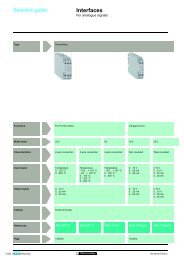
Sepam - HV/MV Protection and control units (ENG) - Trinet
Sepam - HV/MV Protection and control units (ENG) - Trinet
Sepam - HV/MV Protection and control units (ENG) - Trinet

Create successful ePaper yourself
Turn your PDF publications into a flip-book with our unique Google optimized e-Paper software.
<strong>Protection</strong><strong>and</strong> <strong>control</strong><strong>Sepam</strong> range<strong>Sepam</strong> 2000Metering <strong>and</strong> protectionfunctions<strong>Protection</strong><strong>and</strong> <strong>control</strong><strong>Sepam</strong> range<strong>Sepam</strong> 2000Metering <strong>and</strong> protectionfunctions
Contentschapter / pagemetering functions 1/1protection functions 2/1appendix 3/1Notationc <strong>Sepam</strong> 2000 may include several current signal acquisition boards or severalvoltage signal acquisition boards.The currents, voltages <strong>and</strong> frequency related to the first acquisition boardare noted I for current, V for phase voltages, U for system voltages <strong>and</strong>F for frequency.The currents, voltages <strong>and</strong> frequency related to the second acquisition boardare noted I’ for current, V’ for phase voltages, U’ for system voltages <strong>and</strong>F’ for frequency.Example :metering function: phase currentv I1, I2 <strong>and</strong> I3 are the currents connected to the first current acquisition board,v I’1, I’2 <strong>and</strong> I’3 are the currents connected to the second current acquisitionboard.c <strong>Sepam</strong> 2000 may include several times the same function:v X is the identification number of a function which uses the signals acquiredby the first acquisition board,v Y is the identification number of a function which uses the signals acquiredby the second acquisition board.Example :protection function: phase overcurrentv F01X, 1 i X i 6 means that F011, F012, F013, F014, F015 <strong>and</strong> F016are the 6 modules which perform the overcurrent function for phases I1, I2 <strong>and</strong> I3acquired by the first current acquisition board.v F02Y, 1 i Y i 2 means that F021, F022, are the 2 modules which performthe overcurrent function for phases I’1, I’2 <strong>and</strong> I’3 acquired by the second currentacquisition board.c In the rest of the document, the term “pocket terminal” refers to any terminalthat can be connected to 9-pin sub-D plug on the front of <strong>Sepam</strong> 2000, namely:v TSM 2001 or PC equipped with the SFT 2801 software program formeasurement display,v TSM 2001 or PC equipped with either the SFT 2801 or SFT 2821 softwareprogram for protection setting.Metering functions1
ContentsMetering functionschapter / pagemetering functions 1/1phase current 1/2maximum dem<strong>and</strong> phase currents 1/3tripping currents 1/4residual current 1/5phase-to-neutral <strong>and</strong> phase-to-phase voltages 1/6frequency 1/7real/reactive power <strong>and</strong> power factor 1/8maximum dem<strong>and</strong> real/reactive power 1/10real <strong>and</strong> reactive energy meters 1/11temperature 1/12residual voltage 1/13starting current <strong>and</strong> time 1/14cumulative breaking current <strong>and</strong> number of breaks 1/15true rms current 1/16differential current <strong>and</strong> through current 1/17disturbance recording 1/18Metering functions1/1
Phase currentOperationThis function gives the phase current rms values:c I1 : phase 1 current,c I2 : phase 2 current,c I3 : phase 3 current,c I1’ : phase 1 current,c I2’ : phase 2 current,c I3’ : phase 3 current.It is based on measurement of the fundamentalcomponent.Characteristicsmeasurement range 0.015 In to 24 In (1)unitaccuracy (2)display unit <strong>and</strong> pocket terminal formatrefresh interval(1)In rated current set in the status menu.(2)at In, in reference conditions (IEC 60255-6).A or kA±0.5% or ±1 digit3 significant digits1 second (typical)ReadoutThe measurements may be accessed via:c the display unit by pressing the A key,c the pocket terminal, metering menu,I phase heading,c the communication link.%2,521,510,500 0,1 0,2 0,8 1,2 1,5Accuracy according to the measurement rangexInSensorsThis measurement is related to the currents in thecircuits that are connected to the following connectors:Measurement of currents I1, I2, I3sensorCTCSPconnector2B2L1, 2L2, 2L3Measurement of currents I1’, I2’, I3’sensorTCCSPconnector3B3L1, 3L2, 3L31/2 Metering functions
Maximum dem<strong>and</strong> phase currentsOperationThis function gives the greatest average rms currentvalue for each phase that has been obtained sincethe last reset.It is based on measurement of the fundamentalcomponent.The average is refreshed after each “integrationinterval”.The integration interval is set using the pocketterminal, status menu, max. dem<strong>and</strong> interv.heading, IM1, IM2, IM3.Characteristicsmeasurement range 0.015 In to 24 In (1)unitA or kAaccuracy (2)±0.5% or ±1 digitresolutiondisplay unit <strong>and</strong> pocket terminal formatintegration interval(1)In rated current set in the status menu.(2)at In, in reference conditions (IEC 60255-6).0.1 A3 significant digits5, 10, 15, 30, 60 minutesReadoutThe measurements may be accessed via:c the display unit by pressing the A key,c the pocket terminal, metering menu,max. current dem<strong>and</strong> heading,c the communication link.Resetting to zero:c press the clear key on the display unit when a max.dem<strong>and</strong> current is displayed,c press the clear key on the pocket terminalwhen a max. dem<strong>and</strong> is displayed,c via program logic coil K851.The value is saved in the event of a powersupply failure.SensorsThis measurement is related to the currents in thecircuits that are connected to following connectors:sensorCTCSPconnector2B2L1, 2L2, 2L3Metering functions1/3
Tripping currentsOperationThis function gives the rms value of currentsat the prospective tripping time:c TRIP1: phase 1 current,c TRIP2: phase 2 current,c TRIP3: phase 3 current,c TRIP0: residual current.It is based on measurement of the fundamentalcomponent.ITRIP 1Characteristicsmeasurement range (2) phase current 0.015 In to 24 In (1)accuracydisplay unit <strong>and</strong> pocketterminal formatresolutionunitresidual current 0.015 to 10 Ino (1)±5% or ±1 digit3 significant digits0.1 AA or kA(1)In, Ino rated current set in the status menu.(2)the display unit indicates > when the current is greater than the measurement range.SensorsK855T0Readout30 msThis measurement is defined as the maximum rms valuemeasured during an interval of 30 ms following activationof the K855 coil.The measurements may be accessed via:c the display unit by pressing the A key,c the pocket terminal, metering menu,tripping current heading,c the communication link.tThis measurement is related to the currents in thecircuits that are connected to following connectors:Phase currentsensorCTCSPResidual currentsensorCTCSHCT + CSH30CSPconnector2B2L1, 2L2, 2L3connector2B2A2A2L1, 2L2, 2L3Resetting to zero:c press the clear key on the display unit when a TRIPvalue is displayed,c press the clear key on the pocket terminalwhen a TRIP value is displayed,c the communication link,c via program logic coil K856.The value is saved in the event of a powersupply failure.1/4 Metering functions
Residual currentOperationThis operation gives the residual current rms value–> –> –>(I1 + I2 + I3):c Io: residual current on connector 2,c Io’: residual current on connector 3,c Io”: residual current on connector 4.It is based on measurement of the fundamentalcomponent.ReadoutThese measurements may be accessed via:c the pocket terminal, add. reading menu, I residual,I’ residual, I” residual heading,c the communication link.Characteristicsmeasurement rangeconnection to 3 phase CTs: 0.05 In to 10 In (1)connection to core balance CT2 A rating input 0.1 to 20 A30 A rating input 1.5 to 300 Aconnection to 1 CTwith CSH30 interposing ring CT 0.015 to 10 Ino (1)connection to core balance CTwith ACE 990 interface 0.015 to 10 Ino (1)unitA or kAaccuracy (2)±5% or ±1 digitdisplay unit <strong>and</strong> pocket3 significant digitsterminal formatresolution0.1 Arefresh interval1 second (typical)(1)In, Ino rated current set in the status menu.(2)in reference conditions (IEC 60255-6).SensorsThis measurement is related to the currents in thecircuits that are connected to the followingconnectors, according to the settings of the relatedSW1 microswitches:Measurement of current IosensorCTCSPCSHCT + CSH30core bal. CT + ACE 990connector2B2L1, 2L2, 2L32A2A2AMeasurement of current Io’sensorconnectorCT3BCSP3L1, 3L2, 3L3CSH3ACT + CSH303Acore bal. CT + ACE 990 3AMeasurement of current Io”sensorconnectorCT3BCSH4ACT + CSH304Acore bal. CT + ACE 990 4A* available as of version 9940 SFT2800.Metering functions1/5
Phase-neutral <strong>and</strong> phase-to-phase voltagesOperationThis function gives the rms value of:c phase-to-neutral <strong>and</strong> phase-to-phase voltageson connector 3 or 4 according to the <strong>Sepam</strong> model:v U21 voltage between phases 2 <strong>and</strong> 1,v U32 voltage between phases 3 <strong>and</strong> 2,v U13 voltage between phases 1 <strong>and</strong> 3,v V1 phase 1 phase-to-neutral voltage,v V2 phase 2 phase-to-neutral voltage,v V3 phase 3 phase-to-neutral voltage.c phase-to-neutral <strong>and</strong> phase-to-phase voltageson connector 4 of <strong>Sepam</strong> 2000 S26 <strong>and</strong> S46:v U21' voltage between phases 2 <strong>and</strong> 1,v U32' voltage between phases 3 <strong>and</strong> 2,v U13' voltage between phases 1 <strong>and</strong> 3,v V1' phase 1 phase-to-neutral voltage,v V2' phase 2 phase-to-neutral voltage,v V3' phase 3 phase-to-neutral voltage.For <strong>Sepam</strong> S26, only the U21 <strong>and</strong> U22 voltages aremeasured <strong>and</strong> the U13 voltage is obtained by takingthe vector sum. The phase-to-neutral voltages areobtained by the vector sum, taking into account theresidual voltage.For <strong>Sepam</strong> S36, all the phase-to-phase voltages aremeasured. The phase-to-neutral voltages areobtained by the vector sum, taking into account theresidual voltage.For <strong>Sepam</strong> S46, the phase-to-phase voltages arecalculated according to the phase-to-neutral voltagesV1, V2 <strong>and</strong> V3.Characteristicsmeasurement rangephase-to-phase voltages 0.015 Un to 1.5 Un (1)phase-to-neutral voltages S26/S36** 0.015 Un to 1.5 Un (1)unitaccuracy (2)display unit <strong>and</strong> pocket terminal formatresolutionrefresh interval(1)Un nominal rating set in the status menu.(2)at Un in reference conditions (IEC 60255-6).(3)Vn nominal rating set in the status menu.%2.521.510.500 0.1 0.2 0.81.5Accuracy according to the measurement range.S46 0.015 Vn to 1.5 Vn (3)V or kV±0.5% or ±1 digitxUn3 significant digits1 V1 second (typical)ReadoutThe measurements may be accessed via:c the display unit by pressing the V key,c the pocket terminal, metering menu,U <strong>and</strong> V phase reading,c the communication link.If there is only one sensor (phase-to-neutral or phaseto-phasevoltage), the function gives only the rmsvalues of one phase-to-phase voltage U <strong>and</strong> onephase-to-neutral voltage V.SensorsThis measurement is related to the voltages in thecircuits that are connected to the following connectors:Measurement of voltages V1, V2, V3, U21, U32, U13<strong>Sepam</strong>connectorS36* 4A (1)S26* 3AS463 A(1)3A connector for S36*TR <strong>and</strong> S36TS models.Measurement of voltages V1', V2', V3', U21', U32', U13'<strong>Sepam</strong>connectorS36*TR4AS36TS4AIf there is only one sensor (phase-to-neutral or phaseto-phasevoltage), the voltage signal is connectedto terminals 4 <strong>and</strong> 5 of the connector, whateverthe phase.* S35, S25 for earlier versions.** available as of version 9940 SFT2800.1/6 Metering functions
FrequencyOperationThis function gives the frequency value.Frequency is measured via the following:c U21, if only one phase-to-phase voltage is wiredto the <strong>Sepam</strong> 2000,c positive sequence voltage, if the <strong>Sepam</strong> 2000includes U21 <strong>and</strong> U32 measurements, in which casethe number of phase-to-phase voltage set in the VTratio heading of the status menu should be 3U,c based on phase-to-neutral voltage forthe <strong>Sepam</strong> S46.Frequency is not measured if:c the voltage U21 or V is less than 38 V on the VTsecondary windings (when VT number is otherthan 3U),c the voltage U21 or V is less than 20 V on the VTsecondary windings (when VT number is equalto 3U),c the frequency is outside the measurement range.ReadoutThe measurements may be accessed via:c the display unit by pressing the V/Hz key,c the pocket terminal, metering menu,frequency heading,c the communication link.Characteristicsrated frequency50 Hz, 60 Hzmeasurement range 50 Hz 45 Hz to 55 Hz60 Hz 55 Hz to 65 Hzaccuracy (1)±0.02 Hzdisplay unit <strong>and</strong> pocket terminal formatresolutionrefresh interval(1)at Un in reference conditions (IEC 60255-6).SensorsThis measurement is related to the currents in thecircuits that are connected to the following connector:<strong>Sepam</strong>connectorS36* 4A (1)S26* 3AS463A(1)3A connector for S36*TR <strong>and</strong> S36TS models.4 significant digits0,01 Hz1 second (typical)Metering functions1/7
Real/reactive power <strong>and</strong> power factorOperationThis function gives the power <strong>and</strong> power factorvalues:c P real power = eU.I.cos ϕ,c Q reactive power = eU.I.sin ϕ,c power factor (pf. or cos ϕ).It is based on measurement of the fundamentalcomponent.where-CAPI = phase current,V = phase-to-neutral voltage,ϕ = delay of I with respect to V.Q+IND4 1Real <strong>and</strong> reactive powerThis function measures the real <strong>and</strong> reactive power in3-wire 3-phase arrangements by means of the“two wattmeter” method. The powers are obtainedfrom phase-to-phase voltage U21 <strong>and</strong> U32 <strong>and</strong> phasecurrents I1 <strong>and</strong> I3.Whether the system is balanced or unbalanced,the power is calculated as follows:P = U21.I1.cos(U21,I1) - U32.I3.cos(U32,I3)Q = U21.I1.sin(U21,I1) - U32.I3.sin(U32,I3).When only one voltage is connected, U21 or V, P<strong>and</strong> Q are calculated assuming that thephase-to-phase voltage is balanced.The sign of the measurement indicates the directionof the flow of power.According to st<strong>and</strong>ard practice, it is considered that:c for the outgoing circuit (1) :v power consumed by the feeder is positive,v power supplied to the busbar is negative.-IND3The + <strong>and</strong> - signs <strong>and</strong> IND (inductive) <strong>and</strong> CAP (capacitive) indications givethe direction of power flow <strong>and</strong> the type of load.Readout2+CAPPThe measurements may be accessed via:c the display unit by pressing the W key,c the pocket terminal, metering menu, power & power factor heading,c the communication link.Please note:the direction information is in accordance with the following wiring diagram:normalinverseL1direction of flow– +L2L3c for the incoming circuit (1) :v power supplied to the busbar is positive,v power consumed by the incomer is negative.(1)3A– +direction of flow(1)choice to be made using the pocket terminal, status menu,power flow sense.87654321414A2B3U/VoDPCECMPower factor (PF)The power factor is defined by:pf. = P/√(P 2 + Q 2 )It expresses the phase unbalance between the phasecurrents <strong>and</strong> phase voltages.ϕϕIIPf. = +0.8CAPVPf. = +0.8IND(1)…….A.Aterminal numberfor compact (S26)*<strong>Sepam</strong> 2000terminal numberfor st<strong>and</strong>ard (S36)*<strong>Sepam</strong> 20005263Please note: refer to the installation document for other arrangements.* or S35, S25 for earlier versions.1/8 Metering functions
%32.521.510.5%0.10.050.0100 0.1000.2 0.8 1.2 1.5Real power function accuracy according to the currentmeasurement range for Pf. > 0.8.0.2 0,4 0.4 0.6 0.8 1.0Accuracy of the Pf. measurement.%32.521.510.5cos ϕxInCharacteristicspower real reactiverange (2) 1.5% Sn to 999 MW 1.5% Sn to 999 <strong>MV</strong>Arwith Sn = e. Un . Inaccuracy (1)±1% or ±1 digit (see curves)display unit <strong>and</strong>3 significant digitspocket terminal formatresolution 1 W 1 VArrefresh interval< 0.5 secondsrelated logic contacts K831 = 1 if P > 0 K832 = 1 if Q > 0K831 = 0 if P < 0 K832 = 0 if Q < 0Pf.range-1 to 1 IND/CAPaccuracy (1) 0.01display unit <strong>and</strong>3 significant digitspocket terminal formatrefresh interval< 0.5 seconds (typical)related logic contacts K833 = 1, if the system is inductiveK833 = 0, if the system is capacitiveK834 = 1, if Pf. u 0K834 = 0, if Pf. < 0(1)at In, Un <strong>and</strong> at p.f. > 0.8, in reference conditions (IEC 60255-6)(2)resolution 1 W, 1 VAr.SensorsThese measurements are related to the circuitsconnected to the following connectors:CT current voltage<strong>Sepam</strong> connector connectorS36* 2B 4A (1)S26* 2B 3AS46 2B 3A00 0.1Reactive power function accuracy according to the currentmeasurement range for Pf. < 0,6.%50.2 0,5 0.8 1.2 1.5xInCSP current voltage<strong>Sepam</strong> connector connectorS36* 2L1,2L2, 2L3 4A (1)S26* 2L1,2L2, 2L3 3A(1)3A connector for S36*TR <strong>and</strong> S36TS models.4321000.6 0.8 0.94 0.98 cos ϕReactive power function accuracy according to the currentmeasurement range for Pf. <strong>and</strong> for current between 0.8 In<strong>and</strong> 1.2 In.* or S35, S25 for earlier versions.Metering functions1/9
Maximum dem<strong>and</strong> real <strong>and</strong> reactive powerOperationThis function gives the greatest average real orreactive power value obtained since the last reset.It is based on measurement of the fundamentalcomponent.The time it takes to calculate the average, whichis also called the integration interval, is set usingthe pocket terminal, status menu, max. dem<strong>and</strong>interv. heading.Characteristicspower real reactiverange 1.5% Sn to 999 MW 1.5% Sn to 999 <strong>MV</strong>Ar (1)accuracysee power measurementsdisplay unit <strong>and</strong>3 significant digitspocket terminal formatintegration interval 5, 10, 15, 30, 60 minutes(1)Sn = e Un.In.ReadoutThe measurements may be accessed via:c the display unit by pressing the W key,c the pocket terminal, metering menu, max. powerdem<strong>and</strong> heading,c the communication link.The peak dem<strong>and</strong> values are saved in the eventof a DC power failure.Resetting to zero:c press the clear key on the pocket terminal if peakdem<strong>and</strong>s are displayed,c press the clear key on the display unit if at leastone peak dem<strong>and</strong> is displayed,c set the <strong>control</strong> logic coil K852 to 1.SensorsThese measurements are related to the circuitsconnected to the following connectors:CT current voltage<strong>Sepam</strong> connector connectorS36* 2B 4A (1)S26* 2B 3AS46 2B 3ACSP current voltage<strong>Sepam</strong> connector connectorS36* 2L1, 2L2, 2L3 4A (1)S26* 2L1, 2L2, 2L3 3A(1)3A connector for S36*TR <strong>and</strong> S36TS models.* or S35, S25 for earlier versions.1/10 Metering functions
Accumulated real/reactive energyOperationThis function gives the real <strong>and</strong> reactive energyvalues:c accumulated energy conveyed in one direction,c accumulated energy conveyed in the otherdirection.It is based on measurement of the fundamentalcomponent.The accumulated energy values are savedin the event of a power failure.ReadoutThe measurements may be accessed via:c the display unit by pressing the Wh key,c the pocket terminal, metering menu,energy meter heading,c the communication link.To reset the accumulated energy values to zero,the cartridge needs to be reprogrammed.Characteristicspower real reactivecounting capacity 2.8 x 10 8 MWh 2.8 x 10 8 <strong>MV</strong>Arh (2)display capacity:pocket terminal 2.8 x 10 8 MWh 2.8 x 10 8 <strong>MV</strong>Arhdisplay unit 99999.99 MWh 99999.99 <strong>MV</strong>Arhresolution0.01 MWhaccuracy (1)±1% or ±1 digit(1)at In, Un <strong>and</strong> at Pf. > 0.8, in reference conditions (IEC 60255-6)(2)Sn = e Un.In.SensorsThese measurements are related to the circuitsconnected to the following connectors:CT current voltage<strong>Sepam</strong> connector connectorS36* 2B 4A (1)S26* 2B 3AS46 2B 3ACSP current voltage<strong>Sepam</strong> connector connectorS36* 2L1, 2L2, 2L3 4A (1)S26* 2L1, 2L2, 2L3 3A(1)3A connector for S36*TR <strong>and</strong> S36TS models.* or S35, S25 for earlier versions.Metering functions1/11
TemperatureOperationThis function gives the temperature value measuredby RTDs (Pt100 platinum probe, 100 Ω at 0 °C)in accordance with the IEC 751 <strong>and</strong> DIN 43760st<strong>and</strong>ards.Each RTD channel gives one measurement:tx = RTD temperature.The function also indicates RTD faults(RTD disconnected or shorted):c *//* in the case of a disconnected RTD(or a temperature greater than 302 °C ±27 °C),c **** in the case of a shorted RTD (or a temperatureless than -70 °C ±10 °C).ReadoutThe measurements may be accessed via:c the display unit by pressing the Wh key,c the pocket terminal, metering menu,temperature <strong>and</strong> add. temperature heading.c the communication link.Characteristicsrange -50°C to 250°Caccuracy±1°Cresolution 1°Crefresh intervalAccuracy derating according to wiringc Connection in 3-wire mode: the error ∆t isproportional to the length of the wire <strong>and</strong> inverselyproportional to the wire cross-section:I (km)∆t (°C) = 2 xS (mm 2 )v ±2.1°C/km for a cross-section of 0.93 mm 2 ,v ±1°C/km for a cross-section of 1.92 mm 2 ,c Connection in 2-wire mode: wiring resistancecompensation is not ensured in this mode. Thiscreates the following error:I (km)∆t (°C) = 100 xS (mm 2 )3 seconds (typical)SensorsThese measurements are related to the RTDsconnected to the following connectors:<strong>Sepam</strong> connector connectorS26* LS 3A —S36* LS — 8AS36* KZ — 8AS36* SS 3A 8AS36* SR 3A —S36* ZR 3A —S36TS — 8AS46 ZR 3A —S46 ZM 3A —* or S35, S25 for earlier versions.1/12 Metering functions
Residual voltageOperationThis function gives residual voltage value–> –> –>(V1 + V2 + V3). It is measured by taking the internalsum of the 3 phase voltages or by a star / opendelta VT.Vo = residual voltageVo’ = residual voltage.It is based on measurement of the fundamentalcomponent.Characteristicsmeasurement rangeunitaccuracydisplay unit <strong>and</strong> pocket terminal formatresolutionrefresh interval0.015 Un to e UnV or kV±5% or ±1 digit3 significant digits1 V1 second (typical)ReadoutThis measurement may be accessed via:c the pocket terminal, add. reading menu,V residual, V’ residual heading,c the communication link.SensorsThis function is related to the voltages connectedto the following connectors:Measurement of voltage Vo<strong>Sepam</strong>connectorS36* 4A (1)S26* 3A(1)3A connector for S36*TR <strong>and</strong> S36TS modelsMeasurement of voltage Vo’<strong>Sepam</strong>connectorS36*TR4AS36TS4A* or S35, S25 for earlier versions.** available as of version 9940 SFT2800.Metering functions1/13
Starting current <strong>and</strong> timeOperationThis function indicates the value of a current peak(Imax) <strong>and</strong> its duration (Tstart). It is based onmeasurement of the fundamental component.Current measurement with a quick refresh interval(Istart) enables the user to view current developmentduring the starting phase.The function is used especially for motor protectioncommissioning: it indicates the starting time <strong>and</strong>maximum rms value of the starting current.The time Tstart is measured when the greatestof the three phase currents is greater than 1.2Ib.Istart current is displayed whenever one of the threephase currents is greater than 1.2 Ib.The Imax current value changes when the greatestof the three phase currents is greater than 1.2Ib.IImaxCharacteristicsIstartrange 1.2 Ib to 24 In (1)unitA or kAaccuracy±5% or ±1 digitpocket terminal format3 significant digitssampling interval50 ms (typical)resolution0.1 A or 1 digitrefresh interval0.2 seconds (typical)Tstartrange0.05 to 555 secondsaccuracy±10% or 100 mspocket terminal format3 significant digitssampling interval50 ms (typical)resolution10 ms or 1 digitrefresh interval0.2 seconds (typical)(1)Ib = base current.I start1.2IbIbI startMeasurement of starting duration <strong>and</strong> current.tSensorsThis measurement is related to the currents in thecircuits that are connected to the followingconnectors:sensorCTCSPconnector2B2L1, 2L2, 2L3ReadoutThe starting time <strong>and</strong> current measurements may beaccessed via the pocket terminal:c add. reading menu, start current <strong>and</strong> time heading.1/14 Metering functions
Cumulative breaking current <strong>and</strong> number of breaksOperationThis function indicates the cumulative numberof breaking operations <strong>and</strong> the cumulative breakingcurrent in square kiloamperes (kA) 2 for five currentranges.It is based on measurement of the fundamentalcomponent.The current ranges are:c 0 < I < 2Inc 2In < I < 5Inc 5In < I < 10Inc 10In < I < 24Inc I > 24InThe function also provides the total number of breaks<strong>and</strong> the cumulative total of breaking current in (kA) 2 .Refer to switchgear documentation for useof this information.The function is activated by the <strong>control</strong> logicK855 coil.Each value is saved in the eventof a DC power failure.ReadoutCharacteristicsnumber of breaksrange 0 to 99999(kA) 2range 0 to 9999 (kA) 2unit primary (kA) 2resolution primary 0.0001 (kA) 2pocket terminal formatsignificant digitsaccuracy (1) ±10%(1)at In, in reference conditions (IEC 60255-6).SensorsThis measurement is related to the currentsin the circuits that are connected to the followingconnectors:sensorCTCSPconnector2B2L1, 2L2, 2L3The measurements may be accessed:c via the pocket terminal, add. reading menu,break. nb <strong>and</strong> (kA) 2 heading.c the communication link.The cumulative values are reset by the clear buttonon the pocket terminal, in parameter setting mode,if the function is displayed.** available as of version 9940 SFT2800.Metering functions1/15
True rms currentOperationThis function gives the greatest of the followingmeasurements:c rms value of the fundamental component of phase 1current up to 24 Inc rms value of phase 1 current up to 4 In, taking intoaccount:v fundamental component,v harmonics.ReadoutThis measurement may be accessed via:c the pocket terminal, add. reading menu,Irms heading.Characteristicstrue rms current I1 rmsmeasurement rangeunitaccuracy (1)pocket terminal formattaking into account harmonicsresolutionrefresh interval(1)in reference conditions (IEC 60255-6).Sensors0.015 In to 24 Inprimary A or kA±1% or ±1 digit at Fn±3% or ±1 digit for F < 1kHz3 significant digitsfrom 1 st to 21 st0.1 A or 1 digit1 second (typical)This function is related to the current of phase 1connected to the following connectors:sensorCTCSPconnector2B2L11/16 Metering functions
Differential current <strong>and</strong> through currentOperationThis function gives the rms value of the followingcurrents:c differential currents Id of the 3 phases:v Id1 = I1 - I1’v Id2 = I2 - I2’v Id3 = I3 - I3’.c through currents It of the 3 phases:v It1 = I1 + I1’2v It2 = I1 + I1’2v It3 = I1 + I1’2It is based on measurement of the fundamentalcomponent. When combined with motor generatordifferential protection (ANSI code 87M/87G,function n° F621), this function gives the valuesof the differential currents <strong>and</strong> through currentsfor the 3 phases, measured <strong>and</strong> stored whenthe motor differential protection trips:v Trip Id1, Trip Id2, Trip Id3,v Trip It1, Trip It2, Trip It3.Storage of the values is activated by the <strong>control</strong>logic K855 coil.CharacteristicsId <strong>and</strong> Itmeasurement range 0.015 In to 24 In (1)unitaccuracy (2)pocket terminal formatresolutionrefresh interval(1)In nominal rating set in the status menu.(2)at In, in reference conditions (IEC 60255-6).SensorsThese measurements are related to the differentialcurrents Id <strong>and</strong> through currents It of the I <strong>and</strong> I’currents connected to the following connectors:sensor connectorcurrent I current I’CT 2B 3BA or kA±5% or ±1 digit3 significant digits0.1 A or 1 digit1 second (typical)ReadoutThe measurements may be accessed via:c the pocket terminal, add. reading menu,Idiff./Ithrough heading.The Trip Id <strong>and</strong> Trip It measurements are reset by:c the clear button on the pocket terminal,c the <strong>control</strong> logic K856 coil.Metering functions1/17
Disturbance recordingOperationThis function is used to record analog signals<strong>and</strong> logical states.Record storage is initiated by the activationof the K865 coil by a triggering event.The stored record begins before the triggeringevent <strong>and</strong> continues afterwards.The duration of the signal recording before thetriggering event may be adjusted via the pocketterminal, status menu, disturbance recordingheading.The record storage date may also bee accessedvia the pocket terminal, status menu, disturbancerecording heading <strong>and</strong> via the communication link(refer to “Jbus/Modbus communication”documentation). The date corresponds to the dateof the triggering event.The record comprises the following information:c values samples from the different signals,c date,c characteristics of the recorded channels.The files are recorded in FIFO (First In First Out)shift storage: the oldest record is erased when a newrecord is triggered.TransferFiles may be transferred locally or remotely:c locally: using a PC which is connected to the pocketterminal connector <strong>and</strong> includes the SFT 2801software package (version more recent than 9802),c remotely: using a software package specific to theremote monitoring <strong>and</strong> <strong>control</strong> system.Principlestored recordCharacteristicsrecord durationtime beforetriggering eventrecord contentanalog signals recordedlogical states recordedtriggering event (K865)time86 periodsadjustable from 1 to 85 periods*set-up file:date, channel characteristics,measuring transformer ratiodata file:12 values per period/recorded signal4 to 12 according to the number of acquisition boards:4 signals per current acquisition board4 signals per voltage acquisition board for S363 signals per voltage acquisition board for S26(U21, U32, Vo)16 logic inputs I11 to I18, I21 to I2816 logic data items defined by program logic(Kfr1 to Kfr16)number of stored records2file format COMTRADE IEEE C37.111 - 1997IEC 60255 - 24DisplayThe signals can be displayed from a record by meansof the SFT 2826 software package.SensorsThe disturbance recording function is related to the analog signals connected tothe following connectors:current sensor connector 2 connector 3 connector 41 A or 5 A CT 2B 3B 4BCSH or 2A 3A 4ACT + CSH30 orcore bal. CT+ ACE 990CSP 2L1, 2L2, 2L3 3L1, 3L2, 3L3 —voltage <strong>Sepam</strong> connector 2 connector 3 connector 4S36 — — 4AS26 — 3A —S36TR<strong>and</strong> S36TS — 3A 4A* value set to 6 periods for SFT2800 versions earlier than 9940.1/18 Metering functions
Contents<strong>Protection</strong> functionschapter / pagefunction n° ANSI code protection functions 2/1F01X, F02Y 50/51 phase overcurrent 2/2F19X, F20Y 50V-51V voltage restrained overcurrent 2/4F52X 67 directional over current 2/6F06X, FF40X 50N-51N earth fault 2/10F08X, F09Y 50G-51GF50X 67N directional earth fault 2/13F48X 67NC directional earth fault for 2/16compensated neutral systemsF101 50G-51G resistive earth fault 2/19F431 49 thermal overload 2/21F45X 46 negative sequence / unbalance 2/30F421 66 starts per hour 2/34F221 37 phase undercurrent 2/37F441 51LR excessive starting time <strong>and</strong> locked rotor 2/38F32X, F33Y, 27 system undervoltage 2/40F34X, F24Y,F36X, F37YF35X, F25Y 27R remanent undervoltage 2/42F38X 27D - 47 positive sequence undervoltage 2/43<strong>and</strong> phase rotation direction checkF28X, F29Y, 59 system overvoltage 2/44F30X, F31YF39X, F41Y 59N neutral voltage displacement 2/45F40X 47 negative sequence overvoltage 2/46F58X 81R rate of change of frequency protection 2/47F56X 81L underfrequency 2/50F57X 81H overfrequency 2/51F531 32P real overpower 2/52F541 32Q reactive overpower 2/54F551 37P real underpower 2/56F171, F181 25 synchro-check 2/58F03X, F04X, 50-51 percentage-based single-phase 2/61F05X, F11Y,overcurrentF12Y, F13YF981 50BF + 62 breaker failure protection 2/62F621 87G-87M motor-generator differential 2/64F641, F651 64REF restricted earth fault protection 2/66F661F46X, F47Y 49T- 38 temperature monitoring 2/68<strong>Protection</strong> functions2/1
Phase overcurrentANSI code 50-51function n° F01X for phase overcurrentI1, I2, I3 1 ≤ X ≤ 6F02Y for phase overcurrentI1’, I2’, I3’ 1 ≤ Y ≤ 2Is is the vertical asymptote of the curve, <strong>and</strong> T is the operation time delay for 10 Is.The curve is defined according to the following equations:c st<strong>and</strong>ard inverse time SIT0.14 Tt = .(I/Is) 0.02 -1 2.97c very inverse time VIT or LTIOperationPhase overcurrent protection is three-pole.It picks up when one, two or three of the currentsreaches the set point. It is time-delayed.The time delay may be definite (definite DT) or IDMT(st<strong>and</strong>ard inverse SIT, very inverse VIT or LTI (1) ,extremely inverse EIT, ultra inverse time UIT).See curves in appendix.(1)The very inverse time VIT delay setting range may be usedto create LTI curves.Logic data K859 = 1 may be used to inhibit startup of the time delay.(regarding use, refer to “start-up of time delays”in appendix).Definite time protectionIs is the set point expressed in Amps,<strong>and</strong> T is the protection time delay.13.5t = .(I/Is)-1c extremely inverse time EITc ultra inverse time UITt =315. T(I/Is) 2.5 -1The function also takes into account current variations during the time delayinterval.For currents with a very large amplitude, the protection has a definite timecharacteristic:c if I > 20 Is, tripping time is the time that corresponds to 20 Is,c if I > 24 In, tripping time is the time that corresponds to 24 In.Block diagramT1.580 Tt = .(I/Is) 2 -1 0.808tI1I2I3I > Ist0F01X/2(F02Y/2)TK859F01X/1(F02Y/1)IsIDefinite time protection principle.IDMT protectionIDMT protection operates in accordance with the IEC60255-3 <strong>and</strong> BS 142 st<strong>and</strong>ards.tT11.2 10 20 I/IsIDMT protection principle.2/2 <strong>Protection</strong> functions
Commissioning, settingCheck:c the connections,c the positions of the microswitches SW2 associatedwith the current inputs,c the general parameters in the status menu.Set the following:c type of time delay,v definite time DT,v IDMT: st<strong>and</strong>ard inverse time SIT,very inverse time VIT, extremely inverse time EIT,ultra inverse time UIT.c Is current: Is is set in rms, amps or kiloamps.The 999 kA setting may be used to inhibit theprotection: all the outputs are set to 0.c T time delay:v DT: T is the operation time delay,v SIT, VIT, EIT, UIT: T is the operation time delayat 10 Is.SensorsPhase overcurrent I1, I2, I3 protection is relatedto the currents connected to the following connectors:current sensor connector1 A or 5 A CT 2BCSP2L1, 2L2, 2L3Phase overcurrent I1’, I2’, I3’ protection is relatedto the currents connected to the following connectors:current sensor connector1 A or 5 A CT 3BCSP3L1, 3L2, 3L3CharacteristicscurvesettingIs set pointdefinite, inverse, very inv., ext. Inv., ultra inv.setting definite time 0.3 In i Is i 24 In expressed in ampsresolutionIDMTaccuracy (1) ±5%inhibition0.3 In i Is i 2.4 In expressed in amps1 A or 1 digit999 kAdrop out/pick-up ratio 93.5% ±5%T time delaysetting definite time 50 ms i T i 655 sresolutionIDMTaccuracy (1) definite timeIDMT100 ms i T i 12.5 s10 ms or 1 digit±2% or +25 msclass 5 or +25 ms±12.5% at 2 Is±7.5%, or from 0 to +25 ms at 5 Is±5%, or from 0 to +25 ms at 10 Is±5%, or from 0 to +25 ms at 20 Ischaracteristic timesinstantaneous< 40 ms to 2 Istripping time30 ms (typical)time-delayed tripping time according to time delaymemory time20 ms < t < 55 msfault recognition time < 25 msreset time< 70 msoutputs available for program logicinstantaneous F01X/1, F02Y/1 1 i X i 6 1 i Y i 2time-delayed F01X/2, F02Y/2 1 i X i 6 1 i Y i 2remote reading <strong>and</strong> remote setting (2)function code F01, F0201h <strong>and</strong> 02hidentification number X, Y (3)parameters curve unit: 0..4 (4)(order of parameters) Is set point unit: AT time delayunit: 10 x ms(1)in reference conditions (IEC 60255-6).(2)the data formats are defined in the manuals which describe each communication protocol.(3)the number of protection function modules depends on the type of <strong>Sepam</strong>.(4)meaning of curve index:0: definite time,1: inverse time,2: very inverse time,3: extremely inverse time,4: ultra inverse time.* function available as of version 9802 SFT2800.<strong>Protection</strong> functions2/3
Voltage restrained overcurrentANSI codefunction n°Operation50V-51VF19X for voltagerestrained overcurrentI1, I2, I3 1 i X i 2F20Y for voltagerestrained overcurrentI1', I2', I3' 1 i Y i 2Voltage restrained overcurrent protectionis three-phase.It picks up when one, two or three of the currentsreaches the voltage-adjusted set point Is*. It is timedelayed.The time delay may be definite (definite DT)or IDMT (st<strong>and</strong>ard inverse SIT, very inverse VIT orLTI (1), extremely inverse EIT, ultra inverse time UIT).See curves in appendix.The set point is adjusted in accordance with thelowest measured system voltage.The adjusted set point Is* is defined by the followingequation:Logic data K859 = 1 may be used to inhibit start up of the time delay(regarding use, refer to “start-up of time delays” in appendix).Definite time protectionIs is the set point expressed in Amps, <strong>and</strong> T is the protection time delay.IDMT protectionIDMT protection operates in accordance with the IEC 60255-3 <strong>and</strong> BS 142st<strong>and</strong>ards.Is is the vertical asymptote of the curve, <strong>and</strong> T is the operation time delay for 10 Is.Block diagramU21U32U13I1I2I3I > KIsKK859t0F19X/2F19X/1Is* = 4x U Un - 0.2 x Is 3K = Is*Is10.20.2Un0.8UnUOperation set point adjusted according to voltage.(1)The very inverse time VIT delay setting range may be usedto create LTI curves.2/4 <strong>Protection</strong> functions
Commissioning, settingCheck:c the connections,c the positions of the microswitches SW associatedwith the current <strong>and</strong> voltage inputs,c the general parameters in the status menu.The number of voltages set up in the status menu,VT ratio heading must be different from V.Set the following:c type of time delay,v definite time DT,v IDMT: st<strong>and</strong>ard inverse time SIT,very inverse time VIT, extremely inverse time EIT,ultra inverse time UIT.c Is current: Is is set in rms, amps or kiloamps.The 999 kA setting may be used to inhibit theprotection: all the outputs are set to 0.c T time delay:v DT: T is the operation time delay,v SIT, VIT, EIT, UIT: T is the operation time delayat 10 Is.SensorsVoltage restrained overcurrent protection is relatedto the currents <strong>and</strong> voltages connected to thefollowing connectors:current sensor connector1A or 5A CT 2BCSP2L1, 2L2, 2L3voltage sensor connectorS36* 4A (1)S26* 3A(1)3A connector for S36*TR <strong>and</strong> S36TS models.Characteristicscurvesetting definite, inverse, very inv., ext. Inv., ultra inv.Is set pointsetting definite time 0.5 In i Is i 24 In expressed in ampsresolutionIDMTaccuracy (1) ±5%inhibition0.5 In i Is i 2.4 In expressed in amps1 A or 1 digit999 kAdrop out/pick-up ratio (93.5 ±5) %T time delaysetting definite time 50 ms i T i 655 sresolutionIDMT100 ms i T i 12.5 s10 ms or 1 digitaccuracy (1) definite time ±2% or ±25 msIDMTcharacteristic timesinstantaneous tripping timetime-delayed tripping timememory timefault recognition timereset timeoutputs available for program logicclass 5 or +25 ms (for U > 0.8 Un):±12.5% at 2 Is±7.5%, or from 0 to +25 ms at 5 Is±5%, or from 0 to +25 ms at 10 Is±5%, or from 0 to +25 ms at 20 Is< 50 ms for I > 3 Isaccording to time delay50 ms < t < 95 ms< 25 ms< 60 ms < t < 110 msinstantaneous F19X/1 1 i X i 2 F20Y/1 1 i Y i 2time-delayed F19X/2 1 i X i 2 F20Y/2 1 i Y i 2remote reading <strong>and</strong> remote setting** (1)function code F19, F20identification number X (2)19h <strong>and</strong> 20hparameters curve unit: 0..4 (3)(order of parameters) Is set point unit: AT time delayunit: 10 x ms(1)the data formats are defined in the manuals which describe each communication protocol.(2)the number of protection function modules depends on the type of <strong>Sepam</strong>.(3)meaning of curve index:0: definite time,1: inverse time,2: very inverse time,3: extremely inverse time,4: ultra inverse time.(4)in reference conditions (IEC 60255-6).* or S35, S25 for earlier versions.* * function available as of version 9802 SFT2800.<strong>Protection</strong> functions2/5
Directional phase overcurrentANSI code 67Operating principlefunction n° F52X* 1 ≤ X ≤ 2OperationI1V1U13V1V1U21PrincipleThis protection is three-phase. It includes a phaseovercurrent function combined with directiondetection. It picks up when the phase overcurrentfunction in the chosen direction (normal or inverse)is activated for at least one of the 3 phases.It is time-delayed. The time delay may be definite(definite DT) or IDMT (st<strong>and</strong>ard inverse SIT,very inverse VIT or LTI (1) , extremely inverse EIT,ultra inverse time UIT). See phase overcurrentprotection curves in appendix.(1)The very inverse time VIT delay setting range may be usedto create LTI curves.Vnormalzone90°I1ϕ1V2U32U13θ = 30°V390°inversezoneV2I2V3I3U21θ = 30°ϕ390°V2Logic data K859 = 1 (K860) may be used to inhibitstart up of the time delay (normal zone) <strong>and</strong>K860 = 1 may be used to inhibit start up ofthe time delay (inverse zone)(regarding use, refer to “start-up of time delays”in appendix).inversezoneU32U13θ = 30°I2normalzoneϕ2I3normalzoneinversezoneThe direction of the current is determinedby the phase current measurement in relationto a polarization value.The polarization value is the system voltagein quadrature with the current for cos ϕ = 1(90° connection angle).The current vector plane of a phase is divided into2 half-planes which correspond to the normal zone<strong>and</strong> the inverse zone. The characteristic angle θ isthe angle of the line perpendicular to the boundaryline between the 2 zones <strong>and</strong> the polarization value.The protection is operational whenever thepolarization voltage value is greater than 1.5% of Un.normalzonenormalzoneI1inversezoneI1ϕ1ϕ1θ = 45°U32θ = 60°inversezoneU13θ = 45°inversezoneϕ2I2normalzoneθ = 45°ϕ3I3normalzoneθ = 60°U21U21inversezoneinversezoneinversezoneU32U13ϕ2θ = 60°normalzoneI2ϕ3I3normalzone* for versions earlier than version 9802 SFT2800,the function number is F51X <strong>and</strong> the protection is 2-phase(phases L1 <strong>and</strong> L3).2/6 <strong>Protection</strong> functions
Measurement of phase shift with respect to thepolarization valueIn order to facilitate commissioning, phase shifts ϕ1,ϕ2 <strong>and</strong> ϕ3 between currents I1, I2 <strong>and</strong> I3 <strong>and</strong> thecorresponding polarization values U32, U13 <strong>and</strong> U21may be measured using the pocket terminalor via the communication link (Jbus/Modbus)*.IDMT protectionIDMT protection operates in accordance with the IEC 60255-3<strong>and</strong> BS 142 st<strong>and</strong>ards.Is is the vertical asymptote of the curve, <strong>and</strong> T is the operation time delay for 10 Is.tI1U21ϕ1U32U13ϕ2I2I3ϕ3T1 1.2 10 20 I/IsDefinite time protectionIso is the set point expressed in amps <strong>and</strong> T is the protection time delay.tTBlock diagramIsIU32I1ϕ1θ - 90° < ϕ1 < θ + 90°θ + 90° < ϕ1 < θ + 270°&K859t0≥1F52X/1instantaneousnormal zoneI >&K860t0≥1F52X/3instantaneousinverse zoneU13I2ϕ2θ - 90° < ϕ2 < θ + 90°θ + 90° < ϕ2 < θ + 270°&K859t0≥1&F52X/2time delaynormal zoneI >&K860t0&&≥1F52X/5U21I3ϕ3θ - 90° < ϕ3 < θ + 90°θ + 90° < ϕ3 < θ + 270°&K859t0≥1F52X/4I >&K860t0&&≥1time delayinverse zoneF52X/6* available as of version 9940 SFT2800.&<strong>Protection</strong> functions2/7
Directional phase overcurrent (cont’d)Commissioning, settingCheck:c the connections,c the positions of the microswitches SW associatedwith the current <strong>and</strong> voltage inputs,c the general parameters in the status menu.Set the following:c type of time delay,v definite time DT,v IDMT: st<strong>and</strong>ard inverse time SIT,very inverse time VIT, extremely inverse time EIT,ultra inverse time UIT.c Is current: Is is set in rms, amps or kiloamps.The 999 kA setting may be used to inhibit theprotection: all the outputs are set to 0.c T time delay:v DT: T is the operation time delay,v SIT, VIT, EIT, UIT:T is the operation time delay at 10 Is,c characteristic angle θ.Please noteWhen several directional phase overcurrentprotections are included in the same <strong>Sepam</strong>,the characteristic angle setting applies to all of them.The normal <strong>and</strong> inverse directions correspondto the diagram below:inversenormal<strong>Protection</strong> detection directionCharacteristicscurvesettingcharacteristic angle θsetting (2) 30°, 45°, 60°acccuracy (1) ±5%Is set pointdefinite, std. inv., very inv., ext. inv, ultra inv.setting definite time 0.3In i Is i 24In expressed in ampsresolutionIDMTaccuracy (1) ±5%inhibition0.3In i Is i 2.4In expressed in amps1 A or 1 digit999 kAdrop out/pick-up ratio (93.5 ±5)%T time delaysetting definite time 50 ms i T i 655 sresolutionIDMTaccuracy (1) definite timeIDMTϕ1, ϕ2, ϕ3 measurement100 ms i T i 12.5 s10 ms or 1 digit±2% or +25 msclass 5 or +25 ms±12.5% at 2Ismeasurement range 0° to 359°accuracy (1)resolution 1°characteristic timesinstantaneous tripping timetime delayed tripping timememory timefault recognition timereset timeoutputs available for program logic±7.5%, or from 0 to +25 ms at 5 Is±5%, or from 0 to +25 ms at 10 Is±5%, or from 0 to +25 ms at 20 Is3° at In, Un50 ms < t < 70 ms60 ms typicalaccording to time delay20 ms < t < 55 ms35 ms < t < 53 ms30 ms < t < 70 msinstantaneous F52X/1 for normal zone 1 i X i 2F52X/3 for inverse zonetime-delayed F52X/2 for normal zone 1 i X i 2F52X/5 for normal zone (2 out of 3 phases)F52X/4 for inverse zoneF52X/6 for inverse zone (2 out of 3 phases)remote reading <strong>and</strong> remote setting* (3)function code F5252hidentification number X (4)parameters curve unit: 0..4 (5)(order of parameters) Is set point unit: AT time delayunit: 10 x mscharacteristic angle unit: degree(1)in reference conditions (IEC 60255-6).(2)setting is common to both relays.(3)the data formats are defined in the manuals which describe each communication protocol.(4)the number of protection functions depends on the type of <strong>Sepam</strong>.(5)meaning of curve index:0: definite time,1: inverse time,2: very inverse time,3: extremely inverse time,4: ultra inverse time.* function available as of version 9802 SFT2800.2/8 <strong>Protection</strong> functions
Example of useWhen the current sensors are connected(see diagram) with the index (e.g. P1) on the busbarside, the normal direction corresponds to the st<strong>and</strong>arduses of the directional phase overcurrent protection.Direction data are in accordance with the following wiring diagram:L1L2L3direction oftrippingdirection ofno tripping(1)3A876543214A3U/VoDPCload41522BECMSensors63Directional phase overcurrent protection is related tothe currents <strong>and</strong> voltages connected to the followingconnectors:(1) terminal number forcompact (S26)*<strong>Sepam</strong> 2000.Acurrent sensor connector1A or 5A CT 2BCSP2L1, 2L2, 2L3voltage <strong>Sepam</strong> connectorS36* 4A (1)S26* 3A…….Aterminal number forst<strong>and</strong>ard (S36)*<strong>Sepam</strong> 2000Note: refer to the installation document for other arrangements.(1)3A connector for S36*TR <strong>and</strong> S36TS models.* or S35, S25 for earlier versions.** function available as of version 9802 SFT2800.<strong>Protection</strong> functions2/9
Earth faultANSI codefunction n°50N-51N or 50G-51GF06X, F08X for earth fault Io1 i X i 4F07Y, F09Y for earth fault Io’1 i Y i 2Iso is the vertical asymptote of the curve,<strong>and</strong> T is the operation time delay for 10 Iso.The curve is defined according to the following equations:c st<strong>and</strong>ard inverse time SIT0.14t = .(Io/Iso) 0.02 -1T2.97OperationEarth fault protection is single-pole.It picks up when earth fault current reaches theoperation set point.It is time-delayed. The time delay may be definite(definite DT) or IDMT (st<strong>and</strong>ard inverse SIT,very inverse VIT or LTI (1) , extremely inverse EIT,ultra inverse time UIT) see phase current protectioncurves in appendix.The F08X <strong>and</strong> F09X functions include a harmonic 2restraint element which ensures protection stabilityduring transformer energizing.This element is calculated according to the phasecurrents.It can be enabled or disable by protection setting.(1)The very inverse time VIT delay setting range may be usedto create LTI curves.Logic data K859 = 1 may be used to inhibitstart up of the time delay(regarding use, refer to “start-up of time delays”in appendix).Definite time protectionIso is the set point expressed in Amps,<strong>and</strong> T is the protection time delay.tTc very inverse time VIT or LTI13.5t = .(Io/Iso)-1T1.5c extremely inverse time EIT80 Tt = .(Io/Iso) 2 -1 0.808c ultra inverse time UIT315t =. T(Io/Iso) 2.5 -1The function also takes into account current variations during the time delayinterval.For currents with a very large amplitude, the protection has a definite timecharacteristic:c si I > 20 Iso, tripping time is the time that corresponds to 20 Iso,c si I > 10 Ino, tripping time is the time that corresponds to 10 Ino.Block diagram for functions F06X <strong>and</strong> F07YI1I2I3core bal. CT CT + CSH 30+ ACE 990 2 A core bal.CSH30 A core bal.CSHSW1Io > IsoK859t0F06X/2F07Y/2F06X/1F07Y/1IsoIoBlock diagram for functions F08X <strong>and</strong> F09YDefinite time protection principle.IDMT protectionIDMT protection operates in accordance with theIEC 60255-3 <strong>and</strong> BS 142 st<strong>and</strong>ards.tI1I2I3core bal. CT+ ACE 990CT + CSH302 A core bal.CSH30 A core bal.CSHharmonic 2restraint*I0 Io > Iso Is0&K859t0F08X/2F09Y/2F08X/1F09Y/1T11.2 10 Io/Iso* available as of version 9940 SFT2800.IDMT protection principle.2/10 <strong>Protection</strong> functions
Commissioning, settingEarth fault current is measured:c by a CSH core balance CT through which 3 phaseconductors pass <strong>and</strong> which directly detects the sumof the 3 currents. This solution is the most accurateone,c by a 1A or 5A current transformer, using a CSH30interposing ring CT which acts as an adapter.c by a core balance CT with a ratioof 1/n (50 i n i 1500) using the ACE 990 interface.c by the phase CTs. The measurement is obtainedby taking the internal vector sum of the three phasecurrents.It becomes falsified when the CTs are saturated.Saturation may be due either to overcurrent or to thepresence of a DC component in a transformer inrushcurrent or in a phase-to-phase fault current.Check:c the connections,c the positions of the microswitches SW associatedwith the current inputs,c the general parameters in the status menu.Set the following:c type of time delay,v definite time DT,v IDMT: st<strong>and</strong>ard inverse time SIT,very inverse time VIT, extremely inverse time EIT,ultra inverse time UIT.c Iso current: Iso is set in rms, amps or kiloamps.The 999 kA setting may be used to inhibit theprotection: all the outputs are set to 0.c T time delay:v DT: T is the operation time delay,v SIT, VIT, EIT, UIT: T is the operation time delayat 10 Iso.c taking into account of harmonic 2 restraint.SensorsEarth fault Io protection is related to the currentsconnected to the following connectors:current sensor connector1A or 5A CT2BCSH2ACSP2L1, 2L2, 2L3CT + CSH302Acore bal. CT + ACE 990 2AEarth fault Io’ protection is related to the currentsconnected to the following connectors:current sensor connector1A or 5A CT3BCSH3ACSP3L1, 3L2, 3L3CT + CSH303Acore bal. CT + ACE 990 3ACharacteristicscurvesettingIso set pointdefinite time settingIDMTdefinite, inverse, very inv., ext. Inv., ultra inv.using CT sumwith CSH core bal. CT2 A rating inputwith CSH core bal. CT30 A rating inputwith CT + CSH300.05 Ino i Iso i 10 Ino (1) expressed in amps0.05 In to 10 In0.1 A to 20 A1.5 A to 300 A0.05 In i Iso i 10 In (0.1 A min.)with core bal. CT + ACE 990 0.05 Ino i Iso i 10 Ino (1) (0.1 A min.)using CT sumwith CSH core bal. CT2 A rating inputwith CSH core bal. CT30 A rating inputCT + CSH300.05 Ino i Iso i Ino (1) expressed in amps0.5 In at In0.1 A to 20 A1.5 A to 30 A0.05 In i Iso i 1 In (0.1 A min.)with core bal. CT + ACE 990 0.05 Ino i Iso i Ino (1) (0.1 A min.)resolution0.1 A or 1 digitaccuracy (2 ) ±5%inhibition999 kAdrop out/pick-up ratio(93.5 ±5)% for Iso > 0.1 InoT time delaysetting definite time 50 ms i T i 655 sIDMT100 ms i T i 12.5 sresolution10 ms or 1 digitaccuracy (2) definite time±2% or +25 msIDMTclass 5 or +25 ms:±12.5% at 2 Is±7.5%, or from 0 to +25 ms at 5 Is±5%, or from 0 to +25 ms at 10 Iso±5%, or from 0 to +25 ms at 20 Isotaking into accountof harmonic 2 restraintF08X, F09Ysettingyes / nocharacteristic times F08X, F09Y F06X, F07Yinstantaneous < 40 ms < 85 mstripping time 30 ms (typical) 50 ms (typical)instantaneous < 4 ms < 85 mstripping time 30 ms (typical) 50 ms (typical)time-delayed tripping time according to time delaymemory time < 30 ms < 65 msfault recognition time < 30 ms < 65 msreset time < 45 ms < 85 msoutputs available for <strong>control</strong> logicinstantaneous F06X/1, F07Y/1 1 i X i 4 1 i Y i 2F08X/1, F09Y/1time-delayed F06X/2, F07Y/2 1 i X i 4 1 i Y i 2F08X/2, F09Y/2(1)Ino = In if the sum of the three phase currents is used for the measurementIno = sensor rating if the measurement is taken by a CSH core balance CT.Ino = In of the CT if the measurement is taken by a 1A or 5A current transformer.Ino = core balance CT rating if the measurement is taken by a core balance CT other than CSH.(2)in reference conditions (IEC 60255-6).<strong>Protection</strong> functions2/11
Earth fault (cont’d)remote reading <strong>and</strong> remote setting* (1)function code F06, F0706h <strong>and</strong> 07hidentification number X, Y (2)parameters curve unit: 0..4 (3)(order of parameters) Iso set point unit: 0.1 x Afunction code F08, F09T time delay08h <strong>and</strong> 09hidentification number X, Y (2)unit: 10 x msparameters curve unit: 0..4 (3)(order of parameters) Iso set point unit: 0.1 x AT time delaytaking into accountof harmonic 2 restraint unit: 0 or 1 (4)unit: 10 x ms(1)the data formats are defined in the manuals which describe each communication protocol.(2)the number of protection functions depends on the type of <strong>Sepam</strong>.(3)meaning of curve index:0: definite time,1: inverse time,2: very inverse time,3: extremely inverse time,4: ultra inverse time.(4)0: no1: yes* function available as of version 9802 SFT2800.2/12 <strong>Protection</strong> functions
Directional earth faultANSI code 67Nfunction n° F50X 1 i X i 2Operationinverse zonenormal zone inverse zonePrincipleThis protection is single-pole.It includes an earth fault function combinedwith direction detection.It picks up when the earth fault function in the chosendirection (normal or inverse) is activated.It is time delayed.The time delay is definite (definite time).Iponormal zoneIo-IsoIsoθoVoIpoIo-IsoIsoVoLogic data K859 = 1 (K860) may be used to inhibitstart up of the time delay (normal zone) <strong>and</strong> K860= 1 may be used to inhibit start up of the timedelay (inverse zone)(regarding use, refer to “start-up of time delays”in appendix).The direction of the current is determinedby the phase measurement in relation to the residualvoltage.The function determines the projection Ipo of currentIo on the characteristic line, the position of whichis set by the setting of the characteristic angle θo inrelation to the residual voltage.The Ipo value is compared with the Iso set point;the protection picks up in the following direction:c normal if Ipo i -Isoc inverse if Ipo i +IsoWhen the characteristic angle θo = 0°, the function isactivated when the phase shift between Io <strong>and</strong> Vo is:c u 104° or i +256° in the normal direction,c u -76° or i +76° in the inverse direction,whatever the value of Io.This protection is operational whenever thepolarization voltage value is greater than 2.6% of Un.This protection is appropriate for high impendanceearthed <strong>and</strong> ungrounded systems. It is notappropriate for compensated neutral systems(earthed by a Petersen coil).Definite time protectionIso is the set point expressed in amps<strong>and</strong> T is the protection time delay.<strong>Protection</strong> operation zonesMeasurement of Io phase shift with respect to VoIn order to facilitate commissioning, the phase shift ϕo between the earth faultcurrent Io <strong>and</strong> the residual voltage Vo may be measured:c using the pocket terminal,c via the communication link (Jbus/Modbus*).IoBlock diagramϕoV1V2V3VoI1I2I3VoIoϕoOperation with a characteristic angle equalto 0°Io cos (ϕo-θo)IsoK859tt00F50X/2normal zoneF50X/1F50X/3inverse zoneF50X/4K860tTcore bal. CT+ ACE 990CT+ CSH302 A core bal.CSH30 A core bal.CSHIsoDefinite time protection principle.Ipo* available as of version 9940 SFT2800.<strong>Protection</strong> functions2/13
Directional earth fault (cont’d)Commissioning, settingEarth fault current is measured:c by a CSH core balance CT through which 3 phaseconductors pass <strong>and</strong> which directly detects the sumof the 3 currents. This solution is the most accurateone,c by a 1A or 5A current transformer, using a CSH30interposing ring CT which acts as an adapter.c by the phase CTs. The measurement is obtainedby taking the internal vector sum of the three phasecurrents.c by a core balance CT with a ratioof 1/n (50 i n i 1500) using the ACE 990 interface.It becomes falsified when the CTs are saturated.Saturation may be due either to overcurrent or to thepresence of a DC component in a transformer inrushcurrent or in a phase-to-phase fault current.Residual voltage is measured by:c 3 voltage transformers. The measurementis obtained by taking the internal vector sumof the three phase voltages,c 3 voltage transformers with secondary windingsconnected in an open delta arrangement.Check:c the connections,c the positions of the microswitches SW1 associatedwith the current <strong>and</strong> voltage inputs,c the general parameters in the status menu.Set the following using the pocket terminal:c Iso current: Iso is set in rms, amps or kiloamps.The 999 kA setting may be used to inhibit theprotection: all the outputs are set to 0.c characteristic angle θo,c T time delay: T is the operation time delay.The θo setting depends essentially on the earthingsystem:v ungrounded: the earth fault current is capacitive.The recommended setting is θo = 90°,v resistive neutral: the protection should only detectresistive earth fault current <strong>and</strong> should not besensitive to capacitive current. The recommendedsetting is θo = 0°,v solidly grounded: the earth fault current is onlylimited by the cable <strong>and</strong> source induction coils.The recommended setting is θo = -45°.Characteristicscharacteristic angle θosetting (3) 0°, 15°, 30°, 45°, 60°, 90°, -45°accuracy (1) ±5°Iso set pointsettingresolution0.05 Ino i Iso i 10 Ino (2) expressedin ampsusing CT sum 0.05 In to 10 Inwith CSH core bal. CT2 A rating 0.1 A to 20 Awith CSH core bal. CT30 A rating 1.5 A to 300 Awith CT + CSH30 0.05 In i Iso i 10 In (0.1 A min)with core bal. CT+ ACE 990 0.05 Ino i Iso i 10 Ino (2) (0.1 A min.)accuracy (1) ±5%inhibition0.1 A or 1 digit999 kAdrop out/pick-up ratio (93.5 ±5)%T time delaysettingaccuracy (1)resolutionϕo measurement50 ms i T i 655 s±2% or -10 ms to 25 ms10 ms or 1 digitmeasurement range 0° to 359°accuracy (1) ±2°resolution 1°characteristic timesinstantaneous tripping timetime delayed tripping timememory time timefault recognition timereset time20 ms < t < 65 msT< 40 ms< 40 ms< 40 msoutputs available for <strong>control</strong> logicinstantaneous F50X/1 for normal zone 1 i X i 2F50X/3 for inverse zonetime delayed F50X/2 for normal zone 1 i X i 2Please note:When several directional earth fault protections areincluded in the same <strong>Sepam</strong> 2000, the characteristicangle setting is common.remote reading, remote setting* (4)function code F5050hidentification number X (5)F50X/4 for inverse zoneparameters Iso set point unit : 0.1 x A(order of parameters) characteristic angle unit : degreeT time delayunit : 10 x ms(1)in reference conditions (IEC 60255-6).(2)Ino = In if the sum of the three phase currents is used for the measurement.Ino = sensor rating if the measurement is taken by a CSH core balance CT.Ino = In of the CT is the measurement is taken by a 1 A or 5 A current transformer.Ino = core balance CT rating if the measurement is taken by a core balance CT other than CSH.(3)this setting is common to both modules.(4)the data formats are defined in the manuals which describe each communication protocol.(5)the number of protection function modules depends on the type of <strong>Sepam</strong> 2000.* function available as of version 9802 SFT2800.2/14 <strong>Protection</strong> functions
<strong>Protection</strong> detection directionThe normal <strong>and</strong> inverse directions correspond to thediagram below.Direction data are in accordance with the following wiring diagram:normalinverseL1L2L3inverseSensorsnormalDirectional earth fault protection is related to thecurrents <strong>and</strong> voltages connected to the followingconnectors:current sensor connector1A or 5A CT2BCSH2ACSP2L1, 2L2, 2L3CT + CSH302Acore bal. CT + ACE 990 2Atvoltage <strong>Sepam</strong> connectorS36* 4A (1)S26* 3A(1)3A connector for S36*TR <strong>and</strong> S36TS models.876543214152634A2B3U/VoDPCECM5 DPC6 2A 4321(1)3A30 A2 ASpecial usesIDMT (st<strong>and</strong>ard inverse SIT, very inverse VITor LTI, extremely inverse EIT, ultra inverse UIT)earth fault protection may be obtained by combining:c directional earth fault protection(using the instantaneous output relay <strong>and</strong> theappropriate set point <strong>and</strong> characteristic anglesettings),c IDMT earth fault protection.(1)…….A.Aterminal number forcompact (S26)*<strong>Sepam</strong> 2000terminal number forst<strong>and</strong>ard (S36)*<strong>Sepam</strong> 2000Note: refer to the installation document for other arrangements.* or S35, S25 for earlier versions.** function available as of version 9745 SFT 2800.<strong>Protection</strong> functions2/15
Directional earth fault for compensated neutral systemsANSI code67NCfunction n° F48X 1 i X i 2*OperationMeasurement of Io phase shift with respect to VoIn order to facilitate commissioning, the phase shift ϕo between the earth faultcurrent Io <strong>and</strong> the residual voltage Vo may be measured:c using the pocket terminal,c via the communication link (Jbus/Modbus)*.ϕoPrincipleThis protection is single-pole.It picks up when the active component of the earthfault current is greater than a set point in the chosendirection (normal or inverse).It is time delayed. The time delay is definite(definite time).It is characterized by its capacity to detect very short,repetitive faults during the time delay(recurring faults).The function determines the projection Ipo of currentIo on the residual voltage Vo axis.The Ipo value is compared with the Iso set point:the protection picks up in the following direction:c normal if Ipo i -Iso,c inverse if Ipo u +Iso <strong>and</strong> if the earth fault vectoris in a sector that can be adjusted with respect to theresidual voltage.This sector makes it possible to obtain a highlysensitive <strong>and</strong> stable function.This protection is operational whenever the residual–> –> –>voltage value (V1+V2+V3) is greater than the setpoint Vso.This protection is appropriate for compensatedneutral systems (earthed by a Petersen coil).IoBlock diagramcore bal. CT+ ACE 990V1V2V3VoI1I2I3CT+ CSH302 A core bal.CSH30 A core bal.CS<strong>HV</strong>0 > Vs0VoIo Io cos (ϕo-θo)Iso&&0 t0 tt memtt00F481/5F481/1normal zoneF481/2F481/3inverse zoneF481/4normal zone inverse zoneIpo-IsoIsoVoIo<strong>Protection</strong> operation zones<strong>Protection</strong> detection directionThe normal <strong>and</strong> inverse directions correspondto the diagram below.inversenormal* available as of version 9940 SFT2800.2/16 <strong>Protection</strong> functions
Commissioning, settingEarth fault current is measured:c by a CSH core balance CT through which 3 phaseconductors pass <strong>and</strong> which directly detects the sumof the 3 currents.This solution is the most accurate one,c by a 1A or 5A current transformer, using a CSH30interposing ring CT which acts as an adapter.c by a core balance CT with a ratioof 1/n (50 i n i 1500) using the ACE 990 interface.c by the phase CTs. The measurement is obtainedby taking the internal vector sum of the three phasecurrents. It becomes falsified when the CTs aresaturated. Saturation may be due either toovercurrent or to the presence of a DC component ina transformer inrush current or in a phase-to-phasefault current.Residual voltage is measured by:c 3 voltage transformers. The measurement isobtained by taking the internal vector sum of the threephase voltages,c 3 voltage transformers with secondary windingsconnected in an open delta arrangement.Check:c the connections,c the positions of the microswitches SW1 associatedwith the current <strong>and</strong> voltage inputs,c the general parameters in the status menu.Set the following:c Iso current:Iso is set in rms, amps or kiloamps.The 999 kA setting may be used to inhibitthe protection: all the outputs are set to 0.c sector:v 83° by default,v 86° for precision sensors.c Vso residual voltage:Vso is set in rms, volts or kilovolts.Recommended setting: the Vso setting must begreater than the residual voltage detected when thereare no earth faults, due to system dissymmetry <strong>and</strong>measuring chain inaccuracy,c T time delayT is the operation time delay,c Tmem time delayTmem is the time for which the set point overruninformation is memorized after the fault hasdisappeared.Recommended setting: in the range of 250 ms.* available as of version 9802 SFT2800.CharacteristicsIso set pointsettingresolution0.05Ino i Iso i 10Ino (2) expressed in ampsusing CT sum0.05In to 10Inwith CSH core bal. CT2 A rating 0.1 A to 20 Awith CSH core bal. CT30 A rating 1.5 A to 300 Awith CT + CSH30 0,05 In i Iso i 10 In (0.1 A min)with core bal. CT+ ACE 990 0.05 Ino i Iso i 10 Ino (2) (0.1 A min.)accuracy (1) ±5%inhibition0.1 A or 1 digit999 kAdrop out/pick-up ratio (93.5 ±5)%sectorsetting ±83°, ±86°accuracy (1) ±2°Vso set pointvalueaccuracyT time delay <strong>and</strong> Tmem/ memory timesettingaccuracy (1)resolutionϕ measurement0.02Un i Vso i 0.8Un expressed in volts±2% or 0.005Un50 ms i T i 655 s±2% or +25 ms10 ms or 1 digitmeasurement range 0° to 359°accuracy (1) ±2°resolution 1°characteristic timesinstantaneous tripping timetime delayed tripping timememory timefault recognition timereset time< 65 msTTmem10 ms < t < 40 ms< Tmem + 35 msoutputs available for program logicinstantaneous F48X/1 for normal zone 1 i X i 2F48X/3 for inverse zonetime delayed F48X/2 for normal zone 1 i X i 2F48X/4 for inverse zoneVo u Vso F48X/5 1 i X i 2remote reading, remote setting* (3)function code F48identification number 148hparameters Iso set point unit : 0.1 x A(order of parameters) tripping sector unit: index (4)Vso set pointT time delaymemory timeunit: Vunit: 10 x msunit: 10 x ms(1)in reference conditions (IEC 60255-6).(2)Ino = In if the sum of the three phase currents is used for the measurement.Ino = sensor rating if the measurement is taken by a CSH core balance CT.Ino = In of the CT is the measurement is taken by a 1 A or 5 A current transformer.Ino = core balance CT rating if the measurement is taken by a core balance CT other than CSH.(3)the data formats are defined in the manuals which describe each communication protocol.(4)meaning of tripping index: 0: ±83° angle 2: ±86° angle.<strong>Protection</strong> functions2/17
Directional earth fault for compensated neutral systems (cont’d)SensorsDirection data are in accordance with the following wiring diagram:Directional earth fault protection is related to thecurrents <strong>and</strong> voltages connected to the followingconnectors:current sensor connector1A or 5A CT 2BCSH2ACSP2L1, 2L2, 2L3CT + CSH30 2Acore bal. CT+ ACE 990 2Avoltage <strong>Sepam</strong> connectorS364AS26* 3Anormalinverse876543213A3U/VoDPCL1L2L3412BECM52635 DPC6 2A 432130 A2 ANote: refer to the installation document for other arrangements.* S25 for earlier versions(limited to systems with rated frequency 50 Hz).2/18 <strong>Protection</strong> functions
Resistive earth faultANSI codefunction n°Operation50G-51GF101Resistive earth fault curvest(s)1000The resistive earth fault function is single-pole.It picks up when earth fault current (measured bya CSH120 or CSH200 core balance CT connected tothe 30 A rating input) reaches the operation set point.It is time-delayed. The time delay is definite(see curve) <strong>and</strong> takes into account variations in earthfault current during the time delay interval.<strong>Protection</strong> operation may be inhibited by logicinformation input. The protection has a set pointof 15 A. The function is characterized by its very highlevel of sensitivity <strong>and</strong> its capacity to discriminatebetween a faulty feeder <strong>and</strong> fault-free feeders throughwhich capacitive earth fault current is flowing.Definite time protectionIso is the set point expressed in Amps, <strong>and</strong> T is thetime delay for Io u 200 A. The operation times aredefined by the following curves.10010T = 1sT = 0.8s1Io(A)0.10.1 1 10 100 1000Block diagramF101/1CSH corebal. CT30A ratingK857Io&Io > IsoIo > 15AtoF101/2F101/3<strong>Protection</strong> functions2/19
Resistive earth fault (cont’d)SensorsResistive earth fault protection is related to thecurrents connected to the following connector:current sensor connectorCSH120 or2ACSH200Special usesThe resistive earth fault function is used in publicdistribution networks.The EPATR-B curve defined by Electricité de Francecorresponds to the time delay setting T = 0.8 saccording to the following chart:Io time delay (s) Io time delay(s)(A) t=1s t=0.8s (A) t=1s t=0.8s0.6 153.24 122.59 14.0 13.38 10.700.7 137.40 109.92 15.0 12.50 10.000.8 125.00 100.00 16.0 11.74 9.390.9 115.00 92.00 17.0 11.06 8.851.0 106.74 85.39 18.0 10.46 8.371.1 99.76 79.81 19.0 9.93 7.941.2 93.81 75.05 20.0 9.44 7.551.3 88.64 70.91 25.0 7.60 6.081.4 84.11 67.29 30.0 6.36 5.091.5 80.10 64.08 35.0 5.48 4.381.6 76.53 61.22 40.0 4.80 3.841.7 73.30 58.64 45.0 4.29 3.431.8 70.40 56.32 50.0 3.86 3.091.9 67.75 54.20 55.0 3.53 2.822.0 65.34 52.27 60.0 3.24 2.592.5 55.79 44.63 65.0 2.99 2.393.0 49.04 39.23 70.0 2.79 2.233.5 43.96 35.17 75.0 2.60 2.084.0 40.00 32.00 80.0 2.44 1.954.5 36.80 29.44 85.0 2.30 1.845.0 34.15 27.32 90.0 2.18 1.745.5 31.93 25.54 95.0 2.06 1.656.0 30.01 24.01 100.0 1.96 1.576.5 28.25 22.60 110.0 1.79 1.437.0 26.29 21.03 120.0 1.65 1.327.5 24.58 19.66 130.0 1.53 1.228.0 23.08 18.46 140.0 1.41 1.138.5 21.75 17.40 150.0 1.33 1.069.0 20.58 16.46 160.0 1.24 0.999.5 19.51 15.61 170.0 1.18 0.9410.0 18.56 14.85 180.0 1.11 0.8911.0 16.91 13.53 190.0 1.05 0.8412.0 15.54 12.43 200.0 1.00 0.8013.0 14.38 11.50 >200 1.00 0.80Commissioning, settingEarth fault current is measured by a CSH120 or CSH200 core balance CTconnected to the 30 A rating (terminals 3 <strong>and</strong> 4).SettingsCheck:c the connections,c the positions of the microswitches SW associated with the current inputs,c the general parameters in the status menu.Set the following:c Iso current: Iso is set in rms, amps or kiloamps.The 999 kA setting may be used to inhibit the protection: all the outputs are set to 0.c T time delay: T is the operation time delay for Io > 200 A.CharacteristicsIs set pointsettingresolution0.6 A i Iso i 5 A0.1 Aaccuracy (1) ±5%inhibitiondrop out/pick-up ratio15 A set pointsetting999 kA(93.5 ±5)% for Io u 1.5 Afixedaccuracy (1) ±5%return varianceT time delaysettingresolution1 Aaccuracy (1) ±10%characteristic timesinstantaneous tripping timetime-delayed tripping timememory timefault recognition timereset timeinhibition input relayK857outputs available for <strong>control</strong> logic500 ms i T i 1 s10 ms or 1 digit< 50 mssee curve< 30 ms< 30 ms< 45 ms1 = inhibition0 = validationinstantaneous F101/1time-delayed F101/2Io ≥ 15A F101/3remote reading <strong>and</strong> remote setting* (2)function code F10identification number 110hparameters Iso set point unit: 0.1 x A(order of parameters) T time delay unit: 10 x ms(1)in reference conditions (IEC 60255-6).(2)the data formats are defined in the manuals which describe each communication protocol.* function available as of version 9802 SFT2800.2/20 <strong>Protection</strong> functions
Thermal overloadANSI code 49function n°OperationF431This function simulates the heat rise in the protectedequipment using the current measurements taken ontwo (I1 <strong>and</strong> I3) or three phases.It complies with theIEC 60255-8 st<strong>and</strong>ard.It monitors the heat rise <strong>and</strong> compares it with 2 setpoints OL1 <strong>and</strong> OL2:c according to the application, the first detectionset point is designed for alarm signaling(transformers, generators, capacitors) or detectionof hot status which is used by the starts per hourfunction (motors),c the second set point is designed for protection.The heat rise measurement may be accessedvia the via the pocket terminal or the communicationlink (Jbus/Modbus) even if the function is disabled.Taking into account of harmonicsHeat rise in equipment depends on the form of thecurrent flowing through it. Measurement of the rmsvalue of phase 1 current, which integratesthe influence of harmonics up to number 21,takes into account the wave form to calculate heatrise in balanced three-phase loads.Taking into account of negative sequence currentNegative sequence current is a significant factorin calculating heat rise in rotating machines.The rotating field that corresponds to the negativesequence current creates a double frequency rotatingcurrent that causes major losses.This is why the thermal overload function takesinto account the following equivalent current:Ieq 2 = I 2 + K.Ii 2I is the greatest of the following values:I1, I2, I3 et I1rmsIi is the current negative sequence.Adjust is the negative sequence factor(weighting coefficient).Operation curveThe protection gives a tripping order when the heat rise heating calculatedaccording to the measurement of an equivalent current Ieq is greater thanthe OL set point.The highest permissible continuous current is I = Ib e.The protection tripping time is set for the time constant T.The heat rise calculated depends on the current absorbed <strong>and</strong> the previous heatrise status.c The cold curve defines the protection tripping time according to a heat riseof 100%.10 1 cold curve1010 -110 -210 -3 0 510Influence of the time constantThe time constant depends on the equipment's thermal characteristics.It takes heat release <strong>and</strong> cooling into account.For a non-ventilated rotating machine, cooling is more effective when the machineis running than when it is stopped due to the ventilation caused by rotation.c Equipment running <strong>and</strong> stopping are calculated according to the current value:v running if I > 0.015Ib,v stopped if I < 0.015Ib.Two time constants can be set:c T1: heat rise time constant: concerns equipment that is running.The T1 thermal time constant is the time needed for the equipment under ratedload to reach 0.63 times the rated heat rise (obtained after an infinite time).c T2: cooling time constant: concerns equipment that is stopped.The T2 time constant is the time needed after stopping for the initial heat risein the protected equipment to drop to 0.36 times the rated heat rise.heating10.630T1Heat rise time constant.ttT = Loghot curvetT = LogleqIbleqIbleqIbleqIb22- OL2- 12- OLheating10.360T2Cooling time constant.t<strong>Protection</strong> functions2/21
Thermal overload (cont’d)Block diagramI1I2I3IrmsIinegativesequenceIx Kcalculationof equivalentcurrent Ieqheat riseE k= E k - 1+leqIb2. ∆tT - E k - 1 . ∆tTE>OL1E>OL2F431/1F431/2Cold curves:t/T1 = f(OL, I/Ib)10t/T1The following charts provide the numerical valuesof the cold curves.Example of chart useFor an operation set point OL of 115% with a timeconstant T1 of 15 mn, what is the operation timewhen cold at 2.6 Ib?Using the cold curve chart:c read at the intersection of rowOL =115 <strong>and</strong> column I/Ib = 2.6 the value t/T1 = 0.1865c calculate the operation time t = 0.1865 x Ti.e. t = 0.1865 x 15 x 60 = 167.8s10.150%200%75%150%0.01100%125%I/Ib0.0011.00 10.00 100.002/22 <strong>Protection</strong> functions
Cold curvesI/Ib 1.00 1.05 1.10 1.15 1.20 1.25 1.30 1.35 1.40 1.45 1.50 1.55 1.60 1.65 1.70 1.75 1.80OL (%)50 0.6931 0.6042 0.5331 0.4749 0.4265 0.3857 0.3508 0.3207 0.2945 0.2716 0.2513 0.2333 0.2173 0.2029 0.1900 0.1782 0.167655 0.7985 0.6909 0.6061 0.5376 0.4812 0.4339 0.3937 0.3592 0.3294 0.3033 0.2803 0.2600 0.2419 0.2257 0.2111 0.1980 0.186060 0.9163 0.7857 0.6849 0.6046 0.5390 0.4845 0.4386 0.3993 0.3655 0.3360 0.3102 0.2873 0.2671 0.2490 0.2327 0.2181 0.204865 1.0498 0.8905 0.7704 0.6763 0.6004 0.5379 0.4855 0.4411 0.4029 0.3698 0.3409 0.3155 0.2929 0.2728 0.2548 0.2386 0.223970 1.2040 1.0076 0.8640 0.7535 0.6657 0.5942 0.5348 0.4847 0.4418 0.4049 0.3727 0.3444 0.3194 0.2972 0.2774 0.2595 0.243475 1.3863 1.1403 0.9671 0.8373 0.7357 0.6539 0.5866 0.5302 0.4823 0.4412 0.4055 0.3742 0.3467 0.3222 0.3005 0.2809 0.263380 1.6094 1.2933 1.0822 0.9287 0.8109 0.7174 0.6413 0.5780 0.5245 0.4788 0.4394 0.4049 0.3747 0.3479 0.3241 0.3028 0.283685 1.8971 1.4739 1.2123 1.0292 0.8923 0.7853 0.6991 0.6281 0.5686 0.5180 0.4745 0.4366 0.4035 0.3743 0.3483 0.3251 0.304390 2.3026 1.6946 1.3618 1.1411 0.9808 0.8580 0.7605 0.6809 0.6147 0;5587 0.5108 0.4694 0.4332 0.4013 0.3731 0.3480 0.325495 1.9782 1.5377 1.2670 1.0780 0.9365 0.8258 0.7366 0.6630 0.6012 0.5486 0.5032 0.4638 0.4292 0.3986 0.3714 0.3470100 2.3755 1.7513 1.4112 1.1856 1.0217 0.8958 0.7956 0.7138 0.6455 0.5878 0.5383 0.4953 0.4578 0.4247 0.3953 0.3691105 3.0445 2.0232 1.5796 1.3063 1.1147 0.9710 0.8583 0.7673 0.6920 0.6286 0.5746 0.5279 0.4872 0.4515 0.4199 0.3917110 2.3979 1.7824 1.4435 1.2174 1.0524 0.9252 0.8238 0.7406 0.6712 0.6122 0.5616 0.5176 0.4790 0.4450 0.4148115 3.0040 2.0369 1.6025 1.3318 1.1409 0.9970 0.8837 0.7918 0.7156 0.6514 0.5964 0.5489 0.5074 0.4708 0.4384120 2.3792 1.7918 1.4610 1.2381 1.0742 0.9474 0.8457 0.7621 0.6921 0.6325 0.5812 0.5365 0.4973 0.4626125 2.9037 2.0254 1.6094 1.3457 1.1580 1.0154 0.9027 0.8109 0.7346 0.6700 0.6146 0.5666 0.5245 0.4874130 2.3308 1.7838 1.4663 1.2493 1.0885 0.9632 0.8622 0.7789 0.7089 0.6491 0.5975 0.5525 0.5129135 2.7726 1.9951 1.6035 1.3499 1.1672 1.0275 0.9163 0.8253 0.7494 0.6849 0.6295 0.5813 0.5390140 2.2634 1.7626 1.4618 1.2528 1.0962 0.9734 0.8740 0.7916 0.7220 0.6625 0.6109 0.5658145 2.6311 1.9518 1.5877 1.3463 1.1701 1.0341 0.9252 0.8356 0.7606 0.6966 0.6414 0.5934150 3.2189 2.1855 1.7319 1.4495 1.2498 1.0986 0.9791 0.8817 0.8007 0.7320 0.6729 0.6217155 2.4908 1.9003 1.5645 1.3364 1.1676 1.0361 0.9301 0.8424 0.7686 0.7055 0.6508160 2.9327 2.1030 1.6946 1.4313 1.2417 1.0965 0.9808 0.8860 0.8066 0.7391 0.6809165 2.3576 1.8441 1.5361 1.3218 1.1609 1.0343 0.9316 0.8461 0.7739 0.7118170 2.6999 2.0200 1.6532 1.4088 1.2296 1.0908 0.9793 0.8873 0.8099 0.7438175 3.2244 2.2336 1.7858 1.5041 1.3035 1.1507 1.0294 0.9302 0;8473 0.7768180 2.5055 1.9388 1.6094 1.3832 1.2144 1.0822 0.9751 0.8861 0.8109185 2.8802 2.1195 1.7272 1.4698 1.2825 1.1379 1.0220 0.9265 0.8463190 3.4864 2.3401 1.8608 1.5647 1.3555 1.1970 1.0713 0.9687 0.8829195 2.6237 2.0149 1.6695 1.4343 1.2597 1.1231 1.0126 0.9209200 3.0210 2.1972 1.7866 1.5198 1.3266 1.1778 1.0586 0.9605<strong>Protection</strong> functions2/23
Thermal overload (cont’d)Cold curvesI/Ib 1.85 1.90 1.95 2.00 2.20 2.40 2.60 2.80 3.00 3.20 3.40 3.60 3.80 4.00 4.20 4.40 4.60OL (%)50 0.1579 0.1491 0.1410 0.1335 0.1090 0.0908 0.0768 0.0659 0.0572 0.0501 0.0442 0.0393 0.0352 0.0317 0.0288 0.0262 0.023955 0.1752 0.1653 0.1562 0.1479 0.1206 0.1004 0.0849 0.0727 0.0631 0.0552 0.0487 0.0434 0.0388 0.0350 0.0317 0.0288 0.026360 0.1927 0.1818 0.1717 0.1625 0.1324 0.1100 0.0929 0.0796 0.069 0.0604 0.0533 0.0474 0.0424 0.0382 0.0346 0.0315 0.028865 0.2106 0.1985 0.1875 0.1773 0.1442 0.1197 0.1011 0.0865 0.075 0.0656 0.0579 0.0515 0.0461 0.0415 0.0375 0.0342 0.031270 0.2288 0.2156 0.2035 0.1924 0.1562 0.1296 0.1093 0.0935 0.081 0.0708 0.0625 0.0555 0.0497 0.0447 0.0405 0.0368 0.033675 0.2474 0.2329 0.2197 0.2076 0.1684 0.1395 0.1176 0.1006 0.087 0.0761 0.0671 0.0596 0.0533 0.0480 0.0434 0.0395 0.036180 0.2662 0.2505 0.2362 0.2231 0.1807 0.1495 0.1260 0.1076 0.0931 0.0813 0.0717 0.0637 0.0570 0.0513 0.0464 0.0422 0.038585 0.2855 0.2685 0.2530 0.2389 0.1931 0.1597 0.1344 0.1148 0.0992 0.0867 0.0764 0.0678 0.0607 0.0546 0.0494 0.0449 0.041090 0.3051 0.2868 0.2701 0.2549 0.2057 0.1699 0.1429 0.1219 0.1054 0.092 0.0811 0.0720 0.0644 0.0579 0.0524 0.0476 0.043595 0.3251 0.3054 0.2875 0.2712 0.2185 0.1802 0.1514 0.1292 0.1116 0.0974 0.0858 0.0761 0.0681 0.0612 0.0554 0.0503 0.0459100 0.3456 0.3244 0.3051 0.2877 0.2314 0.1907 0.1601 0.1365 0.1178 0.1028 0.0905 0.0803 0.0718 0.0645 0.0584 0.0530 0.0484105 0.3664 0.3437 0.3231 0.3045 0.2445 0.2012 0.1688 0.1438 0.1241 0.1082 0.0952 0.0845 0.0755 0.0679 0.0614 0.0558 0.0509110 0.3877 0.3634 0.3415 0.3216 0.2578 0.2119 0.1776 0.1512 0.1304 0.1136 0.1000 0.0887 0.0792 0.0712 0.0644 0.0585 0.0534115 0.4095 0.3835 0.3602 0.3390 0.2713 0.2227 0.1865 0.1586 0.1367 0.1191 0.1048 0.0929 0.0830 0.0746 0.0674 0.0612 0.0559120 0.4317 0.4041 0.3792 0.3567 0.2849 0.2336 0.1954 0.1661 0.1431 0.1246 0.1096 0.0972 0.0868 0.0780 0.0705 0.0640 0.0584125 0.4545 0.4250 0.3986 0.3747 0.2988 0.2446 0.2045 0.1737 0.1495 0.1302 0.1144 0.1014 0.0905 0.0813 0.0735 0.0667 0.0609130 0.4778 0.4465 0.4184 0.3930 0.3128 0.2558 0.2136 0.1813 0.156 0.1358 0.1193 0.1057 0.0943 0.0847 0.0766 0.0695 0.0634135 0.5016 0.4683 0.4386 0.4117 0.3270 0.2671 0.2228 0.1890 0.1625 0.1414 0.1242 0.1100 0.0982 0.0881 0.0796 0.0723 0.0659140 0.5260 0.4907 0.4591 0.4308 0.3414 0.2785 0.2321 0.1967 0.1691 0.147 0.1291 0.1143 0.1020 0.0916 0.0827 0.0751 0.0685145 0.5511 0.5136 0.4802 0.4502 0.3561 0.2900 0.2414 0.2045 0.1757 0.1527 0.1340 0.1187 0.1058 0.0950 0.0858 0.0778 0.0710150 0.5767 0.5370 0.5017 0.4700 0.3709 0.3017 0.2509 0.2124 0.1823 0.1584 0.1390 0.1230 0.1097 0.0984 0.0889 0.0806 0.0735155 0.6031 0.5610 0.5236 0.4902 0.3860 0.3135 0.2604 0.2203 0.189 0.1641 0.1440 0.1274 0.1136 0.1019 0.0920 0.0834 0.0761160 0.6302 0.5856 0.5461 0.5108 0.4013 0.3254 0.2701 0.2283 0.1957 0.1699 0.1490 0.1318 0.1174 0.1054 0.0951 0.0863 0.0786165 0.6580 0.6108 0.5690 0.5319 0.4169 0.3375 0.2798 0.2363 0.2025 0.1757 0.1540 0.1362 0.1213 0.1088 0.0982 0.0891 0.0812170 0.6866 0.6366 0.5925 0.5534 0.4327 0.3498 0.2897 0.2444 0.2094 0.1815 0.1591 0.1406 0.1253 0.1123 0.1013 0.0919 0.0838175 0.7161 0.6631 0.6166 0.5754 0.4487 0.3621 0.2996 0.2526 0.2162 0.1874 0.1641 0.1451 0.1292 0.1158 0.1045 0.0947 0.0863180 0.7464 0.6904 0.6413 0.5978 0.4651 0.3747 0.3096 0.2608 0.2231 0.1933 0.1693 0.1495 0.1331 0.1193 0.1076 0.0976 0.0889185 0.7777 0.7184 0.6665 0.6208 0.4816 0.3874 0.3197 0.2691 0.2301 0.1993 0.1744 0.1540 0.1371 0.1229 0.1108 0.1004 0.0915190 0.8100 0.7472 0.6925 0.6444 0.4985 0.4003 0.3300 0.2775 0.2371 0.2052 0.1796 0.1585 0.1411 0.1264 0.1140 0.1033 0.0941195 0.8434 0.7769 0.7191 0.6685 0.5157 0.4133 0.3403 0.2860 0.2442 0.2113 0.1847 0.1631 0.1451 0.1300 0.1171 0.1062 0.0967200 0.8780 0.8075 0.7465 0.6931 0.5331 0.4265 0.3508 0.2945 0.2513 0.2173 0.1900 0.1676 0.1491 0.1335 0.1203 0.1090 0.09932/24 <strong>Protection</strong> functions
Cold curvesI/Ib 4.80 5.00 5.50 6.00 6.50 7.00 7.50 8.00 8.50 9.00 9.50 10.00 12.50 15.00 17.50 20.00OL (%)50 0.0219 0.0202 0.0167 0.0140 0.0119 0.0103 0.0089 0.0078 0.0069 0.0062 0.0056 0.0050 0.0032 0.0022 0.0016 0.001355 0.0242 0.0222 0.0183 0.0154 0.0131 0.0113 0.0098 0.0086 0.0076 0.0068 0.0061 0.0055 0.0035 0.0024 0.0018 0.001460 0.0264 0.0243 0.0200 0.0168 0.0143 0.0123 0.0107 0.0094 0.0083 0.0074 0.0067 0.0060 0.0038 0.0027 0.0020 0.001565 0.0286 0.0263 0.0217 0.0182 0.0155 0.0134 0.0116 0.0102 0.0090 0.0081 0.0072 0.0065 0.0042 0.0029 0.0021 0.001670 0.0309 0.0284 0.0234 0.0196 0.0167 0.0144 0.0125 0.0110 0.0097 0.0087 0.0078 0.0070 0.0045 0.0031 0.0023 0.001875 0.0331 0.0305 0.0251 0.0211 0.0179 0.0154 0.0134 0.0118 0.0104 0.0093 0.0083 0.0075 0.0048 0.0033 0.0025 0.001980 0.0353 0.0325 0.0268 0.0225 0.0191 0.0165 0.0143 0.0126 0.0111 0.0099 0.0089 0.0080 0.0051 0.0036 0.0026 0.002085 0.0376 0.0346 0.0285 0.0239 0.0203 0.0175 0.0152 0.0134 0.0118 0.0105 0.0095 0.0085 0.0055 0.0038 0.0028 0.002190 0.0398 0.0367 0.0302 0.0253 0.0215 0.0185 0.0161 0.0142 0.0125 0.0112 0.0100 0.0090 0.0058 0.0040 0.0029 0.002395 0.0421 0.0387 0.0319 0.0267 0.0227 0.0196 0.0170 0.0150 0.0132 0.0118 0.0106 0.0095 0.0061 0.0042 0.0031 0.0024100 0.0444 0.0408 0.0336 0.0282 0.0240 0.0206 0.0179 0.0157 0.0139 0.0124 0.0111 0.0101 0.0064 0.0045 0.0033 0.0025105 0.0466 0.0429 0.0353 0.0296 0.0252 0.0217 0.0188 0.0165 0.0146 0.0130 0.0117 0.0106 0.0067 0.0047 0.0034 0.0026110 0.0489 0.0450 0.0370 0.0310 0.0264 0.0227 0.0197 0.0173 0.0153 0.0137 0.0123 0.0111 0.0071 0.0049 0.0036 0.0028115 0.0512 0.0471 0.0388 0.0325 0.0276 0.0237 0.0207 0.0181 0.0160 0.0143 0.0128 0.0116 0.0074 0.0051 0.0038 0.0029120 0.0535 0.0492 0.0405 0.0339 0.0288 0.0248 0.0216 0.0189 0.0167 0.0149 0.0134 0.0121 0.0077 0.0053 0.0039 0.0030125 0.0558 0.0513 0.0422 0.0353 0.0300 0.0258 0.0225 0.0197 0.0175 0.0156 0.0139 0.0126 0.0080 0.0056 0.0041 0.0031130 0.0581 0.0534 0.0439 0.0368 0.0313 0.0269 0.0234 0.0205 0.0182 0.0162 0.0145 0.0131 0.0084 0.0058 0.0043 0.0033135 0.0604 0.0555 0.0457 0.0382 0.0325 0.0279 0.0243 0.0213 0.0189 0.0168 0.0151 0.0136 0.0087 0.0060 0.0044 0.0034140 0.0627 0.0576 0.0474 0.0397 0.0337 0.0290 0.0252 0.0221 0.0196 0.0174 0.0156 0.0141 0.0090 0.0062 0.0046 0.0035145 0.0650 0.0598 0.0491 0.0411 0.0349 0.0300 0.0261 0.0229 0.0203 0.0181 0.0162 0.0146 0.0093 0.0065 0.0047 0.0036150 0.0673 0.0619 0.0509 0.0426 0.0361 0.0311 0.0270 0.0237 0.0210 0.0187 0.0168 0.0151 0.0096 0.0067 0.0049 0.0038155 0.0696 0.0640 0.0526 0.0440 0.0374 0.0321 0.0279 0.0245 0.0217 0.0193 0.0173 0.0156 0.0100 0.0069 0.0051 0.0039160 0.0720 0.0661 0.0543 0.0455 0.0386 0.0332 0.0289 0.0253 0.0224 0.0200 0.0179 0.0161 0.0103 0.0071 0.0052 0.0040165 0.0743 0.0683 0.0561 0.0469 0.0398 0.0343 0.0298 0.0261 0.0231 0.0206 0.0185 0.0166 0.0106 0.0074 0.0054 0.0041170 0.0766 0.0704 0.0578 0.0484 0.0411 0.0353 0.0307 0.0269 0.0238 0.0212 0.0190 0.0171 0.0109 0.0076 0.0056 0.0043175 0.0790 0.0726 0.0596 0.0498 0.0423 0.0364 0.0316 0.0277 0.0245 0.0218 0.0196 0.0177 0.0113 0.0078 0.0057 0.0044180 0.0813 0.0747 0.0613 0.0513 0.0435 0.0374 0.0325 0.0285 0.0252 0.0225 0.0201 0.0182 0.0116 0.0080 0.0059 0.0045185 0.0837 0.0769 0.0631 0.0528 0.0448 0.0385 0.0334 0.0293 0.0259 0.0231 0.0207 0.0187 0.0119 0.0083 0.0061 0.0046190 0.0861 0.0790 0.0649 0.0542 0.0460 0.0395 0.0344 0.0301 0.0266 0.0237 0.0213 0.0192 0.0122 0.0085 0.0062 0.0048195 0.0884 0.0812 0.0666 0.0557 0.0473 0.0406 0.0353 0.0309 0.0274 0.0244 0.0218 0.0197 0.0126 0.0087 0.0064 0.0049200 0.0908 0.0834 0.0684 0.0572 0.0485 0.0417 0.0362 0.0317 0.0281 0.0250 0.0224 0.0202 0.0129 0.0089 0.0066 0.0050<strong>Protection</strong> functions2/25
Thermal overload (cont’d)Hot curves:t/T1 = f(OL, I/Ib)The following charts provide the numerical valuesof the hot curves.Example of chart useFor an operation set point OL of 115% with a timeconstant T1 of 15 mn, what is the operation time whenhot at 2.6 Ib?Using the hot curve chart:c read at the intersection of row OL = 115 <strong>and</strong> columnI/Ib = 2.6 the value t/T1 = 0.0264,c calculate the operation time t = 0.0264 x T1i.e. t = 0.0264 x 15 x 60 = 23.7s10t/T110.1200%175%0.01150%115%0.001125%I/Ib0.00011,00 10.00 100.002/26 <strong>Protection</strong> functions
Hot curvesI/Ib 1.00 1.05 1.10 1.15 1.20 1.25 1.30 1.35 1.40 1.45 1.50 1.55 1.60 1.65 1.70 1.75 1.80OL (%)105 0.6690 0.2719 0.1685 0.1206 0.0931 0.0752 0.0627 0.0535 0.0464 0.0408 0.0363 0.0326 0.0295 0.0268 0.0245 0.0226110 3.7136 0.6466 0.3712 0.2578 0.1957 0.1566 0.1296 0.1100 0.0951 0.0834 0.0740 0.0662 0.0598 0.0544 0.0497 0.0457115 1.2528 0.6257 0.4169 0.3102 0.2451 0.2013 0.1699 0.1462 0.1278 0.1131 0.1011 0.0911 0.0827 0.0755 0.0693120 3.0445 0.9680 0.6061 0.4394 0.3423 0.2786 0.2336 0.2002 0.1744 0.1539 0.1372 0.1234 0.1118 0.1020 0.0935125 1.4925 0.8398 0.5878 0.4499 0.3623 0.3017 0.2572 0.2231 0.1963 0.1747 0.1568 0.1419 0.1292 0.1183130 2.6626 1.1451 0.7621 0.5705 0.4537 0.3747 0.3176 0.2744 0.2407 0.2136 0.1914 0.1728 0.1572 0.1438135 1.5870 0.9734 0.7077 0.5543 0.4535 0.3819 0.3285 0.2871 0.2541 0.2271 0.2048 0.1860 0.1699140 2.3979 1.2417 0.8668 0.6662 0.5390 0.4507 0.3857 0.3358 0.2963 0.2643 0.2378 0.2156 0.1967145 1.6094 1.0561 0.7921 0.6325 0.5245 0.4463 0.3869 0.3403 0.3028 0.2719 0.2461 0.2243150 2.1972 1.2897 0.9362 0.7357 0.6042 0.5108 0.4408 0.3864 0.3429 0.3073 0.2776 0.2526155 3.8067 1.5950 1.1047 0.8508 0.6909 0.5798 0.4978 0.4347 0.3846 0.3439 0.3102 0.2817160 2.0369 1.3074 0.9808 0.7857 0.6539 0.5583 0.4855 0.4282 0.3819 0.3438 0.3118165 2.8478 1.5620 1.1304 0.8905 0.7340 0.6226 0.5390 0.4738 0.4215 0.3786 0.3427170 1.9042 1.3063 1.0076 0.8210 0.6914 0.5955 0.5215 0.4626 0.4146 0.3747175 2.4288 1.5198 1.1403 0.9163 0.7652 0.6554 0.5717 0.5055 0.4520 0.4077180 3.5988 1.7918 1.2933 1.0217 0.8449 0.7191 0.6244 0.5504 0.4908 0.4418185 2.1665 1.4739 1.1394 0.9316 0.7872 0.6802 0.5974 0.5312 0.4772190 2.7726 1.6946 1.2730 1.0264 0.8602 0.7392 0.6466 0.5733 0.5138195 4.5643 1.9782 1.4271 1.1312 0.9390 0.8019 0.6985 0.6173 0.5518200 2.3755 1.6094 1.2483 1.0245 0.8688 0.7531 0.6633 0.5914I/Ib 1.85 1.90 1.95 2.00 2.20 2.40 2.60 2.80 3.00 3.20 3.40 3.60 3.80 4.00 4.20 4.40 4.60OL (%)105 0.0209 0.0193 0.0180 0.0168 0.0131 0.0106 0.0087 0.0073 0.0063 0.0054 0.0047 0.0042 0.0037 0.0033 0.0030 0.0027 0.0025110 0.0422 0.0391 0.0363 0.0339 0.0264 0.0212 0.0175 0.0147 0.0126 0.0109 0.0095 0.0084 0.0075 0.0067 0.0060 0.0055 0.0050115 0.0639 0.0592 0.0550 0.0513 0.0398 0.0320 0.0264 0.0222 0.0189 0.0164 0.0143 0.0126 0.0112 0.0101 0.0091 0.0082 0.0075120 0.0862 0.0797 0.0740 0.0690 0.0535 0.0429 0.0353 0.0297 0.0253 0.0219 0.0191 0.0169 0.0150 0.0134 0.0121 0.0110 0.0100125 0.1089 0.1007 0.0934 0.0870 0.0673 0.0540 0.0444 0.0372 0.0317 0.0274 0.0240 0.0211 0.0188 0.0168 0.0151 0.0137 0.0125130 0.1322 0.1221 0.1132 0.1054 0.0813 0.0651 0.0535 0.0449 0.0382 0.0330 0.0288 0.0254 0.0226 0.0202 0.0182 0.0165 0.0150135 0.1560 0.1440 0.1334 0.1241 0.0956 0.0764 0.0627 0.0525 0.0447 0.0386 0.0337 0.0297 0.0264 0.0236 0.0213 0.0192 0.0175140 0.1805 0.1664 0.1540 0.1431 0.1100 0.0878 0.0720 0.0603 0.0513 0.0443 0.0386 0.0340 0.0302 0.0270 0.0243 0.0220 0.0200145 0.2055 0.1892 0.1750 0.1625 0.1246 0.0993 0.0813 0.0681 0.0579 0.0499 0.0435 0.0384 0.0341 0.0305 0.0274 0.0248 0.0226150 0.2312 0.2127 0.1965 0.1823 0.1395 0.1110 0.0908 0.0759 0.0645 0.0556 0.0485 0.0427 0.0379 0.0339 0.0305 0.0276 0.0251155 0.2575 0.2366 0.2185 0.2025 0.1546 0.1228 0.1004 0.0838 0.0712 0.0614 0.0535 0.0471 0.0418 0.0374 0.0336 0.0304 0.0277160 0.2846 0.2612 0.2409 0.2231 0.1699 0.1347 0.1100 0.0918 0.0780 0.0671 0.0585 0.0515 0.0457 0.0408 0.0367 0.0332 0.0302165 0.3124 0.2864 0.2639 0.2442 0.1855 0.1468 0.1197 0.0999 0.0847 0.0729 0.0635 0.0559 0.0496 0.0443 0.0398 0.0360 0.0328170 0.3410 0.3122 0.2874 0.2657 0.2012 0.1591 0.1296 0.1080 0.0916 0.0788 0.0686 0.0603 0.0535 0.0478 0.0430 0.0389 0.0353175 0.3705 0.3388 0.3115 0.2877 0.2173 0.1715 0.1395 0.1161 0.0984 0.0847 0.0737 0.0648 0.0574 0.0513 0.0461 0.0417 0.0379180 0.4008 0.3660 0.3361 0.3102 0.2336 0.1840 0.1495 0.1244 0.1054 0.0906 0.0788 0.0692 0.0614 0.0548 0.0493 0.0446 0.0405185 0.4321 0.3940 0.3614 0.3331 0.2502 0.1967 0.1597 0.1327 0.1123 0.0965 0.0839 0.0737 0.0653 0.0583 0.0524 0.0474 0.0431190 0.4644 0.4229 0.3873 0.3567 0.2671 0.2096 0.1699 0.1411 0.1193 0.1025 0.0891 0.0782 0.0693 0.0619 0.0556 0.0503 0.0457195 0.4978 0.4525 0.4140 0.3808 0.2842 0.2226 0.1802 0.1495 0.1264 0.1085 0.0943 0.0828 0.0733 0.0654 0.0588 0.0531 0.0483200 0.5324 0.4831 0.4413 0.4055 0.3017 0.2358 0.1907 0.1581 0.1335 0.1145 0.0995 0.0873 0.0773 0.0690 0.0620 0.0560 0.0509<strong>Protection</strong> functions2/27
Thermal overload (cont’d)Hot curvesI/Ib 4.80 5.00 5.50 6.00 6.50 7.00 7.50 8.00 8.50 9.00 9.50 10.00 12.50 15.00 17.50 20.00OL (%)105 0.0023 0.0021 0.0017 0.0014 0.0012 0.0010 0.0009 0.0008 0.0007 0.0006 0.0006 0.0005 0.0003 0.0002 0.0002 0.0001110 0.0045 0.0042 0.0034 0.0029 0.0024 0.0021 0.0018 0.0016 0.0014 0.0013 0.0011 0.0010 0.0006 0.0004 0.0003 0.0003115 0.0068 0.0063 0.0051 0.0043 0.0036 0.0031 0.0027 0.0024 0.0021 0.0019 0.0017 0.0015 0.0010 0.0007 0.0005 0.0004120 0.0091 0.0084 0.0069 0.0057 0.0049 0.0042 0.0036 0.0032 0.0028 0.0025 0.0022 0.0020 0.0013 0.0009 0.0007 0.0005125 0.0114 0.0105 0.0086 0.0072 0.0061 0.0052 0.0045 0.0040 0.0035 0.0031 0.0028 0.0025 0.0016 0.0011 0.0008 0.0006130 0.0137 0.0126 0.0103 0.0086 0.0073 0.0063 0.0054 0.0048 0.0042 0.0038 0.0034 0.0030 0.0019 0.0013 0.0010 0.0008135 0.0160 0.0147 0.0120 0.0101 0.0085 0.0073 0.0064 0.0056 0.0049 0.0044 0.0039 0.0035 0.0023 0.0016 0.0011 0.0009140 0.0183 0.0168 0.0138 0.0115 0.0097 0.0084 0.0073 0.0064 0.0056 0.0050 0.0045 0.0040 0.0026 0.0018 0.0013 0.0010145 0.0206 0.0189 0.0155 0.0129 0.0110 0.0094 0.0082 0.0072 0.0063 0.0056 0.0051 0.0046 0.0029 0.0020 0.0015 0.0011150 0.0229 0.0211 0.0172 0.0144 0.0122 0.0105 0.0091 0.0080 0.0070 0.0063 0.0056 0.0051 0.0032 0.0022 0.0016 0.0013155 0.0253 0.0232 0.0190 0.0158 0.0134 0.0115 0.0100 0.0088 0.0077 0.0069 0.0062 0.0056 0.0035 0.0025 0.0018 0.0014160 0.0276 0.0253 0.0207 0.0173 0.0147 0.0126 0.0109 0.0096 0.0085 0.0075 0.0067 0.0061 0.0039 0.0027 0.0020 0.0015165 0.0299 0.0275 0.0225 0.0187 0.0159 0.0136 0.0118 0.0104 0.0092 0.0082 0.0073 0.0066 0.0042 0.0029 0.0021 0.0016170 0.0323 0.0296 0.0242 0.0202 0.0171 0.0147 0.0128 0.0112 0.0099 0.0088 0.0079 0.0071 0.0045 0.0031 0.0023 0.0018175 0.0346 0.0317 0.0260 0.0217 0.0183 0.0157 0.0137 0.0120 0.0106 0.0094 0.0084 0.0076 0.0048 0.0034 0.0025 0.0019180 0.0370 0.0339 0.0277 0.0231 0.0196 0.0168 0.0146 0.0128 0.0113 0.0101 0.0090 0.0081 0.0052 0.0036 0.0026 0.0020185 0.0393 0.0361 0.0295 0.0246 0.0208 0.0179 0.0155 0.0136 0.0120 0.0107 0.0096 0.0086 0.0055 0.0038 0.0028 0.0021190 0.0417 0.0382 0.0313 0.0261 0.0221 0.0189 0.0164 0.0144 0.0127 0.0113 0.0101 0.0091 0.0058 0.0040 0.0030 0.0023195 0.0441 0.0404 0.0330 0.0275 0.0233 0.0200 0.0173 0.0152 0.0134 0.0119 0.0107 0.0096 0.0061 0.0043 0.0031 0.0024200 0.0464 0.0426 0.0348 0.0290 0.0245 0.0211 0.0183 0.0160 0.0141 0.0126 0.0113 0.0102 0.0065 0.0045 0.0033 0.00252/28 <strong>Protection</strong> functions
Commissioning, settingsCheck:c the connections,c the positions of the microswitches SW associatedwith the current inputs,c the general parameters in the status menu.Set the following:c OL1 <strong>and</strong> OL2 set points as %.The protection may be disabled by being set to 999%:all the outputs are set to zero, but heat riseis calculated <strong>and</strong> may be read on the pocket terminalor via the communication link (Jbus/Modbus),c time constants T1 <strong>and</strong> T2,c negative sequence factor adjust.T1 <strong>and</strong> T2 settingFor rotating machines, T1 < T2, since there is noventilation when the motor is stopped.For transformers, capacitors or cables, T1 = T2.Adjust settingFor motor, the adjust factor may have the followingvalues: 0 - 2,25 - 4,5 - 9.For asynchronous motors the setting is determinedas follows:c calculate kk 2 x CdCb x 1=Cn⎛ Idg .Ib⎝ ⎞ ⎠- 12Cn, Cd = rated <strong>and</strong> starting torque,Ib, Id = rated <strong>and</strong> starting currentg = pole slippingc choose the adjust value that is the closest to k.For transformers, capacitors or cables, adjust = 0Characteristicshot state detection set point OL1setting 50 to 200%resolution 1%inhibition 999%tripping set point OL2setting 50 to 200%resolution 1%heat rise time constant T1setting5 mn to 120 mncooling time constant T2setting5 mn to 600 mnaccounting for harmonicsnumbers 1 to 21accounting for negative sequence factor adjustsetting none (0), low (2.25), average (4.5), high (9)heat rise measurement heatingmeasurement range 0% to 999%characteristic timesaccuracy (4) 2%outputs available for <strong>control</strong> logichot status set point reached F431/1tripping set point reached F431/2remote reading, remote setting* (1)function code F43 43hidentification number 1parameters hot state detection set point OL1 unit: % (2)(order of parameters) tripping set point OL2 unit: % (2)neg. sequence component factor adjust unit: index (3)heat rise time constant T1unit: mncooling time constant T2unit: mn(1)the data formats are defined in the manuals which describe each communication protocol.(2)rated heat rise percentage of the equipment to be protected when it is operating with itsrated load.(3)meaning of negative sequence index:0: adjust setting = 01: adjust setting = 2.252: adjust setting = 4.53: adjust setting = 9(4)in reference conditions (IEC 60255-8).SensorsThermal overload protection is related to the currents connectedto the following connectors::current sensor connector1A or 5A CT 2BCSP2L1, 2L2, 2L3* function available as of version 9802 SFT2800.<strong>Protection</strong> functions2/29
Negative sequence / unbalanceANSI code 46function n° F45X 1 i X i 2OperationThis functions is designed to protect equipmentagainst unbalances:c it picks up when the negative sequence componentof phase currents is greater than the set point,c it is time delayed. The time delay may be definiteor IDMT time (see curve).Negative sequence current Ii is calculatedfor the 3 phase currents:Ii = 1 –>3 x I1 + –> –>a2 I2 + aI3with a=e j 2π3When <strong>Sepam</strong> is connected to 2 phase currentsensors only, the negative sequence current is:Ii = 1 3 x I1 - a2 I3witha=e j 2π3The function may be used to display the negativesequence percentage on the pocket terminal.It corresponds to the ratio Ii/Ib expressedas a percentage(Ib: equipment basis current set in the status menu).Definite time delayFor Ii > Is, the time delay is definite (independent of Ii)<strong>and</strong> equal to T.IDMT time delayFor Ii > Is, the time delay depends on the value of Ii/Ib.T corresponds to the time delay for Ii/Ib = 5.tIs 5IbIDMT protection principle.The tripping curve is defined according to the following equations:c for Is/Ib ≤ Ii/Ib ≤ 0.53.19t =(Ii/Ib)c for 0.5 ≤ Ii/Ib ≤ 54.64t =(Ii/Ib)1.5.T0.96.Tc for Ii/Ib > 5t = TThe function takes into account negative sequence current variations duringthe time delay.The negative sequence measurement expressed as a percentage of the basiscurrent may be accessed via the pocket terminal.It is available even if the protection is disabled.Block diagramIitI1I2Ii > Ist0F45X/2I3TF45X/1IsDefinite time protection principle.Ii2/30 <strong>Protection</strong> functions
CharacteristicscurvesettingIs set pointdefinite, IDMTsetting definite time 10% Ib i Is i 500% IbIDMTresolution 1%accuracy (1) ±5%inhibitionT time delay10% Ib i Is i 50% Ib999 %Ibsetting definite time 100 ms i T i 655 sresolutionIDMT100 ms i T i 1 s10 ms or 1 digitaccuracy (1) definite time ±2% or ±25 msIDMT ±5 ou ±35 ms :drop out/pick-up ratio (93.5 ±5)%current unbalance % measurement (Ii)measurement rangeaccuracy (1)resolution 1%1%Ib to 999%Ib±5% at Incharacteristic timesinstantaneous< 85 mstripping timetime delayedtripping timeaccording to time delaymemory time< 65 msfault recognition time90 ms < t < 120 msreturn time< 45 msoutputs available for program logicinstantaneous F45X/1 1 i X i 2time delayed F45X/2 1 i X i 2remote reading, remote setting* (1)function code F4545hidentification number X (2)parameters curve unit: 0..1 (3)(order of parameters) Is set point unit: % (4)T time delayunit: 10 x ms(1)the data formats are defined in the manuals which describe each communication protocol.(2)the number of protection functions depends on the type of <strong>Sepam</strong>.(3)meaning of curve index:0: definite time,1: IDMT.(4)percentage of basis current of load Ib.(5)under reference conditions (IEC 60255.6)<strong>Protection</strong> functions2/31
Negative sequence / unbalance (cont’d)SensorsNegative sequence unbalance protection is relatedto the currents connected to the following connectors:current sensor connector1A or 5A CT 2BCSP2L1, 2L2, 2L3IDMT tripping curvet(s)10000500020001000500200100502010max.curve (T=1s)5210.50.20.10.05min.curve (T=0,1s)0.020.010.0050.0020.001I/Ib0.05 0.1 0.2 0.3 0.5 0.7 1 2 3 5 7 10 202/32 <strong>Protection</strong> functions
Commissioning, settingsCheck:c the connections,c the positions of the microswitches SW associatedwith the current inputs,c the general parameters in the status menu.Set the following:c type of time delay:v definite time,v IDMT;c Is set point:Is is set as a percent of the basis current Ib.The 999% setting may be used to inhibitthe protection: all the outputs are set to 0.c T time delay:v definite time: T is the operation time delay,v IDMT: T is the operation time delay at 5Ib.The negative sequence unbalance time delay settingmust be greater than the earth fault protection settingso as to avoid unwanted tripping before the earth faultprotection in the presence of earth fault current.Typical settingsc Generator:v definite time,v Is = 0.15 Ib.c Motor <strong>control</strong>led by contactor / fuse:v IDMT,v 0.3Ib < Is < 0.4 Ib,v T > 5 s.How does the user find out the tripping timefor different negative sequence current valuesfor a given curve?Using the chart, the user finds the value of K thatcorresponds to the desired negative sequencecurrent. The tripping time is equal to KT.ExampleGiven a tripping curve with the setting T = 0.5sWhat will the tripping time be at 0.6Ib?Using the chart, find the value of K that correspondsto 60% of Ib. It isK = 7.55. The tripping time is: 0.5 x 7.55 = 3.755 sIi (% Ib)K10 99.9515 54.5020 35.4425 25.3830 19.3233.33 16.5135 15.3440 12.5645 10.5350 9.0055 8.2157.7 7.8460 7.5565 7.0070 6.5275 6.1180 5.7485 5.4290 5.1395 4.87100 4.64110 4.24120 3.90130 3.61140 3.37150 3.15160 2.96170 2.80180 2.65190 2.52200 2.40Ii (% Ib)K210 2.29220 2.14230 2.10240 2.01250 1.94260 1.86270 1.80280 1.74290 1.68300 1.627310 1.577320 1.53330 1.485340 1.444350 1.404360 1.367370 1.332380 1.298390 1.267400 1.236410 1.18420 1.167430 1.154440 1.13450 1.105460 1.082470 1.06480 1.04490 1.02u 500 1* function available as of version 9802 SFT2800.<strong>Protection</strong> functions2/33
Starts per hourANSI code 66function n°OperationF421This function is three-phase.It picks up when the number of starts reachesthe following limits:c maximum number of starts allowed per hour (Nstart),c maximum allowed number of consecutive hot starts(Hstart),c maximum allowed number of consecutive coldstarts (Cstart).Set the following:c number of starts still allowed before the maximum,if the protection has not picked up,c waiting time before a start is allowed, if theprotection has picked up.The information is saved in the event of an auxiliarypower failure.Starting is detected when the absorbed currentbecomes greater than 5% of Ib current after havingbeen lower during the time delay T.TDetection of startingThe number of starts per hour is the number of startscounted during the last 60 minutes.The number of consecutive starts is the numberof starts counted during the last 60/Nstart minutes,Nstart being the number of starts allowed per hour.Motor hot status corresponds to overrunningof the first set point of the thermal overload function.It is posible to increment the number of starts bya logic data input.tI0.05IbExampleNstart = 5 <strong>and</strong> Hstart = 3Consecutive starts are counted over an interval of 60/Nstart, i.e. 12 minutes.1 2 3 4 5startF421/1F421/2F421/3minutes32 6 2 4 1 5 10 512t12602/34 <strong>Protection</strong> functions
Block diagramk1>NstartF421/3I1I2I3I>0,05Ib0T&&F421/4u 160 mnk2>Cstartu 1F421/1K85360 mn/Nstartu 1F421/2F431/1"Clear"&k3>Hstart60 mn/NstartCharacteristicsNstart total number of startssetting 1 to 60resolution 1Hsart <strong>and</strong> Cstart number of consecutive hot <strong>and</strong> cold startssettingresolution 1T time delay between startssettingresolutionaccuracy (1)waiting time measurementmeasurement rangeresolutionaccuracy (1)1 to Nt500 ms i T i 655 s10 ms or 1 digit±2% or ±25 ms1 mn to 60 mn1 mn±2 mnN number of remaining starts measurementmeasurement range 1 to 60resolution 1outputs available for program logictotal or consecutive starts F421/1consecutive F421/2total F421/3lock-out between starts F421/4in progressremote reading, remote setting* (1)function code F42 42hidentification number 1parametersN start: total(order of parameters) number of starts unit: 1..60H start: number ofconsecutive hot starts unit: 1..60C start: number ofconsecutive cold starts unit: 1..60T time between starts unit: 10 x ms(1)under reference conditions (IEC 60255-6)(2)the data formats are defined in the manuals which describe each communication protocol.* function available as of version 9802 SFT2800.<strong>Protection</strong> functions2/35
Starts per hour (cont’d)Commissioning, settingCheck:c the connections,c the positions of the microswitches SW associatedwith the current inputs,c the general parameters in the status menu.Set the following:c N start: starts per hour, N start may be set to 999 todisable the protection; all the outputs are set to zero,c H start: number of consecutive hot starts,c C start: number of consecutive cold starts,c T: time delay between starts, which defines aminimum shutdown time before another start will beallowed <strong>and</strong> counted.The T time delay between starts has several possibleuses:v to space out consecutive starts by a minimum time,v to avoid counting a start during transient currentcancellation, e.g. changeover to synchronousoperation after asynchronous starting.PrecautionIt is necessary to use the lock-out between starts in progress (F421/4) dataitem in program logic in order for all the starts to be counted.Kxxx F421/4closingoutput relayKxxx identifies the closing condition.Diagram of use of lock-out between starts dataSpecial useDuring reacceleration, the motor undergoes stress similar to starting stress withoutthe current having previously dropped to a value of less than 5% of Ib.This logic data may be used to increment the start counters.(1)under reference conditions (IEC 60255-6)SensorsThe starts per hour protection is related to thecurrents connected to the following connectors:current sensor connector1A or 5A CT 2BCSP2L1, 2L2, 2L3KyyyKyyy identifies reacceleration.Diagram of use of user-set incrementationK8532/36 <strong>Protection</strong> functions
Phase undercurrentANSI code 37Block diagramfunction n°F221I1I < Is15ms0&T0F221/2OperationThis protection is single-phase:c it picks up when phase 1 current is less than the setpoint Is,c it is inactive when the current is less than 1.5%of In,c it is insensitive to current drops (breaking)due to circuit breaker tripping,c it includes a definite time delay T.Tt0 0.015In Is IOperating principle.1.06IsIs0.015Ininstantaneousoutputinstantaneoustime delayedCase of current sag.1.06IsIs0.015Ininstantaneousoutput = 0instantaneoustime delayed = 0Case of circuit breaker opening.0.015 Inoutputs available for <strong>control</strong> logic(106 ±5)% for Is > 0.1 In50 ms i T i 655 s±2% or ±25 ms10 ms or 1 digit< 50 msT< 25 ms10 ms < t < 40 ms< 45 msinstantaneous F221/1time delayed F221/2remote reading, remote setting* (2)function numberidentification number 122hparameters Is set point unit: % (3)(order of parameters) T time delay unit : 10 x ms(1)in reference conditions (IEC 60255-6).(2)the data formats are defined in the manuals which describe each communication protocol.(3)percentage of load basis currentSensorsThis protection is related to the CTs connectedto the following connector:current sensor connector1A or 5A CT 2BCSP2L1, 2L2, 2L3F221/1* function available as of version 9802 SFT2800.<strong>Protection</strong> functions2/37
Excessive starting time <strong>and</strong> locked rotorANSI codefunction n°IIs0.05Ib51LRF441OperationThis function is three-phase.It comprises two parts:c excessive starting time: during starting, this protection picks up when oneof the 3 phase currents is greater than the set point Is for a longer time periodthan the time delay ST (normal starting time),c locked rotor: at the normal operating rate (post starting), this protection picks upwhen one of the 3 phase currents is greater than the set point Is for a longer timeperiod than the time delay LT of the definite time type.Starting is detected when the absorbed current is 5% greater than the Ib current.The time delay ST which corresponds to the normal starting time may bereinitialized by a logic data input for a particular use.F441/1STBlock diagramF441/2F441/5F441/3F441/4F441/5Case of normal startingI1I2I3I>0.05Ib ST 0u1K854&<0u1F441/2F441/3F441/4II>Is&F441/1Is0.05IbSTF441/1F441/2F441/3F441/4F441/5Case of excessive starting timeCommissioning, settingsCheck:c the connections,c the positions of the microswitches SW associated with the current inputs,c the general parameters in the status menu.Set the following:c Is set point: Is is set as a percentage of the operating currrent (Ib). The value ofIs must be between the operating current (Ib) value <strong>and</strong> the starting current value.999 % Ib may be set to disable the protection: all the outputs are set to zero:c ST time delay: ST corresponds to the normal starting time;c LT time delay: LT is designed for reacceleration which is not detectedas being a restart.IIs0.05IbF441/1STLTF441/2F441/3F441/4F441/5Case of a locked rotor2/38 <strong>Protection</strong> functions
0,05IbIsF441/1F441/2F441/3F441/4F441/5ISTCase of excessive starting time followed by a locked rotorSensorsLTExcessive starting time <strong>and</strong> locked rotor protectionis related to the currents connected to the followingconnectors:current sensor connector1 A or 5 A CT 2BCSP2L1, 2L2, 2L3CharacteristicsIs set pointsettingresolution 1%accuracy (1) ±5%inhibition50% Ib i Is i 500% Ib999 %Ibpercentage of pick-up (93.5 ±5)%ST <strong>and</strong> LT time delayssetting ST 500 ms i T i 655 sresolutionaccuracy (1)LT50 ms i T i 655 s10 ms or 1 digit±2% or ±25 mscharacteristics timesexcessive starting time < 40 mstripping timelocked rotorLTtripping timememory time< 25 msfault recognition time < 30 msreset time< 45 msoutputs available for <strong>control</strong> logicexcessive starting time F441/1ST time delay in progress F441/2locked rotor F441/3F441/1 or F441/3 F441/4I greater than 5% Ib F441/5remote reading, remote setting* (1)function code F44 44hidentification number 1parameters Is unit: % Ib (2)(order of parameters) ST time delay unit: 10 x msLT time delayunit: 10 x ms(1)the data formats are defined in the manuals which describe each communication protocol.(2)percentage of basis current of load Ib.(3)under reference conditions (IEC 60255-6)Special useReaccelerationDuring reacceleration, the motor absorbs current that is similar to starting current(> Is) without the current having previously dropped to a value of 5% less than Ib.A logic data input may be used to:c reset the excessive starting time protection,c set the locked rotor protection LT time delay to a low value.Diagram of useKxxxKxxx identifies reaccelerationK854* function available as of version 9802 SFT2800.<strong>Protection</strong> functions2/39
Phase-to-phase undervoltageANSI code 27function n° F32X (1) for U13 phase-to-phaseundervoltage 1 i X i 2F34X for U21 phase-to-phaseundervoltageF36X for U32 phase-to-phaseundervoltageF33Y for U13' phase-to-phaseundervoltage 1 i Y i 2F24Y for U21' phase-to-phaseundervoltageF37Y for U32' phase-to-phaseundervoltage(1)function not available on S25.OperationThis protection is single-phase:c it picks up when the system voltage is less thanthe set point Us,c the protection includes a definite time delay,c the set point <strong>and</strong> time delay are independent foreach single-phase function,c if there is only one sensor, the F34X <strong>and</strong> F24Yprotections operate with system undervoltage (systemvoltage setting):v based on a single phase voltage signal, if the phaseVT ratio number parameter is V,v based on a single system voltage signal,if the phase VT ratio number parameter is 1U.Block diagramU13 or U13’U21 or U21’U32 or U32’U < UsT0F32X/2 or F33Y/2F34X/2 or F24Y/2F36X/2 or F37Y/2F32X/1 or F33Y/1F34X/1 or F24Y/1F36X/1 or F37Y/1Commissioning, settingCheck:c the connections,c the positions of the microswitches SW associated with the voltage inputs,c the general parameters in the status menu.status V 1U 3Ufunction n°SensorsundervoltageF32, F33 U13, U13’(1) (1)cF34, F24 U21, U21’ c c cF36, F37 U32, U32’(1) (1)c(1)it is impossible to set the protection, the protection is disabled <strong>and</strong> the correspondingoutputs are set to zero.Set the following:c Us set point:Us is set in rms, volts or kilovolts. The 999 kV setting disablesthe protection: all the outputs are set to zero.c T time delayThis protection is related to the voltages of the VTsconnected to the following connector:U13, U21, U32 voltages<strong>Sepam</strong>connectorS36* 4A (1)S26* 3A(1)3A connector for S36*TR <strong>and</strong> S36TS models.U13’, U21’, U32’ voltages<strong>Sepam</strong>S36*TRS36TSconnector4A4AIf there is only one sensor (phase-to-neutral or phaseto-phasevoltage), the voltage signal is connectedto terminals 4 <strong>and</strong> 5 of the connector, whateverthe phase.* S35, S25 for earlier versions.2/40 <strong>Protection</strong> functions
CharacteristicsUs set pointsettingaccuracy (1)resolutiondrop out/pick-up ratioT time delaysettingaccuracy (1)resolutioncharacteristic timesinstantaneous output response timetime delayed tripping timememory timefault recognition timereset time5% Un to 100%Un±1.5%Un to 0.5Un, ±5%Un to 0.05Un1 Volt or 1 digit(103 ±25)% for Us > 0.1 Un50 ms to 655 s±2% or 35 ms10 ms or 1 digit< 60 msT< 25 ms< 40 ms< 45 msoutputs available for program logicinstantaneous F32X/1 1 i X i 2 F33Y/1 1 i Y i 2F34X/1F24Y/1F36X/1F37Y/1time delayed F32X/2 1 i X i 2 F33Y/2 1 i Y i 2F34X/2F24Y/2F36X/2F37Y/2remote reading, remote setting* (1)function code F32, F33 32h <strong>and</strong> 33hidentification number X, Y (2)parameters Us set point unit: V(order of parameters) T time delay unit: 10 x msfunction code F34, F24 34h <strong>and</strong> 24hidentification number X, Y (2)parameters Us set point unit: V(order of parameters) T time delay unit: 10 x msfunction code F36, F37 36h <strong>and</strong> 37hidentification number X, Y (2)parameters Us set point unit: V(order of parameters) T time delay unit: 10 x ms(1)the data formats are defined in the manuals which describe each communication protocol.(2)the number of protection functions depends on the type of <strong>Sepam</strong>.(3)in reference conditions (IEC 60255-6).* function available as of version 9802 SFT2800.<strong>Protection</strong> functions2/41
Remanent undervoltageANSI codefunction n°Operation27RF35X for remanentundervoltage (U or V) 1 i X i 2F25Y for remanentundervoltage (U’ or V’) 1 i Y i 2This protection is single-phase:c it picks up when phase-to-phase voltage U21is less than the set point Us,c it includes a definite time delay,c if there is only one sensor, the protection operatesas phase-to-phase undervoltage protection(adjustable phase-to-phase voltage):v via a single phase-to-neutral voltage signal if thephase VT number set up is V,v via a single phase-to-phase voltage signal if thephase VT number set up is 1U.Block diagramU21 or U21’U < UsCommissioning, settingCheck:c the connections,c the positions of the microswitches SW associatedwith the voltage inputs,c the general parameters in the status menu.Set the following:c Us set point: Us is set in rms, volts or kilovolts.The 999 kV setting disables the protection:all the outputs are set to zero.c T time delayT0F35X/2 or F25Y/2F35X/1 or F25Y/1CharacteristicsUs set pointsetting5%Un to 100%Unaccuracy ±5%drop out/pick-up ratioresolutionT time delaysettingaccuracy (1)resolutioncharacteristic timesinstantaneous output reponse timetime delayed tripping timememory timefault recognition timereset timeoutputs available for program logic(104 ±3)% for Us > 0.1 Un1 Volt or 1 digit50 ms to 655 s±2% or 35 ms10 ms or 1 digit< 60 msT< 25 ms< 40 ms< 45 msinstantaneous F35X/1 1 i X i 2 F25Y/1 1 i Y i 2time delayed F35X/2 F25Y/2remote reading, remote setting** (2)function code F35, F2535h <strong>and</strong> 25hidentification number X, Y (3)parameters Us set point unit: V(order of parameters) T time delay unit: 10 x ms(1)in reference conditions (IEC 60255-6).(2)the data formats are defined in the manuals which describe each communication protocol.(3)the number of protection functions depends on the type of <strong>Sepam</strong>.SensorsThis protection is related to the voltages of the VTsconnected to the U21 input of the following connectors:U21 voltage<strong>Sepam</strong>connectorS36* 4A (1)S26* 3A(1)3A connector for S36*TR <strong>and</strong> S36TS models.U21’ voltage<strong>Sepam</strong>S36*TRS36TSconnector4A4A* S35, S25 for earlier versions.** function available as of version 9802 SFT2800.2/42 <strong>Protection</strong> functions
Positive sequence undervoltage<strong>and</strong> phase rotation direction checkANSI code 27D - 47function n° F38X 1 i X i 2OperationPositive sequence undervoltageThis protection picks up when the positive sequencecomponent Vd of the three-phase system voltagesis less than the set point Vsd with:–> –> –> –>Vd = (1/3) [V1 + aV2 + a 2 V3]–> –> –>Vd = (1/3) [U21 - a 2 U32]withc it includes a definite time delay T,c it allows drops in motor electrical torqueto be detected.Phase rotation directionThis protection also allows the phase rotationdirection to be detected.The protection considers that the phase rotationdirection is inverse when the positive sequencevoltage is less than 10% of Un <strong>and</strong> when the systemvoltage is greater than 80% of Un.Positive sequence voltage measurementThis protection also indicates the positive sequencevoltage value on the pocket terminal.The voltage is expressed in volts or kilovolts.When the phase rotation direction is inversethe following is displayed:Vd = InverseBlock diagramU21 T 0Vd < VsdU32V = U 2πa = e je <strong>and</strong> 3SensorsVd 0.8 Un(1)3A connector for S36*TR <strong>and</strong> S36TS models.&F38X/2F38X/1F38X/3This protection is related to the voltages of the VTsconnected to the following connector:<strong>Sepam</strong>connectorS36* 4A (1)S26* 3ACommissioning, settingCheck:c the connections,c the positions of the microswitches SW associated with the voltage inputs,c the general parameters in the status menu. The number of voltages set upin the phase VT heading of the status menu should be 3U. Otherwise it isimpossible to set the protection.Set the following:c Vsd voltage:Vsd is set in rms, volts or kilovolts. The 999 kV setting disables the protection:all the outputs are set to zero.c T time delayCharacteristicsVsd set pointsettingaccuracy (1) ±2%30%Vn to 100%Vndrop out/pick-up ratio (103 ±25)%resolutionT time delaysettingaccuracy (1)resolutioncharacteristic timesinstantaneous output response timetime delayed tripping timememory timefault recognition timereset timeVd measurement1 V or 1 digit50 ms to 655 s±2% or +50 ms10 ms or 1 digit< 80 msT< 65 ms< 65 ms< 85 msmeasurement range 0 to 150% Vn (2)accuracyresolutionoutputs available for program logic±5% at Vn10 V or 1 digitinstantaneous F38X/1 1 i X i 2time delayedinverse rotation direction detectionremote reading, remote setting** (3)function code F38F38X/2F38X/338hidentification number X (4)parameters Vsd set point unit: V(order of parameters) T time delay unit: 10 x msVn = Un / e(1)in reference conditions (IEC 60255-6).(2)Vd = inverse displayed if the system is rotating backwards.(3)the formats of remotely read data are defined in the manuals that describe eachcommunication protocol (JBUS, FIP,...)(4)the number of protection functions depends on the type of <strong>Sepam</strong>.* or S35, S25 for earlier versions.** function available as of version 9802 SFT2800.<strong>Protection</strong> functions2/43
Phase-to-phase overvoltageANSI code 59function n° F28X for U32 overvoltageF30X for U21 overvoltage1 i X i 2F29Y for U32' overvoltageF31Y for U21' overvoltage1 i Y i 2OperationThis protection is single-phase:c it picks up when the phase-to-phase voltageis greater than the set point Us.c the protection includes a definite time delay,c the set point <strong>and</strong> time delay are independent foreach single-phase function,c if there is only one sensor, the F30X <strong>and</strong> F31Yprotections operate with system overvoltage(phase-to-phase voltage setting):v based on a single phase-to-neutral voltage signal,if the phase VT ratio number parameter is V,v based on a single phase-to-phase voltage signal,if the phase VT ratio number parameter is 1U.Block diagramU32 ou U32’U21 ou U21’U > UsCommissioning, settingT0F28X/2 or F29Y/2F30X/2 or F31Y/2F28X/1 or F29Y/1F30X/1 or F31Y/1Check:c the connections,c the positions of the microswitches SW associatedwith the voltage inputs,c the general parameters in the status menustatus V 1U 3Ufunction overvoltagen°F28, F29 U32, U32’(1) (1)cF30, F31 U21, U21’ c c c(1)it is impossible to set the protection, the protection isdisabled <strong>and</strong> the corresponding outputs are set to zero.Set the following:c Us set point: Us is set in rms, volts or kilovolts.The 999 kV setting disables the protection:all the outputs are set to zero.c T time delay.SensorsThis protection is related to the voltages of the VTsconnected to the following connector:U32, U21 voltages<strong>Sepam</strong>connectorS36* 4A (1)S26* 3A(1)3A connector for S36*TR <strong>and</strong> S36TS models.U32’, U21’ voltages<strong>Sepam</strong>S36*TRS36TSCharacteristicsUs set pointsetting5%Un to 150%Unaccuracy (1) ±1%resolution1 V or 1 digitdrop out/pick-up ratio 97% ±1%T time delaysettingaccuracy (1)resolutioncharacteristic timesinstantaneous output response timetime delayed tripping timememory timefault recognition timereset timeconnector4A4AIf there is only one sensor (phase-to-neutralor phase-to-phase voltage), the voltage signalis connected to terminals 4 <strong>and</strong> 5 of the connector,whatever the phase.50 ms to 655 s±2%, or 35 ms10 ms or 1 digit< 60 msT< 25 ms< 40 ms< 45 msoutputs available for program logicinstantaneous F28X/1 1 i X i 2 F29Y/1 1 i Y i 2F30X/1F31Y/1time delayed F28X/2 F29Y/2F30X/2F31Y/2remote reading, remote setting** (2)function code F28, F2928h et 29hidentification number X, Y (3)parameters Us set point unit: V(order of parameters) T time delay unit: 10 x msfunction code F30, F3130h <strong>and</strong> 31hidentification number X, Y (3)parameters Us set point unit: V(order of parameters) T time delay unit: 10 x ms(1)in reference conditions (IEC 60255-6).(2)the data formats are defined in the manuals which describe each communication protocol.(3)the number of protection functions depends on the type of <strong>Sepam</strong> 2000.* S35, S25 for earlier versions.** function available as of version 9802 SFT2800.2/44 <strong>Protection</strong> functions
Neutral voltage displacementANSI codefunction n°59NF39X for neutral voltagedisplacement Vo 1 i X i 2F41Y for neutral voltagedisplacement Vo’ 1 i Y i 2Block diagramV1 or V1’V2 or V2’V3 or V3’SW1Vo > VsoT0F39X/2 or F41Y/2OperationThis protection picks up when the neutral voltageVo is greater than a set point Vso,→ → → →with Vo = V1 + V2 + V3,c it includes a definite time delay T,c neutral voltage is either calculated from the 3 phasevoltages or measured by an external VT.Commissioning, settingCheck:c the connections,c the positions of the microswitches SW associatedwith the voltage inputs,c the general parameters in the status menu.Set the following:c Vso set point: Vso is set in rms, volts or kilovolts.The 999 kV setting disables the protection:all the outputs are set to zero.c T time delay.SensorsThis protection is related to the voltages of the VTsconnected to the following connectors:Vo voltage<strong>Sepam</strong>connectorS36* 4A (1)S26* 3A(1)3A connector for S36*TR <strong>and</strong> S36TS models.Vo’ voltage<strong>Sepam</strong>S36*TRS36TSconnector4A4Aexternal VTCharacteristicsVso set pointsettingaccuracy (1)resolution2% Un to 80% Un if Vnso (2) = sum 3V2% Un to 80% Un if Vnso (2) = Uns / e5% Un to 80% Un if Vnso (2) = Uns / 3±1% or 0.25% Un1 V or 1 digitdrop out/pick-up ratio (97 ±1)%T time delaysettingaccuracy (1)resolutioncharacteristic timesinstantaneous output response timetime delayed tripping timememory timefault recognition timereset timeoutputs available for program logic50 ms to 655 s±2%, or 25 ms at 2 Vso10 ms or 1 digit< 85 msT< 65 ms< 65 ms< 85 msinstantaneous F39X/1 1 i X i 2 F41Y/1 1 i Y i 2time delayed F39X/2 F41Y/2remote reading, remote setting* (3)function code F39, F4139h <strong>and</strong> 41hidentification number X, Y (4)F39X/1 or F41Y/1parameters Vso set point unit: V(order of parameters) T time delay unit: 10 x ms(1)in reference conditions (IEC 60255-6).(2)Vnso is one of the general parameters in the status menu.(3)the formats of remotely read data are defined in the manuals that describe eachcommunication protocol.(4)the number of protection function modules depends on the type of <strong>Sepam</strong>.* or S35, S25 for earlier versions.** function available as of version 9802 SFT2800.<strong>Protection</strong> functions2/45
Negative sequence overvoltageANSI code 47Block diagramfunction n° F40X 1 i X i 2U21U32Vi > VsiT0F40X/2OperationF40X/1This function picks up when the negative sequenceof voltages (Vi) is greater than the setting (Vsi).It includes a definite time T time delay.The negative sequence voltage Vi is determined fromthe three phase voltages:–> –> –> –>Vi = (1/3) [V1 + a 2 V 2+ aV 3]–> –> –>Vi = (1/3) [U 21- a U 32]with a = e j2π / 3This function is used to display the negativesequence voltage on the pocket terminal.The voltage is expressed in primary volts or kilovolts.Commissioning, settingCheck:c the connections,c the positions of the microswitches SW associatedwith the voltage inputs,c general parameters in the status menu.Access to the protection settings is impossible if theNumber setting accessible via the status menu is setto V or 1U. The protection is inhibited in this case:all the outputs are set to zero.Set the following:c Vsi set point: Vsi is set in rms, volts or kilovolts.The 999 kV setting may be used to inhibitthe protection: all the outputs are set to 0.c T time delay.SensorsThis protection is related to the voltages of the VTsconnected to the following connector:<strong>Sepam</strong>connectorS36* 4A (1)S26* 3A(1)3A connector for S36*TR <strong>and</strong> S36TS models.CharacteristicsVsi set pointsettingaccuracy (1)drop out/pick-up ratioresolutionT time delaysettingaccuracy (1)resolutioncharacteristic timesinstantaneousoutput response timetime delayed tripping timememory timefault recognition timereset timeVi measurementmeasurement rangeaccuracyresolution2%Vn to 80%Vn±2% for Vi u 10% Un±5% for Vi < 10% Un(97.5 ±2.5)% with Vsi > 10% Un1 V ou 1 digit50 ms to 655 s±2% or 25 ms with 2 Vsi10 ms or 1 digit< 85 msT< 65 ms< 60 ms< 80 ms0 to 150% Un±2% for Vi > 10% Un±5% for Vi < 10% Un1 V or 1 digitoutputs available for program logicinstantaneous F40X/1 1 i X i 2time delayedF40X/2remote reading, remote setting** (2)function code F4040hidentification number X (3)parameters Vs set point unit: V(order of parameters) T time delay unit: 10 x msVn = Un / e(1)in reference conditions (IEC 60255-6).(2)the data formats are defined in the manuals which describe each communication protocol.(3)the number of protection functions depends on the type of <strong>Sepam</strong> 2000.* S35, S25 for earlier versions.** function available as of version 9802 SFT 2800.2/46 <strong>Protection</strong> functions
Rate of change of frequency protectionANSI code81Rfunction n° F58X 1 i X i 2Block diagramF58X/5F58X/6OperationU21< F maxF58X/3This protection picks up if the rate of changeof frequency (dF/dt) of the voltage DC componentis greater than the set point. It includes a definitetime delay T.The protection operates if:c the positive sequence voltage (Vd) is greater than50% of the rated phase-to-neutral voltage (Vn),c the system frequency measured is between 42.2 Hz<strong>and</strong> 56.2 Hz for 50 Hz systems <strong>and</strong> between 51.3 Hz<strong>and</strong> 67.8 Hz for 60 Hz systems,c the value of the rate of change of frequencymonitored is greater than the preset limit.The positive sequence voltage is obtained as follows:VdU32> 0,5 VnF> F min&dF/dt+ dFs/dt >- dFs/dt –> –> –>3Vd = V1 + aV2 + a 2 V3orSensors–> –> –>3Vd = U21 - a 2 U322πj/3with a = e<strong>Sepam</strong>connectorS36 4A (1)S263A(1)3A connector for S36TR <strong>and</strong> S36TS models.CharacteristicsdFs/dt set pointsetting0.1 to 10 Hz/saccuracy (1)- 0.05 Hz/s, + 5% or- 0.05 Hz/s, + 0.1 Hz/sdrop-out/pick-up ratio (93% ±5)%resolutionT time delaysettingaccuracy (1)resolutionoutputs available for program logic0.01 Hz/s100 ms to 655 s±2% or ±40 ms10 ms or 1 digitinstantaneous F58X/1 1 i X i 2time delayeddF/dt u + dFs/dtdF/dt i - dFs/dtvoltage inhibitionfrequency inhibitionremote reading, remote setting (2)function code F58identification numberF58X/2F58X/3F58X/4F58X/5F58X/6parameters dFs/dt set point unit: 0.01 Hz/s(order of parameters) T time delay unit: 10 x ms58hX(1)in reference conditions (IEC 60255-6).(2)the data formats are defined in the manuals which describe each communication protocol.(3)the number of protection function modules depends on the type of <strong>Sepam</strong> 2000.<strong>Protection</strong> functions2/47
Rate of change of frequency protection (cont’d)CommissioningCheck:c the connections,c the positions of the microswitches SW associatedwith the voltage inputs,c the general parameters in the status menu.Set the following:c dFs/dt set point:dFs/dt is set in Hertz per second.The 999 Hz/s setting disables the protection:all the outputs are set to zero.c T time delay.It is impossible to access the protection settings if theNumber setting in phase VT heading of the statusmenu is set to V or 1U. If that is the case, theprotection is disabled: all the outputs are set to zero.Application, settingThe rate of change of frequency protectionis a complement to the underfrequency <strong>and</strong>overfrequency protections used to detect lossof mains protection or load shedding.The protection settings must be consistent with theother frequency protections.Loss of mains applicationThis function is used on the incomer of an installationwhich includes a generator that can be run in parallelwith the mains.Its role is to detect the loss of the mains, resulting inisolated operation of the generator. If the powerthrough the mains prior to isolated generatoroperation is not zero, the generator frequency varies.The rate of change of frequency protection detectsthis conditions more rapidly than a conventionalfrequency protection would.Other disturbances such as short-circuits, loadchanges <strong>and</strong> switching can cause frequency changes.The low set point may be temporarily reached duringsuch conditions so a time delay is necessary.In order to maintain the frequency derivativeprotection’s advantage of speed compared toconventional frequency protections, a second, higherset point with a short time delay may be added.Overfrequency <strong>and</strong> underfrequency protections in loss of mains applications areconventionally set to the fundamental frequency + 0.5 Hz or – 0.5 Hz. Based onthe assumption of a constant rate of change of frequency, the tripping times of therate of change of frequency protection <strong>and</strong> the underfrequency <strong>and</strong> overfrequencyprotections may be shown on the same graph:tripping time (s)21,81,61,41,210,80,60,40,200overfrequency protection: Fs = 50.5 Hz T = 0.1srate of change of frequency protection:dFs/dt = 0.15 Hz/s T = 0.5 srate of change of frequency protection:dFs/dt = 0.15 Hz/s T = 0.5 s0,5 1 1,5 2 2,5 3 3,5 4 4,5 5dF/dt (Hz/s)Comparison of an overfrequency protection <strong>and</strong> two rate of change of frequency protectionsset points. The rate of change of frequency protection detects isolated generator operationfaster than a frequency protection does.In fact, the rate of change of frequency is not constant. Often the rate of changeof frequency is the highest at the beginning of the disturbance <strong>and</strong> then decreases,which extends the frequency protection tripping time but does not affect thetripping time of the rate of change of frequency protection.c Low set pointv If rules have been established by the utility, they should be followed.v If no rules are given by the utility:- If the maximum rate of change of frequency on the mains in normal conditions isknown, dFs/dt should be set above it.- If no information on the mains is available, the low set point may be establishedbased on generator data. A good approximation of the rate of change of frequencyfollowing a loss of mains accompanied by a load change ∆P is:df ∆ P * Fn= -dt 2 * Sn * HwithSn: Rated loadFn: Rated frequencyH: inertia constant MW*s/<strong>MV</strong>ATypical inertia constant value:0.5 i H i 1.5 for diesel <strong>and</strong> low rated generators (i 2 <strong>MV</strong>A)2 i H i 5 for gas turbine <strong>and</strong> medium rated generators (i 40 <strong>MV</strong>A)H = 1 2J x Ω 2SnExampleswithJ = inertia momentΩ = machine speedrated load 2 <strong>MV</strong>A 20 <strong>MV</strong>Ainertia constant 0.5 s 2 sload variation 0.1 <strong>MV</strong>A 1 <strong>MV</strong>Adf/dt - 2.5 Hz/s - 0.6 Hz/s2/48 <strong>Protection</strong> functions
c Low set point time delayFor good protection stability in the event of short-circuits or transient disturbances,the recommended time delay is 300 ms or more.v If an automatic recloser is in service upstream from the installation, detection ofisolated generator operation <strong>and</strong> coupling circuit breaker opening should takeplace during the recloser isolation time.c High set pointThe second set point may be chosen so that the rate of change of frequencytripping curve remains below the underfrequency <strong>and</strong> overfrequency protectioncurves.If the frequency protections are set to Fn+/-0.5 Hz <strong>and</strong> if the low set point timedelay of the rate of change of frequency protection is T, the high set point could beset to 0.5/T.c High set point time delayNo particular recommendations.c Recommendations on setting when no information is availablesettings rated generator rated generator2 - 10 <strong>MV</strong>A > 10 <strong>MV</strong>AF581 dFs 0.5 Hz/s 0.2 Hz/sT 500 ms 500 msF582 dFs 2.5 Hz/s 1 Hz/sT 150 ms 150 msc Precautions for use:At the time the generator is being coupled to the mains, power oscillations mayappear until the generator becomes fully synchronized.The rate of change of frequency protection is sensitive to this phenomenon.It is advisable to inhibit the protection for a few seconds after the closingof the circuit breaker.Load shedding applicationThe rate of change of frequency protection may also be used for load sheddingcombined with underfrequency protections.In such cases, it equips the installation’s busbar protection.Two methods are available:c acceleration of load shedding:The rate of change of frequency protection comm<strong>and</strong>s load shedding. It acts fasterthan an underfrequency protection does <strong>and</strong> the value measured (df/dt) is directlyproportional to the load to be shed.c inhibition of load shedding:The rate of change of frequency protection inhibits load shedding in the case of afast change in frequency. This method is used when it is considered that a strongchange in frequency is not due to an overload but to a production facilityinsufficiency. Load shedding in those conditions is unnecessary.When that is the case, the underfrequency protections must be time-delayedin order to be sure that the rate of change of frequency protection inhibition orderwill be conveyed before the tripping of the underfrequency protection(underfrequency protection tripping time setting T = 0.2 s).In both of these applications, only negative rates of change of frequency protectionare used.<strong>Protection</strong> functions2/49
UnderfrequencyANSI code 81function n° F56X 1 i X i 4OperationThe protection may be supplied in different ways:c by U21 <strong>and</strong> U32, if the phase VT ratio numberparameter is set to 3U. It picks up if the positivesequence voltage frequency is less than the set pointFs <strong>and</strong> if U21 voltage is greater than 20% (± 5%)of Un,c by a single voltage, phase-to-neutral or phase-tophase,if the phase VT ratio number parameter is setto V or 1U.It picks up if the frequency is less than the set pointFs <strong>and</strong> if the voltage is greater than 35% (± 5%)of Vn or Un respectively.It includes a definite time delay T.Commissioning, settingCheck:c the connections,c the positions of the microswitches SW associatedwith the voltage inputs,c lthe general parameters in the status menu.Set the following:c Fs set point: Fs is set in Hertz. The 999 Hz settingdisables the protection: all the outputs are set to zero.c T time delay.(1)(2)4555accuracy in Hz47570.150.150 Hz60(1)curve for a measurement taken from a single phase-toneutralor phase-to-phase voltage (U21).(2)curve for a measurement taken on U21 <strong>and</strong> U32.t (in ms)150140130120110T = 100 ms10090807060T instantaneous5040302010-4 -3 -2 -1 -0.5 0 ∆Fin HzTime delay accuracy curve* S35, S25 for earlier versions.** function available as of version 9802 SFT2800.Block diagramU32U21CharacteristicsFs set pointsettingresolutionaccuracy (1)U21 <strong>and</strong> U32 measurementU21 measurementdrop out - pick-up differenceT time delaysettingresolutionaccuracy (1)characteristic times (1)instantaneous tripping timetime delayed tripping timememory timefault recognition timereset timeoutputs available for program logic45 to 50 Hz or 55 to 60 Hz0.1 Hz0.1 Hz across the dynamicrange measurementsee curve0.2 Hz ± 0.1 Hz100 ms to 655 s10 ms or 1 digit± 2%, or 40 ms (see curve)see curveT< 65 ms< 65 ms< 85 msinstantaneous F56X/1 1 i X i 4time delayedU21 < U minVdU > Un min (1)remote reading, remote setting (2)function code F56F < Fs(1)U min = 20% Un if phase VT number set up is equal to 3U,35% Un if phase VT number set up is equal to 1U,35% Un if phase VT number set up is equal to V.SensorsThis protection is related to the voltages of the VTsconnected to the following connector:<strong>Sepam</strong>connectorS36* 4A (1)S26* 3A(1)3A connector for S36*TR <strong>and</strong> S36TS models.If there is only one sensor (phase-to-neutral or phaseto-phasevoltage), the voltage signal is connectedto terminals 4 <strong>and</strong> 5 of the connector, whateverthe phase.F56X/2F56X/356hidentification number X (3)&F56X/2F56X/1F56X/3parameters Fs set point unit: 0,1 x Hz(order of parameters) T time delay unit : 10 x ms(1)in reference conditions (IEC 60255-6) <strong>and</strong> df/dt < 3 Hz/s.(2)the data formats are defined in the manuals which describe each communication protocol.(3)the number of protection function modules depends on the type of <strong>Sepam</strong>.T02/50 <strong>Protection</strong> functions
OverfrequencyANSI code 81function n° F57X 1 ≤ X ≤ 2OperationThe protection may be supplied in different ways:c by U21 <strong>and</strong> U32, if the phase VT ratio numberparameter is set to 3U. It picks up if the positivesequence voltage frequency is greater than the setpoint Fs <strong>and</strong> if U21 voltage is greater than 20%(+ 5%) of Un,c by a single voltage, phase-to-neutral or phase-tophase,if the phase VT ratio number parameter is setto V or 1U. It picks up if the frequency is greater thanthe set point Fs<strong>and</strong> if the voltage is greater than 35% (± 5%)of Vn or Un respectively.It includes a definite time delay T.Commissioning, settingCheck:c the connections,c the positions of the microswitches SW associatedwith the voltage inputs,c the general parameters in the status menu.Set the following:c Fs set point: Fs is set in Hertz.The 999 Hz setting disables the protection:all the outputs are set to zero.c T time delay.0.150.1(1)curve for a measurement taken from a singlephase-to-neutral or phase-to-phase voltage (U21).(2)curve for a measurement taken on U21 <strong>and</strong> U32.1501401301201101009080706050403020105060accuracy in Hzt (in ms)52625565(1)(2)HzT = 100 msT instantaneous0.5 1 2 3 4 ∆Fin HzTime delay accuracy curve0* or S35, S25 for earlier versions.** function available as of version 9802 SFT 2800.Block diagramU32U21SensorsCharacteristicsFs set pointsettingresolutionaccuracy (1)U21 <strong>and</strong> U32 measurementU21 measurementpick-up-drop out differenceT time delaysettingaccuracy (1)resolutioncharacteristic times (1)instantaneous tripping timetime delayed tripping timememory timefault recognition timereset timeoutputs available for program logicinstantaneoustime delayedU21 < U minVdU > U min (1)This protection is related to the voltages of the VTsconnected to the following connector:<strong>Sepam</strong>connectorS36* 4A (1)S26* 3Aremote reading, remote setting** (2)function code F57F > Fs(1)U min = 20% Un if phase VT number set up is equal to 3U,35% Un if phase VT number set up is equal to 1U,35% Un if phase VT number set up is equal to V.(1)3A connector for S36*TR <strong>and</strong> S36TS models.If there is only one sensor (phase-to-neutral or phaseto-phasevoltage), the voltage signal is connectedto terminals 4 <strong>and</strong> 5 of the connector, whateverthe phase.50 to 55 Hz or 60 to 65 Hz0.1 Hz0.1 Hz across the dynamic rangemeasurementsee curve0.2 Hz ± 0.1 Hz100 ms to 655 s± 2%, or 40 ms (see curve)10 ms or 1 digitsee curveT< 65 ms< 65 ms< 85 msF57X/1F57X/2F57X/357hidentification number X (3)&F57X/2F57X/1F57X/3parameters Fs set point unit: 0.1 x Hz(order of parameters) T time delay unit: 10 x ms(1)in reference conditions (IEC 60255-6) <strong>and</strong> df/dt < 3 Hz/s.(2)the data formats are defined in the manuals which describe each communication protocol.(3)the number of protection function modules depends on the type of <strong>Sepam</strong> 2000.T0<strong>Protection</strong> functions2/51
Real overpowerANSI codefunction n°32PF531Block diagramF531/1OperationThis protection is designed for balanced<strong>and</strong> unbalanced 3-wire, 3-phase systems(non distributed neutral).c It picks up when the real power flowing in onedirection or the other, depending on the use(supplied or absorbed) is above the set point,c It includes a definite time delay.The function only operates when the followingcondition is met: P > 3.1% Q which provides a highlevel of sensitivity <strong>and</strong> stability in the eventof a short-circuit.It is based on the "two wattmeter" method.c The direction of power is in accordancewith parameter selection feeder or incomerin the status menu.T 0I1P > PsF531/2xU21PF531/3I3xT 0U32P < -PsF531/4Direction data are in accordance with the following wiring diagram:L1L2L3Q(1)reverse power-Psoverpower+PsP876543213A4A3U/VoDPC412BECM52Operating zone63FeederIncomer(1) terminal numberfor compact (S26)*<strong>Sepam</strong> 2000.Areversepoweroverpowerreversepoweroverpower…….Aterminal numberfor st<strong>and</strong>ard (S36)*<strong>Sepam</strong> 2000Note: Refer to the installation document for other arrangements.* or S35, S25 for earlier versions.2/52 <strong>Protection</strong> functions
Commissioning, settingCheck:c the connections,c the positions of the microswitches SW associatedwith the current <strong>and</strong> voltage inputs,c the general parameters in the status menu.The Number parameter in the phase VT headingshould be se to 1U or 3U.Set the following:c Ps set point:Ps is set in W, kW, MW or GW.The 999 GW setting disables the protection:all the outputs are set to zero.c T time delay.It corresponds to the operation time for 3Ps.As shown in the curve below, the operation time is notalways constant P < 3Ps, which improves the stabilityof the function in the vicinity of the set point.190180170160150140130120110100908070605040302010t (in ms)T = 100 msT instantaneous1 1.5 2 3 4 5Operation time t = f(P/Ps).P/PsSensorsReal overpower protection is related to the currents<strong>and</strong> voltages connected to the following connectors:voltage <strong>Sepam</strong> connector1A or 5A CT 2BCSP2L1, 2L2, 2L3voltage <strong>Sepam</strong> connectorS36* 4A (1)S26* 3A(1)3A connector for S36*TR <strong>and</strong> S36TS models.CharacteristicsPs set pointsettingaccuracy (1)resolution1% Sn to 120%Sn expressed in W±0.3% Sn between 1% Sn <strong>and</strong> 5% Sn±5% Sn between 5% Sn <strong>and</strong> 40% Sn±3% Sn between 40% Sn <strong>and</strong> 120% Sn1 W or 1 digitdrop out/pick-up ratio (93.5 ±5)%min. return varianceT time delaysettingaccuracy (1)resolutioncharacteristic timesinstantaneous output response timememory timefault recognition timereset timeoutputs available for program logicinstantaneoustime delayed0.004Sn100 ms to 655 s±5%, or 25 ms (see curve)10 ms or 1 digitsee curve< 115 ms< 115 ms< 130 msF531/1 for real overpowerF531/3 for reverse real powerF531/2 for real overpowerF531/4 for reverse real powerremote reading, remote setting** (2)function code F5353hidentification number 1parameters Ps set point unit: W(order of parameters) T time delay unit: 10 x ms(1)in reference conditions (IEC 60255-6) with Pf. > 0.3.(2)the data formats are defined in the manuals which describe each communication protocol.* S35, S25 for earlier versions.** function available as of version 9802 SFT2800.<strong>Protection</strong> functions2/53
Reactive overpower (cont’d)ANSI codefunction n°32QF541Block diagramF541/1OperationI1U21xQ > QsT0F541/2This protection is designed for balanced<strong>and</strong> unbalanced 3-wire, 3-phase systems(non distributed neutral).c It picks up when the real power flowing in onedirection or the other, depending on the use(supplied or absorbed) is greater than the set point,c It includes a definitie time delay.The function only operates when the followingcondition is met: Q > 3.1% P which provides a highlevel of sensitivity <strong>and</strong> stability.It is based on the "two wattmeter" method.c The direction of power is in accordance withparameter selection feeder or incomer in the status.QI3xU32Q < -QsT 0Direction data are in accordance with the following wiring diagram:F541/3F541/4L1L2L3(1)3AQQsoverpower876543214A3U/VoDPC-QsP41522BECMreverse power63Operating zoneFeederIncomer(1) terminal numberfor compact (S26)*<strong>Sepam</strong> 2000.A…… .Aterminal numberfor st<strong>and</strong>ard (S36)*<strong>Sepam</strong> 2000reversepoweroverpowerreversepoweroverpowerNote: refer to the installation document for other arrangements.* S35, S25 for earlier versions.2/54 <strong>Protection</strong> functions
Commissioning, settingCheck:c the connections,c the positions of the microswitches SW of the analogacquisition boards,c the general parameters in the status menu.The Number parameter in the phase VT headingshould be se to 1U or 3U.Set the following:c Qs set point:Qs is set in VAR, kVAR, <strong>MV</strong>Ar or GVAr.The 999 GVAr setting disables the protection:all the outputs are set to zero.c T time delay.It corresponds to the operation time for 3Qs.As shown in the curve below, the operation time is notalways constant Q < 3Qs, which improves the stabilityof the function in the vicinity of the set point.SensorsReactive overpower protection is related to thecurrents <strong>and</strong> voltages connected to the followingconnectors:voltage <strong>Sepam</strong> connector1A or 5A CT 2BCSP2L1, 2L2, 2L3voltage <strong>Sepam</strong> connectorS36* 4A (1)S26* 3A(1)3A connector for S36*TR <strong>and</strong> S36TS models.Characteristicst (in ms)190180170160150140130120110T = 100ms1009080T instantaneous706050403020101 1.5 2 3 4 5Operation time t = f(Q/Qs).Q/QsQs set pointsettingaccuracy (1)drop out/pick-up ratio (93.5 ±5)%T time delay (at 3xQs)settingaccuracy (1)characteristic timesinstantaneous output response timememory timefault recognition timereset timeoutputs available for program logicinstantaneoustime delayed5% to 120% Sn expressed in VAr±5% Sn between 5% Sn <strong>and</strong> 40% Sn±3% Sn between 40% Sn <strong>and</strong> 120% Sn100 ms to 655 s±5%, or 25 ms (see curve)see curve< 115 ms< 115 ms< 130 msF541/1 for reactive overpowerF541/3 for for reverse reactive powerF541/2 for for reactive overpowerF541/4 for for reverse reactive powerremote reading, remote setting** (2)function code F5454hidentification number 1parameters Qs set point unit: VAr(order of parameters) T time delay unit: 10 x ms(1)in reference conditions (IEC 60255-6) with Pf. < 0.8.(2)the data formats are defined in the manuals which describe each communication protocol.* S35, S25 for earlier versions.** function available as of version 9802 SFT2800.<strong>Protection</strong> functions2/55
Real underpowerANSI Codefunction n°37PF551Block diagramF551/1OperationThis protection is designed for balanced <strong>and</strong>unbalanced 3-wire, 3-phase systems(non distributed neutral).c It picks up when the real power flowing in onedirection or the other, depending on the use(supplied or absorbed), is below the set point,c It includes a definite time delay.It is based on the “two wattmeter” method.c The direction of power is in accordancewith parameter selection incomer or feederin the status menu.T 0I1P < PsxU21PI3xT 0U32P > -PsDirection data are in accordance with the following wiring diagram:F551/2F551/3F551/4QnormalinverseL1L2L3-PsOperating zone.+PsP87654321(1)3A4A3U/VoDPCfeederincomer41522BECM63underpowerunderpower(1).Aterminal numberfor compact (S26)*<strong>Sepam</strong> 2000…….Aterminal numberfor st<strong>and</strong>ard (S36)*<strong>Sepam</strong> 2000Note: refer to the installation document for other arrangements.* S35, S25 for earlier versions.2/56 <strong>Protection</strong> functions
Commissioning, settingCheck:c the connections,c the positions of the microswitches SW associatedwith the current <strong>and</strong> voltage inputs,c the general parameters in the status menu.The Number parameter in the phase VT headingshould be se to 1U or 3U.Set the following:c Ps set point:Ps is set in W, kW, MW or GW.The 999 GW setting disables the protection:all the outputs are set to zero.c T time delay.It corresponds to the operation time for 5Ps.As shown in the curve below, the operation time is notalways constant for P < 5Ps, which improves thestability of the function in the vicinity of the set point.170160150140130120110100908070605040302010t (in ms)1 2 3 4 5T = 150 msT = 100 msinstantaneous6 7 8 9Operation time curves when the real power goes from xPsto 0.xPsSensorsReal underpower protection is related to the currents<strong>and</strong> voltages connected to the following connectors:voltage <strong>Sepam</strong> connector1A or 5A CT 2BCSP2L1, 2L2, 2L3voltage <strong>Sepam</strong> connectorS36* 4A (1)S26* 3A(1)3A connector for S36*TR <strong>and</strong> S36TS models.CharacteristicsPs set pointssettingaccuracy (1)resolution5% Sn to 100% Sn expressed in W±5% Sn between 5% Sn <strong>and</strong> 40% Sn±3% Sn between 40% Sn <strong>and</strong> 120% Sn1 W or 1 digitdrop out/pick-up ratio (106 ±5)%min. return varianceT time delaysettingaccuracy (1)resolutioncharacteristic timesinstantaneous output response timememory timefault recognition timereset timeoutputs available for program logic0.004Sn100 ms to 655 s±5%, or 25 ms (see curve)10 ms or 1 digitsee curve< 115 ms< 115 ms< 130 msinstantaneous F551/1 P< + Pstime delayed F551/2 P< + Psinstantaneous F551/3 P> - Pstime delayed F551/4 P> - Psremote reading, remote setting** (2)function code F55identification number 155hparameters Ps set point unit: W(order of parameters) T time delay unit: 10 x ms(1)in reference conditions (IEC 60255-6) with Pf. > 0.3.(2)the data formats are defined in the manuals which describe each communication protocol.* S35, S25 for earlier versions.** function available as of version 9802 SFT2800.<strong>Protection</strong> functions2/57
Synchro-checkANSI code 25function n° F171 synchro-check on first voltageacquisition boardF181 synchro-check on secondvoltage acquisition boardOperationThe synchro-check function is single-phase.It is designed to allow a circuit breaker to closewithout the risk of dangerous coupling of two voltagesUsync 1 <strong>and</strong> Usync 2.The voltages that are compared may be 2 phase-tophasevoltages Uxy or two phase-to-neutral voltages Vx.The relay picks up if the voltages compared areequal, i.e., if the phase, frequency <strong>and</strong> amplitudedifferences are within the set limits.In addition, it comprises 4 operating modes which allow coupling in different casesof voltage absence:c mode 1 if voltage Usync 2 is present <strong>and</strong> voltage Usync1 is absent,c mode 2 if voltage Usync 1 is present <strong>and</strong> voltage Usync 2 is absent,c mode 3 if one of the two voltages is present <strong>and</strong> the other one is absent,c mode 4 if one of the two voltages or both voltages are absent.The presence of each of the 2 voltages is detected by comparing the voltage withthe high setting (Us high).The absence of each of the 2 voltages is detected by comparison with the lowsetting (Us low).Anticipation*It is possible to anticipate function action by a time Ta taking into account thefrequency difference <strong>and</strong> circuit breaker closing time in order for synchronism to bereached at the time of coupling.MeasurementsThe following measurements may be accessed via the pocket terminal:c phase difference between voltages Usync 1 <strong>and</strong> Usync 2,c amplitude of voltage Usync 1,c amplitude of voltage Usync 2.Block diagramUsync 1Usync 2∆ϕ + 360 ∆F Ta < dPhisF171/4F181/4U > Us high∆F < dFS&U > Us highF171/5U > UsF181/5high∆U < dUSF171/6F181/6F171/1F181/1mode 2≥1F171/3F181/3&&≥1U > Us high0mode 3mode 10.1sF171/2F181/2U < Us low&≥1mode 4U < Us lowF172/1**F182/1**F172/2**F182/2*** available as version 9802 SFT2800.** available as version 9940 SFT2800.2/58 <strong>Protection</strong> functions
CharacteristicsdUs set pointrangeresolutionaccuracy (1)dFs set pointrangeresolutionaccuracy (1)dPhi set pointrangeresolutionaccuracy (1)Us high set pointrangeresolution3 to 30% of Un1 digit±2.5% or 0.003 Un0.05 to 0.5 Hz0.01 Hz±10 mHz5 to 80 degrees1 degreeaccuracy (1) ±1%±2 degrees0.8 Un to 1.1 Un1 Volt or 1 digitdrop out/pick-up ratio (93 ±5)%Us low set pointrangeresolutionaccuracy (1)0.1 Un to 0.7 Un1 Volt or 1 digit±1% or ±0.003 Undrop out/pick-up ratio (106 ±5)%operating mode with voltage absentUsync 1 absent <strong>and</strong> Usync 2 present mode 1Usync 2 absent <strong>and</strong> Usync 1 present mode 2(Usync 1 absent, <strong>and</strong> Usync 2 present) mode 3or (Usync 2 absent, <strong>and</strong> Usync 1 present)(Usync 1 absent, Usync 2 absent) mode 4or (Usync 2 absent, Usync 1 present)or (Usync 1 absent, Usync 2 present)anticipation Tarange0 i T i 500 msresolution10 ms or 1 digitcharacteristic times (1) dUs dFs dPhioperation time < 120 ms < 190 ms < 120 msreset time < 120 ms < 190 ms < 40 msmeasurement of phase differencemeasurement rangeresolutionaccuracy (1)0 to 359 degrees1 degree±2 degreesmeasurement of voltages Usync 1 <strong>and</strong> Usync 2rangeresolutionaccuracy (1)outputs available for program logic0 <strong>and</strong> 1.5 Un1 Volt or 1 digit±1.5% at Unsynchro-check F171/1, F181/1power off checking F171/2, F181/2enable coupling F171/3, F181/3phase difference check F171/4, F181/4frequency difference check F171/5, F181/5voltage difference check F171/6, F181/6Usync 1 < Us low (2) F172/1, F182/1Usync 2 < Us low (2) F172/2, F182/2(1)in reference conditions (IEC 60255-6).(2)available as of version 9940 SFT2800.<strong>Protection</strong> functions2/59
Synchro-check (cont’d)Commissioning, settingCheck:c the connections,c the positions of the microswitches SW associatedwith voltage inputs,c general parameters in the status menu.Set the following:c voltage difference dUs: dUs is set as an rms valuein volts or kilovolts.The 999 kV setting may be used to inhibitthe protection: all the outputs are set to zero,c frequency difference dFs: dFs is set in Hertz,c phase difference dPhi: dPhi is set in degrees,c voltage present Us high setting: Us high is setin volts or kilovolts (phase-to-phase voltage),c voltage absent Us low setting: Us low is set in voltsor kilovolts (phase-to-phase voltage),c operating mode with voltage absent:mode 1, mode 2, mode 3, mode 4.c anticipation Ta: Ta is the anticipation time whichcorresponds to the circuit breaker closing time.Ta is set in ms.remote reading, remote setting** (1)function code F17, F18 17h <strong>and</strong> 18hidentification number 1parameters dUs set point unit: V(order of parameters) dFs set point unit: 0.01 x Hzangleunit: degreeUs high set point unit: VUs low set point unit: Vmode 0 : mode 12 : mode 24 : mode 36 : mode 4anticipation Ta unit: x10 ms(1)the data formats are defined in the manuals that describe each communication protocol.SensorsThe F171 synchro-check protection is relatedto the voltages of the VTs connected to the followingconnector:<strong>Sepam</strong>connectorS36* 4A (1)S26* 3A(1)3A connector for the S36*TR <strong>and</strong> S36TS models.(2)The Usync 1 <strong>and</strong> Usync 2 voltages connected should bephase-to-phase voltages U21 if the <strong>Sepam</strong> includes otherfunctions related to voltages (voltage <strong>and</strong> powermeasurements, voltage protections, directional protections).Usync 1Vx orUxy*Usync 2Vx orUxy*87654321A3U/VoDPCThe F181 synchro-check protection is relatedto the voltages of the VTs connected to the followingconnector:<strong>Sepam</strong>S36*TRS36TSconnector4A4AUsync 1Vx orUxyUsync 2Vx orUxy87654321A3U/VoDPC* S35, S25 for earlier versions.** function available as of version 9802 SFT2800.2/60 <strong>Protection</strong> functions
Percentage-based single-phase overcurrentANSI code 50-51function n° F03X for phase overcurrent I1F04X for phase overcurrent I2F05X for phase overcurrent I31 i X i 2F11Y for phase overcurrent I1’F12Y for phase overcurrent I2’F13Y for phase overcurrent I3’1 i Y i 2OperationThis function includes 3 independent single-phaseovercurrent protections.Each single-phase overcurrent protection picks upwhen the related current reaches the operation setpoint, expressed as a percentage of 1 A or 5 Aaccording to the parameter setting of the currentinputs.It is time-delayed with a definite time delay (DT).The set point <strong>and</strong> time delay are independent foreach single-phase function.Current measurementIn order to facilitate commissioning of the function,the values of the 3 single-phase currents may bemeasured as a percentage of 1 A or 5 A usingthe pocket terminal.Commissioning, settingCheck:c the connections,c the positions of the microswitches SW2 associatedwith the current inputs,c the general parameters in the status menu(rated frequency).Set the following:c Is set point: Is is set as a relative value,% of 1 A or 5 A.The 999% setting may be used to inhibit the protection:all the outputs are set to 0.c T time delay: T is the operation time delay.SensorsThe percentage-based single-phase overcurrentprotection is related to the currents connectedto the following connectors:current sensor connectorI1, I2, I3 1 A or 5 A CT 2BI1’, I2’, I3’ 1 A or 5 A CT 3BBlock diagramI1(I1’)I2(I2’)I3(I3’)Is set pointsettingresolution 1%accuracy (1) +5%inhibition 999%drop out/pick-up ratio (93.5 ±5)%T time delaysettingresolutionaccuracy (1)3% to 200% of 1 A or 5 A(according to parameter setting)50 ms to 655 ms10 ms or 1 digit±2% or 35 msmeasurement of single-phase current as % of Inmeasurement range1% to 999% of 1 A or 5 A(according to parameter setting)accuracy (1) ±5 %resolution 1%characteristic timesinstantaneous tripping timetime-delayed tripping timememory timefault recognition timereset timeI > IsI > IsI > IsCharacteristics< 85 msT< 65 ms< 65 ms< 85 msoutputs available for program logicinstantaneous F03X/1, F04X 1, F05X/1 1 i X i 2F11Y/1 F12Y/1 F13Y/1 1 i Y i 2time-delayed F03X/2, F04X/2, F05X/2 1 i X i 2F11Y/2, F12Y/2, F13Y/2 1 i Y i 2remote reading, remote setting* (2)TTT000F03X/2 (F11Y/2)F03X/1 (F11Y/1)F04X/2 (F12Y/2)F04X/1 (F12Y/1)F05X/2 (F13Y/2)F05X/1 (F13Y/1)function codeF03X, F04X, F05X03 h, 04 h, 05 hF11Y, F12Y, F13Y11 h, 12 h, 13 hidentification number X, Y (3)parameters Is set point unit: %(order of parameters) T time delay unit: 10 x ms1)in reference conditions (IEC 60255-6).(2)the data formats are defined in the manuals that describe each communication protocol.(3)the number of function modules relays depends on the type of <strong>Sepam</strong>.* function available as of version 9802 SFT2800.<strong>Protection</strong> functions2/61
Breaker failure protectionANSI code 50BF + 62function n°OperationF981This function is designed to protect against the failureof a circuit breaker to open.It is suited to circuit breakers with 3-pole <strong>control</strong>or 1-pole <strong>control</strong> used in systems in which 3-phaseor single-phase reclosing is practised ‡ in which3-phase or single-phase reclosing is usedThe “Breaker failure protection” function picks upwhen triggered by a tripping order from a protection:c internal to <strong>Sepam</strong> 2000 (phase overcurrent,directional overcurrent, ...) via logic data K858,c external to <strong>Sepam</strong> 2000 via the logic inputs chosenby setting:v I 3ph for 3-pole action,v I ph 1 for action on phase 1,v I ph 2 for action on phase 2,v I ph 3 for action on phase 3.The function comprises 3 outputs:c F981/1 picks up if the presence of current is detected in the phases,after a 1-pole or 3-pole tripping order is received from a <strong>Sepam</strong> 2000 internalprotection or an external protection, taking into account the circuit breaker trippingtime (time delay T1).This output is designed to initiate a 3-pole retripping order.c F981/2 picks up if the presence of current is detected in the phases, after a 1-pole or 3-pole tripping order is received from tripping of the adjacent circuitbreakers or an external protection, taking into account the circuit breaker trippingtime <strong>and</strong> retripping time (time delay T2). This output is designed to initiatethe adjacent circuit breakers tripping.c F981/3 picks up if time delay T2 has elapsed aftera 1-pole or 3-pole tripping order is received from a <strong>Sepam</strong> 2000 internal protectionor an external protection.This output associated with the circuit breaker position report is designed to triggeran adjacent circuit breaker tripping order.F981/2F981/3breaker position O/Oadjacentbreaker tripBlock diagramT10¤t I1I > I Slogic input I ph 1≥ 1T20&K858logic input I tricurrent I2≥ 1T1 0&≥ 1I > I SF981/1≥ 1T20&≥ 1F981/2logic input I ph 2T10≥ 1F981/3¤t I3I > I S≥ 1T20&logic input I ph 32/62 <strong>Protection</strong> functions
PerformanceThe performance of this function is linked to currentdetection memory time <strong>and</strong> time delay accuracy.Example :The function's fault clearance time is 200 ms,given the following assumptions:c operation time of line protection = 20 ms,c operation time of circuit breaker = 60 ms,c operation time of auxiliary tripping relay = 10 ms,fault20ms60msT1=80msoperating timefault clearancemax. memory timeaccuracyoutput relaytripping relay20ms 13ms 10ms10ms60msCommissioning, settingCheck:c the connections,c the positions of the microswitches SW associatedwith current inputs,c general parameters in status menu.Set the following:c Is set point: Is set as an rms value, in amps orkiloamps. The 999 kA setting may be used to inhibitthe protection: all the outputs are set to zero.c time delays T1 <strong>and</strong> T2:v T1 is the time after which an attempt to retrip maybe made if the function does not detect zero current(if the breaker has not operated).T1 should be greater than circuit breaker operatingtime + memory time.v T2 is the time after which the adjacent circuitbreaker tripping order may be given if the functiondoes not detect zero current (if the breaker has notoperated for retripping). T2 should be equal to 2 x T1.c choice of logic input I 3ph used for 3-pole trippingby protection external to <strong>Sepam</strong> 2000.c choice of logic input I ph 1 used for 1-pole phase 1tripping by protection external to <strong>Sepam</strong> 2000.c choice of logic input I ph 2 used for 1-pole phase 2tripping by protection external to <strong>Sepam</strong>.c choice of logic input I ph 3 used for 1-pole phase 3tripping by protection external to <strong>Sepam</strong> 2000.Sensors<strong>Protection</strong> against circuit breaker faults is related tothe currents connected to the following connectors:sensorTC 1A or 5ACSPconnector2B2L1, 2L2, 2L3CharacteristicsIs set pointrange0.2 In to 2 In expressed in Ampsresolution1 A or 1 digitaccuracy (1) ±5%inhibition999 kAdrop out/pick-up ratio (87.5 ±10)%T1 <strong>and</strong> T2 time delaysrangeresolutionaccuracy (1)I ph 1, I ph 2, I ph 3, I 3phlogic inputs (2)50 ms to 65.5 s10 ms or 1 digit0 + 13 msI1 to 12 on ESB boardI11 to I18 on ESTOR 1 boardI21 to I28 on ESTOR 2 boardI31 to I38 on ESTOR 3 boardcharacteristic timesoperation time T1 < t < T1 + 13 ms T2 < t < T2 + 13 msmemory time< 20 ms (10 ms typically)outputs available for program logicretrip. of circuit breaker with fault F981/1tripping of adjacent circuit breakers F981/2time delay setting reached F981/3remote reading, remote setting* (3)function code F9898hidentification number 1parameters Is set point unit: A(order of parameters) T1 time delay unit: 10 x msT2 time delayunit: 10 x msph 1 logic input (2)ph 2 logic input (2)ph 3 logic input (2)3 phase logic input (2)(1)in reference conditions (IEC 60255-6).(2)chosen according to model <strong>and</strong> ESTOR option.(3)the data formats are defined in the manuals which describe each communication protocol.(4)base 10 index of tripping input (XY):X 0 = ESB board Y 1 = input 1 (ESB <strong>and</strong> ESTOR boards)1 = ESTOR1 board 2 = input 2 (ESB <strong>and</strong> ESTOR boards)2 = ESTOR2 board 3 = input 3 (ESTOR board)3 = ESTOR3 board 4 = input 4 (ESTOR board)5 = input 5 (ESTOR board)6 = input 6 (ESTOR board)7 = input 7 (ESTOR board)8 = input 8 (ESTOR board)<strong>Protection</strong> functions2/63
Moto-generator differentialANSI codefunction n°Operation87G - 87MF621Motor-generator differential protection is 3-phase.It is based on phase by phase comparison of thecurrents on either side of the windings of a generatoror motor.IPercentage-based differentialThe protection picks up when the difference between–> –>currents I - I’ for at least one phase is above theoperation set point.The set point is defined by the curve opposite(based characteristic curve). It has an adjustableminimum value <strong>and</strong> depends on the through current.It = I + I’2The based characteristic curve comprises twohalf-curves defined by the following inequations:half-curve 1:Id x 2 – It x 232 > Is2in which ≤ It x ≤ rIn <strong>and</strong> x = 1,half-curve 2*:I'Restraint elementThe stability of the protection in the event of external faults, of the energizingof transformers supplied by a machine or of machine starting, is ensured by meansof a tripping restraint when one of the following conditions is met on one of thephases:c detection of an external fault or a starting phase,c detection of CT saturation,c detection of transformer energizing.Detection of an external fault or starting phaseAt the time of starting or an external fault, the through current is much higherthan 1.5 In. As long as the CTs do not saturate, the differential current is low.This transient state is detected by the following characteristic:Id x 2–2Since external faults may be followed by a brief high differential current, a restrainttime over 10 network periods is included so as to ensure protection stabilitywith this type of phenomenon.Detection of CT saturationThe saturation of a CT may cause the appearance of a false differential current<strong>and</strong> inadvertently trip the protection. This type of detection simply analyzes theasymmetry of the signals <strong>and</strong> restrains tripping in the event of CT saturation.Detection of transformer energizing*This type of detection is carried out by ensuring that the harmonic 2 distortionof the differential current is greater than 15%.Id xh2Id xIt x 232 < –(0.25In)2 in which x = 1, 2, 3> 0.15 in which x = 1,High set differential*To avoid unwanted tripping at the time of starting, the protection stability can beimproved by cross-blocking <strong>and</strong> detection of external faults. To avoid anyprotection delay in the event of high asymmetric faults, a high set differential,which is not subject to restraints, is applied.The characteristic of this set point is as follows:Id xId x > 5,5 In <strong>and</strong>It xOperation curveIt = I – I’> 100 % in which x = 1, 2, 3Id x 2–8It x 232 > (0.05In)2in which rIn < It x <strong>and</strong> x = 1, 2, 3(xIn)65.55100 %43half-curve 221Is0.50.050 1 r 2 3 4 5(xIn)It = I + I’2* available as of version 9840 SFT2800.half-curve 1detection of an external faultor starting phase2/64 <strong>Protection</strong> functions
Block diagramF621/1> 5,5 In&I1I1’IdItIdIdh2ItélémentderetenueI1I1’IdItId/It > 1≥ 1≥ 1 F621/5I2I2’≥ 1&F621/2I3I2I2’I3’≥ 1F621/4I3I3’F621/3Commissioning, settingCharacteristicsCheck:c the connections,c the positions of the microswitches SW associatedwith the current inputs,c the general parameters in the status menu.Set the following:c Is current:Is is set in rms, amps or kiloamps.The 999 kA setting may be used to inhibitthe protection: all the outputs are set to 0.Operation time depends on the differential currentvalue.It is defined by the curve opposite <strong>and</strong> provides a highlevel of function stability.SensorsThe current transformers (CTs) must be of the 5P20type.The power rating should be chosen so that the wiringresistance is greater than the rated load of the currenttransformer, i.e.:VA CT> R W.In 2R W: wiring resistanceIn: CT secondary rated currentVA CT: current transformer rated loadThe motor-generator differential protectionis related to the currents connected to the followingconnectors:current sensor connectorsI1, I2, I3 1 A or 5 A CT 2BI1', I2', I3' 1 A or 5 A CT 3B* available as of version 9802 SFT2800.** available as of version 9940 SFT2800.<strong>Protection</strong> functionsIs set pointsettingresolutionaccuracy (1)inhibition100806040t (in ms)0 0.1 0.5 1 10Operation time.I - I'In0.05In 0.5In expressed in amps1 A or 1 digit±5% Is or 0,4% In999 kAdrop out/pick-up ratio (93.5 ±5)%characteristic timesoperation timememory timefault recognition timereset timeoutputs available for program logicsee curve< 25 ms< 25 ms (for I - I’ > In)< 35 msfault on phase 1 F621/1fault on phase 2 F621/2fault on phase 3 F621/3fault on one phase F621/4high set tripping** F621/5remote reading, remote setting* (2)function code F62identification number 162hparameters Is set point unit: A(1)in reference conditions (IEC 60255-13).(2)the data formats are defined in the manuals which describe each communication protocol.2/65
Restricted earth fault protectionANSI codefunction n°64REFF641 for restricted earth faultprotection winding 1F651 for restricted earth faultprotection winding 2F661 for restricted earth faultprotection winding 3Curve4Io - Ineutral(x In)Operation3Restricted earth fault protection detects phase toearth faults in earthed neutral three-phase windings.I12Iso set point zoneI2I3<strong>Sepam</strong> 20000.81I neutral0.050Io (x In)0 1 2 3The function is based on the comparison of residual–> –> –> –>current Io (Io = I1 + I2 + I3) <strong>and</strong> neutral current Ineutral.It is activated when the Io - Ineutral differenceis greater than the operation set point.This set point is defined based on the minimum setpoint Iso <strong>and</strong> also by a percentage-based trippingcurve with a slope of 1.05 <strong>and</strong> restraint current Iroin normal conditions (see curve).–> –> –>Iro = I1 + I2 + I3In: phase CT rating.The protection sensitivity is determined by the phasecurrent sensors with a minimum set point of 5% In.The protected zone is between the phase CTs <strong>and</strong>the neutral point.External fault stabilityWhen an external fault is detected, the restraint–> –> –> –>current becomes 2* (I1 + I2 + I3) + Io/3 .This makes it possible to make the protectioninsensitive to current transformer saturation withoutdisabling it.Block diagram2 A CSH core bal. CT30 A CSH core bal. CTCT + CSH30SW1IneutralIdo = I1 + I2 + I3 – IneutralIdo > IsoIdo> 105 %Iro&F641/1F651/1F661/1Iro = I1 + I2 + I3I1 + I2 + I3externalfaultdetectionIro = 2* I1 + I2 + I3 +Ineutral32/66 <strong>Protection</strong> functions
Commissioning, settingNeutral current is measured:c by CSH sensor,c by a 1A or 5A current transformer associated with aCSH30.Residual current is measured by the internal vectorsum of the 3 phase currents.Check:c the connections,c the position of microswitch SW1:c the position of microswitch SW2 for the useof 1A or 5A CT or CSP sensor,c general parameters in the status menu.Set the Iso current:c Iso is set as an rms value, in amps or kiloamps.The 999 kA setting may be used to inhibit theprotection: all the outputs are set to zero.SensorsRestricted earth fault protection F641 is relatedto the currents connected to the following connectors:current sensor connectorI1, I2, I3 1A or 5A CT 2BCSP2L1, 2L2, 2L3Ineutral CSH 2AIo CT+CSH30 2ARestricted earth fault protection F651 is relatedto the currents connected to the following connectors:current sensor connectorI1’, I2’, I3’ 1A or 5A CT 3BCSP3L1, 3L2, 3L3Ineutral CSH 3AIo’ CT+CSH30 3ARestricted earth fault protection F651 is relatedto the currents connected to the following connectors:current sensor connectorI1”, I2”, I3” 1A or 5A CT 4BCSP4L1, 4L2, 4L3Ineutral CSH 4AIo” CT+CSH30 4AIn order to guarantee the accuracy <strong>and</strong> stability of the protection, the currenttransformers must be of the 5P20 type.The power rating should be chosen so that the wiring resistance is less than therated load of the current transformer, i.e.:VA CT> R wIn 2VA CT: current transformer rated loadR w: wiring resistanceIn: CT secondary rated currentIn those conditions, correct operation is ensured in most applications.To size class X CTs, the following rules must be followed:c restricted earth fault protection on the transformer secondary circuit:external fault stability is ensured if the phase CT saturation current is more than2.4 times the phase-to-earth fault current <strong>and</strong> 1.6 times the 3-phase fault current.Internal fault sensitivity is ensured if the neutral CT saturation current is more than2 times the phase-to-earth fault current.c restricted earth fault protection on the transformer primary circuit:external fault stability is ensured if the phase CT saturation current is more than2.4 times the protected transformer phase-to-earth fault current.Internal fault sensitivity is ensured if the neutral CT saturation current is more than2 times the protected transformer phase-to-earth fault current.c restricted earth fault protection for generators:external fault stability is ensured if the phase CT saturation current is more than 2times the generator rated current.Internal fault sensitivity is ensured if the neutral CT saturation current is more than2 times the generator phase-to-earth fault current.CharacteristicsIso set pointrangeresolutionaccuracy (1)0.05 In to 0.8 In for In u 20 A0.1 In to 0.8 In for In < 20A1 A or 1 digit±5% or 5% Indrop out/pick-up ratio (93 ±5)%minimum return varianceIo restraint-Ineutral/Iofixed value 1.05accuracy (1) ±2%characteristic timesoperation timememory timefault recognition timereset timeoutputs availaible for program logicmin. 0.4% In< 40 ms< 25 ms< 25 ms< 40 msinstantaneous F641/1, F651/1, F661/1remote reading, remote setting* (1)function code F64, F65, F66identification number 164h, 65h <strong>and</strong> 66hparameters Iso set point unit: 1 A(1)in reference conditions (IEC 60255-13).(1)the data formats are defined in the manuals that describe each communication protocol.<strong>Protection</strong> functions2/67
Temperature monitoringANSI code 49T - 38function n° F46X for RTD monitoringX is the RTD number 1 i X i 6F47Y for additional RTD monitoringY is the RTD number 1 i Y i 6The F47Y protection is related to the RTDs connectedto the following connector:<strong>Sepam</strong>connectorS36* SS 8ABlock diagramOperationThis protection is associated with RTDs(Pt100 platinum probe 100 Ω at 0 °C)in accordance with the IEC 60751<strong>and</strong> DIN 43760 st<strong>and</strong>ards.c It picks up when the monitored temperatureis greater than the set point Ts.c It has two independent set points:v alarm set point,v tripping set point.Self-calibration of each RTD channel takes placeonce a minute.c The protection detects if an RTD is shortedor disconnected:v RTD shorting is detected when the measuredtemperature is less than -70 + 10 °C,v RTD disconnection is detected when the measuredtemperature is greater than 302° + 27 °C (minimum).If an RTD fault is detected, the set point output relaysare disabled: the protection outputs are set to zero.Commissioning, settingsIt is preferable for temperature to be measuredin the 3-wire mode(see Metering functions - temperature chapter).The 2-wire mode is reserved for use on anexceptional basis in installations which already exist(see commissioning manuals).Set the following:c Ts1 <strong>and</strong> Ts2 set points.Ts1 <strong>and</strong> Ts2 are set in degrees Celsius.Setting 999°C inhibits the protection:all the outputs are set to zero.SensorsPt 100CharacteristicsTs1 <strong>and</strong> Ts2 set pointssetting 0 °C to 180 °Caccuracy (1) ±1.5 °Cresolution 1 °Cpick-up-drop out difference 3 °C + 0.5 °Cinhibition Ts1 = 999 °Ccharacteristic timestripping timeT < +300°T > -70°&&T > Ts1T > Ts2< 3 secondsF46X/1, F47Y/1F46X/2, F47Y/2F46X/3, F47Y/3outputs available for program logicset point overrun alarm F46X/1, F47Y/1tripping F46X/2, F47Y/2faulty RTD detectionF46X/3, F47Y/3remote reading <strong>and</strong> remote setting** (2)function code F46, F4746h et 47hidentification number X, Y (3)parameters Ts1 set point unit: °C(order of parameters) Ts2 set point unit: °C(1)refer to the Metering functions - temperature chapter for information on accuracy deratingaccording to wiring cross-section.(2)the data formats are defined in the manuals which describe each communication protocol.(3)the number of protection function modules depends on the type of <strong>Sepam</strong> 2000.The F46X protection is related to the RTDs connectedto the following connector:<strong>Sepam</strong>connectorS26* LS 3AS36* SR 3AS36* SS 3AS36* ZR 3AS36* LS 8AS36* KZ 8AS36 TS8AS46 ZR3AS46 ZM3A* S35, S25 for earlier versions.** function available as of version 9802 SFT2800.2/68 <strong>Protection</strong> functions
AppendixContentschapter / pageappendix 3/1IDMT protections 3/2start-up of time delays 3/8general parameter settings 3/8Appendix3/1
IDMT protectionsOperation time depends on the type of protection(phase current, earth fault current, ...).Operation is represented by a characteristic curve:c t = f(I) curve for the phase overcurrent function,c t = f(Io) curve for the earth fault function.The rest of the document is based ont = f(I); the same reasoning may be extended to othervariables Io,…The curve is defined by:c the type (st<strong>and</strong>ard inverse SIT, very inverse VITor LTI, extremely inverse EIT, ultra inverse UIT),c the Is setting current which corresponds to thevertical asympote of the curve,c the T time delay setting which corresponds to theoperation time for I = 10Is.These 3 settings are made in the followingchronological order: type, Is current, T time delay.Changing the T setting by x% changes all theoperation times in the curves by x%.Examples of problems to be solvedProblem n°1Knowing the type of IDMT time,determine the Is <strong>and</strong> T settings.Theoretically, Is is set to the maximum current thatmay be permanent: it is generally the rated currentof the protected equipment (cable, transformer).Time delay T is set to the operation point at 10Ison the curve. This setting is determined taking intoaccount the constraints involved in discriminationwith the upstream <strong>and</strong> downstream protections.The discrimination constraint leads to the definitionof point A on the operation curve (IA, tA),e.g. the point that corresponds to the maximum faultcurrent affecting the downstream protection.Problem n°2Knowing the type of IDMT time, the Is current setting<strong>and</strong> a point K (Ik, tk) on the operation curve,determine the T time delay setting.On the st<strong>and</strong>ard curve of the same type, read theoperation time tsk that corresponds to the relativecurrentI kIs<strong>and</strong> the operation time Ts10 that corresponds to therelative currentIIs =10The time delay setting that should be made in order for the operation curve to passthrough the point K (I k, t k) is:tsT = Ts10 xAnother practical method:The chart below gives the values ofk= tsTs10 as a function of IIsTs10In the column that corresponds to the type of time delay,tread the value k = skin the line that corresponds toTs10The time delay setting to be used so that the operation curve passes throughthe point K (I k, t k) is:ExampleData:T =t kkc type of time delay: st<strong>and</strong>ard inverse time (SIT)c set point: Isc a point K on the operation curve: K (3.2 Is; 4 s)Question: What is the time delay T setting (operation time at 10Is)?Chart reading: inverse columnline IIs= 3.2k = 2.00Answer: The time delay setting is T= 4 2 =2s1 Ik/Is 10Problem n°3Knowing the settings of Is current <strong>and</strong> T time delay for a type of time delay(st<strong>and</strong>ard inverse, very inverse, extremely inverse),find the operation time for a current value of IA.On the st<strong>and</strong>ard curve of the same read the operation time tsA that correspondsto the relative currentIAIs<strong>and</strong> the operation time Ts10 that corresponds to the relative currentIIs = 10The operation time tA for current IA with the Is <strong>and</strong> T settings ist A= t sAxt kt skTTs10tst kt skKI kIsI/IstATtsATs101 IA/Is 10I/Is3/2 Appendix
Another practical method: the chart below gives thevalues of k =tsTs10 as a function of IIsIn the column that corresponds to the type of timedelay, read the valueIAk= tsA in the line that corresponds toTs10IsThe operation time tA for current IA with the Is <strong>and</strong> Tsettings is tA = kTExampleData:c type of time delay: very inverse time (VIT)c set point: Isc time delay T = 0.8 sQuestion: What is the operation timefor current IA = 6Is?Chart reading: very inverse columnIline = 6Isk = 1.80Answer: The operation time for current IA ist = 1.80 x 0.8 = 1.44sI/Is std inv. very inv. ext. inv. ultra inv.1.2 12.90 45.00 225.00 545.511.3 8.96 30.00 143.48 339.841.4 6.98 22.50 103.13 238.801.5 5.79 18.00 79.20 179.421.6 4.99 15.00 63.46 140.741.7 4.42 12.86 52.38 113.801.8 3.99 11.25 44.20 94.121.9 3.65 10.00 37.93 79.222.0 3.38 9.00 33.00 67.642.1 3.15 8.18 29.03 58.432.2 2.97 7.50 25.78 50.982.3 2.81 6.92 23.08 44.852.4 2.67 6.43 20.80 39.762.5 2.55 6.00 18.86 35.462.6 2.44 5.63 17.19 31.822.7 2.35 5.29 15.74 28.692.8 2.27 5.00 14.47 25.992.9 2.19 4.74 13.36 23.653.0 2.12 4.50 12.38 21.593.1 2.06 4.29 11.50 19.793.2 2.00 4.09 10.71 18.193.3 1.95 3.91 10.01 16.773.4 1.90 3.75 9.38 15.513.5 1.86 3.60 8.80 14.373.6 1.82 3.46 8.28 13.353.7 1.78 3.33 7.80 12.433.8 1.74 3.21 7.37 11.603.9 1.71 3.10 6.97 10.854.0 1.68 3.00 6.60 10.164.1 1.65 2.90 6.26 9.534.2 1.62 2.81 5.95 8.964.3 1.59 2.73 5.66 8.444.4 1.57 2.65 5.39 7.954.5 1.54 2.57 5.14 7.514.6 1.52 2.50 4.91 7.104.7 1.50 2.43 4.69 6.724.8 1.48 2.37 4.49 6.374.9 1.46 2.31 4.30 6.045.0 1.44 2.25 4.13 5.745.1 1.42 2.20 3.96 5.465.2 1.41 2.14 3.80 5.195.3 1.39 2.09 3.65 4.955.4 1.37 2.05 3.52 4.725.5 1.36 2.00 3.38 4.505.6 1.34 1.96 3.26 4.305.7 1.33 1.91 3.14 4.115.8 1.32 1.88 3.03 3.945.9 1.30 1.84 2.93 3.776.0 1.29 1.80 2.83 3.616.1 1.28 1.76 2.73 3.476.2 1.27 1.73 2.64 3.336.3 1.26 1.70 2.56 3.196.4 1.25 1.67 2.48 3.076.5 1.24 1.64 2.40 2.95I/Is std inv. very inv. ext. inv. ultra inv.6.6 1.23 1.61 2.33 2.846.7 1.22 1.58 2.26 2.736.8 1.21 1.55 2.19 2.636.9 1.20 1.53 2.12 2.547.0 1.19 1.50 2.06 2.457.1 1.18 1.48 2.00 2.367.2 1.17 1.45 1.95 2.287.3 1.16 1.43 1.89 2.207.4 1.15 1.41 1.84 2.137.5 1.15 1.38 1.79 2.067.6 1.14 1.36 1.74 1.997.7 1.13 1.34 1.70 1.937.8 1.12 1.32 1.65 1.867.9 1.12 1.30 1.61 1.818.0 1.11 1.29 1.57 1.758.1 1.10 1.27 1.53 1.708.2 1.10 1.25 1.49 1.648.3 1.09 1.23 1.46 1.608.4 1.08 1.22 1.42 1.558.5 1.08 1.20 1.39 1.508.6 1.07 1.18 1.36 1.468.7 1.07 1.17 1.33 1.428.8 1.06 1.15 1.30 1.388.9 1.05 1.14 1.27 1.349.0 1.05 1.13 1.24 1.309.1 1.04 1.11 1.21 1.279.2 1.04 1.10 1.18 1.239.3 1.03 1.08 1.16 1.209.4 1.03 1.07 1.13 1.179.5 1.02 1.06 1.11 1.149.6 1.02 1.05 1.09 1.119.7 1.01 1.03 1.06 1.089.8 1.01 1.02 1.04 1.059.9 1.00 1.01 1.02 1.0210.0 1.00 1.00 1.00 1.0010.5 0.98 0.95 0.91 0.8811.0 0.96 0.90 0.83 0.7911.5 0.94 0.86 0.75 0.7012.0 0.92 0.82 0.69 0.6312.5 0.91 0.78 0.64 0.5713.0 0.90 0.75 0.59 0.5213.5 0.88 0.72 0.55 0.4714.0 0.87 0.69 0.51 0.4314.5 0.86 0.67 0.47 0.3915.0 0.85 0.64 0.44 0.3615.5 0.84 0.62 0.41 0.4316.0 0.83 0.60 0.39 0.3116.5 0.82 0.58 0.36 0.2917.0 0.81 0.56 0.34 0.2617.5 0.80 0.55 0.32 0.2518.0 0.79 0.53 0.31 0.2318.5 0.78 0.51 0.29 0.2119.0 0.78 0.50 0.28 0.2019.5 0.77 0.49 0.26 0.1920.0 0.76 0.47 0.25 0.18Appendix3/3
IDTM protections (cont'd)Inverse time curve SITt (s)100.00curve (T = 12.5 s)10.00curve (T = 1 s)1.00curve (T = 100 ms)0.10I/Is0.011 10 1003/4 Appendix
Very inverse time curve VIT or LTIt (s)100.00curve (T = 12.5 s)10.00curve (T = 1 s)1.00curve (T = 100 ms)0.10I/Is0.011 10 100Appendix3/5
IDTM protections (cont'd)Extremely inverse time curve EITt (s)1 000.00100.00curve (T = 12.5 s)10.00curve (T = 1 s)1.00curve (T = 100 ms)0.10I/Is0.011 10 1003/6 Appendix
Ultra inverse time curve UITt (s)1 000.00100.00curve (T = 12.5 s)10.001.00curve (T = 1 s)curve (T = 100 ms)0.10I/Is0.011 10 100Appendix3/7
Start-up of time delaysUse of logical data K859<strong>and</strong> K860Logical data K859 <strong>and</strong> K860 may be used to detect recurring faults.They may be used to adjust the reset time of the internal timers.Logical data K859 = 1 may be used to prevent the start-up of the time delaysof the following functions:c phase overcurrent protection (F01X, F02Y) with 1 i X i 6 <strong>and</strong> 1 i Y i 2,c voltage-restrained overcurrent protection (F19X, F20Y) with 1 i X, Y i 2,c earth fault protection (F06X, F07X, F08X, F09Y) with 1 i X i 4 <strong>and</strong> 1 i Y i 2,c directional overcurrent protection in normal zone (F52X) with 1 i X i 2,c directional earth fault protection in normal zone (F50X) with 1 i X i 2,Logical data K860 = 1 may be used to prevent the start-up of the time delaysof the following functions:c directional earth fault protection in inverse zone (F50X) with 1 i X i 2,c directional overcurrent protection in inverse zone (F52X) with 1 i X i 2.The operation is shown in the following diagram:Ifaultcurrent valuettTinternaltimer valuetrippingtT resetT resetT resetAs an example, the related program logic sequence (used in the case of a recloser)could be as follows:Fxx/instantaneousFyy/instantaneousFzz/instantaneousT1breakeropenpositionK859T1 = adjustable reset time programmed by program logic.3/8 Appendix
General parameter settingsThe general parameters adapt the <strong>Sepam</strong> metering<strong>and</strong> protection functions according to the electricalvalues that are connected.The parameters are accessible:c in the "status" menu of the pocket terminal,c remotely using the remote reading function.General parameters chartheading name function comm<strong>and</strong> selectionfrequency Fn mains frequency data + <strong>and</strong> - 50 or 60 Hzkeysphase CT, In CT ratings numeric adjustablephase CT’ keys 10 A <strong>and</strong> 6250 Arating or CSP data + <strong>and</strong> - setting betweenkeys 20 A <strong>and</strong> 5000 AIb basis current of the numeric 0.4 to 1.3Inequipment being protected keys in amperesnumber number of current data + <strong>and</strong> - 2 sensors (I1-I3)sensors keys 3 sensors (I1-I2-I3)Io sensor, sensor type of residual data + <strong>and</strong> - c 3I sum (CT)Io’ sensor current measurement keys c 3I sum 1 (CSP)Io” sensorc 3I sum 2 (CSP)c 2 A core bal. CTc 30 A core bal. CTc CT + CSH30c core bal. CT+ ACE 990Ino CT rating with CT numeric setting between+ CSH30 keys 1 A <strong>and</strong> 6250 Acore bal. CT sensitivity numeric setting betweenwith core bal. CT keys 1,0 A <strong>and</strong> 6250 A+ ACE 990max. interval max. dem<strong>and</strong> data + <strong>and</strong> - adjustable: 5, 10,interval integration period keys 15, 30, 60 mnVT ratio, number number of VTs wired data + <strong>and</strong> - S26/36** S46VT’ ratio keys V V11U V23U V3V1-V2-V3Unp rated VT primary numeric S26/S36***voltage keys adjustable between220 V <strong>and</strong> 250 kVS46adjustable between220 V <strong>and</strong> 500 kVUns rated VT secondary data + <strong>and</strong> - 100, 110, 115,voltage keys 120 VVnso type of residual voltage data + <strong>and</strong> - c sum of 3Vsmeasurement keys c Uns/ec Uns / 3direction incomer reverses the sign of data + <strong>and</strong> - incomer (1)of energy feeder power <strong>and</strong> energy keys cable –-> busbarsmeasurement feeder (1)busbars –-> cabletransducer range EANA board input data + <strong>and</strong> - 0-20 mArange keys 0-10 mA4-20 mA-10/+10 mAdisturbance pretrig time before numeric 1 to 85recording**** triggering event keys periodsJbus/Modbus bauds transmission data + <strong>and</strong> - 300, 600, 1200communi- speed keys 2400, 4800, 9600cation (2) 19200, 38400baudsstation <strong>Sepam</strong> station numeric 1 to 255number in network keysparity transmission data + <strong>and</strong> - even, odd,format keys no parityJbus/Modbus synchro type of data + <strong>and</strong> - by:time- synchronization used keys c networktagging (2)c logic inputsI11 or I21* for versions prior to SFT 2800 9802 (S25/S35), Ino is setevent data to be or not to be numeric 0 = not time-taggedusing the data + <strong>and</strong> - comm<strong>and</strong>.time-tagged keys 1 = time-tagged** for versions prior to SFT 2800 9649, the values of theI1, I2“number” of VTs wired parameter are: U21, U21-U32, 3U.I11 to I18For versions between SFT 2800 9649 <strong>and</strong> SFT 2800 9802,I21 to I28the values of the «number» of VTs wired parameter are: V,I31 to I381U, 2U, 3U.KTS1 to KTS32*** S25, S35 for earlier versions.KTS33 to KTS64**** Available as of version 9940 SFT 2800.Set to 6 network periods for SFT 2800For the other parameters, refer to the user’s documentation.versions earlier than 9940.(1)incomer + , feeder +Appendix3/9
General parameter settings (cont’d)heading name function comm<strong>and</strong> selectionIEC 870-5 bauds transmission speed data + <strong>and</strong> - 9600, 19200,communication keys 38400 baudsstation <strong>Sepam</strong> station numeric keys 0 to 254number in networkFIP station <strong>Sepam</strong> station numeric keys 1 to 62communicationnumber in networkFIP synchro type of synchronization data + <strong>and</strong> - by logic inputtime-tagging used keys I11 or I21event data to be or not to be numeric keys 0 = not time-taggedtime-tagged1 = time-taggedI1, I2I11 to I18I21 to I28I31 to I38KTS1 to KTS32KTS33 to KTS64Remote reading of parameters *function function n° parameter unityphase CT setting D0h rated primary current Aphase CT’ setting D9h load basis current Aphase CT” setting DAh number of CTs index (1)phase VT setting D1h number of VTs wired index (2)phase VT’ setting D8h rated primary voltage Unp Vrated secondary voltage Uns Vtype of secondary for Vnso index (3)E/F sensor setting Io D2h value of Ino AIo’ DBh type of Ino measurement index (4)Io’’ DFhenergy flow direction setting D4h type of cubicle index (5)rated frequency setting D5h frequency Hztransducer setting DDh EANA board input range index (6)disturbance recording** DDh recording time before periodtriggering eventprogram logic timer setting C3h set points T1 to T60 10 x msparameter setting C7h KP1 to KP16 <strong>and</strong>(7)KP33 to KP48(1)meaning of the number of CTs index2 : (I1 - I3)3 : (I1 - I2 - I3)(2)meaning of the number of the number of VTs wired index (base 10)S26/S36 S461: V 1: V13: 1U 2: V27: 2U 4: V315: 3U 7: V1-V2-V3(3)meaning of the Vnso index0: Uns /e (gain = 1)1: Uns / 3 (gain = 1/e)2: 3V (sum of 3 phase-to-neutral voltages V1, V2, V3)(4)meaning of type of Ino measurement index0: 3I (sum of 3 phases I1, I2, I3)1: by core balance CT2: by CT + CHS303: core balance CT + ACE 990(5)meaning of the index regarding the type of cubicle to detect the normal direction of current flow:0: incomer1: feeder(6)meaning of EANA board input index0: 0-20 mA1: 0-10 mA2: 4-20 mA3: -10 +10 mA(7)each parameter KP is coded in double word (value: 0 or 1).* The data formats remotely read are defined in the manuals that describe each communication protocol.**** Available as of version 9940 SFT2800.3/10 Appendix
<strong>Protection</strong><strong>and</strong> <strong>control</strong><strong>Sepam</strong> range<strong>Protection</strong><strong>and</strong> <strong>control</strong><strong>Sepam</strong> range<strong>Sepam</strong> 2000Control <strong>and</strong> monitoringfunction
Definition of symbolsThis sheet gives the meaning of the symbols usedin the different block diagrams in the <strong>control</strong> <strong>and</strong>monitoring function data sheets.c "falling": delays the disappearance of a data item for a time T.X 0 t SLogic functionsc "OR"XTXY≥1SZEquation: S = X + Y + ZSPulse processingc “Rising”: creates a short pulse (1 cycle) each time a data item appears.c "AND"XYZ&SXXSEquation: S = X.Y.Zc exclusive "Or"SXYZ=1Sc “Falling”: creates a short pulse (1 cycle) each time a data item disappears.XSS = 1 if one <strong>and</strong> only 1 input is set to 1(S = 1 if X + Y + Z = 1)c ComplementThese functions are capable of usingcomplementary data.XSXSN.B. The disappearance of a data item may be caused by the loss of auxiliarypower.Bistable functionThe bistables are used to store data (e.g. protection output latching).Equation: S = X ( S=1 if X=0 )SR10BTime delaysTwo types of time delays:c "rising": delays the appearance of a data itemfor a time T,SXt0 SRBXSTEquation: B = S + R.BPlease noteThe status of data stored by the bistables is saved in <strong>Sepam</strong> in the eventof power failures.2 Control <strong>and</strong> monitoring functions
Control <strong>and</strong> monitoring functionsContentschapter / pageopen / close <strong>control</strong> 1/3open / close <strong>control</strong> of circuit breakers with shunt-trip coil 1/4open / close <strong>control</strong> of circuit breakers with undervoltage 1/6release coilopen / close <strong>control</strong> of latching contactors with shunt-trip coil 1/8open / close <strong>control</strong> of contactors with impulse orders 1/10open / close <strong>control</strong> contactors with latched orders 1/12trip circuit supervision 1/14open / closed matching supervision 1/15logic discrimination 1/16operation counter phase fault trip counter running - hours counter 1/19hours counter 1/20load shedding 1/21restart 1/22intertripping 1/23Buchholz Thermostat / DGPT / PTC relaying 1/24delay capacitor re-energizing 1/26recloser 1/27group shutdown 1/30de-excitation 1/30synchro-check 1/32load shedding request 1/34disturbance recording triggering 1/35capacitor switch open / closed matching supervision 1/36open / close <strong>control</strong> capacitor bank circuit breakerwith shunt tripping 1/37open / close <strong>control</strong> capacitor bank circuit breakerwith undervoltage release coil 1/38capacitor <strong>control</strong> 1/39capacitor unbalance 1/42VT supervision 1/45Control <strong>and</strong> monitoring functions1/1
1/2 Control <strong>and</strong> monitoring functions
Open / close <strong>control</strong>UseThis function is used to <strong>control</strong> different typesof closing <strong>and</strong> trip coils.A setting by the mean of a pocket terminal (TSM 2001 pocket terminal or SFT2801,SFT2821 PC software programs) allows to adapt the program logic used to thehardware.If the set up does not match any of the combinations included in the chart below,the message ! ERROR ! appears on the display unit.The KP17 contact may be activated via the pocket terminal at any time in order todisplay a message which indicates the <strong>control</strong> diagram set up.parametersdisplayKP1 KP2 KP3 message (***)circuit breaker with shunt-trip coi (*) 0 0 0 SHUNT-TRIPcircuit breaker with undervoltage release coil 1 0 0 U/V RELEASElatching contactor with shunt-trip coil 0 1 0 LATCH CTRLcontactor with impulse orders (****) 1 1 0 IMP. CTRLcontactor with latched orders (**) 1 1 1 PERM. CTRL(*) default set up(**) <strong>control</strong> logic for motor applications only(***) after activation of the KP17 terminal contact(****) program logic for motor <strong>and</strong> generator applications only.other combinations ! ERROR !OperationEach of the <strong>control</strong> logic schemes is described in the5 diagrams on the pages which follow.They may comprise 6 main functions:c grouping of protection outputs <strong>and</strong> input I15 (externalprotection), with storage of tripping orders (latching).User action is required to deactivate closing inhibition(acknowledgement) after the storage of fault triporders.Faults may be acknowledged:v by pressing the reset key on the front of the<strong>Sepam</strong> 2000,v by the communication link, via remote <strong>control</strong>KTC35, this type of acknowledgement requiringactivation of input I18 remote <strong>control</strong> enable.c breaking device monitoring:v tripping circuit fault or open / closed matching fault,v pole pressure fault on I16 (SF6 pressure, vacuum).Device faults are stored <strong>and</strong> inhibit closing.Faults may be acknowledged:v by pressing the reset key on the front of the<strong>Sepam</strong>2000,v by the communication link, via remote <strong>control</strong>KTC35, this type of acknowledgement requiringactivation of input I18 remote <strong>control</strong> enable.c management of tripping orders received from:v the protections,v input I13 (tripping order),v the communication link, via remote <strong>control</strong> KTC33,v the load shedding function (*).Tripping orders systematically take priority over closing orders,regardless of the source (local, remote, communication).c inhibition of closing:v after fault tripping (fault not acknowledged),v in the case of a breaking device fault,v when the phase rotation direction is incorrect (*),v in the case of an overrun of the maximum number of starts (*),v when the synchronism conditions are not met (**).c management of closing orders received from:v input I14 (closing order),v the communication link, via remote <strong>control</strong> KTC34. This comm<strong>and</strong> requiresactivation of input I18 remote <strong>control</strong> enable,v the restart function (*).c antipumping: this function prevents the processing of closing orders thatare present at the time closing inhibition is cancelled.c Trip indicator: this indicator goes on when <strong>Sepam</strong> 2000 or external protections trip.(*) for motor <strong>Sepam</strong> 2000 only.(**) for <strong>Sepam</strong> 2000 which include the function.Control <strong>and</strong> monitoring functions1/3
Open / close <strong>control</strong>of circuit breakers with shunt-trip coilBlock diagramtripping devicegrouping of protection functionsmonitoringstorage <strong>and</strong> acknowledgementtripping protectionwith latchingfunctionsKP4input I15:external protectiontrip circuit faultinput I16:pressure faultinput I13: trippingKTC33: trippingdŽlestage (*)=1≥1group stop or desexcitation (**)(****)t0T16 = 200 msresetreset≥10 tT5 = 200 ms1010reset≥110≥1(****)0 tT25 = 200 ms"RESET" keyKTC35: acknowledgementinput I18:remote <strong>control</strong> enable&≥1≥1resetfault trippingbreaking device faulttrippingO12O13O1priority trip.protection F421: starts per hour (*)antipumping closing closinginhibitionprotection F381: rotation direction (*)input l1: closedinput I26 : closing inhibition coming from G00 (**)input l24: coupling enable (**)closing enabled by synchro-check (***)<strong>control</strong>led closing request (***)restart (*)KTC34: closinginput I18: remote<strong>control</strong> enableinput I14: closingtripping order orclosing inhibited(output O2 set to 0)&(****)≥1≥1&0 tT6 = 200 ms&≥1(****)0 tT26 = 200 ms&closingO2(*) motor <strong>Sepam</strong> only.(**) generator <strong>Sepam</strong> only.(***) <strong>Sepam</strong> with Òsynchro-checkÓ function only.(****) for <strong>Sepam</strong> 2000 S09 <strong>and</strong> B07 types only.1/4 Control <strong>and</strong> monitoring functions
Special featuresc Input I15 (external protection) <strong>control</strong> logic may beset via the pocket terminal.logicKP4normally open contact 0tripping if I15 = 1normally closed contact 1tripping if I15 = 0(KP4 = 0 by default)c T5 time delay:used to calibrate the duration of the pulse on the tripcoil when an order is transmitted by thetelecommunication link.c T6 time delay:used to calibrate the duration of the pulse on theclosing coil when an order is transmitted by thetelecommunication link or when an order is transmittedby the restart function (motor applications).c T16 time delay:used to confirm the information from the circuit breakerpressure sensor (recommended setting70 ms < T16 < 200 ms).c T25 time delay:it may be used to calibrate the tripping order(recommended setting: 200 ms).c T26 time delay:it may be used to calibrate the tripping order(recommended setting: 200 ms).Commissioningc Set the protections.c Connect the inputs / outputs in accordance with the st<strong>and</strong>ard connection diagramgiven in the application manual.c Set KP1, KP2, KP3 to 0 (default set up).c Set input I15 logic (external protection tripping): KP4 = 0 by default, normally opencontact set up.c Set time delay T16 to 200 ms (default setting).c Set time delays T5 <strong>and</strong> T6 to 200 ms if the communication link is used(default setting).c Set T6 to 200 ms if the restart function is used (default setting).The settings are made:c using the pocket terminal:v KPx set up: parameter option in the program logic menu,v time delay setting: timer option in the program logic menu,v protection setting: Fx option in the protection menu.c via the communication link: time delay <strong>and</strong> protection only.For information on the commissioning of the protection functions <strong>and</strong> <strong>control</strong> <strong>and</strong>monitoring functions (load shedding, restart, trip circuit supervision of closing by theÒsynchro-checkÓ function), please refer to the corresponding function data sheets.Please noteIt is necessary to put the TSM 2001 pocket terminalinto Òparameter settingÓ mode, using the password, inorder to set the KPx contacts to 1, change the timedelay values <strong>and</strong> set the protections.Control <strong>and</strong> monitoring functions1/5
Open / close <strong>control</strong>of circuit breakers with undervoltage release coilBlock diagramtripping devicegrouping of protection functionsmonitoringstorage <strong>and</strong> acknowledgementtripping protectionwith latchingfunctionsKP4input I15:external protection=1≥1open / closed matchingfaultinput I16: t 0pressure faultT16 = 200 msgroup stop or desexcitation (**)input I13: tripping(normally activated)KTC33: trippingresetreset≥1(****)0 tT5 = 200 ms1010reset10&≥1(****)"RESET" keyKTC35: acknowledgementinput I18:remote <strong>control</strong> enable0 tT25 = 200 ms&&≥1resetfault tripping(normally deactivated)breaking device fault(normally deactivated)trippingactivated normallyO12O13O1load shedding (*)protection F421: starts per hour (*)priority trip.antipumping closing closinginhibitedprotection F381: rotation direction (*)input l1: closedinput I26 : closing inhibition coming from G00 (**)input l24: coupling enable (**)closing enabled by synchro-check (***)<strong>control</strong>led closing request (***)restart (*)KTC34: closinginput I18: remote<strong>control</strong> enableinput I14: closingtripping order orclosing inhibited(output O2 set to 0)&(****)≥1≥1&0 tT6 = 200 ms&≥1(****)0 tT26 = 200 ms&closingO2(*) motor <strong>Sepam</strong> only.(**) generator <strong>Sepam</strong> only.(***) <strong>Sepam</strong> with Òsynchro-checkÓ function only.(****) for <strong>Sepam</strong> 2000 S09 <strong>and</strong> B07 types only.1/6 Control <strong>and</strong> monitoring functions
Special featuresc Input I15 (external protection) <strong>control</strong> logic may beset via the pocket terminal.logicKP4normally open contact 0tripping if I15 = 1normally closed contact 1tripping if I15 = 0(KP4 = 0 by default)c T5 time delay:used to calibrate the duration of the pulse on the tripcoil when an order is transmitted by thetelecommunication link.c T6 time delay:used to calibrate the duration of the pulse on theclosing coil when an order is transmitted by thetelecommunication link or when an order is transmittedby the restart function (motor applications).c T16 time delay:used to confirm the information from the circuit breakerpressure sensor (recommended setting70 ms i T16 i 200 ms).c T25 time delay:it may be used to calibrate the tripping order(recommended setting: 200 ms).c T26 time delay:it may be used to calibrate the tripping order(recommended setting: 200 ms).Commissioningc Set the protections.c Connect the inputs / outputs in accordance with the st<strong>and</strong>ard connection diagramgiven in the application manual.c Set KP1 to 1 (KP2 <strong>and</strong> KP3 are at 0, the default set up).c Set input I15 logic (external protection tripping): KP4 = 0 by default, normally opencontact set up.c Set T16 to 200 ms (default setting).c Set time delays T5 <strong>and</strong> T6 to 200 ms if the communication link is used(default setting).c Set T6 to 200 ms if the restart function is used (default setting).The settings are made:c using the pocket terminal:v KPx set up: parameter option in the program logic menu,v time delay setting: timer option in the program logic menu,v protection setting: Fx option in the protection menu.c via the communication link: time delay <strong>and</strong> protection only.For information on the commissioning of the protection functions <strong>and</strong> <strong>control</strong> <strong>and</strong>monitoring functions (load shedding, restart, trip circuit supervision of closing by theÒsynchro-checkÓ function), please refer to the corresponding function data sheets.Please noteIt is necessary to put the pocket terminal intoÒparameter settingÓ mode, using the password,in order to set the KPx contacts to 1, change the timedelay values <strong>and</strong> set the protections.Control <strong>and</strong> monitoring functions1/7
Open / close <strong>control</strong>of latching contactors with shunt-trip coilBlock diagramtripping devicegrouping of protection functionsmonitoringstorage <strong>and</strong> acknowledgementtripping protectionwith latchingfunctionsKP4input I15:external protectiontrip circuit faultinput I16:pressure faultinput I13: trippingKTC33: tripping=1≥1t 0T16 = 200 msgroup stop or desexitation (**)0resetreset(****)t≥11010reset10≥1≥1"RESET" keyKTC35: acknowledgementinput I18 :remote <strong>control</strong> enable≥1&≥1resetfault trippingbreaking device faulttrippingO12O13O1load shedding (*)T5 = 200 msprotection F421: starts per hour (*)priority trip.antipumping closing closinginhibitionprotection F381: rotation direction (*)input I1: closedinput I26 : closing inhibition coming from G00 (**)input I24: coupling enable (**)closing enabled by synchro-check (***)<strong>control</strong>led closing request (***)restart (*)KTC34: closing≥1&input I18:remote<strong>control</strong> enable (****)input I14: closingtripping order orclosing inhibited(output O2 set to 0)≥1&&≥1(****)0 tT26 = 200 ms&input I1: closed&≥1&min. closingpulse duration(200 ms)t 0T2 = 200 ms(*) motor <strong>Sepam</strong> only.(**) generator <strong>Sepam</strong> only.(***) <strong>Sepam</strong> with Òsynchro-checkÓ function only.(***) for <strong>Sepam</strong> 2000 S09 <strong>and</strong> B07 types only.≥1O2closing1/8 Control <strong>and</strong> monitoring functions
Special featuresc Input I15 (external protection) <strong>control</strong> logic may beset via the pocket terminal.logicKP4normally open contact 0tripping if I15 = 1normally closed contact 1tripping if I15 = 0(KP4 = 0 by default)c T2 time delay:used to ensure a minimum duration of the closing orderbefore a tripping order is processed (closing on fault).c T5 time delay:used to calibrate the duration of the impulse on the tripcoil when an order is transmitted by thetelecommunication link.c T16 time delay:used to confirm the information from the contactorpressure sensor (recommended setting70 ms i T16 i 200 ms).c T26 time delay:it may be used to calibrate the tripping order(recommended setting: 200 ms).Commissioningc Set the protections.c Connect the inputs / outputs in accordance with the st<strong>and</strong>ard connection diagramgiven in the application manual.c Set KP2 to 1 (KP1 <strong>and</strong> KP3 are at 0, the default set up).c Set input I15 logic (external protection tripping): KP4 = 0 by default, normally opencontact set up.c Set time delays T2 <strong>and</strong> T16 to 200 ms (default setting).c Set T5 to 200 ms if the communication is link is used (default setting).The settings are made:c using the pocket terminal:v KPx set up: parameter option in the program logic menu,v time delay setting: timer option in the program logic menu.v protection setting: Fx option in the protection menu.c via the communication link: time delay <strong>and</strong> protection only.For information on the commissioning of the protection functions <strong>and</strong> <strong>control</strong> <strong>and</strong>monitoring functions (load shedding, restart, trip circuit supervision of closing by theÒsynchro-checkÓ function), please refer to the corresponding function data sheets.Please noteIt is necessary to put the pocket terminal intoÒparameter settingÓ mode, using the password,in order to set the KPx contacts to 1, change the timedelay values <strong>and</strong> set the protections.Control <strong>and</strong> monitoring functions1/9
Open / close <strong>control</strong>of contactors with impulse ordersBlock diagramtripping devicegrouping of protection functionsmonitoringstorage <strong>and</strong> acknowledgementtrippingprotectionwith latchingfunctionsKP4input: I15external protectionopen / closedmatching faultinput: I16pressure faultinput I13: tripping(normally activated)KTC33: tripping=1≥1t 0T16 = 200 msgroup stop or desexcitation (**)resetreset≥11010reset10&≥1"RESET" keyacknowledgement: KTC35input: I18remote <strong>control</strong> enable&≥1reset& self-maintained closing O12fault trippingO13breaking device faultload shedding (*)antipumping closing closinginhibitionprotection F421: starts per hour (*)protection F381: rotation direction (*)input l1: closedinput I26 : closing inhibition coming from G00 (**)input I24: coupling enable (**)closing enabled by synchro-check (***)<strong>control</strong>led closing request (***)restart (*)KTC34: closinginput I18: remote <strong>control</strong> enableinput I14: closingtripping order orclosing inhibited(output 01 set to 0)≥1&&&priority trip.≥1&input I1: closed&≥1&min. closingpulse duration(200 ms)t 0T2 = 200 ms≥1O1(*) motor <strong>Sepam</strong> only.(**) generator <strong>Sepam</strong> only.(***) <strong>Sepam</strong> with Òsynchro-checkÓ function only.1/10 Control <strong>and</strong> monitoring functions
Special featuresc Input I15 (external protection) <strong>control</strong> logic may beset via the pocket terminal.logicKP4normally open contact 0tripping if I15 = 1normally closed contact 1tripping if I15 = 0(KP4 = 0 by default)c T2 time delay:ensures a minimum duration of the closing orderbefore a tripping order is processed (closing on fault).c T16 Time delay:used to confirm the information from the contactorpressure sensor (recommended setting70 ms i T16 i 200 ms).Commissioningc Set the protections.c Connect the inputs / outputs in accordance with the st<strong>and</strong>ard connection schemegiven in the application manual.c Set KP1 <strong>and</strong> KP2 to 1 (KP3 is at 0, the default set up).c Set input I15 logic (tripping by external protection): KP4 = 0 by default, normallyopen contact set up.c Set time delays T2 <strong>and</strong> T16 to 200 ms (default setting).The settings are made:c using the ˆpocket terminal:v KPx set up: parameter option in the program logic menu,v time delay setting: timer option in the proram logic menu,v protection setting: Fx option in the protection menu.c via the communication link: time delay <strong>and</strong> protection only.For information on the commissioning of the protection functions <strong>and</strong> <strong>control</strong> <strong>and</strong>monitoring functions (load shedding, restart, trip circuit supervision of closing by theÒsynchro-checkÓ function), please refer to the corresponding function data sheets.Please noteIt is necessary to put the pocket terminal intoÒparameter settingÓ mode, using the password,in order to set the KPx contacts to 1, change the timedelay values <strong>and</strong> set the protections.Control <strong>and</strong> monitoring functions1/11
Open / close <strong>control</strong>contactors with latched ordersBlock diagramgrouping of protection functionsstorage <strong>and</strong> acknowledgementtripping protectionwith latchingfunctionsKP4input I15:external protection=1≥1resetreset1010≥1"RESET key"KTC35: acknowledgementinput I18:remote <strong>control</strong> enable&≥1resetfault trippingO12devicemonitoringopen / closedmatching faultinput I16:pressure faultt 0T16 = 200 ms≥1reset10breaking device faultO13load shedding≥1fault tripping <strong>and</strong>closing inhibitioninput I1: closed≥1protection F421: starts per hour≥1protection F381: rotation direction&input I1: closed≥1&min. closingpulse duration(200 ms)antipumping close/trip ordermanagementKTC33: trippinginput I13 trippinginput I14: closing / trippingtripping order orclosing inhibited(output O1 set to 0)≥1&&t 0T2 = 200 ms≥1O11/12 Control <strong>and</strong> monitoring functions
Special featuresc Input I15 (external protection) <strong>control</strong> logic may beset via the pocket terminal.logicKP4normally open contact 0tripping if I15 = 1normally closed contact 1tripping if I15 = 0(KP4 = 0 by default)c T2 time delay:used to ensure a minimum duration of the closing orderbefore a tripping order is processed (closing on fault).c T16 time delay:used to confirm the information fromthe contactorpressure sensor (recommended setting70 ms < T16 < 200 ms).Commissioningc Set the protections.c Connect the inputs / outputs in accordance with the st<strong>and</strong>ard connection diagramgiven in the application manual.c Set KP1, KP2 <strong>and</strong> KP3 to 1.c Set input I15 logic (external protection): KP4=0 by default, normally open contactset up.c Set time delay T2 <strong>and</strong> T16 to 200 ms (default setting).The settings are madec using the pocket terminal:v KPx set up: parameter option in the program logic menu,v time delay setting: timer option in the program logic menu,v protection setting: Fx option in the protection menu.c via the communication link: time delay <strong>and</strong> protection only.For information on the commissioning of the protection functions <strong>and</strong> <strong>control</strong> <strong>and</strong>monitoring functions (load shedding, restart, trip circuit supervision), please refer tothe corresponding function data sheets.Please noteThe latched order contactor <strong>control</strong> diagram does notprocess close orders transmitted by:c the restart function,c the communication link.The pulsing nature of those orders is not compatiblewith the latched closing order on input I14.If the restart function or the communication link is used,it is preferable to use the impulse order contactor<strong>control</strong> diagram.It is necessary to put pocket terminal into “parametersetting” mode using the password in order to set theIpx contacts to 1, change the time delay values <strong>and</strong> setthe protections.Control <strong>and</strong> monitoring functions1/13
Trip circuit supervisionApplicationBlock diagramTrip circuit supervision is designed for shunt-trip coilcircuits.It is not designed for undervoltage release coil tripcircuits which do not require supervision since coilcircuit failures cause tripping.PrincipleI1I2&&≥1t 0T1 = 200 msreset10Two inputs are used for the function in accordance withthe connection scheme shown below.Doutput O13closinginhibitO1ESBA654I232I1 19 +87Shunt-trip coil circuit connection for circuit breaker or latchingcontactor.c Normal circuit:v device D closed, input I1 is excited, input I2is not excited,v device D open, input I1 is not excited, input I2is excited.c Faulty circuit:inputs I1 <strong>and</strong> I2 are not excited:v either the trip circuit has failed(wire cut, coil burnt out),v or the position contacts do not match(not closed, not open).Inputs I1 <strong>and</strong> I2 are excited simultaneously:v either the trip circuit has failed(shorted or grounded wire),v or the position contacts do not match(closed <strong>and</strong> open simultaneously).xy-OperationWhen the function detects a failure in the trip circuit:c output O13 breaking device fault is activated,c the message ? CONTROL ? appears on the display unit,c remote indication KTS1 is transmitted by the communication link,c closing <strong>control</strong> is inhibited.Time delay T1 recovers open / close data when the device position changes.Trip circuit supervision is combined with the open / closed matching supervisionfunction.Commissioning? CONTROL ?messageremote indicationKTS1Ensure that:c the device is equipped with a shunt-trip coil (see set up of the open / close <strong>control</strong>function),c the auxiliary <strong>control</strong> source voltage is the same as that of the <strong>Sepam</strong> 2000,c inputs I1 <strong>and</strong> I2 <strong>and</strong> output O1 are connected in accordance with the scheme.Order for supervision to be optimal, the wiring diagram should have the followingdirect connections:v terminal 8 - terminal 4,v terminal 7 - terminal 1,v terminal 4 - terminal 2,v terminal x - terminal y.c the T1 time delay is set to 200 ms by default. It may be increased to avoidswitching problems (recommended setting = 2 s).The setting is made:c using the pocket terminal (timer option in the program logic menu),c via the communication link.TestingThe function should detect a fault when:c the power supply wire is disconnected from terminal 8,c circuit breaker closed, the tripping wire is disconnected from terminal 7,c circuit breaker open, the trip coil wire is disconnected from terminal 3.The message ? CONTROL ? should appear on the display unit each timea test is run.1/14 Control <strong>and</strong> monitoring functions
Open / close matching supervisionApplicationBlock diagramOpen / close matching supervision is designed for tripcircuit using undervoltage release coil. For shunt-tripcoil trip circuits, it is preferable to use connection ofinputs I1 <strong>and</strong> I2 for trip circuit supervision.PrincipleI1I2&&≥1t 0T1 = 200 msreset10Two inputs are used for the position data matchingfunction in accordance with the connection schemeshown below.output O13closinginhibitESBA? CONTROL ?message54remote indicationKTS1I232OperationI1Undervoltage release coil trip circuit connection for circuitbreaker or contactor.Position contact discrepancies are detected wheninputs I1 <strong>and</strong> I2 are not excited (neither closed noropen), or are excited simultaneously(closed <strong>and</strong> open).1When the function detects a position discrepancy:c output O13 breaking device fault is activated,c the message ? CONTROL ? appears on the display unit,c remote indication KTS1 is transmitted by the communication link,c closing <strong>control</strong> is inhibited.Time delay T1 overlaps open / closed data when the device position changes.Commissioningc Ensure that inputs I1 <strong>and</strong> I2 are connected in accordance with the scheme,c the T1 time delay is set to 200 ms by default. It may be increased to avoidswitching problems (recommended setting = 2 s).The setting is made:c using the pocket terminal (timer option in the program logic menu),c via the communication link.Special case of impulseorder contactor diagramsWith this type of diagram, closing orders on output O1 are self-maintained bycontactor closed position feedback (see open / close <strong>control</strong> function).Because of this, loss of the closed position causes the contactor to open <strong>and</strong>activates the function in the same manner as position discrepancies:c ? CONTROL ? message,c closing inhibition,c activation of output O13,c activation of remote indication KTS1.Control <strong>and</strong> monitoring functions1/15
Logic discriminationUseOperating principleThis function is used to obtain:c full tripping discrimination,c a substantial reduction in delayed tripping of thecircuit breakers located nearest to the source(drawback of the classical time-based discriminationfunction).This system applies to the definite time (DT) <strong>and</strong> IDMT(st<strong>and</strong>ard inverse time SIT, very inverse time VIT,extremely inverse time EIT <strong>and</strong> ultra inverse time UIT)phase overcurrent <strong>and</strong> earth fault protections.level "n + 1"<strong>Sepam</strong>BI transmissionO14outputs O14otherlevel "n"<strong>Sepam</strong>slevel "n"<strong>Sepam</strong>I12-+O14I12td: X+0.9 sBI receipttd: X+0.6 sRadial distribution with use of time-based discrimination(td: tripping time, definite time curves).td: Xstd: X+0.3 std: Xstd: X sWhen a fault occurs in a radial network, the fault current flows through the circuitbetween the source <strong>and</strong> the location of the fault:c the protections upstream from the fault are triggered,c the protections downstream from the fault are not triggered,c only the first protection upstream from the fault should trip.Each <strong>Sepam</strong> 2000 is capable of transmitting <strong>and</strong> receiving blocking input (BI) ordersexcept for motor <strong>and</strong> capacitor <strong>Sepam</strong>s which can only transmit blocking inputorders.When a <strong>Sepam</strong> 2000 is triggered by a fault current:c It transmits a blocking input order from output O14,c It trips the associated circuit breaker if it does not receive a blocking input order oninput I12.Transmission of the blocking input lasts for the time required to clear the fault. It isinterrupted after a time delay that takes into account the breaking device operatingtime <strong>and</strong> the protection returning time.<strong>Sepam</strong> 2000 includes several phase overcurrent <strong>and</strong> earth fault protection itemswhich provide multi-level protection (low set, high set,...).All the items (set points 1 to 4)* are capable of transmitting blocking inputs.The 2 items, set points 1 <strong>and</strong> 2, do not involve the receipt of a blocking input order<strong>and</strong> are designed for use with time-based discrimination.The 2 items, set points 3 <strong>and</strong> 4, involve the receipt of a blocking input <strong>and</strong> providefast selective operation.This system makes it possible to minimize the duration of the fault, optimizediscrimination <strong>and</strong> guarantee safety in downgraded situations(wiring or switchgear failures).td: Xs(*) Motor <strong>and</strong> capacitor <strong>Sepam</strong> 2000 include two items (set points 1 <strong>and</strong> 2).They do not involve the receipt of blocking inputs since they are designed for loads.Bl ordertd: XsRadial distribution with use of the <strong>Sepam</strong> 2000 logicdiscrimination system.With this type of system, the time delays should be setwith respect to the element to be protected withoutconsidering the discrimination aspect.1/16 Control <strong>and</strong> monitoring functions
Block diagram: substation - busbar - transformer applicationsBI transmissionBI receipttime delay settingsfor time-baseddiscriminationovercurrentinst. set point 1 (F011/1)inst. set point 2 (F012/1)inst. set point 3 (F013/1)inst. set point 4 (F014/1)earth faultinst. set point 1 (F081/1)inst. set point 2 (F082/1)inst. set point 3 (F083/1)inst. set point 4 (F084/1)overcurrent (time)t-d set point 1 (F011/2)t-d set point 2 (F012/2)earth fault (time)t-d set point 1 (F081/2)t-d set point 2 (F082/2)≥1≥1to BI transmissionoutput O14: BI transmission≥1t0T3 = 0,2 s&inhibition of BI transmissionif fault not clearedtrippingtime delay settingsfor logic-baseddiscriminationovercurrent (logic)t-d set point 3 (F013/2)t-d set point 4 (F014/2)earth fault (logic)t-d set point 3 (F083/2)t-d set point 4 (F084/2)≥1&input I12: BI receiptBlock diagram: generator applicationBI transmission(G00 type only)dir. overcurrentinst. set point (F521/1)dir. earth faultinst. set point (F501/1)dir. overcurrentt-d set point (F521/2)dir. earth faultdir. eartht-d set point (F501/2)≥1≥1to BI transmissionoutput O14: BI transmissiont 0T3 = 0,2&inhibition of BI transmissionif fault not clearedtime delay settingsfor time-baseddiscriminationovercurrent (time)t-d set point 1 (F011/2)t-d set point 2 (F012/2)earth fault (time)t-d set point 1 (F061/2)t-d set point 2 (F062/2)≥1≥1trippingtime delay settingsfor logic-baseddiscriminationovercurrent (logic)t-d set point 3 (F013/2)t-d set point 4 (F014/2)earth fault (logic)t-d set point 3 (F063/2)t-d set point 4 (F064/2)≥1&input I12: BI receiptControl <strong>and</strong> monitoring functions1/17
Logic discrimination (cont’d)Block diagram: motor - capacitor applicationsovercurrentinst. set point 1 (F011/1)inst. set point 2 (F012/1)earth faultinst. set point 1 (F081/1)inst. set point 2 (F082/1)overcurrentt-d set point 1 (F011/2)t-d set point 2 (F012/2)earth faultt-d set point 1 (F081/2)t-d set point 2 (F082/2)≥1≥1output O14: BI transmissionto BI transmission&t 0T3 = 0.2 sinhibition of BI transmissionif fault is not clearedtrippingSettingsSettings:c using the pocket terminal:v KPx parameter setting: parameter item in the program logic menu,v time delay setting: timer item in the program logic menu,v protection setting: F item in the protection menu.c via the communication link: time delay <strong>and</strong> protection only.Pilot wire testingBI may be transmitted b y setting terminal contact KP18 to 1. The <strong>Sepam</strong> 2000 thatreceive the BI will display the message RECEIVE BI. The KP18 contactautomatically returns to zero after it has been activated.This terminal contact facilitates pilot wire testing.Commissioningc Connect the pilot wires between the I12 receive BI inputs of the level "n+1"<strong>Sepam</strong> or <strong>Sepam</strong>s <strong>and</strong> the O14 transmit BI outputs of the level "n" <strong>Sepam</strong>s.c Set time delay T3 to 200 ms.c Set the phase overcurrent <strong>and</strong> earth fault protections.The time delays for the items (set points 1 to 4) used are set according to thefollowing discrimination rules:function(**)discriminationovercur.1 F011overcur.2 F012 time-basedearth fault1 F081(*)earth fault2 F082 time-basedovercur.3 F013overcur.4 F014 logicearth fault3 F083(*)earth fault4 F084 logic(*) For generator <strong>Sepam</strong> 2000, F06x replace F08x.(**) The names of the protections correspond to the names sed in the pocket terminal.1/18 Control <strong>and</strong> monitoring functions
Operation counterphase fault trip counter runningOperation counterApplicationThis counter displays the number of closing operationsperformed by the breaking device. This data gives anindication of the degree of equipment mechanicalwear <strong>and</strong> facilitates equipment maintenance.OperationPhase fault trip counterApplicationThis counter displays the number of opening operations for which breakingperfomances were required (phase-to-phase short-circuits, breaking of strongcurrents). This data gives an indication of equipment electrical wear <strong>and</strong> facilitatesequipment maintenance.Operationinput I1KP19access to pocket terminal:- reading of counter C1- reset by contact KP19counter C1countingresetThe event counter C1 increments with each rising edgeof input I1, the image of the closed position of thebreaking device.input I2input I17O/C trippingdir. O/C tripping≥1&KP20access to pocket terminal:- reading of counter C2- reset by contact KP20counter C2countingresetUseThis counter is used via the pocket terminal:c reading of the number of operations, value of counterC1 (counter heading in the program logic menu),c resetting to zero of the counter by setting internalcontact KP19 to 1 (parameter heading in the programlogic menu).The contact KP19 automatically returns to zero after ithas been activated.c The counter automatically returns to zero after itreaches the value 65535.Event counter C2 increments in the following situation:c input I2=1, device open,c input I17=0, device not drawn out,c phase-to-phase short-circuit fault tripping (detection by a phase overcurrentprotection, time-delayed setting).UseThis counter is used via the pocket terminal:c reading of the number of phase fault trips, value of counter C2(counter heading in the program logic menu),c resetting to zero of the counter by setting internal contact KP20 to 1(parameter heading in the program logic menu).The contact KP20 automatically returns to zero after it has been activated.c The counter automatically returns to zero after it reaches the value 65535.Control <strong>and</strong> monitoring functions1/19
Hours counterApplicationThis counter is used to find out the time during whichthe equipment is supplied with power.Operationc motor <strong>Sepam</strong>UseThe counters are used via the pocket terminal:c reading of running hours counters, value of counters C3, C4, C5 <strong>and</strong> C6(counter item in program logic menu).c resetting of counters by setting parameter KP21 to 1 (parameter item in programlogic menu).The contact KP21 automatically returns to zero after it has been activated.c The counter automatically returns to zero after it reaches the value 65535.I1 inputI17 input&C3 counterKP21counting (h)resetaccess via pocket terminal:- reading of C3 counter- reset via KP21 contactThe C3 counter gives the time during which thebreaking device is in the connected-closed position:v input I1=1, device closed,v input I17=0, device not connected.c capacitor <strong>Sepam</strong>I24 inputKP 21I26 inputKP 21C4 countercounting(reset)C5 countercounting(reset)capacitor 1capacitor 2I28 inputKP 21C6 countercounting(reset)capacitor 3access via pocket terminal:- reading of C4, C5, C6 counter- reset via KP21 contactCounters C4, C5 <strong>and</strong> C6 give the time during whichthe capacitors are supplied with power (1 counter percapacitor).1/20 Control <strong>and</strong> monitoring functions
Load sheddingBlock diagramlogic input I1logic input I17 drawnlogic input I12 loadsheddingpos. seq. U/V set point 1(load shed. set point)pos. seq. U/V set point 2(correct voltage)logic input I17 drawnt 0T4≥1&≥1&≥1trippingclosing inhibitLOAD SHED. messageKTS30 remote indicationT4: time delay of external load shedding order (I12)ApplicationMotor load shedding is designed to unload theelectrical system in order for the voltage to remainwithin an acceptable range.PrincipleLoad shedding may be triggered by an order externalto the <strong>Sepam</strong>, or by the detection of a voltage drop by<strong>Sepam</strong> itself.OperationWhen the device is in the "in service-closed" position,two situations may occur:c receipt of an order on input I12. Processing of thisorder may be time delayed (T4),c detection of a mains supply voltage drop (*) by timedelayedset point 1 of the positive sequenceundervoltage protection (function F381).Load shedding causes:c tripping (motor shutdown),c inhibition of closing while the load shedding orderpersists,c display of the LOAD SHED. message,c activation of remote indication KTS30.The load shedding order is maintained as long as oneof the following three data items is present:c load shedding order on input I12,c mains voltage is less than set point 1 of the positivesequence undervoltage protection (*),c mains voltage is less than set point 2 of the positivesequence undervoltage protection. Set point 2 is alsoused in the restart function (*).In all cases, when the device is drawn out, closing dueto the presence of a load shedding order is inhibited.CommissioningCommissioning involves the 2 methods of activating load shedding:c load shedding triggered by an external order: for this type of use, input I12must be connected <strong>and</strong> time delay T4 must be set.This setting is made:v using the pocket terminal (timer option in the program logic menu),v via the communication link.Default setting: 200 ms.c load shedding triggered by a mains voltage drop (*): for this type of use, timedelayedset point 1 of the positive sequence undervoltage protection must be set(function F381).This setting is made:v using the pocket terminal (F381 P SEQ U/V1 option in the protection menu),v via the communication link.When set point 1 is set the 999 kV, the load shedding operating mode is inhibited.Set point 2 is adjusted in relation to the restart function.(*) Operation is possible with <strong>Sepam</strong> 2000 which include positive sequence undervoltageprotection.Control <strong>and</strong> monitoring functions1/21
RestartBlock diagramlogic input I1 closedlogic input I17 drawn outtime-del. pos. seq. U/V set point 1(load shed. set point)inst. pos. seq. U/V set point 2(correct voltage)&pos. seq. U/V set point 2(correct voltage)(=1 if load shedding)≥1&t 0T90 tT6 = 200 mscircuit breakerdiagram:closing order T6:pulse calibrationinst. pos. seq. U/V set point 1(load shed. set point)≥1t 0T8&&contactor diagram:closing orderT8: maximum voltage sag duration enabling restart.T9: restart staggering time delay.ApplicationThis function is used for automatic motor restart aftera shutdown brought about by a voltage sag(load shedding).PrincipleThe restart function is combined with the load sheddingfunction. It enables staggered restart of process motorswhen the voltage sag that triggers load shedding is ofshort duration.OperationAfter tripping caused by a voltage drop in the mainspower supply, detected by set point 1 of the positivesequence overcurrent protection, 2 situations mayoccur:c the duration of the voltage drop is greater than timedelay T8; tripping is final. External action is required forrestart,c the duration of the voltage drop is less than timedelay T8; a restart order is given. Time delay T9enables motor restart orders to be staggered in orderto avoid overloading the network.Restart enabling is detected after set point 2 of theundervoltage protection (function F382) drops out.This set point enables the return of voltage to bedetected regardless of the load shedding set point(typical setting: 85% Un).The restart order transmitted by this function fits into the open / close <strong>control</strong>scheme.For circuit breaker <strong>control</strong> schemes, a 200 ms pulse is obtained on the closing coilby using time delay T6.For contactors, the pulse on the closing coil is calibrated using time delay T2.Please noteThis function may not be activated with the <strong>control</strong> scheme for latched ordercontactors (see open / close <strong>control</strong> function).CommissioningThe restart function is available on <strong>Sepam</strong>s that include positive sequenceundervoltage protection. The function is linked to the load shedding function.Settings to be enteredc load shedding set point: time-delayed set point 1 of the positive sequenceundervoltage protection (F381) (typically: 30 to 70% Un),c restart enable: instantaneous set point 2 of the positive sequence undervoltageprotection (F382) (typically: 85% Un),c time delay T8: maximum voltage sag duration,c time delay T9: restart staggering time delay (setting range: 0.05 s to 655 s, defaultsetting: 200 ms), the T9 setting must be greater than T the time delay between startsof the "number of starts" protection (0.5 s by default),c time delay T6 to 200 ms (for circuit breaker <strong>control</strong> diagrams only),c To disable the restart function, inhibit set point 2 of the positive sequenceundervoltage protection (F382): set to 999 kV (default setting).Settingsc via the pocket terminal:v P SEQ U/V1 F381 <strong>and</strong> P SEQ U/V2 F382 headings in the protection menuto set the set points,v timer heading in the program logic menu for T6,T8 <strong>and</strong> T9.c via the communication link.mains UUnUs2Us1Ttload shedding restart if T < T81/22 Control <strong>and</strong> monitoring functions
IntertrippingBlock diagramprotection:neutral voltage displ. (F391)tank earth leakage (F021)neutral set point 1 (F091)neutral set point 2 (F092)monitoring devices:DPG: gas detector (I23)with parameter KP6 = 0 (*)DGP: pressure detector (I24)Buchholz tripping (I28)≥1 1acknowledge.0tripping see "open / close"<strong>control</strong> functionoutput 023: intertripping(to input I15)(*) cf. "Buchholz thermostat /DGPT/PTC relaying" function data sheetApplicationThis function is used for intertripping of the<strong>Sepam</strong> 2000 upstream <strong>and</strong> downstream from thetransformer when faults are detected by theprotections:c neutral voltage displacement,c tank earth leakage,c neutral.And by the monitoring devices:c Buchholz,c DGP.external faultinputI15-+OperationThis data triggers tripping of the breaking device linked to the <strong>Sepam</strong> <strong>and</strong> activationof output O23.Output O23 may be connected to input I15 of the <strong>Sepam</strong> used for intertripping.A tripping order on input I15 is stored (lockout) <strong>and</strong> inhibits closing (see open / close<strong>control</strong> function).To deactivate inhibition, if the origin of the fault has disappeared, proceed as follows:c acknowledge the fault on the <strong>Sepam</strong> which sends the intertripping order,c acknowledge the fault on the <strong>Sepam</strong> which receives the intertripping order.Faults are acknowledged by pressing the reset key on the front of the <strong>Sepam</strong> or viaremote <strong>control</strong> relay coil KTC35.Note regarding commissioningInput I15 logic may be set up via pocket terminal contact KP4:logicKP4normally open contact tripping if I15 = 1 0normally closed contact tripping if I15 = 0 1Normally open contact logic (default set up) must be used in order to use I15for intertripping.O23intertrippingoutputExample of application: Buchholz, tank earth leakage, neutralprotections ensured by the downstream <strong>Sepam</strong>: intertrippingwith the upstream <strong>Sepam</strong>.Commissioningc Connect output O23 to input I15 of the <strong>Sepam</strong>s involved in intertrippingin accordance with the diagram opposite.c Ensure that pocket terminal contact KP4 is set to 0 (default set up)using pocket terminal (parameter heading in the program logic menu).Testingc Activate an input linked to the Buchholz (I28) or DGPT (I24).The associated <strong>Sepam</strong> triggers tripping (display of the message BUCHHOLZor TR PRESSURE <strong>and</strong> the TRIP indicator).c The <strong>Sepam</strong> which receives intertripping data gives a tripping order<strong>and</strong> the message EXT. TRIP should appear on the display unit.Control <strong>and</strong> monitoring functions1/23
Buchholz thermostat / DGPT / PTC relayingBlock diagram (except G15 <strong>and</strong> G16 types)input I28: Buchholz trippingKP5KP35(*)=1input I26: thermostat trippingKP5KP35(*)=1input I24: DGP pressure detectorinput I23: DGP gas detectorKP5KP35(*)KP5KP35(*)=1=1KP6KP36(*)&≥1reset10tripping (output O1)<strong>and</strong> closing inhibitionoutput O12:fault trippingannunciationoutput O23:intertrippinginput I25: thermostat alarmKP5KP35(*)=1KP6KP36(*)&≥1reset10closing inhibitioninput I27: Buchholz alarmKP5KP35(*)=1input I22: PTC sensor auxiliary voltage(*) for <strong>Sepam</strong> 2000 G00 type .≥1output O11:alarm annunciationBlock diagram (G15 <strong>and</strong> G16 types)KP35input I27 :transformer sensors (tripping)=1reset10output O1 :tripping <strong>and</strong> closing inhibitionoutput O12 :fault tripping annunciationKP35input I26 :transformer sensors (alarm)=1reset10closing inhibitioninput I28 : PTC sensor auxiliary voltageu1output O11 :alarm annunciation1/24 Control <strong>and</strong> monitoring functions
ApplicationThis function provides relaying of the monitoringdevices for the different sorts of transformers:c sealed, liquid-filled transformers, relaying of theDGPT2 (Detection of Gas, Pressure, Temperature)outputs,c expansion-tank transformers with conservator,relaying of the thermostat <strong>and</strong> Buchholz outputs,c dry coated transformers, relaying of the PTC sensoroutputs <strong>and</strong> sensor box auxiliary voltage <strong>control</strong>mechanism.It is used in transformer applications, <strong>and</strong> in generatorapplications protecting generator-transformer <strong>units</strong>(G00, G15 <strong>and</strong> G16 types).The block diagram above indicates the role of each ofthe inputs assigned to the different monitoring devices:c tripping of the breaking device linked to the <strong>Sepam</strong>,c inhibition of closing; inhibition is active as long as thefault is stored,c storage of the fault (lockout); if the fault hasdisappeared, acknowledgement is required todeactivate storage <strong>and</strong> enable a closing order to betransmitted; the user acknowledges by pressing thereset key or via the communication link,c activation of the alarm annunciation output (O11),c activation of the fault tripping annunciationoutput (O12),c activation of the intertripping output (O23); thisoutput is used to give a tripping order to other<strong>Sepam</strong>2000 (upstream or downstream from thetransformer).Input I23 to I28 logic may be set up via pocket terminal contact KP5.logicnormally open contact tripping or alarm if Ixx = 1 0normally closed contact tripping or alarm if Ixx = 0 1with Ixx: I23 i Ixx i I28KP5 = 0 by default, KP35 = 0 by defaultKP5 (KP35 forG00, G15 <strong>and</strong> G16)The role of input I23 linked to DGPT2 gas detection or level drop may be setvia pocket terminal contact KP6. This input may be linked to a tripping or analarm action.logic KP6 (KP36 for G00)input I23 tripping 0input I23 alarm 1The following chart indicates, for each of the inputs:c the message that appears on the display unit (the TRIP led goes ON if the relatedfault causes tripping),c remote indication (KTS) transmitted by the communication link.input description display message remote indicationI22 PTC sensor box auxiliary voltage monitoring PTC FAULT KTS30I23 DGP: level drop or gas detector TR. GAS KTS30trip LED on if trip (KP6 = 0)I24 DGP: pressure detector TR PRESSURE KTS31trip LED onI25 thermostat or PTC sensors: alarm TR. TEMP. KTS28 (KTS29 for G00 type)I26 thermostat or PTC sensors: tripping TR. TEMP. KTS29 (KTS32 for G00 type)trip LED ontransformer sensors : alarm TX AL/TRIP KTS33(G15, G16 type only)I27 Buchholz alarm BUCHHOLZ KTS30transformer sensors : tripping TX AL/TRIP KTS34(G15, G16 types only)I28 Buchholz tripping BUCHHOLZ KTS31trip LED onchecking of the PTC sensor box auxiliary voltage PTC OVERTEM KTS31(G15, G16 types only)Commissioningc Connect the monitoring device outputs to the corresponding <strong>Sepam</strong> 2000 inputs.c Set KP5 to 1 if the monitoring device outputs are normally closed contacts (KP35for G00, G15 <strong>and</strong> G16 types).c Set KP6 to 1 if DGPT gas detection should only trigger an alarm, rather thantripping (KP36 for G00 type).KP5, KP6, KP35 <strong>and</strong> KP6 may be accessed via the pocket terminal(parameter heading in the <strong>control</strong> logic menu).Control <strong>and</strong> monitoring functions1/25
Delay capacitor re-energizingBlock diagramFor capacitors operated by a circuit breaker(1 time delay).I2 input:circuit breaker opent 0T7For capacitors operated by switches(1 time delay per capacitor).I23 input:capacitor 1 switchopent 0T31closingenabledclosingenabledApplicationAfter tripping, this function is used to inhibit capacitor re-energizing for an adjustabletime period.Time-delayed authorization of closing ensures that the capacitors are dischargedcorrectly before they are re-energized.OperationTime delay T7, T31, T32 or T33 is started up after the breaking device opens.Reclosing is inhibited until the time delay runs out. The message DISCHARGEappears on the display unit during the time that closing is inhibited.After the message disappears, closing is enabled, provided it has not been inhibitedfor other reasons (fault tripping, acknowledgement required).I25 input:capacitor 2 switchopenI27 input:capacitor 3 switchopent 0T32t 0T33closingenabledclosingenabledCommissioningSet the T7, T31, T32 or T33 time delay:c using the pocket terminal: timer option in the program logic menu. Defaultsetting: 200 ms.c via the communication link.Testingc Activate input I2, I23, I25 or I27 to 1 then 0 (breaking device in open position).The message DISCHARGE should appear on the display unit during the T7, T31,T32 or T33 setting period. Closing is inhibited while the message is displayed.1/26 Control <strong>and</strong> monitoring functions
RecloserApplicationDesigned essentially for overhead lines, this function isused to eliminate transient <strong>and</strong> semi-permanent faults,thereby limiting interruptions of user service as muchas possible. It consists of resupplying the circuit thathas been interrupted by protection tripping after a timedelay required to restore isolation with the power off.Main characteristicsc Local or remote start-up via the communication link.c Recloser inhibition via a logic input.c The number of reclosing cycles may be setfrom 1 to 4.This set up may be entered locally or remotely via thecommunication link,c Each cycle is associated with an adjustable isolationperiod.c Tripping associated with each cycle may be assignedby the set up operation to the instantaneous or timedelayedoutputs of the phase overcurrent or earth faultprotections.c The disengagement <strong>and</strong> inhibition time delays areadjustable <strong>and</strong> independent.OperationRecloser initialization:The recloser is ready to operate when all the following conditions are met:c recloser in service, in local mode (KP6) or remote mode (KTC40),c circuit breaker in service <strong>and</strong> closed,c T15 inhibition time delay not running,c none of the recloser inhibition conditions is true (see below).Cycles:If the recloser is in service, ready to operate,<strong>and</strong> a fault appears, 2 situations may occur:c fault not cleared:v after the instantaneous or time-delayed protection has tripped, the isolation timedelay associated withthe first active cycle starts up. When it runs out, a closing order is given <strong>and</strong> thisorder starts up the disengagement time delay. If the protection detects the faultbefore the end of the time delay, a tripping orderis given <strong>and</strong> the next reclosing cycle is activated,v if the fault persists after all the active cycles have taken place, a permanenttripping order is given, the message DEFINITIVE appears on the display unit <strong>and</strong>closing is inhibited until the user has acknowledged the fault.c fault cleared:v if, after a reclosing order, the fault does not appear after the disengaging timedelay has expired, the recloser initializes <strong>and</strong> the message SUCCESSFULappears on the display unit,v if the fault appears after the disengagement time delay, a complete reclosing cycleis started up again.Closing on fault:If the circuit breaker is closed when the fault occurs, or if the fault appears before theend of the inihition time delay, the <strong>Sepam</strong> gives a permanent tripping order(protection time-delayed contact), <strong>and</strong> SEQ OVER appears on the display unit.Recloser inhibition conditions:The recloser is inhibited when one of the following conditions appears:c receipt of an opening order by input I13 or by the telecommunication link,c receipt of a closing order by input I14 or by the telecommunication link,c recloser disabled by KP6 (locally) or by KTC41 (remotely),c receipt of an inhibition order on input I12,c appearance of a fault related to the switchgear.Inhibition lasts until one of the conditions is true.If it appears during a reclosing cycle, 3 situations may occur:c the circuit breaker is closed <strong>and</strong> the fault is cleared: the circuit breaker remainsclosed,c the circuit breaker is closed <strong>and</strong> a protection again detects the presenceof the fault: tripping is permanent,c the circuit breaker is open: it remains pemanently open with inhibition of closinguntil the fault has been acknowledged (reset).Case of switchgear-related faults3 types of faults may cause inhibition of closing:c "pole pressure" fault on input I16 (display message: PRESSURE),c fault linked to trip circuit supervision or position matching supervision(display message: ? CONTROL ?),c fault linked to the failure to execute an open or close comm<strong>and</strong>(display message: ? CONTROL ?).This type of supervision consists of checking that the position report (open / closed)matches the open or close order given during a reclosing cycle.ExampleClosing feedback should appear throughout the duration of the closing pulse(200ms, set by time delay T6).These 3 types of faults are stored <strong>and</strong> result in inhibition of closing.Control <strong>and</strong> monitoring functions1/27
Recloser (cont'd)CommissioningEnabling / disablingThe recloser may be enabled according to 2 modes:c local mode: (input I18 = 0)using the pocket terminal via terminal contact KP6.KP61 enabled0 disabledc distance mode (input I18 = 1):via remote <strong>control</strong> relays KTC40 <strong>and</strong> KTC41.remote <strong>control</strong>KTC40disabledKTC41enabledThese are impulse remote <strong>control</strong> relays <strong>and</strong> therecloser takes the status of the last remote <strong>control</strong>order received.c changing modes:v remote->local:the recloser takes the status set by KP6,v local->remote:the recloser takes the status of the last remote <strong>control</strong>order received.The enabled / disabled status is saved in the event of a<strong>Sepam</strong> 2000 power supply failure.Input I12: inhibit recloserInput I12 enables the recloser to be inhibited.input I12reclosing status0 cf. enabled /disabled status1 inhibitedIf inhibition occurs while a reclosing cycle is inprogress, the recloser is immediately inhibited(seeinhibition conditions).After input I12 falls, the recloser is inhibited throughoutthe duration of the inhibition time delay T15.Input I12 is also used for the receipt of blocking inputs(see Logic discrimination). Terminal contact KP16makes it possible to inhibit I12 action related to thereceipt of BI orders.KP16 role of I120 recloser <strong>and</strong> receipt of BI inhibition1 recloser inhibitionCycle set upReclosing cycles may be activated according to 2 modes:c local mode (input18 = 0): using the pocket terminal via terminal contacts KP7, 8, 9<strong>and</strong> 10.cycle n° active inactive1 KP7 = 1 KP7 = 02 KP8 = 1 KP8 = 03 KP9 = 1 KP9 = 04 KP10 = 1 KP10 = 0c remote mode (input I18 = 1): via the following remote <strong>control</strong> relays.cycle n° active inactive1 KTC42 KTC462 KTC43 KTC473 KTC44 KTC484 KTC45 KTC49These are impulse remote <strong>control</strong> relays <strong>and</strong> the recloser takes the status of the lastremote <strong>control</strong> order received. The active / inactive status of each cycle is saved inthe event of a <strong>Sepam</strong> 2000 power supply failure.Choice of tripping: instantaneous or time-delayedBy default, the tripping order is given by the time-delayed contacts of the phasecurrent or earth fault protections. Set up using the terminal contacts, enables trippingon the instantaneous contacts:cycle time-delayed instantaneousn° tripping tripping1 KP11 = 0 KP11 = 12 KP12 = 0 KP12 = 13 KP13 = 0 KP13 = 14 KP14 = 0 KP14 = 1perm. KP15 = 0 KP15 = 1Examples:If KP12 = 1, tripping associated with reclosing cycle 2 will be instantaneous.KP15 is associated with permanent tripping, in cases in which the fault has not beencleared by the previous reclosing cycles.The choice between time-delayed tripping <strong>and</strong> instantaneous tripping for each cycleis saved in the event of a <strong>Sepam</strong> power failure.Time delay setting8 time delays must be set for recloser operation:T5T6T10T11T12T13T14T15tripping pulseclosing pulsedisengagement time delaycycle 1 isolation time delaycycle 2 isolation time delaycycle 3 isolation time delaycycle 4 isolation time delayinhibition time delayc T5 <strong>and</strong> T6: may be used to calibrate the duration of tripping or closing pulses onoutputs O1 <strong>and</strong> O2 (default settings: 0.2 s),c T10: this time delay starts up after a closing order has been transmitted by therecloser. If the fault occurs before time delay T10 runs out, the reclosers goes onwith the next cycle. If the fault does not appear during time delay T10, the fault ispresumed to have been cleared <strong>and</strong> the recloser is initialized again,c T11, T12, T13, T14: these time delays set the duration of opening prior to areclosing order for each cycle,c T15: after each intentional closing order is given via an input or the communicationlink, the recloser is inhibited for the duration of time delay T15. If a fault occursduring this time delay, tripping is permanent.1/28 Control <strong>and</strong> monitoring functions
IndicationsDisplay messagesList of recloser-related messages:OVERCURRENTE/FINST O/CINST E/FCYCLE 1CYCLE 2CYCLE 3CYCLE 4DEFINITIVEtime-delayed phaseovercurrent trippingtime-delayed earth fault trippinginstantaneous phaseovercurrent trippinginstantaneous earth fault trippingcycle 1 in progresscycle 2 in progresscycle 3 in progresscycle 4 in progressdefinitive tripping (fault not cleared)SUCCESSFUL successful reclosing (fault cleared)The message DEFINITIVE appears on the display unitin the following 2 cases:c permanent tripping at the end of the reclosingsequence (fault not cleared),c manual tripping order (via an input or via thecommunication link) during the reclosing cycle.CountersList of event counters:C1 operation counterC2 phase fault tripping counterC3 earth fault tripping counterC4 successful reclosing counterC5 cycle 1 counterC6 cycle 2 counterC7 cycle 3 counterC8 cycle 4 counterThe counters may be reset to zero using the pocketterminal via the following terminal contacts:TelecommunicationRemote annunciationList of remote indications related to the recloser:KTS23KTS24KTS25KTS26KTS27KTS28KTS29KTS30KTS31recloser enabledcycle 1 activecycle 2 activecycle 3 activecycle 4 activecycle in progresspermanent trippingclosing by recloserreclosing successful (fault cleared)Remote annunciation status may be accessed using the pocket terminal under theremote signaling heading of the program logic menu.Remote <strong>control</strong>List of remote <strong>control</strong> orders related to the recloser:KTC40 enableKTC41 disableKTC42 activate cycle 1KTC43 activate cycle 2KTC44 activate cycle 3KTC45 activate cycle 4KTC46 deactivate cycle 1KTC47 deactivate cycle 2KTC48 deactivate cycle 3KTC49 deactivate cycle 4These remote <strong>control</strong> orders are processed if the<strong>Sepam</strong> is in remote mode (input I18 = 1).C1 KP19 = 1C2 - C3 KP20 = 1C4 to C8 KP22 = 1These terminal contacts automatically return to zeroafter they have been activated.Control <strong>and</strong> monitoring functions1/29
Group shutdownBlock diagrampriority shutdown (latching): KTC54priority shutdown (unlatching): KTC5510shutdown ordershutdown input I23shutdown by communication KTC2remote <strong>control</strong> enable input I18&shutdown input I22shutdown by communication KTC1protectionsreverse active powertime delayedcontactsnot storedresetovercurrentdir. overcurrentearth faultdir. earth faultvoltage restrained O/Cneutral voltage displacementcircuit breaker open position input I210≥1KP12&&≥1024:Group shutdowntrippingrestraint earth fault1reset0generator differential1reset0ApplicationThis function, available in generator <strong>Sepam</strong> 2000 , isused for generator shutdown:c mechanical shutdown by stopping the drive,c electrical shutdown by tripping.commissioningc Connect the inputs / outputs in accordance with the scheme in the <strong>Sepam</strong> 2000generators manual.c Set the different protections.c Set parameter KP12 to 1 to use real reverse power in the function.OperationShutdown logic is activated by:c shutdown order:v priority shutdown,v close <strong>control</strong> on inputI23,v open <strong>control</strong> on inputI22,v latched remote <strong>control</strong> KTC1 = 1,v latched remote <strong>control</strong> KTC2 = 1 validated by remote<strong>control</strong> enable on input I18.c protection:v real reverse power validated if KP12 = 1,v overcurrent,v earth fault,v voltage restraint overcurrent,v directional phase overcurrent,v directional earth fault,v overcurrent for internal faults.1/30 Control <strong>and</strong> monitoring functions
De-excitationBlock diagramde-excitation input I25protections shutdown or de-activation orderKTC54priority shutdownKTC55shutdown input I23shutdown input I22phase overcurrentdir. overcurrentearth faultdir. earth faultvoltage restraint overcurrentneutral voltage displacementbreaker open position input 2restraint earth faultresetgenerator differentialreset10shutdown by remote <strong>control</strong> KTC1=1shutdown by remote <strong>control</strong> KTC2=1remote <strong>control</strong> enable I18&≥11010&≥1O14 de-excitation outputtrippingovervoltagethrehold 1KP15&reset10≥1KP7&overvoltagethrehold 2KP16&reset10≥1KP8&reactive over power 1reset0ApplicationThis function, available in generator <strong>Sepam</strong> 2000, maybe used to quickly cut off the power supply to aninternal fault when the generator is disconnected fromthe mains.Commissioningc Connect the inputs / outputs in accordance with thescheme in the <strong>Sepam</strong> 2000 generators manual.c Set the different protections OVERVOLT. 1,OVERVOLT 2, OVER/Q <strong>and</strong> N VOL DISP.c Set parameters KP7, KP8 to 1 to use systemovervoltages <strong>and</strong> KP15, KP16 to 1 to memorizesystem overvoltage action <strong>and</strong> maintain output O14at1.OperationDe-excitation logic is activated by:c de-excitation order:v close <strong>control</strong> on inputI25.c shutdown order:v priority shutdown,v close <strong>control</strong> on inputI23,v open order on inputI22,v latched remote <strong>control</strong> KTC1 = 1,v latched remote <strong>control</strong> KTC2 = 1 validated by remote <strong>control</strong> enable on I18.c protection:v phase overcurrent,v earth fault,v voltage restrained overcurrent,v directionnal phase overcurrent,v directionnal earth fault,v neutral voltage displacement,v restraint earth fault <strong>and</strong> <strong>and</strong> generator differential for internal faults,v reactive overpower,v overvoltage according to parameter setting(KP7 = 1 for setting 1 <strong>and</strong> KP8 = 1 for setting 2).Control <strong>and</strong> monitoring functions1/31
Synchro-checkBlock diagramI14 input: closing&I18 input: remote<strong>control</strong> enableKTC34&≥ 1&1closing requestcheck by synchro-checkI1 input: closedprotection functiontripped (O12)breaker failure (O13)I13 input: openingKTC33external shutdown *group shutdown *de-excitation *input Usync1 failureinput Usync2 failure≥1t0T10≥10interruptionof closing request&KTC58 * 1KTC59 * 0input I18 remote<strong>control</strong> enableKP34 *dU < dUsdF < dFsdPhi < dPhisvoltage absent mode&F181/1&F181/2&> 1&≥1closing enabledby "synchro-check" functionÒif 0 closing prohibitedÓÒif 1 closing enabledÓKTC56 1KTC57 0&&input I18 remote<strong>control</strong> enable≥1KP35&≥10T8TO33 output Òsynchronization" indication **Ó* ÒgeneratorÓ <strong>Sepam</strong> only.** ÒBusbarÓ <strong>Sepam</strong> only.PrincipleThis function monitors the voltages upstream <strong>and</strong>downstream (or right / left) from a breaking device <strong>and</strong>is involved in the ÒclosingÓ part of each Òopen / closeÓ<strong>control</strong> function (circuit breaker / contactor).ApplicationThis checking function is used to monitor the coupling of two networks in certainÒgeneratorÓ <strong>Sepam</strong> 2000 <strong>and</strong> ÒbusbarÓ <strong>Sepam</strong> 2000. Synchronism may be carriedout by two measurement systems which may be adjusted in the synchronismprotection <strong>and</strong> checking function:c measurement of gaps in voltage (dUs), frequency (dFs) <strong>and</strong> phase angle (dPhis),c fulfilment of the conditions of the four voltage absent modes (mode 1, 2, 3 or 4)selected (see protection functions documentation).1/32 Control <strong>and</strong> monitoring functions
OperationA closing request made locally or remotely by the user is maintained in <strong>Sepam</strong>2000for a time T10 <strong>and</strong> triggers closing of the coupling device when the intendedsynchronism conditions are met.Special features<strong>Sepam</strong> 2000 de-activates the closing request when a fault occurs or when anintentional order interrupts the request.The gap checking function is active by default but may be de-activated forÒgeneratorÓ <strong>Sepam</strong> 2000 by setting the KP34 parameter to 1 or by the remotecommunication impulse contact KTC58 (reactivation is possible by setting KP34back to 0 or via the KTC59 contact).The checking by absent voltage mode is inactive by default but may be activated,only when the gap checking function is activated, by setting the KP35 parameter to 1or via the remote communication impulse contact KTC56 (de-activation is possiblevia the KTC57 contact).The synchro-check activation <strong>and</strong> de-activation functions are interlocked with theposition of the Òlocal/remoteÓ selector switch wired to input I18.Local closing <strong>control</strong> via I14 is prohibited when the selector switch is in the remoteposition.Changeover of the selector switch from the local position to the remote position, for atime of T10, triggers interruption of the request if synchro-check is not activated inremote mode.Monitoring of the voltages at either end of the breaking device is carried out via twoinputs with normally closed contacts which allow LV circuit breaker fault contacts orstriker fuse contacts or voltage transformer drawout contacts to be connected.Annunciation managementSetting of the T8 time delay guarantees a minimum closing time for the O33annunciation output in ÒbusbarÓ <strong>Sepam</strong> 2000.A closing request triggers the appearance on the display unit of the blinkingmessage ÒSYNCHROÓ.For generator <strong>Sepam</strong> 2000, should the closing request fail, the message ÒVOLTAGEGAPÓ is displayed or when the value of the voltage gaps is within the set limit, themessages ÒANGLE GAPÓ <strong>and</strong> ÒFREQ. GAPÓ are displayed.Any interruption in the closing request triggers the appearance of the messageÒSTOP SYNC.Ó, accompanied by the message which goes with the event that hascaused the interruption.A voluntary shutdown via input I13 or via KTC33 during the closing request does notgenerate any messages other than ÒSTOP SYNC.Ó.The ÒTaÓ time delay may be used to anticipate the breaking device closing comm<strong>and</strong>when the networks to be coupled are moving dynamically toward the synchronismconditions.The setting of ÒTaÓ depends on the coupling device closing time <strong>and</strong> thecharacteristics of the networks to be coupled.CommissioningUse the pocket terminal or communication:v set the time delay T10 (the default setting is 200 ms),v set the synchro-check function parameters (F181: Syn. CheckÕ).For the operating mode with voltage absent, see ÇMetering <strong>and</strong> protection functionsdocumentationÈ..Control <strong>and</strong> monitoring functions1/33
Load shedding requestBlock diagramUNDERVOLT 1KP13&reset10≥1UNDERVOLT 2KP14&reset10UNDERFREQbreaker closed position input I1&O21 Load sheddingrequest outputApplicationThis function, available in generator <strong>Sepam</strong>, may beused to shed generator loads (e.g. motor, etc…).OperationIf the circuit breaker is closed, the load sheddingrequest is activated by:c undervoltage setting 1 or 2,c underfrequency.Commissioningc Connect the inputs / outputs in accordance with the <strong>Sepam</strong> 2000 generatorsmanual.c Set the different protections.c Set parameters KP13 <strong>and</strong>/or KP14 to 1 to memorize undervoltage actionin the function.1/34 Control <strong>and</strong> monitoring functions
Disturbance recording triggeringBlock diagram“INHIB.OPG” messageKP50*KTC50≥ 1protection of records10KTS50KP51*KTC51≥ 1≥ 1unlocking of record protectionKP52*KTC52O12inst. overcurrentinst. earth fault≥ 1inst. voltage restraint O/Cinst. dir. overcurrentinst. dir. earth faultmanual <strong>control</strong>≥ 1automatical<strong>control</strong>≥ 1&K865* the contacts that may be set to 1 by pocket terminal are of the impulse type.distrubance recordingtriggeringChart of logic states recordedfunction KFR1 KFR2 KFR3 KFR4 KFR5 KFR6O1cO2cO12cO14cinst. O/Ccinst. E/FcApplicationThis function is used to record electrical signals(currents <strong>and</strong> voltages) <strong>and</strong> logic states (KFR).OperationRecording is started up by setting the K865 coil to 1.This may be done:c automatically, by the protective devices,c locally, via parameter KP52 = 1,c remotely, via remote <strong>control</strong> order KTC52 = 1.Please note:Simultaneous activation of contacts KP50, KP51, KP52or remote <strong>control</strong> orders KTC50, KTC51, KTC52triggers, in the same <strong>Sepam</strong> 2000 cycle, theperformance of each function linked to the contacts, inincreasing number order.Example:Simultaneous activation of KP50 <strong>and</strong> KP52 bringsabout manual triggering of a record followed by areturn to the automatic position.Simultaneous activation of KTC50, KTC51 <strong>and</strong> KTC52brings about manual triggering of a record followed bya return to the automatic position.CommissioningThe record is transferred using the SFT2801 software.c Set KP50 = 1 via the pocket terminal,orc set KTC50 = 1 via the communication link.The “INHIB. OPG” message appears on the display unit. No new recording may takeplace while this message is present.At the end of the transfer of records:c set KP51 = 1 via the pocket terminal,orc set KTC51 = 1 via the communication link.The “INHIB. OPG” message disappears from the display unit.The disturbance recording function is ready for a new record.The settings are made:c using the pocket terminal for the parameterization of KP50, KP51,KP52 parameter item in the program logic menu,c via the communication link for KTC50, KTC51 <strong>and</strong> KTC52.Control <strong>and</strong> monitoring functions1/35
Capacitor switch open / closed matching supervisionPrincipleBlock diagramThe open / closed matching supervision function uses2 inputs in accordance with the connection schemebelow:ESTORAIxIy&≥1t 0Tx = 200 ms≥ 1reset&&IyIx“open” position“closed” positionConnection for tripping by undervoltage release coil.A position switch discrepancy is detected when the 2inputs Ix <strong>and</strong> Iy are not activated (not closed or open)or are activated at the same time (closed <strong>and</strong> open).O24 outputclosinginhibition?CONTROLx?messageremote indicationKTSxOperationWhen the function detects a position discrepancy:c the capacitor switch failure output O24 is activated,c the message “?CONTROLx?” appears on thedisplay unit,c a remote indication KTS60, KTS61 or KTS62is transmitted by the communication link,c closing <strong>control</strong> is inhibited.The T34, T35 <strong>and</strong> T36 time delays ensures therecovery of the open / closed information when there isa change in the position of the switching device.switch switch time delay remote messageinput closed input open indicationcapacitor 1 I23 I24 T34 KTS60 ?CONTROL 1?capacitor 2 I25 I26 T35 KTS61 ?CONTROL 2?capacitor 3 I27 I28 T36 KTS62 ?CONTROL 3?Commissioningc Ensure that the inputs are connected in accordancewith the scheme.c By default, the T34, T35 <strong>and</strong> T36 time delays are setto 200 ms. They should be extended to mask r<strong>and</strong>omswitching, recommended setting = 2 s.The setting is made:c using the pocket terminal(time delay item in the program logic menu),c via the communication link.1/36 Control <strong>and</strong> monitoring functions
Open / close <strong>control</strong>capacitor bank circuit breaker with shunt trippingPrinciplegrouping of protection functionsstorage <strong>and</strong> acknowledgementtripping protectionwith latchingfunctionsKP4input I15:external protection=1≥1resetreset1010≥1"RESET" keyKTC35: acknowledgementinput I18:remote <strong>control</strong> enable&≥1resetfault trippingO12trip circuit faultdevicemonitoringinput I16:pressure faultt 0T16 = 200 ms≥1reset10breaking device faultO13input I2: open&capacitor trippingby protection(see capacitor <strong>control</strong>)tripping≥1trippingO1input I13: trippingKTC33: tripping 0 tT5 = 200 ms≥1capacitor trippingintentional(see capacitor <strong>control</strong>)antipumping closing closinginhibitioninput l1: closedinput l23: capacitor 1 switch openinput l25: capacitor 2 switch openinput l27: capacitor 3 switch openKTC34: closinginput I18: remote<strong>control</strong> enableinput I14: closingtripping order orclosing inhibited(output O2 set to 0)&≥1priority trip.0 tT6 = 200 ms≥1&&closingO2Control <strong>and</strong> monitoring functions1/37
Open / close <strong>control</strong>capacitor bank circuit breaker with undervoltage release coilPrinciplegrouping of protection functionsstorage <strong>and</strong> acknowledgementtripping protectionwith latchingfunctionsKP4input I15:external protection=1≥1resetreset1010≥1"RESET" keyKTC35: acknowledgementinput I18:remote <strong>control</strong> enable&≥1resetfault tripping(normally deactivated)O12devicemonitoringdiscrepency faultopen/closedinput I16:t 0pressure faultT16 = 200 ms≥1reset10breaking device fault(normally deactivated)O13input I2: open&capacitor trippingby protection(see capacitor <strong>control</strong>)trippinginput I13: tripping(normally activated)KTC33: tripping0 tT5 = 200 ms&&tripping(normally activated)intentionalcapacitor tripping(see capacitor <strong>control</strong>)O1closinginhibitioninput l1: closedinput l23: capacitor 1 switch openinput l25: capacitor 2 switch openinput l27: capacitor 3 switch openpriority trip.antipumping closingKTC34: closinginput I18: remote<strong>control</strong> enableinput I14: closingtripping order orclosing inhibited(output O2 set to 0)&≥10 tT6 = 200 ms&≥1&closingO21/38 Control <strong>and</strong> monitoring functions
Capacitor <strong>control</strong>Block diagramintentional trippingKTC55t 0T21&input I18KP55manual <strong>control</strong>automatic <strong>control</strong>≥1&≥1capacitor 1unbalance≥1capacitor 1tripping0 tT25O22input I36: VAr <strong>control</strong>&&Ainput I31: ext. inhibitionKTC57t 0T22&input I18KP57manual <strong>control</strong>automatic <strong>control</strong>≥1&≥1capacitor 2unbalance≥1capacitor 2tripping0 tT26O32input I37: VAr <strong>control</strong>&&Binput I31: ext. inhibitionKTC59t 0T23&input I18KP59manual <strong>control</strong>automatic <strong>control</strong>≥1&≥1capacitor 3unbalance≥1capacitor 3tripping0 tT27O34input I38: VAr <strong>control</strong>&&Cinput I31: ext. inhibitiontripping by protectionControl <strong>and</strong> monitoring functions1/39
Capacitor <strong>control</strong> (cont’d)Block diagramKTC54&input I18≥1KP54manual <strong>control</strong>automatic <strong>control</strong>input I36: VAr <strong>control</strong>&&≥1I31ext. inhibitionAcapacitor 1 closing0 tT31tripping&O21&circuit breakerclosed≥1t 0KTC56capacitor 1<strong>control</strong> failureT28&input I18KP56manual <strong>control</strong>automatic <strong>control</strong>≥1&≥1KP36KP37KP36&≥1Bcapacitor 2 closing0 tT32tripping&O31input I37: VAr <strong>control</strong>&I31ext. inhibitioncircuit breakerclosed&KP37&&≥1t 0T29KTC58capacitor 2<strong>control</strong> failureinput I18KP58&≥1&Ccapacitor 3 closing0 tT33manual <strong>control</strong>automatic <strong>control</strong>≥1KP36tripping&O33input I38: VAr <strong>control</strong>&I31ext. inhibitioncircuit breakerclosed&KP37&≥1t 0T30capacitor 3<strong>control</strong> failure1/40 Control <strong>and</strong> monitoring functions
ApplicationThis function may be used to <strong>control</strong> one, two or threecapacitor banks. It is linked to the capacitor feedercircuit breaker. It may be set to automatic or manual<strong>control</strong> mode:c on location via the pocket terminal,c remotely:v via logic inputs,v by remote <strong>control</strong>.Manual <strong>control</strong>The opening / closing of the capacitor switchesis <strong>control</strong>led individually:c on location (with pocket terminal),c remotely:v by remote <strong>control</strong>.Automatic <strong>control</strong> is inhibited.After each tripping operation, the T31, T32 <strong>and</strong> T33time delays prohibit all closing. This locking outensures correct discharging of the capacitors priorto re-energizing.Automatic <strong>control</strong>The opening / closing of the capacitor switchesis <strong>control</strong>led via a varmeter-regulation automationsystem.Manual <strong>control</strong> is inhibited.After each tripping operation, the T31, T32 <strong>and</strong> T33time delays prohibit all closing. This locking outensures correct discharging of the capacitors beforere-energizing.OperationCapacitor <strong>control</strong> is interlocked with <strong>control</strong> of the capacitor feeder circuit breaker.Intentional opening of the capacitor feeder circuit breakerIt causes staggered opening of the capacitor switches beforeh<strong>and</strong> to preventbreaking of capacitive current by the circuit breaker.T21T22T23T24capacitor 1 openingcapacitor 2 openingcapacitor 3 openingcircuit breaker openingOpening by capacitor feeder circuit breaker protectionThe protections installed on the capacitor feeder trigger tripping of the circuitbreaker. The opening of the circuit breaker, via interlocking, triggers thesimultaneous opening of the capacitor switches. The switch opening order is onlysent on the condition hat the capacitor feeder circuit breaker is open.Opening of a capacitor switch by unbalancced protectionThe unbalance protection triggers the opening of the capacitor.Closing of the capacitor feeder circuit breakerIn all cases, the circuit breaker closes with all the capacitor switches open. If openingis carried out by the overcurrent or earth fault protection, it is necessary to unlockclosing by pressing the <strong>Sepam</strong> 2000 Reset button.Closing of a capacitor switchThe capacitor unbalance protection must be of the latched type. If a capacitor switchhas been opened by the unbalance protection, the unbalance relay must beunlocked locally.CommissioningManual <strong>control</strong> / automaticWhen the device is energized for the first time, capacitor <strong>control</strong> is in automaticmode by default. Manual / automatic mode may be chosen in three ways:c on location (with pocket terminal):v KP60 manual,v KP61 automatic.c remotely via logic inputs:v I34 manual,v I35 automatic.c remotely by remote <strong>control</strong>:v KTC 60 manual,v KTC 61 automatic.The orders may be of the impulse or latched type. If a power failure occurs.Only the last order transmitted is acknowledged <strong>and</strong> stored.Choice of the number of capacitorsWhen the device is energized for the first time, the choice is 3 capacitors bydefault. The choice of one, two or three capacitors is made on location(with pocket terminal);KP36 = 0 <strong>and</strong> KP37 = 0 3 capacitorsKP36 = 0 <strong>and</strong> KP37 = 1 2 capacitorsKP36 = 1 <strong>and</strong> KP37 = 1 1 capacitorControl <strong>and</strong> monitoring functions1/41
Capacitor <strong>control</strong> (cont’d)Closing / tripping of capacitor switchesThese orders are enabled if the capacitor feeder circuitbreaker is closed, <strong>and</strong> logic input I31=0(no external inhibition).c Manual <strong>control</strong>Orders may be given in two ways:v on location (with pocket terminal)KP54KP55KP56KP57KP58KP59v remotely by remote <strong>control</strong>capacitor 1 closingcapacitor 1 openingcapacitor 2 closingcapacitor 2 openingcapacitor 3 closingcapacitor 3 openingTime delay settingsitem description recommended settingT21 capacitor 1 opening 0.05 sT22 capacitor 2 opening 0.5 sT23 capacitor 3 opening 1 sT24 circuit breaker opening 4 sT25 capacitor 1 opening pulse 0.2 sT26 capacitor 2 opening pulse 0.2 sT27 capacitor 3 opening pulse 0.2 sT28 capacitor 1 closing pulse 0.2 sT29 capacitor 2 closing pulse 0.2 sT30 capacitor 3 closing pulse 0.2 sT31capacitor 1 discharge time delayT32capacitor 2 discharge time delayT33capacitor 3 discharge time delayKTC54KTC55KTC56KTC57KTC58KTC59capacitor 1 closingcapacitor 1 openingcapacitor 2 closingcapacitor 2 openingcapacitor 3 closingcapacitor 3 openingActionsClosing / tripping.OutputsThe remote <strong>control</strong> orders are acknowledgedif the <strong>Sepam</strong> is in remote mode (I18 input = 1).The orders may be of the impulse or latched type.Only the last order transmitted is acknowledged.c Remote automatic <strong>control</strong> via logic inputs(varmeter-regulation automation system)I36=1 capacitor 1 closingI36=0 capacitor 1 openingI37=1 capacitor 2 closingI37=0 capacitor 2 openingI38=1 capacitor 3 closingI38=0 capacitor 3 openingThese orders are of the latched type.O1O21O22O31O32O33O34Remote indicationscircuit breaker openingswitch 1 closingswitch 1 openingswitch 2 closingswitch 2 openingswitch 3 closingswitch 3 openingitem description storage resetKTS63 manual capacitor <strong>control</strong> yes by changeof orderKTS64 Automatic capacitor <strong>control</strong> yes by changeof order1/42 Control <strong>and</strong> monitoring functions
Capacitor unbalanceBlock diagram"RESET" buttonKTS35: acknowledgment≥1resetinput I18: remote <strong>control</strong> enable&O/C I'1/S1 (F111)KTS 54message: UNBAL. AL1O/C I'2/S1 (F121)KTS 55≥1output O11: alarmmessage: UNBAL. AL2O/C I'3/S1 (F131)KTS 56message: UNBAL. AL3O/C I'1/S2 (F112)“RESET” button1output O22: capacitor 1 trippingKTS 57manual capacitor <strong>control</strong>&0message: UNBAL. TRIP1O/C I'2/S2 (F122)“RESET” button1output O32: capacitor 2 trippingKTS 58manual capacitor <strong>control</strong>&0message: UNBAL. DECL2O/C I'3/S2 (F132)“RESET” button1output O34: capacitor 3 trippingKTS 59manual capacitor <strong>control</strong>&0message: UNBAL. DECL3Control <strong>and</strong> monitoring functions1/43
Capacitor unbalance (cont’d)ApplicationThis function may be used to detect a through currentbetween two neutral points of capacitor banksmounted in a double star arrangement.OperationWhenever a current reaches the first alarm set point:c output O11 is activated,c the message “UNBAL.AL1”, “UNBAL.AL2” or “UNBAL.AL3” appears on the displayunit,c the remote indication KTS54, KTS55 or KTS56 is transmitted by thecommunication sytem.When the fault disappears, the message is automatically erased.If the current reaches the second protection set point:c a tripping order is given to the switch concerned (outputs O22, O32 or O34),c the message “UNBAL.TRIP1”, “UNBAL.TRIP2” or “UNBAL.TRIP3” appears on thedisplay unit,c the remote indication KTS57, KTS58 or KTS59 is transmitted by thecommunication sytem.CommissioningSet the protections: F111, F112, F121, F122, F131, F132.The settings are made:c using the pocket terminal: Fxx item in the protection menu,c via the communication link.1/44 Control <strong>and</strong> monitoring functions
VT supervisionApplicationThis function is used to supervise the LV circuit ofvoltage transformers <strong>and</strong> correct protection functionaction accordingly:v undervoltage,v remanent undervoltage,v synchro-check.OperationThe LV circuit is protected by a LV circuit breaker or by fuses.The corresponding logic input (for example I22 for a <strong>Sepam</strong> 2000 B07 type) is equalto 0 if the LV circuit breaker is open or if the fuses have blown.In this case :c appearance of a message on the display according to the type of <strong>Sepam</strong> 2000,capacitor, generator or busbar (VT, USYNC1 FAIL, USYNC2 FAIL, BB1 VT or BB2VT).This message is automatically erased as soon as the logic input goes back to 1,c inhibition of tripping by the undervoltage protection,c inhibition of remanent undervoltage data,c interruption of the closing request by the “synchro-check”.CommissioningWire the LV circuit breaker auxiliary position contact (circuit breaker closed:contact closed) or the fuse-melting contact (fuses OK: contact closed)to the corresponding logic input.Control <strong>and</strong> monitoring functions1/45
AppendixContentschapter / pageremote <strong>control</strong> <strong>and</strong> remote annunciation 2/2function set up summary chart 2/3(parameters <strong>and</strong> time delays)Control <strong>and</strong> monitoring functions2/1
Remote <strong>control</strong> <strong>and</strong> remote annunciationThe st<strong>and</strong>ard <strong>Sepam</strong> 2000 <strong>control</strong> logic includescommunication tables. In the specific documents foreach application (motors, transformers,...), these tablespresent the assignment of remote <strong>control</strong> <strong>and</strong> remoteannunciation relaycoils.This function data file gives some information on theuse of the tables.Remote annunciationc Control fault: KTS1KTS1 = 1 if trip circuit fault (coil burnt out or wire cut)or position discrepancy fault occurs.c Remote <strong>control</strong> open / close fault: KTS2KTS2 = 1 if an open or close remote <strong>control</strong> order is not executed (discrepancybetween the remote <strong>control</strong> order <strong>and</strong> device position report).Use of this remote annunciation requires time delays T5 <strong>and</strong> T6to be set to 200 ms (with pocket terminal, timer heading in the program menu)or for communication).c Position / remote <strong>control</strong> discrepancy: KTS3KTS3 = 1 if the device's open / closed position does not match the last remote<strong>control</strong> order that was transmitted. In such cases, the device was actuated bycomm<strong>and</strong> that was not transmitted by the communication link (local comm<strong>and</strong>,protection tripping, process comm<strong>and</strong>...). Use of this remote annunciation requirestime delays T5 <strong>and</strong> T6 to be set to 200 ms (rubrique pocket terminal, timer headingin the <strong>control</strong> logic menu) or for communication).c External protection tripping: KTS4KTS4 = 1 if the <strong>Sepam</strong> has received a tripping order on input I15. This order isstored in the <strong>Sepam</strong> (lockout) <strong>and</strong> the user must acknowledge in order to unlockclosing. Input I15 is used to connect the output of a protection relay external to the<strong>Sepam</strong> or to connect an intertripping order.c <strong>Sepam</strong> not reset: KTS5KTS5 = 1 until the <strong>Sepam</strong> 2000 is reset (acknowledgement) after fault tripping orinhibition of closing.c Device closed: KTS10KTS10 = 1 if the breaking device is closed (input I1 at 1).c Device drawn out: KTS11KTS11 = 1 if the breaking device is drawn out (input I17 at 1).c Breaking pole fault: KTS12KTS12 = 1 if there is a "pressure" fault in the breaking device (input I16 at 1).c Earthing switch closed: KTS13KTS13 = 1 if input I11 is at 1.c Remote <strong>control</strong> enable: KTS14KTS14 = 1 if input I18 remote <strong>control</strong> enable is at 1. This enabling relates to theremote <strong>control</strong> closing order (KTC34) <strong>and</strong> acknowledgement order (KTC35). Theremote <strong>control</strong> opening order (KTC33) takes priority, it does not depend on input I18.c KTS15 to 31: assigned to protection functionsEach <strong>Sepam</strong> 2000 protection function output is assigned a remote annunciation(latching outputs).c Transmit "blocking input": KTS32KTS32 = 1 if the <strong>Sepam</strong> 2000 send a blocking input (output O14 activated).c Disturbance recording inhibition: KTS51.c Remote setting inhibition: KTS51.Remote <strong>control</strong> ordersc "Open": KTC33Use of KTC33 may require time delay T5 to be set to 200 ms (see open / close<strong>control</strong> function data sheet). KTC33 does not depend on the status of I18 remote<strong>control</strong> enable.c "Close": KTC34Use of KTC34 may require time delay T6 to be set to 200 ms (see open / close<strong>control</strong> function data sheet).KTC34 is processed if input I18 remote <strong>control</strong> enable is at 1.c Acknowledgement (reset): KTC35KTC35 plays the same role as the Reset key on the front of the <strong>Sepam</strong> 2000,KTC35 is processed if input I18 remote <strong>control</strong> enable is at 1.c Peak dem<strong>and</strong> phase current zero reset: KTC36 (equivalent to the Clear key).c Peak dem<strong>and</strong> W <strong>and</strong> VAr zero reset: KTC37 (equivalent to the Clear key).c Tripping current zero reset: KTC38 (equivalent to the Clear key).c Emmergency stop: KTC1v KTC1 = 1 activate breaker tripping <strong>control</strong>, group stop <strong>and</strong> desexcitation,v need to be reseted to 0 by the communication,v reseted to 0 in case of DC failure.c Group stop: KTC2v KTC2 = 1 activate breaker tripping <strong>control</strong>, group stop <strong>and</strong> desexcitation,v need to be reseted to 0 by the communication,v reseted to 0 in case of DC failure.2/2 Control <strong>and</strong> monitoring functions
Function set-up summary chartSet up<strong>Sepam</strong> 2000: substationfunctionsparametersopen / close <strong>control</strong> KP1 KP2circuit breaker with shunt-trip coil 0 0circuit breaker with undervoltage release coil 1 0latching contactor with tripping by shunt-trip coil 0 1external protection logic inputsinput I15, external protection tripping normally open contact KP4 = 0recloser: enable / disablenormally closed contact KP4 = 1with <strong>Sepam</strong> in local mode (input I18 = 0) disabled KP6 = 0recloser: recloser cycle set upenabled KP6 = 1reclosing cycle 1 inactive KP7 = 0active KP7 = 1reclosing cycle 2 inactive KP8 = 0active KP8 = 1reclosing cycle 3 inactive KP9 = 0active KP9 = 1reclosing cycle 4 inactive KP10 = 0recloser: tripping set upactive KP10 = 1tripping linked to cycle 1 time-delayed KP11 = 0instantaneous KP11 = 1tripping linked to cycle 2 time-delayed KP12 = 0instantaneous KP12 = 1tripping linked to cycle 3 time-delayed KP13 = 0instantaneous KP13 = 1tripping linked to cycle 4 time-delayed KP14 = 0instantaneous KP14 = 1definitive tripping time-delayed KP15 = 0countersinstantaneous KP15 = 1reset to zero of operation counter KP19 = 1reset to zero of phase fault trip counter KP20 = 1reverse real power (<strong>Sepam</strong> 2000, S09 type)reverse real power with tripping KP36 = 1reverse real power with annunciation KP36 = 0remote settingremote setting enable KP38 = 0remote setting disable KP38 = 1disturbance recordinginhibition KP50 = 1automatic triggering KP51 = 1manual triggering KP52 = 1otherThe parameters may be set using:c TSM 2001 pocket terminal,c SFT 2801 or SFT 2821 software.display of program logic set up KP17 = 1BI (blocking input) pilot wire test KP18 = 1Control <strong>and</strong> monitoring functions2/3
Function set-up summary chart (cont’d)<strong>Sepam</strong> 2000: busbarsfunctionsparametersopen / close <strong>control</strong> KP1 KP2circuit breaker with shunt-trip coil 0 0circuit breaker with undervoltage release coil 1 0atching contactor with tripping by shunt-trip coil 0 1external protection logic inputsinput I15, external protection tripping normally open contact KP4 = 0normally closed contact KP4 = 1countersreset to zero of operation counter KP19 = 1reset to zero of phase fault trip counter KP20 = 1type of load shedding (<strong>Sepam</strong> 2000, B12 type)underfrequency or dF/dt KP33 = 0underfrequency AND NOT dF/dt KP33 = 1synchro-check (<strong>Sepam</strong> 2000, B07 type)acknowledgment of operating mode with power off KP35 = 1no acknowledgment of operating mode with power off KP35 = 0remote settingremote setting enable KP38 = 0remote setting disable KP38 = 1disturbance recordinginhibition KP50 = 1automatic triggering KP51 = 1manual triggering KP52 = 1otherdisplay of program logic set up KP17 = 1BI (blocking input) pilot wire test KP18 = 1The parameters are set using the TSM 2001 pocket terminal.<strong>Sepam</strong> 2000: SXfunctionsparametersopen / close <strong>control</strong> KP1 KP2circuit breaker with shunt-trip coil 0 0circuit breaker with undervoltage release coil 1 0latching contactor with tripping by shunt-trip coil 0 1inputsI1 = close, I2 = open KP3 = 0I1 = close, I2 = receive blocking input KP3 = 1outputsO1 = open, O2 = close KP4 = 0O1 = open, O2 = send blocking input KP4 = 1countersreset to zero of operation counter KP19 = 1reset to zero of phase fault trip counter KP20 = 1remote settingremote setting enable KP38 = 0remote setting disable KP38 = 1disturbance recordinginhibition KP50 = 1automatic triggering KP51 = 1manual triggering KP52 = 1otherdisplay of program logic set up KP17 = 1BI (blocking input) pilot wire test KP18 = 12/4 Control <strong>and</strong> monitoring functions
<strong>Sepam</strong> 2000: transformersfunctionsparametersopen / close <strong>control</strong> KP1 KP2circuit breaker with shunt-trip coil 0 0circuit breaker with undervoltage release coil 1 0latching contactor with tripping by shunt-trip coil 0 1external protection logic inputinput I15, external protection tripping normally open contact KP4 = 0normally closed contact KP4 = 1Buchholz / thermostat / DGPT / external protection logic inputsinputs I23 to I28 excited, normally open contact KP5 = 0if fault detection by Buchholz / thermostat / DGPT normally closed contact KP5 = 1input I23, detection of gas or drop in level tripping KP6 = 0alarm KP6 = 1protectiontank frame leakage KP7 = 0restricted earth fault KP7 = 1countersreset to zero of operation counter KP19 = 1reset to zero of phase fault trip counter KP20 = 1remote settingremote setting enable KP38 = 0remote setting disable KP38 = 1disturbance recordinginhibition KP50 = 1automatic triggering KP51 = 1manual triggering KP52 = 1otherdisplay of program logic set up KP17 = 1BI (blocking input) pilot wire test KP18 = 1Control <strong>and</strong> monitoring functions2/5
Function set-up summary chart (cont’d)<strong>Sepam</strong> 2000: generators (except for G00 type)functionsparametersopen / close <strong>control</strong> KP1 KP2circuit breaker with shunt-trip coil 0 0circuit breaker with undervoltage release coil 1 0latching contactor with tripping by shunt-trip coil 0 1contactor with impulse <strong>control</strong> 1 1transformer monitoring (<strong>Sepam</strong> 2000, G15 <strong>and</strong> G16 types)transformer sensors normally closed contact KP4 = 0normally open contact KP4 = 1countersrest to zero of operation counter KP19 = 1reset to zero of phase fault trip counter KP20 = 1reset to zero of running hours counter KP21 = 1othertripping undervoltage, setting 1 KP5 = 1undervoltage, setting 2 KP6 = 1overvoltage, setting 1 KP7 = 1overvoltage, setting 2 KP8 = 1neutral voltage displacement KP9 = 1underfrequency KP10 = 1overfrequency KP11 = 1latching undervoltage, setting 1 KP13 = 1undervoltage, setting 2 KP14 = 1overvoltage, setting 1 KP15 = 1overvoltage, setting 2 KP16 = 1de-energizing overvoltage, setting 1 KP7 = 1overvoltage, setting 2 KP8 = 1shutdown reverse real power KP12 = 1display of set up <strong>control</strong> scheme KP17 = 1BI (blocking input) pilot wire test KP18 = 1remote settingremote setting enable KP38 = 0remote setting disable KP38 = 1disturbance recordinginhibition KP50 = 1automatic triggering KP51 = 1manual triggering KP52 = 1synchro-check (<strong>Sepam</strong> 2000, G03 <strong>and</strong> G04 types)with synchro-check KP34 = 0no synchro-check KP34 = 1acknowledgment of operating mode with power off KP35 = 1no acknowledgment of operating mode with power off KP35 = 0transformer monitoring (<strong>Sepam</strong> 2000, G15 <strong>and</strong> G16 types)transformer sensors normally closed contact KP35 = 0normally open contact KP35 = 1use of <strong>Sepam</strong> 2000, G01, G02 <strong>and</strong> G12 types with G00 (generator-transformer <strong>units</strong>)disabling of reverse real <strong>and</strong> reactive power protections KP33 = 12/6 Control <strong>and</strong> monitoring functions
<strong>Sepam</strong> 2000: generators, G00 typefunctionsparametersBuchholz / thermostat / DGPT logic inputstransformer sensors normally closed contact KP5 = 0normally open contact KP5 = 1input I23, detection of gas or drop in level tripping KP6 = 0alarm KP6 = 1latchingunderfrequency KP10 = 1undervoltage, setting 1 KP13 = 1undervoltage, setting 2 KP14 = 1overvoltage, setting 1 KP15 = 1overvoltage, setting 2 KP16 = 1assignment of inputs / outputsoutputs O21 to O24 without transformer failure O21 undervoltage KP33 = 0O22 overfrequencyO23 underfrequencyO24 overvoltageoutputs O21 to O24 with transformer failure O21 undervoltage OR underfrequency KP33 = 1O22 overfrequency OR overfrequencyO23 Buchholz / thermostat / DGPT with alarmO24 Buchholz / thermostat / DGPT with trippinginput I18: remote <strong>control</strong> enable enable if I18 = 1 KP34 = 1(acknowledgment, remote setting) enable regardless of position of I18 KP34 = 0remote settingremote setting enable KP38 = 0remote setting disable KP38 = 1disturbance recordinginhibition KP50 = 1automatic triggering KP51 = 1manual triggering KP52 = 1<strong>Sepam</strong> 2000: motorsfunctionsparametersopen / close <strong>control</strong> KP1 KP2 KP3circuit breaker with shunt-trip coil 0 0 0circuit breaker with undervoltage release coil 1 0 0latching contactor with tripping by shunt-trip coil 0 1 0contactor with impulse <strong>control</strong> 1 1 0contactor with latched <strong>control</strong> 1 1 1transformer monitoringtransformer sensors normally closed contact KP4 = 0normally open contact KP4 = 1countersreset to zero of operation counter KP19 = 1reset to zero of phase fault trip counter KP20 = 1reset to zero of running hours counter KP21 = 1remote settingremote setting enable KP38 = 0remote setting disable KP38 = 1disturbance recordinginhibition KP50 = 1automatic triggering KP51 = 1manual triggering KP52 = 1otherdisplay of program logic set up KP17 = 1BI (blocking input) pilot wire test KP18 = 1Control <strong>and</strong> monitoring functions2/7
Function set-up summary chart (cont’d)Set up: capacitorsfunctionsparametersopen / close <strong>control</strong> KP1 KP2circuit breaker with shunt-trip coil 0 0circuit breaker with undervoltage release coil 1 0latching contactor with tripping by shunt-trip coil 0 1transformer monitoringtransformer sensors normally closed contact KP4 = 0normally open contact KP4 = 1countersreset to zero of operation counter KP19 = 1reset to zero of phase fault trip counter KP20 = 1reset to zero of running hours counters KP21 = 1choice of number of capacitors KP36 KP373 capacitors 0 02 capacitors 0 11 capacitor 1 1remote settingremote setting enable KP38 = 0remote setting disable KP38 = 1disturbance recordinginhibition KP50 = 1automatic triggering KP51 = 1manual triggering KP52 = 1switch open / close <strong>control</strong>capacitor 1 switch closing KP54 = 1capacitor 1 switch opening KP55 = 1capacitor 2 switch closing KP56 = 1capacitor 2 switch opening KP57 = 1capacitor 3 switch closing KP58 = 1capacitor 3 switch opening KP59 = 1capacitor <strong>control</strong>manual <strong>control</strong> KP60 = 1automatic <strong>control</strong> KP61 = 1otherdisplay of program logic set up KP17 = 1BI (blocking input) pilot wire test KP18 = 12/8 Control <strong>and</strong> monitoring functions
The parameters in the chart below serve as operating assistance.They do not correspond to <strong>control</strong> <strong>and</strong> monitoring function parameter settings.They automatically switch back to zero 30 seconds after they are set to 1.parameterfunctionopen / close <strong>control</strong>KP17 = 1 display of program logic set up: display messagecircuit breaker with shunt-trip coilSHUNT-TRIPcircuit breaker with undervoltage release coilU/V RELEASElatching contactorLATCH CTRLcontactor with impulse ordersIMP. CTRLcontactor with latched ordersPERM. CTRLlogic discriminationKP18 = 1pilot wire testing: KP18 active if output O14 set to send blocking input<strong>Sepam</strong> <strong>units</strong> which receive the blocking input display the message RECEIVE BI.This contact facilitates pilot wire testing.countersKP19 = 1reset to zero of operation counter (C1)KP20 = 1reset to zero of phase fault trip counter (C2)<strong>and</strong> earth fault trip counter (C3 for substation <strong>Sepam</strong>)KP21 = 1motor <strong>and</strong> generator <strong>Sepam</strong>: reset to zero of running hours counter (C3)capacitor <strong>Sepam</strong>: reset to zero of running hours counters (C4, C5, C6)KP22 = 1 substation <strong>Sepam</strong>: reset to zero of specific recloser counters (C4 to C8)Control <strong>and</strong> monitoring functions2/9
Function set-up summary chart (cont’d)Time delay settingsThe time delays are factory-set by default to 200 ms.In the chart below, if the function is not used, setting of the related time delaysis unnecessary.time delays functiontrip circuit or open / closed matching supervisionT1 = 2 s (2) time delay for recovery of open/closed information upon changes in device positionopen / close <strong>control</strong>T2 = 0.2 s contactor diagram: tripping order durationlogic discriminationT3 = 0.2 s inhibition of blocking input transmission after trippingopen / close <strong>control</strong> by telecommunicationT5 = 0.2 s duration of tripping order pulse transmitted via remote <strong>control</strong>T6 = 0.2 s duration of closing order pulse transmitted via remote <strong>control</strong>(T6 is also used by the restart function)T16 = 0.2 s confirmation of pressure switch fault<strong>Sepam</strong> 2000 : motorT4 load shedding: external load shedding order time delay (input I12)T6 = 0.2 s restart: duration of closing order pulse transmitted via a restart orderT8restart: maximum duration of voltage sag enabling restartT9restart: restart staggering time delay<strong>Sepam</strong> 2000 : capacitorT7after tripping, duration of reclosing inhibition(allows correct discharging of capacitors prior to re-energizing)T21capacitor 1 opening time delay(allows staggered opening of capacitor switches)T22capacitor 2 opening time delay(allows staggered opening of capacitor switches)T23capacitor 3 opening time delay(allows staggered opening of capacitor switches)T24circuit breaker opening time delay(the breaker only opens after the straggered opening of the capacitors)T25duration of capacitor 1 tripping pulseT26duration of capacitor 2 tripping pulseT27duration of capacitor 3 tripping pulseT28duration of capacitor 1 closing pulseT29duration of capacitor 2 closing pulseT30duration of capacitor 3 closing pulseT31after tripping, duration of capacitor 1 inhibitionT32after tripping, duration of capacitor 2 inhibitionT33after tripping, duration of capacitor 3 inhibitionT34time delay for recovery of capacitor 1 switch open/closed informationT35time delay for recovery of capacitor 2 switch open/closed informationT36time delay for recovery of capacitor 3 switch open/closed information<strong>Sepam</strong> 2000 : busbarsT7 = 10 s time during which instantaneous dF/dt data is maintainedwhen load shedding with underfrequency only is chosen (KP33 = 1)T8maintain output O32 for synchro-check(set the time delay to several secondes if the output is not used)T10maintain closing request for synchro-checkT24duration of load shedding pulses on O31T25duration of load shedding pulses on O32T26duration of load shedding pulses on O33T27duration of load shedding pulses on O34<strong>Sepam</strong> 2000 : substationT4 = 1 stime delay after closing (used to display transient phenomena)T25 = 0.2 s duration of tripping pulseT26 = 0.2 s duration of closing pulseT10recloser function: disengaging time delayT11 recloser function: isolation time delay linked to cycle 1T12 recloser function: isolation time delay linked to cycle 2T13 recloser function: isolation time delay linked to cycle 3T14 recloser function: isolation time delay linked to cycle 4T15recloser function: inhibition time delay<strong>Sepam</strong> 2000 : generatorT10maintain closing request for synchro-check(1)This time delay may be increased to mask switching problems.2/10 Control <strong>and</strong> monitoring functions
<strong>Protection</strong><strong>and</strong> <strong>control</strong><strong>Sepam</strong> range<strong>Sepam</strong> 2000S25, S26 <strong>and</strong> S35, S36InstallationUseCommissioningGeneral characteristics
InstallationContentschapter / pageinstallation 1/2use conditions 1/2installation of <strong>Sepam</strong> 2000 1/2h<strong>and</strong>ling, transport <strong>and</strong> storage 1/2environment of the installed <strong>Sepam</strong> 2000 1/2equipment identification 1/3identification of <strong>Sepam</strong> 2000 1/3accessories supplied with <strong>Sepam</strong> 2000 1/4optional accessories 1/5assembly <strong>and</strong> wiring 1/6dimensions <strong>and</strong> drilling 1/6assembly 1/6<strong>Sepam</strong> 2000 components 1/7connections principle 1/7use <strong>and</strong> connection of current inputs to CTs 1/8connection of 1 A or 5 A CTs 1/8selection of operating modes 1/8CCA 660 or CCA 650 connector 1/9use <strong>and</strong> connection of current inputs to CSPs 1/10CSP current sensors 1/10connection of CSPs 1/10accessories for CSP current sensors 1/11selection of operating modes (microswitches) 1/14use <strong>and</strong> connection of split core balance CTs 1/15PO, GO split core balance CTs 1/15assembly of core balance CTs 1/15connection of split core balance CTs 1/15selection of operating mode (microswitches) 1/15use <strong>and</strong> connection of CSH 120 <strong>and</strong> CSH 200 core balance CTs 1/16CSH 120 <strong>and</strong> CSH 200 core balance CTs 1/16selection of operating mode (microswitches) 1/16connection of CSH 120 <strong>and</strong> CSH 200 core balance CTs 1/17assembly 1/17wiring 1/17parallel cables 1/17use <strong>and</strong> connection of CSH 30 interposing ring CT 1/18CSH 30 interposing ring CT 1/18assembly 1/18wiring 1/18connection to CT with 1 A secondary 1/19connection to CT with 5 A secondary 1/19connection to neutral of 3 CTs 1/19selection of operating mode (microswitches) 1/19use <strong>and</strong> connection of ACE 990 interface 1/20connection 1/20characteristics 1/21dimensions 1/21selection of operating mode (microswitches) 1/21assembly 1/21wiring 1/21connection of voltage inputs 1/22connection of 3 VTs 1/22connection of 3 VTs (residual voltage measurement) 1/22connection of 2 VTs 1/23connection of 1 VT 1/23connection of residual voltage input 1/23connection of 2 phase-to-phase voltages (synchro-check function) 1/24connection of 2 phase-to-neutral voltages (synchro-check function) 1/24connection of 3 VTs or 2 VTs in V arrangement (synchro-check function) 1/24connection of Pt100 temperature sensors 1/25connection of sensors in 3-wire mode 1/25connection of sensors in 2-wire mode 1/25wiring 1/25Installation - Use - General characteristics - Testing1/1
InstallationUse conditionsInstallation of <strong>Sepam</strong> 2000Each <strong>Sepam</strong> 2000 comes in a single packagewhich contains:c <strong>Sepam</strong> 2000,c mounting accessories,c connection accessories (connectors).The other optional accessories come in a separatepackage.We recommend that you follow the instructions givenin this document for quick, correct installation of your<strong>Sepam</strong> 2000:c equipment identification,c assembly,c connection of current <strong>and</strong> voltage inputs, probes,c microswitch setting,c connection of power supply <strong>and</strong> earth,c checking prior to commissioning.H<strong>and</strong>ling,transport <strong>and</strong> storage<strong>Sepam</strong> 2000 in its original packagingTransport:<strong>Sepam</strong> 2000 may be shipped to any destinationwithout taking any additional precautions by all usualmeans of transport.H<strong>and</strong>ling:<strong>Sepam</strong> 2000 may be h<strong>and</strong>led without any particularcare <strong>and</strong> can even withst<strong>and</strong> being dropped by aperson h<strong>and</strong>ling it (person st<strong>and</strong>ing on floor).Environment of the installed <strong>Sepam</strong> 2000Operation in a damp environmentThe temperature/relative humidity factors must compatible with the unit’senvironmental withst<strong>and</strong> characteristics.If the use conditions are outside the normal zone, commissioning arrangementsshould be made, such as air conditioning of the premises.T (°C)5540normal use zone35 65 93 95humidity (%)Operation in a polluted atmosphere<strong>Sepam</strong> 2000 is designed to be used in a clean industrial environment as definedby IEC 60654-4 class 1. A contaminated industrial atmosphere components(such as the presence of chlorine, hydrofluoric acid, sulfur, solvents…)may cause corrosion of the electronic components, in which case environmental<strong>control</strong> arrangements should be made (such as closed, pressurized premiseswith filtered air,…) for commissioning.Storage:<strong>Sepam</strong> 2000 may be stored in closed premisesfor several years. Periodic, yearly checkingof the environment <strong>and</strong> the packaging conditionis recommended.<strong>Sepam</strong> 2000 installed in a cubicleTransport:<strong>Sepam</strong> 2000 may be transported by all usual meansof transport in the customary conditions used forcubicles. Storage conditions should be taken intoconsideration for a long period of transport.H<strong>and</strong>ling:Should the <strong>Sepam</strong> 2000 fall out of a cubicle, check itscondition by visual inspection <strong>and</strong> energizing. If thereis any doubt, return the <strong>Sepam</strong> 2000 for checking inthe factory.Storage:Keep the cubicle protection packing for as long aspossible. <strong>Sepam</strong> 2000, like all electronic <strong>units</strong>, shouldnot be stored in a damp environment for more than amonth. <strong>Sepam</strong> 2000 should be energized as quicklyas possible. If this is not possible, the cubiclereheating system should be activated.1/2 Installation - Use - General characteristics - Testing
InstallationEquipment identificationIdentification of <strong>Sepam</strong> 2000Each <strong>Sepam</strong> is identified by a 14-character reference which describes its hardware<strong>and</strong> functional composition in accordance with the chart below.series model type variant communication number operating current auxiliary operatingof ESTOR language sensor supply temperatureboardsS26 LX B = Busbars 1 to 99 X = none 0 = 0 F = French C = CS A = 24/30Vdc N = -5/55°CS36 LT C = Capacitor J = Jbus 1 = 1 A = English T = CT B = 48/125VdcLS G = Generator F = FIP ISIS 2 = 2 I = Italian C = 220/250VdcXT M = Motor O = FIP I/O 3 = 3 E = SpanishKRKZZRYRXRLRSRSSTSTRCRCCS = SubstationT = TransformerR = RTUThere are five labels for identifying <strong>Sepam</strong> 2000:c two labels on the right side panel which givethe product’s hardware features (1) ,c a label on the front of the cartridge which givesthe functional features (2) ,c a label on the left side of the cartridge whichincludes its references (3) ,c a label on the right side of the cartridgewhich may be used to note the referencesof a non-st<strong>and</strong>ard program logic scheme (4) .Example of <strong>Sepam</strong> references:S36 <strong>Sepam</strong> 2036XRtypeSsubstation03 03Xno communication2 2 ESTOR boardsAEnglishTTCA24VN-5/+55°CMERLIN GERINMERLIN GERINequipment upgradinglabelSEPAM 2036S36 XR *** X2* TAN9641087origin : FRANCEmodelequipment reference(<strong>Sepam</strong>, model <strong>and</strong>application)serial n°S36 XR S03 X 2 A TAN 9641087spaces reserved forequipment changese.g. addition of anESTOR boardspaces reserved forafter-sales servicingoperationse.g. replacementof an ECM board(1)Example of labels on the right side panel.board nameservicing datesS36 XR S036 XR S03 AA161 SF B<strong>Sepam</strong> modeltype of applicationprogram logic diagramreference(2)example of a label on the front side of the cartridge.S36 : st<strong>and</strong>ard <strong>Sepam</strong>XR : modelS03 : type6 : <strong>Sepam</strong> S36XR : modelS03 : typeA : EnglishA : rev. level<strong>Sepam</strong> réf. :Proj réf. :Drwg n° :Cubicle ID :DateVersion(4)label on the right side of the cartridge.Identificationof a non-st<strong>and</strong>ardprogram logicscheme03143764FA-B0-01-9740208(3)example of a label on the left side of the cartridge.Installation - Use - General characteristics - Testing1/3
InstallationEquipment identification (cont’d)Accessories suppliedwith <strong>Sepam</strong> 2000Each <strong>Sepam</strong> 2000 comes with the followingaccessories.CCA 660 or CCA 650 connector for connectionof 1 A or 5 A CTs:c for 4 mm eye lugs,c for max. 6 mm 2 cable (awg 10),or CCA 601 BNC/BNC cable,length 5.5 m for connection to the CSP sensors.CCA 604 connector4-pin connector.Connection of power supply:c screw terminals,c 0.6 to 2.5 mm 2 cable(awg 20 to awg 14).CCA 606 connector6-pin connector.Connection of a core balance CT:c screw terminals,c 0.6 to 2.5 mm 2 cable(awg 20 to awg 14).CCA 608 connector (according to type of <strong>Sepam</strong>)8-pin connector.Connection of VTs:c screw terminals,c 0.6 to 2.5 mm 2 cable(awg 20 to awg 14).CCA 621 connector21-pin connector.Connection of logic inputs/outputs,<strong>and</strong> RTDs:c screw terminals,c 0.6 to 2.5 mm 2 cable(awg 20 to awg 14).2 <strong>Sepam</strong> mounting lugsCCA 602 cable3 m long cable with connectors supplied with<strong>Sepam</strong>2000 equiped with the Jbus communicationfunctions.1/4 Installation - Use - General characteristics - Testing
Optional accessoriesTSM 2001 pocket terminalUsed to make <strong>Sepam</strong> 2000 settings. It does not havea battery since it is supplied with power bythe <strong>Sepam</strong> 2000.SFT 2801 / SFT 2821 kitThe SFT 2801 software tool installed on a PCmicrocomputer may be used instead of the TSM 2001pocket terminal.c The SFT 2821 software tool installed on a PC maybe used to:v prepare a protection setting file <strong>and</strong> transfer it to<strong>Sepam</strong> 2000 via the pocket terminal connection,v transfer to a PC, via the pocket terminal connection,all the <strong>Sepam</strong> 2000 protection settings <strong>and</strong> storethem in a file.These software tools are delivered together.They comprise:c three 3"1/2 diskettes,c an instruction manual,c a connection kit (ACE 900 interface + cord).In the rest of the document, the term «pocketterminal» refers to both the TSM 2001 pocket terminal<strong>and</strong> the SFT 2801 kit.ACE 900 adapter to be connected to the pocket terminal inlet.AMT 819 plateUsed to mount <strong>Sepam</strong> 2000 on a 19" rack.11,5459265,5 190,520237,5 31,526,5429482AMT 820 shieldUsed to block off the space between <strong>Sepam</strong> 2000<strong>and</strong> the edge of the AMT 819 plate.87Communication accessoriesRefer to the “RS485 communication networkconnection guide”.Installation - Use - General characteristics - Testing1/5
InstallationAssembly <strong>and</strong> wiringDimensions <strong>and</strong> drillingDrilling diagram<strong>Sepam</strong> 2000 is flush-mounted in a rectangular cut-out.Maximum thickness of mounting plate: 3 mm.mounting lugs (x 2)<strong>Sepam</strong> A (mm) B (mm) C (mm)S26 * 244 250 264222201202S36 * 332 338 352* S25, S35 for earlier versions.20 300BCAAssemblyc Insert <strong>Sepam</strong> 2000 through the front of the cut-out.Slide it into the cut-out until the front of <strong>Sepam</strong> 2000is in contact with the mounting plate.The 2 notches (1) at the base of the <strong>Sepam</strong> 2000case allow it to hold by its own weight.c Position the 2 lugs (2) in the holes on the topof <strong>Sepam</strong>. Tighten the threaded studs of the lug.c Make sure not to block the ventilation openings onthe top <strong>and</strong> bottom of <strong>Sepam</strong> 2000. Leave a space ofat least 5 cm above <strong>and</strong> below <strong>Sepam</strong> 2000.(2)(2)(1)1/6 Installation - Use - General characteristics - Testing
<strong>Sepam</strong> 2000 componentsslot 6 5 4 3 2 1ESTOR2 (1) ESTOR1 ESB ECM (2) CE40S26 model*XT ESTOR ESTOR ESB 3U/VoLX ESTOR (4) ESTOR (4) ESB_LT ESTOR (4) ESTOR (4) ESB 3U/Vo ECM CE40LS ESTOR ESTOR ESB SONDE ECM CE40slot 8 7 6 5 4 3 2 1ESTOR2 (1) (3) ESTOR1 ESB 3U/Vo ECM (2) CE40S36 model*XR ESTOR ESTOR ESTOR ESB 3U/VoLR ESTOR ESTOR ESTOR ESB 3U/Vo ECM ECM CE40LS SONDE ESTOR ESTOR ESB 3U/Vo ECM ECM CE40SS SONDE ESTOR ESTOR ESB 3U/Vo SONDE ECM CE40SR ESTOR ESTOR ESTOR ESB 3U/Vo SONDE ECM CE40KR ESTOR ESTOR ESTOR ESB_ECM ECM CE40KZ SONDE ESTOR ESTOR ESB_ECM ECM CE40YR ESTOR ESTOR ESTOR ESB__ECM CE40ZR ESTOR ESTOR ESTOR ESB_SONDE ECM CE40TR ESTOR ESTOR ESTOR ESB 3U/Vo 3U/Vo ECM CE40TS SONDE ESTOR ESTOR ESB 3U/Vo 3U/Vo ECM CE40CR ESTOR (5) ESTOR (5) ESTOR ESB_ECMD ECMD CE40CC ESTOR ESTOR ESTOR ESB ECMD ECMD ECMD CE40(1)the ESTOR board may be installed, depending on the application,(2)or ECA for CSP sensors(3)option for ESTOR board(4)for SX1 <strong>and</strong> SX2 applications ESTOR boards are not installed.(5)except for S35 CR.__ECMECMCE40CE40CE40Connection principleThe <strong>Sepam</strong> 2000 connections are made on the removable connectors locatedon the rear of the device. All the connectors are screw-lockable.Wiring of screw connectors:c recommended wire fitting:v Telemecanique DZ5CE0155 for 1.5 mm 2 ,v DZ5CE0253 for 2.5 mm 2 .Stripped length with fitting: 17 mm.Without fitting:c stripped length: 10 to 12 mm,c maximum 2 wires per terminal.The 21-pin connectors must be connected correctly by h<strong>and</strong> before being lockedby the 2 screws (top/bottom).SONDE ESTOR ESTOR ESB 3U/V0 SONDE212019181716151413121110987654321A8PROBES212019181716151413121110987654321A24-30 48-125 220-250V-DC7INPUTS ANDOUTPUTS212120201919181817171616151514141313121211111010998877665544332211AA65INPUTS AND INPUTS ANDOUTPUTS OUTPUTS* S25, S35 for earlier versions.24-30 48-125 220-250V-DC24-30 48-125 220-250V-DC87654321ASW14VOLTAGEINPUT212019181716151413121110987654321A3PROBESECMBSW2SW1B654321A2CURRENTINPUT43 +21ACE40B24-30 48-125 220-250V-DC1POWER SUPPLY(communicationoption)All the <strong>Sepam</strong> 2000 connection terminals are located on the rear of the device.The <strong>Sepam</strong> 2000 boards are fitted into numbered slots on the back;<strong>Sepam</strong> S26*: 1 to 6,<strong>Sepam</strong> S36*: 1 to 8.The connections are identified by adding different markings:c slots 1 to 8,c connectors A or B,c terminals 1 to 21.Example: 5 A16slot n° 5, connector A, terminal 16.Each connector is used for a specific functionalunit identified in the top right-h<strong>and</strong> corner according to the function:c CE40: auxiliary supply <strong>and</strong> communication option,c ECM: current sensor (CT) interface,c ECA: current sensor (CSP) interface,c 3U/Vo: voltage sensor interface,c ESB: circuit breaker <strong>control</strong> interface,c ESTOR: auxiliary <strong>control</strong> circuit interface,c SONDE: Pt100 temperature sensor interface.The relative position of the <strong>units</strong> depends on the <strong>Sepam</strong> 2000 model.Installation - Use - General characteristics - Testing1/7
InstallationUse <strong>and</strong> connection of current inputs to CTsConnection of 1 A or 5 A CTsSONDE ESTOR ESTOR ESB 3U/V0 SONDEECMCE40The current transformer (1 A or 5 A) secondarycircuits are connected to the CCA 660 or CCA 650 (1)connector ECM module.This connector contains 3 core balance CTprimary-through adapters to ensure impedancematching <strong>and</strong> isolation between the 1 A or 5 A circuits<strong>and</strong> the <strong>Sepam</strong> 2000.This connector may be disconnected with the poweron since disconnection does not open the CTsecondary circuits.212019181716151413121110987654321A212019181716151413121110987654321A24-30 48-125 220-250V-DC212019181716151413121110987654321A24-30 48-125 220-250V-DC212019181716151413121110987654321A24-30 48-125 220-250V-DC87654321ASW1212019181716151413121110987654321ABSW2SW1B654321A43 +21AB24-30 48-125 220-250V-DC(communicationoption)87654321PROBESINPUTS ANDOUTPUTSINPUTS ANDOUTPUTSINPUTS ANDOUTPUTSVOLTAGEINPUTPROBESCURRENTINPUTPOWER SUPPLYECMDPCL1L2L3<strong>Sepam</strong> current inputsB4B1B5B2B6B3CCA 660or CCA 650P1P21 2 3Selection of operating modes(microswitches)<strong>Sepam</strong> 2000 has several possible operating modes.The operating mode is selected via microswitcheson the rear of the device. They must be set before<strong>Sepam</strong> 2000 is put into service.The microswitches must be switched while the<strong>Sepam</strong> 2000 is de-energized.The microswitches are hidden by the CCA 660or CCA 650 (1) connector once it has been installed.N.B. <strong>Sepam</strong> S36 <strong>and</strong> S35 models LR, LS, KR, KZ,CR <strong>and</strong> CC have 2 or 3 inputs for connecting CTs.Remember to set the microswitches for the 2 or 3inputs.(1)do not use for S26, S36 or S35 CR.Microswitch settingSW2for use on the 5 Asecondary circuit.SW2for measuring residualcurrent by the sum of thecurrents.SW1SW1SW2SW1for use on the 1 Asecondary circuit.SW2SW1for measuring residual current:c by a CSH core balance CT,c by CT + CSH 30,c by core balance CT + ACE 990,c by CSH 30 via phase CT return1/8 Installation - Use - General characteristics - Testing
CCA 660 or CCA 650connectorc Open the 2 side shields for access to theconnection terminals. The shields may be removed,if necessary, to facilitate wiring.If removed, replace them after wiring.c Remove the bridging strap if necessary.The strap links terminals 1, 2 <strong>and</strong> 3.c Connect the wires using 4 mm eye lugs.The connector accommodates wires with crosssections of 1.5 to 6 mm 2 (awg 16 to awg 10).c Close the side shields.c Plug the connector into the 9-point inlet on the rearof the device. Item B of the ECM module.c Tighten the CT connector fastening screwson the rear of <strong>Sepam</strong> 2000.Installation - Use - General characteristics - Testing1/9
InstallationUse <strong>and</strong> connection of current inputs to CSPsCSP current sensorsCSP type current sensors operate according to theRogowski coil principle. They deliver to the secondarycircuit a voltage that is proportional to the derivativeof the primary current.The CSP sensor – <strong>Sepam</strong> 2000 assembly forms aconsistent protection <strong>and</strong> metering system.The CSP’s special coiling principle <strong>and</strong> the absenceof a magnetic core gives the sensors the followingproperties:- no saturation: linearity of the curve,- no hysteresis or remanence: transient phenomenaare accurately restituted, without undergoing anydeformation.This simplifies current sensor specification<strong>and</strong> provides a wide dynamic operating range.Connection of CSPsThe CSP sensors are connected by prefabricatedcoaxial cables, part no. CCA 601, supplied with<strong>Sepam</strong> 2000.The cables are plugged into:c <strong>Sepam</strong> 2000, in the BNC inlets on the rear of thedevice, identified L1, L2 <strong>and</strong> L3 of the ECA modules,c the CSP sensors, in the BNC outlet on each sensor,c the 3 BNC outlets are not equipped with theplugged detector detection system.ECAL1L2CCA 601 cableP1P2L31 2 3The CCA 601 cable shielding is earthed naturallyby the connection to <strong>Sepam</strong> 2000's BNC inlets.Do not earth by another means.The CSP sensors should be earthed via the earthingscrew on the side of the device.ECAL1CCA 601 cableP1P2CSP sensorDetailed view ofa connection1/10 Installation - Use - General characteristics - Testing
Accessories for CSPcurrent sensorsAccessory connection principlephaseThe use of specific CSP sensors requires the useof suitable accessories for injecting current<strong>and</strong> recording the current signals from the sensorsecondary circuits.1 CSP3CCA 603BOutput4 Input 7C1 AmpACE 907injection boxCCA 6012AouDInput5ACE 908OutputE6recorderSEPAM1 – CSP phase sensor connected to <strong>Sepam</strong> by 5.5 m cable (CCA 601), the ends of whichare fitted with BNC type connectors (supplied with <strong>Sepam</strong>).2 – <strong>Sepam</strong> phase current input with BNC type connection with a T-shaped connector(delivered with CCA 603 box).3 – optional CCA 603 connection box installed on front of cubicle <strong>and</strong> connected to <strong>Sepam</strong>by 5.5 m cable A (supplied with CCA 603 box).4 – ACE 907 injection interface connected to CCA 603 box by 1 m cable B(supplied with ACE 907 interface).5 – ACE 908 recording interface connected to CCA 603 box by cable D <strong>and</strong> to a recorder 6by 1 m cable E with BNC end (cables supplied with ACE 908 interface).7 – st<strong>and</strong>ard injection box delivering a 1 A current connected to ACE 907 interface by wireswith ø 4 mm fittings not supplied.N.B. Do not use the ACE 907 interface with 100 A RCAF 1B sensors.CCA 603 connection box (3-phase)Box delivered with: three BNC T-connectors, three 1.5 m BNC cables,weight: 200 g42.523.644 4667.567.569mounting lugInstallation - Use - General characteristics - Testing1/11
InstallationUse <strong>and</strong> connection of current inputs to CSPs (cont’d)Common characteristicsof ACE 907 <strong>and</strong> ACE 908 interfacesCurrent inputsc Rated current: 1 A.c Impedance i 1 Ω.c Thermal withst<strong>and</strong>: 80 A 1 s.Voltage outputsc Impedance i 1 Ω.c Load impedance u 30 kΩ.c Short-circuits tolerated.Voltage inputc Rated voltage: 40 mV.c Input impedance u 100 kΩ.c Response in 47 to 63 Hz frequency b<strong>and</strong>(25 to 100 Hz for ACE 908).c Phase shift between input <strong>and</strong> output +90° ±1%for ACE 907 (-90° +1% for ACE 908).c Module between input <strong>and</strong> output +6 dB/octave±2% for ACE 907 (- 6 dB/octave ±2% for ACE 908).c Supply voltage: 127 or 230 volts ±15%(250 mA time-delayed fuse).c Operating frequency: 47 to 63 Hz.c Operation: -10°C to + 55 °C.c Storage: -25°C to +70 °C.c No-load consumption: 2 watts.c Weight: 1.5 kg.c Dimensions :v height 70 mm,v width 170 mm,v depth 260 mm.17070260ACE 907 interface (3-phase)Interface delivered in a case containing:c ACE 907 interface,c one 2 m mains supply cable,c three 1 m BNC cables.ConnectioninputoutputL1L1currentinjectionL25 674 8932 101 11L2L3L3115/230 VACACE 908 interface (3-phase)Interface delivered in a case containing:c ACE 908 interface,c one 2 m mains supply cable,c six 1 m BNC cables.ConnectioninputoutputL1L1L25 674 8932 101 11L2L3L3115/230 VAC1/12 Installation - Use - General characteristics - Testing
Use of ACE 907 <strong>and</strong> AC 908c Connect the interface as indicated in the connectiondiagram.c Set the “current sensor” selector switch to theposition that corresponds to the CSP sensor rating.Correspondence between sensor rating, <strong>Sepam</strong> 2000 SW2 microswitch setting<strong>and</strong> the position of the “current sensor” selector switch.CSP network rated current In (in Amps)sensorcurrent range30-300 A 30 36 45 60 75 90 120 150 180 225 300160-1600 A 160 192 240 320 400 480 640 800 960 1200 1600500-2500 A 500 600 750 1000 1250 1500 2000 2500SW2setting0 1 0 1 0 1 0 1 0 1 0 1 0 1 0 1 0 1 0 1 0 1selector 1 2 3 4 5 6 7 8 5 10 11switch settingExamplec CSP 3110 sensor, 30-300 A rating.c Rated current 90 A.Set the selector switch to position 6.ACE 907 or ACE 908 interface conversion characteristics“current sensor” selector switch position1 2 3 4 5 6 7 8 9 10 11ACE 907current input (A)1 1 1 1 1 1 1 1 1 1 1maximum permissible current (A)24 24 24 24 24 24 24 24 24 22 16output voltage (mV)40 48 60 80 100 120 160 200 240 300 400ACE 908input voltage (mV)40 48 60 80 100 120 160 200 240 300 400maximum permissible voltage (V)3,6 4,3 5,4 7,2 9 10,8 14,4 18 21,6 27 36output voltage (mV)100 100 100 100 100 100 100 100 100 100 100Example (“current sensor” = 6)A 1 A current injected into the ACE 907 interface will be interpreted by <strong>Sepam</strong>as a 90 A primary current.For a 90 A primary current, the ACE 908 interface will deliver a 120 mV voltagesignal to the recorder.PrecautionTo eliminate possible measurement errors, due to ground currents(interface or analyzer supply network ground different from <strong>Sepam</strong> ground),it may be necessary to supply the ACE 908 interface <strong>and</strong> the measuring instrumentvia an isolating transformer.Installation - Use - General characteristics - Testing1/13
InstallationUse <strong>and</strong> connection of current inputs to CSPs (cont’d)Selection of operating modes(microswitches)The operating mode is selected by settingmicroswitches on the rear of the device. They mustbe set prior before <strong>Sepam</strong> 2000 is switched on, whileit is de-energized.Set microswitches SW1 <strong>and</strong> SW2 in accordance withthe chart opposite. They are to be set according to:c the CSP model used (30 A-300 A, 160 A-1600 A,500 A-2500 A),c the rated current of the protected installation,c the earth fault current measurement method(sum or core balance CT).N.B.: when the rated current of the electricalinstallation to be protected does not appear inthe chart, choose the column that corresponds tothe current rating immediately above.Example of microswitch settingThis example indicates the microswitch settingin the following case:c network rated current: 160 A.c CSP sensor used: model 160-1600 A.c residual current measured by the sum ofthe 3 phase currents.Microswitch setting chartCorrespondence between sensor rating <strong>and</strong> SW1 <strong>and</strong> SW2 microswitch settingsCSP network rated current In (in Amps)sensorcurrent range30-300 A 30 36 45 60 75 90 120 150 180 225 300160-1600 A 160 192 240 320 400 480 640 800 960 1200 1600500-2500 A 500 600 750 1000 1250 1500 2000 2500SW2: phase current0 10 10 10 10 10 10 10 10 10 10 1phase 1phase 2phase 30 1167SW212131812 SW1SW1: residual current measured by the sum of the 3 phase currentsSOM1SOM20 1 0 1 0 1 0 1 0 1 0 1 0 1 0 1 0 1 0 1 0 1SW1: residual current measured by core balance CT0 1 0 1 0 1 0 1 0 1 0 1 0 1 0 1 0 1 0 1 0 1SOM 1 <strong>and</strong> SOM 2 are parameters to be set in the pocket terminal status menu.In is a parameter to be in the pocket terminal status menu.1/14 Installation - Use - General characteristics - Testing
InstallationUse <strong>and</strong> connection of split core balance CTsPO, GO split core balance CTsThese core balance CTs are used when it isimpossible to dismantle the cables.They are connected to the <strong>Sepam</strong> 2 A or 30 A ratinginput.c Transformation ratio 1/470.DimensionsØø 5BLHdimensions (mm)weight (kg)Ø H L BPO46 72 148 57 1.3GO110 78 224 76 3.2Assembly of core balance CTsc Install the core balance CT with the cables groupedin the middle.c If unwanted tripping occurs due to occasionalcurrent surges or motor starts:a) core balance CT ø = 2 x cable øb) magnetic sleeve - L = core balance CT ø.(a)(b)LConnection of splitcore balance CTsTo measure residual current up to 20A,connect the core balance CT to the “2A rating” input.To measure residual current up to 300 A, connectthe core balance CT to the “30 A rating” input.ECA/ECMDPCREF30 A rating2 A ratingcore bal. CTAA6A5A4A3A2A1S2S1P1P2S2S1P1P2core balance CT1 2 3earthed metalliccable shieldingSelection of operating mode(microswitches)1 2 3Cable shield earthing.c Set the corresponding <strong>Sepam</strong> 2000 switches SW1.The switches concerned are found on the inputmodule.They must be set while <strong>Sepam</strong> 2000 is de-energized.The microswitches may be hidden by the CCA660or CCA650 connector when it is installed.SW2SW1for measuring residual currentby split core balance CTsInstallation - Use - General characteristics - Testing1/15
InstallationUse <strong>and</strong> connection of CSH 120 <strong>and</strong> CSH 200 core balance CTsCSH 120 <strong>and</strong> CSH 200core balance CTsThe specific CSH 120 <strong>and</strong> CSH 200 core balanceCTs are used for direct measurement of earth faultcurrent. The only difference between them is theirinner diameter <strong>and</strong> they operate with 2 input ratings:c 2 A input rating:settings from 0.1 A to 20 A,c 30 A input rating:settings from 1.5 to 300 A.Due to the CSHs’ low voltage isolation,they may only be used on cables.300 A100 A80 A50 ACSH 20030 A corebalanceCSH 120 CT ratingI mm2 Ω 10 ΩCharacteristics:c inner diameter:v CSH 120 : ø 120 mm,v CSH 200 : ø 200 mm.c accuracy: ±5%,c transformer ratio: 1/470,c maximum permissible current: 20kA-1 second,c operating temperature: - 25 °C to +70 °C,c storage temperature: - 40 °C to +85 °C,c maximum metering current I mm.This is a current value beyond which the <strong>Sepam</strong>CSH core balance assembly saturates.The user must therefore be careful not to set thetripping threshold higher than I mm.The maximum metering current depends on:v chosen rating (2 A or 30 A core balance CT),v core balance CT used (CSH 120 or CSH 200),v wiring resistance Rw back <strong>and</strong> forth between thecore balance CT <strong>and</strong> <strong>Sepam</strong> 2000.20 A0.1 Ω 1 ΩCSH 120CSH 200R W2 A corebalanceCT ratingThe graph above gives the value of I mmfor Rw < 10 Ω.This graph is used to choose the required core balance CT <strong>and</strong> wiring.Example: the high setting of the earth fault protection is 80 A.Therefore, the 30 A rating of <strong>Sepam</strong> 2000 is chosen (wiring to terminals 3 <strong>and</strong> 4of the earth fault connector).From the graph, it may be deduced that the CSH 120 <strong>and</strong> CSH 200 are suitableregardless of the wiring resistance, within the limit of 10 Ω.Dø 5 mountingCFHø AGKBSelection of operating mode(microswitches)c Set the SW1 microswitches on the <strong>Sepam</strong> 2000.The microswitches concerned are found on the inputmodule. They should be switched while the <strong>Sepam</strong>2000 is de-energized.The microswitches are hidden by the CCA 660 orCCA 650 connector once it has been installed.JLEdimensions (mm)weight (kg)A B C D E F G H J K LCSH 120120 164 26,5 44 190 76 52 40 166 62 35 0.6CSH 200200 256 28 46 274 120 90 60 257 104 37 1.4SW2SW1for measuring residual currentby a CSH core balance CT.1/16 Installation - Use - General characteristics - Testing
Connection of CSH 120 <strong>and</strong>CSH 200 core balance CTsTo measure residual current up to 20 A, connect thecore balance CT to the “2 A rating” input.To measure residual current up to 300 A, connect thecore balance CT to the “30 A rating” input.ECA/ECMDPCREF30 A rating2 A ratingcore bal. CTAA6A5A4A3A2A1S2S1P1P2S2P11 2 3core bal.S1P2earthed metalliccable shielding1 2 3Cable shielding earthing.AssemblyIt is essential to mount the core balance C in the rightdirection in order for the protections to operatecorrectly. The assembly direction should be such thatthe silk-screen printed side of the core balance CT(P2 side) is at the cable end <strong>and</strong> the unmarked side(P1 side) at the busbar end.The core balance CT S2 terminal is always connectedto the A4 terminal of the 6-pin connector.Mounting directly on cable.Mounting on plate or rail.In both cases, group the cables in the middle of thecore balance CT.Non-conductive binding to hold the cable.Remember to insert the 3 medium voltagecable-shielding earthing cable through the corebalance CT.WiringParallel cablesPh1Ph2Ph3Ph1Ph2Ph3The CSH 120 or CSH 200 core balance CT isconnected to the CCA 606 6-point connector(item B) of the current input module.Recommended cable:c sheathed, shielded cable,c min.cable cross-section 0.93 mm 2 (awg 18),c resistance per unit length < 100 milli ohms/m,c min. dielectric strenght: 1000 V.Connect the connection cable shielding in theshortest manner possible to the <strong>Sepam</strong>2000 6-pointconnector.Flatten the connection cable shielding againstthe metal frames of the cubicle.The cable shielding is grounded in <strong>Sepam</strong> 2000.Do not ground the cable by any other means.If it is impossible to insert the cables into a CSH 200core balance CT, they may be connected in parallel.c Install one core balance CT per set of cables(max. 5).c Comply with the energy flow direction.c Loss of accuracy:2 core balance CTs = - 10%5 core balance CTs = - 25%.Installation - Use - General characteristics - Testing1/17
InstallationUse <strong>and</strong> connection of CSH 30 interposing ring CTCSH interposing ring CTThe CSH 30 interposing ring CT is used as adaptorwhen residual current is measured by a currenttransformer with a secondary circuit (1 A or 5 A).It acts as an adaptor between the CT <strong>and</strong> the<strong>Sepam</strong> 2000 residual current input.It should be connected to the CT input of the <strong>Sepam</strong>2000 <strong>and</strong> installed near the corresponding <strong>Sepam</strong>input (max. 2 m).Characteristicsc inner diameter: 30 mm,c accuracy: ± 5%,c transformer ratio: 1/470,c maximum permissible current: 20 kA-1 second,c operating temperature: - 25°C to + 70°C,c storage temperature: - 40°C to + 85°C,c maximum metering current: 10 Ino.EDCø A5B82 ø 4.52 ø 4.5dimensions (mm)weight (kg)A B C D E F30 31 60 53 82 50 0.12F2921416AssemblyThe CSH 30 interposing ring CT is mountedon a symmetrical DIN rail. It may also be mountedon a plate through the mounting holes provided onits base.WiringThe cable must be inserted into the CSH 30interposing ring CT in the right direction in orderfor the directional earth fault protection to operatecorrectly: the cable coming from S2 of the CT must beinserted through the P2 side of the CSH 30 corebalance CT.The secondary winding of the CSH 30 is connectedto the CCA 606 6-pin connector.Cable to be used:c sheathed, shielded cable,c min. cable cross-section 0.93 mm 2 (awg 18)(max. 2.5 mm 2 ),c resistance per unit length < 100 mΩ/m,c min. dielectric strength: 1000 V.Connect the CSH 30 interposing ring CT connectioncable shield in the shortest manner possible(2 m maximum) to the <strong>Sepam</strong> 2000 6-pin connector.Flatten the cable against the metal frames of thecubicle. The connection cable shielding is groundedin <strong>Sepam</strong> 2000. Do not ground the cable by anyother means.Horizontal mounting on DIN rail.Vertical mounting on DIN rail.1/18 Installation - Use - General characteristics - Testing
Connectionto CT with 1 A secondaryc plug into the CCA 606 connector,c wind the transformer secondary wire aroundthe CSH 30 interposing ring CT 5 times.ECA/ECMDPCREF30 A rating2 A ratingcore bal. CTA6A5A4A3A2A15 turnsS2 P1 S1S1 P2 S2P1P2CSH 30core balance CT1 A TC1 2 3Connectionto CT with 5 A secondaryc plug into the CCA 606 connector,c wind the transformer secondary wire aroundthe CSH 30 interposing ring CT once.ECA/ECMDPCREF30 A rating2 A ratingcore bal. CTA6A5A4A3A2A1S2S11 turnP1P2S1S2P1P2CSH 30core balance CT5 A TC1 2 3Connection to neutralof 3 CTsc plug into the CCA 606 connector.c wind the current transformer secondary neutral wirearound the CSH 30 interposing ring CT once(CT with 5 A secondary) or 5 times(CT with 1 A secondary).ECA/ECMDPCL1L2L3DPCREF30 A rating2 A ratingcore bal. CT<strong>Sepam</strong>current inputsA6A5A4A3A2A1CCA 660or CCA 650B4B1B5B2B6B3S2CSH 30core bal. CTS11 or 5turnsP1P21 2 3Selection of operating mode(microswitches)c Set the SW1 microswitches on the <strong>Sepam</strong> 2000.The microswitches concerned are found on the inputmodule. They should be switched while the <strong>Sepam</strong>2000 is de-energized.The microswitches are hidden by the CCA 660 orCCA 650 connector once it has been installed.SW2SW1for measuring residual currentby a CSH core balance CT.Installation - Use - General characteristics - Testing1/19
InstallationUse <strong>and</strong> connection of ACE 990 interfaceThe ACE 990 is used to match the measurement of a<strong>MV</strong> core balance CT with ratio 1/n (50 ≤ n ≤ 1500),with that of the residual current input of <strong>Sepam</strong> 2000.So as not to downgrade measurement accuracy, the<strong>MV</strong> core balance CT must be able to supply sufficientpower. The value is given in the chart opposite.ConnectionTo wire the ACE 990 interface correctly, the followingmust be known:c ratio of the core balance CT (1/n)c core balance CT power,c close approximation of Ino (1) rating, essential for<strong>Sepam</strong> 2000 protection setting.The chart opposite may be used to determine thepossible choices for the connection of the ACE 990interface primary circuit to the <strong>Sepam</strong> 2000 earthcurrent input, as well as the Ino (1) setting.E5E4E3E2 S2E1 S1ACE 990Example of wiring.ECA/ECMA6A5A4REFA3A2A1The exact value of the rated Ino (1) to be set is givenby the following formula:Ino = k x number of core balance turnswhere k is the factor defined in the chart opposite.Example:The core balance CT used has a ratio of 1/400 <strong>and</strong>power rating of 2 VA.If the earth fault protection settings are between 0.5 A<strong>and</strong> 85 A, the rated Ino (1) used may be 10 A.This value makes it possible to accurately measurefrom 0.5 A to 100 A.c Calculate the following ratio:close approximation of Inonumber of turnsi.e. 10/400 = 0.025c In the chart opposite, find the closest value of k.A close value is k=0.02632.It corresponds to core balance CTs that are supposedto deliver at least 0.1 VA of power.c In the chart opposite, find the wiring thatcorresponds to the value of k.The secondary circuit of the <strong>MV</strong> core balance CTis wired to terminals E2 <strong>and</strong> E3 of the ACE 990.The terminals S1 an S2 of the ACE990 should bewired to terminals A2 <strong>and</strong> A4 of <strong>Sepam</strong> 2000respectively.c Calculate the value of Ino to be set:Ino = 0.02632 x 400 = 10.5 AThis value of Ino may be used to monitor a currentbetween 0.5 A <strong>and</strong> 105 A.value of k ACE 990 <strong>Sepam</strong> 2000 Min. power deliveredinput input by <strong>MV</strong> core balance CT0.00578 E1 – E5 A2 - A4 0.1 VA0.00676 E2 – E5 A2 - A4 0.1 VA0.00885 E1 – E4 A2 - A4 0.1 VA0.00909 E3 – E5 A2 - A4 0.1 VA0.01136 E2 – E4 A2 - A4 0.1 VA0.01445 E1 – E5 A1 - A4 0.4 VA0.01587 E1 – E3 A2 - A4 0.1 VA0.01667 E4 – E5 A2 - A4 0.1 VA0.01689 E2 – E5 A1 - A4 0.4 VA0.02000 E3 – E4 A2 - A4 0.1 VA0.02212 E1 – E4 A1 - A4 0.4 VA0.02273 E3 – E5 A1 - A4 0.4 VA0.02632 E2 – E3 A2 - A4 0.1 VA0.02841 E2 – E4 A1 - A4 0.4 VA0.03968 E1 – E3 A1 - A4 0.4 VA0.04000 E1 – E2 A2 - A4 0.1 VA0.04167 E4 – E5 A1 - A4 0.4 VA0.05000 E3 – E4 A1 - A4 0.4 VA0.06579 E2 – E3 A1 - A4 0.4 VA0.08671 E1 – E5 A3 - A4 2 VA0.10000 E1 – E2 A1 - A4 0.4 VA0.10135 E2 – E5 A3 - A4 2 VA0.13274 E1 – E4 A3 - A4 2 VA0.13636 E3 – E5 A3 - A4 2 VA0.17045 E2 – E4 A3 - A4 3 VA0.23810 E1 – E3 A3 - A4 4 VA0.25000 E4 – E5 A3 - A4 4 VA0.30000 E3 – E4 A3 - A4 4 VA0.39474 E2 – E3 A3 - A4 6 VA0.60000 E1 – E2 A3 - A4 10 VA(1): this is the current value for which the earth faultprotection setting rage extends to between 5% <strong>and</strong> 1000%of this value, at the most.1/20 Installation - Use - General characteristics - Testing
Characteristicsc Accuracy:v amplitude: ± 1 %,v phase: < 2°.c Maximum permissible current: 20 kA, 1 s(on primary of <strong>MV</strong> core balance CT with ratio 1/50which does not saturate).c Operating temperature: - 5 °C to + 55 °C.c Storage temperature: - 25 °C to + 70 °C.Selection of operating mode (microswitches)c Set the SW1 microswitches on the <strong>Sepam</strong> 2000.The microswitches concerned are found on the input module. They should beswitched while the <strong>Sepam</strong> 2000 is de-energized.The microswitches are hidden by the CCA 660 or CCA 650 connector once it hasbeen installed.SW2SW1for measuring residual current with core balance CTconnected to ACE 990 interface.c In the E/F sensor headings of the Status menu:v Set the E/F sensor to “Core bal. CT+ACE990”.v Set the Ino parameter as a multiple of 0.1 A according to the calculationrule described earlier.DimensionsAssemblyThe ACE 990 interface is mounted on a symmetrical DIN rail.5072E1 E2E3E4 E51125WiringS1 S22077Weight: 640 grMERLIN GERINACE 9901146 99Only one core balance CT may be connected to the ACE 990 interface.The secondary of the <strong>MV</strong> core balance CT is connected to 2 of the 5 inputsof the ACE 990 interface.The output terminals of the ACE 990 are connected to the 6-pin connector,CCA 606.The core balance must be connected to the interface in the right direction in orderfor the directional earth fault <strong>and</strong> restricted earth fault protections to operatecorrectly.The cable coming from the core balance terminal marked S1 should be connectedto the terminal with the lowest index.Cables to be used:Cables to be used:c cable between core balance CT <strong>and</strong> ACE 990:v wiring resistance less than 200mΩ/m,v cross-section between 1.5 mm 2 (awg 15) <strong>and</strong> 2.5 mm 2 (awg 13)c cable between ACE 990 <strong>and</strong> <strong>Sepam</strong> 2000:v shielded <strong>and</strong> encased (max. length = 2 meters),v cable cross-section between 0.93 mm 2 (awg 18) <strong>and</strong> 2.5 mm 2 (awg 13),v resistance per unit of length less than 100 mΩ / m,v minimum dielectric strength: 100 V.Connect the ACE 990 connection cable shielding in the shortest manner possible(max. 2 cm) to the 6-pin connector on the <strong>Sepam</strong> 2000.Flatten the cable against the metallic frames of the cubicle.The connection cable earthing is grounded in <strong>Sepam</strong> 2000.Do not ground the cable by any other means.Installation - Use - General characteristics - Testing1/21
InstallationConnection of voltage inputsThis concerns the types of <strong>Sepam</strong> 2000s that havevoltage inputs.Type S26* LT, XT.S36* XR, LR, LS, SS, SR, TR, TS.The phase <strong>and</strong> residual voltage transformers (VTs)are connected to the CCA 608 8-pin connectoron the 3U/Vo module. <strong>Sepam</strong> 2000 can functionwith 1, 2 or 3 VTs.The residual voltage can be measured by twomethods:c calculated by <strong>Sepam</strong> 2000 based on the phasevoltages,c wired directly to <strong>Sepam</strong> 2000 from a transformerwith broken delta-star windings.SW1 microswitch setting:The microswitches must be set beforethe <strong>Sepam</strong> 2000 is energized, accordingto the chosen connection diagram.N.B. <strong>Sepam</strong> 2000 S36 ou S35 TR <strong>and</strong> TS modelshave two VT connection inputs. Remember to setthe microswitches for both inputs.SONDE ESTOR ESTOR ESB 3U/V0 SONDE212019181716151413121110987654321A8PROBES212019181716151413121110987654321A24-30 48-125 220-250V-DC7INPUTS ANDOUTPUTS212019181716151413121110987654321A624-30 48-125 220-250V-DCINPUTS ANDOUTPUTS212019181716151413121110987654321A524-30 48-125 220-250V-DCINPUTS ANDOUTPUTS87654321ASW14VOLTAGEINPUT212019181716151413121110987654321A3PROBESECMBSW2SW1B654321A2CURRENTINPUT43 +21ACE40B24-30 48-125 220-250V-DC1POWER SUPPLY(communicationoption)* S25, S35 for earlier versions.Connection of 3 VTsThis arrangement does not allow residual voltageto be measured by the sum of the 3 phase voltages.Use the pocket terminal to set the Number parameterof the phase VT ratio heading in the Status menuto 3U.or1233U/V0U21U32U13V2DPCSW1A8A7A6A5A4A3A2A1P1S1P2S2microswitch settingvoltage inputsConnection of 3 VTs (residualvoltage measurement)123This arrangement enables <strong>Sepam</strong> 2000 to measuresystem voltages <strong>and</strong> calculate the residual voltagebased on the VT secondary voltages.It requires the use of 3 VTs with the primary betweenphase <strong>and</strong> earth. Terminals 1 <strong>and</strong> 6 must be strappedin order for <strong>Sepam</strong> to calculate the residual voltage.Use the pocket terminal to set the Number parameterto 3U <strong>and</strong> the Vnso parameter of the phase VT ratioheading in the Status men to 3V.3U/V0U21U32U13V2DPCA8A7A6A5A4A3A2A1P1S1P2S2SW1microswitch settingvoltage inputs1/22 Installation - Use - General characteristics - Testing
Connection of 2 VTsThis arrangement does not allow residual voltageto be measured by the sum method.Use the pocket terminal to set the Number parameterof the phase VT ratio heading in the Status menuto 3U.or1233U/V0U21U32U13V2DPCSW1A8A7A6A5A4A3A2A1P1S1P2S2microswitch settingvoltage inputsNumber = 3UConnection of 1 VTThis arrangement does not allow residual voltageto be measured by the sum method.Use the pocket terminal to set the Number parameterof the phase VT ratio heading in the Status menu tothe value indicated in the diagram opposite.o1233U/VoU21U32U13VoDPCSW1P1S1A8A7A6A5A4A3A2A1P2S2microswitch settingo1233U/VoU21U32U13VoDPCSW1P1S1A8A7A6A5A4A3A2A1P2S2microswitch settingvoltage inputsNumber = 1Uvoltage inputsNumber = VConnection of residualvoltage input123This arrangement is used to connect the residualvoltage measured outside <strong>Sepam</strong> 2000 viaa transformer with broken delta-star windings.The connection is made on terminals A1 <strong>and</strong> A2of the 8-pin connector.Use the pocket terminal to set the Vnso parameterto Uns/e or Uns/3 according to the type of VT used.3U/V0U21U32U13V2DPCA8A7A6A5A4A3A2A1P1S1P2S2SW1microswitch settingvoltage inputsInstallation - Use - General characteristics - Testing1/23
InstallationConnection of voltage inputs (cont’d)Connectionof 2 phase-to-phase voltages(synchro-check function)123The connections are made so that the voltagesapplied to inputs 5 <strong>and</strong> 4 (U sync 1) <strong>and</strong> 2 <strong>and</strong>1 (U sync 2) correspond to the same phases.example : U21U21’This arrangement allows <strong>Sepam</strong> 2000 to measurevoltage <strong>and</strong> power.Use the pocket terminal to set the Number parameterto 1U.3U/V0U21U32U13U sync 2DPCSW1A8A7A6A5A4A3A2A1microswitch settingvoltage inputsConnectionof 2 phase-to-neutralvoltages(synchro-check function)The connections are made so that the voltagesapplied to inputs 5 <strong>and</strong> 4 (U sync 1) <strong>and</strong> 2 <strong>and</strong>1 (U sync 2) correspond to the same phases.example : V1V1’Use the pocket terminal to set the Number parameterto V.3U/V0U21U32U13U sync 2DPCSW1A8A7A6A5A4A3A2A1microswitch settingvoltage inputsConnection of 3 VTs or 2 VTsin V arrangement(synchro-check function)123The connections are made so that the voltagesapplied to inputs 5 <strong>and</strong> 4 (U sync 1) <strong>and</strong> 2 <strong>and</strong>1 (U sync 2) correspond to the same phases.V1, V2, V3 or U21, U13 <strong>and</strong> U21.This arrangement allows <strong>Sepam</strong> 2000 to measurevoltage <strong>and</strong> power.Use the pocket terminal to set the Number parameterto 3U.3U/V0U21U32U13U sync 2DPCSW1A8A7A6A5A4A3A2A1microswitch settingvoltage inputs1/24 Installation - Use - General characteristics - Testing
InstallationConnection of Pt100 termperature sensorsThis concerns the types of <strong>Sepam</strong> 2000 that haveinputs for Pt100 type temperature sensors.SONDE ESTOR ESTOR ESB 3U/V0 SONDEECMCE40The Pt100 sensors are connected to the CCA 62121-pin connector on the SONDE module.212019181716151413121110987654321A212019181716151413121110987654321A24-30 48-125 220-250V-DC212019181716151413121110987654321A24-30 48-125 220-250V-DC212019181716151413121110987654321A24-30 48-125 220-250V-DC87654321ASW1212019181716151413121110987654321ABSW2SW1B654321A43 +21AB24-30 48-125 220-250V-DC(communicationoption)87654321PROBESINPUTS ANDOUTPUTSINPUTS ANDOUTPUTSINPUTS ANDOUTPUTSVOLTAGEINPUTPROBESCURRENTINPUTPOWER SUPPLYConnection of sensorsin 3-wire modeThe following wiring should be done when one of themeasurement channels is not being used.sensorsDPCA18A17A16A21A20A19A18A17A16A15A14A13A12A11A10A9A8A7A6A5A4A3A2A1e.g. channel 6 not used.Pt100n°5Pt100n°4Pt100n°3Pt100n°2Pt100n°1Connection of sensors in 2-wire modeThis connection mode should only be used when it is impossible to use the 3-wiremode (e.g. existing cable) since it introduces a substantial measurement error.The following wiring should be done when one of the measurement channels is notbeing used.Example: channel 6 not used.sensorsDPCWiringA21A20A19A18A17A16A15A14A13A12A11A10A9A8A7A6A5A4A3A2A1Pt100n°5Pt100n°4Pt100n°3Pt100n°2Pt100n°1A18A17A16It is preferable to use shielded cables. The useof unshielded cables may cause measurement errors, the size of which dependson the degree of electrical <strong>and</strong> magnetic disturbance in the cable surroundings.Only connect the shielding at the <strong>Sepam</strong> 2000 end: connect the connection cableshielding in the shortest manner possible to the corresponding terminals of the 21-pin connector.Do not connect the shielding at the temperature sensor end.Recommended cross-sections according to distance :c up to 100 m > 1 mm 2 , awg 16,c up to 300 m > 1.5 mm 2 , awg 14,c up to 1 km > 2.5 mm 2 , awg 12.Installation - Use - General characteristics - Testing1/25
InstallationConnection of power supply <strong>and</strong> logic inputs <strong>and</strong> outputsConnection of power supply<strong>and</strong> earthThe <strong>Sepam</strong> 2000 power supply is connectedto the CCA 604 4-pin connector on the CE40 modulesituated on the rear of the device.The power supply input is protected againstaccidental polarity inversion.Safety:The <strong>Sepam</strong> 2000 chassis must beearthed via the grounding screwsituated on the right side panel(rear view).Use a braid or cable fitted with a 4 mm eye lug.The eye lug fastening screw is already mounted on<strong>Sepam</strong> when it is delivered.(Should the screw be lost, never replace it by a screwlonger than 8 mm)SONDE ESTOR ESTOR ESB 3U/V0 SONDE212019181716151413121110987654321A8PROBES212019181716151413121110987654321A724-30 48-125 220-250V-DCINPUTS ANDOUTPUTS212019181716151413121110987654321A624-30 48-125 220-250V-DCINPUTS ANDOUTPUTS212019181716151413121110987654321A524-30 48-125 220-250V-DCINPUTS ANDOUTPUTS487654321ASW1VOLTAGEINPUTS212019181716151413121110987654321A3PROBESECMBSW2SW1B654321A2CURRENTINPUTS43 +21ACE40B24-30 48-125 220-250V-DC1POWER SUPPLY(communicationoption)Connection of logic inputs<strong>and</strong> outputsThe logical data are connected to the CCA 621connector on the ESB <strong>and</strong> ESTOR modules.Check that the voltage applied to the inputsis compatible with the voltage indicated by a doton the sub-assembly.Cabling should be done in accordance with thediagram for your application.ESTORl18l17l16l15l14l13O14O13O12O11l12l11DPCAA21A20A19A18A17A16A15A14A13A12A11A10A9A8A7A6A5A4A3A2A1ESBCDGO2O1l2l1DPCAA21A20A19A18A17A16A15A14A13A12A11A10A9A8A7A6A5A4A3A2A1SONDE ESTOR ESTOR ESB 3U/V0 SONDE212019181716151413121110987654321A8PROBES212019181716151413121110987654321A724-30 48-125 220-250V-DCINPUTS ANDOUTPUTS212019181716151413121110987654321A624-30 48-125 220-250V-DCINPUTS ANDOUTPUTS212019181716151413121110987654321A524-30 48-125 220-250V-DCINPUTS ANDOUTPUTS487654321ASW1VOLTAGEINPUTS212019181716151413121110987654321A3PROBESECMBSW2SW1B654321A2CURRENTINPUTS43 +21ACE40B24-30 48-125 220-250V-DC1POWER SUPPLY(communicationoption)Example : ESTOR 1 <strong>and</strong> ESB.1/26 Installation - Use - General characteristics - Testing
InstallationConnection of the Jbus/Modbus communication coupler<strong>Sepam</strong> 2000 can be equiped, as an option, with acommunication coupler situated on the CE40 module.Please refer to the “RS 485 network connectionguide” <strong>and</strong> “<strong>Sepam</strong> 2000, Jbus/Modbuscommunication” documents for commissioninginstructions <strong>and</strong> the choice of accessories.SONDE ESTOR ESTOR ESB 3U/V0 SONDE212019181716151413121110987654321A212019181716151413121110987654321A24-30 48-125 220-250V-DC212019181716151413121110987654321A24-30 48-125 220-250V-DC212019181716151413121110987654321A24-30 48-125 220-250V-DC87654321ASW1212019181716151413121110987654321AECMBSW2SW1B654321A43 +21ACE40B24-30 48-125 220-250V-DC(communicationoption)87654321PROBESINPUTS ANDOUTPUTSINPUTS ANDOUTPUTSINPUTS ANDOUTPUTSVOLTAGEINPUTSPROBESCURRENTINPUTSPOWER SUPPLYInstallation - Use - General characteristics - Testing1/27
Use - commissioningContentschapter / pageuse - commissioning 2/1description / use 2/2front face 2/2TSM 2001 pocket terminal 2/4use (current operation) 2/6energizing 2/6operation via the front face or the TSM 2001 pocket terminal 2/6operation via the TSM 2001 pocket terminal alone 2/7clearing measurements 2/8annunciation 2/8list of messages 2/8commissioning 2/10checking prior to commissioning 2/10commissioning using the pocket terminal 2/10parameter <strong>and</strong> setting errors 2/11status menu parameters chart 2/11microswitch SW1 <strong>and</strong> SW2 settings 2/12protection 2/12protection function setting ranges 2/14program logic <strong>and</strong> annunciation 2/18resource <strong>and</strong> program logic chart 2/18connection of logic inputs 2/18connection of logic outputs 2/18time delay settings 2/22disturbance recording 2/40maintenance 2/41list of <strong>Sepam</strong> 2000 self-tests 2/41indicators lamps <strong>and</strong> display messages 2/42communication indicator lamps 2/43unwanted tripping, no tripping 2/43tests 2/43<strong>Sepam</strong> replacement 2/43<strong>Sepam</strong> 2000 identification 2/44<strong>Sepam</strong> identification using the pocket terminal 2/44compatibility of types <strong>and</strong> models 2/45<strong>Sepam</strong> 2000 documentation 2/47password 2/48use of the password 2/48modification of the password 2/48loss of the password 2/48Installation - Use - General characteristics - Testing2/1
Use - commissioningDescription/useYour <strong>Sepam</strong> 2000 is a multifunction,microprocessor-based device which includesin the same case:c <strong>control</strong> <strong>and</strong> monitoring of the associated circuitbreaker or contactor,c measurement of electrical variables,c display of operating messages,c protection of the network <strong>and</strong> the drives it supplies.<strong>Sepam</strong> 2000 may be equiped (as an option)with a communication link with the remote monitoringstation. There are two models of <strong>Sepam</strong>.Front face1 status indicators2 display3 keys for access to measurement <strong>and</strong> alarm processing4 cartridge5 pocket terminal socketSt<strong>and</strong>ard model: <strong>Sepam</strong> 2000 S36 or S35 (for all types).Status indicators 1 :c green on indicator lamp shows that <strong>Sepam</strong> 2000 is energized,c red trip indicator lamp: <strong>Sepam</strong> has tripped the circuit breaker after detecting afault. A related alarm message indicates the cause of tripping,c red indicator lamp shows internal <strong>Sepam</strong> faults. All the output relays aredropped out (fail-safe position). (Refer to the chapter on maintenance),c yellow I on indicator lamp <strong>and</strong> green O off indicator lamp show the positionof the circuit breaker:v I = circuit breaker closed,v O = circuit breaker open.Compact model: <strong>Sepam</strong> 2000 S26 or S25 (for certain types).2/2 Installation - Use - General characteristics - Testing
Display 2The display unit indicates:c measurements,c operating messages.Keys for access to measurements <strong>and</strong> alarmprocessing 3c metering keyThe measurements may be accessed by pressingthe A, V/Hz, W/ϕ, Wh/°C metering keys.Each key provides access to a set of measurementsaccording to the ring method.v reset key:The protections trigger circuit breaker tripping <strong>and</strong> display of the relatedmessages.The red trip indicator lights up.After the fault has been cleared, the user presses the reset key to acknowledge.The trip indicator is extinguished, the list of alarms is erased <strong>and</strong> the device canbe closed. The reset key is disabled until the fault has been cleared.TRIP0I1I2key- A -TRIP3I3TRIP2IM1TRIP1IM3IM2Example: current measurementWhen a measurement is not available in a typeof <strong>Sepam</strong>, ----------- is displayed,c clear key:this key erases the stored value being displayed(reset):- max. current dem<strong>and</strong> IM1, IM2, IM3,- tripping currents TRIP1, TRIP2, TRIP3, TRIP0,- peak dem<strong>and</strong> power PM, QM,c alarm processing keyv alarm key:each time tripping or another event occurs, an alarmmessage stored in a list of alarms is displayed.The most recent message appears on the display.This key provides access to step by step readingof the list of stored alarm messages.The previous message may be displayed by pressingthis key.Display of: ----------- indicates the end of the listof alarm messages.Cartridge 4The cartridge contains the information required for <strong>Sepam</strong> operation, such as:c settings,c stored data,c program <strong>and</strong> annunciation logicPocket terminal socket 5This socket is used to connect the TSM 2001 pocket terminal or the ACE 900interface to the SFT 2801 / SFT 2821 software (PC link).Installation - Use - General characteristics - Testing2/3
Use - commissioningDescription/use (cont'd)TSM 2001 pocket terminal /SFT 28011 4-line display2data entry keypadThe TSM 2001 pocket terminal <strong>and</strong> the SFT 2801 software for PC operate in thesame way.The pocket terminal provides access to allthe <strong>Sepam</strong> 2000 information, such as:c current measurements,c operating assistance messages,c protection settings.The pocket terminal is supplied with power by <strong>Sepam</strong> 2000 <strong>and</strong> does not requireany batteries; it can be connected with the power on.The pocket terminal beeps when it is connected.The main menu appears (if nothing is displayed, check the brightness adjustmentusing the key).The user may access the various items of information from three menu levels.A menu may comprise several pages.To access a menu, simply position the blinking cursor on the desired line <strong>and</strong> pressthe enter key.The first line of the menu contains the name of the current menu or function.Indication of P/ at the head of the menu indicates that the user has enteredthe password.P/Select:Metering<strong>Protection</strong>Program logicP/Select:Add. readingStatusAbout <strong>Sepam</strong>Role of the keys:c the pocket terminal beeps when the user presses a key that is disabled.c the menu key is used to display the previous menu,c the ▲ <strong>and</strong> ▼ keys are used to move the c cursor one line up or down in a menu.To move to the next screen of a menu, the user simply positions the cursor on thelast line <strong>and</strong> presses the ▼key.To move to the previous screen of a menu, the user simply positions the cursor onthe second line <strong>and</strong> presses the ▲ key,c the code key is used to enter <strong>and</strong> exit the parameter setting mode,c the numeric <strong>and</strong> . keys are used to enter settings <strong>and</strong> the password,c the <strong>units</strong> key is used to change setting unit multiplying factors (e.g. A, kA,...),c the data+ <strong>and</strong> data- keys are used to select values from preset data lists.These lists are used when only a limited number of values may be usedfor a parameter, e.g. network frequency value,c the clear key is used:v to clear error messages,v to call back a previous setting value during data input,v to reset tripping currents <strong>and</strong> maximum dem<strong>and</strong> readings to zero,c the enter key is used to confirm a menu selection or to confirm all the settingsfor a function.N.B. The first line always contains the name of the current menu or function.2/4 Installation - Use - General characteristics - Testing
MenuEnterP/Select:Metering<strong>Protection</strong>Program logicEnterP/Select:Add. readingStatusAbout <strong>Sepam</strong>MenuMenu Menu Menu Menu MenuP/ABOUT...SFT 2800Program logicCommunicationP/STATUSRated frequencyPhase CT ratioE/F SensorP/ADD. READINGResidual IResidual VI <strong>and</strong> V startP/PROGRAM LOGICLogic inputLogic outputMonostable relayP/PROTECTION50-5150N-51N49F011F081F431P/METERINGPhase currentSystem voltagePower & pwr factorEnterEnterEnterEnterEnterEnterMenuMenuMenuMenuMenuMenuP/PROGRAM LOGICM01PA001 CAT H NOLAPPLICATIONMOTORP/PHASE CT RATIOIn = 500 AIb = 450 ANumber = I1-I2-I3P/I RESIDUAL CURRENTI0 = 12.3 AP/LOGIC OUTPUT01-02 = 10011-014 = 0000021-024 = 1010P/50-51CurveIsTF011= Definite= 1,2 kA= 300 msP/I PHASE CURRENTI1 = 453 AI2 = 452 AI3 = 453 AExample of use of the SFT 2801 software with <strong>Sepam</strong> 2000.Installation - Use - General characteristics - Testing2/5
Use - commissioningUse (current operation)Energizing<strong>Sepam</strong> is energized when operating normally.In the event of re-energizing after a break in theauxiliary power supply, <strong>Sepam</strong> 2000 automaticallyrestarts according to the following sequence,which lasts about 5 s:c green on <strong>and</strong> red indicators light up,c beep (if the pocket terminal is connected),c extinction of the red indicator,c resetting of watchdog contact,c testing of display:0,0,0,0,0,0,0,0,0,0,0 then ***********, then I1 = 0.0 Ac breaker position indicator lights up,c display of the first message.<strong>Sepam</strong> is then in operation. If the pocket terminal is connected, it displays:Press Menu keyto getthe main menu<strong>Sepam</strong> 2000 performs the functions of a precision measurement <strong>and</strong> alarmprocessing unit. The values are displayed directed with the related uit A, kA, etc.The messages clearly worded. There are two ways of operating the device:c via the front face (metering, annunication keys),c via theTSM2001 pocket terminals (using menus).Whenever a measurement is not available in the user's type of <strong>Sepam</strong>,-----------is displayed.Operation via the front face or pocket terminalfunctions key TSM menu desig. description range accuracy commentsphase current A metering I1 measurement of each 0 to 24In ±0.5% value depends onI2 phase current associated CTI3maximum current A metering IM1 measurement of the 0 to 24In ±0.5% the value isdem<strong>and</strong> IM2 average current in periodicallyIM3 the 3 phases recalculated.Value set in Statusmenu to 5, 10, 15, 30or 60 mnRESET: clear keytripping A metering TRIP1 measurement of phase 0 to 24In ±5% RESET: clear keycurrent TRIP2 <strong>and</strong> earth currents atTRIP3the time of the trippingTRIP0ordervoltage V/Hz metering V1,V2,V3 measurement of 0 to 1.5Un ±0.5% Value depends onphase-neutral <strong>and</strong>associated VTU21,U32,U13 phase-phase voltagesfrequency V/Hz metering F measurement of 45 to 65 Hz ±0.02 Hz measured onfrequencyinput U21real power W/ϕ metering P measurement of 0 to 999 MW ±1% positive or negativereal powerreactive W/ϕ metering Q measurement of 0 to 999 <strong>MV</strong>Ar ±1% positive or negativepowerreactive powerpower factor W/ϕ metering PF measurement of -1 to +1 0.01 P sign inductive orpower factorcapacitivemaximum real W/ϕ metering PM measurement of the 0 to 999 MW ±1% same remarks as<strong>and</strong> reactive greatest average for maximum currentpower dem<strong>and</strong> W/ϕ metering QM power value 0 to 999 <strong>MV</strong>Ar ±1% dem<strong>and</strong>real <strong>and</strong> reactive Wh/°C metering +MWH measurement of 0 to 99999.99 ±1% for the displayenergyreal energy consumedWh/°C metering +<strong>MV</strong>RH measurement ofreactive energy consumedWh/°C metering -MWH measurement of real 0 to 280x10 6 ±1% for the pocketpower suppliedterminalWh/°C metering -<strong>MV</strong>RH measurement of reactive values are stored inpower suppliedthe event of a powerfailuretemperatures Wh/°C metering T1, T2 measurement of -50° to 250°C ±1°C operates with Pt100T3, T4 temperatures sensorsT5, T6N.B. No values are displayed when the measurement is less than 1.5% of the rated value.2/6 Installation - Use - General characteristics - Testing
Operation via the pocket terminal alonefunction pocket terminal menu name description range accuracyearth fault add. reading Io measurement of residual current 0 to 10Ino ±5%residual currentresidual voltage add. reading Vo measurement of residual voltage 0 to 1.5Un ±5%residual voltagestart current add-reading Tstart start time 0 to 999 s ±5%<strong>and</strong> time start current & time Imax maximum start current 0 to 24In ±5%Istart instantaneous current if > 1.2Ib 0 to 24In ±5%cumulative breaking add. reading number of breaking operation 5% In at 24 In ±10%current Nb of operation in (kA) 2 cumulative value of (kA) 2differentiel current add. reading Idiff I measuremnt of 0 to 24 In ±5%<strong>and</strong> through current Idiff & Ithrough Ithrough differential <strong>and</strong> through currentstrue rms current add. reading Irms measurement of true rms current 0 to 4 In +1%Irms up to harmonic 21phase rotation protection Vd measurement of positive seq. voltage 0 to 100% Vn ±5%pos. seq. U/V1indication of "inverse" if the networkis rotating backwardsnumber of starts protection Tblock blocked start time 0.5 to 655 snb. starts Nrest number of starts allowed 1 to 60/hourthermal overload protection thermal E % heat rise 0 to 999% ±2%unbalance ratio protection unbalance Ii negative current 0 to 1Ib ±5%directional protection Phi 1 phase shift between I1 <strong>and</strong> U32 0° to 360° ±3° at In,Unovercurrent directional O/C Phi 2 phase shift between I2 <strong>and</strong> U13 0° to 360° ±3° at In,UnPhi 3 phase shift between I3 <strong>and</strong> U21 0° to 360° ±3° at In,Undirectional earth fault protection directional E/F Phi 0 phase shift between Io <strong>and</strong> Vo 0° to 360° ±3°name description zero reset (1)general counters for all types of applicationC1 number of closing operations performed by the breaking device Kp19C2 number of phase-to-phase short-circuit fault trips Kp20counters for the motor - generator applicationsC3 number of hours of motor running Kp21C4number of minutes associated with running hours counter C3counters for the capacitor application with capacitor <strong>control</strong>C4 capacitor 1 running hours counter Kp21C5 capacitor 2 running hours counter Kp21C6 capacitor 3 running hours counter Kp21counters for the substation application with recloser functionC3 number of earth fault trips Kp20C4 number of successful reclosing operations Kp22C5 number of cycle 1s performed Kp22C6 number of cycle 2s performed Kp22C7 number of cycle 3s performed Kp22C8 number of cycle 4s performed Kp22(1)requires use of the passwordInstallation - Use - General characteristics - Testing2/7
Use - commissioningUse (current operation) (cont’d)Clearing measurementsc maximum phase current dem<strong>and</strong>.To reset to zero:v press clear on the pocket terminal if the maximumcurrent dem<strong>and</strong> readings are displayed,v press clear on the display if at least one maximumdem<strong>and</strong> is displayed,c tripping current (phase or earth).To reset to zero:v press clear on the pocket terminal if all the trippingcurrents are displayed,v press clear on the display if at least one trippingcurrent is displayed,c maximum real <strong>and</strong> reactive power dem<strong>and</strong>s.To reset to zero:v press clear on the pocket terminalif all the maximum dem<strong>and</strong>s are displayed,v press clear on the display if at least one maximumpower dem<strong>and</strong> is displayed,N.B.Zero resetting of the maximum dem<strong>and</strong> readingsallows calculations to be started for a new integrationinterval.c motor heat rise.To reset to zero, press the clear key on the pocketterminal if the heat rise measurement is displayed<strong>and</strong> if the user is in parameter setting mode,c number of starts.To reset, press the clear key on the pocket terminalif the blocked time is displayed <strong>and</strong> if the useris in parameter setting mode.The resetting of these functions alters the normaloperation of the protections (changes their priorstatus).AnnunciationWhen an event is detected by <strong>Sepam</strong> 2000,an operating message appears on the display.The messages are stored in a list of alarms <strong>and</strong> maybe reviewed in chronological order of appearance,starting with the most recent, by pressing thealarm key.Beware:pressing the reset key will erase the contentsof any list of alarms.typeA = automation (program logic)P = protectionM = maintenance(1)If your <strong>Sepam</strong> 2000 has been customzied, other messagesmay appear.Please refer to the information package providedby your OEM.List of messages(according to the type of <strong>Sepam</strong>).message (1) type meaning? CONTROL ? A tripping order discrepancy? CONTROLX ? P capac capacitor x switch <strong>control</strong> supervisionRECEIVE BI A blocking inputEXT. TRIP A tripping by external protectionPRESSURE A breaking pole pressure faultINST O/C A reclose instantaneous overcurrentINST E/F A reclose instaneous earth faultCYCLE 1 A reclose cycle 1 in progressCYCLE 2 A reclose cycle 2 in progressCYCLE 3 A reclose cycle 3 in progressCYCLE 4 A reclose cycle 4 in progressSUCCESSFUL A reclose successful reclosing (fault cleared)DEFINITIVE A reclose definitive tripping (fault not cleared)TR.GAS A gas detector (alarm or tripping)DISCHARGE A time-delayed energizingOPG INHIB A inhibition of disturbance recordingRESTART A staggering of restartsTX AL/TRIP A transformer fault (alarm or tripping)START INHIB A motor restart inhibitedCARTRIDGE M cartridge <strong>and</strong> <strong>Sepam</strong> not compatibleCONNECTOR M unplugged connectorMAINTENANCE M internal <strong>Sepam</strong> faultM.CARTRIDGE M internal cartridge faultRTD FAULT M PTC or PT100 sensor faultLOCK. ROTOR P locked rotorBUCHHOLZ P buchholz, alarm or trippingLOAD SHED. P positive sequence undervoltage (or I12)LONG START P excessive starting timeUNBALANCE P negative sequence / unbalanceUNBAL.ALARM P capac neutral to neutral unbalance, alarmUNBAL.TRIP P capac neutral to neutral unbalance, trippingUNBAL. ALARM 1 PUNBAL. ALARM 2 PUNBAL. ALARM 3 Pneutral to neutral unbalance capacitor 1, alarmneutral to neutral unbalance capacitor 2, alarmneutral to neutral unbalance capacitor 3, alarmUNBAL. TRIP 1 P neutral to neutral unbalance capacitor 1, trippingUNBAL. TRIP 2 P neutral to neutral unbalance capacitor 2, trippingUNBAL. TRIP 3 P neutral to neutral unbalance capacitor 3, trippingLOM 1 P rate of change of frequency, setting 1LOM 2 P rate of change of frequency, setting 2GEN. DIFF. P generator differentialMOTOR DIFF. P motor differentialFIELD LOSS P reactive overpower (de-energizing)FRAME LEAK P frame leakOVERFREQ.1 P frequency too high, setting 1OVERFREQ.2 P frequency too high, setting 2OVERCURRENT P phase overcurrentLOW O/C P phase overcurrent, settings 1 <strong>and</strong> 3O/C V REST P voltage restrained overcurrentDIR. O/C P directional phase overcurrent2/8 Installation - Use - General characteristics - Testing
message (1) type meaningFAULT SSLdefault SSL receptionHIGH O/C P phase overcurrent, settings 2 <strong>and</strong> 4NEUTR. O/C1 P neutral overcurrent, setting 1NEUTR. O/C2 P neutral overcurrent, setting 2EARTH FAULT P earth faultDIR. E/F P directional earth faultOVERVOLT. 1 P overvoltage, setting 1OVERVOLT. 2 P overvoltage, setting 2O/VOLT.X By P overvoltage setting x busbar yN VOLT DISP P neutral voltage displacementEXT. STOP. A gen emergency generator shutdownEXT. LOCK A gen coupling inhibitedE/F P earth fault current Io’FIELD STOP A gen generator de-energizing orderFREQ. GAP A gen frequency variance greater than set point,synchro-check protectionANGLE GAP A gen angle variance greater than set point,synchro-check protectionVOLTAGE GAP A gen voltage variance greater than set point,synchro-check protectionSYNCHRO. A search for synchronismSTOP SYNC. A stopping of search for synchronismU.SYN1 FAIL A VT circuit 1 openU.SYN2 FAIL A VT circuit 2 openUNDERFREQ.1 P frequency too low, setting 1UNDERFREQ.2 P frequency too low, setting 2UNDERFREQ.3 P frequency too low, setting 3UNDERFREQ.4 P frequency too low, setting 4U/CURRENT P phase undercurrentUNDERVOLT. P undervoltageUNDERVOLT.1 P undervoltage, setting 1UNDERVOLT.2 P undervoltage, setting 2UNDERVOLT’1 P undervoltage, setting 1UNDERVOLT’2 P undervoltage, setting 2U/VOLT.X By P undervoltage setting x busbar ySTARTS/HOUR P number of allowed starts reachedTR PRESSURE P transformer pressure faultREF P restricted earth faultREF’ P restricted earth faultREVERSE P. P reverse real powerROTATION P phase rotation direction faultRTD XX P temperature fault (alarm or tripping) on RTD n°XXTHERMAL P thermal overload (alarm or tripping)LATCH. CTRL P&T latching contactorIMP. CTRL P&T contactor with impulse ordersPERM. CTRL P&T contactor with latched ordersU/V RELEASE P&T circuit breaker with undervoltage release coilSHUNT-TRIP P&T circuit breaker with shunt-trip coil! ERROR ! P&T error in comm<strong>and</strong> parameter settingtypeA = automation (program logic)P = protectionP&T = <strong>control</strong> function parameter setting test(1)If your <strong>Sepam</strong> 2000 has been customzied, other messages may appear.Please refer to the information package provided by your OEM.Installation - Use - General characteristics - Testing2/9
Use - commissioningCommissioningChecking priorto commissioningThese operations must be carried out before<strong>Sepam</strong> 2000 is energized.Checks:c supply voltageEnsure that the cubicle auxiliary supply voltagematches <strong>Sepam</strong> 2000's operating voltage. It isindicated on the rear of the device, beside the powersupply connector, by a dot in the voltage box,4321A+24-30 48-125 220-250V-DCc earthingCheck that the <strong>Sepam</strong> 2000 chassis is earthed bythe ground nut situated on the <strong>Sepam</strong> side panel,on the power supply side.Check that the screw is tightened.c cartridgev Check that the cartridge is in its slot behind the frontwicket door. To do so, open the wicket door by pullingon the notch situated on the left side panel.The <strong>Sepam</strong> S36 or S35 has a shield on the right,which resembles the memory cartridge wicket door.This shield is not another wicket door.Do not try to open it. Check that the cartridge hasbeen inserted correctly.Check the tightening of the 2 threaded screwsby h<strong>and</strong>. Above all do not insert or removethe cartridge when <strong>Sepam</strong> 2000 is energized,v the cartridge has an identification label on the front.The first 5 characters in the first line indicatethe <strong>Sepam</strong> 2000 model. Ensure that the typeof cartridge matches the <strong>Sepam</strong> model indicatedon the side of <strong>Sepam</strong>.ExampleS26L X on the cartridgelabel should matchS26LX on the <strong>Sepam</strong>label.c connectorsCheck that all theconnectors are correctlyconnected to the rearof the device <strong>and</strong> screwlocked.MERLIN GERINS26 LX S014LXS01FA161SFAMERLIN GERINSEPAM 2026S26 LX J2 TBN*** *Setting of microswitches on the rear of the device.Check that the microswitches which define operatingmodes <strong>and</strong> <strong>Sepam</strong> 2000 calibration operations werecorrectly set at the time of installation (1) .The microswitches must be set with <strong>Sepam</strong>de-energized.If the microswitches are incorrectly set, themeasurements given by <strong>Sepam</strong> 2000 will beerroneous <strong>and</strong> the protections will fail to trip at thedesired set points.Default parameter settingFactory-set parameter status:c microswitches:v they are set for a 5A secondary current transformer power supply,v residual current measurement by the core balance CT,v residual voltage measurement by the sum of the 3 voltages,c protection:v settings: 999 kA or kVv time delays: 655 sc program logic time delay:v t = 200 ms,v number of starts (motor protection):v N = 999,v time between starts = 0.5 sCommissioning using the pocket terminalSwitch on the <strong>Sepam</strong>After the <strong>Sepam</strong> 2000 has started up, check that no messages are present bypressing the “alarm” key.Checking modeAll the data may be accessed for checking purposes without the risk of changingparameters or settings.Parameter setting mode (2)This mode is reserved for commissioning <strong>and</strong> maintenance.The entry of a password is required. P\ appears at the top left of the screen (3) .212019181716151413121110987654321ABSW2SW1654321BA4321A+B24-30 48-125 220-250V-DC(1)Refer to “Installation” chapter.(2)All parameters <strong>and</strong> settings must be based on a network discrimination study that is to becarried out prior to commissioning.(3)This mode is automatically cancelled if no keys are pressed for about 1 minute. It may becancelled manually by pressing the Code key.2/10 Installation - Use - General characteristics - Testing
Parameter <strong>and</strong> setting errorsChanging a status parameter may put a protectionsetting outside the tolerance range.<strong>Sepam</strong> detects this problem <strong>and</strong> displays thefollowing message:P\CT ratioprotection settingout of rangepress clear keyThe user should then check <strong>and</strong>, if necessary, changethe protection settings. The PROTECTION line blinksuntil the settings have been corrected.Settings out of range.A protection value may be out of range when it is set..<strong>Sepam</strong> detects this <strong>and</strong> indicates the permissiblerange of settings.P\50N-51N F081Iso out of range0.05Ino < Iso < InoPress clear keyExample: 50N, 51N earth protection.All the parameters <strong>and</strong> settings are accessible in3 menus:v general parameters: status menu,v protection : protection menu,v operating parameters:program logic menu,General parametersThe general parameters are accessiblein the status menu; they are to be set at the timeof commissioning, using the setting sheet(see corresponding chapter) <strong>and</strong> must not bemodified during current operation.Installation - Use - General characteristics - TestingStatus menu parameter chartheading name function comm<strong>and</strong> selectionfrequency Fn network frequency data + <strong>and</strong> - 50 or 60 Hzkeysphase CT In CT rating numeric adjustable fromratio keys 10 A to 6250 Aphase CT' Ib basis current of numeric 0.4 to 1.3Inratio for CT equip. being protected keys in ampsnumber number of current data + <strong>and</strong> - 2 or 3 sensorssensorskeysphase CT In CT rating (st<strong>and</strong>ard data + <strong>and</strong> - 30 values betweenratio for CSP values see table on keys 30 A <strong>and</strong> 2500 Athe next page)Ib basis current of the numeric 0.4In to 1.3Inequipment being protected keys in amperesnumber number of data + <strong>and</strong> - 2 or 3 sensorscurrent sensors keyscapteur Io sensor type of earth data + <strong>and</strong> - c sum of 3Icapteur Io’ fault current keys c 2 A core bal. CTc tore 30 Ac 30 A core bal. CTc core bal. CT+ ACE 990Ino CT rating with CT S26, S36 adjustable from+ CSH 30 option numeric 1.0 A <strong>and</strong> 6250 Akeyscore bal. CT rating with S25, S35 56 values fromcore bal. CT + data + <strong>and</strong> - 1 A to 6250 AACE 990 option keysmax. period max. dem<strong>and</strong> integration data + <strong>and</strong> - adjustable frominterval period keys 5, 10, 15, 30, 60 mnphase VT number number of VTs wirred data + <strong>and</strong> - S26-S36 S25-S35phase VT’ keys V U211U U21-U323U 3UUnp rated VT primary numeric adjustable fromvoltage keys 220 V to 250 kVUns rated VT secondary data + <strong>and</strong> - 100, 110, 115,voltage keys 120 VVnso type of residual data + <strong>and</strong> - c sum of 3Vsvoltage measurement keys c Uns / ec Uns / 3direction of incomer reverses the signs data + <strong>and</strong> - incomer:energy feeder of power <strong>and</strong> energy keys cable --> busbars (1)measurementsfeeder:busbars --> cable (1)disturbance pretrig number of periods numeric adjustable fromrecording (4) before triggering keys 1 <strong>and</strong> 85 periodseventcommuni- speed transmission speed data + <strong>and</strong> - 300, 600, 1200,cation (2) keys 2400, 4800, 9600,19200, 38400 bdsstation <strong>Sepam</strong> station number numeric 1 to 255in the networkkeysparity transmission format data + <strong>and</strong> - even, odd,keys without paritytime synchro type of synchronization data + <strong>and</strong> - via:tagging (2) used keys - network- inputs I11 or I21events I1 I2 numeric(3)I11 to I18keysI21 to I28I31 to I38KTS1 to KTS32 by 8-bit wordsKTS33 to KTS64 for S26, S36onlypasswordsee correspondingpage(1)incomer + , feeder +(2)for commissioning, refer to “communication” document.(3)0 = not time-tagged1 = time-tagged.All events are set to zero by default.(4)available as of version 9940 of SFT 2800.2/11
Use - commissioningCommissioning (cont’d)Microswitch SW1 <strong>and</strong> SW2settingsThe microswitch settings must be coherent with thechoices made in the status, phase CT ratio<strong>and</strong> VT ratio menus:c current input for 1 A / 5 A CT1 A secondary 5 A secondarySW2SW2v residual current measurement by sum of 3 currentsSW1c connection voltage inputv residual voltage measurement by sumSW1SW1v residual current measurement by corebalance CTSW1SW1c current input for CSP sensorcurrentsensor rangerated current of networkCSP30-300 A 30 36 45 60 75 90 120 150 180 225 300160-1600 A 160 192 240 320 400 480 640 800 960 1200 1600500-2500 A 500 600 750 1000 1250 1500 2000 2500SW2v no residual voltage measurementSW10 10 10 10 1v residual current measurement by sum of 3 currentsSW10 1 0 1Som10 10 1v residual voltage measurement by broken delta-startransformer0 10 10 10 10 10 1Som2v residual current measurement by core balance CTSW10 1 0 1 0 1 0 1 0 1 0 1 0 1 0 1 0 1 0 1 0 10 10 10 10 10 10 10 10 1<strong>Protection</strong>According to the type of <strong>Sepam</strong> 2000, the following functions are available:Locked rotor / excessive starting time (48/51 LR)<strong>Protection</strong> of motors that are liable to start with overloads or insufficient supplyvoltage <strong>and</strong>/or drive loads that are liable to become locked (e.g. crusher). It is anovercurrent protection that is only confirmed after a time delay which correspondsto the normal start time.Recommendation: use short, definite time.Negative sequence / unablance (46)<strong>Protection</strong> of equipment against overheating caused by an unbalanced powersupply, phase inversion or phase break, <strong>and</strong> against low levels of overcurrentbetween 2 phases.Recommendation: use IDMT curves.Neutral unbalance (50/51)Detection of unbalance current between the neutral points of doublestar-connected capacitor banks; unbalance current indicates that componentsof one of the capacitors are damaged.Rate of change of frequency (81R)<strong>Protection</strong> which calculates the rate of frequency variation <strong>and</strong> comparesit to a set point (used with uncoupling <strong>and</strong> load shedding).Machine differential (87M-87G)Fast, sensitive protection of motors <strong>and</strong> generators against internal faultsdue to damaged insulation. The protection is based on the principle of percentagedifferentials, i.e. starting current restraint to sustain stability in spite of its high levelof sensitivity.Thermal overload (49)Protetion of equipment against thermal damage caused by overloads. Thermaloverload is calculated according to a mathematical model, with 2 time constants,taking into account the effect of negative sequence current by means of anadjustable weighting coefficient:This function includes:v an adjustable setting to define equipment warm state (or alarm setting),v an adjustable tripping settingStarts per hour (66)<strong>Protection</strong> against overheating caused by too frequent starts. Checking of:v number of starts per hour,v number of consecutive warm starts (detected by the thermal overloadprotection),v number of consecutive cold starts. The protection inhibits energizingfor a preset time period when the permissible limits are reached.Tank frame leakage (50/51)Quick, selective detection of earth leakage current in transformer primary <strong>and</strong>secondary windings. This overcurrent protection is associated with a currentsensor installed on the frame earthing connection. It calls for isolation of thetransformer tank.Phase overcurrent (50/51)Three-phase connection <strong>and</strong> equipment protection against phase-to-phase faults.The following types of time delay settings are available: definite, st<strong>and</strong>ard inverse,very inverse, extremely inverse <strong>and</strong> ultra inverse.Percentage type overcurrent (50/51 - 50N/51N)Detection of an unbalance current flowing between the two neutral pointsof double star mounted capacitor banks; this current indicates that the componentsof one of the banks are damaged.Directional overcurrent (67)Incomer protection, which provides quick, selective protection against upstreamfaults when there are several power supplies in parallel.SW12/12 Installation - Use - General characteristics - Testing
Earth fault (50N/51N)<strong>Protection</strong> against earth faults. The following typesof time delay settings are available: definite, st<strong>and</strong>ardinverse, very inverse, extremely inverse <strong>and</strong> ultrainverse.Earth fault current detection can be provided by:v three phase current transformers,v a current transformer (1 A, 5 A), combined witha CSH30 interposing ring CT,v a CSH120 or CSH200 core balance CT, accordingto the required diameter, this method being the mostaccurate one.The two ratings available (2 A <strong>and</strong> 30 A) providea very wide setting range,Directional earth fault (67N)This protection has several uses:v highly sensitive earth fault protection of transformerfeeders supplied by long cables characterized by highcapacitive current,v quick, selective detection of upstream earth faultswhen there are several incomers in parallel.Overvoltage (59)<strong>Protection</strong> against abnormally high voltage <strong>and</strong>checking that there is sufficient voltage of powersupply changeover. This protection monitors systemvoltage U21.Neutral voltage displacement (59N)Detection of insulation faults in ungrounded systemsby measurement of neutral voltage displacement.This protection is generally used for transformerincomers or busbars.Undercurrent (37)Pump protection against the consequences of primingloss. This protection detects delayed undercurrentcorresponding to motor no-load operation which istypical of a loss of pump priming.Underfrequency (81L)Detection of variances with respect to the rated frequency, in order to maintainhigh quality power supply. This protection can be used for overall tripping or forload shedding.Overfrequency (81H)<strong>Protection</strong> against abnormally high frequency.Undervoltage (27)<strong>Protection</strong> used either for automated functions (changeover, load shedding)or for the protection of several motors against undervoltage. This protection checksfor undervoltage in each of the phase-to-phase voltages measured.Positive sequence undervoltage (27D)<strong>Protection</strong> of several motors against malfunctioning due to insufficientor unbalanced supply voltage.Remanent undervoltage (27R)Monitoring of the clearing of voltage sustained by rotating machines after theopening of the circuit. This protection is used with automatic changeover functionsto prevent transient electrical <strong>and</strong> mechanical phenomena that are caused by fastresupply of power to motors. It monitors system voltage U21.Neutral (50N/51N)Overload protection of neutral earthing impedance <strong>and</strong> sensitive overall networkprotection against earth faults. This “earth fault” protection is associated witha current sensor installed on the neutral earthing connection.Reactive overpower (32Q/40)<strong>Protection</strong> of synchronous drives against field loss which causes overconsumptionof reactive power <strong>and</strong> leads to the loss of synchronism.Reverse real power (32P)<strong>Protection</strong> of motors against operation as generators when driven by their loads or,in the case of double sources, to avoid the output of one source into the other.It is based on the real overpower function F531.Direction of rotation (47)<strong>Protection</strong> which prevents the changing of direction of motor rotation followinga power supply modification.Temperature monitoring (38/49T)<strong>Protection</strong> which detects abnormal overheating of equipment fittedwith Pt100 type platinum resistor type temperature sensors.v 1 alarm setting,v 1 tripping setting.The cabling of each sensor is continuously monitored.Voltage restrained overcurrent (51V)Three-phase protection against alternator phase faults. Its characteristics aresuitable for the weak current suppied by the alternator when a short-circuit occurs.Synchro-check (25)Closing of the breaking device if the two circuits have voltage, frequency or phasevariances within the planned limits.Restricted earth fault (64 REF)Detection of phase to earth faults in the winding of the transformer connected tothe secondary end of the protection. This protection may be used when thesecondary neutral is earthed inside the protected zone.Installation - Use - General characteristics - Testing2/13
Use - commissioningCommissioning (cont’d)<strong>Protection</strong> function setting rangesdisplay function ANSI pocket parameters comm<strong>and</strong>s setting limitsmessagesterminalitemLOCK. ROTOR locked rotor / 48/51LR F441 Is setting numeric keys 0.5 to 5IbLONG START excessive starting<strong>and</strong> <strong>units</strong>timeST long start numeric keys 0.5 s to 655 stime delay <strong>and</strong> <strong>units</strong>LT locked rotor numeric keys 0.05 s to 655 stime delay <strong>and</strong> <strong>units</strong>UNBALANCE negative 46 F451 curve choice of data + <strong>and</strong> - keys DT or IDMTsequence /tripping curveunbalanceIs setting numeric keys DT: 0.1 to 5Ib<strong>and</strong> <strong>units</strong>IDMT: 0.1 to 0.5IbT time delay numeric keys DT: 0.1 to 655 s<strong>and</strong> <strong>units</strong>IDMT: 0.1 to 1s at 5IbLOAD SHED positive27D F381 Vsd setting numeric keys 0.3 Vnp to VnpUNDERVOLT.1 sequence<strong>and</strong> <strong>units</strong>UNDERVOLT.2 undervoltageF382 T time delay numeric keys 0.05 s to 655 s<strong>and</strong> <strong>units</strong>ROTATION direction of 47 Vd rotation direction metering (Vnp = Unp/V3)rotationfaultLOM1 rate of change 81R F581 dFs/dt setting numeric keys 0.1 to 10 Hz/sof frequency<strong>and</strong> <strong>units</strong>LOM2 F582 T time delay numeric keys 0.1 to 655 s<strong>and</strong> <strong>units</strong>MOTOR DIFF. machine 87M F621 Is setting numeric keys 0.05 In to 0.5 Indifferential <strong>and</strong> <strong>units</strong> (min.: 1A)GEN. DIFF.87GFIELD LOSS reactive 32Q/40 F541 Qs setting numeric keys O.05 to 1.2 Snoverpower<strong>and</strong> <strong>units</strong>T time delay numeric keys 0.1 s to 655 s<strong>and</strong> <strong>units</strong>FRAME LEAK frame leak 50/51 F021 curve choice of data + <strong>and</strong> - keys DT, SIT, VIT, EIT, UITtripping curveIs setting numeric keys DT: 0.3 to 24 In<strong>and</strong> <strong>units</strong>SIT, VIT, EIT, UIT:0.3 to 2.4 InT time delay numeric keys DT: 0.05 to 655 s<strong>and</strong> <strong>units</strong>SIT, VIT, EIT, UIT, LIT:0.1 to 12.5 s at 10 IsOVERCURRENT phase 50/51 F011 to curve choice of data + <strong>and</strong> - keys DT, SIT, VIT, EIT, UITor HIGH O/C overcurrent F014 tripping curveLOW O/CIs setting numeric keys DT : 0,3 to 24 In<strong>and</strong> <strong>units</strong> SIT, VIT, EIT, UIT :0.3 to 2.4 InT time delay numeric keys DT : 0.05 to 655 s<strong>and</strong> <strong>units</strong> SIT, VIT, EIT, UIT :0.1 to 12.5 s at 10 IsO/C V REST voltage restrained 50/51V F191 curve choice of data + <strong>and</strong> - keys DT, SIT, VIT, EIT, UITovercurrenttripping curveIs setting numeric keys DT: 0.3 to 24 In<strong>and</strong> <strong>units</strong>SIT, VIT, EIT,UIT:0.3 to 2.4 InT time delay numeric keys DT: 0.05 to 655 s<strong>and</strong> <strong>units</strong>SIT, VIT, EIT, UIT:0.1 to 12.5 s at 10 IsDT: definite timeSIT, VIT, EIT, UIT: IDMT (inverse)2/14 Installation - Use - General characteristics - Testing
display function ansi pocket parameters comm<strong>and</strong>s setting limitsmessagesterminalitemDIR. O/C directional 67 F511* curve choice of data + <strong>and</strong> - keys DT, SIT, VIT, EIT,UITovercurrent F521 tripping curveIs setting numeric keys DT: 0.3 to 24In<strong>and</strong> <strong>units</strong>SIT, VIT, EIT, UIT:0.3 to 2.4InT time delay numeric keys DT: 0.05 to 655 s<strong>and</strong> <strong>units</strong>SIT, VIT, EIT, UIT:0.1 to 12.5 s at 10 Isangle characteristic data + <strong>and</strong> - keys 30°, 45° or 60°anglePhi1 phase shift metring between I1 <strong>and</strong> U32Phi2between I2 <strong>and</strong> U13Phi3between I3 <strong>and</strong> U21EARTH FAULT earth fault 50N/51N F061 to curve choice of data + <strong>and</strong> - keys DT, SIT, VIT, EIT, UIT50G/51G F064tripping curveF081 to Iso setting numeric keys DT with:F084<strong>and</strong> <strong>units</strong>Sum3I: 0.05 to 10InCT+CSH 30: 0.05 to 10InoCSH 2A: 0.1 to 20 ACSH 30A: 1.5 A to 300 ACore bal. CT+ ACE 990:0.05 to 10 InoSIT, VIT, EIT, UIT with:Sum3I: 0.05 to InCSH 30: 0.05 to 10InoCSH 2A: 0.1 to 2 ACSH 30A: 1.5 A to 300 ACore bal. CT + ACE 990:0.05 to InoT time delay numeric keys DT: 50 ms to 655 s<strong>and</strong> <strong>units</strong>SIT, VIT, EIT, UIT:0.1 to 12.5 s at 10 IsoDIR. E/F directional 67N F501 Iso setting numeric keys Sum3I: 0.05 to 10Inearth fault <strong>and</strong> <strong>units</strong> CSH 30: 0.05 to 10InoCSH 2A: 0.1 to 20 ACSH 30A: 1.5 A to 300 ACore bal. CT + ACE 990:0.05 to 10 InoT time delay numeric keys 0.05 to 655 s<strong>and</strong> <strong>units</strong>angle characteristic data + <strong>and</strong> - keys 0°, 15°, 30°, 45°, 60°,angle 90°, -45°Phi0 phase shift metering between Io <strong>and</strong> VoNEUTR. O/C1 neutral 50N/51N F091 curve choice of data + <strong>and</strong> - keys DT, SIT, VIT, EIT, UITNEUTR. O/C2 unbalance F092 tripping curveor E/F IO’F071 Iso setting numeric keys DT with:F072 <strong>and</strong> <strong>units</strong> Sum3I: 0.05 to 10InCT+CSH 30: 0.05 to 10 InoCSH 2A : 0.1 to 20 ACSH 30A:1.5 A to 300 ACore bal. CT + ACE 990:0.05 to 10 InoSIT, VIT, EIT, UIT, with:Sum3I: 0.05 to InCT+CSH 30:1.5 A to 300 ACore bal. CT + ACE 990:0.05 to InoCSH 2A: 0.1 to 2 ACSH 30A: 1.5 to 30 AT time delay numeric keys DT: 50 ms to 655 s<strong>and</strong> <strong>units</strong>SIT, VIT, EIT, UIT:0.1 to 12.5 s at 10 IsoRET** H2 restraint data + <strong>and</strong> - keys yes / noOVERFREQ. 1 overfrequency 81H F571 Fs setting numeric keys for 50 Hz: 50 to 55 HzOVERFREQ. 2 F572 <strong>and</strong> <strong>units</strong> for 60 Hz: 60 to 65 HzT time delay numeric keys 0.1 to 655 s<strong>and</strong> <strong>units</strong>* for <strong>Sepam</strong> 2000 S25 <strong>and</strong> S35.** for F081 to F084 <strong>and</strong> F091, F092 only.Installation - Use - General characteristics - Testing2/15
Use - commissioningCommissioning (cont’d)display function ANSI pocket parameters comm<strong>and</strong>s setting limitsmessagesterminalitemOVERVOLT. 1 overvoltage 59 F301 Us setting numeric keys 0.5 to 1.5UnOVERVOLT. 2 F302 <strong>and</strong> <strong>units</strong>F311T time delay numeric keys 0.05 to 655 s<strong>and</strong> <strong>units</strong>N VOLT DISP neutral voltage 59N F391, F392 Vso setting numeric keys 0,02 to 0.8Undisplacement F411, F412 <strong>and</strong> <strong>units</strong> (VT: Un/e/100/e)0.05 to 0.8Un(VT: Un/e/100/3)T time delay numeric keys 0.05 to 655 s<strong>and</strong> <strong>units</strong>U/CURRENT undercurrent 37 F221 Is setting numeric keys 0.05Ib to Ib<strong>and</strong> <strong>units</strong>T time delay numeric keys 0.05 to 655 s<strong>and</strong> <strong>units</strong>UNDERFREQ.1 underfrequency 81 F561 Fs setting numeric keys for 50 Hz: 45 to 50 HzUNDERFREQ.2 F562 <strong>and</strong> <strong>units</strong> for 60 Hz: 55 to 60 HzT time delay numeric keys 0.1 to 655 s<strong>and</strong> <strong>units</strong>UNDERVOLT.1 undervoltage 27 F241 Us setting numeric keys 0.05 Unp to UnpUNDERVOLT.2F321, F322<strong>and</strong> <strong>units</strong>F331, F332T time delay numeric keys 0.05 to 655 sF341, F342<strong>and</strong> <strong>units</strong>F361, F362F371, F372remanent 27R F351, F352 Us setting numeric keys 0.05 Un to Unundervoltage<strong>and</strong> <strong>units</strong>T time delay numeric keys 0.05 to 655 s<strong>and</strong> <strong>units</strong>STARTS/HOUR checking of 66 F421 Nstart starts per numeric keys 1 to 60number of hour <strong>and</strong> <strong>units</strong>startsH start number of warm numeric keys 1 to 60starts per hour/Nstart <strong>and</strong> <strong>units</strong>C start number of cold numeric keys 1 to 60starts per hour/Nstart <strong>and</strong> <strong>units</strong>T time delay numeric keys 0.5 s to 655 s<strong>and</strong> <strong>units</strong>N.rest nb. of possible meteringor starts orT.block blocking timeREVERSEP. reverse real 32P F531 Ps setting numeric keys 1% to 120% of Snpower<strong>and</strong> <strong>units</strong>T time delay numeric keys 0.1 to 655 s<strong>and</strong> <strong>units</strong>RTD XX temperature 38/49T F461 to Ts1 to temperature numeric keys 0°C to 180°Cmonitoring F466 Ts2 settings <strong>and</strong> <strong>units</strong>XX = 1 to 12F471 toF4762/16 Installation - Use - General characteristics - Testing
display function ANSI pocket parameters comm<strong>and</strong>s setting limitsmessagesterminalitemTHERMAL thermal overload 49 F431 OL1 alarm setting numeric keys 50% to 200%(or hot state) <strong>and</strong> <strong>units</strong>OL2 tripping numeric keys 50% to 200%setting<strong>and</strong> <strong>units</strong>Adjust unbalance data + <strong>and</strong> - keys without = 0, low = 2.25factor average = 4.5, high = 9T1 heat rise numeric keys 5 to 120 mntime constant <strong>and</strong> <strong>units</strong>T2 cooling numeric keys 5 to 600 mntime constant <strong>and</strong> <strong>units</strong>Heating heat rise meteringSYN CHECK synchronism 25 F171 dUs voltage variance numeric keys 0.03 to 0.3Uncheck F181 setting <strong>and</strong> <strong>units</strong>dFs frequency variancenumeric keys 0.05 to 0.5 Hzsetting<strong>and</strong> <strong>units</strong>dPhi phase variance numeric keys 5 to 45 degreessetting<strong>and</strong> <strong>units</strong>Us high setting numeric keys 0.8 to 1.1 Un<strong>and</strong> <strong>units</strong>Us low setting numeric keys 0.1 to 0.7 Un<strong>and</strong> <strong>units</strong>mode operating data + <strong>and</strong> - keys mode 1 to 4modedPhi phase shift meteringvalueUsync1 voltage metering<strong>and</strong> Usync2 valuesREF restricted 64REF F641 Iso setting numeric keys 0.05 to 0.8 Inearth fault F651 <strong>and</strong> <strong>units</strong>F661BREAKER protection 50BF-62 F981 Is setting numeric keys 0.2 to 2 InFAILURE against <strong>and</strong> <strong>units</strong>circuit breaker T1 faulty CB numeric keys 0.05 to 65.5 sfailures retripping <strong>and</strong> <strong>units</strong>time delayT2 adjacent CB numeric keys 0.05 to 65.5 sretripping <strong>and</strong> <strong>units</strong>time delay3-ph I, assignment data + <strong>and</strong> - keys Ioo-I1-I2phase 1 I, of logic inputsI11 to I18phase 2 I, to trip data I21 to I28 (1)phase 3 I. I31 to I38 (1)UNBAL.ALx percentage 50/51 F111 Is setting numeric keys 3 to 200% In,UNBAL.TRIPx type<strong>and</strong> <strong>units</strong>overcurrentx = capacitornumberF112F121F122F131F132T time delay numeric keys 0.05 to 655 svalue<strong>and</strong> <strong>units</strong>(1)according to the number of ESTOR logic input/output boards.Refer to the document entitled "testing", ref. 3140746, regarding protection testing.For further information on the protection function characteristics, .refer to the document entitled “Metering <strong>and</strong> protection functions”, ref. 3140747.Installation - Use - General characteristics - Testing2/17
Use - commissioningCommissioning (cont’d)Program logic<strong>and</strong> annunciation<strong>Sepam</strong> 2000 comprises st<strong>and</strong>ard program logic for operation in the mostcommonly used installations. The logic is adapted to suit each application diagramby parameter setting at the time of commissioning.If <strong>Sepam</strong> 2000 is customized, the parameters may serve a different purpose:please refer to the information package supplied by your OEM.Resource <strong>and</strong> program logic chartfunction item item remarksfor S26, S36 for S25, S35logic input status I1, I2 I1, I2 1 = input suppliedI11 to I38 I11 to I38 0 = input not suppliedoutput relay status O1, O2 O1, O2 1 = contact closedO11 to O34 O11 to O34 0 = contact openinternal relay status K1 to K512 K1 to K256 1 = contact closed; 0 = contact openstored bistable status B1 to B128 B1 to B32 1 = contact closed; 0 = contact opencounter contents C1 to C24 C1 to C16 readtime delay output status T1 to T60 T1 to T60 set between 50 ms <strong>and</strong> 655 s via numeric <strong>and</strong> <strong>units</strong> keysparameters:latched contacts KP1 to KP16 <strong>and</strong> KP1 to KP16 set to 1 or 0 via data + <strong>and</strong> - keysKP33 to KP48 or numeric keys 0 <strong>and</strong> 1latched contacts KP17 to KP32 KP17 to KP32impulse contactsKP49 to KP64remote <strong>control</strong> contactslatched contacts KTC1 to KTC32 KTC1 to KTC32 contacts set to 1 or 0 via a remoteimpulse contacts KTC33 to KTC96 KTC33 to KTC64 <strong>control</strong> <strong>and</strong> monitoring systemremote indication contacts KTS1 to KTS64 KTS1 to KTS32 contacts set to 1 or 0 for reading by the remote <strong>control</strong> <strong>and</strong>monitoring systemalarm messages Bl1 to Bl16 not available reading of the last 16 automation activated messages(even if erased from display)For further information on the <strong>control</strong> <strong>and</strong> annunciation functions, refer to the document entitled “Control <strong>and</strong> monitoring functions” Réf 3140748.Connection of logic inputsESB <strong>Sepam</strong> <strong>Sepam</strong> <strong>Sepam</strong> <strong>Sepam</strong> <strong>Sepam</strong> (2)ESTOR1 motors substations transfor- capacitors generatorsbusbars mersI1 closed position c c c c c (2)I2 open position c c c c c (2)I11 earthing switch position: c c c c c (2)contact open for earthing switch openI12 load shedding: NO contact creceive "blocking input" c c cinhibit recloser c (1)VT circuit: contact closed for power ONI13 opening order: NC contact for shunt trip coil, c c c c c (2)NC contact for undervoltage release coilI14 close: NO contact c c c c c (2)I15 external protection tripping: NC or NC contact c c c c c (2)according to set upI16 pole pressure: contact closed for c c c c c (2)"breaking pole fault"I17 "drawn out" position: c c c c c (2)contact closed for "drawn out"I18 remote <strong>control</strong> enable: enables closing c c c c c<strong>and</strong> acknowledgment: contact closed for enable(1)for substation application with recloser(2)except for G00cInput I12 is used to inhibit the recloserinput I12 recloser status0 enabled/disabled status1 inhibitedIf locking takes place while a reclosing cycle is in progress, reclosing is instantlyinhibited.2/18 Installation - Use - General characteristics - Testing
ESTOR2 <strong>Sepam</strong> <strong>Sepam</strong> <strong>Sepam</strong> <strong>Sepam</strong>substations transformers capacitors generatorsbusbarsI21 reserved for external synchronization c c c cof communicationI22 auxiliary voltage on, PTC sensors c c (3)emergency stop (NC contact) c (1)busbar VT circuit 1 c (2)(contact closed for power on)I23 DGP: gas, level c c (3)external generator shutdown <strong>control</strong> c (1)capacitor 1 switch opencontact closed when switch open (C/O)I24 DGP: pressure c c (3)coupling enabled (closed for enabled) c (1)capacitor 1 switch closedccontact closed when switch closed (O/O)I25 thermostat: alarm c c (3)external de-energizing <strong>control</strong> c (1)capacitor 1 switch openccontact closed when switch closed (C/O)I26 thermostat: tripping c c (3)busbar VT circuit c (5)transformer failure (alarm) c (4)capacitor 2 switch closedccontact closed when switch closed (O/O)I27 Buchholz: alarm c c (3)generator VT circuit c (5)transformer failure (tripping) c (4)capacitor 3 switch openccontact closed when switch closed (C/O)I28 Buchholz: tripping c c (3)capacitor 3 switch closedccontact closed when switch closed (O/O)PTC sensor auxiliary voltage present c (4)ESTOR3 <strong>Sepam</strong> <strong>Sepam</strong> <strong>Sepam</strong> <strong>Sepam</strong> (2)substations transformers capacitors generatorsbusbarsmotorsI31 busbar VT circuit 2 c (2)(contact closed for power on)(1)except for G00(2)for B07(3)for G00(4)for G15, G16(5)for G03, G04external disabling of capacitor <strong>control</strong>I34 manual capacitor <strong>control</strong> cI35 automatic capacitor <strong>control</strong> cI36 varmeter <strong>control</strong> of capacitor 1 switch, ccontact closed for closingI37 varmeter <strong>control</strong> of capacitor 2 switch, ccontact closed for closingI38 varmeter <strong>control</strong> of capacitor 3 switch, ccontact closed for closingcInstallation - Use - General characteristics - Testing2/19
Use - commissioningCommissioning (cont’d)Connection of logic outputsESB <strong>Sepam</strong> <strong>Sepam</strong> <strong>Sepam</strong> <strong>Sepam</strong> <strong>Sepam</strong> (2)ESTOR1 motors substations transfor- capacitors generatorsbusbars mersO1 open: NO or NC contact c c c c c (2)according to set upovercurrent or c (7)directional overcurrentO2 close: NO contact c c c c c (2)neutral or directional earth fault c (7)or restricted earth faultO11 RTD alarm or RTD fault c c (2)neutral voltage displacementreverse real power c c (7)neutral unbalance alarm, thermal overeloadcycle in progress c (1)reverse real power c (5)O12 fault tripping indication c c c c c (2)field loss (reverse reactive power) c (7)O13 device fault c c c c c (2)(pressure fault or <strong>control</strong> fault)neutral voltage displacement c (7)O14 transmit "blocking input" c c c c c (7)de-energizing c (2)ccESTOR2 <strong>Sepam</strong> <strong>Sepam</strong> <strong>Sepam</strong> <strong>Sepam</strong> <strong>Sepam</strong> (2)motors substations transfor- capacitors generatorsbusbars mersO21 positive sequence undervoltage c (9)undervoltage c (6) c c (10)underfrequency c (10)undervoltage, or underfrequency busbars 1 c (4)closing order capacitor 1 switchO22 remanent undervoltage c (3)(3) covervoltage, or overfrequency c (10)undervoltage busbars 2 c (4)closing order capacitor 1 switchO23 underfrequency c (9)(11)intertrippingneutral voltage displacement c (2)underfrequency or alarm: c (7)thermal overload, Buchholz,thermostat, gas detector, PTC sensorsremanent undervoltage busbars 1 c (4)O24 overfrequency c (8)(9)(11)overvoltage c (3) cgenerator shutdown c (2)overvoltage or tripping: c (7)thermal overload, Buchholz,thermostat, gas detector, PTC sensorsminimum de tension rémanente barres 2 c (4)capacitor switch fault(1)substation applications with recloser(2)except for G00(3)except for B07(4)for B07(5)for S09(6)except for S09(7)for G00(8)for B12(9)for B02(10)except for G01, GO2, G12(11)for S07, S08cccc2/20 Installation - Use - General characteristics - Testing
ESTOR3 <strong>Sepam</strong> <strong>Sepam</strong> <strong>Sepam</strong> <strong>Sepam</strong> (1)substations transfor- capacitors generatorsbusbars mers motorsO31 closing order capacitor 2 switch covervoltage, or overfrequency busbars 1 c (2)underfrequency setting x / rate of change of frequency setting x c (3)O32 opening order capacitor 2 switch covervoltage busbars 2 c (2)underfrequency setting x / rate of change of frequency setting x c (3)O33 closing order capacitor 3 switch csynchronization c (2)underfrequency setting x / rate of change of frequency setting x c (3)O34 opening order capacitor 3 switch c(1)except for G00(2)for B07(3)for B12underfrequency setting x / rate of change of frequency setting x c (3)Installation - Use - General characteristics - Testing2/21
Use - commissioningCommissioning (cont’d)Time delay settingsThe time delays are factory-set by default to 200 ms.In the chart below, if the function is not used, setting of the related time delaysis unnecessary.time delays functiontrip circuit or open / closed matching supervisionT1 = 2 s (2) time delay for recovery of open/closed information upon changes in device positionopen / close <strong>control</strong>T2 = 0.2 s contactor diagram: tripping order durationlogic discriminationT3 = 0.2 s inhibition of blocking input transmission after trippingopen / close <strong>control</strong> by telecommunicationT5 = 0.2 s duration of tripping order pulse transmitted via remote <strong>control</strong>T6 = 0.2 s duration of closing order pulse transmitted via remote <strong>control</strong>(T6 is also used by the restart function)T16 = 0.2 s confirmation of pressure switch fault<strong>Sepam</strong> 2000 : motorT4 load shedding: external load shedding order time delay (input I12)T6 = 0.2 s restart: duration of closing order pulse transmitted via a restart orderT8restart: maximum duration of voltage sag enabling restartT9restart: restart staggering time delay<strong>Sepam</strong> 2000 : capacitorT7after tripping, duration of reclosing inhibition(allows correct discharging of capacitors prior to re-energizing)T21capacitor 1 opening time delay(allows staggered opening of capacitor switches)T22capacitor 2 opening time delay(allows staggered opening of capacitor switches)T23capacitor 3 opening time delay(allows staggered opening of capacitor switches)T24circuit breaker opening time delay(the breaker only opens after the straggered opening of the capacitors)T25duration of capacitor 1 tripping pulseT26duration of capacitor 2 tripping pulseT27duration of capacitor 3 tripping pulseT28duration of capacitor 1 closing pulseT29duration of capacitor 2 closing pulseT30duration of capacitor 3 closing pulseT31after tripping, duration of capacitor 1 inhibitionT32after tripping, duration of capacitor 2 inhibitionT33after tripping, duration of capacitor 3 inhibitionT34time delay for recovery of capacitor 1 switch open/closed informationT35time delay for recovery of capacitor 2 switch open/closed informationT36time delay for recovery of capacitor 3 switch open/closed information<strong>Sepam</strong> 2000 : busbarsT7 = 10 s time during which instantaneous dF/dt data is maintainedwhen load shedding with underfrequency only is chosen (KP33 = 1)T8maintain output O32 for synchro-check(set the time delay to several secondes if the output is not used)T10maintain closing request for synchro-checkT24duration of load shedding pulses on O31T25duration of load shedding pulses on O32T26duration of load shedding pulses on O33T27duration of load shedding pulses on O34<strong>Sepam</strong> 2000 : substationT4 = 1 stime delay after closing (used to display transient phenomena)T25 = 0.2 s duration of tripping pulseT26 = 0.2 s duration of closing pulseT10recloser function: disengaging time delayT11 recloser function: isolation time delay linked to cycle 1T12 recloser function: isolation time delay linked to cycle 2T13 recloser function: isolation time delay linked to cycle 3T14 recloser function: isolation time delay linked to cycle 4T15recloser function: inhibition time delay<strong>Sepam</strong> 2000 : generatorT10maintain closing request for synchro-check(1)This time delay may be increased to mask switching problems.2/22 Installation - Use - General characteristics - Testing
Set up<strong>Sepam</strong> 2000: substationfunctionsparametersopen / close <strong>control</strong> KP1 KP2circuit breaker with shunt-trip coil 0 0circuit breaker with undervoltage release coil 1 0latching contactor with tripping by shunt-trip coil 0 1external protection logic inputsinput I15, external protection tripping normally open contact KP4 = 0recloser: enable / disablenormally closed contact KP4 = 1with <strong>Sepam</strong> in local mode (input I18 = 0) disabled KP6 = 0recloser: recloser cycle set upenabled KP6 = 1reclosing cycle 1 inactive KP7 = 0active KP7 = 1reclosing cycle 2 inactive KP8 = 0active KP8 = 1reclosing cycle 3 inactive KP9 = 0active KP9 = 1reclosing cycle 4 inactive KP10 = 0recloser: tripping set upactive KP10 = 1tripping linked to cycle 1 time-delayed KP11 = 0instantaneous KP11 = 1tripping linked to cycle 2 time-delayed KP12 = 0instantaneous KP12 = 1tripping linked to cycle 3 time-delayed KP13 = 0instantaneous KP13 = 1tripping linked to cycle 4 time-delayed KP14 = 0instantaneous KP14 = 1definitive tripping time-delayed KP15 = 0countersinstantaneous KP15 = 1reset to zero of operation counter KP19 = 1reset to zero of phase fault trip counter KP20 = 1reverse real power (<strong>Sepam</strong> 2000, S09 type)reverse real power with tripping KP36 = 1reverse real power with annunciation KP36 = 0remote settingremote setting enable KP38 = 0remote setting disable KP38 = 1disturbance recordinginhibition KP50 = 1automatic triggering KP51 = 1manual triggering KP52 = 1otherThe parameters may be set using:c TSM 2001 pocket terminal,c SFT 2801 or SFT 2821 software.display of program logic set up KP17 = 1BI (blocking input) pilot wire test KP18 = 1Installation - Use - General characteristics - Testing2/23
Use - commissioningCommissioning (cont’d)<strong>Sepam</strong> 2000: busbarsfunctionsparametersopen / close <strong>control</strong> KP1 KP2circuit breaker with shunt-trip coil 0 0circuit breaker with undervoltage release coil 1 0atching contactor with tripping by shunt-trip coil 0 1external protection logic inputsinput I15, external protection tripping normally open contact KP4 = 0normally closed contact KP4 = 1countersreset to zero of operation counter KP19 = 1reset to zero of phase fault trip counter KP20 = 1type of load shedding (<strong>Sepam</strong> 2000, B12 type)underfrequency or dF/dt KP33 = 0underfrequency AND NOT dF/dt KP33 = 1synchro-check (<strong>Sepam</strong> 2000, B07 type)acknowledgment of operating mode with power off KP35 = 1no acknowledgment of operating mode with power off KP35 = 0remote settingremote setting enable KP38 = 0remote setting disable KP38 = 1disturbance recordinginhibition KP50 = 1automatic triggering KP51 = 1manual triggering KP52 = 1otherdisplay of program logic set up KP17 = 1BI (blocking input) pilot wire test KP18 = 1The parameters are set using the TSM 2001 pocket terminal.<strong>Sepam</strong> 2000: SXfunctionsparametersopen / close <strong>control</strong> KP1 KP2circuit breaker with shunt-trip coil 0 0circuit breaker with undervoltage release coil 1 0latching contactor with tripping by shunt-trip coil 0 1inputsI1 = close, I2 = open KP3 = 0I1 = close, I2 = receive blocking input KP3 = 1outputsO1 = open, O2 = close KP4 = 0O1 = open, O2 = send blocking input KP4 = 1countersreset to zero of operation counter KP19 = 1reset to zero of phase fault trip counter KP20 = 1remote settingremote setting enable KP38 = 0remote setting disable KP38 = 1disturbance recordinginhibition KP50 = 1automatic triggering KP51 = 1manual triggering KP52 = 1otherdisplay of program logic set up KP17 = 1BI (blocking input) pilot wire test KP18 = 12/24 Installation - Use - General characteristics - Testing
<strong>Sepam</strong> 2000: transformersfunctionsparametersopen / close <strong>control</strong> KP1 KP2circuit breaker with shunt-trip coil 0 0circuit breaker with undervoltage release coil 1 0latching contactor with tripping by shunt-trip coil 0 1external protection logic inputinput I15, external protection tripping normally open contact KP4 = 0normally closed contact KP4 = 1Buchholz / thermostat / DGPT / external protection logic inputsinputs I23 to I28 excited, normally open contact KP5 = 0if fault detection by Buchholz / thermostat / DGPT normally closed contact KP5 = 1input I23, detection of gas or drop in level tripping KP6 = 0alarm KP6 = 1protectiontank frame leakage KP7 = 0restricted earth fault KP7 = 1countersreset to zero of operation counter KP19 = 1reset to zero of phase fault trip counter KP20 = 1remote settingremote setting enable KP38 = 0remote setting disable KP38 = 1disturbance recordinginhibition KP50 = 1automatic triggering KP51 = 1manual triggering KP52 = 1otherdisplay of program logic set up KP17 = 1BI (blocking input) pilot wire test KP18 = 1Installation - Use - General characteristics - Testing2/25
Use - commissioningCommissioning (cont’d)<strong>Sepam</strong> 2000: generators (except for G00 type)functionsparametersopen / close <strong>control</strong> KP1 KP2circuit breaker with shunt-trip coil 0 0circuit breaker with undervoltage release coil 1 0latching contactor with tripping by shunt-trip coil 0 1contactor with impulse <strong>control</strong> 1 1transformer monitoring (<strong>Sepam</strong> 2000, G15 <strong>and</strong> G16 types)transformer sensors normally closed contact KP4 = 0normally open contact KP4 = 1countersrest to zero of operation counter KP19 = 1reset to zero of phase fault trip counter KP20 = 1reset to zero of running hours counter KP21 = 1othertripping undervoltage, setting 1 KP5 = 1undervoltage, setting 2 KP6 = 1overvoltage, setting 1 KP7 = 1overvoltage, setting 2 KP8 = 1neutral voltage displacement KP9 = 1underfrequency KP10 = 1overfrequency KP11 = 1latching undervoltage, setting 1 KP13 = 1undervoltage, setting 2 KP14 = 1overvoltage, setting 1 KP15 = 1overvoltage, setting 2 KP16 = 1de-energizing overvoltage, setting 1 KP7 = 1overvoltage, setting 2 KP8 = 1shutdown reverse real power KP12 = 1display of set up <strong>control</strong> scheme KP17 = 1BI (blocking input) pilot wire test KP18 = 1remote settingremote setting enable KP38 = 0remote setting disable KP38 = 1disturbance recordinginhibition KP50 = 1automatic triggering KP51 = 1manual triggering KP52 = 1synchro-check (<strong>Sepam</strong> 2000, G03 <strong>and</strong> G04 types)with synchro-check KP34 = 0no synchro-check KP34 = 1acknowledgment of operating mode with power off KP35 = 1no acknowledgment of operating mode with power off KP35 = 0transformer monitoring (<strong>Sepam</strong> 2000, G15 <strong>and</strong> G16 types)transformer sensors normally closed contact KP35 = 0normally open contact KP35 = 1use of <strong>Sepam</strong> 2000, G01, G02 <strong>and</strong> G12 types with G00 (generator-transformer <strong>units</strong>)disabling of reverse real <strong>and</strong> reactive power protections KP33 = 12/26 Installation - Use - General characteristics - Testing
<strong>Sepam</strong> 2000: generators, G00 typefunctionsparametersBuchholz / thermostat / DGPT logic inputstransformer sensors normally closed contact KP5 = 0normally open contact KP5 = 1input I23, detection of gas or drop in level tripping KP6 = 0alarm KP6 = 1latchingunderfrequency KP10 = 1undervoltage, setting 1 KP13 = 1undervoltage, setting 2 KP14 = 1overvoltage, setting 1 KP15 = 1overvoltage, setting 2 KP16 = 1assignment of inputs / outputsoutputs O21 to O24 without transformer failure O21 undervoltage KP33 = 0O22 overfrequencyO23 underfrequencyO24 overvoltageoutputs O21 to O24 with transformer failure O21 undervoltage OR underfrequency KP33 = 1O22 overfrequency OR overfrequencyO23 Buchholz / thermostat / DGPT with alarmO24 Buchholz / thermostat / DGPT with trippinginput I18: remote <strong>control</strong> enable enable if I18 = 1 KP34 = 1(acknowledgment, remote setting) enable regardless of position of I18 KP34 = 0remote settingremote setting enable KP38 = 0remote setting disable KP38 = 1disturbance recordinginhibition KP50 = 1automatic triggering KP51 = 1manual triggering KP52 = 1<strong>Sepam</strong> 2000: motorsfunctionsparametersopen / close <strong>control</strong> KP1 KP2 KP3circuit breaker with shunt-trip coil 0 0 0circuit breaker with undervoltage release coil 1 0 0latching contactor with tripping by shunt-trip coil 0 1 0contactor with impulse <strong>control</strong> 1 1 0contactor with latched <strong>control</strong> 1 1 1transformer monitoringtransformer sensors normally closed contact KP4 = 0normally open contact KP4 = 1countersreset to zero of operation counter KP19 = 1reset to zero of phase fault trip counter KP20 = 1reset to zero of running hours counter KP21 = 1remote settingremote setting enable KP38 = 0remote setting disable KP38 = 1disturbance recordinginhibition KP50 = 1automatic triggering KP51 = 1manual triggering KP52 = 1otherdisplay of program logic set up KP17 = 1BI (blocking input) pilot wire test KP18 = 1Installation - Use - General characteristics - Testing2/27
Use - commissioningCommissioning (cont’d)Set up: capacitorsfunctionsparametersopen / close <strong>control</strong> KP1 KP2circuit breaker with shunt-trip coil 0 0circuit breaker with undervoltage release coil 1 0latching contactor with tripping by shunt-trip coil 0 1transformer monitoringtransformer sensors normally closed contact KP4 = 0normally open contact KP4 = 1countersreset to zero of operation counter KP19 = 1reset to zero of phase fault trip counter KP20 = 1reset to zero of running hours counters KP21 = 1choice of number of capacitors KP36 KP373 capacitors 0 02 capacitors 0 11 capacitor 1 1remote settingremote setting enable KP38 = 0remote setting disable KP38 = 1disturbance recordinginhibition KP50 = 1automatic triggering KP51 = 1manual triggering KP52 = 1switch open / close <strong>control</strong>capacitor 1 switch closing KP54 = 1capacitor 1 switch opening KP55 = 1capacitor 2 switch closing KP56 = 1capacitor 2 switch opening KP57 = 1capacitor 3 switch closing KP58 = 1capacitor 3 switch opening KP59 = 1capacitor <strong>control</strong>manual <strong>control</strong> KP60 = 1automatic <strong>control</strong> KP61 = 1otherdisplay of program logic set up KP17 = 1BI (blocking input) pilot wire test KP18 = 12/28 Installation - Use - General characteristics - Testing
The parameters in the chart below serve as operating assistance.They do not correspond to <strong>control</strong> <strong>and</strong> monitoring function parameter settings.They automatically switch back to zero 30 seconds after they are set to 1.parameterfunctionopen / close <strong>control</strong>KP17 = 1 display of program logic set up: display messagecircuit breaker with shunt-trip coilSHUNT-TRIPcircuit breaker with undervoltage release coilU/V RELEASElatching contactorLATCH CTRLcontactor with impulse ordersIMP. CTRLcontactor with latched ordersPERM. CTRLlogic discriminationKP18 = 1pilot wire testing: KP18 active if output O14 set to send blocking input<strong>Sepam</strong> <strong>units</strong> which receive the blocking input display the message RECEIVE BI.This contact facilitates pilot wire testing.countersKP19 = 1reset to zero of operation counter (C1)KP20 = 1reset to zero of phase fault trip counter (C2)<strong>and</strong> earth fault trip counter (C3 for substation <strong>Sepam</strong>)KP21 = 1motor <strong>and</strong> generator <strong>Sepam</strong>: reset to zero of running hours counter (C3)capacitor <strong>Sepam</strong>: reset to zero of running hours counters (C4, C5, C6)KP22 = 1 substation <strong>Sepam</strong>: reset to zero of specific recloser counters (C4 to C8)Installation - Use - General characteristics - Testing2/29
Use - commissioningCommissioning (cont’d)Comm<strong>and</strong>s <strong>and</strong> annunciation, busbar <strong>Sepam</strong> <strong>and</strong> substation <strong>Sepam</strong> (except for B07, B12 <strong>and</strong> S09)functions comm<strong>and</strong>s outputs annunciationtrip O1 inhibit lockout transmit O11 O21 O22 O23 O24 fault trip device message (1)closing BI O14 O12 faultO13phase c c (2) c (2) c c OVERCURRENTovercurrentearth fault c c (2) c (2) c c E/Fundervoltage c UNDERVOLT.1setting 1undervoltage c UNDERVOLT.2setting 2pos. seq. undervoltage, c P SEQ U/V1setting 1pos. seq. undervoltage, c P SEQ U/V2setting 2remanentcundervoltageovervoltage c OVERVOLT.1setting 1overvoltage c OVERVOLT.2setting 2neutral voltage c c N VOLT DISPdisplacementdirectional c c c c DIR O/Covercurrentdirectional c c c c DIR. E/Fearth faultreverse real power c c c c REVERSE P.underfrequency c c UNDERFREQ.1setting 1underfrequency c c UNDERFREQ.2setting 2overfrequency c OVERFREQ. 1setting 1overfrequency c OVERFREQ. 2setting 2external protection c c c c EXT. TRIPtrippingpole pressure c c c PRESSUREtrip circuit supervision c c c ? CONTROL ?detection of pluggedconnectors (DPC).(1) On <strong>Sepam</strong> 2000 display unit (according to language versions).(2)Unless the recloser function is active.CONNECTOR2/30 Installation - Use - General characteristics - Testing
Busbar <strong>Sepam</strong> B07functions comm<strong>and</strong>s annunciationtrip inhibit lockout transmit fault trip device message (1)O1 closing BI O14 O12 fault O13phase overcurrent c c c c c OVERCURRENTearth fault c c c c c E/Fexternal protection tripping c c c c EXT. TRIPpole pressure c c c PRESSUREtrip circuit supervision c c c ? CONTROL ?detection of plugged connectors (DPC)VT supervisionCONNECTORBUS 1 OR 2 VTfunctions outputs annunciationO11 O21 O22 O23 O24 O31 O32 O33 message (1)undervoltage setting 1 busbars 1 c U/VOLT.1 B1undervoltage setting 2 busbars 1 c U/VOLT.2 B1undervoltage setting 1 busbars 2 c U/VOLT.1 B2undervoltage setting 2 busbars 2 c U/VOLT.2 B2remanent undervoltage busbars 1cremanent undervoltage busbars 2covervoltage setting 1 busbars 1 c O/VOLT.1 B1overvoltage setting 2 busbars 1 c O/VOLT.2 B1overvoltage setting 1 busbars 2 c O/VOLT.1 B2overvoltage setting 2 busbars 2 c O/VOLT.2 B2neutral voltage displacement busbars 1 c N VOLT DISPunderfrequency setting 1 busbars 1 c UNDERFREQ.1underfrequency setting 2 busbars 1 c UNDERFREQ.2overfrequency setting 1 busbars 1 c OVERFREQ.1overfrequency setting 2 busbars 1 c OVERFREQ.2synchronization c SYNCHRO..(1)On <strong>Sepam</strong> 2000 display (according to language versions).Installation - Use - General characteristics - Testing2/31
Use - commissioningCommissioning (cont’d)Busbar <strong>Sepam</strong> B12 (load shedding)functions comm<strong>and</strong>s annunciationtrip inhibit lockout transmit fault trip device message (1)O1 closing BI O14 O12 fault O13phase overcurrent c c c c c OVERCURRENTearth fault c c c c c E/Fexternal protection tripping c c c c EXT. TRIPpole pressure c c c PRESSUREtrip circuit supervision c c c ? CONTROL ?detection of plugged connectors (DPC)CONNECTORfunctions outputs annunciationO11 O21 O22 O23 O24 O31 O32 O33 O34 message (1)undervoltage setting 1 c U/VOLT.1undervoltage setting 2 c U/VOLT.2positive sequence undervoltage, setting 1 c P SEQ U/V1positive sequence undervoltage, setting 2 c P SEQ U/V2remanent undervoltage c REM. U/Vovervoltage, setting 1 c O/VOLT.1overvoltage, setting 2 c O/VOLT.2neutral voltage displacement c (2) N VOLT DISPunderfrequency, setting 1 c UNDERFREQ.1underfrequency, setting 2 c UNDERFREQ.2underfrequency, setting 3 c UNDERFREQ.3underfrequency, setting 4 c UNDERFREQ.4overfrequency, setting 1 c OVERFREQ.1overfrequency, setting 2 c OVERFREQ.2rate of change of frequency, setting 1 c (4)(3) c (4) c (4) c (4) LOM 1rate of change of frequency, seting 2 c (3) LOM 2(1)on <strong>Sepam</strong> 2000 display (according to language versions).(2)latching type(3)<strong>and</strong> (4) two possible set-ups according to choice of KP33:(3) (4)KP33 0 1use c load shedding in all cases c load shedding with underfrequency onlyc the frequency derivative c the frequency derivative may be usedmay be used to load shed to inhibit load shedding in cases of afaster triggered only by sudden drop in frequency, indicatingunderfrequency with a problem that cannot be solvedmoderate frequency drop by load shedding.O31 UNDERFREQ.1 OR dF/dT 1 UNDERFREQ.1 AND NOT(instantaneous dF/dT setting 1)O32 UNDERFREQ.2 OR dF/dT 2 UNDERFREQ.2 AND NOT(instantaneous dF/dT setting 1)O33 UNDERFREQ.3 UNDERFREQ.3 AND NOT(instantaneous dF/dT setting 1)O34 UNDERFREQ.4 UNDERFREQ.4 AND NOT(instantaneous dF/dT setting 1)2/32 Installation - Use - General characteristics - Testing
Substation <strong>Sepam</strong> S09 (uncoupling)functions comm<strong>and</strong>s outputs annunciationtrip O1 inhibit lockout transmit O11 O21 O22 O23 O24 fault trip device message (1)closing BI O14 O12 faultO13phase c c c c c OVERCURRENTovercurrentearth fault c c c c c E/Fundervoltage c c c c UNDERVOLT.overvoltage c OVERVOLT.1setting 1overvoltage c c c c OVERVOLT.2setting 2neutral voltage c c c c N VOLT DISPdisplacementdirectional c c c c DIR O/Covercurrentdirectional c c c c DIR E/Fearth faultreverse real power c (2) c (2) c (2) c (3) c (2) REVERSE P.underfrequency c c c c UNDERFREQ.1setting 1underfrequency c c c c UNDERFREQ.2setting 2overfrequency c c c c OVERFREQ.1setting 1overfrequency c c c c OVERFREQ.2setting 2rate of change c c c c LOM 1of frequencysetting 1rate of change c c c c LOM 2of frequencysetting 2external protection c c c c EXT. TRIPtrippingpole pressure c c c PRESSUREtrip circuit supervision c c c ? CONTROL ?detection of pluggedconnectors (DPC)(1)on <strong>Sepam</strong> 2000 display (according to language versions).(2)if KP36 = 1 (tripping triggered by reverse real power).(3)if KP 36 = 0 (annunciation of reverse real power).(2)<strong>and</strong> (3) one or the other according to choice of KP36.CONNECTORInstallation - Use - General characteristics - Testing2/33
Use - commissioningCommissioning (cont’d)Operation: motorsfunctions comm<strong>and</strong>s annunciationtrip O1 inhibit lockout transmit alarm fault trip device message (1)closing BI O14 O11 O12 faultO13thermal overload c c c c THERMALphase overcurrent c c c c c OVERCURRENTearth fault c c c c c E/Fnegative sequence / c c c c UNBALANCEunbalancelocked rotor / c c c c LOCK. ROTORexcessive start timeLONG STARTundercurrent c c c c U/CURRENTnumber of starts c STARTS/HOURpositive sequence c c LOAD SHEDundervoltagedirection of rotation c ROTATIONdirectional c c c c DIR. E/Fearth faultreverse real power c c c c REVERSE P.reactive overpower c c c c FIELD LOSSRTD x (1...12) (2) alarm c c RTD X (1...12)RTD x (1...12) (2) c c c c RTD X (1...12)trippingmotor differential c c c c MOTOR DIFF.external protection c c c c EXT. TRIPtrippingRTD fault c RTD FAULTpole pressure c c c PRESSUREload shedding c c LOAD SHEDtrip circuit supervision c c c ? CONTROL ?detection of pluggedconnectors (DPC)(1)on <strong>Sepam</strong> 2000 display (according to language versions).(2)6 or 12 RTDs according to types of <strong>Sepam</strong> 2000.CONNECTOR2/34 Installation - Use - General characteristics - Testing
Operation: transformersfunctions comm<strong>and</strong>s outputs annunciationtrip O1 inhibit lock transmit O21 O22 O23 O24 alarme fault trip device message (1)closing out BI O14 O11 O12 faultO13thermal overload c c c c THERMAL(tripping)thermal overload c THERMAL(alarm)phase overcurrent c c c c c LOW O/Csettings 1 <strong>and</strong> 3 (2)phase overcurrent c c c c c HIGH O/Csettings 2 <strong>and</strong> 4 (2)earth fault (3) c c c c c E/Fneutral voltage c c c c c N VOLT DISPdisplacement (4)directional c c c c DIR. O/Covercurrent (2)directional earth c c c c DIR. E/Ffault (3)tank frame leakage c c c c c FRAME LEAKneutral setting 1 c c c c c NEUTR. O/C1neutral setting 2 c c c c c NEUTR. O/C2undervoltage (5) c UNDERVOLT.remanentcundervoltage (5)overvoltage setting 1 (6) c OVERVOLT.1overvoltage setting 2 (6) c OVERVOLT.2RTD x (1 to 6) alarm c c RTD X (1 to 6)RTD x (1 to 6) tripping c c c c RTD X (1 to 6)restricted earth fault c c c c REFBuchholz alarm c c c BUCHHOLZBuchholz tripping c c c c c BUCHHOLZthermostat alarm c c c TR. TEMPthermostat tripping c c c c TR. TEMPgas detector alarm c c c TR. GASgas detector tripping c c c c c TR. GASpressure detector c c c c c TRPRESSURERTD alarm c c c TR. TEMPRTD tripping c c c c TR. TEMPRTD auxiliary c RTD FAULTvoltage detectedexternal protection c c c c EXT. TRIPtrippingRTD sensor fault c RTD FAULTpole pressure c c c PRESSUREtrip circuit supervision c c c ? CONTROL ?detection of pluggedconnectors (DPC)(1)on <strong>Sepam</strong> 2000 display (according to language versions).(2)phase overcurrent.(3)earth fault.(4)neutral voltage displacement.(5)undervoltage.(6)overvoltage.CONNECTORInstallation - Use - General characteristics - Testing2/35
Use - commissioningCommissioning (cont’d)Generator <strong>Sepam</strong> (except for G00)functions comm<strong>and</strong>s outputs annunciationtrip O1 inhibit lockout O14 O21 O22 O23 O24 alarm fault trip device message (1)closing O11 O12 faultlO13phase overcurrent c c c c (3) c (3) c OVERCURRENTthermal overload c c c c THERMALtrippingthermal overload c THERMALalarmvoltage restrained c c c c (3) c (3) c O/C V RESTovercurrentnegative sequence/ c c c c UNBLANCEunblanceneutral c c c c (3) c (3) c E/Fearth faultdirectional overcurrent c c c c (3) c (3) c DIR. O/Cdirectional earth fault c c c c (3) c (3) c DIR. E/Frestricted earth fault c c c c c c REFgenerator differential c c c c c c GEN. DIFFundervoltage c (2) c (2) c (2) c (4) c (2) UNDERVOLT.1setting 1undervoltage c (2) c (2) c (2) c (4) c (2) UNDERVOLT.2setting 2overvoltage c (2) c (2) c (2) c (2) c c (2) OVERVOLT. 1setting 1overvoltage c (2) c (2) c (2) c (2) c c (2) OVERVOLT. 2setting 2neutral voltage c (2) c (2) c (2) c (3) c c (2) N VOLT DISPdisplacementunderfrequency c (2) c (2) c (2) c (4) c (2) UNDERFREQ.overfrequency c (2) c (2) c (2) c (4) c (2) OVERFREQ.(1)on <strong>Sepam</strong> 2000 display (according to language versions).(2)depending on set up(3)if circuit breaker (contactor) open(4)if circuit breaker (contactor) closedE/F’2/36 Installation - Use - General characteristics - Testing
functions comm<strong>and</strong>s outputs annunciationtrip O1 inhibit lockout O14 O21 O22 O23 O24 alarm fault trip device message (1)closing O11 O12 faultlO13reverse real power c (3) c (3) c (3) c (2)(3) c (3) REVERSE P.field loss (reverse c (3) c (3) c (3) c (3) c (3) FIELD LOSSreactive power)RTD x (1...12) alarm c c RTD XRTD x (1...12) tripping c c c c RTD Xexternal protection c c c c EXT. TRIPtrippingRTD sensor fault c RTD FAULTtransformer alarm c c c TRANSFOtransformer tripping c c c c TRANSFOPTC sensor c PTC FAULTauxiliary voltagepole pressure c c c PRESSUREsynchro-check c (4)(2) ANGLE GAP (5)FREQ. GAP (5)VOLTAGE GAP (5)SYNC GAP (5)VT supervision c c U. SYNC 1 FAILU. SYNC 2 FAILtrip circuit c c c ? CONTROL ?supervisiondetection of pluggedCONNECTORconnectors (DPC)emergency stop c c c c EXT. STOP.de-energizing c c c DESEXCIT.(1)on <strong>Sepam</strong> 2000 display (according to language versions).(2)phase overcurrent.(3)earth fault.(4)neutral voltage displacement.(5)undervoltage.(6)overvoltage.Installation - Use - General characteristics - Testing2/37
Use - commissioningCommissioning (cont’d)Generator <strong>Sepam</strong> G00functions comm<strong>and</strong>s outputs annunciationlockout transmit O1 O2 O11 O12 O13 O21 O22 O23 O24 messages (1)BI O14phase overcurrent c c OVERCURRENTdirectional overcurrent c c c DIR. O/Cneutral c c EARTH FAULTdirectional earth fault c c c DIR E/Frestricted earth fault c c REFundervoltage c (1) c UNDERVOLT.xovervoltage c (1) c c (2) c (2) OVERVOLT.xunderfrequency c (1) c (2) c (2) UNDERFREQ.overfrequency c c OVERFREQ.neutral voltage displacement c c N VOLT DISPreverse real power c c REVERSEP.field loss c c FIELD LOSS(reverse reactive power)Buchholz alarm c c (2) BUCHHOLZBuchholz tripping c c (2) BUCHHOLZthermostat alarm c c (2) TR. TEMPPTC alarmthermostat tripping c c (2) TR. TEMPPTC trippinggas detector c c (2) TR. GASalarm (KP6 = 1)gas detector c c (2) TR. GAStripping (KP6 = 0)pressure detector c c (2) TRPRESSUREPTC sensor auxiliary voltage c (2) RTD FAULTdetection of pluggedconnectors (DPC)(1)according to set-up (protection latching)(2)according to set-up (assignment of outputs: according to G00-A or new assignment).The use of the G00 type generator <strong>Sepam</strong> 2000 is limited to the protection ofaverage-size generator-transformer <strong>units</strong>, combined with types G01, G02 <strong>and</strong> G12.CONNECTOR2/38 Installation - Use - General characteristics - Testing
Operation: capacitorsfunctions comm<strong>and</strong>s annunciationtrip O1 inhibit lockout transmit alarm fault trip device message (1)closing BI O14 O11 O12 faultO13thermal overload alarm c THERMALthermal overload c c c c THERMALtrippingphase overcurrent c c c c c OVERCURRENTearth fault c c c c c EARTH FAULTneutral to neutral c UNBAL. ALARMunbalance alarm(single capacitor)neutral to neutral c c c c UNBAL. TRIPunbalance tripping(single capacitor)undervoltage c c c c UNDERVOLT.overvoltage setting 1 c c c c OVERVOLT.1overvoltage setting 2 c c c c OVERVOLT.2delay capacitor c DISCHARGE X (2)re-energizingexternal protection c c c c EXT. TRIPtrippingpole pressure c c c PRESSUREtrip circuit supervision c c c ? CONTROL ?detection of pluggedconnectors (DPC)VT supervisionCONNECTORVTfunctions comm<strong>and</strong>s annunciationclose trip close trip close trip alarm device message (1)switch 1 switch 1 switch 2 switch 2 switch 3 switch 3 faultO21 O22 O31 O32 O33 O34 O11 O24unbalance (3 cap.) c UNBAL.AL1capacitor 1 alarmunbalance (3 cap.) c UNBAL.AL2capacitor 2 alarmunbalance (3 cap.) c UNBAL.AL3capacitor 3 alarmunbalance (3 cap.) c UNBAL.TRIP1capacitor 1 trippingunbalance (3 cap.) c UNBAL.TRIP2capacitor 2 trippingunbalance (3 cap.) c UNBAL.TRIP3capacitor 3 trippingtrip circuit supervision c ? CONTROL1 ?capacitor 1 switchtrip circuit supervision c ? CONTROL2 ?capacitor 2 switchtrip circuit supervision c ? CONTROL3 ?capacitor 3 switchvarmeter <strong>control</strong> c c c c c c(1)On <strong>Sepam</strong> 2000 display (according to language versions).(2)With x = capacitor number, if several of them.Installation - Use - General characteristics - Testing2/39
Use - commissioningCommissioning (cont’d)Disturbance recordingThis function is only available with S26 <strong>and</strong> S36.Activation of disturbance recordingapplication busbars substations motors transformers capacitors generators SXKP52 c c c c c c cKTC52 c c c c c c cinstantaneous O/C c c c c c c cdirectional inst. O/C c c c cinstantaneous earth fault c c c c c c cdirectional inst. earth fault c c c c cO12 output c c c c c c (1)Logical states recordedfunction KFR1 KFR2 KFR3 KFR4 KFR5 KFR6output O1coutput O2coutput O12 (1)coutput O14cinstantaneous O/Ccdirectional inst. O/Cinstantaneous earth faultcdirectional inst. earth fault(1)for the G00 type <strong>Sepam</strong> 2000, O12 is replaced by the OR parameter of the tripping outputs (O1, O2, O11, O12, O13, O21, O22, O23 <strong>and</strong> O24).2/40 Installation - Use - General characteristics - Testing
Use – commissioningMaintenanceList of <strong>Sepam</strong> 2000 self-testsfunctions type of self-test execution periodicity fail-safe positionpower supply detection of processor supply out of range continuously YESdetection of a drop in supply voltageYEScurrent acquisition detection of analog channel saturation continuously YES (1)current channel consistency check (2) YES (2)voltage acquisition detection of analog channel saturation periodically YES (1)CB <strong>control</strong> inputs/outputs output relay supply checking switching on YESInput / Output (I/O) <strong>control</strong> tests <strong>and</strong> continuously YESchecking of Output status (3)YESlogic inputs / outputs program logic output relay supply checking switching on YESInput / Output (I/O) <strong>control</strong> tests (3) <strong>and</strong> continuously YESchecking of Output status (3)YESprocessing <strong>units</strong>witching on <strong>and</strong>:CPU test continuously YESworking memory test periodically YESsignal selector & signal digitization test continuously YESmeasurement acquisition test continuously YEShardware & cartridge software consistency test periodically YESsoftware watchdog continuously YES(limited time allocation to each function)cartridgeswitching on <strong>and</strong>:cartridge present test continously YESmemory test periodically YESnumber of entries in parameter backup memory test continuously NOdisplay memory test switching on NOdisplay CPU test <strong>and</strong> periodically NOcommunicationswitching on <strong>and</strong>:memory test periodically NOcommunication CPU test periodically NOmonitoring of dialogue with processing unit continouusly NOanalog inputs (3) reference channel checking (3) continuously NOinput validity checking (3)NO(1)does not cause switching to fail-safe position for <strong>Sepam</strong> 2000 S46.(2)seft-test not performed for <strong>Sepam</strong> 2000 S46.(3)for <strong>Sepam</strong> 2000 S46 only.Installation - Use - General characteristics - Testing2/41
Use - commissioningMaintenance (cont’d)<strong>Sepam</strong> 2000 comprises self-testing <strong>and</strong> self-diagnosisto facilitate installation maintenance.Indicator lamps <strong>and</strong> displaymessagesc Green indicator lamp lit up:Le <strong>Sepam</strong> 2000 est sous tension.c No indicator lamps lit up:there is probably an auxiliary power supply fault.Check the auxiliary power supply <strong>and</strong> CE40 boardconnections <strong>and</strong> perform the lamp test.c Red lamp indicates internal <strong>Sepam</strong> 2000 faults.<strong>Sepam</strong> 2000 continuously performs on-line internaltests. When the test results are negative, <strong>Sepam</strong>automatically runs a series of sequences which resultin either:v automatic reinitialization (minor fault, e.g. transientauxiliary power supply break).<strong>Sepam</strong> 2000 carries out a complete restart sequence.If restart is successful, <strong>Sepam</strong> operates againnormally; during the sequence, all the output relaysare dropped out (1) ,v switching to the fail-safe position (major fault).<strong>Sepam</strong> 2000 goes into the fail-safe position.All the output relays drop out (1 ) in order to avoidinadvertent comm<strong>and</strong>s, <strong>and</strong> the watchdog dropsout as well.The following may cause internal faults:c missing cartridge:v red indicator lamp lit up,v display OFF,v no dialogue with pocket terminal,v no dialogue with communication link,v watchdog dropped out,v switching to fail-safe position.<strong>Sepam</strong> 2000 will not start, lacking a program:this is a major fault,c set-up fault:v red indicator lamp lit up,v red lamp indicates CARTRIDGE,v no dialogue with pocket terminal,v no dialogue with communication link,v the watchdog is dropped out,v switching to fail-safe position.<strong>Sepam</strong> 2000 is shut down: this is a major fault.v on <strong>Sepam</strong>s (S35 LS, LR, KR, KZ) with a date codehigher than 97 xx, the 2 ECM boards are not thesame model; two ref. 3122 288 boards or tworef. 03143179FA boards are required.v The type of cartridge is not compatible withthe <strong>Sepam</strong> model.c hardware fault on cartridge:v red indicator lamps lit up,v display indicates M CARTRIDGE,v no dialogue with pocket terminal,v no dialogue with communication,v the watchdog is dropped out,v switching to fail-safe position.<strong>Sepam</strong> 2000 is shut down: this is a major fault.v the cartridge is faulty,v disconnect the auxiliary power supply,v <strong>Sepam</strong> is automatically out of order until a new cartridge is installed.Consult your maintenance department.c other major faults:v red indicator lit up,v display indicates MAINTENANCE,v no dialogue with the pocket terminal,v no dialogue with the communication link (if the CPU is faulty),v the watchdog is dropped out,v switching to the fail-safe position.<strong>Sepam</strong> 2000 is shut down: this is a major fault.Consult your maintenance department.c minor or partial fault:v red indicator extinguished,v display indicates MAINTENANCE,v dialogue with the pocket terminal is maintained,v dialogue with the communication link is maintained,v the watchdog does not drop out.<strong>Sepam</strong> 2000 is operating, however it has detected a transient fault or a componenthas failed to pass self-testing.Consult your maintenance department.c other minor or partial fault:v red indicator extinguished,v display indicates M CARTRIDGE,v dialogue with the pocket terminal is maintained,v dialogue with communication is maintained,v the watchdog does not drop out again<strong>Sepam</strong> 2000 is operating, but it has detected a fault in the status parameter settingor an overrun of the number of entries written in the cartridge memory(S25/S35 only).Set the status parameters that are blinking or consult your maintenancedepartment.(1)this may cause tripping with undervoltage program logic (so-called fail-safe logic).Caution: do not insert or remove cartridge while <strong>Sepam</strong>is energized.v Disconnect the auxiliary power supply <strong>and</strong> wait2 seconds before h<strong>and</strong>ling the cartridge.Check the references on the <strong>Sepam</strong> <strong>and</strong> on thecartridge (refer to your <strong>Sepam</strong> 2000 identificationchapter).v <strong>Sepam</strong> 2000 is automatically disabled untilthe appropriate cartridge is installed.2/42 Installation - Use - General characteristics - Testing
c The display indicates: ********** or -----------v No measurements have been requested.v The requested measurement is not available.v Measure is out of range.c The display indicates: CONNECTORv Indication that one or more connectorsare unplugged.Check that the connectors are plugged in <strong>and</strong>tightened by screws on the rear of the device.Check that the DPC has been strapped on allthe connectors.c The display indicates: ? CONTROL ?v The circuit breaker shunt trip mechanism is faulty.Possible causes:- loss of auxiliary power supply,- broken coil ,- disconnected or damaged wiring,- device position contacts stuck.Check the cabling <strong>and</strong> the state of the differentcontacts.<strong>Sepam</strong> prevents the device from closing.v When the ? CONTROL ? message appears the firsttime that <strong>Sepam</strong> 2000 is energizedPress the reset key to acknowledge the message.Set the T1 time delay to 2 s.c The display indicates: RTD FAULTThe wiring of the temperature sensor (or sensors)is faulty:- broken wire,- shorted wire.Check the wiring <strong>and</strong> condition of the different RTDsas well as the PTC sensor power supply.n The display indicates: PTC FAULTThe PTC sensor auxiliary voltage is faulty.Check the PTC sensor power supply.c The display indicates: PRESSUREThe breaking pole pressure contact indicates a dropin gas pressure.<strong>Sepam</strong> 2000 inhibits breaking device closing.Please refer to the breaking device maintenancemanual.c The display indicates: ! ERROR !Parameter setting incoherent with parameters KP1,KP2, KP3Check parameter setting.Communication indicator lampsThese lamps are located at the rear of the device on the CE40 module whenthe module is equipped with the communication option.c green indicator lamp blinking: indicates traffic on the line.This is the normal operating mode.c indicator lamps extinguished: there is no communication.Check the cabling <strong>and</strong> inquiries at the level above.c red indicator lamp lit up: indicates initialization of the coupler, which lasts about2 seconds, or a coupler fault.Consult your maintenance department.c red indicator lamp lit up <strong>and</strong> the recommendations given in the maintenancechapter do not allow <strong>Sepam</strong> 2000 to be restarted.Call in the maintenance department.Unwanted tripping, no tripppingIncorrect parameter setting may cause unwanted tripping or no tripping (1) .Check the parameter <strong>and</strong> protection settings.Testsc Lamp test:when the user presses the A et V/Hz measurement keys simultaneously, all theindicators on the front of the device light up as well as the display which indicatesalternately ******** <strong>and</strong> 0000000000.c Logic discrimination pilot wire link test.Program logic menuparametersKP18 = 1activation of "blocking input" outputcheck processing by upstream <strong>Sepam</strong> input I12 (RECEIVE BI message)<strong>Sepam</strong> 2000 replacementWhen <strong>Sepam</strong> 2000 is replaced:c switch off <strong>Sepam</strong> 2000,c dismantle the <strong>Sepam</strong> 2000 to be replaced,c remove the cartridge,c mount the <strong>Sepam</strong> 2000 replacement, (hardware configuration)c install the cartridge,c verify the compatibility of the cartridge <strong>and</strong> <strong>Sepam</strong> 2000(see chapter on identification),c set microswitches SW1 <strong>and</strong> SW2 on the rear of the device in the same positionsas they were in on the <strong>Sepam</strong> 2000 that was replaced,c install the connectors, checking their markings,c energize <strong>Sepam</strong> 2000.(1)All the settings should be based on a networkdiscrimination study that is to be carriedout prior to commissioning.Installation - Use - General characteristics - Testing2/43
Use – commissioning<strong>Sepam</strong> 2000 identification<strong>Sepam</strong> identificationusing the pocket terminalAbout <strong>Sepam</strong>SFT2800Program logicCommunicationMenu: About <strong>Sepam</strong>EnterSFT28006XRS05FA CATSFT2800 98.02About <strong>Sepam</strong>SFT2800Program logicCommunicationapplication typeConfiguratorversion no.6 = <strong>Sepam</strong> S36XR = modelS05 = typeF = FrenchA = rev. levelCAT = st<strong>and</strong>ardconfigurationEnterIn the event of a cartridge error or incompatibility<strong>Sepam</strong> 2000, the message CARTRIDGE appearson the front of the device.Check the coherence between the cartridge <strong>and</strong><strong>Sepam</strong> 2000 using the compatibility list givenon the next page.Program Logic161SFA CAT LDRAPPLICATIONSUBSTATIONProgram Logicprogram date :97/12/01 15:08LOGIPAM : 98.02CommunicationJ bus : V 3.0program logic diagram referCAT : st<strong>and</strong>ard program logic (1)LDR : the "source" file is loaded in the cartridge (1)name of program diagramproduced by LOGIPAMprogram logic programming dateconfigurator versionJbus communication version 3.0Others messages:- FIP ISIS- FIP I/O- Communication not installedpress menu key(1)remark: labelsLDR <strong>and</strong> NOL labels: these labels refer to thepresence or absence of a “source” file visiblewith the “Logipam” software package.NOL: the program logic “source” file is not includedin the cartridge.LDR: the “source” file has been changed in thecartridge <strong>and</strong> therefore cannnot be reinitialized (2)using a PC, equipped with the LOGIPAM softwarepackage <strong>and</strong> the PER2901 programming device.CAT: this label signifies that the st<strong>and</strong>ard programlogic is factory-set. When this label is not present,the logic in the <strong>Sepam</strong> has been customized.(2)the “reuse” operation is described in the LOGIPAMprogramming manual.2/44 Installation - Use - General characteristics - Testing
Compatibility of types <strong>and</strong> modelstype <strong>Sepam</strong> 2000 nb ofmodelESTORS25-S26 S35-S36 st<strong>and</strong>ardsubstationS01 LX YR 1S02 LT XR 2S03 LT XR 2S04 LT XR 1S05 LT XR 1S06 LT XR 2S07 LT XR 2S08 LT XR 2S09 (2) LT XR 2SX1 LX - 0SX2 LT - 0busbarsB01 LX YR 1B02 LT XR 2B03 LT XR 1B04 LT XR 2B07 (1) - TR 3B12 (1) - XR 3type <strong>Sepam</strong> 2000 nb ofmodelESTORS25-S26 S35-S36 st<strong>and</strong>ardtransformersT01 LX YR 2T02 LT XR 2T03 - KR 2T04 LX YR 1T05 LT XR 1T06 - LR 2T07 - LR 1T09 LT XR 2T10 LT XR 2T11 LT XR 1T12 - LR 1T13 - LR 1T14 LT XR 2T15 - LR 2T16 LT XR 1T17 LT XR 2T18 - LR 2T19 LT XR 2T21 LS ZR 2T22 - SR 2T23 - KZ 2T24 LS ZR 1T25 - SR 1T26 - LS 2T27 - LS 1T29 - SR 2T30 - SR 2T31 - SR 1T32 - LS 1T33 - LS 1T34 - SR 2T35 - LS 2T36 - SR 1T37 - SR 2T38 - LS 2T39 - SR 2(1)types available with S36 only.(2)types available with S26 <strong>and</strong> S36 only.Installation - Use - General characteristics - Testing2/45
Use – commissioning<strong>Sepam</strong> 2000 identification (cont’d)type <strong>Sepam</strong> 2000 nb ofmodelESTORS25-S26 S35-S36 S46 st<strong>and</strong>ardmetering <strong>and</strong> <strong>control</strong>R01 LT XR - 2R02 - XR - 3R03 - SR - 3R04 - SS - 2R06 - - RR 3R07 - - XR 3R08 - - NR 3R09 - - ZR 3motorsM02 LX YR 1M03 LT XR 1M04 LT XR 1M05 LS ZR 1M06 - LR 1M07 - LS 1M08 - LS 1M09 - SR 1M11 - SR 1M14 - LS 1M15 LT XR 1M16 - SR 1M20 - SS 1M21 - SS 1M22 - SS 1M23 - SS 1capacitorsC01 LX YR 1C02 - KR 1C03 LT XR 1C04 - LR 1C06 (1) - LR 1C08 (1) - LR 3type <strong>Sepam</strong> 2000 nb ofmodelESTORS25-S26 S35-S36 S46 st<strong>and</strong>ardgeneratorsG00 LT - 2G01 LT XR 2G02 - SR 2G03 (1) - TR 2G04 (1) - TS 2G05 - XR 2G06 - SR 2G07 (1) - XR 2G08 (1) - SR 2G12 - SS 2G13 - SS 2G15 (1) - LR 2G16 (1) - LS 2G17 (1) - LR 2G18 (1) - LS 2(1)types available with S36 only.(2)types available with S26 <strong>and</strong> S36 only.2/46 Installation - Use - General characteristics - Testing
Use – commissioning<strong>Sepam</strong> 2000 documentationdocumentation (1) reference (2) content use<strong>Sepam</strong> range AC0401 summarized description of selecting the type of <strong>Sepam</strong>:the <strong>Sepam</strong> range 100, 1000, 2000motors PCRED398020 characteristics, selection installation studiestable, connectionssubstations - busbars PCRED398021 characteristics, selection installation studiestable, connectionstransformers PCRED398022 characteristics, selection installation studiestable, connectionsgenerators PCRED398023 characteristics, selection installation studiestable, connectionscapacitors PCRED398024 characteristics, selection installation studiestable, connections<strong>Sepam</strong> 2000 D22 PCRED398061EN characteristics <strong>and</strong> connections installation studiesdifferential protectiontransformergenerator-transformer unitauto-transformermetering <strong>and</strong> <strong>control</strong> PCRED398025 characteristics, selection installation studiestable, connectionsSX PCRED398026 characteristics, selection installation studiestable, connectionsfor customized applications PCRED398027 description of programming making customizedresourcesprogramstesting 3140746 A testing methods testing methodsmetering <strong>and</strong> protection 3140747 A operating principle, installation studies, choice offunction characteristicsprotections, settings<strong>control</strong> <strong>and</strong> monitoring 3140748 A operating principle, installation studiesfunctionscaractéristiquesinstallation, use <strong>and</strong> 3140750 A cubicle mounting instructions installation, parametercommissioning description of display <strong>and</strong> setting, commissioning, useS25, S26, S35, S36 TSM 2001 pocket terminal<strong>Sepam</strong> 2000 D22 03146372EN-B0 cubicle mounting instructions installation, parameter setting,installation, description of display commissioning, useuse <strong>and</strong> commissioning<strong>and</strong> pocket terminal, characteristicsinstallation, use 03144988EN-A0 cubicle mounting instructions installation, parameter<strong>and</strong> commissioning S46 description of display <strong>and</strong> setting, commissioning, usepocket terminalJbus/Modbus communication 3140751 A implementation of communication programming of the remote <strong>control</strong><strong>and</strong> monitoring systemRS 485 network connection guide 03146896EN-A0 choice of accessories installation studycommissioning of communication <strong>and</strong> installationdiagnosis guide 3140758 A diagnosis of <strong>Sepam</strong> 2000, use, commissioning1000 + failures(1)This documentation may be procured from your Merlin Gerin correspondent.(2)References: followed by the letter A for documentation in English, followed by the letter F for documentation in French.Installation - Use - General characteristics - Testing2/47
Use – commissioningPasswordUse of the passwordc at the end of the sequence, the following window is displayed:The user enters a password via the pocket terminalin order to be able to change parameters <strong>and</strong> settings.Code keyWhen the user presses the code key, the followingmenu appears:Validate settingsYes = EnterNo = ClearEnter yourpassword thenpress enter keyc presser enter: the new password is validated.Please note:If the passwords entered for "new" <strong>and</strong> "verif" are different, the followingmeassage is displayed:type the following on the keyboard6543210 (1) <strong>and</strong> then press enter.This the password for st<strong>and</strong>ard <strong>Sepam</strong>s.If your <strong>Sepam</strong> has been customized,refer to the documentation provided by your OEM.To exit from this mode, simply:c press the code keyc wait 2 min after activating any key.When the pocket terminal is in parameter settingmode, P\ appears on the top left of the screen.Modification of the passwordc go to parameter setting modec in the Status menu, choose the password headingusing the arrow <strong>and</strong> press enter.The following window is displayed:PASSWORDold =new =verif. =new passwordnot validpress "clear"Loss of the passwordIf the original password has been modified <strong>and</strong> the latest password entered hasbeen permanently lost by the user, the only means of regaining access tomodification of parameters <strong>and</strong> settings is to reprogram the cartridge using a PCequipped with the LOGIPAM software package, the PER2901 programmer<strong>and</strong> the <strong>Sepam</strong> program logic “source” file (regarding the “source” file,see the section on <strong>Sepam</strong> 2000 identification using the pocket terminal).N.B. Before reprogramming the cartridge, it is advisable to make a completerecord of the values set in the <strong>Sepam</strong> as well as the identification information.This operation may be carried out using the TSM 2001 pocket terminal,SFT 2801 software package or SFT 2821 software package (upload).In case of difficulties, contact the Schneider after-sales department.(1)Code by default in st<strong>and</strong>ard program logic; with customization, the password is givenby the installer.(2)4 to 7 digits are necessary.c enter, one after the other- the password to be modified in the "old" line (2)- the new password in the "new" <strong>and</strong> "verif" lines- after each password, press enter to go to the nextlineN.B. If you do not want your operating personnelto know the password that gives access to theparameter setting mode, remove this page fromthe user's documentation.2/48 Installation - Use - General characteristics - Testing
General characteristicsContentschapter / pagegeneral characteristics 3/2qualification tests 3/6electrical tests 3/7aim 3/7preliminary operating test 3/7grounding continuity 3/7insulation testing 3/7dielectric strength 3/7impulse wave withst<strong>and</strong> 3/7power supply circuit robustness 3/7performance tests in reference conditions 3/8aim 3/8checking of parameter specifications 3/8miscellaneous 3/8testing of output effects in rated domains 3/9aim 3/9DC power supply 3/9analog input circuits 3/9logic input circuits 3/9logic output circuits 3/9ambient temperature 3/9effects of the equipment on the environment 3/10aim 3/10DC power supply 3/10radiofrequency interference 3/10effects of the environment on the equipment 3/11aim 3/11sensitivity to electromagnetic interference 3/11climatic <strong>and</strong> mechanical robustness tests 3/12dependability 3/14definition 3/14dependability needs: a trade-off between to unwanted events 3/14consideration of dependability in <strong>Sepam</strong> 2000 3/14self-monitoring functions <strong>and</strong> fail-safe position 3/14reference documents 3/16st<strong>and</strong>ards 3/16Installation - Use - General characteristics - Testing3/1
General characteristicsCharacteristicsphase current inputs for 1 A or 5 A CTconnection of 1 or 5 A CTswire cross-sectioninput impedancepower consumptionby 4 mm eye lugs, to CCA 660 or CCA 650 connector(connector with incorporated CTs) disconnectable on line6 mm 2 max.< 0.001 Ω< 0.001 VA for 1 A< 0.025 VA for 5 A3 In80 Inup to 24 Insteady state thermal withst<strong>and</strong>1-second overloadoperating rangeCCA 660 or CCA 650 dielectric insulation 2 kV rms 1 min. (1) - IEC 60255-5phase current inputs for CSP sensorconnection of CSP sensorsto BNC inlets by 5.5 m CCA 601 connection cablesteady state thermal withst<strong>and</strong>3 In1-second overload80 Inoperating rangeup to 24 Ininsulationinput not insulated from earthinput for earth current measurement with CSH 120 or CSH 200 core balance CTconnectionby 0.93 to 2.5 mm 2 wire to CCA 606 screw terminal padinput impedance2 A rating: 10 Ω30 A rating: 0.7 Ωpower consumption< 0.01 VAsteady state thermal withst<strong>and</strong> 10 x rating (2)1-second overload 20 kA (2)operating rangeup to 10 x ratinginsulationinput not insulated from earthchoice of rating2 A or 30 A, according to the terminalused on the CCA 606 screw terminal padinput for earth current measurement with 1 A or 5 A CT (CT + CSH 30)connectionby 0.6 to 2.5 mm 2 wire, to CCA 606 screw terminal padinput impedance< 4 Ωpower consumption< 0.1 VAsteady state thermal withst<strong>and</strong> 10 x core balance CT rating (4)1-second overload 500 x core balance CT rating (4)operating range 10 x core balance CT rating (4)insulation input not insulated from earth (3)input for earth current measurement with core balance CT other than CSH (core balance CT + ACE 990)connectioninput impedancepower consumptionby 0.6 to 2.5 mm 2 wire, to CCA 606 screw terminal padon terminals A2-A4: < 10 Ωon terminals A1-A4: < 4 Ωon terminals A3-A4: < 0.7 Ωon terminals A2-A4: < 0.1 VAon terminals A1-A4: < 0.4 VAon terminals A3-A4: between 2 <strong>and</strong> 10 VA (5)steady state thermal withst<strong>and</strong> 10 x core balance CT rating (4)1-second overload 20 kA on core balance CT primary (4)operating range 10 x core balance CT rating (4)insulation input not insulated from earth (3)(1)this refers to insulation provided by the CCA 660 or CCA 650 CT connector.The <strong>Sepam</strong> input on the sub D connector is not insulated from earth.(2)current in primary circuit of CSH core balance CT, expressed in amps.(3)this refers to the <strong>Sepam</strong> 2000 input. The CSH 30 primary circuit is insulated from earth.(4)expressed as CT primary current (CT or core balance CT).(5)the consumption is given for an ACE 990 interface primary wiring resistance of less than 200 mΩ.Refer to Installation: use <strong>and</strong> connection of the ACE 990 interface.3/2 Installation - Use - General characteristics - Testing
voltage inputs for voltage transformerconnectioninput impedancesteady state thermal withst<strong>and</strong>1-second overloadoperating rangeby 0.6 to 2.5 mm 2 wire to CCA 608 terminal> 100 kΩ230 V480 V0 to 180 Vinsulation 2 kV rms 1 min. - IEC 60255-5external residual voltage inputconnectioninput impedancesteady state thermal withst<strong>and</strong>1-second overloadoperating rangeby 0.6 to 2.5 mm 2 wire to CCA 608 terminal> 100 kΩ220 V480 V0 to 200 Vinsulation 2 kV rms 1 min. - IEC 60255-5RTD inputs (Pt 100)connectioncurrent injected in RTDpower consumptiontype of RTDsrecommended wiringinsulationDC analog inputsconnectioninput impedanceinput current rangerange choiceby 1 to 2.5 mm 2 wireto CCA 621 terminal 2 or 3 wire mode4 mA< 0.1 VARTD using IEC 60751 variation principleshielded wiringinput not insulated from earthby 0.6 to 2.5 mm 2 wire to CCA 621 terminali 300 Ω0-20 ; 4-20 ; 0-10 ; ± 10 mAparamoterizableself-calibrationyesaccuracy ± 0.3% full scale at 25 °C± 0.5% full scale at 0-55 °Cpermanent overloadbreaking frequency30 mAi 5 Hzinsulation 2 kV rms 1 min. - IEC 60255-5output relaysconnectionmaking capacityby 0.6 to 2.5 mm 2 wire to CCA 621 terminal15 A400 ms overload 15 Asteady state currentnumber of switching operationscontact/coil insulation8 A10 000 at full load2 kV rmsbreaking capacity 24/30 Vdc 48 Vdc 125 Vdc 220/250 VdcDC with resistive load 8 A 4 A 0.8 A 0.3 ADC at L/R = 20 ms 6 A 2 A 0.4 A 0.15 ADC at L/R = 40 ms 4 A 1 A 0.2 A 0.1 AAC with resistive load 8 A 8 A 8 A 8 AAC with p.f. = 0.3 5 A 5 A 5 A 5 AInstallation - Use - General characteristics - Testing3/3
General characteristicsCharacteristics (cont’d)Output relays of ESB <strong>and</strong> ESTOR boards manufactured prior to 1.1.2000.c ref. ESB24/30V : 3124217c ref. ESB48/125V : 3122347c ref. ESB220/250V : 3124287I (A)I (A)108AC : resistive load1086AC : cos ϕ = 0.3644AC : resistive load2DC : L = 0.04 sRDC:resistive load500 W210.80.6DC : L = 0.02 sR250 W10.80.6DC : L = 0.02 sR250 WDC : resistive load0.4100 W0.4100 W0.250 W0.250 W25 W0.10.110 20 24 40 48 60 80 100 125 20010 20 24 40 48 60 80 100 125 200U (V)c <strong>Sepam</strong> 2000 output relay :c <strong>Sepam</strong> 2000 "watch dog" output.O1, O2, O11 to O14, O21 to O24, O31 to O34 contacts.Output relays of ESB <strong>and</strong> ESTOR boards manufactured as of 1.1.2000.Output relays of SBW, STOR boards.c ref. ESB24/30V : 03145141FA c ref. ESTOR24/30V : 03145157FA c ref. STOR : 03143281FAc ref. ESB48/125V : 03145347FA c ref. ESTOR48/125V : 03145161FA c ref. SBW : 03143287FAc ref. ESB220/250V : 03145149FA c ref. ESTOR220/250V : 03145165FA25 WV (V)I (A)I (A)108AC: resistive load1086AC: cos ϕ = 0.3644AC: resistive load2DC : L = 0.04 sRDC: resistive load500 W210.80.6DC : L = 0.02 sR250 W10.80.6DC : L = 0.02 sR250 WDC: resistive load0.4100 W0.4100 W0.250 W0.250 W25 W0.10.110 20 24 40 48 60 80 100 125 20010 20 24 40 48 60 80 100 125 200U (V)25 WV (V)c <strong>Sepam</strong> 2000 output relay :O1, O2, O11 to O14, O21 to O24, O31 to O34contacts.c <strong>Sepam</strong> 2000 "watch dog" output.3/4 Installation - Use - General characteristics - Testing
<strong>Sepam</strong> 2000 logic inputsconnectionby 0.6 to 2.5 mm 2 wire to CCA 621 terminalaccording to <strong>Sepam</strong> 2000 power supply 24/30 Vdc 48/127 Vdc 220/250 Vdcconsumption 4 mA (4) 4 mA (4) 3 mAlevel 0 < 6 V < 25,4 V < 50 Vlevel 1 > 17 V > 33,6 V > 154 Vpermissible steady state overload 36 V 152 V 275 Vpick up time 10 ms 10 ms 10 msinsulation 2 kV 2 kV 2 kVJbus/Modbus communication inputconnectioncable (CCA 602 or CCA 619 accessory)transmissionasynchronous serialprotocolJbus/Modbus slaveelectrical interfaceaccording to EIA- RS 485 st<strong>and</strong>ardmaximum distance without repeater 1200 mnumber of <strong>Sepam</strong> 2000s on the line 31 max.rates300, 600, 1200, 2400, 4800, 9600 19200, 38400 bits/sinsulation1 kV rmspower supplyconnectionby 0.6 to 2.5 mm 2 wire to CCA 604 terminaldielectric insulation2 kV rms - 1 min.power supply voltage 24/30 Vdc (5) 48/127 Vdc 220/250 Vdcpermissible variations (3) -20% to +20% -20% to +20% -20% to +10%20 V to 36 V 39 V to 152 V 176 V to 275 Vpower supply circuit consumption (<strong>Sepam</strong> 2000) (1)power supply voltage 24 Vdc 48 Vdc 127 Vdc 220 Vdcinrush current 5 A/0.2 s 1 A/0.5 s 1,5 A/0.5 s 1 A/0.2 s<strong>Sepam</strong> S26 or S25 all relays deactivated 0.5 A 0.25 A 0.12 A 0.08 A<strong>Sepam</strong> S26 or S25 all relays activated 0.8 A 0.5 A 0.2 A 0.12 A<strong>Sepam</strong> S36 or S35 all relays deactivated 0.6 A 0.28 A 0.12 A 0.08 A<strong>Sepam</strong> S36 or S35 all relays activated 1 A 0.6 A 0.22 A 0.13 A<strong>Sepam</strong> 2046 all relays deactivated 0.24 A 0.11 A 0.07 A<strong>Sepam</strong> 2046 all relays activated 0.52 A 0.22 A 0.12 Aweight (2) min. max.<strong>Sepam</strong> S26 or S25 6 kg 8.5 kg<strong>Sepam</strong> S36 or S35 8 kg 10.5 kg<strong>Sepam</strong> S46 9.5 kg 10.6 kg(1)the figures are given for:c Jbus/Modbus coupler option included (Subtract 1 W for <strong>Sepam</strong> 2000 without communication).c TSM 2001 pocket terminal not connected (Add 1/2 W if the pocket terminal is connected).c <strong>Sepam</strong> S25 or S26 equipped with 2 ESTOR. boardsc <strong>Sepam</strong> S35 or S36 equipped with 3 ESTOR. boards.c <strong>Sepam</strong> S46 equipped with 5 ETOR boards.(2)The figures give the weight according to the number of options for each model.(3)correct operation of <strong>Sepam</strong> is only guaranteed within these ranges.(4)10 mA for ESB <strong>and</strong> ESTOR boards manufactured prior to 1.1.2000.(5)not available with <strong>Sepam</strong> 2000 S46.Installation - Use - General characteristics - Testing3/5
General characteristicsQualification testsThis chapter presents the main specified properties(mechanical, electrical, functional, etc...)that are verified during the qualification tests carriedout in the factory ("manufacturer" tests).It describes:c the content of each test,c the st<strong>and</strong>ards <strong>and</strong> reference documents,c the expected results.It is divided into seven sections, grouping together the different items involved inproduct qualification by theme:GeneralDescription of the general conditions which apply to all the tests.Technological testsTests designed to ensure conformity of device manufacturing(with respect to the manufacturing specifications, company st<strong>and</strong>ards,...),<strong>and</strong> the device's implementation capability (installation, operation,...).Electrical testsTests related to the protection of people <strong>and</strong> equipment (grounding continuity,insulation, fuses…).Performance tests in reference conditionsVerification of special functional features (hardware <strong>and</strong> software) of the productwhen used in the "reference environment" (i.e. temperature, power supply…using strict tolerances).Testing of output effects in rated domainsExamination of the rated operating domain (input signals, output loads,power supply...), using one variable at a time.Effects of the equipment on the environmentTesting of interference (electromagnetic, mechanical...) generated by the product.Effects of the environment on the equipmentTesting of the product's sensitivity <strong>and</strong>/or resistance to electromagnetic, mechanical,chemical... interference.Reference documentsIn order to facilitate reading, only documents of prime importance are succinctlyreferenced in each test description.For more details, please refer to the appendix.3/6 Installation - Use - General characteristics - Testing
General characteristicsElectrical testsAimThe aim of these tests is to test the effectivenessof the measures taken to protect people<strong>and</strong> equipment.Preliminary operating testAim: to ensure the integrity of the item being tested(the test procedure allows the device,its integrated components <strong>and</strong> remote functions to betested at the same time).N.B. The test is not exhaustive. It is merely aimed atproviding a good "macroscopic" view of the item before<strong>and</strong>/or after the applicationof potentially destructive stress, in a minimaltest environment.Grounding continuityAim: to test the continuity of grounding protection.Reference documents:St<strong>and</strong>ards: IEC 61131-2Severity: polarizing current: 30 A.Acceptance criterion: R ≤ 0.1 Ω.Insulation testingMeasurement of insulation resistanceAim: to test the constructive integrity of the item beforedielectric stress is applied.Reference documents:St<strong>and</strong>ards: IEC 60255-5Special conditions: measurement is performed inboth common <strong>and</strong> differential modes.Severity: applied voltage: 500 V DCAcceptance criterion: R i≥100 MΩ.Dielectric strengthAim: to ensure that the dielectric strength of the insulation complies withspecifications.Reference documents:St<strong>and</strong>ards: IEC 60255-5Acceptance criteria:During the test:c no breakdowns, perforations, warpingAfter the test:c the device must correspond to all of its functional specifications.Severity :circuitstest voltagecommon mode differential modepower supply 2 kVrms/50 Hz N/Alogic inputs 2 kVrms/50 Hz N/Aanalog inputs 2 kVrms/50 Hz N/A (incl. phase currents)logic outputs 2 kVrms/50 Hz 1 kVrms/50 Hz(*)setting terminal socket 0.5 kVrms/50 Hz N/A setting(*): with contacts openImpulse wave withst<strong>and</strong>Aim: to ensure that the device is capable of withst<strong>and</strong>ing high overvoltage for veryshort periods of time without any damage.Reference documents:St<strong>and</strong>ards: IEC 60255-5Acceptance criteria:During the test:c no breakdowns, performations, warpingAfter the test:c the device must correspond to all of its functional specifications.Severity :circuitstest voltagecommon modedifferential modepower supply 5 kV 5 kVlogic inputs 5 kV 5 kVanalog inputs 5 kV 5 kV (incl. phase currents)logic outputs 5 kV N/Apocket terminal socket 1 kV 0.5 kVPower supply circuit robustnessShort-circuit current behaviourAim: to ensure that the device's circuits are capable of withst<strong>and</strong>ing, withoutdamage, stress caused by short-circuit currents resulting from internal failures.Acceptance criteria:During the test:c short-circuit current less than 15 A for a maximum of 20 ms.c effectiveness of protective devices.After the test:c visual check of cabling, connectors, printed circuit paths.c return to normal operation after resetting or replacement of the protective devices.Polarity reversal behaviourAim: to ensure that the device is capable of withst<strong>and</strong>ing, without damage,an accidental power supply polarity reversal.Reference documents:St<strong>and</strong>ards: IEC 61131-2.Severity: operation for at least10 seconds with the power supply polarities reversed.Acceptance criterion:Return to normal operation after the power supply polarities have been correctlyre-established.Installation - Use - General characteristics - Testing3/7
General characteristicsPerformance tests in reference conditionsAimThe aim of these tests is to test the special functionalfeatures (hardware <strong>and</strong> software) of a device in its"reference environment", i.e. temperature, powersupply, etc., using strict tolerances.Checking of parameter specificationsAim: to check conformity of input/output interfacing characteristics.Analog input circuitsCompostion of testsFor each type of input (sensors, process, etc.), minimum testing includes:c dynamics <strong>and</strong> accuracy (examination of the rated domain),c input impedance (examination of the rated domain),c passb<strong>and</strong>.Logic input circuitsComposition of testsFor each type of input (static relay, etc.), minimum testing includes:c input impedance (exploration of rated domain),c thresholds (high, low, hysteresis),c minimum set-up time (high <strong>and</strong> low levels).Logic output circuitsComposition of testsFor static type outputs, minimum testing includes:c output dynamics (I or V),c output compliance (I or V),c influence of load (transition time, over/undershoots),c for datacom: protocol, frequency, gigue, etc.For relay type outputs, minimum testing includes:c breaking capacity (min.-max. I/V, load impedance),c bounce time.MiscellaneousInitializationAim: to verify the efficiency of self-testing carried out by the device during start-up.Downgraded operationAim: to verify the efficiency of self-testing carried out by the device while functioning.Module interchangeabilityAim: to test maintenance capability.Comments: the tests include:c power source converter,c core-connector.3/8 Installation - Use - General characteristics - Testing
General characteristicsTesting of output effects in rated domainsAimThese tests verify the operation of the device in therated domain of input signal variations, output loads,power supply voltage, etc.One degree of freedom is variable for each test,the other values being kept at their reference values.DC power supplyReference documents:St<strong>and</strong>ards: IEC 60255-22-xx, IEC 61131-2for determination of sensitivity limits.Voltage amplitudeAim: to test the device’s ability to functionwith all acceptable power supply voltages.Alternating componentAim: to test the device’s ability to functionwith an alternating component (rectifier-batterycharger) superimposed on its DC supply voltage.Severity: alternating component (= ripple batteryvoltage) with frequency >100 Hz <strong>and</strong> peak-to-peakamplitude = 0.12 UnomComments: the test is performed:c at the extreme limits of the power supply domain.Fading cancellationAim: to check the device’s ability to maintain operationin spite of power supply micro-outages(source changeover or faulty device nearby).Severity: 10 voltage outages, at minimum 1 sec.intervals, lasting:75 ms for Vpower = Vnom30 ms for Vpower = VminComments: the voltage outages correspond:c first, to an opening in the power supply line(infinite impedance during disturbance),c then, to a shorting of the power supply line(zero impedance during disturbance).Accidental voltage surgesAim: to test the device’s ability to maintain operationin the presence of transient surge voltage in the powersupply (h<strong>and</strong>ling shocks, reactive load switching).Severity: 10 surges, at minimum 1 sec. Intervals,lasting 10 ms, with a maximum slope of 100 V/ms,<strong>and</strong> maximum amplitude:+ 20 V for Un < 48 V,+ 40 V for Un > 48 V.Analog input circuitsReference documents:St<strong>and</strong>ards: IEC 60255-6 , IEC 61131-2Composition of tests: for each type of input (sensors, process, etc.),testing includes, in particular:c behaviour at limits (saturation, voltage limiter operation).c input currents/voltages when saturated.c passb<strong>and</strong> / recovery time.c permissible overload <strong>and</strong> dynamic thermal limit for sensor inputs.Logic input circuitsReference documents:St<strong>and</strong>ards: IEC 60255-6, IEC 61131-2Composition of tests: testing includes, in particular:c static inputs.v input dynamics (examination of saturation).v input currents/voltages (examination of saturation)c relay type inputs.v maximum permissible voltage.v input impedance (voltage limiters, R.L. diodes).v resolution (min. duration of a single-shot input signal).v maximum frequency.Logic output circuitsReference documents:St<strong>and</strong>ards: IEC 60255-6, IEC 61131-2Composition of tests:Testing includes, in particular:c static outputs.v effectiveness of protective devices.v maximum length of datacom link.c relay type outputs.v effectiveness of protective devices (damping circuits, overvoltage suppressors).Ambient temperatureAim: to confirm the hypothesis of temperature rise of the device when being cooledby natural air convection in a confined area.Reference documents:St<strong>and</strong>ards: IEC 60068-2-2Comments: This test is complementary to the st<strong>and</strong>ardized test describedin the section on "dry heat".Installation - Use - General characteristics - Testing3/9
General characteristicsEffects of the equipment on the environmentAimThese tests test the level of interference (electrical,electromagnetic, etc.) generated by the device.DC power supplyReference documents:St<strong>and</strong>ards: IEC 61131-2Power consumptionAim: to check the conformity of the device to specifications.Severity: the test is performed at the rated voltages of the two operational domains,i.e. 48 V <strong>and</strong> 127 V.Inrush currentAim: to check the conformity of the device to specifications.Acceptance criteria:time50 µs i t < 1.5 ms 10 A1.5 ms i t < 500 ms 10 A500 ms i t 1.2* In (1)(1)In = steady-state currentinrush current maximum peakRadiofrequency interferenceConducted interferenceAim: to check the interference voltage introduced by the device at the energynetwork terminal posts.Reference documents:St<strong>and</strong>ards: CISPR 22Acceptance criteria:maximum emission (virtually peak):c 79 dB (µV) from 0.15 to 0.5 MHz,c 73 dB (µV from 0.5 to 30 MHz.Radiated interferenceAim: to test the electromagnetic field interference radiated by the device.Reference documents:St<strong>and</strong>ards: CISPR 22Acceptance criteria:maximum emission (virtually peak) at 10 m:c 40 dB (mV/m) from 30 to 230 MHz,c 47 dB (mV/m) from 230 to 1000 MHz.3/10 Installation - Use - General characteristics - Testing
General characteristicsEffects of the environment on the equipmentAimThese tests check device sensitivity <strong>and</strong> resistanceto electromagnetic, mechanical, chemical, etc.interference.Reference documents:St<strong>and</strong>ards: IEC 60255-22-xx for determinationof sensitivity limits.Sensitivity to electromagnetic interferenceSensitivity to conducted interference1MHz damped waveAim: to test that the device does not operate in an unwanted manner whensubjected to high frequency transients (switching of auxiliary relays or isolationswitches/circuit breakers).Reference documents: St<strong>and</strong>ards: IEC 60255-22-1Severitycircuitstest voltagecommon mode differential modepower supply 2.5 kV 1 kVlogic inputs 2.5 kV 1 kVanalogic inputs 2.5 kV 1 kV (incl. phase currents)logic outputs 2.5 kV 1 kVFast transient burstsAim: to test device immunity when subjected to rapid, repeated electrical transients(inductive load breaks, relay contact bounces).Reference documents: Stadards: IEC 60255-22-4Severitycircuitstest voltage [coupling]common mode differential modepower supply 4 kV [direct] 4 kV [direct]logic inputs 4 kV [direct] 4 kV [direct]analog inputs 4 kV [direct] 4 kV [direct](incl. phase currents)logic outputs 4 kV [direct] 4 kV [direct]pocket 1 kV [direct] 1 kV [direct]terminal 4 kV [capacitive] 4 kV [capacitive]socketImpulse waveAim: to test the device’s immunity when it is submitted to transients caused bylightning <strong>and</strong> switching (capacitor bank, short-circuit to earth, etc.).Reference document: St<strong>and</strong>ard: IEC 61000-4-5Severitycircuitstest voltage (test impedance)common mode differential modepower supply 2 kV (42 Ω) 1 kV (42 Ω)logic inputs 2 kV (42 Ω) 1 kV (42 Ω)logic outputs 2 kV (42 Ω) 1 kV (42 Ω)phase current inputs (ECM) 2 kV (42 Ω) 1 kV (42 Ω)earth fault current input 2 kV (42 Ω) 1 kV (42 Ω)CT+CSH 302 A <strong>and</strong> 30 A 2 kV (2 Ω) N/Aearth fault current inputs on shieldingvoltage inputs 2 kV (42 Ω) 1 kV (42 Ω)RTD input 2 kV (2 Ω) N/Aon shieldingcommunication interface 2 kV (2 Ω) N/Aon shieldingInstallation - Use - General characteristics - Testing3/11
General characteristicsEffects of the environment on the equipment (cont’d)Sensitivity to radiated interferenceAim: to test that the device does not operate in an unwanted manner whensubjected to an electromagnetic field of radiation (especially transmitters/receivers).Reference documents: St<strong>and</strong>ards: IEC 60255-22-3, IEC 61000-4-3Severity: intensity of field: 30V/m not modulated10V/m amplitude-modulatedSensitivity to electrostatic dischargesAim: to test that the device does not operate in an unwanted manner whensubjected to electrostatic discharge (operator contact or nearby objets).Reference documents:St<strong>and</strong>ards: IEC 60255-22-2Severity: generator load voltage: 8 kV in air6 kV on contactTesting in a simulated <strong>MV</strong> environmentAim: to check that there is no nuisance tripping during <strong>MV</strong> switchgear operations.Composition of tests: device installed in a cubicle shunt-wired to a high voltagegenerator.Severity: generator voltage: 30 kV / 50Hz.Number of operations: 30 closing operations.Climatic <strong>and</strong> mechanical robustness testsForeword: Test sequencec the same device undergoes all the tests.c the sequential testing order complies with the recommendationsin the IEC 60068-1 st<strong>and</strong>ard (as testing order maximizes the significanceof the results, each test potentially reveals deterioration caused by previous tests).ColdAim: to test the device's ability to be used at low temperatures.Reference documents:St<strong>and</strong>ards: IEC 60068-2-1Severity:Ad test, without forced air circulation:c device in operation,c temperature: 0 ˚C,c duration: 16 hours,c recovery: 1 hour, device energized.N.B. The pocket terminal is not subjected to the tests.Dry heatAim: to test the device's ability to be used at high temperatures.Reference documents:St<strong>and</strong>ards: IEC 60068-2-2Severity:Bd test, without forced air circulation:c device in operation,c temperature: 55 ˚C.3/12 Installation - Use - General characteristics - Testing
Fast temperature variationsAim: to test the device's ability to function duringchanges in ambient temperature.Reference document: St<strong>and</strong>ards: IEC 60068-2-14Severity:Nb test, device in operation:c device in operation,c low temperature: 0 ˚C,c high temperature: 55 ˚C,c speed of temperature variation: 5 ±1 ˚C/mn,c duration of exposure at each level: 2 hours,c number of cycles: 2,c recovery: 1 hour, device energized.N.B. The pocket terminal is not subjected to the tests.Shocks / Behaviour to shocksAim: to test the device's ability to function in spiteof shocks which may occur during normal operation.Reference documents: St<strong>and</strong>ards: IEC 60255-21-2Severity:Class 1:c device in operation,c peak acceleration: 5 gn,c pulse duration: 11 ms,c number of pulses per axis: 3 in each direction.N.B. The pocket terminal is not subjected to the tests.Shock resistanceAim: to test the device's ability to withst<strong>and</strong> shockswhich may occur during transportation or h<strong>and</strong>ling.Reference documents: St<strong>and</strong>ards: IEC 60255-21-2Severity:Class 1:c peak acceleration: 15 gn,c pulse duration: 11 ms,c number of pulses per axis: 3 in each direction.N.B. The pocket terminal is not subjected to the tests.BumpsAim: to check the device's ability to withst<strong>and</strong> bumpswhich may occur during transportation.Reference documents: St<strong>and</strong>ards: IEC 60255-21-2Severity:Class 1:c peak acceleration: 10 gn,c pulse duration: 16 ms,c number of pulses per axis: 1000 in each direction.N.B. The pocket terminal is not subjected to the tests.Vibrations / Behaviour to vibrationsAim: to test the device's ability to function in spite of vibrations during normaloperation.Reference documents: St<strong>and</strong>ards: IEC 60255-21-1Severity:Class 1:c device in operation,c frequency range: 10 to 150 Hz,c acceleration: 0.5 gn or 0.035 mm (peak values),c number of cycles per axis: 1,c sweep speed: 1 octave/mn ±10%,N.B. The pocket terminal is not subjected to the tests.Vibration resistanceAim: accelerated aging test to test the device's ability to withst<strong>and</strong> weak but longvibrations while in operation or during transportation.Reference documents: St<strong>and</strong>ards: IEC 60255-21-1Severity:Class 1:c frequency range: 10 to 150 Hzc acceleration: 1 gn (peak value)c number of cycles per axis: 20N.B. The pocket terminal is not subjected to the tests.Damp heatAim: to test the device's ability to be stored under high relative humidity conditions.Reference documents: St<strong>and</strong>ards: IEC 60068-2-3Severity:Ca test (continuous test).c temperature: 40 ± 2˚Cc relative humidity: 93% +2/-3%c duration: 56 days.c recovery: 1 hour drying at 55˚C, then 1 hour cooling at 20˚C before final test.N.B. The pocket terminal is not subjected to the tests.Salt mist / Test for special use only / Corrosive atmosphereAim: to define the atmosphere to which the device may be exposed in operation <strong>and</strong>/or storage.Reference documents: St<strong>and</strong>ards: IEC 60654-4.Severity:c class 1: clean industrial air.Enclosure protection degreeAim: to test the protection provided by the enclosure:c for people: against direct contact with energized parts.c or equipment: against solid foreign objects or water.Reference documents: St<strong>and</strong>ards: IEC 60529Severity:c front panel: IP51c other sides:v without cabling accessories: IP20v with cabling accessories: IP21.N.B. The pocket terminal is not subjected to the tests.Fire behaviour / Glow wire testAim: to evaluate the risk of fire <strong>and</strong> test extinction of the flames when the product isexposed to abnormal thermal conditions.Reference documents: St<strong>and</strong>ards: IEC 60695-2-1Severity:c temperature: 650˚Cc applied duration: 30 ±1 s.N.B. The pocket terminal is not subjected to the tests.Installation - Use - General characteristics - Testing3/13
General characteristicsDependabilityThis chapter presents the main definitionsof dependability <strong>and</strong> how it is taken into considerationin <strong>Sepam</strong> 2000, an analysis of the experience gainedfrom feedback on the installed equipment base<strong>and</strong> the maintenance of <strong>Sepam</strong> 2000.DefinitionsThe definitions which follow are the main definitionsof dependability applied to protective devices:c The reliability of a protective device is its capabilityof performing its function (or functions) over a givenperiod of time in the operating conditions specified bythe manufacturer, i.e. mainly the capability of trippingwhen required <strong>and</strong> the capability of not tripping whenunwanted.c The maintainability of a protective device is mainly itscapability of being easily repaired when maintenancepersonnel dispose of the means prescribed by themanufacturer.c The availability of a protective device is its capabilityof being in a state to perform its function (or functions)at a given point in time in the operating conditionsspecified by the manufacturer.These values do not necessarily have the samemeanings, depending on whether they are consideredfrom the viewpoint of the protective device or theelectrical installation.The availability <strong>and</strong> maintainability of the protectivedevice contribute to the safety of people <strong>and</strong>equipment. The reliability of the protective devicecontributes to the uninterrupted availability of thepower supply.Dependability needs:a trade-off betweentwo unwanted eventsThe mission of protection systems used with circuitbreakers is to guarantee the safety of the installationwhile, at the same time, ensuring the best levelof interrupted power supply.For <strong>Sepam</strong> 2000, this mission is conveyed by twoevents, the target occurrence of which should be zero.c First unwanted event:unwanted tripping of the protective device.An uninterrupted power supply is essential for bothindustrialists <strong>and</strong> utilities. Unwanted tripping dueto the protective device is liable to generate substantialfinancial losses. This event can be avoided byimproving the reliability of the protective device.c Second unwanted event:failure of the protective device to trip.The consequences of a fault that is not cleared areliable to be disastrous. For the sake of operatingsafety, the protective equipment must detect powersystem faults selectively <strong>and</strong> as quickly as possible.This event can be avoided by improving theavailability of the protective device.Consideration of dependabilityin <strong>Sepam</strong> 2000By the same token as electromagnetic compatibility, dependability is taken intoconsideration right from the start of the development of <strong>Sepam</strong> 2000.A Preliminary Risk Analysis (PRA) is used to list the unwanted events linked to thedifferent functions performed by <strong>Sepam</strong>. Quantified dependability targets are setin accordance with the main unwanted events revealed by the PRA.Specialized dependability assessment <strong>and</strong> modeling techniques are used to interpretthe targets in terms of design requirements.c The predicted reliability analysis determines the failure rate of each <strong>Sepam</strong> 2000component in use-related conditions. Compendiums of reliability data such as theMilitary H<strong>and</strong>book 217 (MIL HDBK 217) <strong>and</strong> the CNET RDF93 are used for this.c The Failure Modes, Effects <strong>and</strong> Criticality Analysis (FMECA) analysis is used toanalyze the effects of a simple component failure on the <strong>Sepam</strong> 2000 functions <strong>and</strong>to list the means available to detect them. The FMECA makes it possible to correctcertain risks of malfunctions <strong>and</strong> specify the self-monitoring functions.c The unwanted events are modeled to calculate the probability of their occurrence<strong>and</strong> to check that the dependability targets are being met.A large share of the functions of digital protective equipment devices are performedby the software. It is therefore essential to master the quality of the software in orderto attain the overall dependability targets. Software quality is mastered by theimplementation of a rigorous development method.This method is derived from the recommendations set by the French (AFCIQ) <strong>and</strong>international (IEEE) quality authorities. It stipulates:c the breakdown of development into a series of phases,c the use of design <strong>and</strong> encoding rules <strong>and</strong> methods aimed at achieving a high levelof software structuring,c the use of software configuration management tools which allow all the softwarecomponent parts to be managed.Self-monitoring functions<strong>and</strong> fail-safe position<strong>Sepam</strong> 2000 <strong>units</strong> are equipped with self-monitoring functions (self-tests),which detect internal failures. The failures are classified in two categories:major failures <strong>and</strong> minor failures.c A major failure affects the system’s common hardware resources(e.g. program memory <strong>and</strong> working memory).<strong>Sepam</strong> 2000 is no longer operational. This type of failure may or may not lead to <strong>MV</strong>fault tripping or unwanted tripping, in which case <strong>Sepam</strong> 2000 must react quickly <strong>and</strong>go into the fail-safe position.The fail-safe position is characterized by:v lockout in neutral position of the Processing Unit,v an indicator lit up on the front of the device,v a message on the display,v the Watchdog relay in fault position (deactivated),v the relay outputs (logic outputs) in the deactivated position,v a break in the relay output supply for <strong>Sepam</strong> S46.c Following a minor failure, <strong>Sepam</strong> 2000 is in downgraded operation.It can continue to carry out all of its protection functions if the functions affectedare peripheral ones (display, communication).This classification of failures makes it possible to obtain a compromise betweenbetween a high level of safety <strong>and</strong> a high level of availability.The self-tests performed in <strong>Sepam</strong> 2000 are summarized in the diagramon the next page.3/14 Installation - Use - General characteristics - Testing
<strong>Sepam</strong> 2000 functional diagramcurrentacquisitioninternal Buspower supplydisplay / keypadvoltageacquisitionCB <strong>control</strong>I/Oprocessingunitcommunicationto level 2program logiclogic I/Ocartridge(EPROM)analoginputs<strong>Sepam</strong> 2000 S46Installation - Use - General characteristics - Testing3/15
Appendix 1: reference documentsSt<strong>and</strong>ardstitle reference statusvibration, shock, bump <strong>and</strong> seismic tests on measuring IEC 60255-21-1 1988relays <strong>and</strong> protection equipment: vibration tests (sinusoidal).vibration, shock, bump <strong>and</strong> seismic tests on measuring IEC 60255-21-2 1988relays <strong>and</strong> protection equipment: shock <strong>and</strong> bump tests.electrical disturbance for measuring relays <strong>and</strong> protection IEC 60255-22-1 1988equipment: 1MHz burst disturbance tests.electrical disturbance for measuring relays <strong>and</strong> protection IEC 60255-22-2 1989-10equipment: electrostatic discharge tests.electrical disturbance for measuring relays <strong>and</strong> protection IEC 60255-22-3 1989-10equipment: radiated electromagnetic field disturbance tests.electrical disturbance for measuring relays <strong>and</strong> protection IEC 60255-22-4 1992equipment: 1 MHz damped oscillating wave tests.sensitivity to fast transient interference tests.electromagnetic compatibility (EMC) IEC 61000-4-3 1998part 4-3: testing <strong>and</strong> measurement techniquesimmunity to electromagnetic fieldsradiated at radioelectric frequencies testsingle input energising quantity measuring relays with IEC 60255-5 1977dependent specified time.electrical relays: insulation tests for electrical relays: IEC 60255-6 1988degrees of protection provided by enclosures (IP code). IEC 60529 1989programmable logic <strong>control</strong>lers: equipment characteristics. IEC 61131-2 1992environmental testing: general <strong>and</strong> guidance. IEC 60068-1 1988environmental testing: IEC 60068-2-1 1990-04test A: cold.basic environmental testing procedures: IEC 60068-2-14 1986test N: change of temperature.basic environmental testing procedures: IEC 60068-2-2 1974test B: dry heat.basic environmental testing procedures: IEC 60068-2-3 1969test Ca: damp heat, steady state.basic environmental testing procedures: IEC 60068-2-52 1984test Kb: salt mist, cyclic (sodium chloride solution).limits <strong>and</strong> methods of measurement of radio interference: IEC CISPR 22 1993characteristics of information technology equipment.test methods IEC 60695-2-1 1994fire behaviour: glow wire test.operating conditions for measurement <strong>and</strong> <strong>control</strong> equipment IEC 60654-4 1987in industrial processes: effects of corrosion <strong>and</strong> erosion.3/16 Installation - Use - General characteristics - Testing
Testing – setting record sheetsContentschapter / pagetesting – setting record sheets 4/2commissioning tests 4/2test sheets 4/3setting record sheets 4/6Installation - Use - General characteristics - Testing4/1
Testing – setting record sheetsCommissioning tests<strong>Sepam</strong> 2000 commissioning does not call forindividual testing of the metering <strong>and</strong> protectionfunctions.<strong>Sepam</strong> 2000 has been designed <strong>and</strong> developed toensure all of the functions:c protection,c metering,c program logic.Each of the functions has been factory-tested inits entirety. In addition, <strong>Sepam</strong> 2000 has a highperforming self-testing system which continuallychecks function integrity, (e.g. no settings outsidethe tolerance range, etc.).The product is ready to use <strong>and</strong> commissioninghas been simplified accordingly.Simple testing of one function ensures the correctoperation of the whole group of functions,provided that the product is installed correctly.It is therefore sufficient to check the <strong>Sepam</strong> 2000installation.Checking relates to:c parameter setting,c connection to current, voltage <strong>and</strong> temperaturesensors,c connection of switchgear <strong>control</strong> <strong>and</strong> annunciation.4/2 Installation - Use - General characteristics - Testing
TEST SHEET <strong>Sepam</strong> 2000Project : ....................................................................................................Switchboard: .........................................................................................Type of <strong>Sepam</strong> 2000Panel: ........................................................................................................serial number.......................................................................................................................Commissioning testsCheck current <strong>and</strong> voltage sensor wiring <strong>and</strong> phase rotation order beforeh<strong>and</strong>.Set the status parameters <strong>and</strong> set the protections according to the setting record sheet.type of test scheme result display<strong>Sepam</strong> connected to current sensors only (1)secondary injection I1 = 1 or 5 A B6 primary rated I1 = ................................of rated current I2 = 1 or 5 A current I2 = ................................I3 = 1 or 5 A I3 = ................................<strong>Sepam</strong> connected to current <strong>and</strong> voltage sensors(1)see “Testing” documentation3-phase secondary rated current B6 P=+ 3Un.InP = + ............................. feeder2injection (1 or 5 A)rated voltage Q=+3Un.InQ = + .............................2(Uns)phase shift ϕ = -30° P=- 3Un.InP = - ............................. incomer2inductive3Un.InQ=-Q = -.............................2residual current according to assemblySum 3I3-phase secondaryrated currentinjection (1 or 5 A) residual I = 0 Ir =in 1 phase rated current residual I = rated I Ir =(1 or 5 A)CSHprimary injection 30 A 28.5 ≤ residual I ≤ 31.5 A Ir =primary injection 0.2 A 0.18 ≤ residual I ≤ 0.22 A Ir =B6B7................................................................................................................................CT (with CSH 30 or ACE 990)B7secondary injection(with CSH 30) rated current (1 or 5 A) residual I = rated I Ir = ................................primary injectionresidual I = injected currentresidual voltage according to assemblyVT in broken deltaB7single-phase Unsresidual voltage Vo = ..............................secondary injection3= phase voltageVT in starB63-phase secondary Unsresidual voltage Vo = ..............................injection3= phase voltagelogic input / output wiringcheck the conformity of logic input <strong>and</strong> output connectioncircuit breaker/contactor program logicclosing by closing button closing of device<strong>control</strong>tripping by tripping button opening of device<strong>control</strong>pilot wire test (st<strong>and</strong>ard <strong>Sepam</strong>)test the link (KP18)(message) RECEIVE.BI(on upstream <strong>Sepam</strong>)Tests carried out on:by:Comments:SignatureSignatureInstallation - Use - General characteristics - Testing4/3
Program logic parameters (customized logic)KP 0 or 1 commentsKP1KP2KP3KP4KP5KP6KP7KP8KP9KP10KP11KP12KP13KP14KP15KP16KP17KP18KP19KP20KP21KP22KP23KP24KP25KP26KP27KP28KP29KP30KP31KP32KP 0 or 1 commentsKP33KP34KP35KP36KP37KP38KP39KP40KP41KP42KP43KP44KP45KP46KP47KP 0 or 1 impulseKP48KP49KP50KP51KP52KP53KP54KP55KP56KP57KP58KP59KP60KP61KP62KP63KP644/4 Installation - Use - General characteristics - Testing
Program logic parameters (customized logic)time delay (value) comments time delay (value) commentsT1 s T31 sT2 s T32 sT3 s T33 sT4 s T34 sT5 s T35 sT6 s T36 sT7 s T37 sT8 s T38 sT9 s T39 sT10 s T40 sT11 s T41 sT12 s T42 sT13 s T43 sT14 s T44 sT15 s T45 sT16 s T46 sT17 s T47 sT18 s T48 sT19 s T49 sT20 s T50 sT21 s T51 sT22 s T52 sT23 s T53 sT24 s T54 sT25 s T55 sT26 s T56 sT27 s T57 sT28 s T58 sT29 s T59 sT30 s T60 sv tick off the box when the setting is doneInstallation - Use - General characteristics - Testing4/5
SETTING RECORD SHEETProject: .....................................................................................................Switchboard: .........................................................................................Panel: ...............................................................................................................................................................................................................................<strong>Sepam</strong> 2000 SubstationType of <strong>Sepam</strong> 2000 Sserial numberStatus menu parametersmenu name functionfrequency Fn network frequency 50 Hz 60 Hzphase CTboard 2 (ECM or ECA)ratio In CT rating or CSP (in Amps) A kAIb basis current (in Amps) A kAnumber number of current sensors I1-I3 I1-I2-I3Io sensorboard 2 (ECM or ECA)Ino residual current Sum 3I for CTmeasurement Sum1 3I or Sum2 3I for CSP2 A core bal. CT 30 A core bal. CTCT + CSH 30 for S26, S36AkAAkA for S25, S35core bal. CT + ACE 990AkAmax. dem<strong>and</strong> interval max. dem<strong>and</strong> 5 mn 10 mn 15 mn 30 mninterval integration time 60 mnVT ratio number number of wired VTs V 1U 3U S26, S36U21 U21-U32 3U S25, S35Unp rated VT voltsprimary voltage kilovoltsUns rated VT 100 V 110 V 115 V 120 Vsecondary voltageVnso type of residual voltage Sum 3V Uns/ 3 Uns/3measurementpower flow incomer reverses the signs of power Incomer = cables to busbarsdirection feeder <strong>and</strong> energy measurements Feeder = busbars to cablesoscillography pretrig number of periodsbefore triggering event of thedisturbance recordingperiodscommuni- bauds transmission speed 300 600 1200 2400cation 4800 9600 19200 38400address <strong>Sepam</strong> station numberin networkparity transmission format even odd no paritytime tagging synchro type of synchronization via network via input I11used via input I21events KTS1 to 8KTS9 to 16N.B. KTS17 to 24For each event, KTS25 to 32choose 0 or 1 KTS33 to 400 = not time-tagged KTS41 to 481 = time-tagged KTS49 to 56all events are set KTS57 to 64to 0 by defaultI1 I2I11 to I18KTS33 to 64 for S26, S36 I21 to I28onlyI31 to I384/6 Installation - Use - General characteristics - Testing
Status menu parameters (cont’d)menu name functionMicroswitchvoltage boardsettingsSW1current board board 2 board 3CT (ECM 1) CSP (ECA) CT (ECM 2)SW2 SW2 SW2put an X in the boxto indicate switchsettinge.g. switch set to rightXSW1 SW1 SW1<strong>Sepam</strong> 2000 substation program logic parametersKP 0 or 1 KP 0 or 1KP1KP2KP4KP6KP7KP8KP9KP10KP11KP12KP13KP14KP15time delay (value)T1T2T3T5T6open/close <strong>control</strong>open/close <strong>control</strong>external protection NO/NCrecloser enabled/disabledreclosing cycle 1 inactive / activereclosing cycle 2 inactive / activereclosing cycle 3 inactive / activereclosing cycle 1 inactive / activecycle 1 trippingtime-delayed / instantaneouscycle 2 trippingtime-delayed / instantaneouscycle 3 trippingtime-delayed / instantaneouscycle 4 trippingtime-delayed / instantaneousdefinitive trippingtime-delayed / instantaneoussssssrecovery ofopen/closed data uponchange in device positionduration of closing orderinhibition of transmit blockinginput after trippingduration of remote <strong>control</strong>tripping impulseduration of remote <strong>control</strong>closing impulseKP16KP17KP18KP19KP20KP22KP36KP38KPKP50KP51KP52input I12 BI receipt <strong>and</strong> inhibitrecloser / inhibit recloserdisplay of programmedprogram logicBI pilot wire testreset operation counterreset phase faulttripping counterreset specificrecloser countersreverse P with annunciation / trippingremote setting active / inactive0 or 1 impulsetime delay (value)T10T11T12T13T14T15T16T25T26inhibition of disturbance recording recordsautomatic triggeringof disturbance recordingmanual triggeringof disturbance recordingsssssssssconfirmation waiting timeafter successful reclosingduration of cycle 1 isolationduration of cycle 2 isolationduration of cycle 3 isolationduration of cycle 4 isolationduration of recloser inhibitionwith manual circuit breaker closingconfirmation of pressure switch faulttripping pulseclosing pulseInstallation - Use - General characteristics - Testing4/7
<strong>Sepam</strong> 2000 Substationfunction identification settingovercurrent curve Is TF011F012F013F014earth fault curve Iso TF081F082F083F084undervoltage Us TF321-341-361remanent undervoltage Us TF351overvoltage Us TF301F302directional overcurrent curve θ Is TF511-F521directional earth fault angle Iso TF501reverse power Ps TF531underfrequency Fs TF561F562overfrequency Fs TF571F572rate of change of dFs/dt TfrequencyF581F582tick off the box when the setting is doneSettings made on:by:SignatureSignatureComments:4/8 Installation - Use - General characteristics - Testing
SETTING RECORD SHEETProject: .....................................................................................................Switchboard: .........................................................................................Panel: ...............................................................................................................................................................................................................................<strong>Sepam</strong> 2000 BusbarsType of <strong>Sepam</strong> 2000 Bserial numberStatus menu parametersmenu name functionrated Fn network frequency 50 Hz 60 Hzfrequencyphase CTboard 2 (ECM or ECA)ration In CT rating or CSP (in Amps) A kAIb basis current (in Amps) A kAnumber number of current sensors I1-I3 I1-I2-I3Io sensorboard 2 (ECM or ECA)Ino residual current Sum 3I for CTmeasurement Sum1 3I or Sum2 3I for CSP2 A core bal. CT 30 A core bal. CTCT + CSH 30 for S26, S36AkAAkA for S25, S35core bal. CT + ACE 990AkAmax. dem<strong>and</strong> interval max. dem<strong>and</strong> 5 mn 10 mn 15 mn 30 mninterval integration time 60 mnVT ratio number number of wired VTs V 1U 3U S26, S36U21 U21-U32 3U S25, S35Unp rated VT voltsprimary voltage kilovoltsUns rated VT 100 V 110 V 115 V 120 Vsecondary voltageVnso type of residual voltage Sum 3V Uns/ 3 Uns/3measurementpower flow incomer reverses the signs of power Incomer = cables to busbarsdirection feeder <strong>and</strong> energy measurements Feeder = busbars to cablesoscillography pretrig number of periodsbefore triggering event of thedisturbance recordingperiodscommuni- bauds transmission speed 300 600 1200 2400cation 4800 9600 19200 38400address <strong>Sepam</strong> station numberin networkparity transmission format even odd no paritytime tagging synchro type of synchronization via network via input I11used via input I21events KTS1 to 8KTS9 to 16N.B.: KTS17 to 24For each event, KTS25 to 32choose 0 or 1 KTS33 to 400 = not time-tagged KTS41 to 481 = time-tagged KTS49 to 56all events are set KTS57 to 64to 0 by defaultI1 I2I11 to I18KTS33 to 64 for S26, S36 I21 to I28onlyI31 to I38Installation - Use - General characteristics - Testing4/9
Status menu parameters (cont’d)menu name function 3U +Vo 1 3U + Vo 2Microswitchvoltage boardsettingscurrent boardSW1board 2SW1board 3CT (ECM 1) CSP (ECA) CT (ECM 2)SW2 SW2 SW2put an X in the boxto indicate switchsettinge.g. switch set to rightXSW1 SW1 SW1<strong>Sepam</strong> 2000 substation program logic parametersKP 0 or 1 KP 0 or 1KP1 open/close <strong>control</strong>KP33 choice of type of load sheddingKP2KP4KP17open/close <strong>control</strong>external protection NO/NCdisplay of programmed program logicKP35KP38KPacknowledgment of operating modewith voltage absent for synchro-checkremote setting active / inactive0 or 1 impulseKP18KP19BI pilot wire testreset operation counterKP50inhibition of disturbancerecording recordsKP20reset phase fault tripping counterKP51automatic triggering of disturbance recordingKP52manual triggering of disturbance recordingtime delay (value)T1T2T3T5T6sssssrecovery ofopen/closed data uponchange in device positiondurationof closing orderinhibition of transmit blockinginput after trippingduration of remote <strong>control</strong>tripping impulseduration of remote <strong>control</strong>closing impulsetime delay (value)T7T16extension of dF/dT = 1 (KP33=1)confirmation of pressureswitch faultT8 s maintain output O33for synchro-checkT10 s maintain closing requestfor synchro-checkT24T25T26T27duration of load sheddingpulse (O31)duration of load sheddingpulse (O32)duration of load sheddingpulse (O33)duration of load sheddingpulse (O34)4/10 Installation - Use - General characteristics - Testing
<strong>Sepam</strong> 2000 Busbarsfunction identification settingovercurrent curve Is TF011F012F013F014earth fault curve Iso TF081F082F083F084undervoltage Us TF321-341-361F322-342-362F241-331-371F242-332-372positive sequence Vsd TundervoltageF381F382remanent undervoltage Us TF351F251overvoltage Us TF301F302F311F312neutral voltage Vso TdisplacementF391underfrequency Fs TF561F562F563F564overfrequency Fs TF571F572rate of change dFs/dt Tof frequencyF581F582synchro-check F181 dUs dFs dϕs Us high Us lowmodeTatick off the box when the setting is doneSettings made on:by:SignatureSignatureComments:Installation - Use - General characteristics - Testing4/11
SETTING RECORD SHEETProject: .....................................................................................................Switchboard: .........................................................................................Panel: ...............................................................................................................................................................................................................................<strong>Sepam</strong> 2000 TransformerType of <strong>Sepam</strong> 2000 Tserial numberStatus menu parametersmenu name functionrated Fn network frequency 50 Hz 60 Hzfrequencyphase CT board 2 (ECM 1 or ECA) board 3 (ECM 2)ratio In CT rating or CSP (in Amps) A kA A kAIb basis current (in Amps) A kA A kAnumber number of current sensors I1-I3 I1-I2-I3 I1-I3 I1-I2-I3Io sensor board 2 (ECM 1 or ECA) board 3 (ECM 2)Ino residual current Sum 3I for CTmeasurement Sum1 3I or sum2 3I for CSP2 A core bal. CT 30 A core bal. CTCT + CSH 30 for S26, S36AkAAkA for S25, S35core bal. CT + ACE 990AkAmax. dem<strong>and</strong> interval max. dem<strong>and</strong> 5 mn 10 mn 15 mn 30 mninterval integration time 60 mnVT ratio number number of wired VTs V 1U 3U S26, S36U21 U21-U32 3U S25, S35Unp rated VT voltsprimary voltage kilovoltsUns rated VT 100 V 110 V 115 V 120 Vsecondary voltageVnso type of residual voltage Sum 3V Uns/ 3 Uns/3measurementpower flow incomer reverses the signs of power Incomer = cables to busbarsdirection feeder <strong>and</strong> energy measurements Feeder = busbars to cablesoscillography pretrig number of periodsbefore triggering event of thedisturbance recordingperiodscommuni- bauds transmission speed 300 600 1200 2400cation 4800 9600 19200 38400address <strong>Sepam</strong> station numberin networkparity transmission format even odd no paritytime tagging synchro type of synchronization via network via input I11used via input I21events KTS1 to 8KTS9 to 16N.B.: KTS17 to 24For each event, KTS25 to 32choose 0 or 1 KTS33 to 400 = not time-tagged KTS41 to 481 = time-tagged KTS49 to 56all events are set KTS57 to 64to 0 by defaultI1 I2I11 to I18KTS33 to 64 for S26, S36 I21 to I28onlyI31 to I384/12 Installation - Use - General characteristics - Testing
Status menu parameters (cont’d)menu name functionMicroswitchvoltage boardsettingscurrent boardSW1board 2 board 3CT (ECM 1) CSP (ECA) CT (ECM 2)SW2 SW2 SW2put an X in the boxto indicate switchsettinge.g. switch set to rightXSW1 SW1 SW1<strong>Sepam</strong> 2000 transformer program logic parametersKP 0 or 1 KP 0 or 1KP1 open/close <strong>control</strong>KP18 BI pilot wire testKP2open/close <strong>control</strong>KP19reset operation counterKP4external protection NO/NCKP5 Buchholz / thermostat /DGPT NO/NCKP20KP38reset phase faulttripping counterremote setting active / inactiveKP6KP7tripping / alarm input I23tank earth leakage choiceKP0 or 1 impulseKP17display of programmed<strong>control</strong> schemeKP50inhibition of disturbancerecording recordsKP51automatic triggering of disturbance recordingKP52manual triggering of disturbance recordingtime delay (value)time delay (value)T1T2ssrecovery ofopen/closed data uponchange in devicepositiondurationof closing orderT5T6ssduration of remote <strong>control</strong>tripping impulseduration of remote <strong>control</strong>closing impulseT3sinhibition of transmit blockinginput after trippingT16sconfirmation of pressureswitch faultInstallation - Use - General characteristics - Testing4/13
<strong>Sepam</strong> 2000 Transformerfunction identification settingthermal overload Adjust. T1 <strong>and</strong> T2 OL1 alarm OL2 tripF431 0overcurrent curve Is TF011F012F013F014earth fault curve Iso TF081F082F083F084neutral voltage Vso TdisplacementF391directional overcurrent curve θ Is TF521directional earth fault angle Iso TF501tank frame leakage curve Is TF021neutral curve Iso TF091F092undervoltage Us TF321-341-361remanent undervoltage Us TF351overvoltage Us TF301F302RTD Ts1 Ts2F461F462F463F464F465F466restricted earth fault IsF651tick off the box when the setting is doneSettings made on:by:SignatureSignatureComments:4/14 Installation - Use - General characteristics - Testing
SETTING RECORD SHEETProject: .....................................................................................................Switchboard: .........................................................................................Panel: ...............................................................................................................................................................................................................................<strong>Sepam</strong> 2000 MotorType of <strong>Sepam</strong> 2000 Mserial numberStatus menu parametersmenu name functionrated Fn network frequency 50 Hz 60 Hzfrequencyphase CT board 2 (ECM 1 or ECA) board 3 (ECM 2)ratio In CT rating or CSP (in Amps) A kA A kAIb basis current (in Amps) A kA A kAnumber number of current sensors I1-I3 I1-I2-I3 I1-I3 I1-I2-I3Io sensor board 2 (ECM 1 or ECA) board 3 (ECM 2)Ino residual current Sum 3I for CTmeasurement Sum1 3I or sum2 3I for CSP2 A core bal. CT 30 A core bal. CTCT + CSH 30 for S26, S36AkAAkA for S25, S35core bal. CT + ACE 990AkAmax. dem<strong>and</strong> interval max. dem<strong>and</strong> 5 mn 10 mn 15 mn 30 mninterval integration time 60 mnVT ratio number number of wired VTs V 1U 3U S26, S36U21 U21-U32 3U S25, S35Unp rated VT voltsprimary voltage kilovoltsUns rated VT 100 V 110 V 115 V 120 Vsecondary voltageVnso type of residual voltage Sum 3V Uns/ 3 Uns/3measurementpower flow incomer reverses the signs of power Incomer = cables to busbarsdirection feeder <strong>and</strong> energy measurements Feeder = busbars to cablesoscillography pretrig number of periodsbefore triggering event of thedisturbance recordingperiodscommuni- bauds transmission speed 300 600 1200 2400cation 4800 9600 19200 38400address <strong>Sepam</strong> station numberin networkparity transmission format even odd no paritytime tagging synchro type of synchronization via network via input I11used via input I21events KTS1 to 8KTS9 to 16N.B.: KTS17 to 24For each event, KTS25 to 32choose 0 or 1 KTS33 to 400 = not time-tagged KTS41 to 481 = time-tagged KTS49 to 56all events are set KTS57 to 64to 0 by defaultI1 I2I11 to I18KTS33 to 64 for S26, S36 I21 to I28onlyI31 to I38Installation - Use - General characteristics - Testing4/15
Status menu parameters (cont’d)menu name functionMicroswitchvoltage boardsettingsSW1current board board 2 board 3CT (ECM 1) CSP (ECA) CT (ECM 2)SW2 SW2 SW2put an X in the boxto indicate switchsettinge.g. switch set to rightXnot usedSW1 SW1 SW1<strong>Sepam</strong> 2000 motor program logic parametersKP 0 ou 1 KP 0 ou 1KP1KP2KP3KP4open/close <strong>control</strong>open/close <strong>control</strong>open/close <strong>control</strong>external protection NO/NCKP20KP21KP38reset phase faulttripping counterreset to zero of running hours counterremote setting active / inactiveKP17display of programmed<strong>control</strong> schemeKP0 or 1 impulseKP18KP19BI pilot wire testreset operation counterKP50KP51storage of disturbancerecording recordsautomatic triggering of disturbance recordingKP52manual triggering of disturbance recordingtime delay (value)time delay (value)T1T2ssrecovery ofopen/closed data uponchange in devicepositiondurationof closing orderT6T8ssduration of remote <strong>control</strong>closing impulsemaximum duration of voltagesag enabling restartT3sinhibition of transmit blockinginput after trippingT9srestart staggeringT4T5s external load shedding ordersduration of tripping pulse froma remote <strong>control</strong> orderT16 s confirmation of pressureswitch fault4/16 Installation - Use - General characteristics - Testing
<strong>Sepam</strong> 2000 Moteurfunction identification settingthermal overload Adjust. T1 T2 OL1 warm state OL2 tripF431overcurrent curve Is TF011F012earth fault curve Iso TF081F082negative sequence / curve Is TunbalanceF451locked rotor /Is ST LTexcessive starting time F441undercurrent Is TF221number of starts n° start per hour n° cold start n° hot start TF421positive sequence Vsd TundervoltageF381F382directional earth fault angle Iso TF501reverse power Ps TF531reactive overpower Qs TF541RTD Ts1 Ts2F461F462F463F464F465F466F471F472F473F474F475F476motor differentialIsF621tick off the box when the setting is doneSettings made on:by:SignatureSignatureComments:Installation - Use - General characteristics - Testing4/17
SETTING RECORD SHEETProject: .....................................................................................................Switchboard: .........................................................................................Panel: ...............................................................................................................................................................................................................................<strong>Sepam</strong> 2000 CapacitorType of <strong>Sepam</strong> 2000 Cserial numberStatus menu parametersmenu name functionrated Fn network frequency 50 Hz 60 Hzfrequencyphase CT board 2 (ECM 1 or ECA) board 3 (ECM 2)ratio In CT rating or CSP (in Amps) A kA A kAIb basis current (in Amps) A kA A kAnumber number of current sensors I1-I3 I1-I2-I3 I1-I3 I1-I2-I3Io sensor board 2 (ECM 1 or ECA) carte 3 (ECM 2)Ino residual current Sum 3I for CTmeasurement Sum1 3I or sum2 3I for CSP2 A core bal. CT 30 A core bal. CTCT + CSH 30 for S26, S36AKAAKA for S25, S35core bal. CT + ACE 990AkAmax. dem<strong>and</strong> interval max. dem<strong>and</strong> 5 mn 10 mn 15 mn 30 mninterval integration time 60 mnVT ratio number number of wired VTs V 1U 3U S26, S36U21 U21-U32 3U S25, S35Unp rated VT voltsprimary voltage kilovoltsUns rated VT 100 V 110 V 115 V 120 Vsecondary voltageVnso type of residual voltage Sum 3V Uns/ 3 Uns/3measurementpower flow incomer reverses the signs of power Incomer = cables to busbarsdirection feeder <strong>and</strong> energy measurements Feeder = busbars to cablesoscillography pretrig number of periodsbefore triggering event of thedisturbance recordingperiodscommuni- bauds transmission speed 300 600 1200 2400cation 4800 9600 19200 38400address <strong>Sepam</strong> station numberin networkparity transmission format even odd no paritytime tagging synchro type of synchronization via network via input I11used via input I21events KTS1 to 8KTS9 to 16N.B.: KTS17 to 24For each event, KTS25 to 32choose 0 or 1 KTS33 to 400 = not time-tagged KTS41 to 481 = time-tagged KTS49 to 56all events are set KTS57 to 64to 0 by defaultI1 I2I11 to I18KTS33 to 64 for S26, S36 I21 to I28onlyI31 to I384/18 Installation - Use - General characteristics - Testing
Status menu parameters (cont’d)menu name functionMicroswitchvoltage boardsettingsSW1current board board 2 board 3CT (ECM 1) CSP (ECA) CT (ECM 2)SW2 SW2 SW2put an X in the boxto indicate switchsettinge.g. switch set to rightXSW1 SW1 SW1<strong>Sepam</strong> 2000 capacitor program logic parametersKP 0 or 1 KP 0 or 1 impulseKP1 open / close <strong>control</strong>KP50 inhibition of disturbancerecording recordsKP2 open/close <strong>control</strong>KP51 automatic triggering of disturbance recordingKP4 external protection NO/NCKP52 manual triggering of disturbance recordingKP17 display programmed<strong>control</strong> schemeKP54 capacitor 1 switch closingKP18BI pilot wire testKP55capacitor 1 switch openingKP19reset operation counterKP56capacitor 2 switch closingKP20KP21KP36KP37KP38reset phase faulttripping counterrunning hours counter resetchoice of number of capacitorschoice of number of capacitorsremote setting enable / disableKP57KP58KP59KP60KP61capacitor 2 switch openingcapacitor 3 switch closingcapacitor 3 switch openingmanual capacitor <strong>control</strong>automatic capacitor <strong>control</strong>Installation - Use - General characteristics - Testing4/19
Status menu parameters (cont’d)<strong>Sepam</strong> 2000 capacitor program logic parameterstime delay (value)T1 s recovery ofopen/closed data uponchange in devicepositionT2 s durationof closing orderT3 s inhibition of transmit blockinginput after trippingT5 s duration of remote <strong>control</strong>tripping impulseT6 s duration of remote <strong>control</strong>closing impulseT7 s duration reclosinginhibition after trippingT21 s capacitor 1opening time delayT22 s capacitor 2opening time delayT23 s capacitor 3opening time delayT24 s circuit breakeropening time delayT25 s duration of capacitor 1tripping pulsetime delay (value)T26 s duration of capacitor 2tripping pulseT27 s duration of capacitor 3tripping pulseT28 s duration of capacitor 1closing pulseT29 s duration of capacitor 2closing pulseT30 s duration of capacitor 3closing pulseT31 s after tripping,duration of inhibitionof capacitor 1 closingT32 s after tripping,duration of inhibitionof capacitor 2 closingT33 s after tripping,duration of inhibitionof capacitor 3 closingT34 s time delay for recoveryof capacitor 1 switchopen/closed informationT35 s time delay for recoveryof capacitor 2 switchopen/closed informationT36 s time delay for recoveryof capacitor 3 switchopen/closed information4/20 Installation - Use - General characteristics - Testing
<strong>Sepam</strong> 2000 Capacitorfunction identification settingthermal overload Adjust. T1 T2 OL1 hot status OL2 trippingF431overcurrent curve Is TF011F012earth fault curve Iso TF081F082neutral unbalance curve Iso T1 capacitor F091F092neutral unbalance Is T3 capacitor F111F112F121F122F131F132undervoltage Us TF321-341-361overvoltage Us TF281F282F301F302tick off the box when the setting is doneSettings made on:by:SignatureSignatureComments:Installation - Use - General characteristics - Testing4/21
SETTING RECORD SHEETProject: .....................................................................................................Switchboard: .........................................................................................Panel: ...............................................................................................................................................................................................................................Status menu parametersmenu name function<strong>Sepam</strong> 2000 GeneratorType of <strong>Sepam</strong> 2000 Gserial numberrated Fn network frequency 50 Hz 60 Hzfrequencyphase CT board 2 (ECM 1 or ECA) board 3 (ECM 2)ratio In CT rating or CSP (in Amps) A kA A kAIb basis current (in Amps) A kA A kAnumber number of current sensors I1-I3 I1-I2-I3 I1-I3 I1-I2-I3Io sensor board 2 (ECM 1 or ECA) board 3 (ECM 2)Ino residual current Sum 3I for CTmeasurement Sum1 3I or sum2 3I for CSP2 A core bal. CT 30 A core bal. CTCT + CSH 30 for S26, S36AkAAkA for S25, S35core bal. CT + ACE 990AkAmax. dem<strong>and</strong> interval max. dem<strong>and</strong> 5 mn 10 mn 15 mn 30 mninterval integration time 60 mnVT ratio number number of wired VTs V 1U 3U S26, S36U21 U21-U32 3U S25, S35Unp rated VT voltsprimary voltage kilovoltsUns rated VT 100 V 110 V 115 V 120 Vsecondary voltageVnso type of residual voltage Sum 3V Uns/ 3 Uns/3measurementpower flow incomer reverses the signs of power Incomer = cables to busbarsdirection feeder <strong>and</strong> energy measurements Feeder = busbars to cablesoscillography pretrig number of periodsbefore triggering event of thedisturbance recordingperiodscommuni- bauds transmission speed 300 600 1200 2400cation 4800 9600 19200 38400address <strong>Sepam</strong> station numberin networkparity transmission format even odd no paritytime tagging synchro type of synchronization via network via input I11used via input I21events KTS1 to 8KTS9 to 16N.B.: KTS17 to 24For each event, KTS25 to 32choose 0 or 1 KTS33 to 400 = not time-tagged KTS41 to 481 = time-tagged KTS49 to 56all events are set KTS57 to 64to 0 by defaultI1 I2I11 to I18KTS33 to 64 for S26, S36 I21 to I28onlyI31 to I384/22 Installation - Use - General characteristics - Testing
Status menu parameters (cont’d)menu name functionMicroswitchvoltage boardsettingsSW1current board board 2 board 3CT (ECM 1) CSP (ECA) CT (ECM 2)SW2 SW2 SW2put an X in the boxto indicate switchsettinge.g. switch set to rightXSW1 SW1 SW1<strong>Sepam</strong> 2000 generator program logic parametersKP 0 or 1 KP 0 or 1KP1 open/close <strong>control</strong>KP16 lockout by undervoltage setting 2KP2 open/close <strong>control</strong>KP17 display of programmed program logicKP4 external protection NO/NCKP18 BI pilot wire testKP19 reset operation counterKP5 undervoltage tripping,KP20 reset phase fault tripping countersetting 1KP21 reset to zero of running hours counterKP6 undervoltage tripping,KP33 for G01, G02, G12 used with G00,setting 2deactivation of reverse power P <strong>and</strong> QKP7 undervoltage tripping,for G00, assignment of outputssetting 1O21 to O24KP8KP34 closing without synchro-checkundervoltage tripping,setting 2for G00, use of I18KP9KP35 for G03, G04: acknowledgmentneutral voltage displacementof operating mode with voltage absenttrippingKP38 remote setting active / inactiveKP10 underfrequency trippingKP11 overfrequency trippingKP 0 or 1 impulseKP12generator shutdown by reversepower activeKP13 lockout by undervoltage setting 1KP14 lockout by undervoltage setting 2KP15 lockout by undervoltage setting 1KP50KP51KP52inhibition of disturbance recording recordsautomatic triggering of disturbance recordingmanual triggering of disturbance recordingtime delay (value)time delay (value)T1T2T3sssrecovery of open/closed data uponchange in device positionduration of closing orderinhibition of transmit blockinginput after trippingT5T6T10sssduration of remote <strong>control</strong>tripping impulseduration of remote <strong>control</strong>closing impulsemaintaining of closingrequest with synchro-checkT16sconfirmation of pressure switch faultInstallation - Use - General characteristics - Testing4/23
<strong>Sepam</strong> 2000 Generatorfunction identification settingovercurrent curve Is TF011F012F013F014F021F022thermal overload Adjust. T1 T2 OL1 alarm OL2 trip.F431voltage restrained curve Is TovercurrentF191negative sequence / curve Is TunbalanceF451earth fault curve Iso T R <strong>and</strong> H2F061F062F063F064F071F072F091F092undercurrent Us TF321-341-361F322-342-362overcurrent Us TF301F302positive sequence Vso TundervoltageF391underfrequency Fs TF561overfrequency Fs TF571directional overcurrent curve angle Is TF511-F521directional earth fault θo Iso TF501reverse power Ps TF531reactive overpower Qs TF541RTD Ts1 Ts2F461F462F463F464F465F466tick off the box when the setting is done4/24 Installation - Use - General characteristics - Testing
<strong>Sepam</strong> 2000 Generator (cont’d)function identification settingRTD (cont’d) Ts1 Ts2F471F472F473F474F475F476synchro-check F181 dUs dFs dϕsUs high Us low modeTarestricted earth faultgeneratordifferentialF641F651F621IsoIstick off the box when the setting is doneSettings made on:by:SignatureSignatureComments:Installation - Use - General characteristics - Testing4/25
<strong>Protection</strong><strong>and</strong> <strong>control</strong><strong>Sepam</strong> range<strong>Sepam</strong> 2000 S46InstallationUseCommissioning
InstallationContentschapter / pageinstallation 1/2equipment identification 1/2installation of <strong>Sepam</strong> 2000 S46 1/2identification of <strong>Sepam</strong> 2000 S46 1/2accessories supplied with <strong>Sepam</strong> 2000 S46 1/4optional accessories 1/5assembly <strong>and</strong> wiring 1/7dimensions <strong>and</strong> drilling 1/7assembly 1/7<strong>Sepam</strong> 2000 S46 components 1/8connections 1/8terminal identification principle 1/8connection of current inputs to 1 A or 5 A CTs 1/91 A or 5 A CT block <strong>and</strong> connection diagram 1/9selection of operating modes (SW2) 1/9microswitch setting 1/9CCA 660 connector 1/10connection of voltage inputs 1/11connection of 3 VTs 1/11connection of 1 VTs 1/11connection of analog inputs 1/12connection 1/12cabling precaultions 1/12connection of Pt100 temperature sensors 1/13connection of sensors in 3-wire mode 1/13connection of sensors in 2-wire mode 1/13cabling precautions 1/13connection of power supply <strong>and</strong> communication coupler 1/14connection of power supply <strong>and</strong> earth 1/14connection of communication coupler 1/14connection of logic inputs <strong>and</strong> outputs 1/15connection of inputs 1/15connection of outputs 1/15Installation - Use - Sheets1/1
InstallationEquipment identificationInstallationof a <strong>Sepam</strong> 2000 S46Each <strong>Sepam</strong> 2000 comes in a single package whichcontains:c <strong>Sepam</strong>,c mounting accessories,c connection accessories (connectors).The other optional accessories comein a separate package.We recommend that you follow the instructions givenin this document for quick, correct installation of your<strong>Sepam</strong> 2000 S46:c equipment identification,c assembly,c connection of current <strong>and</strong> voltage inputs, sensors,c microswitch setting,c connection of power supply <strong>and</strong> earth,c checking prior to commissioning.<strong>Sepam</strong> 2000 S46 identificationThere are five labels to be checked to identify a <strong>Sepam</strong>:c two labels on the right side panel which give the product’s hardwarecharacteristics (1) ,c a label on the front of the cartridge which gives the functional characteristics (2) ,c a label on the left side of the cartridge which gives the references (3) .c a label on the right side of the cartridge which gives the referencesof a non-st<strong>and</strong>ard logic scheme (4) .MERLIN GERINSEPAM 2046modelS46 XR *** X7* TBNequipment reference(<strong>Sepam</strong>, model <strong>and</strong> applications)9747001origin : FRANCEserial numberMERLIN GERINequipment revision labelS46 XR R07 X 1 A TBN 9747001spaces reserved for equipmentchanges, e.g. addition of Jbuscommunication kitspaces reserved for after-salesservice interventions, e.g.replacement of an ECM boardname of boardintervention dates(1)example of labels on the right side panel.1/2 Installation - Use - Sheets
Each <strong>Sepam</strong> is identified by a 14-character referencewhich describes its hardware <strong>and</strong> functionalcomposition in accordance with the chart below.series model type variants com. total number operating current auxiliary operatingof boards ETOR language sensor supply temperatureS46 RR R = RTU 1 to 99 x = none 3 = 3 F = French x = none N = -5 / +55 °CXR J = Jbus 4 = 4 A = English T = CT B = 48/125 VdcNR 5 = 5 I = Italian C = 220 VdcZR 6 = 6 E = Spanish7 = 7S46 XR R07<strong>Sepam</strong> modelS46: <strong>Sepam</strong> 2046XR: modelR07: type8 XR R07 AA363 RA Atype of application<strong>control</strong> logicdiagram reference8: <strong>Sepam</strong> S46XR: modelR07: typeA: englishA: rev. level(2)example of label on front of cartridge.03143764FA-B0-01-97322211(3)example of label on left side of cartridge.identification ofa non-st<strong>and</strong>ardlogic scheme<strong>Sepam</strong> réf.DateVersionProj réf.Drwg réf.Cubicle réf.(4)lable on right side of cartridge.Installation - Use - Sheets1/3
InstallationEquipment identification (cont’d)Accessories suppliedwith <strong>Sepam</strong>Each <strong>Sepam</strong> comes with the following accessories:CCA 660 connector for connectionof 1 A or 5 A CTs:c for 4 mm eye lugs,c for max. 6 mm 2 wire (awg 10).CCA 604 connector4-pin. Connection of power supply:c screw terminals,c 0.6 to 2.5 mm 2 wire(awg 20 to awg 14).CCA 606 connector(according to type of <strong>Sepam</strong>)6-pin:c screw terminals,c 0.6 to 2.5 mm 2 wire(awg 20 to awg 14).CCA 608 connector(according to type of <strong>Sepam</strong>)8-pin. Connection of VTs:c screw terminals,c 0.6 to 2.5 mm 2 wire(awg 20 to awg 14).CCA 621 connector21-pin. Connection of logic inputs/outputs, temperature sensors <strong>and</strong>low level analog inputs:c screw terminals,c 0.6 to 2.5 mm 2 wire (awg 20 to awg 14).2 <strong>Sepam</strong> mounting lugs1/4 Installation - Use - Sheets
Optional accessoriesTSM 2001 pocket terminalUsed to make <strong>Sepam</strong> 2000 settings.It does not have a battery since it is supplied withpower by the <strong>Sepam</strong> 2000.SFT 2801 kitSoftware tool installed on PC microcomputer whichmay be used instead of the TSM 2001 pocketterminal.It comprises:c a 3"1/2 diskette,c an instruction manual,c a connection kit (ACE 900 adapter + cord).ACE 900 adapter to be connected to the pocket terminal inlet.AMT 819 plateUsed to mount <strong>Sepam</strong> 2000 on a 19" rack.266482Installation - Use - Sheets1/5
InstallationEquipment identification (cont’d)Optional Jbus/Modbuscommunication accessoriesCCA 609 connection box <strong>and</strong> CCA 602 cable (3 m)Connection to the Jbus communication network.These accessories simplify the wiring of thecommunication network:c the network is connected to the screw terminalsof the CCA 609 box,c the CCA 609 box is mounted on a DIN rail,c the CCA 602 cable links up the CCA 609 box<strong>and</strong> <strong>Sepam</strong>.909 101112 131415161 2 3 4 5 6 7 880CCA 619 chaining connectorConnector used for connection to the Jbus field busby chaining.467050CCA 600 9-pin sub D type connectorUsed to connect the communication network.This is an alternative to using the CCA 609 box <strong>and</strong>the CCA 602 cable or the CCA 619 connector.Please noteFor further information, refer to Jbus documentno.3140751.1/6 Installation - Use - Sheets
InstallationAssembly <strong>and</strong> wiringDimensions <strong>and</strong> drillingDrilling diagram<strong>Sepam</strong> 2000 S46 is flush-mounted in a rectangularcut-out.Maximum thickness of mounting: 3 mm.mounting lugs (x 2)222201 20220 300429440 425Assemblyc Insert <strong>Sepam</strong> 2000 through the front of the cut-out.Slide it into the cut-out until the front of <strong>Sepam</strong> 2000 isin contact with the mounting plate. The 2 notches (1)at the base of the <strong>Sepam</strong> 2000 case allow it to hold byits own weight (*).c Position the 2 lugs (2) in the holes on the top of<strong>Sepam</strong>. Tighten the threaded studs of the lugs.c Make sure not to block the ventilation openings onthe top <strong>and</strong> bottom of <strong>Sepam</strong> 2000. Leave a space ofat least 5 cm above <strong>and</strong> below <strong>Sepam</strong> 2000.(2)(2)(*)Transport precautionsFor the transport of a panel containing the <strong>Sepam</strong>2000 S46, provide additional internal mounting at theback of the chassis at the level of the grounding shieldsituated on the right side panel (e.g. square bracket).(1)Installation - Use - Sheets1/7
InstallationAssembly <strong>and</strong> wiring (cont’d)<strong>Sepam</strong> 2000 S46 componentsIdentification of board slots in <strong>Sepam</strong>slot1 2 3 4 5 6 7 8 9 10 11 12 13 14S46 RR CE40 — — SBW STOR STOR STOR ETOR ETOR ETOR ETOR ETOR ETOR ETORS46 XR CE40 ECM 3V+V SBW STOR STOR STOR ETOR ETOR ETOR ETOR ETOR ETOR ETORS46 NR CE40 EANA — SBW STOR STOR STOR ETOR ETOR ETOR ETOR ETOR ETOR ETORS46 ZR CE40 EANA SONDE SBW STOR STOR STOR ETOR ETOR ETOR ETOR ETOR ETOR ETORoptional modulesConnectionsThe <strong>Sepam</strong> 2000 connections are made using theremovable connectors located on the rear of thedevice. All the connectors are screw-lockable.Wiring of screw connectors:c recommended cable fitting:v Telemecanique DZ5CE0155 for 1.5 mm 2 ,v DZ5CE0253 for 2.5 mm 2 .Stripped length with fitting: 17 mm.Without fitting:c stripped length: 10 to 12 mm,c maximum of 2 wires per terminal.The 21-pin connectors, should be pluggedin correctly by h<strong>and</strong>, above locked by the 2screws provided (top/bottom).Terminal identificationprincipleAll the <strong>Sepam</strong> 2000 connection terminals are locatedon the rear of the device.On the rear panel, the boards that make up the<strong>Sepam</strong> 2000 S46 are fitted into the slots numbered1 to 14.Connections are identified by adding differentmarkings:v slot (1 to 14),v connector A or B,v terminal (1 to 21).Example: 4 A16, slot no. 4, connector A, terminal 16.7 6 5 4 3 2 1STOR STOR STOR SBW 3U/Vo3V+VECM212019181716151413121110987654321212019181716151413121110987654321212019181716151413121110987654321A87654321ASW1BSW2SW1B654321A4321ACE40+B24-30 48-125 220-250V-DC1/8 Installation - Use - Sheets
InstallationConnection of current inputs to 1 A or 5 A CTsConcerns <strong>Sepam</strong> 2000 S46 XR.The current transformer (1 A or 5 A) secondary circuitsare connected to the CCA 660 connector on the ECMmodule. This connector contains 3 core balance CTprimary crossing adapters, which ensure impedancematching <strong>and</strong> isolation between the 1 A or 5 A circuits<strong>and</strong> <strong>Sepam</strong> 2000.This connector may be disconnected with the poweron since disconnection does not open the CTsecondary circuit.7 6 5 4 3 2 1STOR STOR STOR SBW 3U/Vo3V+VECM212019181716151413121110987654321212019181716151413121110987654321212019181716151413121110987654321A87654321ASW1BSW2SW1B654321A4321ACE40+B24-30 48-125 220-250V-DC1 A or 5 A CT block<strong>and</strong> connection diagramECMDPCL1L2L3B4B1B5B2B6B3P1P2CCA 660<strong>Sepam</strong>currentinputs1 2 3Selection of operating modes(SW2 microswitches)<strong>Sepam</strong> 2000 has several possible operating modes.The operating mode is selected via microswitcheson the rear of the device. They must be set before<strong>Sepam</strong> 2000 is put into operation. The microswitchesmust be set while <strong>Sepam</strong> 2000 is de-energized.The microswitches are hidden by the CCA 660connector once it has been installed.Microswitch settingFor use on 5 Asecondary.5 A CTFor use on 1 Asecondary.1 A CTSW2SW2SW1not used(not applicable)SW1not used(not applicable)Installation - Use - Sheets1/9
InstallationConnection of current inputs to 1 A or 5 A CTs (cont’d)CCA 660 connectorc Open the 2 side shields for access to theconnection terminals. The shields may be removedif necessary to facilitate wiring. If they are removed,put them back after wiring.c Remove the bridging strap if necessary.The strap links terminals 1, 2 <strong>and</strong> 3.c Connect the cables using 4 mm eye lugs.The connector accommodates cables withcross-sections of 1.5 to 6 mm 2 (awg 16 to awg 10).c Close the side shields.c Plug the connector into the 9-pin inlet on the rearof the device. Item B on the ECM module.c Tighten the CT connector fastening screwson the rear of <strong>Sepam</strong>.1/10 Installation - Use - Sheets
InstallationConnection of voltage inputsConcerns <strong>Sepam</strong> 2000 S46 XR with voltage inputs.The voltage transformers (VTs) are connected to the8-pin CCA 608 connectors on the 3V + V module.The <strong>Sepam</strong> 2000 S46 can operate with 1 or 3 VTs.The SW1 microswitches are factory-set.Any other position can cause incorrect operation.7 6 5 4 3 2 1STOR STOR STOR SBW 3U/Vo3V+VECM212019181716151413121110987654321212019181716151413121110987654321212019181716151413121110987654321A87654321ASW1BSW2SW1B654321A4321ACE40+B24-30 48-125 220-250V-DCConnection of 3 VTsThis arrangement allows <strong>Sepam</strong> to measure the 3phase-to-neutral <strong>and</strong> phase-to-phase voltages.(Associated with the parameter setting of Number =“V1-V2-V3” in the VT ratio status menu).L1L2L3P2P1S2S1876123453A3V+VDPCConnection of 1 VTsL1L2L3L1L2L3L1L2L3876123453A3V+VDPC876123453A3V+VDPC83A76123453V+VDPCConnection of a V1 voltagetransformer (*).Connection of a V2 voltagetransformer (**).Connection of a V3 voltagetransformer (***).Connection associated with parameters setting:(*) Number = V1(**) Number = V2(***) Number = V3in the <strong>Sepam</strong> VT ratio status menu.Installation - Use - Sheets1/11
InstallationConnection of analog inputsThe DC analog inputs (st<strong>and</strong>ard formats 0-20, 4-20,0-10 or + 10 mA) are connected to a 21-pin CCA 621connector on the EANA module.Concerns slot 2 on <strong>Sepam</strong> 2000 vS46 NR or ZR.7 6 5STOR STOR STOR2120191817161514131211109876543212120191817161514131211109876543214212019181716151413121110987654321ASBW3SONDE212019181716151413121110987654321A2AEANA21201918171615141312111098765432114321ACE40+B24-30 48-125 220-250V-DCConnectionSame input range for the 8 channels (parametersetting of the range in the status menu, transducerheading).The 4 grounding terminals (3, 8, 13 <strong>and</strong> 18) areintended for the connection of cable shielding.Ref E8+ E8Ref E7+ E7Ref E6+ E6Ref E5+ E5A21A20A19A18A17A16A15A14A13A12A11EANARef E4+ E4Ref E3+ E3A10A9A8A7A6Ref E2+E2Ref E1+E1A5A4A3A2A1Cabling precautionsIt is preferable to use shielded cables. The use of unshielded cables can causemeasurement errors, the value of which depends on the extent of electrical<strong>and</strong> magnetic disturbance in the environment through which the cable runs.Only connect the shielding at the <strong>Sepam</strong> 2000 end: connect the connection cableshielding in the shortest way possible to the corresponding terminals on the 21-pinconnector.1/12 Installation - Use - Sheets
InstallationConnection of Pt100 temperature sensorsThe Pt100 sensors are connected tothe CCA 621 21-pin connector on the SONDEmodule of <strong>Sepam</strong> 2000 S46 ZR.7 6 5STOR STOR STOR2120191817161514131211109876543212120191817161514131211109876543214212019181716151413121110987654321ASBW3SONDE212019181716151413121110987654321A2AEANA21201918171615141312111098765432114321ACE40+B24-30 48-125 220-250V-DCConnectionof temperature sensorsUse the 2-wire connection mode only when the 3-wiremode is impossible (e.g. existing cable) since itintroduces a substantial measurement error.3-wire modesensorsDPCA21A20A19A18A17A16A15A14A13A12A11A10A9A8A7A6A5A4A3A2A1Pt100n°5Pt100n°4Pt100n°3Pt100n°2Pt100n°12-wire modesensorsDPCA21A20A19A18A17A16A15A14A13A12A11A10A9A8A7A6A5A4A3A2A1Pt100n°5Pt100n°4Pt100n°3Pt100n°2Pt100n°1A18A17A16N.B. The following wiring must be donewhen one of the measurement channelsis not being used, e.g. channel 6.Cabling precautionsIt is preferable to use shielded cables.The use of unshielded cables can cause measurement errors, the value of whichdepends on the extent of electrical <strong>and</strong> magnetic disturbance in the environmentthrough which the cable runs.Only connect the shielding at the <strong>Sepam</strong> 2000 end: connect the connection cableshielding in the shortest way possible to the corresponding terminals on the 21-pinconnector.Do not connect the shielding at the temperature sensor end.Recommended cross-sections according to distance:c up to 100 m > 1 mm 2 , awg 16,c up to 300 m u 1,5 mm 2 , awg 14,c up to 1 km u 2,5 mm 2 , awg 12.Installation - Use - Sheets1/13
InstallationConnection of power supply <strong>and</strong> communication couplerConnection of power supply<strong>and</strong> earthThe <strong>Sepam</strong> 2000 chassis must be earthed via thegrounding screw situated on the right side panel(rear view).Use a 20 mm wide braid fitted with a 4 mm eye lug.They eye lug fastening screw is already mountedon <strong>Sepam</strong> when it is delivered. (Should the screw belost, never replace it by a screw longer than 8 mm).The <strong>Sepam</strong> 2000 power supply is connected to theCCA 604 4-pin terminal block on the CE40 modulesituated on the rear of the device. The power supplyinput is protected against accidental polarityinversion.7 6 5 4 3 2 1STOR STOR STOR SBW 3U/Vo3V+VECM212019181716151413121110987654321212019181716151413121110987654321212019181716151413121110987654321A87654321ASW1BSW2SW1B654321A4321ACE40+B24-30 48-125 220-250V-DCConnection of thecommunication coupler<strong>Sepam</strong> 2000 can be equipped with a communicationcoupler option situated on the CE40 module.Please refer to the “<strong>Sepam</strong> 2000”documents for instructions on commissioningaccording to the type of communication.7 6 5 4 3 2 1STOR STOR STOR SBW 3U/Vo3V+VECM212019181716151413121110987654321212019181716151413121110987654321212019181716151413121110987654321A87654321ASW1BSW2SW1B654321A4321ACE40+B24-30 48-125 220-250V-DC1/14 Installation - Use - Sheets
InstallationConnection of logic inputs <strong>and</strong> outputs14 13 12 11 10 9 8 7 6 5 4 3 2 1ETOR ETOR ETOR ETOR ETOR ETOR ETOR STOR STOR STOR SBW 3U/VoECM3V+VCE40212019181716151413121110987654321212019181716151413121110987654321212019181716151413121110987654321212019181716151413121110987654321212019181716151413121110987654321212019181716151413121110987654321212019181716151413121110987654321212019181716151413121110987654321212019181716151413121110987654321212019181716151413121110987654321212019181716151413121110987654321A87654321ASW1BSW2SW1B654321A4321A+B24-30 48-125 220-250V-DClogic inputslogic outputsCheck that the voltageapplied to the inputsis compatible with thevoltage indicated by a pointon the subassembly.The logic information is connected to the CCA 621 connector on the followingmodules:c SBW (slot 4),c STOR (slots 5 to 7),c ETOR (slots 8 to 10 as st<strong>and</strong>ard, <strong>and</strong> 11 to 14 according to options).The A21 terminals (DPC) on the SBW, STOR <strong>and</strong> ETOR modules do not requireany wiring.ConnectionInputsOutputsA21A20A19A18A17A16A15A14A13A12A11A10A9A8A7A6A5A4A3A2A1ETORDPCIx16Ix15Ix14Ix13Ix12Ix11Ix10Ix09Ix08Ix07Ix06Ix05Ix04Ix03Ix02Ix01A21A20A19A18A17A16A15A14A13A12A11A10A9A8A7A6A5A4A3A2A1SBWDPCCDGO008O007O006O005O004O003O002O001A21A20A19A18A17A16A15A14A13A12A11A10A9A8A7A6A5A4A3A2A1STORDPCOx10Ox09Ox08Ox07Ox06Ox05Ox04Ox03Ox02Ox01x = ETOR board number,from 1 (slot 8) to 7 (slot 14).x = STOR board number,from 1 (slot 5) to 3 (slot 7).Installation - Use - Sheets1/15
Notes1/16 Installation - Use - Sheets
Use - commissioningContentschapter / pageuse - commissioning 2/1description / use 2/2front panel 2/2TSM 2001 pocket terminal 2/4use (current operation) 2/6energizing 2/6operation via front panel or TSM 2001 pocket terminal 2/6operation via TSM 2001 pocket terminal only 2/7clearing measurements 2/7annunciation 2/7commissioning 2/8checking prior to commissioning 2/8commissioning using TSM 2001 pocket terminal 2/9<strong>control</strong> logic <strong>and</strong> annunciation 2/10<strong>control</strong> logic resource chart 2/10maintenance 2/11display indicators <strong>and</strong> messages 2/11tests 2/12<strong>Sepam</strong> replacement 2/12<strong>Sepam</strong> identification using TSM 2001 pocket terminal 2/13access password 2/15use of access password 2/15setting record sheets 3/1Installation - Use - Sheets2/1
Use - commissioningDescription / useYour <strong>Sepam</strong> 2000 S46 is a digital unit which performsthe switchgear <strong>control</strong> <strong>and</strong> monitoring functionsnecessary for operation:c masurements via current <strong>and</strong> voltage transformers,<strong>and</strong> existing measurement converters,c indication of switchgear status via logic inputs,c <strong>control</strong> of devices via relay outputs,c remote monitoring <strong>and</strong> remote <strong>control</strong>via a computer.<strong>Sepam</strong> 2000 may be equipped (as an option)with a communication link with the tele<strong>control</strong> station.There is a single st<strong>and</strong>ard <strong>Sepam</strong> S46 model.Front panel12onI on O off tripA V/Hz W/ϕ Wh clear alarm reset53MERLIN GERINS35XRS053XRS05FA101SFB41 status indicators2 display3 keys for access to measurements <strong>and</strong> alarms4 cartridge5 pocket terminal socketSt<strong>and</strong>ard model: <strong>Sepam</strong> 2000 S46.Status indicators 1 :c green on lamp shows that <strong>Sepam</strong> 2000 is energized,c red lamp indicates internal <strong>Sepam</strong> faults.All the output relays are dropped out (fail-safe position).Refer to the chapter on maintenance,c yellow LS1, green LS2, red LS3 indications according to <strong>control</strong> logicprogramming (e.g. grouping of alarms).2/2 Installation - Use - Sheets
Display 2The display unit indicates:c measurements,c operating messages,c switchgear monitoring data.Keys for access to measurements 3c Metering keyThe measurements may be accessed by pressingthe A/V <strong>and</strong> W/Wh keys.Each key provides access to a set of measurementsaccording to the ring method. The followingmeasurement may be accessed by pressing this key.Keys for access to alarm processing 3 :c Alarm key: each time tripping or another event occurs, an alarm messagestored in a list of alarms is displayed. The most recent message appearson the display unit.This key provides access to step by step reading of the list of stored alarmmessages. The previous message may be displayed by pressing this key.Display of: “- - - - - - - - - - -” indicates the end of the list of alarm messages.c Reset keyAssociated with the K 828 contact (LOGIPAM), this key is used to acknowledgealarms <strong>and</strong> indications generated by the monitoring functions.I1A/V keyV3I2statusV2I3onLS1LS2LS3V1IM1indicators 1 2displayFIM2U13U32U21IM3metermonitoringA/V W/Wh CB GIS clear alarmresetExample: current/voltage measurement.keys3When a measurement is not available in a typeof <strong>Sepam</strong>, “- - - - - - - - - - -” is displayed,c Clear keyThis key erases the stored value being displayed(reset):v max. current dem<strong>and</strong> IM1, IM2, IM3,v peak dem<strong>and</strong> power PM, QM,Keys for access to switchgear monitoringdata 3 :c CB key: disabled,Access, according to the ring method, to thecumulative number of breaks of circuit breaker polesas well as the number of starts of the correspondingpumps or compressors.c GIS key: disabled.Access to 8 counters of the cumulative numberof switch operations.Cartridge 4The cartridge contains the information required for <strong>Sepam</strong> operation,such as:c settings,c stored data,c <strong>control</strong> <strong>and</strong> monitoring logic…Pocket terminal socket 5This socket is used to connect the TSM 2001 pocket terminal or the ACE 900adapter to the SFT 2801 bit (PC link).Display unit <strong>and</strong> indicator testWhen the A/V <strong>and</strong> W/Wh measurement keys are pressed at the same time,all the indicator lamps on the front panel light up as well as the display unit whichindicates *********** <strong>and</strong> 00000000000 alternatively.Installation - Use - Sheets2/3
Use - commissioningDescription / use (cont’d)TSM 2001 pocket terminalYour pocket terminal provides you with access to allthe <strong>Sepam</strong> 2000 functions, such as:c current measurements,c operating assistance messages,c parameter settings.Role of keys:c the pocket terminal beeps when the user presses a key that is disabled,c the menu key is used to display the previous menu,c the <strong>and</strong> keys are used to move the c cursor one line up or downin a menu.To move to the next screen of a menu, the user simply positions the cursoron the last line <strong>and</strong> presses the key.P/Select:Metering<strong>Protection</strong>Program logicMERLIN GERINTSM 2001SelectMetering<strong>Protection</strong>Program logic13menu784512. 0clear -codedata963<strong>units</strong>+enter2P/Select:Add. readingStatusAbout <strong>Sepam</strong>1 4-line display.2 data entry keypad.3 brightness adjustment dial.The pocket terminal is supplied with power by <strong>Sepam</strong><strong>and</strong> does not require any batteries; it can beconnected with the power on. The pocket terminalbeeps when it is connected.The start-up menu appears (if nothing is displayed,check the brightness adjustment using the dial 3 ).The user may access the various data from threemenu levels. A menu may comprise several pages.To access a menu, simply position the blinking cursoron the desired line <strong>and</strong> press the enter key.The first line of the menu contains the nameof the current menu or function.When P/ appears at the head of the menu, it meansthat the user has entered the password.To move to the previous screen of a menu, the user simply positions the cursoron the second line <strong>and</strong> presses the key,c the code key is used to enter <strong>and</strong> exit the parameter setting mode,c the number <strong>and</strong> . keys are used to enter settings <strong>and</strong> the password,c the <strong>units</strong> key is used to change the setting unit multiplying factor (e.g. A, kA, …),c the data+ <strong>and</strong> data- keys are used to select values from preset data tables.The tables are used when only a limited number of values may be usedfor a parameter, e.g. frequency value.c the clear key is used:v to clear error messages,v to call back a previous setting value during data input,v to reset tripping currents <strong>and</strong> peak dem<strong>and</strong> readings to zero,c the enter key is used to confirm a menu selection or to confirm all the settingsfor a function.N.B. The first line always contains the name of the current menu or function.2/4 Installation - Use - Sheets
MenuEnterP/Select:Metering<strong>Protection</strong>Program logicEnterP/Select:StatusAbout <strong>Sepam</strong>MenuMenu Menu Menu MenuP/ABOUT SEPAMSFT 2800Program logicCommunicationP/STATUSRated frequencyPhase CT ratioMax dem<strong>and</strong> interv.P/PROGRAM LOGICLogic inputRelay outputTimerP/PROTECTIONsensor 1 F461sensor 2 F462sensor 3 F463P/METERINGI PhaseMax dem<strong>and</strong> currentsystem voltageEnterEnterEnterEnterEnterMenuMenuMenuMenuMenuP/PROGRAM LOGIC363RAA LDR CATTESTING PROGRAMP/PHASE CT RATIOIn = 500 AIb = 500 ANumber= I1-I2-I3P/LOGIC INPUTI101-108=0000 0000I109-116=0000 0000…P/sensor 2 F462Ts1 = 50 degTs2 = 100 degI PHASEI1 = 453 AI2 = 452 AI3 = 453 AMERLIN GERINTSM 2001SelectMetering<strong>Protection</strong>Program logicmenu784512. 0clear -codedata963<strong>units</strong>+enterInstallation - Use - Sheets2/5
Use - commissioningUse (current operation)Energizing<strong>Sepam</strong> is energized when operating normally.In the event of re-energizing after a break in theauxiliary power supply, <strong>Sepam</strong> 2000 automaticallyrestarts according to the following sequence whichlasts about 5 s:c green on <strong>and</strong> red indicators light up,c beep (if the pocket terminal is connected),c extinction of the red indicator,c resetting of watchdog contact,c testing of display:00000000000 then ***********, then - - - - - - - - - - -or I1 = 0.0 A<strong>Sepam</strong> is then operating.If the pocket terminal is connected, it displays:Press menu key toget main menuOperation via the front panelor TSM 2001 pocket terminalfunctions key pocket terminal name descriptionmenuphase current A/V metering I1 measurement of eachI2 phase currentI3max dem<strong>and</strong> IM1 measurement of thecurrent IM2 greatest value of averageIM3 currents in the 3 phasessystem U21 measurement ofvoltage U32 phase-to-phase voltages (1)U13frequency F measurement of frequencyphase V1 measurement ofvoltage V2 phase voltages (1)V3real W/Wh metering P measurementpowerof real powerreactive Q measurement ofpowerreactive powerpower COS measurementfactorof power factorreal <strong>and</strong> +MWH measurement of real energyreactiveconsumedenergymeters +<strong>MV</strong>RH measurement of reactiveenergy consumed-MWH measurement of real energysupplied-<strong>MV</strong>RH measurement of reactiveenergy suppliedpeak dem<strong>and</strong> PM measurementreal <strong>and</strong>of the greatestreactive QM average power valuepowertemperatures metering T1, T2 temperature measurementsT3, T4 provided by the 6T5, T6 Pt100 RTDsNota :(1)U <strong>and</strong> V if only one VT connected.2/6 Installation - Use - Sheets
Operation via the TSM 2001pocket terminal onlyfunctions pocket terminal name descriptionmenuanalog add. Eana1, Eana2 measurement of the DCinputs reading Eana3, Eana4 current of eachEana5, Eana6 input (values convertedEana7, Eana8 into points)AnnunciationWhen an event is detected by <strong>Sepam</strong>, an operating message appearson the display. The messages are stored in a list of alarms <strong>and</strong> may be reviewedin chronological order of appearance, starting with the most recent, by pressingthe alarm key.Please note: Pressing the reset key may erase the contents of the entirelist of alarms (according to the programming done in the customized<strong>control</strong> logic).Mesures accessibles sur l’afficheur de <strong>Sepam</strong>et sur la console TSM 2001.Clearing measurementsc max dem<strong>and</strong> phase currents.To reset to zero:v press clear on the TSM 2001 pocket terminalif max dem<strong>and</strong> currents are displayed,v press clear on the display if at least onemax dem<strong>and</strong> is displayed,c peak dem<strong>and</strong> real <strong>and</strong> reactive power.To reset to zero:v press clear on the TSM 2001 pocket terminalif peak dem<strong>and</strong>s are displayed,v press clear on the display if at least one peakdem<strong>and</strong> power is displayed.List of messagesdesignation type messagecustomized <strong>control</strong> logic messages. C M01 to M64Refer to the documents providedby your installerunplugged connector M CONNECTORcartridge <strong>and</strong> <strong>Sepam</strong> not compatible M CARTRIDGEinternal <strong>Sepam</strong> fault M MAINTENANCEinternal cartridge fault M M.CARTRIDGEC = <strong>control</strong> <strong>and</strong> monitoring.M = maintenance.N.B. Clearing of the max dem<strong>and</strong>s allows calculationsto be started for a new integration interval.Installation - Use - Sheets2/7
Use - commissioningCommissioningChecking priorto commissioningThese operation must be carried out before<strong>Sepam</strong> 2000 S46 is energized.Checksc Supply voltage.Ensure that the auxiliary supply voltage matches<strong>Sepam</strong> 2000’s operating voltage. It is indicatedon the rear of the device, beside the power supplyconnector, by a dot in the voltage box. The supplyvoltage is also marked on the ETOR logic inputboards.v the cartridge has an identification label on the front. The last 3 charactersin the first line of the label indicate the type of <strong>Sepam</strong> 2000 (the type correspondsto the functions performed). Ensure that the type matches the <strong>Sepam</strong> modelindicated on the side of <strong>Sepam</strong>.ExampleS46 XR on the cartridge label should match S46 XR on the <strong>Sepam</strong> label.S46 XR R078XRR07AA363RAA4321A+24-30 48-125 220-250V-DCSEPAM 2046S46 XR X7 TBN*** *c Earthing.Check that the <strong>Sepam</strong> 2000 chassis is earthedby the ground nut situation on the <strong>Sepam</strong> side panel,on the power supply side.c Cartridge.v Check that the cartridge is in its slot behind the frontwicket door. To do so, open the wicket door by pullingon the notch situation on the left side panel.The <strong>Sepam</strong> S46 has 2 shields on the right whichresemble the memory cartridge wicket door. Theseshields are not wicket doors <strong>and</strong> the user should nottry to open them. Check that the cartridge is fullyinserted. Check the tightening of the 2 threadedscrews by h<strong>and</strong>.Above all, do not insert or removethe cartridge while <strong>Sepam</strong> 2000is energized.c ConnectorCheck that the connectors are correctly connected to the rear of the device<strong>and</strong> screwed on.Setting of microswitches on rearCheck that the microswitches which define operating modes <strong>and</strong> <strong>Sepam</strong>calibration operations were correctly set at the time of installation (1) .The microswitches must be set with <strong>Sepam</strong> de-energizedIf the microswitches are incorrectly set, the measurements given by <strong>Sepam</strong> 2000will be false.Default parameter settingFactory-set parameter status:c microswitches:v they are set for supply by a 5 A secondary current transformer,c protection <strong>and</strong> monitoring:v set points inhibited,v <strong>control</strong> logic time delay: t = 200 ms.(1)see “installation, connection of current <strong>and</strong> voltage inputs” chapter.2/8 Installation - Use - Sheets
Commissioning usingTSM 2001 pocket terminalSwitch on the <strong>Sepam</strong>After the <strong>Sepam</strong> starts up, check that thereare no messages on the display unit by pressingthe “alarm” key.Checking modeAll information may be accessed for checkingpurposes without the risk of changing parameters<strong>and</strong> settings.Parameter setting modeThis mode is reserved for commissioning<strong>and</strong> maintenance. The entry of a password isrequired. P\ appears at the top left of the screen (1) .Parameter <strong>and</strong> setting errorsChanging a status parameter may put a protectionsetting outside the tolerance range.<strong>Sepam</strong> detects this problem <strong>and</strong> displays thefollowing message:P\VT ratioprotection settingsout of rangepress clearThe user should then check <strong>and</strong>, if necessary, changethe protection settings.The PROTECTION line blinks until the settings havebeen corrected.Settings out of range.A protection or monitoring value may be out of rangewhen it is set.<strong>Sepam</strong> detects this <strong>and</strong> indicates the permissiblerange of settings.P\Sensor2 F462TS1 out of range0 deg < TS1 < 180 degPress ClearAll the parameters <strong>and</strong> settings are accessible in 3 menus (6) :c general parameters: status menu,c protection: protection menu,c operating parameters: program logic menu.General parametersThe general parameters are accessible in the status menu. They are to be setat the time of commissioning <strong>and</strong> must not be modified during current operation.Status menu parameter chartheading name function comm<strong>and</strong> selectionrated Fn network frequency data + <strong>and</strong> - 50 or 60 Hzfrequencyphase CT In CT rating number adjustable fromratio (st<strong>and</strong>ard values) keys 10 A to 6250 AIb basis current number Ib set to thekeys value of Innumber number of data + <strong>and</strong> - 2 or 3 sensorscurrent sensorsmax dem<strong>and</strong> interval peak dem<strong>and</strong> data + <strong>and</strong> - adjustable: 5, 10,interval integration times 15, 30, 60 mnVT ratio number number of wired VTs data + <strong>and</strong> - V1, V2, V3V1 - V2 - V3Unp rated VT number adjustable fromprimary voltage keys 220 V to 500 kVUns rated VT data + <strong>and</strong> - 100, 110, 115,secondary voltage120 Vpower flow incomer reverses the signs data + <strong>and</strong> - incomersense feeder of power <strong>and</strong> energy feedermeasurementstransducer range EANA board data + <strong>and</strong> - 0-20 mAinput range0-10 mA4-20 mA-10/+10 mAcommuni- speed transmission speed data + <strong>and</strong> - 300, 600, 1200,cation (2) 2400, 4800,9600, 19200,38400 bdsadress <strong>Sepam</strong> station number 1 to 255number in the network keysparity transmission format data + <strong>and</strong> - even, odd,no paritytime synchro type of synchronization data + <strong>and</strong> - via networktagging (2) used via inputsI413 or I501events (3) KTS 1-8 numberto KTS 57-64keysI101-108to I709-716passwordsee lastpage(2)please refer to the document “Jbus communication” ref. 3140751 regarding commissioningof the communication link.(3)8 lines for KTSs, 14 lines for ETOR 1 inputs = time-tagged, 0 = not time-tagged,by default all the events are set to zero.Example: temperature sensor.(1)this mode is automatically removed if no keys are activatedfor about 1 mn, or manually by pressing the Code key.Installation - Use - Sheets2/9
Use - commissioningCommissioning (cont’d)Control logic<strong>and</strong> annunciation<strong>Sepam</strong> 2000 S46 has st<strong>and</strong>ard <strong>control</strong> logic foroperation suited to the most current installations,it can be adapted for each application scheme byparameter setting at the time of commissioning.If your <strong>Sepam</strong> is customized, the role of theparameters may be different. Please refer tothe file provided by your installer.The use of <strong>control</strong> logic resources <strong>and</strong> the setting of the parameters<strong>and</strong> time delays used are described in the documents providedby your installer.Control logic resource chartThis chart describes the resources (*) that may be displayed using the TSM 2001pocket terminal (“program logic” menu).function name commentslogic input status I101 1 = input supplied ;to I7160 = input not suppliedrelay output status O001 to 0008 1 = contact closed;O101 to O310 0 = contact opentime delay T1 to T60 adjustable fromoutput status50 ms to 655 s using number<strong>and</strong> <strong>units</strong> keyscounter content C1 to C24 readingstored bistable status B1 to B128 1 = contact closed;0 = contact openinternal relay status K1 to K512 1 = contact closed;0 = contact openparameters:latched contacts KP1 to KP16 adjustable to 1 or 0temporary contacts KP17 to KP32 using data + <strong>and</strong> - keyslatched contacts KP33 to KP48 or number keys 0 <strong>and</strong> 1impulse contactsKP49 to KP64remote <strong>control</strong> KTC1 to KTC96 contacts positioned at 1 or 0contactsfrom a remote <strong>control</strong> systemremote indication KTS1 to KTS64 contacts positioned at 1 or 0,contactsintended to be readby a remote <strong>control</strong> systemalarm messages AL1 to AL16 reading of the last 16 <strong>control</strong>logic messages activated(even if erased fromthe display)(*) for more information, refer to Logipam - Control logic diagram resources -document n° 3140011.2/10 Installation - Use - Sheets
Use - commissioningMaintenance<strong>Sepam</strong> comprises self-testing <strong>and</strong> self-diagnosisto facilitate installation maintenance.Indicator lamps<strong>and</strong> display messagesc Green indicator lamp lit up:<strong>Sepam</strong> is energized.c No indicator lamps lit up:there is probably an auxiliary power supply fault.Check the auxiliary power supply, CE40 boardconnections <strong>and</strong> perform the “lamp test”.c Red lamp indicates internal <strong>Sepam</strong> faults.<strong>Sepam</strong> continuously performs internal tests. Whenthe test results are negative, <strong>Sepam</strong> automaticallyruns a series of sequences which result in either:v automatic reinitialization (minor fault, e.g. transientauxiliary supply outage).<strong>Sepam</strong> carries out a complete restart sequence.If restart is successful, <strong>Sepam</strong> operates normallyagain. All the output relays are dropped out (1) ,v switching to the fail-safe position (major fault)<strong>Sepam</strong> goes into the fail-safe position. All the outputrelays drop out (1) in order to avoid inadvertentcomm<strong>and</strong>s, <strong>and</strong> the watchdog drops out as well.The following may cause internal faults:c missing cartridge:v red indicator lamp lit up,v display OFF,v no dialogue with TSM 2001 pocket terminal,v no dialogue with communication link,v watchdog dropped out,v switching to fail-safe position.<strong>Sepam</strong> 2000 will not start, lacking a program:this is a major fault.v <strong>Sepam</strong> is automatically disabled until the appropriate cartridge is installed.c hardware fault on cartridge:v red indicator lamp lit up,v display indicates M CARTRIDGE,v no dialogue with TSM 2001 pocket terminal,v no dialogue with communication,v watchdog dropped out,v switching to fail-safe position.<strong>Sepam</strong> 2000 is shut down: this is a major fault.v the cartridge is fault,v disconnect the auxiliary power supply,v <strong>Sepam</strong> is automatically disabled until a new cartridge is installed.Consult your maintenance department.c other major faults:v red indicator lamp lit up,v display indicates MAINTENANCE,v no dialogue with TSM 2001 pocket terminal,v no dialogue with communication (if CPU is faulty),v watchdog dropped out,v switching to fail-safe position.<strong>Sepam</strong> 2000 is shut down: this is a major fault.Consult your maintenance department.c minor or partial fault:v red indicator lamp extinguished,v display indicates MAINTENANCE,v dialogue with TSM 2001 pocket terminalis maintained,v dialogue with communication link is maintained,v watchdog does not drop out.<strong>Sepam</strong> 2000 is operating, however it has detecteda transient fault or a component has failed to pass self-testing.Consult your maintenance department.(1)this may cause tripping with undervoltage type <strong>control</strong> logicschemes (so-called fail-safe logic).c set-up fault,v red indicator lamp lit up,v red lamp indicates CARTRIDGE,v no dialogue with TSM 2001 pocket terminal,v no dialogue with communication link,v watchdog dropped out,v switching to fail-safe position.<strong>Sepam</strong> 2000 is shut down: this is a major fault.v the type of cartridge is not compatible withthe <strong>Sepam</strong> model.Caution: do not insert or remove cartridge while<strong>Sepam</strong> is energized.v disconnect the auxiliary power supply <strong>and</strong> wait2 seconds before h<strong>and</strong>ling the cartridge.Check the references on the <strong>Sepam</strong> <strong>and</strong>on the cartridge (refer to chapter on <strong>Sepam</strong>identification).Installation - Use - Sheets2/11
Use - commissioningMaintenance (cont’d)Communication indicator lampsThese lamps are located at the rear of the deviceon the CE40 module when the module is equippedwith the communication option.c Green indicator lamp blinking: indicates trafficon the line. This is the normal operating mode.c Indicator lamps extinguished: there is no communication.Check network cabling <strong>and</strong> inquiriesat the level above.c Red indicator lamp lit up: indicates initializationof the coupler, which lasts about 2 seconds, or acoupler fault.Consult your maintenance department.c Red indicator lamp lit up <strong>and</strong> therecommendations given in the maintenance chapterdo not allow <strong>Sepam</strong> to be restarted.Call in the maintenance department.Lamp testWhen the user presses the A/V <strong>and</strong> W/Wh measurement keys simultaneously,all the indicators on the front of the device light up, as well as the display whichindicates *********** <strong>and</strong> 00000000000 alternatively..<strong>Sepam</strong> replacementWhen <strong>Sepam</strong> is replaced:c switch off <strong>Sepam</strong>,c dismantle the <strong>Sepam</strong> to be replaced,c remove the cartridge,c mount the <strong>Sepam</strong> replacement (hardware set-up),c install the cartridge,c check the compatibility of the cartridge <strong>and</strong> <strong>Sepam</strong>(see chapter on identification),c set microswitches SW2 on the rear of the device in the same positionsas they were in on the <strong>Sepam</strong> that was replaced,c install the connectors, checking their markings,c energize <strong>Sepam</strong>.c CONNECTORv indication that on e or more connectors areunplugged (according to customized <strong>control</strong> logic).Check that the connectors are plugged in <strong>and</strong>tightened by the screws on the rear of the device.Check that the DPC has been strappedto the connectors on the ECM, 3V+V<strong>and</strong> SONDE boards.2/12 Installation - Use - Sheets
<strong>Sepam</strong> identification using the TSM 2001pocket terminalMenu: About <strong>Sepam</strong>ABOUT SEPAMSFT2800Program logicCommunicationEnterSFT28008XRR07FA CATSFT2800 97.45ABOUT SEPAMSFT2800Program logicCommunicationEnterapplication typeconfiguratorversion no.8 = <strong>Sepam</strong> S46XR = modelR07 = typeF = FrenchA = rev. level.CAT = st<strong>and</strong>ardconfigurationPROGRAM LOGIC363RFAAPPLICATIONRTU<strong>control</strong> logicdiagram referencename of <strong>control</strong> diagramproduced by LOGIPAMPROGRAM LOGICprogram date:97/12/01 15:08LOGIPAM : 97.45CommunicationJ bus : V 3.0<strong>control</strong> logic diagramprogramming dateconfigurator versionJbus communication version 3.0- Communication not installedpress menu keyReminderIn the event of a cartridge error or incompatibility with <strong>Sepam</strong>, the CARTRIDGE messageappears on the front of <strong>Sepam</strong>. Check consistency between the cartridge <strong>and</strong> <strong>Sepam</strong>.Installation - Use - Sheets2/13
2/14 Installation - Use - Sheets
Use - commissioningPasswordUse of the passwordThe user enters a password via the TSM 2001 pocketterminal in order to able to change parameters<strong>and</strong> settings.Code keyWhen the user presses the code key, the followingmenu appears:Enter your passwordthen press enter keyType 6543210 (1) on the keypad <strong>and</strong> then press enterThis is the password for st<strong>and</strong>ard <strong>Sepam</strong>s.If your <strong>Sepam</strong> has been customized, referto the documentation provided by your installer.To exist this mode, simply:c press the code key,c wait 2 min after activating any key.When the pocket terminal is in parameter settingmode, P\ appears on the top left of the screen.Modification of the passwordc go to parameter setting mode,c in the Status menu, choose the password heading using the arrow <strong>and</strong> pressenter.The following window is displayed:PASSWORDold =new =verif =c enter, one after the other:v the password to be modified in the “old” line, (2)v the new password in the “new” <strong>and</strong> “verif” lines, (2)v after each password, press enter to go to the next line.c at the end of the sequence, the following window is displayed:P/PASSWORDValidate settingsYes = Enter No = Clearc press enter: the new password is validated.Please note:If the passwords entered for “new” <strong>and</strong> “verif” are different, the following messageis displayed:P/PASSWORDnew passwordnot validpress clearN.B. If you do not want your operating personnel to know thepassword that gives access to the parameter setting mode,remove this page from the user’s documentation.(1)code by default in st<strong>and</strong>ard <strong>control</strong> logic; withcustomization, the password is given by the installer.(2)7 figures are m<strong>and</strong>atory.Loss of the passwordIf the original password has been modified <strong>and</strong> the latest password entered hasbeen permanently lost by the user, the only means of regaining access tomodification of parameters <strong>and</strong> settings is to reprogram the cartridge using a PCequipped with the LOGIPAM software package, the PER2901 programmer <strong>and</strong>the <strong>Sepam</strong> program logic “source” file (regarding the “source” file, see the sectionon <strong>Sepam</strong> identification using the TSM 2001 pocket terminal).N.B. Before reprogramming the cartridge, it is advisable to make a complete record ofthe values set in the <strong>Sepam</strong> as well as the identification information. This operation may becarried out using the TSM 2001 pocket terminal or the SFT 2801 software package.Installation - Use - Sheets2/15
Notes2/16 Installation - Use - Sheets
SETTING RECORD SHEETProject: ............................................................................................................................................................................................................................Type<strong>Sepam</strong> 2000 S46G..............................................................................................................................................................................................................................................serial no.Status menu parametersmenu name functionfrequency Fn network frequency 50 Hz 60 HzPhase CT In CT rating (in Amps) Aratio Ib basis current (in Amps) A(set to the value of In)number number of current sensors I1-I3 I1-I2-I3max dem<strong>and</strong> interval max dem<strong>and</strong> 5 mn 10 mn 15 mn 30 mninterval integration time 60 mnVT ratio number number of wired VTs V1 V2 V3 V1-V2-V3Unp rated VT primary VvoltageUns rated VT secondary 100 V 110 V 115 V 120 Vvoltagecommuni- speed transmission speed 300 600 1200cation (bauds) 2400 4800 960019200 38400adress <strong>Sepam</strong> stationnumber in networkparity transmission format even odd no paritypower flow type reverses the signs of power incomer = cables to busbarssense <strong>and</strong> energy measurements feeder = busbars to cablestransducer range parameter setting of EANA 0-20 mA 0-10 mA 4-20 mAboard input range-10/+10 mApassword old current passwordnew new passwordverif verification of newpasswordmicroswitchcurrent board (ECM)settingsN.B. the position of SW1is of no importanceput an X in the box toindicate switch settinge.g. switchset to rightSW2SW1Installation - Use - Sheets3/1
Status menu parameters (cont’d)menu name functiontime tagging synchro type of synchronization network I413 I501usedeventsKTS1-8N.B. For each event,KTS9-16choose 0 or 1KTS17-240 = not time-tagged (by default) KTS25-321 = time-tagged network KTS33-40KTS41-48KTS49-56KTS57-64I101-108I109-116I201-208I209-216I301-308I309-316I401-408I409-416I501-508I509-516I601-608I609-616I701-708I709-716protection functionsfunctions identification settingtemperature monitoring Ts1 Ts2(RTD)F461 deg degF462 deg degF463 deg degF464 deg degF465 deg degF466 deg deg3/2 Installation - Use - Sheets
Control logic parameters *KP (0 or 1) comment KP (0 or 1) commentKP1KP33KP2KP34KP3KP35KP4KP36KP5KP37KP6KP38KP7KP39KP8KP40KP9KP41KP10KP42KP11KP43KP12KP44KP13KP45KP14KP46KP15KP47KP16KP48KP17KP49KP18KP50KP19KP51KP20KP52KP21KP53KP22KP54KP23KP55KP24KP56KP25KP57KP26KP58KP27KP59KP28KP60KP29KP61KP30KP62KP31KP63KP32KP64* menu: program logic.Installation - Use - Sheets3/3
<strong>Protection</strong><strong>and</strong> <strong>control</strong><strong>Sepam</strong> range<strong>Sepam</strong> 2000 D02UseCommissioning
InstallationContentspageEquipment identification 1/2Installation of <strong>Sepam</strong> 2000 1/2<strong>Sepam</strong> 2000 1/2Accessories supplied with <strong>Sepam</strong> 1/3Optional accessories 1/4Assembly <strong>and</strong> cabling 1/5Dimensions <strong>and</strong> drilling 1/5Assembly 1/5Composition of <strong>Sepam</strong> 2000 1/6Connections 1/6Terminal identification principle 1/6Connection of current inputs to 1 A or 5 A CTs 1/71 A or 5 A CT block <strong>and</strong> connection diagram 1/7Selection of microswitch SW1 <strong>and</strong> SW2 operating modes 1/7Microswitch setting 1/7CCA 651 or 660 connector 1/8Use of the CSH 30 core balance CT 1/9Connection to 1 A secondary circuit 1/9Connection to 5 A secondary circuit 1/10Assembly 1/10Cabling 1/10Selection of operating modes (microswitches) 1/10Connection of power supply <strong>and</strong> logic inputs <strong>and</strong> outputs 1/11Connection of power supply <strong>and</strong> earth 1/11Connection of logic inputs <strong>and</strong> outputs 1/11Connection of Jbus communication coupler 1/12Checking prior to commissioning 1/13Checks 1/13Microswitch setting on rear of device 1/14Installation1/1
InstallationEquipment identificationInstallation of <strong>Sepam</strong> 2000Each <strong>Sepam</strong> 2000 comes in a single packagewhich contains:c <strong>Sepam</strong>,c Mounting accessories,c Connection accessories (connectors).The other optional accessories come in a separatepackage.We recommend that you follow the instructions givenin this document for quick, correctinstallation of your <strong>Sepam</strong> 2000:c Equipment identification,c Assembly,c Current input connections,c Microswitch setting,c Connection of power supply <strong>and</strong> earth,c Checking prior to commissioning.MERLIN GERINSEPAM 2035S35 CR D02 J1F TBN9540013 C08Example of label on right side panel (1) .modelequipment reference (<strong>Sepam</strong> <strong>and</strong> model)serial number<strong>Sepam</strong> 2000There are two labels for identifying <strong>Sepam</strong>:c A label on the right side panel which gives producthardware information (1) ,c A label on the front of the cartridge which givesfunctional information (2) .MERLIN GERINS35 CR D023 CR D02 FA102 DFACompatible<strong>Sepam</strong> modeltype d'applicationSt<strong>and</strong>ard<strong>control</strong> logic n°S35 : st<strong>and</strong>ard <strong>Sepam</strong>CR : modelD02 : type3 : <strong>Sepam</strong> S35CR : modelD02 : typeF : FrenchA : revision indexExample of label on the front of the cartridge (2) .MERLIN GERINSEPAM 2000CARTOUCHE3140 422 A 019517103C11case referenceinspectionserial n°Label on the left side of the cartridge (1) .1/2 Installation
Accessories suppliedwith <strong>Sepam</strong>Each <strong>Sepam</strong> comes with the following accessories.CCA 621 connector21 points. connection of logic inputs/outputs:c screw terminals,c 0.6 to 2.5 mm 2 wire (awg 20 to awg 14).CCA 651 connector for connectionof 1 A or 5 A CTs:c For 4 mm eye lugs,c For max. 6 mm 2 wire (awg 10)Use the grey CCA 660 connectors or CCA 651connectors, marked "for S35 only".warning !for S35 CRonly2 <strong>Sepam</strong> mounting lugsCCA660CCA651CCA 604 connector4 points. Connection of power supply:c screw terminals,c 0.6 to 2.5 mm 2 wire (awg 20 to awg 14).CCA 602 cable3 m long cable supplied with <strong>Sepam</strong>s equipped withthe Jbus communication option.CCA 606 connector6 points. Connection of a core balance CT:c screw terminals,c 0.6 to 2.5 mm 2 wire (awg 20 to awg 14).Installation1/3
InstallationEquipment identificationOptional accessoriesTSM 2001 pocket terminalUsed to make <strong>Sepam</strong> 2000 settings. It does not havea battery since it is supplied with power by <strong>Sepam</strong>2000.AMT 819 plateUse to mount <strong>Sepam</strong> 2000 on a 19” rack.AMT 820 shieldUsed to block off the space between <strong>Sepam</strong> <strong>and</strong> theedge of the AMT 819 plate.1/4 Installation
InstallationAssembly <strong>and</strong> wiringDimensions <strong>and</strong> drillingdrilling diagram<strong>Sepam</strong> 2000 is flush mounted in a rectangularcut-out.Maximum thickness of mounting: 3 mmverrous de fixation (x 2)22220120220 300338352 332Assemblyc Insert <strong>Sepam</strong> 2000 through the front of the cut-out.Slide it into the cut-out until the front of <strong>Sepam</strong> 2000is in contact with the mounting plate. The 2 notches (1)at the base of the <strong>Sepam</strong> 2000 case allow it to holdby its own weight.c Position the 2 lugs (2) in the holes on the topof <strong>Sepam</strong>. Tighten the threaded studs of the lug.c Make sure not to block the ventilation openingson the top <strong>and</strong> bottom of <strong>Sepam</strong> 2000.Leave a space of at least 5 cm above <strong>and</strong> below<strong>Sepam</strong> 2000.(2)(2)(1)Installation1/5
InstallationAssembly <strong>and</strong> wiring (cont'd)Composition of <strong>Sepam</strong> 2000Slot numbers of <strong>Sepam</strong> boardsslot1 2 3 4 5 6 7 8S35CR CE40 ECMD ECMD - ESB ESTOR- -ConnectionsThe <strong>Sepam</strong> 2000 connections are madeon the removable connectors located on the rearof the device. All the connectors are screw-lockable.Wiring of screw connectors:c Recommended wire fittings:v Telemecanique DZ5CE0155 for 1.5 mm 2 ,v DZ5CE0253 for 2.5 mm 2 .Stripped length with fitting: 17 mm,c Without fitting:v stripped length: 10 to 12 mm,v maximum 2 wires per terminal.Terminal identificationprincipleAll the <strong>Sepam</strong> 2000 connection terminals are locatedon the rear of the device.The <strong>Sepam</strong> 2000 DO2 boards are fitted into the rearslots numbered 1 to 8.The connections are identified by adding differentmarkings.Slot (1 to 8),connector A or B, terminal (1 to 21).Example : 5 A16slot n°5, connector A, terminal 16.ESTOR ESB ECMDECMDCE4021201918171615141312111098765432124-30 48-125 220-250V-DCA21201918171615141312111098765432124-30 48-125 220-250AV-DCBSW2SW1654321BABSW2SW1654321BA4321A+B24-30 48-125 220-250V-DC(optioncommunication)87654321INPUTS ANDOUTPUTSINPUTS ANDOUTPUTSSECONDARYCURRENTINPUTSPRIMARYCURRENTINPUTSPOWER SUPPLY1/6 Installation
InstallationConnection of current inputs to 1 A or 5 A CTsThe current transformer (1 A or 5 A) secondarycircuits are connected to the CCA 660or 651 connector on the ECMD module.The connector contains 3 core balance CT primarycrossing adapters to ensure impedance matching<strong>and</strong> isolation between the 1 A or 5 A circuits<strong>and</strong> <strong>Sepam</strong> 2000.The connector may be disconnected with the poweron since disconnection does not open the CT'ssecondary circuit.ESTOR ESB ECMDECMDCE4021201918171615141312111098765432124-30 48-125 220-250V-DCA21201918171615141312111098765432124-30 48-125 220-250AV-DCBSW2SW1654321BABSW2SW1654321BA4321A+B24-30 48-125 220-250V-DC(optioncommunication)87654321INPUTS ANDOUTPUTSINPUTS ANDOUTPUTSSECONDARYCURRENTINPUTSPRIMARYCURRENTINPUTSPOWER SUPPLY1 A or 5 A CT block<strong>and</strong> connection diagramECMDPCL1L2L3B4B1B5B2B6B3P1P2CCA 651entrées courant du <strong>Sepam</strong>1 2 3Selection of microswitchSW1 <strong>and</strong> SW2operating modes<strong>Sepam</strong> 2000 has several possible operating modes.The operating mode is selected via microswitcheson the rear of the device. They must be set before<strong>Sepam</strong> 2000 is switched on, i.e. while <strong>Sepam</strong> 2000is de-energized.The microswitches are hidden by the CCA 660or 651 connector once it has been installed.N.B. <strong>Sepam</strong> 2035 model CR has 2 inputsfor connecting CTs.Remember to set the microswitches for both inputs.Microswitch settingSW2For use on the 5 Asecondary circuit.SW2For measuring residual currentby the sum of the currents.SW1SW1SW2For use on the 1 Asecondary circuit.SW2For measuring residual currentby a core balance CT.SW1SW1Default position.Installation1/7
InstallationConnection of current inputs to 1 A or 5 A CTs (cont'd)CCA 660 or 651 connectorc Open the 2 side shields for access to theconnection terminals. The shields may be removed,if necessary, to facilitate wiring. If removed, replacethem after wiring.c Remove the bridging strap if necessary.The strap links teminals 1, 2 <strong>and</strong> 3.c Connect the wires using 4 mm eye lugs.The connector accommodates wires with crosssections of 1.5 to 6 mm 2 (awg 16 to awg 10).c Close the side shields.c Plug the connector into the 9-point inlet on the rearof the device. Item B on the ECMD module.c Tighten the CT connector fastening screwson the rear of <strong>Sepam</strong>.1/8 Installation
InstallationUse of the CSH 30 core balance CTThe CSH 30 core balance CT should be used whenresidual current is measured by a current transformerwith a secondary circuit (1 A or 5 A). It acts as aninterface between the current transformer <strong>and</strong> the<strong>Sepam</strong> 2000 residual current input.The CSH 30 core balance CT is mountedon a symmetrical DIN rail. It may also be mounted ona plate by means of the mounting holes on its base.Connection to the 1 Asecondary circuitc Plug into the CCA 606 connector.c Wind the transformer secondary wire 5 timesaround the CSH 30 core balance CT.NECMDDPCREFcalib. 30 Acalib. 2 ACT toreA6A5A4A3A2A1CSH 30core balance CT5 turns1 ACTInstallation1/9
InstallationUse of the CSH 30 core balance CT (cont'd)Connection to the 5 Asecondary circuitc Plug into the CCA 606 connector.c Wind the transformer secondary wire once aroundthe CSH 30 core balance CT.AssemblyThe cable must pass through the CSH 30 in the rightdirection in order for protection to function correctly:the cable leaving terminal 2 of the current transformershould enter through the P2 side of the CSH 30 corebalance CT.The earth side of the primary connection correspondsto the terminal A4 of the secondary connection.CablingThe secondary winding of the CSH 30 is connectedto the 6-point terminal block.Cable to be used:c Sheathed, shielded cable,c Min. cable cross section 0.93 mm 2(awg 18) (max. 2.5 mm 2 ),c Resistance per unit length < 100 mΩ/m,c Min. dielectric strength: 1000V.Connect the CSH 30 core balance CT connectioncable shielding in the shortest manner possible to the<strong>Sepam</strong> 2000 6-point connector.The connection cable shielding is groundedin <strong>Sepam</strong> 2000. Do not ground the cableby any other means.ECMDDPCREFcalib. 30 Acalib. 2 ACT toreA6A5A4A3A2A1CSH 30core balance CT1 turn5 ACTNSelection of operating modes(microswitches)Set the microswitches, referring to the chapter entitled'"connection of current inputs", in the "selectionof operating modes" section.1/10 Installation
InstallationConnection of power supply <strong>and</strong> logic inputs <strong>and</strong> outputsConnection of power supply<strong>and</strong> earthThe <strong>Sepam</strong> 2000 power supply is connected to theCCA 604 4-point terminal block on the CE40 modulesituated on the rear of the device.The power supply input is protected againstaccidental polarity inversion.The <strong>Sepam</strong> 2000 chassis must be earthed viathe grounding screw situated on the right side panel(rear view).Use a braid or cable fitted with a 4 mm eye lug.The eye lug fastening screw is already mountedon <strong>Sepam</strong> when it is delivered. (Should this screw belost, never replace it by a screw longer than 8 mm).ESTOR ESB ECMDECMDCE4021201918171615141312111098765432124-30 48-125 220-250V-DCA21201918171615141312111098765432124-30 48-125 220-250AV-DCBSW2SW1654321BABSW2SW1654321BA4321A+B24-30 48-125 220-250V-DC(optioncommunication)87654321INPUTS ANDOUTPUTSINPUTS ANDOUTPUTSSECONDARYCURRENTINPUTSPRIMARYCURRENTINPUTSPOWER SUPPLYConnection of logic inputs<strong>and</strong> outputsThe logic information is connected to the CCA 621on the ESB <strong>and</strong> ESTOR modules.Check that the voltage applied to the inputs iscompatible with the permissible voltage indicated bya dot on the subassembly.Cabling should be done in accordance with thediagram given in the general <strong>Sepam</strong> 2000 D02manual.ESBCDGO2O1l2l1DPCAA21A20A19A18A17A16A15A14A13A12A11A10A9A8A7A6A5A4A3A2A1ESTORl18l17l16l15l14l13O14O13O12O11l12l11DPCAA21A20A19A18A17A16A15A14A13A12A11A10A9A8A7A6A5A4A3A2A187ESTOR ESB ECMDECMDCE40212019181716151413121110987654321624-30 48-125 220-250V-DCAINPUTS ANDOUTPUTS212019181716151413121110987654321524-30 48-125 220-250AV-DCINPUTS ANDOUTPUTS4SW13BSW2654321BASECONDARYCURRENTINPUTSBSW2SW1654321BA2PRIMARYCURRENTINPUTS4321A+B24-30 48-125 220-250V-DC1POWER SUPPLY(optioncommunication)Example : ESTOR <strong>and</strong> ESB.Installation1/11
InstallationConnection of the Jbus communication coupler<strong>Sepam</strong> 2000 can be equipped, as an option, with acommunication coupler situated on the CE40 coupler.Refer to the "<strong>Sepam</strong> 2000" documents forcommissioning instructions according to the typeof communication.ESTOR ESB ECMDECMDCE4021201918171615141312111098765432124-30 48-125 220-250V-DCA21201918171615141312111098765432124-30 48-125 220-250AV-DCBSW2SW1654321BABSW2SW1654321BA4321A+B24-30 48-125 220-250V-DC(optioncommunication)87654321INPUTS ANDOUTPUTSINPUTS ANDOUTPUTSSECONDARYCURRENTINPUTSPRIMARYCURRENTINPUTSPOWER SUPPLY1/12 Installation
InstallationChecking prior to commissioningChecksESTOR ESB ECMDECMDCE40These operations should be carried out before<strong>Sepam</strong> 2000 is energized.Supply voltageEnsure that the cubicle auxiliary power supply hasthe same operating voltage as <strong>Sepam</strong> 2000.It is indicated on the rear of the device,beside the power supply connector, by a dot in the boxcorresponding to voltage.EarthingCheck that the <strong>Sepam</strong> 2000 chassis is earthed by thegrounding nut situated on the side panel of <strong>Sepam</strong>,on the power supply side. Check that the screw hasbeen tightened.21201918171615141312111098765432124-30 48-125 220-250V-DCA21201918171615141312111098765432124-30 48-125 220-250AV-DCBSW2SW1654321BABSW2SW1654321BA4321A+B24-30 48-125 220-250V-DC(optioncommunication)87654321INPUTS ANDOUTPUTSINPUTS ANDOUTPUTSSECONDARYCURRENTINPUTSPRIMARYCURRENTINPUTSPOWER SUPPLYCartridgeCheck that the cartridge is in its slot behind the dooron the front of the device. To do so:c Open the door by pulling on the notch situatedon the left side. On the right side of the frontof the <strong>Sepam</strong> S35, there is a shield that resembles thememory cartridge door. This shield is not another door,do not try to open it,c Check that the cartridge is pushed in,c Check, by h<strong>and</strong>, that the 2 threaded screws havebeen tightened. Never insert or remove the cartridgewhen <strong>Sepam</strong> 2000 is energized.There is an identification label on the front of thememory cartridge.The last 3 characters of the first line on the labelindicate the type of <strong>Sepam</strong> 2000 (the typecorresponds to the protection <strong>and</strong> metering functionsthat are included). Make sure that the type matchesthe <strong>Sepam</strong> model indicated on the side panel of thedevice.ConnectorsCheck that all the connectors on the rear of thedevice are correctly plugged in <strong>and</strong> screw-locked.MERLIN GERINS35 CR D023 CR D02 FA102 D FAMERLIN GERINSEPAM 2035S35 CR9346013 C08J11 TBNExample: S35 CR on the cartridge label should match S35 CR on the chassis label.Installation1/13
InstallationChecking prior to commissioning (cont'd)Microswitch setting on rearof deviceCheck that the microswitches used to set the<strong>Sepam</strong> 2000 operating mode <strong>and</strong> calibrations arecorrectly set before commissioning <strong>Sepam</strong>.The switch settings are given in the chapter :c "connection of current inputs to 1 A or 5 A CTs",the microswitches must be set while <strong>Sepam</strong> isde-energized,If the microswitches are incorreclty set,the measurements supplied by <strong>Sepam</strong> 2000 will beerroneous <strong>and</strong> the protections will not tripat the required set points.1/14 Installation
Use - commissioningContentspageDescription / use 2/2Front face 2/2TSM2001 pocket terminal 2/3Rear face 2/5Use (current operation) 2/6Energizing 2/6Operation via the TSM2001 pocket terminal 2/6Annunciation 2/7Commissioning 2/8Checking prior to commissioning 2/8Commissioning using the TSM2001 pocket terminal 2/9Comm<strong>and</strong>s <strong>and</strong> annunciation 2/12Maintenance 2/13Indicators <strong>and</strong> display messages 2/13Unwanted tripping, no tripping 2/14<strong>Sepam</strong> replacement 2/14<strong>Sepam</strong> 2000 identification 2/15<strong>Sepam</strong> identification using the TSM2001 pocket terminal 2/16Password 2/17Use - commissioning2/1
Use - commissioningDescription / use<strong>Sepam</strong> 2000 D02 is a microprocessor-basedtransformer differential protection device, whichincludes annunciation of all internal transformerfaults. <strong>Sepam</strong> may be equipped (as an option)with a communication link with the remote monitoringstation.Front face1ontesttrip- - - - - - - - - - - - - - -52tamp test alarm reset3MERLIN GERINS35CD023CRD02FA101DFA4St<strong>and</strong>ard model: <strong>Sepam</strong> 2000 S35Status indicators 1 :c Green on indicator: lamp shows that <strong>Sepam</strong> 2000is energized,c Red trip indicator lamp: <strong>Sepam</strong> has tripped thecircuit breaker after detecting a fault. A related alarmmessage indicates the cause of tripping,c Red indicator: lamp shows internal <strong>Sepam</strong>faults. All the output relays are dropped out(fail-safe position). Refer to the chapter onmaintenance,c Green test indicator: in this mode:the settings are modified to allow easier testing of theprotection <strong>and</strong> the tripping <strong>and</strong> annunciation outputsare disabled.Display 2 :The display unit indicates:c Measurements,c Operating messages.Keys for access to alarm processing 3 :c Alarm processing keyv alarm key:each time tripping or another event occurs, an alarmmessage stored in a list of alarms is displayed.The most recent message appears on the display.This key provides access to step by step readingof the list of stored alarm messages.The previous message may be displayed by pressingthis key.Display of: ----------- indicates the end of the listof alarm messages.v reset key:the protections trigger circuit breaker tripping<strong>and</strong> display of the related messages.The red trip indicator lamp lights up.After the fault has been cleared, the user pressesthe reset key to acknowledge. The trip indicatoris extinguished, the list of alarms is erased <strong>and</strong> thedevice can be closed. The reset key is disabled untilthe fault has been cleared.v lamp test keys: indicator lamp <strong>and</strong> display unitoperation may be tested by pressing the two keysat the same time.1 status indicators 4 cartridge2 display 5 pocket terminal socket3 keys for access to alarm processingonlamp testtestCartridge 4 :The cartridge contains the information required for <strong>Sepam</strong> operation, such as:c Settings,c Stored data,c Control <strong>and</strong> monitoring logic…alarmPocket terminal socket 5 :The socket is used to connect the TSM 2001 pocket terminal.tripreset? statusindicato? display? keys1232/2 Use - commissioning
TSM 2001 pocket terminalYour pocket terminal provides accessto all the <strong>Sepam</strong> 2000 information, such as:c Current measurements,c Operating assistance messages,c <strong>Protection</strong> settings.Role of the keys:c The pocket terminal beeps when the user presses a key that is disabled.c The menu key is used to display the previous menu,c The ▲ <strong>and</strong> ▼ keys are used to move the c cursor one line up or down in a menu.To move to the next screen of a menu, the user simply positions the cursor on thelast line <strong>and</strong> presses the ▲ key.MERLIN GERINTSM 2001SelectMetering<strong>Protection</strong>Program logic13P/Select:<strong>Protection</strong>Program logicAdd. readingmenu784512. 0clear -codedata963<strong>units</strong>+enter2P/Select:StatusAbout <strong>Sepam</strong>1 4-line display2 data entry keyboard3 brightness adjustment dialThe pocket terminal is supplied with power by <strong>Sepam</strong><strong>and</strong> does not require any batteries; it can beconnected with the power on.The pocket terminal beeps when it is connected.The main menu appears (check the brightnessadjustment using the dial 3 ).The user may access the various items of informationfrom three menu levels. A menu may compriseseveral pages.To access a menu, simply position the blinking cursoron the desired line <strong>and</strong> press the enter key.The first line of the menu contains the name of thecurrent menu or function.Indication of P/ at the top of the menu shows that theuser has entered the password.To move to the previous screen of a menu, the user simply positions the cursor onthe second line <strong>and</strong> presses the ▲ key,c The code key is used to enter <strong>and</strong> exit the parameter setting mode,c The numeric <strong>and</strong> . keys are used to enter settings <strong>and</strong> the password,c The <strong>units</strong> key is used to change setting unit multiplying factors (e.g. A, kA, …),c The data+ <strong>and</strong> data- keys are used to select setting values from a predefineddata table. The tables are used when a parameter can only be assigned a limitednumber of values, such as transformer coupling,c The clear key is used:v to clear error messages,v to call back a previous setting value during data input,v to reset tripping currents <strong>and</strong> maximum dem<strong>and</strong> readings to zero,c The enter key is used to confirm a menu selection or to confirm all the settingsfor a function.N.B. The first line always contains the name of the current menu or function.Use - commissioning2/3
Use - commissioningDescription / use (cont'd)Menu <strong>Sepam</strong> 2000 D02MenuEnterP/Select:<strong>Protection</strong>Program logicAdd. readingEnterP/Select:StatusAbout <strong>Sepam</strong>MenuMenu Menu Menu MenuP/ABOUTSFT 2800Program 1P/STATUSRated frequencyPhase CT ratioPhase CT' ratioP/ADD. READINGI <strong>and</strong> I' phaseI' residualI diff., I thruP/PROGRAM LOGICLogic inputLogic outputMonostableP/PROTECTIONDIFF. TRANSREF.F591F651EnterEnterEnterEnterEnterMenuMenuMenuMenuMenuP/PROGRAM LOGIC102 DFA CATTransformerDifferentialP/PHASE CT RATIOIn = 500 AIb = 450 ANumber= I1-I2-I3P/I, I' PHASEI1 = 123 AI2 = 125 AI3 = 123 AP/LOGIC OUTPUT01-02 = 10011-014 = 0000P/DIFF. TRANSId/It = 15%Id >> = 5.1 IbCoupl. = Yd11MERLIN GERINTSM 2001SelectMetering<strong>Protection</strong>Program logicmenu784512. 0clear -codedata963<strong>units</strong>+enter2/4 Use - commissioning
Terminal identification principlec All the <strong>Sepam</strong> 2000 connection terminals arelocated on the rear of the device.c The boards included in <strong>Sepam</strong> 2000 are inserted inthe slots numbered: 1 to 8.c Connections are identified by adding differentmarkings:v slot 1 to 8,v connector A or B,v terminal 1 to 21.Example5A16: slot n°5, connector A, terminal 16.Each connector is used for a group of functionsindicated on the top right:c CE40: auxiliary power supply <strong>and</strong> communicationoption,c ECMD: current sensor interface (CT),c ESB: circuit breaker <strong>control</strong> interface,c ESTOR: auxiliary <strong>control</strong> circuit interface,Rear faceESTOR ESB ECMDECMDCE4021201918171615141312111098765432124-30 48-125 220-250V-DCA21201918171615141312111098765432124-30 48-125 220-250AV-DCBSW2SW1654321BABSW2SW1654321BA4321A+B24-30 48-125 220-250V-DC(optioncommunication)87654321INPUTS ANDOUTPUTSINPUTS ANDOUTPUTSSECONDARYCURRENTINPUTSPRIMARYCURRENTINPUTSPOWER SUPPLYComposition of <strong>Sepam</strong>sSlot 1 2 3 4 5 6 7 8Model S35CR CE40 ECMD ECMD — ESB ESTOR — —Use - commissioning2/5
Use - commissioningUse (current operation)Energizing<strong>Sepam</strong> is energized when operating normally.In the event of re-energizing after a break in theauxiliary power supply, <strong>Sepam</strong> 2000 automaticallyrestarts according to the following sequence:c Green on <strong>and</strong> red indicators light up,c Beep (if pocket terminal is connected),c Extinction of the red indicator,c Watchdog contact picks up,c Testing of display:00000000000 then ***********, then -----------<strong>Sepam</strong> is operational. If the pocket terminal is connected, it displays:pressmenu keyto accessopening menuOperation via the TSM 2001pocket terminalFunction Pocket terminal menu Name Description Range AccuracyPhase currents Special function phase I <strong>and</strong> I' I1 Primary current measurement 0 to 24In ±1% to InI2I3I'1 Secondary current measurement 0 to 24In ±1% to InI'2I'3Phi1 Measurement of secondary current 0 to 360° ±3° to InPhi2 phase shift with respect to primaryPhi3 currentsResidual current Special function residual I' Io Measurement of secondary neutral 0 to 10Ino ±1% to Inopoint current or secondary residualcurrent, according to the sensor usedDifferential <strong>and</strong> Special function Id1 Measurement of differential current 0 to 24In ±10%through currents I diff. <strong>and</strong> I thr. Id2 after resetting phase <strong>and</strong> amplitude;Id3 in primary AIt1 Measurement of through current after 0 to 24In ±10%It2 resetting phase <strong>and</strong> amplitude;It3 in primary ATrip Id1 Value of differential current at the 0 to 24In ±10%Trip Id2 time of tripping;Trip Id3 in primary ATrip It1 Value of through current at 0 to 24In ±10%Trip It2 the time of tripping;Trip It3 in primary AThe currents read at the time of tripping are reset by pressing clear.2/6 Use - commissioning
Event counterName Description Reset (1)C2 Number of fault trips Kp20(1)requires use of the passwordAnnunciationWhen an event is detected by <strong>Sepam</strong>, an operatingmessage appears on the display.The messages are stored in a list of alarms <strong>and</strong> maybe reviewed in chronological order of appearance,starting with the most recent,by pressing the alarm key.Beware:Pressing the reset key will erase the contentsof any list of alarms.List of messagesMessage (1) Type DescriptionDIFF. P Differential protection tripping, percentage settingHIGH SET P Differential protection tripping, high settingREF P Restricted earth fault protection trippingBUCHHOLZ C Buchholz, alarm or trippingTR.TEMP C Thermostat, alarm or trippingAUX.1 C Auxiliary 1, alarm or trippingAUX.2 C Auxiliary 2, alarm or trippingCOUPL. TEST T Differential protection parameterized in test modeINHIBIT. T Inhibition of alarm <strong>and</strong> tripping outputsCONNECTOR M Connector unpluggedCARTRIDGE M Cartridge <strong>and</strong> <strong>Sepam</strong> not compatibleMAINTENANCE M Internal <strong>Sepam</strong> faultM.CARTRIDGE M Internal cartridge faultP = protectionC = <strong>control</strong> <strong>and</strong> monitoringM = maintenanceT = test(1)If your <strong>Sepam</strong> has been customized, other messages may appear. Please refer to the information package supplied by your OEM.Use - commissioning2/7
Use - commissioningCommissioningChecking priorto commissioningSetting of microswitches on the rear of the deviceThese operations must be carried out before <strong>Sepam</strong>2000 is energized.Checks:c Supply voltageEnsure that the cubicle auxiliary supply voltagematches <strong>Sepam</strong> 2000's operating voltage. It isindicated on the rear of the device, beside the powersupply connector, by a dot in the voltage box,43 +21A24-30 48-125 220-250V-DCBSW2SW1654321BABSW2SW1654321BA4321A+B24-30 48-125 220-250V-DCThe microswitch settings must be coherent with the choices made in the status,phase CT ratio menus:v current input for 1A / 5A CT1 A secondary 5 A secondaryc EarthingCheck that the <strong>Sepam</strong> 2000 chassis is earthed by thegrounding nut situated on the <strong>Sepam</strong> side panel, onthe power supply side. Check that the screw hasbeen tightened,c Cartridgev Check that the cartridge is in its slot behind the frontwicket door. To do so, open the door by pulling on thenotch situated on the left side panel. <strong>Sepam</strong> S35 hasa shield on the right, which resembles the memorycartridge door. This shield is not another door; do nottry to open it. Check, by h<strong>and</strong>, that the 2 threadedscrews have been tightened.Above all, do not insert or remove the cartridgewhen <strong>Sepam</strong> 2000 is energized,v the cartridge has an identification label on the front.The last 3 characters in the first line of the labelindicate the type of <strong>Sepam</strong> 2000 (the typecorresponds to the protection <strong>and</strong> metering functionsperformed). The first 5 characters in the label indicatethe <strong>Sepam</strong> 2000 model. Ensure that the type ofcartridge matches the <strong>Sepam</strong> model indicated on theside of <strong>Sepam</strong>.ExampleS35CR on the cartridge label should match S35CRon the <strong>Sepam</strong> label.SW2v residual current measurement by sum of 3 currentsSW1v residual current measurement by core balance CT Default positionSW1SW2Default parameter settingFactory-set parameter status:c Microswitches:v they are set for power supply by a 5A secondary current transformer,v residual current measurement by core balance CTc Differential protectionv Id/It = 999% (disabled)v Id>> = 5 Ibv coupl. = Dy11c Control logic time delay:v t = 200 ms,c Restricted earth fault protectionv Iso = 999 kA (disabled)MERLIN GERINMERLIN GERINS35 CR D023CRD02FA102DFASEPAM 2035S35CRD02J1FTBN9540013 C08c ConnectorCheck that all the connectors are correctly connectedto the rear of the device <strong>and</strong> screwed in.2/8 Use - commissioning
ConnectionsESB board(2 inputs <strong>and</strong> 2 outputs)ESBDPCCDGO2O1I2I1A212019181716151413121110987654321Terminals Connected data19181716 Watchdog1514131211 O2 Secondary tripping (downstream)1098 O1 Primary tripping (upstream)764 I2 Auxiliary 1 tripping32 I1 Auxiliary 1 alarm1ESTOR1 board(8 inputs <strong>and</strong> 4 outputs)ESTOR1I18I17I16I15I14I13O14O13O12O11I2I1DPCA212019181716151413121110987654321Terminals Connected data19 I18 Buchholz tripping18 I17 Buchholz alarm17 I16 Thermostat tripping16 I15 Thermostat alarm15 I14 Auxiliary 2 tripping14 I13 Auxiliary 2 alarm13 Common12 O14 Transformer differential indication1110 O13 Indication of secondary tripping (downstream) 0298 O12 Indication of primary tripping (upstream) 0176 O11 Alarm : thermostat <strong>and</strong> Buchholz54 I12 Remote <strong>control</strong> authorized32 I11 Reserved for communication synchronization1Commissioning using theTSM 2001 pocket terminalParameter setting mode (1)This mode is reserved for commissioning <strong>and</strong> maintenance.The entry of a password is required.P\ appears at the top left of the screen (2) .Checking modeAll information may be accessed for checkingpurposes without the risk of changing parameters <strong>and</strong>settings.(1)All parameters <strong>and</strong> settings must be based on a network discrimination study that is to becarried out prior to commissioning.(2)This mode is automatically cancelled if no keys are pressed for about 2 min.It may be cancelled manually by pressing the Code key.Use - commissioning2/9
Use - commissioningCommissioning (cont'd)Parameterization <strong>and</strong> setting errorsChanging a status parameter may put a protectionsetting outside the tolerance range.<strong>Sepam</strong> detects this problem <strong>and</strong> displays thefollowing message:P\ CT ratioprotection settingout of rangepress clear keyThe user should then check <strong>and</strong>, if necessary, changethe protection settings. ThePROTECTION line blinks until the settings have beencorrected.Settings out of range.A protection value may be out of range when it is set.<strong>Sepam</strong> detects this <strong>and</strong> indicates the permissiblerange of settings.P\ DIFF.TRANS F591Id/It out of range15% < Id/It < 50%press clearAll the parameters <strong>and</strong> settings are availablein 3 menus:v general parameters: status menu,v protection: protection menu,v operating parameters: program logic menu.Status menu parameter chartMenu Name Function Comm<strong>and</strong> SelectionFrequency Fn Network frequency Data + <strong>and</strong> - 50 or 60 HzPhase CT In Primary CT rating Numeric 10 A to 6250 AratiokeysIb Rated transformer Numeric 0.4 to 1.3Inprimary current keys in AmpsNumber Number of current DisabledsensorsPhase CT' In Secondary CT rating Numeric 10 A to 6250 AratiokeysIb Rated transformer Numeric 0.7 to 1.3Insecondary current keys in AmpsNumber Number of current DisabledsensorsIo' sensor Ino Residual current Data + <strong>and</strong> - c Sum of 3Imeasurementc 2 A or 30 A CTc 56 values betw.1 A <strong>and</strong> 6250 Awith the followingcondition:0.1 InCT'to 2 InCT'Communi- Bauds Transmission speed Data + <strong>and</strong> - 300, 600, 1200,cation (1) 2400, 9600,19200, 38400 bdsStation Number of the <strong>Sepam</strong> Numeric 1 to 255in the networkkeysParity transmission format Data + <strong>and</strong> - Even, oddno paritytime Synchro Type of synchronization Data + <strong>and</strong> - Via networktagging(1) used via inputsI11 or I21(1)please refer to the document "JBUS communication" regarding commissioning of thecommunication link (Ref. 3140751)General parametersThe general parameters are accessible in the statusmenu. They are set at the time of commissioning<strong>and</strong> must not be modified during current operation.2/10 Use - commissioning
Transformer differential protection setting rangesAnsi TSM Parameters Comm<strong>and</strong>s Setting limits Unit Scope of settingsitem87T F591 Id/It Percentage Numeric Per cent 15 to 50%settingkeysId>> Differential Numeric Primary A 3 to 8Ib primaryhigh setkeysCoupl. Group vector Data + <strong>and</strong> - No <strong>units</strong> Star-star coupling: Yy0 - Yy6referencesdelta-star coupling:Yd1 - Yd3 - Yd5 - Yd7 - Yd9 - Yd11delta-star coupling:Dy1 - Dy3 - Dy5 - Dy7 - Dy9 - Dy11star-delta coupling withneutral in protected zone:Yd1+Go - Yd3+Go - Yd5+Go - Yd7+Go -Yd9+Go - Yd11+Godelta-delta coupling for protection test : test64REF F651 Iso Setting Numeric Amperes From 1 A to 5 kA, with the following conditions:keysfrom 0.05 InCT' to 0.8 InCT' if InCT' u 20 Afrom 0.1 InCT' to 0.8 InCT' if InCT' < 20 ARefer to the "testing" section for information on protection testing.For further information on protection function characteristics, refer to the main <strong>Sepam</strong> 2000 D01 technical manual.The time delays are factory-set to 200 ms by default.Time delayT1 = 0.2 sT2 = 0.2 sFunctionDuration of trippingorder O1 <strong>and</strong>indication O12Duration of trippingorder O2 <strong>and</strong>indication O13ParameterFunctionParameterization of inputsKP5 = 0 Inputs I15, I16, I17, I18 (buchholz/thermostat) activated by N/OcontactKP5 = 1 Inputs I15, I16, I17, I18 (buchholz/thermostat) activated by N/CcontactKP7 = 0 Inputs I1, I2 (auxiliaries 1) activated by N/O contactKP7 = 1 Inputs I1, I2 (auxiliaries 1) activated by N/C contactKP8 = 0 Inputs I13, I14 (auxiliaries 2) activated by N/O contactKP8 = 1 Inputs I13, I14 (auxiliaries 2) activated by N/C contactParameterization of outputsKP10 = 0 I2 (Aux.1) <strong>and</strong> I14 (Aux.2) trigger primary tripping (O2 <strong>and</strong> O13)KP10 = 1 I2 (Aux.1) <strong>and</strong> I14 (Aux.2) trigger primary <strong>and</strong> secondary tripping(O1 <strong>and</strong> O2, O12 <strong>and</strong> O13)KP13 = 0 Impulse outputs O1, O2, O12, O13 (tripping <strong>and</strong> indication)(set by T1 <strong>and</strong> T2)KP13 = 1 Latching outputs O1, O2, O12, O13 (tripping <strong>and</strong> indication)Maintenance <strong>and</strong> testingKP6 = 1 Changeover to test mode <strong>and</strong> inhibition of outputs O1, O2, O12<strong>and</strong> O13KP9 = 1 Inhibition of outputs O1, O2, O12 <strong>and</strong> O13KP20 = 1 Resetting of fault trip counterUse - commissioning2/11
Use - commissioningCommissioning (cont'd)Comm<strong>and</strong>s <strong>and</strong> annunciationFunctions Comm<strong>and</strong> AnnunciationO1 O2 O11 O12 O13 O14 Message Indiprimarysecondary alarm primary secondary differential catortripping tripping tripping trippingDifferential protection: c c c c c DIFF. trippercentage settingDifferential protection: c c c c c HIGH SET triphigh settingRestricted earth fault c c c c c REF tripBuchholz alarm c BUCHHOLZBuchholz c c c c BUCHHOLZ triptrippingThermostat alarm c TR. TEMPThermostat c c TR. TEMP triptrippingAuxiliary 1 alarm c AUX. 1Auxiliary 1 c c (1) c c (1) AUX. 1 triptrippingAuxiliary 2 alarm c AUX. 2Auxiliary 2 c c (1) c c (1) AUX. 2 triptrippingInhibition differential INHIBIT. testprotection<strong>Sepam</strong> connectorCONNECTORunplugged(1)according to parameter setting2/12 Use - commissioning
Use - commissioningMaintenance<strong>Sepam</strong> comprises self-testing <strong>and</strong> self-diagnosisto facilitate installation maintenance.Indicator lamps <strong>and</strong> displaymessagesc Green indicator lamp lit up <strong>Sepam</strong> is energized.c No indicator lamps lit upThere is probably an auxiliary power supply fault.Check the auxiliary power supply <strong>and</strong> connections tothe CE40 board. Perform the lamp test.c Red lamp indicates internal <strong>Sepam</strong> faults.<strong>Sepam</strong> continuously performs on-line internal tests.When the test results are negative, <strong>Sepam</strong>automatically runs a series of sequences which resultin either:v automatic reinitialization (minor fault, e.g. transientauxiliary power supply break).<strong>Sepam</strong> carries out a complete restart sequence. Ifrestart is successful, <strong>Sepam</strong> operates again normally.All the output relays arede-energized (1) ,v switching to the fail-safe position. All the outputrelays drop out (1) in order to avoid inadvertentcomm<strong>and</strong>s, <strong>and</strong> the watchdog drops out as well.The following may cause internal faults:c Missing cartridge:v red indicator lamp lit up,v display OFF,v no dialogue with TSM2001 pocket terminal,v no dialogue with communication link,v watchdog dropped out,v switching to fail-safe position.<strong>Sepam</strong> 2000 will not start, lacking a program: this is amajor fault,c Configuration fault:v red indicator lamp lit up,v red lamp indicates CARTRIDGE,v no dialogue with the TSM2001 pocket terminal,v no dialogue with the communication link,v the watchdog is dropped out,v switching to fail-safe position.<strong>Sepam</strong> 2000 is shut down: this is a major fault.v The type of cartridge is not compatible with the<strong>Sepam</strong> model.Caution: do not insert or remove the cartridgewhile <strong>Sepam</strong> is energized.v Disconnect the auxiliary power supply <strong>and</strong> wait 2seconds before h<strong>and</strong>ling the cartridge.Check the references on the <strong>Sepam</strong> <strong>and</strong> on thecartridge (refer to chapter on <strong>Sepam</strong> identification).v <strong>Sepam</strong> is automatically disabled until theappropriate cartridge is installed.c Other major faults:v red indicator lit up,v display indicates MAINTENANCE or CARTRIDGE,v no dialogue with the TSM2001 pocket terminal,v no dialogue with the communication link (if the CPU is faulty),v the watchdog is dropped out,v switching to the fail-safe position.<strong>Sepam</strong> 2000 is shut down: this is a major fault.Consult your maintenance department.c Minor or partial fault:v red indicator extinguished,v display indicates MAINTENANCE or CARTRIDGE,v dialogue with the TSM2001 pocket terminal is maintained,v dialogue with the communication link is maintained,v the watchdog does not drop out.<strong>Sepam</strong> 2000 is operating, however it has detected a transient fault or one of thecomponents has failed to pass self-testing.Consult your maintenance department.Communication indicator lampsThese lamps are located at the rear of the device on the CE40 module when themodule is equipped with the communication option.c Green indicator lamp blinking: indicates traffic on the line.This is the normal operating mode.c Indicator lamps extinguished: There is no communication.Check the cabling <strong>and</strong> inquiries at the level above.c Red indicator lamp lit:indicates initialization of the coupler, which lasts about 2 seconds, or a couplerfault.Consult your maintenance department.c Red indicator lamp lit up <strong>and</strong> the recommendations given in the maintenancechapter do not allow <strong>Sepam</strong> to be restarted.Call in the maintenance department.c CONNECTORv Indication that one or more connectors are unplugged.Check that the connectors are plugged in <strong>and</strong> tightened by screws on the rear ofthe device.Check that the DPC has been strapped on all the connectors.(1)this may cause tripping with undervoltage <strong>control</strong> logic ("fail-safe" logic).Use - commissioning2/13
Use - commissioningMaintenance (cont'd)Unwanted tripping,no trippingIncorrect parameter setting may cause unwantedtripping or no tripping (1) .Check the parameters <strong>and</strong> settings.Testsc Lamp test:when the user presses the - lamp test - keys at thesame time, all the indicators on the front of the devicelight up, as well as the display which alternatelyindicates *********** <strong>and</strong> 0000000000.<strong>Sepam</strong> replacementWhen <strong>Sepam</strong> is replaced:c Dismantle the <strong>Sepam</strong> to be replaced,c Retrieve the cartridge,c Mount the <strong>Sepam</strong> replacement (hardwareconfiguration),c Install the cartridge,c Check the compatibility between <strong>Sepam</strong> <strong>and</strong> thecartridge (see chapter on identification),c Set microswitches SW1 <strong>and</strong> SW2 on the rear of thedevice in the same positions as they were in on the<strong>Sepam</strong> that was replaced,c Install the connectors, checking their markings,c Energize <strong>Sepam</strong>.(1)This may cause tripping with undervoltage program logic(so-called fail-safe logic).2/14 Use - commissioning
Use - commissioning<strong>Sepam</strong> 2000 identificationEach <strong>Sepam</strong> is identified by a 14-character referncewhich describes its hardware <strong>and</strong> functional contentsin accordance with the chart below.Series Model Type Variant Communication Nb. of Working Current Auxiliary OperatingESTOR language sensor power tempeboardssupply rature1 to 99 X = none 1 = 1 F = French A = 24Vdc N = -5/55°CS35 CR D = Differential J = JBUS 2 = 2 A = English T = CT B = 48/125VdcF = FIP 3 = 3 I = Italian C = 220VdcE = SpanishThe reference is indicated on <strong>Sepam</strong>.c To identify a <strong>Sepam</strong>, the user checks two labels:v a label on the right side panel of the device whichgives the product's hardware characteristics (1) .v a label on the front of the cartridge which gives thefunctional characteristics (2) .Example of <strong>Sepam</strong> reference:MERLIN GERINSEPAM 2035S35CR D02 J1 FTBNmodelequipment referenceS35 1 <strong>Sepam</strong> 2035CR 1 typeD 2 differential02 2 02J 1 J-Bus1 1 1 ESTOR board9540013 C08Example of a label on the right side panel (1)serial n°F 2 FrenchT 1 CTB 1 48VMERLIN GERINN 1 -5/+55°CS35CRD02compatible <strong>Sepam</strong>modelS35=st<strong>and</strong>ard<strong>Sepam</strong>CR=modelD02=type3CRD02FA102DFAtype of applicationreference of st<strong>and</strong>ard<strong>control</strong> logic diagram3=<strong>Sepam</strong> S35CR=modelD02=typeF=FrenchA=irev. levelExample of a label on the front of the cartridge (2)Use - commissioning2/15
Use - commissioning<strong>Sepam</strong> 2000 identification (cont'd)MERLIN GERINSEPAM2000CARTOUCHE3140422 A 019517103 C11Example of a label on the left side of the cartridgecase referenceinspectionserial n°<strong>Sepam</strong> identification using the TSM 2001pocket terminalMenu: About <strong>Sepam</strong>About <strong>Sepam</strong>SFT2800Program logicEnterSFT28003CRD02FA CATSFT2800 95.16About <strong>Sepam</strong>SFT2800Program logicapplication typeconfiguratorrev nbr3 = <strong>Sepam</strong> S35CR = modelD02 = typeF = French versionA = indice d'évolutionCAT = st<strong>and</strong>ardconfigurationEnterProgram logic102DFA CATTransformerDifferentialProgram logicprogram :95/05/02 15:08LOGIPAM : 95.02<strong>control</strong> logicdiagram reference<strong>control</strong> diagramname designedwith LOGIPAMprogramming dateof <strong>control</strong> logicdiagramconfigurator revision1 = number of ESTOR boads02 = order number in theapplicationD = Transformer DifferentialF = French versionA = revision indexReminderIn the event of a cartridge error or incompatibility with <strong>Sepam</strong>, the messageCARTRIDGE appears on the front of the device.Check the coherence between the cartridge <strong>and</strong> <strong>Sepam</strong>.2/16 Use - commissioning
Use - commissioningPasswordThe user enters a password via the TSM 2001 pocketterminal in order to be able to change parameters <strong>and</strong>settings.Code keyWhen the user presses the code key, the followingmenu appears:Modification of the password using the TSM 2001 pocket terminalc Change to Parameterization mode <strong>and</strong> access the "Password" heading in the"Status" menu.v enter the old code <strong>and</strong> validate by pressing the "enter" key.v enter the new code <strong>and</strong> validate by pressing the "enter" key.v verify by entering the new code <strong>and</strong> validating by pressing the "enter" key.v validate again in the window which appears.Enter yourpassword thenpress enter keyP\Password:Validate settingsYES = Enter NO = ClearType the following on the keyboard6543210 <strong>and</strong> the press enterThis is the password for st<strong>and</strong>ard <strong>Sepam</strong>s. If your<strong>Sepam</strong> has been customized, refer to thedocumentation provided by your OEM.To exit this mode, simply:c Press the code keyc Wait 2 min after activating any key.When the pocket terminal is in parameter settingmode, P\ appears on the top left of the screen.v choose "clear" to cancel all modifications in progress.c To exit the parameterization mode:v press the "menu" key.Use - commissioning2/17
2/18 Use - commissioning
TestingContentspageGeneral information 3/2Procedure 3/2Equipment 3/2Inhibition of outputs <strong>and</strong> test parameterization 3/2Wiring diagram 3/3Differential protection testing with simplified parameterization 3/5Cabling testing by current injection 3/6Restricted earth fault protection testing 3/11Setting record sheet 3/12Test sheet: cable testing by current injection 3/13Test sheet: testing with simplified parameterization 3/14Testing3/1
TestingGeneral informationProcedureSet the parameters(use the setting sheets which are included in theappendix to record the values)c Statusc Control logicc Differential protection settingPerform testingDifferent test methods are proposed:c Differential protection testing with simplifiedparameterization.This parameterization may be used to check theprotection operating curve using two single-phaseinjection <strong>units</strong>. The outputs used for tripping <strong>and</strong>indication are disabled, which makes it possible tocarry out this test while the network is operatingnormally.c Cabling testing by current injection:correct cabling <strong>and</strong> parameterization of the differentialprotection may be checked by injecting a knowncurrent in the protection <strong>and</strong> reading the phasecurrents, differential currents <strong>and</strong> restrained currentsmeasured by the protectionAt the time of start-up, this test is the only one that isrequired.c Restricted earth fault protection test.Equipmentc Two 50 Hz (60 Hz) single-phase current generators,in phase with each other.c 2 ammeters.c this document.c 1 TSM 2001 pocket terminal.Inhibition of outputs<strong>and</strong> test parameterizationDisabling of outputsIt is useful to be able to inhibit differential protection actions, in particular to runtests while the electrical distribution system is operating normally.Parameter KP9 is used for inhibition. It consists of disabling differential protectionswitching of outputs O1, O2, O12 <strong>and</strong> O13, assigned to tripping <strong>and</strong> indication.Output O14 (differenital protection indication) remains valid <strong>and</strong> is used to testprotection operation.KP6 = 0 KP9 = 0 No inhibition Outputs: all validIndicator: -Message : ------------KP9 = 1 Inhibition Outputs: O1 - O2 - O12 - O13not activated by differentialO11 - O14 validIndicator: test lit upMessage: INHIBIT.Test modeThe test mode is designed to simplify current injection for the differential protectiontest.The test mode is obtained by using the KP6 parameter. The changeover to testmode automatically parameterizes a Dd0 coupling <strong>and</strong> a rated transformer currentIb = In <strong>and</strong> Ib' = In' <strong>and</strong> invalidates the switching of the O1 - O2 - O12 - O13outputs. Upon the return to normal mode (KP6 = 0), the initial parameter settingsare recovered <strong>and</strong> the outputs become active again.Changeover from normal mode to test mode: KP6 = 1Changeover to test Automatic Outputs: O1 - O2 - O12 -mode (whatever the inhibition O13 inoperativevalue of KP9)O11 - O14operative"Test" indicator onMessage: TEST COUPL.Test mode: KP6 = 1KP9 0 ➞ 1➞ 0 Cancels Outputs: all operativeor inhibition "Test" indicator blinkingKP9 1➞ 0Message: TEST COUPL.Return to normal mode: KP6 = 0KP9 = 0 No inhibition Outputs: all operativeIndicator offMessage: --------------ResetKP9 = 1 Inhibition Outputs: O1 - O2 - O12 -O13 inoperativeO11 - O14operative"Test" indicator onMessage: INHIBITReset3/2 Testing
Wiring diagramThe protection wiring block diagram is one of thefollowing two diagrams: whatever the transformercoupling, the CTs are star connected <strong>and</strong> no resettingCT is necessary.primarysecondaryph1ph2ph3ph1ph2ph3tore CSH 302B63 ECM D252416543212ASEPAM 2000ECM D36352413B6543213Aappropriate for all couplingsNoteECMD 2 is the board located in slot 2.Neutral point current measurement is necessary forthe restricted earth fault protection to be used.c Neutral point current measurement:v by a 1A CT:make 5 turns in the CSH30 core balance CT.v by a 5A CT:make 1 turn in the CSH30 core balance CT.Testing3/3
TestingGeneral information (cont'd)primarysecondaryph1ph2ph3ph1ph2ph3CSH 30core balance CT2B63 ECM D252416543212ASEPAM 2000ECM D36352413B6543213Ato be used to protect a Yd transformer with artificial neutral point on the secondary circuit, when the current in the neutral earthing connection can be measured.c Neutral point current measurement:v by a 1A CT:make 5 turns in the CSH30 core balance CT.v by a 5A CT:make 1 turn in the CSH30 core balance CT.3/4 Testing
TestingDifferential protection testing with simplified parameterizationc Parameterization of the protection in Test mode(using the TSM2001 pocket terminal) KP6 = 1.The test indicator is on.CautionThis operation should carried be out first sinceit inhibits protection tripping.c Wiring in accordance with the diagram below.c Return to normal operation: carry out the operationsin the following order:1. disconnect the injection <strong>units</strong>2. normal operating mode (KP6 = 0)The test indicator is off.NoteThe return to normal operating mode by KP6 = 0clears all messages <strong>and</strong> latching.I1A63 ECM D25241654321SEPAM 2000ECM D3635241654321I2Ac Reading of the tripping curveUse the corresponding sheet in annex.in : CT=1 or 5 A secondary rated currentN.B.High setting tripping is distinguished from percentagecharacteristic tripping by the message displayed.10I1(x in)trippingHIGH SETTING8 Ib50 %5Id>>3 IbtrippingDIFF.Id / It15 %0,3no tripping510I2 + 0,5. I1(x in)Testing3/5
TestingCabling testing by current injectionc Inhibition of tripping output by KP9=1 :test indicator on.c Calculation of injection coefficients, k <strong>and</strong> k'Primary injection coefficient: k = InIb . 1inIn : primary CT rated currentIb : transformer primary rated currentIn : 1 or 5 ASecondary injection coeffcient: k'=In'Ib'In' : secondary CT rated currentIb' : transformer secondary rated currentIn : 1 or 5 A. 1inc Calculation of neutral injection coefficient ko: caseof Yd coupling with neutral point in protected zoneMeasurement of neutral point current by CTNeutral injection coefficient: ko = InoIb' . 13.inIno : neutral point CT rated currentIb' : transformer secondary rated currentIn : 1 or 5 AMeasurement of neutral point current Neutral injection coefficient: ko = 1 . 1 Ib' 3by CSH core balance CTIb' : transformer secondary rated currentMeasurement of secondary residual currentNeutral injection coefficient: ko = In'Ib' . 13.inby sum of the 3 phase currents In' : secondary CT rated currentIb' : transformer secondary rated currentIn : 1 ou 5 Ac Cabling of the injection box:Use the diagram that matches the coupling of thetransformer being protected.c Reading of measurements taken by <strong>Sepam</strong>(using the TSM 2001 pocket terminal, Specialfunction menu) <strong>and</strong> comparison with the theoreticalvalues.Use the test sheet which is found at the end of thismanual.3/6 Testing
Dy couplingsI63 ECM D25241654321SEPAM 2000ECM D3635241654321Dy1 Dy5 Dy9 Dy7 Dy11 Dy3635241635241635241635241635241Measurement values available on the pocket terminalaccording to the currents injected:Special function - Idiff. <strong>and</strong> IthruId1= (k − k'/ 3).I.Ib It1= (k + k'/ 3).I.Ib / 2Id2 = 0 It2 = 0Id3 = (k − k'/ 3).I.Ib It3 = (k + k'/ 3).I.Ib / 2Special function - phase I <strong>and</strong> I'I1 = k.Ib.I I'1 = k'.Ib'.I = 0 = 0 = k'.Ib'.I = 0 = 0I2 = 0 I'2 = 0 = 0 = k'.Ib'.I = 0 = 0 = k'.Ib'.II3 = k.Ib.I I'3 = 0 = k'.Ib'.I = 0 = 0 = k'.Ib'.I = 0Dy1 Dy5 Dy9 Dy7 Dy11 Dy3Testing3/7
ITestingCabling testing by current injection (cont'd)Yd couplingsYd9 Yd1 Yd5 Yd3 Yd7 Yd1163524163524163524163524163524163 ECM D25241654321SEPAM 2000ECM D3635241654321Measurement values available on the pocket terminalaccording to the currents injected:Special function - Idiff. <strong>and</strong> IthruId1= (k' − k / 3).I.Ib It1= (k' + k / 3).I.Ib / 2Id2 = 0 It2 = 0Id3 = (k' − k / 3).I.Ib It3 = (k' + k / 3).I.Ib / 2Special function - phase I <strong>and</strong> I'I'1 = k'.Ib'.I I1 = k.Ib.I = 0 = 0 = k.Ib.I = 0 = 0I'2 = 0 I2 = 0 = 0 = k.Ib.I = 0 = 0 = k.Ib.II'3 = k'.Ib'.I I3 = 0 = k.Ib.I = 0 = 0 = k.Ib.I = 0Yd11 Yd7 Yd3 Yd5 Yd1 Yd93/8 Testing
Yy couplingsI63 ECM D25241654321SEPAM 2000ECM D3635241654321Yy6Yy0635241Measurement values available on the pocket terminalaccording to the currents injected:Special function - Idiff. <strong>and</strong> Ithru( )( )Id1= (k' − k).I.Ib / 3 It1= (k' + k).I.Ib / 2 . 3Id2 = (k' − k).I.Ib / 3 It2 = (k' + k).I.Ib / 2 . 3Id3 = (k' − k).I.Ib . 2 / 3 It3 = (k' + k).I.Ib / 3Special function - phase I <strong>and</strong> I'I1 = k.Ib.I I1' = k'.Ib'.I = k'.Ib'.II2 = 0 I2' = 0 = 0I3 = k.Ib.I I3' = k'.Ib'.I = k'.Ib'.IYy0Yy6Testing3/9
ITestingCabling testing by current injection (cont'd)Yd couplings with neutral point in the protected zoneYd9+Go635241Yd1+Go635241Yd5+Go635241Yd3+Go635241Yd11+GoYd7+Go63524163 ECM D25241SEPAM 2000ECM D363524165432165432121toreCSH 30P2P1The wiring shows the case of neutral point currentbeing measured by a CT.c 5 A CT: make 1 turn in the CSH30 core balance CTc 1 A CT: make 5 turns in the CSH30 core balance CTc case of secondary residual current measured bysum of the 3 phase currents: injection of primary <strong>and</strong>secondary currents only.Measurement values available on the pocket terminalaccording to the currents injected:Special function - Idiff. <strong>and</strong> IthruId1= (k' − k / 3 − ko).I.Ib I1= (k'+k / 3 − ko).I.Ib / 2Id2 = ko .I.Ib It2 = ko .I.Ib / 2Id3 = (k / 3 − ko).I.Ib It3 = (k / 3 + ko).I.Ib / 2Special function - phase I <strong>and</strong> I'I'1 = k'.Ib'.I I1 = k.Ib.I = 0 = 0 = k.Ib.I = 0 = 0I'2 = 0 I2 = 0 = 0 = k.Ib.I = 0 = 0 = k.Ib.II'3 = 0 I3 = 0 = k.Ib.I = 0 = 0 = k.Ib.I = 0Special function - residual I'Io = 3.ko.I.Ib'Yd11+Go Yd7+Go Yd3+Go Yd5+Go Yd1+Go Yd9+Go3/10 Testing
TestingRestricted earth fault protection testingc Parameterization of the protection for Test coupling(using the TSM2001 pocket terminal, KP6 = 1).The test indicator lights up.Please noteThis operation should be carried out first sinceit inhibits tripping of the protection.c Checking of the setting:Cabling according to the diagram below63 ECM D25241654321SEPAM 2000ECM D3635241654321CSH 30AInject a current in the CSH 30 sensor associatedwith the neutral point current measurement CTto check the value of the setting.c Checking of stability:Cabling according to the diagram below63 ECM D25241SEPAM 2000ECM D3635241A654321654321CSH 30Inject a current in series in the CSH 30 sensorassociated with the neutral point currentmeasurement CT <strong>and</strong> in one of the phase currentinputs, to simulate a fault outside the zone.Check the stability for a current of 2 In.c Return to normal operation: perform the operationsin the following order:1. disconnect the injection box2. go back to normal operating mode;the test indicator goes off; the messages <strong>and</strong> latchingare cleared.Testing3/11
SETTING RECORD SHEETSite : ...........................................................................................................Switchboard : .......................................................................................Panel : .......................................................................................................<strong>Sepam</strong> 2000 differentialType of <strong>Sepam</strong> 2000 D 0 2serial number.......................................................................................................................Status menu parametersMenu Name FunctionFrequency Fn Network frequency 50 Hz 60 HzPhase CT board 3-secondary-phase CT' board 2-primary-phase CTPhase CT' In TC rating (inamps)Ib Basis current (in amps)Number Number of current sensors 2 X 3 2 X 3Io' sensor Board 3Ino Residual current measurement ∑3lphTore 2A Tore 30 ATCCommuni- Station Number of the <strong>Sepam</strong> stationcationin the networkBauds Transmission speed (JBus) 100 600 1200 24009600 19200 38400Parity Transmission format (JBus) Even Odd No parityTime tagging Synchro Type of synchronization Via network Via input I11usedMicroswitch Current board Board 3-secondary Board 2-primarysettings CT (ECMD) CT (ECMD)tick the box toindicate lever positione.g. lever in rightpositionSW2SW2XSW1SW1<strong>control</strong> logic parametersDifferential protection settingKP 0 or 1 parameters valueKP5 Inputs I15, I16, I17, I18 activated byNC/NO contactId/It % Percentage settingKP7 Inputs I1, I2 activated by Id>> A DifferentialNC/NO contacthigh setKP8 Inputs I13, I14 activated by coupl. Coupling <strong>and</strong>NC/NO contactvector groupKP9 Inhibition of tripping Restricted earth fault protection settingsKP10 Aux 1 <strong>and</strong> 2 trigger secondary Iso A Settingtripping(inhibition : 999 kA)KP13 Latching outputs O1, O2, O12<strong>and</strong> O13KP20 Reset fault trip counterTime delay (value)T1sT2sDuration of tripping orderO1 <strong>and</strong> O12Duration of tripping orderO2 <strong>and</strong> O33/12 Setting record sheet
TEST SHEET <strong>Sepam</strong> 2000Site : ...........................................................................................................Switchboard : .............................................................Panel : ...............................................................................................................................................................................................Type of <strong>Sepam</strong> 2000serial numberTest by current injectionCoupling .................... Current injection coefficient : (2)Ib = .................... k = .................... = ....................Ib' = .................... k' = .................... = ....................ko = .................... = .................... (1)Injected current : I = ....................Data Formula (2) Calculated value Accuracy Reading valueI1 ........................................................ ....................................... ±5 % ......................................I2 ........................................................ ....................................... ±5 % ......................................I3 ........................................................ ....................................... ±5 % ......................................I'1 ........................................................ ....................................... ±5 % ......................................I'2 ........................................................ ....................................... ±5 % ......................................I'3 ........................................................ ....................................... ±5 % ......................................Id1 ........................................................ ....................................... ±10 % ......................................Id2 ........................................................ ....................................... ±10 % ......................................Id3 ........................................................ ....................................... ±10 % ......................................It1 ........................................................ ....................................... ±10 % ......................................It2 ........................................................ ....................................... ±10 % ......................................It3 ........................................................ ....................................... ±10 % ......................................Io (1) ........................................................ ....................................... ±5 % ......................................(1) only Yd + Go coupling(2) writte down formula included in the leafletSetting done on the :by :SignatureSignatureComments :Test sheet3/13
TEST SHEET <strong>Sepam</strong> 2000Site : ...........................................................................................................Switchboard : .......................................................................................Panel : ..............................................................................................................................................................................................................................Type of <strong>Sepam</strong> 2000serial numberDifferential protection testing with simplified parameterizationCurrent calculations Value ResultsI1 I2 I1 I2 Order/message0,27 in 0 .............................. A .............................. A n.t./0,33 in 0 .............................. A .............................. A t./DIFF.2.in100Id/it − 2 − 0,52.in100Id/it + 2− 0,55.in100Id/it − 2 − 0,52.in .............................. A .............................. A n.t./2.in .............................. A .............................. A t./DIFF.5.in .............................. A .............................. A n.t./5.in100Id/it + 2 − 0,55.in .............................. A .............................. A t./DIFF.0,85 .Id >>In. inin .............................. A .............................. A t./DIFF.Id >>In. inin .............................. A .............................. A t./HIGH SETin = 1 or 5 AIn : primary CT rating currentId/It : percentage settingId>> : high setn.t. : no tripping t. : trippingTest done on the :by :SignatureSignatureComments :3/14 Test sheet
Control logic parameters (cont’d)time delay (value) comment time delay (value) commentT1 s T31 sT2 s T32 sT3 s T33 sT4 s T34 sT5 s T35 sT6 s T36 sT7 s T37 sT8 s T38 sT9 s T39 sT10 s T40 sT11 s T41 sT12 s T42 sT13 s T43 sT14 s T44 sT15 s T45 sT16 s T46 sT17 s T47 sT18 s T48 sT19 s T49 sT20 s T50 sT21 s T51 sT22 s T52 sT23 s T53 sT24 s T54 sT25 s T55 sT26 s T56 sT27 s T57 sT28 s T58 sT29 s T59 sT30 s T60 sv tick the box when the setting is donesettings made on: …… / …… / …… .................... Signature Signatureby: .....................................................................................................................................................................comments: ...............................................................................................................................................................................................................................................................................................................................................................................3/4 Installation - Use - Sheets
<strong>Protection</strong><strong>and</strong> <strong>control</strong><strong>Sepam</strong> range<strong>Sepam</strong> 2000 D21 - D22 - D31InstallationUseCommissioning
InstallationContentschapter / pageinstallationuse conditions 1/2installation of <strong>Sepam</strong> 2000 1/2h<strong>and</strong>ling, transport <strong>and</strong> storage 1/2Environment of the installed <strong>Sepam</strong> 2000 1/2equipment identification 1/3identification of <strong>Sepam</strong> 2000 1/3accessories supplied with <strong>Sepam</strong> 1/4optional accessories 1/5assembly <strong>and</strong> wiring 1/6dimensions <strong>and</strong> drilling 1/6assembly 1/6<strong>Sepam</strong> 2000 components 1/7connections 1/7terminal identification principle 1/7Use <strong>and</strong> connection of current inputs to CTs 1/81 A or 5 A CT connection diagram 1/8selection of operating modes (microswitches) 1/8CCA 660 connector 1/9Use <strong>and</strong> connection of CSH 30 interposing ring CT 1/10CSH interposing ring CT 1/10assembly 1/10cabling 1/10connection to the 1 A secondary circuit 1/11connection to the 5 A secondary circuit 1/11selection of operating modes (microswitches) 1/11connection of power supply <strong>and</strong> logic inputs <strong>and</strong> outputs 1/12connection of power supply <strong>and</strong> earth 1/12connection of logic inputs <strong>and</strong> outputs 1/12connection of the Jbus/Modbus communication coupler 1/13connection of logic inputs <strong>and</strong> outputs 1/13replacement <strong>Sepam</strong> 2000 D01 <strong>and</strong> D02 by <strong>Sepam</strong> 2000 D22 1/14assembly 1/14setting <strong>Sepam</strong> 2000 D22 1/14communication 1/14D21 - D22 - D31 - Installation - Use - Commissioning1/1
InstallationUse conditionsInstallation of <strong>Sepam</strong> 2000Each <strong>Sepam</strong> 2000 comes in a single packagewhich contains:c <strong>Sepam</strong> 2000,c mounting accessories,c connection accessories (connectors).The other optional accessories come in a separatepackage.We recommend that you follow the instructions givenin this document for quick, correct installation of your<strong>Sepam</strong> 2000:c equipment identification,c assembly,c connection of current <strong>and</strong> voltage inputs, probes,c microswitch setting,c connection of power supply <strong>and</strong> earth,c checking prior to commissioning.H<strong>and</strong>ling,transport <strong>and</strong> storage<strong>Sepam</strong> 2000 in its original packagingTransport:<strong>Sepam</strong> 2000 may be shipped to any destinationwithout taking any additional precautions by all usualmeans of transport.H<strong>and</strong>ling:<strong>Sepam</strong> 2000 may be h<strong>and</strong>led without any particularcare <strong>and</strong> can even withst<strong>and</strong> being dropped by aperson h<strong>and</strong>ling it (person st<strong>and</strong>ing on floor).Environment of the installed <strong>Sepam</strong> 2000Operation in a damp environmentThe temperature/relative humidity factors must compatible with the unit’senvironmental withst<strong>and</strong> characteristics.If the use conditions are outside the normal zone, commissioning arrangementsshould be made, such as air conditioning of the premises.T (°C)5540normal use zone35 65 93 95humidity (%)Operation in a polluted atmosphere<strong>Sepam</strong> 2000 is designed to be used in a clean industrial environment as definedby IEC 60654-4 class 1. A contaminated industrial atmosphere components(such as the presence of chlorine, hydrofluoric acid, sulfur, solvents…)may cause corrosion of the electronic components, in which case environmental<strong>control</strong> arrangements should be made (such as closed, pressurized premiseswith filtered air,…) for commissioning.Storage:<strong>Sepam</strong> 2000 may be stored in closed premisesfor several years. Periodic, yearly checkingof the environment <strong>and</strong> the packaging conditionis recommended.<strong>Sepam</strong> 2000 installed in a cubicleTransport:<strong>Sepam</strong> 2000 may be transported by all usual meansof transport in the customary conditions used forcubicles. Storage conditions should be taken intoconsideration for a long period of transport.H<strong>and</strong>ling:Should the <strong>Sepam</strong> 2000 fall out of a cubicle, check itscondition by visual inspection <strong>and</strong> energizing. If thereis any doubt, return the <strong>Sepam</strong> 2000 for checking inthe factory.Storage:Keep the cubicle protection packing for as long aspossible. <strong>Sepam</strong> 2000, like all electronic <strong>units</strong>, shouldnot be stored in a damp environment for more than amonth. <strong>Sepam</strong> 2000 should be energized as quicklyas possible. If this is not possible, the cubiclereheating system should be activated.1/2D21 - D22 - D31 - Installation - Use - Commissioning
InstallationEquipment identificationIdentification of <strong>Sepam</strong> 2000Each <strong>Sepam</strong> is identified by a 14-character reference which describes its hardware<strong>and</strong> functional composition in accordance with the chart below.series model type variant communication number operating current auxiliary operatingof ESTOR language sensor supply temperatureboardsS36 CR D=differential 21-22 = 2 ends X = without 0 = 0 F = French T = CT A = 24Vdc N = -5/55°CCC 31 = 3 ends J = Jbus/Modbus 1 = 1 A = English B = 48/125Vdc2 = 2 I = Italian C = 220Vdc3 = 3 E = SpanishThere are five labels for identifying <strong>Sepam</strong>:v two labels on the right side panel which give theproduct’s hardware features (1) ,v a label on the front of the cartridge which gives thefunctional features (2) ,v a label on the left side of the cartridge whichincludes its references (3) ,v a label on the right side of the cartridge which maybe used to note the references of a non-st<strong>and</strong>ard<strong>control</strong> logic scheme (4) .Example of <strong>Sepam</strong> references:S36 <strong>Sepam</strong> 2036CRTypeDDifferential22 2 windingsXno communication1 1 ESTOR boardFFrenchTTCB48 - 125 VN -5/+55 °CMERLIN GERINSEPAM 2000S35/S36 CR *** J1* TBN9837056origin : FRANCE(1)example of label on right side panel.modelequipment reference(<strong>Sepam</strong>, model <strong>and</strong>application)serial numberMERLIN GERINS36 CR D22 J 1 F TBN 98370562 9850ECMD 18/10/98board name servicing datesequipment upgradinglabelspaces reserved forequipment changese.g. addition of anESTOR boardspaces reserved forafter-sales servicingoperationse.g. replacementof an ECMD boardS36 D22 F6 CDR22FA961 T F A<strong>Sepam</strong>modelapplication type<strong>control</strong> logic n°(2)example of label on the front of the cartridge.S36 : st<strong>and</strong>ard <strong>Sepam</strong>D22 : typeF : French6 : <strong>Sepam</strong> S36CR : modelD22 : typeF : FrenchA : revisionindex<strong>Sepam</strong> réf. :Proj réf. :Drwg n° :Cubicle ID :DateVersion(4)label on the right side of the cartridge.Identificationof a non-st<strong>and</strong>ardprogram logic scheme03143764FA-B0-01-9740208(3)example of a label on the left side of the cartridge.D21 - D22 - D31 - Installation - Use - Commissioning1/3
InstallationEquipment identificationAccessories suppliedwith <strong>Sepam</strong>Each <strong>Sepam</strong> 2000 comeswith the following accessories.CCA 660 connector for connection of 1 Aor 5 A CT:c For 4 mm eye lugs,cFor max. 6 mm 2 wire (awg 10)CCA 604 connector4 points connector.Connection of power supply:c screw terminals,c 0.6 to 2.5 mm 2 wire (awg 20 to awg 14).CCA 606 connector6 points connector.Connection of a core balance TC:c screw terminals,c 0.6 to 2.5 mm 2 wire (awg 20 to awg 14).CCA 621 connector21 points connector.Connection of logic inputs/outputs:c screw terminals,c 0.6 to 2.5 mm 2 wire (awg 20 to awg 14).2 <strong>Sepam</strong> 2000 mounting lugsCCA 602 cable3 m long cable with connectors supplied <strong>Sepam</strong> 2000equiped with the communication option.1/4D21 - D22 - D31 - Installation - Use - Commissioning
Optional accessoriesTSM 2001 pocket terminalUsed to mount <strong>Sepam</strong> 2000 settings. It does not havea battery since it is supplied with powerby <strong>Sepam</strong> 2000.SFT 2801 / SFT 2821 kitThe SFT 2801 software tool installed on a PCmicrocomputer may be used instead of the TSM 2001pocket terminal.c The SFT 2821 software tool installed on a PC maybe used to:v prepare a protection setting file <strong>and</strong> transfer it to<strong>Sepam</strong> 2000 via the pocket terminal connection,v transfer to a PC, via the pocket terminal connection,all the <strong>Sepam</strong> 2000 protection settings <strong>and</strong> storethem in a file.These software tools are delivered together.They comprise:c three 3"1/2 diskettes,c an instruction manual,c a connection kit (ACE 900 interface + cord).In the rest of the document, the term «pocketterminal» refers to both the TSM 2001 pocket terminal<strong>and</strong> the SFT 2801 kit.ACE 900 adapter to be connected to the pocket terminal inlet.AMT 819 plateUsed to mount <strong>Sepam</strong> 2000 on a 19” rack.11,5459265,5 190,520237,5 31,526,5429482AMT 820 shieldUsed to block off the space between <strong>Sepam</strong> <strong>and</strong> theedge of the AMT 819 plate.Communication accessoriesRefer to the “RS485 communication networkconnection guide”.87D21 - D22 - D31 - Installation - Use - Commissioning1/5
InstallationAssembly <strong>and</strong> wiringDimensions <strong>and</strong> drilling<strong>Sepam</strong> 2000 is flush mounted in a rectangularcut-out.Maximum thickness of mounting: 3 mmdrilling diagrammounting lugs (x 2)22220120220 300338352 332Assemblyc Insert <strong>Sepam</strong> 2000 through the front of the cut-out.Slide it into the cut-out until the front of <strong>Sepam</strong> 2000is in contact with the mounting plate. The 2 notches (1)at the base of the <strong>Sepam</strong> 2000 case allow it to holdby its own weight.c Position the 2 lugs (2) in the holes on the topof <strong>Sepam</strong> 2000. Tighten the threaded studs of the lug.c Make sure not to block the ventilation openingson the top <strong>and</strong> bottom of <strong>Sepam</strong> 2000.Leave a space of at least 5 cm above <strong>and</strong> below<strong>Sepam</strong>2000.(2)(2)(1)1/6D21 - D22 - D31 - Installation - Use - Commissioning
<strong>Sepam</strong> 2000 componentsSlot numbers of <strong>Sepam</strong> 2000 boardsslot8 7 6 5 4 3 2 1S36 CR ESTOR (1) ESTOR ESB - ECMD ECMD CE40S36 CC ESTOR ESTOR ESTOR ESB ECMD ECMD ECMD CE40(1)<strong>Sepam</strong> 2000 D21 only.ConnectionsThe <strong>Sepam</strong> 2000 connections are made on theremovable connectors located on the rear of thedevice. All the connectors are screw-lockable.Wiring of screw connectors:c Recommended wire fittings:v Telemecanique DZ5CE0155 for 1.5 mm 2 ,v DZ5CE0253 for 2.5 mm 2 .Stripped length with fitting: 17 mm,c Without fitting:v stripped length: 10 to 12 mm,v maximum 2 wires per terminal.The 21-pin connectors must be connected correctlyby h<strong>and</strong> before being locked by the 2 screws(top/bottom).Terminal identificationprincipleAll the <strong>Sepam</strong> 2000 connection terminals are locatedon the rear of the device.The <strong>Sepam</strong> 2000 boards are fitted into the rear slotsnumbered 1 to 8.The connections are identified by adding differentmarkings:c slot (1 to 8),c connector A or B,c terminal (1 to 21).Example : 5 A16slot n°5, connector A, terminal 16.ESTOR21201918171615141312111098765432124-30 48-125 220-250V-DCAESTOR21201918171615141312111098765432124-30 48-125 220-250V-DCAESTOR ESB ECMDECMDECMDCE4021201918171615141312111098765432124-30 48-125 220-250V-DCA21201918171615141312111098765432124-30 48-125 220-250AV-DCBSW2SW1654321BABSW2SW1654321BABSW2SW1654321BA4321A+B24-30 48-125 220-250V-DC(communicationoption)Each connector is used for a specific functionalunit identified in the top right-h<strong>and</strong> corner accordingto the function:c CE40: auxiliary supply <strong>and</strong> communication option,c ECMD: current sensor (CT) interface,c ESB: <strong>control</strong> interface,c ESTOR: <strong>control</strong> interface,87654INPUTS AND INPUTS AND INPUTS AND INPUTS AND CURRENTOUPUTS OUTPOUTS OUTPUTS OUTPUTS INPUTSESTOR3 ESTOR2 ESTOR1 ESB WINDING 3(1) (1)(1)<strong>Sepam</strong> 2000 D31 only.3CURRENTINPUTSWINDING 22CURRENTINPUTSWINDING 11POWER SUPPLYD21 - D22 - D31 - Installation - Use - Commissioning1/7
InstallationUse <strong>and</strong> connection of current inputs to CTs1 A or 5 A CT connectiondiagramThe current transformer (1 A or 5 A) secondarycircuits are connected to the CCA 660 connectoron theECMD module.The connector contains 3 core balance CT primarythroughtadapters to ensure impedance matching<strong>and</strong> isolation between the 1 A or 5 A circuits <strong>and</strong><strong>Sepam</strong> 2000.The connector may be disconnected with the poweron since disconnection does not open the CT'ssecondary circuit.ESTOR21201918171615141312111098765432124-30 48-125 220-250V-DCAESTOR21201918171615141312111098765432124-30 48-125 220-250V-DCAESTOR ESB ECMDECMDECMDCE4021201918171615141312111098765432124-30 48-125 220-250V-DCA21201918171615141312111098765432124-30 48-125 220-250AV-DCBSW2SW1654321BABSW2SW1654321BABSW2SW1654321BA4321A+B24-30 48-125 220-250V-DC(communicationoption)87654INPUTS AND INPUTS AND INPUTS AND INPUTS AND CURRENTOUPUTS OUTPOUTS OUTPUTS OUTPUTS INPUTSESTOR3 ESTOR2 ESTOR1 ESB WINDING 3(1) (1)(1)<strong>Sepam</strong> 2000 D31only.3CURRENTINPUTSWINDING 22CURRENTINPUTSWINDING 11POWER SUPPLYECMDPCL1L2L3B4B1B5B2B6B31 2 3CCA 660<strong>Sepam</strong> 2000 current inputs.Selection of operatingmodes (microswitches)<strong>Sepam</strong> 2000 has several possible operating modes.The operating mode is selected via microswitches onthe rear of the device. They must be set before <strong>Sepam</strong>2000 is put into service.The microswitches must be switched while the <strong>Sepam</strong>2000 is de-energized.Microswitch settingSW2SW1SW2SW1For use on the 5 Asecondary circuit.For use on the 1 Asecondary circuit.They are hidden by the CCA connector once it hasbeen installed.Please note: <strong>Sepam</strong> 2036 models CR <strong>and</strong> CC haveseveral inputs for connecting CTs. Remember to setthe microswitches for all the inputs.SW2SW1For measuring neutralpoint current.1/8D21 - D22 - D31 - Installation - Use - Commissioning
CCA 660 connectorc Open the 2 side shields for access to the connectionterminals. The shields may be removed,if necessary, to facilitate wiring. If removed, replacethem after wiring.c Remove the bridging strap if necessary.The strap links teminals 1, 2 <strong>and</strong> 3.c Connect the wires using 4 mm eye lugs.The connector accommodates wires with crosssections of 1.5 to 6 mm 2 (awg 16 to awg10).c Close the side shieldsc Plug the connector into the 9-point inlet on the rearof the device. Item B on the ECMD module.c Tighten the CT connector fastening screwson the rear of <strong>Sepam</strong> 2000.D21 - D22 - D31 - Installation - Use - Commissioning1/9
InstallationUse <strong>and</strong> connection of CSH 30 interposing ring CTCSH interposing ring CTThe CSH 30 interposing ring CT should be used whenresidual current is measured by a current transformerwith a secondary circuit (1 A or 5 A).It acts as an adapter between the CT <strong>and</strong> the<strong>Sepam</strong> 2000 residual current input.It should be connected to the CT input of the <strong>Sepam</strong>2000 <strong>and</strong> installed near the corresponding <strong>Sepam</strong>input (max. 2 m).Characteristicsc inner diameter: 30 mm,c accuracy: ± 5%,c transformer ratio: 1/470,c maximum permissible current: 20 kA-1 second,c operating temperature: - 25°C to + 70°C,c storage temperature: - 40°C to + 85°C,c maximum metering current: 10 Ino.EDCø A5B82 ø 4.5F29214162 ø 4.5dimensions (mm)weight (kg)A B C D E F30 31 60 53 82 50 0.12AssemblyThe CSH 30 interposing ring CT is mountedon a symmetrical DIN rail. It may also be mountedon a plate through the mounting holes provided onits base.WiringThe cable must be inserted into the CSH 30interposing ring CT in the right direction in orderfor the directional earth fault protection to operatecorrectly: the cable coming from S2 of the CT must beinserted through the P2 side of the CSH 30 corebalance CT.The secondary winding of the CSH 30 is connectedto the CCA 606 6-pin connector.Cable to be used:c sheathed, shielded cable,c min. cable cross-section 0.93 mm 2 (awg 18)(max. 2.5 mm 2 ),c resistance per unit length < 100 mΩ/m,c min. dielectric strength: 1000 V.Connect the CSH 30 interposing ring CT connectioncable shield in the shortest manner possible(2 m maximum) to the <strong>Sepam</strong> 2000 6-pin connector.Flatten the cable against the metal frames of thecubicle. The connection cable shielding is groundedin <strong>Sepam</strong> 2000. Do not ground the cable by anyother means.Horizontal mounting on DIN rail.Vertical mounting on DIN rail.1/10D21 - D22 - D31 - Installation - Use - Commissioning
Connection to the 1 Asecondary circuitv Plug into the CCA 606 connector.v Wind the transformer secondary wire around the CSH30 interposing ring CT 5times.NECMDDPCREFcalib. 30 Acalib. 2 Acb CTA6A5A4A3A2A1CSH 30interposing5 turns1 A CTConnection to the 5 Asecondary circuitv Plug into the CCA 606 connector.v Wind the transformer secondary wire once around the CSH30 core balance CT .NECMDDPCREFcalib. 30 Acalib. 2 Acb CTA6A5A4A3A2A1CSH 30interposing1 turn5 A CTSelection of operatingmodes (microswitches)The SW1 micro-switches are found on the rear of the device. They must be setbefore <strong>Sepam</strong> 2000 is put into service.They should be switched while the <strong>Sepam</strong> 2000 is de-energized.The microswitches are hidden by the CCA 660 connector once it has beeninstalled.Please note:<strong>Sepam</strong> 2036 models CR or CC have some inputs for connecting CTs. Rememberto set the micro-switches of all inputs.SW2SW1For neutral point current measurementD21 - D22 - D31 - Installation - Use - Commissioning1/11
InstallationConnection of power supply <strong>and</strong> logic inputs <strong>and</strong> outputsConnection of powersupply <strong>and</strong> earthThe <strong>Sepam</strong> 2000 power supply is connected to theCCA 604 4-point terminal block on the CE40 modulesituated on the rear of the device.The power supply input is protected againstaccidental polarity inversion.Safety:The <strong>Sepam</strong> 2000 chassis must beearthed via the grounding screwsituated on the right side panel(rear view).Use a braid or cable fitted with a 4 mm eye lug.The eye lug fastening screw is already mountedon <strong>Sepam</strong> 2000 when it is delivered.(Should this screw be lost, never replace it by ascrew longer than 8mm).ESTOR21201918171615141312111098765432124-30 48-125 220-250V-DCAESTOR21201918171615141312111098765432124-30 48-125 220-250V-DCA87654INPUTS AND INPUTS AND INPUTS AND INPUTS AND CURRENTOUPUTS OUTPOUTS OUTPUTS OUTPUTS INPUTSESTOR3 ESTOR2 ESTOR1 ESB WINDING 3(1) (1)(1)<strong>Sepam</strong> 2000 D31onlyESTOR ESB ECMDECMDECMDCE4021201918171615141312111098765432124-30 48-125 220-250V-DCA21201918171615141312111098765432124-30 48-125 220-250AV-DCBSW2SW1654321BASW13BSW2654321BACURRENTINPUTSWINDING 2BSW2SW1654321BA2CURRENTINPUTSWINDING 14321A+1POWER SUPPLYB24-30 48-125 220-250V-DC(communicationoption)Connection of logic inputs<strong>and</strong> outputsThe logical data are connected to the CCA 621connector on the ESB <strong>and</strong> ESTOR modules.Check that the voltage applied to the inputs iscompatible with the permissible voltage indicatedby a dot on the subassembly.Cabling should be done in accordance withthe diagram given in the technical manual foryour <strong>Sepam</strong> (<strong>Sepam</strong> 2000 D22 or <strong>Sepam</strong> 2000D21 - D31).ESBCDGO2O1l2l1DPCAA21A20A19A18A17A16A15A14A13A12A11A10A9A8A7A6A5A4A3A2A1ESTORl18l17l16l15l14l13O14O13O12O11l12l11DPCAA21A20A19A18A17A16A15A14A13A12A11A10A9A8A7A6A5A4A3A2A1ESTOR21201918171615141312111098765432124-30 48-125 220-250V-DCAESTOR21201918171615141312111098765432124-30 48-125 220-250V-DC87654INPUTS AND INPUTS AND INPUTS AND INPUTS AND CURRENTOUPUTS OUTPOUTS OUTPUTS OUTPUTS INPUTSESTOR3 ESTOR2 ESTOR1 ESB WINDING 3(1) (1)(1)<strong>Sepam</strong> 2000 D31onlyAESTOR ESB ECMDECMDECMDCE4021201918171615141312111098765432124-30 48-125 220-250V-DCA21201918171615141312111098765432124-30 48-125 220-250AV-DCBSW2SW1654321BASW13BSW2654321BACURRENTINPUTSWINDING 2BSW2SW1654321BA2CURRENTINPUTSWINDING 14321A+1POWER SUPPLYB24-30 48-125 220-250V-DC(communicationoption)Example : ESTOR <strong>and</strong> ESB1/12D21 - D22 - D31 - Installation - Use - Commissioning
InstallationConnection of the Jbus/Modbus communication coupler<strong>Sepam</strong> 2000 can be equipped, as an option, with acommunication coupler situated on the CE40 coupler.Please refer to the “RS 485 network connectionguide” <strong>and</strong> “<strong>Sepam</strong> 2000, Jbus/Modbuscommunication” documents for commissioninginstructions <strong>and</strong> the choice of accessories.A CCA 602 cable (optional), 3 meters long, fitted witha 9-pin plug at either end, may be used to connectthe coupler directly to the CCA 609 networkconnection box (optional).This box allows quick connection to thecommunication network <strong>and</strong> does all the earthingnecessary for dependable operation.ESTOR21201918171615141312111098765432124-30 48-125 220-250V-DCAESTOR21201918171615141312111098765432124-30 48-125 220-250V-DCAESTOR ESB ECMDECMDECMDCE4021201918171615141312111098765432124-30 48-125 220-250V-DCA21201918171615141312111098765432124-30 48-125 220-250AV-DCBSW2SW1654321BABSW2SW1654321BABSW2SW1654321BA4321A+B24-30 48-125 220-250V-DC(communicationoption)87654INPUTS AND INPUTS AND INPUTS AND INPUTS AND CURRENTOUPUTS OUTPOUTS OUTPUTS OUTPUTS INPUTSESTOR3 ESTOR2 ESTOR1 ESB WINDING 3(1) (1)(1)<strong>Sepam</strong> 2000 D31only3CURRENTINPUTSWINDING 22CURRENTINPUTSWINDING 11POWER SUPPLYD21 - D22 - D31 - Installation - Use - Commissioning1/13
InstallationReplacement of <strong>Sepam</strong> 2000 D01 <strong>and</strong> <strong>Sepam</strong> 2000 D22<strong>Sepam</strong> 2000 D01 <strong>and</strong> D02 <strong>units</strong> may be replaced by a <strong>Sepam</strong> D22. The followingprecautions must be taken during the replacement operation.AssemblyThe sizes <strong>and</strong> drilling dimensions are the same regardless of the type of <strong>Sepam</strong>2000 used.Connection of phase inputsThe CCA 651 phase current input connectors may be kept or replaced by CCA 660connectors.Connection of neutral point current inputsIt is only necessary to connect the neutral point current inputs for the use of theF65 restricted earth fault protection.Other connectionsThey are all the same unless the <strong>control</strong> logic has been customized.<strong>Sepam</strong> 2000 D22 settingsprotectiontransformer differential (F601)restricted earth fault (F651)parameter<strong>control</strong> logictime delayparameterstatusrated frequencyCT ratioCT' ratioIo' sensortransformerdisturbance recordingcommunicationtime-taggingId/It = unchangedsetting unchangedsettings unchangedsettings unchangedsettings unchangedsetting unchangedthe setting is limited to the In <strong>and</strong> In' setting(CT rating)any setting for a D01setting unchanged for a D02S : transformer powerUn : rated voltage of winding 1 connectedto the ECMD2 boardUn' : rated voltage of winding 1 connectedto the ECMD2 boardIndex' : vector group of winding 2 comparedto winding 1setting to be defined according to operationavailable as of version 9940 SFT 2800for earlier versions, pretrig 9 is equal to 24periodssettings unchangedsettings unchangedCommunicationGiven the change of application, access to the settings by remote reading isdifferent for the following functions:functionsdifferencesdifférential transformer the function number is 60 instead of 59the number of settings is reduced from 3 to 1CT ratio the number of settings is reduced from 3 to 1CT' ratiotransformernew function with 4 settingsdisturbance recordingaccess to the setting prétrig1/14D21 - D22 - D31 - Installation - Use - Commissioning
Use - commissioningContentsChapter / pageuse - commissionningdescription / use 2/2front face 2/3TSM 2001/SFT 2801 pocket terminal 2/4menu <strong>Sepam</strong> 2000 2/5use (current operation) 2/6energizing 2/6operation via the pocket terminal 2/6event counter 2/7annunciation 2/7list of messages 2/8commissioning 2/9checking prior to commissioning 2/9commissioning using the pocket terminal 2/10status menu parameter chart 2/11protection function setting ranges 2/12comm<strong>and</strong>s <strong>and</strong> annunciation 2/12<strong>control</strong> logic resource chart 2/12connection of logic intputs 2/13connection of logic outputs 2/14parameter setting 2/15time delays 2/15D22 operation 2/16D21 <strong>and</strong> D31 operation 2/16disturbance recording 2/17maintenance 2/18indicators <strong>and</strong> display messages 2/18unwanted tripping, no tripping 2/20tests 2/20<strong>Sepam</strong> replacement 2/20<strong>Sepam</strong> identification using the pocket terminal 2/21password 2/22D21 - D22 - D31 - Installation - Use - Commissioning2/1
Use - commissioningDescription / useFront face1 2 5c Status indicators 1 :v Green on indicator: lamp shows that <strong>Sepam</strong> 2000 is energized,v Red trip indicator lamp: <strong>Sepam</strong> 2000 has tripped the circuit breaker afterdetecting a fault. A related alarm message indicates the cause of tripping,v Red indicator: lamp shows internal <strong>Sepam</strong> faults. All the output relays aredropped out (fail-safe position). Refer to the chapter on maintenance,v Green test indicator: <strong>Sepam</strong> 2000 is in this mode. Refer to the "Testing" chapter.c Display 2The display unit indicates operating <strong>and</strong> maintenance messges.123453 4status indicatorsdisplaykeys for access to alarm processingcartridgepocket terminal pocketc Keys for access to alarm processing 3 :v Alarm processing keyv alarm key:each time tripping or another event occurs, an alarm message stored in a listof alarms is displayed.The most recent message appears on the display.This key provides access to step by step reading of the list of stored alarmmessages.The previous message may be displayed by pressing this key.Display of: ----------- indicates the end of the list of alarm messages.v reset key: the protections trigger circuit breaker tripping <strong>and</strong> displayof the related messages.The red trip indicator lamp lights up. After the fault has been cleared, the userpresses the reset key to acknowledge. The trip indicator is extinguished, the listof alarms is erased <strong>and</strong> the device can be closed. The reset key is disabled untilthe fault has been cleared.v lamp test keys: indicator lamp <strong>and</strong> display unit operation may be testedby pressing the two keys at the same time.c Cartridge 4The cartridge contains the information required for <strong>Sepam</strong> 2000 operation,such as:v Settings,v Stored data,v Control <strong>and</strong> monitoring logicÉc Pocket terminal socket 5This socket is used to connect the TSM 2001 pocket terminal or the ACE 900adapter to the SFT 2801 / SFT 2821 kit (PC link).statusindicators1diplay2keys32/2 D21 - D22 - D31 - Installation - Use - Commissioning
TSM 2001 / SFT 2801pocket terminal1 4-line display2data entry keypadThe TSM 2001 pocket terminal <strong>and</strong> the SFT 2801 software for PC operate in thesame way.The TSM 2001 pocket terminal provides access to all the <strong>Sepam</strong> 2000 datasuch as:c operating assistance messages,c protection settings.The pocket terminal is supplied with power by <strong>Sepam</strong> 2000 <strong>and</strong> does not requireany batteries; it can be connected with the power on.The pocket terminal beeps when it is connected.The main menu appears. If not check the brightness adjustment using the dial .The user may access the various items of information from three menu levels.A menu may comprise several pages.To access a menu, simply position the blinking cursor on the desired line <strong>and</strong> pressthe enter key.The first line of the menu contains the name of the current menu or function.Indication of P/ at the top of the menu shows that the user has entered thepassword.P/Select:<strong>Protection</strong>Program logicAdd. readingRole of the keys:c The pocket terminal beeps when the user presses a key that is disable.c The menu key is used to display the previous menu,c The ▲ <strong>and</strong> ▼ keys are used to move the cursor one line up or down in a menu.To move to the next screen of a menu, the user simply positions the cursor on thelast line <strong>and</strong> presses the ▲ key.To move to the previous screen of a menu, the user simply positions the cursor onthe second line <strong>and</strong> presses the ▲ key.c The code key is used to enter <strong>and</strong> exit the parameter setting mode,c The numeric <strong>and</strong> . keys are used to enter settings <strong>and</strong> the password,c The <strong>units</strong> key is used to change setting unit multiplying factors (e.g. A, kA, …),P/Select:StatusAbout <strong>Sepam</strong>N.B. The first line always contains the name of thecurrent menu or function.c The data+ <strong>and</strong> data- keys are used to select setting values from a predefineddata table,c The clear key is used:v to clear error messages,v to call back a previous setting value during data input,v to reset tripping currents <strong>and</strong> maximum dem<strong>and</strong> readings to zero,c The enter key is used to confirm a menu selection or to confirm all the settingsfor a function.D21 - D22 - D31 - Installation - Use - Commissioning2/3
Use - commissioningDescription / use (cont'd)Menu <strong>Sepam</strong> 2000 D31Exemple menu : <strong>Sepam</strong> 2000 D31menuP/Select:<strong>Protection</strong>Program logicAdd. readingenterenterP/Select:StatusAbout <strong>Sepam</strong>menumenu menu menu menuP/ABOUTSFT 2800Program logicP/STATUSRated frequencyPhase CT ratioPhase CT' ratioP/ADD. READINGI phaseI' residualI diff., I thruP/PROGRAM LOGICLogic inputLogic outputMonostable relayP/PROTECTIONDIFF. TRANSREF'.REF''.F601F651F661enter enter enter enter entermenumenumenumenumenuP/PROGRAM LOGIC203 DFA CATTransformerDifferentialP/PHASE CT RATIOIn = 500 AP/I PHASEI1 = 123 AI2 = 125 AI3 = 123 AP/LOGIC OUTPUT01-02 = 10011-014 = 0000021-024 = 0000P/DIFF. TRANSId/It = 15%Example of use of the SFT 2801 software with <strong>Sepam</strong> 2000.2/4 D21 - D22 - D31 - Installation - Use - Commissioning
Use - commissioningUse (current operation)Energizing<strong>Sepam</strong> 2000 is energized when operating normally.In the event of re-energizing after a break in the auxiliary power supply,<strong>Sepam</strong> 2000 automatically restarts according to the following sequence:c green on <strong>and</strong> red indicators light up,c beep (if pocket terminal is connected),c extinction of the red indicator,c watchdog contact picks up,c testing of display:0.0.0.0.0.0.0.0.0.0.0 then ***********, then -----------pressmenu keyto accessopening menuD21 - D22 - D31 - Installation - Use - Commissioning2/5
Use - commissioningUse (current operation) (cont'd)Operation via the pocketterminalfunction pocket terminal menu name description range accuracyphase currents add. reading I phase I1 winding 1 current measurement 0 to 24In ±0.5% at InI2I3I1' winding 2 current measurement 0 to 24In ±0.5% at InI2'I3'I1" winding 3 current measurement (1) 0 to 24In ±0.5% at InI2"I3"dPhi1' measurement of phase shift between 0 to 360° ±3° at IndPhi2' winding 2 currents <strong>and</strong> winding 1 currents (2)dPhi3'dPhi1" Measurement of phase shift between 0 to 360° ±3° at IndPhi2"(2) (1)winding 3 currents <strong>and</strong> winding 1 currentsdPhi3"neutral point current add. reading I phase Io measurement of winding 1 neutral 0 to 10Ino ±5% at Inopoint currentadd. reading I' phase Io' measurement of winding 2 neutral 0 to 10Ino ±5% at Inopoint currentadd. reading I" phase Io" measurement of winding 3 neutral 0 to 10Ino ±5% at Inopoint currentdifferential <strong>and</strong> add. reading Id1 measurement of differential current 0 to 24In ±5%through currents I diff. <strong>and</strong> I thr. Id2 after phase <strong>and</strong> amplitude;Id3 expressed in winding 1 ampsIt1 measurement of through current after 0 to 24In ±5%It2 phase <strong>and</strong> amplitude;It3 expressed in winding 1 ampstrip Id1 value of differential current at the 0 to 24In ±5%trip Id2 time of trippingtrip Id3 expressed in winding 1 ampstrip It1 value of through current at 0 to 24In ±5%trip It2 the time of trippingtrip It3 expressed in winding 1 amps(1)<strong>Sepam</strong> 2000 D31 only,(2)angles counted in the clockwise direction,e.g.: for a Yd1 transformer, dPhi1' = dPhi2' = dPhi3' = 30°,(3)the pocket terminal clear key is pressed to resset currents at the time of tripping.2/6 D21 - D22 - D31 - Installation - Use - Commissioning
Use - commissioningUse (current operation)Event counterName Description Reset (1)C2 Number of fault trips KP20(1)requires use of the passwordAnnunciationWhen an event is detected by <strong>Sepam</strong> 2000, an operating message appears on thedisplay.The messages are stored in a list of 16 alarms <strong>and</strong> may be reviewed inchronological order of appearance, starting with the most recent:c on <strong>Sepam</strong> 2000, by pressing the alarm key,c on the pocket terminal, in the program logic menu.Please note:Pressing the reset key will erase the alarms that can be consultedon <strong>Sepam</strong> 2000. The alarms on the pocket terminal are not erased.List of messagesmessage (1) type descriptionDIFF. P differential protection tripping, percentage settingREF 1 (2) or REF P restricted earth fault protection tripping, winding 2REF 2 (2) P restricted earth fault protection tripping, winding 3BUCHHOLZ (3) C Buchholz, alarm or trippingTR TEMP. (3) C thermostat, alarm or trippingAUX.1 (3) C auxiliary 1, alarm or trippingAUX.2 (3) C auxiliary 2, alarm or trippingCOUPL. TEST T differential protection parameterized in test modeOPG INHIB. T inhibition of alarm <strong>and</strong> tripping outputsOPG INHIB. T locking, disturbance recording trippingCONNECTOR M connector unpluggedCARTRIDGE M cartridge <strong>and</strong> <strong>Sepam</strong> not compatibleMAINTENANCE M internal <strong>Sepam</strong> faultM.CARTRIDGE M internal cartridge faultP = protectionC = <strong>control</strong> <strong>and</strong> monitoringM = maintenanceT = test(1)If your <strong>Sepam</strong> 2000 has been customized, other messages may appear. Please refer to the information package supplied by your OEM.(2)<strong>Sepam</strong> 2000 D31 only.(3)<strong>Sepam</strong> 2000 D22 only.D21 - D22 - D31 - Installation - Use - Commissioning2/7
Use - commissioningCommissioningChecking priorto commissioning43 +21A24-30 48-125 220-250V-DCThese operations must be carried out before <strong>Sepam</strong>2000 is energized.Checks:c Supply voltageEnsure that the cubicle auxiliary supply voltagematches <strong>Sepam</strong> 2000's operating voltage. It isindicated on the rear of the device, beside the powersupply connector, by a dot in the voltage box,c EarthingCheck that the <strong>Sepam</strong> 2000 chassis is earthed by the grounding nut situated onthe <strong>Sepam</strong> side panel, on the power supply side. Check that the screw has beentightened,c Cartridgev Check that the cartridge is in its slot behind the front wicket door. To do so, openthe door by pulling on the notch situated on the left side panel. <strong>Sepam</strong> S35 has ashield on the right, which resembles the memory cartridge door. This shield is notanother door; do not try to open it. Check, by h<strong>and</strong>, that the 2 threaded screwshave been tightened.Do not plug in or unplug the cartridge while <strong>Sepam</strong> 2000 is energized.v the cartridge has an identification label on the front. The characters in the secondline of the label indicate the type of <strong>Sepam</strong> 2000. Ensure that the type matches the<strong>Sepam</strong> 2000 model indicated on the side of <strong>Sepam</strong> 2000.S36 D22 F6CRD22FA961TFASEPAM 2000S35/S36 CR J1 TBN*** *Example :CR (resp. CC) on the cartridge label should match CR (resp. CC)on the <strong>Sepam</strong> 2000 label.BSW2SW1654321BABSW2SW1654321BA43 +21AB24-30 48-125 220-250V-DCSetting of microswitches on rearCheck that the microswitches which defineoperating modes <strong>and</strong> <strong>Sepam</strong> calibrationoperations were correctly set at the time ofinstallation (1) .The microswitches must be set with<strong>Sepam</strong> de-energizedIf the microswitches are incorrectly set,the measurements given by <strong>Sepam</strong> 2000will be false <strong>and</strong> the protections will not tripat the required set points.c ConnectorCheck that all the connectors are correctly connected to the rear of the device <strong>and</strong>screwed in.(1)see ÒinstallationÓ chapter .2/8 D21 - D22 - D31 - Installation - Use - Commissioning
Commissioning using theTSM 2001 pocket terminalSwitch on the <strong>Sepam</strong>After the <strong>Sepam</strong> starts up, check that there are no messages on the display unit bypressing the ÒalarmÓ key.Checking modeAll information may be accessed for checking purposes without the risk ofchanging parameters <strong>and</strong> settings.Parameter setting mode (1)This mode is reserved for commissioning <strong>and</strong> maintenance.The entry of a password is required.P\ appears at the top left of the screen (2) .Parameterization <strong>and</strong> setting errorsChanging a status parameter may put a protection setting outside the tolerancerange.<strong>Sepam</strong> 2000 detects this problem <strong>and</strong> displays the following message:P\ CT ratioprotection settingout of rangepress clearThe user should then check <strong>and</strong>, if necessary, change the protection settings.The PROTECTION line blinks until the settings have been corrected.Settings out of range.A protection value may be out of range when it is set.<strong>Sepam</strong> 2000 detects this <strong>and</strong> indicates the permissible range of settings.P\ DIFF.TRANS F601Id/It out of range15% < Id/It < 50%press clearAll the parameters <strong>and</strong> settings are available in 4 menus:c general parameters: status menu,c protections: protection menu,c operating parameters: program logic menu,c commissining <strong>and</strong> operating assistance measurements: add. reading menu.(1)All parameters <strong>and</strong> settings must be based on a network discrimination studythat is to be carried out prior to commissioning.(2)This mode is automatically cancelled if no keys are pressed for about 2 min. It may becancelled manually by pressing the Code key.D21 - D22 - D31 - Installation - Use - Commissioning2/9
Use - commissioningCommissioning (cont'd)Status menu parameter chart heading name function comm<strong>and</strong> selection(1)<strong>Sepam</strong> D31 only.(2)Refer to Jbus/Modbus communication document regardingcommissioning of communication.(3)For a 2-winding transformer, S is the tranformer ratedpower. For a 3-winding transformer, S is the rated powerof the most powerful winding.(4)Setting limits : 0,1In i Ino i 2In(5)Setting limits for each winding :S0,4 < < 10e Un In(6)CT + CSH 30 is the recommended value.Cor bal. CT + ACE 990 is not opŽrational.(7)0 = not time-tagged,1 = time tagged.All events are set to zero by default.(8)available as of version 9940 of SFT 2800.frequency Fn network frequency data + <strong>and</strong> - 50 or 60 Hzkeysphase CT In CT rating numeric adjustable fromratio winding 1 keys 10 A to 6250 A (4)phase CT' In CT rating numeric adjustable fromwinding 2 keys 10 A to 6250 A (4)phase CT" (1) In CT rating numeric adjustable fromwinding 3 keys 10 A to 6250 A (4)Io sensor sensor type of neutral point data + <strong>and</strong> - c sum of 3Icurrent measurement keys c 2 A core bal. CTwinding 1c 30 A core bal. CTc CT + CSH 30c core bal. CT+ ACE 990 (8)Ino CT rating in the case of numeric setting betweenCT + CSH 30 keys 1 A <strong>and</strong> 6250 A (4)Io' sensor sensor (6) type of neutral point data + <strong>and</strong> - c sum of 3IIo" sensor current measurement keys c 2 A core bal. CTwinding 2c 30 A core bal. CTc CT + CSH 30c core bal. CT+ ACE 990 (8)Ino CT rating in the case of numeric setting betweenCT + CSH 30 keys 1 A <strong>and</strong> 6250 A (4)transformer index' vector group of winding 2 numeric 0 to 11reference winding 1 keysindex" (1) vector group of winding 3 numeric 0 to 11reference winding 1 keysS rated power (3) numeric 1 <strong>MV</strong>A to 999 <strong>MV</strong>A (5)keysUn rated voltage numericwinding 1 keys 220 V to 800 kVUn' rated voltage numericwinding 2 keys 220 V to 800 kVUn" (1) rated voltage numericwinding 3 keys 220 V to 800 kVdisturbance pretrig number of periods numeric setting betweenrecording (8) before triggering keys 1 <strong>and</strong> 85 periodseventcommuni- speed transmission speed data + <strong>and</strong> - 300, 600, 1200,cation (2) keys 2400, 4800,Jbus/Modbus19200, 38400 bdsadress <strong>Sepam</strong> 2000 station numeric from 1 to 255number in the network keysparity transmission format data + <strong>and</strong> - even, oddkeys no paritytime synchro type of synchronization data + <strong>and</strong> - via networktagging (2) used keys via inputI11 ou I21events I1, I2numeric(7)I11 ˆ I18keysI21 ˆ I28I31 ˆ I38KTS1 ˆ KTS32KTS33 ˆ KTS64passwordsee paragraph at the endof this chapter2/10 D21 - D22 - D31 - Installation - Use - Commissioning
<strong>Protection</strong> function settingrangesdisplay function ANSI rep parameters comm<strong>and</strong>s scope of settingsmessagesDIFF. transformer 87 T F601 Id/It numeric 15 to 50 % (1)differential Percentage setting keysREF' (2) restricted 64REF F651 Iso numeric from1 A to 5 kA, with the followingor earth fault setting keys conditions:REF winding 2 0.05 to 0.8 In' if In' ≥ 20 Afrom 0.1 to 0.8 In' if In' < 20 AREF'' (2) restricted 64REF F661 Iso numeric from 1 A to 5 kA, with the followingearth fault setting keys conditions:winding 30,05 to 0.8 In" if In" ≥ 20 Afrom 0.1 to 0.8 In" if In" < 20 A(1)RŽglage recomm<strong>and</strong>Ž : pour des TC de type 5P, Id/It = tr + 15% o• tr correspond ˆ la plage de variation du rapport de transfor mation (du rŽgleur en charge).Pour des TC de type 10P, Id/It = tr + 30%(2)<strong>Sepam</strong> 2000 D31 seulement.Refer to the "testing" section for information on protection testing.For further information on protection function characteristics, refer to the main <strong>Sepam</strong> 2000 D22 or <strong>Sepam</strong> 2000 D21 - D31. technical manual.Control logic <strong>and</strong>annunciation<strong>Sepam</strong> 2000 has a st<strong>and</strong>ard program logic which allows operation for mostcommon installations; it can be adapted to suit each application scheme byparameter setting at the time of commissioning.If the <strong>Sepam</strong> 2000 program logic is customized, the role of the parameters may bedifferent; please refer to the information package provided by the installer.Control logic resource chartfunction name commentslogic input status I1, I2 1 = input suppliedI11 to I38 0 = input not suppliedinput relay status O1, O2 1 = contact closedO11 to O34 0 = contact openinternal relay status K1 to K512 1 = contact closed0 = contact openstored bistable status B1 to B128 1 = contact closed0 = contact opencounter content C1 to C24 readingtime delay output status T1 to T60 adjustable from 50 ms to 655 susing number <strong>and</strong> unit keysparameters:latched contacts KP1 to KP16 set to 1 or 0 using data +KP33 to KP48 <strong>and</strong> data - keys or number keystemporary contacts KP17 to KP32 0 <strong>and</strong> 1impulse contactsKP49 to KP64remote <strong>control</strong> contactslatched contacts KTC1 to KTC32 contacts set to 1 or 0 fromimpulse contacts KTC33 to KTC96 remote <strong>control</strong> systemremote indication contacts KTS1 to KTS64 contacts set to 1 or 0 in orderto be read by a remote <strong>control</strong>systemalarms messages AL1 to AL16 reading of the last 16 <strong>control</strong> logicmessages activated (even iferased from the display)D21 - D22 - D31 - Installation - Use - Commissioning2/11
Use - commissioningCommissioning (cont'd)Connection of logic inputs ESB <strong>Sepam</strong> D21 <strong>Sepam</strong> D22<strong>Sepam</strong> D31ESTOR2I1 available auxiliary alarm 1I2 available auxiliary tripping 1ESTOR1 <strong>Sepam</strong> D21 <strong>Sepam</strong> D21<strong>Sepam</strong> D31I11 available reserved for external synchronizationI12 available remote <strong>control</strong> enableI13 available auxiliary alarm 2I14 available auxiliary tripping 2I15 available thermostat alarmI16 available thermostat trippingI17 circuit breaker tripping buchholz alarminhibited, winding 1I18 available buchholz trippingESTOR2 <strong>Sepam</strong> D21<strong>Sepam</strong> D31I21reserved forexternal synchronizationI22fault acknowledgmentI23availableI24availableI25availableI26availableI27availableI28availableESTOR3 <strong>Sepam</strong> D31I31availableI32availableI33availableI34availableI35availableI36availableI37availableI38available2/12 D21 - D22 - D31 - Installation - Use - Commissioning
Connection of logic outputs ESB <strong>Sepam</strong> D21 <strong>Sepam</strong> D22ESTOR1 <strong>Sepam</strong> D31ESTOR2O1 breaker failure protection winding 1 trippingactivationO2 differential <strong>and</strong> restricted winding 2 trippingearth fault protection indicationESTOR1 <strong>Sepam</strong> D21 <strong>Sepam</strong> D21<strong>Sepam</strong> D31O11 winding 1 breaker phase 1 alarm: thermostat or buchholztripping or auxiliary 1 ou auxiliary 2O12 winding 1 breaker phase 2 winding 1 tripping indicationtrippingO13 winding 1 breaker phase 3 winding 2 tripping indicationtrippingO14 winding 1 breaker closing differential or restricted earthinhibitedfault protection tripping indicationESTOR2 <strong>Sepam</strong> D21 <strong>Sepam</strong> D21<strong>Sepam</strong> D31O21winding 2 breaker trippingO22differential protection indicationO23 restricted earth fault winding 2protection indicationO24winding 2 breaker closinginhibitedESTOR3 <strong>Sepam</strong> D31O31winding 3 breaker trippingO32availableO33restricted earth fault winding 3 protection indicationO34winding 3 breaker closing inhibitedD21 - D22 - D31 - Installation - Use - Commissioning2/13
Use - commissioningCommissioning (cont'd)Parameter settingparameter function <strong>Sepam</strong> D21 <strong>Sepam</strong> D31 <strong>Sepam</strong> D22tripping <strong>control</strong>KP1 = 0 winding 1 breaker with shunt trip coil cKP1 = 1 winding 1 breaker with undervoltage release coil tripping cKP2 = 0 winding 2 breaker with shunt trip coil c c cKP2 = 1 winding 2 breaker with undervoltage release coil tripping c c cKP3 = 0 winding 3 breaker with shunt trip coil cKP3 = 1 winding 3 breaker with undervoltage release coil tripping cparameterization of inputsKP5 = 0 inputs I15, I16, I17, I18 (thermostat/buchholz) activated by N/O contact cKP5 = 1 inputs I15, I16, I17, I18 (thermostat/buchholz) activated by N/C contact cKP7 = 0 inputs I1, I2 (auxiliary 1) activated by N/O contact cKP7 = 1 inputs I1, I2 (auxiliary 1) activated by N/C contact cKP8 = 0 inputs I13, I14 (auxiliary 2) activated by N/O contact cKP8 = 1 inputs I13, I14 (auxiliary 2) activated by N/C contact cparameterization of ouputsKP10 = 0 I2 (auxiliary 1) <strong>and</strong> I14 (auxiliary 2) trip winding 1breaker (O2 <strong>and</strong> O3)cKP10 = 1 I2 (auxiliary 1) <strong>and</strong> I14 (auxiliary 2) trip winding 1<strong>and</strong> winding 2 1 breakers (O1 <strong>and</strong> O2, O12 <strong>and</strong> O13)cKP13 = 0 Impulse outputs O1, O2, O12, O13 (tripping <strong>and</strong> indication)(set by T1 <strong>and</strong> T2)cKP13 = 1 Latching outputs O1, O2, O12, O13 (tripping <strong>and</strong> indication) cmaintenance <strong>and</strong> testingKP6 = 1 change to test mode <strong>and</strong> inhibition of tripping outputs c c cKP9 = 1 inhibition of tripping outputs c c cKP20 = 1 resetting of fault trip counter c c cdisturbance recordingKP50 = 1 tripping (inhibition) c c cKP51 = 1 unlocking <strong>and</strong> automatic tripping c c cKP52 = 1 unlocking <strong>and</strong> manual tripping c c cremote settingKP38 = 0 remote setting active c c cKP38 = 1 remote setting inactive c c cTime delaysThe time delays are factory - set by default to 0.2 s.time function <strong>Sepam</strong> D21 <strong>Sepam</strong> D31 <strong>Sepam</strong> D22delayT1 minimum duration of tripping order O1 <strong>and</strong> indication O12 cT2 minimum duration of tripping order O2 <strong>and</strong> indication O13 c2/14 D21 - D22 - D31 - Installation - Use - Commissioning
D22 operationfunctions comm<strong>and</strong> annunciationO1 O2 O11 O12 O13 O14 message indicatorwinding 1 winding2differential protection c c c c c DIFF. triprestricted earth fault c c c c c REF tripalarm buchholz c BUCHHOLZbuchholz trip c c (1) c c (1) BUCHHOLZ tripalarm thermostat c TR TEMP.thermostat trip c c TR TEMP. tripauxiliary 1 alarm c AUX. 1auxiliary 1 trip c c (1) c c (1) AUX. 1 tripauxiliary 2 alarm c AUX. 2auxiliary 2 trip c c (1) c c (1) AUX. 2 triptrip output inhibition INHIBIT. test (fixed)test mode <strong>and</strong> trip COUPL.TEST testouput inhibition(fixed)test mode <strong>and</strong> outputs COUPL.TEST testoperative(blinking)<strong>Sepam</strong> connectorunpluggeddisturbance recordingtriggering inhibition(1)according to parameter settingCONNECTOROPG INHIB.D21 <strong>and</strong> D31 operationfunctions comm<strong>and</strong> annunciationO11 O12 O13 O21 O31 (1) O1 O2 O22 O23 O33 O14 O24 O34 message indica.differential c c c c c c c c c c c DIFF. triprestricted earth fault c c c c c c c c c c c REF tripwinding 2 REF' (1)restricted earth fault c c c c c c c c c c c REF'' tripwinding 3 (1)differential protection INHIBIT. testinhibitiontest mode <strong>and</strong> trip COUPL.TEST testoutput inhibition(fixed)test mode <strong>and</strong> outputs COUPL.TEST testoperative(blinking)<strong>Sepam</strong> connectorCONNECTORunpluggeddisturbance recordingOPG INHIB.triggering inhibition(1)<strong>Sepam</strong> 2000 D31 onlyD21 - D22 - D31 - Installation - Use - Commissioning2/15
Use - commissioningCommissioning (cont'd)Disturbance recordingActivation of disturbance recordingA new record is activated:c locally, via the KP52 parameter,c remotely, via the KTC52 remote <strong>control</strong> order,c automatically, when one of the following protections trips:v differential,v restricted earth fault, winding 2,v restricted earth fault, winding 3 (<strong>Sepam</strong> D31 only).Data recordedAll the analog inputs are recorded a,d the logical states recorded are as follow:functionname of logical stateD21 D31 D22winding 1 tripping KFR1 KFR1 KFR1winding 2 tripping KFR2 KFR2 KFR2winding 3 trippingKFR6differential protection KFR3 KFR3 KFR3restricted earth fault protection, winding 2 KFR4 KFR4 KFR4restricted earth fault protection, winding 3KFR52/16 D21 - D22 - D31 - Installation - Use - Commissioning
Use - commissioningMaintenance<strong>Sepam</strong> 2000 comprises self-testing <strong>and</strong> self-diagnosis to facilitate installationmaintenance.Indicator lamps<strong>and</strong> display messagesc Green indicator lamp lit up <strong>Sepam</strong> 2000 is energized.c No indicator lamps lit upCheck the auxiliary power supply <strong>and</strong> connections to the CE40 board. Perform thelamp test.c Red lamp indicates internal <strong>Sepam</strong> 2000 faults.<strong>Sepam</strong> continuously performs on-line internal tests. When the test results arenegative, <strong>Sepam</strong> 2000 automatically runs a series of sequences which result ineither:v automatic reinitialization (minor fault, e.g. transient auxiliary power supply break).<strong>Sepam</strong> 2000 carries out a complete restart sequence. If restart is successful,<strong>Sepam</strong> 2000 operates again normally. All the output relays are de-energized (1) ,v switching to the fail-safe position. All the output relays drop out (1) in order toavoid inadvertent comm<strong>and</strong>s, <strong>and</strong> the watchdog drops out as well.The following may cause internal faults:c Missing cartridge:v red indicator lamp lit up,v display OFF,v no dialogue with pocket terminal,v no dialogue with communication link,v watchdog dropped out,v switching to fail-safe position.<strong>Sepam</strong> 2000 will not start, lacking a program: this is amajor fault,c Configuration fault:v red indicator lamp lit up,v red lamp indicates CARTRIDGE,v no dialogue with the pocket terminal,v no dialogue with the communication link,v the watchdog is dropped out,v switching to fail-safe position.<strong>Sepam</strong> 2000 is shut down: this is a major fault.Check whether the type of cartridge with the type of <strong>Sepam</strong> 2000.Caution: do not insert or remove the cartridge while <strong>Sepam</strong>is energized.Disconnect the auxiliary power supply <strong>and</strong> wait 2 seconds before h<strong>and</strong>lingthe cartridge.Check the references on the <strong>Sepam</strong> 2000 <strong>and</strong> on the cartridge (refer to chapteron <strong>Sepam</strong> identification).c Other major faults:v red indicator lit up,v display indicates MAINTENANCE OR CARTRIDGE or MCARTRIDGE ,v no dialogue with the pocket terminal,v no dialogue with the communication link (if the CPU is faulty),v the watchdog is dropped out,v switching to the fail-safe position. <strong>Sepam</strong> 2000 is shut down: this is a major fault.Consult your maintenance department.(1)this may cause tripping with undervoltage <strong>control</strong> logic ("fail-safe" logic)("fail-safe" logic scheme).D21 - D22 - D31 - Installation - Use - Commissioning2/17
Use - commissioningMaintenance (cont'd)c Minor or partial faults:v red indicator extinguihed,v display indicates MAINTENANCE or CARTRIDGE,v dialogue with the pocket terminal is maintained,v dialogue with the communication link is maintained,v the watchdog does not drop out,v switching to the fail-safe position.<strong>Sepam</strong> 2000 is operating, however it has detected a transient fault or has failed topass self-testing.Consult your maintenance department.c The display indicates: CONNECTORIndication that one or more connectors are unplegged.Check the plugging in <strong>and</strong> screwing on of the connectors on the rear of the device.Check that the DPC has been strapped on all the connectors.Communicationindicator lampsThese lamps are located at the rear of the device on the CE40 modulewhen the module is equipped with the communication option.c Green indicator lamp blinking: indicates traffic on the line.This is the normal operating mode.c Indicator lamps extinguished: There is no communication.Check the cabling <strong>and</strong> inquiries at the level above.c Red indicator lamp lit:indicates initialization of the coupler, which lasts about 2 seconds, or a coupler fault.Consult your maintenance department.c Red indicator lamp lit up <strong>and</strong> the recommendations given in the maintenancechapter do not allow <strong>Sepam</strong> 2000 to be restarted.Call in the maintenance department.Unwanted tripping,no trippingTests<strong>Sepam</strong> replacementIncorrect parameter setting may cause unwantedtripping or no tripping. All of the parameters <strong>and</strong> settings must be basedon the network discrimination study to be carried out prior to commissioning.Check the parameters <strong>and</strong> settings.c Lamp test: when the user presses the - lamp test - keys at the same time,all the indicators on the front of the device light up, as well as the displaywhich alternately indicates 0.0.0.0.0.0.0.0.0.0.0 then ***********, then -----------When <strong>Sepam</strong> 2000 is replaced:c dismantle the <strong>Sepam</strong> 2000 to be replaced,c retrieve the cartridge,c mount the <strong>Sepam</strong> replacement (hardware configuration),c install the cartridge,c check the compatibility between <strong>Sepam</strong> <strong>and</strong> the cartridge (see chapter onidentification),c set microswitches SW1 <strong>and</strong> SW2 on the rear of the device in the same positionsas they were in on the <strong>Sepam</strong> 2000 that was replaced,c install the connectors, checking their markings,c energize <strong>Sepam</strong>.2/18 D21 - D22 - D31 - Installation - Use - Commissioning
Use - commissioning<strong>Sepam</strong> identification using the pocket terminalMenu : About <strong>Sepam</strong> 2000About <strong>Sepam</strong>SFT2800Program logicenterSFT28006CRD21FA CATSFT2800 9907About <strong>Sepam</strong>SFT2800Program logicCommunicaionapplication typeconfiguratorrevision number6 = <strong>Sepam</strong> S36CR = modelD21 = typeF = French versionA = indice d'ŽvolutionCAT = st<strong>and</strong>ardconfigurationenterProgram logic203DFA CATTransformerDifferentialProgram logicprogram :99/01/02 15:08LOGIPAM : 98.14<strong>control</strong> logicdiagram reference<strong>control</strong> diagramname designedwith LOGIPAMprogramming dateof <strong>control</strong> logicdiagramconfigurator revision2 = number of ESTOR boads03 = order number in theapplicationD = Transformer DifferentialF = French versionA = revision indexD21 - D22 - D31 - Installation - Use - Commissioning2/19
Use - commissioningPasswordThe user enters a password via the setting pocket terminal in order to be able tochange parameters <strong>and</strong> settings.Code keyWhen the user presses the code key, the following menu appears:Enter your passwordthenpress enter keyType the following on the keyboard6543210 <strong>and</strong> the press enterThis is the password for st<strong>and</strong>ard <strong>Sepam</strong> 2000. If your <strong>Sepam</strong> 2000 has beencustomized, refer to the documentation provided by your OEM.To exit this mode, simply:c Press the code key, orc Wait 2 minutes after activating any key.When the pocket terminal is in parameter setting mode, P\ appears on the top leftof the screen.Modifiaction of the password using the pocket terminalc Change to Parameterization mode <strong>and</strong> access the "Password" heading in the"Status" menu.v enter the old code <strong>and</strong> validate by pressing the "enter" key.v enter the new code <strong>and</strong> validate by pressing the "enter" key.v verify by entering the new code <strong>and</strong> validating by pressing the "enter" key.v validate again in the window which appears.P\PasswordValidate settingsYes = Enter No = Clearv choose "clear" to cancel all modifications in progress.c To exit the parameterization mode:v press the "menu" key.2/20 D21 - D22 - D31 - Installation - Use - Commissioning
General characteristicsContentsChapitre / pagegeneral characteristicsgeneral characteristics 3/2dependability 3/4definitions 3/4dependability needs: a trade-off between two unwanted events 3/4consideration of dependability in <strong>Sepam</strong> 2000 3/4self-monitoring functions <strong>and</strong> fail-safe position 3/4list of <strong>Sepam</strong> 2000 self-tests 3/5D21 - D22 - D31 - Installation - Use - Commissioning3/1
General characteristics<strong>Sepam</strong> 2000 logic inputsconnection by 0.6 to 2.5 mm 2 wire to CCA 621 (CCA 621)according to <strong>Sepam</strong> 2000 power supply 24/30 Vcc 48/127 Vcc 220/250 Vccconsumption 4 mA 4 mA 3 mAlevel 0 < 6 V < 25,4 V < 50 Vlevel 1 > 17 V > 33,6 V > 154 Vpermissible steady state overload 36 V 152 V 275 Vpick up time 10 ms 10 ms 10 msinsulation 2 kV 2 kV 2 kV<strong>Sepam</strong> 2000 output relaysconnectionby 0.6 to 2.5 mm 2 wire to CCA 621 terminalmaking capacity15 A400 ms overload 15 Asteady state current8 Anumber of switching operations10 000 at full loadcontact/coil insulation2 kV rmsbreaking capacity 48 Vdc 125 Vdc 220/250 VdcDC with resistive load 4 A 0.8 A 0.3 ADC at L/R = 20 ms 2 A 0.4 A 0.15 ADC at L/R = 40 ms 1 A 0.2 A 0.1 AAC with resistive load 8 A 8 A 8 AAC with p.f. = 0.3 5 A 5 A 5 Aphase current inputs for 1 A or 5 A CTconnection of 1 or 5 A CTsby 4 mm eye lugs, to CCA 660 or CCA 650 connector(connector with incorporated CTs) disconnectable on linewire cross-section6 mm 2 max.input impedance< 0.001 Ωpower consumption< 0.001 VA for 1 A< 0.025 VA for 5 Asteady state thermal withst<strong>and</strong>3 In1-second overload80 Inoperating rangeup to 24 InCCA 660 or CCA 650 dielectric insulation 2 kV rms 1 min. (4) - IEC 60255-5input for earth current measurement with 1 A or 5 A CTconnectionby 0.6 to 2.5 mm 2 wire, to CCA 606 screw terminal padinput impedance< 4 Ωpower consumption< 0.1 VAsteady state thermal withst<strong>and</strong> 10 x core balance CT rating (6)1-second overload 500 x core balance CT rating (6)operating range 10 x core balance CT rating (6)insulation input not insulated from earth (5)Jbus/Modbus communication inputconnectioncable (CCA 602 or CCA 619 accessory)transmissionasynchronous serialprotocolJbus/Modbus slaveelectrical interfaceaccording to EIA- RS 485 st<strong>and</strong>ardmaximum distance without repeater 1200 mnumber of <strong>Sepam</strong> 2000s on the line 31 max.rates300, 600, 1200, 2400, 4800, 9600 19200, 38400 bits/sinsulation1 kV rmspower supplyconnectionby 0.6 to 2.5 mm 2 wire to CCA 604 terminaldielectric insulation2 kV rms - 1 min.voltage (1) 24/30 Vdc 48/127 Vdc 220/250 Vdcpermissible variations (3) -20% to +20% -20% to +20% -20% to +10%20 V to 36 V 39 V to 152 V 176 V to 275 Vpower supply voltage 18 W 19,5 W 21 W24/30 Vdc 48 Vdc 127 Vdc 220/250 Vdcinrush current 5 A/0.2 s 1 A/0.5 s 1.5 A/0.5 s 1 A/0.2 sconsumption all relays deactivated 0.6 A 0.28 A 0.12 A 0.08 Aconsumption all relays activated 1 A 0.6 A 0.22 A 0.13 Aweight (2) minimum maximum<strong>Sepam</strong> S36 8 kg 10,5 kg(1)the figures are given for:c Jbus/Modbus coupler option included (Subtract 1 W for <strong>Sepam</strong> 2000 without communication).c pocket terminal not connected (Add 1/2 W if the pocket terminal is connected).c <strong>Sepam</strong> S36 equipped with 3 ESTOR boards.(2)the figures give the weight according to the number of options for each model.(3)correct operation of <strong>Sepam</strong> 2000 is only guaranteed within these ranges.(4)this refers to the isolation procured by the CCA 660 core balance CT connector. The <strong>Sepam</strong> 2000 input on the sub-D connector is not isolated from the earth.(5)this refers to the <strong>Sepam</strong> 2000 input. The CSH 30 primary, for its part, is isolated from the earth.(6)expressed as CT primary current.3/2D21 - D22 - D31 - Installation - Use - Commissioning
Output relays of ESB <strong>and</strong> ESTOR boards manufactured prior to 1.1.2000.c ref. ESB24/30V : 3124217c ref. ESB48/125V : 3122347c ref. ESB220/250V : 3124287I (A)I (A)108AC : resistive load1086AC : cos ϕ = 0.3644AC : resistive load2DC : L = 0.04 sRDC:resistive load500 W210.80.6DC : L = 0.02 sR250 W10.80.6DC : L = 0.02 sR250 WDC : resistive load0.4100 W0.4100 W0.250 W0.250 W25 W0.10.110 20 24 40 48 60 80 100 125 20010 20 24 40 48 60 80 100 125 200U (V)25 WV (V)c <strong>Sepam</strong> 2000 output relay :O1, O2, O11 to O14, O21 to O24, O31 to O34 contacts.Output relays of ESB <strong>and</strong> ESTOR boards manufactured as of 1.1.2000.Output relays of SBW, STOR boards.c ref. ESB24/30V : 03145141FA c ref. ESTOR24/30V : 03145157FA c ref. STOR : 03143281FAc ref. ESB48/125V : 03145347FA c ref. ESTOR48/125V : 03145161FA c ref. SBW : 03143287FAc ref. ESB220/250V : 03145149FA c ref. ESTOR220/250V : 03145165FAI (A)I (A)108AC: resistive load1086AC: cos ϕ = 0.3644AC: resistive load2DC : L = 0.04 sRDC: resistive load500 W210.80.6DC : L = 0.02 sR250 W10.80.6DC : L = 0.02 sR250 WDC: resistive load0.4100 W0.4100 W0.250 W0.250 W25 W0.10.110 20 24 40 48 60 80 100 125 20010 20 24 40 48 60 80 100 125 200U (V)c <strong>Sepam</strong> 2000 output relay :O1, O2, O11 to O14, O21 to O24, O31 to O34 contacts.c <strong>Sepam</strong> 2000 "watch dog" output.25 WV (V)D21 - D22 - D31 - Installation - Use - Commissioning3/3
General characteristicsDependabilityThis chapter presents the main definitionsof dependability <strong>and</strong> how it is taken into considerationin <strong>Sepam</strong> 2000, an analysis of the experience gainedfrom feedback on the installed equipment base<strong>and</strong> the maintenance of <strong>Sepam</strong> 2000.DefinitionsThe definitions which follow are the main definitionsof dependability applied to protective devices:c The reliability of a protective device is its capabilityof performing its function (or functions) over a givenperiod of time in the operating conditions specified bythe manufacturer, i.e. mainly the capability of trippingwhen required <strong>and</strong> the capability of not tripping whenunwanted.c The maintainability of a protective device is mainlyits capability of being easily repaired whenmaintenance personnel dispose of the meansprescribed by the manufacturer.c The availability of a protective device is itscapability of being in a state to perform its function (orfunctions) at a given point in time in the operatingconditions specified by the manufacturer.These values do not necessarily have the samemeanings, depending on whether they are consideredfrom the viewpoint of the protective device or theelectrical installation.The availability <strong>and</strong> maintainability of the protectivedevice contribute to the safety of people <strong>and</strong>equipment. The reliability of the protective devicecontributes to the uninterrupted availability of thepower supply.Dependability needs:a trade-off betweentwo unwanted eventsThe mission of protection systems used with circuitbreakers is to guarantee the safety of the installationwhile, at the same time, ensuring the best levelof interrupted power supply.For <strong>Sepam</strong> 2000, this mission is conveyed by twoevents, the target occurrence of which should bezero.c First unwanted event:unwanted tripping of the protective device.An uninterrupted power supply is essential for bothindustrialists <strong>and</strong> utilities. Unwanted tripping dueto the protective device is liable to generatesubstantial financial losses. This event can beavoided by improving the reliability of the protectivedevice.c Second unwanted event:failure of the protective device to trip.The consequences of a fault that is not cleared areliable to be disastrous. For the sake of operatingsafety, the protective equipment must detect powersystem faults selectively <strong>and</strong> as quickly as possible.This event can be avoided by improving theavailability of the protective device.Consideration of dependabilityin <strong>Sepam</strong> 2000By the same token as electromagnetic compatibility, dependability is taken intoconsideration right from the start of the development of <strong>Sepam</strong> 2000.A Preliminary Risk Analysis (PRA) is used to list the unwanted events linked to thedifferent functions performed by <strong>Sepam</strong>. Quantified dependability targets are setin accordance with the main unwanted events revealed by the PRA.Specialized dependability assessment <strong>and</strong> modeling techniques are used tointerpret the targets in terms of design requirements.c The predicted reliability analysis determines the failure rate of each <strong>Sepam</strong> 2000component in use-related conditions. Compendiums of reliability data such as theMilitary H<strong>and</strong>book 217 (MIL HDBK 217) <strong>and</strong> the CNET RDF93 are used for this.c The Failure Modes, Effects <strong>and</strong> Criticality Analysis (FMECA) analysis is used toanalyze the effects of a simple component failure on the <strong>Sepam</strong> 2000 functions<strong>and</strong> to list the means available to detect them. The FMECA makes it possible tocorrect certain risks of malfunctions <strong>and</strong> specify the self-monitoring functions.c The unwanted events are modeled to calculate the probability of their occurrence<strong>and</strong> to check that the dependability targets are being met.A large share of the functions of digital protective equipment devices areperformed by the software. It is therefore essential to master the quality of thesoftware in order to attain the overall dependability targets. Software quality ismastered by the implementation of a rigorous development method.This method is derived from the recommendations set by the French (AFCIQ) <strong>and</strong>international (IEEE) quality authorities. It stipulates:c the breakdown of development into a series of phases,c the use of design <strong>and</strong> encoding rules <strong>and</strong> methods aimed at achieving a highlevel of software structuring,c the use of software configuration management tools which allow all the softwarecomponent parts to be managed.Self-monitoring functions<strong>and</strong> fail-safe position<strong>Sepam</strong> 2000 <strong>units</strong> are equipped with self-monitoring functions (self-tests),which detect internal failures. The failures are classified in two categories:major failures <strong>and</strong> minor failures.c A major failure affects the system’s common hardware resources(e.g. program memory <strong>and</strong> working memory).<strong>Sepam</strong> 2000 is no longer operational. This type of failure may or may not lead to<strong>MV</strong> fault tripping or unwanted tripping, in which case <strong>Sepam</strong> 2000 must reactquickly <strong>and</strong> go into the fail-safe position.The fail-safe position is characterized by:v lockout in neutral position of the Processing Unit,v an indicator lit up on the front of the device,v a message on the display,v the Watchdog relay in fault position (deactivated),v the relay outputs (logic outputs) in the deactivated position,v a break in the relay output supply for <strong>Sepam</strong> S46.c Following a minor failure, <strong>Sepam</strong> 2000 is in downgraded operation.It can continue to carry out all of its protection functions if the functions affectedare peripheral ones (display, communication).This classification of failures makes it possible to obtain a compromise betweenbetween a high level of safety <strong>and</strong> a high level of availability.The self-tests performed in <strong>Sepam</strong> 2000 are summarized in the diagramon the next page.3/4D21 - D22 - D31 - Installation - Use - Commissioning
<strong>Sepam</strong> 2000 functional diagramcurrentacquisitioninternal Buspower supplydisplay / keypadCB <strong>control</strong> I/Oprocessingunitcommunicationprogram logiclogic I/Ocartridge(EPROM)List of <strong>Sepam</strong> 2000 self-testsfunctions type of self-test execution periodicity fail-safe positionpower supply detection of processor supply out of range continuously YESdetection of a drop in supply voltageYEScurrent acquisition detection of analog channel saturation continuously YEScurrent channel consistency checkYESCB <strong>control</strong> inputs/outputs output relay supply checking switching on YESInput / Output (I/O) <strong>control</strong> tests <strong>and</strong> continuously YESchecking of output statusYESlogic inputs / outputs program logic output relay supply checking switching on YES<strong>and</strong> continuouslyYESprocessing <strong>units</strong>witching on <strong>and</strong>:CPU test continuously YESworking memory test periodically YESsignal selector & signal digitization test continuously YESmeasurement acquisition test continuously YEShardware & cartridge software consistency test periodically YESsoftware watchdog continuously YES(limited time allocation to each function)cartridgeswitching on <strong>and</strong>:cartridge present test continously YESmemory test periodically YESnumber of entries in parameter backup memory test continuously NOdisplay memory test switching on NOdisplay CPU test <strong>and</strong> periodically NOcommunicationswitching on <strong>and</strong>:memory test periodically NOcommunication CPU test periodically NOmonitoring of dialogue with processing unit continuously NOanalog inputs reference channel checking continuously NOinput validity checkingNOD21 - D22 - D31 - Installation - Use - Commissioning3/5
Testingchapitre / pagetestinggeneral information 4/2procedure 4/2equipment 4/2inhibition of outputs <strong>and</strong> test parameterization 4/3differential protection test with simplified set-up 4/4tripping value chart 4/6cabling testing by current injection 4/7cabling of the injection box 4/7even couplings 4/7odd couplings 4/8restricted earth fault protection testing 4/9setting <strong>and</strong> test sheets 4/11qualification tests 4/14electrical tests 4/15aim 4/15preliminary operation test 4/15grounding continuity 4/15isolation tests 4/15dielectric strength 4/15impulse wave withst<strong>and</strong> 4/15power supply circuit robustness 4/15performance testing in reference conditions 4/16aim 4/16parametric specification test 4/16miscellaneous 4/16testing in rated domains of influencing variables 4/17aim 4/17DC supply 4/17analog input circuits 4/17logical input circuits 4/17logical output circuits 4/17ambient temperature 4/17influence of the equipment on the environment 4/18aim 4/18DC supply 4/18radiofrequency interference 4/18influence of the environment on the equipment 4/19aim 4/19susceptibility to electromagnetic disturbances 4/19climatic <strong>and</strong> mechanical robustness tests 4/19reference documents 4/21st<strong>and</strong>ards 4/21D21 - D22 - D31 - Installation - Use - Commissioning4/1
TestingGeneral informationProcedureSet the parameters(use the setting sheets which are included in the appendix to record the values)c Statusc Control logicc <strong>Protection</strong>Perform testingDifferent test methods are proposed:c differential protection testing with simplified parameterization.This parameterization may be used to check the protection characteristic usingtwo single-phase injection <strong>units</strong>. The outputs used for tripping <strong>and</strong> indication aredisabled, which makes it possible to carry out this test while the network isoperating normally.c cabling testing by current injection:correct cabling <strong>and</strong> parameterization of the differential protection may be checkedby injecting a known current in the protection <strong>and</strong> reading the phase currents,differential currents <strong>and</strong> restrained currents measured by the protectionIt is recommended that this test be performed at the time of commissioning.c restricted earth fault protection test. It is recomm<strong>and</strong>ed that this test beperformed for each restricted earth fault used at the time of commissioning.Equipmentc Two 50 Hz (60 Hz) single-phase current generators.c 2 ammeters.c this document.c Pocket terminal4/2 D21 - D22 - D31 - Installation - Use - Commissioning
Inhibition of outputs<strong>and</strong> test parameterizationnormalKP6KP6 <strong>and</strong> KP9protectiontesting <strong>and</strong> trippinginhibitedDepending on the settings of the KP6 <strong>and</strong> KP9 parameters, the protection is in oneof the following 4 operating modes:c normal,c tripping inhibited,c protection testing <strong>and</strong> tripping inhibited,c protection testing <strong>and</strong> tripping active.KP9KP9trippinginhibitionKP6KP6 <strong>and</strong> KP9KP9KP6 <strong>and</strong> KP9KP9protectiontesting <strong>and</strong> trippingactiveInhibition of outputsIt is useful to be able to inhibit differential <strong>and</strong> restricted earth fault protectionactions, in particular to run tests while the electrical distribution system is operatingnormally.Parameter KP9 is used for inhibition, which consists of disabling the switching ofthe tripping outputs.The indication outputs of the differential <strong>and</strong> restricted earth fault protectionsremain valid, allowing protection operation to be checked.KP6 = 0 KP9 = 0 normal mode outputs: all operativeIndicator offMessage : ------------KP9 = 1 tripping inhibited outputs inoperative according to chart"test" indicator onmessage: INHIBIT.outputs inoperative indication outputs operative<strong>Sepam</strong> D21, D31 O1, O2, O11, O12, O13, O22 (differential)(1)D31 only O21, O31 (1) O23 (restricted earth fault winding 2)O14, O24, O34 (1) O33 (restricted earth fault winding 3) (1)<strong>Sepam</strong> D22 O1, O2, O12, O13 O14 (differential or restricted earth fault)chart of output status in tripping onhibited modeTest modeThe test mode is designed to simply current injection for the differential protectiontest.The test mode is obtained by using the KP6 parameter.The changeover to test mode automatically parameterizes the differential protection.c vector groups equal to 0c Un, Un' <strong>and</strong> Un" values such that Un.In = Un'.In' = Un".In".It disables switching of the tripping outputs. Upon the return to normal mode(KP9 = 0), the initial parameter settings are recovered <strong>and</strong> the outputs becomeactive again.Changeover from normal mode to test mode:KP6 0 → 1 protection test mode <strong>and</strong> outputs inoperative according to chart(whatever the tripping inhibited "Test" indicator blinkingvalue of KP9)Message: TEST COUPL.Test mode:KP9 0 → 1 → 0 protection test mode <strong>and</strong> Outputs: all operativeou tripping active "Test" indicator blinkingKP9 1 → 0Message: TEST COUPL.(KP6 = 1)Return to normal mode:KP6 1 → 0 No inhibition Outputs: all operative(KP9 = 0)Indicator offMessage: ------------resetKP6 1 → 0 inhibition outputs inoperative according to chart(KP9 = 1)Indicator offMessage : INHIBITresetD21 - D22 - D31 - Installation - Use - Commissioning4/3
TestingDifferential protection testing with simplified parameterizationc Parameterization of the protection in Test mode(setting pocket terminal) KP6=1.The test indicator is on.CautionThis operation should be carried out first sinceit inhibits protection tripping.635241ECM D2SEPAM 2000ECM D3 ou 4635241c Wiring in accordance with the diagram opposite.v For <strong>Sepam</strong> 2000 D21 <strong>and</strong> D22, connect theinjection boxes to the ECMD2 <strong>and</strong> ECMD3 boards.v For <strong>Sepam</strong> 2000 D31, carry out two tests, one withthe injection boxes connected to the ECMD2 <strong>and</strong>ECMD3 boards <strong>and</strong> the other with them connected tothe ECMD2 <strong>and</strong> ECMD4 boards.c Return to normal operation: carry out the operationsin the following order:1. disconnect the injection <strong>units</strong>2. normal operating mode (KP6 = 0).The test indicator is off.Ai1i2 - i1654321i2i2654321APlease note:The return to normal operating mode by KP6 = 0clears all messages <strong>and</strong> latching.Conventional diagram:This arrangement has the advantage of maintaining a through current at a constantvalue, whatever the value of the differential current.There is zero residual current.Current i2 is injected in the opposite direction to that of current i1.This arrangement may be made using either two generators without any commonpoint or two generators with a common point (i2 being shifted by 180°).With the wiring example above, the following is obtained:c for phases 1 <strong>and</strong> 2 :Inv I1 = I2 = (i2- in) ,inv I1' = I2' = i2 In,inv Id' = Id2 = i1 In,inv It = In max (i2 - i1, i2) = i2 x In.ininc for phases 3 :v I3 = I3' = 0,v Id3 = It3 = 0.4/4 D21 - D22 - D31 - Installation - Use - Commissioning
Other diagram:This diagram may be used if two current generatorswith a single common point are available.There is zero residual current.With the wiring example above, the following isobtained:635241ECM D2SEPAM 2000ECM D3 ou 4635241c for phases 1 <strong>and</strong> 2 :i1I1 = I2 = x In,ini2I1' = I2' = in In,i1 + i2Id1 = Id2 = in In,In max (i1, i2)Id1 = Id2 = inc for phase 3 :Id3 = It3 = 0Ai1i2 - i1654321i2654321Ai2c Reading of the tripping curveUse the corresponding sheet in annex.The curves opposite define the protectioncharacteristic with no harmonics.in : 1 or 5 A CT secondary rated current.Id/It = protection setting.i1(x In)4Id / It = 50 %tripping32curve B max.curve CId / ItId / It = 15 %curve A10,32no trippingcurve B mini.4 6 810i2(x in)The different curves:curve A : I1 = 0,3 in,curve B : I1 = (Id/It) x i 2,curve C : i1 = 0,744 i 2- 3,475 in(approximation between 6 In <strong>and</strong> 10 In at ± 5%),with Id/It the setting of the protection.D21 - D22 - D31 - Installation - Use - Commissioning4/5
TestingTripping value chartThe following chart gives an indication, according to the through current injected <strong>and</strong> the Id/It setting, of the differential current (xin) value as ofwhich the protection trips.Id (xin)Id/It (setting of the protection)It (xin) 0.15 0.2 0.25 0.3 0.35 0.4 0.45 0.50.0 0.300 0.300 0.300 0.300 0.300 0.300 0.300 0.3000.5 0.300 0.300 0.300 0.300 0.300 0.300 0.300 0.3001.0 0.300 0.300 0.300 0.300 0.350 0.400 0.450 0.5001.5 0.300 0.300 0.375 0.450 0.525 0.600 0.675 0.7502.0 0.300 0.400 0.500 0.600 0.700 0.800 0.900 1.0002.5 0.375 0.500 0.625 0.750 0.875 1.000 1.125 1.2503.0 0.450 0.600 0.750 0.900 1.050 1.200 1.350 1.5003.5 0.525 0.700 0.875 1.050 1.225 1.400 1.575 1.7504.0 0.600 0.800 1.000 1.200 1.400 1.600 1.800 2.0004.5 0.675 0.900 1.125 1.350 1.575 1.800 2.025 2.2505.0 0.750 1.000 1.250 1.500 1.750 2.000 2.250 2.5005.5 0.825 1.100 1.375 1.650 1.925 2.200 2.475 2.7506.0 1.032 1.200 1.500 1.800 2.100 2.400 2.700 3.0006.5 1.344 1.344 1.625 1.950 2.275 2.600 2.925 3.2507.0 1.656 1.656 1.750 2.100 2.450 2.800 3.150 3.5007.5 2.016 2.016 2.016 2.250 2.625 3.000 3.375 3.7508.0 2.376 2.376 2.376 2.400 2.800 3.200 3.600 4.0008.5 2.736 2.736 2.736 2.736 2.975 3.400 3.825 4.2509.0 3.144 3.144 3.144 3.144 3.150 3.600 4.050 4.5009.5 3.552 3.552 3.552 3.552 3.552 3.800 4.275 4.75010.0 4.008 4.008 4.008 4.008 4.008 4.008 4.500 5.00010.5 4.488 4.488 4.488 4.488 4.488 4.488 4.725 5.25011.0 4.992 4.992 4.992 4.992 4.992 4.992 4.992 5.50011.5 5.544 5.544 5.544 5.544 5.544 5.544 5.544 5.75012.0 6.120 6.120 6.120 6.120 6.120 6.120 6.120 6.12012.5 6.720 6.720 6.720 6.720 6.720 6.720 6.720 6.72013.0 7.320 7.320 7.320 7.320 7.320 7.320 7.320 7.32013.5 7.920 7.920 7.920 7.920 7.920 7.920 7.920 7.92014.0 8.496 8.496 8.496 8.496 8.496 8.496 8.496 8.49614.5 9.048 9.048 9.048 9.048 9.048 9.048 9.048 9.04815.0 9.576 9.576 9.576 9.576 9.576 9.576 9.576 9.57615.5 10.032 10.032 10.032 10.032 10.032 10.032 10.032 10.03216.0 10.488 10.488 10.488 10.488 10.488 10.488 10.488 10.48816.5 10.896 10.896 10.896 10.896 10.896 10.896 10.896 10.89617.0 11.280 11.280 11.280 11.280 11.280 11.280 11.280 11.28017.5 11.640 11.640 11.640 11.640 11.640 11.640 11.640 11.64018.0 12.000 12.000 12.000 12.000 12.000 12.000 12.000 12.00018.5 12.336 12.336 12.336 12.336 12.336 12.336 12.336 12.33619.0 12.648 12.648 12.648 12.648 12.648 12.648 12.648 12.64819.5 12.960 12.960 12.960 12.960 12.960 12.960 12.960 12.96020.0 13.248 13.248 13.248 13.248 13.248 13.248 13.248 13.24820.5 13.560 13.560 13.560 13.560 13.560 13.560 13.560 13.56021.0 13.848 13.848 13.848 13.848 13.848 13.848 13.848 13.84821.5 14.136 14.136 14.136 14.136 14.136 14.136 14.136 14.13622.0 14.424 14.424 14.424 14.424 14.424 14.424 14.424 14.42422.5 14.712 14.712 14.712 14.712 14.712 14.712 14.712 14.71223.0 14.976 14.976 14.976 14.976 14.976 14.976 14.976 14.97623.5 15.264 15.264 15.264 15.264 15.264 15.264 15.264 15.26424.0 15.552 15.552 15.552 15.552 15.552 15.552 15.552 15.5524/6 D21 - D22 - D31 - Installation - Use - Commissioning
TestingCabling testing by current injectionCabling of the injection boxc Inhibition of tripping outputs by KP9 = 1; the test indicator is on.c Cabling of the injection boxv <strong>Sepam</strong> D21 <strong>and</strong> D22: connect the injection box to the ECMD2 <strong>and</strong> ECMD3boards using the diagram that matches the time index set (index').v <strong>Sepam</strong> D31: carry out 2 testsconnect the injection box to the ECMD2 <strong>and</strong> ECMD3 boards using the diagram thatmatches the time index (index') set; carry out the first test.connect the injection box to the ECMD2 <strong>and</strong> ECMD4 boards using the diagram thatmatches the time index (index") set: carry out the second test.c Calculation of the injection coefficient kUn' In'Un'' In''k = (test between windings 1 <strong>and</strong> 2) k =Un InUn Inwindings 1 <strong>and</strong> 3) (1)In, In', In" (1) CT rated current, windings 1, 2 <strong>and</strong> 3 (1)Un, Un', Un" (1) rated voltage, windings 1, 2 <strong>and</strong> 3 (1)(1)<strong>Sepam</strong> 2000 D31 only(test betweenc Reading of measurements taken by <strong>Sepam</strong> 2000 (using the pocket terminal,Add.reading menu) <strong>and</strong> comparison with the theoretical values.Use the test sheet which is found at the end of this manual.Even couplings635241ECM D2SEPAM 2000ECM D3 or 463524104 8 6 10 2635241635241635241635241635241AI654321654321Measurement values available on the pocket terminal according to thecurrents injected:Add.reading - Idiff. <strong>and</strong> Itrav.Id1 = abs(1-k).I.In/inIt1 = max (1,k).I.In/inId2 = 0 It2 = 0Id3 = abs(1-k).I.In/inIt3 = max (1,k).I.In/inAdd.reading - I phase <strong>and</strong> I' phase or I" phaseI1 = I.In/in I1' = I.In'/in = 0 = I.In'/in = I.In'/in = 0 = I.In'/inI2 = 0 I2' = 0 = I.In'/in =I.In'/in = 0 = I.In'/in = I.In'/inI3 = I.In'/in I3' = I.In'/in = I.In'/in = 0 = I.In'/in = I.In'/in = 00 4 8 6 10 2in : CT secondary rated current ; in = 1 A or 5 A.D21 - D22 - D31 - Installation - Use - Commissioning4/7
TestingCabling testing by current injectionOdd couplingsAI63 ECM D25241654321SEPAM 2000ECM D3 or 463524165432115 9 7 11 3635241635241635241635241635241Measurement values available on the pocket terminal according to thecurrents injected:Special function - Idiff. <strong>and</strong> IthruId1 = 1 -kIt1 =e. I . In/in1 ,Id2 = 0It2 = 0Id3 = 1 -kIt3 =e . I . In/in 1 ,Special function - phase I , phase I' oder phase I"I1 = I.In/in I1' = I.In'/in = 0 = 0 = I.In'/in = 0 = 0I2 = 0 I2' = 0 = 0 = I.In'/in = 0 = 0 = I.In'/inI3 = I.In/in I3' = 0 = I.In'/in = 0 = 0 = I.In'/in = 0in : CT secondary rated current ; in = 1 A or 5 A.keke. I . In/in. I . In/in1 5 9 7 11 34/8 D21 - D22 - D31 - Installation - Use - Commissioning
TestingRestricted earth fault protection testingc Parameterization of the protection for Test coupling(using the pocket terminal, KP6 = 1)The test indicator lights up.Please noteThis operation should be carried out first since itinhibits tripping of the protection.c Checking of the setting:The Iso set point is checked by simulating a faultbetween the neutral point CT <strong>and</strong> a phase CT, whenthe circuit breaker is open. In this case, only theneutral point CT detects the fault. There is zerorestraint current.635241654321ECM D2SEPAM 2000ECM D3635241654321CSH 30ATo perform the test, wire according to the diagramopposite.Inject a current in the CSH 30 sensor associated withthe neutral point current measurement CT to checkthe value of the setting.5 A neutral point current CT : 1 turn1 A neutral point current CT : 5 turnsc Check the stability:The stability is checked by considering a phase-toearthfault outside the zone to be protected.This test is only possible if Ino = In for the winding towhich the restricted earth fault protection isconnected.To perform the test, wire according to the diagramopposite.Inject a current into the CSH 30 sensor associatedwith the neutral point current CT <strong>and</strong> into one of thephase current inputs to simulate a fault outside thezone. Check the stability for a current of 2 In.635241654321ECM D2SEPAM 2000ECM D3635241654321CSH 30A5 A neutral point current CT : 1 turn1 A neutral point current CT : 5 turnsD21 - D22 - D31 - Installation - Use - Commissioning4/9
TestingRestricted earth fault protection test (cont'd)Checking of the slopeThe slope can be checked by simulating a phase-toearthfault inside the zone to be protected on anetwork with the circuit breaker closed. In this case,the fault is detected by the neutral point CT <strong>and</strong>partially by the phase CT.Ac To facilitate the test <strong>and</strong> calculations, set Ino to thesame value as In.c To perform the test, wire according to the diagramopposite.635241ECM D2SEPAM 2000ECM D33B635241I16543213A654321CSH 30AI neutralc To facilitate the test <strong>and</strong> calculations, set Ino to thesame value as In.c Inject a current through the CSH30 interposing ringCT <strong>and</strong> a phase current in the opposite direction.The restraint current is equal to I1, the differentialcurrent is equal to I1 + I neutral.When there is no I neutral, the slope is equal to100%.c Gradually inject Io until tripping occurs.c Record I neutral <strong>and</strong> I1 <strong>and</strong> calculate 100 x (I1 + Ineutral)/I1 <strong>and</strong> compare to 105%.Io - I neutralIA + I neutralIAI neutral105 %100 %Isoc To return to normal operation, perform theoperations in the following order:1. disconnect the injection box;2. restore normal operation mode;the test lamp is off; the messages <strong>and</strong> latching arereset to zero.IAIo4/10 D21 - D22 - D31 - Installation - Use - Commissioning
SETTING RECORD SHEETProject: .....................................................................................................Switchboard: .........................................................................................Panel: ...............................................................................................................................................................................................................................Status menu parameterMenu Name FunctionFrequency Fn Network frequency 50 Hz 60 HzTC,TC',TC" phase In CT rating (in Amps)board 2 winding 1 board 3 winding 2 board 4 winding 3Io sensor Ino Residual current Sum 3l Sum 3l Sum 3lI'o sensor measurement Core bal. 2A Core bal.2A Core bal. 2AI''o sensor Core bal. 30A Core bal.30A Core bal. 30ACT + CSH30 CT + CSH30 CT + CSH30A kA A kA A kAcore bal. CT + ACE990 core bal. CT + ACE990 core bal. CT + ACE990A kA A kA A kATransformer index' vector group compared toindex" winding 1S powerUn, Un',Un" rated voltage<strong>Sepam</strong> 2000 differentialType of <strong>Sepam</strong> 2000serial numberDisturbance pretrig number of periodsrecording before triggering event periodsCommuni- Address <strong>Sepam</strong> station numbercationin networkBauds transmission speed 300 600 1200 2400(Jbus/Modbus) 4800 9600 19200 38400Parity transmission format even odd no parity(Jbus/Modbus)Time tagging Synchro Type of synchronization via network via input I11usedvia input I21MicroswitchECMD current boardsettingsPut an X in a box toindicate switchsettinge.g. switch set to rightSW2SW2SW2XSW1SW1SW1Program logic parametersKP 0 or 1KP1winding 1 breaker: undervolt. trip coilKP2winding 2 breaker: undervolt. trip coilKP3winding 3 breaker: undervolt. trip coilKP5I15, I16, I17, I18 for normallyclosed contact (NC)KP7I1, I2 for normallyclosed contact (NC)KP8I13, I14 for normallyclosed contactKP10 I2, I14 for tripping winding 1 <strong>and</strong> 2KP13 latching outputsKP38 remote setting disableTime delay (value)T1impulse O1 <strong>and</strong> O12T2impulse O2 <strong>and</strong> O13D21 - D22 - D31 - Setting record sheet - test sheetKP 0 or 1 impulse D21 D31D22KP50 disturbance recordinginhibitionKP51 automatic trippingof disturbance recordingKP50 disturbance recordinginhibition<strong>Protection</strong> setting recordDifférentialId/It % percentage set pointrestricted earth fault, winding 2IsoAmps set pointrestricted earth fault, winding 3IsoAmps set point4/11
TEST SHEET <strong>Sepam</strong> 2000Project: .....................................................................................................Switchboard: .........................................................................................Panel: ...............................................................................................................................................................................................................................Type of <strong>Sepam</strong> 2000Serial numberCabling testing by current injectionindex' = .................... injection coefficient : (2) test between windings 1 <strong>and</strong> 2index" = .................... k = .................... = .................... test between windings 1 <strong>and</strong> 3In = .................... Un = .................... Current injected : I = ....................I'n = .................... Un = ....................I"n = .................... Un" = ....................Variable Formula (2) Value calculated Tolerance Value readI1 ........................................................ ....................................... ±5 % ......................................I2 ........................................................ ....................................... ±5 % ......................................I3 ........................................................ ....................................... ±5 % ......................................I1' ........................................................ ....................................... ±5 % ......................................I2' ........................................................ ....................................... ±5 % ......................................I3' ........................................................ ....................................... ±5 % ......................................Id1 ........................................................ ....................................... ±10 % ......................................Id2 ........................................................ ....................................... ±10 % ......................................Id3 ........................................................ ....................................... ±10 % ......................................It1 ........................................................ ....................................... ±10 % ......................................It2 ........................................................ ....................................... ±10 % ......................................It3 ........................................................ ....................................... ±10 % ......................................(2) copy the formulas which appear in the manuelTests carried out on:by:SignatureSignatureComments:4/12 D21 - D22 - D31 - Setting record sheet - test sheet
TEST SHEET <strong>Sepam</strong> 2000Project: .....................................................................................................Switchboard: .........................................................................................Panel: ...............................................................................................................................................................................................................................Type of <strong>Sepam</strong> 2000serial numberDifferential protection testing with simplified parameterizationCalculation of current Value RésultI1 I2 I1 I2 Action/message0,27 in 0 .............................. A .............................. A no tripping/0,33 in 0 .............................. A .............................. A tripping/DIFF.2.In100id/it - 2 - 12.In100id/it + 2 - 15.In100id/it - 2 - 15.In100id/it + 2 - 12.in .............................. A .............................. A no tripping/2.in .............................. A .............................. A tripping/DIFF.5.in .............................. A .............................. A no tripping/5.in .............................. A .............................. A tripping/DIFF.in = 1 or 5 AId/It : percentage set point, expressed as a %Tests carried out on:by:SignatureSignatureComments:D21 - D22 - D31 - Setting record sheet - test sheet4/13
Qualification testsThis chapter presents the main specified properties(mechanical, electrical, functional, etc...)that are verified during the qualification tests carriedout in the factory ("manufacturer" tests).It describes:c the content of each test,c the st<strong>and</strong>ards <strong>and</strong> reference documents,c the expected results.It is divided into seven sections, grouping together the different items involved inproduct qualification by theme:GeneralDescription of the general conditions which apply to all the tests.Technological testsTests designed to ensure conformity of device manufacturing(with respect to the manufacturing specifications, company st<strong>and</strong>ards,...),<strong>and</strong> the device's implementation capability (installation, operation,...).Electrical testsTests related to the protection of people <strong>and</strong> equipment (grounding continuity,insulation, fuses…).Performance tests in reference conditionsVerification of special functional features (hardware <strong>and</strong> software) of the productwhen used in the "reference environment" (i.e. temperature, power supply…using strict tolerances).Testing of output effects in rated domainsExamination of the rated operating domain (input signals, output loads,power supply...), using one variable at a time.Effects of the equipment on the environmentTesting of interference (electromagnetic, mechanical...) generated by the product.Effects of the environment on the equipmentTesting of the product's sensitivity <strong>and</strong>/or resistance to electromagnetic,mechanical, chemical... interference.Reference documentsIn order to facilitate reading, only documents of prime importance are succinctlyreferenced in each test description.For more details, please refer to the appendix.4/14 D21 - D22 - D31 - Setting record sheet - test sheet
Electrical testsAimThe aim of these tests is to test the effectivenessof the measures taken to protect people<strong>and</strong> equipment.Preliminary operating testAim: to ensure the integrity of the item being tested(the test procedure allows the device,its integrated components <strong>and</strong> remote functions to betested at the same time).N.B. The test is not exhaustive. It is merely aimed atproviding a good "macroscopic" view of the itembefore <strong>and</strong>/or after the applicationof potentially destructive stress, in a minimaltest environment.Grounding continuityAim: to test the continuity of grounding protection.Reference documents:St<strong>and</strong>ards: IEC 61131-2Severity: polarizing current: 30 A.Acceptance criterion: R ≤ 0.1 Ω.Insulation testingMeasurement of insulation resistanceAim: to test the constructive integrity of the itembefore dielectric stress is applied.Reference documents:St<strong>and</strong>ards: IEC 60255-5Special conditions: measurement is performed inboth common <strong>and</strong> differential modes.Severity: applied voltage: 500 V DCAcceptance criterion: R i≥100 MΩ.Dielectric strengthAim: to ensure that the dielectric strength of the insulation complies withspecifications.Reference documents: St<strong>and</strong>ards: IEC 60255-5Acceptance criteria:During the test:c no breakdowns, perforations, warpingAfter the test:c the device must correspond to all of its functional specifications.Severity :circuitstest voltagecommon mode differential modepower supply 2 kVrms/50 Hz N/Alogic inputs 2 kVrms/50 Hz N/Aanalog inputs 2 kVrms/50 Hz N/Alogic outputs 2 kVrms/50 Hz 1 kVrms/50 Hz(*)setting terminal socket 0.5 kVrms/50 Hz N/A(*): with contacts openImpulse wave withst<strong>and</strong>Aim: to ensure that the device is capable of withst<strong>and</strong>ing high overvoltage for veryshort periods of time without any damage.Reference documents: St<strong>and</strong>ards: IEC 60255-5Acceptance criteria:During the test:c no breakdowns, performations, warpingAfter the test:c the device must correspond to all of its functional specifications.Severity :circuitstest voltagecommon modedifferential modepower supply 5 kV 5 kVlogic inputs 5 kV 5 kVanalog inputs 5 kV 5 kVlogic outputs 5 kV N/Apocket terminal socket 1 kV 0.5 kVPower supply circuit robustnessShort-circuit current behaviourAim: to ensure that the device's circuits are capable of withst<strong>and</strong>ing, withoutdamage, stress caused by short-circuit currents resulting from internal failures.Acceptance criteria:During the test:c short-circuit current less than 15 A for a maximum of 20 ms.c effectiveness of protective devices.After the test:c visual check of cabling, connectors, printed circuit paths.c return to normal operation after resetting or replacement of the protectivedevices.Polarity reversal behaviourAim: to ensure that the device is capable of withst<strong>and</strong>ing, without damage,an accidental power supply polarity reversal.Reference documents: St<strong>and</strong>ards: IEC 61131-2.Severity: operation for at least 10 seconds with the power supply polaritiesreversed.Acceptance criterion:Return to normal operation after the power supply polarities have been correctlyre-established.D21 - D22 - D31 - Setting record sheet - test sheet4/15
Performance tests in reference conditionsAimThe aim of these tests is to test the special functionalfeatures (hardware <strong>and</strong> software) of a device in its"reference environment", i.e. temperature, powersupply, etc., using strict tolerances.Checking of parameter specificationsAim: to check conformity of input/output interfacing characteristics.Analog input circuitsCompostion of testsFor each type of input (sensors, process, etc.), minimum testing includes:c dynamics <strong>and</strong> accuracy (examination of the rated domain),c input impedance (examination of the rated domain),c passb<strong>and</strong>.Logic input circuitsComposition of testsFor each type of input (static relay, etc.), minimum testing includes:c input impedance (exploration of rated domain),c thresholds (high, low, hysteresis),c minimum set-up time (high <strong>and</strong> low levels).Logic output circuitsComposition of testsFor static type outputs, minimum testing includes:c output dynamics (I or V),c output compliance (I or V),c influence of load (transition time, over/undershoots),c for datacom: protocol, frequency, gigue, etc.For relay type outputs, minimum testing includes:c breaking capacity (min.-max. I/V, load impedance),c bounce time.MiscellaneousInitializationAim: to verify the efficiency of self-testing carried out by the device during start-up.Downgraded operationAim: to verify the efficiency of self-testing carried out by the device whilefunctioning.Module interchangeabilityAim: to test maintenance capability.Comments: the tests include:c power source converter,c core-connector.4/16 D21 - D22 - D31 - Setting record sheet - test sheet
Testing of output effects in rated domainsAimThese tests verify the operation of the device in therated domain of input signal variations, output loads,power supply voltage, etc.One degree of freedom is variable for each test,the other values being kept at their reference values.DC power supplyReference documents:St<strong>and</strong>ards: IEC 60255-22-xx, IEC 61131-2for determination of sensitivity limits.Voltage amplitudeAim: to test the device’s ability to functionwith all acceptable power supply voltages.Alternating componentAim: to test the device’s ability to functionwith an alternating component (rectifier-batterycharger) superimposed on its DC supply voltage.Severity: alternating component (= ripple batteryvoltage) with frequency >100 Hz <strong>and</strong> peak-to-peakamplitude = 0.12 UnomComments: the test is performed:c at the extreme limits of the power supply domain.Fading cancellationAim: to check the device’s ability to maintainoperationin spite of power supply micro-outages(source changeover or faulty device nearby).Severity: 10 voltage outages, at minimum 1 sec.intervals, lasting:75 ms for Vpower = Vnom30 ms for Vpower = VminComments: the voltage outages correspond:c first, to an opening in the power supply line(infinite impedance during disturbance),c then, to a shorting of the power supply line(zero impedance during disturbance).Accidental voltage surgesAim: to test the device’s ability to maintain operationin the presence of transient surge voltage in thepower supply (h<strong>and</strong>ling shocks, reactive loadswitching).Severity: 10 surges, at minimum 1 sec. Intervals,lasting 10 ms, with a maximum slope of 100 V/ms,<strong>and</strong> maximum amplitude:+ 20 V for Un < 48 V,+ 40 V for Un > 48 V.Analog input circuitsReference documents:St<strong>and</strong>ards: IEC 60255-6 , IEC 61131-2Composition of tests: for each type of input (sensors, process, etc.),testing includes, in particular:c behaviour at limits (saturation, voltage limiter operation).c input currents/voltages when saturated.c passb<strong>and</strong> / recovery time.c permissible overload <strong>and</strong> dynamic thermal limit for sensor inputs.Logic input circuitsReference documents:St<strong>and</strong>ards: IEC 60255-6, IEC 61131-2Composition of tests: testing includes, in particular:c static inputs.v input dynamics (examination of saturation).v input currents/voltages (examination of saturation)c relay type inputs.v maximum permissible voltage.v input impedance (voltage limiters, R.L. diodes).v resolution (min. duration of a single-shot input signal).v maximum frequency.Logic output circuitsReference documents:St<strong>and</strong>ards: IEC 60255-6, IEC 61131-2Composition of tests:Testing includes, in particular:c static outputs.v effectiveness of protective devices.v maximum length of datacom link.c relay type outputs.v effectiveness of protective devices (damping circuits, overvoltage suppressors).Ambient temperatureAim: to confirm the hypothesis of temperature rise of the device when beingcooled by natural air convection in a confined area.Reference documents:St<strong>and</strong>ards: IEC 60068-2-2Comments: This test is complementary to the st<strong>and</strong>ardized test describedin the section on "dry heat".D21 - D22 - D31 - Setting record sheet - test sheet4/17
Effects of the equipment on the environmentAimThese tests test the level of interference (electrical,electromagnetic, etc.) generated by the device.DC power supplyReference documents:St<strong>and</strong>ards: IEC 61131-2Power consumptionAim: to check the conformity of the device to specifications.Severity: the test is performed at the rated voltages of the two operationaldomains, i.e. 48 V <strong>and</strong> 127 V.Inrush currentAim: to check the conformity of the device to specifications.Acceptance criteria:time50 µs i t < 1.5 ms 10 A1.5 ms i t < 500 ms 10 A500 ms i t 1.2* In (1)(1)In = steady-state currentinrush current maximum peakRadiofrequency interferenceConducted interferenceAim: to check the interference voltage introduced by the device at the energynetwork terminal posts.Reference documents:St<strong>and</strong>ards: CISPR 22Acceptance criteria:maximum emission (virtually peak):c 79 dB (µV) from 0.15 to 0.5 MHz,c 73 dB (µV from 0.5 to 30 MHz.Radiated interferenceAim: to test the electromagnetic field interference radiated by the device.Reference documents:St<strong>and</strong>ards: CISPR 22Acceptance criteria:maximum emission (virtually peak) at 10 m:c 40 dB (mV/m) from 30 to 230 MHz,c 47 dB (mV/m) from 230 to 1000 MHz.4/18 D21 - D22 - D31 - Setting record sheet - test sheet
Effects of the environment on the equipmentAimThese tests check device sensitivity <strong>and</strong> resistanceto electromagnetic, mechanical, chemical, etc.interference.Reference documents:St<strong>and</strong>ards: IEC 60255-22-xx for determinationof sensitivity limits.Sensitivity toelectromagnetic interferenceSensitivity to conducted interference1MHz damped waveAim: to test that the device does not operate in anunwanted manner when subjected to high frequencytransients (switching of auxiliary relays or isolationswitches/circuit breakers).Reference documents:St<strong>and</strong>ards: IEC 60255-22-1Severitycircuitstest voltagecommonmodepower supply 2,5 kV 1 kVlogic inputs 2,5 kV 1 kVanalogic inputs 2,5 kV 1 kVlogic outputs 2,5 kV 1 kVdifferentialmodeFast transient burstsAim: to test device immunity when subjected to rapid,repeated electrical transients (inductive load breaks,relay contact bounces).Reference documents:Stadards: IEC 60255-22-4Severitycircuitstest voltage [coupling]modemodecommun différentielpower supply 4 kV [direct] 4 kV [direct]logic inputs 4 kV [direct] 4 kV [direct]analogic inputs 4 kV [direct] 2 kV [direct]logic outputs 4 kV [direct] 4 kV [direct]pocket4 kV [capacitive]terminalsocketSensitivity to radiated interferenceAim: to test that the device does not operate in anunwanted manner when subjected to anelectromagnetic field of radiation (especiallytransmitters/receivers).Reference documents:St<strong>and</strong>ards: IEC 60255-22-3, IEC 61000-4-3Severity: intensity of field:30V/m not modulated10V/m amplitude-modulatedImpulse waveAim: to test the device’s immunity when it is submitted to transients caused bylightning <strong>and</strong> switching (capacitor bank, short-circuit to earth, etc.).Reference document: St<strong>and</strong>ard: IEC 61000-4-5Severitycircuitstest voltage (test impedance)common mode differential modepower supply 2 kV (42 Ω) 1 kV (42 Ω)logic inputs 2 kV (42 Ω) 1 kV (42 Ω)logic outputs 2 kV (42 Ω) 1 kV (42 Ω)phase current inputs (ECM) 2 kV (42 Ω) 1 kV (42 Ω)earth fault current input 2 kV (42 Ω) 1 kV (42 Ω)CT+CSH 30communication interface 2 kV (2 Ω) N/Aon shieldingSensitivity to electrostatic dischargesAim: to test that the device does not operate in an unwanted manner whensubjected to electrostatic discharge (operator contact or nearby objets).Reference documents:St<strong>and</strong>ards: IEC 60255-22-2Severity: generator load voltage: 8 kV in air6 kV on contactTesting in a simulated <strong>MV</strong> environmentAim: to check that there is no nuisance tripping during <strong>MV</strong> switchgear operations.Composition of tests: device installed in a cubicle shunt-wired to a high voltagegenerator.Severity: generator voltage: 30 kV / 50Hz.Number of operations: 30 closing operations.Climatic <strong>and</strong> mechanical robustness testsForeword: Test sequencec the same device undergoes all the tests.c the sequential testing order complies with the recommendationsin the IEC 60068-1 st<strong>and</strong>ard (as testing order maximizes the significanceof the results, each test potentially reveals deterioration caused by previous tests).ColdAim: to test the device's ability to be used at low temperatures.Reference documents:St<strong>and</strong>ards: IEC 60068-2-1Severity:Ad test, without forced air circulation:c device in operation,c temperature: 0 ˚C,c duration: 16 hours,c recovery: 1 hour, device energized.Please note: The pocket terminal is not subjected to the tests.Dry heatAim: to test the device's ability to be used at high temperatures.Reference documents:St<strong>and</strong>ards: IEC 60068-2-2Severity:Bd test, without forced air circulation:c device in operation,c temperature: 55 ˚C.D21 - D22 - D31 - Setting record sheet - test sheet4/19
Effects of the environment on the equipment (cont’d)Fast temperature variationsAim: to test the device's ability to function duringchanges in ambient temperature.Reference document: St<strong>and</strong>ards: IEC 60068-2-14Severity:Nb test, device in operation:c device in operation,c low temperature: 0 ˚C,c high temperature: 55 ˚C,c speed of temperature variation: 5 ±1 ˚C/mn,c duration of exposure at each level: 2 hours,c number of cycles: 2,c recovery: 1 hour, device energized.Please note: The pocket terminal is not subjected tothe tests.Shocks / Behaviour to shocksAim: to test the device's ability to function in spiteof shocks which may occur during normal operation.Reference documents: St<strong>and</strong>ards: IEC 60255-21-2Severity:Class 1:c device in operation,c peak acceleration: 5 gn,c pulse duration: 11 ms,c number of pulses per axis: 3 in each direction.Please note: The pocket terminal is not subjected tothe tests.Shock resistanceAim: to test the device's ability to withst<strong>and</strong> shockswhich may occur during transportation or h<strong>and</strong>ling.Reference documents: St<strong>and</strong>ards: IEC 60255-21-2Severity:Class 1:c peak acceleration: 15 gn,c pulse duration: 11 ms,c number of pulses per axis: 3 in each direction.Please note: The pocket terminal is not subjected tothe tests.BumpsAim: to check the device's ability to withst<strong>and</strong> bumpswhich may occur during transportation.Reference documents: St<strong>and</strong>ards: IEC 60255-21-2Severity:Class 1:c peak acceleration: 10 gn,c pulse duration: 16 ms,c number of pulses per axis: 1000 in each direction.Please note: The pocket terminal is not subjected tothe tests.Vibrations / Behaviour to vibrationsAim: to test the device's ability to function in spite of vibrations during normaloperation.Reference documents: St<strong>and</strong>ards: IEC 60255-21-1Severity:Class 1:c device in operation,c frequency range: 10 to 150 Hz,c acceleration: 0.5 gn or 0.035 mm (peak values),c number of cycles per axis: 1,c sweep speed: 1 octave/mn ±10%,Please note: The pocket terminal is not subjected to the tests.Vibration resistanceAim: accelerated aging test to test the device's ability to withst<strong>and</strong> weak but longvibrations while in operation or during transportation.Reference documents: St<strong>and</strong>ards: IEC 60255-21-1Severity:Class 1:c frequency range: 10 to 150 Hzc acceleration: 1 gn (peak value)c number of cycles per axis: 20Please note: The pocket terminal is not subjected to the tests.Damp heatAim: to test the device's ability to be stored under high relative humidity conditions.Reference documents: St<strong>and</strong>ards: IEC 60068-2-3Severity:Ca test (continuous test).c temperature: 40 ± 2˚Cc relative humidity: 93% +2/-3%c duration: 56 days.c recovery: 1 hour drying at 55˚C, then 1 hour cooling at 20˚C before final test.Please note: The pocket terminal is not subjected to the tests.Salt mist / Test for special use only / Corrosive atmosphereAim: to define the atmosphere to which the device may be exposed in operation<strong>and</strong>/or storage.Reference documents: St<strong>and</strong>ards: IEC 60654-4.Severity:c class 1: clean industrial air.Enclosure protection degreeAim: to test the protection provided by the enclosure:c for people: against direct contact with energized parts.c or equipment: against solid foreign objects or water.Reference documents: St<strong>and</strong>ards: IEC 60529Severity:c front panel: IP51c other sides:v without cabling accessories: IP20v with cabling accessories: IP21.Please note: The pocket terminal is not subjected to the tests.Fire behaviour / Glow wire testAim: to evaluate the risk of fire <strong>and</strong> test extinction of the flames when the productis exposed to abnormal thermal conditions.Reference documents: St<strong>and</strong>ards: IEC 60695-2-1Severity:c temperature: 650˚Cc applied duration: 30 ±1 s.Please note: The pocket terminal is not subjected to the tests.4/20 D21 - D22 - D31 - Setting record sheet - test sheet
Appendix 1: reference documentsSt<strong>and</strong>ardstitle reference statusvibration, shock, bump <strong>and</strong> seismic tests on measuring IEC 60255-21-1 1988relays <strong>and</strong> protection equipment: vibration tests (sinusoidal).vibration, shock, bump <strong>and</strong> seismic tests on measuring IEC 60255-21-2 1988relays <strong>and</strong> protection equipment: shock <strong>and</strong> bump tests.electrical disturbance for measuring relays <strong>and</strong> protection IEC 60255-22-1 1988equipment: 1MHz burst disturbance tests.electrical disturbance for measuring relays <strong>and</strong> protection IEC 60255-22-2 1989-10equipment: electrostatic discharge tests.electrical disturbance for measuring relays <strong>and</strong> protection IEC 60255-22-3 1989-10equipment: radiated electromagnetic field disturbance tests.electrical disturbance for measuring relays <strong>and</strong> protection IEC 60255-22-4 1992equipment: 1 MHz damped oscillating wave tests.sensitivity to fast transient interference tests.electromagnetic compatibility (EMC) IEC 61000-4-3 1998part 4-3: testing <strong>and</strong> measurement techniquesimmunity to electromagnetic fieldsradiated at radioelectric frequencies testelectromagnetic compatibility (EMC) IEC 61000-4-5 1998part 4: testing <strong>and</strong> measurement techniquesimpulse wavesingle input energising quantity measuring relays with IEC 60255-5 1977dependent specified time.electrical relays: insulation tests for electrical relays: IEC 60255-6 1988degrees of protection provided by enclosures (IP code). IEC 60529 1989programmable logic <strong>control</strong>lers: equipment characteristics. IEC 61131-2 1992environmental testing: general <strong>and</strong> guidance. IEC 60068-1 1988environmental testing: IEC 60068-2-1 1990-04test A: cold.basic environmental testing procedures: IEC 60068-2-14 1986test N: change of temperature.basic environmental testing procedures: IEC 60068-2-2 1974test B: dry heat.basic environmental testing procedures: IEC 60068-2-3 1969test Ca: damp heat, steady state.basic environmental testing procedures: IEC 60068-2-52 1984test Kb: salt mist, cyclic (sodium chloride solution).limits <strong>and</strong> methods of measurement of radio interference: IEC CISPR 22 1993characteristics of information technology equipment.test methods IEC 60695-2-1 1994fire behaviour: glow wire test.operating conditions for measurement <strong>and</strong> <strong>control</strong> equipment IEC 60654-4 1987in industrial processes: effects of corrosion <strong>and</strong> erosion.D21 - D22 - D31 - Setting record sheet - test sheet4/21
<strong>Protection</strong><strong>and</strong> <strong>control</strong><strong>Sepam</strong> range<strong>Sepam</strong> 2000Jbus/Modbus communication
Contentspagepresentation 2connection 2functions supported by Jbus communication 2data available 2characteristics 2setting the communication parameters 3operating modes 3testing the link 4malfunctions 4version readout 4use of remote <strong>control</strong> bits (KTC) 5use of remote annunciation bits (KTS) 5diagnosis counters 5setting the parameters on the master 5data addresses <strong>and</strong> encoding 6presentation 6synchronization zone 6identification zone 6events zone 7grouping zone 7test zone 9<strong>control</strong> logic zone 9measurements x1 zone 11measurements x10 zone 12compact zone 13measurement (32 bits) zone 13<strong>Sepam</strong> 2000 S46 measurement zone 14configuration zone 15Jbus data encoding (analog) 16Jbus data encoding (logical) 17time tagging of events 19presentation 19other processing operations 20date <strong>and</strong> time 20synchronization clock 20description of event coding 21communication with time tagging 22synchronisation 23time tagging characteristics 24setting of time tagging parameters 24<strong>Sepam</strong> 2000 internal events 25examples 26access to remote settings 28reading of remote settings (remote reading) 28remote setting 29description of settings 31examples 32disturbance recording 34presentation 34time setting 34transfering records 34reading identification zone 34reading the contents of the different files 34acknowledging a transfer 35rereading the identification zone 35example 36appendix 38Jbus/Modbus communication1
PresentationThe Jbus/Modbus communication option enables<strong>Sepam</strong> 2000s to be connected to a remote monitoring<strong>and</strong> <strong>control</strong> system equipped with a master Jbus/Modbuscommunication channel <strong>and</strong> a physical linkof the RS 485 2 or 4-wire topology type, or anotherinterface equipped with an appropriate converter.The Jbus protocol used by <strong>Sepam</strong> 2000is a compatible sub-group of the Modbus (1) protocol(a Modbus master can communicate with several<strong>Sepam</strong> 2000s).All the <strong>Sepam</strong> 2000s can be equipped withthe Jbus/Modbus serial communication option.(1)Modbus is a Modicon patented trademark.ConnectionSee “RS 485 network connection guide“.Functions supportedby Jbus communication<strong>Sepam</strong> 2000’s Jbus protocol supports 11 st<strong>and</strong>ardJbus functions:c function 1: reading of n output or internal bits,c function 2: reading of n input bits,c function 3: reading of n output or internal words,c function 4: reading of n input words,c function 5: reading of 1 bit,c function 6: reading of 1 word,c function 7: high-speed reading of 8 bits,c function 8: reading of diagnosis counters,c function 11: reading of Jbus event counters,c function 15: writing of n bits,c function 16: writing of n words.The following exception codes are supported:c 1: unknown function code,c 2: incorrect address,c 3: incorrect data,c 4: <strong>Sepam</strong> 2000 not ready (<strong>Sepam</strong> 2000 is faulty),c 7: not acknowledged (remote reading <strong>and</strong> setting).Data availableMeasurement readoutc phase currents,c line to line voltages,c frequency,c real <strong>and</strong> reactive power, <strong>and</strong> power factor,c accumulated real <strong>and</strong> reactive energy,c peak dem<strong>and</strong> phase current,c peak dem<strong>and</strong> real <strong>and</strong> reactive power,c tripping currents,c temperatures,c thermal capacity used,c number of starts <strong>and</strong> inhibit time,c running hours counter.The measurements presented in a <strong>Sepam</strong> 2000 depend on the type of <strong>Sepam</strong> 2000.Readout of <strong>control</strong> logic resource statusc event counter values,c logical input status,c status of the 96 remote <strong>control</strong> bits (KTC),c status of the 64 remote annunciation bits (KTS).Remote <strong>control</strong>c writing of 32 latched remote <strong>control</strong> orders,c writing of 64 impulse remote <strong>control</strong> orders.Other functionsc time tagging,c remote reading of <strong>Sepam</strong> 2000 settings (remote reading),c remote setting of protections <strong>and</strong> <strong>control</strong> logic time delays (remote setting);c transfer of disturbance recording data.Characteristicstype of transmissionasynchronous serialprotocolJbus slaverate 300, 600, 1200, 2400, 4800, 9600,19200, 38400 bauds. (1)data formats1 start, 8 no parity bits, 1 stop.1 start, 8 even parity bits, 1 stop.1 start, 8 odd parity bits, 1 stop.RS 485 electrical interfacecomplies with EIA RS 485 st<strong>and</strong>ardmaximum distance1300 mbranch distanceless than 3 mnumber of <strong>Sepam</strong> 2000s on a line 31number of masters 1type of connector9-pin sub-D socketresponse timeless than 10 msinsulation testIEC 60255-41.2 impulse wave / 50 micro-seconds 1 kV in differential mode3 kV in common mode1.4 kVdc rms - 50/60 Hz - 1 mnIEC 60255-10.5 kV in differential mode1 MHz damped oscillating wave 1 kV in common modeelectromagnetic compatibilitysee <strong>Sepam</strong> 2000 general characteristics(1)the 300 <strong>and</strong> 6000 baud rates may not be used with the ACE 909 converter.2 Jbus/Modbus communication
ImplementationSetting the communicationparametersBefore a <strong>Sepam</strong> 2000 equipped with the Jbuscommunication system is put into service,3 parameters need to be set. These parametersare accessed in the setting terminal “Status” menu.The user presses the “code” key on the settingterminal, enters the password <strong>and</strong> can then modifythe communication parameters.selectiontransmission rate9600 bauds by defaultpress + or - for setting from 300 to 38400 baudsslave n° assigned to the <strong>Sepam</strong> 2000n° 001 by defaultenter directly for setting from 1 to 255parity: no parity, even parity, odd parityeven parity by defaultpress + or -These 3 parameters are saved in the event of a power failure.The Jbus slave number should be assigned before the <strong>Sepam</strong> 2000 is connectedto the communication network.The Jbus slave number is factory-set to 1 on all <strong>Sepam</strong> 2000s.The user sets the communication parameters before connecting the <strong>Sepam</strong> 2000to the communication network.The communication parameters may be changed while the <strong>Sepam</strong> 2000 is operatingwithout disturbing operation.<strong>Sepam</strong> 2000 ignores the first frame received after it is energizedor after the communication parameters are changed via the setting terminal.CE40Bindicatorsredgreencommunicationconnector(item 1B)Operating modes<strong>Sepam</strong> 2000s have 2 indicators on the back, near the communication connector.They provide help for commissioning <strong>and</strong> diagnosis:c green light:The green indicator is activated by variations of the electrical signal on the RS 485network. When the master communicates with <strong>Sepam</strong> 2000, (in transmission orreceiving mode), the green indicator on each <strong>Sepam</strong> 2000 in the RS 485 networkblinks,c red light:the red light goes on when the <strong>Sepam</strong> 2000 communication coupleris in the initialization phase after being energized (initialization status)or after a communication coupler fault has occurred (fault status).The red light stays on for 5 to 6 seconds after the power is switched on, this beingthe duration of the <strong>Sepam</strong> 2000 communication coupler initialization phase.ABack of <strong>Sepam</strong> 2000 with communication option.The communication coupler may be in one of the four following states:c normal:the <strong>Sepam</strong> 2000 CPU <strong>and</strong> the communication coupler are functioning normally:the red lights on the front <strong>and</strong> back (item 1B) of <strong>Sepam</strong> 2000 are off; the green lighton the back is blinking,c downgraded: <strong>Sepam</strong> 2000 is experiencing a fault: the red light on the front is on.There is a break in the dialogue between the <strong>Sepam</strong> 2000 CPU <strong>and</strong> itscommunication coupler, but the coupler is working.All Jbus requests are ignored <strong>and</strong> give rise to the exception reply “<strong>Sepam</strong> 2000 notready” (the red light on the back is off),c initialization:the coupler is in the process of initializing after energizing or after it has been in faultstatus; the red light on the back stays on for 5 to 6 seconds,c fault:the communication coupler has detected an internal communication failure <strong>and</strong>is experiencing a fault, but <strong>Sepam</strong> 2000 is functioning correctly.The coupler is no longer communicating <strong>and</strong> the red communication coupler lightis on or blinking.Jbus/Modbus communication3
Implementation (cont’d)Testing the linkc After cabling, check the indications given bythe green <strong>and</strong> red lights on the back of <strong>Sepam</strong> 2000.c Carry out reading <strong>and</strong> writing cycles using the testzone <strong>and</strong> the Jbus echo mode.c If possible, use <strong>control</strong> logic latched remote <strong>control</strong>bits (KTC1 to KTC32) which the master can read<strong>and</strong> write. The status of these bits may also be readon the setting terminal.The following Jbus frames, transmitted or receivedby a master are given for test purposes whenthe communication option is implemented.Example :Test zonereadingtransmission 01 03 0C00 0002 (C75B) crc,receipt 01 03 04 0000 0000 (FA33) crc.writingtransmission 01 10 0C00 0001 02 1234 (6727) crc,receipt 01 10 0C00 0001 (0299) crc.readingtransmission 01 03 0C00 0001 (875A) crc,receipt 01 03 02 1234 (B533) crc.Jbus echo mode (see function 8 of Jbus protocol)transmissionreceipt01 08 0000 1234 (ED7C) crc,01 08 0000 1234 (ED7C)crcThe CRC transmitted by <strong>Sepam</strong> 2000 is recalculated,which makes it possible to test the calculationof the CRC transmitted by the Jbus master:c if <strong>Sepam</strong> 2000 replies, the CRC received is correct,c if <strong>Sepam</strong> 2000 does not replay, the CRC receivedis not correct.MalfunctionsIn case of problems, it is advisable to connect the <strong>Sepam</strong> 2000s one by oneto the RS 485 network.The display of the Jbus diagnosis counters on the setting terminal makes it possibleto check Jbus exchanges(please refer to the section on “diagnosis counters”).Red light off <strong>and</strong> green light blinking (normal operating situation)The communication coupler is functioning normally but the contents of the messagesmay be false.SolutionCheck the Jbus slave number, the rate <strong>and</strong> the format using the setting terminal<strong>and</strong> at the master level. Ensure that the master is transmitting framesto the <strong>Sepam</strong> 2000 concerned via the RS 232 - RS 485 converter (when applicable).Red light on (steady or blinking) <strong>and</strong> green light blinking or offIf, a few seconds after the <strong>Sepam</strong> 2000 is energized, the red signal lamp is still lit up,the communication coupler is experiencing a fault.SolutionSwitch off <strong>Sepam</strong> 2000 <strong>and</strong> then switch it on again. If the fault persists,a maintenance operation is required.Red light off <strong>and</strong> green light offThe communication coupler is functioning normally but the RS 485 link cablingis faulty.Solutionc Check the cabling on the CCA 619 connector, the CCA branching cable,the CCA 609 connection box <strong>and</strong> the RS 485 network cable.Ensure that the master is transmitting frames to the <strong>Sepam</strong> 2000 concerned viathe RS 232 - RS 485 converter (when applicable).c Check the cabling of each CCA 609;incoming L+ on terminal 1 <strong>and</strong> outgoing L+ on terminal 3;incoming L- on terminal 2 <strong>and</strong> outgoing L- on terminal 4.c Check impedance matching at either end as well as polarization of the RS 485network.<strong>Sepam</strong> 2000 is not communicating correctly with the communication networkSolutionc Check polarization, which should be in one location only, <strong>and</strong> impedancematching, which should be at the ends of the RS 485 network.c Check that you are using the recommended cable, with the characteristicsdescribed in this document.c Check that the ACE 909 converter being used is connected <strong>and</strong> parameterizedcorrectly.Version readoutUsed to display the communication version number on the TSM 2001pocket terminal or with the SFT 2801 PC software program:c “About <strong>Sepam</strong>” menu,c “Communication” heading.Example: Jbus: V3.1<strong>Sepam</strong> 2000 S26, S36 <strong>and</strong> S46 require a Jbus 3.1 or higher versioncommunication coupler.4 Jbus/Modbus communication
Use of remote <strong>control</strong> bitsThe remote <strong>control</strong> bits (KTC) are <strong>control</strong> logic bitswhich may be set to 1 by Jbus communication.They allow <strong>Sepam</strong> 2000 to be remote <strong>control</strong>ledby Jbus communication.To use the remote <strong>control</strong> bits, they must be cabledin the <strong>control</strong> logic scheme. They may be accessed viaJbus communication.Bits KTC 1 to KTC 32 are latched orders (KTCM):they remain in the status in which they are writtenby the master.The operating principle is similar to that of a manualselector switch. The status of bits KTC 1 to KTC 32may be read by Jbus communication <strong>and</strong> usingthe TSM 2001 pocket terminal.The KTC 33 to KTC 96 bits are “impulse” comm<strong>and</strong>s(KTCI) or automatic reset comm<strong>and</strong>s. <strong>Sepam</strong> 2000<strong>control</strong> logic automatically resets them to 0 whenthey have been acknowledged by <strong>Sepam</strong> 2000.The operating principle is similar to that ofa push-button.The KTC bits are reset to zero each time <strong>Sepam</strong> 2000or the communication coupler is started up again.The KTC bits are not stored in the event of a <strong>Sepam</strong>2000 power failure.40 ms must elapse between two consecutivetransmissions of KTCI messages by the master;27 ms must elapse between two consecutivetransmissions of KTCMs.Use of remoteannunciation bitsThe KTS remote annunciation bits are <strong>control</strong> logic bitsrepresented in the form of relay coils, which may beread by Jbus communication. They are implementedin the programmable <strong>control</strong> logic <strong>and</strong> may beaccessed in reading mode by Jbus communication.Diagnosis countersThe following diagnosis counters are managed by <strong>Sepam</strong> 2000:c CPT1, first word: number frames received OK, whether or not the slaveis concerned,c CPT2, second word: number of frames received with a CRC error, or framesreceived with more than 255 bytes <strong>and</strong> not interpreted, or frames received withat least one character that has a parity error, “overrun, “framing”, “break” on the line.Incorrect causes incrementation of CPT2.c CPT3, third word: number of exception replies generated (even if not transmitted,as a result of a broadcast request),c CPT4, fourth word: number of frames specifically addressed to the station(excluding broadcasting),c CPT5, fifth word: number of broadcast frames received with no errors,c CPT6, sixth word: not significant,c CPT7, seventh word: number of “<strong>Sepam</strong> 2000 not ready” replies generated,c CPT8, eighth word: number of frames received with at least one character that hasa parity error, “overrun”, “framing”, “break” on the line,;c CPT9, ninth word: number of correct requests received <strong>and</strong> correctly executed.The counters are accessed using the special reading function(see function 11 of Jbus protocol in appendix).When the value of a counter is equal to FFFFh (65535), it automatically switchesto 0000h (0).After a mains outage or a communication parameter change made using thesetting terminal, the diagnosis counters are initialized to zero.Jbus diagnosis counters CPT2 <strong>and</strong> CPT9 are also accessed using the settingterminal Status-Communication menu (by pressing the “▼” key).Setting the parameters on the masterIn order to set the parameters on the master,it is necessary to have the following information:c list of functions included in the <strong>Sepam</strong> 2000:each <strong>Sepam</strong> 2000 contains a varying number of functions.Only the data for the functions included in the cartridge will be refreshed. The otherdata remain at zero,c cabling of:v logical inputs <strong>and</strong> output relays,v remote <strong>control</strong>led internal bits <strong>and</strong> remote annunciation internal bits(the user should refer to the <strong>Sepam</strong> 2000 <strong>control</strong> logic scheme).c data addresses <strong>and</strong> formats:the addresses <strong>and</strong> formats are listed in the chapter entitled“data addresses <strong>and</strong> encoding”. They are the same for all <strong>Sepam</strong> 2000 models.Jbus/Modbus communication5
Data addresses <strong>and</strong> encodingPresentationData which are similar from the application viewpointare grouped together in adjacent address zones:c the synchronization zone is a table which containsthe absolute date <strong>and</strong> time for time tagging of events,c the identification zone contains system typeinformation pertaining to the identificationof the <strong>Sepam</strong> 2000 equipment,c the events zone is a table which containsa maximum of 4 time tagged events available via Jbuscommunication,c the automation zone contains the <strong>Sepam</strong> 2000logical data <strong>and</strong> PLC event counters,c the test zone is a 16-word zone that is accessiblevia communication by all the Jbus functions, in bothreading <strong>and</strong> writing modes, to facilitate communicationtesting at the time of commissioning. The Jbus mastercan write or read any value without disturbing <strong>Sepam</strong>2000 operation,c the measurements x 1 zone contains the analog measurements,c the measurements x 10 zone contains the same analog dataas the measurements x 1 zone, but in a different format: the unit order is multipliedby 10. This zone is used for applications in which the data in the measurements x 1zone are liable to exceed the maximum value possible,c the measurement (32 bits) zone contains certain measurements of themeasurements x 1 zone expressed in 32 bits,c the <strong>Sepam</strong> 2000 S46 measurement zone contains the measurements whichare specific to this type of <strong>Sepam</strong> 2000.These 4 analog measurement zones are refreshed simultaneously.c The compact zone contains the characteristic data most often used in the mimicdiagrams. They are grouped together to provide quick access via Jbuscommunication.c The configuration zone contains information pertaining to the hardware <strong>and</strong>software configurations; it allows precise identification of the <strong>Sepam</strong> 2000 model.The data addresses are independent of the <strong>Sepam</strong> 2000 model.<strong>Sepam</strong> 2000 sets data to 0 for the functions which are not available.In the tables blow:The first column gives the name of the <strong>Sepam</strong> 2000 information; the word address<strong>and</strong> bit address columns indicate the Jbus address of the information.The access column indicates read or write mode access to read or write data.The “format” <strong>and</strong> “unit” columns indicate the data encoding. The reader should referto the section entitled “Jbus data encoding” in the appendix which describesJbus protocol for a more detailed explanation of the meaning of each of the columnsin the table.Synchronization zoneThe synchronization zone is a table which contains the absolute date <strong>and</strong> timefor the time tagging function. Time messages should be written in a single blockcontaining 4 words, using the Jbus n° 16 function “word writing”.Messages can be read word by word or by groups of words using function n° 3.synchronization zone word address access Jbus functionenabledbinary time (year) 0002 read/write 3,16binary time (month+year) 0003 read 3binary time (hours+minutes) 0004 read 3binary time (milliseconds) 0005 read 3See “time tagging of events” chapter for data format.Identification zoneThe identification zone contains system type information pertainingto the identification of the <strong>Sepam</strong> 2000 equipment.Some of the information in the identification zone is also found in the configurationzone at the Jbus address FC00h.identification zone word address access Jbus function format valueenabledmanufacturer 0006 read 3 none 0100equipment 0007 read 3 none 0000customer + <strong>Sepam</strong> 2000 type 0008 read 3 none Jbus slaveidentificationn° + 0y(see FC01)communication version 0009 read 3 none equal to wordFC02reserved 000A - 000B read 3 none 0000equipment status 000C read 3 X equal to word0C8Freserved 000D read 3 none 0000reserved 000E read 3 none 0000address to another zone 000F read 3 none FC006 Jbus/Modbus communication
Events zoneThe events zone is a table which contains a maximum of 4 time tagged eventsavailable via Jbus communication.Events should be read in a single block containing 33 words using Jbus function 3.The exchange word can be written using Jbus functions 6 or 16, <strong>and</strong> readindividually using Jbus function 3.events zone word access Jbus functionaddressenabledexchange word 0040 read/write 3,6,16event n° 1 0041-0048 read 3event n° 2 0049-0050 read 3event n° 3 0051-0058 read 3event n° 4 0059-0060 read 3See “time tagging of events” chapter for data format.Grouping zoneThe grouping zone (version 4.0 <strong>and</strong> higher) contains the main <strong>Sepam</strong> 2000 datain a single table of 125 words. The table may be read:c totally (125 words) via a single query,c or by zone via one or more queries. The KTCs may be accessed in reading modefrom the 0105 to 010A or 0C80 to 0C8B addresses.grouping zone word bit access Jbus function format valueaddress address authorized<strong>Sepam</strong> check word 0100 read 3 X noneKTS1-KTS16 (status) 0101 read 3 E noneKTS17-KTS32 (status) 0102 read 3 E noneKTS33-KTS48 (status) 0103 read 3 E noneKTS49-KTS64 (status) 0104 read 3 E noneKTC1-KTC16 (KTCM) 0105 1050/5F read/write 1/5/3/15/6/16 E noneKTC17-KTC32 (KTCM) 0106 1060/6F read/write 1/5/3/15/6/16 E noneKTC33-KTC48 (KTCI) 0107 1070/7F read/write 1/5/3/15/6/16 E noneKTC49-KTC64 (KTCI) 0108 1080/8F read/write 1/5/3/15/6/16 E noneKTC65-KTC80 (KTCI) 0109 1090/9F read/write 1/5/3/15/6/16 E noneKTC81-KTC96 (KTCI) 010A 10A0/AF read/write 1/5/3/15/6/16 E nonereserved 010B/010F read 3 0I1-I2 + oscillating status 0110 read 3 E noneI11-I18 + oscillating status 0111 read 3 E noneI21-I28 + oscillating status 0112 read 3 E noneI31-I38 + oscillating status 0113 read 3 E noneI1 0114 read 3 A 0.1 AI2 0115 read 3 A 0.1 AI3 0116 read 3 A 0.1 AIo 0117 read 3 A 0.1 Athermal cap. used 0118 read 3 A 0.1 Areserved 0119 read 3starts per hour (if > 0) 011A read 3 B 1 starttime before start (if < 0)1 mnreserved 011B read 3 0U21 011C read 3 A 10 VU32 011D read 3 A 10 VU13 011E read 3 A 10 VV1 011F read 3 A 10 VV2 0120 read 3 A 10 VV3 0121 read 3 A 10 VVo 0122 read 3 A 1 VF 0123 read 3 A 0.01 Hzpower factor 0124 read 3 C 0.01P 0125 read 3 B 1 kWP 0126 read 3 B 10 kWQ 0127 read 3 B 1 kVArQ 0128 read 3 B 10 kVArI1’ 0129 read 3 A 0.1 AI2’ 012A read 3 A 0.1 AI3’ 012B read 3 A 0.1 AU21’ 012C read 3 A 10 VU32’ 012D read 3 A 10 VU13’ 012E read 3 A 10 Vreserved 012F/0133 read 3 0Jbus/Modbus communication7
Data addresses <strong>and</strong> encoding (cont’d)Grouping zone (cont’d)grouping zone word access Jbus function format value(cont’d) address authorizedpositive real energy (Ea+) 0134/37 read 3 D 1 Whnegative real energy (Ea-) 0138/3B read 3 D 1 Whpositive reactive energy (Er+) 013C/3F read 3 D 1 VArhnegative reactive energy (Er-) 0140/43 read 3 D 1 VArhC1 0144 read 3 A noneC2 0145 read 3 A noneC3 0146 read 3 A noneC4 0147 read 3 A noneC5 0148 read 3 A noneC6 0149 read 3 A noneC7 014A read 3 A noneC8 014B read 3 A noneC9 014C read 3 A noneC10 014D read 3 A noneC11 014E read 3 A noneC12 014F read 3 A noneC13 0150 read 3 A noneC14 0151 read 3 A noneC15 0152 read 3 A noneC16 0153 read 3 A noneC17 0154 read 3 A noneC18 0155 read 3 A noneC19 0156 read 3 A noneC20 0157 read 3 A noneC21 0158 read 3 A noneC22 0159 read 3 A noneC23 015A read 3 A noneC24 015B read 3 A noneT1 : temperature n°1 015C read 3 B 1 °CT2 : temperature n°2 015D read 3 B 1 °CT3 : temperature n°3 015E read 3 B 1 °CT4 : temperature n°4 015F read 3 B 1 °CT5 : temperature n°5 0160 read 3 B 1 °CT6 : temperature n°6 0161 read 3 B 1 °CT7 : temperature n°7 0162 read 3 B 1 °CT8 : temperature n°8 0163 read 3 B 1 °CT9 : temperature n°9 0164 read 3 B 1 °CT10 : temperature n°10 0165 read 3 B 1 °CT11 : temperature n°11 0166 read 3 B 1 °CT12 : temperature n°12 0167 read 3 B 1 °CIM1 0168 read 3 A 0.1 AIM2 0169 read 3 A 0.1 AIM3 016A read 3 A 0.1 APM 016B read 3 B 1 kWTrip I1 016C read 3 A 10 ATrip I2 016D read 3 A 10 ATrip I3 016E read 3 A 10 ATrip Io 016F read 3 A 1 AP 0170/1 read 3 32 unsigned 1 kWbitsQ 0172/3 read 3 32 unsigned 1 kVArbitsPM 0174/5 read 3 32 unsigned 1 kWbitsnumber of breaks 0176 read 3 A 1kA 2 cumulative breaking current (LSB) 0177 read 3 32 unsigned (10 A) 2bitskA 2 cumulative breaking current (MSB) 0178 read 3phase shift angle (Phi 0) 0179 read 3 A 1 °phase shift angle (Phi 1) 017A read 3 A 1 °phase shift angle (Phi 2) 017B read 3 A 1 °phase shift angle (Phi 3) 017C read 3 A 1 °reserved 017D/0BFF prohibited8 Jbus/Modbus communication
Test zoneThe test zone is a 16-word zone that is accessible via communicationby all the Jbus functions, in both reading <strong>and</strong> writing modes,to facilitate communication testing at the time of commissioning or to test the link.test zone word bit access Jbus function formataddress address enabledtest 0C00 C000-C00F read/write 1,2,3,4,5,6,15,16 none init. to 00C0F C0F0-C0FF read/write 1,2,3,4,5,6,15,16 none init. to 0Control logic zoneThe <strong>control</strong> logic zone contains the <strong>Sepam</strong> 2000 <strong>control</strong> logic logical data<strong>and</strong> event counters.<strong>control</strong> logic word bit access Jbus function format unitzone address address enabledlogical inputsI1-I2+ oscillating status (1) 0C10 C100/1+ C108/ 9 read 1, 2, 3, 4 E noneI101-I116 (status)C100/FI11-I18+ oscillating status 0C11 C110/7+ C118/ F read 1, 2, 3, 4 E noneI201-I216 (status)C110/FI21-I28+ oscillating status 0C12 C120/7+ C128/ F read 1, 2, 3, 4 E noneI301-I316 (status)C120/FI31-I38+ oscillating status 0C13 C130/7+ C138/ F read 1, 2, 3, 4 E noneI401-I416 (status)C130/FI501-I516 (status) 0C14 C140/F read 1, 2, 3, 4 E noneI601-I616 (états) 0C15 C150/F read 1, 2, 3, 4 E noneI701-I716 (status) 0C16 C160/F read 1, 2, 3, 4 E noneI101-I116 (oscillating status) 0C17 C170/F read 1, 2, 3, 4 E noneI201-I216 (oscillating status) 0C18 C180/F read 1, 2, 3, 4 E noneI301-I316 (oscillating status) 0C19 C190/F read 1, 2, 3, 4 E noneI401-I416 (oscillating status) 0C1A C1A0/F read 1, 2, 3, 4 E noneI501-I516 (oscillating status) 0C1B C1B0/F read 1, 2, 3, 4 E noneI601-I616 (oscillating status) 0C1C C1C0/F read 1, 2, 3, 4 E noneI701-I716 (oscillating status) 0C1D C1D0/F read 1, 2, 3, 4 E nonereserved 0C1E-0C1F init. to 0logical outputsO1-O2-Trip indic. status 0C20 C200/2 read 1.3 E noneO11-O14 0C21 C210/3 read 1.3 E noneO21-O24 0C22 C220/3 read 1.3 E noneO31-O34 0C23 C230/3 read 1.3 E nonereserved 0C24-0C2F init. to 0(1)oscillating status: For further information on oscillating status, please refer to the chapter entitled “time tagging of events” on page 26.The bit zones (0C10 to 0C2F in the table above)as well as some other zones (0C00 to 0C0F, 0C80to 0C9F) may be addressed in word or bit mode.The address of bit i (00 < (< 0F) of the address word jis therefore (j x 16) + i. The address of bit 0 of addressword 0C80 is C800 <strong>and</strong> the address of bit 7 of addressword 0C15 is C157.Logical input oscillating status is included in the most significant byte of each word,with the following positioning within the word: position of the oscillating status digitassociated with logical input Ixx = position of logical input Ixx status digit + 8Example: position of logical input I12 oscillating status digit = C111 + 8 = C119Jbus/Modbus communication9
Data addresses <strong>and</strong> encoding (cont’d)Control logic zone (cont’d)<strong>control</strong> logic word bit access Jbus function format unit as ofzone address address enabled versionremote <strong>control</strong>KTC1-16 (latched KTC) 0C80 C800- C80F read/write 1, 3, 5, 6, 15, 16 E noneKTC17-32 (latched KTC) 0C81 C810- C81F read/write 1, 3, 5, 6, 15, 16 E nonereserved 0C82-0C87 init. to 0KTC33-48 (impulse KTC) 0C88 C880- C88F read/write 1, 3, 5, 6, 15, 16 E noneKTC49-64 (impulse KTC) 0C89 C890- C89F read/write 1, 3, 5, 6, 15, 16 E noneKTC65-KTC80 (impulse KTC) 0C8A C8A0-C8AF read/write 1, 3, 5, 6, 15, 16 E none 3.1KTC81-KTC96 (impulse KTC) 0C8B C8B0-C8BF read/write 1, 3, 5, 6, 15, 16 E none 3.1remote annunciationreserved 0C8C C8C0- C8CF read 1, 3 init. to 0reserved 0C8D C8D0- C8DF read 1, 3 init. to 0reserved 0C8E C8E0- C8EF read 1, 3 init. to 0<strong>Sepam</strong> check 0C8F C8F0- C8FF read 1, 3, 7(b15-b8) (1) X noneKTS1-KTS16 0C90 C900- C90F read 1, 3 E noneKTS17-KTS32 0C91 C910- C91F read 1, 3 E noneKTS33-KTS48 0C92 C920-C92F read 1, 3 E none 3.1KTS49-KTS64 0C93 C930-C93F read 1, 3 E none 3.1reserved 0C94 C940-C94F read 1, 3 init. to 0reserved 0C95 read 3 init. to 0reserved 0C96 read 3 init. to 0reserved 0C97 read 3 init. to 0KTS1-KTS16 (oscill. status) 0C98 C980- C98F read 1, 3 E noneKTS17-KTS32 (oscill. status) 0C99 C990- C99F read 1, 3 E noneKTS33-KTS48 (oscill. status) 0C9A C9A0-C9AF read 1, 3 E none 3.1KTS49-KTS64 (oscill. status) 0C9B C9B0-C9BF read 1, 3 E none 3.1reserved 0C9C-0C9F C9C0-C9FF read 1, 3 init. to 0event countersC1 0C40 read 3 A noneC2 0C41 read 3 A noneC3 0C42 read 3 A noneC4 0C43 read 3 A noneC5 0C44 read 3 A noneC6 0C45 read 3 A noneC7 0C46 read 3 A noneC8 0C47 read 3 A noneC9 0C48 read 3 A noneC10 0C49 read 3 A noneC11 0C4A read 3 A noneC12 0C4B read 3 A noneC13 0C4C read 3 A noneC14 0C4D read 3 A noneC15 0C4E read 3 A noneC16 0C4F read 3 A noneC17 0C50 read 3 A none 3.1C18 0C51 read 3 A none 3.1C19 0C52 read 3 A none 3.1C20 0C53 read 3 A none 3.1C21 0C54 read 3 A none 3.1C22 0C55 read 3 A none 3.1C23 0C56 read 3 A none 3.1C24 0C57 read 3 A none 3.1(1)Jbus/Modbus function n° 7 “high-speed 8 bit reading” can be used to read the value of the most significant byte of the “<strong>Sepam</strong> check” word, with Jbus address0C8F (refer to the appendix which describes Jbus protocol).10 Jbus/Modbus communication
Measurements x 1 zoneThe measurements x 1 zone contains the analog measurements.measurements x 1 zone word access Jbus function format unit as ofaddress enabled versionI1: phase 1 current FA00 read 3 A 0.1 AI2: phase 2 current FA01 read 3 A 0.1 AI3: phase 3 current FA02 read 3 A 0.1 AIm1: peak dem<strong>and</strong> phase 1 current FA03 read 3 A 0.1 AIm2: peak dem<strong>and</strong> phase 2 current FA04 read 3 A 0.1 AIm3: peak dem<strong>and</strong> phase 3 current FA05 read 3 A 0.1 AU21: line to line voltage FA06 read 3 A 1 VU32: line to line voltage FA07 read 3 A 1 VU13: line to line voltage FA08 read 3 A 1 VF: frequency FA09 read 3 A 0.01 HzP: real power FA0A read 3 B 1 kWQ: reactive power FA0B read 3 B 1 kVArpower factor FA0C read 3 C 0.01Pm: peak dem<strong>and</strong> real power FA0D read 3 A 1 kWQm: peak dem<strong>and</strong> reactive power FA0E read 3 A 1 kVArIo FA0F read 3 A 0.1 A 4.0T1: temperature n° 1 FA10 read 3 B 1° CT2: temperature n° 2 FA11 read 3 B 1° CT3: temperature n° 3 FA12 read 3 B 1° CT4: temperature n° 4 FA13 read 3 B 1° CT5: temperature n° 5 FA14 read 3 B 1° CT6: temperature n° 6 FA15 read 3 B 1° CT7: temperature n° 7 FA16 read 3 B 1° CT8: temperature n° 8 FA17 read 3 B 1° CT9: temperature n° 9 FA18 read 3 B 1° CT10: temperature n° 10 FA19 read 3 B 1° CT11: temperature n° 11 FA1A read 3 B 1° CT12: temperature n° 12 FA1B read 3 B 1° Cthermal capacity used FA1C read 3 A 0.1% 2.4number of starts/inhibit time FA1D read 3 B (1) 1 start/time 2.4I1’: phase 1 current FA1E read 3 A 0.1 A 2.4I2’: phase 2 current FA1F read 3 A 0.1 A 2.4I3’: phase 3 current FA20 read 3 A 0.1 A 2.4Io’ FA21 read 3 A 0.1 A 4.0V1 FA22 read 3 A 1 V 4.0V2 FA23 read 3 A 1 V 4.0V3 FA24 read 3 A 1 V 4.0Vo FA25 read 3 A 1 V 4.0reserved FA26 read 3 4.0U21’ FA27 read 3 A 1 V 4.0U32’ FA28 read 3 A 1 V 4.0U13’ FA29 read 3 A 1 V 4.0V1’ FA2A read 3 A 1 V 4.0V2’ FA2B read 3 A 1 V 4.0V3’ FA2C read 3 A 1 V 4.0Vo’ FA2D read 3 A 1 V 4.0Io’’ FA2E read 3 A 0,1 A 4.0reserved FA2F read 3reserved FA30/FA7F read 3Ea+: positive real energy (LSB) FA80 read 3 D 1 WhFA81FA82(MSB) FA83Ea-: negative real energy (LSB) FA84 read 3 D 1 WhFA85FA86(MSB) FA87Er+: positive reactive energy (LSB) FA88 read 3 D 1 VArhFA89FA8A(MSB) FA8BEr-: negative reactive energy (LSB) FA8C read 3 D 1 VArhFA8DFA8E(MSB) FA8FAccuracyThe accuracy of the measurements depends on theorder of the unit: it is equal to the value of the pointdivided by 2.TemperatureThe measurements not included in <strong>Sepam</strong> 2000are set to the value 0 except for temperaturemeasurements which are set to the value -32768.Examples :I1 unit = 1 A accuracy = 1/2 = 0.5 AU21 unit = 10 V accuracy = 10/2 = 5 VP x10 unit = 10 kW accuracy = 10/2 = 5 kWQ x1 unit = 1 kVAr accuracy = 1/ 2 = 500 VAr(1)the measurementsare exclusive.Positive values representthe number of starts<strong>and</strong> negative valuesrepresent inhibit time.Jbus/Modbus communication11
Data addresses <strong>and</strong> encoding (cont’d)measurements x 1 zone word access Jbus function format unit as ofaddress enabled versionEa+: positive real energy (LSB) FA90 read 3 BCD 1 WhFA91 3 BCDFA92 3 BCD(MSB) FA93 3 BCDEa-: negative real energy (LSB) FA94 read 3 BCD 1 WhFA95 3 BCDFA96 3 BCD(MSB) FA97 3 BCDEr+: positive reactive energy (LSB) FA98 read 3 BCD 1 VArhFA99 3 BCDFA9A 3 BCD(MSB) FA9B 3 BCDEr-: negative reactive energy (LSB) FA9C read 3 BCD 1 VArhFA9D 3 BCDFA9E 3 BCD(MSB) FA9F 3 BCDrunning hours counter FAA0 read 3 A 1 hour 2.4reserved FAA1-FAFF read 3 init. to 0Measurements x 10 zoneLThe measurements x 10 zone contains the same analog dataas the measurements x 1 zone, but the unit order is multiplied by 10.This zone is used for applications in which the data in the measurements x 1 zoneis liable to exceed the maximum value possible. The measurements x 1 zone<strong>and</strong> measurements x 10 zones are refreshed simultaneously.measurements x 10 zone word access Jbus function format unit as ofaddress enabled versionI1: phase 1 current FB00 read 3 A 1.0 AI2: phase 2 current FB01 read 3 A 1.0 AI3: phase 3 current FB02 read 3 A 1.0 AIm1: peak dem<strong>and</strong> phase 1 current FB03 read 3 A 1.0 AIm2: peak dem<strong>and</strong> phase 2 current FB04 read 3 A 1.0 AIm3: peak dem<strong>and</strong> phase 3 current FB05 read 3 A 1.0 AU21: line to line voltage FB06 read 3 A 10 VU32: line to line voltage FB07 read 3 A 10 VU13: line to line voltage FB08 read 3 A 10 VF: frequency FB09 read 3 A 0.1 HzP: real power FB0A read 3 B 10 kWQ: reactive power FB0B read 3 B 10 kVArpower factor FB0C read 3 C 0.01Pm: peak dem<strong>and</strong> real power FB0D read 3 A 10 kWQm: peak dem<strong>and</strong> reactive power FB0E read 3 A 10 kVArIo FB0F read 3 A 1 A 4.0Trip I1: tripping current 1 FB10 read 3 A 10.0 ATrip I2: tripping current 2 FB11 read 3 A 10.0 ATrip I3: tripping current 3 FB12 read 3 A 10.0 ATrip Io: tripping current 0 FB13 read 3 A 1.0 AI1’: phase 1 current FB14 read 3 A 1 AI2’: phase 2 current FB15 read 3 A 1 AI3’: phase 3 current FB16 read 3 A 1 AV1 FB17 read 3 A 10 V 4.0V2 FB18 read 3 A 10 V 4.0V3 FB19 read 3 A 10 V 4.0U21’: line to line voltage FB1A read 3 A 10 VU32’: line to line voltage FB1B read 3 A 10 VU13’: line to line voltage FB1C read 3 A 10 Vreserved FB1D- FB7F read 3 init. to 0Vo FB1D read 3 A 10 V 4.0Io’ FB1E read 3 A 1 A 4.0V1’ FB1F read 3 A 10 V 4.0V2’ FB20 read 3 A 10 V 4.0V3’ FB21 read 3 A 10 V 4.0Vo’ FB22 read 3 A 10 V 4.0Io’’ FB23 read 3 A 1 A 4.0reserved FB24 read 3reserved FB25/2F read 3reserved FB30/7F prohibited12 Jbus/Modbus communication
Compact zoneThe compact zone contains the characteristic data most used in mimic diagrams.They are grouped together to provide quick access via Jbus communication.compact zone word access Jbus function format unitaddressenabledI1: phase 1 current FB80 read 3 A 0.1 AU21: line to line voltage FB81 read 3 A 1 VP: real power FB82 read 3 B 1 kWQ: reactive power FB83 read 3 B 1 kVAr<strong>Sepam</strong> check FB84 read 3 X noneKTS1-KTS16 FB85 read 3 E noneKTS17-KTS32 FB86 read 3 E noneKTS33-KTS48 FB87 read 3 E noneKTS49-KTS64 FB88 lread 3 E noneI1-I2+oscillating status FB89 read 3 E noneI101-I116 (status)I11-I188+oscillating status FB8A read 3 E noneI201-I216 (status)I21-I288+oscillating status FB8B read 3 E noneI301-I316 (status)I31-I388+oscillating status FB8C read 3 E noneI401-I416 (status)C1: event counter FB8D read 3 AC2: event counter FB8E read 3 Areserved FB8F read 3 init. to 0Measurement (32 bits) zoneThe measurement (32 bits) zone contains certain measurementsof the measurements x 1 zone expressed in 32 bits.This zone is only used by <strong>Sepam</strong> 200 S26, S36 <strong>and</strong> S46.measurements (32 bits) zone word access Jbus function format unitaddressenabledU21: line to line voltage (MSB) FBC0 read 3 32 bits 1 V(LSB) FBC1 unsignedU32: line to line voltage (MSB) FBC2 read 3 32 bits 1 V(LSB) FBC3 unsignedU13: line to line voltage (MSB) FBC4 read 3 32 bits 1 V(LSB) FBC5 unsignedP: real power (MSB) FBC6 read 3 32 bits 1 W(LSB) FBC7 signedQ: reactive power (MSB) FBC8 read 3 32 bits 1 VAr(LSB) FBC9 signedPm: peak dem<strong>and</strong> (MSB) FBCA read 3 32 bits 1 Wreal power (LSB) FBCB signedQm: peak dem<strong>and</strong> (MSB) FBCC read 3 32 bits 1 VArreactive power (LSB) FBCD signedJbus/Modbus communication13
Data addresses <strong>and</strong> encoding (cont’d)<strong>Sepam</strong> 2000 S46measurement zoneThese measurements are specific to <strong>Sepam</strong> 2000 S46.They are in addition to the other measurements.measurement zone bit access function format unitaddressenabledline voltage V1 FE00 read 3 A 10Vline voltage V2 FE01 read 3 A 10Vline voltage V3 FE02 read 3 A 10Vlast breaker opening time (pole 1) FE03 read 3 A 0.1 mslast breaker opening time (pole 2) FE04 read 3 A 0.1 mslast breaker opening time (pole 3) FE05 read 3 A 0.1 ms(n-1) breaker opening time (pole 1) FE06 read 3 A 0.1 ms(n-1) breaker opening time (pole 2) FE07 read 3 A 0.1 ms(n-1) breaker opening time (pole 3) FE08 read 3 A 0.1 ms(n-2) breaker opening time (pole 1) FE09 read 3 A 0.1 ms(n-2) breaker opening time (pole 2) FE0A read 3 A 0.1 ms(n-2) breaker opening time (pole 3) FE0B read 3 A 0.1 mslast breaker closing time (pole 1) FE0C read 3 A 0.1 mslast breaker closing time (pole 2) FE0D read 3 A 0.1 mslast breaker closing time (pole 3) FE0E read 3 A 0.1 ms(n-1) breaker closing time (pole 1) FE0F read 3 A 0.1 ms(n-1) breaker closing time (pole 2) FE10 read 3 A 0.1 ms(n-1) breaker closing time (pole 3) FE11 read 3 A 0.1 ms(n-2) breaker closing time (pole 1) FE12 read 3 A 0.1 ms(n-2) breaker closing time (pole 2) FE13 read 3 A 0.1 ms(n- 2) breaker closing time (pole 3) FE14 read 3 A 0.1 msbreaker inactive time FE15 read 3 A 1 hournumber of CB operations (pole 1) FE16 read 3 A 1number of CB operations (pole 2) FE17 read 3 A 1number of CB operations (pole 3) FE18 read 3 A 1number of switch 1 to 8 operations FE19/20 read 3 A 1number of pump 1 to 3 operations FE21/26 read 3 32 bits unsigned 1analog inputs 1 to 8 (EANA 1) FE27/2E read 3 binary pointsanalog inputs 1 to 8 (EANA 2) FE2F/FE36 read 3 binary pointsreserved FE47/7F read 3 init. to 0reserved FE80/FFFF prohibitedFE00/FFFF14 Jbus/Modbus communication
Configuration zoneThe configuration zone contains information pertaining to the hardware<strong>and</strong> software configurations.configuration zone word address access Jbus function hexadécimal valuereserved FC00 read 3 undetermined<strong>Sepam</strong> 2000 type FC01 (MSB) read 3 00h = <strong>Sepam</strong> 2000 S2501h = <strong>Sepam</strong> 2000 S3526h = <strong>Sepam</strong> 2000 S26 (for version u 3.1)36h = <strong>Sepam</strong> 2000 S36 (for version u 3.1)46h = <strong>Sepam</strong> 2000 S46 (for version u 3.1)number of logical input FC01 (LSB) read 3 00, 01, 02, 03 for <strong>Sepam</strong> 2000boardsS25, S26, S35, S36 (ESTOR boards)00 à 07 for <strong>Sepam</strong> 2000 S46 (ETOR boards)communication option type FC02 (MSB) read 3 01 for Jbus/Modbusversion communication FC02 (LSB) read 3 XY for version X.Yoption (e.g. 40 for the version 4.0)communication FC03 (MSB) read 3 00 for RS485interface typecommunication FC03 (LSB) read 3 01interface versionreserved FC04-FC7F read 3 undeterminedJbus/Modbus communication15
Data addresses <strong>and</strong> encoding (cont’d)Jbus data encoding (analog)For all formats:If a measurements overruns the maximum permissiblevalue for the related format, the value read for themeasurement will be the maximum permissible valuefor the format.Format A :All information is encoded in 16-bit words, in absolute value (unsigned), binaryformat. The zero bit (b0) is the least significant bit in the word.Format B: signed measurements (P, Q, temperatures, ...)information encoded as follows in <strong>Sepam</strong> 2000:CODING = MEASUREMENT = 32768.For power measurements, the minimum value is -32768 kW or kVAr<strong>and</strong> the maximum value is +32768 kW or kVAr (measurements x 1 zone).measurements decimal coding value transmitted-32768 00000 0000h0 32768 8000h+32766 65534 FFFEhThe master makes the following conversion:MEASUREMENT = CODING received - 32768.N.B.+32767 corresponds to a positive data overload (FFFFh)-32768 corresponds to a negative data overload (0000h)Format C: power factorInformation encoded as follows in <strong>Sepam</strong> 2000:CODING = MEASUREMENT + 32768measurements measurements x 10 decimal coding value transmitted-1.00 -100 32668 7F9Ch0.00 000 32768 8000h+1.00 +100 32868 8064hThe data item “inductive or capacitive network” is encoded in the <strong>Sepam</strong> check-word(see format X).If the power factor is equal to 0, the data item “inductive or capacitive network”is not significant.Format D: accumulated energyEach accumulated energy data item is encoded in 4 x 16 bit format, in absolutevalue (unsigned binary form), in Wh or VArh to maintain full accuracy of accumulatedenergy metering.The lower address word = least significant word (word 3); b0 = least significantbit equal to 1 Wh or 1 VArh.The following formula give the accumulated energy value:E = E 0x 1 + E 1x 2 16 32 (1)+ E 2x 2with 2 16 = 65536; 2 32 = 4 294 967 296;E 0= least significant word;E 1= most significant word.E 2= reserve word.Example:Ea += (FA80) x 1 + (FA81) x 65536 + (FA82) x 4 294 967 296.At addresses FA90 to FA9F, the accumulated energy data items are encoded in 16-digit BCD format. The max. value is encoded in 48 bits, i.e.:c binary FFFF FFFF FFFFc BCD 0281 4749 7671 0655Example :binaryBCDword 1 0000 0110 0101 0101 0 6 5 5word 2 0111 0110 0111 0001 7 6 7 1word 3word 40100 0111 0100 10010000 0010 1000 00014 7 4 90 2 8 116 Jbus/Modbus communication
Jbus data encoding (logical)Format E: Ix, Ox, KTS, KTCBit in position i of the word, with i between 0 <strong>and</strong> Fi bitvalue0 logical in low status (0)1 logical in high status (1)Examples :c for data item I11, the status is given by the Jbus bit at address C110,c for data item I18, the status is given by the Jbus bit at address C117,c the status of data items I11 to I18 is obtained by reading the Jbus word 0C11,c the status of bits KTS1 to KTS16 is given with 1 bit per remote annunciation,in the Jbus word at address 0C90 with the following correspondence:KTS1 corresponds to bit b0 of the Jbus word at address 0C90,KTS16 corresponds to bit b15 of the Jbus word at address 0C90.c the values of KTS bits may be accessed bit by bit with 1 bit per remote <strong>control</strong>,in a word with the following correspondence:KTC1 corresponds to bit b0 of the Jbus word at address 0C80,KTC16 corresponds to bit b15 of the Jbus word at address 0C80.The impulse remote <strong>control</strong> bits (KTC33 to KTC96) are bits which must be writtento 1 <strong>and</strong> which are automatically reset to zero as soon as they are acknowledgedby the <strong>Sepam</strong> 2000 communication coupler.Format X: <strong>Sepam</strong> 2000 check-wordThis format applies only to the <strong>Sepam</strong> check-word which may be accessedat the Jbus word address 0C8F. This word contains various data relating to:- the <strong>Sepam</strong> 2000 operating mode;- time tagging of events,- time electrical distribution network being monitored.Each data contained in the <strong>Sepam</strong> check-word may be accessed bit to bit,from the C8F0 address for the b1 bit to C8FF for the b16 bit.b1-b7 = initialized to 0 (address C8F0 to C8F6)b8 = 1 if the <strong>Sepam</strong> time is not correct (address C8F7)b9 = 1 if there is a partial fault in the <strong>Sepam</strong> Processing Unit (address C8F8)b10 = 1 if there is a major fault (address C8F9)b11 = 1 if the setting terminal is in parameter setting mode (address C8FA)b12 = 1 if it is imposible to access remote settings (address C8FB)b13 = 1 if the network is INDuctive, 0 if the network is CAPactive(address C8FC)b14 = 1 if the <strong>Sepam</strong> 2000 is not synchronous (address C8FD)b15 = 1 if the <strong>Sepam</strong> 2000 is in “data loss” status; the internal event storagequeue is full (saturation) (address C8FE)b16 = 1 if there is at least one event in the <strong>Sepam</strong> 2000 internal eventstorage queue (address C8FF)Refer to “Time tagging of events” for a description of the bits connectedwith the function (b8, b14, b15, b16).Jbus/Modbus communication17
Data addresses <strong>and</strong> encoding (cont’d)The table below gives a summary of each of the addressable zones.starting address ending address Jbus function meaningenabled0002 0005 3.16 synchronization table0006 000F 3 identification zone0040 0040 3.6,16 exchange word0041 0060 3 event table0100 0104 3 grouping zone0105 010A 1, 3, 5, 6, 15, 16 KTC grouping zone010B 017C 3 grouping zone0C00 0C0F 3, 4, 6, 16 open zone for tests0C10 0C1F 4 logical inputs0C20 0C2F 3 logical outputs0C40 0C57 3 event counter0C80 0C8B 1, 3, 5, 6, 15, 16 remote <strong>control</strong> (KTC)0C8F 0C8F 3, 7 <strong>Sepam</strong> check0C90 0C9B 3 remote annunciation (KTS)C000 C0FF 1, 2, 5, 15 test zoneC100 C1FF 1, 2 logical inputsC200 C2FF 1, 2 logical outputsC300 C3FF incorrect addressC800 C8BF 1, 5, 15 remote contol (KTC)C8C0 C8CF 1 logical inputC8F0 C8FF 1, 7 <strong>Sepam</strong> checkC900 C9FF 1 remote annunciation (KTS)D000 D07C 3 remote reading <strong>and</strong> setting zoneD080 D080 3, 6, 16 remote reading zoneD100 D17C 3, 16 remote setting zoneD200 D228 3, 16 disturbance recording zoneD300 D300 3, 6, 16 disturbance recording zoneD301 D37C 3 disturbance recording zoneFA00 FA7F 3 measurements x 1FA80 FAFF 3 accumulated energyFB00 FB2F 3 measurements x 10FB80 FB8F 3 compact zoneFBC0 FBCD 3 32 bit measurementsFC00 FC7F 3 configurationFE00 FE7F 3 additional S46 measurementsIt sould be noted that the non-addressable zones may either reply by an exception message or supply significant data.18 Jbus/Modbus communication
I onA V/Hz W/ϕ Wh clear alarm resetI onO offO offMERLIN GERINA V/Hz W/ϕ Wh clear alarm resettriptripMERLIN GERINTime tagging of eventsPresentationThe <strong>Sepam</strong> 2000 communication system time tagsthe data processed by <strong>Sepam</strong> 2000. The time taggingfunction assigns a date <strong>and</strong> precise time to statuschanges so that they can be accurately classifiedwith respect to time.Time tagged data can be processed in the <strong>control</strong>room by the remote monitoring <strong>and</strong> <strong>control</strong> systemvia Jbus communication protocol for data logging<strong>and</strong> chronological reports.<strong>Sepam</strong> 2000 time tags the following data:c logical inputs,c internal remote annunciation bits,c information pertaining to <strong>Sepam</strong> 2000 equipment(see <strong>Sepam</strong> check-word at Jbus address 0C8Fh),c oscillating status of logical inputs <strong>and</strong> KTS bits inorder to avoid saturation of the monitoring <strong>and</strong> <strong>control</strong>system in the event of abnormally frequent statuschanges.At the time of commissioning, the user enablesthe logical inputs <strong>and</strong> the KTS that he wishes to timetag in <strong>Sepam</strong> 2000 using the setting terminal.Time tagging of these events is disabled by default.Chronological sorting of the time tagged events isperformed by the remote monitoring <strong>and</strong> <strong>control</strong>system.Time tagging<strong>Sepam</strong> 2000 time tagging uses absolute time (see section on date <strong>and</strong> time). Whenan event is detected, it is tagged with the absolute time given by <strong>Sepam</strong> 2000’sinternal clock.All the <strong>Sepam</strong> 2000 internal clocks must be synchronized so as to avoid drifts <strong>and</strong> toallow inter-<strong>Sepam</strong> 2000 chronological sorting.<strong>Sepam</strong> 2000 has two mechanisms for managing its internal clock:c time setting:for initializing or modifying the absolute time. A special Jbus message, called “timemessage”, is used to time-set each <strong>Sepam</strong> 2000,c synchronization:to avoid <strong>Sepam</strong> 2000 internal clock drifts <strong>and</strong> ensure inter-<strong>Sepam</strong> 2000synchronization.Internal clocks can be synchronized according to two principles:c internal synchronization:via the Jbus communication network without any additional cabling,c external synchronization:via a logical input with additional cabling.At the time of commissioning, the user sets the synchronization mode parameterusing the setting terminal.Jbus communication<strong>Sepam</strong> 2000 is always the slave with respect to the Jbus master, which means thatthe master station reads the events that are stored in <strong>Sepam</strong> 2000.Time tagged events are transferred between <strong>Sepam</strong> 2000 <strong>and</strong> the master by 4-eventblocks.A special acknowledgment procedure is used for data exchanges.Example of architecture“internal synchronization via the communication network” architecture.master computer<strong>Sepam</strong> 2000Jbus/Modbusnetwork<strong>Sepam</strong> 2000Architecture for “internal synchronization via the communication network”Jbus/Modbus communication19
Time tagging of events (cont’d)Other processing operationsFiltering of oscillating dataAs protection against abnormally frequent statuschanges, <strong>Sepam</strong> 2000 filters oscillating data in orderto avoid saturation of the time tagging communicationfunction. A data item is declared to be oscillating whenit changes status more than 10 +3 times in 2 seconds.Once this occurs, no further status change eventsare generated. A time tagged event “appearanceof oscillating channel” is transmitted. The data itembecomes non-oscillating again when it remains stablefor at least 10 seconds. When this occurs, a timetagged event: “disappearance of oscillating channel”is transmitted. In order to guarantee data consistencyin the monitoring <strong>and</strong> <strong>control</strong> system, a “theoretical”status change is generated, with the same date<strong>and</strong> time, to indicate the stabilized statusof the channel which has ceased to oscillate,whatever its previous status.Data synthesisA synthesis of <strong>Sepam</strong> 2000 data is produced by meansof the <strong>Sepam</strong> status check-word. Status changes ofcertain bits in the words are time tagged. The meaningof each of the bits in the <strong>Sepam</strong> 2000 check-wordis given in the chapter entitled “data addresses<strong>and</strong> encoding” (see format X).The time tagging function processes the followingstatus changes:c presence of a partial fault in <strong>Sepam</strong> 2000,c presence of a major fault in <strong>Sepam</strong> 2000,c setting terminal: in parameter setting mode / inreading mode,c <strong>Sepam</strong> 2000: incorrect time / correct time,c <strong>Sepam</strong> 2000: non-synchronous. / synchronous,c <strong>Sepam</strong> 2000: in data loss status / not in data lossstatus (refer to t he next section entitled “descriptionof event coding”.Installation of the time tagging functionEach time the communication system is initialized(energizing of <strong>Sepam</strong> 2000),the events are generated in the following order:c appearance of “data loss”,c appearance of “incorrect time”,c appearance of “non-synchronous”,c disappearance of “data loss”.The function is initialized with the current valuesof the KTS <strong>and</strong> logical input status without creatingany events related to these data. After the initializationphase, event detection is activated. It can only beinterrupted by saturation of the internal event storagequeue or by the presence of a major fault in<strong>Sepam</strong> 2000.Date <strong>and</strong> timeAn absolute date <strong>and</strong> time are generated internally by <strong>Sepam</strong> 2000, comprising thefollowing information: Year : Month : Day : Hour : minute : millisecond. <strong>Sepam</strong> 2000’sinternal clock is not saved; it needs to be time-set via the Jbus communicationnetwork each time the <strong>Sepam</strong> 2000 is energized.The time that is tagged on events is encoded in 8 bytes as follows:b15 b14 b13 b12 b11 b10 b09 b08 b07 b06 b05 b04 b03 b02 b01 b00 mot0 0 0 0 0 0 0 0 0 Y Y Y Y Y Y Y word 10 0 0 0 M M M M 0 0 0 D D D D D word 20 0 0 H H H H H 0 0 mn mn mn mn mn mn word 3ms ms ms ms ms ms ms ms ms ms ms ms ms ms ms ms word 4Y - 1 byte for years: 0 to 99 years.The remote monitoring <strong>and</strong> <strong>control</strong> system must ensure that the year 00 is greaterthan 99.M - 1 byte for months: varies from 1 to 12.D - 1 byte for days: varies from 1 to 31.H - 1 byte for hours: varies from 0 to 23.mn - 1 byte for minutes: varies from 0 to 59.ms - 2 bytes for milliseconds: varies from 0 to 59999.This information is encoded in binary form. <strong>Sepam</strong> 2000 is time-set via the Jbus“word writing” function (Jbus function n° 16) at Jbus address 0002 with a m<strong>and</strong>atory4-word time message.The bits set to “0” in the description above correspond to format fields whichare not used <strong>and</strong> not generated by <strong>Sepam</strong> 2000.Since these bits can be transmitted to <strong>Sepam</strong> 2000 with r<strong>and</strong>om values,<strong>Sepam</strong> 2000 performs the necessary disabling.<strong>Sepam</strong> 2000 does not check the consistency or validity of the date <strong>and</strong> timereceived.Synchronization clockA synchronization clock is required for setting the date <strong>and</strong> time of <strong>Sepam</strong> 2000.Merlin Gerin has tested the equipment sold by the following suppliers:c SCLE, ref. RH 20000 -B,c Gorgy Timing, ref. RT 300, equipped with the M540 module.20 Jbus/Modbus communication
Description of event codingAn event is encoded in 8 words with the following structure:most significant byteleast significant byteword 1: type of event08 00 for remote annunciation, internal data00 00 for logical inputword 2: Jbus event addressSee bit addresses C100 to C1DF,C8F0 to C8FF, C900 to C99Fof the program logic scheme.word 3: reserved00 00word 4: falling edge: disappearance or rising edge: appearance00 00 falling edge00 01 rising edgeword 5: year00 0 to 99 (year)word 6: month-day1 to 12 (month) 1 to 31 (day)word 7: hours-minutes0 to 23 (hours) 0 to 59 (minutes)word 8: milliseconds0 to 59999Jbus/Modbus communication21
Time tagging of events (cont’d)Communicationwith time taggingEvent tableWhen the Jbus master station makes an event readingrequest, <strong>Sepam</strong> 2000 fills in the event table situatedat the Jbus address 0040h. This table containsthe exchange word (address 0040h) <strong>and</strong> a blockof 4 events (address 0041h to 0060h).Exchange wordThe exchange word is used to manage a special protocol to be sure not to loseevents following a Jbus communication problem. The event table is numbered forthis purpose.The exchange word includes two fields:c a most significant byte = exchange number (8 bits): 0..255,b15 b14 b13 b12 b11 b10 b09 b08The events transmitted by <strong>Sepam</strong> 2000 are notsorted chronologically.Structure of the event table:c exchange word 0040h,c event number 10041h ... 0048h,c event number 20049h ... 0050h,c event number 30051h ... 0058h,c event number 40059h ... 0060hThe master necessarily reads a block of 33 wordsstarting at the address 0040h or one wordat the address 0040h.When changes are made to the communicationparameters or the time tagging function, this doesnot modify the contents of the event tableor the exchange word.Exchange number: 0 .. 255Description of the MS byte of the exchange wordThe exchange number contains a numbering byte which identifies the exchanges.The exchange number is initialized to zero when <strong>Sepam</strong> 2000 is energized. When itreaches its maximum value (FFh), it automatically returns to 0.<strong>Sepam</strong> 2000 numbers the exchanges <strong>and</strong> the master acknowledges the numbering.c least significant byte = number of events (8 bits): 0..4.b07 b06 b05 b04 b03 b02 b01 b00Number of events: 0 .. 4Description of least significant byte of the exchange word<strong>Sepam</strong> 2000 indicates the number of significant events in the event table in the leastsignificant byte of the exchange word. Each non-significant event word is initializedto zero.Event table acknowledgmentTo inform <strong>Sepam</strong> 2000 that the block read by the master has been correctlyreceived, the master writes the number of the last exchange made in the “Exchangenumber” field, <strong>and</strong> writes zero in the “Number of events” field of the exchange word.After acknowledgment, the 4 events in the event table are initialized to zero<strong>and</strong> the old, acknowledged events are erased in <strong>Sepam</strong> 2000.Until the exchange word written by the master becomes “X,0”(with X = number of the previous exchange that the master wishes to acknowledge),the exchange word in the table remains at “X, number of previous events”.<strong>Sepam</strong> 2000 only increments the exchange number when new events are present(X+1, number of new events).If the event table is empty, <strong>Sepam</strong> 2000 performs no processing operations whenthe master reads the event table or the exchange word.The data are encoded in binary form.Oscillating dataWhen a data item is declared to be oscillating, its status continues to be updatednormally in the <strong>control</strong> logic zone.If <strong>Sepam</strong> 2000 is in data loss status, i.e. its internal event storage queue is full, theoscillating status information is frozen in the status it was in prior to data loss status.Processing of oscillating data is interrupted when a major fault or data loss occurs.22 Jbus/Modbus communication
I onO offA V/Hz W/ϕ Wh clear alarm resetMERLIN GERINA V/Hz W/ϕ Wh clear alarm resetI onI onO offtripMERLIN GERINA V/Hz W/ϕ Wh clear alarm resetI onO offO offtripMERLIN GERINA V/Hz W/ϕ Wh clear alarm resettriptripMERLIN GERINSynchronization<strong>Sepam</strong> 2000 accommodates two synchronizationmodes:c “internal via the network” mode by the broadcastingof a “time message” frame via the Jbus communicationnetwork. Slave number 0 is used for Jbusbroadcasting,c “external” transmission via a logical input mode.The synchronization mode is selected at the timeof commissioning by means of the setting terminal.Jbus/Modbusnetworkmaster computer<strong>Sepam</strong> 2000<strong>Sepam</strong> 2000“Internal synchronization via the communication network”architectureJbus/Modbusnetworkmaster computer<strong>Sepam</strong> 2000<strong>Sepam</strong> 2000clocksynchronizationlinkInternal synchronization via the network modeThe “time message” is used both for time-setting <strong>and</strong> synchronization of<strong>Sepam</strong> 2000. For synchronization, it must be transmitted regularly at brief intervalsin order (between 10 to 60 s) to obtain synchronized time.<strong>Sepam</strong> 2000’s internal clock is reset each time a new time frame is received,<strong>and</strong> synchronization is maintained if the reset amplitude is less than 50 milliseconds.With internal synchronization via the network, accuracy is linked to the Jbus master<strong>and</strong> its mastery of time frame transmission in the Jbus communication network.<strong>Sepam</strong> 2000 is synchronized without delay at the end of the receipt of the Jbusframe.Time changes are made by the transmission to the <strong>Sepam</strong> 2000 of a framecontaining the new date <strong>and</strong> time. <strong>Sepam</strong> 2000 then switches into a transitionalnon-synchronous status.Example of time pulse: 11h 30 mn 10s, ...11h 30mn 20s, ... 11h 30mn 30s... .External synchronization via a logical input mode<strong>Sepam</strong> 2000 can be synchronized externally using a logical input(I11, I21, I413 or I501 according to the <strong>Sepam</strong> 2000 model).Synchronization is carried out on the rising edge of the logical input.<strong>Sepam</strong> 2000 can adapt to all external synchronization time pulse periods from 10to 60 s, by 10 s steps.The shorter the synchronization period, the more accurate time tagging of statuschanges will be. The first time frame is used to initialize <strong>Sepam</strong> 2000 with theabsolute date <strong>and</strong> time; the following frames are used for the detection of any timechanges. The synchronization “logical time pulse” is used to reset <strong>Sepam</strong> 2000’sinternal clock. During the initialization phase, when <strong>Sepam</strong> 2000 is in“non-synchronous” mode, resetting is allowed, within an amplitude of + 4 s.In the initialization phase, the resetting process (switching of <strong>Sepam</strong> 2000 into“synchronous” mode) is based on a measurement of the difference between<strong>Sepam</strong> 2000’s current time <strong>and</strong> the nearest ten second period.This measurement is taken at the time of the receipt of the synchronization timepulse following the initialization time frame. Resetting is allowed if the valueof the difference is less than or equal to 4 seconds, in which case <strong>Sepam</strong> 2000switches to “synchronous” mode. As of that time (the switching to “synchronous”mode), the resetting process is based on the measurement of a different (between<strong>Sepam</strong> 2000’s current time <strong>and</strong> the nearest ten second period at the timeof the receipt of a synchronization time pulse), which is adapted to match the“logical time pulse” period.The synchronization time pulse period is determined automatically by <strong>Sepam</strong>2000 when it is energized: the synchronization time pulse must thereforebe operational before <strong>Sepam</strong> 2000 is energized.To measure the synchronization time pulse period, <strong>Sepam</strong> 2000 uses the first2 synchronization time pulses following the receipt of the initialization frame.The synchronization function only operates after <strong>Sepam</strong> 2000 is time-set, i.e.after the disappearance of the “incorrect time” event.Any time changes greater than + 4 s in amplitude are made by transmitting a newtime frame. The switch from summer time to winter time (<strong>and</strong> vice versa) is madein this way. There is a temporary loss of synchronism when the time is changed.The external synchronization mode requires additional equipment,a “synchronization clock”, to generate a precise periodic synchronization time pulse.If <strong>Sepam</strong> 2000 is in correct time <strong>and</strong> synchronous status when the synchronizationtime pulse is generated, <strong>and</strong> if the difference in synchronism between the nearestten second period <strong>and</strong> the receipt of the synchronization time pulse is greater thanthe synchronism error for 2 consecutive synchronization time pulses, it switches intonon-synchronous status <strong>and</strong> generates the appearance of a “not synchronous”event. Likewise, if <strong>Sepam</strong> 2000 is in “correct time <strong>and</strong> synchronous” status,the failure to receive a synchronization time pulse for 200 seconds generatesthe appearance of a “not synchronous” event.“External synchronization” via a logical input architectureJbus/Modbus communication23
Time tagging of events (cont’d)Time tagging characteristicsDiscrimination of eventsminimum typical maximum2 ms 3 ms 5 msThese figures are given for the externalsynchronization mode with a synchronization timepulse which has a period of 10 s, <strong>and</strong> accuracyof within less than 1 ms.Time tagging is done as close as possible to the generation of the datato be time tagged.c The logical inputs are time tagged when there is a signal status changeon the connection terminal.c The internal remote annunciation bits are time tagged at the time they changestatus during program logic processing.The figures in the chart opposite concern the time tagging of the logical inputs of thesame <strong>Sepam</strong> 2000. They are indicated for an external synchronization mode with asynchronization “logical signal” with 10-second period synchronization, with accuracyof less than 1 ms.Internal management of eventsc internal storage capacity: 63 time tagged events,c avalanche of events: 63 simultaneous changes.Processing of oscillating datac appearance: if there are 10 ±3 status changes in 2 seconds,c disappearance: if there are 0 status changes during 10 seconds.External synchronizationThe synchronization time pulse should have a duration of more than 40 ms <strong>and</strong> lessthan 4 s.If its duration is more than 1 s, its status may be read on the setting terminal.Setting of time taggingparametersCommissioning of the time tagging function requires prior setting of the followingparameters:c choice of the synchronization mode, internal or external,c validation of events for remote annunciation <strong>and</strong> logical inputs.These settings are accessible via the “time tagging” heading of the setting terminal“Status” menu.The user presses the “code” key on the setting terminal <strong>and</strong> enters the passwordbefore modifying the parameters.Using the ▼ or ▲, keys, <strong>and</strong> the “enter” key:c select the “Status” <strong>and</strong> then “Time tagging” menus,c choose the external synchronization mode <strong>and</strong> validation of events.Time tagging menuChoice of synchronization modec Network (st<strong>and</strong>ard by default),c Logical input I11,c Logical input I21,c Logical input I413,c Logical input I501,according to the <strong>Sepam</strong> 2000 model.The dynamic status of bits b8, b14 <strong>and</strong> b16 of the <strong>Sepam</strong> check-word is displayedin the menu (b8 = C8F7, b14 = C8FD, b15 = C8FE, b16 = C8FF).Validation of eventsDirect input, 0 or 1 for each remote annunciation <strong>and</strong> logical input.c Not validated (by default): 0c Validated: 1.A value of 1 for each remote annunciation <strong>and</strong> logical input indicates that the timetagging operations have been validated for the corresponding resources.A value of 0 disables time tagging processing operations (use keys ▼,▲).Modification of these parameters triggers initialization of the <strong>Sepam</strong> 2000communication function. The parameters are saved in the event of a power failure.24 Jbus/Modbus communication
<strong>Sepam</strong> 2000 internal eventsThe internal events are associated <strong>Sepam</strong> check-wordstatus at the Jbus address 0C8h.Presence of a major fault in <strong>Sepam</strong> 2000Whenever a major fault appears, <strong>Sepam</strong> 2000responds by an exception reply: “<strong>Sepam</strong> 2000not ready”. When the fault disappears, the masterreads the following in the event table:c appearance of “major fault”,c appearance of “data loss”,c disappearance of “major fault”,c disappearance of “data loss”,c appearance / disappearance of “non-synchronous”according to <strong>Sepam</strong> 2000’s synchronism status.Setting terminal: in parameter setting mode (1) /in reading mode (0)The appearance of “terminal in setting mode” eventis generated when a user connects locally to <strong>Sepam</strong>2000 using the setting terminal in parameter settingmode, i.e. after having pressed the “code” key on thesetting terminal <strong>and</strong> entered the password.The complementary event is generated when thesetting terminal is switched back to reading mode.Internal synchronization modeIn this mode, <strong>Sepam</strong> 2000 is in “correct time” <strong>and</strong> “synchronous”status after the receipt of the first “time message” frame.If <strong>Sepam</strong> 2000 is in correct time <strong>and</strong> synchronous status, it switchesto non-synchronous status if the synchronism error is greater than 50 milliseconds.<strong>Sepam</strong> 2000 declares itself “non-synchronous” when the difference betweenthe current <strong>Sepam</strong> 2000 time <strong>and</strong> the time frame received is greater than 50milliseconds for 3 consecutive time frames.When <strong>Sepam</strong> 2000 is in synchronous status, if no “time message” is receivedfor 200 seconds, the appearance of a “non-synchronous” event is generated.<strong>Sepam</strong> 2000 in data loss (1) / no data loss (0) status<strong>Sepam</strong> 2000 has an internal storage queue with a 64-message capacity.In the event of saturation of the queue, i.e. 63 events already present,the “data loss”, event is generated by <strong>Sepam</strong> 2000 in the 64th position<strong>and</strong> detection of events is interrupted.Event detection is only started up again when the internal queue has beencompletely emptied by the master. The system event, disappearance of “data loss”is then generated.The appearance/disappearance of “non-synchronous” is generated accordingto <strong>Sepam</strong> 2000 synchronization status.<strong>Sepam</strong> 2000: incorrect time (1) / correct time (0)The appearance of the “incorrect time” event isgenerated by <strong>Sepam</strong> 2000 each time it is energized<strong>and</strong> after re-initialization of the <strong>Sepam</strong> 2000communication system. <strong>Sepam</strong> 2000 initializes witha default time: 1 June 1993 0 hours 0 minutes 0milliseconds <strong>and</strong> the “incorrect time” status is set.The appearance of the “incorrect time” event indicatesthat time-setting by the master is required.When a time frame is received, <strong>Sepam</strong> 2000 switchesto “correct time” status <strong>and</strong> the “incorrect time” eventdisappears.<strong>Sepam</strong> 2000: non-synchronous (1) /synchronous (0)The date <strong>and</strong> time associated with the status changeswhich follow the appearance of a “non-synchronous”event prevent correct inter-<strong>Sepam</strong> 2000 chronologicalevent sorting. Once <strong>Sepam</strong> 2000 has becomesynchronous again, the disappearanceof “non-synchronous” event is generated.When the disappearance of the “incorrect time” <strong>and</strong>“non-synchronous” events takes place, <strong>Sepam</strong> 2000time tagging enables correct chronological sorting.Jbus/Modbus communication25
Time tagging of events (cont’d)ExamplesThe following examples are given for informationpurposes to illustrate the Jbus framesthat are transmitted or received by master.time reading after <strong>Sepam</strong> energizingtransmitted01 03 0002 0004 (E5C9) crc(reading of 4 words at the address 0002 of slave n° 1).received01 03 08 005D 0601 0001 3DEA (E46B) crcThe reply indicates that the date is 1 June 1993(005Dh 0601h) <strong>and</strong> the time is 0 hours: 1 minute:15850 milliseconds (0001h 3DEAh), at the time of readingtime writingtransmittedreceivedtime readingtransmittedreceivedevent table readingtransmitted00 10 0002 0004 08 005D 0714 0B05 1234 (2C9E) crcThe date encoded in the frame is 20 July 1993<strong>and</strong> the time is 11 hours: 5 minutes: 4660 milliseconds.no reply since the transmission is a broadcast.01 03 0002 0004 (E5C9) crc01 03 08 005D 0714 OB06 150F (8427) crcThe date encoded in the frame is 20 July 1993<strong>and</strong> the time is 11 hours: 6 minutes: 5391 milliseconds.01 03 0040 0021 (8406) crcReading of the event table after energizing.received 01 03 42 (reading of 66 bytes of slave n° 1)0004 (exchange n° 0, 4 events)1° 0800 C8FE 0000 0001 005D 0601 0000 006C2° 0800 C8F7 0000 0001 005D 0601 0000 006D3° 0800 C8FD 0000 0001 005D 0601 0000 006D4° 0800 C8FE 0000 0000 005D 0601 0000 006E (CB40) crcdescription of the first event0800 <strong>Sepam</strong> 2000 internal dataC8FE“data loss” event0000 reserved0001 appearance005D (19) 930601 1 June0000 0 hours, 0 minutes006C 108 ms (after energizing of <strong>Sepam</strong> 2000)acknowledgment of the previous readingtransmitted01 06 0004 0000 (881E) crc(writing at address 0040h of the value 0000)received01 06 0040 0000 (881E) crcreading of the next event tabletransmitted01 03 0040 0021 (8406) crcreceived 01 03 420102 (exchange n° 1, 2 events)0800 C8F7 0000 0000 005D 0714 0F38 00000800 C8FD 0000 0000 005D 0714 0F38 00000000 0000 0000 0000 0000 0000 0000 00000000 0000 0000 0000 0000 0000 0000 0000 (D73D) crcacknowledgment of the previous readingtransmitted01 06 0040 0100 (898E) crcreceived01 06 0040 0100 (898E) crcreading of the next event tabletransmitted01 03 0040 0021 (8406) crcreceived 01 03 420100 (exchange n° 1, 0 events)0000 0000 0000 0000 0000 0000 0000 00000000 0000 0000 0000 0000 0000 0000 00000000 0000 0000 0000 0000 0000 0000 00000000 0000 0000 0000 0000 0000 0000 0000 (2E72) crc26 Jbus/Modbus communication
switching of the setting terminal to setting mode to modify a protection setting<strong>and</strong> then switching of the terminal to reading mode,<strong>and</strong> reading of the event tabletransmitted01 03 0040 0021 (8406) crcreceived 01 03 420203 (exchange n° 2, 3 events)0800 C8FA 0000 0001 005D 0714 1009 6FDD0800 C8FA 0000 0000 005D 0714 1009 83E50800 C8FD 0000 0001 005D 0714 100A 2AF30000 0000 0000 0000 0000 0000 0000 0000 (EF5A) crcacknowledgment of the previous readingtransmitted01 06 0040 0200 (897E) crc(acknowledgment of exchange n° 2)receivedreading of the next event tabletransmittedreceived 01 03 4201 06 0040 0200 (897E) crc01 03 0040 0021 (8406) crc0301 (exchange n° 2, 1 event)0800 C8FD 0000 0000 005D 0714 100A 4E200000 0000 0000 0000 0000 0000 0000 00000000 0000 0000 0000 0000 0000 0000 00000000 0000 0000 0000 0000 0000 0000 0000 (EFC3) crcThe frames above give the example of the transitional switching of <strong>Sepam</strong> 2000 from “nonsynchronous”to “synchronous” status with generation of the corresponding events.Jbus/Modbus communication27
Access to remote settingsReading of remote settings(remote reading)Settings accessible for remote readingThese data are:c settings of all the protection functions. For eachprotection function, the settings are available relayby relay or for all the relays performing the function,c general parameters (status), accessible functionby function,c <strong>control</strong> logic time delay settings,c status parameters adjusted via the setting terminal.Exchange principleRemote reading of settings takes place in two steps:c first of all, the master indicates the codeof the function for which it wishes to know the settingsby means of a «request frame».The request is acknowledged, in the Jbus senseof the term, to free the network,c the master then reads a reply zone to findthe required information by means of a «reply frame».Each function has its own particular reply zonecontents. The time needed between the request<strong>and</strong> reply is linked to <strong>Sepam</strong> 2000”s low prioritycycle time <strong>and</strong> may vary by several tens to severalhundreds of ms. The typical value is 500 ms.Request frameThe request is made by the master using a Jbus “write word” (code 6 or 16)operation at the address D080h of a 1-word frame consisting of the following:D080hB15 B14 B13 B12 B11 B10 B09 B08 B07 B06 B05 B04 B03 B02 B01 B00Reply frameThe reply sent back by the <strong>Sepam</strong> 2000 fits into a zone containing a maximumof 125 words at the address D000h, which is composed of the following:D000hfunction code relay numberThe content of the address D080h may be read using a Jbus “read word” (code 3).The function code field may have the following values:c 01h to 99h (BCD encoding) for protection functions F01 to F99(see Metering <strong>and</strong> protection functions manual),c C3h for <strong>control</strong> logic time delays,c C7h for the status of parameters accessible via the setting terminal,c D0h to DFh for general parameters (status).The relay number field is used as follows:c for protections, it indicates the relay involved, varying from 1 to N, N beingthe maximum number of relays available in the <strong>Sepam</strong> 2000. It may also be equalto 0, in which case all the relays present are involved,c for <strong>control</strong> logic time delays <strong>and</strong> general parameters, it is compulsory for the fieldto be equal to 1.Exception repliesIn addition to the usual cases, <strong>Sepam</strong> 2000 can send Jbus type 07 exception replies(not acknowledged) if another remote reading request is being processed.B15 B14 B13 B12 B11 B10 B09 B08 B07 B06 B05 B04 B03 B02 B01 B00function coderelay numbersettings…………(special field for each function)…………This zone is read by a Jbus “read word” operation (code 3) at the address D000H.The length of the exchange may include:c the first word only (validity test),c the maximum size of the zone (125 words),c the usable size of the zone (determined by the function being addressed).However, reading must always begin at the first word in the zone(any other address triggers an exception reply “incorrect address”).The first word in the zone (function code <strong>and</strong> relay number) may havethe following values:xxyy: withv function code xx different from 00 at FFh,v relay number yy different from FFh.The settings are available <strong>and</strong> validated. The word is a copy of the “request frame”.The zone contents remain valid until the next request is made.No “request frame” has been formulated yet0000h: as it is the case, in particular, when the <strong>Sepam</strong> 2000 is switched on.00FFh: the program in the cartridge is a version prior to 94/92. Remote readingof the function settings is impossible.FFFFh: the “request frame” has been processed, but the results in the “reply frame”are not yet available. It is necessary to repeat “reply frame” reading.xxFFh: with function code xx different from 00 <strong>and</strong> FFh. The function for whichthe remote reading request has been made is not valid. The function is not includedin that particular <strong>Sepam</strong> 2000, or remote reading of it is not authorize: refer to the listof functions which accommodate remote reading of settings (see <strong>Sepam</strong> “Metering<strong>and</strong> protection functions” manual). The other words are not significant28 Jbus/Modbus communication
Access to remote settings (cont’d)Remote settingData that can be remotely setThese data are:c settings of all the protection functions,c <strong>control</strong> logic time delay settings.Exchange principleFor <strong>Sepam</strong> S26 <strong>and</strong> S36, remote setting is authorizedif the <strong>control</strong> logic K862 internal relay coil is notactivated (K862 = 0). For <strong>Sepam</strong> 2000s of the S46type, remote setting is always authorized.Remote setting is not authorized for <strong>Sepam</strong> 2000S25 <strong>and</strong> S35.Remote setting is carried out, for a given function,relay by relay. It takes place in two steps:c first of all, the master indicates the function code<strong>and</strong> relay number, followed by the values of all thesettings in a «write request frame».The request is acknowledged, in the Jbus senseof the term, to free the network,c the master then reads a reply zone intendedfor checking that the settings have been processed.Each function has its own particular reply zonecontents. It is the same as that of the remote readingfunction reply frame.The setting terminal has priority over the setting,which means that as long as the setting terminalis in parameter setting mode, the remote settingfunction is not operational.To use remote setting, it is necessary to make all thesettings for the function concerned, even if some ofthem have not changed.Request frameThe request is made by the master using a Jbus «write n words» (code 16)operation at the address D100h. The zone to be written contains a maximum of 125words. It contains the values of all the settings. It consists of the following:D100hB15 B14 B13 B12 B11 B10 B09 B08 B07 B06 B05 B04 B03 B02 B01 B00function codesettings…………(special field for each function)…………relay numberThe content of the address D100h may be read using a Jbus «read n words»(code 3).The function code field may have the following values:c 01h to 99h (BCD encoding) for the list of protection functions F01 to F99,c C3h for <strong>control</strong> logic time delays.The relay number field is used as follows:c for protections, it indicates the relay involved, varying from 1 to N, N being themaximum number of relays available in the <strong>Sepam</strong> 2000. It may never be equal to 0,c for <strong>control</strong> logic time delays, it is compulsory for the field to be equal to 1.Exception repliesIn addition to the usual cases, <strong>Sepam</strong> 2000 can send Jbus type 07 exception replies(not acknowledged) if:c another remote reading or setting request is being processed,c the <strong>Sepam</strong> 2000 is in parameter setting mode (local setting in progress),c the remote setting function is inhibited (the status of the <strong>control</strong> logic K862 internalrelay coil is set to 1),c the <strong>Sepam</strong> 2000 does not support the remote setting function.Jbus/Modbus communication29
Access to remote settings (cont’d)Reply frameThe reply sent back by the <strong>Sepam</strong> 2000 is the same as the remote reading replyframe. It fits into a zone containing a maximum of 125 words at the address D000h,<strong>and</strong> is composed of the effective settings of the function following a semantic check:D000hB15 B14 B13 B12 B11 B10 B09 B08 B07 B06 B05 B04 B03 B02 B01 B00function coderelay numbersettings…………(special field for each function)…………This zone is read by a Jbus «read n words» operation (code 3)at the address D000H.The length of the exchange may include:c the first word only (validity test),c the maximum size of the reply zone (125 words),c the usable size of the reply zone (determined by the function being addressed).However, reading must always begin at the first word in the address zone(any other address triggers an exception reply «incorrect address»).The first word in the reply zone (function code <strong>and</strong> relay number) has the samevalues as those described for the remote reading reply frame:c xxyy: withv function code xx different from 00 at FFh,v relay number yy different from FFh.The settings are available <strong>and</strong> validated. The word is a copy of the «request frame».The zone contents remain valid until the next request is made.c 0000h: no «request frame» has been formulated yet, as it is the case, in particular,when the <strong>Sepam</strong> 2000 is switched on.c FFFFh: the «request frame» has been processed, but the results in the«reply frame» are not yet available. It is necessary to repeat «reply frame» reading.The other words are not significant. This reply is also used when the <strong>Sepam</strong> 2000is in the process of setting locally (parameter setting mode).c xxFFh: with function code xx different from 00 <strong>and</strong> FFh. The function for whichthe remote reading request has been made is not valid. The function is not includedin that particular <strong>Sepam</strong> 2000, or remote reading of it is not authorize: refer to the listof functions which accommodate remote reading of settings (see <strong>Sepam</strong> «Metering<strong>and</strong> protection functions» manual). The other words are not significant.c 00FFh:v the <strong>Sepam</strong> 2000 does not support the remote setting function,v the <strong>Sepam</strong> 2000 is in parameter setting mode (local setting in progress),v the remote setting function is inhibited (the status of the <strong>control</strong> logic K862 internalrelay coil is set to 1).Exception replyThis corresponds to the usual cases for <strong>Sepam</strong> 2000 Jbus communication.In particular, a type 04 reply is sent in the event of an internal <strong>Sepam</strong> 2000 fault.30 Jbus/Modbus communication
Description of settingsData typeThe number <strong>and</strong> type of settings vary according to thefunctions. However, all the data are part of a limitednumber of categories:c physical variables: electrotechnical variables, angles,time delays...c index: unsigned whole number which representsthe value of a choice in a predetermined list; the typeof tripping curve for a phase overcurrent protectivedevice is encoded as follows:0 definite time1 st<strong>and</strong>ard inverse time2 very inverse time3 extremely inverse time4 ultra inverse timeThe settings are described, function by function, in the«Metering <strong>and</strong> protection functions» manual.Example: the phase overcurrent function is functionnumber F01, it includes several relays with thefollowing parameters:1-type of curve (0...3),2-Is setting (A),3-time delay T (x 10 mx).The data zone of the “remote reading <strong>and</strong> remote setting reply frame”has the structure described below for the reading of 9 words starting at theaddress D000h :D000hB15 B14 B13 B12 B11 B10 B09 B08 B07 B06 B05 B04 B03 B02 B01 B00function code = 01 relay number = 01type of curve = 00 00 (MSB)type of curve 00 00 (definite time)Is setting = 00 00 (MSB)Is setting = 00 64 (set to 100 A)time delay = 00 00 (MSB)time delay = 00 0A (time delay set to 10 x 10 = 100 ms)00 00 (MSB)00 00 (values which follow are not significant <strong>and</strong> are initialized to 0)The data zone of the remote setting “reply frame” is the same as the structuredescribed below D100h:Data formatAll the settings are transmitted in the form of signed 32-bit whole numbers (encodingas two’s complement).Special setting valuesA value equal to 7FFF FFFFh means that the setting is outside its range of validity.To inhibit a protection, the inhibition parameter is simply set to 8000 0000h, with theother parameters remaining unchanged. If all the setting values are read at 8000000h, this means that the protection function concerned is inhibited.Example: the protection is inhibitedB15 B14 B13 B12 B11 B10 B09 B08 B07 B06 B05 B04 B03 B02 B01 B00function code = 01 relay number = 01type of curve = 80 00 (MSB)type of curve 00 00 Function inhibitedIs setting = 80 00 (MSB)Is setting = 00 60 Function inhibitedtime delay = 80 00 (MSB)time delay = 00 00 Function inhibited00 00 (MSB)00 00 (values which follow are not significant <strong>and</strong> are initialized to 0)Example: the protection setting is outside the rangeB15 B14 B13 B12 B11 B10 B09 B08 B07 B06 B05 B04 B03 B02 B01 B00function code = 01 relay number = 01type of curve = 00 00 (MSB)type of curve 00 00 (definite time)Is setting = 7F FF (MSB)Is setting = FF FF outside rangetime delay = 00 00 (MSB)time delay = 00 0A (time delay set to 10 x 10 = 100 ms)00 00 (MSB)00 00 (values which follow are not significant <strong>and</strong> are initialized to 0)Jbus/Modbus communication31
Access to remote settings (cont’d)ExamplesThe following examples are given as examples toexplain the Jbus frames transmitted or received by amaster. These examples relate to the <strong>Sepam</strong> 2000 ataddress 01.Reading of the rated frequency setting (function 05h)request frametransmitted use of 1-word writing (Jbus function 6h)01 06 D080 D501 (2FB2)crcreceived01 06 D080 D501 (2FB2)crcreply frametransmitted(reading of 3 words is sufficient)01 03 D000 0003 (3D0B)crcreceived01 03 06 D501 0000 0032 (8EA5)crc(with 0000 0032h = 50 hz)reading of <strong>control</strong> logic time delay settings (function C3h)request frametransmitted01 10 D080 0001 02 C301 (096D)crcreceived01 10 D080 0001 (38E1)crcreply frametransmittedreading of 125 words 01 03 D000 007D (BD2B)crcreceived01 03 FA C3010000 0064 0000 00C8 0000 012C 0000 01900000 01F4 0000 0258 0000 02BC 0000 03200000 0384 0000 03E8 0000 044C 0000 04B00000 0514 0000 0578 0000 05DC 0000 06400000 06A4 0000 0708 0000 076C 0000 07D00000 0834 0000 0898 0000 08FC 0000 09600000 09C4 0000 0A28 0000 0A8C 0000 0AF00000 0B54 0000 0BB8 0000 0C1C 0000 0C800000 0CE4 0000 0D48 0000 0DAC 0000 0E100000 0E74 0000 0ED8 0000 0F3C 0000 0FA00000 1004 0000 1068 0000 10CC 0000 11300000 1194 0000 11F8 0000 125C 0000 12C00000 1324 0000 1388 0000 13EC 0000 14500000 14B4 0000 1518 0000 157C 0000 15E00000 1644 0000 16A8 0000 170C 0000 17700000 0000 0000 0000(4C6D)crc(with 0000 0064h = 100 x 0.01 second = 1 second)In the example, the settings read are:T1 = 1 sT2 = 2 s...T60 = 60 s32 Jbus/Modbus communication
Reading of phase overcurrent protection settings (F011)request frametransmittedreceivedreply frametransmittedreceived01 10 D080 0001 02 0101 (A80D)crc01 10 D080 0001 (38E1)crc01 03 D000 007D (BD2B)crc0103FA0101 0000 0002 0000 0064 0000 00C8 0000 0000 00000000 0000 0000 0000 0000 0000 0000 0000 0000 00000000 0000 0000 0000 0000 0000 0000 0000 0000 00000000 0000 0000 0000 0000 0000 0000 0000 0000 00000000 0000 0000 0000 0000 0000 0000 0000 0000 00000000 0000 0000 0000 0000 0000 0000 0000 0000 00000000 0000 0000 0000 0000 0000 0000 0000 0000 00000000 0000 0000 0000 0000 0000 0000 0000 0000 00000000 0000 0000 0000 0000 0000 0000 0000 0000 00000000 0000 0000 0000 0000 0000 0000 0000 0000 00000000 0000 0000 0000 0000 0000 0000 0000 0000 00000000 0000 0000 0000 0000 0000 0000 0000 0000 00000000 0000 0000 0000 0000 (2A3B)crcthe settings read are:curve = 2 (very inverse curve)Is = 100 AT = 2 ssetting of phase overcurrent protection (F011)request frametransmitted 01 10 D100 0008 100101 0000 0001 0000 0032 0000 0064 0000 (9CF1)crcreceived01 10 D100 0008 F8F3the desired settings are:curve = 1 (st<strong>and</strong>ard inverse curve)Is = 50 AT = 1 sreply frametransmitted01 03 D000 007D (BD2B)crcreceived01 03 FA0101 0000 0001 0000 0032 0000 0064 0000 0000 00000000 0000 0000 0000 0000 0000 0000 0000 0000 00000000 0000 0000 0000 0000 0000 0000 0000 0000 00000000 0000 0000 0000 0000 0000 0000 0000 0000 00000000 0000 0000 0000 0000 0000 0000 0000 0000 00000000 0000 0000 0000 0000 0000 0000 0000 0000 00000000 0000 0000 0000 0000 0000 0000 0000 0000 00000000 0000 0000 0000 0000 0000 0000 0000 0000 00000000 0000 0000 0000 0000 0000 0000 0000 0000 00000000 0000 0000 0000 0000 0000 0000 0000 0000 00000000 0000 0000 0000 0000 0000 0000 0000 0000 00000000 0000 (91FB)crcthe settings are the same as those requestedJbus/Modbus communication33
Disturbance recordingPresentationThe disturbance recording function is used to recordanalog <strong>and</strong> logical signals during a time interval.<strong>Sepam</strong> 2000 can store two records. Each recordcomprises two files:c configuration file with suffix .CFG,c data file with suffix .DAT.The data of each record may be transferred viathe Jbus link.It is possible to transfer 1 or 2 records to a remotemonitoring <strong>and</strong> <strong>control</strong> system. The record may betransferred as many times as possible,until it is overwritten by a new record.If a record is made by <strong>Sepam</strong> 2000 while the oldestrecord is being transferred, the oldest record is altered.If a Jbus comm<strong>and</strong> (e.g. a remote reading or remotesetting request) is carried out during the transferof a disturbance recording record,the record is not disturbed.Time settingEach record may be dated.Time setting of the <strong>Sepam</strong> 2000 is only carriedout by the remote monitoring <strong>and</strong> <strong>control</strong> system.Time setting is done in the same way as time tagging(see section on synchronization). If no time setting iscarried out, the date <strong>and</strong> time are 1 June 1993 0 hour,each time the <strong>Sepam</strong> 2000 is energized.Transferring recordsThe transferring request is made record by record, i.e.one configuration file <strong>and</strong> one data file per record.The master sends the Jbus comm<strong>and</strong>s in order to:c find out the characteristics of the records storedin an identification zone,c read the contents of the different files,c acknowledge each transfer,c reread the identification zone to ensure that therecord still appears in the list of records available.Reading the identification zoneGiven the volume of data to be transmitted, the master must ensurethat there are data to be recovered <strong>and</strong> prepare the exchanges when necessary.The identification zone, described below, is read by Jbus reading of N words startingat the address D204h:c 2 reserve words forced to 0,c size of record configuration files encoded in 1 word,c size of record data files encoded in 1 word,c number of records encoded in 1 word,c date of the record (most recent) encoded in 4 words (see format below),c date of the record (oldest) encoded in 4 words (see format below),c 25 reserve words.All of these data are consecutive.Reading the contents of the different filesRequest frameThe request is carried out by the master by writing in 4 words, starting at the addressD200h, the date of the record to be transferred (Jbus code 16).It should be noted that requesting a new record amounts to stopping the transferswhich are in progress. This is not the case of an identification zone transfer request.D200hB15 B14 B13 B12 B11 B10 B09 B08 B07 B06 B05 B04 B03 B02 B01 B00OOOmsOOOmsOOOmsO O O O O Y Y Y YO M M M M O O O TH H H H H O O mn mnms ms ms ms ms ms ms ms msY - 1 byte for years: varies from 0 to 99 years.The remote monitoring <strong>and</strong> <strong>control</strong> system must ensure that the year 00 is greaterthan 99.M - 1 byte for months: varies from 1 to 12.D - 1 byte for days: varies from 1 to 31.H - 1 byte for hours: varies from 0 to 23.mn - 1 byte for minutes: varies from 0 to 59.ms - 2 bytes for milliseconds: varies from 0 to 59999.Reply frameReading of each portion of configuration <strong>and</strong> data file records by a Jbus reading(Jbus code 3) 125 words from at D300.YTmnmsYTmnmsYTmnmsYTmnmsD300hB15 B14 B13 B12 B11 B10 B09 B08 B07 B06 B05 B04 B03 B02 B01 B00number of usable bytesexchange numberin the data zone…………data zone…………Reading should always begin with the first word in the address zone(any other address triggers an exception reply «incorrect address»).The configuration <strong>and</strong> data files are read in their entirety in the <strong>Sepam</strong> 2000.They are transferred adjacently.34 Jbus/Modbus communication
If the master requests more exchanges than necessary, the exchange numberremains unchanged <strong>and</strong> the number of usable bytes is forced to 0.To guarantee the data transfers, it is necessary to allow a response time of about500 ms between each reading operation at D300h.The first word transmitted is an exchange word. The exchange word comprisestwo fields:c the most significant byte contains the exchange number.It is incremented by 1 by the <strong>Sepam</strong> 2000 each time a successful transfer takesplace. When it reaches the value FF, it automatically goes back to zero,c the least significant byte contains the number of usable bytes in the data zone.It is initialized to zero after energizing <strong>and</strong> must be different from FFh.The exchange word may also have the following values:c xxyy: the exchange number xx must be different from FFh, the number of usablebytes in the data zone yy must be different from FFh,c 0000h: no «request frame» has been formulated yet, as it is the case, in particular,when the <strong>Sepam</strong> 2000 is switched on. The other words are not significant,c FFFFh: the «request frame» has been processed, but the results in the «replyframe» are not yet available.It is necessary to repeat «reply frame» reading. The other words are not significant.c 00FFh: the communication coupler supports the disturbance recording functionsbut not the program in the <strong>Sepam</strong> 2000 cartridge. The other words are notsignificant. However, if the master requests records from a <strong>Sepam</strong> 2000 which doesnot support the disturbance recording function at the coupler level, the <strong>Sepam</strong> 2000replies by a exception reply in the Jbus sense of the term.The words which follow the exchange word make up the data zone.Since the configuration <strong>and</strong> data files are adjacent, a Jbus frame may containthe end of the configuration file <strong>and</strong> the beginning of the data file of a record.It is up to the remote monitoring <strong>and</strong> <strong>control</strong> system software to reconstruct the filesin accordance with the transmitted number of usable bytes <strong>and</strong> the size of the filesindicated in the identification zone.Acknowledging a transferTo inform the <strong>Sepam</strong> 2000 that a record block that it has just read has been receivedcorrectly, the master must write the number of the last exchange that it has carriedout in the “exchange number” filed <strong>and</strong> set the “number of usable bytes in the datazone” of the exchange word to zero.The <strong>Sepam</strong> 2000 only increments the exchange number if the new acquisition burstsare present.Rereading the identification zoneTo ensure that the record has not been modified, during its transfer by a new record,the master rereads the contents of the identification zone <strong>and</strong> ensures thatthe recovered record date is still present.Jbus/Modbus communication35
Disturbance recording (cont’d)ExampleThe following example is given for informationpurposes to explain the Jbus frames transmitted<strong>and</strong> received by the master.The size of the .CGF file is 1167 bytes.The size of the .DAT file is 28896 bytes.The total number of bytes transmitted istherefore 30063.Since there are 248 bytes of data per block, it isnecessary to transfer 122 blocks. (30063/248 = 121.3).reading of the identification zonetransmitted01 03 D204 00 25 (+crc)(reading of 37 words at address D204 of slave n° 1)received01 03 4A0000 0000 048F 70E0 0002 0061 0B0E 0801 8FF0 00610B0E 0800 80E9 0000 0000 0000 0000 0000 0000 00000000 0000 0000 0000 0000 0000 0000 0000 0000 00000000 0000 0000 0000 0000 0000 0000 (+crc)048Fh = 1167 bytes of .CFG data70E0h = 28896 bytes of .DAT data0002 = Number of record available0061 0B0E 0801 8FF0 = date of most recent whichcorresponds to 14 November 1997 at 8h 00mn 33001ms0061 0B0E 0800 80E9 = date of most recent whichcorresponds to 14 November 1997 at 8h 00mn 33001mschoice of the record to be recovered by the mastertransmitted 01 10 D200 00 04 080061 0B0E 0801 8FF0 (+crc)(reading of 4 words at address D200 of slave n° 1)The 4 words in our example contain the dateof the most recent record.received01 10 D200 00 04 (+crc)reading of block n° 0 of the recordtransmitted01 03 D300 00 7D (+crc)(reading of 125 words at address D300 of slave n° 1)received01 03 FA 00F8.........(+crc)00F8 = (exchange n° 0, number bytes of data = 248)acknowledgment of block n° 0 of the recordtransmitted01 10 D300 00 01 02 0000.........(+crc)0000 (exchange n° 0, number of usable bytes = 0)(writing of 1 word at address D300 of slave n° 1)received01 10 D300 00 01 (+crc)reading of block n° 1 of the recordtransmitted01 03 D300 00 7D (+crc)(reading of 125 words at address D300 of slave n° 1)received01 03 FA 01 F8 ........(+crc)01 F8 = (exchange n° 1, bytes of data)acknowledgment of block n° 1 of the recordtransmitted01 10 D300 00 01 02 0100 (+crc)0100 = (exchange n° 1, number of usable bytes = 0)(writing of 1 word at address D300 of slave n° 1)received01 10 D300 00 01 (+crc)reading of block n° 2 of the recordtransmitted01 03 D300 00 7D (+crc)(reading of 125 words at address D300 of slave n° 1)received01 03 FA 02F8 ........(+crc)02F8 = (exchange n° 2, bytes of data)acknowledgment of block n° 2 of the recordtransmitted01 10 D300 00 01 02 0200 (+crc)0200 = (exchange n° 2, bytes of data)(writing of 1 word at address D300 of slave n° 1)received01 10 D300 00 01 (+crc)Repeat reading <strong>and</strong> acknowledgment up to:in our example there are 122 blocks of 250 bytes to be read36 Jbus/Modbus communication
eading of block n° 79h of the recordtransmitted01 03 D300 00 7D (+crc)(reading of 125 words at address D300 of slave n° 1)received01 03 FA 7937 .........(+crc)7937 = (exchange n° 79h, number of usable bytes = 55)Only the first 55 bytes (37h) are part of the recordacknowledgment of block n° 79h of the recordtransmitted01 10 D300 00 01 02 7900 ........(+crc)7900 = (exchange n° 79h, number of usable bytes = 0)(writing of 1 word at address D300 of slave n° 1)received01 10 D300 00 01 (+crc)Reading of block 7Ah is not necessarily compulsoryIt may served as the end of the program loop due to the fact that the number ofusable bytes is equal to 00.reading of block n° 7Ah of the recordtransmitted01 03 D300 00 7D (+crc)(reading of 125 words at address D300 of slave n° 1)received01 03 FA 7A00 .........(+crc)7A00 = (exchange n° 7Ah, number of usable bytes = 0)The 248 bytes have no significant valuesRereading of the identification zoneto check that the requested record is still presentreading of the identification zonetransmitted01 03 D204 00 0025 (+crc)(writing of 37 words at address D204 of slave n° 1)received01 03 4A0000 0000 048F 70E0 0002 0061 0B0E 0801 8FF0 00610B0E 0800 80E9 0000 0000 0000 0000 0000 0000 00000000 0000 0000 0000 0000 0000 0000 0000 0000 00000000 0000 0000 0000 0000 0000 0000 (+crc)Jbus/Modbus communication37
MERLIN GERINMERLIN GERINMERLIN GERINMERLIN GERINMERLIN GERINMERLIN GERINMERLIN GERINAppendixJbus protocolDescription of exchangesJbus protocol may be used to read or write oneor more bits, one or more words, the contentof the event counter or the contents of the diagnosiscounters.14 functions are available:c reading of n output or internal bits,c reading of n input bits,c reading of n output or internal words,c reading of n input words,c writing of 1 bit,c writing of 1 word,c high-speed reading of 8 bits,c diagnosis of exchanges,c reading of the event counter,c writing of n bits,c writing of n words.replyrequestmasterslave slave slaveExchanges are initiated by the master <strong>and</strong> include a request by the master <strong>and</strong> a replyby the slave (<strong>Sepam</strong> 2000). Requests by the master are either addressed to a given <strong>Sepam</strong>identified by its number in the first byte of the request frame, or addressed to allthe <strong>Sepam</strong> 2000s (broadcasting).masterbroadcastingslave slave slaveBroadcast comm<strong>and</strong>s are necessarily writing comm<strong>and</strong>s. No replies are transmitted by the<strong>Sepam</strong> 2000s.masterrequestreplyslaveIt is not necessary to have a detailed knowledge of the protocol unless the master is a centralcomputer which requires the corresponding programming. All Jbus exchanges include2 messages: a request by the master <strong>and</strong> a reply by the <strong>Sepam</strong> 2000.All the frames that are exchanged have the same structure.Each messages or frame contains 4 types of data:slavenumberfunctioncodedatazoneCRC 16check zonec slave number (1 byte): this indicates the receiving <strong>Sepam</strong> 2000 (0 to FFh). If it isequal to zero, therequest concerns all the slaves (broadcasting) <strong>and</strong> there is no reply message,c function code (1 byte): this is used to select a comm<strong>and</strong> (read, write, bit, word)<strong>and</strong> t ocheck that the reply is correct,c data zone (n bytes): this zone contains theparameters relating to the function: bit address, word address, bit value, word value,number of bits, number of words,c check zone (2 bytes): this zone is used to detect transmission errors.Synchronization of exchangesAny character that is received after a silence of more than 3 characters is consideredas the beginning of a frame. A silence of at least 3 characters must be left on the linebetween two frames.Example: at 9600 bauds, this time is equal to approximately 3 milliseconds.38 Jbus/Modbus communication
Request framethis codeis used to selectthe availablecomm<strong>and</strong>sinformation requiredfor the request bitor word address,bit or word value,number of bits or wordswhen the message is receivedby the slave, the slave readsthe check word <strong>and</strong> acceptsor refuses the message0 à FFhcodefonctioninformations CRC 161 octet 1 octet N octets 2 octetsReply frameaddress of bits or words readvalue of bits or words readnumber of bits or words0 to FFhfunction codefonction codeinformation CRC 161 byte 1 byte N bytes 2 bytesChecking of messages received by <strong>Sepam</strong> 2000When the master transmits a request, after havingindicated:c the lave number,c the function code,c the function parameters,it computes <strong>and</strong> transmits the contents of the checkword (CRC 16). When the slave receives the requestmessage, it stores it, computes the CRC 16 <strong>and</strong>compares it with the CRC 16 received.If the message received is incorrect(CRC 16s not equal), the slave does not reply.If the message received is correct but the slave cannotprocess it (wrong address, incorrect data, ...),it sends an exception reply.masterContents of an exception replyfunction code (Y) received<strong>and</strong> MS bit at 1slave n°CRC 16datafunctionslaveCRC 16calculationcomparison of CRC 16exception code01. unknown function code02. incorrect address03. incorrect data04. PLC not ready07. not acknowledged0 to FFh 1Y hCRC 161 byte (8 x h) 1 byte2 bytesExample :c request01 09 00 00 00 00CRC 16c reply01 : unknown function code01 89 01CRC 16Jbus/Modbus communication39
Appendix (cont’d)Reading of N bits:function 1 or 2In the rest of the document, MS is used as the abbreviation of Most Significant<strong>and</strong> LS as the abbreviation of Least Significant.Function 1: reading of output bits or internal bits,Function 2: reading of input bits.The number of bits to be read must be less than or equal to 2000.Requestslavenumber1 or 2addressof 1st bit (MS + LS)numberof bits to be readCRC 161 byte 1 byte2 bytes 2 bytes2 bytesReplyslavenumber1 or 2numberof bytesread1st bytereadlastbytereadCRC 161 byte 1 byte 1 byte N bytes2 bytesByte detailslast bit transmittedfirst bit transmittedThe bits that are not used in the byte are set to zero.ExampleReading of bits 204 to 211 of slave n° 1:c request01 01 C0040ECRC 16c replyC00BC004C011C00C01 01 02 10101001 00101110CRC 16A92E40 Jbus/Modbus communication
Reading of N words:function 3 or 4The number of words to be read must be less than or equal to 125.Function 3: reading of output words or internal words,Function 4: reading of input words.Requestslavenumber3 or 4addressof 1st word (MS + LS)numberof words (MS + LS)CRC 161 byte 1 byte2 bytes 2 bytes2 bytesReplyslavenumber3 or 4numberof bytesread1st wordread(MS + LS)lastword read(MS + LS)CRC 161 byte 1 byte 1 byte 2 bytes2 bytes 2 bytesExample:Reading of words 0805h to 080Ah of slave n° 2:c request02 03 0C0506CRC 16c replyvaluevalue02 03 0C of wordof word CRC 160805080AWriting of a bit: function 5Requestslavenumber5 address of bit value of bit 0CRC 161 byte 1 byte 2 bytes 1 byte 1 byte2 bytesbit forced to 0: write 0bit forced to 1: write FFhReplyFor function 5, the reply frame is the same as the request frame.slavenumber5 address of bit value of bit 0CRC 161 byte 1 byte 2 bytes 1 byte 1 byte2 bytesExample:Forcing to 1 of bit C010h of slave n° 2:0205 C010 FFh 00CRC 16Jbus/Modbus communication41
Appendix (cont’d)Writing of a word:function 6Requestslavenumber6address of word(MS + LS)value of word(MS +LS)CRC 161 byte 1 byte 2 bytes 2 bytes2 bytesReplyThe reply is an echo of the request, indicating that the slave has processed the valuecontained in the request.slavenumber6address of word(MS + LS)value of word(MS +LS)CRC 161 byte 1 byte2 bytes 2 bytes2 bytesExampleWriting of the value 1000 in the word with address 0810h of slave n° 1:1 6 0C0E1000CRC 16High-speed reading of 8 bits:function 7Requestslavenumber7CRC 161 byte 1 byte2 bytesReplyslavenumber7xxxxxxxxstatus of bitsCRC 161 byte 1 byte 1 byte 2 bytesThe address of the 8 bits in high-speed reading is set in the <strong>Sepam</strong> 2000 in the most significantbyte of the word at the address 0C8F (bit addresses C8F8h to C8FFh).42 Jbus/Modbus communication
Reading of diagnosiscounters: function 8Each <strong>Sepam</strong> 2000 is assigned event counters(or diagnosis counters). In all, there are 8 countersper <strong>Sepam</strong> 2000.The counters are 16-bit words. In the chart opposite,the value of data XXXX is equal to:c 0000 for the request,c the content of the counter concerned for the reply.If the counters reach FFFF, they automatically switchto 0000.Request / replyslavenumber8sub-functioncodesub-function datacodesthe <strong>Sepam</strong> 2000 must send the echo 0000 XYZT (1)of the requestrreset to zero of the diagnosis counters 000A 0000reading of the total number of:frames received with no CRC error (CPT1) 000B XXXXframes received with a CRC error (CPT2) 000C XXXXexception replies (CPT3) 000D XXXXframes addressed to <strong>Sepam</strong> 2000 (CPT4) 000E XXXX(excluding broadcasting)broadcasting requests received (CPT5) 000F XXXXexception replies(including broadcasting (CPT6 / function 13) 0010 XXXX<strong>Sepam</strong> 2000 not ready replies (CPT7) 0011 XXXXcharacters not processed (CPT8) 0012 XXXX(1)X, Y, Z, T set by the user (for transmission checking).dataCRC 161 byte 1 byte2 bytes 2 bytes2 bytesReading of event counter:function 11Each <strong>Sepam</strong> 2000 has an event counter (CPT9).The counter is incremented each time a frameis correctly received <strong>and</strong> interpreted by the slave(except for the specific counter reading com<strong>and</strong>:function 11). A correct broadcasting comm<strong>and</strong>increments the counter. If the slave transmitsan exception reply, the counter is not incremented.The counter makes it possible to find out fromthe master whether the <strong>Sepam</strong> 2000 has correctlyinterpreted the comm<strong>and</strong> (event counter incremented)or not interpreted if (counter not incremented).Reading of the different elements makes it possibleto diagnose the exchanges that have taken placebetween the master <strong>and</strong> the <strong>Sepam</strong> 2000.If the master counter = the <strong>Sepam</strong> 2000 counter,the comm<strong>and</strong> sent by the master has been executed.If the master counter = the slave counter + 1, thecomm<strong>and</strong> sent by the master has not been executed.RequestslavenumberReply0BCRC 161 byte 1 byte2 bytesslavenumber0B0slave countercontentPlease refer to the «implementation» chapter, «diagnosis counter» section.CRC 161 byte 1 byte 2 bytes 2 bytes2 bytesJbus/Modbus communication43
Appendix (cont’d)Writing of n consecutivebits: function 15Requestslavenumber0Faddressof 1st bitto be forcednumber ofbits to beforcednumber ofbytes to beforcedvalue ofbits to beforcedCRC 161 byte 1 byte 2 bytes 2 bytes 2 bytes N bytes 2 bytesThe number of bits is between 1 <strong>and</strong> 1968, the number of bytes is between 1 <strong>and</strong> 246.Order of bits to be forced:last bit1st byte1st bit1 bytelast bitbyte N1st bitbyte NReplyslavenumber0Faddressof 1st forced bitnumberof forced bitsCRC 161 byte 1 byte 2 bytes 2 bytes2 bytesExampleForcing to 1 of bits 200 <strong>and</strong> 201 of slave n° E:c request03 0F C010 0002 01 03CRC 16c reply03 0F C010 0002CRC 16Writing of n consecutiveword: function 16Requestaddress number of number of value ofslave10 h of 1st word words to be bytes to be bits to be CRC 16numberto be forced forced force forced1 byte 1 byte 2 bytes 2 bytes 1 byte N bytes 2 bytesThe number of words is between 1 <strong>and</strong> 123, the number of bytes is between 2 <strong>and</strong> 246.Order of words to be forced:1st wordto be forcedlast word tobe forcedMSLSMSpMSLSMSLSReplyslavenumber10 haddressof 1st forced wordnumber offorced wordsCRC 161 byte 1 byte2 bytes 2 bytes2 bytes44 Jbus/Modbus communication
ExampleForcing of words 0800h to 0803h of slave n° 1:c (0800) = 0001,c (0801) = 0010,c (0802) = 0100,c (0803) = 1000.Request01 10 0C00 0004 08 0001 0010 0100 1000 CRC 16Reply01 10 0C00 0004 08CRC 16CRC 16 computationalgorithmHex FFFF CRC 16CRC 16 byte CRC 16n = 0shift to right CRC 16nocarryyesCRC 16 poly CRC 16n = n + 1non > 7yesnext bytenoend of messageyes= exclusive ORn = number of data bitsPoly = CRC 16 computation polynomial = ...(the generating polynomial is = ...).endJbus/Modbus communication45
Appendix (cont’d)Example of CRCcomputationExample of CRC computation with word 0207most significant least significantinitialization of CRC register exclusive OR with most significant byte (02)1111 1111 1111 11110000 0000 0000 00101111 1111 1111 1101shift 1 0111 1111 1111 1110/11010 0000 0000 0001external at 1, exclusive OR with polynomial1101 1111 1111 1111shift 2 0110 1111 1111 1111/11010 0000 0000 0001carry at 1, exclusive OR polynomial1100 1111 1111 1110shift 3 0110 0111 1111 1111/0carry at 0shift 4 0011 0011 1111 1111/11010 0000 0000 00011001 0011 1111 1110shift 5 0100 1001 1111 1111/0shift 6 0010 0100 1111 1111/11010 0000 0000 00011000 0100 1111 1110shift 7 0100 0010 0111 1111/0shift 8 0010 0001 0011 1111/11010 0000 0000 00011000 0001 0011 1110continuation of computation with least significant byte (07)0000 0000 0000 01111000 0001 0011 1001shift 1 0100 0000 1001 1100/11010 0000 0000 00011110 0000 1001 1101shift 2 0111 0000 0100 1110/11010 0000 0000 00011101 0000 0100 1111shift 3 0110 1000 0010 0111/11010 0000 0000 00011100 1000 0010 0110shift 4 0110 0100 0001 0011/0shift 5 0011 0010 0000 1001/11010 0000 0000 00011001 0010 0000 1000shift 6 0100 1001 0000 0100/0shift 7 0010 0100 1000 0010/0shift 8 0001 0010 0100 0001/0The CRC 16 of the frame to be sent is: 4112 (with LSB <strong>and</strong> MSB).<strong>Sepam</strong> 2000 response timeThe communication coupler response time (Tr) is less than 10 ms,including a 3-character silence: approximately 3 ms at 9600 bauds.This time is given with the following parameters:c 9600 bauds,c format 8 bits, odd parity, 1 stop bit.questionreplyTr < 10 msThis time is 20 ms for access to the grouping table from addresses 0100 to 017C.46 Jbus/Modbus communication
<strong>Protection</strong><strong>and</strong> <strong>control</strong><strong>Sepam</strong> range<strong>Sepam</strong> 2000Testing
<strong>Sepam</strong> 2000 testsWhen commissioning <strong>Sepam</strong>, it is not necessaryto test the metering <strong>and</strong> protection functionsindividually.<strong>Sepam</strong> has been designed <strong>and</strong> developed to provide the following functions:c protection,c metering,c program logic.Each of the functions has been fully tested. In addition, <strong>Sepam</strong> 2000 has a highlyefficient self-testing system which continuously checks function integrity (e.g. nosettings outside the tolerance range, etc.).The product is ready to use, which simplifies commissioning.By simply testing a function, the user is assured of overall device operation,provided the device has been correctly installed.It is therefore sufficient to check that <strong>Sepam</strong> has been installed properly.The following are checked:c parameter setting,c current <strong>and</strong> voltage sensor connections,c switchgear <strong>control</strong> <strong>and</strong> annunciation connections.The chapter entitled commissioning tests describes the simple, exhaustivemethod that is applied for checking.Individual testing of each protection <strong>and</strong> <strong>control</strong> function is no longer essential.However, should the testing of a function prove to be necessary, please refer to thesection entitled function tests.2 <strong>Sepam</strong> 2000 - Testing
<strong>Protection</strong> function testsContentANSI codechapter/pageprotection function tests 1/1introduction 1/2measurement <strong>and</strong> testing method 1/350-51 phase overcurrent protection 1/450V-51V voltage restrained overcurrent protection 1/750N-51N earth fault protection 1/950-51 percentage-based single-phase overcurrent 1/1167 directional overcurrent protection 1/1267N directional earth fault protection 1/1467NC directional earth fault protection for compensated 1/16networks49 thermal overload protection 1/1850G-51G sensitive earth fault protection 1/2546 negative sequence / unbalance 1/2666 starts per hour 1/2851LR excessive starting time <strong>and</strong> locked rotor protection 1/3037 phase undercurrent protection 1/3127 phase-to-phase undervoltage protection 1/3227R remanent undervoltage protection 1/3327D - 47 positive sequence undervoltage <strong>and</strong> phase 1/34rotation direction check protection59 phase-to-phase overvoltage protection 1/3559N neutral voltage displacement protection 1/3681L underfrequency protection 1/3881H overfrequency protection 1/3981R rate of change of frequency protection 1/4037P under power protection 1/4132P real overpower protection 1/4332Q reactive overpower protection 1/4549T - 38 temperature monitoring by PT100 RTD 1/4787M-87G motor/generator differential protection 1/4947 negative sequence overvoltage 1/5164REF restricted earth fault protection 1/5225 synchronism check 1/5350BF-62 protection against circuit breaker faults 1/54<strong>Sepam</strong> 2000 - Testing1/1
IntroductionThis chapter describes the procedures used to testthe protection functions that are available in the<strong>Sepam</strong> 2000 range.The tests call for:c knowledge of how to use <strong>Sepam</strong> 2000c a set of testing equipmentc a TSM 2001 pocket terminal or a PC microcomputerwhich includes the SFT 2801 PC software packagec documentationThe tests that are described relate to the methodreferred to as the "current <strong>and</strong> voltage sensorsecondary injection" method.In the rest of the document, "pocket terminal" refers to:c the TSM 2001 pocket terminal,c a computer which includes the SFT 2801 PC softwarepackage.1/2 <strong>Sepam</strong> 2000 - Testing
Measurement <strong>and</strong> testing methodGeneral informationEach protection function may be activated individuallyby disabling the set points of the other functions.Activating <strong>and</strong> de-activating functions does not disturbfunction operation in any way.Most of the tests may be performed using aSingle-Phase injection unit, with the exception ofphase rotation checking.Three-phase injection is recommended for checkingcertain functions, in particular:c earth fault current measured by the sum of the3 CTs,c neutral voltage displacement measured by the sumof the 3 VTs,c positive sequence undervoltage <strong>and</strong> phase rotation,c directional overcurrent.Terminal boxes (type "Entrelec", "Secura", etc…) aregenerally used for testing in LV cubicles, which meansthat it is not necessary to disconnect any existingwiring connections.Checksc prior to energizingCheck:v auxiliary voltages of <strong>Sepam</strong> <strong>and</strong> ESB, ESTOR modules,v coherency between the cartridge <strong>and</strong> <strong>Sepam</strong> labels (model, type),v module insertion <strong>and</strong> presence of DPC straps,v setting of microswitches on the ECM, 3U/Vo <strong>and</strong> ECA modules,v connection of the core balance CT (P1-P2 <strong>and</strong> S1-S2 directions),v wiring of currents <strong>and</strong> voltages (rotation <strong>and</strong> matching),v wiring <strong>and</strong> polarization of the required inputs <strong>and</strong> ouputs.c after energizingv set the parameters under the status heading,v set (1) the time delays required by the automation systems (T1, T2 etc…),the parameters values (KPxx),v in the case of customized program logic: check that the protection contacts(FXXX/X) to be tested, as well as the output relays associated with the protections,are being used.c prior to injectionv set the values of the protections to be tested,v disable the set points of other protections that are liable to interfere with testing.Please note:Remember to re-activate the protections at the end of testing (protections aregenerally disabled by setting to 999, kA, kV, etc …).c tolerance ranges <strong>and</strong> injection limitsv current:- minimum 1.5% of CT In (150 mA or 750 mA) (2) ,- maximum 3 times steady state In (3 A or 15 A) (2) , 24 times In for 3 s(24 A or 120 A) (2) ,- 50 Hz (±10%);v voltage:- minimum 1.5% of Un (0.86% of Vn) i.e. 1.5 V for 100 V (3) ,- maximum 150% of Un,- 50 Hz (±10%).Remarks:In order to simplify the presentation of examples, injection current values are givenin primary amperes (like <strong>Sepam</strong> 2000 measurements).When the current injection unit is equipped with electronic ON/OFF <strong>control</strong>s,check that current is zero in the automatic OFF position (since the static contactormay allow more than 5% of the current to flow through, depending on the positionof the cursor). When the starts per hour protection is being tested, in particular,the current broken should be less than 5% of Ib.(1)in the case of st<strong>and</strong>ard logic, refer to the <strong>control</strong> <strong>and</strong>monitoring function manuals(2)to the position corresponding to 1 or 5 A according to themicroswitch setting(3)according to SM2001 pocket terminal setting of the value(Uns) of the VT secondary circuitUn : phase-to-phase voltageVn : phase voltageIn : rated current on CT primaryIb : exact load current (manufacturer data)<strong>Sepam</strong> 2000 - Testing1/3
Phase overcurrent protectionANSI Code 50-51function n° F01X for phase I overcurrent protection 1 ≤ X ≤ 6F02Y for phase I' overcurrent protection 1 ≤ Y ≤ 2Equipmentc single-phase or three-phase current generatorc ammetersc adapter for ECA modulec chronometerc documentationInjection unit wiringc diagram B1 or B2 or B8c protection relays:F011/1, F011/2 F021/1, F021/2F012/1, F012/2 F022/1, F022/2F013/1, F013/2F014/1, F014/2F015/1, F015/2F016/1, F016/2Procedurec protection parameter setting: O/C X or frame leakv select the curvev set Is to the desired valuev set T to the desired valuev disable the following protections (2) : unbalance; the other O/C protections, E/F(if CT sum is used)Checking of definite time Is set pointtTTestIsIc read the section entitled measurement <strong>and</strong> testingmethodThis protection is three-phase <strong>and</strong> may be tested oneach phase individually with single-phase current.c status parameter settingv select the value of the CT primary circuitsv check the microswitches (1A or 5A) whichcorrespond to the CT secondary circuitsv or check <strong>and</strong> set the microswitches on the ECAmodule.c protection parameter settingv select the definite curvev set T to 0.05 s (for immediate pick-up of the output relay)c testv gradually inject the current or currents until the output relay linked to theprotection in program logic picks upv read the Is current value on the ammeterv check the meter <strong>and</strong> the I TRIP (1) values on the display unit or pocket terminalv stop the injectionv press reset (1) on the <strong>Sepam</strong> to erase the messages <strong>and</strong> reset the output relayChecking of the definite time set point <strong>and</strong> time delayc protection parameter setting: O/C Xv set T to the desired valuev prepare the injection with twice the value of Isv set the chronometer to zeroc testv start up injection <strong>and</strong> the chronometer at the same timev <strong>Sepam</strong>'s output relay stops the chronometerv read the value T measured by the chronometer(1)this function may only be activated if your program logichas been customized.(2)remember to reactivate the protections at the end oftesting.X = number of the protective relay.1/4 <strong>Sepam</strong> 2000 - Testing
Checking of IDMT set point <strong>and</strong> time delayThe set point <strong>and</strong> time delay are interrelated. They correspond to curve coordinates(see appendices).ttT1,2Is i 10Isa time t corresponds to an injected value i.I/Isc protection parameter setting: O/C Xv select the st<strong>and</strong>ard inverse (SIT), very inverse (VIT), extremely inverse (EIT)or ultra inverse (UIT) curvev set Is (asymptote: for an injection i = Is, so t = infinity)v set T (corresponding to 10 Is: for an injection i = 10 Is, so t = T)v identify on the curve the different coordinates of the points that you will be testing(i <strong>and</strong> t)c test the different points on the curvev preset the injection i (to a value > 1.2 Is) <strong>and</strong> make a note of the valuev stop the injection <strong>and</strong> reset the chronometer to zerov press reset if required (1)v start up injection <strong>and</strong> the chronometer at the same timev check the injection value on the ammeter (stability)v <strong>Sepam</strong>'s 2000 output relay stops the chronometerv read the t value measured by the chronometerv compare with the value given in the curvev check the meter <strong>and</strong> the I TRIP (1) values on the display unit or pocket terminalv stop the injectionv press reset (1) on <strong>Sepam</strong> 2000 to erase the messages <strong>and</strong> reset the output relayExampleStatus In = 400 Asettings very inverse curveIs = 200 AT = 0.5 sinjection i = 300 A (0.75 or 3.75 A)In the very inverse column of the chart which gives Kfor I/Is, read the value K = 18 which corresponds to I/Is = 1.5 (= 300/200)for an injection i = 300 A, the relay will pick up after a time periodt = 18 x 0.5 s = 9 s (t = K x T) (Ib is not used in the O/C protections)(1)this function may only be activated if your program logichas been customized.X = number of the protective relay.<strong>Sepam</strong> 2000 - Testing1/5
Phase overcurrent protection (cont'd)K factor chartI/Is inverse (SIT) very inv. (VIT) ext. inv. (EIT) ultra inv. (UIT)1.2 12.90 45.00 225.00 545.511.3 8.96 30.00 143.48 339.841.4 6.98 22.50 103.13 238.801.5 5.79 18.00 79.20 179.421.6 4.99 15.00 63.46 140.741.7 4.42 12.86 52.38 113.801.8 3.99 11.25 44.20 94.121.9 3.65 10.00 37.93 79.222.0 3.38 9.00 33.00 67.642.1 3.15 8.18 29.03 58.432.2 2.97 7.50 25.78 50.982.3 2.81 6.92 23.08 44.852.4 2.67 6.43 20.80 39.762.5 2.55 6.00 18.86 35.462.6 2.44 5.63 17.19 31.822.7 2.35 5.29 15.74 28.692.8 2.27 5.00 14.47 25.992.9 2.19 4.74 13.36 23.653.0 2.12 4.50 12.38 21.593.1 2.06 4.29 11.50 19.793.2 2.00 4.09 10.71 18.193.3 1.95 3.91 10.01 16.773.4 1.90 3.75 9.38 15.513.5 1.86 3.60 8.80 14.373.6 1.82 3.46 8.28 13.353.7 1.78 3.33 7.80 12.433.8 1.74 3.21 7.37 11.603.9 1.71 3.10 6.97 10.854.0 1.68 3.00 6.60 10.164.1 1.65 2.90 6.26 9.534.2 1.62 2.81 5.95 8.964.3 1.59 2.73 5.66 8.444.4 1.57 2.65 5.39 7.954.5 1.54 2.57 5.14 7.514.6 1.52 2.50 4.91 7.104.7 1.50 2.43 4.69 6.724.8 1.48 2.37 4.49 6.374.9 1.46 2.31 4.30 6.045.0 1.44 2.25 4.13 5.745.1 1.42 2.20 3.96 5.465.2 1.41 2.14 3.80 5.195.3 1.39 2.09 3.65 4.955.4 1.37 2.05 3.52 4.725.5 1.36 2.00 3.38 4.505.6 1.34 1.96 3.26 4.305.7 1.33 1.91 3.14 4.115.8 1.32 1.88 3.03 3.945.9 1.30 1.84 2.93 3.776.0 1.29 1.80 2.83 3.616.1 1.28 1.76 2.73 3.476.2 1.27 1.73 2.64 3.336.3 1.26 1.70 2.56 3.196.4 1.25 1.67 2.48 3.076.5 1.24 1.64 2.40 2.95I/Is inverse (SIT) very inv. (VIT) ext. inv. (EIT) ultra inv. (UIT)6.6 1.23 1.61 2.33 2.846.7 1.22 1.58 2.26 2.736.8 1.21 1.55 2.19 2.636.9 1.20 1.53 2.12 2.547.0 1.19 1.50 2.06 2.457.1 1.18 1.48 2.00 2.367.2 1.17 1.45 1.95 2.287.3 1.16 1.43 1.89 2.207.4 1.15 1.41 1.84 2.137.5 1.15 1.38 1.79 2.067.6 1.14 1.36 1.74 1.997.7 1.13 1.34 1.70 1.937.8 1.12 1.32 1.65 1.867.9 1.12 1.30 1.61 1.818.0 1.11 1.29 1.57 1.758.1 1.10 1.27 1.53 1.708.2 1.10 1.25 1.49 1.648.3 1.09 1.23 1.46 1.608.4 1.08 1.22 1.42 1.558.5 1.08 1.20 1.39 1.508.6 1.07 1.18 1.36 1.468.7 1.07 1.17 1.33 1.428.8 1.06 1.15 1.30 1.388.9 1.05 1.14 1.27 1.349.0 1.05 1.13 1.24 1.309.1 1.04 1.11 1.21 1.279.2 1.04 1.10 1.18 1.239.3 1.03 1.08 1.16 1.209.4 1.03 1.07 1.13 1.179.5 1.02 1.06 1.11 1.149.6 1.02 1.05 1.09 1.119.7 1.01 1.03 1.06 1.089.8 1.01 1.02 1.04 1.059.9 1.00 1.01 1.02 1.0210.0 1.00 1.00 1.00 1.0010.5 0.98 0.95 0.91 0.8811.0 0.96 0.90 0.83 0.7911.5 0.94 0.86 0.75 0.7012.0 0.92 0.82 0.69 0.6312.5 0.91 0.78 0.64 0.5713.0 0.90 0.75 0.59 0.5213.5 0.88 0.72 0.55 0.4714.0 0.87 0.69 0.51 0.4314.5 0.86 0.67 0.47 0.3915.0 0.85 0.64 0.44 0.3615.5 0.84 0.62 0.41 0.4316.0 0.83 0.60 0.39 0.3116.5 0.82 0.58 0.36 0.2917.0 0.81 0.56 0.34 0.2617.5 0.80 0.55 0.32 0.2518.0 0.79 0.53 0.31 0.2318.5 0.78 0.51 0.29 0.2119.0 0.78 0.50 0.28 0.2019.5 0.77 0.49 0.26 0.1920.0 0.76 0.47 0.25 0.181/6 <strong>Sepam</strong> 2000 - Testing
Voltage restrained overcurrent protectionANSI code50V-51Vfunction n° F19X for voltage-restrained overcurrent protection 1 ≤ X ≤ 2F20Y for voltage-restrained overcurrent protection 1 ≤ Y ≤ 2Equipmentc single-phase <strong>and</strong> three-phase current <strong>and</strong> voltagegeneratorsc phase shifter with angle indicatorc ammetersc voltmeterc chronometerc calculatorc adapter for ECA modulec documentationProcedurec protection parameter setting: V Rest O/C (refer to the section entitledphase overcurrent)v select the curve (definite or IDMT)v set Is to the desired valuev set T to the desired value (10Is IDMT)v disable the unbalance protections;O/C X; U U/V X; U U/V; U/C; E/F X (when the sum of 3 CTs is used)tWiringc B5 or B6 diagramc protective relay:F191/1, F191/2F202/1, F202/2TestT00,2IsI* zonedependenton "u"IsTesting of definite time set pointsIc read the section entitled measurement <strong>and</strong> testingmethodThis protection is three-phase <strong>and</strong> may be tested oneach phase individually with single-phase.The set point is adjusted in accordance with thelowest phase-to-phase voltage measured.c checking of the set points for this protection,at rated voltage Uns, is the same as for the phaseovercurrent protection testc for voltage lower than Uns, an adjustment factor isused which, when multiplied by the Is set point,gives the new protection activation set point I*.Set point to be tested I* = K.Isor with K = 1/3 x (4u / Uns - 0.2)c status parameter setting: enter all data itemsv Fn network frequencyv Unp network phase-to-phase voltagev Uns phase-to-phase voltage of the VT secondarycircuitsv number of VTs connected(1 VT for single-phase testing)v select In the CT primary valuev check <strong>and</strong> set the microswitches on the 3U/Vo,ECM <strong>and</strong> ECA modules(1)remember to reactivate the protections at the end of testing.X = number of the protective relay.c parameter settingv set Is to the desired valuev set T to 0.05 sc testv inject "u" = Uns (into U21 for single-phase injection)v lower one of the voltages <strong>and</strong> calculate the ratio u/Unsv gradually increase the current or currents until the protective relay picks upv read the value I* on the ammeterTesting of definite time delayc parameter settingv inject "u" = Uns (into U21 for single-phase injection)v set i higher than Isv set T to the desired valuec testv set the chronometer to zerov start up the chronometer <strong>and</strong> injection at the same timev the <strong>Sepam</strong> 2000 relay stops the chronometerv read the value T measured by the chronometerChart giving the Is set point adjustment factor as a function of the change ofvoltage.u/Uns K u/Uns K u/Uns K u/Uns K< 0.2 0.2 0.36 0.413 0.54 0.653 0.72 0.8930.2 0.2 0.38 0.44 0.56 0.68 0.74 0.920.22 0.227 0.4 0.467 0.58 0.707 0.76 0.9470.24 0.253 0.42 0.493 0.6 0.733 0.78 0.9730.26 0.28 0.44 0.52 0.62 0.76 0.8 10.28 0.306 0.46 0.547 0.64 0.787 > 0.8 10.3 0.333 0.48 0.573 0.66 0.8130.32 0.36 0.5 0.6 0.68 0.840.34 0.387 0.52 0.627 0.7 0.867<strong>Sepam</strong> 2000 - Testing1/7
Voltage restrained overcurrent protection (cont'd)Testing of IDMT set pointsFor injection voltage u = Uns, testing of the O/C V REST protection is the same asIDMT phase overcurrent testing.tT0,2IsIs10I*10IsIc protection parameter setting: V Rest O/Cv select the st<strong>and</strong>ard inverse, very inverse, extremely inverse or ultra inversecurvev set Is (asymptote: for an injection i = Is, so t = infinity)v set T (corresponding to 10Is: for an injection i = 10Is, so t = T)v identify on the curve the different coordinates of the points that you will be testing(i <strong>and</strong> t)c test the different points on the curvev set <strong>and</strong> inject voltage u <strong>and</strong> calculate u/Unsv preset the injection i = I* = Is.u/Unsv stop the injection <strong>and</strong> reset the chronometer to zerov press reset if required (1)v start up injection <strong>and</strong> the chronometer at the same timev check the injection value on the ammeter (stability)v <strong>Sepam</strong>'s 2000 output relay stops the chronometerv read the value t measured by the chronometerv compare with the value given in the curve <strong>and</strong> the chart corresponding to I*v check the meter <strong>and</strong> the I TRIP value on the display unit or pocket terminal (1)v stop the injectionv press reset (1) on <strong>Sepam</strong> 2000 to erase the messages <strong>and</strong> reset the output relayExampleStatus In = 1000 AUns = 100 Vsettings very inverse curveIs = 200 AT = 0.5 sfor u = 44 VUUns = 44 = 0,44 : k = 0,52100the new value of I* will therefore be 200 x 0.52 = 104 AInjection i = 200 AIn the very inverse column of the chart which gives K for i/I*, read the value K =10 which corresponds toi/I* = 1.9 (= 200 / (200.u/Uns)).for an injection i = 200 A the relay will pick up after a period of timet = 10 x 0.5 s = 5 s (t = K x T)(1)this function may only be activated if your program logichas been customized.1/8 <strong>Sepam</strong> 2000 - Testing
Earth fault protectionANSI code 50N-51N or 50G-51Gfunction n° F06X, F08X for earth fault protection Io 1 ≤ X ≤ 4F07Y, F09Y for additional earth fault protection Io' 1 ≤ Y ≤ 2Equipmentc single-phase or three-phase current generatorc ammetersc CTc adapter for ECA modulec chronometerc documentationWiringc diagram B1, B7 or B8c protective relays:F061/1, F061/2, F071/1, F071/2F062/1, F062/2, F072/1, F072/2F063/1, F063/2,F064/1, F064/2,F081/1, F081/2, F091/1, F091/2F082/1, F082/2, F092/1, F092/2F083/1, F083/2,F084/1, F084/2.Testc read the section entitled measurement <strong>and</strong> testingmethodc status parameter setting:v select the Io measurement method: interposing ringCT, core balance CT or sum of CTsv check the microswitches on the ECM <strong>and</strong> ECAmodulesv check the connection of the interposing ring CT tothe connector.Procedurec protection parameter setting: E/F Xv select the definite curvev set Iso to the desired valuev set T to the desired valuev disable the Unbalance protections (2) ;O/C X, (for sum of CTs); the other earth fault set points IoChecking of definite time Iso set pointtTIsIoThe direction of current injection is irrelevant for this protection.c parameter settingv set T to 0.05 sc testv gradually inject the real current until the output relay linked with the protection inprogram logic picks upv read the Iso current value on the ammeterv check the meter <strong>and</strong> I TRIP0 (1) values on the display unit or pocket terminalv stop the injectionv press reset (1) on the <strong>Sepam</strong> 2000 to erase the messages <strong>and</strong> reset theoutput relayChecking of harmonic 2 restraint (3)c parameter settingv set H2 Rest = yesc testingv inject a real current IA until the output relay linked to the protection in the programlogic picks upv inject a harmonic 2 current (frequency 100 Hz or 120 Hz according to thenetwork frequency) with a value greater than 0.2 IA into another phasev the output relay should drop outv stop the injectionv preset reset (1) on <strong>Sepam</strong> 2000 to erase the messages(1)this function may only be activated if your program logichas been customized.(2)remember to reactivate the protections at the end oftesting.(3)for F08X <strong>and</strong> F09Y protections only. Restaint available asof version 9940 SFT 2800.X = number of the protective relay.Checking of the definite time delay Tc protection parameter setting: E/F Xv set T to the desired valuev prepare the injection with twice the value of Isov set the chronometer to zeroc testv start up injection <strong>and</strong> the chronometer at the same timev <strong>Sepam</strong>'s output relay stops the chronometerv read the T value measured by the chronometer.<strong>Sepam</strong> 2000 - Testing1/9
Earth fault protection (cont'd)Checking of IDMT set points <strong>and</strong> time delayThe set point <strong>and</strong> time delay are IDMT <strong>and</strong>correspond to the curve <strong>and</strong> chart coordinates(see protection function sheets in appendix).The protection testing is the same as the IDMT phaseovercurrent test.ttoT1,2Isoio10Isoa time to corresponds to an injected value io.I/Isoc protection parameter setting: E/F Xv select the st<strong>and</strong>ard inverse, very inverse orextremely inverse or ultra inverse curvev set Iso(asymptote: for an injection io = Is, to = infinity)v set T (corresponding to 10 Iso: for an injectionio = 10 Iso, to = T)v identify on the curve the different coordinates of thepoints that you will be testing (io <strong>and</strong> to)c test the different points on the curvev preset the injection i <strong>and</strong> make a note of the valuev stop the injection <strong>and</strong> reset the chronometer to zerov press reset if required (1)v start up injection <strong>and</strong> the chronometer at the sametimev check the injection value on the ammeter (stability)v <strong>Sepam</strong>'s 2000 output relay stops the chronometerv read the t value measured by the chronometerv compare with the value given in the curve <strong>and</strong>calculate using the chartsv check the meter <strong>and</strong> I TRIP0 (1) values on thepocket terminalv stop the injectionv press reset (1) on <strong>Sepam</strong> 2000 to erase themessages <strong>and</strong> reset the output relay.Example 1In = 400 AStatus measurement by 2 A CT (connection of A4 <strong>and</strong> A2)Settings definiteIso = 1 AT = 0.5 sInjection i = 2 AFor an injection io = 2 A, the output relay picks up after time t = 0.5 s.<strong>Sepam</strong> measures Io = 2 A <strong>and</strong> I TRIP0 = 2 AExample 2In = 400 AStatus measurement by 30 A CT (connection of A4 <strong>and</strong> A3)The 30 A CT test is the equivalent of the 2 A CT test; measurement range isdifferent.Settings st<strong>and</strong>ard inverse curveIso = 10 AT = 0.5 sInjection i = 100 AIn the st<strong>and</strong>ard inverse column of the chart which gives K for I/Is, read the valueK = 1 that corresponds to I/Is = 10 = (100A/10A)For an injection io = 100 A, the output relay picks up after time t = 1 x 0.5 s = 0.5 s(t=K x T).<strong>Sepam</strong> measures Io = 100 A <strong>and</strong> ITRIP0 = 100 A.Example 3In = 400 AStatus measurement by core balance CT (connection of A4 <strong>and</strong> A1)c select for the Io sensor the value of the CT primary circuit.In the example: In = 400 Ac check that number of times the wire enters the CHS30 interposing ring CT is inaccordance with the value of the CT secondary circuit(5 times for 1 A or once for 5 A)Settings extremely inverse curveIso = 20 A (minimum = 5% x 400 A)T = 0.3 sInjection io = 100 AIn the extremement inverse column of the chart which gives K for I/Is,read the value K = 4.125 that corresponds to I/Is = 5 = (100A/20A)For an injection io = 100 A, the output relay picks up after timet = 4.13 x 0.3 ≈ 1.24 s (t = K x T).<strong>Sepam</strong> measures Io = 100 A <strong>and</strong> ITRIP0 = 100 A.Example 4In = 200/5 AStatus measurement by sum of CTsSettings st<strong>and</strong>ard inverse curveIso = 20 AT = 4 sInjection io = 400 A (10 A secondary)In the st<strong>and</strong>ard inverse column of the chart that gives K for I/Is, read the valueK = 0.763 that corresponds to I/Is = 20 = (400A/20A)For an injection io = 400 A, the output relay picks up after timet = 0.76 x 4 ≈ 3.04 s (t=K x T).<strong>Sepam</strong> measures Io = 400 A <strong>and</strong> ITRIP0 = 400 A.Please note:In order to reduce the injection unit current Ii, it is possible insert the wire throughthe CT several times.The <strong>Sepam</strong> 2000 measurement will be equal to: Ii multiply by the number of turnsin CT.(1)this function may only be activated if your program logichas been customized.X = number of the protective relay.1/10 <strong>Sepam</strong> 2000 - Testing
Percentage-based single-phase overcurrent protectionANSI code 50-51function n° F03X for the phase overcurrent I1 protection 1 ≤ X ≤ 2F04X for the phase overcurrent I2 protectionF05X for the phase overcurrent I3 protectionF11Y for the phase overcurrent I1' protection 1 ≤ Y ≤ 2F12Y for the phase overcurrent I2' protectionF13Y for the phase overcurrent I3' protectionEquipmentc single-phase current generatorc ammetersc chronometerc documentationWiringc B1 diagramc protective relays:F031/1, F031/2,F041/1, F041/2,F051/1, F051/2,F111/1, F111/2,F121/1, F121/2,F131/1, F131/2.Testc read the section entitled measurement <strong>and</strong> testingmethodc status parameter settingv check the microswitches (1 A or 5 A) thatcorrespond to the CT secondary circuits.Please note:the choice of the CT primary value has no effect.Procedurec protection parameter setting: Iph O/C X with ph = 1.2 or 3v set Is to the desired valuev set T to the desired valuev disable the set points of the following protections (2) :- unbalance, O/C, E/F (if 3 CT sum is used)- the other Iph O/C protectionsChecking of the set pointc parameter settingv set T to 0.05 sc testv gradually inject a current until the output relay linked to to the protection in theprogram logic picks upv read the Is value of the current on the ammeterv stop the injectionv press reset (1) on <strong>Sepam</strong> 2000 to erase the messages <strong>and</strong> de-activatethe outputs.Checking of the time delayc parameter settingv set T to the desired valuev preset the injection to twice the value of Isv set the chronometer to zeroc testv start up the chronometer <strong>and</strong> the injection at the same timev the <strong>Sepam</strong> 2000 output relay stops the chronometerv read the value t measured by the chronometer.(1)this function may only be activated if your program logichas been customized.(2)remember to reactivate the protections at the end oftesting.X = number of the protective relay.<strong>Sepam</strong> 2000 - Testing1/11
Directional overcurrent protectionANSI code 67function n° F51X for 2-phase directional overcurrent (I1, I3) 1 ≤ X ≤ 2F52X for 3-phase directional overcurrent (I1, I2, I3)In order to use this function, it is necessary to befamiliar with the overcurrent <strong>and</strong> overvoltageprotection function procedures <strong>and</strong> settings(refer to appropriate sections).Equipmentc single-phase <strong>and</strong> three-phase current <strong>and</strong> voltagegeneratorsc phase shifter with angle indicatorc ammetersc voltmeterc chronometerc calculatorc adaptater for ECA modulec documentationWiringc diagrams B5 or B6c protective relays:F511/1, F511/2 for normal zone of set point 1F511/3, F511/4 for inverse zone of set point 1F512/1, F512/2 for normal zone of set point 2 (2)F512/3, F512/4 for inverse zone of set point 2 (2)F521/1, F521/2 for normal zone of set point 1F521/3, F521/4 for inverse zone of set point 1F522/1, F522/2 for normal zone of set point 2 (2)F522/3, F522/4 for inverse zone of set point 2 (2)Testc read the section entitled measurement <strong>and</strong> testingmethodc status parameter settingv select Fn network frequencyv set Unp the VT secondary circuit phase-to-phasevoltagev set Uns, the VT secondary phase-to-phase voltagev set the number of wired VTs to 3Uv select the value of the CT primary circuitsv check the microswitches on the 3U/Vo, ECM orECA modules.(1)this function may only be activated if your program logichas been customized.(2)only one relay is used in st<strong>and</strong>ard applications.(3)remember to reactivate the protections at the end oftesting.(4)input value not taken into account by the F51X functionX = number of the protective relay.ProcedureThis protection checks the direction of currents I1, I2 (4) <strong>and</strong> I3 in comparison withvoltages U32, U13 (4) <strong>and</strong> U21 respectively, so that testing can be carried out usingsingle-phase current <strong>and</strong> voltage, changing only one current <strong>and</strong> the shift withrespect to its voltage each time.Iϕ1= α1θ°c protection parameter setting:Dir O/C Xv select the curvev set Is to the desired valuev set T to the desired value (see curves in appendix)v select angle θ (characteristic angle)v disable the following protections (3) O/C X; Under/C X; U/V X ; Unbalance;E/F (for sum of CTs) ; N Vol Disp (for sum of VTs)v inject the voltage or voltages <strong>and</strong> the current or currents in accordance withdiagram B5 or B6v select the appropriate phase shift in accordance with the protection activationzone, given:ϕ1 = α1 or ϕ2 = α2 or ϕ3 = α3 (single phase)ϕ1 = α1 + 90° or ϕ2 = α2 + 90° or ϕ3 = α3 + 90° (three phase) or ϕ1, ϕ2 <strong>and</strong> ϕ3being the angles read on the pocket terminal(±) α1, α2 et α3 being the phase shift angles of the injection unit.Example of test on U32 <strong>and</strong> I1 using single-phase current <strong>and</strong> voltage(see diagram B5)I1Isinverse zoneθinverse zoneV1ϕ1α1 θ°Isϕ1=90°+(α1)CharacteristiclineUnormal zoneCharacteristiclineU32normal zonev connect voltage U32: 0 to input U3 (terminal A3) <strong>and</strong> V to input U2 (terminal A4)v connect current I1: 0 to input N (terminal B1) <strong>and</strong> I to input I1 (terminal B4)c testing of Is set point for θ = 30° <strong>and</strong> definite timev inject phase-to-phase voltage Unsv set T to 0.05 sv inject current so that the phase shift angle ϕ1 can be set to 30° <strong>and</strong> 210°v check ϕ1 on the pocket terminalv stop current injection <strong>and</strong> reset <strong>Sepam</strong> 2000 to zero (1)v gradually increase the current until the protection output relay picks up:F511/1 or F511/2 for ϕ1 = 30°F511/3 or F511/4 for ϕ1 = 210°v read Is on the ammeter.1/12 <strong>Sepam</strong> 2000 - Testing
c testing of TOnce the protection activation zone has beendetermined, the T tests are the same as the definitetime <strong>and</strong> IDMT curve phase overcurrent protectiontests (see section on phase overcurrent).c testing of protective relay normal <strong>and</strong> inversezonesThe zone limits are: ϕ = 90° + θ to ϕ = 270° + θv inject phase-to-phase voltage Unsv set T to 0.05 sv select θ according to the different examples givenbelowv preset the current to twice Is <strong>and</strong> the phase shiftaccording to the chartv stop current injection <strong>and</strong> reset <strong>Sepam</strong> 2000 (1)v inject the current with a phase shift that is outsidethe zone concerned by the protective relay to betestedv vary the phase shift angle a of the injection unit soas to determine the angle limits of the activation zonev reset to zero when leaving the zone each time theoutput relay (1) is activated.c three-phase testingThese tests are performed using the same procedures as those describedpreviously.v connect the voltages (N, V1, V2, V3) <strong>and</strong> currents according to diagram B6v inject the voltages <strong>and</strong> currentsv the change in the injection box phase difference angle is determined by theprotection activation zone (see chart).characteristic normal zone inverse zoneangle F51X/1 <strong>and</strong> F51X/2 F51X/3 <strong>and</strong> F51X/4F52X/1 <strong>and</strong> F52X/2F52X/3 <strong>and</strong> F52X/4ϕ1 or ϕ2 or ϕ3ϕ1 or ϕ2 or ϕ3θ = 30° 300° … (0°) … to … 120° 120° … (180°) … to … 300°θ = 45° 315° … (0°) … to … 135° 135° … (180°) … to … 315°θ = 60° 330° … (0°) … to … 150° 150° … (180°) … to … 330°RemarkAs a rule, the angle indicated by the injection unit is the phase shift between phasevoltage <strong>and</strong> current.Exampleinjection unitpocket terminalαϕ+ 180° 180°+ 90° 270°0° 0° ou 360°- 90° 90°- 180° 180°The voltage is created electronically <strong>and</strong> is shifted with respect to the current thatserves as the reference for phase shift measurement.(1)this function may only be activated if your program logichas been customized.X = number of the protective relay.<strong>Sepam</strong> 2000 - Testing1/13
Directional earth fault protectionANSI code 67Nfunction n° F50X 1 ≤ X ≤ 2In order to use this function, it is necessary to befamiliar with the overcurrent <strong>and</strong> residual voltageprotection function procedures <strong>and</strong> settings(refer to appropriate sections).Equipmentc single-phase current <strong>and</strong> voltage generatorsc phase shifter with angle indicatorc ammetersc voltmeterc chronometerc calculatorc adapter for ECA modulec documentationWiringc B5 or B6 or B7 diagramc protective relays:F501/1, F501/2 for normal zone of set point 1F501/3, F501/4 for inverse zone of set point 1F502/1, F502/2 for normal zone of set point 2 (2)F502/3, F502/4 for inverse zone of set point 2 (2)Testc read the section entitled measurement <strong>and</strong> testingmethodc status parameter settingv select Fn network frequencyv set Unp phase-to-phase voltagev set Uns VT secondary circuit phase-to-phasevoltagev select Vo measurement methodv select CT primary valuev select Io measurement methodv check microswitches on the 3U/Vo, ECM orECA modules.Procedurec protection parameter setting: Dir. E/Fv set Iso to the desired valuev set T to the desired valuev select angle θo (characteristic angle)v disable the following protections (3) :- related to Vo if measurement is by the sum of the 3 VTs: U O/V; U O/V X; U U/V;U U/V X- related to Io if measurement is by the sum of the 3 CTs: all O/C, E/F <strong>and</strong>Unbalance set pointsv inject voltage which corresponds to Vo > 2.6 % of UnpChecking of set point with θo = 0°c parameter settingv set T to 0.05 sv select θo = 0°c test (see figure 1)v gradually inject current i with a phase shift of 180° with respect to Vo until theoutput relay linked with the normal protection zone in program logic picks upv read the current value on the ammeterv stop current injectionv press reset (1) on <strong>Sepam</strong> 2000 to erase the messages <strong>and</strong> reset the output relay.Checking of time delay Tc parameter settingv set T to the desired valuec test (see figure 1)v preset the current injection to 1.2 times the Iso value <strong>and</strong> the 180° phase shiftwith respect to Vov set the chronometer to zerov start up injection <strong>and</strong> the chronometer at the same timev <strong>Sepam</strong>'s 2000 output relay stops the chronometerv read the value measured by the chronometerChecking of the protection range using a phase shifterc parameter settingv set T to the minimum (0.05 s)v set Isoc test (see figures 2, 3 <strong>and</strong> 4)v set the injection current i to a value that is clearly greater than Iso so that itsprojection Ipo will be greater than Isov the angle limits of the normal <strong>and</strong> inverse ranges will be:- normal zone[ϕo] = 180° + θo ±ω- inverse zone[ϕo] = 360° + θo ±ωwith cosω = Iso/iθo = angle of the line formed by the projection of i with respect to Vo(set via the pocket terminal).(1)this function may only be activated if your program logichas been customized(2)only one relay is used in st<strong>and</strong>ard applications(3)remember to reactivate the protections at the end of the test.X = number of the protective relay.1/14 <strong>Sepam</strong> 2000 - Testing
examplec angle θo = 0° (see figure 2 graph)settings Iso = 2 AT = 0.05 sfor injection i = 5 A, the protection is activated:cosω = 2/5 = 0.4 hence ω = 66.4°v in normal zone 180° + 0° ±ω i.e. [ϕo] equal to113.6° to 246.4°.v in inverse zone 360° + 0° ±66.4° i.e. [ϕo] equal to293.6° to 66.4° (426.4).c angle θo = 0° (see figure 2 graph)with strong current (limit of 14° ranges)settings Iso = 2 AT = 0.05 sfor injection i = 20 A, the protection is activated:cosω = 2/20 = 0.1 hence ω = 84.2°v in normal zone 180° + 0° ±84.2° i.e. [ϕo] equal to104° to 256°, no processing outside this range.v in inverse zone 360° + 0° ±84.2° i.e. [ϕo] equal to284° to 76° (436°), no porcessing outside this range.c angle θo = 30° (see figures 3 <strong>and</strong> 4 graphs)settings Iso = 2 AT = 0.05 sfor injection i = 5 A, the protection is activated:cosω = 2/5 = 0.4 hence ω = 66.4°v in normal zone 180° + 30° ±ω i.e. [ϕo] equal to143.6° to 276.4°.v in inverse zone 360° + 30° ±66.4° i.e. [ϕo] equal to323.6° to 96.4° (456.4°).c angle θo = -45° (see figures 3 <strong>and</strong> 4 graphs)setttings Iso = 2 AT = 0.05 sfor injection i = 10 A, the protection is activated:cosω = 2/10 = 0.2 hence ω = 78.4°v in normal zone 180° +(-45° ±ω) i.e. [ϕo] equal to56.6° to 213.4°.v in inverse zone 360° +(-45° ±66.4°) i.e. [ϕo] equal to248.6° to 21.4° (381.4°).Fig 1normalzoneF501/1F501/2F502/1F502/2Fig 2normalzoneF501/1F501/2F502/1F502/2Iporesistive "i"projected fault Ipo"i""i"14°-Iso14°Fig 3 Fig 4Iponormalzoneω"i"Iso0ϕo (parameter)α (injection)θo(protection)VoIsoIso0Iponormalzone"i"plan whereIpo > Isoangles :θo protection = 0°ϕo parameter = 180°α injection = 180°VoVoinversezoneF501/3F501/4F502/3F502/4angles :θo protection = 0°ϕo parameter = 104° à 256°α injection = 104° à 256°ωω"i"Iso0ϕo (parameter)α (injection)projectionlineθo(protection)VoVariation in "i"around Vonormal zoneinverse zoneF501/3Special casesc the injection unit performs a special phase shift <strong>and</strong> angle measurement,which makes it necessary to make an angle correspondence chart.ExampleInjection according to wiring diagram B7 (i is 180° from Vo).F081/2IsoVoθo = oF501/15%InoCorresponding program logic diagram:F501/1KxxF081/2injection unitapocket terminalϕo+ 180° + 180°+ 90° + 270°0° 0° or 360°- 90° + 90°- 180° + 180°The voltage is created electronically <strong>and</strong> has a phase shift with respect to thecurrent that serves as the reference for phase shift measurement.c when combined with an earth fault protection set point, the directional protectioncan use the inverse time time delay. The combination is made via customizedprogram logic.<strong>Sepam</strong> 2000 - Testing1/15
Directional earth fault protection for compensated networksANSI code67NCfunction n° F48X 1 ≤ X ≤ 2In order to use this function, it is necessary to befamiliar with the overcurrent <strong>and</strong> residual voltageprotection function procedures <strong>and</strong> settings(refer to appropriate sections).Equipmentc single-phase current <strong>and</strong> voltage generatorsc phase shifter with angle indicatorc ammetersc voltmeterc chronometer 1616c calculatorc adapter for ECA modulec documentationWiringc diagram B5 or B6 or B7c protective relays:F481/1, F481/2 for normal zone set point 1F481/3, F481/4 for inverse zone set point 2F481/5 for Vo > Vso.F482/1, F482/2 for normal zone set point 1F482/3, F482/4 for inverse zone set point 2F482/5 for Vo > Vso.Testc read the section entitled measurement <strong>and</strong> testingmethodc status parameter settingv select Fn network frequencyv set Unp to the phase-to-phase voltage valuev select Uns the VT secondary circuit phase-to-phasevoltagev select the Vo measurement methodv select the value of the CT primary circuitv select the Io measurement methodv check the microswitches on the 3U/Vo, ECM orECA modules.Procedurec protection parameter setting: CNSdir, E/Fv set Iso to the desired valuev select sector angle 83° or 86°v set T the protection time delayv set Vsov set Tmem disengaging timev disable the following protections:- related to Vo if measurement is by the sum of the 3 VTs: U U/V; U U/V X; U O/V;U O/V X, N Vol Disp (if included)- related to Io if measurement is by the sum of the 3 CTs: O/C X, E/F X <strong>and</strong>unbalance.Checking of Iso set pointc parameter settingv set Iso to the desired valuev set T to 0.05 sc testv inject voltage which corresponds to Vo > Vso (see chapter on N Vol Disp)v once the activation zone has been determined (normal or inverse), phase shiftbetween i <strong>and</strong> u of 0° for inverse zone <strong>and</strong> of 180° for normal zonev inject current i, gradually increasing it until the relay linked to the protection picksupv read the Iso value on the ammeter.v stop the current injectionv press reset (1) on <strong>Sepam</strong> 2000 to erase the messages <strong>and</strong> deactivate the output.Checking of Tc parameter settingv set T to the desired valuec testv present current i to twice Iso <strong>and</strong> the injection unit angle in accordancewith the zone concernedv reset <strong>Sepam</strong> 2000 <strong>and</strong> the chronometerv start up injection <strong>and</strong> the chronometer at the same timev the output relay stops the chronometerv read T on the chronometernormal zoneinverse zoneIpoIosectorIsoVo(1)this function may only be activated if your program logichas been customized.(2)remember to reactivate these protections if need be at theend of testing.X = number of the protective relay.1/16 <strong>Sepam</strong> 2000 - Testing
Checking of protection disengaging timeThis time delay is activated on the falling edge of each fault signal. It processesvery brief transient faults which, when repetitive, allow T to be reached.The relay linked with the protection must not be a latching relay in order for thischeck to be performed.c parameter settingv set Tdis to the desired valuec testv set up the chronometer wiring so that it will start up when injection stops <strong>and</strong> thedropping out of the protective relay will stop the counting operationv create a fault by injecting current <strong>and</strong> voltagev reset the chronometer to zerov stop current or voltage injection <strong>and</strong> start up the chronometerv when the <strong>Sepam</strong> relay drops out, read the Tdis value on the chronometerChecking of the protection activation zone (sector)c parameter settingv set T to 0.05 sv select the sectorc testv inject voltage which corresponds to Vo > Vso (see section on N Vol Disp)v preset current Io to twice Iso, with a phase shift of 90° <strong>and</strong> then 270° with respectto Vov vary the phase shift angle a of the injection unit so as to determine the anglelimits of the activation zonesector normal zone inverse zone83° 97°…180°…263° 277°…0°…83°86° 94°…180°…266° 274°…0°…86°v reset to zero when leaving the zone each time the output relay is activated.<strong>Sepam</strong> 2000 - Testing1/17
Thermal overload protectionANSI code 49function n° F431Equipmentc single-phase current generatorc ammetersc chronometerc CSP adapterc calculatorc documentationWiringc diagram B1 or B2 or B8 or B9 or B10c protective relays:F431/1 corresponding to OL1F431/2 corresponding to OL2Testc read the section entitled measurement <strong>and</strong> testingmethodc status parameter settingv select the value of the CT primary circuitv set the value of Ib (rated current given by themanufacturer on the manufacturer plate of the motoror transformer)v check the microswitches (1 A or 5 A) whichcorrespond to the CT secondary circuitsv or check <strong>and</strong> set the microswitches on the ECAmoduleProcedurec set protection parameters: thermalv set OL1, OL2 (% heat rise set points)v set Adjust (none, low, average or high)v set T1 (heating time constant)v set T2 (cooling time constant)v disable: O/C X, Unbalance, E/F X if sum of CTs is usedChecking of heat rise timec parameter settingv preset i to the desired value (X times Ib)c testv stop injectionv set the chronometer to zeroCold curvev reset Heating to zero on the pocket terminal (password + clear)v start up injection <strong>and</strong> the chronometer at the same timev monitor the injection value on the ammeter (stability)v use the pocket terminal to monitor heat rise HeatingWhen OL2 is reached:v the <strong>Sepam</strong> 2000 output relay stops the chronometerv read the t value measured by the chronometerv stop the injectionv press reset (1) on <strong>Sepam</strong> 2000 to erase the messages <strong>and</strong> reset the relay(if Heating < OL2)c example: heat riseCase of a transformer (T1 = T2, Adjust = None)In = 400 AIb = 280 Av set OL1 = 95%v set OL2 = 115%v set T1 = 5 mnv set T2 = 5 mnv set Adjust = NoneSee the chart which gives t/T1 for f(OL, I/Ib).In the example, i = 1.3 IbFor an injection i = Ib + 30% = 1.3 x 280 = 364 A the protection trips OL1 in a timeperiod of t1 = 0.8258 x 5 x 60 = 247.7 s (4 mn 8 s) <strong>and</strong> OL2 in a time period oft2 = 1.1409 x 5 x 60 = 342.2 s (5 mn 42 s)Monitor Heating the variation in heat rise on the pocket terminal.(1)this function may only be activated if your program logichas been customized.(2)remember to reactivate the protections at the end of testingif required.X = number of the protective relay.1/18 <strong>Sepam</strong> 2000 - Testing
Setting Adjust = None does not take into account the unbalance value <strong>and</strong> doesnot allow single-phase injection to be used.c example: heat riseCase of an unbalanced motor. Use of diagram B9.In = 400 AIb = 280 AI1, I2, I3v set OL1 = 95%v set OL2 = 115%v set T1 = 5 mnv set T2 = 20 mnv set Adjust = High (= 9)v Heating = 0%The equivalent current value should be calculated so as to enable the user toselect the right I/Ib ratio in the chart that gives t/T1 for f(OL, I/Ib).In the example i = 1.3 Ibieq 2 = (Ib+30%Ib) 2 + 9([Ib+30%Ib] / 1.732) 2i.e. ieq 2 = 364 2 + 9(210) 2 fi ieq = 728 Ahence I/Ib = 728 A/280 A = 2.6For an injection i = 364 A, in accordance with diagram B9 or B10, the protectionwill trip OL1 in a time period of t1 = 0.1514 x 5 x 60 = 45 s <strong>and</strong> OL2 in a timeperiod of t2 = 0.1865 x 5 x 60 = 55.9 sMonitor Heating the variation in heat rise Heating on the pocket terminal.Hot curvev reach Heating = 100%v start up injection <strong>and</strong> the chronometer at the same timev monitor the injection value on the ammeter (stability)v use the pocket termial to monitor the variation in heat rise HeatingWhen OL2 is reachedv the <strong>Sepam</strong> 2000 output relay stops the chronometerv read the t value measured by the chronometerv stop the injectionv press reset (1) on <strong>Sepam</strong> 2000 to erase the messages <strong>and</strong> reset the relay(if Heating > OL).Practical method of protection time measurement <strong>and</strong> testing using initialheat risev set OL2 to the initial heat rise value Eiv reset heat rise to zero using the pocket terminal (password + clear)v start up injection <strong>and</strong> the chronometerWhen OL2 = Ei is reachedv the chronmeter indicates the time tiv set OL2 to the desired valuev reset heat rise Heating to zero using the pocket terminal (access code + clear)v start up injection <strong>and</strong> the chronometer.When OL2 is reachedv the chronmeter indicates the time tf.v the protection operating time starting from initial heat rise Ei is t = tf - ti.<strong>Sepam</strong> 2000 - Testing1/19
Thermal overload protection (cont'd)Cold curves:t/T1 = f(OL, I/Ib)The following charts give the numerical values of thecold curves.Example of chart useFor an operation set point OL of 115% with a time constant T1 of 15 mn, what isthe operation time when cold at 2.6 Ib?Using the cold curve chart:c read the value of t/T1 = 0.1865 at the intersection of row OL = 115<strong>and</strong> column I/Ib = 2.6c calculate the operation timet = 0.1865 x Ti.e. t = 0.1865 x 15 x 60 = 167.8 sI/Ib 1.00 1.05 1.10 1.15 1.20 1.25 1.30 1.35 1.40 1.45 1.50 1.55 1.60 1.65 1.70 1.75 1.80OL (%)50 0.6931 0.6042 0.5331 0.4749 0.4265 0.3857 0.3508 0.3207 0.2945 0.2716 0.2513 0.2333 0.2173 0.2029 0.1900 0.1782 0.167655 0.7985 0.6909 0.6061 0.5376 0.4812 0.4339 0.3937 0.3592 0.3294 0.3033 0.2803 0.2600 0.2419 0.2257 0.2111 0.1980 0.186060 0.9163 0.7857 0.6849 0.6046 0.5390 0.4845 0.4386 0.3993 0.3655 0.3360 0.3102 0.2873 0.2671 0.2490 0.2327 0.2181 0.204865 1.0498 0.8905 0.7704 0.6763 0.6004 0.5379 0.4855 0.4411 0.4029 0.3698 0.3409 0.3155 0.2929 0.2728 0.2548 0.2386 0.223970 1.2040 1.0076 0.8640 0.7535 0.6657 0.5942 0.5348 0.4847 0.4418 0.4049 0.3727 0.3444 0.3194 0.2972 0.2774 0.2595 0.243475 1.3863 1.1403 0.9671 0.8373 0.7357 0.6539 0.5866 0.5302 0.4823 0.4412 0.4055 0.3742 0.3467 0.3222 0.3005 0.2809 0.263380 1.6094 1.2933 1.0822 0.9287 0.8109 0.7174 0.6413 0.5780 0.5245 0.4788 0.4394 0.4049 0.3747 0.3479 0.3241 0.3028 0.283685 1.8971 1.4739 1.2123 1.0292 0.8923 0.7853 0.6991 0.6281 0.5686 0.5180 0.4745 0.4366 0.4035 0.3743 0.3483 0.3251 0.304390 2.3026 1.6946 1.3618 1.1411 0.9808 0.8580 0.7605 0.6809 0.6147 0.5587 0.5108 0.4694 0.4332 0.4013 0.3731 0.3480 0.325495 1.9782 1.5377 1.2670 1.0780 0.9365 0.8258 0.7366 0.6630 0.6012 0.5486 0.5032 0.4638 0.4292 0.3986 0.3714 0.3470100 2.3755 1.7513 1.4112 1.1856 1.0217 0.8958 0.7956 0.7138 0.6455 0.5878 0.5383 0.4953 0.4578 0.4247 0.3953 0.3691105 3.0445 2.0232 1.5796 1.3063 1.1147 0.9710 0.8583 0.7673 0.6920 0.6286 0.5746 0.5279 0.4872 0.4515 0.4199 0.3917110 2.3979 1.7824 1.4435 1.2174 1.0524 0.9252 0.8238 0.7406 0.6712 0.6122 0.5616 0.5176 0.4790 0.4450 0.4148115 3.0040 2.0369 1.6025 1.3318 1.1409 0.9970 0.8837 0.7918 0.7156 0.6514 0.5964 0.5489 0.5074 0.4708 0.4384120 2.3792 1.7918 1.4610 1.2381 1.0742 0.9474 0.8457 0.7621 0.6921 0.6325 0.5812 0.5365 0.4973 0.4626125 2.9037 2.0254 1.6094 1.3457 1.1580 1.0154 0.9027 0.8109 0.7346 0.6700 0.6146 0.5666 0.5245 0.4874130 2.3308 1.7838 1.4663 1.2493 1.0885 0.9632 0.8622 0.7789 0.7089 0.6491 0.5975 0.5525 0.5129135 2.7726 1.9951 1.6035 1.3499 1.1672 1.0275 0.9163 0.8253 0.7494 0.6849 0.6295 0.5813 0.5390140 2.2634 1.7626 1.4618 1.2528 1.0962 0.9734 0.8740 0.7916 0.7220 0.6625 0.6109 0.5658145 2.6311 1.9518 1.5877 1.3463 1.1701 1.0341 0.9252 0.8356 0.7606 0.6966 0.6414 0.5934150 3.2189 2.1855 1.7319 1.4495 1.2498 1.0986 0.9791 0.8817 0.8007 0.7320 0.6729 0.6217155 2.4908 1.9003 1.5645 1.3364 1.1676 1.0361 0.9301 0.8424 0.7686 0.7055 0.6508160 2.9327 2.1030 1.6946 1.4313 1.2417 1.0965 0.9808 0.8860 0.8066 0.7391 0.6809165 2.3576 1.8441 1.5361 1.3218 1.1609 1.0343 0.9316 0.8461 0.7739 0.7118170 2.6999 2.0200 1.6532 1.4088 1.2296 1.0908 0.9793 0.8873 0.8099 0.7438175 3.2244 2.2336 1.7858 1.5041 1.3035 1.1507 1.0294 0.9302 0.8473 0.7768180 2.5055 1.9388 1.6094 1.3832 1.2144 1.0822 0.9751 0.8861 0.8109185 2.8802 2.1195 1.7272 1.4698 1.2825 1.1379 1.0220 0.9265 0.8463190 3.4864 2.3401 1.8608 1.5647 1.3555 1.1970 1.0713 0.9687 0.8829195 2.6237 2.0149 1.6695 1.4343 1.2597 1.1231 1.0126 0.9209200 3.0210 2.1972 1.7866 1.5198 1.3266 1.1778 1.0586 0.96051/20 <strong>Sepam</strong> 2000 - Testing
Cold curvesI/Ib 1.85 1.90 1.95 2.00 2.20 2.40 2.60 2.80 3.00 3.20 3.40 3.60 3.80 4.00 4.20 4.40 4.60OL (%)50 0.1579 0.1491 0.1410 0.1335 0.1090 0.0908 0.0768 0.0659 0.0572 0.0501 0.0442 0.0393 0.0352 0.0317 0.0288 0.0262 0.023955 0.1752 0.1653 0.1562 0.1479 0.1206 0.1004 0.0849 0.0727 0.0631 0.0552 0.0487 0.0434 0.0388 0.0350 0.0317 0.0288 0.026360 0.1927 0.1818 0.1717 0.1625 0.1324 0.1100 0.0929 0.0796 0.069 0.0604 0.0533 0.0474 0.0424 0.0382 0.0346 0.0315 0.028865 0.2106 0.1985 0.1875 0.1773 0.1442 0.1197 0.1011 0.0865 0.075 0.0656 0.0579 0.0515 0.0461 0.0415 0.0375 0.0342 0.031270 0.2288 0.2156 0.2035 0.1924 0.1562 0.1296 0.1093 0.0935 0.081 0.0708 0.0625 0.0555 0.0497 0.0447 0.0405 0.0368 0.033675 0.2474 0.2329 0.2197 0.2076 0.1684 0.1395 0.1176 0.1006 0.087 0.0761 0.0671 0.0596 0.0533 0.0480 0.0434 0.0395 0.036180 0.2662 0.2505 0.2362 0.2231 0.1807 0.1495 0.1260 0.1076 0.0931 0.0813 0.0717 0.0637 0.0570 0.0513 0.0464 0.0422 0.038585 0.2855 0.2685 0.2530 0.2389 0.1931 0.1597 0.1344 0.1148 0.0992 0.0867 0.0764 0.0678 0.0607 0.0546 0.0494 0.0449 0.041090 0.3051 0.2868 0.2701 0.2549 0.2057 0.1699 0.1429 0.1219 0.1054 0.092 0.0811 0.0720 0.0644 0.0579 0.0524 0.0476 0.043595 0.3251 0.3054 0.2875 0.2712 0.2185 0.1802 0.1514 0.1292 0.1116 0.0974 0.0858 0.0761 0.0681 0.0612 0.0554 0.0503 0.0459100 0.3456 0.3244 0.3051 0.2877 0.2314 0.1907 0.1601 0.1365 0.1178 0.1028 0.0905 0.0803 0.0718 0.0645 0.0584 0.0530 0.0484105 0.3664 0.3437 0.3231 0.3045 0.2445 0.2012 0.1688 0.1438 0.1241 0.1082 0.0952 0.0845 0.0755 0.0679 0.0614 0.0558 0.0509110 0.3877 0.3634 0.3415 0.3216 0.2578 0.2119 0.1776 0.1512 0.1304 0.1136 0.1000 0.0887 0.0792 0.0712 0.0644 0.0585 0.0534115 0.4095 0.3835 0.3602 0.3390 0.2713 0.2227 0.1865 0.1586 0.1367 0.1191 0.1048 0.0929 0.0830 0.0746 0.0674 0.0612 0.0559120 0.4317 0.4041 0.3792 0.3567 0.2849 0.2336 0.1954 0.1661 0.1431 0.1246 0.1096 0.0972 0.0868 0.0780 0.0705 0.0640 0.0584125 0.4545 0.4250 0.3986 0.3747 0.2988 0.2446 0.2045 0.1737 0.1495 0.1302 0.1144 0.1014 0.0905 0.0813 0.0735 0.0667 0.0609130 0.4778 0.4465 0.4184 0.3930 0.3128 0.2558 0.2136 0.1813 0.156 0.1358 0.1193 0.1057 0.0943 0.0847 0.0766 0.0695 0.0634135 0.5016 0.4683 0.4386 0.4117 0.3270 0.2671 0.2228 0.1890 0.1625 0.1414 0.1242 0.1100 0.0982 0.0881 0.0796 0.0723 0.0659140 0.5260 0.4907 0.4591 0.4308 0.3414 0.2785 0.2321 0.1967 0.1691 0.147 0.1291 0.1143 0.1020 0.0916 0.0827 0.0751 0.0685145 0.5511 0.5136 0.4802 0.4502 0.3561 0.2900 0.2414 0.2045 0.1757 0.1527 0.1340 0.1187 0.1058 0.0950 0.0858 0.0778 0.0710150 0.5767 0.5370 0.5017 0.4700 0.3709 0.3017 0.2509 0.2124 0.1823 0.1584 0.1390 0.1230 0.1097 0.0984 0.0889 0.0806 0.0735155 0.6031 0.5610 0.5236 0.4902 0.3860 0.3135 0.2604 0.2203 0.189 0.1641 0.1440 0.1274 0.1136 0.1019 0.0920 0.0834 0.0761160 0.6302 0.5856 0.5461 0.5108 0.4013 0.3254 0.2701 0.2283 0.1957 0.1699 0.1490 0.1318 0.1174 0.1054 0.0951 0.0863 0.0786165 0.6580 0.6108 0.5690 0.5319 0.4169 0.3375 0.2798 0.2363 0.2025 0.1757 0.1540 0.1362 0.1213 0.1088 0.0982 0.0891 0.0812170 0.6866 0.6366 0.5925 0.5534 0.4327 0.3498 0.2897 0.2444 0.2094 0.1815 0.1591 0.1406 0.1253 0.1123 0.1013 0.0919 0.0838175 0.7161 0.6631 0.6166 0.5754 0.4487 0.3621 0.2996 0.2526 0.2162 0.1874 0.1641 0.1451 0.1292 0.1158 0.1045 0.0947 0.0863180 0.7464 0.6904 0.6413 0.5978 0.4651 0.3747 0.3096 0.2608 0.2231 0.1933 0.1693 0.1495 0.1331 0.1193 0.1076 0.0976 0.0889185 0.7777 0.7184 0.6665 0.6208 0.4816 0.3874 0.3197 0.2691 0.2301 0.1993 0.1744 0.1540 0.1371 0.1229 0.1108 0.1004 0.0915190 0.8100 0.7472 0.6925 0.6444 0.4985 0.4003 0.3300 0.2775 0.2371 0.2052 0.1796 0.1585 0.1411 0.1264 0.1140 0.1033 0.0941195 0.8434 0.7769 0.7191 0.6685 0.5157 0.4133 0.3403 0.2860 0.2442 0.2113 0.1847 0.1631 0.1451 0.1300 0.1171 0.1062 0.0967200 0.8780 0.8075 0.7465 0.6931 0.5331 0.4265 0.3508 0.2945 0.2513 0.2173 0.1900 0.1676 0.1491 0.1335 0.1203 0.1090 0.0993<strong>Sepam</strong> 2000 - Testing1/21
Thermal overload protection (cont'd)Cold curvesI/Ib 4.80 5.00 5.50 6.00 6.50 7.00 7.50 8.00 8.50 9.00 9.50 10.00 12.50 15.00 17.50 20.00OL (%)50 0.0219 0.0202 0.0167 0.0140 0.0119 0.0103 0.0089 0.0078 0.0069 0.0062 0.0056 0.0050 0.0032 0.0022 0.0016 0.001355 0.0242 0.0222 0.0183 0.0154 0.0131 0.0113 0.0098 0.0086 0.0076 0.0068 0.0061 0.0055 0.0035 0.0024 0.0018 0.001460 0.0264 0.0243 0.0200 0.0168 0.0143 0.0123 0.0107 0.0094 0.0083 0.0074 0.0067 0.0060 0.0038 0.0027 0.0020 0.001565 0.0286 0.0263 0.0217 0.0182 0.0155 0.0134 0.0116 0.0102 0.0090 0.0081 0.0072 0.0065 0.0042 0.0029 0.0021 0.001670 0.0309 0.0284 0.0234 0.0196 0.0167 0.0144 0.0125 0.0110 0.0097 0.0087 0.0078 0.0070 0.0045 0.0031 0.0023 0.001875 0.0331 0.0305 0.0251 0.0211 0.0179 0.0154 0.0134 0.0118 0.0104 0.0093 0.0083 0.0075 0.0048 0.0033 0.0025 0.001980 0.0353 0.0325 0.0268 0.0225 0.0191 0.0165 0.0143 0.0126 0.0111 0.0099 0.0089 0.0080 0.0051 0.0036 0.0026 0.002085 0.0376 0.0346 0.0285 0.0239 0.0203 0.0175 0.0152 0.0134 0.0118 0.0105 0.0095 0.0085 0.0055 0.0038 0.0028 0.002190 0.0398 0.0367 0.0302 0.0253 0.0215 0.0185 0.0161 0.0142 0.0125 0.0112 0.0100 0.0090 0.0058 0.0040 0.0029 0.002395 0.0421 0.0387 0.0319 0.0267 0.0227 0.0196 0.0170 0.0150 0.0132 0.0118 0.0106 0.0095 0.0061 0.0042 0.0031 0.0024100 0.0444 0.0408 0.0336 0.0282 0.0240 0.0206 0.0179 0.0157 0.0139 0.0124 0.0111 0.0101 0.0064 0.0045 0.0033 0.0025105 0.0466 0.0429 0.0353 0.0296 0.0252 0.0217 0.0188 0.0165 0.0146 0.0130 0.0117 0.0106 0.0067 0.0047 0.0034 0.0026110 0.0489 0.0450 0.0370 0.0310 0.0264 0.0227 0.0197 0.0173 0.0153 0.0137 0.0123 0.0111 0.0071 0.0049 0.0036 0.0028115 0.0512 0.0471 0.0388 0.0325 0.0276 0.0237 0.0207 0.0181 0.0160 0.0143 0.0128 0.0116 0.0074 0.0051 0.0038 0.0029120 0.0535 0.0492 0.0405 0.0339 0.0288 0.0248 0.0216 0.0189 0.0167 0.0149 0.0134 0.0121 0.0077 0.0053 0.0039 0.0030125 0.0558 0.0513 0.0422 0.0353 0.0300 0.0258 0.0225 0.0197 0.0175 0.0156 0.0139 0.0126 0.0080 0.0056 0.0041 0.0031130 0.0581 0.0534 0.0439 0.0368 0.0313 0.0269 0.0234 0.0205 0.0182 0.0162 0.0145 0.0131 0.0084 0.0058 0.0043 0.0033135 0.0604 0.0555 0.0457 0.0382 0.0325 0.0279 0.0243 0.0213 0.0189 0.0168 0.0151 0.0136 0.0087 0.0060 0.0044 0.0034140 0.0627 0.0576 0.0474 0.0397 0.0337 0.0290 0.0252 0.0221 0.0196 0.0174 0.0156 0.0141 0.0090 0.0062 0.0046 0.0035145 0.0650 0.0598 0.0491 0.0411 0.0349 0.0300 0.0261 0.0229 0.0203 0.0181 0.0162 0.0146 0.0093 0.0065 0.0047 0.0036150 0.0673 0.0619 0.0509 0.0426 0.0361 0.0311 0.0270 0.0237 0.0210 0.0187 0.0168 0.0151 0.0096 0.0067 0.0049 0.0038155 0.0696 0.0640 0.0526 0.0440 0.0374 0.0321 0.0279 0.0245 0.0217 0.0193 0.0173 0.0156 0.0100 0.0069 0.0051 0.0039160 0.0720 0.0661 0.0543 0.0455 0.0386 0.0332 0.0289 0.0253 0.0224 0.0200 0.0179 0.0161 0.0103 0.0071 0.0052 0.0040165 0.0743 0.0683 0.0561 0.0469 0.0398 0.0343 0.0298 0.0261 0.0231 0.0206 0.0185 0.0166 0.0106 0.0074 0.0054 0.0041170 0.0766 0.0704 0.0578 0.0484 0.0411 0.0353 0.0307 0.0269 0.0238 0.0212 0.0190 0.0171 0.0109 0.0076 0.0056 0.0043175 0.0790 0.0726 0.0596 0.0498 0.0423 0.0364 0.0316 0.0277 0.0245 0.0218 0.0196 0.0177 0.0113 0.0078 0.0057 0.0044180 0.0813 0.0747 0.0613 0.0513 0.0435 0.0374 0.0325 0.0285 0.0252 0.0225 0.0201 0.0182 0.0116 0.0080 0.0059 0.0045185 0.0837 0.0769 0.0631 0.0528 0.0448 0.0385 0.0334 0.0293 0.0259 0.0231 0.0207 0.0187 0.0119 0.0083 0.0061 0.0046190 0.0861 0.0790 0.0649 0.0542 0.0460 0.0395 0.0344 0.0301 0.0266 0.0237 0.0213 0.0192 0.0122 0.0085 0.0062 0.0048195 0.0884 0.0812 0.0666 0.0557 0.0473 0.0406 0.0353 0.0309 0.0274 0.0244 0.0218 0.0197 0.0126 0.0087 0.0064 0.0049200 0.0908 0.0834 0.0684 0.0572 0.0485 0.0417 0.0362 0.0317 0.0281 0.0250 0.0224 0.0202 0.0129 0.0089 0.0066 0.00501/22 <strong>Sepam</strong> 2000 - Testing
Hot curves:t/T1 = f(OL, I/Ib)The following charts give the numerical values of thehot curves.Example of chart useFor an operation set point OL of 115% with a time constant T1 of 15 mn,what is the operation time when hot at 2.6 Ib?Using the hot curve chart:c read the value t/T1 = 0. 0264 at the intersection of row OL = 115 <strong>and</strong> columnI/Ib = 2.6c calculate the operation timet = 0.0264 x T1i.e. t = 0.0264 x 15 x 60 = 23.7 sI/Ib 1.00 1.05 1.10 1.15 1.20 1.25 1.30 1.35 1.40 1.45 1.50 1.55 1.60 1.65 1.70 1.75 1.80OL (%)105 0.6690 0.2719 0.1685 0.1206 0.0931 0.0752 0.0627 0.0535 0.0464 0.0408 0.0363 0.0326 0.0295 0.0268 0.0245 0.0226110 3.7136 0.6466 0.3712 0.2578 0.1957 0.1566 0.1296 0.1100 0.0951 0.0834 0.0740 0.0662 0.0598 0.0544 0.0497 0.0457115 1.2528 0.6257 0.4169 0.3102 0.2451 0.2013 0.1699 0.1462 0.1278 0.1131 0.1011 0.0911 0.0827 0.0755 0.0693120 3.0445 0.9680 0.6061 0.4394 0.3423 0.2786 0.2336 0.2002 0.1744 0.1539 0.1372 0.1234 0.1118 0.1020 0.0935125 1.4925 0.8398 0.5878 0.4499 0.3623 0.3017 0.2572 0.2231 0.1963 0.1747 0.1568 0.1419 0.1292 0.1183130 2.6626 1.1451 0.7621 0.5705 0.4537 0.3747 0.3176 0.2744 0.2407 0.2136 0.1914 0.1728 0.1572 0.1438135 1.5870 0.9734 0.7077 0.5543 0.4535 0.3819 0.3285 0.2871 0.2541 0.2271 0.2048 0.1860 0.1699140 2.3979 1.2417 0.8668 0.6662 0.5390 0.4507 0.3857 0.3358 0.2963 0.2643 0.2378 0.2156 0.1967145 1.6094 1.0561 0.7921 0.6325 0.5245 0.4463 0.3869 0.3403 0.3028 0.2719 0.2461 0.2243150 2.1972 1.2897 0.9362 0.7357 0.6042 0.5108 0.4408 0.3864 0.3429 0.3073 0.2776 0.2526155 3.8067 1.5950 1.1047 0.8508 0.6909 0.5798 0.4978 0.4347 0.3846 0.3439 0.3102 0.2817160 2.0369 1.3074 0.9808 0.7857 0.6539 0.5583 0.4855 0.4282 0.3819 0.3438 0.3118165 2.8478 1.5620 1.1304 0.8905 0.7340 0.6226 0.5390 0.4738 0.4215 0.3786 0.3427170 1.9042 1.3063 1.0076 0.8210 0.6914 0.5955 0.5215 0.4626 0.4146 0.3747175 2.4288 1.5198 1.1403 0.9163 0.7652 0.6554 0.5717 0.5055 0.4520 0.4077180 3.5988 1.7918 1.2933 1.0217 0.8449 0.7191 0.6244 0.5504 0.4908 0.4418185 2.1665 1.4739 1.1394 0.9316 0.7872 0.6802 0.5974 0.5312 0.4772190 2.7726 1.6946 1.2730 1.0264 0.8602 0.7392 0.6466 0.5733 0.5138195 4.5643 1.9782 1.4271 1.1312 0.9390 0.8019 0.6985 0.6173 0.5518200 2.3755 1.6094 1.2483 1.0245 0.8688 0.7531 0.6633 0.5914<strong>Sepam</strong> 2000 - Testing1/23
Thermal overload protection (cont'd)Hot curvesI/Ib 1.85 1.90 1.95 2.00 2.20 2.40 2.60 2.80 3.00 3.20 3.40 3.60 3.80 4.00 4.20 4.40 4.60OL (%)105 0.0209 0.0193 0.0180 0.0168 0.0131 0.0106 0.0087 0.0073 0.0063 0.0054 0.0047 0.0042 0.0037 0.0033 0.0030 0.0027 0.0025110 0.0422 0.0391 0.0363 0.0339 0.0264 0.0212 0.0175 0.0147 0.0126 0.0109 0.0095 0.0084 0.0075 0.0067 0.0060 0.0055 0.0050115 0.0639 0.0592 0.0550 0.0513 0.0398 0.0320 0.0264 0.0222 0.0189 0.0164 0.0143 0.0126 0.0112 0.0101 0.0091 0.0082 0.0075120 0.0862 0.0797 0.0740 0.0690 0.0535 0.0429 0.0353 0.0297 0.0253 0.0219 0.0191 0.0169 0.0150 0.0134 0.0121 0.0110 0.0100125 0.1089 0.1007 0.0934 0.0870 0.0673 0.0540 0.0444 0.0372 0.0317 0.0274 0.0240 0.0211 0.0188 0.0168 0.0151 0.0137 0.0125130 0.1322 0.1221 0.1132 0.1054 0.0813 0.0651 0.0535 0.0449 0.0382 0.0330 0.0288 0.0254 0.0226 0.0202 0.0182 0.0165 0.0150135 0.1560 0.1440 0.1334 0.1241 0.0956 0.0764 0.0627 0.0525 0.0447 0.0386 0.0337 0.0297 0.0264 0.0236 0.0213 0.0192 0.0175140 0.1805 0.1664 0.1540 0.1431 0.1100 0.0878 0.0720 0.0603 0.0513 0.0443 0.0386 0.0340 0.0302 0.0270 0.0243 0.0220 0.0200145 0.2055 0.1892 0.1750 0.1625 0.1246 0.0993 0.0813 0.0681 0.0579 0.0499 0.0435 0.0384 0.0341 0.0305 0.0274 0.0248 0.0226150 0.2312 0.2127 0.1965 0.1823 0.1395 0.1110 0.0908 0.0759 0.0645 0.0556 0.0485 0.0427 0.0379 0.0339 0.0305 0.0276 0.0251155 0.2575 0.2366 0.2185 0.2025 0.1546 0.1228 0.1004 0.0838 0.0712 0.0614 0.0535 0.0471 0.0418 0.0374 0.0336 0.0304 0.0277160 0.2846 0.2612 0.2409 0.2231 0.1699 0.1347 0.1100 0.0918 0.0780 0.0671 0.0585 0.0515 0.0457 0.0408 0.0367 0.0332 0.0302165 0.3124 0.2864 0.2639 0.2442 0.1855 0.1468 0.1197 0.0999 0.0847 0.0729 0.0635 0.0559 0.0496 0.0443 0.0398 0.0360 0.0328170 0.3410 0.3122 0.2874 0.2657 0.2012 0.1591 0.1296 0.1080 0.0916 0.0788 0.0686 0.0603 0.0535 0.0478 0.0430 0.0389 0.0353175 0.3705 0.3388 0.3115 0.2877 0.2173 0.1715 0.1395 0.1161 0.0984 0.0847 0.0737 0.0648 0.0574 0.0513 0.0461 0.0417 0.0379180 0.4008 0.3660 0.3361 0.3102 0.2336 0.1840 0.1495 0.1244 0.1054 0.0906 0.0788 0.0692 0.0614 0.0548 0.0493 0.0446 0.0405185 0.4321 0.3940 0.3614 0.3331 0.2502 0.1967 0.1597 0.1327 0.1123 0.0965 0.0839 0.0737 0.0653 0.0583 0.0524 0.0474 0.0431190 0.4644 0.4229 0.3873 0.3567 0.2671 0.2096 0.1699 0.1411 0.1193 0.1025 0.0891 0.0782 0.0693 0.0619 0.0556 0.0503 0.0457195 0.4978 0.4525 0.4140 0.3808 0.2842 0.2226 0.1802 0.1495 0.1264 0.1085 0.0943 0.0828 0.0733 0.0654 0.0588 0.0531 0.0483200 0.5324 0.4831 0.4413 0.4055 0.3017 0.2358 0.1907 0.1581 0.1335 0.1145 0.0995 0.0873 0.0773 0.0690 0.0620 0.0560 0.0509I/Ib 4.80 5.00 5.50 6.00 6.50 7.00 7.50 8.00 8.50 9.00 9.50 10.00 12.50 15.00 17.50 20.00OL (%)105 0.0023 0.0021 0.0017 0.0014 0.0012 0.0010 0.0009 0.0008 0.0007 0.0006 0.0006 0.0005 0.0003 0.0002 0.0002 0.0001110 0.0045 0.0042 0.0034 0.0029 0.0024 0.0021 0.0018 0.0016 0.0014 0.0013 0.0011 0.0010 0.0006 0.0004 0.0003 0.0003115 0.0068 0.0063 0.0051 0.0043 0.0036 0.0031 0.0027 0.0024 0.0021 0.0019 0.0017 0.0015 0.0010 0.0007 0.0005 0.0004120 0.0091 0.0084 0.0069 0.0057 0.0049 0.0042 0.0036 0.0032 0.0028 0.0025 0.0022 0.0020 0.0013 0.0009 0.0007 0.0005125 0.0114 0.0105 0.0086 0.0072 0.0061 0.0052 0.0045 0.0040 0.0035 0.0031 0.0028 0.0025 0.0016 0.0011 0.0008 0.0006130 0.0137 0.0126 0.0103 0.0086 0.0073 0.0063 0.0054 0.0048 0.0042 0.0038 0.0034 0.0030 0.0019 0.0013 0.0010 0.0008135 0.0160 0.0147 0.0120 0.0101 0.0085 0.0073 0.0064 0.0056 0.0049 0.0044 0.0039 0.0035 0.0023 0.0016 0.0011 0.0009140 0.0183 0.0168 0.0138 0.0115 0.0097 0.0084 0.0073 0.0064 0.0056 0.0050 0.0045 0.0040 0.0026 0.0018 0.0013 0.0010145 0.0206 0.0189 0.0155 0.0129 0.0110 0.0094 0.0082 0.0072 0.0063 0.0056 0.0051 0.0046 0.0029 0.0020 0.0015 0.0011150 0.0229 0.0211 0.0172 0.0144 0.0122 0.0105 0.0091 0.0080 0.0070 0.0063 0.0056 0.0051 0.0032 0.0022 0.0016 0.0013155 0.0253 0.0232 0.0190 0.0158 0.0134 0.0115 0.0100 0.0088 0.0077 0.0069 0.0062 0.0056 0.0035 0.0025 0.0018 0.0014160 0.0276 0.0253 0.0207 0.0173 0.0147 0.0126 0.0109 0.0096 0.0085 0.0075 0.0067 0.0061 0.0039 0.0027 0.0020 0.0015165 0.0299 0.0275 0.0225 0.0187 0.0159 0.0136 0.0118 0.0104 0.0092 0.0082 0.0073 0.0066 0.0042 0.0029 0.0021 0.0016170 0.0323 0.0296 0.0242 0.0202 0.0171 0.0147 0.0128 0.0112 0.0099 0.0088 0.0079 0.0071 0.0045 0.0031 0.0023 0.0018175 0.0346 0.0317 0.0260 0.0217 0.0183 0.0157 0.0137 0.0120 0.0106 0.0094 0.0084 0.0076 0.0048 0.0034 0.0025 0.0019180 0.0370 0.0339 0.0277 0.0231 0.0196 0.0168 0.0146 0.0128 0.0113 0.0101 0.0090 0.0081 0.0052 0.0036 0.0026 0.0020185 0.0393 0.0361 0.0295 0.0246 0.0208 0.0179 0.0155 0.0136 0.0120 0.0107 0.0096 0.0086 0.0055 0.0038 0.0028 0.0021190 0.0417 0.0382 0.0313 0.0261 0.0221 0.0189 0.0164 0.0144 0.0127 0.0113 0.0101 0.0091 0.0058 0.0040 0.0030 0.0023195 0.0441 0.0404 0.0330 0.0275 0.0233 0.0200 0.0173 0.0152 0.0134 0.0119 0.0107 0.0096 0.0061 0.0043 0.0031 0.0024200 0.0464 0.0426 0.0348 0.0290 0.0245 0.0211 0.0183 0.0160 0.0141 0.0126 0.0113 0.0102 0.0065 0.0045 0.0033 0.00251/24 <strong>Sepam</strong> 2000 - Testing
Sensitive earth fault protectionANSI codefunction n°50G-51GF101EquipmentThe test equipment <strong>and</strong> procedures are the same asthose used for CT earth fault protection.The protection operates according to a particular setof curves (see protection function sheets) <strong>and</strong> maybe used to measure very low currents via a singlecore balance CT.In addition, a F101/3 relay which switches to 1 whenthere is fault current greater than 15 A, <strong>and</strong> aninternal relay for disabling protection K857,are available for program logic.The chart of characteristic values followingcorresponds to the curve that is used in distributionsystems, called EPATR B, <strong>and</strong> it is used as the basisfor calculating protection activation times.Procedurec protection parameter settingv set Iso to the desired value (minimum value for detecting a 0.6 A to 5 A fault)v set T which corresponds to protection activation for 200 A fault currentc test the different points on the curvev preset the injection i <strong>and</strong> make a note of the valuev stop the injection <strong>and</strong> reset the chronometer to zerov press reset if required (1)v start up injection <strong>and</strong> the chronometer at the same timev check the injection value on the ammeter (stability)v <strong>Sepam</strong>'s 2000 output relay stops the chronometerv read the value t measured by the chronometerv compare with the value given in the curve <strong>and</strong> calculate using the chartsv check the meter <strong>and</strong> I TRIP0 (1) value on the pocket terminalv stop the injectionv press reset (1) on <strong>Sepam</strong> 2000 to erase the messages <strong>and</strong> reset the output relaytTIsoexampleSetting Iso = 1 AT = 0.5 sWhat is the tripping time for injections of i = 2 A <strong>and</strong> i = 15 A?Use the chart to determine the operating time required to obtain:Test0,6 5 i 15 200A Ii = 2 A ➞i = 15 A➞t = 65.34 x 0.5 = 32.67 st = 12.5 x 0.5 = 6.25 sc status parameter settingv select the 30 A CT value for Ino(1)this function may only be activated if your program logichas been customized.Io time delay (s) Io time delay (s) Io time delay (s)(A) t=1s t=0.8s (A) t=1s t=0.8s (A) t=1s t=0.8s0.6 153.24 122.590.7 137.40 109.920.8 125.00 100.000.9 115.00 92.001.0 106.74 85.391.1 99.76 79.811.2 93.81 75.051.3 88.64 70.911.4 84.11 67.291.5 80.10 64.081.6 76.53 61.221.7 73.30 58.641.8 70.40 56.321.9 67.75 54.202.0 65.34 52.272.5 55.79 44.633.0 49.04 39.233.5 43.96 35.174.0 40.00 32.004.5 36.80 29.445.0 34.15 27.325.5 31.93 25.546.0 30.01 24.016.5 28.25 22.607.0 26.29 21.037.5 24.58 19.668.0 23.08 18.468.5 21.75 17.409.0 20.58 16.469.5 19.51 15.6110.0 18.56 14.8511.0 16.91 13.5312.0 15.54 12.4313.0 14.38 11.5014.0 13.38 10.7015.0 12.50 10.0016.0 11.74 9.3917.0 11.06 8.8518.0 10.46 8.3719.0 9.93 7.9420.0 9.44 7.5525.0 7.60 6.0830.0 6.36 5.0935.0 5.48 4.3840.0 4.80 3.8445.0 4.29 3.4350.0 3.86 3.0955.0 3.53 2.8260.0 3.24 2.5965.0 2.99 2.3970.0 2.79 2.2375.0 2.60 2.0880.0 2.44 1.9585.0 2.30 1.8490.0 2.18 1.7495.0 2.06 1.65100.0 1.96 1.57110.0 1.79 1.43120.0 1.65 1.32130.0 1.53 1.22140.0 1.41 1.13150.0 1.33 1.06160.0 1.24 0.99170.0 1.18 0.94180.0 1.11 0.89190.0 1.05 0.84200.0 1.00 0.80>200 1.00 0.80<strong>Sepam</strong> 2000 - Testing1/25
Negative sequence unbalance protectionANSI code 46function n° F45X 1 ≤ X ≤ 2Equipmentc single-phase current generatorc ammetersc adapter for ECA modulec chronometerc documentationWiringc diagram B1,B8, B9 or B10c protective relays:F451/1 F451/2F452/1 F452/2.Testc read the section entitled measurement <strong>and</strong> testingmethodc status parameter settingv select the value of the CT primary circuitsv set Ibv check the microswitches (1A or 5A) whichcorrespond to the CT secondary circuits on the ECMmodulev or check <strong>and</strong> set the microswitches on the ECAmodule.Procedurec set the protection parameters: Unbalancev select the definite curvev set Is to the desired value as a % of Ibv set T to the desired valuev disable protections (2) : O/C X, E/F X (when sum of 3 CTs is used)Testing of definite time Is set pointtTIsIc parameter settingv set T to 0.1 sv the current i to be injected varies according to the injection diagram used<strong>and</strong> the number of CTs set in the status menu:- diagram B1: 2CT status: i = 1.732 Is- diagram B1: 3CT status: i = 3 Is- diagram B9: 2 or 3 CT status: i = 1.732 Isc testv gradually inject current i until the output relay linked with the protection inprogram logic picks up, <strong>and</strong> monitor Ii on the pocket terminalv read the i current value on the ammeterv check measurement <strong>and</strong> I TRIP (1) value on the display unit or pocket terminalv stop the injectionv press reset (1) on the <strong>Sepam</strong> 2000 to erase the messages <strong>and</strong> reset theoutput relay.Testing of time delay Tc protection parameter setting: Unbalancev set T to the desired valuec testv prepare the injection i with 1.2 times the value of Isv set the chronometer to zerov start up injection <strong>and</strong> the chronometer at the same timev <strong>Sepam</strong>'s 2000 output relay stops the chronometerv read the T value measured by the chronometer.(1)this function may only be activated if your program logichas been customized.(2)remember to reactivate the protections at the end of testing.X = number of the protective relay.1/26 <strong>Sepam</strong> 2000 - Testing
Ii (% Ib) K10 99.9515 54.5020 35.4425 25.3830 19.3233.33 16.5135 15.3440 12.5645 10.5350 9.0055 8.2157.5 7.8460 7.5565 7.0070 6.5275 6.1180 5.7485 5.4290 5.1395 4.87100 4.64110 4.24120 3.90130 3.61140 3.37150 3.15160 2.96170 2.80180 2.65190 2.52200 2.40Ii (% Ib) K210 2.29220 2.14230 2.10240 2.01250 1.94260 1.86270 1.80280 1.74290 1.68300 1.627310 1.577320 1.53330 1.485340 1.444350 1.404360 1.367370 1.332380 1.298390 1.267400 1.236410 1.18420 1.167430 1.154440 1.13450 1.105460 1.082470 1.06480 1.04490 1.02≥ 500 1Testing of IDMT set points <strong>and</strong> time delayThe set point <strong>and</strong> time delay are IDMT <strong>and</strong> correspond to the curve <strong>and</strong> chartcoordinates (see in appendix).tTIs5Ibc protection parameter setting: Unbalancev select the IDMT curvev set Is as a % of Ibv set Tv disable the O/C <strong>and</strong> E/F X protections (if sum of 3 CTs is used)c checking of tripping timev preset the injection i > 1.732 Is or 3 Is (according to the injection wiring diagram)v stop the injection <strong>and</strong> reset the chronometer to zerov press reset if required (1)v start up injection <strong>and</strong> the chronometer at the same timev check the injection value on the ammeter (stability)v <strong>Sepam</strong>'s 2000 output relay stops the chronometerv read the t value measured by the chronometerv check the measurement <strong>and</strong> the I TRIP (1) values on the pocket terminalv stop the injectionv press reset (1) on <strong>Sepam</strong> 2000 to erase the messages <strong>and</strong> reset the output relayexamplestatus In = 400 A Ib = 320 AFinding settingsFor a given unbalance value of 80A that is supposed to trip in 5 s, the IDMT curvedetermined by T should be selected using the chart which gives K in relation to Ii(%Ib).In the example above, Ii = 25% Ib, hence k = 25.38T should be set to 5/25.38 = 197 msT = 200 ms will be selectedSetting Is ≤ 25% of Ib, T = 200 msInjectionIn accordance with the injection diagram used:- diagram B1 (2CT): i = 80 x 1.732 = 138 A- diagram B1 (3CT): i = 80 x 3 = 240 A- diagram B9 (2 or 3CT): i = 138 AThe operating time measured should be:t = 25.38 x 0.2 = 5 sI(1)this function may only be activated if your program logichas been customized.X = number of the protective relay.<strong>Sepam</strong> 2000 - Testing1/27
Starts per hour protectionANSI code 66function n°F421Equipmentc single-phase or three-phase current generatorc ammeterc adapter for ECA modulec chronometerc calculatorc documentationWiringc diagram B1 or B2 or B8c protective relays:F421/1 total or consecutiveF421/2 consecutiveF421/3 totalF421/4 lock-out between starts by TTestc read the section entitled measurement <strong>and</strong> testingmethodThis protection function is linked to thermal overloadprotection.The test is largely dependent on the use of protectiverelays in program logic, in particular for the assignedmessages <strong>and</strong> lock-outs. This is why the descriptionswhich follow mainly apply to the st<strong>and</strong>ard schemes,but may still be used for other customizedapplications.c status parameter settingv select the value of the CT primary circuitsv check the microswitches (1 A or 5 A) whichcorrespond to the CT secondary circuitsv or check <strong>and</strong> set the microswitches on the ECAmodulec thermal overload protection parameter setting(see section on thermal overload protection)Procedurec <strong>Protection</strong> parameters setting: Start/Hourv set: N Start = number of permissible consecutive starts per hourv set: C Start = number of permissible consecutive starts for a motor for which theheat rise Heating has reached the thermal overload set point OL1.v set: C Start = number of permissible consecutive starts for a motor for which theheat rise Heating is below the thermal overload set point OL1.v set T: to temporarily disable (1) start orders which follow stop orders(in systems, this time is linked to the type of load driven by the motor)v disable the O/C, Unbalance <strong>and</strong> E/F set points (2) if the sum of the 3 CTs is used.Testing of total number Ntc parameter settingv enter the password <strong>and</strong> press the "clear" key before starting the testv set N Start = H Start = C Startc testv inject a current greater than 5% of Ibv stop injection for a time period greater than TRemark:If current injection is <strong>control</strong>led by a static contactor, it is necessary to ensurethat leakage current is less than 5% of Ib <strong>and</strong> does not interfere with testing.v repeat this operation N Start timesv at the same time, use the pocket terminal to check that the number of remainingstarts decreases on the counterv the display indicates the waiting period at the N th Start time before the motorcan be started again.This time is calculated as follows:60 mn - (time of N th Start - time of first start included in the calculation period).c Example with total starts.1 2 3 4 5T T T T60mn conveyor belt01mn2mn10mn6th possibleImage of waiting period between starts (N Start = 5)(1)this function may only be activated if your program logic has beencustomized.(2)remember to reactivate the protections at the end of testing.1/28<strong>Sepam</strong> 2000 - Testing
Testing of number of consecutive cold startsc parameter settingv set N Start > (H Start = C Start)v enter the password <strong>and</strong> press the "clear" key before starting the testc testv inject a current greater than 5% of Ibv stop injection for a period greater than Tv repeat this operation Nf Start timesv at the same time, use the pocket terminal to check that the number of remainingstarts decreases on the counterv the display indicates the waiting period at the N Start time before the motor canbe started againThis period is calculated as follows:60/Nt - (time of N th C start - time of 1 st C start)c Example:N Start = 10C Start = 5H Start = 5The number of C Start starts take place in less than 6 mn (60/10):v first start at t = 0v second start at t = 1 mnv third start at t = 1.5 mn followed by a fourth <strong>and</strong> a fifth at t = 2 mnThe waiting period is therefore 4 mn6 mn - (t5 - t1).After 4 mn, a 6th start is possible <strong>and</strong> the waiting period will be 1 mn, etc … until,for instance, the 10 th (N Start) at t = 15 mn.The waiting period is therefore60 mn - 15 mn = 45 mn.After 45 mn, an 11 th start is possible after a waiting period of 1 mn.Testing of number of consecutive hot startsThis test is the same as the test for the number of consecutive cold starts.The number of hot starts is only counted when the thermal overload protectionheat rise Heating is greater than the OL1 set point.See the section on thermal overload protection regarding parameter setting.Testing of T ("Time between starts") (1)This test serves to test that the "number of remaining starts" counter does notprocess starts made during the time delay.c parameter settingv set N Start, H Start <strong>and</strong> C Startv set T to the desired valuec testv inject a current greater than 5% of Ibv stop injection <strong>and</strong> start up the chronometerv inject the current again before the end of T <strong>and</strong> check on the pocket terminal thatthe "remaining starts" counter has not movedv inject the current again after the end of T <strong>and</strong> check on the pocket terminal thatthe "remaining starts" counter has decremented (by 1).(1)this function may only be activated if your program logichas been customized.<strong>Sepam</strong> 2000 - Testing 1/29
Excessive starting time <strong>and</strong> locked rotor protectionANSI codefunction n°51LRF441Equipmentc single-phase current generatorc contactorc ammeterc chronometerc adapter for ECA modulec documentationWiringc diagram B1 or B2 or B8 or B12c protective relays:F441/1 for excessive starting timeF441/2 for start time delay in progressF441/3 for locked rotorF441/4 for excessive starting time or locked rotorF441/5 for i greater than 5% IbTestc read the section entitled measurement <strong>and</strong> testingmethodThe protection may be tested on each phaseindividually with single-phase current.c status parameter settingv select the In value of the CT primary circuitsv set the value of Ibv check the microswitches on the ECM modulev or check <strong>and</strong> set the microswitches on the ECAmodule.Procedurec protection parameter setting: LR/EStv set Is to the desired value as a % of Ibv set ST motor start timev set LT locked rotor timev disable the protections (2) :O/C X, Unbalance, E/F X (if sum of 3 CTs is used)Testing of Is set point (diagram B1 or B2 or B8).IIsIb5%Ib0STc parameter settingv set ST to 0.5 s (minimum)v set LT to 0.5 s (minimum)c testv start up the injection unit with a current > 5% Ib <strong>and</strong> then, after 1 sv gradually inject the current or currents until the locked rotor protective relaypicks upv read the i value on the ammeterTesting of excessive starting time ST (diagram B1 or B2 or B8)c parameter settingv set ST to the desired valuec testv preset the injection to 1.2 times Isv stop the injection <strong>and</strong> reset <strong>Sepam</strong> 2000 <strong>and</strong> the chronometer to zero (1)v start up injection <strong>and</strong> the chronometer at the same timev <strong>Sepam</strong>'s 2000 output relay stops the chronometerv read the t value on the chronometerLTtRemark:If current injection is <strong>control</strong>led by a static contactor, it is necessary to ensure thatleakage current is less than 5% of Ib <strong>and</strong> does not interfere with testing.(1)this function may only be activated if your program logic hasbeen customized.(2)remember to reactivate the protections at the end of testing.X = number of the protective relay.Testing of locked rotor time LT (diagram B12)c parameter settingv set ST to 0.5 sv set LT to the desired valuec testv preset the injection as follows:- contactor closed i > Is- with load resistance Is > i > 5% Ibv stop injection <strong>and</strong> reset <strong>Sepam</strong> 2000 to zerov start up injection with the contactor openv reset the chronometer to zerov after a first time period greater than ST (0.5 s), close the contactor <strong>and</strong> start upthe chronometer at the same timev <strong>Sepam</strong>'s 2000 output relay stops the chronometerv read the t value on the chronometer1/30<strong>Sepam</strong> 2000 - Testing
Phase undercurrent protectionANSI code 37function n° F221Equipmentc single-phase current generatorc power resistorc contactorc ammeterc chronometerc adapter for ECA modulec documentationProcedurec protection parameter setting: U/currentv set Is as a % of Ib to the desired valuev set T to the desired valuev disable the protections (2) :O/C, Unbalance, E/F (if sum of 3 CTs is used)Testing of set pointWiringc diagram B1 or B8 or B12c protective relays: F221/1, F221/2TesttTtime-delayedprotectionactivation zonec read the section on measurement <strong>and</strong> testingmethodUndercurrent protection is single-phase et <strong>control</strong>sphase I1.c status parameter settingv select the value of the CT primary circuitsv set the value of Ibv check the microswitches (1 A or 5 A) whichcorrespond to the CT secondary circuitsv or check <strong>and</strong> set the microswitches on the ECAmodule.0 1,5%In Is Ib In Ic parameter settingv set T to 0.05 sc testv preset the current to i > Isv inject the current iv gradually reduce the current until the output relay linked with the protection inprogram logic picks upv read the i value on the ammeterTesting of time delayc parameter settingv set T to the desired valuec testv first method (diagram B1 or B8)- preset i below set point Is(1.5% In < i < Is)- cut off current completely (be careful of injection unit leakage current)- press the <strong>Sepam</strong>’s 2000 reset key (1)- start up injection <strong>and</strong> the chronometer at the same time- <strong>Sepam</strong>'s 2000 output relay stops the chronometer after a period T- read the t value on the chronometerv second method with resistor (B12 diagram)- present current injection i into I1 as follows:with load resistance i> 1.5% Incontactor closed i> Is- inject current with the contactor closed.- press the <strong>Sepam</strong>’s 2000 reset key (1)- cut off the contactor power supply <strong>and</strong> start up the chronometer at the same time- the <strong>Sepam</strong>’s 2000 output relay stops the chronometer after a period T- read the t value on the chronometer(1)this function may only be activated if your program logic hasbeen customized.(2)remember to reactivate the protections at the end of testing.<strong>Sepam</strong> 2000 - Testing 1/31
Phase-to-phase undervoltage protectionANSI code 27function n° F32X for U13 phase-to-phase undervoltage protection 1 ≤ X ≤ 2F33X for U13’ phase-to-phase undervoltage protectionF34X for U21 phase-to-phase undervoltage protectionF35X for U21’ phase-to-phase undervoltage protectionF36X for U32 phase-to-phase undervoltage protectionF37X for U32’ phase-to-phase undervoltage protectionEquipmentc single-phase or three-phase voltage generatorc voltmetersc chronometerc documentationWiringc diagram B3 or B4c protective relays:F321/1, F321/2 F322/1,F322/2 for U13F331/1, F331/2 F332/1,F332/2 for U13’F341/1, F341/2 F342/1,F342/2 for U21F351/1, F351/2 F352/1,F352/2 for U21’F361/1, F361/2 F362/1,F362/2 for U32F371/1, F371/2 F372/1,F372/2 for U32’Testc read the section entitled measurement <strong>and</strong> testingmethod.Since the different phase-to-phase undervoltageprotections are single-phase, the tests may beperformed by using a single-phase injection unit <strong>and</strong>disabling the other set points(by setting them to 999 kV).c status parameter settingv select Fn network frequency (50 or 60 Hz)v set Unp network phase-to-phase voltagev select the number of connected VTs given that:- U13 U/V does not exist if the number of VTs is 2- U32 U/V <strong>and</strong> U13 U/V do not exist if the number ofVTs is 1- U13 U/V does not exist in compact<strong>Sepam</strong> 2000 S25 modelsv select Uns VT secondary circuit phase-to-phasevoltageProcedurec protection parameter setting: U21 U/V Xv disable the other protection set points (Us = 999 kV)v set Us to the desired value (in kV)v set T to the desired valueChecking of set pointc parameter settingv set T to 0.05 sc testv inject voltage Uns into U21v gradually reduce U21 voltage until the relay linked with the protection picks upv read the value on the voltmeterv increase the voltage to Unsv press reset (1) on <strong>Sepam</strong> 2000 to erase the message <strong>and</strong> reset the output relayChecking of time delayc parameter settingv set T to the desired valuec testv wire the chronometer so that it starts when voltage injection stops <strong>and</strong> is stoppedby the output relay linked with undervoltage protectionv set the chronometer to zerov cut off the voltage <strong>and</strong> start up the chronometer at the same timev <strong>Sepam</strong>'s 2000 output relay stops the chronometerv read the t value displayed by the chronometer(1)this function may only be activated if your program logic hasbeen customized.(2)remember to reactivate the protections at the end of testing.X = number of the protective relay.1/32<strong>Sepam</strong> 2000 - Testing
Remanent undervoltage protectionANSI code 27Rfunction n° F25 for U’ remanent undervoltage protection 1 ≤ X ≤ 2F35 for U remanent undervoltage protectionEquipmentc single-phase voltage generatorc voltmetersc chronometerc documentationWiringc B3 or B4 diagramc protective relays:F251/1, F251/2F252/1, F252/2 (2)F351/1, F351/2F352/1, F352/2 (2)Testc read the section entitled measurement <strong>and</strong> testingmethodc status parameter settingv select Fn network frequency (50 or 60 Hz)v set Unp network phase-to-phase voltagev set Uns VT secondary circuit phase-to-phasevoltageProcedurec protection parameter setting: REM U/Vv disable the U21 U/V X protection set points (3) (Us = 999 kV)v set Us of protection's REM U/V to the desired value (in kV).Checking of set pointc parameter setingv set T to 0.05 sc testv inject Uns voltage into U21v gradually reduce voltage U21 until the relay linked with the protection picks upv read the value on the voltmeterv increase the voltage to Unsv press reset (1) on <strong>Sepam</strong> 2000 to erase the message <strong>and</strong> reset the output relayChecking of time delayc parameter settingv set T to the desired valuec testv wire the chronometer so that it starts when voltage injection stops <strong>and</strong> is stoppedby the output relay linked with undervoltage protection F35X/2v set the chronometer to zerov cut off the voltage <strong>and</strong> start the chronometer at the same timev <strong>Sepam</strong>'s 2000 output relay stops the chronometerv read the t value displayed on the chronometer(1)this function may only be activated if your program logic hasbeen customized.(2)only one protective relay is used in st<strong>and</strong>ard applications(3)remember to reactivate the protections at the end of testing.X = number of the protective relay.<strong>Sepam</strong> 2000 - Testing 1/33
Positive sequence undervoltage <strong>and</strong> phase rotation directioncheck protectionANSI code 27D - 47function n° F38X 1 ≤ X ≤ 2Equipmentc three-phase voltage generatorc voltmetersc chronometerc documentationWiringc diagram B4c protective relays:F381/1, F381/2 for set point 1F382/1, F382/2 for set point 2 (2)F381/3, F382/3 (2) for phase rotation direction checkTestc read the section entitled measurement <strong>and</strong> testingmethodc status parameter settingv select Fn network frequency (50 or 60 Hz)v set Unp network phase-to-phase voltagev set Uns VT secondary circuit phase-to-phasevoltagev set the number of wired VTs to 3UProcedurec set P Seq U/V X protection parametersv inject the 3 rated phase voltages Vnsv set Vsd to the desired value (in kV)v disable the other protection set points, the U U/V x, U U/V <strong>and</strong> N Vol Disp(when sum of VTs is used)Checking of set pontc parameter settingv set T to 0.05 s testv gradually reduce the three voltages at the same time until the relay linked withthe protection picks upv read the Vd value on the pocket terminalv increase the voltages to Vnsv press reset (1) on <strong>Sepam</strong> 2000 to erase the message <strong>and</strong> reset the output relayChecking of time delayc parameter settingv set T to the desired valuec testv wire the chronometer so that it starts when voltage injection stops <strong>and</strong> is stoppedby the output relay linked with the positive sequence undervoltage protectionF38X/2v set the chronometer to zerov cut off the voltage or voltages <strong>and</strong> start the chronometer at the same timev <strong>Sepam</strong>'s 2000 output relay stops the chronometerv read the t value displayed on the chronometerChecking of phase rotation (1)The protection considers that the network connected to <strong>Sepam</strong> 2000 is turning inreverse when the positive sequence voltage is less than 10% Un <strong>and</strong> thephase-to-phase voltages are greater than 80% Un.c inject the rated voltages in inverse order: the rotation message is displayed <strong>and</strong>power readout is disabled.c noteBalanced networkVd = Vn = Un/√3Unbalanced networkLoss of 1 phasev Vd = 0.66 Vn = 0.385 UnTwo phases faultv Vd = 0.5 Vn = 0.288 UnThree phases faultv Vd = 0 VTwo phase to earth faultv Vd = 1/3 Vn = 0.192 Un(1)this function may only be activated if your program logic hasbeen customized.(2)only one protective relay is used in st<strong>and</strong>ard applications(3)remember to reactivate the protections at the end of testing.X = number of the protective relay.1/34<strong>Sepam</strong> 2000 - Testing
Phase-to-phase overvoltage protectionANSI code 59function n° F28X for U32 overvoltage protection 1≤ X ≤ 2F30X for U21 overvoltage protectionEquipmentc single-phase or three-phase voltage generatorc voltmetersc chronometerc calculatorc documentationWiringc diagram B3 or B4c protective relays:F281/1, F281/2, F282/1, F282/2 (2) for U32 voltageF301/1, F301/2, F302/1, F302/2 for U21 voltageTestc read the section entitled measurement <strong>and</strong> testingmethodc status parameter settingv select Fn network frequency (50 or 60 Hz)v set Unp network phase-to-phase voltagev set Uns VT secondary circuit phase-to-phasevoltagev select the number of connected VTsProcedurec protection parameters:U 21 O/V, U21 O/V X, U32 O/V, U32 O/V X (2)v set Us to the desired valuev set T to the desired valuev disable the lowest protection set point (3)Testing of set pointc protection parameters settings:v set T to 0.05 s to obtain the shortest output relay response timec testv inject voltage Uns into U21v gradually increase U21 voltage until the output relay picks upv read the voltage value on the voltmeter <strong>and</strong> on the <strong>Sepam</strong> 2000 display unitv stop injectionv press reset (1) on <strong>Sepam</strong> 2000 to erase the messages <strong>and</strong> reset the output relayTesting of time delay Tc protection parameter settings:v set T to the desired valuec testv prepare the injection with 1.2 times the value of Usv set the chronometer to zerov start injection <strong>and</strong> the chronometer at the same timev <strong>Sepam</strong>'s 2000 output relay stops the chronometerv read the value measured by the chronometer(1)this function may only be activated if your program logichas been customized.(2)this function is not used in st<strong>and</strong>ard applications (checkingof U21 is sufficient).(3)remember to reactivate the protections at the end of testing.X = number of the protective relay.<strong>Sepam</strong> 2000 - Testing 1/35
Neutral voltage displacement protectionANSI code59Nfunction n° F39X for Vo neutral voltage displacement 1 ≤ X ≤ 2F41X for Vo’ neutral voltage displacementEquipmentc single-phase <strong>and</strong> three-phase voltage generatorsc voltmetersc chronometerc calculatorc documentationWiringc diagram B4 or B7c protective relays:F391/1, F391/2F392/1, F392/2F411/1, F411/2F412/1, F412/2Testc read the section entitled measurement <strong>and</strong> testingmethodc status parameter settingv select Fn network frequency (50 or 60 Hz)v set Unp network phase-to-phase voltagev select the number of connected VTs given thatmeasurement by the sum of Vo voltages can only beused with 3 VTsv set Uns VT secondary circuit phase-to-phasevoltagev select Vnso the VT secondary circuit value whichenables Vo to be measured(Uns/1.732 or Uns/3 or sum of 3 Vs)v check the microswitches on the 3U/Vo moduleMicroswitch setting determines the Vo measurementmethod, i.e.:- no Vo measurement- measurement by open delta star VT of secondaryvalue Uns/1.732 or Uns/3 (A1-A2 inputs)- measurement by the sum of the 3 voltages(A1-A6 connection)Procedurec protection parameter setting: N Vol Dispv set Uso to the desired valuev set T to the desired valuev disable the lowest protection set point <strong>and</strong> P Seq U/V XTesting by injection with sum of the 3 voltages (diagram B4)Cut off <strong>Sepam</strong>'s 2000 auxiliary power supply to set the microswitches (SW1).Measurement of Voby sum of 3VTsSum of3 VTsTesting of set pointc status parameter settingv select number = 3Uv select Vnso = sum 3Vc protection parameter setting: N Vol Dispv set Vso to the desired valuev set T to 0.05 sv wire all the voltage inputsc testv gradually increase one of the voltages (leaving the other 2 voltages at zero) untilthe output relay picks upv read the voltage value on the voltmeter <strong>and</strong> on the pocket terminalThe value will be: u = Vsov stop injectionv press reset (1) on <strong>Sepam</strong> 2000 to erase the messages <strong>and</strong> reset the output relayTesting of time delay T (sum of VTs)c protection parameter setting: N Vol Dispv set T to the desired valuec testv prepare the injection with 1.2 times the value of Vso (see above)v set the chronometer to zerov start injection <strong>and</strong> the chronometer at the same timev <strong>Sepam</strong>'s 2000 output relay stops the chronometerv read the value measured by the chronometerIt is possible to conduct the test with a single-phase voltage generator.Remember to short-circuit the 2 voltage inputs which are not being used viaterminal A2.Example: microswitches set for sum of VTsc status parameter settingv Unp = 20 kVv Uns = 100 Vv number = 3Uv Vnso = 3 Vc protection parameter settingv Uso = 11.5 kVv T = 0.5 sFor an injection of u > 57.7 V, in accordance with diagram B4, into one of the phasevoltage inputs (the others = 0), the protection will trip after a period T = 0.5 s.(1)remember to reactivate the protections at the end of testing.X = number of the protective relay.1/36<strong>Sepam</strong> 2000 - Testing
Testing by injection into input A1-A2 (diagram B7) external VTsCut off <strong>Sepam</strong>'s 2000 auxiliary power supply to set the microswitches (SW1).Measurement of VoA1-A2 by external VTinputTesting of set pointc status parameter settingv select Vnso = Uns/1.732 or = Uns/3These values correspond to the value of the Vo measurement VT secondarycircuitsc protection parameter setting: N Vol Dispv set Vso to the desired valuev set T to 0.05 s to obtain the shortest output relay response timec testv gradually inject Vo voltage until the output relay picks upv read the voltage value on the voltmeter <strong>and</strong> on the pocket terminalv stop injectionv press reset (1) on <strong>Sepam</strong> 2000 to erase the messages <strong>and</strong> reset the output relayTesting of time delayc protection parameter setting: N Vol Dispv set T to the desired valuec testv prepare the injection with 1.2 times the value of Vso (see above)v set the chronometer to zerov start injection <strong>and</strong> the chronometer at the same timev <strong>Sepam</strong>'s 2000 output relay stops the chronometerv read the T value measured by the chronometerExample: microswitches on external VTc status parameter settingv Unp = 20 kVv Uns = 100 Vv Vso = 11.5 kVv T = 0.5 sVnso = Uns/1.732 for injection of u > 57.7 V in accordance with diagram B7Vnso = Uns/3 for injection of u > 33.3 V in accordance with diagram B7The protection will trip after a period T = 0.5 s.(1)remember to reactivate the protections at the end of testing.X = number of the protective relay.<strong>Sepam</strong> 2000 - Testing 1/37
Negative sequence overvoltage protectionANSI code 47function n° F40X 1 ≤ X ≤ 2Equipmentc 3-phase voltage generatorc voltmeterc chronometerc documentationWiringc B4 diagramc protective relays:F401/1, F401/2,F402/1, F402/2Testc read the section entitled measurement <strong>and</strong> testingmethodc status parameter settingv select Fn network frequency (50 or 60 Hz)v set Unp network phase-to-phase voltagev select the number of connected VTsv select Uns VT secondary circuit phase-to-phasevoltageProcedurec protection parameter setting: Neq Sq O/Vv set Vsi to the desired value (en kV)v disable the protections: U U/V; U U/V X; U O/V; U O/V XTesting of set pointc parameter settingv set T to 0.05 sc testv wire all the voltage inputsv gradually increase one of the voltages (leaving the other 2 voltages at zero) untilthe output relay picks upv read the injection voltage value on the voltmeter <strong>and</strong> on the pocket terminal.The value will be 3Vsiv stop injectionv press reset (1) on <strong>Sepam</strong> 2000 to erase the message <strong>and</strong> reset the output relay.testing of time delay Tc parameter settingv set T to the desired valuec testv prepare the injection of a voltage greater than 3 times the value of Vsiv set the chronometer to zerov start injection <strong>and</strong> the chronometer at the same timev <strong>Sepam</strong>'s 2000 output relay stops the chronometerv read the value t measured by the chronometerPlease note:This test may be performed using a single-phase voltage generator:c don’t change the SW1 microswitch settingsc set the status parameters in the same way as for the 3-phase arrangementc inject the voltage according to diagram B3, with the following in addition:v terminals A1 <strong>and</strong> A6v terminals A2, A3 <strong>and</strong> A4in this case, the maximum reverse voltage that can obtained is Vn/3. Therefore thereverse voltage setting must not be set higher (i.e. 19% of Un).(1)this function may only be activated if your program logic hasbeen customized.(2)remember to reactivate the protections at the end of testing.X = number of the protective relay.1/38<strong>Sepam</strong> 2000 - Testing
Underfrequency protectionANSI code81Lfunction n° F56X 1 ≤ X ≤ 4Equipmentc single-phase voltage generator with frequencyvariatorc voltmeterc chronometerc documentationWiringc diagram B3c protective relays:F561/1, F561/2, F561/3F562/1, F562/2, F562/3Testc read the section entitled measurement <strong>and</strong> testingmethodSince the different underfrequency protections aresingle-phase, the tests may be performed by usinga single-phase injection unit on the U21 voltage input<strong>and</strong> disabling the other set points(by setting them to 999 kV).c status parameter settingv select Fn network frequency (50 or 60 Hz)v set Unp network phase-to-phase voltagev select the number of connected VTsv select Uns VT secondary circuit phase-to-phasevoltageProcedurec protection parameter setting: UNDER/F X; UNDER/Fv set Fs to the desired valuev disable the other underfrequency protection set points (Fs = 999 Hz)v disable the U U/V or U U/V X set points (2)Testing of set pointc parameter settingv set T to 0.1sc testv inject a voltage of at least 35% Uns <strong>and</strong> frequency Fn into U21v gradually reduce the frequency injected into U21 until the <strong>Sepam</strong> 2000 relaylinked to the protection picks upv read the value on the frequency indicatorv increase the frequency to Fn or cut off the voltagev press reset (1) on <strong>Sepam</strong> 2000 to erase the message <strong>and</strong> reset the output relay.Testing of time delayc parameter settingv set T to the desired valuec testv preset voltage (Uns) <strong>and</strong> frequency below the set point Fsv stop injectionv set the chronometer to zerov start up injection <strong>and</strong> the chronometer at the same timev <strong>Sepam</strong>'s 2000 output relay stops the chronometerv read the t value measured by the chronometer(1)this function may only be activated if your program logic hasbeen customized.(2)remember to reactivate the protections at the end of testing.X = number of the protective relay.<strong>Sepam</strong> 2000 - Testing 1/39
Overfrequency protectionANSI code81Hfunction n° F57X 1 ≤ X ≤ 2Equipmentc single-phase voltage generator with frequencyvariatorc voltmeterc chronometerc documentationWiringc B3 diagramc protective relays:F571/1, F571/2, F571/3F572/1, F572/2, F572/3Testc read the section entitled measurement <strong>and</strong> testingmethodSince the different overfrequency protections aresingle-phase, the tests may be performed by usinga single-phase injection unit on the U21 voltage input<strong>and</strong> disabling the other set points(by setting them to 999 kV).c status parameter settingv select Fn network frequency (50 or 60 Hz)v set Unp network phase-to-phase voltagev select the number of connected VTsv select Uns VT secondary circuit phase-to-phasevoltageProcedurec protection parameter setting: OVER/F X; OVER/Fv set Fs to the desired valuev disable the other overfrequency protection set points (Fs = 999 Hz)v disable the U U/V or U U/V X set points (2)Testing of set pointc parameter settingv set T to 0.1 sc testv inject a voltage of at least 35% Uns <strong>and</strong> frequency Fn into U21v gradually increase the frequency injected into U21 until the <strong>Sepam</strong> 2000relay linked to the protection picks upv read the value on the frequency indicatorv decrease the frequency to Fn or cut off the voltagev press reset (1) on <strong>Sepam</strong> 2000 to erase the message <strong>and</strong> reset the output relay.Testing of time delayc parameter settingv set T to the desired valuec testv preset voltage (Uns) <strong>and</strong> frequency above the set point Fsv stop injectionv set the chronometer to zerov start injection <strong>and</strong> the chronometer at the same timev <strong>Sepam</strong>'s 2000 output relay stops the chronometerv read the value t measured by the chronometer(1)this function may only be activated if your program logic hasbeen customized.(2)remember to reactivate the protections at the end of testing.X = number of the protective relay.1/40<strong>Sepam</strong> 2000 - Testing
Rate of change of frequency protectionANSI code81Rfunction n° F58X 1 ≤ X ≤ 2Equipmentc single-phase voltage generator with frequencyvariatorc voltmeterc frequency meterc chronometerc documentationWiringc B4 diagramc protective relays:F581/1, F581/2, F581/3, F581/4, F581/5, F581/6F582/1, F582/2, F582/3, F582/4, F582/5, F582/6Testc read the section entitled measurement <strong>and</strong> testingmethodc status parameter settingv select Fn network frequency (50 or 60 Hz)v set Unp network phase-to-phase voltagev select Uns VT secondary circuit phase-to-phasevoltagev set the number of connected VT to 3UProcedurec protection parameter setting: LOMxv set the dFs/dt set point to the desired valuev set T to the desired valuev disable the set points of the UNDER/F <strong>and</strong> OVER/F as well as the U U/V <strong>and</strong>U O/V (2) protectionsTesting of the set pointc parameter settingv set T to 0.1 sc testv inject 3 phase-to-neutral voltages equal to at least 50% Vn (with Vn = Uns/√3)<strong>and</strong> at rated frequencyv change the voltage frequencies consistently until the <strong>Sepam</strong> 2000 contactrelated to the protection picks up.The change may be increasing or decreasing:- for an increasing change, the frequency should change,in a time t, from Fn to Fn + (dFs/dt x t + 0.1 Hz)- for a decreasing change, the frequency should change, in a time t,from Fn to Fn - (dFs/dt x t + 0.1 Hz).The value of t may be equal to 1 second as long as the following inequation isfollowed:42.2 Hz < 50 ± (dF/dt x t + 0.1 Hz) < 56.2 Hz pour une fréquence nominale à 50 Hz51.3 Hz < 60 ± (dF/dt x t + 0.1 Hz) < 67.8 Hz for a rated frequency of 60 Hzv stop the injectionv press reset (1) on <strong>Sepam</strong> 2000 to erase the messages <strong>and</strong> de-activate theoutputs.Testing of the time delayc parameter settingv set T to the desired valuev set the chronometer to zeroc testv inject 3 phase-to-neutral voltage equal to at least 50% Uns/√3 <strong>and</strong> at ratedfrequencyv change the voltage frequencies consistently in accordance with the test methoddescribed earlier, making sure that the injection time t is greater than the settingof Tv start up the chronometer <strong>and</strong> frequency changing at the same timev the <strong>Sepam</strong> 2000 output relay stops the chronometerv read the t value displayed by the chronometer.(1)this function may only be activated if your program logic hasbeen customized.(2)remember to reactivate the protections at the end of testing.X = number of the protective relay.<strong>Sepam</strong> 2000 - Testing 1/41
Underpower protectionANSI codefunction n°37PF551Equipmentc single-phase current <strong>and</strong> voltage generatorsc phase shifter with angle indicatorc ammetersc voltmeterc chronometerc calculatorc adapter for ECA modulec documentationWiringProcedurec protection parameter setting: Under/Pv set Ps set point to the desired valuev set T to the desired value (see curves in metering <strong>and</strong> protection functiondocumentation)v disable the following protections (1) :O/C; Unbalance; E/F (if sum of 3 CTs is used); Reverse Q; U U/V; U/current;N Vol Disp (if sum of 3 VTs is used)Qc diagram B5c protective relays:F551/1, F551/2 for real underpowerF551/3, F551/4 for reverse real power-Psreverseunderpowerunderpower+PsTestPc read the section entitled measurement <strong>and</strong> testingmethodThe real underpower protection may be tested byinjecting single-phase voltage <strong>and</strong> current,in accordance with diagram B5, into U21 <strong>and</strong> I1respectively.c status parameter settingEnter all data items:v Fn network frequencyv Unp network phase-to-phase voltagev Uns phase-to-phase voltage of the VT secondarycircuitsv number of VTs connected(set 1U for a single-phase testing)v select In CT primary valuev check <strong>and</strong> set the microswitches on the 3U/Vo,ECM <strong>and</strong> ECA modulesv choose the direction of power flow:feeder or incomerFeederreverseunderpowerunderpowerIncomerreverseunderpowerunderpower(1)remember to reactivate the protections at the end of testing.1/42<strong>Sepam</strong> 2000 - Testing
Testing Ps set pointv using single-phase, inject Uns into the U21 input <strong>and</strong> current I into the I1 input,with a phase shift of a between I <strong>and</strong> U in accordance with the following chart:Reverse U/P Under Pfeeder 180° 0°incomer 0° 180°v press the <strong>Sepam</strong> 2000 "reset" keyv gradually decrease the current until the associated output relay picks upv read the real power value on the <strong>Sepam</strong> 2000 display unit or on thepocket terminalv calculate the real power value:P = Uns X Ior P = Uns X I.cos aTesting of time delayc parameter settingv set T to the desired valuec testv inject voltage Uns into U21 <strong>and</strong> rated current I1v press the <strong>Sepam</strong> 2000 "reset" keyv set the chronometer to zerov stop current injection <strong>and</strong> start the chronometer at the same timev the <strong>Sepam</strong> 2000 relay stops the chronometerv read the t value on the chronometer.<strong>Sepam</strong> 2000 - Testing 1/43
Real overpower protectionANSI codefunction n°32PF531Equipmentc single-phase current <strong>and</strong> voltage generatorsc phase shifter with angle indicatorc ammetersc voltmeterc chronometerc calculatorc adapter for ECA modulec documentationWiringProcedurec protection parameter setting: Reverse P (used as st<strong>and</strong>ard) or Over Pv set Ps set point to the desired valuev set T to the desired value (see curves in metering <strong>and</strong> protection functiondocumentation)v disable the following protections (1) :O/C; Unbalance; E/F (if sum of 3 CTs is used); Reverse Q; U/UV; U/current;N Vol Disp (if sum of 3 VTs is used)Qc diagram B5c protective relays:F531/1, F531/2 for overpowerF531/3, F531/4 for reverse powerreversepower-Ps88°overpower+PsTestPc read the section entitled measurement <strong>and</strong> testingmethodThe real overpower protection may be tested byinjecting single-phase voltage <strong>and</strong> current,in accordance with diagram B5, into U21 <strong>and</strong> I1respectively.c status parameter setting: enter all data itemsv Fn network frequencyv Unp network phase-to-phase voltagev Uns phase-to-phase voltage of the VT secondarycircuitsv number of VTs connected(set 1U for single-phase testing)v select In CT primary valuev check <strong>and</strong> set the microswitches on the 3U/Vo,ECM <strong>and</strong> ECA modulesv choose the direction of power flow:feeder or incomerFeederIncomerreverseunderpowerunderpowerreverseunderpowerunderpower(1)remember to reactivate the protections at the end of testing.1/44<strong>Sepam</strong> 2000 - Testing
Testing Ps set pointv using single-phase, inject Uns into the U21 input <strong>and</strong> current I into the I1 input,with a phase shift of a between I <strong>and</strong> U in accordance with the following chart:Reverse P Over Pfeeder 180° 0°incomer 0° 180°v gradually increase the current until the associated output relay picks upv read the real power value on the <strong>Sepam</strong> 2000 display unit or on the pocketterminalv calculate the real power value:P = Uns X Ior P = Uns X I.cos aTesting the operating planv using single-phase, inject Uns into the U21 input <strong>and</strong> current I into the I1 inputI = 2 Ps / Unsv vary the phase shift a between Uns <strong>and</strong> I from 0° to 360°.The protection should operate for the following values of a:Reverse P Over Pfeeder -120° <strong>and</strong> 120° -60° <strong>and</strong> 60°incomer -60° <strong>and</strong> 60° -120° <strong>and</strong> 120°Testing of time delayc parameter settingv set T to the desired valuec testv inject voltage Uns into U21v preset current I1 to twice the value of Ps/Uns in phase or shifted by 180°according to the type of protection being tested (reverse power or overpower)v stop current injection onlyv press the <strong>Sepam</strong> 2000 reset key <strong>and</strong> set the chronometer to zerov start current injection <strong>and</strong> the chronometer at the same timev the <strong>Sepam</strong> 2000 relay stops the chronometerv read the t value on the chronometer.<strong>Sepam</strong> 2000 - Testing 1/45
Reactive overpower protectionANSI codefunction n°32QF541Equipmentc single-phase current <strong>and</strong> voltage generatorsc phase shifter with angle indicatorc ammetersc voltmeterc chronometerc calculatorc adapter for ECA modulec documentationWiringc diagram B5c protective relays:F541/1, F541/2 for overpowerF541/3, F541/4 for reverse overpower,TestProcedurec protection parameter setting:Reverse Q (used as st<strong>and</strong>ard) or Over / Qv set Qs set point to the desired valuev set T to the desired value (see in metering <strong>and</strong> protection functiondocumentation)v disable the following protections (1) :O/C X; Unbalance; E/F X (if sum of 3 CTs is used); Over P or Reverse P;U U/V X; U/current; N Vol Disp (if sum of 3 VTs is used)QoverpowerQs-Qs88°Pc read the section entitled measurement <strong>and</strong> testingmethodThe reactive overpower protection may be tested byinjecting single-phase voltage <strong>and</strong> current,in accordance with diagram B5, into U21 <strong>and</strong> I1respectively.c status parameter setting: enter all data itemsv Fn network frequencyv Unp network phase-to-phase voltagev Uns phase-to-phase voltage of the VT secondarycircuitsv number of VTs connected(set 1U for single-phase testing)v select In the CT primary valuev check <strong>and</strong> set the microswitches on the 3U/Vo,ECM <strong>and</strong> ECA modulesv number of VTs connectedv choose the direction of power flow:feeder or incomerFeederreversepowerreverseunderpowerunderpowerIncomerreverseunderpowerunderpower(1)remember to reactivate the protections at the end of testing.1/46<strong>Sepam</strong> 2000 - Testing
Testing of Qs set pointv using single-phase, inject Uns into the U21 input <strong>and</strong> current I into the I1 input,with a phase shift of a between I <strong>and</strong> U in accordance with the following chart:Reverse Q Over Qfeeder -90° 90°incomer 90° -90°v gradually increase the current until the associated output relay picks upv read the reactive power value on the <strong>Sepam</strong> 2000 display unit or on the pocketterminalv calculate the reactive power value:Q = Uns X Ior Q = Uns X I. sin aTesting the operating planv using single-phase, inject Uns into the U21 input <strong>and</strong> current I into the I1 inputI = 2 Qs / Unsv vary the phase shift a between Uns <strong>and</strong> I from 0° to 360°.The protection should operate for the following values of a:Reverse Q Over Qfeeder -30° <strong>and</strong> -150° 30° <strong>and</strong> 150°incomer 30° <strong>and</strong> 150° -30° <strong>and</strong> -150°Testing of time delayc parameter settingv set T to the desired valuec testv inject voltage Uns into U21v preset current I1 to 1.2 times the value of Qs/Uns with a phase shift of +90° or+270° according to the type of protection being tested (reactive overpower orreactive reverse power)v stop current injection onlyv press the <strong>Sepam</strong> 2000 reset key <strong>and</strong> set the chronometer to zerov start up current injection <strong>and</strong> the chronometer at the same timev the <strong>Sepam</strong> 2000 relay stops the chronometerv read the t value on the chronometer.<strong>Sepam</strong> 2000 - Testing 1/47
Temperature monitoring by RTD protectionANSI code 49T - 38function n° F46X for RTD monitoring X is the RTD number 1 ≤ X ≤ 6F47Y for additional RTD monitoring Y is the RTD number 1 ≤ Y ≤ 6Equipmentc 500 ohm multitour potentiometerc ohmmetersc chronometerc documentationWiringc B11 diagramc protective relays:F46X/1, F47X/1 for set point 1F46X/2, F47X/2 for set point 2F46X/3, F47X/3 for RTD faultTestc read the section entitled measurement <strong>and</strong> testingmethod12B*//* ****ARTD 1ProcedureAccording to the channel to be tested, temporarily strap the other RTD inputs.c protection parameter setting: RTD XTesting of temperature set pointc parameter settingv set set point 1 Ts1 of channel X to the desired temperaturev set set point Ts2 of channel X to the desired temperaturec testv preset the variable resistor to about 100Ωv press reset (1)v gradually increase the resistance (according to temperative/resistance table)v the output relay which corresponds to set point 1 will pick up after a maximum of3 s when the resistance value reaches ts1v same for set point 2v monitor the temperature evolution in degrees Celsius of the channel on thedisplay unit (Wh/ °C key) or pocket terminal <strong>and</strong> the increase in resistance on theohmmeter.Testing of off-limit zonesc wire cutv remove the wire from the channel being testedv or simulate a temperature greater than 330°c probe shortedv short (A) or (B)v or simulate a temperature less than -70°Please note:(*//*) or (****) on the display unit or pocket terminal correspond to the diagrambelow.3*****//*********temperature300°RTDfault0°-70°RTDfault100 ΩRTD resistance(1)this function may only be activated if your program logichas been customized.1/48<strong>Sepam</strong> 2000 - Testing
Resistance values as afunction of temperature°C Ω °C Ω °C Ω °C Ω °C Ω °C Ω-80 68.3-50 80.31 0 100.00 50 119.40 100 138.50 150 157.31 200 175.84-49 80.70 1 100.39 51 119.78 101 138.88 151 157.69 201 176.21-48 81.10 2 100.78 52 120.16 102 139.26 152 158.06 202 176.57-47 81.50 3 101.17 53 120.55 103 139.64 153 158.43 204 176.94-46 81.89 4 101.56 54 120.93 104 140.04 154 158.81 204 177.31-45 82.29 5 101.95 55 121.32 105 140.39 155 159.18 205 177.68-44 82.69 6 102.34 56 121.70 106 140.77 156 159.55 206 178.04-43 83.08 7 102.73 57 122.09 107 141.15 157 159.93 207 178.41-42 83.48 8 103.12 58 122.47 108 141.53 158 160.30 208 178.78-41 83.88 9 103.51 59 122.86 109 141.91 159 160.67 209 179.14-40 84.27 10 103.90 60 123.24 110 142.29 160 161.04 210 179.51-39 84.67 11 104.29 61 123.62 111 142.66 161 161.42 211 179.88-38 85.06 12 104.68 62 124.01 112 143.04 162 161.79 212 180.24-37 85.46 13 105.07 63 124.39 113 143.42 163 162.16 213 180.61-36 85.85 14 105.46 64 124.77 114 143.80 164 162.53 214 180.97-35 86.25 15 105.85 65 125.16 115 144.17 165 162.90 215 181.34-34 86.64 16 106.24 66 125.54 116 144.55 166 163.27 216 181.71-33 87.04 17 106.63 67 125.92 117 144.93 167 163.65 217 182.07-32 87.43 18 107.02 68 126.31 118 145.31 168 164.02 218 182.44-31 87.83 19 107.40 69 126.69 119 145.68 169 164.39 219 182.80-30 88.22 20 107.79 70 127.07 120 146.06 170 164.76 220 183.17-29 88.62 21 108.18 71 127.45 121 146.44 171 165.13 221 183.53-28 89.01 22 108.57 72 127.84 122 146.81 172 165.50 222 183.90-27 89.40 23 108.96 73 128.22 123 147.19 173 165.87 223 184.26-26 89.80 24 109.35 74 128.60 124 147.57 174 166.24 224 184.63-25 90.19 25 109.73 75 128.98 125 147.94 175 166.61 224 184.99-24 90.59 26 110.12 76 129.37 126 148.32 176 166.98 226 185.36-23 90.98 27 110.51 77 129.75 127 148.70 177 167.35 227 185.72-22 91.37 28 110.90 78 130.13 128 149.07 178 167.72 228 186.09-21 91.77 29 111.28 79 130.51 129 149.45 179 168.09 229 186.45-20 92.16 30 111.67 80 130.89 130 149.82 180 168.46 230 186.82-19 92.55 31 112.06 81 131.27 131 150.20 181 168.83 231 187.18-18 92.95 32 112.45 82 131.66 132 150.57 182 169.20 232 187.54-17 93.34 33 112.83 83 132.04 133 150.95 183 169.57 233 187.91-16 93.73 34 113.22 84 132.42 134 151.33 184 169.94 234 188.27-15 94.12 35 113.61 85 132.80 135 151.70 185 170.31 235 188.63-14 94.52 36 113.99 86 133.18 136 152.08 186 170.68 236 189.00-13 94.91 37 114.38 87 133.56 137 152.45 187 171.05 237 189.36-12 95.30 38 114.77 88 133.94 138 152.83 188 171.42 238 189.72-11 95.69 39 115.15 89 134.32 139 153.20 189 171.79 239 190.09-10 96.09 40 115.54 90 134.70 140 153.58 190 172.16 240 190.45-9 96.48 41 115.93 91 135.08 141 153.95 191 172.53 241 190.81-8 96.87 42 116.31 92 135.46 142 154.32 192 172.90 242 191.18-7 97.26 43 116.70 93 135.84 143 154.70 193 173.26 243 191.54-6 97.69 44 117.08 94 136.22 144 155.07 194 173.63 244 191.90-5 98.04 45 117.47 95 136.60 145 155.45 195 174.00 245 192.26-4 98.44 46 117.85 96 136.98 146 155.82 196 174.37 246 192.63-3 98.83 47 118.24 97 137.36 147 156.19 197 174.74 247 192.99-2 99.22 48 118.62 98 137.74 148 156.57 198 175.10 248 193.35-1 99.61 49 119.01 99 138.12 149 156.94 199 175.47 249 193.71250 194.07270 202.60<strong>Sepam</strong> 2000 - Testing 1/49
Motor/generator differential protectionANSI codefunction n°87M - 87GF621Equipmentc 2 current generatorsc 2 ammetersc 2 adapters for ECA modulesc "protection function" documentationc calculatorWiringc diagrams B1 <strong>and</strong> B13c protective relays: F621/4Testc read the section entitled measurement <strong>and</strong> testingmethodThis function operates on the 3 phases individually<strong>and</strong> may be tested with single-phase, one phaseat a time.The test calls for the use of two current injection <strong>units</strong>.In order for the measurements to be accurate,the two currents must be in phase.c status parameter settingv check the microswitches on the two ECM or ECAProcedurec <strong>Protection</strong> parameter setting: motor diff or gene diffv set Is as a % of In to the desired value (5% to 50% of In)v disable the following protections (2) :O/Cx, E/Fx (if sum of 3 CTs is used), thermal overload, unbalance, Start Hour,LR/ESttesting of operationv determine the operating point to be tested, i.e :choose the value of It/Inchoose the value of Is/Inv read in the chart which follows the minimum value of Id/In that trips theprotection, with Id/In ≥ 1.2 Is/Inv preset the injections:v inject the two currents IA <strong>and</strong> Id at the same time according to diagram B13,with IA = It - Id 2v check on F621/4 that the function has picked upv cut off the injectionsv press the "reset" button (1) on <strong>Sepam</strong> 2000 to earase the messages <strong>and</strong> make therelay drop out again.c examplev testing the protection for a through- current of In <strong>and</strong> an Is setting of 20% of Inv use the chart to read:for It/In = 1 <strong>and</strong> Is/In = 0.2read the value of Id/In: 0.2669Preset Is = 0.84 In et Id = 0.32 Inv inject the 2 currents at the same timev the relay picks upv press reset (1) on <strong>Sepam</strong> 2000 to erase the message <strong>and</strong> make the relay drop outagain.Testing of tripping timev wire according to diagram B1; use a single current generator (I' = 0)v given I = 1,2 Inv preset I1 to 40 A, i.e. 1 A in the secondary circuitv set the chronometer to zerov start injection <strong>and</strong> the chronometer at the same timev after the chronometer is stopped by the <strong>Sepam</strong> 2000 relay, read the time(about 40 ms)(1)this function may only be activated if your program logichas been customized.(2)remember to reactivate the protections at the end of testing.X = number of the protective relay.1/50<strong>Sepam</strong> 2000 - Testing
It/InIs/In0.05 0.1 0.15 0.2 0.25 0.3 0.35 0.4 0.45 0.50 0.05 0.1 0.15 0.2 0.25 0.3 0.35 0.4 0.45 0.50.1 0.0530 0.1015 0.1510 0.2008 0.2506 0.3005 0.3504 0.4004 0.4503 0.50030.2 0.0612 0.1061 0.1541 0.2031 0.2525 0.3021 0.3518 0.4016 0.4503 0.50120.3 0.0729 0.1132 0.1591 0.2069 0.2556 0.3046 0.354 0.4035 0.4531 0.50280.4 0.0866 0.1224 0.1658 0.2121 0.2598 0.3082 0.3571 0.4062 0.4555 0.5050.5 0.1015 0.1741 0.2187 0.2652 0.2652 0.3127 0.361 0.4096 0.4586 0.50770.6 0.1173 0.1458 0.1837 0.2264 0.2716 0.3182 0.3657 0.4138 0.4623 0.51110.7 0.1335 0.1591 0.1944 0.2352 0.2789 0.3245 0.3712 0.4187 0.4667 0.51510.8 0.15 0.1732 0.2062 0.2449 0.2872 0.3317 0.3775 0.4243 0.4717 0.51960.9 0.1668 0.1879 0.2187 0.2556 0.2963 0.3396 0.3845 0.4305 0.4773 0.52471 0.1837 0.2031 0.2318 0.2669 0.3062 0.3482 0.3921 0.4373 0.4835 0.53031.5 0.2698 0.2834 0.3046 0.3321 0.3644 0.4004 0.4391 0.4799 0.5223 0.5662 0.3571 0.3674 0.3841 0.4062 0.4330 0.4637 0.4975 0.5338 0.5723 0.61242.5 0.4448 0.4531 0.4667 0.4851 0.5077 0.5341 0.5637 0.5961 0.6307 0.66733 0.5327 0.5397 0.5511 0.5668 0.5863 0.6093 0.6354 0.6643 0.6955 0.72893.5 0.6207 0.6267 0.6366 0.6502 0.6673 0.6876 0.7108 0.7368 0.7651 0.79554 0.7089 0.7141 0.7228 0.7348 0.75 0.7681 0.789 0.8124 0.8381 0.8664.5 0.7971 0.8018 0.8095 0.8202 0.8338 0.8502 0.8691 0.8904 0.9139 0.93965 0.8853 0.8895 0.8965 0.9062 0.9186 0.9334 0.9507 0.9702 0.9918 1.01555.5 0.9736 0.9774 0.9838 0.9926 1.0039 1.0175 1.0333 1.0513 1.0714 1.09336 1.0618 1.0654 1.0712 1.0793 1.0897 1.1023 1.1169 1.1336 1.1522 1.1726<strong>Sepam</strong> 2000 - Testing 1/51
Restricted earth fault protectionANSI codefunction n°64 REFF641, F651, F661Equipmentc single-phase current generatorc ammeterc documentationWiringc B7, B14, B15 diagramc protective relays:F641/1, F651/1, F661/1Testc read the section entitled measurement <strong>and</strong> testingmethodc check the SW microswitchesc status parameter setting:v choose the Io measurement method, by CSH corebalance CT or TC + CSH30v check the connection of the core balance CT to theconnectorv make the function settingsProcedureChecking of set pointThe Iso set point is checked by simulating a fault between the neutral point CT <strong>and</strong>a phase CT, when the circuit breaker is open. In this case, only the neutral pointCT detects the fault. There is zero restaint current.c wire according to the B7 diagramc inject a current in the the CSH neutral I current measurement sensor (CSHsensor installed at the neutral point or CSH 30 associated with the CT installed atthe neutral point) <strong>and</strong> progressively raise the current being injected until it exceedsthe setting value.c check the current value measured on the ammeter at the time the output contactassociated with the function picks up (or read the TRIP 0 value if trip currentmeasurement is associated with the function)c stop the injectionc press reset (1) on <strong>Sepam</strong> 2000 to erase the messages <strong>and</strong> reset the output relaytesting of stabilityThe stability can be checked by considering a phase-to-earth fault outside the zoneto be protected.This test is only possible if Ino is equal to In for the winding to which the restrictedearth fault protection is linked.c wire (according to B14 or B15 diagram) to inject the same current in series in theCSH neutral point current measurement sensor <strong>and</strong> in one of the phase currentinputs to simulate a fault outside the zone, for example:injectionB(o)(o)414A1c inject a current of 2 In in the circuitc check that the output contact associated with the function remains dropped outc stop the injection.(1)this function cannot be activated if the <strong>control</strong> logichas been customized.1/52<strong>Sepam</strong> 2000 - Testing
Checking of the slopeThe slope can be checked by simulating a phase-toearthfault inside the zone to be protected on a networkwith the circuit breaker closed. In this case, the fault isdetected by the neutral point CT <strong>and</strong> partially by thephase CT.c To facilitate the test <strong>and</strong> calculations, set Ino to thesame value as In.c To perform the test, wire according to the diagramopposite.ECM33B635241AI13A654321CSH 30AI neutralc Inject a current through the CSH30 interposing ringCT <strong>and</strong> a phase current in the opposite direction.The restraint current is equal to I1, the differentialcurrent is equal to I1 + I neutral.When there is no I neutral, the slope is equal to100%.c Gradually inject Io until tripping occurs.c Record I neutral <strong>and</strong> I1 <strong>and</strong> calculate100 x (I1 + I neutral)/I1 <strong>and</strong> compare to 105%.c Stop the injection.c Press reset (1) on <strong>Sepam</strong> 2000 to erase themessages <strong>and</strong> reset the output to 0.Io - I neutralI1 + I neutralI1IsoI neutral105 %100 %I1Io(1)this function cannot be activated if the <strong>control</strong> logic hasbeen customized<strong>Sepam</strong> 2000 - Testing 1/53
Synchronism checkANSI code 25function n°F171, F181Equipmentc single-phase current generator (1)c voltmeterc documentationWiringc B3, B16 diagramc protective relays:F171/3, F181/3Testc read the section entitled measurement <strong>and</strong> testingmethodc check the SW microswitchesc status parameter setting:v mains frequency (50 or 60 Hz)v Unp, mains phase-to-phase voltage.v Uns, phase-to-phase voltage of the VT secondarycircuitv number of VTs connected.v make the function settings.Proceduretesting of operation with the phase <strong>and</strong> the voltage indicator(a single single-phase voltage generator is required).c apply rated voltage Uns between terminals 4 <strong>and</strong> 5 <strong>and</strong> between terminals2 <strong>and</strong> 1.v use the pocket terminal to measure:phase shift phase dphi = 0°voltages U = Un <strong>and</strong> U' = Unv check that the output associated with the function (F171/3 or F181/3) picks upc apply rated voltage Uns between terminals 4 <strong>and</strong> 5 <strong>and</strong> between terminals2 <strong>and</strong> 1.v use the pocket terminal to measure:phase shift phase dphi = 180°voltages U = Un <strong>and</strong> U' = Unv check that the output associated with the function (F171/3 or F181/3) does notpick upc set the chosen operating mode: mode 1, 2, 3 or 4v apply rated voltage Uns: between terminals 4 <strong>and</strong> 5 which correspond to U orbetween terminals 2 <strong>and</strong> 1 which correspond to U' or no voltage according to thechosen mode.v check that the output associated with the function (F171/3 or F181/3) picks uptesting of operation with frequency <strong>and</strong> voltage(optional test that calls for two single-phase voltage generators)Apply rated voltage Uns to the rated frequency of one of the voltage generatorsbetween terminals 4 <strong>and</strong> 5c apply rated voltage Uns to the other voltage generator between terminals2 <strong>and</strong> 1v at a frequency F = Fn - dFs - 0.02 Hzcheck that the output associated with the function (F171/3 or F181/3)is dropped outv at a frequency F = Fn + dFs + 0.02 Hzcheck that the output associated with the function (F171/3 or F181/3)is dropped outv at a frequency F = Fn - dFs /2check that the output associated with the function (F171/3 ou F181/3) picks up <strong>and</strong>drops out periodicallyv at a frequency F = Fn + dFs/2check that the output associated with the function (F171/3 ou F181/3) picks up <strong>and</strong>drops out periodically.c apply the signal at the rated frequency Fn of the other voltage generator betweenterminals 2 <strong>and</strong> 1v with an amplitude U = Uns - dUs - 5%check that the output associated with the function (F171/3 or F181/3)is dropped outv with an amplitude U = Uns + dUs + 5%check that the output associated with the function (F171/3 or F181/3)is dropped outv with an amplitude U = Uns - dUs/2check that the output associated with the function (F171/3 or F181/3) is picked upv with an amplitude U = Uns + dUs/2check that the output associated with the function (F171/3 or F181/3) is picked up.(1)2 single-phase generators, one with variable frequency, arenecessary for the optional tests1/54<strong>Sepam</strong> 2000 - Testing
<strong>Protection</strong> against circuit breaker faultsANSI code 50BF + 62function n° F981Equipmentc current generatorc ammeterc chronometerc documentationWiringc B1, B2, B8 diagramc protective relays:F981/1, F981/2Testc read the section entitled measurement <strong>and</strong> testingmethodc check the SW microswitchesc status parameter setting:v frequencyv phase CTv make the function settingsProceduretesting of the retripping functionc preset current injection to I ≥ 1.2 Isc set the chronometer to zeroc inject the current into the phase current 1 inputc activate the phase 1 I logic input <strong>and</strong> start up the chronometer at the same timec check that the F981/1 output associated with the function stops the chronometerc check that the chronometer displays time T1c stop the injection <strong>and</strong> activation of the phase 1 logic inputc press reset on <strong>Sepam</strong> 2000 to erase the messages <strong>and</strong> reset the output.The test may be repeated by injecting the current into the phase 2 or 3 currentinput <strong>and</strong> activating the phase 2 or 3 logic input of the corresponding phase,or the three-phase logic input.testing of the adjacent circuit breaker tripping functionc preset the current current injection I ≥ 1.2 Is.c set the chronometer to zeroc inject the current into the phase 1 current inputc activate the phase 1 I logic input <strong>and</strong> start up the chronometer at the same timec check that the F981/2 output associated with the function stops the chronometerc check that the chronometer displays time T2c stop the injection <strong>and</strong> activation of the phase 1 logic inputc press reset on <strong>Sepam</strong> 2000 to erase the messages <strong>and</strong> reset the output.The test may be repeated by injecting the current into the phase 2 or 3 currentinput <strong>and</strong> activating the phase 2 or 3 logic input of the corresponding phase,or the three-phase logic input<strong>Sepam</strong> 2000 - Testing 1/55
Appendixchapter/pagetesting equipment 2/2test wiring diagram B1 to B16 2/3 to 2/18commissioning tests 2/19<strong>Sepam</strong> 2000 - Testing 2/1
Testing equipmentMeasurement <strong>and</strong> testing equipmentrequired according to the type of testThe injection apparatus should transmit a pure sine wave signal (with noharmonics (2) .Measuring instrumentsThe instruments should have accuracy <strong>and</strong> tolerance characteristics which are atleast equivalent to those of <strong>Sepam</strong> 2000 (minimum class 1).Current generatorc single-phase <strong>and</strong>/or three-phase: différential protection test require 2 currentgeneratorsc dynamic range: 0 to 100 A rmsc % harmonics of level (≥ 3) < 7%c synchronous ON/OFF contactsVoltage generatorc single-phase or three-phasec dynamic range: 0 to 220 V rmsc % harmonics of level (≥ 3) < 7%c synchronous ON/OFF contactsFrequency generator (1)c dynamic range: 0 to 100 V rms, sine wavec frequency range: 45 Hz to 65 HzPhase shifter (1)c accuracy of 360°/1°Please note:Some <strong>units</strong> perform <strong>and</strong> display voltage phase shift using the current as areference. This is liable to cause angle interpretation errors.Contactor or relay (k)c minimum breaking capacity 10 A ACc coil: supply voltage (according to the auxiliary source available)c used to shunt injection current limitingOhmmeterc 0 to 1 kΩ 0.03%Ammeterc 0 to 10 A rmsClamp-on probec 100 A (measurement for 20 In) identified as P1 <strong>and</strong> P2, S1 <strong>and</strong> S2ACE 907 injection interfacec rated current: 1 A (for CSP type current sensor)Voltmeterc 0 to 220 V rms (AC <strong>and</strong> DC)c 20 Mohms/voltChronometerc 0 to 2h, accuracy 0.1 sc synchronous <strong>and</strong> manual ON/OFF contacts (for very long time periods)Variable resistorsc 0 to 500 ohms, 0.03%, 1/4 W (simulation of RTDs)(1)these instruments are very often linked to the voltagegenerator <strong>and</strong> include their own measurement indicators.(2)in order to validate the tests, it is recommended to use anoscilloscope to verify the shape of the injection unit signals<strong>and</strong> to use a spectral analyzer to verify the amplitude oflevel 3, 5 <strong>and</strong> 7 harmonics.Power resistorc 1 ohm ≥ 25W (simulation of undercurrent)Scientific calculator( Log, square root, Cos, Sin)2/2 <strong>Sepam</strong> 2000 - Testing
Test wiring diagramB1: single-phase currentinjection (phase / neutral)INJECTION UNIT SEPAM 20008Hz 76V1V054V2302V310A3U/VoDPCCE401B1231A 4AngAI10I20I30A415263BECM654321DPC30A2ACT+CSH30core bal.CT+ ACE 9902120ESBorESTORChronoSTOPOXI/OTSM 2001<strong>Sepam</strong> 2000 - Testing 2/3
Test wiring diagram (cont'd)B2: three-phase currentinjectionINJECTION UNIT SEPAM 20008Hz 76V1V054V2302V310A3U/VoDPCCE401B1231A 4AngAI10I20I30AAA415263BECM654321DPC30A2ACT+CSH30core bal.CT+ ACE 9902120ESBorESTORChronoSTOPOXXI/OTSM 20012/4 <strong>Sepam</strong> 2000 - Testing
B3: single-phase voltageinjectionINJECTION UNIT SEPAM 20008Hzex : U21 7VV 6V1054V2302V310A3U/VoDPCCE401B1231A 4AngAI10I20I30415263BECM654321DPC30A2ACT+CSH30core bal.CT+ ACE 9902120ESBorESTORChronoSTOPOXXI/OTSM 2001<strong>Sepam</strong> 2000 - Testing 2/5
Test wiring diagram (cont'd)B4: three-phase voltageinjectionINJECTION UNIT SEPAM 2000U21 U32 U138 AV V V3U/VoHz 7DPC6V1V054V2032V301CE401B1231A 4AngAI10I20I30415263BECM654321DPC30A2ACT+CSH30core bal.CT+ ACE 9902120ESBorESTORChronoSTOPOXXI/OTSM 20012/6 <strong>Sepam</strong> 2000 - Testing
B5: single-phase current <strong>and</strong>voltage injectionINJECTION UNIT SEPAM 20008VHz 76V1ex : U21V054V2032V301A3U/VoDPCCE401B1231A 4AngAI10I20I30A415263BECM654321DPC30A2ACT+CSH30core bal.CT+ ACE 9902120ESBorESTORChronoSTOPOXXI/OTSM 2001<strong>Sepam</strong> 2000 - Testing 2/7
Test wiring diagram (cont'd)B6: three-phase current <strong>and</strong>voltage injectionINJECTION UNIT SEPAM 2000U21 U32 U138 AV V V3U/VoHz 7DPC6V1V054V2032V301CE401B1231A 4AngAI10I20I30AAA415263BECM654321DPC30A2ACT+CSH30core bal.CT+ ACE 9902120ESBorESTORChronoSTOPOXXI/OTSM 20012/8 <strong>Sepam</strong> 2000 - Testing
B7: single-phase current <strong>and</strong>voltage injection with corebalance CTINJECTION UNIT SEPAM 20008Hz 7Vo 6V1V05V4V2302V310A3U/VoDPCCE401B1231A 4AngAI10I20I30A415263BECMCOREBAL. P1CTP2S2S1654321DPC30A2ACT+CSH30core bal.CT+ ACE 9902120ESBorESTORChronoSTOPOXXI/OTSM 2001<strong>Sepam</strong> 2000 - Testing 2/9
Test wiring diagram (cont'd)B8: current injection withCSA adapterINJECTION UNIT SEPAM 20008Hz 76V1V054V2032V301A3U/VoDPCCE401B1231A 4AngAI10I20I30AE1E2ACE 907L1L2L3ECA654321DPC30A2ACT+CSH30core bal.CT+ ACE 9902120ESBorESTORChronoSTOPOXXI/OTSM 20012/10 <strong>Sepam</strong> 2000 - Testing
B9: single-phase injection into2 current inputsINJECTION UNIT SEPAM 20008Hz 76V1V054V2302V310A3U/VoDPCCE401B1231A 4AngAI10I20I30A415263BECM654321DPC30A2ACT+CSH30core bal.CT+ ACE 9902120ESBorESTORChronoSTOPOXI/OTSM 2001<strong>Sepam</strong> 2000 - Testing 2/11
Test wiring diagram (cont'd)B10: single-phase currentinjection into 2 CSP currentinputsINJECTION UNIT SEPAM 20008Hz 76V1V054V2302V310AngA3U/VoDPCCE401B1231A 4AI10I20I30AE2E1E1E2ACE 907L1L2L3ECA654321DPC30A2ACT+CSH30core bal.CT+ ACE 9902120ESBorESTORChronoSTOPOXXI/OTSM 20012/12 <strong>Sepam</strong> 2000 - Testing
B11: RTD temperaturemonitoring testINJECTION UNIT SEPAM 200021 RTDHz 20 DPC19V1Pt100V01817V2n°6016AngAV30I10I20I30n°4n°3Strap if n°5is not used151413121110987CE401B1231A 4Channel n°2 test500 Ωmultiturnvariableresistorn°16543212120ESBorESTORChronoSTOPOXXI/OTSM 2001<strong>Sepam</strong> 2000 - Testing 2/13
Test wiring diagram (cont'd)B12: undercurrent <strong>and</strong>locked rotor testINJECTION UNIT SEPAM 20008Hz 76V1V054V2302V310AngAI10I20I30A"i"< Is"i"≥ 5% IbkR415263AB3U/VoDPCECMCE401B1231A 4+654321DPC30A2ACT+CSH30core bal.CT+ ACE 990k-2120ESBorESTORChronoSTOPOXI/OTSM 20012/14 <strong>Sepam</strong> 2000 - Testing
B13: differential protection testTest with 2 injection boxesAC mainsI 110IA = It - Id2A415263654321BECM1DPC30A2ACT+CSH30SEPAM 2000core bal.CT+ ACE 990CE401B1231A 4I 2410A415263BECM2Id65321DPC2120ESBorESTOROXTSM 2001<strong>Sepam</strong> 2000 - Testing 2/15
Test wiring diagram (cont'd)B14: restricted earth faultprotection testINJECTION UNITSEPAM 2000HzVV10V20V3087654321A3U/VoDPCCE401B1231A 4AngAI10I20I30oror415263BECMCSH654321DPC30A2ACT+CSH302120ESBorESTORChronoSTOPI/OTSM 20012/16 <strong>Sepam</strong> 2000 - Testing
B15 : restricted earth faultprotection testINJECTION UNIT SEPAM 20008Hz 76V1V054V2032V301A3U/VoDPCCE401B1231A 4AngAI10I20I30E1E2ACE 907L1L2L3ECACSH654321DPC30A2ACT+CSH302120ESBorESTORChronoSTOPI/OTSM 2001<strong>Sepam</strong> 2000 - Testing 2/17
Test wiring diagram (cont'd)B16 : synchronism check testwith frequency <strong>and</strong> voltage(optional test)INJECTION UNITSEPAM 2000HzVV10V20V3087654321A3U/VoDPCCE401B1231A 4AngAV10V20V30415263BECM654321DPC30A2ACT+CSH302120ESBorESTORChronoSTOPOXXI/OTSM 20012/18 <strong>Sepam</strong> 2000 - Testing
Commissioning testsThis test procedure is used to check <strong>Sepam</strong>connections, parameter settings <strong>and</strong> adjustmentsprior to commissioning.It does not involve testing individual protectionfunctions which are factory-tested.The use of this test method considerably reducescommissioning time.ProcedureSetting the parameters(use the corresponding setting sheets, which are found in the appendix, to set theparameter <strong>and</strong> adjustment values)c statusc program logicc protection settingPerforming the testsUse the test sheet in the appendix, which indicates:c the tests to be performedc the test equipment connection diagramc the expected results (if the test results do not comply, the user should search forthe cause)v parameter setting (status, microswitch settings …)v cablingv etc …c an X in a box indicates that the test has been performed <strong>and</strong> the results aresatisfactory.The following items are required for testing:c testing equipment, refer to the chapter entitled testing equipment,c <strong>Sepam</strong> 2000 documentation:v use <strong>and</strong> commissioning (3140750A),v metering <strong>and</strong> protection functions (3140747A),v <strong>control</strong> <strong>and</strong> monitoring functions (3140748A).<strong>Sepam</strong> 2000 - Testing 2/19
TEST SHEET <strong>Sepam</strong> 2000Project : ....................................................................................................Switchboard: .........................................................................................Type of <strong>Sepam</strong> 2000Panel: ........................................................................................................serial number.......................................................................................................................Commissioning testsCheck current <strong>and</strong> voltage sensor wiring <strong>and</strong> phase rotation order beforeh<strong>and</strong>.Set the status parameters <strong>and</strong> set the protections according to the setting record sheet.type of test scheme result display<strong>Sepam</strong> connected to current sensors only (1)secondary injection I1 = 1 or 5 A B6 primary rated I1 = ................................of rated current I2 = 1 or 5 A current I2 = ................................I3 = 1 or 5 A I3 = ................................<strong>Sepam</strong> connected to current <strong>and</strong> voltage sensors(1)see “Testing” documentation3-phase secondary rated current B6 P=+ 3Un.InP = + ............................. feeder2injection (1 or 5 A)rated voltage Q=+3Un.InQ = + .............................2(Uns)phase shift ϕ = -30° P=- 3Un.InP = - ............................. incomer2inductive3Un.InQ=-Q = -.............................2residual current according to assemblySum 3I3-phase secondaryrated currentinjection (1 or 5 A) residual I = 0 Ir =in 1 phase rated current residual I = rated I Ir =(1 or 5 A)CSHprimary injection 30 A 28.5 ≤ residual I ≤ 31.5 A Ir =primary injection 0.2 A 0.18 ≤ residual I ≤ 0.22 A Ir =B6B7................................................................................................................................CT (with CSH 30 or ACE 990)B7secondary injection(with CSH 30) rated current (1 or 5 A) residual I = rated I Ir = ................................primary injectionresidual I = injected currentresidual voltage according to assemblyVT in broken deltaB7single-phase Unsresidual voltage Vo = ..............................secondary injection3= phase voltageVT in starB63-phase secondary Unsresidual voltage Vo = ..............................injection3= phase voltagelogic input / output wiringcheck the conformity of logic input <strong>and</strong> output connectioncircuit breaker/contactor program logicclosing by closing button closing of device<strong>control</strong>tripping by tripping button opening of device<strong>control</strong>pilot wire test (st<strong>and</strong>ard <strong>Sepam</strong>)test the link (KP18)(message) RECEIVE.BI(on upstream <strong>Sepam</strong>)Tests carried out on:by:Comments:SignatureSignature3/2 <strong>Sepam</strong> 2000 - Testing
Program logic parameters (customized logic)KP 0 or 1 commentsKP1KP2KP3KP4KP5KP6KP7KP8KP9KP10KP11KP12KP13KP14KP15KP16KP17KP18KP19KP20KP21KP22KP23KP24KP25KP26KP27KP28KP29KP30KP31KP32KP 0 or 1 commentsKP33KP34KP35KP36KP37KP38KP39KP40KP41KP42KP43KP44KP45KP46KP47KP 0 or 1 impulseKP48KP49KP50KP51KP52KP53KP54KP55KP56KP57KP58KP59KP60KP61KP62KP63KP64<strong>Sepam</strong> 2000 - Testing3/3
Program logic parameters (customized logic)time delay (value) comments time delay (value) commentsT1 s T31 sT2 s T32 sT3 s T33 sT4 s T34 sT5 s T35 sT6 s T36 sT7 s T37 sT8 s T38 sT9 s T39 sT10 s T40 sT11 s T41 sT12 s T42 sT13 s T43 sT14 s T44 sT15 s T45 sT16 s T46 sT17 s T47 sT18 s T48 sT19 s T49 sT20 s T50 sT21 s T51 sT22 s T52 sT23 s T53 sT24 s T54 sT25 s T55 sT26 s T56 sT27 s T57 sT28 s T58 sT29 s T59 sT30 s T60 sv tick off the box when the setting is done3/4 <strong>Sepam</strong> 2000 - Testing
SETTING RECORD SHEETProject: .....................................................................................................Switchboard: .........................................................................................Panel: ...............................................................................................................................................................................................................................<strong>Sepam</strong> 2000 SubstationType of <strong>Sepam</strong> 2000 Sserial numberStatus menu parametersmenu name functionfrequency Fn network frequency 50 Hz 60 Hzphase CTboard 2 (ECM or ECA)ratio In CT rating or CSP (in Amps) A kAIb basis current (in Amps) A kAnumber number of current sensors I1-I3 I1-I2-I3Io sensorboard 2 (ECM or ECA)Ino residual current Sum 3I for CTmeasurement Sum1 3I or Sum2 3I for CSP2 A core bal. CT 30 A core bal. CTCT + CSH 30 for S26, S36AkAAkA for S25, S35core bal. CT + ACE 990AkAmax. dem<strong>and</strong> interval max. dem<strong>and</strong> 5 mn 10 mn 15 mn 30 mninterval integration time 60 mnVT ratio number number of wired VTs V 1U 3U S26, S36U21 U21-U32 3U S25, S35Unp rated VT voltsprimary voltage kilovoltsUns rated VT 100 V 110 V 115 V 120 Vsecondary voltageVnso type of residual voltage Sum 3V Uns/ 3 Uns/3measurementpower flow incomer reverses the signs of power Incomer = cables to busbarsdirection feeder <strong>and</strong> energy measurements Feeder = busbars to cablesdisturbance pretrig number of periodsrecordingbefore triggering event of thedisturbance recordingperiodscommuni- bauds transmission speed 300 600 1200 2400cation 4800 9600 19200 38400address <strong>Sepam</strong> station numberin networkparity transmission format even odd no paritytime tagging synchro type of synchronization via network via input I11used via input I21events KTS1 to 8KTS9 to 16N.B. KTS17 to 24For each event, KTS25 to 32choose 0 or 1 KTS33 to 400 = not time-tagged KTS41 to 481 = time-tagged KTS49 to 56all events are set KTS57 to 64to 0 by defaultI1 I2I11 to I18KTS33 to 64 for S26, S36 I21 to I28onlyI31 to I38<strong>Sepam</strong> 2000 - Testing3/5
Status menu parameters (cont’d)menu name functionMicroswitchvoltage boardsettingsSW1current board board 2 board 3CT (ECM 1) CSP (ECA) CT (ECM 2)SW2 SW2 SW2put an X in the boxto indicate switchsettinge.g. switch set to rightXSW1 SW1 SW1<strong>Sepam</strong> 2000 substation program logic parametersKP 0 or 1 KP 0 or 1KP1KP2KP4KP6KP7KP8KP9KP10KP11KP12KP13KP14KP15time delay (value)T1T2T3T5T6open/close <strong>control</strong>open/close <strong>control</strong>external protection NO/NCrecloser enabled/disabledreclosing cycle 1 inactive / activereclosing cycle 2 inactive / activereclosing cycle 3 inactive / activereclosing cycle 1 inactive / activecycle 1 trippingtime-delayed / instantaneouscycle 2 trippingtime-delayed / instantaneouscycle 3 trippingtime-delayed / instantaneouscycle 4 trippingtime-delayed / instantaneousdefinitive trippingtime-delayed / instantaneoussssssrecovery ofopen/closed data uponchange in device positionduration of closing orderinhibition of transmit blockinginput after trippingduration of remote <strong>control</strong>tripping impulseduration of remote <strong>control</strong>closing impulseKP16KP17KP18KP19KP20KP22KP36KP38KPKP50KP51KP52input I12 BI receipt <strong>and</strong> inhibitrecloser / inhibit recloserdisplay of programmedprogram logicBI pilot wire testreset operation counterreset phase faulttripping counterreset specificrecloser countersreverse P with annunciation / trippingremote setting active / inactive0 or 1 impulsetime delay (value)T10T11T12T13T14T15T16T25T26inhibition of disturbance recording recordsautomatic triggeringof disturbance recordingmanual triggeringof disturbance recordingsssssssssconfirmation waiting timeafter successful reclosingduration of cycle 1 isolationduration of cycle 2 isolationduration of cycle 3 isolationduration of cycle 4 isolationduration of recloser inhibitionwith manual circuit breaker closingconfirmation of pressure switch faulttripping pulseclosing pulse3/6 <strong>Sepam</strong> 2000 - Testing
<strong>Sepam</strong> 2000 Substationfunction identification settingovercurrent curve Is TF011F012F013F014earth fault curve Iso TF081F082F083F084undervoltage Us TF321-341-361remanent undervoltage Us TF351overvoltage Us TF301F302directional overcurrent curve θ Is TF511-F521directional earth fault angle Iso TF501reverse power Ps TF531underfrequency Fs TF561F562overfrequency Fs TF571F572rate of change of dFs/dt TfrequencyF581F582tick off the box when the setting is doneSettings made on:by:SignatureSignatureComments:<strong>Sepam</strong> 2000 - Testing3/7
SETTING RECORD SHEETProject: .....................................................................................................Switchboard: .........................................................................................Panel: ...............................................................................................................................................................................................................................<strong>Sepam</strong> 2000 BusbarsType of <strong>Sepam</strong> 2000 Bserial numberStatus menu parametersmenu name functionrated Fn network frequency 50 Hz 60 Hzfrequencyphase CTboard 2 (ECM or ECA)ration In CT rating or CSP (in Amps) A kAIb basis current (in Amps) A kAnumber number of current sensors I1-I3 I1-I2-I3Io sensorboard 2 (ECM or ECA)Ino residual current Sum 3I for CTmeasurement Sum1 3I or Sum2 3I for CSP2 A core bal. CT 30 A core bal. CTCT + CSH 30 for S26, S36AkAAkA for S25, S35core bal. CT + ACE 990AkAmax. dem<strong>and</strong> interval max. dem<strong>and</strong> 5 mn 10 mn 15 mn 30 mninterval integration time 60 mnVT ratio number number of wired VTs V 1U 3U S26, S36U21 U21-U32 3U S25, S35Unp rated VT voltsprimary voltage kilovoltsUns rated VT 100 V 110 V 115 V 120 Vsecondary voltageVnso type of residual voltage Sum 3V Uns/ 3 Uns/3measurementpower flow incomer reverses the signs of power Incomer = cables to busbarsdirection feeder <strong>and</strong> energy measurements Feeder = busbars to cablesdisturbance pretrig number of periodsrecordingbefore triggering event of thedisturbance recordingperiodscommuni- bauds transmission speed 300 600 1200 2400cation 4800 9600 19200 38400address <strong>Sepam</strong> station numberin networkparity transmission format even odd no paritytime tagging synchro type of synchronization via network via input I11used via input I21events KTS1 to 8KTS9 to 16N.B.: KTS17 to 24For each event, KTS25 to 32choose 0 or 1 KTS33 to 400 = not time-tagged KTS41 to 481 = time-tagged KTS49 to 56all events are set KTS57 to 64to 0 by defaultI1 I2I11 to I18KTS33 to 64 for S26, S36 I21 to I28onlyI31 to I383/8 <strong>Sepam</strong> 2000 - Testing
Status menu parameters (cont’d)menu name function 3U +Vo 1 3U + Vo 2Microswitchvoltage boardsettingscurrent boardSW1board 2SW1board 3CT (ECM 1) CSP (ECA) CT (ECM 2)SW2 SW2 SW2put an X in the boxto indicate switchsettinge.g. switch set to rightXSW1 SW1 SW1<strong>Sepam</strong> 2000 substation program logic parametersKP 0 or 1 KP 0 or 1KP1 open/close <strong>control</strong>KP33 choice of type of load sheddingKP2KP4KP17open/close <strong>control</strong>external protection NO/NCdisplay of programmed program logicKP35KP38KPacknowledgment of operating modewith voltage absent for synchro-checkremote setting active / inactive0 or 1 impulseKP18KP19BI pilot wire testreset operation counterKP50inhibition of disturbancerecording recordsKP20reset phase fault tripping counterKP51automatic triggering of disturbance recordingKP52manual triggering of disturbance recordingtime delay (value)T1T2T3T5T6sssssrecovery ofopen/closed data uponchange in device positiondurationof closing orderinhibition of transmit blockinginput after trippingduration of remote <strong>control</strong>tripping impulseduration of remote <strong>control</strong>closing impulsetime delay (value)T7T16extension of dF/dT = 1 (KP33=1)confirmation of pressureswitch faultT8 s maintain output O33for synchro-checkT10 s maintain closing requestfor synchro-checkT24T25T26T27duration of load sheddingpulse (O31)duration of load sheddingpulse (O32)duration of load sheddingpulse (O33)duration of load sheddingpulse (O34)<strong>Sepam</strong> 2000 - Testing3/9
<strong>Sepam</strong> 2000 Busbarsfunction identification settingovercurrent curve Is TF011F012F013F014earth fault curve Iso TF081F082F083F084undervoltage Us TF321-341-361F322-342-362F241-331-371F242-332-372positive sequence Vsd TundervoltageF381F382remanent undervoltage Us TF351F251overvoltage Us TF301F302F311F312neutral voltage Vso TdisplacementF391underfrequency Fs TF561F562F563F564overfrequency Fs TF571F572rate of change dFs/dt Tof frequencyF581F582synchro-check F181 dUs dFs dϕs Us high Us lowmodeTatick off the box when the setting is doneSettings made on:by:SignatureSignatureComments:3/10 <strong>Sepam</strong> 2000 - Testing
SETTING RECORD SHEETProject: .....................................................................................................Switchboard: .........................................................................................Panel: ...............................................................................................................................................................................................................................<strong>Sepam</strong> 2000 TransformerType of <strong>Sepam</strong> 2000 Tserial numberStatus menu parametersmenu name functionrated Fn network frequency 50 Hz 60 Hzfrequencyphase CT board 2 (ECM 1 or ECA) board 3 (ECM 2)ratio In CT rating or CSP (in Amps) A kA A kAIb basis current (in Amps) A kA A kAnumber number of current sensors I1-I3 I1-I2-I3 I1-I3 I1-I2-I3Io sensor board 2 (ECM 1 or ECA) board 3 (ECM 2)Ino residual current Sum 3I for CTmeasurement Sum1 3I or sum2 3I for CSP2 A core bal. CT 30 A core bal. CTCT + CSH 30 for S26, S36AkAAkA for S25, S35core bal. CT + ACE 990AkAmax. dem<strong>and</strong> interval max. dem<strong>and</strong> 5 mn 10 mn 15 mn 30 mninterval integration time 60 mnVT ratio number number of wired VTs V 1U 3U S26, S36U21 U21-U32 3U S25, S35Unp rated VT voltsprimary voltage kilovoltsUns rated VT 100 V 110 V 115 V 120 Vsecondary voltageVnso type of residual voltage Sum 3V Uns/ 3 Uns/3measurementpower flow incomer reverses the signs of power Incomer = cables to busbarsdirection feeder <strong>and</strong> energy measurements Feeder = busbars to cablesdisturbance pretrig number of periodsrecordingbefore triggering event of thedisturbance recordingperiodscommuni- bauds transmission speed 300 600 1200 2400cation 4800 9600 19200 38400address <strong>Sepam</strong> station numberin networkparity transmission format even odd no paritytime tagging synchro type of synchronization via network via input I11used via input I21events KTS1 to 8KTS9 to 16N.B.: KTS17 to 24For each event, KTS25 to 32choose 0 or 1 KTS33 to 400 = not time-tagged KTS41 to 481 = time-tagged KTS49 to 56all events are set KTS57 to 64to 0 by defaultI1 I2I11 to I18KTS33 to 64 for S26, S36 I21 to I28onlyI31 to I38<strong>Sepam</strong> 2000 - Testing3/11
Status menu parameters (cont’d)menu name functionMicroswitchvoltage boardsettingscurrent boardSW1board 2 board 3CT (ECM 1) CSP (ECA) CT (ECM 2)SW2 SW2 SW2put an X in the boxto indicate switchsettinge.g. switch set to rightXSW1 SW1 SW1<strong>Sepam</strong> 2000 transformer program logic parametersKP 0 or 1 KP 0 or 1KP1 open/close <strong>control</strong>KP18 BI pilot wire testKP2open/close <strong>control</strong>KP19reset operation counterKP4external protection NO/NCKP5 Buchholz / thermostat /DGPT NO/NCKP20KP38reset phase faulttripping counterremote setting active / inactiveKP6KP7tripping / alarm input I23tank earth leakage choiceKP0 or 1 impulseKP17display of programmed<strong>control</strong> schemeKP50inhibition of disturbancerecording recordsKP51automatic triggering of disturbance recordingKP52manual triggering of disturbance recordingtime delay (value)time delay (value)T1T2ssrecovery ofopen/closed data uponchange in devicepositiondurationof closing orderT5T6ssduration of remote <strong>control</strong>tripping impulseduration of remote <strong>control</strong>closing impulseT3sinhibition of transmit blockinginput after trippingT16sconfirmation of pressureswitch fault3/12 <strong>Sepam</strong> 2000 - Testing
<strong>Sepam</strong> 2000 Transformerfunction identification settingthermal overload Adjust. T1 <strong>and</strong> T2 OL1 alarm OL2 tripF431 0overcurrent curve Is TF011F012F013F014earth fault curve Iso TF081F082F083F084neutral voltage Vso TdisplacementF391directional overcurrent curve θ Is TF521directional earth fault angle Iso TF501tank frame leakage curve Is TF021neutral curve Iso TF091F092undervoltage Us TF321-341-361remanent undervoltage Us TF351overvoltage Us TF301F302RTD Ts1 Ts2F461F462F463F464F465F466restricted earth fault IsF651tick off the box when the setting is doneSettings made on:by:SignatureSignatureComments:<strong>Sepam</strong> 2000 - Testing3/13
SETTING RECORD SHEETProject: .....................................................................................................Switchboard: .........................................................................................Panel: ...............................................................................................................................................................................................................................<strong>Sepam</strong> 2000 MotorType of <strong>Sepam</strong> 2000 Mserial numberStatus menu parametersmenu name functionrated Fn network frequency 50 Hz 60 Hzfrequencyphase CT board 2 (ECM 1 or ECA) board 3 (ECM 2)ratio In CT rating or CSP (in Amps) A kA A kAIb basis current (in Amps) A kA A kAnumber number of current sensors I1-I3 I1-I2-I3 I1-I3 I1-I2-I3Io sensor board 2 (ECM 1 or ECA) board 3 (ECM 2)Ino residual current Sum 3I for CTmeasurement Sum1 3I or sum2 3I for CSP2 A core bal. CT 30 A core bal. CTCT + CSH 30 for S26, S36AkAAkA for S25, S35core bal. CT + ACE 990AkAmax. dem<strong>and</strong> interval max. dem<strong>and</strong> 5 mn 10 mn 15 mn 30 mninterval integration time 60 mnVT ratio number number of wired VTs V 1U 3U S26, S36U21 U21-U32 3U S25, S35Unp rated VT voltsprimary voltage kilovoltsUns rated VT 100 V 110 V 115 V 120 Vsecondary voltageVnso type of residual voltage Sum 3V Uns/ 3 Uns/3measurementpower flow incomer reverses the signs of power Incomer = cables to busbarsdirection feeder <strong>and</strong> energy measurements Feeder = busbars to cablesdisturbance pretrig number of periodsrecordingbefore triggering event of thedisturbance recordingperiodscommuni- bauds transmission speed 300 600 1200 2400cation 4800 9600 19200 38400address <strong>Sepam</strong> station numberin networkparity transmission format even odd no paritytime tagging synchro type of synchronization via network via input I11used via input I21events KTS1 to 8KTS9 to 16N.B.: KTS17 to 24For each event, KTS25 to 32choose 0 or 1 KTS33 to 400 = not time-tagged KTS41 to 481 = time-tagged KTS49 to 56all events are set KTS57 to 64to 0 by defaultI1 I2I11 to I18KTS33 to 64 for S26, S36 I21 to I28onlyI31 to I383/14 <strong>Sepam</strong> 2000 - Testing
Status menu parameters (cont’d)menu name functionMicroswitchvoltage boardsettingsSW1current board board 2 board 3CT (ECM 1) CSP (ECA) CT (ECM 2)SW2 SW2 SW2put an X in the boxto indicate switchsettinge.g. switch set to rightXnot usedSW1 SW1 SW1<strong>Sepam</strong> 2000 motor program logic parametersKP 0 ou 1 KP 0 ou 1KP1KP2KP3KP4open/close <strong>control</strong>open/close <strong>control</strong>open/close <strong>control</strong>external protection NO/NCKP20KP21KP38reset phase faulttripping counterreset to zero of running hours counterremote setting active / inactiveKP17display of programmed<strong>control</strong> schemeKP0 or 1 impulseKP18KP19BI pilot wire testreset operation counterKP50KP51storage of disturbancerecording recordsautomatic triggering of disturbance recordingKP52manual triggering of disturbance recordingtime delay (value)time delay (value)T1T2ssrecovery ofopen/closed data uponchange in devicepositiondurationof closing orderT6T8ssduration of remote <strong>control</strong>closing impulsemaximum duration of voltagesag enabling restartT3sinhibition of transmit blockinginput after trippingT9srestart staggeringT4T5s external load shedding ordersduration of tripping pulse froma remote <strong>control</strong> orderT16 s confirmation of pressureswitch fault<strong>Sepam</strong> 2000 - Testing3/15
<strong>Sepam</strong> 2000 Moteurfunction identification settingthermal overload Adjust. T1 T2 OL1 warm state OL2 tripF431overcurrent curve Is TF011F012earth fault curve Iso TF081F082negative sequence / curve Is TunbalanceF451locked rotor /Is ST LTexcessive starting time F441undercurrent Is TF221number of starts n° start per hour n° cold start n° hot start TF421positive sequence Vsd TundervoltageF381F382directional earth fault angle Iso TF501reverse power Ps TF531reactive overpower Qs TF541RTD Ts1 Ts2F461F462F463F464F465F466F471F472F473F474F475F476motor differentialIsF621tick off the box when the setting is doneSettings made on:by:SignatureSignatureComments:3/16 <strong>Sepam</strong> 2000 - Testing
SETTING RECORD SHEETProject: .....................................................................................................Switchboard: .........................................................................................Panel: ...............................................................................................................................................................................................................................<strong>Sepam</strong> 2000 CapacitorType of <strong>Sepam</strong> 2000 Cserial numberStatus menu parametersmenu name functionrated Fn network frequency 50 Hz 60 Hzfrequencyphase CT board 2 (ECM 1 or ECA) board 3 (ECM 2)ratio In CT rating or CSP (in Amps) A kA A kAIb basis current (in Amps) A kA A kAnumber number of current sensors I1-I3 I1-I2-I3 I1-I3 I1-I2-I3Io sensor board 2 (ECM 1 or ECA) carte 3 (ECM 2)Ino residual current Sum 3I for CTmeasurement Sum1 3I or sum2 3I for CSP2 A core bal. CT 30 A core bal. CTCT + CSH 30 for S26, S36AKAAKA for S25, S35core bal. CT + ACE 990AkAmax. dem<strong>and</strong> interval max. dem<strong>and</strong> 5 mn 10 mn 15 mn 30 mninterval integration time 60 mnVT ratio number number of wired VTs V 1U 3U S26, S36U21 U21-U32 3U S25, S35Unp rated VT voltsprimary voltage kilovoltsUns rated VT 100 V 110 V 115 V 120 Vsecondary voltageVnso type of residual voltage Sum 3V Uns/ 3 Uns/3measurementpower flow incomer reverses the signs of power Incomer = cables to busbarsdirection feeder <strong>and</strong> energy measurements Feeder = busbars to cablesdisturbance pretrig number of periodsrecordingbefore triggering event of thedisturbance recordingperiodscommuni- bauds transmission speed 300 600 1200 2400cation 4800 9600 19200 38400address <strong>Sepam</strong> station numberin networkparity transmission format even odd no paritytime tagging synchro type of synchronization via network via input I11used via input I21events KTS1 to 8KTS9 to 16N.B.: KTS17 to 24For each event, KTS25 to 32choose 0 or 1 KTS33 to 400 = not time-tagged KTS41 to 481 = time-tagged KTS49 to 56all events are set KTS57 to 64to 0 by defaultI1 I2I11 to I18KTS33 to 64 for S26, S36 I21 to I28onlyI31 to I38<strong>Sepam</strong> 2000 - Testing3/17
Status menu parameters (cont’d)menu name functionMicroswitchvoltage boardsettingsSW1current board board 2 board 3CT (ECM 1) CSP (ECA) CT (ECM 2)SW2 SW2 SW2put an X in the boxto indicate switchsettinge.g. switch set to rightXSW1 SW1 SW1<strong>Sepam</strong> 2000 capacitor program logic parametersKP 0 or 1 KP 0 or 1 impulseKP1 open / close <strong>control</strong>KP50 inhibition of disturbancerecording recordsKP2 open/close <strong>control</strong>KP51 automatic triggering of disturbance recordingKP4 external protection NO/NCKP52 manual triggering of disturbance recordingKP17 display programmed<strong>control</strong> schemeKP54 capacitor 1 switch closingKP18BI pilot wire testKP55capacitor 1 switch openingKP19reset operation counterKP56capacitor 2 switch closingKP20KP21KP36KP37KP38reset phase faulttripping counterrunning hours counter resetchoice of number of capacitorschoice of number of capacitorsremote setting enable / disableKP57KP58KP59KP60KP61capacitor 2 switch openingcapacitor 3 switch closingcapacitor 3 switch openingmanual capacitor <strong>control</strong>automatic capacitor <strong>control</strong>3/18 <strong>Sepam</strong> 2000 - Testing
Status menu parameters (cont’d)<strong>Sepam</strong> 2000 capacitor program logic parameterstime delay (value)T1 s recovery ofopen/closed data uponchange in devicepositionT2 s durationof closing orderT3 s inhibition of transmit blockinginput after trippingT5 s duration of remote <strong>control</strong>tripping impulseT6 s duration of remote <strong>control</strong>closing impulseT7 s duration reclosinginhibition after trippingT21 s capacitor 1opening time delayT22 s capacitor 2opening time delayT23 s capacitor 3opening time delayT24 s circuit breakeropening time delayT25 s duration of capacitor 1tripping pulsetime delay (value)T26 s duration of capacitor 2tripping pulseT27 s duration of capacitor 3tripping pulseT28 s duration of capacitor 1closing pulseT29 s duration of capacitor 2closing pulseT30 s duration of capacitor 3closing pulseT31 s after tripping,duration of inhibitionof capacitor 1 closingT32 s after tripping,duration of inhibitionof capacitor 2 closingT33 s after tripping,duration of inhibitionof capacitor 3 closingT34 s time delay for recoveryof capacitor 1 switchopen/closed informationT35 s time delay for recoveryof capacitor 2 switchopen/closed informationT36 s time delay for recoveryof capacitor 3 switchopen/closed information<strong>Sepam</strong> 2000 - Testing3/19
<strong>Sepam</strong> 2000 Capacitorfunction identification settingthermal overload Adjust. T1 T2 OL1 hot status OL2 trippingF431overcurrent curve Is TF011F012earth fault curve Iso TF081F082neutral unbalance curve Iso T1 capacitor F091F092neutral unbalance Is T3 capacitor F111F112F121F122F131F132undervoltage Us TF321-341-361overvoltage Us TF281F282F301F302tick off the box when the setting is doneSettings made on:by:SignatureSignatureComments:3/20 <strong>Sepam</strong> 2000 - Testing
SETTING RECORD SHEETProject: .....................................................................................................Switchboard: .........................................................................................Panel: ...............................................................................................................................................................................................................................Status menu parametersmenu name function<strong>Sepam</strong> 2000 GeneratorType of <strong>Sepam</strong> 2000 Gserial numberrated Fn network frequency 50 Hz 60 Hzfrequencyphase CT board 2 (ECM 1 or ECA) board 3 (ECM 2)ratio In CT rating or CSP (in Amps) A kA A kAIb basis current (in Amps) A kA A kAnumber number of current sensors I1-I3 I1-I2-I3 I1-I3 I1-I2-I3Io sensor board 2 (ECM 1 or ECA) board 3 (ECM 2)Ino residual current Sum 3I for CTmeasurement Sum1 3I or sum2 3I for CSP2 A core bal. CT 30 A core bal. CTCT + CSH 30 for S26, S36AkAAkA for S25, S35core bal. CT + ACE 990AkAmax. dem<strong>and</strong> interval max. dem<strong>and</strong> 5 mn 10 mn 15 mn 30 mninterval integration time 60 mnVT ratio number number of wired VTs V 1U 3U S26, S36U21 U21-U32 3U S25, S35Unp rated VT voltsprimary voltage kilovoltsUns rated VT 100 V 110 V 115 V 120 Vsecondary voltageVnso type of residual voltage Sum 3V Uns/ 3 Uns/3measurementpower flow incomer reverses the signs of power Incomer = cables to busbarsdirection feeder <strong>and</strong> energy measurements Feeder = busbars to cablesdisturbance pretrig number of periodsrecordingbefore triggering event of thedisturbance recordingperiodscommuni- bauds transmission speed 300 600 1200 2400cation 4800 9600 19200 38400address <strong>Sepam</strong> station numberin networkparity transmission format even odd no paritytime tagging synchro type of synchronization via network via input I11used via input I21events KTS1 to 8KTS9 to 16N.B.: KTS17 to 24For each event, KTS25 to 32choose 0 or 1 KTS33 to 400 = not time-tagged KTS41 to 481 = time-tagged KTS49 to 56all events are set KTS57 to 64to 0 by defaultI1 I2I11 to I18KTS33 to 64 for S26, S36 I21 to I28onlyI31 to I38<strong>Sepam</strong> 2000 - Testing3/21
Status menu parameters (cont’d)menu name functionMicroswitchvoltage boardsettingsSW1current board board 2 board 3CT (ECM 1) CSP (ECA) CT (ECM 2)SW2 SW2 SW2put an X in the boxto indicate switchsettinge.g. switch set to rightXSW1 SW1 SW1<strong>Sepam</strong> 2000 generator program logic parametersKP 0 or 1 KP 0 or 1KP1 open/close <strong>control</strong>KP16 lockout by undervoltage setting 2KP2 open/close <strong>control</strong>KP17 display of programmed program logicKP4 external protection NO/NCKP18 BI pilot wire testKP19 reset operation counterKP5 undervoltage tripping,KP20 reset phase fault tripping countersetting 1KP21 reset to zero of running hours counterKP6 undervoltage tripping,KP33 for G01, G02, G12 used with G00,setting 2deactivation of reverse power P <strong>and</strong> QKP7 undervoltage tripping,for G00, assignment of outputssetting 1O21 to O24KP8KP34 closing without synchro-checkundervoltage tripping,setting 2for G00, use of I18KP9KP35 for G03, G04: acknowledgmentneutral voltage displacementof operating mode with voltage absenttrippingKP38 remote setting active / inactiveKP10 underfrequency trippingKP11 overfrequency trippingKP 0 or 1 impulseKP12generator shutdown by reversepower activeKP13 lockout by undervoltage setting 1KP14 lockout by undervoltage setting 2KP15 lockout by undervoltage setting 1KP50KP51KP52inhibition of disturbance recording recordsautomatic triggering of disturbance recordingmanual triggering of disturbance recordingtime delay (value)time delay (value)T1T2T3sssrecovery of open/closed data uponchange in device positionduration of closing orderinhibition of transmit blockinginput after trippingT5T6T10sssduration of remote <strong>control</strong>tripping impulseduration of remote <strong>control</strong>closing impulsemaintaining of closingrequest with synchro-checkT16sconfirmation of pressure switch fault3/22 <strong>Sepam</strong> 2000 - Testing
<strong>Sepam</strong> 2000 Generatorfunction identification settingovercurrent curve Is TF011F012F013F014F021F022thermal overload Adjust. T1 T2 OL1 alarm OL2 trip.F431voltage restrained curve Is TovercurrentF191negative sequence / curve Is TunbalanceF451earth fault curve Iso T R <strong>and</strong> H2F061F062F063F064F071F072F091F092undercurrent Us TF321-341-361F322-342-362overcurrent Us TF301F302positive sequence Vso TundervoltageF391underfrequency Fs TF561overfrequency Fs TF571directional overcurrent curve angle Is TF511-F521directional earth fault θo Iso TF501reverse power Ps TF531reactive overpower Qs TF541RTD Ts1 Ts2F461F462F463F464F465F466tick off the box when the setting is done<strong>Sepam</strong> 2000 - Testing3/23
<strong>Sepam</strong> 2000 Generator (cont’d)function identification settingRTD (cont’d) Ts1 Ts2F471F472F473F474F475F476synchro-check F181 dUs dFs dϕsUs high Us low modeTarestricted earth faultgeneratordifferentialF641F651F621IsoIstick off the box when the setting is doneSettings made on:by:SignatureSignatureComments:3/24 <strong>Sepam</strong> 2000 - Testing
Contentschapitre/pageIDMT protection curves 4/2negative sequence/unbalance protection curve 4/6<strong>Sepam</strong> 2000 - Testing 4/1
IDMT protection curvesSt<strong>and</strong>ard inverse time SIT curvet (s)100,00curve (T = 12,5 s)10,00curve (T = 1s)1,00curve (T = 100 ms)0,10I/Is0,011 10 1004/2 <strong>Sepam</strong> 2000 - Testing
Very inverse time VIT or LTI curvet (s)100,00curve (T = 12,5 s)10,00curve (T = 1s)1,00curve (T = 100 ms)0,10I/Is0,011 10 100<strong>Sepam</strong> 2000 - Testing 4/3
IDMT protection curves (cont'd)Extremely inverse time EIT curvet (s)1 000,00100,00curve (T = 12,5 s)10,00curve (T = 1s)1,00curve (T = 100 ms)0,10I/Is0,011 10 1004/4 <strong>Sepam</strong> 2000 - Testing
Ultra inverse time UIT curvet (s)1 000,00100,00curve (T = 12,5 s)10,001,00curve (T = 1 s)curve (T = 100 ms)0,10I/Is0,011 10 100<strong>Sepam</strong> 2000 - Testing 4/5
Negative sequence/unbalance protection curveIDMT tripping curvet(s)10000500020001000500200100502010curve maxi (T=1s)5210,50,20,10,05curve mini (T=0,1s)0,020,010,0050,0020,001I/Ib0,05 0,1 0,2 0,3 0,5 0,7 1 2 3 5 7 10 204/6 <strong>Sepam</strong> 2000 - Testing
Notes<strong>Sepam</strong> 2000 - Testing 4/7
Schneider Electric3140746A-EART.75733Postal addressF-38050 Grenoble cedex 9Tél : +33 (0)4 76 57 60 60Télex : merge 320842 Fhttp://www.schneiderelectric.comRcs Nanterre B 954 503 439As st<strong>and</strong>ards, specifications <strong>and</strong> designs change from time totime, please ask for confirmation of the information given in thispublication.Publishing : Schneider ElectricDesign, production : Schneider ElectricPrinting :This document has beenprinted on ecological paper.12 / 1999
AnnexesDifferences between Jbus <strong>and</strong> Modbusframe structure Jbus Modbusslave number 1 to 255 1 to 247function code 1 to 16 (except for 9 <strong>and</strong> 10) 1 to 21frame width 255 bytes max. 261 bytes max.CRC CRC16 CRC16frame detection* silence > 3 characters silence > 1.5 or > 3.5 charactersdata addresses 0 to FFFF depending on manufacturer 0 to FFFF or 0 to 9999* This difference does not create any problems with rates higher than 1200 bauds since these times are less than the equipment processing time (response time).st<strong>and</strong>ard functionsfunction 1 reading of n bits reading of n bitsfunction 2 reading of n bits reading of n bitsfunction 3 reading of n words reading of n wordsfunction 4 reading of n words reading of n wordsfunction 5 writing of 1 bit writing of 1 bitfunction 6 writing of 1 word writing of 1 wordfunction 7 fast reading of 8 bits reading of exception status (8 bits)indicates faults on equipmentfunction 15 writing of n bits writing of n bitsfunction 16 writing of n words writing of n wordsThe information below is given for information purposes <strong>and</strong> does not necessarily concern <strong>Sepam</strong> 2000.extended functions** (sub-functions)function 13 program comm<strong>and</strong>s program comm<strong>and</strong>s(01-02) identical identical(03-04) address on 24 bits address on 16 bits + 8 bits for page n°address extension(25) identical identical(26) data byte = 00 or 80h data byte = 06hfonction 14 identical identicalPlease note: function 13 has 43 sub-functions, Jbus only uses 6 of them.diagnosis functions (sub-functions)function 8 reading of diagnosis counters reading of diagnosis counters(01)** data = 0000 => no reply sent replydata = FF00 zero reset of countersno zero reset of counters(00-02**-03**-0A) identicalidentical(0B) not incremented after broadcast incremented with broadcast(0C - 0D) identical identical(0E) not incremented after broadcast incremented with broadcast(0F) counts the number of broadcasts received counts the number of non-replies from slave(10-11) identical identical(12) counts character errors (format, parity,..) counts overrunsfunction 11 even counter even counterincremented with broadcastnot incremented with broadcastin the reply, the 1 st word is always at 0in the reply, the 1 st word is at 0 or FFFF (status)function 12 ** history of last 64 exchanges history of last 64 exchangesin the reply, the 1 st word is always at 0in the reply, the 1 st word is at 0 or FFFF (status)exception codes0 -02-03-05-07-08** identical identical04 equipment not ready error during processing of query09** overlapping of memory zone not implemented** does not concern <strong>Sepam</strong> 2000.Jbus/Modbus communication47