Brocade MLX Series and Brocade NetIron XMR Hardware ...
Brocade MLX Series and Brocade NetIron XMR Hardware ...
Brocade MLX Series and Brocade NetIron XMR Hardware ...

You also want an ePaper? Increase the reach of your titles
YUMPU automatically turns print PDFs into web optimized ePapers that Google loves.
53-1002373-0226 September 2011®<strong>Brocade</strong> <strong>MLX</strong> <strong>Series</strong> <strong>and</strong><strong>Brocade</strong> <strong>NetIron</strong> <strong>XMR</strong><strong>Hardware</strong> Installation GuideSupported Release: Multi-Service IronWare R05.2.00b
Copyright © 2006-2011 <strong>Brocade</strong> Communications Systems, Inc. All Rights Reserved.<strong>Brocade</strong>, the B-wing symbol, DCX, Fabric OS, <strong>and</strong> SAN Health are registered trademarks, <strong>and</strong> <strong>Brocade</strong> Assurance, <strong>Brocade</strong> NET Health, <strong>Brocade</strong>One, CloudPlex, <strong>MLX</strong>, VCS, VDX, <strong>and</strong> When the Mission Is Critical, the Network Is <strong>Brocade</strong> are trademarks of <strong>Brocade</strong> Communications Systems,Inc., in the United States <strong>and</strong>/or in other countries. Other br<strong>and</strong>s, products, or service names mentioned are or may be trademarks or servicemarks of their respective owners.Notice: This document is for informational purposes only <strong>and</strong> does not set forth any warranty, expressed or implied, concerning any equipment,equipment feature, or service offered or to be offered by <strong>Brocade</strong>. <strong>Brocade</strong> reserves the right to make changes to this document at any time,without notice, <strong>and</strong> assumes no responsibility for its use. This informational document describes features that may not be currently available.Contact a <strong>Brocade</strong> sales office for information on feature <strong>and</strong> product availability. Export of technical data contained in this document mayrequire an export license from the United States government.The authors <strong>and</strong> <strong>Brocade</strong> Communications Systems, Inc. shall have no liability or responsibility to any person or entity with respect to any loss,cost, liability, or damages arising from the information contained in this book or the computer programs that accompany it.The product described by this document may contain “open source” software covered by the GNU General Public License or other open sourcelicense agreements. To find out which open source software is included in <strong>Brocade</strong> products, view the licensing terms applicable to the opensource software, <strong>and</strong> obtain a copy of the programming source code, please visithttp://www.brocade.com/support/oscd.<strong>Brocade</strong> Communications Systems, IncorporatedCorporate <strong>and</strong> Latin American Headquarters<strong>Brocade</strong> Communications Systems, Inc.130 Holger Way,San Jose, CA 95134Tel: 1-408-333-8000Fax: 1-408-333-8101E-mail: info@<strong>Brocade</strong>.comEuropean Headquarters<strong>Brocade</strong> Communications Switzerl<strong>and</strong> SàrlCentre SwissairTour B - 4ème étage29, Route de l'AéroportCase Postale 105CH-1215 Genève 15Switzerl<strong>and</strong>Tel: +41 22 799 5640Fax: +41 22 799 5641E-mail: emea-info@<strong>Brocade</strong>.comAsia-Pacific Headquarters<strong>Brocade</strong> Communications Systems China HK, Ltd.No. 1 Guanghua RoadChao Yang DistrictUnits 2718 <strong>and</strong> 2818Beijing 100020, ChinaTel: +8610 6588 8888Fax: +8610 6588 9999E-mail: china-info@<strong>Brocade</strong>.comAsia-Pacific Headquarters<strong>Brocade</strong> Communications Systems Co., Ltd. (Shenzhen WFOE)Citic PlazaNo. 233 Tian He Road NorthUnit 1308 – 13th FloorGuangzhou, ChinaTel: +8620 3891 2000Fax: +8620 3891 2111E-mail: china-info@<strong>Brocade</strong>.comDocument HistoryTitle Publication number Summary of changes Date<strong>Brocade</strong> <strong>MLX</strong> <strong>Series</strong> <strong>and</strong> <strong>Brocade</strong><strong>NetIron</strong> <strong>XMR</strong> <strong>Hardware</strong> Installation Guide53-1002373-01 New document 21 June 20011<strong>Brocade</strong> <strong>MLX</strong> <strong>Series</strong> <strong>and</strong> <strong>Brocade</strong><strong>NetIron</strong> <strong>XMR</strong> <strong>Hardware</strong> Installation Guide53-1002373-02 Added MR2 information <strong>and</strong>updated power supplyinformation.26 September 2011<strong>Brocade</strong> <strong>MLX</strong> <strong>Series</strong> <strong>and</strong> <strong>Brocade</strong> <strong>NetIron</strong> <strong>XMR</strong> <strong>Hardware</strong> Installation Guide53-1002373-02
ContentsAbout This DocumentAudience . . . . . . . . . . . . . . . . . . . . . . . . . . . . . . . . . . . . . . . . . . . . . . . xiiiHow this document is organized . . . . . . . . . . . . . . . . . . . . . . . . . . . . xiiiSupported hardware . . . . . . . . . . . . . . . . . . . . . . . . . . . . . . . . . . . . . . xivWhat’s new in this document. . . . . . . . . . . . . . . . . . . . . . . . . . . . . . . xivDocument conventions. . . . . . . . . . . . . . . . . . . . . . . . . . . . . . . . . . . . xvText formatting . . . . . . . . . . . . . . . . . . . . . . . . . . . . . . . . . . . . . . . xvComm<strong>and</strong> syntax conventions . . . . . . . . . . . . . . . . . . . . . . . . . . xvComm<strong>and</strong> examples . . . . . . . . . . . . . . . . . . . . . . . . . . . . . . . . . . xvNotes, cautions, <strong>and</strong> danger notices . . . . . . . . . . . . . . . . . . . . . xvNotice to the reader . . . . . . . . . . . . . . . . . . . . . . . . . . . . . . . . . . . . . . xviNotice to the reader . . . . . . . . . . . . . . . . . . . . . . . . . . . . . . . . . . . . . . xviRelated publications . . . . . . . . . . . . . . . . . . . . . . . . . . . . . . . . . . . . . . xviGetting technical help. . . . . . . . . . . . . . . . . . . . . . . . . . . . . . . . . . . . .xviiChapter 1Product Overview<strong>Brocade</strong> router overview. . . . . . . . . . . . . . . . . . . . . . . . . . . . . . . . . . . . 1Router applications. . . . . . . . . . . . . . . . . . . . . . . . . . . . . . . . . . . . . . . . 1<strong>Hardware</strong> features . . . . . . . . . . . . . . . . . . . . . . . . . . . . . . . . . . . . . . . . 1<strong>Brocade</strong> <strong>MLX</strong>e routers . . . . . . . . . . . . . . . . . . . . . . . . . . . . . . . . . . 2<strong>Brocade</strong> <strong>MLX</strong> routers . . . . . . . . . . . . . . . . . . . . . . . . . . . . . . . . . . . 8<strong>Brocade</strong> <strong>NetIron</strong> <strong>XMR</strong> routers . . . . . . . . . . . . . . . . . . . . . . . . . . .13Router modules. . . . . . . . . . . . . . . . . . . . . . . . . . . . . . . . . . . . . . . . . . 17Management modules . . . . . . . . . . . . . . . . . . . . . . . . . . . . . . . . 17Interface modules . . . . . . . . . . . . . . . . . . . . . . . . . . . . . . . . . . . .22POS interface modules . . . . . . . . . . . . . . . . . . . . . . . . . . . . . . . .44Switch fabric modules . . . . . . . . . . . . . . . . . . . . . . . . . . . . . . . . .48High-speed switch fabric modules . . . . . . . . . . . . . . . . . . . . . . .50Power supplies . . . . . . . . . . . . . . . . . . . . . . . . . . . . . . . . . . . . . . .50Rack mounting brackets . . . . . . . . . . . . . . . . . . . . . . . . . . . . . . .52Cooling system for <strong>Brocade</strong> <strong>MLX</strong>e routers . . . . . . . . . . . . . . . . .52Cooling system for <strong>Brocade</strong> <strong>MLX</strong> <strong>Series</strong> <strong>and</strong> <strong>Brocade</strong> <strong>NetIron</strong> <strong>XMR</strong>routers . . . . . . . . . . . . . . . . . . . . . . . . . . . . . . . . . . . . . . . . . . . . . 57NIBI-16-FAN-EXH-A high-speed fan assemblies . . . . . . . . . . . . . 61Rack mount kit. . . . . . . . . . . . . . . . . . . . . . . . . . . . . . . . . . . . . . . 61Supported software features . . . . . . . . . . . . . . . . . . . . . . . . . . . . . . . 61<strong>Brocade</strong> <strong>MLX</strong> <strong>Series</strong> <strong>and</strong> <strong>Brocade</strong> <strong>NetIron</strong> <strong>XMR</strong> <strong>Hardware</strong> Installation Guide53-1002373-02iii
Chapter 2Installing a <strong>Brocade</strong> <strong>MLX</strong>e RouterInstallation precautions . . . . . . . . . . . . . . . . . . . . . . . . . . . . . . . . . . .63General precautions . . . . . . . . . . . . . . . . . . . . . . . . . . . . . . . . . .63Power precautions . . . . . . . . . . . . . . . . . . . . . . . . . . . . . . . . . . . .65Installing 2x100GbE interface modules in <strong>Brocade</strong> <strong>MLX</strong>e routers .67Installation considerations . . . . . . . . . . . . . . . . . . . . . . . . . . . . .67Installation procedure . . . . . . . . . . . . . . . . . . . . . . . . . . . . . . . . .68Installing a <strong>Brocade</strong> <strong>MLX</strong>e-4 router . . . . . . . . . . . . . . . . . . . . . . . . . . 71Preparing the installation site . . . . . . . . . . . . . . . . . . . . . . . . . . . 71Unpacking a <strong>Brocade</strong> <strong>MLX</strong>e-4 router . . . . . . . . . . . . . . . . . . . . . 71Installing a <strong>Brocade</strong> <strong>MLX</strong>e-4 router in a rack or cabinet. . . . . . 71Installing <strong>Brocade</strong> <strong>MLX</strong>e-4 modules . . . . . . . . . . . . . . . . . . . . . .73Installing power supplies in a <strong>Brocade</strong> <strong>MLX</strong>e-4 router . . . . . . . 76Connecting AC power. . . . . . . . . . . . . . . . . . . . . . . . . . . . . . . . . . 77Connecting DC power . . . . . . . . . . . . . . . . . . . . . . . . . . . . . . . . .78Final steps . . . . . . . . . . . . . . . . . . . . . . . . . . . . . . . . . . . . . . . . . .79Installing a <strong>Brocade</strong> <strong>MLX</strong>e-8 router . . . . . . . . . . . . . . . . . . . . . . . . . .80Preparing the installation site . . . . . . . . . . . . . . . . . . . . . . . . . . .80Unpacking a <strong>Brocade</strong> <strong>MLX</strong>e-8 router . . . . . . . . . . . . . . . . . . . . .80Installing a <strong>Brocade</strong> <strong>MLX</strong>e-8 router in a rack. . . . . . . . . . . . . . .80Installing <strong>Brocade</strong> <strong>MLX</strong>e-8 modules . . . . . . . . . . . . . . . . . . . . . .82Installing power supplies in the <strong>Brocade</strong> <strong>MLX</strong>e-8 router. . . . . .85Connecting AC power. . . . . . . . . . . . . . . . . . . . . . . . . . . . . . . . . . 87Connecting DC power . . . . . . . . . . . . . . . . . . . . . . . . . . . . . . . . . 87Final steps . . . . . . . . . . . . . . . . . . . . . . . . . . . . . . . . . . . . . . . . . .89Installing a <strong>Brocade</strong> <strong>MLX</strong>e-16 router . . . . . . . . . . . . . . . . . . . . . . . . .89Preparing the installation site . . . . . . . . . . . . . . . . . . . . . . . . . . .89Unpacking a <strong>Brocade</strong> <strong>MLX</strong>e-16 router . . . . . . . . . . . . . . . . . . . .90Installing a <strong>Brocade</strong> <strong>MLX</strong>e-16 router in a rack. . . . . . . . . . . . . .90Installing modules in a <strong>Brocade</strong> <strong>MLX</strong>e 16-slot router . . . . . . . .92Installing power supplies in a <strong>Brocade</strong> <strong>MLX</strong>e-16 router . . . . . .96Connecting AC power. . . . . . . . . . . . . . . . . . . . . . . . . . . . . . . . . . 97Connecting DC power . . . . . . . . . . . . . . . . . . . . . . . . . . . . . . . . .98Final steps . . . . . . . . . . . . . . . . . . . . . . . . . . . . . . . . . . . . . . . . .100Mounting <strong>Brocade</strong> <strong>MLX</strong>e-4, -8, or -16 routers in a 4-post rack or cabinet100Cabinet or 4-Post Rack Mount Kit contents. . . . . . . . . . . . . . .100Installing <strong>Brocade</strong> <strong>MLX</strong>e-4 <strong>and</strong> <strong>Brocade</strong> <strong>MLX</strong>e-8 routers in a cabinetor 4-post rack . . . . . . . . . . . . . . . . . . . . . . . . . . . . . . . . . . . . . . .100Installing a <strong>Brocade</strong> <strong>MLX</strong>e-16 router in a cabinet or 4-post rack105iv<strong>Brocade</strong> <strong>MLX</strong> <strong>Series</strong> <strong>and</strong> <strong>Brocade</strong> <strong>NetIron</strong> <strong>XMR</strong> <strong>Hardware</strong> Installation Guide53-1002373-02
Installing a <strong>Brocade</strong> <strong>MLX</strong>e-32 router . . . . . . . . . . . . . . . . . . . . . . . .109Preparing the installation site . . . . . . . . . . . . . . . . . . . . . . . . . .109<strong>Brocade</strong> <strong>MLX</strong>e-32 router shipping carton contents. . . . . . . . .109Unpacking your <strong>Brocade</strong> <strong>MLX</strong>e-32 router. . . . . . . . . . . . . . . . .109Installing a <strong>Brocade</strong> <strong>MLX</strong>e-32 router in a rack. . . . . . . . . . . . .111Installing modules in the <strong>Brocade</strong> <strong>MLX</strong>e-32 router . . . . . . . . .122<strong>Brocade</strong> <strong>MLX</strong>e-32 cable management. . . . . . . . . . . . . . . . . . .126Accessing modules for service . . . . . . . . . . . . . . . . . . . . . . . . .134Installing power supplies in a <strong>Brocade</strong> <strong>MLX</strong>e-32 router . . . . .136Connecting AC power. . . . . . . . . . . . . . . . . . . . . . . . . . . . . . . . .137Connecting DC power . . . . . . . . . . . . . . . . . . . . . . . . . . . . . . . .137Removing <strong>Brocade</strong> <strong>MLX</strong>e-32 router DC power supplies . . . . .139Final steps . . . . . . . . . . . . . . . . . . . . . . . . . . . . . . . . . . . . . . . . .140Attaching a management station. . . . . . . . . . . . . . . . . . . . . . . . . . .140Attaching a PC or terminal to the console port or Ethernet port140Activating the power source . . . . . . . . . . . . . . . . . . . . . . . . . . . . . . .141Verifying proper operation . . . . . . . . . . . . . . . . . . . . . . . . . . . . . . . .142Observing the LEDs . . . . . . . . . . . . . . . . . . . . . . . . . . . . . . . . . .142Displaying the module status . . . . . . . . . . . . . . . . . . . . . . . . . .145. . . . . . . . . . . . . . . . . . . . . . . . . . . . . . . . . . . . . . . . . . . . . . . . . . . . . .146Chapter 3Installing a <strong>Brocade</strong> <strong>MLX</strong> RouterInstallation precautions . . . . . . . . . . . . . . . . . . . . . . . . . . . . . . . . . .147General precautions . . . . . . . . . . . . . . . . . . . . . . . . . . . . . . . . .147Power precautions . . . . . . . . . . . . . . . . . . . . . . . . . . . . . . . . . . .149Installing 2x100GbE interface modules in <strong>Brocade</strong> <strong>MLX</strong> routers .151Installation considerations . . . . . . . . . . . . . . . . . . . . . . . . . . . .151Installation procedure . . . . . . . . . . . . . . . . . . . . . . . . . . . . . . . .151Installing a <strong>Brocade</strong> <strong>MLX</strong>-4 router . . . . . . . . . . . . . . . . . . . . . . . . . .155Preparing the installation site . . . . . . . . . . . . . . . . . . . . . . . . . .155Unpacking a <strong>Brocade</strong> <strong>MLX</strong>-4 router . . . . . . . . . . . . . . . . . . . . .155Installing a <strong>Brocade</strong> <strong>MLX</strong>-4 router in a rack. . . . . . . . . . . . . . .156Installing <strong>Brocade</strong> <strong>MLX</strong>-4 modules . . . . . . . . . . . . . . . . . . . . . .158Installing <strong>Brocade</strong> <strong>MLX</strong>-4 router power supplies . . . . . . . . . . .160Connecting AC power. . . . . . . . . . . . . . . . . . . . . . . . . . . . . . . . .161Connecting DC power . . . . . . . . . . . . . . . . . . . . . . . . . . . . . . . .162Final steps . . . . . . . . . . . . . . . . . . . . . . . . . . . . . . . . . . . . . . . . .164Installing a <strong>Brocade</strong> <strong>MLX</strong>-8 router . . . . . . . . . . . . . . . . . . . . . . . . . .164Preparing the installation site . . . . . . . . . . . . . . . . . . . . . . . . . .164Unpacking a <strong>Brocade</strong> <strong>MLX</strong>-8 router . . . . . . . . . . . . . . . . . . . . .165Installing a <strong>Brocade</strong> <strong>MLX</strong>-8 router in a rack. . . . . . . . . . . . . . .165Installing <strong>Brocade</strong> <strong>MLX</strong>-8 modules . . . . . . . . . . . . . . . . . . . . . .167Installing <strong>Brocade</strong> <strong>MLX</strong>-8 router power supplies . . . . . . . . . . .170Connecting AC power. . . . . . . . . . . . . . . . . . . . . . . . . . . . . . . . . 171Connecting DC power . . . . . . . . . . . . . . . . . . . . . . . . . . . . . . . .172Final steps . . . . . . . . . . . . . . . . . . . . . . . . . . . . . . . . . . . . . . . . . 174<strong>Brocade</strong> <strong>MLX</strong> <strong>Series</strong> <strong>and</strong> <strong>Brocade</strong> <strong>NetIron</strong> <strong>XMR</strong> <strong>Hardware</strong> Installation Guide53-1002373-02v
Installing a <strong>Brocade</strong> <strong>MLX</strong>-16 router . . . . . . . . . . . . . . . . . . . . . . . . .175Preparing the installation site . . . . . . . . . . . . . . . . . . . . . . . . . .175Unpacking a <strong>Brocade</strong> <strong>MLX</strong>-16 router . . . . . . . . . . . . . . . . . . . .175Installing a <strong>Brocade</strong> <strong>MLX</strong>-16 router in a rack. . . . . . . . . . . . . . 176Installing <strong>Brocade</strong> <strong>MLX</strong>-16 router modules . . . . . . . . . . . . . . .178Installing NIBI-16-FAN-EXH-A fan assemblies . . . . . . . . . . . . .182Installing <strong>Brocade</strong> <strong>MLX</strong>-16 router power supplies . . . . . . . . . .186Connecting AC power. . . . . . . . . . . . . . . . . . . . . . . . . . . . . . . . .187Connecting DC power . . . . . . . . . . . . . . . . . . . . . . . . . . . . . . . .188Final steps . . . . . . . . . . . . . . . . . . . . . . . . . . . . . . . . . . . . . . . . .190Installing a <strong>Brocade</strong> <strong>MLX</strong>-32 router . . . . . . . . . . . . . . . . . . . . . . . . .190Preparing the installation site . . . . . . . . . . . . . . . . . . . . . . . . . .190Unpacking a <strong>Brocade</strong> <strong>MLX</strong>-32 router . . . . . . . . . . . . . . . . . . . .190Installing a <strong>Brocade</strong> <strong>MLX</strong>-32 router in a rack. . . . . . . . . . . . . .192Installing a <strong>Brocade</strong> <strong>MLX</strong>-32 router . . . . . . . . . . . . . . . . . . . . . . . . .195Preparing the installation site . . . . . . . . . . . . . . . . . . . . . . . . . .195<strong>Brocade</strong> <strong>MLX</strong>-32 router shipping carton contents. . . . . . . . . .195Unpacking your <strong>Brocade</strong> <strong>MLX</strong>-32 router. . . . . . . . . . . . . . . . . .196Installing a <strong>Brocade</strong> <strong>MLX</strong>-32 router in a rack. . . . . . . . . . . . . .197Installing <strong>Brocade</strong> <strong>MLX</strong>-32 router modules . . . . . . . . . . . . . . .209<strong>Brocade</strong> <strong>MLX</strong>-32 cable management. . . . . . . . . . . . . . . . . . . .213Accessing modules for service . . . . . . . . . . . . . . . . . . . . . . . . .221Installing power supplies in a <strong>Brocade</strong> <strong>MLX</strong>-32 router . . . . . .222Connecting AC power. . . . . . . . . . . . . . . . . . . . . . . . . . . . . . . . .224Connecting DC power . . . . . . . . . . . . . . . . . . . . . . . . . . . . . . . .224Removing <strong>Brocade</strong> <strong>MLX</strong>-32 router DC power supplies . . . . . .227Final steps . . . . . . . . . . . . . . . . . . . . . . . . . . . . . . . . . . . . . . . . .227Attaching a management station. . . . . . . . . . . . . . . . . . . . . . . . . . .227Attaching a PC or terminal to the console port or the Ethernet port228Activating the power source . . . . . . . . . . . . . . . . . . . . . . . . . . . . . . .228Verifying proper operation . . . . . . . . . . . . . . . . . . . . . . . . . . . . . . . .229Observing the LEDs . . . . . . . . . . . . . . . . . . . . . . . . . . . . . . . . . .229Displaying the module status . . . . . . . . . . . . . . . . . . . . . . . . . .232Chapter 4Installing a <strong>Brocade</strong> <strong>NetIron</strong> <strong>XMR</strong> RouterInstallation precautions . . . . . . . . . . . . . . . . . . . . . . . . . . . . . . . . . .235General precautions . . . . . . . . . . . . . . . . . . . . . . . . . . . . . . . . .236Power precautions . . . . . . . . . . . . . . . . . . . . . . . . . . . . . . . . . . .236Installing 2x100GbE interface modules in <strong>Brocade</strong> <strong>MLX</strong> routers .239Installation considerations . . . . . . . . . . . . . . . . . . . . . . . . . . . .239Installation procedure . . . . . . . . . . . . . . . . . . . . . . . . . . . . . . . .240vi<strong>Brocade</strong> <strong>MLX</strong> <strong>Series</strong> <strong>and</strong> <strong>Brocade</strong> <strong>NetIron</strong> <strong>XMR</strong> <strong>Hardware</strong> Installation Guide53-1002373-02
Managing the cooling system. . . . . . . . . . . . . . . . . . . . . . . . . . . . . .331Configuring the cooling system. . . . . . . . . . . . . . . . . . . . . . . . .331Manually setting the fan speed . . . . . . . . . . . . . . . . . . . . . . . .336Monitoring the cooling system . . . . . . . . . . . . . . . . . . . . . . . . .336Temperature log reduction . . . . . . . . . . . . . . . . . . . . . . . . . . . .337Managing interface modules . . . . . . . . . . . . . . . . . . . . . . . . . . . . . .338Configuring interface module boot parameters. . . . . . . . . . . .338Changing priority of slots for interface modules . . . . . . . . . . .344Disabling <strong>and</strong> re-enabling power to interface modules. . . . . .344Enabling <strong>and</strong> disabling management module CPU usage calculations345Displaying CPU usage . . . . . . . . . . . . . . . . . . . . . . . . . . . . . . . .346Displaying management module CPU usage . . . . . . . . . . . . . . . . .347Removing MAC address entries . . . . . . . . . . . . . . . . . . . . . . . . . . . .348Chapter 8Maintenance <strong>and</strong> Field Replacement<strong>Hardware</strong> maintenance schedule . . . . . . . . . . . . . . . . . . . . . . . . . .349Replacing a management module. . . . . . . . . . . . . . . . . . . . . . . . . .350Replacing the Compact Flash Card in an MR2 management module350Replacing an interface module . . . . . . . . . . . . . . . . . . . . . . . . . . . .351Removing <strong>and</strong> replacing an interface module. . . . . . . . . . . . .351Replacing a switch fabric module . . . . . . . . . . . . . . . . . . . . . . . . . .352Replacing a fiber-optic transceiver . . . . . . . . . . . . . . . . . . . . . . . . .353Cabling a fiber-optic transceiver . . . . . . . . . . . . . . . . . . . . . . . .354Replacing a power supply. . . . . . . . . . . . . . . . . . . . . . . . . . . . . . . . .354Determining which power supply failed . . . . . . . . . . . . . . . . . .354Setting the threshold for power supply monitoring . . . . . . . . .354Clearing power supply failure timestamps. . . . . . . . . . . . . . . .355Displaying power supply monitoring timestamps . . . . . . . . . .355Enabling a power supply shutdown . . . . . . . . . . . . . . . . . . . . .356Powering on the power supply through the CLI . . . . . . . . . . . .356Replacing a power supply . . . . . . . . . . . . . . . . . . . . . . . . . . . . .356Replacing fan assemblies. . . . . . . . . . . . . . . . . . . . . . . . . . . . . . . . .359Replacing fan assemblies in all 32-slot routers. . . . . . . . . . . .359Replacing fan assemblies in 16-slot routers . . . . . . . . . . . . . .362Replacing the fan tray assembly in 4-slot <strong>and</strong> 8-slot routers .365Replacing the air filters . . . . . . . . . . . . . . . . . . . . . . . . . . . . . . .367Installing upward deflectors on fan assemblies . . . . . . . . . . .373<strong>Brocade</strong> <strong>MLX</strong> <strong>Series</strong> <strong>and</strong> <strong>Brocade</strong> <strong>NetIron</strong> <strong>XMR</strong> <strong>Hardware</strong> Installation Guide53-1002373-02ix
Chapter 9Appendix AAppendix BAppendix C<strong>Hardware</strong> Specifications<strong>Hardware</strong> specifications for <strong>Brocade</strong> <strong>MLX</strong>e routers . . . . . . . . . . . .379Power specifications . . . . . . . . . . . . . . . . . . . . . . . . . . . . . . . . .379Physical dimensions . . . . . . . . . . . . . . . . . . . . . . . . . . . . . . . . .382Operating environment . . . . . . . . . . . . . . . . . . . . . . . . . . . . . . .382Storage environment . . . . . . . . . . . . . . . . . . . . . . . . . . . . . . . . .382Safety agency approvals . . . . . . . . . . . . . . . . . . . . . . . . . . . . . .382Electromagnetic approvals . . . . . . . . . . . . . . . . . . . . . . . . . . . .382<strong>Hardware</strong> specifications for <strong>Brocade</strong> <strong>MLX</strong> routers . . . . . . . . . . . . .384Power specifications . . . . . . . . . . . . . . . . . . . . . . . . . . . . . . . . .384Physical dimensions . . . . . . . . . . . . . . . . . . . . . . . . . . . . . . . . .386Operating environment . . . . . . . . . . . . . . . . . . . . . . . . . . . . . . .386Storage environment . . . . . . . . . . . . . . . . . . . . . . . . . . . . . . . .386Safety agency approvals . . . . . . . . . . . . . . . . . . . . . . . . . . . . . .387Electromagnetic approvals . . . . . . . . . . . . . . . . . . . . . . . . . . . .387<strong>Hardware</strong> specifications for <strong>Brocade</strong> <strong>NetIron</strong> <strong>XMR</strong> routers . . . . . .387Power specifications . . . . . . . . . . . . . . . . . . . . . . . . . . . . . . . . .387Physical dimensions . . . . . . . . . . . . . . . . . . . . . . . . . . . . . . . . .389Operating environment . . . . . . . . . . . . . . . . . . . . . . . . . . . . . . .389Storage environment . . . . . . . . . . . . . . . . . . . . . . . . . . . . . . . .390Safety agency approvals . . . . . . . . . . . . . . . . . . . . . . . . . . . . . .390Electromagnetic approvals . . . . . . . . . . . . . . . . . . . . . . . . . . . .390Port specifications for all router models . . . . . . . . . . . . . . . . . . . . .390Console port pin assignments . . . . . . . . . . . . . . . . . . . . . . . . .390Management port pin assignments . . . . . . . . . . . . . . . . . . . . .391Power cords . . . . . . . . . . . . . . . . . . . . . . . . . . . . . . . . . . . . . . . . . . . .392<strong>Brocade</strong> <strong>MLX</strong>e Chassis bundlesRegulatory StatementsU.S.A. . . . . . . . . . . . . . . . . . . . . . . . . . . . . . . . . . . . . . . . . . . . . . . . . .409Industry Canada statement . . . . . . . . . . . . . . . . . . . . . . . . . . . . . . .409Europe <strong>and</strong> Australia. . . . . . . . . . . . . . . . . . . . . . . . . . . . . . . . . . . . .409Germany. . . . . . . . . . . . . . . . . . . . . . . . . . . . . . . . . . . . . . . . . . . . . . .409Japan . . . . . . . . . . . . . . . . . . . . . . . . . . . . . . . . . . . . . . . . . . . . . . . . .410Power cords (Japan Denan) . . . . . . . . . . . . . . . . . . . . . . . . . . . . . . .411China . . . . . . . . . . . . . . . . . . . . . . . . . . . . . . . . . . . . . . . . . . . . . . . . .411Taiwan . . . . . . . . . . . . . . . . . . . . . . . . . . . . . . . . . . . . . . . . . . . . . . . .412Korea . . . . . . . . . . . . . . . . . . . . . . . . . . . . . . . . . . . . . . . . . . . . . . . . .412Russia . . . . . . . . . . . . . . . . . . . . . . . . . . . . . . . . . . . . . . . . . . . . . . . .412Brazil . . . . . . . . . . . . . . . . . . . . . . . . . . . . . . . . . . . . . . . . . . . . . . . . .413Caution <strong>and</strong> Danger NoticesCautions. . . . . . . . . . . . . . . . . . . . . . . . . . . . . . . . . . . . . . . . . . . . . . .415x<strong>Brocade</strong> <strong>MLX</strong> <strong>Series</strong> <strong>and</strong> <strong>Brocade</strong> <strong>NetIron</strong> <strong>XMR</strong> <strong>Hardware</strong> Installation Guide53-1002373-02
Dangers . . . . . . . . . . . . . . . . . . . . . . . . . . . . . . . . . . . . . . . . . . . . . . .426<strong>Brocade</strong> <strong>MLX</strong> <strong>Series</strong> <strong>and</strong> <strong>Brocade</strong> <strong>NetIron</strong> <strong>XMR</strong> <strong>Hardware</strong> Installation Guide53-1002373-02xi
xii<strong>Brocade</strong> <strong>MLX</strong> <strong>Series</strong> <strong>and</strong> <strong>Brocade</strong> <strong>NetIron</strong> <strong>XMR</strong> <strong>Hardware</strong> Installation Guide53-1002373-02
About This DocumentAudienceThis document is designed for system administrators with a working knowledge of Layer 2 <strong>and</strong>Layer 3 switching <strong>and</strong> routing.If you are using a <strong>Brocade</strong> device, you should be familiar with the following protocols if applicable toyour network – IP, RIP, OSPF, BGP, ISIS, IGMP, PIM, MPLS, <strong>and</strong> VRRP.How this document is organizedThis document is organized to help you find the information that you want as quickly <strong>and</strong> easily aspossible.The document contains the following components:• Chapter 1, “Product Overview,”provides an overview of <strong>Brocade</strong> <strong>MLX</strong> <strong>Series</strong> <strong>and</strong> <strong>Brocade</strong><strong>NetIron</strong> <strong>XMR</strong> routers.• Chapter 2, “Installing a <strong>Brocade</strong> <strong>MLX</strong>e Router,” provides installation instructions for <strong>Brocade</strong><strong>MLX</strong>e routers.• Chapter 3, “Installing a <strong>Brocade</strong> <strong>MLX</strong> Router,” provides installation instructions for <strong>Brocade</strong><strong>MLX</strong> routers.• Chapter 4, “Installing a <strong>Brocade</strong> <strong>NetIron</strong> <strong>XMR</strong> Router,” provides installation instructions for<strong>Brocade</strong> <strong>NetIron</strong> <strong>XMR</strong> routers.• Chapter 5, “Using <strong>Brocade</strong> Structured Cabling Components,” provides information on how touse the cabling components with <strong>Brocade</strong> <strong>MLX</strong> <strong>Series</strong> <strong>and</strong> <strong>Brocade</strong> <strong>NetIron</strong> <strong>XMR</strong> routers.• Chapter 6, “Connecting a Router to a Network Device,” describes how to connect <strong>Brocade</strong> <strong>MLX</strong><strong>Series</strong> <strong>and</strong> <strong>Brocade</strong> <strong>NetIron</strong> <strong>XMR</strong> routers to network devices.• Chapter 7, “Managing Routers <strong>and</strong> Modules,” provides information on management tasks for<strong>Brocade</strong> <strong>MLX</strong> <strong>Series</strong> <strong>and</strong> <strong>Brocade</strong> <strong>NetIron</strong> <strong>XMR</strong> routers.• Chapter 8, “Maintenance <strong>and</strong> Field Replacement,” describes maintenance procedures for<strong>Brocade</strong> <strong>MLX</strong> <strong>Series</strong> <strong>MLX</strong>e, <strong>Brocade</strong> <strong>MLX</strong>, <strong>and</strong> <strong>Brocade</strong> <strong>NetIron</strong> <strong>XMR</strong> routers.• Chapter 9, “<strong>Hardware</strong> Specifications,” provides hardware specifications for <strong>Brocade</strong> <strong>MLX</strong><strong>Series</strong> <strong>and</strong> <strong>Brocade</strong> <strong>NetIron</strong> <strong>XMR</strong> routers.• Appendix A, “<strong>Brocade</strong> <strong>MLX</strong>e Chassis bundles,” provides a list of FRU bundle contents for the<strong>Brocade</strong> <strong>MLX</strong>e router.• Appendix B, “Regulatory Statements,” contains regulatory information for <strong>Brocade</strong> <strong>MLX</strong> <strong>Series</strong><strong>and</strong> <strong>Brocade</strong> <strong>NetIron</strong> <strong>XMR</strong> routers.• Appendix C, “Caution <strong>and</strong> Danger Notices,” contains Caution <strong>and</strong> Danger notices in fourlanguages for <strong>Brocade</strong> <strong>MLX</strong> <strong>Series</strong> <strong>and</strong> <strong>Brocade</strong> <strong>NetIron</strong> <strong>XMR</strong> routers.<strong>Brocade</strong> <strong>MLX</strong> <strong>Series</strong> <strong>and</strong> <strong>NetIron</strong> <strong>XMR</strong> <strong>Hardware</strong> Installation Guide53-1002373-02xiii
How this document is organizedSupported hardwareIn instances in which procedures or parts of procedures documented here apply to some devicesbut not to others, this guide identifies exactly which devices are supported <strong>and</strong> which are not.Although many different hardware configurations are tested <strong>and</strong> supported by <strong>Brocade</strong>Communications Systems, Inc., documenting all possible configurations <strong>and</strong> scenarios is beyondthe scope of this document.The following hardware platforms are described in this document:• <strong>Brocade</strong> <strong>MLX</strong>e-4 router• <strong>Brocade</strong> <strong>MLX</strong>e-8 router• <strong>Brocade</strong> <strong>MLX</strong>e-16 router• <strong>Brocade</strong> <strong>MLX</strong>e-32 router• <strong>Brocade</strong> <strong>MLX</strong>-4 router• <strong>Brocade</strong> <strong>MLX</strong>-8 router• <strong>Brocade</strong> <strong>MLX</strong>-16 router• <strong>Brocade</strong> <strong>MLX</strong>-32 router• <strong>Brocade</strong> <strong>NetIron</strong> <strong>XMR</strong> 4000 router• <strong>Brocade</strong> <strong>NetIron</strong> <strong>XMR</strong> 8000 router• <strong>Brocade</strong> <strong>NetIron</strong> <strong>XMR</strong> 16000 router• <strong>Brocade</strong> <strong>NetIron</strong> <strong>XMR</strong> 32000 routerWhat’s new in this documentThis document has been updated for this release to include the following new information:• MR2 management modules:• BR-<strong>MLX</strong>-MR2-M management module (MR2 for <strong>Brocade</strong> <strong>MLX</strong> <strong>and</strong> <strong>Brocade</strong> <strong>MLX</strong>e 4, 8, <strong>and</strong>16-slot devices)• BR-<strong>MLX</strong>-MR2-X management module (MR2 for <strong>Brocade</strong> <strong>NetIron</strong> <strong>XMR</strong> 4, 8, <strong>and</strong> 16-slotdevices)• BR-<strong>MLX</strong>-32-MR2-M management module (MR2 for <strong>Brocade</strong> <strong>MLX</strong> <strong>and</strong> <strong>Brocade</strong> <strong>MLX</strong>e32-slot devices)• BR-<strong>MLX</strong>-32-MR2-X (MR2 for <strong>Brocade</strong> <strong>NetIron</strong> <strong>XMR</strong> 32-slot devices)• 3000W power supply informationxiv<strong>Brocade</strong> <strong>MLX</strong> <strong>Series</strong> <strong>and</strong> <strong>NetIron</strong> <strong>XMR</strong> <strong>Hardware</strong> Installation Guide53-1002373-02
Document conventionsDocument conventionsThis section describes text formatting conventions <strong>and</strong> important notice formats used in thisdocument.Text formattingThe narrative-text formatting conventions that are used are as follows:bold textitalic textcode textIdentifies comm<strong>and</strong> namesIdentifies the names of user-manipulated GUI elementsIdentifies keywordsIdentifies text to enter at the GUI or CLIProvides emphasisIdentifies variablesIdentifies document titlesIdentifies CLI output. Comm<strong>and</strong> syntax conventionsComm<strong>and</strong> syntax in this manual follows these conventions:comm<strong>and</strong> <strong>and</strong>parametersComm<strong>and</strong> examplesComm<strong>and</strong>s <strong>and</strong> parameters are printed in bold.[ ] Optional parameter. Variables are printed in italics enclosed in angled brackets < >.... Repeat the previous element, for example “member [;member...]”| Choose from one of the parameters.This document describes how to perform simple upgrade <strong>and</strong> configuration tasks using thecomm<strong>and</strong> line interface (CLI), but does not describe the comm<strong>and</strong>s in detail. For completedescriptions of comm<strong>and</strong>s for <strong>Brocade</strong> <strong>MLX</strong> <strong>Series</strong> <strong>and</strong> <strong>Brocade</strong> <strong>NetIron</strong> <strong>XMR</strong> routers, see the<strong>Brocade</strong> <strong>MLX</strong> <strong>Series</strong> <strong>and</strong> <strong>Brocade</strong> <strong>NetIron</strong> Family Configuration Guide.Notes, cautions, <strong>and</strong> danger noticesThe following notices <strong>and</strong> danger statements are used in this manual. They are listed below inorder of increasing severity of potential hazards.NOTEA note provides a tip, guidance, or advice, emphasizes important information, or provides areference to related information.<strong>Brocade</strong> <strong>MLX</strong> <strong>Series</strong> <strong>and</strong> <strong>NetIron</strong> <strong>XMR</strong> <strong>Hardware</strong> Installation Guide53-1002373-02xv
Document conventionsCAUTIONA Caution statement alerts you to situations that can be potentially hazardous to you or causedamage to hardware, firmware, software, or data.DANGERA Danger statement indicates conditions or situations that can be potentially lethal or extremelyhazardous to you. Safety labels are also attached directly to products to warn of these conditionsor situations.Notice to the readerThis document may contain references to the trademarks of the following corporations. Thesetrademarks are the properties of their respective companies <strong>and</strong> corporations.These references are made for informational purposes only.Notice to the readerThis document may contain references to the trademarks of the following corporations. Thesetrademarks are the properties of their respective companies <strong>and</strong> corporations.These references are made for informational purposes only.CorporationPhillips Screw Company, Inc.Microsoft CorporationMozilla CorporationSun MicrosystemsReferenced Trademarks <strong>and</strong> ProductsPhillipsInternet ExplorerMozilla FirefoxJava Runtime EnvironmentRelated publicationsThe following <strong>Brocade</strong> Communications documents supplement the information in this guide:• Multi-Service IronWare Software Upgrade Guide• <strong>Brocade</strong> <strong>MLX</strong> <strong>Series</strong> <strong>and</strong> <strong>NetIron</strong> Family Configuration Guide• Unified IP MIB Reference• <strong>Brocade</strong> <strong>MLX</strong> <strong>Series</strong> <strong>and</strong> <strong>NetIron</strong> <strong>XMR</strong> <strong>Series</strong> Diagnostic Reference• Multi-Service IronWare Software Upgrade Procedures for <strong>Brocade</strong> <strong>MLX</strong> <strong>Series</strong> <strong>and</strong> <strong>NetIron</strong>Family devicesxvi<strong>Brocade</strong> <strong>MLX</strong> <strong>Series</strong> <strong>and</strong> <strong>NetIron</strong> <strong>XMR</strong> <strong>Hardware</strong> Installation Guide53-1002373-02
Document conventionsGetting technical helpTo contact Technical Support, go to http://www.brocade.com/services-support/index.page for thelatest e-mail <strong>and</strong> telephone contact information.<strong>Brocade</strong> <strong>MLX</strong> <strong>Series</strong> <strong>and</strong> <strong>NetIron</strong> <strong>XMR</strong> <strong>Hardware</strong> Installation Guide53-1002373-02xvii
Document conventionsxviii<strong>Brocade</strong> <strong>MLX</strong> <strong>Series</strong> <strong>and</strong> <strong>NetIron</strong> <strong>XMR</strong> <strong>Hardware</strong> Installation Guide53-1002373-02
Product OverviewChapter1<strong>Brocade</strong> router overview<strong>Brocade</strong> routers provide high-performance routing to service providers, metro topologies, <strong>and</strong>Internet Exchange Points, offering the following benefits:• Scalable multi-service IP/MPLS carrier Ethernet routers.• 100 Gbps Ethernet <strong>and</strong> 1 Gbps Ethernet wire-speed ports in a single router.• Wire-speed IPv4, IPv6, <strong>and</strong> MPLS forwarding performance.• Comprehensive IPv4 <strong>and</strong> IPv6 routing support based on <strong>Brocade</strong> Multi-Service IronWare.• High-availability design with redundant management modules, switch fabric modules, powersupplies <strong>and</strong> fans, supporting hitless failover, hitless software upgrades, <strong>and</strong> non-stop routing.• Advanced, scalable Metro Ethernet Layer 2 services.• Advanced Layer 2/Layer 3 VPN <strong>and</strong> multicast capabilities support residential triple-play <strong>and</strong>business services.• Comprehensive hardware-based security <strong>and</strong> policies.• Advanced QoS for differentiated SLAs.Router applications<strong>Brocade</strong> routers are commonly deployed in the following situations:• Layer 2 metro networks• Multiprotocol Label Switching (MPLS) Layer 3 Virtual Private Network (VPN) service providernetworks supporting multi-VRFs <strong>and</strong> RFC 2547bis• MPLS Layer 2 VPN service provider networks supporting both Virtual Private LAN Service(VPLS) <strong>and</strong> Virtual Leased Line (VLL)<strong>Hardware</strong> featuresThis section describes the major hardware components of <strong>Brocade</strong> routers. The figures in thissection show the router slots where you install modules <strong>and</strong> power supplies. For installationinstructions for these devices, refer to the appropriate installation chapter in this guide for yourmodel.<strong>Brocade</strong> <strong>MLX</strong> <strong>Series</strong> <strong>and</strong> <strong>Brocade</strong> <strong>NetIron</strong> <strong>XMR</strong> <strong>Hardware</strong> Installation Guide 153-1002373-02
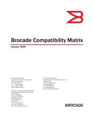
1<strong>Hardware</strong> features<strong>Brocade</strong> <strong>MLX</strong>e routers<strong>Brocade</strong> <strong>MLX</strong>e routers are available in the following models:• <strong>Brocade</strong> <strong>MLX</strong>e-4: 4 interface slots (see Figure 1 on page 2)• <strong>Brocade</strong> <strong>MLX</strong>e-8: 8 interface slots (see Figure 2 on page 3)• <strong>Brocade</strong> <strong>MLX</strong>e-16: 16 interface slots (see Figure 3 on page 5)• <strong>Brocade</strong> <strong>MLX</strong>e-32: 32 interface slots (see Figure 4 on page 7)The following sections described the components you can install in the router slots. For a detailedlist of components that ships with each router, refer to Appendix A, “<strong>Brocade</strong> <strong>MLX</strong>e Chassisbundles”.<strong>Brocade</strong> <strong>MLX</strong>e-4 router componentsYou can install the following components in the router slots:• Up to two management modules (one active <strong>and</strong> one redundant).• Up to three switch fabric modules.• Up to four interface modules.• Up to four power supplies (AC or DC).For a detailed list of components that ships with each router, refer to Appendix A, “<strong>Brocade</strong> <strong>MLX</strong>eChassis bundles”.Figure 1 displays the <strong>Brocade</strong> <strong>MLX</strong>e-4 router.FIGURE 1<strong>Brocade</strong> <strong>MLX</strong>e-4 router21345678 91011 12 13 141 Interface slot 2 4 ESD connector 7 Interface slot 3 10 Interface slot 42 Switch fabric slot 2 5 Interface slot 1 8 Management slot 1 11-14 Power supplies3 Switch fabric slot 3 6 Switch fabric slot 1 9 Management slot 22 <strong>Brocade</strong> <strong>MLX</strong> <strong>Series</strong> <strong>and</strong> <strong>Brocade</strong> <strong>NetIron</strong> <strong>XMR</strong> <strong>Hardware</strong> Installation Guide53-1002373-02
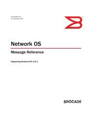
<strong>Hardware</strong> features 1<strong>Brocade</strong> <strong>MLX</strong>e-8 router componentsYou can install the following components in the router slots:• Up to two management modules (one active <strong>and</strong> one redundant).• Up to three switch fabric modules.• Up to eight interface modules.• Up to four power supplies (AC or DC).For a detailed list of components that ships with each router, refer to Appendix A, “<strong>Brocade</strong> <strong>MLX</strong>eChassis bundles”.Figure 2 displays the <strong>Brocade</strong> <strong>MLX</strong>e-8 router.FIGURE 2<strong>Brocade</strong> <strong>MLX</strong>e-8 router1 23456810791112181314 15 16 171 Interface slot 1 6 Switch fabric slot 2 11 Interface slot 8 16 Power supply slot 32 interface slot 2 7 Switch fabric slot 3 12 Management slot 1 17 Power supply slot 43 Interface slot 3 8 Interface slot 5 13 Management slot 2 18 ESD connector4 Interface slot 4 9 Interface slot 6 14 Power supply slot 15 Switch fabric slot 1 10 Interface slot 7 15 Power supply slot 2<strong>Brocade</strong> <strong>MLX</strong> <strong>Series</strong> <strong>and</strong> <strong>Brocade</strong> <strong>NetIron</strong> <strong>XMR</strong> <strong>Hardware</strong> Installation Guide 353-1002373-02
1<strong>Hardware</strong> features<strong>Brocade</strong> <strong>MLX</strong>e-16 router componentsYou can install the following components in the router slots:• Up to two management modules (one active <strong>and</strong> one redundant).• Up to four switch fabric modules.• Up to 16 interface modules.• Up to eight power supplies (AC or DC).For a detailed list of components that ships with each router, refer to Appendix A, “<strong>Brocade</strong> <strong>MLX</strong>eChassis bundles”.4 <strong>Brocade</strong> <strong>MLX</strong> <strong>Series</strong> <strong>and</strong> <strong>Brocade</strong> <strong>NetIron</strong> <strong>XMR</strong> <strong>Hardware</strong> Installation Guide53-1002373-02
<strong>Hardware</strong> features 1Figure 3 displays the <strong>Brocade</strong> <strong>MLX</strong>e-16 router.FIGURE 3<strong>Brocade</strong> <strong>MLX</strong>e-16 router135717199111323152122246816141210182024282529263027311-16 Interface slots 1-16 20 Switch fabric slot 4 24-31 Power supplies17 Switch fabric slot 1 21 Management slot 118 Switch fabric slot 2 22 Management slot 219 Switch fabric slot 3 23 ESD connector<strong>Brocade</strong> <strong>MLX</strong> <strong>Series</strong> <strong>and</strong> <strong>Brocade</strong> <strong>NetIron</strong> <strong>XMR</strong> <strong>Hardware</strong> Installation Guide 553-1002373-02
1<strong>Hardware</strong> features<strong>Brocade</strong> <strong>MLX</strong>e-32 router componentsYou can install the following components in the router slots:• Up to two management modules.• Up to eight switch fabric modules.• Up to 32 interface modules.• Up to eight power supplies (AC or DC).For a detailed list of components that ships with each router, refer to Appendix A, “<strong>Brocade</strong> <strong>MLX</strong>eChassis bundles”.6 <strong>Brocade</strong> <strong>MLX</strong> <strong>Series</strong> <strong>and</strong> <strong>Brocade</strong> <strong>NetIron</strong> <strong>XMR</strong> <strong>Hardware</strong> Installation Guide53-1002373-02
AC OKDC OKALMAC OKDC OKALMAC OKDC OKALMAC OKDC OKALMAC OKDC OKALMAC OKDC OKALMAC OKDC OKALMAC OKDC OK<strong>Hardware</strong> features 1Figure 4 displays the <strong>Brocade</strong> <strong>MLX</strong>e-32 router.FIGURE 4<strong>Brocade</strong> <strong>MLX</strong>e-32 router1PwrActivePwrActive3 5 7 33 35 911 13 15PwrActive2 4 6 8 34 41 36 10 12PwrActive14 1643 4344PwrActive17 19 21 23 37 39 25 27 29 31PwrActivePwrActive18 20 22 24 38 42 40 26 28 30 32PwrActive46 47454849ALM5250 511-32 Interface slots 1-32 38 Switch fabric slot 6 44 ESD connector 50 Power supply 633 Switch fabric slot 1 39 Switch fabric slot 7 45 Power supply 1 51 Power supply 734 Switch fabric slot 2 40 Switch fabric slot 8 46 Power supply 2 52 Power supply 835 Switch fabric slot 3 41 Management slot 1 47 Power supply 336 Switch fabric slot 4 42 Management slot 2 48 Power supply 437 Switch fabric slot 5 43 Captive screws 49 Power supply 5<strong>Brocade</strong> <strong>MLX</strong> <strong>Series</strong> <strong>and</strong> <strong>Brocade</strong> <strong>NetIron</strong> <strong>XMR</strong> <strong>Hardware</strong> Installation Guide 753-1002373-02
1<strong>Hardware</strong> features<strong>Brocade</strong> <strong>MLX</strong> routers<strong>Brocade</strong> <strong>MLX</strong> routers are available in the following models:• <strong>Brocade</strong> <strong>MLX</strong>-4: 4 interface slots (see Figure 5 on page 8)• <strong>Brocade</strong> <strong>MLX</strong>-8: 8 interface slots (see Figure 6 on page 9)• <strong>Brocade</strong> <strong>MLX</strong>-16: 16 interface slots (see Figure 7 on page 10)• <strong>Brocade</strong> <strong>MLX</strong>-32: 32 interface slots (see Figure 8 on page 12)The following sections described the components you can install in the router slots.<strong>Brocade</strong> <strong>MLX</strong>-4 router componentsYou can install the following components in the router slots:• Up to two management modules (one active <strong>and</strong> one redundant).• Up to three switch fabric modules.• Up to four interface modules.• Up to three power supplies (AC or DC).Figure 5 displays the <strong>Brocade</strong> <strong>MLX</strong>-4 router.FIGURE 5<strong>Brocade</strong> <strong>MLX</strong>-4 router1 2 3 41112513678 9 101 Interface slot 2 4 ESD connector 7 Interface slot 3 10 Interface slot 42 Switch fabric slot 2 5 Interface slot 1 8 Management slot 1 11 - 13 Three power supplies3 Switch fabric slot 3 6 Switch fabric slot 1 9 Management slot 28 <strong>Brocade</strong> <strong>MLX</strong> <strong>Series</strong> <strong>and</strong> <strong>Brocade</strong> <strong>NetIron</strong> <strong>XMR</strong> <strong>Hardware</strong> Installation Guide53-1002373-02
<strong>Hardware</strong> features 1<strong>Brocade</strong> <strong>MLX</strong>-8 router componentsYou can install the following components in the router slots:• Up to two management modules (one active <strong>and</strong> one redundant).• Up to three switch fabric modules.• Up to eight interface modules.• Up to four power supplies (AC or DC).Figure 6 displays the <strong>Brocade</strong> <strong>MLX</strong>-8 router.FIGURE 6<strong>Brocade</strong> <strong>MLX</strong>-8 router1 234568101279111314 1516 17181 Interface slot 1 6 Switch fabric slot 2 11 Interface slot 8 16 Power supply slot 32 interface slot 2 7 Switch fabric slot 3 12 Management slot 1 17 Power supply slot 43 Interface slot 3 8 Interface slot 5 13 Management slot 2 18 ESD connector4 Interface slot 4 9 Interface slot 6 14 Power supply slot 15 Switch fabric slot 1 10 Interface slot 7 15 Power supply slot 2<strong>Brocade</strong> <strong>MLX</strong> <strong>Series</strong> <strong>and</strong> <strong>Brocade</strong> <strong>NetIron</strong> <strong>XMR</strong> <strong>Hardware</strong> Installation Guide 953-1002373-02
1<strong>Hardware</strong> features<strong>Brocade</strong> <strong>MLX</strong>-16 router componentsYou can install the following components in the router slots:• Up to two management modules (one active <strong>and</strong> one redundant).• Up to four switch fabric modules.• Up to 16 interface modules.• Up to eight power supplies (AC or DC).Figure 7 displays the <strong>Brocade</strong> <strong>MLX</strong>-16 router.FIGURE 7<strong>Brocade</strong> <strong>MLX</strong>-16 router135717199111323152122246816141210182024282529263027311-16 Interface slots 1-16 20 Switch fabric slot 4 24-31 Power supplies17 Switch fabric slot 1 21 Management slot 118 Switch fabric slot 2 22 Management slot 219 Switch fabric slot 3 23 ESD connector10 <strong>Brocade</strong> <strong>MLX</strong> <strong>Series</strong> <strong>and</strong> <strong>Brocade</strong> <strong>NetIron</strong> <strong>XMR</strong> <strong>Hardware</strong> Installation Guide53-1002373-02
<strong>Hardware</strong> features 1<strong>Brocade</strong> <strong>MLX</strong>-32 router componentsYou can install the following components in the router slots:• Two management modules.• Up to eight switch fabric modules.• Up to 32 interface modules.• Up to eight power supplies (AC or DC).<strong>Brocade</strong> <strong>MLX</strong> <strong>Series</strong> <strong>and</strong> <strong>Brocade</strong> <strong>NetIron</strong> <strong>XMR</strong> <strong>Hardware</strong> Installation Guide 1153-1002373-02
AC OKDC OKALMAC OKDC OKALMAC OKDC OKALMAC OKDC OKALMAC OKDC OKALMAC OKDC OKALMAC OKDC OKALMAC OKDC OKALM1<strong>Hardware</strong> featuresFigure 8 displays the <strong>Brocade</strong> <strong>MLX</strong>-32 router.FIGURE 8<strong>Brocade</strong> <strong>MLX</strong>-32 router1PwrActivePwrActive3 5 7 33 35 911 13 15PwrActive2 4 6 8 34 41 36 10 12PwrActive14 16434344PwrActive17 19 21 23 37 39 25 27 29 31PwrActivePwrActive18 20 22 24 38 42PwrActive40 26 28 30 3246 474548495250 511-32 Interface slots 1-32 38 Switch fabric slot 6 44 ESD connector 50 Power supply 633 Switch fabric slot 1 39 Switch fabric slot 7 45 Power supply 1 51 Power supply 734 Switch fabric slot 2 40 Switch fabric slot 8 46 Power supply 2 52 Power supply 835 Switch fabric slot 3 41 Management slot 1 47 Power supply 336 Switch fabric slot 4 42 Management slot 2 48 Power supply 437 Switch fabric slot 5 43 Captive screws 40 Power supply 512 <strong>Brocade</strong> <strong>MLX</strong> <strong>Series</strong> <strong>and</strong> <strong>Brocade</strong> <strong>NetIron</strong> <strong>XMR</strong> <strong>Hardware</strong> Installation Guide53-1002373-02
<strong>Hardware</strong> features 1<strong>Brocade</strong> <strong>NetIron</strong> <strong>XMR</strong> routers<strong>Brocade</strong> <strong>NetIron</strong> <strong>XMR</strong> <strong>Series</strong> routers are available in the following models:• <strong>Brocade</strong> <strong>NetIron</strong> <strong>XMR</strong> 4000: 4 interface slots (see Figure 9 on page 13).• <strong>Brocade</strong> <strong>NetIron</strong> <strong>XMR</strong> 8000: 8 interface slots (see Figure 10 on page 14).• <strong>Brocade</strong> <strong>NetIron</strong> <strong>XMR</strong> 16000: 16 interface slots (see Figure 11 on page 15).• <strong>Brocade</strong> <strong>NetIron</strong> <strong>XMR</strong> 32000: 32 interface slots (see Figure 12 on page 16).The following sections described the components you can install in the router slots. For a detailedlist of components that ships with each router, refer to >>>>>>>>>>.<strong>Brocade</strong> <strong>NetIron</strong> <strong>XMR</strong> 4000 router componentsYou can install the following components in the router slots:• Up to two management modules (one active <strong>and</strong> one redundant).• Up to three switch fabric modules.• Up to four interface modules.• Up to three power supplies (AC or DC).Figure 9 displays the <strong>Brocade</strong> <strong>NetIron</strong> <strong>XMR</strong> 4000 router.FIGURE 9<strong>Brocade</strong> <strong>NetIron</strong> <strong>XMR</strong> 4000 router1 2 3 41156712138 9 101 Interface slot 2 4 ESD connector 7 Interface slot 3 10 Interface slot 42 Switch fabric slot 2 5 Interface slot 1 8 Management slot 1 11 -13 Three power supplies3 Switch fabric slot 3 6 Switch fabric slot 1 9 Management slot 2installed in rear ofdevice<strong>Brocade</strong> <strong>MLX</strong> <strong>Series</strong> <strong>and</strong> <strong>Brocade</strong> <strong>NetIron</strong> <strong>XMR</strong> <strong>Hardware</strong> Installation Guide 1353-1002373-02
1<strong>Hardware</strong> features<strong>Brocade</strong> <strong>NetIron</strong> <strong>XMR</strong> 8000 router componentsYou can install the following components in the router slots:• Up to two management modules (one active <strong>and</strong> one redundant).• Up to three switch fabric modules.• Up to eight interface modules.• Up to four power supplies (AC or DC).Figure 10 displays the <strong>Brocade</strong> <strong>NetIron</strong> <strong>XMR</strong> 8000 router.FIGURE 10<strong>Brocade</strong> <strong>NetIron</strong> <strong>XMR</strong> 8000 router1 234568101279111314 1516 17181 Interface slot 1 6 Switch fabric slot 2 11 Interface slot 8 16 Power supply slot 32 interface slot 2 7 Switch fabric slot 3 12 Management slot 1 17 Power supply slot 43 Interface slot 3 8 Interface slot 5 13 Management slot 2 18 ESD connector4 Interface slot 4 9 Interface slot 6 14 Power supply slot 15 Switch fabric slot 1 10 Interface slot 7 15 Power supply slot 214 <strong>Brocade</strong> <strong>MLX</strong> <strong>Series</strong> <strong>and</strong> <strong>Brocade</strong> <strong>NetIron</strong> <strong>XMR</strong> <strong>Hardware</strong> Installation Guide53-1002373-02
<strong>Hardware</strong> features 1<strong>Brocade</strong> <strong>NetIron</strong> <strong>XMR</strong> 16000 router componentsYou can install the following components in the router slots:• Up to two management modules (one active <strong>and</strong> one redundant).• Up to four switch fabric modules.• Up to 16 interface modules.• Up to eight power supplies (AC or DC)Figure 11 displays the <strong>Brocade</strong> <strong>NetIron</strong> <strong>XMR</strong> 16000 router.FIGURE 11<strong>Brocade</strong> <strong>NetIron</strong> <strong>XMR</strong> 16000 router135717199111323152122246816141210182024282529263027311-16 Interface slots 1-16 20 Switch fabric slot 4 24-31 Power supplies17 Switch fabric slot 1 21 Management slot 118 Switch fabric slot 2 22 Management slot 219 Switch fabric slot 3 23 ESD connector<strong>Brocade</strong> <strong>MLX</strong> <strong>Series</strong> <strong>and</strong> <strong>Brocade</strong> <strong>NetIron</strong> <strong>XMR</strong> <strong>Hardware</strong> Installation Guide 1553-1002373-02
AC OKDC OKALMAC OKDC OKALMAC OKDC OKALMAC OKDC OKALMAC OKDC OKALMAC OKDC OKALMAC OKDC OKALMAC OKDC OK1<strong>Hardware</strong> features<strong>Brocade</strong> <strong>NetIron</strong> <strong>XMR</strong> 32000 router componentsYou can install the following components in the router slots:• Up to two management modules (one active <strong>and</strong> one redundant).• Up to eight switch fabric modules.• Up to 32 interface modules.• Up to eight power supplies (AC or DC).Figure 12 displays the <strong>Brocade</strong> <strong>NetIron</strong> <strong>XMR</strong> 32000 router.FIGURE 12<strong>Brocade</strong> <strong>NetIron</strong> <strong>XMR</strong> 32000 routerr1PwrActivePwrActive3 5 7 33 35 911 13 15PwrActive2 4 6 8 34 41 36 10 12PwrActive14 1643 4344PwrActive17 19 21 23 37 39 25 27 29 31PwrActivePwrActive18 20 22 24 38 42 40 26 28 30 32PwrActive46 47454849ALM5250 5116 <strong>Brocade</strong> <strong>MLX</strong> <strong>Series</strong> <strong>and</strong> <strong>Brocade</strong> <strong>NetIron</strong> <strong>XMR</strong> <strong>Hardware</strong> Installation Guide53-1002373-02
Router modules 11-32 Interface slots 1-32 38 Switch fabric slot 6 44 ESD connector 50 Power supply 633 Switch fabric slot 1 39 Switch fabric slot 7 45 Power supply 1 51 Power supply 734 Switch fabric slot 2 40 Switch fabric slot 8 46 Power supply 2 52 Power supply 835 Switch fabric slot 3 41 Management slot 1 47 Power supply 336 Switch fabric slot 4 42 Management slot 2 48 Power supply 437 Switch fabric slot 5 43 Captive screws 49 Power supply 5Router modulesThis section describes management modules, interface modules, <strong>and</strong> switch fabric modules.Management modules<strong>Brocade</strong> <strong>MLX</strong>, <strong>Brocade</strong> <strong>MLX</strong>e, <strong>and</strong> <strong>Brocade</strong> <strong>NetIron</strong> <strong>XMR</strong> routers support the following managementmodules types:• MR management module• MR2 management moduleTable 1 lists the management modules available for <strong>Brocade</strong> <strong>MLX</strong>e, <strong>Brocade</strong> <strong>MLX</strong>, <strong>and</strong> <strong>Brocade</strong><strong>NetIron</strong> <strong>XMR</strong> routers.TABLE 1 Management modules for all <strong>Brocade</strong> <strong>MLX</strong> <strong>Series</strong> <strong>and</strong> <strong>Brocade</strong> <strong>NetIron</strong> <strong>XMR</strong> routersPart numberDescriptionNI-<strong>MLX</strong>-MRNI-<strong>MLX</strong>-32-MRNI-<strong>XMR</strong>-MRNI-<strong>XMR</strong>-32-MRBR-<strong>MLX</strong>-MR2-MBR-<strong>MLX</strong>-MR2-X(MR)<strong>Brocade</strong> <strong>MLX</strong>e <strong>and</strong> <strong>Brocade</strong> <strong>MLX</strong> management module, 1 GB SDRAM, dual auxiliary flashslots, EIA or TIA-232 <strong>and</strong> 10/100/1000 Ethernet ports for out-of-b<strong>and</strong> management.(MR)<strong>Brocade</strong> <strong>MLX</strong>e-32 <strong>and</strong> <strong>Brocade</strong> <strong>MLX</strong>-32 management module, 1 GB SDRAM, dual auxiliaryflash slots, EIA or TIA-232 <strong>and</strong> 10/100/1000 Ethernet ports for out-of-b<strong>and</strong> management.(MR)<strong>Brocade</strong> <strong>NetIron</strong> <strong>XMR</strong> management module, 2 GB SDRAM, dual auxiliary flash slots, EIA orTIA-232 <strong>and</strong> 10/100/1000 Ethernet ports for out-of-b<strong>and</strong> management.(MR)<strong>Brocade</strong> <strong>NetIron</strong> <strong>XMR</strong> 32000 management module, 2 GB SDRAM, dual auxiliary flash slots,EIA or TIA-232 <strong>and</strong> 10/100/1000 Ethernet ports for out-of-b<strong>and</strong> management.(MR2)<strong>MLX</strong>e/<strong>MLX</strong> Gen2 management (M) module for 4-, 8- <strong>and</strong> 16-slot systems. Includes 4 GBRAM, 1 internal compact flash drive (2GB), 1 external compact flash slot with included 2GBcard, RS-232 serial console port <strong>and</strong> 10/100/1000 Ethernet port for management.(MR2)<strong>MLX</strong>e/<strong>XMR</strong> Gen2 management (X) module for 4-, 8- <strong>and</strong> 16-slot systems. Includes 4 GBRAM, 1 internal compact flash drive (2GB), 1 external compact flash slot with included 2GBcard, RS-232 serial console port <strong>and</strong> 10/100/1000 Ethernet port for management.<strong>Brocade</strong> <strong>MLX</strong> <strong>Series</strong> <strong>and</strong> <strong>Brocade</strong> <strong>NetIron</strong> <strong>XMR</strong> <strong>Hardware</strong> Installation Guide 1753-1002373-02
1Router modulesTABLE 1Part numberManagement modules for all <strong>Brocade</strong> <strong>MLX</strong> <strong>Series</strong> <strong>and</strong> <strong>Brocade</strong> <strong>NetIron</strong> <strong>XMR</strong> routers (Continued)DescriptionBR-<strong>MLX</strong>-32-MR2-MBR-<strong>MLX</strong>-32-MR2-X(MR2)<strong>MLX</strong>e/<strong>MLX</strong> Gen2 management (M) module for 32-slot systems. Includes 4 GB RAM, 1internal compact flash drive (2GB), 1 external compact flash slot with included 2GB card,RS-232 serial console port <strong>and</strong> 10/100/1000 Ethernet port for management.(MR2)<strong>MLX</strong>e/<strong>XMR</strong> Gen2 management (X) module for 32-slot systems. Includes 4 GB RAM, 1internal compact flash drive (2GB), 1 external compact flash slot with included 2GB card,RS-232 serial console port <strong>and</strong> 10/100/1000 Ethernet port for management.The management module controls the hardware components, runs the networking protocols, <strong>and</strong>provides the Real Time Operating System (RTOS).Each router requires one management module, <strong>and</strong> can accommodate a second module forredundancy. A redundant management module works in conjunction with the active managementmodule. If the active module becomes unavailable, the redundant management moduleautomatically takes over the system operation, minimizing system downtime. For information aboutthe redundancy feature, refer to the “Using a Redundant Management Module” chapter in the<strong>Brocade</strong> <strong>MLX</strong> <strong>Series</strong> <strong>and</strong> <strong>Brocade</strong> <strong>NetIron</strong> Family Configuration Guide.Management modules are installed in dedicated slots marked M1 <strong>and</strong> M2. By default, the moduleinstalled in slot M1 is the active management module.Management modules are hot-swappable, which means you can remove <strong>and</strong> replace them withoutpowering down the system.NOTEMR <strong>and</strong> MR2 management modules cannot be mixed in the same chassis.NOTEPrior to installing or replacing the MR2 management module, you must read the <strong>Hardware</strong>Installation Notes that shipped with the hardware.NOTEAlthough management modules are designed to be hot-swappable, you must upgrade the softwareon all interface modules <strong>and</strong> management modules to the appropriate software release beforeinstalling them. For more information on the appropriate software release, refer to the <strong>Hardware</strong>Installation Notes that shipped with the management module.Figure 13 shows a management module front panel.FIGURE 13MR management module front panelRX-BI-MRPwrActiveConsole10/100/1000Port 1Port 218 <strong>Brocade</strong> <strong>MLX</strong> <strong>Series</strong> <strong>and</strong> <strong>Brocade</strong> <strong>NetIron</strong> <strong>XMR</strong> <strong>Hardware</strong> Installation Guide53-1002373-02
Router modules 1Figure 14 shows the MR2 management module front panel.FIGURE 14MR2 management module front panelThe front panel of the management module contains the following control features:• Two auxiliary flash slots (available on MR management modules only)• Compact flash slot (available on MR2 management modules only)• Console port• A 10/100/1000 Ethernet port• Six LEDsAuxiliary flash slotsAuxiliary flash slots support flash PC cards where you can store boot images, startup <strong>and</strong> runningconfiguration files, <strong>and</strong> other system files, in addition to what is stored in system flash memory.This allows you to perform system management tasks, such as copying files between flash PCcards, or copying files between a flash PC card <strong>and</strong> flash memory.For maximum performance, it is recommended that you use <strong>Brocade</strong> auxiliary flash cards, partnumber FLASH-PCC, which can be ordered from <strong>Brocade</strong>. <strong>Brocade</strong> auxiliary flash cards ship withthe label on the bottom of the card; take caution to insert the card with the label on the bottomside.NOTESome older auxiliary flash cards can be inserted the wrong way in the slot because there is noindication in the card about which is the right way. If you insert the card backwards, you will seecontinuous messages in the console <strong>and</strong> the card inserted/ card removed syslog. If this occurs, youmust remove the card <strong>and</strong> reinsert it the correct way.External compact flashMR2 management modules do not contain an auxiliary flash slot. Instead, they contain a 2 GBinternal compact flash card <strong>and</strong> an external compact flash drive. MR2 management modules comewith a factory installed compact flash card in the external compact flash slot. The internal compactflash provides greater storage space for image retention, improving the upgrade process.NOTEDo not use compact flash cards over 2GB; they will render the system unstable.The internal compact flash card cannot be accessed for removal or replacement.The external compact flash slot allows you to insert a 2 GB compact flash card. If you need toreplace or add an additional compact flash card, contact <strong>Brocade</strong> technical support.<strong>Brocade</strong> <strong>MLX</strong> <strong>Series</strong> <strong>and</strong> <strong>Brocade</strong> <strong>NetIron</strong> <strong>XMR</strong> <strong>Hardware</strong> Installation Guide 1953-1002373-02
1Router modulesConsole portThe console port is a st<strong>and</strong>ard DB-9 serial connector through which you can attach a PC or terminalto configure the router using the CLI.NOTEThe console port interfaces the control plane only. It does not interface the data plane.10/100/1000 Ethernet portManagement modules also contain a 10BaseT, 100BaseTX, or 1000BaseTX auto-sensing,auto-negotiating Ethernet port. This port has an RJ45 unshielded twisted pair (UTP) connector.Typical uses of this port include, but are not limited to, the following:• Connecting a PC to configure, monitor, <strong>and</strong> manage the system through a Telnet or SSHv2connection.• Connecting to the 10BaseT, 100BaseTX, or 1000BaseTX port for connectivity to your existingmanagement network. You can then access the router <strong>and</strong> configure, monitor, <strong>and</strong> manage thesystem from a management station.NOTEThe existing management network into which you can connect the 10/100/1000 Ethernet portmust be separate <strong>and</strong> isolated from the network over which user packets are switched <strong>and</strong> routed.For information about the functionality of the management port, refer to “Underst<strong>and</strong>ingmanagement port functions” on page 317.For information about connecting a PC to the 10/100/1000 Ethernet port, refer to “Attaching amanagement station” on page 227.Unlike the 10 Gbps Ethernet ports, the out-of-b<strong>and</strong> port does not interface the LAN. Instead, theout-of-b<strong>and</strong> port can interface with a separate system management network, <strong>and</strong> allows you to dothe following tasks:• Access the router through Telnet, the Web management interface, or the IronView NetworkManager software.• Access a TFTP server to perform system upgrade tasks.• Access SNMP messages or protocol data units (PDUs).• Send Syslog packets.• Access the system through RADIUS AAA.20 <strong>Brocade</strong> <strong>MLX</strong> <strong>Series</strong> <strong>and</strong> <strong>Brocade</strong> <strong>NetIron</strong> <strong>XMR</strong> <strong>Hardware</strong> Installation Guide53-1002373-02
Router modules 1Management module LEDsThe LEDs on all management module models are the same. Table 2 describes the LEDs on themanagement module.TABLE 2 Management module LEDsLED Position State MeaningPort 1<strong>and</strong>Port 2Each adjacent tothe auxiliary flashslot that itrepresentsOn or blinkingOffThe software is currently accessing the auxiliaryflash card.The software is not currently accessing a auxiliaryflash card, although there is one inserted in the slot.Active Lower Left On The module is functioning as the activemanagement module.OffThe module is functioning as the redundantmanagement module.Pwr Upper Left On The module is receiving power.10/100/1000Ethernet Port10/100/1000Ethernet PortAbove <strong>and</strong> right ofRJ45 connectorAbove <strong>and</strong> left ofRJ45 connectorOffOn (Green)OffOn or blinking(Yellow)Off for anextended periodThe module is not receiving power.A link is established with the remote port.No link is established with the remote port.The port is transmitting <strong>and</strong> receiving packets.The port is not transmitting or receiving packets.<strong>Brocade</strong> <strong>MLX</strong> <strong>Series</strong> <strong>and</strong> <strong>Brocade</strong> <strong>NetIron</strong> <strong>XMR</strong> <strong>Hardware</strong> Installation Guide 2153-1002373-02
1Router modulesInterface modulesInterface modules for <strong>Brocade</strong> <strong>MLX</strong>, <strong>Brocade</strong> <strong>MLX</strong>e, <strong>and</strong> <strong>Brocade</strong> <strong>NetIron</strong> <strong>XMR</strong> routers are availablein two types:• Gen-1 interface modules• Gen-2 interface modules, which provide additional functionality, more memory, <strong>and</strong> higheroperation speeds.Table 3 lists the interface modules that are available for <strong>Brocade</strong> <strong>MLX</strong> <strong>Series</strong> <strong>and</strong> <strong>Brocade</strong> <strong>NetIron</strong><strong>XMR</strong> routers.TABLE 3 Interface modules for all <strong>Brocade</strong> <strong>MLX</strong> <strong>Series</strong> <strong>and</strong> <strong>Brocade</strong> <strong>NetIron</strong> <strong>XMR</strong> routersSKU Ports Supported on DescriptionNI-<strong>MLX</strong>-10GX2 2 <strong>MLX</strong>e, <strong>MLX</strong> <strong>NetIron</strong> <strong>MLX</strong> <strong>Series</strong> 2-port 10-GbE module withIPv4/IPv6/MPLS hardware support - requires XFP opticsNI-<strong>XMR</strong>-10GX2 2 <strong>XMR</strong> (no longeravailable)NI-X-OC192-1 2 <strong>MLX</strong>e, <strong>MLX</strong>, <strong>XMR</strong> (nolonger available)Gen-1 2-port 10-Gbps Ethernet module - requires XFPoptics. IPv4, IPv6, MPLS supportGen-1 2-port OC-192 POS/SDH module. IPv4, IPv6,MPLS support. Requires SFP optics.NI-X-OC48X2 2 <strong>MLX</strong>e, <strong>MLX</strong>, <strong>XMR</strong> <strong>NetIron</strong> <strong>XMR</strong>/<strong>MLX</strong> 2-port OC-12/48 (STM-4/16) Packetover SONET/SDH module interface module withIPv4/IPv6/MPLS hardware support. Requires SFPoptics.BR-<strong>MLX</strong>-100GX-1 1 <strong>MLX</strong>e, <strong>MLX</strong>, <strong>XMR</strong> <strong>MLX</strong>E/<strong>XMR</strong>/<strong>MLX</strong> 1-port 100-GbE (X) Module withIPv4/IPv6/MPLS hardware support - requires CFPoptics. Supports 1M IPv4 routes in FIB in <strong>XMR</strong> mode <strong>and</strong>512K IPv4 routes in <strong>MLX</strong> mode. Requires high speedswitch fabric modules. License upgradable to 2-ports ona <strong>MLX</strong>e.BR-<strong>MLX</strong>-100GX-2 2 <strong>MLX</strong>e, <strong>MLX</strong> <strong>MLX</strong>E 2-port 100-GbE (X) Module with IPv4/IPv6/MPLShardware support - requires CFP optics. Supports 1MIPv4 routes in FIB in <strong>XMR</strong> mode <strong>and</strong> 512K IPv4 routes in<strong>MLX</strong> mode. Requires high speed switch fabric modules.NI-<strong>MLX</strong>-10GX4 4 <strong>MLX</strong>e, <strong>MLX</strong> <strong>NetIron</strong> <strong>MLX</strong> <strong>Series</strong> 4-port 10-GbE module withIPv4/IPv6/MPLS hardware support - requires XFP opticsNI-<strong>XMR</strong>-10Gx4 4 <strong>XMR</strong> <strong>NetIron</strong> <strong>XMR</strong> <strong>Series</strong> 4-port 10-GbE module withIPv4/IPv6/MPLS hardware support - requires XFP opticsNI-X-OC48X4 4 <strong>MLX</strong>e, <strong>MLX</strong>, <strong>XMR</strong> <strong>NetIron</strong> <strong>XMR</strong>/<strong>MLX</strong> 4-port OC-12/48 (STM-4/16) Packetover SONET/SDH module interface module withIPv4/IPv6/MPLS hardware support. Requires SFPoptics.BR-<strong>MLX</strong>-10GX4-X 4 <strong>MLX</strong>e, <strong>MLX</strong>, <strong>XMR</strong> <strong>XMR</strong>/<strong>MLX</strong>e 4-port 10-GbE (X) module withIPv4/IPv6/MPLS hardware support - requires XFP optics.Supports 1M IPv4 routes in FIB.BR-<strong>MLX</strong>-10Gx4-X-ML 4 <strong>MLX</strong>e, <strong>MLX</strong>, <strong>XMR</strong> <strong>MLX</strong>/<strong>MLX</strong>e 4-port 10-GbE (ML) module withIPv4/IPv6/MPLS hardware support-requires XFP optics.Supports 512K IPv4 routes in FIB. License Upgradableto "X" scalability (1M IPv4 routes in FIB).22 <strong>Brocade</strong> <strong>MLX</strong> <strong>Series</strong> <strong>and</strong> <strong>Brocade</strong> <strong>NetIron</strong> <strong>XMR</strong> <strong>Hardware</strong> Installation Guide53-1002373-02
Router modules 1TABLE 3 Interface modules for all <strong>Brocade</strong> <strong>MLX</strong> <strong>Series</strong> <strong>and</strong> <strong>Brocade</strong> <strong>NetIron</strong> <strong>XMR</strong> routers (Continued)SKU Ports Supported on DescriptionNI-X-OC48X8 8 <strong>MLX</strong>e, <strong>MLX</strong>, <strong>XMR</strong> <strong>NetIron</strong> <strong>XMR</strong>/<strong>MLX</strong> 8-port OC-12/48 (STM-4/16) Packetover SONET/SDH module interface module withIPv4/IPv6/MPLS hardware support. Requires SFPoptics.NI-<strong>MLX</strong>-10GX8-M 8 <strong>MLX</strong>e, <strong>MLX</strong> <strong>Brocade</strong> <strong>MLX</strong> <strong>Series</strong> 8-port 10-GbE (M) module withIPv4/IPv6/MPLS hardware support - requires SFPPoptics. Supports 512K IPv4 routes in FIB. Requires highspeed switch fabric modulesNI-<strong>MLX</strong>-10GX8-D 8 <strong>MLX</strong>e, <strong>MLX</strong> <strong>Brocade</strong> <strong>MLX</strong> <strong>Series</strong> 8-port 10-GbE (D) module withIPv4/IPv6 hardware support - requires SFPP optics.Supports 256K IPv4 routes in FIB. Doesn't supportMPLS. Requires high speed switch fabric modulesBR-<strong>MLX</strong>-10GX8-X 8 <strong>MLX</strong>e, <strong>MLX</strong>, <strong>XMR</strong> <strong>MLX</strong>e/<strong>XMR</strong> 8-port 10-GbE (X) module withIPv4/IPv6/MPLS hardware support-requires SFPPoptics. Supports 1M IPv4 routes in FIB. Requires highspeed switch fabric modules.NI-<strong>MLX</strong>-1GX20-SFP 20 <strong>MLX</strong>e, <strong>MLX</strong> <strong>NetIron</strong> <strong>MLX</strong> <strong>Series</strong> 20-port FE/GE (100/1000) modulewith IPv4/IPv6/MPLS hardware support - requires SFPoptics. Note: Copper SFPs are supported at 1000MbpsonlyNI-<strong>XMR</strong>-1GX20-SFP 20 <strong>XMR</strong> <strong>NetIron</strong> <strong>XMR</strong> <strong>Series</strong> 20-port FE/GE (100/1000) modulewith IPv4/IPv6/MPLS hardware support - requires SFPoptics. Note: Copper SFPs are supported at 1000MbpsonlyNI-<strong>MLX</strong>-1GX20-GC 20 <strong>MLX</strong>e, <strong>MLX</strong> <strong>NetIron</strong> <strong>MLX</strong> <strong>Series</strong> 20-port 10/100/1000 coppermodule with IPv4/IPv6/MPLS hardware supportNI-<strong>XMR</strong>-1Gx20-GC 20 <strong>XMR</strong> <strong>NetIron</strong> <strong>XMR</strong> <strong>Series</strong> 20-port 10/100/1000 coppermodule with IPv4/IPv6/MPLS hardware supportBR-<strong>MLX</strong>-1GCX24-X 24 <strong>MLX</strong>e, <strong>MLX</strong>, <strong>XMR</strong> <strong>XMR</strong>/<strong>MLX</strong>E 24-port 1-GbE (X) Copper (RJ-45) Module.Supports 1M IPv4 routes in FIB.BR-<strong>MLX</strong>-1GCX24-X-ML 24 <strong>MLX</strong>e, <strong>MLX</strong>, <strong>XMR</strong> <strong>MLX</strong>/<strong>MLX</strong>E 24-port 1-GbE (ML) Copper (RJ-45) Module.Supports 512K IPv4 routes in FIB. License Upgradableto “X” scalability (1M IPv4 routes in FIB).BR-<strong>MLX</strong>-1GFx24-X 24 <strong>MLX</strong>e, <strong>MLX</strong>, <strong>XMR</strong> <strong>XMR</strong>/<strong>MLX</strong>E 24-port 1-GbE (X) Copper (RJ-45) Module.Supports 1M IPv4 routes in FIB.BR-<strong>MLX</strong>-1GFX24-X-ML 24 <strong>MLX</strong>e, <strong>MLX</strong>, <strong>XMR</strong> <strong>MLX</strong>/<strong>MLX</strong>E 24-port 1-GbE (ML) Fiber (SFP) Module.Supports 512K IPv4 routes in FIB. License Upgradableto “X” scalability (1M IPv4 routes in FIB).NI-<strong>MLX</strong>-1GX48-T-A 48 <strong>MLX</strong>e, <strong>MLX</strong> <strong>NetIron</strong> <strong>MLX</strong> <strong>Series</strong> 48-port 10/100/1000Base-T,MRJ21 module with IPv4/IPv6/MPLS hardware support.Requires high speed fans NIBI-16-FAN-EXH-A on <strong>MLX</strong>-16.Depending on your router model, you can install up to 32 single-slot interface modules, or 16double-slot interface modules.Interface modules are hot-swappable, which means you can remove <strong>and</strong> replace them withoutpowering down the system.<strong>Brocade</strong> <strong>MLX</strong> <strong>Series</strong> <strong>and</strong> <strong>Brocade</strong> <strong>NetIron</strong> <strong>XMR</strong> <strong>Hardware</strong> Installation Guide 2353-1002373-02
1Router modulesTable 4provides a compatibility matrix for <strong>MLX</strong>e modules.TABLE 4 <strong>Brocade</strong> <strong>MLX</strong>e module compatibility matrixModule <strong>MLX</strong> <strong>XMR</strong> <strong>MLX</strong>e with <strong>MLX</strong>or MR2-M mgmtmodule<strong>MLX</strong>e with <strong>XMR</strong>or MR2-X mgmtmoduleGeneration(G)FabricCompatibility<strong>MLX</strong> 4x10G Yes No Yes No G1 SFM, hSFM<strong>MLX</strong> 2x10G Yes No Yes No G1 SFM, hSFM<strong>MLX</strong> 20x1G Yes No Yes No G1 SFM, hSFM<strong>MLX</strong>48x1G-T<strong>MLX</strong>8x10G-D<strong>MLX</strong>8x10G-MYes No Yes No G1 SFM, hSFMYes No Yes No G2 hSFMYes No Yes No G2 hSFM<strong>XMR</strong> 4x10G No Yes No Yes G1 SFM, hSFM<strong>XMR</strong> 20x1G No Yes No Yes G1 SFM, hSFMPOS Yes Yes Yes Yes G1 SFM, hSFM24x1G-X Yes Yes++ Yes Yes++ G1 SFM, hSFM4x10G-X Yes Yes++ Yes Yes++ G1 SFM, hSFM8x10G-X Yes Yes Yes Yes G2 hSFM100G Yes Yes Yes Yes G2 hSFMSFM Yes Yes No No G1 N/AhSFM Yes Yes Yes Yes G2 N/A++ Requires “X” scalability requirement100xGbE 2-port interface moduleThe 100xGbE 2-port interface module is supported on all <strong>Brocade</strong> <strong>MLX</strong> <strong>Series</strong> <strong>and</strong> <strong>Brocade</strong> <strong>NetIron</strong><strong>XMR</strong> routers. This interface module has two 100 Gbps CFP optics ports, 2 Gbps memory, aninternal flash of 32MB for local storage of CPU images, <strong>and</strong> 64MB for local storage of FPGAimages. The 100xGbE 2-port interface module supports 1.5 MB buffering per port.NOTEOnly <strong>Brocade</strong> <strong>MLX</strong>e devices support both ports on the 100xGbE module. <strong>Brocade</strong> <strong>MLX</strong> <strong>and</strong> <strong>Brocade</strong><strong>NetIron</strong> <strong>XMR</strong> models support one port only.The 100xGbE interface module occupies two interface module slots in any chassis, with one slotactive <strong>and</strong> one slot inactive. In all devices, the lower number of the two occupied slots becomes theactive slot.NOTEBecause of the possibility of overheating, 2x100GbE interface modules should not be installed inthe top slot of a <strong>Brocade</strong> <strong>MLX</strong> 4-slot chassis.24 <strong>Brocade</strong> <strong>MLX</strong> <strong>Series</strong> <strong>and</strong> <strong>Brocade</strong> <strong>NetIron</strong> <strong>XMR</strong> <strong>Hardware</strong> Installation Guide53-1002373-02
Router modules 1Before you install a 2x100GbE module, you will need to remove the center slot guide that dividesthe slot into two partitions. Do not discard this guide, as you will need it if you ever want to convertthe slot into two slots. For information about how to remove the center guide <strong>and</strong> install high-speedfabric modules, refer to the 2x100GbE module installation instructions in the appropriateinstallation chapter for your router model.NOTEBefore installing the 100GbE module in a chassis, the tm-credit-size must be changed to 1024bytes.You will also need to change the system tm credit size to 1024b (which readies the device toforward 100 Gbps traffic). Log into your system <strong>and</strong> enter the following comm<strong>and</strong>s in theconfiguration level of the CLI. Remember to write to memory <strong>and</strong> reload the device.<strong>Brocade</strong># config<strong>Brocade</strong>(config)# system-init tm-credit-size credit_1024b<strong>Brocade</strong>(config)# exit<strong>Brocade</strong># write memory<strong>Brocade</strong># reloadNOTEThe 100GbE module requires a minimum software version of R05.2.00. Please upgrade all softwareon the system to a minimum version of R05.2.00 before you inst all your 2x100G module.NOTE100xGbE modules require high-speed switch fabric modules to operate.Figure 15 shows the front panel of the 2x100GbE 2-port interface module.FIGURE 15100xGbE 2-port interface module front panel1 2PwrLnk/ActLnk/ActThe front panel contains the following features:• Power LED <strong>and</strong> Lnk/Act LED for each port (as described in Table 5)• Two 100xGbE CFP ports100xGbE interface module LEDsThe LEDs on the 100xGbE interface modules indicate the status of each port, as described inTable 5.TABLE 5100xGbE module LEDsLED Location State MeaningPower (module state) Left side of module Green Module is receiving powerOffModule is not receiving powerLink/Act To the right of each port. Green blinking Port is enabled <strong>and</strong> link is up.OffPort is disabled.<strong>Brocade</strong> <strong>MLX</strong> <strong>Series</strong> <strong>and</strong> <strong>Brocade</strong> <strong>NetIron</strong> <strong>XMR</strong> <strong>Hardware</strong> Installation Guide 2553-1002373-02
1Router modulesCFP opticsThe 100 GbE interface module is 802.3ba compliant, supports CFP-based optics, <strong>and</strong> isbackwards-compatible with existing <strong>Brocade</strong> <strong>MLX</strong> <strong>and</strong> <strong>Brocade</strong> <strong>NetIron</strong> <strong>XMR</strong> interface modules.This interface module requires high-speed fabric modules. 100GbE interface modules will boot inturbo mode if all modules in the chassis are Gen-2 modules.You must insert CFP-compliant fiber-optic transceivers in each port you intend to use.CFP-compliant transceivers provide an optical or physical medium-dependent (PMD) interface forsingle- or multi-mode fiber that can be used with either the LAN physical layer (PHY) or WANphysical layer (WAN PHY).For a list of supported 100xGbE CFP-compliant fiber-optic transceivers that are available from<strong>Brocade</strong>, refer to the latest version of the <strong>Brocade</strong> Optics Family Data Sheet, available online in thefollowing location:http://www.brocade.com/downloads/documents/data_sheets/product_data_sheets/Optics_DS.pdfFor more information about fiber-optic transceivers <strong>and</strong> associated cabling, refer to “Installing afiber-optic transceiver” on page 318.Power supply requirements for 100xGbE modulesTable 6 lists the power supply requirements for each type of router when installing 100xGbEmodules.TABLE 6 Power supply requirements for 100xGbE modulesRouter typeNumber of 100xGbEmodules installedPower supply requirements (minimum required-redundancy requirements)<strong>MLX</strong>e-4 one one 1200W PSUfor 1+1 redundancy, install two 1200W PSU<strong>MLX</strong>-4 <strong>and</strong><strong>Brocade</strong> <strong>NetIron</strong><strong>XMR</strong> 4000twotwo (1x100GE)one 1800W PSUfor 1+1 redundancy, install two 1800W PSUtwo 1200W PSUfor 2+1 redundancy, install three 1200W PSUone 1800W PSUfor 1+1 redundancy, install two 1800W PSUone 1200W PSUfor 1+1 redundancy, install two 1200W PSU<strong>MLX</strong>e-8 two two 1200W PSUfor 1+1 redundancy, install four 1200W PSU<strong>Brocade</strong> <strong>NetIron</strong><strong>XMR</strong> 8000three or fourfour (1x100GE)one 1800W PSUfor 1+1 redundancy, install two 1800W PSUthree 1200W PSUfor 3+1 redundancy, install four 1200W PSUtwo 1800W PSUfor 2+2 redundancy, install four 1800Q PSUtwo 1200W PSUfor 2+2 redundancy, install four 1200W26 <strong>Brocade</strong> <strong>MLX</strong> <strong>Series</strong> <strong>and</strong> <strong>Brocade</strong> <strong>NetIron</strong> <strong>XMR</strong> <strong>Hardware</strong> Installation Guide53-1002373-02
Router modules 1TABLE 6Router typePower supply requirements for 100xGbE modules (Continued)Number of 100xGbE Power supply requirements (minimum required-redundancy requirements)modules installed<strong>MLX</strong>e-16 six four 1200W PSUfor 4+4 redundancy, install eight 1200W PSUfor 3+3 redundancy, install four 1800W PSU<strong>Brocade</strong> <strong>NetIron</strong><strong>XMR</strong> 16008x10GE-X interface modulesThe 8x10GE-X interface modules provide 8 ports of 10 Gigabit Ethernet with support for 1M IPv4routes in hardware.NOTEGen-2 8x10GE-X modules require high speed switch fabric modules to operate. You can replaceswitch fabric modules with high-speed switch fabric modules while the system is powered on <strong>and</strong>running. For more information about high-speed switch fabric modules, refer to “High-speed switchfabric modules” on page 50.Figure 16 shows the faceplate of the 8x10GE-X module.FIGURE 16seven to eighteight (1x100GE)8x10GE-X module faceplatea minimum of five 1200W PSUfor 4+4 redundancy, install eight 1800W PSUfor 5+3 redundancy, install eight 1200W PSUfour 1200W PSUfor 4+4 redundancy, install eight 1200W PSU<strong>MLX</strong>e-32 twelve four 2400W PSUfor 4+4 redundancy, install eight 2400W PSU<strong>Brocade</strong> <strong>NetIron</strong><strong>XMR</strong> 3200thirteen to sixteensixteen (1x100GE)five 2400W PSUfor 5+3 redundancy, install eight 2400W PSUfour 3000W PSUfor 4x4 redundancy, instal eight 3000W PSUfour 2400W PSUfor 4+4 redundancy, install eight 2400W PSU17288x10GE-X modules support SFP+ optics only; they do not support SFP or CFP optics. For a list ofsupported SFP+ optics, refer to the latest version of the <strong>Brocade</strong> Optics Family Data Sheet,available online in the following location:http://www.brocade.com/downloads/documents/data_sheets/product_data_sheets/Optics_DS.pdf<strong>Brocade</strong> <strong>MLX</strong> <strong>Series</strong> <strong>and</strong> <strong>Brocade</strong> <strong>NetIron</strong> <strong>XMR</strong> <strong>Hardware</strong> Installation Guide 2753-1002373-02
1Router modules8x10GE-X interface module LEDsThe 8x10GE-X interface module LEDs indicate module <strong>and</strong> port status, as described in Table 7.TABLE 7 8x10GE-X module LEDsLED Location State MeaningPower Lower left corner of module Green Module is receiving powerOffModule is not receiving powerLink/ActBelow the ports. Top portLED on left, bottom port LEDon right.GreenblinkingOffPort enabled <strong>and</strong> link is passing traffic. LED is solidgreen when link is idle.Port is disabled.Power supply requirements for 8x10GE-X modulesTable 8 lists the power supply requirements for each type of router when installing 8x10GE-Xmodules.TABLE 8 Power supply requirements for 8x10GE-X modulesRouter typeNumber of 8x10GE-X Power supply requirementsmodules installed<strong>MLX</strong>e-4 one one 1200W PSUfor 1+1 redundancy, install two 1200W PSU<strong>MLX</strong>-4 <strong>and</strong><strong>Brocade</strong> <strong>NetIron</strong><strong>XMR</strong> 4000<strong>MLX</strong>e-8 <strong>and</strong><strong>Brocade</strong> <strong>NetIron</strong><strong>XMR</strong> 8000two to fourfourseveneighttwo 1200W PSUfor 2+2 redundancy, install four 1200W PSUone 1800W PSUfor 1+1 redundancy, install two 1800W PSUone 1200W PSUfor 1+1 redundancy, install two 1200W PSUtwo 1200W PSUfor 2+2 redundancy, install four 1200W PSUthree 1200W PSUfor 3+1 redundancy, install four 1200W PSUtwo 1800W PSUfor 2+3 redundancy, install four 1800W PSUAll 16-slot routers fifteen four 1200W PSUfor 4+4 redundancy, install eight 1200W PSUsixteenfive 1200W PSUfor 5+3 redundancy, install eight 1200W PSUfour 1800W PSUfor 4+4 redundancy, install eight 1800W PSUAll 32-slot routers twenty-eight four 2400W PSUfor 4+4 redundancy, install eight 2400W PSUtwenty-nine tothirty-twofive 2400W PSUfor 4+4 redundancy, install eight 2400W PSUfour 3000W PSUfor 4+4 redundancy, install 3000W PSU28 <strong>Brocade</strong> <strong>MLX</strong> <strong>Series</strong> <strong>and</strong> <strong>Brocade</strong> <strong>NetIron</strong> <strong>XMR</strong> <strong>Hardware</strong> Installation Guide53-1002373-02
Router modules 1Gen-1 10Gx2 <strong>and</strong> 10Gx4 Ethernet interface modulesGen-1 2-port <strong>and</strong> 4-port 10 Gbps Ethernet interface modules are available in the following formats:• NI-<strong>MLX</strong>-10Gx2 - 2-port interface module for <strong>MLX</strong> devices• NI-<strong>XMR</strong>-10Gx2 - 2-port interface module for <strong>XMR</strong> devices• NI-<strong>MLX</strong>-10Gx4 - 4-port interface module for <strong>MLX</strong> devices• NI-<strong>XMR</strong>-10Gx4 - 4-port interface module for <strong>XMR</strong> devicesNOTEWhen you install Gen-1 2-port or 4-port 10 Gbps Ethernet interface modules, you must upgrade thesoftware on all interface modules <strong>and</strong> management modules to the appropriate software release.For more information on the appropriate software release refer to the <strong>Hardware</strong> Installation Notesthat shipped with the interface module.Figure 17 shows Gen-1 2-port <strong>and</strong> 4-port 10 Gbps Ethernet interface module front panels.FIGURE 17Gen-1 2-port <strong>and</strong> 4-port 10 Gbps Ethernet module front panelsLnk1 2LnkActiveActiveLnk1 2 3 4LnkLnkLnkActiveActiveActiveActiveThe front panel of the 2-port module includes the following features:• Two LEDs per port (as described in Table 9)• Two 10 Gbps Ethernet XFP optics portsThe front panel of the 4-port module includes the following features:• Two LEDs per port (as described in Table 9)• Four 10 Gbps Ethernet XFP optics ports10 Gbps Ethernet interface module LEDsGen-1 2-port <strong>and</strong> 4-port interface modules have LEDs that indicate the status of each port, asdescribed in Table 9.TABLE 9Gen-1 2-port or 4-port 10 Gbps Ethernet module LEDsLED Location State MeaningLinkLeft of eachEthernet portOnOffA link is established with the remote port.A link is not established with the remote port.ActiveLeft of eachEthernet portOnOffThe port is transmitting <strong>and</strong> receiving packets.The port is not transmitting or receiving packets.<strong>Brocade</strong> <strong>MLX</strong> <strong>Series</strong> <strong>and</strong> <strong>Brocade</strong> <strong>NetIron</strong> <strong>XMR</strong> <strong>Hardware</strong> Installation Guide 2953-1002373-02
1Router modules10 Gbps Ethernet portsThe Gen-1 2-port or 4-port Ethernet modules (BR-<strong>MLX</strong>-10Gx4-X) have either two or four physicalports that allow you to connect your router to other network routers at a speed of 10 Gbps.You must insert XFP-compliant fiber-optic transceivers in each port you intend to use.XFP-compliant transceivers provide an optical or physical medium-dependent (PMD) interface forsingle- or multi-mode fiber that can be used with either the LAN physical layer (PHY) or WANphysical layer (WAN PHY).For a list of XFP-compliant fiber-optic transceivers supported for Gen-1 2-port or 4-port modules,refer to the latest version of the <strong>Brocade</strong> Optics Family Data Sheet, available online in the followinglocation:http://www.brocade.com/downloads/documents/data_sheets/product_data_sheets/Optics_DS.pdfFor more information about fiber-optic transceivers <strong>and</strong> associated cabling, refer to “Installing afiber-optic transceiver” on page 318.30 <strong>Brocade</strong> <strong>MLX</strong> <strong>Series</strong> <strong>and</strong> <strong>Brocade</strong> <strong>NetIron</strong> <strong>XMR</strong> <strong>Hardware</strong> Installation Guide53-1002373-02
Router modules 1Power supply requirements for Gen-1 2-port or 4-port 10 Gbps Ethernet interface modulesTable 10 lists the power supply requirements for each type of router when installing Gen-1 2-port or4-port 10 Gbps Ethernet interface modules.TABLE 10 Power supply requirements for Gen-1 2-port or 4-port 10 Gbps Ethernet interface modulesRouter typeNumber of Gen-12-port or 4-port GbpsEthernet interfacemodules installedPower supply requirements<strong>MLX</strong>e-4 three one 1200W PSUfor 1+1 redundancy, install two 1200W PSU<strong>MLX</strong>-4 <strong>and</strong><strong>Brocade</strong> <strong>NetIron</strong><strong>XMR</strong> 4000fourfourtwo 1200W PSUfor 2+2 redundancy, install four 1200W PSUone 1200W PSUfor 1+1 redundancy, install two 1200W PSU<strong>MLX</strong>e-8 seven two 1200W PSUfor 2+2 redundancy, install four 1200W PSU<strong>Brocade</strong> <strong>NetIron</strong><strong>XMR</strong> 8000eighteightthree 1200W PSUfor 3+1 redundancy, install four 1200W PSUtwo 1200W PSUfor 2+2 redundancy, install eight 1200W PSUAll 16-slot routers sixteen four 1200W PSUfor 4+4 redundancy, install eight 1200W PSUAll 32-slot routers thirty-two four 2400W PSUfor 4+4 redundancy, install eight 2400W PSU<strong>Brocade</strong> <strong>MLX</strong> <strong>Series</strong> <strong>and</strong> <strong>Brocade</strong> <strong>NetIron</strong> <strong>XMR</strong> <strong>Hardware</strong> Installation Guide 3153-1002373-02
1Router modulesGen-2 4-port 10 Gbps Ethernet interface modulesGen-2 4-port 10 Gbps Ethernet interface modules are available in the following formats:• BR-<strong>MLX</strong>-10Gx4-X-ML - 4-port interface module for <strong>MLX</strong> <strong>and</strong> <strong>MLX</strong>e devices• BR-<strong>MLX</strong>-10GX4-X - 4-port interface module for <strong>XMR</strong> <strong>and</strong> <strong>MLX</strong>e devicesNOTEThe 10Gx4-X10 GbE module requires a minimum software version of R0.51.00. Please upgrade allsoftware on the system to a minimum of R05.1.00 before installing your 10Gx4-X module.Figure 18 shows the front panel of 4-port 10 Gbps Ethernet interface modules.FIGURE 18BR-<strong>MLX</strong>-10Gx4-X <strong>and</strong> BR-<strong>MLX</strong>-10Gx4-X-ML interface module front panelLnk1 2 3 4LnkLnkLnkActiveActiveActiveActiveThe front panel of the BR-<strong>MLX</strong>-10GX4-X <strong>and</strong> BR-<strong>MLX</strong>-10Gx4-X-ML modules includes the followingfeatures:• Two LEDs per port• Four 10 Gbps Ethernet XFP optics portsBR-<strong>MLX</strong>-10GX4-X <strong>and</strong> BR-<strong>MLX</strong>-10Gx4-X-ML interface module LEDsThe BR-<strong>MLX</strong>-10GX4-X <strong>and</strong> BR-<strong>MLX</strong>-10Gx4-X-ML interface module LEDs indicate the status of eachport, as described in Table 11.TABLE 11BR-<strong>MLX</strong>-10GX4-X <strong>and</strong> BR-<strong>MLX</strong>-10Gx4-X-ML Ethernet module LEDsLED Location State MeaningLinkLeft of eachEthernet portOnOffA link is established with the remote port.A link is not established with the remote port.ActiveLeft of eachEthernet portOnOffThe port is transmitting <strong>and</strong> receiving packets.The port is not transmitting or receiving packets.BR-<strong>MLX</strong>-10GX4-X <strong>and</strong> BR-<strong>MLX</strong>-10Gx4-X-ML interface module Ethernet portsThe BR-<strong>MLX</strong>-10GX4-X interface module has four physical ports that allow you to connect your routerto other network routers at a speed of 10 Gbps. BR-<strong>MLX</strong>-10Gx4-X-ML supports up to 512K IPv4routes in hardware. BR-<strong>MLX</strong>-10Gx4-X supports up to 1M IPv4 routes. BR-<strong>MLX</strong>-10Gx4-X-ML can beupgraded to an X version through a software license. Please contact <strong>Brocade</strong> to purchase thelicense upgrade.You must insert XFP-compliant fiber-optic transceivers in each port you intend to use.XFP-compliant transceivers provide an optical or physical medium-dependent (PMD) interface forsingle- or multi-mode fiber that can be used with either the LAN physical layer (PHY) or WANphysical layer (WAN PHY).32 <strong>Brocade</strong> <strong>MLX</strong> <strong>Series</strong> <strong>and</strong> <strong>Brocade</strong> <strong>NetIron</strong> <strong>XMR</strong> <strong>Hardware</strong> Installation Guide53-1002373-02
Router modules 1For an up to date list of the 10 Gbps XFP-compliant fiber-optic transceivers that are available from<strong>Brocade</strong>, refer to the latest version of the <strong>Brocade</strong> Optics Family Data Sheet, available online in thefollowing location:http://www.brocade.com/downloads/documents/data_sheets/product_data_sheets/Optics_DS.pdfFor more information about fiber-optic transceivers <strong>and</strong> associated cabling, refer to “Installing afiber-optic transceiver” on page 318.Power supply requirements for 10Gx4 interface modulesTable 12 lists the power supply requirements for each type of router when installingBR-<strong>MLX</strong>-10GX4-X interface modules.TABLE 12 Power supply requirements for BR-<strong>MLX</strong>-10GX4-X <strong>and</strong> BR-<strong>MLX</strong>-10Gx4-X-ML interface modulesRouter typeNumber of Gen-210GX4-X interfacemodules installedPower supply requirements<strong>MLX</strong>e-4 three one 1200W PSUfor 1+1 redundancy, install two 1200W PSU<strong>MLX</strong>-4 <strong>and</strong><strong>Brocade</strong> <strong>NetIron</strong><strong>XMR</strong> 4000fourfourtwo 1200W PSUfor 2+2 redundancy, install four 1200W PSUone 1200W PSUfor 1+1 redundancy, install two 1200W PSU<strong>MLX</strong>e-8 seven two 1200W PSUfor 2+2 redundancy, install four 1200W PSU<strong>Brocade</strong> <strong>NetIron</strong><strong>XMR</strong> 8000eighteightthree 1200W PSUfor 3+1 redundancy, install four 1200W PSUtwo 1200W PSUfor 2+2 redundancy, install eight 1200W PSUAll 16-slot routers sixteen four 1200W PSUfor 4+4 redundancy, install eight 1200W PSUAll 32-slot routers thirty-two four 2400W PSUfor 4+4 redundancy, install eight 2400W PSU<strong>Brocade</strong> <strong>MLX</strong> <strong>Series</strong> <strong>and</strong> <strong>Brocade</strong> <strong>NetIron</strong> <strong>XMR</strong> <strong>Hardware</strong> Installation Guide 3353-1002373-02
1Router modulesGen-2 8-port 10 Gbps interface modulesFor <strong>Brocade</strong> <strong>MLX</strong>e <strong>and</strong> <strong>Brocade</strong> <strong>MLX</strong> routers, the 8-port, 10 Gbps interface modules(NI-<strong>MLX</strong>-10Gx8-M <strong>and</strong> NI-<strong>MLX</strong>-10Gx8-D) provide eight 10 Gbps ports that support SFP+ optics.These modules contain an internal flash memory of 16 MB for local storage of CPU images, <strong>and</strong> 32MB for local storage of FPGA images. The NI-<strong>MLX</strong>-10Gx8-M interface module supports a buffer of 3GB buffering per module. The NI-<strong>MLX</strong>-10Gx8-D module supports 1 GB buffering per module.NOTENI-<strong>MLX</strong>-10Gx8-M <strong>and</strong> NI-<strong>MLX</strong>-10Gx8-D modules are designed for use with <strong>Brocade</strong> <strong>MLX</strong>e <strong>and</strong><strong>Brocade</strong> <strong>MLX</strong> routers only. They are not supported for <strong>Brocade</strong> <strong>NetIron</strong> <strong>XMR</strong> routers.NOTEWhen installing NI-<strong>MLX</strong>-10Gx8-M or NI-<strong>MLX</strong>-10Gx8-D modules, you must first upgrade the softwareon all interface modules <strong>and</strong> management modules to Multi-Service IronWare software R05.0.00 orlater. For more information, refer to the <strong>Hardware</strong> Installation Notes that shipped with the modules.NOTENI-<strong>MLX</strong>-10Gx8-D interface modules do not support MPLS.NOTENI-<strong>MLX</strong>-10Gx8-M or NI-<strong>MLX</strong>-10Gx8-D modules require high-speed switch fabric modules to operate.You can replace switch fabric modules with high-speed switch fabric modules while the system ispowered on <strong>and</strong> running. For more information about high-speed switch fabric modules, see“High-speed switch fabric modules” on page 50.For <strong>Brocade</strong> <strong>MLX</strong> 16-slot routers, NI-<strong>MLX</strong>-10Gx8-M <strong>and</strong> NI-<strong>MLX</strong>-10Gx8-D modules require theinstallation of high-speed fans in addition to high-speed switch fabric modules. For informationabout the high-speed fans, see “NIBI-16-FAN-EXH-A high-speed fan assemblies” on page 61.Figure 19 displays the faceplate of the NI-<strong>MLX</strong>-10Gx8-M <strong>and</strong> NI-<strong>MLX</strong>-10Gx8-D modules. Figure 20shows the RX <strong>and</strong> TX orientation for the ports, <strong>and</strong> identifies which LED goes with which port.FIGURE 19NI-<strong>MLX</strong>-10Gx8-M <strong>and</strong> NI-<strong>MLX</strong>-10Gx8-D module faceplate172834 <strong>Brocade</strong> <strong>MLX</strong> <strong>Series</strong> <strong>and</strong> <strong>Brocade</strong> <strong>NetIron</strong> <strong>XMR</strong> <strong>Hardware</strong> Installation Guide53-1002373-02
Router modules 1FIGURE 20Port RX <strong>and</strong> TX, <strong>and</strong> LED designations for NI-<strong>MLX</strong>-10Gx8-M <strong>and</strong> NI-<strong>MLX</strong>-10Gx8-D modules1 TX RX3 TX RX 5 TX RX 7 TX RX17282 RX TX 4 RX TX 6 RX TX 8 RX TXLEDs 1 2 3 4 5 6 7 8NI-<strong>MLX</strong>-10Gx8-M <strong>and</strong> NI-<strong>MLX</strong>-10Gx8-D modules support the SFP+ optics; they do not support SFPoptics. For a list of supported SFP+ optics, refer to the latest version of the <strong>Brocade</strong> Optics FamilyData Sheet, available online in the following location:http://www.brocade.com/downloads/documents/data_sheets/product_data_sheets/Optics_DS.pdfNI-<strong>MLX</strong>-10Gx8-M <strong>and</strong> NI-<strong>MLX</strong>-10Gx8-D interface module LEDsThe NI-<strong>MLX</strong>-10Gx8-M <strong>and</strong> NI-<strong>MLX</strong>-10Gx8-D interface module LEDs indicate module <strong>and</strong> port status,as described in Table 13.TABLE 13 NI-<strong>MLX</strong>-10Gx8-M <strong>and</strong> NI-<strong>MLX</strong>-10Gx8-D interface module LEDsLED Location State MeaningPower Lower left corner of module Green Module is receiving powerOffModule is not receiving powerLink/ActivityUnderneath the ports. Top port LEDon left, bottom port LED on right.GreenblinkingPort enabled <strong>and</strong> link is up.OffPort is disabled.Installation considerationsWhen you install NI-<strong>MLX</strong>-10Gx8-M or NI-<strong>MLX</strong>-10Gx8-D modules, you must upgrade the software onall interface modules <strong>and</strong> management modules to the appropriate software release. Refer to the<strong>Hardware</strong> Installation Notes that shipped with the interface module.NOTENI-<strong>MLX</strong>-10Gx8-D modules do not support Multiprotocol Label Switching (MPLS).If you try to configure MPLS on a device that has NI <strong>MLX</strong> 8x10G -D modules installed, you will seethe following error message.<strong>Brocade</strong>(config)# router mplsThe comm<strong>and</strong> can't be used when system contains -d class modules.If you install an NI-<strong>MLX</strong>-10Gx8-D module in a device that is running MPLS, the NI-<strong>MLX</strong>-10Gx8-Dmodule boots in INTERACTIVE mode, <strong>and</strong> the following error message is displayed.<strong>Brocade</strong>#Module is inserted into slot 7<strong>Brocade</strong> <strong>MLX</strong> <strong>Series</strong> <strong>and</strong> <strong>Brocade</strong> <strong>NetIron</strong> <strong>XMR</strong> <strong>Hardware</strong> Installation Guide 3553-1002373-02
1Router modulesSYSLOG: May 28 16:22:35:May 28 16:22:35 System: Module was inserted to slot 7Module 7 is -d class, it can't work when router mpls is enabled.Reset slot 7SYSLOG: May 28 16:22:48 :May 28 16:22:48 Module 7 is reset by mgmt (reason:boot to interactive mode)Power supply requirements for NI-<strong>MLX</strong>-10Gx8-M <strong>and</strong> NI-<strong>MLX</strong>-10Gx8-D modulesTable 14 lists the power supply requirements for each type of router when installing Gen-2 8-port10 Gbps interface modules (NI-<strong>MLX</strong>-10Gx8-M <strong>and</strong> NI-<strong>MLX</strong>-10Gx8-D).TABLE 14Router typePower supply requirements for Gen-2 8-port 10 Gbps interface modulesNumber of Gen-28-port 10 Gbpsinterface modulesinstalledPower supply requirements<strong>MLX</strong>e-4 three one 1200W PSUfor 1+1 redundancy, install two 1200W PSU<strong>MLX</strong>-4 <strong>and</strong><strong>Brocade</strong> <strong>NetIron</strong><strong>XMR</strong> 4000fourfourtwo 1200W PSUfor 2+2 redundancy, install four 1200W PSUone 1200W PSUfor 1+1 redundancy, install two 1200W PSU<strong>MLX</strong>e-8 seven two 1200W PSUfor 2+2 redundancy, install four 1200W PSU<strong>Brocade</strong> <strong>NetIron</strong><strong>XMR</strong> 8000eighteightthree 1200W PSUfor 3+1 redundancy, install four 1200W PSUtwo 1200W PSUfor 2+2 redundancy, install eight 1200W PSUAll 16-slot routers sixteen four 1200W PSUfor 4+4 redundancy, install eight 1200W PSUAll 32-slot routers thirty-two four 2400W PSUfor 4+4 redundancy, install eight 2400W PSU24-port 1 Gbps Ethernet copper RJ45 interface moduleThe 24-port 1 Gbps Ethernet copper interface module is available in the following formats:• BR-<strong>MLX</strong>-1GCx24-X-ML• BR-<strong>MLX</strong>-1GCx24-XThis module has 32 Mb of flash memory <strong>and</strong> contains 24 RJ45 physical ports, through which youcan connect your router to other network routers. BR-<strong>MLX</strong>-1GCx24-X-ML support s up to 512K IPv4routes in hardware <strong>and</strong> BR-<strong>MLX</strong>-1GCx24-X version supports up to 1M IPv4 routes in hardware.BR-<strong>MLX</strong>-1GCx24-X-ML does not include a software license, but can be upgraded to an X versionthrough a software license. Please contact <strong>Brocade</strong> to purchase the license upgrade.36 <strong>Brocade</strong> <strong>MLX</strong> <strong>Series</strong> <strong>and</strong> <strong>Brocade</strong> <strong>NetIron</strong> <strong>XMR</strong> <strong>Hardware</strong> Installation Guide53-1002373-02
Router modules 1NOTEWhen you install BR-<strong>MLX</strong>-1GCx24-X modules, you must upgrade the software on all interfacemodules <strong>and</strong> management modules to the appropriate software release. For more information onthe appropriate software release refer to the <strong>Hardware</strong> Installation Notes that shipped with themodules.NOTEWhen you are replacing older modules with 24x1G modules, you must first delete the softwareconfiguration for the older module. If you do not delete the old configuration, a configurationmismatch will occur when you install the new module. This mismatch will be displayed in the resultsof the show config comm<strong>and</strong>.NOTEThe SNMP Management Information Base (MIB) uses the Interface Index (ifIndex) to assign a uniquevalue to each port on a module or slot. The number of indexes that can be assigned per module is20, 40, or 64, depending on the number of ports on the module. When installing 24-port copper orfiber interface modules, you must change the ifIndex allocation to 64 before you install the module,or the module will not operate properly.Figure 21 shows the front panel of the BR-<strong>MLX</strong>-1GCx24-X interface module.FIGURE 21BR-<strong>MLX</strong>-1GCx24-X copper interface module front panelThe front panel includes the following features:• LEDs to the left support the top ports, LEDs to the right support the bottom ports• 24 1 Gbps RJ45 copper portsTable 15 describes the LEDs for the BR-<strong>MLX</strong>-1GCx24-X interface module.TABLE 15BR-<strong>MLX</strong>-1GCx24-X copper module LEDsPosition State MeaningLEDs located at top right <strong>and</strong>left edge of top row ports. LeftLED for top port, right LED forbottom port)Solid greenGreen blinkingOffA link has been established.The port is transmitting <strong>and</strong> receiving packets.No link exists <strong>and</strong> the port is not transmitting orreceiving packets.<strong>Brocade</strong> <strong>MLX</strong> <strong>Series</strong> <strong>and</strong> <strong>Brocade</strong> <strong>NetIron</strong> <strong>XMR</strong> <strong>Hardware</strong> Installation Guide 3753-1002373-02
1Router modulesPower supply requirements for BR-<strong>MLX</strong>-1GCx24-X interface modulesTable 16 lists the power supply requirements for each type of router when installing 24-port 1 GbpsEthernet copper RJ45 interface module (BR-<strong>MLX</strong>-1GCx24-X).TABLE 16Power supply requirements for 24-port 1 Gbps Ethernet copper RJ45 interface moduleRouter type Number of 24-port 1Gbps Ethernet copperRJ45 interfacemodule installedPower supply requirements<strong>MLX</strong>e-4 three one 1200W PSUfor 1+1 redundancy, install two 1200W PSU<strong>MLX</strong>-4 <strong>and</strong><strong>Brocade</strong> <strong>NetIron</strong><strong>XMR</strong> 4000fourfourtwo 1200W PSUfor 2+2 redundancy, install four 1200W PSUone 1200W PSUfor 1+1 redundancy, install two 1200W PSU<strong>MLX</strong>e-8 seven two 1200W PSUfor 2+2 redundancy, install four 1200W PSU<strong>Brocade</strong> <strong>NetIron</strong><strong>XMR</strong> 8000eighteightthree 1200W PSUfor 3+1 redundancy, install four 1200W PSUtwo 1200W PSUfor 2+2 redundancy, install eight 1200W PSUAll 16-slot routers sixteen four 1200W PSUfor 4+4 redundancy, install eight 1200W PSUAll 32-slot routers thirty-two four 2400W PSUfor 4+4 redundancy, install eight 2400W PSU24-port 1 Gbps fiber interface moduleThe 24-port 1 Gbps fiber interface module is available in the following formats:• BR-<strong>MLX</strong>-1GFx24-X• BR-<strong>MLX</strong>-1GFx24-X-MLThe 24-port 1 Gbps fiber interface modules has 32 Mb of flash memory <strong>and</strong> provide 24 physicalports, through which you can connect your router to other network routers. BR-<strong>MLX</strong>-1GFx24-X-MLsupports up to 512K IPv4 routes in hardware. BR-<strong>MLX</strong>-1GFx24-X supports up to 1M IPv4 routes inhardware. The ML version can be upgraded to a X version through a software license. Pleasecontact <strong>Brocade</strong> to purchase the license upgrade.NOTEWhen you install BR-<strong>MLX</strong>-1GFx24-X <strong>and</strong> BR-<strong>MLX</strong>-1GFx24-X-ML modules, you must upgrade thesoftware on all interface modules <strong>and</strong> management modules to the appropriate software release.For more information on the appropriate software release refer to the <strong>Hardware</strong> Installation Notesthat shipped with the modules.38 <strong>Brocade</strong> <strong>MLX</strong> <strong>Series</strong> <strong>and</strong> <strong>Brocade</strong> <strong>NetIron</strong> <strong>XMR</strong> <strong>Hardware</strong> Installation Guide53-1002373-02
Router modules 1NOTEWhen you are replacing older modules with 24x1G modules, you must first delete the softwareconfiguration for the older module. If you do not delete the old configuration, a configurationmismatch will occur when you install the new module. This mismatch will be displayed in the resultsof the show config comm<strong>and</strong>.NOTEThe SNMP Management Information Base (MIB) uses the Interface Index (ifIndex) to assign a uniquevalue to each port on a module or slot. The number of indexes that can be assigned per module is20, 40, or 64, depending on the number of ports on the module. When installing 24-port copper orfiber interface modules, you must change the ifIndex allocation to 64 before you install the module,or the module will not operate properly when installed.Figure 22 shows the front panel of the BR-<strong>MLX</strong>-1GFx24-X <strong>and</strong> BR-<strong>MLX</strong>-1GFx24-X-ML fiber interfacemodules.FIGURE 22BR-<strong>MLX</strong>-1GFx24-X <strong>and</strong> BR-<strong>MLX</strong>-1GFx24-X-ML fiber interface module front panelThe front panel includes the following features:• Arrow-shaped LEDs in center horizontal strip for all ports. LEDs to the left support the bottomports, LEDs to the right (pointing up) support the top ports.• 24 1 Gbps fiber portsTable 17 describes the LEDs for the BR-<strong>MLX</strong>-1GFx24-X <strong>and</strong> BR-<strong>MLX</strong>-1GFx24-X interface modules.TABLE 17BR-<strong>MLX</strong>-1GFx24-X <strong>and</strong> BR-<strong>MLX</strong>-1GFx24-X fiber module LEDsPosition State MeaningArrow-shaped LEDs in centerhorizontal strip between ports.Left LEDs support upper ports.Right LEDs support lower ports.Solid greenGreen blinkingOffA link has been established.The port is transmitting <strong>and</strong> receiving packets.No link exists, <strong>and</strong> the port is not transmitting or receivingpackets.For a list of SFP optics supported for the BR-<strong>MLX</strong>-1GFx24-X <strong>and</strong> BR-<strong>MLX</strong>-1GFx24-X interfacemodules, refer to the latest version of the <strong>Brocade</strong> Optics Family Data Sheet, available online in thefollowing location:http://www.brocade.com/downloads/documents/data_sheets/product_data_sheets/Optics_DS.pdf<strong>Brocade</strong> <strong>MLX</strong> <strong>Series</strong> <strong>and</strong> <strong>Brocade</strong> <strong>NetIron</strong> <strong>XMR</strong> <strong>Hardware</strong> Installation Guide 3953-1002373-02
1Router modulesPower supply requirements for BR-<strong>MLX</strong>-1GFx24-X <strong>and</strong> BR-<strong>MLX</strong>-1GFx24-X-ML interface modulesTable 18 lists the power supply requirements for each type of router when installing 24-port 1 Gbpsfiber interface modules.TABLE 18Power supply requirements for 24-port 1 Gbps fiber interface moduleRouter type Number of 24-port 1Gbps fiber interfacemodule installedPower supply requirements<strong>MLX</strong>e-4 three one 1200W PSUfor 1+1 redundancy, install two 1200W PSU<strong>MLX</strong>-4 <strong>and</strong><strong>Brocade</strong> <strong>NetIron</strong><strong>XMR</strong> 4000fourfourtwo 1200W PSUfor 2+2 redundancy, install four 1200W PSUone 1200W PSUfor 1+1 redundancy, install two 1200W PSU<strong>MLX</strong>e-8 seven two 1200W PSUfor 2+2 redundancy, install four 1200W PSU<strong>Brocade</strong> <strong>NetIron</strong><strong>XMR</strong> 8000eighteightthree 1200W PSUfor 3+1 redundancy, install four 1200W PSUtwo 1200W PSUfor 2+2 redundancy, install eight 1200W PSUAll 16-slot routers sixteen four 1200W PSUfor 4+4 redundancy, install eight 1200W PSUAll 32-slot routers thirty-two four 2400W PSUfor 4+4 redundancy, install eight 2400W PSU20-port 100/1000 Ethernet interface moduleFigure 23 shows the front panel of the 20-port 100/1000 Gbps Ethernet SFP interface module.FIGURE 23 20-port 100/1000 Ethernet module front panel40 <strong>Brocade</strong> <strong>MLX</strong> <strong>Series</strong> <strong>and</strong> <strong>Brocade</strong> <strong>NetIron</strong> <strong>XMR</strong> <strong>Hardware</strong> Installation Guide53-1002373-02
Router modules 1The front panel includes the following features:• LEDs to the left support the top ports, LEDs to the right support the bottom ports• 20 100/1000 Ethernet SFP portsTable 19 describes the LEDs for the 20-port 100/1000 Ethernet moduleTABLE 1920-port 100/1000 Ethernet module LEDsPosition State MeaningBelow each Ethernet port.(Left-side LED supports port intop row. Right-side LED supportsport in bottom row.)On or blinkingOff for an extended periodThe port is transmitting <strong>and</strong> receiving packets.The port is not transmitting or receiving packets.100/1000 Ethernet portsThe 100/1000 Ethernet interface module contains 20 physical ports, through which you canconnect your router to other network routers at a speed of 100 Mbps or 1 Gbps.You must insert an SFP-compliant fiber-optic transceiver (provided by <strong>Brocade</strong>) into a physical port.SFP-compliant fiber-optic transceivers provide a physical medium-dependent (PMD) fiber interfacethat can be used with either the LAN physical layer (PHY) or WAN physical layer (WAN PHY).For a list of SFP optics supported by <strong>Brocade</strong>, refer to the latest version of the <strong>Brocade</strong> OpticsFamily Data Sheet, available online in the following location:http://www.brocade.com/downloads/documents/data_sheets/product_data_sheets/Optics_DS.pdf20-port 10/100/1000 Ethernet interface moduleFigure 24 shows the front panel of the 20-port 10/100/1000 Ethernet RJ45 module.FIGURE 2420-port 10/100/1000 copper Ethernet interface module front panelThe front panel includes the following features:• LEDs• Twenty 10/100/1000 copper Ethernet ports.Table 20 describes the 20-port 10/100/1000 Ethernet module LEDs.TABLE 20 20-port 10/100/1000 Ethernet module LEDsLED Position State MeaningLink orActiveAbove the ports. The topport LED is on the left side,the bottom port LED is onthe right side.On (solid)BlinkingOffA link is established with the remote port (with no traffic).The port is transmitting <strong>and</strong> receiving packets.A link is not established with the remote port <strong>and</strong> no traffic isbeing passed.<strong>Brocade</strong> <strong>MLX</strong> <strong>Series</strong> <strong>and</strong> <strong>Brocade</strong> <strong>NetIron</strong> <strong>XMR</strong> <strong>Hardware</strong> Installation Guide 4153-1002373-02
1Router modulesNI-<strong>MLX</strong>-1Gx48-T-A interface moduleFigure 25 shows the front panel of the NI-<strong>MLX</strong>-1Gx48-T-A interface module.FIGURE 25 NI-<strong>MLX</strong>-1Gx48-T-A module front panelAThe front panel includes the following features:• A power LED located below the part number• Eight mini-RJ21 connectors, each supporting six 10/100/1000 Mbps Ethernet portsThe eight mini-RJ21 connectors support six 1 Gbps Ethernet ports each. You can connect a patchpanel with a mini-RJ21 connector to a mini-RJ21 connector on the interface module. The patchpanel provides RJ45 connectors. You can also use a cable with a mini-RJ21 connector on one endthat connects to the mini-RJ21 connector on the interface module. The other end of the cable splitsinto six cables with RJ45 connectors on each cable.The NI-<strong>MLX</strong>-1Gx48-T-A module ships with two cable cinches. Each cable cinch consists of a plasticpart <strong>and</strong> a velcro strap. For instructions on using the cable cinches, see Chapter 5, “Using <strong>Brocade</strong>Structured Cabling Components”.Cables <strong>and</strong> patch panels that support this module are available through any Tyco Internationaldistribution partner. Information about these products is available at the following URL.https://www.ampnetconnect.com/foundrynetworksNOTEBefore you install NI-<strong>MLX</strong>-1Gx48-T-A modules, you must first upgrade the software on all interfacemodules <strong>and</strong> management modules to the appropriate software release. For more information referto the <strong>Hardware</strong> Installation Notes that shipped with the modules.42 <strong>Brocade</strong> <strong>MLX</strong> <strong>Series</strong> <strong>and</strong> <strong>Brocade</strong> <strong>NetIron</strong> <strong>XMR</strong> <strong>Hardware</strong> Installation Guide53-1002373-02
Router modules 1Power supply requirements for NI-<strong>MLX</strong>-1Gx48-T-A modulesTable 21 lists the power supply requirements for each type of router when installingNI-<strong>MLX</strong>-1Gx48-T-A modules.TABLE 21Router typePower supply requirements for NI-<strong>MLX</strong>-1Gx48-T-A modulesNumber ofNI-<strong>MLX</strong>-1Gx48-T-Amodules installedPower supply requirements<strong>MLX</strong>e-4 one one 1200W PSUfor 1+1 redundancy, install two 1200W PSU<strong>MLX</strong>-4 <strong>and</strong><strong>Brocade</strong> <strong>NetIron</strong><strong>XMR</strong> 4000<strong>MLX</strong>e-8 <strong>and</strong><strong>Brocade</strong> <strong>NetIron</strong><strong>XMR</strong> 8000two to fourfourseveneighttwo 1200W PSUfor 2+2 redundancy, install four 1200W PSUone 1800W PSUfor 1+1 redundancy, install two 1800W PSUone 1200W PSUfor 1+1 redundancy, install two 1200W PSUtwo 1200W PSUfor 2+2 redundancy, install four 1200W PSUthree 1200W PSUfor 3+1 redundancy, install four 1200W PSUtwo 1800W PSUfor 2+3 redundancy, install four 1800W PSUAll 16-slot routers fifteen four 1200W PSUfor 4+4 redundancy, install eight 1200W PSUsixteenfive 1200W PSUfor 5+3 redundancy, install eight 1200W PSUfour 1800W PSUfor 4+4 redundancy, install eight 1800W PSUAll 32-slot routers twenty-eight four 2400W PSUfor 4+4 redundancy, install eight 2400W PSUtwenty-nine tothirty-twofive 2400W PSUfor 4+4 redundancy, install eight 2400W PSUfour 3000W PSUfor 4+4 redundancy, install 3000W PSUNOTEWhen one or more NI-<strong>MLX</strong>-1GX48-T-A modules are installed in an <strong>MLX</strong>16-slot router, you mustreplace the NI-X-16-FAN-EXH modules with NIBI-16-FAN-EXH-A high-speed fan modules. For moreinformation about high-speed fan modules, see “NIBI-16-FAN-EXH-A high-speed fan assemblies” onpage 61. If the 16-slot router is not upgraded to support NIBI-16-FAN-EXH-A modules beforeNI-<strong>MLX</strong>-1GX48-T-A modules are installed, the following Syslog message is displayed.SYSLOG: Mar 26 14:19:53:R1, 48X1G modules in slots 10,11,13,16 shouldn't berunning without high speed fans.NOTEThe NIBI-16-FAN-EXH-A fan module does not ship with <strong>Brocade</strong> <strong>MLX</strong>-16 routers. Contact <strong>Brocade</strong> topurchase this module.<strong>Brocade</strong> <strong>MLX</strong> <strong>Series</strong> <strong>and</strong> <strong>Brocade</strong> <strong>NetIron</strong> <strong>XMR</strong> <strong>Hardware</strong> Installation Guide 4353-1002373-02
1Router modulesNOTEFan upgrades are not required on <strong>Brocade</strong> <strong>MLX</strong>-16 routers.To display information about NIBI-16-FAN-EXH-A modules installed in a 16-slot router, enter theshow chassis comm<strong>and</strong>.<strong>Brocade</strong># show chassis*** <strong>Brocade</strong> <strong>MLX</strong>-16 chassis ***Power 1 (H1250CFN - AC 1200W): Installed (OK)Power 2: Installed (Failed or Disconnected)Power 3: not presentPower 4: Installed (Failed or Disconnected)Power 5: (H1250CFN - AC 1200W): Installed (OK)Power 6: (30351200 - AC 1200W): Installed (OK)Power 7: Installed (Failed or Disconnected)Power 8: (30351200 - AC 1200W): Installed (OK)Total power budget for chassis = 4800 WTotal power used by system core = 762 WTotal power used by LPs = 1040 WTotal power available = 2998 WSlot Power-On Priority <strong>and</strong> Power Usage:Slot10 pri=1 module type=NI-<strong>MLX</strong>-1Gx48-T-A 48-port 10/100/1000Base-T MRJ21Module power usage=260WSlot11 pri=1 module type=NI-<strong>MLX</strong>-1Gx48-T-A 48-port 10/100/1000Base-T MRJ21Module power usage=260WSlot13 pri=1 module type=NI-<strong>MLX</strong>-1Gx48-T-A 48-port 10/100/1000Base-T MRJ21Module power usage=260WSlot16 pri=1 module type=NI-<strong>MLX</strong>-1Gx48-T-A 48-port 10/100/1000Base-T MRJ21Module power usage=260W--- FANS ----Bottom fan tray (fan 1): Status = OK, Speed = LOW (50%)Bottom fan tray (fan 2): Status = OK, Speed = LOW (50%)Bottom fan tray (fan 3): Status = OK, Speed = LOW (50%)Bottom fan tray (fan 4): Status = OK, Speed = LOW (50%)Bottom fan tray (fan 5): Status = OK, Speed = LOW (50%)Bottom fan tray (fan 6): Status = OK, Speed = LOW (50%)Rev A Back Fan A (revision 0x09): Status = OK, Speed = LOW (50%)Rev A Back Fan B (revision 0x0c): Status = OK, Speed = LOW (50%)The output displays firmware Revision A (Rev A) for NIBI-16-FAN-EXH-A modules. Rev Aindicates that the router contains the required rear fan modules to support theNI-<strong>MLX</strong>-1Gx48-T-A modules. The RPM value thresholds (LOW/MED/MED-HI/HI) are alsodisplayed for rear fan modules.NOTEIf the router does not contain NIBI-16-FAN-EXH-A modules, the show chassis comm<strong>and</strong> will notdisplay Rev A for rear fan modules.POS interface modules<strong>Brocade</strong> <strong>MLX</strong> <strong>and</strong> <strong>Brocade</strong> <strong>NetIron</strong> <strong>XMR</strong> routers support the following Packet Over SONET or SDH(POS) interface modules:• Dual speed (OC-48c or STM-16)/(OC-12c or STM-4) – Available with 2, 4, or 8 ports• Single speed OC-192c or STM-64 – Available with 1 or 2 ports<strong>Brocade</strong> <strong>MLX</strong>e routers support POS interface modules, beginning with release 05.0.00 <strong>and</strong> later.44 <strong>Brocade</strong> <strong>MLX</strong> <strong>Series</strong> <strong>and</strong> <strong>Brocade</strong> <strong>NetIron</strong> <strong>XMR</strong> <strong>Hardware</strong> Installation Guide53-1002373-02
Router modules 1NOTEAll POS modules support both Packet over SONET <strong>and</strong> Packet over SDH.Dual speed OC-12c <strong>and</strong> OC-48c POS interface modulesDual-speed OC-48c or OC-12c POS interface modules can be reconfigured through the CLI tosupport OC-48 or OC-12 speeds.The front panels of OC-12c <strong>and</strong> OC-48c POS interface modules contain the following features:• Two, four, or eight ports that can accommodate SFP optics.• A power LED to indicate if power is being received by the module.• Four LEDs per port that indicate the following port states: Active or Local Fail, TX Pkt, RX Pkt,<strong>and</strong> Carrier Rcvd or Remote Fail.• Two IN <strong>and</strong> two OUT RJ-48 connectors to provide a BITS external clock source <strong>and</strong> to propagatea common clock source (Line or BITS) among POS modules.Figure 26, Figure 27, <strong>and</strong> Figure 28 illustrate these features.FIGURE 262-port OC-12X <strong>and</strong> OC-48c POS interface module1 2 4 5Power1 212Active /Local FailTx PktRx PktCarrier Rcvd /Remote FailINOU TBITS1BITS2INOU T31 Power 3 Port 2 5 BITS clocking port2 Port 1 4 Port status LEDsFIGURE 274-port OC-12c <strong>and</strong> OC-48c POS interface module1 2 46 7Power1 2 3 41 32 4Active /Local FailTx PktRx PktCarrier Rcvd /Remote FailINOU TBITS1BITS2INOU T3 51 Power 3 Port 2 5 Port 4 7 BITS clocking ports2 Port 1 4 Port 3 6 Port status LEDs<strong>Brocade</strong> <strong>MLX</strong> <strong>Series</strong> <strong>and</strong> <strong>Brocade</strong> <strong>NetIron</strong> <strong>XMR</strong> <strong>Hardware</strong> Installation Guide 4553-1002373-02
1Router modulesFIGURE 288-port OC-12c <strong>and</strong> OC-48c POS interface module1 2 4 6 8 10 11Power1 3 5 72 4 6 81 2 3 4 Active /Local FailTx Pkt5 6 7 8Rx PktCarrier Rcvd /Remote FailINOU TBITS1BITS2INOU T3 5 7 91 Power 4 Port 3 7 Port 6 10 Port status LEDs2 Port 1 5 Port 4 8 Port 7 11 BITS clocking ports3 Port 2 6 Port 5 9 Port 8Single-Speed OC-192c POS interface modulesThe front panel of the single-speed OC-192c POS interface modules contain the following features:• One or two ports that accommodate XFP optics.• An LED that indicates if power is being received by the module.• Four LEDs per port that indicate the following port status: Active or Local Rail, TX Pkt, RX Pkt,<strong>and</strong> Carrier Rcvd or Remote Fail.• Two IN <strong>and</strong> two OUT RJ-48C connectors to provide a BITS external clock source <strong>and</strong> topropagate a common clock source (Line or BITS) among POS modules.Figure 29, <strong>and</strong> Figure 30 illustrate these features.FIGURE 291-port OC-192c POS interface module1 2 3 4Power1Active /Local FailTx PktRx PktCarrier Rcvd /Remote FailINOU T1 I N O UTBITS1BITS21 Power 2 Port 1 3 Port status LEDs 4 ZBITS clocking portsFIGURE 302-port OC-192c POS interface module1 2 3 4 5Power1 2Active /Local FailTx PktRx PktCarrier Rcvd /Remote FailINOU T1 2 I N O UTBITS1BITS21 Power 2 Port 1 3 Port 2 4 Port status LEDs 5 BITS clocking ports46 <strong>Brocade</strong> <strong>MLX</strong> <strong>Series</strong> <strong>and</strong> <strong>Brocade</strong> <strong>NetIron</strong> <strong>XMR</strong> <strong>Hardware</strong> Installation Guide53-1002373-02
Router modules 1POS module LEDsPOS interface module front panels contain a power LED <strong>and</strong> four LEDs per port to indicate portstates as described in Table 22.TABLE 22POS module LEDsLED Position State MeaningPower Far left of module On Power is being received by the moduleOffThe module is not receiving power.Active or LocalFailureCenter of board:top positionOne LED per port asdefined by columnpositionGreenRedOffPort is enabled.Port is enabled <strong>and</strong> their is a locally detected errorcondition.Port is disabled.TX PktCenter of board:2nd from top positionOne LED per port asdefined by columnpositionBlinkingGreenOffBlinks during transmission of packets from the specifiedport.No packets are being transmitted from the specified port.Rx PktCenter of board:3rd from top positionOne LED per port asdefined by columnpositionBlinkingGreenOffBlinks during reception of packets on the specified port.Carrier ReceivedorRemote FailureCenter of board:4th from top positionOne LED per port asdefined by columnpositionGreenYellowOffLaser signal is being received at the specified port.Laser signal is being received at the specified port with analarm.Laser signal is not being received at the specified port.<strong>Brocade</strong> <strong>MLX</strong> <strong>Series</strong> <strong>and</strong> <strong>Brocade</strong> <strong>NetIron</strong> <strong>XMR</strong> <strong>Hardware</strong> Installation Guide 4753-1002373-02
1Router modulesOC-12c <strong>and</strong> OC-48c POS interface module portsOC-12c <strong>and</strong> OC-48c POS interface modules have two, four, or eight ports that accept SFP opticaltransceivers (provided by <strong>Brocade</strong>). For a list of SFP optics supported by <strong>Brocade</strong>, refer to the latestversion of the <strong>Brocade</strong> Optics Family Data Sheet, available online in the following location:http://www.brocade.com/downloads/documents/data_sheets/product_data_sheets/Optics_DS.pdfOC-192c POS interface module portsOC-192c POS interface modules have one or two ports that accept XFP optical transceivers(provided by <strong>Brocade</strong>). For a list of XFP optics supported by <strong>Brocade</strong>, refer to the latest version ofthe <strong>Brocade</strong> Optics Family Data Sheet, available online in the following location:http://www.brocade.com/downloads/documents/data_sheets/product_data_sheets/Optics_DS.pdfClocking <strong>and</strong> timing a POS interface modulePOS interface modules support the following timing configurations:• Internal Timing – This option uses the internal stratum 3 clock. This is the default clockingconfiguration.• Loop Timing – This option receives timing from the line.• Line Timing – This interface receives timing from the line <strong>and</strong> is used to clock all ports on thesame interface module but not for the entire router.• External (BITS) Timing – This option allows timing to be provided by a central office BITSsystem. Each POS interface module has four RJ48C ports for connections to the external BITSsystem. The two input ports (labeled IN) are for receiving clocking. The two output ports(labeled OUT) provide clocking to another POS interface module.DANGERThe ports labeled BITS1 <strong>and</strong> BITS2 are safety extra low voltage (SELV) circuits. SELV circuitsshould only be connected to other SELV circuits. All interconnected equipment should be locatedin the same building as the unit.Configuration of the internal <strong>and</strong> external clocking <strong>and</strong> timing options is described in the “UsingPacket Over SONET Modules” chapter in the <strong>Brocade</strong> <strong>MLX</strong> <strong>Series</strong> <strong>and</strong> <strong>Brocade</strong> <strong>NetIron</strong> FamilyConfiguration Guide.Clocking port pin assignmentsThe clocking ports are st<strong>and</strong>ard RJ48C connectors. Refer to Chapter 9, “<strong>Hardware</strong> Specifications”for pin-out descriptions <strong>and</strong> diagrams.Switch fabric modulesTable 23 lists the switch fabric modules that are available for <strong>Brocade</strong> <strong>MLX</strong> <strong>Series</strong> <strong>and</strong> <strong>Brocade</strong><strong>NetIron</strong> <strong>XMR</strong> routers.48 <strong>Brocade</strong> <strong>MLX</strong> <strong>Series</strong> <strong>and</strong> <strong>Brocade</strong> <strong>NetIron</strong> <strong>XMR</strong> <strong>Hardware</strong> Installation Guide53-1002373-02
lRouter modules 1TABLE 23Part numberNI-X-SF1NI-X-SF3NI-X-32-SFNI-X-4-HSFNI-X-16-8-HSFNI-X-32-HSFSwitch fabric modulesDescriptionSwitch fabric module for 4-slot routersSwitch fabric module for 8- <strong>and</strong> 16-slot routersSwitch fabric module for 32-slot routersHigh speed switch fabric module for 4-slot routersHigh speed switch fabric module for 8- <strong>and</strong> 16-slot routersHigh speed switch fabric module for 32-slot routersSwitch fabric modules switch packets from one interface module to another. <strong>Brocade</strong> <strong>MLX</strong> <strong>Series</strong><strong>and</strong> <strong>Brocade</strong> <strong>NetIron</strong> <strong>XMR</strong> routers can be configured with multiple switch fabric modules asdescribed:• 4-slot router: Accommodates three switch fabric modules (two required <strong>and</strong> one redundant) fora fully-loaded system. Ships with two switch fabric modules. You must purchase an additionalswitch fabric module to equip your router for redundancy.• 8-slot router: Accommodates three switch fabric modules (two required <strong>and</strong> one redundant) fora fully-loaded system. Ships with two switch fabric modules. You must purchase an additionalswitch fabric module to equip your router for redundancy.• 16-slot router: Accommodates four switch fabric modules (three required <strong>and</strong> one redundant)for a fully-loaded system. Ships with three switch fabric modules. You must purchase anadditional switch fabric module to equip your router for redundancy.• 32-slot router: Accommodates <strong>and</strong> ships with eight switch fabric modules.NOTE<strong>Brocade</strong> <strong>MLX</strong> <strong>Series</strong> <strong>and</strong> <strong>Brocade</strong> <strong>NetIron</strong> <strong>XMR</strong> router switch fabric modules are dedicated, whichmeans that they function properly in these routers only. If you attempt to install a <strong>Brocade</strong> <strong>MLX</strong><strong>Series</strong> or <strong>Brocade</strong> <strong>NetIron</strong> <strong>XMR</strong> router switch fabric module in another <strong>Brocade</strong> device or a switchfabric module intended for another <strong>Brocade</strong> device in a <strong>Brocade</strong> <strong>MLX</strong> <strong>Series</strong> or <strong>Brocade</strong> <strong>NetIron</strong> <strong>XMR</strong>router, the router <strong>and</strong> switch fabric module will not function properly.Figure 31 shows the front panel of a switch fabric module.FIGURE 31Switch fabric module front panelBI-SWFPwrActiveThe front panel contains two LEDs, as described in Table 24.TABLE 24 Switch fabric module LEDsLED Position State MeaningPwr Above Active LED On The module is receiving power.OffThe module is not receiving power.<strong>Brocade</strong> <strong>MLX</strong> <strong>Series</strong> <strong>and</strong> <strong>Brocade</strong> <strong>NetIron</strong> <strong>XMR</strong> <strong>Hardware</strong> Installation Guide 4953-1002373-02
1Router modulesTABLE 24 Switch fabric module LEDs (Continued)LED Position State MeaningActive Below Pwr LED On The switch fabric is active <strong>and</strong> ready to switch user packets.Off forextendedperiodThe switch fabric is not active <strong>and</strong> cannot switch user packets.High-speed switch fabric modulesGen-2 high-speed fabric (HSF) modules support wire-speed forwarding for all packet sizes,including jumbo frames.NOTEGen-1 switch fabric modules <strong>and</strong> Gen-2 HSF module are not compatible <strong>and</strong> will not operatetogether in the same device.HSF modules are supported on <strong>Brocade</strong> <strong>MLX</strong> <strong>Series</strong> <strong>and</strong> <strong>Brocade</strong> <strong>NetIron</strong> <strong>XMR</strong> routers, <strong>and</strong> areinteroperable with all existing interface modules.HSF modules are hot-swappable, which means you can install or replace them while the system ispowered up <strong>and</strong> running.NOTEHot-swapping or installing high-speed switch fabric modules one-at-a-time may affect theperformance of 2x100GbE interface modules. If you have 2x100GbE modules in your device, it isrecommended that you bring your system down <strong>and</strong> install all required high-speed switch fabricmodules before you bring the system back up.HSF modules can operate in normal mode or turbo mode but will boot in turbo mode only if allactive interface modules are Gen-2 modules. For a list of Gen-1 <strong>and</strong> Gen-2 modules, refer toTable 3.Power supplies<strong>Brocade</strong> offers the following power supply types:• 1200W AC or DC power supply (ships st<strong>and</strong>ard with 4, 8, <strong>and</strong> 16-slot devices)• 1800W AC or DC power supply• 2100W AC or DC power supply (no longer available)• 2400W AC or DC power supply• 3000W AC or DC power supply<strong>Brocade</strong> <strong>MLX</strong> <strong>Series</strong> <strong>and</strong> <strong>Brocade</strong> <strong>NetIron</strong> <strong>XMR</strong> routers support the following power supply options:• 4-slot router: Supports 1200W <strong>and</strong> 1800W AC <strong>and</strong> DC power supplies.• <strong>MLX</strong> <strong>and</strong> <strong>XMR</strong> devices can accommodate three 1200W power supplies. For powerredundancy you must purchase additional power supplies depending on how you populateyour router.• <strong>MLX</strong>e devices can accommodate four 1200W or 1800W power supplies. For powerredundancy, you must purchase additional power supplies depending on how you populateyour router.50 <strong>Brocade</strong> <strong>MLX</strong> <strong>Series</strong> <strong>and</strong> <strong>Brocade</strong> <strong>NetIron</strong> <strong>XMR</strong> <strong>Hardware</strong> Installation Guide53-1002373-02
Router modules 1• 8-slot router: Can accommodate up to four 1200W or 1800W AC <strong>and</strong> DC power supplies.Because power is supplied over a common power bus, any power supply installed in addition tothe two required provides backup for any supply that fails. For full redundancy for the requiredpower supplies, you must add two additional power supplies.• 16-slot router: Can accommodate eight 1200W or 1800W AC <strong>and</strong> DC power supplies. Becausepower is supplied over a common power bus, any power supply installed in addition to the fourrequired provides backup for any power supply that fails. For full redundancy for the requiredpower supplies, you must add four additional power supplies.NOTE1800W AC power supplies support low <strong>and</strong> high line operation. For line voltages between 90 -180, the power supply operates at 1200W. For line voltages between 180 - 264, the powersupply operates at 1800W.• 32-slot router: Supports 2100W AC, 2400W AC <strong>and</strong> DC, <strong>and</strong> 3000W AC <strong>and</strong> DC models.Accommodates eight power supplies.The following redundancy configurations apply:- If you are using 2100W AC power supplies, five are required <strong>and</strong> three are redundant(200-240 volts AC only).- If you are using 2400W AC or 2400W DC power supplies, four are required <strong>and</strong> four areredundant (200-240 volts AC only).- If you are using 2100W <strong>and</strong> 2400W power supplies (AC or DC) in combination, five arerequired <strong>and</strong> three are redundant.- If you are using 3000W AC or DC power supplies, four are required <strong>and</strong> four are redundant.Because power is supplied over a common power bus, any power supply installed in addition torequired power supplies provides backup for any power supply that fails.Power supply interoperabilityFor <strong>Brocade</strong> <strong>MLX</strong>e routers, power supplies for the 4-slot, 8-slot, <strong>and</strong> 16-slot devices areinterchangeable. Power supplies for the <strong>Brocade</strong> <strong>MLX</strong>e 32-slot devices cannot be used in <strong>Brocade</strong><strong>MLX</strong>e 4-slot, 8-slot, or 16-slot devices.For <strong>Brocade</strong> <strong>MLX</strong> <strong>Series</strong> <strong>and</strong> <strong>Brocade</strong> <strong>NetIron</strong> <strong>XMR</strong> 32-slot devices, you can mix 2400W <strong>and</strong>3000W power supply units.For <strong>Brocade</strong> <strong>MLX</strong> <strong>and</strong> <strong>Brocade</strong> <strong>NetIron</strong> <strong>XMR</strong> devices, only the 8-slot <strong>and</strong> 16-slot router powersupplies are interchangeable. The 4-slot <strong>and</strong> 32-slot power supplies cannot be used in 8-slot or16-slot <strong>Brocade</strong> <strong>MLX</strong> or <strong>Brocade</strong> <strong>NetIron</strong> <strong>XMR</strong> devices.For power supply specifications, refer to “Power specifications” on page 384.Power supplies are installed in slots along the bottom of 8-slot, 16-slot, <strong>and</strong> 32-slot routers. Powersupplies are installed in slots in the rear of 4-slot routers.Power supplies provide power to all router components, share the workload equally, <strong>and</strong> reportstatus to the management module. If the management module detects that a power supply hasfailed or overheated, the management module redistributes the workload of the failed powersupply to the remaining power supplies.Power supplies generally have three LEDs on the faceplate that provide status for input power,output power, <strong>and</strong> notification of alarms. If the input power <strong>and</strong> output power LEDs are on (steadygreen), the power supply is providing power to the router components. For more information aboutpower supply LEDs, refer to the AC <strong>and</strong> DC power supply sections in Table 39 on page 229.<strong>Brocade</strong> <strong>MLX</strong> <strong>Series</strong> <strong>and</strong> <strong>Brocade</strong> <strong>NetIron</strong> <strong>XMR</strong> <strong>Hardware</strong> Installation Guide 5153-1002373-02
1Router modulesNOTEAfter a power supply is removed from a router, the software determines if there is enough power tooperate all of the interface modules. If there is not enough power, some interface modules will bepowered off.NOTEIf you want to perform a hitless upgrade, replace one power supply unit at a time, <strong>and</strong> make surethe device has at least +1 redundancy at all times.DANGERPower supplies are hot-swappable, which means they can be removed <strong>and</strong> replaced while therouter is powered on <strong>and</strong> running. However, <strong>Brocade</strong> recommends that you disconnect a powersupply from the power source before removing <strong>and</strong> replacing the supply. The 4-, 8-, <strong>and</strong> 16-slotrouter can be running while a power supply is being removed <strong>and</strong> replaced, but the power supplyitself should not be connected to a power source. Otherwise, you could be injured, or the powersupply or other parts of the router could be damaged. (In the 32-slot router, you cannot unlatch<strong>and</strong> remove a power supply without first releasing the cord retainer <strong>and</strong> removing the powercord.)Rack mounting bracketsAll routers ship with pre-installed mounting brackets that allow you to front-mount the router in ast<strong>and</strong>ard 19-inch (EIA310-D) rack. For instructions about how to mount the router in a rack, refer tothe installation chapter that is appropriate for your router model.You can also mid-mount your 4-, 8- or 16-slot router in a rack using the brackets that ship with therouter. You simply remove the brackets from the front of the router <strong>and</strong> mount them midway alongthe sides of the router. For more information, see the installation chapter appropriated for yourrouter model.<strong>Brocade</strong> <strong>MLX</strong>e routers can also be mounted in a cabinet or 4-post rack using optional rack mountkits available from <strong>Brocade</strong>. For information about how to install your <strong>Brocade</strong> <strong>MLX</strong>e router in acabinet or 4-post rack, refer to “Cabinet or 4-Post Rack Mount Kit contents” on page 100.Cooling system for <strong>Brocade</strong> <strong>MLX</strong>e routersThe cooling systems for <strong>Brocade</strong> <strong>MLX</strong>e routers contain the following components:• 4-slot router: Equipped with one fan assembly that contains two 4-speed fans <strong>and</strong> two fancontrollers to support redundancy.• 8-slot router: Equipped with one fan assembly containing four 4-speed fans <strong>and</strong> four fancontrollers to support redundancy.• 16-slot router: Equipped with two high-speed fan assemblies. Each fan assembly contains two4-speed fans with four fan controllers to support redundancy. High-speed fans are identified inthe show chassis comm<strong>and</strong> output in the following manner:Rev A Back Fan A-1: Status = OK, Speed = LOW (50%)Rev A Back Fan A-2: Status = OK, Speed = LOW (50%)52 <strong>Brocade</strong> <strong>MLX</strong> <strong>Series</strong> <strong>and</strong> <strong>Brocade</strong> <strong>NetIron</strong> <strong>XMR</strong> <strong>Hardware</strong> Installation Guide53-1002373-02
Router modules 1• 32-slot router: Equipped with ten fan assemblies. Each fan assembly contains a 4-speed fan.The fan trays support four settings, 50%, 60%, 75%, <strong>and</strong> 100%, as the normal fan speeds,which are set by the management module.You can install an optional upward air deflector on the fans of 32-slot routers using a f<strong>and</strong>eflector kit from <strong>Brocade</strong>. For more information, refer to “Cooling system for <strong>Brocade</strong> <strong>MLX</strong><strong>Series</strong> <strong>and</strong> <strong>Brocade</strong> <strong>NetIron</strong> <strong>XMR</strong> routers” on page 57.Figure 32 <strong>and</strong> Figure 33 show the fan locations for 4-slot <strong>and</strong> 8-slot routers. Figure 34 <strong>and</strong>Figure 35 show the fan locations for 16-slot routers. Figure 36 shows the fan locations for 32-slotrouters.FIGURE 32Fan locations for <strong>Brocade</strong> <strong>MLX</strong>e-4 routers11 Fans in rear of chassis<strong>Brocade</strong> <strong>MLX</strong> <strong>Series</strong> <strong>and</strong> <strong>Brocade</strong> <strong>NetIron</strong> <strong>XMR</strong> <strong>Hardware</strong> Installation Guide 5353-1002373-02
1Router modulesFIGURE 33Fan locations for <strong>Brocade</strong> <strong>MLX</strong>e-8-routers11 Fan moduleFIGURE 34Front fan location for <strong>Brocade</strong> <strong>MLX</strong>-16 routers11 Front fan assembly54 <strong>Brocade</strong> <strong>MLX</strong> <strong>Series</strong> <strong>and</strong> <strong>Brocade</strong> <strong>NetIron</strong> <strong>XMR</strong> <strong>Hardware</strong> Installation Guide53-1002373-02
Router modules 1FIGURE 35Rear fan location for <strong>Brocade</strong> <strong>MLX</strong>e-16 routers11 Rear fan assemblies<strong>Brocade</strong> <strong>MLX</strong> <strong>Series</strong> <strong>and</strong> <strong>Brocade</strong> <strong>NetIron</strong> <strong>XMR</strong> <strong>Hardware</strong> Installation Guide 5553-1002373-02
1Router modulesFIGURE 36Rear fan locations for <strong>Brocade</strong> <strong>MLX</strong>e 32-slot routers214365871091 - 10 Fan modules 1 - 10, numbered as labeledAt startup, the fans operate at high speed. After a period of time, the management modulechanges the fan speed to low.By default, the router polls the temperature sensor on each module every 60 seconds for atemperature reading. Depending on the results, the router will:• Leave the fan speed as is• Increase the fan speed• Decrease the fan speed• Shut down a module to prevent damageIf the temperature of a module exceeds specified high temperature thresholds, the systemgenerates a Syslog message <strong>and</strong> SNMP trap. The system can also shut down the module if thetemperature exceeds the highest threshold.You can change default low <strong>and</strong> high temperature thresholds for modules <strong>and</strong> fan speeds. Refer to“Changing temperature thresholds for modules <strong>and</strong> fan speeds” on page 331.56 <strong>Brocade</strong> <strong>MLX</strong> <strong>Series</strong> <strong>and</strong> <strong>Brocade</strong> <strong>NetIron</strong> <strong>XMR</strong> <strong>Hardware</strong> Installation Guide53-1002373-02
Router modules 1The fan control modules include a bi-color LED, which indicates the status of the fans. Table 26describes the states of this LED.TABLE 25 <strong>Brocade</strong> <strong>MLX</strong>e-32 router fan control LEDLED Position State MeaningFan control LEDRear of routeron the fanassemblyOffGreenThe fans are not receiving power.The fans are working <strong>and</strong> responding to comm<strong>and</strong>s from thefan control module.RedThe fans are not working <strong>and</strong> not responding to comm<strong>and</strong>sthe fan control module.The router ships with fan assemblies fully installed. Fan assemblies are hot-swappable, whichmeans you can remove <strong>and</strong> replace them without powering down the system.Cooling system for <strong>Brocade</strong> <strong>MLX</strong> <strong>Series</strong> <strong>and</strong> <strong>Brocade</strong> <strong>NetIron</strong> <strong>XMR</strong> routersThe cooling systems for <strong>Brocade</strong> <strong>MLX</strong> <strong>and</strong> <strong>Brocade</strong> <strong>NetIron</strong> <strong>XMR</strong> routers contain the followingcomponents:• 4-slot router: Equipped with a fan assembly that contains two 4-speed fans <strong>and</strong> two fancontrollers to support redundancy.• 8-slot router: Equipped with a fan assembly containing four 4-speed fans <strong>and</strong> four fancontrollers to support redundancy.• 16-slot router: Equipped with three fan assemblies. The fan tray located in the lower front ofthe router contains six 4-speed fans. There are two fan assemblies located in the rear of therouter. For <strong>Brocade</strong> <strong>MLX</strong>-16 routers, each fan assembly contains one 4-speed fan. Eight fancontrollers support redundancy. High-speed fans for <strong>Brocade</strong> <strong>MLX</strong>-16 routers are identified inthe show chassis comm<strong>and</strong> output in the following manner:Rev A Back Fan A-1: Status = OK, Speed = LOW (50%)Rev A Back Fan A-2: Status = OK, Speed = LOW (50%)• 32-slot router: Equipped with ten fan assemblies located in the rear of the router. Each fanassembly contains a 4-speed fan. The fan trays support four settings, 50%, 75%, 90%, <strong>and</strong>100%, as the normal fan speeds, which are set by the management module.Figure 37 <strong>and</strong> Figure 38 show the fan locations for 4-slot <strong>and</strong> 8-slot routers. Figure 39 <strong>and</strong>Figure 40 show the fan locations for 16-slot routers. Figure 41 shows the fan locations for 32-slotrouters.<strong>Brocade</strong> <strong>MLX</strong> <strong>Series</strong> <strong>and</strong> <strong>Brocade</strong> <strong>NetIron</strong> <strong>XMR</strong> <strong>Hardware</strong> Installation Guide 5753-1002373-02
1Router modulesFIGURE 37Fan locations for <strong>Brocade</strong> <strong>MLX</strong> <strong>and</strong> <strong>Brocade</strong> <strong>NetIron</strong> <strong>XMR</strong> 4-slot routers11 Fan moduleFIGURE 38Fan locations for <strong>Brocade</strong> <strong>MLX</strong> <strong>and</strong> <strong>Brocade</strong> <strong>NetIron</strong> <strong>XMR</strong> 8-slot routers11 Fan module58 <strong>Brocade</strong> <strong>MLX</strong> <strong>Series</strong> <strong>and</strong> <strong>Brocade</strong> <strong>NetIron</strong> <strong>XMR</strong> <strong>Hardware</strong> Installation Guide53-1002373-02
Router modules 1FIGURE 39Front fan location for <strong>Brocade</strong> <strong>MLX</strong> <strong>and</strong> <strong>Brocade</strong> <strong>NetIron</strong> <strong>XMR</strong> 16-slot routers11 Front fan assemblyFIGURE 40Rear fan location for <strong>Brocade</strong> <strong>MLX</strong> <strong>and</strong> <strong>Brocade</strong> <strong>NetIron</strong> <strong>XMR</strong> 16-slot routers11 Rear fan assemblies<strong>Brocade</strong> <strong>MLX</strong> <strong>Series</strong> <strong>and</strong> <strong>Brocade</strong> <strong>NetIron</strong> <strong>XMR</strong> <strong>Hardware</strong> Installation Guide 5953-1002373-02
1Router modulesFIGURE 41Rear fan locations for <strong>Brocade</strong> <strong>MLX</strong> <strong>and</strong> <strong>Brocade</strong> <strong>NetIron</strong> <strong>XMR</strong> 32-slot routers214365871091 - 10 Fan modules 1 - 10, numbered as labeledAt startup, the fans operate at high speed. After a period of time, the management modulechanges the fan speed to low.By default, the router polls the temperature sensor on each module every 60 seconds for atemperature reading. Depending on the results, the router will:• Leave the fan speed as is• Increase the fan speed• Decrease the fan speed• Shut down a module to prevent damageIf the temperature of a module exceeds specified high temperature thresholds, the systemgenerates a Syslog message <strong>and</strong> SNMP trap. The system can also shut down the module if thetemperature exceeds the highest threshold.You can change default low <strong>and</strong> high temperature thresholds for modules <strong>and</strong> fan speeds. Refer to“Changing temperature thresholds for modules <strong>and</strong> fan speeds” on page 331.60 <strong>Brocade</strong> <strong>MLX</strong> <strong>Series</strong> <strong>and</strong> <strong>Brocade</strong> <strong>NetIron</strong> <strong>XMR</strong> <strong>Hardware</strong> Installation Guide53-1002373-02
Supported software features 1The 32-slot router fan control modules include a bi-color LED, which indicates the status of thefans. Table 26 describes the states for this LED.TABLE 26<strong>Brocade</strong> <strong>MLX</strong> <strong>and</strong> <strong>Brocade</strong> <strong>NetIron</strong> <strong>XMR</strong> 32-slot router fan control LEDLED Position State MeaningFan control LEDRear of routeron the fanassemblyOffGreenThe fans are not receiving power.The fans are working <strong>and</strong> responding to comm<strong>and</strong>s from thefan control module.RedThe fans are not working <strong>and</strong> not responding to comm<strong>and</strong>sthe fan control module.The router ships with fan assemblies fully installed. Fan assemblies are hot-swappable, whichmeans you can remove <strong>and</strong> replace them without powering down the system.NIBI-16-FAN-EXH-A high-speed fan assembliesNIBI-16-FAN-EXH-A high-speed fan assemblies are required for <strong>Brocade</strong> <strong>MLX</strong> <strong>Series</strong> 16-slot routerswhen you install NI-<strong>MLX</strong>-10Gx8-M, NI-<strong>MLX</strong>-10Gx8-D, or NI-<strong>MLX</strong>-1Gx48-T-A modules. <strong>Brocade</strong> <strong>MLX</strong><strong>Series</strong>-16 routers ship with high-speed fan assemblies factory installed. Refer to “InstallingNIBI-16-FAN-EXH-A fan assemblies” on page 182 for high-speed fan installation instructions.Rack mount kit<strong>Brocade</strong> <strong>MLX</strong> <strong>Series</strong> <strong>and</strong> <strong>Brocade</strong> <strong>NetIron</strong> <strong>XMR</strong> routers can be mounted in a st<strong>and</strong>ard 19-inch(EIA310-D) 2-post rack, using the pre-installed mounting brackets. For flush-mounting, simply usethe mounting brackets as installed. For mid-mounting, move the pre-installed brackets from thefront edges of the device to the holes provided in the sides of the device. For more information,refer to the appropriate installation chapter for your router model.Supported software featuresFor a complete list of software features supported on <strong>Brocade</strong> <strong>MLX</strong> <strong>Series</strong> <strong>and</strong> <strong>Brocade</strong> <strong>NetIron</strong><strong>XMR</strong> routers, refer to the <strong>Brocade</strong> <strong>MLX</strong> <strong>Series</strong> <strong>and</strong> <strong>Brocade</strong> <strong>NetIron</strong> Family Configuration Guide.<strong>Brocade</strong> <strong>MLX</strong> <strong>Series</strong> <strong>and</strong> <strong>Brocade</strong> <strong>NetIron</strong> <strong>XMR</strong> <strong>Hardware</strong> Installation Guide 6153-1002373-02
1Supported software features62 <strong>Brocade</strong> <strong>MLX</strong> <strong>Series</strong> <strong>and</strong> <strong>Brocade</strong> <strong>NetIron</strong> <strong>XMR</strong> <strong>Hardware</strong> Installation Guide53-1002373-02
Installing a <strong>Brocade</strong> <strong>MLX</strong>e RouterChapter2This chapter describes how to install a <strong>Brocade</strong> <strong>MLX</strong>e router <strong>and</strong> its modules in the followingsections:• “Installation precautions” on page 63• “Installing 2x100GbE interface modules in <strong>Brocade</strong> <strong>MLX</strong>e routers” on page 67• “Installing a <strong>Brocade</strong> <strong>MLX</strong>e-4 router” on page 71• “Installing a <strong>Brocade</strong> <strong>MLX</strong>e-8 router” on page 80• “Installing a <strong>Brocade</strong> <strong>MLX</strong>e-16 router” on page 89• “Mounting <strong>Brocade</strong> <strong>MLX</strong>e-4, -8, or -16 routers in a 4-post rack or cabinet” on page 100• “Installing a <strong>Brocade</strong> <strong>MLX</strong>e-32 router” on page 109• “Attaching a management station” on page 140• “Activating the power source” on page 141• “Verifying proper operation” on page 142The illustrations in this chapter display how to correctly insert the modules <strong>and</strong> routers. For acomplete router module description <strong>and</strong> slot number identification, refer to “<strong>Brocade</strong> <strong>MLX</strong>erouters” on page 2 of this guide.NOTEIllustrations in this chapter may differ slightly from the actual equipment.Installation precautionsRead the following cautions <strong>and</strong> danger notices before installing <strong>Brocade</strong> <strong>MLX</strong>e routers.General precautionsDANGERThe procedures in this manual are for qualified service personnel.DANGERAll fiber-optic interfaces use Class 1 Lasers.<strong>Brocade</strong> <strong>MLX</strong> <strong>Series</strong> <strong>and</strong> <strong>NetIron</strong> <strong>XMR</strong> <strong>Hardware</strong> Installation Guide 6353-1002373-02
2Installation precautionsCAUTIONDo not install the router in an environment where the operating ambient temperature mightexceed 40 C (104 F).CAUTIONMake sure the air flow around the front, sides, <strong>and</strong> back of the router is not restricted.CAUTIONIf you do not install a module in a slot, you must keep the slot blank in place. If you operate therouter with an uncovered slot, the system may overheat.CAUTIONNever leave tools inside the router.64 <strong>Brocade</strong> <strong>MLX</strong> <strong>Series</strong> <strong>and</strong> <strong>NetIron</strong> <strong>XMR</strong> <strong>Hardware</strong> Installation Guide53-1002373-02
Installation precautions 2Power precautionsCAUTIONUse a separate branch circuit for each AC power cord for redundancy in case one of the circuitsfails.DANGERMake sure to choose the appropriate circuit device, depending on the number of AC powersupplies installed in the router.DANGERDisconnect the power cord from all power sources to completely remove power from the router.DANGERMake sure that the power source circuits are properly grounded, then use the power cordsupplied with the router to connect it to the power source.DANGERIf the installation requires a different power cord than the one supplied with the router, makesure you use a power cord displaying the mark of the safety agency that defines the regulationsfor power cords in your country. The mark is your assurance that the power cord can be usedsafely with the router.DANGERMake sure the rack or cabinet housing the router is adequately secured to prevent it frombecoming unstable or falling over.DANGERMount the routers you install in a rack or cabinet as low as possible. Place the heaviest router atthe bottom <strong>and</strong> progressively place lighter routers above.<strong>Brocade</strong> <strong>MLX</strong> <strong>Series</strong> <strong>and</strong> <strong>Brocade</strong> <strong>NetIron</strong> <strong>XMR</strong> <strong>Hardware</strong> Installation Guide 6553-1002373-02
2Installation precautionsCAUTIONEnsure that the router does not overload the power circuits, wiring, <strong>and</strong> over-current protection.To determine the possibility of overloading the supply circuits, add the ampere (amp) ratings of alldevices installed on the same circuit as the router. Compare this total with the rating limit for thecircuit. The maximum ampere ratings are usually printed on the routers near the input powerconnectors.CAUTION<strong>Brocade</strong> <strong>MLX</strong>e routers with DC power sources are intended for installation in restricted accessareas only. A restricted access area is where access can be gained only by service personnelthrough the use of a special tool, lock <strong>and</strong> key, or other means of security, <strong>and</strong> is controlled by theauthority responsible for the location.CAUTION<strong>Brocade</strong> <strong>MLX</strong>e routers with AC power sources are intended for installation in restricted accessareas only. A restricted access area is a location where access can be gained only by servicepersonnel through the use of a special tool, lock <strong>and</strong> key, or other means of security.CAUTIONFor the DC input circuit to the system of <strong>Brocade</strong> <strong>MLX</strong>e-4. <strong>Brocade</strong> <strong>MLX</strong>e-8, <strong>and</strong> <strong>Brocade</strong> <strong>MLX</strong>e-16routers (1800W supply), make sure there is a 60 amp circuit breaker, minimum -48VDC, doublepole, on the input lugs to the power supply. The input wiring for connection to the product shouldbe copper wire, 6 AWG, marked VW-1, <strong>and</strong> rated minimum 90 C.CAUTIONFor the DC input circuit to the system of <strong>Brocade</strong> <strong>MLX</strong>e-4. <strong>Brocade</strong> <strong>MLX</strong>e-8, <strong>and</strong> <strong>Brocade</strong> <strong>MLX</strong>e16routers (1200W supply), make sure there is a 40 amp circuit breaker, minimum -48VDC, doublepole, on the input lugs to the power supply. The input wiring for connection to the product shouldbe copper wire, 6 AWG, marked VW-1, <strong>and</strong> rated minimum 90 C.CAUTIONFor the DC input circuit to the system of a <strong>Brocade</strong> <strong>MLX</strong>e-32 router (3000W supply), make surethere is a 80 amp circuit breaker, minimum -48VDC, double pole, on the input lugs to the powersupply. The input wiring for connection to the product should be copper wire, 2 AWG, markedVW-1, <strong>and</strong> rated minimum 90 C.66 <strong>Brocade</strong> <strong>MLX</strong> <strong>Series</strong> <strong>and</strong> <strong>NetIron</strong> <strong>XMR</strong> <strong>Hardware</strong> Installation Guide53-1002373-02
Installing 2x100GbE interface modules in <strong>Brocade</strong> <strong>MLX</strong>e routers 2CAUTIONFor the NEBS-compliant installation of <strong>Brocade</strong> <strong>MLX</strong>e-4, <strong>Brocade</strong> <strong>MLX</strong>e--8, <strong>and</strong> <strong>Brocade</strong> <strong>MLX</strong>e-16routers with AC <strong>and</strong> DC systems, use a ground wire of at least 6 American Wire Gauge (AWG). Theground wire should have an agency-approved crimped connector (provided with the device)attached to one end, with the other end attached to building ground. The connector must becrimped with the proper tool, allowing it to be connected to both ground screws on the enclosure.Before crimping the ground wire into the provided ground lug, ensure the bare copper wire hasbeen cleaned <strong>and</strong> antioxidant is applied to the bare wire.CAUTIONFor the NEBS-compliant installation of <strong>Brocade</strong> <strong>MLX</strong>e-32, routers with AC <strong>and</strong> DC systems, use aground wire of at least 2 American Wire Gauge (AWG). The ground wire should have anagency-approved crimped connector (provided with the device) attached to one end, with theother end attached to building ground. The connector must be crimped with the proper tool,allowing it to be connected to both ground screws on the enclosure. Before crimping the groundwire into the provided ground lug, ensure the bare copper wire has been cleaned <strong>and</strong> antioxidantis applied to the bare wire.Installing 2x100GbE interface modules in <strong>Brocade</strong> <strong>MLX</strong>e routersThis section provides installation instructions for 2x100G interface modules.Installation considerations• 2x100G interface modules cannot be installed in slot 1 of a <strong>Brocade</strong> <strong>MLX</strong> 4-slot or a <strong>Brocade</strong><strong>NetIron</strong> <strong>XMR</strong>4000 chassis. This restriction does not apply to <strong>Brocade</strong> <strong>MLX</strong>e 4-slot devices.• 2x100G modules occupy two adjacent slots. When you install a 2x100G module, the oddnumbered (low number) slot of the slot pair becomes the active slot, <strong>and</strong> the even numberedslot (higher number) is blocked.The acceptable slots in which to install this module are odd-numbered interface module slots(1, 3, 5, 7, 9. 11, 13, <strong>and</strong> 15 for a 16-slot chassis, for example). Adjacent even-numbered slotswill be in blocked state. In all cases, the lower number (odd number) becomes the active slot<strong>and</strong> the higher number (even number) becomes the blocked slot.• 2x100G modules cannot be installed in the following scenarios:- If there is another type of module installed in either of the slots- If either slot is configured as something else. Before you install your 2x100G module, youwill need to reconfigure the slot using the no module comm<strong>and</strong>.• The following conditions will prevent a 2x100G interface module from operating properly:- If either of the two slots required to house the module is already configured for anothertype of module.<strong>Brocade</strong> <strong>MLX</strong> <strong>Series</strong> <strong>and</strong> <strong>Brocade</strong> <strong>NetIron</strong> <strong>XMR</strong> <strong>Hardware</strong> Installation Guide 6753-1002373-02
2Installing 2x100GbE interface modules in <strong>Brocade</strong> <strong>MLX</strong>e routersIf the higher-number slot (even number) is configured for another type of module, you mustreconfigure it by entering the no module comm<strong>and</strong>.- If there is a module of another type installed in either of the slots. You must remove theexisting module, remove the center slot guide, <strong>and</strong> reconfigure the higher-numbered (evennumber) of the two slots as no module.• For maximum performance you must operate your 2x100G module with high speed switchfabric modules in turbo mode.Installation procedureWhen installing modules, wear an ESD wrist strap with a plug for connection to the ESD connectoron the router chassis or other suitable ground.DANGERFor safety reasons, the ESD wrist strap should contain a 1 megohm series resistor.1. Upgrade the software on all management modules <strong>and</strong> interface modules to Multi-ServiceIronWare R05.2.00 or later. For specific upgrade instructions, refer to the Multi-ServiceIronWare Upgrade Guide.2. Before you install your 2x100G interface module into a working device, you must change thesystem tm credit size to 1024b (which readies the device to forward 100 Gbps traffic). Log intoyour system <strong>and</strong> enter the following comm<strong>and</strong>s in the configuration level of the CLI. Rememberto write to memory <strong>and</strong> reload the device.<strong>Brocade</strong># config<strong>Brocade</strong>(config)# system-init tm-credit-size credit_1024b<strong>Brocade</strong>(config)# exit<strong>Brocade</strong># write memory<strong>Brocade</strong># reloadNOTEThe system-init tm-credit-size comm<strong>and</strong> is only available in R05.2.00 or later, so it is importantto upgrade all software to R05.2.00 before you install your 2x100G module.3. Remove the center slot guide. In some devices, you must lift a plunger to remove the centerslot guide. Be sure to keep the plunger raised so that it does not reseat while you are removingthe guide. In some devices, you must loosen a screw to remove the center slot guide. Figure 42shows the two types of center slot guides.Remove the guide carefully so that it does not move from side to side. Excess movement of theguide may damage pins on the backplane before it is fully removed from the chassis.NOTEDo not discard the center slot guide, as you will need it if you want to revert to a 2-slotconfiguration. If you misplace your center slot guide, you can purchase a replacement from<strong>Brocade</strong>.68 <strong>Brocade</strong> <strong>MLX</strong> <strong>Series</strong> <strong>and</strong> <strong>NetIron</strong> <strong>XMR</strong> <strong>Hardware</strong> Installation Guide53-1002373-02
Installing 2x100GbE interface modules in <strong>Brocade</strong> <strong>MLX</strong>e routers 2FIGURE 42Removing the center slot guidePlunger styleScrew stylePull up on plunger whilepulling guide out of chassisLoosen screw beforepulling guide out of chassis4. Remove the two connector covers from the rear connectors of the module. Refer to Figure 43.5. Remove the port cover from one or both ports, depending on how you plan to use your module.If you are using one port only (always Port 1), you must leave the port cover in the inactive port(always Port 2). Port covers are designed for a tight fit <strong>and</strong> will take some effort to remove.Refer to Figure 43.NOTEDo not use the port cover tabs to lift the module. They are not designed to support the weightof the module, which can fall <strong>and</strong> be damaged.FIGURE 43Port covers <strong>and</strong> connector coversRear connector coversPort coversCaution: do not lift moduleby port cover tabs6. Insert the module into the slot until the connectors securely engage the backplane.In 4- <strong>and</strong> 8-slot devices, the modules are installed horizontally. In 16- <strong>and</strong> 32-slot devices themodules are installed vertically. Figure 44 <strong>and</strong> Figure 45 show how to install 2x100G modulesin horizontal <strong>and</strong> vertical slots (4-slot <strong>and</strong> 16-slot devices are shown, but the process is thesame for 8-slot <strong>and</strong> 32-slot devices).<strong>Brocade</strong> <strong>MLX</strong> <strong>Series</strong> <strong>and</strong> <strong>Brocade</strong> <strong>NetIron</strong> <strong>XMR</strong> <strong>Hardware</strong> Installation Guide 6953-1002373-02
2Installing 2x100GbE interface modules in <strong>Brocade</strong> <strong>MLX</strong>e routersNOTEThe 2x100G interface module is sensitive to dust <strong>and</strong> debris. Keep the optics covers in placeuntil you are ready to connect the fiber cable. Clean all fiber cables properly before youconnect them to the 2x100G interface module.FIGURE 44Installing 2x100G modules in a 4- or 8-slot device (4-slot shown)FIGURE 45Installing 2x100G modules in a 16- or 32-slot device (16-slot shown)70 <strong>Brocade</strong> <strong>MLX</strong> <strong>Series</strong> <strong>and</strong> <strong>NetIron</strong> <strong>XMR</strong> <strong>Hardware</strong> Installation Guide53-1002373-02
Installing a <strong>Brocade</strong> <strong>MLX</strong>e-4 router 2Installing a <strong>Brocade</strong> <strong>MLX</strong>e-4 routerThis section describes how to install a <strong>Brocade</strong> <strong>MLX</strong>e-4 router.Preparing the installation siteBefore installing the router, plan the location <strong>and</strong> orientation relative to other devices <strong>and</strong>equipment. For cooling purposes, allow a minimum of six inches of space between the sides, front,<strong>and</strong> the back of the router <strong>and</strong> walls or other obstructions. If a router is installed in a perforatedenclosure, the perforations must cover at least 60 percent of the surface.NOTEThis equipment is suitable for installation in a Network Telecommunication facility <strong>and</strong> where NECrequirements apply. Additionally, it may be installed in either a Common Bonding Network (CBN) orIsolated Bonding Network (IBN). It is not intended for Outside Plant (OSP) installations.Ensure that the proper cabling is installed at the site.For information on cabling, refer to “Installing power supplies in a <strong>Brocade</strong> <strong>MLX</strong>e-4 router” onpage 76, “Attaching a management station” on page 140, <strong>and</strong> “Connecting the router to a networkdevice” on page 317.Unpacking a <strong>Brocade</strong> <strong>MLX</strong>e-4 routerThe <strong>Brocade</strong> <strong>MLX</strong>e-4 router ships with the following items:• Router chassis with switch fabric modules installed in slots marked SF, slot blanks installed inall empty module slots, <strong>and</strong> mounting brackets attached for front-mount.• Insertion or extraction tool for use with RJ45 <strong>and</strong> fiber-optic connectors.NOTEIf any items are missing, contact the place of purchase.Follow these steps to unpack your <strong>Brocade</strong> <strong>MLX</strong>e-4 router.1. Remove the router from the shipping carton.2. Save the shipping carton <strong>and</strong> packing materials in case you need to move or ship the router ata later time.Installing a <strong>Brocade</strong> <strong>MLX</strong>e-4 router in a rack or cabinetYour <strong>Brocade</strong> <strong>MLX</strong>e-4 router ships from the factory with mounting brackets attached. You canmount your router in the following ways:• Front-mount in a st<strong>and</strong>ard two-post rack using the factory-installed brackets.• Mid-mount in a st<strong>and</strong>ard two-post rack by moving the factory-installed brackets to the center ofthe device• Mount the device in a four-post rack or cabinet using the Cabinet Mount Kit. Refer to “” onpage 146.<strong>Brocade</strong> <strong>MLX</strong> <strong>Series</strong> <strong>and</strong> <strong>Brocade</strong> <strong>NetIron</strong> <strong>XMR</strong> <strong>Hardware</strong> Installation Guide 7153-1002373-02
2Installing a <strong>Brocade</strong> <strong>MLX</strong>e-4 routerNOTEBecause of the weight of a fully loaded <strong>Brocade</strong> <strong>MLX</strong>e-4 router, <strong>Brocade</strong> recommends mounting itin a rack before installing the modules <strong>and</strong> AC power supplies.You can install up to eight <strong>Brocade</strong> <strong>MLX</strong>e-4 routers in a st<strong>and</strong>ard 19-inch (EIA310-D) two-post rackusing the factory-installed mounting brackets for either front- or mid-mounts.Mounting your device in a st<strong>and</strong>ard 2-post rackThe factory-installed mounting brackets allow you to front-mount or mid-mount your device in therack. For a mid-mount, you must remove the factory installed brackets from the front edge of thedevice <strong>and</strong> install them using the holes in the center-sides of the device. Refer to Figure 47.You will need to provide four st<strong>and</strong>ard #12-24 pan-head screws (per router) to secure routers in therack. You will also need a #2 Phillips screwdriver. Complete the following steps.NOTEWhen connecting the device to the rack frame, use thread-forming screws <strong>and</strong> paint-piercingwashers.1. Determine the position of each router in the rack according to the weight of the router. Forexample, mount the router with the fewest modules near the top of the rack, a router with moremodules near the middle of the rack, <strong>and</strong> fully populated routers near the bottom of the rack.2. Using the keyhole slots in the router mounting brackets as a guide, align one screw per rackpost, as shown in Figure 46. On one side of the rack, the screw should align with the top hole inthe mounting bracket. On the other side of the rack, the screw should align with the bottomhole of the mounting bracket. When tightening these screws, leave approximately 1/4 inch ofclearance between the back of the screw head <strong>and</strong> the rack post.FIGURE 46Positioning the mounting screws in rack posts5" 3"1 21 Unequal flange equipment rack 2 Network equipment rack3. Mount the lowest router first. With one person on each side, lift the router <strong>and</strong> slip the widestpart of each keyhole slot on the mounting bracket over the corresponding screw in the rackpost. See Figure 47.72 <strong>Brocade</strong> <strong>MLX</strong> <strong>Series</strong> <strong>and</strong> <strong>NetIron</strong> <strong>XMR</strong> <strong>Hardware</strong> Installation Guide53-1002373-02
Installing a <strong>Brocade</strong> <strong>MLX</strong>e-4 router 2FIGURE 47installing the router in a rack112 31 Screws on mounting posts 2 Front-mount position 3 Mid-mount position4. Slide the router down so that the mounting screw heads are in the narrowest part of thekeyhole slots.5. Tighten the screws to secure the router in place. For extra support, use additional screws.NOTEFor better grounding of the router to the rack, attach the router using star washers. You should alsouse star washers with any single-hole grounding lugs to keep the lugs from rotating.6. Repeat step 2 through step 5 to mount each router in the rack, moving from lowest to highest.Installing <strong>Brocade</strong> <strong>MLX</strong>e-4 modulesThe sequence for installing multiple modules is important to ensure proper fit. The recommendedsequence for the <strong>Brocade</strong> <strong>MLX</strong>e-4 router is to install right-to-left, beginning with the lowest row <strong>and</strong>moving up.For instructions about installing 2x100GbE interface modules, refer to “Installing 2x100GbEinterface modules in <strong>Brocade</strong> <strong>MLX</strong>e routers” on page 67.NOTEInstallation procedures are identical for interface, management <strong>and</strong> switch fabric modules.DANGERThe intra-building ports of the equipment or subassembly is suitable for connection tointra-building or unexposed wiring or cabling only. The intra-building ports of the equipment orsubassembly MUST NOT be metallically connected to interfaces that connect to the outside plant(OSP) or its wiring. These interfaces are designed for use as intra-building interfaces only (Type 2or Type 4 ports as described in GR-1089-CORE, Issue 5) <strong>and</strong> require isolation from the exposedOSP cabling. The addition of Primary Protectors is not sufficient protection in order to connectthese interfaces metallically to OSP wiring.<strong>Brocade</strong> <strong>MLX</strong> <strong>Series</strong> <strong>and</strong> <strong>Brocade</strong> <strong>NetIron</strong> <strong>XMR</strong> <strong>Hardware</strong> Installation Guide 7353-1002373-02
2Installing a <strong>Brocade</strong> <strong>MLX</strong>e-4 routerNOTE<strong>Brocade</strong> <strong>MLX</strong>e modules are dedicated, which means that you must install them in <strong>Brocade</strong> <strong>MLX</strong>erouters only. If you install a <strong>Brocade</strong> <strong>MLX</strong>e module in a non-<strong>Brocade</strong> <strong>MLX</strong>e router, or install a moduleintended for a non-<strong>Brocade</strong> <strong>MLX</strong>e router in a <strong>Brocade</strong> <strong>MLX</strong>e router, the router <strong>and</strong> module will notfunction properly.Although management modules are designed to be hot-swappable, you must upgrade the softwareon all interface modules <strong>and</strong> management modules to the appropriate software release beforeinstalling them. For more information on the appropriate software release, refer to the <strong>Hardware</strong>Installation Notes that shipped with the management module.For information about how to disable <strong>and</strong> re-enable power to interface modules, see “Disabling <strong>and</strong>re-enabling power to interface modules” on page 321Table 27 identifies the router slot numbers where the modules must be installed. An identifyinglabel can be seen at the base of each slot.NOTEThe <strong>Brocade</strong> <strong>MLX</strong>e-4 router ships with the required switch fabric modules installed.TABLE 27Module<strong>Brocade</strong> <strong>MLX</strong>e-4 module installationSlot numberManagement modulesActive module – M1 (left).Redundant module – M2 (right).Interface modules 1 – 4Switch fabric modulesSF1 – SF3If you are installing a redundant management module, see the chapter titled “Using a RedundantManagement Module” in the <strong>Brocade</strong> <strong>MLX</strong> <strong>Series</strong> <strong>and</strong> <strong>Brocade</strong> <strong>NetIron</strong> Family Configuration Guidefor information about how the redundant module works, optional software configurations, <strong>and</strong> howto manage redundancy.You can install modules while the router is powered on <strong>and</strong> running.Before installing a new interface module, you will need to remove the slot blank from the moduleslot. You should also have the following items available:• A 1/4 inch #8 flat-blade screwdriver, or a #2 Phillips screwdriver• A new interface module, which you can order from <strong>Brocade</strong>• An ESD wrist strap with a plug for connection to the ESD connector on the <strong>Brocade</strong> <strong>MLX</strong>erouter.DANGERFor safety reasons, the ESD wrist strap should contain a 1 megohm series resistor.The <strong>Brocade</strong> <strong>MLX</strong>e-4 router ships with slot blanks installed in all empty module slots. The slotblanks help ensure proper airflow inside the router. You must remove the slot blank to install amodule into a slot.74 <strong>Brocade</strong> <strong>MLX</strong> <strong>Series</strong> <strong>and</strong> <strong>NetIron</strong> <strong>XMR</strong> <strong>Hardware</strong> Installation Guide53-1002373-02
Installing a <strong>Brocade</strong> <strong>MLX</strong>e-4 router 2CAUTIONIf you do not install a module in a slot, you must keep the slot blank in place. If you operate therouter with an uncovered slot, the system may overheat. Tighten the screws that secure the slotblanks so that they remain in place when removing adjacent panels or modules.CAUTIONIf you are hot-swapping a module, allow a minimum of two seconds after a module (or powersupply or fan tray) has been removed before inserting a module in the same slot.Although the slot blanks differ in size, the procedure for removing them is identical. You will need aflat-blade screwdriver to remove slot blanks.Follow these steps to remove a slot blank.1. Loosen the screws on either end of the slot blank by h<strong>and</strong> or with a flat-blade screwdriver.2. Pull the slot blank out of the router, <strong>and</strong> store it in a safe place for future use.Follow these steps to install a module.1. If you are installing a module in a slot which may have been configured for a different moduletype, remove the old configuration information by following these steps.a. Use the show running-config comm<strong>and</strong> in config mode to determine the currentconfiguration of the slot.<strong>Brocade</strong>(config)# show running-configCurrent configuration:!ver V5.0.0T163module 1 ni-mlx-20-port-1g-copper!This example shows that slot 1 has already been configured for a 20-port 1 Gbps copperinterface module.b. Enter the no module comm<strong>and</strong> to remove the configurationfrom slot 1, using the information shown as a result of the show running-config comm<strong>and</strong>.<strong>Brocade</strong>(config)# no module 1 ni-mlx-20-port-1g-copperThis example removes the existing configuration from slot 1, leaving it ready for a newmodule.2. Put on the ESD wrist strap <strong>and</strong> ground yourself by inserting the plug into the ESD connector onthe front of the chassis.3. Remove the module from the packaging.4. Insert the module into the router slot, <strong>and</strong> slide the card along the card guide until the ejectorson either side of the module move close to the module front panel. Refer to Figure 48.NOTEWhen inserting the module into the router, be sure that the faceplate does not overlap thefaceplate of an adjacent module.<strong>Brocade</strong> <strong>MLX</strong> <strong>Series</strong> <strong>and</strong> <strong>Brocade</strong> <strong>NetIron</strong> <strong>XMR</strong> <strong>Hardware</strong> Installation Guide 7553-1002373-02
2Installing a <strong>Brocade</strong> <strong>MLX</strong>e-4 router5. Rotate the ejectors until they are flush with the module front panel. This action will fully seatthe module in the backplane.6. Tighten the screws at each end of the module faceplate by pushing them in <strong>and</strong> turning themclockwise. Complete the tightening process using the flat-blade screwdriver.7. Enter the write memory comm<strong>and</strong> to ensure that the slot will be correctly configured for thenew module after a reboot.<strong>Brocade</strong>(config)# write memoryWrite startup-config done.FIGURE 48Installing a moduleInstalling power supplies in a <strong>Brocade</strong> <strong>MLX</strong>e-4 routerYou need a small Phillips or flat-blade screwdriver to install power supplies.Follow these steps to install a power supply.1. Remove the power supply slot blank <strong>and</strong> store it for future use.2. Remove the power supply from the packaging.3. Insert the power supply into the slot <strong>and</strong> slide it along the guides on each side of the slot. Referto Figure 49.NOTEEmpty power supply slots must be covered with slot blanks.NOTEDo not overtighten screws when installing power supplies.CAUTIONCarefully follow the mechanical guides on each side of the power supply slot <strong>and</strong> make sure thepower supply is properly inserted in the guides. Never insert the power supply upside down.76 <strong>Brocade</strong> <strong>MLX</strong> <strong>Series</strong> <strong>and</strong> <strong>NetIron</strong> <strong>XMR</strong> <strong>Hardware</strong> Installation Guide53-1002373-02
Installing a <strong>Brocade</strong> <strong>MLX</strong>e-4 router 2FIGURE 49Installing a power supply4. Push the power supply front panel into the router until it engages the backplane connector.5. Pull the latch h<strong>and</strong>le on the power supply up to lock the power supply in place.For information about connecting power to the router, refer to “Connecting AC power” on page 77 or“Connecting DC power” on page 78.Connecting AC powerAC power is supplied through a power cord connected to the AC power supply installed in the router.NOTEFor the NEBS-compliant installation, AC power connections must use a surge protection device(SPD) to protect the AC power supplies from damage due to excessive power line surges.Follow these steps to connect the AC power cord.1. Locate the power supply AC inlet on rear of chassis for the associated installed power supply.2. Lift the cord retainer <strong>and</strong> connect the AC power cord to the AC inlet.3. Snap the cord retainer over the power plug to hold it in place.DANGERIf the installation requires a different power cord than the one supplied with the router, makesure you use a power cord displaying the mark of the safety agency that defines the regulationsfor power cords in your country. The mark is your assurance that the power cord can be usedsafely with the router.For information about powering on the system, refer to “Activating the power source” on page 141.<strong>Brocade</strong> <strong>MLX</strong> <strong>Series</strong> <strong>and</strong> <strong>Brocade</strong> <strong>NetIron</strong> <strong>XMR</strong> <strong>Hardware</strong> Installation Guide 7753-1002373-02
2Installing a <strong>Brocade</strong> <strong>MLX</strong>e-4 routerConnecting DC powerYou can provide DC power for the <strong>Brocade</strong> <strong>MLX</strong>e-4 router by installing a DC-to-DC power supply. TheDC-to-DC supply converts 48V-DC input from a power source to 12V-DC for your router.DANGERThe procedure in this section is for qualified service personnel.NOTEBecause there are multiple power supply vendors, the LED layout on your DC power supply may differfrom what is shown in Figure 50. However, the LED functions are identical.Follow these steps to connect a DC power source.1. Use a #1 Phillips screwdriver to remove the two screws that hold the transparent cover overthe power supply lugs, as shown in Figure 50.FIGURE 50The <strong>Brocade</strong> <strong>MLX</strong>e-4 DC power supply2DC INDC OUT ALM11 Screws holding transparent cover 2 Power lug screws2. Use a #2 Phillips screwdriver to remove the power lugs.3. Crimp #8 AWG power supply wire into the power lugs <strong>and</strong> reconnect the lugs to the powersupply unit. Refer to Figure 51.CAUTIONFor the NEBS-compliant installation of <strong>Brocade</strong> <strong>MLX</strong>e-4, <strong>Brocade</strong> <strong>MLX</strong>e--8, <strong>and</strong> <strong>Brocade</strong> <strong>MLX</strong>e-16routers with AC <strong>and</strong> DC systems, use a ground wire of at least 6 American Wire Gauge (AWG). Theground wire should have an agency-approved crimped connector (provided with the device)attached to one end, with the other end attached to building ground. The connector must becrimped with the proper tool, allowing it to be connected to both ground screws on the enclosure.Before crimping the ground wire into the provided ground lug, ensure the bare copper wire hasbeen cleaned <strong>and</strong> antioxidant is applied to the bare wire.78 <strong>Brocade</strong> <strong>MLX</strong> <strong>Series</strong> <strong>and</strong> <strong>NetIron</strong> <strong>XMR</strong> <strong>Hardware</strong> Installation Guide53-1002373-02
Installing a <strong>Brocade</strong> <strong>MLX</strong>e-4 router 2CAUTIONFor the NEBS-compliant installation of <strong>Brocade</strong> <strong>MLX</strong>e-32, routers with AC <strong>and</strong> DC systems, use aground wire of at least 2 American Wire Gauge (AWG). The ground wire should have anagency-approved crimped connector (provided with the device) attached to one end, with theother end attached to building ground. The connector must be crimped with the proper tool,allowing it to be connected to both ground screws on the enclosure. Before crimping the groundwire into the provided ground lug, ensure the bare copper wire has been cleaned <strong>and</strong> antioxidantis applied to the bare wire.CAUTIONTo ensure adequate bonding when attaching the ground lug, a minimum of 20 PSI of torque isrequired to be applied to the mounting hardware used to attach the ground lug.FIGURE 51Crimping the power supply wire in the lug11 AWG power supply wire:#8 AWG power supply wire for 1200W power supplies#6 AWG power supply wire for 1800W power supplies4. Connect the -48V cable to the negative terminal <strong>and</strong> the 0V cable to the positive terminal.NOTEDC return must be isolated from the router ground (DC-I) when connecting to DC powersupplies.5. Replace the transparent cover over the lugs.This equipment installation must meet NEC/CEC code requirements. Consult local authorities forregulations.Final stepsComplete these steps in the order listed:• “Attaching a management station”• “Activating the power source”• “Verifying proper operation”<strong>Brocade</strong> <strong>MLX</strong> <strong>Series</strong> <strong>and</strong> <strong>Brocade</strong> <strong>NetIron</strong> <strong>XMR</strong> <strong>Hardware</strong> Installation Guide 7953-1002373-02
2Installing a <strong>Brocade</strong> <strong>MLX</strong>e-8 routerInstalling a <strong>Brocade</strong> <strong>MLX</strong>e-8 routerThis section describes how to install a <strong>Brocade</strong> <strong>MLX</strong>e-8 router.NOTEIllustrations in this chapter may differ slightly from the actual equipment.Preparing the installation siteBefore installing the router, plan the location <strong>and</strong> orientation relative to other devices <strong>and</strong>equipment. For cooling purposes, allow a minimum of six inches of space between the sides, front,<strong>and</strong> the back of the router <strong>and</strong> walls or other obstructions. If a router is installed in a perforatedenclosure, the perforations must cover at least 60 percent of the surface.NOTEThis equipment is suitable for installation in a Network Telecommunication facility <strong>and</strong> where NECrequirements apply. Additionally, it may be installed in either a Common Bonding Network (CBN) orIsolated Bonding Network (IBN). It is not intended for Outside Plant (OSP) installations.Ensure that the proper cabling is installed at the site.For information on cabling, refer to “Installing power supplies in the <strong>Brocade</strong> <strong>MLX</strong>e-8 router” onpage 85, “Attaching a management station” on page 140, <strong>and</strong> “Connecting the router to a networkdevice” on page 317.Unpacking a <strong>Brocade</strong> <strong>MLX</strong>e-8 routerThe <strong>Brocade</strong> <strong>MLX</strong>e-8 router ships with the following items:• Switch fabric modules installed in slots marked SF, <strong>and</strong> slot blanks installed in all emptymodule slots.• Two AC or two DC power supplies• Insertion or extraction tool for use with RJ45 <strong>and</strong> fiber-optic connectors.Save the shipping carton <strong>and</strong> packing materials in case you need to move or ship the router at alater time.Lifting guidelines for <strong>Brocade</strong> <strong>MLX</strong>e-8 routersFollow these guidelines for lifting <strong>and</strong> moving <strong>Brocade</strong> <strong>MLX</strong>e-8 routers:• Before lifting or moving the router, disconnect all external cables.• Do not attempt to lift a fully configured router by yourself.• It is recommended that you install router components after you have installed the router in arack.Installing a <strong>Brocade</strong> <strong>MLX</strong>e-8 router in a rackBecause of the weight of a fully loaded <strong>Brocade</strong> <strong>MLX</strong>e-8 router, <strong>Brocade</strong> recommends mounting itin a rack before installing the modules <strong>and</strong> AC power supplies.80 <strong>Brocade</strong> <strong>MLX</strong> <strong>Series</strong> <strong>and</strong> <strong>NetIron</strong> <strong>XMR</strong> <strong>Hardware</strong> Installation Guide53-1002373-02
Installing a <strong>Brocade</strong> <strong>MLX</strong>e-8 router 2You can install up to six <strong>Brocade</strong> <strong>MLX</strong>e-8 routers in a st<strong>and</strong>ard 19-inch (EIA310-D) rack using thest<strong>and</strong>ard rack installation method. If you use the cabinet mounting kit, you can install up to 4<strong>Brocade</strong> <strong>MLX</strong>e-8 routers in a st<strong>and</strong>ard 19-inch rack.Front- or mid-mount your device in a st<strong>and</strong>ard rackYour <strong>Brocade</strong> <strong>MLX</strong>e-8 router ships from the factory with mounting brackets attached forfront-mount installation in a st<strong>and</strong>ard 2-post rack. You can also use these brackets for a mid-mountinstallation by simply removing the brackets from the front edges of the device <strong>and</strong> re-attachingthem in the center sides of the device using the pre-drilled holes. Refer to Figure 53.You will need to provide four st<strong>and</strong>ard #12-24 pan-head screws (per router) <strong>and</strong> a #2 Phillipsscrewdriver to secure routers in the rack.If you are installing your <strong>Brocade</strong> <strong>MLX</strong>e-8 router in a cabinet or 4-post rack, refer to “” on page 146.NOTEWhen connecting the device to the rack frame, use thread-forming screws <strong>and</strong> paint-piercingwashers.Follow these steps to mount your device in a st<strong>and</strong>ard 2-post rack in either a front- or mid-mountconfiguration.1. Determine the position of each router in the rack according to weight. For example, mount therouter with the fewest modules near the top of the rack, the router with more modules near themiddle of the rack, <strong>and</strong> a fully populated router near the bottom of the rack.2. Using the keyhole slots in the router mounting brackets as a guide, align one screw per rackpost, as shown in Figure 52. On one side of the rack, the screw should align with the top hole inthe mounting bracket. On the other side of the rack, the screw should align with the bottomhole of the mounting bracket. When tightening these screws, leave approximately 1/4 inch ofclearance between the back of the screw head <strong>and</strong> the rack post.FIGURE 52Positioning the mounting screws in rack posts5" 3"1 21 Unequal flange equipment rack 2 Network equipment rack<strong>Brocade</strong> <strong>MLX</strong> <strong>Series</strong> <strong>and</strong> <strong>Brocade</strong> <strong>NetIron</strong> <strong>XMR</strong> <strong>Hardware</strong> Installation Guide 8153-1002373-02
2Installing a <strong>Brocade</strong> <strong>MLX</strong>e-8 router3. Mount the lowest router first. With one person on each side, lift the router <strong>and</strong> slip the widestpart of each keyhole slot on the mounting bracket over the corresponding screw in the rackpost. See Figure 53.FIGURE 53Mounting the router in a rack112 31 Screws in mounting posts 2 Front-mount position installation 3 Mid-mount installation4. Slide the router down so that the mounting screw heads are in the narrowest part of thekeyhole slots.5. Tighten the screws to secure the router in place. For extra support, use additional screws.NOTEFor better grounding of the router to the rack, attach the router using star washers. You should alsouse star washers with any single-hole grounding lugs to keep the lugs from rotating.Repeat step 2 through step 5 to mount each router in the rack, moving from lowest to highest.Installing <strong>Brocade</strong> <strong>MLX</strong>e-8 modulesThe sequence for installing multiple modules is important to ensure proper fit. The recommendedsequence for the <strong>Brocade</strong> <strong>MLX</strong>e-8 router is to install right-to-left, beginning with the lowest row <strong>and</strong>moving up.The <strong>Brocade</strong> <strong>MLX</strong>e-8 router ships with the required switch fabric modules installed.For instructions about installing 2x100GbE interface modules, refer to “Installing 2x100GbEinterface modules in <strong>Brocade</strong> <strong>MLX</strong>e routers” on page 67.NOTEinstallation instructions are identical for interface, management, <strong>and</strong> switch fabric modules.82 <strong>Brocade</strong> <strong>MLX</strong> <strong>Series</strong> <strong>and</strong> <strong>NetIron</strong> <strong>XMR</strong> <strong>Hardware</strong> Installation Guide53-1002373-02
Installing a <strong>Brocade</strong> <strong>MLX</strong>e-8 router 2DANGERThe intra-building ports of the equipment or subassembly are suitable for connection tointra-building or unexposed wiring or cabling only. The intra-building ports of the equipment orsubassembly MUST NOT be metallically connected to interfaces that connect to the outside plant(OSP) or its wiring. These interfaces are designed for use as intra-building interfaces only (Type 2or Type 4 ports as described in GR-1089-CORE, Issue 5) <strong>and</strong> require isolation from the exposedOSP cabling. The addition of Primary Protectors is not sufficient protection in order to connectthese interfaces metallically to OSP wiring.NOTE<strong>Brocade</strong> <strong>MLX</strong>e modules are dedicated, which means that you must install them in the <strong>Brocade</strong> <strong>MLX</strong>erouter only. If you try to install a <strong>Brocade</strong> <strong>MLX</strong>e module in a non-<strong>Brocade</strong> <strong>MLX</strong>e router, or install amodule intended for a non-<strong>Brocade</strong> <strong>MLX</strong>e router in a <strong>Brocade</strong> <strong>MLX</strong>e router, the router <strong>and</strong> modulewill not function properly.Although management modules are designed to be hot-swappable, you must upgrade the softwareon all interface modules <strong>and</strong> management modules to the appropriate software release beforeinstalling them. For more information on the appropriate software release, refer to the <strong>Hardware</strong>Installation Notes that shipped with the management module.Table 28 identifies the router slot numbers where the modules must be installed. An identifyinglabel can be seen at the base of each slot.TABLE 28Module<strong>Brocade</strong> <strong>MLX</strong>e-8 module slot designationsSlot numberManagement modulesActive module – M1 (left).Redundant module – M2 (right).Interface modules 1 – 8Switch fabric modulesSF1 – SF3For information about how to disable <strong>and</strong> re-enable power to interface modules, see “Disabling <strong>and</strong>re-enabling power to interface modules” on page 321If you are installing a redundant management module, refer to the chapter titled “Using aRedundant Management Module” in the <strong>Brocade</strong> <strong>MLX</strong> <strong>Series</strong> <strong>and</strong> <strong>Brocade</strong> <strong>NetIron</strong> FamilyConfiguration Guide for information about how the redundant module works, optional softwareconfigurations, <strong>and</strong> how to manage redundancy.Before installing a module in the <strong>Brocade</strong> <strong>MLX</strong>e-8 router, have the following items available:• A large flat-blade screwdriver.• An ESD wrist strap with a plug for connection to the ESD connector on the router.DANGERFor safety reasons, the ESD wrist strap should contain a 1 megohm series resistor.You can install modules while the router is powered on <strong>and</strong> running.<strong>Brocade</strong> <strong>MLX</strong> <strong>Series</strong> <strong>and</strong> <strong>Brocade</strong> <strong>NetIron</strong> <strong>XMR</strong> <strong>Hardware</strong> Installation Guide 8353-1002373-02
2Installing a <strong>Brocade</strong> <strong>MLX</strong>e-8 routerThe router ships with slot blanks installed in all empty module slots. The slot blanks help ensureproper airflow inside the router. You must remove the slot blank to install a module.CAUTIONIf you do not install a module in a slot, you must keep the slot blank in place. If you run the routerwith an uncovered slot, the system may overheat. Tighten the screws that secure the slot blanksso that they remain in place when removing adjacent panels or modules.Although the slot blanks differ in size, the procedure for removing them is identical. You will need aflat-blade screwdriver to perform this task.Follow these steps to remove a slot blank.1. Loosen the screws on either end of the slot blank by h<strong>and</strong> or with a flat-blade screwdriver.2. Pull the slot blank out of the router, <strong>and</strong> store it in a safe place for future use.CAUTIONIf you are hot-swapping a module, allow a minimum of two seconds after a module (or powersupply or fan tray) has been removed before inserting a module in the same slot.Follow this procedure to install a module in the router.1. If you are installing a module in a slot which may have been configured for a different moduletype, remove the old configuration information by following these steps.a. Use the show running-config comm<strong>and</strong> in config mode to determine the currentconfiguration of the slot.<strong>MLX</strong>e(config)# show running-configCurrent configuration:!ver V5.0.0T163module 1 ni-mlx-20-port-1g-copper!This example shows that slot 1 has already been configured for a 20-port 1 Gbps copperinterface module.Enter the no module comm<strong>and</strong> to remove the configurationfrom slot 1. Use the slot number <strong>and</strong> module type shown in the output from the showrunning-config comm<strong>and</strong>.<strong>MLX</strong>e(config)# no module 1 ni-mlx-20-port-1g-copperThis example removes the configuration from slot 1, leaving it ready for a new module.2. Put on the ESD wrist strap <strong>and</strong> ground yourself by inserting the plug into the ESD connector onthe chassis.3. Remove the module from the packaging.4. Insert the module into the router slot, <strong>and</strong> slide the card along the card guide until the ejectorson either side of the module move close to the module front panel. Refer to Figure 54.84 <strong>Brocade</strong> <strong>MLX</strong> <strong>Series</strong> <strong>and</strong> <strong>NetIron</strong> <strong>XMR</strong> <strong>Hardware</strong> Installation Guide53-1002373-02
Installing a <strong>Brocade</strong> <strong>MLX</strong>e-8 router 2NOTEWhen inserting the module into the router, be sure that the faceplate does not overlap thefaceplate of an adjacent module.5. Rotate the ejectors until they are flush with the module faceplate. This action will fully seat themodule in the backplane.6. Tighten the screws at each end of the module faceplate by pushing them in <strong>and</strong> turning themclockwise. Complete the tightening process using the flat-blade screwdriver.7. Enter the write memory comm<strong>and</strong> to ensure that the slot will be correctly configured for thenew module after a reboot.<strong>Brocade</strong>(config)# write memoryWrite startup-config done.FIGURE 54Installing a module in a <strong>Brocade</strong> <strong>MLX</strong>e-8 router8. Rotate the ejectors flush with the module faceplate to fully seat the module in the backplane.Modules have a snug fit for maximum EMI protection.9. Tighten the two screws on each side of the module faceplate by pushing them in <strong>and</strong> turningthem clockwise. Complete the tightening process using a flat-blade screwdriver.Installing power supplies in the <strong>Brocade</strong> <strong>MLX</strong>e-8 routerYou need a small Phillips or flat-blade screwdriver to install additional power supplies.Follow these steps to install a power supply in the <strong>Brocade</strong> <strong>MLX</strong>e-8 router.1. Remove the power supply slot blank.<strong>Brocade</strong> <strong>MLX</strong> <strong>Series</strong> <strong>and</strong> <strong>Brocade</strong> <strong>NetIron</strong> <strong>XMR</strong> <strong>Hardware</strong> Installation Guide 8553-1002373-02
2Installing a <strong>Brocade</strong> <strong>MLX</strong>e-8 router2. Remove the power supply from the packaging.3. Insert the power supply into the slot <strong>and</strong> slide it along the guides on each side of the slot. Referto Figure 55.NOTEEmpty power supply slots must be covered with slot blanks.NOTEDo not overtighten screws when installing power supplies.CAUTIONCarefully follow the mechanical guides on each side of the power supply slot <strong>and</strong> make sure thepower supply is properly inserted in the guides. Never insert the power supply upside down.FIGURE 55Installing a power supply in a <strong>Brocade</strong> <strong>MLX</strong>e-8 router4. Push the power supply front panel into the router until it engages the backplane connector.5. Pull the latch h<strong>and</strong>le on the power supply up to lock the power supply in place.For information about connecting power to the router, refer to “Connecting AC power” on page 87,or “Connecting DC power” on page 87.86 <strong>Brocade</strong> <strong>MLX</strong> <strong>Series</strong> <strong>and</strong> <strong>NetIron</strong> <strong>XMR</strong> <strong>Hardware</strong> Installation Guide53-1002373-02
Installing a <strong>Brocade</strong> <strong>MLX</strong>e-8 router 2Connecting AC powerAC power is supplied through the power cord that is connected to the AC power supply in the router.NOTEFor the NEBS-compliant installation, AC power connections must use a surge protection device(SPD) to protect the AC power supplies from damage due to excessive power line surges.Follow these steps to connect the AC power cord.1. Locate the AC inlet on rear of chassis for the associated installed AC power supply.2. Lift the cord-retainer <strong>and</strong> connect the AC power cord to the associated power supply AC inlet.3. Snap the cord-retainer over the power plug to hold it in place.DANGERIf the installation requires a different power cord than the one supplied with the router, makesure you use a power cord displaying the mark of the safety agency that defines the regulationsfor power cords in your country. The mark is your assurance that the power cord can be usedsafely with the router.For information about powering on the system, refer to “Activating the power source” on page 141.Connecting DC powerYou can provide DC power for the router by installing a DC-to-DC power supply. The DC-to-DC supplyconverts 48V-DC input from a power source to 12V-DC for your router.DANGERThe procedure in this section is for qualified service personnel.NOTEBecause there are multiple power supply vendors, the LED layout on your DC power supply may differfrom what is shown in Figure 56. However, the LED functions are identical.Follow these steps to connect a DC power source.1. Use a #1 Phillips screwdriver to remove the two screws that hold the transparent cover overthe power supply lugs, as shown in Figure 56.<strong>Brocade</strong> <strong>MLX</strong> <strong>Series</strong> <strong>and</strong> <strong>Brocade</strong> <strong>NetIron</strong> <strong>XMR</strong> <strong>Hardware</strong> Installation Guide 8753-1002373-02
2Installing a <strong>Brocade</strong> <strong>MLX</strong>e-8 routerFIGURE 56The <strong>Brocade</strong> <strong>MLX</strong>e-8 DC power supply2DC INDC OUT ALM1 Screws holding transparent cover 2 Power lug screws12. Use a #2 Phillips screwdriver to remove the power lugs.3. Crimp #8 AWG power supply wire into the power lugs <strong>and</strong> reconnect the lugs to the powersupply unit. Refer to Figure 57.CAUTIONFor the NEBS-compliant installation of <strong>Brocade</strong> <strong>MLX</strong>e-4, <strong>Brocade</strong> <strong>MLX</strong>e--8, <strong>and</strong> <strong>Brocade</strong> <strong>MLX</strong>e-16routers with AC <strong>and</strong> DC systems, use a ground wire of at least 6 American Wire Gauge (AWG). Theground wire should have an agency-approved crimped connector (provided with the device)attached to one end, with the other end attached to building ground. The connector must becrimped with the proper tool, allowing it to be connected to both ground screws on the enclosure.Before crimping the ground wire into the provided ground lug, ensure the bare copper wire hasbeen cleaned <strong>and</strong> antioxidant is applied to the bare wire.CAUTIONFor the NEBS-compliant installation of <strong>Brocade</strong> <strong>MLX</strong>e-32, routers with AC <strong>and</strong> DC systems, use aground wire of at least 2 American Wire Gauge (AWG). The ground wire should have anagency-approved crimped connector (provided with the device) attached to one end, with theother end attached to building ground. The connector must be crimped with the proper tool,allowing it to be connected to both ground screws on the enclosure. Before crimping the groundwire into the provided ground lug, ensure the bare copper wire has been cleaned <strong>and</strong> antioxidantis applied to the bare wire.CAUTIONTo ensure adequate bonding when attaching the ground lug, a minimum of 20 PSI of torque isrequired to be applied to the mounting hardware used to attach the ground lug.88 <strong>Brocade</strong> <strong>MLX</strong> <strong>Series</strong> <strong>and</strong> <strong>NetIron</strong> <strong>XMR</strong> <strong>Hardware</strong> Installation Guide53-1002373-02
Installing a <strong>Brocade</strong> <strong>MLX</strong>e-16 router 2FIGURE 57Crimping the power supply wire in the lug11 AWG power supply wire:#8 AWG power supply wire for 1200W power supplies#6 AWG power supply wire for 1800W power supplies4. Connect the -48V cable to the negative terminal <strong>and</strong> the 0V cable to the positive terminal.NOTEDC return must be isolated from the router ground (DC-I) when connecting to DC powersupplies.5. Replace the transparent cover.This equipment installation must meet NEC/CEC code requirements. Consult local authorities forregulations.Final stepsComplete these final steps in the order listed:• “Attaching a management station”• “Activating the power source”• “Verifying proper operation”Installing a <strong>Brocade</strong> <strong>MLX</strong>e-16 routerThe following sections describe how to install a <strong>Brocade</strong> <strong>MLX</strong>e-16 router.NOTEIllustrations may differ slightly from the actual equipment.Preparing the installation siteBefore installing the router, plan the location <strong>and</strong> orientation relative to other devices <strong>and</strong>equipment. For cooling purposes, allow a minimum of six inches of space between the sides, front,<strong>and</strong> the back of the router <strong>and</strong> walls or other obstructions. If you are installing the router in aperforated enclosure, the perforations must cover at least 60 percent of the surface.Ensure that the proper power <strong>and</strong> network cabling is installed at the site. For information aboutcabling, refer to “Installing power supplies in a <strong>Brocade</strong> <strong>MLX</strong>e-16 router” on page 96,<strong>and</strong> “Attachinga management station” on page 140.<strong>Brocade</strong> <strong>MLX</strong> <strong>Series</strong> <strong>and</strong> <strong>Brocade</strong> <strong>NetIron</strong> <strong>XMR</strong> <strong>Hardware</strong> Installation Guide 8953-1002373-02
2Installing a <strong>Brocade</strong> <strong>MLX</strong>e-16 routerNOTEThis equipment is suitable for installation in a Network Telecommunication facility <strong>and</strong> where NECrequirements apply. Additionally, it may be installed in either a Common Bonding Network (CBN) orIsolated Bonding Network (IBN). It is not intended for Outside Plant (OSP) installations.Unpacking a <strong>Brocade</strong> <strong>MLX</strong>e-16 routerThe <strong>Brocade</strong> <strong>MLX</strong>e-16 router ships with the following items:• Router chassis with switch fabric modules installed in the slots marked SF, <strong>and</strong> slot blanksinstalled in all empty module slots.• Four AC or four DC power supplies• Insertion or extraction tool for use with RJ45 <strong>and</strong> fiber-optic connectors.If any of these items are missing, contact the place of purchase.Remove your <strong>Brocade</strong> <strong>MLX</strong>e-16 router from the shipping carton. Save the shipping carton <strong>and</strong>packing materials in case you need to move or ship the router at a later time.Lifting guidelines for <strong>Brocade</strong> <strong>MLX</strong>e-16 routersDANGERA fully-populated <strong>Brocade</strong> <strong>MLX</strong>e-16 router is heavy. TWO PEOPLE ARE REQUIRED WHEN LIFTING,HANDLING, OR MOUNTING THESE DEVICES.Follow these guidelines for lifting <strong>and</strong> moving your <strong>Brocade</strong> <strong>MLX</strong>e-16 router:• Before lifting or moving the router, disconnect all external cables.• Do not attempt to lift a fully configured router by yourself. Use two people to lift the router.• It is recommended that you remove router components before installing the router in a rack.Installing a <strong>Brocade</strong> <strong>MLX</strong>e-16 router in a rackDANGERMake sure the rack or cabinet housing the router is adequately secured to prevent it frombecoming unstable or falling over.DANGERMount the routers you install in a rack or cabinet as low as possible. Place the heaviest router atthe bottom <strong>and</strong> progressively place lighter routers above.You can install your router in a st<strong>and</strong>ard rack in either a front- or mid-mount position using thefactory-installed mounting brackets. For a mid-mount configuration, simply remove the mountingbrackets from the front edges of the device <strong>and</strong> re-attach them using the pre-drilled holes in thecenter sides of the device.90 <strong>Brocade</strong> <strong>MLX</strong> <strong>Series</strong> <strong>and</strong> <strong>NetIron</strong> <strong>XMR</strong> <strong>Hardware</strong> Installation Guide53-1002373-02
Installing a <strong>Brocade</strong> <strong>MLX</strong>e-16 router 2You can install up the three <strong>Brocade</strong> <strong>MLX</strong>e-16 routers in a st<strong>and</strong>ard 19-inch (EIA310-D) rack.If you are installing your <strong>Brocade</strong> <strong>MLX</strong>e-16 router in a cabinet or 4-post rack, refer to “” onpage 146.Front- or mid-mount in a st<strong>and</strong>ard rackFollow these steps to mount a <strong>Brocade</strong> <strong>MLX</strong>e-16 router in a rack.You will need to provide st<strong>and</strong>ard #12-24 pan-head screws to mount each router in a rack. You willneed a Phillips screwdriver to perform this task.NOTEWhen connecting the device to the rack frame, use thread-forming screws <strong>and</strong> paint-piercingwashers.1. Determine the position of each router in the rack. For example, place routers with the fewestmodules near the top of the rack, routers with more modules near the middle of the rack, <strong>and</strong>fully populated routers near the bottom of the rack.2. Position four mounting screws for each router using the spacing of the keyhole slots (the oneswith the narrow portion pointing up) on the mounting brackets as a guide, as shown inFigure 58. When tightening the mounting screws, leave approximately 1/4 inch of clearancebetween the back of the screw head <strong>and</strong> the rack posts.FIGURE 58Positioning the mounting screws in the rack posts5" 3"1 21 Unequal flange equipment rack 2 Network equipment rack3. Starting with the router that will be in the lowest position in the rack, mount the router in therack as shown in Figure 59. With two or more people lifting the router, slip the wide portion ofeach keyhole slot over the corresponding mounting screw in the rack post.<strong>Brocade</strong> <strong>MLX</strong> <strong>Series</strong> <strong>and</strong> <strong>Brocade</strong> <strong>NetIron</strong> <strong>XMR</strong> <strong>Hardware</strong> Installation Guide 9153-1002373-02
2Installing a <strong>Brocade</strong> <strong>MLX</strong>e-16 routerFIGURE 59Mounting the <strong>Brocade</strong> <strong>MLX</strong>e-16 router in a rack1 21 Front-mount configuration 2 Mid-mount configuration4. Slide the router down so that the mounting screw heads are in the narrow portion of thekeyhole slots.5. Tighten the screws to secure the router in place. For extra support, use additional screws.NOTEFor better grounding of the router to the rack, attach the router using star washers. You should alsouse star washers with any single-hole grounding lugs to keep the lugs from rotating.NOTEWhen making the primary ground connection, use a star washer to prevent lug rotation.Repeat step 2 through step 5 to mount each router in the rack.Installing modules in a <strong>Brocade</strong> <strong>MLX</strong>e 16-slot routerThe <strong>Brocade</strong> <strong>MLX</strong>e-16 router ships with the required switch fabric modules installed.The installation sequence for multiple modules is important to ensure proper fit. Always fill thebottom slots in the <strong>Brocade</strong> <strong>MLX</strong>e-16 router first. Begin by filling the slots from the left side of therouter, <strong>and</strong> work towards the right side. Refer to Figure 7 on page 10 for slot locations.NOTEInstallation instructions are identical for interface, management, <strong>and</strong> switch fabric modules.However, there are specific requirements <strong>and</strong> installation instructions for the following devices:For installing NI-<strong>MLX</strong>-10x8G <strong>and</strong> NI-<strong>MLX</strong>-1Gx48-T-A modules in the 16-slot router., refer to “Installingmodules in a <strong>Brocade</strong> <strong>MLX</strong>e 16-slot router” on page 92.For installing 2x100GbE interface modules, refer to “Installing 2x100GbE interface modules in<strong>Brocade</strong> <strong>MLX</strong>e routers” on page 67.92 <strong>Brocade</strong> <strong>MLX</strong> <strong>Series</strong> <strong>and</strong> <strong>NetIron</strong> <strong>XMR</strong> <strong>Hardware</strong> Installation Guide53-1002373-02
Installing a <strong>Brocade</strong> <strong>MLX</strong>e-16 router 2DANGERThe intra-building ports of the equipment or subassembly are suitable for connection tointra-building or unexposed wiring or cabling only. The intra-building ports of the equipment orsubassembly MUST NOT be metallically connected to interfaces that connect to the outside plant(OSP) or its wiring. These ports are designed for use as intra-building interfaces only (Type 2 orType 4 ports as described in GR-1089-CORE, Issue 5) <strong>and</strong> require isolation from the exposedOSP cabling. The addition of Primary Protectors is not sufficient protection to connect theseinterfaces metallically to OSP wiring.Table 29 provides the router slot numbers into which you must install the modules. Markings forthe router slots appear at the base of the slots.TABLE 29Module<strong>Brocade</strong> <strong>MLX</strong>e-16 module slot designationsSlot numberManagement modulesActive module – M1 (upper).Redundant module – M2 (lower).Interface modules 1 – 16Switch Fabric modulesSF1 – SF4NOTEIf you are installing a redundant management module, refer to the chapter titled “Using a RedundantManagement Module” in the <strong>Brocade</strong> <strong>MLX</strong> <strong>Series</strong> <strong>and</strong> <strong>Brocade</strong> <strong>NetIron</strong> Family Configuration Guidefor information about how the redundant module works, optional software configurations that youcan perform, <strong>and</strong> how to manage the redundancy feature.NOTE<strong>Brocade</strong> <strong>MLX</strong>e modules are dedicated, which means that you must install them in <strong>Brocade</strong> <strong>MLX</strong>erouters only. If you install a <strong>Brocade</strong> <strong>MLX</strong>e module in another <strong>Brocade</strong> router or install a moduleintended for another <strong>Brocade</strong> router in a <strong>Brocade</strong> <strong>MLX</strong>e router, the router <strong>and</strong> module may notfunction properly.Although management modules are designed to be hot-swappable, you must upgrade the softwareon all interface modules <strong>and</strong> management modules to the appropriate software release beforeinstalling them. For more information on the appropriate software release, refer to the <strong>Hardware</strong>Installation Notes that shipped with the management module.For information about how to disable <strong>and</strong> re-enable power to interface modules, see “Disabling <strong>and</strong>re-enabling power to interface modules” on page 321Before installing modules in the <strong>Brocade</strong> <strong>MLX</strong>e-16 router, have the following items available:• A large flat-blade screwdriver.• A new or replacement interface module, which you can order from <strong>Brocade</strong>• An ESD wrist strap with a plug to attach to the ESD connector on the router chassis.<strong>Brocade</strong> <strong>MLX</strong> <strong>Series</strong> <strong>and</strong> <strong>Brocade</strong> <strong>NetIron</strong> <strong>XMR</strong> <strong>Hardware</strong> Installation Guide 9353-1002373-02
2Installing a <strong>Brocade</strong> <strong>MLX</strong>e-16 routerDANGERFor safety reasons, the ESD wrist strap should contain a 1 megohm series resistor.CAUTIONUse of a power screwdriver may twist the heads from the screws <strong>and</strong> is not recommended.CAUTIONIf you do not install a module in a slot, you must keep the slot blank in place. If you operate therouter with an uncovered slot, the system may overheat. Tighten the screws that secure the slotblanks so that they remain in place when removing adjacent panels or modules.Reset fan speed to autoFor <strong>Brocade</strong> <strong>MLX</strong>e 16-slot routers, if you insert a module into a slot where the fan speed for aprevious module was manually configured, you will need to change the fan speed back to auto. Forexample, if the fan speed was manually configured to “slow”, <strong>and</strong> you are installing a module thatrequires more cooling power, the “slow” setting will cause the module to overheat. To configure thefan speed to auto, enter the following comm<strong>and</strong>:<strong>Brocade</strong># set-fan-speed autoThe <strong>Brocade</strong> <strong>MLX</strong>e-16 router ships with slot blanks installed in all empty module slots. The slotblanks help ensure proper airflow inside the router. You must remove the slot blank to install amodule in a slot.Although the slot blanks differ in size, the procedure for removing them is identical. You will need aflat-blade screwdriver to perform this task.Follow these steps to remove a slot blank.1. Loosen the screws on either end of the slot blank by h<strong>and</strong> or with a flat-blade screwdriver.2. Pull the slot blank out of the router <strong>and</strong> store it in a safe place for future use.CAUTIONIf you are hot-swapping a module, allow a minimum of two seconds after a module (or powersupply or fan tray) has been removed before inserting a module in the same slot.Follow this procedure to install modules in the router.1. If you are installing a module in a slot which may have been previously configured for adifferent module type, remove the old configuration information using this procedure:a. Use the show running-config comm<strong>and</strong> in config mode to determine the currentconfiguration of the slot.<strong>MLX</strong>e-16(config)# show running-configCurrent configuration:!94 <strong>Brocade</strong> <strong>MLX</strong> <strong>Series</strong> <strong>and</strong> <strong>NetIron</strong> <strong>XMR</strong> <strong>Hardware</strong> Installation Guide53-1002373-02
Installing a <strong>Brocade</strong> <strong>MLX</strong>e-16 router 2ver V5.0.0T163module 1 ni-mlx-20-port-1g-copper!This example shows that slot 1 is currently configured for a 20-port 1 Gbps copperinterface module.b. With the module designation from show running-config comm<strong>and</strong> output, use the nomodule comm<strong>and</strong> to remove the configuration from slot 1.<strong>MLX</strong>e-16(config)# no module 1 ni-mlx-20-port-1g-copperThis comm<strong>and</strong> removes the configuration from slot 1, leaving it ready for a new module.2. Put on the ESD wrist strap <strong>and</strong> ground yourself by inserting the plug into the ESD connector onthe chassis.3. Remove the module from the packaging.4. Insert the module into the slot, <strong>and</strong> slide the module along the card guide until the ejectors oneither side of the module rotate towards the module front panel.NOTEWhen inserting a module in the router, make sure that the module faceplate does not overlapthe faceplate of an adjacent module.5. Rotate the ejectors flush with the module faceplate. This action will fully seat the module in thebackplane.6. Tighten the two screws on the module faceplate by pushing them in <strong>and</strong> turning themclockwise. Complete the tightening process using the flat-blade screwdriver.7. Enter the write memory comm<strong>and</strong> to ensure that the slot will be correctly configured for thenew module after a reboot.<strong>Brocade</strong>(config)# write memoryWrite startup-config done.<strong>Brocade</strong> <strong>MLX</strong> <strong>Series</strong> <strong>and</strong> <strong>Brocade</strong> <strong>NetIron</strong> <strong>XMR</strong> <strong>Hardware</strong> Installation Guide 9553-1002373-02
2Installing a <strong>Brocade</strong> <strong>MLX</strong>e-16 routerFIGURE 60Installing a module in a <strong>Brocade</strong> <strong>MLX</strong>e-16 routerInstalling power supplies in a <strong>Brocade</strong> <strong>MLX</strong>e-16 routerDANGERHigh Touch Current. Earth connection is essential before connecting supply.Follow these steps to install a power supply in a <strong>Brocade</strong> <strong>MLX</strong>e-16 router.1. Remove the power supply slot blank.2. Remove the power supply from the packaging.3. Insert the power supply into the slot, using the guides on either side of the slot. Refer toFigure 61.96 <strong>Brocade</strong> <strong>MLX</strong> <strong>Series</strong> <strong>and</strong> <strong>NetIron</strong> <strong>XMR</strong> <strong>Hardware</strong> Installation Guide53-1002373-02
Installing a <strong>Brocade</strong> <strong>MLX</strong>e-16 router 2FIGURE 61Installing a power supply in a <strong>Brocade</strong> <strong>MLX</strong>e-16 routerCAUTIONCarefully follow the mechanical guides on each side of the power supply slot <strong>and</strong> make sure thepower supply is properly inserted in the guides. Never insert the power supply upside down.4. Push the power supply front panel toward the back of the router. This action causes the powersupply connector to engage the backplane connector.NOTEDo not overtighten screws when installing power supplies.5. For information about connecting power to the router, refer to “Connecting AC power”.6. For information about powering on the system, refer to “Activating the power source” onpage 141.Connecting AC powerNOTEFor the NEBS-compliant installation, AC power connections must use a surge protection device(SPD) to protect the AC power supplies from damage due to excessive power line surges.AC power is supplied through a power cord connected to the power supply in the <strong>Brocade</strong> <strong>MLX</strong>e-16router.<strong>Brocade</strong> <strong>MLX</strong> <strong>Series</strong> <strong>and</strong> <strong>Brocade</strong> <strong>NetIron</strong> <strong>XMR</strong> <strong>Hardware</strong> Installation Guide 9753-1002373-02
2Installing a <strong>Brocade</strong> <strong>MLX</strong>e-16 routerFollow these steps to connect AC power:1. Locate the power supply AC inlet at the bottom rear of chassis for the associated installedpower supply.2. Lift the cord retainer <strong>and</strong> connect an AC power cord to the associated power supply AC inlet.3. Snap the cord retainer over the power plug to hold it in place.DANGERIf the installation requires a different power cord than the one supplied with the router, makesure you use a power cord displaying the mark of the safety agency that defines the regulationsfor power cords in your country. The mark is your assurance that the power cord can be usedsafely with the router.4. For information about powering on the system, refer to “Activating the power source” onpage 141.Connecting DC powerYou can supply DC power to the <strong>Brocade</strong> <strong>MLX</strong>e-16 router using a DC-to-DC power supply. DC powermust be supplied at 48 V <strong>and</strong> 30 A minimum. The DC-to-DC supply provides the DC power to therouter at 12 V <strong>and</strong> 100 A.DANGERThe procedure in this section is for qualified service personnel.Follow these steps to connect a DC power source.1. Use a #1 Phillips screwdriver to remove the two screws that secure the plastic cover over thepower supply lugs, then remove the cover, as shown in Figure 62.FIGURE 62Cover screws <strong>and</strong> DC power lugs2DC INDC OUT ALM1 Transparent cover screws 2 Power lugs12. Use a #2 Phillips head screwdriver to remove the power lugs.3. Crimp #8 AWG power supply wire into the power lugs <strong>and</strong> reconnect the power lugs to thepower supply unit. Refer to Figure 63.98 <strong>Brocade</strong> <strong>MLX</strong> <strong>Series</strong> <strong>and</strong> <strong>NetIron</strong> <strong>XMR</strong> <strong>Hardware</strong> Installation Guide53-1002373-02
Installing a <strong>Brocade</strong> <strong>MLX</strong>e-16 router 2CAUTIONFor the NEBS-compliant installation of <strong>Brocade</strong> <strong>MLX</strong>e-4, <strong>Brocade</strong> <strong>MLX</strong>e--8, <strong>and</strong> <strong>Brocade</strong> <strong>MLX</strong>e-16routers with AC <strong>and</strong> DC systems, use a ground wire of at least 6 American Wire Gauge (AWG). Theground wire should have an agency-approved crimped connector (provided with the device)attached to one end, with the other end attached to building ground. The connector must becrimped with the proper tool, allowing it to be connected to both ground screws on the enclosure.Before crimping the ground wire into the provided ground lug, ensure the bare copper wire hasbeen cleaned <strong>and</strong> antioxidant is applied to the bare wire.CAUTIONFor the NEBS-compliant installation of <strong>Brocade</strong> <strong>MLX</strong>e-32, routers with AC <strong>and</strong> DC systems, use aground wire of at least 2 American Wire Gauge (AWG). The ground wire should have anagency-approved crimped connector (provided with the device) attached to one end, with theother end attached to building ground. The connector must be crimped with the proper tool,allowing it to be connected to both ground screws on the enclosure. Before crimping the groundwire into the provided ground lug, ensure the bare copper wire has been cleaned <strong>and</strong> antioxidantis applied to the bare wire.CAUTIONTo ensure adequate bonding when attaching the ground lug, a minimum of 20 PSI of torque isrequired to be applied to the mounting hardware used to attach the ground lug.FIGURE 63Crimping the power supply wire in the power lug11 AWG power supply wire:#8 AWG power supply wire for 1200W power supplies#6 AWG power supply wire for 1800W power supplies4. Connect the -48V cable to the negative terminal <strong>and</strong> the 0V cable to the positive terminal onthe power supply.NOTEDC return must be isolated from the router ground (DC-I) when connecting to the power supply.5. Replace the transparent cover.This equipment installation must meet NEC/CEC code requirements. Consult local authorities forregulations.<strong>Brocade</strong> <strong>MLX</strong> <strong>Series</strong> <strong>and</strong> <strong>Brocade</strong> <strong>NetIron</strong> <strong>XMR</strong> <strong>Hardware</strong> Installation Guide 9953-1002373-02
2Mounting <strong>Brocade</strong> <strong>MLX</strong>e-4, -8, or -16 routers in a 4-post rack or cabinetFinal stepsComplete these steps in the order listed:• “Attaching a management station”• “Activating the power source”• “Verifying proper operation”Mounting <strong>Brocade</strong> <strong>MLX</strong>e-4, -8, or -16 routers in a 4-post rack orcabinetTABLE 30Cabinet or 4-Post Rack Mount Kit contentsYou can mount <strong>Brocade</strong> <strong>MLX</strong>e routers in a cabinet or 4-post rack using the optional cabinet/4-postrack mount kits available from <strong>Brocade</strong>. Table 30 lists these kits, <strong>and</strong> their contents.Cabinet/4-Post Rack Mount Kits for <strong>Brocade</strong> <strong>MLX</strong>e-4, <strong>MLX</strong>e-8, <strong>and</strong> <strong>MLX</strong>e-16 routersContents for RMK-CAB-<strong>MLX</strong>E-4 Contents for RMK-CAB-<strong>MLX</strong>E-8 Contents for RMK-CAB-<strong>MLX</strong>E-16Front bracket left A (1)Front bracket right B (1)Left side plate A (1)Right side plate (B 1)2U shelf assembly (1)Adjustable top rail (1)Rail extender for top rail, 27-29” (1)Rail extender for top rail, 29-31” (1)Thermal duct (1)Right transport bracket, 27-29” (1)Left transport bracket, 27-29” (1)Right transport bracket, 29-31” (1)Left transport bracket, 29-31” (1)Alignment washers (4)Phillips pan-head screws, 10-32x.63”, squarecone (30)Floating clip nut, 10-32 (26)Retainer nut, 10-32 (26)Snap plastic rivets (12)Phillips flat-head screws, 6-32x1/4” (10)Screws, 6-32, 1/4” Phillips flat-head, zinc,black (18)Screws, 10-32, 1/4” Phillips flat-head,100Deg, steel, black (16)Front bracket left A (1)Front bracket right B (1)Left side plate A (1)Right side plate B (1)2U shelf assembly (1)Adjustable top rail (1)Rail extender for top rail, 27-29” (1)Rail extender for top rail, 29-31” (1)Thermal duct (1)Right transport bracket, 27-29” (1)Left transport bracket, 27-29” (1)Right transport bracket, 29-31” (1)Left transport bracket, 29-31” (1)Alignment washers (4)Phillips pan-head screws, 10-32x.63”, squarecone (30)Floating clip nut, 10-32 (26)Retainer nut, 10-32 (26)Snap plastic rivets (12)Phillips flat-head screws, 6-32x1/4” (10)Screws, 6-32, 1/4” Phillips flat-head, zinc,black (18)Screws, 10-32, 1/4” Phillips flat-head,100Deg, steel, black (16)Front bracket left A (1)Front bracket right B (1)Left side plate A (1)Right side plate B (1)Chassis alignment rail ((1)Air block shelf (1)Phillips flat-head screws, 6-32x1/4” (10)Snap plastic rivets (12)Right transport bracket, 27-29” (1)Left transport bracket, 27-29” (1)Right transport bracket, 29-31” (1)Left transport bracket, 29-31” (1)Alignment washers (4)Phillips pan-head screws, 10-32x.63”,square cone (30)Floating clip nut, 10-32 (26)Retainer nut, 10-32 (26)Screws, 6-32, 1/4” Phillips flat-head, zinc,black (18)Screws, 10-32, 1/4” Phillips flat-head,100Deg, steel, black (16)Installing <strong>Brocade</strong> <strong>MLX</strong>e-4 <strong>and</strong> <strong>Brocade</strong> <strong>MLX</strong>e-8 routers in a cabinet or 4-postrackThis section describes how to install <strong>Brocade</strong> <strong>MLX</strong>e-4 or <strong>MLX</strong>e-8 routers in a cabinet or a 4-postrack using the RMK-CAB-<strong>MLX</strong>E-4 or RMK-CAB-<strong>MLX</strong>E-8 Cabinet/4-Post Rack Mount Kits.100 <strong>Brocade</strong> <strong>MLX</strong> <strong>Series</strong> <strong>and</strong> <strong>NetIron</strong> <strong>XMR</strong> <strong>Hardware</strong> Installation Guide53-1002373-02
Mounting <strong>Brocade</strong> <strong>MLX</strong>e-4, -8, or -16 routers in a 4-post rack or cabinet 2To install a <strong>Brocade</strong> <strong>MLX</strong>e-16 router, use the RMK-CAB-<strong>MLX</strong>E-16 Cabinet/4-Post Rack Mount Kit,<strong>and</strong> refer to “Installing a <strong>Brocade</strong> <strong>MLX</strong>e-16 router in a cabinet or 4-post rack” on page 105.NOTEBecause of the weight of fully loaded routers, it is recommended that you mount the router in a rackor cabinet before installing modules <strong>and</strong> power supplies.You can install up to six <strong>Brocade</strong> <strong>MLX</strong>e-4 routers in a cabinet or rack using the RMK-CAB-<strong>MLX</strong>E-4Cabinet/4-Post Rack Mount Kit. You can install up to four <strong>Brocade</strong> <strong>MLX</strong>e-8 routers in a cabinet orrack using the RMK-CAB-<strong>MLX</strong>E-8 Cabinet/4-Post Rack Mount Kit.Many of the parts in these rack mount kits can be adjusted to accommodate a variety of cabinet<strong>and</strong> rack configurations.Mounting your router in a cabinet or 4-post rackFollow these steps to mount each <strong>Brocade</strong> <strong>MLX</strong>e-4 or <strong>Brocade</strong> <strong>MLX</strong>e-8 router in a cabinet or rackusing the Cabinet/4-Post Rack Mount Kit, starting with the lowest device first.The kits contain a variety of screws, nuts, clip nuts, <strong>and</strong> washers, for use in the following ways:• Use floating clip nuts in cabinets or racks with round holes.• Use retainer nuts in cabinets or racks with square holes.• Use the square alignment washers for both round <strong>and</strong> square holes.Select the appropriate hardware for your cabinet or rack configuration.1. Place routers in the rack according to their weight. For example, mount the router with thefewest modules near the top of the rack, a router with more modules near the middle of therack, <strong>and</strong> a fully populated router near the bottom of the rack.2. Remove the factory-installed mounting brackets from the chassis.3. Attach the front mounting brackets to the chassis using eight 6-32 flat head screws.Brackets are marked with A or B. As you face the front of the cabinet or rack, A brackets mustbe installed on the left side, <strong>and</strong> B brackets are installed on the right side. Do not mix A <strong>and</strong> Bbrackets. Refer to Figure 64. The process is identical for 4-slot <strong>and</strong> 8-slot routers.FIGURE 64Attach front mounting brackets to the router (<strong>MLX</strong>e-4 shown)BA<strong>Brocade</strong> <strong>MLX</strong> <strong>Series</strong> <strong>and</strong> <strong>Brocade</strong> <strong>NetIron</strong> <strong>XMR</strong> <strong>Hardware</strong> Installation Guide 10153-1002373-02
2Mounting <strong>Brocade</strong> <strong>MLX</strong>e-4, -8, or -16 routers in a 4-post rack or cabinet4. Attach the side plates to the rear of the router, using eight 6-32 flat-head screws. Refer toFigure 65.FIGURE 65Attach side plates to the rear of the router (<strong>MLX</strong>e-4 shown)BBAAThere are two sizes of side plates to accommodate cabinets or racks with depths of 27-28inches, <strong>and</strong> depths of 29-31 inches. Be sure to select the side plate that is appropriate for yourcabinet or rack.5. The mounting shelf adjusts to accommodate racks with depths from 27 to 31 inches, for both4-slot <strong>and</strong> 8-slot routers. Slide the adjustable rails to the proper depth for your installation, <strong>and</strong>Install the mounting shelf to the rack rails using eight 10-32 screws. Refer to Figure 66.FIGURE 66Install the mounting shelf in the rack102 <strong>Brocade</strong> <strong>MLX</strong> <strong>Series</strong> <strong>and</strong> <strong>NetIron</strong> <strong>XMR</strong> <strong>Hardware</strong> Installation Guide53-1002373-02
Mounting <strong>Brocade</strong> <strong>MLX</strong>e-4, -8, or -16 routers in a 4-post rack or cabinet 26. Install the side duct to the mounting shelf, using the tab <strong>and</strong> slot features at the base of theduct assembly. Refer to Figure 67.FIGURE 67Install side air ducts to the mounting shelf (<strong>MLX</strong>e-4 <strong>and</strong> <strong>MLX</strong>e-8)7. Select the rail extender that is appropriate for the depth of your cabinet or rack <strong>and</strong> attach it tothe front of the top rail. Install the top rail to the cabinet or rack rails using four 10-32 screws.Attach the top rail to the duct assembly using two 6-32 flat-head screws. Refer to Figure 68.FIGURE 68Install top rails to the rack11. Rail extender<strong>Brocade</strong> <strong>MLX</strong> <strong>Series</strong> <strong>and</strong> <strong>Brocade</strong> <strong>NetIron</strong> <strong>XMR</strong> <strong>Hardware</strong> Installation Guide 10353-1002373-02
2Mounting <strong>Brocade</strong> <strong>MLX</strong>e-4, -8, or -16 routers in a 4-post rack or cabinet8. Install the router in the cabinet or rack. The router slides into the rack on top of the mountingshelf. Secure the router to the rack rails using eight 10-32 screws. Refer to Figure 69 (<strong>MLX</strong>e-4slot router shown).FIGURE 69Install the router on the mounting shelf9. Install the transport brackets to the cabinet or rack rails <strong>and</strong> to the side plates on the router,using six 10-32 screws. Refer to Figure 70.NOTEThe transport brackets provide extra stability, <strong>and</strong> must be installed if you plan to ship the devicewhile it is mounted in the cabinet or rack. Before you install the transport brackets, you must firstremove any installed fans.FIGURE 70Attach transport brackets to router <strong>and</strong> to cabinet or rack104 <strong>Brocade</strong> <strong>MLX</strong> <strong>Series</strong> <strong>and</strong> <strong>NetIron</strong> <strong>XMR</strong> <strong>Hardware</strong> Installation Guide53-1002373-02
Mounting <strong>Brocade</strong> <strong>MLX</strong>e-4, -8, or -16 routers in a 4-post rack or cabinet 2Installing a <strong>Brocade</strong> <strong>MLX</strong>e-16 router in a cabinet or 4-post rackUsing the Cabinet/4-Post Rack Mount Kit, you can install up to four <strong>Brocade</strong> <strong>MLX</strong>e-8 routers in acabinet or rack.DANGERMake sure the rack or cabinet housing the router is adequately secured to prevent it frombecoming unstable or falling over.DANGERMount the routers you install in a rack or cabinet as low as possible. Place the heaviest router atthe bottom <strong>and</strong> progressively place lighter routers above to prevent the rack or cabinet frombecoming top-heavy <strong>and</strong> tipping over.To install your <strong>Brocade</strong> <strong>MLX</strong>e-16 router in a cabinet or 4-post rack, perform the following steps.1. Remove the factory-installed mounting brackets from the sides of the router.2. Attach the cabinet mounting brackets to the front of the router using the 12 8-32 flat headscrews. Refer to Figure 71.FIGURE 71Attach the mounting brackets to the front of the router<strong>Brocade</strong> <strong>MLX</strong> <strong>Series</strong> <strong>and</strong> <strong>Brocade</strong> <strong>NetIron</strong> <strong>XMR</strong> <strong>Hardware</strong> Installation Guide 10553-1002373-02
2Mounting <strong>Brocade</strong> <strong>MLX</strong>e-4, -8, or -16 routers in a 4-post rack or cabinet3. Attach the side plates to the router using 8 4-40 flat head screws. Refer to Figure 72.FIGURE 72Attach the side plates to the rear sides of the device4. Attach the telescoping rails to the mounting posts in the cabinet or rack. Refer to Figure 73,FIGURE 73Attach telescoping rails to cabinet or rack mounting posts (one rail shown)106 <strong>Brocade</strong> <strong>MLX</strong> <strong>Series</strong> <strong>and</strong> <strong>NetIron</strong> <strong>XMR</strong> <strong>Hardware</strong> Installation Guide53-1002373-02
Mounting <strong>Brocade</strong> <strong>MLX</strong>e-4, -8, or -16 routers in a 4-post rack or cabinet 25. Install the router in the cabinet or rack using 8 10-32 screws. Refer to Figure 74.FIGURE 74Install the router in the cabinet or rack6. Secure the transport brackets to the rear of the router using 10 10-32 screws, <strong>and</strong> to thecabinet or rack mounting posts using 6 10-32 screws. Refer to Figure 75.NOTEThe transport brackets provide extra stability, <strong>and</strong> must be installed if you plan to ship the devicewhile it is mounted in the cabinet or rack. Before you install the transport brackets, you must firstremove any installed fans.FIGURE 75Secure transport brackets to the device <strong>and</strong> cabinet mounting postsBBAA<strong>Brocade</strong> <strong>MLX</strong> <strong>Series</strong> <strong>and</strong> <strong>Brocade</strong> <strong>NetIron</strong> <strong>XMR</strong> <strong>Hardware</strong> Installation Guide 10753-1002373-02
2Mounting <strong>Brocade</strong> <strong>MLX</strong>e-4, -8, or -16 routers in a 4-post rack or cabinet7. Attach the air block bracket to the front of the cabinet. Refer to Figure 76.FIGURE 76Install the air block bracket8. Attach the cable management comb. Refer to Figure 77. For cable management instructions,refer to “<strong>Brocade</strong> <strong>MLX</strong>e-32 cable management” on page 126.FIGURE 77Attach the cable management comb• Repeat steps 1 through 9 for each router you install in the cabinet.108 <strong>Brocade</strong> <strong>MLX</strong> <strong>Series</strong> <strong>and</strong> <strong>NetIron</strong> <strong>XMR</strong> <strong>Hardware</strong> Installation Guide53-1002373-02
Installing a <strong>Brocade</strong> <strong>MLX</strong>e-32 router 2Installing a <strong>Brocade</strong> <strong>MLX</strong>e-32 routerThis section describes how to install a <strong>Brocade</strong> <strong>MLX</strong>e-32 router.NOTEIllustrations in this chapter may differ slightly from the actual equipment.Preparing the installation siteBefore installing the router, plan the location <strong>and</strong> orientation relative to other devices <strong>and</strong>equipment. For cooling purposes, allow a minimum of six inches of space between the sides, front,<strong>and</strong> the back of the router <strong>and</strong> walls or other obstructions. If a router is installed within a perforatedenclosure, the perforations must cover at least 60 percent of the surface.NOTEThis equipment is suitable for installation in a Network Telecommunication facility <strong>and</strong> where NECrequirements apply. Additionally, it may be installed in either a Common Bonding Network (CBN) orIsolated Bonding Network (IBN). It is not intended for Outside Plant (OSP) installations.You will need to use a mechanical lift to move <strong>and</strong> install the router. Be sure to allow enoughworking room for the lift.NOTEMake sure your site provides 200-240 AC power.Ensure that the proper power <strong>and</strong> network cabling is installed at the site.For information on cabling, refer to “<strong>Brocade</strong> <strong>MLX</strong>e-32 cable management” on page 126,“Installing power supplies in a <strong>Brocade</strong> <strong>MLX</strong>e-32 router” on page 136, “Attaching a managementstation” on page 140.<strong>Brocade</strong> <strong>MLX</strong>e-32 router shipping carton contentsThe <strong>Brocade</strong> <strong>MLX</strong>e-32 router ships with the following items:• Router chassis with the empty slots covered with upper <strong>and</strong> lower shipping panels. The routeris housed in a wooden shipping crate that is strapped to a pallet.• The appropriate number of interface modules, switch fabric modules, management modules,<strong>and</strong> power supplies (four AC or four DC) in separate shipping cartons.• 32 slot blanks in separate shipping carton.• Insertion or extraction tool for use with RJ45 <strong>and</strong> fiber-optic connectors.If any of these items are missing, contact the place of purchase.Unpacking your <strong>Brocade</strong> <strong>MLX</strong>e-32 routerYou will need the following tools to remove your router from the shipping crate:• A forklift or pallet jack with a minimum limit of 550 lbs to move the router crate on the pallet.<strong>Brocade</strong> <strong>MLX</strong> <strong>Series</strong> <strong>and</strong> <strong>Brocade</strong> <strong>NetIron</strong> <strong>XMR</strong> <strong>Hardware</strong> Installation Guide 10953-1002373-02
2Installing a <strong>Brocade</strong> <strong>MLX</strong>e-32 router• A mechanical lift with a minimum 350 lb limit to move the router off the pallet. The ideal liftconfiguration is a counterweight base material lift with a metal lift plate installed in place ofthe forks. The metal plate should be no wider than 17 inches, so that it will fit between the rackmount rails.• A strap to stabilize the router while you are moving it on the mechanical lift.• A power drill with the following attachments:- Large Phillips screwdriver- Large flat-blade screwdriver- 7/16-inch socket wrenchThe <strong>Brocade</strong> <strong>MLX</strong>e-32 router ships in a wooden crate bolted to a wooden platform that rests on apallet. Follow these steps to uncrate the router.1. The router shipping crate must be in the upright position with enough space to slide the crateoff of the pallet.2. Use a power drill with Phillips <strong>and</strong> large flat-blade screwdriver attachments to remove the bolts<strong>and</strong> screws that hold the front shipping crate panel in place, as shown in Figure 78. Removethe front panel <strong>and</strong> set it aside.FIGURE 78Removing bolts <strong>and</strong> screws <strong>and</strong> the front panel of the shipping crate3. Remove the remaining bolts <strong>and</strong> screws that attach the bottom of the crate to the pallet.4. Slide the sides, top, <strong>and</strong> back of the crate backwards as one unit until it clears the pallet.5. Save the crate (including the shipping panel) in case the router needs to be shipped again.110 <strong>Brocade</strong> <strong>MLX</strong> <strong>Series</strong> <strong>and</strong> <strong>NetIron</strong> <strong>XMR</strong> <strong>Hardware</strong> Installation Guide53-1002373-02
Installing a <strong>Brocade</strong> <strong>MLX</strong>e-32 router 2Installing a <strong>Brocade</strong> <strong>MLX</strong>e-32 router in a rackDANGERMake sure the rack or cabinet housing the router is adequately secured to prevent it frombecoming unstable or falling over.DANGERMount the routers you install in a rack or cabinet as low as possible. Place the heaviest router atthe bottom <strong>and</strong> progressively place lighter routers above.Because of the weight of a fully loaded <strong>Brocade</strong> <strong>MLX</strong>e-32 router, it is recommended that you installthe router in a rack before installing any modules <strong>and</strong> power supplies.You can install one 32-slot router in a st<strong>and</strong>ard 19-inch 2-post or 4-post rack or open cabinet, ineither a front-mount position or a mid-mount position. You must provide eight st<strong>and</strong>ard #12-24pan-head screws to secure the router in the rack. You will need a #2 Phillips screwdriver to performthis task.NOTEBecause of the weight of a fully-populated 32-slot chassis, it is not recommended that you installyour 32-slot router in a 2-post rack or open cabinet. The preferred installation is in a 4-post rack oropen cabinet. Refer to “Installing your 32-slot router in a 4-post rack or open cabinet” on page 118for installation instructionsInstallation requirementsAllow 1 to 2 hours to complete this procedure. Your installation site must meet the followingrequirements to ensure correct installation <strong>and</strong> operation:• Provide 35 U of space in a 19 inch rack.• Verify that the additional weight of the router does not exceed the weight limits for the rack orthe floor.• Ensure that an electrical branch circuit with the following characteristics is available:- Required voltage <strong>and</strong> frequency as indicated in the hardware reference manual.- Protection by a circuit breaker in accordance with local electrical codes.- Supply circuit, line fusing, <strong>and</strong> wire size that conform to the electrical rating on the routernameplate.- Grounded outlet compatible with the power cord <strong>and</strong> installed by a licensed electrician.• Ensure that all equipment installed in the rack is grounded through a reliable branch circuitconnection. Do not rely on a secondary connection to a branch circuit, such as a power strip.• Ensure that the rack is mechanically secured to support the router model.Ensure that theairflow available at the inlet air vents does not exceed 40 o Celsius (104 o Fahrenheit).• Only one 32-slot device can be mounted per rack, positioned as close to the bottom of the rackas possible.<strong>Brocade</strong> <strong>MLX</strong> <strong>Series</strong> <strong>and</strong> <strong>Brocade</strong> <strong>NetIron</strong> <strong>XMR</strong> <strong>Hardware</strong> Installation Guide 11153-1002373-02
2Installing a <strong>Brocade</strong> <strong>MLX</strong>e-32 router• The empty device weighs approximately 362 lbs. You will need a mechanical device (such as amaterial lift), <strong>and</strong> at least two people to guide the device into place.• Before you install the device, make sure that the rack is in a permanent location <strong>and</strong> issecured to the floor or wall of the building. The installation site must allow adequate clearancefor airflow, installation, <strong>and</strong> maintenance.Tool requirements <strong>and</strong> parts listYou will need the following tools to install a 32-slot device in any rack or cabinet.• A forklift or pallet jack to move the router while it is on the pallet (500 lbs. minimum).• Insertion-extraction tool for use with RJ45 <strong>and</strong> fiber-optic connectors• A mechanical lift tool fitted with a lift plate (instead of forks) to move the device off the pallet<strong>and</strong> transport it to the rack. The lift should be rated for 500 lbs. minimum.• A strap to secure <strong>and</strong> stabilize the device while it is being moved on the mechanical lift• A power drill with the following attachments:- Large #2 Phillips screwdriver attachment- A 7/16 inch socket wrench attachment- Large 3/8 inch flat blade screwdriver attachmentPreparing the installation siteBefore installation, plan the location <strong>and</strong> orientation of the device relative to other equipment inthe rack. For cooling purposes, allow a minimum of six inches of space between the front <strong>and</strong> backof the device, <strong>and</strong> walls or other obstructions.Because you will need to use a mechanical lift to move <strong>and</strong> install the device, make sure you allowenough space to operate the lift. You will also need at least two people to slide the router off the lift<strong>and</strong> into the rack.Preliminary rack mount installation stepsFollow these initial steps to mount a 32-slot device in any rack or open cabinet. To install yourdevice in a 2-post rack or open cabinet (not recommended), refer to “Installing your 32-slot devicein a 2-post rack or open cabinet” on page 113. To install your device in a 4-post rack or opencabinet, refer to “Installing your 32-slot router in a 4-post rack or open cabinet” on page 118.1. Ensure the rack is in a permanent location <strong>and</strong> is secured to the building. Ensure that theinstallation site allows adequate clearance for airflow, installation, <strong>and</strong> maintenance.2. Move the pallet <strong>and</strong> router as close to the installation site as possible.3. Remove the chassis from the shipping pallet.4. Position the mechanical lift equipped with a lift plate as close to the front of the router aspossible. Adjust the lift plate height so that it is even with the bottom of the router.5. Slide the router onto the lift plate.DANGERFour or more people are required to position the unpopulated router into the rack.112 <strong>Brocade</strong> <strong>MLX</strong> <strong>Series</strong> <strong>and</strong> <strong>NetIron</strong> <strong>XMR</strong> <strong>Hardware</strong> Installation Guide53-1002373-02
Installing a <strong>Brocade</strong> <strong>MLX</strong>e-32 router 2DANGERDo not use the h<strong>and</strong>les on the power supply units or fan modules to position the router.6. Secure the router to the mechanical lift with a strap to prevent tipping.7. Carefully position the router in front of the rack where it is to be installed.NOTEMake sure your site provides 200-240V power.Installing your 32-slot device in a 2-post rack or open cabinetNOTEBecause of the weight of a fully-populated 32-slot chassis, it is not recommended that you installyour 32-slot router in a 2-post rack or open cabinet. The preferred installation is in a 4-post rack oropen cabinet. Refer to “Installing your 32-slot router in a 4-post rack or open cabinet” on page 118for installation instructionsYou can install your 32-slot device in a 2-post rack or open cabinet in either a front-mountconfiguration or a mid-mount configuration using the factory-installed mounting brackets. For amid-mount configuration, simply remove the factory-installed mounting brackets from the frontedges of the device <strong>and</strong> re-attach them to the center sides of the device using the pre-drilled holes.Once you have completed the preliminary installation preparations (refer to “Preliminary rackmount installation steps” on page 112), complete the following steps to install your router in a2-post rack or cabinet.1. Unpack the Open Frame EIA 310-D Rack Mount Kit that shipped with your router, (you can alsoorder this kit separately from <strong>Brocade</strong>. Refer toTable 31 <strong>and</strong> Figure 79 for a list <strong>and</strong> illustrationof the kit components.Table 31 lists the items that are included in your Open Frame EIA 310-D Rack Mount Kit.TABLE 31Open Frame EIA 310-D Rack Mount Kit contentsPart Number Description Quantity42-1000452-01 Saddle 152-0000211-01 10-32 x 5/8 inch screws 1452-1000141-01 12-24 x 1/2 inch screws 1452-1000138-01 M6 x 12 mm screws 14ATTENTIONUse the screws specified for the type of rack. Make sure you have the items listed above <strong>and</strong> shownin Figure 79.<strong>Brocade</strong> <strong>MLX</strong> <strong>Series</strong> <strong>and</strong> <strong>Brocade</strong> <strong>NetIron</strong> <strong>XMR</strong> <strong>Hardware</strong> Installation Guide 11353-1002373-02
2Installing a <strong>Brocade</strong> <strong>MLX</strong>e-32 routerFIGURE 79Open Frame EIA 310-D Rack Mount Kit contents12 3 41 Saddle2 10-32 x 5/8 inch screw3 12-24 x 1/2 inch screw4 M6 x 12 mm screw2. Allow 35U in the rack to accommodate the router. See Figure 80 for alignment:• The saddle requires 1U of permanent space in the rack.• The router requires 33U of space in the rack, plus 1U temporary space above forinstallation.3. Align the holes in the saddle with the holes on the mounting posts <strong>and</strong> attach the saddle usinga minimum of eight st<strong>and</strong>ard pan head screws that were provided in the kit, either #12-24,#10-32, or M6, as appropriated for your rack (four screws on each post, in the three top holes<strong>and</strong> one bottom hole). See Figure 81.NOTEAdditional screws may be used for more support.114 <strong>Brocade</strong> <strong>MLX</strong> <strong>Series</strong> <strong>and</strong> <strong>NetIron</strong> <strong>XMR</strong> <strong>Hardware</strong> Installation Guide53-1002373-02
Installing a <strong>Brocade</strong> <strong>MLX</strong>e-32 router 2FIGURE 80Align the saddle in the rack1211Front view(port side)1211Rear view(non-port side)101099887766541 154332122 211 Saddle2 Seat of saddle aligns with U marking on mounting posts as shownFIGURE 81Saddle installation1 122Slide chassis onto the saddle1 Front (port side) of rack mounting post2 Rear side of rack mounting post<strong>Brocade</strong> <strong>MLX</strong> <strong>Series</strong> <strong>and</strong> <strong>Brocade</strong> <strong>NetIron</strong> <strong>XMR</strong> <strong>Hardware</strong> Installation Guide 11553-1002373-02
2Installing a <strong>Brocade</strong> <strong>MLX</strong>e-32 routerFIGURE 82Slide the device into the rack211 Align bottom of router slightly above the seat of the saddle using mechanical lift.2 Using at least two people, slide router gently onto saddle <strong>and</strong> into the rack.4. Use the provided st<strong>and</strong>ard #12-24, #10-32 or M6 pan head screws (dependent on thespecifications of your rack) in each available hole on the rack mount bracket to attach therouter to the rack mounting poles. See Figure 83.5. Visually inspect the alignment of the router. If the router is installed properly, the mountingscrews on both sides rack should be aligned with the mounting screws on the opposite side<strong>and</strong> the router should be level.116 <strong>Brocade</strong> <strong>MLX</strong> <strong>Series</strong> <strong>and</strong> <strong>NetIron</strong> <strong>XMR</strong> <strong>Hardware</strong> Installation Guide53-1002373-02
Installing a <strong>Brocade</strong> <strong>MLX</strong>e-32 router 2FIGURE 83Secure the router to the rack1231 11 Router installed in open frame rack2 Rack mounting poles3 Router mounting brackets6. Remove the strap securing the router to the mechanical lift.7. With two people in front <strong>and</strong> two people in back, slide the router into the rack.8. For a mid-mount, remove the factory-installed mounting brackets from the front edges of thedevice. Re-attach the mounting brackets to the center sides of the device using the pre-drilledholes in the device. For a front-mount, use the brackets as they were installed at the factory.9. If you are installing the router in a st<strong>and</strong>ard rack, install a mounting screw <strong>and</strong> a cage nut intoeach of the holes on the rack posts aligned with the threaded holes in the spacer bars.NOTEWhen connecting the chassis to the rack frame, use thread-forming screws <strong>and</strong> paint-piercingwashers.<strong>Brocade</strong> <strong>MLX</strong> <strong>Series</strong> <strong>and</strong> <strong>Brocade</strong> <strong>NetIron</strong> <strong>XMR</strong> <strong>Hardware</strong> Installation Guide 11753-1002373-02
2Installing a <strong>Brocade</strong> <strong>MLX</strong>e-32 router10. Visually inspect the alignment of the router. If the router is installed properly in the rack, themounting screws on one side of the rack should align with the mounting screws on theopposite side <strong>and</strong> the router should be level. Add all remaining screws.NOTEFor better grounding of the router to the rack, attach the router using star washers. You should alsouse star washers with any single-hole grounding lugs to keep the lugs from rotating.Installing your 32-slot router in a 4-post rack or open cabinetYou can install <strong>Brocade</strong> <strong>MLX</strong> <strong>Series</strong> 32-slot routers in a 4-post rack or open cabinet using theoptional 4-post rack mount kit available from <strong>Brocade</strong>. Table 32 lists the contents of this kit.TABLE 32 4-Post Rack Mount Kit contentsPart number Description Quantity49-1000166-01 27-31” rail, left 149-1000167-01 27-31” rail, right 142-1000901-01 Rack mount bracket, left 142-1000902-01 Rack mount bracket, right 152-1000278-01 8-32 Phillips flat-head screws, black 12NOTEBecause of the weight of fully loaded 32-slot routers, it is recommended that you mount the routerin the rack or cabinet before installing modules <strong>and</strong> power supplies.You will need the following items to install your 32-slot router in a 4-post rack or open cabinet:• A mechanical lift fitted with a lift plate (instead of forks) to move the device off the pallet <strong>and</strong>transport it to the rack. The lift should be rated for 500 lbs. minimum.• A strap to secure <strong>and</strong> stabilize the device while it is being moved on the mechanical lift.• Screws to attach the rails to your cabinet type. (These are usually provided with the cabinet orrack.)DANGERFour or more people are required to position the unpopulated router into the rack.DANGERDo not use the h<strong>and</strong>les on the power supply units or fan modules to position the router.Before installation, plan the location <strong>and</strong> orientation of the device relative to other equipment inthe rack. For cooling purposes, allow a minimum of six inches of space between the front <strong>and</strong> backof the device, <strong>and</strong> walls or other obstructions.118 <strong>Brocade</strong> <strong>MLX</strong> <strong>Series</strong> <strong>and</strong> <strong>NetIron</strong> <strong>XMR</strong> <strong>Hardware</strong> Installation Guide53-1002373-02
Installing a <strong>Brocade</strong> <strong>MLX</strong>e-32 router 2Because you will need to use a mechanical lift to move <strong>and</strong> install the device, make sure you allowenough space to operate the lift. You will also need at least two people to slide the router off the lift<strong>and</strong> into the rack.Once you have completed the preliminary installation preparations (refer to “Preliminary rackmount installation steps” on page 112), follow these steps to mount your 32-slot router in a 4-postrack or open cabinet.1. Remove the factory-installed mounting brackets from the router chassis.2. Attach the front right <strong>and</strong> left mounting brackets to the chassis using 12 8-32 Phillips flat headscrews (provided). Refer to Figure 84.FIGURE 84Attach front right <strong>and</strong> left mounting brackets to the router chassis<strong>Brocade</strong> <strong>MLX</strong> <strong>Series</strong> <strong>and</strong> <strong>Brocade</strong> <strong>NetIron</strong> <strong>XMR</strong> <strong>Hardware</strong> Installation Guide 11953-1002373-02
2Installing a <strong>Brocade</strong> <strong>MLX</strong>e-32 router3. Adjust the telescoping rails to fit your rack. The rails can accommodate rack depths from 27 -31 inches.4. Attach the side rails to the front <strong>and</strong> back of the rack, using screws appropriate for your racktype. (You must provide these screws). Refer to Figure 85.NOTEThe narrow telescoping ends of the side rails should attached at the back of the rack.FIGURE 85Attach the telescoping side rails to the rack.5. Use the mechanical lift to position the chassis as close to the rack as possible. Slide thechassis off the lift <strong>and</strong> onto the side rails <strong>and</strong> gently guide the chassis into the rack. Refer toFigure 86.120 <strong>Brocade</strong> <strong>MLX</strong> <strong>Series</strong> <strong>and</strong> <strong>NetIron</strong> <strong>XMR</strong> <strong>Hardware</strong> Installation Guide53-1002373-02
Installing a <strong>Brocade</strong> <strong>MLX</strong>e-32 router 2FIGURE 86Slide the chassis in the rack6. Once the chassis is securely inserted in the rack, fasten the mounting ears to the front rails ofthe rack using screws appropriate for your rack type (eight screws per side). Refer to Figure 87.<strong>Brocade</strong> <strong>MLX</strong> <strong>Series</strong> <strong>and</strong> <strong>Brocade</strong> <strong>NetIron</strong> <strong>XMR</strong> <strong>Hardware</strong> Installation Guide 12153-1002373-02
2Installing a <strong>Brocade</strong> <strong>MLX</strong>e-32 routerFIGURE 87Secure chassis in rackYour rack installation is completeInstalling modules in the <strong>Brocade</strong> <strong>MLX</strong>e-32 routerThe <strong>Brocade</strong> <strong>MLX</strong>e-32 router ships with empty module slots <strong>and</strong> upper <strong>and</strong> lower shipping panelsinstalled.For instructions about installing 2x100GbE interface modules, refer to “Installing 2x100GbEinterface modules in <strong>Brocade</strong> <strong>MLX</strong>e routers” on page 67.DANGERThe intra-building ports of the equipment or subassembly are suitable for connection tointra-building or unexposed wiring or cabling only. The intra-building ports of the equipment orsubassembly MUST NOT be metallically connected to interfaces that connect to the outside plant122 <strong>Brocade</strong> <strong>MLX</strong> <strong>Series</strong> <strong>and</strong> <strong>NetIron</strong> <strong>XMR</strong> <strong>Hardware</strong> Installation Guide53-1002373-02
Installing a <strong>Brocade</strong> <strong>MLX</strong>e-32 router 2(OSP) or its wiring. These interfaces are designed for use as intra-building interfaces only (Type 2or Type 4 ports as described in GR-1089-CORE, Issue 5) <strong>and</strong> require isolation from the exposedOSP cabling. The addition of Primary Protectors is not sufficient protection in order to connectthese interfaces metallically to OSP wiring.The sequence for installing management, interface, <strong>and</strong> switch fabric modules is important toensure proper fit in the <strong>Brocade</strong> <strong>MLX</strong>e-32 router. When populating the router, start with the middleslot, <strong>and</strong> work towards the edge. Always fill the bottom slots of the upper <strong>and</strong> lower card cage of therouter first. Refer to Figure 8 on page 12 for slot locations.During the initial installation of modules, it is recommended that you insert all the modules into theappropriate router slots before tightening the module screws.For information about how to disable <strong>and</strong> re-enable power to interface modules, refer to “Disabling<strong>and</strong> re-enabling power to interface modules” on page 321When populating the 32-slot router, the modules must be installed in the appropriate slots:• Management modules: management slots 1 <strong>and</strong> 2• Switch fabric modules: switch fabric slots 1-8• Interface modules: Interface slots 1-32Refer to Figure 12 for the locations of these slots.NOTE<strong>Brocade</strong> <strong>MLX</strong>e modules are dedicated, which means that you must install them in the <strong>Brocade</strong> <strong>MLX</strong>erouters only. If you install a <strong>Brocade</strong> <strong>MLX</strong>e module in another <strong>Brocade</strong> router or a module intendedfor another <strong>Brocade</strong> router in the <strong>Brocade</strong> <strong>MLX</strong>e router, the router <strong>and</strong> module will not functionproperly.Although management modules are designed to be hot-swappable, you must upgrade the softwareon all interface modules <strong>and</strong> management modules to the appropriate software release beforeinstalling them. For more information on the appropriate software release, refer to the <strong>Hardware</strong>Installation Notes that shipped with the management module.If you are installing a redundant management module, refer to the chapter titled Using a RedundantManagement Module in the <strong>Brocade</strong> <strong>MLX</strong> <strong>Series</strong> <strong>and</strong> <strong>Brocade</strong> <strong>NetIron</strong> Family Configuration Guidefor information about how the redundant module works, optional software configurations that youcan perform, <strong>and</strong> how to manage the redundancy feature.Before installing modules in the <strong>Brocade</strong> <strong>MLX</strong>e-32 router, have the following items available:• A large flat-head screwdriver.• An ESD wrist strap with a plug for connection to the ESD connector on the router.DANGERFor safety reasons, the ESD wrist strap should contain a 1 megohm series resistor.<strong>Brocade</strong> <strong>MLX</strong> <strong>Series</strong> <strong>and</strong> <strong>Brocade</strong> <strong>NetIron</strong> <strong>XMR</strong> <strong>Hardware</strong> Installation Guide 12353-1002373-02
2Installing a <strong>Brocade</strong> <strong>MLX</strong>e-32 routerCAUTIONAll empty module slots must have slot blanks installed. Operating the router without slot blanksmay cause the router to overheat.CAUTIONIf you are hot-swapping a module, allow a minimum of two seconds after a module (or powersupply or fan tray) has been removed before inserting a module in the same slot.Follow these steps to install a module in the <strong>Brocade</strong> <strong>MLX</strong>e router.1. If you are installing a module into a slot which may have been configured for a different moduletype, first remove the old configuration information by following these steps:a. Use the show running-config comm<strong>and</strong> in config mode to determine the currentconfiguration of the slot.<strong>MLX</strong>e-32(config)# show running-configCurrent configuration:!ver V5.0.0T163module 1 ni-mlx-20-port-1g-copper!This example shows that slot 1 has already been configured for a 20-port 1 Gbps copperinterface module.b. Enter the no module comm<strong>and</strong> to remove the configuration from slot 1.Use the slot <strong>and</strong> module information shown as a result of the show running-configcomm<strong>and</strong>.<strong>MLX</strong>e-32(config)# no module 1 ni-mlx-20-port-1g-copperThe comm<strong>and</strong> removes the configuration from slot 1, leaving it ready for a new module.2. Put on the ESD wrist strap <strong>and</strong> ground yourself by inserting the plug into the ESD connector onthe chassis.3. Remove the module from the packaging.4. Insert the module into the slot, <strong>and</strong> slide it along the card guide until the ejectors on either sideof the module rotate towards the module faceplate. Refer to Figure 88.NOTEWhen inserting the module into the router, make sure that the faceplate doesn’t overlap thefaceplate of an adjacent module.5. Rotate the ejectors until they are flush with the module faceplate. This action will fully seat themodule in the backplane.6. Tighten the screws at each end of the module faceplate by pushing them in <strong>and</strong> turning themclockwise. Complete the tightening process using the flat-blade screwdriver.7. Enter the write memory comm<strong>and</strong> to ensure that the slot will be correctly configured for thenew module after a reboot.<strong>Brocade</strong>(config)# write memory124 <strong>Brocade</strong> <strong>MLX</strong> <strong>Series</strong> <strong>and</strong> <strong>NetIron</strong> <strong>XMR</strong> <strong>Hardware</strong> Installation Guide53-1002373-02
Installing a <strong>Brocade</strong> <strong>MLX</strong>e-32 router 2Write startup-config done.FIGURE 88Installing a module in a <strong>Brocade</strong> <strong>MLX</strong>e-32 routerPower supply requirements for NI-<strong>MLX</strong>-1Gx48-T-A modulesYou can install up to twenty NI-<strong>MLX</strong>-1Gx48-T-A modules <strong>and</strong> populate the remaining slots with othermodules, which requires four 2400W power supplies. You can achieve 4+4 power redundancy byinstalling four additional power supplies.If you install 21 or more NI-<strong>MLX</strong>-1Gx48-T-A modules in your router, you will need a minimum of fivepower supplies. You can achieve 5+3 power redundancy by installing three additional powersupplies.Using the insertion <strong>and</strong> extraction toolDue to the high density of cables that the <strong>Brocade</strong> <strong>MLX</strong>e-32 router can support, it may be difficultto insert <strong>and</strong> remove the RJ45 <strong>and</strong> optical connectors. An insertion <strong>and</strong> extraction tool has beenprovided in the <strong>Brocade</strong> <strong>MLX</strong>e-32 accessory kit to make this task easier. Refer to Figure 89.<strong>Brocade</strong> <strong>MLX</strong> <strong>Series</strong> <strong>and</strong> <strong>Brocade</strong> <strong>NetIron</strong> <strong>XMR</strong> <strong>Hardware</strong> Installation Guide 12553-1002373-02
2Installing a <strong>Brocade</strong> <strong>MLX</strong>e-32 routerFIGURE 89insertion <strong>and</strong> extraction tool21 Hooked tab 2 Stepped tabUse the tool to grasp the plug of the modular connector at its narrow end (the end closest to theattached cable), <strong>and</strong> insert the connector into the proper interface module. Grasping the plug atthe wide end during insertion may result in the tool being difficult to release <strong>and</strong> remove.When using the tool to extract the plug of a modular connector, cover the entire length of the plugwith the tool. Notice that one end of the tool has a “hook” side. Use this side to compress thelocking tab while you remove the connector.<strong>Brocade</strong> <strong>MLX</strong>e-32 cable management1The <strong>Brocade</strong> <strong>MLX</strong>e-32 cable management system allows access to the power supplies at thebottom of the router, <strong>and</strong> keeps the air inlet clear in the center of the router (this is essential forproper cooling). Cable management hardware at the top, bottom <strong>and</strong> sides of the router make iteasier to route the cables in the proper directions.In general, cables from the outer interface modules are routed horizontally <strong>and</strong> away from therouter. Cables from the remaining modules in the upper half of the router are routed up, thenoutwards along the channels.Cables for modules in the lower half of the router follow a similar path downwards, above the powersupplies. Figure 90 shows the cable routing, with the upper <strong>and</strong> lower cable management systemcovers removed for clarity. The following sections describe cable routing for each quadrant of therouter.126 <strong>Brocade</strong> <strong>MLX</strong> <strong>Series</strong> <strong>and</strong> <strong>NetIron</strong> <strong>XMR</strong> <strong>Hardware</strong> Installation Guide53-1002373-02
Installing a <strong>Brocade</strong> <strong>MLX</strong>e-32 router 2FIGURE 90<strong>Brocade</strong> <strong>MLX</strong>e-32 cable routing diagramCAUTIONBe sure not to exceed the minimum recommended bend radius for the cables: 2 in. for MRJ-21cables, <strong>and</strong> 1.5 in. for Category 5 (RJ45) <strong>and</strong> fiber-optic cables.Cable routing for the upper-left quadrantRoute cabling from slots in numerical order starting with the cables for slot #1.1. Route cables for slots #1 <strong>and</strong> #2 directly to the left through the side comb. Refer to Figure 91.<strong>Brocade</strong> <strong>MLX</strong> <strong>Series</strong> <strong>and</strong> <strong>Brocade</strong> <strong>NetIron</strong> <strong>XMR</strong> <strong>Hardware</strong> Installation Guide 12753-1002373-02
2Installing a <strong>Brocade</strong> <strong>MLX</strong>e-32 routerFIGURE 91Routing upper-left quadrant cables12341 Upper left quadrant 3 Cables from slot #12 Side combs (18) 4 Cables from slot #2FIGURE 92Routing upper-left quadrant cables up12341 Upper left quadrant 3 Comb B (slot #5 <strong>and</strong> #6 cables)2 Comb C (slot #7 <strong>and</strong> #8 cables) 4 Comb A (slot #3 <strong>and</strong> #4 cables)128 <strong>Brocade</strong> <strong>MLX</strong> <strong>Series</strong> <strong>and</strong> <strong>NetIron</strong> <strong>XMR</strong> <strong>Hardware</strong> Installation Guide53-1002373-02
Installing a <strong>Brocade</strong> <strong>MLX</strong>e-32 router 22. Route cables from slots #3 <strong>and</strong> #4 up through comb A. Refer to Figure 92.3. Route cables from slots #5 <strong>and</strong> #6 up through comb B.4. Route cables from slots #7 <strong>and</strong> #8 up through comb C.Cable routing for the upper-right quadrantRoute cables from slots in numerical order starting with the cables for slot #15.1. Route cables from slots #15 <strong>and</strong> #16 directly to the right through the side comb. Refer toFigure 93.FIGURE 93Routing Upper-right quadrant cables to the right12341 Upper right quadrant 3 Cables from slot #152 Side combs (18) 4 Cables from slot #16<strong>Brocade</strong> <strong>MLX</strong> <strong>Series</strong> <strong>and</strong> <strong>Brocade</strong> <strong>NetIron</strong> <strong>XMR</strong> <strong>Hardware</strong> Installation Guide 12953-1002373-02
2Installing a <strong>Brocade</strong> <strong>MLX</strong>e-32 routerFIGURE 94Routing upper-right quadrant cables up21341 Upper right quadrant 3 Comb B (slot #11 <strong>and</strong> #12 cables)2 Comb C (slot #9 <strong>and</strong> #10 cables) 4 Comb A (slot #13 <strong>and</strong> #14 cables)2. Route cables from slots #13 <strong>and</strong> #14 up through comb A. Refer to Figure 94.3. Route cables from slots #11 <strong>and</strong> #12 up through comb B.4. Route cables from slots #9 <strong>and</strong> #10 up through comb C.130 <strong>Brocade</strong> <strong>MLX</strong> <strong>Series</strong> <strong>and</strong> <strong>NetIron</strong> <strong>XMR</strong> <strong>Hardware</strong> Installation Guide53-1002373-02
Installing a <strong>Brocade</strong> <strong>MLX</strong>e-32 router 2Cable routing for the lower-left quadrant1. Route cables from slots #18 <strong>and</strong> #17 directly to the left through the side comb. Refer toFigure 95.FIGURE 95Routing lower-left quadrant cables12341 Lower left quadrant 3 Cables from slot #182 Cables from slot #17 4 Side combs (18)<strong>Brocade</strong> <strong>MLX</strong> <strong>Series</strong> <strong>and</strong> <strong>Brocade</strong> <strong>NetIron</strong> <strong>XMR</strong> <strong>Hardware</strong> Installation Guide 13153-1002373-02
2Installing a <strong>Brocade</strong> <strong>MLX</strong>e-32 routerFIGURE 96Routing lower-left quadrant cables12341 Lower left quadrant 3 Comb B (slot #21 <strong>and</strong> #22 cables)2 Comb A (slot #19 <strong>and</strong> #20 cables) 4 Comb C (slot #23 <strong>and</strong> #24 cables)2. Route cables from slots #20 <strong>and</strong> #19 down through comb A. Refer to Figure 95.3. Route cables from slots #22 <strong>and</strong> #21 down through comb B.4. Route cables from slots #24 <strong>and</strong> #23 down through comb C.132 <strong>Brocade</strong> <strong>MLX</strong> <strong>Series</strong> <strong>and</strong> <strong>NetIron</strong> <strong>XMR</strong> <strong>Hardware</strong> Installation Guide53-1002373-02
Installing a <strong>Brocade</strong> <strong>MLX</strong>e-32 router 2Cable routing for the lower-right quadrant1. Route cables from slots #32 <strong>and</strong> #31 directly to the right through the side comb. Refer toFigure 97.FIGURE 97Routing the lower-right quadrant cables12341 Lower right quadrant 3 Cables from slot #322 Cables from slot #31 4 Side combs (18)<strong>Brocade</strong> <strong>MLX</strong> <strong>Series</strong> <strong>and</strong> <strong>Brocade</strong> <strong>NetIron</strong> <strong>XMR</strong> <strong>Hardware</strong> Installation Guide 13353-1002373-02
2Installing a <strong>Brocade</strong> <strong>MLX</strong>e-32 routerFIGURE 98Routing lower-right quadrant cables12341 Lower right quadrant 3 Comb B (slots #27 <strong>and</strong> #28 cables)2 Comb A (slots #29 <strong>and</strong> #30 cables) 4 Comb C (slots #25 <strong>and</strong> #26 cables)2. Route cables from slots #30 <strong>and</strong> #29 down through comb A. Refer to Figure 98.3. Route cables from slots #28 <strong>and</strong> #27 down through comb B.4. Route cables from slots #26 <strong>and</strong> #25 down through comb C.Accessing modules for serviceWith the cables bundled correctly, it is easier to access the modules for service. Gently move thecable bundles to the side to access a module. Use the appropriate Phillips or flat-blade screwdriverwith an extended shaft to disconnect the cables from the module <strong>and</strong> remove the module. There isno need to undo the cable cinches or cable ties. Refer to Figure 99.NOTEThis procedure is easier with two people. One person can hold the cable bundles aside while theother person loosens the connectors <strong>and</strong> removes the module.CAUTIONBe careful not to overtighten or cross-thread cable connector screws.134 <strong>Brocade</strong> <strong>MLX</strong> <strong>Series</strong> <strong>and</strong> <strong>NetIron</strong> <strong>XMR</strong> <strong>Hardware</strong> Installation Guide53-1002373-02
Installing a <strong>Brocade</strong> <strong>MLX</strong>e-32 router 2FIGURE 99Accessing modules by shifting cable bundles11 Cable bundlesCable management notesThe following rules apply when setting up cable management for a heavily- or fully-loaded system:• All cables must be firmly connected, supported, <strong>and</strong> contained.• Use cable cinches, spaced approximately every 24 inches, to secure all of the cables for eachmodule into a single bundle. This is especially important at the ends nearest the moduleconnections. Each cable cinch holds up to 8 MRJ21 cables, or 48 RJ45 cables.• For additional security, use cable ties to secure cables to the cable management systemhardware on the sides of the unit.• The cable routing slots at the top <strong>and</strong> bottom of the unit are strong enough to hold manycables, but the more cable cinches <strong>and</strong> cable ties you use, the more secure your cablemanagement system will be.• If you bundle the cables correctly, you will be able to move the bundles to the side to accessthe modules for service, without disturbing the connections. Refer to Figure 99.• Always route the cables for the outer-most modules out the sides of the unit. Route the cablesfor the innermost modules through the top or through the bottom cable management hardwareon the unit.<strong>Brocade</strong> <strong>MLX</strong> <strong>Series</strong> <strong>and</strong> <strong>Brocade</strong> <strong>NetIron</strong> <strong>XMR</strong> <strong>Hardware</strong> Installation Guide 13553-1002373-02
2Installing a <strong>Brocade</strong> <strong>MLX</strong>e-32 routerInstalling power supplies in a <strong>Brocade</strong> <strong>MLX</strong>e-32 routerDANGERHigh Touch Current. Earth connection is essential before connecting supply.Follow these steps to install a power supply in a <strong>Brocade</strong> <strong>MLX</strong>e-32 router.1. Remove the blank power supply faceplate.2. Remove the power supply from the packaging.3. Insert the power supply into the slot, using the guides on each side of the slot. Refer toFigure 100.FIGURE 100Installing a power supply in a <strong>Brocade</strong> <strong>MLX</strong>e-32 router23AC OKDC OKALMPwrActivePwrActive41PwrActivePwrActive5PwrActivePwrActivePwrActivePwrActive67891 Power supply indicators 6 Latch h<strong>and</strong>le locked2 AC OK 7 Power supply blank cover3 DC OK 8 Pull down on plunger to remove4 ALM 9 Power supply5 Latch h<strong>and</strong>le open136 <strong>Brocade</strong> <strong>MLX</strong> <strong>Series</strong> <strong>and</strong> <strong>NetIron</strong> <strong>XMR</strong> <strong>Hardware</strong> Installation Guide53-1002373-02
Installing a <strong>Brocade</strong> <strong>MLX</strong>e-32 router 2CAUTIONCarefully follow the mechanical guides on each side of the power supply slot <strong>and</strong> make sure thepower supply is properly inserted in the guides. Never insert the power supply upside down.4. Push the power supply front panel toward the back of the router to engage the backplaneconnector.5. Pull the release latch on the power supply front panel up to lock the power supply in place.6. Install a blank power supply faceplate into each empty slot.For information about connecting power to the router, refer to “Connecting AC power” on page 137.For information about powering on the system, refer to “Activating the power source” on page 141.Connecting AC powerNOTEFor the NEBS-compliant installation, AC power connections must use a surge protection device(SPD) to protect the AC power supplies from damage due to excessive power line surges.AC power is supplied through a power cord that is connected to each power supply in the <strong>Brocade</strong><strong>MLX</strong>e-32 router. Follow the steps below to connect AC power to a <strong>Brocade</strong> <strong>MLX</strong>e-32 router:1. Locate the power receptacle on each installed power supply. Refer to Figure 101.2. Lift the cord retainer <strong>and</strong> connect an AC power cord to the power supply.3. Snap the cord retainer over the power plug to hold it in place.FIGURE 101<strong>Brocade</strong> <strong>MLX</strong>e-32 power supply receptacle <strong>and</strong> cord retainer1AC OKDC OKALM21 Cord retainer 2 Power receptacleConnecting DC powerYou can use a DC power source for the <strong>Brocade</strong> <strong>MLX</strong>e-32 router by installing a DC-to-DC powersupply. For 2400W power supplies, DC power must be supplied at 48 V <strong>and</strong> 60 A. For 3000Wpower supplies, power must be supplied at 48 V <strong>and</strong> 90 A. The 2400W DC-to-DC supply providesthe DC power to the router at 12 V <strong>and</strong> 200 A. The 3000W DC-to-DC power supply provides the DCpower to the router at 12 V <strong>and</strong> 245 A.DANGERThe procedure in this section is for qualified service personnel.<strong>Brocade</strong> <strong>MLX</strong> <strong>Series</strong> <strong>and</strong> <strong>Brocade</strong> <strong>NetIron</strong> <strong>XMR</strong> <strong>Hardware</strong> Installation Guide 13753-1002373-02
2Installing a <strong>Brocade</strong> <strong>MLX</strong>e-32 routerFollow these steps to connect a DC power source.1. Use a #1 Phillips screwdriver to remove the screw that secures the safety cover, as shown inFigure 102. Remove the safety cover.FIGURE 102Removing the safety cover (2400W power supply <strong>and</strong> 3000W power supply displayed)2. Use a #2 Phillips screwdriver to unscrew the power lugs. Refer to Figure 103.FIGURE 103Removing the power lugs (2400W power supply <strong>and</strong> 3000W power supply displayed)12211 Power lug screws 2 Power lug3. Crimp the correct AWG power supply wire into the power lugs.For 2400W power supplies: #4 AWG power supply wireFor 3000W power supplies: #2 AWG power supply wireRefer to Figure 104.138 <strong>Brocade</strong> <strong>MLX</strong> <strong>Series</strong> <strong>and</strong> <strong>NetIron</strong> <strong>XMR</strong> <strong>Hardware</strong> Installation Guide53-1002373-02
Installing a <strong>Brocade</strong> <strong>MLX</strong>e-32 router 2CAUTIONFor the NEBS-compliant installation of 32-slot routers with AC <strong>and</strong> DC systems, use a ground wireof at least 2 American Wire Gauge (AWG). The ground wire should have an agency-approvedcrimped connector (provided with the device) attached to one end, with the other end attached tobuilding ground. The connector must be crimped with the proper tool, allowing it to be connectedto both ground screws on the enclosure. Before crimping the ground wire into the providedground lug, ensure the bare copper wire has been cleaned <strong>and</strong> antioxidant is applied to the barewire.CAUTIONTo ensure adequate bonding when attaching the ground lug, a minimum of 20 PSI of torque isrequired to be applied to the mounting hardware used to attach the ground lug.FIGURE 104Crimping the power supply wire in the lug2 1 121 AWG power supply wire:for 2400W power supply, use#4 AWGfor 3000W power supply, use #2 AWG2 Power lug4. Reconnect the power lugs to the power supply unit.5. Connect the -48V wire to the negative terminal <strong>and</strong> the 0V wire to the positive terminal.NOTEDC return must be isolated from the router ground (DC-I) when making connections to theconnections to the power supply.6. Replace the safety cover. Refer to Figure .This equipment installation must meet NEC/CEC code requirements. Consult local authorities forregulations.Removing <strong>Brocade</strong> <strong>MLX</strong>e-32 router DC power suppliesFollow these steps to remove a 2400W DC power supply in a <strong>Brocade</strong> <strong>MLX</strong>e-32 router:1. Ensure the main DC power breaker is OFF.2. Use a #1 Phillips screwdriver to remove screw that secures the safety cover, as shown inFigure 102 on page 138. Remove the safety cover.3. Use a #2 Phillips screwdriver to remove the screws securing the power lugs. Refer toFigure 103 on page 138.4. Pull down on h<strong>and</strong>le to remove power supply. Refer to Figure 100 on page 136.<strong>Brocade</strong> <strong>MLX</strong> <strong>Series</strong> <strong>and</strong> <strong>Brocade</strong> <strong>NetIron</strong> <strong>XMR</strong> <strong>Hardware</strong> Installation Guide 13953-1002373-02
2Attaching a management stationFollow these steps to remove a 3000W DC power supply in a <strong>Brocade</strong> <strong>MLX</strong>e-32 router:1. Ensure the main DC power breaker is OFF.2. Use a #1 Phillips screwdriver to remove the screw that secures the safety cover, as shown inFigure 102 on page 138.3. Pull down on the h<strong>and</strong>le to remove the 3000W power supply. Refer to Figure 100 on page 136.4. Use a #2 Phillips screwdriver to remove the screws securing the power lugs. Refer toFigure 103 on page 138.Final stepsComplete these steps in the order in which they are listed:• “Attaching a management station”• “Activating the power source”• “Verifying proper operation”Attaching a management stationYou can manage your router in the following ways:• Connect a PC or terminal to the console port on the management module. From this port, youcan assign an IP address to the management module <strong>and</strong> establish connections throughTelnet or SSH.• Connect the router to your existing management network <strong>and</strong> manage the router <strong>and</strong> othernetwork devices from a management station.NOTEThe management network that you connect to through the 10/100 Ethernet port must beseparate <strong>and</strong> isolated from the network over which user packets are switched <strong>and</strong> routed. Forinformation about functionality on the management port, Refer to “Underst<strong>and</strong>ingmanagement port functions” on page 317.Attaching a PC or terminal to the console port or Ethernet portYou can attach a PC or terminal to either the console port (which has a male DB-9 serialconnector), or the 10/100/1000 or 1000Base TX Ethernet port (which has an RJ45 UTPconnector) on the management module. From the console port, you can access the router CLIdirectly from the PC or terminal or through a Telnet connection. From the Ethernet port, you canaccess the router CLI or Web management interface directly from the PC or terminal or through aTelnet connection.Before performing this task, have the following items available:• PC running a terminal emulation application or a terminal.• For console port connections, a straight-through EIA or TIA DB-9 serial cable with one endterminated in a female DB-9 connector <strong>and</strong> the other end terminated in a male or female DB-9or DB-25 connector, depending on the specifications of your PC or terminal. You can order thiscable from <strong>Brocade</strong> or build your own cable. If you build your own cable, refer to the pinoutinformation in “Console port pin assignments” on page 390.140 <strong>Brocade</strong> <strong>MLX</strong> <strong>Series</strong> <strong>and</strong> <strong>NetIron</strong> <strong>XMR</strong> <strong>Hardware</strong> Installation Guide53-1002373-02
Activating the power source 2• For Ethernet port connections, a Category 5 UTP crossover cable, which you must supply. Forinformation about the management port pin assignments, refer to “Management port pinassignments” on page 391.Follow these steps to attach a PC or terminal to the console port or Ethernet port.1. Connect a PC or terminal to the console port or Ethernet port using the appropriate cable.2. Open the terminal emulation program, <strong>and</strong> set the session parameters as follows:• Baud: 9600 bps• Data bits: 8• Parity: None• Stop bits: 1• Flow control: NoneActivating the power sourceWhen you complete the hardware installation, you are ready to activate the power source.1. Verify that all modules <strong>and</strong> power supplies are properly installed <strong>and</strong> all empty slots arecovered by slot blanks.CAUTIONIf you do not install a module in a slot, you must keep the slot blank in place. If you run the routerwith an uncovered slot, the system may overheat.2. If you are supplying a DC power source to your router, attach a power cable to each installed DCpower supply as described in the appropriate section:Connect the other end of each cable to the DC power source. When you have completed thesesteps for each power supply you can activate the power source.3. If you are supplying AC power to your router, attach one end of an AC power cord to eachinstalled AC power supply as described in the appropriate section:Insert the other end of each cable into a wall outlet. The following rules apply:• 1200W power supplies require 115V/120V outlets.• 1800W power supplies require 200V-240V for full power or are limited to 1200W with115V/120V outlets.• 2400W <strong>and</strong> 3000W power supplies require high line (200V-240V) outlets.DANGERIf the installation requires a different power cord than the one supplied with the router, makesure you use a power cord displaying the mark of the safety agency that defines the regulationsfor power cords in your country. The mark is your assurance that the power cord can be usedsafely with the router.<strong>Brocade</strong> <strong>MLX</strong> <strong>Series</strong> <strong>and</strong> <strong>Brocade</strong> <strong>NetIron</strong> <strong>XMR</strong> <strong>Hardware</strong> Installation Guide 14153-1002373-02
2Verifying proper operationNOTEBecause the router is designed to provide uninterrupted service even when you insert orremove management modules <strong>and</strong> interface modules, there is no on/off power switch. To turnthe system off, simply unplug the power cords.NOTEWall outlets should be installed near the equipment <strong>and</strong> should be easily accessible.4. Verify that the router has initialized successfully. Refer to “Verifying proper operation” onpage 142.Verifying proper operationTo verify that your router is operating properly, observe the LEDs, or display the status of themodules using the CLI.Observing the LEDsWhen power is supplied to the router, you can observe the LEDs to verify that the router initializedsuccessfully. Table 33 describes the LEDs, the desired state of each LED, possible abnormal statesof each LED, <strong>and</strong> what to do if an LED indicates an abnormal state.TABLE 33Router LED states <strong>and</strong> actionsLED label Desired state Meaning AbnormalstateMeaning or actionManagement moduleActiveThe Active LED onone of the installedmanagementmodules should beon.The module isfunctioning as theactive managementmodule.Pwr On The module isreceiving power.10/100/1000Ethernet PortOn (green)A link is establishedwith the remoteport.OffOffOffNeither of the management modules is managing the switchfabric <strong>and</strong> interface modules. A problem may have occurredduring initialization. Check your attached PC or terminal forpossible error messages.The module is not receiving power. Check the following:• Make certain that the module is installed properly. For moreinformation, refer to the module installation section in thischapter that applies to your router model.• If you are using AC power supplies, refer to the AC powersupply LED information in this table for more information.A link is not established with the remote port. Check thefollowing:• Verify that the connection to the other router has beenproperly made. Also, make certain that the other router ispowered on <strong>and</strong> operating correctly.• Try using a different cable.142 <strong>Brocade</strong> <strong>MLX</strong> <strong>Series</strong> <strong>and</strong> <strong>NetIron</strong> <strong>XMR</strong> <strong>Hardware</strong> Installation Guide53-1002373-02
Verifying proper operation 2TABLE 33 Router LED states <strong>and</strong> actions (Continued)LED label Desired state Meaning AbnormalstateMeaning or action10/100/1000Ethernet PortInterface moduleOn or blinking(yellow)The port istransmitting <strong>and</strong>receiving packets.Pwr On The module isreceiving power.Mgmt ActDuringinitialization:steady blinking.After initialization:occasionalblinking.The activemanagementmodule processor<strong>and</strong> the interfacemodule processorare communicating.Link On A link is establishedwith the remoteport.Active On or blinking The port istransmitting <strong>and</strong>receiving userpackets.Switch Fabric modulePwr On The module isreceiving power.Off for anextendedperiodOffOff for anextendedperiod.OffOff for anextendedperiod.OffThe port is not transmitting or receiving packets. Check thefollowing:• Look at the LED for the other 10/100/1000 Ethernet port tosee if a link has been established with the remote port.• Verify that the connection to the other router has beenproperly made. Also, make certain that the other router ispowered on <strong>and</strong> operating correctly.• Try using a different cable.The module is not receiving power. Check the following:• Make certain that the module is installed properly. For moreinformation, refer to the module installation section in thischapter that applies to your router model.• The module may not be receiving enough power. <strong>Brocade</strong>recommends installing power supplies in a fully redundantconfiguration as described for each router model in thischapter.• Check the Pwr LED on the management module. If it is on,the management module may be preventing power fromgetting to the interface module.• Enter the show chassis comm<strong>and</strong> at any level of the CLI todetermine if the management module recognizes thepresence of all power sources.• If you are using AC power supplies, see the entry for the ACpower supply LED in this table for more information.The interface module may be in interactive mode. Check thestatus of the module by entering the show module comm<strong>and</strong> atany level of the CLI.This LED will remain off until you have cabled the interfacemodule ports.After cabling the ports, if this LED is still off, a link is notestablished with the remote port. For more information, refer toTable 45 on page 319.This LED will remain off until you have cabled the interfacemodule ports.After cabling the ports, if this LED is still off, the port is nottransmitting or receiving user packets. For more information,refer to Table 45 on page 319.The module is not receiving power. Check the following:• Make certain that the module is installed properly. For moreinformation, refer to the module installation section in thischapter that applies to your router model.• If you are using AC power supplies, refer to the AC powersupply LED information in this table for more information.<strong>Brocade</strong> <strong>MLX</strong> <strong>Series</strong> <strong>and</strong> <strong>Brocade</strong> <strong>NetIron</strong> <strong>XMR</strong> <strong>Hardware</strong> Installation Guide 14353-1002373-02
2Verifying proper operationTABLE 33Router LED states <strong>and</strong> actions (Continued)LED label Desired state Meaning AbnormalstateMeaning or actionActive On The switch fabricmodule is active<strong>and</strong> ready to switchuser packets.AC power suppliesAC Green (steady) The power supply isreceiving powerfrom the AC powersource.AC OK Green (steady) The power supply isproviding AC powerto the router.ALM Off The power supply isin normal operatingcondition.Off for anextendedperiod.OffOffAmberThe switch fabric module is not active <strong>and</strong> user packets are notbeing switched from one interface module to another.You must replace the switch fabric module. Refer to “Replacing aswitch fabric module” on page 352.The power supply is not receiving power from an AC power sourceYou can do the following:• Make sure that the power cord is connected securely to thewall outlet <strong>and</strong> the power supply.• Make sure that the wall outlet is rated for 115/120V <strong>and</strong>20A. If it is not, obtain a cable that is rated for the outlet.• Make sure that the wall outlet has power.The power supply is not supplying power to the router. If the ACLED is green, there is a problem with the power supply <strong>and</strong> itmust be replaced.The power supply is malfunctioning.DC power suppliesDC IN Green (steady) The power supply isreceiving powerfrom the DC powersource.DC OUT Green (steady) The power supply isproviding DC powerto the router.ALM Off The power supply isin normal operatingcondition.OffOffAmberThe power supply is not receiving power from a DC power sourceYou can do the following:• Make sure that the power supply cables are connectedsecurely to the power source <strong>and</strong> the power supply.• Make sure the wall outlet is rated for high line, 200-240 VAC<strong>and</strong> 20A. If it is not obtain a cable that is rated for the outlet.• Make sure that the power source has power.The power supply is not supplying power to the router. If the DC INLED is green, then there is a problem with the power supply <strong>and</strong>it must be replaced.The power supply is malfunctioning.144 <strong>Brocade</strong> <strong>MLX</strong> <strong>Series</strong> <strong>and</strong> <strong>NetIron</strong> <strong>XMR</strong> <strong>Hardware</strong> Installation Guide53-1002373-02
Verifying proper operation 2TABLE 33 Router LED states <strong>and</strong> actions (Continued)LED label Desired state Meaning AbnormalstateMeaning or actionFan control module (two LEDs on rear panel of router)Unlabeled Green (steady) The fans areworking <strong>and</strong>responding tocontrols from thefan control module.Off oramberThe fans are not receiving power (off), or the fans are not working<strong>and</strong> not responding to controls from the fan control module(amber). Check the following:• If the LED is off, check the power LED on the other modulesto make sure they are receiving power. If you are using a DCpower source, check your power source for problems.• If you are using AC power supplies, take the actionsdescribed in the Meaning or Action column for the AC powersupply LED. If these actions do not resolve the problem,check the LED on each power supply or enter the showchassis comm<strong>and</strong> at any CLI prompt to determine if a powersupply has failed. If a power supply has failed, you mustreplace it.• If the LED is amber, you must replace the fan module.If a problem persists after taking the actions described in this table, contact technical support.Displaying the module statusAfter you have attached a PC or terminal to the console port or Ethernet port on the managementmodule <strong>and</strong> the router has initialized successfully, press Enter to display the CLI prompt in theterminal emulation window. This example is a prompt for a 16-slot router.<strong>Brocade</strong>>If you do not see this prompt, check the following items.1. Make sure the cable is securely connected to your PC or terminal <strong>and</strong> the console port orEthernet port.2. Check the settings in your terminal emulation program. In addition to the session settingslisted in “Attaching a PC or terminal to the console port or Ethernet port” on page 140, makesure the terminal emulation session is running on the same serial port you attached to theconsole port.When you see this prompt (<strong>MLX</strong>e-16# or <strong>MLX</strong>e-32#), you are connected to the system <strong>and</strong> c<strong>and</strong>isplay module status using the CLI. Enter the show module comm<strong>and</strong> at any CLI level.<strong>MLX</strong>e-32# show moduleModule Status Ports Starting MACM1 (upper): <strong>Brocade</strong> <strong>MLX</strong>e Mgmt Module ActiveM2 (lower):F0: <strong>Brocade</strong> <strong>MLX</strong>e Switch Fabric Module ActiveS1:S2:S3:S4: <strong>Brocade</strong> <strong>MLX</strong>e 4-Port 10Gig Module CARD_STATE_UP 4 000c.db80.0000S5: <strong>Brocade</strong> <strong>MLX</strong>e 4-Port 10Gig Module CARD_STATE_UP 4 000c.db80.0000S6: <strong>Brocade</strong> <strong>MLX</strong>e 4-Port 10Gig Module CARD_STATE_UP 4 000c.db80.0000S7:S8:Syntax: show module<strong>Brocade</strong> <strong>MLX</strong> <strong>Series</strong> <strong>and</strong> <strong>Brocade</strong> <strong>NetIron</strong> <strong>XMR</strong> <strong>Hardware</strong> Installation Guide 14553-1002373-02
2The Status column shows the module status. The management module status can be one of thefollowing:• ACTIVE – The module is currently the active management module.• STANDBY – The module is currently the st<strong>and</strong>by management module.• COMING UP – The module is coming up as the st<strong>and</strong>by module. This status occurs if thest<strong>and</strong>by management module becomes the active module during a switchover.The switch fabric module status can be one of the following:• ACTIVE – The module is up <strong>and</strong> running.• BAD – The management module cannot initialize the switch fabric module.An interface module status can be one of the following:• CARD_STATE_INIT – The system detects the module but the module is not up <strong>and</strong> running yet.• CARD_STATE_BOOT – The module is booting.• CARD_STATE_INTERACTIVE – The module is booting from interactive mode.• CARD_STATE_LP_SYNC – The software images are synchronized between the managementmodule <strong>and</strong> interface module.• CARD_STATE_SYNC – The system is currently synchronizing the software image between themanagement module <strong>and</strong> interface module.• CARD_STATE_SOFTWARE_LOADED – The module has loaded the software image.• CARD_STATE_POWER_OFF – The module does not have power.• CARD_STATE_UP – The module is operating normally.• CARD_STATE_FAILED – The management module was unable to bring up an interface module.If you see this status, make certain that the interface module is installed properly. For moreinformation, refer to “Installing modules in a <strong>Brocade</strong> <strong>MLX</strong>e 16-slot router” on page 92, or“Installing modules in the <strong>Brocade</strong> <strong>MLX</strong>e-32 router” on page 122.• CARD_DOWN_REASON_ – The module is in a nonfunctional state. This statusappears with an explanation for why the module is down. For example,"CARD_DOWN_REASON_BOOT_FAILED.” If the explanation does not help you resolve theproblem, contact technical support <strong>and</strong> provide the explanation included with this status.146 <strong>Brocade</strong> <strong>MLX</strong> <strong>Series</strong> <strong>and</strong> <strong>NetIron</strong> <strong>XMR</strong> <strong>Hardware</strong> Installation Guide53-1002373-02
Installing a <strong>Brocade</strong> <strong>MLX</strong> RouterChapter3This chapter describes how to install a <strong>Brocade</strong> <strong>MLX</strong> router <strong>and</strong> its modules in the followingsections:• “Installation precautions” on page 147• “Installing 2x100GbE interface modules in <strong>Brocade</strong> <strong>MLX</strong> routers” on page 151• “Installing a <strong>Brocade</strong> <strong>MLX</strong>-4 router” on page 155• “Installing a <strong>Brocade</strong> <strong>MLX</strong>-8 router” on page 164• “Installing a <strong>Brocade</strong> <strong>MLX</strong>-16 router” on page 175• “Installing a <strong>Brocade</strong> <strong>MLX</strong>-32 router” on page 190• “Installing a <strong>Brocade</strong> <strong>MLX</strong>-32 router” on page 195• “Attaching a management station” on page 227• “Activating the power source” on page 228• “Verifying proper operation” on page 229The illustrations in this chapter display how to correctly insert the modules <strong>and</strong> routers. For acomplete router module description <strong>and</strong> slot number identification, refer to “<strong>Brocade</strong> <strong>MLX</strong> routers”on page 8 of this guide.NOTEIllustrations in this chapter may differ slightly from the actual equipment.Installation precautionsRead the following cautions <strong>and</strong> danger notices before installing <strong>Brocade</strong> <strong>MLX</strong> routers.General precautionsDANGERThe procedures in this manual are for qualified service personnel.DANGERAll fiber-optic interfaces use Class 1 Lasers.<strong>Brocade</strong> <strong>MLX</strong> <strong>Series</strong> <strong>and</strong> <strong>Brocade</strong> <strong>NetIron</strong> <strong>XMR</strong> <strong>Hardware</strong> Installation Guide 14753-1002373-02
3Installation precautionsCAUTIONDo not install the device in an environment where the operating ambient temperature mightexceed 40 C (104 F).CAUTIONMake sure the airflow around the front, sides, <strong>and</strong> back of the device is not restricted.CAUTIONIf you do not install a module in a slot, you must keep the slot blank in place. If you run the devicewith an uncovered slot, the system may overheat.CAUTIONNever leave tools inside the device.148 <strong>Brocade</strong> <strong>MLX</strong> <strong>Series</strong> <strong>and</strong> <strong>Brocade</strong> <strong>NetIron</strong> <strong>XMR</strong> <strong>Hardware</strong> Installation Guide53-1002373-02
Installation precautions 3Power precautionsCAUTIONUse a separate branch circuit for each AC power cord for redundancy in case one of the circuitsfails.DANGERMake sure to choose the appropriate circuit device, depending on the number of AC powersupplies installed in the device.DANGERDisconnect the power cord from all power sources to completely remove power from the device.DANGERMake sure that the power source circuits are properly grounded, then use the power cordsupplied with the device to connect it to the power source.DANGERIf the installation requires a different power cord than the one supplied with the device, makesure you use a power cord displaying the mark of the safety agency that defines the regulationsfor power cords in your country. The mark is your assurance that the power cord can be usedsafely with the device.DANGERMake sure the rack or cabinet housing the device is adequately secured to prevent it frombecoming unstable or falling over.DANGERMount the devices you install in a rack or cabinet as low as possible. Place the heaviest device atthe bottom <strong>and</strong> progressively place lighter devices above.<strong>Brocade</strong> <strong>MLX</strong> <strong>Series</strong> <strong>and</strong> <strong>Brocade</strong> <strong>NetIron</strong> <strong>XMR</strong> <strong>Hardware</strong> Installation Guide 14953-1002373-02
3Installation precautionsCAUTIONEnsure that the device does not overload the power circuits, wiring, <strong>and</strong> over-current protection.To determine the possibility of overloading the supply circuits, add the ampere (amp) ratings of alldevices installed on the same circuit as the device. Compare this total with the rating limit for thecircuit. The maximum ampere ratings are usually printed on the devices near the input powerconnectors.CAUTION<strong>Brocade</strong> <strong>MLX</strong> 4-, 8-, 16-, <strong>and</strong> 32-slot devices with DC power sources are intended for installationin restricted access areas only. A restricted access area is where access can be gained only byservice personnel through the use of a special tool, lock <strong>and</strong> key, or other means of security, <strong>and</strong>is controlled by the authority responsible for the location.CAUTIONAll devices with AC power sources are intended for installation in restricted access areas only. Arestricted access area is a location where access can be gained only by service personnelthrough the use of a special tool, lock <strong>and</strong> key, or other means of security.CAUTIONFor the DC input circuit to the system of <strong>Brocade</strong> <strong>MLX</strong>-4, <strong>MLX</strong>-8 <strong>and</strong> <strong>MLX</strong>-16 routers (1200Wsupply), make sure there is a 40 amp circuit breaker, minimum -48VDC, double pole, on the inputlugs to the power supply. The input wiring for connection to the product should be copper wire, 8AWG, marked VW-1, <strong>and</strong> rated minimum 90 C.CAUTIONFor the DC input circuit to the system of a <strong>Brocade</strong> <strong>MLX</strong>-32 router (2400W supply), make surethere is a 75 amp circuit breaker, minimum -48VDC, double pole, on the input lugs to the powersupply. The input wiring for connection to the product should be copper wire, 4 AWG, markedVW-1, <strong>and</strong> rated minimum 90 C.CAUTIONFor the NEBS-compliant installation of <strong>Brocade</strong> <strong>MLX</strong>e-4, <strong>Brocade</strong> <strong>MLX</strong>e--8, <strong>and</strong> <strong>Brocade</strong> <strong>MLX</strong>e-16routers with AC <strong>and</strong> DC systems, use a ground wire of at least 6 American Wire Gauge (AWG). Theground wire should have an agency-approved crimped connector (provided with the device)attached to one end, with the other end attached to building ground. The connector must becrimped with the proper tool, allowing it to be connected to both ground screws on the enclosure.Before crimping the ground wire into the provided ground lug, ensure the bare copper wire hasbeen cleaned <strong>and</strong> antioxidant is applied to the bare wire.150 <strong>Brocade</strong> <strong>MLX</strong> <strong>Series</strong> <strong>and</strong> <strong>Brocade</strong> <strong>NetIron</strong> <strong>XMR</strong> <strong>Hardware</strong> Installation Guide53-1002373-02
Installing 2x100GbE interface modules in <strong>Brocade</strong> <strong>MLX</strong> routers 3CAUTIONFor the NEBS-compliant installation of <strong>Brocade</strong> <strong>MLX</strong>e-32, routers with AC <strong>and</strong> DC systems, use aground wire of at least 2 American Wire Gauge (AWG). The ground wire should have anagency-approved crimped connector (provided with the device) attached to one end, with theother end attached to building ground. The connector must be crimped with the proper tool,allowing it to be connected to both ground screws on the enclosure. Before crimping the groundwire into the provided ground lug, ensure the bare copper wire has been cleaned <strong>and</strong> antioxidantis applied to the bare wire.Installing 2x100GbE interface modules in <strong>Brocade</strong> <strong>MLX</strong> routersThis section provides installation instructions for 2x100G interface modules.Installation considerations• 2x100G interface modules cannot be installed in slot 1 of a <strong>Brocade</strong> <strong>MLX</strong> 4-slot or a <strong>Brocade</strong><strong>NetIron</strong> <strong>XMR</strong>4000 chassis. This restriction does not apply to <strong>Brocade</strong> <strong>MLX</strong>e 4-slot devices.• 2x100G modules occupy two adjacent slots. When you install a 2x100G module, the oddnumbered (low number) slot of the slot pair becomes the active slot, <strong>and</strong> the even numberedslot (higher number) is blocked.The acceptable slots in which to install this module are odd-numbered interface module slots(1, 3, 5, 7, 9. 11, 13, <strong>and</strong> 15 for a 16-slot chassis, for example). Adjacent even-numbered slotswill be in blocked state. In all cases, the lower number (odd number) becomes the active slot<strong>and</strong> the higher number (even number) becomes the blocked slot.• 2x100G modules cannot be installed in the following scenarios:- If there is another type of module installed in either of the slots- If either slot is configured as something else. Before you install your 2x100G module, youwill need to reconfigure the slot using the no module comm<strong>and</strong>.• The following conditions will prevent a 2x100G interface module from operating properly:- If either of the two slots required to house the module is already configured for anothertype of module.If the higher-number slot (even number) is configured for another type of module, you mustreconfigure it by entering the no module comm<strong>and</strong>.- If there is a module of another type installed in either of the slots. You must remove theexisting module, remove the center slot guide, <strong>and</strong> reconfigure the higher-numbered (evennumber) of the two slots as no module.• For maximum performance you must operate your 2x100G module with high speed switchfabric modules in turbo mode.Installation procedureWhen installing modules, wear an ESD wrist strap with a plug for connection to the ESD connectoron the router chassis or other suitable ground.<strong>Brocade</strong> <strong>MLX</strong> <strong>Series</strong> <strong>and</strong> <strong>Brocade</strong> <strong>NetIron</strong> <strong>XMR</strong> <strong>Hardware</strong> Installation Guide 15153-1002373-02
3Installing 2x100GbE interface modules in <strong>Brocade</strong> <strong>MLX</strong> routersDANGERFor safety reasons, the ESD wrist strap should contain a 1 megohm series resistor.1. Upgrade the software on all management modules <strong>and</strong> interface modules to Multi-ServiceIronWare R05.2.00 or later. For specific upgrade instructions, refer to the Multi-ServiceIronWare Upgrade Guide.2. Before you install your 2x100G interface module into a working device, you must change thesystem tm credit size to 1024b (which readies the device to forward 100 Gbps traffic). Log intoyour system <strong>and</strong> enter the following comm<strong>and</strong>s in the configuration level of the CLI. Rememberto write to memory <strong>and</strong> reload the device.<strong>Brocade</strong># config<strong>Brocade</strong>(config)# system-init tm-credit-size credit_1024b<strong>Brocade</strong>(config)# exit<strong>Brocade</strong># write memory<strong>Brocade</strong># reloadNOTEThe system-init tm-credit-size comm<strong>and</strong> is only available in R05.2.00 or later, so it is importantto upgrade all software to R05.2.00 before you install your 2x100G module.3. Remove the center slot guide. In some devices, you must lift a plunger to remove the centerslot guide. Be sure to keep the plunger raised so that it does not reseat while you are removingthe guide. In some devices, you must loosen a screw to remove the center slot guide.Figure 105 shows the two types of center slot guides.Remove the guide carefully so that it does not move from side to side. Excess movement of theguide may damage pins on the backplane before it is fully removed from the chassis.NOTEDo not discard the center slot guide, as you will need it if you want to revert to a 2-slotconfiguration. If you misplace your center slot guide, you can purchase a replacement from<strong>Brocade</strong>.FIGURE 105Removing the center slot guidePlunger styleScrew stylePull up on plunger whilepulling guide out of chassisLoosen screw beforepulling guide out of chassis4. Remove the two connector covers from the rear connectors of the module. Refer to Figure 106.152 <strong>Brocade</strong> <strong>MLX</strong> <strong>Series</strong> <strong>and</strong> <strong>Brocade</strong> <strong>NetIron</strong> <strong>XMR</strong> <strong>Hardware</strong> Installation Guide53-1002373-02
Installing 2x100GbE interface modules in <strong>Brocade</strong> <strong>MLX</strong> routers 35. Remove the port cover from one or both ports, depending on how you plan to use your module.If you are using one port only (always Port 1), you must leave the port cover in the inactive port(always Port 2). Port covers are designed for a tight fit <strong>and</strong> will take some effort to remove.Refer to Figure 106.NOTEDo not use the port cover tabs to lift the module. They are not designed to support the weightof the module, which can fall <strong>and</strong> be damaged.FIGURE 106Port covers <strong>and</strong> connector coversRear connector coversPort coversCaution: do not lift moduleby port cover tabs6. Insert the module into the slot until the connectors securely engage the backplane.In 4- <strong>and</strong> 8-slot devices, the modules are installed horizontally. In 16- <strong>and</strong> 32-slot devices themodules are installed vertically. Figure 107 <strong>and</strong> Figure 108 show how to install 2x100Gmodules in horizontal <strong>and</strong> vertical slots (4-slot <strong>and</strong> 16-slot devices are shown, but the processis the same for 8-slot <strong>and</strong> 32-slot devices).NOTEThe 2x100G interface module is sensitive to dust <strong>and</strong> debris. Keep the optics covers in placeuntil you are ready to connect the fiber cable. Clean all fiber cables properly before youconnect them to the 2x100G interface module.<strong>Brocade</strong> <strong>MLX</strong> <strong>Series</strong> <strong>and</strong> <strong>Brocade</strong> <strong>NetIron</strong> <strong>XMR</strong> <strong>Hardware</strong> Installation Guide 15353-1002373-02
3Installing 2x100GbE interface modules in <strong>Brocade</strong> <strong>MLX</strong> routersFIGURE 107Installing 2x100G modules in a 4- or 8-slot device (4-slot shown)FIGURE 108Installing 2x100G modules in a 16- or 32-slot device (16-slot shown)154 <strong>Brocade</strong> <strong>MLX</strong> <strong>Series</strong> <strong>and</strong> <strong>Brocade</strong> <strong>NetIron</strong> <strong>XMR</strong> <strong>Hardware</strong> Installation Guide53-1002373-02
Installing a <strong>Brocade</strong> <strong>MLX</strong>-4 router 3Installing a <strong>Brocade</strong> <strong>MLX</strong>-4 routerThis section describes how to install a <strong>Brocade</strong> <strong>MLX</strong>-4 router.Preparing the installation siteBefore installing the router, plan the location <strong>and</strong> orientation relative to other devices <strong>and</strong>equipment. For cooling purposes, allow a minimum of six inches of space between the sides, front,<strong>and</strong> the back of the router <strong>and</strong> walls or other obstructions. If a router is installed in a perforatedenclosure, the perforations must cover at least 60 percent of the surface.NOTEThis equipment is suitable for installation in a Network Telecommunication facility <strong>and</strong> where NECrequirements apply. Additionally, it may be installed in either a Common Bonding Network (CBN) orIsolated Bonding Network (IBN). It is not intended for Outside Plant (OSP) installations.Ensure that the proper cabling is installed at the site.For information on cabling, refer to “Installing <strong>Brocade</strong> <strong>MLX</strong>-4 router power supplies” on page 160,“Attaching a management station” on page 227, <strong>and</strong> “Connecting the router to a network device”on page 317.Unpacking a <strong>Brocade</strong> <strong>MLX</strong>-4 routerThe <strong>Brocade</strong> <strong>MLX</strong>-4 router ships with the following items:• Router chassis with switch fabric modules installed in slots marked SF, <strong>and</strong> slot blanksinstalled in all empty module slots.• Insertion or extraction tool for use with RJ45 <strong>and</strong> fiber-optic connectors.• A 115V AC power cable for each AC power supply you purchase from <strong>Brocade</strong>.If any items are missing, contact the place of purchase.Follow these steps to unpack your <strong>Brocade</strong> <strong>MLX</strong>-4 router.1. Remove the router from the shipping carton.2. Save the shipping carton <strong>and</strong> packing materials in case you need to move or ship the router ata later time.Removing the shipping screwsThe <strong>Brocade</strong> <strong>MLX</strong>-4 router ships with two screws installed in the right side of the router. Thesescrews secure the fan tray <strong>and</strong> protect it from damage during shipment. You must remove thesescrews before installing the router. Figure 109 shows the location of these screws.NOTEYou will need a #2 Phillips screwdriver to remove these screws.<strong>Brocade</strong> <strong>MLX</strong> <strong>Series</strong> <strong>and</strong> <strong>Brocade</strong> <strong>NetIron</strong> <strong>XMR</strong> <strong>Hardware</strong> Installation Guide 15553-1002373-02
3Installing a <strong>Brocade</strong> <strong>MLX</strong>-4 routerFIGURE 109Removing the shipping screws1 231 Front 2 Rear 3 Shipping screwsInstalling a <strong>Brocade</strong> <strong>MLX</strong>-4 router in a rackBecause of the weight of a fully loaded <strong>Brocade</strong> <strong>MLX</strong>-4 router, <strong>Brocade</strong> recommends mounting it ina rack before installing the modules <strong>and</strong> AC power supplies.You can install up to eight <strong>Brocade</strong> <strong>MLX</strong>-4 routers in a st<strong>and</strong>ard 19-inch (EIA310-D) rack. You caninstall the routers in either a front-mount configuration (using the factory-installed mountingbrackets) or a mid-mount configuration. For a mid-mount configuration, simply remove thefactory-installed mounting brackets from the front edges of the device <strong>and</strong> re-attach them to thecenter sides of the device using the pre-drilled holes.NOTEYou will need to provide four st<strong>and</strong>ard #12-24 pan-head screws per router <strong>and</strong> a #2 Phillipsscrewdriver to secure each router in the rack.Follow these steps to mount a <strong>Brocade</strong> <strong>MLX</strong>-4 router in a rack.1. Determine the position of each router in the rack according to the weight of the router. Forexample, mount the router with the fewest modules near the top of the rack, the router withmore modules near the middle of the rack, <strong>and</strong> a fully populated router near the bottom of therack.2. Using the keyhole slots in the router mounting brackets as a guide, align one screw per rackpost, as shown in Figure 110. On one side of the rack, the screw should align with the top holein the mounting bracket. On the other side of the rack, the screw should align with the bottomhole of the mounting bracket. When tightening these screws, leave approximately 1/4 inch ofclearance between the back of the screw head <strong>and</strong> the rack post.156 <strong>Brocade</strong> <strong>MLX</strong> <strong>Series</strong> <strong>and</strong> <strong>Brocade</strong> <strong>NetIron</strong> <strong>XMR</strong> <strong>Hardware</strong> Installation Guide53-1002373-02
Installing a <strong>Brocade</strong> <strong>MLX</strong>-4 router 3FIGURE 110Positioning the mounting screws in rack posts5" 3"1 21 Unequal flange equipment rack 2 Network equipment rack3. Mount the lowest router first. With one person on each side, lift the router <strong>and</strong> slip the widestpart of each keyhole slot on the mounting bracket over the corresponding screw in the rackpost. See Figure 111.FIGURE 111Mounting the <strong>Brocade</strong> <strong>MLX</strong>-4 router in a rack (front-mount configuration)121 St<strong>and</strong>ard 19-inch rack 2 Mounting screws4. Slide the router down so that the mounting screw heads are in the narrowest part of thekeyhole slots.5. Tighten the screws to secure the router in place. For extra support, use additional screws.NOTEFor better grounding of the router to the rack, attach the router using star washers. You should alsouse star washers with any single-hole grounding lugs to keep the lugs from rotating.6. Repeat step 2 through step 5 to mount each router in the rack, moving from lowest to highest.<strong>Brocade</strong> <strong>MLX</strong> <strong>Series</strong> <strong>and</strong> <strong>Brocade</strong> <strong>NetIron</strong> <strong>XMR</strong> <strong>Hardware</strong> Installation Guide 15753-1002373-02
3Installing a <strong>Brocade</strong> <strong>MLX</strong>-4 routerInstalling <strong>Brocade</strong> <strong>MLX</strong>-4 modulesThe <strong>Brocade</strong> <strong>MLX</strong>-4 router ships with the required switch fabric modules installed.The sequence for installing multiple modules is important to ensure proper fit. The recommendedsequence for the <strong>Brocade</strong> <strong>MLX</strong>-4 router is to install right-to-left, beginning with the lowest row <strong>and</strong>moving up.Installation procedures are identical for interface, management, <strong>and</strong> switch fabric modules.Installing 2x100GbE interface modulesFor instructions on installing 2x100GbE interface modules, refer to “Installing 2x100GbE interfacemodules in <strong>Brocade</strong> <strong>MLX</strong> routers” on page 151.NOTEBecause of the possibility of overheating, 2x100GbE interface modules should not be installed inthe top slot of a <strong>Brocade</strong> <strong>MLX</strong> 4-slot or a <strong>Brocade</strong> <strong>NetIron</strong> <strong>XMR</strong>4000 chassis. There are no heatlimitations for <strong>Brocade</strong> <strong>MLX</strong>e devices.For information about how to disable <strong>and</strong> re-enable power to interface modules, see “Disabling <strong>and</strong>re-enabling power to interface modules” on page 321.DANGERThe intra-building ports of the equipment or subassembly is suitable for connection tointra-building or unexposed wiring or cabling only. The intra-building ports of the equipment orsubassembly MUST NOT be metallically connected to interfaces that connect to the outside plant(OSP) or its wiring. These interfaces are designed for use as intra-building interfaces only (Type 2or Type 4 ports as described in GR-1089-CORE, Issue 5) <strong>and</strong> require isolation from the exposedOSP cabling. The addition of Primary Protectors is not sufficient protection in order to connectthese interfaces metallically to OSP wiring.NOTE<strong>Brocade</strong> <strong>MLX</strong> modules are dedicated, which means that you must install them in <strong>Brocade</strong> <strong>MLX</strong>routers only. If you install a <strong>Brocade</strong> <strong>MLX</strong> management module in another <strong>Brocade</strong> device, or installa management module intended for another <strong>Brocade</strong> device in a <strong>Brocade</strong> <strong>MLX</strong> router, the router <strong>and</strong>module will not function properly.Although management modules are designed to be hot-swappable, you must upgrade the softwareon all interface modules <strong>and</strong> management modules to the appropriate software release beforeinstalling them. For more information on the appropriate software release, refer to the <strong>Hardware</strong>Installation Notes that shipped with the management module.If you are installing a redundant management module, refer to the chapter titled “Using a RedundantManagement Module” in the <strong>Brocade</strong> <strong>MLX</strong> <strong>Series</strong> <strong>and</strong> <strong>Brocade</strong> <strong>NetIron</strong> Family Configuration Guidefor information about how the redundant module works, optional software configurations, <strong>and</strong> howto manage redundancy.Table 34 identifies the router slot numbers where the modules must be installed. An identifyinglabel is located on the base of each slot.158 <strong>Brocade</strong> <strong>MLX</strong> <strong>Series</strong> <strong>and</strong> <strong>Brocade</strong> <strong>NetIron</strong> <strong>XMR</strong> <strong>Hardware</strong> Installation Guide53-1002373-02
Installing a <strong>Brocade</strong> <strong>MLX</strong>-4 router 3TABLE 34Module<strong>Brocade</strong> <strong>MLX</strong>-4 module slot designationsSlot numberManagement modulesActive module – M1 (left)Redundant module – M2 (right)Interface modules 1 – 4Switch fabric modulesSF1 – SF3Before installing modules in the <strong>Brocade</strong> <strong>MLX</strong>-4 router, have the following items available:• A large flat-blade screwdriver• An ESD wrist strap with a plug for connection to the ESD connector on the router chassisDANGERFor safety reasons, the ESD wrist strap should contain a 1 megohm series resistor.You can install modules while the router is powered on <strong>and</strong> running. However, for a gracefulshutdown of the links on switch fabric modules, it is recommended that you disable the switchfabric module before removing it from the router.The <strong>Brocade</strong> <strong>MLX</strong>-4 router ships with slot blanks installed in all empty module slots. The slot blankshelp ensure proper airflow inside the router. You must remove the slot blank to install a module intoa slot.CAUTIONIf you do not install a module in a slot, you must leave the slot blank installed. If you operate therouter with an uncovered slot, the system may overheat.Although the slot blanks differ in size, the procedure for removing them is identical. You will need aflat-blade screwdriver to remove slot blanks.CAUTIONIf you are hot-swapping a module, allow a minimum of two seconds after a module (or powersupply or fan tray) has been removed before inserting a module in the same slot.Follow these steps to remove a slot blank.1. Loosen the screws on either end of the slot blank by h<strong>and</strong> or with a flat-blade screwdriver.2. Pull the slot blank out of the router, <strong>and</strong> store it in a safe place for future use.Follow this procedure to install a new interface module in the router.1. If you are installing a module in a slot which may have been configured for a different moduletype, remove the old configuration information by following these steps.a. Use the show running-config comm<strong>and</strong> in config mode to determine the currentconfiguration of the slot.<strong>Brocade</strong>(config)# show running-config<strong>Brocade</strong> <strong>MLX</strong> <strong>Series</strong> <strong>and</strong> <strong>Brocade</strong> <strong>NetIron</strong> <strong>XMR</strong> <strong>Hardware</strong> Installation Guide 15953-1002373-02
3Installing a <strong>Brocade</strong> <strong>MLX</strong>-4 routerCurrent configuration:!ver V5.0.0T163module 1 ni-mlx-20-port-1g-copper!This example shows that slot 1 has already been configured for a 20-port 1Gig copperinterface module.b. With the module designation from show running-config comm<strong>and</strong> output, use the nomodule comm<strong>and</strong> to remove the configuration from slot 1.<strong>Brocade</strong>(config)# no module 1 ni-mlx-20-port-1g-copperThis example removes the configuration from slot 1, leaving it ready for a new module.2. Put on the ESD wrist strap <strong>and</strong> ground yourself by inserting the plug into the ESD connector onthe front of the router.3. Remove the module from the packaging.4. Insert the module into the router slot, <strong>and</strong> slide the card along the card guide until the ejectorson either side of the module move close to the module front panel. Refer to Figure 112.NOTEWhen inserting the module into the router, be sure that the faceplate does not overlap thefaceplate of an adjacent module.5. Rotate the ejectors until they are flush with the module front panel. This action will fully seatthe module in the backplane.6. Tighten the screws at each end of the module faceplate by pushing them in <strong>and</strong> turning themclockwise. Complete the tightening process using the flat-blade screwdriver.7. Enter the write memory comm<strong>and</strong> to ensure that the slot will be correctly configured for thenew module after a reboot.<strong>Brocade</strong>(config)# write memoryWrite startup-config done.FIGURE 112Installing a moduleInstalling <strong>Brocade</strong> <strong>MLX</strong>-4 router power suppliesYou need a small Phillips or flat-blade screwdriver to install power supplies.160 <strong>Brocade</strong> <strong>MLX</strong> <strong>Series</strong> <strong>and</strong> <strong>Brocade</strong> <strong>NetIron</strong> <strong>XMR</strong> <strong>Hardware</strong> Installation Guide53-1002373-02
Installing a <strong>Brocade</strong> <strong>MLX</strong>-4 router 3Follow these steps to install a power supply in the router.1. Remove the power supply slot blank <strong>and</strong> store if for future use.2. Remove the power supply from the packaging.3. Insert the power supply into the slot <strong>and</strong> slide it along the guides on each side of the slot. Referto Figure 113.NOTEEmpty power supply slots must be covered with slot blanks.Do not overtighten screws when installing power supplies.CAUTIONCarefully follow the mechanical guides on each side of the power supply slot <strong>and</strong> make sure thepower supply is properly inserted in the guides. Never insert the power supply upside down.FIGURE 113Installing a power supply in a <strong>Brocade</strong> <strong>MLX</strong>-4 router4. Push the power supply front panel into the router until it engages the backplane connector.5. Rotate the ejector levers towards the front of the power supply to secure it in place.6. Tighten the two screws on the power supply front panel by pushing them in <strong>and</strong> turning themclockwise. Finish tightening the screws using the flat-blade screwdriver.For information about connecting power to the router, refer to “Connecting AC power” on page 161or “Connecting DC power” on page 162.Connecting AC powerAC power is supplied through a power cord connected to the AC power supply installed in the router.NOTEFor the NEBS-compliant installation, AC power connections must use a surge protection device(SPD) to protect the AC power supplies from damage due to excessive power line surges.<strong>Brocade</strong> <strong>MLX</strong> <strong>Series</strong> <strong>and</strong> <strong>Brocade</strong> <strong>NetIron</strong> <strong>XMR</strong> <strong>Hardware</strong> Installation Guide 16153-1002373-02
3Installing a <strong>Brocade</strong> <strong>MLX</strong>-4 routerFollow these steps to connect the AC power cord:1. Locate the power receptacle on the left side of the AC power supply.2. Lift the cord retainer <strong>and</strong> connect an AC power cord to the power supply. Refer to Figure 114.3. Snap the cord retainer over the power plug to hold it in place.FIGURE 114Connecting a power cord to the power supply3211 Ground point 2 Power cord 3 Cord retainerDANGERIf the installation requires a different power cord than the one supplied with the router, makesure you use a power cord displaying the mark of the safety agency that defines the regulationsfor power cords in your country. The mark is your assurance that the power cord can be usedsafely with the router.For information about powering on the system, refer to “Activating the power source” on page 228.Connecting DC powerYou can provide DC power for the <strong>Brocade</strong> <strong>MLX</strong>-4 router by installing a DC-to-DC power supply. TheDC-to-DC supply converts 48V-DC input from a power sou ce to 12V-DC for your router.DANGERThe procedure in this section is for qualified service personnel.NOTEBecause there are multiple power supply vendors, the LED layout on your DC power supply may differfrom what is shown in Figure 115. However, the LED functions are identical.162 <strong>Brocade</strong> <strong>MLX</strong> <strong>Series</strong> <strong>and</strong> <strong>Brocade</strong> <strong>NetIron</strong> <strong>XMR</strong> <strong>Hardware</strong> Installation Guide53-1002373-02
Installing a <strong>Brocade</strong> <strong>MLX</strong>-4 router 3Follow these steps to connect a DC power source:1. Use a #1 Phillips screwdriver to remove the two screws that hold the transparent cover overthe power supply lugs, as shown in Figure 115.FIGURE 115The <strong>Brocade</strong> <strong>MLX</strong>-4 DC power supply1 11 Screws holding transparent cover 2 Power lug screws2. Use a #2 Phillips screwdriver to remove the power lugs.3. Crimp #8 AWG power supply wire into the power lugs <strong>and</strong> reconnect the lugs to the powersupply unit. Refer to Figure 116.This equipment installation must meet NEC/CEC code requirements. Consult local authorities forregulations.CAUTIONFor the NEBS-compliant installation of <strong>Brocade</strong> <strong>MLX</strong> 4-, 8-, <strong>and</strong> 16-slot routers with AC <strong>and</strong> DCsystems, use a ground wire of at least 6 American Wire Gauge (AWG). The ground wire shouldhave an agency-approved crimped connector (provided with the router) attached to one end, withthe other end attached to building ground. The connector must be crimped with the proper tool,allowing it to be connected to both ground screws on the enclosure. Before crimping the groundwire into the provided ground lug, ensure the bare copper wire has been cleaned <strong>and</strong> antioxidantis applied to the bare wire.CAUTIONTo ensure adequate bonding when attaching the ground lug, a minimum of 20 PSI of torque isrequired to be applied to the mounting hardware used to attach the ground lug.<strong>Brocade</strong> <strong>MLX</strong> <strong>Series</strong> <strong>and</strong> <strong>Brocade</strong> <strong>NetIron</strong> <strong>XMR</strong> <strong>Hardware</strong> Installation Guide 16353-1002373-02
3Installing a <strong>Brocade</strong> <strong>MLX</strong>-8 routerFIGURE 116Crimping the power supply wire in the lug11 #8 AWG power supply wire4. Connect the -48V cable to the negative terminal <strong>and</strong> the 0V cable to the positive terminal.NOTEDC return must be isolated from the router ground (DC-I) when connecting to DC power supplies.5. Replace the transparent cover over the lugs.Final stepsComplete these steps in the order listed:• “Attaching a management station”• “Activating the power source”• “Verifying proper operation”Installing a <strong>Brocade</strong> <strong>MLX</strong>-8 routerThis section describes how to install a <strong>Brocade</strong> <strong>MLX</strong>-8 router.Preparing the installation siteBefore installing the router, plan the location <strong>and</strong> orientation relative to other devices <strong>and</strong>equipment. For cooling purposes, allow a minimum of six inches of space between the sides, front,<strong>and</strong> the back of the router <strong>and</strong> walls or other obstructions. If a router is installed in a perforatedenclosure, the perforations must cover at least 60 percent of the surface.NOTEThis equipment is suitable for installation in a Network Telecommunication facility <strong>and</strong> where NECrequirements apply. Additionally, it may be installed in either a Common Bonding Network (CBN) orIsolated Bonding Network (IBN). It is not intended for Outside Plant (OSP) installations.Ensure that the proper cabling is installed at the site.For information on cabling, refer to “Installing <strong>Brocade</strong> <strong>MLX</strong>-8 router power supplies” on page 170,“Attaching a management station” on page 227, <strong>and</strong> “Connecting the router to a network device”on page 317.164 <strong>Brocade</strong> <strong>MLX</strong> <strong>Series</strong> <strong>and</strong> <strong>Brocade</strong> <strong>NetIron</strong> <strong>XMR</strong> <strong>Hardware</strong> Installation Guide53-1002373-02
Installing a <strong>Brocade</strong> <strong>MLX</strong>-8 router 3Unpacking a <strong>Brocade</strong> <strong>MLX</strong>-8 routerThe <strong>Brocade</strong> <strong>MLX</strong>-8 router ships with the following items:• Switch fabric modules installed in slots marked SF, <strong>and</strong> slot blanks installed in all emptymodule slots.• Insertion or extraction tool for use with RJ45 <strong>and</strong> fiber-optic connectors.If any items are missing, contact the place of purchase.Save the shipping carton <strong>and</strong> packing materials in case you need to move or ship the router at alater time.Removing the shipping screwsThe router ships with two screws installed in the right side of the router. These screws secure thefan tray <strong>and</strong> protect it from damage during shipment. You must remove these screws beforeinstalling the router. Figure 117 shows the location of these screws.You will need a #2 Phillips screwdriver to remove these screws.FIGURE 117Removing the shipping screws1 231 Front 2 Rear 3 Shipping screwsLifting guidelines for <strong>Brocade</strong> <strong>MLX</strong>-8 routersFollow these guidelines for lifting <strong>and</strong> moving <strong>Brocade</strong> <strong>MLX</strong>-8 routers:• Before lifting or moving the router, disconnect all external cables.• Do not attempt to lift a fully configured router by yourself.• It is recommended that you install router components after you have installed the router in arack.Installing a <strong>Brocade</strong> <strong>MLX</strong>-8 router in a rackYou can install up to six <strong>Brocade</strong> <strong>MLX</strong>-8 routers in a st<strong>and</strong>ard 19-inch (EIA310-D) rack. You caninstall the routers in either a front-mount configuration (using the factory-installed mountingbrackets) or a mid-mount configuration. For a mid-mount configuration, simply remove thefactory-installed mounting brackets from the front edges of the device <strong>and</strong> re-attach them to thecenter sides of the device using the pre-drilled holes.<strong>Brocade</strong> <strong>MLX</strong> <strong>Series</strong> <strong>and</strong> <strong>Brocade</strong> <strong>NetIron</strong> <strong>XMR</strong> <strong>Hardware</strong> Installation Guide 16553-1002373-02
3Installing a <strong>Brocade</strong> <strong>MLX</strong>-8 routerFollow these steps to mount a router in a rack.NOTEYou will need a Phillips screwdriver <strong>and</strong> four st<strong>and</strong>ard #12-24 pan-head screws (per router) to mountthe router in a rack.1. Determine the position of each router in the rack according to the weight of the router. Forexample, mount the router with the fewest modules near the top of the rack, the router withmore modules near the middle of the rack, <strong>and</strong> a fully populated router near the bottom of therack.2. Using the keyhole slots in the router mounting brackets as a guide, align one screw per rackpost, as shown in Figure 110. On one side of the rack, the screw should align with the top holein the mounting bracket. On the other side of the rack, the screw should align with the bottomhole of the mounting bracket. When tightening these screws, leave approximately 1/4 inch ofclearance between the back of the screw head <strong>and</strong> the rack post.FIGURE 118Positioning the mounting screws in the rack posts5" 3"1 21 Unequal flange equipment rack 2 Network equipment rack3. Mount the lowest router first. With two or more people lifting the router, slip the widest part ofeach keyhole slot on the mounting bracket over the corresponding mounting screw in the rackpost. See Figure 119.166 <strong>Brocade</strong> <strong>MLX</strong> <strong>Series</strong> <strong>and</strong> <strong>Brocade</strong> <strong>NetIron</strong> <strong>XMR</strong> <strong>Hardware</strong> Installation Guide53-1002373-02
Installing a <strong>Brocade</strong> <strong>MLX</strong>-8 router 3FIGURE 119Mounting the router in a rack (front-mount configuration)121 St<strong>and</strong>ard 19-inch rack 2 Mounting screws4. Slide the router down so that the screw heads are in the narrowest part of the keyhole slots.5. Tighten the screws to secure the router in place. For extra support, use additional screws.NOTEFor better grounding of the router to the rack, attach the router using star washers. You should alsouse star washers with any single-hole grounding lugs to keep the lugs from rotating.Repeat step 2 through step 6 to mount each router in the rack, moving from lowest to highest.Installing <strong>Brocade</strong> <strong>MLX</strong>-8 modulesThe <strong>Brocade</strong> <strong>MLX</strong>-8 router ships with the required switch fabric modules installed.The sequence for installing multiple modules is important to ensure proper fit. The recommendedsequence for the <strong>Brocade</strong> <strong>MLX</strong>-8 router is to install right-to-left, beginning with the lowest row <strong>and</strong>moving up.Installation instructions are identical for interface, management, <strong>and</strong> switch fabric modules. Youcan install modules while the router is powered on <strong>and</strong> running. However, for a graceful shutdownof the links on switch fabric modules, it is recommended that you disable the switch fabric modulebefore removing it from the router.For instructions about installing 100xGbE interface modules, refer to “Installing 2x100GbEinterface modules in <strong>Brocade</strong> <strong>MLX</strong> routers” on page 151.<strong>Brocade</strong> <strong>MLX</strong> <strong>Series</strong> <strong>and</strong> <strong>Brocade</strong> <strong>NetIron</strong> <strong>XMR</strong> <strong>Hardware</strong> Installation Guide 16753-1002373-02
3Installing a <strong>Brocade</strong> <strong>MLX</strong>-8 routerFor information about how to disable <strong>and</strong> re-enable power to interface modules, see “Disabling <strong>and</strong>re-enabling power to interface modules” on page 321DANGERThe intra-building ports of the equipment or subassembly are suitable for connection tointra-building or unexposed wiring or cabling only. The intra-building ports of the equipment orsubassembly MUST NOT be metallically connected to interfaces that connect to the outside plant(OSP) or its wiring. These interfaces are designed for use as intra-building interfaces only (Type 2or Type 4 ports as described in GR-1089-CORE, Issue 5) <strong>and</strong> require isolation from the exposedOSP cabling. The addition of Primary Protectors is not sufficient protection in order to connectthese interfaces metallically to OSP wiring.NOTE<strong>Brocade</strong> <strong>MLX</strong> modules are dedicated, which means that you must install them in the <strong>Brocade</strong> <strong>MLX</strong>router only. If you try to install a <strong>Brocade</strong> <strong>MLX</strong> module in another <strong>Brocade</strong> device, or install a moduleintended for a another <strong>Brocade</strong> device in a <strong>Brocade</strong> <strong>MLX</strong> router, the router <strong>and</strong> module will notfunction properly.Although management modules are designed to be hot-swappable, you must upgrade the softwareon all interface modules <strong>and</strong> management modules to the appropriate software release beforeinstalling them. For more information on the appropriate software release, refer to the <strong>Hardware</strong>Installation Notes that shipped with the management module.If you are installing a redundant management module, refer to the chapter titled “Using a RedundantManagement Module” in the <strong>Brocade</strong> <strong>MLX</strong> <strong>Series</strong> <strong>and</strong> <strong>Brocade</strong> <strong>NetIron</strong> Family Configuration Guidefor information about how the redundant module works, optional software configurations, <strong>and</strong> howto manage redundancy.Table 35 identifies the router slot numbers where the modules must be installed. An identifyinglabel can be seen at the base of each slot.TABLE 35Module<strong>Brocade</strong> <strong>MLX</strong>-8 module slot designationsSlot numberManagement modulesActive module – M1 (left).Redundant module – M2 (right).Interface modules 1 – 8Switch fabric modulesSF1 – SF3CAUTIONIf you do not install a module in a slot, you must leave the slot blank installed in the slot. If yourun the router with an uncovered slot, the system may overheat.Before installing a module in the <strong>Brocade</strong> <strong>MLX</strong>-8 router, have the following items available:• A large flat-blade screwdriver.168 <strong>Brocade</strong> <strong>MLX</strong> <strong>Series</strong> <strong>and</strong> <strong>Brocade</strong> <strong>NetIron</strong> <strong>XMR</strong> <strong>Hardware</strong> Installation Guide53-1002373-02
Installing a <strong>Brocade</strong> <strong>MLX</strong>-8 router 3• An ESD wrist strap with a plug for connection to the ESD connector on the <strong>Brocade</strong> <strong>MLX</strong>-8router.DANGERFor safety reasons, the ESD wrist strap should contain a 1 megohm series resistor.You can install a new interface module while the router is powered on <strong>and</strong> running.The router ships with slot blanks installed in all empty module slots. The slot blanks help ensureproper airflow inside the router. You must remove the slot blank to install a module into a slot.Although the slot blanks differ in size, the procedure for removing them is identical. You will need aflat-blade screwdriver to perform this task.Follow these steps to remove a slot blank.1. Loosen the screws on either end of the slot blank by h<strong>and</strong> or with a flat-blade screwdriver.2. Pull the slot blank out of the router, <strong>and</strong> store it in a safe place for future use.CAUTIONIf you are hot-swapping a module, allow a minimum of two seconds after a module (or powersupply or fan tray) has been removed before inserting a module in the same slot.Follow these steps to install a module.1. If you are installing a module in a slot which may have been configured for a different moduletype, remove the old configuration information by following these steps.a. Use the show running-config comm<strong>and</strong> in config mode to determine the currentconfiguration of the slot.<strong>Brocade</strong>(config)# show running-configCurrent configuration:!ver V5.0.0T163module 1 ni-mlx-20-port-1g-copper!This example shows that slot 1 has already been configured for a 20-port 1 Gbps copperinterface module.With the module designation from show running-config comm<strong>and</strong> output, use the nomodule comm<strong>and</strong> to remove the configuration from slot 1.<strong>Brocade</strong>(config)# no module 1 ni-mlx-20-port-1g-copperThis example removes the configuration from slot 1, leaving it ready for a new module.2. Put on the ESD wrist strap <strong>and</strong> ground yourself by inserting the plug into the ESD connector onthe front of the chassis.3. Remove the module from the packaging.4. Insert the module into the router slot, <strong>and</strong> slide the card along the card guide until the ejectorson either side of the module move close to the module front panel. Refer to Figure 120.<strong>Brocade</strong> <strong>MLX</strong> <strong>Series</strong> <strong>and</strong> <strong>Brocade</strong> <strong>NetIron</strong> <strong>XMR</strong> <strong>Hardware</strong> Installation Guide 16953-1002373-02
3Installing a <strong>Brocade</strong> <strong>MLX</strong>-8 routerNOTEWhen inserting the module into the router, be sure that the faceplate does not overlap thefaceplate of an adjacent module.5. Rotate the ejectors until they are flush with the module front panel. This action will fully seatthe module in the backplane.6. Tighten the two screws at either end of the module front panel by pushing them in <strong>and</strong> turningthem clockwise. Complete the tightening process using the flat-blade screwdriver.7. Enter the write memory comm<strong>and</strong> to ensure that the slot will be correctly configured for thenew module after a reboot.<strong>Brocade</strong>(config)# write memoryWrite startup-config done.FIGURE 120Installing a module in a <strong>Brocade</strong> <strong>MLX</strong>-8 routerNOTEWhen inserting the module into the router, make sure that the faceplate does not overlap thefaceplate of an adjacent interface module.8. Push the ejectors in until they are flush with the module front panel to fully seat the module inthe backplane. Modules have a snug fit for maximum EMI protection.9. Tighten the two screws on each side of the module front panel by pushing them in <strong>and</strong> turningthem clockwise. Complete the tightening process using the flat-blade screwdriver.Installing <strong>Brocade</strong> <strong>MLX</strong>-8 router power suppliesYou need a small Phillips or flat-blade screwdriver to install power supplies.Follow these steps to install a power supply in the <strong>Brocade</strong> <strong>MLX</strong>-8 router.1. Remove the power supply slot blank.2. Remove the power supply from the packaging.3. Insert the power supply into the slot <strong>and</strong> slide it along the guides on each side of the slot. Referto Figure 121.170 <strong>Brocade</strong> <strong>MLX</strong> <strong>Series</strong> <strong>and</strong> <strong>Brocade</strong> <strong>NetIron</strong> <strong>XMR</strong> <strong>Hardware</strong> Installation Guide53-1002373-02
Installing a <strong>Brocade</strong> <strong>MLX</strong>-8 router 3NOTEEmpty power supply slots must be covered with slot blanks.Do not overtighten screws when installing power supplies.CAUTIONCarefully follow the mechanical guides on each side of the power supply slot <strong>and</strong> make sure thepower supply is properly inserted in the guides. Never insert the power supply upside down.FIGURE 121Installing a power supply in a <strong>Brocade</strong> <strong>MLX</strong>-8 router4. Push the power supply front panel into the router until it engages the backplane connector.5. Pull the latch h<strong>and</strong>le on the power supply up to lock the power supply in place.For information about connecting power to the router, refer to “Connecting AC power” on page 171,or “Connecting DC power” on page 172.Connecting AC powerAC power is supplied through the power cord that is connected to the AC power supply in the router.NOTEFor the NEBS-compliant installation, AC power connections must use a surge protection device(SPD) to protect the AC power supplies from damage due to excessive power line surges.Follow these steps to connect the AC power cord.1. Locate the power supply AC Inlet at the bottom rear of chassis for the associated installedpower supply.<strong>Brocade</strong> <strong>MLX</strong> <strong>Series</strong> <strong>and</strong> <strong>Brocade</strong> <strong>NetIron</strong> <strong>XMR</strong> <strong>Hardware</strong> Installation Guide 17153-1002373-02
3Installing a <strong>Brocade</strong> <strong>MLX</strong>-8 router2. Lift the cord retainer <strong>and</strong> connect an AC power cord to the associated power supply AC Inlet, asshown in Figure 122.3. Snap the cord-retainer over the power plug to hold it in place.FIGURE 122Connecting a power cord to the power supply in a <strong>Brocade</strong> <strong>MLX</strong>-8 router12341 Lift h<strong>and</strong>le 3 Power cord2 Cord retainer 4 Ground pointDANGERIf the installation requires a different power cord than the one supplied with the device, makesure you use a power cord displaying the mark of the safety agency that defines the regulationsfor power cords in your country. The mark is your assurance that the power cord can be usedsafely with the router.For information about powering on the system, refer to “Activating the power source” on page 228.Connecting DC powerYou can provide DC power for the <strong>Brocade</strong> <strong>MLX</strong>-8 router by installing a DC-to-DC power supply. TheDC-to-DC supply converts 48V-DC input from a power source to 12V-DC for your router.DANGERThe procedure in this section is for qualified service personnel.172 <strong>Brocade</strong> <strong>MLX</strong> <strong>Series</strong> <strong>and</strong> <strong>Brocade</strong> <strong>NetIron</strong> <strong>XMR</strong> <strong>Hardware</strong> Installation Guide53-1002373-02
Installing a <strong>Brocade</strong> <strong>MLX</strong>-8 router 3NOTEBecause there are multiple power supply vendors, the LED layout on your DC power supply may differfrom what is shown in Figure 123. However, the LED functions are identical.Follow these steps to connect a DC power source.1. Use a #1 Phillips screwdriver to remove the two screws that hold the transparent cover overthe power supply lugs, as shown in Figure 123.FIGURE 123The <strong>Brocade</strong> <strong>MLX</strong>-8 DC power supply2DC INDC OUT ALM11 Screws holding transparent cover 2 Power lug screws2. Use a #2 Phillips screwdriver to remove the power lugs.3. Crimp #8 AWG power supply wire into the power lugs <strong>and</strong> reconnect the lugs to the powersupply unit. Refer to Figure 124.CAUTIONFor the NEBS-compliant installation of <strong>Brocade</strong> <strong>MLX</strong>e-4, <strong>Brocade</strong> <strong>MLX</strong>e--8, <strong>and</strong> <strong>Brocade</strong> <strong>MLX</strong>e-16routers with AC <strong>and</strong> DC systems, use a ground wire of at least 6 American Wire Gauge (AWG). Theground wire should have an agency-approved crimped connector (provided with the device)attached to one end, with the other end attached to building ground. The connector must becrimped with the proper tool, allowing it to be connected to both ground screws on the enclosure.Before crimping the ground wire into the provided ground lug, ensure the bare copper wire hasbeen cleaned <strong>and</strong> antioxidant is applied to the bare wire.CAUTIONFor the NEBS-compliant installation of <strong>Brocade</strong> <strong>MLX</strong>e-32, routers with AC <strong>and</strong> DC systems, use aground wire of at least 2 American Wire Gauge (AWG). The ground wire should have anagency-approved crimped connector (provided with the device) attached to one end, with theother end attached to building ground. The connector must be crimped with the proper tool,<strong>Brocade</strong> <strong>MLX</strong> <strong>Series</strong> <strong>and</strong> <strong>Brocade</strong> <strong>NetIron</strong> <strong>XMR</strong> <strong>Hardware</strong> Installation Guide 17353-1002373-02
3Installing a <strong>Brocade</strong> <strong>MLX</strong>-8 routerallowing it to be connected to both ground screws on the enclosure. Before crimping the groundwire into the provided ground lug, ensure the bare copper wire has been cleaned <strong>and</strong> antioxidantis applied to the bare wire.CAUTIONTo ensure adequate bonding when attaching the ground lug, a minimum of 20 PSI of torque isrequired to be applied to the mounting hardware used to attach the ground lug.FIGURE 124Crimping the power supply wire in the lug11 AWG power supply wire:#8 AWG wire for 1200W power supply#6 AWG wire for 1800W power supply4. Connect the -48V cable to the negative terminal <strong>and</strong> the 0V cable to the positive terminal.NOTEDC return must be isolated from the router ground (DC-I) when connecting to DC powersupplies.5. Replace the transparent cover.This equipment installation must meet NEC/CEC code requirements. Consult local authorities forregulations.Final stepsComplete these final steps in the order listed:• “Attaching a management station”• “Activating the power source”• “Verifying proper operation”174 <strong>Brocade</strong> <strong>MLX</strong> <strong>Series</strong> <strong>and</strong> <strong>Brocade</strong> <strong>NetIron</strong> <strong>XMR</strong> <strong>Hardware</strong> Installation Guide53-1002373-02
Installing a <strong>Brocade</strong> <strong>MLX</strong>-16 router 3Installing a <strong>Brocade</strong> <strong>MLX</strong>-16 routerThis section describes how to install a <strong>Brocade</strong> <strong>MLX</strong>-16 router.Preparing the installation siteBefore installing the router, plan the location <strong>and</strong> orientation relative to other devices <strong>and</strong>equipment. For cooling purposes, allow a minimum of six inches of space between the sides, front,<strong>and</strong> the back of the router <strong>and</strong> walls or other obstructions. If a router is installed in a perforatedenclosure, the perforations must cover at least 60 percent of the surface.Ensure that the proper power <strong>and</strong> network cabling is installed at the site. For information aboutcabling, refer to “Installing <strong>Brocade</strong> <strong>MLX</strong>-16 router power supplies” on page 186, “Attaching amanagement station” on page 227, <strong>and</strong> “Connecting the router to a network device” on page 317.Unpacking a <strong>Brocade</strong> <strong>MLX</strong>-16 routerThe <strong>Brocade</strong> <strong>MLX</strong>-16 router ships with the following items:• Switch fabric modules installed in the slots marked SF, <strong>and</strong> slot blanks installed in all emptymodule slots.• Insertion or extraction tool for use with RJ45 <strong>and</strong> fiber-optic connectors.If any of these items are missing, contact the place of purchase.Remove your <strong>Brocade</strong> <strong>MLX</strong>e-16 router from the shipping carton. Save the shipping carton <strong>and</strong>packing materials in case you need to move or ship the router at a later time.Lifting guidelines for <strong>Brocade</strong> <strong>MLX</strong>-16 routersDANGERA fully-populated <strong>Brocade</strong> <strong>MLX</strong>-16 device is heavy. TWO PEOPLE ARE REQUIRED WHEN LIFTING,HANDLING, OR MOUNTING THESE DEVICES.Follow these guidelines for lifting <strong>and</strong> moving your <strong>Brocade</strong> <strong>MLX</strong>-16 router:• Before lifting or moving the router, disconnect all external cables.• Do not attempt to lift a fully configured router by yourself. Use two people to lift the router.• It is recommended that you remove router components before installing the router in a rack.<strong>Brocade</strong> <strong>MLX</strong> <strong>Series</strong> <strong>and</strong> <strong>Brocade</strong> <strong>NetIron</strong> <strong>XMR</strong> <strong>Hardware</strong> Installation Guide 17553-1002373-02
3Installing a <strong>Brocade</strong> <strong>MLX</strong>-16 routerInstalling a <strong>Brocade</strong> <strong>MLX</strong>-16 router in a rackDANGERMake sure the rack or cabinet housing the device is adequately secured to prevent it frombecoming unstable or falling over.DANGERMount the devices you install in a rack or cabinet as low as possible. Place the heaviest device atthe bottom <strong>and</strong> progressively place lighter devices above.You can install up the three <strong>Brocade</strong> <strong>MLX</strong>-16 routers in a st<strong>and</strong>ard 19-inch (EIA310-D) rack. It isrecommended that you install your router in a rack before you install any router components.You can install the routers in either a front-mount configuration (using the factory-installedmounting brackets) or a mid-mount configuration. For a mid-mount configuration, simply removethe factory-installed mounting brackets from the front edges of the device <strong>and</strong> re-attach them tothe center sides of the device using the pre-drilled holes.Follow these steps to mount a <strong>Brocade</strong> <strong>MLX</strong>-16 router in a rack.NOTEYou must provide st<strong>and</strong>ard #12-24 pan-head screws to mount each router in a rack. You will need aPhillips screwdriver to perform this task.1. Determine the position of each router in the rack. For example, place routers with the fewestmodules near the top of the rack, routers with more modules near the middle of the rack, <strong>and</strong>fully populated routers near the bottom of the rack.2. Position four mounting screws for each router according to the spacings of the keyhole slots(the ones with the narrow portion pointing up) on the mounting brackets, as shown inFigure 125. When tightening the mounting screws, leave approximately 1/4 inch of clearancebetween the back of the screw head <strong>and</strong> the rack posts.176 <strong>Brocade</strong> <strong>MLX</strong> <strong>Series</strong> <strong>and</strong> <strong>Brocade</strong> <strong>NetIron</strong> <strong>XMR</strong> <strong>Hardware</strong> Installation Guide53-1002373-02
Installing a <strong>Brocade</strong> <strong>MLX</strong>-16 router 3FIGURE 125Positioning the mounting screws in the rack posts3. Starting at the bottom of the rack, mount the router as shown in Figure 126. With two or morepeople lifting the router, slip the wide portion of each keyhole slot over the correspondingmounting screw in the rack post.FIGURE 1265" 3"1 21 Unequal flange equipment rack 2 Network equipment rackMounting the <strong>Brocade</strong> <strong>MLX</strong>-16 router in a rack1 21 Front-mount configuration 2 Mid-mount configuration4. Slide the router down so that the mounting screw heads are in the narrow portion of thekeyhole slots.5. Tighten the screws to secure the router in place. For extra support, use additional screws.NOTEFor better grounding of the router to the rack, attach the router using star washers. You should alsouse star washers with any single-hole grounding lugs to keep the lugs from rotating.Repeat step 2 through step 5 to mount each router in the rack.<strong>Brocade</strong> <strong>MLX</strong> <strong>Series</strong> <strong>and</strong> <strong>Brocade</strong> <strong>NetIron</strong> <strong>XMR</strong> <strong>Hardware</strong> Installation Guide 17753-1002373-02
3Installing a <strong>Brocade</strong> <strong>MLX</strong>-16 routerInstalling <strong>Brocade</strong> <strong>MLX</strong>-16 router modulesThe <strong>Brocade</strong> <strong>MLX</strong>-16 router ships with the required switch fabric modules installed.The installation sequence for multiple modules is important to ensure proper fit. Always fill thebottom slots in the <strong>Brocade</strong> <strong>MLX</strong>-16 router first. Begin by filling the slots from the left side of therouter, <strong>and</strong> work towards the right side. Refer to Figure 7 on page 10 for slot locations.Follow this installation sequence:1. Install a management module in management slot 2.2. Install interface modules in interface slots 2, 4, 6, <strong>and</strong> 8.3. Install switch fabric modules in switch fabric slots 2 <strong>and</strong> 4.4. Install interface modules in interface slots 10, 12, 14, <strong>and</strong> 16.5. Install a management module in management slot 1.6. Install interface modules in interface slots 1, 3, 5, <strong>and</strong> 7.7. Install switch fabric modules in switch fabric slots 1 <strong>and</strong> 3.8. Install interface modules in interface slots 9. 11, 13, <strong>and</strong> 15.NOTEWhen installing a module in an empty device (with all slots covered by filler panels), first slightlyloosen the screws on all of the filler panels. If you do not loosen all of the filler panel screws, the fitwill be too tight when you install a module.Installation instructions are identical for interface, management, <strong>and</strong> switch fabric modules.However, there are specific switch fabric <strong>and</strong> fan requirements for NI-<strong>MLX</strong>-10Gx8-M <strong>and</strong>NI-<strong>MLX</strong>-1Gx48-T-A modules in the 16-slot router. Refer to “Fan <strong>and</strong> switch fabric requirements forNI-<strong>MLX</strong>-10Gx8-M <strong>and</strong> NI-<strong>MLX</strong>-1Gx48-T-A interface modules in 16-slot routers” on page 179 <strong>and</strong>“Installing <strong>Brocade</strong> <strong>MLX</strong>-16 router modules” on page 178.For instructions about installing 100xGbE interface modules, refer to “Installing 2x100GbEinterface modules in <strong>Brocade</strong> <strong>MLX</strong> routers” on page 151.Modules for the <strong>Brocade</strong> <strong>MLX</strong>-16 router are hot-swappable, which means you can remove <strong>and</strong>replace them while the router is powered on <strong>and</strong> running. However, for a graceful shutdown of thelinks on switch fabric modules, it is recommended that you disable the switch fabric module beforeremoving it from the router.For information about how to disable <strong>and</strong> re-enable power to interface modules, see “Disabling <strong>and</strong>re-enabling power to interface modules” on page 321DANGERThe intra-building ports of the equipment or subassembly are suitable for connection tointra-building or unexposed wiring or cabling only. The intra-building ports of the equipment orsubassembly MUST NOT be metallically connected to interfaces that connect to the outside plant(OSP) or its wiring. These ports are designed for use as intra-building interfaces only (Type 2 orType 4 ports as described in GR-1089-CORE, Issue 5) <strong>and</strong> require isolation from the exposedOSP cabling. The addition of Primary Protectors is not sufficient protection to connect theseinterfaces metallically to OSP wiring.178 <strong>Brocade</strong> <strong>MLX</strong> <strong>Series</strong> <strong>and</strong> <strong>Brocade</strong> <strong>NetIron</strong> <strong>XMR</strong> <strong>Hardware</strong> Installation Guide53-1002373-02
Installing a <strong>Brocade</strong> <strong>MLX</strong>-16 router 3Table 36 provides the router slot numbers into which you must install the modules. Markings forthe router slots are at the base of the slots.TABLE 36 <strong>Brocade</strong> <strong>MLX</strong>-16 module slot designations<strong>Brocade</strong> <strong>MLX</strong>-16 module Slot numberManagement modulesActive module – M1 (upper).Redundant module – M2 (lower).Interface modules 1 – 16Switch Fabric modulesSF1 – SF4Fan <strong>and</strong> switch fabric requirements for NI-<strong>MLX</strong>-10Gx8-M <strong>and</strong> NI-<strong>MLX</strong>-1Gx48-T-Ainterface modules in 16-slot routersIf you install NI-<strong>MLX</strong>-10Gx8-M, NI-<strong>MLX</strong>-10x8G-D or NI-<strong>MLX</strong>-1Gx48-T-A interface modules in a 16-slotrouter, you must replace the st<strong>and</strong>ard fans on the back of the router with high speed fans. Youmust also replace st<strong>and</strong>ard switch fabric modules with high-speed switch fabric modules.If you are installing a redundant management module, refer to the chapter titled “Using aRedundant Management Module” in the <strong>Brocade</strong> <strong>MLX</strong> <strong>Series</strong> <strong>and</strong> <strong>Brocade</strong> <strong>NetIron</strong> FamilyConfiguration Guide for information about how the redundant module works, optional softwareconfigurations that you can perform, <strong>and</strong> how to manage the redundancy feature.NOTE<strong>Brocade</strong> <strong>MLX</strong> modules are dedicated, which means that you must install them in a <strong>Brocade</strong> <strong>MLX</strong>router only. If you install a <strong>Brocade</strong> <strong>MLX</strong> module in another <strong>Brocade</strong> device or install a moduleintended for another <strong>Brocade</strong> device in a <strong>Brocade</strong> <strong>MLX</strong> router, the router <strong>and</strong> module may notfunction properly.Although management modules are designed to be hot-swappable, you must upgrade the softwareon all interface modules <strong>and</strong> management modules to the appropriate software release beforeinstalling them. For more information on the appropriate software release, refer to the <strong>Hardware</strong>Installation Notes that shipped with the management module.Before installing modules in the <strong>Brocade</strong> <strong>MLX</strong>-16 router, have the following items available:• A large flat-blade screwdriver.• A new or replacement interface module, which you can order from <strong>Brocade</strong>• An ESD wrist strap with a plug to attach to the ESD connector on the router chassis.DANGERFor safety reasons, the ESD wrist strap should contain a 1 megohm series resistor.The <strong>Brocade</strong> <strong>MLX</strong>-16 router ships with slot blanks installed in all empty module slots. The slotblanks help ensure proper airflow inside the router. You must remove the slot blank to install amodule in a slot.<strong>Brocade</strong> <strong>MLX</strong> <strong>Series</strong> <strong>and</strong> <strong>Brocade</strong> <strong>NetIron</strong> <strong>XMR</strong> <strong>Hardware</strong> Installation Guide 17953-1002373-02
3Installing a <strong>Brocade</strong> <strong>MLX</strong>-16 routerCAUTIONIf you do not install a module in a slot, you must keep the slot blank in place. If you run the devicewith an uncovered slot, the system may overheat. Tighten the screws that secure the slot blanksso that they remain in place when removing adjacent panels or modules.Although the slot blanks differ in size, the procedure for removing them is identical. You will need aflat-blade screwdriver to perform this task.Follow these steps to remove a slot blank.1. Loosen the screws on either end of the slot blank by h<strong>and</strong> or with a flat-blade screwdriver.2. Pull the slot blank out of the router <strong>and</strong> store it in a safe place for future use.CAUTIONIf you are hot-swapping a module, allow a minimum of two seconds after a module (or powersupply or fan tray) has been removed before inserting a module in the same slot.Follow this procedure to install an interface module, management module, or switch fabric modulein the <strong>Brocade</strong> <strong>MLX</strong>-16 router1. If you are installing a module in a slot which may have been previously configured for adifferent module type, remove the old configuration information using this procedure:a. Use the show running-config comm<strong>and</strong> in config mode to determine the currentconfiguration of the slot.<strong>Brocade</strong>(config)# show running-configCurrent configuration:!ver V5.0.0T163module 1 ni-mlx-20-port-1g-copper!This example shows that slot 1 is currently configured for a 20-port 1 Gbps copperinterface module.b. With the module designation from show running-config comm<strong>and</strong> output, use the nomodule comm<strong>and</strong> to remove the configuration from slot 1.<strong>Brocade</strong>(config)# no module 1 ni-mlx-20-port-1g-copperThis comm<strong>and</strong> removes the configuration from slot 1, leaving it ready for a new module.2. Put on the ESD wrist strap <strong>and</strong> ground yourself by inserting the plug into the ESD connector onthe front of the chassis.3. Remove the module from the packaging.4. Insert the module into the router slot, <strong>and</strong> slide the module along the card guide until theejectors on either side of the module rotate towards the module front panel.NOTEWhen inserting a module into the router, make sure that the module faceplate does notoverlap the faceplate of an adjacent module.180 <strong>Brocade</strong> <strong>MLX</strong> <strong>Series</strong> <strong>and</strong> <strong>Brocade</strong> <strong>NetIron</strong> <strong>XMR</strong> <strong>Hardware</strong> Installation Guide53-1002373-02
Installing a <strong>Brocade</strong> <strong>MLX</strong>-16 router 35. Rotate the ejectors flush with the module front panel. This action will fully seat the module inthe backplane.6. Tighten the two screws on the module faceplate by pushing them in <strong>and</strong> turning themclockwise. Complete the tightening process using the flat-blade screwdriver.7. Enter the write memory comm<strong>and</strong> to ensure that the slot will be correctly configured for thenew module after a reboot.<strong>Brocade</strong>(config)# write memoryWrite startup-config done.FIGURE 127Installing a module in a <strong>Brocade</strong> <strong>MLX</strong>-16 routerIf you install thirteen or more NI-<strong>MLX</strong>-1Gx48-T-A modules are installed in your router, you will need aminimum of five power supplies. You can achieve 5+3 power redundancy by installing an additionalthree power supplies.When one or more NI-<strong>MLX</strong>-1GX48-T-A modules are installed in the <strong>Brocade</strong> <strong>MLX</strong>-16 router, youmust replace the NI-X-16-FAN-EXH fan modules with NIBI-16-FAN-EXH-A high speed fan modules.Refer to “Installing NIBI-16-FAN-EXH-A fan assemblies” on page 182.NIBI-16-FAN-EXH-A fan assemblies are not shipped with the <strong>Brocade</strong> <strong>MLX</strong>-16 router. Contact<strong>Brocade</strong> to purchase these assemblies.If the <strong>Brocade</strong> <strong>MLX</strong>-16 is not upgraded to support NIBI-16-FAN-EXH-A modules whenNI-<strong>MLX</strong>-1Gx48-T-A modules are installed, the following syslog message is displayed:SYSLOG: Mar 26 14:19:53:R1, 48X1G modules in slots 10,11,13,16 shouldn't berunning without high speed fans.<strong>Brocade</strong> <strong>MLX</strong> <strong>Series</strong> <strong>and</strong> <strong>Brocade</strong> <strong>NetIron</strong> <strong>XMR</strong> <strong>Hardware</strong> Installation Guide 18153-1002373-02
3Installing a <strong>Brocade</strong> <strong>MLX</strong>-16 routerThis message is displayed at bootup, or when the NI-<strong>MLX</strong>-1Gx48-T-A module is inserted in therouter.When installing NI-<strong>MLX</strong>-1Gx48-T-A modules, you must upgrade the software on all installedinterface modules <strong>and</strong> management modules to the appropriate software release. For moreinformation refer to the Multi-Service IronWare Software Release 05.2.00 for <strong>Brocade</strong> <strong>MLX</strong> <strong>Series</strong><strong>and</strong> <strong>Brocade</strong> <strong>NetIron</strong> Family. For more information on upgrading the software, refer to theMulti-Service IronWare Software Upgrade Guide.Installing NIBI-16-FAN-EXH-A fan assembliesNOTEYou can remove <strong>and</strong> replace fan assemblies <strong>and</strong> switch fabric modules while the <strong>Brocade</strong> <strong>MLX</strong>16-slot router is powered on <strong>and</strong> running.CAUTIONTo avoid overheating of the router, remove one fan assembly at a time, <strong>and</strong> replace it promptly.Do not remove all fans from the device at once.To install the high speed fans, you need the following:• Two high-speed fan assemblies, as shown in Figure 128.• A small flat-blade screwdriver.• An ESD wrist strap with a plug for connection to the ESD connector on the router chassis.DANGERFor safety reasons, the ESD wrist strap should contain a 1 megohm series resistor.FIGURE 128High-speed fan assemblies for <strong>Brocade</strong> <strong>MLX</strong> 16-slot routersPerform these steps to replace st<strong>and</strong>ard rear fan assemblies with high-speed rear fan assembliesin a 16-slot router.182 <strong>Brocade</strong> <strong>MLX</strong> <strong>Series</strong> <strong>and</strong> <strong>Brocade</strong> <strong>NetIron</strong> <strong>XMR</strong> <strong>Hardware</strong> Installation Guide53-1002373-02
Installing a <strong>Brocade</strong> <strong>MLX</strong>-16 router 31. Put on the ESD wrist strap <strong>and</strong> ground yourself by inserting the plug into the ESD connector onthe front of the device.2. Using the flat-blade screwdriver, loosen the four captive screws that secure each fan assemblyto the device.3. Remove the st<strong>and</strong>ard fan assemblies by inserting your fingers underneath each assembly <strong>and</strong>pulling it toward you as shown in Figure 129.DANGERBe careful not to insert your fingers into the fan while removing it. The fan may still be spinning ata high speed.FIGURE 129Removing a st<strong>and</strong>ard fan assembly from the <strong>Brocade</strong> <strong>MLX</strong>-16-slot router1 Power connector 2 Fan assembly 3 Captive screws4. Insert the high-speed fan assembly into the fan slot <strong>and</strong> push the assembly in until theconnection plate is flush with the device. Pushing the assembly in seats the fan connector withthe device connector. Refer to Figure 130.<strong>Brocade</strong> <strong>MLX</strong> <strong>Series</strong> <strong>and</strong> <strong>Brocade</strong> <strong>NetIron</strong> <strong>XMR</strong> <strong>Hardware</strong> Installation Guide 18353-1002373-02
3Installing a <strong>Brocade</strong> <strong>MLX</strong>-16 routerFIGURE 130Installing high-speed fan assemblies5. Secure each high-speed fan assembly to the device by tightening the four captive screws.6. Access the CLI <strong>and</strong> enter the show chassis comm<strong>and</strong> to verify that all fans are operatingnormally.<strong>Brocade</strong># show chassis*** <strong>Brocade</strong> 16-slot Chassis ***---POWERS ---Power 1 (32015000 - AC 1200W): Installed (OK)Power 2 (32015000 - AC 1200W): Installed (OK)Power 3 (H1250CFN - AC 1200W): Installed (OK)Power 4 (32015000 - AC 1200W): Installed (OK)Power 5: not presentPower 6: not presentPower 7 (32015000 - AC 1200W): Installed (OK)Power 8 (32015000 - AC 1200W): Installed (OK)Total power budget for chassis = 7200 WTotal power used by system core = 762 WTotal power used by LPs = 3788 WTotal power available = 2650 WSlot Power-On Priority <strong>and</strong> Power UsageSlot1 pri=1 module type=NI-<strong>MLX</strong>-10Gx8-M 8-port 10GbE (M) Module power usage=246WSlot2 pri=1 module type=NI-<strong>XMR</strong>-10Gx4 4-port 10GbE Module power usage=245WSlot3 pri=1 module type=NI-<strong>MLX</strong>-10Gx4 4-port 10GbE Module power usage=225WSlot4 pri=1 module type=NI-<strong>MLX</strong>-10Gx8-M 8-port 10GbE (M) Module power usage=246WSlot5 pri=1 module type=NI-<strong>MLX</strong>-10Gx8-M 8-port 10GbE (M) Module power usage=246WSlot6 pri=1 module type=NI-<strong>MLX</strong>-10Gx4 4-port 10GbE Module power usage=225WSlot7 pri=1 module type=NI-<strong>MLX</strong>-10Gx4 4-port 10GbE Module power usage=225W184 <strong>Brocade</strong> <strong>MLX</strong> <strong>Series</strong> <strong>and</strong> <strong>Brocade</strong> <strong>NetIron</strong> <strong>XMR</strong> <strong>Hardware</strong> Installation Guide53-1002373-02
Installing a <strong>Brocade</strong> <strong>MLX</strong>-16 router 3Slot8 pri=1 module type=NI-<strong>MLX</strong>-10Gx8-M 8-port 10GbE (M) Module power usage=246WSlot9 pri=1 module type=NI-<strong>MLX</strong>-10Gx8-M 8-port 10GbE (M) Module power usage=246WSlot10 pri=1 module type=NI-<strong>MLX</strong>-10Gx4 4-port 10GbE Module power usage=225WSlot11 pri=1 module type=NI-<strong>MLX</strong>-10Gx4 4-port 10GbE Module power usage=225WSlot12 pri=1 module type=NI-<strong>MLX</strong>-10Gx8-M 8-port 10GbE (M) Module power usage=246WSlot13 pri=1 module type=NI-<strong>MLX</strong>-10Gx8-M 8-port 10GbE (M) Module power usage=246WSlot14 pri=1 module type=NI-<strong>MLX</strong>-10Gx4 4-port 10GbE Module power usage=225WSlot15 pri=1 module type=NI-<strong>MLX</strong>-10Gx4 4-port 10GbE Module power usage=225WSlot16 pri=1 module type=NI-<strong>MLX</strong>-10Gx8-M 8-port 10GbE (M) Module power usage=246W--- FANS ---Bottom fan tray (fan 1): Status = OK, Speed = HI (100%)Bottom fan tray (fan 2): Status = OK, Speed = HI (100%)Bottom fan tray (fan 3): Status = OK, Speed = HI (100%)Bottom fan tray (fan 4): Status = OK, Speed = HI (100%)Bottom fan tray (fan 5): Status = OK, Speed = HI (100%)Bottom fan tray (fan 6): Status = OK, Speed = HI (100%)Rev A Back Fan A (revision 0x09): Status = OK, Speed = HI (100%)Rev A Back Fan B (revision 0x09): Status = OK, Speed = HI (100%)--- TEMPERATURE READINGS ---Active Mgmt Module: 40.250C 60.875CSt<strong>and</strong>by Mgmt Module: 34.500C 821384312.545015484CSNM1: FE1:50.0C FE2:50.0C FE3:50.625CSNM2: FE1:46.375C FE2:43.875C FE3:41.750CSNM3: FE1:48.875C FE2:47.375C FE3:48.250CSNM4: FE1:47.375C FE2:42.375C FE3:39.875CLP1 Sensor1: 47.625CLP1 Sensor2: 51.625CLP1 Sensor3: UNUSEDLP1 Sensor4: 51.375CLP1 Sensor5: 48.500CLP1 Sensor6: UNUSEDLP1 Sensor7: 183.0C...Fans are in auto mode (current speed is HI (100%)). Temperature monitoring pollperiod is 60 seconds.--- MISC INFO ---Backplane EEPROM MAC Address: 000c.dbdf.6400This output shows firmware Revision A (Rev A) for NIBI-16-FAN-EXH-A fan modules. Rev A indicatesthat the <strong>Brocade</strong> <strong>MLX</strong>-16 contains the required rear fan modules to support NI-<strong>MLX</strong>-10Gx8 <strong>and</strong>NI-<strong>MLX</strong>-1Gx48-T-A modules. The RPM value thresholds (LOW/MED/MED-HI/HI) are also displayedfor rear fan modules.NOTEIf the <strong>Brocade</strong> <strong>MLX</strong>-16 does not contain NIBI-16-FAN-EXH-A modules, the show chassis comm<strong>and</strong>output will not list Rev A for rear fan modules.<strong>Brocade</strong> <strong>MLX</strong> <strong>Series</strong> <strong>and</strong> <strong>Brocade</strong> <strong>NetIron</strong> <strong>XMR</strong> <strong>Hardware</strong> Installation Guide 18553-1002373-02
3Installing a <strong>Brocade</strong> <strong>MLX</strong>-16 routerInstalling <strong>Brocade</strong> <strong>MLX</strong>-16 router power suppliesDANGERHigh Touch Current. Earth connection is essential before connecting supply.Follow these steps to install a power supply in a <strong>Brocade</strong> <strong>MLX</strong>-16 router.1. Remove the power supply slot blank.CAUTIONEmpty power supply slots must be covered with slot blanks.2. Remove the power supply from the packaging.3. Insert the power supply into the slot, using the guides on either side of the slot.FIGURE 131Installing a power supply in a <strong>Brocade</strong> <strong>MLX</strong>-16 router11 Power supply 2 Release latch2186 <strong>Brocade</strong> <strong>MLX</strong> <strong>Series</strong> <strong>and</strong> <strong>Brocade</strong> <strong>NetIron</strong> <strong>XMR</strong> <strong>Hardware</strong> Installation Guide53-1002373-02
Installing a <strong>Brocade</strong> <strong>MLX</strong>-16 router 3CAUTIONCarefully follow the mechanical guides on each side of the power supply slot <strong>and</strong> make sure thepower supply is properly inserted in the guides. Never insert the power supply upside down.4. Push the power supply front panel toward the back of the router. This action causes the powersupply connector to engage the backplane connector.NOTEDo not overtighten screws when installing power supplies.5. For information about connecting power to the router, refer to “Connecting AC power”.6. For information about powering on the system, refer to “Activating the power source” onpage 228.Connecting AC powerAC power is supplied through a power cord connected to the power supply in the <strong>Brocade</strong> <strong>MLX</strong>-16router. Follow these steps to connect AC power.NOTEFor the NEBS-compliant installation, AC power connections must use a surge protection device(SPD) to protect the AC power supplies from damage due to excessive power line surges.Follow these steps to connect AC power to your router.1. Locate the power supply AC Inlet at the bottom rear of chassis for the associated installedpower supply as shown in Figure 132.2. Lift the cord-retainer <strong>and</strong> connect an AC power cord to the power supply. Refer to Figure 132.3. Snap the cord-retainer over the power plug to hold it in place.<strong>Brocade</strong> <strong>MLX</strong> <strong>Series</strong> <strong>and</strong> <strong>Brocade</strong> <strong>NetIron</strong> <strong>XMR</strong> <strong>Hardware</strong> Installation Guide 18753-1002373-02
3Installing a <strong>Brocade</strong> <strong>MLX</strong>-16 routerFIGURE 132Connecting a power cord to the power supply in a <strong>Brocade</strong> <strong>MLX</strong>-16 router12351 Rear lift h<strong>and</strong>le 3 Power cord 5 Side lift h<strong>and</strong>les2 Cord retainer 4 Ground point4DANGERIf the installation requires a different power cord than the one supplied with the device, makesure you use a power cord displaying the mark of the safety agency that defines the regulationsfor power cords in your country. The mark is your assurance that the power cord can be usedsafely with the device.4. For information about powering on the system, refer to “Activating the power source” onpage 228.Connecting DC powerYou can supply DC power to the <strong>Brocade</strong> <strong>MLX</strong>-16 router using a DC-to-DC power supply. For 1200Wpower supplies, DC power must be supplied at 48 V <strong>and</strong> 40 A. For 1800W power supplies, DCpower must be supplied at 48 V <strong>and</strong> 60 A. The DC-to-DC supply provides the DC power to the routerat 12 V <strong>and</strong> 100 A.DANGERThe procedure in this section is for qualified service personnel.188 <strong>Brocade</strong> <strong>MLX</strong> <strong>Series</strong> <strong>and</strong> <strong>Brocade</strong> <strong>NetIron</strong> <strong>XMR</strong> <strong>Hardware</strong> Installation Guide53-1002373-02
Installing a <strong>Brocade</strong> <strong>MLX</strong>-16 router 3Follow these steps to connect a DC power source.1. Use a #1 Phillips screwdriver to remove the two screws that hold the transparent cover overthe power supply lugs, as shown in Figure 133.FIGURE 133Cover screws <strong>and</strong> DC power lugs2DC INDC OUT ALM1 Transparent cover screws 2 Power lugs12. Use a #2 Phillips head screwdriver to remove the power lugs.3. Crimp #8 AWG power supply wire into the power lugs <strong>and</strong> reconnect the power lugs to thepower supply unit. Refer to Figure 134.CAUTIONFor the NEBS-compliant installation of a <strong>Brocade</strong> router with AC <strong>and</strong> DC systems, use a groundwire of at least 6 American Wire Gauge (AWG). The ground wire should have an agency-approvedcrimped connector (provided with the device) attached to one end, with the other end attached tobuilding ground. The connector must be crimped with the proper tool, allowing it to be connectedto both ground screws on the enclosure. Before crimping the ground wire into the providedground lug, ensure the bare copper wire has been cleaned <strong>and</strong> antioxidant is applied to the barewire.CAUTIONTo ensure adequate bonding when attaching the ground lug, a minimum of 20 PSI of torque isrequired to be applied to the mounting hardware used to attach the ground lug.FIGURE 134Crimping the power supply wire in the power lug1<strong>Brocade</strong> <strong>MLX</strong> <strong>Series</strong> <strong>and</strong> <strong>Brocade</strong> <strong>NetIron</strong> <strong>XMR</strong> <strong>Hardware</strong> Installation Guide 18953-1002373-02
3Installing a <strong>Brocade</strong> <strong>MLX</strong>-32 router1 AWG power supply wire:#8 AWG wire for 1200W power supply#6 AWG wire for 1800W power supply4. Connect the -48V cable to the negative terminal <strong>and</strong> the 0V cable to the positive terminal onthe power supply.NOTEDC return must be isolated from the router ground (DC-I) when connecting to the power supply.5. Replace the transparent cover.This equipment installation must meet NEC/CEC code requirements. Consult local authorities forregulations.Final stepsComplete these steps in the order listed:• “Attaching a management station”• “Activating the power source”• “Verifying proper operation”Installing a <strong>Brocade</strong> <strong>MLX</strong>-32 routerThe <strong>Brocade</strong> <strong>MLX</strong>-32 router can be installed on a 2-post Telco open frame rack or a 4-postenclosed rack or cabinet.Preparing the installation siteBefore installing the router, plan the location <strong>and</strong> orientation relative to other devices <strong>and</strong>equipment. For cooling purposes, allow a minimum of six inches of space between the sides, front,<strong>and</strong> the back of the router <strong>and</strong> walls or other obstructions. If a router is installed within a perforatedenclosure, the perforations must cover at least 60 percent of the surface.You will need to use a mechanical lift to move <strong>and</strong> install the router. Be sure to allow enoughworking room for the lift.NOTEMake sure your site provides 200-240 AC power.Ensure that the proper power <strong>and</strong> network cabling is installed at the site.For information on cabling, refer to “<strong>Brocade</strong> <strong>MLX</strong>-32 cable management” on page 213, “Installingpower supplies in a <strong>Brocade</strong> <strong>MLX</strong>-32 router” on page 222, “Attaching a management station” onpage 227, <strong>and</strong> “Connecting the router to a network device” on page 317.Unpacking a <strong>Brocade</strong> <strong>MLX</strong>-32 routerThe <strong>Brocade</strong> <strong>MLX</strong>-32 router ships with the following items:190 <strong>Brocade</strong> <strong>MLX</strong> <strong>Series</strong> <strong>and</strong> <strong>Brocade</strong> <strong>NetIron</strong> <strong>XMR</strong> <strong>Hardware</strong> Installation Guide53-1002373-02
Installing a <strong>Brocade</strong> <strong>MLX</strong>-32 router 3• <strong>Brocade</strong> <strong>MLX</strong>-32 router chassis with the empty slots covered with upper <strong>and</strong> lower shippingpanels. The router is housed in a wooden shipping crate that is strapped to a pallet.• The appropriate number of interface modules, switch fabric modules, management modules,<strong>and</strong> power supplies in separate shipping cartons.• 32 slot blanks in separate shipping carton.• Insertion or extraction tool for use with RJ45 <strong>and</strong> fiber-optic connectors.If any of these items are missing, contact the place of purchase.Removing the <strong>Brocade</strong> <strong>MLX</strong>-32 router from the shipping crateThe <strong>Brocade</strong> <strong>MLX</strong>-32 router ships in a wooden crate that is bolted to a wooden platform that restson a pallet.You will need the following tools to remove the router from the shipping crate:• A forklift or pallet jack with a minimum limit of 550 lbs to move the router crate on the pallet.• A mechanical lift with a minimum 350 lb limit to move the router off the pallet. The ideal liftconfiguration is a counterweight base material lift with a metal lift plate installed in place ofthe forks. The metal plate should be no wider than 17 inches, so that it will fit between the rackmount rails.• A strap to stabilize the router while you are moving it on the mechanical lift.• A power drill with the following attachments:- Large Phillips screwdriver- Large flat-blade screwdriver- 7/16-inch socket wrench1. The router shipping crate must be in the upright position with enough space to slide the crateoff of the pallet.2. Use a power drill with Phillips <strong>and</strong> large flat-blade screwdriver attachments to remove the bolts<strong>and</strong> screws that hold the front shipping crate panel in place, as shown in Figure 135. Removethe front panel <strong>and</strong> set it aside.<strong>Brocade</strong> <strong>MLX</strong> <strong>Series</strong> <strong>and</strong> <strong>Brocade</strong> <strong>NetIron</strong> <strong>XMR</strong> <strong>Hardware</strong> Installation Guide 19153-1002373-02
3Installing a <strong>Brocade</strong> <strong>MLX</strong>-32 routerFIGURE 135Removing bolts <strong>and</strong> screws <strong>and</strong> the front panel of the shipping crate3. Remove the remaining bolts <strong>and</strong> screws that attach the bottom of the crate to the pallet.4. Slide the sides, top, <strong>and</strong> back of the crate backwards as one unit until it clears the pallet.5. Save the crate (including the shipping panel) in case the router needs to be shipped again.Installing a <strong>Brocade</strong> <strong>MLX</strong>-32 router in a rackDANGERMake sure the rack or cabinet housing the router is adequately secured to prevent it frombecoming unstable or falling over.DANGERMount the routers you install in a rack or cabinet as low as possible. Place the heaviest router atthe bottom <strong>and</strong> progressively place lighter routers above.Because of the weight of a fully loaded <strong>Brocade</strong> <strong>MLX</strong>-32 router, it is recommended that you mountthe router in a rack before installing any modules <strong>and</strong> power supplies. You can mount one 32-slotrouter in a st<strong>and</strong>ard 19-inch (EIA310-D) rack or in an open frame rack. You must provide eightst<strong>and</strong>ard #12-24 pan-head screws to secure the router in the rack. You will need a #2 Phillipsscrewdriver to perform this task.192 <strong>Brocade</strong> <strong>MLX</strong> <strong>Series</strong> <strong>and</strong> <strong>Brocade</strong> <strong>NetIron</strong> <strong>XMR</strong> <strong>Hardware</strong> Installation Guide53-1002373-02
Installing a <strong>Brocade</strong> <strong>MLX</strong>-32 router 3NOTEIf you are installing your device in an open frame rack, you will need to purchase the Open FrameEIA 310-D Rack Mount Kit.Installation requirementsAllow 1 to 2 hours to complete this procedure. Your installation site must meet the followingrequirements to ensure correct installation <strong>and</strong> operation:• Provide 35 U of space in a 19 inch EIA 310 D open frame rack.- Allow 1U of space for the rack mount saddle, 33U for the router, <strong>and</strong> 1U of temporaryspace above the router for the purposes of installation.• Verify that the additional weight of the router does not exceed the weight limits for the rack orthe floor.• Ensure that an electrical branch circuit with the following characteristics is available:- Required voltage <strong>and</strong> frequency as indicated in the hardware reference manual.- Protection by a circuit breaker in accordance with local electrical codes.- Supply circuit, line fusing, <strong>and</strong> wire size that conform to the electrical rating on the routernameplate.- Grounded outlet compatible with the power cord <strong>and</strong> installed by a licensed electrician.• Ensure that all equipment installed in the rack is grounded through a reliable branch circuitconnection. Do not rely on a secondary connection to a branch circuit, such as a power strip.• Ensure that the rack is mechanically secured to support the router model.Ensure that theairflow available at the inlet air vents does not exceed 40 o Celsius (104 o Fahrenheit).• Only one 32-slot device can be mounted in each Open Frame EIA 310-D rack, positioned asclose to the bottom of the rack as possible.• The empty device weighs approximately 362 lbs. You will need a mechanical device (such as amaterial lift), <strong>and</strong> at least two people to guide the device into place.• Before you install the device, make sure that the rack is in a permanent location <strong>and</strong> issecured to the floor or wall of the building. The installation site must allow adequate clearancefor airflow, installation, <strong>and</strong> maintenance.Tool requirements <strong>and</strong> parts listYou will need the following tools to install a 32-slot device in a rack.NOTEIf you are installing your device in an open frame rack, you will need to purchase the Open FrameEIA 310-D Rack Mount Kit.• A forklift or pallet jack to move the router while it is on the pallet (500 lbs. minimum).• Insertion-extraction tool for use with RJ45 <strong>and</strong> fiber-optic connectors• A mechanical lift tool fitted with a lift plate (instead of forks) to move the device off the pallet<strong>and</strong> transport it to the rack. The lift should be rated for 500 lbs. minimum.• A strap to secure <strong>and</strong> stabilize the device while it is being moved on the mechanical lift<strong>Brocade</strong> <strong>MLX</strong> <strong>Series</strong> <strong>and</strong> <strong>Brocade</strong> <strong>NetIron</strong> <strong>XMR</strong> <strong>Hardware</strong> Installation Guide 19353-1002373-02
3Installing a <strong>Brocade</strong> <strong>MLX</strong>-32 router• A power drill with the following attachments:- Large #2 Phillips screwdriver attachment- A 7/16 inch socket wrench attachment- Large 3/8 inch flat blade screwdriver attachmentPreparing the installation siteBefore installation, plan the location <strong>and</strong> orientation of the device relative to other equipment inthe rack. For cooling purposes, allow a minimum of six inches of space between the front <strong>and</strong> backof the device, <strong>and</strong> walls or other obstructions.Because you will need to use a mechanical lift to move <strong>and</strong> install the device, make sure you allowenough space to operate the lift. You will also need at least two people to slide the router off the lift<strong>and</strong> into the rack.You can install your 32-slot device in either a front-mount configuration (using the factory-installedmounting brackets) or a mid-mount configuration. For a mid-mount configuration, simply removethe factory-installed mounting brackets from the front edges of the device <strong>and</strong> re-attach them tothe center sides of the device using the pre-drilled holes.Follow these initial steps to mount a 32-slot device in a st<strong>and</strong>ard 19-inch rack.1. Ensure the rack is in a permanent location <strong>and</strong> is secured to the building. Ensure that theinstallation site allows adequate clearance for airflow, installation, <strong>and</strong> maintenance.2. Move the pallet <strong>and</strong> router as close to the installation site as possible.3. Use a power drill with a large Phillips screwdriver attachment to remove the front panel <strong>and</strong>four L-brackets that attach the base of the router to the inner pallet. Refer to Figure 136.FIGURE 136Remove pallet front panel <strong>and</strong> router retaining brackets121 Bolts that attach removable front panel to the pallet2 Removable front panel3 Retaining brackets (4) on each side of router <strong>and</strong> pallet. Each bracket has 2 screws <strong>and</strong> 2 bolts4. Position the mechanical lift equipped with a lift plate as close to the front of the router aspossible. Adjust the lift plate height so that it is even with the bottom of the router.3194 <strong>Brocade</strong> <strong>MLX</strong> <strong>Series</strong> <strong>and</strong> <strong>Brocade</strong> <strong>NetIron</strong> <strong>XMR</strong> <strong>Hardware</strong> Installation Guide53-1002373-02
Installing a <strong>Brocade</strong> <strong>MLX</strong>-32 router 35. Slide the router onto the lift plate.DANGERFour or more people are required to position the unpopulated router into the rack.DANGERDo not use the h<strong>and</strong>les on the power supply units or fan modules to position the router.6. Secure the router to the mechanical lift with a strap to prevent tipping.7. Carefully position the router in front of the rack where it is to be installed.8. Remove the strap securing the router to the lift.Installing a <strong>Brocade</strong> <strong>MLX</strong>-32 routerThis section describes how to install a <strong>Brocade</strong> <strong>MLX</strong>-32 router.NOTEIllustrations in this chapter may differ slightly from the actual equipment.Preparing the installation siteBefore installing the router, plan the location <strong>and</strong> orientation relative to other devices <strong>and</strong>equipment. For cooling purposes, allow a minimum of six inches of space between the sides, front,<strong>and</strong> the back of the router <strong>and</strong> walls or other obstructions. If a router is installed within a perforatedenclosure, the perforations must cover at least 60 percent of the surface.You will need to use a mechanical lift to move <strong>and</strong> install the router. Be sure to allow enoughworking room for the lift.NOTEMake sure your site provides 200-240 AC power.Ensure that the proper power <strong>and</strong> network cabling is installed at the site.For information on cabling, refer to “<strong>Brocade</strong> <strong>MLX</strong>-32 cable management” on page 213, “Installingpower supplies in a <strong>Brocade</strong> <strong>MLX</strong>-32 router” on page 222, “Attaching a management station” onpage 227.<strong>Brocade</strong> <strong>MLX</strong>-32 router shipping carton contentsThe <strong>Brocade</strong> <strong>MLX</strong>-32 router ships with the following items:• Router chassis with the empty slots covered with upper <strong>and</strong> lower shipping panels. The routeris housed in a wooden shipping crate that is strapped to a pallet.• The appropriate number of interface modules, switch fabric modules, management modules,<strong>and</strong> power supplies (four AC or four DC) in separate shipping cartons.<strong>Brocade</strong> <strong>MLX</strong> <strong>Series</strong> <strong>and</strong> <strong>Brocade</strong> <strong>NetIron</strong> <strong>XMR</strong> <strong>Hardware</strong> Installation Guide 19553-1002373-02
3Installing a <strong>Brocade</strong> <strong>MLX</strong>-32 router• 32 slot blanks in separate shipping carton.• Insertion or extraction tool for use with RJ45 <strong>and</strong> fiber-optic connectors.If any of these items are missing, contact the place of purchase.Unpacking your <strong>Brocade</strong> <strong>MLX</strong>-32 routerYou will need the following tools to remove your router from the shipping crate:• A forklift or pallet jack with a minimum limit of 550 lbs to move the router crate on the pallet.• A mechanical lift with a minimum 350 lb limit to move the router off the pallet. The ideal liftconfiguration is a counterweight base material lift with a metal lift plate installed in place ofthe forks. The metal plate should be no wider than 17 inches, so that it will fit between the rackmount rails.• A strap to stabilize the router while you are moving it on the mechanical lift.• A power drill with the following attachments:- Large Phillips screwdriver- Large flat-blade screwdriver- 7/16-inch socket wrenchThe <strong>Brocade</strong> <strong>MLX</strong>-32 router ships in a wooden crate bolted to a wooden platform that rests on apallet. Follow these steps to uncrate the router.1. The router shipping crate must be in the upright position with enough space to slide the crateoff of the pallet.2. Use a power drill with Phillips <strong>and</strong> large flat-blade screwdriver attachments to remove the bolts<strong>and</strong> screws that hold the front shipping crate panel in place, as shown in Figure 135. Removethe front panel <strong>and</strong> set it aside.196 <strong>Brocade</strong> <strong>MLX</strong> <strong>Series</strong> <strong>and</strong> <strong>Brocade</strong> <strong>NetIron</strong> <strong>XMR</strong> <strong>Hardware</strong> Installation Guide53-1002373-02
Installing a <strong>Brocade</strong> <strong>MLX</strong>-32 router 3FIGURE 137Removing bolts <strong>and</strong> screws <strong>and</strong> the front panel of the shipping crate3. Remove the remaining bolts <strong>and</strong> screws that attach the bottom of the crate to the pallet.4. Slide the sides, top, <strong>and</strong> back of the crate backwards as one unit until it clears the pallet.5. Save the crate (including the shipping panel) in case the router needs to be shipped again.Installing a <strong>Brocade</strong> <strong>MLX</strong>-32 router in a rackDANGERMake sure the rack or cabinet housing the router is adequately secured to prevent it frombecoming unstable or falling over.DANGERMount the routers you install in a rack or cabinet as low as possible. Place the heaviest router atthe bottom <strong>and</strong> progressively place lighter routers above.Because of the weight of a fully loaded <strong>Brocade</strong> <strong>MLX</strong>-32 router, it is recommended that you installthe router in a rack before installing any modules <strong>and</strong> power supplies.<strong>Brocade</strong> <strong>MLX</strong> <strong>Series</strong> <strong>and</strong> <strong>Brocade</strong> <strong>NetIron</strong> <strong>XMR</strong> <strong>Hardware</strong> Installation Guide 19753-1002373-02
3Installing a <strong>Brocade</strong> <strong>MLX</strong>-32 routerYou can install one 32-slot router in a st<strong>and</strong>ard 2-post or 4-post 19-inch rack or open framecabinet, in either a front-mount position or a mid-mount position. You must provide eight st<strong>and</strong>ard#12-24 pan-head screws to secure the router in the rack. You will need a #2 Phillips screwdriver toperform this task.NOTEBecause of the weight of a fully-populated 32-slot chassis, it is not recommended that you installyour 32-slot router in a 2-post rack or open cabinet. The preferred installation is in a 4-post rack oropen cabinet. Refer to “Installing your 32-slot router in a 4-post rack or open cabinet” on page 205for installation instructionsNOTEIf you are installing your device in a 2-post rack or open cabinet, you will need to purchase the OpenFrame EIA 310-D Rack Mount Kit.Installation requirementsAllow 1 to 2 hours to complete this procedure. Your installation site must meet the followingrequirements to ensure correct installation <strong>and</strong> operation:• Provide 35 U of space in a 19 inch rack or open cabinet.• Verify that the additional weight of the router does not exceed the weight limits for the rack orthe floor.• Ensure that an electrical branch circuit with the following characteristics is available:- Required voltage <strong>and</strong> frequency as indicated in the hardware reference manual.- Protection by a circuit breaker in accordance with local electrical codes.- Supply circuit, line fusing, <strong>and</strong> wire size that conform to the electrical rating on the routernameplate.- Grounded outlet compatible with the power cord <strong>and</strong> installed by a licensed electrician.• Ensure that all equipment installed in the rack is grounded through a reliable branch circuitconnection. Do not rely on a secondary connection to a branch circuit, such as a power strip.• Ensure that the rack is mechanically secured to support the router model.Ensure that theairflow available at the inlet air vents does not exceed 40 o Celsius (104 o Fahrenheit).• Only one 32-slot device can be mounted in each rack or cabinet, positioned as close to thebottom of the rack as possible.• The empty device weighs approximately 362 lbs. You will need a mechanical device (such as amaterial lift), <strong>and</strong> at least two people to guide the device into place.• Before you install the device, make sure that the rack is in a permanent location <strong>and</strong> issecured to the floor or wall of the building. The installation site must allow adequate clearancefor airflow, installation, <strong>and</strong> maintenance.Tool requirements <strong>and</strong> parts listYou will need the following tools to install a 32-slot device in a rack or open cabinet.• A forklift or pallet jack to move the router while it is on the pallet (500 lbs. minimum).• Insertion-extraction tool for use with RJ45 <strong>and</strong> fiber-optic connectors198 <strong>Brocade</strong> <strong>MLX</strong> <strong>Series</strong> <strong>and</strong> <strong>Brocade</strong> <strong>NetIron</strong> <strong>XMR</strong> <strong>Hardware</strong> Installation Guide53-1002373-02
Installing a <strong>Brocade</strong> <strong>MLX</strong>-32 router 3• A mechanical lift tool fitted with a lift plate (instead of forks) to move the device off the pallet<strong>and</strong> transport it to the rack. The lift should be rated for 500 lbs. minimum.• A strap to secure <strong>and</strong> stabilize the device while it is being moved on the mechanical lift• A power drill with the following attachments:- Large #2 Phillips screwdriver attachment- A 7/16 inch socket wrench attachment- Large 3/8 inch flat blade screwdriver attachmentPreparing the installation siteBefore installation, plan the location <strong>and</strong> orientation of the device relative to other equipment inthe rack. For cooling purposes, allow a minimum of six inches of space between the front <strong>and</strong> backof the device, <strong>and</strong> walls or other obstructions.Because you will need to use a mechanical lift to move <strong>and</strong> install the device, make sure you allowenough space to operate the lift. You will also need at least two people to slide the router off the lift<strong>and</strong> into the rack.Preliminary rack mount installation stepsFollow these initial steps to mount a 32-slot device in any rack or open cabinet. To install yourdevice in a 2-post rack or open cabinet (not recommended), refer to “Installing your 32-slot devicein a 2-post rack or open cabinet” on page 200. To install your device in a 4-post rack or opencabinet, refer to “Installing your 32-slot router in a 4-post rack or open cabinet” on page 205.1. Ensure the rack is in a permanent location <strong>and</strong> is secured to the building. Ensure that theinstallation site allows adequate clearance for airflow, installation, <strong>and</strong> maintenance.2. Move the pallet <strong>and</strong> router as close to the installation site as possible.3. Remove the chassis from the shipping pallet.4. Position the mechanical lift equipped with a lift plate as close to the front of the router aspossible. Adjust the lift plate height so that it is even with the bottom of the router.5. Slide the router onto the lift plate.DANGERFour or more people are required to position the unpopulated router into the rack.DANGERDo not use the h<strong>and</strong>les on the power supply units or fan modules to position the router.6. Secure the router to the mechanical lift with a strap to prevent tipping.7. Carefully position the router in front of the rack where it is to be installed.NOTEMake sure your site provides 200-240V power.<strong>Brocade</strong> <strong>MLX</strong> <strong>Series</strong> <strong>and</strong> <strong>Brocade</strong> <strong>NetIron</strong> <strong>XMR</strong> <strong>Hardware</strong> Installation Guide 19953-1002373-02
3Installing a <strong>Brocade</strong> <strong>MLX</strong>-32 routerInstalling your 32-slot device in a 2-post rack or open cabinetNOTEBecause of the weight of a fully-populated 32-slot chassis, it is not recommended that you installyour 32-slot router in a 2-post rack or open cabinet. The preferred installation is in a 4-post rack oropen cabinet. Refer to “Installing your 32-slot router in a 4-post rack or open cabinet” on page 205for installation instructionsYou can install your 32-slot device in a 2-post rack or open cabinet in either a front-mountconfiguration or a mid-mount configuration using the factory-installed mounting brackets. For amid-mount configuration, simply remove the factory-installed mounting brackets from the frontedges of the device <strong>and</strong> re-attach them to the center sides of the device using the pre-drilled holes.Once you have completed the preliminary installation preparations (refer to “Preliminary rackmount installation steps” on page 199), complete the following steps to install your device in a2-post rack or cabinet.1. Unpack the Open Frame EIA 310-D Rack Mount Kit. Refer toTable 37 <strong>and</strong> Figure 138 for a list<strong>and</strong> illustration of the kit components.Table 37 lists the items that are included in your Open Frame EIA 310-D Rack Mount Kit.TABLE 37Open Frame EIA 310-D Rack Mount Kit contentsPart Number Description Quantity42-1000452-01 Saddle 152-0000211-01 10-32 x 5/8 inch screws 1452-1000141-01 12-24 x 1/2 inch screws 1452-1000138-01 M6 x 12 mm screws 14ATTENTIONUse the screws specified for the type of rack. Make sure you have the items listed above <strong>and</strong> shownin Figure 138.200 <strong>Brocade</strong> <strong>MLX</strong> <strong>Series</strong> <strong>and</strong> <strong>Brocade</strong> <strong>NetIron</strong> <strong>XMR</strong> <strong>Hardware</strong> Installation Guide53-1002373-02
Installing a <strong>Brocade</strong> <strong>MLX</strong>-32 router 3FIGURE 138Open Frame EIA 310-D Rack Mount Kit contents12 3 41 Saddle2 10-32 x 5/8 inch screw3 12-24 x 1/2 inch screw4 M6 x 12 mm screw2. Allow 35U in the rack to accommodate the router. See Figure 139 for alignment:• The saddle requires 1U of permanent space in the rack.• The router requires 33U of space in the rack, plus 1U temporary space above forinstallation.3. Align the holes in the saddle with the holes on the mounting posts <strong>and</strong> attach the saddle usinga minimum of eight st<strong>and</strong>ard pan head screws that were provided in the kit, either #12-24,#10-32, or M6, as appropriated for your rack (four screws on each post, in the three top holes<strong>and</strong> one bottom hole). See Figure 140.NOTEAdditional screws may be used for more support.<strong>Brocade</strong> <strong>MLX</strong> <strong>Series</strong> <strong>and</strong> <strong>Brocade</strong> <strong>NetIron</strong> <strong>XMR</strong> <strong>Hardware</strong> Installation Guide 20153-1002373-02
3Installing a <strong>Brocade</strong> <strong>MLX</strong>-32 routerFIGURE 139Align the saddle in the rack1211Front view(port side)1211Rear view(non-port side)101099887766541 154332122 211 Saddle2 Seat of saddle aligns with U marking on mounting posts as shownFIGURE 140Saddle installation1 122Slide chassis onto the saddle1 Front (port side) of rack mounting post2 Rear side of rack mounting post202 <strong>Brocade</strong> <strong>MLX</strong> <strong>Series</strong> <strong>and</strong> <strong>Brocade</strong> <strong>NetIron</strong> <strong>XMR</strong> <strong>Hardware</strong> Installation Guide53-1002373-02
Installing a <strong>Brocade</strong> <strong>MLX</strong>-32 router 3FIGURE 141Slide the device into the rack211 Align bottom of router slightly above the seat of the saddle using mechanical lift.2 Using at least two people, slide router gently onto saddle <strong>and</strong> into the rack.4. Use the provided st<strong>and</strong>ard #12-24, #10-32 or M6 pan head screws (dependent on thespecifications of your rack) in each available hole on the rack mount bracket to attach therouter to the rack mounting poles. See Figure 142.5. Visually inspect the alignment of the router. If the router is installed properly, the mountingscrews on both sides rack should be aligned with the mounting screws on the opposite side<strong>and</strong> the router should be level.<strong>Brocade</strong> <strong>MLX</strong> <strong>Series</strong> <strong>and</strong> <strong>Brocade</strong> <strong>NetIron</strong> <strong>XMR</strong> <strong>Hardware</strong> Installation Guide 20353-1002373-02
3Installing a <strong>Brocade</strong> <strong>MLX</strong>-32 routerFIGURE 142Secure the router to the rack1231 11 Router installed in open frame rack2 Rack mounting poles3 Router mounting brackets6. Remove the strap securing the router to the mechanical lift.7. With two people in front <strong>and</strong> two people in back, slide the router into the rack.8. For a mid-mount, remove the factory-installed mounting brackets from the front edges of thedevice. Re-attach the mounting brackets to the center sides of the device using the pre-drilledholes in the device. For a front-mount, use the brackets as they were installed at the factory.9. If you are installing the router in a st<strong>and</strong>ard rack, install a mounting screw <strong>and</strong> a cage nut intoeach of the holes on the rack posts aligned with the threaded holes in the spacer bars.NOTEWhen connecting the chassis to the rack frame, use thread-forming screws <strong>and</strong> paint-piercingwashers.204 <strong>Brocade</strong> <strong>MLX</strong> <strong>Series</strong> <strong>and</strong> <strong>Brocade</strong> <strong>NetIron</strong> <strong>XMR</strong> <strong>Hardware</strong> Installation Guide53-1002373-02
Installing a <strong>Brocade</strong> <strong>MLX</strong>-32 router 310. Visually inspect the alignment of the router. If the router is installed properly in the rack, themounting screws on one side of the rack should align with the mounting screws on theopposite side <strong>and</strong> the router should be level. Add all remaining screws.NOTEFor better grounding of the router to the rack, attach the router using star washers. You should alsouse star washers with any single-hole grounding lugs to keep the lugs from rotating.Installing your 32-slot router in a 4-post rack or open cabinetYou can install <strong>Brocade</strong> <strong>MLX</strong> <strong>Series</strong> 32-slot routers in a 4-post rack or open cabinet using theoptional 4-post rack mount kit available from <strong>Brocade</strong>. Table 38 lists the contents of this kit.TABLE 38 4-Post Rack Mount Kit contentsPart number Description Quantity49-1000166-01 27-31” rail, left 149-1000167-01 27-31” rail, right 142-1000901-01 Rack mount bracket, left 142-1000902-01 Rack mount bracket, right 152-1000278-01 8-32 Phillips flat-head screws, black 12NOTEBecause of the weight of fully loaded 32-slot routers, it is recommended that you mount the routerin the rack or cabinet before installing modules <strong>and</strong> power supplies.You will need the following items to install your 32-slot router in a 4-post rack or open cabinet:• A mechanical lift fitted with a lift plate (instead of forks) to move the device off the pallet <strong>and</strong>transport it to the rack. The lift should be rated for 500 lbs. minimum.• A strap to secure <strong>and</strong> stabilize the device while it is being moved on the mechanical lift.• Screws to attach the rails to your cabinet type. (These are usually provided with the cabinet orrack.)DANGERFour or more people are required to position the unpopulated router into the rack.DANGERDo not use the h<strong>and</strong>les on the power supply units or fan modules to position the router.Before installation, plan the location <strong>and</strong> orientation of the device relative to other equipment inthe rack. For cooling purposes, allow a minimum of six inches of space between the front <strong>and</strong> backof the device, <strong>and</strong> walls or other obstructions.<strong>Brocade</strong> <strong>MLX</strong> <strong>Series</strong> <strong>and</strong> <strong>Brocade</strong> <strong>NetIron</strong> <strong>XMR</strong> <strong>Hardware</strong> Installation Guide 20553-1002373-02
3Installing a <strong>Brocade</strong> <strong>MLX</strong>-32 routerBecause you will need to use a mechanical lift to move <strong>and</strong> install the device, make sure you allowenough space to operate the lift. You will also need at least two people to slide the router off the lift<strong>and</strong> into the rack.Once you have completed the preliminary installation preparations (refer to “Preliminary rackmount installation steps” on page 199), follow these steps to mount your 32-slot router in a 4-postrack or open cabinet.1. Remove the factory-installed mounting brackets from the router chassis.2. Attach the front right <strong>and</strong> left mounting brackets to the chassis using 12 8-32 Phillips flat headscrews (provided). Refer to Figure 143.FIGURE 143Attach front right <strong>and</strong> left mounting brackets to the router chassis206 <strong>Brocade</strong> <strong>MLX</strong> <strong>Series</strong> <strong>and</strong> <strong>Brocade</strong> <strong>NetIron</strong> <strong>XMR</strong> <strong>Hardware</strong> Installation Guide53-1002373-02
Installing a <strong>Brocade</strong> <strong>MLX</strong>-32 router 33. Adjust the telescoping rails to fit your rack. The rails can accommodate rack depths from 27 -31 inches.4. Attach the side rails to the front <strong>and</strong> back of the rack, using screws appropriate for your racktype. (You must provide these screws). Refer to Figure 144.NOTEThe narrow telescoping ends of the side rails should attached at the back of the rack.FIGURE 144Attach the telescoping side rails to the rack.5. Use the mechanical lift to position the chassis as close to the rack as possible. Slide thechassis off the lift <strong>and</strong> onto the side rails <strong>and</strong> gently guide the chassis into the rack. Refer toFigure 145.<strong>Brocade</strong> <strong>MLX</strong> <strong>Series</strong> <strong>and</strong> <strong>Brocade</strong> <strong>NetIron</strong> <strong>XMR</strong> <strong>Hardware</strong> Installation Guide 20753-1002373-02
3Installing a <strong>Brocade</strong> <strong>MLX</strong>-32 routerFIGURE 145Slide the chassis in the rack6. Once the chassis is securely inserted in the rack, fasten the mounting ears to the front rails ofthe rack using screws appropriate for your rack type (eight screws per side). Refer toFigure 146.208 <strong>Brocade</strong> <strong>MLX</strong> <strong>Series</strong> <strong>and</strong> <strong>Brocade</strong> <strong>NetIron</strong> <strong>XMR</strong> <strong>Hardware</strong> Installation Guide53-1002373-02
Installing a <strong>Brocade</strong> <strong>MLX</strong>-32 router 3FIGURE 146Secure chassis in rackYour installation is complete.Installing <strong>Brocade</strong> <strong>MLX</strong>-32 router modulesThe sequence for installing management, interface, <strong>and</strong> switch fabric modules is important toensure proper fit in the <strong>Brocade</strong> <strong>MLX</strong>-32 router. When populating the router, start with the middleslot, <strong>and</strong> work towards the edge. Always fill the bottom slots of the upper <strong>and</strong> lower card cage of therouter first. Refer to Figure 8 on page 12 for slot locations.The following rules apply when installing modules in a 32-slot router:• Do not insert interface modules running software releases below 02.3.00 into slots 17 to 32 ofa <strong>Brocade</strong> <strong>MLX</strong>-32 router. Interface modules running software releases below 02.3.00 shouldonly be inserted in slots 1 to 16.• All empty slots must contain slot blanks to ensure proper air flow within the router.<strong>Brocade</strong> <strong>MLX</strong> <strong>Series</strong> <strong>and</strong> <strong>Brocade</strong> <strong>NetIron</strong> <strong>XMR</strong> <strong>Hardware</strong> Installation Guide 20953-1002373-02
3Installing a <strong>Brocade</strong> <strong>MLX</strong>-32 router• During the initial installation of modules, it is recommended that you insert all the modulesinto the appropriate router slots before tightening the module screws.For instructions about installing 100xGbE interface modules, refer to “Installing 2x100GbEinterface modules in <strong>Brocade</strong> <strong>MLX</strong> routers” on page 151.For information about how to disable <strong>and</strong> re-enable power to interface modules, see “Disabling <strong>and</strong>re-enabling power to interface modules” on page 321When populating the <strong>Brocade</strong> <strong>MLX</strong>-32 router, the modules must be installed in the appropriateslots:• Management modules - management slots 1 <strong>and</strong> 2• Switch fabric modules - switch fabric slots 1-8• Interface modules - interface slots 1-32Figure 12 on page 16 shows the locations of these slots.Using the insertion <strong>and</strong> extraction toolDue to the high density of cables that the <strong>Brocade</strong> <strong>MLX</strong>-32 router can support, it may be difficult toinsert <strong>and</strong> remove the RJ45 <strong>and</strong> optical connectors, especially when replacing an existing module.An insertion <strong>and</strong> extraction tool has been provided in the <strong>Brocade</strong> <strong>MLX</strong>-32 accessory kit to makethis task easier. Refer to Figure 147.FIGURE 147insertion <strong>and</strong> extraction tool211 Hooked tab 2 Stepped tabUse the tool to grasp the plug of the modular connector at its narrow end (the end closest to theattached cable), <strong>and</strong> insert the connector into the proper interface module. Grasping the plug atthe wide end during insertion may result in the tool being difficult to release <strong>and</strong> remove.When using the tool to extract the plug of a modular connector, cover the entire length of the plugwith the tool. Notice that one end of the tool has a “hook” side. Use this side to compress thelocking tab while you remove the connector.The <strong>Brocade</strong> <strong>MLX</strong>-32 ships with empty module slots, <strong>and</strong> upper <strong>and</strong> lower shipping panelsinstalled.DANGERThe intra-building ports of the equipment or subassembly is suitable for connection tointra-building or unexposed wiring or cabling only. The intra-building ports of the equipment orsubassembly MUST NOT be metallically connected to interfaces that connect to the outside plant(OSP) or its wiring. These interfaces are designed for use as intra-building interfaces only (Type 2210 <strong>Brocade</strong> <strong>MLX</strong> <strong>Series</strong> <strong>and</strong> <strong>Brocade</strong> <strong>NetIron</strong> <strong>XMR</strong> <strong>Hardware</strong> Installation Guide53-1002373-02
Installing a <strong>Brocade</strong> <strong>MLX</strong>-32 router 3or Type 4 ports as described in GR-1089-CORE, Issue 5) <strong>and</strong> require isolation from the exposedOSP cabling. The addition of Primary Protectors is not sufficient protection in order to connectthese interfaces metallically to OSP wiring.CAUTIONIf you do not install a module in a slot, you must leave the slot blank installed in the slot. If youoperate the router with an uncovered slot, the system may overheat.NOTE<strong>Brocade</strong> <strong>MLX</strong> modules are dedicated, which means that you must install them in the <strong>Brocade</strong> <strong>MLX</strong>routers only. If you install a <strong>Brocade</strong> <strong>MLX</strong> module in another <strong>Brocade</strong> device or install a moduleintended for another <strong>Brocade</strong> device in a <strong>Brocade</strong> <strong>MLX</strong> router, the router <strong>and</strong> module will notfunction properly.Although management modules are designed to be hot-swappable, you must upgrade the softwareon all interface modules <strong>and</strong> management modules to the appropriate software release beforeinstalling them. For more information on the appropriate software release, refer to the <strong>Hardware</strong>Installation Notes that shipped with the management module.If you are installing a redundant management module, refer to the chapter titled “Using aRedundant Management Module” in the <strong>Brocade</strong> <strong>MLX</strong> <strong>Series</strong> <strong>and</strong> <strong>Brocade</strong> <strong>NetIron</strong> FamilyConfiguration Guide for information about how the redundant module works, optional softwareconfigurations that you can perform, <strong>and</strong> how to manage the redundancy feature.For information about how to disable <strong>and</strong> re-enable power to interface modules, see “Disabling <strong>and</strong>re-enabling power to interface modules” on page 321Before installing modules in the <strong>Brocade</strong> <strong>MLX</strong>-32 router, have the following items available:• A large flat-blade screwdriver.• An ESD wrist strap with a plug for connection to the ESD connector on the <strong>Brocade</strong> <strong>MLX</strong>-32router.DANGERFor safety reasons, the ESD wrist strap should contain a 1 megohm series resistor.CAUTIONIf you are hot-swapping a module, allow a minimum of two seconds after a module (or powersupply or fan tray) has been removed before inserting a module in the same slot.Follow this procedure to install a module in the <strong>Brocade</strong> <strong>MLX</strong> router.1. If you are installing a module into a slot which may have been configured for a different moduletype, remove the old configuration information by following these steps:<strong>Brocade</strong> <strong>MLX</strong> <strong>Series</strong> <strong>and</strong> <strong>Brocade</strong> <strong>NetIron</strong> <strong>XMR</strong> <strong>Hardware</strong> Installation Guide 21153-1002373-02
3Installing a <strong>Brocade</strong> <strong>MLX</strong>-32 routera. Use the show running-config comm<strong>and</strong> in config mode to determine the currentconfiguration of the slot.<strong>Brocade</strong>(config)# show running-configCurrent configuration:!ver V5.0.0T163module 1 ni-mlx-20-port-1g-copper!This example shows that slot 1 has already been configured for a 20-port 1g copperinterface module.b. With the module designation from show running-config comm<strong>and</strong> output, use the nomodule comm<strong>and</strong> to remove the configuration from slot 1.<strong>Brocade</strong>(config)# no module 1 ni-mlx-20-port-1g-copperThis example removes the configuration from slot 1, leaving it ready for a new module.2. Put on the ESD wrist strap <strong>and</strong> ground yourself by inserting the plug into the ESD connector onthe front of the router.3. Remove the module from the packaging.4. Insert the module into the router slot, <strong>and</strong> slide the card along the card guide until the ejectorson either side of the module rotate towards the module faceplate. Refer to Figure 148.NOTEWhen inserting the module into the router, make sure that the faceplate does not overlap thefaceplate of an adjacent module.5. Rotate the ejectors until they are flush with the module faceplate. This action will fully seat themodule in the backplane.6. Tighten the screws at each end of the module faceplate by pushing them in <strong>and</strong> turning themclockwise. Complete the tightening process using the flat-blade screwdriver.7. Enter the write memory comm<strong>and</strong> to ensure that the slot will be correctly configured for thenew module after a reboot.<strong>Brocade</strong>(config)# write memoryWrite startup-config done.212 <strong>Brocade</strong> <strong>MLX</strong> <strong>Series</strong> <strong>and</strong> <strong>Brocade</strong> <strong>NetIron</strong> <strong>XMR</strong> <strong>Hardware</strong> Installation Guide53-1002373-02
Installing a <strong>Brocade</strong> <strong>MLX</strong>-32 router 3FIGURE 148Installing a module in a <strong>Brocade</strong> <strong>MLX</strong>-32 routerPwrActivePwrActivePwrActivePwrActivePwrActivePwrActivePwrActivePwrActivePwrActivePower supply requirements for NI-<strong>MLX</strong>-1Gx48-T-A modulesYou can install up to 20 NI-<strong>MLX</strong>-1Gx48-T-A modules <strong>and</strong> populate the remaining slots with othermodules using four 2400W power supplies. You can achieve 4+4 power redundancy by installingfour additional power supplies.If you install 21 or more NI-<strong>MLX</strong>-1Gx48-T-A modules in a <strong>Brocade</strong> <strong>MLX</strong>-32 router, you will need aminimum of five power supplies. You can achieve 5+3 power redundancy by installing threeadditional power supplies.<strong>Brocade</strong> <strong>MLX</strong>-32 cable management<strong>Brocade</strong> <strong>MLX</strong>-32 cable management is designed to allow access to the power supplies at thebottom of the router, <strong>and</strong> to keep the air inlet clear in the center of the router (this is essential forproper cooling). Cable management hardware at the top, bottom <strong>and</strong> sides of the router helps youroute the cables in the proper directions.In general, cables from the outer interface modules are routed horizontally away from the router.Cables from the remaining modules in the upper half of the router are routed up, then outwardsalong the channels.<strong>Brocade</strong> <strong>MLX</strong> <strong>Series</strong> <strong>and</strong> <strong>Brocade</strong> <strong>NetIron</strong> <strong>XMR</strong> <strong>Hardware</strong> Installation Guide 21353-1002373-02
3Installing a <strong>Brocade</strong> <strong>MLX</strong>-32 routerCables for modules in the lower half of the router follow a similar path downwards, above the powersupplies. Figure 149 shows the cable routing, with the upper <strong>and</strong> lower cable management systemcovers removed for clarity. The following sections describe cable routing for each quadrant of therouter.Cable management notesThe following rules apply when setting up cable management for a heavily- or fully-loaded system:• All cables must be firmly connected, supported, <strong>and</strong> contained.• Use cable cinches, spaced approximately every 24 inches, to secure all of the cables for eachmodule into a single bundle. This is especially important at the ends nearest the moduleconnections. Each cable cinch holds up to 8 MRJ21 cables, or 48 RJ45 cables.• For additional security, use cable ties to secure cables to the cable management systemhardware on the sides of the unit (Refer to Figure 1.8).• The cable routing slots at the top <strong>and</strong> bottom of the unit are strong enough to hold manycables, but the more cable cinches <strong>and</strong> cable ties you use, the more secure your cablemanagement system will be.• If you bundle the cables correctly, you will be able to move the bundles to the side to accessthe modules for service, without disturbing the connections. Refer to Figure 158.• Always route the cables for the outer-most modules out the sides of the unit. Route the cablesfor the innermost modules through the top or through the bottom cable management hardwareon the unit.214 <strong>Brocade</strong> <strong>MLX</strong> <strong>Series</strong> <strong>and</strong> <strong>Brocade</strong> <strong>NetIron</strong> <strong>XMR</strong> <strong>Hardware</strong> Installation Guide53-1002373-02
Installing a <strong>Brocade</strong> <strong>MLX</strong>-32 router 3FIGURE 149<strong>Brocade</strong> <strong>MLX</strong>-32 cable routing diagramCAUTIONBe sure not to exceed the minimum recommended bend radius for the cables: 2 in. for MRJ-21cables, <strong>and</strong> 1.5 in. for Category 5 (RJ45) <strong>and</strong> fiber-optic cables.Cable routing for the upper-left quadrantRoute cabling from slots in numerical order starting with the cables for slot #1.1. Route cables for slots #1 <strong>and</strong> #2 directly to the left through the side comb. Refer to Figure 150.<strong>Brocade</strong> <strong>MLX</strong> <strong>Series</strong> <strong>and</strong> <strong>Brocade</strong> <strong>NetIron</strong> <strong>XMR</strong> <strong>Hardware</strong> Installation Guide 21553-1002373-02
3Installing a <strong>Brocade</strong> <strong>MLX</strong>-32 routerFIGURE 150Routing upper-left quadrant cables12341 Upper left quadrant 3 Cables from slot #12 Side combs (18) 4 Cables from slot #2FIGURE 151Routing upper-left quadrant cables up12341 Upper left quadrant 3 Comb B (slot #5 <strong>and</strong> #6 cables)2 Comb C (slot #7 <strong>and</strong> #8 cables) 4 Comb A (slot #3 <strong>and</strong> #4 cables)2. Route cables from slots #3 <strong>and</strong> #4 up through comb A. Refer to Figure 151.216 <strong>Brocade</strong> <strong>MLX</strong> <strong>Series</strong> <strong>and</strong> <strong>Brocade</strong> <strong>NetIron</strong> <strong>XMR</strong> <strong>Hardware</strong> Installation Guide53-1002373-02
Installing a <strong>Brocade</strong> <strong>MLX</strong>-32 router 33. Route cables from slots #5 <strong>and</strong> #6 up through comb B.4. Route cables from slots #7 <strong>and</strong> #8 up through comb C.Cable routing for the upper-right quadrantRoute cables from slots in numerical order starting with the cables for slot #15.1. Route cables from slots #15 <strong>and</strong> #16 directly to the right through the side comb. Refer toFigure 152.FIGURE 152Routing upper-right quadrant cables to the right21341 Upper right quadrant 3 Cables from slot #152 Side combs (18) 4 Cables from slot #16<strong>Brocade</strong> <strong>MLX</strong> <strong>Series</strong> <strong>and</strong> <strong>Brocade</strong> <strong>NetIron</strong> <strong>XMR</strong> <strong>Hardware</strong> Installation Guide 21753-1002373-02
3Installing a <strong>Brocade</strong> <strong>MLX</strong>-32 routerFIGURE 153Routing upper-right quadrant cables up21341 Upper right quadrant 3 Comb B (slot #11 <strong>and</strong> #12 cables)2 Comb C (slot #9 <strong>and</strong> #10 cables) 4 Comb A (slot #13 <strong>and</strong> #14 cables)2. Route cables from slots #13 <strong>and</strong> #14 up through comb A. Refer to Figure 153.3. Route cables from slots #11 <strong>and</strong> #12 up through comb B.4. Route cables from slots #9 <strong>and</strong> #10 up through comb C.Cable routing for the lower-left quadrant1. Route cables from slots #18 <strong>and</strong> #17 directly to the left through the side comb. Refer toFigure 154.218 <strong>Brocade</strong> <strong>MLX</strong> <strong>Series</strong> <strong>and</strong> <strong>Brocade</strong> <strong>NetIron</strong> <strong>XMR</strong> <strong>Hardware</strong> Installation Guide53-1002373-02
Installing a <strong>Brocade</strong> <strong>MLX</strong>-32 router 3FIGURE 154Routing lower-left quadrant cables12341 Lower left quadrant 3 Cables from slot #182 Cables from slot #17 4 Side combs (18)FIGURE 155Routing lower-left quadrant cables12341 Lower left quadrant 3 Comb B (slot #21 <strong>and</strong> #22 cables)2 Comb A (slot #19 <strong>and</strong> #20 cables) 4 Comb C (slot #23 <strong>and</strong> #24 cables)<strong>Brocade</strong> <strong>MLX</strong> <strong>Series</strong> <strong>and</strong> <strong>Brocade</strong> <strong>NetIron</strong> <strong>XMR</strong> <strong>Hardware</strong> Installation Guide 21953-1002373-02
3Installing a <strong>Brocade</strong> <strong>MLX</strong>-32 router2. Route cables from slots #20 <strong>and</strong> #19 down through comb A. Refer to Figure 155.3. Route cables from slots #22 <strong>and</strong> #21 down through comb B.4. Route cables from slots #24 <strong>and</strong> #23 down through comb C.Cable routing for the lower-right quadrant1. Route cables from slots #32 <strong>and</strong> #31 directly to the right through the side comb. Refer toFigure 156.FIGURE 156Routing the lower-right quadrant cables21341 Lower right quadrant 3 Cables from slot #322 Cables from slot #31 4 Side combs (18)220 <strong>Brocade</strong> <strong>MLX</strong> <strong>Series</strong> <strong>and</strong> <strong>Brocade</strong> <strong>NetIron</strong> <strong>XMR</strong> <strong>Hardware</strong> Installation Guide53-1002373-02
Installing a <strong>Brocade</strong> <strong>MLX</strong>-32 router 3FIGURE 157Routing lower-right quadrant cables12341 Lower right quadrant 3 Comb B (slots #27 <strong>and</strong> #28 cables)2 Comb A (slots #29 <strong>and</strong> #30 cables) 4 Comb C (slots #25 <strong>and</strong> #26 cables)2. Route cables from slots #30 <strong>and</strong> #29 down through comb A. Refer to Figure 157.3. Route cables from slots #28 <strong>and</strong> #27 down through comb B.4. Route cables from slots #26 <strong>and</strong> #25 down through comb C.Accessing modules for serviceWith the cables bundled correctly, it is easier to access the modules for service. Gently move thecable bundles to the side to access a module. Use the appropriate Phillips or flat-blade screwdriverwith an extended shaft to disconnect the cables from the module <strong>and</strong> remove the module. There isno need to undo the cable cinches or cable ties. Refer to Figure 158.NOTEThis procedure is easier with two people. One person can hold the cable bundles aside while theother person loosens the connectors <strong>and</strong> removes the module.CAUTIONBe careful not to overtighten or cross-thread cable connector screws.<strong>Brocade</strong> <strong>MLX</strong> <strong>Series</strong> <strong>and</strong> <strong>Brocade</strong> <strong>NetIron</strong> <strong>XMR</strong> <strong>Hardware</strong> Installation Guide 22153-1002373-02
3Installing a <strong>Brocade</strong> <strong>MLX</strong>-32 routerFIGURE 158Accessing modules by shifting cable bundles11 Cable bundlesInstalling power supplies in a <strong>Brocade</strong> <strong>MLX</strong>-32 routerDANGERHigh Touch Current. Earth connection is essential before connecting supply.Follow these steps to install a power supply in a <strong>Brocade</strong> <strong>MLX</strong>-32 router.1. Remove the blank power supply faceplate.2. Remove the power supply from the packaging.3. Insert the power supply into the slot, using the guides on each side of the slot.222 <strong>Brocade</strong> <strong>MLX</strong> <strong>Series</strong> <strong>and</strong> <strong>Brocade</strong> <strong>NetIron</strong> <strong>XMR</strong> <strong>Hardware</strong> Installation Guide53-1002373-02
Installing a <strong>Brocade</strong> <strong>MLX</strong>-32 router 3FIGURE 159Installing a power supply in a <strong>Brocade</strong> <strong>MLX</strong>-32 router23AC OKDC OKALMPwrActivePwrActive41PwrActivePwrActive5PwrActivePwrActivePwrActivePwrActive67891 Power supply indicators 6 Latch h<strong>and</strong>le locked2 AC OK 7 Power supply blank cover3 DC OK 8 Pull down on plunger to remove4 ALM 9 Power supply5 Latch h<strong>and</strong>le openCAUTIONCarefully follow the mechanical guides on each side of the power supply slot <strong>and</strong> make sure thepower supply is properly inserted in the guides. Never insert the power supply upside down.4. Push the power supply front panel toward the back of the router to engage the backplaneconnector.5. Pull the release latch on the power supply front panel up to lock the power supply in place.6. Install a blank power supply faceplate into each empty slot.<strong>Brocade</strong> <strong>MLX</strong> <strong>Series</strong> <strong>and</strong> <strong>Brocade</strong> <strong>NetIron</strong> <strong>XMR</strong> <strong>Hardware</strong> Installation Guide 22353-1002373-02
3Installing a <strong>Brocade</strong> <strong>MLX</strong>-32 routerFor information about connecting power to the router, refer to “Connecting AC power” on page 224.For information about powering on the system, refer to “Activating the power source” on page 228.Connecting AC powerNOTEFor the NEBS-compliant installation, AC power connections must use a surge protection device(SPD) to protect the AC power supplies from damage due to excessive power line surges.AC power is supplied through a power cord that is connected to each power supply in the <strong>Brocade</strong><strong>MLX</strong> router. Follow the steps below to connect AC power to a <strong>Brocade</strong> <strong>MLX</strong>-32 router.1. Locate the power receptacle on the front panel of each installed power supply. Refer toFigure 160.2. Lift the cord retainer <strong>and</strong> connect an AC power cord to the power supply.3. Snap the cord retainer over the power plug to hold it in place.FIGURE 160<strong>Brocade</strong> <strong>MLX</strong>-32 power supply receptacle <strong>and</strong> cord retainer1AC OKDC OKALM21 Cord retainer 2 Power receptacleConnecting DC powerYou can supply DC power to the <strong>Brocade</strong> <strong>MLX</strong>-32 router with a DC-to-DC power supply. For 2400Wpower supplies, DC power must be supplied at 48V <strong>and</strong> 60 A for 2400W. For 3000W powersupplies, power must be supplied at 48V <strong>and</strong> 90A. The 2400W DC-to-DC power supply provides theDC power to the router at 12V <strong>and</strong> 200A. The 3000W DC-to-DC power supply provides DC power tothe router at 12V <strong>and</strong> 245A.DANGERThe procedure in this section is for qualified service personnel.Follow these steps to connect a DC power source:1. Use a#1 Phillips screwdriver to remove the screw that secures the safety cover, as shown inFigure 161. Remove the safety cover.224 <strong>Brocade</strong> <strong>MLX</strong> <strong>Series</strong> <strong>and</strong> <strong>Brocade</strong> <strong>NetIron</strong> <strong>XMR</strong> <strong>Hardware</strong> Installation Guide53-1002373-02
Installing a <strong>Brocade</strong> <strong>MLX</strong>-32 router 3FIGURE 161Removing the safety cover2. Use a #2 Phillips screwdriver to unscrew the power lugs. Refer to Figure 162.FIGURE 162Removing the power lugs (2400W power supply <strong>and</strong> 3000W power supply displayed)12211 Power lug screws 2 Power lug3. Crimp the correct AWG power supply wire into the power lugs:#4 AWG wire for 2400 W power supply#2 AWG for 3000 W power supplyRefer to Figure 162.<strong>Brocade</strong> <strong>MLX</strong> <strong>Series</strong> <strong>and</strong> <strong>Brocade</strong> <strong>NetIron</strong> <strong>XMR</strong> <strong>Hardware</strong> Installation Guide 22553-1002373-02
3Installing a <strong>Brocade</strong> <strong>MLX</strong>-32 routerCAUTIONFor the NEBS-compliant installation of <strong>Brocade</strong> <strong>MLX</strong>e-4, <strong>Brocade</strong> <strong>MLX</strong>e--8, <strong>and</strong> <strong>Brocade</strong> <strong>MLX</strong>e-16routers with AC <strong>and</strong> DC systems, use a ground wire of at least 6 American Wire Gauge (AWG). Theground wire should have an agency-approved crimped connector (provided with the device)attached to one end, with the other end attached to building ground. The connector must becrimped with the proper tool, allowing it to be connected to both ground screws on the enclosure.Before crimping the ground wire into the provided ground lug, ensure the bare copper wire hasbeen cleaned <strong>and</strong> antioxidant is applied to the bare wire.CAUTIONFor the NEBS-compliant installation of <strong>Brocade</strong> <strong>MLX</strong>e-32, routers with AC <strong>and</strong> DC systems, use aground wire of at least 2 American Wire Gauge (AWG). The ground wire should have anagency-approved crimped connector (provided with the device) attached to one end, with theother end attached to building ground. The connector must be crimped with the proper tool,allowing it to be connected to both ground screws on the enclosure. Before crimping the groundwire into the provided ground lug, ensure the bare copper wire has been cleaned <strong>and</strong> antioxidantis applied to the bare wire.CAUTIONTo ensure adequate bonding when attaching the ground lug, a minimum of 20 PSI of torque isrequired to be applied to the mounting hardware used to attach the ground lug.FIGURE 163Crimping the power supply wire in the lug2 1 11 #4 AWG for 2400W power supply#2 AWG for 3000W power supply.22 Power lug4. Reconnect the power lugs to the power supply unit.5. Connect the -48V wire to the negative terminal <strong>and</strong> the 0V wire to the positive terminal.NOTEDC return must be isolated from the router ground (DC-I) when making connections to thepower supply.6. Replace the safety cover. Refer to Figure 163.This equipment installation must meet NEC/CEC code requirements. Consult local authorities forregulations.226 <strong>Brocade</strong> <strong>MLX</strong> <strong>Series</strong> <strong>and</strong> <strong>Brocade</strong> <strong>NetIron</strong> <strong>XMR</strong> <strong>Hardware</strong> Installation Guide53-1002373-02
Attaching a management station 3Removing <strong>Brocade</strong> <strong>MLX</strong>-32 router DC power suppliesFollow these steps to remove a 2400W DC power supply in a <strong>Brocade</strong> <strong>MLX</strong>-32 router:1. Ensure the main DC power breaker is OFF.2. Use a #1 Phillips screwdriver to remove screw that secures the safety cover, as shown inFigure 161 on page 225. Remove the safety cover.3. Use a #2 Phillips screwdriver to remove the screws securing the power lugs. Refer toFigure 162 on page 225.4. Pull down on h<strong>and</strong>le to remove power supply. Refer to Figure 159 on page 223.Follow these steps to remove a 3000W DC power supply in a <strong>Brocade</strong> <strong>MLX</strong>-32 router:1. Ensure the main DC power breaker is OFF.2. Use a #1 Phillips screwdriver to remove the screw that secures the safety cover, as shown inFigure 161 on page 225.3. Pull down on the h<strong>and</strong>le to remove the 3000W power supply. Refer to Figure 159 on page 223.4. Use a #2 Phillips screwdriver to remove the screws securing the power lugs. Refer toFigure 162 on page 225.Final stepsComplete these steps in the order in which they are listed:• “Attaching a management station”• “Activating the power source”• “Verifying proper operation”Attaching a management stationYou can manage your router in the following ways:• Connect a PC or terminal to the console port on the management module. From this port, youcan assign an IP address to the management module <strong>and</strong> establish connections throughTelnet or SSH.• Connect the router to your existing management network <strong>and</strong> manage the router <strong>and</strong> othernetwork devices from a management station.NOTEThe management network that you connect to through the 10/100 Ethernet port must beseparate <strong>and</strong> isolated from the network over which user packets are switched <strong>and</strong> routed. Forinformation about functionality on the management port, Refer to “Underst<strong>and</strong>ingmanagement port functions” on page 317.<strong>Brocade</strong> <strong>MLX</strong> <strong>Series</strong> <strong>and</strong> <strong>Brocade</strong> <strong>NetIron</strong> <strong>XMR</strong> <strong>Hardware</strong> Installation Guide 22753-1002373-02
3Activating the power sourceAttaching a PC or terminal to the console port or the Ethernet portYou can attach a PC or terminal to either the console port (which has a male DB-9 serialconnector), or the 10/100/1000 or 1000Base TX Ethernet port (which has an RJ45 UTPconnector) on the management module. From the console port, you can access the router CLIdirectly from the PC or terminal or through a Telnet connection. From the Ethernet port, you canaccess the router CLI or Web management interface directly from the PC or terminal or through aTelnet connection.Before performing this task, you need the following items:• PC running a terminal emulation application or a terminal.• For console port connections, a straight-through EIA or TIA DB-9 serial cable with one endterminated in a female DB-9 connector <strong>and</strong> the other end terminated in a male or female DB-9or DB-25 connector, depending on the specifications of your PC or terminal. You can order thiscable from <strong>Brocade</strong> or build your own cable. If you build your own cable, refer to the pinoutinformation in “Console port pin assignments” on page 390.• For Ethernet port connections, a Category 5 UTP crossover cable, which you must supply. Forinformation about the management port pin assignments, refer to “Management port pinassignments” on page 391.Follow these to attach a PC or terminal to the console port or Ethernet port.1. Connect a PC or terminal to the console port or Ethernet port using the appropriate cable.2. Open the terminal emulation program, <strong>and</strong> set the session parameters as follows:• Baud: 9600 bps• Data bits: 8• Parity: None• Stop bits: 1• Flow control: NoneActivating the power sourceWhen you complete the hardware installation, you are ready to activate the power source.1. Verify that all modules <strong>and</strong> power supplies are properly installed <strong>and</strong> all empty slots arecovered by slot blanks.CAUTIONIf you do not install a module in a slot, you must keep the slot blank in place. If you run the routerwith an uncovered slot, the system may overheat.2. If you are supplying a DC power source to your router, attach a power cable to each installed DCpower supply as described in the appropriate section.Connect the other end of each cable to the DC power source. When you have completed thesesteps for each power supply you can activate the power source.3. If you are supplying AC power to your router, attach one end of an AC power cord to eachinstalled AC power supply as described in the appropriate section:228 <strong>Brocade</strong> <strong>MLX</strong> <strong>Series</strong> <strong>and</strong> <strong>Brocade</strong> <strong>NetIron</strong> <strong>XMR</strong> <strong>Hardware</strong> Installation Guide53-1002373-02
Verifying proper operation 3Insert the other end of each cable into a wall outlet. The following rules apply:• 1200W power supplies require 115V/120V outlets.• 1800W power supplies require 200V-240V for full power or are limited to 1200W with115V/120V outlets.• 2400W <strong>and</strong> 3000W power supplies require high line (200V-240V) outlets.DANGERIf the installation requires a different power cord than the one supplied with the device, makesure you use a power cord displaying the mark of the safety agency that defines the regulationsfor power cords in your country. The mark is your assurance that the power cord can be usedsafely with the device.NOTEBecause the router is designed to provide uninterrupted service even when you insert orremove management modules <strong>and</strong> interface modules, there is no on/off power switch. To turnthe system off, simply unplug the power cords.NOTEWall outlets should be installed near the equipment <strong>and</strong> should be easily accessible.4. Verify that the router has initialized successfully. Refer to “Verifying proper operation” onpage 229.Verifying proper operationTo verify that your router is operating properly, observe the LEDs, or display the status of themodules using the CLI.Observing the LEDsWhen power is supplied to the router, you can observe the LEDs to verify that the router initializedsuccessfully. Table 39 describes the LEDs, the desired state of each LED, possible abnormal statesof each LED, <strong>and</strong> what to do if an LED indicates an abnormal state.TABLE 39Router LED states <strong>and</strong> actionsLED label Desired state Meaning AbnormalstateMeaning or actionManagement moduleActiveThe Active LED onone of the installedmanagementmodules should beon.The module isfunctioning as theactive managementmodule.OffNeither of the management modules is managing the switchfabric <strong>and</strong> interface modules. A problem may have occurredduring initialization. Check your attached PC or terminal forpossible error messages.<strong>Brocade</strong> <strong>MLX</strong> <strong>Series</strong> <strong>and</strong> <strong>Brocade</strong> <strong>NetIron</strong> <strong>XMR</strong> <strong>Hardware</strong> Installation Guide 22953-1002373-02
3Verifying proper operationTABLE 39Router LED states <strong>and</strong> actionsLED label Desired state Meaning AbnormalstateMeaning or actionPwr On The module isreceiving power.10/100/1000Ethernet Port10/100/1000Ethernet PortInterface moduleOn (green)On or blinking(yellow)A link is establishedwith the remoteport.The port istransmitting <strong>and</strong>receiving packets.Pwr On The module isreceiving power.Mgmt ActDuringinitialization:steady blinking.After initialization:occasionalblinking.The activemanagementmodule processor<strong>and</strong> the interfacemodule processorare communicating.Link On A link is establishedwith the remoteport.OffOffOff for anextendedperiodOffOff for anextendedperiod.OffThe module is not receiving power. Check the following:• Make certain that the module is installed properly. For moreinformation, refer to the module installation section in thischapter that applies to your router model.• If you are using AC power supplies, refer to the AC powersupply LED information in this table for more information.A link is not established with the remote port. Check thefollowing:• Verify that the connection to the other router has beenproperly made. Also, make certain that the other router ispowered on <strong>and</strong> operating correctly.• Try using a different cable.The port is not transmitting or receiving packets. Check thefollowing:• Look at the LED for the other 10/100/1000 Ethernet port tosee if a link has been established with the remote port.• Verify that the connection to the other router has beenproperly made. Also, make certain that the other router ispowered on <strong>and</strong> operating correctly.• Try using a different cable.The module is not receiving power. Check the following:• Make certain that the module is installed properly. For moreinformation, refer to the module installation section in thischapter that applies to your router model.• The module may not be receiving enough power. <strong>Brocade</strong>recommends installing power supplies in a fully redundantconfiguration as described for each router model in thischapter.• Check the Pwr LED on the management module. If it is on,the management module may be preventing power fromgetting to the interface module.• Enter the show chassis comm<strong>and</strong> at any level of the CLI todetermine if the management module recognizes thepresence of all power sources.• If you are using AC power supplies, see the entry for the ACpower supply LED in this table for more information.The interface module may be in interactive mode. Check thestatus of the module by entering the show module comm<strong>and</strong> atany level of the CLI.This LED will remain off until you have cabled the interfacemodule ports.After cabling the ports, if this LED is still off, a link is notestablished with the remote port. For more information, refer toTable 45 on page 319.230 <strong>Brocade</strong> <strong>MLX</strong> <strong>Series</strong> <strong>and</strong> <strong>Brocade</strong> <strong>NetIron</strong> <strong>XMR</strong> <strong>Hardware</strong> Installation Guide53-1002373-02
Verifying proper operation 3TABLE 39 Router LED states <strong>and</strong> actionsLED label Desired state Meaning AbnormalstateMeaning or actionActive On or blinking The port istransmitting <strong>and</strong>receiving userpackets.Switch Fabric modulePwr On The module isreceiving power.Active On The switch fabricmodule is active<strong>and</strong> ready to switchuser packets.AC power suppliesAC Green (steady) The power supply isreceiving powerfrom the AC powersource.AC OK Green (steady) The power supply isproviding AC powerto the router.ALM Off The power supply isin normal operatingcondition.Off for anextendedperiod.OffOff for anextendedperiod.OffOffAmberThis LED will remain off until you have cabled the interfacemodule ports.After cabling the ports, if this LED is still off, the port is nottransmitting or receiving user packets. For more information,refer to Table 45 on page 319.The module is not receiving power. Check the following:• Make certain that the module is installed properly. For moreinformation, refer to the module installation section in thischapter that applies to your router model.• If you are using AC power supplies, refer to the AC powersupply LED information in this table for more information.The switch fabric module is not active <strong>and</strong> user packets are notbeing switched from one interface module to another.You must replace the switch fabric module. Refer to “Replacing aswitch fabric module” on page 352.The power supply is not receiving power from an AC power sourceYou can do the following:• Make sure that the power cord is connected securely to thewall outlet <strong>and</strong> the power supply.• Make sure the wall outlet is rated for high line, 200-240 VAC<strong>and</strong> 20A. If it is not, obtain a cable that is rated for theoutlet.• Make sure that the wall outlet has power.The power supply is not supplying power to the device. If the ACLED is green, there is a problem with the power supply <strong>and</strong> itmust be replaced.The power supply is malfunctioning.DC power suppliesDC IN Green (steady) The power supply isreceiving powerfrom the DC powersource.OffThe power supply is not receiving power from a DC power sourceYou can do the following:• Make sure that the power supply cables are connectedsecurely to the power source <strong>and</strong> the power supply.• Make sure that the DC power source for <strong>MLX</strong> -4, -8, <strong>and</strong> -16is 48 VDC @ 30 A. The DC power source for <strong>MLX</strong>-32 must be48 VDC @60A. The operating voltage range is 40 to 60 VDC.• Make sure that the power source has power.<strong>Brocade</strong> <strong>MLX</strong> <strong>Series</strong> <strong>and</strong> <strong>Brocade</strong> <strong>NetIron</strong> <strong>XMR</strong> <strong>Hardware</strong> Installation Guide 23153-1002373-02
3Verifying proper operationTABLE 39 Router LED states <strong>and</strong> actionsLED label Desired state Meaning AbnormalstateMeaning or actionDC OUT Green (steady) The power supply isproviding DC powerto the router.ALM Off The power supply isin normal operatingcondition.Fan control module (two LEDs on rear panel of router)Unlabeled Green (steady) The fans areworking <strong>and</strong>responding tocontrols from thefan control module.OffAmberOff oramberThe power supply is not supplying power to the device. If the DCIN LED is green, then there is a problem with the power supply<strong>and</strong> it must be replaced.The power supply is malfunctioning.The fans are not receiving power (off), or the fans are not working<strong>and</strong> not responding to controls from the fan control module(amber). Check the following:• If the LED is off, check the power LED on the other modulesto make sure they are receiving power. If you are using a DCpower source, check your power source for problems.• If you are using AC power supplies, take the actionsdescribed in the Meaning or Action column for the AC powersupply LED. If these actions do not resolve the problem,check the LED on each power supply or enter the showchassis comm<strong>and</strong> at any CLI prompt to determine if a powersupply has failed. If a power supply has failed, you mustreplace it.• If the LED is amber, you must replace the fan module.If a problem persists after taking action described in this table, contact technical support.Displaying the module statusAfter you have attached a PC or terminal to the console port or Ethernet port on the managementmodule <strong>and</strong> the router has initialized successfully, press Enter to display the CLI prompt in theterminal emulation window.<strong>Brocade</strong>>If you do not see this prompt, check the following items.1. Make sure the cable is securely connected to your PC or terminal <strong>and</strong> the console port orEthernet port.2. Check the settings in your terminal emulation program. In addition to the session settingslisted in “Attaching a PC or terminal to the console port or the Ethernet port” on page 228,make sure the terminal emulation session is running on the same serial port you attached tothe console port.When you see this prompt (<strong>Brocade</strong>>), you are connected to the system <strong>and</strong> can display the statusof the modules using the CLI. Enter the show module comm<strong>and</strong> at any CLI level.232 <strong>Brocade</strong> <strong>MLX</strong> <strong>Series</strong> <strong>and</strong> <strong>Brocade</strong> <strong>NetIron</strong> <strong>XMR</strong> <strong>Hardware</strong> Installation Guide53-1002373-02
Verifying proper operation 3<strong>Brocade</strong># show moduleModule Status Ports Starting MACM1 (upper): <strong>Brocade</strong> router Mgmt Module ActiveM2 (lower):F0: <strong>Brocade</strong> router Switch Fabric Module ActiveS1:S2:S3:S4: <strong>Brocade</strong> router 4-Port 10Gig Module CARD_STATE_UP 4 000c.db80.0000S5: <strong>Brocade</strong> router 4-Port 10Gig Module CARD_STATE_UP 4 000c.db80.0000S6: <strong>Brocade</strong> router 4-Port 10Gig Module CARD_STATE_UP 4 000c.db80.0000S7:S8:Syntax: show moduleThe Status column shows the module status. The management module status can be one of thefollowing:• ACTIVE – The module is currently the active management module.• STANDBY – The module is currently the st<strong>and</strong>by management module.• COMING UP – The module is coming up as the st<strong>and</strong>by module. This status occurs if thest<strong>and</strong>by management module becomes the active module during a switchover.The switch fabric module status can be one of the following:• ACTIVE – The module is up <strong>and</strong> running.• BAD – The management module cannot initialize the switch fabric module.An interface module status can be one of the following:• CARD_STATE_INIT – The system detects the module but the module is not up <strong>and</strong> running yet.• CARD_STATE_BOOT – The module is booting.• CARD_STATE_INTERACTIVE – The module is booting from interactive mode.• CARD_STATE_LP_SYNC – The software images are synchronized between the managementmodule <strong>and</strong> interface module.• CARD_STATE_SYNC – The system is currently synchronizing the software image between themanagement module <strong>and</strong> interface module.• CARD_STATE_SOFTWARE_LOADED – The module has loaded the software image.• CARD_STATE_POWER_OFF – The module does not have power.• CARD_STATE_UP – The module is operating normally.• CARD_STATE_FAILED – The management module was unable to bring up an interface module.If you see this status, make certain that the interface module is installed properly. For moreinformation, refer to “Installing <strong>Brocade</strong> <strong>MLX</strong>-4 modules” on page 158, “Installing <strong>Brocade</strong><strong>MLX</strong>-8 modules” on page 167, “Installing <strong>Brocade</strong> <strong>MLX</strong>-16 router modules” on page 178, or“Installing <strong>Brocade</strong> <strong>MLX</strong>-32 router modules” on page 209.• CARD_DOWN_REASON_ – The module is in a nonfunctional state. This statusappears with an explanation for why the module is down. For example,"CARD_DOWN_REASON_BOOT_FAILED.” If the explanation does not help you resolve theproblem, contact technical support <strong>and</strong> provide the explanation included with this status.<strong>Brocade</strong> <strong>MLX</strong> <strong>Series</strong> <strong>and</strong> <strong>Brocade</strong> <strong>NetIron</strong> <strong>XMR</strong> <strong>Hardware</strong> Installation Guide 23353-1002373-02
3Verifying proper operation234 <strong>Brocade</strong> <strong>MLX</strong> <strong>Series</strong> <strong>and</strong> <strong>Brocade</strong> <strong>NetIron</strong> <strong>XMR</strong> <strong>Hardware</strong> Installation Guide53-1002373-02
Installing a <strong>Brocade</strong> <strong>NetIron</strong> <strong>XMR</strong> RouterChapter4This chapter describes how to install a <strong>Brocade</strong> <strong>NetIron</strong> <strong>XMR</strong> router <strong>and</strong> its modules in the followingsections:• “Installation precautions” on page 235• “Installing 2x100GbE interface modules in <strong>Brocade</strong> <strong>MLX</strong> routers” on page 239• “Installing a <strong>Brocade</strong> <strong>NetIron</strong> <strong>XMR</strong> 4000 router” on page 243• “Installing a <strong>Brocade</strong> <strong>NetIron</strong> <strong>XMR</strong> 8000 router” on page 252• “Installing a <strong>Brocade</strong> <strong>NetIron</strong> <strong>XMR</strong> 16000 router” on page 262• “Installing a <strong>Brocade</strong> <strong>NetIron</strong> <strong>XMR</strong> 32000 router” on page 273• “Attaching a management station” on page 296• “Activating the power source” on page 297• “Verifying proper operation” on page 298The illustrations in this chapter display how to correctly insert the modules <strong>and</strong> routers. For acomplete router module description <strong>and</strong> slot number identification, refer to “<strong>Brocade</strong> <strong>NetIron</strong> <strong>XMR</strong>routers” on page 13 of this guide.NOTEIllustrations in this chapter may differ slightly from the actual equipment.Installation precautionsBefore proceeding, please read all cautions <strong>and</strong> danger notices for installing <strong>Brocade</strong> <strong>NetIron</strong> <strong>XMR</strong>routers.<strong>Brocade</strong> <strong>MLX</strong> <strong>Series</strong> <strong>and</strong> <strong>NetIron</strong> <strong>XMR</strong> <strong>Hardware</strong> Installation Guide 23553-1002373-02
4Installation precautionsGeneral precautionsFollow these general precautions when installing a <strong>Brocade</strong> <strong>NetIron</strong> <strong>XMR</strong> router.DANGERThe procedures in this manual are for qualified service personnel.DANGERIf the installation requires a different power cord than the one supplied with the router, makesure you use a power cord displaying the mark of the safety agency that defines the regulationsfor power cords in your country. The mark is your assurance that the power cord can be usedsafely with the router.DANGERAll fiber-optic interfaces use Class 1 Lasers.CAUTIONDo not install the router in an environment where the operating ambient temperature mightexceed 40 C (104 F).CAUTIONMake sure the air flow around the front, sides, <strong>and</strong> back of the router is not restricted.CAUTIONIf you do not install a module in a slot, you must keep the slot blank in place. If you run the routerwith an uncovered slot, the system may overheat.CAUTIONNever leave tools inside the router.Power precautions236 <strong>Brocade</strong> <strong>MLX</strong> <strong>Series</strong> <strong>and</strong> <strong>NetIron</strong> <strong>XMR</strong> <strong>Hardware</strong> Installation Guide53-1002373-02
Installation precautions 4CAUTIONUse a separate branch circuit for each AC power cord, which provides redundancy in case one ofthe circuits fails.DANGERMake sure to choose the appropriate circuit device, depending on the number of AC powersupplies installed in the router.DANGERDisconnect the power cord from all power sources to completely remove power from the router.DANGERMake sure that the power source circuits are properly grounded, then use the power cordsupplied with the router to connect it to the power source.DANGERIf the installation requires a different power cord than the one supplied with the router, makesure you use a power cord displaying the mark of the safety agency that defines the regulationsfor power cords in your country. The mark is your assurance that the power cord can be usedsafely with the router.DANGERMake sure the rack or cabinet housing the router is adequately secured to prevent it frombecoming unstable or falling over.DANGERMount the routers you install in a rack or cabinet as low as possible. Place the heaviest router atthe bottom <strong>and</strong> progressively place lighter routers above.<strong>Brocade</strong> <strong>MLX</strong> <strong>Series</strong> <strong>and</strong> <strong>Brocade</strong> <strong>NetIron</strong> <strong>XMR</strong> <strong>Hardware</strong> Installation Guide 23753-1002373-02
4Installation precautionsCAUTIONEnsure that the router does not overload the power circuits, wiring, <strong>and</strong> over-current protection.To determine the possibility of overloading the supply circuits, add the ampere (amp) ratings of allrouters installed on the same circuit as the router. Compare this total with the rating limit for thecircuit. The maximum ampere ratings are usually printed on the devices near the input powerconnectors.CAUTION<strong>Brocade</strong> <strong>NetIron</strong> <strong>XMR</strong> 4000, 8000 16000, <strong>and</strong> 32000 routers with DC power sources areintended for installation in restricted access areas only. A restricted access area is where accesscan be gained only by service personnel through the use of a special tool, lock <strong>and</strong> key, or othermeans of security, <strong>and</strong> is controlled by the authority responsible for the location.CAUTION<strong>Brocade</strong> <strong>NetIron</strong> <strong>XMR</strong> 32000 routers with AC power sources are intended for installation inrestricted access areas only. A restricted access area is a location where access can be gainedonly by service personnel through the use of a special tool, lock <strong>and</strong> key, or other means ofsecurity.CAUTIONFor the DC input circuit to the system of <strong>Brocade</strong> <strong>NetIron</strong> <strong>XMR</strong> 4000, 8000, <strong>and</strong> 16000 routers(1200W supply), make sure there is a 30 amp circuit breaker, minimum -48Vdc, double pole, onthe input lugs to the power supply. The input wiring for connection to the product should becopper wire,#8 AWG for 1200W power supply <strong>and</strong> #6 AWG for 1800W power supply, markedVW-1, <strong>and</strong> rated minimum 90o C.CAUTIONFor the DC input circuit to the system of a <strong>Brocade</strong> <strong>NetIron</strong> <strong>XMR</strong> 32000 router (2400W supply)make sure there is a 75 amp circuit breaker, minimum -48Vdc, double pole, on the input lugs tothe power supply. The input wiring for connection to the product should be copper wire, 4 AWG,marked VW-1, <strong>and</strong> rated minimum 90 C.CAUTIONFor the NEBS-compliant installation of a <strong>Brocade</strong> <strong>NetIron</strong> <strong>XMR</strong> 4000, 8000, <strong>and</strong> 16000 routerswith AC <strong>and</strong> DC systems, use a ground wire of at least 6 American Wire Gauge (AWG). The groundwire should have an agency-approved crimped connector (provided with the device) attached toone end, with the other end attached to building ground. The connector must be crimped with the238 <strong>Brocade</strong> <strong>MLX</strong> <strong>Series</strong> <strong>and</strong> <strong>NetIron</strong> <strong>XMR</strong> <strong>Hardware</strong> Installation Guide53-1002373-02
Installing 2x100GbE interface modules in <strong>Brocade</strong> <strong>MLX</strong> routers 4proper tool, allowing it to be connected to both ground screws on the enclosure. Before crimpingthe ground wire into the provided ground lug, insure the bare copper wire has been cleaned <strong>and</strong>antioxidant is applied to the bare wire.Installing 2x100GbE interface modules in <strong>Brocade</strong> <strong>MLX</strong> routersThis section provides installation instructions for 2x100G interface modules.Installation considerations• 2x100G interface modules cannot be installed in slot 1 of a <strong>Brocade</strong> <strong>MLX</strong> 4-slot or a <strong>Brocade</strong><strong>NetIron</strong> <strong>XMR</strong>4000 chassis. This restriction does not apply to <strong>Brocade</strong> <strong>MLX</strong>e 4-slot devices.• 2x100G modules occupy two adjacent slots. When you install a 2x100G module, the oddnumbered (low number) slot of the slot pair becomes the active slot, <strong>and</strong> the even numberedslot (higher number) is blocked.The acceptable slots in which to install this module are odd-numbered interface module slots(1, 3, 5, 7, 9. 11, 13, <strong>and</strong> 15 for a 16-slot chassis, for example). Adjacent even-numbered slotswill be in blocked state. In all cases, the lower number (odd number) becomes the active slot<strong>and</strong> the higher number (even number) becomes the blocked slot.• 2x100G modules cannot be installed in the following scenarios:- If there is another type of module installed in either of the slots- If either slot is configured as something else. Before you install your 2x100G module, youwill need to reconfigure the slot using the no module comm<strong>and</strong>.• The following conditions will prevent a 2x100G interface module from operating properly:- If either of the two slots required to house the module is already configured for anothertype of module.If the higher-number slot (even number) is configured for another type of module, you mustreconfigure it by entering the no module comm<strong>and</strong>.- If there is a module of another type installed in either of the slots. You must remove theexisting module, remove the center slot guide, <strong>and</strong> reconfigure the higher-numbered (evennumber) of the two slots as no module.• For maximum performance you must operate your 2x100G module with high speed switchfabric modules in turbo mode.<strong>Brocade</strong> <strong>MLX</strong> <strong>Series</strong> <strong>and</strong> <strong>Brocade</strong> <strong>NetIron</strong> <strong>XMR</strong> <strong>Hardware</strong> Installation Guide 23953-1002373-02
4Installing 2x100GbE interface modules in <strong>Brocade</strong> <strong>MLX</strong> routersInstallation procedureWhen installing modules, wear an ESD wrist strap with a plug for connection to the ESD connectoron the router chassis or other suitable ground.DANGERFor safety reasons, the ESD wrist strap should contain a 1 megohm series resistor.1. Upgrade the software on all management modules <strong>and</strong> interface modules to Multi-ServiceIronWare R05.2.00 or later. For specific upgrade instructions, refer to the Multi-ServiceIronWare Upgrade Guide.2. Before you install your 2x100G interface module into a working device, you must change thesystem tm credit size to 1024b (which readies the device to forward 100 Gbps traffic). Log intoyour system <strong>and</strong> enter the following comm<strong>and</strong>s in the configuration level of the CLI. Rememberto write to memory <strong>and</strong> reload the device.<strong>Brocade</strong># config<strong>Brocade</strong>(config)# system-init tm-credit-size credit_1024b<strong>Brocade</strong>(config)# exit<strong>Brocade</strong># write memory<strong>Brocade</strong># reloadNOTEThe system-init tm-credit-size comm<strong>and</strong> is only available in R05.2.00 or later, so it is importantto upgrade all software to R05.2.00 before you install your 2x100G module.3. Remove the center slot guide. In some devices, you must lift a plunger to remove the centerslot guide. Be sure to keep the plunger raised so that it does not reseat while you are removingthe guide. In some devices, you must loosen a screw to remove the center slot guide.Figure 164 shows the two types of center slot guides.Remove the guide carefully so that it does not move from side to side. Excess movement of theguide may damage pins on the backplane before it is fully removed from the chassis.NOTEDo not discard the center slot guide, as you will need it if you want to revert to a 2-slotconfiguration. If you misplace your center slot guide, you can purchase a replacement from<strong>Brocade</strong>.240 <strong>Brocade</strong> <strong>MLX</strong> <strong>Series</strong> <strong>and</strong> <strong>NetIron</strong> <strong>XMR</strong> <strong>Hardware</strong> Installation Guide53-1002373-02
Installing 2x100GbE interface modules in <strong>Brocade</strong> <strong>MLX</strong> routers 4FIGURE 164Removing the center slot guidePlunger styleScrew stylePull up on plunger whilepulling guide out of chassisLoosen screw beforepulling guide out of chassis4. Remove the two connector covers from the rear connectors of the module. Refer to Figure 165.5. Remove the port cover from one or both ports, depending on how you plan to use your module.If you are using one port only (always Port 1), you must leave the port cover in the inactive port(always Port 2). Port covers are designed for a tight fit <strong>and</strong> will take some effort to remove.Refer to Figure 165.NOTEDo not use the port cover tabs to lift the module. They are not designed to support the weightof the module, which can fall <strong>and</strong> be damaged.FIGURE 165Port covers <strong>and</strong> connector coversRear connector coversPort coversCaution: do not lift moduleby port cover tabs6. Insert the module into the slot until the connectors securely engage the backplane.In 4- <strong>and</strong> 8-slot devices, the modules are installed horizontally. In 16- <strong>and</strong> 32-slot devices themodules are installed vertically. Figure 166 <strong>and</strong> Figure 167 show how to install 2x100Gmodules in horizontal <strong>and</strong> vertical slots (4-slot <strong>and</strong> 16-slot devices are shown, but the processis the same for 8-slot <strong>and</strong> 32-slot devices).<strong>Brocade</strong> <strong>MLX</strong> <strong>Series</strong> <strong>and</strong> <strong>Brocade</strong> <strong>NetIron</strong> <strong>XMR</strong> <strong>Hardware</strong> Installation Guide 24153-1002373-02
4Installing 2x100GbE interface modules in <strong>Brocade</strong> <strong>MLX</strong> routersNOTEThe 2x100G interface module is sensitive to dust <strong>and</strong> debris. Keep the optics covers in placeuntil you are ready to connect the fiber cable. Clean all fiber cables properly before youconnect them to the 2x100G interface module.FIGURE 166Installing 2x100G modules in a 4- or 8-slot device (4-slot shown)FIGURE 167Installing 2x100G modules in a 16- or 32-slot device (16-slot shown)242 <strong>Brocade</strong> <strong>MLX</strong> <strong>Series</strong> <strong>and</strong> <strong>NetIron</strong> <strong>XMR</strong> <strong>Hardware</strong> Installation Guide53-1002373-02
Installing a <strong>Brocade</strong> <strong>NetIron</strong> <strong>XMR</strong> 4000 router 4Installing a <strong>Brocade</strong> <strong>NetIron</strong> <strong>XMR</strong> 4000 routerThe following sections describe how to install a <strong>Brocade</strong> <strong>NetIron</strong> <strong>XMR</strong> 4000 router:Preparing the installation siteBefore installing the router, plan the location <strong>and</strong> orientation relative to other devices <strong>and</strong>equipment. For cooling purposes, allow a minimum of six inches of space between the sides, front,<strong>and</strong> the back of the router <strong>and</strong> walls or other obstructions. If a router is installed within a perforatedenclosure, the perforations must cover at least 60 percent of the surface.NOTEThis equipment is suitable for installation in a Network Telecommunication facility <strong>and</strong> where NECrequirements apply. Additionally it may be installed in either a Common Bonding Network (CBN) orIsolated Bonding Network (IBN). It is not intended for Outside Plant installations (OSP).Ensure that the proper cabling is installed in the site.For information on cabling, refer to “Installing <strong>Brocade</strong> <strong>NetIron</strong> <strong>XMR</strong> 4000 router power supplies”on page 248, <strong>and</strong> “Attaching a management station” on page 296.Unpacking a <strong>Brocade</strong> <strong>NetIron</strong> <strong>XMR</strong> 4000 routerThe <strong>Brocade</strong> <strong>NetIron</strong> <strong>XMR</strong> 4000 router ships with the following items:• Router chassis with the appropriate number of switch fabric modules installed in the slotsmarked SF <strong>and</strong> slot blanks installed in all other module slots.• Insertion or extraction tool for use with RJ45 <strong>and</strong> fiber-optic connectors.If any items are missing, contact the place of purchase.NOTEYou must provide st<strong>and</strong>ard #12-24 pan-head screws (per device) to mount the device in a rack.Follow these steps to unpack your router.7. Remove the router from the shipping carton <strong>and</strong> remove packing materials.8. Save the shipping carton <strong>and</strong> packing materials in case you need to move or ship the router ata later time.Installing a <strong>Brocade</strong> <strong>NetIron</strong> <strong>XMR</strong> 4000 router in a rackBecause of the weight of a fully loaded <strong>Brocade</strong> <strong>NetIron</strong> <strong>XMR</strong> 4000 router, it is recommended thatyou mount the router in a rack before installing the modules <strong>and</strong> AC power supplies.YOu can install up to eight <strong>Brocade</strong> <strong>NetIron</strong> <strong>XMR</strong> 4000 routers In a st<strong>and</strong>ard 19 inch (EIA310-D)rack. You can install your devices in either a front-mount or mid-mount configuration using thefactory-installed mounting brackets. For a mid-mount configuration, simply remove the bracketsfrom the front edges of the device <strong>and</strong> re-attach them to the center sides of the device using thepre-drilled holes.You must provide four st<strong>and</strong>ard #12-24 pan-head screws to secure each router in the rack. Toperform this task, you will need a #2 Phillips screwdriver.<strong>Brocade</strong> <strong>MLX</strong> <strong>Series</strong> <strong>and</strong> <strong>Brocade</strong> <strong>NetIron</strong> <strong>XMR</strong> <strong>Hardware</strong> Installation Guide 24353-1002373-02
4Installing a <strong>Brocade</strong> <strong>NetIron</strong> <strong>XMR</strong> 4000 routerRemoving the extra shipment screwsThe <strong>Brocade</strong> <strong>MLX</strong>- ships with two extra screws installed in the right side of the chassis. Thesescrews secure the fan tray, protecting it from damage during shipment. You must remove thesescrews before installing the router. Figure 168 shows the location of the screws.To perform this task, you need a #2 Phillips-head screwdriver.FIGURE 168 Shipping screw locations1 231 Front 3 Shipping screws2 RearFollow these steps to mount a <strong>Brocade</strong> <strong>NetIron</strong> <strong>XMR</strong> 4000 router in a rack.1. Determine the position of each router in the rack. For example, place routers with the fewestmodules near the top of the rack, routers with more modules near the middle of the rack, <strong>and</strong>fully populated routers near the bottom of the rack.2. Position two of the four mounting screws for each router according to the spacings of thekeyhole slots on the mounting brackets, as shown in Figure 169. When tightening themounting screws in the rack post, leave approximately 1/4 inch clearance between the back ofthe screw head <strong>and</strong> the rack post.FIGURE 169Positioning the mounting screws in rack posts5" 3"1 21 Unequal flange equipment rack 2 Network equipment rack244 <strong>Brocade</strong> <strong>MLX</strong> <strong>Series</strong> <strong>and</strong> <strong>NetIron</strong> <strong>XMR</strong> <strong>Hardware</strong> Installation Guide53-1002373-02
Installing a <strong>Brocade</strong> <strong>NetIron</strong> <strong>XMR</strong> 4000 router 43. Mount the lowest router in the rack as shown in Figure 170. Slip the wide portion of eachkeyhole slot over the corresponding mounting screw in the rack. Two people may be required toperform this task.FIGURE 170Mounting the <strong>Brocade</strong> <strong>NetIron</strong> <strong>XMR</strong> 4000 router in a rack (front-mount configuration)121 St<strong>and</strong>ard 19 inch rack4. Slide the router down so that the screw heads are in the narrow portion of the keyhole slots.5. Tighten the screws to secure the router.NOTETo provide better grounding of the router to the rack, use star washers to attach the router. You canalso use star washers with any single-hole grounding lugs to prevent rotation of the lug.6. Add additional screws as needed.7. Repeat step 2 through step 6 to mount each subsequent router in the same rack.Installing <strong>Brocade</strong> <strong>NetIron</strong> <strong>XMR</strong> 4000 modulesThe <strong>Brocade</strong> <strong>NetIron</strong> <strong>XMR</strong> 4000 router ships with the required switch fabric modules installed.The installation procedure in this section applies to all modules. The sequence for installingmultiple modules is important to ensure proper fit. The recommended sequence for the <strong>Brocade</strong><strong>NetIron</strong> <strong>XMR</strong> 4000 router is to start with the lowest row, then move upwards from right-to-left.For instructions about installing 2x100GbE interface modules, refer to “Installing 2x100GbEinterface modules in <strong>Brocade</strong> <strong>MLX</strong> routers” on page 239.DANGERThe intra-building port or ports of the equipment or subassembly is suitable for connection tointra-building or unexposed wiring or cabling only. The intra-building port or ports of theequipment or subassembly MUST NOT be metallically connected to interfaces that connect to the<strong>Brocade</strong> <strong>MLX</strong> <strong>Series</strong> <strong>and</strong> <strong>Brocade</strong> <strong>NetIron</strong> <strong>XMR</strong> <strong>Hardware</strong> Installation Guide 24553-1002373-02
4Installing a <strong>Brocade</strong> <strong>NetIron</strong> <strong>XMR</strong> 4000 routeroutside plant (OSP) or its wiring. These interfaces are designed for use as intra-buildinginterfaces only (Type 2 or Type 4 ports as described in GR-1089-CORE, Issue 5) <strong>and</strong> requireisolation from the exposed OSP cabling. The addition of Primary Protectors is not sufficientprotection in order to connect these interfaces metallically to OSP wiring.NOTE<strong>Brocade</strong> <strong>NetIron</strong> <strong>XMR</strong> modules are dedicated, which means that you must install them in the<strong>Brocade</strong> <strong>NetIron</strong> <strong>XMR</strong> router only. For example, if you install a <strong>Brocade</strong> <strong>NetIron</strong> <strong>XMR</strong> module inanother <strong>Brocade</strong> router or install a module intended for another <strong>Brocade</strong> router in the <strong>Brocade</strong><strong>NetIron</strong> <strong>XMR</strong> router, the router <strong>and</strong> module will not function properly.Although management modules are designed to be hot-swappable, you must upgrade the softwareon all interface modules <strong>and</strong> management modules to the appropriate software release beforeinstalling them. For more information on the appropriate software release, refer to the <strong>Hardware</strong>Installation Notes that shipped with the management module.For information about how to disable <strong>and</strong> re-enable power to interface modules, see “Disabling <strong>and</strong>re-enabling power to interface modules” on page 321Table 40 provides the router slot numbers where you install the modules. Identification markingsappear at the base of each slot.TABLE 40Module<strong>Brocade</strong> <strong>NetIron</strong> <strong>XMR</strong> 4000 module installationSlot numberManagement modulesInterface modules 1 – 4Switch fabric modulesActive module – M1 (left).Redundant module – M2 (right).SF1 – SF3If you are installing a redundant management module, refer to the <strong>Brocade</strong> <strong>MLX</strong> <strong>Series</strong> <strong>and</strong><strong>Brocade</strong> <strong>NetIron</strong> Family Configuration Guide, Chapter 8, Using a Redundant Management Module,for information about how the redundant module works, optional software configurations, <strong>and</strong> howto manage redundancy.For information about how to replace an interface module in an active system, refer to “Replacingan interface module” on page 351.The <strong>Brocade</strong> <strong>NetIron</strong> <strong>XMR</strong> 4000 router ships with slot blanks installed in all module slots. Slotblanks cover empty slots to ensure proper airflow. To install a module, first remove the slot blankfrom the module slot.CAUTIONIf you do not install a module in a slot, you must keep the slot blank in place. If you run the routerwith an uncovered slot, it may overheat. Tighten the screws that secure the slot blanks so thatthey remain in place when removing adjacent panels or modules.246 <strong>Brocade</strong> <strong>MLX</strong> <strong>Series</strong> <strong>and</strong> <strong>NetIron</strong> <strong>XMR</strong> <strong>Hardware</strong> Installation Guide53-1002373-02
Installing a <strong>Brocade</strong> <strong>NetIron</strong> <strong>XMR</strong> 4000 router 4Although slot blanks differ in size, the procedure for removing them is the same. The procedure inthis section applies to all slot blanks. You will need a flat-blade screwdriver to perform this task.Follow these steps to remove a slot blank:1. Loosen the screws on each end of the slot blank by h<strong>and</strong> or with a flat-blade screwdriver.2. Pull the slot blank out of the router, <strong>and</strong> store it in a safe place for future use.Before installing modules in the <strong>Brocade</strong> <strong>NetIron</strong> <strong>XMR</strong> 4000 router, have these items available:• A large flat blade screwdriver.• An ESD wrist strap with a plug for connection to the ESD connector on the router.DANGERFor safety reasons, the ESD wrist strap should contain a 1 megohm series resistor.Although slot blanks differ in size, the procedure for removing them is the same. The procedure inthis section applies to all slot blanks. You will need a flat-blade screwdriver to perform this task.CAUTIONIf you do not install a module in a slot, you must keep the slot blank in place. If you run the routerwith an uncovered slot, it may overheat. Tighten the screws that secure the slot blanks so thatthey remain in place when removing adjacent panels or modules.Follow these steps to remove a slot blank.1. Loosen the screws on each end of the slot blank by h<strong>and</strong> or with a flat-blade screwdriver.2. Pull the slot blank out of the router, <strong>and</strong> store it in a safe place for future use.CAUTIONIf you are hot-swapping a module, allow a minimum of two seconds after a module (or powersupply or fan tray) has been removed before inserting a module in the same slot.Follow these steps to install a module in the <strong>Brocade</strong> <strong>NetIron</strong> <strong>XMR</strong> 4000 router.1. Put on the ESD wrist strap <strong>and</strong> ground yourself by inserting the plug into the ESD connector onthe router chassis.2. Remove the module from the packaging.3. With the ejectors in the outward position, insert the module into the appropriate slot (refer toTable 40) <strong>and</strong> slide the card along the card guide until the ejectors on either side of themodule rotate towards the module faceplate.<strong>Brocade</strong> <strong>MLX</strong> <strong>Series</strong> <strong>and</strong> <strong>Brocade</strong> <strong>NetIron</strong> <strong>XMR</strong> <strong>Hardware</strong> Installation Guide 24753-1002373-02
4Installing a <strong>Brocade</strong> <strong>NetIron</strong> <strong>XMR</strong> 4000 routerFIGURE 171Installing a module in the <strong>Brocade</strong> <strong>NetIron</strong> <strong>XMR</strong> routerNOTEWhen inserting the module into the router, make sure that the faceplate doesn’t overlap withthe faceplate of an adjacent module.4. Rotate the ejectors flush with the module faceplate to fully seat the module in the backplane.Modules have a snug fit for maximum EMI protection.5. Tighten the screws at each end of the module faceplate by pushing them in <strong>and</strong> turning themclockwise. Complete the tightening process using the flat-blade screwdriver.Installing <strong>Brocade</strong> <strong>NetIron</strong> <strong>XMR</strong> 4000 router power suppliesYou will need a small Phillips or flat-blade screwdriver to install power supplies.Follow these steps to install a power supply.1. Remove the power supply slot blank.2. Remove the power supply from the packaging.3. Insert the power supply into the empty power supply slot, using the card guides on each side ofthe slot. Slide the card along the card guides until the ejectors on either side of the powersupply rotate towards the faceplate.NOTEEmpty power supply slots must be covered with slot blanks.Do not overtighten screws when installing power supplies.CAUTIONCarefully follow the mechanical guides on each side of the power supply slot <strong>and</strong> make sure thepower supply is properly inserted in the guides. Never insert the power supply upside down.248 <strong>Brocade</strong> <strong>MLX</strong> <strong>Series</strong> <strong>and</strong> <strong>NetIron</strong> <strong>XMR</strong> <strong>Hardware</strong> Installation Guide53-1002373-02
Installing a <strong>Brocade</strong> <strong>NetIron</strong> <strong>XMR</strong> 4000 router 4FIGURE 172Installing a power supply in a <strong>Brocade</strong> <strong>NetIron</strong> <strong>XMR</strong> router4. Push the power supply faceplate towards the back of the router until the power supplyconnector engages the backplane connector.5. Rotate the ejectors flush with the power supply faceplate to connect the power supply into thebackplane.6. Tighten the screws at each end of the power supply faceplate by pushing them in <strong>and</strong> turningthem clockwise. Complete the tightening process using the flat-blade screwdriver.For information about connecting power to the router, refer to “Connecting AC power” on page 249or “Connecting DC power” on page 250.Connecting AC powerAC power is supplied through a power cord installed in the AC power supply installed in the router.Follow these steps to connect an AC power source.NOTEFor the NEBS-compliant installation, AC power connections must use a surge protection device(SPD) to protect the AC power supplies from damage due to excessive power line surges.1. Locate the power receptacle on the left side of the AC power supply.2. Lift the cord retainer <strong>and</strong> connect an AC power cord to the power supply.3. Snap the cord retainer over the power plug to hold it in place.<strong>Brocade</strong> <strong>MLX</strong> <strong>Series</strong> <strong>and</strong> <strong>Brocade</strong> <strong>NetIron</strong> <strong>XMR</strong> <strong>Hardware</strong> Installation Guide 24953-1002373-02
4Installing a <strong>Brocade</strong> <strong>NetIron</strong> <strong>XMR</strong> 4000 routerFIGURE 173Connecting a power cord to the power supply in a <strong>Brocade</strong> <strong>NetIron</strong> <strong>XMR</strong> 4000 router3211 Ground point 3 Cord retainer2 Power cordDANGERIf the installation requires a different power cord than the one supplied with the router, makesure you use a power cord displaying the mark of the safety agency that defines the regulationsfor power cords in your country. The mark is your assurance that the power cord can be usedsafely with the router.4. For information about powering on the system, refer to “Activating the power source” onpage 297.Connecting DC powerYou can provide DC power for the <strong>Brocade</strong> <strong>NetIron</strong> <strong>XMR</strong> 4000 router using a DC-to-DC powersupply. DC power must be supplied at 48 V <strong>and</strong> 40 A. The DC-to-DC supply provides the DC power tothe router at 12 V <strong>and</strong> 100 A.DANGERThe procedure in this section is for qualified service personnel.250 <strong>Brocade</strong> <strong>MLX</strong> <strong>Series</strong> <strong>and</strong> <strong>NetIron</strong> <strong>XMR</strong> <strong>Hardware</strong> Installation Guide53-1002373-02
Installing a <strong>Brocade</strong> <strong>NetIron</strong> <strong>XMR</strong> 4000 router 4Follow these steps to connect DC power source:NOTEDue to multiple power supply vendors, the layout of the LEDs on your DC power supply may differfrom what is shown in Figure 174, but their function is the same.1. Use a #1 Phillips screwdriver to remove the two screws that hold the transparent cover overthe power supply lugs, as shown in Figure 174. Remove the transparent cover.FIGURE 174The <strong>Brocade</strong> <strong>NetIron</strong> <strong>XMR</strong> 4000 DC power supply21 11 Screws holding transparent cover 2 Screws holding power lugs2. Use a #2 Phillips screwdriver to remove the power lugs, as shown in Figure 174.3. Crimp #8 AWG power supply wire into the power lugs <strong>and</strong> reconnect the lugs to the powersupply unit.CAUTIONFor the NEBS-compliant installation of a <strong>Brocade</strong> <strong>NetIron</strong> <strong>XMR</strong> 4000, 8000, <strong>and</strong> 16000 routerswith AC <strong>and</strong> DC systems, use a ground wire of at least 6 American Wire Gauge (AWG). The groundwire should have an agency-approved crimped connector (provided with the device) attached toone end, with the other end attached to building ground. The connector must be crimped with theproper tool, allowing it to be connected to both ground screws on the enclosure. Before crimpingthe ground wire into the provided ground lug, insure the bare copper wire has been cleaned <strong>and</strong>antioxidant is applied to the bare wire.CAUTIONTo ensure adequate bonding when attaching the ground lug, a minimum of 20 PSI of torque isrequired to be applied to the mounting hardware used to attach the ground lug.<strong>Brocade</strong> <strong>MLX</strong> <strong>Series</strong> <strong>and</strong> <strong>Brocade</strong> <strong>NetIron</strong> <strong>XMR</strong> <strong>Hardware</strong> Installation Guide 25153-1002373-02
4Installing a <strong>Brocade</strong> <strong>NetIron</strong> <strong>XMR</strong> 8000 routerFIGURE 175Crimping the power supply wire in the lug11 #8 AWG power supply wire4. Connect the -48V cable to the negative terminal on the power supply <strong>and</strong> the 0V cable to thepositive terminal on your DC power source.NOTEDC return must be isolated from the device ground (DC-I) when connecting to the power supply.5. Replace the transparent cover.This equipment installation must meet NEC/CEC code requirements. Consult local authorities forregulations.Final stepsFollow these steps in the order listed to complete the installation:• “Attaching a management station”• “Activating the power source”• “Verifying proper operation”Installing a <strong>Brocade</strong> <strong>NetIron</strong> <strong>XMR</strong> 8000 routerThe following sections describe how to install a <strong>Brocade</strong> <strong>NetIron</strong> <strong>XMR</strong> 8000 router.Preparing the installation siteBefore installing the router, plan the location <strong>and</strong> orientation relative to other devices <strong>and</strong>equipment. For cooling purposes, allow a minimum of six inches of space between the sides, front,<strong>and</strong> the back of the router <strong>and</strong> walls or other obstructions. If a router is installed in a perforatedenclosure, the perforations must cover at least 60 percent of the surface.Ensure that the proper power <strong>and</strong> network cabling is installed in the site. For information oncabling, refer to “Installing <strong>Brocade</strong> <strong>NetIron</strong> <strong>XMR</strong> 8000 router power supplies” on page 258, <strong>and</strong>“Attaching a management station” on page 296.252 <strong>Brocade</strong> <strong>MLX</strong> <strong>Series</strong> <strong>and</strong> <strong>NetIron</strong> <strong>XMR</strong> <strong>Hardware</strong> Installation Guide53-1002373-02
Installing a <strong>Brocade</strong> <strong>NetIron</strong> <strong>XMR</strong> 8000 router 4Unpacking a <strong>Brocade</strong> <strong>NetIron</strong> <strong>XMR</strong> 8000 routerThe <strong>Brocade</strong> <strong>NetIron</strong> <strong>XMR</strong> 8000 router ships with the following items:• Router chassis with the appropriate number of switch fabric modules already installed in theslot marked SF <strong>and</strong> a slot blank installed in all other module slots.• Insertion or extraction tool for use with RJ45 <strong>and</strong> fiber-optic connectors.If any items are missing, contact the place of purchase.Follow these steps to unpack a <strong>Brocade</strong> <strong>NetIron</strong> <strong>XMR</strong> 8000 router.1. Remove the router from the shipping carton <strong>and</strong> packing materials.2. Save the shipping carton <strong>and</strong> packing materials in case you need to move or ship the router ata later time.Removing the shipping screwsThe <strong>Brocade</strong> <strong>NetIron</strong> <strong>XMR</strong> 8000 router ships with two shipping screws installed in the right side ofthe router. These screws secure the fan tray, protecting it from damage during shipment. You mustremove these screws before installing the router. Figure shows the location of the screws.To perform this task, you need a #2 Phillips screwdriver.FIGURE 176 Shipping screw locations1 231 Router front 2 Router back 3 Shipping screwsLifting guidelines for <strong>Brocade</strong> <strong>NetIron</strong> <strong>XMR</strong> 8000 routersDANGERA fully-populated <strong>Brocade</strong> <strong>NetIron</strong> <strong>XMR</strong> 8000, router is heavy. TWO OR MORE PEOPLE AREREQUIRED WHEN LIFTING, HANDLING, OR MOUNTING THESE DEVICES.Follow these guidelines for lifting <strong>and</strong> moving a <strong>Brocade</strong> <strong>NetIron</strong> <strong>XMR</strong> 8000 router:• Before lifting or moving the router, disconnect all external cables.• Do not attempt to lift a fully configured router by yourself. Use two people to lift the router, <strong>and</strong>remove components from the router before lifting.<strong>Brocade</strong> <strong>MLX</strong> <strong>Series</strong> <strong>and</strong> <strong>Brocade</strong> <strong>NetIron</strong> <strong>XMR</strong> <strong>Hardware</strong> Installation Guide 25353-1002373-02
4Installing a <strong>Brocade</strong> <strong>NetIron</strong> <strong>XMR</strong> 8000 routerInstalling the <strong>Brocade</strong> <strong>NetIron</strong> <strong>XMR</strong> 8000 router in a rackBecause of the weight of a fully loaded <strong>Brocade</strong> <strong>NetIron</strong> <strong>XMR</strong> 8000 router, <strong>Brocade</strong> recommendsmounting the router in a rack before installing the modules <strong>and</strong> AC power supplies.You can install up to six <strong>Brocade</strong> <strong>NetIron</strong> <strong>XMR</strong> 8000 routers in a st<strong>and</strong>ard 19 in. (EIA310-D) rack.You can install your devices in a front-mount or mid-mount configuration using the factory-installedmounting brackets. For a mid-mount configuration, simply remove the factory-installed bracketsfrom the front edge of the device <strong>and</strong> re-attach them to the center sides of the device using thepre-drilled holes.For each <strong>Brocade</strong> <strong>NetIron</strong> <strong>XMR</strong> 8000 router you install in a rack, you must provide four st<strong>and</strong>ard#12-24 pan-head screws to secure the router. Before performing this task, you should have anassembled rack <strong>and</strong> a #2 Phillips-head screwdriver.Follow these steps to mount a <strong>Brocade</strong> <strong>NetIron</strong> <strong>XMR</strong> 8000 router in a rack.1. Determine the position of each router in the rack. For example, install routers with the fewestmodules near the top of a rack, routers with more modules near the middle of the rack, <strong>and</strong>fully populated routers near the bottom of the rack.2. Position two of the four mounting screws for each router according to the spacings of thekeyhole slots on the mounting brackets, as shown in Figure 177. When tightening the screwsleave approximately 1/4 inch clearance between the back of the screw head <strong>and</strong> the rack post.FIGURE 177Positioning the screws in a rack5" 3"1 21 Unequal flange equipment rack 2 Network equipment rack3. Starting at the bottom of the rack, mount the router in the rack as shown in Figure 178. Slipthe wide portion of each keyhole slot over the corresponding screw in the rack.254 <strong>Brocade</strong> <strong>MLX</strong> <strong>Series</strong> <strong>and</strong> <strong>NetIron</strong> <strong>XMR</strong> <strong>Hardware</strong> Installation Guide53-1002373-02
Installing a <strong>Brocade</strong> <strong>NetIron</strong> <strong>XMR</strong> 8000 router 4FIGURE 178Mounting the <strong>Brocade</strong> <strong>NetIron</strong> <strong>XMR</strong> 8000 router in a rack (front-mount configuration)121 St<strong>and</strong>ard 19-inch rack 2 Mounting screws4. Slide the router down so that the screw heads are in the narrow portion of the keyhole slots.5. Tighten the screws to secure the router.NOTEFor better grounding of the router to the rack, attach the router using star washers. You can also usestar washers with single hole grounding lugs to prevent rotation of the lug.6. Add additional screws as required.7. Repeat step 2 through step 6 to mount each router in the rack.Installing <strong>Brocade</strong> <strong>NetIron</strong> <strong>XMR</strong> 8000 modulesThe <strong>Brocade</strong> <strong>NetIron</strong> <strong>XMR</strong> 8000 router ships with the required switch fabric modules installed.The sequence for installing multiple modules is important to ensure proper fit. For the <strong>Brocade</strong><strong>NetIron</strong> <strong>XMR</strong> 8000 router, start from the lowest row <strong>and</strong> move up, from right-to-left. The procedurein this section applies to all modules.For instructions about installing 2x100GbE interface modules, refer to “Installing 2x100GbEinterface modules in <strong>Brocade</strong> <strong>MLX</strong> routers” on page 239.DANGERThe intra-building ports of the equipment or subassembly is suitable for connection tointra-building or unexposed wiring or cabling only. The intra-building ports of the equipment orsubassembly MUST NOT be metallically connected to interfaces that connect to the outside plant(OSP) or its wiring. These interfaces are designed for use as intra-building interfaces only (Type 2<strong>Brocade</strong> <strong>MLX</strong> <strong>Series</strong> <strong>and</strong> <strong>Brocade</strong> <strong>NetIron</strong> <strong>XMR</strong> <strong>Hardware</strong> Installation Guide 25553-1002373-02
4Installing a <strong>Brocade</strong> <strong>NetIron</strong> <strong>XMR</strong> 8000 routeror Type 4 ports as described in GR-1089-CORE, Issue 5) <strong>and</strong> require isolation from the exposedOSP cabling. The addition of Primary Protectors is not sufficient protection in order to connectthese interfaces metallically to OSP wiring.NOTE<strong>Brocade</strong> <strong>NetIron</strong> <strong>XMR</strong> modules are dedicated, which means that you must install them in a <strong>Brocade</strong><strong>NetIron</strong> <strong>XMR</strong> router only. For example, if you install the <strong>Brocade</strong> <strong>NetIron</strong> <strong>XMR</strong> module in another<strong>Brocade</strong> device or install a module intended for another <strong>Brocade</strong> device in the <strong>Brocade</strong> <strong>NetIron</strong> <strong>XMR</strong>router, the router <strong>and</strong> module will not function properly.Although management modules are designed to be hot-swappable, you must upgrade the softwareon all interface modules <strong>and</strong> management modules to the appropriate software release beforeinstalling them. For more information on the appropriate software release, refer to the <strong>Hardware</strong>Installation Notes that shipped with the management module.For information about how to disable <strong>and</strong> re-enable power to interface modules, see “Disabling <strong>and</strong>re-enabling power to interface modules” on page 321Table 41 provides the slot numbers where you can install modules. Identification marks appear athe base of each slot.TABLE 41Module<strong>Brocade</strong> <strong>NetIron</strong> <strong>XMR</strong> 8000 module installationSlot numberManagement modulesActive module – M1 (left).Redundant module – M2 (right).1 – 8 Interface modulesSF1 – SF3Switch fabric modulesThe <strong>Brocade</strong> <strong>NetIron</strong> <strong>XMR</strong> 8000 router ships with slot blanks installed in all empty module slots.The slot blanks cover empty slots, ensuring proper airflow within the router. Before you install amodule in a slot, you must remove the slot blank.CAUTIONIf you do not install a module in a slot, you must keep the slot blank in place. If you operate therouter with an uncovered slot, the system may overheat. Tighten the screws that secure the slotblanks so that they remain in place when removing adjacent panels or modules.Although slot blanks differ in size, the procedure for removing them is the same. You will need aflat-blade screwdriver to perform this task.Follow the steps to remove a slot blank.1. Loosen the screws on either end of the slot blank by h<strong>and</strong> or with a flat blade screwdriver.2. Pull the slot blank out of the router, <strong>and</strong> store it in a safe place for future use.NOTEIf you are installing a redundant management module, refer to <strong>Brocade</strong> <strong>MLX</strong> <strong>Series</strong> <strong>and</strong> <strong>Brocade</strong><strong>NetIron</strong> Family Configuration Guide, Chapter 8: Using a Redundant Management Module, forinformation about how the redundant module works, optional software configurations, <strong>and</strong> how tomanage redundancy.256 <strong>Brocade</strong> <strong>MLX</strong> <strong>Series</strong> <strong>and</strong> <strong>NetIron</strong> <strong>XMR</strong> <strong>Hardware</strong> Installation Guide53-1002373-02
Installing a <strong>Brocade</strong> <strong>NetIron</strong> <strong>XMR</strong> 8000 router 4Before installing a module, have these items available:• A large flat-blade screwdriver.• An ESD wrist strap with a plug for connection to the ESD connector on the router.DANGERFor safety reasons, the ESD wrist strap should contain a 1 megohm series resistor.CAUTIONIf you are hot-swapping a module, allow a minimum of two seconds after a module (or powersupply or fan tray) has been removed before inserting a module in the same slot.Follow these steps to install a module in the <strong>Brocade</strong> <strong>NetIron</strong> <strong>XMR</strong> 8000 router.1. Put on the ESD wrist strap <strong>and</strong> ground yourself by inserting the plug into the ESD connector onthe router chassis.2. Remove the module from the packaging.3. With the ejectors in the outward position, insert the module into the slot <strong>and</strong> slide the modulealong the card guides until the ejectors rotate towards the faceplate of the module.FIGURE 179Installing a module in a <strong>Brocade</strong> <strong>NetIron</strong> <strong>XMR</strong> 8000 routerNOTEWhen inserting the module into the router, make sure that the faceplate doesn’t overlap withthe faceplate of an adjacent interface module.4. Rotate the ejectors flush with the module faceplate to fully seat the module in the backplane.Modules have a snug fit for maximum EMI protection.5. Tighten the two screws at each end of the module faceplate by pushing them in <strong>and</strong> turningthem clockwise. Complete the tightening process using the flat-blade screwdriver.<strong>Brocade</strong> <strong>MLX</strong> <strong>Series</strong> <strong>and</strong> <strong>Brocade</strong> <strong>NetIron</strong> <strong>XMR</strong> <strong>Hardware</strong> Installation Guide 25753-1002373-02
4Installing a <strong>Brocade</strong> <strong>NetIron</strong> <strong>XMR</strong> 8000 routerInstalling <strong>Brocade</strong> <strong>NetIron</strong> <strong>XMR</strong> 8000 router power suppliesYou will need a small Phillips screwdriver to install power supplies.Follow these steps to install a power supply in the <strong>Brocade</strong> <strong>NetIron</strong> <strong>XMR</strong> 8000 router.1. Remove the power supply slot blank.2. Remove the power supply from the packaging.3. Insert the power supply into the slot, using the guides provided on either side of the slot.CAUTIONCarefully follow the mechanical guides on each side of the power supply slot <strong>and</strong> make sure thepower supply is properly inserted in the guides. Never insert the power supply upside down.FIGURE 180Installing a power supply in a <strong>Brocade</strong> <strong>NetIron</strong> <strong>XMR</strong> 8000 router4. Push the power supply toward the back of the router until the power supply connector engagesthe backplane connector.5. Pull the h<strong>and</strong>le on the power supply front panel up to lock the power supply in place.6. Install a power supply slot blank into all empty slots.For information about connecting power to the router, refer to “Connecting AC power” on page 258,or “Connecting DC power” on page 260.Connecting AC powerAC power is supplied through an AC power cord that is installed at the back panel of the router.258 <strong>Brocade</strong> <strong>MLX</strong> <strong>Series</strong> <strong>and</strong> <strong>NetIron</strong> <strong>XMR</strong> <strong>Hardware</strong> Installation Guide53-1002373-02
Installing a <strong>Brocade</strong> <strong>NetIron</strong> <strong>XMR</strong> 8000 router 4NOTEFor the NEBS-compliant installation, AC power connections must use a surge protection device(SPD) to protect AC power supplies from damage due to excessive power line surges.Follow these steps to connect AC power source.1. Locate the power receptacle on the back panel of the router.2. Lift the cord retainer <strong>and</strong> connect an AC power cord to the power supply.3. Snap the cord retainer over the power plug to hold it in place.FIGURE 181Connecting a power cord to the power receptaclee12341 Lift h<strong>and</strong>le 3 Power cord2 Cord retainer 4 Ground pointDANGERIf the installation requires a different power cord than the one supplied with the router, makesure you use a power cord displaying the mark of the safety agency that defines the regulationsfor power cords in your country. The mark is your assurance that the power cord can be usedsafely with the router.For information about powering on the system, refer to “Activating the power source” on page 297.<strong>Brocade</strong> <strong>MLX</strong> <strong>Series</strong> <strong>and</strong> <strong>Brocade</strong> <strong>NetIron</strong> <strong>XMR</strong> <strong>Hardware</strong> Installation Guide 25953-1002373-02
4Installing a <strong>Brocade</strong> <strong>NetIron</strong> <strong>XMR</strong> 8000 routerConnecting DC powerYou can supply DC power to your router using a DC-to-DC power supply. DC power must be suppliedat 48 V <strong>and</strong> 40A for 1200W power supplies <strong>and</strong> 48 V <strong>and</strong> 60A for 1800W power supplies. The1200 W DC-to-DC supply provides the DC power to the router at 12 V <strong>and</strong> 100 A. The 1800WDC-to-DC supply provides the DC power to the router at 12 V <strong>and</strong> 150 A.DANGERThe procedure in this section is for qualified service personnel.Follow these steps to connect a DC power source.1. Use a #1 Phillips screwdriver to remove the two screws that hold the transparent coverover the power supply lugs, as shown in Figure 182.2. Remove the transparent cover.FIGURE 182The <strong>Brocade</strong> <strong>NetIron</strong> <strong>XMR</strong> 8000 DC power supply2DC INDC OUT ALM11 Screws holding transparent cover 2 Screws holding power lugs3. Use a #2 Phillips screwdriver to remove the power lugs, as shown in Figure 182.4. Crimp the correct AWG power supply wire into the power lugs <strong>and</strong> reconnect the lugs to thepower supply:For a 1200 W power supply, crimp #8 AWGFor a 1800 W power supply, crimp #6 AWGCAUTIONFor the NEBS-compliant installation of a <strong>Brocade</strong> <strong>NetIron</strong> <strong>XMR</strong> 4000, 8000, <strong>and</strong> 16000 routerswith AC <strong>and</strong> DC system use a ground wire of at least 6 American Wire Gauge (AWG). The groundwire should have an agency-approved crimped connector (provided with the router) attached toone end, with the other end attached to building ground. The connector must be crimped with theproper tool, allowing it to be connected to both ground screws on the enclosure. Before crimpingthe ground wire into the provided ground lug, insure the bare copper wire has been cleaned <strong>and</strong>antioxidant is applied to the bare wire.260 <strong>Brocade</strong> <strong>MLX</strong> <strong>Series</strong> <strong>and</strong> <strong>NetIron</strong> <strong>XMR</strong> <strong>Hardware</strong> Installation Guide53-1002373-02
Installing a <strong>Brocade</strong> <strong>NetIron</strong> <strong>XMR</strong> 8000 router 4CAUTIONTo ensure adequate bonding when attaching the ground lug, a minimum of 20 PSI of torque isrequired to be applied to the mounting hardware used to attach the ground lug.FIGURE 183Crimping the power supply wire in the lug11 AWG power supply wire:#8 AWG wire for 1200 W power supply#6 AWG wire for 1800 W power supply5. Connect the -48V cable to the negative terminal <strong>and</strong> the 0V cable to the positive terminal asmarked on the power supply.NOTEDC return must be isolated from the device ground (DC-I) when connecting to the power supply.6. Replace the transparent cover.This equipment installation must meet NEC/CEC code requirements. Consult local authorities forregulations.Final stepsFollow these steps to complete the installation:• “Attaching a management station”• “Activating the power source”• “Verifying proper operation”<strong>Brocade</strong> <strong>MLX</strong> <strong>Series</strong> <strong>and</strong> <strong>Brocade</strong> <strong>NetIron</strong> <strong>XMR</strong> <strong>Hardware</strong> Installation Guide 26153-1002373-02
4Installing a <strong>Brocade</strong> <strong>NetIron</strong> <strong>XMR</strong> 16000 routerInstalling a <strong>Brocade</strong> <strong>NetIron</strong> <strong>XMR</strong> 16000 routerThis section describes how to install a <strong>Brocade</strong> <strong>NetIron</strong> <strong>XMR</strong> 16000 router.Preparing the installation siteBefore installing the router, plan the location <strong>and</strong> orientation relative to other devices <strong>and</strong>equipment. For cooling purposes, allow a minimum of six inches of space between the sides, front,<strong>and</strong> the back of the router <strong>and</strong> walls or other obstructions. If a router is installed in a perforatedenclosure, the perforations must cover at least 60 percent of the surface.Ensure that the proper power <strong>and</strong> network cabling is installed in the site. For information oncabling, refer to “Installing power supplies in a <strong>Brocade</strong> <strong>NetIron</strong> <strong>XMR</strong> 16000 router” on page 268,<strong>and</strong> “Attaching a management station” on page 296.Unpacking a <strong>Brocade</strong> <strong>NetIron</strong> <strong>XMR</strong> 16000 routerThe <strong>Brocade</strong> <strong>NetIron</strong> <strong>XMR</strong> 16000 router ships with the following items:• Router chassis with the appropriate number of switch fabric modules installed in slots markedSF, <strong>and</strong> slot blanks installed in all empty slots.• Insertion or extraction tool for use with RJ45 <strong>and</strong> fiber-optic connectors.If any items are missing, contact the place of purchase.Follow these steps to unpack a <strong>Brocade</strong> <strong>NetIron</strong> <strong>XMR</strong> 16000 router.1. Remove the router from the shipping carton <strong>and</strong> all packing materials.2. Save the shipping carton <strong>and</strong> packing materials in case you need to move or ship the router ata later time.Lifting guidelines for <strong>Brocade</strong> <strong>NetIron</strong> <strong>XMR</strong> 16000 routersDANGERA fully-populated <strong>Brocade</strong> <strong>NetIron</strong> <strong>XMR</strong> 16000 router is heavy. TWO OR MORE PEOPLE AREREQUIRED WHEN LIFTING, HANDLING, OR MOUNTING THESE DEVICES.Follow these guidelines for lifting <strong>and</strong> moving a <strong>Brocade</strong> <strong>NetIron</strong> <strong>XMR</strong> 16000 router:• Before lifting or moving the router, disconnect all external cables.• Do not attempt to lift a fully configured router by yourself. If possible, use a mechanical lift tomaneuver the router into a rack. If a lift cannot be used, a minimum of two people must lift therouter, <strong>and</strong> you must remove components from the router before lifting.262 <strong>Brocade</strong> <strong>MLX</strong> <strong>Series</strong> <strong>and</strong> <strong>NetIron</strong> <strong>XMR</strong> <strong>Hardware</strong> Installation Guide53-1002373-02
Installing a <strong>Brocade</strong> <strong>NetIron</strong> <strong>XMR</strong> 16000 router 4Installing a <strong>Brocade</strong> <strong>NetIron</strong> <strong>XMR</strong> 16000 router in a rackKeep the following precautions in mind when installing a <strong>Brocade</strong> <strong>NetIron</strong> <strong>XMR</strong> 16000 router in arack:DANGERA fully-populated <strong>Brocade</strong> <strong>NetIron</strong> <strong>XMR</strong> 16000 router is heavy. TWO OR MORE PEOPLE AREREQUIRED WHEN LIFTING, HANDLING, OR MOUNTING THESE DEVICES.DANGERDo not use the h<strong>and</strong>les on the power supply units to lift or carry routers.DANGERMake sure the rack or cabinet housing the router is adequately secured to prevent it frombecoming unstable or falling over.DANGERMount the router in a rack or cabinet as close to the floor as possible. Place the heaviest routerat the bottom <strong>and</strong> progressively place lighter routers above.Because of the weight of a fully loaded <strong>Brocade</strong> <strong>NetIron</strong> <strong>XMR</strong> 16000 router, it is recommended thatyou mount it in a rack before installing modules <strong>and</strong> AC power supplies.You can install up to three <strong>Brocade</strong> <strong>NetIron</strong> <strong>XMR</strong> 16000 routers in a st<strong>and</strong>ard 19-inch (EIA310-D)rack. You can install your device in a front-mount or a mid-mount configuration using thefactory-installed mounting brackets. For a mid-mount configuration, simply remove the bracketsfrom the front edges of the device <strong>and</strong> re-attach them to the center sides of the device using thepre-drilled holes.You must provide four st<strong>and</strong>ard #12-24 pan-head screws for each <strong>Brocade</strong> <strong>NetIron</strong> <strong>XMR</strong> 16000router that you install in a rack. To perform this task, you will need a #2 Phillips screwdriver.Follow these steps to mount a <strong>Brocade</strong> <strong>NetIron</strong> <strong>XMR</strong> 16000 router in a rack.1. Determine the position of each router in the rack. For example, mount a router with the fewestmodules near the top, a router with more modules near the middle, <strong>and</strong> a fully populatedrouter near the bottom of the rack.2. Position the four mounting screws for each router in the rack posts according to the spacingsof the keyhole slots (the ones with the narrow portion pointing up) on the mounting brackets asshown in Figure 184. When tightening the screws, leave approximately 1/4 inch clearancebetween the back of the screw head <strong>and</strong> the rack post.<strong>Brocade</strong> <strong>MLX</strong> <strong>Series</strong> <strong>and</strong> <strong>Brocade</strong> <strong>NetIron</strong> <strong>XMR</strong> <strong>Hardware</strong> Installation Guide 26353-1002373-02
4Installing a <strong>Brocade</strong> <strong>NetIron</strong> <strong>XMR</strong> 16000 routerFIGURE 184Positioning the mounting screws in a rack5" 3"1 21 Unequal flange equipment rack 2 Network equipment rack3. Mount in the router that will have the lowest position in the rack first, as shown in Figure 185.With two or more people lifting the router, slip the wide portion of each keyhole slot over thecorresponding screw in the rack.FIGURE 185Mounting the <strong>Brocade</strong> <strong>NetIron</strong> <strong>XMR</strong> 16000 router in a rack (front-mount configuration)4. Slide the router down so that the screw heads are in the narrow portion of the keyhole slots.264 <strong>Brocade</strong> <strong>MLX</strong> <strong>Series</strong> <strong>and</strong> <strong>NetIron</strong> <strong>XMR</strong> <strong>Hardware</strong> Installation Guide53-1002373-02
Installing a <strong>Brocade</strong> <strong>NetIron</strong> <strong>XMR</strong> 16000 router 45. Tighten the screws to secure the router.NOTEFor better grounding of the router to the rack, attach the router using star washers. You can also usestar washers with single-hole grounding lugs to prevent rotation of the lug.6. Repeat step 2 through step 5 to mount each router in the rack.Installing <strong>Brocade</strong> <strong>NetIron</strong> <strong>XMR</strong> 16000 modulesThe <strong>Brocade</strong> <strong>NetIron</strong> <strong>XMR</strong> 16000 router ships with the required switch fabric modules installed.The procedure in this section applies to all modules. The sequence for installing multiple modulesis important to ensure proper fit. For the <strong>Brocade</strong> <strong>NetIron</strong> <strong>XMR</strong> 16000 router, start with the lowestrow, <strong>and</strong> move upwards, installing modules from left to right.For instructions about installing 2x100GbE interface modules, refer to “Installing 2x100GbEinterface modules in <strong>Brocade</strong> <strong>MLX</strong> routers” on page 239.DANGERThe intra-building port or ports of the equipment or subassembly is suitable for connection tointra-building or unexposed wiring or cabling only. The intra-building port or ports of theequipment or subassembly MUST NOT be metallically connected to interfaces that connect to theoutside plant (OSP) or its wiring. These interfaces are designed for use as intra-buildinginterfaces only (Type 2 or Type 4 ports as described in GR-1089-CORE, Issue 5) <strong>and</strong> requireisolation from the exposed OSP cabling. The addition of Primary Protectors is not sufficientprotection in order to connect these interfaces metallically to OSP wiring.NOTE<strong>Brocade</strong> <strong>NetIron</strong> <strong>XMR</strong> modules are dedicated, which means that you must install them in <strong>Brocade</strong><strong>NetIron</strong> <strong>XMR</strong> routers only. For example, if you install a <strong>Brocade</strong> <strong>NetIron</strong> <strong>XMR</strong> module in another<strong>Brocade</strong> router or install a module intended for another <strong>Brocade</strong> router in the <strong>Brocade</strong> <strong>NetIron</strong> <strong>XMR</strong>router, the router <strong>and</strong> module will not function properly.Although management modules are designed to be hot-swappable, you must upgrade the softwareon all interface modules <strong>and</strong> management modules to the appropriate software release beforeinstalling them. For more information on the appropriate software release, refer to the <strong>Hardware</strong>Installation Notes that shipped with the management module.For information about how to disable <strong>and</strong> re-enable power to interface modules, see “Disabling <strong>and</strong>re-enabling power to interface modules” on page 321Table 42 identifies the slots where you install modules. Identification markings are located at thebase of each slot.TABLE 42Module<strong>Brocade</strong> <strong>NetIron</strong> <strong>XMR</strong> 16000 module installationSlot numberManagement modulesActive module – M1 (upper).Redundant module – M2 (lower).<strong>Brocade</strong> <strong>MLX</strong> <strong>Series</strong> <strong>and</strong> <strong>Brocade</strong> <strong>NetIron</strong> <strong>XMR</strong> <strong>Hardware</strong> Installation Guide 26553-1002373-02
4Installing a <strong>Brocade</strong> <strong>NetIron</strong> <strong>XMR</strong> 16000 routerTABLE 42Module<strong>Brocade</strong> <strong>NetIron</strong> <strong>XMR</strong> 16000 module installation (Continued)Slot numberInterface modules 1 – 16Switch Fabric modulesSF1 – SF4Removing slot blanksAlthough slot blanks differ in size, the procedure for removing them is the same. You will need aflat-blade screwdriver to perform this task.Follow these steps to remove a slot blank.1. Loosen the screws on each end of the slot blank by h<strong>and</strong> or with a flat-blade screwdriver.2. Pull the slot blank out of the router, <strong>and</strong> store it in a safe place for future use.CAUTIONIf you do not install a module in a slot, you must leave the slot blank installed in the slot. If youoperate the router with an uncovered slot, the system may overheat.Rules for populating a <strong>Brocade</strong> <strong>NetIron</strong> <strong>XMR</strong> 16000 routerThe sequence for installing multiple modules is important to ensure proper fit in the <strong>Brocade</strong><strong>NetIron</strong> <strong>XMR</strong> 16000 router. Always fill the bottom slots in the router first <strong>and</strong> install modules fromthe left side to the right side of the router. Refer to Figure 7 on page 10 for slot locations.Follow these rules for populating a <strong>Brocade</strong> <strong>NetIron</strong> <strong>XMR</strong> 16000 router:• Install a management module in management slot 2.• Install interface modules in interface slots 2, 4, 6, <strong>and</strong> 8.• Install switch fabric modules in the switch fabric slots 2 <strong>and</strong> 4.• Install interface modules in interface slots 10, 12, 14, <strong>and</strong> 16.• Install a management module in management slot 1.• Install interface modules in interface slots 1, 3, 5, <strong>and</strong> 7.• Install switch fabric modules in the switch fabric slots 1 <strong>and</strong> 3.• Install interface modules in interface slots 9,11,13, <strong>and</strong> 15.NOTEIf you are installing a redundant management module, refer to the <strong>Brocade</strong> <strong>MLX</strong> <strong>Series</strong> <strong>and</strong> <strong>Brocade</strong><strong>NetIron</strong> Family Configuration Guide, Chapter 8, “Using a Redundant Management Module” forinformation about how the redundant module works, optional software configurations that you canperform, <strong>and</strong> how to manage the redundancy feature.266 <strong>Brocade</strong> <strong>MLX</strong> <strong>Series</strong> <strong>and</strong> <strong>NetIron</strong> <strong>XMR</strong> <strong>Hardware</strong> Installation Guide53-1002373-02
Installing a <strong>Brocade</strong> <strong>NetIron</strong> <strong>XMR</strong> 16000 router 4Before installing a module in the <strong>Brocade</strong> <strong>NetIron</strong> <strong>XMR</strong> 16000 router, have these items available:• A large flat-blade screwdriver.• An ESD wrist strap with a plug for connection to the ESD connector on the router.DANGERFor safety reasons, the ESD wrist strap should contain a 1 megohm series resistor.CAUTIONIf you are hot-swapping a module, allow a minimum of two seconds after a module (or powersupply or fan tray) has been removed before inserting a module in the same slot.NOTEFor 16-slot devices, if you insert a module into a slot where the fan speed for a previous module wasmanually configured, you will need to change the fan speed back to auto. For example, if the fanspeed was manually configured to “slow”, <strong>and</strong> you are installing a module that requires more coolingpower, the “slow” setting will cause the module to overheat. To configure the fan speed to auto, enterthe following comm<strong>and</strong>:<strong>Brocade</strong># conf t<strong>Brocade</strong># set-fan-speed autoSyntax: set-fan-speed autoFollow these steps to install a module in the <strong>Brocade</strong> <strong>NetIron</strong> <strong>XMR</strong> 16000 router.1. Put on the ESD wrist strap <strong>and</strong> ground yourself by inserting the plug into the ESD connector onthe router.2. Remove the module from the packaging.3. With the ejectors rotated away from the module faceplate, insert the module into the slot (refer<strong>and</strong> slide the module along the card guide until the ejectors rotate towards the modulefaceplate.NOTEWhen inserting the module into the router, make sure that the faceplate doesn’t overlap withthe faceplate of an adjacent interface module.4. Rotate the ejectors flush with the module faceplate to seat the module in the backplane.Modules have a snug fit for maximum EMI protection.<strong>Brocade</strong> <strong>MLX</strong> <strong>Series</strong> <strong>and</strong> <strong>Brocade</strong> <strong>NetIron</strong> <strong>XMR</strong> <strong>Hardware</strong> Installation Guide 26753-1002373-02
4Installing a <strong>Brocade</strong> <strong>NetIron</strong> <strong>XMR</strong> 16000 routerFIGURE 186Installing a module in the <strong>Brocade</strong> <strong>NetIron</strong> <strong>XMR</strong> 16000 router1 Interface module5. Tighten the screws at each end of the module faceplate by pushing them in <strong>and</strong> turning themclockwise. Complete the tightening process using the flat-blade screwdriver.Installing power supplies in a <strong>Brocade</strong> <strong>NetIron</strong> <strong>XMR</strong> 16000 routerThis section describes how to install power supplies in the <strong>Brocade</strong> <strong>NetIron</strong> <strong>XMR</strong> 16000 router.Follow these steps to install a power supply in a <strong>Brocade</strong> <strong>NetIron</strong> <strong>XMR</strong> 16000 router.1. Remove the power supply slot blank.2. Remove the power supply from the packaging.3. Insert the power supply into the slot, using the guides on each side of the slot. Refer to268 <strong>Brocade</strong> <strong>MLX</strong> <strong>Series</strong> <strong>and</strong> <strong>NetIron</strong> <strong>XMR</strong> <strong>Hardware</strong> Installation Guide53-1002373-02
Installing a <strong>Brocade</strong> <strong>NetIron</strong> <strong>XMR</strong> 16000 router 4FIGURE 187Installing a power supply in a <strong>Brocade</strong> <strong>NetIron</strong> <strong>XMR</strong> 16000 router121 Power supply 2 Release latchCAUTIONCarefully follow the mechanical guides on each side of the power supply slot <strong>and</strong> make sure thepower supply is properly inserted. Never insert the power supply upside down.4. Push the power supply faceplate toward the back of the router until the power supplyconnector engages the backplane connector.For information about connecting power to the router, refer to “Connecting AC power”below. Forinformation about powering on the system, refer to “Activating the power source” on page 297.<strong>Brocade</strong> <strong>MLX</strong> <strong>Series</strong> <strong>and</strong> <strong>Brocade</strong> <strong>NetIron</strong> <strong>XMR</strong> <strong>Hardware</strong> Installation Guide 26953-1002373-02
4Installing a <strong>Brocade</strong> <strong>NetIron</strong> <strong>XMR</strong> 16000 routerConnecting AC powerAC power is supplied through a power cord connected to the power supply installed in the <strong>Brocade</strong><strong>NetIron</strong> <strong>XMR</strong> 16000 router.Follow these steps to connect the AC power source.NOTEFor the NEBS-compliant installation, AC power connections must use a surge protection device(SPD) to protect AC power supplies from damage due to excessive power line surges.1. Locate the power receptacles in the power supplies on the back panel.2. Lift the cord retainer <strong>and</strong> connect an AC power cord to each power supply.3. Snap the cord retainer over the power plug to hold it in place.FIGURE 188 Connecting a power cord to the power supply in a <strong>Brocade</strong> <strong>NetIron</strong> <strong>XMR</strong> 16000 router132541 Lift h<strong>and</strong>le 3 Power cord 5 Lift h<strong>and</strong>les2 Cord retainer 5 Ground pointFor information about powering on the system, refer to “Activating the power source” on page 297.270 <strong>Brocade</strong> <strong>MLX</strong> <strong>Series</strong> <strong>and</strong> <strong>NetIron</strong> <strong>XMR</strong> <strong>Hardware</strong> Installation Guide53-1002373-02
Installing a <strong>Brocade</strong> <strong>NetIron</strong> <strong>XMR</strong> 16000 router 4DANGERIf the installation requires a different power cord than the one supplied with the router, makesure you use a power cord displaying the mark of the safety agency that defines the regulationsfor power cords in your country. The mark is your assurance that the power cord can be usedsafely with the router.Connecting DC powerYou can use a DC power for the <strong>Brocade</strong> <strong>NetIron</strong> <strong>XMR</strong> 16000router by installing a DC-to-DC powersupply. DC power must be supplied at 48 V <strong>and</strong> 30 A. The DC-to-DC power supply provides the DCpower to the router at 12 V <strong>and</strong> 100 A.DANGERThe procedure in this section is for qualified service personnel.Follow these steps to connect a DC power source.1. Use a #1 Phillips screwdriver to remove the two screws that hold the transparent cover overthe power supply lugs, as shown in Figure 189.FIGURE 189The <strong>Brocade</strong> <strong>NetIron</strong> <strong>XMR</strong> 16000 DC power supply2DC INDC OUT ALM11 Screws holding transparent cover 2 Screws holding power lugs2. Remove the transparent plastic cover.3. Use a #2 Phillips screwdriver to remove the power lugs, as shown in Figure 189.4. Crimp the correct AWG wire into the power lugs <strong>and</strong> reconnect the lugs to the power supplyunit:For 1200 W power supply, crimp #8 AWGFor 1800 W power supply, crimp #6 AWG<strong>Brocade</strong> <strong>MLX</strong> <strong>Series</strong> <strong>and</strong> <strong>Brocade</strong> <strong>NetIron</strong> <strong>XMR</strong> <strong>Hardware</strong> Installation Guide 27153-1002373-02
4Installing a <strong>Brocade</strong> <strong>NetIron</strong> <strong>XMR</strong> 16000 routerCAUTIONFor the NEBS-compliant installation of <strong>Brocade</strong> <strong>NetIron</strong> <strong>XMR</strong> 4000, 8000, <strong>and</strong> 16000 routerswith AC <strong>and</strong> DC systems, use a ground wire of at least 6 American Wire Gauge (AWG). The groundwire should have an agency-approved crimped connector (provided with the device) attached toone end, with the other end attached to building ground. The connector must be crimped with theproper tool, allowing it to be connected to both ground screws on the enclosure. Before crimpingthe ground wire into the provided ground lug, insure the bare copper wire has been cleaned <strong>and</strong>antioxidant is applied to the bare wire.CAUTIONTo ensure adequate bonding when attaching the ground lug, a minimum of 20 PSI of torque isrequired to be applied to the mounting hardware used to attach the ground lug.FIGURE 190Crimping the power supply wire in the lug11 AWG power supply wireFor 1200 W power supply, #8 AWGFor 1800 W power supply, #6 AWG5. Connect the -48V cable to the negative terminal <strong>and</strong> the 0V cable to the positive terminal asmarked on the power supply.NOTEDC return must be isolated from the device ground (DC-I) when connecting to the power supply.6. Replace the transparent plastic cover <strong>and</strong> screws.This equipment installation must meet NEC/CEC code requirements. Consult local authorities forregulationsFinal stepsFollow these steps to complete the installation:• “Attaching a management station”• “Activating the power source”• “Verifying proper operation”272 <strong>Brocade</strong> <strong>MLX</strong> <strong>Series</strong> <strong>and</strong> <strong>NetIron</strong> <strong>XMR</strong> <strong>Hardware</strong> Installation Guide53-1002373-02
Installing a <strong>Brocade</strong> <strong>NetIron</strong> <strong>XMR</strong> 32000 router 4Installing a <strong>Brocade</strong> <strong>NetIron</strong> <strong>XMR</strong> 32000 routerThis section describes how to install a <strong>Brocade</strong> <strong>NetIron</strong> <strong>XMR</strong> 32000 router:Preparing the installation siteBefore installing the router, plan the location <strong>and</strong> orientation relative to other devices <strong>and</strong>equipment. For cooling purposes, allow a minimum of six inches of space between the sides, front,<strong>and</strong> the back of the router <strong>and</strong> walls or other obstructions. If a router is installed within a perforatedenclosure, the perforations must cover at least 60 percent of the surface.Since you will be using a mechanical lift to move <strong>and</strong> install the router, make sure you allow enoughworking room.NOTEMake sure your site provides 200-240 AC power.Ensure that the proper network <strong>and</strong> power cabling is installed in the site. For information oncabling, refer to “<strong>Brocade</strong> <strong>NetIron</strong> <strong>XMR</strong> 32000 cable management” on page 280, “Installing<strong>Brocade</strong> <strong>NetIron</strong> <strong>XMR</strong> 32000 router power supplies” on page 290, <strong>and</strong> “Attaching a managementstation” on page 296.Unpacking a <strong>Brocade</strong> <strong>NetIron</strong> <strong>XMR</strong> 32000 routerThe <strong>Brocade</strong> <strong>NetIron</strong> <strong>XMR</strong> 32000 router ships with the following items:• Router chassis with the card slots empty, <strong>and</strong> covered with upper <strong>and</strong> lower shipping panels• The appropriate number of interface modules, switch fabric modules, management modules,<strong>and</strong> power supplies• A total of 32 slot blanks• Insertion or extraction tool for use with RJ 45 <strong>and</strong> fiber-optic connectorsIf any items are missing, contact the place of purchaseRemoving the <strong>Brocade</strong> <strong>NetIron</strong> <strong>XMR</strong> 32000 from the shipping crateThe <strong>Brocade</strong> <strong>NetIron</strong> <strong>XMR</strong> 32000 router ships in a wooden crate, bolted to an inner pallet, <strong>and</strong>resting on an outer pallet. To remove the router, the crate must be in the upright (vertical) position.Before unpacking the router, the site should be prepared as described in “Preparing the installationsite” on page 273. You will need these tools:• A forklift or pallet jack with a minimum weight limit of 550 lb to move the router while still onthe pallet.• A mechanical lift with a minimum weight limit of 350-lb limit to move the router off the pallet.The ideal configuration is a counterweight base material lift with a metal lift plate installed inplace of the forks. The metal plate should be no wider than 17 inches, so that it will fit betweenthe rack mount rails.• A strap to stabilize the router while it is being moved on the mechanical lift• A power drill• A large Phillips screwdriver attachment<strong>Brocade</strong> <strong>MLX</strong> <strong>Series</strong> <strong>and</strong> <strong>Brocade</strong> <strong>NetIron</strong> <strong>XMR</strong> <strong>Hardware</strong> Installation Guide 27353-1002373-02
4Installing a <strong>Brocade</strong> <strong>NetIron</strong> <strong>XMR</strong> 32000 router• A 7/16 inch socket wrench attachmentFollow these steps to remove the router from the shipping crate.1. Position the crate so that you have access to the front <strong>and</strong> the rear. There must be enoughspace to the rear of the pallet to slide <strong>and</strong> remove the crate.2. Use a power drill with Phillips <strong>and</strong> large flat-blade screwdriver attachments to remove the bolts<strong>and</strong> screws that hold the front shipping panel in place, as shown in Figure 191. Remove thefront shipping panel <strong>and</strong> set it aside.FIGURE 191Removing bolts <strong>and</strong> screws on the shipping crate3. Remove the remaining bolts <strong>and</strong> screws that attach the bottom of the crate to the pallet.4. Slide the sides, top, <strong>and</strong> back of the crate backwards as one unit until it clears the pallet.5. Save the crate (including the shipping panel) in case the router needs to be shipped again.274 <strong>Brocade</strong> <strong>MLX</strong> <strong>Series</strong> <strong>and</strong> <strong>NetIron</strong> <strong>XMR</strong> <strong>Hardware</strong> Installation Guide53-1002373-02
Installing a <strong>Brocade</strong> <strong>NetIron</strong> <strong>XMR</strong> 32000 router 4Installing a <strong>Brocade</strong> <strong>NetIron</strong> <strong>XMR</strong> 32000 router in a rackThis section describes how to install a <strong>Brocade</strong> <strong>NetIron</strong> <strong>XMR</strong> 32000 router in a rack.Keep the following precautions in mind when mounting a <strong>Brocade</strong> <strong>NetIron</strong> <strong>XMR</strong> 32000 router in arack:DANGERMake sure the rack or cabinet housing the router is adequately secured to prevent it frombecoming unstable or falling over.Because of the weight of a fully loaded <strong>Brocade</strong> <strong>NetIron</strong> <strong>XMR</strong> 32000 router, it is recommended thatyou mount the router in a rack before installing the modules <strong>and</strong> AC power supplies.• You can install one <strong>Brocade</strong> <strong>NetIron</strong> <strong>XMR</strong> 32000 router in a st<strong>and</strong>ard 19-inch (EIA310-D) rack.YOu can install your device in either a front-mount configuration or a mid-mount configurationusing the factory-installed mounting brackets. For a mid-mount configuration, simply removethe mounting brackets from the front edges of the device <strong>and</strong> re-attach them to the centersides of the device using the pre-drilled holes.• You must provide eight st<strong>and</strong>ard #12-24 pan-head screws to secure the router in the rack.Before performing this task, you should have an assembled rack <strong>and</strong> a #2 Phillips screwdriver.• An empty <strong>Brocade</strong> <strong>NetIron</strong> <strong>XMR</strong> 32000 chassis weighs approximately 325 lbs. You must use amechanical device (such as a material lift or work positioner), <strong>and</strong> four people are required toguide the router into place.Follow these steps to install a <strong>Brocade</strong> <strong>NetIron</strong> <strong>XMR</strong> 32000 router in a rack.NOTEFor better grounding of the router to the rack, attach the router using star washers. You can also usestar washers with single hole grounding lugs to prevent rotation of the lug.1. Ensure the rack is in a permanent location <strong>and</strong> is secured to the building. Ensure that theinstallation site allows adequate clearance for airflow, installation, <strong>and</strong> maintenance.2. Move the pallet <strong>and</strong> router as close to the installation site as possible.3. Use a power drill with a large Phillips screwdriver attachment to remove the four L-brackets thatattach the base of the router to the inner pallet. Refer to Figure 192.<strong>Brocade</strong> <strong>MLX</strong> <strong>Series</strong> <strong>and</strong> <strong>Brocade</strong> <strong>NetIron</strong> <strong>XMR</strong> <strong>Hardware</strong> Installation Guide 27553-1002373-02
4Installing a <strong>Brocade</strong> <strong>NetIron</strong> <strong>XMR</strong> 32000 routerFIGURE 192L-brackets that secure the <strong>Brocade</strong> <strong>NetIron</strong> <strong>XMR</strong> 32000 router to the inner pallet11 L-brackets (two brackets on either side of router)4. Use a mechanical lift equipped with a lift plate. Position the lift plate as close to the front of therouter as possible. Adjust the lift plate height to be even with the bottom of the router.5. Slide the router onto the lift plate.DANGERA <strong>Brocade</strong> <strong>NetIron</strong> <strong>XMR</strong> 32000 router is extremely heavy, even when it is unpopulated. Four ormore people are required to position the unpopulated router into the rack.DANGERDo not use the h<strong>and</strong>les on the power supply units or fan modules to position the router.6. Secure the router to the mechanical lift with a strap to prevent tipping.7. Carefully position the router in front of the rack where it is to be installed.8. Remove the strap securing the router to the lift.9. With two people in front <strong>and</strong> two people in back, slide the router into the rack.10. If you are installing the router in a four-post rack or cabinet, install a mounting screw <strong>and</strong> acage nut into each of the holes aligned with the threaded holes in the spacer bars. If you areinstalling the router in an open-frame rack, install four st<strong>and</strong>ard #12-24 pan-head screws intothe keyhole mounting holes aligned with the rack.11. Visually inspect the alignment of the router. If the router is installed properly in the rack, themounting screws on one side of the rack should align with the mounting screws on theopposite side <strong>and</strong> the router should be level. Add all additional screws.276 <strong>Brocade</strong> <strong>MLX</strong> <strong>Series</strong> <strong>and</strong> <strong>NetIron</strong> <strong>XMR</strong> <strong>Hardware</strong> Installation Guide53-1002373-02
Installing a <strong>Brocade</strong> <strong>NetIron</strong> <strong>XMR</strong> 32000 router 4Installing <strong>Brocade</strong> <strong>NetIron</strong> <strong>XMR</strong> 32000 modulesThe <strong>Brocade</strong> <strong>NetIron</strong> <strong>XMR</strong> 32000 ships with empty module slots, <strong>and</strong> upper <strong>and</strong> lower shippingpanels installed.For instructions about installing 2x100GbE interface modules, refer to “Installing 2x100GbEinterface modules in <strong>Brocade</strong> <strong>MLX</strong> routers” on page 239.The sequence for installing multiple modules is important to ensure proper fit in the <strong>Brocade</strong><strong>NetIron</strong> <strong>XMR</strong> 32000 router. When populating the <strong>Brocade</strong> <strong>NetIron</strong> <strong>XMR</strong> 32000 router, start with themiddle slot, <strong>and</strong> work towards the edge. Always fill the bottom slots of the upper <strong>and</strong> lower cardcage first. Refer to Figure 8 on page 12 for slot locations. The following rules apply:• Do not insert interface modules running software releases below 02.3.00 into slots 17 to 32 ofa <strong>Brocade</strong> <strong>NetIron</strong> <strong>XMR</strong> 32000 router. They should only be inserted into slots 1 to 16.• All empty slots must contain slot blanks to ensure proper air flow within the router.• During the initial installation of the modules, it is recommended that you insert all the modulesinto the slots before tightening the module faceplate screws.When populating the <strong>Brocade</strong> <strong>NetIron</strong> <strong>XMR</strong> 32000 router, the modules must be installed in theappropriate slots:• Management modules: management slots 1 <strong>and</strong> 2• Switch fabric modules: switch fabric slots 1-8• Interface modules: Interface slots 1-32DANGERThe intra-building port or ports of the equipment or subassembly is suitable for connection tointra-building or unexposed wiring or cabling only. The intra-building port or ports of theequipment or subassembly MUST NOT be metallically connected to interfaces that connect to theoutside plant (OSP) or its wiring. These interfaces are designed for use as intra-buildinginterfaces only (Type 2 or Type 4 ports as described in GR-1089-CORE, Issue 5) <strong>and</strong> requireisolation from the exposed OSP cabling. The addition of Primary Protectors is not sufficientprotection in order to connect these interfaces metallically to OSP wiring.NOTE<strong>Brocade</strong> <strong>NetIron</strong> <strong>XMR</strong> modules are dedicated, which means that you must install them in the<strong>Brocade</strong> <strong>NetIron</strong> <strong>XMR</strong> router only. For example, if you install the <strong>Brocade</strong> <strong>NetIron</strong> <strong>XMR</strong> module inanother <strong>Brocade</strong> router or install a module intended for another <strong>Brocade</strong> router in the <strong>Brocade</strong><strong>NetIron</strong> <strong>XMR</strong> router, the router <strong>and</strong> module will not function properly.Although management modules are designed to be hot-swappable, you must upgrade the softwareon all interface modules <strong>and</strong> management modules to the appropriate software release beforeinstalling them. For more information on the appropriate software release, refer to the <strong>Hardware</strong>Installation Notes that shipped with the management module.If you are installing a redundant management module, refer to the <strong>Brocade</strong> <strong>MLX</strong> <strong>Series</strong> <strong>and</strong> <strong>Brocade</strong><strong>NetIron</strong> Family Configuration Guide, Chapter 8: Using a Redundant Management Module forinformation about how the redundant module works, optional software configurations, <strong>and</strong> how tomanage redundancy.<strong>Brocade</strong> <strong>MLX</strong> <strong>Series</strong> <strong>and</strong> <strong>Brocade</strong> <strong>NetIron</strong> <strong>XMR</strong> <strong>Hardware</strong> Installation Guide 27753-1002373-02
4Installing a <strong>Brocade</strong> <strong>NetIron</strong> <strong>XMR</strong> 32000 routerFor information about how to disable <strong>and</strong> re-enable power to interface modules, refer to “Disabling<strong>and</strong> re-enabling power to interface modules” on page 321.Before installing a module in the <strong>Brocade</strong> <strong>NetIron</strong> <strong>XMR</strong> 32000 router, have the following itemsavailable:• A large flat-blade screwdriver.• An ESD wrist strap with a plug for connection to the ESD connector on the router chassis.DANGERFor safety reasons, the ESD wrist strap should contain a 1 megohm series resistor.CAUTIONIf you are hot-swapping a module, allow a minimum of two seconds after a module (or powersupply or fan tray) has been removed before inserting a module in the same slot.Follow these steps to install a module in the <strong>Brocade</strong> <strong>NetIron</strong> <strong>XMR</strong> 32000 router. The installationsteps are identical for management modules, interface modules, <strong>and</strong> switch fabric modules.1. Put on the ESD wrist strap <strong>and</strong> ground yourself by inserting the plug into the ESD connector onthe router chassis.2. Remove the module from the packaging.3. Remove the two shipping panels by unscrewing the six captive screws holding each panel.4. With the ejectors rotated away from the module faceplate, insert the module into the slot (referto Table 40) <strong>and</strong> slide the module along the card guide until the ejectors rotate towards themodule faceplate.NOTEWhen inserting the module into the router, make sure that the faceplate doesn’t overlap withthe faceplate of an adjacent interface module.5. Rotate the ejectors flush with the module faceplate to seat the module in the backplane.Modules have a snug fit for maximum EMI protection.278 <strong>Brocade</strong> <strong>MLX</strong> <strong>Series</strong> <strong>and</strong> <strong>NetIron</strong> <strong>XMR</strong> <strong>Hardware</strong> Installation Guide53-1002373-02
Installing a <strong>Brocade</strong> <strong>NetIron</strong> <strong>XMR</strong> 32000 router 4FIGURE 193Installing a module in the <strong>Brocade</strong> <strong>NetIron</strong> <strong>XMR</strong> 32000 routerPwrActivePwrActivePwrActivePwrActivePwrActivePwrActivePwrActivePwrActivePwrActive6. Tighten the screws at each end of the module faceplate by pushing them in <strong>and</strong> turning themclockwise. Complete the tightening process using the flat blade screwdriver.<strong>Brocade</strong> <strong>MLX</strong> <strong>Series</strong> <strong>and</strong> <strong>Brocade</strong> <strong>NetIron</strong> <strong>XMR</strong> <strong>Hardware</strong> Installation Guide 27953-1002373-02
4Installing a <strong>Brocade</strong> <strong>NetIron</strong> <strong>XMR</strong> 32000 routerUsing the insertion or extraction toolDue to the high density of cables that the <strong>Brocade</strong> <strong>NetIron</strong> <strong>XMR</strong> 32000 router can support, it maybe difficult to insert <strong>and</strong> remove the RJ45 <strong>and</strong> optical connectors. An insertion or extraction toolhas been provided in the <strong>Brocade</strong> <strong>NetIron</strong> <strong>XMR</strong> 32000 accessory kit to make this task easier. Referto Figure 194.FIGURE 194Insertion or extraction Tool211 Hooked tab 2 Stepped tabUse the tool to grasp the boot or the plug of the modular connector at the narrow end (the endclosest to the attached cable), <strong>and</strong> insert the connector into the proper interface module. Graspingthe boot or plug at the wide end during insertion may cause the tool to be difficult to release <strong>and</strong>remove.When using the tool to extract the boot or plug of a modular connector, cover the entire length ofthe boot or plug with the tool. Notice that one end of the tool has a “hook” side. Use this side tocompress the locking tab while you remove the connector.<strong>Brocade</strong> <strong>NetIron</strong> <strong>XMR</strong> 32000 cable management<strong>Brocade</strong> <strong>NetIron</strong> <strong>XMR</strong> 32000 cable management is designed to ensure access to the powersupplies at the bottom of the router, <strong>and</strong> to keep the air inlet clear in the center of the router (this isessential for proper cooling). Cable management hardware at the top, bottom <strong>and</strong> sides of therouter help you route the cables in the proper direction.In general, cables from the outer interface modules are routed horizontally <strong>and</strong> away from therouter. Cables from the remaining modules in the upper half of the router are routed up, thenoutwards along the channels.The modules in the lower half of the router are routed downwards, above the power supplies.Figure 195 shows the cable routing, with the upper <strong>and</strong> lower cable management covers removedfor clarity.Cable management notesThe following rules apply when setting up cable management for a heavily- or fully-loaded system:• All cables must be firmly connected, supported, <strong>and</strong> contained.• Use cable cinches, spaced approximately every 24 inches, to secure all of the cables for eachmodule into a single bundle. This is especially important at the ends nearest the moduleconnections. Each cable cinch holds up to 8 MRJ21 cables, or 48 RJ45 cables.280 <strong>Brocade</strong> <strong>MLX</strong> <strong>Series</strong> <strong>and</strong> <strong>NetIron</strong> <strong>XMR</strong> <strong>Hardware</strong> Installation Guide53-1002373-02
Installing a <strong>Brocade</strong> <strong>NetIron</strong> <strong>XMR</strong> 32000 router 4• For additional security, use cable ties to secure cables to the cable management systemhardware on the sides of the unit (Refer to Figure 1.8).• The cable routing slots at the top <strong>and</strong> bottom of the unit are strong enough to hold manycables, but the more cable cinches <strong>and</strong> cable ties you use, the more secure your cablemanagement system will be.• If you bundle the cables correctly, you will be able to move the bundles to the side to accessthe modules for service, without disturbing the connections. Refer to Figure 204.• Always route the cables for the outer-most modules out the sides of the unit. Route the cablesfor the innermost modules through the top or through the bottom cable management hardwareon the unit.FIGURE 195:<strong>Brocade</strong> <strong>NetIron</strong> <strong>XMR</strong> 32000 cable routing schemeCAUTIONBe sure not to exceed the minimum recommended bend radius for the cables: 2 in. for MRJ-21cables, <strong>and</strong> 1.5 in. for Category 5 (RJ45) <strong>and</strong> fiber-optic cables.<strong>Brocade</strong> <strong>MLX</strong> <strong>Series</strong> <strong>and</strong> <strong>Brocade</strong> <strong>NetIron</strong> <strong>XMR</strong> <strong>Hardware</strong> Installation Guide 28153-1002373-02
4Installing a <strong>Brocade</strong> <strong>NetIron</strong> <strong>XMR</strong> 32000 routerCable routing for the upper-left quadrantRoute cabling from slots in numerical order starting with the cables for slot #1.1. Route cables for slots #1 <strong>and</strong> #2 directly to the left through the side comb. Refer to Figure 196.FIGURE 196 Routing upper-left quadrant cables12341 Upper left quadrant 3 Cables from slot #12 Side combs (18) 4 Cables from slot #2282 <strong>Brocade</strong> <strong>MLX</strong> <strong>Series</strong> <strong>and</strong> <strong>NetIron</strong> <strong>XMR</strong> <strong>Hardware</strong> Installation Guide53-1002373-02
Installing a <strong>Brocade</strong> <strong>NetIron</strong> <strong>XMR</strong> 32000 router 4FIGURE 197Routing upper-left quadrant cables up12341 Upper left quadrant 3 Comb B (slot #5 <strong>and</strong> #6 cables)2 Comb C (slot #7 <strong>and</strong> #8 cables) 4 Comb A (slot #3 <strong>and</strong> #4 cables)2. Route cables from slots #3 <strong>and</strong> #4 up through comb A. Refer to Figure 197.3. Route cables from slots #5 <strong>and</strong> #6 up through comb B.4. Route cables from slots #7 <strong>and</strong> #8 up through comb C.<strong>Brocade</strong> <strong>MLX</strong> <strong>Series</strong> <strong>and</strong> <strong>Brocade</strong> <strong>NetIron</strong> <strong>XMR</strong> <strong>Hardware</strong> Installation Guide 28353-1002373-02
4Installing a <strong>Brocade</strong> <strong>NetIron</strong> <strong>XMR</strong> 32000 routerCable routing for the upper-right quadrantRoute cables from slots in numerical order starting with the cables for slot #15.1. Route cables from slots #15 <strong>and</strong> #16 directly to the right through the side comb. Refer toFigure 198.FIGURE 198Routing Upper-right quadrant cables to the right21341 Upper right quadrant 3 Cables from slot #152 Side combs (18) 4 Cables from slot #16284 <strong>Brocade</strong> <strong>MLX</strong> <strong>Series</strong> <strong>and</strong> <strong>NetIron</strong> <strong>XMR</strong> <strong>Hardware</strong> Installation Guide53-1002373-02
Installing a <strong>Brocade</strong> <strong>NetIron</strong> <strong>XMR</strong> 32000 router 4FIGURE 199Routing upper-right quadrant cables up21341 Upper right quadrant 3 Comb B (slot #11 <strong>and</strong> #12 cables)2 Comb C (slot #9 <strong>and</strong> #10 cables) 4 Comb A (slot #13 <strong>and</strong> #14 cables)2. Route cables from slots #13 <strong>and</strong> #14 up through comb A. Refer to Figure 199.3. Route cables from slots #11 <strong>and</strong> #12 up through comb B.4. Route cables from slots #9 <strong>and</strong> #10 up through comb C.<strong>Brocade</strong> <strong>MLX</strong> <strong>Series</strong> <strong>and</strong> <strong>Brocade</strong> <strong>NetIron</strong> <strong>XMR</strong> <strong>Hardware</strong> Installation Guide 28553-1002373-02
4Installing a <strong>Brocade</strong> <strong>NetIron</strong> <strong>XMR</strong> 32000 routerCable routing for the lower-left quadrant1. Route cables from slots #18 <strong>and</strong> #17 directly to the left through the side comb. Refer toFigure 200.FIGURE 200Routing lower-left quadrant cables12341 Lower left quadrant 3 Cables from slot #182 Cables from slot #17 4 Side combs (18)286 <strong>Brocade</strong> <strong>MLX</strong> <strong>Series</strong> <strong>and</strong> <strong>NetIron</strong> <strong>XMR</strong> <strong>Hardware</strong> Installation Guide53-1002373-02
Installing a <strong>Brocade</strong> <strong>NetIron</strong> <strong>XMR</strong> 32000 router 4FIGURE 201Routing lower-left quadrant cables12341 Lower left quadrant 3 Comb B (slot #21 <strong>and</strong> #22 cables)2 Comb A (slot #19 <strong>and</strong> #20 cables) 4 Comb C (slot #23 <strong>and</strong> #24 cables)2. Route cables from slots #20 <strong>and</strong> #19 down through comb A. Refer to Figure 201.3. Route cables from slots #22 <strong>and</strong> #21 down through comb B.4. Route cables from slots #24 <strong>and</strong> #23 down through comb C.<strong>Brocade</strong> <strong>MLX</strong> <strong>Series</strong> <strong>and</strong> <strong>Brocade</strong> <strong>NetIron</strong> <strong>XMR</strong> <strong>Hardware</strong> Installation Guide 28753-1002373-02
4Installing a <strong>Brocade</strong> <strong>NetIron</strong> <strong>XMR</strong> 32000 routerCable routing for the lower-right quadrant1. Route cables from slots #32 <strong>and</strong> #31 directly to the right through the side comb. Refer toFigure 202.FIGURE 202Routing the lower-right quadrant cables12341 Lower right quadrant 3 Cables from slot #322 Cables from slot #31 4 Side combs (18)288 <strong>Brocade</strong> <strong>MLX</strong> <strong>Series</strong> <strong>and</strong> <strong>NetIron</strong> <strong>XMR</strong> <strong>Hardware</strong> Installation Guide53-1002373-02
Installing a <strong>Brocade</strong> <strong>NetIron</strong> <strong>XMR</strong> 32000 router 4FIGURE 203Routing lower-right quadrant cables12341 Lower right quadrant 3 Comb B (slots #27 <strong>and</strong> #28 cables)2 Comb A (slots #29 <strong>and</strong> #30 cables) 4 Comb C (slots #25 <strong>and</strong> #26 cables)2. Route cables from slots #30 <strong>and</strong> #29 down through comb A. Refer to Figure 203.3. Route cables from slots #28 <strong>and</strong> #27 down through comb B.4. Route cables from slots #26 <strong>and</strong> #25 down through comb C.Accessing modules for serviceWith the cables bundled correctly, it is easier to access the modules for service. Gently move thecable bundles to the side to access a module. Use the appropriate Phillips or flat-blade screwdriverwith an extended shaft to disconnect the cables from the module <strong>and</strong> remove the module. There isno need to undo the cable cinches or cable ties. Refer to Figure .NOTEThis procedure is easier with two people. One person can hold the cable bundles aside while theother person loosens the connectors <strong>and</strong> removes the module.<strong>Brocade</strong> <strong>MLX</strong> <strong>Series</strong> <strong>and</strong> <strong>Brocade</strong> <strong>NetIron</strong> <strong>XMR</strong> <strong>Hardware</strong> Installation Guide 28953-1002373-02
4Installing a <strong>Brocade</strong> <strong>NetIron</strong> <strong>XMR</strong> 32000 routerCAUTIONBe careful not to overtighten or cross-thread cable connector screws.FIGURE 204Accessing modules by shifting cable bundles11 Cable bundlesInstalling <strong>Brocade</strong> <strong>NetIron</strong> <strong>XMR</strong> 32000 router power suppliesDANGERHigh Touch Current. Earth connection essential before connecting supply.Follow the steps to install a power supply in a <strong>Brocade</strong> <strong>NetIron</strong> <strong>XMR</strong> 32000 router.1. Remove the power supply slot blank.2. Remove the power supply from the packaging.3. Insert the power supply into the empty power supply slot, using the guides provided on eitherside of the slot.290 <strong>Brocade</strong> <strong>MLX</strong> <strong>Series</strong> <strong>and</strong> <strong>NetIron</strong> <strong>XMR</strong> <strong>Hardware</strong> Installation Guide53-1002373-02
Installing a <strong>Brocade</strong> <strong>NetIron</strong> <strong>XMR</strong> 32000 router 4FIGURE 205Installing a power supply in a <strong>Brocade</strong> <strong>NetIron</strong> <strong>XMR</strong> 32000 router23AC OKDC OKALMPwrActivePwrActive41PwrActivePwrActive5PwrActivePwrActivePwrActivePwrActive67891 Power supply indicators 6 Latch h<strong>and</strong>le locked2 AC OK 7 Power supply blank cover3 DC OK 8 Pull down on plunger to remove4 ALM 9 Power supply5 Latch h<strong>and</strong>le openCAUTIONCarefully follow the mechanical guides on each side of the power supply slot <strong>and</strong> make sure thepower supply is properly inserted in the guides. Never insert the power supply upside down.4. After the power supply is fully inserted, push the power supply front panel toward the back ofthe router. This action causes the power supply connector to seat into the backplaneconnector.<strong>Brocade</strong> <strong>MLX</strong> <strong>Series</strong> <strong>and</strong> <strong>Brocade</strong> <strong>NetIron</strong> <strong>XMR</strong> <strong>Hardware</strong> Installation Guide 29153-1002373-02
4Installing a <strong>Brocade</strong> <strong>NetIron</strong> <strong>XMR</strong> 32000 router5. Gently pull the release latch on the power supply front panel upward <strong>and</strong> toward the top of thepower supply front panel. This action locks the power supply in place.6. Install a power supply slot blank into each empty slot.For information about connecting power to the router, refer to “Connecting AC power” on page 292.For information about powering on the system, refer to “Activating the power source” on page 297.Connecting AC powerAC power is supplied through an AC power cord installed in each power supply in the <strong>Brocade</strong><strong>NetIron</strong> <strong>XMR</strong> 32000 router.NOTEFor the NEBS-compliant installation, AC power connections must use a surge protection router (SPD)to protect the AC power supplies from damage due to excessive power line surges.Follow these steps to connect AC power.1. Locate the power receptacle on each power supply. Refer to Figure 206.2. Lift the cord retainer <strong>and</strong> connect an AC power cord to the power supply.3. Snap the cord retainer over the power plug to hold it in place.FIGURE 206 <strong>Brocade</strong> <strong>NetIron</strong> <strong>XMR</strong> 32000 power supply receptacle <strong>and</strong> cord retainer1AC OKDC OKALM21 Cord retainer 2 Power receptacle292 <strong>Brocade</strong> <strong>MLX</strong> <strong>Series</strong> <strong>and</strong> <strong>NetIron</strong> <strong>XMR</strong> <strong>Hardware</strong> Installation Guide53-1002373-02
Installing a <strong>Brocade</strong> <strong>NetIron</strong> <strong>XMR</strong> 32000 router 4Connecting DC powerYou can supply DC power to the <strong>Brocade</strong> <strong>NetIron</strong> <strong>XMR</strong> 32000 router using a DC-to-DC power supply.DC power must be supplied at 48 V <strong>and</strong> 60 A for 2400 W power supply <strong>and</strong> 48 V <strong>and</strong> 90 A for 3000W power supply. The 2400 W DC-to-DC supply provides the DC power to the router at 12 V <strong>and</strong> 200A. The 3000 W DC-to-DC supply provides the DC power to the router at 12V <strong>and</strong> 245A.DANGERThe procedure in this section is for qualified service personnel.Follow these steps to connect a DC power source.1. Use a Phillips screwdriver to remove the center screw that secures the safety cover. Removethe safety cover, as shown in Figure 207.FIGURE 207Removing the safety cover (2400W power supply <strong>and</strong> 3000W power supply displayed)2. Use a #2 Phillips screwdriver to unscrew the power lugs. Refer to Figure 208.<strong>Brocade</strong> <strong>MLX</strong> <strong>Series</strong> <strong>and</strong> <strong>Brocade</strong> <strong>NetIron</strong> <strong>XMR</strong> <strong>Hardware</strong> Installation Guide 29353-1002373-02
4Installing a <strong>Brocade</strong> <strong>NetIron</strong> <strong>XMR</strong> 32000 routerFIGURE 208Removing the power lugs (2400W power supply <strong>and</strong> 3000W power supply displayed)12211 Lug screws 2 Power lug (2)3. Crimp the correct AWG wire into the power lugs:For 2400 W power supply, crimp #4 AWGFor 3000 W power supply, crimp #2 AWG.Refer to Figure 209.CAUTIONFor the NEBS-compliant installation of a <strong>Brocade</strong> <strong>NetIron</strong> <strong>XMR</strong> 4000, 8000, <strong>and</strong> 16000 routerswith AC <strong>and</strong> DC systems, use a ground wire of at least 6 American Wire Gauge (AWG). The groundwire should have an agency-approved crimped connector (provided with the router) attached toone end, with the other end attached to building ground. The connector must be crimped with theproper tool, allowing it to be connected to both ground screws on the enclosure. Before crimpingthe ground wire into the provided ground lug, insure the bare copper wire has been cleaned <strong>and</strong>antioxidant is applied to the bare wire.294 <strong>Brocade</strong> <strong>MLX</strong> <strong>Series</strong> <strong>and</strong> <strong>NetIron</strong> <strong>XMR</strong> <strong>Hardware</strong> Installation Guide53-1002373-02
Installing a <strong>Brocade</strong> <strong>NetIron</strong> <strong>XMR</strong> 32000 router 4CAUTIONTo ensure adequate bonding when attaching the ground lug, a minimum of 20 PSI of torque isrequired to be applied to the mounting hardware used to attach the ground lug.FIGURE 209Crimping the power supply wire in the lug2 1 121 #4 AWG power supply wire 2 Power lug4. Reconnect the power lugs to the power supply unit.5. Replace the safety cover. Refer to Figure 210.FIGURE 210 Attaching the safety cover6. Connect the wire to your DC power source, making sure to connect the -48V cable to thenegative terminal on the power supply <strong>and</strong> the 0V cable to the positive terminal as marked onthe power supply.NOTEDC return must be isolated from the device ground (DC-I) when connecting to the powersupply.This equipment installation must meet NEC/CEC code requirements. Consult local authorities forregulations.<strong>Brocade</strong> <strong>MLX</strong> <strong>Series</strong> <strong>and</strong> <strong>Brocade</strong> <strong>NetIron</strong> <strong>XMR</strong> <strong>Hardware</strong> Installation Guide 29553-1002373-02
4Attaching a management stationRemoving <strong>Brocade</strong> <strong>NetIron</strong> <strong>XMR</strong> 3200 router DC power suppliesFollow these steps to remove a 2400W DC power supply in a <strong>Brocade</strong> <strong>NetIron</strong> <strong>XMR</strong> 3200 router:1. Ensure the main DC power breaker is OFF.2. Use a #1 Phillips screwdriver to remove the screws that secures the safety cover, as shown inFigure 207 on page 293. Remove the safety cover.3. Use a #2 Phillips screwdriver to remove the screws securing the power lugs. Refer toFigure 208 on page 294.4. Pull down on h<strong>and</strong>le to remove power supply. Refer to Figure 205 on page 291.Follow these steps to remove a 3000W DC power supply in a <strong>Brocade</strong> <strong>NetIron</strong> <strong>XMR</strong> 3200 router:1. Ensure the main DC power breaker is OFF.2. Use a #1 Phillips screwdriver to remove the screw that secures the safety cover, as shown inFigure 207 on page 293.3. Pull down on the h<strong>and</strong>le to remove the 3000W power supply. Refer to Figure 205 on page 291.4. Use a #2 Phillips screwdriver to remove the screws securing the power lugs. Refer toFigure 208 on page 294.Final stepsFollow these steps in the order listed to complete the installation:• “Attaching a management station”• “Activating the power source”• “Verifying proper operation”Attaching a management stationYou can manage your router in the following ways:• Connect a PC or terminal to the console port on the management module. From this port, youcan assign an IP address to the management module <strong>and</strong> establish connections throughTelnet or SSH.• Connect the router to your existing management network <strong>and</strong> manage the router <strong>and</strong> othernetwork devices from a management station.NOTEThe management network that you connect to through the 10/100 Ethernet port must beseparate <strong>and</strong> isolated from the network over which user packets are switched <strong>and</strong> routed. Forinformation about functionality on the management port, Refer to “Underst<strong>and</strong>ingmanagement port functions” on page 317.296 <strong>Brocade</strong> <strong>MLX</strong> <strong>Series</strong> <strong>and</strong> <strong>NetIron</strong> <strong>XMR</strong> <strong>Hardware</strong> Installation Guide53-1002373-02
Activating the power source 4Attaching a PC or terminal to the console port or to the Ethernet portYou can attach a PC or terminal to either the console port (which has a male DB-9 serialconnector), or the 10/100/1000 or 1000Base TX Ethernet port (which has an RJ45 UTPconnector) on the management module. From the console port, you can access the router CLIdirectly from the PC or terminal or through a Telnet connection. From the Ethernet port, you canaccess the router CLI or Web management interface directly from the PC or terminal or through aTelnet connection.Before performing this task, you need the following items:• PC running a terminal emulation application or a terminal.• For console port connections, a straight-through EIA or TIA DB-9 serial cable with one endterminated in a female DB-9 connector <strong>and</strong> the other end terminated in a male or female DB-9or DB-25 connector, depending on the specifications of your PC or terminal. You can order thiscable from <strong>Brocade</strong> Communications Systems, Inc. or build your own cable. If you build yourown cable, refer to the pinout information in “Console port pin assignments” on page 390.• For Ethernet port connections, a Category 5 UTP crossover cable, which you must supply. Forinformation about the management port pin assignments, refer to “Management port pinassignments” on page 391.Follow these steps to attach a PC or terminal to the console port or Ethernet port.1. Connect a PC or terminal to the console port or Ethernet port using the appropriate cable.2. Open the terminal emulation program, <strong>and</strong> set the session parameters as follows:• Baud: 9600 bps• Data bits: 8• Parity: None• Stop bits: 1• Flow control: NoneActivating the power sourceWhen you complete the hardware installation, you are ready to activate the power source.1. Verify that all modules <strong>and</strong> power supplies are properly installed <strong>and</strong> all empty slots arecovered by slot blanks.CAUTIONIf you do not install a module in a slot, you must keep the slot blank in place. If you run the routerwith an uncovered slot, the system may overheat.2. If you are supplying a DC power source to your router, attach a power cable to each installed DCpower supply as described in the appropriate section.Connect the other end of each cable to the DC power source. When you have completed thesesteps for each power supply you can activate the power source.3. If you are supplying AC power to your router, attach one end of an AC power cord to eachinstalled AC power supply as described in the appropriate section.<strong>Brocade</strong> <strong>MLX</strong> <strong>Series</strong> <strong>and</strong> <strong>Brocade</strong> <strong>NetIron</strong> <strong>XMR</strong> <strong>Hardware</strong> Installation Guide 29753-1002373-02
4Verifying proper operationInsert the other end of each cable into a wall outlet. The following rules apply:• 1200W power supplies require 115V/120V outlets.• 1800W power supplies require 200V-240V for full power or are limited to 1200W with115V/120V outlets.• 2400W <strong>and</strong> 3000W power supplies require high line (200V-240V) outlets.DANGERIf the installation requires a different power cord than the one supplied with the router, makesure you use a power cord displaying the mark of the safety agency that defines the regulationsfor power cords in your country. The mark is your assurance that the power cord can be usedsafely with the router.NOTEBecause the router is designed to provide uninterrupted service even when you insert orremove management modules <strong>and</strong> interface modules, there is no on/off power switch. To turnthe system off, simply unplug the power cords.NOTEWall outlets should be installed near the equipment <strong>and</strong> easily accessible.4. Verify that the router has initialized successfully. Refer to “Verifying proper operation” onpage 298.Verifying proper operationTo verify that your router is operating properly, observe the LEDs, or display the status of themodules using the CLI.Observing the LEDsWhen power is supplied to the router, you can observe the LEDs to verify that the router initializedsuccessfully. Table 43 describes the LEDs, the desired state of each LED, possible abnormal statesof each LED, <strong>and</strong> what to do if an LED indicates an abnormal state.TABLE 43Router LED states <strong>and</strong> actionsLED label Desired state Meaning AbnormalstateMeaning or actionManagement moduleActiveThe Active LED onone of the installedmanagementmodules should beon.The module isfunctioning as theactive managementmodule.OffNeither of the management modules is managing the switchfabric <strong>and</strong> interface modules. A problem may have occurredduring initialization. Check your attached PC or terminal forpossible error messages.298 <strong>Brocade</strong> <strong>MLX</strong> <strong>Series</strong> <strong>and</strong> <strong>NetIron</strong> <strong>XMR</strong> <strong>Hardware</strong> Installation Guide53-1002373-02
Verifying proper operation 4TABLE 43Router LED states <strong>and</strong> actions (Continued)LED label Desired state Meaning AbnormalstateMeaning or actionPwr On The module isreceiving power.10/100/1000Ethernet Port10/100/1000Ethernet PortInterface moduleOn (green)On or blinking(yellow)A link is establishedwith the remoteport.The port istransmitting <strong>and</strong>receiving packets.Pwr On The module isreceiving power.Mgmt ActDuringinitialization:steady blinking.After initialization:occasionalblinking.The activemanagementmodule processor<strong>and</strong> the interfacemodule processorare communicating.Link On A link is establishedwith the remoteport.OffOffOff for anextendedperiodOffOff for anextendedperiod.OffThe module is not receiving power. Check the following:• Make certain that the module is installed properly. For moreinformation, refer to the module installation section in thischapter that applies to your router model.• If you are using AC power supplies, refer to the AC powersupply LED information in this table for more information.A link is not established with the remote port. Check thefollowing:• Verify that the connection to the other router has beenproperly made. Also, make certain that the other router ispowered on <strong>and</strong> operating correctly.• Try using a different cable.The port is not transmitting or receiving packets. Check thefollowing:• Look at the LED for the other 10/100/1000 Ethernet port tosee if a link has been established with the remote port.• Verify that the connection to the other router has beenproperly made. Also, make certain that the other router ispowered on <strong>and</strong> operating correctly.• Try using a different cable.The module is not receiving power. Check the following:• Make certain that the module is installed properly. For moreinformation, refer to the module installation section in thischapter that applies to your router model.• The module may not be receiving enough power. <strong>Brocade</strong>recommends installing power supplies in a fully redundantconfiguration as described for each router model in thischapter.• Check the Pwr LED on the management module. If it is on,the management module may be preventing power fromgetting to the interface module.• Enter the show chassis comm<strong>and</strong> at any level of the CLI todetermine if the management module recognizes thepresence of all power sources.• If you are using AC power supplies, see the entry for the ACpower supply LED in this table for more information.The interface module may be in interactive mode. Check thestatus of the module by entering the show module comm<strong>and</strong> atany level of the CLI.This LED will remain off until you have cabled the interfacemodule ports.After cabling the ports, if this LED is still off, a link is notestablished with the remote port. For more information, refer toTable 45 on page 319.<strong>Brocade</strong> <strong>MLX</strong> <strong>Series</strong> <strong>and</strong> <strong>Brocade</strong> <strong>NetIron</strong> <strong>XMR</strong> <strong>Hardware</strong> Installation Guide 29953-1002373-02
4Verifying proper operationTABLE 43Router LED states <strong>and</strong> actions (Continued)LED label Desired state Meaning AbnormalstateMeaning or actionActive On or blinking The port istransmitting <strong>and</strong>receiving userpackets.Switch Fabric modulePwr On The module isreceiving power.Active On The switch fabricmodule is active<strong>and</strong> ready to switchuser packets.AC power suppliesAC Green (steady) The power supply isreceiving powerfrom the AC powersource.AC OK Green (steady) The power supply isproviding AC powerto the router.ALM Off The power supply isin normal operatingcondition.DC power suppliesDC IN Green (steady) The power supply isreceiving powerfrom the DC powersource.DC OUT Green (steady) The power supply isproviding DC powerto the router.ALM Off The power supply isin normal operatingcondition.Off for anextendedperiod.OffOff for anextendedperiod.OffOffAmberOffOffAmberThis LED will remain off until you have cabled the interfacemodule ports.After cabling the ports, if this LED is still off, the port is nottransmitting or receiving user packets. For more information,refer to Table 45 on page 319.The module is not receiving power. Check the following:• Make certain that the module is installed properly. For moreinformation, refer to the module installation section in thischapter that applies to your router model.• If you are using AC power supplies, refer to the AC powersupply LED information in this table for more information.The switch fabric module is not active <strong>and</strong> user packets are notbeing switched from one interface module to another.You must replace the switch fabric module. Refer to “Replacing aswitch fabric module” on page 352.The power supply is not receiving power from an AC power sourceYou can do the following:• Make sure that the power cord is connected securely to thewall outlet <strong>and</strong> the power supply.• Make sure the wall outlet is rated for high line, 200-240 VAC<strong>and</strong> 20A. If not, obtain a cable that is rated for the outlet.• Make sure that the wall outlet has power.The power supply is not supplying power to the router. If the ACLED is green, there is a problem with the power supply <strong>and</strong> itmust be replaced.The power supply is malfunctioning.The power supply is not receiving power from a DC power sourceYou can do the following:• Make sure that the power supply cables are connectedsecurely to the power source <strong>and</strong> the power supply.• Make sure that the DC power source for <strong>MLX</strong> -4, -8, <strong>and</strong> -16is 48 VDC @ 30 A. The DC power source for <strong>MLX</strong>-32 must be48 VDC @60A. The operating voltage range is 40 to 60 VDC.• Make sure that the power source has power.The power supply is not supplying power to the router. If the DC INLED is green, then there is a problem with the power supply <strong>and</strong>it must be replaced.The power supply is malfunctioning.300 <strong>Brocade</strong> <strong>MLX</strong> <strong>Series</strong> <strong>and</strong> <strong>NetIron</strong> <strong>XMR</strong> <strong>Hardware</strong> Installation Guide53-1002373-02
Verifying proper operation 4TABLE 43 Router LED states <strong>and</strong> actions (Continued)LED label Desired state Meaning AbnormalstateMeaning or actionFan control module (two LEDs on rear panel of router)Unlabeled Green (steady) The fans areworking <strong>and</strong>responding tocontrols from thefan control module.Off oramberThe fans are not receiving power (off), or the fans are not working<strong>and</strong> not responding to controls from the fan control module(amber). Check the following:• If the LED is off, check the power LED on the other modulesto make sure they are receiving power. If you are using a DCpower source, check your power source for problems.• If you are using AC power supplies, take the actionsdescribed in the Meaning or Action column for the AC powersupply LED. If these actions do not resolve the problem,check the LED on each power supply or enter the showchassis comm<strong>and</strong> at any CLI prompt to determine if a powersupply has failed. If a power supply has failed, you mustreplace it.• If the LED is amber, you must replace the fan module.If a problem persists after taking action described in this table, contact technical support.Displaying the module statusAfter you have attached a PC or terminal to the console port or Ethernet port on the managementmodule <strong>and</strong> the router has initialized successfully, press Enter to display the CLI prompt in theterminal emulation window.<strong>Brocade</strong>>If you do not see this prompt, check the following items.1. Make sure the cable is securely connected to your PC or terminal <strong>and</strong> the console port orEthernet port.2. Check the settings in your terminal emulation program. In addition to the session settingslisted in “Attaching a PC or terminal to the console port or to the Ethernet port” on page 297,make sure the terminal emulation session is running on the same serial port you attached tothe console port.When you see this prompt (<strong>Brocade</strong>>), you are connected to the system <strong>and</strong> can display the statusof the modules using the CLI. Enter the show module comm<strong>and</strong> at any CLI level.<strong>Brocade</strong># show moduleModule Status Ports Starting MACM1 (upper): <strong>Brocade</strong> router Mgmt Module ActiveM2 (lower):F0: <strong>Brocade</strong> router Switch Fabric Module ActiveS1:S2:S3:S4: <strong>Brocade</strong> router 4-Port 10Gig Module CARD_STATE_UP 4 000c.db80.0000S5: <strong>Brocade</strong> router 4-Port 10Gig Module CARD_STATE_UP 4 000c.db80.0000S6: <strong>Brocade</strong> router 4-Port 10Gig Module CARD_STATE_UP 4 000c.db80.0000S7:S8:Syntax: show module<strong>Brocade</strong> <strong>MLX</strong> <strong>Series</strong> <strong>and</strong> <strong>Brocade</strong> <strong>NetIron</strong> <strong>XMR</strong> <strong>Hardware</strong> Installation Guide 30153-1002373-02
4Verifying proper operationThe Status column shows the module status. The management module status can be one of thefollowing:• ACTIVE – The module is currently the active management module.• STANDBY – The module is currently the st<strong>and</strong>by management module.• COMING UP – The module is coming up as the st<strong>and</strong>by module. This status occurs if thest<strong>and</strong>by management module becomes the active module during a switchover.The switch fabric module status can be one of the following:• ACTIVE – The module is up <strong>and</strong> running.• BAD – The management module cannot initialize the switch fabric module.An interface module status can be one of the following:• CARD_STATE_INIT – The system detects the module but the module is not up <strong>and</strong> running yet.• CARD_STATE_BOOT – The module is booting.• CARD_STATE_INTERACTIVE – The module is booting from interactive mode.• CARD_STATE_LP_SYNC – The software images are synchronized between the managementmodule <strong>and</strong> interface module.• CARD_STATE_SYNC – The system is currently synchronizing the software image between themanagement module <strong>and</strong> interface module.• CARD_STATE_SOFTWARE_LOADED – The module has loaded the software image.• CARD_STATE_POWER_OFF – The module does not have power.• CARD_STATE_UP – The module is operating normally.• CARD_STATE_FAILED – The management module was unable to bring up an interface module.If you see this status, make certain that the interface module is installed properly. For moreinformation, refer to “Installing <strong>Brocade</strong> <strong>NetIron</strong> <strong>XMR</strong> 4000 modules” on page 245, “Installing<strong>Brocade</strong> <strong>NetIron</strong> <strong>XMR</strong> 8000 modules” on page 255, “Installing <strong>Brocade</strong> <strong>NetIron</strong> <strong>XMR</strong> 16000modules” on page 265, or “Installing <strong>Brocade</strong> <strong>NetIron</strong> <strong>XMR</strong> 32000 modules” on page 277.• CARD_DOWN_REASON_ – The module is in a nonfunctional state. This statusappears with an explanation for why the module is down. For example,“CARD_DOWN_REASON_BOOT_FAILED.” If the explanation does not help you resolve theproblem, contact technical support <strong>and</strong> provide the explanation included with this status.302 <strong>Brocade</strong> <strong>MLX</strong> <strong>Series</strong> <strong>and</strong> <strong>NetIron</strong> <strong>XMR</strong> <strong>Hardware</strong> Installation Guide53-1002373-02
Using <strong>Brocade</strong> Structured Cabling ComponentsChapter5Cable cinch overviewPosition the cable cinch with the open end to the left (no slot) as shown in Figure 211.FIGURE 211 Cable cinch overview51 2 3 4671 Slot 1 5 Open end2 Slot 2 6 Rear3 Slot 3 7 Front4 Slot 4mRJ21 proceduresThe following procedure demonstrates securing up to eight mRJ21 cables into the cable cinch.When securing fewer than the maximum cables, follow the procedure to secure the desirednumber of cables <strong>and</strong> simply wrap the remaining Velcro strap around the cable cinch. Use theadditional slots in the clip to secure groups of cables as required.<strong>Brocade</strong> <strong>MLX</strong> <strong>Series</strong> <strong>and</strong> <strong>Brocade</strong> <strong>NetIron</strong> <strong>XMR</strong> <strong>Hardware</strong> Installation Guide 30353-1002373-02
5mRJ21 proceduresCable cinch with two mRJ21 cablesTo secure two mRJ21 cables, place the Velcro strap through slot one <strong>and</strong> use the front <strong>and</strong> rear leftrecesses as shown in Figure 212.FIGURE 212TTwo mRJ21 cablesCable cinch with three mRJ21 cablesThree mRJ21 cables may be secured as shown in Figure 213.FIGURE 213 Three mRJ21 cables304 <strong>Brocade</strong> <strong>MLX</strong> <strong>Series</strong> <strong>and</strong> <strong>Brocade</strong> <strong>NetIron</strong> <strong>XMR</strong> <strong>Hardware</strong> Installation Guide53-1002373-02
mRJ21 procedures 5Cable cinch with four mRJ21 cablesFour mRJ21 cables may be secured as shown in Figure 214.FIGURE 214 Four mRJ21 cablesCable cinch with five mRJ21 cablesFive mRJ21 cables may be secured as shown in Figure 215.FIGURE 215 Five mRJ21 cables<strong>Brocade</strong> <strong>MLX</strong> <strong>Series</strong> <strong>and</strong> <strong>Brocade</strong> <strong>NetIron</strong> <strong>XMR</strong> <strong>Hardware</strong> Installation Guide 30553-1002373-02
5mRJ21 proceduresCable cinch with six mRJ21 cablesSix mRJ21 cables may be secured as shown in Figure 216.FIGURE 216 Six mRJ21 cablesCable cinch with seven mRJ21 cablesSeven mRJ21 cables may be secured as shown in Figure 217.FIGURE 217 Seven mRJ21 cables306 <strong>Brocade</strong> <strong>MLX</strong> <strong>Series</strong> <strong>and</strong> <strong>Brocade</strong> <strong>NetIron</strong> <strong>XMR</strong> <strong>Hardware</strong> Installation Guide53-1002373-02
RJ45 procedures 5Cable cinch with eight mRJ21 cablesEight mRJ21 cables may be secured as shown in Figure 218.FIGURE 218 Eight mRJ21 cablesRJ45 proceduresUse the following guidelines when using the cable cinch clips with RJ45 cables.Cable cinch with one group of RJ45 cablesRJ45 cables may be secured in groups of six. To secure up to six RJ45 cables in one group, placethe Velcro strap through slot one <strong>and</strong> use the front left recesses as shown in Figure 219.FIGURE 219One group of RJ45 cables<strong>Brocade</strong> <strong>MLX</strong> <strong>Series</strong> <strong>and</strong> <strong>Brocade</strong> <strong>NetIron</strong> <strong>XMR</strong> <strong>Hardware</strong> Installation Guide 30753-1002373-02
5RJ45 proceduresCable cinch with two groups of RJ45 cables12 RJ45 cables, in two groups, may be secured as shown in Figure 220.FIGURE 220 12 RJ45 cables in two groupsCable cinch with three groups of RJ45 cables18 RJ45 cables, in three groups, may be secured as shown in Figure 221.FIGURE 221 18 RJ45 cables in three groups308 <strong>Brocade</strong> <strong>MLX</strong> <strong>Series</strong> <strong>and</strong> <strong>Brocade</strong> <strong>NetIron</strong> <strong>XMR</strong> <strong>Hardware</strong> Installation Guide53-1002373-02
RJ45 procedures 5Cable cinch with four groups of RJ45 cables24 RJ45 cables, in four groups, may be secured as shown in Figure 222.FIGURE 222 24 RJ45 cables in four groupsCable cinch with five groups of RJ45 cables30 RJ45 cables, in five groups, may be secured as shown in Figure 223.FIGURE 223 30 RJ45 cables in five groups<strong>Brocade</strong> <strong>MLX</strong> <strong>Series</strong> <strong>and</strong> <strong>Brocade</strong> <strong>NetIron</strong> <strong>XMR</strong> <strong>Hardware</strong> Installation Guide 30953-1002373-02
5RJ45 proceduresCable cinch with six groups of RJ45 cables36 RJ45 cables, in six groups, may be secured as shown in Figure 224.FIGURE 224 36 RJ45 cables in six groupsCable cinch with seven groups of RJ45 cables42 RJ45 cables, in seven groups, may be secured as shown in Figure 225.FIGURE 225 42 RJ45 cables in seven groups310 <strong>Brocade</strong> <strong>MLX</strong> <strong>Series</strong> <strong>and</strong> <strong>Brocade</strong> <strong>NetIron</strong> <strong>XMR</strong> <strong>Hardware</strong> Installation Guide53-1002373-02
RJ45 procedures 5Cable cinch with eight groups of RJ45 cables48 RJ45 cables, in eight groups, may be secured as shown in Figure 226.FIGURE 226 48 RJ45 cables in eight groups<strong>Brocade</strong> <strong>MLX</strong> <strong>Series</strong> <strong>and</strong> <strong>Brocade</strong> <strong>NetIron</strong> <strong>XMR</strong> <strong>Hardware</strong> Installation Guide 31153-1002373-02
5RJ45 procedures312 <strong>Brocade</strong> <strong>MLX</strong> <strong>Series</strong> <strong>and</strong> <strong>Brocade</strong> <strong>NetIron</strong> <strong>XMR</strong> <strong>Hardware</strong> Installation Guide53-1002373-02
Connecting a Router to a Network DeviceChapter6Assigning permanent passwordsDANGERThe procedures in this manual are for qualified service personnel.By default, the CLI is not protected by passwords. To secure CLI access, it is strongly recommendedthat you assign passwords.The CLI contains the following access levels:• Privileged EXEC – This level is also called the Enable level <strong>and</strong> can be secured by a password.From this level you can manage files on the management module flash memory or a auxiliaryflash card in the management module slots 1 or 2, save the system configuration to flashmemory, <strong>and</strong> clear caches.• CONFIG – The configuration level. From this level you can configure a system IP address <strong>and</strong>configure routing features. To access the CONFIG mode, you must already be logged into thePrivileged level of the EXEC mode.NOTEYou cannot assign a password using the Web management interface. You can assign passwordsusing the IronView Network Manager software if an Enable password for a super user is alreadyconfigured on the device.You can set the following levels of Enable passwords:• Super user – Allows complete read-<strong>and</strong>-write access to the system. This is generally for systemadministrators <strong>and</strong> is the only password level that allows you to configure passwords.NOTEYou must set a super-user password before you can set other types of passwords.• Port configuration – Allows read-<strong>and</strong>-write access for specific ports but not for global(system-wide) parameters.• Read only – Allows access to the Privileged EXEC mode <strong>and</strong> CONFIG mode but only with readaccess.To set passwords, perform the following steps:1. At the opening CLI prompt, enter enable to change to the Privileged level of the EXEC mode.<strong>Brocade</strong>> enable<strong>Brocade</strong>#2. Access the CONFIG level of the CLI by entering the configure terminal comm<strong>and</strong>.<strong>Brocade</strong> <strong>MLX</strong> <strong>Series</strong> <strong>and</strong> <strong>Brocade</strong> <strong>NetIron</strong> <strong>XMR</strong> <strong>Hardware</strong> Installation Guide 31353-1002373-02
6Configuring IP addresses<strong>Brocade</strong># configure terminal<strong>Brocade</strong>(config)#Syntax: configure terminal3. Enter the enable super-user-password comm<strong>and</strong> to set the super-user password.<strong>Brocade</strong>(config)# enable super-user-password mustangSyntax: enable super-user password NOTEYou must set the super-user password before you can set other types of passwords.4. Enter the following comm<strong>and</strong>s to set the port configuration <strong>and</strong> read-only passwords.<strong>Brocade</strong>(config)# enable port-config-password mustang<strong>Brocade</strong>(config)# enable read-only-password mustangNOTEIf you forget your super-user password, see the Multi-Service IronWare Software Release05.2.00 for <strong>Brocade</strong> <strong>MLX</strong> <strong>Series</strong> <strong>and</strong> <strong>Brocade</strong> <strong>NetIron</strong> Family.Syntax: enable | super-user-password | read-only-password | port-config-password The text for the read-only--password <strong>and</strong> the port-config password should be different from thetext for the super-user password. Passwords can be up to 48 characters long.Configuring IP addresses<strong>Brocade</strong> routers implement separate data <strong>and</strong> control planes. This architecture affects how youassign IP addresses. Table 44 outlines the interfaces to which you can assign IP addresses.In this table, “In b<strong>and</strong>” refers to an interface over which user packets are routed, while “Out ofb<strong>and</strong>” refers to an interface over which control packets related to system management areforwarded.TABLE 44 Interfaces that can be given IP addressesInterface Associated physical port Out of b<strong>and</strong> or In b<strong>and</strong>Management interfaceAny interface over which user packetsare routedAny virtual interface over which userpackets are routedEthernet 10/100/1000 port on active orredundant management moduleAny interface module portAny interface portOut of b<strong>and</strong>In b<strong>and</strong>In b<strong>and</strong>Loopback interface – In b<strong>and</strong>314 <strong>Brocade</strong> <strong>MLX</strong> <strong>Series</strong> <strong>and</strong> <strong>Brocade</strong> <strong>NetIron</strong> <strong>XMR</strong> <strong>Hardware</strong> Installation Guide53-1002373-02
Configuring IP addresses 6Support of subnet masks<strong>Brocade</strong> routers support both classical IP network masks (Class A, B, <strong>and</strong> C subnet masks, <strong>and</strong> soon) <strong>and</strong> Classless Interdomain Routing (CIDR) network prefix masks.• Enter a classical network mask in IP address format. For example, enter“209.157.22.99 255.255.255.0” for an IP address with a Class-C subnet mask.• To enter a prefix number for a network mask, enter a forward slash (/) <strong>and</strong> the number of bitsin the mask immediately after the IP address. For example, enter “209.157.22.99/24” for anIP address that has a network mask with 24 significant (“mask”) bits.Assigning an IP address to a management interfaceInstead of assigning a global IP address to the router for system management purposes, you mustassign an IP address to the active management module. If the active management modulebecomes unavailable <strong>and</strong> the redundant module becomes the active module, the IP address isautomatically assigned to the new active management module.For example, to assign the IP address 10.0.1.1 to the management module, use these steps.1. At the opening CLI prompt, enter enable.<strong>Brocade</strong>> enable2. Enter the erase startup-config comm<strong>and</strong> at the Privileged EXEC level prompt (for example,<strong>Brocade</strong>#), then press Enter. This comm<strong>and</strong> erases the factory test configuration if it is stillpresent.<strong>Brocade</strong># erase startup-configSyntax: erase startup-configAfter entering this comm<strong>and</strong>, perform a reload on the system.CAUTIONUse the erase startup-config comm<strong>and</strong> only for new systems. If you enter this comm<strong>and</strong> on asystem you have already configured, the comm<strong>and</strong> erases the configuration. If you accidentallyerase the configuration on a configured system, enter the write memory comm<strong>and</strong> to save therunning configuration to the startup-config file.3. Access the configuration level of the CLI by entering the configure terminal comm<strong>and</strong>.<strong>Brocade</strong># configure terminal<strong>Brocade</strong>(config)#4. Configure the IP address <strong>and</strong> mask for the management interface by entering thesecomm<strong>and</strong>s.<strong>Brocade</strong>(config)# interface management 1<strong>Brocade</strong>(config-if-mgmt-1)# ip address 10.0.1.1 255.255.255.0Syntax: enable []Syntax: configure terminalSyntax: interface management Syntax: [no] ip address or<strong>Brocade</strong> <strong>MLX</strong> <strong>Series</strong> <strong>and</strong> <strong>Brocade</strong> <strong>NetIron</strong> <strong>XMR</strong> <strong>Hardware</strong> Installation Guide 31553-1002373-02
6Configuring IP addressesSyntax: [no] ip address /Assigning IP addresses to an interface, virtual interface,or loopback interfaceYou must assign an IP address to each interface <strong>and</strong> virtual interface over which user packets arerouted. You can also assign an IP address to a loopback interface, which is generally used fortesting <strong>and</strong> diagnostic purposes.You must use the serial connection to assign the first IP address. For subsequent addresses, youcan also use the CLI through Telnet or the Web management interface. Use IronView NetworkManager to assign IP addresses to virtual routing interfaces only.By default, you can configure up to 24 IP addresses on each interface, virtual interface, <strong>and</strong>loopback interface.For example, to assign the IP address 192.22.3.44 <strong>and</strong> subnet mask 255.255.255.0 to Ethernetinterface 1/1, do the following.1. At the opening CLI prompt, enter enable.<strong>Brocade</strong>> enable2. Enter the following comm<strong>and</strong> at the Privileged EXEC level prompt, then press Enter. Thiscomm<strong>and</strong> erases the factory test configuration if it is still present.<strong>Brocade</strong># erase startup-configAfter you enter this comm<strong>and</strong>, you will need to restart the system.CAUTIONUse the erase startup-config comm<strong>and</strong> only for new systems. If you enter this comm<strong>and</strong> on asystem you have already configured, the comm<strong>and</strong> erases the configuration. If you accidentallyerase the configuration on a configured system, enter the write memory comm<strong>and</strong> to save therunning configuration to the startup-config file.3. Access the configuration level of the CLI by entering the following comm<strong>and</strong>.<strong>Brocade</strong># configure terminal<strong>Brocade</strong>(config)#4. Configure the IP address <strong>and</strong> subnet mask for Ethernet interface 1/1 by entering the followingcomm<strong>and</strong>s.<strong>Brocade</strong>(config)# interface ethernet 1/1<strong>Brocade</strong>(config-if-e10000-1/1)# ip address 192.22.3.44 255.255.255.0Syntax: enable []Syntax: configure terminalSyntax: [no] ip address [secondary]orSyntax: [no] ip address / [secondary]Use the secondary parameter if you have already configured an IP address within the samesub-net on the interface.316 <strong>Brocade</strong> <strong>MLX</strong> <strong>Series</strong> <strong>and</strong> <strong>Brocade</strong> <strong>NetIron</strong> <strong>XMR</strong> <strong>Hardware</strong> Installation Guide53-1002373-02
Underst<strong>and</strong>ing management port functions 6Enabling <strong>and</strong> disabling the interfacesBy default, all router interfaces are disabled. To enable an interface, enter the enable comm<strong>and</strong> atthe appropriate interface configuration level of the CLI. For example, to enable the managementinterface, enter the enable comm<strong>and</strong> at the management interface configuration level of the CLI.<strong>Brocade</strong>(config-if-mgmt-1)# enableSyntax: enableYou can disable each of these interfaces using the disable comm<strong>and</strong> at the appropriate interfaceconfiguration level of the CLI. For example, to disable the management port, enter the disablecomm<strong>and</strong> at the management interface configuration level of the CLI.<strong>Brocade</strong>(config-if-mgmt-1)# disableSyntax: disableUnderst<strong>and</strong>ing management port functionsThe management port performs specific functions <strong>and</strong> is subject to some limitations, as described:• Because the management port allows you to configure, monitor, <strong>and</strong> manage routers only, thisport has the same limited functionality as an IP host port.• You cannot enable <strong>and</strong> run routing protocols on the management port.• You cannot configure routes from the management interface.• The management port uses static IP routes from the interface routing tables.• If you configure the redistribution of static or directly connected routes for a particular routingprotocol, the protocol redistributes routes associated with the interface module ports, but notthe routes associated with the management port.To display configuration information <strong>and</strong> statistics about the management port, enter the showinterface management 1 comm<strong>and</strong> at any CLI level.Connecting the router to a network deviceYou can connect a router to another Ethernet network device. <strong>Brocade</strong> <strong>MLX</strong> <strong>Series</strong> <strong>and</strong> <strong>Brocade</strong><strong>NetIron</strong> <strong>XMR</strong> routers support connections to other vendors’ devices as well as <strong>Brocade</strong> networkdevices.The Ethernet interface modules available with <strong>Brocade</strong> <strong>MLX</strong> <strong>Series</strong> <strong>and</strong> <strong>Brocade</strong> <strong>NetIron</strong> <strong>XMR</strong>routers are described in “Interface modules” on page 22. These include XFP fiber, SFP <strong>and</strong> SFP+fiber, <strong>and</strong> RJ45 copper interfaces. Details regarding the SFP, SFP+, <strong>and</strong> XFP fiber-optic transceiverssupported for these interface modules are also described.To connect a router to another network device, you must do the following:• Install the fiber-optic modules if required.• Cable the modules with either copper cable or fiber-optic cable as required.The following sections provide information about module installation <strong>and</strong> cabling, as well as how toclean fiber-optic connectors <strong>and</strong> troubleshoot network connections.<strong>Brocade</strong> <strong>MLX</strong> <strong>Series</strong> <strong>and</strong> <strong>Brocade</strong> <strong>NetIron</strong> <strong>XMR</strong> <strong>Hardware</strong> Installation Guide 31753-1002373-02
6Connecting the router to a network deviceInstalling a fiber-optic transceiverTo connect a router to another network device using a fiber port, install a fiber-optic transceiver(SFP, SFP+, or XFP, as required by your interface module).DANGERAll fiber-optic interfaces use Class 1 Lasers.NOTERefer to “Installation precautions” on page 147 for other hardware installation precautions.Before installing a fiber-optic transceiver, have on h<strong>and</strong> an ESD wrist strap with a plug forconnection to the ESD connector on the router chassis.DANGERFor safety reasons, the ESD wrist strap should contain a 1 megohm series resistor.Follow these steps to install a fiber-optic transceiver.1. Put on the ESD wrist strap <strong>and</strong> ground yourself by inserting the plug into the ESD connector onthe router chassis.2. Remove the transceiver from the protective packaging.3. Remove the metal cover from the port on the interface module.4. Gently insert the fiber-optic transceiver into the port until the transceiver clicks into place.Transceivers are keyed to prevent incorrect insertion.Cabling a fiber-optic transceiverFollow these steps to cable a fiber-optic transceiver.1. Remove the protective covering from the fiber-optic port connectors <strong>and</strong> store the covering forfuture use.2. Before cabling a fiber-optic transceiver, it is strongly recommended that you clean the cableconnectors <strong>and</strong> the port connectors. For more information, refer to “Cleaning fiber-optic ports<strong>and</strong> connectors”.3. Gently insert the two cable connectors (a tab on each connector should face upward) into theports until the tabs lock into place.318 <strong>Brocade</strong> <strong>MLX</strong> <strong>Series</strong> <strong>and</strong> <strong>Brocade</strong> <strong>NetIron</strong> <strong>XMR</strong> <strong>Hardware</strong> Installation Guide53-1002373-02
Connecting the router to a network device 6Cleaning fiber-optic ports <strong>and</strong> connectorsTo avoid problems with connections between fiber-optic ports <strong>and</strong> fiber cable connectors, it isstrongly recommended that you clean ports <strong>and</strong> connectors each time you make a connection.Dust can accumulate inside the port <strong>and</strong> connector <strong>and</strong> cause problems as serious as reducing theoptic launch power.To clean the fiber-optic ports <strong>and</strong> cable connectors, it is recommended that you use a fiber-opticreel-type cleaner. You can purchase this type of cleaner from the following website:http://www.fisfiber.com/When you are not using a fiber-optic transceiver port, always replace the protective cover.Troubleshooting network connectionsObserve connection LEDs to determine if network connections are functioning properly. Table 45lists the LEDs related to the network connections, the desired state of each LED, possibleabnormal states of each LED, <strong>and</strong> what to do if an LED indicates an abnormal state.TABLE 45LEDDesiredstateInterface moduleNetwork connection-related LED statesMeaningAbnormalstateMeaning or actionLink On A link isestablishedwith the remoteport.ActiveOn orblinkingThe port istransmitting<strong>and</strong> receivinguser packets.OffOff for anextendedperiod.A link is not established with the remote port. Try thefollowing:• Verify that the connection to the other network devicehas been properly made, <strong>and</strong> that the other networkdevice is powered on <strong>and</strong> operating correctly.• Verify that the transmit port on a router is connected tothe receive port on the other network device, <strong>and</strong> thatthe receive port on the router is connected to thetransmit port on the other network device. If you are notcertain, remove the two cable connectors <strong>and</strong> reinsertthem in the port connector, reversing their order.• Dust may have accumulated in the cable connector orport connector. For information about cleaning theconnectors, refer to “Cleaning fiber-optic ports <strong>and</strong>connectors” on page 319.• If these actions do not resolve the problem, try using adifferent port or a different cable.The port is not transmitting or receiving user packets. Try thefollowing:• Check the Link LED to make sure the link is stillestablished with the remote port. If not, take the actionsdescribed in the Meaning or Action column for the LinkLED.• Verify that the port has not been disabled through aconfiguration change. You can use the CLI. If you haveconfigured an IP address on the device, you also can usethe Web management interface or IronView NetworkManager.If a problem persists after taking these actions, contact <strong>Brocade</strong> Technical Support.<strong>Brocade</strong> <strong>MLX</strong> <strong>Series</strong> <strong>and</strong> <strong>Brocade</strong> <strong>NetIron</strong> <strong>XMR</strong> <strong>Hardware</strong> Installation Guide 31953-1002373-02
6Testing network connectivityTesting network connectivityAfter you cable the fiber-optic transceivers, you can test connectivity to other network devices bypinging those devices. You also can perform traceroutes.Pinging an IP addressTo verify that the router can reach another device through the network, enter a comm<strong>and</strong> such asthe following at any level of the CLI.<strong>Brocade</strong>> ping 192.33.4.7Syntax: ping | [source ] [count ] [timeout ] [ttl] [size ] [quiet] [numeric] [no-fragment] [verify] [data ][brief]Beginning with version 03.6.00 of the Multi-Service IronWare software, the maximum allowablesize is 9170 bytes.NOTEIf you send the ping to the IP broadcast address, the device lists the first four responses to the ping.Tracing a routeTo determine the path through which the router can reach another network device, enter acomm<strong>and</strong> such as the following at any level of the CLI.<strong>Brocade</strong>> traceroute 192.33.4.7Syntax: traceroute [maxttl ] [minttl ] [numeric] [timeout ][source-ip ]The CLI displays traceroute information for each hop on the route as soon as the information isreceived. Traceroute requests display all responses to a given TTL. If there are multiple equal-costroutes to the destination, the router displays up to three responses by default.320 <strong>Brocade</strong> <strong>MLX</strong> <strong>Series</strong> <strong>and</strong> <strong>Brocade</strong> <strong>NetIron</strong> <strong>XMR</strong> <strong>Hardware</strong> Installation Guide53-1002373-02
Managing Routers <strong>and</strong> ModulesChapter7Managing the deviceYou can perform these management tasks for the router:• Enable <strong>and</strong> disable a DC power source, if necessary.• Display status <strong>and</strong> temperatures of all hardware components.• Display the Syslog configuration <strong>and</strong> static <strong>and</strong> dynamic buffers.• Disable <strong>and</strong> re-enable power to interface modulesEnabling <strong>and</strong> disabling a DC Power SourceTo block the router from recognizing a DC power source (<strong>and</strong> as a result, enabling the device torecognize an AC power source), enter the following comm<strong>and</strong> at the global CONFIG level of the CLI:<strong>Brocade</strong>(config)# no use-dc-powerSyntax: no use-dc-powerDisabling <strong>and</strong> re-enabling power to interface modulesYou can disable power <strong>and</strong> re-enable power to all interface modules, or to a specified interfacemodule using the power-off comm<strong>and</strong> in the CLI, as shown in the following example:<strong>Brocade</strong># power-off lp allSyntax: power-off lp [all |]• all - disables power to all interface modules• - disables power to the interface module in the specified slot. You can specify1-4 for 4-slot routers, 1-8 for 8-slot routers, 1-16 for 16-slot routers, <strong>and</strong> 1-32 for 32-slotrouters.NOTEIt is recommended that you do not disable power to interface modules during a software upgrade.If you try to disable power during a software upgrade, the following message will be displayed:Warning: There is an outst<strong>and</strong>ing software download.Do you want to continue ? (enter “y” or “n”)Type “n” <strong>and</strong> wait until the upgrade is complete.To re-enable power to all interfaces or to a specific interface, enter the power-on lp comm<strong>and</strong>, asshown in this example:<strong>Brocade</strong># power-on lpSyntax: power-on lp [all |]<strong>Brocade</strong> <strong>MLX</strong> <strong>Series</strong> <strong>and</strong> <strong>Brocade</strong> <strong>NetIron</strong> <strong>XMR</strong> <strong>Hardware</strong> Installation Guide 32153-1002373-02
7Managing the device• all - enables power to all interface modules• disables power to the interface module in the specified slot. You can specify1-4 for 4-slot routers, 1-8 for 8-slot routers, 1-16 for 16-slot routers, <strong>and</strong> 1-32 for 32-slotrouters.Monitoring I2C failures on management modulesThe management module accesses temperature sensors, fan controllers, power supplies, serialPROMs, <strong>and</strong> other devices are all accessed through the I2C serial bus. When I2C devices areinaccessible, generic (<strong>and</strong> uninformative) error messages are displayed on the managementmodule console interface. If you do not keep a record of the console messages before themanagement module resets or reloads, these error messages will be lost.At the first occurrence of an I2C failure, the Global I2C Error Indicator (GIEI) flag severity is set tomajor. The GIEI flag is cleared only when the management module is able to access the samephysical device successfully. The GIEI severity flag is set to minor only if other I2C devices areaccessible. A set of static <strong>and</strong> dynamic Syslog messages are generated when any or all of thefollowing events occur:• When an I2C failure is first detected• When the GIEI severity is changed from major to minor• When the GIEI flag is clearedThese Syslog messages are generated in both the static <strong>and</strong> dynamic sections of the show loggingcomm<strong>and</strong> output. A Syslog message is also sent to the SNMP log server.When the GIEI is set to major, the first Syslog message displayed is an Alert. The following exampleshows an Alert Syslog message where the GIEI is set to major:<strong>Brocade</strong># show loggingSysloglogging: enabled (0 messages dropped, 0 flushes, 1 overruns)Buffer logging: level ACDMEINW, 50 messages loggedlevel code: A=alert C=critical D=debugging M=emergency E=errorI=informational N=notification W=warningStatic Log Buffer:Apr 16 18:21:25:A:System: Power Supply 2 , middle, Not Installed (FAILED)Apr 16 18:21:25:A:System: Power Supply 3 , top, Not Installed (FAILED)Apr 16 18:21:25:A:System: bad i2c access (GIEI = set), Severity Major, Muxindex 0, Muxtap 4, ID 0x4, Addr0x5, (FANTRAY4)Apr 16 18:21:25:I:System: last good i2c access, Muxindex 0, Muxtap 1, ID0x9, Addr0x1, (SNM1TEMP)Dynamic Log Buffer (50 lines):Apr 16 18:21:25:A:System: bad i2c access (GIEI = set), Severity Major, Muxindex 0, Mux tap 4, ID 0x4, Addr 0x5, (FANTRAY4)Apr 16 18:21:25:I:System: last good i2c access, Mux index 0, Mux tap 1, ID0x9, Addr 0x1, (SNM1TEMP)Mar 28 12:36:47:A:System: Set fan speed to MED (75%)Mar 25 21:40:47:A:System: Set fan speed to MED-HI (90%)The Syslog message shows the last successful I2C access by the management module <strong>and</strong> alsocontains the following information about the failed device:• Current state of the GIEI flag• Severity of the failure: major or minor322 <strong>Brocade</strong> <strong>MLX</strong> <strong>Series</strong> <strong>and</strong> <strong>Brocade</strong> <strong>NetIron</strong> <strong>XMR</strong> <strong>Hardware</strong> Installation Guide53-1002373-02
Managing the device 7• MUX index number:- 0-1 - there are total of 2 MUX indexes in <strong>Brocade</strong> <strong>NetIron</strong> <strong>XMR</strong> 32000 <strong>and</strong> <strong>Brocade</strong><strong>MLX</strong>-32 devices.- The MUX index is always zero in 4-, 8-, <strong>and</strong> 16-slot <strong>Brocade</strong> <strong>NetIron</strong> <strong>XMR</strong> or <strong>Brocade</strong> <strong>MLX</strong>devices• MUX tap number:- 0-7 - there are total of 8 MUX taps connected to a MUX device.- 15 - MUX tap is non applicable• Device ID• Device address• Description of the loadIf the GIEI severity changes from the time the GIEI is set to major, the first Syslog message in thestatic section of the log is updated to reflect this change. A copy of this updated message isgenerated in the dynamic section of the log <strong>and</strong> a copy is sent to SNMP log server.When an I2C failure is first detected, a second Syslog message is generated containing informationabout the last successful I2C access before the GIEI error flag was set. The last successful accessinformation remains unchanged until the GIEI is cleared. A copy of the second Syslog message isalso sent to the SNMP log server.The second Syslog message is always displayed as an informational Syslog. The following exampleshows an informational Syslog message:<strong>Brocade</strong># show loggingSyslog logging: enabled (0 messages dropped, 0 flushes, 1 overruns)Buffer logging: level ACDMEINW, 50 messages loggedlevel code: A=alert C=critical D=debugging M=emergency E=errorI=informational N=notification W=warningStatic Log Buffer:Apr 16 18:21:25:A:System: Power Supply 2 , middle, Not Installed(FAILED)Apr 16 18:21:25:A:System: Power Supply 3 , top, Not Installed (FAILED)Apr 16 18:22:12:I:System: i2c recovered (GIEI = clear), Severity Minor,Mux index 0, Mux tap 4, ID 0x4, Addr 0x5, (FANTRAY4)Dynamic Log Buffer (50 lines):Apr 16 18:22:12:I:System: i2c recovered (GIEI = clear), Severity Minor,Mux index 0, Mux tap 4, ID 0x4, Addr 0x5, (FANTRAY4)Apr 16 18:21:27:I:System: bad i2c access (GIEI = set), Severity Minor,Mux index 0, Mux tap 4, ID 0x4, Addr 0x5, (FANTRAY4)Apr 16 18:21:25:A:System: bad i2c access (GIEI = set), Severity Major,Mux index 0, Mux tap 4, ID 0x4, Addr 0x5, (FANTRAY4)Apr 16 18:21:24:I:System: last good i2c access, Mux index 0, Mux tap 1,ID 0x9, Addr 0x1, (SNM1TEMP)When the GIEI flag is cleared, the first Syslog message in the static section of the log is updated toshow that the GIEI is set to clear. The second Syslog message in the static section is removed. Acopy of the updated first Syslog message is also generated in the dynamic section of the log <strong>and</strong> inSNMP log server.When a problematic device is removed from the system, the GIEI is cleared <strong>and</strong> all Syslogmessages are updated to show that the GIEI is set to clear.<strong>Brocade</strong> <strong>MLX</strong> <strong>Series</strong> <strong>and</strong> <strong>Brocade</strong> <strong>NetIron</strong> <strong>XMR</strong> <strong>Hardware</strong> Installation Guide 32353-1002373-02
7Managing the deviceIf an I2C failure has not occurred, there will be no I2C messages in the static log, dynamic log, orSNMP log server. The following example shows output from the show logging comm<strong>and</strong> when thereis no I2C failure.<strong>Brocade</strong># show loggingSyslog logging: enabled (0 messages dropped, 0 flushes, 1 overruns)Buffer logging: level ACDMEINW, 50 messages loggedlevel code: A=alert C=critical D=debugging M=emergency E=errorI=informational N=notification W=warningStatic Log Buffer:Apr 16 18:21:25:A:System: Power Supply 2 , middle, Not Installed (FAILED)Apr 16 18:21:25:A:System: Power Supply 3 , top, Not Installed (FAILED)Dynamic Log Buffer (50 lines):Mar 28 12:36:47:A:System: Set fan speed to MED (75%)Mar 25 21:40:47:A:System: Set fan speed to MED-HI (90%)Mar 25 16:30:47:A:System: Set fan speed to MED (75%)Mar 23 23:12:07:A:System: Set fan speed to MED-HI (90%)If the system detects a major I2C failure, the system prevents the management module fromaccessing devices through the l2C serial bus. The output from the show chassis comm<strong>and</strong> <strong>and</strong> theshow temperature comm<strong>and</strong> reflect this action, as shown in these examples.<strong>Brocade</strong># show chassis*** Note: ****** Global I2C Error Indicator is set (severity: Major). ****** All I2C access are skipped. ****** <strong>Brocade</strong> <strong>MLX</strong>-4 device ***---POWERS ---Slot Power-On Priority <strong>and</strong> Power Usage:Slot2 pri=1 module type=NI-<strong>MLX</strong>-1Gx20-GC 20-port 10/100/1000 Copper Module power usage=146WSlot4 pri=1 module type=NI-X-OC48x4 4-port OC48/12 STM16/STM4 Module power usage=132W---FANS ------TEMPERATURE READINGS ---LP2 Sensor1: 34.500CLP2 Sensor2: 44.125CThe following output is from the show temperature comm<strong>and</strong> with the GIEI set to major severity.<strong>Brocade</strong># show temperature*** Note: ****** Global I2C Error Indicator is set (severity: Major). ****** All I2C access are skipped. ***SLOT #: CARD TYPE: SENSOR # TEMPERATURE (C):2 LP 1 34.0C2 LP 2 44.250C4 LP 1 36.0C4 LP 2 45 750CDisplaying device status <strong>and</strong> temperature readingsYou can display the following information about the router:• Power-on priority of the device slots• Status of the fans• Temperature readings of the management, switch fabric, interface, <strong>and</strong> fan control modules<strong>and</strong> the interval at which the system reads the temperature of these modules• MAC address of the device324 <strong>Brocade</strong> <strong>MLX</strong> <strong>Series</strong> <strong>and</strong> <strong>Brocade</strong> <strong>NetIron</strong> <strong>XMR</strong> <strong>Hardware</strong> Installation Guide53-1002373-02
Managing the device 7To display this information, enter the show chassis comm<strong>and</strong> at any level of the CLI.<strong>Brocade</strong># show chassis*** <strong>Brocade</strong> <strong>MLX</strong>-4 chassis ***---POWERS ---Power 1 (32011000 - AC 1200W): Installed (OK)Power 2: not presentPower 3: not presentTotal power budget for device = 1200 WTotal power used by system core = 183 WTotal power used by LPs = 386 WTotal power available = 631 WSlot Power-On Priority <strong>and</strong> Power Usage:Slot1 pri=1 module type=NI-<strong>MLX</strong>-1Gx20-GC 20-port 10/100/1000 Copper Module powerusage=156WSlot4 pri=1 module type=NI-X-OC48x8 8-port OC48/12 STM16/STM4 Module powerusage=230W--- FANS ---right fan tray (fan 1): Status = OK, Speed = MED-HI (90%)right fan tray (fan 2): Status = OK, Speed = MED-HI (90%)--- TEMPERATURE READINGS ---Active Mgmt Module: 36.500C 49.625CSt<strong>and</strong>by Mgmt Module: 36.250C 51.0CSNM1: 37.0CSNM2: 38.0CSNM3: not presentLP1 Sensor1: 41.5CLP1 Sensor2: 50.625CLP4 Sensor1: 39.0CLP4 Sensor2: 49.250CLP4 Sensor3: UNUSEDLP4 Sensor4: 38.5CLP4 Sensor5: 47.750CLP4 Sensor6: UNUSEDFans are in auto mode. Temperature Monitoring Poll Period is 60 secondsTable 46 describes the show chassis comm<strong>and</strong> output.TABLE 46FieldPowersshow chassis comm<strong>and</strong> outputDescriptionPower , The Power is the power supply number as positioned in the device. Thenumber of power supplies are as follows:4-slot devices: 1 – 38-slot devices: 1 – 416-slot devices: 1 – 832-slot devices: 1 – 8The is the part number of the power supply purchased. Thisapplies to AC <strong>and</strong> DC power supplies.<strong>Brocade</strong> <strong>MLX</strong> <strong>Series</strong> <strong>and</strong> <strong>Brocade</strong> <strong>NetIron</strong> <strong>XMR</strong> <strong>Hardware</strong> Installation Guide 32553-1002373-02
7Managing the deviceTABLE 46Fieldshow chassis comm<strong>and</strong> output (Continued)DescriptionPower Total power budget for deviceTotal power used by system coreTotal power used by LPsTotal power availableSlot Power-On PrioritySlot Slot1 – Slot164-slot device: Slot1 – Slot48-slot device: Slot1 – Slot816-slot device: Slot1 – Slot1632-slot device: Slot1 – Slot32FansFan StatusSpeedTemperature readingsActive <strong>and</strong> St<strong>and</strong>by MgmtModuleFan Indicates whether an AC or DC power supply is installed in the specified powersupply slot <strong>and</strong> the status of the power supply, which can be one of thefollowing:• Installed (Shutdown)-The power supply has shut down. A power supply willshut down due to flapping, or if a shut down is enabled manually using thepower-off power-supply comm<strong>and</strong>. Refer to “Enabling a power supplyshutdown” on page 356.• Installed (OK) – The power supply is functioning properly <strong>and</strong> supplyingpower to the device <strong>and</strong> installed modules.• Failed – The power supply is not functioning <strong>and</strong> is not supplying power tothe device <strong>and</strong> installed modules.• not present – There is no power supply installed in the slot.• Installed (Failed or Disconnected) - The power supply is not functioning, orthe power supply is not connected to the device <strong>and</strong> installed modules.The sum of all power (in watts), used by all power supplies currently functioningin the device. Refer to “Maximum power consumption for <strong>Brocade</strong> <strong>MLX</strong> routercomponents” on page 385.The total power used by the management modules, switch fabric modules, <strong>and</strong>fans. Each component consumes different amounts of power.The total power used by the interface modules. Each module type consumesdifferent amounts of power.The total power budget for the device minus the total power used by the systemcore <strong>and</strong> the installed interface modules.The configured power-on priority of each interface module.The slot is the device slot number.The priority of each device slot as configured by the lp-slot-priority comm<strong>and</strong>.The priority can be 1 (low, default) – 8 (high). If the amount of power supplied tothe device falls below a minimum threshold, the device slots with the lowestpriority will likely lose power. For information about using the lp-slot-prioritycomm<strong>and</strong>, refer to “Changing priority of slots for interface modules” onpage 344.Information about fans in the device.The fan status of a fan can be OK or Failed:• OK – The fan is functioning properly <strong>and</strong> is keeping the temperature ofeach module within an acceptable range.• Failed – The fan is not working or the fan control module cannot controlthe fan.Fan speed can be one of four settings:• Low – The fan is functioning at 50 percent of capacity.• Medium – The fan is functioning at 75 percent of capacity.• Medium-high – The fan is functioning at 90 percent of capacity.• High – The fan is functioning at 100 percent of capacity.The temperature of the active <strong>and</strong> st<strong>and</strong>by management modules.The temperature of fan0 <strong>and</strong> fan1.326 <strong>Brocade</strong> <strong>MLX</strong> <strong>Series</strong> <strong>and</strong> <strong>Brocade</strong> <strong>NetIron</strong> <strong>XMR</strong> <strong>Hardware</strong> Installation Guide53-1002373-02
Managing the device 7TABLE 46Fieldshow chassis comm<strong>and</strong> output (Continued)DescriptionSNMLPTemperature Monitoring PollPeriodMAC addressBackplane EEPROM MACAddressThe temperature of the switch fabric module.The temperature of the interface module.The interval at which the system reads the temperature sensor on themanagement, switch fabric, interface, <strong>and</strong> fan control modules.The MAC address of the device.Displaying the Syslog configuration <strong>and</strong> static <strong>and</strong> dynamic buffersTo display the Syslog parameters currently in effect on a device, enter the show logging comm<strong>and</strong>from any level of the CLI.<strong>Brocade</strong>> show loggingSyslog logging: enabled (0 messages dropped, 0 flushes, 0 overruns)Buffer logging: level ACDMEINW, 7 messages loggedlevel code: A=alert C=critical D=debugging M=emergency E=errorI=informational N=notification W=warning...Syntax: show loggingTable 47 describes the Syslog output buffer configuration information, in the rows above the logentries.TABLE 47FieldSyslog buffer configurationDescriptionSyslog loggingmessages droppedflushesoverrunslevelmessages loggedlevel codeThe state (enabled or disabled) of the Syslog buffer.The number of Syslog messages dropped due to user-configured filters. By default, thesoftware logs messages for all Syslog levels. You can disable individual Syslog levels, inwhich case the software filters out messages at those levels. Each time the softwarefilters out a Syslog message, this counter is incremented.The number of times the Syslog buffer has been cleared by the clear loggingcomm<strong>and</strong>. For information about clearing the Syslog buffer, refer to “Static <strong>and</strong>dynamic buffers” on page 328.The number of times the dynamic log buffer has filled up <strong>and</strong> been cleared to hold newentries. For example, if the buffer is set for 100 entries, the 101st entry causes anoverrun. After that, the 201st entry causes a second overrun.The message levels that are enabled. Each letter represents a message type <strong>and</strong> isidentified by the key (level code) below the value. If you disable logging of a messagelevel, the code for that level is not listed.The total number of messages that have been logged since the software was loaded.The message levels represented by the one-letter codes.<strong>Brocade</strong> <strong>MLX</strong> <strong>Series</strong> <strong>and</strong> <strong>Brocade</strong> <strong>NetIron</strong> <strong>XMR</strong> <strong>Hardware</strong> Installation Guide 32753-1002373-02
7Managing the deviceStatic <strong>and</strong> dynamic buffersThe software provides a static buffer <strong>and</strong> a dynamic buffer:• Static – logs power supply failures, fan failures, <strong>and</strong> temperature warning or shutdownmessages• Dynamic – logs all other message types. In previous releases, power supply messages weredisplayed in static logs only, with only the last event logged. Beginning with release 03.8.00,power supply messages are displayed in both static <strong>and</strong> dynamic logs.In the static log, new messages replace older ones, so only the most recent message is displayed.For example, only the most recent temperature warning message will be present in the log. Ifmultiple temperature warning messages are sent to the log, the latest one replaces the previousone. The static buffer is not configurable.The message types that appear in the static buffer do not appear in the dynamic buffer. Thedynamic buffer contains up to the maximum number of messages configured for the buffer (50 bydefault), then begins removing the oldest messages (at the bottom of the log) to make room fornew ones.The static <strong>and</strong> dynamic buffers are both displayed when you enter the show logging comm<strong>and</strong>.<strong>Brocade</strong>(config)# show logging...Static Log Buffer:Aug 27 12:42:42:A:Power Supply 6, 1st right, failedDynamic Log Buffer (50 lines):Aug 27 12:19:04:I:Interface ethernet3/4, state upAug 27 12:19:04:I:Interface ethernet6/3, state upAug 27 12:19:04:I:Interface ethernet3/2, state upAug 27 12:19:04:I:Interface ethernet6/1, state upAug 27 12:19:00:N:Module up in slot 6Aug 27 12:19:00:N:Module up in slot 3Aug 27 12:18:43:I:Warm startWhen you clear log entries, you can selectively clear the either buffer, or you can clear both. Forexample, to clear only the dynamic buffer, enter the clear logging comm<strong>and</strong> at the Privileged EXEClevel.<strong>Brocade</strong># clear logging dynamic-bufferSyntax: clear logging [dynamic-buffer | static-buffer]Specify the dynamic-buffer keyword to clear the dynamic buffer, or the static-buffer keyword toclear the static buffer. If you do not specify a buffer, both buffers are cleared.328 <strong>Brocade</strong> <strong>MLX</strong> <strong>Series</strong> <strong>and</strong> <strong>Brocade</strong> <strong>NetIron</strong> <strong>XMR</strong> <strong>Hardware</strong> Installation Guide53-1002373-02
Managing switch fabric modules 7Managing switch fabric modulesThis section provides information about how to manage st<strong>and</strong>ard switch fabric modules <strong>and</strong> highspeed switch fabric modules.NOTEIn CLI output, st<strong>and</strong>ard modules are referred to as generation 1 (G1) modules, <strong>and</strong> high-speedmodules are referred to as generation 2 (G2) modules. The following interface modules areclassified by the system as G2 modules: 8x10G, 100G modules. All other interface modules such as4-port 10G, 2-port 10G, 20-port 1G, 24-port 1G, 48-port 1G <strong>and</strong> POS modules are classified by thesystem as G1 modules.High speed switch fabric (HSF) modules can operate in Normal mode or Turbo mode. St<strong>and</strong>ardswitch fabric modules (SFM) can only operate in Normal mode. The HSF module is classified as aG2 module <strong>and</strong> SFM module is classified as a G1 module.When operating in Normal mode, the system uses fixed size cells across the backplane. Whenoperating in Turbo mode, the system uses variable size cells across the backplane. Turbo modeprovides higher performance since it is a more efficient mechanism of sending cells across thebackplane.The system selects the operating mode for switch fabric modules at startup, or when the firstswitch fabric or interface module is installed. The system uses this mode for all modules that aresubsequently installed. HSF modules will boot in Turbo mode only if all active interface modules areG2 modules. In a chassis loaded with G1 <strong>and</strong> G2 modules, the HSF modules will default to Normalmode.NOTEIf a system is operating in Turbo mode, G1 interface modules are blocked from operation. The userhas to change the switch fabric mode to Normal mode <strong>and</strong> restart the system before using the G1interface modules.If the system fabric mode is changed to Normal mode from Turbo mode, or vice versa, the systemwill not change the current operating mode unless the chassis is reloaded.NOTEChanges to the switch fabric operating mode do not take effect until after a system reload.The switch fabric modes have the following restrictions:• The system blocks discovery of any st<strong>and</strong>ard switch fabric (G1) module if you have issued thesystem-init block-g1-sfm comm<strong>and</strong>. Refer to “Blocking discovery of G1 switch fabric modules”on page 330.• If the system is operating in Turbo mode, st<strong>and</strong>ard switch fabric modules (G1) <strong>and</strong> st<strong>and</strong>ard(G1) interface modules are automatically blocked.• If there are any active G1 switch fabric modules, G2 interface modules are blocked.• If there are any active G2 interface modules, G1 switch fabric modules are blocked.<strong>Brocade</strong> <strong>MLX</strong> <strong>Series</strong> <strong>and</strong> <strong>Brocade</strong> <strong>NetIron</strong> <strong>XMR</strong> <strong>Hardware</strong> Installation Guide 32953-1002373-02
7Managing switch fabric modulesForcing HSF modules to operate in normal modeNOTEThis procedure requires that you restart your router.If necessary, you can configure HSF modules to operate in normal mode using the system-initfabric-data-mode force normal comm<strong>and</strong>.<strong>Brocade</strong>(config)# system-init fabric-data-mode force-normalSyntax: [no] system-init fabric-date-mode force-normalIf you remove the forced normal condition using the no version of this comm<strong>and</strong>, you must enterthe write-memory comm<strong>and</strong> <strong>and</strong> restart the router.Blocking discovery of G1 switch fabric modulesNOTEThis procedure requires that you restart your router.In a router with both st<strong>and</strong>ard (G1) switch fabric modules <strong>and</strong> G2 HSF modules, you can block thediscovery of the G1 switch fabric modules by entering the system-init block-g1-sfm comm<strong>and</strong>.Syntax: system-init block-g1-sfmAfter you enter this comm<strong>and</strong>, enter the write -memory comm<strong>and</strong> <strong>and</strong> restart the router.330 <strong>Brocade</strong> <strong>MLX</strong> <strong>Series</strong> <strong>and</strong> <strong>Brocade</strong> <strong>NetIron</strong> <strong>XMR</strong> <strong>Hardware</strong> Installation Guide53-1002373-02
Managing the cooling system 7Managing the cooling systemThis section provides configuration, management, <strong>and</strong> monitoring information about router coolingsystems.Configuring the cooling systemYour router is pre-configured with default settings for all cooling system parameters. Although noinitial configuration of the cooling system is necessary, you can change the settings of the followingcooling system parameters:• Low <strong>and</strong> high temperature thresholds for modules <strong>and</strong> fan speeds• Interval at which the system polls the temperature sensors on the module for a readingNOTEAuto control of fan speed is not monitored when cards are in interactive mode. Set fan speed to highto prevent over-temp condition.NOTEAdjusting fan controls out of the default setting can negatively affect the efficient cooling of blades<strong>and</strong> may cause a blade to overheat <strong>and</strong> shutdown.Changing temperature thresholds for modules <strong>and</strong> fan speedsThe cooling system includes fans that operate at four speeds: low, medium, medium-high, <strong>and</strong>high. In general, each fan speed, (except for low), has a low <strong>and</strong> high temperature thresholdassociated with it, as shown in Figure 227. The low fan speed has a high temperature thresholdonly.NOTEAdjusting fan controls out of the default setting can negatively affect the efficient cooling of blades<strong>and</strong> may cause a blade to overheat <strong>and</strong> shutdown.FIGURE 227Fan speeds <strong>and</strong> temperature thresholdsOperatingTemperatureLow SpeedHigh, 60 deg.MediumSpeedMed-HighSpeed50 55 60 65 70 75 80 85 90 95Low 57, deg.Low, 67 deg.High, 70 deg.High, 80 deg.HighSpeedLow, 77 deg.High, 85 deg.The low <strong>and</strong> high temperature thresholds allow the router to determine the speed at which the fansshould operate. In general, the fans operate according to these guidelines:• If the temperature of all modules falls between the low <strong>and</strong> high thresholds for a fan speed, thefan continues to operate at that speed.<strong>Brocade</strong> <strong>MLX</strong> <strong>Series</strong> <strong>and</strong> <strong>Brocade</strong> <strong>NetIron</strong> <strong>XMR</strong> <strong>Hardware</strong> Installation Guide 33153-1002373-02
7Managing the cooling system• If the temperature of a management module, switch fabric module, or one interface moduleexceeds the high threshold specified for a fan speed, the fan changes to the next higher speed.If the temperature of any of the modules exceeds the high threshold for the high speed, therouter shuts down the modules to prevent damage. The router also sends a warning messageto the system log <strong>and</strong> an SNMP trap. For information about viewing the warning messages,refer to “Displaying temperature warnings” on page 337.• The frequency with which the temperature is checked is determined by the setting of thetemp-poll-period comm<strong>and</strong>. For information about temp-poll-period comm<strong>and</strong>, refer to“Changing the temperature polling interval” on page 336.• If the temperature of a management module, switch fabric module, <strong>and</strong> interface modulesfalls below the low threshold for a fan speed, the fan changes to the next lower speed. If thetemperature of all modules falls below the high threshold for the low speed, the fan operatesat the low speed.Table 48 describes the default temperature thresholds for <strong>Brocade</strong> <strong>MLX</strong>e devices.TABLE 48Default temperature thresholds for modules <strong>and</strong> fan speeds for <strong>Brocade</strong> <strong>MLX</strong>e devicesFan speed Low temperature threshold High temperature thresholdManagement modulesHigh 77 C 85CMedium-high 67C 80CMedium 57C 70CLow –1 60CInterface modulesHigh 56 C 95CMedium-high 51C 60CMedium 46 C 55 CLow –1 50CSwitch fabric moduleHigh 72 C 85 CMedium-high 67 C 80CMedium 57C 70CLow –1 60 C332 <strong>Brocade</strong> <strong>MLX</strong> <strong>Series</strong> <strong>and</strong> <strong>Brocade</strong> <strong>NetIron</strong> <strong>XMR</strong> <strong>Hardware</strong> Installation Guide53-1002373-02
Managing the cooling system 7Table 49 describes default low <strong>and</strong> high temperature thresholds for each module <strong>and</strong> fan speed for<strong>Brocade</strong> <strong>MLX</strong> <strong>and</strong> <strong>Brocade</strong> <strong>NetIron</strong> <strong>XMR</strong> routers.TABLE 49 Default temperature thresholds for modules <strong>and</strong> fan speeds for <strong>Brocade</strong> <strong>MLX</strong> <strong>and</strong> <strong>Brocade</strong> <strong>NetIron</strong><strong>XMR</strong> devicesFan speed Low temperature threshold High temperature thresholdManagement modulesHigh 77 C 85CMedium-high 67C 80CMedium 57C 70CLow –1 60CInterface modulesHigh 56 C 95CMedium-high 51C 60CMedium 46 C 55 CLow –1 50CSwitch fabric moduleHigh 72 C 85 CMedium-high 67 C 80CMedium 57C 70CLow –1 60 CFor information about checking the current low <strong>and</strong> high temperature threshold settings formodules <strong>and</strong> fan speeds, refer to “Displaying temperature thresholds for modules <strong>and</strong> fan speeds”on page 334.NOTEAdjusting fan controls out of the default setting can negatively affect the efficient cooling of blades<strong>and</strong> may cause a blade to overheat <strong>and</strong> shutdown.You can change the default low <strong>and</strong> high temperature thresholds for a particular module <strong>and</strong> fanspeed. For example, to change the low <strong>and</strong> high thresholds of the medium fan speed for themanagement modules to 56 C <strong>and</strong> 72 s C, respectively, enter the following comm<strong>and</strong> at theglobal CONFIG level of the CLI.<strong>Brocade</strong>(config)# fan-threshold mp med 56 72Syntax: fan-threshold [low ] [med ][med-hi ] [high ]For the parameter, you can specify the following:• lp – Changes low <strong>and</strong> high temperature thresholds for interface modules• mp – Changes low <strong>and</strong> high temperature thresholds for management modules• mp-cpu – Changes low <strong>and</strong> high temperature thresholds for the management module CPU• switch fabric – Changes low <strong>and</strong> high temperature thresholds for switch fabric modules<strong>Brocade</strong> <strong>MLX</strong> <strong>Series</strong> <strong>and</strong> <strong>Brocade</strong> <strong>NetIron</strong> <strong>XMR</strong> <strong>Hardware</strong> Installation Guide 33353-1002373-02
7Managing the cooling systemFor the <strong>and</strong> parameters, you can specify any temperature inCentigrade. However, when changing low <strong>and</strong> high temperature thresholds for module fan speeds,remember that the low temperature threshold of a higher fan speed must be lower than the hightemperature threshold of the lower fan speed. <strong>Brocade</strong> has established this guideline to ensure fanspeed stability.For example, if you are changing the temperature thresholds for a management module high <strong>and</strong>medium-high fan speeds, the system will accept the following values because the low temperaturethreshold for the high speed (79 C) is lower than the high temperature threshold (82 C) for themedium-high speed.Fan speed Low temperature threshold High temperature thresholdHigh 79C 87CMedium-high 69C 82 CThe device will not accept the following values because the low temperature threshold for the highspeed (83 C) is higher than the high temperature threshold (82 C) for the medium-high speed.Fan speed Low temperature threshold High temperature thresholdHigh 83C 87 CMedium-high 69C 82 CDisplaying temperature thresholds for modules <strong>and</strong> fan speedsTo check the current settings of the low <strong>and</strong> high temperature thresholds for modules <strong>and</strong> fanspeeds, you can enter the show fan-threshold comm<strong>and</strong> at any level of the CLI.<strong>Brocade</strong># show fan-threshold=== Thermal Sensor Control Block (THERMAL_SENSOR_TEST_RULE_MP) ===Fan Speed Low: -1 - 60Fan Speed Med: 57 - 70Fan Speed Med-Hi: 67 - 80Fan Speed Hi: 77 - 85state = 0 (FAN_STATE_LOW)max_ts_shut_off_count = 1shut_off_count = 0 0 0 0 0 0 0 0 0 0 0 0 0 0 0 0=== Thermal Sensor Control Block (THERMAL_SENSOR_TEST_RULE_SNM) ===Fan Speed Low: -1 - 30Fan Speed Med: 27 - 40Fan Speed Med-Hi: 37 - 50Fan Speed Hi: 47 - 75state = 2 (FAN_STATE_MED_HI)max_ts_shut_off_count = 1shut_off_count = 0 0 0 0 0 0 0 0 0 0 0 0 0 0 0 0=== Thermal Sensor Control Block (THERMAL_SENSOR_TEST_RULE_LP) ===Fan Speed Low: -1 - 50Fan Speed Med: 46 - 55Fan Speed Med-Hi: 51 - 60Fan Speed Hi: 56 - 95state = 0 (FAN_STATE_LOW)max_ts_shut_off_count = 1shut_off_count = 0 0 0 0 0 0 0 0 0 0 0 0 0 0 0 0=== Thermal Sensor Control Block (THERMAL_SENSOR_TEST_RULE_LP_XPP) ===Fan Speed Low: -1 - 50Fan Speed Med: 45 - 65Fan Speed Med-Hi: 60 - 75334 <strong>Brocade</strong> <strong>MLX</strong> <strong>Series</strong> <strong>and</strong> <strong>Brocade</strong> <strong>NetIron</strong> <strong>XMR</strong> <strong>Hardware</strong> Installation Guide53-1002373-02
Managing the cooling system 7Fan Speed Hi: 70 - 113state = 1 (FAN_STATE_MED)max_ts_shut_off_count = 1shut_off_count = 0 0 0 0 0 0 0 0 0 0 0 0 0 0 0 0=== Thermal Sensor Control Block (THERMAL_SENSOR_TEST_RULE_STANDBY_MP) ===Fan Speed Low: -1 - 60Fan Speed Med: 57 - 70Fan Speed Med-Hi: 67 - 80Fan Speed Hi: 77 - 85state = 0 (FAN_STATE_LOW)max_ts_shut_off_count = 1shut_off_count = 0 0 0 0 0 0 0 0 0 0 0 0 0 0 0 0=== Thermal Sensor Control Block (THERMAL_SENSOR_TEST_RULE_MP_CPU) ===Fan Speed Low: -1 - 60Fan Speed Med: 57 - 70Fan Speed Med-Hi: 67 - 80Fan Speed Hi: 77 - 95state = 1 (FAN_STATE_MED)max_ts_shut_off_count = 1shut_off_count = 0 0 0 0 0 0 0 0 0 0 0 0 0 0 0 0=== Thermal Sensor Control Block (THERMAL_SENSOR_TEST_RULE_STANDBY_MP_CPU) ===Fan Speed Low: -1 - 60Fan Speed Med: 57 - 70Fan Speed Med-Hi: 67 - 80Fan Speed Hi: 77 - 95state = 0 (FAN_STATE_LOW)max_ts_shut_off_count = 1shut_off_count = 0 0 0 0 0 0 0 0 0 0 0 0 0 0 0 0Syntax: show fan-thresholdThe output displays the following information.TABLE 50This field...Temperature threshold information for modules <strong>and</strong> fan speedsDisplays...Thermal Sensor Control Block(THERMAL_SENSOR_TEST_RULE_)Fan Speed Low or Med or Med-Hi orHiState = 0 (FAN_STATE_LOW)max_ts_shut_off_countshut_off_count = 0 0 0 0 0 0 0 0The temperature threshold information for the various modules. The parameter indicates the following:• MP – The active management module• STANDBY_MP – The st<strong>and</strong>by management module• SNM – The switch fabric module• LP – An interface moduleThe current setting of the low <strong>and</strong> high temperature thresholds for the low,medium, medium-high, <strong>and</strong> high fan speeds.NOTE: As indicated in Table 49 on page 333, the low fan speed for eachmodule does not have a default low temperature threshold value,nor can you configure this value. The “-1” value that appears in theFan Speed Low field for each module is a <strong>Brocade</strong> internal valueonly.For <strong>Brocade</strong> internal use only.For <strong>Brocade</strong> internal use only.For <strong>Brocade</strong> internal use only.<strong>Brocade</strong> <strong>MLX</strong> <strong>Series</strong> <strong>and</strong> <strong>Brocade</strong> <strong>NetIron</strong> <strong>XMR</strong> <strong>Hardware</strong> Installation Guide 33553-1002373-02
7Managing the cooling systemChanging the temperature polling intervalBy default, the router reads the temperature sensor on each module every 60 seconds. To changethe polling interval, enter the temp-poll-period comm<strong>and</strong> at the global CONFIG level of the CLI.<strong>Brocade</strong>(config)# temp-poll-period 120Syntax: temp-poll-period For the parameter, you can specify a value from 30 – 120.NOTEAdjusting temperature polling interval out of the default setting can negatively affect the efficientcooling of blades <strong>and</strong> may cause a blade to overheat <strong>and</strong> shutdown.Manually setting the fan speedTypically, the management module, in conjunction with default settings of low <strong>and</strong> hightemperature thresholds, determines the speed of the two four-speed fans. (For information aboutchanging the low <strong>and</strong> high temperature thresholds, refer to “Changing temperature thresholds formodules <strong>and</strong> fan speeds” on page 331.) You can manually set the fan speed using theset-fan-speed comm<strong>and</strong> in the Global CONFIG level of the CLI.NOTEAuto control of fan speed is not monitored when cards are in interactive mode. Set fan speed to highto prevent over-temp condition.NOTESetting a value other than auto or high disables auto fan control <strong>and</strong> will negatively affect theefficient cooling of blades <strong>and</strong> may cause a blade to overheat <strong>and</strong> shutdown.For example, to set the speed of fan 0 to medium-high, enter the following comm<strong>and</strong>.<strong>Brocade</strong># set-fan-speed med-highSyntax: set-fan-speed For the parameter, you can specify the following:• auto – The system is adjusted by the monitoring system.• high – The system sets the fan speed to high.• low – The system sets the fan speed to low.• med – The system sets the fan speed to medium.• med-high – The system sets the fan speed to medium-high.Monitoring the cooling systemYou can monitor the following aspects of the router cooling system:• The temperature of the fan control modules• The status <strong>and</strong> speed of the fans• The temperature warnings sent to the system log <strong>and</strong> that generate an SNMP trap336 <strong>Brocade</strong> <strong>MLX</strong> <strong>Series</strong> <strong>and</strong> <strong>Brocade</strong> <strong>NetIron</strong> <strong>XMR</strong> <strong>Hardware</strong> Installation Guide53-1002373-02
Managing the cooling system 7Displaying fan tray status <strong>and</strong> speedTo display the status <strong>and</strong> speed of the 4-speed fans in the router, enter the show chassis comm<strong>and</strong>at any level of the CLI.<strong>Brocade</strong># show chassis...--- FANS ---Back fan tray 1: Status = OK, Speed = LOW (50%)Back fan tray 2: Status = OK, Speed = LOW (50%)Back fan tray 3: Status = OK, Speed = LOW (50%)Back fan tray 4: Status = OK, Speed = LOW (50%)Syntax: show chassisFor information about all output generated by the show chassis comm<strong>and</strong>, refer to “Displayingdevice status <strong>and</strong> temperature readings” on page 324.TABLE 51FieldFan status <strong>and</strong> speed fieldsDescriptionStatusSpeedThe status can be one of the following:• OK – The fan is functioning properly <strong>and</strong> is keeping the temperature of each module withinan acceptable temperature range.• Failed – The fan is not functioning properly or the fan control module cannot control the fan.The speed can be one of the following:• LOW – The fan is functioning at 50 percent of capacity.• MEDIUM – The fan is functioning at 75 percent of capacity.• MEDIUM-HIGH – The fan is functioning at 90 percent of capacity.• HIGH – The fan is functioning at 100 percent of capacity.Displaying temperature warningsIf the temperature of a module exceeds the high temperature threshold for any of the fan speeds,the system sends a warning message to the system log <strong>and</strong> an SNMP trap. (For more informationabout the low <strong>and</strong> high temperature thresholds, refer to “Changing temperature thresholds formodules <strong>and</strong> fan speeds” on page 331.) This section describes how to view the system log. If youhave configured your router to use a Syslog server or SNMP trap receiver, refer to thedocumentation for the server or receiver.To display the system log, enter the show log comm<strong>and</strong> at any CLI level.<strong>Brocade</strong># show logSyntax: show logTemperature log reductionDepending on settings <strong>and</strong> temperature readings, fan speeds are changed dynamically within thefollowing ranges: low, med, med-hi, <strong>and</strong> high. Fan speed changes are determined by temperaturethresholds set for sensors on the management modules, interface modules <strong>and</strong> switch fabricmodules. When a temperature threshold is passed upward on any module, the fan speed changesto the assigned fan speed. This occurs even if the temperature is within the threshold for the slowerfan speed on other modules. In previous versions of the software, a log message is sent whenevera temperature threshold is crossed on any module whether the fan speed is actually increased ornot. This can result in excessive log messages.<strong>Brocade</strong> <strong>MLX</strong> <strong>Series</strong> <strong>and</strong> <strong>Brocade</strong> <strong>NetIron</strong> <strong>XMR</strong> <strong>Hardware</strong> Installation Guide 33753-1002373-02
7Managing interface modulesThe default behavior is a for log message to be sent only when the fan speed is actually changed,which reduces the number of messages. A CLI option allows you to log all messages or have asingle log message sent when any temperature threshold is crossed.Details about how to set temperature thresholds <strong>and</strong> default threshold values are described in the“Configuring the cooling system” on page 331Configuring temperature loggingThe temp log-threshold comm<strong>and</strong> sets the temperature logging threshold to send a single messagewhenever any of the thresholds are crossed.<strong>Brocade</strong>(config) temp-log-threshold lowSyntax: temp-log-threshold [verbose | high | low | med | med-high]• The verbose option generates logs whenever a temperature threshold is crossed. This is theoperational mode of previous versions of Multi-Service IronWare software <strong>and</strong> providesbackward compatibility.• The high option generates logs only when the high threshold is crossed.• The low option generates logs whenever any threshold (low, medium, medium-high or high) iscrossed.• The med option generates logs only when the medium, medium-high, <strong>and</strong> high thresholds arecrossed.• The med-high option generates logs only when the medium-high <strong>and</strong> high thresholds arecrossed. This is the default setting.This output displays two instances of a module temperature exceeding the warning threshold.Managing interface modulesConfiguring interface module boot parametersEthernet interface modules contain independent copies of system software <strong>and</strong> boot after themanagement module boots. By default, the following boot-related events occur:• The router synchronizes, or prompts you to synchronize, the software image on the interfacemodules with the software on the management module.• Interface modules boot from a source specified by the management module (the defaultsource is a primary image in the flash memory on the interface module.)You can make these changes:• Disable the synchronization of images between the management module <strong>and</strong> all interfacemodules. You can also initiate an immediate synchronization.• Change the boot source of one or all interface modules.Synchronizing the software image between management modules <strong>and</strong> interfacemodulesAn interface module can have primary <strong>and</strong> secondary images that reside in the flash memory.338 <strong>Brocade</strong> <strong>MLX</strong> <strong>Series</strong> <strong>and</strong> <strong>Brocade</strong> <strong>NetIron</strong> <strong>XMR</strong> <strong>Hardware</strong> Installation Guide53-1002373-02
Managing interface modules 7If you copy the primary or secondary image to all interface modules using the copy comm<strong>and</strong> withthe all keyword, the management module makes a copy of the file <strong>and</strong> stores it in code flash underthe names lp-primary-0 or lp-secondary-0. The images are stored in this location only <strong>and</strong> are notrun by the management module or the interface modules. If you copy the primary or secondaryimage to a specified device slot using the copy comm<strong>and</strong> with the parameter, the management module does not make a copy of the file.If the management module has a copy of the primary or secondary image in code flash, by default,the router synchronizes, or prompts you to synchronize, images between the management module<strong>and</strong> the interface modules during the boot process. When the router synchronizes the images, themanagement module copies the images from flash memory to the flash memory on the interfacemodule (the default boot source for the interface modules).You can manage synchronization of the software images between management <strong>and</strong> interfacemodules in the following situations:• You are prompted to synchronize the software images during the boot process.• You want to initiate an immediate synchronization; for example, you want an immediate updateof the software images on one or all interface modules.• You want to disable synchronization; for example, you have upgraded the image of oneinterface module but want to continue running the older image on all other interface modules.The following sections discuss how to manage software image synchronization in these situations.Synchronizing the software image on interface modules during the boot processBy default, the router checks the software images in the flash memory on interface modules duringthe boot process to see if they are the same as the images in the flash memory on themanagement module. If an interface module does not have a software image, the systemautomatically downloads the image from the management module to the interface module.If an interface module has an image that is different from that on the management module, thesystem prompts you to take one of the following steps:• To update the primary <strong>and</strong> secondary images on the interface module with the images on themanagement module, enter the lp cont-boot sync comm<strong>and</strong> at the PrivilegedEXEC prompt.• To retain the software images on the interface module, enter the lp cont-boot no-sync comm<strong>and</strong> at the Privileged EXEC prompt.Syntax: lp cont-boot sync Syntax: lp cont-boot no-sync Specifying an immediate synchronizationTo immediately synchronize software images between the management module <strong>and</strong> one or allinterface modules, enter the following comm<strong>and</strong> at the Privileged EXEC level.<strong>Brocade</strong># lp sync allSyntax: lp sync [all | ]• The all keyword indicates that the immediate synchronization applies to all interface modulesin the router.• The parameter specifies the slot number that contains the interface module towhich the immediate synchronization applies. You can specify 1 – 4 for 4-slot devices, 1 – 8 for8-slot devices, 1 – 16 for 16-slot devices, or 1 – 32 for 32-slot devices.<strong>Brocade</strong> <strong>MLX</strong> <strong>Series</strong> <strong>and</strong> <strong>Brocade</strong> <strong>NetIron</strong> <strong>XMR</strong> <strong>Hardware</strong> Installation Guide 33953-1002373-02
7Managing interface modulesSpecifying an immediate shutdownThe management module takes approximately 16-20 seconds to shutdown all interface modules ina device after a reload is issued. During this time, the interface module continues sending packets.Enter the lp fast-powerdown comm<strong>and</strong> to immediately shut down all interface modules in a deviceafter a reload is issued.<strong>Brocade</strong>(config)# lp fast-powerdownSyntax: [no] lp fast-powerdownIf you do not enter this comm<strong>and</strong>, by default, the interface module continues to forward packets foran extended time after the router is reloaded.NOTEYou do not need to change the state of the interface module, or synchronize this shutdown with thest<strong>and</strong>by management module.Changing the boot sourceBy default, the interface modules boot from the primary image located in flash memory. You canchange the boot source of one or all interface modules to one of the following sources:• Management module- auxiliary flash card in slot 1 or 2- Primary or secondary image in the management module flash memory• Interface module- Secondary image in interface module flash memory• TFTP serverYou can also specify an interactive boot, which allows you to enter a separate comm<strong>and</strong> after theinterface module comes up. The comm<strong>and</strong> specifies the source from which one or all interfacemodules should boot.When changing the boot source for one or all interface modules, you can specify one of thefollowing:• An immediate boot for one interface module from a specified source• An automatic boot for one or all interface modules from a specified source starting with thenext software reload or system reset <strong>and</strong> each reload or reset after thatThe CLI comm<strong>and</strong> for specifying an immediate boot for one interface module is the same as thatfor specifying an automatic boot for one or all modules. The only difference is the CLI level fromwhich you execute the comm<strong>and</strong>. You must specify the comm<strong>and</strong> for an immediate boot in thePrivileged EXEC level <strong>and</strong> the comm<strong>and</strong> for an automatic boot in the global CONFIG level.The following sections explain how to specify an immediate boot <strong>and</strong> an automatic boot.Specifying an immediate bootYou can specify an immediate boot for one interface module from a specified source by enteringthe lp boot system comm<strong>and</strong> in the Privileged EXEC level. The entered comm<strong>and</strong> will override thedefault or configured boot source one time only.340 <strong>Brocade</strong> <strong>MLX</strong> <strong>Series</strong> <strong>and</strong> <strong>Brocade</strong> <strong>NetIron</strong> <strong>XMR</strong> <strong>Hardware</strong> Installation Guide53-1002373-02
Managing interface modules 7Specifying an immediate boot from the auxiliary flash slots on the management moduleTo specify an immediate boot for the interface module installed in slot 1 from the auxiliary flash sloton the management module, enter the lp boot system comm<strong>and</strong> at the Privileged EXEC level of theCLI.<strong>Brocade</strong># lp boot system slot1 primary 1Syntax: lp boot system slot1 | slot2 • The slot1 <strong>and</strong> slot2 keywords indicate the auxiliary flash slot on the management module fromwhich to boot the interface module.• The parameter specifies the name of the image from which to boot the interfacemodule.• The parameter specifies the device slot number that contains the interfacemodule that will undergo an immediate boot. You can specify 1 – 4 for 4-slot devices, 1 – 8 for8-slot devices, 1 – 16 for 16-slot devices, or 1 – 32 for 32-slot devices.Specifying an immediate boot from management module flash memoryTo specify an immediate boot from the primary image on the management module for the interfacemodule installed in slot 1, enter the following comm<strong>and</strong> at the Privileged EXEC level of the CLI.<strong>Brocade</strong># lp boot system mp primary 1Syntax: lp boot system mp primary | secondary • The primary <strong>and</strong> secondary keywords specify the primary or secondary software image in flashmemory on the management module.• The parameter specifies the device slot number that contains the interfacemodule that will undergo an immediate boot.You can specify 1 – 4 for 4-slot devices, 1 – 8 for8-slot devices, 1 – 16 for 16-slot devices, or 1 – 32 for 32-slot devices.Specifying an immediate boot from flash memory on the interface moduleTo specify an immediate boot from the primary image in flash memory on the interface moduleinstalled in slot 1, enter the following comm<strong>and</strong> at the Privileged EXEC level of the CLI.<strong>Brocade</strong># lp boot system flash primary 1Syntax: lp boot system flash [primary | secondary] • The primary <strong>and</strong> secondary keywords specify the primary or secondary image in the interfacemodule flash memory.• The parameter specifies the slot number that contains the interface modulethat will undergo an immediate boot.You can specify 1 – 4 for 4-slot devices, 1 – 8 for 8-slotdevices, 1 – 16 for 16-slot devices, or 1 – 32 for 32-slot devices.Specifying an immediate boot from a TFTP serverTo specify an immediate boot for the interface module installed in slot 1 from a TFTP server, enterthe following comm<strong>and</strong> at the Privileged EXEC level of the CLI.<strong>Brocade</strong># lp boot system tftp 123.123.123.123 primary 1Syntax: lp boot system tftp • The parameter specifies the IP address of the TFTP server from which theinterface module will be booted.<strong>Brocade</strong> <strong>MLX</strong> <strong>Series</strong> <strong>and</strong> <strong>Brocade</strong> <strong>NetIron</strong> <strong>XMR</strong> <strong>Hardware</strong> Installation Guide 34153-1002373-02
7Managing interface modules• The parameter specifies the name of the image from which to boot the interfacemodule.• The parameter specifies the slot number that contains the interface modulethat will undergo an immediate boot. You can specify 1 – 4 for 4-slot devices, 1 – 8 for 8-slotdevices, 1 – 16 for 16-slot devices, or 1 – 32 for 32-slot devices.Specifying an immediate interactive bootTo specify an immediate interactive boot for the interface module installed in slot 1, enter thefollowing comm<strong>and</strong> at the Privileged EXEC level of the CLI.<strong>Brocade</strong># lp boot system interactive 1Syntax: lp boot system interactive • The parameter specifies the slot number that contains the interface modulethat will undergo an immediate boot. You can specify 1 – 4 for 4-slot devices, 1 – 8 for 8-slotdevices, 1 – 16 for 16-slot devices, or 1 – 32 for 32-slot devices.After you enter this comm<strong>and</strong>, the system enters monitor mode on the interface module. To bootfrom the primary image in flash memory on the interface module, enter the following comm<strong>and</strong> atthe monitor prompt.LP MONITOR> boot system flash primarySyntax: boot system flash primaryConfiguring an automatic bootTo configure an automatic boot for one or all interface modules from a specified source, enter thelp boot system comm<strong>and</strong> in the global CONFIG level. If you save this configuration by entering thewrite memory comm<strong>and</strong>, the system implements the automatic boot starting with the nextsoftware reload or system reset <strong>and</strong> each reload or reset after that.Configuring an automatic boot from the auxiliary flash slot on the management moduleTo configure an automatic boot for all interface modules from auxiliary flash slot1 on themanagement module, enter the following comm<strong>and</strong> at the global CONFIG level of the CLI.<strong>Brocade</strong>(config)# lp boot system slot1 primary allSyntax: lp boot system [slot1 | slot2] [all | ]• The slot1 <strong>and</strong> slot2 keywords indicate the auxiliary flash slot on the management module fromwhich to boot the interface modules.• The parameter specifies the name of the image from which to boot the interfacemodules.• The all | parameter specifies that the automatic boot applies to all interfacemodules in the device or to an interface module in the specified device slot number only. Youcan specify 1 – 4 for 4-slot devices, 1 – 8 for 8-slot devices, 1 – 16 for 16-slot devices, or 1 –32 for 32-slot devices.Configuring an automatic boot from flash memory on the management moduleTo configure an automatic boot from the primary image in flash memory on the managementmodule for all interface modules, enter the following comm<strong>and</strong> at the global CONFIG level of theCLI.<strong>Brocade</strong>(config)# lp boot system mp primary all342 <strong>Brocade</strong> <strong>MLX</strong> <strong>Series</strong> <strong>and</strong> <strong>Brocade</strong> <strong>NetIron</strong> <strong>XMR</strong> <strong>Hardware</strong> Installation Guide53-1002373-02
Managing interface modules 7Syntax: lp boot system mp [primary | secondary] [all | ]• The primary <strong>and</strong> secondary keywords specify the primary or secondary image in flash memoryon the management module.• The all | parameter specifies that the automatic boot applies to all interfacemodules in the device, or to an interface module in the specified device slot number only. Youcan specify 1 – 4 for 4-slot devices, 1 – 8 for 8-slot devices, 1 – 16 for 16-slot devices, or 1 –32 for 32-slot devices.Configuring an automatic boot from flash memory on the interface moduleTo configure an automatic boot from the primary image in flash memory on the interface modulefor all interface modules, enter the following comm<strong>and</strong> at the global CONFIG level of the CLI.<strong>Brocade</strong>(config)# lp boot system flash primary allSyntax: lp boot system flash [primary | secondary] [all | ]• The primary <strong>and</strong> secondary keywords specify the primary or secondary image in the interfacemodule flash memory.• The all | parameter specifies that the automatic boot applies to all interfacemodules in the device or to an interface module in the specified slot number only. You canspecify 1 – 4 for 4-slot devices, 1 – 8 for 8-slot devices, 1 – 16 for 16-slot devices, or 1 – 32 for32-slot devices.Configuring an automatic boot from a TFTP serverTo configure an automatic boot for all interface modules from a TFTP server, enter the followingcomm<strong>and</strong> at the global CONFIG level of the CLI.<strong>Brocade</strong>(config)# lp boot system tftp 123.123.123.123 primary allSyntax: lp boot system tftp [all | ]• The parameter specifies the IP address of the TFTP server from which theinterface modules will be booted.• The parameter specifies the name of the image from which to boot the interfacemodules.• The all | parameter specifies that the automatic boot applies to all interfacemodules in the router or to an interface module in the specified router slot number. You canspecify 1 – 4 for 4-slot routers, 1 – 8 for 8-slot routers, 1 – 16 for 16-slot routers, or 1 – 32 for32-slot routers.Configuring an automatic interactive bootTo configure an automatic interactive boot for all interface modules, enter the following comm<strong>and</strong>at the global CONFIG level of the CLI.<strong>Brocade</strong>(config)# lp boot system interactive allSyntax: lp boot system interactive [all | ]The all | parameter specifies that the automatic boot applies to all interfacemodules in the router, or to an interface module in the specified slot number. You can specify 1 – 4for 4-slot routers, 1 – 8 for 8-slot routers, 1 – 16 for 16-slot routers, or 1 – 32 for 32-slot routers.<strong>Brocade</strong> <strong>MLX</strong> <strong>Series</strong> <strong>and</strong> <strong>Brocade</strong> <strong>NetIron</strong> <strong>XMR</strong> <strong>Hardware</strong> Installation Guide 34353-1002373-02
7Managing interface modulesAfter you enter this comm<strong>and</strong>, the system enters monitor mode on the interface module. To bootfrom the primary image in flash memory on the interface module, enter the following comm<strong>and</strong> atthe monitor prompt.LP MONITOR> boot system flash primarySyntax: boot system flash primaryChanging priority of slots for interface modulesYou can prioritize the slots in which the interface modules are installed. The priority range is 1 (low)– 8 (high). You can set one, some, or all slots to the same priority or each slot to a different priority.If you assign the same priority to all slots, the lowest-number slot has the highest priority, while thehighest-numbered slot has the lowest priority.By default, the priority of all slots is 1, which is the lowest priority. If the supply of power to therouter falls below a minimum threshold, the slots will likely lose power because of their low priority.In this scenario for an 8-slot router, slot 8 will lose power first, then slot 7, slot 6, <strong>and</strong> so on until slot1 loses power.To set the priority of slot 1 to the highest priority (8), enter the following comm<strong>and</strong>.<strong>Brocade</strong>(config)# lp-slot-priority 1 8Syntax: lp-slot-priority • The parameter indicates that the slot number for which you are changing thepriority. You can specify 1 – 4 for 4-slot routers, 1 – 8 for 8-slot routers, 1 – 16 for 16-slotrouters, or 1 – 32 for 32-slot routers.• The parameter indicates the priority of the slot if the router loses power. You canspecify a value of 1 – 8, where 1 is the lowest priority <strong>and</strong> 8 is the highest priority. You can setone, some, or all slots to the same priority or each slot to a different priority.Disabling <strong>and</strong> re-enabling power to interface modulesYou can disable <strong>and</strong> re-enable power to a specified interface module, or to all interface modules.For example. to disable power to the interface module in slot 1, enter the following comm<strong>and</strong> at thePrivileged EXEC level of the CLI.<strong>Brocade</strong># power-off lp 1To disable power on all interface modules, enter the following comm<strong>and</strong>:<strong>Brocade</strong># power-off lp allIn this output example, there is one interface module in slot 2, which is powered off.<strong>Brocade</strong># power-off lp allSlot 2 is powered off.rw_power_off_lp: write 00030000 to RW_MBRIDGE_CARD_POWER_OFF_REGSyntax: power-off lp all• The parameter indicates the slot number for which you are disabling the power.You can specify 1 – 4 for 4-slot routers, 1 – 8 for 8-slot routers, 1 – 16 for 16-slot routers, or 1– 32 for 32-slot routers.• The all parameter allows you to power off all interface modules.To re-enable power to the interface module in slot 1, enter the following comm<strong>and</strong> at the PrivilegedEXEC level of the CLI.344 <strong>Brocade</strong> <strong>MLX</strong> <strong>Series</strong> <strong>and</strong> <strong>Brocade</strong> <strong>NetIron</strong> <strong>XMR</strong> <strong>Hardware</strong> Installation Guide53-1002373-02
Enabling <strong>and</strong> disabling management module CPU usage calculations 7<strong>Brocade</strong># power-on lp 1To re-enable power on all interface modules, enter the following comm<strong>and</strong>.<strong>Brocade</strong># power-on lp allIn this output example, there is one interface module in slot 3 <strong>and</strong> slot 3 is powered on.<strong>Brocade</strong># power-on lp allSlot 3 is powering on.rw_power_on_lp: write 00070004 to RW_MBRIDGE_CARD_POWER_OFF_REGSyntax: power-on lp [| all]• The parameter indicates the slot number for which you are re-enabling thepower. You can specify 1 – 4 for 4-slot routers, 1 – 8 for 8-slot routers, 1 – 16 for 16-slotrouters, or 1 – 32 for 32-slot routers.• The all parameter allows you to power on all interface modules.Enabling <strong>and</strong> disabling management module CPU usage calculationsYou can enable the router to perform usage averaging calculations on tasks h<strong>and</strong>led by CPU on themanagement module. You can then display usage averages for all tasks performed by the CPU onthe management module for an interval of up to one hour. You can display these statistics usingthe show cpu comm<strong>and</strong>.NOTETypically, these statistics are used for debugging purposes.By default, the performance of the calculations is disabled. When disabled, you can use the showcpu comm<strong>and</strong> without optional parameters to display usage averages for all tasks performed byCPU on the management module.NOTEThe cpu-usage comm<strong>and</strong> must be configured in order to poll the MP CPU utilization.To enable the usage averaging calculations, enter the following comm<strong>and</strong> at the global CONFIGlevel of the CLI.<strong>Brocade</strong>(config)# cpu-usage onSyntax: cpu-usage onTo disable the usage averaging calculations, enter the following comm<strong>and</strong> at the global CONFIGlevel of the CLI.<strong>Brocade</strong>(config)# cpu-usage offSyntax: cpu-usage offNOTEWhen you are finished gathering statistics for debugging purposes, it is recommended that youdisable the usage averaging calculations, which are CPU-intensive <strong>and</strong> can affect the performanceof the management module.<strong>Brocade</strong> <strong>MLX</strong> <strong>Series</strong> <strong>and</strong> <strong>Brocade</strong> <strong>NetIron</strong> <strong>XMR</strong> <strong>Hardware</strong> Installation Guide 34553-1002373-02
7Enabling <strong>and</strong> disabling management module CPU usage calculationsDisplaying CPU usageUse the show cpu comm<strong>and</strong> to display usage averages for all tasks performed by the managementmodule as shown in this example.<strong>Brocade</strong># show cpu... Usage average for all tasks in the last 1 seconds ...==========================================================Name us/sec %idle 755423 100monitor 13 0wd 46 0flash 0 0dbg 6 0boot 92 0main 0 0itc 0 0tmr 588 0ip_rx 211 0scp 36 0console 54 0vlan 0 0mac_mgr 38 0mrp 0 0vsrp 0 0snms 71 0rtm 640 0rtm6 40 0ip_tx 2478 0rip 0 0mpls 119 0nht 0 0mpls_glue 13 0bgp 0 0bgp_io 0 0ospf 737 0ospf_r_calc 0 0isis 38 0isis_spf 0 0mcast 18 0msdp 134 0vrrp 0 0ripng 0 0ospf6 66 0ospf6_rt 0 0mcast6 7 0bfd 0 0l4 98 0stp 0 0gvrp_mgr 0 0snmp 0 0rmon 13 0web 86 0lacp 0 0dot1x 0 0dot1ag 7 0hw_access 1049 0346 <strong>Brocade</strong> <strong>MLX</strong> <strong>Series</strong> <strong>and</strong> <strong>Brocade</strong> <strong>NetIron</strong> <strong>XMR</strong> <strong>Hardware</strong> Installation Guide53-1002373-02
Displaying management module CPU usage 7ospf_msg_task 0 0telnet_0 0 0telnet_1 44 0Syntax: show cpuDisplaying management module CPU usageYou can display the tasks h<strong>and</strong>led by the management module <strong>and</strong> the amount of themanagement module CPU used by each task by entering the show tasks comm<strong>and</strong> at any level ofthe CLI.<strong>Brocade</strong># show tasksTask Name Pri State PC Stack Size CPU Usage(%) task id task vid---------- --- ----- --------- -------- ----- --------- ------ -------idle 0 run 00001904 040560a0 256 66 0 0monitor 20 susp 0000c658 0404bd80 8192 0 0 0int 16 susp 0000c658 04051f90 16384 0 0 0timer 15 susp 0000c658 04055f90 16384 0 0 0dbg 30 susp 0000c658 0404df10 8192 0 0 0flash 17 susp 0000c658 0409cf98 8192 0 0 0wd 31 susp 0000c658 0409af80 8192 0 0 0boot 17 susp 0000c658 041dbe30 65536 0 0 0main 3 susp 0000c658 2060cf38 65536 0 0 1itc 6 susp 0000c658 20610af0 16384 0 0 1tmr 5 susp 0000c658 206a7638 16384 0 0 1ip_rx 5 susp 0000c658 206aef48 16384 0 0 1scp 5 susp 0000c658 206b3638 16384 0 0 1console 5 susp 0000c658 206bf628 32768 0 0 1vlan 5 susp 0000c658 206c6628 16384 0 0 1mac_mgr 5 susp 0000c658 206d5638 16384 0 0 1mrp_mgr 5 susp 0000c658 206db638 16384 0 0 1vsrp 5 susp 0000c658 206e1630 16384 0 0 1snms 5 susp 0000c658 206e5638 16384 0 0 1rtm 5 susp 0000c658 20756638 16384 0 0 1ip_tx 5 run 0000c658 20763638 16384 0 0 1mcast 5 susp 0000c658 20767638 16384 0 0 1l4 5 susp 0000c658 2076b630 16384 0 0 1stp 5 susp 0000c658 20970628 16384 0 0 1gvrp_mgr 5 susp 0000c658 20979638 16384 0 0 1snmp 5 susp 0000c658 20982638 32768 0 0 1web 5 susp 0000c658 2098d638 32768 0 0 1lacp 5 susp 0000c658 20991638 16384 0 0 1hw_access 5 susp 0000c658 20996638 16384 0 0 1telnet_0 5 run 0000c658 209db638 32768 0 0 1Syntax: show tasksExamine the CPU Usage (%) field to determine the percentage of management module CPU used byeach task.<strong>Brocade</strong> <strong>MLX</strong> <strong>Series</strong> <strong>and</strong> <strong>Brocade</strong> <strong>NetIron</strong> <strong>XMR</strong> <strong>Hardware</strong> Installation Guide 34753-1002373-02
7Removing MAC address entriesNOTEThe total CPU usage may not add up to 100 percent. The total may not include resources used bythe management processes.A problem could exist If the CPU usage is distributed unevenly to one task, other than the idle task,for a prolonged period. If this situation occurs, contact <strong>Brocade</strong> Technical Support for assistance.Removing MAC address entriesYou can remove the following learned MAC address entries from the system MAC address table:• All MAC address entries• All MAC address entries for a specified interface module• All MAC address entries for a specified Ethernet port• All MAC address entries for a specified VLAN• A specified MAC address entry in all VLANsFor example, to remove entries for the MAC address 000d.cb80.00d in all VLANs, enter thefollowing comm<strong>and</strong> at the Privileged EXEC level of the CLI.<strong>Brocade</strong># clear mac-address 000d.cb80.00d0Syntax: clear mac-address [ethernet /] | [module] | vlan • If you enter the clear mac-address comm<strong>and</strong> without any parameters, the software removes allMAC entries.• Use the parameter to remove a specified MAC address from all VLANs. Specifythe MAC address in the following format: HHHH.HHHH.HHHH.• Use the ethernet / parameter to remove all MAC addresses for aspecified Ethernet port. For the parameter, enter the number of the device slot in whichthe Ethernet interface module is installed. For the parameter, enter the Ethernet portfor which to remove all MAC addresses.• Use the module parameter to remove all MAC addresses for an interface module ina specified device slot.• Use the vlan parameter to remove all MAC addresses for a specified VLAN.348 <strong>Brocade</strong> <strong>MLX</strong> <strong>Series</strong> <strong>and</strong> <strong>Brocade</strong> <strong>NetIron</strong> <strong>XMR</strong> <strong>Hardware</strong> Installation Guide53-1002373-02
Maintenance <strong>and</strong> Field ReplacementChapter8This chapter describes how to perform any required maintenance on your device. It also describeshow to install the following field-replaceable hardware:• Management modules• Compact flash cards in management modules• Interface modules• Switch fabric modules• Fiber optic transceivers• Fans• Power supplies• Fan deflectors• Air filters<strong>Hardware</strong> maintenance scheduleDANGERThe procedures in this manual are for qualified service personnel.<strong>Brocade</strong> routers require minimal maintenance for hardware components. It is recommended thatyou perform the following regular maintenance tasks:• Clean the fiber-optic connectors on a fiber-optic transceiver port <strong>and</strong> the connected fiber cableeach time you disconnect the cable.• Replace the air filters quarterly.You can also replace the following hardware components, as needed:• All modules (management, interface, <strong>and</strong> switch fabric).• Fiber-optic transceivers.• AC or DC power supplies.• Fan assemblies.NOTEThe management, interface, <strong>and</strong> switch fabric modules are dedicated, which means that you mustinstall them in <strong>Brocade</strong> routers only. If you install these modules in another <strong>Brocade</strong> device or youinstall a module intended for another <strong>Brocade</strong> device in a <strong>Brocade</strong> router, the device <strong>and</strong> moduleswill not function properly.<strong>Brocade</strong> <strong>MLX</strong> <strong>Series</strong> <strong>and</strong> <strong>Brocade</strong> <strong>NetIron</strong> <strong>XMR</strong> <strong>Hardware</strong> Installation Guide 34953-1002373-02
8Replacing a management moduleReplacing a management moduleFor instructions on how to install or replace modules, refer to the module installation section in theinstallation chapter for your router model.Replacing the Compact Flash Card in an MR2 management moduleMR2 management modules allow users to insert an additional 2 Gbps compact flash card. Toinstall the card, you need a flat head Philips screw driver. Refer to Figure 228 to see where the slotcard should be placed.NOTEMR <strong>and</strong> MR2 management modules should not be used together in the same chassis.Please read the <strong>Hardware</strong> Installation Notes that came with your hardware before installing theMR2.The internal compact flash card cannot be accessed for removal or replacement.To obtain a replacement or a new compact flash card, contact <strong>Brocade</strong> technical support.To install a compact flash card in an MR2 management module:1. Remove the two screws holding the compact flash card cover in place using a flat head Phillipsscrew driver.Put the screws <strong>and</strong> cover plate aside; you will need to reattach the cover using the screws afterinstalling the card.2. Slide the compact flash card into the slot.3. Reattach the cover plate using the two screws <strong>and</strong> screwdriver.350 <strong>Brocade</strong> <strong>MLX</strong> <strong>Series</strong> <strong>and</strong> <strong>Brocade</strong> <strong>NetIron</strong> <strong>XMR</strong> <strong>Hardware</strong> Installation Guide53-1002373-02
Replacing an interface module 8FIGURE 228Inserting a compact flash card in the MR2 management moduleReplacing an interface moduleYou can remove or replace interface modules while the router is powered on <strong>and</strong> running. For moreinformation on module slot locations, refer to Chapter 1, “Product Overview”.NOTEIt is not recommended that you hot-swap an interface module that is running a software image olderor newer than the image on the management module. Although the management module willattempt to sync the application image on the interface module, it may not be able to sync older FPGAimages. In this case the interface module may attempt to continuously reload. Always upgrade ordowngrade the FPGA images on replacement interface modules to match the software version onthe management module before you install the interface modules in your device.For information about how to install a new or replacement module, refer to the installation chapterfor your router model.CAUTIONIf you are hot-swapping a component, allow a minimum of two seconds after a component hasbeen removed before inserting a replacement component in the same slot.Removing <strong>and</strong> replacing an interface moduleTo remove or replace an interface module, see the module instructions in the installation chapterthat is appropriate for your router model.<strong>Brocade</strong> <strong>MLX</strong> <strong>Series</strong> <strong>and</strong> <strong>Brocade</strong> <strong>NetIron</strong> <strong>XMR</strong> <strong>Hardware</strong> Installation Guide 35153-1002373-02
8Replacing a switch fabric moduleFor 16-slot routers, if you insert a module into a slot where the fan speed for a previous module wasmanually configured, you will need to change the fan speed back to auto. For example, if the fanspeed was manually configured to “slow”, <strong>and</strong> you are installing a module that requires morecooling power, the “slow” setting will cause the module to overheat. To configure the fan speed toauto, enter the following comm<strong>and</strong>:<strong>Brocade</strong># set-fan-speed autoSyntax: set-fan-speed autoDue to the high cable capacity of 32-slot routers, cable bundles can be very dense. The design ofthe cable management system allows you to access interface modules in the top row of the uppercard cage without having to disconnect cables from the bottom row of the same card cage. Simplymove the cable bundles from the lower card cage to the side, as shown in Figure 229.FIGURE 229Accessing the interface modules on a fully-loaded 32-slot chassisReplacing a switch fabric moduleYou can replace a switch fabric module while the router is powered on <strong>and</strong> running. For moreinformation on switch fabric slot locations, refer to“Switch fabric modules” on page 48. Forinstallation instructions for switch fabric modules, see the installation chapter that is appropriatefor your router model.CAUTIONIf you are hot-swapping a component, please allow a minimum of two seconds after the oldcomponent has been removed before inserting a replacement component in the same slot.352 <strong>Brocade</strong> <strong>MLX</strong> <strong>Series</strong> <strong>and</strong> <strong>Brocade</strong> <strong>NetIron</strong> <strong>XMR</strong> <strong>Hardware</strong> Installation Guide53-1002373-02
Replacing a fiber-optic transceiver 8For a graceful shutdown of the links, it is recommended that you disable the switch fabric modulebefore removing it from the device. It is also recommended that you remove or replace switchfabric modules one at a time. If you need to remove all of the switch fabric modules at the sametime, you must shut down the router <strong>and</strong> remove the power source.Replacing a fiber-optic transceiverYou can replace a fiber-optic transceiver in a 10 Gigabit Ethernet port while the device is poweredon <strong>and</strong> running.DANGERAll fiber optics interfaces use Class 1 lasers.DANGERLaser Radiation. Do Not View Directly with Optical Instruments. Class 1M Laser ProductsBefore removing a fiber-optic transceiver, have the following items available:• The protective covering that you removed from the fiber-optic transceiver port when you initiallyinstalled the module• An ESD wrist strap with a plug for connection to the ESD connector on the router chassis.DANGERFor safety reasons, the ESD wrist strap should contain a 1 megohm series resistor.To replace a fiber-optic transceiver in a 10 Gbps Ethernet port, perform the following steps:1. Put on the ESD wrist strap <strong>and</strong> ground yourself by inserting the plug into the ESD connectorlocated on the front of the router.2. Disconnect the two fiber cable connectors from the port connectors.3. Replace the protective cover on the port connectors.4. Pull down the latch on the front of the transceiver.5. Pull the transceiver out of the port <strong>and</strong> place it in an anti-static bag for storage.6. Remove the new transceiver from the protective packaging.7. Insert the fiber-optic transceiver into the port until it clicks into place. Fiber-optic transceiversare keyed to prevent incorrect insertion.<strong>Brocade</strong> <strong>MLX</strong> <strong>Series</strong> <strong>and</strong> <strong>Brocade</strong> <strong>NetIron</strong> <strong>XMR</strong> <strong>Hardware</strong> Installation Guide 35353-1002373-02
8Replacing a power supplyCabling a fiber-optic transceiverTo cable a fiber-optic transceiver, perform the following steps:1. Before cabling a fiber-optic transceiver, it is strongly recommended that you clean the cableconnectors <strong>and</strong> the port connectors. For more information, refer to “Replacing a managementmodule” on page 350.2. Gently insert the two cable connectors (a tab on each connector should face upward) into theport connectors until the tabs lock into place.Replacing a power supplyYou can replace a power supply while the device is powered on <strong>and</strong> running. For the location of thepower supplies (AC or DC) refer to Chapter 1, “Product Overview”.CAUTIONIf you are hot-swapping a module, power supply, or fan tray, allow a minimum of two secondsafter a module (or power supply or fan tray) has been removed before inserting a module in thesame slot.Determining which power supply failedTo determine which power supply has failed, enter the show chassis comm<strong>and</strong> at any CLIcomm<strong>and</strong> prompt.<strong>Brocade</strong># show chassisThis comm<strong>and</strong> displays status information for the fans <strong>and</strong> power supplies, <strong>and</strong> temperaturereadings for various components in the device. The power supplies are numbered in the display.Refer to “Displaying device status <strong>and</strong> temperature readings” on page 324 for more information.If a power supply has failed, the display indicates “Installed (Failed)” <strong>and</strong> identifies the slot in whichthe failed power supply is installed.Setting the threshold for power supply monitoringThe power-supply monitoring threshold comm<strong>and</strong> monitors the power supply state, <strong>and</strong> indicateswhen a power supply will shut down due to failure.To set a threshold value for power supply monitoring, enter the following comm<strong>and</strong>.<strong>Brocade</strong>(config)#power-supply monitoring threshold 3A Power Supply will be Shutdown if it fails 3 times within an HourThe power supply will flap three times within an hour, after which the power supply willautomatically shut down.Syntax: [no] power-supply monitoring [threshold ]The variable specifies the number of flaps within an hour after which a power supply willautomatically shutdown. The threshold range is from 0 through 32. The default value is 5. A valueof 0 disables the power supply auto-shutdown on flapping.354 <strong>Brocade</strong> <strong>MLX</strong> <strong>Series</strong> <strong>and</strong> <strong>Brocade</strong> <strong>NetIron</strong> <strong>XMR</strong> <strong>Hardware</strong> Installation Guide53-1002373-02
Replacing a power supply 8NOTEA threshold value of 0 will not automatically shutdown a power supply due to failures.For Syslog messages, please refer to Appendix A, Using Syslog in the <strong>Brocade</strong> <strong>MLX</strong> <strong>Series</strong> <strong>and</strong><strong>Brocade</strong> <strong>NetIron</strong> Family Configuration Guide.Clearing power supply failure timestampsUse the power-supply monitoring clear comm<strong>and</strong> to clear all collected failure timestamps for agiven power supply, or for all available power supplies.To clear all collected failure timestamps for a power supply, enter the following comm<strong>and</strong>.<strong>Brocade</strong>(config)# power-supply monitoring clear 1This will clear all collected failure timestamps for the Power Supply # 1Are you sure? (enter 'y' or 'n'): yTo clear all collected failure timestamps for all available power supplies, enter the followingcomm<strong>and</strong>.<strong>Brocade</strong>(config)# power-supply monitoring clear allThis will clear all collected failure timestamps for all available Power SuppliesAre you sure? (enter 'y' or 'n'): yYou are asked to verify this comm<strong>and</strong> by entering “yes” or “no.Syntax: power-supply monitoring clear ]By default, no power-supply monitoring is configured.The variable specifies a power supply number, The all keyword clears all available powersupplies.Displaying power supply monitoring timestampsTo display timestamps for failures on any power supply, enter the following comm<strong>and</strong>.<strong>Brocade</strong># show power-supply-monitoringPS-1 PS-2 PS-3 PS-4 PS-5 PS-6 PS-7 PS-81 ) 0 0 0 0 0 0 0 02 ) 0 0 0 0 0 0 0 03 ) 0 0 0 0 0 0 0 04 ) 0 0 0 0 0 0 0 05 ) 0 0 0 0 0 0 0 06 ) 0 0 0 0 0 0 0 07 ) 0 0 0 0 0 0 0 08 ) 0 0 0 0 0 0 0 09 ) 0 0 0 0 0 0 0 0The show power-supply-monitoring comm<strong>and</strong> displays the last 32 recorded failure timestamps fora power supply. The current configured power supply monitoring threshold value is also displayedat the end of the output.Syntax: show power-supply-monitoring<strong>Brocade</strong> <strong>MLX</strong> <strong>Series</strong> <strong>and</strong> <strong>Brocade</strong> <strong>NetIron</strong> <strong>XMR</strong> <strong>Hardware</strong> Installation Guide 35553-1002373-02
8Replacing a power supplyEnabling a power supply shutdownThe power-off power-supply comm<strong>and</strong> allows you to shut down a power supply manually.To shut down a power supply, enter the following comm<strong>and</strong>.<strong>Brocade</strong># power-off power-supply 3This will Shutdown The Power Supply # 3Are you sure? (enter 'y' or 'n'): yERROR: Power Supply # 3 is the Last Available in the system <strong>and</strong> will not beshutdown.To force the shutdown, please use keyword "forced"Syntax: power-off power-supply [forced] The power-supply keyword allows you to shut down a power supply.The variable specifies a power supply index number.The forced option forces the last power supply available in the system to shut down.The CLI will notshut down the last power supply unless the forced option is used.Powering on the power supply through the CLIUse the power-on power-supply comm<strong>and</strong> to turn on a power supply that has been shut down.A power supply will shut down due to flapping, or if a shutdown is enabled manually using thepower-off power-supply comm<strong>and</strong>. Refer to “Enabling a power supply shutdown” on page 356.To turn on a power supply that has shut down, enter the following comm<strong>and</strong>.<strong>Brocade</strong># power-on power-supply 1AC Power Supply 1 is OKThe output example displays the status for power supply 1 as OK.NOTEIf a power supply has shut down, power to the interface module will be lost. There will not be enoughpower remaining in the system.Syntax: power-on [power-supply ]The variable specifies a power supply index number.Replacing a power supplyTo replace a power supply, have the following items available:• A new power supply (AC or DC), which you can order from <strong>Brocade</strong>• A small flat-blade or Phillips screwdriver (<strong>Brocade</strong> <strong>MLX</strong>-4 only)DANGERThe power supplies are hot swappable, which means they can be removed <strong>and</strong> replaced whilethe device is powered on <strong>and</strong> running. However, <strong>Brocade</strong> recommends that you disconnect thepower supply from its power source before removing <strong>and</strong> replacing the supply. The device can be356 <strong>Brocade</strong> <strong>MLX</strong> <strong>Series</strong> <strong>and</strong> <strong>Brocade</strong> <strong>NetIron</strong> <strong>XMR</strong> <strong>Hardware</strong> Installation Guide53-1002373-02
Replacing a power supply 8running while a power supply is being removed <strong>and</strong> replaced, but the power supply itself shouldnot be connected to a power source. Otherwise, you could be injured or the power supply or otherparts of the device could be damaged.DANGERThe front panel of a power supply includes a h<strong>and</strong>le that locks the power supply in the device.This h<strong>and</strong>le is a locking mechanism only <strong>and</strong> should not be used to lift <strong>and</strong> carry the powersupply. You may sustain physical injury or harm if you attempt to lift <strong>and</strong> carry a power supplyusing the locking h<strong>and</strong>le.1. Disconnect the power supply from the power source.2. Disconnect the power cables from the power supply.3. Remove the power supply from the device:• For a 4-slot device: Use the screwdriver to loosen the two screws on both sides of thepower supply faceplate. Then pull the ejectors forward until the power supply disconnectsfrom the backplane.• For an 8-slot or 16-slot device: Pull up on the plunger on the faceplate <strong>and</strong> pull the h<strong>and</strong>letoward you until the power supply is released.• For a 32-slot device: Make sure the captured screw underneath the latch h<strong>and</strong>le on thepower supply faceplate is loose. Pull down on the latch h<strong>and</strong>le <strong>and</strong> curl your fingers overthe h<strong>and</strong>le. Pull the h<strong>and</strong>le straight out toward you to unlock the power supply (seeFigure 230).Pull the power supply out of the device.<strong>Brocade</strong> <strong>MLX</strong> <strong>Series</strong> <strong>and</strong> <strong>Brocade</strong> <strong>NetIron</strong> <strong>XMR</strong> <strong>Hardware</strong> Installation Guide 35753-1002373-02
8Replacing a power supplyFIGURE 230Removing <strong>and</strong> replacing a power supply in a 32-slot device.23AC OKDC OKALMPwrActivePwrActive41PwrActivePwrActive5PwrActivePwrActivePwrActivePwrActive67891 Power supply indicators 6 Latch h<strong>and</strong>le locked2 AC OK 7 Power supply blank cover3 DC OK 8 Pull down on plunger to remove4 ALM 9 Power supply5 Latch h<strong>and</strong>le open4. Insert the new power supply into the empty power supply slot, using the guides provided oneither side of the slot.CAUTIONCarefully follow the mechanical guides on each side of the power supply slot <strong>and</strong> make sure thepower supply is properly inserted in the guides. Never insert the power supply upside down.5. After you insert the power supply, push gently on the power supply faceplate until the powersupply is fully seated.6. Pull up on the h<strong>and</strong>le on the power supply faceplate to lock the power supply in place.358 <strong>Brocade</strong> <strong>MLX</strong> <strong>Series</strong> <strong>and</strong> <strong>Brocade</strong> <strong>NetIron</strong> <strong>XMR</strong> <strong>Hardware</strong> Installation Guide53-1002373-02
Replacing fan assemblies 87. For a 4-slot device only, use the screwdriver to secure the two screws on either side of thepower supply faceplate.8. For a 2400W DC power supply only, crimp the #4 AWG power supply wire in the power lugs.9. For a 3000W DC power supply only, crimp the #2 AWG power supply wire in the power lugs.10. Connect the AC power cord or DC power lugs to the power supply faceplate.11. Connect the power to the AC or DC source.LEDs on the power supply faceplate show the status of the power supply with the following colors:• For a DC supply, the DC IN <strong>and</strong> DC OUT LEDs should be green, indicating the power supply isproviding power to the device components.• For an AC supply, the AC OK <strong>and</strong> DC OK LEDs should be green, indicating the power supply isproviding power to the device components (refer to Figure 230).• If the ALM LED is lit (amber), the power supply has failed.For information about troubleshooting this problem, refer to Table 39 on page 229.Replacing fan assembliesYou can replace a fan or a fan control module while the router is powered on <strong>and</strong> running. The fans<strong>and</strong> fan control modules are located on the rear panel of the router.NOTEFan trays are hot swappable. However, a hot-swap procedure should be completed within fiveminutes so the device will continue to function correctly without any fans. It is recommended thatyou disconnect the power supply from AC or DC power before installing or removing the fan tray.Replacing fan assemblies in all 32-slot routersThis section describes how to replace fan assemblies in <strong>MLX</strong>e, <strong>MLX</strong>, <strong>and</strong> <strong>XMR</strong> 32-slot routers.CAUTIONRemoving the rear fan modules on a 32-slot router provides access to bus bars <strong>and</strong> backplane.Avoid contact with these parts. There are hazardous energy levels at these locations.A 32-slot router has ten fan assemblies located at the rear of the router. They are numbered asindicated in Figure 231.You can remove <strong>and</strong> replace a fan assembly while the router is powered on <strong>and</strong> running.CAUTIONTo avoid overheating of the router, remove one fan assembly at a time, <strong>and</strong> replace it promptly.Wait for the LED on the fan assembly being replaced to turn green before replacing another fanassembly. Do not remove all fans from the device at once.<strong>Brocade</strong> <strong>MLX</strong> <strong>Series</strong> <strong>and</strong> <strong>Brocade</strong> <strong>NetIron</strong> <strong>XMR</strong> <strong>Hardware</strong> Installation Guide 35953-1002373-02
8Replacing fan assembliesBefore replacing a fan assembly, have the following items available:• A new fan assembly, which you can order from <strong>Brocade</strong>• A small flat-blade screwdriver• An ESD wrist strap with a plug for connection to the ESD connector on the front of the device.DANGERFor safety reasons, the ESD wrist strap should contain a 1 megohm series resistor.Use the following steps to replace a fan assembly.1. Put on the ESD wrist strap <strong>and</strong> ground yourself by inserting the plug into the ESD connector onthe router.2. Using the screwdriver, remove the screws that secure the fan assembly faceplate to the rear ofthe router.3. Remove the fan assembly by grasping the h<strong>and</strong>le on the faceplate <strong>and</strong> pulling the assemblytoward you as shown in Figure 232. Pulling the fan assembly unseats the fan connector fromthe device.DANGERThe 32-slot router fan assembly is heavy <strong>and</strong> will be off-balance as you remove it. Use bothh<strong>and</strong>s on the h<strong>and</strong>le.DANGERBe careful not to insert your fingers into the fan while removing it from the device. The fan maystill be spinning at a high speed.360 <strong>Brocade</strong> <strong>MLX</strong> <strong>Series</strong> <strong>and</strong> <strong>Brocade</strong> <strong>NetIron</strong> <strong>XMR</strong> <strong>Hardware</strong> Installation Guide53-1002373-02
Replacing fan assemblies 8FIGURE 23132-slot router fan assemblies214365871091 Fan module 1 6 Fan module 62 Fan module 2 7 Fan module 73 Fan module 3 8 Fan module 84 Fan module 4 9 Fan module 95 Fan module 5 10 Fan module 104. Insert the new fan assembly into the fan slot <strong>and</strong> push the assembly in until the faceplate isflush with the router. Pushing the fan assembly in seats the fan connector in the routerconnector.5. Secure the fan assembly to the router by replacing <strong>and</strong> tightening the four screws (on theupper eight fan assemblies) <strong>and</strong> the two screws (on the lower two fan assemblies).<strong>Brocade</strong> <strong>MLX</strong> <strong>Series</strong> <strong>and</strong> <strong>Brocade</strong> <strong>NetIron</strong> <strong>XMR</strong> <strong>Hardware</strong> Installation Guide 36153-1002373-02
8Replacing fan assemblies6. Check the fan status LED in the lower left corner of the faceplate. It will light red momentarilywhen power is applied, then change to green when the fan comes up to speed.7. Access the CLI, <strong>and</strong> enter the show chassis comm<strong>and</strong> to verify that the fan is operatingnormally.Replacing fan assemblies in 16-slot routers<strong>Brocade</strong> <strong>MLX</strong> <strong>and</strong> <strong>Brocade</strong> <strong>NetIron</strong> <strong>XMR</strong> 16-slot routers have one fan assembly accessible from thefront of the router <strong>and</strong> two assemblies accessible from the rear of the router.<strong>Brocade</strong> <strong>MLX</strong>e 16-slot routers have two fan assemblies accessible from the rear of the router.You can remove <strong>and</strong> replace a fan assembly while the router is powered on <strong>and</strong> running.CAUTIONTo avoid overheating of the 16-slot router, remove one fan assembly at a time, <strong>and</strong> replace itpromptly. Do not remove all fans from the device at once.To replace a fan assembly, you need the following:• A new fan assembly, which you can order from <strong>Brocade</strong>.• A small flat-blade screwdriver.• An ESD wrist strap with a plug for connection to the ESD connector on the router.DANGERFor safety reasons, the ESD wrist strap should contain a 1 megohm series resistor.Replacing the rear fan assemblies in 16-slot routersThe instructions for replacing the rear fan assemblies in the 16-slot router apply to both st<strong>and</strong>ard)<strong>and</strong> high-speed fan assemblies.Perform these steps to replace a rear fan assembly.1. Put on the ESD wrist strap <strong>and</strong> ground yourself by inserting the plug into the ESD connector onthe router.2. Loosen the four captive screws that secure the fan assembly to the router.3. Remove the fan by inserting your fingers underneath the fan assembly <strong>and</strong> pulling theassembly toward you as shown in Figure 232 <strong>and</strong> Figure . Pulling the fan assembly unseats thefan connector from the router connector.DANGERBe careful not to insert your fingers into the fan while removing it. The fan may still be spinning ata high speed.362 <strong>Brocade</strong> <strong>MLX</strong> <strong>Series</strong> <strong>and</strong> <strong>Brocade</strong> <strong>NetIron</strong> <strong>XMR</strong> <strong>Hardware</strong> Installation Guide53-1002373-02
Replacing fan assemblies 8FIGURE 232Replacing a rear fan assembly from a <strong>MLX</strong> or <strong>XMR</strong> 16-slot routerFIGURE 233Replacing a fan assembly in a <strong>MLX</strong>e 16-slot router<strong>Brocade</strong> <strong>MLX</strong> <strong>Series</strong> <strong>and</strong> <strong>Brocade</strong> <strong>NetIron</strong> <strong>XMR</strong> <strong>Hardware</strong> Installation Guide 36353-1002373-02
8Replacing fan assemblies4. Insert the new fan assembly into the slot <strong>and</strong> push the assembly in until the faceplate is flushwith the device. Pushing the assembly in seats the fan connector with the device connector.5. Secure the fan assembly to the device by tightening the four captive screws.6. Access the CLI, <strong>and</strong> enter the show chassis comm<strong>and</strong> to verify that both fans are operatingnormally.Front fan assembly replacement stepsPerform the following steps to replace a fan assembly.1. Put on the ESD wrist strap <strong>and</strong> ground yourself by inserting the plug into the ESD connectorlocated on the front of the router.2. Using the flat-blade screwdriver, loosen the four captive screws that secure the fan assemblyto the front of the router.3. Grasp the h<strong>and</strong>le on the fan assembly <strong>and</strong> pull it toward you as shown in Figure 234. Pullingthe fan assembly unseats the assembly connector from the router connector.DANGERBe careful not to accidently insert your fingers into the fan while removing it. The fan may still bespinning at a high speed.FIGURE 234Replacing a front fan assembly from an <strong>MLX</strong> or <strong>XMR</strong> 16-slot router4. Insert the new fan assembly into the slot <strong>and</strong> push the assembly in until the faceplate is flushwith the device. Pushing the assembly in seats the fan connector with the device connector.5. Tighten the four captive screws to secure the fan to the device.6. Access the CLI, <strong>and</strong> enter the show chassis comm<strong>and</strong> to verify that the fans are operatingnormally.364 <strong>Brocade</strong> <strong>MLX</strong> <strong>Series</strong> <strong>and</strong> <strong>Brocade</strong> <strong>NetIron</strong> <strong>XMR</strong> <strong>Hardware</strong> Installation Guide53-1002373-02
Replacing fan assemblies 8Replacing the fan tray assembly in 4-slot <strong>and</strong> 8-slot routersThe fan tray assembly on <strong>Brocade</strong> <strong>MLX</strong> <strong>and</strong> <strong>Brocade</strong> <strong>NetIron</strong> <strong>XMR</strong> 4-slot <strong>and</strong> 8-slot routers isaccessible from the front of the device. Fan tray assemblies for <strong>Brocade</strong> <strong>MLX</strong>e 4-slot <strong>and</strong> 8-slotrouters are accessible from the back of the device.You can remove <strong>and</strong> replace a fan tray assembly while the router is powered on <strong>and</strong> running.To replace a fan tray assembly, have these items available:• A new fan tray assembly, which you can order from <strong>Brocade</strong>.• An ESD wrist strap with a plug for connection to the ESD connector on the router.DANGERFor safety reasons, the ESD wrist strap should contain a 1 megohm series resistor.NOTEIf you did not remove the extra shipment screws from the router during installation, you will not beable to remove the fan tray assembly. You will need to remove the router from the rack to removethe shipping screws, (refer to the installation chapter appropriate for your router model) before youcan remove the fan tray assembly.Follow these steps to replace fan tray assemblies in 4-slot routers.1. Put on the ESD wrist strap <strong>and</strong> ground yourself by inserting the plug into the ESD connector onthe router.2. To remove the fan tray assembly from the router, push down on the latch release with yourthumb, grasp the h<strong>and</strong>le, <strong>and</strong> pull it toward you as shown in Figure 235, Figure 236,Figure 237 <strong>and</strong> Figure 238. Pulling the assembly unseats the fan tray assembly connectorfrom a router connector.DANGERBe careful not to insert your fingers into the fan while removing it. The fan may still be spinning ata high speed.<strong>Brocade</strong> <strong>MLX</strong> <strong>Series</strong> <strong>and</strong> <strong>Brocade</strong> <strong>NetIron</strong> <strong>XMR</strong> <strong>Hardware</strong> Installation Guide 36553-1002373-02
8Replacing fan assembliesFIGURE 235Replacing a fan tray assembly in a <strong>Brocade</strong> <strong>MLX</strong> or <strong>Brocade</strong> <strong>NetIron</strong> <strong>XMR</strong> 4-slot router.121 Latch release 2 Fan tray assemblyFIGURE 236Replacing a fan tray assembly in a <strong>Brocade</strong> <strong>MLX</strong> or <strong>Brocade</strong> <strong>NetIron</strong> <strong>XMR</strong> 8-slot router.121 Latch release 2 Fan tray assembly366 <strong>Brocade</strong> <strong>MLX</strong> <strong>Series</strong> <strong>and</strong> <strong>Brocade</strong> <strong>NetIron</strong> <strong>XMR</strong> <strong>Hardware</strong> Installation Guide53-1002373-02
Replacing fan assemblies 8FIGURE 237Replacing the fan assembly in a <strong>Brocade</strong> <strong>MLX</strong>e 4-slot routerFIGURE 238Replacing the fan assembly in a <strong>Brocade</strong> <strong>MLX</strong>e 8-slot router3. Insert the new fan assembly into the fan slot <strong>and</strong> push the enclosure in until the faceplate isflush with the router. Pushing the enclosure in seats the fan connector with the routerconnector.4. Tighten the four captive screws to secure the fan to the router.5. Access the CLI, <strong>and</strong> enter the show chassis comm<strong>and</strong> to verify that the fans are operatingnormally.Replacing the air filtersIt is strongly recommended that routers be installed in environments that have minimal dust <strong>and</strong>airborne contaminants. If routers are installed in environments where dust or other airbornecontaminants may be present, air filters should be inspected <strong>and</strong> replaced as needed. Maintainingclean air filters ensures optimal airflow through the devices.<strong>Brocade</strong> <strong>MLX</strong> <strong>Series</strong> <strong>and</strong> <strong>Brocade</strong> <strong>NetIron</strong> <strong>XMR</strong> <strong>Hardware</strong> Installation Guide 36753-1002373-02
8Replacing fan assembliesYou can replace the air filters while a router is powered on <strong>and</strong> running. Before performing thistask, have these items available:• A 7/64 inch hex head screwdriver• Replacement air filters, which you can order from <strong>Brocade</strong>Replacing the air filters in 32-slot routersThe two air filters in 32-slot routers are located between the upper <strong>and</strong> lower card cages. To replacean air filter, perform these steps.NOTEAir filters for 32-slot routers are marked with a directional arrow to indicate proper alignment for thedirection of airflow in the device. The upper filter should be inserted with the arrow pointing up, <strong>and</strong>the lower filter should be inserted with the arrow pointing down.1. From the front of the router, remove the air inlet cover by unscrewing the four captive screwswith a 7/64 inch hex head screwdriver, as shown in Figure 239.FIGURE 23932-slot router air inlet panel.PwrActivePwrActive1 1PwrActivePwrActive1 Captive screws2. Remove the old air filter by pulling it straight out from the router, as shown in Figure 240.3. Insert a new filter, being careful that it aligns within the narrow channel.4. Repeat steps 2 <strong>and</strong> 3 to replace the second filter.5. Replace the air inlet cover <strong>and</strong> tighten the four captive screws to secure the air filter to therouter.368 <strong>Brocade</strong> <strong>MLX</strong> <strong>Series</strong> <strong>and</strong> <strong>Brocade</strong> <strong>NetIron</strong> <strong>XMR</strong> <strong>Hardware</strong> Installation Guide53-1002373-02
Replacing fan assemblies 8FIGURE 240Air filter removal <strong>and</strong> replacement for 32-slot routersPwrActivePwrActivePwrActivePwrActive1PwrActivePwrActivePwrActivePwrActive1 Direction of airflow in deviceReplacing the air filter in <strong>Brocade</strong> <strong>MLX</strong> <strong>and</strong> <strong>Brocade</strong> <strong>NetIron</strong> <strong>XMR</strong> 16-slot routersFollow these steps to replace the air filter in a <strong>Brocade</strong> <strong>MLX</strong> or <strong>Brocade</strong> <strong>NetIron</strong> <strong>XMR</strong> 16-slot router.1. Loosen the two screws in the front of the filter retainer.2. Pull the filter retainer away from the router as shown in Figure 241.There is a hook on the back of the retainer that is attached to the grab-strap. As you pull theretainer out, the filter is pulled along with it.<strong>Brocade</strong> <strong>MLX</strong> <strong>Series</strong> <strong>and</strong> <strong>Brocade</strong> <strong>NetIron</strong> <strong>XMR</strong> <strong>Hardware</strong> Installation Guide 36953-1002373-02
8Replacing fan assembliesFIGURE 241Air filter removal <strong>and</strong> replacement for <strong>Brocade</strong> <strong>MLX</strong> <strong>and</strong> <strong>Brocade</strong> <strong>NetIron</strong> <strong>XMR</strong>16-slot routers\1241 Fan tray 3 Filter retainer 5 Airflow direction2 Filter 4 Filter grab-strap33. Unhook the filter retainer from the air filter <strong>and</strong> discard the used filter.4. Partially insert the replacement air filter by sliding it along the metal guides.The filter is marked with an arrow that indicates how the filter should be installed in relation tothe direction of airflow in the router. Because air is pulled through the device, the arrow mustpoint up towards the fan tray.5. Attach the hook on the back of the filter retainer to the filter grab-strap.6. Push the filter retainer into the router <strong>and</strong> tighten the two screws.Replacing the air filter in <strong>Brocade</strong> <strong>MLX</strong> <strong>and</strong> <strong>Brocade</strong> <strong>NetIron</strong> <strong>XMR</strong> 4-slot <strong>and</strong> 8-slotroutersFollow these steps to replace the air filter in 4-slot <strong>and</strong> 8-slot routers.1. Loosen the two screws in the front of the filter retainer.2. Pull the filter retainer away from the router as shown in Figure 242 or Figure 243.370 <strong>Brocade</strong> <strong>MLX</strong> <strong>Series</strong> <strong>and</strong> <strong>Brocade</strong> <strong>NetIron</strong> <strong>XMR</strong> <strong>Hardware</strong> Installation Guide53-1002373-02
Replacing fan assemblies 8FIGURE 242Air filter removal <strong>and</strong> replacement for a <strong>Brocade</strong> <strong>MLX</strong> or <strong>Brocade</strong> <strong>NetIron</strong> <strong>XMR</strong> 4-slot router.123 41 Direction of airflow in device 3 Filter retainer2 Filter 4 Fan trapFIGURE 243Air filter removal <strong>and</strong> replacement for the 8-slot router.123 41 Direction of airflow in device 3 Filter retainer2 Filter 4 Fan trap3. Pull the old air filter out of the router <strong>and</strong> discard it.4. Insert the replacement air filter by sliding it along the metal guides.The filter is marked with an arrow that indicates how the filter should be installed for properairflow in the device. Since air is pulled through the router, the arrow must point right towardsthe fan tray.5. Push the filter retainer into the router <strong>and</strong> tighten the two screws.<strong>Brocade</strong> <strong>MLX</strong> <strong>Series</strong> <strong>and</strong> <strong>Brocade</strong> <strong>NetIron</strong> <strong>XMR</strong> <strong>Hardware</strong> Installation Guide 37153-1002373-02
8Replacing fan assembliesReplacing the air filter in <strong>Brocade</strong> <strong>MLX</strong>e 4-slot <strong>and</strong> 8-slot routersFollow these steps to replace the air filter in <strong>Brocade</strong> <strong>MLX</strong>e 4-slot <strong>and</strong> 8-slot routers.1. Loosen the two screws in the front of the filter tray.2. Pull the filter tray away from the router as shown in Figure 244 or Figure 245.FIGURE 244Replacing an air filter in a <strong>Brocade</strong> <strong>MLX</strong>e 4-slot router.121 Air filter 2 Air filter trayFIGURE 245Air filter removal <strong>and</strong> replacement for the <strong>Brocade</strong> <strong>MLX</strong>e 8-slot router.121 Air filter 2 Air filter tray3. Remove the old air filter from the tray <strong>and</strong> discard it.4. Insert the replacement air filter into the air filter tray.372 <strong>Brocade</strong> <strong>MLX</strong> <strong>Series</strong> <strong>and</strong> <strong>Brocade</strong> <strong>NetIron</strong> <strong>XMR</strong> <strong>Hardware</strong> Installation Guide53-1002373-02
Replacing fan assemblies 85. Replace the filter tray in the router <strong>and</strong> tighten the two screws.Replacing the air filter in <strong>Brocade</strong> <strong>MLX</strong>e 16-slot routersFollow these steps to replace the air filter in a <strong>Brocade</strong> <strong>MLX</strong>e 16-slot router.1. Loosen the two screws in the front of the filter.2. Pull the filter out of the router as shown in Figure 246.FIGURE 246Replacing the air filter in a <strong>Brocade</strong> <strong>MLX</strong>e 16-slot routers\3. Remove the old filter from the chassis <strong>and</strong> discard the used filter.4. Insert a new air filter into the filter slot <strong>and</strong> tighten the two screws.Installing upward deflectors on fan assembliesBefore beginning this procedure, verify that you have the correct number of upward deflectors (partnumber 80-1004745-01). You can install up to eight deflectors on each router. You can removeeach fan assembly while the router is running; however, you must not remove more than one fanassembly at any time to prevent the router from overheating.NOTEIf the router is not receiving power, you can remove more than one fan assembly at a time.It will take about one hour to complete this procedure for each <strong>Brocade</strong> <strong>MLX</strong>-32 or <strong>Brocade</strong><strong>MLX</strong>e-32 router.The following items are required for this procedure:• Phillips screwdriver• Small flathead screwdriver• ESD wrist strap<strong>Brocade</strong> <strong>MLX</strong> <strong>Series</strong> <strong>and</strong> <strong>Brocade</strong> <strong>NetIron</strong> <strong>XMR</strong> <strong>Hardware</strong> Installation Guide 37353-1002373-02
8Replacing fan assembliesDANGERFor safety reasons, the ESD wrist strap should contain a 1 megohm series resistor.Removing a fan assembly from the chassisTo remove a fan assembly from the chassis that is receiving power, complete the following steps:1. Put on the ESD wrist strap <strong>and</strong> ground yourself by inserting the plug into the ESD connector onthe router.2. Depending on your router model (<strong>Brocade</strong> <strong>MLX</strong>-32 or <strong>Brocade</strong> <strong>MLX</strong>e-32) use the appropriatescrewdriver to remove the screws that secure the fan assembly faceplate to the rear of therouter.DANGERThe 32-slot router fan assembly is heavy <strong>and</strong> will be off-balance as you remove it. Use bothh<strong>and</strong>s on the h<strong>and</strong>le.DANGERBe careful not to insert your fingers into the fan while removing it from the device. The fan bladesmay still be spinning at a high speed.CAUTIONRemoving the rear fan modules on a 32-slot router provides access to bus bars <strong>and</strong> thebackplane. Avoid contact with these parts. Hazardous energy levels exist at these locations.3. Remove the fan assembly by grasping the h<strong>and</strong>le on the faceplate <strong>and</strong> pulling the fanassembly toward you. Pulling the fan assembly unseats the fan connector from the router.Attaching the upward deflectorThe upward deflector is placed between the fan assembly h<strong>and</strong>le <strong>and</strong> the fan assembly faceplate.To install the upward deflector to each fan assembly, complete the following steps:1. Using a Phillips screwdriver, detach the fan assembly faceplate by removing the three screwsfrom each side of the fan assembly. Refer to Figure 237 on page 367.2. If present, remove <strong>and</strong> discard the tape that stabilizes louvers in some fan assembly models.When present, the tape is located on the right <strong>and</strong> left sides of the fan assembly.374 <strong>Brocade</strong> <strong>MLX</strong> <strong>Series</strong> <strong>and</strong> <strong>Brocade</strong> <strong>NetIron</strong> <strong>XMR</strong> <strong>Hardware</strong> Installation Guide53-1002373-02
Replacing fan assemblies 8FIGURE 247Removing the fan assembly faceplateFIGURE 248Removing tape from the fan assembly3. If louvers are present inside the fan assembly faceplate, detach them by removing the 11 rollpins that secure the louvers to the inside of the fan assembly faceplate.NOTELegacy <strong>Brocade</strong> <strong>MLX</strong>-32 fan assemblies may have louvers. Louvers are not present in <strong>Brocade</strong><strong>MLX</strong>e-32 <strong>and</strong> newer <strong>Brocade</strong> <strong>MLX</strong>-32 fan assemblies.<strong>Brocade</strong> <strong>MLX</strong> <strong>Series</strong> <strong>and</strong> <strong>Brocade</strong> <strong>NetIron</strong> <strong>XMR</strong> <strong>Hardware</strong> Installation Guide 37553-1002373-02
8Replacing fan assembliesFIGURE 249Removing the louver on a legacy chassis.The louvers will fall out of the fan assembly faceplate as you pull out the roll pins. Refer toFigure 249.4. Remove the fan assembly h<strong>and</strong>le by detaching the two screws from the inside of the fanassembly faceplate using a Phillips screwdriver. Refer to Figure 250.FIGURE 250H<strong>and</strong>le removal5. Orient the upward deflector on the fan assembly faceplate so that the exhaust will flow upward<strong>and</strong> the holes in the upward deflector align with the holes where the screws secure the h<strong>and</strong>leto the fan assembly faceplate. Refer to Figure 250 in step 4.376 <strong>Brocade</strong> <strong>MLX</strong> <strong>Series</strong> <strong>and</strong> <strong>Brocade</strong> <strong>NetIron</strong> <strong>XMR</strong> <strong>Hardware</strong> Installation Guide53-1002373-02
Replacing fan assemblies 86. Place the h<strong>and</strong>le over the upward deflector aligning the h<strong>and</strong>le with the screw holes <strong>and</strong>secure the h<strong>and</strong>le to the upward deflector <strong>and</strong> fan assembly faceplate with the two screws.Refer to Figure 251.FIGURE 251Upward deflector oriented correctly between the h<strong>and</strong>le <strong>and</strong> fan assembly faceplate7. Re-attach the fan assembly faceplate to the fan assembly by securing three screws on eachside.NOTEReplacing the tape is not required.Reinstalling the modified fan assembly in the chassisTo reinstall the modified fan assembly, complete the following steps:1. Insert the modified fan assembly into the fan slot <strong>and</strong> push the assembly in until the fanassembly faceplate is flush with the chassis. Pushing the fan assembly in seats the fanconnector in the router connector.2. Secure the fan assembly to the router by replacing <strong>and</strong> tightening the four screws.3. Check the fan status LED in the lower left corner of the faceplate. It will glow red momentarilywhen power is applied, <strong>and</strong> then it will change to green when the fan comes up to speed.4. To verify that the fan is operating correctly, access the CLI <strong>and</strong> enter the show chassiscomm<strong>and</strong>.<strong>Brocade</strong> <strong>MLX</strong> <strong>Series</strong> <strong>and</strong> <strong>Brocade</strong> <strong>NetIron</strong> <strong>XMR</strong> <strong>Hardware</strong> Installation Guide 37753-1002373-02
8Replacing fan assemblies378 <strong>Brocade</strong> <strong>MLX</strong> <strong>Series</strong> <strong>and</strong> <strong>Brocade</strong> <strong>NetIron</strong> <strong>XMR</strong> <strong>Hardware</strong> Installation Guide53-1002373-02
<strong>Hardware</strong> SpecificationsChapter9This chapter describes hardware specifications for <strong>Brocade</strong> <strong>MLX</strong>e, <strong>Brocade</strong> <strong>MLX</strong>, <strong>and</strong> <strong>Brocade</strong><strong>NetIron</strong> <strong>XMR</strong> routers.<strong>Hardware</strong> specifications for <strong>Brocade</strong> <strong>MLX</strong>e routersThe following sections describe hardware specifications for <strong>Brocade</strong> <strong>MLX</strong>e routers.Power specificationsThe following power supply frequency requirements apply to <strong>Brocade</strong> <strong>MLX</strong>e-4, <strong>Brocade</strong> <strong>MLX</strong>e-8,<strong>and</strong> <strong>Brocade</strong> <strong>MLX</strong>e-16 routers:• AC Input Rating: 100 to 240V, 50/60 Hz, 16.0 A maximum per power supply• 1200W Power Output for 1200W PSU (100-240V)• 1200W Power Output for 1800W PSU (100-180V)• 1800W Power Output for 1800W PSU (180-240V)• AC Operating Voltage Range: 90 to 264V, 50/60 Hz- Inrush current
9<strong>Hardware</strong> specifications for <strong>Brocade</strong> <strong>MLX</strong>e routers• DC Operating Range: -40 to -60V- Inrush current
<strong>Hardware</strong> specifications for <strong>Brocade</strong> <strong>MLX</strong>e routers 9TABLE 52ComponentMaximum power consumption for <strong>Brocade</strong> <strong>MLX</strong>e router components (Continued)Maximum powerconsumption, in watts20-port Gbps Ethernet fiber Interface with fiber-optic transceivers (<strong>MLX</strong> routers)20-port Gbps Ethernet copper Interface module24-port 1 Gbps Ethernet copper RJ45 interface module24-port 1 Gbps Ethernet fiber interface module48-port Gbps Ethernet with MRJ-21 interface175W146W160W160W260WTable 53 lists power consumption information for <strong>Brocade</strong> <strong>MLX</strong>e routers with all base componentsinstalled, <strong>and</strong> with only the specified interface modules installed.TABLE 53<strong>Brocade</strong> <strong>MLX</strong>e router power consumption valuesModel @100 VAC @200 VAC @-48VDCAmps Watts BTU/hr Amps Watts BTU/hr Amps Watts BTU/hr<strong>MLX</strong>e routers with 8x10G interface modules only<strong>MLX</strong>e-4 17 1706 5824 9 1706 5824 36 1706 5824<strong>MLX</strong>e-8 33 3332 11372 17 3332 11372 69 3332 11372<strong>MLX</strong>e-16 57 5674 19365 28 5674 19365 118 5674 19365<strong>MLX</strong>e-32 N/A N/A N/A 57 11391 38876 237 11391 38876<strong>MLX</strong>e routers with48-T-A interface modules only<strong>MLX</strong>e-4 18 1773 6052 9 1773 6052 37 1773 6052<strong>MLX</strong>e-8 35 3465 11827 17 3465 11827 72 3465 11827<strong>MLX</strong>e-16 59 5940 20275 30 5940 20275 124 5940 20275<strong>MLX</strong>e-32 N/A N/A N/A 60 11924 40696 248 11924 40696<strong>MLX</strong>e routers with legacy <strong>MLX</strong> interface modules only<strong>MLX</strong>e-4 16 1630 5564 8 1630 5564 34 1630 5564<strong>MLX</strong>e-8 32 5180 10852 16 3180 10852 66 3180 10852<strong>MLX</strong>e-16 54 5369 18325 27 5369 18325 112 5369 18325<strong>MLX</strong>e-32 N/A N/A N/A 54 10781 36797 225 10781 36797<strong>MLX</strong>e routers with <strong>XMR</strong> interface modules only<strong>MLX</strong>e-4 17 1702 5808 9 1702 5808 35 1702 5808<strong>MLX</strong>e-8 33 3322 11340 17 3322 11340 69 3322 11340<strong>MLX</strong>e-16 57 5655 19300 28 5655 19300 118 5655 19300<strong>MLX</strong>e-32 N/A N/A N/A 57 11353 38746 237 11353 38746<strong>Brocade</strong> <strong>MLX</strong> <strong>Series</strong> <strong>and</strong> <strong>Brocade</strong> <strong>NetIron</strong> <strong>XMR</strong> <strong>Hardware</strong> Installation Guide 38153-1002373-02
9<strong>Hardware</strong> specifications for <strong>Brocade</strong> <strong>MLX</strong>e routersPhysical dimensionsTable 54 provides the physical dimensions for <strong>Brocade</strong> <strong>MLX</strong>e routers.TABLE 54 <strong>Brocade</strong> <strong>MLX</strong>e physical dimensionsRouter model Height Width Depth Depth withFan FRUWeight(empty)Weight(fully loaded)<strong>Brocade</strong> <strong>MLX</strong>e-422.13 cm(8.714 in.)43.69 cm(17.20 in.)58.42 cm(23.0 in.)63.5 cm(25.0 in.)27.40 kg(60.4 lbs)52.84 kg(116.5 lbs.)<strong>Brocade</strong> <strong>MLX</strong>e-831.01 cm(12.21 in.)43.69 cm(17.20 in.)60.96 cm(24.0 in.)66.04 cm(26.0 in.)35.47 kg(78.2 lbs.)77.72 kg(171.35 lbs.)<strong>Brocade</strong> <strong>MLX</strong>e-1662.15 cm(24.47 in.)44.32 cm(17.45 in.)64.77 cm(24.18 in.)66.50 cm(26.18 in.)41.66 kg(91.95 lbs.)159.39 kg(351.4 lbs)<strong>Brocade</strong> <strong>MLX</strong>e-32146.58 cm(57.71 in.)44.32 cm(17.45 in.)61.21 cm(26.9 in.)68.58 cm(27.0 in.)128.68 kg(283.7 lbs.)228.97 kg(504.8 lbs)Operating environmentTable 55 provides the operating environment specifications for <strong>Brocade</strong> <strong>MLX</strong>e routers.TABLE 55 <strong>Brocade</strong> <strong>MLX</strong>e router operating environmentOperating temperature Relative humidity Operating altitude(0° – 40°C) 32° – 104°F 5 to 90%, at (40°C) 104°F, non-condensing (0 – 2012 meters) 0 – 6600 ftStorage environmentTable 56 provides the storage environment specifications for the <strong>Brocade</strong> <strong>MLX</strong>e routers.TABLE 56 <strong>Brocade</strong> <strong>MLX</strong>e router storage environmentStorage temperature Storage humidity Storage altitude(-25° – 70°C) -13° – 158°F 95% maximum relative humidity,non-condensing(0 – 4500 meters) 0 – 15,000 ftSafety agency approvals• CAN/CSA-C22.2 No. 60950-1-07/UL60950-1 – Second Edition, Safety of InformationTechnology Equipment• EN 60825-1 Safety of Laser Products – Part 1: Equipment Classification, Requirements <strong>and</strong>User’s Guide• EN 60825-2 Safety of Laser Products – Part 2: Safety of Optical Fibre CommunicationsSystems• EN 60950-1:2006\IEC 60950-1:2005, Second Edition, Safety of Information TechnologyEquipmentElectromagnetic approvals• FCC Part 15, Subpart B (Class A)• EN 55022 (CE mark) (Class A)382 <strong>Brocade</strong> <strong>MLX</strong> <strong>Series</strong> <strong>and</strong> <strong>Brocade</strong> <strong>NetIron</strong> <strong>XMR</strong> <strong>Hardware</strong> Installation Guide53-1002373-02
<strong>Hardware</strong> specifications for <strong>Brocade</strong> <strong>MLX</strong>e routers 9• EN 55024 (CE mark) (Immunity) for Information Technology Equipment• ICES-003 (Canada) (Class A)• AS/NZ 55022 (Australia) (Class A)• VCCI (Japan) (Class A)• EN 61000-3-2• EN 61000-3-3• EN 61000-6-1<strong>Brocade</strong> <strong>MLX</strong> <strong>Series</strong> <strong>and</strong> <strong>Brocade</strong> <strong>NetIron</strong> <strong>XMR</strong> <strong>Hardware</strong> Installation Guide 38353-1002373-02
9<strong>Hardware</strong> specifications for <strong>Brocade</strong> <strong>MLX</strong> routers<strong>Hardware</strong> specifications for <strong>Brocade</strong> <strong>MLX</strong> routersThe following sections describe hardware specifications for <strong>Brocade</strong> <strong>MLX</strong> routers.Power specificationsThe following power supply frequency requirements apply to <strong>Brocade</strong> <strong>MLX</strong> 4-slot, 8-slot, <strong>and</strong> 16-slotrouters:• AC Input Rating: 100 to 240V, 50/60 Hz, 16.0 A maximum per power supply• AC Operating Voltage Range: 90 - 264V, 50/60 Hz• Inrush current: 40A peak maximum at 25 degrees C (77 degrees F)• DC Input Rating: -48V, 30.0 A maximum per power supply• DC Operating Range: -40 to -60V• Inrush current: 45A peak maximum at 25 degrees C (77 degrees F)The following power supply frequency requirements apply to the <strong>Brocade</strong> <strong>MLX</strong>-32 routers:• AC Input Rating: 200 -240V, 50/60 Hz, 16.0 A maximum per power supply• AC Operating Voltage Range: 180 to 264V• Inrush current: 30A peak maximum at 25 degrees C (77 degrees F)• DC Input Rating: -48V, 60.0 A maximum per power supply• DC Operating Range: -40 to -60V• Inrush current: 45A peak maximum at 25 degrees C (77 degrees F)Table 57 lists power consumption information for <strong>Brocade</strong> <strong>MLX</strong> routers with all base componentsinstalled, <strong>and</strong> with only the specified interface modules installed.TABLE 57<strong>Brocade</strong> <strong>MLX</strong> router power consumption valuesModel @100 VAC @200 VAC @-48VDCAmps Watts BTU/hr Amps Watts BTU/hr Amps Watts BTU/hr<strong>MLX</strong> routers with 8x10G interface modules only<strong>MLX</strong>-4 14 1389 4740 7 1389 4740 29 1389 4740<strong>MLX</strong>-8 28 2760 9419 14 2760 9419 57 2760 9419<strong>MLX</strong>-16 56 5591 19081 28 5591 19081 116 5591 19081<strong>MLX</strong>-32 N/A N/A N/A 57 11391 38876 237 11391 38876<strong>MLX</strong> routers with48-T-A interface modules only<strong>MLX</strong>-4 15 1445 4967 7 1455 4967 30 1435 4967<strong>MLX</strong>-8 29 2893 9873 14 2893 9873 60 2893 9873<strong>MLX</strong>-16 59 5857 19991 29 5857 19991 122 5857 19991<strong>MLX</strong>-32 N/A N/A N/A 60 11924 40696 248 11924 40696<strong>MLX</strong> routers with legacy <strong>MLX</strong> interface modules only<strong>MLX</strong>-4 13 1313 4480 7 1313 4480 27 1313 4480<strong>MLX</strong>-8 26 2607 8899 13 2607 8899 54 2607 8899384 <strong>Brocade</strong> <strong>MLX</strong> <strong>Series</strong> <strong>and</strong> <strong>Brocade</strong> <strong>NetIron</strong> <strong>XMR</strong> <strong>Hardware</strong> Installation Guide53-1002373-02
<strong>Hardware</strong> specifications for <strong>Brocade</strong> <strong>MLX</strong> routers 9TABLE 57<strong>Brocade</strong> <strong>MLX</strong> router power consumption values (Continued)Model @100 VAC @200 VAC @-48VDCAmps Watts BTU/hr Amps Watts BTU/hr Amps Watts BTU/hr<strong>MLX</strong>-16 53 5286 18041 26 5286 18041 110 5286 18041<strong>MLX</strong>-32 N/A N/A N/A 54 10781 36797 225 10781 36797Table 58 lists power consumption values for <strong>Brocade</strong> <strong>MLX</strong> router components.InterTABLE 58ComponentMaximum power consumption for <strong>Brocade</strong> <strong>MLX</strong> router componentsMaximum powerconsumption, in wattsManagement ModulesMR management module (<strong>Brocade</strong> <strong>MLX</strong> 4-slot, 8-slot <strong>and</strong> 16-slot routers)MR management module (<strong>Brocade</strong> <strong>MLX</strong> 32-slot routers)MR2 management module (BR-<strong>MLX</strong>-MR2-M for <strong>Brocade</strong> <strong>MLX</strong> 4-slot, 8-slot, <strong>and</strong> 16-slotrouters)MR2 management module (BR-MLx-32-MR2-M for <strong>Brocade</strong> <strong>MLX</strong> 32-slot routers)Switch Fabric ModulesNI-X-SF1 4-slot switch fabric module (<strong>Brocade</strong> <strong>MLX</strong> 4-slot, 8-slot <strong>and</strong> 16-slot routers)NI-X-SF3 8/16-slot switch fabric module (<strong>Brocade</strong> <strong>MLX</strong> 4-slot, 8-slot <strong>and</strong> 16-slot routers)NI-X-32-SF 32-slot switch fabric module (<strong>Brocade</strong> <strong>MLX</strong> 32-slot routers)High-speed switch fabric modulesNI-X-4-HSFNI-X-16-8-HSFNI-X-32-HSFPOS interface modules1-port POS OC1922-port POS OC1922-port POS OC484-port POS OC488-port POS OC48Interface modules1-port 100 Gbps Ethernet interface module2-port 10 Gbps Ethernet interface module with fiber-optic transceivers4-port 10 Gbps Ethernet interface module with fiber-optic transceivers8-port 10 Gbps Gen 2 Ethernet interface module (M)4-port 10 Gbps Ethernet interface module (X)8-port 10 Gbps Ethernet interface module (D)20-port Gbps Ethernet fiber Interface with fiber-optic transceivers30W35W40W45W19W53W60W19W53W60W125W220W115W132W230W485W150W225W246W240W246W175W<strong>Brocade</strong> <strong>MLX</strong> <strong>Series</strong> <strong>and</strong> <strong>Brocade</strong> <strong>NetIron</strong> <strong>XMR</strong> <strong>Hardware</strong> Installation Guide 38553-1002373-02
9<strong>Hardware</strong> specifications for <strong>Brocade</strong> <strong>MLX</strong> routersTABLE 58ComponentMaximum power consumption for <strong>Brocade</strong> <strong>MLX</strong> router components (Continued)Maximum powerconsumption, in watts20-port Gbps Ethernet copper Interface module24-port 1 Gbps Ethernet copper RJ45 interface module24-port 1 Gbps Ethernet fiber interface module48-port Gbps Ethernet with MRJ-21 interfaceFan assemblies<strong>Brocade</strong> <strong>MLX</strong>-4 fan tray<strong>Brocade</strong> <strong>MLX</strong>-8 fan tray<strong>Brocade</strong> <strong>MLX</strong>-16 front fan tray<strong>Brocade</strong> <strong>MLX</strong>-16 rear fan modules (2 fans)<strong>Brocade</strong> <strong>MLX</strong>-32 fan modules (8 cooling Interface fans, 2 power supply fans)146W160W160W260W66W132W202W288W1150WPhysical dimensionsTable 59 provides the physical dimensions for <strong>Brocade</strong> <strong>MLX</strong> routers.TABLE 59 <strong>Brocade</strong> <strong>MLX</strong> router physical dimensionsModel Height Width Depth Weight (fully loaded)<strong>Brocade</strong> <strong>MLX</strong>-4 17.68 cm (6.96 in.) 44.32 cm (17.45 in.) 57.15 cm (22.5 in.) 35 kg (78 lbs)<strong>Brocade</strong> <strong>MLX</strong>-8 31.01 cm (12.21 in.) 44.32 cm (17.45 in.) 57.15 cm (22.5 in.) 60 kg (131 lbs)<strong>Brocade</strong> <strong>MLX</strong>-16 62.15 cm (24.47 in.) 44.32 cm (17.45 in.) 64.77 cm (25.5 in.) 107 kg (236 lbs)<strong>Brocade</strong> <strong>MLX</strong>-32 146.58 cm (57.71 in.) 44.32 cm (17.45 in.) 61.21 cm (24.1 in.) 255 kg (561 lbs)Operating environmentTable 60 provides the operating environment specifications for <strong>Brocade</strong> <strong>MLX</strong> routers.TABLE 60 <strong>Brocade</strong> <strong>MLX</strong> router operating environmentOperating temperature Relative humidity Operating altitude(0° – 40°C) 32° – 104°F 5 to 90%, at (40°C) 104°F, non-condensing (0 – 2012 meters) 0 – 6600 ftStorage environmentTable 61 provides the storage environment specifications for the <strong>Brocade</strong> <strong>MLX</strong> routers.TABLE 61 <strong>Brocade</strong> <strong>MLX</strong> router storage environmentStorage temperature Storage humidity Storage altitude(-25°– 70°C) -13° – 158° F 95% maximum relative humidity,non-condensing(0 – 4500 meters) 0 – 15,000 ft386 <strong>Brocade</strong> <strong>MLX</strong> <strong>Series</strong> <strong>and</strong> <strong>Brocade</strong> <strong>NetIron</strong> <strong>XMR</strong> <strong>Hardware</strong> Installation Guide53-1002373-02
<strong>Hardware</strong> specifications for <strong>Brocade</strong> <strong>NetIron</strong> <strong>XMR</strong> routers 9Safety agency approvals• CAN/CSA-C22.2 No. 60950-1-07/UL60950-1 – Second Edition, Safety of InformationTechnology Equipment• EN 60825-1 Safety of Laser Products – Part 1: Equipment Classification, Requirements <strong>and</strong>User’s Guide• EN 60825-2 Safety of Laser Products – Part 2: Safety of Optical Fibre CommunicationsSystems• EN 60950-1:2006\IEC 60950-1:2005, Second Edition, Safety of Information TechnologyEquipmentElectromagnetic approvals• FCC Part 15, Subpart B (Class A)• EN 55022 (CE mark) (Class A)• EN 55024 (CE mark) (Immunity) for Information Technology Equipment• ICES-003 (Canada) (Class A)• AS/NZ 55022 (Australia) (Class A)• VCCI (Japan) (Class A)• EN 61000-3-2• EN 61000-3-3• EN 61000-6-1<strong>Hardware</strong> specifications for <strong>Brocade</strong> <strong>NetIron</strong> <strong>XMR</strong> routersThe following sections describe hardware specifications for <strong>Brocade</strong> <strong>NetIron</strong> <strong>XMR</strong> routers.Power specificationsThe following power supply frequency requirements apply to <strong>Brocade</strong> <strong>NetIron</strong> <strong>XMR</strong> 4000, 8000,<strong>and</strong> 16000 routers:• AC Input Rating: 100 to 240V, 50/60 Hz, 16.0 A maximum per power supply• AC Operating Voltage Range: 90 - 264V, 50/60 Hz• Inrush current: 40A peak maximum at 25 degrees C (77 degrees F)• DC Input Rating: -48V, 30.0 A maximum per power supply• DC Operating Range: -40 to -60V• Inrush current: 45A peak maximum at 25 degrees C (77 degrees F)The following power supply frequency requirements apply to <strong>Brocade</strong> <strong>NetIron</strong> <strong>XMR</strong> 32000 routers:• AC Input Rating: 200 -240V, 50/60 Hz, 16.0 A maximum per power supply• AC Operating Voltage Range: 180-264V• Inrush current: 30A peak maximum at 25 degrees C (77 degrees F)• DC Input Rating: -48V, 60.0 A maximum per power supply• DC Operating Range: -40 to -60V<strong>Brocade</strong> <strong>MLX</strong> <strong>Series</strong> <strong>and</strong> <strong>Brocade</strong> <strong>NetIron</strong> <strong>XMR</strong> <strong>Hardware</strong> Installation Guide 38753-1002373-02
9<strong>Hardware</strong> specifications for <strong>Brocade</strong> <strong>NetIron</strong> <strong>XMR</strong> routers• Inrush current: 45A peak maximum at 25 degrees C (77 degrees F)Table 62 lists the maximum power calculations for <strong>Brocade</strong> <strong>NetIron</strong> <strong>XMR</strong> routers.TABLE 62 <strong>Brocade</strong> <strong>NetIron</strong> <strong>XMR</strong> router power consumption valuesModel @100 VAC @200 VAC @ 48 VDCAmps Watts BTU/hr Amps Watts BTU/hr Amps Watts BTU/hr<strong>Brocade</strong> <strong>NetIron</strong> <strong>XMR</strong> 4000 14 1384 4724 7 1384 4724 29 1384 4724<strong>Brocade</strong> <strong>NetIron</strong> <strong>XMR</strong> 8000 28 2750 9386 14 2750 9386 57 2740 9386<strong>Brocade</strong> <strong>NetIron</strong> <strong>XMR</strong> 16000 56 5572 19017 28 5572 19017 116 5572 19017<strong>Brocade</strong> <strong>NetIron</strong> <strong>XMR</strong> 32000 N/A N/A N/A 57 11353 38476 237 11353 38476Table 63 lists the maximum power consumption, in watts, for individual components within a<strong>Brocade</strong> <strong>NetIron</strong> <strong>XMR</strong> router.TABLE 63ComponentMaximum power consumption for <strong>Brocade</strong> <strong>NetIron</strong> <strong>XMR</strong> router componentsMaximum powerconsumption, in wattsManagement modulesMR management module (<strong>Brocade</strong> <strong>NetIron</strong> <strong>XMR</strong> 4000, 8000 <strong>and</strong> 16000)MR management module (<strong>Brocade</strong> <strong>NetIron</strong> <strong>XMR</strong> 32000)MR2 management module (BR-<strong>MLX</strong>-MR-X for <strong>Brocade</strong> <strong>NetIron</strong> <strong>XMR</strong> 4000, 8000 <strong>and</strong>16000)MR2 management module (BR-<strong>MLX</strong>-32-MR2-X for <strong>Brocade</strong> <strong>NetIron</strong> <strong>XMR</strong> 32000)Switch fabric modulesNI-X-SF1 switch fabric module (<strong>Brocade</strong> <strong>NetIron</strong> <strong>XMR</strong> 4000, 8000, <strong>and</strong> 16000)NI-X-SF3 switch fabric module (<strong>Brocade</strong> <strong>NetIron</strong> <strong>XMR</strong> 4000, 8000, <strong>and</strong> 16000)NI-X-32-SF switch fabric module (<strong>Brocade</strong> <strong>NetIron</strong> <strong>XMR</strong> 32000)High-speed switch fabric modulesNI-X-4-HSFNI-X-16-8-HSFNI-X-32-HSFPOS interface modules1-port POS OC1922-port POS OC1922-port POS OC484-port POS OC488-port POS OC48Interface modules1-port 100 Gbps Ethernet interface module2-port 10 Gbps Ethernet interface module with fiber-optic transceivers4-port 10 Gbps Ethernet interface module with fiber-optic transceivers30W35W40W45W19W53W60W19W53W60W125W220W115W132W230W485W150W245W388 <strong>Brocade</strong> <strong>MLX</strong> <strong>Series</strong> <strong>and</strong> <strong>Brocade</strong> <strong>NetIron</strong> <strong>XMR</strong> <strong>Hardware</strong> Installation Guide53-1002373-02
<strong>Hardware</strong> specifications for <strong>Brocade</strong> <strong>NetIron</strong> <strong>XMR</strong> routers 9TABLE 63ComponentMaximum power consumption for <strong>Brocade</strong> <strong>NetIron</strong> <strong>XMR</strong> router components (Continued)Maximum powerconsumption, in watts4-port 10 Gbps Ethernet Interface module (X)8-port 10 Gbps Ethernet interface module (X)20-port Gbps Ethernet fiber Interface with fiber-optic transceivers20-port Gbps Ethernet copper Interface module24-port 1 Gbps Ethernet copper RJ45 interface module24-port 1 Gbps Ethernet fiber interface moduleFan assemblies<strong>Brocade</strong> <strong>NetIron</strong> <strong>XMR</strong> 4000 fan tray<strong>Brocade</strong> <strong>NetIron</strong> <strong>XMR</strong> 8000 fan tray<strong>Brocade</strong> <strong>NetIron</strong> <strong>XMR</strong> 16000 front fan tray<strong>Brocade</strong> <strong>NetIron</strong> <strong>XMR</strong> 16000 rear fan module (2 fans are required)<strong>Brocade</strong> <strong>NetIron</strong> <strong>XMR</strong> 32000 fan modules (8 cooling interface fans, 2 power supply fans,all inclusive)240W270W175W146W160W160W66W132W202W144W1150WNOTEAt power-up or during the hot swap of an interface module, the system checks to make sure that therouter remains within the power budget. If not, modules exceeding the power budget are preventedfrom becoming active.Physical dimensionsTable 64 provides the physical dimensions for <strong>Brocade</strong> <strong>NetIron</strong> <strong>XMR</strong> routers.TABLE 64<strong>Brocade</strong> <strong>NetIron</strong> <strong>XMR</strong> router physical dimensionsModel Height Width Depth Weight (fully loaded)<strong>Brocade</strong> <strong>NetIron</strong><strong>XMR</strong> 4000<strong>Brocade</strong> <strong>NetIron</strong><strong>XMR</strong> 8000<strong>Brocade</strong> <strong>NetIron</strong><strong>XMR</strong> 16000<strong>Brocade</strong> <strong>NetIron</strong><strong>XMR</strong> 3200017.68 cm (6.96 in.) 44.32 cm (17.45 in.) 57.15 cm (22.5 in.) 35 kg (78 lbs)31.01 cm (12.21 in.) 44.32 cm (17.45 in.) 57.15 cm (22.5 in.) 60 kg (131 lbs)62.15 cm (24.47 in.) 44.32 cm (17.45 in.) 64.77 cm (25.5 in.) 107 kg (236 lbs)146.58 cm (57.71 in.) 44.32 cm (17.45 in.) 61.21 cm (24.1 in.) 217 kg (478 lbs)Operating environmentTable 65 provides the operating environment specifications for the <strong>Brocade</strong> <strong>NetIron</strong> <strong>XMR</strong> routers.TABLE 65 <strong>Brocade</strong> <strong>NetIron</strong> <strong>XMR</strong> router operating environmentOperating temperature Relative humidity Operating altitude(0° – 40°C) 32° – 104° F 5 to 90%, at (40°C) 104° F,non-condensing(0 – 2012 meters) 0 – 6600 ft<strong>Brocade</strong> <strong>MLX</strong> <strong>Series</strong> <strong>and</strong> <strong>Brocade</strong> <strong>NetIron</strong> <strong>XMR</strong> <strong>Hardware</strong> Installation Guide 38953-1002373-02
9Port specifications for all router modelsStorage environmentTable 66 provides the storage environment specifications for the <strong>Brocade</strong> <strong>NetIron</strong> <strong>XMR</strong> routers.TABLE 66 <strong>Brocade</strong> <strong>NetIron</strong> <strong>XMR</strong> router storage environment requirementsStorage temperature Storage humidity Storage altitude(-25° – 70° C) -13°– 158°F 95% maximum relative humidity,non-condensing(0 – 4500 meters) 0 – 15,000 ftSafety agency approvals• CAN/CSA-C22.2 No. 60950-1-07/UL60950-1 – Second Edition, Safety of InformationTechnology Equipment• EN 60825-1 Safety of Laser Products – Part 1: Equipment Classification, Requirements <strong>and</strong>User’s Guide• EN 60825-2 Safety of Laser Products – Part 2: Safety of Optical Fibre CommunicationsSystems• EN 60950-1:2006\IEC 60950-1:2005, Second Edition, Safety of Information TechnologyEquipmentElectromagnetic approvals• FCC Part 15, Subpart B (Class A)• EN 55022 (CE mark) (Class A)• EN 55024 (CE mark) (Immunity) for Information Technology Equipment• ICES-003 (Canada) (Class A)• AS/NZ 55022 (Australia) (Class A)• VCCI (Japan) (Class A)• EN 61000-3-2• EN 61000-3-3• EN 61000-6-1Port specifications for all router modelsThis section describes port specifications for all router models.Console port pin assignmentsThe console port is a st<strong>and</strong>ard male DB-9 connector, as shown in Figure 252. For informationabout how you can use this port, refer to “Console port” on page 20.390 <strong>Brocade</strong> <strong>MLX</strong> <strong>Series</strong> <strong>and</strong> <strong>Brocade</strong> <strong>NetIron</strong> <strong>XMR</strong> <strong>Hardware</strong> Installation Guide53-1002373-02
Port specifications for all router models 9FIGURE 252Console port pin <strong>and</strong> signalling detailsPin AssignmentPin NumberSwitch Signal1 DB-9 male 569123456789ReservedTXD (output)RXD (input)ReservedGNDReservedCTS (input)RTS (output)ReservedMost PC serial ports require a cable with a female DB-9 connector. Terminal connections will vary,requiring a cable with either a DB-9 or DB-25 connector, male or female.Serial cable options between the router <strong>and</strong> a PC or terminal are shown in Figure 253.NOTEAs shown in Figure 252 <strong>and</strong> Figure 253, some wires should not be connected. If you connect wiresthat are labeled “Reserved”, you may experience unexpected results with some terminals.FIGURE 253Console port pin assignments with connection options to a terminal or PCDB-9 to DB-9Female SwitchTerminal or PCDB-9 to DB-25Female SwitchTerminal or PC1Reserved11Reserved8222333324Reserved44Reserved2055576Reserved66Reserved6777488859Reserved99Reserved22Management port pin assignmentsThe management port is an RJ45 UTP connector. Table 67 describes the pin assignments for thisconnector. For information about how you can use this port, refer to “10/100/1000 Ethernet port”on page 20.<strong>Brocade</strong> <strong>MLX</strong> <strong>Series</strong> <strong>and</strong> <strong>Brocade</strong> <strong>NetIron</strong> <strong>XMR</strong> <strong>Hardware</strong> Installation Guide 39153-1002373-02
9Power cordsTABLE 67Pin numberManagement port pin assignmentsMDI-X ports1 TD+2 TD-3 RD+4 Not used (10BaseT)CMT (100BaseTX)5 Not used (10BaseT)CMT (100BaseTX)6 RD-7 Not used (10BaseT)CMT (100BaseTX)8 Not used (10BaseT)CMT (100BaseTX)Power cordsThe types of power cords provided with routers are specific to the country where they are installed.To order a power cord, contact your <strong>Brocade</strong> supplier. Table 68 describes power cord types.TABLE 68CountryPower cord types (international)Plug styleNEMA 5-15P125V for<strong>MLX</strong>e/<strong>MLX</strong> 4,8, 16-slotdevicesNEMA 5-20P125V. 16A for<strong>MLX</strong>e/<strong>MLX</strong> 4,8, 16-slotdevicesNEMA L6-20CEE-7/7“Schuko”BS-1363A AS 3112 IEC-6030920A. 3-wire, 220- 250VNBR 14136ArgentinaXAustraliaXAustriaXBahrainXBelgiumXBrazilXCanada X XChileXChina,People’s Rep.XCzech. Rep.X392 <strong>Brocade</strong> <strong>MLX</strong> <strong>Series</strong> <strong>and</strong> <strong>Brocade</strong> <strong>NetIron</strong> <strong>XMR</strong> <strong>Hardware</strong> Installation Guide53-1002373-02
Power cords 9TABLE 68CountryPower cord types (international) (Continued)Plug styleNEMA 5-15P125V for<strong>MLX</strong>e/<strong>MLX</strong> 4,8, 16-slotdevicesNEMA 5-20P125V. 16A for<strong>MLX</strong>e/<strong>MLX</strong> 4,8, 16-slotdevicesNEMA L6-20CEE-7/7“Schuko”BS-1363A AS 3112 IEC-6030920A. 3-wire, 220- 250VNBR 14136DenmarkEgyptEngl<strong>and</strong>Finl<strong>and</strong>FranceGermanyGreeceHong KongHungaryIndiaIndonesiaIrel<strong>and</strong>, NorthIrel<strong>and</strong>,SouthIsraelItalyJapan X X XKorea, SouthMalaysia Alternate RecommendedMexico X X XMonacoNetherl<strong>and</strong>sNew Zeal<strong>and</strong>NorwayPol<strong>and</strong>PortugalPuerto Rico X X XRussiaSaudi ArabiaXXXXXXXXXXXXXXXXXXXXXXXX<strong>Brocade</strong> <strong>MLX</strong> <strong>Series</strong> <strong>and</strong> <strong>Brocade</strong> <strong>NetIron</strong> <strong>XMR</strong> <strong>Hardware</strong> Installation Guide 39353-1002373-02
9Power cordsTABLE 68CountryPower cord types (international) (Continued)Plug styleNEMA 5-15P125V for<strong>MLX</strong>e/<strong>MLX</strong> 4,8, 16-slotdevicesNEMA 5-20P125V. 16A for<strong>MLX</strong>e/<strong>MLX</strong> 4,8, 16-slotdevicesNEMA L6-20CEE-7/7“Schuko”BS-1363A AS 3112 IEC-6030920A. 3-wire, 220- 250VNBR 14136Scotl<strong>and</strong>XSingaporeXSouth AfricaXSpainXSwedenXSwitzerl<strong>and</strong>XTaiwan X X XTurkeyXUnited ArabEmirateXUnitedKingdomXUnited States X XVenezuela X X XYugoslaviaXNOTENEMA 5-15P should be considered for total power consumption on the system. Before you chooseNEMA 5-15P on the system, calculate the total power consumption on the system to see whetherNEMA 5-15P can be supported as per the country's legal requirements or contact <strong>Brocade</strong> technicalsupport.394 <strong>Brocade</strong> <strong>MLX</strong> <strong>Series</strong> <strong>and</strong> <strong>Brocade</strong> <strong>NetIron</strong> <strong>XMR</strong> <strong>Hardware</strong> Installation Guide53-1002373-02
<strong>Brocade</strong> <strong>MLX</strong>e Chassis bundlesAppendixAPre-Installation notice for <strong>Brocade</strong> <strong>MLX</strong>e chassis bundles with MR2 managementmodulesThe following conditions must be met for any chassis with a MR2 management module to operateproperly:• The MR2 module requires a minimum software version of R05.2.00b to operate. Do notattempt to downgrade the MR2 module to a release lower than R05.2.00b.• MR2-M <strong>and</strong> MR2-X modules cannot be mixed together in any <strong>MLX</strong>e, <strong>MLX</strong> <strong>and</strong> <strong>XMR</strong> chassis• MR <strong>and</strong> MR2 modules cannot be mixed together in any <strong>MLX</strong>e, <strong>MLX</strong>, <strong>XMR</strong> chassis• Do not downgrade the MBRIDGE version on the MR2 module.• The MR2 management module requires MBRIDGE version 36 or later for -4, -8, <strong>and</strong> -16slot devices• The MR2 management module requires MBRIDGE32 version 35 or later for -32 slotdevices• In certain module combinations, you will need to make sure the supported software is loaded.Pre-Installation notice for the <strong>Brocade</strong> <strong>MLX</strong>e chassis bundlesThe following software requirements must be met for any chassis bundle to operate properly:• All <strong>Brocade</strong> <strong>MLX</strong>e-4 <strong>and</strong> <strong>MLX</strong>e-8 chassis bundle interface modules <strong>and</strong> management modulesmust be running Multi-Service IronWare R05.0.00c or later.• All <strong>Brocade</strong> <strong>MLX</strong>e-16 <strong>and</strong> <strong>MLX</strong>e-32 chassis bundle interface modules <strong>and</strong> managementmodules must be running Multi-Service IronWare R05.0.00 or later.• In certain module combinations, you will need to make sure the supported software is loaded.NOTEIn certain module combinations, a <strong>Brocade</strong> <strong>MLX</strong>e system may not have enough power supplies tosupport the configuration. Check the power specifications for the <strong>MLX</strong>e chassis <strong>and</strong> the modules inthe “<strong>Hardware</strong> Specifications” chapter of the installation guide to determine if an additional powersupply is required. Additional power supplies can be ordered through <strong>Brocade</strong>.For additional information on upgrade procedures, refer to the Multi-Service IronWare SoftwareUpgrade Guide.<strong>Brocade</strong> <strong>MLX</strong> <strong>Series</strong> <strong>and</strong> <strong>Brocade</strong> <strong>NetIron</strong> <strong>XMR</strong> <strong>Hardware</strong> Installation Guide 39553-1002373-02
A<strong>Brocade</strong> <strong>MLX</strong>e Chassis bundlesTABLE 69Part number<strong>Brocade</strong> <strong>MLX</strong>e-4 chassis bundles<strong>Hardware</strong>BR-<strong>MLX</strong>E-4-ACBR-<strong>MLX</strong>E-4-DCBR-<strong>MLX</strong>E-4-MR-M-ACBR-<strong>MLX</strong>E-4-MR-M-DCBundle contents:• 1 <strong>Brocade</strong> <strong>MLX</strong>e-4 chassis• 2 high speed switch fabric modules(NI-X-4-HSF)• 1 1200W AC power supply(NI-X-ACPWR)• 4 exhaust fan assembly kits(BR-<strong>MLX</strong>E-4-FAN)• 1 air filter(BR-<strong>MLX</strong>E-4-FLTR)Management modules must be ordered separately.Power cord is not included.Bundle contents:• 1 <strong>Brocade</strong> <strong>MLX</strong>e-4 chassis• 2 high speed switch fabric modules(NI-X-4-HSF)• 1 1200W DC power supply(NI-X-DCPWR)• 4 exhaust fan assembly kits(BR-<strong>MLX</strong>E-4-FAN)• 1 air filter(BR-<strong>MLX</strong>E-4-FLTR)Management modules must be ordered separately.Power cord is not included.Bundle contents:• 1 <strong>Brocade</strong> <strong>MLX</strong>e-4 AC chassis• 1 MR management module(NI-<strong>MLX</strong>-MR)• 2 high speed switch fabric modules(NI-X-4-HSF)• 1 1200W AC power supply(NI-X-ACPWR)• 4 exhaust fan assembly kits(BR-<strong>MLX</strong>E-4-FAN)• 1 air filter(BR-<strong>MLX</strong>E-4-FLTR)Power cord is not included.Bundle contents:• 1 <strong>Brocade</strong> <strong>MLX</strong>e-4 DC chassis• 1 MR management module(NI-<strong>MLX</strong>-MR)• 2 high speed switch fabric modules(NI-X-4-HSF)• 1 1200W DC power supply(NI-X-DCPWR)• 4 exhaust fan assembly kits(BR-<strong>MLX</strong>E-4-FAN)• 1 air filter(BR-<strong>MLX</strong>E-4-FLTR)Power cord is not included.396 <strong>Brocade</strong> <strong>MLX</strong> <strong>Series</strong> <strong>and</strong> <strong>Brocade</strong> <strong>NetIron</strong> <strong>XMR</strong> <strong>Hardware</strong> Installation Guide53-1002373-02
<strong>Brocade</strong> <strong>MLX</strong>e Chassis bundlesAPart numberBR-<strong>MLX</strong>E-4-MR-X-ACBR-<strong>MLX</strong>E-4-MR-X-DCBR-<strong>MLX</strong>E-4-MR2-M-ACBR-<strong>MLX</strong>E-4-MR2-M-DC<strong>Hardware</strong>Bundle contents:• 1 <strong>Brocade</strong> <strong>MLX</strong>e-4 AC chassis• 1 MR management module(NI-<strong>XMR</strong>-MR)• 2 high speed switch fabric modules(NI-X-4-HSF)• 1 1200W AC power supply(NI-X-ACPWR)• 4 exhaust fan assembly kits(BR-<strong>MLX</strong>E-4-FAN)• 1 air filter(BR-<strong>MLX</strong>E-4-FLTR)Power cord is not included.Bundle contents:• 1 <strong>Brocade</strong> <strong>MLX</strong>e-4 AC chassis• 1 MR management module(NI-<strong>XMR</strong>-MR)• 2 high speed switch fabric modules(NI-X-4-HSF)• 1 1200W DC power supply(NI-X-DCPWR)• 4 exhaust fan assembly kits(BR-<strong>MLX</strong>E-4-FAN)• 1 air filter(BR-<strong>MLX</strong>E-4-FLTR)Power cord is not included.Bundle contents:• 1 <strong>Brocade</strong> <strong>MLX</strong>e-4 AC chassis• 1 MR2 (M) management module(BR-<strong>MLX</strong>-MR2-M)• 2 high speed switch fabric modules(NI-X-4-HSF)• 1 1800W AC power supply(BR-<strong>MLX</strong>E-ACPWR-1800)• 4 exhaust fan assembly kits(BR-<strong>MLX</strong>E-4-FAN)• 1 air filter(BR-<strong>MLX</strong>E-4-FLTR)Power cord is not included.Bundle contents:• 1 <strong>Brocade</strong> <strong>MLX</strong>e-4 DC chassis• 1 MR2 (M) management module(BR-<strong>MLX</strong>-MR2-M)• 2 high speed switch fabric modules(NI-X-4-HSF)• 1 1800W DC power supply(BR-<strong>MLX</strong>E-DCPWR-1800)• 4 exhaust fan assembly kits(BR-<strong>MLX</strong>E-4-FAN)• 1 air filter(BR-<strong>MLX</strong>E-4-FLTR)Power cord is not included.<strong>Brocade</strong> <strong>MLX</strong> <strong>Series</strong> <strong>and</strong> <strong>Brocade</strong> <strong>NetIron</strong> <strong>XMR</strong> <strong>Hardware</strong> Installation Guide 39753-1002373-02
A<strong>Brocade</strong> <strong>MLX</strong>e Chassis bundlesPart numberBR-<strong>MLX</strong>E-4-MR2-X-ACBR-<strong>MLX</strong>E-4-MR2-X-DC<strong>Hardware</strong>Bundle contents:• 1 <strong>Brocade</strong> <strong>MLX</strong>e-4 AC chassis• 1 MR2 (X) management module(BR-<strong>MLX</strong>-MR2-X)• 2 high speed switch fabric modules(NI-X-4-HSF)• 1 1800W AC power supply(BR-<strong>MLX</strong>E-ACPWR-1800)• 4 exhaust fan assembly kits(BR-<strong>MLX</strong>E-4-FAN)• 1 air filter(BR-<strong>MLX</strong>E-4-FLTR)Power cord is not included.Bundle contents:• 1 <strong>Brocade</strong> <strong>MLX</strong>e-4 DC chassis• 1 MR2 (X) management module(BR-<strong>MLX</strong>-MR2-X)• 2 high speed switch fabric modules(NI-X-4-HSF)• 1 1800W DC power supply(BR-<strong>MLX</strong>E-DCPWR-1800)• 4 exhaust fan assembly kits(BR-<strong>MLX</strong>E-4-FAN)• 1 air filter(BR-<strong>MLX</strong>E-4-FLTR)Power cord is not included.398 <strong>Brocade</strong> <strong>MLX</strong> <strong>Series</strong> <strong>and</strong> <strong>Brocade</strong> <strong>NetIron</strong> <strong>XMR</strong> <strong>Hardware</strong> Installation Guide53-1002373-02
<strong>Brocade</strong> <strong>MLX</strong>e Chassis bundlesATABLE 70 <strong>Brocade</strong> <strong>MLX</strong>e-8 chassis bundlesPart numberBR-<strong>MLX</strong>E-8-ACBR-<strong>MLX</strong>E-8-DCBR-<strong>MLX</strong>E-8-MR-M-ACBR-<strong>MLX</strong>E-8-MR-M-DC<strong>Hardware</strong>Bundle contents:• 1 <strong>Brocade</strong> <strong>MLX</strong>e-8 chassis• 2 high speed switch fabric modules(NI-X-16-8-HSF)• 2 1200W AC power supplies(NI-X-ACPWR)• 2 exhaust fan assembly kits(BR-<strong>MLX</strong>E-8-FAN)• 1 air filter(BR-<strong>MLX</strong>E-8-FLTR)Management modules must be ordered separately.Power cord is not included.Bundle contents:• 1 <strong>Brocade</strong> <strong>MLX</strong>e-8 chassis• 2 high speed switch fabric modules(NI-X-16-8-HSF)• 2 1200W DC power supplies(NI-X-DCPWR)• 2 exhaust fan assembly kits(BR-<strong>MLX</strong>E-8-FAN)• 1 air filter(BR-<strong>MLX</strong>E-8-FLTR)Management modules must be ordered separately.Power cord is not included.Bundle contents:• 1 <strong>Brocade</strong> <strong>MLX</strong>e-8 AC chassis• 1 MR management module(NI-<strong>MLX</strong>-MR)• 2 high speed switch fabric modules(NI-X-16-8-HSF)• 2 1200W AC power supply(NI-X-ACPWR)• 2 exhaust fan assembly kits(BR-<strong>MLX</strong>E-8-FAN)• 1 air filter(BR-<strong>MLX</strong>E-8-FLTR)Power cord is not included.Bundle contents:• 1 <strong>Brocade</strong> <strong>MLX</strong>e-8 DC chassis• 1 MR management module(NI-<strong>MLX</strong>-MR)• 2 high speed switch fabric modules(NI-X-16-8-HSF)• 2 1200W DC power supply(NI-X-DCPWR)• 2 exhaust fan assembly kits(BR-<strong>MLX</strong>E-8-FAN)• 1 air filter(BR-<strong>MLX</strong>E-8-FLTR)Power cord is not included.<strong>Brocade</strong> <strong>MLX</strong> <strong>Series</strong> <strong>and</strong> <strong>Brocade</strong> <strong>NetIron</strong> <strong>XMR</strong> <strong>Hardware</strong> Installation Guide 39953-1002373-02
A<strong>Brocade</strong> <strong>MLX</strong>e Chassis bundlesPart numberBR-<strong>MLX</strong>E-8-MR-X-ACBR-<strong>MLX</strong>E-8-MR-X-DCBR-<strong>MLX</strong>E-8-MR2-M-ACBR-<strong>MLX</strong>E-8-MR2-M-DC<strong>Hardware</strong>Bundle contents:• 1 <strong>Brocade</strong> <strong>MLX</strong>e-8 AC chassis• 1 MR management module(NI-<strong>XMR</strong>-MR)• 2 high speed switch fabric modules(NI-X-16-8-HSF)• 2 1200W AC power supply(NI-X-ACPWR)• 2 exhaust fan assembly kits(BR-<strong>MLX</strong>E-8-FAN)• 1 air filter(BR-<strong>MLX</strong>E-8-FLTR)Power cord is not included.Bundle contents:• 1 <strong>Brocade</strong> <strong>MLX</strong>e-8 DC chassis• 1 MR management module(NI-<strong>XMR</strong>-MR)• 2 high speed switch fabric modules(NI-X-16-8-HSF)• 2 1200W DC power supply(NI-X-DCPWR)• 2 exhaust fan assembly kits(BR-<strong>MLX</strong>E-8-FAN)• 1 air filter(BR-<strong>MLX</strong>E-8-FLTR)Power cord is not included.Bundle contents:• 1 <strong>Brocade</strong> <strong>MLX</strong>e-8 AC chassis• 1 MR2 (M) management module(BR-<strong>MLX</strong>-MR2-M)• 2 high speed switch fabric modules(NI-X-4-HSF)• 2 1800W AC power supplies(BR-<strong>MLX</strong>E-ACPWR-1800)• 2 exhaust fan assembly kits(BR-<strong>MLX</strong>E-8-FAN)• 1 air filter(BR-<strong>MLX</strong>E-8-FLTR)Power cord is not included.Bundle contents:• 1 <strong>Brocade</strong> <strong>MLX</strong>e-8 DC chassis• 1 MR2 (M) management module(BR-<strong>MLX</strong>-MR2-M)• 2 high speed switch fabric modules(NI-X-4-HSF)• 2 1800W DC power supplies(BR-<strong>MLX</strong>E-DCPWR-1800)• 2 exhaust fan assembly kits(BR-<strong>MLX</strong>E-8-FAN)• 1 air filter(BR-<strong>MLX</strong>E-8-FLTR)Power cord is not included.400 <strong>Brocade</strong> <strong>MLX</strong> <strong>Series</strong> <strong>and</strong> <strong>Brocade</strong> <strong>NetIron</strong> <strong>XMR</strong> <strong>Hardware</strong> Installation Guide53-1002373-02
<strong>Brocade</strong> <strong>MLX</strong>e Chassis bundlesAPart numberBR-<strong>MLX</strong>E-8-MR2-X-ACBR-<strong>MLX</strong>E-8-MR2-X-DC<strong>Hardware</strong>Bundle contents:• 1 <strong>Brocade</strong> <strong>MLX</strong>e-8 AC chassis• 1 MR2 (X) management module(BR-<strong>MLX</strong>-MR2-X)• 2 high speed switch fabric modules(NI-X-4-HSF)• 2 1800W AC power supplies(BR-<strong>MLX</strong>E-ACPWR-1800)• 2 exhaust fan assembly kits(BR-<strong>MLX</strong>E-8-FAN)• 1 air filter(BR-<strong>MLX</strong>E-8-FLTR)Power cord is not included.Bundle contents:• 1 <strong>Brocade</strong> <strong>MLX</strong>e-8 DC chassis• 1 MR2 (X) management module(BR-<strong>MLX</strong>-MR2-X)• 2 high speed switch fabric modules(NI-X-4-HSF)• 2 1800W DC power supplies(BR-<strong>MLX</strong>E-DCPWR-1800)• 2 exhaust fan assembly kits(BR-<strong>MLX</strong>E-8-FAN)• 1 air filter(BR-<strong>MLX</strong>E-8-FLTR)Power cord is not included.<strong>Brocade</strong> <strong>MLX</strong> <strong>Series</strong> <strong>and</strong> <strong>Brocade</strong> <strong>NetIron</strong> <strong>XMR</strong> <strong>Hardware</strong> Installation Guide 40153-1002373-02
A<strong>Brocade</strong> <strong>MLX</strong>e Chassis bundlesTABLE 71 <strong>Brocade</strong> <strong>MLX</strong>e-16 chassis bundlesPart number<strong>Hardware</strong>BR-<strong>MLX</strong>E-16-ACBR-<strong>MLX</strong>E-16-DCBR-<strong>MLX</strong>E-16-MR-M-ACBR-<strong>MLX</strong>E-16-MR-M-DCBundle contents:• 1 <strong>Brocade</strong> <strong>MLX</strong>e-16 chassis• 3 high speed switch fabric modules(NI-X-16-8-HSF)• 4 1200W AC power supplies(NI-X-ACPWR)• 2 exhaust fan assembly kits(BR-<strong>MLX</strong>E-16-FAN)• 1 air filter(BR-<strong>MLX</strong>E-16-FLTR)Management modules must be ordered separately.Power cord is not included.Bundle contents:• 1 <strong>Brocade</strong> <strong>MLX</strong>e-16 chassis• 3 high speed switch fabric modules(NI-X-16-8-HSF)• 4 1200W DC power supplies(NI-X-DCPWR)• 2 exhaust fan assembly kits(BR-<strong>MLX</strong>E-16-FAN)• 1 air filter(BR-<strong>MLX</strong>E-16-FLTR)Management modules must be ordered separately.Power cord is not included.Bundle contents:• 1 <strong>Brocade</strong> <strong>MLX</strong>e-16 AC chassis• 1 MR management module(NI-<strong>MLX</strong>-MR)• 3 high speed switch fabric modules(NI-X-16-8-HSF)• 4 1200W AC power supply(NI-X-ACPWR)• 2 exhaust fan assembly kits(BR-<strong>MLX</strong>E-16-FAN)• 1 air filter(BR-<strong>MLX</strong>E-16-FLTR)Power cord is not included.Bundle contents:• 1 <strong>Brocade</strong> <strong>MLX</strong>e-16 DC chassis• 1 MR management module(NI-<strong>MLX</strong>-MR)• 3 high speed switch fabric modules(NI-X-16-8-HSF)• 4 1200W DC power supply(NI-X-ACPWR)• 2 exhaust fan assembly kits(BR-<strong>MLX</strong>E-16-FAN)• 1 air filter(BR-<strong>MLX</strong>E-16-FLTR)Power cord is not included.402 <strong>Brocade</strong> <strong>MLX</strong> <strong>Series</strong> <strong>and</strong> <strong>Brocade</strong> <strong>NetIron</strong> <strong>XMR</strong> <strong>Hardware</strong> Installation Guide53-1002373-02
<strong>Brocade</strong> <strong>MLX</strong>e Chassis bundlesATABLE 71 <strong>Brocade</strong> <strong>MLX</strong>e-16 chassis bundles (Continued)Part number<strong>Hardware</strong>BR-<strong>MLX</strong>E-16-MR-X-ACBR-<strong>MLX</strong>E-16-MR-X-DCBR-<strong>MLX</strong>E-16-MR2-M-ACBR-<strong>MLX</strong>E-16-MR2-M-DCBundle contents:• 1 <strong>Brocade</strong> <strong>MLX</strong>e-16 AC chassis• 1 MR management module(NI-<strong>XMR</strong>-MR)• 3 high speed switch fabric modules(NI-X-16-8-HSF)• 4 1200W AC power supply(NI-X-ACPWR)• 2 exhaust fan assembly kits(BR-<strong>MLX</strong>E-16-FAN)• 1 air filter(BR-<strong>MLX</strong>E-16-FLTR)Power cord is not included.Bundle contents:• 1 <strong>Brocade</strong> <strong>MLX</strong>e-16 DC chassis• 1 MR management module(NI-<strong>XMR</strong>-MR)• 3 high speed switch fabric modules(NI-X-16-8-HSF)• 4 1200W DC power supply(NI-X-ACPWR)• 2 exhaust fan assembly kits(BR-<strong>MLX</strong>E-16-FAN)• 1 air filter(BR-<strong>MLX</strong>E-16-FLTR)Power cord is not included.Bundle contents:• 1 <strong>Brocade</strong> <strong>MLX</strong>e-16 AC chassis• 1 MR2 (M) management module(BR-<strong>MLX</strong>-MR2-M)• 3 high speed switch fabric modules(NI-X-4-HSF)• 4 1800W AC power supplies(BR-<strong>MLX</strong>E-ACPWR-1800)• 2 exhaust fan assembly kits(BR-<strong>MLX</strong>E-16-FAN)• 1 air filter(BR-<strong>MLX</strong>E-16-FLTR)Power cord is not included.Bundle contents:• 1 <strong>Brocade</strong> <strong>MLX</strong>e-16 DC chassis• 1 MR2 (M) management module(BR-<strong>MLX</strong>-MR2-M)• 3 high speed switch fabric modules(NI-X-4-HSF)• 4 1800W DC power supplies(BR-<strong>MLX</strong>E-DCPWR-1800)• 2 exhaust fan assembly kits(BR-<strong>MLX</strong>E-16-FAN)• 1 air filter(BR-<strong>MLX</strong>E-16-FLTR)Power cord is not included.<strong>Brocade</strong> <strong>MLX</strong> <strong>Series</strong> <strong>and</strong> <strong>Brocade</strong> <strong>NetIron</strong> <strong>XMR</strong> <strong>Hardware</strong> Installation Guide 40353-1002373-02
A<strong>Brocade</strong> <strong>MLX</strong>e Chassis bundlesTABLE 71 <strong>Brocade</strong> <strong>MLX</strong>e-16 chassis bundles (Continued)Part number<strong>Hardware</strong>BR-<strong>MLX</strong>E-16-MR2-X-ACBR-<strong>MLX</strong>E-16-MR2-X-DCBundle contents:• 1 <strong>Brocade</strong> <strong>MLX</strong>e-16 AC chassis• 1 MR2 (X) management module(BR-<strong>MLX</strong>-MR2-X)• 3 high speed switch fabric modules(NI-X-4-HSF)• 4 1800W AC power supplies(BR-<strong>MLX</strong>E-ACPWR-1800)• 2 exhaust fan assembly kits(BR-<strong>MLX</strong>E-16-FAN)• 1 air filter(BR-<strong>MLX</strong>E-16-FLTR)Power cord is not included.Bundle contents:• 1 <strong>Brocade</strong> <strong>MLX</strong>e-16 DC chassis• 1 MR2 (X) management module(BR-<strong>MLX</strong>-MR2-X)• 3 high speed switch fabric modules(NI-X-4-HSF)• 4 1800W DC power supplies(BR-<strong>MLX</strong>E-DCPWR-1800)• 2 exhaust fan assembly kits(BR-<strong>MLX</strong>E-16-FAN)• 1 air filter(BR-<strong>MLX</strong>E-16-FLTR)Power cord is not included.404 <strong>Brocade</strong> <strong>MLX</strong> <strong>Series</strong> <strong>and</strong> <strong>Brocade</strong> <strong>NetIron</strong> <strong>XMR</strong> <strong>Hardware</strong> Installation Guide53-1002373-02
<strong>Brocade</strong> <strong>MLX</strong>e Chassis bundlesATABLE 72Part number<strong>Brocade</strong> <strong>MLX</strong>e-32 chassis bundles<strong>Hardware</strong>BR-<strong>MLX</strong>E-32-ACBR-<strong>MLX</strong>E-32-DCBR-<strong>MLX</strong>E-32-MR-M-ACBundle contents:• 1 <strong>Brocade</strong> <strong>MLX</strong>e-32 chassis• 7 high speed switch fabric modules(NI-X-32-HSF)• 4 2400W AC power supplies(NIBI-32-ACPWR-A)• 2 power supply fans(NIBI-32-PSFAN)• 8 exhaust fan assembly kits(BR-<strong>MLX</strong>E-32-FAN)• 2 air filters(BR-<strong>MLX</strong>E-32-FLTR)• Cable management systemManagement modules must be ordered separately.Power cord is not included.Bundle contents:• 1 <strong>Brocade</strong> <strong>MLX</strong>e-32 chassis• 7 high speed switch fabric modules(NI-X-32-HSF)• 4 2400W DC power supplies(NIBI-32-DCPWR)• 2 power supply fans(NIBI-32-PSFAN)• 8 exhaust fan assembly kits(BR-<strong>MLX</strong>E-32-FAN)• 2 air filters(BR-<strong>MLX</strong>E-32-FLTR)• Cable management systemManagement modules must be ordered separately.Power cord is not included.Bundle contents:• 1 <strong>Brocade</strong> <strong>MLX</strong>e-32 AC chassis• 1 MR management module(NI-<strong>MLX</strong>-32-MR)• 7 high speed switch fabric modules(NI-X-32-HSF)• 4 2400W AC power supplies(NIBI-32-ACPWR-A)• 2 power supply fans(NIBI-32-PSFAN)• 8 exhaust fan assembly kits(BR-<strong>MLX</strong>E-32-FAN)• 2 air filters(BR-<strong>MLX</strong>E-32-FLTR)• Cable management systemPower cord is not included.<strong>Brocade</strong> <strong>MLX</strong> <strong>Series</strong> <strong>and</strong> <strong>Brocade</strong> <strong>NetIron</strong> <strong>XMR</strong> <strong>Hardware</strong> Installation Guide 40553-1002373-02
A<strong>Brocade</strong> <strong>MLX</strong>e Chassis bundlesPart numberBR-<strong>MLX</strong>E-32-MR-M-DCBR-<strong>MLX</strong>E-32-MR-X-ACBR-<strong>MLX</strong>E-32-MR-X-DC<strong>Hardware</strong>Bundle contents:• 1 <strong>Brocade</strong> <strong>MLX</strong>e-32 DC chassis• 1 MR management module(NI-<strong>MLX</strong>-32-MR)• 7 high speed switch fabric modules(NI-X-32-HSF)• 4 2400W DC power supplies(NIBI-32-DCPWR)• 2 power supply fans(NIBI-32-PSFAN)• 8 exhaust fan assembly kits (BR-<strong>MLX</strong>E-32-FAN)• 2 air filters(BR-<strong>MLX</strong>E-32-FLTR)• Cable management systemPower cord is not included.Bundle contents:• 1 <strong>Brocade</strong> <strong>MLX</strong>e-32 AC chassis• 1 MR management module(BR-<strong>MLX</strong>-32-MR)• 7 high speed switch fabric modules(NI-X-32-HSF)• 4 2400W AC power supplies(NIBI-32-ACPWR-A)• 2 power supply fans(NIBI-32-PSFAN)• 8 exhaust fan assembly kits(BR-<strong>MLX</strong>E-32-FAN)• 2 air filters(BR-<strong>MLX</strong>E-32-FLTR)• Cable management systemPower cord is not included.Bundle contents:• 1 <strong>Brocade</strong> <strong>MLX</strong>e-32 DC chassis• 1 MR management module(BR-<strong>MLX</strong>-32-MR)• 7 high speed switch fabric modules(NI-X-32-HSF)• 4 2400W DC power supplies(NIBI-32-DCPWR)• 2 power supply fans(NIBI-32-PSFAN)• 8 exhaust fan assembly kits(BR-<strong>MLX</strong>E-32-FAN)• 2 air filters(BR-<strong>MLX</strong>E-32-FLTR)• Cable management systemPower cord is not included.406 <strong>Brocade</strong> <strong>MLX</strong> <strong>Series</strong> <strong>and</strong> <strong>Brocade</strong> <strong>NetIron</strong> <strong>XMR</strong> <strong>Hardware</strong> Installation Guide53-1002373-02
<strong>Brocade</strong> <strong>MLX</strong>e Chassis bundlesAPart numberBR-<strong>MLX</strong>E-32-MR2-M-ACBR-<strong>MLX</strong>E-32-MR2-M-DC<strong>Hardware</strong>Bundle contents:• 1 <strong>Brocade</strong> <strong>MLX</strong>e-32 AC chassis• 1 MR2 (M) management module(BR-<strong>MLX</strong>-32-MR2-M)• 7 high speed switch fabric modules(NI-X-32-HSF)• 4 3000W AC power supplies(BR-<strong>MLX</strong>E-32-ACPWR-3000)• 2 power supply fans(NIBI-32-PSFAN)• 8 exhaust fan assembly kits(BR-<strong>MLX</strong>E-32-FAN)• 2 air filters(BR-<strong>MLX</strong>E-32-FLTR)• Cable management systemPower cord is not included.Bundle contents:• 1 <strong>Brocade</strong> <strong>MLX</strong>e-32 DC chassis• 1 MR2 (M) management module(BR-<strong>MLX</strong>-32-MR2-M)• 7 high speed switch fabric modules(NI-X-32-HSF)• 4 3000W DC power supplies(BR-<strong>MLX</strong>E-32-DCPWR-3000)• 2 power supply fans(NIBI-32-PSFAN)• 8 exhaust fan assembly kits (BR-<strong>MLX</strong>E-32-FAN)• 2 air filters(BR-<strong>MLX</strong>E-32-FLTR)• Cable management systemPower cord is not included.<strong>Brocade</strong> <strong>MLX</strong> <strong>Series</strong> <strong>and</strong> <strong>Brocade</strong> <strong>NetIron</strong> <strong>XMR</strong> <strong>Hardware</strong> Installation Guide 40753-1002373-02
A<strong>Brocade</strong> <strong>MLX</strong>e Chassis bundlesPart numberBR-<strong>MLX</strong>E-32-MR2-X-ACBR-<strong>MLX</strong>E-32-MR2-X-DC<strong>Hardware</strong>Bundle contents:• 1 <strong>Brocade</strong> <strong>MLX</strong>e-32 AC chassis• 1 MR2 (X) management module(BR-<strong>MLX</strong>-32-MR2-X)• 7 high speed switch fabric modules(NI-X-32-HSF)• 4 3000W AC power supplies(BR-<strong>MLX</strong>E-32-ACPWR-3000)• 2 power supply fans(NIBI-32-PSFAN)• 8 exhaust fan assembly kits(BR-<strong>MLX</strong>E-32-FAN)• 2 air filters(BR-<strong>MLX</strong>E-32-FLTR)• Cable management systemPower cord is not included.Bundle contents:• 1 <strong>Brocade</strong> <strong>MLX</strong>e-32 DC chassis• 1 MR2 (X) management module(BR-<strong>MLX</strong>-32-MR2-X)• 7 high speed switch fabric modules(NI-X-32-HSF)• 4 3000W DC power supplies(BR-<strong>MLX</strong>E-32-DCPWR-3000)• 2 power supply fans(NIBI-32-PSFAN)• 8 exhaust fan assembly kits(BR-<strong>MLX</strong>E-32-FAN)• 2 air filters(BR-<strong>MLX</strong>E-32-FLTR)• Cable management systemPower cord is not included.408 <strong>Brocade</strong> <strong>MLX</strong> <strong>Series</strong> <strong>and</strong> <strong>Brocade</strong> <strong>NetIron</strong> <strong>XMR</strong> <strong>Hardware</strong> Installation Guide53-1002373-02
Regulatory StatementsAppendixBU.S.A.This equipment has been tested <strong>and</strong> found to comply with the limits for a Class A digital devicepursuant to Part 15 of the FCC Rules. These limits are designed to provide reasonable protectionagainst harmful interference when the equipment is operated in a commercial environment. Thisequipment generates, uses, <strong>and</strong> can radiate radio frequency energy <strong>and</strong>, if not installed <strong>and</strong> usedin accordance with the instruction manual, may cause harmful interference to radiocommunications. Operation of this equipment in a residential area is likely to cause harmfulinterference in which case the user will be required to correct the interference at his own expense.CAUTIONChanges or modifications made to this device which are not expressly approved by the partyresponsible for compliance could void the user’s authority to operate the equipment.Industry Canada statementThis Class A digital apparatus complies with Canadian ICES-003.Cet appareil numérique de la classe A est conforme à la norme NMB-003 du Canada.Europe <strong>and</strong> AustraliaThis is a Class A product. In a domestic environment this product may cause radio interference inwhich case the user may be required to take adequate measures.GermanyFor <strong>Brocade</strong> <strong>MLX</strong>e-32 <strong>and</strong> <strong>Brocade</strong> <strong>MLX</strong>-32 routers:Machine noise information regulation - 3. GPSGV, the highest sound pressure level value is 88.4dB(A) in accordance with EN ISO 7779.Maschinenlärminformations-Verordnung - 3. GPSGV, der höchste Schalldruckpegel beträgt 88.4dB(A) gemäss EN ISO 7779.For <strong>Brocade</strong> <strong>MLX</strong>e-16 routers:Machine noise information regulation - 3. GPSGV, the highest sound pressure level value is 89dB(A) in accordance with EN ISO 7779.<strong>Brocade</strong> <strong>MLX</strong> <strong>Series</strong> <strong>and</strong> <strong>Brocade</strong> <strong>NetIron</strong> <strong>XMR</strong> <strong>Hardware</strong> Installation Guide 40953-1002373-02
BJapanMaschinenlärminformations-Verordnung - 3. GPSGV, der höchste Schalldruckpegel beträgt 89dB(A) gemäss EN ISO 7779.For <strong>Brocade</strong> <strong>MLX</strong>e-8 routers:Machine noise information regulation - 3. GPSGV, the highest sound pressure level value is 87.4dB(A) in accordance with EN ISO 7779.Maschinenlärminformations-Verordnung - 3. GPSGV, der höchste Schalldruckpegel beträgt 87.4dB(A) gemäss EN ISO 7779.For <strong>Brocade</strong> <strong>MLX</strong>e-4 routers:Machine noise information regulation - 3. GPSGV, the highest sound pressure level value is 86dB(A) in accordance with EN ISO 7779.Maschinenlärminformations-Verordnung - 3. GPSGV, der höchste Schalldruckpegel beträgt 86dB(A) gemäss EN ISO 7779.JapanEnglish translation of above statementThis is Class A product based on the st<strong>and</strong>ard of the Voluntary Control Council For Interference byInformation Technology Equipment (VCCI). If this equipment is used in a domestic environment,radio disturbance may arise. When such trouble occurs, the user may be required to take correctiveactions.410 <strong>Brocade</strong> <strong>MLX</strong> <strong>Series</strong> <strong>and</strong> <strong>Brocade</strong> <strong>NetIron</strong> <strong>XMR</strong> <strong>Hardware</strong> Installation Guide53-1002373-02
Power cords (Japan Denan)BPower cords (Japan Denan)English translation of above statementATTENTION: Never use the power cord packed with your equipment for other products.ChinaThe following statement applies to <strong>Brocade</strong> <strong>MLX</strong> <strong>Series</strong> <strong>and</strong> <strong>Brocade</strong> <strong>NetIron</strong> <strong>XMR</strong> devices.English translation of above statementThis is a class A product. In a domestic environment this product may cause radio interference inwhich case the user may be required to take adequate measures<strong>Brocade</strong> <strong>MLX</strong> <strong>Series</strong> <strong>and</strong> <strong>Brocade</strong> <strong>NetIron</strong> <strong>XMR</strong> <strong>Hardware</strong> Installation Guide 41153-1002373-02
BTaiwanTaiwanEnglish translation of above statementWarning:This is Class A product. In a domestic environment this product may cause radio interference inwhich case the user may be required to take adequate measures.Korea .English translation of above statementClass A device (Broadcasting Communication Device for Office Use): This device obtained EMCregistration for office use (Class A), <strong>and</strong> may be used in places other than home. Sellers <strong>and</strong>/orusers need to take note of this.Russia "C " -2--0561, : 29 2009 . 29 2012 .English Translation of above statementCertificate of Conformity in "Certification System in the field of telecommunications" #??-2-???-0561, validity from the 29 of October 2009 to the 29 of October 2012.412 <strong>Brocade</strong> <strong>MLX</strong> <strong>Series</strong> <strong>and</strong> <strong>Brocade</strong> <strong>NetIron</strong> <strong>XMR</strong> <strong>Hardware</strong> Installation Guide53-1002373-02
BrazilBBrazilThe following <strong>Brocade</strong> products are currently certified by Anatel:• <strong>Brocade</strong> <strong>MLX</strong>-4• <strong>Brocade</strong> <strong>MLX</strong>-8,• <strong>Brocade</strong> <strong>MLX</strong>-16• <strong>Brocade</strong> <strong>MLX</strong>-32• <strong>Brocade</strong> <strong>NetIron</strong> <strong>XMR</strong> 4000• <strong>Brocade</strong> <strong>NetIron</strong> <strong>XMR</strong> 8000• <strong>Brocade</strong> <strong>NetIron</strong> <strong>XMR</strong> 16000• <strong>Brocade</strong> <strong>NetIron</strong> <strong>XMR</strong> 32000All certificates can be found at the Anatel web site.NOTEFor regulatory purposes, the <strong>Brocade</strong> <strong>MLX</strong>-4 <strong>and</strong> <strong>Brocade</strong> <strong>NetIron</strong> <strong>XMR</strong> 4000 are identified by modelnumber BI-RX-4. The <strong>Brocade</strong> <strong>MLX</strong>-8 <strong>and</strong> <strong>Brocade</strong> <strong>NetIron</strong> <strong>XMR</strong> 8000 are identified by modelnumber BI-RX-8. The <strong>Brocade</strong> <strong>MLX</strong>-16 <strong>and</strong> <strong>Brocade</strong> <strong>NetIron</strong> <strong>XMR</strong> 16000 are identified by modelnumber BI-RX-16. The <strong>Brocade</strong> <strong>MLX</strong>-32 <strong>and</strong> <strong>Brocade</strong> <strong>NetIron</strong> <strong>XMR</strong> 32000 are identified by modelnumber BI-RX-32.2024CTABLE 73Model numberAnatel certificatesCertificate numberBI-RX-08 1786-09-5661BI-RX-16 1784-09-5661BI-RX-04 1785-09-5661BI-RX-32 1787-09-5661<strong>Brocade</strong> <strong>MLX</strong> <strong>Series</strong> <strong>and</strong> <strong>Brocade</strong> <strong>NetIron</strong> <strong>XMR</strong> <strong>Hardware</strong> Installation Guide 41353-1002373-02
BBrazil414 <strong>Brocade</strong> <strong>MLX</strong> <strong>Series</strong> <strong>and</strong> <strong>Brocade</strong> <strong>NetIron</strong> <strong>XMR</strong> <strong>Hardware</strong> Installation Guide53-1002373-02
Caution <strong>and</strong> Danger NoticesAppendixCCautionsThe cautions <strong>and</strong> dangers that appear in this manual are listed below in English, German, French,<strong>and</strong> Spanish.A caution calls your attention to a possible hazard that can damage equipment."Vorsicht" weist auf eine mögliche Beschädigung des Geräts hin. Sie finden die folgendenVorsichtshinweise in diesem H<strong>and</strong>buch.Une mise en garde attire votre attention sur un risque possible d'endommagement del'équipement. Ci-dessous, vous trouverez les mises en garde utilisées dans ce manuel.Un mensaje de precaución le advierte sobre un posible peligro que pueda dañar el equipo. Lassiguientes son precauciones utilizadas en este manual.CAUTIONVORSICHTMISE EN GARDEPRECAUCIÓNAll devices with DC power supplies (<strong>Brocade</strong> <strong>NetIron</strong> <strong>XMR</strong> 4000, 8000, 16000, <strong>and</strong>32000, <strong>Brocade</strong> <strong>MLX</strong>-4, -8, -16, <strong>and</strong> -32, <strong>and</strong> <strong>Brocade</strong> <strong>MLX</strong>e--16, <strong>and</strong> -32) are intendedfor installation in restricted access areas only. A restricted access area is where accesscan be gained only by service personnel through the use of a special tool, lock <strong>and</strong> key, orother means of security, <strong>and</strong> is controlled by the authority responsible for the location.Alle Geräte mit Direktstromquellen (<strong>Brocade</strong> <strong>NetIron</strong> <strong>XMR</strong> 4000, 8000, 16000, und32000, <strong>Brocade</strong> <strong>MLX</strong>-4, -8, -16, und -32, und <strong>Brocade</strong> <strong>MLX</strong>e--16, und -32) sind nur zurInstallation in Sperrbereichen bestimmt. Ein Sperrbereich ist ein Ort, zu dem nurWartungspersonal mit einem Spezialwerkzeug, Schloss und Schlüssel oder einer<strong>and</strong>eren Schutzvorrichtung Zugang hat. Er unterliegt außerdem der Kontrolle durch diefür den St<strong>and</strong>ort verantwortliche Stelle.Tous les équipements dotés d'un bloc d'alimentation en courant continu (<strong>Brocade</strong><strong>NetIron</strong> <strong>XMR</strong> 4000, 8000, 16000, et 32000, <strong>Brocade</strong> <strong>MLX</strong>-4, -8, -16, et -32, et <strong>Brocade</strong><strong>MLX</strong>e-16, <strong>and</strong> -32) sont conçus pour l'installation dans des zones à accès réglementéuniquement. Une zone à accès réglementé est un local qui n'est accessible que par lepersonnel d'entretien à l'aide d'un outil, verrou ou clé conçus à cet effet, ou de tout autreaccessoire de sécurité, et qui est contrôlé par l'autorité responsable de ce local.Todos aquellos dispositivos con fuentes de alimentación de CC (<strong>Brocade</strong> <strong>NetIron</strong> <strong>XMR</strong>4000, 8000, 16000, y 32000, <strong>Brocade</strong> <strong>MLX</strong>-4, -8, -16, y -32, y <strong>Brocade</strong> <strong>MLX</strong>e-16, y -32)están diseñados para su instalación en zonas de acceso restringido solamente. Una zonade acceso restringido es un lugar al que sólo puede acceder personal de mantenimientohaciendo uso de una herramienta especial, una llave y un c<strong>and</strong>ado, o algún otro mediode seguridad, y que está controlado por la autoridad responsable.<strong>Brocade</strong> <strong>MLX</strong> <strong>Series</strong> <strong>and</strong> <strong>Brocade</strong> <strong>NetIron</strong> <strong>XMR</strong> <strong>Hardware</strong> Installation Guide 41553-1002373-02
CCautionsCAUTIONVORSICHTFor a DC system (<strong>Brocade</strong> <strong>NetIron</strong> <strong>XMR</strong> 4000, 8000, <strong>and</strong> 16000, <strong>Brocade</strong> <strong>MLX</strong>-4, -8, <strong>and</strong>-16, <strong>and</strong> <strong>Brocade</strong> <strong>MLX</strong>e-16), use a grounding wire of at least 6 American Wire Gauge(AWG). The 6 AWG wire should be attached to an agency-approved crimp connector(provided on the chassis), <strong>and</strong> crimped with the proper tool. The crimp connector shouldallow for securement to both ground screws on the enclosure. For the ground lug use aUL-listed P<strong>and</strong>uit crimp connector, P/N LCD6-10A, <strong>and</strong> two 10-32, PPH, 1/2 screws tosecure crimp connector to chassis. The grounding position is located on the side of thechassis adjacent to the ground symbol.Für ein Gleichstromsystem (<strong>Brocade</strong> <strong>NetIron</strong> <strong>XMR</strong> 4000, 8000, und 16000, <strong>Brocade</strong><strong>MLX</strong>-4, -8, und -16, und <strong>Brocade</strong> <strong>MLX</strong>e-16) ist ein Erdleiter von mindestens 6 AWG(amerikanische Norm für Drahtquerschnitte) zu verwenden. Der 6-AWG-Leiter sollte aneinem geprüften gecrimpten Anschluss (am <strong>Brocade</strong> <strong>MLX</strong>-16 und <strong>Brocade</strong> <strong>MLX</strong>e-16Chassis bereitgestellt) angebracht und mit dem vorschriftsmäßigen Werkzeug gecrimptwerden. Der gecrimpte Anschluss sollte eine Sicherung an beiden Erdungsschrauben amGehäuse ermöglichen. Für <strong>Brocade</strong> <strong>MLX</strong>-8 und <strong>Brocade</strong> <strong>MLX</strong>-4 ist ein Erdleiter vonmindestens 6 AWG (American Wire Gauge) zu verwenden. Für den Erdungskabelschuh istein UL-geprüfter P<strong>and</strong>uit-Crimp-Anschluss (Best.-Nr. LCD6-10A) und zwei 10-32, PPH,1/2-Schrauben zur Sicherung des Crimp-Anschlusses am Chassis zu verwenden. DieErdungsposition befindet sich seitlich am Chassis neben dem Erdungssymbol.MISE EN GARDE Pour un système à alimentation continue (<strong>Brocade</strong> <strong>NetIron</strong> <strong>XMR</strong> 4000, 8000, et 16000,<strong>Brocade</strong> <strong>MLX</strong>-4, -8, et -16, et <strong>Brocade</strong> <strong>MLX</strong>e-16), utiliser un câble de mise à la terre decalibre AWG 6 (13 mm²) au minimum. Le conducteur de 13 mm² doit être fixé à un raccordà sertir agréé (directement présent sur le châssis du <strong>Brocade</strong> <strong>MLX</strong>-16 et <strong>Brocade</strong><strong>MLX</strong>e-16) à l'aide de la pince à sertir appropriée. Le raccord à sertir doit pouvoir êtreraccordé aux deux vis de mise à la terre du châssis. Pour les <strong>Brocade</strong> <strong>MLX</strong>-8 et <strong>Brocade</strong><strong>MLX</strong>-4, utiliser un câble de mise à la terre de calibre AWG 6 (13 mm²) au minimum. Pour laborne de mise à la terre, utiliser un raccord à sertir P<strong>and</strong>uit agréé (réf. LCD6-10A). Pourfixer ce raccord au châssis, utiliser deux 1/2 vis 10-32 PPH. L'emplacement prévu pour lamise à la terre, identifié par le symbole international correspondant, se trouve sur le côtédu châssis.PRECAUCIÓNPara un sistema de CC (<strong>Brocade</strong> <strong>NetIron</strong> <strong>XMR</strong> 4000, 8000, y 16000, <strong>Brocade</strong> <strong>MLX</strong>-4, -8, y-16, y <strong>Brocade</strong> <strong>MLX</strong>e-16), utilice un conductor de tierra de al menos 6 CAE (Calibre deAlambre Estadounidense, American Wire Gauge o AWG en sus siglas en inglés). Elconductor de 6 CAE debe estar acoplado a un conector rizado homologado (suministradocon el chasis <strong>Brocade</strong> <strong>MLX</strong>-16 y <strong>Brocade</strong> <strong>MLX</strong>e-16), que haya sido rizado con laherramienta apropiada. El conector rizado debe permitir el acoplamiento a los dos tornillosde tierra del recinto. Para los sistemas <strong>Brocade</strong> <strong>MLX</strong>-8 y <strong>Brocade</strong> <strong>MLX</strong>-4, utilice unconductor de tierra de al menos 6 CAE. Para el terminal de tierra, utilice un conector rizadoP<strong>and</strong>uit homologado por UL, P/N LCD6-10A, y dos tornillos 1/2, PPH, 10-32 para fijar elconector rizado al chasis. La posición de conexión a tierra está situada en el lateral delchasis junto al símbolo de tierra.416 <strong>Brocade</strong> <strong>MLX</strong> <strong>Series</strong> <strong>and</strong> <strong>Brocade</strong> <strong>NetIron</strong> <strong>XMR</strong> <strong>Hardware</strong> Installation Guide53-1002373-02
CautionsCCAUTION For the DC input circuit to the system of a <strong>Brocade</strong> <strong>MLX</strong>e-16, <strong>MLX</strong>e-8 <strong>and</strong> <strong>MLX</strong>e-4 (1800Wsupply) make sure there is a UL-Listed 60 amp circuit breaker, minimum -48Vdc, doublepole, on the input lugs to the power supply. The input wiring for connection to the productshould be Listed copper wire, 8 AWG, marked VW-1, <strong>and</strong> rated minimum 90o C.VORSICHTMISE EN GARDEPRECAUCIÓNBei der Gleichstromeingangsschaltung zum System eines <strong>Brocade</strong> <strong>MLX</strong>e-16, <strong>MLX</strong>e-8 und<strong>MLX</strong>e-4 (1800W supply), muss sichergestellt werden, dass an den Eingangskabelschuhenzur Stromversorgung ein zweipoliger Schalter mit UL-Zulassung, 60 Ampere undmindestens -48 V Gleichstrom vorh<strong>and</strong>en ist. Die Eingangsleitung zum Anschluss an dasProdukt sollte als Kupferdraht, 8 AWG, angegeben, als VW-1 gekennzeichnet und fürmindestens 90 °C bemessen sein.Pour le circuit d'alimentation en courant continu du système <strong>Brocade</strong> <strong>MLX</strong>e-16, <strong>MLX</strong>e-8 et<strong>MLX</strong>e-4 (1800W supply), vérifier la présence d'un disjoncteur bipolaire homologué de 60A, minimum -48 Vcc, sur l'entrée de l'alimentation. Les câbles d'alimentation du produitdoivent être des fils de cuivre homologués de section 10 mm² (8 AWG), marqués VW-1 ettestés à 90° C.Para el circuito de entrada de CC al sistema de un <strong>Brocade</strong> <strong>MLX</strong>e-16, <strong>MLX</strong>e-8 y <strong>MLX</strong>e-4(1800W supply), verifique que existe un disyuntor catalogado por UL de 60 amperios,-48VCC como mínimo, bipolar, en las orejetas de entrada a la fuente de alimentación. Elcableado de entrada para la conexión al producto deberá ser de cable de cobrecatalogado, 8 AWG, marcado con VW-1, y tener una capacidad nominal mínima para90°C.CAUTIONFor the DC input circuit to the system of a <strong>Brocade</strong> <strong>MLX</strong>e-32 (3000W supply) make surethere is a UL-Listed 80 amp circuit breaker, minimum -48Vdc, double pole, on the inputlugs to the power supply. The input wiring for connection to the product should be Listedcopper wire, 4 AWG, marked VW-1, <strong>and</strong> rated minimum 90o C.VORSICHT Bei der Gleichstromeingangsschaltung zum System eines <strong>Brocade</strong> <strong>MLX</strong>e-32 (3000Wsupply), muss sichergestellt werden, dass an den Eingangskabelschuhen zurStromversorgung ein zweipoliger Schalter mit UL-Zulassung, 80 Ampere und mindestens-48 V Gleichstrom vorh<strong>and</strong>en ist. Die Eingangsleitung zum Anschluss an das Produkt sollteals Kupferdraht, 4 AWG, angegeben, als VW-1 gekennzeichnet und für mindestens 90 °Cbemessen sein.MISE EN GARDE Pour le circuit d'alimentation en courant continu du système <strong>Brocade</strong> <strong>MLX</strong>e-32 (3000Wsupply), vérifier la présence d'un disjoncteur bipolaire homologué de 80 A, minimum -48Vcc, sur l'entrée de l'alimentation. Les câbles d'alimentation du produit doivent être desfils de cuivre homologués de section 10 mm² (4 AWG), marqués VW-1 et testés à 90° C.PRECAUCIÓNPara el circuito de entrada de CC al sistema de un <strong>Brocade</strong> <strong>MLX</strong>e-32 (3000W supply),verifique que existe un disyuntor catalogado por UL de 80 amperios, -48VCC como mínimo,bipolar, en las orejetas de entrada a la fuente de alimentación. El cableado de entradapara la conexión al producto deberá ser de cable de cobre catalogado, 4 AWG, marcadocon VW-1, y tener una capacidad nominal mínima para 90°C.<strong>Brocade</strong> <strong>MLX</strong> <strong>Series</strong> <strong>and</strong> <strong>Brocade</strong> <strong>NetIron</strong> <strong>XMR</strong> <strong>Hardware</strong> Installation Guide 41753-1002373-02
CCautionsCAUTIONVORSICHTMISE EN GARDEPRECAUCIÓNFor the DC input circuit to the system of a <strong>Brocade</strong> <strong>MLX</strong>-4, <strong>Brocade</strong> <strong>MLX</strong>-8, <strong>Brocade</strong><strong>MLX</strong>-16, <strong>and</strong> <strong>Brocade</strong> <strong>MLX</strong>e-16, <strong>Brocade</strong> <strong>MLX</strong>e-8 <strong>and</strong> <strong>Brocade</strong> <strong>MLX</strong>e-4 (1200W supply),make sure there is a UL-Listed 30 amp circuit breaker, minimum -48Vdc, double pole, onthe input lugs to the power supply. The input wiring for connection to the product should beListed copper wire, 8 AWG, marked VW-1, <strong>and</strong> rated minimum 90o C.Bei der Gleichstromeingangsschaltung zum System eines <strong>Brocade</strong> <strong>MLX</strong>-4, <strong>Brocade</strong> <strong>MLX</strong>-8,und <strong>Brocade</strong> <strong>MLX</strong>-16, <strong>Brocade</strong> <strong>MLX</strong>e-16, <strong>Brocade</strong> <strong>MLX</strong>e-8 <strong>and</strong> <strong>Brocade</strong> <strong>MLX</strong>e-4 (1200Wsupply) muss sichergestellt werden, dass an den Eingangskabelschuhen zurStromversorgung ein zweipoliger Schalter mit UL-Zulassung, 30 Ampere und mindestens-48 V Gleichstrom vorh<strong>and</strong>en ist. Die Eingangsleitung zum Anschluss an das Produkt sollteals Kupferdraht, 8 AWG, angegeben, als VW-1 gekennzeichnet und für mindestens 90 °Cbemessen sein.Pour le circuit d'alimentation en courant continu du système <strong>Brocade</strong> <strong>MLX</strong>-4, <strong>Brocade</strong><strong>MLX</strong>-8, et <strong>Brocade</strong> <strong>MLX</strong>-16, <strong>Brocade</strong> <strong>MLX</strong>e-16, <strong>Brocade</strong> <strong>MLX</strong>e-8 <strong>and</strong> <strong>Brocade</strong> <strong>MLX</strong>e-4(1200W supply), vérifier la présence d'un disjoncteur bipolaire homologué de 30 A,minimum -48 Vcc, sur l'entrée de l'alimentation. Les câbles d'alimentation du produitdoivent être des fils de cuivre homologués de section 10 mm² (8 AWG), marqués VW-1 ettestés à 90° C.Para el circuito de entrada de CC al sistema de un <strong>Brocade</strong> <strong>MLX</strong>-4, <strong>Brocade</strong> <strong>MLX</strong>-8, y<strong>Brocade</strong> <strong>MLX</strong>-16, <strong>Brocade</strong> <strong>MLX</strong>e-16, <strong>Brocade</strong> <strong>MLX</strong>e-8 <strong>and</strong> <strong>Brocade</strong> <strong>MLX</strong>e-4 (1200Wsupply), verifique que existe un disyuntor catalogado por UL de 30 amperios, -48VCC comomínimo, bipolar, en las orejetas de entrada a la fuente de alimentación. El cableado deentrada para la conexión al producto deberá ser de cable de cobre catalogado, 8 AWG,marcado con VW-1, y tener una capacidad nominal mínima para 90°C.CAUTIONFor the DC input circuit to the system of a <strong>Brocade</strong> <strong>NetIron</strong> <strong>XMR</strong> 4000, <strong>Brocade</strong> <strong>NetIron</strong><strong>XMR</strong> 8000, <strong>and</strong> <strong>Brocade</strong> <strong>NetIron</strong> <strong>XMR</strong> 16000 (1200W supply), make sure there is aUL-Listed 30 amp circuit breaker, minimum -48Vdc, double pole, on the input lugs to thepower supply. The input wiring for connection to the product should be Listed copper wire,8 AWG, marked VW-1, <strong>and</strong> rated minimum 90o C.VORSICHT Bei der Gleichstromeingangsschaltung zum System eines <strong>Brocade</strong> <strong>NetIron</strong> <strong>XMR</strong> 4000,<strong>Brocade</strong> <strong>NetIron</strong> <strong>XMR</strong> 8000 und <strong>Brocade</strong> <strong>NetIron</strong> <strong>XMR</strong> 16000 (1200W supply), musssichergestellt werden, dass an den Eingangskabelschuhen zur Stromversorgung einzweipoliger Schalter mit UL-Zulassung, 30 Ampere und mindestens -48 V Gleichstromvorh<strong>and</strong>en ist. Die Eingangsleitung zum Anschluss an das Produkt sollte als Kupferdraht, 8AWG, angegeben, als VW-1 gekennzeichnet und für mindestens 90 °C bemessen sein.MISE EN GARDE Pour le circuit d'alimentation en courant continu du système <strong>Brocade</strong> <strong>NetIron</strong> <strong>XMR</strong> 4000,<strong>Brocade</strong> <strong>NetIron</strong> <strong>XMR</strong> 8000 ou <strong>Brocade</strong> <strong>NetIron</strong> <strong>XMR</strong> 16000 (1200W supply), vérifier laprésence d'un disjoncteur bipolaire homologué de 30 A, minimum -48 Vcc, sur l'entrée del'alimentation. Les câbles d'alimentation du produit doivent être des fils de cuivrehomologués de section 10 mm² (8 AWG), marqués VW-1 et testés à 90° C.PRECAUCIÓNPara el circuito de entrada de CC al sistema de un <strong>Brocade</strong> <strong>NetIron</strong> <strong>XMR</strong> 4000, <strong>Brocade</strong><strong>NetIron</strong> <strong>XMR</strong> 8000, y <strong>Brocade</strong> <strong>NetIron</strong> <strong>XMR</strong> 16000 (1200W supply), verifique que existe undisyuntor catalogado por UL de 30 amperios, -48VCC como mínimo, bipolar, en lasorejetas de entrada a la fuente de alimentación. El cableado de entrada para la conexiónal producto deberá ser de cable de cobre catalogado, 8 AWG, marcado con VW-1, y teneruna capacidad nominal mínima para 90°C.418 <strong>Brocade</strong> <strong>MLX</strong> <strong>Series</strong> <strong>and</strong> <strong>Brocade</strong> <strong>NetIron</strong> <strong>XMR</strong> <strong>Hardware</strong> Installation Guide53-1002373-02
CautionsCCAUTIONFor the DC input circuit to the system of a <strong>Brocade</strong> <strong>MLX</strong>-32 (2400W supply), make surethere is a UL-Listed 75 amp circuit breaker, minimum -48Vdc, double pole, on the inputlugs to the power supply. The input wiring for connection to the product should be Listedcopper wire, 4 AWG, marked VW-1, <strong>and</strong> rated minimum 90o C.VORSICHT Bei der Gleichstromeingangsschaltung zum System eines <strong>Brocade</strong> <strong>MLX</strong>-32 (2400Wsupply), muss sichergestellt werden, dass an den Eingangskabelschuhen derStromversorgung ein zweipoliger Schalter mit UL-Zulassung, 75 Ampere und mindestens-48 V Gleichstrom vorh<strong>and</strong>en ist. Die Eingangssignalleitung zum Anschluss an das Produktsollte als Kupferdraht, 4 AWG, angegeben sein, als VW-1 gekennzeichnet und fürmindestens 90 °C bemessen sein.MISE EN GARDE Pour le circuit d'alimentation en courant continu du système <strong>Brocade</strong> <strong>MLX</strong> -32 (2400Wsupply), vérifier la présence d'un disjoncteur bipolaire homologué de 75 A, minimum -48Vcc, sur l'entrée vers l'alimentation. Les câbles d'alimentation du produit doivent être desfils de cuivre homologués de section 20 mm² (4 AWG), marqués VW-1 et testés à 90° C.PRECAUCIÓNPara el circuito de entrada de CC al sistema de un <strong>Brocade</strong> <strong>MLX</strong> 32 (2400W supply),verifique que existe un disyuntor catalogado por UL de 75 amperios, -48VCC como mínimo,bipolar, en las orejetas de entrada a la fuente de alimentación. El cableado de entradapara la conexión al producto deberá ser de cable de cobre catalogado, 4 AWG, marcadocon VW-1, y tener una capacidad nominal mínima para 90°C.CAUTIONFor the DC input circuit to the system of a <strong>Brocade</strong> <strong>NetIron</strong> <strong>XMR</strong> 32000 (2400W supply),make sure there is a UL-Listed 75 amp circuit breaker, minimum -48Vdc, double pole, onthe input lugs to the power supply. The input wiring for connection to the product should beListed copper wire, 4 AWG, marked VW-1, <strong>and</strong> rated minimum 90o C.VORSICHT Bei der Gleichstromeingangsschaltung zum System eines <strong>Brocade</strong> <strong>NetIron</strong> <strong>XMR</strong> 32000(2400W supply), muss sichergestellt werden, dass an den Eingangskabelschuhen derStromversorgung ein zweipoliger Schalter mit UL-Zulassung, 75 Ampere und mindestens-48 V Gleichstrom vorh<strong>and</strong>en ist. Die Eingangssignalleitung zum Anschluss an das Produktsollte als Kupferdraht, 4 AWG, angegeben sein, als VW-1 gekennzeichnet und fürmindestens 90 °C bemessen sein.MISE EN GARDE Pour le circuit d'alimentation en courant continu du système <strong>Brocade</strong> <strong>NetIron</strong> <strong>XMR</strong> 32000(2400W supply), vérifier la présence d'un disjoncteur bipolaire homologué de 75 A,minimum -48 Vcc, sur l'entrée vers l'alimentation. Les câbles d'alimentation du produitdoivent être des fils de cuivre homologués de section 20 mm² (4 AWG), marqués VW-1 ettestés à 90° C.PRECAUCIÓN Para el circuito de entrada de CC al sistema de un <strong>Brocade</strong> <strong>NetIron</strong> <strong>XMR</strong> 32000 (2400Wsupply), verifique que existe un disyuntor catalogado por UL de 75 amperios, -48VCC comomínimo, bipolar, en las orejetas de entrada a la fuente de alimentación. El cableado deentrada para la conexión al producto deberá ser de cable de cobre catalogado, 4 AWG,marcado con VW-1, y tener una capacidad nominal mínima para 90°C.<strong>Brocade</strong> <strong>MLX</strong> <strong>Series</strong> <strong>and</strong> <strong>Brocade</strong> <strong>NetIron</strong> <strong>XMR</strong> <strong>Hardware</strong> Installation Guide 41953-1002373-02
CCautionsCAUTIONFor the DC input circuit to the system of a <strong>Brocade</strong> <strong>MLX</strong>e-32 (3000W suppy), make surethere is a UL-Listed 80 amp circuit breaker, minimum -48Vdc, double pole, on the inputlugs to the power supply. The input wiring for connection to the product should be Listedcopper wire, 4 AWG, marked VW-1, <strong>and</strong> rated minimum 90o C.VORSICHT Bei der Gleichstromeingangsschaltung zum System eines <strong>Brocade</strong> <strong>MLX</strong>e-32 (3000Wsuppy) muss sichergestellt werden, dass an den Eingangskabelschuhen derStromversorgung ein zweipoliger Schalter mit UL-Zulassung, 80 Ampere und mindestens-48 V Gleichstrom vorh<strong>and</strong>en ist. Die Eingangssignalleitung zum Anschluss an das Produktsollte als Kupferdraht, 4 AWG, angegeben sein, als VW-1 gekennzeichnet und fürmindestens 90 °C bemessen sein.MISE EN GARDE Pour le circuit d'alimentation en courant continu du système <strong>Brocade</strong> <strong>MLX</strong>e-32 (3000Wsuppy), vérifier la présence d'un disjoncteur bipolaire homologué de 80 A, minimum -48Vcc, sur l'entrée vers l'alimentation. Les câbles d'alimentation du produit doivent être desfils de cuivre homologués de section 20 mm² (4 AWG), marqués VW-1 et testés à 90° C.PRECAUCIÓNPara el circuito de entrada de CC al sistema de un <strong>Brocade</strong> <strong>MLX</strong>e-32 (3000W suppy),verifique que existe un disyuntor catalogado por UL de 80 amperios, -48VCC como mínimo,bipolar, en las orejetas de entrada a la fuente de alimentación. El cableado de entradapara la conexión al producto deberá ser de cable de cobre catalogado, 4 AWG, marcadocon VW-1, y tener una capacidad nominal mínima para 90°C.CAUTIONVORSICHTMISE EN GARDEPRECAUCIÓNCarefully follow the mechanical guides on each side of the power supply slot <strong>and</strong> makesure the power supply is properly inserted in the guides. Never insert the power supplyupside down.Beachten Sie mechanischen Führungen an jeder Seite des Netzteils, das ordnungegemäßin die Führungen gesteckt werden muss. Das Netzteil darf niemals umgedreht eingestecktwerden.Suivez attentivement les repères mécaniques de chaque côté du slot du blocd'alimentation et assurez-vous que le bloc d'alimentation est bien inséré dans les repères.N'insérez jamais le bloc d'alimentation à l'envers.Siga cuidadosamente las guías mecánicas de cada lado de la ranura del suministro deenergía y verifique que el suministro de energía está insertado correctamente en lasguías. No inserte nunca el suministro de energía de manera invertida.CAUTIONVORSICHTMISE EN GARDEPRECAUCIÓNDo not add or remove a flash card while a file operation involving the flash card slot is inprogress. Doing so can result in corruption of the flash card. If this occurs, you may need toreformat the flash card to make it usable again. Reformatting the card erases all datastored on the card.Eine Flash-Karte darf nur dann eingesteckt oder herausgenommen werden, wenn keineDateifunktion läuft, die der Flash-Karte bedarf. Wenn dies nicht beachtet wird, kann dieszur Korruption der Flash-Karte führen. Die Karte kann dann erst nach Neuformattierungwieder benutzt werden. Bei Neuformattietung gehen alle auf der Karte gespeichertenDaten verloren.N'ajoutez pas ou ne supprimez pas une carte mémoire au cours d'une opération de fichierdans laquelle le slot de carte mémoire est impliqué. Vous risquez sinon de corrompre lacarte mémoire. Si cela se produit, vous devrez peut-être reformater la carte mémoire pourqu'elle soit à nouveau utilisable. Le reformatage de la carte efface toutes les données quiy sont stockées.No añada ni quite una tarjeta flash mientras una operación de archivo que conlleve el usode una ranura de tarjeta flash se encuentre en uso. De hacerlo así se podría dar lugar a lacorrupción de la tarjeta flash. Si esto ocurriera, podría ser necesario que vuelva aformatear la tarjeta flash para hacer que vuelva sea utilizable. Cu<strong>and</strong>o se formatea latarjeta se borran todos los datos almacenados en la tarjeta.420 <strong>Brocade</strong> <strong>MLX</strong> <strong>Series</strong> <strong>and</strong> <strong>Brocade</strong> <strong>NetIron</strong> <strong>XMR</strong> <strong>Hardware</strong> Installation Guide53-1002373-02
CautionsCCAUTIONVORSICHTMISE EN GARDEPRECAUCIÓNDo not install the device in an environment where the operating ambient temperaturemight exceed 40 C (104 F).Das Gerät darf nicht in einer Umgebung mit einer Umgebungsbetriebstemperatur von über40 C (104 F) installiert werden.N'installez pas le dispositif dans un environnement où la température d'exploitationambiante risque de dépasser 40 C (104 F).No instale el instrumento en un entorno en el que la temperatura ambiente de operaciónpueda exceder los 40 C (104 F).CAUTIONVORSICHTMISE EN GARDEPRECAUCIÓNEnsure that the device does not overload the power circuits, wiring, <strong>and</strong> over-currentprotection. To determine the possibility of overloading the supply circuits, add the ampere(amp) ratings of all devices installed on the same circuit as the device. Compare this totalwith the rating limit for the circuit. The maximum ampere ratings are usually printed on thedevices near the input power connectors.Stromkreise, Verdrahtung und Überlastschutz dürfen nicht durch das Gerät überbelastetwerden. Addieren Sie die Nennstromleistung (in Ampere) aller Geräte, die am selbenStromkreis wie das Gerät installiert sind. Somit können Sie feststellen, ob die Gefahr einerÜberbelastung der Versorgungsstromkreise vorliegt. Vergleichen Sie diese Summe mit derNennstromgrenze des Stromkreises. Die Höchstnennströme (in Ampere) stehennormalerweise auf der Geräterückseite neben den Eingangsstromanschlüssen.Assurez-vous que le dispositif ne risque pas de surcharger les circuits d'alimentation, lecâblage et la protection de surintensité. Pour déterminer le risque de surcharge descircuits d'alimentation, additionnez l'intensité nominale (ampères) de tous les dispositifsinstallés sur le même circuit que le dispositif en question. Comparez alors ce total avec lalimite de charge du circuit. L'intensité nominale maximum en ampères est généralementimprimée sur chaque dispositif près des connecteurs d'entrée d'alimentation.Verifique que el instrumento no sobrecargue los circuitos de corriente, el cableado y laprotección para sobrecargas. Para determinar la posibilidad de sobrecarga en los circuitosde suministros, añada las capacidades nominales de corriente (amp) de todos losinstrumentos instalados en el mismo circuito que el instrumento. Compare esta suma conel límite nominal para el circuito. Las capacidades nominales de corriente máximas estángeneralmente impresas en los instrumentos, cerca de los conectores de corriente deentrada.CAUTIONVORSICHTMISE EN GARDEPRECAUCIÓNMake sure the air flow around the front, sides, <strong>and</strong> back of the device is not restricted.Stellen Sie sicher, dass an der Vorderseite, den Seiten und an der Rückseite der Luftstromnicht behindert wird.Vérifiez que rien ne restreint la circulation d'air devant, derrière et sur les côtés dudispositif et qu'elle peut se faire librement.Asegúrese de que el flujo de aire en las inmediaciones de las partes anterior, laterales yposterior del instrumento no esté restringido.<strong>Brocade</strong> <strong>MLX</strong> <strong>Series</strong> <strong>and</strong> <strong>Brocade</strong> <strong>NetIron</strong> <strong>XMR</strong> <strong>Hardware</strong> Installation Guide 42153-1002373-02
CCautionsCAUTIONVORSICHTMISE EN GARDEPRECAUCIÓNMake sure the flash card is empty or does not contain files you want to keep. Formatting aflash card completely erases all files on the card.Stellen Sie sicher, dass die Flash-Karte leer ist oder keine Dateien auf ihr gespeichert sind,die Sie behalten möchten. Die Formattierung einer Flash-Karte löscht alle Dateien auf derKarte.Vérifiez que la carte mémoire est vide ou ne contient pas de fichiers que vous voulezconserver. Le reformatage de la carte mémoire efface tous les fichiers qui s'y trouvent.Verifique que la tarjeta flash esté vacía o que no contenga archivos que desee conservar.Al formatear una tarjeta flash todos los archivos de ésta se borran.CAUTIONVORSICHTMISE EN GARDEPRECAUCIÓNNever leave tools inside the chassis.Lassen Sie keine Werkzeuge im Chassis zurück.Ne laissez jamais d'outils à l'intérieur du châssis.No deje nunca herramientas en el interior del chasis.CAUTIONVORSICHTMISE EN GARDEPRECAUCIÓNOnce you start the formatting process, you cannot stop it. Even if you enter CTRL-C to stopthe CLI output <strong>and</strong> a new prompt appears, the formatting continues. Make sure you wantto format the card before you enter the comm<strong>and</strong>.Wenn Sie mit dem Formattieren beginnen, können Sie diesen Prozess nicht anhalten.Selbst wenn zum Anhalten der CLI-Ausgabe Strg-C drücken und eine neue Aufforderunggezeigt wird, wird mit dem Formattieren fortgefahren. Stellen Sie sicher, dass Sie die Karteformattieren wollen, bevor Sie den Befehl eingeben.Une fois le processus de formatage commencé, vous ne pouvez pas l'interrompre. Mêmesi vous appuyez sur CTRL-C pour arrêter la sortie CLI et si une nouvelle invite apparaît, leformatage continue. Soyez bien sûr de vouloir formater la carte avant d'entrer lacomm<strong>and</strong>e.Una vez que empiece con el proceso de formateado, no se puede detener. Incluso si pulsaCTRL-C para detener la salida de CLI y aparece un nuevo indicador, el formateadocontinuará. Esté seguro que desea formatear la tarjeta antes de introducir el com<strong>and</strong>o.CAUTIONVORSICHTMISE EN GARDEPRECAUCIÓNUse the erase startup-config comm<strong>and</strong> only for new systems. If you enter this comm<strong>and</strong> ona system you have already configured, the comm<strong>and</strong> erases the configuration. If youaccidentally do erase the configuration on a configured system, enter the write memorycomm<strong>and</strong> to save the running configuration to the startup-config file.Verwenden Sie den Befehl "Erase startup-config" (Löschen Startup-Konfig) nur für neueSysteme. Wenn Sie diesen Befehl in ein bereits konfiguriertes System eingeben, löscht derBefehl die Konfiguration. Falls Sie aus Versehen die Konfiguration eines bereitskonfigurierten Systems löschen, geben Sie den Befehl "Write Memory" (Speicherschreiben) ein, um die laufende Konfiguration in der Startup-Konfig-Datei zu speichern.N'utilisez la comm<strong>and</strong>e erase startup-config que pour les nouveaux systèmes. Si vousentrez cette comm<strong>and</strong>e sur un système que vous avez déjà configuré, elle efface laconfiguration. Si vous effacez la configuration par accident sur un système configuré,entrez la comm<strong>and</strong>e write memory pour enregistrer la configuration actuelle dans lefichier startup-config.Use el com<strong>and</strong>o erase startup-config (borrar configuración de inicio) para sistemas nuevossolamente. Si usted introduce este com<strong>and</strong>o en un sistema que ya ha configurado, elcom<strong>and</strong>o borrará la configuración. Si usted borra accidentalmente la configuración en unsistema ya configurado, introduzca el com<strong>and</strong>o write memory (escribir memoria) paraguardar la configuración en ejecución en el archivo startup-config.422 <strong>Brocade</strong> <strong>MLX</strong> <strong>Series</strong> <strong>and</strong> <strong>Brocade</strong> <strong>NetIron</strong> <strong>XMR</strong> <strong>Hardware</strong> Installation Guide53-1002373-02
CautionsCCAUTIONVORSICHTRemoval of <strong>Brocade</strong> <strong>NetIron</strong> <strong>XMR</strong> 32000 rear fan modules allows access to bus bars <strong>and</strong>backplane. Avoid contact with these parts. There are hazardous energy levels at theselocations.Durch die Entfernung der rückwärtigen <strong>Brocade</strong> <strong>NetIron</strong> <strong>XMR</strong> 32000 Ventilatormodulewird der Zugang zu den Sammelschienen und der Rückw<strong>and</strong>platine ermöglicht. Kontaktmit diesen Teilen vermeiden. An diesen Stellen liegen gefährliche Stromstärken an.MISE EN GARDE La dépose des modules de ventilation en face arrière du <strong>Brocade</strong> <strong>NetIron</strong> <strong>XMR</strong> 32000permet d'accéder à la distribution électrique et au fond de panier. Éviter tout contact avecces éléments, car les tensions électriques dans cette zone sont très élevées.PRECAUCIÓNEl desmontaje de los módulos del ventilador trasero del sistema <strong>Brocade</strong> <strong>NetIron</strong> <strong>XMR</strong>32000 permite el acceso a las barras del bus y a la placa posterior. Evite el contacto conestas piezas. Hay niveles peligrosos de energía en tales lugares.CAUTION To avoid overheating of the <strong>Brocade</strong> <strong>NetIron</strong> <strong>XMR</strong> 16000 <strong>and</strong> <strong>Brocade</strong> <strong>NetIron</strong> <strong>XMR</strong> 32000chassis, remove only one fan assembly at a time.VORSICHTMISE EN GARDEPRECAUCIÓNEs darf nur ein Ventilatorblech zur Zeit entfernt werden, um ein Überhitzen des <strong>Brocade</strong><strong>NetIron</strong> <strong>XMR</strong> 16000 und <strong>Brocade</strong> <strong>NetIron</strong> <strong>XMR</strong> 32000 chassis Gehäuses zu vermeiden. Esdürfen nicht beide Ventilatorbleche auf einmal entfernt werden.Pour éviter la surchauffe du châssis des <strong>Brocade</strong> <strong>NetIron</strong> <strong>XMR</strong> 16000 et <strong>Brocade</strong> <strong>NetIron</strong><strong>XMR</strong> 32000, n'enlever qu'un seul boîtier de ventilateur à la fois. Ne pas enlever les deuxboîtiers du châssis en même temps.Para evitar el sobrecalentamiento del chasis <strong>Brocade</strong> <strong>NetIron</strong> <strong>XMR</strong> 16000 y <strong>Brocade</strong><strong>NetIron</strong> <strong>XMR</strong> 32000, desmonte solamente una b<strong>and</strong>eja de ventilador a la vez. No retire lasdos b<strong>and</strong>ejas de ventilador del chasis a la vez.CAUTIONVORSICHTMISE EN GARDEPRECAUCIÓNUse a separate branch circuit for each AC power cord, which provides redundancy in caseone of the circuits fails.Es empfiehlt sich die Installation eines separaten Stromkreiszweiges für jedeWechselstrom-Elektroschnur als Redundanz im Fall des Ausfalls eines Stromkreises.Utilisez un circuit de dérivation différent pour chaque cordon d’alimentation C.A. Ainsi, il yaura un circuit redondant en cas de panne d’un des circuits.Use un circuito derivado separado para cada cordón de alimentación de CA, con lo que seproporcionará redundancia en caso de que uno de los circuitos falle.CAUTIONVORSICHTMISE EN GARDEPRECAUCIÓNIf you do not install a module in a slot, you must keep the slot panel in place. If you run thechassis with an uncovered slot, the system may overheat.Falls kein Modul im Steckplatz installiert wird, muss die Steckplatztafel angebrachtwerden. Wenn ein Steckplatz nicht abgedeckt wird, läuft das System heiß.Si vous n’installez pas de module dans un slot, vous devez laisser le panneau du slot enplace. Si vous faites fonctionner le châssis avec un slot découvert, le systèmesurchauffera.Si no instala un módulo en la ranura, deberá mantener el panel de ranuras en su lugar. Sipone en funcionamiento el chasis con una ranura descubierta, el sistema sufrirásobrecalentamiento.<strong>Brocade</strong> <strong>MLX</strong> <strong>Series</strong> <strong>and</strong> <strong>Brocade</strong> <strong>NetIron</strong> <strong>XMR</strong> <strong>Hardware</strong> Installation Guide 42353-1002373-02
CCautionsCAUTIONVORSICHTMISE EN GARDEPRECAUCIÓNIf you do not install a module in a slot, you must keep the slot blank in place. If you run thechassis with an uncovered slot, the system may overheat. Tighten the screws that securethe slot blanks so that they remain in place when removing adjacent panels or modules.Wenn in einem Steckplatz kein Modul installiert wird, muss die Steckplatz-Leerblendeimmer angebracht sein. Wird das Chassis mit einem leeren Steckplatz ohne Leerblendebetrieben, kann dies zu Überhitzung führen. Die Befestigungsschrauben der Leerblendenfestziehen, damit sie sich beim Herausnehmen benachbarter Blenden oder Module nichtlösen können.Si aucun module n'est installé dans un emplacement, laisser le cache de cetemplacement en place. Le système peut chauffer si le châssis est mis en service avec unemplacement ouvert. Serrer les vis de fixation des caches des emplacements vides defaçon à les laisser en place lors de la dépose des panneaux ou des modules adjacents.En caso de no instalar un módulo en una ranura, deberá taparla con la cubierta al efecto.Si llegara a poner en funcionamiento el chasis con una ranura descubierta el sistemapodría sobrecalentarse. Apriete los tornillos que fijan las cubiertas de las ranuras paraimpedir que se muevan al desmontar los paneles o módulos adyacentes.CAUTION:VORSICHTMISE EN GARDEPRECAUCIÓNAll devices with AC power sources are intended for installation in restricted access areasonly. A restricted access area is a location where access can be gained only by servicepersonnel through the use of a special tool, lock <strong>and</strong> key, or other means of security.Alle Geräte mit Wechselstromquellen sind nur zur Installation in Sperrbereichen bestimmt.Ein Sperrbereich ist ein Ort, zu dem nur Wartungspersonal mit einem Spezialwerkzeug,Schloss und Schlüssel oder einer <strong>and</strong>eren Schutzvorrichtung Zugang hat.Tous les équipements dotés de sources d'alimentation électrique secteur sont destinés àêtre installés uniquement dans des zones à accès réglementé. Une zone à accèsréglementé est une zone dont l'accès n'est possible qu'au personnel de service utilisantun verrou, une clé ou un outil spécial, ou d'autres moyens de sécurité.Todos aquellos dispositivos con fuentes de alimentación de CA están diseñados para suinstalación en zonas de acceso restringido solamente. Una zona de acceso restringido esun lugar al que sólo puede acceder personal de mantenimiento haciendo uso de unaherramienta especial, una llave y un c<strong>and</strong>ado, o algún otro medio de seguridad.424 <strong>Brocade</strong> <strong>MLX</strong> <strong>Series</strong> <strong>and</strong> <strong>Brocade</strong> <strong>NetIron</strong> <strong>XMR</strong> <strong>Hardware</strong> Installation Guide53-1002373-02
CautionsCCAUTIONVORSICHTMISE EN GARDEPRECAUCIÓNFor a <strong>Brocade</strong> <strong>NetIron</strong> <strong>XMR</strong> 32000 AC system, use a ground wire of at least 6 AmericanWire Gauge (AWG). The ground wire should have an agency-approved crimped connector(provided with the chassis) attached to one end, with the other end attached to buildingground. The connector must be crimped with the proper tool, allowing it to be connected toboth ground screws on the enclosure.Für ein Wechselstromsystem <strong>Brocade</strong> <strong>NetIron</strong> <strong>XMR</strong> 32000 ist ein Erdleiter von mindestens6 AWG (amerikanische Norm für Drahtquerschnitte) zu verwenden. An einem Ende desErdleiters sollte ein geprüfter gecrimpter Anschluss (mit Chassis bereitgestellt) angebrachtsein. Das <strong>and</strong>ere Ende sollte an der Gebäudeerdung angeschlossen werden. DerAnschluss muss mit dem richtigen Werkzeug gecrimpt werden, so dass er an beidenErdungsschrauben am Gehäuse angeschlossen werden kann.Pour un système à alimentation secteur <strong>Brocade</strong> <strong>NetIron</strong> <strong>XMR</strong> 32000, utiliser un câble demise à la terre de calibre AWG 6 (13 mm²) minimum. Ce fil de terre doit être équipé d'uncôté d'un connecteur à sertir agréé (fourni avec le châssis), et l'autre extrémité doit êtrereliée à la terre du bâtiment. Ce connecteur doit être serti à l'aide de l'outil approprié afind'être raccordé aux deux vis de mise à la terre du boîtier.Para un sistema de CA <strong>Brocade</strong> <strong>NetIron</strong> <strong>XMR</strong> 32000, utilice un conductor de tierra de almenos 6 CAE (Calibre de Alambre Estadounidense, American Wire Gauge o AWG en sussiglas en inglés). El conductor de tierra debe tener un conector rizado homologado(suministrado con el chasis) acoplado a un extremo, y el otro extremo debe estarconectado a la tierra del edificio. El conector debe rizarse con la herramienta apropiada,de manera que se conecte a los dos tornillos de tierra del recinto.CAUTIONVORSICHTMISE EN GARDEPRECAUCIÓNBe sure not to exceed the minimum recommended bend radius for the cables: 2" forMRJ-21 cables, <strong>and</strong> 1.5" for Category 5 (RJ45) <strong>and</strong> fiber-optic cables.Der empfohlene Mindestbiegeradius für die Kabel darf nicht überschritten werden: 2 Zoll(5,08 cm) bei MRJ-21-Kabeln und 1,5 Zoll (3,81 cm) bei Kabeln der Kategorie 5 (RJ45)und Glasfaserkabeln.Respecter le rayon de courbure minimal recomm<strong>and</strong>é pour les câbles (5,08 cm pour lescâbles MRJ-21 et 3,81 cm pour les câbles Ethernet de catégorie 5 (RJ45) et les fibresoptiques).Asegúrese de no exceder el radio de curvatura recomendado para los cables: 2" para loscables MRJ-21 y 1,5" para cables de Categoría 5 (RJ45) y de fibra óptica.CAUTIONVORSICHT:MISE EN GARDEPRECAUCIÓNIf hot removing or inserting a module, please allow a minimum of two seconds after amodule (or power supply or fan tray) has been removed before inserting a module in thesame slot.Beim Herausnehmen oder Einschieben eines Moduls bei laufendem Betrieb sollte nachdem Herausnehmen des Moduls (oder einer Stromversorgung oder eines Lüftereinsatzes)mindestens zwei Minuten gewartet werden, bevor ein Modul in denselben Steckplatzeingeschoben wird.En cas de dépose et d'insertion à chaud d'un module, attendre au moins 2 secondes entrela dépose du module d'origine (y compris les modules de ventilation et d'alimentation) etl'insertion du nouveau module dans le même emplacement.En caso de desmontar o insertar un módulo mientras el chasis está en funcionamiento,espere un mínimo de dos segundos después de haber desmontado el módulo (o la fuentede alimentación o la b<strong>and</strong>eja del ventilador) antes de introducir un módulo en la mismaranura.<strong>Brocade</strong> <strong>MLX</strong> <strong>Series</strong> <strong>and</strong> <strong>Brocade</strong> <strong>NetIron</strong> <strong>XMR</strong> <strong>Hardware</strong> Installation Guide 42553-1002373-02
CDangersDangersA danger calls your attention to a possible hazard that can cause injury or death. The following arethe dangers used in this manual."Gefahr" weist auf eine mögliche Gefährdung hin, die zu Verletzungen oder Tod führen können. Siefinden die folgenden Warnhinweise in diesem H<strong>and</strong>buch.Un danger attire votre attention sur un risque possible de blessure ou de décès. Ci-dessous, voustrouverez les dangers utilisés dans ce manuel.Una advertencia le llama la atención sobre cualquier posible peligro que pueda ocasionar dañospersonales o la muerte. A continuación se dan las advertencias utilizadas en este manual.DANGERGEFAHRDANGERPELIGROLaser Radiation. Do Not View Directly with Optical Instruments. Class 1M Laser Products.Laserstrahlung! Schauen Sie nicht direkt mit optischen Instrumenten in den Laserstrahlherein. Klasse 1M Laserprodukte.Rayonnement de laser. Ne regardez pas directement avec les instruments optiques.Produits de laser de la classe 1M.Radiacion de Laser. No vea directamente con Instrumentos Opticos. Clase 1M deProductos de Laser.DANGERAll fiber optic interfaces use Class 1 lasers.GEFAHR Alle Glasfaser-Schnittstellen verwenden Laser der Klasse 1.DANGER Toutes les interfaces en fibres optiques utilisent des lasers de classe 1.PELIGRO Todas las interfaces de fibra óptica utilizan láser de clase 1.DANGERGEFAHRDANGERPELIGROInstallation <strong>and</strong> removal of the unit must be carried out by qualified personnel only.Die Installation und Entfernung der Einheit dürfen nur von qualifiziertem Personalausgeführt werden.L'installation et la dépose de l'unité doivent être confiées uniquement à du personnelqualifié.La instalación y desinstalación de la unidad debe llevarse a cabo solamente por personalcualificado.DANGERGEFAHRDANGERPELIGROBefore beginning the installation, refer to the precautions in the Power precautionssection.Vor der Installation siehe Vorsichtsmaßnahmen unter "Power Precautions"(Vorsichtsmaßnahmen in Bezug auf elektrische Ablagen).Avant de commencer l'installation, consultez les précautions décrites dans "PowerPrecautions " (Précautions quant à l'alimentation).Antes de comenzar la instalación, consulte las precauciones en la sección "PowerPrecautions" (Precauciones sobre corriente).426 <strong>Brocade</strong> <strong>MLX</strong> <strong>Series</strong> <strong>and</strong> <strong>Brocade</strong> <strong>NetIron</strong> <strong>XMR</strong> <strong>Hardware</strong> Installation Guide53-1002373-02
DangersCDANGERGEFAHRDANGERPELIGRODisconnect the power cord from all power sources to completely remove power from thedevice.Ziehen Sie das Stromkabel aus allen Stromquellen, um sicherzustellen, dass dem Gerätkein Strom zugeführt wird.Débranchez le cordon d'alimentation de toutes les sources d'alimentation pour coupercomplètement l'alimentation du dispositif.Para desconectar completamente la corriente del instrumento, desconecte el cordón decorriente de todas las fuentes de corriente.DANGERGEFAHRDANGERPELIGROIf the installation requires a different power cord than the one supplied with the device,make sure you use a power cord displaying the mark of the safety agency that defines theregulations for power cords in your country. The mark is your assurance that the power cordcan be used safely with the device.Falls für die Installation ein <strong>and</strong>eres Stromkabel erforderlich ist (wenn das mit dem Gerätgelieferte Kabel nicht passt), müssen Sie sicherstellen, dass Sie ein Stromkabel mit demSiegel einer Sicherheitsbehörde verwenden, die für die Zertifizierung von Stromkabeln inIhrem L<strong>and</strong> zuständig ist. Das Siegel ist Ihre Garantie, dass das Stromkabel sicher mitIhrem Gerät verwendet werden kann.Si l'installation nécessite un cordon d'alimentation autre que celui fourni avec le dispositif,assurez-vous d'utiliser un cordon d'alimentation portant la marque de l'organisationresponsable de la sécurité qui définit les normes et régulations pour les cordonsd'alimentation dans votre pays. Cette marque vous assure que vous pouvez utiliser lecordon d'alimentation avec le dispositif en toute sécurité.Si la instalación requiere un cordón de corriente distinto al que se ha suministrado con elinstrumento, verifique que usa un cordón de corriente que venga con la marca de laagencia de seguridad que defina las regulaciones para cordones de corriente en su país.Esta marca será su garantía de que el cordón de corriente puede ser utilizado conseguridad con el instrumento.DANGERGEFAHRDANGERPELIGROMake sure that the power source circuits are properly grounded, then use the power cordsupplied with the device to connect it to the power source.Stellen Sie sicher, dass die Stromkreise ordnungsgemäß geerdet sind. Benutzen Sie danndas mit dem Gerät gelieferte Stromkabel, um es an die Srromquelle anzuschließen.Vérifiez que les circuits de sources d'alimentation sont bien mis à la terre, puis utilisez lecordon d'alimentation fourni avec le dispositif pour le connecter à la source d'alimentation.Verifique que circuitos de la fuente de corriente están conectados a tierra correctamente;luego use el cordón de potencia suministrado con el instrumento para conectarlo a lafuente de corriente.DANGERGEFAHRDANGERPELIGROMake sure the rack or cabinet housing the device is adequately secured to prevent it frombecoming unstable or falling over.Stellen Sie sicher, dass das Gestell oder der Schrank für die Unterbringung des Geräts aufangemessene Weise gesichert ist, so dass das Gestell oder der Schrank nicht wackelnoder umfallen kann.Vérifiez que le bâti ou le support abritant le dispositif est bien fixé afin qu'il ne deviennepas instable ou qu'il ne risque pas de tomber.Verifique que el bastidor o armario que alberga el instrumento está aseguradocorrectamente para evitar que pueda hacerse inestable o que caiga.<strong>Brocade</strong> <strong>MLX</strong> <strong>Series</strong> <strong>and</strong> <strong>Brocade</strong> <strong>NetIron</strong> <strong>XMR</strong> <strong>Hardware</strong> Installation Guide 42753-1002373-02
CDangersDANGERGEFAHRDANGERPELIGROMount the devices you install in a rack or cabinet as low as possible. Place the heaviestdevice at the bottom <strong>and</strong> progressively place lighter devices above.Montieren Sie die Geräte im Gestell oder Schrank so tief wie möglich. Platzieren Sie dasschwerste Gerät ganz unten, während leichtere Geräte je nach Gewicht (je schwerer destotiefer) darüber untergebracht werden.Montez les dispositifs que vous installez dans un bâti ou support aussi bas que possible.Placez le dispositif le plus lourd en bas et le plus léger en haut, en plaçant tous lesdispositifs progressivement de bas en haut du plus lourd au plus léger.Monte los instrumentos que instale en un bastidor o armario lo más bajos posible. Pongael instrumento más pesado en la parte inferior y los instrumentos progresivamente máslivianos más arriba.DANGERGEFAHRFor safety reasons, the ESD wrist strap should contain a series 1 megohm resistor.Aus Sicherheitsgründen sollte ein EGB-Armb<strong>and</strong> zum Schutz von elektronischengefährdeten Bauelementen mit einem 1 Megaohm-Reihenwiderst<strong>and</strong> ausgestattet sein.DANGER Pour des raisons de sécurité, la dragonne ESD doit contenir une résistance de série 1méga ohm.PELIGROPor razones de seguridad, la correa de muñeca ESD deberá contener un resistor en seriede 1 mega ohmio.DANGERGEFAHRDANGERPELIGROThe power supplies are hot swappable, which means they can be removed <strong>and</strong> replacedwhile the chassis is powered on <strong>and</strong> running. However, <strong>Brocade</strong> recommends that youdisconnect a power supply from its power source before removing <strong>and</strong> replacing thesupply. The <strong>Brocade</strong> <strong>NetIron</strong> <strong>XMR</strong> 4000, 8000, or 16000 chassis can be running while apower supply is being removed <strong>and</strong> replaced, but the power supply itself should not beconnected to a power source. Otherwise, you could be injured or the power supply or otherparts of the device could be damaged.Die Wechselstrom-Netzteile können während des Betriebs des Gehäuse abgenommenund ausgetauscht werden. Allerdings empfiehlt <strong>Brocade</strong>, den Stecker desWechselstrom-Netzteils aus der Steckdose zu ziehen, bevor das Netzteil abgenommen undausgetauscht wird. Ein Netzteil kann während des Betriebs des <strong>Brocade</strong> <strong>NetIron</strong> <strong>XMR</strong>4000, 8000, or 16000 abgenommen und ausgetauscht werden. Allerdings sollte dasNetzteil nicht an eine Stromquelle angeschlossen sein. Bei Nichtbeachtung könnte dies zuVerletzungen des Bedieners oder Beschädigung des Wechselstrom-Netzteils oder <strong>and</strong>ererGeräteteile führen.Les alimentations électriques sont échangeables à chaud. Elles peuvent être déposées etremplacées pendant que le châssis est allumé et en cours de fonctionnement. Cependant,<strong>Brocade</strong> recomm<strong>and</strong>e de débrancher le bloc d'alimentation C.A. du secteur avantd'enlever ou de remplacer le bloc d'alimentation. Le châssis <strong>Brocade</strong> <strong>NetIron</strong> <strong>XMR</strong> 4000,8000 ou 16000 peut fonctionner pendant le retrait et le remplacement d'une alimentationélectrique, mais il est important que celle-ci ne soit pas raccordée à la source secteur.Faute de déconnecter l'alimentation électrique du secteur, le personnel risque d'êtreblessé ou d'endommager l'alimentation électrique ou d'autres composants.Los suministros de corriente alterna pueden desmontarse y reemplazarse cu<strong>and</strong>o elchasis está activado y en funcionamiento. No obstante, <strong>Brocade</strong> recomienda que sedesconecte el suministro de corriente alterna del tomacorriente antes de desmontar yreemplazar el suministro. El chasis <strong>Brocade</strong> <strong>NetIron</strong> <strong>XMR</strong> 4000, 8000, ó 16000 puedeestar en funcionamiento cu<strong>and</strong>o un suministro de corriente esté siendo desmontado yreemplazado, pero el suministro de corriente en sí no deberá estar conectado a lacorriente. De lo contrario, podría sufrir daños personales o el suministro de corrientealterna u otras partes del dispositivo podrían sufrir desperfectos.428 <strong>Brocade</strong> <strong>MLX</strong> <strong>Series</strong> <strong>and</strong> <strong>Brocade</strong> <strong>NetIron</strong> <strong>XMR</strong> <strong>Hardware</strong> Installation Guide53-1002373-02
DangersCDANGERAll fiber-optic interfaces use Class 1 Lasers.GEFAHR Alle Glasfaser-Schnittstellen verwenden Laser der Klasse 1.DANGER Toutes les interfaces en fibres optiques utilisent des lasers de classe 1.ADVERTENCIA Todas las interfaces de fibra óptica utilizan láser de clase 1.DANGERGEFAHRDANGERPELIGROThe front panel of an AC power supply includes a h<strong>and</strong>le that locks the power supply in thechassis. This h<strong>and</strong>le is a locking mechanism only <strong>and</strong> should not be used to lift <strong>and</strong> carrythe power supply. You may sustain physical injury or harm if you attempt to lift <strong>and</strong> carry apower supply using the locking h<strong>and</strong>le.Die Vorderabdeckung eines Wechselstrom-Netzteils verfügt über einen Griff, mit dem dasNetzteil im Gehäuse verriegelt werden kann. Dieser Griff dient nur der Verriegelung. Mitihm sollte das Netzteil weder angehoben noch getragen werden. Anheben und Trageneines Netzteils mit dem Verriegelungsgriff kann zu Verletzungen führen.Le panneau avant d’un bloc d’alimentation C.A. comprend une poignée qui permet deverrouiller le bloc d’alimentation dans le châssis. Cette poignée est un mécanisme deverrouillage uniquement, elle ne doit pas être utilisée pour soulever et transporter lechâssis. Vous risquez d’être blessé si vous essayez de soulever et de transporter un blocd’alimentation avec la poignée de verrouillage.El panel delantero de un suministro de corriente alterna incluye un mango que bloquea elsuministro de corriente al chasis. El mango es un mecanismo de bloqueo solamente y nodeberá usarse para alzar ni transportar el suministro de corriente. De hacerlo así, podríasufrir daños personales.DANGERGEFAHRDANGERPELIGROA fully-populated <strong>Brocade</strong> <strong>NetIron</strong> <strong>XMR</strong> 4000, 8000, or 16000 chassis is heavy. TWO ORMORE PEOPLE ARE REQUIRED WHEN LIFTING, HANDLING, OR MOUNTING THESE DEVICES.Ein voll bestücktes <strong>Brocade</strong> <strong>NetIron</strong> <strong>XMR</strong> 4000, 8000, oder 16000 Gehäuse ist schwer.ZUM ANHEBEN, HANDHABEN ODER MONTIEREN DIESER GERÄTE SIND MINDESTENSZWEI PERSONEN ERFORDERLICH.Un châssis <strong>Brocade</strong> <strong>NetIron</strong> <strong>XMR</strong> 4000, 8000 ou 16000 entièrement équipé estextrêmement lourd. POUR SOULEVER, MANIPULER OU MONTER CES ÉQUIPEMENTS, DEUXPERSONNES AU MINIMUM SONT NÉCESSAIRES.Un chasis <strong>Brocade</strong> <strong>NetIron</strong> <strong>XMR</strong> 4000, 8000, ó 16000 muy concurrido es muy pesado. SEREQUIEREN DOS O MÁS PERSONAS CUANDO SE VAYA A ALZAR, MANEJAR O MONTAR ESTEDISPOSITIVO.DANGERGEFAHRDANGERPELIGROA fully-populated <strong>Brocade</strong> <strong>MLX</strong> <strong>Series</strong>-4, -8, or -16 chassis is heavy. TWO OR MORE PEOPLEARE REQUIRED WHEN LIFTING, HANDLING, OR MOUNTING THESE DEVICES.Ein voll bestücktes <strong>Brocade</strong> <strong>MLX</strong> <strong>Series</strong>-4, -8, oder -16 Gehäuse ist schwer. ZUM ANHEBEN,HANDHABEN ODER MONTIEREN DIESER GERÄTE SIND MINDESTENS ZWEI PERSONENERFORDERLICH.Un châssis <strong>Brocade</strong> <strong>MLX</strong> <strong>Series</strong>-4, -8, ou -16 entièrement équipé est extrêmement lourd.POUR SOULEVER, MANIPULER OU MONTER CES ÉQUIPEMENTS, DEUX PERSONNES AUMINIMUM SONT NÉCESSAIRES.Un chasis <strong>Brocade</strong> <strong>MLX</strong> <strong>Series</strong>-4, -8, ó -16 muy concurrido es muy pesado. SE REQUIERENDOS O MÁS PERSONAS CUANDO SE VAYA A ALZAR, MANEJAR O MONTAR ESTEDISPOSITIVO.<strong>Brocade</strong> <strong>MLX</strong> <strong>Series</strong> <strong>and</strong> <strong>Brocade</strong> <strong>NetIron</strong> <strong>XMR</strong> <strong>Hardware</strong> Installation Guide 42953-1002373-02
CDangersDANGERGEFAHRDANGERPELIGROA fully-populated <strong>Brocade</strong> <strong>MLX</strong> <strong>Series</strong>--16 chassis is heavy. TWO OR MORE PEOPLE AREREQUIRED WHEN LIFTING, HANDLING, OR MOUNTING THESE DEVICES.Ein voll bestücktes <strong>Brocade</strong> <strong>MLX</strong> <strong>Series</strong>-16 Gehäuse ist schwer. ZUM ANHEBEN,HANDHABEN ODER MONTIEREN DIESER GERÄTE SIND MINDESTENS ZWEI PERSONENERFORDERLICH.Un châssis <strong>Brocade</strong> <strong>MLX</strong> <strong>Series</strong>-16 entièrement équipé est extrêmement lourd. POURSOULEVER, MANIPULER OU MONTER CES ÉQUIPEMENTS, DEUX PERSONNES AU MINIMUMSONT NÉCESSAIRES.Un chasis <strong>Brocade</strong> <strong>MLX</strong> <strong>Series</strong>-16 muy concurrido es muy pesado. SE REQUIEREN DOS OMÁS PERSONAS CUANDO SE VAYA A ALZAR, MANEJAR O MONTAR ESTE DISPOSITIVO.DANGERGEFAHRDANGERPELIGROThe <strong>Brocade</strong> <strong>NetIron</strong> <strong>XMR</strong> 32000 fan assembly is heavy <strong>and</strong> will be off-balance as youremove it. Use both h<strong>and</strong>s on the h<strong>and</strong>le.Die <strong>Brocade</strong> <strong>NetIron</strong> <strong>XMR</strong> 32000-Ventilatoreinheit ist schwer und kommt aus demGleichgewicht, wenn sie entfernt wird. Den Griff mit beiden Händen anfassen.Le module de ventilation du <strong>Brocade</strong> <strong>NetIron</strong> <strong>XMR</strong> 32000 est lourd et peut déséquilibrerlors de la dépose. Tenir la poignée à l'aide des deux mains.La unidad del ventilador del sistema <strong>Brocade</strong> <strong>NetIron</strong> <strong>XMR</strong> 32000 es pesada y quedarádesequilibrada al desmontarla. Agarre el asa con las dos manos.DANGERGEFAHRDANGERPELIGROMake sure to choose the appropriate circuit device depending on the number of AC powersupplies installed in the chassis.Je nach Anzahl der Wechselstrom-Netzteile im Gehäuse muss das passende Stromgerätausgewählt werden.Assurez-vous de choisir le dispositif de circuit approprié selon le nombre de blocsd’alimentation C.A. installés dans le châssis.Asegúrese de que elige el dispositivo de circuitos apropiado dependiendo del número desuministros de corriente alterna instalados en el chasis.DANGERGEFAHRDANGERPELIGROBe careful not to accidently insert your fingers into the fan tray while removing it from thechassis. The fan may still be spinning at a high speed.Die Finger dürfen nicht versehentlich in das Ventilatorblech gesteckt werden, wenn diesesvom Gehäuse abgenommen wird. Der Ventilator kann sich unter Umständen noch mithoher Geschwindigkeit drehen.Faites attention de ne pas accidentellement insérer vos doigts dans le boîtier duventilateur lorsque vous l’enlevez du châssis. Il est possible que le ventilateur tourneencore à gr<strong>and</strong>e vitesse.Procure no insertar los dedos accidentalmente en la b<strong>and</strong>eja del ventilador cu<strong>and</strong>o estédesmont<strong>and</strong>o el chasis. El ventilador podría estar gir<strong>and</strong>o a gran velocidad.430 <strong>Brocade</strong> <strong>MLX</strong> <strong>Series</strong> <strong>and</strong> <strong>Brocade</strong> <strong>NetIron</strong> <strong>XMR</strong> <strong>Hardware</strong> Installation Guide53-1002373-02
DangersCDANGERGEFAHRDANGERPELIGROTo prevent damage to the chassis <strong>and</strong> components, never attempt to lift the chassis usingthe fan or power supply h<strong>and</strong>les. These h<strong>and</strong>les were not designed to support the weight ofthe chassis.Alle Geräte mit Wechselstromquellen sind nur zur Installation in Sperrbereichen bestimmt.Ein Sperrbereich ist ein Ort, zu dem nur Wartungspersonal mit einem Spezialwerkzeug,Schloss und Schlüssel oder einer <strong>and</strong>eren Schutzvorrichtung Zugang hat.Pour éviter d’endommager le châssis et les composants, ne jamais tenter de soulever lechâssis par les poignées du ventilateur ou de l’alimentation. Ces poignées n’ont pas étéconçues pour supporter le poids du châssis.Para prevenir daños al chasis y a los componentes, nunca intente levantar el chasisus<strong>and</strong>o las asas de la fuente de alimentación o del ventilador. Tales asas no han sidodiseñadas para soportar el peso del chasis.DANGERGEFAHRDANGERPELIGRODo not attempt to lift a <strong>Brocade</strong> <strong>NetIron</strong> <strong>XMR</strong> 32000 chassis. It is extremely heavy.REMOVE THE POWER SUPPLIES AND INTERFACE MODULES FIRST (management, switchfabric, <strong>and</strong> all line cards). Use a mechanical lifting device to lift the chassis. Four or morepeople are required to position the unpopulated chassis into the rack.Nicht versuchen, ein <strong>Brocade</strong> <strong>NetIron</strong> <strong>XMR</strong> 32000 Chassis anzuheben. Es ist sehr schwer.ZUERST DIE STROMVERSORGUNGEN UND SCHNITTSTELLENMODULE ENTFERNEN(Management, Switch-Fabric und alle Line-Cards). Das Chassis mit Hilfe einermechanischen Hebevorrichtung anheben. Mindestens vier Personen sind erforderlich, umdas unbeladene Chassis im Rack zu positionieren.Ne jamais tenter de soulever un châssis <strong>Brocade</strong> <strong>NetIron</strong> <strong>XMR</strong> 32000 car il est alorsextrêmement lourd. DÉPOSER AU PRÉALABLE LES ALIMENTATIONS ÉLECTRIQUES ET LESMODULES D'INTERFACE (supervision, matrice de commutation et cartes de lignes). Poursoulever le châssis, utiliser un appareil élévateur. Quatre personnes au moins sontnécessaires pour positionner dans le rack le châssis vidé de ses éléments.No trate de levantar un chasis <strong>Brocade</strong> <strong>NetIron</strong> <strong>XMR</strong> 32000. Es extremadamente pesado.QUITE PRIMERO LOS MÓDULOS DE INTERFAZ Y DE ALIMENTACIÓN (administración, matrizde conmutación, y todas las tarjetas de línea). Utilice un elevador mecánico para levantarel chasis. Hacen falta cuatro personas o más para colocar el chasis no poblado en elinterior del armazón.DANGERGEFAHRDANGERPELIGRODo not attempt to lift a <strong>Brocade</strong> <strong>MLX</strong> <strong>Series</strong>-32 chassis. It is extremely heavy. REMOVE THEPOWER SUPPLIES AND INTERFACE MODULES FIRST (management, switch fabric, <strong>and</strong> allline cards). Use a mechanical lifting device to lift the chassis. Four or more people arerequired to position the unpopulated chassis into the rack.Nicht versuchen, ein <strong>Brocade</strong> <strong>MLX</strong> <strong>Series</strong>-32 Chassis anzuheben. Es ist sehr schwer.ZUERST DIE STROMVERSORGUNGEN UND SCHNITTSTELLENMODULE ENTFERNEN(Management, Switch-Fabric und alle Line-Cards). Das Chassis mit Hilfe einermechanischen Hebevorrichtung anheben. Mindestens vier Personen sind erforderlich, umdas unbeladene Chassis im Rack zu positionieren.Ne jamais tenter de soulever un châssis <strong>Brocade</strong> <strong>MLX</strong> <strong>Series</strong>-32 car il est alorsextrêmement lourd. DÉPOSER AU PRÉALABLE LES ALIMENTATIONS ÉLECTRIQUES ET LESMODULES D'INTERFACE (supervision, matrice de commutation et cartes de lignes). Poursoulever le châssis, utiliser un appareil élévateur. Quatre personnes au moins sontnécessaires pour positionner dans le rack le châssis vidé de ses éléments.No trate de levantar un chasis <strong>Brocade</strong> <strong>NetIron</strong> <strong>XMR</strong>-32. Es extremadamente pesado.QUITE PRIMERO LOS MÓDULOS DE INTERFAZ Y DE ALIMENTACIÓN (administración, matrizde conmutación, y todas las tarjetas de línea). Utilice un elevador mecánico para levantarel chasis. Hacen falta cuatro personas o más para colocar el chasis no poblado en elinterior del armazón.<strong>Brocade</strong> <strong>MLX</strong> <strong>Series</strong> <strong>and</strong> <strong>Brocade</strong> <strong>NetIron</strong> <strong>XMR</strong> <strong>Hardware</strong> Installation Guide 43153-1002373-02
CDangersDANGERGEFAHRDANGERPELIGRODo not attempt to lift a <strong>Brocade</strong> <strong>MLX</strong> <strong>Series</strong>-32 chassis. It is extremely heavy. REMOVE THEPOWER SUPPLIES AND INTERFACE MODULES FIRST (management, switch fabric, <strong>and</strong> allline cards). Use a mechanical lifting device to lift the chassis. Four or more people arerequired to position the unpopulated chassis into the rack.Nicht versuchen, ein <strong>Brocade</strong> <strong>MLX</strong> <strong>Series</strong>-32 Chassis anzuheben. Es ist sehr schwer.ZUERST DIE STROMVERSORGUNGEN UND SCHNITTSTELLENMODULE ENTFERNEN(Management, Switch-Fabric und alle Line-Cards). Das Chassis mit Hilfe einermechanischen Hebevorrichtung anheben. Mindestens vier Personen sind erforderlich, umdas unbeladene Chassis im Rack zu positionieren.Ne jamais tenter de soulever un châssis <strong>Brocade</strong> <strong>MLX</strong> <strong>Series</strong>-32 car il est alorsextrêmement lourd. DÉPOSER AU PRÉALABLE LES ALIMENTATIONS ÉLECTRIQUES ET LESMODULES D'INTERFACE (supervision, matrice de commutation et cartes de lignes). Poursoulever le châssis, utiliser un appareil élévateur. Quatre personnes au moins sontnécessaires pour positionner dans le rack le châssis vidé de ses éléments.No trate de levantar un chasis <strong>Brocade</strong> <strong>MLX</strong> <strong>Series</strong>-32. Es extremadamente pesado. QUITEPRIMERO LOS MÓDULOS DE INTERFAZ Y DE ALIMENTACIÓN (administración, matriz deconmutación, y todas las tarjetas de línea). Utilice un elevador mecánico para levantar elchasis. Hacen falta cuatro personas o más para colocar el chasis no poblado en el interiordel armazón.DANGERGEFAHRDANGERPELIGROHigh Touch Current. Earth connection essential before connecting supply (<strong>Brocade</strong> <strong>NetIron</strong><strong>XMR</strong> 32000, <strong>Brocade</strong> <strong>MLX</strong> <strong>Series</strong>-32).Hoher Ableitstrom. Vor Anschluss ans Netz Schutzerdung herstellen. (<strong>Brocade</strong> <strong>NetIron</strong> <strong>XMR</strong>32000, <strong>Brocade</strong> <strong>MLX</strong> <strong>Series</strong>-32)Courant de fuite élevé. Mise à la terre obligatoire avant la connexion de l'alimentation(<strong>Brocade</strong> <strong>NetIron</strong> <strong>XMR</strong> 32000, <strong>Brocade</strong> <strong>MLX</strong> <strong>Series</strong>-32).Alta tensión al tacto. La conexión a tierra es esencial antes de conectar la alimentación(<strong>Brocade</strong> <strong>NetIron</strong> <strong>XMR</strong> 32000, <strong>Brocade</strong> <strong>MLX</strong> <strong>Series</strong>-32).DANGERGEFAHRDANGERPELIGROThe ports labeled BITS1, BITS2 are safety extra low voltage (SELV) circuits. SELV circuitsshould only be connected to other SELV circuits. All interconnected equipment should belocated in the same building as the unit.Die Anschlüsse BITS1, BITS2 sind SELV (Safety Extra Low Voltage)- Stromkreise.SELV-Stromkreise sollten nur an <strong>and</strong>ere SELV-Stromkreise angeschlossen werden. Alle mitein<strong>and</strong>er verbundenen Geräte sollten sich im gleichen Gebäude wie die Einheit befinden.Les ports marqués BITS1, BITS2 sont des circuits de sécurité à très basse tension (SELV).Ces circuits doivent uniquement être connectés à d’autres circuits SELV. Tous leséquipements interconnectés via ces ports doivent se trouver dans le même bâtiment quel’unité.Los puertos que llevan las marcas BITS1, BITS2 son circuitos de bajo voltaje de seguridadextra (SELV, por sus siglas en inglés). Los circuitos SELV sólo deben conectarse a otroscircuitos SELV. Todos los equipos interconectados deben estar situados en el mismoedificio que la unidad.432 <strong>Brocade</strong> <strong>MLX</strong> <strong>Series</strong> <strong>and</strong> <strong>Brocade</strong> <strong>NetIron</strong> <strong>XMR</strong> <strong>Hardware</strong> Installation Guide53-1002373-02
DangersCDANGERGEFAHRDANGERPELIGROThe intra-building port or ports of the equipment or subassembly is suitable for connectionto intra-building or unexposed wiring or cabling only. The intra-building port or ports of theequipment or subassembly MUST NOT be metallically connected to interfaces that connectto the outside plant (OSP) or its wiring. These interfaces are designed for use asintra-building interfaces only (Type 2 or Type 4 ports as described in GR-1089-CORE, Issue5) <strong>and</strong> require isolation from the exposed OSP cabling. The addition of Primary Protectors isnot sufficient protection in order to connect these interfaces metallically to OSP wiring.Die gebäudeinternen Anschlüsse des Geräts bzw. der Unterbaugruppe sind nur zurVerbindung mit gebäudeinternen bzw. nicht freiliegenden Drähten und Kabeln geeignet.Die gebäudeinternen Anschlüsse des Geräts bzw. der Baugruppe DÜRFEN NICHTmetallisch mit Schnittstellen verbunden werden, die an Außenbereiche (OSP) oder derenVerdrahtung angeschlossen sind. Diese Schnittstellen sind ausschließlich zur Verwendungals gebäudeinterne Schnittstellen ausgelegt (Anschlüsse des Typs 2 oder 4 gemäßGR-1089-CORE, Ausgabe 5) und müssen von den freiliegenden OSP-Kabeln isoliertwerden. Eine hinzugefügte Primärschutzeinrichtung ist kein ausreichender Schutz gegenden metallischen Anschluss dieser Schnittstellen an die OSP-VerdrahtungLe ou les ports réservés à l'utilisation de l'appareil à l'intérieur d'un bâtiment(intra-building) sont uniquement destinés à une connexion en intérieur ou avec du câblagenon exposé aux intempéries. Il est rigoureusement interdit d'établir un contact métalliqueentre le ou les ports réservés à l'utilisation de l'équipement à l'intérieur d'un bâtiment etdes interfaces connectées à des installations extérieures(OSP) ou à leur câblage. Cesinterfaces sont en effet destinées uniquement à un usage en intérieur (les ports de type 2ou 4 sont décrits dans le document GR-1089-CORE, volume 5) ; elles doivent être isoléesde tout câblage exposé à l'extérieur. L'ajout de dispositifs de protection primaire n'offre pasune protection suffisante pour permettre de raccorder par contact métallique cesinterfaces à un câblage ou une installation en extérieur.Los puertos del equipo o del sistema secundario situados en el interior de un edificioúnicamente podrán conectarse a instalaciones eléctricas o cableados que se encuentrendentro del edificio o que no estén expuestos. Los puertos del equipo o del sistemasecundario situados en el interior del edificio NO DEBEN conectarse metálicamente ainterfaces que se encuentren conectadas a la planta exterior (OSP por sus siglas en inglés)o a su sistema eléctrico. Dichas interfaces han sido diseñadas para uso exclusivo en elinterior de un edificio (puertos Tipo 2 o Tipo 4, según lo descrito en GR-1089-CORE,Número 5) y deben aislarse del cableado de la OSP expuesto. La incorporación deProtectores Primarios no proporciona protección suficiente para conectar dichas interfacesmetálicamente al sistema eléctrico de la OSP.<strong>Brocade</strong> <strong>MLX</strong> <strong>Series</strong> <strong>and</strong> <strong>Brocade</strong> <strong>NetIron</strong> <strong>XMR</strong> <strong>Hardware</strong> Installation Guide 43353-1002373-02
CDangers434 <strong>Brocade</strong> <strong>MLX</strong> <strong>Series</strong> <strong>and</strong> <strong>Brocade</strong> <strong>NetIron</strong> <strong>XMR</strong> <strong>Hardware</strong> Installation Guide53-1002373-02