New Products - Chroma Systems Solutions
New Products - Chroma Systems Solutions
New Products - Chroma Systems Solutions

You also want an ePaper? Increase the reach of your titles
YUMPU automatically turns print PDFs into web optimized ePapers that Google loves.
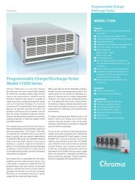
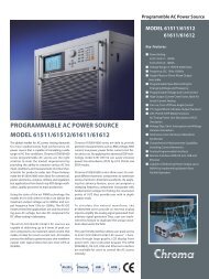
Functional IndexPhotovoltaic Test EquipmentSolar Wafer Inspection System 3710 5-1Solar Cell Test/Sorting System 3720 5-2Solar Cell Inspection Test/Sorting System ★ 3730 5-3Automatic Optical Solar CellInspectionModules ★ 7200 Series 5-4c-Si Solar Cell Tester ★ 58301 5-6Solar Cell/Module I-V Tester ★ 53310 Series 5-7Semiconductor/IC Test EquipmentVLSI Test System ★ 3360-D 6-1VLSI Test System 3360-P 6-2VLSI Test System 3360 6-3LCD Driver IC Test System 3520 6-5SoC Test System 3600 6-6SoC Test System ★ 3650-CX 6-8SoC Test System 3650 6-9Programmable Pin Electronics Module ★ 36010 6-11Four-quadrant DUT Power Supply ★ 36020 6-12Automatic System Function Tester 3240 6-13Automatic System Function Tester 3260 6-14Miniature IC Handler 3270 6-15xSD Card Tester and Handler 3280 6-16Touch Panel Multi-sites Test Handler ★ 3813 6-18CMOS Image Sensor Inspection System ★ 7970 6-19LED Test EquipmentLED Test System 58151 7-1ESD Test System ★ 58154 Series 7-2LED Total Power Test System 58173 7-3LED Total Power Test System 58173-M 7-5LED Die Inspection System ★ 7930 7-7AC/DC LED Test System ★ 58158 7-8LED Light Bar Test System ★ 58182 7-9LED Light Bar Electrical Test System ★ 58183 7-10LCD/LCM Test EquipmentLCD Shorting Bar Pattern Generator ★ 58162 Series 8-1LCD Shorting Bar Pattern Generator ★ 58168 8-2LCM Pattern Generator Card 27010 Series 8-3LCM Tester 27011 8-4LCM Tester 27012 8-5LCM Tester 27013 8-6LCM ATS 29130/29132/29133/29135 8-7LCM ATS 2915 8-9LCM ATS ★ 2916 8-11DC Power Supply forLCM Oven Burn-In System 67300 Series 8-132-1Video & Color Test EquipmentSelection Guides 9-1Video Pattern Generator 22293 9-3Video Pattern Generator 22293-A 9-5Video Pattern Generator 22293-B 9-7Video Pattern Generator ★ 22294 9-9Video Pattern Generator 2233 9-11Video Pattern Generator 2233-A 9-13Video Pattern Generator 2233-B 9-15Video Pattern Generator ★ 2234 9-17Video Pattern Generator 23293-B 9-19Video Pattern Generator ★ 23294 9-21Video Pattern Generator 2333-B 9-23Video Pattern Generator 2401/2402 9-25HDMI Distributor ★ A222907 9-27SDI Module ★ A222915 9-29Digital Video Distributor 28101/ 28102/28111 9-29Display Color Analyzer 7123 9-30Spectrocolorimeter ★ 71611 9-32Front Projector ATS 7600 9-34Display Multi-probe ATS 7660 9-35Optical Inspection EquipmentVideo Microscope 7310 10-1Sub-nanometer 3D Optical Profiler ★ 7503 10-3Power Electronics Test EquipmentSelection Guides 11-1DC Electronic Load System 6300 Series 11-5Programmable DC Electronic Load 6310A Series 11-7Programmable DC Electronic Load(LED Load Simulator) ★ 63110A/63113A 11-12High Power DC Electronic Load 63200 Series 11-14High Speed DC Electronic Load ★ 6330A Series 11-19High Slew Rate DC Electronic Load 63472 11-25Programmable DC Electronic Load 63600 Series 11-26Programmable AC&DC Electronic Load 63800 Series 11-29Programmable AC Source 61500 Series 11-31Programmable AC Source 61600 Series 11-35Programmable AC Source 61700 Series 11-39Programmable AC Source 6400 Series 11-41Programmable AC Source 6500 Series 11-44Power Analyzer 6630/6632 11-46Digital Power Meter 66200 Series 11-47Programmable DC Power Supply 62000P Series 11-49Programmable DC Power Supply ★ 62000H Series 11-53Programmable DC Power Supply ★ 62150H-600S/(Solar Array Simulator) 62150H-1000S 11-57★ <strong>New</strong> products are asterisked.
Functional IndexModular DC Power Supply 62000B Series 11-61Switching Power Supply ATS 6000 11-63Switching Power Supply ATS 8000 11-65Switching Power Supply ATS 8200 11-68PC Power Supply ATS ★ 8010 11-69Adapter/Charger ATS ★ 8020 11-71LCD Inverter ATS 8490 11-73LED Power Driver ATS ★ 8491 11-77Ground Bond Tester 19572 13-14High Voltage Meter 900A/900B 13-15Hipot Calibrator 9102 13-16Electrical Equipment ATS 8900 13-17Medical Electrical Safety ATS 8910 13-18High Capacitance ElectrolyticCapacitor ATS ★ 1911 13-19Options of Electrical Safety Test Instruments 13-20Passive Component Test InstrumentsSelection Guides 12-1LCR Meter 11021/11021-L 12-3LCR Meter 11022/11025 12-4Precision LCR Meter 1061A/ 1062A/1075 12-5Capacitance Meter 11020 12-6Automatic Transformer Tester ★ 13350 12-7Automatic Transformer Test System 3250/3252/ 3302 12-9Telecom Transformer Test System 3312 12-11Test Fixture of Auto Transformer Scanning Box 12-12Bias Current Source 1310/1320/1320S/1320-10A 12-13Bias Current Test System 11300 12-14Electrolytic Capacitor Analyzer 13100 12-15Ripple Current Tester ★ 11800/11801/11810 12-17Capacitor Leakage Current/IR Meter 11200 12-18Programmable HF AC Tester ★ 11802/11805/11890/11891 12-19Milliohm Meter 16502 12-21Component Test Scanner 13001 12-23Magnetic Component Test System ★ 1810 12-24Electrical Double Layer Capacitor ATS ★ 1850 Series 12-25Component ATS 8800 12-27Electrical Double Layer Capacitor ATS 8801 12-29EDLC Leakage Current Monitoring System 8802 12-31Options of Passive Component Test Instruments 12-33General Purpose Test Instruments6½ Digital Multimeter 12061 14-1Multifunction Calibrator 16801 14-3Multipath Fading Channel Simulator 42010 14-5GNSS Signal Simulator 49003 14-7PXI Instruments & <strong>Systems</strong>PXI General-purpose Chassis 52100 Series 15-1PXI Portable Chassis 52151 15-23U/6U Super Chassis 52022 15-3PXI Mini Chassis 52131 15-4PXI Backplane 52200 Series 15-5Four Quardrant Source ★ 52400 Series 15-6Programmable DC Power Supply 52912/ 52914 15-7Current Source/Measure Module 52956 15-8Leakage Test Module 52958 15-9Dual Channel NANO-AMP Meter 52961 15-10Extension Card 52906 15-113U cPCI Hot SwapPower Supply cPWR-59100 Series 15-126U cPCI Hot Swap Power Supply cPWR-59400 Series 15-13Electrical Safety Test InstrumentsSelection Guides 13-1Electrical Safety Analyzer 19032/19032-P 13-3Wound Component EST Scanner ★ 19035 Series 13-5Multi-channel Hipot Tester ★ 19020 Series 13-7AC/DC/IR/SCAN Hipot Tester 19050 Series 13-8Hipot Analyzer ★ 19055/19055-C 13-9AC/DC/IR Hipot Tester 19070 Series 13-10AC/DC/IR/SCAN Hipot Tester 9055/ 9056/9056-20kV 13-11Electrical Safety Test Scanner 19200 13-12★ <strong>New</strong> products are asterisked.2-2
Model Index➊1061A Precision LCR Meter 12-51062A Precision LCR Meter 12-51075 LCR Meter 12-511020 CLC/IR Meter 12-611021 LCR Meter 12-311021-L LCR Meter 12-311022 LCR Meter 12-411025 LCR Meter 12-411200 CLC/IR Meter 12-1811300 Bias Current Test System 12-1411800 Ripple Current Tester 12-1711801 Ripple Current Tester 12-1711802 Programmable HF AC Tester 12-1911805 ★ Programmable HF AC Tester 12-1911810 Ripple Current Tester 12-1711890 HF Hipot Tester 12-1911891 ★ HF Load Life Tester 12-1912061 6½ Digital Multimeter 14-113001 Component Test Scanner 12-2313100 Electrolytic Capacitor Analyzer 12-151310 Bias Current Source 12-131320 Bias Current Source 12-131320-10A Bias Current Source 12-131320S Bias Current Source (Slave) 12-1313350 ★ Automatic Transformer Tester 12-716502 MilliOhm Meter 12-2116801 Multi-Function Calibrator 14-31810 ★ Magnetic Component Test System 12-241850 ★ Electrical Double Layer Capacitor ATS 12-2519020 Series ★ Multi-channel Hipot Tester 13-719020 ★ Multi-channel Hipot Tester 13-719020-4 ★ Multi-channel Hipot Tester 13-719021 ★ Multi-channel Hipot Tester 13-719022 ★ Multi-channel Hipot Tester 13-719022-4 ★ Multi-channel Hipot Tester 13-719032 Electrical Safety Analyzer 13-319032-P Electrical Safety Analyzer 13-319035 Series ★ Wound Component EST Scanner 13-519035 ★ Wound Component EST Scanner 13-519035-L ★ Wound Component EST Scanner 13-519035-M ★ Wound Component EST Scanner 13-519035-ML ★ Wound Component EST Scanner 13-519035-S ★ Wound Component EST Scanner 13-519050 Series AC/DC/IR/SCAN Hipot Tester 13-819052 AC/DC/IR Hipot Tester 13-819053 AC/DC/SCAN Hipot Tester 13-819054 AC/DC/SCAN Hipot Tester 13-819055 ★ Hipot Analyzer 13-919055-C ★ Hipot Analyzer 13-919070 Series AC/DC/IR Hipot Tester 13-1019071 AC Hipot Tester 13-1019073 AC/DC/IR Hipot Tester 13-101911 ★ High CapacitanceElectrolytic Capacitor ATS 13-1919200 Electrical Safety Test Scanner 13-1219572 Ground Bond Tester 13-14➋22293 Video Pattern Generator 9-322293-A Video Pattern Generator 9-522293-B Video Pattern Generator 9-722294 ★ Video Pattern Generator 9-92233 Video Pattern Generator 9-112233-A Video Pattern Generator 9-132233-B Video Pattern Generator 9-152234 ★ Video Pattern Generator 9-1723293-B Video Pattern Generator 9-1923294 ★ Video Pattern Generator 9-212333-B Video Pattern Generator 9-232401 Video Pattern Generator 9-252402 Video Pattern Generator 9-2527010 Series LCM Pattern Generator Card 8-327011 LCM Tester 8-427012 LCM Tester 8-527013 LCM Tester 8-628101 Digital Video Distributor 9-2928102 Digital Video Distributor 9-2928111 Digital Video Distributor 9-2929130 LCM ATS 8-729132 LCM ATS 8-729133 LCM ATS 8-729135 ★ LCM ATS 8-72915 LCM ATS 8-92916 ★ LCM ATS 8-11➌3240 Automatic System Function Tester 6-133250 Automatic Transformer Test System 12-93252 Automatic Component Analyzer 12-93260 Automatic System Function Tester 6-143270 Miniature IC Handler 6-153280 xSD Card Tester and Handler 6-163302 Automatic Component Analyzer 12-93312 Telecom Transformer Test System 12-113360 VLSI Test System 6-33-1★ <strong>New</strong> products are asterisked.
Model Index3360-D ★ VLSI Test System 6-13360-P VLSI Test System 6-23520 LCD Driver IC Test System 6-53600 SoC Test System 6-63650 SoC Test System 6-93650-CX ★ SoC Test System 5-836010 ★ Programmable Pin Electronics Module 6-1136020 ★ Four-quadrant DUT Power Supply 6-123710 ★ Solar Wafer Inspection System 5-13720 Automatic Solar Cell Test/Sorting System 5-23730 ★ Solar Cell Inspection Test/Sorting System 5-23813 ★ Touch Panel Multi-sites Test Handler 6-18➍42010 Multipath Fading Channel Simulator 14-549003 GNSS Signal Simulator 14-8➎52022 PXI 3U/6U Super Chassis 15-352100 Series PXI General-purpose Chassis 15-152101 PXI 8-slot General-purpose Chassis 15-152102 PXI 14-slot General-purpose Chassis 15-152105 PXI 18-slot General-purpose Chassis 15-152131 PXI Mini Chassis 15-452151 PXI 8-slot Portable Chassis 15-252200 Series PXI Backplane 15-552201 PXI 8-slot PXI Backplane 15-552203 PXI 4-slot PXI Backplane 15-552205 PXI 18-slot PXI Backplane 15-552207 PXI 14-slot PXI Backplane 15-552400 Series Four Quardrant Source 15-652401-25-200m Four Quardrant Source 15-652405-10-2.5 Four Quardrant Source 15-652405-25-1 Four Quardrant Source 15-652410-100-2 Four Quardrant Source 15-652410-25-4 Four Quardrant Source 15-652420-100-4 Four Quardrant Source 15-652906 PXI Extension Card 15-1152912 PXI Programmable DC Power Supply 15-752914 PXI Programmable DC Power Supply 15-752956 PXI Current Source/Measure Module 15-852958 PXI Leakage Test Module 15-952961 PXI Dual Channel NANO-AMP Meter 15-1053310 Series ★ Solar Cell/Module I-V Tester 5-753311 ★ c-Si Cell I-V Tester 5-753312 ★ c-Si Module I-V Tester 5-753313 ★ TF Module I-V Tester 5-753314 ★ Multi-junction & CPV Cell I-V Tester 5-758151 LED Test System 7-158154 Series ★ ESD Test System 7-258154-8KV ★ ESD Test System 7-258154-A ★ ESD Test System 7-258154-B ★ ESD Test System 7-258154-C ★ ESD Test System 7-258162 Series LCD Shorting Bar Pattern Generator 8-158162 LCD Shorting Bar Pattern Generator 8-158162-A LCD Shorting Bar Pattern Generator 8-158162-AE LCD Shorting Bar Pattern Generator 8-158162-E LCD Shorting Bar Pattern Generator 8-158162-EE LCD Shorting Bar Pattern Generator 8-158168 LCD Shorting Bar Pattern Generator 8-258173 LED Total Power Test System 7-358173-M LED Total Power Test System 7-558182 ★ LED Light Bar Test System 7-958183 ★ LED Light Bar Electrical Test System 7-658301 ★ c-Si Solar Cell Tester 5-5➏6000 Switching Power Supply ATS 11-6361500 Series Programmable AC Source 11-3161501 Programmable AC Source 11-3161502 Programmable AC Source 11-3161503 Programmable AC Source 11-3161504 Programmable AC Source 11-3161505 Programmable AC Source 11-3161511 ★ Programmable AC Source 11-3161512 ★ Programmable AC Source 11-3161600 Series Programmable AC Source 11-3561601 Programmable AC Source 11-3561602 Programmable AC Source 11-3561603 Programmable AC Source 11-3561604 Programmable AC Source 11-3561605 Programmable AC Source 11-3561611 ★ Programmable AC Source 11-3561612 ★ Programmable AC Source 11-3561700 Series Programmable AC Source 11-3961701 Programmable AC Source 11-3961702 Programmable AC Source 11-3961703 Programmable AC Source 11-3961704 Programmable AC Source 11-3961705 Programmable AC Source 11-3962000B Series Modular DC Power Supply 11-6162015B-15-90 Modular DC Power Supply 11-6162015B-150-10 Modular DC Power Supply 11-6162015B-30-50 Modular DC Power Supply 11-6162015B-60-25 Modular DC Power Supply 11-61★ <strong>New</strong> products are asterisked. 3-2
Model Index62015B-80-18 Modular DC Power Supply 11-6162000H Series ★ Programmable DC Power Supply 11-5362050H-40 ★ Programmable DC Power Supply 11-5362050H-450 ★ Programmable DC Power Supply 11-5362050H-600 ★ Programmable DC Power Supply 11-5362050H-600S ★ Programmable DC Power Supply 11-5762075H-30 ★ Programmable DC Power Supply 11-5362100H-30 ★ Programmable DC Power Supply 11-5362100H-40 ★ Programmable DC Power Supply 11-5362100H-450 ★ Programmable DC Power Supply 11-5362100H-600 ★ Programmable DC Power Supply 11-5362100H-600S ★ Programmable DC Power Supply 11-5762150H-1000S ★ Programmable DC Power Supply 11-5762150H-40 ★ Programmable DC Power Supply 11-5362150H-450 ★ Programmable DC Power Supply 11-5362150H-600 ★ Programmable DC Power Supply 11-5362150H-600S ★ Programmable DC Power Supply 11-5762000P Series Programmable DC Power Supply 11-4962006P-100-25 Programmable DC Power Supply 11-4962006P-300-8 Programmable DC Power Supply 11-4962006P-30-80 Programmable DC Power Supply 11-4962012P-100-50 Programmable DC Power Supply 11-4962012P-40-120 Programmable DC Power Supply 11-4962012P-600-8 Programmable DC Power Supply 11-4962012P-80-60 Programmable DC Power Supply 11-4962024P-100-50 Programmable DC Power Supply 11-4962024P-40-120 Programmable DC Power Supply 11-4962024P-600-80 Programmable DC Power Supply 11-4962024P-80-60 Programmable DC Power Supply 11-4962050P-100-100 Programmable DC Power Supply 11-496300 Series DC Electronic Load System 11-563006 DC Electronic Load System 11-563010 DC Electronic Load System 11-563025 DC Electronic Load System 11-563030 DC Electronic Load System 11-56310A Series ★ Programmable DC Electronic Load 11-763101A Programmable DC Electronic Load 11-763102A Programmable DC Electronic Load 11-763103A Programmable DC Electronic Load 11-763105A Programmable DC Electronic Load 11-763106A Programmable DC Electronic Load 11-763107A Programmable DC Electronic Load 11-763108A Programmable DC Electronic Load 11-763110A ★ Programmable DC Electronic Load 11-1263112A ★ Programmable DC Electronic Load 11-763113A ★ Programmable DC Electronic Load 11-1263123A ★ Programmable DC Electronic Load 11-763200 Series High Power DC Electronic Load 11-1463201 High Power DC Electronic Load 11-1463202 High Power DC Electronic Load 11-1463203 High Power DC Electronic Load 11-1463204 High Power DC Electronic Load 11-1463205 High Power DC Electronic Load 11-1463206 High Power DC Electronic Load 11-1463207 High Power DC Electronic Load 11-1463208 High Power DC Electronic Load 11-1463209 High Power DC Electronic Load 11-1463210 High Power DC Electronic Load 11-146330A Series ★ High Speed DC Electronic Load 11-1963301A High Speed DC Electronic Load 11-1963302A High Speed DC Electronic Load 11-1963303A High Speed DC Electronic Load 11-1963305A High Speed DC Electronic Load 11-1963306A High Speed DC Electronic Load 11-1963307A High Speed DC Electronic Load 11-1963308A High Speed DC Electronic Load 11-1963310A ★ High Speed DC Electronic Load 11-1963312A ★ High Speed DC Electronic Load 11-1963313A ★ High Speed DC Electronic Load 11-1963323A ★ High Speed DC Electronic Load 11-1963472 High Slew Rate DC Electronic Load 11-2563600 Series Programmable DC Electronic Load 11-2663610-80-20 Programmable DC Electronic Load 11-2663630-80-60 Programmable DC Electronic Load 11-2663640-80-80 Programmable DC Electronic Load 11-2663800 Series Programmable AC&DC Electronic Load 11-2963802 Programmable AC&DC Electronic Load 11-2963803 Programmable AC&DC Electronic Load 11-2963804 Programmable AC&DC Electronic Load 11-296400 Series Programmable AC Source 11-416404 Programmable AC Source 11-416408 Programmable AC Source 11-416415 Programmable AC Source 11-416420 Programmable AC Source 11-416430 Programmable AC Source 11-416460 Programmable AC Source 11-416463 Programmable AC Source 11-416490 Programmable AC Source 11-416500 Series Programmable AC Source 11-446512 Programmable AC Source 11-446520 Programmable AC Source 11-446530 Programmable AC Source 11-446560 Programmable AC Source 11-446590 Programmable AC Source 11-4466200 Series Digital Power Meter 11-4766201 Digital Power Meter 11-473-3★ <strong>New</strong> products are asterisked.
Model Index66202 Digital Power Meter 11-476630 Power Analyzer 11-466632 Power Analyzer 11-4667300 Series Modular DC Power Supplyfor LCM Burn-in Applications 8-1367322 Modular DC Power Supplyfor LCM Burn-in Applications 8-1367346 Modular DC Power Supplyfor LCM Burn-in Applications 8-1367366 Modular DC Power Supplyfor LCM Burn-in Applications 8-13➐7123 Display Color Analyzer 9-3071611 ★ Spectrocolorimeter 9-327200 Series ★ Automatic Optical Solar CellInspection Modules 5-47211-D ★ Solar Cell Color Classifier 5-47212-HD7213-AD★ Solar Cell Frontside Printing &Surface Inspector 5-4★ Solar Cell Backside Printing &Surface Inspector 5-47214-D ★ Anti-Reflection Coating Inspector 5-47310 Video Microscope 10-17503 ★ Subnanometer 3D Optical Profiler 10-37600 Front Projector ATS 9-347660 Multi-probe Display ATS 9-357930 ★ LED Die Inspection System 7-77970 ★ CMOS Image Sensor Inspection System 7-79056 AC/DC/IR Hipot Tester 13-119056-20kV AC/DC/IR Hipot Tester 13-119102 Hipot Calibrator 13-16AA222907 HDMI Distributor 9-27A222915 SDI Module 9-29CcPWR-59100 Series 3U CompactPCI Power Supply 15-12cPWR-59102 3U CompactPCI Power Supply 15-12cPWR-59104 3U CompactPCI Power Supply 15-12cPWR-59105 3U CompactPCI Power Supply 15-12cPWR-59400 Series 6U CompactPCI Power Supply 15-13cPWR-59401 6U CompactPCI Power Supply 15-13cPWR-59402 6U CompactPCI Power Supply 15-13➑8000 Switching Power Supply ATS 11-658010 ★ PC Power Supply ATS 11-698020 ★ Adapter/Charger ATS 11-718200 Switching Power Supply ATS 11-688490 LCD Inverter ATS 11-738491 ★ LED Power Driver ATS 11-778800 Component ATS 12-278801 Electrical Double Layer Capacitor ATS 12-298802 EDLC Leakage CurrentMonitoring System 12-318900 Electrical Equipment ATS 13-178910 Medical Electrical Safety ATS 13-18➒900A High Voltage Meter 13-15900B High Voltage Meter 13-159055 AC/DC/IR Hipot Tester 13-11★ <strong>New</strong> products are asterisked. 3-4
<strong>New</strong> <strong>Products</strong>Solar Wafer Inspection System Model 3710 Good for 5 inches and 6 inches wafer High throughput and low breakage rate 0.2% 2D Geometry Inspection Surface Inspection Micro Crack Inspection Saw Mark Inspection Resistively/ Thickness Tester Lifetime Tester Easy trouble shooting Loader : Coin stack / Cassette Unload : Coin stack/ Cassette4 See Page 5-1Solar Cell Inspection Test/Sorting System Model 3730 Good for 5 inches and 6 inches mono/multi-crystalline silicon cells High throughput and low breakage rate 0.2% Loader can automatically pick up and place cell finished by firing Efficiency and Color classes and Sorting Bins can be defined by customers' request Integrated with Inspector and IV Tester by customers' request High cell positioning repeatability to ensure consistent test result Sorting Bins can be extended by module4 See Page 5-3Automatic Optical Solar Cell Inspection ModulesModel 7200 Series Capable to integrate any c-Si cell line due to compact sizes Adjustable criteria for different process application or model Flexible algorithms programming editor for mono-crystalline and multi-crystalline siliconsolar cells Multiple interface to communicate with manufacturing equipment or information system Various defects inspection capability from multilayer LED lighting design Flexible design that can be easily integrate to your in-line printing system and sorting system4 See Page 5-4c-Si Solar Cell Tester Model 58301 Measurements: Eff, Pmpp, Impp, Vmpp, Isc, Voc, FF, Rshunt, Rs, Irev. Full four-quadrant source for both light forward/reverse & dark forward/reverse test Class AAA+ solar simulator Versatile system software and user editable test sequences Low stress probe PV cell sorter integration (<strong>Chroma</strong> 3720)4 See Page 5-64-1
<strong>New</strong> <strong>Products</strong>VLSI Test System Model 3360-D 50 MHz Test Rate 16 ~ 64 I/O channels 8M Pattern Memory Flexible Configuration Parallel Testing : max 2 devices Real Parallel Trim/Match function Timing / Frequency measurement unit(TFMU)SoC Test System 50 /100 MHz Test Rate Up to 256 digital I/O pins 16/32 MW vector memory 16/32 MW pattern instruction memory Multi-site testing up to 16 sites 16 DPS Channels 8 PMU Channels Per-Pin timing/frequencymeasurement resource Up to 1024M bit x 4 CH scan depth option ALPG option for memory test Test program/pattern converter(V7, V50, SC312, J750) Analog PE card option (16 bits) SCAN test option (512M) ALPG test option for Memory STDF tools support (Option) CRAFT C/C++ programming language4 See Page 6-1Model 3650-CX Up to 16 high-voltage pins 8 ~ 32-CH / board for VI-45 analog option 2 ~ 8-CH / board for PVI-100 analog option 16 high-performance DPS channels C++ and GUI programming interface CRISP, full suite of intuitive software tools Easy integration with 3rd party instruments Air-cooled, All-in-one design andspace-saving footprint Cable Mount / Direct Mount4 See Page 6-8Programmable Pin Electronics Module Model 36010Four-quadrant DUT Power Supply Model 3602036010 Standard PXI 3U form factor 100MHz maximum data rate 8 channels with per-pin, per-cyclebidirectional control Scalable architecture to provide up to 64-pin 32M sequence command memory More than 17 pattern sequence commands 32M vector memory per pin 32 sets of clock and waveform per pin Waveforms changes on-the-fly36020 4 channels in a PXI Standard 3U form factor +5V/-2V and +10V/-2V force ranges 16-bit voltage force resolution 18-bit current measurement resolution 6 selectable ranges from 5uA to 250mA forcurrent measurement Programmable current clamp function Ganged function available for larger current Board-to-board isolation Support LabView and LabWindowsMiniature IC Handler Model 32704 See Page 6-11,6-12 Hign throughtput got IC testing Reliable high-speed pick & place handler 3x3 mm miniature device handling capability Air damper for contact balance Auto contact force learning Socket damage free4 See Page 6-15CMOS Image Sensor Inspection System Model 7970 High speed tray-based CMOS image sensor inspection system Complete chip appearance inspection including glass and ball side of the chip On-fly acquisition can get clear images and reduce processing time. Multi-nozzles pick & place technology (patented) to improve throughput Advance and flexible illumination modules are suitable for specific defect mode Adjustable inspection criteria can be set for different type of the chip4 See Page 6-194-2
<strong>New</strong> <strong>Products</strong>ESD Test SystemModel 58154 Series Two Model ESD Pulse Generation : Human body model and Machine model Programmable Auto Test : Interval, cycle and polarity are programmable Resolution : 5V per-step for Machine model, 20V per-step for Human body model (58154) Resolution : 10V per-step for Machine model, 20V per-step for Machine model,30V per-step for Human body model (58154-A, 58154-B) Resolution : 10V per-step for Machine model, 30V per-step for Human body model (58154-C) Diversity Control Interface : PCI DIO card or PXI DIO card Up to 8000V (58154-C)4 See Page 7-2LED Die Inspection System Model 7930 High speed inspection for LED wafer Auto Compensation for wafer Z-axis leveling Fast auto focus are using for clearly acquisition images Software edge finding technology can be applied to different shape of wafer Advance and flexible illumination modules are suitable for surface-textured and non-texturedLED die Inspection mapping file can be output for down-stream sorter Adjustable inspection criteria can be set for different type LED die 4 See Page 7-7Solar Array Simulator Model 58158 Simulate the real AC test condition and environment Integrate AC, DC, and optical features test to one platform Support DC test for AC LED Support dual-optical test module in one platform (Integrating sphere or average intensity)(optional) Support AC /DC LIV Analysis Offer standard light source for calibration4 See Page 7-8LED Total Power Test System Model 58173 <strong>Chroma</strong>® Huge Photo Detector <strong>New</strong> method and unique design for LED total power measurement High speed automatic LED wafer/chip prober machine 6" wafer chuck on board Wide range of electrical test Flexible PXI platform interface4 See Page 7-34-3
<strong>New</strong> <strong>Products</strong>LED Light Bar Electrical Test System Model 58182 High Slew Rate Strong Driving Capacity 0-255 step waves output Auto discharge 12 Source Output 8 Gate Output (expandable up to 16 channels) 4 COM Output Powerful PC-based platform Auto FTP download Friendly Flow editing Easy to integrate with AOI & Optical adjustment Engineer Analysis Function4 See Page 7-9LED Light Bar Electrical Test System Model 58183 Integrating customer's extened power supply Maximun support 4 control boxes PC base design Support multi- channels test Commen DUT adapter offers widely test application Software support authority managerment4 See Page 7-10LCD Shorting Bar Pattern Generator High Slew Rate Strong Driving Capacity 0-255 step waves output Auto discharge 12 Source Output 8 Gate Output (expandable up to 16 channels) 4 COM Output Powerful PC-based platform Auto FTP download Friendly Flow editing Easy to integrate with AOI & Optical adjustment Engineer Analysis FunctionModel 58162 Series4 See Page 8-1LCM ATS Model 2916 LCM signal and power source test systems Easy for Timing / Pattern / Program editing Suitable for Full HD measurement The Resolution up to 1920x1080 / 240 Hz LVDS 4 channel output LVDS data Even / Odd switch support High accurate programmable DC source Network function base on fast Ethernet (option) Power protection OVP/OCP/UVP/UCP Production line process control and data collection4 See Page 8-114-4
<strong>New</strong> <strong>Products</strong>Video Pattern Generator Model 22294 Fully Comparable with HDMI 1.4 Standard- 3D Format Output- 4Kx2K Graphic Size- Audio Return Channel- sYCC601 / Adobe RGB / Adobe sYCC601- Ethernet Channel- CEC / Deep Color / Lip-Sync / xvYCC Multi ports output test application- HDMI port output x 3- SCART port x 2 330MHz digital (DVI) frequency Support Dual HDCP in DVI test application HDCP ON / OFF IN DVI & HDMI Interface S-Video / CVBS / SCART / RGB / Y.Pb.Pr / Y.Cb.Cr / Y,R-Y,B-Y / D-terminal NTSC / PAL / SECAM signals EDID Read/ Write/Compare Optical / coaxial audio input / output (SPDIF) Support pattern dynamic scrolling HDMI/DVI Hot-Plug function ESD protection circuit PIP & OSD function4 See Page 9-9Spectrocolorimeter Model 71611 Use of spectrophotometric technique Suitable for laboratories and production lines Display luminance, chromaticity and spectral measurement 0.01 cd/m 2 low luminance measurement Wide range of luminance display: 0.01 to 2000 cd/m 2 Highly accurate measurement Up to 9 display modes: xyY, TuvY, u v Y, XYZ, d/Pe, Spectral, Contrast, Program andUser Define Wide view color LCD to facilitate the reading and operation Able to control the Video Pattern Generator and DUT Built-in contrast measurement for contrast ratio calculation Embedded with programmable test items to test the planned items with one key Support USB interface for data control and process Equipped with judgment function for production line to use easily4 See Page 9-323D Optical Profiler Model 7503 Up to 0.1 nm height resolution for measurement Use white light interference measurement technique to do nondestructive and rapidsurface texture measurement and analysis Modulized design to select parts based on test demands or budget concerns Work with color or monochrome camera to do 2D measurement and enable the measuringmicroscope function Equipped with electric nose gear to mount various lens for switch programmatically LED or halogen light source for selection Measurement range 150 mm x150 mm Integrate low magnification lens (5X & 2.5X ratio) for large area 3D measurement Provide various surface measurement parameters, such as sectional difference,included angle, area, dimension, roughness, waviness, film thickness and flatness Powerful STA (Surface Texture Analysis) Master software providing more than 150 lines andsurfaces profiling parameters Automated rapid self calibration to ensure the systems measurement capability Provide measurement script for auto test4 See Page 10-34-5
<strong>New</strong> <strong>Products</strong>PV Inverter ATS Model 8000 For PV Inverter Testing Open architecture software platform Test command optimizer helps to improve test speed Comprehensive hardware modules provide high accuracy and repetitive measurements Other hardware expandable upon request Windows 98/NT/2000 or higher based software4 See Page 11-65LED Power Driver ATS Model 8491 For LED Power Driver testing (lighting & TV backlight) Capable to test Multi-UUT/Multi-output concurrently that improve productivity Provide optimized standard test items for the Unit Under Test (LED Power Driver) to deliverexcellent test performance Open architecture software- Expandable hardware support- Support instrument with GPIB/RS-232/RS-485/I2C interface- User editable test library- User editable test programs- User editable reports- Statistical report- On-line Softpanel- User authority control- Release control- Activity log- Support bar code reader Windows 98/2000/NT/XP based software4 See Page 11-77Programmable DC Power Supply Power range: 5KW / 10KW / 15KW Voltage range: 0 ~ 600V Current range: 0 ~ 375A High power density (15KW in 3U) Easy Master / Slave parallel & series operation up to 150KW Voltage ramp function (time range: 10 ms ~ 99 hours) Auto Sequencing Programming: 10 Programs / 100 Sequences Standard Analog Programming interface Standard USB / RS-232 / RS485 interface Optional GPIB / Ethernet interfaceModel 62000H Series4 See Page 11-53Solar Array SimulatorProgrammable DC Power SupplyModel 62150H-600S/1000S Voltage range : 0 ~600V&1000V 3U/15kW high power density module with easy master/slave parallel operation up to 150kW Fast transient response solar array simulation Simulation of multiple solar cell materials I-V characteristic (fill factor) Simulation of dynamic irradiation intensity and temperature level from clear day to cloudcover conditions Shadowed I-V curve output simulation Low leakage current (< 3mA) Precision V & I measurements Auto I-V program: 100 I-V curves & Dwell time 1-15,000s4 See Page 11-574-6
<strong>New</strong> <strong>Products</strong>Programmable AC Source Model 61511/61512/61611/61612 Power rating : 61511/61611-12KW, 61512/61612-18KW; Voltage range : 0-150V/0-300V/Auto Frequency : DC,15Hz – 1500Hz 1-phase or 3-phase output selectable Programmable slew rate setting for changing voltage and frequency Programmable voltage, current limit High output current crest factor, ideal for inrush current testing Turn on, turn off phase angle control TTL signal which indicates output transient LIST, PULSE, STEP mode functions for testing power line disturbance (PLD) simulation Voltage dips, short and variation simulation Harmonics, inter-harmonics waveform synthesizer Comprehensive measurement capability, including current harmonics Analog programmable interface Remote interface : GPIB, RS-232, USB and EthernetModel 61511/61512 4 See Page 11-31Model 61611/61612 4 See Page 11-35Programmable DC Electronic LoadModel 6310A Series Max Power: 200W, 100W2(Dual), 30W & 250W, 300W, 600W, 1200W Wide range 0~500V operating voltage Compatibility between 6310 and 6310A Up to 8 channels in one mainframe, for testing multiple output SMPS Parallel load modules up to 1200W for high current and power application Flexible CC, CR, CP and CV operation modes Dynamic loading with speeds up to 20kHz User programmable 100 sequences. Front panel input status for user-friendly operating Digital I/O control Over current protection (OCP) testing function4 See Page 11-7 USB, GPIB & RS-232 interfacesProgrammable DC Electronic LoadModel Model 63110A/63113ALED Load Simulator Unique LED mode for LED power driver test Programmable LED operating resistance (Rd) Programmable internal resistance (Rr) for simulating LED ripple current Fast response for PWM dimming test Up to eight channels in one mainframe 16-bit precision voltage and current measurement with dual-range Full Protection: OC, OP, OT protection and OV alarm4 See Page 11-124-7Programmable AC & DC Electronic Load Power Rating : 1800W, 4500W Voltage Range : 50V - 350Vrms Current Range : Up to 45Arms Peak Current : Up to 135A Frequency Range : 45 to 440Hz, DC Crest Factor Range : 1.414 to 5.0 Power Factor Range : 0 to 1 lead or lag (Rectified mode) CC, CR, CV, CP for DC Loading Constant & Rectified Load Modes for AC Loading Analog Voltage & Current Monitor Measurement : V, I, PF, CF, P, Q, S, F, R, Ip-/+ and THDv Full Protection : OP, OC, OV and OT protection GPIB & RS-232 interfacesModel Model 63800 Series4 See Page 11-29
<strong>New</strong> <strong>Products</strong>Automatic Transformer Tester Model 13350 Enhanced Turn Ratio measurement accuracy for low permeability core Integrate scanning fixture with optimum high speed transformer scan test, speed up to 2.2 sec(N.A.) with 46 test items. English and simplified Chinese for selection Separate monitor for space allocation flexibly Support bias voltage (+35Vdc max.) Set measurement speed of various items independently Built-in comparator; 100 bin sorting Support multi-digit design (24 characters at most) Built-in 100mA bias for RJ45 transmission transformer (option), install before shipment only 10 internal and and USB external instrument setups for store/recall capability4 See Page 12-7Hipot AnalyzerFUNCTIONS Hi-Pot- AC 5kV/100mA- DC 6kV/20mA Insulation Resistance- 5kVmax- 1M~50GModel 19055/19055-CKEY FEATURES 500VA output rating Floating output complies with EN50191 Corona Discharge Detection (CDD, 19055-C) Flashover Detection Discharge Level Analysis (DLA) Open Short Check (OSC) High Frequency Contact Check (HFCC) Ground Fault Interrupt4 See Page 13-9High Capacitance Electrolytic Capacitor ATS Model 1911 Test parameter LC/C/D Test 8 electrolytic capacitors Constant current for test leakage current Special test clip fix DUT Testing specification from program management Test report auto generate Statistic analysis Software interface easy to operate Stand-alone measurement4 See Page 13-19Electrical Double Layer Capacitor ATSModel 1850 Series Auto electrical double layer capacitor aging function Electrical double layer capacitor leakage current, static capacitance, internal resistance (IR),series equivalent resistance ESR measurement 5 static capacitance bin sorting & fail bin sorting Auto loading and feeding system Mechanical polarity judge, DUT polarity error auto reverse Auto lead setting mechanism Unique closed temperature isolated aging oven Capacitor auto testing conveyor belt Test data storage function, provide Excel CSV format for customers use Modularized design, easy to maintain Small-sized production equipment, never occupied space Multiple layer user authorization management4 See Page 12-254-8
Photovoltaic Test EquipmentSolar Wafer Inspection System 5-1Solar Cell Test/Sorting System 5-2Solar Cell Inspection Test/Sorting System 5-3Automatic Optical Solar Cell Inspection Modules 5-4c-Si Solar Cell Tester 5-6Solar Cell/Module I-V Tester 5-7
OverviewSolar Wafer Inspection SystemSolar Cell Test/Sorting SystemSolar Cell Inspection Test/Sorting SystemAutomatic Optical Solar CellInspection Modulesc-Si Solar Cell TesterSolar Cell/ModuleI-V Tester
Solar Wafer Inspection System Model 3710KEY FEATURES Good for 5 inches and 6 inches wafer High throughput and low breakage rate≤0.2% 2D Geometry Inspection Surface Inspection Micro Crack Inspection Saw Mark Inspection Resistively/ Thickness Tester Lifetime Tester Easy trouble shooting Loader : Coin stack / Cassette Unload : Coin stack / CassetteIntegrated with 2D Geometry, Surface, MicroCrack, Saw mark inspection system and Resistively& Thickness, Lifetime tester by customer defined,<strong>Chroma</strong> 3710 is a fully user configuration wafersorter system with very low breakage rate andhigh throughput.<strong>Chroma</strong> 3710 solar waferinspection system is ideal for PV incomingprocess. Plus wafer can be sorted by user definedalgorithm fully automatically into coin stack orcassette. The unique auto coin stack/cassetteexchange feature eliminates system down timewhen changing full coin stack/cassette to emptycoin stack/cassette manually.For the breakage rate that is one of the keyconcern for PV wafer handling system. <strong>Chroma</strong>3710 uses state-of-the-art cell transportationtechnique to ensure minimum breakage rate.Loading Auto-unloading Manual-unloadingORDERING INFORMATION3710 : Solar Wafer Inspection SystemLoading Auto-unloading Manual-unloading5-1 All specifications are subject to change without notice.
Solar Cell Inspection Test/Sorting System Model 3730KEY FEATURES Good for 5 inches and 6 inches mono/multi-crystalline silicon cells High throughput and low breakage rate0.2% Loader can automatically pick up and placecell finished by firing Efficiency and Color classes and Sorting Binscan be defined by customers' request Integrated with Inspector and IV Tester bycustomers' request High cell positioning repeatability to ensureconsistent test result Sorting Bins can be extended by module<strong>Chroma</strong> 3730 Solar Cell Inspection Test/SortingSystem is ideal for PV backend process. In loaderit can automatically pick up and place PV cellfinished by firing. Then it will inspect cell surfaceand backside defects and will automatically sortthe cells into carrier by different efficiency andcolor classes defined by customers' request.Breakage rate is one of the key concern for PVcell handling system. <strong>Chroma</strong> 3730 uses state-ofthe-artcell transportation technique to ensureminimum breakage rate. Based on customers requirement of different processes, the carriertype and the amount of sorting bins also can bedesigned and adjusted.ORDERING INFORMATION3730 : Solar Cell Inspection Test/Sorting SystemFiring Unload Loading AOIIV Testing Sorting5-3All specifications are subject to change without notice.
Automatic Optical Solar Cell Inspection Modules Model 7200 SeriesPhotovoltaicTest EquipmentSemiconductor/ICTest EquipmentLEDTest EquipmentKEY FEATURES Capable to integrate any c-Si cell line due tocompact sizes Adjustable criteria for different processapplication or model Flexible algorithms programming editor formono-crystalline and multi-crystalline siliconsolar cells Multiple interface to communicate withmanufacturing equipment or informationsystem Various defects inspection capability frommultilayer LED lighting design Flexible design that can be easily integrate toyour in-line printing system and sorting systemAmong several fac tors for PV to achievegrid-parity, reliability of the PV modules plays animportant roll. Since its known that some ofthe cell defects such as edge chips/flakes, bumpsof cell surface were proved to be source of infantmortality of the c-Si PV modules, therefore, todefine those defects is very important for c-Si cellmanufacturers.D ue to the increasing BIPV and rooftopapplication, even for those defects that does notdirectly link to reliability issues such as watermark, surface stain, have to be detected andconsidered as fail or secondary grade of cells forc-Si cell buyers.Conventionally, those defects were visuallyinspected by operators. But, the inconsistentinspect result makes fully automatic opticalinspection (AOI) solution becomes unavoidableequipment for c-Si cell lines.<strong>Chroma</strong> 7200 series are specially designedfor detection yield for wide variety of defectso b s e r ved fo r c-S i c e l l s fo r a l l s i zes a n dcrystallizations. Base on the process needs, threeinspectors are available for both in-line and finalsorting requirements.Color ClassifierModel 7211-DThe <strong>Chroma</strong> 7211-D c-Si cell color classifier was designed to provide high repetitive color classificationfor c-Si PV cells. CIE 1931 Lab color space and up to 60x60 grids for entire cell surface allows <strong>Chroma</strong>7211-D to provide numeric color severities down to each of the 3600 blocks throughout the cell undertest. By using the color information of each block and user definable algorithm, user may determinethe represented color for non-uniform color cells such as poly-crystalline cells or cells have unevenanti-reflection coating thickness.<strong>Chroma</strong> 7211-D can be used right afteranti-reflection coating process to ensureonly cells with acceptable color uniformitygo down to metallization process. And thefail cells may then be sent for re-work. Itcan also be integrated to in-line or off-linesorter for final inspection prior to shipping.Light Blue Dark Blue Purple Mix ColorFrontside Printing and Surface InspectorModel 7212-HDDefects causes by front-side (sunny side) printing process of c-Si PV cells may cause performance,reliability or appearance impact. Therefore, a reliable and repetitive inspection to defects such as losingAg paste on busbars, gridline interruptions, printing shift or rotation, water mark etc., have to be detectedand avoid shipping those cells to ensure shipping quality. <strong>Chroma</strong> 7212-HD c-Si cell front-side printinginspector equips with high resolution CCD camera and superior software algorithm to recognize theunwanted defects on front-side of c-Si PV cells.<strong>Chroma</strong> 7212-HD can be used right afterfront-side process to retire cells with majordefects. This allows best use of the capacityof the following process like I-V testing andsorting which is known to be one of thebottlenecks of c-Si cell line. It can also beintegrated to in-line or off-line sorter forfinal inspection prior to shipping.LCD/LCMTest EquipmentVideo & ColorTest EquipmentOptical InspectionEquipmentPower ElectronicsTest EquipmentPassive ComponentTest InstrumentsElectrical SafetyTest InstrumentsGeneral PurposeTest InstrumentsPXI Instruments& <strong>Systems</strong>All specifications are subject to change without notice.Chipping Discolorationt Finger Width Stains5-4
Automatic Optical Solar Cell Inspection Modules Model 7200 SeriesA Backside Printing and Surface InspectorModel 7213-ADDefects causes by back-side printing process of c-Si PV cells will also cause performance,reliability impact. Among all the back-side printing defects, bumps caused by improperprinting may cause high cell breakage rate during lamination of c-Si module process. <strong>Chroma</strong>7213-AD c-Si cell back-side printing inspector uses unique lighting technique to detectcommon back-side printing defects plus most demanding bumps.Another model <strong>Chroma</strong> 7213, with same inspection capability but was designed for specialupward-detection. This brings unparallel advantageagainst conventional downward-detection design. Withupward detection, the cell can be checked without beingflipped twice which helps to minimize the cell breakageand reduce the production line length.Same as <strong>Chroma</strong> 7212-HD, <strong>Chroma</strong> 7213-AD can be usedafter back-side process to retire cells with major defects. Itcan also be integrated to in-line or off-line sorter for finalinspection prior to shipping. Bump BUSBar Defect Stain Alignment ShiftAnti-Reflection Coating InspectorModel 7214-D<strong>Chroma</strong> 7214-D is the inspector for Anti-reflection coating process. With 4M mono CCD and <strong>Chroma</strong>s experience RGB illumination design, we could assurethat each defined defectives could be identified through our specified combination. The 7214-D anti-reflection inspector could be applied in discovering :(1) Color difference, (2) Brownish stains, (3) Stripe shape watermark, (4) Particles, (5) Belt mark, (6) Acid mark, (7) Stacking cells, (8) ChippingWith our flexible hierarchy software design, customercould set up the parameters to perfectly meet theirunique manufacturing process. <strong>Chroma</strong> understood thatevery different manufacturing equipment will sometimesgenerate different failure patterns, we would closelywork with our valuable customer to come out with asolution that meet our customers requirement.Stain Watermark stripe shape Particles Acid markSPECIFICATIONSModel 7211-D 7212-HD 7213-AD 7214-DCamera 1024x768CCD 16M mono CCD 4M mono CCD 4M mono CCDResolution 240µm 60µm 90µm 90µmLight Source LED strobe lighting WRGB LED strobe lightingLensLow distortion LensDimension(WxDxH)320mm x 324mm x 1032mmWeight35kgAccessoryExternal Keyboard, Mouse, PC, MonitorInterfaceEthernet, Option : IO, RS-232ORDERING INFORMATION7211-D: Solar Cell Color Classifier7212-HD: Solar Cell Frontside Printing and Surface Inspector7213-AD: Solar Cell Backside Printing and Surface Inspector7214-D: Anti-reflection Coating Inspector5-5 All specifications are subject to change without notice.
c-Si Solar Cell Tester Model 58301SYSTEM FEATURES Measurements: Eff, Pmpp, Impp, Vmpp, Isc, Voc,FF, Rshunt, Rs, Irev. Full four-quadrant source for both lightforward/reverse & dark forward/reverse test Class AAA+ solar simulator Versatile system software and user editable testsequences Low stress probe PV cell sorter integration (<strong>Chroma</strong> 3720)SPECIFICATIONSModel 58301Solar Simulator SectionLamp TypeXenon Short ArcLamp Life2,000 hrsIllumination Area163mm x163mmLight SourceSteady State (w/Shutter Control)Air MassAM1.5G (IEC60904-3)Irradiation Intensity100mW/cm215% (1 Sun15%)Spectral Mismatch25% or BetterPositional Non-uniformity2% or BetterTemporal Stability1% or BetterLight Collimation
c-Si Solar Cell Tester Model 58301KEY FEATURES For both indoor simulated or outdoornatural sun light I-V testing Configure to use any type of solar simulators(not included) Measurements: Eff, Pmpp, Impp, Vmpp, Isc,Voc, FF, Rshunt, Rs, Irev (53311, 58314 only) Full four-quadrant source for both lightforward/reverse& dark forward /reverse test Versatile system software and user editabletest sequencesI-V test is the most common test for various typeof PV technologies including crystalline siliconcell/module, Si-base, CIGS, CdTe TF modules& GaAs-base multi-junction cell etc. The onlytwo differences among different types of PVtechnologies are : Solar simulator illuminatedarea and intensity I-V tester's voltage/currentand power ranges.<strong>Chroma</strong> 53310 series Solar Cell/Module I-VTesters provide various models for differenttypes of PV devices that give proven solutionfor professional or in-house system integrators.Or the system alone can be used for outdoor I-Vtesting.The system provides all necessary hardwarehandshaking and software interface that allowsusers to integrate any type of solar simulatorsthat best fit to the application.<strong>Chroma</strong> also provide integration service byusing customer defined solar simulator to givecomplete PV module or III-V PV cell test solution.SPECIFICATIONSModel 53311 53312 53313 53314Application c-Si Cell c-Si Module TF ModuleMulti-junction&CPV CellPower SectionVoltageVoltage Forward Range 20V 100V 200V 20VV FORWARD Program Resolution 16 bits 16 bits 16 bits 16 bitsV FORWARD Ripple
Semiconductor/IC Test EquipmentVLSI Test System 6-1LCD Driver IC Test System 6-5SoC Test System 6-6Programmable Pin Electronics Module 6-11Four-quadrant DUT Power Supply 6-12Automatic System Function Tester 6-13Miniature IC Handler 6-15xSD Card Tester and Handler 6-16Touch Panel Multi-sites Test Handler 6-18CMOS Image Sensor Inspection System 6-19
OverviewLCD Driver IC Test SystemVLSI Test SystemSoC Test SystemProgrammable Pin Electronics ModuleFour-quadrant DUT Power SupplyAutomatic System Function Tester Miniature IC Handler xSD Card Tester and HandlerTouch Panel Multi-sites Test HandlerCMOS Image Sensor Inspection System
VLSI Test System Model 3360-PKEY FEATURES 50 MHz 256 logic I/O pins 8~16 M Pattern Memory Flexible configuration(Interchangeable I/O, UVI, ADDA, and LCD) Parallel testing up to 32 devices Real parallel Trim/Match function Time & Frequency Measurement Unit (TFMU) Test program/pattern converter(V7, TRI6020, V50, E320, SC312, D10, J750, ITS9K,TS670, ND1) AD/DA card option (16 bit~24bit) SCAN test option (512M) ALPG test option for memory STDF tools support User friendly Windows XP environment CRAFT C/C++ programming languageThe Full Functions - Logic, LCD, LED, ADDA, Power, ALPG, SCAN, Match... etc.OLED/CSTNDriver ICLED Driver ICSmart Card<strong>Chroma</strong>3360-PMCU(Flash Embedded) ICAll Consumer ICPower IC(LDO, Class D... IC)Engineering Board Available for Test Development on-the-spot & Ready for Direct-mount Solution3360P FT Direct-mount Solution3360P CP Direct-mount SolutionSPECIFICATIONSModel3360P (I/O)Test Rate50MHz ( HSCLK I/O 100MHz)Logic I/O pinsMax. 256 PinsPattern Memory8M (16 M option)Parallel Testing CapabilityMax. 32 DUTsEPA 625psResource Per Pin ArchitectureYesDPS ( 10V, 2 A) 8PMU ( 48V, 100mA) 16PPMU ( 0.5V ~ 6.5V, 35mA)Per PinTFMU functionPer PinProgrammable Load (Active)Per Pin ( 35 mA)Windows EnvironmentWindows XPProgramming LanguageC\C++Test OptionHi-V (LCD- 80V) ChannelMax. 224 LCD pinsAD / DA Converter Test Option4 AWG / 4 DGT (16 Bits)Mixsig (AD/DA) Test OptionHA : 24bits / HF : 200 MS/sUVI ( DPS 10V, 500 mA ) 16HCDPS ( DPS 32V, 6A ) 8HVREF ( DPS 60V, 1A ) 8 ( Max 24 )SCAN Option512M / boardALPG Memory Test Option16X, 16Y, 16DSystem And DimensionPower consumptionMax. 3KVAOnly Test HeadW640 x D470 x H639 mm (Max. 90 Kg)Note *1 : The "Cable-Mount" is standard, and the Direct-Mount is option.PhotovoltaicTest EquipmentSemiconductor/ICTest EquipmentLEDTest EquipmentLCD/LCMTest EquipmentVideo & ColorTest EquipmentOptical InspectionEquipmentPower ElectronicsTest EquipmentPassive ComponentTest InstrumentsElectrical SafetyTest InstrumentsGeneral PurposeTest InstrumentsPXI Instruments& <strong>Systems</strong>All specifications are subject to change without notice.6-2
VLSI Test System Model 3360Most Flexible Configuration for Various Devices(Logic, LCD, LED, ADDA, ALPG, SCAN, Power and etc.)Smart CardOLED/CSTNDriver ICLED Driver IC<strong>Chroma</strong>3360All Consumer ICPower IC(LDO, Class D... IC)MCU(Flash Embedded) ICKEY FEATURES 50 MHz Test Rate(100Mhz HSCLK) 608 I/O channels 8~16 M Pattern Memory Flexible Configuration (Interchangeable I/O,UVI, ADDA and LCD) Parallel Testing for 32 devices Real Parallel Trim/Match function Accepts SC312, TS670 probe card Test program/pattern converter (V7, TRI6020,V50, SC312, J750, ITS9K, TS670, ND1) Analog PE card option (16 bit~24bit) SCAN test option (512M) ALPG test option for Memory STDF tools support User friendly Windows XP environment CRAFT C/C++ programming language Real time pattern editor with fail pin/failaddress display Versatile test analysis tools:Shmoo plot, Waveform display,Wafer Map, Pin Margin, Scope tool,Histogramtool and etc.CRAFT (User Friendly and Powerful Test Development Software)The Craft Software ToolShmoo ToolWaveform ToolPattern Editor ToolThe Most Efficient Patterns/Test Program Converterfor V7, TRI6020, V50(scud-1a), SC312, J750, ITS9K, TS670, ND132 Sites Parallel Production CardMounting SC312/TS670 probe cards directly -In addition to patterns/program converter , <strong>Chroma</strong> 3360 has a special Pogo-ring tower to mountthe SC312/TS670 probe cards directly.6-3 All specifications are subject to change without notice.
VLSI Test System Model 3360SPECIFICATIONSModel 3360StandardTest Rate50MHz (high-speed clock 100MHz)IO Channel608 Pins (Max.)Pattern Memory8M ( 16 M Option)Parallel Testing CapabilityMaximum 32 DUTsEdge Placement Accuracy±625 psResource Per Pin ArchitectureYesDPS (±10V, ±2 A)24 (8 DPS, 16 PREF ±45V)PMU (±45V, ±100mA) 32PPMU (±0.5V ~ 6.5V, ±35mA)Per PinProgrammable Load (Active)Per Pin ( ±35 mA)Windows EnvironmentWindows XPProgramming LanguageC or C++Test OptionLCD ChannelMax. 544 LCD PinAD/DA Test Option4 AWG / 4 DGT (16 bits)High accuracy ADDA Option2 AWG/ 2 DGT (24 bits)SCAN Test Option512 M (Per I/O Board)ALPG Memory Test Option16X, 16Y, 16DUVI (±10V, ±500mA) 16System DimensionPower Consumption8KVA Max.Cooling systemForced air coolingTest Head (WxDxH)700 x 700 x 430 mmMainframe (WxDxH)960 x 670 x 1750 mm3360 / 3360-P / 3360-D VI SOURCE SPECIFICATIONSTDPS STPMU LXUVI LFUVI HVREF HVREF-48 HV-100 HCDPS LXREF-48 SPREF PMUVI-16 PMUVI-48V Range 10 V 48 V 10 V 24 V 60 V 48 V 100 V 32 V 48 V 48 V 16 V 48 VPMU : PMU :I Range 2 A 100 mA 500 200100mA 100mA/ 1.5A 2 A 500mA 6 A 250 mA 100 mAmAmAUVI :UVI :250mA 250mAChannel 8 /board 8 /board 16 /board 4 /board 8 /board 8 /board 8 /board 8 /board 16 /board 8 /board 8+8/board 8+8/boardSlot DPS slot PMU slot I/O slot I/O slot I/O slot I/O slot I/O slot DPS slot I/O slot PREF slot PMUVI slot PMUVI slotEPBNoneNone None None None Yes None Yes Yes None None Nonemodule(3360-D-48)3360-D X X O X X X X X O X S O3360-P S S O O O O O O O X X X3360 S S O O X X X X X S X XAccuracy 1.5mV 1.25mV 1.0mV 0.5mV 1.5mV 1.5mV 2.5mV 1.5mV 1.25mV 1.0mV 0.75mV 1.0mVS : StandardO : OptionX : NonePhotovoltaicTest EquipmentSemiconductor/ICTest EquipmentLEDTest EquipmentLCD/LCMTest EquipmentVideo & ColorTest EquipmentOptical InspectionEquipmentPower ElectronicsTest EquipmentPassive ComponentTest InstrumentsElectrical SafetyTest InstrumentsGeneral PurposeTest InstrumentsPXI Instruments& <strong>Systems</strong>All specifications are subject to change without notice.6-4
LCD Driver IC Test System Model 3520CRAFT(User Friendly Software Test Environment)Minimizing the learning curveThe software test environment for <strong>Chroma</strong> 3520is based on Windows XP operating system thatcombines a software platform called developmentsuite for engineering and mass production todevelop the test program, analyze the test result,debug the test program for engineering issues,create mass production platform and maintainutility tools.KEY FEATURES I/O 100 MHz Test Rate 128 I/O channels 1008 LCD channels 4~8 M Pattern Memory Parallel Testing for 16 devices High Accuracy Digitizer (3mV) High Accuracy Current PPMU Direct mount ND1, T670 probe card Test program/pattern converter(ND1, T670 converter) User friendly Windows XP environment CRAFT C/C++ programming language Real time pattern editor with fail pin/fail addressdisplay Versatile test analysis tools : Shmoo plot,Waveform display, Wafer Map, Pin Margin,Scope tool, Histogram tool etc.C h r o m a 3 5 2 0 i s d e s i g n e d t o p r o v i d e ahigh-throughput and the most cost effective testfor IC designers / manufacturers in the LCD testingmarket. The flexibility and efficiency <strong>Chroma</strong>3520 provided significantly reduces test cost for<strong>Chroma</strong>'s customers.Powerful Engineering & Production UtilitiesThe software test environment for <strong>Chroma</strong>3520 is based on the software platform calledCRAFT(ChRomA Fabricate Test system). The CRAFTcontains 3 parts of tools which are EngineeringUtility, Production Utility, and Maintain Utility.This environment covers the needs for bothdevelopment / analysis engineers and theproduction test personnel. The Software panelsare provided for fast product characterizationand debugging. Statistics, security and factoryintegration tools aid the manufacturing engineersin integrating the systems easily on the test floor.Comprehensive Engineering Utility Tools areable to on-line debug digital waveform, scopewaveform, pin margin and shmoo plot, whileHistograms tool is capable of iterating virtuallyany test parameters.The Most Efficient Software converter forT67XX/ND1C h r o m a 3 5 2 0 i s d e s i g n e d t o p r o v i d e ahigh-throughput and the most cost effective testfor IC designers / manufacturers in the LCD testingmarket. The flexibility and efficiency <strong>Chroma</strong>3520 provided significantly reduces test cost for<strong>Chroma</strong>'s customers.Mount the T67XX/ND1 Probe Card Directly<strong>Chroma</strong> 3520 has a special Pogo-ring tower tomount the T67XX/ND1 probe card directly thatmakes it the best engineering test solution in themarket.Peripheral<strong>Chroma</strong> 3520 supports multiple device drivers andinterfaces (TTL & GPIB) for communication withprobers and handlers including Ando, Hitachi, TEL,TSK, OPUS II.<strong>New</strong> Position LCD Tester<strong>Chroma</strong> 3520 that provides up to 128 digital I/Ochannels and 1008 LCD channels is compatiblewith T67XX/ND1. I ts power ful LCD testingfunctions are able to enhance the mass productionperformance.Full Functions LCD Test SolutionOLEDDriver ICTFT Driver IC<strong>Chroma</strong>3520CSTNDriver ICSPECIFICATIONSModel 3520Logic I/O PinTest Rate100MHzIO Channel128 Pins(Max.)Pattern Memory4M ( 8 M Option)InterfaceTTL/RSDSRSDS-Vpp 100mVResource Per Pin ArchitectureYesDPS 40PPMUPer Pin (Current Accuracy 4nA)Programmable LoadPer PinWindows EnvironmentWindows ® XPMonitor Driver ICProgramming LanguageC\C++LCD ChannelLCD ChannelMax 1008 LCD pinLCD Comparator 40V, Accuracy 3mVDigitizer16 bits, Accuracy 3mVSystem and DimensionPower Consumption8KVA MaxCooling systemForced airTest HeadW700 x D700 x H430mm6-5MainframeW960 x D670 x H1750mmAll specifications are subject to change without notice.
SoC Test System Model 3600KEY FEATURES 50/ 100 MHz Test Rate 256 I/O channels 16M Pattern Memory Flexible Resource Per Pin Architecture Parallel Testing of 4 DUT Hardware Algorithmic Pattern Generator ADC/DAC Test Capability Very Small footprint 76cm x 73cm x 48cm User friendly Windows ® NT environment Flexible MS C Programming language Real time pattern editor with fail pin/failaddress display Credence ® test pattern converter Powerful test analysis tool: Shmoo plot,Waveform display, Wafer Map, Pin Margin,Scope tool, Histogram tool etc. Cost effective solution for production testingof VLSI and consumer mixed signal devicesPerformanceIntegrated systems-on-a-chip (SoC), combininga wide variety of functions is a challenge to anydevice tester. This demanding mixture of digital,analog and power features call for a highlyversatile ATE system. The <strong>Chroma</strong> 3600 is designedto meet this challenge today and for years tocome. It offers powerful, integrated and flexibleresources, such as 100MHz, 16V and 400mA, in asingle test head.100MHz True Test-Per-Pin ArchitectureProgrammable driver/comparator levels from-2Vto +7V. Up to 16M Words of vector memory perpin-deep enough for complex test vectors orsophisticated serial data streams. Test patternrates up to 100MHz resource per pin design.Timing, format and period changes can beperformed on the fly. For enabling parallel andmulti-site testing, PMU per pin design(PPMU)can be performed in fully parallel test mode.Preprogrammed operating modes can be storedfor short set-up times between tests.Parallel Test CapacityThe powerful, versatile parallel pin electronicsresources can simultaneously perform identicalparametric tests on multiple pins. Local controllercircuitry manages resources set-up and resultreadout, therefore cuts the test system controlleroverhead time.Multi Site TestMulti-site testing increases the number ofdevices tested by simultaneously measuringmultiple devices in a test cycle on one test head.This requires more than just parallel resources.Devices, especially those in digital tests withlooped or nested vectors or sequential datastreams, may need varying test sequences. Thedigital pin electronics contains local controllerscapable of independently managing patternsequence, timing and formatting for smallpin increments. Using this capability, the<strong>Chroma</strong>3600 can split up the test head intomultiple test sites for a further throughput boost.FlexibilityThe semiconductor industry is a fast movingone, and capital equipment must be built tooutlive several device generations. With selectiveoptions, like ALPG, Converter Test, High VoltagePE Options. <strong>Chroma</strong> 3600 employed pro-activeplanning during the design of its architecture tomake sure that it will serve you for years to come.RAISE (Software Test Environment)The software test environment for <strong>Chroma</strong> 3600is based on the software platform called RAISE.This environment covers the needs for bothdevelopment engineers and the productions testpersonnel. Software panels are provided for fastproduct characterizations and debug. Statistics,security and factory integration tools aid themanufacturing engineers to easily integrate thesystems in the test floor. Using industry standardtools based on Windows ® NT and C keeps thelearning curve to a minimum. Comprehensivedebug tools for on-line debugging of digitalwaveforms and Shmoo plot capabilities can iteratevirtually any test parameter including timing,voltage and current for an assessment of processand test stability.Statistical Analysis3600 provides histogram tool for statisticalanalysis purpose. It can collect the measured dataof selected test items from mass DUT samplesat run-time. Analyze the logged data by statisticmethod to show basic information about the dataset, such as mean value, maximum / minimumvalue, standard deviation and normal distributioncurve at off-line. Display the measurement andstatistical result by histogram chart to show howthe logged data distributed at off-line.Time To MarketTe s t i n g c a n b e a b o t t l e n e c k i n b r i n g i n gyour products to market - it takes time tog e n e r a t e c o m p r e h e n s i v e t e s t p r o g r a m sand circuitr y. Through the use of power fulgraphic programming and debugging tools,comprehensive hardware resources and a highlyversatile pin electronics design, <strong>Chroma</strong> 3600dramatically reduces the time needed to createyour test programs and eliminates the need fordevice specific test circuitry.Lowest Cost of Test SolutionToday's complex devices call for powerful andversatile test systems. Low test costs can only beachieved by reducing test times and overall cost,not just by simply reducing the system price.The design of <strong>Chroma</strong> 3600 is to suit for all kindof application environment, like engineeringverification, wafer sorting, and final testing.Small FootprintClean room space is scarce and costly. To avoidthe need for expensive clean room expansion,only compact test systems should be considered.The <strong>Chroma</strong> 3600 delivers high throughput in ahighly integrated package, offering an unrivalledcombination of throughput and test capabilities.Application Support<strong>Chroma</strong> offers wide bandwidth of applicationsupport solutions to its new and establishedcustomers, all designed to accurately meetuser needs. Whether you need fast productionramp-up, want to capitalize on emerging marketopportunities, enhance productivity, lowertesting costs with innovative strategies or requireadditional capacity for peak load situations,the <strong>Chroma</strong> worldwide customer support staffis committed to generate timely and efficientsolutions for you.PhotovoltaicTest EquipmentSemiconductor/ICTest EquipmentLEDTest EquipmentLCD/LCMTest EquipmentVideo & ColorTest EquipmentOptical InspectionEquipmentPower ElectronicsTest EquipmentPassive ComponentTest InstrumentsElectrical SafetyTest InstrumentsGeneral PurposeTest InstrumentsPXI Instruments& <strong>Systems</strong>All specifications are subject to change without notice.• Continued on next page ➟6-6
SoC Test SystemModel 3650-CXKEY FEATURES 50 / 100 MHz Test Rate Up to 256 digital I/O pins 16/32 MW vector memory 16/32 MW pattern instruction memory Multi-site testing up to 16 sites 16 DPS Channels 8 PMU Channels Per-Pin timing / frequency measurementresource Up to 1024M bit x 4 CH scan depth option ALPG option for memory test Up to 16 high-voltage pins 8 ~ 32-CH / board for VI-45 analog option 2 ~ 8-CH / board for PVI-100 analog option 16 high-performance DPS channels Microsoft Windows® XP OS C++ and GUI programming interface CRISP, full suite of intuitive software tools Easy integration with 3rd party instruments Air-cooled, All-in-one design andspace-saving footprint Cable Mount / Direct MountAPPLICATIONS MCU/MCU + EmbeddedMemory NAND Flash Controller PC I/O Switch ICs Smart Power ManagementDevices Mixed Signal, Digital andAnalog ICs ADC/DAC/CODEC ICs Consumer ICs Engineering, Wafer Sort andFinal Test Power ICs LED Driver ICs<strong>Chroma</strong> 3650-CX brings you the low cost andhigh performance test solution3650-CX adopts the all-in-one design to providea compact size ATE with very low cost, highaccuracy and high throughput for customersto save the cost and raise the profit. With theversatile test capabilities and powerful softwaretools, 3650-CX is designed for MCU, NAND flashcontrollers, the peripheral devices of PC, switchdevices, LED driver ICs, power ICs and consumerSoC devices.CRISP, the powerful system software for3650-CXThe 3650-CX features powerful suite of softwaretools using <strong>Chroma</strong> Integrated SoftwarePlatform, CRISP. It not only provides the rapidtest developing functions, CRISP also coversall needs for test debugging, production anddata analysis. Base on the Microsoft WindowsXP® operation system and C++ programminglanguage, CRISP provides powerful, easy-to-use,intuitive and fast-runtime GUI tools for users. TheCRISP includes test plan debugger, pattern editor,waveform tool, scope tool, pin margin, Shmoo,wafer map, histogram, STDF tool, datalog and etc.SPECIFICATIONSModel3650-CXTest Rate50/100MHzMaximum Number of Pins(increment)256 pins (64 pins/board)Vector Depth16M/32M (max.) per pinSystem ProgrammingLanguage / OSC, C++, Window XPParallel test capability 16 DUTPer Pin Timing GeneratorNo. of Edges6 edges (2 Driver,2 Driver & I/O, 2 Strobe)No. of Timing Sets 32 setsEdge Setting Resolution 62.5psDevice power supplyDPS Channel16 channelsVoltage Range 8V, 16VPrecision Measurement UnitPMU Channels2 Channels / 64 pinsPMU Voltage range±2.5V / 8V / 16V±800nA/8uA/80uA/PMU Current range 800uA/8mA/80mA/250mAPer-Pin PMUPPMU Channelper pinPPMU Voltage range -2V~ + 7VPPMU Current force range ±35mAAll-in-one design and compact size to save thefloor spaceWith the air-cooled and zero footprint testerin-a-test-headdesign, 3650-CX delivers highthroughput in a highly integrated packagefor minimum floor space. With an optionalmanipulator, 3650-CX can be used in bothpackage and wafer sort test.PeripheralThe 3650-CX provides multiple drivers forcommunications with handler and prober byGPIB and TTL interface. The supported handlersor probers include SEIKO-EPSON, SHIBASOKU,MULTITEST, ASECO, DAYMARC, TEL, TSK and OPUSII, and so forth.Power ICsPC I/OTCON/LCD ControllerSTB<strong>Chroma</strong> 3650-CXConsumer ICLED Driver ICsSoCHigh PerformanceMCUPEVIL/VIH Range-2V~+6V / -1.9V~+7VVOL/VOH Range -2V ~ +7VComparator Functions Edge and Window StrobeProgrammable LoadIOL/IOH Range0 ~ ±35 mAVREF Range -2V ~ +7VOptionalADDA4 channels / 256 pinsALPG X=16, Y=16, D=16ScanMax. 1024M depth / Scan ChainVI Analog Test Option ±50V, ±50mAPVI Analog Test Option ±100V, ±2AVI-45Channels8 ~ 32-CH / BoardVoltage / Current Range 45V / 100mACurrent Ganged Channels 2 / 4 / 8TMUper channelPVI-100Channels2 ~ 8-CH / BoardVoltage / Current Range 100V / 2A , 50V / 4ACurrent Ganged Channels 2TMUper channelSystem and DimensionsPower Consumption 3.5KW Max.Cooling SystemForced Air CoolingFrame SizeL 643 x W369 x H 760 mmWeight130 KgPhotovoltaicTest EquipmentSemiconductor/ICTest EquipmentLEDTest EquipmentLCD/LCMTest EquipmentVideo & ColorTest EquipmentOptical InspectionEquipmentPower ElectronicsTest EquipmentPassive ComponentTest InstrumentsElectrical SafetyTest InstrumentsGeneral PurposeTest InstrumentsPXI Instruments& <strong>Systems</strong>All specifications are subject to change without notice.6-8
SoC Test System Model 365050/100 MHzKEY FEATURES 50 /100 MHz 512 digital I/O pins 16/32 MW vector memory 16/32 MW pattern instruction memory Multi-site testing up to 32 sites Per-pin test architecture Up to 8 16-bit ADDA channels option Up to 2Gbit X 8 CH scan depth option ALPG option for memory test Up to 32 high-voltage pins 32 high-performance DPS channels Overall timing accuracy < 550ps 8 ~ 32-CH / board for VI-45 analog option 2 ~ 8-CH / board for PVI-100 analog option Microsoft Windows® XP OS C++ and GUI programming interface CRISP full suite of intuitive software tools Test template for test program creation Test program and pattern converters for otherplatforms Accept DIB and probe card of other testersdirectly Support STDF data output Air-cooled, small footprint tester-in-a-test-headdesign<strong>Chroma</strong> 3650 brings you the mostcost-effective SoC testerWhen the cost of devices keep going downand profit margin keep shrinking, how to finda good test solution for reducing the cost oftesting, raising the yield and also keepingthe good quality of devices has never beenmore important than it is today. <strong>Chroma</strong> 3650is a SoC tester with high throughput andhigh parallel test capabilities to provide themost cost-effective solution for fabless, IDMand testing houses. With the full functionsof test,high accuracy, powerful softwaretools and excellent reliability,3650 has theversatile test capabilities for high-performancemicrocontroller, consumer SoC devices, theperipheral IC devices of PC and digital wafer sortapplications.Power ICsSTBLED Driver ICsHigh performance in a low-cost productionsystemThe 3650 achieves lower test cost not only byreducing the cost of tester system but also bytesting more devices faster and the high paralleltest capability. With the <strong>Chroma</strong> PINF IC andthe sophisticated calibration system, 3650 hasthe excellent overall timing accuracy within 550ps. The pattern generator of 3650 has upto 32M pattern instruction memory. By havingthe same depth as the vector memory, <strong>Chroma</strong>3650 allows to add pattern instruction for eachvector. Moreover, the powerful sequentialpattern generator provides the variety of patterncommands to meet the demands of complex testvectors. The true test-per-pin architecture and theflexible site mapping with no slot boundaries aredesigned for multi-site test with high throughput.Up to 512 digital pins, 32 device power supplies,per-pin PMU and the analog test capability, 3650delivers a combination of high test performanceand throughput with cost-effective test solution.High parallel test capabilityThe powerful, versatile parallel pin electronicsresources of 3650 can simultaneously performidentical parametric tests on multiple pins. The3650 integrates 64 digital pins onto one singleLPC board. In each LPC board, it contains 16 highperformance <strong>Chroma</strong> PINF ICs which owns 4channelstiming generator within 50ps accuracy. Theintegration of local controller circuitry managesresources setup and result readout, andtherefore cuts the overhead time of the systemcontroller. With the any-pin-to-any-site mappingdesign,3650 provides up to 32 sites highthroughput parallel testingcapabilities to enlarget h e m a s s p r o d u c t i o nperformance with moreflexible and easy layout.64 channel Digital Pin CardFlexibilityThe semiconductor industry is a fast moving one,and capital equipment must be built to outliveseveral device generations. With selective options,like AD/DA converter test, ALPG for memory test,high voltage PE and multiple scan chain testoption,<strong>Chroma</strong> 3650 makes sure that it will serveyou for years to come.CP Docking Solution for other Tester PlatformPowerful suite of software tools – CRISPThe 3650 features the powerful suite of softwaretools using <strong>Chroma</strong> I ntegrated S oftwarePlatform, CRISP. Not only provides the rapid testdevelopment function, CRISP covers all needs fortest debugging, production and data analysis.The CRISP integrates the software functionsof test development, test execution control,data analysis and tester management together.Based on the Microsoft Windows XP® operationsystem and C++ programming language, CRISPprovides the powerful, easy-to-use, intuitive, andfast-runtime GUI tools for users. In the ProjectIDE tool, test developer can easily shift betweenstandard template, user-defined template and C++code-based editor to create their test programquickly and automatically scale to multi-site forparallel test. Besides, CRISP also provides the testprogram and test pattern converters to facilitatethe test conversion from other tester platforms to3650.For the test program execution controller, user canselect the System Control tool or Plan Debuggertool for normal mode or debugging mode. Inthe Plan Debugger tool, user can control theexecution of test program by setting break point,step, step-into, step-over, resume execution,variable-watch and variable-modify, etc. For thetest debugging and data analyzing purposes, 3650provides abundant software utility tools. Datalog,Waveform and Scope tools are designed tosupport the measured data and digital waveformdisplay. To find the parametric margin, SHMOOand Pin Margin tools can easily accomplish debugSystem Control<strong>Chroma</strong> 3650PC I/OSoC Moreover, <strong>Chroma</strong> 3650 platform architectureallows development of focused instruments byTCON/High Performance third-party suppliers that can be easily added forLCD ControllerMCUConsumer ICspecific applications. It can stretch the boundariesof test by covering a broader range of devicesthan ever before possible in a low-cost production6-9test system.Test Program DebuggerAll specifications are subject to change without notice.
SoC Test System Model 3650Scope ToolChannel Debuggerby auto-mode or manual-mode execution. Besides, theWafer Map, Summary, Histogram and STDF tools are veryhelpful and powerful for collecting the test results andanalyzing the parametric characterization. As for the TestCondition Monitor and Pattern Editor tools, they providethe superior functions for run-time debugging to changethe test conditions or pattern data without breaking thetest or modifying the source files. Besides, CRISP alsoprepares the ADDA tool and Bit Map tool for the analogand ALPG option. Using the ADDA tool, user can not onlysee the AD/DA test result by graphic tool, user can alsocreate the ADC pattern easily.The full suite of powerfulGUI tools will definitely meet the various purposes for testdebugging and test report.The OCI tool is the solution of CRISP for mass production.Easy-and-correct operation is the most important requestfor production run. Programmer can customize the setupof OCI tool by the Production Setup tool to meet theproduction environment requirement in advance. Then,what an operator has to do is just to select the plannedprocess to start the mass production.PeripheralThe 3650 provides multiple drivers for communicationswith handler and prober by GPIB and TTL interface. Thesupported handlers or probers include SEIKO-EPSON,SHIBASOKU, MULTITEST, ASECO, DAYMARC, TEL, TSKand OPUS II, and so forth. In addition to provide theconvenient converter tools for test platform migration,3650 provides the adaptor board solution for existedtester platform to save the cost of users. Through theadaptor board solution, <strong>Chroma</strong> 3650 can accept the DIBand probe card of other testers directly to save the costfor making the new load boards and probe cards.Small footprintWith the air-cooled and small footprint tester-in-atest-headdesign, 3650 delivers high throughput in ahighly integrated package for minimum floor space.A mainframe cabinet contains the power distributionunits and the space for third-party instruments. With anoptional manipulator, 3650 can be used in both packageand wafer test.Application support<strong>Chroma</strong> offers the application support solutions to its new and established customers toaccurately meet user needs. On request <strong>Chroma</strong> can provide customized support designedaround your specific needs. Whether you need ramp up production, want to capitalize onemerging market opportunities, enhance productivity, lower testing costs with innovativestrategies, <strong>Chroma</strong> worldwide customer support staff is committed to generate timely andefficient solution for you.SPECIFICATIONSModel 3650Data Rate100MHz / 200MHz (MUX mode)Pattern Memory Size16 / 32MOverall Timing Accuracy550psParallel Testing Capability32 DUTsSoftware /Programming Language / OS CRISP/ C++ / Windows XPPin Electronics BoardLPCIO Channels64-pin / Board X 8 Boards / SystemVector Depth16 / 32M per pinDrive VIL / VIH -2 ~ +6V / -1.9 ~ +7VMaximum Driver Current50mA (static) / 100mA (dynamic)Comparator VOL / VOH -2 ~ +7VCompare ModesEdge, WindowEPA (Drive / IO / Compare)300ps / 300ps / 300psDynamic Load Current35mATiming Generator32 sets per pinTiming Edges6 (2 Drive, 2 Drive & IO, 2 Compare)Rate / Edge Resolution125 / 62.5psEPA (Drive / IO / Compare)300ps / 300ps / 300psWaveform Generator32 sets per pinWaveform Format4096 Timing-Waveform Combination Changes on-the-flyUtility Pin Relay Control64 (8 / Board)PPMUper pinFrequency Measurement Unit (OSC) per pinDUT Power SupplyDPSChannels16-CH / Board X 2 Boards / SystemVoltage Range8V, 16VMaximum Output Current0.8A / 1-CHCurrent Gang Channels 8Precision Measurement UnitPMUChannels2-CH / Board X 8 Boards / SystemVoltage Range2.5V, 8V, 16VCurrent Range800nA ~ 250mAOptionsADDAChannels8-CH / 512 pins ( 1 ADDA Channel / LPC)AWG / Digitizer per ADDA Channel 1-CH / 1-CHResolution / Max. Conversion Rate 16-bit / 500KHzVoltage Range2.5V / 4.5V / 9VAlgorithm Pattern Generator (ALPG) X = 16, Y = 16 / D = 16Scan1 / 2 / 4 / 8 / 16 / 32 scan chains / LPC maximum 1024 /2048M scan depthVI-45Channels8 ~ 32-CH / BoardVoltage / Current Range45V / 100mACurrent Ganged Channels 2 / 4 / 8TMUper channelPVI-100Channels2 ~ 8-CH / BoardVoltage / Current Range100V / 2A , 50V / 4ACurrent Ganged Channels 2TMUper channelSystem and DimensionPower Consumption5.5KW / forced air coolingTest Head Dimension (L x W x H) 800 X 744 X 612 mmMainframe Dimension (L x W x H) 850 X 850 X 1680 mmPhotovoltaicTest EquipmentSemiconductor/ICTest EquipmentLEDTest EquipmentLCD/LCMTest EquipmentVideo & ColorTest EquipmentOptical InspectionEquipmentPower ElectronicsTest EquipmentPassive ComponentTest InstrumentsElectrical SafetyTest InstrumentsGeneral PurposeTest InstrumentsPXI Instruments& <strong>Systems</strong>All specifications are subject to change without notice.6-10
Programmable Pin Electronics Module Model 36010KEY FEATURES Standard PXI 3U form factor 100MHz maximum data rate 8 channels with per-pin, per-cyclebidirectional control Scalable architecture to provide up to 64-pin 32M sequence command memory More than 17 pattern sequence commands Per-pin architecture 32M vector memory per pin 32 sets of clock and waveform per pin Waveforms changes on-the-fly Programmable tri-level driver in 610uVresolution One high voltage driver per board Per-channel PMU Per-channel timing measurement unit Support scan pattern function Windows 2000/XP operating system Support LabView and LabWindows Proprietary software tools optionAPPLICATIONS Logic and mixed signal validation and test Digital pattern generator and vector capture Consumer IC and electronics test Logic test subsystem for DC and RF ATEThe 36010 is a 100MHz programmable pinelectronic module designed for characterizing,validating and testing digital and mixed signalIC or electronics. Each module consists of aSequence Pattern Generator and Logic PinElectronics Card containing 8 channels. The36010 module is expandable to provide up to 64channels hardware resource for various purposes.Besides, based on the per-pin architecture, eachchannel is equipped with 32M vector memory, 32sets of clocks, 32 sets of waveforms and one PMUchannel. It provides fast and accurate testing, withsame performance and features as other standATE equipment.Sequence Pattern GeneratorThe Sequence Pattern Generator of the 36010module provides more than 17 sequencecommands including jump, match, loop, repeat, etc, to control the flow ofpattern execution. It equips with 32M sequencecommand memory, which allows each vector tohas its own sequence command to control theflow of pattern execution flexibly. Besides, eachSequence Pattern Generator can support up to8 Logic Pin Electronics Cards, which means itcan support up to 64 I/O channels and performstesting on 8 DUT simultaneously.Logic Pin Electronics CardIn each Logic Pin Electronics Card, it adopts<strong>Chroma</strong>® PINF ICs on it to achieve high timingaccuracy and flexible waveform output functions.The per-pin timing generator provides 32 setsof clock containing 6 programmable edges. Asfor the per-pin waveform generator, it provideseach digital I/O channel 32 sets of programmablewaveform with the change-one-the-fly feature. Inthe analog function, the Logic Pin Electronics cardhas the tri-level driver and comparator with 610uVprogrammable resolution. It also equips withactive load, per-pin PMU and high voltage driverfunctions. Moreover, the 36010 supports scanpattern function for scan test.Proprietary Software, CRISPI n a d d i t i o n t o s u p p o r t t h e L a b V i e w a n dLabWindows environments, <strong>Chroma</strong>® also providesthe proprietary software option, CRISP. To coverthe various requirements for the IC debugging,CRISP contains lots of software modules. Runningon the Microsoft Windows XP® operation systemand using C++ as the test program language,CRISP provides users the flexible, easy-to-use andfast-runtime GUI software to meet the variousdemands. The project IDE tool makes it easyto create the test program quickly. In the testprogram debugging stage, CRISP provides thesuite of debugging software tools for user, whichincludes Plan Debugger, Datalog, Waveform,Scope, SHMOO, Pin Margin, Wafer Map, Summary,Histogram, STDF, Test Condition Monitor, PatternEditor, and so on.ORDERING INFORMATION36010 : Programmable Pin Electronics CardA360100 : Sequence Pattern GeneratorA360101 : Load Board Test FixtureA360102 : 250W/48V DC Power SupplyUniversal Load BoardCRISP System SoftwareSPECIFICATIONSModel 36010Test Rate50/100MHzChannels Per Board8 (Scalable to 64 channels)Vector Depth32MSequence Control Memory 32MNumber of Sequence ControlCommand17Parallel test capability 8Timing Generator Per PinNo. of Edges6 edges / pin (2 Driver,2 Driver & I/O, 2 Strobe)No. of Timing Sets32 sets / pinRate / Edge Setting Resolution 125ps / 62.5psRate Setting Range20nS 1mSWaveform Generator Per PinNo. of Waveform Sets32 sets / pinDriverVIL/VIH Range-1.5V~+5.9V / -1.4V~+6VVIL/VIH Accuracy5mV@VIH VIL+200mVOutput Current (Static/Dynamic) 50mV/100mAOutput Impedance505ComparatorVOL/VOH Range -1.5V ~ +6VVOL/VOH Accuracy15mVProgrammable LoadIOL/IOH Range 12mAIOL/IOH Accuracy 25uAVREF Setting Range -1.5V ~ +6VVREF Accuracy 50mVHigh Voltage DriverHV Channel1 HV channels / boardVIL/VIH Range0V ~ +13.5VVIL/VIH Accuracy 20mVVIL/VIH Output Current 60mAScan ChainChain number / LPC 1/2/4Size per chain256M/128M/64MPPMUChannel Number 1 channel / 1 pinVoltage Force Range -1.5V ~ +6VCurrent Measured Range 32mA/2mA/200µA/20µA/2µACurrent Forced Range 32mA/2mA/200µA/20µA/2µAVoltage Measured Range -1.5V ~ +6VPower and DimensionsPower Consumption 25W per SlotSizePXI 3U Standard Board(Extendable)Cooling SystemStandard PXI Chassis Fan(Forced Air Cooling)Universal Load BoardLoad Board Test Fixture6-11 All specifications are subject to change without notice.
Four-quadrant DUT Power Supply Model 36020KEY FEATURES 4 channels in a PXI Standard 3U form factor +5V/-2V and +10V/-2V force ranges 16-bit voltage force resolution 18-bit current measurement resolution 6 selectable ranges from 5uA to 250mA forcurrent measurement Programmable current clamp function Ganged function available for larger current Board-to-board isolation Windows 2000/XP operating system Support LabView and LabWindows Proprietary software tools for data analysisAPPLICATIONS Logic and mixed signal validation and test Consumer IC and electronics test DUT Power SupplyThe 36020 is a four-quadrant programmable DUTpower supply in a single-slot 3U PXI module.Each 36020 features 4 channels with the abilityto source voltage and measure current. Thereare two selectable voltage ranges, +5V/-2V and+10V/-2V, with 16-bit resolution for programmingthe voltage output. In order to provide bettera c c u r a c y, 36020 p r o v i d e s s i x s e l e c t a b l ecurrent ranges including 5µA, 25µA, 250µA, 2.5mA, 25mA and 250mA with18-bit resolution for the current measurementfunctionality. Moreover, the board-to-boardisolation design makes it possible to source thelarger voltage than 10V by the series connectionwith multiple 36020 modules. The versatile supplyrails and high accuracy make 36020 an excellentgeneral-purpose, four-quadrant power supplyfor design validation and manufacturing testapplication. Especially, the extraordinary accuracyin the small current measurement makes the36020 very suitable for semiconductor IC test.Power Supply with Precision Source andMeasurement CapabilityThe 36020 uses a combination of switchingand linear regulation to provide the excellentvoltage source and accuracy. It has the abilityto source voltage from each of its four outputs.It can be programmed in 113V steps on the+5V/-2V range and 189V steps on the +10V/-2Vchannels. As a current measure unit, it canmeasure in minimum 47.6pA resolution on eachchannel in the 5A current range. You can usethis impressive level of current resolution in manypower supply applications.Proprietary Software, CRISPI n a d d i t i o n t o s u p p o r t t h e L a b Vi e w a n dLabWindows environment, <strong>Chroma</strong>® providesthe front panel tool of the 36020 for usersto quickly troubleshoot or debug. Users canmonitor or refer the setting of the 36020through this front panel tool. Besides, <strong>Chroma</strong>® also provides the proprietary software option,CRISP, for the 36020 to meet the demands ofusers for various purposes. Based on MicrosoftWi n d o w s X P® o p e r a t i o n s y s t e m a n d C++programming language, CRISP provides thepowerful, easy-to-use, intuitive, and fast-runtimeGUI tools for users. For the test debugging anddata analyzing purposes, CRISP provides usersthe abundant software modules for the 36020,including Datalog, SHMOO, Summary, Histogram,STDF and Test Condition Monitor.ORDERING INFORMATION36020 : Four-quadrant DUT Power SupplyCRISP System SoftwareSPECIFICATIONSModel 36020InputPXI Internal PowerChannel Number 4Voltage SourceRangeVR1: +10v/-2vVR2: +5v/-2vResolution16bitsAccuracy 0.1%+4.64mVNoise3mVrmsCurrent MeasurementRange5µA, 25µA, 250µA, 2.5mA, 25mA, 250mAResolution18bits250mA 0.2%+200µA25mA 0.15%+20µAAccuracy2.5mA 0.15%+2µA250µA 0.15%+200nA+1nA/V25µA 0.15%+150nA+1nA/V5µA range 0.15%+50nA+1nA/VSlew Rate5v/25µsLoad Regulation2mVLoad TransientTime Response 100µsVoltage Response50mvOvershoot/Undershoot
Automatic System Function Tester Model 3240KEY FEATURES Reliable high-speed pick & place handler Tester zero waiting time Gull wing package capability No socket damage Air damper for contact balance IC-in-socket protection NS-5000/6000 change kits compatible<strong>Chroma</strong> 3240 is an innovative handler for highvolume/multi-site IC testing at system level. It iscapable of handling packages of various typesincluding QFP, TQFP, BGA, PGA, etc. The handleruses pick and place technology to pick up devicesfrom JEDEC trays, move them to the test site,then move them to the appropriate bin after test.It features a 90-degree device rotation which isrequired for various pin one orientations.<strong>Chroma</strong> 3240 can test up to 4 devices in parallelat high temperature with ATC (Auto TemperatureCooling) ranging from 50˚C to 125˚C..SPECIFICATIONSModel 3240Dimensions : 1640 mm (W) by 1190mm (D) by 1774 mm (H)Dimensions and Weight "Excluding Signal Tower"Net Weight : 800kgPower Supply : AC 220V , 50/60 Hz Single-phaseMaximum Power Consumption : 3.0 KVA MaxPower RequirementController Circuit : 3.0 KVA Max.Heater Circuit : 1.0 KVAMax.Compressed AirDry Air of 5.0 kg/cm 2 ( 0.49 Mpa ) or over constant supplyBuilt-Diaphragm Vacuum Pump : Pumping Volume 100 L/minVacuum SourceUltimate Pressure : 100 Torr Max.Package Type :BGA series , µGA, PGA, QFP series, CSP, BCC, QFN , Flip-Chip , TSOPDimensions : 7 mm x 7 mm to 40 mm x 40 mmApplicable DeviceDepth : 0.9mm to 5mmLead / Ball pitch : 0.4mm / 0.5mm and aboveWeight : 0.2g to 20gMultiple Testing Layout 4 sites (Pitch 400 mm)Index Time2.1 sec (Excluding test communication time) / One site cycle time : 3.2 Sec.Jam Rate1/3000 pcsType :Input / Empty Tray : 130 mm ~ 143 mm (D) by 310 mm ~ 330 mm (W)Output Tray : 135 mm ~ 150 mm (D) by 290 mm ~ 330 mm (W)Applicable TrayCapacity :Input / Empty Tray : Elevator with 210 mm stroke (JEDEC)Output Tray 1, 2, 3 : Elevator with 210 mm stroke (JEDEC)Categories3 Categories (Max. 128 bin signals with RS-232)Test Site Pitch : 400mmContact AreaTest Module Dimensions : 400 mm x 400 mmContact Force Max. 50 kgf ( Accuracy 1kgf )Operating Mode : Room Temperature / High TemperatureHigh TemperatureTemperature Range : Ambient to 125˚C (Heat-up time : Within 30 min)(Optional)Accuracy : Pre-heater Buffer 5˚C , Contact Area 3˚CStandard : TTL,Tester InterfaceOptional : RS-232, GPIBTray map fit for producion analysisUniversal kit designChange over time within 15 min.ECD function (Easy -edit Communication Define) for various equipmentTwo Tray (Color tray) mode availableSpecial FunctionContinue Fail AlarmAuto Z functionYield Control (Average yield of socket)Yield Monitor (Per contact head plug)ATC (Auto Temperature Cooling) High Temperature FunctionTest Site Floating FunctionOptionIon Fan FunctionORDERING INFORMATION3240 : Automatic System Function Tester6-13 All specifications are subject to change without notice.
Automatic System Function Tester Model 3260KEY FEATURES Reliable high-speed pick & place handler Tester zero waiting time Gull wing package capability No socket damage Air damper for contact balance IC-in-socket protection Invention patent 190373,190377,1227324,125307<strong>Chroma</strong> 3260 is an innovative handler for highvolume/multi-site IC testing at system level. It iscapable of handling packages of various typesincluding QFP, TQFP, BGA, PGA, etc. The handleruses pick and place technology to pick up devicesfrom JEDEC trays, move them to the test site,then move them to the appropriate bin after test.It features a 90-degree device rotation which isrequired for various pin one orientations.<strong>Chroma</strong> 3260 can test up to 6 devices in parallelat high temperature with ATC (Auto TemperatureCooling) ranging from 50˚C to 125˚C.SPECIFICATIONSModel 3260Dimensions : 2570 mm (W) by 1360mm (D) by 1780 mm (H)Dimensions and Weight "Excluding Signal Tower"Net Weight : 1300kgPower Supply : AC 220V, 50/60 Hz Single-phaseMaximum Power Consumption : 6.0KVA MaxPower RequirementController Circuit : 3.0 KVA Max.Heater Circuit : 3.0 KVA (Option)Compressed AirDry Air of 5.0 kg/cm 2 ( 0.49 Mpa ) or higher, constant supplyBuild-in diaphragm Vacuum Pump : Pumping Volume 100 L/minVacuum SourceUltimate Pressure : 100 Torr (-13.3Kpa) Max.Type : BGA series, µBGA, PGA, QFP series, CSP, BCC, QFN, Flip-Chip, TSOPOuter dimensions : 7 mm x 7 mm to 45 mm x 45 mmApplicable DeviceDepth : 0.9 mm to 5 mmLead / Ball pitch : 0.4 mm / 0.5 mm and aboveWeight : 0.2g to 20gMultiple testing Layout 6 sites (Pitch 400 mm)Index Time3.0 sec (excluding test communication time )/ One site cycle time: 3.5 SecJam Rate1/3000 pcsType :Input / Empty tray : 130 mm ~ 143 mm (D) by 310 mm ~ 330 mm (W)Output tray : 135 mm ~ 150 mm (D) by 290 mm ~ 330 mm (W)Applicable TrayCapacity :Input / Empty tray : Elevator with 210 mm stroke (JEDEC)Output tray 1, 2, 3, 4 : Elevator with 210 mm stroke (JEDEC)Categories4 Categories (128 bin signals for RS-232)Contact Force Max. 50 kgf ( Accuracy 1kgf )Operating Mode : Room Temperature / High TemperatureHigh TemperatureTemperature Range : Ambient to125˚C (Heat-up time : Within 30 min)(Optional)Accuracy : Pre-heater Buffer 5˚C , Contact Area 3˚COperating Mode : Room Temperature / Cold TemperatureCold Temperature (Optional) Temperature Range : Room Temperature ~ -40˚CAccuracy : Contact Area 3˚CStandard RS-232,Tester InterfaceOptional GPIB,USB and TTLUniversal kit designECD function (Easy-edit communication define)Two tray (Color tray) mode availableAdvantageContinuous fail retest functionReal pick and place systemYield control (Average yield of socket)Yield monitor (Per contact head plug)CCD camera for device orientation detectionATC high temperature system functionSocket sensorOptionRF Shielding Box: 65db for PCIe, 80db for PCI/USB/RS-232Tri Temp SLT Solution (cold chamber): to -40˚CMEMS: Microphone, AccelerometerORDERING INFORMATION3260 : Automatic System Function TesterPhotovoltaicTest EquipmentSemiconductor/ICTest EquipmentLEDTest EquipmentLCD/LCMTest EquipmentVideo & ColorTest EquipmentOptical InspectionEquipmentPower ElectronicsTest EquipmentPassive ComponentTest InstrumentsElectrical SafetyTest InstrumentsGeneral PurposeTest InstrumentsPXI Instruments& <strong>Systems</strong>All specifications are subject to change without notice.6-14
Miniature IC Handler Model 3270KEY FEATURES Hign throughtput got IC testing Reliable high-speed pick & place handler 3x3 mm miniature device handling capability Air damper for contact balance Auto contact force learning Socket damage free<strong>Chroma</strong> 3270 is an innovative handler for highvolume/multi-site miniature IC testing at systemlevel. It is capable of handling devices of a largevariety of package types including QFP, TQFP,BGA, PGA, etc. The handler uses pick and placetechnology to pick up devices from JEDEC trays,move them to the test site, then move them to theappropriate bin after test.SPECIFICATIONSModel 3270Dimensions and WeightDimensions : 2100 mm(W) x 1540 mm(D) x 1720 mm(H)Net Weight : 1300 kgPower supply : AC220V 10%, 50/60 Hz 3-PhaseFacility Requirement Maximum power consumption : 12KVA, 20ACompressed Air : Dry air of 5.0 kg/cm 2 (0.49 Mpa) or higher, constant supplyType : BGA series, µBGA, PGA, QFP series, CSP, WCSP, PLCC, QFN, TSOPApplicable Device Outer dimensions : 3 mm x 3 mm to 14 mm x 14 mmLead / Ball pitch : 0.4 mm / 0.5 mm aboveMultiple Test Sites 16 sitesIndex Time5 sec (Exclude power and communication time)Cycle TimeOne site cycle time 6 sec (4 site simultaneously, tray pitch fixed)Jam Rate1/2000 pcsApplicable TrayStandard tray size : JEDEC 135.9 mm(W) x 315 mm(L)Tray thickness : 7.62 mmCategories5 Categories, 1 Auto, 4 Fixed (accepts 128 bin signals for RS-232)Contact ForceMax. 50 kgf (Accuracy force 1kgf)High Temperature(Optional)Operating mode : room temperature / high temperatureTemperature setting range : Ambient to 50˚C (Heating time : within 30 min.)Tester InterfaceStandard : RS-232ORDERING INFORMATION3270 : Miniature IC Handler<strong>Chroma</strong> 3270 can handle up to 32 devices forparallel test at ambient temperature or hightemperature ranging to 50˚C.6-15 All specifications are subject to change without notice.
xSD Card Tester and Handler Model 3280SPECIFICATIONSModel 3280SystemSD Cards Handler & TesterTemperature Control Range: AmbientTray Input: 1 Auto Stack. Output Tray: 1 Auto StackBasic SpecificationTest hive interfaced with TesterTester integrated into HandlerOne Pick & Place arm, one buffer tray and one reject tray<strong>Chroma</strong> TnT Production Test ToolTesterSkymedi Production Test ToolBy Customer Request: Phison, Silicon Motion & InCOMMOne micro SD change kit per handlerChange KitSD, Mini SD and MMC (optional)Power Source: 220VAC 10%, 50/60 Hz, single phase, less than 4KWFacility RequirementCompressed Air: 0.5MPaApplicable Packagemicro SDmini SD, SD and MMC (Optional)Standard tray size: JEDEC 135.9mm(W)x 315mm(L)Applicable TrayApplicable tray thickness: 7.62mmDimensions and1640 mm (W) x 790 mm(D) x 1800 mm(H); WEIGHT: 650KGWeight LimitIndex Time andMax. UPH = 42,000, when test time is 0ThroughputUPH = 5400, when test time is 70 sec with DUTs better than 97% yieldX Arm Max. Speed: 2.9 M.P.S.Y Arm Max. Speed: 3.75 M.P.S.Pick & Place ArmRegular Sorting Speed: 6 sec per failed DUTSorting concurrently occurs with testing960 Pogo Pins each insertionDevice7.1 <strong>New</strong>ton per DUTContact method8 Pogo pins per DUTCurrent Motor Max. Force: 320KG FRS-232Test InterfaceUSBEthernet optionalLoader andInput Tray Stacker: 1 Automatic with 30 JEDEC TraysUn-loader CapacityOutput Tray Stacker: 1 Automatic with 30 JEDEC TraysSystem Jam RateLess than 1/5000 devicesLess than 5 min. for SD productsKit conversion timeChange Kit Setting File is saved in handler. Any necessary software and hardware adjust within 1 minuteORDERING INFORMATION3280 : xSD Card Tester and Handler6-17 All specifications are subject to change without notice.
Touch Panel Multi-sites Test Handler Model 3813KEY FEATURES Reliable Touch Panel Test Handler For both digital and analog touch panel test Touch panel size:6 inch x 3 sites or 12.1 inch x 1 site Up to 6 sites for test at the same time No test panel contact force damage problem Able to measure the test pressure efficientlyfrom 15g~1000g: 3g Able to draw dot, line Real time monitoring program (optional)<strong>Chroma</strong> 3813 is a brand new Touch PanelMulti-sites Test Handler that can work with theresistive and conductive panels for test. Thehandler uses new parallel test technology onthe touch panel for diverse tests. The uniquecontact bar design is able to move the directionof X, Y and Z axis for contact. It can apply thefootprints set by customer or convert the filesdirectly from CAD for test. In addition, it canset multiple test items and up to 6 sites can betested at the same time. The 3813 is equippedwith user-friendly Graphic User Interface(G U I) i n b o t h E n g l i s h a n d C h i n e s e m o d e,Windows Operating System and connectinginterfaces for the use of various test devices.SPECIFICATIONSModel 3813Dimensions:1200 x1600 x1400 mm(H)Dimensions & Weight (W x L x H) (total height include warning light 1800mm)Weight : 600KgPower : AC single phase 220V1Ø/60HZ, 16A ; Max 3.6KWFacilityCompressed Air : 0.3MPaVacuum Source : -70KPaPanel Thickness : 0.1 mm ~ 2.0 mmMultiple SiteTest Panel : 6 inch x 3 sites or 12.1 inch x 1 sitesMax. Working Stage Dim. For 1 set : X : 480mm, Y : 360mmPanel LoadingManualContact force15g~1000g : 3gTransfer accuracy0.2 % (Within 50mm)TemperatureOperating Mode : AMBIsolation impedance(DC 25V; 1~20M)Accuracy : 1%End point impedance(100~5k)Accuracy : 1%1Loop impedance (0~100) Accuracy : 2%Testing speed250mm/secPanel fix type and accuracyType : VacuumAccuracy : +/-0.5mmPhotovoltaicTest EquipmentSemiconductor/ICTest EquipmentLEDTest EquipmentLCD/LCMTest EquipmentVideo & ColorTest EquipmentOptical InspectionEquipmentPower ElectronicsTest EquipmentPassive ComponentTest InstrumentsElectrical SafetyTest InstrumentsGeneral PurposeTest InstrumentsPXI Instruments& <strong>Systems</strong>All specifications are subject to change without notice.6-18
CMOS Image Sensor Inspection System Model 7970<strong>Chroma</strong> 7970 CMOS Image (CIS) Sensor InspectionSystem is an automatic inspection system fortray-based CMOS image sensor. There are fivemain stations in <strong>Chroma</strong> 7970: loader, ball sideinspector, optical side inspector, sorter andunloader. Each station can operate simultaneouslyto increase inspection time.KEY FEATURES High speed tray-based CMOS image sensorinspection system Complete chip appearance inspectionincluding glass and ball side of the chip On-fly acquisition can get clear images andreduce processing time. Multi-nozzles pick & place technology(patented) to improve throughput Advance and flexible illumination modules aresuitable for specific defect mode Adjustable inspection criteria can be set fordifferent type of the chipThe appearance feature of image sensor anddefects on it can be clearly conspicuous by usingadvanced illumination technology. Illuminationcondition can be adjusted depended on the typeof image sensor. Applied with high speed cameraand software algorithms, the throughput canreach UPH 6600 for 4mmX4mm chip size.In addition, <strong>Chroma</strong> 7970 owns a friendly userinterface to reduce users learning time. All ofinspection information, like tray map, stationcondition, is visualized for easy reading.ORDERING INFORMATION7970 : CMOS Image Sensor Inspection SystemMarking Defect Ball Defect Lead Defect BlemishOver Glue Chipping Broken Glass ScratchSPECIFICATIONSSuitable IC and Package TypeApplicable PackageJedec tray, chips need to be carried in chip trayChip Size3mm x 3mm to 6.5mm x 6.5mmPackage TypeCSPInspector SpecInspection Section Ball side inspector unit X 1, optical side inspector unit X 2ResolutionBall side inspector: 12um, optical side inspector: 6umThroughputUPH Over 6600, base on 4mmX4mm chip size, 90% yieldLoader/ Unloader and SortingTray StackerInput and output, motor control, elevator stroke >= 200mmSorting Buffer8 chip trays for good chip, 16 chip trays for fail chip categoriesFacility RequirementPower Input220VAC 10%, 50/60 Hz, 3 phase 5 line, 5 KWCompressed Air300 Liter/min @ 5 KG/cm2 (0.49Mpa)General SpecDimension1200 mm(W) x 1600 mm(D) x 2100 mm(H)Weight800kg6-19 All specifications are subject to change without notice.
LED Test EquipmentLED Test System 7-1ESD Test System 7-2LED Total Power Test System 7-3LED Die Inspection System 7-7AC/DC LED Test System 7-8LED Light Bar Test System 7-9LED Light Bar Electrical Test System 7-10
OverviewESD Test SystemLED Test SystemLED Light Bar Electrical Test SystemLED Die Inspection SystemAC/DC LED Test SystemLED Total Power Test SystemLED Light Bar Test System
LED Test System Model 58151KEY FEATURES Speed- High speed measurement for current andvoltage- High speed spectrum analysis for wavelength/color measurement- Complete whole test within 90ms(selected test items) Accuracy- 16-bit resolution- 4 wire measurements Easy to Use- Turnkey system for LED Test Solution- Open and friendly user interface Flexibility- Support various types of probers- Capable of testing Single Die/Multiple Die- Support LIV test (option)- Integration with ESD test (option)<strong>Chroma</strong> has developed a PXI high speed LED/LDtest system that is specialized in analyzing thefeatures of LED/LD chips. With the basis of PXIopen architecture it is able to provide optimumflexibility and fast integration capability. Thetest items include output measurement forcurrent/voltage, optical power measurementand spectrum analysis. Besides the precise PXItest instruments, the PXI high speed LED/LD testsystem also supports test fixtures for LED/LDchip so that users can perform the test easilyand rapidly. As the test speed of PXI LED/LDTest System is much faster than the test systemsavailable in the field today, it is the best solutionfor high speed LED/LD tests.The system supports Multiple-Die test modeto reduce the time lost owing to prober moveand enhance the entire test productivity. Inaddition, its open PXI architecture is capable ofinserting multiple measurement cards in parallelto raise the test efficiency remarkably. PXI is themost compatible and powerful measurementplatform in this post-PC era, and the IntegratedSystem Solution group in <strong>Chroma</strong> ATE Inc. is ableto provide the best products and services formeasurement industries.Current480mA250mAFigure 16V7VVoltageSoftwareThe test system provides a windowsinterface for easy configuration of allelectrical & optical tests including pass/failthresholds. Each test comprises : A list of optional measurements, eachproducing a measurement outputparameter Evaluation and logical combination ofthese measurement parameters toproduce a test result Multiple test configurations may becreated, stored and recalled. All testresults are saved in a configurable CSV(comma separated value) file formatProber SupportA prober inter face digital I/O moduleallows the tester to be easily connected toLED wafer probers from a wide range ofmanufacturers.CalibrationAll instruments used in the test platformare carefully calibrated by <strong>Chroma</strong> befored elive r y. Cu stomers can re-c alibrateusing <strong>Chroma</strong>'s optional Mercury Argonwavelength Calibration Source.Hardware<strong>Chroma</strong> 58151 is delivered as a configuredPXI platform comprising 18 Slot Chassis PCI connectivity card or PXI controller Source/Measure module Leakage Test module Optical Spectrometer Dual Channel NANO-AMP Meter foroptical power measurement Digital I/O module Optional Electrical Switch for multi-dietesting Optional ESD Test ModuleORDERING INFORMATION58151 : LED Test SystemSPECIFICATIONSCurrent - Voltage TestingStimulus Current 10µA/2mA/20mA/480mARanges(see Figure 1)depends on selected card andAccuracy/Precisionrange/16 BitsCompliance Voltage1 ~ 7VRangeCompliance Voltage0.6% + 8mVAccuracyVoltage Measurement 1 ~ 7VVoltage Accuracy 0.5% + 2mVVoltage - Current TestingStimulus Voltage 0 ~ 10V, 0 ~ 200VRanges(Accuracy 0.3% 0.1% F.S.)Voltage Measurement 0 ~ 10V, 0 ~ 200VRanges(Accuracy 0.3% 0.1% F.S.)Current Measurement 100µA/ 5mA0.3%,0.2%Ranges0.1%F.S.1µA*1 ,2%0.1%F.S.Compliance Current 0 ~ 100nA, 0 ~ 5mARanges(Accuracy 5% 0.1% F.S.)Wavelength/Colour MeasurementsDetector TypeSilicon CCD, 2048 PixelsWavelength Range380 ~ 780nmVisibleExposure Time3 ms ~ 6.5 Sec., adjustableWavelength Resolution 1.3 nmMeasurement Time 15 ms (min.)Temperature:15~30Operation EnvironmentHumidity: 30nA and under resistor loadSOFTWAREOperating<strong>Systems</strong>SupportedTestApplicationMicrosoft Windows 2000 or XPTurnkey application supports thefollowing measurements1. Forward Voltage2. Reverse Breakdown Voltage3. Reverse Leakage current4. Series Resistance5. Luminous Intensity (Brightness)6. Dominant Wavelength7. Peak Wavelength8. FWHM9. CIE <strong>Chroma</strong>ticityTurnkey application supports thefollowing features1. Single-die2. Luminous intensity (mcd) measurementuses CIE eye3. Sensitivity function to account for humaneye response4. User definable compliance values forcurrent and Voltage5. User definable min & max pass/failthresholds for each measurement6. Any number of measirements can beoptionally selected, evaluated and logicallycombined to produce a test result7. User can assign each test result a specificoutput value for bin allocation8. Measurements automatically sequencedfor best test speed9. In process wafer map display10. Post process binning reprot for die sorter7-1 All specifications are subject to change without notice.
ESD Test SystemModel 58154 SeriesKEY FEATURES Two Model ESD Pulse Generation :Human body model and Machine model Programmable Auto Test : Interval, cycleand polarity are programmable Resolution :5V per-step for Machine model,20V per-step for Human body model (58154) Resolution :10V per-step for Machine model,20V per-step for Machine model,30V per-step for Human body model(58154-A, 58154-B) Resolution :10V per-step for Machine model,30V per-step for Human body model (58154-C) Diversity Control Interface :PCI DIO card or PXI DIO card Up to 8000V (58154-C)<strong>Chroma</strong> 58154 series ESD Test <strong>Systems</strong> are PXI/PCI controlled module to simulate electrostaticdischarge pulse during electronic device testing.The 58154 series offer both ESD STM5.1-2001-Human Body Model and ESD STM5.2-1999-Machine Model. The user friendly software offersprogrammable and flexible features, such assampling test on a wafer, ESD model, ESD pulsepolarity, ESD pulse interval in a sequence, andautomatic testing function.The 58154 series includes a control module anda pulse output external box. High voltage powersupply unit (PSU) and pulse shaping circuitsprovide the ESD STM standards compliant pulsewaveform.The 58154 series offer a flexible, widelyand totally ESD test solution to customers.Furthermore, the ESD pulse is generally appliedto the device under test before measuringdevice electric parameters and the 58154 seriescan be perfectly integrated with <strong>Chroma</strong> 58151tester and <strong>Chroma</strong> 58153 prober, which is a totalsolution in production line.ORDERING INFORMATIONPXI-58154 : ESD Test System (4kV/400V)PCI-58154 : ESD Test System (4kV/400V)58154-A : ESD Test System (6kV/500V)58154-B : ESD Test System (6kV/800V)58154-C : ESD Test System (8kV/800V)58154-8KV : ESD Test System (6kV/800V)ESD Test on LED chipPhotovoltaicTest EquipmentSemiconductor/ICTest EquipmentLEDTest EquipmentLCD/LCMTest EquipmentVideo & ColorTest Equipment58154-A, 58154-B, 58154-C58154--8KVOptical InspectionEquipmentHBM 2KVHBM 1KVHBM 500VHBM 1KVHBM 500VHBM 1.5KVPower ElectronicsTest Equipment80ms<strong>New</strong> Function and improvement -3 HBM pulses within 80 ms362msTraditional way -3 HBM pulses within 362 msMachine Model waveformHuman Body Model waveformSPECIFICATIONSModel 58154 58154-A 58154-B 58154-CParameterValueESD ModeMachine Model / Human body modelMachine model:Machine model:Machine model:Machine model:Pulse Voltage50V to 400V 5V100V to 500V 10V100V to 800V 10V100V to 800V 10VHuman body model:Human body model:Human body model:Human body model:500V to 4KV 20V250V to 6KV 30V250V to 6KV 30V250V to 8KV 30VESD Specification *1Machine model reference on STM5.2-1999 ; Human body model reference on STM5.1-2001Pulse Interval20 ms to 1 s (User definable)Pulse RepetitionSingle or multiplePulse PolarityPositive or negative (software control)AC Input100 to 240V, 47 to 63 HzDimensions434.6mm(W) x 97.7mm(H) x 306.8mm(D)Weight11kgPattern No: 95137265Pattern Name: Discharge and remote feedback integrated testing systemNote*1 : The test condition is under output terminal of equipmentPassive ComponentTest InstrumentsElectrical SafetyTest InstrumentsGeneral PurposeTest InstrumentsPXI Instruments& <strong>Systems</strong>All specifications are subject to change without notice.7-2
LED Total Power Test System Model 58173KEY FEATURES <strong>Chroma</strong> ® Huge Photo Detector <strong>New</strong> method and unique design for LEDtotal power measurement High speed automatic LED wafer/chipprober machine 6" wafer chuck on board Wide range of electrical test Flexible PXI platform interfaceThe <strong>Chroma</strong> 58173, in automatic operation, comeswith unique design and a whole new method forLED total power measurement. In bare wafer/chipLED test production, partial flux correction oftotal flux is the common measurement method inLED epitaxy industry. (See Figure 1 on flip page)However, conventional method causes somedisadvantages, i.e., lower accuracy, low S/N ratio,and slow test time etc., and which are difficult tobe applied on LED bar wafer/chip total power/fluxtest production.<strong>Chroma</strong> has developed a high speed and highaccuracy measurement method of LED totalpower/flux. (See Figure 2 on flip page) Applingthis innovative test method enhances to gathermore LED partial flux than using the conventionalmethod. (See Figure 1 on flip page) It improvesthe accuracy dramatically and significantly.B e n e f i t e d C h roma's u n i q u e o p t i c a l a n dmechanical design, LED total radiant flux willbe collected by a wide photo detector. Otheroptical features like dominant wavelength,peak wavelength, CCT, etc. will be detected by<strong>Chroma</strong>'s spectrometer. In addition, the 58173offers a 6-inch wafer chuck and a packaged LEDholder which users can collect variety of samplesin one station. With a wide range of power sourceand meter, users can gather all of LED electricaldata like forward voltage, leakage current, andreverse break voltage in one test step.Standard Optical Module<strong>Chroma</strong> Huge Photo DetectorOptional Optical ModulesMicroscope 128LED StageChipFigure 1 - <strong>Chroma</strong>'s Innovative Method of LED Total FluxMeasurement by Huge Photo DetectorV() DetectorChipLED StageFigure 2 - Conventional Method of LED Wafer/chip TotalFlux Measurement by Microscope ModuleHARDWARES Automatic LED wafer/chips prober 18 slots PXI chassis Leakage test module Source/measure module Optical test module Optional ESD test modulePhoto MeterAuxiliary LEDBaffleCurrent480mA50mm250mAVoltageIntegrating ShereDChipCurrent6V7VLED StageFigure 3 - Conventional Method of LED Wafer/chip TotalFlux Measurement by Integrating Sphere800mAORDERING INFORMATION58173 : LED Total Power Test SystemVoltage20VOptional Source Meter Unit<strong>Chroma</strong> ® Huge Photo Detector7-3 All specifications are subject to change without notice.
LED Total Power Test System Model 58173SPECIFICATIONS-1Model 58173Current-Voltage TestingStimulus Current Ranges10uA/2mA/20mA/480mA (800mA optional)Current AccuracySee specification-2, 0.6%500uA (800mA optional)Voltage RangeCompliance Voltage Range1~7V / 7~20V (optinal)Compliance Voltage accuracySee specification-2 / 3.5%±40mVVoltage Measurement 7V / 7~20VVoltage AccuracySee specification-2 / 0.75%±40mV (7~20V optional)Voltage-Current Testing (Reverse Voltage)Stimulus Voltage Ranges0~10V, 0~200V (Accuracy0.3% 0.1% FS)Voltage Measurement Ranges0~10V, 0~200V (Accuracy0.3% 0.1% FS)Current Measurement Ranges100A/ 5mA0.3%, 0.2%0.1%FS ; 1A*1 , 2%0.1%FSCompliance Current Ranges0~100A, 0~5mA (Accuracy5%, 0.1% FS)Wavelength / Colour measurementsDetector Type<strong>Chroma</strong> ® Huge Photo DetectorSpectrameter <strong>Chroma</strong> ® 52962Wavelength Range Visible380~780nmTotal Measurement LED Angle128Wavelength Resolution (FWHM)±1.3nmRadiant Flux repeatability (mW) *2 ±5%Dominant Wavelength Repeatability±1nmCIEx,y Accuracy ±0.004Operation EnvironmentTemperature:23~28Humidity: 30nA and under resistor loadNotes *2 : depends on DUT quality and without thermal effectSPECIFICATIONS-2Voltage AccuracyRange 0~1V 1~7VSource Accuracy±(% reading. + volts) 3%+2.5mV 0.6%+8mVProgramming Voltage 0~1V 1~7VMeasure Accuracy±(% reading. + volts) 0.5%+1.5mV 0.5%+2mVCurrent AccuracyRange 10uA 2mA 20mA 480mAProgramming Current 0~0.5uA 0.5~10uA 0~0.3mA 0.3mA~2mA 0~3mA 3mA~20mA 0~50mA 50mA~500mASource Accuracy ±(% reading. + amp) 0.5%+30nA 0.1%+30nA 0.45%+2uA 0.45%+2uA 0.66%+20uA 0.66%+20uA 0.3%+900uA 0.3%+900uAMeasure Accuracy ±(% reading. + amp) 0.5%+300nA 0.2%+20nA 0.6%+1uA 0.35%+600nA 0.7%+60uA 0.5%+60uA 0.6%+600uA 0.3%+600uAPhotovoltaicTest EquipmentSemiconductor/ICTest EquipmentLEDTest EquipmentLCD/LCMTest EquipmentVideo & ColorTest EquipmentOptical InspectionEquipmentPower ElectronicsTest EquipmentPassive ComponentTest InstrumentsElectrical SafetyTest InstrumentsGeneral PurposeTest InstrumentsPXI Instruments& <strong>Systems</strong>All specifications are subject to change without notice.7-4
LED Total Power Test System Model 58173-MKEY FEATURES <strong>Chroma</strong> ® Huge Photo Detector <strong>New</strong> method and unique design forLED total power measurement Dual test platform(wafer/chip chuck and packaged LED holder) Wide range of electrical test (200V/2A) Flexible PXI platform interfaceHARDWARES 18 slots PXI chassis Leakage test module Source/measure module Optical test module Optional ESD test moduleThe <strong>Chroma</strong> 58173-M, in manual operation, comeswith unique design and a whole new method forLED total power measurement. In bare wafer/chipLED test production, partial flux correction oftotal flux is the common measurement method inLED epitaxy industry. (See Figure 1 on flip page)However, conversional method causes somedisadvantages, i.e., lower accuracy, low S/N ratio,and slow test time etc., and which are difficult tobe applied on LED bar wafer/chip total power/fluxtest production.<strong>Chroma</strong> has developed a high speed and highaccuracy measurement method of LED totalpower/flux. (See Figure 2 on flip page) Applingthis innovative test method enhances to gathermore LED partial flux than using the conventionalmethod. (See Figure 1 on flip page) It improvesthe accuracy dramatically and significantly.B e n e f i t e d C h roma's u n i q u e o p t i c a l a n dmechanical design, LED total radiant flux willbe collected by a wide photo detector. Otheroptical features like dominant wavelength,peak wavelength, CCT, etc. will be detected by<strong>Chroma</strong>'s spectrometer. In addition, the 58173-Moffers a 6-inch wafer chuck and a packaged LEDholder which users can collect variety of samplesin one station. With a wide range of power sourceand meter, users can gather all of LED electricaldata like forward voltage, leakage current, andreverse break voltage in one test step.The 58173-M has dual test platform, powerfulelectrical test module, and unique optical design.It's definitely the best test solution for LED wafer/chip/packaged total power/flux test system.Standard Optical Module<strong>Chroma</strong> Huge Photo DetectorOptional Optical ModulesMicroscope 128LED StageChipFigure 1 - <strong>Chroma</strong>'s Innovative Method of LED Total FluxMeasurement by Huge Photo DetectorV() DetectorChipLED StageFigure 2 - Conventional Method of LED Wafer/chip TotalFlux Measurement by Microscope Module480mACurrentPhoto MeterAuxiliary LEDBaffle250mAVoltage6V7V50mmCurrentDChip800mALED StageVoltageIntegrating ShereFigure 3 - Conventional Method of LED Wafer/chip TotalFlux Measurement by Integrating SphereOptional Source Meter Unit20VORDERING INFORMATION58173-M : LED Total Power Test Systemwith manual proper<strong>Chroma</strong> ® Huge Photo Detector7-5 All specifications are subject to change without notice.
LED Total Power Test System Model 58173-MSPECIFICATIONS-1Model 58173-MCurrent-Voltage TestingStimulus Current Ranges10uA/2mA/20mA/480mA (800mA optional)Current AccuracySee specification-2, 0.6%500uA (800mA optional)Voltage RangeCompliance Voltage Range1~7V / 7~20V (optinal)Compliance Voltage accuracySee specification-2 / 3.5%±40mVVoltage Measurement 1V~7V / 7~20VVoltage AccuracySee specification-2 / 0.75%±40mV (7~20V optional)Voltage-Current Testing (Reverse Voltage)Stimulus Voltage Ranges0~10V, 0~200V (Accuracy0.3% 0.1% FS)Voltage Measurement Ranges0~10V, 0~200V (Accuracy0.3% 0.1% FS)Current Measurement Ranges100A/ 5mA0.3%, 0.2%0.1%FS ; 1A*1 , 2%0.1%FSCompliance Current Ranges0~100A, 0~5mA (Accuracy5%, 0.1% FS)Wavelength / Colour measurementsDetector Type<strong>Chroma</strong> ® Huge Photo DetectorSpectrameter <strong>Chroma</strong> ® 52962Wavelength Range Visible380~780nmTotal Measurement LED Angle128Wavelength Resolution (FWHM)±0.24nmRadiant Flux repeatability (mW) *2 ±5%Dominant Wavelength Repeatability±1nmCIEx,y Accuracy ±0.004Operation EnvironmentTemperature:23~28Humidity: 30nA and under resistor loadNotes *2 : depends on DUT quality and without thermal effectSPECIFICATIONS-2Voltage AccuracyRange 0~1V 1~7VSource Accuracy±(% reading. + volts) 3%+2.5mV 0.6%+8mVProgramming Voltage 0~1V 1~7VMeasure Accuracy±(% reading. + volts) 0.5%+1.5mV 0.5%+2mVCurrent AccuracyRange 10uA 2mA 20mA 480mAProgramming Current 0~0.5uA 0.5~10uA 0~0.3mA 0.3mA~2mA 0~3mA 3mA~20mA 0~50mA 50mA~500mASource Accuracy±(% reading. + amp) 0.5%+30nA 0.1%+30nA 0.45%+2uA 0.45%+2uA 0.66%+20uA 0.66%+20uA 0.3%+900uA 0.3%+900uAMeasure Accuracy±(% reading. + amp) 0.5%+300nA 0.2%+20nA 0.6%+1uA 0.35%+600nA 0.7%+60uA 0.5%+60uA 0.6%+600uA 0.3%+600uAPhotovoltaicTest EquipmentSemiconductor/ICTest EquipmentLEDTest EquipmentLCD/LCMTest EquipmentVideo & ColorTest EquipmentOptical InspectionEquipmentPower ElectronicsTest EquipmentPassive ComponentTest InstrumentsElectrical SafetyTest InstrumentsGeneral PurposeTest InstrumentsPXI Instruments& <strong>Systems</strong>All specifications are subject to change without notice.7-6
LED Die Inspection System Model 7930Inspection ItemsPad Contamination Finger Interruption Pad Shift Pad Scratch SiO2 PeelingITO Pinholes ITO Pad Residue Mesa Abnormal Die Chipping Chip ResidueKEY FEATURES High speed inspection for LED wafer Auto Compensation for wafer Z-axis leveling Fast auto focus are using for clearly acquisitionimages Software edge finding technology can beapplied to different shape of wafer Advance and flexible illumination modules aresuitable for surface-textured and non-texturedLED die Inspection mapping file can be output fordown-stream sorter Adjustable inspection criteria can be set fordifferent type LED die<strong>Chroma</strong> 7930 LED die inspection system is anautomatic inspection system for textured andnon-textured LED die wafer. The appearancefeature of LED die and defects on it are clearlyconspicuous by using advanced illuminationtechnology. Illumination and camera shot modecan be adjusted for the different type of LED die.Applied with high speed camera and inspectionalgorithms, <strong>Chroma</strong> 7930 can inspect a 2 waferwithin 3.5 minutes and the number of die chips isaround 12000 die chips (calculated base on sizeof 250um x 550um). <strong>Chroma</strong> 7930 also providesauto focus and tilts compensation function toovercome wafer/chunk leveling issue.A f t e r t h e t a p e e x p a n s i o n p r o c e s s , t h earrangement of dies on wafer may be formed anirregular alignment. <strong>Chroma</strong> 7930 offers a uniquesoftware alignment function to mapping thewafer file from LED tester. And add inspectionresults to generate a new wafer file for sortingprocess.In addition, <strong>Chroma</strong> 7930 owns a friendly userinterface to reduce users learning time. All ofinspection information are visualized for easyreading, like mapping map, Interactive editwindow.In conclusion, <strong>Chroma</strong> 7930 is an ideal cost andperformance selection for LED die process.SPECIFiCATIONSuitable Wafer and LED DieDie SizeDie HeightChunk SizeWafer SizeInspector SpecCameraResolutionField of ViewThroughputFocusTilt CompensationStagesAccessoryFacility RequirementPower InputGeneral SpecDimension (WxDxH)WeightORDERING INFORMATION7930 : LED Die Inspection System150µm x 150µm~1300µmx1300µm60µm~200µm (Max. Tolerance ±15µm)6 in, (8 in option)2~4 in wafer5.0M pixel Color Camera (2450Hx2045V)0.8um~3.45um (standard 1.7um)4.165mmX3.476mm for 1.7um resolution0.018sec/pcs(base on 1.7um resolution and die size 250umX550um, real time)Software auto focus with Z axis motorSoftware auto focus with Z axis motorX, Y, axis motorized stagesBarcode reader220V, 1ø, 50/60Hz1000mm(W)x1000mm(D)x1500mm(H)300kg7-7 All specifications are subject to change without notice.
AC/DC LED Test System Model 58158KEY FEATURES Simulate the real AC test condition andenvironment Integrate AC, DC, and optical features test toone platform Support DC test for AC LED Support dual-optical test module in oneplatform (Integrating sphere or averageintensity) (optional) Support AC /DC LIV Analysis Offer standard light source for calibration<strong>Chroma</strong> 58158 AC/DC LED Integrated TestSystem, compliances the AC LED Device NationalStandard, has integrated <strong>Chroma</strong>'s PowerElectronics Test Equipment - Programmable ACPower Source and Digital Power Meter to offerusers a real AC environment for measuring ACLED.Furthermore, the 58158 also integrates <strong>Chroma</strong>DC Power Supplies with the flexible optical testplatform which equips with integrating sphere,photo detector, and etc.. Users can measureoptical and electrical parameters of AC/DC LEDthrough a friendly softtware interface.ORDERING INFORMATION58158 : AC/DC LED Test SystemSPECIFICATIONSModel 58158Measurement ItemsOptical Measurement ItemsLumens (lm), mW, Wp, Wd, FWHM,CIE(x,y), CIE(u',v'), CCT, CRIVdc, Idc, Vrms, Vpeak+, Vpeak-, Irms, Irms+, Irms-, Inrushcurrent, Frequency, Real power P,Electrical Measurement Itemsreactive power VAR,apparent power VA,power factor PF, energy,THD (current and voltage), Vf, IfOptical MeasurementPhoto DetectorWavelength Range380~780nmLumens Range *11~70 lm (>70lm optional)Detector Type2048 Pixels Linear CCD arrayWavelength Range380~780nmSlit100umResolution(FWHM)3.8nmSpectrometerIntegration Time1.2ms~ 10secDynamic Range(Single scan)2x10 8Fiber OpticConnectorSMA 905Electrical AC SourceOutput Rating-AC500VA~36KVARange/Phase150V/300V/AutoAccuracy0.2%+0.2%F.S.Resolution 0.1VVoltageDistortion0.3%@50/60Hz 1%,15~1KHz (Typical)Line Regulation 0.10%Load Regulation 0.20%Max.Current / r.m.s32A/20A (150V/300V)Phasepeak192A/96A (150V/300V)FrequencyRange/PhaseDC, 15~1KHzAccuracy 0.15%Harmonic-InterHarmonic StimulatonBandwidth2400HzDC MeasurementOutput Voltage0~64V (> 64V optional)Output Current0~3A (> 3A Optional)Ripple and Noise1400 uVrms & 14 mVp-p /< 1mADC Power SupplyLine Regulation0.01% +4mV / 0.01% + 300ALoad Regulation< 6mV / 0.01% + 300AProgram Accuracy0.02% + 10mV /0.01%+1mARead back Accuracy0.02% + 10mV /0.01%+1mAOthersDimension (H x W x D)1081 x 532 x 700 mmWeight100k gPower Consumption300 WOperating100~240V VAC 50/60HZSoftware Support DC Source<strong>Chroma</strong> 11200 (650V), <strong>Chroma</strong> 11200 (800V), <strong>Chroma</strong> 52958,<strong>Chroma</strong> 6200P-300-8, Keithley 24XX Series, Motech PPS3210Electrical AC MeterACVoltageRange150/300/500Vrmx (CF=1.6)Accuracy0.1%+0.05%*KHZ of rdg + 0.08% of rngImput Resistance1MRangeSHUNT H : 0.2/2/8/20Arms (CF=2 @ 0.2/2/8A, CF=4 @ 20A)ACSHUNT L : 0.01/0.1/0.4/2Arms (CF=4)CurrentSHUNT H : (0.1%+0.05%*KHz) of rdg + 0.12%rdgAccuracy *2SHUNT L & 20A : (0.1%+0.05%*KHz) of rdg + 0.25% rngRange(W)1.5W~10KW, 24 rangesPowerAccuracy *3SHUNT H : [0.2% + 0.1%*KHz + (0.3/PF)%*KHz] of rdg + 0.2% of rdgSHUNT L & 20A : [0.2% + 0.1%*KHz + (0.3/PF)%*KHz] of rdg +0.33% of rdg 300V x 0.01ARange : 0.2%of rdg + 7mWPower Factoraccuracy *40.006 + (0.003 / PF) KHzHarmonic Range 2~50 orderPhotovoltaicTest EquipmentSemiconductor/ICTest EquipmentLEDTest EquipmentLCD/LCMTest EquipmentVideo & ColorTest EquipmentOptical InspectionEquipmentPower ElectronicsTest EquipmentPassive ComponentTest InstrumentsElectrical SafetyTest InstrumentsGeneral PurposeTest InstrumentsPXI Instruments& <strong>Systems</strong>All specifications are subject to change without notice.7-8
LED Light Bar Test System Model 58182<strong>Chroma</strong> 58182 LED Light Bar Test System is afully automatic test system able to measurethe top-view/side-view light bar uniformitycomposed of white light. With image recognitionfunction, it can accurately capture the locationof LED and identify the center of LED under themeasurement. With automatic mechanical andoptical measurement function, the 58182 canperform extremely accurate optical and electricalmeasurement.KEY FEATURES Measure the top-view/side-view light baruniformity composed of white light Equipped with image recognition function tocapture the LED location accurately Excellent optical performance ESD damaged sorting function FPC/PCB light bar adaptabilityThe 58182 integrates image recognition function,automatic mechanical and optical measurement.It can not only improve the yield rate by siftingout the defect products, but also reduce theproduct verification time and development cost.In addition, the 58182 has a flexible measurementplatform to adapt different type of top-view /side-view LED light bar measurement, and friendlyuser interface to reduce user's learning time.Consequently, the 58182 is the best choice fortesting top-view/side-view light bar.CIE127 Partial Flux Measurement ModuleCIE127 Condition B measurement ModuleORDERING INFORMATION58182 : Top-view LED Light Bar Test SystemSPECIFICATIONSModel 58182Optical ModuleCIE 127 condition B optical tube or Partial flux measurement moduleRange100~10000mcdAverage Intenstive (mcd) Accuracy 5%Repeatability 2%CIE x, yAccuracy 0.004Repeatability 0.002Wavelength Range380~780nmSpectrumeterOptical resolution2nmA/D16 bitsLight Bar length600mmOffer Channels20 X 12 ChVoltage 0~200V 0~60V 0~300VPower SupplyCurrent 10uA~5mA 1mA~2A 40mA~2AVoltage accuracy 0.3%+0.1%F.S 0.01%+10mV 0.05%+0.05%F.SCurrent accuracy 0.3%+0.1%F.S 0.01%+1mA 0.03%+40mAData outputFormatExcel (*.csv)Output itemsmcd, CIEx, CIEyXY moving range600x250mmDimension1300 (D) 2360 (W) 1815 (H)mm7-9 All specifications are subject to change without notice.
LED Light Bar Electrical Test System Model 58183KEY FEATURES Integrating customer's extened power supply Maximun support 4 control boxes PC base design Support multi- channels test Commen DUT adapter offers widely testapplication Software support authority managerment<strong>Chroma</strong> 58183 is a PC base test system for LEDlight bar electrical test. In hardware design,<strong>Chroma</strong> 58183 not only offers a accurately current(10uA~5mA) to test LED electrical features butalso can integrate a extra high power supply forhigh current test. Otherwise, <strong>Chroma</strong> 58183 offersmulti-channels test function. It is widely using inmany application. In LED light bar manufactory,58183 can test more 10 pieces Light bar at theone time. In LED backlight manufactory, 58183can test 4 pieces LED backlight via a 4 channelscontrol box. To sum up, 58183 is a very strong andpowerful tool for LED light bar and LED backlightmanufactories.PhotovoltaicTest EquipmentSemiconductor/ICTest EquipmentLEDTest EquipmentLCD/LCMTest EquipmentAll specifications are subject to change without notice.ORDERING INFORMATION58183 : LED Light Bar Electrical Test SystemSPECIFICATIONSModel 58183System specificationsPower supplyOutput voltage 1~200VOutput current 10µA~5mA *1Voltage Range 1~200VProgram AccuracyVoatage Accuracy0.3% 0.2% FSCurrent Range100µA / 5mACurrent Compliance5% 0.2% FSApplicative TypeTop / Side-view LED light barDimension (D x W x H)IPC 418 x 330 x 175 , RelayBox 430 x 276 x 102 mmWeight18 Kg( IPC 13Kg, RelayBox 5Kg)Electrical measurement specificationsTesting condition2 wiresVoltageAccruacy (1~200V)0.3% 0.2% FSResolution50mVRelayBox specifications(Not in live wire)Ch1~24Ch25~32Switch voltage 200VDC 300VDCCarry current 300mA 600mALife expectancy of mechanical 10 6 10 6Power INIPC110 / 220V,50~60Hz, 7 /3.5ARelayBox110 / 220V,50~60Hz,2AOthersGeneral purpose relay32 ChannelsOperation environmentTemperature:10~40 ; Humidity:10~70%Optional AccessoryPass/Fail indicatorBuzzerControl BoxCommon DUT adapterExtension Power supply switcherUSB Port for Bar code readerAutomatic and manual measurement availableNote*1 : Specifications not contain AUX Power, need to check relaybox loss if use AUX Power.7-10Video & ColorTest EquipmentOptical InspectionEquipmentPower ElectronicsTest EquipmentPassive ComponentTest InstrumentsElectrical SafetyTest InstrumentsGeneral PurposeTest InstrumentsPXI Instruments& <strong>Systems</strong>
LCD/LCM Test EquipmentLCD Shorting Bar Pattern Generator 8-1LCM Pattern Generator Card 8-3LCM Tester 8-4LCM ATS 8-7DC Power Supply for LCM Burn-in Applications 8-13IN LINE APPLICATIONMES/CIM SystemFINAL TEST/QCIn-line DirectionLCM ATS FamilyLCM Production Line
OverviewIn-line ApplicationSignal Generator & DC PowerAGING OVENOff-line ApplicationDC Power SupplyOff-line ApplicationLCM Pattern Generator CardASSEMBLY TESTLCM Tester Family
LCD Shorting Bar Pattern GeneratorModel 58162 SeriesKEY FEATURES High Slew Rate of max. 2500V/µs Strong Driving Capacity 0-255 step waves output Auto discharge 12 Source Output 8 Gate Output(expandable up to 16 channels) 4 COM Output Powerful PC-based platform Auto FTP download Friendly Flow editing Easy to integrate with AOI & Opticalmeasure system Real-time voltage & time parameteradjustment Engineer Analysis Function58162 is a high capability Shor ting BarPa t tern G e n e rator e s p e c i a l l y d e s i gnedf o r LC D C e l l i n s p e c t i o n. T h e e xc l u s i v ePC-Based architecture can download theinspection Flow settings automatically fromSer ver through FTP network for updatewithout doing it on the client respectivelythat increases the production efficiencysignificantly. The built-in RS-232 and USBinterfaces can integrate with any AOI andGamma optical measurement systems. 58162can solve the problems of complex upgradefor traditional equipment, unfriendly userinterface, difficult system integration and etc.58162 works with 0.5S high-resolution timeunit to edit the output waveforms of Sourceand Gate. The strong driving capacity and HighSlew Rate design along with the step wavesoutput for maximum 512 steps can output theinspected waveform accurately to eliminatepanel from any block. In addition the uniqueengineer analysis mode can provide engineersthe best test environment for waveformanalysis. Utilizing the flexible adjustmentfunction to change the parameters of voltageand time in real time can acquire the mostapplicable test conditions for the productionline during mass production. Auto dischargefunction is especially designed to preventthe residual charge and ESD from damagingthe panel. 58162 not only increases the paneldefect inspection ability, reduce the inspectionprocess but also improve the production yieldrate and lower down the measurement cost.58162 is expandable with Gate extensionboard up to 24 channels that can satisfy thea-Si/LTPS multiple panel design in the future.It is the most compatible Shorting Bar PatternGenerator in the market today.SPECIFICATIONSModel 58162 58162-A 58162-AE 58162-E 58162-EEPower sourcevoltage110/220VAC(50/60Hz)Electric powerconsumptionMain unit : Maximum 500WattInsulationresistanceMin. 10M at DC500V Mega (Between AC power source terminal and housing case)Dielectric strength 1 minute of AC 1000V (Between AC power source terminal and housing case)Storagetemperature0 ~ 75˚CWorkingenvironmental5 ~ 35˚CtemperatureWorking humidity35 - 90% RH (No condensation)AtmosphereNo corrosive gas environmentGroundingGrounding with 3-Pin-PlugDimension ofMain unit (HxWxD)130 x 442 x 504 (mm)WeightApproximately 14kgType of signalNumberof signal Voltagerange of Numbersignal Voltagerange of Numbersignal Voltagerange of Numbersignal Voltagerange of Numbersignal VoltagerangeSource (Data) 6*2-20 ~+20V6-20 ~+20V6-20 ~+20V1*2Common-20 ~ 1 -20 ~ 1 -20 ~1*2 +20V 1 +20V 1 +20V12*2-40 ~+40V124-40 ~Gate 4*2-40 ~+40V4-40 ~+40V+40V12-40 ~+40VSpecifications of Inspection SignalGeneralTime base 0.5 µsFrame period8000us ~1000000usSource andCommon total75 Watt -- --output powerGate total outputpower75 WattSource signal generatorOutput -20 ~ +20V / 400mA -- --Voltage accuracy 2% 0.1V -- --Number of output 12 16 -- --Load Regulation 1.5%(full load, 2m cable) -- --Gate signal generatorOutput-40V ~ +40V/ 500mAVoltage accuracy0.2VNumber of output 8 4 16 12 24Load Regulation2% (full load, 2m cable)DC Voltage generatorOutput -20V ~ +20V / 400mA -- --Voltage accuracy 2% 0.1V -- --Number of output 4 2 -- --Load Regulation 1.5%(full load, 2m cable) -- --Patent Name : Multi-Channel Signal Generator for Optical Display Device with Protective CircuitPatent No. : 96208025ORDERING INFORMATION58162 : LCD Shorting Bar Pattern Generator 12S-8G-4C58162-A : LCD Shorting Bar Pattern Generator 6S-4G-2C58162-AE : LCD Shorting Bar Pattern Generator 6S-16G-2C58162-E : LCD Shorting Bar Pattern Generator 12G58162-EE : LCD Shorting Bar Pattern Generator 24G-40 ~+40V8-1 All specifications are subject to change without notice.
LCD Shorting Bar Pattern Generator Model 581684 Colonization by 4 OP BOX12ch Output5816812ch OutputPhotovoltaicTest EquipmentKEY FEATURES 24CH Output(12CH or 24CH, optional) 0~1024 step waves output Prober integration with RS-232 Loading Recipes via SD Card 4 Colonization by 4 OP BOX Low cost58168 is a high C/P ratio Shorting Bar PatternGenerator especially designed for small sizeLCD cell inspection. The exclusive modularizedarchitecture provides the unique implement ofinspections by 1 instrument, 4 Colonization, which provide 4 users 4 OP boxs to operate theonly one 58168 instrument simultaneously buteach one of them feel like that they own a wholeinstrument without interferenced by others.58168 is truly suitable in low cost applicationdisplay field.58168 works with 0.5s high-resolution timeunit to edit the output waveforms of Datachannels. All channels of each model are editedin PCs software and saved to SD card, whichis capable of more than 500 models . Fastduplication of SD which is easy in PC provide theengineer with efficiency with the lack of network.In addition no PC is required while 58168operates ensures low power consumption.Conversion Board1Conversion Board2Conversion Board3Conversion Board4Panel 1 Box 1 Panel 2 Box 2 Panel 3 Box 3 Panel 4 Box 4SPECIFICATIONSModel 58168Power source voltage110/220VAC(50/60Hz)Electric power consumptionMain unit: Maximum 200WattStorage temperature0 ~ 75˚COperation humiditytemperature5 ~ 35˚COperation humidity35 ~ 90% RH (No condensation)Dimension of Main unit(HxWxD)190 x 320 x 370 mmWeightApproximately 9.5kgType of signal Signal name Number of signal Voltage rangeDataData1, Data2, Data3Data4, Data5, Data66*4 -40V~+40VSpecifications of Inspection SignalGeneralTime base 0.5 µsFrame period8000us ~1000000usTotal data output power75 WattSource signal generatorItemContentOutput-40V ~ +40V / 120mAVoltage accuracy2% 0.1VTime base0.5 usNumber of output 24Load Regulation2% (full load, 1.8m cable)Semiconductor/ICTest EquipmentLEDTest EquipmentLCD/LCMTest EquipmentVideo & ColorTest EquipmentOptical InspectionEquipmentPower ElectronicsTest EquipmentPassive ComponentTest InstrumentsElectrical SafetyTest InstrumentsChannel Editing ScreenWaveform of all channels Screen Channel Information ScreenORDERING INFORMATION58168 : LCD Shorting Bar Pattern Generator with 4 ColonizationChannel Editing ScreenGeneral PurposeTest InstrumentsPXI Instruments& <strong>Systems</strong>All specifications are subject to change without notice.8-2
LCM Pattern Generator CardModel 27010 SeriesKEY FEATURES LVDS / TTL (Optional) output Display size up to WQXGA 2560 x 1600@60Hz max Data Clock: Single 135MHz / Dual 270MHz /4 Link 330MHz max Data Bits: 6/8/10bit programmable max Vdd output 2V~13V/3.5A programmable max Vbl output 10V~25V/10A programmable max Vbl/Vdim Dimming adjustable 0~7V, 1.1V step Power OCP protection Up / down load function Timing / Pattern Auto / Manual Run Low cost Customer design for user defineAll specifications of 27010 series are customerdesign, please contact sales directly for moredetails.To comply with the current digital standards i g n a l, LC D a n d d i g i t a l d i s p l a y f o r t e s tapplication, the Pattern Generator Card is a lowcost and high value-added product that canprovide LCD manufactures for In-line or Batchoven of aging test.screen up to WQXGA, it is capable of performingLCD pixel inspection during production, OLB test,burn-in test, combination test, final test and lifetest widely.The PG Card uses Programmable Logic Devicewhich is the pattern generator for LCD MODULEtest. It supports VGA~WQXGA, 1 Link / 2 Link / 4Link and 30 sets Timings, 64 sets Patterns and 30sets Programs max for testing.The signal transmission using the method ofreplacement output to panel depends on theinterface the LCD Module installed for the signal(LVDS, T TL) used. As to power rating, its DCsupport 5~15V max input power and 3.3~12Amax output power is applicable to signal andLCD Module. Furthermore the required pattern,Color and other test func tions can be setmanually via the system control.The PG card is equipped with a unique windowbasedediting software. Its convenient operatingenvironment allows users to set timings, create27010 Series Pattern Generator Card2701020 2701018 27010072701015patterns, and edit programs as well as controlt h e p ower o n/o f f t i m i n g s o f t h e P G Cardvia PC. The created files can be uploaded ordownloaded from data buffer to PG Card easilyfor modification. This useful and practical designenables the software and testing parameter ofPG Card be updated efficiently and optimizes itsfunctions. Under this series could be customerdesign by user define.ORDERING INFORMATION27010 : Pattern Generator Card2CH Signal 81Hz/Dual 162Hz2701007 : Pattern Generator Card2CH Signal 90Hz/Dual 180Hz2701015 : Pattern Generator Card2CH Signal 90Hz/Dual 180Hz2701018 : Pattern Generator Card2CH Signal 100/Dual 200Hz2701020 : Pattern Generator Card4CH 330Hz/10bitA270100 : Data BankA2701005 : Remote KeypadA270114 : HubA270121 : External Control BoxThis 27010 s e r i e s LC M Pa t tern G e n e r a torCard can be output with LVDS signal. For themultimedia applications, the 27010 series can besupport TTL(optional). By supporting the displaySPECIFICATIONSModel 27010 2701007 2701015 2701018 2701020LVDS InterfaceResolution up to 1600 x 1200/60Hz up to 2560 x1600/60Hz up to 2560 x1600/60Hz up to 2560 x1600/60Hz up to 2560 x1600/60Hz1 Link 81MHz 90MHz 90MHz 100MHz 135MHzPixel Rate 2 Link 162MHz (81MHz x 2) 180MHz (90MHz x 2) 180MHz (90MHz x 2) 200MHz (100MHz x 2) 270MHz (135MHz x 2)4 Link - x x x 330MHz (135MHz x 4)Color Depth 6/8bits 6/8bits 6/8bits 6/8bits6/8/10bitsOutput Mode 2 Channel x 2 2 Channel x 2 2 Channel x 2 2 Channel x 2(10bit for gray scale)2 Channel x 24 Channel x 1I/O Box Head 26pin Box Head 34pin Box Head 30pin Box Head 30pin Box Head 40pinPower RequirementInput (Vdd) 15V/3A 15V/3A 15V/3A 15V/3A 16V/10AOutput (DC)Vdd:3.3,5V/1.5AVbl:12,24V/6AVif:3.3,5VVdd:3.3,5,12V/2.5AVbl:12,24V/6A maxVif:3.3,5VVdd:3.3,5,12V/3AVbl:12,24V/6AVif:5VVdd:3.3,5,12V/3AVbl:12,24V/6AVif:5VVdd:3.3~13V/4A maxVbl:10~25V/26AVif:5VVbl interface RS-485 RS-485 RS-485 RS-485 RS-485Vdim - 0~7V/0.1 step 0~7V/0.1 step 0~7V/0.1 step 0~7V/0.1 stepInverter Voltage On:5V, Off:0V On:5V, Off:0V On:5V, Off:0V On:5V, Off:0V On:5V, Off:0VPower Sequence ResolutionTurn-on (Vdd/Signal/Vbl) 1ms 1ms 1ms 1ms 1msTurn-off (Vdd/Signal/Vbl) 1ms 1ms 1ms 1ms 1msOperationPattern Control64 sets auto/manual(32 sets by editing)16 sets by editingA270114 A270100 A27012164 sets auto/manual(30 sets by editing)64 sets auto/manual(30 sets by editing)A270100564 sets auto/manual(30 sets by editing)64 sets auto/manual(30 sets by editing)Timing Control(8 sets by DIP switch)30 sets by editing 30 sets by editing 30 sets by editing 30 sets by editingProgram Control16 programs(total 3553 sequence)30 sets by editing 30 sets by editing 30 sets by editing 30 sets by editingEnvironmentOperation Temperature 0~60˚C 0~60˚C 0~60˚C 0~60˚C 0~60˚CStorage Temperature -20~80˚C -20~80˚C -20~80˚C -20~80˚C -20~80˚CHumidity 0~80% 0~80% 0~80% 0~80% 0~80%DimensionHxWxD 180x90x25 mm 180x140x30 mm 210x180x30 mm 186x173x35 mm 210x230x60mm8-3Weight 330g 845g 455g 1365g 1870gAll specifications are subject to change without notice.
LCM Tester Model 27011KEY FEATURESLVDS / TTL (Optional) / TMDS (Optional)outputPixel rate up to 162 MHz (LVDS x 2 Link)Display size up to UXGA (1600 x 1200)16 timings selecting and editing64 patterns library (32 sets by editing)16 programs (total 3553 sequence)12V / 5V output for backlight12V / 5V / 3.3V output for VddPower on sequence for signal / VddTiming / Pattern editing via PCUp / down load functionTiming / Pattern Auto / Manual RunLow costAll specifications are subject to change without notice.To meet the high accurac y and low pricerequirements for LCM test device, <strong>Chroma</strong> 27011that integrates the signal and power sourceprovide a complete test solution for LCD Module.Its LVDS / TTL signal source fully complies withthe digital signal standard, meanwhile with the12V/5V/3.3V DC source output it is able to supplypower to VDD/Backlight for LCM test withoutobtaining external power source. Equippedwith the interface of single key to switch thetiming/pattern/program rapidly for test in autoor manual mode, the 27011 is able to provide adirect and convenient test environment for LCMby its complete hardware configuration and easyoperation.To fulfill the standard test signal requirements ofvarious panels, this device supports LVDS signalwith optional TTL signal available for use. It has 16timings, 64 patterns, auto image rotation displaysystem and multiple test functions settings. Inaddition an editor software is available for editingtiming / pattern / program at PC site to create aproduct specific test program. The design of signaland power source integration for 27011 allows it tobe utilized extensively in R&D/Quality Assurance/Quality Inspection/After Sales Services/Sales fieldsfor LCM related tests.The Programmable Logic Device is used in 27011as the image generator to test the LCD Module.It supports VGA, SVGA, XGA, SXGA, UXGA andA270111A270112A2701001 Link / 2 Link digital signal output, also it hasquartz oscillator built in to supply stable testsignals as the standard signal source to theDevice Under Test. This test device provides LVDSsignal primarily, however, users can purchase theoptional TTL signal conversion board for use tocope with the LCM features.Besides the power source input of AC 90~250V, ithas the 12V / 5V / 3.3V DC power switch requiredby the LCM Vdd in the market and the 12V / 5Vpower for Backlight Inverter. Moreover, it hasSignal/Vdd power on sequence to fit in the LCMTurn On test sequence.As regards operation, 27011 can switch theTiming / Pattern and Program by the Mode keyon the front panel directly to show the status on a7-segament display. Users can select the requiredTiming and switch it to Pattern mode by pressingthe Mode key, or switch it to program; and thenconduct the test automatically or manually. Itcan execute tests easily and quickly with theconvenient operation method and multiplefunction keys.ORDERING INFORMATION27011 : LCM TesterA270100 : Data BankA270111 : LVDS to TTL Signal AdapterA270112 : TTL to TMDS Signal AdapterSPECIFICATIONSModel 27011OutputLVDSOptionTTL (A270111) / TMDS (A270112)Pixel RangePixel Rate 1 Link 2 Link25.175MHz VGA (25.175MHz) -40MHz SVGA (40MHz) -32.5MHz XGA (65MHz) XGA (65MHz)54MHz - SXGA (108MHz)81MHz - UXGA (162MHz)Signal InterfaceSignalLVDS (6 or 8 bit)ConnectorBox Header 26 Pin Right AnglePower RequirementInput (AC)90 ~ 250 VacOutput (DC)5V/2.5A max. and 12V/4A max. (for Backlight)12V/5V/3.3V (for Vdd)Power SequenceResolutionMain Board PWR Vdd SignalTurn-on 1ms 1ms 1msTurn-off - 1ms 1msOperationPattern Control64 sets auto / manual (32 sets by editing)Timing Control16 sets auto / manualProgram Control16 programs (Total 3553 sequence max.)EnvironmentOperation Temperature0 ~ 60˚CStorage Temperature-20 ~ +80˚CHumidity 0 ~ 80 %Dimension (H x W x D) 84.4 x 103.5 x 232.2 mm / 3.32 x 4.07 x 9.14 inchWeight1.4 kg / 3.08 lbsPhotovoltaicTest EquipmentSemiconductor/ICTest EquipmentLEDTest EquipmentLCD/LCMTest EquipmentVideo & ColorTest EquipmentOptical InspectionEquipmentPower ElectronicsTest EquipmentPassive ComponentTest InstrumentsElectrical SafetyTest InstrumentsGeneral PurposeTest InstrumentsPXI Instruments& <strong>Systems</strong>8-4
LCM Tester Model 27012KEY FEATURESSupport LCD TV Module TestingLVDS signals outputTTL (Optional) signals outputPixel rate up to 162 MHz (LVDSX2 Link)Display size up to 1920X1080 @ 60Hz16 timings for selection64 patterns library16 programs (total 3553 sequence)24V / 12V / 5V output for Vbl12V / 5V / 3.3V output for VddPower on sequence for signal / VddTiming / Pattern editing & downloadTiming / Pattern Auto / Manual RunLow costTo meet the high accurac y and low pricerequirements for LCM TV test device, <strong>Chroma</strong>27012 that integrates the signal and power sourceprovide a complete test solution for LCD Module.Its LVDS / TTL(Option) signal source fully complieswith the digital signal standard, meanwhilewith the 24V/12V/5V/3.3V DC source output it isable to supply power to VDD/ Backlight for LCMtest without obtaining external power source.Equipped with the interface of single key to switchthe Timing/Pattern/Program rapidly for test in autoor manual mode, the 27012 is able to provide adirect and convenient test environment for LCM TVby its complete hardware configuration and easyoperation.To fulfill the standard test signal requirements ofvarious panels, this device supports LVDS signalwith optional TTL signal available for use. It has 16timings, 64 patterns, auto image rotation displaysystem and multiple test functions settings. Inaddition an editor software is available for editingTiming/Pattern/Program at PC site to create aproduct specific test program. The design of signaland power source integration for 27012 allows it tobe utilized extensively in R&D/Quality Assurance/Quality Inspection/After Sales Services/Sales fieldsfor LCM related tests.The Programmable Logic Device is used in 27012as the image generator to test the LCD TV Module.It supports VGA~UXGA and 1 Link/2 Link digitalsignal output, also it has quartz oscillator built into supply stable test signals as the standard signalsource to the Device Under Test. This test deviceprovides LVDS signal primarily, however, users canpurchase the optional TTL signal conversion boardfor use to cope with the LCM TV features.Besides the power source input of AC 100V~240V,it has the 12V/5V/3.3V DC power switch requiredby the LCM Vdd in the market and the 24V/12V/5Vpower for Backlight Inverter. Moreover, it hasSignal/Vdd power on sequence to fit in the LCM TVTurn On test sequence.As regards operation, 27012 can switch theTiming/Pattern and Program by the Mode keyon the front panel directly to show the statuson a 7-segament display. Users can select therequired Timing and switch it to Pattern mode bypressing the Mode key, or switch it to program fortest program editing; and then conduct the testautomatically or manually. It can execute testseasily and quickly with the convenient operationmethod and multiple function keys.ORDERING INFORMATION27012 : LCM TesterA270100 : Data BankA270103 : Editor SoftwareA270111 : LVDS to TTL Signal AdapterA270112 : TTL to TMDS Signal AdapterA270111A270112A270100SPECIFICATIONSModel 27012OutputLVDSOptionTTL (A270111) / TMDS (A270112) / Data Bank (A270100)Pixel RangePixel Rate 1 Link up to 81 MHz 2 Link up to 162 MHz25.175MHz VGA (25.175MHz) -40MHz SVGA (40MHz) -32.5MHz XGA (65MHz) XGA (65MHz)54MHz - SXGA (108MHz)81MHz - UXGA (162MHz)Signal InterfaceSignalLVDS (6 or 8 bit)Connector Box Header 34 Pin (Compatible with 27011)Power RequirementInput (AC)100 ~ 240 VacOutput (DC)5V / 1.5A ; 12V / 7A ; 24V / 6.5A max. (for Vbl) ;12V / 5V / 3.3V / 3.5A (for Vdd)Power SequenceResolutionVdd Signal VblTurn-on 1ms 1ms 1msTurn-off 1ms 1ms 1msOperationPattern Control64 sets auto / manual (32 sets by editing)Timing Control16 sets auto / manualProgram Control16 programs (Total 3553 sequence max.)EnvironmentOperation Temperature0 ~ 40˚CStorage Temperature-20 ~ +70˚CHumidity 0 ~ 70 %Dimension (H x W x D) 69.6 x 310.5 x 273 mm / 2.74 x 12.22 x 10.75 inchWeight3.3 kg / 7.27 lbs8-5 All specifications are subject to change without notice.
LCM Tester Model 27013KEY FEATURES LVDS Signals support- 1 / 2 / 4 Channel output- Color depth 6 / 8 / 10bits- 2 output port- Pixel rate up to 330MHz (1 Link 135MHz /2 Link 270MHz / 4 Link 330MHz) The Resolution up to 2560x1600 30 sets Timing / Power / Program selection 64 sets Pattern Vdd output 3.3~13V / 3.5A programmable Vbl by pass outside DC source DC Power protection OCP EDID Read / Write / Compare 10 sets EDID data store Auto / Manual Pattern switch Auto Pattern switch delay time setting Power on sequence for signal / Vdd / Vbl(External) RGB Signal reverse Hot Key Control by RS-232<strong>Chroma</strong> 27013 is a portable tester that supportshigh resolution and large scale LCM with thesignals, power supply and test patterns requiredfor LCD Module test.Users can edit various timing parameters andpatterns on PC via software applications. Autoexecution or one-key manual control on thedevice can switch the Timing / Pattern / Programmode rapidly. The easy and convenient operationalong with compound key usage made the27013 LCM Tester most applicable for R&D/Quality Assurance/ Quality Verification/ Services/Sales areas for LCM related tests.27013 LCM Tester contains the following features:(1) Comply with Full HD 120Hz Test: The 27013LCM Tester supports LVDS signal with pixel ratePG Master SoftwareHardware SettingTiming SettingPattern SettingPower SettingAll specifications are subject to change without notice.330MHz (1 Link 135MHz/2 Link 270MHz/4 Link330MHz ) that can test the screen resolutionu p t o 2560x1600 p i xe l s t o m e e t t h e t e s trequirements for standard test signal of variouspanels today and Full HD 120Hz (Double framerate.)(2) Providing, Measuring & DeterminingOutput Power: The system provides 3.3~13V /3.5A VDD output power for users to set auto testby LCM's electrical features. Each output channelis able to simulate the timing relationship ofpower on/off and over voltage protectionfunction. Protection occurs when the powerparameter exceeds the predefined range.(3) Complete Test Patterns: The large capacityof memory provides 30 Timings/64 Patterns withmany built-in standard test patterns. The 27013not only can generate the patterns of 10Bitgrayscale, pure color, stripes, text and cross.(4) Separate RGB Signal Control: The panelof 27013 LCM Tester has several rapid one-keyoperation modes which include: R, G, B &Inversion signal separation and resume – it canseparate or resume one of the RGB signals in thedisplay screen; while the Inversion reverses thepattern display on the screen.Timing / Pattern / Program / Power mode – userscan create the test program specially for UUT bythe PC software application and conduct one-keyoperation from the panel directly.The VDD rapid key is able to switch the built-in3 fixed voltage settings 3.3V/5V/12V directly tomeet the power output conditions for most LCMtests rapidly.(5) R S -232 I n t e r f a c e f o r D a t a U p l o a d/Download: 27013 LCM Tester with PG MASTERsoftware can edit the test programs and upload/download edited data through the RS-232interface data control box. Users can update testprograms on different testers via the data controlbox directly without controlling by PC to save thetime effectively.<strong>Chroma</strong> 27013 carried complete test functionswith highly accurate signals and power source.It adopts 20x4 LCD screen in compact size withfriendly user interface, and its small-scale designcan be used flexibly on various tests to satisfythe work unit that needs to move often. Thepowerful function and fast test speed make it thebest tool for production test.ORDERING INFORMATION27013 : LCM TesterA270122 : Conversion Board 50pin to 34pinSPECIFICATIONSModel 27013Output LVDSOption DataBankLVDS interfaceResolution Up to 2560x1600 / 60Hz , 1920X1080 / 120HzPixel Rate 1 link up to 135MHz / 2 link up to 270MHz / 4 link up to 330MHzColor Deep 6/8/10bits Programmable (10bit for gray scale)Output mode 2 Channel x2 / 4 Channel x1ConnectorBox Header 50PinPower RequirementInput (AC) 90~264 VacVdd : 3.3V~13V, 3.5A programmableOutput (DC)Vbl : Internal 12V / 24V 4A MaxExtenal 25V / 26A MaxVdim 0V~7V Step 0.1VInverter Voltage On: 5V , Off: 0VPower Sequence ResolutionVdd Signal VblTurn-on 1ms 1ms 1msTuren-off 1ms 1ms 1msOperationPattern Control 64 sets auto/manual (30 sets by editing)Timing Control 30 sets by editingProgram Control 30 sets by editingEDID ApplicationEDID 1 Read / Write / CompareEDID 2 Read / Write / CompareEEDID Read / Write / CompareEDID store10 sets EDID Data storeEnvironmentOperation Temperature 0~40˚CStorage Temperature -20~70˚CHumidity 0~80%Dimension (H x W x D) 69 x 309.3 x 271.5 mm / 2.74 x 12.18 x 10.69 inchWeight2.9 kg / 6.39 lbsA270122PhotovoltaicTest EquipmentSemiconductor/ICTest EquipmentLEDTest EquipmentLCD/LCMTest EquipmentVideo & ColorTest EquipmentOptical InspectionEquipmentPower ElectronicsTest EquipmentPassive ComponentTest InstrumentsElectrical SafetyTest InstrumentsGeneral PurposeTest InstrumentsPXI Instruments& <strong>Systems</strong>8-6
LCM ATS Model 29130/29132/29133/29135Model 29130291322913329135KEY FEATURES For full HD measurement (29132/29133/29135) True Color computer base LCM Testing LVDS/TTL(OPT)/TMDS signals support(29130 LVDS 8 bit only) Display Up to WUXGA @ 60Hz Precise programmable DC source Extension Power control (option) Power protection OVP/OCP/UVP/UCP Voltage/Current measurement GO/NOGO fast measurement Easy for Timing/Pattern/Program editing Unlimited Timing/Pattern/Program storage EDID read/write/compare LCM failure code editing & record Cross Mark for cell checking JPG/BMP/AVI/MPEG file support Keypad operation Special I/O Network management function (option)Production line process control and datacollectionThe <strong>Chroma</strong> 29130/29132/29133/29135 LCMAutomatic Test System (ATS) which is structuredin computer based system with powerful on-linenetwork function and easy-to-use interface isdesigned to fulfill the key requirements of LCMtests and the production line management theoryfrom factory. By integrating the video generator,multi-channel precision power supply and processcontrol unit, the LCM ATS is capable of providingcomplete test solutions for LCM signals, patternsand electricityThe test programs performed by LCM ATS taskscan be edited by the embedded test editor. Themouse and remote keypads used by the testprogram editor give the production line a mostcomplete and convenient test mode to expeditethe productivity. The test functions <strong>Chroma</strong>29130/29132/29133/29135 LCM ATS have are:(1) Test Program Editor: It contains theparameters settings of power Turn On/ Turn Off,scanning timing, pattern, over and under voltage/current protection (OCP/OVP/UCP/UVP), andreal-time voltage Ramp Up/Ramp Down based onthe LCM electricity specifications for accurate andcomprehensive tests.(2) Screen Quality Test: Besides the built-instandard patterns, users can define the geometrypatterns that composed of various ICONs;moreover, the natural picture file with BMP/JPGfilename extension can be imported. In additionthe animation function is available for the LCDResponse time test. All patterns can be scaledautomatically according to the LCM resolution tofacilitate the pattern editing preview function.(3 Timing Setting and Pattern Editing: Itprovides VESA timings and patterns; furthermore,the user-defined test timings and patterns canbe created as per request. The LVDS / TMDS / TTL(OPTION) signals required by LCM are offered aswell.(4 Output voltage, current measurement andjudgment: The system has 3 programmableDC power outputs 15V/4A, 16V/1A and 25V/3Aand A291300 Ext. Power 25V/20A or A291301Ext. Power 25V/10A to provide the power sourcerequired by LCM control chip, driver chip andbacklight module through the RS-232 interface.(5 Test Methods: Mouse and keypad are used tocontrol the cross mark for cell checking and logduring test, also the LCM defect types can be builtby the test patterns that minimize the test timeintensely. Thus the test can be done rapidly nomatter it is applied in R&D or production line.(6) Network Management Control(Option):The system administrator is able to perform thetest program maintenance and management,hardware configuration, data upload/download,computing and EDID read/write/compare networkon-line function via the network interface forproduction status control at the first time as wellas analysis of production, efficiency and yield rate.The <strong>Chroma</strong> 29130/29132/29133/29135 LCM ATSutilizes the computer based system to integratethe signal source /power source for LCM patternsand electricity specification tests, also equips witheasy-to-use system program for Timing/Pattern/Power/Program editing, mouse or keypad for LCMdefect log, system self test for electricity judgmentand rapid selection for defect types greatly reducethe test time in production line.LCM Master II SoftwareMain Test Screen Model and Test Program Mapping Setting System layout and on-line status for factoryproduction line Visualization management in factory to showreal time information Real time production line fail rate display,warning appears when the failure rate is toohigh VDD/VBL voltage/current setting, real timereading for 2D display, and high speed autovoltage/current maximum/minimum judgmentand warning Display all of the information requiredincluding, model, test date and time, detecteddate, production area, fail status, and etc.Pattern Edit Screen More than 23 types of ICON for patternscreation Various ICON composition for logic computing Support BMP / JPG file format Various resolution auto scaling Support animation Real time preview functionTiming Edit Screen H / V Display, Sync, Back-Porch,Front-Porch,setting H / V Sync Polarity setting LVDS / TMDS / TTL output setting Pixel rate setting 1 / 2 Clock Mode, 6 / 8 / 10 bit link setting(29130 6 / 8 bit link setting only) Bit Rotate setting8-7 All specifications are subject to change without notice.
LCM ATS Model 29130/29132/29133/29135The application of LCM ATSPhotovoltaicTest EquipmentPower Edit Screen 3 channel DC source setting OVP / OCP / UVP / UCP setting Vdd / Signal / Vbl On / Off sequence setting Vdd / Vbl / Idd / Ibl spec judgment Power Sweep settingTest Program Edit Screen Provide TIMING / PATTERN / POWER forLCM test programs creation Provide Loop function Provide Pre-test functionSPECIFICATIONSModel 29130 29132 29133 (CE) 29135 (CE)LVDS InterfaceResolution640x480; 800x600; 1024x768; 1152x864; 1280x768; 1280x960; 1280x1024; 1400x1050;1600x900; 1600x1024;1600x1200; 1920x1080; 1920x1200; 1280x800; 1366x768;1280x854Pixel Rate 1 link 90 / 2 link 162MHz 1 link 135/2 link 162MHz 1 link 135/2 link 270MHzSignal 6 / 8 bit 6 / 8 / 10 bit (10 bit for Gray Scale)H,V Sync Polarity + or -Video signal output can turn ON OFF by softwareDVI InterfaceResolution640x480; 800x600; 1024x768; 1152x864; 1280x768; 1280x960; 1280x1024; 1400x1050;1600x900; 1600x1024;1600x1200 ; 1920x1080 ; 1920x1200; 1280x800; 1366x768;1280x854Pixel RateUp to 162MHzInterlace Non-Interlace Interlace or Non-InterlaceH,V Sync Polarity + or -Video signal output can turn ON OFF by softwareInternal Power SourceChannel Channel 1 Channel 2 Channel 3Output Voltage 2 ~ 15V 3 ~ 16V 3 ~ 25VOutput Current 0 ~ 4A 0 ~ 1A 0 ~ 3AProgrammable ResolutionORDERING INFORMATIONOutput Voltage 5mV 5mV 12.5mVCurrent Protect 1mA 1mA 1mA29130 : LCM Automatic Test SystemMeter Ratings29132 : LCM Automatic Test SystemRead back Voltage 0 ~ 20V 0 ~ 20V 0 ~ 30V29133 (CE) : LCM Automatic Test System Read back Current 0 ~ 5A 0 ~ 2A 0 ~ 4A29135 (CE) : LCM Automatic Test System Meter ResolutionA270111 : LVDS to TTL Signal Adapter Read back Voltage 2mV 2mV 4mVA291300 : Extension Power 20ARead back Current 0.3mA 0.2mA 0.4mAA291301 : Extension Power 10AOn / Off Sequence ResolutionNetwork management function of software Turn-On/Off 1ms 1ms 1msV-dim functionPWM functionFreq: 100~500Hz / 1Hz step;VdimDuty: 0%~100%;Level: 5V / 3.3V programmableAnalog function 0~8V / 0.1V stepOthersAC Input Voltage 110V~220V 10%AC Input Frequency54 Hz~66 HzOperation Temperature10~30˚CA291300/A291301Operation Humidity Max. 70%Extension PowerChannel Channel 4Model A291300 A291301Output Voltage10 ~ 25VOutput Current 0 ~ 20A 0 ~ 10AProgrammable ResolutionOutput Voltage20mVCurrent Protect8mAMeter RatingsRead back Voltage0 ~ 30VA270111Read back Current 0 ~ 25A 0 ~ 12AMeter ResolutionRead back Voltage10mVRead back Current2mAOn / Off Sequence ResolutionTurn-On/Off1msAll specifications are subject to change without notice.Semiconductor/ICTest EquipmentLEDTest EquipmentLCD/LCMTest EquipmentVideo & ColorTest EquipmentOptical InspectionEquipmentPower ElectronicsTest EquipmentPassive ComponentTest InstrumentsElectrical SafetyTest InstrumentsGeneral PurposeTest InstrumentsPXI Instruments& <strong>Systems</strong>8-8
LCM ATS Model 2915automatically according to the LCM resolution tofacilitate the pattern editing preview function.KEY FEATURES LCM signal and power source test systems Easy for Timing/Pattern/Program editing Suitable for Full HD measurement The Resolution up to 2560x1600 LVDS 4 channel output MPEG/AVI Playback High accurate programmable DC source Power source for LED backlight (OPT) Output voltage and current measurement Power protection OVP/OCP/UVP/UCP EDID read/write/compare Cross coordinate defect positioning function Network management function (OPT) In-line process control and data collection Operator authority control GO/NOGO fast measurement High efficient GUI for easy operationThe technology development of liquid displayhas been moving toward the features of largescale, high quality, high contrast and fastdynamic response recently that made the FullHD (1920X1080) high resolution specificationbecome a new mainstream in the market. Inorder to meet the test requirements of today'sindustries, <strong>Chroma</strong> 2915 LCM ATS is structuredin modulized with integrated signals and powersource. The powerful on-line network functionand easy-to-use interface are equipped to fulfillthe test requirements such as all kinds of standardsignal sources, test patterns and voltage/currentmeasurements for various sizes of LCM.This ATS provides LVDS signals and users can setthe settings through mouse and Remote Keypadin accordance with the LCM features to give theproduction line a most complete and convenienttest mode to expedite the productivity. The testfunctions <strong>Chroma</strong> 2915 LCM ATS have are:(1) Modulized Design: To cope with the testrequirements of various sizes panels, the designconcept of modulization is applied to fit in thespecifications of different signals and powermodules for application.(4) Timing Setting and Pattern Editing: The ATSallows users to define the test timings and patternsfor application as need and provides LVDS signalsfor comprehensive LCM tests by setting the signal/power supply activation time. Other signals likeTMDS (option) can also be applied for testing.(5) Output voltage, current measurement andjudgment: This system has multiple modulizedexternal power supplies that can be used fordifferent sizes of panels / LED backlight constantcurrent sources (option) and to provide the powersource required by LCM control chip, driver chipand backlight module through the USB interface.Also Provide the optional of multi-channelmetering system for readback applications.(6) Test Methods: Mouse and keypad are used tocontrol the cross mark for cell checking and logduring test, also the LCM defect types can be builtby the test patterns that minimize the test timeintensely. Thus the test can be done rapidly nomatter it is applied in R&D or production line.(7).Network Management Control: The systemadministrator is able to perform the test programmaintenance and management, hardwareconfiguration, data upload/download, computingand EDID read/write/compare network on-linefunction via the network interface for productionstatus control at the first time as well as analysis ofproduction, efficiency and yield rate.<strong>Chroma</strong> 2915 LCM ATS integrates the signalsource/power source for LCM patterns andelectricity specification tests. The user-friendlyinterface along with simple system programscan be used to edit the Timing/Pattern/Power/Program while the mouse or keypad can be usedto log the LCM defects. Moreover, the PC basedplatform can fully utilize the network function fordata collection and analysis that makes it mostapplicable for production line management.LCM Master II SoftwarePattern Edit Screen More than 23 types of ICON for patternscreation Various ICON composition for logic computing Support BMP / JPG file format Various resolution auto scaling Support animation Real time preview functionTiming Edit Screen H / V Display, Sync, Back-Porch, Front-Porch,setting H / V Sync Polarity setting LVDS / TMDS / TTL / ANALOG output setting Pixel rate setting Clock Mode, 6 / 8 / 10 bit link setting Bit Rotate settingPower Edit Screen8 channel DC source settingOVP / OCP / UVP / UCP settingVdd / Signal / Vbl On/Off sequencesetting Vdd / Vbl / Idd / Ibl spec judgment Power Sweep setting(2) Test Program Editor: It contains theparameters settings of power Turn On/ Turn Off,scanning timing, pattern, over and under voltage/current protection (OCP/OVP/UCP/UVP), andreal-time voltage Ramp Up/Ramp Down based onthe LCM electricity specifications for accurate andcomprehensive tests.Main Test Screen Model and Test Program Mapping Setting System Layout and on-line status for factoryproduction line Visualization management in factory to showreal time information Real time production line fail rate display,warning appears when the failure rate is toohigh VDD/VBL voltage/current setting, high speedauto voltage/current maxi Display all of the information required includingmodel, test date and time, detected date,Test Program Edit Screen Provide TIMING / PATTERN / POWER forLCM test Provide Loop function Provide Pre-test function(3) Screen Quality Test: Besides the built-instandard patterns, users can define the geometrypatterns that composed of various ICONs;moreover, the natural picture file with BMP/JPGfilename extension can be imported. In additionthe animation function is available for the LCDResponse time test. All patterns can be scaledproduction area, fail status, and etc.8-9 All specifications are subject to change without notice.
LCM ATS Model 29152915 System Application Block DiagramPhotovoltaicTest EquipmentSPECIFICATIONSModel2915 (CE)LVDS Interface640x480; 800x600; 1024x768; 1152x864; 1280x768;1280x960; 1280x1024;1400x1050; 1600x900;Resolution1600x1024; 1600x1200; 1920x1080; 1920x1200;1280x800; 1366x768; 1280x854; 2560x16001 Link up to 135MHzPixel Rate2 Link up to 270MHz (135MHzx2)4 Link up to 297MHz (74.25MHzx4)Signal6/8/10 Bit and support bit rotate (10 Bit for Gray Scale)H,V Sync Polarity + or -Video signal output can turn ON OFF by softwareGeneral specificationsAC Input Voltage110V~220V10% (Auto Range)AC Input Frequency54Hz~66HzOperationTemperature10~30˚COperation Humidity Max 70%Dimension & Weight2915 Main SystemH x W x D150 x 320 x 422.6 mm / 5.91 x 12.6 x 16.64 inchWeight8 kg / 17.62 lbsA291500 Signal moduleH x W x D47 x 320 x 200.2 mm / 1.85 x 12.6 x 7.88 inchWeight2.2 kg / 4.85 lbsA291510 Ext. Power moduleH x W x D200 x 100 x 421.4 mm / 7.87 x 3.94 x 16.59 inchWeight4.6 kg / 10.13 lbs2915 LCM ATS System (Main Unit+signal module+power module)H x W x D200 x 420 x 422.6 mm / 7.87 x 16.54 x 16.64 inchWeight14.8 kg / 32.6 lbsORDERING INFORMATION2915 : LCM Automatic Test SystemA291500 : Signal Module LVDS135/270/297MHzA291510 : Power Module 450WA291511 : LED Backlight TesterA291512 : Power Module 780WNetwork Management Function of SoftwareA291500Power SourceChannel Channel 1 Channel 2 Channel 3~8Output Voltage 2-20V 5-30V 0-5VOutput Current 0-4A 0-15A 0-1AProgrammable ResolutionOutput Voltage 20mV 20mV -Current Protect 5mA 20mA -Meter RatingsRead back Voltage 0-25V 0-35V -Read back Current 0-5A 0-20A -Meter ResolutionVoltage 20mV 20mV -Current 5mA 20mV -On / Off Sequence ResolutionTurn-On/Off 1 ms 1 ms 1 msI 2 C BUS FunctionSDA3.3/5V/device selectSCL50~100KHzV-dim functionAnalogAnalog function 0~8/0.1V stepV-pwm functionVpwmSelectable 3.3/5V/FVFout100~15KHzDout0~100%1% StepSMBUS FunctionSDA3.3/5V/device selectSCL10~100KHzA291511A291510 / A291512Semiconductor/ICTest EquipmentLEDTest EquipmentLCD/LCMTest EquipmentVideo & ColorTest EquipmentOptical InspectionEquipmentPower ElectronicsTest EquipmentPassive ComponentTest InstrumentsElectrical SafetyTest InstrumentsGeneral PurposeTest InstrumentsPXI Instruments& <strong>Systems</strong>All specifications are subject to change without notice.• Continued on next page ➟8-10
LCM ATS Model 2916SPECIFICATIONSModel2916 (CE)LVDS Interface640x480; 800x600; 1024x768; 1152x864; 1280x768;1280x960;1280x1024;1400x1050; 1600x900; 1600x1024;Resolution1600x1200; 1920x1080; 1920x1200; 1280x800;1366x768; 1280x854; 2560x16001 Link up to 150 MHzPixel Rate2 Link up to 300 MHz (150 MHz x 2)4 Link up to 600 MHz (150 MHz x 4)6/8/10 Bit and support bit rotateSignal(10 Bit for Gray Scale)H,V Sync Polarity + or -Connector 10 Bit Four Link by MDR36 x 2Video signal output can turn ON OFF by softwareGeneral SpecificationsAC Input Voltage110V~220V+/-10% (Auto Range)AC Input Frequency54Hz~66HzOperation Temperature 10~40Operation Humidity Max. 70%Dimension & Weight2916 Main SystemDimension (HxWxD) 156.4x320x430 mm / 6.16x12.6x16.9 inchWeight8 kg / 17.62 lbsA291600 Signal ModuleDimension (HxWxD) 50x320x230 mm / 1.96x12.59x9.06 inchWeight1.7 kg / 3.8 lbsA291512 Power moduleDimension (HxWxD) 206.4x100x430 mm / 8.12x3.937x16.92 inchWeight4.6 kg / 10.1 lbs2916LCM ATS (2916+A291600+A291512)Dimension (HxWxD) 206.4x420x430 mm / 8.13x16.54x16.93 inchWeight14.3 kg / 31.5 lbsORDERING INFORMATION2916 : LCM Automatic Test SystemA291600 : Signal Module LVDS 150/300/600 MHzA291512 : Power Module 780WNetwork Management Function of SoftwareA291600Power SourceChannel DC1 DC2 DC3~DC8Output Voltage 2-25V 5-25V 0-50VOutput Current 0-4A 0-26.5A 0-1AProgrammable ResolutionOutput Voltage 20mV 20mV -Current Protect 5mA 20mA -Meter RatingsRead back Voltage 0-30 0-30V -Read back Current 0-5A 0-30A -Meter ResolutionVoltage 20mV 20mV -Current 5mA 20mA -On / Off Sequence ResolutionTurn-On/Off 1ms 1ms 1msI2C BUS FunctionSDA3.3 / 5V / device selectSCL50~100KHzDIM FunctionAnalogAnalog function 0~8 / 0.1V stepV-PWM FunctionVpwm3.3 / 5V / FV SelectableFout100~15KHzDout0~100% 1% StepSMBUS FunctionSDA3.3 / 5V / device selectSCL10~100KHzA291512PhotovoltaicTest EquipmentSemiconductor/ICTest EquipmentLEDTest EquipmentLCD/LCMTest EquipmentVideo & ColorTest EquipmentOptical InspectionEquipmentPower ElectronicsTest EquipmentPassive ComponentTest InstrumentsElectrical SafetyTest InstrumentsGeneral PurposeTest InstrumentsPXI Instruments& <strong>Systems</strong>All specifications are subject to change without notice.8-12
DC Power Supply for LCM Burn-in ApplicationsModel 67300 SeriesKEY FEATURES Three models: 67322 5V/100A67346 12V/90A67366 24V/50A N+1 Redundancy Power System Ideal forBurn-in Applications High Power Density (464mW / cm 3 ) Hot-swappable Cost-effective Remote Sense, 1V Line Loss Compensation Remote ON/OFF Signal Remote RS-485 Interface Control Graphic Softpanel Control and Monitor (option)<strong>Chroma</strong>'s new 67300 Series of modular DCpower supplies offer many unique features forBurn-in applications. The features include a N+1redundancy power system, high power density,hot-swappable for maintenance, remote ON/OFFinput signal as well as the ability to create acustom burn-in chamber system.The 67300 Series contain 3 different modulesranging from 600W to 1500W, up to 100A and30V. The 67300 mainframe allows encasing up tosix modules for parallel or stand-alone operationthat made it easy to expand up to thirty units ofmainframe for high power applications via RS-485control.The Modular DC Power Supplies of 67300 Seriesare cost effective with high power density(464mW/cm 3 ). They are most suitable for burn-inapplications such as the typical LCD panel, D2Dconverter, power inverter, notebook, batterycharger, and etc.Modern power factor correction circuitr y isincorporated in 67300 Series to increase theinput power factor above 0.98 to meet the IECregulation. It not only reduces the input currentrequirement but also raises the efficiency over80%. In addition, an optional graphic Softpanelconnected via RS-485 is offered to control andmonitor the power system which is a user friendlytool applicable for factory automation.ORDERING INFORMATION67300 : Six Position 67300 Mainframe with 1 output BUS bar, 220V 1ø67300 : Six Position 67300 Mainframe with 2 output BUS bar, 220V 1ø67300 : Six Position 67300 Mainframe with 3 output BUS bar, 220V 1ø67300 : Six Position 67300 Mainframe with 6 output BUS bar, 220V 1øA673002 : Six Position 67300 Mainframe with 2 output BUS bar, 220V/380V 3øA673003 : Six Position 67300 Mainframe with 3 output BUS bar, 220V/380V 3øA673004 : Six Position 67300 Mainframe with 6 output BUS bar, 220V/380V 3øA673005 : Three Position 67300 Mainframe with 2 output BUS bar, 220V/380V 3ø67322 : DC Power Supply Module 5V/100A/600W67346 : DC Power Supply Module 12V/90A/1484W67366 : DC Power Supply Module 30V/50A/1500WModuleSPECIFICATIONSModel 67322 67346 67366Electrical SpecificationsOutput RatingsOutput Voltage Range 2.5 ~ 6V 9 ~ 16V 10 ~ 30VDefault Voltage Setting 5V 15V 24VOutput Current 100A 90A 50AOutput Power 600W 1440W 1500WLine Regulation 0.10%Load Regulation 5%Meter Accuracy1% F.S.Noise (0-20MHz) : V (P-P) 100mV 100 mV 100 mVOutput Ripple (rms) : V 30 mV 30 mV 30 mVEfficiency> 80% @ Full LoadTransient response time -Time< 5 ms25% step change-LeveTime for the output voltage to recover within 1%of its rated for a load changed of 25%Protection FunctionOVPAutomatically shuts down when over setting voltage plus0.2V (67322) / plus 0.5V( 67346 / 67366)OCP0A - Full Scale setting current limit, CC modeOTPAutomatically shuts downI/O SignalRemote ON/OFFClosed is enable, vice versaRemote InterfaceRS-485Standard (Adjustable via DIP switch of each power supply)General SpecificationsRemote Sensing1V line loss compensationParallel Operation Current Sharing ( 5%)Operating Temperature-5˚C to 50˚CHumidity Range0 ~ 90% RH. Non-condensingAC Input Voltage187 to 253Vac (single phase), 45 ~ 65 HzInput Power Factor> 0.98@ full loadWeight3.7 kg / 8.15 lbsDimension (H x W x D)132.5 x 67.5 x 376 mm / 5.22 x 2.66 x 14.8 inchFront Panel OverviewControl FunctionV&I display change buttom, main switchIndications LEDNormal, Warming, V, I, 7-segment LED8-13 All specifications are subject to change without notice.
PhotovoltaicTest EquipmentSemiconductor/ICTest EquipmentLEDTest EquipmentLCD/LCMTest EquipmentVideo & ColorTest EquipmentOptical InspectionEquipmentPower ElectronicsTest EquipmentPassive ComponentTest InstrumentsElectrical SafetyTest InstrumentsGeneral PurposeTest InstrumentsPXI Instruments& <strong>Systems</strong>All specifications are subject to change without notice.8-14
Video & Color Test EquipmentSelection Guides 9-1Video Pattern Generator (VPG) 9-3HDMI Distributor 9-27SDI Module 9-28Digital Video Distributor 9-29Color Analyzer 9-30Spectrocolorimeter 9-32Front Projector ATS 9-34Display Multi-probe ATS 9-35
OverviewAll other brand and logo and trademarks or registered trademarks of theirrespective holders.VIDEO PATTERN GENERATORHDMI DistributorSDI ModuleSignal Video DistributorVideo Pattern GeneratorCOLOR ANALYZER / SPECTROCOLORIMETER / FPD ATSSpectrocolorimeterDisplay Color AnalyzerDisplay Multi-probe ATSFront Projector ATS
Selection GuidesVideo Pattern Generator Selection Guide-1TYPE Model AnalogDVI (TMDS) HDMIDigitalDisplayPort Standard InterfacePAGE22293 250MHz 330MHz * 165MHz HDMI 1.3 HDMI x 1 9-322293-A 250MHz 330MHz * 165MHz HDMI 1.3 HDMI x 1 9-522293-B 250MHz 330MHz * 165MHz HDMI 1.3 HDMI x 3 9-722294 250MHz 330MHz 165MHz HDMI 1.4 HDMI x 3 9-9ProgrammableNon-ProgrammableEconomy* TMDS Rate 225MHz2233 250MHz 330MHz * 165MHz 270MHz2233-A 250MHz 330MHz * 165MHz 270MHz2233-B 250MHz 330MHz * 165MHz 270MHz2234 250MHz 330MHz 165MHz 270MHzHDMI 1.3DP 1.1HDMI 1.3DP 1.1HDMI 1.3DP 1.1HDMI 1.3DP 1.1HDMI x 1DP x 1HDMI x 1DP x 1HDMI x 3DP x 2HDMI x 3DP x 223293-B 250MHz 330MHz * 165MHz HDMI 1.3 HDMI x 3 9-1923294 360MHz 330MHz 165MHz HDMI 1.4 HDMI x 3 9-212333-B 250MHz 330MHz * 165MHz 270MHzHDMI 1.3DP 1.1HDMI x 3DP x 22401 165MHz 9-252402 165MHz 165MHz 165MHz HDMI 1.3 HDMI x 1 9-259-119-139-159-179-23Video Pattern Generator Selection Guide-2TYPEModelDTVTVSDTV HDTV NTSC PAL SECAM HDCP AUDIO I/OPAGE22293 V V V V V V V USB 9-322293-A V V V V V V V USB 9-522293-B V V V V V V V USB 9-7Programmable22294 V V V V V V V USB 9-92233 V V V V V V V USB 9-112233-A V V V V V V V USB 9-132233-B V V V V V V V USB 9-152234 V V V V V V V USB 9-1723293-B V V V V V V V USB 9-19Non-Programmable23294 V V V V V V V USB 9-212333-B V V V V V V V USB 9-23Economy2401 V V V V V V USB 9-252402 V V USB 9-25* TMDS Rate 225MHz9-1All specifications are subject to change without notice.
Distributor Selection GuideDistributorModelDVI (TMDS)Signal InterfaceHDMI LVDSPAGE28101 V 9-2928102 V 9-2928111 V 9-29A222907 V 9-27SDI Signal Module Selection GuideSDI Signal ModuleOutput SignalModelSD HD 3GPAGEA222915 V V V 9-28All specifications are subject to change without notice. 9-2
Video Pattern Generator Model 22293TV NTSC/PALSECAMAnalog 250 MHzDVI (TMDS) 330 MHzHDMI V1.3b 165 MHz(TMDS Rate 225 MHz)KEY FEATURES 4K x 2K Graphic size Analog pixel rate 250MHz DVI pixel rate 330MHz HDMI V1.3b (with 36 bit deep color /xvYCC / CEC) DVI & HDMI with HDCP output Y, Pb, Pr / Y, Cb, Cr / Y, R-Y, B-Y output S-Video/CVBS/SCART/RGB/Color Component/D-terminal NTSC / PAL / SECAM signal Closed Caption function ( NTSC ) V-Chip function ( NTSC ) Teletext function ( PAL ) E-EDID Read / Write / Compare Easy and variable pattern edit HDMI/DVI Plug & Play function Gamma correction ESD protection circuit USB interface 3.5" LCD panel display performance<strong>Chroma</strong> 22293 Programmable Video PatternGenerator provides a total solution for multimediatests that are applied in the industries ofhigh frequency digital and analog displays suchas LCD Monitor / LCD TV / PDP / Projector of todayand in the future.Large scale and high definition have become thetrend as the development of video industry goes.<strong>Chroma</strong> 22293 has high speed signal transmissionfeatures that presented in a user friendly interfacenot only provide complete and standard digitaland analog signals but also support the up-todateinterface, HDMI V1.3, for video imagetransmission with higher speed bandwidth anddeep color.HDMI (High Definition Multimedia Interface) isthe digital signal standard interface of the latestgeneration. A single cable can synchronize thevideo image signals without any interrupts duringtransmission. The advantage of simple layout andhigh speed transmission capability has becomethe interface that can provide various audio andvideo sources in-between for the equipment likeSet Top Box, DVD Player, A/V Receiver, Amplifierand all kinds of video monitors.<strong>Chroma</strong> 22293 is able to provide analog/digital/TVsignals concurrently: For the analog signal RGBoutput, the pixel frequency is up to 250MHz thatmeets the RS-343A standard, and it supports Y,Pb, Pr/Y, Cb, Cr/Y, R-Y, B-Y. Meanwhile it can selectthe sync signal of tri-level output to fit in theHDTV test application. For the digital signal TMDSoutput, the pixel frequency is 25~330MHz andthe resolution of test screen supports UXGA andhigher.As to the specification of TV output, the imageand chrominance signals of <strong>Chroma</strong> 22293 meetthe NTSC, PAL and SECAM standards. The outputsignals include CVBS composite signals, BNC andY/C (Luminance/ Chrominance) separated signalsas well as S-Video/SCART output connectors. Testsfor special TV functions such as Closed Caption,V-Chip and Teletext are also supported.<strong>Chroma</strong> 22293 is designed with embeddedarchitecture that uses Power PC to carry the highspeed/high density FPGA as Graphics RenderingEngine to provide highly efficient system controland save the test time.<strong>Chroma</strong> 22293 equipped with 3.5 inches superlarge screen and graphic operation interfaceis convenient for users to edit various timingparameters and patterns directly via the panelicon. The comprehensive, rapid and easy tounderstand user interface can improve the testefficiency effectively. The USB interface usingVPG MASTER control software on PC can also beapplied to show the patterns on display for test byrunning automatically or manually.Following the rising market of new generationdisplay the competition and demand for productquality are getting more and more sever. Underthe consideration of quality and cost, <strong>Chroma</strong>22293 Video Pattern Generator has built in themost complete multi-media test interfacescovering all standard signals output that can meetthe requirements for various video tests in theindustry. It is the best solution for the users in thefield of RD, production and inspection.Model 22293 Rear ViewORDERING INFORMATION22293 : Video Pattern GeneratorAnalog 250MHz/DVI 330MHz/HDMI 165MHz(TMDS Rate 225MHz)/TV/HDTVA222906: IR ControllerA240001: Remote ControllerA240100: USB Disk 1GBSpecial PatternChina SDTV / HDTV PatternxvYCC Pattern9-3 All specifications are subject to change without notice.
Video Pattern Generator Model 22293SPECIFICATIONSANALOG OUTPUTDisplay Size 4096 x 2048Pixel Rate Range 0.5~250MHzVideo LevelR,G,B (75 ohms) 0~1.0V programmableSync on Green / Level 0~0.5V On/Off programmableWhite Level0~1.2V programmableBlack Level7.5 IRE / 0 IRE selectableHORIZONTAL TIMINGTotal Pixels32~8192 pixels / 1 pixels resolutionVERTICAL TIMING4~4096 lines (non-interlace) /Total Pixels1 line programmable4~2048 lines (interlace) / 1 line programmableCOMPOSITE SYNC H+V, H EXOR V, Equalization & Serration PulseBNC: Hs, Vs, XsSEPARATE SYNCD-SUB: Hs (Xs), VsVIDEO FORMATR,G,B/RS-343AY, R-Y, B-YVideo Output Y, Cb, Cr / ITU 601Y, Pb, Pr / ITU 709, RP 177, SMPTE 240MDDC II B (D-SUB)MULTI OUTPUT Y, Cb, Cr & R,G,B independence outputDVI (TMDS) OUTPUTPixel Rate Range 25< 1 link< 165MHz / 165< 2 link< 330MHzE-EDIDRead / Write / Compare / EditHDCP Support HDCP V.1.0CompliantDVI 1.0 specificationVideo Signal Type RGBSampling Mode 4:4:4HDMI VIDEO OUTPUTVersionHDMI V1.3b(with 24, 30, 36 bit deep color/xvYCC/CEC)Pixel Rate Range 25 ~ 165 MHz ( TMDS rate 225MHz)Support HDMI Timing 77 Timing(CEA-861D)Pixel Repetition 4Video Signal Type RGB or YCbCrSampling Mode RGB 4:4:4 / YCbCr 4:4:4 or 4:2:2Bits per Component 8 / 10 / 12 @RGB & YCbCrColor SpaceRGB / ITU-R BT.601 / ITU-R BT.709 / xvYCCHDCP Support HDCP V.1.2EDIDRead / Write / Compare / EditHDMI AUDIO OUTPUTSample Rate32,44.1,48,88.2, 96,176.4, 192KHzNumber of Channel 8 Channel (Fl/FR/LR/RR/FC/LFE/RLC/RRC)Bits per Sample 16 / 24 bitWaveformSine waveAmplitude-90.3 to 0.0 dBFS / -138.4 to 0.0 dBFSFrequency Range 10Hz to 20KHzFrequency Resolution 10Hz / StepExternal Audio Input Optical and Coaxial ( S/PDIF )Special Control Mode Tone / Sweep / Mute / Repeat / Play TimeTV OUTPUTOutput Mode NTSC PAL SECAMSubcarrier Frequency443 M,J BDGHI M 60 N Nc4.41/4.25 MHz4.43 3.58 4.43 3.57 4.43 4.43 3.58Subcarrier Stability 50 HzVideo OutputComposite (BNC, RCA), S-VideoBurst On/Off (NTSC, PAL)Contrast programmableBrightness programmableSaturation programmableHue programmableClosed CaptionSupport (NTSC)C1, C2, C3, C4/ T1, T2, T3, T4V-CHIP (NTSC)MPAA Rating : G, PG, PG-13, R, NC-17, XFCC Rating : TV-Y, TV-Y7, TV-G, TV-PG, TV-14, TV-MACanada English Rating : C, C8+, G, PG, 14+, 18+Canada French Rating :G, 8 ans+, 13 ans+, 16 ans+, 18 ans+Teletext (PAL) Teletext System B Level 1 , 1.5SDTV FORMATProgressive Mode Frame Interlace Mode FrameTimingStandardRate (Hz)Rate (Hz)59.94P 60/1.001 SMPTE 293720 x 483ITU 60159.94I 59.94/2SMPTE 170M50P 50 ITU 1382720 x 57650I 25 ITU 601HDTV FORMATTimingProgressive Mode Frame Interlace Mode FrameRate (Hz)Rate (Hz)Standard60P 60 60I 30 SMPTE 27459.94P 60/1.001 59.94I 30/1.001 SMPTE 27450P 50 50I 25 SMPTE 2741920 x 108030P 30 SMPTE 27429.97P 30/1.001 SMPTE 27425P 25 SMPTE 27424P 24 SMPTE 27423.98P 24/1.001 SMPTE 2741920 x 103560I 30 SMPTE 24059.94I 30/1.001 SMPTE 24060P 60 SMPTE 2961280 x 720 59.94P 60/1.001 SMPTE 29650P 50 SMPTE 296DATA STORAGE DEVICEDefault2000 timings + 2000 patternsInternal Memory3000 timings + 3000 patterns + 1000 programsExternal Memory USB Host interfaceOTHERSAC Input100~240V, AC 50~60Hz, 5A maximumOperation/Storage Temp. +5~+40 deg.C / -20~+60 deg.CHumidity 20~90 %DIMENSION22293 (H x W x D) 88 x 350 x 350 mm / 3.46 x 13.78 x 13.78 inchWEIGHT22293 5.6 kg / 12.33 lbsPhotovoltaicTest EquipmentSemiconductor/ICTest EquipmentLEDTest EquipmentLCD/LCMTest EquipmentVideo & ColorTest EquipmentOptical InspectionEquipmentPower ElectronicsTest EquipmentPassive ComponentTest InstrumentsElectrical SafetyTest InstrumentsGeneral PurposeTest InstrumentsPXI Instruments& <strong>Systems</strong>All specifications are subject to change without notice.9-4
Video Pattern Generator Model 22293-ATV NTSC/PALSECAMAnalog 250 MHzDVI (TMDS) 330 MHzHDMI V1.3b 165 MHz(TMDS Rate 225 MHz)DVI Dual HDCPKEY FEATURES Analog pixel rate 250MHz Digital (DVI) pixel rate 330MHz DVI Dual HDCP test application support HDCP supports Auto / Manual Mode HDMI V1.3b (with 24/30/36 bit deep color /xvYCC / CEC / Lip Sync) HDMI V1.3b maximum 687 billion colordepth DVI and HDMI with HDCP output Y, Pb, Pr / Y, Cb, Cr / Y, R-Y, B-Y colordifference output S-Video / CVBS / SCART / RGB / ColorComponent / D-terminal NTSC / PAL / SECAM signal Closed Caption function (NTSC) V-Chip function (NTSC) Teletext function (PAL) EDID read / write / compare Optical / Coaxial audio input (S/PDIF) Easy and variable pattern edit Scrolling Pattern support HDMI / DVI plug & play function Gamma correction ESD protection circuit USB Host / Device<strong>Chroma</strong> 22293-A Programmable Video PatternGenerator provides a total solution for multimediatests that are applied in the industries ofhigh frequency digital and analog displays such asLCM Monitor / LCD TV / PDP / Projector of todayand in the future.Large scale and high definition have becomethe trend as the development of video industrygoes. <strong>Chroma</strong> 22293-A designed with brand newarchitecture uses high performance CPU to carrythe high speed/high density FPGA as GraphicsRendering Engine. It provides highly efficientsystem control as well as supports the up-to-datehigh resolution multimedia digital/video interface,HDMI V1.3, for the following features:Higher bandwidth and Color Deep : It supports 24,30, 36 bit (RGB or YCbCr) and new color standardxvYCC to implement real natural color and highresolution image screen with larger color range.CEC (Consumer Electronics Control) Function:It allows users to activate the HD device thatequipped with multiple CEC functions via aremote controller. <strong>Chroma</strong> 22293-A is able to setthe CEC test parameters automatically or manuallyand support TX (transmission) / RX (reception) /MONITOR (monitoring) & FEATURE (user property)test modes. The built-in CEC test patterns giveusers easier and faster test judgment.Lip Sync: Since the technology of digital signalprocess improves continuously, to have a highdefinition video presentation, there may havepotential factors to cause delay when processingthe video. HDMI 1.3 allows CE devices tocompensate the time difference automaticallythat can synchronize both video and audio toenhance viewer's feeling.<strong>Chroma</strong> 22293-A is able to provide Analog/Digital/TV signals concurrently:For the analog signal RGB output, the pixel rate isup to 250MHz that meets the RS-343A standard,and it supports Y,Pb,Pr / Y,Cb,Cr / Y,R-Y,B-Y. Thedigital signal output is TMDS with pixel rate up to330MHz and the test screen resolution supportsbeyond UXGA. Furthermore, to cope with higherfrequency signal test, <strong>Chroma</strong> 22293-A supportsDVI Dual HDCP test for dual channel DVI testapplication.As to the specification of TV output, the imageand chrominance signals of <strong>Chroma</strong> 22293-A meetthe NTSC, PAL and SECAM standards. The outputsignals include CVBS compound signals, BNC andY/C (Luminance/ Chrominance) separated signalsas well as S-Video/SCART output connectors.Testsfor special TV functions such as Closed Caption,V-chip and Teletext are also supported.As to operation, <strong>Chroma</strong> 22293-A has equippedwith a 3.5 inches multicolor display with graphicoperation interface. Users can edit various timingparameters and patterns through the icons on thepanel directly or using the VPG MASTER controlsoftware via the USB interface to do remote controlmanually or automatically. <strong>Chroma</strong> 22293-A VideoPattern Generator has built-in the most completemulti-media test interfaces that can meet therequirements for various video tests in theindustry. It is the best solution for the users in thefield of RD, production and inspection.Model 22293-A Rear ViewORDERING INFORMATION22293-A : Video Pattern GeneratorAnalog 250MHz/DVI 330MHz/HDMI 165MHz(TMDS Rate 225MHz)/TV/HDTVA222906: IR ControllerA240001: Remote ControllerA240100: USB Disk 1GBSpecial PatternPIP FunctionDual HDCP9-5 All specifications are subject to change without notice.
Video Pattern Generator Model 22293-ASPECIFICATIONSANALOG OUTPUTDisplay Size 4096 x 2048Pixel Rate Range 0.5~250MHzVideo LevelR,G,B (75 ohms) 0~1.0V programmableSync on Green/Level 0~0.5V On/Off programmableWhite Level0~1.2V programmableBlack Level7.5 IRE / 0 IRE selectableHORIZONTAL TIMINGTotal Pixels32~8192 pixels / 1 pixels resolutionVERTICAL TIMING4~4096 lines (non-interlace) / 1 line programmableTotal Pixels4~2048 lines (interlace) / 1 line programmableCOMPOSITE SYNCH+V, H EXOR V, Equalization & Serration PulseSEPARATE SYNCBNC : Hs,Vs,Xs ; D-SUB : Hs(Xs), VsVIDEO FORMATR, G, B / RS-343AY, R-Y, B-YVideo Output Y, Cb, Cr / ITU 601Y, Pb, Pr / ITU 709, RP177, SMPTE 240MDDC II B (D-SUB)DVI (TMDS) OUTPUTPixel Rate Range 25< 1 link< 165MHz / 165< 2 link< 330MHzEDIDRead / Write / Compare / EditHDCPHDCP V.1.0 (with Dual Mode)CompliantDVI 1.0 specificationVideo Signal Type RGBSampling Mode 4:4:4HDMI VIDEO OUTPUTVersionHDMI 1.3b (with 24,30,36bit deep color/xvYCC/CEC/Lip Sync)Pixel Rate Range 25 ~ 165 MHz ( TMDS CLK: 225MHz)Support HDMI Timing 77 Timing (CEA-861D)Pixel Repetition 4Video Signal Type RGB or YCbCrSampling Mode RGB 4:4:4 / YCbCr 4:4:4 or 4:2:2Bits per Component 8 / 10 / 12 @RGB & YCbCrColor SpaceRGB/ITU-R BT.601/ITU-R BT.709/xvYCCHDCPHDCP V.1.2EDIDRead / Write / Compare / EditHDMI AUDIO OUTPUTSample Rate32, 44.1, 48, 88.2, 96, 176.4, 192KHzNumber of Channel 8 Channel (Fl/FR/LR/RR/FC/LFE/RLC/RRC)Bits per Sample 16 / 24 bitWaveformSine waveAmplitude-90.3 to 0.0 dBFS / -138.4 to 0.0 dBFSFrequency Range 10Hz to 20KHzFrequency Resolution 10Hz / StepExternal Audio Input Optical and Coaxial (S/PDIF)Special Control Mode Tone / Sweep / Mute / Repeat / Play TimeTV OUTPUTOutput Mode NTSC PAL SECAMSubcarrier Frequency443 M,J BDGHI M 60 N Nc 4.41/4.43 3.58 4.43 3.57 4.43 4.43 3.58 4.25MHzSubcarrier Stability 50 HzVideo OutputComposite (BNC, RCA), S-VideoBurst On/Off (NTSC, PAL)Contrast programmableBrightness programmableSaturation programmableHue programmableClosed Caption SupportC1, C2, C3, C4 / T1, T2, T3, T4(NTSC)MPAA Rating : G, PG, PG-13, R, NC-17, XFCC Rating : TV-Y, TV-Y7, TV-G, TV-PG, TV-14, TV-MAV-CHIP (NTSC)Canada English Rating : C, C8+, G, PG, 14+, 18+Canada French Rating :G, 8ans+, 13ans+, 16ans+, 18ans+Teletext (PAL) Teletext System B Level 1 , 1.5SDTV FORMATTimingProgressive Mode Interlace ModeFrame Rate (Hz) Frame Rate (Hz)Standard59.94P 60/1.001 SMPTE 293720 x 483ITU 60159.94I 59.94/2SMPTE 170M720 x 57650P 50 ITU 138250I 25 ITU 601HDTV FORMATTimingProgressive Mode Frame Interlace Mode FrameRate (Hz)Rate (Hz)Standard60P 60 60I 30 SMPTE 27459.94P 60/1.001 59.94I 30/1.001 SMPTE 27450P 50 50I 25 SMPTE 2741920 x 108030P 30 SMPTE 27429.97P 30/1.001 SMPTE 27425P 25 SMPTE 27424P 24 SMPTE 27423.98P 24/1.001 SMPTE 2741920 x 103560I 30 SMPTE 24059.94I 30/1.001 SMPTE 24060P 60 SMPTE 2961280 x 720 59.94P 60/1.001 SMPTE 29650P 50 SMPTE 296DATA STORAGE DEVICEDefault2000 timings + 2000 patternsInternal Memory 3000 timings + 3000 patterns + 1000 programsExternal Memory USB Host interfaceOTHERSAC Input100-240V, AC 50-60Hz, 5A maximumOperation/Storage Temp. +5~+40 deg.C / -20~+60 deg.CHumidity 20~90 %DIMENSION & WEIGHT88 x 350 x 350 mm / 3.46 x 13.78 x 13.78 inch (HxWxD)22293-A5.6 kg / 12.33 lbsPhotovoltaicTest EquipmentSemiconductor/ICTest EquipmentLEDTest EquipmentLCD/LCMTest EquipmentVideo & ColorTest EquipmentOptical InspectionEquipmentPower ElectronicsTest EquipmentPassive ComponentTest InstrumentsElectrical SafetyTest InstrumentsGeneral PurposeTest InstrumentsPXI Instruments& <strong>Systems</strong>All specifications are subject to change without notice.9-6
Video Pattern Generator Model 22293-BTV NTSC/PALSECAMAnalog 250 MHzDVI (TMDS) 330 MHzHDMI V1.3C 165 MHz(TMDS Rate 225 MHz)Multi-port (HDMIx3)KEY FEATURES Multi-port independent output testapplication- HDMI port output x 3- SCART port x 2 (output x1 / input x1) Analog pixel rate 250MHz Digital (DVI) pixel rate 330MHz DVI Dual HDCP test application support HDCP supports Auto / Manual Mode HDMI V1.3C (with 24/30/36 bit deep color /xvYCC / CEC / Lip Sync) HDMI V1.3C maximum 687 billion colordepth DVI and HDMI with HDCP output Y, Pb, Pr / Y, Cb, Cr / Y, R-Y, B-Y colordifference output S-Video / CVBS / SCART / RGB /Color Component / D-terminal NTSC / PAL / SECAM signal EDID read / write / compare Optical / Coaxial audio input (S/PDIF) Easy and variable pattern edit Scrolling Pattern support HDMI / DVI plug & play function Gamma correction ESD protection circuit USB Host / DeviceThe 22293-B Programmable Video PatternGenerator provides a total solution for multimediatests that are applied in the industries ofhigh frequency digital and analog displays such asLCM Monitor / LCD TV / PDP / Projector of todayand inthe future.Large scale and high definition have becomethe trend as the development of video industrygoes. The 22293-B designed with brand newarchitecture uses high performance CPU to carrythe high speed/high density FPGA as GraphicsRendering Engine. It provides highly efficientsystem control as well as supports the up-to-datehigh resolution multimedia digital/video interface,HDMI V1.3, for the following features: Higher bandwidth and Color Deep : It supports 24,30, 36 bit (RGB or YCbCr) and new color standardxvYCC to implement real natural color and highresolution image screen with larger color range.CEC (Consumer Electronics Control) Function :It allows users to activate the HD device thatequipped with multiple CEC functions via aremote controller. The 22293-B is able to set theCEC test parameters automatically or manuallyand support TX (transmission) / RX (reception) /MONITOR (monitoring) & FEATURE (user property)test modes. The built-in CEC test patterns giveusers easier and faster test judgment.Lip Sync: Since the technology of digital signalprocess improves continuously, to have a highdefinition video presentation, there may havepotential factors to cause delay when processingthe video. HDMI 1.3 allows CE devices tocompensate the time difference automaticallythat can synchronize both video and audio toenhance viewer's feeling.The 22293-B is able to provide Analog/Digital/TVsignals concurrently:For the analog signal RGB output, the pixel rate isup to 250MHz that meets the RS-343A standard,and it supports Y,Pb,Pr / Y,Cb,Cr / Y,R-Y,B-Y. Thedigital signal output is TMDS with pixel rateup to 330MHz and the test screen resolutionSpecial Patternsupports beyond UXGA. Furthermore, to cope withhigher frequency signal test, the 22293-B supportsDVI Dual HDCP test for dual channel DVI testapplication.As to the specification of TV output, the imageand chrominance signals of the 22293-B meetthe NTSC, PAL and SECAM standards. The outputsignals include CVBS compound signals, BNC andY/C (Luminance/ Chrominance) separated signals aswell as S-Video/SCART output connectors. Tests forspecial TV functions such as Closed Caption, V-chipand Teletext are also supported. In the meantime tofulfill the test application for multi-port output, the22293-B has built-in 3 HDMI and 2 SCART ports toreduce a great deal of test time, so as to finish thetests in the fastest way possible.As to operation, the 22293-B has equipped with a3.5 inches multicolor display with graphic operationinterface. Users can edit various timing parametersand patterns through the icons on the paneldirectly or using the VPG MASTER control softwarevia the USB interface to do remote control manuallyor automatically. The comprehensive, rapid andeasy to understand user interface can improvethe test efficiency effectively. Following the risingmarket of new generation display the competitionand demand for product quality are getting moreand more sever. Under the consideration of qualityand cost, the 22293-B Video Pattern Generatorhas built in the most complete multi-media testinterfaces that can meet the requirements forvarious video tests in the industry. It is the bestsolution for the users in the field of RD, productionand inspection.Model 22293-B Rear ViewORDERING INFORMATION22293-B : Video Pattern GeneratorAnalog 250MHz/DVI 330MHz/HDMI 165MHz(TMDS Rate 225MHz)/TV/HDTVA222906: IR ControllerA240001: Remote ControllerA240100: USB Disk 1GBMulti-HDCP PatternCEC Analysis9-7 All specifications are subject to change without notice.
Video Pattern Generator Model 22293-BSPECIFICATIONSANALOG OUTPUTDisplay Size 4096 x 2048Pixel Rate Range 0.5~250MHzVideo LevelR,G,B (75 ohms) 0~1.0V programmableSync on Green/Level 0~0.5V On/Off programmableWhite Level0~1.2V programmableBlack Level7.5 IRE / 0 IRE selectableHORIZONTAL TIMINGTotal Pixels32~8192 pixels / 1 pixels resolutionVERTICAL TIMING4~4096 lines (non-interlace) / 1 line programmableTotal Pixels4~2048 lines (interlace) / 1 line programmableCOMPOSITE SYNCH+V, H EXOR V, Equalization & Serration PulseSEPARATE SYNCBNC : Hs,Vs,Xs ; D-SUB : Hs(Xs), VsVIDEO FORMATR, G, B / RS-343AY, R-Y, B-YVideo Output Y, Cb, Cr / ITU 601Y, Pb, Pr / ITU 709, RP177, SMPTE 240MDDC II B (D-SUB)DVI (TMDS) OUTPUTPixel Rate Range 25< 1 link< 165MHz / 165< 2 link< 330MHzEDIDRead / Write / Compare / EditHDCPHDCP V.1.0 (with Dual Mode)CompliantDVI 1.0 specificationVideo Signal Type RGBSampling Mode 4:4:4HDMI VIDEO OUTPUTVersionHDMI 1.3C(with 24,30,36bit deep color/xvYCC/CEC/Lip Sync)Pixel Rate Range 25 ~ 165 MHz ( TMDS CLK: 225MHz)Support HDMI Timing 77 Timing (CEA-861D)Pixel Repetition 4Video Signal Type RGB or YCbCrSampling Mode RGB 4:4:4 / YCbCr 4:4:4 or 4:2:2Bits per Component 8 / 10 / 12 @RGB & YCbCrRGB/ITU-R BT.601/ITU-R BT.709/xvYCCColor Space(IEC61966-2-4)/sYCC 601/Adobe RGB/Adobe YCC601)HDCPHDCP V.1.2EDIDRead / Write / Compare / EditHDMI AUDIO OUTPUTSample Rate32, 44.1, 48, 88.2, 96, 176.4, 192KHzNumber of Channel 8 Channel (Fl/FR/LR/RR/FC/LFE/RLC/RRC)Bits per Sample 16 / 24 bitWaveformSine waveAmplitude-90.3 to 0.0 dBFS / -138.4 to 0.0 dBFSFrequency Range 10Hz to 20KHzFrequency Resolution 10Hz / StepExternal Audio Input Optical and Coaxial (S/PDIF)Special Control Mode Tone / Sweep / Mute / Repeat / Play TimeTV OUTPUTOutput Mode NTSC PAL SECAMSubcarrier Frequency443 M,J BDGHI M 60 N Nc 4.41/4.43 3.58 4.43 3.57 4.43 4.43 3.58 4.25MHzSubcarrier Stability 50 HzVideo OutputComposite (BNC, RCA), S-VideoBurst On/Off (NTSC, PAL)Contrast programmableBrightness programmableSaturation programmableHue programmableClosed CaptionSupport (NTSC)C1, C2, C3, C4 / T1, T2, T3, T4V-CHIP (NTSC)MPAA Rating : G, PG, PG-13, R, NC-17, XFCC Rating : TV-Y, TV-Y7, TV-G, TV-PG, TV-14, TV-MACanada English Rating : C, C8+, G, PG, 14+, 18+Canada French Rating :G, 8ans+, 13ans+, 16ans+, 18ans+Teletext (PAL) Teletext System B Level 1 , 1.5SDTV FORMATTimingProgressive ModeInterlace ModeFrame Rate (Hz)Frame Rate (Hz)Standard59.94P 60/1.001 SMPTE 293720 x 483ITU 60159.94I 59.94/2SMPTE 170M720 x 57650P 50 ITU 138250I 25 ITU 601HDTV FORMATTimingProgressive Mode Frame Interlace Mode FrameRate (Hz)Rate (Hz)Standard60P 60 60I 30 SMPTE 27459.94P 60/1.001 59.94I 30/1.001 SMPTE 27450P 50 50I 25 SMPTE 2741920 x 108030P 30 SMPTE 27429.97P 30/1.001 SMPTE 27425P 25 SMPTE 27424P 24 SMPTE 27423.98P 24/1.001 SMPTE 2741920 x 103560I 30 SMPTE 24059.94I 30/1.001 SMPTE 24060P 60 SMPTE 2961280 x 720 59.94P 60/1.001 SMPTE 29650P 50 SMPTE 296DATA STORAGE DEVICEDefault2000 timings + 2000 patternsInternal Memory 3000 timings + 3000 patterns + 1000 programsExternal Memory USB Host interfaceOTHERSAC Input100-240V, AC 50-60Hz, 5A maximumOperation/Storage Temp. +5~+40 deg.C / -20~+60 deg.CHumidity 20~90 %DIMENSION & WEIGHT88 x 350 x 350 mm / 3.46 x 13.78 x 13.78 inch (HxWxD)22293-B5.6 kg / 12.33 lbsPhotovoltaicTest EquipmentSemiconductor/ICTest EquipmentLEDTest EquipmentLCD/LCMTest EquipmentVideo & ColorTest EquipmentOptical InspectionEquipmentPower ElectronicsTest EquipmentPassive ComponentTest InstrumentsElectrical SafetyTest InstrumentsGeneral PurposeTest InstrumentsPXI Instruments& <strong>Systems</strong>All specifications are subject to change without notice.9-8
Video Pattern Generator Model 22294TV NTSC/PALSECAMAnalog 250 MHzDVI (TMDS) 330 MHzHDMI V1.4a 165 MHz(TMDS Rate 225 MHz)Multi-port (HDMIx3)3D OutputKEY FEATURES Fully Comparable with HDMI 1.4 Standard- 3D Format Output- Audio Return Channel- Ethernet Channel- 4Kx2K Graphic Size- sYCC601 / Adobe RGB / Adobe sYCC601- CEC / Deep Color / Lip-Sync / xvYCCMulti ports output test application- HDMI port output x 3- SCART port x 2 (output x1/input x1)330MHz digital (DVI) frequencySupport Dual HDCP in DVI test applicationHDCP supports Auto / Manual ModeEthernet Browser on ScreenHDCP ON / OFF IN DVI & HDMI InterfaceS-Video / CVBS / SCART / RGB /Y.Pb.Pr / Y.Cb.Cr / Y,R-Y,B-Y / D-terminalNTSC / PAL / SECAM signalsEDID Read/ Write/CompareOptical / coaxial audio input (SPDIF)Support pattern dynamic scrollingBuilt-in China high definition standardHD patternsHDMI/DVI Hot-Plug functionSupport Gamma calibrationESD protection circuitFront USB & control interfacePIP & OSD function<strong>Chroma</strong> 22294 Programmable Video PatternGenerator is a multi-functional test device withhigh speed signal transmission features. It hashigh resolution test quality and multiple outputssupport that can meet the test requirements forthe multimedia display industries such as LCDMonitor / LCD TV / PDP / Projector of today and inthe future.<strong>Chroma</strong> 22294 supports the up-to-date highresolution multimedia digital/video interface,HDMI V1.4, with the features described below.The VPG has 3D signal standard format output,Audio Return function that is able to test theexternal audio source and the Ethernet functionthat is able to do two-way data transmission. Inaddition, higher bandwidth and Color Deep areequipped to support 24, 30, 36 bit (RGB or YCbCr)and the new generation color standard xvYCC,sYCC601, Adobe RGB as well as Adobe YCC601 forthe implementation of 4Kx2K real natural colorsand high resolution image screens with largercolor range.CEC(Consumer Electronics Control) Function:<strong>Chroma</strong> 22294 is able to set the CEC testparameters automatically or manually andsupport TX (transmission) / RX (reception) /MONITOR (monitoring) & FEATURE (user property)test modes.Lip Sync : Since the technology of digital signalprocess improves progressively, potential factorsmay exist to cause delay when processing thevideo for a high definition presentation. TheHDMI 1.3 allows CE devices to compensate thetime difference automatically by synchronizingboth of the video and audio to enhance viewer'sexperiance.This video pattern generator is able to provideanalog/digital/TV control signals concurrently:For the analog signal RGB output, the pixel rateis up to 250MHz that meets the RS-343A signalstandard, and it supports Y, Pb, Pr/Y, Cb, Cr/Y, R-Y,B-Y.The digital signal output is TMDS with pixel rateup to 330MHz and the test screen resolutionsupports beyond WQUXGA. Furthermore, to copewith the higher frequency signal tests, <strong>Chroma</strong>22294 also supports DVI Dual HDCP test for dualchannel DVI test application.As to the specification of TV output, the imageand chrominance signals of <strong>Chroma</strong> 22294 meetthe NTSC, PAL and SECAM standards. The outputsignals include CVBS compound signals, BNC andY/C (Luminance/ Chrominance) separated signals aswell as S-Video/SCART output connectors. Tests forspecial TV functions such as Closed Caption, V-chipand Teletext are also supported.For the application of multiple tests, <strong>Chroma</strong> 22294supports a variety of audio/video and pattern fileformats for play with the resolution up to 1080p.Meanwhile, to fulfill the test application for multiports output, 3 HDMI have been built in to reducea great deal of test time and finish the tests in thefastest way possible.For operation, <strong>Chroma</strong> 22294 has adopted fullcolor graphic interface and built in super capacitymemory for storage with the diversified special testpatterns like xvYCC, HDCP&E-EDID, 8/10/12bit deepcolor, CEC, Lipsync and Chinese high definitiontest patterns embedded for use. Tests can beperformed easily and rapidly to save the time andcontrol the cost. Besides using the panel or remotecontroller for editing, users can edit various timingparameters and test patterns via the VPG Masterapplication. Its easy operating interface andcomplete test functions are applicable for all videoand related industries in R&D, production test andquality assurance.Model 22294 Rear ViewORDERING INFORMATION22294 : Video Pattern GeneratorAnalog 250MHz/DVI 330MHz/HDMI 165MHz(TMDS Rate 225MHz)/TV/HDTVA222906: IR ControllerA240001: Remote ControllerA240100: USB Disk 1GBSpecial PatternMulti-HDCP PatternCEC AnalysisHEC & ARC Test Pattern3D Operation Interface9-9 All specifications are subject to change without notice.
Video Pattern Generator Model 22294SPECIFICATIONSANALOG OUTPUTDisplay Size 4096 x 2160Pixel Rate Range 0.5~250MHzVideo LevelR,G,B (75 ohms) 0~1.0V programmableSync on Green/Level 0~0.5V On/Off programmableWhite Level0~1.2V programmableBlack Level7.5 IRE / 0 IRE selectableHORIZONTAL TIMINGTotal Pixels32~8192 pixels / 1 pixels resolutionVERTICAL TIMING4~4096 lines (non-interlace)Total Pixels4~2160 lines (interlace) / 1 line programmableCOMPOSITE SYNCH+V, H EXOR V, Equalization & Serration PulseSEPARATE SYNCBNC : Hs,Vs,Xs ; D-SUB : Hs(Xs), VsVIDEO FORMATR, G, B / RS-343AY, R-Y, B-YVideo Output Y, Cb, Cr / ITU 601Y, Pb, Pr / ITU 709, RP177, SMPTE 240MDDC II B (D-SUB)DVI (TMDS) OUTPUTPixel Rate Range 25 < 1 link ≤ 165MHz/165 < 2 link ≤ 330MHzEDIDRead / Write / Compare / EditHDCPHDCP V.1.0 (with Dual Mode)CompliantDVI 1.0 specificationVideo Signal Type RGBSampling Mode 4:4:4HDMI VIDEO OUTPUTVersionHDMI V1.4a(3D Format / ARC / HEC / CEC / Lip Sync)Pixel Rate Range 25 ~ 165 MHz (TMDS rate 225MHz)Support HDMI Timing 85 Timing(CEA-861E)Pixel Repetition 4Video Signal Type RGB or YCbCrSampling Mode RGB 4:4:4 / YCbCr 4:4:4 or 4:2:2Bits per Component 8 / 10 / 12 @RGB & YCbCrRGB / ITU-R BT.601 / ITU-R BT.709 / xvYCCColor Space(IEC61966-2-4) / sYcc601 / Adobe RGB /Adobe sYcc601)HDCPHDCP V.1.2EDIDRead / Write / Compare / EditHDMI AUDIO OUTPUTSample Rate32, 44.1, 48, 88.2, 96, 176.4, 192KHzNumber of Channel 8 Channel (Fl/FR/LR/RR/FC/LFE/RLC/RRC)Bits per Sample 16 / 24 bitWaveformSine waveAmplitude-90.3 to 0.0 dBFS / -138.4 to 0.0 dBFSFrequency Range 10Hz to 20KHzFrequency Resolution 1Hz / StepExternal Audio Input Optical and Coaxial (S/PDIF)Special Control Mode Tone / Sweep / Mute / Repeat / Play TimeTV OUTPUTOutput Mode NTSC PAL SECAMSubcarrier Frequency443 M,J BDGHI M 60 N Nc 4.41/4.43 3.58 4.43 3.57 4.43 4.43 3.58 4.25MHzClosed Caption (NTSC) C1, C2, C3, C4 / T1, T2, T3, T4MPAA Rating : G, PG, PG-13, R, NC-17, XFCC Rating : TV-Y, TV-Y7, TV-G, TV-PG, TV-14, TV-MAV-CHIP (NTSC) Canada English Rating : C, C8+, G, PG, 14+, 18+Canada French Rating :G, 8ans+, 13ans+, 16ans+, 18ans+Teletext (PAL) Teletext System B Level 1 , 1.5SDTV / HDTV FORMATTimingProgressive Mode Frame Interlace Mode FrameRate (Hz)Rate (Hz)Standard59.94P 60/1.001 SMPTE 293720 x 483ITU 60159.94I 59.94/2SMPTE 170M720 x 57650P 50 ITU 138250I 25 ITU 60160P 60 60I 30 SMPTE 27459.94P 60/1.001 59.94I 30/1.001 SMPTE 27450P 50 50I 25 SMPTE 2741920 x 108030P 30 SMPTE 27429.97P 30/1.001 SMPTE 27425P 25 SMPTE 27424P 24 SMPTE 27423.98P 24/1.001 SMPTE 2741920 x 103560I 30 SMPTE 24059.94I 30/1.001 SMPTE 24060P 60 SMPTE 2961280 x 720 59.94P 60/1.001 SMPTE 29650P 50 SMPTE 2963D VIDEO FORMAT OUTPUTFrame packingField alternativeLine alternative3D Scanning Mode Side-by-Side (Full)L + depthL + depth + graphics + graphics-depthTop & BottomSide-by-Side (Half)DATA STORAGE DEVICEDefault2000 timings + 2000 patternsInternal Memory 3000 timings + 3000 patterns + 1000 programsExternal Memory USB Host interfaceOTHERSAC Input100-240V, AC 50-60Hz, 5A maximumOperation/Storage Temp. +5~+40 deg.C / -20~+60 deg.CHumidity 20~90 %DIMENSION & WEIGHT88 x 350 x 350 mm / 3.46 x 13.78 x 13.78 inch (HxWxD)222945.6 kg / 12.33 lbsPhotovoltaicTest EquipmentSemiconductor/ICTest EquipmentLEDTest EquipmentLCD/LCMTest EquipmentVideo & ColorTest EquipmentOptical InspectionEquipmentPower ElectronicsTest EquipmentPassive ComponentTest InstrumentsElectrical SafetyTest InstrumentsGeneral PurposeTest InstrumentsPXI Instruments& <strong>Systems</strong>All specifications are subject to change without notice.9-10
Video Pattern Generator Model 2233TV NTSC/PALSECAMAnalog250 MHzDVI (TMDS) 330 MHzHDMI V1.3b 165 MHz(TMDS Rate 225 MHz)DisplayPort V1.1a270 MHzKEY FEATURES 4K x 2K Graphic size DisplayPort V1.1a pixel rate 270MHz DisplayPort with HDCP V1.3 support Support Automatically & Manually settingfor DisplayPort function- 2 Link rate (1.62/2.7Gbps) selectable- 1, 2, 4 Video lane selectable- 0/3.5/6/9.5dB pre-emphasis selectable- 400/600/800/1200mV Swing levelselectable HDMI V1.3b (with 24, 30, 36bit deep color/xvYCC/CEC) DVI & HDM & DisplayPort with HDCP output Y, Pb, Pr/Y, Cb, Cr/Y, R-Y, B-Y output S-Video/CVBS/SCART/RGB/ColorComponent/D-terminal NTSC/PAL/SECAM signal E-EDID Read/Write/Compare Easy and variable pattern edit HDMI/DVI Plug & Play function Power saving mode support Gamma correction ESD protection circuit USB Host / Device 3.5" LCD panel display performance<strong>Chroma</strong> 2233 Programmable Video PatternGenerator is a multi-function measurementequipment. Combining Analog / DVI / HDMI/ DisplayPort / SDTV / HDTV signals with highresolution test quality and multiple outputsupport it is capable of providing a complete testsolution to customers.H D M I i s t h e f i r s t i n d u s t r y s u p p o r t e d,uncompressed and full digitalized audio/videointerface that can synchronize and integratevideo/audio signals through a cable line. Sincelarge scale and high definition have become thetrend for video industry, HDMI V1.3 is able toprovide higher speed bandwidth and color depththat support 24,30,36 bits (RGB or YCbCr) and newcolor standard xvYCC to get real natural color andhigh resolution image.DisplayPort is the state-of-the-art video outputinterface defined by Video Electronics StandardsAssociation (VESA). It is an open and extendableinterface standard for industrial applications.The objective of this standard is to lowerdown the platform design cost and provide aninteroperable digital communication interfacefor PC and components. Same as HDMI, the highdefinition digital audio and video frequency canbe received via a digital video transmission cable.Its maximum transmission bandwidth is up to10.8Gb/s. The sufficient bandwidth is able to fulfillthe requirements for large display with higherresolution in the future.<strong>Chroma</strong> 2233 is equipped with DisplayPortstandard format with the following key features:The connection of DisplayPort is composed ofmain channel, AUX CH and Hot Plug Detect (HPD)3 types of signals. The main channel is formed by4 lanes (1, 2, 4Lane) and each lane can support2.7Gbps or 1.62Gbps transmission rate. Up to10.8Gbps can be transmitted by 4 lanes.DPCD (DisplayPort Configuration Data) is themain function of DisplayPort that acted as acommunication bridge between source and sink.<strong>Chroma</strong> 2233 is able to adjust the parameterssuch as Lane, Main link rate and etc. automaticallyor manually after connection. As the signalattenuation may occur during long distancetransmission for DisplayPort, the Pre-emphasisand Swing voltage can also be adjusted.In addition <strong>Chroma</strong> 2233 supports SSC (SpreadSpectrum Clock, the technology to eliminate EMI)test that can significantly reduce the EMI problemsoccurred among displays and components, andsimplify the product design.For TV output, the image and chromaticity of2233 are complies with NTSC, PAL and SECAMregulations. There are CVBS composite signal,BNC and Y/C (Luminance/Chrominance) image/chromaticity separation signal for output alongwith S-Video/SCART output connector. <strong>Chroma</strong>2233 also supports special TV function tests suchas Closed Caption, V-Chip and Teletext.<strong>Chroma</strong> 2233 can use remote control box(optional) instead of editing on the panel directly.The unique Timing/Pattern/Program/User keydesign is the same as the editing icons on panelthat can be utilized flexibly for production line testin particular.For operation, <strong>Chroma</strong> 2233 has adopted fullcolor graphic interface and built in super capacitymemory for storage. Besides using the panel forediting, users can edit various timing parametersand test patterns via the VPG Master applicationon PC site. Its easy operating interface andcomplete test functions are applicable for allvideo and related industries in R&D, productiontest and quality assurance that can satisfy the testrequirements for the multimedia displays of todayand in the future.Model 2233 Rear ViewORDERING INFORMATION2233 : Video Pattern GeneratorAnalog 250MHz/DVI 330MHz/HDMI 165MHz(TMDS Rate 225MHz)/DisplayPort 270MHzA222906: IR ControllerA240001: Remote ControllerA240100: USB Disk 1GBGraphic InterfaceDPCD ScreenGraphic Interface Function Menu Pattern Icon Control Data Upload F/W UpgradeDisplayPort Timing Screen9-11 All specifications are subject to change without notice.
Video Pattern Generator Model 2233SPECIFICATIONSANALOG OUTPUTDisplay Size 4096 x 2048Pixel Rate Range 0.5~250MHzVideo LevelR,G,B (75 ohms) 0~1.0V programmableSync on Green / Level 0~0.5V On/Off programmableWhite Level0~1.2V programmableBlack Level7.5 IRE / 0 IRE selectableHORIZONTAL TIMINGTotal Pixels32~8192 pixels / 1 pixels resolutionVERTICAL TIMING4~4096 lines (non-interlace)Total Pixels4~2048 lines (interlace) / 1 line programmableCOMPOSITE SYNC H+V, H EXOR V, Equalization & Serration PulseBNC: Hs, Vs, XsSEPARATE SYNCD-SUB: Hs (Xs), VsVIDEO FORMATR,G,B/RS-343AY, R-Y, B-YVideo Output Y, Cb, Cr / ITU 601Y, Pb, Pr / ITU 709, RP 177, SMPTE 240MDDC II B (D-SUB)DVI (TMDS) OUTPUTPixel Rate Range 25 < 1 link 165MHz/165 < 2 link 330MHzE-EDIDRead / Write / Compare / EditHDCP Support HDCP V.1.0CompliantDVI 1.0 specificationVideo Signal Type RGBSampling Mode 4:4:4HDMI VIDEO OUTPUTVersionHDMI V1.3b(with 24,30,36 bit deep color/xvYCC/CEC)Pixel Rate Range 25 ~ 165 MHz ( TMDS CLK : 225MHz)Support HDMI Timing 77 Timing(CEA-861D)Pixel Repetition 4Video Signal Type RGB or YCbCrSampling Mode RGB 4:4:4 / YCbCr 4:4:4 or 4:2:2Bits per Component 8 / 10 / 12 @RGB & YCbCrColor SpaceRGB / ITU-R BT.601 / ITU-R BT.709 / xvYCCHDCP Support HDCP V.1.2EDIDRead / Write / Compare / EditHDMI AUDIO OUTPUTSample Rate32,44.1,48,88.2, 96,176.4, 192KHzNumber of Channel 8 Channel (Fl/FR/LR/RR/FC/LFE/RLC/RRC)Bits per Sample 16 / 24 bitWaveformSine waveAmplitude-90.3 to 0.0 dBFS / -138.4 to 0.0 dBFSFrequency Range 10Hz to 20KHzFrequency Resolution 10Hz / StepExternal Audio Input Optical and Coaxial ( S/PDIF )Special Control Mode Tone / Sweep / Mute / Repeat / Play TimeDISPALY PORT OUTPUTPixel Rate Range 25~270MHzVideo Signal Type RGB/YCbCrSampling Mode RGB 4:4:4 / YCbCr 4:4:4 or 4:2:2Color DepthTransmission6/8/10/12 bits per componentHDCP Support HDCP V1.3Main Link Data Rate 2.7Gbps or 1.62Gbps per laneLane Count1/2/4 LanesPre-emphasis0dB/3.5dB/6dB/9.5dB selectableSwing level400mV/600mV/800mV/1200mV selectableAudio2 Channel (L-PCM)-Internal8 Channel (AC3/DTS)-ExternalBit Per Sample24bitSample Rate32, 44.1, 48, 88.2, 96, 176.4, 192KHzTV OUTPUTOutput Mode NTSC PAL SECAMSubcarrier Frequency443 M,J BDGHI M 60 N Nc4.41/4.25 MHz4.43 3.58 4.43 3.57 4.43 4.43 3.58Subcarrier Stability 50 HzVideo OutputComposite (BNC, RCA), S-VideoBurst On/Off (NTSC, PAL)Contrast programmableBrightness programmableSaturation programmableHue programmableClosed CaptionSupport (NTSC)C1, C2, C3, C4/ T1, T2, T3, T4V-CHIP (NTSC)MPAA Rating : G, PG, PG-13, R, NC-17, XFCC Rating : TV-Y, TV-Y7, TV-G, TV-PG, TV-14, TV-MACanada English Rating : C, C8+, G, PG, 14+, 18+Canada French Rating :G, 8 ans+, 13 ans+, 16 ans+, 18 ans+Teletext (PAL) Teletext System B Level 1 , 1.5HDTV FORMATTimingProgressive Mode Frame Interlace Mode FrameRate (Hz)Rate (Hz)Standard60P 60 60I 30 SMPTE 27459.94P 60/1.001 59.94I 30/1.001 SMPTE 27450P 50 50I 25 SMPTE 2741920 x 108030P 30 SMPTE 27429.97P 30/1.001 SMPTE 27425P 25 SMPTE 27424P 24 SMPTE 27423.98P 24/1.001 SMPTE 2741920 x 103560I 30 SMPTE 24059.94I 30/1.001 SMPTE 24060P 60 SMPTE 2961280 x 720 59.94P 60/1.001 SMPTE 29650P 50 SMPTE 296DATA STORAGE DEVICEDefault2000 timings + 2000 patternsInternal Memory3000 timings + 3000 patterns + 1000 programsExternal Memory USB Host interfaceOTHERSAC Input100~240V, AC 50~60Hz, 5A maximumOperation/Storage Temp. +5~+40 deg.C / -20~+60 deg.CHumidity 20~90 %DIMENSION2233 (H x W x D) 88 x 350 x 350 mm / 3.46 x 13.78 x 13.78 inchWEIGHT2233 5.6 kg / 12.33 lbsPhotovoltaicTest EquipmentSemiconductor/ICTest EquipmentLEDTest EquipmentLCD/LCMTest EquipmentVideo & ColorTest EquipmentOptical InspectionEquipmentPower ElectronicsTest EquipmentPassive ComponentTest InstrumentsElectrical SafetyTest InstrumentsGeneral PurposeTest InstrumentsPXI Instruments& <strong>Systems</strong>All specifications are subject to change without notice.9-12
Video Pattern Generator Model 2233-ATV NTSC/PALSECAMAnalog250 MHzDVI (TMDS) 330 MHzHDMI V1.3b 165 MHz(TMDS Rate 225 MHz)DisplayPort V1.1a 270 MHzDVI Dual HDCPKEY FEATURES4K x 2K Graphic sizeDVI pixel rate 330MHzSupport DVI Dual HDCP test applicationDisplayPort V1.1a pixel rate 270MHzDisplayPort with HDCP V1.3 supportSupport Automatically & Manually settingfor DisplayPort function- 2 Link rate (1.62/2.7Gbps) selectable- 1, 2, 4 Video lane selectable- 0/3.5/6/9.5dB pre-emphasis selectable- 400/600/800/1200mV Swing level selectableHDMI V1.3b (with 24, 30, 36bit deepcolor/xvYCC/CEC/Lip Sync)DVI & HDMI DisplayPort with HDCP outputY, Pb, Pr/Y, Cb, Cr/Y, R-Y, B-Y outputS-Video/CVBS/SCART/RGB/Color Component/D-terminalNTSC/PAL/SECAM signalE-EDID Read/Write/CompareEasy and variable pattern editHDMI/DVI Plug & Play functionPower saving mode supportGamma correctionESD protection circuitUSB Host / Device<strong>Chroma</strong> 2233-A Programmable Video PatternGenerator is a multi-function measurementequipment. Combining Analog / DVI / HDMI/ DisplayPort / SDTV / HDTV signals with highresolution test quality and multiple outputsupport, it is capable of providing a complete testsolution to customers.For the digital signal of TMDS output, the pixelrate is up to 330MHz with resolution supportingabove UXGA. Moreover, for the higher frequencytest application, the 2233-A supports DVI DualHDCP for 2 Link DVI transmission.Since large scale and high definition have becomethe trend for video industry, HDMI V1.3 is able toprovide higher speed bandwidth and color depththat support 24,30,36 bits (RGB or YCbCr) and newcolor standard xvYCC to get real natural color andhigh resolution image.DisplayPort is the state-of-the-art video outputinterface defined by Video Electronics StandardsAssociation (VESA). It is an open and extendableinterface standard for industrial applications.Same as HDMI, the high definition digital audioand video frequency can be received via adigital video transmission cable. Its maximumtransmission bandwidth is up to 10.8Gb/s.The sufficient bandwidth is able to fulfill therequirements for large display with higherresolution in the future.The 2233-A is equipped with DisplayPort standardformat with the following key features:The connection of DisplyPort is composed of mainchannel, AUX CH and Hot Swap (HPD) 3 types ofsignals. The main channel is formed by 4 lanes (1,2, 4 Lanes) and each lane can support 2.7Gbps or1.62Gbps transmission rate. Up to 10.8Gbps canbe transmitted by 4 lanes.DPCD (DisplayPort Configuration Data) is themain function of DisplayPort that acts as acommunication bridge between source andsink. The 2233-A is able to adjust the parameterssuch as Lane, Main link rate, etc. automaticallyor manually after connection. As the signalattenuation may occur during long distancetransmission for DisplayPort, the Pre-emphasisand Swing voltage can also be adjusted.In addition The 2233-A supports SSC (SpreadSpectrum Clock, the technology to eliminate EMI)test that can significantly reduce the EMI problemsoccurred among displays and components, andsimplify the product design. For TV output, the image and chromaticity of2233-A are complied with NTSC, PAL and SECAMregulations. There are CVBS compound signals,BNC and Y/C (Luminance/ Chrominance) image/chromaticity separation signals for output alongwith S-Video/SCART output connector. The2233-A also supports special TV function testssuch as Closed Caption, V-chip and Teletext.The 2233-A can use remote control box (optional)instead of editing on the panel directly. Theunique Timing/ Pattern/ Program/User key designis the same as the editing icons on panel thatcan be utilized flexibly for production line test inparticular.Special PatternDVI Dual HDCPFor operation, The 2233-A has adopted full colorgraphic interface and built in super capacitymemory for storage. Besides using the panel forediting, users can edit various timing parametersand test patterns via the VPG Master applicationon PC site. Its easy operating interface andcomplete test functions are applicable for allvideo and related industries in R&D, productiontest and quality assurance which satisfy the testrequirements for the multimedia displays of todayand in the future.DPCD ScreenDisplayPort Timing ScreenModel 2233-A Rear ViewORDERING INFORMATION2233-A : Video Pattern GeneratorAnalog 250MHz/DVI 330MHz/HDMI 165MHz(TMDS Rate 225MHz)/DisplayPort 270MHzA222906: IR ControllerA240001: Remote ControllerA240100: USB Disk 1GBDPCD Information9-13 All specifications are subject to change without notice.
Video Pattern Generator Model 2233-ASPECIFICATIONSANALOG OUTPUTDisplay Size 4096 x 2048Pixel Rate Range 0.5~250MHzVideo LevelR,G,B (75 ohms) 0~1.0V programmableSync on Green / Level 0~0.5V On/Off programmableWhite Level0~1.2V programmableBlack Level7.5 IRE / 0 IRE selectableHORIZONTAL TIMINGTotal Pixels32~8192 pixels / 1 pixels resolutionVERTICAL TIMING4~4096 lines (non-interlace)Total Pixels4~2048 lines (interlace) / 1 line programmableCOMPOSITE SYNC H+V, H EXOR V, Equalization & Serration PulseBNC: Hs, Vs, XsSEPARATE SYNCD-SUB: Hs (Xs), VsVIDEO FORMATR,G,B/RS-343AY, R-Y, B-YVideo Output Y, Cb, Cr / ITU 601Y, Pb, Pr / ITU 709, RP 177, SMPTE 240MDDC II B (D-SUB)DVI (TMDS) OUTPUTPixel Rate Range 25 < 1 link ≤ 165MHz/165 < 2 link ≤ 330MHzE-EDIDRead / Write / Compare / EditHDCP Support HDCP V1.0 (with Dual Mode)CompliantDVI 1.0 specificationVideo Signal Type RGBSampling Mode 4:4:4HDMI VIDEO OUTPUTVersionHDMI V1.3b(with 24,30,36 bit deep color/xvYCC/CEC/Lip Sync)Pixel Rate Range 25 ~ 165 MHz ( TMDS CLK : 225MHz)Support HDMI Timing 77 Timing(CEA-861D)Pixel Repetition 4Video Signal Type RGB or YCbCrSampling Mode RGB 4:4:4 / YCbCr 4:4:4 or 4:2:2Bits per Component 8 / 10 / 12 @RGB & YCbCrColor SpaceRGB / ITU-R BT.601 / ITU-R BT.709 / xvYCCHDCP Support HDCP V.1.2EDIDRead / Write / Compare / EditHDMI AUDIO OUTPUTSample Rate32,44.1,48,88.2, 96,176.4, 192KHzNumber of Channel 8 Channel (Fl/FR/LR/RR/FC/LFE/RLC/RRC)Bits per Sample 16 / 24 bitWaveformSine waveAmplitude-90.3 to 0.0 dBFS / -138.4 to 0.0 dBFSFrequency Range 10Hz to 20KHzFrequency Resolution 10Hz / StepExternal Audio Input Optical and Coaxial ( S/PDIF )Special Control Mode Tone / Sweep / Mute / Repeat / Play TimeDISPALY PORT OUTPUTPixel Rate Range 25~270MHzVideo Signal Type RGB/YCbCrSampling Mode RGB 4:4:4 / YCbCr 4:4:4 or 4:2:2Color DepthTransmission6/8/10/12 bits per componentHDCP Support HDCP V1.3Main Link Data Rate 2.7Gbps or 1.62Gbps per laneLane Count1/2/4 LanesPre-emphasis0dB/3.5dB/6dB/9.5dB selectableSwing level400mV/600mV/800mV/1200mV selectableAudio2 Channel (L-PCM)-Internal8 Channel (AC3/DTS)-ExternalBit Per Sample24bitSample Rate32, 44.1, 48, 88.2, 96, 176.4, 192KHzTV OUTPUTOutput Mode NTSC PAL SECAMSubcarrier Frequency443 M,J BDGHI M 60 N Nc4.41/4.25 MHz4.43 3.58 4.43 3.57 4.43 4.43 3.58Subcarrier Stability 50 HzVideo OutputComposite (BNC, RCA), S-VideoBurst On/Off (NTSC, PAL)Contrast programmableBrightness programmableSaturation programmableHue programmableClosed CaptionSupport (NTSC)C1, C2, C3, C4/ T1, T2, T3, T4V-CHIP (NTSC)MPAA Rating : G, PG, PG-13, R, NC-17, XFCC Rating : TV-Y, TV-Y7, TV-G, TV-PG, TV-14, TV-MACanada English Rating : C, C8+, G, PG, 14+, 18+Canada French Rating :G, 8 ans+, 13 ans+, 16 ans+, 18 ans+Teletext (PAL) Teletext System B Level 1 , 1.5HDTV FORMATTimingProgressive Mode Frame Interlace Mode FrameRate (Hz)Rate (Hz)Standard60P 60 60I 30 SMPTE 27459.94P 60/1.001 59.94I 30/1.001 SMPTE 27450P 50 50I 25 SMPTE 2741920 x 108030P 30 SMPTE 27429.97P 30/1.001 SMPTE 27425P 25 SMPTE 27424P 24 SMPTE 27423.98P 24/1.001 SMPTE 2741920 x 103560I 30 SMPTE 24059.94I 30/1.001 SMPTE 24060P 60 SMPTE 2961280 x 720 59.94P 60/1.001 SMPTE 29650P 50 SMPTE 296DATA STORAGE DEVICEDefault2000 timings + 2000 patternsInternal Memory3000 timings + 3000 patterns + 1000 programsExternal Memory USB Host interfaceOTHERSAC Input100~240V, AC 50~60Hz, 5A maximumOperation/Storage Temp. +5~+40 deg.C / -20~+60 deg.CHumidity 20~90 %DIMENSION2233-A (H x W x D) 88 x 350 x 350 mm / 3.46 x 13.78 x 13.78 inchWEIGHT2233-A 5.6 kg / 12.33 lbsPhotovoltaicTest EquipmentSemiconductor/ICTest EquipmentLEDTest EquipmentLCD/LCMTest EquipmentVideo & ColorTest EquipmentOptical InspectionEquipmentPower ElectronicsTest EquipmentPassive ComponentTest InstrumentsElectrical SafetyTest InstrumentsGeneral PurposeTest InstrumentsPXI Instruments& <strong>Systems</strong>All specifications are subject to change without notice.9-14
Video Pattern Generator Model 2233-BTV NTSC/PALSECAMAnalog250 MHzDVI (TMDS)330 MHzHDMI V1.3C165 MHz(TMDS Rate 225 MHz)DisplayPort V1.1a 270 MHzMulti-port (HDMIx3, DPx2)KEY FEATURES Multi-port independent output test application- HDMI port output x 3- DisplayPort port output x 2- SCRAT port (output x 1 / input x 1) DisplayPort V1.1a pixel rate 270MHz DisplayPort with HDCP V1.3 support Support Automatically & Manually settingfor DisplayPort function- 2 Link rate (1.62/2.7Gbps) selectable- 1, 2, 4 Video lane selectable- 0/3.5/6/9.5dB pre-emphasis selectable- 400/600/800/1200mV Swing level selectable HDMI V1.3C (with 24,30,36bit deep color /xvYCC / CEC / Lip Sync function) DVI pixel rate 330MHz Support DVI Dual HDCP test application DVI & HDMI DisplayPort with HDCP output YPbPr / YCbCr / YR-YB-Y output S-Video / CVBS / SCART / RGB / ColorComponent / D-terminal output NTSC / PAL / SECAM TV signal EDID Read / Write / Compare Easy and variable pattern edit HDMI/DVI Plug & Play function Power saving mode support USB Host / Device<strong>Chroma</strong> 2233-B Programmable Video PatternGenerator is a multi-function measurementequipment. Combining Analog / DVI / HDMI/ DisplayPort / SDTV / HDTV signals with highresolution test quality and multiple outputsupport, it is capable of providing a complete testsolution to customers.For the digital signal of TMDS output, the pixelrate is up to 330MHz with resolution supportingabove UXGA. Moreover, for the higher frequencytest application, <strong>Chroma</strong> 2233-B supports DVIDual HDCP for 2 Link DVI transmission.As large scale and high definition have becomethe trend for video industry, <strong>Chroma</strong> 2233-Bsuppor ts the up-to-date high resolutionmultimedia digital video transmission interface,HDMI V1.3 is able to provide higher speedbandwidth and color depth. It supports 24,30,36bits (RGB or YCbCr) and new color standardxvYCC, sYCC 601, Adobe RGB, and Adobe YCC601 (CEA-861E) to get real natural color and highresolution image.DisplayPort is the state-of-the-art video outputinterface defined by Video Electronics StandardsAssociation (VESA). It is an open and extendableinterface standard for industrial applications.The objective of this standard is to lower downthe platform design cost and provides aninteroperable digital communication interfacefor PC and components. Same as HDMI, the highdefinition digital audio and video frequency canbe received via a digital video transmission cable.Its maximum transmission bandwidth is up to10.8Gb/s. The sufficient bandwidth is able to fulfillthe requirements for large display with higherresolution in the future.The 2233-B is equipped with DisplayPort standardformat with the following key features:The connection of DisplyPort is composed of mainchannel, AUX CH and Hot Plug Detect (HPD) 3types of signals. The main channel is formed by4 lanes (1, 2, 4Lane) and each lane can support2.7Gbps or 1.62Gbps transmission rate. Up to10.8Gbps can be transmitted by 4 lanes.DPCD (DisplayPort Configuration Data) is themain function of DisplayPort that acts as acommunication bridge between source andsink. The 2233-B is able to adjust the parameterssuch as Lane, Main link rate, etc. automaticallyor manually after connection. As the signalattenuation may occur during long distancetransmission for DisplayPort, the Pre-emphasisand Swing voltage can also be adjusted.In addition the 2233-B supports SSC (SpreadSpectrum Clock, the technology to eliminate EMI)test that can significantly reduce the EMI problemsoccurred among displays and components, andsimplify the product design. In the meantime to fulfill the test application formulti-port output, the 2233-B has built-in 3 HDMI,2 DisplayPort and 2 SCART ports to reduce a greatdeal of test time, so as to finish the tests in thefastest way.For operation, the 2233-B has adopted full colorgraphic interface and built in super capacitymemory for storage. Besides using the panel forMulti-output with HDCP Testediting, users can edit various timing parametersand test patterns via the VPG Master applicationon PC site. Its easy operating interface andcomplete test functions are applicable for allvideo and related industries in R&D, productiontest and quality assurance that can satisfy the testrequirements for the multimedia displays of todayand in the future.DPCD ScreenDisplayPort Timing ScreenModel 2233-B Rear ViewORDERING INFORMATION2233-B : Video Pattern GeneratorAnalog 250MHz/DVI 330MHz/HDMI 165MHz(TMDS Rate 225MHz)/DisplayPort 270MHzA222906: IR ControllerA240001: Remote ControllerA240100: USB Disk 1GB9-15 All specifications are subject to change without notice.
Video Pattern Generator Model 2233-BSPECIFICATIONSANALOG OUTPUTDisplay Size 4096 x 2048Pixel Rate Range 0.5~250MHzVideo LevelR,G,B (75 ohms) 0~1.0V programmableSync on Green / Level 0~0.5V On/Off programmableWhite Level0~1.2V programmableBlack Level7.5 IRE / 0 IRE selectableHORIZONTAL TIMINGTotal Pixels32~8192 pixels / 1 pixels resolutionVERTICAL TIMING4~4096 lines (non-interlace)Total Pixels4~2048 lines (interlace) / 1 line programmableCOMPOSITE SYNC H+V, H EXOR V, Equalization & Serration PulseBNC: Hs, Vs, XsSEPARATE SYNCD-SUB: Hs (Xs), VsVIDEO FORMATR,G,B/RS-343AY, R-Y, B-YVideo Output Y, Cb, Cr / ITU 601Y, Pb, Pr / ITU 709, RP 177, SMPTE 240MDDC II B (D-SUB)DVI (TMDS) OUTPUTPixel Rate Range 25 < 1 link ≤ 165MHz/165 < 2 link ≤ 330MHzE-EDIDRead / Write / Compare / EditHDCP Support HDCP V1.0 (with Dual Mode)CompliantDVI 1.0 specificationVideo Signal Type RGBSampling Mode 4:4:4HDMI VIDEO OUTPUTVersionHDMI V1.3C(with 24,30,36 bit deep color/xvYCC/CEC/Lip Sync)Pixel Rate Range 25 ~ 165 MHz ( TMDS CLK : 225MHz)Support HDMI Timing 77 Timing(CEA-861D)Pixel Repetition 4Video Signal Type RGB or YCbCrSampling Mode RGB 4:4:4 / YCbCr 4:4:4 or 4:2:2Bits per Component 8 / 10 / 12 @RGB & YCbCrRGB/ITU-R BT.601/ITU-R BT.709/xvYCCColor Space(IEC61966-2-4) /sYCC 601/Adobe RGB/Adobe YCC 601)HDCP Support HDCP V.1.2EDIDRead / Write / Compare / EditHDMI AUDIO OUTPUTSample Rate32,44.1,48,88.2, 96,176.4, 192KHzNumber of Channel 8 Channel (Fl/FR/LR/RR/FC/LFE/RLC/RRC)Bits per Sample 16 / 24 bitWaveformSine waveAmplitude-90.3 to 0.0 dBFS / -138.4 to 0.0 dBFSFrequency Range 10Hz to 20KHzFrequency Resolution 10Hz / StepExternal Audio Input Optical and Coaxial ( S/PDIF )Special Control Mode Tone / Sweep / Mute / Repeat / Play TimeDISPALY PORT OUTPUTPixel Rate Range 25~270MHzVideo Signal Type RGB/YCbCrSampling Mode RGB 4:4:4 / YCbCr 4:4:4 or 4:2:2Color DepthTransmission6/8/10/12 bits per componentHDCP Support HDCP V1.3Main Link Data Rate 2.7Gbps or 1.62Gbps per laneLane Count1/2/4 LanesPre-emphasis0dB/3.5dB/6dB/9.5dB selectableSwing level400mV/600mV/800mV/1200mV selectableAudio2 Channel (L-PCM)-Internal8 Channel (AC3/DTS)-ExternalBit Per Sample24bitSample Rate32, 44.1, 48, 88.2, 96, 176.4, 192KHzTV OUTPUTOutput Mode NTSC PAL SECAMSubcarrier Frequency443 M,J BDGHI M 60 N Nc4.41/4.25 MHz4.43 3.58 4.43 3.57 4.43 4.43 3.58Subcarrier Stability 50 HzVideo OutputComposite (BNC, RCA), S-VideoBurst On/Off (NTSC, PAL)Contrast programmableBrightness programmableSaturation programmableHue programmableClosed CaptionSupport (NTSC)C1, C2, C3, C4/ T1, T2, T3, T4V-CHIP (NTSC)MPAA Rating : G, PG, PG-13, R, NC-17, XFCC Rating : TV-Y, TV-Y7, TV-G, TV-PG, TV-14, TV-MACanada English Rating : C, C8+, G, PG, 14+, 18+Canada French Rating :G, 8 ans+, 13 ans+, 16 ans+, 18 ans+Teletext (PAL) Teletext System B Level 1 , 1.5HDTV FORMATTimingProgressive Mode Frame Interlace Mode FrameRate (Hz)Rate (Hz)Standard60P 60 60I 30 SMPTE 27459.94P 60/1.001 59.94I 30/1.001 SMPTE 27450P 50 50I 25 SMPTE 2741920 x 108030P 30 SMPTE 27429.97P 30/1.001 SMPTE 27425P 25 SMPTE 27424P 24 SMPTE 27423.98P 24/1.001 SMPTE 2741920 x 103560I 30 SMPTE 24059.94I 30/1.001 SMPTE 24060P 60 SMPTE 2961280 x 720 59.94P 60/1.001 SMPTE 29650P 50 SMPTE 296DATA STORAGE DEVICEDefault2000 timings + 2000 patternsInternal Memory3000 timings + 3000 patterns + 1000 programsExternal Memory USB Host interfaceOTHERSAC Input100~240V, AC 50~60Hz, 5A maximumOperation/Storage Temp. +5~+40 deg.C / -20~+60 deg.CHumidity 20~90 %DIMENSION2233-B (H x W x D) 88 x 350 x 350 mm / 3.46 x 13.78 x 13.78 inchWEIGHT2233-B 5.6 kg / 12.33 lbsPhotovoltaicTest EquipmentSemiconductor/ICTest EquipmentLEDTest EquipmentLCD/LCMTest EquipmentVideo & ColorTest EquipmentOptical InspectionEquipmentPower ElectronicsTest EquipmentPassive ComponentTest InstrumentsElectrical SafetyTest InstrumentsGeneral PurposeTest InstrumentsPXI Instruments& <strong>Systems</strong>All specifications are subject to change without notice.9-16
Video Pattern Generator Model 2234TV NTSC/PALSECAMAnalog250 MHzDVI (TMDS)330 MHzHDMI V1.3C165 MHz(TMDS Rate 225 MHz)DisplayPort V1.1a 270 MHzMulti-port (HDMIx3, DPx2)Multimedia Audio/VideoKEY FEATURES Support multimedia audio / video play formats Support up to 1080p high definition resolution Multi ports independent output testapplication- HDMI port output x 3- DisplayPort output x 2- SCART port x 2 (output x 1 / input x 1) DisplayPort V1.1a pixel rate 270MHz DisplayPort supports HDCP V1.3 Support automatically & manually settingfor DisplayPort function- 2 Link rate (1.62 / 2.7Gbps) selectable- 1, 2, 4 Video lane selectable- 0 / 3.5 / 6 / 9.5dB pre-emphasis selectable- 400 / 600 / 800 / 1200mV swing levelselectable Support HDMI V1.3C (with 24, 30, 36bitcolor depth / xvYCC / CEC / Lip Sync) Support dual HDCP in DVI test application HDCP supports auto / manual mode HDMI and DisplayPort multiplexer functionor switching for independent output HDCP ON/OFF in DVI, HDMI & DisplayPortinterface Y, Pb, Pr / Y, Cb, Cr / Y, R-Y, B-Y output S-Video / CVBS / SCART / RGB /Color Component / D-terminal NTSC / PAL / SECAM signals EDID read / write / compare Optical / coaxial audio input (SPDIF) Scrolling pattern support Built-in China HD standard test patterns HDMI / DVI hot plug functionIn order to perform motion pictures on thedisplays nowadays, the 2234 Video PatternGenerator has integrated the Multi-Mediaplayback technology to provide versatile motionpictures for display quality evaluation test. It hashigh resolution test quality and multiple outputssupport that can meet the requirements formultimedia video tests such as LCD Monitor / LCDTV / PDP / Projector of today and in the future.This Video Pattern Generator provides both analogand digital signals, also supports multiple portsfor independent output test and multimediaaudio/video formats for play application. For thedigital signal, the pixel rate of TMDS output is upto 330MHz and the test screen resolution is ableto support beyond WQUXGA. Moreover, to copewith the higher frequency signal test for DVI DualHDCP tests, it also supports dual link DVI testapplication.<strong>Chroma</strong> 2234 has built in the up to date highresolution multimedia digital video transmissioninterface, HDMI V1.3, to provide high speedbandwidth and color depth. It supports 24, 30,36 bits (RGB or YCbCr) and new color standardxvYCC along with sYCC, Adobe RGB, and AdobeYCC(CEA-861E) to implement the real naturalcolors and high resolution images.DisplayPort is the state-of-the-art video outputinterface defined by VESA. The signal transmissionis mainly composed of main channel, AUX CHand hot plug (HPD) 3 types of signals. The mainchannel is formed by 4 lanes (1, 2, 4 Lane) andeach lane can support 2.7Gbps or 1.62Gbpstransmission rate. Up to 10.8Gbps can betransmitted by 4 lanes. <strong>Chroma</strong> 2234 supports theDisplayPort standard formats with the followingkey features:DPCD (DisplayPort Configuration Data) is themain function of DisplayPort that acted as acommunication bridge between source and sink.<strong>Chroma</strong> 2234 is able to adjust the parameterssuch as Lane, Main link rate and etc. automaticallyor manually after connection. As the signalattenuation may occur during long distancetransmission for DisplayPort, the Pre-emphasisand Swing voltage can also be adjusted.In addition <strong>Chroma</strong> 2234 supports SSC (SpreadSpectrum Clock, the technology to eliminate EMI)test that can significantly reduce the EMI problemsoccurred among displays and components, andsimplify the product design.For the application of multiple tests, <strong>Chroma</strong> 2234supports a variety of audio/video and pattern fileformats for play with the resolution up to 1080p.Meanwhile, to fulfill the test application for multiports output, 3 HDMI and 2 DisplayPorts of whichthe output settings can be executed separatelyhave been built in to reduce a great deal oftest time and finish the tests in the fastest waypossible.For operation, <strong>Chroma</strong> 2234 has adopted full colorgraphic interface and built in memory for storagewith the diversified special test patterns likexvYCC, HDCP&E-EDID, 8/10/12bit deep color, CEC,Lipsync and China high definition test patternsembedded for use. Tests can be performed easilyand rapidly to save the time and control the cost.A remote controller (optional) can be used toreplace the direct panel editing for flexiblepractice in a large test area. It is suitable for massapplication in the production line. In addition,various timing parameters and test patterns canbe edited via the VPG Master application on PCsite. The easy operating interface and completetest functions of <strong>Chroma</strong> 2234 are applicable forall video and related industries in R&D, productiontest and quality assurance.Model 2234 Rear ViewORDERING INFORMATION2234 : Video Pattern GeneratorAnalog 250MHz/DVI 330MHz/HDMI 165MHz(TMDS Rate 225MHz)/DisplayPort 270MHzA222906: IR ControllerA240001: Remote ControllerA240100: USB Disk 1GBMultimeda Operation interface9-17 All specifications are subject to change without notice.
Video Pattern Generator Model 2234SPECIFICATIONSANALOG OUTPUTDisplay Size 4096 x 2160Pixel Rate Range 0.5~250MHzVideo LevelR,G,B (75 ohms) 0~1.0V programmableSync on Green / Level 0~0.5V On/Off programmableWhite Level0~1.2V programmableBlack Level7.5 IRE / 0 IRE selectableHORIZONTAL TIMINGTotal Pixels32~8192 pixels / 1 pixels resolutionVERTICAL TIMING4~4096 lines (non-interlace)Total Pixels4~2160 lines (interlace) / 1 line programmableCOMPOSITE SYNC H+V, H EXOR V, Equalization & Serration PulseBNC: Hs, Vs, XsSEPARATE SYNCD-SUB: Hs (Xs), VsVIDEO FORMATR,G,B/RS-343AY, R-Y, B-YVideo Output Y, Cb, Cr / ITU 601Y, Pb, Pr / ITU 709, RP 177, SMPTE 240MDDC II B (D-SUB)DVI (TMDS) OUTPUTPixel Rate Range 25 < 1 link ≤ 165MHz/165 < 2 link ≤ 330MHzE-EDIDRead / Write / Compare / EditHDCP Support HDCP V1.0 (with Dual Mode)CompliantDVI 1.0 specificationVideo Signal Type RGBSampling Mode 4:4:4HDMI VIDEO OUTPUTVersionHDMI V1.3C(with 24,30,36 bit deep color/xvYCC/CEC/Lip Sync)Pixel Rate Range 25 ~ 165 MHz ( TMDS CLK : 225MHz)Support HDMI Timing 77 Timing(CEA-861D)Pixel Repetition 4Video Signal Type RGB or YCbCrSampling Mode RGB 4:4:4 / YCbCr 4:4:4 or 4:2:2Bits per Component 8 / 10 / 12 @RGB & YCbCrRGB/ITU-R BT.601/ITU-R BT.709/xvYCCColor Space(IEC61966-2-4) /sYCC 601/Adobe RGB/Adobe YCC 601)HDCP Support HDCP V.1.2EDIDRead / Write / Compare / EditHDMI AUDIO OUTPUTSample Rate32,44.1,48,88.2, 96,176.4, 192KHzNumber of Channel 8 Channel (Fl/FR/LR/RR/FC/LFE/RLC/RRC)Bits per Sample 16 / 24 bitWaveformSine waveAmplitude-90.3 to 0.0 dBFS / -138.4 to 0.0 dBFSFrequency Range 10Hz to 20KHzFrequency Resolution 10Hz / StepExternal Audio Input Optical and Coaxial ( S/PDIF )Special Control Mode Tone / Sweep / Mute / Repeat / Play TimeDISPALY PORT OUTPUTPixel Rate Range 25~270MHzVideo Signal Type RGB/YCbCrSampling Mode RGB 4:4:4 / YCbCr 4:4:4 or 4:2:2Color DepthTransmission6/8/10/12 bits per componentHDCP Support HDCP V1.3Main Link Data Rate 2.7Gbps or 1.62Gbps per laneLane Count1/2/4 LanesPre-emphasis0dB/3.5dB/6dB/9.5dB selectableSwing level400mV/600mV/800mV/1200mV selectableAudio2 Channel (L-PCM)-Internal8 Channel (AC3/DTS)-ExternalBit Per Sample24bitSample Rate32, 44.1, 48, 88.2, 96, 176.4, 192KHzTV OUTPUTOutput Mode NTSC PAL SECAMSubcarrier Frequency443 M,J BDGHI M 60 N Nc4.41/4.25 MHz4.43 3.58 4.43 3.57 4.43 4.43 3.58Subcarrier Stability 50 HzVideo OutputComposite (BNC, RCA), S-VideoBurst On/Off (NTSC, PAL)Contrast programmableBrightness programmableSaturation programmableHue programmableClosed CaptionSupport (NTSC)C1, C2, C3, C4/ T1, T2, T3, T4V-CHIP (NTSC)MPAA Rating : G, PG, PG-13, R, NC-17, XFCC Rating : TV-Y, TV-Y7, TV-G, TV-PG, TV-14, TV-MACanada English Rating : C, C8+, G, PG, 14+, 18+Canada French Rating :G, 8 ans+, 13 ans+, 16 ans+, 18 ans+Teletext (PAL) Teletext System B Level 1 , 1.5MULTIMEDIA PLAYVideo FormatMPEG-1(.mpg, .dat) ; MPEG-2(.vob)MPEG-4(.avi, .mp4) ; Support Up to 40Mbps(1080p)Audio Format MPEG-1 Layer-3(.mp3) ; LPCM(.wav) ; AAC(.aac)Picture Format BitMap(.bmp) ; JPEG(.jpg)Interface USB 2.0File systemInternal: EXT-3, External: EXT-3 / FAT-32Storage method Internal: 16GB Flash Memory, External: Media USB PortDATA STORAGE DEVICEDefault2000 timings + 2000 patternsInternal Memory3000 timings + 3000 patterns + 1000 programsExternal Memory USB Host interfaceOTHERSAC Input100~240V, AC 50~60Hz, 5A maximumOperation/Storage Temp. +5~+40 deg.C / -20~+60 deg.CHumidity 20~90 %DIMENSION2234 (H x W x D) 88 x 350 x 350 mm / 3.46 x 13.78 x 13.78 inchWEIGHT2234 5.6 kg / 12.33 lbsPhotovoltaicTest EquipmentSemiconductor/ICTest EquipmentLEDTest EquipmentLCD/LCMTest EquipmentVideo & ColorTest EquipmentOptical InspectionEquipmentPower ElectronicsTest EquipmentPassive ComponentTest InstrumentsElectrical SafetyTest InstrumentsGeneral PurposeTest InstrumentsPXI Instruments& <strong>Systems</strong>All specifications are subject to change without notice.9-18
Video Pattern Generator Model 23293-BTV NTSC/PALSECAMAnalog 250 MHzDVI (TMDS) 330 MHzHDMI V1.3C 165 MHz(TMDS Rate 225 MHz)KEY FEATURES Multi-port output tests- 3 HDMI output ports- 2 SCART ports (output x1/ input x1) Analog Pixel rate 250MHz DVI Pixel rate 330MHz (dual channel) DVI Dual HDCP test application support HDMI V1.3C- True 30 bits color depth output- Support xvYCC & sYCC, Adobe RGB,Adobe YCC color space- Support CEC Function- Built-in Lip Sync test pattern- Digital audio output- 3 HDMI outputs to provide individualHDCP Enable/Disable DVI & HDMI with HDCP output Support HDCP V1.0 (DVI) / V1.2 (HDMI) Y, Pb, Pr / Y, Cb, Cr / Y, R-Y, B-Y output S-Video / CVBS / SCART / RGB / colorcomponent / D-terminal NTSC / PAL / SECAM TV signals Support Closed Caption / V-Chip / Teletext EDID read / write / compare Built-in low low-distortion audio output(2ch/8ch) Easy-to-use audio hot key Optical/Coaxial audio input (S/PDIF) Easy-to-use pattern editor Scrolling Pattern support HDMI / DVI plug & play function USB (Host & Device) User Key (up to 32 continuous actions can becombined)<strong>Chroma</strong> 23293-B Video Pattern Generator is a highvalue-added test device that is designed by brandnew architecture with high speed transmissionfeatures to provide high performance systemcontrol. It also supports the up-to-date highresolution multimedia digital/audio transmissioninterface, HDMI V1.3.C h r o m a 23293-B h a s A n a l o g/D i g i t a l/ T Vsignals. For the analog signal of RGB output,the pixel rate is up to 250MHz, while thedigital signal of TMDS output, the pixelrate is up to 330MHz. Also, it supports theDVI dual channel HDCP test to satisfy therequirements for higher bandwidth application.In TV output specification, the image andchromaticity signals comply with the NTSC,PAL and SECAM standards. Furthermore, thetests for special TV functions such as ClosedCaption, V-chip and Teletext are supported.The HDMI output video signals are RGB &YCbCr with the sampling modes of 4:4:4 &4:2:2. The audio output contains the built-inlow distortion sine wave. <strong>Chroma</strong> 23293-Bsupports the brand new HDMI V1.3 features:Higher speed bandwidth and color depth: Itsupports 24,30 bits (RGB or YCbCr) and the newgeneration color standards xvYCC, sYCC 601,Adobe RGB and Adobe YCC 601 to attain trulynatural color and high resolution image screen.CEC (Consumer Electronics Control): The CECparameter settings (VPG Master) supportmultiple test modes that is able to facilitateusers for easier and faster tests with thepatterns built-in specially for CEC tests.Lip Sync: Since the technology of digital signalsprocess improves continuously to have ahigh definition video presentation, there mayhave potential factors to cause delay whenprocessing the video. HDMI 1.3 allows CEdevices to compensate the time differenceautomatically that can synchronize bothvideo and audio to enhance viewer's feeling.To fulfill the application of multi-port outputtest, <strong>Chroma</strong> 23293-B has built-in 3 HDMIand 2 SCART ports that can finish testing thedisplays with multi-port in the fastest speedand reduce the test time in a great deal.Various test patterns and timing parametersare built-in <strong>Chroma</strong> 23293-B for operation.Shortcuts are provided for Timing/Pattern/Program/Audio to simplify the settings.The test program edited by the user on PCcan be downloaded to <strong>Chroma</strong> 23293-Bdirectly for storage and recall next time.Moreover, for the function keys used frequently,a special User Key is designed to combine thesefunctions. Up to 32 keys can be memorized forcontinuous actions and executed by a singlekey. Besides the panel operation, remotecontrol can be enabled with a remote controllerfor users to operate the device more easily.ORDERING INFORMATION23293-B : Video Pattern GeneratorAnalog 250MHz/DVI 330MHz/HDMI 165MHz(TMDS Rate 225MHz)/TV/HDTVA222906: IR ControllerA240001: Remote ControllerA240100: USB Disk 1GBA240001A240100Model 23293-B Rear ViewA2229069-19 All specifications are subject to change without notice.
Video Pattern Generator Model 23293-BSPECIFICATIONSANALOG OUTPUTDisplay Size 4096 x 2160Pixel Rate Range 0.5~250MHzVideo LevelR,G,B (75 ohms) 0~1.0V programmableSync on Green / Level 0~0.5V On/Off programmableWhite Level0~1.2V programmableBlack Level7.5 IRE / 0 IRE selectableHORIZONTAL TIMINGTotal Pixels32~8192 pixels / 1 pixels resolutionVERTICAL TIMING4~4096 lines (non-interlace)Total Pixels4~2160 lines (interlace) / 1 line programmableCOMPOSITE SYNC H+V, H EXOR V, Equalization & Serration PulseSEPARATE SYNC D-SUB: Hs (Xs), VsVIDEO FORMATR, G, B / RS-343A / RS-170 / VESA (VSIS)Y, R-Y, B-YVideo Output Y, Cb, Cr / ITU 601Y, Pb, Pr / ITU 709, RP 177, SMPTE 240MDDC II B (D-SUB)DVI (TMDS) OUTPUTPixel Rate Range 25 < 1 link ≤ 165MHz/165 < 2 link ≤ 330MHzE-EDIDRead / Write / Compare / EditHDCP Support HDCP V1.0 (with Dual Mode)CompliantDVI 1.0 specificationVideo Signal Type RGBSampling Mode 4:4:4HDMI VIDEO OUTPUTVersionHDMI V1.3C(with 24,30,36 bit deep color/xvYCC/CEC/Lip Sync)Pixel Rate Range 25 ~ 165 MHz ( TMDS CLK : 225MHz)Support HDMI Timing 77 Timing(CEA-861D)Pixel Repetition 4Video Signal Type RGB or YCbCrSampling Mode RGB 4:4:4 / YCbCr 4:4:4 or 4:2:2Bits per Component 8 / 10 @RGB & YCbCrRGB/ITU-R BT.601/ITU-R BT.709/xvYCCColor Space(IEC61966-2-4) /sYCC 601/Adobe RGB/Adobe YCC 601)HDCP Support HDCP V.1.2EDIDRead / Write / Compare / EditHDMI AUDIO OUTPUTSample Rate32,44.1,48,88.2, 96,176.4, 192KHzNumber of Channel 8 Channel (Fl/FR/LR/RR/FC/LFE/RLC/RRC)Bits per Sample 16 / 24 bitWaveformSine waveAmplitude-90.3 to 0.0 dBFS / -138.4 to 0.0 dBFSFrequency Range 10Hz to 20KHzFrequency Resolution 10Hz / StepExternal Audio Input Optical and Coaxial ( S/PDIF )Special Control Mode Tone / Sweep / Mute / Repeat / Play TimeTV OUTPUTOutput Mode NTSC PAL SECAMSubcarrier Frequency443 M,J BDGHI M 60 N Nc4.41/4.25 MHz4.43 3.58 4.43 3.57 4.43 4.43 3.58Subcarrier Stability 50 HzVideo OutputComposite (BNC, RCA), S-VideoBurst On/Off (NTSC, PAL)Contrast programmableBrightness programmableSaturation programmableHue programmableClosed CaptionSupport (NTSC)C1, C2, C3, C4/ T1, T2, T3, T4V-CHIP (NTSC)MPAA Rating : G, PG, PG-13, R, NC-17, XFCC Rating : TV-Y, TV-Y7, TV-G, TV-PG, TV-14, TV-MACanada English Rating : C, C8+, G, PG, 14+, 18+Canada French Rating :G, 8 ans+, 13 ans+, 16 ans+, 18 ans+Teletext (PAL) Teletext System B Level 1 , 1.5AUDIO (ANALOG) OUTPUTNumber of Channel 2 Channel (R / L)Sample Rate32, 44.1 , 48 , 88.2 , 96 , 176.4 , 192KHzLevel Resolution 10mV / StepLevel Range0V to 2V (at 600 Ohms Load)Frequency Range 10Hz to 20KHz / 10Hz StepSpecial Control Mode Tone / Sweep / Mute / Repeat / Play TimeHDTV FORMATTimingProgressive Mode Frame Interlace Mode FrameRate (Hz)Rate (Hz)Standard60P 60 60I 30 SMPTE 27459.94P 60/1.001 59.94I 30/1.001 SMPTE 27450P 50 50I 25 SMPTE 2741920 x 108030P 30 SMPTE 27429.97P 30/1.001 SMPTE 27425P 25 SMPTE 27424P 24 SMPTE 27423.98P 24/1.001 SMPTE 2741920 x 103560I 30 SMPTE 24059.94I 30/1.001 SMPTE 24060P 60 SMPTE 2961280 x 720 59.94P 60/1.001 SMPTE 29650P 50 SMPTE 296DATA STORAGE DEVICEDefault2000 timings + 2000 patternsInternal Memory3000 timings + 3000 patterns + 1000 programsExternal Memory USB Host interfaceOTHERSAC Input100~240V, AC 50~60Hz, 5A maximumOperation/Storage Temp. +5~+40 deg.C / -20~+60 deg.CHumidity 20~90 %DIMENSION23293-B (H x W x D) 88 x 350 x 350 mm / 3.46 x 13.78 x 13.78 inchWEIGHT23293-B 4.5 kg / 9.9 lbsPhotovoltaicTest EquipmentSemiconductor/ICTest EquipmentLEDTest EquipmentLCD/LCMTest EquipmentVideo & ColorTest EquipmentOptical InspectionEquipmentPower ElectronicsTest EquipmentPassive ComponentTest InstrumentsElectrical SafetyTest InstrumentsGeneral PurposeTest InstrumentsPXI Instruments& <strong>Systems</strong>All specifications are subject to change without notice.9-20
Video Pattern Generator Model 23294TV NTSC/PALSECAMAnalog 250 MHzDVI (TMDS) 330 MHzHDMI V1.4a 165 MHz(TMDS Rate 225 MHz)3D OutputKEY FEATURES Multiport independent output testapplication- 3 HDMI port output- 2 SCART port (Input/Output x1/Outputx1) Analog frequency 250MHz Digital (DVI) frequency 330MHz(dual channel) DVI Dual HDCP test application support HDMI 1.4 standard- 3D standard format output- ARC audio return function- HEC network test function- Color vector sYCC601 / Adobe RGB /Adobe YCC601- CEC / Deep Color / Lip-Sync / xvYCC 4Kx2K graphic display capability CEC analysis & multi-directional monitor Real 30bit deep color output DVI & HDMI with HDCP output Support HDCP V1.0 (DVI) / V1.2(HDMI) Y, Pb, Pr / Y, Cb, Cr / Y,R-Y, B-Y Output S-Video / CVBS / SCART / RGB /color component / D terminal NTSC / PAL / SECAM TV signals Support Close Caption / V-Chip / Teletext EDID read / write / compare HDMI supports fiber/coaxial audio input(S/PDIF) ARC supports fiber/coaxial audio output(S/PDIF) Built-in low distortion audio output(2ch / 8ch) Easy to use audio shortcuts Support graphic dynamic movement(Scrolling) function Built in China high definition standardtest patterns / 3D test images HDMI / DVI plug and play function ESD protective circuit Front USB control interface User Key (maximum 32 combinations ofserial actions)<strong>Chroma</strong> 23294 Video Pattern Generator providesvarious international standard signals with built-in3 HDMI and 2 SCART ports that can satisfy theoutput tests for multiple ports to shorten the testtime and improve productivity.<strong>Chroma</strong> 23294 adopts a brand new structuredesign with a high performance CPU to carry highspeed / high density FPGA as the graphic engine.It has highly efficient system control and supportsthe up-to-date high definition multimedia digitalvideo interface HDMI V1.4 standard to supply thefollowing features: 3D signal standard format output: It is a fastoperating interface designed specially for 3Donly that can adjust and switch to various 3Doutput easily.The ARC (Audio Return Channel) function isable to test the external audio source and theEthernet (HDMI Ethernet Channel) functionis able to provide dual data transmission test,higher speed bandwidth & Color Deep. Itsupports 24, 30, 36 byte (RGB or YCbCr) andthe color standards of new generation such asxvYCC, sYCC601, Adobe RGB and Adobe YCC601to realize the true natural color of 4Kx2K andhigh definition image with broader color range.CEC (Consumer Electronics Control) Function:The CEC test parameters can be set via theproprietary software VPG MASTER whichalso supports the test modes of TX (send)/RX(receive)/MONITOR (monitor) & FEATURE (users).<strong>Chroma</strong> 23294 has analog/digital/TV controlsignals as well.For the analog RGB output, its pixel frequency isup to 250MHz that complies with the RS-343Asignal standard and support Y,Pb,Pr / Y,Cb,Cr/ Y,R-Y& B-Y. As to the digital signal, it is TMDSpixel frequency up to 330MHz with dual channelDVI output that can support DVI Dual HDCPtests to satisfy the application for testing higherbandwidth display.In TV output specification, the image andchromaticity signals of 23294 comply with NTSC,PAL and SECAM regulations. The output signalsinclude CVBS composite signals, BNC & Y/C(Luminance/ Chrominance) image/chromaticityseparate signals and S-Video/SCART outputconnector. It can also support special TV testfunctions such as Closed Caption, V-chip andTeletext.To supply multiple test applications, <strong>Chroma</strong> isable to play the picture file format up to 4Kx2Kresolution. Moreover, 3 HDMI and 2 SCARTports are built in to satisfy the test for multiportindependent output and reduce the test timesubstantially.<strong>Chroma</strong> 23294 has many special test patternssuch as xvYCC, HDCP&E-EDID, 8/10/12bit deepcolor, CEC, Lipsync and China high definitionpatterns for easy test assessment to save thetime and increase productivity efficiently. Inaddition, the equipped application VPG Masterwith easy-to-use interface and complete testfunctions that is capable of editing variouskinds of test procedures and parameters makes<strong>Chroma</strong> 23294 suitable for the R&D, productiontest and quality assurance of all video andrelated industries.Model 23294 Rear ViewORDERING INFORMATION23294 : Video Pattern GeneratorAnalog 250MHz/DVI 330MHz/HDMI 165MHz(TMDS Rate 225MHz)/TV/HDTVA222906: IR ControllerA240001: Remote ControllerA240100: USB Disk 1GB9-21 All specifications are subject to change without notice.
Video Pattern Generator Model 23294SPECIFICATIONSANALOG OUTPUTDisplay Size 4096 x 2160Pixel Rate Range 0.5~250MHzVideo LevelR,G,B (75 ohms) 0~1.0V programmableSync on Green / Level 0~0.5V On/Off programmableWhite Level0~1.2V programmableBlack Level7.5 IRE / 0 IRE selectableHORIZONTAL TIMINGTotal Pixels32~8192 pixels / 1 pixels resolutionVERTICAL TIMING4~4096 lines (non-interlace)Total Pixels4~2160 lines (interlace) / 1 line programmableCOMPOSITE SYNC H+V, H EXOR V, Equalization & Serration PulseSEPARATE SYNC D-SUB: Hs (Xs), VsVIDEO FORMATR, G, B / RS-343A / RS-170 / VESA (VSIS)Y, R-Y, B-YVideo Output Y, Cb, Cr / ITU 601Y, Pb, Pr / ITU 709, RP 177, SMPTE 240MDDC II B (D-SUB)DVI (TMDS) OUTPUTPixel Rate Range 25 < 1 link ≤ 165MHz/165 < 2 link ≤ 330MHzE-EDIDRead / Write / Compare / EditHDCP Support HDCP V1.0 (with Dual Mode)CompliantDVI 1.0 specificationVideo Signal Type RGBSampling Mode 4:4:4HDMI VIDEO OUTPUTVersionHDMI V1.3C(with 24,30,36 bit deep color/xvYCC/CEC/Lip Sync)Pixel Rate Range 25 ~ 165 MHz ( TMDS CLK : 225MHz)Support HDMI Timing 77 Timing(CEA-861D)Pixel Repetition 4Video Signal Type RGB or YCbCrSampling Mode RGB 4:4:4 / YCbCr 4:4:4 or 4:2:2Bits per Component 8 / 10 @RGB & YCbCrRGB/ITU-R BT.601/ITU-R BT.709/xvYCCColor Space(IEC61966-2-4) /sYCC 601/Adobe RGB/Adobe YCC 601)HDCP Support HDCP V.1.2EDIDRead / Write / Compare / EditHDMI AUDIO OUTPUTSample Rate32,44.1,48,88.2, 96,176.4, 192KHzNumber of Channel 8 Channel (Fl/FR/LR/RR/FC/LFE/RLC/RRC)Bits per Sample 16 / 24 bitWaveformSine waveAmplitude-90.3 to 0.0 dBFS / -138.4 to 0.0 dBFSFrequency Range 10Hz to 20KHzFrequency Resolution 10Hz / StepExternal Audio Input Optical and Coaxial ( S/PDIF )Special Control Mode Tone / Sweep / Mute / Repeat / Play TimeTV OUTPUTOutput Mode NTSC PAL SECAMSubcarrier Frequency443 M,J BDGHI M 60 N Nc4.41/4.25 MHz4.43 3.58 4.43 3.57 4.43 4.43 3.58Subcarrier Stability 50 HzVideo OutputComposite (BNC, RCA), S-VideoBurst On/Off (NTSC, PAL)Contrast programmableBrightness programmableSaturation programmableHue programmableClosed CaptionSupport (NTSC)C1, C2, C3, C4/ T1, T2, T3, T4V-CHIP (NTSC)MPAA Rating : G, PG, PG-13, R, NC-17, XFCC Rating : TV-Y, TV-Y7, TV-G, TV-PG, TV-14, TV-MACanada English Rating : C, C8+, G, PG, 14+, 18+Canada French Rating :G, 8 ans+, 13 ans+, 16 ans+, 18 ans+Teletext (PAL) Teletext System B Level 1 , 1.5HDTV FORMATTimingProgressive Mode Frame Interlace Mode FrameRate (Hz)Rate (Hz)Standard60P 60 60I 30 SMPTE 27459.94P 60/1.001 59.94I 30/1.001 SMPTE 27450P 50 50I 25 SMPTE 2741920 x 108030P 30 SMPTE 27429.97P 30/1.001 SMPTE 27425P 25 SMPTE 27424P 24 SMPTE 27423.98P 24/1.001 SMPTE 2741920 x 103560I 30 SMPTE 24059.94I 30/1.001 SMPTE 24060P 60 SMPTE 2961280 x 720 59.94P 60/1.001 SMPTE 29650P 50 SMPTE 2963D VIDEO FORMAT OUTPUTFrame packingField alternativeLine alternative3D Scanning Mode Side-by-Side (Full)L + depthL + depth + graphics + graphics-depthTop & BottomSide-by-Side (Half)DATA STORAGE DEVICEDefault2000 timings + 2000 patternsInternal Memory3000 timings + 3000 patterns + 1000 programsExternal Memory USB Host interfaceOTHERSAC Input100~240V, AC 50~60Hz, 5A maximumOperation/Storage Temp. +5~+40 deg.C / -20~+60 deg.CHumidity 20~90 %DIMENSION23293-B (H x W x D) 88 x 350 x 350 mm / 3.46 x 13.78 x 13.78 inchWEIGHT23294 4.5 kg / 9.9 lbsPhotovoltaicTest EquipmentSemiconductor/ICTest EquipmentLEDTest EquipmentLCD/LCMTest EquipmentVideo & ColorTest EquipmentOptical InspectionEquipmentPower ElectronicsTest EquipmentPassive ComponentTest InstrumentsElectrical SafetyTest InstrumentsGeneral PurposeTest InstrumentsPXI Instruments& <strong>Systems</strong>All specifications are subject to change without notice.9-22
Video Pattern Generator Model 2333-BTV NTSC/PALSECAMAnalogDVI (TMDS)HDMI V1.3C(TMDS Rate 225 MHz)DisplayPort V1.1a250 MHz330 MHz165 MHz270 MHzFor HDMI output: The 2333-B provides higherspeed bandwidth and color depth. It supports24,30 bits (R GB or YCbCr) and the newgeneration color standards xvYCC, sYCC, AdobeRGB and Adobe YCC to attain truly naturalcolor and high resolution image screen.It alsosupports complete CEC and Lip Sync tests.Model 2333-B Rear ViewKEY FEATURES Multi-port output tests- 3 HDMI output ports- 2 DisplayPort output ports- 2 SCART ports (output x1/ input x1) DisplayPort V1.1a pixel rate 270MHz- 2 Link Rate (1.62/2.7Gbps)- 1,2,4 Video Lane HDMI V1.3C- True 30 bits color depth output- Support xvYCC & sYCC, Adobe RGB,Adobe YCC color space- Support CEC Function- Built-in Lip Sync test pattern- Digital audio output- 3 HDMI outputs to provide individualHDCP Enable/Disable DVI pixel rate 330MHz (dual channel) DVI Dual HDCP test application support DVI, HDMI & DisplayPort with HDCP output Support HDCP V1.0 (DVI) / V1.2 (HDMI) / V1.3(DisplayPort) Y, Pb, P r / Y, Cb, Cr / Y, R-Y, B-Y output S-Video / CVBS / SCART / RGB / color component/ D-terminal output NTSC/PAL/SECAM TV signal Support Closed caption / V-Chip / Teletext Built-in low low-distortion audio output(2ch/8ch) Easy-to-use audio hot key EDID read/write/compare USB (Host & Device) User key (up to 32 continuous actions can becombined)<strong>Chroma</strong> 2333-B is a high value-added testequipment that can meet the diversified demandsfor multi-media displays. It has high resolution testquality and multiple output types that can supportcomprehensive tests for large-scale applicationin the field of R&D, quality assurance and massproduction.<strong>Chroma</strong> 2333-B combines Analog / DVI / HDMI /DisplayPort / SDTV / HDTV signals that can satisfythe needs for testing various signals from multimediadisplays.DisplayPort is the new video output interfacepromoted by Video Electronics Standards Association; VESA. It is an open and extendableinterface standard for display devices. Itsmaximum transmission bandwidth is up to10.8Gb/s. With the official certification ofVESA, <strong>Chroma</strong> 2333-B is able to provide theconsistency and integrity signals in higheststandard.DisplayPort is composed of main channel,auxiliary channel and hot swap (HPD) 3 types ofsignals. The main channel is made by 4lanes (1, 2, 4 Lane) and each lane supports2.7Gbps or 1.62Gbps transmission rate. Theparameters can be adjusted automaticallyvia DPCD connection and complete the testprocedure in sequential.For TV output, the image and chromaticitysignals are complying with the NTSC, PAL andSECAM standards. Also, the tests for specialTV functions such Closed Caption, V-chip andTeletext are supported.To fulfill the application of multi-port outputtest, <strong>Chroma</strong> 2333-B has built-in 3 HDMI, 2DisplayPort and 2 SCART ports that can finishtesting the displays with multi-port in the fastestspeed and reduce the test time in a great deal.Various test patterns and timing parameters arebuilt-in <strong>Chroma</strong> 2333-B for operation. Shortcutsare provide for Timing/Pattern/Program/Audioto simplify the settings. The test programedited by the user on PC can be downloaded to<strong>Chroma</strong> 2333-B directly forstorage and recall next time.Moreover, for the function keys used frequentlya special User Key is designed to combine thesefunctions. Up to 32 keys can be memorized forcontinuous actions and executed by a single key.Besides the panel operation, remote control canbe enabled with a remote controller for users tooperate the device more easily.ORDERING INFORMATION2333-B : Video Pattern GeneratorAnalog 250MHz/DVI 330MHz/HDMI 165MHz(TMDS Rate 225MHz)/DisplayPort 270MHzA222906: IR ControllerA240001: Remote ControllerA240100: USB Disk 1GBA240001A240100A222906For digital signal: The TMDS output with pixelrate 25~330MHz that supports the dual channelHDCP test is able to fit in the high bandwidth testrequirements under 120Hz screen refresh rate.9-23 All specifications are subject to change without notice.
Video Pattern Generator Model 2333-BSPECIFICATIONSANALOG OUTPUTDisplay Size 4096 x 2160Pixel Rate Range 0.5~250MHzVideo LevelR,G,B (75 ohms) 0~1.0V programmableSync on Green / Level 0~0.5V On/Off programmableWhite Level0~1.2V programmableBlack Level7.5 IRE / 0 IRE selectableHORIZONTAL TIMINGTotal Pixels32~8192 pixels / 1 pixels resolutionVERTICAL TIMING4~4096 lines (non-interlace)Total Pixels4~2160 lines (interlace) / 1 line programmableCOMPOSITE SYNC H+V, H EXOR V, Equalization & Serration PulseSEPARATE SYNC D-SUB: Hs (Xs), VsVIDEO FORMATR, G, B / RS-343A / RS-170 / VESA (VSIS)Y, R-Y, B-YVideo Output Y, Cb, Cr / ITU 601Y, Pb, Pr / ITU 709, RP 177, SMPTE 240MDDC II B (D-SUB)DVI (TMDS) OUTPUTPixel Rate Range 25 < 1 link ≤ 165MHz/165 < 2 link ≤ 330MHzE-EDIDRead / Write / Compare / EditHDCP Support HDCP V1.0 (with Dual Mode)CompliantDVI 1.0 specificationVideo Signal Type RGBSampling Mode 4:4:4HDMI VIDEO OUTPUTVersionHDMI V1.3C(with 24,30,36 bit deep color/xvYCC/CEC/Lip Sync)Pixel Rate Range 25 ~ 165 MHz ( TMDS CLK : 225MHz)Support HDMI Timing 77 Timing(CEA-861D)Pixel Repetition 4Video Signal Type RGB or YCbCrSampling Mode RGB 4:4:4 / YCbCr 4:4:4 or 4:2:2Bits per Component 8 / 10 @RGB & YCbCrRGB/ITU-R BT.601/ITU-R BT.709/xvYCCColor Space(IEC61966-2-4) /sYCC 601/Adobe RGB/Adobe YCC 601)HDCP Support HDCP V.1.2EDIDRead / Write / Compare / EditHDMI AUDIO OUTPUTSample Rate32,44.1,48,88.2, 96,176.4, 192KHzNumber of Channel 8 Channel (Fl/FR/LR/RR/FC/LFE/RLC/RRC)Bits per Sample 16 / 24 bitWaveformSine waveAmplitude-90.3 to 0.0 dBFS / -138.4 to 0.0 dBFSFrequency Range 10Hz to 20KHzFrequency Resolution 10Hz / StepExternal Audio Input Optical and Coaxial ( S/PDIF )Special Control Mode Tone / Sweep / Mute / Repeat / Play TimeDISPLAYPORT OUTPUTVersion DisplayPort 1.1aPixel Rate Range 25~270MHzVideo Signal Type RGB/YCbCrSampling Mode RGB 4:4:4 / YCbCr 4:4:4 or 4:2:2Color DepthTransmission6/8/10 bits per componentHDCP HDCP V1.3DPCDRead / WriteMain Link Data Rate 2.7Gbps or 1.62Gbps per laneLane Count1/2/4 LanesAudio2 Channel (L-PCM)-InternalBit Per Sample24bitSample Rate32, 44.1, 48, 88.2, 96, 176.4, 192KHzTV OUTPUTOutput Mode NTSC PAL SECAMSubcarrier Frequency443 M,J BDGHI M 60 N Nc4.41/4.25 MHz4.43 3.58 4.43 3.57 4.43 4.43 3.58Subcarrier Stability 50 HzS-Video, RCABurst On/Off (NTSC, PAL)Video OutputContrast programmableBrightness programmableSaturation programmableHue programmableClosed CaptionSupport (NTSC)C1, C2, C3, C4/ T1, T2, T3, T4MPAA Rating : G, PG, PG-13, R, NC-17, XFCC Rating : TV-Y, TV-Y7, TV-G, TV-PG, TV-14, TV-MAV-CHIP (NTSC) Canada English Rating : C, C8+, G, PG, 14+, 18+Canada French Rating :G, 8 ans+, 13 ans+, 16 ans+, 18 ans+Teletext (PAL) Teletext System B Level 1 , 1.5AUDIO (ANALOG) OUTPUTNumber of Channel 2 Channel (R / L)Sample Rate32, 44.1 , 48 , 88.2 , 96 , 176.4 , 192KHzLevel Resolution 10mV / StepLevel Range0V to 2V (at 600 Ohms Load)Frequency Range 10Hz to 20KHz / 10Hz StepSpecial Control Mode Tone / Sweep / Mute / Repeat / Play TimeDATA STORAGE DEVICEDefault2000 timings + 2000 patternsInternal Memory3000 timings + 3000 patterns + 1000 programsExternal Memory USB Host interfaceOTHERSAC Input100~240V, AC 50~60Hz, 5A maximumOperation/Storage Temp. +5~+40 deg.C / -20~+60 deg.CHumidity 20~90 %DIMENSION2333-B (H x W x D) 88 x 350 x 350 mm / 3.46 x 13.78 x 13.78 inchWEIGHT2333-B 4.5 kg / 9.9 lbsPhotovoltaicTest EquipmentSemiconductor/ICTest EquipmentLEDTest EquipmentLCD/LCMTest EquipmentVideo & ColorTest EquipmentOptical InspectionEquipmentPower ElectronicsTest EquipmentPassive ComponentTest InstrumentsElectrical SafetyTest InstrumentsGeneral PurposeTest InstrumentsPXI Instruments& <strong>Systems</strong>All specifications are subject to change without notice.9-24
Video Pattern Generator Model 2401/2402TV NTSC/PALSECAMAnalog 165MHzDVI(TMDS) 165MHz (2402)HDMI V1.3b 165MHz (2402)(TMDS Rate 225MHz)KEY FEATURES Analog pixel rate 165MHz Analog output with DDC 2K x 2K Graphic size NTSC / PAL / SECAM signal (Model 2401) Closed Caption function ( NTSC ) (Model 2401) V-Chip function ( NTSC ) (Model 2401) Teletext function ( PAL ) (Model 2401) S-Video / CVBS / SCART / RGB ColorComponent / D-Terminal (Model 2401) Bi-level SDTV format (Model 2401) Tri-level HDTV Format (Model 2401) DVI pixel rate 165MHz (Model 2402) HDMI V1.3b (with xvYCC) (Model 2402) DVI & HDMI with HDCP output (Model 2402) Y, Pb, Pr/ Y, Cb, Cr/ Y, R-Y, B-Y output(Model 2401) PC remote control User Define Key Built-in variety of video timings & patterns Scrolling Pattern USB interface High Capacity Memory ESD protection circuit Economy(3). Convenient & Rapid Func tion : Thetest programs created in advance increasethe production efficiency; in addition for thefrequently used function keys, users can edit theUser KEY to work with compound functions inspecific test to save the test time.(4). USB Interface : The convenient USB interfacecan use USB Disk on PC to edit test programs,patterns and even to upload or download theupgrade programs to 2401/2402 to reduceengineer's workload in setup and management.(5). Large Capacity : It has built in large capacityof storage memory that allows users to swapand save for different UUT without backup ordownload.(1000 TIMINGS and PATTERNS, 500PROGRAMS)(6). Abundant Test Patterns : It includesstandard static, dynamic and pattern screens tocheck the characteristics response, white balanceand residual of UUT. Also it can use PC to createthe test patterns required.(7). Extended Control : The default extendedfunction on the front/rear panel is able to addremote control device or output control device foron-line link automatically.Software - Model 2401Model 2401 Rear ViewModel 2402 Rear ViewORDERING INFORMATION2401: Video Pattern GeneratorAnalog 165MHz/TV/HDTV2402: Video Pattern GeneratorAnalog 165MHz/DVI 250MHz/HDMI 165MHz(TMDS Rate 225MHz)A222906: IR ControllerA240001: Remote ControllerA240100: USB DiskAlong with the rapid development of LCDTV industry, all manufacturers are facing thecompetition of producing high value added andlow cost products; and seeking for a total testsolution to meet their needs has become the firstpriority.<strong>Chroma</strong> 2401/2402 Video Pattern Generator withthe features described below is specially designedto fit in the requirements and application ofproduction line for LCD-TV manufacturers.(1). Lightweight Design : The size of <strong>Chroma</strong>2401/2402 VPG is close to A4 that is portable andhandy for various kinds of spaces or locations.(2). Exclusive Signals : The mapped internationalstandard signal sources are provided fordiverse Video signals requirements such as therequisite TV and monitor that are applied in theconfiguration of production line planning and testworkstation.Closed Capation ScreenSoftware - Model 2402InfoFrame ScreenUser Key ScreenE-EDID ScreenA240001A240100A2229069-25 All specifications are subject to change without notice.
Video Pattern Generator Model 2401/2402SPECIFICATIONSANALOG OUTPUTDisplay Size 2048 x 2048Pixel Rate Range 0.5~165MHzVideo LevelR,G,B (75 ohms) 0~1.0V programmableSync on Green / Level 0~0.5V On/Off programmableWhite Level0~1.2V programmableBlack Level7.5 IRE / 0 IRE selectableHORIZONTAL TIMINGTotal Pixels64~8192 pixels / 2 pixels resolutionVERTICAL TIMING4~4096 lines (non-interlace) /Total Pixels1 line programmable4~2048 lines (interlace) / 1 line programmableCOMPOSITE SYNC H+V, H EXOR V, Equalization & Serration PulseSEPARATE SYNC Hs(Xs), VsVIDEO FORMATR, G, B / RS-343AY, R-Y, B-YVideo Output Y, Cb, Cr / ITU 601Y, Pb, Pr / ITU 709, RP 177, SMPTE 240MDDC II BHDMI VIDEO OUTPUT (Model 2402 only)VersionHDMI V1.3b (with xvYCC)Pixel Rate Range 25 ~ 165 MHz ( TMDS CLK : 225MHz)Support HDMI Timing 77 Timing(CEA-861D)Pixel Repetition 4Video Signal Type RGB or YCbCrSampling Mode RGB 4:4:4 / YCbCr 4:4:4 or 4:2:2Bits per Component 8 bits (1024 color)Color SpaceRGB / ITU-R BT.601 / ITU-R BT.709 / xvYCCHDCP Support HDCP V.1.2EDIDRead / Write / Compare / EditHDMI AUDIO OUTPUTSample Rate32,44.1,48,88.2, 96,176.4, 192KHzNumber of Channel 8 Channel (Fl/FR/LR/RR/FC/LFE/RLC/RRC)Bits per Sample 16WaveformSine waveAmplitude-90.3 to 0.0 dBFSFrequency Range 10Hz to 20KHzFrequency Resolution 10Hz / StepExternal Audio Input Optical and Coaxial ( S/PDIF )Special Control Mode Tone / Sweep / Mute / Repeat / Play TimeDVI (TMDS) OUTPUT (Model 2402 only)Pixel Rate Range 25< 1 link< 165MHz (256 color)E-EDIDRead / Write / Compare / EditHDCP Support HDCP V1.0CompliantDVI 1.0 specificationVideo Signal Type RGBSampling Mode 4:4:4TV OUTPUT (Model 2401 only)Output Mode NTSC PAL SECAMSubcarrier Frequency443 M,J BDGHI M 60 N Nc4.41/4.25 MHz4.43 3.58 4.43 3.57 4.43 4.43 3.58Subcarrier Stability 50 HzVideo OutputComposite (RCA), S-VideoBurst On/Off (NTSC, PAL)Contrast programmableBrightness programmableSaturation programmableHue programmableClosed CaptionSupport (NTSC)C1, C2, C3, C4/ T1, T2, T3, T4V-CHIP (NTSC)MPAA Rating : G, PG, PG-13, R, NC-17, XFCC Rating : TV-Y, TV-Y7, TV-G, TV-PG, TV-14, TV-MACanada English Rating : C, C8+, G, PG, 14+, 18+Canada French Rating :G, 8 ans+, 13 ans+, 16 ans+, 18 ans+Teletext (PAL) Teletext System B Level 1 , 1.5SDTV / HDTV FORMAT (Model 2401 only)TimingProgressive Mode Frame Interlace Mode FrameRate (Hz)Rate (Hz)Standard59.94P 60/1.001 SMPTE 293720 x 483ITU 60159.94I 59.94/2SMPTE 170M720 x 57650P 50 ITU 138250I 25 ITU 60160P 60 60I 30 SMPTE 27459.94P 60/1.001 59.94I 30/1.001 SMPTE 27450P 50 50I 25 SMPTE 2741920 x 108030P 30 SMPTE 27429.97P 30/1.001 SMPTE 27425P 25 SMPTE 27424P 24 SMPTE 27423.98P 24/1.001 SMPTE 2741920 x 103560I 30 SMPTE 24059.94I 30/1.001 SMPTE 24060P 60 SMPTE 2961280 x 720 59.94P 60/1.001 SMPTE 29650P 50 SMPTE 296AUDIO (ANALOG) OUTPUTFrequency Range 50Hz~20KHzWaveformSine waveNumber of Channel 2 Channel (R / L)Level Range0V to 2V (at 600 Ohms Load)Special Control Mode Tone / Sweep / Mute / Repeat / Play TimeDATA STORAGE DEVICEDefault1000 timings + 1000 patternsInternal Memory1000 timings + 1000 patterns + 500 programsExternal Memory USB Host interfaceOTHERSAC Input100~240V, AC 50~60Hz, 0.8A maximumOperation/Storage Temp. +5~+40 deg.C / -20~+60 deg.CHumidity 20~90 %DIMENSION2401 (H x W x D) 88 x 320 x 240 mm / 3.46 x 12.6 x 9.45 inch2402 (H x W x D) 88 x 320 x 240 mm / 3.46 x 12.6 x 9.45 inchWEIGHT2401 3.2 kg / 7.05 lbs2402 3.1 kg / 6.83 lbsPhotovoltaicTest EquipmentSemiconductor/ICTest EquipmentLEDTest EquipmentLCD/LCMTest EquipmentVideo & ColorTest EquipmentOptical InspectionEquipmentPower ElectronicsTest EquipmentPassive ComponentTest InstrumentsElectrical SafetyTest InstrumentsGeneral PurposeTest InstrumentsPXI Instruments& <strong>Systems</strong>All specifications are subject to change without notice.9-26
HDMI DistributorModel A222907KEY FEATURES One HDMI Source to connect up to4 displays Support Full-HD 1080P resolution Compliant with HDMI V1.3 Compliant HDCP V1.2 HDCP Key sets allows each outputindependently Control by Smart I/O interface DDCIIB Plug & Play Function Distributor / Multiplexer Mode selection ESD protection Low cost<strong>Chroma</strong> A222907 HDMI Distributor has HDMIsignal output interface that can work with theVideo Pattern Generator of <strong>Chroma</strong> to performextended tests for HDMI signals.HDMI Distributor Application 1for single unitO n e A222907 h a s 4 o u t p u t sto test all of the HDMI por ts(maximum 4) on the displaydirectly.HDMI Distributor Application 2for single unitOne A222907 can output signalsto 4 displays to test the EDID &HDCP functions and interpret thedata separately or concurrently.HDMI Distributor Application 3for multiple unitsM u l t i p l e A 2 2 2 9 0 7 c a n b econnected in series to test evenmore displays for the seriesparallelapplication of multipledevices.HDMI Distributor Application 4for CEC featureOne A222907 can output featuresto 4 different displays to test CECfunction of TV independently.HDMI DISTRIBUTOR APPLICATIONSApplication 1Application 2Application 3This distributor has 1-In/4-Out HDMI ports thatcomply with the HDMI 1.3 standards to supportthe tests for the newest HDMI 1.3 functions.In addition, <strong>Chroma</strong> A222907 is equipped withDistributor and Multiplexer modes that eachoutput port can set the HDCP/EDID to be enabledor disabled concurrently or separately to facilitatethe user's tests greatly.Supporting most of CEC features which are usedto communicate with HDMI network. <strong>Chroma</strong>A222907 can also output 4 CEC commandssimultaneously to reduce user's test time.Depends on the showing response message fromA222907 on the screen, users can verify the CECfunction immediately.In order to comply with the multi-port inputdesign of digital FPD industry, this distributoradopts external connection with handy compactsize to ease the use in variety of production linesand R&D labs.<strong>Chroma</strong> A222907 has dynamic message functionwhich can display HDCP key data and EDIDcontent of TV and help users to check the datacorrectness.This distributor is applicable for the SignalGenerators with Smart I/O manufactured by<strong>Chroma</strong> to extend and expand the HDMI signalsfor various applications such as the long distancetransmission of serial production line or parallelusage in demonstration room and etc. In themeantime, its special output design can be usedto protect the back-end of a signal generator.SPECIFICATIONSOutputSignal FormatTMDS signal LinkVideo SignalPixel Rate 25 to 165 MHz (TMDS CLK : 225MHz )Color SpaceRGB, ITU-601, ITU-709, xvYccAudio SignalSampling Frequency32 to 192 KHzNumber of Channels8 ChannelESD / Surge protect ( IEC 61000-4-2 Level 4 Regulation) Contact 8KV / Air 15 KVHDMI / HDCPHDMI Version Version 1.3aHDCP Version Version 1.2DDCDDC2B compliantE-EDIDVersion1.3ConnectorInput Signal Sourcefrom <strong>Chroma</strong> VPG SeriesEquipped with Smart I/O portin 22xx / 23xx SeriesHDMIHDMI 19 Pin x5Smart I/O3 In 3 Out x1CECONE TOUCH PLAYSYSTEM STANDBYSupport FeatureOSD DISPLAYSET OSD NAMEGIVE POWER STATUSAUDIO CONTROLFront Control ModeRemote ModeControl by VPG or ManualManual ModeOutput ON / OFF, or selectionOtherUser InterfaceSmart I/ODC Input9V/2A (With <strong>Chroma</strong> adapter only)TemperatureOperation+5~+40 deg.CStorage-20~+60 deg.CHumidity 20~90%DIMENSION & WEIGHTA222907 (H x W x D)88 x 45 x 200 mm / 3.46 x 1.77 x 7.87 inch750g / 1.65lbs9-27 All specifications are subject to change without notice.
Digital Video Distributor Model 28101/28102/28111KEY FEATURESModel 28101/28102 LVDS signal input / output Video pixel rate up to 85 MHz(1 link) /170 MHz(2 link) Graphics display size up to XGA(1 link) /UXGA(2 link) Support MDR-26 ConnectorModel 28111 TMDS signal input / output Video pixel rate up to 165 MHz(1 link) Graphics display size up to UXGA(1 link) Support DVI-I Connector<strong>Chroma</strong> Model 281XX Series Digital Distributorscan distribute 1 signal to 5 output signals.Conforming to the digital video standards oftoday, they are able to work alone or be extendedfor additional signals for remote or multipledisplay devices.The digital video distributor is suitable forapplications like long distance transmission,burn-in system, production line, multi-display inexhibition, signal source protection and repaircenter.The high-speed differential transmission featureprovides the qualities of high volume datawithout any output distortion, high anti-noise,and long distance transmission that can bebroadly used in video and communicationindustries.Total four models of Low Voltage DifferentialSignaling (LVDS), and Transition MinimizedDifferential Signaling (TMDS), with 1 link / 2 linksare provided for various applications withoutchanging the connectors to avoid the distortioncaused by signal conversion. Its unique circuitdesign and internal regulator device enable itto work stably when operating under maximumfrequency. The 19" Rack Mount design chassis canfit in the industrial cabinet easily for unification.Model 28101(1 link) / 28102(2 link) are LVDSsignal distributors. The frequency range for 1 linkis 20MHz~85MHz that can support up to XGAdisplay, and for 2 link is 40MHz~170MHz thatcan support up to UXGA display. The MDR-26connector used has up to 10M transmissionlength and does not cause any signal distortion.Model 28111(1 link) is TMDS signal distributor. Thefrequency range for 1 link is 25MHz~165MHz thatcan support up to UXGA display.ORDERING INFORMATION28101 : LVDS Digital video distributor 85MHz28102 : LVDS Digital video distributor 170MHz28111 : TMDS Digital video distributor 165MHzDistributorApplicationDistributorApplicationVideo SourceDistributorApplication1 to 5 Video Distributor Block DiagramSPECIFICATIONSMODEL 28101 28102 28111In / Out 1 In / 5 Out 1 In / 5 Out 1 In / 5 OutPIXEL RANGE1 Link 20 - 85 MHz 20 - 85 MHz 25 - 165MHz2 Link - 40 - 170 MHz -DISPLAYDisplay Size Up to XGA Up to UXGA Up to UXGASIGNAL INTERFACELVDS Yes Yes TMDS YesDDC 2B YesConnector MDR-26 MDR-26 DVI-DTransmission Distance 5m 5m 2mINPUT LEVELDifferential Input Voltage 200mV (Typ) 200mV (Typ) 250 - 1000mV (Typ)OUTPUT LEVELDifferential Output Voltage 250 - 450mV 250 - 450mV 400mV (min)Terminator Resistance 100Typical 100Typical 50TypicalPOWERInput Power110V 10%/ 60Hz 0.3A 110V 10%/ 60Hz 0.3A 110V 10% / 60Hz 0.5A220V 10%/ 50Hz 0.1A 220V 10%/ 50Hz 0.1A 220V 10% / 50Hz 0.2APower IndicatorYesENVIRONMENTOperation Temp.0 - 40˚CStorage Temp.-20 - 60˚CHumidity 20 - 90DIMENSION (H x W x D) 44.5 x 424.6 x 112.5 mm / 1.75 x 16.72 x 4.43 inch 44.5 x 424.6 x 175 mm / 1.75 x 16.72 x 6.89 inchWEIGHT 1.5 kg / 3.3 lbs 1.2 kg / 2.64 lbs 1.8kg / 3.96 lbs9-29 All specifications are subject to change without notice.
Display Color Analyzer Model 7123KEY FEATURESLuminance and chromaticity measurement ofColor Display0.005 cd/m 2 low luminance measurement(A712301)Wide luminance range:0.0001 to 25,000 cd/m 2 (A712301)0.01 to 200,000 cd/m 2 (A712302)0.01 to 6000 cd/m 2 (A712200)High accuracy measurementMaximum 9 display modes:xyY, TuvY, u v Y, RGB, XYZ, FMA(A712200),FLVL(A712200), Contrast, ProgramSupport Contrast, JEITA and VESA for flickermeasurements (A712200)Able to control Video Pattern Generator andUUT (Unit Under Test)Built-in contrast measurement function tocalculate the contrast ratio directlyEquipped with programmable test items thatcan complete the planned tests with onesingle buttonSupport USB flash disk that can copy the testprocedures to other station for useJudgment function embedded to judge thetest result automatically with one singlebuttonCalibration period setting and remindingfunctionMemory for storing 100 channels of standardcolor data and calibration dataBuilt-in flat display calibration data LCD-D65& LED-D65* to be applied for chromaticitymeasurement instantlyOptional display white balance alignmentsystem can be used to integrate all opticaltest stations to one single stationIt uses the typical fluorescent excited whitelight LED display<strong>Chroma</strong> 7123 Display Color Analyzer adoptsthe design of contact and non-contact typemeasurements based on the probe selectedto measure the luminance and chromaticityof display panels. Developed with the mostadvanced digital signal processor and thetechnology of optoelectronic transfer as wellas precision optical parts and circuit design,the 7123 Display Color Analyzer is capable ofperforming high speed, accurate and stable colortests.USBFlash Diskcolor analyzer measurement area larger than the display area withits 5mm measurement area.To satisfy the needs for automation, the 7123 is equipped withthe function to control the video pattern generator and the UUTwithout using a personal computer to cut down the acquisitionand management cost. The 7123 also has the functions of contrastmeasurement, result judgment and programmable test items thatcan fulfill the auto test requirements to enhance the productionefficiency.The Optical Measurement Software incorporated by <strong>Chroma</strong>7123 is able to do chromaticity, luminance, Flicker (A712200) andGamma measurements on PC, and then show the measured dataon CIE 1931 and CIE1976 UCS chromaticity coordinate chart directly.Besides the function of drawing Gamma curve, the measured datacan also be stored on PC and exported to EXCEL® for process. Theexample programs enclosed in optical measurement software allowusers to develop the test programs that suit their needs.<strong>Chroma</strong> 7123 Display Color Analyzer has 100 channels of built-inmemory for storing the value of standard colors and calibrateddata. In addition, <strong>Chroma</strong> 7123 also provides many friendly userinterfaces for operation such as the way test data shows, theposition set for push buttons, the positioning projector, USB andRS-232 interfaces for data transmission, calibration period setting aswell as reminding function and etc. to satisfy the requirements foractual measures. Using the USB flash disk, the test procedures canbe copied to other stations for use and reduce the time for repeatedediting considerably.As the technology and products of flat displays have become themainstream in the market today, every manufacturer is seekingfor high value-added and low cost measurement solutions to raiseits competitiveness; <strong>Chroma</strong> 7123 Display Color Analyzer is theexcellent tool to assist in achieving that purpose.Software Development Kit (SDK) Example Program:- Color Measurement -Gamma Measurement-Color Calibration -Multiple ControlFlicker Measurement API Development LibrarySystem RequirementsOperating System: Windows® 2000/XPWindows ® & EXCEL ® are the registered trademarks of Microsoft in United States and other countries.System DiagramColor MeasurementGamma MeasurementPhotovoltaicTest EquipmentSemiconductor/ICTest EquipmentLEDTest EquipmentLCD/LCMTest EquipmentVideo & ColorTest EquipmentOptical InspectionEquipmentPower ElectronicsTest EquipmentPassive ComponentTest InstrumentsElectrical SafetyTest InstrumentsThe configuration of <strong>Chroma</strong> 7123 complies withthe color matching function sensor of CIE 1931and CIE1976 UCS that can measure the luminanceand chromaticity of display panel accurately.Users can switch to various types of chromaticitycoordinates freely including xyY, TuvY, uvY, RGB, XYZ, FMA (A712200), FLVL (A712200),Contrast and Program 9 modes in total. TheA712301 that is designed to test the LCDcharacteristics with LED backlight is able to meetthe low luminance test requirements of 0.005cd/m 2 . In addition, the A712302, designed for smallsize display in particular can solve the problem ofAll specifications are subject to change without notice.• Continued on next page ➟General PurposeTest InstrumentsPXI Instruments& <strong>Systems</strong>9-30
Display Color Analyzer Model 7123SPECIFICATIONSModel 7123Probe ModelA712301(Ultra-Low luminance measuring probe)A712302(Small size high Luminance measuring probe)A712200(Flicker measuring probe)Measurement Area Ø27 mm / Ø1.06 inch Ø5 mm / Ø0.20 inch Ø27 mm / Ø1.06 inchMeasurement Distance 3010mm 0~10mm 3010mmAcceptance Angle 2.5˚ 5˚ 2.5˚Display RangeLuminance 0.0001 to 25,000 cd/m 2 0.01 to 200,000 cd/m 2 0.01 to 6,000 cd/m 2<strong>Chroma</strong>ticity4 or 3 digits displayLuminance unitcd/m 2 or fL, selectable via button on the front panelDigitalxyY ; T∆uvY; u' v' Y ; RGB ; XYZ ; Contrast; ProgramxyY; T∆uvY; u' v' Y; RGB; XYZ; FMA; FLVL;Display ModeContrast; ProgramAnalog ∆x ∆y ∆Y; ∆R ∆G ∆B; ∆R G/R B/R; R/G ∆G B/G ∆x ∆y ∆Y; ∆R ∆G ∆B; ∆R G/R B/R; R/G ∆G B/G;FMAMeas. Range 0.0050 to 6,000cd/m 2 (0.001 to 1751fL) 0.30 to 6,000 cd/m 2 (0.09 to 1751 fL) 0.10 to 6,000 cd/m 2 (0.03 to 1751 fL)0.0050 to 0.0199 cd/m 2 :0.0005cd/m 2Accuracy 0.020 to 0.099 cd/m 2 :4% 2 digits2%1 digit2%1 digit0.100 to 6,000 cd/m 2 :2% 1 digiLuminance*1<strong>Chroma</strong>ticity*1Flicker -ContrastMethod(FMA)Flicker -JEITA/VESA Method(FLVL)MeasurementSpeedRepeatabilityAccuracyRepeatabilityORDERING INFORMATION0.0050 to 0.0199 cd/m 2 :0.0003cd/m 20.020 to 0.099 cd/m 2 : 1% + 2 digits(2)0.100 to 0.999 cd/m 2 : 0.2% + 1 digit(2)1.00 to 6,000 cd/m 2 : 0.1% + 1 digit (2)0.100 to 2.99 cd/m 2 : 0.0083.00 to 4.99 cd/m 2 : 0.0055.00 to 9.99 cd/m 2 : 0.00310.00 to 6,000 cd/m 2 : 0.0020.100 to 0.199 cd/m 2 : 0.015(2)0.200 to 0.499 cd/m 2 : 0.008(2)0.500 to 1.99 cd/m 2 : 0.003(2)2.00 to 6,000 cd/m 2 : 0.001(2)7123 : Display Color Analyzer Main UnitA712200 : Flicker measuring probe (with 2.5m signal cable)A712301 : Ultra-Low luminance measuring probe (with 2.5m signal cable)A712302 : Small size high luminance measuring probe (with 2.5m signal cable)A712102 : Tripod (including a level gauge)A240100 : USB flash disk0.30 to 2.99cd/m 2 : 0.2% +1 digit(2)3.00 to 6,000 cd/m 2 :0.1%+1 digit(2)0.30 to 14.99 cd/m 2 : 0.00815.00 to 119.9 cd/m 2 : 0.005120.0 to 6,000 cd/m 2 : 0.0030.30 to 0.59 cd/m 2 : 0.015 (2)0.60 to 1.49 cd/m 2 : 0.008 (2)1.50 to 7.99 cd/m 2 : 0.003 (2)8.00 to 6,000 cd/m 2 : 0.001 (2)0.10 to 0.99 cd/m 2 : 0.2% + 1 digit (2)1.00 to 6,000 cd/m 2 : 0.1% + 1 digit (2)0.1 to 2.99 cd/m 2 : 0.0083.00 to 4.99 cd/m 2 : 0.0055.00 to 9.99 cd/m 2 : 0.00310.00 to 6,000 cd/m 2 : 0.0020.10 to 0.19 cd/m 2 : 0.015 (2)0.20 to 0.49 cd/m 2 : 0.008 (2)0.50 to 1.99 cd/m 2 : 0.003 (2)2.00 to 6,000 cd/m 2 : 0.001 (2)Range --- --- 5 cd/m 2 or higherDisplay Range --- --- 0.0 to 100%Accuracy --- ---1% (Flicker frequency:30 Hz AC/DC10 % sine wave)2% (Flicker frequency:60 Hz AC/DC 10 % sine wave)Repeatability --- ---1% (2) (Flicker frequency:20 to 65 Hz AC/DC 10 % sine wave)Range --- --- 5 cd/m 2 or higherDisplay Range --- --- 6-240HzAccuracy --- ---0.5dB (Flicker frequency:30 Hz AC/DC10 % sine wave)Repeatability --- ---0.3dB (2) (Flicker frequency:30 Hz AC/DC 10 % sine wave)xyYY:0.0050 to 0.0199 cd/m 2 : 1 times/sec(Low luminance Mode)Y:0.010 to 1.99 cd/m 2 : 4 times/sec.(Auto mode) ;2.00 cd/m 2 and above: 15 times/sec.0.3 to 7.99 cd/m 2 :1 time/sec.8.00 cd/m 2 : and above:15 times/sec.FMA --- ---0.1 to 3.99 cd/m 2 : 5 times/sec. ;4.00 cd/m 2 and above: 15 times/sec.6 times/sec. (UNIV) ; 20 time/sec.(NTSC);16 times/sec. (PAL)FLVL --- --- 0.5 time/sec.Dimension Ø 46 x 234.9(D) mm / Ø 1.81 x 9.25(D) inch Ø 46 x 221.9(D) mm / Ø 1.81 x 8.74 (D) inch Ø 46 x 234.9(D) mm / Ø 1.81 x 9.25(D) inchWeight 0.5 kg / 1.1 lbs 0.5 kg / 1.1 lbs 0.5 kg / 1.1 lbsCord Length2.5m / 98.43 inchOptical SystemLED positioning functionMain unitMemory Channel100 ChannelsSync ModeNTSC, PAL, EXT, UNIV, INTObject Under Measurement10~240 HzInterface USB(2.0), USB flash disk port, RS-232C (Baud rate max. 115200)Input Voltage RangeAC 100~240V, 50/60 Hz, 50VAOperating Temperature/Humidity Range10˚C to 30˚C (50˚F to 86˚F); less than 75% relative humidity (with no condensation)Storage Temperature /HumidityRange0˚C to 40˚C (32˚F to 104˚F); less than 75% relative humidity (with no condensation)Dimension (H x W x D)115x320x260 mm / 4.5x12.6x10.2 inchWeight2.7 Kg / 5.95lbsCustomized light source calibration, memory channel ID storage, variable analog display range, display pause, remote control,Other Functionscomparison, video pattern generator and UUT control, programmable test item, test result judgment, calibration period setting andreminding function, USB flash disk supported. *2CertificationNote *1: Standard illuminant A is used for test according to <strong>Chroma</strong>'s test condition.*Reference standards: IEC 61747-6, EIAJ ED-2522, ASTM E455-03, VESA StandardCENote *2: Only the USB flash disks certified by <strong>Chroma</strong> are supported.9-31 All specifications are subject to change without notice.
Spectrocolorimeter Model 71611KEY FEATURES Use of spectrophotometric technique Suitable for laboratories and production lines Display luminance, chromaticity and spectralmeasurement 0.01 cd/m 2 low luminance measurement Wide range of luminance display:0.01 to 2000 cd/m 2 Highly accurate measurement Up to 9 display modes:xyY, TuvY, u v Y, XYZ, d/Pe, Spectral,Contrast, Program and User Define Wide view color LCD to facilitate the readingand operation Able to control the Video Pattern Generatorand DUT Built-in contrast measurement for contrast ratiocalculation Embedded with programmable test items totest the planned items with one key Support USB interface for data control andprocess Equipped with judgment function forproduction line to use easily Built-in calibration period setting andreminding function Able to connect external device forsynchronized trigger functionUSBFlash Disk<strong>Chroma</strong> 71611 Spectrocolorimeter is speciallydesigned to meet the requirements of laboratoryand production line by implementing thecontact and non-contact measurement to testthe luminance and color presentation of displaypanels. Developed with the most advanced digitalsignal processor and photoelectric conversiontechnology, <strong>Chroma</strong> 71611 is able to measure thecolor with high speed, accuracy and stability whenintegrated with precision optics and circuit design.The spectrophotometric technique applied to71611 can measure the display panel spectralprecisely and calculate the luminance andchromaticity correctly. It is applicable for thedisplays in different technologies and solves theproblem of measurement errors caused by theDUT (Device Under Test) spectral difference tosave the time and cost from frequent calibrations.The user is able to change various display modesincluding xyY, TuvY, uvY, XYZ, d/Pe,Spectral, Contrast, Program and User Define.For the LCD with LED backlight, the 71611 hasdesigned in particular to meet the 0.01cd/m 2 lowluminance requirement.The 71611 is able to control the Video PatternGenerator and DUT directly for automationwithout using a PC to save the cost of PC purchaseand management. Moreover, there are functionsof contrast measurement, result judgment andprogrammable test items to fulfill the needs ofautomated test and increase the productionefficiency.The optical measurement software 71611usesis able to measure the chromaticity, luminance,spectral and Gamma on a PC, and show the dataon the chromaticity coordinate of CIE 1931 andCIE1976 directly with Gamma curve drawing. Itcan also save the measured data to PC or importto EXCEL® for process. The program example ofoptical measurement software allows the userto develop a suitable test program fits the needrapidly.<strong>Chroma</strong>ticity MeasurementSpectrum MeasurementTest Result JudgmentPhotovoltaicTest EquipmentSemiconductor/ICTest EquipmentLEDTest EquipmentLCD/LCMTest EquipmentVideo & ColorTest EquipmentOptical InspectionEquipmentPower ElectronicsTest EquipmentPassive ComponentTest Instruments71611 Rear PanelThe 71611 has 9 memories built in to store thestandard spectral calibration data. In addition the71611 has many user-friendly designs to complywith the users requirements, such as the colordisplay, the way test data displays, the buttons position, the light positioning device, the USBand RS-232 data transmission interface, as well asthe setting and reminding functions of calibrationperiod. The supported USB flash disk drive cancopy the test programs to other devices for use tosave the time for repeat editing.As the technology and products of flat paneldisplay have become the mainstream of market,every manufacturer is in search of the solutionfor high value-added and low cost automatedmeasurement. <strong>Chroma</strong> 71611 Spectrocolorimeteris the excellent tool to assist the FPD industry inimproving the efficiency and the competitiveness.Contrast MeasurementElectrical SafetyTest InstrumentsGeneral PurposeTest InstrumentsPXI Instruments& <strong>Systems</strong>All specifications are subject to change without notice.• Continued on next page ➟9-32
Spectrocolorimeter Model 71611SPECIFICATIONSModel 71611Wavelength400~700 nmWavelength Resolution0.3nm/pixelWavelength Interval1nmSpectral Accuracy0.3nm(average wavelength:546.1nm Hg lamp)Acceptance Angle2.5Measuring Distance3010mmMeasuring Area27mmLuminance Unitcd/m 2 or fLDisplay ModexyYTuvYu' v' YXYZd/PeSpectralContrastProgramUser DefineRange 0.010 to 2,000 cd/m 2 (0.003 to 583.8)0.01 to 0.99 cd/m 2 0.02 cd/m 2 1digitAccuracy1.00 to 2,000 cd/m 2 2 % 1digitLuminance *10.01 to 0.99 cd/m 2 0.01 cd/m 2 + 1digit (2)Repeatability Accuracy1.00 to 7.99 cd/m 2 0.5 % + 1digit(2)8.00 to 2,000 cd/m 2 0.1 % + 1digit (2)0.01 to 0.49 cd/m 2 Accuracy0.50 to 0.99 cd/m 2 0.0071.00 to 9.99 cd/m 2 0.00410.00 to 2,000 cd/m 2 0.003<strong>Chroma</strong>ticity *10.50 to 0.99 cd/m 2 0.003 (2)1.00 to 1.99 cd/m 2 0.002 (2)Repeatability Accuracy2.00 to 3.99 cd/m 2 0.001 (2)4.00 to 7.99 cd/m 2 0.0005 (2)8.00 to 2,000 cd/m 2 0.0004 (2)Measurement SpeedFast: 2~10 sec./per test , Slow: 4~15 sec./per testOptical SystemLED positioning functionData DisplayColor displayMemory9 channelsSync ModeEXT, INTSync Frequency10~200 HzData Comm. Interface USB(2.0), USB flash disk drive communication port, RS232C (Baud rate max. 115200)Input Voltage Range Transformer AC100 - 240V 50/60Hz 1A ; DC 24V 1.67AOperating Temperature / Humidity Range5 to 30 (50 to 86) ; less than 80% relative humidity (non-condensing)Storage Temperature Range0 to 30 (32 to 104) ; less than 80% relative humidity (non-condensing)Dimension (H x W x D)218 x 138 x 364 mm / 8.59 x 5.44 x 14.33 inchWeight5.08 kg / 11.17 lbsCustomized light source calibration, memory channel ID storage, display pause, remote control, contrastOther Functionmeasurement, video pattern generator and DUT control, programmable test items, test result judgment,calibration period setting and reminding, USB flash disk drive supported *2Note*1: The standard A light source is used for test which set measure mode on AUTO and measure speed on slow.Note*2: Only the <strong>Chroma</strong> certified USB flash disk drive is supported.* Reference standards: IEC 61747-6, EIAJ ED-2522, ASTM E455-03, VESA StandardORDERING INFORMATION71611 : SpectrocolorimeterA240100 : USB flash diskSuit Case9-33 All specifications are subject to change without notice.
Front Projector ATS Model 7600KEY FEATURES Hardware & software compliance with ANSI(ANSI/NAPM IT 7.228-1997) and JBMA standard High measuring speed: 15 seconds to completeall ANSI testing items with video patterngenerator integration Measuring Area: Rectangle in 4 : 3 and 16 : 9ratio and 2 in 1 (4:3 & 16:9), with diagonal lineof 60 inches One click to complete all the ANSI and JBMAtesting items: ANSI Lumens, Light Uniformity,Color Uniformity, Contrast Ratio, JBMA LightUniformity, JBMA Contrast Ratio andCorrelated Color Temperature Accurate chroma meter with tuned color filters(closely approximates CIE 1931 color matchingfunctions), and cosine correctors High accuracy measurement:Y : 2% 1 digitx, y : 0.002 Precise repeatability measurement: Y:1% 1 digitx, y: 0.0005All specifications are subject to change without notice. NIST traceable calibration User-defined calibration function facilitates thesystem maintenance Programmable Video Pattern Generator whosespecifications meet the requirement of ANSIstandard Testing criteria storage for various modelsrequirements "Pre-Test" function for programmable testingitems setting Friendly graphic user interface User authority control Data output for statistical analysis Heavy-duty fixtureThe <strong>Chroma</strong> 7600 is an automatic test system foridentifying the performance of front projectors bymeasuring the optical properties. It is compliancewith ANSI (ANSI/NAPM IT 7.228-1997) and JBMAstandard and suitable for different types of frontprojectors, including LCD, DLP and LCOS etc.Designed with advanced microprocessor, A/Dconverter and precision optical components, itoffers accurate, stable and high-speed chromaticmeasurements performance.The software of <strong>Chroma</strong> 7600 is a Windows TM -based control program with comprehensivegraphic user interface and facilitates fast, simplecolorimetric measurements of front projectors.To accommodate the diversified needs usersmay have, <strong>Chroma</strong> 7600 provides various testresults including ANSI Lumens, Light Uniformity,Color Uniformity, Contrast Ratio, JBMA LightUniformity, JBMA Contrast Ratio and CorrelatedColor Temperature for one's choice. With theSPECIFICATIONSModel 7600Photo Sensor29 points of measurement with tuned color filters (closely approximatesCIE 1931 color matching functions), and cosine correctorsIlluminance Range0.10 to 29.999 LuxDisplay Range0.01 to 29.999 LuxOS Windows 200013 points with Yxy; Yu'v';CCT and 16 points with Lux for Contrast Ratio AnalysisSoftware UserInterfaceCalculation: ANSI Lumens/Uniformity/Contrast Ratio/Max/Min/Avg/JBMALight Uniformity/JBMA Contrast RatioUser-defined testing parametersData storageRectangle in 4 : 3 and 16 : 9 ratio and 2 in 1 (4:3 & 16:9),Measuring Areawith diagonal line of 60 inches20 mm in diameter for each measurement pointsAllocating meets ANSI/NAPM IT7.228-1997Repeatability Y : 1% 1 digit ; x, y : 0.0005AccuracyY : 2% 1 digitx, y : 0.002 (Measurement conditions: 300 Lux Illuminant A , at 18~22˚C)Measurement Time15 seconds for full ANSI testPower100~230 VAC, 50~60HzData CommunicationUSB InterfacePower Consumption55VA max.Dimension ( H x W x D )Approx. 1149.6 x 1464.4 x 156.7 mm / 45.26 x 57.65 x 6.17 inch(without foot-stand)Temperature (Measurement Body, without PC)Operating5~40˚C (41~104˚F)Storage0~50˚C (32~122˚F)Humidity (Measurement Body, without PC)Operating 20%~85% R.H. (at 35˚C/95˚F with no condensation)Storage 10%~85% R.H. (at 35˚C/95˚F with no condensation)integration with video pattern generator, justone click you can complete all the ANSI testingitems and it takes only 15 seconds. In addition,you can use the Pre-Test" function to edit yourown testing items for non-ANSI standard tests, likeconvergence, grayscale tests and VR adjustmentetc. And with the user-defined calibrationfunction, it is very convenient for the systemmaintenance.As the demand of compact, high brightness andresolution display devices is increasing quicklynow, the front projector will play a leading rolein the near future. Every front projector maker islooking for the most cost-effective test solutionto keep up with this trend. Such a versatile andeasy-to-use instrument like <strong>Chroma</strong> 7600 must7600 SOFTWARE PACKAGEKEY FEATURES Open architecture software- Friendly graphic user interface- User editable test item- User editable outputted pattern- User editable calculating formula- User editable test program- User editable report format- Testing parameters storage for variousmodels' requirements- User authority control- Support bar code reader- Data output for statistic analysis Cost effective High test throughput User-defined calibration function facilitatessystem maintenanceORDERING INFORMATION7600 : Front Projector ATSProbe : 29 sets (<strong>Chroma</strong> Meter & Lux Meter) for60in only; 13 sets (<strong>Chroma</strong> Meter)Bobdy Modular : 4:3 ratio/ 60in or 25in;16:9 ratio/ 60in or 25inProject Board : 4:3 ratio/ 60in or 25in/ white orblack; 16:9 ratio/ 60in or 25in/ white or blackPersonal ComputerVPG : Refer to <strong>Chroma</strong> ModelPhotovoltaicTest EquipmentSemiconductor/ICTest EquipmentLEDTest EquipmentLCD/LCMTest EquipmentVideo & ColorTest EquipmentOptical InspectionEquipmentPower ElectronicsTest EquipmentPassive ComponentTest InstrumentsElectrical SafetyTest InstrumentsGeneral PurposeTest InstrumentsPXI Instruments& <strong>Systems</strong>9-34
Display Multi-probe ATS Model 7660KEY FEATURES Multiple dots non-contact luminance andchromaticity measurements for colordisplay Wide luminance range: 0.005 to 6000 cd/m 2(A712301) Support LCD, PDP and various types of flatpanels Support 2, 5, 9, 16, 25 sensors measurementsimultaneously with fast speed Available test items are: Luminance,chromaticity, color temperature, luminanceuniformity, chromaticity uniformity andcontrast Exclusive test software that can beprogrammed by user with high flexibility andoperation efficiency User can complete all planned measurementsby pressing a single button when integratedwith video pattern generator Multiple Pre Test modes: Y, xyY, TuvY, u' v' Y,XYZ, FMA, FLVL Both English and Chinese operation interfacesare available for switch as need Test results can be saved and outputautomatically for statistics analysis Able to work with white balance autoalignment system to integrate the optical teststations into one single station<strong>Chroma</strong> 7660 Display Multi-Probe ATS adopts thedesign of non-contact type measurement with thesensor that complied with CIE 1931 and CIE1976UCS color matching function can measurethe luminance and chromaticity uniformity ofdisplay panels accurately. Developed with themost advanced digital signal processor and thetechnology of optoelectronic transfer as well asprecision optical parts and circuit design, theprobes are able to perform high speed, accurateand stable color tests.makes the system maintenance fairly convenientand reduces the succeeding calibration costeffectively.When the presentation of light chromaticitybecomes a key factor for display products, theidentification of color has to be standardizedand more efficient. As the technology andproducts of flat panel displays have turnedinto the mainstream in the market today,the consistency of product quality and theimprovement of production efficiency as wellas the reduction of cost are the competitions ofall manufacturers. <strong>Chroma</strong> 7660 with excellentcapability is the device of best choice for gainingand increasing competitiveness.WHITE BALANCE ALIGNMENT7660 Display Multi-Probe ATS is able toconfigure the optional display white balanceauto alignment system (purchased additionally)to get white balance through the IIC alignmentof the UUT parameters. The algorithm withlearning capability (patent pending) is ableto adjust to the color coordinate requiredrapidly. Each test program is able to set theSYSTEM STRUCTUREalignment for various color temperatures that canbe switched by program automatically. Whenworking with test system, it can integrate thestations of alignment and inspection into one thatcuts down the signal cable connections when thestations are reduced. It can save the test time, costand manpower a great deal.System RequirementOperation System : Windows ® XPWi n d ows ® a n d E XC E L ® a re t h e registeredtrademarks of Microsoft in United States and othercountries.<strong>Chroma</strong> 7660 Multi-Probe Measurement Softwareis structured on the OS of Windows XP forgraphics operation. The comprehensive and easyto use interface design not only improves thetest efficiency effectively but also reduces thehuman cost for manufacturers. Users can executeall programmed measurement items within ashort time by pressing one button when a VideoPattern Generator is integrated. In the meantime, the acceptance and archive are determinedautomatically as well.To satisfy different requirements from user,<strong>Chroma</strong> 7660 provides the user-defined testitems that can be edited as need. The Pre Test"function provided by control software allowsusers to monitor the readings of each sensor onevery pattern in real time for analysis. <strong>Chroma</strong>7660 has the function of selfcalibration thatORDERING INFORMATION7660 : Display Multi-Probe ATS (Probe *2 + Multi-Probe Control Unit *1 + IPC)7660 : Display Multi-Probe ATS (Probe *5 + Multi-Probe Control Unit *1 + IPC)7660 : Display Multi-Probe ATS (Probe *9 + Multi-Probe Control Unit *1 + IPC)7660 : Display Multi-Probe ATS (Probe *16 + Multi-Probe Control Unit *2 + IPC)7660 : Display Multi-Probe ATS (Probe *25 + Multi-Probe Control Unit *3 + IPC)A766000 : Multi-Probe Control Unit (10 ports)A766003 : Industrial ComputerA766004 : Multi-probe Measurement SoftwareA766005 : Probes HolderA766006 : USB to IIC BridgeA766007 : Display White Balance Auto Alignment System (S/W, Keypro)A712301 : Ultra-low luminance measuring probe (with 2.5m signal cable)A712302 : Small size high luminance measuring probe (with 2.5m signal cable)A712200 : Flicker measuring probe (with 2.5m signal cable)VPG : Refer to <strong>Chroma</strong> Model9-35 All specifications are subject to change without notice.
Display Multi-probe ATS Model 7660SPECIFICATIONSModel 7660Probe ModelA712301(Ultra-Low luminance measuring probe)A712302(Small size high luminance measuring probe)A712200(Flicker measuring probe)Measurement Area Ø27 mm / Ø1.06 inch Ø5 mm / Ø0.20 inch Ø27 mm / Ø1.06 inchMeasurement Distance 3010mm 0~10mm 3010mmAcceptance Angle 2.5˚ 5˚ 2.5˚Display Range Luminance 0.0001 to 25,000 cd/m2 0.01 to 200,000 cd/m 2 0.01 to 6,000 cd/m 2<strong>Chroma</strong>ticity4 or 3 digits displayLuminance unitcd/m 2 or fL, selectable via button on the front panelDisplay ModeDigitalxyY ; T∆uvY ; u' v' Y ; RGB ; XYZ ; Contrast ; ProgramxyY ; T∆uvY ; u' v' Y ; RGB ; XYZ ; FMA;FLVL ; Contrast ; ProgramAnalog∆x ∆y ∆Y ; ∆R ∆G ∆B ; ∆R G/R B/R ; R/G ∆G B/G∆x ∆y ∆Y ; ∆R ∆G ∆B ; ∆R G/R B/R ;R/G ∆G B/G ; FMALuminance*1<strong>Chroma</strong>ticity*1Flicker-ContrastMethod(FMA)Flicker -JEITA/VESA Method(FLVL)MeasurementSpeedMeas. Range 0.0050 to 6,000cd/m 2 (0.001 to 1751fL) 0.30 to 6,000 cd/m 2 (0.09 to 1751fL) 0.10 to 6,000 cd/m 2 (0.03 to 1751 fL)Accuracy0.0050 to 0.0199 cd/m 2 :0.0005cd/m 20.020 to 0.099 cd/m 2 :4% 2 digits2%1 digit2%1 digit0.100 to 6,000 cd/m 2 :2% 1 digi0.0050 to 0.0199 cd/m 2 :0.0003cd/m 2Repeatability0.020 to 0.099 cd/m 2 : 1% + 2 digits(2)0.100 to 0.999 cd/m 2 : 0.2% + 1 digit(2)0.30 to 2.99cd/m 2 : 0.2% +1 digit(2)3.00 to 6,000 cd/m 2 :0.1%+1 digit(2)0.10 to 0.99 cd/m 2 : 0.2% + 1 digit (2)1.00 to 6,000 cd/m 2 : 0.1% + 1 digit (2)1.00 to 6,000 cd/m 2 : 0.1% + 1 digit (2)AccuracyRepeatability0.100 to 2.99 cd/m 2 : 0.0083.00 to 4.99 cd/m 2 : 0.0055.00 to 9.99 cd/m 2 : 0.00310.00 to 6,000 cd/m 2 : 0.0020.100 to 0.199 cd/m 2 : 0.015(2)0.200 to 0.499 cd/m 2 : 0.008(2)0.500 to 1.99 cd/m 2 : 0.003(2)2.00 to 6,000 cd/m 2 : 0.001(2)0.30 to 14.99 cd/m 2 : 0.00815.00 to 119.9 cd/m 2 : 0.005120.0 to 6,000 cd/m 2 : 0.0030.30 to 0.59 cd/m 2 : 0.015 (2)0.60 to 1.49 cd/m 2 : 0.008 (2)1.50 to 7.99 cd/m 2 : 0.003 (2)8.00 to 6,000 cd/m 2 : 0.001 (2)0.1 to 2.99 cd/m 2 : 0.0083.00 to 4.99 cd/m 2 : 0.0055.00 to 9.99 cd/m 2 : 0.00310.00 to 6,000 cd/m 2 : 0.0020.10 to 0.19 cd/m 2 : 0.015 (2)0.20 to 0.49 cd/m 2 : 0.008 (2)0.50 to 1.99 cd/m 2 : 0.003 (2)2.00 to 6,000 cd/m 2 : 0.001 (2)Range --- --- 5 cd/m 2 or higherDisplay Range --- --- 0.0 to 100%Accuracy --- ---1% (Flicker frequency:30 Hz AC/DC10 % sine wave)2% (Flicker frequency:60 Hz AC/DC 10 % sine wave)Repeatability --- ---1% (2) (Flicker frequency:20 to 65 Hz AC/DC 10 % sine wave)Range --- --- 5 cd/m 2 or higherDisplay Range --- --- 6-240HzAccuracy --- ---0.5dB (Flicker frequency:30 Hz AC/DC10 % sine wave)Repeatability --- ---0.3dB (2) (Flicker frequency:30 Hz AC/DC 10 % sine wave)Y:0.0050 to 0.0199 cd/m 2 :xyY1 times/sec (Low luminance Mode)Y:0.010 to 1.99 cd/m 2 :0.3 to 7.99 cd/m 2 :1 time/sec.0.1 to 3.99 cd/m 2 : 5 times/sec. ;4 times/sec. (Auto mode) ;8.00 cd/m 2 : and above:15 times/sec. 4.00 cd/m 2 and above: 15 times/sec.2.00 cd/m 2 and above: 15 times/sec.FMA --- ---6 times/sec. (UNIV) ; 20 time/sec.(NTSC);16 times/sec. (PAL)FLVL --- --- 0.5 time/sec.DimensionØ 46 x 234.9(D) mm /Ø 1.81 x 9.25(D) inchØ 46 x 221.9(D) mm /Ø 1.81 x 8.74 (D) inchØ 46 x 234.9(D) mm /Ø 1.81 x 9.25(D) inchWeight 0.5 kg / 1.1 lbs 0.5 kg / 1.1 lbs 0.5 kg / 1.1 lbsCord Length2.5m / 98.43 inchOptical SystemLED positioning functionMulti-Probe Control UnitNo. of Port 10Communication InterfaceUSBLength of USB Cable4.5 m / 177.17 inchInput Voltage RangeAC 100~240V, 50/60 Hz, 50VATemperature RangeOperating : 0˚C to 40˚C (32˚F to 104˚F)Storage : -20˚C to 55˚C (-4˚F to 131˚F)Humidity RangeLess than 85% relative humidity (at 35˚C/95˚F non-condensing)Dimension (H x W x D)303(W) x 206(D) x 70(H) mmWeight2.0 KgIndustrial ComputerOperating SystemWindows ® XPSoftware Installation7660 Multi-Probe Measurement SoftwareCommunication InterfaceSocket, RS-232Input Voltage RangeAC 100~240V, 50/60 Hz, 300W (Max.)OptionLCD MonitorNote* 1: Standard illuminant A is used for test according to <strong>Chroma</strong>s test condition*Reference Standard: IEC 61747-6, EIAJ ED-2522, ASTM E455-03, VESA Standard, TCOAll specifications are subject to change without notice.PhotovoltaicTest EquipmentSemiconductor/ICTest EquipmentLEDTest EquipmentLCD/LCMTest EquipmentVideo & ColorTest EquipmentOptical InspectionEquipmentPower ElectronicsTest EquipmentPassive ComponentTest InstrumentsElectrical SafetyTest InstrumentsGeneral PurposeTest InstrumentsPXI Instruments& <strong>Systems</strong>9-36
OverviewVideo MicroscopeSub-nanometer 3D Optical Profiler
Video Microscope Model 7310FUNCTIONS Handy Type Easy to OperateIt can be held by hand easily to view theobject in clear image without adjusting thefocus Picture FreezeYou can freeze the frame and release it easilyby touching the frame freeze button onthe handle. Besides, you are also able touse remote cord to freeze the frame via theterminal on the rear panel. Frame SplitIf you need to compare two objects, youcan choose one-two frame on the screen byswitching the "Memory" to "2". Measurement for Multiple MasksThe mask designed for multiple functions canbe used with magnification lens to observethe object with non-contact, contact andoblique for three-dimension effect. Fully Field UseIt provides complete lens combination frommagnification 5X to 1000X with maximumworking distance up to 18cm. To work withappropriate accessories and measurementsoftware, the Measurement Master canmeet the different requirements for variousindustries. Multiple Peripherals SupportThe 7310 can connect diverse recordingmedia, color displays, and PC environment(with appropriate interface card installed)via the video out terminal. You can select thedesired peripheral.The 7310 video microscope is a color CCD videobasedmicroscope system that allows you to clearlyview small objects on any TV monitor or videoprojector. Unlike conventional optical microscopesthat are complicated and intimidating for theviewer to use, the 7310 is an easy-to-use andfriendly video-based system. High resolution videoviewing eliminates the operator eyestrain andfatigue associated with conventional and binocularmicroscopes and the unnatural hologram effect"of optical projection systems.The 7310 guided LED light surrounds the lens andautomatically provides the best illumination foryou to obtain the optimum viewing angle andcolor of the target object on the video monitor.By using the advanced automatic gain control ofDSP technology, it gives the user distortion-freemicroscope quality images.With the frame freeze button and memory switch,it allows you to freeze the images with one, orone-two frame on the screen. Image retention onhard copy and image storage are possible by simplyconnecting the video output of 7310 directly to anoptional Color Video Printer, Video Tape Recorder(VTR), or Personal Computer (PC with appropriateimage capture card installed).Two illumination heads of contact and non-contactmeasurement are available. The user can use the onethat meets versatile applications of top-view angle oroblique-view angle. The compact size allows it to behand held for observation anywhere, anytime. Morethan one person can observe the same clear imageon the color monitor for discussion getting the bestresults and solutions.T h e C h r o m a v i d e o m i c r o s c o p e o f f e r s t h esophisticated inspection methods in the applicationsof semiconductor, SMD PCB, electronics, tab and wirebonding, hybrid circuit, metal works, quality control,textiles, etc. The versatile and easy-to-use productintroduces wholly new ways of treatment. It makesyou work faster and more effectively than before.Resistor PCB connector20X ContactScrew Driver SMD Capacitor199.280˚40X Contactwith Measurement Master5.46220X Non-Contactwith Measurement Master40X Oblique20X Non-Contact1.718100X Non-Contactwith Measurement MasterScrew LED Textile2.118100X Non-Contactwith Measurement Master100X Non-Contact200X ContactDie Chip Halftone Dot Fiber Connector0.549200X Non-Contact200X Non-Contactwith Measurement Master1000X Non-Contact10-1 All specifications are subject to change without notice.
3D Optical Profiler Model 7503KEY FEATURES Up to 0.1 nm height resolution formeasurement Use white light interference measurementtechnique to do nondestructive and rapidsurface texture measurement and analysis Modulized design to select parts based on testdemands or budget concerns Work with color or monochrome camera todo 2D measurement and enable the measuringmicroscope function Equipped with electric nose gear to mountvarious lens for switch programmatically LED or halogen light source for selection Measurement range 150 mm x150 mm Integrate low magnification lens (5X & 2.5Xratio) for large area 3D measurement Provide various surface measurementparameters, such as sectional difference,included angle, area, dimension, roughness,waviness, film thickness and flatness Equipped with dark point and boundary errorcorrection algorithms Friendly user interface with simple graphicalcontrol system and 3D graphics display Exchangeable file format to save and readvarious 3D profile file formats Powerful STA (Surface Texture Analysis) Mastersoftware providing more than 150 lines andsurfaces profiling parameters Automated rapid self calibration to ensure thesystems measurement capability Provide Chinese/English user interface forswitch Provide measurement script for auto test<strong>Chroma</strong> 7503 is a sub-nano 3D Optical Profilerdeveloped using the technology of whitelight interference to measure and analyze thesurface profile of micro-nano structures withsophisticated scanning system and innovativealgorithms. It can work with color or monochromecamera as required for 2D and microscopemeasurements.The latest system modular design of <strong>Chroma</strong> 7503has flexible configurations that can comply withdiversified test applications. When equippedwith electric nose gear, maximum 5 types oflens can be mounted and switched directly foruse without changing manually. In additionthe equipped electrical adjustment mobileplatform is able to adjust and position the sampleautomatically. The large scanning range of verticaland horizontal axis is applicable for various automeasurements. Nondestructive and rapid surfacetexture measurement as well as analysis can bedone on the sample without any preprocessingthat is most suitable for R&D, production, processimprovement and academic research.The height resolution <strong>Chroma</strong> 7503 is up to0.1 nm and it can achieve 100mm when Zvertical axis is used to measure the scanningstroke. Also the horizontal axis is able to reachsub-micro resolution with scanning range up to150 150mm when a PC is used to control themobile platform as demand. The fast calibrationprocedure and algorithm theory enables thesystem calibration result to be traced to NISTstandard. Combined with several innovative,robust and reliable algorithms, <strong>Chroma</strong> 7503has the quality of high precision and large scalemeasurement.The configured auto scanning platform is able tofind the best focus position via the automatedvertical axis mobile platform with rapid autofocusalgorithm. Moreover, the tilt adjustment platformis able to level the unit under test within a fewseconds without complex operations.The c o m m e rcial w h i t e l i g h t i n t e r fe renceanalyzers frequently use the centroid algorithmto calculate the surface height. Since the lightdiffraction causes incorrect height calculationof some positions and results wrong profilingdata. <strong>Chroma</strong> 7503 applies the most advanced3D Profiler Master software along with thei n ter fe rence s i gnal p rocess a l g o r i t h m o f<strong>Chroma</strong> to analyze the spectrum of white lightinterference and prevent the boundary errorproblem. The system has dark point processfunction to filter out and correct the data thatis incapable of creating interference to reducethe error in measurement. Since the dark pointprocess runs while the data is retrieving, thedark point filter function can be executedeffectively; meanwhile the correction is made byreferencing the surrounding data that makes themeasurement more robust and reliable.STA (Surface Texture Analysis) Master softwareanalyzes and corrects the data of surface texture,also provides complete profiles in icon. It has morethan 150 lines or surfaces profiling parametersincluding roughness, ripple, flatness, apex andvalley. The high pass filter, low pass filter, fastFourier transformation and cusp removal spacefilter tools allow the user to filter out the high/low/bandpass signals. The software has polynomialfitting, region growth, the entire surface andmultiple area leveling tools that can used in dataprocessing and analysis flexibly.In many hi-tech industries such as semiconductor,flat panel display, fiber communication, MEMS,biomedical and elec tronic pack aging, theaccuracy of micro structure surface texturedetermines the performance and function ofthe product, thus it needs to be monitored forquality during manufacturing. <strong>Chroma</strong> 7503 hasmany surface measurement parameters such assection height, included angle, area, dimension,roughness, ripple, film thickness and flatness thatcan meet the requirements of the industries andR&D units.<strong>Chroma</strong> 7503 has 2D and 3D measurements withfast switch of ratio and large area map interlinkingfunction that can cope with various applicationsneeds. Furthermore, the flexible modular designallows customization for practical use to gain thebalance between price and performance. <strong>Chroma</strong>7503 is the best choice for improving efficiencyand saving cost.ORDERING INFORMATION7503 : 3D Optical ProfilerImaging system: 640x480 pixel (mono),640x480 pixel (color), 1000x1000 pixel (mono) *1,1000x1000 pixel (color) *1Interference objective lens:2.5X *2, 5X, 10X, 20X, 50X, 100XConventional objective lens:5X, 10X, 20X, 50X, 100XTube lens: 0.45X, 0.5X, 1.0XNose gear:None, Manual rotary 5 holes, Electric rotary 5 holesLight Source:White light LED, Halogen, Mono LEDAnti-vibration tableSoftware: STA Master10-3 All specifications are subject to change without notice.
3D Optical Profiler Model 7503Application ExamplesPhotovoltaicTest EquipmentLCD-Photo SpacerPCB-Laser ViaMaterial-Rough SurfacePCB-Wire high, wide, pitchSemiconductor/ICTest EquipmentLEDTest EquipmentLCD-Prism SheetMEMS-Printer Nozzle MEMS-Hard Disk Read Head Semiconductor-Thin Film TransistorSPECIFICATIONSModel 7503MeasurementNoncontact 3D & 2D measurementsImaging system (CCD video camera)640x480 pixel (mono), 640x480 pixel (color)Optional 1000x1000 pixel (mono)*1, 1000x1000 pixel (color)*1Interference objective lens2.5X*2, 5X, 10X, 20X, 50X, 100XConventional objective lens5X, 10X, 20X, 50X, 100XSupported tube lens ratio 0.45X, 0.5X, 1.0XNose gearElectric rotary 5 holesOptional None, Manual rotary 5 holesLight SourceWhite light LEDOptional Halogen, Mono LEDMeasurement Mode*3PSI, VSIStroke150 mmXY mobile platformResolution2 µm (auto version)Load capacity1.1 Kg (without carrying tray)Control modeAutoLevel Measurement Range150 x 150 mmZ axisStroke150 mm (Electrical platform)Resolution< 0.5 µm (Electrical platform)Level adjustment platformManual 2 axes , 6PZT Scan Stroke 100 µmAccuracyVSI1.5 % (measured with 8.0µm standard step height)(Step Height) PSI 5.0 % ( measured with 46nm standard step height )Vertical directionRepeatability VSI 0.14 % ( measured with 8.0µm standard step height )(Step Height) PSI 1.7 % ( measured with 46nm standard step height )Scan speed PZT 12 µm / secOperating system Microsoft Windows ® XP, Window ® 7Operating environmentNoise : ≤ 60dbVibration : VC-C or aboveInput voltage rangeAC 100~240V, 50/60 Hz, 50VAOperating temperature/ humidity15~35 (47 to 67) ; less than 75 % relative humidity (non condensing)Dimension (H x W x D)950 x 770 x 600 mmWeightApprox. 110 Kg*4Note*1: Only support 1.0X and 2.5X tube lens ratio.Note*2: Only independently. Can not be used with other objective.Note*3: VSI: Vertical Scanning Interferometry; PSI: Phase Shift InterferenceNote*4: The actual weight varies with selected option.LCD/LCMTest EquipmentVideo & ColorTest EquipmentOptical InspectionEquipmentPower ElectronicsTest EquipmentPassive ComponentTest InstrumentsElectrical SafetyTest InstrumentsGeneral PurposeTest InstrumentsPXI Instruments& <strong>Systems</strong>All specifications are subject to change without notice.10-4
Power Electronics Test EquipmentSelection Guides 11-1DC Electronic Load 11-5AC Electronic Load 11-29AC Power Source 11-31Power Analyzer / Meter 11-46DC Power Supply 11-49Automatic Test System 11-63
OverviewAutomatic Test SystemAC Electronic LoadAC SourceDC Electronic LoadDigital Power MeterPower AnalyzerDC Power SupplyBurn-inDC Power SupplySolar Array SimulationDC Power Supply
Selection GuidesDC Electronic Load Selection GuideSeries 6300 Series 6310A Series 6330A Series 63472 63200 Series 63600 Series 63800 SeriesPower Rating (Modular)60W, 100W,250W, 300W200W,100Wx2(Dual),30W&250W,300W,600W, 1200W200W,100Wx2(Dual)30W&250W,300W,600W, 1200W200W2600W, 5200W,6500W,10400W, 15600W100W, 300W,400W1800W, 3600W,4500WCurrent Up to 60A Up to 240A Up to 240A Up to 150A Up to 1000A Up to 80A Up to 45AVoltage Up to 254V Up to 500V Up to 500V Up to 2V Up to 500V Up to 80V Up to 500VConfiguration Modular Modular Modular Stand-Alone Stand-Alone Modular Stand-AloneMax. Channel / Mainframe 4 8 8 1 1 10 1Operating Mode CC/CR/CV/CP CC/CR/CV/CP CC/CR/CV/CP CC CC/CR/CV/CP CC/CR/CV/CP/CZCC/CR/CV/CP/DC RectifiedSlew Rate Up to 2.5A/µs Up to 10A/µs Up to 10A/µs Up to 1000A/µs Up to 41A/µs Up to 8A/µs Up to 600A/msDynamic Loading Y Y Y Y Y Y -Measurement V, I, P, Noise V, I V, I V, I, Vpeak V, I, P V, I, P, Vpeak V, I, P, RExternal WaveformControlY - - - Y Y -Short Circuit Test Y Y Y Y Y YVon Point Control Y Y Y Y Y Y -V&I Monitor Y - - Y Y Y YCurrent sharemeasurement- - - Y - - -Synchronize Dynamic - - Y - Y Y -Synchronize ControlMulti-loadY Y Y - - Y -Master/Slave ParallelMode- - Y - Y Y YData Setting (Rotary) Y Y Y Y Y Y YData Setting (Keyped) - Y Y Y Y - YStatus Storage (100 files) Y Y Y Y Y Y YRemote Controller Option Option Option Y Option - -GO/NG Test Y Y Y - Y Y -Fan speed control Y Y Y Y Y Y YSelf test at power on Y Y Y Y Y Y YProgrammable test(10 Pro.)- Y Y Y Y Y -RS-232 Interface Standard Standard Standard Standard Standard - StandardGPIB Interface Option Option Option Option Standard Option StandardUSB Interface - Option Option - Option Standard -Ethernet Interface - - - - - Option -PAGE 11-5 11-7 11-19 11-25 11-14 11-26 11-2911-1All specifications are subject to change without notice.
AC Power Source Selection GuideStep 1 by FunctionSeries 6400 Series 6500 Series 61500 Series 61600 Series 61700 SeriesPower Measurement Standard Standard Standard Standard StandardPLD simulation - Standard Standard - StandardArbitrary waveform - Standard Standard - StandardDC output - - Standard Standard StandardProgrammable outputimpedance- - Standard - -Harmonic measurement - - Standard - -IEC Regulation Testing - Standard Standard - -GPIB interface Option Option Option Option OptionRS-232 interface Option Option Option Option OptionPAGE 11-41 11-44 11-31 11-35 11-39Step 2 by ModelSeries 6400 Series 6500 Series 61500 Series 61600 Series 61700 SeriesPower 1 ø 3 ø 1 ø 3 ø 1 ø 3 ø 1ø 3 ø 3 ø375VA 6404 - - - - - - - -500VA - - - - 61501 - 61601 - -800VA 6408 - - - - - - - -1000VA - - - - 61502 - 61602 - -1200VA - - 6512 - - - - - -1500VA 6415 - - - 61503 - 61603 - 617012000VA 6420 - 6520 - 61504 - 61604 - -3000VA 6430 - 6530 - - - - - 617024000VA - - - - 61505 - 61505 - -4500VA - - - - - - - - 617036000VA 6460 - 6560 - - - - - 617046000VA 6463 - - - - - - -9000VA 6490 6590 - - - - -12000VA - - - - 61511 61611 6170518000VA 61512 61612 -30000VA 61511 + A615103 61611 + A615103 -36000VA 61512 + A615103 61612 + A615103 -PAGE 11-41 11-44 11-31 11-35 11-39Power Analyzer and Power Meter Selection GuideModel 6630 6632 66201 66202Phase 1 or 3 1 or 3 1 1Voltage range 600Vrms / 2000Vpk 600Vrms / 2000Vpk 500Vrms 500VrmsCurrent range 20Arms / 300Apk 20Arms / 300Apk 4Arms 20ArmsFrequency 40-70Hz 40-70Hz 15-10kHz 15-10kHzGraphical Display V - - -Result storage V - - -Built-In Floppy disk V - - -Rotary / keypad Data input V - - -GPIB Interface V V V VRS-232 Interface V V USB interface USB interfaceCentronics Interface V V - -ParametersV, I, F, PF, ø, W, Wr, Wa, P, Q, S, V, I, F, PF, ø, W, Wr, Wa, P, Q, S,V, I, F, PF, W, Wr, Wa, P,V, I, PF, W, VA, P, CF, Vpk, IpkCF, Vpk, Vp-p, Ipk, Ip-p, THD CF, Vpk, Vp-p, Ipk, Ip-p, THDCF, Vpk, Ipk, Ip-p, THD, EAC/DC Measurement mode V V AC + DC only AC + DC only40th Harmonics Measurement V V - VPre-Compliance IEC 61000-3-2 V V - SoftwareDFT & DSP Technology V V V VWaveform display V - Software SoftwareWaveform moving cursor V - - -Waveform trigger function V - - -Recording function V - Software SoftwareCombination to <strong>Chroma</strong> 6000ATEV V - -Stand alone operating V - V VPAGE 11-46 11-46 11-47 11-47All specifications are subject to change without notice.11-2
Selection GuidesDC Power Supply Selection GuideModel62000H Series /62000P Series /5KW & 10KW & 15KW600W & 1.2KW & 2.4KW & 5KWVolts Amps Model Amps Model0-150-300-250A/62075H-30/0-375A62100H-300-80 62006P-30-800-400-125A/62050H-40/62012P-40-120/0-250A/62100H-40/0-12062024P-40-1200-375A62150H-400-600-80 0-6062012P-80-60/62024P-80-600-1000-25/0-50/0-10062006P-100-25/62012P-100-50/62024P-100-50/62050P-100-1000-1500-300 0-8 62006P-300-80-4500-11.5A/0-23A/0-34A62050H-450/62100H-450/62150H-4500-6000-8.5A/0-17A/0-25A62050H-600/62050H-600S62100H-600/62100H-600S62150H-600/62150H-600S0-1000 0-15A 62150H-1000SPAGE 11-53, 11-57 11-490-862012P-600-8/62024P-600-8DC Power Supply Selection GuideModel62000B Series /1.5KWVolts Amps Model0-15 1-90 62015B-15-900-30 1-50 62015B-30-500-400-60 1-25 62015B-60-250-80 1-18 62015B-80-180-1000-150 1-10 62015B-150-100-3000-4500-6000-1000PAGE 11-6111-3All specifications are subject to change without notice.
Automatic Test System Selection GuideSystem Model 6000 8000 8010 8020 8200 8490 8491UUT TypeBattery Charger V VSwitching Mode RectifierVSwitching Power Supply(Multi-Output)V V V V VAdapter V V V VDC to DC Converter V VUPS(Uninterruptible Power System)VInverter ( DC to AC )VSwitching Power Supply (PFC Circuit) V VLCD InverterVElectrical BallastLED Power DriverVFunctionalityOpen System Architecture V V VOptional Instrument Extendible V V VSupport Windows 98/NT/2000 or higher V V V V V V VUser Permission Setting V V V V V V VSystem Administrator Access Log V V V V VNetwork Management V V V V V VSupport Shop Floor Control Software *1 V V V V V V VTest Report Editing V V V V V V VTest Item Editing V V VTest Program Editing V V V V V V VTest Program Saving V V V V V V VDebug Run V V V VGO/NO GO Test V V V V V V VStatistical Analysis Control V V V V V V VTest Report Printing V V V V V V VOn-Line Control *2 V V VReport Wizard *3 V V VPAGE 11-63 11-65 11-69 11-71 11-68 11-73 11-77Notes:1. Support Shop Floor Control Software:The system can work with the Shop Floor Control Software that used on the manufacturing production line to attain overall factory control and remote controlthrough internet.2. On-Line Control:Enables user to operate all instruments on-line via one computer screen, which incorporates the test values from individual instrument to save time and resources.3. Report Wizard:It automatically generates various R&D reports including oscilloscope waveform and etc. to meet customer's needs and reduce the report preparation time.All specifications are subject to change without notice.11-4
DC Electronic Load SystemModel 6300 Series60, 100, 250, 300WKEY FEATURES Plug-in electronic load modules in selectablemainframes Parallel load modules up to 2400W for highcurrent and power application Master/Slave interface for synchronizingmultiple loads GPIB & RS-232 Interfaces CC, CR, CV, and CP operation modes Precision loading delivers 150µA resolution Minimize input resistance allowing loadto sink high current at low voltage Dynamic loading with speed up to 20kHz Real time load simulation and outputmeasurement Store up to 100 sets of front panel inputStatus for instant recall 15 bits precision voltage and currentmeasurement with multi-range selection Remote sensing capability 20MHz differential mode noise measurement Short circuit test & short current measurement<strong>Chroma</strong> Model 6300 series Smart Electronic LoadSystem is the state-of-the-art instrument fortesting DC power sources and power electroniccomponents. The system is conf igured byplugging the user selectable load modules intothe system mainframe, and operated usingthe instrument front panel keypads or theremote controlled instructions via GPIB/RS-232interface. The load modules can be programmedindependently for testing multi-output DC/DCpower supplies, or in parallel for testing highpower application.The 6300 family of fers 4 t ypes of modularloads with power ranging from 60 watts to 300watts, current setting from 150µA to 60A, andvoltage measurement from 0.5mV to 250V. Eachload is isolated and floating, programmablein dual current ranges and measuring voltageranges, and capable of synchronizing interfacefor master/slave control operation. The loadcan be operated in constant current, constantresistance,constant voltage, or constant powermode.The 6300 can simulate a wide range of dynamicloading applications. The loading waveform isuser programmable in slew rates, load levels,duration, and conducting voltage. The load canalso be controlled via external analog controlvoltage, or signal generator to simulate specificapplication requirements. Furthermore, up to 100sets of system operating status can be stored inbattery backup SRAM and recalled instantly forautomated testing application.Real time measurement of voltage, current,and power is integrated in each 6300 loadmodule using 15-bit precision measurementcircuit. The user can perform on line voltagemeasurement and adjustment, or simulate shortcircuit test using simple front panel keypadoperation. Additionally, the load module offersoptional noise measurement function capableof detecting 20MHz noise via differential modeinput without the need of a scope.The 6300 has self diagnosis routine to maintaininstrument performance at all time. It is alsoprotected against OP, OC, OV, OT, and reversepolarity to guarantee quality and reliability foreven the most demanding engineering testingand ATE applications.Each load module uses current close loop designand connects all power MOSFET devices parallellyto insure high accurac y load control withminimum drift of less than 0.15% of the currentset ting. The FE T technology accomplishesminimum input resistance and enables the loadto sink high current even at very low voltage.For example, model 63030 is capable of sinking60A at minimum 1V output, and is well suited fortesting the new 3.3V low voltage power supplies.Low voltage operation, down to zero voltageis possible at correspondingly reduced currentlevel.voltageMODEL 63030 INPUT CHARACTERISTICSAmperesORDERING INFORMATION6301 : Mainframe for single Load Module6304 : Mainframe for 4 Load Modules63006 : Load Module 6A/60V/60W63010 : Load Module 20A/60V/100W63025 : Load Module 10A/250V/250W63030 : Load Module 60A/60V/300WA630001 : Noise Measurement (20MHz) Kit forEach Load ModuleA630002 : GPIB Interface for Model6304/6314/6334/6340 MainframeA630003 : RC-63 Remote ControllerA630006 : 19" Rack Mounting Kit for Model 6304MainframeA800042 : Test Fixture6304: Mainframe for 4 Load Modules6301: Mainframe forsingle Load ModuleA630003: RC-63Remote ControllerA630001: NoiseMeasurement (20MHz) Kit11-5 All specifications are subject to change without notice.
DC Electronic Load SystemModel 6300 SeriesSPECIFICATIONSModel 63006 63010 63025 63030Power 20W 60W 20W 100W 25W 250W 30W 300WCurrent 0~0.6A 0~6A 0~2A 0~20A 0~1A 0~10A 0~6A 0~60AVoltage*2 0.9~64V (0.9~60V for CR Mode) 0.9~64V (0.9~60V for CR Mode) 1.3~256V (1.3~250V for CR Mode) 0.8~64V (0.8~60V for CR Mode)Min. Oper. Voltage(DC)0.9V@600mA 1.0V@6A 0.9V@2A 1.0V@20A 1.3V@1A 1.5V@10A 0.8V@6A 1.0V@60AConstant Current ModeRange 0~0.6A 0~6A 0~2A 0~20A 0~1A 0~10A 0~6A 0~60AResolution 0.15mA 1.5mA 0.5mA 5mA 0.25mA 2.5mA 1.5mA 15mAAccuracy 0.1%+0.1%F.S. 0.1%+0.2%F.S. 0.1%+0.1%F.S. 0.1%+0.2%F.S. 0.1%+0.1%F.S. 0.1%+0.2%F.S. 0.1%+0.1%F.S. 0.1%+0.2%F.S.Constant Resistance ModeRange0.25~1k (60W/16V) 0.075~300 (100W/16V) 0.25~1k (250W/25V) 0.025~100 (300W/16V)10~40k (60W/60V)3~12k (100W/60V) 25~100k (250W/250V)1~4k (300W/60V)Resolution*3CRL : 1mSCRL : 3.3333mSCRL : 1mSCRL : 10mSCRM : 0.25mSCRM : 0.0833mSCRM : 0.01mSCRM : 0.25mSAccuracy0.1mho (0.25~1k)0.01mho(10~40k)All specifications are subject to change without notice.0.1mho(0.075~300)0.01mho (100~12k)0.1mho (0.25~1k)0.01mho (25~100k)0.1mho (0.025~100)0.01mho (1~4k)Constant Voltage ModeRange 1~64V 1~64V 1.5~256V 1~64VResolution 16mV 16mV 64mV 16mVAccuracy 0.05% + 0.1%F.S. 0.05% + 0.1%F.S. 0.05% + 0.1%F.S. 0.05% + 0.1%F.S.Constant Power ModeRange 0.003~20W 0.03~60W 0.01~20W 0.1~100W 0.06~25W 0.6~250W 0.03~30W 0.3~300WResolution 0.3mW 3mW 1mW 10mW 2mW 20mW 3mW 30mWAccuracy 2%F.S. 3%F.S. 2%F.S. 3%F.S. 2%F.S. 3%F.S. 2%F.S. 3%F.S.Dynamic ModeDynamic Mode C.C. & C.R. C.C. & C.R. C.C. & C.R. C.C. & C.R.T1&T2 0.025ms~10ms 1ms~10s 0.025ms~10ms 1ms~10s 0.025ms~10ms 1ms~10s 0.025ms~10ms 1ms~10sResolution 1µs 1ms 1µs 1ms 1µs 1ms 1µs 1msAccuracy 2%F.S. 2%F.S. 2%F.S. 2%F.S.Slew Rate 0.1~25mA/µs 1.0~250mA/µs 0.32~80mA/µs 3.2~800mA/µs 0.16~40mA/µs 1.6~400mA/µs 0.001~0.25A/µs 0.01~2.5A/µsResolution 0.1mA/µs 1.0mA/µs 0.32mA/µs 3.2mA/µs 0.16mA/µs 1.6mA/µs 0.001A/µs 0.01A/µsAccuracy 10%20µs 10%20µs 10%20µs 10%20µsMin. Rise Time 15µs (Typical) 15µs (Typical) 15µs (Typical) 15µs (Typical)Current 0~0.6A 0~6A 0~2A 0~20A 0~1A 0~10A 0~6A 0~60AResolution 0.15mA 1.5mA 0.5mA 5mA 0.25mA 2.5mA 1.5mA 15mAAccuracy 0.2%F.S. 0.2%F.S. 0.2%F.S. 0.2%F.S.Ext Wave ModeRange 0~0.6A 0~6A 0~2A 0~20A 0~1A 0~10A 0~6A 0~60ALevel 0~10V 0~10V 0~10V 0~10VAccuracy 0.2%F.S. 0.25%F.S. 0.2%F.S. 0.25%F.S. 0.25%F.S. 0.25%F.S. 0.2%F.S. 0.25%F.S.Short CircuitResistance 0.08 (max.) 0.04 (max.) 0.025 (max.) 0.016 (max.)Current 6A 20A 10A 60AI/P Resistance(Load Off)100k (min.) @ 60V 100k (min.) @ 60V 300k (min.) @ 250V 100k (min.) @ 60VTemp. Coefficient 100PPM/˚C (Typical) CC 100PPM/˚C (Typical) CC 100PPM/˚C (Typical) CC 100PPM/˚C (Typical) CCMeasurement SectionVoltage Read BackRange 0~16V 16~64V 0~16V 16~64V 0~25.6V 25.6~256V 0~16V 16~64VResolution 0.5mV 2mV 0.5mV 2mV 0.8mV 8mV 0.5mV 2mVAccuracy 0.02%+0.1%F.S. 0.02%+0.1%F.S. 0.02%+0.1%F.S. 0.02%+0.1%F.S.Current Read BackRange 0~0.6A 0~6A 0~2A 0~20A 0~1A 0~10A 0~6A 0~60AResolution 0.0187mA 0.1875mA 0.0625mA 0.625mA 0.0312mA 0.312mA 0.1875mA 1.875mAAccuracy 0.1%+0.1%F.S. 0.1%+0.1%F.S. 0.1%+0.1%F.S. 0.1%+0.1%F.S.Power Read BackRange 0~20W 20~60W 0~20W 20~100W 0~25W 25~250W 0~30W 30~300WAccuracy*1 0.5%F.S. 0.5%F.S. 0.5%F.S. 0.5%F.S.GeneralDimensions(H x W x D)143 x 104 x 443.7 mm /143 x 104 x 443.7 mm /143 x 104 x 443.7 mm /5.6 x 4.1 x 17.5 inch5.6 x 4.1 x 17.5 inch5.6 x 4.1 x 17.5 inchWeight 5 kg / 11 lbs 5 kg / 11 lbs 5 kg / 11 lbs 5 kg / 11 lbsNOTE *1 : Power F.S. = Vrange F.S. x Irange F.S.NOTE *2 : If the operating voltage exceeds 1.1 times of the rated voltage, it would cause permanent damage to the device.NOTE *3 : S (siemens) is the SI unit of conductance, equal to one reciprocal ohm.143 x 104 x 443.7 mm /5.6 x 4.1 x 17.5 inchPhotovoltaicTest EquipmentSemiconductor/ICTest EquipmentLEDTest EquipmentLCD/LCMTest EquipmentVideo & ColorTest EquipmentOptical InspectionEquipmentPower ElectronicsTest EquipmentPassive ComponentTest InstrumentsElectrical SafetyTest InstrumentsGeneral PurposeTest InstrumentsPXI Instruments& <strong>Systems</strong>11-6
Programmable DC Electronic LoadModel 6310A SeriesKEY FEATURES Max Power: 200W, 100W2(Dual), 30W &250W, 300W, 350W, 600W, 1200W Wide range 0~500V operating voltage Compatibility between 6310 and 6310A Up to 8 channels in one mainframe, for testingmultiple output SMPS Parallel load modules up to 1400W for highcurrent and power application Synchronization with multiple loads Flexible CC, CR, CP and CV operation modes Dynamic loading with speeds up to 20kHz Fast response of 0.32mA/µs~10A/µs slew rate Minimum input resistance allowing load to sinkhigh current at low voltage (63123A=0.5V@70A) Real time power supply load transientresponse simulation and output measurement User programmable 100 sequences. Frontpanel input status for user-friendly operating High/Low limits of testing parameters to testGO/NG Digital I/O control Over current protection (OCP) testing function 16-bit precision voltage and currentmeasurement with dual-range Remote sensing capability Short circuit test Self-test at power-on Full Protection: OC, OP, OT protection and OValarm USB, GPIB & RS-232 interfacesThe <strong>Chroma</strong> 6310A series Programmable DCElectronic Load is suitable for the test andevaluation of multi-output AC/DC powersupplies, DC/DC converters, chargers and powerelectronic components. It is ideal for applicationsin research and development, production, andincoming inspection. The system is configured byplugging the user selectable load modules intothe system mainframe. The user interfaces includean ergonomically designed user friendly keypadon the front panel and the following computerinterfaces: RS-232, USB or GPIB.The 6310A series has a self-diagnosis routine tomaintain instrument performance. It also providesOP, OC, OT protection and alarm indicating OV,reverse polarity protection to guarantee qualityand reliability for even the most demandingengineering testing and ATE applications.Module Load DesignThe <strong>Chroma</strong> 6314A 1400W and 6312A 700We l e c t r o n i c l o a d m a i n f r a m e s a c c e p t t h euser-installable 6310A series load modules foreasy system configuration and will mount in a 19"instrument rack.Application of Specific Load SimulationThe 6310A load modules operate in constantcurrent, constant voltage, constant power orconstant resistance to satisfy a wide range of testrequirements. For example, the test of a batterycharger can be simulated easily by setting the loadto operate in constant voltage.VV80V70V60V50V40V30V20V10VConstant Current ModeConstant Voltage ModeIIVConstant Resistance ModeVConstant Power ModeModel 63123A Input Characteristics4.375A 10A 20A 30A 40A 50A 60AII70ATiming FunctionThe 6310A series of loads include a unique timing& measurement function, which allows precisetime measurements in the range of 1ms to240A86,400s. This feature allows the user to set the finalvoltage & timeout values for battery discharge220Atesting and other similar applications.200A180AThe Timing function can be used in testing batteryand super capacitor discharge, or other similar 160Aapplications.140A120A100AFinal Voltage 80A60ABattery Voltage40ALoading Current20ATimeBattery Discharge TestingLow Voltage Characteristics (Typical)Model 63101A/63102A/63103A/63106A/63112A/63123A63112A63106A63123A63103A63101A63102A0 0.1 0.2 0.3 0.4 0.5 0.6 0.7 0.8 0.9 1.0 1.1 1.2 1.3 (V)Note: All specifications are measured at loadinput terminals. (Ambient Temperature of 25˚C)11-7 All specifications are subject to change without notice.
Programmable DC Electronic LoadModel 6310A SeriesDynamic Loading and ControlModern electronic devices operate at very highspeeds and require fast dynamic operation of theirpower providing components. To satisfy thesetesting applications, the 6310A loads offer highspeed, programmable dynamic load simulationand control capability. The figure below shows theprogrammable parameters of the 6310A modules.6310A Series DC Electronic Load Family63106A / 63108APhotovoltaicTest EquipmentSemiconductor/ICTest EquipmentLoad 1rise rateT1fall rateLoad 2T263101A63105ALEDTest EquipmentSoft Panel63112A63102A / 63107A63103A/63123ALCD/LCMTest EquipmentVideo & ColorTest EquipmentMain Operation MenuOCP TestCharger Test6314A : 4 in 1 Mainframe6312A : 2 in 1 MainframeMainframe Model 6312A 6314ADimensions(HxWxD)194x275x550mm /7.6x10.8x21.7inch194x439x550mm /7.6x17.3x21.7inchWeight 15 kg / 33.1 lbs 21.5 kg / 47.4 lbsORDERING INFORMATION6312A : Mainframe for 2 Load Modules6314A : Mainframe for 4 Load Modules63101A : Load Module 40A/80V/200W63102A : Load Module 20A/80V/100W x 2 ch63103A : Load Module 60A/80V/300W63105A : Load Module 10A/500V/300W63106A : Load Module 120A/80V/600W63107A : Load Module 5A&40A/80V/30W&250W63108A : Load Module 20A/500V/600W63110A : Load Module 2A/500V/100W x 2 ch63112A : Load Module 240A/80V/1200W63113A : Load Module 20A/300V/300W63123A : Load Module 70A/80V/350WA631000 : GPIB Interface for Model 6314A/6312A MainframeA631001 : Remote ControllerA631003 : USB Interface for Model 6314A/6312A MainframeA631005 : Softpanel for 6310A/6330A seriesA800042 : Test FixtureA631001: Remote ControllerOptical InspectionEquipmentPower ElectronicsTest EquipmentPassive ComponentTest InstrumentsElectrical SafetyTest InstrumentsGeneral PurposeTest InstrumentsPXI Instruments& <strong>Systems</strong>Battery Discharge TestAll specifications are subject to change without notice.• Continued on next page ➟11-8
Programmable DC Electronic LoadModel 6310A SeriesSPECIFICATIONS-1Model 63101A 63102A (100Wx2) 63103APower 20W 200W 20W 100W 30W 300WCurrent 0~4A 0~40A 0~2A 0~20A 0~6A 0~60AVoltage *3 0~80V 0~80V 0~80VTypical Min. Operation0.4V@2A 0.4V@20A 0.4V@1A 0.4V@10A 0.4V@3A 0.4V@30AVoltage (DC)*10.8V@4A 0.8V@40A 0.8V@2A 0.8V@20A 0.8V@6A 0.8V@60AConstant Current ModeRange 0~4A 0~40A 0~2A 0~20A 0~6A 0~60AResolution 1mA 10mA 0.5mA 5mA 1.5mA 15mAAccuracy 0.1%+0.1%F.S. 0.1%+0.2%F.S. 0.1%+0.1%F.S. 0.1%+0.2%F.S. 0.1%+0.1%F.S. 0.1%+0.2%F.S.Constant Resistance ModeRange0.0375~150 (200W/16V)0.075~300 (100W/16V)0.025~100 (300W/16V)1.875~7.5k (200W/80V)3.75~15k (100W/80V)1.25~5k (300W/80V)Resolution*56.667mS (200W/16V)3.333mS (100W/16V)10mS (300W/16V)133µS (200W/80V)66.667µS (100W/80V)200µS (300W/80V)Accuracy150: 0.1S+ 0.2%7.5k: 0.01S + 0.1%300: 0.1S + 0.2%15k: 0.01S + 0.1%100: 0.1S+ 0.2%5k: 0.01S+ 0.1%Constant Voltage ModeRange 0~80V 0~80V 0~80VResolution 20mV 20mV 20mVAccuracy 0.05% + 0.1%F.S. 0.05% + 0.1%F.S. 0.05% + 0.1%F.S.Constant Power ModeRange 0~20W 0~200W 0~20W 0~100W 0~30W 0~300WResolution 5mW 50mW 5mW 25mW 7.5mW 75mWAccuracy 0.5% + 0.5%F.S. 0.5% + 0.5%F.S. 0.5% + 0.5%F.S.Dynamic ModeDynamic Mode C.C. Mode C.C. Mode C.C. ModeT1 & T20.025ms ~ 50ms / Res: 5µs0.1ms ~ 500ms / Res: 25µs10ms ~ 50s / Res: 2.5ms0.025ms ~ 50ms / Res: 5µs0.1ms ~ 500ms / Res: 25µs10ms ~ 50s / Res: 2.5ms0.025ms ~ 50ms / Res: 5µs0.1ms ~ 500ms / Res: 25µs10ms ~ 50s / Res: 2.5msAccuracy 1µs/1ms+100ppm 1µs/1ms+100ppm 1µs/1ms+100ppmSlew Rate 0.64~160mA/µs 6.4~1600mA/µs 0.32~80mA/µs 3.2~800mA/µs 0.001~0.25A/µs 0.01~2.5A/µsResolution 0.64mA/µs 6.4mA/µs 0.32mA/µs 3.2mA/µs 0.001A/µs 0.01A/µsAccuracy 10% 20µs 10% 20µs 10% 20µsMin. Rise Time 10µs (Typical) 10µs (Typical) 10µs (Typical)Current 0~4A 0~40A 0~2A 0~20A 0~6A 0~60AResolution 1mA 10mA 0.5mA 5mA 1.5mA 15mAAccuracy 0.4%F.S. 0.4%F.S. 0.4%F.S.Measurement SectionVoltage Read BackRange 0~16V 0~80V 0~16V 0~80V 0~16V 0~80VResolution 0.25mV 1.25mV 0.25mV 1.25mV 0.25mV 1.25mVAccuracy 0.025% + 0.025%F.S. 0.025% + 0.025%F.S. 0.025% + 0.025%F.S.Current Read BackRange 0~4A 0~40A 0~2A 0~20A 0~6A 0~60AResolution 0.0625mA 0.625mA 0.03125mA 0.3125mA 0.09375mA 0.9375mAAccuracy 0.05% + 0.05%F.S. 0.05% + 0.05%F.S. 0.05% + 0.05%F.S.Power Read Back*2Range 0~20W 0~200W 0~20W 0~100W 0~30W 0~300WAccuracy 0.1% + 0.1%F.S. 0.1% + 0.1%F.S. 0.1% + 0.1%F.S.Protective SectionOver Power Protection 20.8W 208W 20.8W 104W 31.2W 312WOver Current Protection 4.08A 40.8A 2.04A 20.4A 6.12A 61.2AOver TemperatureProtection85˚C 85˚C 85˚COver Voltage Alarm*3 81.6V 81.6V 81.6VGeneralShort CircuitCurrent (CC) - 40A - 20A - 60AVoltage (CV) - 0V - 0V - 0VResistance (CR) - 0.0375 - 0.075 - 0.025Power (CP) - 200W - 100W - 300WInput Resistance(Load Off)100k (Typical) 100k (Typical) 100k (Typical)Temperature Coefficient 100PPM/˚C (Typical) 100PPM/˚C (Typical) 100PPM/˚C (Typical)Power Supply from 6314A Mainframe Supply from 6314A Mainframe Supply from 6314A MainframeDimensions (HxWxD) 172x82x489.5mm / 6.8x3.2x19.3inch 172x82x489.5mm / 6.8x3.2x19.3inch 172x82x489.5mm / 6.8x3.2x19.3inchWeight 4.2 kg / 9.3 lbs 4.2 kg / 9.3 lbs 4.2 kg / 9.3 lbsOperating Range 0~40˚C 0~40˚C 0~40˚CEMC & Safety CE CE CE11-9 All specifications are subject to change without notice.
Programmable DC Electronic LoadModel 6310A SeriesSPECIFICATIONS-2Model 63105A 63106A 63107A (30W & 250W)Power 30W 300W 60W 600W 30W 30W 250WCurrent 0~1A 0~10A 0~12A 0~120A 0~5A 0~4A 0~40AVoltage*3 0~500V 0~80V 0~80VTypical Min. Operation 1.0V@0.5A 1.0V@5A 0.4V@6A 0.4V@60A 0.4V@2.5A 0.4V@2A 0.4V@20AVoltage (DC)*12.0V@1A 2.0V@10A 0.8V@12A 0.8V@120A 0.8V@5A 0.8V@4A 0.8V@40AConstant Current ModeRange 0~1A 0~10A 0~12A 0~120A 0~5A 0~4A 0~40AResolution 0.25mA 2.5mA 3mA 30mA 1.25mA 1mA 10mAAccuracy 0.1%+0.1%F.S. 0.1%+0.2%F.S. 0.1%+0.1%F.S. 0.1%+0.2%F.S. 0.1%+0.1%F.S. 0.1%+0.1%F.S. 0.1%+0.2%F.S.Constant Resistance ModeRange1.25~5k (300W/125V)12.5m~ 50 (600W/16V) 0.3~1.2k (30W/16V) 0.0375~150 (250W/16V)50~200k (300W/500V)0.625~2.5k (600W/80V) 15~60k (30W/80V) 1.875~7.5k (250W/80V)Resolution*5200µS (300W/25V)20mS (600W/16V)833µS (30W/16V)6.667µS (250W/16V)5µS (300W/500V)400µS (600W/80V)16.67µS (30W/80V)133µS (250W/80V)Accuracy5k: 20mS+ 0.2%200k:5mS+ 0.1%50: 0.4S + 0.5%2.5k: 0.04S + 0.2%1.2k: 0.1S + 0.2%60k: 0.01S + 0.1%150: 0.1S + 0.2%7.5k: 0.01S + 0.1%Constant Voltage ModeRange 0~500V 0~80V 0~80VResolution 125mV 20mV 20mVAccuracy 0.05% + 0.1%F.S. 0.05% + 0.1%F.S. 0.05% + 0.1%F.S.Constant Power ModeRange 0~30W 0~300W 0~60W 0~600W 0~30W 0~30W 0~250WResolution 7.5mW 75mW 15mW 150mW 7.5mW 7.5mW 62.5mWAccuracy 0.5% + 0.5%F.S. 0.5% + 0.5%F.S. 0.5% + 0.5%F.S.Dynamic ModeDynamic Mode C.C. Mode C.C. Mode C.C. ModeT1 & T20.025ms ~ 50ms / Res: 5µs0.1ms ~ 500ms / Res: 25µs10ms ~ 50s / Res: 2.5ms0.025ms ~ 50ms / Res: 5µs0.1ms ~ 500ms / Res: 25µs10ms ~ 50s / Res: 2.5ms0.025ms ~ 50ms / Res: 5µs0.1ms ~ 500ms / Res: 25µs10ms ~ 50s / Res: 2.5msAccuracy 1µs/1ms+100ppm 1µs/1ms+100ppm 1µs/1ms+100ppmSlew Rate 0.16~40mA/µs 1.6~400mA/µs 0.002~0.5A/µs 0.02~5A/µs 0.8~200mA/µs 0.64~160mA/µs 6.4~1600mA/µsResolution 0.16mA/µs 1.6mA/µs 0.002A/µs 0.02A/µs 0.8mA/µs 0.64mA/µs 6.4mA/µsAccuracy 10% 20µs 10% 20µs 10% 20µsMin. Rise Time 24µs (Typical) 10µs (Typical) 10µs (Typical)Current 0~1A 0~10A 0~12A 0~120A 0~5A 0~4A 0~40AResolution 0.25mA 2.5mA 3mA 30mA 1.25mA 1mA 10mAAccuracy 0.4%F.S. 0.4%F.S. 0.4%F.S.Measurement SectionVoltage Read BackRange 0~125V 0~500V 0~16V 0~80V 0~16V 0~80V 0~16V 0~80VResolution 2mV 8mV 0.25mV 1.25mV 0.25mV 1.25mV 0.25mV 1.25mVAccuracy 0.025% + 0.025%F.S. 0.025% + 0.025%F.S. 0.025% + 0.025%F.S.Current Read BackRange 0~1A 0~10A 0~12A 0~120A 0~5A 0~4A 0~40AResolution 0.016mA 0.16mA 0.1875mA 1.875mA 0.078125mA 0.0625mA 0.625mAAccuracy 0.05% + 0.05%F.S. 0.05% + 0.05%F.S. 0.05% + 0.05%F.S.Power Read Back*2Range 0~30W 0~300W 0~60W 0~600W 0~30W 0~30W 0~250WAccuracy 0.1% + 0.1%F.S. 0.1% + 0.1%F.S. 0.1% + 0.1%F.S.Protective SectionOver Power Protection 31.2W 312W 62.4W 624W 31.2W 31.2W 260WOver Current Protection 1.02A 10.2A 12.24A 122.4A 5.1A 4.08A 40.8AOver TemperatureProtection85˚C 85˚C 85˚COver Voltage Alarm*3 510V 81.6V 81.6VGeneralShort CircuitCurrent (CC) - 10A - 120A - - 40AVoltage (CV) - 0V - 0V - - 0VResistance (CR) - 1.25 - 0.0125 - - 0.0375Power (CP) - 300W - 600W - - 250WInput Resistance(Load Off)100k (Typical) 100k (Typical) 100k (Typical)Temperature Coefficient 100PPM/˚C (Typical) 100PPM/˚C (Typical) 100PPM/˚C (Typical)Power Supply from 6314A Mainframe Supply from 6314A Mainframe Supply from 6314A MainframeDimensions (HxWxD) 172x82x489.5mm / 6.8x3.2x19.3inch 172x164x489.5mm / 6.8x6.5x19.3inch 172x82x489.5mm / 6.8x3.2x19.3inchWeight 4.2 kg / 9.3 lbs 7.3 kg / 16.1 lbs 4.5 kg / 9.9 lbsOperating Range 0~40˚C 0~40˚C 0~40˚CEMC & Safety CE CE CEPhotovoltaicTest EquipmentSemiconductor/ICTest EquipmentLEDTest EquipmentLCD/LCMTest EquipmentVideo & ColorTest EquipmentOptical InspectionEquipmentPower ElectronicsTest EquipmentPassive ComponentTest InstrumentsElectrical SafetyTest InstrumentsGeneral PurposeTest InstrumentsPXI Instruments& <strong>Systems</strong>All specifications are subject to change without notice.• Continued on next page ➟11-10
Programmable DC Electronic LoadModel 6310A SeriesSPECIFICATIONS-3Model 63108A 63112A 63123APower 60W 600W 120W 1200W 350WCurrent 0~2A 0~20A 0~24A 0~240A 0~7A 0~70AVoltage*3 0~500V 0~80V 0~80VTypical Min. Operation Voltage1.0V@1A 1.0V@10A 0.4V@12A 0.4V@120A 0.25V@3.5A 0.25V@35A(DC)*12.0V@2A 2.0V@20A 0.8V@24A 0.8V@240A 0.5V@7A 0.5V@70AConstant Current ModeRange 0~2A 0~20A 0~24A 0~240A 0~7A 0~70AResolution 0.5mA 5mA 6mA 60mA 0.5mA 5mAAccuracy 0.1%+0.1%F.S. 0.1%+0.2%F.S. 0.1%+0.1%F.S. 0.1%+0.2%F.S. 0.1%+0.1%F.S. 0.1%+0.2%F.S.Constant Resistance ModeRange0.625~2.5k (600W/125V)6.25m~25 (1200W/16V)0.01~100 (350W/16V)*425~100k (600W/500V)0.3125~1.25k (1200W/80V)1.25~7.5k (350W/80V)Resolution*5400µS (600W/125V)40mS (1200W/16V)6.25mS (350W/16V)*4Accuracy10µS (600W/500V)2.5k: 50mS + 0.2%100k: 5mS + 0.1%800µS (1200W/80V)25: 0.8S + 0.8%1.25k: 0.08S + 0.2%50µS (350W/80V)100: 0.1S + 0.2% *412.5k: 0.01S + 0.1%Constant Voltage ModeRange 0~500V 0~80V 0~80VResolution 125mV 20mV 5mVAccuracy 0.05% + 0.1%F.S. 0.05% + 0.1%F.S. 0.05% + 0.1%F.S.Constant Power ModeRange 0~60W 0~600W 0~120W 0~1200W 0~35W 0~350WResolution 15mW 150mW 30mW 300mW 2.5mW 25mWAccuracy 0.5% + 0.5%F.S. 0.5% + 0.5%F.S. 0.5% + 0.5%F.S.Dynamic ModeDynamic Mode C.C. Mode C.C. Mode C.C. MODET1 & T20.025ms ~ 50ms / Res: 5µs0.1ms ~ 500ms / Res: 25µs10ms ~ 50s / Res: 2.5ms0.025ms ~ 50ms / Res: 5µs0.1ms ~ 500ms / Res: 25µs10ms ~ 50s / Res: 2.5ms0.025ms~50ms/Res: 5µs0.1ms500ms / Res: 25µs10ms50s / Res: 2.5msAccuracy 1µs/1ms+100ppm 1µs/1ms+100ppm 1µs /1ms+100ppmSlew Rate 0.32~80mA/µs 3.2~800mA/µs 0.004~1A/µs 0.04~10A/µs 0.001~0.25A/µs 0.01~2.5A/µsResolution 0.32mA/µs 3.2mA/µs 0.004A/µs 0.04A/µs 0.001A/µs 0.01A/µsAccuracy 10% 20µs 10% 20µs 10% 20µsMin. Rise Time 24µs (Typical) 10µs (Typical) 10µs (Typical)Current 0~2A 0~20A 0~24A 0~240A 0~7A 0~70AResolution 0.5mA 5mA 6mA 60mA 0.5mA 5mAAccuracy 0.4%F.S. 0.4%F.S. 0.4% F.S.Measurement SectionVoltage Read BackRange 0~125V 0~500V 0~16V 0~80V 0~16V 0~80VResolution 2mV 8mV 0.25mV 1.25mV 0.25mV 1.25mVAccuracy 0.025% + 0.025%F.S. 0.025% + 0.025%F.S. 0.025%+0.025% F.S.Current Read BackRange 0~2A 0~20A 0~24A 0~240A 0~7A 0~70AResolution 0.03125mA 0.3125mA 0.375mA 3.75mA 0.109375mA 1.09375mAAccuracy 0.05% + 0.05%F.S. 0.075% + 0.075%F.S. 0.05%+0.05% F.S.Power Read Back*2Range 0~60W 0~600W 0~120W 0~1200W 0~35W 0~350WAccuracy 0.1% + 0.1%F.S. 0.1% + 0.1%F.S. 0.1%+0.1% F.S.Protective SectionOver Power Protection 62.4W 624W 124.8W 1248W 36W 360WOver Current Protection 2.04A 20.4A 24.48A 244.8A 6.12A 61.2AOver TemperatureProtection85˚C 85˚C 85˚COver Voltage Alarm*3 510V 81.6V 81.6VGeneralShort CircuitCurrent (CC) - 20A - 240A - 70AVoltage (CV) - 0V - 0V - 0VResistance (CR) - 0.625 - 0.00625 - 0.01Power (CP) - 600W - 1200W - 350WInput Resistance(Load Off)100k (Typical) 100k (Typical) 800k(Typical)Temperature Coefficient 100PPM/˚C (Typical) 100PPM/˚C (Typical) 100PPM/˚C (Typical)Power Supply from 6314A Mainframe Supply from 6314A Mainframe Supply from 6314A MainframeDimensions (HxWxD) 172x164x489.5mm / 6.8x6.5x19.3inch 172x329x495mm / 6.8x12.9x19.5inch 172x82x489.5mm / 6.8x3.2x19.3inchWeight 7.3 kg / 16.1 lbs 14 kg / 30.8 lbs 4.2kg / 9.3 lbsOperating Range 0~40˚C 0~40˚C 0~40˚CEMC & Safety CE CE CENOTE*1 : Low voltage operation, under 0.8 volt, is possible at correspondingly reduced current level. Operating temperature range is 0˚C to 40˚C.All specifications apply for 25˚C5˚C, except as notedNOTE*2 : Power F.S. = Vrange F.S. x Irange F.S.NOTE*3 : When the operating voltage exceeds the rated voltage for 1.02 times, a warning will occur and if it exceeds 1.1 times of the rated voltage,it would cause permanent damage to the device.NOTE*4 : Please refer to user's manual for detail specifications.NOTE*5 : S (siemens) is the SI unit of conductance, equal to one reciprocal ohm.11-11 All specifications are subject to change without notice.
Programmable DC Electronic LoadModel 63110A/63113AKEY FEATURES Unique LED mode for LED power driver test Programmable LED operating resistance (Rd) Programmable internal resistance (Rr) forsimulating LED ripple current Fast response for PWM dimming test Up to eight channels in one mainframe 16-bit precision voltage and currentmeasurement with dual-range Full Protection: OC, OP, OT protection and OValarmAs a constant current source, the LED power driverhas an output voltage range with a constantoutput current. LED power drivers are usuallytested in one of the following ways :1. With LEDs2. Using resistors for loading3. Using Electronic Loads in Constant Resistance(CR) mode, or Constant Voltage (CV) modeHowever, all these testing methods, each of themhas their own disadvantages.As shown on the V-I curve in Figure 1, the LED hasa forward voltage V F and a operating resistance(Rd). When using a resistor as loading, the V-Icurve of the resistor is not able to simulate the V-Icurve of the LED as shown on Figure 1. This maycause the LED power driver to not start up dueto the difference in V-I characteristic betweenthe resistors and the LEDs. When using ElectronicLoads, the CR and CV mode settings are set forwhen the LED is under stable operation andtherefore, is unable to simulate turn on or PWMbrightness control characteristics. This may causethe LED power driver to function improperlyor trigger it's protection circuits. These testingrequirements can be achieved when using a LEDsas a load; however, issues regarding the LED agingas well as different LED power drivers may requiredifferent types of LEDs or a number of LEDs. Thismakes it inconvenient for mass production testing.<strong>Chroma</strong> has created the industries first LEDLoad Simulator for simulating LED loading withour 63110A load model from our 6310A seriesElectronic Loads. By setting the LED power driver'soutput voltage, and current, the Electronic Loadcan simulate the LEDs loading characteristics.The LEDs forward voltage and operatingresistance can also be set to further adjust theloading current and ripple current to bettersimulate LED characteristics. The 63110A designalso has increased bandwidth to allow for PWMdimming testing.Figure 2 shows the dimming current waveformof the LED. Figure 3 shows the dimming currentwaveform when using 63110A as a load.The 6314Aholds up to four 63110A load modules, which willresult in an 8-channel 100W/channel load withstandard front-panel inputs. This makes it idealfor testing single output and multiple output LEDdriver. Additionally, the GO/NG output port isuseful for UUT's pass/fail testing on an automatedproduction line. All modules on the 6314A/6312Amainframe share a common GPIB address tosynchronize and speed up the control of the loadmodules and the read-back of data.IIIoLED CurveVoFigure 2 LED dimming testRdFigure 1 LED V-I CharacteristicsVIIIoR d1 R d2 R d3 R d4IoV o1 V o2 V o3 V o4 VFigure 4 Simulate different number of LEDsIIoR d3 R d2 R d1VV F1 V F2 V F3 V oFigure 5 Simulate different characteristic of LEDs6312A : 2 in 1 Mainframe6314A : 4 in 1 MainframePhotovoltaicTest EquipmentSemiconductor/ICTest EquipmentLEDTest EquipmentLCD/LCMTest EquipmentVideo & ColorTest EquipmentOptical InspectionEquipmentPower ElectronicsTest EquipmentPassive ComponentTest InstrumentsElectrical SafetyTest InstrumentsGeneral PurposeTest InstrumentsFigure 3 63110A dimming testPXI Instruments& <strong>Systems</strong>All specifications are subject to change without notice.• Continued on next page ➟11-12
Programmable DC Electronic LoadModel 63110A/63113ASPECIFICATIONSModel 63110A (100Wx2) 63113A *3Power 100W 300WCurrent 0~0.6A 0~2A 0~5A 0~20AVoltage *1 0~500V 0~300VMin. Operating Voltage 6V@2A 4V@20ALED ModeRangeResolution *2Constant Resistance ModeRangeResolution*2AccuracyOperation Voltage: 0~100V/0~500VRd Coefficient : 0.001~1VF: 0~100V/0~500VCurrent : 0~2ARd: 1~1k/10~10kVo : 4mV/20mVIo : 0.1mARd Coefficient : 0.001Rd : 62.5µs/6.25µsVF : 4mV/20mVCRL : 3~1k (100W/100V)CRH : 10~10k (100W/500V)CRL : 62.5µSCRH : 6.25µS1k : 4mS+0.2%10k : 1mS+0.1%Operating Voltage : 0~60V/0~300VRd Coefficient : 0.001~1VF : 0~60V/0~300VLEDL @ CCH : 0~60V- 0~20A (Rd: 0.05~50)LEDL @ CCL : 0~60V- 0~5A (Rd: 0.8~800)LEDH @ CCL : 0~300V- 0~5A (Rd: 4~4k)Vo : 1.2mV/6mVIo : 100µA/400µARd Coefficient : 0.001Rd : 400µs / 25µS / 5µSVF : 1.2mV/ 6mVCRL @ CCH : 0.2~200 (300W/60V)CRL @ CCL : 0.8~800 (300W/60V)CRH @ CCL : 4~4k (300W/300V)CRL @ CCH : 100µSCRL @ CCL : 25µSCRH @ CCL : 5µS200 : 0.2% (setting + range)800 : 0.2% (setting + range)4k : 0.2% (setting + range)Constant Voltage ModeRange 0~500V 0~300VResolution 20mV 6mVAccuracy 0.05% + 0.1%F.S. 0.05% + 0.1%F.S.Constant Current ModeRange 0~0.6A 0~2A 0~5A 0~20AResolution 12µA 40µA 100µA 400µAAccuracy 0.1%+0.1% F.S. 0.1%+0.1% F.S. 0.1%0.2% F.S.Measurement SectionVoltage Read BackRange 0~100V 0~500V 0~60V 0~300VResolution 2mV 10mV 1.2mV 6mVAccuracy 0.025%+0.025% F.S. 0.025%+0.025% F.S.Current Read BackRange 0~0.6A 0~2A 0~5A 0~20AResolution 12µA 40µA 100µA 400µAAccuracy 0.05%+0.05% F.S. 0.05%+0.05% F.S.NOTE*1 : If the operating voltage exceeds 1.1 times of the rated voltage, it would cause permanent damage to the device.NOTE*2 : S (siemens) is the SI unit of conductance, equal to one reciprocal ohm.NOTE*3 : Call for availability11-13 All specifications are subject to change without notice.
High Power DC Electronic LoadModel 63200 Seriesfront panel operations. Users are able to controlthe 63200 family remotely via GPIB, RS-232 orAPG (Analog Programming) interface.Soft PanelPhotovoltaicTest EquipmentKEY FEATURES Power Rating: 2.6kW, 5.2kW, 6.5kW, 10.4kW,14.5kW, 15.6kW Voltage range: 0~80V/0~500V Current range: Up to 1000A CC, CR, CV, CP load modes Master/Slave paralleling control mode, allowsynchronous load control under static anddynamic loading mode (Up to 93.6kW) Dynamic loading: Up to 20kHz Only need 1V to draw rated current Programmable slew rate, up to 41A/µs Measurement: Voltage / Current / Power/Resistance Large LED/LCD display External loading waveform simulation Short circuit simulation and short circuitcurrent measurement Full protection: OC, OP, OT protection andOV, reverse alarm Versatile remote controller GPIB & RS-232 interfacesThe <strong>Chroma</strong> Electronic Loads 63200 series aredesigned for DC power source, power electronicdevices and components testing. The high powerrating, parallel and synchronization capabilitiesmake them the ideal tool for testing the highpower UUT such as SMR,UPS, battery, and fuel cell.The 63200 series offers 10 different models withpower range from 2600 watts to 15600 watts,current from 50A to 1000A and up to 500V inputvoltage. The 4 load modes setup provide differentload simulations for various application occasions.The CC/CR modes are designed to test constantvoltage type of power supply. CV mode is used totest battery charger and current source, while CPmode is ideal for battery testing by simulating thereal discharge curve.The 63200 series can draw its rated current undervery low voltage (1V typical) even under thehighest specified slew rate. This unique featureguarantees the best loading performance to a lowvoltage power supply. With the unique externalwaveform simulation and Master /Slave controlcapability, the 63200 series electronic loads allowusers to parallel and synchronize more than oneload together from an internal or external loadingcontrol signal. This feature provides unlimited loadsimulation and the possibility of power expansion.T h e 63200 s e r i e s a l s o s u p p l y n e c e s s a r ymeasurement func tions and shor t circuitsimulation that extend the test capability for eventhe most demanding engineering tests and ATEapplications. With the LCD display and rotaryknob, the 63200 electronic loads offer versatileAll specifications are subject to change without notice.<strong>Chroma</strong> 63200 series loads are built in fanspeed control to minimize the audio noise. Theself-diagnosis routine and the full protectionsagainst OP, OC, OT and alarm indicating OV,reverse polarity to ensure the best quality andreliability.63200 Series DC Electronic Load Family63201/632026320563208/63209/63210Battery Discharge TestOCP Test63203/63204ORDERING INFORMATION63201 : DC Electronic Load 2.6kW/300A/80V63202 : DC Electronic Load 2.6kW/50A/500V63203 : DC Electronic Load 5.2kW/600A/80V63204 : DC Electronic Load 5.2kW/100A/500V63205 : DC Electronic Load 6.5kW/180A/80V63206 : DC Electronic Load 10.4kW/600A/80VA63200163207 : DC Electronic Load 10.4kW/300A/80V63208 : DC Electronic Load 15.6kW/600A/80V63209 : DC Electronic Load 15.6kW/1000A/80V63210 : DC Electronic Load 14.5kW/150A/500VA632001 : Remote ControllerA632002 : Load Cable 38mm/242A/200cmx2A632003 : Load Cable 80mm/390A/200cmx2A632004 : Sync. Link Box for 6330A & 63200 seriesA632005 : Softpanel for 63200 seriesA632006 : NI USB-6211 Bus-Powered Multifunction DAQA632007 : Special modification 5.2kW/100A/600V for Model 6320463206/63207• Continued on next page ➟Semiconductor/ICTest EquipmentLEDTest EquipmentLCD/LCMTest EquipmentVideo & ColorTest EquipmentOptical InspectionEquipmentPower ElectronicsTest EquipmentPassive ComponentTest InstrumentsElectrical SafetyTest InstrumentsGeneral PurposeTest InstrumentsPXI Instruments& <strong>Systems</strong>11-14
High Power DC Electronic LoadModel 63200 SeriesSPECIFICATIONS-1Model 63201 63202 63203Power*1 260W 2600W 260W 2600W 520W 5200WCurrent 0~30A 0~300A 0~5A 0~50A 0~60A 0~600AVoltage*7 0~80V 0~500V 0~80VMin. Operatingvoltage0.5V @ 15A 0.5V @ 150A 1.25V @ 2.5A 1.25V @ 25A 0.5V @ 30A 0.5V @ 300A1V @ 30A 1V @ 300A 2.5V @ 5A 2.5V @ 50A 1V @ 60A 1V @ 600AConstant Current modeRange 0~30A 0~300A 0~5A 0~50A 0~60A 0~600AResolution 7.5mA 75mA 1.25mA 12.5mA 15mA 150mAAccuracy 0.1%+0.1%F.S. 0.2%+0.1%F.S. 0.1%+0.1%F.S. 0.2%+0.1%F.S. 0.1%+0.1%F.S. 0.2%+0.1%F.S.Constant Resistance ModeRange 0.005~20 0.25~1000 0.25~1000 10~40000 0.0025~10 0.125~500Resolution*6 52mS 1.04mS 1.2mS 28.8µS 104mS 2.1mSAccuracy*2 0.104S+0.35% 0.9S+0.1% 0.0023S+0.35% 0.04S+0.1% 0.208S+0.35%*4 1.2S+0.1%Accuracy*3(Vin>7V)0.104S+0.35% 0.0021S+0.35% 0.0023S+0.35% 57.56µS+0.35% 0.208S+0.35% 0.0042S+0.35%Constant Voltage modeRange 0~16V 0~80V 0~125V 0~500V 0~16V 0~80VResolution 4mV 20mV 31mV 125mV 4mV 20mVAccuracy 0.05%+0.1%F.S. 0.05%+0.1%F.S. 0.05%+0.1%F.S.Constant Power modeRange 0.6~260W 6~2600W 0.625~260W 6.25~2600W 1.2~520W 12~5200WResolution 7.5mW 75mW 3.125mW 31.25mW 22.5mW 225mWAccuracy 0.5%+0.5%F.S. 0.5%+0.5%F.S. 0.5%+0.5%F.S.Dynamic modeTimingT1&T2 0.025~10ms 1ms~30s 0.025~10ms 1ms~30s 0.025~10ms 1ms~30sResolution 1µs 1ms 1µs 1ms 1µs 1msAccuracy 1µs+100ppm 1ms+100ppm 1µs+100ppm 1ms+100ppm 1µs+100ppm 1ms+100ppmSlew rate 5mA~1.25A/µs 50mA~12.5A/µs 0.8mA~0.2A/µs 8mA~2A/µs 10mA~2.5A/µs 100mA~25A/µsResolution 5mA/µs 50mA/µs 0.8mA/µs 8mA/µs 10mA/µs 100mA/µsAccuracy 10% 20µs 10% 20µs 10% 20µsMin. Rise Time 24µs (typical) 24µs (typical) 24µs (typical)CurrentRange 0~30A 0~300A 0~5A 0~50A 0~60A 0~600AResolution 7.5mA 75mA 1.25mA 12.5mA 15mA 150mAAccuracy 0.4%F.S. 0.4%F.S. 0.4%F.S.MeasurementVoltage Read BackRange 0~16V 0~80V 0~125V 0~500V 0~16V 0~80VResolution 0.5mV 2.4mV 3.5mV 13.7mV 0.5mV 2.4mVAccuracy 0.05%+0.05%F.S. 0.05%+0.05%F.S. 0.05%+0.05%F.S.Current Read BackRange 0~30A 0~300A 0~5A 0~50A 0~60A 0~600AResolution 0.9mA 8.5mA 0.2mA 1.4mA 1.7mA 17mAAccuracy 0.1%+0.1%F.S. 0.1%+0.1%F.S. 0.1%+0.1%F.S.Power Read BackRange 0~260W 0~2600W 0~260W 0~2600W 0~520W 0~5200WAccuracy*5 0.3%+0.3%F.S. 0.3%+0.3%F.S. 0.3%+0.3%F.S.GeneralShort Circuitcurrent 30A 300A 5A 50A 60A 600ADimension(H x W x D)177 x 440 x 589 mm /6.9 x 17.3 x 23.2 inch177 x 440 x 589 mm /6.9 x 17.3 x 23.2 inch353 x 440 x 589 mm /6.9 x 17.3 x 23.2 inchWeight 30 kg / 66.13 lbs 30 kg / 66.13 lbs 62 kg / 136.68 lbsSafety & EMC CE CE CE11-15 All specifications are subject to change without notice.
High Power DC Electronic LoadModel 63200 SeriesSPECIFICATIONS-2Model 63204*8 63205 63206Power*1 520W 5200W 650W 6500W 1040W 10400WCurrent 0~10A 0~100A 0~18A 0~180A 0~60A 0~600AVoltage*7 0~500V 0~80V 0~80VMin. Operatingvoltage1.25V @ 5A 1.25V @ 50A 0.5V @ 9A 0.5V @ 90A 0.5V @ 30A 0.5V @ 300A2.5V @ 10A 2.5V @ 100A 1V @ 18A 1V @ 180A 1V @ 60A 1V @ 600AConstant Current modeRange 0~10A 0~100A 0~18A 0~180A 0~60A 0~600AResolution 2.5mA 25mA 4.5mA 45mA 15mA 150mAAccuracy 0.1%+0.1%F.S. 0.2%+0.1%F.S. 0.1%+0.2%F.S. 0.1%+0.2%F.S. 0.1%+0.2%F.S. 0.1%+0.2%F.S.Constant Resistance ModeRange 0.125~500 5~20000 0.008~32 0.4~1600 0.0025~10 0.125~500Resolution*6 2.3mS 57.56µS 35mS 0.7mS 112.5mS 2.25mSAccuracy*2 0.0046S+0.35% 0.08S+0.1% 0.07S+0.35% 0.75S+0.1% 0.225S+0.35% *4 1.2S+0.1%Accuracy*3(Vin>7V)0.0046S+0.35% 115.51µS+0.35% 0.07S+0.35% 0.0014S+0.35% 0.225S+0.35% 0.0045S+0.35%Constant Voltage modeRange 0~125V 0~500V 0~16V 0~80V 0~16V 0~80VResolution 31mV 125mV 4mV 20mV 4mV 20mVAccuracy 0.05%+0.1%F.S. 0.05%+0.1%F.S. 0.05%+0.1%F.S.Constant Power modeRange 1.25~520W 12.5~5200W 0.36~650W 3.6~6500W 1.2~1040W 12~10400WResolution 6.25mW 62.5mW 4.6mW 46mW 22.5mW 225mWAccuracy 0.5%+0.5%F.S. 0.5%+0.5%F.S. 0.5%+0.5%F.S.Dynamic modeTimingT1&T2 0.025~10ms 1ms~30s 0.025~10ms 1ms~30s 0.025~10ms 1ms~30sResolution 1µs 1ms 1µs 1ms 1µs 1msAccuracy 1µs+100ppm 1ms+100ppm 1µs+100ppm 1ms+100ppm 1µs+100ppm 1ms+100ppmSlew rate 1.6mA~0.4A/µs 16mA~4A/µs 3mA~0.75A/µs 30mA~7.5A/µs 10mA~3A/µs 100mA~25A/µsResolution 1.6mA/µs 16mA/µs 3mA/µs 30mA/µs 12mA/µs 100mA/µsAccuracy 10% 20µs 10% 20µs 10% 20µsMin. Rise Time 24µs (typical) 24µs (typical) 20µs (typical)CurrentRange 0~10A 0~100A 0~18A 0~180A 0~60A 0~600AResolution 2.5mA 25mA 4.68mA 46.8mA 15mA 150mAAccuracy 0.4%F.S. 0.4%F.S. 0.4%F.S.MeasurementVoltage Read BackRange 0~125V 0~500V 0~16V 0~80V 0~16V 0~80VResolution 3.5mV 13.7mV 0.5mV 2.4mV 0.5mV 2.4mVAccuracy 0.05%+0.05%F.S. 0.05%+0.05%F.S. 0.05%+0.05%F.S.Current Read BackRange 0~10A 0~100A 0~18A 0~180A 0~60A 0~600AResolution 0.3mA 2.7mA 0.5mA 4.7mA 1.3mA 16.1mAAccuracy 0.1%+0.1%F.S. 0.1%+0.1%F.S. 0.1%+0.1%F.S.Power Read BackRange 0~520W 0~5200W 0~650W 0~6500W 0~1040W 0~10400WAccuracy*5 0.3%+0.3%F.S. 0.3%+0.3%F.S. 0.3%+0.3%F.S.GeneralShort Circuitcurrent 10A 100A 18A 180A 60A 600ADimension(H x W x D)353 x 440 x 589 mm /13.9 x 17.3 x 23.2 inch310 x 440 x 589 mm /12.2 x 17.3 x 23.2 inch443.7 x 440 x 589 mm /17.5 x 17.3 x 23.2 inchWeight 62 kg / 136.68 lbs 62 kg / 136.68 lbs 90 kg / 198.41 lbsSafety & EMC CE CE CEPhotovoltaicTest EquipmentSemiconductor/ICTest EquipmentLEDTest EquipmentLCD/LCMTest EquipmentVideo & ColorTest EquipmentOptical InspectionEquipmentPower ElectronicsTest EquipmentPassive ComponentTest InstrumentsElectrical SafetyTest InstrumentsGeneral PurposeTest InstrumentsPXI Instruments& <strong>Systems</strong>All specifications are subject to change without notice.• Continued on next page ➟11-16
High Power DC Electronic LoadModel 63200 SeriesSPECIFICATIONS-3Model 63207 63208Power *1 1040W 10400W 1560W 15600WCurrent 0~30A 0~300A 0~60A 0~600AVoltage*7 0~80V 0~80VMin. Operating voltage0.5V @ 15A 0.5V @ 150A 0.5V @ 30A 0.5V @ 300A1V @ 30A 1V @ 300A 1V @ 60A 1V @ 600AConstant Current modeRange 0~30A 0~300A 0~60A 0~600AResolution 9.3mA 75mA 15mA 150mAAccuracy 0.1%+0.2%F.S. 0.1%+0.2%F.S. 0.1%+0.2%F.S. 0.1%+0.2%F.S.Constant Resistance ModeRange 0.005~20 0.25~1000 0.0025~10 0.125~500Resolution*6 55.7mS 1.1mS 110mS 2.22mSAccuracy *2 0.111S+0.35% 0.9S+0.1% 0.22S+0.35% *4 1.2S+0.1%Accuracy *3 (Vin>7V) 0.111S+0.35% 0.0022S+0.35% 0.22S+0.35% 0.0044S+0.35%Constant Voltage modeRange 0~16V 0~80V 0~16V 0~80VResolution 4mV 20mV 4mV 20mVAccuracy 0.05%+0.1%F.S. 0.05%+0.1%F.S.Constant Power modeRange 0.744~1040W 6~10400W 1.2~1560W 12~15600WResolution 9.3mW 75mW 22.5mW 225mWAccuracy 0.5%+0.5%F.S. 0.5%+0.5%F.S.Dynamic modeTimingT1&T2 0.025~10ms 1ms~30s 0.025~10ms 1ms~30sResolution 1µs 1ms 1µs 1msAccuracy 1µs+100ppm 1ms+100ppm 1µs+100ppm 1ms+100ppmSlew rate 6mA~1.5A/µs 50mA~12.5A/µs 12mA~3A/µs 100mA~25A/µsResolution 6mA/µs 50mA/µs 12mA/µs 100mA/µsAccuracy 10% 20µs 10% 20µsMin. Rise Time 20µs (typical) 20µs (typical)CurrentRange 0~30A 0~300A 0~60A 0~600AResolution 9.37mA 75mA 15mA 150mAAccuracy 0.4%F.S. 0.4%F.S.MeasurementVoltage Read BackRange 0~16V 0~80V 0~16V 0~80VResolution 0.5mV 2.4mV 0.5mV 2.4mVAccuracy 0.05%+0.05%F.S. 0.05%+0.05%F.S.Current Read BackRange 0~30A 0~300A 0~60A 0~600AResolution 0.7mA 8.2mA 1.3mA 16.1mAAccuracy 0.1%+0.1%F.S. 0.1%+0.1%F.S.Power Read BackRange 0~1040W 0~10400W 0~1560W 0~15600WAccuracy*5 0.3%+0.3%F.S. 0.3%+0.3%F.S.GeneralShort CircuitCurrent 30A 300A 60A 600ADimension(H x W x D)443.7 x 440 x 589 mm / 17.5 x 17.3 x 23.2 inch 762.8 x 546 x 700 mm / 30 x 21.5 x 27.6 inchWeight 90 kg / 198.24 lbs 170 kg / 374.45 lbsSafety & EMC CE CE11-17 All specifications are subject to change without notice.
High Power DC Electronic LoadModel 63200 SeriesSPECIFICATIONS-4Model 63209 63210Power *1 1560W 15600W 1450W 14500WCurrent 0~100A 0~1000A 0~15A 0~150AVoltage*7 0~80V 0~500VMin. Operating voltage0.5V @ 50A 0.5V @ 500A 1.25V @ 7.5A 1.25V @ 75A1V @ 100A 1V @ 1000A 2.5V @ 15A 2.5V @ 150AConstant Current modeRange 0~100A 0~1000A 0~15A 0~150AResolution 31.25mA 250mA 3.75mA 37.5mAAccuracy 0.1%+0.2%F.S. 0.1%+0.2%F.S. 0.1%+0.1%F.S. 0.2%+0.1%F.S.Constant Resistance ModeRange 0.0015~6 0.075~300 0.083~333 3.3~13200Resolution*6 186.5mS 3.73mS 3.21mS 80.1µSAccuracy *2 0.373S+0.35% *4 1.2S+0.1% 0.0064S+0.35% 0.092S+0.1%Accuracy *3 (Vin>7V) 0.373S+0.35% 0.0075S+0.35% 0.0064S+0.35% 161µS+0.35%Constant Voltage modeRange 0~16V 0~80V 0~125V 0~500VResolution 4mV 20mV 31mV 125mVAccuracy 0.05%+0.1%F.S. 0.05%+0.1%F.S.Constant Power modeRange 2.5~1560W 20~15600W 5~1450W 50~14500WResolution 31.255mW 250mW 25mW 250mWAccuracy 0.5%+0.5%F.S. 0.5%+0.5%F.S.Dynamic modeTimingT1&T2 0.025~10ms 1ms~30s 0.025~10ms 1ms~30sResolution 1µs 1ms 1µs 1msAccuracy 1µs+100ppm 1ms+100ppm 1µs+100ppm 1ms+100ppmSlew rate 20mA~5A/µs 166mA~41.6A/µs 3mA~0.75A/µs 25mA~6A/µsResolution 20mA/µs 166mA/µs 3mA/µs 25mA/µsAccuracy 10% 20µs 10% 20µsMin. Rise Time 20µs (typical) 24 µs (typical)CurrentRange 0~100A 0~1000A 0~15A 0~150AResolution 31.25mA 250mA 3.75mA 37.5mAAccuracy 0.4%F.S. 0.4%F.S.MeasurementVoltage Read BackRange 0~16V 0~80V 0~125V 0~500VResolution 0.5mV 2.4mV 3.5mV 13.7mVAccuracy 0.05%+0.05%F.S. 0.05%+0.05%F.S.Current Read BackRange 0~100A 0~1000A 0~15A 0~150AResolution 2.2mA 27.2mA 0.4mA 4.2mAAccuracy 0.1%+0.1%F.S. 0.1%+0.1%F.S.Power Read BackRange 0~1560W 0~15600W 0~1450W 0~14500WAccuracy*5 0.3%+0.3%F.S. 0.3%+0.3%F.S.GeneralShort CircuitCurrent 100A 1000A 15A 150ADimension(H x W x D)762.8x546x700mm/30x21.5x27.6inch(cabinet)762.8x546x700mm/30x21.5x27.6inch(cabinet)Weight 170 kg / 374.45 lbs 170 kg / 374.45 lbsSafety & EMC CE CENOTE*1 : The power rating specifications at ambient temperature=25˚C and see the diagram below for power derating.NOTE*2 : The Vin must be greater than min. operating voltage of each model.NOTE*3 : The Vin must be greater than 7V of each model.NOTE*4 : Setting error will be 1% for R
High Speed DC Electronic LoadModel 6330A SeriesKEY FEATURES Improve operating speeds of load for auto testsystem integration Synchronous paralleling control mode, allowSynchronous load control under static anddynamic Loading mode up to 7000W Up to 8 channels in one mainframe, fit fortesting Multiple output SMPS. GPIB/RS-232/USB Interface Max Power: 200W, 100W x 2(Dual), 30W&250W,300W, 350W, 600W, 1200W Voltage Range: 0~80V / 0V~500V CC, CR, CV, CP operating modes Dynamic loading with speed up to 20kHz Programmable slew rate, up to 10A/µs Only need 0.5V to draw rated current (63323A) Individual panel meters Real time power supplies load transientresponse simulation and output measurement 16-bit precision voltage and measurement withdual-range selection Remote sensing capability Short circuit test Self-test at power-on CE marking<strong>Chroma</strong> Model 6330A series high speed DCelectronic improves CPU clock, baud rate, parserand added synchronic parallel function for fastoperation, which is ideal for auto test systemintegration to increase your manufacturing testthroughput. Plugging the user selectable loadmodules into the system mainframe can alsoprovide easy system configuration and futurereconfiguration configure the system.The 6330A family offers 11 types of modularloads with power ranging from 30 watts to 1200watts, current from 0.5mA to 240A, and voltagemeasurement from 0.5mV to 500V. Each loadis isolated and floating, programmable in dualcurrent range and measuring voltage range, andcapable of synchronizing with other modules forcontrol operating. The load can be operated inconstant current, constant voltage, and constantresistance.With Synchronic parallel control capability, 6330Aseries loads allow users to parallel and synchronizemore than one load together from an internalloading control signal. This feature providessynchronic dynamic loading test for multi-outputpower and high power test solution.Real time measurement of voltage, current, isintegrated into each 6330A load module usinga 16-bit precision measurement circuit. The usercan perform on line voltage measurement andadjustment, or simulate short circuit test using thesimple keypad on the front panel.The 6330A have self-diagnosis routine to maintaininstrumental performance all the time. It isalso protected against OP, OC, OT protection,and alarm indicating OV, reverse polarity toguarantee quality and reliability for even themost demanding engineering testing and ATEapplication.The FET technology accomplishes minimuminput resistance and enables the load to sink highcurrent even at very low voltage. For example,model 63303A is capable of sinking 60A at 1Voutput, and well-suited for testing the new 3V lowvoltage power supplies. Low voltage operation,down to zero volt, is possible at correspondinglyreduced current level. (see below)<strong>Chroma</strong> has created the industries first LEDLoad Simulator for simulating LED loading withour 63310A load model from our 6330A seriesElectronic Loads. By setting the LED power driver'soutput voltage, and current, the Electronic Loadcan simulate the LEDs loading characteristics.The LEDs forward voltage and operatingresistance can also be set to further adjust theloading current and ripple current to bettersimulate LED characteristics. The 63310A designalso has increased bandwidth to allow for PWMdimming testing.6330A Series High Speed DC Electronic Load Family63306A / 63308ALow Voltage Characteristics (Typical)Model 63301A/63302A/63303A/63306A/63312A/63323A240A63312A220A200A180A160A140A120A63306A100A80A63323A60A63303A40A63301A20A63302A0 0.1 0.2 0.3 0.4 0.5 0.6 0.7 0.8 0.9 1.0 1.1 1.2 1.3 (V)Note: All specifications are measured at loadinput terminals. (Ambient Temperature of 25˚C)80V70V60V50V40V30V20V10VModel 63323A Input Characteristics4.375A 10A 20A 30A 40A 50A 60A70A63301A63305A63312A 63302A/63307A63303A/63323A11-19 All specifications are subject to change without notice.
High Speed DC Electronic LoadModel 6330A SeriesSPECIFICATIONS-1Model 63301A 63302A (100Wx2) 63303APower 20W 200W 20W 100W 30W 300WCurrent 0~4A 0~40A 0~2A 0~20A 0~6A 0~60AVoltage *3 0~80V 0~80V 0~80VMin. Operation Voltage (DC) *1 0.4V@2A 0.4V@20A 0.4V@1A 0.4V@10A 0.4V@3A 0.4V@30A(Typical)0.8V@4A 0.8V@40A 0.8V@2A 0.8V@20A 0.8V@6A 0.8V@60AConstant Current ModeRange 0~4A 0~40A 0~2A 0~20A 0~6A 0~60AResolution 1mA 10mA 0.5mA 5mA 1.5mA 15mAAccuracy 0.1%+0.1%F.S. 0.1%+0.2%F.S. 0.1%+0.1%F.S. 0.1%+0.2%F.S. 0.1%+0.1%F.S. 0.1%+0.2%F.S.Constant Resistance ModeRange0.0375~150 (200W/16V)0.075~300 (100W/16V)0.025~100 (300W/16V)1.875~7.5k (200W/80V)3.75~15k (100W/80V)1.25~5k (300W/80V)Resolution*56.667mS (200W/16V)3.333mS (100W/16V)10mS (300W/16V)133µS (200W/80V)66.667µS (100W/80V)200µS (300W/80V)Accuracy150: 0.1S + 0.2%7.5k: 0.01S + 0.1%300: 0.1S + 0.2%15k: 0.01S + 0.1%100: 0.1S+ 0.2%5k: 0.01S+ 0.1%Constant Voltage ModeRange 0~80V 0~80V 0~80VResolution 20mV 20mV 20mVAccuracy 0.05% + 0.1%F.S. 0.05% + 0.1%F.S. 0.05% + 0.1%F.S.Constant Power ModeRange 0~20W 0~200W 0~20W 0~100W 0~30W 0~300WResolution 5mW 50mW 5mW 25mW 7.5mW 75mWAccuracy 0.5% + 0.5%F.S. 0.5% + 0.5%F.S. 0.5% + 0.5%F.S.Dynamic ModeDynamic Mode C.C. Mode C.C. Mode C.C. ModeT1 & T20.025ms ~ 50ms / Res: 5µs0.1ms ~ 500ms / Res: 25µs10ms ~ 50s / Res: 2.5ms0.025ms ~ 50ms / Res: 5µs0.1ms ~ 500ms / Res: 25µs10ms ~ 50s / Res: 2.5ms0.025ms ~ 50ms / Res: 5µs0.1ms ~ 500ms / Res: 25µs10ms ~ 50s / Res: 2.5msAccuracy 1µs/1ms+100ppm 1µs/1ms+100ppm 1µs/1ms+100ppmSlew Rate 0.64~160mA/µs 6.4~1600mA/µs 0.32~80mA/µs 3.2~800mA/µs 0.001~0.25A/µs 0.01~2.5A/µsResolution 0.64mA/µs 6.4mA/µs 0.32mA/µs 3.2mA/µs 0.001A/µs 0.01A/µsAccuracy 10% 20µs 10% 20µs 10% 20µsMin. Rise Time 10µs (Typical) 10µs (Typical) 10µs (Typical)Current 0~4A 0~40A 0~2A 0~20A 0~6A 0~60AResolution 1mA 10mA 0.5mA 5mA 1.5mA 15mAAccuracy 0.4%F.S. 0.4%F.S. 0.4%F.S.Measurement SectionVoltage Read BackRange 0~16V 0~80V 0~16V 0~80V 0~16V 0~80VResolution 0.25mV 1.25mV 0.25mV 1.25mV 0.25mV 1.25mVAccuracy 0.025% + 0.025%F.S. 0.025% + 0.025%F.S. 0.025% + 0.025%F.S.Current Read BackRange 0~4A 0~40A 0~2A 0~20A 0~6A 0~60AResolution 0.0625mA 0.625mA 0.03125mA 0.3125mA 0.09375mA 0.9375mAAccuracy 0.05% + 0.05%F.S. 0.05% + 0.05%F.S. 0.05% + 0.05%F.S.Power Read Back*2Range 0~20W 0~200W 0~20W 0~100W 0~30W 0~300WAccuracy 0.1% + 0.1%F.S. 0.1% + 0.1%F.S. 0.1% + 0.1%F.S.Protective SectionOver Power Protection 20.8W 208W 20.8W 104W 31.2W 312WOver Current Protection 4.08A 40.8A 2.04A 20.4A 6.12A 61.2AOver TemperatureProtection85˚C 85˚C 85˚COver Voltage Alarm*3 81.6V 81.6V 81.6VGeneralShort CircuitCurrent (CC) - 40A - 20A - 60AVoltage (CV) - 0V - 0V - 0VResistance (CR) - 0.0375 - 0.075 - 0.025Power (CP) - 200W - 100W - 300WInput Resistance(Load Off)100k (Typical) 100k (Typical) 100k (Typical)Temperature Coefficient 100PPM/˚C (Typical) 100PPM/˚C (Typical) 100PPM/˚C (Typical)Power Supply from 6334A Mainframe Supply from 6334A Mainframe Supply from 6334A MainframeDimension (H x W x D) 172x82x489.5mm / 6.8x3.2x19.3inch 172x82x489.5mm / 6.8x3.2x19.3inch 172x82x489.5mm / 6.8x3.2x19.3inchWeight 4.2 kg / 9.3 lbs 4.2 kg / 9.3 lbs 4.2 kg / 9.3 lbsOperating Range 0~40˚C 0~40˚C 0~40˚CEMC & Safety CE CE CEPhotovoltaicTest EquipmentSemiconductor/ICTest EquipmentLEDTest EquipmentLCD/LCMTest EquipmentVideo & ColorTest EquipmentOptical InspectionEquipmentPower ElectronicsTest EquipmentPassive ComponentTest InstrumentsElectrical SafetyTest InstrumentsGeneral PurposeTest InstrumentsPXI Instruments& <strong>Systems</strong>All specifications are subject to change without notice.• Continued on next page ➟11-20
High Speed DC Electronic LoadModel 6330A SeriesSPECIFICATIONS-2Model 63305A 63306APower 30W 300W 60W 600WCurrent 0~1A 0~10A 0~12A 0~120AVoltage*3 0~500V 0~80VMin. Operation Voltage (DC) *1 1.0V@0.5A 1.0V@5A 0.4V@6A 0.4V@60A(Typical)2.0V@1A 2.0V@10A 0.8V@12A 0.8V@120AConstant Current ModeRange 0~1A 0~10A 0~12A 0~120AResolution 0.25mA 2.5mA 3mA 30mAAccuracy 0.1%+0.1%F.S. 0.1%+0.2%F.S. 0.1%+0.1%F.S. 0.1%+0.2%F.S.Constant Resistance ModeRange1.25~5 (300W/125V)12.5m~ 50 (600W/16V)50~200k (300W/500V)0.625~2.5k (600W/80V)Resolution*5200µS (300W/25V)20mS (600W/16V)5µS (300W/500V)400µS (600W/80V)Accuracy5k: 20mS+ 0.2%200k:5mS+ 0.1%50: 0.4S + 0.5%2.5k: 0.04mho + 0.2%Constant Voltage ModeRange 0~500V 0~80VResolution 125mV 20mVAccuracy 0.05% + 0.1%F.S. 0.05% + 0.1%F.S.Constant Power ModeRange 0~30W 0~300W 0~60W 0~600WResolution 7.5mW 75mW 15mW 150mWAccuracy 0.5% + 0.5%F.S. 0.5% + 0.5%F.S.Dynamic ModeDynamic Mode C.C. Mode C.C. ModeT1 & T20.025ms ~ 50ms / Res: 5µs0.1ms ~ 500ms / Res: 25µs10ms ~ 50s / Res: 2.5ms0.025ms ~ 50ms / Res: 5µs0.1ms ~ 500ms / Res: 25µs10ms ~ 50s / Res: 2.5msAccuracy 1µs/1ms+100ppm 1µs/1ms+100ppmSlew Rate 0.16~40mA/µs 1.6~400mA/µs 0.002~0.5A/µs 0.02~5A/µsResolution 0.16mA/µs 1.6mA/µs 0.002A/µs 0.02A/µsAccuracy 10% 20µs 10% 20µsMin. Rise Time 24µs (Typical) 10µs (Typical)Current 0~1A 0~10A 0~12A 0~120AResolution 0.25mA 2.5mA 3mA 30mAAccuracy 0.4%F.S. 0.4%F.S.Measurement SectionVoltage Read BackRange 0~125V 0~500V 0~16V 0~80VResolution 2mV 8mV 0.25mV 1.25mVAccuracy 0.025% + 0.025%F.S. 0.025% + 0.025%F.S.Current Read BackRange 0~1A 0~10A 0~12A 0~120AResolution 0.016mA 0.16mA 0.1875mA 1.875mAAccuracy 0.25mA 2.5mA 0.05% + 0.05%F.S.Power Read Back*2Range 0~30W 0~300W 0~60W 0~600WAccuracy 0.1% + 0.1%F.S. 0.1% + 0.1%F.S.Protective SectionOver Power Protection 31.2W 312W 62.4W 624WOver Current Protection 1.02A 10.2A 12.24A 122.4AOver TemperatureProtection85˚C85˚COver Voltage Alarm*3 510V 81.6VGeneralShort CircuitCurrent (CC) - 10A - 120AVoltage (CV) - 0V - 0VResistance (CR) - 1.25 - 0.0125Power (CP) - 300W - 600WInput Resistance(Load Off)100k (Typical)100k (Typical)Temperature Coefficient 100PPM/˚C (Typical) 100PPM/˚C (Typical)Power Supply from 6334A Mainframe Supply from 6334A MainframeDimension (HxWxD) 172x82x489.5mm / 6.8x3.2x19.3inch 172x164x489.5mm / 6.8x6.5x19.3inchWeight 4.2 kg / 9.3 lbs 7.3 kg / 16.1 lbsOperating Range 0~40˚C 0~40˚CEMC & Safety CE CE11-21 All specifications are subject to change without notice.
High Speed DC Electronic LoadModel 6330A SeriesSPECIFICATIONS-4Model 63312A 63323APower 120W 1200W 350WCurrent 0~24A 0~240A 0~7A 0~70AVoltage*3 0~80V 0~80VMin. Operation Voltage 0.4V@12A 0.4V@120A 0.25V @ 3.5A 0.2V @ 35A(DC) *1 (Typical)0.8V@24A 0.8V@240A 0.5V @ 7A 0.5V @ 70AConstant Current ModeRange 0~24A 0~240A 0~7A 0~70AResolution 6mA 60mA 0.5mA 5mAAccuracy 0.1%+0.1%F.S. 0.1%+0.2%F.S. 0.1%+0.1%F.S. 0.1%+0.2%F.S.Constant Resistance ModeRange6.25m~25 (1200W/16V)0.3125~1.25k (1200W/80V)0.01~100 (350W/16V)*41.25~7.5k (350W/80V)Resolution*540mS (1200W/16V)80µS (1200W/80V)6.25mS (350W/16V)*450µS (350W/80V)Accuracy25: 0.8S+ 0.8%1.25k: 0.08S+ 0.2%100: 0.1S+0.2% *412.5k: 0.01S+0.1%Constant Voltage ModeRange 0~80V 0~80VResolution 20mV 5mVAccuracy 0.05% + 0.1%F.S. 0.05% + 0.1%F.S.Constant Power ModeRange 0~120W 0~1200W 0~35W 0~350WResolution 30mW 300mW 2.5mW 25mWAccuracy 0.5% + 0.5%F.S. 0.5% + 0.5%F.S.Dynamic ModeDynamic Mode C.C. Mode C.C. MODET1 & T20.025ms ~ 50ms / Res: 5µs0.1ms ~ 500ms / Res: 25µs10ms ~ 50s / Res: 2.5ms0.025ms~50ms/Res: 5µs0.1ms500ms / Res: 25µs10ms50s / Res: 2.5msAccuracy 1µs/1ms+100ppm 1µs /1ms+100ppmSlew Rate 0.004~1A/µs 0.04~10A/µs 0.001~0.25A/µs 0.01~2.5A/µsResolution 0.004A/µs 0.04A/µs 0.001A/µs 0.01A/µsAccuracy 10% 20µs 10% 20µsMin. Rise Time 10µs (Typical) 10µs (Typical)Current 0~24A 0~240A 0~7A 0~70AResolution 6mA 60mA 0.5mA 5mACurrent Accuracy 0.4%F.S. 0.4% F.S.Measurement SectionVoltage Read BackRange 0~16V 0~80V 0~16V 0~80VResolution 0.25mV 1.25mV 0.25mV 1.25mVAccuracy 0.025% + 0.025%F.S. 0.025%+0.025% F.S.Current Read BackRange 0~24A 0~240A 0~7A 0~70AResolution 0.375mA 3.75mA 0.109375mA 1.09375mAAccuracy 0.075% + 0.075%F.S. 0.05%+0.05% F.S.Power Read Back*2Range 0~120W 0~1200W 0~35W 0~350WAccuracy 0.1% + 0.1%F.S. 0.1%+0.1% F.S.Protective SectionOver Power Protection 124.8W 1248W 36W 360WOver Current Protection 24.48A 244.8A 6.12A 61.2AOver TemperatureProtection85˚C85˚COver Voltage Alarm*3 81.6V 81.6VGeneralShort CircuitCurrent (CC) - 240A - 70AVoltage (CV) - 0V - 0VResistance (CR) - 0.00625 - 0.01Power (CP) - 1200W - 350WInput Resistance(Load Off)100k (Typical)800k(Typical)Temperature Coefficient 100PPM/˚C (Typical) 100PPM/˚C (Typical)Power Supply from 6334A Mainframe Supply from 6334A MainframeDimension (HxWxD) 172x329x495mm / 6.8x12.9x19.5inch 172x82x489.5mm / 6.8x3.2x19.3inchWeight 14 kg / 30.8 lbs 4.2kg / 9.3 lbsOperating Range 0~40˚C 0~40˚CEMC & Safety CE CENOTE*1 : Low voltage operation, under 0.8 volt, ispossible at correspondingly reduced current level.Operating temperature range is 0ºC to 40˚C. Allspecifications apply for 25˚C5˚C, except as notedNOTE*2 : Power F.S.=Vrange F.S. x Irange F.S.NOTE*3 : When the operating voltage exceeds therated voltage for 1.02 times, a warning will occur andif it exceeds 1.1 times of the rated voltage, it wouldcause permanent damage to the device.NOTE*4 : Please refer to user's manual for detailspecifications.NOTE *5 : S (siemens) is the SI unit of conductance,equal to one reciprocal ohm.11-23 All specifications are subject to change without notice.
High Speed DC Electronic LoadModel 6330A SeriesSPECIFICATIONSModel 63310A (100Wx2) 63313A *3Power 100W 300WCurrent 0~0.6A 0~2A 0~5A 0~20AVoltage *1 0~500V 0~300VMin. Operating Voltage 6V@2A 4V@20ALED ModeRangeResolution *2Constant Resistance ModeRangeResolution*2AccuracyMainframe Model 6332A 6334ADimension (HxWxD) 194x275x550mm / 7.6x10.8x21.7inch 194x439x550mm / 7.6x17.3x21.7inchWeight15 kg /21.5 kg /33.1 lbs47.4 lbsORDERING INFORMATION6332A: Mainframe for 2 Load Modules6334A: Mainframe for 4 Load Modules63301A: Load Module 40A/80V/200W63302A: Load Module 20A/80V/100Wx2 channels63303A: Load Module 60A/80V/300W63305A: Load Module 10A/500V/300W63306A: Load Module 120A/80V/600W63307A: Load Module 5A&40A/80V/30W&250W63308A: Load Module 20A/500V/600W63310A: Load Module 2A/500V/100Wx2 channelsOperation Voltage: 0~100V/0~500VRd Coefficient : 0.001~1VF: 0~100V/0~500VCurrent : 0~2ARd: 1~1k/10~10kVo : 4mV/20mVIo : 0.1mARd Coefficient : 0.001Rd : 62.5µs/6.25µsVF : 4mV/20mVCRL : 3~1k (100W/100V)CRH : 10~10k (100W/500V)CRL : 62.5µSCRH : 6.25µS1k : 4mS+0.2%10k : 1mS+0.1%63312A: Load Module 240A/80V/1200W63313A: Load Module 20A/300V/300W63323A: Load Module 70A/80V/350WA631000: GPIB Interface for Model 6334A/6332A MainframeA631001: Remote ControllerA631003: USB Interface for Model 6334A/6332A MainframeA631005: Softpanel for 6310A/6330A seriesA632004: Sync. Link Box for 6330A/63200 SeriesA800042: Test FixtureOperating Voltage : 0~60V/0~300VRd Coefficient : 0.001~1VF : 0~60V/0~300VLEDL @ CCH : 0~60V- 0~20A (Rd: 0.05~50)LEDL @ CCL : 0~60V- 0~5A (Rd: 0.8~800)LEDH @ CCL : 0~300V- 0~5A (Rd: 4~4k)Vo : 1.2mV/6mVIo : 100µA/400µARd Coefficient : 0.001Rd : 400µs / 25µS / 5µSVF : 1.2mV/ 6mVCRL @ CCH : 0.2~200 (300W/60V)CRL @ CCL : 0.8~800 (300W/60V)CRH @ CCL : 4~4k (300W/300V)CRL @ CCH : 100µSCRL @ CCL : 25µSCRH @ CCL : 5µS200 : 0.2% (setting + range)800 : 0.2% (setting + range)4k : 0.2% (setting + range)Constant Voltage ModeRange 0~500V 0~300VResolution 20mV 6mVAccuracy 0.05% + 0.1%F.S. 0.05% + 0.1%F.S.Constant Current ModeRange 0~0.6A 0~2A 0~5A 0~20AResolution 12µA 40µA 100µA 400µAAccuracy 0.1%+0.1% F.S. 0.1%+0.1% F.S. 0.1%0.2% F.S.Measurement SectionVoltage Read BackRange 0~100V 0~500V 0~60V 0~300VResolution 2mV 10mV 1.2mV 6mVAccuracy 0.025%+0.025% F.S. 0.025%+0.025% F.S.Current Read BackRange 0~0.6A 0~2A 0~5A 0~20AResolution 12µA 40µA 100µA 400µAAccuracy 0.05%+0.05% F.S. 0.05%+0.05% F.S.NOTE*1 : If the operating voltage exceeds 1.1 times of the rated voltage, it would cause permanent damage to the device.NOTE*2 : S (siemens) is the SI unit of conductance, equal to one reciprocal ohm.NOTE*3 : Call for availabilityPhotovoltaicTest EquipmentSemiconductor/ICTest EquipmentLEDTest EquipmentLCD/LCMTest EquipmentVideo & ColorTest EquipmentOptical InspectionEquipmentPower ElectronicsTest EquipmentPassive ComponentTest InstrumentsElectrical SafetyTest InstrumentsGeneral PurposeTest InstrumentsPXI Instruments& <strong>Systems</strong>All specifications are subject to change without notice.11-24
High Slew Rate DC Electronic Load Model 63472200W/ 1200A/µsKEY FEATURES Designed for VRM's, embedded VRD's andPower Pod testing Static Loadin- Power rating: 200W- Voltage range: 0-2V- Current range: 150A Dynamic Loading- Current range: 150A- Slew rate: Up to 1200A/µs- Dynamic Freq: Up to 1MHz- Duty control: 10-90% Built-in and user definable VID tables forflexibility Dynamic VID simulation Current&Voltage monitor output Measurements- Static mode: Vdc, Idc- Dynamic mode: Vpk+, Vpk-- Dynamic VID: Vpk check, Vdc for last VID Customized adapter boards for different typesof VRMs, CPU sockets or Power PodSPECIFICATIONS Optional Bias voltage source for CPU adapterfor embedded testing scenarios Full protection: OC, OP protection and OValarm Versatile remote controller GPIB & RS-232 interfaces LabView Soft-panelAs a result of the exploding increase in CPUcomplexity according to Moore's Law, all modernprocessors require a low voltage with highinstantaneous current power source. VoltageRegulator Modules, along with embeddedsolutions, are the only way to correctly supplythese currents. A need to simulate this lowvoltage, high current with fast di/dt loadinghas become more important than ever. Everymain board design using a VRM, Intel ® Itanium TMpower pod or an embedded regulator (VRD)will need processor voltage supply performancequalification.I n t e g r a t i n g I n t e l ® 's l a t e s t h i g h d i/d t t e s ttechnology with years of experience in the designand manufacture of highly accurate, precisionDC load and measurement instrumentation,the <strong>Chroma</strong> 63472 electronic load is your totalsolution for qualifying all main board Intel ®processor power performance requirements!The <strong>Chroma</strong> 63472 electronic load provides 150Aof static, DC load with 150A of dynamic load -featuring up to 1200A/µs slew rate! This fullycontrollable capability, along with Dynamic VIDcontrol and sophisticated measurement functions,comprises a total solution - all in one unit. Goneis the need for the individual equipment stackof traditional test setups, saving precious benchspace and expense. The <strong>Chroma</strong> 63472 canreplace a function generator, oscilloscope, DVM,DC load bank, in addition to any customizeddynamic load and VID control circuitry.S i m i l a r l y, t h e C h r o m a 6 3 4 7 2 m a k e s a neconomical choice for all your production linetest requirements. From industry data, more than5% of today's main boards fail due to on-boardconverter failures. The <strong>Chroma</strong> 63472 can quicklyidentify suspect units in production - well aheadof an expensive service call.ORDERING INFORMATION63472 : High Slew Rate Load Control &Measurement UnitA634701 : Remote controller for 63472A634702 : Transient Load 1000A/µsA634703 : Test fixture for Power PodA634704 : Test fixture for VRM10.0A634705 : Socket 478 Interposer CardA634706 : Socket 604 Interposer Card ofSingle VoltageA634707 : Socket 604 Interposer Card ofDual VoltageA634708 : Socket 604 Interposer Card ofTriple VoltageA634709 : 19" Rack Mounting KitA634710 : Test fixture for MVR Rev 1.4A634711 : LGA 775 Interposer Card (6 Bits)A634712 : Test fixture for VRM11.0A634713 : Transient Load 1200A/µsA630002 : GPIB Interface for Model6304/6314/6340 MainframeModel 63472Range 0.5V(refer to 5A)/2.5V(refer to 25A) (Auto)Static Load SectionResolution0.078mA/0.39mAPower200WAccuracy0.1% + 0.1%F.S.CurrentStatic ModeRange 0~150AVoltage Read BackResolution37.5mARange 0~2VAccuracy0.1% + 0.2%F.S. Resolution0.031mVVoltageAccuracy0.05% + 0.05%F.S.Range 0~2VCurrent Read BackMin. Voltage 0.5V @ full load Range 0~150AProtectionResolution2.34mAOCP165AAccuracy0.1% + 0.1%F.S.OVP 2.1VDynamic ModeDynamic Load SectionI Monitor Read BackCurrent Range 0~150ARange 0~0.536V (refer to 150A)Dynamic~clock 1MHz(10~90%) Resolution37.5mAA634701 : A634702 :Resolution 1%Accuracy0.5% + 0.2%F.S.Remote Controller Transient LoadAccuracy100 ppmPeak VoltageSlew Rate100A/µs~1000A/µs V Monitor Read BackMin. rise time100nsRange 0~2VTTL OutputResolution0.5mVLevelLow (3.15V) Dynamic VIDVID code0.234mV/0.9mV Voltage Read BackOUTENYesRange 0~2VA634703 : Test fixture for Power PodAux. PowerResolution0.5mVOutputs+12V /+5VAccuracy0.5% + 0.2%F.S.Current 0.5A / 0.3ADynamic VID ControlPower7.5W totalDwell TimeLoad regulation 5%Range5µs~10msMeasurement SectionResolution 1µsInput SectionOthersA634704 : Test fixture for VRM10.0Input Voltage Read BackInterfaceRange15V / 58V (Auto)For A634701 Remote ControllerRS-232Resolution16bitsor PC ControlAccuracy0.05% + 0.05%F.S. GPIBOptionalInput Current Read BackDimension133.35 x 428.3 x 380 mm /(H x W x D)5.25 x 16.86 x 14.96 inchA634705 : Adapter Board for Socket 478Weight16.7 kg / 36.78 lbs11-25 All specifications are subject to change without notice.
Programmable DC Electronic LoadModel 63600 SeriesKEY FEATURES Max. Power : 100W x 2(Dual), 300W & 400W Voltage Range : up to 80V 5 module mainframe Max. 2000W, loadmodules up to 400W/ea Up to 10 channels in one mainframe, fit fortesting multiple output SMPS 0.4V @ 80A (Typical) low voltage operatingcharacteristics Flexible CC, CR, CV and CP operation modes CZ mode for turn on capacitive load simulation Parallel mode for high current and powerapplication up to 2kW Multi Channel synchronous control Auto frequency sweep up to 50kHz Real time power supply load transient responsesimulation and Vpk+/- measurement User programmable 100 sequential front panelinput status for user-friendly operating Precision voltage and current measurement Precision high speed digitizing measurement/data capture Voltage, Current and Pmax measurement forOCP/OLP testing Timing measurement for batteries Short circuit simulation Self-test at power-on Full Protection : OC, OP, OT protection and OValarm Ethernet, USB and GPIB interfaces<strong>Chroma</strong>'s 63600 Series DC Electronic Loads aredesigned for testing multi-output AC/DC powersupplies, DC/DC converters, chargers, batteries,adapters, and power electronic components.They are excellent for research, development,production, and incoming inspection applications.The 63600's state of the art design uses DSPtechnology to simulate non-linear loads usingan unique CZ operation mode allowing realisticloading behavior.The 63600 series can draw its rated current undervery low voltage (0.4V typical). This unique featureguarantees the best loading performance formodern Point-of-Load conditions and fuel cells.The 63600 series can simulate a wide range ofdynamic loading applications, with programmableload levels, slew rates, duration, and conductingvoltage. The 63600 also has a dynamic sweepfunction to meet the test requirements of ATXpower supplies. The instrument allows up to 100sets of system operating status which can bestored in the EEPROM and recalled instantly forautomated testing application.Real time measurement of voltage and currentare integrated into each 63600 load module usinga 16-bit measurement circuit with three currentranges. The user can perform online voltagemeasurements and adjustments or simulate shortcircuit test using the simple keypad on the frontpanel.With the VFD display and rotary knob, the 63600loads offer versatile front panel operation. Usersare able to control the 63600 family remotely viaEthernet, USB, or GPIB interface.Also included in the 63600 are self-diagnosticroutines and full protections against OP, OC, OTand alarm indicating OV, reverse polarity. Thisensures the quality and reliability of the 63600and provides protection of units under test.ORDERING INFORMATION63600-1 : 63600 Mainframe for Single Module63600-2 : 63600 Mainframe for 2 Modules63600-5 : 63600 Mainframe for 5 Modules63610-80-20 : DC Load Module,100Wx2/ 20A/ 80V63630-80-60 : DC Load Module,300W/ 60A/ 80V63640-80-80 : DC Load Module,400W/ 80A/ 80VA636000 : GPIB InterfaceA636001 : Ethernet InterfaceA636003 : External Signal Board (Test Pin)A636005 : External Signal Board (BNC)A632006 : NI USB-6211 BUS-PoweredMultifunction DAQPhotovoltaicTest EquipmentSemiconductor/ICTest EquipmentLEDTest EquipmentLCD/LCMTest EquipmentVideo & ColorTest EquipmentOptical InspectionEquipmentPower ElectronicsTest EquipmentPassive ComponentTest InstrumentsModel 63600-1 63600-2 63600-5Number of slots 1 slot 2 slots 5 slotsOperating temperature 0~40˚C 0~40˚C 0~40˚CInput Rating90~127 / 175~253VAC Switchable / 90~130 / 175~253VAC Switchable / 90~130 / 175~253VAC Auto Range /47~63Hz47~63Hz47~63HzMainframedimension (HxWxD)177x70.22x554.9mm /7x2.76x21.8 inch177x210x554mm /7.0x8.27x21.8 inch177x447x554mm /7.0x17.6x21.8 inch (Full Rack)Weight 7.5kg / 16.53lbs 11.5kg / 23.35lbs 15.6kg / 34.39lbsElectrical SafetyTest InstrumentsGeneral PurposeTest InstrumentsPXI Instruments& <strong>Systems</strong>All specifications are subject to change without notice.• Continued on next page ➟11-26
Programmable DC Electronic LoadModel 63600 SeriesSPECIFICATIONSModel 63610-80-20 63630-80-60 63640-80-80Configuration 100Wx2 300W 400WVoltage *1 *8 0~80V 0~80V 0~80VCurrent 0~0.2A 0~2A 0~20A 0~0.6A 0~6A 0~60A 0~0.8A 0~8A 0~80APower *2 16W 30W 100W 30W 60W 300W 60W 60W 400WStatic ModeTypical min. operatingvoltage (DC)0.5V@0.2A 0.5V@2A 0.5V@20A 0.5V@0.6A 0.5V@6A 0.5V@60A 0.4V@0.8A 0.4V@8A 0.4V@80AConstant Current ModeRange 0~0.2A 0~2A 0~20A 0~0.6A 0~6A 0~60A 0~0.8A 0~8A 0~80AResolution 0.01mA 0.1mA 1mA 0.01mA 0.1mA 1mA 0.01mA 0.1mA 1mAAccuracy 0.1%+0.1%F.S. 0.1%+0.1%F.S. 0.1%+0.1%F.S.Constant Resistance ModeRangeCRL : 0.04~80 (100W/6V)CRM: 1.44~2.9k (100W/16V)CRH : 5.76~12k (100W/80V)CRL : 0.015~30 (300W/6V)CRM: 0.3~600 (300W/16V)CRH : 1.5~3k (300W80V)CRL : 0.01~20 (400W/6V)CRM: 0.36~720 (400W/16V)CRH : 1.45~2.9k (400W/80V)Resolution *9 0.3288mS 0.9864mS 1.322m mhoAccuracy *30.1%+0.075S (6V)0.1%+0.01S (16V)0.1%+0.00375S (80V)0.1%+0.2S (6V)0.1%+0.03S (16V)0.1%+0.01S (80V)0.1%+0.275S (6V)0.1%+0.036S (16V)0.1%+0.01375S (80V)Constant Voltage ModeRange 6V/16V/80V 6V/16V/80V 6V/16V/80VResolution 0.1mV/1mV/1mV 0.1mV/1mV/1mV 0.1mV/1mV/1mVAccuracy 0.05%+0.1%F.S. 0.05%+0.1%F.S. 0.05%+0.1%F.S.Constant Power ModeRange 2W 10W 100W 6W 30W 300W 8W 40W 400WResolution *9 1mW/10mW/100mW 3.2mW/32mW/320mW 4mW/40mW/400mWAccuracy *4 0.3%+0.3%F.S. 0.3%+0.3%F.S. 0.3%+0.3%F.S.Dynamic Mode - CCFrequency 100Hz~50kHz/0.01Hz~1kHz 100Hz~50kHz/0.01Hz~1kHz 100Hz~50kHz/0.01Hz~1kHzDuty 1~99% (Min. Rise Time Dominated) 1~99% (Min. Rise Time Dominated) 1~99% (Min. Rise Time Dominated)Accuracy 1µs/1ms+100ppm 1µs/1ms+100ppm 1µs/1ms+100ppmSlew rate0.04A/ms~ 0.4A/ms~ 4A/ms~ 0.12A/ms~ 1.2A/ms~ 12A/ms~ 0.16A/ms~ 1.6A/ms~ 16A/ms~0.02A/µs 0.2A/µs 2A/µs 0.06A/µs 0.6A/µs 6A/µs 0.08A/µs 0.8A/µs 8A/µsResolution 9 bits 9 bits 9 bitsAccuracy 10% 20µs 10% 20µs 10% 20µsMin.rise time 10 µs 10 µs 10 µsCurrentRange 0~0.2A 0~2A 0~20A 0~0.6A 0~6A 0~60A 0~0.8A 0~8A 0~80AResolution 0.01mA 0.1mA 1mA 0.01mA 0.1mA 1mA 0.01mA 0.1mA 1mAExt Wave Mode(20kHz) : CCRange 0~0.2A 0~2A 0~20A 0~0.6A 0~6A 0~60A 0~0.8A 0~8A 0~80ALevel 0~10V 0~10V 0~10VAccuracy 0.5%F.S. 0.5%F.S. 0.5%F.S.Program modeSequence No. 100/Program 100/Program 100/ProgramDwell / SEQ 0.1ms ~ 30s (Resolution : 0.1ms) 0.1ms ~ 30s (Resolution : 0.1ms) 0.1ms ~ 30s (Resolution : 0.1ms)Load Setting Refer to Static mode specifications Refer to Static mode specifications Refer to Static mode specificationsSpec Check Voltage/Current/Power Voltage/Current/Power Voltage/Current/PowerMeasurementVoltage read backRange 6V/16V/80V 6V/16V/80V 6V/16V/80VResolution 0.1069mV 0.2849mV 1.3537mV 0.1069mV 0.2849mV 1.3537mV 0.1069mV 0.2849mV 1.3537mVAccuracy *50.025%+0.01%F.S.0.01%+0.025%F.S.0.025%+0.01%F.S.0.01%+0.025%F.S.0.025%+0.01%F.S.0.01%+0.025%F.S.Current read backRange 0~0.2A 0~2A 0~20A 0~0.6A 0~6A 0~60A 0~0.8A 0~8A 0~80AResolution 0.003349mA 0.034628mA 0.329561mA 0.009942mA 0.101748mA 1.009878mA 0.013695mA 0.138766mA 1.31406mAAccuracy *5 0.05%+0.05%F.S. 0.05%+0.05%F.S. 0.05%+0.05%F.S.Power read backRange 16W 30W 100W 30W 60W 300W 60W 60W 400WAccuracy *5 0.1%+0.1%F.S. 0.1%+0.1%F.S. 0.1%+0.1%F.S.11-27 All specifications are subject to change without notice.
Programmable DC Electronic LoadModel 63600 SeriesVoltage MonitorBandwidth 20 kHz 20 kHz 20 kHzRange 6V/16V/80V 6V/16V/80V 6V/16V/80VOutput 0~10V 0~10V 0~10VAccuracy 0.5%F.S. 0.5%F.S. 0.5%F.S.Current MonitorBandwidth 20 kHz 20 kHz 20 kHzRange 0~0.2A 0~2A 0~20A 0~0.1A 0~1A 0~10A 0~0.8A 0~8A 0~80AOutput 0~10V 0~10V 0~10VAccuracy 0.5%F.S. 0.5%F.S. 0.5%F.S.ProtectionOver Power 105~110% of Rated Power 105~110% of Rated Power 105~110% of Rated PowerOver Current 105~110% of Rated Current 105~110% of Rated Current 105~110% of Rated CurrentOver VoltageAlarm*8105~110% of Rated Voltage 105~110% of Rated Voltage 105~110% of Rated VoltageOver Temperature Yes Yes YesReverse Yes Yes YesInterfaceUSB Standard Standard StandardRemote controller Optional Optional OptionalEthernet Optional Optional OptionalGPIB Optional Optional OptionalSystem BUS Master/Slave & Remote Controller Master/Slave & Remote Controller Master/Slave & Remote ControllerOthersDoutNo. of bits 2 bits per mainframe 2 bits per mainframe 2 bits per mainframeLevel - H 1.8V/3.3V/5V switchable 1.8V/3.3V/5V switchable 1.8V/3.3V/5V switchableLevel - L
Programmable AC&DC Electronic LoadModel 63800 SeriesKEY FEATURES Power Rating : 1800W, 3600W, 4500W Voltage Range : 50V ~ 350Vrms Current Range : Up to 18Arms, 36Arms, 45Arms Peak Current : Up to 54A, 108A, 135A Parallel / 3-Phase Function Frequency Range : 45 ~ 440Hz, DC Crest Factor Range : 1.414 ~ 5.0 Power Factor Range : 0 ~ 1 lead or lag(Rectified mode) CC, CR, CV, CP for DC Loading Constant & Rectified Load Modes for ACLoading Analog Voltage & Current Monitor Timing Measurement for Battery, UPS, Fuseand Breaker tests Measurement : V, I, PF, CF, P, Q, S, F, R, Ip+/-and THDv Short circuit simulation Full Protection : OC, OP, OT protection and OValarmC h r o m a's 63800 S e r i e s AC&D C E l e c t r o n i cLoads are design for testing uninterruptiblep o w e r s u p p l i e s(U P S), O f f- G r i d I nve r t e r s,AC sources and other power devices such asswitches, circuit breakers, fuses and connectors.The <strong>Chroma</strong> 63800 Loads can simulate loadconditions under high crest factor and varyingpower factors with real time compensation evenwhen the voltage waveform is distorted. Thisspecial feature provides real world simulationcapability and prevents over-stressing therebygiving reliable and unbiased test results.The 63800's state of the art design uses DSPtechnology to simulate non-linear rectified loadswith its unique RLC operation mode. This modeimproves stability by detecting the impedanceof the UUT and dynamically adjusting the load'scontrol bandwidth to ensure system stability.Comprehensive measurements allow users tomonitor the output performance of the UUT.Additionally, voltage & current signals can berouted to an oscilloscope through analog outputs.The instrument's GPIB/RS-232 interface optionsprovide remote control & monitor for systemintegration. Built-in digital outputs may also beused to control external relays for short circuit(crowbar) testing.<strong>Chroma</strong>'s 63800 Loads feature fan speed controlensuring low acoustic noise. The diagnosis/protection functions include self-diagnosisroutines and protection against over-power,over-current, over-temp erature and alarmindicating over-voltage.Parallel / 3-Phase ControlThe 63800 series provides parallel and 3-phasefunc tions for high p ower and three phaseapplications. All the models within the 63800series can be used together for both paralleland 3-phase functions as well as paralleled ACLoad units in a 3-phase configuration, providingexcellent flexibility and cost savings for the 63800series AC load. Parallel and 3-phase controls aremade easy by linking the AC Load units togetherand control of all AC load units is performedthrough the Master Unit.SoftpanelMain Operation MenuAC LoadParallel connectionORDERING INFORMATION63802 : Programmable AC&DC Electronic Load1800W/18A/350V63803 : Programmable AC&DC Electronic Load3600W/36A/350V63804 : Programmable AC&DC Electronic Load4500W/45A/350VParallel/3-Phase Y connectionParallel/3-Phase Delta connection11-29 All specifications are subject to change without notice.
Programmable AC&DC Electronic LoadModel 63800 SeriesSPECIFICATIONSModel 63802 63803 63804Power 1800W 3600W 4500WCurrent 0 ~ 18Arms (54 Apeak, continue) 0 ~ 36Arms (108 Apeak, continue) 0 ~ 45Arms (135 Apeak, continue)Voltage*1 50 ~ 350Vrms (500 Vpeak) 50 ~ 350Vrms (500 Vpeak) 50 ~ 350Vrms (500 Vpeak)Frequency 45 ~ 440Hz, DC 45 ~ 440Hz, DC 45 ~ 440Hz, DCAC SectionConstant Current ModeRange 0 ~ 18Arms, Programmable 0 ~ 36Arms, Programmable 0 ~ 45Arms, ProgrammableAccuracy 0.1% + 0.2%F.S. 0.1% + 0.2%F.S. 0.1% + 0.2%F.S.Resloution 2mA 5mA 5mAConstant Resistance ModeRange 2.77 ~ 2.5k, Programmable 1.39~2.5k, Programmable 1.11~2.5k, ProgrammableAccuracy 0.5% + 0.5%F.S. 0.5% + 0.5%F.S. 0.5% + 0.5%F.S.Resloution*2 20µS 50µS 50µSConstant Power ModeRange 1800W, Programmable 3600W, Programmable 4500W, ProgrammableAccuracy 0.5% + 0.5%F.S. 0.2% + 0.3%F.S. 0.2% + 0.3%F.S.Resloution 0.375W 1.125W 1.125WCrest Factor (under CC, CP modes)Range 1.414 ~ 5.0, Programmable 1.414 ~ 5.0, Programmable 1.414 ~ 5.0, ProgrammableAccuracy (0.5% / Irms) + 1% F.S. (0.5% / Irms) + 1%F.S. (0.5% / Irms) + 1%F.S.Resloution 0.005 0.005 0.005Power FactorRange 0 ~ 1 lead or lag, Programmable 0 ~ 1 lead or lag, Programmable 0 ~ 1 lead or lag, ProgrammableAccuracy 1%F.S. 1%F.S. 1%F.S.Resloution 0.001 0.001 0.001Rectified Load ModeOperating Frequency45Hz ~ 70HzRLC ModeParameter : Ip(max), R S , L S , C, R LConstant Power ModeParameter : Ip(max),Power setting=200W ~ 1800W,PF=0.4 ~ 0.75Parameter : Ip(max),Power setting=200W ~ 3600W,PF=0.4 ~ 0.75Parameter : Ip(max),Power setting=200W ~ 4500W,PF=0.4 ~ 0.75Inrush Current ModeParameter : Ip(max), R S , L S , C, R L , Phase80A (peak current) 160A (peak current) 200A (peak current)R S Range 0 ~ 9.999 0 ~ 9.999 0 ~ 9.999L S Range 0 ~ 9999µH 0 ~ 9999µH 0 ~ 9999µHC Range 100 ~ 9999µF 100 ~ 9999µF 100 ~ 9999µFR L Range 2.77 ~ 9999.99 1.39 ~ 9999.99 1.11 ~ 9999.99DC SectionVoltage Range 7.5V ~ 500V 7.5V ~ 500V 7.5V ~ 500VCurrent Range 0A ~ 18A 0A ~ 36A 0A ~ 45AMin. operating voltage 7.5V 7.5V 7.5VRise time 75µs 75µs 75µsOperating ModeCC, CV, CR, CP, DC RectifiedShort Circuit SimulationUse the CR mode loading under max. power ratingMeasurement SectionDVM Range 500.0V 500.0V 500.0VDVM Accuracy 0.1% + 0.1%F.S. 0.1% + 0.1%F.S. 0.1% + 0.1%F.S.DVM Resloution 10mV 10mV 10mVDAM Range 80.00A 160.00A 200.00ADAM Accuracy(70Hz) 0.1% (1+CF 2 x kHz)+0.2% F.S. 0.1% (1+CF 2 x kHz)+0.2% F.S. 0.1% (1+CF 2 x kHz)+0.2% F.S.DAM Resloution 1.0mA 2.5mA 2.5mAOther ParameterP(W), S(VA), Q(VAR), CF, PF, Freq, R, Ip-, Ip+, THDvOthersVmonitor 500V / 10V (Isolated) 500V / 10V (Isolated) 500V / 10V (Isolated)Imonitor 80A / 10V (Isolated) 200A / 10V (Isolated) 200A / 10V (Isolated)Protection *1OCP : 19.2Arms ;OV alarm: 360Vrms (DC : 510VDC)OPP : 1920W ; OTPOCP : 38.4Arms ;OV alarm: 360Vrms (DC : 510VDC)OPP : 3840W ; OTPGPIB, RS-232115/230 Vac15%310 x 430 x 585 mm /12.2 x 17.0 x 23.0 inchOCP : 48Arms ;OV alarm: 360Vrms (DC : 510VDC)OPP : 4800W ; OTPRemote InterfaceLine Voltage177 x 430 x 585 mm /310 x 430 x 585 mm /Dimension (H x W x D)7.0 x 17.0 x 23.0 inch12.2 x 17.0 x 23.0 inchWeight 34kg / 74.89lbs 60 kg / 132.16 lbs 60 kg / 132.16 lbsNOTE*1 : If the operating voltage exceeds the rated voltage for 1.1 times, it would cause permanent damage to the device.NOTE*2 : S (siemens) is the SI unit of conductance, equal to one reciprocal ohm.PhotovoltaicTest EquipmentSemiconductor/ICTest EquipmentLEDTest EquipmentLCD/LCMTest EquipmentVideo & ColorTest EquipmentOptical InspectionEquipmentPower ElectronicsTest EquipmentPassive ComponentTest InstrumentsElectrical SafetyTest InstrumentsGeneral PurposeTest InstrumentsPXI Instruments& <strong>Systems</strong>All specifications are subject to change without notice.11-30
Programmable AC SourceModel 61500 Series500VA~90kVAKEY FEATURES Compact size and weight attributable toadvance PWM technology AC+DC output mode for voltage DC offsetsimulation Programmable output impedance forIEC 61000-3-3 IEC 61000-4-11, IEC 61000-4-14, IEC 61000-4-28voltage dips and variation simulation Harmonics,inter-harmonics waveformsynthesizer for IEC 61000-4-13 testing Power line disturbance simulation capability Programmable voltage,current limit Comprehensive measurement capability,including current harmonics High output current crest factor, ideal forinrush current testing Turn on, turn off phase angle control TTL signal which indicates output transient Optional analog programmable interface 2 units combined in series for high Voltagesource 3 units combined to 3-phase power output Optional GPIB and RS-232 interface(Model 61501~61505) Easy use graphic user interface: softpanel(Option) Softpanel for IEC regulation test(Model 61501~61505) Capable of delivering power output up to90KVA by implementing Master-slave paralleloperationThe 61500 series AC power source defines newstandard for high performance AC power source.It equips with all the powerful features. Such aspower line disturbance simulation, programmableoutput impedance, comprehensive measurementfunction, wave-shape synthesis and regulationtest software. <strong>Chroma</strong> also provides software foraerospace testing, including MIL-STD-704F, RTCADO-160D, ABD100. These features make <strong>Chroma</strong>61500 ideal for commercial, power electronics,avionics, marine, military and regulation testapplications from bench-top testing to massproductions.The 61500 series line up range from 500VA up to90kVA, with one or three phase output. This allowsuser to have maximum choices from R/D designverification, quality assurance, to productiontesting.Using the state-of-the-art PWM technology,the <strong>Chroma</strong> 61500 AC source is capable ofdelivering up to 6 times of peak current (Model61501~61505) verses to its maximum ratedcurrent which makes it ideal for inrush currenttesting.By using advanced DSP technology, 61500 ACpower source offers precision and high speedpower and harmonics measurements such as RMSvoltage, RMS current, true power, power factor,current crest factor and up to 40 orders of currentharmonics components.The 61500 AC power source allows users tocompose different harmonic componentsto synthesize your own harmonic distortedwave-shapes. The DC and AC+DC mode alsoextend the applications to simulate the naturalwaveform, <strong>Chroma</strong> 61500 also provides anexternal analog input, to amplify the analog signalfrom arbitrary signal generator. Thus, it is capableto simulate the unique waveform observed in thefield.With the versatile programmable outputimpedance and regulation test software, the61500 AC power source allows users to performPre-compliance test against IEC 61000-4-11and compliance test against IEC 61000-4-11/-4-13/-4-14/-4-28 immunity test regulations andIEC 61000-3-2/-3-3 emission test regulations byincorporating <strong>Chroma</strong> 6630 power analyzer.ORDERING INFORMATION61501 : Programmable AC Source 0~300V,15~1kHz / 500VA, 1ø61502 : Programmable AC Source 0~300V,15~1kHz / 1kVA, 1ø61503 : Programmable AC Source 0~300V,15~1kHz / 1.5kVA, 1ø61504 : Programmable AC Source 0~300V,15~1kHz / 2kVA, 1ø61505 : Programmable AC Source 0~300V,15~1kHz / 4kVA, 1ø61511 : Programmable AC Source 0~300V,15~1.5kHz / 12kVA, 1 or 3ø61512 : Programmable AC Source 0~300V,15~1.5kHz / 18kVA, 1 or 3øA615001 : Remote Interface Board for61500/61600/61700 Series(External V Input, RS-232 Interface, GPIB Interface)A610004 : Universal Socket Center for Model 6512/6520/6530/6560/6415/6420/6430/61500/61600/61700 Series (
Programmable AC SourceModel 61500 SeriesSPECIFICATIONS-1Model 61501 61502 61503Output Phase 1 1 1Output Rating -ACPower 500VA 1000VA 1500VAVoltageRange/Phase 150V/300V/Auto 150V/300V/Auto 150V/300V/AutoAccuracy 0.2%+0.2%F.S. 0.2%+0.2%F.S. 0.2%+0.2%F.S.Resolution 0.1V 0.1V 0.1VDistortion*10.3% @ 50/60Hz0.3% @ 50/60Hz0.3% @ 50/60Hz1% @ 15-1kHz (Typical)1% @ 15-1kHz (Typical)1% @ 15-1kHz (Typical)Line Regulation 0.1% 0.1% 0.1%Load Regulation*2 0.2% 0.2% 0.2%Max. CurrentR.m.s. 4A/2A (150V/300V) 8A/4A (150V/300V) 12A/6A (150V/300V)Peak 24A/12A (150V/300V) 48A/24A (150V/300V) 72A/36A (150V/300V)FrequencyRange DC, 15 ~ 1kHz DC, 15 ~ 1kHz DC, 15 ~ 1kHzAccuracy 0.15% 0.15% 0.15%Output Rating-DCPower 250W 500W 750WVoltage 212V/424V 212V/424V 212V/424VCurrent 2A/1A (212V/424V) 4A/2A (212V/424V) 6A/3A (212V/424V)Programmable Output ImpedanceRange0 +200µH ~ 1 +1mHHarmonics & Inter-harmonics SimulationBandwidth 2400Hz 2400Hz 2400HzInput RatingVoltage Range 90~250V, 1Ø 90~250V, 1Ø 90~250V, 1ØFrequency Range 47~63Hz 47~63Hz 47~63HzCurrent (per phase) 10A Max. @ 90V 18A Max. @ 90V 22A Max. @ 90VPower Factor*4 0.97 Min. 0.97 Min. 0.98 Min.MeasurementVoltageRange 150V/300V 150V/300V 150V/300VAccuracy 0.2%+0.2%F.S. 0.2%+0.2%F.S. 0.2%+0.2%F.S.Resolution 0.1V 0.1V 0.1VCurrentRange (peak) 24A 48A 72AAccuracy (r.m.s.) 0.4%+0.3%F.S. 0.4%+0.3%F.S. 0.4%+0.3%F.S.Accuracy (peak) 0.4%+0.6%F.S. 0.4%+0.6%F.S. 0.4%+0.6%F.S.PowerAccuracy 0.4%+0.4%F.S. 0.4%+0.4%F.S. 0.4%+0.4%F.S.Resolution 0.1W 0.1W 0.1WHarmonicsRange 2~40 orders 2~40 orders 2~40 ordersOthersInterfaceGPIB, RS-232 (Optional)TemperatureOperating 0 ~ 40˚C 0 ~ 40˚C 0 ~ 40˚CStorage -40 ~ +85˚C -40 ~ +85˚C -40 ~ +85˚CSafety & EMC CE ( include EMC & LVD )Dimensions(HxWxD)133.35 x 482.6 x 569.5 mm /5.25 x 19 x 22.42 inch133.35 x 482.6 x 569.5 mm /5.25 x 19 x 22.42 inch133.35 x 482.6 x 569.5 mm /5.25 x 19 x 22.42 inchWeight 20 kg / 44.05 lbs 20 kg / 44.05 lbs 20 kg / 44.05 lbsNote*1 : Maximum distortion is tested on output 125VAC (150V RANGE) and 250VAC (300V RANGE) with maximum current to linear load.Note*2 : Load regulation is tested with sine wave and remote sense.Note*3 : Model 61505 can also use single-phase connecting method of input AC power, the maximum input current is 28A @ 190V.Note*4 : Input power factor is tested on input 220V, full load condition.PhotovoltaicTest EquipmentSemiconductor/ICTest EquipmentLEDTest EquipmentLCD/LCMTest EquipmentVideo & ColorTest EquipmentOptical InspectionEquipmentPower ElectronicsTest EquipmentPassive ComponentTest InstrumentsElectrical SafetyTest InstrumentsGeneral PurposeTest InstrumentsPXI Instruments& <strong>Systems</strong>All specifications are subject to change without notice.• Continued on next page ➟11-32
Programmable AC SourceModel 61500 SeriesSoftpanelMain Operation MenuDistorted Waveform EditorAerospace Testing : MIL-STD-704FTransient Voltage ProgrammingVoltage Dip, Short, Variation Regulation TestSPECIFICATIONS-2Model 61504 61505Output Phase 1 1Output Rating -ACPower 2000VA 4000VAVoltageRange/Phase 150V/300V/Auto 150V/300V/AutoAccuracy 0.2%+0.2%F.S. 0.2%+0.2%F.S.Resolution 0.1V 0.1VDistortion*10.3% @ 50/60Hz0.3% @ 50/60Hz1% @ 15-1kHz (Typical)1% @ 15-1kHz (Typical)Line Regulation 0.1% 0.1%Load Regulation*2 0.2% 0.2%Max. CurrentR.m.s. 16A/8A (150V/300V) 32A/20A (150V/300V)Peak 96A/48A (150V/300V) 192A/96A (150V/300V)FrequencyRange DC, 15 ~ 1kHz DC, 15 ~ 1kHzAccuracy 0.15% 0.15%Output Rating-DCPower 1000W 2000WVoltage 212V/424V 212V/424VCurrent 8A/4A (212V/424V) 16A/8A (212V/424V)Programmable Output ImpedanceRangeHarmonics & Inter-harmonics SimulationBandwidth 2400Hz 2400HzInput RatingVoltage Range 90~250V, 1Ø 190~250V, 3Ø*3Frequency Range 47~63Hz 47~63HzCurrent (per phase) 28A Max. @ 90V 14A Max. @ 190VPower Factor*4 0.98 Min. 0.98 Min.MeasurementVoltageRange 150V/300V 150V/300VAccuracy 0.2%+0.2%F.S. 0.2%+0.2%F.S.Resolution 0.1V 0.1VCurrentRange (peak) 96A 192AAccuracy (r.m.s.) 0.4%+0.3%F.S. 0.4%+0.3%F.S.Accuracy (peak) 0.4%+0.6%F.S. 0.4%+0.6%F.S.PowerAccuracy 0.4%+0.4%F.S. 0.4%+0.4%F.S.Resolution 0.1W 0.1WHarmonicsRange 2~40 orders 2~40 ordersOthersInterfaceTemperatureOperating 0 ~ 40˚C 0 ~ 40˚CStorage -40 ~ +85˚C -40 ~ +85˚CSafety & EMCDimensions(HxWxD)133.35 x 482.6 x 569.5 mm /5.25 x 19 x 22.42 inch266.7 x 482.6 x 569.5 mm /10.5 x 19 x 22.42 inchWeight 20 kg / 44.05 lbs 41 kg / 90.31 lbsNote*1 : Maximum distortion is tested on output 125VAC (150V RANGE) and 250VAC (300V RANGE)with maximum current to linear load.Note*2 : Load regulation is tested with sine wave and remote sense.Note*3 : Models with 277VLN/480VLL(5 Wires) AC input voltage are available upon request.Note*4 : Efficiency is tested on input voltage 230V.Note*5 : Dimensions (HxWxD) with wheel sets : 1246 x 546 x 700mm / 49.05 x 21.5 x 27.56 inch.Aerospace Testing : RTCA DO-160D11-33 All specifications are subject to change without notice.
Programmable AC SourceModel 61500 SeriesSPECIFICATIONS-3Model 61511 61512 61511+A615103 61512+A615103Output Phase1 or 3 selectableOutput Rating-ACPower 12kVA 18kVA 30kVA 36kVAEach phase 4kVA 6 kVA 10kVA 12kVAVoltageRange0~150V/0~300VAccuracy0.2%+0.2%F.S.Resolution0.1 VDistortion *10.3% @50/60Hz , 1%@15~1kHz , 1.5%@>1kHzLine regulation 0.1%Load regulation *2 0.2%Temp. coefficient0.02% per degree from 25˚CMax Current (1-phase mode)RMS 96A / 48A 144A / 72A 240A / 120A 288A / 144APeak (CF=4) 384A / 192A 576A / 288A 960A / 480A 1152A / 576AMax Current (each phase in 3-phase mode)RMS 32A / 16A 48A / 24A 80A / 40A 96A / 48APeak (CF=4) 128A / 64A 192A / 96A 320A / 160A 384A / 192AFrequencyRangeDC, 15-1.5kHzAccuracy 0.15%PhaseRange0 ~ 360˚Resolution 0.3˚Accuracy
Programmable AC SourceModel 61600 Series500VA~90kVAKEY FEATURES Built-in PFC, provide input power factor over0.98 (full load) AC+DC output mode for voltage DC offsetsimulation Programmable voltage,current limit Comprehensive measurement capability,V, Hz,Irms, Ipk, Iinrush, P, VAR, VA, PF, CF of currentand etc. High output current crest factor, ideal forinrush current testing Turn on, turn off phase angle control One-key recall for 9 different voltage andfrequency Programmable slew rate setting for changingvoltage and frequency Analog input for power amplifier Optional Analog programming interface Optional GPIB and RS-232 interface(Model 61601~61605) Full protection: OP,OC,OV and OT protection Easy use graphic user interface: softpanel(option) Capable of delivering power output up to90KVA by implementing Master-SlaveoperationThe <strong>Chroma</strong> Model 61600 series ProgrammableAC Power Source delivers pure, instrument gradeAC and DC power at very low cost. The 61600AC power source offers output voltage from 0to 300VAC, and frequency from 15 to 1.5kHz. Aeasy-use software can let users edit an auto-runprofile and record the measuring data duringthe test. It is suitable for commercial , avionics,marine, and military applications from bench-toptesting to mass productions.The 61600 AC power source generates very cleanAC output with typical distortion less than 0.3%.With power factor correction circuit, the 61600 ACpower source yields higher efficiency and delivermore output power .Using the state-of-the-art PWM technology, the<strong>Chroma</strong> 61600 AC source is capable of deliveringup to 6 times of peak current verses to itsmaximum rated current which makes it ideal forinrush current testing.By using advanced DSP technology, 61600 ACpower source offers precision and high speedmeasurements such as RMS voltage, RMS current,true power, power factor, and current crest factor.The DC and AC+DC mode extend the applicationswhen users need DC voltage component. The61600 AC power source also provides an externalanalog input, to amplify the analog signal fromarbitrary signal generator. Thus, it is capable tosimulate the unique waveform which observed inthe field.With the LCD display and rotary nob, the <strong>Chroma</strong>61600 AC power source offers versatile frontpanel operation. Users may also control the61600 remotely via GPIB,RS-232 or APG(AnalogProgramming) interface.The self-diagnosis routine and the full protectionsagainst OPP, OCP, OVP and OTP ensure the qualityand reliability for even the most demandingengineering testing and ATE application.ORDERING INFORMATION61601 : Programmable AC Source 0~300V,15~1kHz / 500VA, 1ø61602 : Programmable AC Source 0~300V,15~1kHz / 1kVA, 1ø61603 : Programmable AC Source 0~300V,15~1kHz / 1.5kVA, 1ø61604 : Programmable AC Source 0~300V,15~1kHz / 2kVA, 1ø61605 : Programmable AC Source 0~300V,15~1kHz / 4kVA, 1ø61611 : Programmable AC Source 0~300V,15~1.5kHz / 12kVA, 1 or 3ø61612 : Programmable AC Source 0~300V,15~1.5kHz / 18kVA, 1 or 3øA615001 : Remote Interface Board for61501~61505 and 61601~61605 (External V Input,RS-232 Interface, GPIB Interface)A610004 : Universal Socket Center for Model 6512/6520/6530/6560/6415/6420/6430/61500/61600/61700 Series (
Programmable AC SourceModel 61600 SeriesSPECIFICATIONS-1Model 61601 61602 61603Output phase 1 1 1Output Rating - ACPower/Phase 500VA 1000VA 1500VAVoltageRange/Phase 150V/300V/Auto 150V/300V/Auto 150V/300V/AutoAccuracy 0.2%+0.2%F.S. 0.2%+0.2%F.S. 0.2%+0.2%F.S.Resolution 0.1V 0.1V 0.1VDistortion (*1)0.3% @ 50/60Hz0.3% @ 50/60Hz0.3% @ 50/60Hz1% @ 15~1kHz (Typical)1% @ 15~1kHz (Typical)1% @ 15~1kHz (Typical)Line Regulation 0.1% 0.1% 0.1%Load Regulation (*2) 0.2% 0.2% 0.2%Max. Current/Phaser.m.s. 4A/2A (150V/300V) 8A/4A (150V/300V) 12A/6A (150V/300V)peak 24A/12A (150V/300V) 48A/24A (150V/300V) 72A/36A (150V/300V)FrequencyRange DC, 15~1kHz DC, 15~1kHz DC, 15~1kHzAccuracy 0.15% 0.15% 0.15%Output Rating - DCPower 250W 500W 750WVoltage 212V/424V 212V/424V 212V/424VCurrent 2A/1A (212V/424V) 4A/2A (212V/424V) 6A/3A (212V/424V)Input RatingVoltage Range 90~250V, 1ø 90~250V, 1ø 90~250V, 1øFrequency Range 47~63Hz 47~63Hz 47~63HzCurrent 10A Max. @ 90V 18A Max. @ 90V 22A Max. @ 90VPower Factor (*4) 0.97 Min. 0.97 Min. 0.98 Min.MeasurementVoltageRange/Phase 150V/300V 150V/300V 150V/300VAccuracy 0.2%+0.2%F.S. 0.2%+0.2%F.S. 0.2%+0.2%F.S.Resolution 0.1V 0.1V 0.1VCurrentRange (peak) 24A 48A 72AAccuracy (r.m.s.) 0.4%+0.3%F.S. 0.4%+0.3%F.S. 0.4%+0.3%F.S.Accuracy (peak) 0.4%+0.6%F.S. 0.4%+0.6%F.S. 0.4%+0.6%F.S.PowerAccuracy 0.4%+0.4%F.S. 0.4%+0.4%F.S. 0.4%+0.4%F.S.Resolution 0.1W 0.1W 0.1WTemperatureOperating 0~40˚C 0~40˚C 0~40˚CStorage -40 ~ +85˚C -40 ~ +85˚C -40 ~ +85˚CSafety & EMC CE ( include EMC & LVD )Dimensions (H x W x D)133.35 x 482.6 x 569.5 mm /133.35 x 482.6 x 569.5 mm /133.35 x 482.6 x 569.5 mm /5.25 x 19 x 22.42 inch5.25 x 19 x 22.42 inch5.25 x 19 x 22.42 inchWeight 20 kg / 44.05 lbs 20 kg / 44.05 lbs 20 kg / 44.05 lbsNote*1 : Maximum distortion is tested on output 125VAC (150V RANGE) and 250VAC (300V RANGE) with maximum current to linear load.Note*2 : Load regulation is tested with sinewave and remote sense.Note*3 : Model 61605 can also use single-phase connecting method of input AC power, the maximum input current is 28A @ 190V.Note*4 : Input power factor is tested on input 220V, full load condition.PhotovoltaicTest EquipmentSemiconductor/ICTest EquipmentLEDTest EquipmentLCD/LCMTest EquipmentVideo & ColorTest EquipmentOptical InspectionEquipmentPower ElectronicsTest EquipmentPassive ComponentTest InstrumentsElectrical SafetyTest InstrumentsGeneral PurposeTest InstrumentsPXI Instruments& <strong>Systems</strong>All specifications are subject to change without notice.• Continued on next page ➟11-36
Programmable AC SourceModel 61600 SeriesSoftpanelMain Operation MenuAuto Run (for ON/OFF Burn in test)SPECIFICATIONS-2Model 61604 61605Output phase 1 1Output Rating - ACPower/Phase 2000VA 4000VAVoltageRange/Phase 150V/300V/Auto 150V/300V/AutoAccuracy 0.2%+0.2%F.S. 0.2%+0.2%F.S.Resolution 0.1V 0.1VDistortion (*1)0.3% @ 50/60Hz0.3% @ 50/60Hz1% @ 15~1kHz (Typical) 1% @ 15~1kHz (Typical)Line Regulation 0.1% 0.1%Load Regulation (*2) 0.2% 0.2%Max. Current/Phaser.m.s. 16A/8A (150V/300V) 32A/20A (150V/300V)peak 96A/48A (150V/300V) 192A/96A (150V/300V)FrequencyRange DC, 15~1kHz DC, 15~1kHzAccuracy 0.15% 0.15%Output Rating - DCPower 1000W 2000WVoltage 212V/424V 212V/424VCurrent 8A/4A (212V/424V) 16A/8A (212V/424V)Input RatingVoltage Range 90~250V, 1ø 190~250V, 3ø (*3)Frequency Range 47~63Hz 47~63HzCurrent 28A Max. @ 90V 14A Max. @ 190VPower Factor (*4) 0.98 Min. 0.98 Min.MeasurementVoltageRange/Phase 150V/300V 150V/300VAccuracy 0.2%+0.2%F.S. 0.2%+0.2%F.S.Resolution 0.1V 0.1VCurrentRange (peak) 96A 192AAccuracy (r.m.s.) 0.4%+0.3%F.S. 0.4%+0.3%F.S.Accuracy (peak) 0.4%+0.6%F.S. 0.4%+0.6%F.S.PowerAccuracy 0.4%+0.4%F.S. 0.4%+0.4%F.SResolution 0.1W 0.1WTemperatureOperating 0~40˚C 0~40˚CStorage -40 ~ +85˚C -40 ~ +85˚CSafety & EMCDimensions (H x W x D)133.35 x 482.6 x 569.5 mm / 266.7 x 482.6 x 569.5 mm /5.25 x 19 x 22.42 inch10.5 x 19 x 22.42 inchWeight 20 kg / 44.05 lbs 41 kg / 90.31 lbsNote*1 : Maximum distortion is tested on output 125VAC (150V RANGE) and 250VAC (300V RANGE)with maximum current to linear load.Note*2 : Load regulation is tested with sinewave and remote sense.Note*3 : Model 61605 can also use single-phase connecting method of input AC power, the maximuminput current is 28A @ 190V.Note*4 : Input power factor is tested on input 220V, full load condition.11-37 All specifications are subject to change without notice.
Programmable AC SourceModel 61600 SeriesSPECIFICATIONS-3Model 61611 61612 61611+A615103 61612+A615103Output Phase1 or 3 selectableOutput Rating-ACPower 12kVA 18kVA 30kVA 36kVAEach phase 4kVA 6kVA 10kVA 12kVAVoltageRange0~150V/0~300VAccuracy0.2%+0.2%F.S.Resolution0.1 VDistortion *10.3% @50/60Hz , 1%@15~1kHz , 1.5%@>1kHzLine regulation 0.1%Load regulation *2 0.2%Temp. coefficient0.02% per degree from 25˚CMax Current (1-phase mode)RMS 96A / 48A 144A / 72A 240A / 120A 288A / 144APeak (CF=4) 384A / 192A 576A / 288A 960A / 480A 1152A / 576AMax Current (each phase in 3-phase mode)RMS 32A / 16A 48A / 24A 80A / 40A 96A / 48APeak (CF=4) 128A / 64A 192A / 96A 320A / 160A 384A / 192AFrequencyRangeDC, 15-1.5kHzAccuracy 0.15%PhaseRange0 ~ 360˚Resolution 0.3˚Accuracy
Programmable AC SourceModel 61700 Series1.5kVA~12kVAKEY FEATURES Output Rating: Power: 1.5kVA, 3ø (61701);3kVA, 3ø (61702) ; 4.5KVA, 3ø (61703) ;6kVA, 3ø (61704) ; 12kVA, 3ø (61705)Voltage: 0-150V/0-300V Frequency: 15~1.2kHz Phase angle: 0~360˚ Programmable Built-in PFC, provides input power factor ofover 0.98 AC+DC output mode Comprehensive measurement capability,V,Irms, Ipk, Iinrush, P, PF, CF of current etc. Programmable r.m.s. current limit Turn on, turn off phase angle control Full protection: OP, OC, OV and OT protection Optional GPIB and RS-232 interface Advanced PWM technology delivers highpower density in a compact rack-mountablepackage User-definable power-on status Built-in output isolation relays Easy use graphic user interface: softpanel(Option) Optional function for transientvoltage output, including LIST, PULSE, STEPans INTERHARMONICS modeThe <strong>Chroma</strong> Programmable AC Power Sourcemodel 61700 series delivers pure, 5-wire, 3-phaseAC power. Unlike the traditional 3-phase ACpower source, it includes low power rating modelsat very low cost. Users can program voltage andfrequency, measure the critical characteristicsof the output on its LCD display. It deliversthe right solution to simulate all kinds of inputcondition of UUT to be utilized in R&D and QA. Itis also suitable for commercial applications fromlaboratory testing to mass productions.The 61700 supplies the output voltage from 0to 300VAC and it can be set individually for eachphase. Users also can set the phase angle from 0˚ to 360˚. These kinds of function make the 61700series can simulate unbalance 3-phase power.Because of the wide output frequency from 15to 1200Hz, it is suitable for avionics, marine andmilitary application. The AC+DC mode extendsthe output function to simulate abnormalsituation when power line contains DC offset.The 61700 series uses the state-of-the-art PWMtechnology, so it is capable to generate very cleanAC output with typical distortion less than 0.3%.With power factor correction circuit, the 61700series yields higher efficiency and deliver moreoutput power.B y u s i n g a d v a n ced D S P technology, t h e61700 series offers precision and high speedmeasurements such as RMS voltage, RMS current,true power, power factor, and current crest factor,etc.The 61700 series offers an optional function tooutput transient voltage. The function includesLIST, PULSE, STEP and INTERHARMONICS mode.Users can easily program variant waveformfor immunity test. The 61700 series can alsobe controlled by a powerful and user friendlysoftpanel through GPIB or RS-232 interface.Besides that, the softpanel includes a waveformeditor that can edit up to 40th order harmoniccomponents. By this way, the 61700 series get theability to output distorted waveform as users like.The self-diagnosis routine and protectionsagainst over power, over current, over voltage,over temperature and fan fail, the 61700 seriesensure the quality and reliability for even the mostdemanding engineering testing and productionline application.ORDERING INFORMATION61701 : Programmable AC Source0~300V/DC, 15~1.2kHz, 3ø 1.5kVA61702 : Programmable AC Source0~300V/DC, 15~1.2kHz, 3ø 3kVA61703 : Programmable AC Source0~300V/DC, 15~1.2kHz, 3ø 4.5kVA61704 : Programmable AC Source0~300V/DC, 15~1.2kHz, 3ø 6kVA61705 : Programmable AC Source0~300V, 15~1.2kHz, 3ø 12kVAA615001 : Remote Interface Board for61500/61600/61700 Series(RS-232 Interface, GPIB Interface)A617001 : Softpanel for Model 61700 SeriesA617002 : Transient voltage output function,including WAVEFORM, LIST, PULSE, STEP andINTERHARMONICS modeSoftpanelSoftpanel of 61700 Series : Main pageAerospace Testing : MIL-STD-704FOptional Function : LIST Mode VoltageTransient OutputAerospace Testing : RTCA DO-160D11-39 All specifications are subject to change without notice.
Programmable AC SourceModel 61700 SeriesSPECIFICATIONSModel 61701 61702 61703 61704 61705AC Output RatingMax. Power 1500VA 3000VA 4500VA 6000VA 12000VAPer Phase 500VA 1000VA 1500VA 2000VA 4000VAVoltage (per phase)Range 150V/ 300V 150V/ 300V 150V/ 300V 150V/ 300V 150V/ 300VAccuracy 0.2%+0.2%F.S. 0.2%+0.2%F.S. 0.2%+0.2%F.S. 0.2%+0.2%F.S. 0.2%+0.2%F.S.Resolution 0.1V 0.1V 0.1V 0.1V 0.1VDistortion *10.3%@50/60Hz0.3%@50/60Hz0.3%@50/60Hz0.3%@50/60Hz0.3%@50/60Hz1.5% @ 15~1.2kHz 1.5% @ 15~1.2kHz 1.5% @ 15~1.2kHz 1.5% @ 15~1.2kHz 1.5% @ 15~1.2kHzLine regulation 0.1% 0.1% 0.1% 0.1% 0.1%Load regulation *2 0.2% 0.2% 0.2% 0.2% 0.2%Temp. coefficient0.02% per degree from 25˚CMaximum Current (per phase)r.m.s. 4A/2A 8A/4A 12A/6A 16A/8A 32A/20Apeak 24A/12A 48A/24A 72A/36A 96A/48A 192A/96AFrequencyRange DC, 15~1.2kHz DC, 15~1.2kHz DC, 15~1.2kHz DC, 15~1.2kHz DC, 15~1.2kHzAccuracy 0.15% 0.15% 0.15% 0.15% 0.15%Phase AngleRange 0~360˚ 0~360˚ 0~360˚ 0~360˚ 0~360˚Resolution 0.3˚ 0.3˚ 0.3˚ 0.3˚ 0.3˚Accuracy < 0.8˚@50/60Hz < 0.8˚@50/60Hz < 0.8˚@50/60Hz < 0.8˚@50/60Hz < 0.8˚@50/60HzDC Output Rating (per phase)Power 250W 500W 750W 1kW 2kWVoltage 212V/424V 212V/424V 212V/424V 212V/424V 212V/424VCurrent 2A/1A 4A/2A 6A/3A 8A/4A 16A/8AInput 3-Phase Power (per phase)Voltage range 90~250V 90~250V 190~250V 190~250V 190~250VFrequency range 47~63Hz 47~63Hz 47~63Hz 47~63Hz 47~63HzCurrent 9A Max. 16A Max. 10A Max. 14A Max. 28A Max.Power factor *3 0.97 Min. 0.98 Min. 0.98 Min. 0.98 Min. 0.98 MinMeasurementVoltage (Line-Neutral)Range 150V/300V 150V/300V 150V/300V 150V/300V 150V/300VAccuracy 0.2%+0.2%F.S. 0.2%+0.2%F.S. 0.2%+0.2%F.S. 0.2%+0.2%F.S. 0.2%+0.2%F.S.Resolution 0.1V 0.1V 0.1V 0.1V 0.1VCurrent (per phase)Range (peak) 24A 48A 72A 96A 192AAccuracy (r.m.s.) 0.4%+0.3%F.S. 0.4%+0.3%F.S. 0.4%+0.3%F.S. 0.4%+0.3%F.S. 0.4%+0.3%F.S.Accuracy (peak) 0.4%+0.6%F.S. 0.4%+0.6%F.S. 0.4%+0.6%F.S. 0.4%+0.6%F.S. 0.4%+0.6%F.S.Resolution 0.01A 0.01A 0.01A 0.01A 0.01APower (per phase)Accuracy 0.4%+0.4% F.S. 0.4%+0.4% F.S. 0.4%+0.4% F.S. 0.4%+0.4% F.S. 0.4%+0.4% F.S.Resolution 0.1W 0.1W 0.1W 0.1W 0.1WOthersEfficiency *4 68 % 77 % 81 % 82% 82%Dimension(H x W x D)400 x 482.6 x 600.5 mm /15.75 x 19 x 23.64 inch400 x 482.6 x 600.5 mm /15.75 x 19 x 23.64 inch400 x 482.6 x 600.5 mm /15.75 x 19 x 23.64 inch400 x 482.6 x 600.5 mm /15.75 x 19 x 23.64 inch896.4 x 546 x 699.9 mm /35.28 x 21.5 x 27.56 inch*5Weight 75 kg / 165.2 lbs 75 kg / 165.2 lbs 75 kg / 165.2 lbs 75 kg / 165.2 lbs 150 kg / 330.4 lbsProtection UVP, OCP, OPP, OTP, FANTemperature RangeOperation0˚C~40˚CStorage-40˚C~85˚CHumidity 30 %~90 %Safety & EMCCENote*1 : Maximum distortion is tested on output 125VAC (150V RANGE) and 250VAC (300V RANGE) with maximum current to linear load.Note*2 : Load regulation is tested with sinewave and remote sense.Note*3 : Input power factor is tested on input 220V, full load conditionNote*4 : Efficiency is tested on input voltage 110V for 61701 and 61702, 220V for 61703, 61704 and 61705.Note*5 : For dimension including the wheel set, please add 80mm to overall height.PhotovoltaicTest EquipmentSemiconductor/ICTest EquipmentLEDTest EquipmentLCD/LCMTest EquipmentVideo & ColorTest EquipmentOptical InspectionEquipmentPower ElectronicsTest EquipmentPassive ComponentTest InstrumentsElectrical SafetyTest InstrumentsGeneral PurposeTest InstrumentsPXI Instruments& <strong>Systems</strong>All specifications are subject to change without notice.11-40
Programmable AC SourceModel 6400 Series375~9000VAKEY FEATURES Output distortion less than 0.3%, and peakrepetitive current over 2.5 times of the rmscurrent High accuracy measurement of RMS voltage,RMS current, true power, frequency, powerfactor, and current crest factor Built-in power factor correction circuit providesinput power factor of over 0.98 to meet IECregulations Programmable current limit Built-in output isolation relays EEPROM storage of user defined voltage &frequency combination for instant recall atanytime Optional GPIB, RS-232, Analog Programminginterface Over-voltage, under-voltage, over-power,over-current, over-temperature, and shortcircuit protection Temperature controlled fan speed Self-test at power-on User-definable power-on state Easy use graphic user interface: softpanel(Option)The <strong>Chroma</strong> 6400 series Programmable AC PowerSource uses state of the art PWM technologyto deliver pure, instrument grade AC power atvery low cost never achieved before. The 6400AC power source offers maximum rated powerfor any output voltage from 0 to 300VAC, at anyfrequency from 45 to 1kHz. It is not only suitablefor commercial applications(47-63Hz), but also foravionics, marine, military applications at 400Hz.All models generate very clean output with typicaldistortion less than 0.3%. Incorporating powerfactor correction circuit, the 6400 AC powersource yields higher efficiency and delivers moreoutput power than competitive instruments.Furthermore, it is capable of high peak repetitivecurrent needed to drive most electronic productswith high crest factor input design.6400 Series Programmable AC Source Family6460The 6400 AC power source uses advanced circuitto offer precision and high speed measurementof true RMS voltage, true RMS current, true power,frequency, power factor, and current crest factor.The 6400 AC power source is very easy to operatefrom the front panel keypad, or from the remotecontroller via IEEE-488, RS-232 or APG (AnalogProgramming) interface. The optional interface isdesigned as a plug-in card to change the unit inseconds into a computer controlled system powersource.Designed with self diagnostic routine andprotected against over-voltage, under-voltage,over-power, over-current, over-temperature andfan fail, the instrument offers quality and reliabilityfor even the most demanding applications inproduction testing, R&D design characterization,and QA verification.6463649064306408641564046420Softpanel of 6400 SeriesORDERING INFORMATION6404 : Programmable AC Source 0~300V/45-500Hz/375VA6408-1: Programmable AC Source 0~300V/45-500Hz/800VA (input rating 90-132V)6408-2 : Programmable AC Source 0~300V/45-500Hz/800VA (input rating 180-250V)6415 : Programmable AC Source 0~300V/45-1000Hz (1500VA)6420 : Programmable AC Source 0~300V/45-1000Hz (2000VA)6430 : Programmable AC Source 0~300V/45-1000Hz (3000VA)6460-2 : Programmable AC Source 0~300V/45-1000Hz (6000VA), output 1Ø, input 3Ø 220V6460-3 : Programmable AC Source 0~300V/45-1000Hz (6000VA), output 1Ø, input 3Ø 380V6463-2 : Programmable AC Source 0~300V/45-1000Hz (6000VA), output 1Ø or 3Ø Selectable, input 3Ø 220V6463-3 : Programmable AC Source 0~300V/45-1000Hz (6000VA), output 1Ø or 3Ø Selectable, input 3Ø 380V6490-2 : Programmable AC Source 0-300V/45-1000Hz (9000VA), output 1Ø or 3Ø Selectable, input 3Ø 220V6490-3 : Programmable AC Source 0-300V/45-1000Hz (9000VA), output 1Ø or 3Ø Selectable, input 3Ø 380VA640002 : Remote Interface for Model 6415/6420/6430 Series (External V Input, RS-232 Interface,GPIB Interface)A640003 : Remote Interface for Model 6404/6408 Series (External V Input, RS-232 Interface, GPIB Interface)A640004 : Softpanel for Model 6400 SeriesA610004 : Universal Socket Center for Model 6415/6420/ 6430 Series11-41 All specifications are subject to change without notice.
Programmable AC SourceModel 6400 SeriesSPECIFICATIONS - 1Model 6404 6408 6415 6420Output / Phase 1 1 1 1Output RatingsPower / Phase 375VA 800VA 1500VA 2000VAVoltageRange / Phase150V/300V/AutoAccuracy 0.2% F.S. for freq. 200Hz, 0.4% F.S. for freq. > 200Hz 0.2% + 0.2% of F.S.Resolution 0.1V 0.1V 0.1V 0.1VDistortion typical. 0.3% for freq. 200Hz, 0.8% for freq.>200Hz 0.5% for (45-500Hz), 1% for (> 500-1kHz)Line Regulation 0.1% 0.1% 0.1% 0.1%Load Regulation 0.1% 0.1% 0.1% 0.1%Temp. Coefficient0.02% per ˚Crms 2.5A/1.25A 5.33A/2.67A 15A/7.5A 20A/10AMax. currentpeak7A/3.5A 100Hz5.5A/12.75A >100Hz14.92A/7.47A 100Hz7.47A/5.87A >100Hz45A/22.5A 100Hz (45-100Hz)37.5A/18.75A (>100-1kHz)60A/30A (45-100Hz)50A/25A (>100-1kHz)FrequencyRange 45-500Hz 45-500Hz 45-1000Hz 45-1000HzAccuracy 0.1% 0.1% 0.1% 0.1%Resolution 0.1Hz 0.1Hz 0.1Hz 0.1HzInput RatingsVoltage Range 90-132V / 180-250V90-132V (6408-1),180-250V (6408-2)190-250V, 1Ø190-250V, 1ØFrequency Range 47-63Hz 47-63Hz 47-63Hz 47-63HzCurrent7.5A max.12A max.(6408-1),6A max. (6408-2)12A max.15A max.Power Factor 0.8 typical. 0.98 min. 0.95 min. 0.97 min.MeasurementVoltage / PhaseRange 0-150V/0-300V 0-150V/0-300V 0-150V/0-300V 0-150V/0-300VAccuracy (rms) 0.1% + 0.1% F.S. 0.25% + 0.1% F.S.Resolution 0.1V 0.1V 0.1V 0.1VCurrent / PhaseRange (peak 0-2A/2-10A 0-4A/4-20A 0-70A 0-100AAccuracy (rms) 0.5% + 0.2% F.S. 0.5% + 0.2% F.S. 0.4% + 0.2% F.S. 0.4% + 0.15% F.S.Resolution 0.01A 0.01A 0.01A 0.01APower / PhaseRange 0-375W 0-800W 0-1500W 0-2000WAccuracy 0.5% F.S. 0.5% F.S. 1% F.S. (CF
Programmable AC SourceModel 6400 SeriesSPECIFICATIONS -2Model 6430 6460 6463 6490Output / Phase 1 1 (parallel or series) 1 or 3 selectable 1 or 3 selectableOutput RatingsPower / Phase 3000VA 6000VA 2000VA 3000VAVoltageRange / Phase150V/300V/Auto150V/300V(parallel),300V/500V(series)150V/300V150V/300VAccuracy 0.2% + 0.2% of F.S. 0.2% + 0.2% of F.S. 0.2% + 0.2% of F.S. 0.2% + 0.2% of F.S.Resolution 0.1V 0.1V 0.1V 0.1VDistortion0.5% for (45-500Hz),1% for (> 500-1KHz)1% 1% 1%Line Regulation 0.1% 0.1% 0.1% 0.1%Load Regulation 0.1% 0.2%(series), 0.8% (parallel) 0.2%(3 phases), 0.8% (1 phase) 0.2%(3 phases), 0.8% (1 phase)Temp. Coefficient 0.02% per ˚C 0.02% per ˚C 0.02% per ˚C 0.02% per ˚CMax. current -rms / Phase 30A/15A 60A/30A/15A (150V/300V/500V) 20A/10A (150V/300V) 30A/15A ( 150V/300V)Peak Current/phase-crest-factor3(45-100Hz),2.5(>100-1KHz)180A/90A/45A (45-100Hz),150A/75A/38A (>100-1kHz)60A/30A (45-100Hz),50A/25A (>100-1kHz)90A/45A (45-100Hz),75A/38A (>100-1kHz)FrequencyRange 45-1000Hz 45-1000Hz 45-1000Hz 45-1000HzAccuracy 0.1% 0.15% 0.15% 0.15%Resolution 0.1Hz 0.01Hz (45-99.9Hz), 0.1Hz (100-999.9Hz)Input RatingsVoltage Range 190-250V, 1Ø 190-250V, 3Ø 190-250V, 3Ø 190-250V, 3ØFrequency Range 47-63Hz 47-63Hz 47-63Hz 47-63HzCurrent 23A max. 23A max./phase 15A max./phase 23A max./phasePower Factor 0.98 min. 0.98 min. under full load 0.97 min. under full load 0.98 min. under full loadMeasurementVoltage / PhaseRange 0-150V/0-300V 0-150V/0-300V 0-150V/0-300V 0-150V/0-300VAccuracy (rms) 0.25% + 0.1% F.S. 0.25% + 0.1% F.S 0.25% + 0.1% F.S 0.25% + 0.1% F.SResolution 0.1V 0.1V 0.1V 0.1VCurrent / PhaseRange (peak) 0-140A 0-280A 0-100A 0-140AAccuracy (rms) 0.4% + 0.1% F.S. 0.4% + 0.1% F.S. 0.4% + 0.15% F.S. 0.4% + 0.1% F.S.Resolution 0.01A 0.01A 0.01A 0.01APower / PhaseRange 0-3000W 0-3000W 0-2000W 0-3000WAccuracy 1% F.S. (CF
Programmable AC SourceModel 6500 Series1200VA~9000VAKEY FEATURES Direct Digital Synthesis (DDS) waveformgeneration Programmable Sine, Square, or Clipped Sinewaveform output Programmable voltage, current limit,frequency, phase, and distortion Power line disturbances simulation capability 30 factory installed harmonic waveforms inthe waveform library User programmable harmonic waveforms User programmable sequential outputwaveforms for auto-execution Powerful measurement of Vrms, Irms, Ipk+,Ipk-, power, frequency, crest factor, powerfactor, inrush current, VA, VAR, etc. Built-in power factor correction circuitprovides input power factor of over 0.98 tomeet the IEC regulations Advanced PWM technology to deliver highpower output in a light and compactrackmountable package Built-in output isolation relays User-definable power-on state TTL output to signal any output transition forATE application Analog Programming Interface for externalamplitude control Optional GPIB, RS-232 interface List mode transient power line disturbancessimulation for Voltage Dip & Variation to meetIEC 61000-4-11 Easy use graphic user interface: softpanel(Option)The global AC power testing requirementsdemand more sophisticated AC Power Sourcethat is capable of simulating a wide varietyof AC line conditions, harmonic waveforms,accurate power measurement and analysis. The<strong>Chroma</strong> 6500 series Programmable AC PowerSource delivers the right solution to simulateall kinds of normal/abnormal input conditionsand measure the critical characteristics of theproduct under test. It can be used for R&Ddesign characterization, production testing, andQA verification of commercial, industrial andaerospace electronic products.The 6500 series delivers maximum rated powerfor any output voltage up to 300 Vac, and atany frequency between 15Hz to 2000Hz. It issuitable for commercial applications (47-63Hz);for avionics, marine, military applications at400Hz or higher frequency; or for electricalmotor, air-conditioner test applications at 20Hz.All models generate very clean sine or squarewaveforms output with typical distortion lessthan 0.5%.All specifications are subject to change without notice.The 6500 series has built-in Direc t DigitalSynthesis (DDS) Waveform Generator to provideuser programmable high precision waveform.For testing products under AC line distortionconditions, clipped sinewave can be generatedwith 0% to 43% distortion and amplitude from0% to 100%. It also can simulate all kinds ofpower line disturbances such as cycle dropout,transient spike, brown out, phase angle, voltageand frequency ramp up (ramp down), etc.. Upto 30 harmonic waveforms are factory installed,and testing for compliance to AC line harmonicimmunity standards can be easily achieved in thefield.The 6500 series has built-in 16-bit precisionmeasurement circuit to offer precision and highspeed measurement of Vrms, Irms, Ipk+, Ipk-,power, frequency, crest factor, power factor,ORDERING INFORMATION6512 : Programmable AC Source0~300V/15~2kHz / 1.2kVA6520 : Programmable AC Source0~300V/15~2kHz / 2kVA6530 : Programmable AC Source0~300V/15~2kHz / 3kVA6560-2 : Programmable AC Source0~500V/45~1kHz / 6kVA I/P 3Ø 220V6560-3 : Programmable AC Source0~500V/45~1kHz / 6kVA I/P 3Ø 380V6590-2 : Programmable AC Source0~300V/45~1kHz / 9kVA 1Ø or 3Ø, 3000VA per phase,I/P 3Ø 220V6590-3 : AC Power Source0~300V/45~1kHz / 9kVA 1Ø or 3Ø, 3000VA per phase,I/P 3Ø 380VA650001 : Remote Interface for Model 6500 Series(External V Reference, RS-232 interface, Printer Interface,GPIB Interface, Special I/O Port , System I/O Port)A650002 : 19" Rack Mounting Kit forModel 6512/6520/6530A650003 : Softpanel for Model 6500 SeriesA610004 : Universal Socket Center forModel 6512/6520/6530/ 6560 Series6512inrush current, VA, VAR, etc. It is designed as anintegral part of the PMS Power MeasurementSystem. By adding the 6630 Power Analyzerit becomes an ATE for testing IEC 61000-3-2harmonic and IEC 61000-3-3 flicker measurement.The 6500 series is very easy to operate fromthe f ront panel key pad, or f rom a remotecontroller via GPIB, RS-232 BUS or APG (AnalogProgramming) interface. Instrument drivers areavailable to integrate the AC source into any ATEapplication operating under Labview control.Designed with self diagnostic routine andprotected against over load, over power, overtemperature, over current and fan fail, theinstrument of fers quality and reliability foreven the most demanding production lineapplications.6500 Series Programmable AC Source Family65906560SoftpanelMain operation menuList Mode: Transient voltage programming65306520• Continued on next page ➟PhotovoltaicTest EquipmentSemiconductor/ICTest EquipmentLEDTest EquipmentLCD/LCMTest EquipmentVideo & ColorTest EquipmentOptical InspectionEquipmentPower ElectronicsTest EquipmentPassive ComponentTest InstrumentsElectrical SafetyTest InstrumentsGeneral PurposeTest InstrumentsPXI Instruments& <strong>Systems</strong>11-44
Programmable AC SourceModel 6500 SeriesSPECIFICATIONSModel 6512 6520 6530 6560 6590Output Phase 1 1 1 1 (parallel or series) 1or 3 selectableOutput RatingsPower 1200VA 2000VA 3000VA 6000VA3000VA per phase,9000VA totalVoltageRange/phase 150V / 300V / Auto 150V / 300V / Auto 150V / 300V / Auto150V / 300V (parallel)300V / 500V (series)150V / 300VAccuracy 0.2% +0.2%of F.S. 0.2% +0.2%of F.S. 0.2% +0.2%of F.S. 0.2% +0.2%of F.S. 0.2% +0.2%of F.S.Resolution 0.1V 0.1V 0.1V 0.1V 0.1VDistortion *11% (15~45Hz)0.5% (> 45~500Hz)1% (> 500~1kHz)2% (> 1K~2kHz)1% (15~45Hz)0.5% (> 45~500Hz)1% (> 500~1kHz)2% (> 1K~2kHz)1% (15~45Hz)0.5% (> 45~500Hz)1% (> 500~1kHz)2% (> 1K~2kHz)1% (45~1kHz) 1% (45~1kHz)Line Regulation 0.1% 0.1% 0.1% 0.1% 0.1%Load Regulation *2 0.1% 0.1% 0.1% 0.2% (series), 0.8% (parallel) 0.2%Temp. Coefficient 0.02% per˚C 0.02% per˚C 0.02% per˚C 0.02% per˚C 0.02% per˚CMax. Current/Phaserms 12A/6A (150V / 300V) 20A/10A (150V / 300V) 30A/15A (150V / 300V) 60/30/15A (150/300/500V)30A/15A (150V / 300V)90A/45A totalpeak36A/18A (15~100Hz)30A/15A (>100~1KHz)24A/12A (>1K~2KHz)60A/30A (15~100Hz)50A/25A (>100~1KHz)40A/20A (>1K~2KHz)90A/45A (15~100Hz)75A/38A (>100~1KHz)60A/30A (>1K~2KHz)180/90/45A (45~100Hz)150/75/38A (>100~1KHz)90A/45A (45~100Hz)75A/38A (>100~1KHz)FrequencyRange 15 ~ 2kHz 15 ~ 2kHz 15 ~ 2kHz 45 ~ 1kHz 45 ~ 1kHzAccuracy 0.15% 0.15% 0.15% 0.15% 0.15%Resolution0.01Hz (15 ~ -99.9Hz)0.1Hz (100 ~ 999.9Hz)0.2Hz (1k ~ 2kHz)0.01Hz (15 ~ 99.9Hz)0.1Hz (100 ~ 999.9Hz)0.2Hz (1k ~ 2kHz)0.01Hz (15 ~ 99.9Hz)0.1Hz (100 ~ 999.9Hz)0.2Hz (1k ~ 2kHz)0.01Hz (45 ~ 99.9Hz)0.1Hz (100 ~ 999.9Hz)0.01Hz (45 ~ 99.9Hz)0.1Hz (100 ~ 999.9Hz)Input RatingsVoltage Range 190 ~ 250V, 1ø 190 ~ 250V, 1ø 190 ~ 250V, 1ø 190 ~ 250V, 3ø 190 ~ 250V, 3øFrequency Range 47 ~ 63Hz 47 ~ 63Hz 47 ~ 63Hz 47 ~ 63Hz 47 ~ 63HzCurrent 10A max. 15A max. 23A max. 23A max./phase 23A max./phasePower Factor 0.95 min. under full load 0.97 min. under full load 0.98 min. under full load 0.98 min. under full load 0.98 min. under full loadMeasurementVoltage/PhaseRange 0 ~ 150V / 0 ~ 300V 0 ~ 150V / 0 ~ 300V 0 ~ 150V / 0 ~ 300V 0 ~ 150V / 0 ~ 300V 0 ~ 150V / 0 ~ 300VAccuracy (rms) 0.25% + 0.1% F.S. 0.25% + 0.1% F.S. 0.25% + 0.1% F.S. 0.25% + 0.1% F.S. 0.25% + 0.1% F.S.Resolution 0.1V 0.1V 0.1V 0.1V 0.1VCurrent/PhaseRange (peak) 0 ~ 60A 0 ~ 100A 0 ~ 140A 0 ~ 280A 0 ~ 140AAccuracy (rms) 0.4% + 0.25%F.S. 0.4% + 0.15%F.S. 0.4% + 0.1%F.S. 0.4% + 0.1%F.S. 0.4% + 0.1%F.S.Accuracy (peak) 0.4% + 0.5%F.S. 0.4% + 0.3% F.S. 0.4% + 0.2% F.S. 0.4% + 0.2% F.S. 0.4% + 0.2% F.S.Resolution 0.01A 0.01A 0.01A 0.01A 0.01APower/PhaseAccuracy 1% F.S. ( CF
Power Analyzer Model 6630/6632KEY FEATURES Test Voltage and Current Harmonics incompliance with IEC61000-3-2,IEC61000-3-2 A14 Test Flicker (voltage fluctuations)pre-compliance with IEC61000-3-3 Advanced DFT and DSP technology Multi-processor system configuration Modular instrument with three measurementmodules in DSP type 5 unique test function modules withHarmonics, Flickers, Multimeter, Recording,and Waveform for multi-purpose testapplication requirements Harmonic analysis and bar graph / table resultsdisplay up to 40 harmonics 2-channel 18-bit A/D converter in eachmeasurement module Simultaneous presentation for voltage andcurrent curves. (1~16 periods) Pre-programmed functions againststandardized limits Wide voltage (6V to 2000Vpk) and current(0.1A to 300Apk) input range 3 1/2" floppy driver for software update andresult storage (Model 6630 only)Model 6632A663010: DSP Measurement ModuleA663009: Measurement Fixture<strong>Chroma</strong> introduces a completely new concept,Power Measurement System, for fast and accuratepower related measurements in compliance withinternational standards.The Power Measurement System consisting of anadvanced 6630/6632 Power Analyzer and a 6530Series or other <strong>Chroma</strong> family AC Power Source isthe ATE for Voltage and Current Harmonics test incompliance with IEC61000-3-2, IEC61000-3-2 A14,and for Flicker test (voltage fluctuations) followingthe IEC 61000-3-3 international standards.Performance testing is pre-programmed limitsto specifications against standardized limits. Theuser-specified limits can be added.<strong>Chroma</strong> 6630/6632 Power Analyzer is a modularinstrument that is equipped with DSP typemeasurement module. Each measurementmodule contains Processor, Memor y (ROM,RAM, Flash ROM), and two channels 18 bits A/Dconverter. As the Discrete Fourier Transform (DFT)technology is implemented in the software with32-bit floating point mathematical algorithms, itSPECIFICATIONSModel 6630 6632Display LCD 640x480 pixels with backlight - -Printer output forhardcopyParallel (Centronics compatible) or serial (RS-232)Floppy drive1.44MB 3" PC-format. For softwareupdates and result storage- -Rack mountingWith optional rack mount kit. Size 19" 3HEDimension (H x W x D)132.6 x 423 x 331 mm / 5.22 x 16.67 x 13.07 inchWeightSingle phase 9 kg / 20 lbs, three phase 11.4 kg / 25 lbsOperating environment0 to +40˚C, < 80 % R.H. non condensingStorage environment-30 to + 60˚C non condensingPower supply100-130V or 200~240V, automatic range selectionPower line frequency50/60 HzPower consumption45 W max.ProtectionFuse 2xF1A on rear panelDesigned to comply with the Low VoltageSafetyDirective 73/23/EEC plus parts of 93/68/EEC.Applied standard, EN61010-1:1993, Installation category II.EMCDesigned to comply with the EMC Directive 89/336/EEC and 92/31/EECApplied standards, EN50081-1:92 and EN50082-1:92WarrantyOne year from date of delivery for manufacturing and material failuresORDERING INFORMATION6630 : Power Analyzer, 1ø DSP6630 : Power Analyzer, 3ø DSP6632 : Power Analyzer, 1ø DSP6632 : Power Analyzer, 3ø DSPA663003 : Measurement Input CablesA663004 : Rack Mounting Kit for Model 6630/6632A663008 : Spare Current Measurement Input FuseA663009 : Measurement FixtureA663010 : DSP Measurement Modulecan measure instruments related power at highspeed and analyze the measurement parameters(value) accurately. The instrument is also acombination of all standard instruments generallyused for power measurements. It providesVoltage (U), Current (I), Active Power (P), ReactivePower (Q), Apparent Power (S), Active Energy(W), Reactive Energy (Wr), Apparent Energy (Wa),Frequency (f), Crest Factor (CF), Power Factor (PF),Phase Angle (ø).<strong>Chroma</strong> 6630/6632 Power Analyzer is a flexibleand unique multipurpose instrument designedfor using stand-alone and integrated. Harmonics,Flicker, Multimeter, Recording, and Waveformare the five major function modules that canwork stand-alone, or be integrated into an ATEenvironment to facilitate the system for testingand analysis. The built in floppy disk drivegives users a convenient way to save the testparameters and results.PhotovoltaicTest EquipmentSemiconductor/ICTest EquipmentLEDTest EquipmentLCD/LCMTest EquipmentVideo & ColorTest EquipmentOptical InspectionEquipmentPower ElectronicsTest EquipmentPassive ComponentTest InstrumentsElectrical SafetyTest InstrumentsGeneral PurposeTest InstrumentsPXI Instruments& <strong>Systems</strong>All specifications are subject to change without notice.11-46
Digital Power MeterModel 66200 SeriesKEY FEATURES Embedded high speed DSP, 16 bits Analog/Digital converters 10mA minimum current range and 0.1mWpower resolution Meet ENERGY STAR / IEC 62301 / EUPecodesign measurement requirement Accumulated energy methods for unstablepower measurement User-define criteria for automatic PASS/FAILjudgment Half rack width and small 2U height, suitablefor system integration Dual shunts for current range selectionproviding high accuracy over a wide currentrange (66202) THD and user-specify orders distortionmeasurement (66202) Inrush current and Energy measurement(66202) Optional remote interface: USB or GPIB+USB Voltage/current harmonics measurement up to50 orders Capable of displaying input waveform DCcomponent measurement reading<strong>Chroma</strong> Digital Power Meter 66200 seriesis a single-phase power meter designed formeasurement of AC or AC+DC power signalsand related parameters common to mostelectronic products. Instead of traditional analogmeasurement circuits, the Power Meter 66200uses state-of-the-art DSP digitizing technology.The internal 16 bits analog/digital converterswith sampling rates of up to 240kHz provide bothhigh speed and high accuracy measurements.The instrument provides excellent function andstability compared to other power meters ofsame class currently available on the market. Itincludes a front panel 4 display area with 5 digitsd,7-segment LED readouts as well as optionalremote control using USB or GPIB interfaces.The 66200 series Power Meter is also designed tomeet ENERGY STAR / IEC 62301 / EUP ecodesignmeasurement requirements. The instrumentprovides 10mA minimum current range and0.1mW power resolution providing less than2% uncer tainty for No-Load mode powermeasurement. Included are not only traditionalaveraging methods but also accumulated energyapproach method used to calculate active powerdata. In this way, users can achieve accuratereadings even if power consumption levels arenot stable or operating on in non-linear modes(i.e. hiccup modes). The Model 66202 can evenmeasure Total-Harmonic-Distortion (THD) andto user-specify distortion orders. Thus, theSoftpanel for Model 66200 Seriesinstrument can easily measure distortion valuesup to and including the 13th harmonic as requiredby ENERGY STAR requirements. The 66200 PowerMeter also includes limit test GO/NG functions.This feature allows users to set pass/fail limits toautomatically display PASS/FAIL according to theseuser-define criteria.The Model 66201 includes simple measurementfunctions designed for testing at low power levels(maximum current 4A). Examples of these devicesare AC adapters, battery chargers, LCD monitorsand similar devices. Included measurement datais Voltage (Vrms, Vpeak+, Vpeak-), Current (Irms,Ipeak+, Ipeak-), Power (W, Power Factor, ApparentPower VA, Reactive Power VAR), Current CrestFactor and Frequency. The Model 66201 Powermeter is competitively priced to be suitable forbench-top testing and automated production linetesting.The Model 66202 includes a 2-shunt design toget 66202 highly accurate for both low and highcurrent measurements. Besides the parametersmeasured on Model 66201, it also providesInrush Current, Total Harmonic Distortion of V/Iand Energy measurement. With these practicalfunctions, The Model 66202 is suitable for meetingthe demanding tasks of R&D and quality controldepartments.ORDERING INFORMATION66201 : Digital Power Meter66202 : Digital Power MeterA662001 : USB Remote Interface BoardA662002 : GPIB+USB Remote Interface BoardA662003 : Measurement Test Fixture (250V/15A)A662004 : Rack Mounting Kit for 66200 SeriesA662005 : USB Cable (180cm)A662006 : External CT 50 Arms for Model 66202A662007 : External CT 100 Arms for Model 66202A662008 : Power Efficiency Test SoftpanelA662009 : Softpanel for Model 66200 SeriesA600009 : GPIB Cable (200cm)A600010 : GPIB Cable (60cm)Power Efficiency Test SoftpanelA662003 : Measurement Test Fixture11-47 All specifications are subject to change without notice.
Digital Power MeterModel 66200 SeriesSPECIFICATIONSModel 66201 66202Channel 1 1ParametersV, Vpk, I, Ipk, W, VA, VAR, PF, CF_I, FV, Vpk, I, Ipk, Is, W, VA, VAR, PF,CF_I, F, THD_V, THD_I, EnergyAC VoltageRange 150/300/500Vrms (CF = 1.6) 150/300/500Vrms (CF = 1.6)Accuracy (0.1% + 0.05%kHz) of rdg + 0.08% of rng (0.1% + 0.05%kHz) of rdg + 0.08% of rngInput Resistance 1M 1MAC CurrentRange 0.01/0.1/0.4/2 Arms (CF=4) *1SHUNT H : 0.2/2/8/20Arms (CF=2@0.2/2/8A, CF = 4@ 20A)SHUNT L : 0.01/0.1/0.4/2Arms (CF=4)Accuracy *20.01A range : (0.1 + 0.05kHz)% of rdg + 0.25% of rng0.1/0.4/2 A range : (0.1 + 0.05kHz)% of rdg + 0.1% of rngSHUNT H : 0.2A range : (0.1 + 0.05kHz)% of rdg + 0.12% of rng2/8/20 A range : (0.1 + 0.05kHz)% of rdg +0.1% of rngSHUNT L : 0.01A range : (0.1 + 0.05kHz)% of rdg + 0.25% of rng0.1/0.4/2 A range: (0.1 + 0.05kHz)% of rdg + 0.1% of rngPowerRange(W)=VoltagexCurrent 1.5W ~ 1000W, 12 ranges 1.5W ~ 10kW, 24 rangesAccuracy *347Hz - 63Hz : 0.1% of rdg + 0.1% of rng15Hz-1kHz : (0.1+ 0.2/PFkHz)% of rdg+0.18% of rng300V x 0.01A Range : 0.2% of rdg + 7mW47Hz - 63Hz : 0.1% of rdg + 0.1% of rng15Hz-1kHz : (0.1+ 0.2/PFkHz)% of rdg+0.18% of rng300V x 0.01A Range : 0.2% of rdg + 7mWPower Factoraccuracy *40.006+(0.003/PF)kHz0.006+(0.003/PF)kHzFrequencyRange DC, 15Hz ~ 10kHz DC, 15Hz ~ 10kHzMeasuring Condition Voltage (10 ~ 100% of the voltage range) Voltage (10 ~ 100% of the voltage range)OthersDisplay Resolution5 DigitsDisplay update rate0.25~2 secPower Supply90V ~ 130V /180V ~ 250V, 50Hz/ 60Hz, 30VAInterfaceOption: USB or GPIB+USBOperating Temperature0˚C ~ 40˚CStorage-40˚C ~ 85˚CSafety & EMCCE (include EMC & LVD)Dimension (H x W x D)88 x 212 x 348.1 mm / 3.46 x 8.35 x 13.7 inch (excluding projections)Weight3.8 kg / 8.37 lbsThe specifications are valid only after the power meter is turned on more than one hour in a thermally stable environment.Note*1 : The maximum measurable current of 66201 is 4 Arms.Note*2 : The current accuracy applies temperature range 23 1˚C for 0.01A & 0.2A(CF=2). For all the other current ranges, the spec. applied under 23 5˚C.Note*3 : The 300V x 0.01A range is usually used to test No-load condition of UUT.Note*4 : The PF spec. applies only when the signals are higher then 50% of the selected voltage and current ranges.PhotovoltaicTest EquipmentSemiconductor/ICTest EquipmentLEDTest EquipmentLCD/LCMTest EquipmentVideo & ColorTest EquipmentOptical InspectionEquipmentPower ElectronicsTest EquipmentPassive ComponentTest InstrumentsElectrical SafetyTest InstrumentsGeneral PurposeTest InstrumentsPXI Instruments& <strong>Systems</strong>All specifications are subject to change without notice.11-48
Programmable DC Power SupplyModel 62000P SeriesSoft Panel600W, 1200W, 2400W, 5000WKEY FEATURES Wide range of voltage & current combinationswith constant power Voltage range: 0 ~ 600VCurrent range: 0 ~ 120APower range: 600W, 1200W, 2400W, 5000W Digital encoder knobs, keypad and functionkeys Power Factor Correction (0.95) High-speed Programming Precision V&I Measurements Current sharing for parallel operation withMaster/Slave Control Voltage vamp function : Time Range(10ms~99 hours) Auto Sequencing Programming :10 Programs /100 Sequences / 8 bit TTL Voltage & Current Slew Rate Control OVP, Current Limit, Thermal protection Remote sense, 5V line loss compensation APG (Analog Programmable Interface) withIsolated Analog Interface Card Optional GPIB control with SCPI Standard RS-232 & USB interface LabView and Labwindows CE Certified Optional Ethernet/LXI interface<strong>Chroma</strong>'s new 62000P Series of programmableDC power supplies offer many unique advantagesfor ATE integration and testing. These advantageinclude a constant power operating envelope,precision readback of output current and voltage,output trigger signals as well as the ability tocreate complex DC transients waveforms totest device behavior to spikes, drops, and othervoltage deviations.Designed for automatedtesting DC-DC converters and similar products,the 62000P sets a new standard for high accuracyprogrammable DC supplies.Another unique capability of the 62000P suppliesis their ability to create complex DC transientwaveforms. This capability allows devices tobe tested to DC voltage dropouts, spikes andother voltage variations making them an idealchoice for airborne device testing, invertertesting and other devices which will experiencevoltage interrupts. Applications include DC/DCConverter & Inverter voltage drop test, enginestart-up simulation, battery automated charging,electronic product life cycle test, and etc.Master/Slave Parallel & Serial ControlWhen high power is required, it is common toconnect two or more power supplies in parallelor series. The 62000P Series supplies have asmart Master / Slave control mode making series/parallel operation fast and simple. In this modethe master scales values and downloads data toslave units so programming is simple and currentsharing automatic.Model 62050P-100-100Master/Slave Parallel & Serial ControlTransient Voltage ProgrammingISO 16750-2 4.5.3 Starting ProfileISO 16750-2 4.5.1 Momentary DropIn Supply VoltageThe 62000P Series includes 12 different modelsranging from 600W to 5000W, up to 120A and upto 600V. Due to their constant power operatingenvelope a single instrument can provide bothhigh voltage/low current AND low voltage/ highcurrent thereby reducing the number of suppliesneeded in typical ATE applications.The 62000P also includes 16 bit readbackcapability for accurate voltage and currentreadings. This means systems no longer needcomplex shunt/multiplexers to make accuratereadings of the UUT's input parameters. Theinstruments also include I/O ports providing 8bit TTLs, DC-ON, fault output signal and remoteinhibit as well as a output trigger signal for systemtiming measurements.ORDERING INFORMATION62006P-30-80 : Programmable DC Power Supply 30V/80A/600W62006P-100-25 : Programmable DC Power Supply 100V/25A/600W62006P-300-8 : Programmable DC Power Supply 300V/8A/600W62012P-40-120 : Programmable DC Power Supply 40V/120A/1200W62012P-80-60 : Programmable DC Power Supply 80V/60A/1200W62012P-100-50 : Programmable DC Power Supply 100V/50A/1200W62012P-600-8 : Programmable DC Power Supply 600V/8A/1200W62024P-40-120 : Programmable DC Power Supply 40V/120A/2400W62024P-80-60 : Programmable DC Power Supply 80V/60A/2400W62024P-100-50 : Programmable DC Power Supply 100V/50A/2400W62024P-600-8 : Programmable DC Power Supply 600V/8A/2400W62050P-100-100 : Programmable DC Power Supply 100V/100A/5000WA620004 : GPIB Interface for Model 62000P SeriesA620006 : Rack mounting kit for Model 62000P Series (2U model)A620009 : Softpanel for 62000P SeriesA620015 : Rack mounting kit for Model 62050P-100-100A620023 : Ethernet/LXI Interface for Model 62000P Series11-49 All specifications are subject to change without notice.
Programmable DC Power SupplyModel 62000P SeriesELECTRICAL SPECIFICATIONS-2Model 62012P-600-8 62024P-40-120 62024P-80-60 62024P-100-50 62024P-600-8 62050P-100-100Output RatingsOutput Voltage 0~600V 0-40V 0~80V 0~100V 0-600V 0~100VOutput Current 0~8A 0-120A*1 0~60A 0~50A 0-8A 0~100AOutput Power 1200W 2400W*1 2400W 2400W 2400W 5000WLine RegulationVoltage 0.01%+18mV 0.01%+2mV 0.01%+8mV 0.01%+10mV 0.01%+18mV 0.01%+8mVCurrent 0.03%+20mA 0.01%+25mA 0.01%+10mA 0.01%+12mA 0.03%+20mA 0.01%+24mALoad RegulationVoltage 0.01%+50mV 0.01%+3mV 0.01%+12mV 0.01%+18mV 0.01%+50mV 0.01%+12mVCurrent 0.03%+40mA 0.01%+10mA 0.01%+20mA 0.01%+28mA 0.03%+40mA 0.01%+56mAVoltage MeasurementRange 120V/600V 8V / 40V 16V/80V 20V/100V 120V / 600V 20V/100VAccuracy 0.05% + 0.05%F.S. 0.05% + 0.05%F.S. 0.05% + 0.05%F.S. 0.05% + 0.05%F.S. 0.05% + 0.05%F.S. 0.05% + 0.05%F.S.Current MeasurementRange 1.6A/8A 24A / 120A 12A/60A 10A/50A 1.6A / 8A 20A/100AAccuracy 0.1% + 0.1%F.S. 0.1% + 0.1%F.S. 0.1% + 0.1%F.S. 0.1% + 0.1%F.S. 0.1% + 0.1%F.S. 0.1% + 0.1%F.S.Output Noise (0 ~ 20MHz)Voltage Ripple (P-P) 180 mV 90 mV 100 mV 100 mV 180 mV 50 mVVoltage Ripple (rms) 90 mV 10 mV 10 mV 15 mV 90 mV 15 mVCurrent Ripple (rms) 60 mA 120 mA 30 mA 20 mA 60 mA 40 mAOVP Adjustment Range110% of Vsetto 110% of Vmax110% of Vsetto 110% of Vmax110% of Vsetto 110% of Vmax110% of Vsetto 110% of Vmax110% of Vsetto 110% of Vmax110% of Vsetto 110% of VmaxSlew Rate RangeVoltage (with USB) 0.01V - 10V/ms 0.001V - 5V/ms 0.001V - 10V/ms 0.001V - 10V/ms 0.01V - 10V/ms 0.001V - 10V/msCurrent (with USB) 0.001A - 1A/ms 0.001A - 1A/ms 0.001A - 1A/ms 0.001A - 1A/ms 0.001A - 1A/ms 0.001A - 2A/msProgramming Response Time (Typical)Rise Time (Full & No Load) 60 ms 8 ms 8 ms 10 ms 60 ms 10 msFall Time 5 s(max) 240ms(max) 240 ms(max) 300 ms(max) 5 s(max) 850 ms(max)Efficiency 0.8 0.8 0.85 0.85 0.8 0.85Drift (8 hours)Voltage 0.02% of Vmax 0.02% of Vmax 0.02% of Vmax 0.02% of Vmax 0.02% of Vmax 0.02% of VmaxCurrent 0.04% of Imax 0.04% of Imax 0.04% of Imax 0.04% of Imax 0.04% of Imax 0.04% of ImaxTemperature CoefficientVoltage 0.02% of Vmax/˚C 0.02% of Vmax/˚C 0.02% of Vmax/˚C 0.02% of Vmax/˚C 0.02% of Vmax/˚C 0.02% of Vmax/˚CCurrent 0.04% of Imax/˚C 0.04% of Imax/˚C 0.04% of Imax/˚C 0.04% of Imax/˚C 0.04% of Imax/˚C 0.04% of Imax/˚CTransient Response Time 3mS 3mS 3mS 3mS 3mS 3mS10 % step change 600 mV 150 mV 250 mV 250 mV 600mV 250 mVVoltage limit @Series Mode800V 200V 400V 500V 800V 500 VAC Input Voltage Ranges95 to 250Vac190 to 250Vac(single phase)190 to 250Vac(single phase)190 to 250Vac(single phase)190 to 250Vac(single phase)190 to 250Vac(3 phase 4 wire, Deltaconnection) or 342 to 440Vac(3phase 5 wire, Y connection)Operating Temperature 0~40˚C 0~40˚C 0~40˚C 0~40˚C 0~40˚C 0~40˚C176 x 428 x 566 mm /Dimension ( H x W x D)89 x 430 x 425 mm / 3.5 x 16.93 x 16.73 inch6.93 x 16.85 x 22.28 inchWeight 11.2 kg / 24.67lbs 13 kg / 28.63 lbs 12.2 kg / 26.87 lbs 13 kg / 28.63 lbs 13 kg / 28.63 lbs 28 kg / 61.67 lbsNote *1 : The Max. power limit of 2400W is under output 22V~40V , and see the diagram below for operating power envelope.The blue area is over specification due to low voltage (110A).The following is operation power envelope :(10V/120A), (11V/110A), (15V/110A), (20V/110A), (22V/109A), (24V/100A), (30V/80A), (40V/60A).11-51 All specifications are subject to change without notice.
Programmable DC Power SupplyModel 62000P SeriesGENERAL SPECIFICATIONSProgramming &Measurement ResolutionVoltage (Front Panel)10 mVCurrent (Front Panel)10 mAVoltage (Remote Interface))0.003% of VmaxCurrent (Remote Interface))0.002% of ImaxVoltage (Analog Programming Interface)0.04% of ImaxCurrent (Analog Programming Interface)0.04% of ImaxProgramming AccuracyVoltage Programming (Front Panel and Remote Interface)0.1% of VmaxVoltage Programming (Analog Programming Interface)0.2% of VmaxCurrent Programming (Front Panel and Remote Interface)0.3% of ImaxCurrent Programming (Analog Programming Interface)0.3% of ImaxProgramming Response TimeRise Time: For a programmed 5 to 95% step in output voltage. (Full & NoLoad)See Electrical SpecificationFall Time: For a programmed 95% to 5 step in output voltage. (The fall time will be affected by theSee Electrical Specificationexternal loading from UUT.)Vout setting (USB send command to DC Power Supply receiver)10msMeasure V & I (under USB command using Fetch)10msMeasure V & I (under USB command using Measure)70msAnalog Programming InterfaceVoltage and Current Programming inputs0~10Vdc or 0~5Vdc of F.S.Voltage and Current monitor0~10Vdc or 0~5Vdc of F.S.Isolation: Maximum working voltage of any analog programming signal with respect to chassis70Vdcpotential.Auxiliary Power SupplyOutput Voltage12VdcMaximum current source capability10mARemote Inhibit Function (I/O)Use to disable the output of DC Power Supply; Active LowTTLDC-ON Output SignalIndicate the output status, Active HighTTLFault Output SignalIndicate if there is a fault/protection occurred, Active LowTTLSeries & Parallel operation function with Master / Slave controlVoltage limit @ Series ModeSee Electrical SpecificationNumber of DC Power Supplies allowed @ master / slave control mode 5Auto Sequencing Programmable Function (List Mode)Number of program 10Number of sequence 100Time Range5ms ~ 15000STTL signal out8 bitsTTL source capability7 mAAuto Sequencing Programmable Function (Step Mode)Start Voltage Range0 ~ full scaleEnd Voltage Range0 ~ full scaleTotal Run Time Range10ms ~ 99 hoursSlew Rate Control FunctionVoltage slew rate range (The fall rate will be affected by the discharge rate of the output capacitorsSee Electrical Specificationespecially under no load condition.)Current slew rate range of currentSee Electrical SpecificationMinimum transition time0.5 msRemote SenseLine loss compensation5VPhotovoltaicTest EquipmentSemiconductor/ICTest EquipmentLEDTest EquipmentLCD/LCMTest EquipmentVideo & ColorTest EquipmentOptical InspectionEquipmentPower ElectronicsTest EquipmentPassive ComponentTest InstrumentsElectrical SafetyTest InstrumentsGeneral PurposeTest InstrumentsPXI Instruments& <strong>Systems</strong>All specifications are subject to change without notice.11-52
Programmable DC Power SupplyModel 62000H SeriesKEY FEATURESPower range: 5KW / 10KW / 15KWVoltage range: 0 ~ 1000VCurrent range: 0 ~ 375AHigh power density (15KW in 3U)Easy Master / Slave parallel & series operationup to 150KWPrecision V&I MeasurementsHigh-speed programmingVoltage & Current Slew Rate ControlDigital encoder knobs, keypad and functionkeysCurrent sharing operationVoltage ramp function(time range: 10 ms ~ 99 hours)Auto Sequencing Programming:10 Programs / 100 SequencesOVP, Current Limit, Thermal protectionStandard Analog Programming interfaceStandard USB / RS-232 / RS485 interfaceOptional GPIB / Ethernet interfaceRemote output ON / OFF (I / P)Remote sense line drop compensationLabView and LabwindowsCE Certified<strong>Chroma</strong>'s new 62000H Series of programmableDC power supplies offer many unique advantagesfor telecom, automated test system & integration,industrial, battery charge & simulation for hybridcars and solar panel simulation. These advantageinclude high power density of 15KW in 3U,precision readback of output current and voltage,output trigger signals as well as the ability tocreate complex DC transients waveforms totest device behavior to spikes, drops, and othervoltage deviations.The 62000H Series includes 12 different modelsranging from 5KW to 15KW, with current rangesup to 375A and voltage ranges up to 600V.The 62000H can easily parallel up to ten unitscapable of 150KW with current sharing for bulkpower applications, for example, battery banksimulation of 450V/150A/67.5KW for electricvehicle and military use.There are 100 user programmable input statuson the front panel for automated test applicationand life cycle ON/OFF test. In addition, the62000H has a 16 bit digital control with brightvacuum fluorescent display readout.The 62000H series DC power supply are very easyto operate either from the front panel keypador from the remote controller via USB / RS-232/ RS485 / APG (Standard) and GPIB & Ethernet(optional). Its compact size with 3U only can bestacked on a bench in a standard rack without anydifficulties.Another unique capability of the 62000H suppliesis their ability to create complex DC transientwaveforms. This capability allows devices to betested to DC voltage dropouts, spikes and othervoltage variations making them an ideal choicefor aerospace device testing, inverter testingand other devices which will experience voltageinterrupts. Applications include DC/DC Converter& Inverter voltage drop test, engine start-upsimulation, battery automated charging, electronicproduct life cycle test, etc.Battery Voltage DropoutReset Behavior at Voltage Dropof ISO 16750-2Engine Starting Profileof ISO 16750-2Master/Slave ParallelOperation - 150kWBattery Voltage Slow Telecom Converter Sag Testing Output Voltage Slew RateDecrease & Decrease profileControl11-53 All specifications are subject to change without notice.
Programmable DC Power SupplyModel 62000H SeriesELECTRICAL SPECIFICATIONS -1Model 62075H-30 62050H-40 62050H-450 62050H-600 62100H-30 62100H-40Output RatingsOutput Voltage 0-30V 0-40V 0-450V 0-600V 0-30V 0-40VOutput Current 0-250A 0-125A 0-11.5A 0-8.5A 0-375A 0-250AOutput Power 7500W 5000W 5000W 5000W 11250W 10000WLine RegulationVoltage0.01% F.S.Current0.05% F.S.Load RegulationVoltage0.02% F.S.Current0.1% F.S.Voltage MeasurementRange 6V / 30V 8V / 40V 90V / 450V 120V / 600V 6V / 30V 8V / 40VAccuracy0.05% + 0.05% F.S.Current MeasurementRange 50A / 250A 25A / 125A 2.3A / 11.5A 1.7A / 8.5A 75A / 375A 50A / 250AAccuracy0.1% + 0.1% F.S.Output Noise & RippleVoltage Noise (P-P) 60mV 60mV 300mV 350mV 60mV 60mVVoltage Ripple (rms) 15mV 15mV 450mV 600mV 15mV 15mVCurrent Ripple (rms) 100mA 50mA 20mA 15mA 150mA 100mAOVP Adjustment RangeRange0-110% programmable from front panel or optional digital inputs.Accuracy1% of full-scale outputProgramming Response TimeRise Time: Full Load 6ms 8ms 60ms 60ms 6ms 8msRise Time: No Load 6ms 8ms 60ms 60ms 6ms 8msFall Time: Full Load 6ms 8ms 60ms 60ms 6ms 8msFall Time: 10% Load 100ms 100ms 250ms 250ms 100ms 100msFall Time: No Load 1s 1s 2.5s 2.5s 1s 1sSlew Rate ControlVoltage slew rate range 0.001V/ms - 5V/ms 0.001V/ms - 5V/ms 0.001V/ms - 7.5V/ms 0.001V/ms - 10V/ms 0.001V/ms - 5V/ms 0.001V/ms - 5V/msCurrent slew rate rangeMinimum transition timeTransient ResponseTimeEfficiencyDrift (30 minutes)VoltageCurrentDrift (8 hours)VoltageCurrentTemperature CoefficientVoltageCurrent0.001A - 1A/ms,or INF0.001A - 1A/ms,or INF0.001A - 0.1A/ms, 0.001A - 0.1A/ms,or INFor INF0.5ms0.001A - 1A/ms,or INF0.001A - 1A/ms,or INFRecovers within 1ms to +/- 0.75% of steady-state output for a 50% to 100% or 100% to 50% load change(1A/µs)0.87(Typical)0.04% of Vmax0.06% of Imax0.02% of Vmax0.04% of Imax0.04% of Vmax/°C0.06% of Imax/°CPhotovoltaicTest EquipmentSemiconductor/ICTest EquipmentLEDTest EquipmentLCD/LCMTest EquipmentVideo & ColorTest EquipmentOptical InspectionEquipmentPower ElectronicsTest EquipmentPassive ComponentTest InstrumentsElectrical SafetyTest InstrumentsGeneral PurposeTest InstrumentsPXI Instruments& <strong>Systems</strong>All specifications are subject to change without notice.• Continued on next page ➟11-54
Programmable DC Power SupplyModel 62000H SeriesELECTRICAL SPECIFICATIONS -2Model 62100H-450 62100H-600 62150H-40 62150H-450 62150H-600Output RatingsOutput Voltage 0-450V 0-600V 0-40V 0-450V 0-600VOutput Current 0-23A 0-17A 0-375A 0-34A 0-25AOutput Power 10000W 10000W 15000W 15000W 15000WLine RegulationVoltage0.01% F.S.Current0.05% F.S.Load RegulationVoltage0.02% F.S.Current0.1% F.S.Voltage MeasurementRange 90V/450V 120V/600V 8V/40V 90V/450V 120V/600VAccuracy0.05% + 0.05%F.S.Current MeasurementRange 4.6A/23A 3.2A/17A 75A/375A 6.8A/34A 5A/25AAccuracy0.1% + 0.1%F.S.Output Noise & RippleVoltage Noise(P-P) 300mV 350mV 60mV 300mV 350mVVoltage Ripple(rms) 450mV 600mV 15mV 450mV 600mVCurrent Ripple(rms) 40mA 30mA 150mA 60mA 45mAOVP Adjustment RangeRange0-110% programmable from front panel or digitalAccuracy1% of full-scale outputProgramming Response TimeRise Time:Full Load 60ms 60ms 8ms 60ms 60msRise Time:No Load 60ms 60ms 8ms 60ms 60msFall Time: Full Load 60ms 60ms 8ms 60ms 60msFall Time: 10% Load 250ms 250ms 100ms 250ms 250msFall Time: No Load 2.5s 2.5s 1s 2.5s 2.5sSlew Rate ControlVoltage slew rate range 0.001V/ms - 7.5V/ms 0.001V/ms - 10V/ms 0.001V/ms - 5V/ms 0.001V/ms - 7.5V/ms 0.001V/ms - 10V/msCurrent slew rate range 0.001A - 0.1A/ms, or INF 0.001A - 0.1A/ms, or INF 0.001A - 1A/ms, or INF 0.001A -0.1A/ms, or INF 0.001A -0.1A/ms, or INFMinimum transition time0.5msTransient ResponseTimeRecovers within 1ms to +/- 0.75% of steady-state output for a 50% to 100% or 100% to 50% load change(1A/µs)Efficiency0.87(Typical)Drift (30 minutes)Voltage0.04% of VmaxCurrent0.06% of ImaxDrift (8 hours)Voltage0.02% of VmaxCurrent0.04% of ImaxTemperature CoefficientVoltage0.04% of Vmax/˚CCurrent0.06% of Imax/˚CORDERING INFORMATIONPower Rating5KW10KW15KWOptions62000H Series Programmable DC Power Supply62050H-40 : Programmable DC Power Supply 40V/125A/5KW62050H-450 : Programmable DC Power Supply 450V/11.5A/5KW62050H-600 : Programmable DC Power Supply 600V/8.5A/5KW62075H-30 : Programmable DC Power Supply 30V/250A/7.5KW62100H-30 : Programmable DC Power Supply 30V/375A/11KW62100H-40 : Programmable DC Power Supply 40V/250A/10KW62100H-450 : Programmable DC Power Supply 450V/23A/10KW62100H-600 : Programmable DC Power Supply 600V/17A/10KW62150H-40 : Programmable DC Power Supply 40V/375A/15KW62150H-450 : Programmable DC Power Supply 450V/34A/15KW62150H-600 : Programmable DC Power Supply 600V/25A/15KWA620024 : GPIB Interface for 62000H series (Factory installed)A620025 : Ethernet Interface for 62000H series (Factory installed)A620026 : Rack Mounting kit for 62000H seriesNote 1 : Please specify GPIB or Ethernet Interface(alternative) at time of order.Note 2 : All models output power are available for380/400Vac line voltage.11-55 All specifications are subject to change without notice.
Programmable DC Power SupplyModel 62000H SeriesGENERAL SPECIFICATIONSProgramming & Measurement ResolutionVoltage (Front Panel )10 mVCurrent (Front Panel)10 mAVoltage (Digital Interface)0.002% of VmaxCurrent (Digital Interface)0.002% of ImaxVoltage (Analog Interface )0.04% of VmaxCurrent (Analog Interface )0.04% of ImaxRemote InterfaceAnalog programmingStandardUSBStandardRS-232StandardRS485StandardGPIBOptionalEthernetOptionalSystem BUS(CAN)Standard for master/slave controlProgramming AccuracyVoltage (Front Panel and Digital Interface )0.1% of VmaxCurrent (Front Panel and Digital Interface )0.3% of ImaxVoltage (Analog Interface)0.2% of VmaxCurrent (Analog Interface)0.3% of ImaxGPIB Command Response TimeVout settingGPIB send command to DC source receiver
Programmable DC Power SupplyModel 62150H-600S/1000SSolar Array SimulatorKEY FEATURESVoltage range : 0 ~600V&1000V3U/15kW high power density module witheasy master/slave parallel operation up to150kWFast transient response solar array simulationSimulation of multiple solar cell materialsI-V characteristic (fill factor)Simulation of dynamic irradiation intensity andtemperature level from clear day to cloudcover conditionsShadowed I-V curve output simulationLow leakage current (< 3mA)Precision V & I measurementsAuto I-V program: 100 I-V curves &Dwell time 1-15,000sStatic & dynamic MPPT efficiency testData recorded via softpanelStandard USB / RS232 / RS485 interfaceOptional GPIB / Ethernet interfaceReal time analysis of PV inverters MPPTtracking via softpanelFree graphic user interface - softpanel foroperationThe latest programmable solar array simulatorpower supply 62150H-600S&1000S releasedby <strong>Chroma</strong> provides simulation of Voc (opencircuit voltage) up to 1000V and Isc (short circuitcurrent) up to 25A. The 62150H provides anindustry leading power density in a small 3U highpackage. The solar array simulator is highly stableand has a fast transient response design, whichare both advantageos to MPPT performanceevaluation on PV inverter devices.The 62150H-600S/1000S has many uniqueadvantages including high speed & precisiondigitizing measurement circuits with a 100kHzA/D, 25kHz D/A controlled I-V curve and a digitalfilter mechanism. It can simulate an I-V curveaccurately and clear the mains ripple effect fromthe PV inverter. In addition, the built-in SAS I-Vmodel in the standalone unit can easily programthe Voc, Isc, Vmp, and Imp parameters for I-Vcurve simulation, without a PC controller.The real solar array is influenced by variousweather conditions such as irradiation,temperature, rain and shade by trees or clouds,which will affect the I-V curve output. The62150H-600S/1000S is capable of storing up to100 I-V curves into the simulator memory, witha programmed time interval range of 1-15,000seconds. It can simulate the I-V curve from theearly morning to nightfall for PV inverter testingor dynamic I-V curve transient testing.The 62150H-600S/1000S has a built-in 16 bitdigital control and precision voltage & currentmeasurement circuits with a voltage accuracyof 0.05%+0.05%FS and a current accuracy of0.1%+0.1%F.S. It is ideal for real time MPPTanalysis and tracking monitoring for PV invertersthrough our softpanel. The user can also enablethe data recording function on the softpanelduring the static MPPT performance test.When high power solar array simulation isrequired it is common to connect two or morepower modules in parallel. The 62150H-600S/1000S with a current range up to 25A and avoltage range up to 1000V offers a high powerdensity envelope maximum of 15KW in a 3Upackage. It can easily parallel up to ten units ina Master/Slave configuration to provide 150kWwith current sharing and synchronized controlsignals for commercial PV inverter (10kW –100kW) testing. The 62000H series supplies havea smart Master/Slave control mode that makesthe parallel operation fast and simple. In thismode, the master scales values and downloadsdata to slave units so that the programming is assimple as using a standalone unit.The 62000H series dc power supplies are veryeasy to operate from the front panel keypador from the remote controller via USB / RS232/RS485/APG (standard) and GPIB & Ethernet(optional). Its compact size (3U) makes it ideal forboth benchtop and standard racking.ORDERING INFORMATIONPower Rating5KW10KW15KWOptions62000H Series Programmable DC Power Supply*62050H-600S : Programmable DC Power Supply 600V/8.5A/5KW with Solar Array Simulation*62100H-600S : Programmable DC Power Supply 600V/17A/10KW with Solar Array Simulation62150H-600S : Programmable DC Power Supply 600V/25A/15KW with Solar Array Simulation62150H-1000S : Programmable DC Power Supply 1000V/15A/15KW with Solar Array SimulationA620024 : GPIB Interface for 62000H series (Factory installed)A620025 : Ethernet Interface for 62000H series (Factory installed)A620026 : Rack Mounting kit for 62000H seriesNote 1 : Please specify GPIB or Ethernet Interface (alternative) at time of order.Note 2 : All models output power are available for 380/400Vac line voltage.Note 3 : Call for more information on customization of high power system (>150KW)* Call for Availability.Master/Slave ParallelOperation - 150kW11-57 All specifications are subject to change without notice.
Programmable DC Power SupplyModel 62150H-600S/1000SSolar Array I-V Curve Simulation Power SupplyThe Model 62150H-600S/1000S has a built in SAS model that can easily program the Voc, Isc, Vmp, Imp parameters to simulate different solar cell materials I-Vcharacteristic outputs with fast response time. Moreover, the TABLE mode is capable of saving a 128 point array of user programmed voltages and currentsvia a remote interface. It can easily create a shadowed I-V curve and the I-V PROGRAM mode can save up to 100 I-V curves and dwell time intervals (1-15,000s)in memory. These advantages provide steady repetitive control conditions required for PV Inverter design as well as for verification testing. The solar arraysimulator is ideal for the following testing: Design and verify the maximum power tracking circuit and algorithm of the PV inverter Verify the high/low limit of operating input voltage allowed for the PV inverter. Verify the high/low limit of operating input voltage allowed for the inverters maximum power point Verify the static maximum power point tracking efficiency of the PV inverter. Measure and verify the overall efficiency & conversion efficiency of PV inverter. * Verify the maximum power point tracking performance of the inverter for dynamic curves Verify the maximum power point tracking performance of the inverter under different time period conditions spanning from morning to nightfall Verify the maximum power point tracking mechanism of the inverter for the I-V curve when the solar array is shaded by clouds or trees Simulate the I-V curve under the actual environmental temperatures within burn-in room to do inverter burn-in testing.*Requires an extra power meterPhotovoltaicTest EquipmentSemiconductor/ICTest EquipmentLEDTest EquipmentLCD/LCMTest EquipmentSolar Array SimulatorDC Voltage InputAC Voltage OutputVideo & ColorTest EquipmentIscImpSAS Mode IV Program Mode Table ModeIscPoint 1 2 3 4 5Voltage(V) 0 30 60 90 120Vmp VocVocCurrent(A) 11 10 9 8 76150671805.....................1286000Optical InspectionEquipmentPower ElectronicsTest EquipmentSolar Array I-V Curve Simulation SoftpanelThe model 62150H-600S/1000S includes a graphical user Interface software throughremote digital interface (USB / GPIB / Ethernet / RS232) control. The user can easilyprogram the I-V curve of the62150H-600S/1000S as well as the I-V & P-V curve forreal-time testing. In addition it will display the MPPT status for the PV inverter. Readingsand the report function with real-time monitoring using the softpanel are shown below.Simulates different solar cell materials I-V characteristic (Fill factor)The purpose of the PV inverter is to convert the dc voltage (from solar array) to theac power (utility). The better a PV inverter can adapt to the various irradiation &temperature conditions of sun, the more power that can be fed into the utility grid overtime. So, the MPPT performance is a very important factor for PV generation system.The model 62150H-600S/1000S is capable of simulating different types of standardcrystalline, multi-crystalline and thin-film fill factor* parameters to verify the MPPTtracking algorithm mechanism and efficiency.*Fill Factor = (Imp*Vmp)/(Isc*Voc)Solar Array Simulation SoftPanelPassive ComponentTest InstrumentsElectrical SafetyTest InstrumentsGeneral PurposeTest InstrumentsFF=0.55Thin-FilmFF=0.68Standard Crystalline ArrayFF=0.80High-efficiency CrystallinePXI Instruments& <strong>Systems</strong>All specifications are subject to change without notice.• Continued on next page ➟11-58
Programmable DC Power SupplyModel 62150H-600S/1000SELECTRICAL SPECIFICATIONS-WITH SOLAR ARRAY SIMULATIONMODEL 62050H-600S*1 62100H-600S*1 62150H-600S 62150H-1000SOutput RatingsOutput Voltage 0-600V 0-600V 0-600V 0-1000VOutput Current 0-8.5A 0-17A 0-25A 0-15AOutput Power 5000W 10000W 15000W 15000WLine RegulationVoltage+/- 0.01% F.S.Current+/- 0.05% F.S.Load RegulationVoltage+/- 0.05% F.S.Current+/- 0.1% F.S.Voltage MeasurementRange 120V / 600V 120V / 600V 120V / 600V 200V / 1000VAccuracy0.05% + 0.05%F.S.Current MeasurementRange 3.4A / 8.5A 6.8A / 17A 10A / 25A 6A / 15AAccuracy0.1% + 0.1%F.S.Output Noise&RippleVoltage Noise(P-P) 1500 mV 1500 mV 1500 mV 2550 mVVoltage Ripple(rms) 650 mV 650 mV 650 mV 1950 mVCurrent Ripple(rms) 150 mA 300 mA 450 mA 270mAOVP Adjustment RangeRange0-110% programmable from front panel, remote digital inputs.Accuracy+/- 1% of full-scale outputProgramming Response TimeRise Time: 50%F.S. CC Load 30ms 30ms 30ms 25msRise Time: No Load 30ms 30ms 30ms 25msFall Time: 50%F.S. CC Load 30ms 30ms 30ms 25msFall Time: 10%F.S. CC Load 100ms 100ms 100ms 80msFall Time: No Load 1.2s 1.2s 1.2s 3sSlew Rate ControlVoltage Slew Rate Range 0.001V/ms - 20V/ms 0.001V/ms - 20V/ms 0.001V/ms - 20V/ms 0.001V/ms - 40V/msCurrent Slew Rate Range0.001A/ms - 0.1A/ms, or INF 0.001A/ms - 0.1A/ms, or INF 0.001A/ms - 0.1A/ms, or INF 0.001A/ms - 0.1A/ms, or INFMinimum Transition Time0.5msTransient response timeRecovers within 1ms to +/- 0.75% of steady-state output for a 50% to 100% or 100% to 50% load change(1A/us)Efficiency0.87(Typical)Programming & Measurement ResolutionVoltage (Front Panel) 10 mV 10 mV 10 mV 100mVCurrent (Front Panel) 1mA 1mA 1mA 1mAVoltage (Digital Interface)0.002% of VmaxCurrent (Digital Interface)0.002% of ImaxVoltage (Analog Interface)0.04% of VmaxCurrent (Analog Inteface)0.04% of ImaxProgramming AccuracyVoltage (Front Panel and Digital Interface)0.1% of VmaxCurrent (Front Panel and Digital Interface)0.3% of ImaxVoltage (Analog Interface)0.2% of VmaxCurrent (Analog Interface)0.3% of ImaxParallel Operation*2 Master / Slave control via CAN for 10 units up to 150KW. (Parallel: ten units )Auto Sequencing (I-V program)Number of program 10Number of sequence 100Dwell time Range 1s - 15,000STrig. Source Manual / AutoNote*1 : Call for Availability.Note*2 : There is parallel mode for DC power supply when the I-V curve function is enabled.11-59 All specifications are subject to change without notice.
Programmable DC Power SupplyModel 62150H-600S/1000SGENERAL SPECIFICATIONSMODEL 62050H-600S*1 62100H-600S*1 62150H-600S 62150H-1000SRemote InterfaceAnalog programmingStandardUSBStandardRS232StandardRS485StandardGPIBOptionalEthernetOptionalSystem bus(CAN)Standard for master/slave controlGPIB Command Response TimeVout settingGPIB send command to DC source receiver
Modular DC Power SupplyModel 62000B SeriesBurn-in & Plating ApplicationsKEY FEATURESVoltage range: 1 ~ 150VCurrent range: 0 ~ 2000A (System)Power range: 1.5kW per module up to 120kWper systemN+1 RedundancyHigh Power Density(464 mW / cm 3 = 7.13 W/In 3 )Hot-swappableIdeal for Burn-in & PlatingRemote SenseRemote ON / OFFCAN BUS ControlDC OK Signal Output<strong>Chroma</strong>'s new 62000B series of Modular DCPower Supplies offer many unique features forBurn-in and plating applications. The featuresinclude a N+1 redundancy, high power densities,hot-swappable maintenance, remote ON/OFFand programmable control via the CAN BUS.The 62000B family offers 5 types of powermodule with ranging from 1V to 150V, currentfrom 10A to 90A, and offers two mainframetype of six and three position. The six positionmainframe can envelop in up to six powermodules paralleled operation for 9KW poweroutput. The 62000B can easily parallel up tofourteen mainframe to 120KW with currentsharing and CAN BUS control for bulk powerapplications.The Modular DC Power Supplies of 62000B arevery cost effective with high power density andlow current ripple. These instruments have bedesigned for burn-in applications such as theLCD panels, DC-DC converters, power inverters,notebook computers, battery chargers and manyother types of electronic devices.Modern power factor correction circuitry isincorporated in 62000B providing an input powerfactor above 0.98 to meet the IEC requirements.This PFC correction circuity not only reducesthe input current but also raises the operatingefficiency to over 80% Optional graphicSoftPanels and CAN BUS control allow for controland monitoring of the power system using aneasy to use graphical interface.Hot-swap OperationEquipped with the func tionality of N+1redundancy and hot-swap, the 62000B Series ofmodular DC power supplies are most applicablefor 24 hours non-stop applications such as theSMD plating production lines, as well as productlife burn-in test for IT products like DC converters,LCD backlight inverters and routers.For continuous operation applications themodular hot-swap design allows engineers toreplace the failure unit on-site without shuttingdown the entire system.High Power Applications with CSUThe 62000B modular power supplies arecapable of providing high power output upto 120KW/2000A with minimum specificationdegradation via CSU(Control & Supervisor Unit).Each chassis is designed to accommodate amaximum of 9KW and include current sharingcapability to ensure system stability. In addition,for convenient control of even large powersystems, a Control & Supervisor unit is providedto set and display output and protection circuitsvia a standard CAN BUS communication protocol.Control & Supervisor UnitORDERING INFORMATION62000B-3-1 : Three Position 62000B Mainframe62000B-6-1 : Six Position 62000B Mainframe62015B-15-90 : DC Power Supply Module,15V/90A/1350W62015B-30-50 : DC Power Supply Module,30V/50A/1500W62015B-60-25 : DC Power Supply Module,60V/25A/1500W62015B-80-18 : DC Power Supply Module,80V/18A/1440W62015B-150-10 : DC Power Supply Module,150V/10A/1500WA620007 : Control & Supervisor UnitA620008 : CAN BUS Interface for mainframeA620010 : Rack Mounting Kit for mainframeA620011 : Ethernet Interface for CSUA620012 : AD-Link PCI 7841 CAN BUS CardA620013 : 19" Rack (23U) for 62000B SeriesA620014 : 19" Rack (41U) for 62000B SeriesA620016 : Rack Mounting Kit for CSUA620017 : Softpanel for 62000B SeriesA620018 : NI USB-8473 high-speed USB to CANinterfaceA620019 : USB Interface Control Box for mainframe& CSUA620020 : GPIB Interface Control Box for mainframe& CSUA620021 : Analog Interface Control Box for mainframeA620022 : RS-485 Interface Control Box mainframe& CSUAVAILABLE POWER RATINGSCurrent PowerRating RatingVoltage9KW 18KW 27KW 36KW 45KWRating15V 540A 1080A 1620A 2160A 2700A30V 300A 600A 900A 1200A 1500A60V 150A 300A 450A 600A 750A80V 108A 216A 324A 432A 540A150V 60A 120A 180A 240A 300AParalleled unit1 2 3 4 5of mainframeNote : Call for more information on customization of high powersystem ( >2000A)Softpanel for Model 62000B SeriesCustomized Power Solution11-61 All specifications are subject to change without notice.
Modular DC Power SupplyModel 62000B SeriesSPECIFICATIONSModel 62015B-15-90 62015B-30-50 62015B-60-25 62015B-80-18 62015B-150-10Electrical SpecificationsOutput RatingsOutput Power 1350W 1500W 1500W 1440W 1500WOutput Voltage 1~15V 1~30V 1~60V 1~80V 1~150VOutput Current 1~90A 1~50A 1~25A 1~18A 1~10ALine Regulation0.1% F.S.Load Regulation *11% F.S.Programming Accuracy1% F.S.Measurement Accuracy1% F.S.Output Noise (20MHz)Voltage Noise (P-P) 100mV 100mV 200mV 200mV 400mVVoltage Ripple (rms) 30mV 30mV 50mV 50mV 100mVCurrent Ripple (rms) 0.9A 0.5A 0.25A 0.18A 0.1AEfficiency > 87% @ full load > 88% @ full loadTurn on over shoot voltage *25% of nominal outputTransient Response Time *3< 5 msAC Input VoltageSix Position Mainframe187 ~ 250 Vac (3 Phase 4 Wire, Connection ) or 323 ~ 437 Vac (3 Phase 5 Wire, Y Connection) / 45 ~ 65 HzThree Position Mainframe187 to 250 Vac (single phase) / 45 ~ 65 HzInput Power Factor> 0.98@ full loadProtection FunctionOVPAutomatically shuts down at 115% of set valueAdjustment Range 1~16V 1~31V 1~65V 1~83V 1~155VOCPCurrent limit (0 ~ 100%) / OCP Shutdown at 115% of F.S.OTPAutomatically shuts down if internal limit is reachedI/O SignalRemote ON/OFF (I/P)Dry contact (closed = enabled), vice versaAUX Voltage4 ~ 24V / 0.5A at mainframe (by trimmer adjust voltage)DC OK Signal Type (O/P)Dry contact (closed = enabled) (Error : OVP / OCP / OTP / AC Fault)Programming Response Time *4 (Typical)Rise Time (Full Load)For a programmed 5% to 95% step in output voltage : 100msRise Time (No Load)For a programmed 5% to 95% step in output voltage : 100msFall Time (Full Load)For a programmed 95% to 5% step in output voltage : 40msFall Time (No Load)For a programmed 95% to 5% step in output voltage : 5sVout SettingCAN BUS send command to DC module receiver : 1sMeasurement V & IUnder CAN command using fetch : 100msDelay TimeFor output ON/OFF enable and disable (under CAN command) : 5s(Single Mainframe)General SpecificationsRemote Sensing3V max. line loss compensationParallel OperationCurrent Sharing (5%)Operating Temperature0 ~ 50˚CHumidity Range0 ~ 90% RH. Non-condensingRemote InterfaceCAN BUS (optional)Safety & EMCCEMainframe : 175.6 x 443.9 x 466.2 mm / 6.91 x 17.48 x 18.35 inch (62000B-6-1)Dimension (H x W x D)Mainframe : 175.6 x 239.9 x 466.2 mm / 6.91 x 9.44 x 18.35 inch (62000B-3-1)Module : 138.5 x 67.5 x 377.5 mm / 5.45 x 2.66 x 14.86 inchMainframe : 14 Kg / 30.8 lbs (62000B-6-1)WeightMainframe : 8 Kg / 17.6 lbs (62000B-3-1)Module : 4 Kg / 8.8 lbsNote*1 : For 50% step load variation with remote sense at maximum output voltageNote*2 : based on rise time of 100msNote*3 : Time for the output voltage to recover within 1% of its rated for a load changed of 25%Note*4 : Six Position Mainframe through CANPhotovoltaicTest EquipmentSemiconductor/ICTest EquipmentLEDTest EquipmentLCD/LCMTest EquipmentVideo & ColorTest EquipmentOptical InspectionEquipmentPower ElectronicsTest EquipmentPassive ComponentTest InstrumentsElectrical SafetyTest InstrumentsGeneral PurposeTest InstrumentsPXI Instruments& <strong>Systems</strong>All specifications are subject to change without notice.11-62
Switching Power Supply ATS Model 6000The <strong>Chroma</strong> 6000 ATE System contains five majorbuilding blocks:Switcher Analyzer offers a programmabledynamic load and precision measurements fortesting the UUT output performance.Extended Measurement Unit provides forcontrol and measurement of other specialfunction circuits.Power Sources including AC and DC sources is toapply UUT power during test execution.DC Power Sources is implement over voltage/under voltage tests.Power Analyzer offers the combination of all thestandard instruments normally used for the inputpower measurement.The hardware configuration is modular, henceflexible to expand. Its maximum capacity includesup to twelve Switcher Analyzers (600 Amperesoutput), one extended measurement unit, onePower Analyzer and a broad selection of AC andDC sources. The system operation is controlled byan IBM PC or compatible via standard IEEE-488interface.The PC-controlled <strong>Chroma</strong> 6000 ATE software- PowerPro is a Windows-based integratedsoftware system for PC-based ATE control,test development and data manipulation. Itadopts open architecture concept and moderndatabase techniques to provide flexible, speedof programming and ease of use test solutionsfor AC/DC type power supplies and DC/DCconverters.By its unique modular design, the softwareenvironment allows a complete product life-cycletest strategy developed from design, throughmanufacturing, maintenance and repair in themost efficient test environment for power suppliesthe industry has ever seen.The features of the PowerPro software are asfollows:- Modular, multi-level design- Friendly Windows 98/NT/2000 or highergraphical user interface- Easy-to-edit flexible test procedure- High speed test execution via softwarecompilation- Report and statistic data management- Network support, high performance dataacquisition and statistics capability.The major function groups of the PowerProsoftware are as follows:The function group of system managementIt lets the user set up the GPIB interface addressesfor individual hardware modules, and lets thesystem manager edit the default parametersaccording to the common testing demands. Itprovides the function to manage the outputformat files of reports, the parameter files of SPCLog, the test programs, and defines the Log datadirectories ...etc.The function group of editorThis function group is designed to let the user edittest programs, output format of reports, recordthe parameters needed by the reports, select SPCLog parameters and edit testing commands in testitems.The function group of executionIt lets the user execute the test program for GO/NOGO inspection, print test results, and do thestatistical analysis. The software includes 25 basicprogrammable test routines for testing powersupplies under any conditions: transient, dynamic,or static.System OperationIn the <strong>Chroma</strong> 6000 architecture, the switcheranalyzer and the extended measurement unit areeach a dedicated power supply function testerwith built-in CPU, memory and test firmware.The ATE System uses parallel test methods:- The PC DOWN LOADS" and stores its testprogram into memory residing in eachtester.- The PC then, synchronizes the start of eachtest execution on all the testers.- All the testers simulate the test conditions andmeasure the UUT performance characteristicsSimultaneously at all the input and outputterminals of a UUT.- The PC then, collects the measurementreadings from all the testers for test resultsmanagement.Synchronization And Measurement AccuracyOne good example of the <strong>Chroma</strong> 6000 testprocess is in testing the performance of a multipleoutput SMPS during its power on stage. criticalcharacteristics such as inrush current, turn-ontime, overshoot voltage, etc. must be measured. Inthe <strong>Chroma</strong> 6000 turn on & sequence test routine:- The switcher analyzers are synchronized as towhen to begin sinking the loads and also atwhat slew rates the loads are to be applied atall UUT output terminals.The extended measurement unit controls whento initiates line input and WHAT input source isapplied to the UUT.- The switcher analyzers measure the turn ontime and check voltage overshoot at allUUT outputs simultaneously in one pass and, atthe same time, the extended measurement Unitmeasures the inrush currents.- All measurement readings are collected by thePC where the power up sequence and timingrelations among all outputs are calculated andthe test report displayed.High Test Throughput And EfficiencyA n o t h e r g o o d e x a m p l e i s i n t e s t i n g t h ep e r fo r m a n ce o f a m u l t i p l e o u t p u t p owe rsupply under various line and load conditions.Voltages, noise, and voltage deviations need tobe measured to see if the UUT outputs stay inregulation under all line and load conditions.Using the total regulation test. The user canspecify the minimum and maximum setting ofthe line input and the loading at each output,the <strong>Chroma</strong> 6000 automatically analyzes all line/load combinations and identifies the worst casevoltage, noise, voltage deviation, and line/loadconditions.Since all of the test simulations and measurementsare processed simultaneously by theswitcher analyzers, the test execution incursminimum I/O overhead, hence the maximumpossible test throughput and efficiency.Unlike the conventional power supply ATEsystems which are more often an accumulation oflaboratory equipment married for a customizedapplication, <strong>Chroma</strong> 6000 is a dedicated ATEsystem designed to test a power supply effectivelyand efficiently.11-63 All specifications are subject to change without notice.
Switching Power Supply ATS Model 8000W i t h t h e p o w e r f u l r e p o r t, s t a t i s t i c a n dmanagement functions, <strong>Chroma</strong> Power SupplyAuto Test System model 8000 is able to providecomplete tools to generate various test documentsand perform system administration. Because thetest and statistical reports are equally importantnowadays for R/D evaluation, QA verification andmass production tests. So these save users a greatdeal of time for paper work.DC to DC Converter TestingSoftware:Special Design Test Items (Load Fault PowerDissipation Test, Switching Frequency Test,Synchnization Frequency Test)Hardware:Create Standard Test Fixture platform (Receiver)KEY FEATURES Open architecture software platform- Support instrument with GPIB / RS-232 orRS-485 / I 2 C /CAN BUS interfaces- User editable test item- User editable test program- User editable report format- Statistical report- On-line control function- User authority control- Release control- Activity log- Master / Slave control mode- Multi-UUT test capability for single-outputPSU- Support bar code reader- Support Shop-floor control- Remote monitoring via internet Test command optimizer helps to improve testspeed Capable of coding for any power supply testingapplications Comprehensive hardware modules providehigh accuracy and repetitive measurements High test throughput by system default testitems Cost effective Other hardware expandable upon request Windows 98/NT/2000 or higher based softwareWorking under Windows 98/NT/2000 or higheroperation system, <strong>Chroma</strong> 8000 Power SupplyAuto Test System is able to get all the resourcesprovided by Windows; thus, it can easily exportthe test results to network or to your web-page forremote manufacturing monitoring.Telecom Power Supply TestingFor the Switching Mode Rectifier or Telecom PowerSupply Testing, it should build in other specialinstruments just like:RF Voltmeter:It offers measurement with high-input impedance,excellent stability and low noise. It measures thewide band noise of SMR at different frequency.Transmission Impairment measurement Set:It offers testing of voice-grade data circuits andmetallic digital circuits. It measures the outputvoltage voice and noise of SMR.Telecom Power Supply ATSDC to DC Converter ATSDC to DC ConverterTest FixtureDC to DC ConverterPV Inverter TestingThe <strong>Chroma</strong> 8000 ATS is equipped with optimizedstandard test items for PV inverters (the UnitUnder Test), It meets IEEE1547, 1547.1, UL1741,GB/T 19939 preliminary test requirements. Theuser is only required to define the test conditionsand specifications for the standard test items toperform the test.This auto test system uses the unique testcommand optimization technology to preventthe repeating control commands from sending tothe system hardware devices. This improves thesystem test speed dramatically and makes <strong>Chroma</strong>8000, which uses open software architecture,highly efficient as a close or optimized auto testsystem.To meet the power supply test requirements,<strong>Chroma</strong> Power Supply Auto Test System model8000 has built in 56 ready-made test items. Usersmay create new test items based on new testrequirements using the test item editing function,which gives users the capability to expand the testitems unlimitedly.11-65 All specifications are subject to change without notice.
Switching Power Supply ATS Model 8000COMPREHENSIVE TEST ITEMSOUTPUT PERFORMANCES1. DC output voltage2. DC output current3. Peak-Peak noise4. RMS noise5. Current ripple*6. Efficiency7. In-test adjustment8. Power good signal9. Power fail signal10. P/ S ON signal11. Extended measure12. Waveform capture13. Overshoot voltageINPUT CHARACTERISTICS14. Input Inrush current15. Input RMS current16. Input peak current17. Input power18. Current harmonicsagainst regulations19. Input power factor20. Input voltage ramp21. Input freq. ramp22. AC cycle drop out23. PLD simulationREGULATION TESTS24. Current regulation25. Voltage regulation26. Total regulationSPECIFICATIONS-1Accurate and highly reliable hardware devices:System ControllerModelPC/IPCCPUPentium III 600 or fasterSRAM256KBDRAM512MB or higherHard drive8.3GB or higherCD-ROM40X or fasterMonitor15''Keyboard101 keysI/OMouse/Print portSystem InterfaceGPIB/RS-232System I/ODIO CardGPIB boardNI-PCI GPIB CardTiming/Noise AnalyzerModel 6011 80611NO. of input module Up to 10 Up to 10Noise measurement range 2V/0.4V 2V/0.4VLow Pass Filter Up to 20MHz Up to 20MHzInput circuit Differential input Differential inputTiming range 0-64 second 0-64 secondNO. of trigger input 4 sets 6 setsNO. of comparator 2 Input module 4 Input moduleControllable TTL bits 16 output 16 output / 16 inputControllable floating relay 6 8NO. of multiplex input 10 10NO. of multiplex output 2 for DMM &. 2 for DSO 1 for DMMOVP/Short Circuit TesterModel 6012 80612NO. of input terminal Up to 6 Up to 6Short circuit impedance < 0.1 ohm < 0.05 ohmShort current measurement Yes YesSync. Signal for short circuit 6 relay signal 6 relay signalOVP/UVP testing Internal / External Internal / ExternalInternal impedance range 1K-1M ohm 100-1M ohmExternal OVP/UVP source DC source DC sourceMeasurement Capability By external DMM InternalControl Interface Via <strong>Chroma</strong> 6011 RS 485TIMING AND TRANSIENT27. Power up sequence28. Power down sequence29. Transient response time30. Transient spike31. Turn ON time32. Rise time33. Fall time34. Hold-up time35. Extra timing36. Tracking37. Swing checkPROTECTION TESTS38. Short circuit39. OV protection40. UV protection41. OL protection42. OP protectionSPECIAL TESTS43. Fan speed44. Auto alignment*45. Correlation test46. UUT measurementverification test47. High di/ dt loading*SPECIAL FEATURE48. Can BUS read/ write49. I 2 C read/ write*50. GPIB read/ write51. RS-232 read/ write52. RS-485 read/ write*53. TTL signal control54. Relay control55. Bar code scan*56. DMM measure* These test items needto be created by users byusing test item editor dueto the variety of the UUTs,and unlimited customizedor user defined test itemsare allowed.Power Analyzer / Power MeterModel 6630 6632 66201 66202NO. of input module 1 to 3 1 to 3 1 1Power measurement range 48 ranges 48 ranges 12 ranges 24 rangesVoltage measurement range 6 ranges 6 ranges 3 ranges 3 rangesCurrent measurement range 8 ranges 8 ranges 4 ranges 8 rangesFront panel display Yes No Yes YesFront panel editable Yes No Yes YesHarmonics measurement Yes Yes No YesFlicker measurement Yes No No NoWaveform measurement Yes Yes No YesBuild-in regulation limit Yes Yes No No* Please refer to respective product catalogs for detail specifications.ON/OFF ControllerModel 6013 80613Input AC/DC AC/DCON/OFF angle - AC 0-360 deg 0-360 degVoltage range - AC 250V 277VCurrent range - AC 30A 30AVoltage range - DC 200V 200VCurrent range - DC 40A 60AMeasurement Capability By external DMM InternalControl Interface Via <strong>Chroma</strong> 6011 RS 485ORDERING INFORMATION8000 : Switching Power Supply Auto Test System6011/80611 : Timing/Noise Analyzer6011N/80611N : Timing/Noise module6012/80612 : OVP/Short Circuit Tester6013/80613 : ON/OFF Controller5004ATM : System ControllerA800005 : PCI BUS GPIB Card (National Instrument)A800004 :19" Rack for Model 8000A800003 : 8000 software PackageA600011/A800027 : Test Fixture for Model 8000DC Load Module: Refer to 6300, 6310A, 63200, 6330A, 6340, 63472 SeriesPower Analyzer : Refer to Model 6630 , 6632Digital Power Meter : Refer to Model 66200 SeriesAC Source : Refer to Model 6400, 6500, 61500, 61600, 61700 SeriesDC Source : Refer to Model 62000H, 62000P SeriesPhotovoltaicTest EquipmentSemiconductor/ICTest EquipmentLEDTest EquipmentLCD/LCMTest EquipmentVideo & ColorTest EquipmentOptical InspectionEquipmentPower ElectronicsTest EquipmentPassive ComponentTest InstrumentsElectrical SafetyTest InstrumentsGeneral PurposeTest InstrumentsPXI Instruments& <strong>Systems</strong>All specifications are subject to change without notice.• Continued on next page ➟11-66
Switching Power Supply ATS Model 8000SPECIFICATIONS-2Electronic LoadModel 6300 series 6310A series 6330A series 63200 series 6340 series 63472 seriesLoad mode CC/CR/CV/CP CC/CR/CV CC/CR/CV CC/CR/CV/CP CC CCPower rating 60-300W 30-1200W 30-1200W 2000-12000W 625W 200WVoltage range 1-254V 1-500V 1-500V 1-500V 0.8-50V 0.5-2VCurrent range Up to 60A Up to 240A Up to 240A Up to 600A Up to 150A 150ASlew rate Up to 2.5A/µs Up to 10A/µs Up to 10A/µs Up to 25A/µs Up to 150A/µs 1000/µsMeasurements Voltage/Current/Power Voltage/Current Voltage/Current Voltage/Current/Power Voltage/Current Voltage/CurrentMonitoring output Current No No Current Voltage/Current Voltage/CurrentCurrent sharemeasurementNo No No No Yes NoNoise measurement Optional No No No No NoVoltage sense input Yes Yes Yes Yes Yes YesSync dynamic No No Yes Yes No No* Please refer to respective product catalogs for detail specifications.DC SourceModel 62000P series 62000H seriesPower rating 600,1200,2400,5000W 10KW,15KWVoltage range 0-100V/600V 0-600V/1000VProgrammable current limit Yes YesProgrammable OV point Yes YesAnalog programming Yes YesRemote sensing Yes YesLine-drop compensation 5V 10%/4%* Please refer to respective product catalogs for detail specifications.AC SourceModel 6400 series 6500 series 61500 series 61600 series 61700 seriesPower rating 375-9000VA 1200-9000VA 500-18000VA 500-18000VA 1500-12000VAVoltage range 0-100V/600V 0-300V 0-300V 0-300V 0-300VOutput phase 1 or 3 phase 1 or 3 phase 1 or 3 phase 1 or 3 phase 3 phaseDC output No No Yes Yes YesOutput measurement Yes Yes Yes Yes YesHarmonic measurement No No Yes No NoWaveform simulation No Yes Yes No YesProgrammable impedance No No Yes No NoHarmonic synthesis No Yes Yes No YesInter-harmonic synthesis No No Yes No Yes* Please refer to respective product catalogs for detail specifications.Other hardware devices : Digital Multimeter (Agilent-34401A / Keithley 2000), other types or brands of DMM supported upon request Digital Storage Oscilloscope (Tektronix TDS-1000/2000/3000/5000/7000 series ,DPO-3000/7000 series),other types or brands of DSO supported upon request11-67 All specifications are subject to change without notice.
Switching Power Supply ATS Model 8200KEY FEATURES User editable test program User editable report format User authority control Release control Activity log Comprehensive hardware modulesprovide high accuracy repetitive andmeasurements High test throughput by system defaulttest items Cost effective Windows 98/NT/2000 or higher basedsoftware<strong>Chroma</strong> Power Supply Auto Test Systemmodel 8200 provides complete solution forPC ATX power supply, adapter and batterycharger testing. The application orientedsystem structure makes it the most costeffective test equipment for initial test inpower supply production line.To meet the power supply test requirements,<strong>Chroma</strong> Power Supply Auto Test Systemmodel 8200 has built in 20 ready-madetest items. Users can simply enter the testconditions and test the power supply featureswhile proceeding.With the report and management functions,<strong>Chroma</strong> Power Supply Auto Test Systemmodel 8200 is able to provide versatile toolsto establish test documents and performsystem administration.Meanwhile, <strong>Chroma</strong> Power Supply AutoTest System model 8200 can be upgradedto <strong>Chroma</strong> model 8000, the ultimate powersupply auto test system, to fit the future testneeds by changing system software andadding new hardware devices.TEST ITEMS1. DC output voltage2. DC output current3. Voltage regulation4. Current regulation5. Turn ON time6. Hold-up time7. Power good signal8. P/S ON signal9. Efficiency10. Input RMS current11. Input peak current12. Input power13. Input power factor14. Short circuit test15. Short circuit current16. OV protection17. OL protection18. OP protection19. In-test adjustmentORDERING INFORMATION8200 : Switching Power Supply Auto Test System8125 : Extended ControllerA820001 : PCI BUS AD CardA800005 : PCI BUS GPIB Card (National Instrument)A600009 : GPIB Cable (200 cm)A600010 : GPIB Cable (60 cm)A600002 :19" Rack for Model 8200A820002 : 8200 software PackageA600011/A800027 : Test Fixture for Model 8200A600013 : Adapter for A600011/A600012 Test Fixture (PC Standard)A600014 : Adapter for A600011/A600012 Test Fixture (Terminal Block)DC Load Module : Refer to Model 6310A, 6330A SeriesAC Source : Refer to Model 6400, 6500,61500, 61600 SeriesSPECIFICATIONSAccurate and highly reliable hardware devices :System ControllerModelPC/IPCExtended ControllerModel 8125CPUPentium III 600 or faster Input channels for timing 8 differentialSRAM256KBTiming accuracy 40 µsDRAM512MB or higher Controllable TTL bits 16Hard drive8.3GB or higher Input circuitDifferential inputCD-ROM40X or faster Input impedance10M ohmMonitor15''Output channels for OVP 3Keyboard101 keysOVP voltage8V/4.8V/16VI/OMouse/Print port Maximum current3A/ChannelSystem InterfaceGPIB/RS-232System I/ODIO CardGPIB boardNI-PCI GPIB CardElectronic LoadModel6310A/6330A seriesLoad modeCC/CR/CVPower rating 30-1200WVoltage range 1-500VCurrent rangeUp to 240ASlew rateUp to 10A/µsMeasurementsVoltage/CurrentMonitoring outputNoCurrent sharemeasurementNoNoise measurementNoVoltage sense inputYes* Please refer to respective product catalogs for detail specifications.AC SourceModel 6400 series 6500 series 61500 series 61600 seriesPower rating 375-9000VA 1200-9000VA 500-18000VA 500-18000VAVoltage range 0-300V 0-300V 0-300V 0-300VOutput phase 1 or 3 phase 1 or 3 phase 1 or 3 phase 1 or 3 phaseDC output No No Yes YesOutput measurement Yes Yes Yes YesHarmonic measurement No No Yes NoWaveform simulation No Yes Yes NoProgrammable impedance No No Yes NoHarmonic synthesis No Yes Yes NoInter-harmonic synthesis No No Yes No* Please refer to respective product catalogs for detail specifications.PhotovoltaicTest EquipmentSemiconductor/ICTest EquipmentLEDTest EquipmentLCD/LCMTest EquipmentVideo & ColorTest EquipmentOptical InspectionEquipmentPower ElectronicsTest EquipmentPassive ComponentTest InstrumentsElectrical SafetyTest InstrumentsGeneral PurposeTest InstrumentsPXI Instruments& <strong>Systems</strong>All specifications are subject to change without notice.11-68
PC Power Supply ATS Model 8010<strong>New</strong> test items and expandable hardware allowsthe <strong>Chroma</strong> 8010 ATS to meet the new testingrequirements in the PC power industry such asvoltage monotonic rise test, average efficiencytest to comply with EPA requirements and variousother tests.<strong>Chroma</strong> 8010 ATS software runs under the userfriendly Windows 98/2000/NT/XP operatingenvironment, providing the test engineer adedicated PC power supply testing system witheasy access to Windows resources.ORDERING INFORMATION8010 : PC Power Supply ATS6011/80611 : Timing/Noise Analyzer80611N : Timing/Noise module8126 : Extended Controller5004ATM : System ControllerA600011/ A800027 : Test FixtureA800004 : 19" Rack for Model 8010A800035 : Monotonic Rise DetectorDC Load Module : Refer to Model 6330A SeriesDigital Power Meter : Refer to Model 66200 SeriesAC Source : Refer to Model 6500, 61500, 61600 SeriesDC Source : Refer to Model 62000P SeriesKEY FEATURES Equipped with both of the test performanceof 6000 ATS and the flexible hardwarearchitecture of 8000 ATS Provide optimized standard test items for theUnit Under Test (PC Power Supply) to deliverexcellent test performance Easy-to-use software function specificallydesigned to meet the production line needs Flexible software platform with the followingfunctions- User editable test program- User editable test report format- Test report generator- Statistical report- User authority control- Release control- Activity log- Support bar code reader <strong>New</strong> test items and expandable hardwareallows the <strong>Chroma</strong> 8010 ATS to meet the newtesting requirements in the PC power industry- Output voltage monotonic rise test- Average efficiency test that complies with EPA& 80Plus Windows 98/2000/NT/XP based software Offer the best performance/price ratio<strong>Chroma</strong> 8010 PC Power Supply ATS is the testsystem of choice for PC power testing on theproduction line. Its test performance not onlycompares favorably with the <strong>Chroma</strong> 6000 ATS,but also has the flexibility of the <strong>Chroma</strong> 8000ATShardware architecture. Available for selection are arange of hardware devices including AC/DC PowerSupply, Electronic Load, Timing/Noise Analyzer,Power Meter and Extended MeasurementController.<strong>Chroma</strong> 8010 ATS was designed specificallywith PC power supply characteristics in mind,with customized standard test items providingexcellent test performance and optimized formass production. The software provides a userfriendly interface and intuitive controls suited forthe production line.OPTIMIZED TEST ITEMSOUTPUT PERFORMANCES1. DC output voltage2. Peak-to-peak noise3. RMS noise4. Efficiency5. In-test adjustment6. Power good (PG) signal7. Power fail (PF) signal8. PS/ON signal9. Extended measure10. Overshoot voltageINPUT CHARACTERISTICS11. Input inrush current12. Input RMS current13. Input power14. Input power factor15. Input voltage ramp16. Input frequency ramp17. AC cycle drop outREGULATION TESTS18. Line regulation19. Load regulation20. Combine regulation21. Dynamic load regulation22. Sync.dynamic load regulationTIMING AND TRANSIENT23. Transient spike24. Power up sequence25. Rise time26. Fall time27. Power off time28. Extended measurePROTECTION TESTS29. Short circuit30. Over voltage protection31. Over load protectionSPECIAL TESTS32. Voltage monotonic test33. Average efficiency test34. Power on/off cycle testSPECIAL FEATURE35. TTL signal control36. Relay control11-69 All specifications are subject to change without notice.
PC Power Supply ATS Model 8010SPECIFICATIONSAccurate and highly reliable hardware devices:System ControllerModelCPUSRAMDRAMHard driveCD-ROMMonitorKeyboardI/OSystem InterfaceSystem I/OGPIB boardPC/IPCPentium III 600 or faster256KB512MB or higher8.3GB or higher40X or faster15''101 keysMouse/Print portGPIB/RS-232DIO CardNI-PCI GPIB CardTiming/Noise AnalyzerModel 6011 80611NO. of input module Up to 10 Up to 10Noise measurement range 2V/0.4V 2V/0.4VLow Pass Filter Up to 20MHz Up to 20MHzInput circuit Differential input Differential inputTiming range 0-64 second 0-64 secondNO. of trigger input 4 sets 6 setsNO. of comparator 2 Input module 4 Input moduleControllable TTL bits 16 output 16 output / 16 inputControllable floating relay 6 8NO. of multiplex input 10 10NO. of multiplex output 2 for DMM &. 2 for DSO 1 for DMMPower MeterModel 66201 66202NO. of input module 1 1Power measurement range 12 ranges 24 rangesVoltage measurement range 3 ranges 3 rangesCurrent measurement range 4 ranges 8 rangesFront panel display Yes YesFront panel editable Yes YesHarmonics measurement No YesFlicker measurement No NoWaveform measurement No YesBuild-in regulation limit No No* Please refer to respective product catalogs for detail specifications.AC SourceModel 6400 series 61500 series 61600 seriesPower rating 375-9000VA 500-18000VA 500-18000VAVoltage range 0-300V 0-300V 0-300VOutput phase 1 or 3 phase 1 or 3 phase 1 or 3 phaseDC output No Yes YesOutput measurement Yes Yes YesHarmonic measurement No Yes NoWaveform simulation No Yes NoProgrammable impedance No Yes NoHarmonic synthesis No Yes NoInter-harmonic synthesis No Yes No* Please refer to respective product catalogs for detail specifications.DC SourceModel62000P seriesPower rating600, 1200, 2400, 5000WVoltage range0-100V/600VProgrammable current limitYesProgrammable OV pointYesAnalog programmingYesRemote sensingYesLine-drop compensation5V* Please refer to respective product catalogs for detail specifications.All specifications are subject to change without notice.Extended ControllerModel 8126Short circuitInput channel 10Input Voltage Rating60VdcInput Current Rating20AdcShort relay30A continuousOVPOutput channel 10Dc source input 1Input Voltage Rating60VdcInput Current Rating20A continuousFloating RelayTypeSPSTNo. of Relay 6Rating5AExternal RelayNo. of Relay1 via rear panelRating5ATiming (For Power Good / Power Fail Time)Input channel 2Input Voltage Rating5.5VdcRange0-6.4SecAccuracy1mSResolution 100µsTrigger Reference Voltage 3Vdc / 4.5Vdc SelectReference Voltage Accuracy 0.1VInput Current Rating20AdcInput Voltage Rating5.5VdcRange0-6.4SecElectronic LoadModel 6330A seriesLoad modeCC/CR/CVPower rating 30-1200WVoltage range 1-500VCurrent rangeUp to 240ASlew rateUp to 10A/µsMeasurementsVoltage/CurrentMonitoring outputNoCurrent sharemeasurementNoNoise measurementNoVoltage sense inputYesSync dynamicYes* Please refer to respective product catalogs for detailspecifications.PhotovoltaicTest EquipmentSemiconductor/ICTest EquipmentLEDTest EquipmentLCD/LCMTest EquipmentVideo & ColorTest EquipmentOptical InspectionEquipmentPower ElectronicsTest EquipmentPassive ComponentTest InstrumentsElectrical SafetyTest InstrumentsGeneral PurposeTest InstrumentsPXI Instruments& <strong>Systems</strong>11-70
Adapter/Charger ATS Model 802020UKEY FEATURES Be able to test multiple UUTs concurrently thatimprove productivity significantly Equipped with both of the test performance of6000 ATS and the flexible hardware architectureof 8000 ATS Provide optimized standard test items for theUnit Under Test (adapter/charger) to deliverexcellent test performance Easy-to-use software function speciallydesigned to meet the production line needs Flexible software platform with the followingfunctions- Test Program editor- Test Report format editor- Test Report Generator- Statistics Analysis Report editor- User level setting- Release control- Activity log- Supporting bar code reader <strong>New</strong> test items and extended hardware are ableto expand to fulfill the new requirements for thePC industry- Average efficiency test that complies withEnergy Star Rack specially designed more meet to theproduction line Windows 98/2000/NT/XP software platform<strong>Chroma</strong> 8020 Adapter/Charger ATS is the besttest system for testing Adapter and Charger inthe production line. 8020 is able to test multipleUUTs concurrently that improve productivitysignificantly, the hardware architecture is alsoas flexible as <strong>Chroma</strong> 8000 ATS. There are manyhardware devices available for selection such asAC Power Supply, Electronic Load, Timing/NoiseAnalyzer and Power Meter.<strong>New</strong> test items and extended hardware areexpanded to <strong>Chroma</strong> 8020 ATS for the new testrequirements in the Adapter/Charger industry,such as average efficiency to comply with EnergyStar requirement, and etc.<strong>Chroma</strong> 8020 ATS runs under the easy-to-learnWindows 98/2000/NT/XP environment with aspecialized power test system for test engineers sothat they can utilize the Windows resources easily.OPTIMIZED TEST ITEMSOUTPUT PERFORMANCES1. DC output voltage2. DC output current3. DC output power4. Peak-to-peak noise5. RMS noise6. Efficiency7. In-test adjustment8. Overshoot voltageINPUT CHARACTERISTICS9. Input inrush current10. Input RMS current11. Input power12. Input power factor13. AC cycle drop out14. Input voltage rampREGULATION TESTS15. Line regulation16. Load regulation17. Combine regulation18. Dynamic load regulation19. Sync. dynamic load regulationTIMING AND TRANSIENT20. Power up sequence21. Rise time22. Fall time23. Power off timePROTECTION TESTS24. Short circuit25. Over load protection26. Over voltage protectionSPECIAL TESTS27. Average efficiency testSPECIAL FEATURE28. TTL signal control29. Relay controlORDERING INFORMATION8020 : Adapter / Charger ATS80611 : Timing/Noise Analyzer80611N : Timing/Noise Module5004ATM : System ControllerA800004 : 19" Rack for Model 8020A802001 : 4+4 Multi-UUT Test FixtureA806102 : Digital Output ModuleDC Load Module : Refer to Model 6330A SeriesDigital Power Meter : Refer to Model 66200 SeriesAC Source : Refer to Model 6500, 61500, 61600 SeriesI/O Card : ADLink 7230A802001 : 4+4 Multi-UUT Test Fixture<strong>Chroma</strong> 8020 has standard test items speciallycustomized and optimized for the features ofAdapter and Charger that provides excellent testperformance to meet the requirements of massproduction. Meanwhile, the software equipped isvery friendly and easy to operate that is suitable forproduction line use.11-71 All specifications are subject to change without notice.
Adapter/Charger ATS Model 8020SPECIFICATIONSAccurate and highly reliable hardware devices:System ControllerModelCPUSRAMDRAMHard driveCD-ROMMonitorKeyboardI/OSystem InterfaceSystem I/OGPIB boardPC/IPCPentium III 600 or faster256KB512MB or higher8.3GB or higher40X or faster15''101 keysMouse/Print portGPIB/RS-232DIO CardNI-PCI GPIB CardPower MeterModel 66201 66202NO. of input module 1 1Power measurement range 12 ranges 24 rangesVoltage measurement range 3 ranges 3 rangesCurrent measurement range 4 ranges 8 rangesFront panel display Yes YesFront panel editable Yes YesHarmonics measurement No YesFlicker measurement No NoWaveform measurement No YesBuild-in regulation limit No No* Please refer to respective product catalogs for detail specifications.Electronic LoadModel 6330A seriesLoad modeCC/CR/CVPower rating 30-1200WVoltage range 1-500VCurrent rangeUp to 240ASlew rateUp to 10A/µsMeasurementsVoltage/CurrentMonitoring outputNoCurrent share measurementNoNoise measurementNoVoltage sense inputYesSync dynamicYes* Please refer to respective product catalogs for detail specifications.Timing/Noise AnalyzerModel 80611NO. of input module Up to 10Noise measurement range2V/0.4VLow Pass FilterUp to 20MHzInput circuitDifferential inputTiming range0-64 secondNO. of trigger input6 setsNO. of comparator4 Input moduleControllable TTL bits16 output / 16 inputControllable floating relay 8NO. of multiplex input 10NO. of multiplex output1 for DMMAC SourceModel 6500 series 61500 series 61600 seriesPower rating 1200-9000VA 500-18000VA 500-18000VAVoltage range 0-300V 0-300V 0-300VOutput phase 1 or 3 phase 1 or 3 phase 1 or 3 phaseDC output No Yes YesOutput measurement Yes Yes YesHarmonic measurement No Yes NoWaveform simulation Yes Yes NoProgrammable impedance No Yes NoHarmonic synthesis Yes Yes NoInter-harmonic synthesis No Yes No* Please refer to respective product catalogs for detail specifications.PhotovoltaicTest EquipmentSemiconductor/ICTest EquipmentLEDTest EquipmentLCD/LCMTest EquipmentVideo & ColorTest EquipmentOptical InspectionEquipmentPower ElectronicsTest EquipmentPassive ComponentTest InstrumentsElectrical SafetyTest InstrumentsGeneral PurposeTest InstrumentsPXI Instruments& <strong>Systems</strong>All specifications are subject to change without notice.11-72
LCD Inverter ATS Model 8490KEY FEATURES For both inverter & LIPS testing Standard & probe pin test fixture selectable Synchronized measurement in multichannelreduce the test time Expandable PCI interface card- Measurement Card- Control Card- DMM Card Three brightness control modes- DC Voltage, PWM, and SM BUS control Built-in timing measurement Compensation function to correlate theerror caused by fixture Burst mode frequency & duty measurement Open architecture software- Expandable hardware support- Support instrument with GPIB/ RS-232/RS-485/I 2 C interface- User editable test library- User editable test programs- User editable reports- Statistical report- On-line Softpanel- User authority control- Release control- Activity log- Support Barcode reader- Support Web-cam for remote monitoringvia internet Other hardware expandable upon request Windows 98/2000/NT or higher basedsoftwareThe <strong>Chroma</strong> LCD Inverter Auto Test System model8490 is the ultimate solution for LCD inverter. Itnot only test traditional DC to AC inverter but alsothe LIPS (LCD Integrated Power Supply) type thatcombines adapter and inverter in one board.It has wild variety of choices in hardware, such asAC/DC Source, Power Analyzer, Electronic Load,DMM, Oscilloscope, Timing/ Noise Analyzer ,OVP/Short Tester and ON/OFF Controller. And 3PCI interface cards-Measurement Card, ControlCard, DMM Card to measure all of the inverterparameter. Combining with the open architecturesystem software platform - PowerPro III, it givesusers a flexible, powerful and cost effective autotest system for both inverter and LIPS type testing.Test fixture has been the most critical ingredientfor LCD inverter ATS due to the inverter is veryeasy to be influenced by loading effect thatfrom measurement circuit and cable (See thefixture module equivalent capacitance in testfixture specification). <strong>Chroma</strong> LCD inverter autotest system model 8490 provides standard andvarious test fixtures such as probe pin design forthose inverters that are keen in reducing loadingeffect. All fixtures use insulation module design.Two different modules can be selected (standard& high current module) for different types ofinverter. The standard module is for CCFl inverterwhile the high current module for EEFl inverter.Each module built-in 5 high voltage relay toguarantee operating in high voltage environment.Furthermore two different resistors can be addedon the fixture for loading selection.W i t h t h e p o w e r f u l r e p o r t, s t a t i s t i c a n dmanagement functions, <strong>Chroma</strong> LCD InverterAuto Test System model 8490 is able to providec o m p l e t e t o o l s t o g e n e r a t e v a r i o u s t e s tdocuments and improve system administration.Since the test and statistical reports are equallyimportant nowadays for R/D evaluation, QAverification and mass production tests. So thesesave users a great deal of time for paper work.Working under Windows98/2000/NT/XP operationsystem, <strong>Chroma</strong> 8490 LCD Inverter Auto TestSystem is able to get all the resources providedby Windows; thus, it can easily export the testresults to network or to your web-page for remotemanufacturing monitoring.THE COMPREHENSIVE TEST ITEMSFOR LIPS TESTINGOUTPUT PERFORMANCES1. Lamp current2. Lamp voltage3. Lamp frequency4. Kickoff (Vopen) voltage5. DC output voltage6. Peak-peak noise7. EfficiencyINPUT CHARACTERISTICS8. Input voltage9. Input current10. Inrush current11. DIM frequency12. DCR13. Input RMS current14. Input peck current15. Input power16. Input power factorREGULATION TESTS17. Voltage regulation18. Combine regulationTIMING TESTS19. Kickoff (Vopen, shut down) delay time20. Voltage turn on time21. Current turn on time22. Voltage turn off time23. Current turn off time24. Voltage rise time25. Current rise time26. Voltage fall time27. Current fall time28. Turn on time29. Rise time30. Fall time31. Hold-up timePROTECTION TESTS32. Short circuit test33. Open circuit test34. Short circuit35. OV protection36. UV protection37. OL protection38. OP protectionSPECIAL TESTS39. Burst Mode frequency & duty measurement40. Lamp current balance41. Waveform unbalance rate check42. Waveform wave height check43. GPIB read/write44. RS-232 read/writeTHE COMPREHENSIVE TEST ITEMSFOR D/A INVERTER TESTINGOUTPUT PERFORMANCES1. Lamp current2. Lamp voltage3. Lamp frequency4. Kickoff (Vopen) voltage5. EfficiencyINPUT CHARACTERISTICS5. Input voltage6. Input current7. Inrush current8. DIM frequency9. DCRTIMING TESTS10. Kickoff (Vopen, shut down) delay time11. Voltage turn on time12. Current turn on time13. Voltage turn off time14. Current turn off time15. Voltage rise time16. Current rise time17. Voltage fall time18. Current fall timePROTECTION TESTS19. Short circuit test20. Open circuit testSPECIAL TESTS21. Burst mode frequency & duty measurement22. Lamp current balance23. Waveform unbalance rate check24. Waveform wave height check11-73 All specifications are subject to change without notice.
LCD Inverter ATS Model 8490SPECIFICATIONS-2Measurement Card 84902No. of channelVx2, Ix2Vac measurementInput Voltage5Vpk max. (reference to 5000 Vpk)Vpk+ / Vpk- / Vpp measurementRange5VpkBandwidth10k ~ 200kHzResolution14 bitsAccuracy0.5 % + 0.5 % F.S. (10K ~ 100kHz) ,1 % + 0.5 % F.S. (100K ~ 200kHz)Vrms measurementRange3.5KVrms~2KVrms / 2KVrms~1KVrms / 1KVrms~500VrmsBandwidth10k ~ 200kHzResolution14 bitsAccuracy1 % + 0.2 % F.S. (10K ~ 100kHz) ,1.5 % + 0.2 % F.S. (100K ~ 200kHz)Iac measurementInput Voltage5Vpk max. ( reference to 50mApk)Ipk+ / Ipk- / Ipp measurementRange50mApkBandwidth10k ~ 200kHzResolution14 bitsAccuracy0.5 % + 0.5 % F.S. (10K ~ 100kHz) ,1 % + 0.5 % F.S. (100K ~ 200kHz)Irms measurement35mArms ~ 20mArms / 20mArms ~ 10mArms /Range10mAVrms ~ 5mArms5mArms ~ 2.5mArms / 2.5mArms ~ 1.25mArms/1.25mA ~ 0.6mArmsBandwidth10K ~ 200KHzResolution14 bitsAccuracy1 % + 0.2 % F.S. (10K ~ 100kHz) ,1.5 % + 0.2 % F.S. (100K ~ 200kHz)Pac measurementRangeV range x I rangeBandwidth10K ~ 200KHzResolution14 bitsAccuracy1 % + 0.2 % F.S. (10K ~ 100kHz) ,2 % + 0.3 % F.S. (100K ~ 200kHz)Frequency measurementRange10K ~ 200KHzResolution1HzAccuracy0.1 % readingInputVia voltage / current inputTiming measurementTrigger inputExternal x 1 and V measurement input andI measurement inputTrigger levelRange5 % ~ 95 % F.S.Resolution10V for voltage / 0.1mA for currentAccuracy1 % settingTiming measureResolution1µS / 1mSAccuracy5µS / 5mSTiming range65mS / 65secBurst Mode measurementFrequencyRange10Hz ~ 2KHzResolution0.1HzAccuracy0.1 % readingDutyRange0.05ms ~ 90msResolution0.001msAccuracy Error Max : 100µSMeasurement speed< 10mSInterfacePCIDimension1 Slot widthControl Card 84903BL controlDC level controlProgram level0 ~ 10VResolution11 bitsLevel Accuracy0.5 % setting + 0.1 % F.S.Sourcing current20mAPWM controlProgram level0 ~ 10VResolution7 bitsAccuracy2 % + 1 % F.S (No Load) /5.5% +1% F.S. (20mA output)Sourcing current20mAFrequency20Hz ~ 10kHz / 10kHz ~ 100kHzFreq. Resolution1HzFreq. Accuracy0.1% (10kHz) / 1% (100kHz)Duty0 % ~ 100 % (10kHz) / 5% ~ 95% (100kHz)Duty Resolution 1 %Duty AccuracyError Max : 100nSSMBUS controlDC Output5VSM DATABidirectionalSM CLKBidirectionalBLI measurement (DC)Range0 ~ 20mAResolution15 bitsAccuracy0.1% reading + 1% F.S.Analog output (Enable V and Vsave1, 2)ChannelNo. of channel1 for Enable 2 for VsaveDC level outputProgram level0 ~ 10VResolution11 bitsLevel Accuracy0.5 % setting + 0.1 % F.S.Sourcing current20mAAnalog I measurement (Idc)Range0 ~ 20mAResolution15 bitsAccuracy0.1% reading + 1% F.S.Digital I/ONo. of channel12 bits For Output 4 bits For InputOutput typeOpen collectorMeasurement speed< 30mSInterfacePCIDimension1 Slot width11-75 All specifications are subject to change without notice.
LCD Inverter ATS Model 8490DMM Card 84904No. of multiplexerinput20 (1 ch max 200V, others max 60V)Vdc measurementRange200V/ 60V/ 20V/ 6V/ 2V/ 0.6V/ AutoResolution15 bitsAccuracy0.05 % + 0.05 % F.S.Frequency measurementRange10 ~ 10kHzResolution1HzAccuracy0.05 % F.S.Resistance measurementRange10 ~ 2K / 10 ~ 20K / AutoResolution 1 / 0.1Accuracy2 % reading + 0.01 % F.S.Measurement speed< 50m Sec including relay switchingMeasurement typeSingle channel and Scan modeInterfacePCIDimension1 Slot widthTest Fixture - Standard with HV RelaysLoad Voltage measurementRange100Vpk ~ 5000VpkBandwidth10k ~ 200kHzAccuracy1% + 0.5 % F.S. (10K~200kHz)Vopen Voltage measurementRange100Vpk ~ 5000VpkBandwidth10k ~ 200kHzAccuracy1.5 % + 0.1 % F.S. (10K~200kHz)Iac measurement0.1mApk ~ 50mApk (Standard Module) ,Range1mApk ~ 500mApk (High Current Module)Bandwidth10k ~ 200kHzAccuracy1 % + 0.1 % F.S. (10K~200kHz)Iin measurementRange 0 ~ 0.01A / 0~5A / 0~20AAccuracy0.5 % + 0.1 % F.S.Module Parasitic CapacitanceH.V.-›RTNApprox. 7.3 pFVopen-›RTNApprox. 4.3 pFTest Fixture - Probe PinCustomized Low Parasitic Capacitance (< 2pF/channels)Automatic Tester design upon request.ORDERING INFORMATION8490 : LCD Inverter ATS84902 : Measurement Card84903 : Control Card84904 : DMM CardA849005 : 16 Channels Inverter Test FixtureA849007 : 8 Channels LIPS Test FixtureA849008 : Control UnitA849009 : 24 Channels Inverter Test FixtureA849010 : 8490 softwareA849013 : 20 Channels Inverter Automatic TesterA849015 : PCI Expansion KitA849016 : 24 Channels Inverter Automatic TesterA849018 : AC to DC Interconnecting Box6011 / 80611 : Timing / Noise Analyzer6011N / 80611N : Timing / Noise Module6012 / 80612 : OVP / Short Circuit Tester6013 / 80613 : ON / OFF ControllerDC Load Module : Refer to Model 6300, 6310A, 6330A, 63200, 6340 seriesPower Analyzer : Refer to Model 6630, 6632Digital Power Meter : Refer to Model 66200 seriesAC Source : Refer to Model 6400, 6500, 61500, 61600 seriesDC Source : Refer to Model 62000H, 62000P series84902 :Measurement Card84903 : Control CardA849005 :16 Channels Inverter Test FixtureA849013 : 20 Channels InverterAutomatic Tester* Patent Number : KR PAT. 0425358(China Patent : 200620112883.6)PhotovoltaicTest EquipmentSemiconductor/ICTest EquipmentLEDTest EquipmentLCD/LCMTest EquipmentVideo & ColorTest EquipmentOptical InspectionEquipmentPower ElectronicsTest EquipmentPassive ComponentTest Instruments84904 : DMM CardA849016 : 24 Channels InverterAutomatic TesterElectrical SafetyTest InstrumentsGeneral PurposeTest InstrumentsModel 8490 for D/A InverterA849018 : AC to DCInterconnecting BoxPXI Instruments& <strong>Systems</strong>All specifications are subject to change without notice.11-76
LED Power Driver ATS Model 8491KEY FEATURES For LED Power Driver testing(lighting & TV backlight) Capable to test Multi-UUT/Multi-outputconcurrently that improve productivity Provide optimized standard test items for theUnit Under Test (LED Power Driver) to deliverexcellent test performance Open architecture software- Expandable hardware support- Support instrument withGPIB/RS-232/RS-485/I2C interface- User editable test library- User editable test programs- User editable reports- Statistical report- On-line Softpanel- User authority control- Release control- Activity log- Support bar code reader Windows 98/2000/NT/XP based software<strong>Chroma</strong> 8491 LED Power Driver ATS is the ultimatetest system for LED Power Driver. It is able to testMulti-UUT/Multi-output concurrently improvingproductivity significantly. The hardware devicesavailable for selection include AC/DC PowerSupply, Power Meter, PCI interface function card,Transducer Unit and the industries first LED Loadsimulator for simulating LED loading with 6330Aseries Electronic Loads.The PCI interface function card - LED Power DriverMeasurement Card & Control Card, they measureDimming Current / Frequency / Duty & provide BLcontrol signal(DC level, PWM, SM BUS), and EnableON/OFF signal. Furthermore the Timing / NoiseCard is using in Ripple Current measurement at20MHz bandwidth.The <strong>Chroma</strong> 8491 ATS is equipped with optimizedstandard test items for LED power driver testing(lighting&TV backlight). The user is only requiredto define the test conditions and specifications forthe standard test items to perform the test.<strong>Chroma</strong> 8491 ATS software runs under the userfriendly Windows 98/2000/NT/XP operatingenvironment, providing the test engineer adedicated LED Power Driver testing system witheasy access to Windows resources.OPTIMIZED TEST ITEMSOUTPUT PERFORMANCES1. Output Voltage2. Output Current3. Ripple Current (RMS & p-p)4. Dimming Current5. Dimming Frequency6. Dimming Duty7. Efficiency8. In-test adjustment9. Turn ON Overshoot CurrentINPUT CHARACTERISTICS10. Input Inrush Current11. Input RMS Current12. Input Peak Current13. Input Power14. Current Harmonics15. Input Power Factor16. Input Voltage Ramp17. Input Freq. Ramp18. AC Cycle Drop Out19. PLD SimulationREGULATION TESTS20. Current Regulation21. Voltage Regulation22. Total RegulationTIMING & TRANSIENT23. Turn ON Time24. Hold Up Time25. Rise Time26. Fall TimePROTECTION TESTS27. Short Circuit28. OV Protection29. OL Protection30. OP ProtectionSPECIAL TESTS31. GPIB Read/Write32. RS-232 Read/WriteORDERING INFORMATION8491 : LED Power Driver ATSA849008 : Control Unit84911 : LED Power Driver Measurement Card84903 : Control CardA849101 : Transducer UnitA849102 : Transducer Module 400mA/500VA849103 : Transducer Module 1600mA/500V6011 / 80611 : Timing / Noise Analyzer6011N / 80611N : Timing / Noise Module6012 / 80612 : OVP / Short Circuit Tester6013 / 80613 : ON / OFF ControllerDC Load Module : Refer to Model 6330A SeriesDigital Power Meter : Refer to Model 66200 SeriesAC Source : Refer to Model 6500, 61500, 61600 SeriesDC Source : Refer to Model 62000P Series84911 : LED Power Driver Measurement Card84903 : Control Card8491 : LED Power Driver ATS11-77 All specifications are subject to change without notice.
LED Power Driver ATS Model 8491SPECIFICATIONS-1System ControllerModelPC/IPCCPUPentium III 600 or fasterSRAM256KBDRAM512MB or higherHard drive8.3GB or higherCD-ROM40X or fasterMonitor15''Keyboard101 keysI/OMouse/Print portSystem InterfaceGPIB/RS-232System I/ODIO CardGPIB boardNI-PCI GPIB Card* Please refer to respective product catalogsfor detail specifications.DC SourceModelPower ratingVoltage rangeProgrammablecurrent limitProgrammable OV pointAnalog programmingRemote sensingLine-drop compensation62000P series600, 1200, 2400, 5000W0-100V/600VYesYesYesYes5VElectronic LoadModel 6330A seriesLoad modeCC/CR/CVPower rating 30-1200WVoltage range 1-500VCurrent rangeUp to 240ASlew rateUp to 10A/µsMeasurementsVoltage/CurrentMonitoring outputNoCurrent sharemeasurementNoNoise measurementNoVoltage sense inputYesSync dynamicYes* Please refer to respective product catalogsfor detail specifications.Timing/Noise AnalyzerModel 6011 80611NO. of input module Up to 10 Up to 10Noise measurement range 2V/0.4V 2V/0.4VLow Pass Filter Up to 20MHz Up to 20MHzInput circuit Differential input Differential inputTiming range 0-64 second 0-64 secondNO. of trigger input 4 sets 6 setsNO. of comparator 2 Input module 4 Input moduleControllable TTL bits 16 output 16 output / 16 inputControllable floating relay 6 8NO. of multiplex input 10 10NO. of multiplex output 2 for DMM &. 2 for DSO 1 for DMMOVP/Short Circuit TesterModel 6012 80612NO. of input terminal Up to 6 Up to 6Short circuit impedance < 0.1 ohm < 0.05 ohmShort current measurement Yes YesSync. Signal for short circuit 6 relay signal 6 relay signalOVP/UVP testing Internal / External Internal / ExternalInternal impedance range 1K-1M ohm 100-1M ohmExternal OVP/UVP source DC source DC sourceMeasurement Capability By external DMM InternalControl Interface Via <strong>Chroma</strong> 6011 RS 485ON/OFF ControllerModel 6013 80613Input AC/DC AC/DCON/OFF angle - AC 0-360 deg 0-360 degVoltage range - AC 250V 277VCurrent range - AC 30A 30AVoltage range - DC 200V 200VCurrent range - DC 40A 60AMeasurement Capability By external DMM InternalControl Interface Via <strong>Chroma</strong> 6011 RS 485Power MeterModel 66201 66202NO. of input module 1 1Power measurement range 12 ranges 24 rangesVoltage measurement range 3 ranges 3 rangesCurrent measurement range 4 ranges 8 rangesFront panel display Yes YesFront panel editable Yes YesHarmonics measurement No YesFlicker measurement No NoWaveform measurement No YesBuild-in regulation limit No No* Please refer to respective product catalogs for detail specifications.AC SourceModel 6500 series 61500 series 61600 seriesPower rating 1200-9000VA 500-18000VA 500-18000VAVoltage range 0-300V 0-300V 0-300VOutput phase 1 or 3 phase 1 or 3 phase 1 or 3 phaseDC output No Yes YesOutput measurement Yes Yes YesHarmonic measurement No Yes NoWaveform simulation Yes Yes NoProgrammable impedance No Yes NoHarmonic synthesis Yes Yes NoInter-harmonic synthesis No Yes No* Please refer to respective product catalogs for detail specifications.PhotovoltaicTest EquipmentSemiconductor/ICTest EquipmentLEDTest EquipmentLCD/LCMTest EquipmentVideo & ColorTest EquipmentOptical InspectionEquipmentPower ElectronicsTest EquipmentPassive ComponentTest InstrumentsElectrical SafetyTest InstrumentsGeneral PurposeTest InstrumentsPXI Instruments& <strong>Systems</strong>All specifications are subject to change without notice.• Continued on next page ➟11-78
LED Power Driver ATS Model 8491SPECIFICATIONS-2Transducer UnitNo. of channelInput Voltage RangeA84910116 (8 slots)95~240 Vac @ 50 / 60HzTransducer Module 400mA/500VA849102InputRange0~80V(max 88Vpk) / 0~500V(max 550Vpk)Vrms*1Bandwidth200 KHz @ 3dBAccuracy0.3%+0.2%F.S.Range0~100mA / 0~200mA / 0~400mAIrms*1Bandwidth200KHz @ 3dBAccuracy0.5%+0.2%F.SRange0~50mAp-p / 0~100mAp-p / 0~150mAp-pRipple Current(rms & p-p)Bandwidth20MHz @ 3dBAccuracy0.5% + 0.2%F.SRange2.5Vp-p / 20Vp-pVoltage Ripple/Noise (rms & p-p)Bandwidth20MHz @ 3dBAccuracy 1%Output9 Pin D-sub(to 84911 M card) Range 4VpkBNC(to 80611N card) Range 2Vp-pTransducer Module 1600mA/500VInputVrms*1Irms*1Ripple Current (rms & p-p)Voltage Ripple/Noise (rms & p-p)A849103Range0~80V(max 88Vpk) / 0~500V(max 550Vpk)Bandwidth200KHz @ 3dBAccuracy0.3%+0.2%F.S.Range0~400mA / 0~800mA / 0~1600mABandwidth200KHz @ 3dBAccuracy0.5%+0.2%F.SRange0~100mAp-p / 0~400mAp-p / 0~800mAp-pBandwidth20MHz @ 3dBAccuracy0.5%+0.2%F.SRange2.5Vp-p / 20Vp-pBandwidth20MHz @ 3dBAccuracy 1%Output9 Pin D-sub(to 84911 M card) Range 4VpkBNC(to 80611N card) Range 2Vp-pNote*1 : OVP or OCP point will be max. range x 1.211-79 All specifications are subject to change without notice.
LED Power Driver ATS Model 8491SPECIFICATIONS-3LED Driver Measurement Card 84911Vac measurementInput Voltage4Vpk max.Vpk+ / Vpk- / Vpp measurementRange4VpkBandwidth10k-200kHzResolution14bitsAccuracy0.5%+0.5%F.S.(100-100kHz) 1%+0.5%F.S.(100K-200kHz)Vrms measurementRange4Vrms~2Vrms / 2Vrms~1Vrms / 1Vrms~0.5VrmsBandwidth10k-200kHzResolution14bitsAccuracy1%+0.2%F.S.(100-100kHz) 1.5%+0.2%F.S.(100K-200kHz)Iac measurementInput Voltage4Vpk maxIpk+ / Ipk- / Ipp measurementRange4VpkBandwidth10k-200kHzResolution14bitsAccuracy0.5%+0.5%F.S.(100-100kHz) 1%+0.5%F.S.(100K-200kHz)Irms measurementRange4Vrms~2Vrms / 2Vrms~1Vrms / 1Vrms~0.5Vrms0.5Vrms~0.25Vrms / 0.25Vrms~0.125Vrms / 0.125Vrms~0.06VrmsBandwidth10K-200KHzResolution14bitsAccuracy1%+0.2%F.S.(10K-100kHz) 1.5%+0.2%F.S.(100K-200kHz)Pac measurementRangeV range x I rangeBandwidth10K-200KHzResolution14bitAccuracy1%+0.2%F.S.(10K-100kHz) 2%+0.3%F.S.(100K-200kHz)Frequency measurementRange10Hz-35KHzResolution1HzAccuracy 0.1%readingInputVia voltage/current inputTiming measurementTrigger inputExternal x1(AC ON/Enable, A849101) and Vmeasurement input and Imeasurement inputTrigger levelRange5% ~ 95%F.S.Resolution2mV for voltage / 2mV for currentAccuracy1%settingTiming measureResolution0.01uS / 0.1mSAccuracy0.1uS / 1mSTiming range 65uS / 650msecBurst Mode measurementFrequencyRange10Hz-35KHzResolution0.1HzAccuracy 0.1%readingDuty(Ton)Range3us-90msResolution1usAccuracyError Max : 1usMeasurement speed
Passive Component Test InstrumentsSelection Guides 12-1LCR Meter / Automatic Transformer Test System 12-3Electrolytic Capacitor Analyzer 12-15Programmable HF AC Tester 12-19Milliohm Tester 12-21Component Test Scanner 12-23Automatic Test System 12-24Options of Passive Component Test Instruments 12-33
OverviewBias CurrentTest SystemComponent ATSEDLC ATSEDLC LCMonitoring SystemMagnetic ComponentTest SystemAutomatic Component AnalyzerMilliohm TesterBias Current SourceLCR MeterCapacitor Leakage Current/IR MeterProgrammable HF AC TesterElectrolytic Capacitor AnalyzerComponent Test ScannerAutomatic Transformer TesterElectrical Double Layer CapacitorAutomatic Test System
Selection GuidesLCR Meter Selection GuideModel Frequency Range Impedance Range Description Page11020 100Hz, 120Hz, 1kHz 0.1pF ~ 4.00 F High speed capacitance inspection 12-611021 100Hz, 120Hz, 1kHz, 10kHz 0.1m ~ 100M Digital bin-sorting and comparator functions, up to 1kHz only optional 12-311021-L 1kHz, 10kHz, 40kHz, 50kHz 0.1m ~ 100M Digital bin-sorting and comparator functions 12-31102250/60/100/120/1k/10k/20k/40k/50k/100k Hz0.01m ~ 100MDigital high speed measurement in all test frequencies,excellent low-impedance measurement accuracy,bin-sorting and comparator functions1102550/60/100/120/1k/10k/20k/40k/50k/100k Hz0.01m ~ 100M Identical Model 11022, and add transformer testing function 12-41061A 40Hz~200kHz, 30 points 0.01m ~ 100MEconomical type, medium frequency,excellent low impedance measurement accuracy12-51062A 40Hz~200kHz, 30 points 0.01m ~ 100M Excellent low impedance measurement accuracy and comparator function 12-51075 20Hz~200kHz 0.01m ~ 100M Excellent low impedance measurement accuracy and bin-sorting function 12-53252 20Hz~200kHz 0.1m ~ 100MLCR + transformer testing and frequency characteristics analysis functionBuilt-in 1A/8mA bias current source optional12-93302 20Hz~1MHz 0.1m ~ 100M Identical Model 3252 1MHz edition 12-9Auto Transformer Test System Selection GuideModel Frequency Range Impedance Range Description Page13350 + A133502Transformer L/C/Z/DCR/Turns-ratio/Pin-short/20Hz ~ 200kHz 0.1m ~ 100M(<strong>New</strong>)Balance scanning test function12-73250 + A132501 20Hz ~ 200kHz 0.1m ~ 100MTransformer L/C/Z/DCR/Turns-ratio/Pin-short/Balance scanning test function12-93250 + A132501 20Hz ~ 200kHz 0.1m ~ 100MTransformer L/C/Z/DCR/Turns-ratio/Pin-short/Balance scanning test function12-93252 + A132501 20Hz ~ 200kHz 0.1m ~ 100M Identical Model 3250 and add LCR Meter function 12-93302 + A132501 20Hz ~ 1MHz 0.1m ~ 100M Identical Model 3252 1MHz edition 12-93312 + A132501 20Hz ~ 1MHz 0.1m ~ 100M Identical Model 3302 and add Telecom parameter measurement function 12-11Bias Current Source / Test System Selection GuideModel Frequency Range Impedance Range Description Page1310 20Hz ~ 200kHz 0~10A Economic type 12-131320 20Hz ~ 1MHz 0~20AProgrammable, and also can be controlled by <strong>Chroma</strong> 3252/3302combined with <strong>Chroma</strong> 1320 to extend drive current12-131320S 20Hz ~ 1MHz 0~20A Slave (1320) 12-131320-10A 20Hz ~ 1MHz 0~10AIdentical 1320 10A edition, mainly used in PFC choke testing which higherDC resistance and the DC voltage dropped exceeds 6V12-1311300 20Hz~1MHz 0~100AIntergration of 1320S with LCR Meter for large bias current testingof power choke12-14Electrolytic Capacitor Tester Selection GuideModel Primary Function Test Signal Description Page12-411800 Ripple current tester100Hz/120Hz/400Hz/1kHz,0~30A DC Bias 0.5V~500VFor load life testing of electrolytic capacitorwhich used in power line rectifier12-1711801 Ripple current tester11810 (<strong>New</strong>) Ripple current tester1120013100Capacitor leakage current /IR meterElectrolytic capacitoranalyzer20k~100kHz, 0~10A,DC Bias 0~500V20k~1000kHz, 0~10A,DC Bias 0~500V1.0~650V/800V,CC 0.5~500mAAC 100Hz/120Hz/1KHz/10KHz/20KHz/50KHz/100KHz, 1V/0.25VDC 1.0~650VFor load life testing of electrolytic capacitorwhich used in SMPS output filterFor load life testing of high frequency MLCC, OS-CON,polymer capacitor that used by DC to DC converterFor electrolytic capacitor leakage current andaluminum-foil W.V. testingFor high and low frequency electrolytic capacitor I.Q.C.,F.Q.C.multi-parameter scanning testing (C/D/Z/ESR/LC)12-1712-1712-1812-15Component Test Scanner Selection GuideModel Primary Function Option Description Page13001 ScannerA130007 40 channelsscan moduleFor RJ-45 equipment, glass substrate, LCD glass substrate,printed circuit glass, PCB, EMI filter, ICT application.It could combined with <strong>Chroma</strong> 8800 Component ATEfor process control and data collection12-2312-1All specifications are subject to change without notice.
Milliohm Meter Selection GuideModel Primary Function Test Range Description Page16502 DC, Pulsed 0.001m~2MDigital milliohm meter with bin-sorting, comparatorfunction, reduce thermal EMF affection12-21HF AC Tester Selection GuidePrimaryModelFunction11802HF, HV, CVHF, HV, CVHF, HI, CC,Bias voltageHF, CV,Bias currentTemperaturemeterHF, HV, CV(or + DCsource)HF, HI,Bias voltageOption Application Description PageA118013 HF HV 5kV/100mA maxA118014 HF HV 2.5kV/200mA maxA118017 HF HV 8kV/100kHz maxStep-up current test module +specified resonant inductor/ capacitorRipple Voltage Test Module<strong>Chroma</strong> 11200 CLC / IR Meter(for DC voltage source with discharge function)Step-up current test module+ AC/DC coupling test fixture<strong>Chroma</strong> DC power supply (for DC bias current)<strong>Chroma</strong> 12061 Digital Multimeter(for temperature measurement)HF HV test moduleOption <strong>Chroma</strong> DC sourceLCD inverter transformer (ceramic capacitor, cable,PCB) load life / withstanding voltage / breakdown voltage testEEFl, backlight load life / lamp current testSMPS main transformer and active PFC choke load life testand electrical analysisMedical equipment high frequency leakage current safetyinspectionAutomobile motor corona discharge inspection, analysis andproduction lineBallast capacitor / inductor ignition voltage load life testSnubber capacitor load life testDC-DC converter SMD power choke temperature rising test(DC Bias current with AC ripple voltage) and electrical analysisFunction as HF HV AC +DC power sourcefor FFl and SED device analysis11805 (<strong>New</strong>)A118015 HF, HI 33V/30A max.Snubber capacitor load life testHF, HV A118018 HF, HV 1KV/1A max. High voltage capacitor load life testLCD inverter transformer( ceramic capacitor, cable, PCB)11890 HF, HV, CVwithstanding voltage test for production lineA118013 HF HV 5kV/100mA maxA118014 HF HV 2.5kV/200mA max11891 (<strong>New</strong>) HF, HV, CVA118013 HF HV 5kV/100mA maxA118014 HF HV 2.5kV/200mA maxMedical equipment high frequency leakage currentsafety inspectionAutomobile motor corona discharge inspection for production line12-1912-1912-19Passive Component(inverter transformer, ceramic capacitor, cable, PCB etc.) 12-19High Frequency and High Voltage Load Life TestAutomatic Test System Selection GuideModel Primary Function Test Signal Description Page1810 (<strong>New</strong>)Magnetic Component TestSystem1850 (<strong>New</strong>) EDLC ATS8800 Component ATSDC Bias Current 60A max.HF AC Voltage 20kHZ~200kHZLeakage Current (LC), C (DC),Internal resistance (DC), ESR (AC)L/C/R/Z/DCR/Turns-ratio/Insulation Resistance (IR)Power choke, Low Inductance Inductor 12-24For Electrical Double Layer Capacitoron automatic production linesFor RJ-45 equipment(including LAN Modules, Ethernet IC, PoE IC, etc.),glass substrate, LCD glass substrate, printed circuit glass(including touch panel, etc), PCB, EMI filter and ICT applications8801 EDLC ATSC (DC), internal resistance (DC),ESR (AC)For Electrical Double Layer Capacitor on production lines 12-298802 EDLC LC Monitoring System Leakage Current (LC) For Electrical Double Layer Capacitor on production lines 12-3112-2512-27All specifications are subject to change without notice. 12-2
LCR MeterModel 11021/11021-LKEY FEATURES Test frequencies:100Hz, 120Hz, 1kHz and 10kHz (9.6kHz) (11021)1kHz, 10kHz, 40kHz, 50kHz (11021-L) Basic accuracy: 0.1% (11021), 0.2% (11021-L) 0.1m~99.99 M measurement range, 4 1/2digits resolution Lower harmonic-distortion affection Fast measurement speed (75ms) Standard RS-232 interface Optional GPIB & Handler interface Programmable trigger delay time is convenientfor measurement timing adjustment inautomatic production Bin-sorting function Comparator and pass/fail alarming beeperfunction Text mode 40x4 matrixes LCD display Friendly user interface Open/short zeroing On-line fireware refreshable (via RS-232) Input protection (1 Joule)The <strong>Chroma</strong> 11021/11021-L LCR Meter are themost cost-effective digital LCR Meter, provides100Hz, 120Hz, 1kHz, and 10kHz test frequenciesfor the 11021 and 1kHz, 10kHz, 40kHz, 50kHz testfrequencies for the 11021-L. Standard RS-232interface, optional GPIB & Handler interface,high speed and stable measurement capabilitiesenable the <strong>Chroma</strong> 11021/11021-L can be usedfor both component evaluation on the productionline and fundamental impedance testing forbench-top applications.The <strong>Chroma</strong> 11021/11021-L use lower harmonicdistortionphase-detection technology to reduceaffection of measurement accuracy caused byhysteresis distortion in magnetic component orhigh dielectric-coefficient capacitor measurement,which is not provided in general low-end LCRMeters.The 11021-L is the ideal selection for highfrequency coil, core, choke, and etc. passivecomponents incoming/outgoing material qualityinspect and automatic production.ORDERING INFORMATION11021 : LCR Meter 1kHz11021 : LCR Meter 10kHz11021-L : LCR MeterA110104 : SMD Test Cable #17A110211 : Component Test FixtureA110212 : Component Remote Test FixtureA110232 : 4 BNC Test Cable with Clip#18A110234 : High Frequency Test CableA110235 : GPIB & Handler InterfaceA110236 : 19" Rack Mounting KitA110242 : Battery ESR Test KitA133004 : SMD Test BoxA165009 : 4 BNC Test Cable with ProbeSPECIFICATIONSModel 11021 11021-LMeasurement ParameterPrimary DisplayL, C, R, |Z|Secondary DisplayQ, D, ESR, Xs, Test Signals InformationTest Level 0.25V / 1V , (10% + 3 mV) 50mV/ 1V, 10%+3mVTest Frequency100Hz, 120Hz, 1kHz, 10kHz(9.6kHz)1kHz, 10kHz, 40kHz, 50kHzFrequency Accuracy 0.25% 0.02%Output Impedance (Typical)Varies as range resistors 25, 100, 1K, 10K, 100KMeasurement Display RangePrimary ParameterL: 0.01µH ~ 9.999kH, C: 0.01pF ~ 99.99mF,R,lZl: 0.1m. ~ 99.99MSecondary ParameterQ: 0.1 ~ 9999.9, D: 0.0001 ~ 9999.9, : -180.00˚~ +180.00˚Basic Accuracy *1 0.1% 0.2%Measurement Time (1KHz) *22)FastFreq = 1K/10KHz : 75mSFreq = 100/120Hz: 85mSFreq = 1KHz/10KHz : 75mSFreq = 40KHz : 105mSFreq = 50KHz : 90mSMedium 145mS *3Slow 325mS *4TriggerInternal, Manual, External, BUSDisplayL, C, R, |Z|, Q, D, R, 40 x 4 (Character Module) LCD DisplayFunctionCorrectionOpen/Short zeroingEquivalent Circuit ModeSeries, ParallelInterface & Input/OutputInterfaceRS-232 (Standard), Handler & GPIB (Optional)Output SignalBin-sorting & HI/GO/LOW judgeComparatorUpper/Lower limits in valueBin Sorting 8 bin limits in %Trigger Delay0 ~ 9999mSGeneralOperation EnvironmentTemperature : 10˚C ~ 40˚C, Humidity < 90 % R.H.Power Consumption50VA max.Power Requirement90 ~ 125Vac or 190 ~ 250Vac, 48Hz ~ 62HzDimension (H x W x D)100 x 320 x 206.4 mm / 3.94 x 12.6 x 8.13 inchWeight4 kg / 8.81 lbsNote*1 : 235˚C after OPEN and SHORT correction, slow measurement speed. Refer to operation manualfor detail measurement accuracy descriptions.Note*2 : Measurement time includes sampling, calculation and judge test parameter measurement.Note*3 : Freq.=1KHz/10KHz 145ms Freq.=40KHz 185ms Freq.=50KHz 150msNote*4 : Freq.=1KHz/10KHz 325ms Freq.=40KHz 415ms Freq.=50KHz 400ms12-3 All specifications are subject to change without notice.
LCR Meter Model 11022/11025KEY FEATURES 0.1% basic accuracy Transformer test parameters (11025),Turns Ratio, DCR, Mutual Inductance 0Hz, 60Hz, 100Hz, 120Hz, 1kHz, 10kHz,20kHz, 40kHz, 50kHz, 100kHz test frequencies 21ms measurement time (100Hz) Agilent 4263B LCR Meter commandscompatible 4 different output resistance modes selectablefor non-linear inductor and capacitormeasuring High resolution in low impedance(0.01m)and high accuracy 0.3% till 100m range Adjustable DC bias current up to 200mA(constant 25) (11025) 1320 Bias Current Source directly controlcapability 0.01m ~ 99.99M wide measurement range(4 1/2 digits) Dual frequency function (11022 option) forautomatic production BIAS comparator function Comparator function and 8/99 bin-sortingfunction Pass/fail judge result for automatic production Handler interface trigger edge (rising/falling)programmable Test signal level monitor function Standard GPIB (IEEE-488) and handler interface,option RS 232 I/F Open/short zeroing, load correction LabView ® DriverThe <strong>Chroma</strong> 11022 and 11025 LCR M etersare the measurement instruments for passivecomponents. They are applicable to the automaticmanufacturers for passive components in materialinspection. With the features of 21ms high-speedmeasurement and 0.1% accuracy, 11022 LCRMeter fulfills the requirements for fast production.Its functions of 8-level counting, 8/99 Bin-sorting,pass/fail judgment, and 50 sets of internal saveand recall settings totally meet the production linerequirements for easy operation.The four impedance output modes can measurethe results with the LCR Meters of other brands toget a common measurement standard. <strong>Chroma</strong>11025 LCR Meter is compatible with HP 4263BLCR Meter IEEE-488.2 control interface and hasthree impedance output modes for selection. Themeasurement results can also be compared withother brand of LCR Meters. <strong>Chroma</strong>11022/11025 isthe ideal selection for passive components qualityassurance and automatic production.ORDERING INFORMATION11022 : LCR Meter11022 : LCR Meter with RS23211022 : LCR Meter with dual frequency function11025 : LCR MeterA110104 : SMD Test Cable #17A110211 : Component Test FixtureA110212 : Component Remote Test FixtureA110232 : 4 BNC Test Cable with Clip#18A110234 : High Frequency Test CableA110236 : 19" Rack Mounting KitSPECIFICATIONSModel 11022 11025Test ParameterL,C, R,|Z|, Q, D, ESR, X,L,C, R,|Z|, Q, D, ESR, X,DCR4, M, Turns Ratio, L2, DCR2Test SignalsLevel10 mV~1V , step 10 mV; (10% + 3 mV)Frequency50Hz, 60Hz, 100Hz, 120Hz, 1kHz, 10kHz, 20kHz, 40kHz, 50kHz,100kHz ; 0.01%Constant OFF: Varies as range resistorsConstant 107 x : 25 ; Constant 320 x : 100Output ImpedanceConstant 106x: 2,for Z10,(Nominal Value)100mA (1V setting) for reactive load10Constant 102x: 25, for Z
Precision LCR MeterModel 1061A/1062A/1075KEY FEATURES Test frequency : 20Hz ~ 200kHz, 0.2%programmable test frequency (1075) Test frequency : 40Hz ~ 200kHz, 30 Steps(1061A/1062A) Basic accuracy : 0.1% 3 different output impedance modes,measurement results are compatible with otherwell-know LCR meters High resolution (0.01m) and high accuracy0.3% till 400m range are the right tool forlow inductance Large capacitance, and low impedancecomponent measuring Single-function keys, clear LED display, easy tooperate 0.01m~99.999m wide measurementrange with 5 digits resolution Optional Handler & GPIB interface (1062A/1075) 8 bin sorting and bin sum count function(1075) Primary parameter: HI/GO/LO and secondaryparameter: GO/NG judge result (1062A) Alarm for GO/NG judge result (1062A/1075) L/C/R/Z nominal value, upper limit %, lowerlimit %, Q/D/R/ limit setting display (1062A) 10 bins sorting and bin sum count function(1075) Test signal level monitor functionT h e 1 0 6 1 A / 1 0 6 2 A / 1 0 7 5 L C R M e t e r s a r ethe measurement instruments for passivecomponents. They are applicable to the automaticmanufacturers for passive components in materialinspection and production line. This series ofLCR Meters can fully fulfill the fast and accuraterequirements for automatic production. Thefunctions of 8-level counting, pass/fail judgment,and 10 sets of internal save and recall settingsmeet the production line requirements for speedand quality, thus make this series of LCR Metesthe best measurement instruments for materialand production line inspection for passivecomponents.ORDERING INFORMATION1061A : Precision LCR Meter1062A : Precision LCR Meter1075 : LCR MeterA110104 : SMD Test Cable #17A110211 : Component Test FixtureA110212 : Component Remote Test FixtureA110232 : 4 BNC Test Cable with Clip#18A110234 : High Frequency Test CableA110239 : 4 Terminals SMD Electrical CapacitorTest Box (Patent)A110601 : GPIB & handler Interface for Model1062A/1075A133004 : SMD Test BoxA165009 : 4 BNC Test Cable with ProbeFunctionCorrection Open/Short Zeroing Open/Short zeroing, LoadEquivalent Circuit ModeSeries, ParallelInterface & Input/OutputInterface GPIB GPIB, Handler (24 pin) GPIB ,Handler (24 pin)Output Signal -- Pass/Fail identification Sorting SignalComparator -- Upper limit/ Lower limit(%) setting --Bin Sorting -- -- 8 bin sorting (%)Memory 1 set 1 set 10 setGeneralOperation EnvironmentTemperature : 10˚C ~ 40˚C, Humidity : < 90 % R.H.Power Consumption55VA max.Power Requirement90 ~ 125Vac or 190 ~ 250Vac, 48 Hz ~ 62 HzDimension (H x W x D)102 x 272 x 350 mm / 4.02 x 10.71 x13.78 inch130 x 410 x 353 mm / 5.12 x 16.14 x 13.9 inchWeight 5.5 kg / 12.11 lbs 6.2 kg / 13.66 lbsNote*1 : The specification of accuracy is under the following conditions:1) Warm up time: >10 min. 2) Environment temperature : 235˚C 3) OPEN/SHORT offset modification completed 4) D < 0.1Note*2 : Measurement time includes all of the time for UUT measurement, calculation and primary/secondary parameters identification.12-5 All specifications are subject to change without notice.Model 1062AModel 1075SPECIFICATIONSModel 1061A 1062A 1075Measurement ParameterPrimary Display L, C, R, Z L,C,R, Z,% L, C, R, Z, %Secondary DisplayQ, D, ESR,Test Signals InformationTest Level10mV~2.5V(non-106x mode),10mV/stepTest Frequency 40 Hz~200 kHz, 30 steps 20 Hz~200 kHz, programmableFrequency Accuracy0.01%Output Impedance(Typical)Constant = 0 : Varies as range resistors; Constant = 1 : 255%Constant = 2 : 1005% ; Constant = 3 : 2, for impedance10 ; 100mA (1V setting), for inductive load 10Measurement Display RangePrimary ParameterR, |Z| : 0. 01m~9999.9M, L: 0.0001uH~9999.9H, C: 0.0001pF~9999.9mFSecondary Parameter Q,D: 0.0001~9999, : -90.00˚~+90.00˚, ESR: 0.01m~9999k, % : 0.0001%~999.99%Basic Accuracy *10.1%Measurement Time (Fast) *2Frequency1kHz55 msFrequency =120Hz115 msFrequency =100Hz130 msTrigger Internal Internal, External, ManualDisplayL, C, R, |Z| : 5 digitsQ, D, R, : 4 digitsFreq./Voltage/Current : 3 digitsL, C, R, |Z| : 5 digitsQ, D, R, : 4 digitsFreq./Voltage/Current : 3 digitsD/Q Limit : 5 digitsL, C, R, |Z| : 5 digitsQ, D, R, : 4 digitsFreq./Voltage/Current : 3 digitsBin No./Range : 1 digits
Capacitance Meter Model 11020KEY FEATURES Test frequencies: 100Hz, 120Hz, 1kHz Basic accuracy: 0.1% High measurement speed: 5ms in 1kHz, 15msin 100Hz/120Hz Large LCD display (240x64 dot-matrix) Wide measurement range: 0.1pF ~ 3.999F Standard Handler interface Comparator and pass/fail alarming beeperfunction Setups backup functionThe <strong>Chroma</strong> 11020 Capacitance Meter is ahigh-speed precision Capacitance Meter. Provides100H z, 120H z, and 1kH z test frequencies.Measurement time is only 5 milliseconds in1kHz, and less than 15 milliseconds in 100Hz and120Hz test frequencies. Combine with 0.1% basicaccuracy and standard Handler interface, enablethe <strong>Chroma</strong> 11020 can be used on high speedproduction line for various capacitors.ORDERING INFORMATION11020 : Capacitance MeterA110104 : SMD Test Cable #17A110211 : Component Test FixtureA110212 : Component Remote Test FixtureA110234 : High Frequency Test CableA110236 : 19" Rack Mounting KitA110239 : 4 Terminals SMD Electrical CapacitorTest Box (Patent)A110244 : High Capacitance Capacitor TestFixtureA133004 : SMD Test BoxSPECIFICATIONSModel 11020Test ParameterCapacitance, Dissipation factorTest SignalsTest Level1V(10% + 3mV)Test Frequency100Hz, 120Hz, 1kHzOutput ImpedanceVaries as range resistorsMeasurement RangeC0.1pF~3.999F(100Hz, 120Hz), 0.01pF~399.9uF(1kHz)Basic Accuracy *10.1%Measurement Speed(Fast) *2C, Frequency 1kHz 5msC, Frequency =100Hz, 120Hz 15msD factor measurement2msTriggerInternal, ExternalEquivalent Circuit ModeSeries, ParallelInterface&Input/OutputInterfaceHandler (24pin)Output SignalHI/GO/LO judge (Capacitor),GO/NG judge (D factor)ComparatorUpper/Lower limits(%, ABS)Display240x64 dot-matrix LCD displayCorrection FunctionZeroingAveraging 1, 2, 4, 8, 16, 32, 64Memory1 instrument setupsGeneralOperation EnvironmentTemperature:10˚C ~ 40˚C, Humidity : < 90 % RHPower Consumption65VA max.Power Requirements90Vac ~ 125Vac or 190Vac ~ 250Vac, 48Hz ~ 62HzDimension (H x W x D)100 x 320 x 347.25 mm / 3.94 x 12.6 x 13.67 inchWeight5.5 kg / 12.11 lbsNote*1 : The specification of accuracy is under the following conditions :1) Warm up time : >10 min. 2) Environment temperature : 235˚C 3) OPEN/SHORT offset modification completedNote*2 : Measurement time includes all of the time for UUT measurement, calculation and primary/secondary parameters identification.PhotovoltaicTest EquipmentSemiconductor/ICTest EquipmentLEDTest EquipmentLCD/LCMTest EquipmentVideo & ColorTest EquipmentOptical InspectionEquipmentPower ElectronicsTest EquipmentPassive ComponentTest InstrumentsElectrical SafetyTest InstrumentsGeneral PurposeTest InstrumentsPXI Instruments& <strong>Systems</strong>All specifications are subject to change without notice.12-6
Automatic Transformer Tester Model 13350KEY FEATURES Test frequency 20 ~ 200KHz, basic 0.02 %accuracy Four kinds of output impedance modes,measurement results are compatible withother well-known LCR meters Enhanced Turn Ratio measurementaccuracy for low permeability core Integrate scanning fixture with optimumhigh speed transformer scan test, speed upto 2.2 sec (N.A.) with 46 test items. English and simplified Chinese forselection Separate monitor for space allocationflexibly Support bias voltage (+35Vdc max.) Set measurement speed of various itemsindependently Choosing short pin arbitrarily Built-in comparator; 100 bin sorting Support multi-digit design (24 characters atmost) Built-in 100mA bias for RJ45 transmissiontransformer 10 internal and and USB externalinstrument setups for store/recall capability Standard RS232, Option GPIB Interface Large-scale 640x480 dot-matrix LCD colordisplayThe 13350 provides 20Hz-200kHz test frequency.The scanning test items of transformer coverslow-voltage measured parameter for varioustransformers.Primary Parameter- Inductance (L)- Leakage Inductance (Lk)- Turn-Ratio- DC Resistance (DCR)- Impedance (Z)- Capacitance between windings (C)Secondary Parameter- Quality Factor (Q)- Equivalent Series Resistance (ESR)- Pin-Short (PS)- Winding Phase (PH)- BalanceThe 13350 provides varied output impedanceselections to solve measured inductance errorsbetween test instrument, which caused by outputimpedance differences and various test currents.Moreover, the leakage magnetic flux generated bylow coupling coefficient transformer with higherratio thus design unique algorithm for inductancecalculation to solve the problem of turn ratiomeasurement error.The automatic and programmable measurementfunctions are controlled internally by the testsystem which provides the test with highaccuracy, convenience, fast and reliability. Itprovides the functions included Hi/Low limit,binning, test frequency, and test voltage, on load,multi- test frequency settings, and testing datastorage function. In addition, full-function scantest via scan box, data transfer and statisticalanalysis via RS-232 & GPIB interfaces are included.The tester also provides DC Bias Current Sourceto coordinate with inductance for measuringinductance loss.Process synchronous multi-set parameter setupfunction from single computer via 10/100LANcommunication interface for the purpose oftime-saving and setting control.ORDERING INFORMATION13350D : Automatic Transformer Tester -Display Unit13350M-200k : Automatic Transformer Tester -Measurement UnitA133502 : 20CH Scanning Box*A133505 : 80CH Scanning BoxA133507 : Connecting Conversion Unit(I/F of 80CH scan box / provide I/O controlinterface/1320 DC bias cable link /BNC terminals)A133509 : GPIB Interface*A133510 : LAN & USB-H Interface* call for availability12-7 All specifications are subject to change without notice.
Automatic Transformer Tester Model 13350SPECIFICATIONSModel 13350Main FunctionTransformer Scanning TestTest ParameterTransformer ScanningTurn Ratio, Phase, Turn, L, Q, Leakage L, Balance, ACR, Cp, DCR, Pin ShortTest Signals InformationTest LevelTurn10mV~10V, 10% 10mV/stepOthers10mV~2V, 10% 10mV/stepTestTurn1kHz~200kHz, (0.1% + 0.01Hz), Resolution: 0.01HzFrequency Others20Hz~200kHz, (0.1% + 0.01Hz), Resolution : 0.001Hz ( 2VOutputImpedance OthersConstant = OFF : Varies as range resistorsConstant = 320X : 100 5% ; Constant = 107X : 25 5%Constant=106X : 100mA 5% (1V setting); for inductive load less than 10,1010%, for impedance 10Measurement Display RangeL, LK 0.00001µH~9999.99HC0.001pF~999.999mFQ, D 0.00001~99999Z, X, R 0.0001~999.999M-90.00˚~ +90.00˚DCR0.01m~99.999MTurn,Ratio0.01~99999.99 turns (Secondary voltage less than 100 Vrms)Ratio (dB)-39.99dB~+99.99dB (seconding voltage less than 100 Vrms)Pin-Short11 pairs, between pin to pinBasic AccuracyL, LK, C, Z, X, Y, R, DCR 0.1% (1kHz if AC parameter)DCR0.5%0.04˚(1kHz)Turn, Ratio (dB)0.5% (1kHz)Measurement Speed (Fast)L, LK, C, Z, X, Y, R, Q, D, 50 meas./sec.DCR12 meas./sec.Turn, Ratio (dB)10meas./sec.JudgeTransformer ScanningPASS/FAIL judge of all test parameters output from Handler interface, 100 bin sorting for LKTriggerInternal, Manual, ExternalDisplayColor 640x480 LCD panelEquivalent Circuit ModeSeries, ParallelCorrection FunctionOpen/Short Zeroing, Load correctionMemory15 instrument setups, expansion is possible via memory cardGeneralOperation EnvironmentTemperature:10˚C~40˚C, Humidity: 10%~90% RHPower Consumption60 VA max.Power Requirement90Vac~125Vac or 190Vac~250Vac, 48Hz~62Hz (Auto Switch)Dimension (H x W x D)13350M : 58 x 280 x 300 mm / 2.28 x 11.02 x 11.8 inch13350D : 45 x 140 x 225 mm / 1.77 x 5.51 x 10.03 inchWeight13350M : Approx. 3.5 kg / 7.71 lbs13350D : Approx. 1.3 kg / 2.86 lbsPhotovoltaicTest EquipmentSemiconductor/ICTest EquipmentLEDTest EquipmentLCD/LCMTest EquipmentVideo & ColorTest EquipmentOptical InspectionEquipmentPower ElectronicsTest EquipmentPassive ComponentTest InstrumentsElectrical SafetyTest InstrumentsGeneral PurposeTest InstrumentsPXI Instruments& <strong>Systems</strong>All specifications are subject to change without notice.12-8
Transformer Test System Model 3250/3252/3302KEY FEATURES Test frequency: 20Hz~200kHz/1MHz,0.02% accuracy Basic accuracy: 0.1% Different output impedance modes,measurement results are compatible withother well-known LCR meters Enhanced Turn Ratio measurement accuracyfor low permeability core Fast Inductance/ Turn Ratio measurementspeed up to 80 meas./sec Fast DCR measurement speed up to50 meas./sec Graphical and tabular display of sweptfrequency, voltage current and bias currentmeasurements (3252/3302) Build-in 8mA bias for RJ45 transmissiontransformer saturation condition (option) Leakage inductance 100 bin sorting andbalance of leakage inductance for TV invertertransformer ALC (Auto Level Compensation) function forMLCC measurement (3252/3302) Test fixture residual capacitance compensationfor transformer inductance measurement 1320 Bias Current Source directly controlcapability (3252/3302) 320x240 dot-matrix LCD display Support versatile standard and custom-designtest jigs Four-terminal test for accurate, stable DCR,inductance and turn ratio measurements Built-in comparator; 10 bin sorting withcounter capability (3252/3302) Lk standard value with Lx measure value 4M SRAM memory card, for setup back-upbetween units Standard RS-232, Handler, and PrinterInterface, option GPIB Interface for LCRfunction only 15 internal instrument setups for store/recallcapabilityThe 3250/3252/3302 Transformer Test Systemare the precision test systems, designed fortransformer produc tion line or incoming/outgoing inspection in quality control process,with high stability and high reliability.T h e 3250/3252 p rovide 20H z-200k H z t e s tfrequencies, and 3302 provides 20Hz-1MHz testfrequencies. In addition to transformer scanningtest function, the 3252/3302 have LCR Meterfunction. In test items, The 3250/3252/3302 covermost of transformer's low-voltage test parameterswhich include primar y test parameters asInductance, Leakage Inductance, Turns-Ratio, DCresistance, Impedance, and Capacitance (betweenwindings) etc.; secondar y test parametersas Quality Factor and ESR etc.; and pin-shorttest function. High-speed digital samplingmeasurement technology combined withscanning test fixture (A132501) design, improvelow-efficiency transformer inspection to be moreaccurate and faster.The 3250/3252/3302 even provide severaloutput impedance selection to solve inductancemeasurement error problem caused by differenttest current caused by different output impedanceprovided by different LCR Meters. And, equivalentturns-ratio calculated from measured inductanceof windings is also provided to improve turnsratiomeasurement error problem caused by largeleakage magnetic flux in transformer with lowpermeability magnetic core.In addition to transformer scanning test function,the 3252/3302 have LCR Meter function, canbe used in component incoming/outgoinginspection, analysis and automatic productionline.ORDERING INFORMATION3250 : Automatic Transformer Test System3250 : Automatic Transformer Test Systemwith 8mA Bias3252 : Automatic Component Analyzer3252 : Automatic Component Analyzerwith GPIB interface3302 : Automatic Component Analyzer3302 : Automatic Component Analyzerwith GPIB interface3302 : Automatic Component Analyzerwith 8mA Bias3302 : Automatic Component Analyzerwithout Transformer ScanA110104 : SMD Test Cable #17A110211 : Component Test FixtureA110212 : Component Remote Test FixtureA110234 : High Frequency Test CableA110239 : 4 Terminals SMD Electrical CapacitorTest Box (Patent)A113012 : Vacuum Generator for A132574A113014 : Vacuum Pump for A132574A132501 : Auto Transformer Scanning Box(3001A)A132563 : WINCPK Transformer Data Statistics &Analysis Software for printer portA132574 : Test Fixture for SMD power chokeA132576 : WINCPK Transformer Data Statistics &Analysis Software for USB portA133004 : SMD Test BoxA133006 : 1A Internal Bias Current SourceA133019 : BNC Test Lead, 2M (singleside open)A132501 :Auto Transformer Scanning Box (3001A)Model 3302A132563 : WINCPK Transformer Data Statistics &Analysis Software for Model 3250/3252/330212-9 All specifications are subject to change without notice.
Transformer Test System Model 3250/3252/3302SPECIFICATIONSModel 3250 3252 3302Main Function Transformer Scanning Test Transformer Scanning Test + LCR METERTest ParameterTransformer ScanningTurn Ratio, Phase, Turn, L, Q, Leakage L, Balance, ACR, Cp, DCR, Pin ShortLCR METER - - L, C, R, |Z|, Y, DCR, Q, D, R, X,, Ratio (dB)Test Signals InformationTest LevelTurn10mV~10V, 10% 10mV/stepOthers10mV~2V, 10% 10mV/stepTurn 1kHz~200kHz, (0.1% + 0.01Hz), Resolution: 0.01 Hz 1kHz~1MHz, (0.1%+0.01Hz), Resolution : 0.01 HzTest20Hz~1MHz, (0.1%+0.01Hz),Frequency Others20Hz~200kHz, (0.1% + 0.01Hz), Resolution : 0.001 Hz (
Telecom Transformer Test System Model 3312KEY FEATURES Includes most test items in telecommunicationtransformer inspection. Programmable frequency : 20Hz~1MHz, 0.02%accuracy Basic accuracy : 0.1% 3 different output impedance modes,measurement results are compatible with otherwell-known LCR meters Enhanced Turn Ratio measurement accuracyfor low permeability core ast Inductance/ Turn Ratio measurement speedup to 80 meas./sec Fast DCR measurement speed up to50 meas./sec 1320 Bias Current Source directly controlcapability 320x240 dot-matrix LCD display Support versatile standard and custom-designtest jigs Four-terminal test for accurate, stable DCR,inductance and turn ratio measurements Built-in comparator; 10 bin sorting withcounter capability 4M SRAM memory card, for setup back-upbetween units Standard RS-232, Handler and Printer interface,option GPIB Interface for LCR function only 15 internal instrument setups for store/recallcapabilityThe 3312 Telecom Transformer Test System isa precision test system, designed for telecomtransformer produc tion line or incoming/outgoing inspection in quality control process,with high stability and high reliability.The 3312 provides 20Hz-1MHz test frequencies.In addition to transformer scanning test function,the 3312 has LCR Meter function. In test items,The 3312 covers most of telecom transformer'slow-voltage test parameters which includetelecom test parameters as Return Loss (RLOS),Reflected Impedance (Zr), Insertion Loss (ILOS),Frequency response (FR), and LongitudinalBalance (LBAL) etc.; primary test parametersof general transformer as Inductance, LeakageI n d u c t a n c e, Tu r n s-R a t i o, D C r e s i s t a n c e,Impedance, and Capacitance (between windings)etc.; secondar y test parameters of generaltransformer as Quality Factor and ESR etc.; andpin-shor t test function. High-speed digitalsampling measurement technology combinedwith scanning test fixture (A132501) design,improve low-efficiency telecom transformerinspection to be more accurate and faster.The 3312 even provides several output impedanceselection to solve inductance measurement errorproblem caused by different test current causedby different output impedance provided bydifferent LCR Meters.ORDERING INFORMATION3312 : Telecom Transformer Test SystemA110104 : SMD Test Cable #17A110211 : Component Test FixtureA110212 : Component Remote Test FixtureA110234 : High Frequency Test CableA110239 : 4 Terminals SMD Electrical Capacitor Test Box(Patent)A132501 : Auto Transformer Scanning BoxA133004 : SMD Test BoxA133006 : 1A Internal Bias Current SourceSPECIFICATIONSModel 3312Main FunctionTransformer Scanning Test + LCR MeterTest ParameterTurn Ratio (TR), Phase, Turn Inductance (L), Quality Factor (Q),Transformer ScanningLeakage Inductance (LK), Inductance Balance (BL), ACR, Capacitance,DCR, Pin Short, Return Loss (RLOS), Insertion Loss (ILOS),Frequency Response (FR), Longitudinal balance (LBAL)LCR MeterL, C, R, IZI, Y, DCR, Q, D, R, X, Test Signals InformationTurn, ILOS,Test LevelFr,LBAL10mV ~ 10V, 10% 10mV/stepOthers10mV ~ 2V, 10% 10mV/stepTest FrequencyTurn1kHz ~ 1MHz, (0.1% + 0.01Hz), Resolution : 0.01 HzOthers20Hz ~ 1MHz, (0.1% + 0.01Hz), Resolution: 0.001 Hz ( 2VConstant = OFF : Varies as range resistorsOutput ImpedanceConstant = 320X : 100 5%OthersConstant = 107X : 25 5%Constant = 106X : 100mA 5% (1V setting),for inductive load less than 10, 10 10%, for impedance 10Measurement RangeLx, x 0.00001µH ~ 9999.99HC0.00001pF ~ 999.999mFQ, D 0.00001 ~ 99999Z, X, R 0.00001~ 99.9999MY 0.01nS ~ 99.9999S-90.00˚ ~ +90.00˚DCR0.01m ~ 99.999MTurn0.01 ~ 99999.99 turns (Secondary voltage less than 100 Vrms)Pin-Short11 pairs, between pin to pinRLOS, ILOS, FR-100dB ~ +100dBLBAL0dB ~ +100dBBasic AccuracyL, LK, C, Z, X, Y, R, DCR 0.1% (1kHz if AC parameter)Q, D 0.0005 (1kHz)0.03% (1kHz)Turn0.5% (1kHz)RLOSN/A (Zr : 0.1%)ILOS, FR, LBAL0.5dBMeasurement Speed (Fastest)L, LK, C, Z, X, Y, R, Q, D, 80meas./sec.DCR50meas./sec.Turn, RLOS, ILOS, LBAL10meas./sec.JudgeTransformer ScanningPASS/FAIL judge of all test parameters output from Handler interfaceLCR Meter10 bins for sorting & Bin sum count output from optional Handlerinterface PASS/FAIL judgement output from standard Handler interfaceTriggerInternal, Manual, ExternalDisplay320x240 dot-matrix LCD displayEquivalent Circuit ModeSeries, ParallelCorrection FunctionOpen/Short Zeroing, Load correctionMemory15 instrument setups, expansion is possible via memory cardGeneralOperation EnvironmentTemperature: 10˚C ~ 40˚C,Humidity: 10%~90% RHPower Consumption140 VA max.Power Requirement90Vac~125Vac or 190Vac~250Vac, 48Hz~62HzDimension (H x W x D)177 x 430 x 300 mm / 6.97 x 16.93 x 11.81 inchWeight9.2 kg / 20.26 lbs12-11 All specifications are subject to change without notice.
Test Fixture of Auto Transformer Scanning BoxTest Fixture Model 3250 3252 3302 3312A132507 2.5mm Test Fixture • • • •A132509 3-4mm Test Fixture • • • •A132513 3.81-5.08-3.81mm Test Fixture • • • •A132515 4-4mm Test Fixture • • • •A132518 5-4mm Test Fixture • • • •A132521 5.08-6.35mm Test Fixture • • • •A132523 5.08-7.62mm Test Fixture • • • •A132524 5-7.5mm Test Fixture • • • •A132526 7.5-5mm Test Fixture • • • •A132531 7.5-7.5-5mm Test Fixture • • • •A132538 3.5-3.5mm Test Fixture • • • •A132539 3.8mm-3.8mm Test Fixture • • • •A132542 3-3mm Test Fixture • • • •A132549 5-3.3mm Test Fixture • • • •A132551 5-5mm Test Fixture • • • •A132572 3.5/4mm Test Fixture for Thin Pin • • • •A132573 3.2/3.5mm Test Fixture for Thin Pin • • • •A132579 7.5-5mm Test Fixture for Thin Pin • • • •*Support custom-design test fixturePhotovoltaicTest EquipmentSemiconductor/ICTest EquipmentLEDTest EquipmentLCD/LCMTest EquipmentVideo & ColorTest EquipmentA132501 A132507 A132542 A132509 A132539Optical InspectionEquipmentA132513 A132515 A132518 A132551 A132521Power ElectronicsTest EquipmentA132523 A132524 A132526 A132531Passive ComponentTest InstrumentsElectrical SafetyTest InstrumentsGeneral PurposeTest InstrumentsPXI Instruments& <strong>Systems</strong>All specifications are subject to change without notice.12-12
Bias Current SourceModel 1310/1320/1320S/1320-10AKEY FEATURESModel 1310 Frequency response : 20Hz~200kHz 0.001A~10.00A, 90W output capability Forward / Reverse current switching capability Bias current sweep (2~11points), automatic ormanual trigger, for core characteristics analysis 16x2 LCD text display 0.001~199.99 DCR measurementcapability Long term continued maximum power outputcapability Excellent protection circuit, keep L Meter fromdamage as bias current was broken abnormallyKEY FEATURESModel 1320 Frequency response : 20Hz~1MHz 0.001A~20.00A, 150W output capability,maximum 100Adc extendable with 1320S Forward / Reverse current switching capability Standard GPIB, Handler interface Bias current sweep (2~21points), automatic ormanual trigger, for core characteristics analysis Direct controlled by LCR Meter 3302/3252/11022/11025 16x2 LCD text display 0.01m~199.99 DCR measurementcapability 50 internal instruments setups for store/recallcapability Single bias current output timer capability(24 hours) Long term continued maximum power outputcapability Excellent protection circuit, keep L Meter fromdamage as bias current was broken abnormallyThe 1320 Bias Current Source output can becontrolled by LCR Meter Model 3302/3252/11022/11025 directly. The 1320S connected externallycan output current up to 100A. The bias currentscan frequency triggered automatically ormanually can analyze the iron core characteristicsin inductor for quality inspection and productfeature analysis. They are the best measurementinstruments combination for inductor test.ORDERING INFORMATION1310 : Bias Current Source 0~10A1320 : Bias Current Source 0~20A1320-10A : Bias Current Source 0~10A1320S : Bias Current Source (Slave)A113011 : 4 Terminals Test Cable with ClipA115001 : Foot Switch #10Model 1320/1320-10AModel 1320SSPECIFICATIONSModel 1310 1320 1320S 1320-10ABias Current SourceOutput CurrentAccuracy0.00~10.00AdcForward/Reverse0.000A~1.000:1%+3mA1.01A~10.00A:2%0.00~ 20.00Adc Forward/Reverse100A extendablewhen linked with 1320S0.000A~1.000A : 1% +3mA1.001A~5.00A:2%5.01A~20.00A:2%20.1A~20.0(1+X)A:3% *10.00~20.00Adc(Slave)Forward/Reverse *20.00~10.00AdcForward/ReverseScan Test Manual or Auto, 2~11 steps Manual or Auto, 2~21 steps --- Manual or Auto, 2~21 stepsFrequency Response 20Hz~200kHz 20Hz~1MHz 20Hz~1MHz 20Hz~1MHzMaximum PowerContinued Output> 24 hours (below 40˚C)Allowable TimeTimer --- 0~24 hours --- 0~24 hoursDelay time --- 0.0~100.0 sec/step, adjustable --- 0.0~100.0 sec/step, adjustableDCR Meter Accuracy & Resolution20m --- 2% + 0.07m, 0.01m --- 2%+ 0.07m,0.01m200m --- 2% + 0.2m, 0.1m --- 2% + 0.2m,0.1mDCR Range 2 3% + 0.002,0.001 3% + 0.002,0.001 --- 3%+ 0.002,0.00120 3% + 0.03, 0.01 3% + 0.02, 0.01 --- 3%+0.02, 0.01200 3% + 0.3, 0.1 3% + 0.2, 0.1 --- 3% + 0.2, 0.1DCV DisplayDisplay Range --- 0.00V~10.00Vdc --- 0.00V~20.00VdcAccuracy --- 2% + 0.05Vdc --- 2% + 0.05VdcDisplay 16 x 2 text dot matrix LCD --- 16 x 2 text dot matrix LCDGeneralOperation EnvironmentTemperature : 10˚C~40˚C, Humidity : 10%~90 % RHPower Consumption 250VA max. 650VA max. 600VA max. 650VA maxPower Requirements90Vac~125Vac or 190Vac~250Vac,48Hz~62HzDimension (H x W x D)132 x 410 x 351 mm /5.2 x 16.14 x 13.82 inch177 x 430 x 450 mm / 6.97 x 16.93 x 17.72 inchWeight 8.8 kg / 19.38 lbs 17.5 kg / 38.55 lbs 15.5 kg / 34.14 lbs 17.5 kg / 38.55 lbsNote*1 : X is the number of linked 1320SNote*2 : 1320S is a slave current source of 13203%0.000A~1.000A:1%+3mA1.001A~5.00A:2%5.01A~10.00A:2%12-13 All specifications are subject to change without notice.
Electrolytic Capacitor Analyzer Model 13100KEY FEATURES C meter provides Z/C/D/Q/ESR parameters fortest Available 7 test frequencies from 100~100kHzfor selection 0.1% basic measurement accuracy The thin-film withstand voltage results can bedisplayed in graph by converting them to anactual rising curve CPK calculation function for 1000 capacitortest results that is convenient for analyzing theproduction capability 320 x 240 dot-matrix LCD display 200 sets of internal memories and 4M SRAMinterface card for saving and recalling theparameter settings Designed for100m range with accuracymeasurement up to 0.1m Non-Relay switch is built in. It is safe andreliable as the discharge circuit is close to thefixed power Perform electric polarity test before charge toavoid the danger of explosion Softpanel for leakage current data statisticsanalysis Equipped with RS-232, printer and scannercontroller interfaces Meet the test regulation of EIAJ RC-2364A A131001 scan box has four terminals designedfor measuring accurate high frequency andlow impedanceT h e <strong>Chroma</strong> 13100 Elec t r o l y t i c C a p a c i to rAnalyzer is a general measurement instrumentdesigned for analyzing the features of electrolyticcapacitors. It has multiple func tions thatcan be programmed based on the capacitorfeatures by altering the settings to test metaloxidization thin-film withstand voltage, capacitorleakage current, capacitance, dissipation factor,impedance and equivalent serial resistance, etc.Used with the special designed sequential switchtest box A131001, it can complete the test formultiple capacitors or aluminum foil rapidly,accurately and simultaneously in a short timewithout changing any test wire.The repor t printing func tion is capable ofprinting the test results correctly and completely;and the built-in data calculation function cancompute the test data of the product instantly forCPK analysis. To avoid the inefficient calculationp r o c e s s d o n e m a n u a l l y, a t e s t s o f t w a r eapplication is also available for you to create aquality report easily. It meets the EIAJ RC-2364Aregulations for electrolytic capacitor test and is atest instrument of choice.<strong>Chroma</strong> A131001 is a sequential switch testbox of ten channels specially designed for<strong>Chroma</strong> 13100. Each test socket on the testbox is implemented with Kelvin measurement,which is suitable for the precise measurementrequirement for low impedance and low leakagecurrent. With the SCAN function in 13100 it isable to control the C, D, Q, Z, ESR and LC tests forelectrolytic capacitor to be done consecutivelywithout switching the capacitor manually. Thisincreases the test efficiency significantly as itcosts only 1/10 of the original test time.ORDERING INFORMATION13100 : Electrolytic Capacitor AnalyzerA131001 : 10 Channels Switching Test FixtureA13100113100 Softpanel12-15 All specifications are subject to change without notice.
Electrolytic Capacitor Analyzer Model 13100SPECIFICATIONSModel 13100Main FunctionC Meter/Leakage Current Tester/Foil WV Tester/Scanner ControllerC MeterTest ParameterCs-D, Cs-Q, Cs-ESR, Cp-D, Cp-Q, |Z|-ESR, |Z|-Test SignalsLevel 1.0V/0.25V, 10%Frequency100Hz, 120Hz, 1kHz, 10kHz, 20kHz, 50kHz, 100kHz; 0.01%Source Ro25, 100, 25/C.C, 100/25 four mode selectableMeasurement Display Range/ Basic Accuracy *1C0.001pF ~ 1.9999F / 0.1%Z, ESR 0.01m~ 99.99M/ 0.1%D, Q 0.0001 ~ 9999 / 0.0005-90.00˚ ~ +90.00˚ / 0.03˚Measurement Speed *2Fast/Medium/SlowFreq. = 100Hz 120Hz : 55ms / 120ms/ 750ms; Freq 1kHz : 35ms / 60ms / 370msFunctionCorrectionOpen / Short zeroingAveraging1~99 timesTest Signal MonitorVm, ImLeakage Current TesterTest ParameterLC, IRTest SignalsVoltage1.0 V ~ 100 V, step 0.1 V;101V~650 V, step 1V; (0.5% + 0.2V)Charge Current LimitV 100V: 0.5mA~500mA; V>100V: 0.5mA~150mA; step 0.5mA; (3% + 0.05mA)Measurement Display Range/ Basic Accuracy *3LC (Leakage Current)0.001uA ~ 99.9mA/ (0.3% +0.005uA)Measurement Speed45mSFunctionCorrectionNull zeroingAveraging1 ~ 99 timesTest Voltage MonitorVm: 0.0 V ~ 660.0V; (0.2%+0.1V)Charge/ Dwell Timer0 ~ 999 Sec.Foil WV TesterTest ParameterTr (Rise Time), Vt (Foil Withstand Voltage), Plot [logT, Vm]Test SignalsVoltage Limit650 V typicalConstant Charge Current0.5mA~100mA, step 0.5mA; (3% +0.05mA)Test Display RangeTr (Rise Time)0.05 ~ 120.00 Sec.Charge Voltage 0.1V ~ 660.0VPlot [logT, Vm]220 plots; Vm: 1.5~10 x VfTest Time30 ~ 600 Sec.Scanner ControllerControllable Fixture<strong>Chroma</strong> A131001Test Parameter C parameter pair x 2, LC parameter x 1Sample Number1~1000 pcs.FunctionCorrectionFixture Open/ Short/ Null zeroingComparison LimitUpper, LowerStatisticsMaximum, Minimum, Average (X bar), CpkInterfaceRS-232, Printer, Scanner Control InterfaceDisplay320 240 dot-matrix LCD displayMemory (Store/Recall)Internal200 instrument setups4M SRAM card (Option)200 instrument setups (for copy and backup)TriggerInternal, Manual, BUS, ScannerGeneralOperation EnvironmentTemperature 0˚C~40˚C, Humidity < 90 % RHPower Consumption400 VA max.Power Requirement90~125V AC or 190~250V AC; 48 Hz~62HzDimension (H x W x D)177 x 430 x 301.4 mm / 6.97 x 16.93 x 11.87 inchWeight14 kg / 30.84 lbsNote*1 : 235˚C after Open and Short correction, slow measurement speed, refer to Operation Manual for detail measurement accuracy descriptionsNote*2 : 235˚C after Null correction, average exceeds 10 times, refer to Operation Manual for detail measurement accuracy descriptionsNote*3 : C/D meter in range >1, refer to Operation Manual for detailPhotovoltaicTest EquipmentSemiconductor/ICTest EquipmentLEDTest EquipmentLCD/LCMTest EquipmentVideo & ColorTest EquipmentOptical InspectionEquipmentPower ElectronicsTest EquipmentPassive ComponentTest InstrumentsElectrical SafetyTest InstrumentsGeneral PurposeTest InstrumentsPXI Instruments& <strong>Systems</strong>All specifications are subject to change without notice.12-16
Ripple Current Tester Model 11800/11801/11810KEY FEATURES Digital constant current output and constantpeak voltage output control function Four terminal contact test jig design, ensureaccurate monitoring of voltage dropped oncapacitors under test (patent pending) Paired cooper-foil wiring test cable to reducevoltage drop on the current driving loop and toensure accurate monitoring of ac level droppedon capacitors under test (patent pending) 0-500 V DC bias voltage source, 0.3% basicaccuracy 0.01~30A, 100Hz/120Hz/400Hz/1kHz AC ripplecurrent source, (0.5% reading+0.1% ofrange) basic accuracy (Model 11800) 0.01~10A, 20kHz~100kHz AC ripple currentsource, 2% basic accuracy (Model 11801) 0.03~10A, 20kHz~1MHz AC ripple currentsource (Model 11810) Monitoring software (option) for multipleRipple Current Testers Lower power consumption and lowerelectricity cost Large LCD display (320 x 240 dot-matrix) Alarm for indicating of normal or abnormal testtermination, Tested time will be recorded if thetest is terminated abnormally. An automaticdischarge is always performed after testtermination Standard RS485 interface is provided forcomputer monitoring Optional 20-fixtures Series or Parallel test jigs Digital timer inside CE marking (Model 11800/11801)The <strong>Chroma</strong> 11800/11801/11810 Ripple CurrentTester is a precision tester designed for electrolyticcapacitors load life testing. Provides constantripple current output and constant peak voltage(Vpeak = Vdc + Vac_peak) output digital controlfunction. Let load life testing for electrolyticcapacitors becomes easier and more reliable. And,The <strong>Chroma</strong> 11800/11801/11810 use excellentoutput amplifier design technology to reducepower consumption and internal temperaturerising. For long time testing requirement, it canreduce electricity cost and perform high stability.The <strong>Chroma</strong> 11800/11801/11810 is a just right testsolution for electrolytic quality evaluation.A118029 : SMD Series Test Fixture for Low VoltageA118010 : Monitoring Software for 11801/11800ORDERING INFORMATION11800 : Ripple Current Tester 1kHz11801 : Ripple Current Tester 100kHz11810 : Ripple Current Tester 1MHzA118004 : Series Test FixtureA118005 : Parallel Test FixtureA118010 : Monitoring Software forModel 11800/11801A118028 : Series Test Fixture for Low VoltageA118029 : SMD Series Test Fixture for Low VoltageA118030 : PCB for SMD CapacitorSPECIFICATIONSModel 11800 11801 11810Ripple Current SourceCurrent Output Range 0.01~30A 0.01~10A 0.03~10A, *3Frequency100Hz/120Hz/400Hz/1kHz 0.1%20kHz~100kHz20kHz~1MHz0.030A~0.199A (3% + 0.005 A)0.03~0.30A,Accuracy 0.20A~1.99A (0.5% of reading + (2.5% + 0.05 A) (3% + 0.01 A), *20.40~10.0A,*1 2.0A~10A 0.1% of range) (2% + 0.2 A)(2% + 0.05 A), *210.0A~30A --Ripple Voltage Output 90Vrms / 10Arms,Range30Vrms / 30Arms15Vrms maximumDC Bias Voltage SourceVoltage Output RangeDC 0 ~ 500V, (0.3% + 0.05V)Charge Current200mA, 40W MaximumSignal Monitor Parameter Accuracy0.001A~0.199A (2% + 0.005 A)0.030A~0.399A:Irms 0.20A~1.99A (2% + 0.05 A) (3% +0.01A),*2, *3 (0.5% of reading +(Ripple0.400A~10.00A:2.0A~10A 0.1% of range) (2% + 0.2 A)Current)(2% +0.05A),*2, *310.0A~30A --Vpeak(Normally, set toVpeak =Vdc + Vac_peakcapacitor rated voltage)Vdc (DC Bias Voltage) (0.3% + 0.05V)Vrms (Ripple Voltage)0~1.99V, (0.3% ofreading + 0.5% of range)2.00~19.99V, (0.3% ofreading + 0.1%of range) (1% + 0.005V) (1% + 0.01V) *220.00V~200.0V, (0.3% of reading +0.1%of range)Control FunctionTimer1 min~10000 hour, 30min error per yearInterfaceRS-485 (Standard)Display320 x 240 dot-matrix LCD displayOperationStart, Stop, ContinueProtectionOCP, OTP, Over LoadGeneralOperation EnvironmentTemperature : 10˚C~40˚C, Humidity : < 90 % RHPower Consumption 3000 VA max. 700 VA max. 1000VA max.Power Requirement220Vac 10%;48 Hz ~62 HzDimension (H x W x D)221.5 x 440 x 609.8 mm / 353.6 x 440 x 609.8 mm / 221.5 x 440 x 609.8 mm /8.72 x 17.32 x 24.01 inch 13.92 x 17.32 x 24.01 inch 8.72 x 17.32 x 24.01 inchWeight 54 kg / 118.94 lbs 60 kg / 132.16 lbs 40 kg / 88 lbsNote*1 : 23 5˚CNote*2 : Multiple accuracy for test frequency 20~100kHz (x 1), 101~500kHz (x 2.5), 501kHz~1MHz (x 5)12-17Model 11801Note*3 : Frequency > 500kHz : 0.10~10.0A only Note*4 : Frequency > 500kHz : 0.100~10.00A onlyAll specifications are subject to change without notice.
CLC/IR Meter Model 11200KEY FEATURES Electrolytic capacitor leakage current testfunction Insulation Resistance (IR) test function Constant current DC power source withdischarge function Forward voltage function for Diode, LED, ZenerDiode and Varistor Surge voltage test function for electrolyticcapacitor (JIS C5101/5102/5140/5141) Option contact check function to improve testreliability Basic accuracy: 0.3% Aluminum-foil withstand voltage and rise-timetest function (For EIAJ RC-2364A) Precision low constant current chargecapability (0.5mA 0.05mA, meet EIAJRC-2364A requirement for withstand voltagetesting of lower WV aluminum-foil) Large charge current (500mA) capability tofasten charge speed 1.0V ~ 650V / 800V DC voltage source 0.001uA - 20.00mA leakage current test rangewith 4 digits resolution Standard RS-232 interface Optional GPIB & Handler interface Digital timer inside Comparator and pass/fail alarming beeperfunction Large LCD display (240 x 64 dot-matrix) Friendly user interface Easy use graphic user interface : softpanel(Option)The <strong>Chroma</strong> 11200 Capacitor Leakage Current/IRMeter is <strong>Chroma</strong>'s newest digital leakage currentmeter. Provides DC 1~650 V, 0.5mA~500mA(150mA for V>100V) DC power source or DC1~800V, 0.5mA~500mA (50mA for V>100V )DC power source. Mainly used for electrolyticcapacitor leakage current testing, and aluminumfoilwithstand voltage testing (EIAJ RC-2364A).And also can be used for active voltage checkingor leakage current testing of absorber, Zenerdiode, and Neon lamp etc.C o n t a c t f a i l u r e b e t w e e n a D U T a n d t h emeasurement plane of an automatic componenthandler is a factor for compare error in productionline testing. Contact check using the built-inmeasurement function (option) improves theaccuracy and efficiency of comparing.Standard RS-232 interface, optional GPIB & Handlerinterface, high speed and stable measurementcapabilities enable the <strong>Chroma</strong> 11200 can be usedfor both component evaluation on the productionline and fundamental leakage current testing forbench-top applications.ORDERING INFORMATION11200 : Capacitor Leakage Current / IR Meter 650V11200 : Capacitor Leakage Current / IR Meter 800V11200 : Capacitor Leakage Current / IR Meterwith contact check function 650VA110235 : GPIB & Handler InterfaceA110236 : 19" Rack Mounting KitA112001 : Triangle Test FixtureA112004 : Softpanel for Model 11200A112004 : Softpanel of Model 11200SPECIFICATIONSModel 11200 (650V) 11200 (800V)Main FunctionCapacitor Leakage Current / IR MeterTest ParameterLC, IRTest Signals InformationVoltage1.0 V~100 V, step 0.1 V;1.0 V~100 V, step 0.1 V;101V~650 V,step 1V; ( 0.5% + 0.2V)101V~800V,step 1V; ( 0.5% + 0.2V)Charge Current LimitV 100V: 0.5mA~500mAV > 100V: 0.5mA~150mA, 65W max.step 0.5mA; ( 3% + 0.05mA)V 100V: 0.5mA~500mA, 50W max.V > 100V: 0.5mA~50mA, 40W max.step 0.5mA; ( 3% + 0.05mA)Measurement Display RangeLC : 0.001µA~20.00mABasic Measurement Accuracy *1LC Reading : (0.3% + 0.005A)Measurement speed Fast77 ms(Ext. Trigger, Hold Range, Medium143 msLine Frequency 60Hz) Slow420 msFunctionCorrectionNull zeroingTest Voltage Monitor Vm: 0.0 V~660.0V; (0.2% of reading + 0.1V) Vm: 0.0 V~900.0V; (0.2% of reading + 0.1V)Charge Timer0~999 Sec.Dwell Timer0.2~999 SecFoil WV TesterTest ParameterTr (Rise Time), Vt (Foil Withstand Voltage)Voltage Limit 650 V typical 800V typicalTest SignalsConstant ChargeCurrent0.5mA~150mA, step 0.5mA;( 3% of reading + 0.05mA)0.5mA~50mA, step 0.5mA;( 3% of reading + 0.05mA)Test Display RangeTr (Rise Time)0.05~600.0 Sec.Charge Voltage 0.1V~660.0V 0.1V~900.0VTest Time30~600 Sec.InterfaceRS-232(Standard), Handler, GPIB (Optional)Display240 64 dot-matrix LCD displayTriggerInternal, External, Manual, BUSGeneralOperation EnvironmentTemperature : 10˚C~40˚C Humidity:< 90 % RHPower Consumption400 VA max.Power Requirement95~125Vac or 190~250Vac; 48 Hz~62 HzDimension (H x W x D)100 x 320 x 346.1 mm / 3.94 x 12.6 x 13.63 inchWeight8 kg / 17.62 lbsNote*1 : 23 5˚C after null correction. Refer to Operation Manual for detail measurement accuracy descriptions.PhotovoltaicTest EquipmentSemiconductor/ICTest EquipmentLEDTest EquipmentLCD/LCMTest EquipmentVideo & ColorTest EquipmentOptical InspectionEquipmentPower ElectronicsTest EquipmentPassive ComponentTest InstrumentsElectrical SafetyTest InstrumentsGeneral PurposeTest InstrumentsPXI Instruments& <strong>Systems</strong>All specifications are subject to change without notice.12-18
Programmable HF AC Tester Model 11802/11805/11890/11891Programmable HF AC TesterModel 11802/11805HF Hipot TesterModel 11890HF HV Load Life TesterModel 11891KEY FEATURES HF HV Load Life Test (CV and CC mode) HF Withstand Voltage Test (CV and CC mode) HF Breakdown Voltage Test (CV mode) Test frequency: 20kHz ~200kHz Wide output voltage and current range whilecombine with different module (Module iscustomized and based on the tester's power) Output voltage and current monitor Programmable output voltage waveformcontrol Cycle count mode or time count mode for loadlife test timer Lower power consumption and lowertemperature rising design Large LCD display (320 x 240 dot-matrix) Built-in digital timer<strong>Chroma</strong> 11802 Series Programmable H ighFrequency AC Tester is a digital controlled highfrequency AC source platform, can be combinedwith high frequency voltage/current step-upmodule to provide high voltage/high current.<strong>Chroma</strong> 11802 Series output test frequencyis 20kHz~200kHz, which cover applicationfrequency range for various SMPS, LCD inverterand etc.<strong>Chroma</strong> 11802 Series provides digital functions,like programmable sine-wave output voltagecontroller to simulate the operation condition forDUT, and cycle count mode or timer mode for loadlife test, etc. <strong>Chroma</strong> 11802 Series uses trackingDC source inside for output amplifier to reducepower consumption and lower temperature rising.It reduces electricity cost and improves stabilityfor long time testing. It is the best choice toperform quality verification for various electroniccomponents which used under high frequency,like LCD Inverter and module, high voltagecapacitors, primary of SMPS main power, CCFl,HCFl, and EEFl etc.<strong>Chroma</strong> 11890 is the best tester for productionline of HF HV electronic components withstandingvoltage test, like LCD inverter transformer, ceramiccapacitor, cable, PCB, automatic motor coronadischarge inspection and medical equipment highfrequency leakage current safety inspection.<strong>Chroma</strong> 11891 is a tester with only function HF HVLoad Life Test (CV and CC mode). It is suitable forpassive component load life test.ORDERING INFORMATION11802 : Programmable HF AC Tester 500VA11805 : Programmable HF AC Tester 1000VA11890 : HF Hipot Tester 500VA11891 : HF HV Load Life Tester 500VAA118011 : H.F. Current Step-up Module- 10V/50A max.A118013 : H.F. Voltage Step-up Module- 5kV/100mA max.A118014 : H.F. Voltage Step-up Module- 2.5kV/200mA max.A118015 : H.F. Current Step-up Module- 33V/30A max. for Model 11805A118016 : H.F. Voltage Step-up Module- 250V/2A max.A118017 : H.F. Voltage Step-up Module- 8kV/60mA max.A118018 : H.F. Voltage Step-up Module- 1kV/1A max. for Model 11805A118019 : H.F. Current Step-up Module- 16V/30A max.A118031 : H.F. Voltage Step-up Module + Shielding- 5kV/100mA max.A118032 : H.F. Voltage Step-up Module- 1kV/500mA max.APPLICATION LISTModel Primary Function Option Application DescriptionHF, HV, CVA118013 HF HV 5kV/100mA maxA118014 HF HV 2.5kV/200mA maxA118017 HF HV 8kV/100kHz maxA118031 HF HV 5kV/100mA max + shieldingLCD inverter transformer (ceramic capacitor, cable,PCB) load life / withstanding voltage / breakdown voltage testEEFl, backlight load life / lamp current testSMPS main transformer and active PFC choke load life testand electrical analysisMedical equipment high frequency leakage current safety inspectionAutomobile motor corona discharge inspection, analysis andproduction line11802HF, HV, CVStep-up current test module +specified resonant inductor/ capacitorBallast capacitor / inductor ignition voltage load life testRipple Current Test ModuleHF, HI, CC,<strong>Chroma</strong> 11200 CLC / IR MeterBias voltage(for DC voltage source with discharge function)Snubber capacitor load life testStep-up current test module + AC/DC coupling test fixtureHF, CV,<strong>Chroma</strong> DC power supply (for DC bias current)DC-DC converter SMD power choke temperature rising testBias current<strong>Chroma</strong> 12061 Digital Multimeter (for temperature (DC Bias current with AC ripple voltage) and electrical analysisTemperature metermeasurement)HF, HV, CVHF HV test moduleFunction as HF HV AC +DC power source for FFl and SED device(or + DC source)Option <strong>Chroma</strong> DC sourceanalysis11890 HF, HV, CVLCD inverter transformer( ceramic capacitor, cable, PCB)A118013 HF HV 5kV/100mA maxwithstanding voltage test for production lineA118014 HF HV 2.5kV/200mA maxMedical equipment high frequency leakage current safety inspectionA118031 HF HV 5kV/100mA max + shieldingAutomobile motor corona discharge inspection for production line11805HF, HI, Bias voltage A118015 HF, HI 33V/30A max. Snubber capacitor load life testHF, HV A118018 HF, HV 1kV/1A max. High voltage capacitor load life test11891 HF, HV, CVPassive Component (inverter transformer, ceramic capacitor, cable,A118013 HF HV 5kV/100mA maxPCB etc.)A118014 HF HV 2.5kV/200mA maxHigh Frequency and High Voltage Load Life Test12-19All specifications are subject to change without notice.
Programmable HF AC Tester Model 11802/11805/11890/11891SPECIFICATIONSModel 11802/11890/11891 11805HF AC Source OutputFrequency20KHz ~ 200KHz 0.02%, ProgrammableBasic Maximum Output Power 500VA 1kVAOutput Current Range (rms) 0.01A ~ 3.00A, (5% of setting + 10mA) 0.05A ~ 6.00A, (5% of setting + 10mA)Output Voltage Range (rms)167V maximumOutput Parameters *1With option A118017 Output Voltage Range 0.05kV ~ 8.00kV, (5% of setting + 0.02kV) *2 --(HF HV, 8.0kV/60mA) Output Current Range 60mA maximum (100kHz maximum) --With option A118013 Output Voltage Range 0.05kV ~ 5.00kV, (5% of setting + 0.02kV) *2 --(HF HV, 5.0kV/100mA) Output Current Range 100mA maximum --With option A118014(HF HV, 2.5kV/100mA)With option A118031(HF HV, 5.0kV/200mA)Shielding includedWith option A118032(HF HV, 1.0kV/500mA)With option A118016(HF HV, 250V/2A)With option A118019(HF HC 16V/30A)With option A118011(HF HC, 10V/50A)With option A118015(HF HV, 33V/30A)With option A118018(HF HV, 1kV/1A)With option A118018(HF HV, 1kV/1A)Control FunctionOutput Voltage Range 0.05kV ~ 2.50kV, (5% of setting + 0.01kV) *2 --Output Current Range 200mA maximum --Output Voltage Range 0.05kV ~ 5.00kV, (5% of setting + 0.02kV) *2 --Output Current Range 100mA maximum --Output Voltage Range 0.05kV ~ 1.00kV, (5% of setting + 0.01kV) *2 --Output Current Range 500mA maximum --Output Voltage Range 5V ~ 250V, (5% of setting + 1V) *2 --Output Current Range 2A maximum --Output Voltage Range 0.1V ~ 16V, (5% of setting + 0.05V) *2 --Output Current Range 30A maximum --Output Voltage Range 0.1V ~ 10V, (5% of setting + 0.05V) *2 --Output Current Range 50A maximum --Output Voltage Range -- 0.1V ~ 33V, (5% of setting + 0.15V) *2Output Current Range -- 30A maximumOutput Voltage Range -- 0.05kV ~ 1.00kV, (5% of setting + 0.01kV) *2Output Current Range -- 1A maximumSignal Monitor Parameter AccuracyWith option A118017 Output Voltage Reading 0.05kV ~ 8.00kV, (4% of reading + 0.02kV) *2 --(HF HV, 8.0kV/60mA) Output Current Reading 0.50mA ~ 60.00mA, (3% of reading + 0.3mA) *2 --With option A118013 Output Voltage Reading 0.05kV ~ 5.00kV, (4% of reading + 0.02kV) *2 --(HF HV, 5.0kV/100mA) Output Current Reading 0.50mA ~ 100.00mA, (3% of reading + 0.3mA) *2 --With option A118014 Output Voltage Reading 0.05kV ~ 2.50kV, (4% of reading + 0.01kV) *2 --(HF HV, 2.5kV/200mA) Output Current Reading 0.50mA ~ 200.00mA, (3% of reading + 0.5mA) *2 --With option A118032 Output Voltage Reading 0.05kV ~ 1.00kV, (4% of reading + 0.01kV) *2 --(HF HV, 1.0kV/500mA) Output Current Reading 2.5mA ~ 500.0mA, (3% of reading + 5mA) *2 --With option A118016 Output Voltage Reading 5.00V ~ 250.0V, (4% of reading + 1V) *2 --(HF HV, 250V/2A) Output Current Reading 0.02A ~ 2.00A, (3% of reading + 0.01A) *2 --With option A118019 Output Voltage Reading 0.10V ~ 16.0V, (4% of reading + 0.1V) *2 --(HF HC 16V/30A) Output Current Reading 0.1A ~ 30.00A, (3% of reading + 0.1A) *2 --With option A118011 Output Voltage Reading 0.10V ~ 10.0V, (4% of reading + 0.1V) *2 --(HF HC, 10V/50A) Output Current Reading 0.5A ~ 50.00A, (3% of reading + 0.1A) *2 --With option A118015 Output Voltage Reading -- 0.10V ~ 33V, (4% of reading + 0.15V) *2(HF HV, 33V/30A) Output Current Reading -- 0.10A ~ 30A, (3% of reading + 0.1A) *2Output Voltage Reading -- 0.05kV ~ 1.00kV, (4% of reading + 0.01kV) *2Output Current Reading -- 0.01A ~ 1.00A, (3% of reading + 10mA) *2Timer1 min ~ 10000 hour, 30min error per year0.1 sec ~ 999.9 secDisplay320 X 240 dot-matrix LCD displayOperationStart, Stop, ContinueProtectionOCP, OTP, Over LoadGeneralOperation EnvironmentTemperature : 10˚C~ 40˚C, Humidity : < 90% RHPower Consumption 2700 VA max. 3000 VA max.Power Requirement220Vac 10% ; 48 Hz ~ 62 HzDimension (H x W x D)241.5 x 440 x 609.8 mm / 8.72 x 17.32 x 24.01 inchWeight32 kg /70.48 lbsNote*1 : Under rated load and voltage correction is well performed.Note*2 : For test frequency above 100kHz, multiply the accuracy error by 2 times.PhotovoltaicTest EquipmentSemiconductor/ICTest EquipmentLEDTest EquipmentLCD/LCMTest EquipmentVideo & ColorTest EquipmentOptical InspectionEquipmentPower ElectronicsTest EquipmentPassive ComponentTest InstrumentsElectrical SafetyTest InstrumentsGeneral PurposeTest InstrumentsPXI Instruments& <strong>Systems</strong>All specifications are subject to change without notice.12-20
Milliohm Meter Model 16502KEY FEATURES Basic accuracy : 0.05% Pulsed test current output mode is used toreduce thermal EMFs affection on milliohmmeasurement DC test current output mode is used to fastenmeasurement speed for inductive DUT Dry-circuit test current output mode (limitedMax. 20mV) is used to measure such contactresistances where the maximum open-circuitvoltage must be limited to 50mV Temperature correction (TC function)regardless of material or temperature Useful temperature conversion function formotor/ coil evaluation 4 channels R scan with balance check functionfor fan motor (combined with A165017 option) 0.001m~1.9999M wide measurementrange with 4½ digits resolution Standard RS-232 interface Optional GPIB & Handler interface Bin-sorting function Comparator and pass/fail alarming beeperfunction Large LCD display (240 x 64 dot-matrix) Friendly user interface LabView ® DriverT h e C h r o m a 16 5 02 M i l l i o h m M e t e r i s<strong>Chroma</strong>'s newest digital Milliohm Meter.0.001m~1.9999M w i d e m e a surementrange. DC, Pulsed, and Dry-circuit test currentdriving modes, enable the <strong>Chroma</strong> 16502 canbe properly used in DC resistance measurementfor various inductive components (coil, choke,and transformer winding etc.), cable, metalliccontact (connector, relay switch etc.) andconduction materials.Using the A165014 Temperature CompensationCard with A165015 PT100 Temperature Probe,r e s i s t a n ce v a l u e s m e a s u r e d a t a m b i e nttemperature can be corrected by applying athermal coefficient so that the display showsthe corresponding resistance values at anyother temperature with temperature correctionfunction. Temperature increase (t) is obtaineda n d d isplaye d by co nve r ting r e s is t a n cemeasurements and ambient temperature withconvenient temperature conversion function.This function is especially useful for verifyingmotor windings or coils, where the maximumtemperature increase needs to be determinedwhen current is applied.Pulsed function application includes powerchoke, switch/Relay contract, multi-braidedt wisted wires, metallic foil or conduc tivematerial, thermo-sensitive material (fuse,thermistor sensor) etc. Dry Circuit functionapplication includes switch /relay contract,thermo-sensitive material (fuse, thermistors e n s o r) e t c . D C+ f u n c t i o n a p p l i c a t i o nincludes high inductance DUT, like primary oftransformer (multi-turn) measurement withMeasurement Delay Function to avoid thetest current not produced that effect by highinductance DUT during test period.Standard RS-232 interface, optional GPIB &Handler inter face, high speed and stablemeasurement capabilities enable the <strong>Chroma</strong>16502 c a n b e u s e d f o r b o t h co m p o n e ntevaluation on the production line and milliohmmeasurement for bench-top applications.Vemf = Thermoelectric EMFsI+I+I-RVemfVemfVxVx - Vemf = IR Vemf = Thermoelectric EMFsV VxVemfORDERING INFORMATION16502 : Milliohm MeterA110235 : GPIB & Handler InterfaceA110236 : 19" Rack Mounting KitA113012 : Vacuum Generator for A165018A113014 : Vacuum Pump for A165018A165013 : GPIB and Handler Interface withTemperature CompensationA165014 : Temperature Compensation CardA165015 : PT100 Temperature ProbeA165016 : Pin Type Leads (flat)A165017 : 4 Channels R ScannerA165018 : Test Fixture for SMD Power ChokeA165019 : Pin Type Leads (taper)A165022 : Four Terminal Test Cable12-21 All specifications are subject to change without notice.
Milliohm Meter Model 16502SPECIFICATIONSModel 16502Range Basic Measurement Accuracy *1;Test Current20m(0.1% of reading + 0.03 % of range) ; 1A typical200m(0.05% of reading + 0.03 % of range) ; 100mA typical2(0.05% of reading + 0.03 % of range) ; 10mA typical20(0.05% of reading + 0.03 % of range) ; 1mA typical200(0.05% of reading + 0.02 % of range) ; 1mA typical2K(0.05% of reading + 0.01 % of range) ; 1mA typical20K(0.1% of reading + 0.01% of range) ; 100uA typical200K(0.2% of reading + 0.01 % of range) ; 10uA typical2M(0.3% of reading + 0.01 % of range) ; 1uA typicalTest SignalDrive ModeDC+, DC-,Pulsed+, Pulsed -, Pulsed , Stand byDry CircuitOpen Circuit Voltage less than 20mV; for 200m, 2, 20 ranges onlyMeasurement Time *2Fast65msMedium150msSlow650msTemp. Correction / Conversion FunctionTemp. Measurement Accuracy -10.0˚C ~ 39.9˚C (0.3% of reading+0.5˚C) *3(Option)40.0˚C ~99.9˚C (0.3% of reading+1.0˚C) *3Temp. Sensor Type (Option)PT100/ PT500Interface & I/OInterfaceRS-232(Standard) , GPIB, Handler (Optional)Output SignalBin-sorting & Pass/Fail judgeComparatorUpper/Lower limits in valueBin Sorting8 bin limits in %, ABSTrigger Delay0~9999msTriggerInternal, Manual, External, BUSDisplay240 x 64 dot-matrix LCD displayCorrection FunctionZeroingGeneralOperation EnvironmentTemperature : 10˚C~40˚C,Humidity : < 90 % R.H.Power Consumption80 VA max.Power Requirement90~125Vac or 190~250Vac,48 Hz~62 HzDimension (H x W x D)100 x 320 x 346 mm / 3.94 x 12.6 x 13.62 inchWeight4.2 kg / 9.25 lbsNote*1 : 23 5˚C after Zeroing correction. Slow measurement speed. Refer to Operation Manual for detail measurement accuracy descriptions.Note*2 : Measurement time includes sampling, calculation and judge test parameter measurement.Note*3 : Not include temp. sensor accuracyPhotovoltaicTest EquipmentSemiconductor/ICTest EquipmentLEDTest EquipmentLCD/LCMTest EquipmentVideo & ColorTest EquipmentOptical InspectionEquipmentPower ElectronicsTest EquipmentPassive ComponentTest InstrumentsElectrical SafetyTest InstrumentsGeneral PurposeTest InstrumentsPXI Instruments& <strong>Systems</strong>All specifications are subject to change without notice.12-22
Component Test Scanner Model 13001KEY FEATURES Support component test scanning Support 8 slots for plug-in (removable), up to320 channels for one unit Option A130007 40 channels scan module,input up to 500VDC for IR test withoutswitching Max. 8 salve units for multiple scanner(master/slave interface) Support <strong>Chroma</strong> LCR meter Support <strong>Chroma</strong> 3302/3252/11025 turn rationfunction Support 11200 CLC/IR meter for IR test Standard RS-232, GPIB and USB interface 13001 can be installed in <strong>Chroma</strong> ComponentATE model 8800 Support ICT applicationsI n the recent years, component is morecomplicated and more multiple. It makes all testsbe performed which are very complicated anddifferent. The problem is not only the course iscomplicated and apt to make mistakes, but alsothe manpower cost more.<strong>Chroma</strong> 13001 can perform switch and scan testfor L, C, R etc measurement combine with LCRMeter (<strong>Chroma</strong> model 3302/3252/11022/11025)include turn ration if the model has and IR testcombine with <strong>Chroma</strong> 11200 CLC/IR Meter. Italso offers short function for leakage inductancemeasurement. One unit could plug-in modules upto 8 slots. It is up to 320 channels for one unit ifcombined with 8 of option A1130007 40 channelsmodule. It provides master and slave designedand up to 8 salve units for multiple scanner. Usercan control the output test circuit through RS-232,GPIB or USB interface.<strong>Chroma</strong> 13001 can be installed in <strong>Chroma</strong> 8800Component ATE for DUT which a lot of proceduresto test like RJ-45 equipment, glass substrate,LCD glass substrate, printed circuit glass, PCB,EMI filter ICT application. The 8800 ATS can savethe manpower cost, reduce the mistake, datamanagement to improve quality and efficiency.ORDERING INFORMATION13001 : Component Test Scanner13001 : Component Test Scanner (Slave)A130000 : 6 BNC Test LeadA130001 : 4 BNC Test LeadA130002 : IR Test LeadA130005 : Long Test LeadA130007 : 40 Channels Scan ModuleA130007 : 40 Channels Scan ModuleSPECIFICATIONSModelModeInterface (Master only)GeneralOperation EnvironmentPower ConsumptionPower RequirementsDimension (H x W x D)Weight13001 (MASTER & SLAVE)SCANRS-232 , USB , GPIBTemperature: 0˚C ~ 45˚C, Humidity: 15% to 80% R.H@ 40˚C150VA Max. (with rated load)90~125Vac or 190~250Vac, 48~62Hz310 x 440 x 573 mm / 12.2 x 17.32 x 22.56 inch21 kg / 46.26 lbs (13001 main frame only, without module)MODULE SPECIFICATIONSModuleA130007Channel 40Port 80Max. voltage without switchDC 500VAC 10VMax. Current without switchDC 1000mAAC 100mA12-23 All specifications are subject to change without notice.
Magnetic Component Test System Model 1810KEY FEATURES Sine Wave Voltage : 20kHz~500kHz High Frequency Current Step-up Module :30A/16V max., 30A/33V/16V max. High Frequency Voltage Step-up Module :250V/2A max. 60A max DC Bias Current Power Consumption Detection Temperature Detection Statistic Report with Software ControlMagnetic component's heat comes from copperloss and iron loss. The copper loss caused byflowing current and wire resistance. The ironloss including Hysteresis Loss and Eddy CurrentLoss, mainly comes out from AC current. Theinductance of magnetic component will dropunexpectedly if the temperature gets too high.<strong>Chroma</strong> 1810 is a test system for detecting thepower loss of magnetic component. It providesDC current and AC voltage to the component,and it has a temperature sensor detects thetemperature on component. The analysis reportswill record the result in computer by using testprogram. These statistic analysis reports areimportant for researching and quality controldepartment.ORDERING INFORMATION1810 : Magnetic Component Test SystemA118016 : H.F. Voltage Step-up Module -250V/2A max.A118019 : H.F. Current Step-up Module -16V/30A max.A118026 : AC+DC Coupling ModuleA118036 : H.F. Current Step-up Modul -30A/33V/16V max.HF AC Tester : Refer to Model 11802, 11805-ADC Source : Refer to Model 62012P-80-60Temperature Sensor : Refer to Model 12061Power Meter : HIOKI 3193PhotovoltaicTest EquipmentSemiconductor/ICTest EquipmentLEDTest EquipmentLCD/LCMTest EquipmentVideo & ColorTest EquipmentOptical InspectionEquipmentTest programA118026 + A118019Power ElectronicsTest EquipmentPassive ComponentTest InstrumentsLoad Current (ldc) and AC Voltage (Vac) CurveElectrical SafetyTest InstrumentsGeneral PurposeTest InstrumentsPXI Instruments& <strong>Systems</strong>All specifications are subject to change without notice.12-24
Electrical Double Layer Capacitor ATSModel 1850 SeriesKEY FEATURES Auto electrical double layer capacitor agingfunction Electrical double layer capacitor leakagecurrent, static capacitance, internal resistance(IR), series equivalent resistance ESRmeasurement 5 static capacitance bin sorting & fail binsorting Auto loading and feeding system Mechanical polarity judge, DUT polarity errorauto reverse Auto lead setting mechanism Unique closed temperature isolated aging oven Digital temperature control Capacitor auto testing conveyor belt Test data storage function, provide Excel CSVformat for customers use PC control system Modularized design, easy to maintain Small-sized production equipment, neveroccupied space Friendly user interface Multiple layer user authorization managementThe 1850 series is <strong>Chroma</strong>'s up-to-date ElectricalDouble Layer Capacitor Automatic Test Systemwhich includes mechanical devices of autoi n c o m i n g m a t e r i a l, a g i n g o ven a n d a u t otesting conveyor belt; measurement devices ofmodularized/programmable DC power supply,Multi-channel EDLC C/IR Tester, multi-functiondata collector and LCR meter. The system designis based on auto convey which can bin sortingby auto charge aging rapidly to meet automatedproduction test manufacturer.<strong>Chroma</strong> 1850 series Electrical Double LayerCapacitor Automatic Test System provides autofeeding system for users placing component instorage bin. The system uses vibration plate toimport component into feeding tray which willseparate and array the component, it also autoserial sorting DUT component to provide bufferto auto complement by DUT incoming materialcondition. Auto mechanical correction wire onturntable and mechanical polarity judge via chuckon top to confirm DUT long/short pin polarity andfix the direction. Auto feeding system in the 1850series to process lead setting and polarity judgesequentially for DUT component serial sortingto increase transmission rate of system, and todecrease fail component affecting mechanicalaction.C h r o m a 1850 s e r i e s s y s t e m a d o p t s a u t osequential transmission from auto incomingmaterial mechanical to bin sorting outgoingmaterial for decreasing human handling betweenstations. The system contains auto inspectionconveyor belt which installed plastic horizontalcomponent chuck on it. In addition, it providesfast stable transmission via electric mechanicalequipment drive to deliver DUT between stations.<strong>Chroma</strong> 1850 series provides charge agingfunc tion and uses unique closed isolatedtemperature aging oven to ensure temperatureuniformity. It adopts digital temperature controlautomatically to up to constant temperaturecontrol. It also cooperated with overtemperatureprotection to auto outage as temperaturecontroller malfunction for avoiding continuousheating to cause DUT damaged and dangerous.Each channel of charge system is equipped withlimit current circuit which can set limit currentvalue by computer programmable to avoidsingle component short causing charge systemabnormal for ensuring other components cannormal charge continuously.I t contains multi-channel leak age currentinspection circuit for measuring several channelssimultaneously; it avoids long transient to affecttotal productivity which caused by the factorsof voltage and mass capacitance. The leakagecurrent inspection circuit is with bad contactcircuit to avoid misjudge bad contact DUT as pass.The leakage current status of bad contact DUT issimilar to pass product.<strong>Chroma</strong> 1850 series provides multi-channel staticcapacitance and IR tester to adopt dischargefor once and synchronization measurement.For avoiding the two tests charge repeatedlyto increase production efficiency and decreasepower consumption. The system also providesquick discharge function to lower DUT componentvoltage as the measurement is ended. There isanother short station to short the DUT component,moreover to lower residual voltage on it.Coordinating with high technology dual frequencyLCR Meter 11022 can test t wo frequenciessimultaneously to decrease test required stationand test time and increase productivity. TheDUT component still with residual voltage canmeasure quickly and correctly. It provides 5 staticcapacitance bin sorting and fail bin sorting as wellas counting function. The system test is completedto save the test data into file in Excel –CSV formatfor users statistic and report application.The series adopts PC control for chargingvoltage, aging time, etc. It also provides storage,loading condition setting file for production lineconvenience to change different specification toprevent personnel from inputting error. Multiplelayer user authorization management, userscan give the appropriate account, passwordand authorization by operator for managementconvenience. The system consists of variouswarning devices and warning hinting windows.The fo r m er i n cludes p re ssure insufficientwarning, gate unreached the position warning;the latter simplified warning hinting windowis for troubleshooting quickly and personnelmaintenance easily to avoid system devicesmalfunction which caused by human error.<strong>Chroma</strong> 1850 series Electrical Double LayerCapacitor is the system of automatic aging testbin sorting which provides the measurement ofcharge aging, leakage current, static capacitance,internal resistance (IR) and ESR to meet high speedproduction requirement.12-25 All specifications are subject to change without notice.
Electrical Double Layer Capacitor ATSModel 1850 SeriesSPECIFICATIONSModel1850 SeriesMain FunctionAging, Static Capacitance /Internal Resistance (IR and ESR)/ Leakage Current MeasurementAgingCharge Voltage1.85V ~ 3.0V, with individual current limit protect fucntionTemperature ControllerDigital, setting range 60 ~ 100 ˚CTest SignalStatic Capacitance (Cap) /Internal Resistance (IR) Discharge Current2.0mA ~ 1.0A ; or 0.1A ~ 4.0A *3Static Capacitance (Cap) / Internal Resistance (IR) /Leakage Current Channel120ch or 72 ch *3Measurement Display RangeStatic Capacitance (Cap) 0.10F ~10.00F, 6.0F~300.0F *3Internal Resistance (IR)0.001 ohm ~ 19.999 ohmLeakage Current 1uA ~ 5,000uA or 10uA ~ 20,000uA *3ESR@100Hz/1kHz, 10ohm Range0.001 ohm ~ 19.999 ohmDUT SizeD 5 L10, D8 L10 ~ D10 L30, D13 L25~ D16L35,D18 L35 ~60(mm)*3Test Data OutputExcel- CSV data format Leakage Current (LC)/Static Capacitance (Cap)/Internal Resistance (IR) / ESR test Data Cap Bin Sorting and Others Pass/Fail JudgeJudgeStatic Capacitance (Cap)5 Bin SortingStatic Capacitance, Internal Resistance (IR and ESR),Leakage Current (LC)Fail judgeGeneralPower Requirement220 Vac, 3 3W/G, 50Hz or 60Hz onlyWeight Approx. 3600Kg *3Size(W*H*D) Approx. 490*180*290cm *3Note*1: 235˚C after Zeroing correction. Refer to Operation Manual for detail measurement accuracy descriptions.Note*2: Detail specification could be depended by customer requirement.Note*3: Detail specification will be depended by customer DUT specification.Note*4: The Picture content varies with the DUT specifications defined by customer and discrepancies may appear on the sample. The picture is forreference only.PhotovoltaicTest EquipmentSemiconductor/ICTest EquipmentLEDTest EquipmentLCD/LCMTest EquipmentVideo & ColorTest EquipmentOptical InspectionEquipmentPower ElectronicsTest EquipmentPC Control System *4Auto lead setting andpolarity judge *4Auto loading and feeding system *4Passive ComponentTest InstrumentsElectrical SafetyTest InstrumentsAuto testing conveyor belt *4Bin sorting detectionequipment *4ORDERING INFORMATION1850 : Electrical Double Layer Capacitor Automatic Test SystemUnique closed temperature isolated aging oven *4General PurposeTest InstrumentsPXI Instruments& <strong>Systems</strong>All specifications are subject to change without notice.12-26
Component ATS Model 8800In recent years, as components become morecomplicated and multi-channel along withother complex problems, the cost of tests hasskyrocketed for manufacturers. <strong>Chroma</strong> 8800component automatic test system (ATS) isdeveloped to effectively help manufacturersreduce the test cost and product risk. This systemis able to complete all measurements and testsin one single test program. This powerful featuresave time and reduce human operation errorsthat decrease the enterprise risk due to impropertests. The employment of open architecturesoftware provides users a flexible, powerful andcost-effective automated test system that isdeemed the best solution for component tests.ORDERING INFORMATION8800: Component Automatic Test SystemLCR Meter : Refer to Model 11022 / 11025 / 3302 /3252 seriesScanner : Refer to Model 13001 seriesScan Module : Refer to Model A130007 seriesIR Meter : Refer to Model 11200 seriesA800005 : PCI BUS GPIB Card (NationalInstrument)KEY FEATURES Open architecture software- Expandable hardware support- Support instruments equipped withGPIB/RS-232 or RS485 interface- User editable test library (test Items)- User editable test programs- Statistical report- User privilege control- Test item/ program release control- Activity log- Support barcode reader Test command editor helps to improve testspeed Comprehensive hardware modules providehighly accurate, repetitive measurements High test throughput by system test items High test throughput generated by system testitems Cost effective Hardware expandable upon request Windows ® 2000/ XP based software* Test items can be customized or created via thetest item editor based on the requirements ofvarious UUTs.APPLICATIONS RJ-45 equipment (including LAN modules,Ethernet IC, PoE IC) test Glass substrate test (including solar panel) LCD glass substrate test Printed circuit glass (including touch panel) test PCB test EMI filter test Rechargeable battery test ICT applications<strong>Chroma</strong> 8800 component automatic test systemintegrates different test instruments in the systembased on test requirements. The open architecturesoftware offers corresponding solutions by varioustest programs and products that give customershighly flexible test combinations. In addition, userexpandable test items are provided for editing ifnew requirements arise.This automatic test system uses a unique testcommand optimization technology to preventthe repetitive control commands from sendingto the system hardware devices. This technologyimproves the system test speed dramatically.Users create new test items based on theirrequirements using the test item editor. The userscan expand the test items as needed.T h e s y s t e m's i n t e g r a t e d s t a t i s t i c a l a n dmanagement functions generate various teststatistical repor ts and per forming systemadministration. Statistical repor ts are ver yimportant in factories for research and design (R/D) evaluation, quality assurance (QA) verificationand production tests. <strong>Chroma</strong> 8800's Window2000/XP environments provide test engineerswith a dedicated components automatic testsystem in a familiar Windows environmentand allows accesses to resources provided byWindows.<strong>Chroma</strong> 8800 component automatic test systemcan combine different testers and hardwareaccording to the test requirements. For instance,<strong>Chroma</strong> 13001 performs multi-channel scan testfor inductance, capacitance and resistance alongwith turn ration (if applicable) measurementswhen combining with the LCR Meters like <strong>Chroma</strong>3302/3252/11022/11025. The 8800 can do IRtest as well as leakage inductance measurementthat is designed specially for short-circuit whencombining with <strong>Chroma</strong> 11200 CLC/IR Meter.<strong>Chroma</strong> 13001 Component Test Scanner supportsup to 320 channels per unit when 8 optionalA1130007 40-channel scan modules are installed.Up to 8 slaves of <strong>Chroma</strong> 13001 can be expandedexternally for an 8800 component ATS and upto 2880 channels (1 master plus 8 slaves) can betested to fulfill the requirements for multi-channeltests.12-27 All specifications are subject to change without notice.
Component ATS Model 8800SPECIFICATIONSAccurate and highly reliable hardware devices :System ControllerModelPC/IPCCPUPentium III 600 or fasterSRAM256KBDRAM128MB or higherHard drive2.1GB or higherCD-ROM24X or fasterMonitor15''Keyboard101 keysI/OMouse/Print portSystem InterfaceGPIB/RS-232GPIB boardNI-PCI GPIB CardCapacitor Leakage Current/ IR MeterModel11200 (650V)Main FunctionCapacitor Leakage Current / IR MeterTest ParameterLC, IRTest Signals InformationVoltage1.0 V~100 V, step 0.1 V; 101V~650 V,step 1V; ( 0.5% + 0.2V)V ≤ 100V: 0.5mA~500mACharge Current LimitV > 100V: 0.5mA~150mA, 65W max.step 0.5mA; ( 3% + 0.05mA)Measurement Display RangeLC : 0.001A~20.00mABasic Measurement Accuracy*1LC Reading : (0.3% + 0.005A)Measurement Fast77 msspeedMedium143 ms(Ext. Trigger, HoldRange,Line FrequencySlow420 ms60Hz)FunctionCorrectionNull zeroingTest Voltage MonitorVm: 0.0 V~660.0V;(0.2% of reading + 0.1V)Charge Timer0~999 Sec.Dwell Timer0.2~999 SecNote*1 : 23 5˚C after Null correction. Refer to Operation Manual fordetail measurement accuracy descriptions.LCR MeterModel 11022Test ParameterL,C, R,|Z|, Q, D, ESR, X,Test SignalsLevel10 mV~1V, step 10 mV; (10% + 3 mV)50Hz, 60Hz, 100Hz, 120Hz,Frequency1kHz, 10kHz, 20kHz, 40kHz,50kHz, 100kHz ; 0.01%Measurement Display RangeC (Capacitance)0.001pF~1.9999FL, M, L2 (Inductance) 0.001H~99.99kHZ (Impedance), ESR0.01m~99.99MQ (Quality Factor)0.0001~9999D (Distortion Factor)(Phase Angle)-180.00˚~ +180.00˚Measurement Accuracy *10.1%Measurement Time (Fast) *221msNote*1 : 23 5˚C after OPEN and SHORT correction. Slow measurementspeed. Refer to Operation Manual for detail measurement accuracydescriptions.Note*2 : Measurement time includes sampling, calculation and judge ofprimary and secondary test parameter measurementComponent Test ScannerModelModeInterface (Master only)GeneralOperation EnvironmentPower ConsumptionPower RequirementsWeightSize(WxHxD)Other hardware devices : Digital Multimeter (<strong>Chroma</strong> 12061 / Agilent-34401A / Keithley 2000), other types or brands of DMM supported upon request Digital Storage Oscilloscope (TDS-3000 / 5000 / 7000 series), other types or brands of DSO supported upon request13001 (MASTER & SLAVE)SCANRS-232 , USB , GPIBTemperature: 0˚C ~ 45˚C,Humidity: 15% to 80% R.H@ 40˚C150VA Max. (with rated load)90~125Vac or 190~250Vac, 48~62HzApprox.20Kg(13001 main frame only, without module)About 430mm x 311mm x 570mmModuleA130007Channel 40Port 80Max. voltage withoutswitchDC 500VAC 10VMax. Current withoutswitchDC 1000mAAC 100mAPhotovoltaicTest EquipmentSemiconductor/ICTest EquipmentLEDTest EquipmentLCD/LCMTest EquipmentVideo & ColorTest EquipmentOptical InspectionEquipmentPower ElectronicsTest EquipmentPassive ComponentTest InstrumentsElectrical SafetyTest InstrumentsGeneral PurposeTest InstrumentsPXI Instruments& <strong>Systems</strong>All specifications are subject to change without notice.12-28
EDLC ATS Model 8801KEY FEATURES Suit for electrical double layer capacitorproduction line automatic test, test parameterincludes Static Capacitanceand Internal Resistance (IR and ESR)(for EIAJ RC-2377 Test Method of ElectricalDouble Layer Capacitor) Open architecture software- Expandable hardware support- Support GPIB instruments&RS-232/RS485interface- User editable test library- User editable test programs- Statistic report- User authority control- Release control- Activity log- Multi-UUT test capability for single-outputPSU- Support barcode reader Measurement function: C/ IR / ESR(For EIAJ RC-2377) High test throughput Synchronized measurement in multi-channelreduce the test time One DC source and one DC load design Hardware protect circuit Microsoft ® Word based evaluation report orUUT characterization Cost effective Other hardware expandable upon request Windows ® 2000/ XP based softwareThe <strong>Chroma</strong> Electrical Double Layer CapacitorAuto matic Test Syste m model 8801 is theultimate solution for EDLC (electrical doublelayer capacitor) testing. The system includes avarious range of hardware choice such as DCSources, Electronic Loads, Timing Analyzer andLCR Meter. This flexibility combined with its openarchitecture software platform gives users aflexible, powerful and cost effective test systemfor almost all range of EDLC.The <strong>Chroma</strong> 8801 EDLC ATS uses a unique testcommand optimization technology to preventrepetitive control commands from being sent tothe system hardware devices. This improve testspeed dramatically and makes the <strong>Chroma</strong> 8801an ideal choice for both high speed productionapplications as well as design verification.T h e C h r o m a 8 8 01 E D L C AT S i n c l u d e s asophisticated test executive which includespre-written test items for standard EIAJ RC-2377EDLC tests. User may also create new test itemsby using a special test item editing function,which users the capability to expand the testlibrary unlimitedly.This open architecture software also includesstatistic and management functions, makingt h e s y s t e m c a p a b l e t o g e n e r a t e v a r i o u st e s t d o c u m e n t s a n d p e r f o r m i n g s y s t e madministration. Because the statistical reports arecritically important in modern factories for R/Devaluation, QA verification and production tests,these functions are an integral part of the system.Working under Window 2000/XP the model8801 provides test engineers with a dedicatedEDLC test system in an easy-to-learn Windowsenvironment and allow access to resourcesprovided by Windows.This auto test system uses the unique testcommand optimization technology to preventthe repeating control commands from sendingto the system hardware devices. This improvesthe system test speed dramatically and makesC h r o m a 8801, w h i c h u s e s o p e n s o f t w a r earchitecture, but still highly efficient as optimizedauto test system.ORDERING INFORMATION8801 : EDLC Automatic Test System6011 : Timing/Noise Analyzer80611N : Timing/Noise module5004ATM : System ControllerA880100 : EDLC 10 Channels C/IR ScannerA800005 : PCI BUS GPIB Card(National Instrument)DC Load Module : Refer to Model 6330A SeriesDC Source : Refer to Model 62000P SeriesLCR Meter : Refer to Model 1102212-29 All specifications are subject to change without notice.
EDLC ATS Model 8801SPECIFICATIONSAccurate and highly reliable hardware devices :System ControllerMODELPC/IPCCPUPentium III 600 or fasterSRAM256KBDRAM128MB or higherHard drive2.1GB or higherCD-ROM24X or fasterMonitor15''Keyboard101 keysI/OMouse/Print portSystem InterfaceGPIB/RS-232GPIB boardNI-PCI GPIB CardLCR MeterModel 11022Test ParameterL,C, R,|Z|, Q, D, ESR, X,Test SignalsLevel10 mV~1V, step 10 mV; (10% + 3 mV)Frequency50Hz, 60Hz, 100Hz, 120Hz, 1kHz, 10kHz,20kHz, 40kHz, 50kHz, 100kHz ; 0.01%Measurement Display RangeC (Capacitance)0.001pF~1.9999FL, M, L2 (Inductance) 0.001µH~99.99kHZ (Impedance), ESR0.01m~99.99MQ (Quality Factor)D (Distortion Factor)0.0001~9999(Phase Angle)-180.00˚~ +180.00˚Measurement Accuracy *10.1%Measurement Time (Fast) *221msTiming/Noise AnalyzerMODEL 6011NO. of input module Up to 10Noise measurement range2V/0.4VLow Pass FilterUp to 20MHzInput circuitDifferential inputTiming range0~16/0~64 second/up to 8365 secondNO. of trigger input4 setsNO. of comparator2 Input moduleControllable TTL bits16 outputControllable floating relay 6NO. of multiplex input 10NO. of multiplex output2 for DMM &. 2 for DSOElectronic LoadMODEL6330A SeriesLoad modeCC/CR/CVPower rating 30-1200WVoltage range 1-500VCurrent rangeUp to 240ASlew rateUp to 10A/µsMeasurementsVoltage/CurrentMonitoring outputNoCurrent sharemeasurementNoNoise measurementNoVoltage sense inputYesSync dynamicYes* Please refer to respective product catalogs for detail specifications.DC SourceMODEL62000P SeriesPower rating600, 1200WVoltage range0-100V/600VProgrammable current limitYesProgrammable OV pointYesAnalog programmingYesRemote sensingYesLine-drop compensation5V* Please refer to respective product catalogs for detail specifications.Note*1 : 23 5˚C after OPEN and SHORT correction. Slow measurement speed. Refer to Operation Manual for detail measurement accuracy descriptions.Note*2 : Measurement time includes sampling, calculation and judge of primary and secondary test parameter measurementOther hardware devices : Digital Multimeter (<strong>Chroma</strong> 12061/Agilent-34401A/Keithley 2000), other types or brands of DMM supported upon request Digital Storage Oscilloscope (TDS-3000/5000/7000 series), other types or brands of DSO supported upon requestPhotovoltaicTest EquipmentSemiconductor/ICTest EquipmentLEDTest EquipmentLCD/LCMTest EquipmentVideo & ColorTest EquipmentOptical InspectionEquipmentPower ElectronicsTest EquipmentPassive ComponentTest InstrumentsElectrical SafetyTest InstrumentsGeneral PurposeTest InstrumentsPXI Instruments& <strong>Systems</strong>All specifications are subject to change without notice.12-30
EDLC LC Monitoring System Model 8802KEY FEATURES Suit for electrical double layer capacitorleakage current long time test Test parameter includes leakage current Charge / discharge current limit function Voltage programmable, 0.9A maximum charge/discharge per-channel 1uA ~ 100mA, 0 ohm input resistance leakagecurrent meter Multi-tank control capability Up to 200 channels per-tank Sequence timing control Windows base control soft-panel Leakage Current, charge current and dischargecurrent limit value programmable Leakage current GO/NG indication on fixtures* Detail specification could be depended bycustomer requirementThe <strong>Chroma</strong> Electrical Double Layer CapacitorLeakage Current Monitoring System model8802 is the ultimate solution for EDLC (electricaldouble layer capacitor) leakage current testing.The system includes modular monitoring boxes,and a control software to offer friend and flexiblesetup and multi-tank control, and a high powerswitching-mode rectifier (SMR) power supply. Thedesign is adaptable for long time of EDLC leakagecurrent test and huge amount of EDLC.The System includes modular monitoring boxes.The monitoring box offers various range ofleakage current meter from 1uA – 100mA. Eachchannel has individual 0 ohm input resistanceleakage current meter. It suits the EDLC's lowinternal resistance characteristic and avoidthat the meter existent effect inaccuracyleakage current measured. The box offers threecircuits, charge, discharge and leakage currentmeasurement circuit. Operators can finish thewhole process in one system. Charge and leakagecurrent circuit have design for reducing the chargevoltage alterable affection and increasing chargefull voltage time. It offers 1A maximum charge/ discharge per channel. The box offers leakagecurrent GO/NG indications in front panel for eachchannel. The leakage current GO/NG indicationswill be automatic latched before enter dischargemode. Operators are easy to see every DUT testresult for picking up pass or fail.The System includes Windows® base control<strong>Chroma</strong> 8802 EDLC LC Monitoring SystemPCsoft-panel. The soft-panel has multi-tank controlcapability. It offers sequence timing controlbase on one tank with setup time for charge,measurement leakage current, and discharge. Theprocess bar is easy for operators to see the testprocess. Operators can set current limit values ofleakage current, charge current, and dischargecurrent through the soft-panel. The systemhas 2.5V – 5.0V charge voltage programmablecapability.The system includes a high power switching-moderectifier (SMR) power supply. It offers a static statecharge voltage to reduce the tiny voltage variationto speed up the leakage current result arrive andincreate the leakage current accuracy.Monitoring Soft-Panel*Leakage Current Reading Value from Softwareonly for ReferenceLC Monitoring TankUSB12-31 All specifications are subject to change without notice.
EDLC LC Monitoring System Model 8802SPECIFICATIONSLeakage Current Monitoring Box*ModelA880200Main FunctionEDLC Charge / Leakage Current / Discharge Monitoring BoxCharge InformationCharge Voltage (from DC Power Supply 67300 Series)2.5 ~ 6.0V, Step 0.1V, (1%)Charge Current Limit0.1A ~ 0.9A Per Channel,Step 0.1A; (10% +0.05A); 18A max Per BoxLeakage Current JudgmentAccuracy *1RangeNormal Mode0.11mA 0.001mA~0.109mA (8% of reading +3% of range), Step 0.001mA;1.1mA 0.11mA~1.09mA (8% of reading +3% of range), Step 0.01mA;11mA 1.1mA~10.9mA (8% of reading +3% of range), Step 0.1mA;110mA 11mA~110mA (8% of reading +3% of range), Step 1mA;IndicationLED (Red Light for Fail)Discharge InformationCurrent Limit0.1A ~ 0.9A Per Channel, Step 0.1A; (10%+0.05A); 18A max Per BoxGeneralOperation EnvironmentTemperature: 10˚C ~ 40˚C Humidity: < 90%RHPower Consumption1000VA maxPower Requirement190 ~ 250Vac; 48Hz ~ 62HzDimension (H x W x D)131 x 428 x 613 mm / 5.16 x 16.85 x 24.13 inchNote*1 : 235˚C after Null correction. Refer to the Operation Manual for detail measurementaccuracy description*Detail specification could be depend by customer requirementORDERING INFORMATION8802 : EDLC Leakage Current Monitoring SystemA880200 : EDLC 20CH LC Monitoring BoxDC Power Supply : Refer to Model 67300 Series** Please refer detailed information to Model 67300 SeriesPhotovoltaicTest EquipmentSemiconductor/ICTest EquipmentLEDTest EquipmentLCD/LCMTest EquipmentVideo & ColorTest EquipmentOptical InspectionEquipmentPower ElectronicsTest EquipmentPassive ComponentTest InstrumentsElectrical SafetyTest InstrumentsGeneral PurposeTest InstrumentsPXI Instruments& <strong>Systems</strong>All specifications are subject to change without notice.12-32
Options of Passive Component Test InstrumentsOPTIONS MODEL 11021 11022 11025 1061A 1062A 1075 11020 3250 3252 3302 3312A110104 SMD Test Cable A110211 ComponentTest Fixture A110212 Component Remote Test Fixture A110232 4 BNC Test Cable with Clip #18 A110234 High Frequency Test Cable A110235 GPIB & Handler Card A110236 19" Rack Mounting KIt A110239 4 Terminals SMD Electrical CapacitorTest Box (Patent) A110242 Battery ESR Test KIt A110244 High Capacitance Capacitor Test Fixture A110245 Ring Core Test Fixture A118030 PCB for SMD Capacitor A132501Auto Transformer Scanning Box(7.5~5mm Test Fixture) A132574 Test Fixture for SMD Power Choke A133004 SMD Test Box A133019 BNC Test Lead, 2M (single side open) A165009 4 BNC Test Cable with Probe OPTIONS MODEL 1310 1320 11300 13100 11800 11801 11810 11802 11890 11200 3282 16502A110211 Component Test Fixture A110212 Component Remote Test Fixture A110235 GPIB & Handler Card A110236 19" Rack Mounting KIt A113008 4 Terminals Test Fixture for DIP 100A A113009 4 Terminals Test Fixture for SMD 60A A113010 4 Terminals PCB for SMD 100A A113011 4 Terminals Test Cable with Clip A115001 Foot Switch #10 A118004 Series Test Fixture A118005 Parallel Test Fixture A118013 H.F. Voltage Step-up Module - 5.0kV/100mA Max. A118014 H.F. Voltage Step-up Module - 2.5kV/200mA Max. A118022H.F. Voltage Step-up Single Lamp Module- 8.0kV/60mA/100kHz Max.A118023H.F. Voltage Step-up Single Lamp Module- 5.0kV/100mA Max.A118028 Series Test Fixture for Low Voltage A118029 Series Test Fixture for Low Voltage A118030 PCB for SMD Capacitor A131001 10 Channels Switching Test Fixture A132801 EMI Filter Scanning Test Box A133004 SMD Test Box A165013GPIB and Handler Interfacewith Temperature CompensationA165014 Temperature Compensation Card A165015 PT100 Temperature Probe A165016 Pin Type Leads (flat) A165017 4 Channels R Scanners A165018 Test Fixture for SMD Power Choke A165019 Pin Type Leads (taper) A165022 4 Terminals Test Cable 12-33 All specifications are subject to change without notice.
Options of Passive Component Test InstrumentsPhotovoltaicTest EquipmentA110104A110211 A110212 A110232A110234Semiconductor/ICTest EquipmentA110235 A110236 A110239A110242A110244LEDTest EquipmentLCD/LCMTest EquipmentA110245A113008A113009 (with 113008)A113010A113011Video & ColorTest EquipmentA113012A113014A115001 A118004 A118005Optical InspectionEquipmentPower ElectronicsTest EquipmentA118013/A118014A118028A118029A118030A131001Passive ComponentTest InstrumentsA132501A132574A132801A133019A133004Electrical SafetyTest InstrumentsA165009 A165013 A165014A165015A165016General PurposeTest InstrumentsPXI Instruments& <strong>Systems</strong>A165017A165018A165019A165022All specifications are subject to change without notice.12-34
Electrical Safety Test InstrumentsSelection Guides 13-1Multi-function Electrical Analyzer 13-3Hipot Tester 13-7Electrical Safety Test Scanner 13-12Ground Bond Tester 13-14EST Meter/ Calibrator 13-15Automatic Test System 13-17Options of Electrical Safety Test Instruments 13-20
OverviewElectrical Equipment ATSHigh Capacitance ElectrolyticCapacitor ATSMulti-Channel Hipot TesterHipot TesterGround Bond TesterHV/Current Meter Electrical Safety AnalyzerHipot TesterWound Component EST ScannerEST ScannerHIPOT AnalyzerElectrical Safety Calibrator
Selection GuidesElectrical Safety Tester Selection Guide – Main FunctionModel19020 (CE)19032(CE,TUV, UL)19032-P (CE)19035 (CE)19052(CE,TUV, UL)19053 (CE)19054(CE,TUV, UL)19055 (CE)AC/DCoutput5kVac6kVdc5kVac6kVdc5kVac6kVdc5kVac6kVdc5kVac6kVdc5kVac6kVdc5kVac6kVdc5kVac6kVdcAC/DC HIPOT Insulation Resistance Ground BondCutoffcurrentAC:10mADC:5mAAC:40mADC:12mAAC:100mADC:20mAAC:30mADC:10mAAC:30mADC:10mAAC:30mADC:10mAAC:30mADC:10mAAC:100mADC:20mAFlashoverDetectionAC:15mADC:5mAAC:20mADC:12mAAC:20mADC:10mAAC:15mADC:10mAAC:15mADC:10mAAC:15mADC:10mAAC:15mADC:10mAAC:20mADC:10mALeakage CurrentTest*1DC output Range Current Range Power CapacityOthersPage1kV 50G - - - 10/4 channels 13-71kV50G30A60A*2510m*3 300V / 20A max.*2 13-31kV 50G 40A 510m*3 300V / 20A max.*25kV 50G - - -500VAFloatingOutputDCR8 portsscanner13-313-51kV 50G - - - 13-81kV 10G - - -1kV 10G - - -5kV 50G - - -8 portsscanner4 portsscanner500VAFloatingOutput,coronadetection19572 (CE) - - - - - 45A 510mt 13-1319071(CE,TUV, UL)5kVac AC:20mA AC:15mA - - - - - 13-1019073(CE,TUV, UL)5kVac6kVdcAC:20mADC:5mAAC:15mADC:5mA13-813-813-91kV 50G - - - 13-109055 10kVac AC:20mA 20mA 1kV - - - - 13-119056 12kVdc DC:10mA 10mA 1kV 50G - - - 13-119056-20KV 20kVdc DC:5mA 5mA 1kV 50G - - - 13-11Note *1 : Leakage current Test is required by standard of Electrical Appliance, Medical Equipment, IT product and Video/Audio Appliance etc.(IEC 60065, 60335, 60601, 60950 etc.)Note *2 : OptionsNote *3 : Depend on current output13-1All specifications are subject to change without notice.
Electrical Safety Tester Selection Guide - Sub-Function and RemoteModelOSC GFi PA GCSub-FunctionSmartStartScanHFCCSub-StepRS-232RS485RS422Remote9 pinGPIBHandler USBD-SUB19020 13-719032 13-319032-P 13-319035 13-519052 13-819053 13-819054 13-819055 13-919071 13-1019073 13-109055 13-119056 13-119056-20KV 13-11PageEST Meter / Calibrator Selection GuideModel Primary Function Calibrator Level Description Page900A AD / DC High Voltage Current Meter AC 11kV, 200mA / DC 14kV, 200mA Economic High Voltage meter, AC/DC current display 13-14900B DC High Voltage Meter DC 40kV Economic DC High Voltage meter 13-149102 Hipot CalibratorAC 6Kv / DC 10kV / ACI/DCI 200mA / GB32A, 100m / IR 1000MFor Hipot testing equipment calibration and verification 13-15All specifications are subject to change without notice. 13-2
Electrical Safety AnalyzerModel 19032/19032-PKEY FEATURES Floating Output Design meet EN50191(19032-P) 500VA Power Rating (19032-P) Five instruments in one: AC Hipot, DC Hipot,Insulation Resistance, Ground Bond andLeakage Current (Option) Twin-Port TM function (Patent) Programmable output voltage to 5kV AC and6kV DC Insulation resistance to 50G/1000V DC Ground bond up to 30A (Option up to 40A /60A) Open/Short check(OSC) ARC detection (Flashover) Password Protected front panel lockout Storage of 50 Tests Setups with 100 Steps persetup Optional dynamic leakage current autoscanning (A190305/A190306/A190307/A190308) Standard RS-232 Interface Standard GB Offset KIT, SCANNER Interface Optional GPIB Interface Optional Bar-code Scanner Optional EST software for test programming,data mining, statistic UL, TüV ,CE mark (Model 19032) CE mark (Model 19032-P)KEY FEATURES - A190308Plug in to 19032 for Hipot, Line Leakage AutoScan Five Different Kinds Human Body RC Network Four measurements mode : Normal, Reverse,Single Fault Normal, Single Fault Reverse Up to 20A Line Input Current Capability Build in A/D and Calibration Data Memory Easyto Install Multiple Display Mode Voltage-LC, Amp-LC,VA-LC Earth LC, Enclosure LC, Patient LC and PatientAuxiliary LC TestThe 19032/19032-P are 5 in 1 Production SafetyAnalyzer. It can perform AC/DC Hipot, insulationresistance, grounding resistance and dynamicleakage current 5 safety test functions forelectronic products. The dynamic leakage currentscan device (A190305/A190307) can be connectedexternally or built in to 19032 Series. It is capableof measuring the complicate safety requirementswith easy installation and operation, and is thefinest auto safety tester to increase productiontest efficiency.Model 19032/19032-P have Twin-Port TM and OSCfunction to minimize the test time greatly; alongwith the super large screen display and intelligentoperation mode, 19032 is the most powerfulsingle unit for auto safety tester.ORDERING INFORMATION19032-P : Electrical Safety Analyzer 500VA19032 : Electrical Safety AnalyzerA190301 : 8HV Scanning BoxA190302 : 5HV/3GC ScannerA190303 : 3HV/5GC ScannerA190304 : 8HV ScannerA190305 : Line Leakage Current Scanner (generally)A190306 : Hipot/Line Leakage/Probe Scanner (10A)A190307 : L-N Scanner & Leakage Current ScannerA190308 : Hipot/Line Leakage/Probe Scanner (20A)A190313 : 500VA Isolation TransformerA190314 : 1000VA Isolation TransformerA190316 : Dummy LoadA190317 : Bar Code ScannerA190321 : GPIB Interface (19032)A190334 : Ground Bond 40A (19032)A190337 : Ground Bond 60A (19032)A190338 : 19001 EST SoftwareA190343 : 19" Rack Mounting Kit (19032)A190344 : HV GunA190349 : Universal Corded Product AdapterA190350 : HV/LC/LAC/DC Probe Scanner (20A)A190353 : 4HV/4GC ScannerA190355 : 19" Rack Mounting Kit (19032-P)A190356 : GPIB Interface (19032-P)A190708 : ARC Verification FixtureAHi-ZFloating output19032INTERNAL SCANNER FUNCTION OF MODEL 19032/19032-POption HIPOT GB LCNo. Name PortsVoltageCurrent PowerPatient Patient AuxPortsReading LC probe Earth LC Touch LCMax.Max. outputLC LCA1903019030A(Ext.)8 ports- - - - - - - - -A190302 6000-01 5 ports 3 ports 30A - - - - - - -A190303 6000-02 3 ports 5 ports 30A - - - - - - -A190304 6000-03 8 ports - - - - - - - - -A190353 6000-11 4 ports 4 ports 40A *1 - - - - - - -A190305 6000-045KVac300V- -6KVdc10ARMS - - - -A190306 6000-05300V- -L+N to E10ARMS P1&P2 A190308 6000-07P to S300V- -20ARMS P1&P2 A190350 6000-08 - -300V RMS &P1&P2 20A Peak(DC only)Note*1 : GB Max Current 40A for Model 19032-P, and 30A for Model 1903213-3 All specifications are subject to change without notice.
Electrical Safety AnalyzerModel 19032/19032-PSPECIFICATIONSModel 19032 19032-PModeAC/DC/IR/GB/LCWithstanding Voltage TestOutput VoltageDC : 0.05 ~ 6kV, AC : 0.05 ~ 5kVLoad Regulation (1% of reading +0.1% of range) (2% of reading +0.1% of range)Voltage Regulation2VVoltage Accuracy (1% of reading +0.1% of range) (2% of reading +0.1% of range)Cutoff Current DC : 12mA , AC : 40mA DC : 20mA , AC : 100mACurrent Resolution0.1 µA DC ; 1 µA ACCurrent Accuracy (1% of reading +0.1% of range) (1% of reading +0.1% of range)Output Frequency50Hz / 60HzTest Time0.3 ~ 999 sec , continueRamp Time0.1 ~ 99.9 sec, OffFall Time0.1 ~ 99.9 sec, OffWaveformSine waveInsulation Resistance TestOutput VoltageDC : 0.05 ~ 1kVVoltage Resolution2VVoltage Accuracy (2% of reading + 0.5% of range) (2% of reading + 0.5% of range)IR Range1M ~ 50GResistance Resolution0.1MResistance Accuracy5% typicalGround Bond TestOutput Current AC : 1 ~ 30A AC : 3 ~ 40ACurrent Accuracy (1% of reading + 0.2% of range) (1% of reading + 0.2% of range)GR Range10m ~ 510mResistance Resolution0.1mResistance Accuracy (1% of reading + 0.1% of full (1% of reading + 0.1% of fullscale)scale)Test Method4 wiresFlashover DetectionSetting ModeProgrammable settingDetection CurrentAC : 20mA, DC : 10mASecure Protection FunctionGround Fault Interrupt - 0.5mA 0.25mA ACFloating Output to
Wound Component EST ScannerModel 19035 SeriesModel 1903519035-M19035-ML19035-L19035-SFUNCTIONS 5KVAC & 6KV DC Hipot Test 1M~50G /5kV IR Test 10m~100k DCR Test DWX Series - Impulse Winding Tester couldbe connected 8 Channel ScannerKEY FEATURES SUB-STEP Function Open / Short Check (OSC) GFI Human Protection Flashover Detection Key Lock Function RS-232 Interface (standard*1) GPIB & HANDLER (optional) Friendly Interface CE MarkWound Component Testing SolutionThe quality verification test items for WoundComponent consist of AC/DC Hipot tests,Insulation Resistance (IR) test and ImpulseWinding test. <strong>Chroma</strong> integrates above tests into19035 Wound Component EST Scanner seriesperforming safety tests for motor, transformer,heater related wound products. The woundcomponent manufacturers in quality verificationtesting not only have reliable quality but alsocontrol product quality efficiently.The 19035 Series support 5kVac/6kVdc highvoltage output to conform with withstandtest requirement for Wound Component, itsmaximum output current can up to 30mA.Insulation Resistance (IR) test measurementrange is 1M to 50G and voltage output canup to 5kV. DCR can measure basic specificationfor Wound Component and also check theconnection before testing safety withstand.The 19035 Series also include powerful functionsin Flashover detection and Open/ Short Check(OSC) as well as programmablevoltage, time parameters, etc. for various DUTsfeatures to promote testing reliability andproduct quality.ApplicationsThe 19035 is a comprehensive safety testerdesigned for motor, transformer, heater relatedwound component requirements. Mostof wound components are equipped withmultiple winding such as 3-phase motor, dualwinding transformer, etc. Moreover, the woundcomponent needs to use Impulse Winding Testerfor high voltage winding to check insulation nogood of winding device.ORDERING INFORMATION19035 : Wound Component EST Scanner19035-M : Wound Component EST Scanner19035-ML : Wound Component EST Scanner19035-L : Wound Component EST Scanner19035-S : Wound Component EST ScannerA190345 : High Voltage cable for Impulse WindingTester Connection.A190346 : RS-232 cable for Impulse Winding TesterConnection.A190347 : GPIB & Handler & Temperature InterfaceA190348 : RS-232 InterfaceA190351 : 8ch-16ch HV box for 19035A190354 : Dual Switch Fixture for A190352A190358 : Handler IndicatorA190359 : 16ch HV External Scanning Box (H,L,X)A190702 : 40KV HV Test ProbeComplex testing - 19035 combined withimpluse winding test (DWX series)The 19035 design is for connecting DWX Series– Impulse Winding Tester directly and using the19035 8-Channel scanning to reach multiplepoints completion in one test instead ofswitching test point by manual. It saves test timeand human cost.A190351 : 8CH-16CH Scan BoxThe 19035 provides OSC and DCR functions toverify if bad contact or short circuit happenedduring test procedure. It solves the WoundComponents of motor, transformer, etc occurredcontact problems, so that test quality greatlyenhanced and the life of test device prolonged. Motor, Fan : 19035-M / 19035-ML Electric Heater Tube : 19035-M / 19035-ML Transformer : 19035/ 19035-L Switch, Wire : 19035 / 19035L Camera Micro Motor, Coil : 19035-S13-5 All specifications are subject to change without notice.
Wound Component EST ScannerModel 19035 SeriesSPECIFICATIONSModel 19035 19035-L 19035-M 19035-ML 19035-SModeACV / DCV / IR / ACV / DCV / IR / ACV / DCV / IR / ACV / DCV / IR /DCR -8CH / IWT DCR -8CH/ IWT DCR -8CH / IWT DCR -8CH / IWTACV / DCR -8CHImpulse Winding Test(Layer Short, IWT)External option Internal standard External option Internal standard -Channel Programming H/L/X in 8CHs H/L/X in 8CHsH/X in CH 1,2,3,5,6,7L/X in CH 4,8H/X in CH 1,2,3,5,6,7L/X in CH 4,8H/L/X in 8CHsWithstanding Voltage TestOutput Voltage AC:0.05 ~ 5KV, DC : 0.05 ~ 6kV AC:0.05 ~ 5KVLoad Regulation1% of setting + 0.1% of full scale.Voltage Resolution2VVoltage Accuracy1% of setting + 0.1% of full scale.Cutoff CurrentAC : 30mA, DC : 10mACurrent ResolutionAC : 1A, DC : 0.1 ACurrent Accuracy1% of reading + 0.5% of range. (1% of reading + 5% of total current)Output Frequency50Hz / 60HzTest / Ramp / Fall / Dwell Time0.3 ~ 999 sec., continue / 0.1 ~ 999 sec., off / 0.1 ~ 999 sec., off / 0.1 ~ 999 sec., offWaveformSine waveInsulation Resistance TestOutput Voltage DC : 0.05 ~ 5kV --Voltage Resolution 2V --Voltage Accuracy 1% of setting + 0.1% of full range --IR Range 1M ~ 50G --Resistance Resolution 0.1M --1000V0.1M ~ 1G : (3% of reading + 0.1% of full range)1G ~ 10G : (7% of reading + 2% of full range)--10G ~ 50G : (10% of reading + 1% of full range)500V~1000VResistance Accuracy0.1M ~ 1G : (3% of reading + 0.1% of full range)--1G ~ 10G : (7% of reading + 2% of full range)10G ~ 50G : (10% of reading + 1% of full range)500V0.1M ~ 1G : 3% of reading + (0.2*500/Vs)% of full scale--Scanner Unit8 ports, phase (4W DCR only 4 ports)DC Resistance MeasurementTest Signal
Multi-Channel Hipot TesterModel 19020 SeriesKEY FEATURES 10/4 channels in one design 10 sets of sync output and measurement AC/DC/IR 3 in 1 EST test Master/Slave link - 10 units max. Programmable V-output and limits OSC (Open/Short Check) Flashover detection 1M~50G insulation resistance test Standard RS-232 / Handler interface Optional GPIB interface Large LCD panel Panel lockup function Easy operating interface CE Mark High Efficiency Hipot Test SolutionHigh Efficiency Hipot Test SolutionHipot test is one of the major test items inelectrical safety test. All electrical componentsand products including transformers, capacitors,power supplies, chargers and home appliances allrequire hipot test.With more than 20 years experience in developingthe instruments for test and measurement,<strong>Chroma</strong> creates the 19020 multi-channel hipottester with a brand new architecture. It canmeasure the hipot leakage current of all channelsat the same time and conduct tests on 100 DUTsat most simultaneously.There is no need to purchase various Hipot testersto save the production line space if <strong>Chroma</strong>19020 is in use. Its one time multi-channel testcan increase the efficiency of electrical regulatorytest. It improves the productivity and reduces therisk of test for the products that require hipot testonly.<strong>Chroma</strong> 19020 also has powerful functions inFlashover detection and Open/Short Check. Itcontains several international patents and is thebest tool for electrical regulatory hipot test asnot only reliable quality can be obtained, highlyefficient test platform can be created.World's First Sync Hipot Test (Patent Registered)<strong>Chroma</strong> 19020 has equipped with the world'sfirst sync hipot test function that one singleunit can perform 10 channels sync output andmeasurements simultaneously. Maximum 10units (master & slave) can be controlled to have100 channels in total. They can be grouped foroutput to avoid creating voltage differencedue to adjacent tests as well as to improve theproductivity.ORDERING INFORMATION19020 : Multi-Channel Hipot Tester19020-4 : Multi-Channel Hipot Tester (4CH)19021 : Multi-Channel Hipot Tester (AC)19022 : Multi-Channel Hipot Tester (DC/IR)19022-4 : Multi-Channel Hipot Tester (DC/IR/4CH)A190200 : 19" Rack Mounting Kit for 19020 SeriesA190508 : GPIB Interface* HV cable is option for customize requirementSPECIFICATIONSModel 19020 19021 19022ModeACV/DCV/IR/Multi-ChannelACV/Multi-Channel DCV/IR/Multi-ChannelWithstanding Voltage TestOutput VoltageAC : 0.05 ~ 5kV,DC : 0.05 ~ 6kVAC : 0.05 ~ 6kVDC : 0.05 ~ 8kVLoad Regulation2% of setting + 0.1% of full scaleVoltage Regulation2VVoltage Accuracy2% of setting + 0.1% of full scaleCutoff CurrentAC : 0.01~10mA, DC :0.001~5mAAC : 0.01 ~ 8mADC : 0.001 ~ 3.5mACurrent ResolutionAC : 1A, DC : 0.1ACurrent Accuracy1% of setting +0.5% of full scaleOutput Frequency50Hz / 60HzFlashover DetectionAC : 1mA ~ 15mA, DC : 1mA ~ 5mA , step 0.1mATest Time0.03 ~ 999.9 sec, continueRamp Time0.1 ~ 999.9 sec, offFall Time0.1 ~ 999.9 sec, offDwell Time0.1 ~ 999.9 sec, offWaveformSine waveInsulation Resistance TestOutput Voltage DC : 0.05 ~ 1kV - DC : 0.05 ~ 1kVVoltage Resolution2VVoltage Accuracy2% of setting + 0.1% of full rangeIR Range1M ~ 50G1M ~ 1G : 3% of reading + 0.1% of full range≥ 500V1G ~ 10G : 7% of reading + 0.2% of full rangeResistance Accuracy10G ~ 50G : 10% of reading + 1% of full range≤ 500V1M ~ 1G : 3% of reading + (0.2*500/Vs)% of full scaleTest Time0.3 ~ 999.9 sec, continueMemory StorageSave/Recall30 instrument setups with up to 10 test steps can be stored into andrecalled from the internal memorySecure Protection FunctionFast Output Cut-off0.4ms after NG happenPanel OperationLockPresent passwordInterlockYESGO/NG Judgment WindowIndication, AlarmGO : Short sound, Green LEDNG : Long sound, Red LEDData HoldLeast tests data memoriesMemory Storage30 instrument setups with up to 10 test stepsInterfaceRS-232 & Handler (Standard), GPIB (Optional)CANBus & data control interface are used for Max. 10 units of master & slaves connectionGeneralOperation18 to 28˚C (64 to 82˚F), 70% RH.EnvironmentMaximum relative humidity 80% for temperature up to 31˚C (88˚F)Decreasing linearly to 50% relative humidity at 40˚C (104˚F)PowerConsumptionStandby : < 250W ; With rated load :
AC/DC/IR/SCAN Hipot TesterModel 19050 SeriesKEY FEATURES 3 in 1 Tester : AC, DC, IR Programmable output voltage to 5kV AC and6kV DC Trip current programmable to 30mA AC and10mA DC Insulation resistance to 50G/1000V DC Built-in 8 channel SCANNER (19053 only) Built-in 4 channel SCANNER (19054 only) Open/Short Check (OSC) Ground Fault Interrupt (GFI) ARC detection (Flashover) Storage of 50 Tests Setups with 100 Steps persetupAll specifications are subject to change without notice. Optional transformer test fixture (19053 only) Standard RS-232 Interface Optional GPIB InterfaceThe <strong>Chroma</strong> Hipot Tester 19050 series provide3 models for choice. The 19052 for AC/DC/IRHipot testing and insulation resistance (IR)measurements, the 19053 which combines bothAC and DC Hipot tests and IR measurements with8HV scan channel capability into a single compactunit, and the 19054 which combines both AC andDC Hipot tests and IR measurements with 4HVscan channel capability into a single compact unit.The front panels of the fevers make them easy tooperate. Digital display and user friendly controlallows test parameters and limits to be set easilywithout the high voltage activating.ORDERING INFORMATION19052 : Hipot Tester (AC/DC/IR)19053 : Hipot Tester (AC/DC/IR/8CH SCAN)19054 : Hipot Tester (AC/DC/IR/4CH SCAN)A190512 : Auto Control TR. Scan Box (3002B)A190508 : GPIB InterfaceA190517 : 19" Rack Mounting Kit for Model19050 SeriesA190702 : 40kV HV Test ProbeA190704 : Start SwitchA190708 : ARC Verification FixtureA190344 : HV GunA190512 : Auto Control TR. Scan Box (3002B)SPECIFICATIONSModel 19052 19053 19054Mode ACV/DCV/IR ACV/DCV/IR/SCANWithstanding Voltage TestOutput VoltageAC : 0.05 ~ 5kV, DC : 0.05 ~ 6kVLoad Regulation1% + 5VVoltage Resolution2VVoltage Accuracy(1% of reading+0.1%of full scale)Cutoff CurrentAC : 30mA, DC : 10mACurrent ResolutionAC : 1µA, DC : 0.1µACurrent Accuracy(1% of reading+0.2% of range)Current Frequency50Hz/ 60HzTest Time0.3 ~ 999 sec, continueRamp up Time0.1 ~ 999sec, offWaveformSine waveInsulation Resistance TestOutput Voltage DC : 0.05 ~ 1kV DC : 0.05 ~ 1kVVoltage Resolution 2V 2VVoltage Accuracy 1.5% + 5V 1.5% + 5VIR Range 1M~ 50 G 1M~ 10 GResistance Resolution 0.1M 0.1M 500V : 1M~2.5G : (5% of reading + 2% of full scale)Resistance Accuracy2.2G~50G : (15% of reading + 1% of full scale) 500V : 0.1M~250M : (10% of reading + 2% of full scale)0.22G~50G : (15% of reading + 1% of full scale)Scanner Unit -- 8 ports, phase 4 ports, phaseARC Detection (Flashover)Setting ModeProgrammable settingDetection CurrentAC : 1mA ~ 15mA, DC : 1mA ~ 10mASecure Protection FunctionFast Output Cut-Off0.4 ms after NG happenFast DC discharge0.2 secGround Fault Interrupt (GFi)0.5mA 0.25mA AC, ClosePanel Operation LockPresent passwordContinuity Check1 0.2, OffGO/NG Judgment WindowIndication, AlarmGO: Short sound, Green LED; NG: Long sound, RED LEDData Hold Least tests data memoriesMemory Storage99 steps or 99 groups for total 500 memory locationsRemote ConnectorReal Panel connectorInput : Start, Stop, Interlock (at 11 pin terminal block only) ; Output : Under test, Pass, FailGeneralOperation EnvironmentTemperature: 0˚C ~ 40 ˚C, Humidity: 80 % RHPower ConsumptionNo load:
Hipot AnalyzerModel 19055/19055-CFUNCTIONS Hi-Pot- AC 5kV/100mA- DC 6kV/20mA Insulation- 5kVmax- 1M~50GAs to the Contact Check during Hipot test, <strong>Chroma</strong>19055 Series is equipped with a new function ofHigh Frequency Contact Check (HFCC) besidesthe Open Short Check (OSC). By conducting theContact Check during Hipot test, it can increasethe test reliability and efficiency significantly.Chrona Discharge in motorFor convenience use, <strong>Chroma</strong> 19055 has large ORDERING INFORMATIONLCD screen for operation and judgment. In19055 : Hipot Analyzer AC/DC/IRaddition, the GFi human protection circuit and19055-C : Hipot Analyzer AC/DC/IRFloating safety output prevent the operators from(with Corona discharge detection)electrical hazard.A190355 : 19" Rack Mounting KitA190356 : GPIB InterfaceKEY FEATURESA190708 : ARC (Flashover) Verification Fixture 500VA output rating Floating output complies with EN50191 SPECIFICATIONS Corona Discharge Detection (CDD, 19055-C) Model19055/19055-C Flashover DetectionModeACV / DCV / IR Discharge Level Analysis (DLA)Withstanding Voltage Test Open Short Check (OSC)Output VoltageAC : 0.05 ~ 5KV, DC : 0.05 ~ 6KV High Frequency Contact Check (HFCC)Load Regulation1% of setting + 0.5% full range Ground Fault Interrupt Standard RS-232 interfaceVoltage Accuracy1% of setting + 0.5% full range Option GPIB & HANDLER interfaceVoltage Resolution2V Key lock when failCutoff CurrentAC:100mA;DC:20mA Programmable voltage & test limitCurrent Accuracy1% of setting + 0.5% full range CE MarkCurrent ResolutionAC : 1µA, DC : 0.1µA Support A190301 8HV Scanning BoxOutput Frequency50Hz / 60HzAPPLICATIONSTest/Ramp/Fall/Dwell Time0.3 ~ 999 sec., continue / 0.1 ~ 999 sec.,off / 0.1 ~ 999 sec., off / 0.1 ~ 999 sec., offMotor : The 19055 Series Hipot Analyzers with WaveformSine wave500VA output rating can be used to test and Insulation Resistance Testanalyze the withstand voltage of high powerOutput VoltageDC : 0.05 ~ 5kVand leakage current for the products like motorVoltage Resolution2Vstators and rotors with high parasitic capacitance.Voltage Accuracy1% of setting + 0.5% full rangeCorona detection can be used for turn-to-turn orturn-to-ground test to avoid winding insulationIR Range1M ~ 50Gfailure from corona discharge.Resistance Resolution0.1M1M ~ 1G : 3% of reading + 0.1% of full range,Transformer : When using a power transformer>1kV1G ~ 10G : 7% of reading + 2% of full range,under the normal voltage, a primary side corona10G ~ 50G : 10% of reading + 1% of full range,Resistancedischarge could cause the adjacent components0.1M ~ 1G : 3% of reading + 0.1% of full range,Accuracy 500Vto be damaged if occurred. Thus, the function of1G ~ 10G : 7% of reading + 2% of full range,1kVCorona Discharge Detection (CDD) of 19055-C can10G ~ 50G : 10% of reading + 1% of full range,be used to detect if there is any corona discharge
AC/DC/IR Hipot TesterModel 19070 SeriesKEY FEATURES Compact size Hipot tester Three instruments in one: AC Hipot, DC Hipot,Insulation Resistance (19073) Open/Short Check (OSC) ARC detection (Flashover) Provide reliable and stable test results Storage of 10 Tests Setups with 60 Steps persetup Ground Fault Interrupt (GFi)<strong>Chroma</strong> 19070 series are the smallest HipotTesters currently available in the world. Its supermini size is easy to carr y and the large LCDdisplay is suitable for viewing measurementresults. These sophisticate Hipot Testers aremost applicable to safety test for electroniccomponents.A190701 : Remote Control BoxORDERING INFORMATION19071 : Hipot Tester (AC)19073 : Hipot Tester (AC/DC/IR)A190701 : Remote Control BoxA190702 : 40kV HV Test ProbeA190704 : Start SwitchA190706 : 19" Rack Mounting Kit for Model19070 seriesA190708 : ARC Verification FixtureA190344 : HV GunA190702 : 40kV HV Test ProbeSPECIFICATIONSModel 19071 19073Mode ACV ACV/DCV/IRWithstanding Voltage TestOutput Voltage AC : 0.05 ~ 5kV AC : 0.05˜ 5kV, DC : 0.05 ~ 6kVLoad Regulation1% + 5VVoltage Resolution2 VVoltage Accuracy(1% of reading+0.1%of full scale)Cutoff Current AC : 0.1mA ~ 20mA AC : 0.1mA ~ 20mA, DC : 0.01mA ~ 5mACurrent ResolutionAC : 1µA, DC : 0.1µACurrent Accuracy(1% of reading+0.2% of range)Current Frequency50Hz/ 60HzTest Time0.1 ~ 999 sec, continueRamp up Time0.1 ~ 999 sec, offWaveformSine waveInsulation Resistance TestOutput Voltage - DC : 50 ~ 1000 VVoltage Resolution - 2VVoltage Accuracy - 5% + 5countsResistance Accuracy - 500V : 1M~2.5G : (5%of reading + 2% of full scale)2.2G~50G : (15%of reading + 1% of full scale) 500V : 0.1M~250M : (10%of reading + 2% of full scale)0.22G~50G : (15%of reading + 1% of full scale)ARC DetectionSetting ModeProgrammable settingDetection CurrentAC : 1mA ~ 15mA, DC : 1mA ~ 5mASecure Protection FunctionFast Output Cut-offApprox. 0.4mS, after NG happenFast DischargeApprox. 0.2S, TypicalGround Fault Interrupt0.5mA 0.25mAac (ON), OFFContinuity Check0.1 ~ 5.0 0.2, GC MODEPanel Operation LockYesGO/NG Judgment WindowIndication, AlarmGO: Short sound; NG: Long soundData HoldLeast tests data memoriesStep HoldStep signal trigger ON / OFFMemory Storage10 tests setups with 60 steps pre setupGeneralOperation EnvironmentTemperature: 0˚C ~ 40 ˚C, Humidity: 80 % RHPower ConsumptionNo load : 60 W, With rated load : 300 WPower Requirement100V / 120V / 220V / 240V, 50 / 60 HzDimension (H x W x D) 105 x 272.8 x350 mm / 4.13 x 10.74 x 13.78 inch 105 x 270 x350 mm / 4.13 x 10.63 x 13.78 inchWeight11 kg / 24.23 lbsCertificationUL, TUV, CEPhotovoltaicTest EquipmentSemiconductor/ICTest EquipmentLEDTest EquipmentLCD/LCMTest EquipmentVideo & ColorTest EquipmentOptical InspectionEquipmentPower ElectronicsTest EquipmentPassive ComponentTest InstrumentsElectrical SafetyTest InstrumentsGeneral PurposeTest InstrumentsPXI Instruments& <strong>Systems</strong>All specifications are subject to change without notice.13-10
AC/DC/IR/SCAN Hipot TesterModel 9055/9056/9056-20kVKEY FEATURES Programmable output voltage to 10kV ac(9055 only) Programmable output voltage to 12kV dc(9056 only) and 20kV dc (9056-20kV only) 50 internal instrument setups with 10 stepsper setup Electronic Fast discharge ARC detection (Flashover) Key lock & test data protection Optional 8 channels scanner (AC: 5kV max.) Standard RS-232 interface Optional GPIB, SCANNER, RS-422 InterfaceThe 9055/9056/9056-20kV are the HipotTesters in super high voltage series. It issuitable for electronic products hi-pottest with super high voltage output.9055 and 9056 are able to supply 10kVand 12kV/10mA output power, while9056 -20k V c an supply super o utputpower up to 20kV/5mA. Working withthe optional 8 sets high voltage scannerbox (A190301), it can perform super highvoltage transformer safety test and is thebest selection for high voltage outputsafety test.ORDERING INFORMATION9055 : Programmable Auto Safety Tester (AC)9056 : Programmable Auto Safety Tester12kV (DC/IR)9056-20kV : Programmable Auto Safety Tester20kV (DC/IR)A190301 : 8HV Scanning BoxA190321 : GPIB InterfaceA190506 : RS-422 InterfaceA190344 : HV GunA190708 : ARC Verification FixtureSPECIFICATIONSModel 9055 9056 9056-20kVMode AC DC/IR DC/IRWithstanding Voltage TestOutput Voltage AC : 0.1 ~ 10kV DC : 0.1 ~ 12kV DC : 0.1 ~ 20kVLoad Regulation 1% + 10V 1 % + 10V 1.5 % + 20VVoltage Resolution 10V 10 V 10 VVoltage Accuracy 1%+10counts 1 % + 5 counts 1.5 % + 5 countsCutoff Current AC : 20mA DC : 10mA DC : 5mACurrent Resolution 1µA 0.1µA 0.1µACurrent Accuracy 1% + 5 counts 1 % + 5 counts 1 % + 5 countsCurrent Frequency 50Hz/ 60Hz -- --Test Time0.3 ~ 999 sec, continueRamp up Time0.1 ~ 999 sec, continueWaveform Sine Wave --Insulation Resistance TestOutput Voltage -- DC : 0.1 ~ 1 kVVoltage Resolution -- 10VVoltage Accuracy -- 5% + 5VIR Range -- 1M ~ 50 GResistance Resolution -- 0.1MResistance Accuracy -- 5% typicalARC Detection (Flashover)Setting ModeProgrammable settingDetection Current 1 ~ 20mA 1 ~ 10mA 1 ~ 5mAMinimum Pulse Width10 µs approx.Secure Protection FunctionFast Output Cut-Off0.4 ms after NG happenPanel Operation LockPresent passwordPower on Data RallyYesGO/NG Judgment WindowIndication, AlarmGO: Short sound; NG: Long soundData HoldLeast tests data memoriesStep HoldStep signal trigger ON / OFFMemory Storage10 steps with 50 groups recallRemote ConnectorReal Panel 9 pin D-type connectorInput : Start, Stop, Interlock(at 11 pin terminal block only); Output : under test, Pass, FailGeneralOperation EnvironmentTemperature: 0˚C ~ 40 ˚C, Humidity: 80 % RHPower ConsumptionNo load : 100 W, With rated load : 500 WPower Requirement100V / 120V / 220V / 240V, 50 / 60 HzDimension (H x W x D)133 x 430 x 440 mm / 5.24 x 16.93 x 17.32 inchWeight 19 kg / 41.85 lbs 28 kg / 61.67 lbs13-11 All specifications are subject to change without notice.
Electrical Safety Test Scanner Model 19200KEY FEATURES Support Electrical Safety Test Scanning Support High / Low voltage circuit insulation(Switch module) Support 8 slots for plug-in (removable) Max. 9 slaves for multiple scanners(master/slave interface) Standard RS-232 and USB interface Optional GPIB interface CE Mark 19200 can be installed in <strong>Chroma</strong> ElectricalEquipment ATS model 8900In recent years, International ElectrotechnicalCommission (IEC) in order to make consumerssafer while using the electrical products, joinmore requirements to test in the standard. Itmakes electric to fit requirements by all testsbe performed which are very complicated anddifferent. The problem not only the course iscomplicated and apt to make mistakes, but alsothe manpower costs more.Removable and Master/Slave designBecause different products have differentrequirements and test procedures, <strong>Chroma</strong>19200 offers different scanning modules forcombinations. These modules are: AC LINEmodule, GENERAL module, AC LINE2 module.EARTH module, GB&GBF module and SWITCHmodule. Due to different modules have differentfunctions, users are able to combine differentmodules for your needs.MODULE DESCRIPTIONAC LINEMODULEAC LINE2MODULEHigh / Low voltage circuit insulationMost of products have to perform Electrical SafetyTest (high voltage) and Function Test (low voltage).<strong>Chroma</strong> 19200 supports high and low voltageisolation by SWITCH module. User can combinehigh and low voltage tests like LCR measurement,power performance and function test for onesequence in one station and data collecting. Thatimproves test efficiency and reduces occurred testrisk.GENERALMODULEEARTHMODULEPhotovoltaicTest EquipmentSemiconductor/ICTest EquipmentLEDTest EquipmentLCD/LCMTest EquipmentVideo & ColorTest EquipmentOptical InspectionEquipment<strong>Chroma</strong> 19200 can perform high / low voltageswitch and scan all safety tests by EST Analyzer(<strong>Chroma</strong> 19032) inputs such as withstanding test;Some modules support 20A for Leakage Currenttest and Function Test; GB & GBF modules support40A and Ground Floating.<strong>Chroma</strong> 19200 can be installed in <strong>Chroma</strong> 8900electrical equipment ATS for DUT which needs alot of procedures to test like medical equipment,medical power, UPS, motor, etc., ATS can savethe manpower cost , reduce the mistake, datamanagement to improve quality and efficiency.SWITCHMODULEGBMODULEGBF-1MODULEGBF-2MODULESPECIFICATION (MASTER & SLAVE)Model 19200ModeSCANWithstanding Voltage Test ScanMax. VoltageAC : 5kV, DC : 6kVInsulation Resistance Test ScanMax. VoltageDC : 5kVGround Bond Test ScanMax. Current40ALeakage Current Test ScanMax. VoltageAC 300VMax. Current20AInterfaceRS-232 , USB (Standard), GPIB (Optional)GeneralOperation EnvironmentTemperature: 0˚C ~ 45˚C ; Humidity: 15% to 95% R.H@ 40˚CPower Consumption500VAPower Requirements90~132Vac or 198~264Vac, 47~66HzDimension (H x W x D)310.8 x 438 x 495 mm / 12.24 x 17.24 x 19.49 inchWeight35 kg / 77.09 lbsCertificationCEPower ElectronicsTest EquipmentPassive ComponentTest InstrumentsElectrical SafetyTest InstrumentsGeneral PurposeTest InstrumentsPXI Instruments& <strong>Systems</strong>All specifications are subject to change without notice.• Continued on next page ➟13-12
Electrical Safety Test Scanner Model 19200MODULE SPECIFICATIONModule Name AC LINE GENERAL AC LINE2 EARTH GB GBF-1 GBF-2 SWITCHPort No. 2 4 4 4 4 2 4 8HIGH/LOW switch Max. Voltage5KVac 5KVac 5KVac 5KVac5KVac 5KVac 5KVac15V peak6KVdc 6KVdc 6KVdc 6KVdc6KVdc 6KVdc 6KVdcMax. current 20A 100mA 100mA 100mA 40A 40A 40A 100mATest ItemFunction TypeWVAC/WVDC/IR TestHIGH LOW GB TestDrive,Sense Earthed4 channelsset + or -Floating1 channelsFloating2 channelsLINE NEUTRAL LC TestSENSE HIGH SENSE LOW EARTH LINE2 Note*1 : GB, GBF-1 and GBF-2 only can be used on frame #0Note*2 : GBF-1 and GBF-2 have GB floating functionNote*3 : The GENERAL, ACLINE2, EARTH modules have flexible design which can be exchanged flexibly by terminals for different testsORDERING INFORMATION19200 : Electrical Safety Test Scanner (Master)19200 : Electrical Safety Test Scanner (Slave)A190349 : Universal corded product adapterA190508 : GPIB InterfaceA192000 : AC LINE moduleA192002 : AC LINE2 moduleA192003 : GENERAL moduleA192004 : EARTH moduleA192005 : GB moduleA192006 : GBF-1 moduleA192007 : GBF-2 moduleA192008 : SWITCH moduleA192010 : Power entry adapter of GBF moduleA192011 : Blank Plate13-13 All specifications are subject to change without notice.
Ground Bond Tester Model 19572KEY FEATURES Wide resistance measurement range :0.1 ~ 510 m High performance AC current output : 45 A Compact size ground bond tester Provide reliable and stable test results Built-in resistance compensation function Standard RS-232 interface Optional GPIB Interface Compatible with the model 19070 series HipotTesterThe 19572 are instrument dedicated to measurethe grounding resistance within the range of0.1~510m. Its compact and easy to operatefeature is most suitable for the grounding testin production line. By supplying high reliabilityand stability test results with built-in resistancecompensate function; it is an economical anduseful grounding tester.ORDERING INFORMATION19572 : Ground Bond TesterA190701 : Remote Control BoxA195720 : GPIB InterfaceSPECIFICATIONSModel 19572ModeGround BondGrounding Resistance TestOutput CurrentAC : 3 ~ 45ALoad Regulation1 % + 0.3 AResolution 3 ~ 30A, 0.01A / 30.1 ~ 45A, 0.1ACurrent Accuracy(1.5% of setting + 0.5% of full scale)Output Frequency50Hz / 60HzResistance Range0.1 ~ 510 mResistance Resolution(R display counts/ I display counts) 0.2, Resolution: 1m(R display counts/ I display counts) < 0.2, Resolution: 0.1mResistance Accuracy(2% of reading + 0.5% of full scale)A predetermined value can be subtracted from the measured value and the result of subtraction can be displayOffsetThe result of subtraction can be compared with a Good/NO Good judgment reference value, and the result of comparison canbe use for the Good/NO Good judgmentOffset Range0 ~ 100mTest Time0.5 ~ 999 sec., continueWaveformSine waveA no-good judgment is made when a resistance greater than the high limit value Is detected.GO/NG JudgmentA no-good judgment is made when the output current is cutout and a no-good Alarm signal is delivered.If no abnormal state is detected during the test time, a good judgment is made and a good signal is deliver.LimitHi-Limit : 0.1 ~ 510m; Low-Limit : off, 0.1m ~ Hi-Limit Value, 510m max.GeneralOperation EnvironmentTemperature : 0˚C ~ 40 ˚C, Humidity : 80 % RHPower ConsumptionNo load(Ready state) : 100 W, Withrated load : 880W max.Power Requirement100V / 120V / 220V (AC 10%) / 240V (AC -10% ~ +5%), 50 / 60 HzDimension (H x W x D)105 x 320 x 400 mm / 4.13 x 12.60 x 15.75 inchWeight16 kg / 35.24 lbsCertificationUL, CEPhotovoltaicTest EquipmentSemiconductor/ICTest EquipmentLEDTest EquipmentLCD/LCMTest EquipmentVideo & ColorTest EquipmentOptical InspectionEquipmentPower ElectronicsTest EquipmentPassive ComponentTest InstrumentsElectrical SafetyTest InstrumentsGeneral PurposeTest InstrumentsPXI Instruments& <strong>Systems</strong>All specifications are subject to change without notice.13-14
High Voltage MeterModel 900A/900BHigh Voltage & Current MeterModel 900AHV MeterModel 900BKEY FEATURES Accurate AC / DC measurement up to 10 kV(900A only) Ultra high DC Voltage measurement : 40 kV(900B only) 4 1/2 digits LED display Easy to use Provide reliable and stable test results Short-circuit current measurement capabilityThe 900A High Voltage & Current Meter providesAC/DC voltage test functions up to 10kV range,and AC/DC current test functions up to 200mArange. Can be used for various DC or 50Hz/60HzAC high voltage source measuring. The 900BHV Meter provides DC voltage test function upto 40kV range. Can be used for various DC highvoltage source measuring.ORDERING INFORMATION900A : High Voltage & Current Meter (AC/DC)900B : HV Meter (DC)Model 900BSPECIFICATIONSModel 900A 900BMode AC/DC DCWithstanding Voltage TestRange AC/DC : 0.1 ~ 10 kV DC : 0.1 ~ 4kV / 0.1kV ~ 40kVResolution 1V 1VAccuracy AC : 1% + 2counts, DC : 0.5% + 2counts DC : 0.5% + 2countsMax. Input Voltage AC : 11kV, DC : 14kV DC : 40kVCurrentRange 200mA -Resolution 0.1mA -Accuracy DC : 1%+2counts, AC : 1.5%+2counts -Display4 1/2 Digitals 7-segment LED, 3 samples/ secImpedance 1000 M 2 % 30 G 5%GeneralOperation EnvironmentTemperature: 0˚C ~ 40 ˚C, Humidity: 80 % RHPower Consumption100 W approx.Power Requirement100V / 120V / 220V / 240V, 50 / 60 HzDimension (H x W x D)120 x 270 x 340 mm / 4.72 x 10.63 x 13.39 inchWeight 3 kg / 6.61 lbs 4 kg / 8.81 lbs13-15 All specifications are subject to change without notice.
Hipot Calibrator Model 9102KEY FEATURES Adequate for versatile testers Precise designed standard calibration kit Stable & accurate calibration equipment Standard GPIB Interface and RS-232 InterfaceThe 9102 Hipot Calibrators is specially designedstandard devices for instrument calibrationlab. The 9102 can simulate multiple loads andapply to various Hipot testers. These calibrationequipment can save manufacturers a great deal ofregular calibration fee.ORDERING INFORMATION9102 : Hipot CalibratorSPECIFICATIONSModel 9102Withstanding Voltage TestVoltage MeterRangeAC : 2kV / 6kV, DC : 2kV / 10kVAccuracyAC : 0.3 % + 6 counts, DC : 0.2% + 2 countsResolution0.1V / 1VCurrent MeterRange200A / 2mA / 20mA / 200mAAccuracyAC : 0.3% + 6counts, DC : 0.2% +2 countsResolution10 nA/ 100nA/ 1A/ 10A36mA : 33.3k, 100W ; 24mA : 50k, 80WDummy Load (1.2kV max.)12mA : 100k, 30W ; 4.8mA : 250k, 10W2.4mA : 500k, 7W ; 0.12mA : 10M, 1WGrounding Resistance TestVoltage MeterRangeAC : 6V (0.050V ~ 6.000V)AccuracyAC : 0.3% + 6 countsResolution1 mVCurrent MeterRangeAC : 45A (0.500A ~ 45.000A)AccuracyAC : 0.3% + 6 countsResolution10 mADummy Load45A Max. : 100 m, 250WInsulation Resistance TestValueAccuracyStandard Resistance(1.2kV max.)1000 M 2%90.9 M 1%9.9 M 1%GeneralOperation EnvironmentTemperature: 0˚C ~ 40˚C, Humidity : 80% RHPower Requirement100V / 120V / 220V / 240V, 50 / 60 HzDimension (H X W X D)89 x 430 x 400 mm / 3.5 x 16.93 x 15.75 inchWeight8 kg / 17.62 lbsPhotovoltaicTest EquipmentSemiconductor/ICTest EquipmentLEDTest EquipmentLCD/LCMTest EquipmentVideo & ColorTest EquipmentOptical InspectionEquipmentPower ElectronicsTest EquipmentPassive ComponentTest InstrumentsElectrical SafetyTest InstrumentsGeneral PurposeTest InstrumentsPXI Instruments& <strong>Systems</strong>All specifications are subject to change without notice.13-16
Electrical Equipment ATS Model 8900Because the requirement in standard of theelectric product increase day by day,, the testingcost then increasing . In order to help themanufacturer Reduce testing cost and productsrisk effectively, <strong>Chroma</strong> provide 8900 electricalequipment auto test system (ATS) be the bestsolution by program the test of the complicatedprocedure like the medical equipment safety andfunction test and instrument safety and functiontest.8900 electrical equipment ATS can completionthat amount measurement and test procedurein once automatically.This strong function notonly can be report formatted simply, but reducethe careless mistake of the artificial writing andimproper test. <strong>Chroma</strong> 8900 electrical equipmentATS is suitable for all electrical equipment testsolution within Electrical Safety Test.<strong>Chroma</strong> 8900 electrical equipment ATS solvethe Electrical Safety Test and special FUNCTIONtest solution. The system can combine differenttesters in the system accordding with differenttest request what your need. The software is allopen architecture structure which can offer thecorresponding program and the most flexible testitem in accordance with special test procedure tothe customer for special products.The all open architecture software of 8900 systemsincludes the strong report editor and generator,statistical analysis and functions of management.Management of various types of different testreports and operation that these functions makethe system have the ability to control quality andreduce risk. These statistical analysis and reportfunction are indispensable for quality controland product line testing in a modern electricalmanufacturer.FUNCTIONS Support electrical safety test and functiontest scanning :- AC/DC WV Test- IR Test- GB Test- LC Test (all types)- Function test Expandable Measurement function- LCR Meter- AC/DC Source- DC Load- Power Analyzer- Timing/Noise Analyzer- DMM- Oscilloscope- Other with GPIB or RS-232 deviceKEY FEATURES Open architecture software Expandable hardware Editable test library Editable test programs Editable and Test Item Editable reports Statistic report User authority control Activity log Support Barcode readerAPPLICATIONS House Appliance SMPS/Charger/UPS Motor Function Test Large EL Capacitor PCB Medical Device Line TransformerORDERING INFORMATIONSystem8900 Electrical Equipment ATSInstrumentElectrical Safety Analyzer Refer to Model 19032Leakage Current Test Module 6000-05(10A) and 6000-07(20A) for 19032Multi Channel Module 6000-01 (3GC/5HV), 6000-02 (5GC/3HV), 6000-03 (8HV), for 19032Isolation Transformer500VA (A190313)/ 1000VA(A190314)Electrical Safety Test Scanner Refer to Model 19200AC LineModule(A192000)General Module (A192003)Scan Modules for 19200AC Line2Module(A192002)Earth Module (A192004)GB Module(A192005)GBF-1 Module (A192006)GBF-2Module(A192007) Switch Module (A192008)LCR Meter Refer to Model 11022, 11025AC SourceRefer to Model 6400, 6500, 61500, 61600, 61700 seriesDC SourceRefer to Model 62000P SeriesPower AnalyzerRefer to Model 6630, 6632 seriesPower MeterRefer to Model 66200 seriesDC LoadRefer to Model 6300, 6310A, 63200, 6330A, 6340, 63472 seriesTiming/Noise Analyzer 6011/80611Timing/Noise module6011N/80611NCable and AccessoryA600009GPIB Cable (200 cm)A600010GPIB Cable (60cm)A800005PCI BUS GPIB Card (National Instrument)13-17 All specifications are subject to change without notice.
Medical Electrical Safety ATS Model 8910KEY FEATURES Support electrical safety test and function testscanning :- AC/DC WV Test- IR Test- GB Test- Earth Leakage Current- Enclosure Leakage Current- Patient Leakage Current- Patient Auxiliary Leakage Current Support customize function test (option) Open architecture softwareThe safety standard of medical equipment is verystrict. Because the medical equipment keeps intouch with the health of the doctor and patientfrequently, make several Electrical safety testscan't be ignored especially leakage current testwhich has already become the most importanttest in electrical safety test.The leakage current test of medical equipmentincludes four kinds - ELC, ECLC, PLC, PALC - totest besides AC/DC/IR/GB test. Additionally,normal / reverse / single fault normal / single faultreverse four powers and earth switch, let medicalequipment safety test difficulty and complexityfurther.<strong>Chroma</strong> 19200 can allocate different modules forspecial medical equipment test reach flexible andtime saving. <strong>Chroma</strong> 19200 with 8900/8910 testsystem can store test procedure and result viacomputer for data mining and researching of linemanager and Quality control department.GPIBPhotovoltaicTest EquipmentSemiconductor/ICTest EquipmentLEDTest EquipmentLCD/LCMTest EquipmentVideo & ColorTest EquipmentOptical InspectionEquipmentPower ElectronicsTest EquipmentORDERING INFORMATIONSystem8910 Medical Electrical Safety ATS base on 8900Main InstrumentElectrical Safety Tester Refer to Model 19032Leakage Current Test Module 6000-05(10A) and 6000-07(20A) for 19032Multi Channel Module 6000-01 (3GC/5HV), 6000-02 (5GC/3HV), 6000-03 (8HV), for 19032Isolation Transformer500VA (A190313)/ 1000VA(A190314)Electrical Safety Test Scanner Refer to Model 19200AC LineModule(A192000)General Module (A192003)Scan Modules for 19200AC Line2Module(A192002)Earth Module (A192004)GB Module(A192005)GBF-1 Module (A192006)GBF-2Module(A192007)Switch Module (A192008)AC SourceRefer to Model 6400, 6500, 61500, 61600, 61700 seriesPassive ComponentTest InstrumentsElectrical SafetyTest InstrumentsGeneral PurposeTest InstrumentsPXI Instruments& <strong>Systems</strong>All specifications are subject to change without notice.13-18
High Capacitance Electrolytic Capacitor ATSModel 1911The system is a aluminum electrolytic capacitorwith high capacitance designed for measuring LCand C/D. It provides the best test solution to highcapacity electrolytic capacitor with data recordfunction. The general users spend longer time towait LC test in testing high capacitance electrolyticcapacitor. The system can install 8 electrolyticcapacitors maximum at a time to enhance 8times of productivity. It will sound an alarm afterthe test is completed. The operating personnelprocess other operations to increase the timeefficiency in testing.The screen consists of DUT model numberand lot number information. The software willautomatically bring out DUT test specificationswhich includes LC test voltage, Dwell time,current limit and C/D value. Count Pass/Fail ratioat the lowermost of main program for analysisconvenience of production line engineer.ORDERING INFORMATION1911 : High Capacitance Electrolytic Capacitor ATSKEY FEATURES Test parameter LC/C/D Test 8 electrolytic capacitors Constant current for test leakage current Special test clip fix DUT Testing specification from program management Test report auto generate Statistic analysis Software interface easy to operateSPECIFICATIONSAccurate and highly reliable hardware devices :Capacitor Leakage Current/ IR MeterModel11200 (650V)Main FunctionCapacitor Leakage Current / IR MeterTest ParameterLC, IRTest Signals InformationVoltage1.0 V~100 V, step 0.1 V; 101V~650 V, step 1V;( 0.5% + 0.2V)V ≤ 100V: 0.5mA~500mACharge Current LimitV > 100V: 0.5mA~150mA, 65W max.step 0.5mA; ( 3% + 0.05mA)Measurement Display RangeLC : 0.001A~20.00mABasic Measurement Accuracy *1LC Reading : (0.3% + 0.005A)Measurement speed Fast77 ms(Ext. Trigger, Hold Range, Medium143 msLine Frequency 60Hz) Slow420 msFunctionCorrectionNull zeroingTest Voltage MonitorVm: 0.0 V~660.0V;(0.2% of reading + 0.1V)Charge Timer0~999 Sec.Dwell Timer0.2~999 SecScannerModel 19200Swith Module *1Channels8ports, 4HV relaysIsolation Voltagemax up to DC 6KV / AC 5KVMax Current40AGB Module *2Channels4 Channels Driver & SenseMax Current40ASystem ControllerModelCPUDRAMHard driveMonitorKeyboardSystem InterfaceGPIB boardPC/IPCPentium III 600 or faster128MB or higher2.1GB or higher15''101 keysGPIB/RS-232NI-PCI GPIB CardLCR MeterModel 11022Test ParameterL,C, R,|Z|, Q, D, ESR, X,Test SignalsLevel10 mV~1V, step 10 mV; (10% + 3 mV)50Hz, 60Hz, 100Hz, 120Hz,Frequency1kHz, 10kHz, 20kHz, 40kHz,50kHz, 100kHz ; 0.01%Measurement Display RangeC (Capacitance)0.001pF~1.9999FL, M, L2 (Inductance) 0.001H~99.99kHZ (Impedance), ESR0.01m~99.99MQ (Quality Factor)0.0001~9999D (Distortion Factor)(Phase Angle)-180.00˚~ +180.00˚Note*1 : Swith module for leakage current measureNote*2 : GB module for C/D measure13-19 All specifications are subject to change without notice.
Options of Electrical Safety Test InstrumentsFiXTURES AND ACCESSORIESNo. Description 19020 19032 19032-P 19035 19052 19053190549055190711905519073 19572 90569056-20KV* A190301 9030A 8HV External Scanning box (5KV max) * A190313 500VA Isolation Transformer * A190314 1000VA Isolation Transformer * A190316 Dummy Load (3KV/25A) A190317 Barcode Scanner A190321 GPIB Interface * A190334 Ground Bond 40A * A190337 Ground Bond 60A A190338 19001 EST Software A190343 19" Rack Mounting Kit for 19032 * A190344 10kV HV Gun * A190345 HV Cable for Impulse Winding Tester Connection A190346 RS-232 Cable for Impulse Winding Tester Connection A190347 GPIB & Handler Interface A190348 RS-232 Interface for 19035 * A190349 Universal Corded Product Adapter * A190351 8ch-16ch HV box for 19035 A190355 19" Rack Mounting Kit for 19032-P A190356 GPIB Interface for 19032-P A190506 RS422 Interface A190507 Scanner Interface A190508 GPIB Interface * A190512 Auto Transformer Scan Box (3002B) A190517 19" Rack Mounting Kit * A190701 Remote Control Box * A190702 40KV HV Probe * A190704 Start Switch A190706 19" Rack Mounting Kit * A190708 ARC Verification Fixture (*) see pictures belowPhotovoltaicTest EquipmentSemiconductor/ICTest EquipmentLEDTest EquipmentLCD/LCMTest EquipmentVideo & ColorTest EquipmentOptical InspectionEquipmentPower ElectronicsTest EquipmentA190301A190313A190314A190316A190334Passive ComponentTest InstrumentsA190337 A190344 A190345A190349A190351Electrical SafetyTest InstrumentsGeneral PurposeTest InstrumentsA190512A190701A190702A190704A190708PXI Instruments& <strong>Systems</strong>All specifications are subject to change without notice.13-20
General Purpose Test Instruments6½ Digital Multimeter 14-1Multifunction Calibrator 14-3Multipath Fading Channel Simulator 14-5GNSS Signal Simulator 14-7
Overview6½ Digital MultimeterMultifunction CalibratorMultipath Fading Channel SimulatorGNSS Signal Simulator
6½ Digital Multimeter Model 12061KEY FEATURES 6½ digits resolution 11 types of measurement characteristics- DC voltage/current (1000V/3A max)- AC voltage/current (750V/3A max)- Resistance 2 or 4-wire ohmsmeasurement- Period & frequency- Diode & continuity- Temperature (RTD) Various math functions- NULL- Max/Min/Avg- High/Low limit- Percentage/Ratio/ MX+B- dB/dBm DC voltage accuracy : 0.0015% AC voltage accuracy : 0.04% Optional Multi-point Scanner Card (10/20ch) Measurement and data transmission up to2000 readings/sec (4½) Up to 2000 readings memory storage Standard SCPI control Standard USB interface, support USBTMC Optional GPIB interface Software control support- <strong>Chroma</strong> 12061 software- LabView® DriverFast & High PerformanceThe 12061 6½ Digital Multimeter has assortedsettings of resolution, integration time and rangesthat allow users to optimize the configurationof measurement speed, resolution and accuracywhen in individual measurement test mode.The 12061 has built-in a high speed, lowinterference A/D converter with a maximumspeed of 2000 rdgs/s it is the best solution for highspeed measurement.Individual Application<strong>Chroma</strong> 12061 equipped with 11 types ofmeasurement functions containing DC voltage/current, AC voltage/current, resistance 2/4-wireohms, period, frequency, diode, continuity andtemperature as well as diverse math functions ofNULL, Max/Min/Avg, High/Low limit, High/Lowlimit, Percentage/Ratio/MX+B, dB/dBm and etc.Along with trigger and memory function, <strong>Chroma</strong>12061 is the right tool for you to perform the basicmeasurement.Test System ApplicationFor user's convenience <strong>Chroma</strong> supports varioussoftware and hardware for different controlplatforms.- <strong>Chroma</strong> 12061 TOOL : It is a real-time displayinterface for value monitoring. It can log data andoutput in CSV format for analysis.- <strong>Chroma</strong> 12061 LINK : It can send the data to PCdirectly in real time and save it to EXCEL or WORDformat file as well as create the data pattern. Testengineers can use ActiveX components to controlthe 12061 using SCPI commands.PASS/FAIL signal output<strong>Chroma</strong> 12061 can provide PASS/FAIL signal tosystem by USB port (either communication orPASS/FAIL signal) with high/low limit set. USB typeB female connect to system with signal (1 floating/2 PSS/ 3 FAIL/ 4 GND) in 2ms low and pleasedisable USB interface. If result over the high/lowlimit, the beeper will alarm and signal output.(Beeper can be off)Multi-Point Scanner Card<strong>Chroma</strong> 6½ Digital Multimeter suppor tsMulti-point Scanner Card which is a scanningmeasurement tool not supported by most of the6½ Digital Multimeters in the field.Multi-point Scanner Card offers multiplexing tentwo poles (ACV, ACI, DCV, DCI, Resistance, Period,Frequency) that can be installed to the extensioncard option directly on the rear panel.Channel 1Channel 2Channel 3Channel 4Channel 5Channel 6Channel 7Channel 8Channel 9Channel 10Scanner Card ConfigurationHILOHILOHILOHILOHILOHILOHILOHILOHILOHILO4-Pole2-PoleHIOUT ALOHIOUT BLOApplication Softpanel - CHROMA 12061 LINKORDERING INFORMATION12061 : 6½ Digital Multimeter12061 : 6½ Digital Multimeter with GPIBA120000 : Multi-point Scanner Card (10ch)A120001 : Thermal-measurement AdapterA120003 : HVProbe (1000:1)14-1 All specifications are subject to change without notice.
6½ Digital Multimeter Model 12061SPECIFICATIONSModel 12061DC VoltageRange Resolution Input Resistance1 year accuracy(reading%+range%)(23˚C5˚C)100.000mV 0.1µV0.0050 + 0.00351.000000V 1.0 µV >10G0.0040 + 0.000710.00000V 10 µV 0.0035 + 0.0005100.0000V 100 µV0.0045 + 0.000610M1000.000V 1mV 0.0045 + 0.0010DC CurrentRangeResolutionShuntResistance1 year accuracy(reading%+range%)(23˚C5˚C)0.050 + 0.02010.00000mA 10nA5.1100.0000mA 100nA 0.050 + 0.0051.000000A 1µA0.100 + 0.0100.13.00000A 10µA 0.120 + 0.020AC RMS Voltage1 year accuracyFrequencyRange Resolution(reading%+range%)(Hz)(23˚C5˚C)100.0000mV1.000000V ~750.000VAC RMS CurrentRange0.1µV1.0µV ~ 1mVResolution3 ~ 5 1.00 + 0.045 ~ 10 0.35 + 0.0410 ~ 20K 0.06 + 0.0420K ~ 50K 0.12 + 0.0550K ~ 100K 0.60 + 0.08100K ~ 300K 4.00 + 0.503 ~ 5 1.00 + 0.035 ~ 10 0.35 + 0.0310 ~ 20K 0.06 + 0.0320K ~ 50K 0.12 + 0.0550K ~ 100K 0.60 + 0.08100K ~ 300K 4.00 + 0.50Frequency(Hz)1 year accuracy(reading%+range%)(23˚C5˚C)3 ~ 5 1.00 + 0.041.000000A 1µA5 ~ 10 0.30 + 0.0410 ~ 5K 0.10 + 0.043 ~ 5 1.10 + 0.063.000000A 1.0µA5 ~ 10 0.35 + 0.0610 ~ 5K 0.15 + 0.06Resistance (4W Measurement)Range Resolution Test Current1 year accuracy(reading%+range%)(23˚C5˚C)100.0000 100µ 1mA 0.010 + 0.0041.000000k 1m 1mA 0.010 + 0.00110.00000k 10m 100A 0.010 + 0.001100.0000k 100m 10A 0.010 + 0.0011.000000M 1 5A 0.010 + 0.00110.00000M 10 500nA 0.040 + 0.001100.0000M 100 500nA 0.800 + 0.010Diode TestRange Resolution Test Current1 year accuracy(reading%+range%)(23˚C5˚C)1.00000V 10V 1mA 0.010 + 0.020Continuity TestRangeResolutionShuntResistance1 year accuracy(reading%+range%)(23˚C5˚C)1000.00 100m 1mA 0.010 + 0.030Frequency and PeriodRangeFrequency (Hz)1 year accuracy(reading%+range%)(23˚C5˚C)3 ~ 5 0.1100mV ~ 750V5 ~ 10 0.0510 ~ 40 0.0340 ~ 300K 0.01Measurement CharacteristicsMath FunctionsNULL, min / max / average, dBm, dB, MX+B,RATIO, %, limit test (with TTL output)MeasurementDC CMRR : 140 dB:Noise RejectionAC CMRR : 70 dB60Hz(50Hz)Integration Time& Normal ModeRejection NMRR10 plc/167 ms (200 ms) : 60 dB1 plc/16.7 ms (20 ms) : 60 dBDC VoltageInput bias current : 25˚C < 30pAInput protection : 1000VDC CurrentInput protection: External 3 A 250V fuseAC VoltageInput impedance: 1 M parallel with 100 pFInput protection: 750Vrms all rangesAC CurrentInput protection: External 3 A 250V fuseMaximum lead resistance (4-wire):Resistance10% of range per lead for 100 and 1k ranges.1k per lead on all other ranges.Input protection: 1000 V all rangesContinuity/DiodeWith audible toneContinuity threshold: Selectable from1 to 1000RTD: 2-wire, 3-wire and 4-wire measurementTemperatureTemperature Conversion:IEC751, Callendar-Van DusenExternal ControlSamples/Trigger 1 ~ 50,000Trigger Delay0 ~ 3600 sec.Memory2000 readingsStandardComplierSCPI (IEEE-488.2), Agilent 34401InterfaceUSB (standard), GPIB (option)GeneralPowerConsumption25VA max.PowerRequirements100 V/120 V/220 V/240 V, 45 Hz ~ 440 HzOperationEnvironment8.5(H) x 21(W) x 35(D) cmWeightApprox. 4.36 kgsPhotovoltaicTest EquipmentSemiconductor/ICTest EquipmentLEDTest EquipmentLCD/LCMTest EquipmentVideo & ColorTest EquipmentOptical InspectionEquipmentPower ElectronicsTest EquipmentPassive ComponentTest InstrumentsElectrical SafetyTest InstrumentsGeneral PurposeTest InstrumentsPXI Instruments& <strong>Systems</strong>All specifications are subject to change without notice.14-2
Multifunction Calibrator Model 16801KEY FEATURES Multi-parameters including:- Standard electric parameters- Temperature parameters- Energy applications Multi-applications to calibrate:- Multi-meters- Analog instruments- Panel meters- Clamp ampere meters- Hand calibrators- Watt meters- Electrometers- Oscilloscopes- Thermometers- Data loggers- X-Y Recorders, etc. Built-in multi-meter can be utilized forsimultaneous testing / calibration oftransmitters, regulators and other controllerswithout the read of using supportingequipment. 16801 can be programmed as a calibratortesterwith up to 10 steps of selected testingprocedure. Easy to use:There are additional functions available,which simplify the use of the instrument,such as programming the relative error band,displaying the actual uncertainty of thegenerated signal, calibration procedures, etc.SPECIFICATIONSModel 16801Multi-meterQuantity Range UncertaintyDC Voltage- DCV 0 ~ 12V 0.1% + 3µVDC Voltage- mVDC 0 ~ 12V 0.02% + 7µVDC current 0 ~ 25mA 0.015% + 300nAFrequency 1Hz ~ 15kHz 0.005Resistance 0 ~ 2.5kU 0.02% + 10mUTemperature- Pt sensor -200 ~ +850˚C 0.1˚CTemperature TC sensor -200 ~ +1820˚C 0.4 ~ 3.2˚C depends on the typeSGS sensorsDepends on the sensor0.05%+10A Uncertainty of thesensorAC VoltageUncertainty % value + % zUncertainty % value + % rangeRangerange20Hz ~ 10kHz10kHz ~ 50kHz1 mV ~ 20mV 0.20+0.05+20µV 0.20+0.10+20µV20mV ~ 200mV 0.10+0.03+20µV 0.15+0.05+20µV200mV ~ 2V 0.025+0.005 0.05+0.012V ~ 20V 0.025+0.005 0.05+0.0320V ~ 240V *2 0.025+0.010 ---240V ~ 1000V 0.03+0.02 ---DC VoltageRangeUncertainty % value + % range0V ~ 20mV0.05+0.0+10µV20mV ~ 200mV0.01+0.0+10µV200mV ~ 2V 0.003+0.00082V ~ 20V 0.003+0.000520V ~ 240V 0.003+0.0005240V ~ 1000V 0.005+0.0005AC CurrentRangeUncertainty % value + % range Uncertainty % value + % range20Hz ~ 1kHz1kHz ~ 5kHz1A ~ 200A 0.15+0.0+20nA 0.30+0.10+20nA200A ~ 2mA 0.07+0.01 0.20+0.052mA ~ 20mA 0.05+0.005 0.20+0.0520mA ~ 200mA 0.05+0.005 0.20+0.05200mA ~ 2A 0.05+0.005 ---2A ~ 20A *3 0.10+0.03 ---DC CurrentRangeUncertainty % value + % range0A ~ 200A0.05+0.0+20nA200A ~ 2mA 0.02+0.0052mA ~ 20mA 0.01+0.00320mA ~ 200mA 0.01+0.003200mA ~ 2A 0.015+0.0052A ~ 20A *3 0.02+0.01Note*1 : valid for f < 1000 Hz.Note*2 : frequency in range 200 to 240V is limited to 1 kHzNote*3 : With OUTPUT ON, maximum duty cycle of (ON/OFF) is (1/10). Continuous output maximumtime is 30 sec for set value 20A. When option 130-50 Current coil is used, add uncertainty 0.3% of the setcurrent to the value specified in the above table. Output current is multiplied by factor 50.Function ShapeRange of Voltage : 1mV to 200VRange of Current : 100µA to 2AUncertainty of peak value : 0.3%Output waveform : square/positive/negative/symmetrical/ramp A/ramp B/triangle/truncated/sinus14-3 All specifications are subject to change without notice.
Multifunction Calibrator Model 16801SPECIFICATIONSResistanceRangeUncertainty % value0 ~ 1000.03 + 10m100 ~ 400 0.015400 ~ 2k 0.0152k ~ 10k 0.01510k~ 40k 0.01540k~ 200k 0.015200k ~ 1M 0.051M ~ 4M 0.14M~ 20M 0.220M ~ 50M 0.5CapacitanceRangeUncertainty % value900pF ~ 2.5nF0.5 + 15pF2.5nF ~ 10nF0.5 + 5pF10nF ~ 50nF 0.550nF ~ 250nF 0.5250nF ~ 1F 0.51F ~ 3.5F 13.5F ~ 5F 15F ~ 10F 1.510F ~ 50F 2.0Maximum allowed voltage on the load is 8Vpk'AC Power, EnergyQuantity Range UncertaintyVoltage 0.2V ~ 250V 0.03 ~ 0.12%Current 2mA ~ 10A 0.05 ~ 0.15%Frequency 20 ~ 400Hz 0.005%Power factor -1 ~ +1 0.005 ~ 0.0005Phase 0 ~ 360˚ 0.15 ~ 0.25˚DC Power, EnergyQuantity Range UncertaintyVoltage 0.2V ~ 240V 0.004 ~ 0.015%Current 2mA ~ 10A 0.05 ~ 0.15%Setting time in energy mode 10s ~ 1999s.Uncertainty of AC power depends on set value of voltage, current, phase. The bestuncertainty is 0.08%.Uncertainty in energy mode depends on set value of voltage, current, phase and time. Thebest uncertainty is 0.09%.FrequencyType Range Frequency unc. [%] Amplitude (note 1) Amplitude unc. [%] Ratio [-] Ratio unc. [-]PWM (POS, NEG, SYM) 0.1Hz ~ 100kHz 0.005 1mV ~ 10V 0.1 + 50V 0.1 ~ 0.99 0.0005HF *1 0.1Hz ~ 20MHz 0.005 4Vpk-pk 10 -- --Note*1 : Rise time < 3nsORDERING INFORMATION16801 : Multifunction CalibratorA168001 : 10A Current Coil (50T)PhotovoltaicTest EquipmentSemiconductor/ICTest EquipmentLEDTest EquipmentLCD/LCMTest EquipmentVideo & ColorTest EquipmentOptical InspectionEquipmentPower ElectronicsTest EquipmentPassive ComponentTest InstrumentsElectrical SafetyTest InstrumentsGeneral PurposeTest InstrumentsPXI Instruments& <strong>Systems</strong>All specifications are subject to change without notice.14-4
Multipath Fading Channel Simulator Model 42010KEY FEATURES 800MHz to 2.5GHz operation frequency Dual channels with customer specifiedcorrelation factor on Rayleigh and Lognormal (0~1.0 with 0.1 increment) Rayleigh plus Lognormal fading channels upto fd = 400Hz selectable fast fading rate andcorresponding slow fading rate (1/50,1/100,1/200, 1/400 @ fd ) Input signal level: -10 ~ - 45 dBm Insertion loss: 28dBAPPLICATIONSFading effects measurements Evaluation of modulated Audio/video qualitythrough fading effects;(modulation accuracy) Performance of Mobile Radio Transceiverdesign; Frequency Deviation, ACLR, EVM (ErrorVector Magnitude), Receiver Sensitivity Bit Error Rate (BER) measurements undermultipath channel Antenna diversity (transmit diversity, receivediversity), Beamforming, Array antenna, Spacedivision multiplexing (SDM) Performance evaluations of modulationTechniques and channel coding schemes Signaling procedure of Basestation to Mobile/Mobile to Basestation; Hand-over timemeasurement, Power control algorithm design<strong>Systems</strong> available using MFCS applications WiFi (WLAN), GSM, WCDMA, cdma2000, OFDM/WiMAX, Ultra-wideband (UWB), MIMO (Channelmatrix 2x2), and other wireless productsdesignsSYSTEM FEATURESParameters selectable by the user include: the fading frequency of the Rayleighcomponent the fading frequency of the lognormalcomponent the standard deviation of the lognormalcomponent the cross-correlation between the two Rayleighcomponents the cross-correlation between the twolognormal componentsThe <strong>Chroma</strong> 42010 is a dual-channel multipathfading simulator that accurately reproducesconditions in which frequency selective effectsare not significant. In other words it simulateschannels that are commonly termed narrowband.However, the frequency-selective fading withs t a n d a rd t i m e -d e l a y s p read fo r W C D MA/cdma2000 and GSM (6~12 tapped delays) arealso available upon request. The simulator iscapable of generating signals with both Rayleighand lognormal fading components and offers anexceptional degree of flexibility and simplicity inselecting the required channel parameters.The MFCS 42010 has been adopted up-to-datetechnologies that makes it simple to test a fullrange multi-mode handset through the userdefined RF scenarios, especially for smart-phonecalibration tests.This product can fully support WiMAX mobileper forming the simulations for 1 x 2 SIMOantenna design over 1.25MHz-10MHz band widthwith Jakes multipath fading channel.The incorporation of both Rayleigh and lognormalfading makes the <strong>Chroma</strong> 42010 ideally suited formeasuring the effects of multipath propagationand co-channel interference and for testingthe effectiveness of micro and macro diversitysystems. Expandable wideband channel modelscan be characterized for Rake receiver, MIMOmultiple antennas, and beam-forming systemdesigns. The instrument replicates real-worldconditions, mak ing it possible to validateperformance issues early in the developmentand design cycle, and calibration tests in theproduction line.The Perfect Tool for Testing Today's SmartPhonesThe model 42010 Multipath fading channelsimulator offers capabilities and ranges makingi t i d e a l fo r p ro d u c t i o n testing o f today'ssophisticated smar t phones as well as forapplications such as communication research, thetesting of mobile communication infrastructure,produc tion line and wireless connec tivityindustrial-scientific-medical devices.Full range measurementsT h e m o d e l 42010 c o n t i n u o u s f r e q u e n c yrange of 800MHz to 2.5GHz spans key wirelessbands including GSM/EDGE/WCDMA/HSDPA/TD-SCDMA/cdma2000/EVDO/iDEN/UWB/WLAN/GPS/WiMAX/MIMO.Ease to useThe model 42010, is an affordable, easy-to-use,a p p l i c a t i o n - s p e c i f i c M u l t i p a t h f a d i n gchannel simulator that addresses the mobilecommunication bands and ISM bands. Thisunique instrument allows you to quickly evaluatethe product performance.Accuracy over whole Frequency and DynamicRangeThis unique instrument is designed for bothresearch and production line use, is a fraction ofthe cost of a full-featured channel emulator, moreaccurately.SG800MHz_Rayleigh Doppler 50Hz ComplexGaussian FadingSG800MHz_Rayleigh Doppler 50Hz.GIF14-5 All specifications are subject to change without notice.
Multipath Fading Channel Simulator Model 42010BER Measurement for Multi-mode HandsetWireless Communications ChallengesPhotovoltaicTest EquipmentThe following charts show fundamental functions of a <strong>Chroma</strong> 42010:1. Rayleigh Fading with frequency shift (Frequency Domain)2. Rayleigh Fading with frequency shift (Time Domain)3. Lognormal shadowing4. 16 QAM EVM measurement with Doppler frequency 40HzFigure 1 Figure 2 Figure 3Figure 4Semiconductor/ICTest EquipmentLEDTest EquipmentLCD/LCMTest EquipmentVideo & ColorTest EquipmentSG800MHz_RayleighDoppler 200Hz ComplexGaussian FadingSG2GHz_RayleighDoppler 200HzSPECIFICATIONSModel 42010Number of channelsDual channelRF frequency range800~ 2500MHzInput Signal Level-10 ~ -45 dBmRF input/output impedance 50 (nominal), VSWR (max) 2:1RF insertion loss28 dB (nominal)Rayleigh fadingFading frequency0~400 Hz in 1 Hz stepsCross-correlation coefficient0~1.0 in 0.1stepsAmplitudeRemains within 0.2dB of the theoretical CDF over a range of -30 to +10dB relative to the median valueLognormal fadingFading frequencySettable at 0.02, 0.01, 0.005, 0.0025 times of the Rayleigh fading frequencyStandard deviation0~9 dB in 1 dB stepsCross-correlation coefficient0~1 in 0.1 stepsAmplitudeRemains within 1.5dB of the theoretical CDF over a range of -20 to +20dB relative to the median valueGeneralPower requirementAC 100 ~ 240V, 50/60 HzPower Consumption90VA approx.Dimensions43cm(W) 14cm(H) 42cm(D)Weight7 KgInput/output connectorN-typeORDERING INFORMATION42010 : Multipath Fading Channel SimulatorA420101 : Fading Simulator Test SetSG2GHz_Rayleigh Doppler50Hz_ Lognormal (slow)0.02 Std Dev 5dBFree from Rayleigh fading effectsWith Doppler frequency 40 HzOptical InspectionEquipmentPower ElectronicsTest EquipmentPassive ComponentTest InstrumentsElectrical SafetyTest InstrumentsGeneral PurposeTest InstrumentsPXI Instruments& <strong>Systems</strong>A420101 : Fading Simulator Test SetAll specifications are subject to change without notice.14-6
GNSS Signal Simulator Model 49003Application-Configuration Proposed for Multi-mode Handset MeasurementKEY FEATURES Selectable Satellite Vehicle (SV) 1 to 32 andNavigation Data Adjustable RF levels from -85dBm to -145dBmin 0.1dB steps Provided calibration output level from -25dBmto -85dBm Embedded OCXO for accurate clock Embedded Doppler function Industry-leading stability, quality and reliability Verify operational integrity of GPS receiversquickly Small size, easy to operationAPPLICATIONS Evaluation of GPS products quality / accuracy Evaluation of GPS receiver sensitivity Mobile phone GPS function test Performance evaluation of receiver and moduledesign Verify operational integrity of GPS receivers andmodule<strong>Chroma</strong> 49003 is a single channel GPS signals i m u l a tor d e s i gned s p e c i f i c a l l y fo r m a s sproduction test applications of GPS receivers. The49003 supports 1.023MHz C/A code modulatedonto 1575.42MHz (L1 band). It also providesaccurate and repeatable / versatile laboratory testsfor GPS receivers.The 49003 GNSS signal simulator can generatePRN and Navigation data from SV1 to SV32 within60dB control range (Power level is within therange of 60dB). It can be applied to laboratory orproduction line for function tests of s GPS receiver.The following diagram shows the connectionstructure of a GPS simulator and Device UnderTest (DUT).The <strong>Chroma</strong> 49003 space is greatly condensedand the measurement functions are highlydiversified, its flexible struc ture and highperformance/low cost advantages are mostapplicable for the frequently upgrade electronicproducts with short life cycle. Nowadays, thesimulators have been successfully and extensivelyapplied to the tests for the mobile devices,automotive, aviation and military applications.SPECIFICATIONSModel 49003RF SignalOutput Frequency1575.42MHz (L1 band)RF output level-85 to -145dBmCalibration RF outputlevel-25 to -85dBmResolution0.1dBRF Output impedance50Spurious(in GPS band)Less than -30dBcCarrier phase noise0.1 rad RMS@10 to 10KHzBaseband SignalModulation methodBPSKOven crystal oscillatorfrequency accuracyLess than 5X10 -10 per dayOCXO StabilityLess than 5X10 -9 -20 to +70˚CC/A Code 1.023 MHz (1023 bit gold code)ChannelsSV1~SV32Navigation Data50BPSRF Output ConnectorsN-Type female RF out & Cal. outOther signals availableLCD keypad RS-232GeneralAC Input Voltage: 90V to 265V, 47 to 63 Hz;Power supplyInput line Current: 0.2A Max.;Max. Output Rating: 250WWeight5.5 KgDimensions318mm (W) x 320mm (D) x 100mm (H)Operating Temperature0 to 55˚COperating Humidity 20 to 90%ORDERING INFORMATION49003 : GNSS Signal SimulatorA490031 : RF Coaxial CableA490032 : Flat GPS AntennaA490033 : 50 ohm Terminator (N Type)A490031 A490032 A49003314-7All specifications are subject to change without notice.
PhotovoltaicTest EquipmentSemiconductor/ICTest EquipmentLEDTest EquipmentLCD/LCMTest EquipmentVideo & ColorTest EquipmentOptical InspectionEquipmentPower ElectronicsTest EquipmentPassive ComponentTest InstrumentsElectrical SafetyTest InstrumentsGeneral PurposeTest InstrumentsPXI Instruments& <strong>Systems</strong>All specifications are subject to change without notice. 14-8
PXI Instruments and <strong>Systems</strong>PXI General-purpose Chassis 15-1PXI Portable Chassis 15-2PXI 3U/6U Super Chassis 15-3PXI Mini Chassis 15-4PXI Backplane 15-5Dual Independent & Isolated Source Measure Unit 15-6PXI Programmable DC Power Supply 15-7PXI Function Cards 15-8PXI Extension Card 15-11CompactPCI Power Supply 15-12
OverviewProgrammable DC Power SupplyGeneral Purpose ChassisFunction CardsPortable ChassisExtension CardDual Independent &Isolated Source Measure Unit3U/6U Super ChassisMini ChassiscPCI Power Supply
PXI General Purpose ChassisModel 52100 Series8-Slot/ 14-Slot/ 18-SlotKEY FEATURES High-Capacity 8-slot/14-slot/18-slot PXI/cPCIBackplane Low-Profile 4U Rugged Design Easily Convertible For Rack or Bench Used 55 cfm for each, High Pressure Tube-Axial Fans 175W/ea plug-in power supply Removable fans and air filter Optional DC ( 24V ) input configurationavailable Comprehensive EMC shielding<strong>Systems</strong> AllianceThe PXI-52100 platform features the industrystandard,8-slot/14-slot/18-slot PXI/ CompactPCIbackplane integrated into a 3U Eurorack enclosurewith a bay for removable power supplies.With hot pluggable power supplies and optionalbattery packs, 52100 offers the widest applicationrange of all chassis on the market.Mounting attachment locations allow thePXI-52100 to be mounted against a wall orbulkhead, with the card cage extended in front foreasy access to adapter card. The rear of the cardcage is enclosed to protect the backplane fromcontamination as well as provide shielding for RFi/EMI.Power SuppliesThe PXI-52100 chassis accepts removablepower supply modules of the cPWR series. Thepower connector is a PCI 47M 400A1 connector,compliant with PICMG 2.11 Power InterfaceSpecification standard, a mechanically andelectrically roBust connector.ORDERING INFORMATIONChassis (w/Backplane)AC Power Supply DC Power Supply(Input 110/220Vac)(Input 24Vdc)52101-1 / 52102-1 1 252101-2 / 52102-2 1 252105-1 1 452105-2 1 4SPECIFICATIONSModel 52101 52102 52105Backplane• 3U-sized; PXI backplane• Compliant with PXI Specification R2.0• PXI and CompactPCI (PICMG 2.0 R3.0) 3U modulesAccessible Slots 8 slots 14 slots 18 slotsOutput: 175W max. x 2 setsOutput: 175W max. x 4 setsPower Supply• AC Input: 90V to 264V• DC Input: 18V to 36VBUS Width64-bitRack Mounting4U, 19" EIA formatCooling CapacitySlot cooling capacity in worst-case slot is 50WModule CoolingForced air circulation ( positivepressurization)Forced air circulation ( positivepressurization)Forced air circulation ( positivepressurization)via 51 cfm (x3) via 51 cfm (x4) via 51 cfm (x6)Slot Airflow DirectionP1 to P2, bottom of module to top of moduleModule Cooling Fan MTBF75,000+hrWeight 8.5kg 9.5kg 13.5kgDimensions (WxDxH) mm• Desktop: 442.2 x 257.8 x 192.1 • Desktop: 442.2 x 481.2 x 192.1• Rack-mount: 482.6 x 257.8 x 177.0 • Rack-mount: 482.6 x 481.2 x 177.0Operating Temp.0˚C ~ 55˚CStorage Temp.-20˚C ~ 570˚CHumidity10 ~ 95% @ 40˚C, non-condensingPackaged Vibration5 ~ 100Hz: 0.015G2/Hz; 100 ~ 200Hz: -6 dB/Oct; 200 Hz: 0.0038 G2/HzUnpackaged Vibration5 ~ 55 ~ 5Hz 0.38mm Peak to PeakDrop TestFalling Height: 76 cm; Falling: 1 corner/3 edges/6 facesShock Test (Operating)Acceleration: 10G; Pulse width: 11ms; Pulse shape: half sine wave; No. of shock: 3 shocks for bottom side15-1 All specifications are subject to change without notice.
PXI Portable Chassis Model 52151KEY FEATURES 8 slots for 3U PXI Modules Front-access power system-AC/DC 175W power supplies Built-in 15 inch LCD with Touch screen Build-in Keyboard with touch pad Complies with PXI specifications Compact size is ideal for portableapplications in- Test and Measurement- Instrumentation- Telecommunications- Military Optional Carrying Bag Optional Shipping CrateA521501A521502<strong>Systems</strong> Alliance<strong>Chroma</strong> 52151 is a portable PXI/cPCI chassisdesigned specifically for applications that canbe deployed in places without the assuranceof a reliable power source. 52151 incorporatesall the necessary peripherals and can be easilypacked, carried and used anywhere. Its ruggedconstruction is designed for mobile applicationson a cart, under an air wing, in a truck, or on abattleship.52151 portable chassis is designed to be poweredfrom AC, DC with glitch less switching. TheUninterruptible Power Supply (UPS) featureallows the system to run smoothly even if thepower is off, making it a great choice for criticalapplications or remote sensing applications.Ability to incorporate high power PXI cardsbroadens the applications 52151 can address.ORDERING INFORMATIONChassis (w/Backplane)Model 52151 has 8 slots for a controller and plugin cards on the left, and power supply modulesand optional battery modules on the right. Quickplug/unplug of cards and modules and thesupport for hot swapping reduces mean time torepair to within minutes. 52151 also incorporatesa foldout keyboard, and a large 15 inch touchscreen LCD display.52151 is a powerful and versatile portable chassisthat allows the system used in developmentbe simply unplugged and deployed to the fielddirectly, with no change in functionality orcapability.For transportation, SUV's appeal is on safety,reliability, and the freedom to go anywhere.<strong>Chroma</strong> 52151 offers the same appeal for testsystems. We expect 52151 to have broad appealsfor industrial control, test and measurement,military, and communications markets.AC Power Supply (Input110/220Vac)52151-1 1 252151-2 1 2OptionA521501 : Shipping CrateA521502 : Carrying BagDC Power Supply (Input24Vdc)SPECIFICATIONSModel 52151• 3U-sized; 8-slot PXI backplane (1 system slot & 7 peripheral slots)Backplane• Compliant with PXI Specification R2.2(Low power chassis power supply specifications 4.3.1)• Accepts both PXI and CompactPCI (PICMG 2.0 R3.0) 3U modulesAccessible Slots8 slotsMonitoringMonitoring for Temperature, Power and FanLCD Display15 inch LCD Display with touch screenKey Board108 key, with touch pad point devicePower Supply• Input Voltage: 90V ~ 264VacAC Power Supply (59102)• Input Frequency: 50 ~ 60Hz• Output Power: 175Wmax (x2 sets)DC Power Supply (59104)• Input Voltage: 18V ~ 36Vdc• Output Power: 175Wmax (x2 sets)BUS Width64-bitCooling CapacitySlot cooling capacity in worst-case slot is 20WModule Cooling4 @ 33 cfmlot Airflow DirectionP1 to P2, bottom of module to top of moduleModule Cooling Fan MTBF50,000+hrWeight9.6kgDimensions419mm(W) x 210mm(D) x 275mm(H)Operating Temp.0 ~ 50˚CHumidity 20 ~ 80%Vibration1.25g@10 ~ 100HzShock15gPhotovoltaicTest EquipmentSemiconductor/ICTest EquipmentLEDTest EquipmentLCD/LCMTest EquipmentVideo & ColorTest EquipmentOptical InspectionEquipmentPower ElectronicsTest EquipmentPassive ComponentTest InstrumentsElectrical SafetyTest InstrumentsGeneral PurposeTest InstrumentsPXI Instruments& <strong>Systems</strong>All specifications are subject to change without notice.15-2
PXI 3U/6U Super Chassis Model 52022<strong>Systems</strong> AllianceThe 52022 is a PXI 3U/6U chassis that of fersunprecedented flexibility and conveniencefor the users. 52022 Super Chassis is factoryconfigured to have 15-3U slots and 7-6U slots.Using the enclosed conversion kit, the user canreconfigure the mix of 3U/6U slots to fit theirapplications. Up to 23-3U slots can be configured,with the 6U slots reduced to 3.ORDERING INFORMATION52022 : PXI 3U/6U Super ChassisA520200 : Accessaries for field configurationKEY FEATURES Multiple Configuration- 15 slots for 3U & 7 slots for 6U cards- 17 slots for 3U & 6 slots for 6U cards- 19 slots for 3U & 5 slots for 6U cards- 23 slots for 3U & 3 slots for 6U cards 8U form factor PXI chassis 19" EIA Rack mounting format 400 W/ea (x2) plug-in power supply Voltage and Fan Monitoring Included Multi-Point Temperature Controlled Fans Easily convertible for rack or bench used 51cfm (x4) and 114cfm (x3), High PressureTube -Axial Fans Comprehensive EMC shielding Compliant with PXI specification R2.2APPLICATIONS Test and Measurement Instrumentation Telecommunications Military52022 Super Chassis has two separate sets of fansfor optimal cooling. One set draws the air in fromthe bottom to provide cooling to the chassis.Another set draws air out of the top of the chassisto ensure proper cooling for the upper deck slots.The Super Chassis is powered by two removeable6U height 400W p ower supplies with N+1redundancy and fault-tolerance features. 52022Super Chassis offers voltage and fan monitoringser vice as well as multipoint temperaturecontrolled fans.* Worldwide patents applied forA520200SPECIFICATIONSModel 52022• 6U-sized; PXI backplaneBackplane• Compliant with PXI Specification R2.2• Accepts both PXI and CompactPCI (PICMG 2.0 R3.0) 3U & 6U modules• 15 slots for 3U cards and 7 slots for 6U cardsAccessible Slots• 17 slots for 3U cards and 6 slots for 6U cards• 19 slots for 3U cards and 5 slots for 6U cards• 23 slots for 3U cards and 3 slots for 6U cards1+1 redundant hot-swappable 6U 400W CompactPCI power suppliesPower Supply• Input voltage range: 90 ~ 264VAC• Input frequency range: 47 ~ 63HzBUS Width64-bitRack Mounting8U, 19" EIA rack mounting formatCooling CapacitySlot cooling capacity in worst-case slot is 25WModule Cooling51cfm (x4) and 114cfm (x3), High Pressure Tube -Axial FansSlot Airflow DirectionP1 to P2, bottom of module to top of moduleModule Cooling Fan MTBF75,000+hrWeight18.4 kg (40.5 lb)Dimensions• Desktop: 437.2mm(W) x 335mm(D) x 354.8mm(H)• Rack-mount: 482.6mm(W) x 370.0mm(D) x 354.8mm(H)Operating Temp.0 ~ 55˚CStorage Temp.-20 ~ 70˚CHumidity10 ~ 95% @ 40˚C, non-condensing~100Hz: 0.015G2/HzPackaged Vibration 5100 ~ 200Hz: -6 dB/Oct200 Hz: 0.0038 G2/HzUnpackaged Vibration5 ~ 55 ~ 5Hz 0.38mm Peak to PeakDrop TestFalling Height: 76 cmFalling: 1 corner/3 edges/6 facesAcceleration: 30GShock Test (Operating)Pulse width: 11msPulse shape: half sine waveNo. of shock: 3 shocks for bottom side15-3 All specifications are subject to change without notice.
PXI Mini Chassis Model 52131KEY FEATURES 4 or 5 slots for 3U PXI modules Built-in 6.4 inch LCD display Build-in keypad 1/2 19" metal housing Easily convertible for rack or bench used Complies with PXI Specifications Touch panelCompact Size is Ideal for Applications Test and Measurement Instrumentation Military Less quantity but multiple varietiestest requirment Portable <strong>Systems</strong><strong>Systems</strong> Alliance<strong>Chroma</strong> 52131 PXI MINI Chassis combines thestrength of traditional instrument and PXIstruc ture is the newest generation chassisof today. It complies with the PXI standardregulation that overturns the existing traditionaltest concepts.<strong>Chroma</strong> 52131 has 4 or 5 standard PXI slots anda 6.4 inch high resolution TFT-LCD touch paneldisplay that can be operated without connectingother devices. Its front panel push button designis same as traditional instrument, which makesit easy-to-use for engineers. In addition, severalstandard USB ports are supplied on the frontpanel to connect various USB devices. With thechassis designed in 1/2 Rack width, two sets ofPXI MINI chassis can be put in at the same time.The PXI slot is located at rear of chassis thatmakes it easy to watch screen from the front andneatens the test environment. The light weightand small size ALL-IN-ONE design is suitablefor various test environments such as small testsystems, less quantity but multiple varieties testrequirements, portable test systems,and etc.PXI MINI chassis can also be used as a traditionalchassis type instrument that can switch functionsat anytime. It not only preserves the convenientoperation of traditional instrument but alsoincorporates the system advantages of PXIstructure, which is the state-of-the-art choice formeasurement.ORDERING INFORMATION52131-4 : PXI MINI Chassis W/Touch Panel (4-slot)52131-5 : PXI MINI Chassis W/Touch Panel (5-slot)A521301 : Rack-mount kitPhotovoltaicTest EquipmentSemiconductor/ICTest EquipmentLEDTest EquipmentLCD/LCMTest EquipmentVideo & ColorTest EquipmentOptical InspectionEquipmentSPECIFICATIONSModel 521313U-sized ;4-slot PXI backplane (1 system slot & 3 peripheral slots),Backplane5-slot PXI backplane (1 system slot & 4 peripheral slots)Compliant with PXI Specification R2.2Accepts both PXI and CompactPCI (PICMG 2.0 R3.0) 3U modulesAccessible Slots4 or 5 SlotsVGA ( 640x480 )TFT LCD Display 6.4"LCD Display262,144 colors,250cd/m227-Key Keypad (USB Compatible)Front PanelUSB Hub (4 x USB Ports)1x Ethernet RJ45 (External)AC Input Voltage: 100V~240VInput Frequency: 50~60HzPower SupplyInput Line Current: 115V 5.0A-rms maximum, 230V 3.0A-rms maximumOutput Rating: 250W(25˚C).220W(50˚C)BUS Width32-bitCooling CapacitySlot cooling capacity in worst-case is 20WSlot Airflow DirectionP1 to P2, bottom of module to top of moduleWeight5.5 kgDimensions215mm(W) x 322mm(D) x 177mm(H)Operating0~40˚CTemperatureOperating Humidity 20~90%Power ElectronicsTest EquipmentPassive ComponentTest InstrumentsElectrical SafetyTest InstrumentsGeneral PurposeTest InstrumentsPXI Instruments& <strong>Systems</strong>All specifications are subject to change without notice.15-4
PXI BackplanesModel 52200 SeriesKEY FEATURES Compliant With PXI Specification R2.0 Accepts Both PXI and CompactPCI(PICMG 2.0 R3.0) 3U Modules Standard 3U Form Factor Two ATX Sockets and Screw Terminals for+3.3V, +5V, +12V & -12V DC Output Connection 64-Bit PCI BUS On P1 & P2, Supports N-1 BUS-Mastering I/O Slots. (N : Slots) System Controller Slot Is Located In Slot 1 Trigger Controller Slot Is Located In Slot 2,Providing Individual Triggers To All OtherPeripherals Dimension :- 8-slot / 212.2mm x 128.7 mm x 3.2 mm- ·4-slot / 130.9mm x 128.7mm x 3.2mm- 14-slot / 337.5mm x 128.7mm x 3.2mm- 18-slot / 420.6mm x 128.7mm x 3.2mm<strong>Systems</strong> AlliancePXI (PCI eXtensions for Instrumentation) definesa rugged PC platform for measurement andinstrumentation. PXI products are compatible withthe CompactPCI industrial computer standard butoffer additional features, such as environmentalspecifications, software requirements, and built-intiming and triggering. Moreover, PXI backplaneprovides configuration control and longer productlifetimes than those typical of the desktop world.PXI backplane is designed for instrumentationcomputer. Its architecture makes rapid repair byboard substitution possible and system upgradesand changes are greatly simplified, with minimumresulting system downtime.ORDERING INFORMATION52201 : 8-Slot, 3U 64-Bit PXI Backplane52203 : 4-Slot, 3U 64-Bit PXI Backplane52205 : 18-Slot, 3U 64-Bit PXI Backplane52207 : 14-Slot, 3U 64-Bit PXI Backplane52203 Backplane52207 Backplane52205 Backplane15-5All specifications are subject to change without notice.
Four Quardrant SourceModel 52400 SeriesKEY FEATURES & FUNCTIONS Power Rating (per slot) :< 150W (source) ; < 20W (load)- High & programmable voltage / currentslew rate- Low output noise- High programming / measurement speed High programming / measurementresolution (by multiple ranges)- Remote sensing capability- Voltage/Current limiting- Simultaneous voltage, current & highaccuracy measurement- Optional measurement log- DIO bits- Soft range switching- Output profiling by hardware sequencer- Calibration data stored on-board NV-Ram- Parallel & series connection for duel channelmodule (current shared)- Floating output- Hot-swappable- Low discharge voltage- LabView/LabWindows drivers- Softpanel GUIAPPLICATIONS Semiconductor Test LED Test Battery Test (before multi-channelstand-alone box available)The <strong>Chroma</strong> 52400 series is a single slot 3U PXIcard that can host 2 programmable source/measure SMU modules. Each SMU is independentand isolated to supplies full four-quadrant whichvoltage has maxima range to 100A, current rangeto 8A. Each SMU has it own output connectiont h r o u g h 6 w i r e s , s e n s e a n d g u a r d s ,maximizing precise measurement. Each SMUcan force voltage or current and measure eithervoltage or current, FVMI or FiMV. Both force andmeasurement circuitry utilize 18 bit DAC/ADC.The 52400 series has multi-range which apply incurrent and voltage. For example, 52401-25-200mhas 7 current force/measure ranges, from 200mAto 200nA; 6 voltage forcing ranges from 25V to 0.5V. The 52400 series has a built inpatented hardware sequence engine that usesdeterministic timing to control each SMU. Thisallows for cross module/card synchronization.ORDERING INFORMATION52401-25-200m: Dual Independent &Isolated SMU, 25V/200mA52405-10-2.5: Dual Independent &Isolated SMU, 10V/2.5A52405-25-1: Dual Independent &Isolated SMU, 25V/1A52410-25-4: Dual Independent &Isolated SMU, 25V/4A52410-100-2: Dual Independent &Isolated SMU, 100V/2A52420-100-4: Dual Independent &Isolated SMU, 100V/4ASPECIFICATIONSModel Name 52401-25-200m 52405-10-2.5 52405-25-1 52410-25-4 52410-100-2 52420-100-4StructurePXIOutput Channels 2 2 2 1 1 1Slot Occupied 1 1 1 1 1 2Power RatingSource 5W x2 25W x2 25W x2 100W 100W 200WLoad 5W x2 10W x2 10W x2 20W 20W 20WInput SectionInput Voltage 48Vdc 48Vdc 48Vdc 48Vdc 48Vdc 48VdcInput Current 0.5Amax 1.5Amax 1.5Amax 3Amax 3Amax 6AmaxOutput SectionNo. of V ranges 6 6 6 6 8 8Voltage Ranges100V(
Programmable DC Power Supply Model 52912/529140~48VDC/2AMP/60WKEY FEATURES Dual Isolated outputs; 0-48VDC/ 2A MAX./ 60W,programmable Direct Universal AC input via front panel(Model 52914) External Trigger function Programmable current limit Over voltage, over current and short circuitprotection Remote Voltage Sense 16 Bit read back voltage and current at output Supplies can be connected in series or parallelC h r o m a 52912/52914 p r o g r a m m a b l e D Cpower supplies are designed specifically fortest applications that demand precision outputvoltage/current and tightly coupled measurementcapabilities. <strong>Chroma</strong> 52912/52914 providesyou a good return on investment. The versatiledesign and world-class performance of <strong>Chroma</strong>52912/52914 make them ideal for a broad rangeof design and production applications in marketsas diverse as communications, semiconductor,and components manufacturing.Measurement FunctionIn operation, the measurement capabilitiesinclude quickly setting I/V and then measuringI/V automatically without processor intervention.52912/52914 has hardware built sequence listthat can execute command and store data inFiFO without processor action. With the tightintegration of a <strong>Chroma</strong> 52912/52914, you'llget high speeds for high throughput and highmeasurement accuracy and repeatability for yieldintegrity.Power LevelsThe 52912/52914 Programmable power suppliesprovide two independent and isolated 60W(MAX)supplies, and each channel is programmablefrom 0-48VDC to a maximum of 2.0 Amps. The52912/52914 include programmable current limitto protect critical UUT's from excessive current,output will automatically switch into constantcurrent mode when limit is reached. For greaterpower or voltage applications, channels can beconnected in series or parallel.Input PowerTo avoid excess power draw from the PXIb a c k p l a n e, t h e 52912 d raws i n p u t p owe r(+56VDC) via front panel connections. Thisapproach not only minimizes power requiredfrom the backplane but also maintains complete<strong>Systems</strong> Allianceisolation between backplane logic and powerconversion circuitry for noise immunity. Forapplications where +56VDC is not available,<strong>Chroma</strong> 52912 provides an optional AC-DCadapter which allows the instrument to beoperate from 100~240VAC mains. <strong>Chroma</strong> 52914incorporates the AC-DC converter circuit onboard. Universal power (100~240VAC) is appliedto the front panel directly in order to produce thedual isolated programmable outputs.Compliant to PXI and cPCI StandardsT h e 52912/52914 P r o g r a m m a b l e p o w e rsupplies comply with the latest PXI Revision2.0 specifications of the PXI System Alliance(PXISA) as well as the CompactPCI specificationsas defined by the PCI Industrial ComputerM anufac turing Group (PICMG). Thus, the52912/52914 may be used in either PXI orCompactPCI mainframes.ORDERING INFORMATION52912 : PXI/cPCI Programmable DC Power Supply(DC Input)52914 : PXI/cPCI Programmable DC Power Supply(AC Input)A529102 : AC/DC Adapter (for Model 52912)A529102SPECIFICATIONSModel 52912 52914Dimensions 1-Slot, 10x16cm 3-Slot, 10x16cmOutputVoltage/Current/PowerChannel #1 : 0 ~ 48VDC, 2A MAX., 60WChannel #2 : 0 ~ 48VDC, 2A MAX, 60WVoltage Accuracy0.5% of programmed value 50mVVoltage setting resolution12 BitsLine Regulation 0.1%Load Regulation0.1% (10% to 90% load change)Transient Response(20MHz)Peak transient less than 150mV and return to within 5% less than 2ms following20% load change. (Test Condition: 24V@1.44A~1.8A, 48V@0.8A~ 1A) at 25˚CCurrent Limit Accuracy0.5% 50mA (12 Bits Resolution)Read backVoltage: 0.2% of Reading + 60mVCurrent: 0.5% of Reading + 10mARise Time < 50 ms (10% ~ 90%)Efficiency84% typicalMeasurement FunctionMaximum sampling rate5K S/s of each channelInput Impedance5kTrigger sourcesSoftware, externalBuffer size2K samples per channelData transfersPollingSequence FunctionTrigger sourcesSoftware, externalInput Impedance3.78kBuffer size256 command words per channelInputDC Input Isolated + 56VDC (dual) --AC Input100V ~ 240VAC, 50 or 60 Hz(Optional A529102)100 ~ 240VAC, 50 or 60 HzSoftware API• VISA compatible via National Instrument's VISA 2.5 or above• 20 Windows DLL's APIPCI Data BUSPCI V2.2 compliant, 33MHz, 32 BitsOperating Temperature0˚C ~ 55˚COperating Humidity10% ˜ 90 % relativeStorage Temperature-30˚C ~ 70˚CIsolationChannel to Channel500VChannel to Chassis500VStandards• PXISA PXI 2.0• PICMG 2.0 R3.0 CompactPCI15-7 All specifications are subject to change without notice.
Current Source/Measure Module Model 52956KEY FEATURES Integrated on a master slave basis with other52956's or other <strong>Chroma</strong> Photonics Cards Fully floating output allowing star groundconnections for multiple units Voltage measurement with Kelvin connection 15-bit stimulus and measure Compliance voltage programmable from0 to 8V PXI Modular Architecture Calibration data stored in on-board NV RamSoftwrae for Windows 2000 & XP Soft Front PanelSoft Front Panel allows control of switchfunctions for "bench-top instrument" use. DriversDrivers based on NI-VISA ® , Visual C++, VisualBasic ® , LabVIEW ® , LabWindows/CVI ® drivers aresupported Install WizardOur install wizard gets you up and running inminutes!Current500mA100mA6.5V 8VVoltage<strong>Systems</strong> AllianceThe 52956 is a high performance programmableconstant current source and voltage measurementunit compatible with the PXI format. A compliancevoltage can be programmed to prevent voltageexcursions outside programmed limits. It includespatented Sequence Engine technology and onboard memory thus allowing it to independentlysynchronise and communicate with othermodules in <strong>Chroma</strong>'s Photonic range.The 52956 can be used in conjunction withother <strong>Chroma</strong> photonics modules such as the52961 Dual NANO-AMP Meter for the test andcharacterisation of tuneable laser diodes or higherbrightness LED diodes.Reverse VoltageForwardCurrentReverseCurrent"Knee"Forward VoltageORDERING INFORMATION52956 : Current Source Measure ModuleTYPICAL APPLICATIONS Laser Diode Test (LIV) of DFB's and VCSEL's Tuneable Laser Test using multiple cards Light Emitting Diodes Signal Diode DC TestSPECIFICATIONSModel 52956Constant Current SourceCurrent Range50/500mAAccuracy0.1%10µA(Range:50mA),0.1%100µA(Range:500mA)Basic Resolution15 bits : 1.6 µA (Range : 50mA)15 bits : 16 µA (Range : 500mA)Compliance Voltage0 ~ 8VCompliance VoltageAccuracy5% 500mVMinimal pulse widthPower DissipationCoolingThermal DriftFront panel safety interlockMechanical LifeDC Voltage MeasurementVoltage RangeAccuracytr tw tftr =1.8mstw = 20mstf =1.8ms15WAt least 15 CFM air flow is required.2µA/˚C (Range : 50mA)25 µA/˚C (Range : 500mA)2 contacts must be closed for output to be on.Multiple interlocks can be connected in parallel.1 x 10 8 MIN.Operation0 ~ 10 V0.1% 5mVTest Condition:Range = 50mA,Output Current = 5mACompliance Voltage = 3VTemperature at 25˚CPhotovoltaicTest EquipmentSemiconductor/ICTest EquipmentLEDTest EquipmentLCD/LCMTest EquipmentVideo & ColorTest EquipmentOptical InspectionEquipmentPower ElectronicsTest EquipmentPassive ComponentTest InstrumentsElectrical SafetyTest InstrumentsGeneral PurposeTest InstrumentsPXI Instruments& <strong>Systems</strong>All specifications are subject to change without notice.15-8
Leakage Test Module Model 52958<strong>Systems</strong> AllianceThe 52958 is a Leakage test module compatiblewith the PXI format. It provides a programmablevoltage source and current measurement. The unitalso has programmable "current limit" and voltage"read-back" functions allowing "breakdown"voltage to be measured. It is optimised for speedfor use in high throughput applications.ORDERING INFORMATION52958 : Leakage Test Module (Mercury Relay)It is typically deployed in conjunction with the52956 Module (Source Current / Measure Voltage).KEY FEATURES Long life time-mercury Relay Sensitive current ranges for accurate leakagemeasurements Up to 200V source for accurate breakdownmeasurements Fully compatible with <strong>Chroma</strong> CurrentSource/Measure module Internal switching for fast sequencing offorward, reverse and breakdown test modes Small footprintSoftwrae for Windows 2000 & XP Soft Front PanelSoft Front Panel allows control of switchfunctions for "bench-top instrument" use. DriversDrivers based on NI-VISA ® , Visual C++, VisualBasic ® , LabVIEW ® , LabWindows/CVI ® drivers aresupported Install WizardOur install wizard gets you up and running inminutes!Reverse VoltageForwardCurrentReverseCurrent"Knee"Forward VoltageAPPLICATIONS Leakage and breakdown testing ofsemiconductor diode junctionsincluding LEDs and Lasers High speed wafer test Low Current Constant Voltage SourceApplicationsSPECIFICATIONSModule 52958ParameterValueUnipolar output with switching to allow inversion of theOutput Polarityoutput stimulus/measurement.All input/output signals are fully floating with respect to chassis ground.Voltage Stimulus (2-wire)Ranges10V / 200VAccuracy0.3% 0.1% F.S.Maximum Current5mAVoltage Measurement (for stimulus verification only)Ranges10V / 200VAccuracy0.3% 0.1% F.S.Current MeasurementRanges100A / 5mAAccuracy0.3% , 0.2% all 0.1% F.S.Ranges1A (Note1)Accuracy2% 0.1% F.S.Current ComplianceRanges100A / 5mAAccuracy5% 0.1% F.S.Dimensions3U PXI (2 slots)Current Accuracy12 bits resolutionVoltage Accuracy12 bits resolutionOperationEnvironmentTemperature : 10~40˚CHumidity : 10%~70%PCI Data BUSPCI V2.2 compliant, 33MHz, 32 BitsStandardsPXISA PXI® 2.0 PICMG 2.0 R3.0CompactPCI®Note1 : test condition > 30nA and under resistor load.15-9 All specifications are subject to change without notice.
Dual Channel NANO-AMP Meter Model 52961KEY FEATURES Typical Applications- Any measurement of nA current within thespecifications- Optical power measurement with externalphotodiode Dual Independent ChannelsSoftwrae for Windows 2000 & XP Soft Front PanelSoft Front Panel allows control of switchfunctions for "bench-top instrument" use. DriversDrivers based on NI-VISA ® , Visual C++, VisualBasic ® , LabVIEW ® , LabWindows/CVI ® driversare supported Install WizardOur install wizard gets you up and running inminutes!Input Type Si Photo Diode InGaAs Photo Diode Electrical input (ext photodiode)<strong>Systems</strong> AllianceThe 52961 NANO-AMP Meter is a single slotPXI module designed to make fast OpticalPower measurements and store the results ofa sequence of Measurements. The unit has 2channels for power measurement. Each channelis provided an electrical input connection toallow external photodiodes to be used.The user can generate a table for result valuesand step rapidly through the table using theHigh Speed Instrument Sequencer (HSIS#)functionality. It can be used in conjunctionwith the 52956 Source / Measure module toprovide a comprehensive test solution to thetesting of optical devices such as laser diodes.The resultant table can be uploaded from themodule to the test system database for analysisand is ideal for optical component test andcharacterization. Multiple units can be usedin combination with other <strong>Chroma</strong> PhotonicsInstruments.ORDERING INFORMATION52961 : Dual Channel NANO-AMP MeterSPECIFICATIONSModel 52961ParameterElectrical InputMinimum Input Current15 nAMaximum Input Current9.5 mAResolution15 bit10mA : 1% 2A1mA : 1% 0.2AAccuracy100A : 1% 0.1A10A : 3% 30nA1A : 3% 10nA100nA : 3% 5nAConnector InterfaceBNCForm Factor3U PXIMaximum PowerConsumption10WChannel2 ChannelsOperation EnvironmentTemperature : 0~40˚CHumidity : 10%~70%Range10mA / 1mA / 100A / 10A / 1A / 100nAPhotovoltaicTest EquipmentSemiconductor/ICTest EquipmentLEDTest EquipmentLCD/LCMTest EquipmentVideo & ColorTest EquipmentOptical InspectionEquipmentPower ElectronicsTest EquipmentPassive ComponentTest InstrumentsElectrical SafetyTest InstrumentsGeneral PurposeTest InstrumentsPXI Instruments& <strong>Systems</strong>All specifications are subject to change without notice.15-10
Extension Card Model 52906KEY FEATURES Extend PXI backplane signals 3U 64-bit PXI extension card available for hotswapping PXI card Extend PXI BUS to outside of chassis, easy forinspection Able to use voltage meter to measure thepower consumption of +5V, +3.3V, +12V,-12Vand VIO Use Jumper to control the cutoff current Power is controlled by mechanical switches Provide external power device Provide short circuit protection<strong>Systems</strong> AllianceThe function of PXI extension card is to extendthe PXI backplane signal outside of the chassis.Inserting the PXI card to extension card caneasily check or measure the PXI card's signalunder power on condition, which resolves theproblems of inconvenient inspection due to thePXI card inside the chassis for RD or maintenancepersonnel. PXI extension card is able to isolatethe voltage and signals sent to the PXI cardfor hot swap when the system is powered on.Every time the extension card activates it cansupply the power required for PXI initialization. Iteliminates the need for rebooting PC when usersread and re-write the configuration files.PXI extension card allows users to measure thevoltage consumption power of PXI standard 5sets voltage easily using the voltage meter. Theextension card has over current protection circuitthat can prevent the system backplane and otherrelated components from damage once the PXIcard malfunctions. Jumpers on the extensioncard are available for users to define the currentrange for protection; in addition an outwardpower connector is attached to supply the powerexternally instead of using the backplane power.ORDERING INFORMATION52906 : Extension CardTest BoardSPECIFICATIONSModel 52906BUSPXI / Compact PCI 32 or 64 bitInput Requirement5V at 250 mA, 12V at 100 mA, -12V at 100 mAFrom chassis or the external power, configurable by jumpers for eachInput for UUTpower source5V, up to 5 Amps, 3 limitations jumper selectable3.3V, up to 3 Amps, 3 limitations jumper selectableOutput Current LimitVIO, up to 2 Amps, 3 limitations jumper selectableProtection12V, up to 1.25 Amps, 3 limitations jumper selectable-12V, up to 1 Amp, 3 limitations jumper selectable0.07 volts drop for every 1 Amp drawn for 5V, 3.3V;0.1 volts drop for every 1 Amp drawn for VIO;Output Voltage Drop0.25 volts drop for every 1 Amp drawn for 12V;0.15 volts drop for every 1 Amp drawn for -12VLess than 500 pico-seconds from the PC BUS to the UUT.Propagation Delay(Switch propagation delay is rated at 250 Pico-seconds)UUT ON-OFF ControlsVia SPDT switch on-boardCurrent draw by the UUT can be measured at connector J5Outputsfor 5V, 3.3V, 12V, -12V and VIO.Each volt represents 1 Amp.Current Sense Accuracy Typical below 10% for 5V, 3.3V, 12V, and VIO; below 15% for -12VMechanical Dimensions100 x 220 mm (3U high)15-11 All specifications are subject to change without notice.
3U cPCI Hot Swap Power SupplyModel cPWR-59100 Series175W/180WKEY FEATURES Eurorack-compatible module design Input: 100V ~ 240Vac, 18V ~ 36Vdc Hot-swappable N+1 redundant Remote sense on main output (+5V, +3.3V) Efficiency 73% Build-in EMI protection EMI Meets EN55022/FCC Class A Overvoltage protection Short circuit protection on all outputs Over temperature output Compliant with PICMG 2.11 (47-pin) Status LEDs indicate power OK or fault Current sharing on main output(+5V and +3.3V) Worldwide Safety Approval including UL,CSA, CE MarkingThe cPWR-59100 series features models of hotswappable, front access power supplies for3U CompactPCI platform. It utilizes switchingtechnology and high power density design aswell to achieve its small size and large poweroutput. Optionally, two or more power suppliescan be used to implement current sharing, N+1redundancy, and fault-tolerance systems.<strong>Systems</strong> AllianceORDERING INFORMATIONcPWR-59102 : 3U cPCI Power Supply,AC 110/220V input, 175WcPWR-59104 : 3U cPCI Power Supply,DC 24V input, 175WcPWR-59105 : 3U cPCI Power Supply,AC 110/220V input, 180WSPECIFICATIONSModel 59102 59104 59105Power Capacity 175W 175W 180WInput RangeVoltage 100 ~ 240 Vac 18 ~ 36 Vdc 100 ~ 240 VacFrequency 50 ~ 60 Hz -- 50 ~ 60 HzMax. Inrush Current 20A (110Vac) 20A 20A (110Vac)P.F.C. 20.97 -- 20.97ProtectionsOver Voltage, Low Voltage, SurgeOutput RangeEfficiency 73% (typical) 74% (typical)Voltage V1(+5V) / V2(+3.3V) / V3(+12V) / V4(-12V)Max. Current 25A/25A/3A/1A 25A/25A/5A/1AHold-up Time 20 ms 5 ms 15 msVoltage Regulation 1% (V1, V2), 3% (V3, V4)Line Regulation0.3%Current Sharing 5%Noise and Ripple 1% peak-peak or 50mV whichever is greaterOver Load Capacity 120% continuous and Shutdown when over current occurTransient ResponsePeak transient less than 200mV and returns to within 1% less than 300Sfollowing 25% load change (V1, V2, V3)Remote SenseTotal voltage compensation for cable losses with 150mV respect to output.Voltage Drop 20%ProtectionsOver Voltage(V1, V2), Low Voltage, Over Current, Over Temperature, Hot-swap,ShortMinimum Load V1 (2A), V2 (1A) --I/O InterfaceDisplay and StatusNormal Indication (Green LED) / Fault Indication (Red LED)Power Connector47 pins: Positronic PC147M400A1 or PCIH47M400A1Safety and EMSSafety UL 1950 / cUL 1950 / EN 60950EMIEN 55022 ClassAEN55024: 1998IEC 61000-4-2: 1995 ESPIEC 61000-4-3: 1995 RSEMSIEC 61000-4-4: 1995 EFT/BIEC 61000-4-5: 1995 SurgeIEC 61000-4-6: 1995 1996 CSIEC 61000-4-8: 1993 Power Frequency Magnetic FieldIEC 61000-4-11: 1994 Volge and Interruption MeasurementCE MarkYesOthersOperating Temperature 0˚C ~ 40˚C (Full-load)Storage Temperature-40˚C ~ 85˚COperating Humidity0 ~ 95% (non-condensing)CoolingAt least 12 C.F.M. air flow is requiredAudible Noise< 40 dBADimensionsH (3U) x W (8HP) x D (172.8 mm)Weight0.85 KgPhotovoltaicTest EquipmentSemiconductor/ICTest EquipmentLEDTest EquipmentLCD/LCMTest EquipmentVideo & ColorTest EquipmentOptical InspectionEquipmentPower ElectronicsTest EquipmentPassive ComponentTest InstrumentsElectrical SafetyTest InstrumentsGeneral PurposeTest InstrumentsPXI Instruments& <strong>Systems</strong>All specifications are subject to change without notice.15-12
6U cPCI Hot Swap Power SupplyModel cPWR-59400 Series<strong>Systems</strong> AllianceThe cPWR-59400 series features models of hotswappable, front access power supplies for6U CompactPCI platform. It utilizes switchingtechnology and high power density design aswell to achieve its small size and large poweroutput. Optionally, two or more power suppliescan be used to implement current sharing, N+1redundancy, and fault-tolerance systems.ORDERING INFORMATIONcPWR-59401 : 6U cPCI Power Supply,AC 110/220V input, 400WcPWR-59402 : 6U cPCI Power Supply,DC -48 input, 400W175W/180WKEY FEATURES Eurorack-compatible Module Design Input: 100V ~ 240Vac, 36V ~ 72Vdc Hot-swappable N+1 Redundant Remote Sense on Main Output(+5V, +3.3V, +12V) Efficiency 74% Build-in EMI Filter EMI Meets EN55022/FCC Class A Overvoltage Protection Short Circuit Protection on all Outputs Over Temperature Protection Compliant with PICMG 2.11 Status LEDs Indicate Power OK or Fault No Minimal Load Required Current Sharing on Main Output(+5V, +3.3V, +12V) Worldwide Safety Approval including UL,CSA, CE MarkingSPECIFICATIONSModel 59401 59402Power Capacity 400W 400WInput RangeVoltage 100 ~ 240 Vac 36 ~ 72 VdcFrequency 50 ~ 60 Hz --Max. Inrush Current < 20A (110Vac) 20AP.F.C. > 0.97 --ProtectionsOver Voltage, Low Voltage, Over Current, SurgeOutput RangeEfficiency73% (typical)VoltageV1 (+5V) / V2 (+3.3V) / V3 (+12V) / V4 (-12V)Max. Current50A/50A/12A/2AHold-up Time 15 ms 16 msVoltage Regulation 2%Line Regulation0.3%Current Sharing 5%Noise and Ripple1% peak-peak or 50mV whichever is greaterOver Load Capacity120% continuous and Shutdown when over current occurTransient ResponsePeak transient less than 200mV and returns to within 1% less than300S following 25% load changeRemote SenseTotal voltage compensation for cable losses with 150mV respect tooutput (V1, V2, V3)Voltage Drop
PhotovoltaicTest EquipmentSemiconductor/ICTest EquipmentLEDTest EquipmentLCD/LCMTest EquipmentVideo & ColorTest EquipmentOptical InspectionEquipmentPower ElectronicsTest EquipmentPassive ComponentTest InstrumentsElectrical SafetyTest InstrumentsGeneral PurposeTest InstrumentsPXI Instruments& <strong>Systems</strong>All specifications are subject to change without notice.15-14
Customer Support & ServiceWARRANTY SERVICEC H R O M A AT E I N C . w a r r a n t s i t si n s t r u m e n t s a g a i n s t a l l d e fe c t s i nwork manship and material. I f youshould experience a problem with yourinstrument, our technicians are availableto help you over the phone, or find thenearest service support for timely repair.CALIBRATION AND REPAIR SERVICEWhatever your test and measurementhardware support needs, <strong>Chroma</strong> canprovide a reliable, cost-effective supportselection that you can trust to reducedowntime and get you back to Businessswiftly.Radiation Test<strong>Chroma</strong> offers total solutions in sellingthe highest quality instrumentationavailable and service. That beginsConduction Testwith the first call to <strong>Chroma</strong> andcontinues after the sale throughlong-term product support. Our salesand service personnel work closely tohelp you make the best selections foryour applications. Then we help youmaximize your investment by ensuringoptimum equipment performance.All this is accomplished throughcustomer support programs rangingfrom training to product installationsand a variety of maintenance plans.HALT & HASS System• Instrument CalibrationKeep your equipment operating withmaximum precision: <strong>Chroma</strong>'s calibrationservices are all traceable to national andinternational standards.- On-site Calibration for All MajorInstrument Brands- Service Center Instrument Calibration• Instrument Repair<strong>Chroma</strong> offers a variety of flexiblechoices to maximize instrument uptime,with just the coverage you need forrepair.ESD TestOptical Laboratory- Instrument Repair Agreements- Instrument Standard Repair• Test System Calibration and RepairMaximize test system uptime. <strong>Chroma</strong>has flexible, custom-configurable serviceand support package, available on selectsolutions for your specific needs.- On-site System Calibration- On-site System RepairProgrammable Temperature &Humidity Chamber16-1For detail customer support services, please visit our website at www.chromaate.com
• Service Warranty<strong>Chroma</strong>'s ser vice is unconditionallyw a r r a n t e d fo r 90 d a y s, e xcept fo rdisposables such as batteries and lamps,abuse and damage. All calibrations aretraceable to National Standards likeCNLA.CUSTOMER-SITE INSTALLATIONS<strong>Chroma</strong> provides on-site installationsfor most <strong>Chroma</strong>-configured systems.Your <strong>Chroma</strong> service person will setup your product to meet all operatingspecifications. Contact your local salesand service office or sales agency formore information.TECHNICAL SUPPORT<strong>Chroma</strong> provides high quality technicalsuppor t on applications, operation,measurement specification, hardware,and software, by expert Applicatione n g i n e e r s . C o n t a c t u s f o r m o r einformation.LONG TERM PRODUCT SUPPORT<strong>Chroma</strong> supports its instruments for aperiod of five to ten years beyond theend of production (depending uponthe instrument), and wherever possible,we m a k e a n e f fo r t t o s u p p o r t o u rinstruments for much longer time.PRODUCT UPGRADEOlder instruments may be upgraded inorder to extend the life of the product onyour bench or in your system. Upgradesinclude adding options or new functions,and/or updating firmware.REPLACEMENT PARTSReduce your inventory and free up yourtechnical staff by taking advantage ofour repair exchange modules and boardassemblies. Simply call or FAX in yourpurchase order and <strong>Chroma</strong> will send youa replacement part.CUSTOMIZED SERVICESIn addition to Taiwan headquarters, wenot only distribute oversea branch officesbut also supply customized serviecsto meet various customs and cultures.In Europe, our customers can inspectinstruments' demonstrations easily onthe CBC (<strong>Chroma</strong> Business Coach) whichworks as a dynamic show-room insteadof taking long Business trips. If you areinterested in this service, please contactour Europe branch office directly.TRAINING<strong>Chroma</strong> provides formal training coursesto help you get up to speed and make themost of our products.For detail customer support services, please visit our website at www.chromaate.com 16-2
Global Service NetworkThe areas and distributors are listed in alphabetical order.HEADQUARTERSCHROMA ATE INC.No. 66, Hwa-Ya 1st Rd., Hwa-YaTechnology Park, Kuei-ShanHsiang,Taoyuan Hsien, TaiwanTel: +886-3-327-9999Fax: +886-3-327-8898E-mail: chroma@chroma.com.twwww.chromaate.comHSINCHU6F, No. 5, Technology Rd.,Science Park, Hsinchu City 300,TaiwanTel: +886-3-563-5788Fax: +886-3-563-5758KAOHSIUNGNo.1, Beineihuan E. Rd., Nanzi Dist.,Kaohsiung City 81170, TaiwanTel:+886-7-365-6188Fax:+886-7-364-9500OVERSEA BRANCH OFFICESU.S.A.CHROMA ATE INC. (U.S.A.)7 Chrysler Irvine CA 92618Tel: +1-949-421-0355Fax: +1-949-421-0353Toll Free: +1-800-478-2026E-mail: info@chromaus.comwww.chromaus.comCHROMA SYSTEMS SOLUTIONS, INC.25612 Commercentre Drive,Lake Forest, CA 92630-8813Tel: +1-949-600-6400Fax: +1-949-600-6401E-mail: sales@<strong>Chroma</strong>usa.comwww.chromausa.comEUROPE<strong>Chroma</strong> ATE Europe B.V.Morsestraat 32, 6716 AH EDE,The NetherlandsTel: +31-318-648282Fax: +31-318-648288E-mail: sales@chromaeu.comwww.chromaeu.comFinland OfficeP.O.Box 17, FiN-15241 LahtiFinlandTel: +358-3-7811-333Fax: +358 -3-7811-333E-mail: info@chromaate.fiwww.chromaate.fiJAPAN<strong>Chroma</strong> Japan Corp.472 Nippa-cho, Kouhoku-ku,Yokohama-shi, Kanagawa,223-0057 JapanE-mail: sales@chroma.co.jpchroma@chroma.com.twwww.chroma.co.jp17-1HONG KONG<strong>New</strong>orld Electronics Ltd.Unit 6, 6F, Shui Hing Centre,No. 13, Sheung Yuet Rd.,Kowloon Bay, Kowloon, H.K.Tel: +852-2331-9350Fax: +852-2331-9406E-mail:neworld_nwd94@neworld.com.hkCHINA<strong>Chroma</strong> Electronics (Shenzhen)Co., Ltd.8F, No.4, Nanyou Tian An IndustrialEstate, Shenzhen, ChinaPC: 518052Tel: +86-755-2664-4598Fax: +86-755-2641-9620www.chroma.com.cnDongguanNo.126, Zheng Wen Xi Rd, ShijieTown, Dongguan City, Guangdong,ChinaPC: 523290Tel: +86-769-8663-9376Fax: +86-769-8631-0896XiamenUnit 306, No. 33, Guan Ri Road,Software Park, Xiamen, Fujian,ChinaPC:361008Tel: +86-592-826-2055Fax: +86-592-826-2022Suzhou<strong>Chroma</strong> ATE (Suzhou) Co., Ltd.Building 6, No. 9-1, Zhuyuan Rd.,Suzhou <strong>New</strong> District, JiangSu,ChinaPC: 215011Tel: +86-512-6824-5425Fax: +86-512-6824-0732Shanghai<strong>Chroma</strong> Electronics (Shanghai)Co., Ltd.3F Building 40, No. 333, Qin JiangRd., Shanghai, ChinaPC: 200233Tel: +86-21-6495-9900Fax: +86-21-6495-3964NanjingNo.811, Hushan Road, JiangningDistrict Nanjing City, ChinaPC: 211100Tel: +86-25-5217-8501Fax: +86-25-5217-8502BeijingUnit 1811, Block B, Vantone <strong>New</strong>World Plaza, No. 2, Fuwai Street,Xicheng District, Beijing, ChinaPC: 100037Tel: +86-10-6803-9350; 6803-9361Fax: +86-10-6803-9852DISTRIBUTORSAUSTRALIAPower Parameters Pty Ltd.(Test & Measurement Instruments)Tel: +61-3-9450-1500Fax: +61-3-9457-6327E-mail: mchitty@parameters.com.auwww.parameters.com.auAUSTRIAPower Control Electronic GmbH(Test & Measurement Instruments)Tel: +49-8374-232-600Fax: +49-8374-232-6099E-mail: info@powercontrol.dewww.powercontrol.deBENELUXTT&MS BV.(Test & Measurement Instruments)Tel: +31-252-621080Fax: +31-252-620702E-mail: info@ttms.nlwww.ttms.nlBRAZILT&M Instruments Repres. Ltda(Test & Measurement Instruments)Tel: +55-11-5092-5229Fax: +55-11-5044-2414E-mail: info@tminstruments.com.brwww.tminstruments.com.brCHINASchmidt International Trading(Shanghai) Co., Ltd.(Semiconductor/IC Test Equipment)Tel: +86-21-6440-0266, 6440-1725Fax: +86-21-6440-1699E-mail: georgemao@schmidt.com.twSchmidt International Trading(Shanghai) Co., Ltd.-Shenzhen office(Semiconductor/IC Test Solution)Tel: +86-755-8398-8928Fax: +86-755-8376-6399E-mail: erichuang@schmidt.com.twCZECH REPUBLIC & SLOVAKIAMeatest s.r.o(Test & Measurement Instruments)Tel: +420-5-4325-0886Fax: +420-5-4325-0890E-mail: vomela@meatest.czwww.meatest.czDENMARKAtimco AS(Test & Measurement Instruments)Tel: +45-86-258899Fax: +45-86-255889E-mail: mj@atimco.dkwww.atimco.dkEGYPTTechnical Solution Engineering Co.(TSEC)(Test & Measurement Instruments)Tel: +202-670-6599Fax: +202-670-6183E-mail: tsec@tsec.com.egwww.tsec.com.egFRANCEQualitysource SA(Test & Measurement Instruments)Tel: +33-1-3048-9966Fax: +33-1-3043-2846E-mail: contact@qualitysource.frwww.qualitysource.frGERMANYPower Control Electronic GmbH(Test & Measurement Instruments)Tel: +49-8374-232-600Fax: +49-8374-232-6099E-mail: info@powercontrol.dewww.powercontrol.deSEMITRONIC(Semiconductor/IC Test Equipment)Tel: +49 89 4513 9633Tel: +49 89 4513 9628Email: info@semitronic.euwww.semitronic.euPXIdirect GmbH(PXI Instruments)Tel: +49-5130-58888-0Fax: +49-5130-58888-22E-mail: info@PXIdirect.comwww.PXIdirect.comGREECENetScope <strong>Solutions</strong> S.A.(Test & Measurement Instruments)Tel: +30-210-272-4107Fax: +30-210-271-1999E-mail: info@netscope.grwww.netscope.geHUNGARYKora BT.(Test & Measurement Instruments)Tel: +36-1-223-1045Fax: +36-1-221-2541E-mail: mkovacs@kora.huwww.kora.huINDIAMEL <strong>Systems</strong> & Services Ltd.(Test & Measurement Instruments)Tel: +91-44-2496-1902Fax: +91-44-2496-0488E-mail: melsschn@melss.comwww.melss.comQuantel Private Ltd.(Test & Measurement Instruments)Tel: +91-22-4229-2211Fax: +91-22-4229-2212E-mail: sales@quantel.com.sgIRANArvin Afzar Co.(Test & Measurement Instruments)Tel: +98-21-873-5143, 874-5982~3Fax: +98-21-874-5984E-mail: sales@afranet.com
All contacts are subject to change without notice, please visit www.chromaate.com to acquire the latest information .IRELANDAnecto(Test & Measurement Instruments)Tel: +353-91-757404Fax: +353-91-757387E-mail: fcashman@anecto.comwww.anecto.comISRAELRDT Equipment and <strong>Systems</strong> Ltd.(Test & Measurement Instruments)Tel: +972-3-645-0749Fax: +972-3-647-8908E-mail: liore@rdt.co.ilwww.rdtest.co.ilITALYBarletta Apparecchi Scientifici(Test & Measurement Instruments)Tel: +39-02-3931-2000Fax: +39-02-3931-1616E-mail: barlett@tin.itwww.barletta-as.comJAPANKei Tech Corp.(PXI Instruments)Tel: +81-3-3526-4880Fax: +81-3-3526-4882E-mail: sales@kei-tech.comwww.kei-tech.comMarubun Corporation(Semiconductor/IC/LED Test Equipment)Tel: +81-3-3639-1336Fax: +81-3-3662-1349www.marubun.co.jpNihon Binary Co., Ltd.(Video Testing Equipment)Tel: +81-3-5427-7111Fax: +81-3-5427-7123E-mail: ikeda@nihonbinary.co.jpwww.nihonbinary.co.jpTOYO Corporation(Power Testing Equipment)Tel: +81-3-3279-0771Fax: +81-3-3246-0645E-mail: psst@toyo.co.jpwww.toyo.co.jpNihon Denkei Co., Ltd.(Test & Measurement Instruments)Tel: +81-3-3251-5731Fax: +81-3-3251-5730www.n-denkei.co.jpKOREAATE Vision Coporation(Semiconductor/IC Test Equipment)Tel: +82-31-287-4485~6Fax: +82-31-287-4474Email: sales@ate-vision.comwww.ate-vision.comJEIL Measuring Instrument Co., Ltd.(General Purpose Instruments)Tel: +82-31-463-3700, 822-587-6311Fax: +82-31-463-3701E-mail: honeykim@jeilmi.comwww.jeilmi.comLEEBESTECH(PVTest & Automation Equipment)Tel: +82-32-437-0367Fax: +82-32-437-0368Email: leebestech@kornet.netbhlee6011@hanafos.comNOISE Technology Co., Ltd.(AC Source, Load, Power Analyzer)Tel: +82-31-781-7816Fax: +82-31-703-7151E-mail: kslee@noisetech.co.krwww.noisetech.co.krTF EastPost Technologies Inc.(Semiconductor/IC Test Equipment)Tel: +82-31-206-0541Fax: +82-31-206-0543Email: kevin@eastpost.co.krWE Corporation(Test & Measurement Instruments)Tel: +82-2-585-8253Fax: +82-2-585-8254E-mail: sales@weco.co.krwww.weco.co.krMALAYSIAiNETest Malaysia Sdn Bhd(Semicondutor/IC Test Equipment)Tel: +60-4-642-5035Fax: +60-4-642-9035E-mail: ong.danny@ellipsiz.comyeoh.alan@ellipsiz.comQTEC Technologies Sdn Bhd(PV Test & Automation,Semiconductor/IC Test Equipment)Tel: +60-6-334-2918Fax: +60-6-334-2920E-mail: tlteh@qtec.com.mysllow@qtec.com.myQuantel Sdn Bhd.(Test & Measurement Instruments)Tel: +60-3-7726-7435+60-4-646-5110/0780Fax: +60-3-7726-1961+60-4-644-2878E-mail:sales@quantel.com.sgNEW ZEALANDElectrotest Ltd.(Test & Measurement Instruments)Tel: +64-9-448-2600Fax: +64-9-448-2611E-mail: sales@electrotest.co.nzwww.electrotest.co.nzNORWAYIKM Instrutek AS(Test & Measurement Instruments)Tel: +47-33-165700Fax: +47-33-165701E-mail: post@instrutek.nowww.instrutek.comPHILIPPINESQTEC Technologies Sdn Bhd (Baguio)(PV Test & Automation,Semiconductor/IC Test Equipment)Tel:+639175223308E-mail: raymund@qtec.com.myQTEC Technologies Sdn Bhd(Cavite)(PV Test & Automation,Semiconductor/IC Test Equipment)Tel:+639197464938E-mail: eiode@qtec.com.myQuantel Philippines Inc.(Test & Measurement Instruments)Tel: +63-2638-6942/6918/+63-32-341-0468Fax: +63-2638-6946E-mail: sales@quantel.com.sgPOLANDNDN Test & Measurementinstruments(Test & Measurement Instruments)Tel: +48-22-641-1547Fax: +48-22-644-4250E-mail: ndn@ndn.com.plwww.ndn.com.plPORTUGALLenave Lda(Test & Measurement Instruments)Tel: +351-213-223-190Fax: +351-213-420-968E-mail: ppedro@lenave.ptwww.lenave.ptROMANIAEE TEST S.A.(Test & Measurement Instruments)Tel: +40-256-491-154Fax: +40-256-493-468E-mail:eetest@eetest.eee.rowww.eee.roRUSSIATechno Inc.(Test & Measurement Instruments)Tel: +7-495-772-2518Fax: +7-495-926-9925E-mail:ywg@techno.ruwww.techno.ruSINGAPOREZMC Technologies Pte. Ltd(Semicondutor/IC Test Equipment)Tel: +65-6285-1159Fax: +65-6382-3096E-mail: steven_leong@zmc.netQuantel Pte Ltd.(Test & Measurement Instruments)Tel: +65-6745-3200Fax: +65-6745-9764E-mail: sales@quantel.com.sgwww.quantel.com.sgSOUTH AFRICAIntercal cc(Test & Measurement Instruments)Tel: +27-11-315-4321Fax: +27-11-312-1322E-mail: intercal@intercal.co.zawww.intercal.co.zaSPAINEnelec S.L.(Test & Measurement Instruments)Tel: +34-93-723-0270Fax: +34-93-723-4717E-mail: enelec@enelec.comwww.enelec.comSWEDENCombinova AB(Test & Measurement Instruments)Tel: +46-8-627-9310Fax: +46-8-295-985E-mail: info@combinova.sewww.combinova.seSWITZERLANDAltrona Mesatec AG(Test & Measurement Instruments)Tel: +41-44-870-0754Fax: +41-44-870-0745E-mail: info@altronamesatec.chwww.altronamesatec.chTHAILANDQuantel Co., Ltd.(Test & Measurement Instruments)Tel: +66-2-261-4050/51Fax:+66-2-261-4052E-mail: sales@quantel.com.sgTURKEYYildirim Elektronik(Test & Measurement Instruments)Tel: +90-312-2211-000Fax: +90-312-2123-535melih@yildirimelektronik.comwww.yildirimelektronik.comUKRAINEElectrovymir Ltd.(Power Testing Equipment)Tel: +38 057 728 13 06Fax: +38 057 728 13 07e-mail: info@electrovymir.comwww.electrovymir.comUNITED KINGDOMAspen Electronics Ltd.(Test & Measurement Instruments)Tel: +44-208-868-1311Fax: +44-208-866-6596E-mail: sales@aspen-electronics.comwww.aspen-electronics.comMDL Technologies Ltd.(Test & Measurement Instruments)Tel: +44-146-243-1981Fax: +44-560-315-2515E-mail: sales@mdltechnologies.co.ukwww.mdltechnologies.co.ukVIETNAMQuan Sieu Co. Ltd.(Test & Measurement Instruments)Tel: +84-8-3517-1894,6674-6858Fax: +84-8-3517-1893Email: sales@quantel.com.sg17-2