Barrel Heaters - Hasmak.com.tr
Barrel Heaters - Hasmak.com.tr
Barrel Heaters - Hasmak.com.tr
- No tags were found...

You also want an ePaper? Increase the reach of your titles
YUMPU automatically turns print PDFs into web optimized ePapers that Google loves.
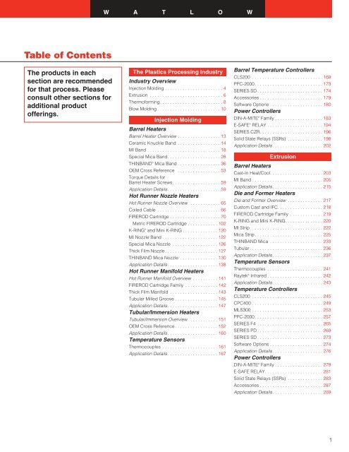
W A T L O WTable of ContentsThe products in eachsection are re<s<strong>tr</strong>ong>com</s<strong>tr</strong>ong>mendedfor that process. Pleaseconsult other sections foradditional productofferings.The Plastics Processing Indus<strong>tr</strong>yIndus<strong>tr</strong>y OverviewInjection Molding . . . . . . . . . . . . . . . . . . . . . . . 4Ex<strong>tr</strong>usion . . . . . . . . . . . . . . . . . . . . . . . . . . . . . 6Thermoforming. . . . . . . . . . . . . . . . . . . . . . . . . 8Blow Molding . . . . . . . . . . . . . . . . . . . . . . . . . 10Injection Molding<s<strong>tr</strong>ong>Barrel</s<strong>tr</strong>ong> <s<strong>tr</strong>ong>Heaters</s<strong>tr</strong>ong><s<strong>tr</strong>ong>Barrel</s<strong>tr</strong>ong> Heater Overview . . . . . . . . . . . . . . . . . 13Ceramic Knuckle Band . . . . . . . . . . . . . . . . . 14MI Band . . . . . . . . . . . . . . . . . . . . . . . . . . . . . 18Special Mica Band. . . . . . . . . . . . . . . . . . . . . 28THINBAND ® Mica Band . . . . . . . . . . . . . . . . . 36OEM Cross Reference . . . . . . . . . . . . . . . . . 53Torque Details for<s<strong>tr</strong>ong>Barrel</s<strong>tr</strong>ong> Heater Screws. . . . . . . . . . . . . . . . . . . 59Application Details. . . . . . . . . . . . . . . . . . . . . 59Hot Runner Nozzle <s<strong>tr</strong>ong>Heaters</s<strong>tr</strong>ong>Hot Runner Nozzle Overview . . . . . . . . . . . . 65Coiled Cable . . . . . . . . . . . . . . . . . . . . . . . . . 66FIREROD Car<strong>tr</strong>idge . . . . . . . . . . . . . . . . . . . . 70Me<strong>tr</strong>ic FIREROD Car<strong>tr</strong>idge . . . . . . . . . . . . 102K-RING ® and Mini K-RING . . . . . . . . . . . . . . 120MI Nozzle Band . . . . . . . . . . . . . . . . . . . . . . 122Special Mica Nozzle . . . . . . . . . . . . . . . . . . 126Thick Film Nozzle. . . . . . . . . . . . . . . . . . . . . 127THINBAND Mica Nozzle . . . . . . . . . . . . . . . 130Application Details. . . . . . . . . . . . . . . . . . . . 138Hot Runner Manifold <s<strong>tr</strong>ong>Heaters</s<strong>tr</strong>ong>Hot Runner Manifold Overview . . . . . . . . . . 141FIREROD Car<strong>tr</strong>idge Family . . . . . . . . . . . . . 142Thick Film Manifold . . . . . . . . . . . . . . . . . . . 143Tubular Milled Groove . . . . . . . . . . . . . . . . . 145Application Details. . . . . . . . . . . . . . . . . . . . 147Tubular/Immersion <s<strong>tr</strong>ong>Heaters</s<strong>tr</strong>ong>Tubular/Immersion Overview . . . . . . . . . . . 151OEM Cross Reference . . . . . . . . . . . . . . . . . 152Application Details. . . . . . . . . . . . . . . . . . . . 160Temperature SensorsThermocouples . . . . . . . . . . . . . . . . . . . . . . 161Application Details. . . . . . . . . . . . . . . . . . . . 167<s<strong>tr</strong>ong>Barrel</s<strong>tr</strong>ong> Temperature Con<strong>tr</strong>ollersCLS200 . . . . . . . . . . . . . . . . . . . . . . . . . . . . 169PPC-2000. . . . . . . . . . . . . . . . . . . . . . . . . . . 173SERIES SD . . . . . . . . . . . . . . . . . . . . . . . . . . 174Accessories . . . . . . . . . . . . . . . . . . . . . . . . . 179Software Options . . . . . . . . . . . . . . . . . . . . . 180Power Con<strong>tr</strong>ollersDIN-A-MITE ® Family . . . . . . . . . . . . . . . . . . . 183E-SAFE ® RELAY . . . . . . . . . . . . . . . . . . . . . . 194SERIES CZR. . . . . . . . . . . . . . . . . . . . . . . . . 196Solid State Relays (SSRs) . . . . . . . . . . . . . . 198Application Details. . . . . . . . . . . . . . . . . . . . 202Ex<strong>tr</strong>usion<s<strong>tr</strong>ong>Barrel</s<strong>tr</strong>ong> <s<strong>tr</strong>ong>Heaters</s<strong>tr</strong>ong>Cast-In Heat/Cool. . . . . . . . . . . . . . . . . . . . . 203MI Band . . . . . . . . . . . . . . . . . . . . . . . . . . . . 205Application Details. . . . . . . . . . . . . . . . . . . . 215Die and Former <s<strong>tr</strong>ong>Heaters</s<strong>tr</strong>ong>Die and Former Overview . . . . . . . . . . . . . . 217Custom Cast and IFC. . . . . . . . . . . . . . . . . . 218FIREROD Car<strong>tr</strong>idge Family . . . . . . . . . . . . . 219K-RING and Mini K-RING. . . . . . . . . . . . . . . 220MI S<strong>tr</strong>ip . . . . . . . . . . . . . . . . . . . . . . . . . . . . 222Mica S<strong>tr</strong>ip. . . . . . . . . . . . . . . . . . . . . . . . . . . 225THINBAND Mica . . . . . . . . . . . . . . . . . . . . . 233Tubular. . . . . . . . . . . . . . . . . . . . . . . . . . . . . 236Application Details. . . . . . . . . . . . . . . . . . . . 237Temperature SensorsThermocouples . . . . . . . . . . . . . . . . . . . . . . 241Raytek ® Infrared . . . . . . . . . . . . . . . . . . . . . . 242Application Details. . . . . . . . . . . . . . . . . . . . 243Temperature Con<strong>tr</strong>ollersCLS200 . . . . . . . . . . . . . . . . . . . . . . . . . . . . 245CPC400 . . . . . . . . . . . . . . . . . . . . . . . . . . . . 249MLS300 . . . . . . . . . . . . . . . . . . . . . . . . . . . . 253PPC-2000. . . . . . . . . . . . . . . . . . . . . . . . . . . 257SERIES F4 . . . . . . . . . . . . . . . . . . . . . . . . . . 265SERIES PD . . . . . . . . . . . . . . . . . . . . . . . . . . 269SERIES SD . . . . . . . . . . . . . . . . . . . . . . . . . . 273Software Options . . . . . . . . . . . . . . . . . . . . . 274Application Details. . . . . . . . . . . . . . . . . . . . 276Power Con<strong>tr</strong>ollersDIN-A-MITE ® Family . . . . . . . . . . . . . . . . . . . 279E-SAFE RELAY. . . . . . . . . . . . . . . . . . . . . . . 281Solid State Relays (SSRs) . . . . . . . . . . . . . . 283Accessories . . . . . . . . . . . . . . . . . . . . . . . . . 287Application Details. . . . . . . . . . . . . . . . . . . . 2891
Table of ContentsThe products in eachsection are re<s<strong>tr</strong>ong>com</s<strong>tr</strong>ong>mendedfor that process. Pleaseconsult other sections foradditional productofferings.Thermoforming<s<strong>tr</strong>ong>Heaters</s<strong>tr</strong>ong>Radiant . . . . . . . . . . . . . . . . . . . . . . . . . . . . 291S<strong>tr</strong>ip . . . . . . . . . . . . . . . . . . . . . . . . . . . . . . . 314Radiant Band and S<strong>tr</strong>ip Emitters . . . . . . . . . 325Application Details. . . . . . . . . . . . . . . . . . . . 326Temperature Con<strong>tr</strong>ollersCLS200 . . . . . . . . . . . . . . . . . . . . . . . . . . . . 329CPC400 . . . . . . . . . . . . . . . . . . . . . . . . . . . . 330MLS300 . . . . . . . . . . . . . . . . . . . . . . . . . . . . 331PPC-2000. . . . . . . . . . . . . . . . . . . . . . . . . . . 332SERIES D8 . . . . . . . . . . . . . . . . . . . . . . . . . . 333SERIES PD . . . . . . . . . . . . . . . . . . . . . . . . . . 337SERIES SD . . . . . . . . . . . . . . . . . . . . . . . . . . 341Application Details. . . . . . . . . . . . . . . . . . . . 342Temperature SensorsThermocouples . . . . . . . . . . . . . . . . . . . . . . 343RAYTEK Infrared . . . . . . . . . . . . . . . . . . . . . 344Application Details. . . . . . . . . . . . . . . . . . . . 349Power Con<strong>tr</strong>ollersDIN-A-MITE Family. . . . . . . . . . . . . . . . . . . . 351E-SAFE RELAY. . . . . . . . . . . . . . . . . . . . . . . 353SERIES CZR . . . . . . . . . . . . . . . . . . . . . . . . 355Solid State Relays (SSRs) . . . . . . . . . . . . . . 357Application Details. . . . . . . . . . . . . . . . . . . . 361Blow Molding<s<strong>tr</strong>ong>Heaters</s<strong>tr</strong>ong>FIREROD Car<strong>tr</strong>idge Family . . . . . . . . . . . . . 363MI Band . . . . . . . . . . . . . . . . . . . . . . . . . . . . 364Radiant. . . . . . . . . . . . . . . . . . . . . . . . . . . . . 368Application Details. . . . . . . . . . . . . . . . . . . . 372Con<strong>tr</strong>ol SystemsCapabilities . . . . . . . . . . . . . . . . . . . . . . . . . 373Packaging<s<strong>tr</strong>ong>Heaters</s<strong>tr</strong>ong>Cable . . . . . . . . . . . . . . . . . . . . . . . . . . . . . . 377Custom Cast and IFC. . . . . . . . . . . . . . . . . . 378FIREROD Car<strong>tr</strong>idge Family . . . . . . . . . . . . . 379Thick Film . . . . . . . . . . . . . . . . . . . . . . . . . . 380Tubular . . . . . . . . . . . . . . . . . . . . . . . . . . . . 381Application Details. . . . . . . . . . . . . . . . . . . . 383Temperature and Power Con<strong>tr</strong>ollersTemperature and Power Con<strong>tr</strong>oller Overview . 387Resources and InformationConversion Charts . . . . . . . . . . . . . . . . . . . . 389Ohms Law, Application Guide Details. . . . . 395Power Con<strong>tr</strong>ollers. . . . . . . . . . . . . . . . . . . . . 404Con<strong>tr</strong>oller Replacement Guide . . . . . . . . . . 408Wiring Practices. . . . . . . . . . . . . . . . . . . . . . 409Thermocouple and Extension WireColor Codes . . . . . . . . . . . . . . . . . . Back Cover2
W A T L O WIndus<strong>tr</strong>y SegmentOverviewsPlastics ProcessingSelecting the right auxiliary equipmentcan assist the plastics processor'sgoal of higher productivity andgreater yields. It is more than justthe cost of heaters, sensors or con<strong>tr</strong>ollers;it's performance that counts.With Watlow's thermal <s<strong>tr</strong>ong>com</s<strong>tr</strong>ong>ponentsprocessors can count on less downtimedue to increased heater reliability;and a reduction in operatingcosts due to energy conservation -both of which help achieve greateroutput. Watlow has provided plasticprocessors with product innovationsfor injection molding, thermoformingand ex<strong>tr</strong>usion operations and blowmolding for more than 50 years.Quality, innovation and reliability arethe hallmarks of our family ofheaters, sensors and con<strong>tr</strong>ollers.Watlow provides not only <strong>tr</strong>aditionalthermal solutions, but also innovative,high-performance technologiesto meet the specific processingdemands of indus<strong>tr</strong>ies such as automotive,medical and packaging,requiring highly-engineered resinsand tight tolerances.Whether OEM, custom or captiveprocessor - Watlow has your thermalsolution with our <strong>tr</strong>aditional products,new technologies, engineeringservices and global manufacturingcapabilities.Plastics Processing Indus<strong>tr</strong>yIndus<strong>tr</strong>y Segment Overviews3
Indus<strong>tr</strong>y SegmentOverviewsInjection MoldingInjection molding is the most versatileof all plastics processing methodsand is used to make a wide variety ofproducts. Watlow provides a broadrange of heaters, sensors and con<strong>tr</strong>ollersfor various applications.Applications include:• Automotive• Consumer products• Medical, dental equipment• Small appliances, hand tools• Agricultural, lawn equipment• Containers and closures• Aircraft, aerospace• Personal care products• Computer, business and officeequipment• Elec<strong>tr</strong>ical, elec<strong>tr</strong>onics• Furniture, fixtures• Recreation, toys and sportinggoods• Communications equipment• Food service, institutional products• Packaging• Transportation• Building, cons<strong>tr</strong>uctionProducts like our barrel heaters areideal for highly engineered or filledresins that require higher temperaturesand tighter tolerances.Regardless of your machine tonnage,Watlow has the product to fityour need, such as:• Multiple barrel heaters• Sprue heaters• Temperature con<strong>tr</strong>ollers• Mercury-free power switchingdevices• Temperature sensors4
W A T L O WIndus<strong>tr</strong>y SegmentOverviewsInjection MoldingPlastics Processing Indus<strong>tr</strong>yIndus<strong>tr</strong>y Segment OverviewsHot Runner Nozzle <s<strong>tr</strong>ong>Heaters</s<strong>tr</strong>ong>• Coiled Cable• FIREROD ® Car<strong>tr</strong>idge• K-RING ®• MI Nozzle Bands• Thick Film Nozzle• THINBAND Mica NozzleHot Runner Manifold <s<strong>tr</strong>ong>Heaters</s<strong>tr</strong>ong>• FIREROD ® Car<strong>tr</strong>idge• Thick Film Manifold• Tubular Milled GrooveTemperature Sensors• ThermocouplesPower Con<strong>tr</strong>ollers• DIN-A-MITE ® s• E-SAFE ® RELAY• SERIES CZR• Solid State RelaysTemperature Con<strong>tr</strong>ollers• CLS200• PPC-2000• SERIES SD<s<strong>tr</strong>ong>Barrel</s<strong>tr</strong>ong> <s<strong>tr</strong>ong>Heaters</s<strong>tr</strong>ong>• Ceramic Knuckle Bands• MI Bands• THINBAND ® Mica Bands5
Indus<strong>tr</strong>y SegmentOverviewsEx<strong>tr</strong>usionProduct quality begins ups<strong>tr</strong>eam.Regardless of your ex<strong>tr</strong>usion system,Watlow's family of thermal solutionsprovides the high-performance, reliabilityand accuracy needed to optimizeyour process.Whether OEM or end-user, many oftoday's applications require processcon<strong>tr</strong>ol data as well as history documentationto <s<strong>tr</strong>ong>com</s<strong>tr</strong>ong>ply with variouspolicies and regulations. Manyprocessors proactively seekproducts that offer both <strong>tr</strong>aceabilityand product repeatability. Watlow'sproduct solutions bridge the gap byproviding evidence of overall productquality, assuring processrepeatability and shortening overallstartup time.Watlow has the heaters, sensors andcon<strong>tr</strong>ollers for your ex<strong>tr</strong>usionprocess:• Blown film and cast film• Profile, shapes and rods• Flat sheet and web ex<strong>tr</strong>usion• Wire and cable coating• Pipe tubing and conduit ex<strong>tr</strong>usionApplications include:• Larger diameter band heaters forsingle- or multi-layer blown filmdies• PPC-2000 for advanced ex<strong>tr</strong>usioncon<strong>tr</strong>ol and system rebuilds• High- and low-watt densitycar<strong>tr</strong>idge heaters for a varietyprofile and shape dies• SERIES SD con<strong>tr</strong>ollers withPalm PDA for a low-cost dataacquisition interface• Cast-in and a variety of bandheaters for <strong>tr</strong>aditional barrelheating• S<strong>tr</strong>ip heaters for versatile surfacedie and former heating• A <s<strong>tr</strong>ong>com</s<strong>tr</strong>ong>prehensive offering ofmercury-free power con<strong>tr</strong>ollers• Traditional and hand-heldtemperature sensors6
W A T L O WIndus<strong>tr</strong>y SegmentOverviewsEx<strong>tr</strong>usionTemperatureCon<strong>tr</strong>ollers• CLS200• CPC400• MLS300• PPC-2000• SERIES F4• SERIES PD• SERIES SDPower Con<strong>tr</strong>ollers• DIN-A-MITE ® s• E-SAFE ® RELAY• Solid State RelaysPlastics Processing Indus<strong>tr</strong>yIndus<strong>tr</strong>y Segment OverviewsDie and Former <s<strong>tr</strong>ong>Heaters</s<strong>tr</strong>ong>• Custom Cast and IFC• FIREROD ® Car<strong>tr</strong>idge• K-RING ®• MI S<strong>tr</strong>ip• Mica S<strong>tr</strong>ip• THINBAND ® Mica• TubularTemperature Sensors• Thermocouples• RAYTEK ® Infrared<s<strong>tr</strong>ong>Barrel</s<strong>tr</strong>ong> <s<strong>tr</strong>ong>Heaters</s<strong>tr</strong>ong>• Cast-In Heat/Cool• MI Bands7
Indus<strong>tr</strong>y SegmentOverviewsThermoformingIn recent years, thermoforming partdesign has developed rapidly andbe<s<strong>tr</strong>ong>com</s<strong>tr</strong>ong>e more multifaceted. Becausethe thermoforming process offersadvantages such as superior finishedpart quality and the ability to formlarge parts, processors are:• investing in larger and fastermachines• expanding both ups<strong>tr</strong>eam anddowns<strong>tr</strong>eam servicesAlthough thermoforming consists of abroad range of materials, materialthicknesses and processing levels,Watlow can help optimize yourprocess. Whether you require a'sealed face' heater to keep sheet/rollcontaminants away from the elementwhile offering ease-of-cleaning andlonger life, or overall precise processcon<strong>tr</strong>ol, Watlow's family of heater,temperature sensor and con<strong>tr</strong>ollersolutions can meet your needs.Regardless of the application, Watlowhas the solution to meet your need:• <s<strong>tr</strong>ong>Heaters</s<strong>tr</strong>ong>- Radiant, S<strong>tr</strong>ip andTubular• Con<strong>tr</strong>ol System Con<strong>tr</strong>ollers-CLS200, CPC400, MLS300,PPC-2000 and SERIES SD/PD• Power Con<strong>tr</strong>ollers- DIN-A-MITE ® ,E-SAFE ® , SERIES CZR andSolid State Relays• Sensors- Infrared non-contact andother Richmond productsApplications include:• Vacuum forming• High definition thermoforming• Pressure assisted thermoforming• Drape forming• Press forming• Line bending8
W A T L O WIndus<strong>tr</strong>y SegmentOverviewsThermoformingTemperature Con<strong>tr</strong>ollers• CLS200 • SERIES D8• CPC400 • SERIES PD• MLS300 • SERIES SD• PPC-2000Power Con<strong>tr</strong>ollers• DIN-A-MITE ® s• E-SAFE ® RELAY• SERIES CZR• Solid State RelayPlastics Processing Indus<strong>tr</strong>yIndus<strong>tr</strong>y Segment Overviews<s<strong>tr</strong>ong>Heaters</s<strong>tr</strong>ong>• Radiant• S<strong>tr</strong>ip• Radiant Bandand S<strong>tr</strong>ip EmittersTemperature Sensors• Raytek ® Infrared• Thermocouples9
Indus<strong>tr</strong>y SegmentOverviewsBlow MoldingBlow molding is the art and scienceof making the hollow plastic containersthat are indispensable parts ofeveryday life. Common processingtechniques such as ex<strong>tr</strong>usion, s<strong>tr</strong>etchblow, injection and co-ex<strong>tr</strong>usion areall utilized in forming these parts.Whether it is a diverse and <s<strong>tr</strong>ong>com</s<strong>tr</strong>ong>plexpart that requires high performancesuch as an elastically functionalautomotive <s<strong>tr</strong>ong>com</s<strong>tr</strong>ong>ponent; or ahigh-volume hollow piece such asa single-serve PET water bottle, thefront-end blow molding process stillrequires an exacting thermal solution.Regardless of your resin choice orfinal part shape, Watlow has anextensive offering of heaters, sensorsand con<strong>tr</strong>ollers to meet the applicationrequirements.Applications include:• Automotive <s<strong>tr</strong>ong>com</s<strong>tr</strong>ong>ponents• Double-walled cases and tonercar<strong>tr</strong>idges• Food and beverage packaging• Medical feeding containers• Specialty consumer containers for:• Personal care products• Household products• Aggressive chemicals• Sporting goods• Toys10
W A T L O WIndus<strong>tr</strong>y SegmentOverviewsBlow MoldingPlastics Processing Indus<strong>tr</strong>yIndus<strong>tr</strong>y Segment OverviewsBand <s<strong>tr</strong>ong>Heaters</s<strong>tr</strong>ong>• FIREROD ® Car<strong>tr</strong>idge<s<strong>tr</strong>ong>Barrel</s<strong>tr</strong>ong> <s<strong>tr</strong>ong>Heaters</s<strong>tr</strong>ong>• MI Bands• Mica Bands• Radiant• THINBAND ®Temperature Con<strong>tr</strong>ollers• CLS200• CPC400• MLS300• PPC-2000• SERIES D8• SERIES PD• SERIES SDPower Con<strong>tr</strong>ollers• DIN-A-MITE ® s• E-SAFE RELAY• SERIES CZRCommunications• Ethernet• DeviceNetTemperature Sensors• Thermocouples• Heat/Cool Cast-Ins• MI Bands• Mica Bands• Radiant• THINBAND ® Mica Bands11
W A T L O W<s<strong>tr</strong>ong>Barrel</s<strong>tr</strong>ong> <s<strong>tr</strong>ong>Heaters</s<strong>tr</strong>ong>Watlow’s Familyof <s<strong>tr</strong>ong>Barrel</s<strong>tr</strong>ong> HeaterSolutionsWatlow offers a full line of barrelheaters for the plastics indus<strong>tr</strong>y.While every Watlow heater has aunique set of qualities, each Watlowbarrel heater is designed with theneeds of plastics processors in mind.Whether you require high performance,high temperature, high wattdensity, or all of these, Watlow hasthe heater to best fit your application.Watlow’s family of barrel heatersinclude:• Ceramic knuckle heaters• MI band heaters• THINBAND ® mica heatersThese barrel heaters are ideallysuited to meet the demands oftoday’s new resins and provide awide range of benefits including:• High performance materials suchas Watlow’s exclusive mineralinsulation and high temperatureceramics which con<strong>tr</strong>ibute toexcellent insulation and longheater life• Aluminized and stainless steelsheaths resulting in corrosionresistance• Flexible designs ensuring easyinstallation and removalApplications• Injection molding machines• Ex<strong>tr</strong>usion equipment• Blown film dies<s<strong>tr</strong>ong>Barrel</s<strong>tr</strong>ong> Heater Termination andClamping OptionsTermination OptionsWatlow offers a large selection oftermination styles providing theopportunity to customize the heaterto a particular application forimproved performance. Some terminationchoices include, but are notlimited to, Post Terminals, StainlessSteel Braids, Flexible Lead Wire,Flexible Stainless Steel Hose andEuropean Style Plugs (Horizontaland Vertical).Clamping OptionsIn addition to Watlow’s offering ofvarious termination styles, we alsooffer a variety of clamping options.Some of these clamping options are,but are not limited to, Tig Welded<s<strong>tr</strong>ong>Barrel</s<strong>tr</strong>ong> Nuts, Low Profile Clamp Bars,Clamping Pads and HV Wedge-Lok.For more information on Watlow’sline of barrel heaters, contact yourlocal Watlow representative.Injection Molding<s<strong>tr</strong>ong>Barrel</s<strong>tr</strong>ong> <s<strong>tr</strong>ong>Heaters</s<strong>tr</strong>ong>13
<s<strong>tr</strong>ong>Barrel</s<strong>tr</strong>ong> <s<strong>tr</strong>ong>Heaters</s<strong>tr</strong>ong>Ceramic KnuckleBandCeramic knuckle band heaters aredesigned to provide high-performancebarrel heating at temperaturesup to 760°C (1400°F). This level ofperformance is achieved from theceramic knuckles that provide excellentinsulation and long heater life.The cons<strong>tr</strong>uction of the ceramicknuckle heater includes interlockingceramic blocks with resistance wiresthreaded through holes within theceramic. This method providessuperior heat dis<strong>tr</strong>ibution across theband, resulting in a uniformly heatedsurface. Ceramic knuckle heatersare specifically engineered andmanufactured with three layers:• Aluminized steel sheath layerimproves mechanical protectionto heater and resists corrosion.• Ceramic fiber layer providesthermal insulation, energy conservationand minimizes heat loss.• Ceramic knuckle layer providesmechanical protectionand elec<strong>tr</strong>ical insulation to theresistance element, whichincreases heater life and conductsor radiates the heat tothe surface.Performance Capabilities• 760°C (1400°F) maximumoperational temperatures• Watt densities up to 45 W/in 2Features and BenefitsCeramic insulator• Allows for high temperatureoperation• Provides longer heater life• Accurate heatingAluminized steel cover• Provides excellent protection fromabrasionRadiation or conduction heat<strong>tr</strong>ansfer• Ensures dependable heat <strong>tr</strong>ansfermethodStandard Cons<strong>tr</strong>uction• Aluminized sheath• Clamp tabs• Post terminalsApplications• Injection molding barrels• Ex<strong>tr</strong>uder barrels• Blown film dies14
W A T L O W<s<strong>tr</strong>ong>Barrel</s<strong>tr</strong>ong> <s<strong>tr</strong>ong>Heaters</s<strong>tr</strong>ong>Ceramic KnuckleBandSpecificationsElec<strong>tr</strong>icalResistance tolerance: -10 percent (+5 percent)Wattage tolerance: +10 percent (-5 percent)Maximum watt density: 114 W/cm 2 (45 W/in 2 )Maximum operating temperature: 760°C (1400°F)Termination OptionsMechanicalOverall thickness: 12.7 mm (0.5 in.)Minimum width: 38.1 mm (1.5 in.)Maximum width: 246 mm (9.69 in.)Minimum I.D.: 50.8 mm (2 in.)Maximum I.D.: 381 mm (15 in.)*Width tolerance: ±3.175 mm (0.125 in.)Standard gap: 6.35 mm (0.25 in.)*One piece cons<strong>tr</strong>uctionInjection Molding<s<strong>tr</strong>ong>Barrel</s<strong>tr</strong>ong> <s<strong>tr</strong>ong>Heaters</s<strong>tr</strong>ong>Post Terminals are the standard termination, providingquick connection with ring or fork connectors or busss<strong>tr</strong>ips, 1 ⁄4 -20 inch thread and includes double nuts andwashers. Standard terminal location is 180° from gap.Stainless Steel Braid method includes a loose metalbraid that is welded to the terminal box with a coupler.This provides excellent abrasion protection and flexibility.Leads are attached to posts with ring connectors.Flexible Lead Wire exits tangential to heater and includesleads connected to the post terminals with ring connectors.This termination method requires a terminal box.Note: These are all standard termination options, for special cons<strong>tr</strong>uctionsplease consult factory.Flexible Stainless Steel Hose is welded to the terminalbox with a coupler. This terminal option provides superiormechanical protection where lead abrasion is a problem.Leads are attached to posts with ring connectors.15
<s<strong>tr</strong>ong>Barrel</s<strong>tr</strong>ong> <s<strong>tr</strong>ong>Heaters</s<strong>tr</strong>ong>Ceramic KnuckleBandClamping OptionsEuropean Style Plugs provide a simple and safe way toapply power. The <s<strong>tr</strong>ong>com</s<strong>tr</strong>ong>bination of high temperature maleand female quick disconnect plug assemblies eliminateall live exposed terminals and elec<strong>tr</strong>ical wiring. Whenordering, specify vertical or horizontal European Plug.Vertical<s<strong>tr</strong>ong>Barrel</s<strong>tr</strong>ong> Clamps are used in applicationswhere access for ins<strong>tr</strong>umentationis required. Includes an oversized gap.HorizontalSpring Loaded <s<strong>tr</strong>ong>Barrel</s<strong>tr</strong>ong> Clamps helpto <s<strong>tr</strong>ong>com</s<strong>tr</strong>ong>pensate for the thermalexpansion of metals.Clamp Tabs are a standard clampingoption that offer a uniform clampingforce across the heater width.Latch And Trunion Clamps providea quick clamp option. Clamping forceis similar to barrel clamps and aspring is included to allow for thermalexpansion of metals.16Physical LimitationsOptions I.D. Width Terminals ClampMin. Max. Min. Max.mm (in.) mm (in.) mm (in.) mm (in.)One piece 64 (2.5) 381 (15) 38 (1.5) 254 (10) — —Partial 178 (7) — — 38 (1.5) 248 (9.75) — Exceptcoverageclamp tabsClamp tabs 64 (2.5) 381 (15) 38 (1.5) 254 (10) — —<s<strong>tr</strong>ong>Barrel</s<strong>tr</strong>ong> nuts 102 (4) — — 38 (1.5) 254 (10) — —Spring loaded 102 (4) — — 38 (1.5) 254 (10) — —barrel nutsLatch and 76 (3) — — 38 (1.5) 254 (10) — —<strong>tr</strong>union clampsStud terminals — — — — — — 254 (10) — —Flexible leads 64 (2.5) — — 64 (2.5) 254 (10) — —SS hose leads 64 (2.5) — — 64 (2.5) 254 (10) — —SS braided 64 (2.5) — — 64 (2.5) 254 (10) — —leadsTerminal box 64 (2.5) — — 64 (2.5) 254 (10) — —Holes and 64 (2.5) — — 64 (2.5) 254 (10) — —notchesCeramic cover 51 (2) — — 38 (1.5) 254 (10) Post —Terminal 76 (3) — — 64 (2.5) 248 (9.75) Post with —clampterminal boxEuropean Plug 64 (2.5) — — 51 (2) 254 (10) — —both verticaland horizontal— No res<strong>tr</strong>ictions.Note: These are all standard clamping options, for special cons<strong>tr</strong>uctionsplease consult factory.
W A T L O W<s<strong>tr</strong>ong>Barrel</s<strong>tr</strong>ong> <s<strong>tr</strong>ong>Heaters</s<strong>tr</strong>ong>Ceramic KnuckleBandOptions:Terminal box provides protection forelec<strong>tr</strong>ical connections in hazardousenvironments.Partial coverage helps heating oflarge pipes and covers large diameterswith two or more sections.Dimensional drawings are requiredwhen ordering.T/C bracket 3 ⁄8 NPT necessary forins<strong>tr</strong>umentation. A dimensionaldrawing is required when ordering.Holes and notches necessary forins<strong>tr</strong>ument access, etc. Heater mustbe 63.5 mm (2.5 in.) minimum widthand 63.5 mm (2.5 in.) minimum I.D.;dimensional drawing required whenordering.Ceramic terminal covers provideeasy installation and protect elec<strong>tr</strong>icalconnections on each individualterminal.Other Options:• Dual voltage (factory approvalrequired)• Stainless steel sheath• Ground stud• Ground lead• Three-phase voltage (factoryapproval required)Ceramic Band Heater Check List:• The surface where a heater willbe mounted must be clean andthe heater maintained free of allcontaminants that might causea short circuit in the heater(typically conductive liquids).• To prevent overheating, Watlowre<s<strong>tr</strong>ong>com</s<strong>tr</strong>ong>mends installing an appropriatetemperature con<strong>tr</strong>oller andchecking the correct performanceof the thermocouple.• Do not use in environmentscontaining <s<strong>tr</strong>ong>com</s<strong>tr</strong>ong>bustible gasesor vapors.• Keep all elec<strong>tr</strong>ical connectionsproperly protected to avoidelec<strong>tr</strong>ical hazards to machineoperators.• Do not over tighten clamps to thepoint where serrated side foldsbegin to collapse. Ceramic bandheaters utilize radiation heatingand excessive force may breakceramic insulators.Injection Molding<s<strong>tr</strong>ong>Barrel</s<strong>tr</strong>ong> <s<strong>tr</strong>ong>Heaters</s<strong>tr</strong>ong>17
W A T L O W<s<strong>tr</strong>ong>Barrel</s<strong>tr</strong>ong> <s<strong>tr</strong>ong>Heaters</s<strong>tr</strong>ong>MI BandApplications andTechnical Data• Review Watt Density chart onpage 20 to ensure that theapplication does not exceed themaximum watt density atoperating temperature afterapplying derating factors.• Locate clamping guideline for unitdiameter, width and watt density.• Description of guideline lettersare below.• Note: Upward arrows are up toand not including specified wattdensity. Downward arrows aregreater than or equal to specifiedwatt density.MI <s<strong>tr</strong>ong>Barrel</s<strong>tr</strong>ong> Clamping Ma<strong>tr</strong>ix Application GuideDia.8 > 10 10 > 12 12 > 14 14 > 16 16 > 18 18 > 20 20 > 22 22 > 24 24 > 26 26 > 28Watt Density–W/in 28075706560555045403530252015100Width1 1 2 in. 4 1 2 in.to 4in.BAto 7in.BA1 1 2 in.to 4in.BA4 1 2 in.to 7in.BA1 1 2 in.to 4in.BA4 1 2 in.to 7in.BA1 1 2 in.to 4in.DC4 1 2 in.to 7in.DC1 1 2 in. 4 11 2 in. 1 1 2 in. 4 1 2 in.to 4in.DCto 7in.to 4in.to 7in.1 1 2 in.to 4in.4 1 2 in.to 7in.1 1 2 in.to 4in.4 1 2 in.to 7in.Above Re<s<strong>tr</strong>ong>com</s<strong>tr</strong>ong>mended Watt DensitiesConsult EngineeringA = Standard clamping, expandable or one piece cons<strong>tr</strong>uction Width Clamp Points at Each GapB = Spring clamps, expandable or one piece cons<strong>tr</strong>uction ≥ 127 mm (5 in.) 3C = Spring clamps, at one gap, welded barrel nuts at other gap ≥ 76.2 mm (3 in.) 2D = Spring clamps, spring clamps at both gaps < 76.2 mm (3 in.) 1DCDCDCDCDCDCDC1 1 2 in.to 4in.DC4 1 2 in.to 7in.DC1 1 2 in.to 4in.DC4 1 2 in.to 7in.DCInjection Molding<s<strong>tr</strong>ong>Barrel</s<strong>tr</strong>ong> <s<strong>tr</strong>ong>Heaters</s<strong>tr</strong>ong>MI Installation Procedures - For Standard Product1.Install heaters over a cleansurface.2.After installing the unit, begin totighten the clamp screw. Thestandard clamping screw is6.35 mm-508 x 31.75 mm(0.25 in.-20 x 1.25 in.), nickelplated allen head cap screw.Begin tightening the clamp bars.If the clamp bars appear not tohave seated, tap the clamp barswith a small hammer to insure thebars are well seated in the angleformed by the 60 degree bent taband the heater.3.If the bar has multiple screws,alternately tighten the screws at10 lb-in. as you would the lug nutson a car wheel to insure evenloading.4.Torque all screws toapproximately 80 lb-in. (9-N-M).5.When installing terminal lugs,torque the top nuts to 15-20 lb-in.or 2.26 N meters.21
<s<strong>tr</strong>ong>Barrel</s<strong>tr</strong>ong> <s<strong>tr</strong>ong>Heaters</s<strong>tr</strong>ong>MI BandTermination VariationsLeads Type B, Type B—90 degreeRotation,Type B—180 degreeRotation or Type C: Two fiberglassinsulatedlead wires exit in a singlemetal braid for good abrasionprotection, lead flexibility and wiringconvenience. Leads are 51 mm(2 in.) longer than braid. Shippedwith 305 mm (12 in.) leads, unlesslonger length is specified. To order,specify type and length.Type BStock17 mm(0.67 in.)9 mm(0.36 in.)I.D.32 mm(1.250 in.)305 mm(12 in.)4 mm(0.16 in.)21 mm(0.812 in.)Width ± . 1.6 mm(0.0625 in.)Type B—90 Degree RotationNon-Stock9 mm(0.36 in.)16 mm(0.625 in.)Nom.Type B—180 Degree RotationStock17 mm(0.67 in.)Type CStock4.90 mm(0.191 in.)9 mm(0.36 in.)I.D.32 mm(1.250 in.)16.70 mm Dia.(0.656 in.)14.10 mm(0.557 in.)4 mm(0.16 in.)21 mm(0.812 in.)Width ± 1.6 mm(0.0625 in.)305 mm(12 in.)19.05 mm Nom.(0.75 in.)I.D.Post TerminalsStockType EStockType FStock19 mm(0.75 in.)I.D.4 mm(0.16 in.)16 mm (0.625 in.)Nom.4.90 mm(0.191 in.)16.70 mm Dia.(0.656 in.)16.10 mm(0.635 in. )19.05 mm Nom.(0.75 in. )4.90 mm(0.191 in.)16.70 mm Dia.(0.656 in.)16.10 mm(0.635 in.)19.05 mm Dia.(0.75 in.)17 mm(0.67 in.)I.D.I.D.2232 mm(1.250 in.)Width ± 1.6 mm(0.0625 in.)Post terminals provide optimumconnections. Screw thread is 10-24.To order, specify post terminals.Type KStock4.90 mm(0.191 in.)I.D.16.70 mm Dia.(0.656 in.)14.10 mm(0.557 in.)19.05 mm Nom.(0.75 in.)Type K: Flexible lead wires exit verticallyfrom the heater. These leadscan be bent adjacent to the heaterfor a quick and easy connection. Toorder, specify Type K and length.Type E: Loose metal braid enclosestwo fiberglass leads for goodabrasion protection, lead flexibilityand wiring convenience. Leads are51 mm (2 in.) longer than braid.Shipped with 305 mm (12 in.) leads,unless longer length is specified. Toorder, specify Type E and length.Type HStock4.90 mm(0.191 in.)I.D.16.70 mm Dia.(0.656 in.)16.10 mm(0.635 in.)19.05 mm Nom.(0.75 in.)Type F: Loose fiberglass sleevingencloses two fiberglass leads foradditional insulation protectionwhere high temperature or minorabrasion is present. Leads are51 mm (2 in.) longer than thesleeving. To order, specify Type Fand length.Type H: A flexible steel hoseencloses the leads for maximumabrasion protection. Leads are51 mm (2 in.) longer than hose.Shipped with 305 mm (12 in.) leads,unless longer length is specified. Toorder, specify Type H and length.
W A T L O W<s<strong>tr</strong>ong>Barrel</s<strong>tr</strong>ong> <s<strong>tr</strong>ong>Heaters</s<strong>tr</strong>ong>MI BandVariationsLead Wire<s<strong>tr</strong>ong>Heaters</s<strong>tr</strong>ong> rated at less than250VÅ(ac) use UL ® approved leadinsulation for operations to 250°C(480°F) as standard. Lead insulationUL ® rated for operation to 450°C(840°F) is available for hightemperature applications where theleads are shrouded or enclosed withthe heater. These leads are availablein any of the Type B with loose braidas well as Types E, F and H leadconfigurations. All heaters rated atmore than 250VÅ(ac) use this wire.When ordering, specify 450˚C(850°F) wire.ThermocoupleASTM Type J or K internal thermocouplesare available on lead Type Bwith loose braid. The thermocouplejunction, which is welded inside thelead cap or spot-welded to heatersheath, provides a signal for measuringrelative heater temperature.Spot welded toheater sheathInjection Molding<s<strong>tr</strong>ong>Barrel</s<strong>tr</strong>ong> <s<strong>tr</strong>ong>Heaters</s<strong>tr</strong>ong>Expandable <s<strong>tr</strong>ong>Heaters</s<strong>tr</strong>ong> With and Without Leads38 mm (1.5 in.) wideand greaterExpandable heaters are two-pieceunits with a <s<strong>tr</strong>ong>com</s<strong>tr</strong>ong>mon top metal thatallows the heater to expand open tothe full diameter of the barrel. Onexpandable bands, each half will beone half of the total wattage. Plus,on both expandable and two-piecebands, each half will be rated at fulloperating voltage, unless otherwisespecified.MI Band heaters 38 mm (1.5 in.)wide or greater will have postterminals located next to theexpansion joint. Leads may belocated anywhere along thecircumference except near the gapand at the expansion joint. Two setsof leads are required.On 25 mm (1 in.) wide MI Bandheaters, post terminals will belocated 90 degrees from theexpansion joint. Leads may belocated anywhere along thecircumference except near the gapand at the expansion joint. Two setsof leads are required. To order,specify expandable.11 mm(0.4375 in.)S<strong>tr</strong>ain ReliefType SLETwo fiberglass lead wires exit asingle tightly woven metal braid a<strong>tr</strong>ight angle on the expandablecons<strong>tr</strong>uction verses two sets ofleads. Minimum diametercapabilities is 100 mm (4 in.).Minimum width capabilities is38 mm (1.5 in.). To order, specifyType SLE and length.UL ® is a registered <strong>tr</strong>ademark ofUnderwriter's Laboratories, Inc.23
<s<strong>tr</strong>ong>Barrel</s<strong>tr</strong>ong> <s<strong>tr</strong>ong>Heaters</s<strong>tr</strong>ong>MI BandVariationsContinued57 mm(2.25 in.)41 mm(1.625 in.)46 mm(1.8125 in.)33 mm(1.3125 in.)102 mm(4 in.)51 mm(2 in.)High Temperature “Quick Disconnect” European Style PlugsThese plugs provide the simplestand safest way to apply power tobarrel heaters. The <s<strong>tr</strong>ong>com</s<strong>tr</strong>ong>bination ofhigh temperature male and femalequick disconnect plug assemblieseliminates all live exposed terminalsand elec<strong>tr</strong>ical wiring that can be apotential hazard to employees ormachine. Maximum 15 amps at240VÅ(ac), maximum volts 240. Toorder, specify vertical or horizontalEuropean Plug.VerticalHorizontalHigh Temperature “Quick Disconnect” European Style Female AdaptersAvailable as an accessory item thatmust be used in conjunction withhigh temperature “quick disconnect”European Style Plugs. To order,specify code number N2027AF049or N6027ZZ028 and quantity.Right AngleCode# N6027AF049S<strong>tr</strong>aightCode# N6027ZZ0286.4 mm(0.250 in.)Heavy Duty S<strong>tr</strong>ain ReliefHeavy duty s<strong>tr</strong>ain relief isre<s<strong>tr</strong>ong>com</s<strong>tr</strong>ong>mended for applicationswhere there is great s<strong>tr</strong>ess orcontinued flexing of the leads.The s<strong>tr</strong>ain relief is available onType B, Type B—90 degree andType B—180 degree leads only. Toorder, specify heavy duty s<strong>tr</strong>ainrelief.Ceramic Terminal CoverCeramic covers, with openingsfor leads, are screwed on to postterminals, providing a convenient,economical insulator. To order,specify code number Z-4918 andquantity.46 mm(1.8125 in.)3.5 in. for 3.5-5.9375 in. I.D.4 in. for 6-28 in. I.D.37 mm(1.4375 in.)Metallic Terminal BoxMetallic terminal boxes are availablefrom stock on 89 mm x 38 mm(3.5 in. inside diameter x 1.5 in. wide)or larger heaters. Terminal boxes,which attach directly to the heater, actas a safety feature by covering theterminals. Conduit may be attachedto the box through 22 mm (0.875 in.)diameter holes in the ends of the box.Two piece heaters require two boxes.To order, specify terminal box.Oversized terminal boxes areavailable on heaters 51 mm (2 in.)and wider. Consult a Watlowrepresentative.24
W A T L O W<s<strong>tr</strong>ong>Barrel</s<strong>tr</strong>ong> <s<strong>tr</strong>ong>Heaters</s<strong>tr</strong>ong>MI BandVariationsContinuedMI Band Heater With HolesMI Band heaters with holes areavailable on all widths except25.4 mm (1 in.) wide. Consult theWatlow factory in St. Louis, Missourifor hole sizes and location res<strong>tr</strong>aints.To order, specify hole size andlocation. 76.2 mm (3 in.) insidediameter minimum.11 mm(0.420 in.)22 mm(0.875 in.)Clamping VariationsOutside Diameter HeaterTwo fiberglass insulated lead wiresrated to 450°C (840°F) exit a metalbraid 180 degrees opposite fromgap, Type B outside diameterdesigned and cons<strong>tr</strong>ucted to mateTig Welded <s<strong>tr</strong>ong>Barrel</s<strong>tr</strong>ong> Nuts With Spring Loaded Clampingwith inside diameter of cylinders.To order, specify outside diameterheater. Note that 76.2 mm (3 in.) isthe minimum cylinder I.D.Injection Molding<s<strong>tr</strong>ong>Barrel</s<strong>tr</strong>ong> <s<strong>tr</strong>ong>Heaters</s<strong>tr</strong>ong>147 mm (5.8 in.)19 mm(0.75 in.)Welded barrel nuts with springloaded clamping are used duringstart-up to maintain a tight heater fiton large barrels. This clampingvariation is standard for all MI <s<strong>tr</strong>ong>Barrel</s<strong>tr</strong>ong>heaters that are greater than355 mm (14 in.) in diameter and38 mm (1.5 in.) or greater in width.Refer to MI <s<strong>tr</strong>ong>Barrel</s<strong>tr</strong>ong> Clamping Ma<strong>tr</strong>ixApplication Guide, page 21. Forsmaller diameter heaters, this isan option and must be orderedseparately. To order, specify springloaded clamping.Tig Welded <s<strong>tr</strong>ong>Barrel</s<strong>tr</strong>ong> NutsTig Welded14 mm(0.563 in.)An ideal way to provide accessfor ins<strong>tr</strong>umentation is to specify anoversized gap between the heaterends. If the clamp bar screwinterferes with the positioning ofthe ins<strong>tr</strong>umentation device, weldedbarrel nuts are re<s<strong>tr</strong>ong>com</s<strong>tr</strong>ong>mended. Toorder, specify tig welded barrelnuts and gap dimension whenordering.Low Profile Tig Welded <s<strong>tr</strong>ong>Barrel</s<strong>tr</strong>ong> NutsLow profile barrel nuts are availableon all widths. Low profile barrel nutshave a clearance of 10 mm(0.406 in.). To order, specify lowprofile tig welded barrel nuts.Low Profile Clamp Bars11 mm(0.45 in.)I.D.Low profile clamp bars are availableon both one 25 mm (1 in.) and38 mm (1.5 in.) wide heaters, forwider widths consult factory. Thebars are 6 mm (0.25 in.) diameterwith an 8-32 screw. To order, specifylow profile clamp bars.25
<s<strong>tr</strong>ong>Barrel</s<strong>tr</strong>ong> <s<strong>tr</strong>ong>Heaters</s<strong>tr</strong>ong>MI BandMI Stock ProductWattApprox.I.D. Width Cons<strong>tr</strong>uction Volts Watts Density Termination Net. Wt. Avail. Code No.mm (in.) mm (in.) W/cm 2 (W/in 2 ) kg (lbs)25.4 (1) 25.4 (1) 1pc 120 100 9.4 (61) Type B,C,E or H 0.05 (0.1) Stock MB1A1AN225.4 (1) 1pc 120 150 14.2 (92) Type B,C,E or H 0.05 (0.1) Stock MB1A1AN125.4 (1) 1pc 120 200 18.9 (122) Type B,C,E or H 0.05 (0.1) Stock MB1A1AN325.4 (1) 1pc 240 200 18.9 (122) Type B,C,E or H 0.05 (0.1) Stock MB1A1AN438.1 (1 1 ⁄2) 1pc 120 200 10.8 (70) Type B,C,E or H 0.05 (0.1) Stock MB1A1JN438.1 (1 1 ⁄2) 1pc 240 200 10.8 (70) Type B,C,E or H 0.05 (0.1) Stock MB1A1JN338.1 (1 1 ⁄2) 1pc 120 300 16.4 (106) Type B,C,E or H 0.05 (0.1) Stock MB1A1JN238.1 (1 1 ⁄2) 1pc 240 300 16.4 (106) Type B,C,E or H 0.05 (0.1) Stock MB1A1JN138.1 (1 1 ⁄2) 1pc 240 400 21.8 (141) Type B,C,E or H 0.05 (0.1) Stock MB1A1JN531.8 (1 1 ⁄4) 25.4 (1) 1pc 120 250 16.1 (104) Type B,C,E or H 0.05 (0.1) Stock MB1E1AN225.4 (1) 1pc 240 250 16.1 (104) Type B,C,E or H 0.05 (0.1) Stock MB1E1AN125.4 (1) 1pc 240 300 19.2 (124) Type B,C,E or H 0.05 (0.1) Stock MB1E1AN338.1 (1 1 ⁄2) 1pc 120 350 13.5 (87) Type B,C,E or H 0.09 (0.2) Stock MB1E1JN238.1 (1 1 ⁄2) 1pc 240 350 13.5 (87) Type B,C,E or H 0.09 (0.2) Stock MB1E1JN138.1 (1 1 ⁄2) 1pc 240 450 17.3 (112) Type B,C,E or H 0.09 (0.2) Stock MB1E1JN331.8 (1 1 ⁄4) 25.4 (1) 1pc 120 200 9.6 (62) Type B,C,E or H 0.05 (0.1) Stock MB1J1AN425.4 (1) 1pc 240 200 9.6 (62) Type B,C,E or H 0.05 (0.1) Stock MB1J1AN325.4 (1) 1pc 120 300 14.4 (93) Type B,C,E or H 0.05 (0.1) Stock MB1J1AN225.4 (1) 1pc 240 300 14.4 (93) Type B,C,E or H 0.05 (0.1) Stock MB1J1AN125.4 (1) 1pc 240 400 19.3 (125) Type B,C,E or H 0.05 (0.1) Stock MB1J1AN538.1 (1 1 ⁄2) 1pc 120 300 9.0 (58) Type B,C,E or H 0.09 (0.2) Stock MB1J1JN138.1 (1 1 ⁄2) 1pc 240 300 9.0 (58) Type B,C,E or H 0.09 (0.2) Stock MB1J1JN338.1 (1 1 ⁄2) 1pc 240 300 10.0 (64) Post 0.09 (0.2) Stock MB1J1JP438.1 (1 1 ⁄2) 1pc 240 450 13.5 (87) Type B,C,E or H 0.09 (0.2) Stock MB1J1JN238.1 (1 1 ⁄2) 1pc 240 450 14.8 (96) Post 0.09 (0.2) Stock MB1J1JP638.1 (1 1 ⁄2) 1pc 240 600 17.9 (116) Type B,C,E or H 0.09 (0.2) Stock MB1J1JN450.8 (2) 1pc 240 300 6.5 (42) Type B,C,E or H 0.14 (0.3) Stock MB1J2AN250.8 (2) 1pc 240 450 8.8 (57) Type B,C,E or H 0.14 (0.3) Stock MB1J2AN150.8 (2) 1pc 240 900 19.3 (125) Type B,C,E or H 0.14 (0.3) Stock MB1J2AN376.2 (3) 1pc 240 350 4.8 (31) Type B,C,E or H 0.18 (0.4) Stock MB1J3AN276.2 (3) 1pc 240 500 7.0 (45) Type B,C,E or H 0.18 (0.4) Stock MB1J3AN176.2 (3) 1pc 240 1000 16.1 (104) Type B,C,E or H 0.18 (0.4) Stock MB1J3AN3CONTINUED26
W A T L O W<s<strong>tr</strong>ong>Barrel</s<strong>tr</strong>ong> <s<strong>tr</strong>ong>Heaters</s<strong>tr</strong>ong>MI BandWattApprox.I.D. Width Cons<strong>tr</strong>uction Volts Watts Density Termination Net. Wt. Avail. Code No.mm (in.) mm (in.) W/cm 2 (W/in 2 ) kg (lbs)44.5 (1 3 ⁄4) 38.1 (1 1 ⁄2) 1pc 120 300 7.7 (50) Type B,C,E or H 0.09 (0.2) Stock MB1N1JN238.1 (1 1 ⁄2) 1pc 240 300 7.3 (47) Type B,C,E or H 0.09 (0.2) Stock MB1N1JN138.1 (1 1 ⁄2) 1pc 240 700 17.0 (110) Type B,C,E or H 0.09 (0.2) Stock MB1N1JN350.8 (2) 1pc 240 750 13.3 (86) Type B,C,E or H 0.14 (0.3) Stock MB1N2AN150.8 (2) 25.4 (1 1 ⁄2) 1pc 120 350 11.3 (73) Type B,C,E or H 0.09 (0.2) Stock MB2A1AN225.4 (1 1 ⁄2) 1pc 240 350 11.3 (73) Type B,C,E or H 0.09 (0.2) Stock MB2A1AN125.4 (1 1 ⁄2) 1pc 240 450 14.5 (94) Type B,C,E or H 0.09 (0.2) Stock MB2A1AN338.1 (1 1 ⁄2) 1pc 240 400 8.2 (53) Type B,C,E or H 0.14 (0.3) Stock MB2A1JN138.1 (1 1 ⁄2) 1pc 240 1000 20.4 (132) Type B,C,E or H 0.14 (0.3) Stock MB2A1JN250.8 (2) 1pc 240 750 11.3 (73) Type B,C,E or H 0.18 (0.4) Stock MB2A2AN150.8 (2) 1pc 240 1200 19.3 (125) Type B,C,E or H 0.18 (0.4) Stock MB2A2AN257.2 (2 1 ⁄4) 63.5 (2 1 ⁄2) 1pc 240 1000 11.2 (72) Type B,C,E or H 0.23 (0.5) Stock MB2E2JN163.5 (2 1 ⁄2) 25.4 (1) 1pc 240 400 9.7 (63) Type B,C,E or H 0.09 (0.2) Stock MB2J1AN138.1 (1 1 ⁄2) 1pc 240 500 7.7 (50) Type B,C,E or H 0.18 (0.4) Stock MB2J1JN176.2 (3) 25.4 (1) 1pc 240 400 8.4 (54) Post 0.14 (0.3) Stock MB3A1AP138.1 (1 1 ⁄2) 1pc 240 500 6.2 (40) Post 0.18 (0.4) Stock MB3A1JP138.1 ( 1 ⁄2) 2pc exp 230/460 525 8.2 (53) Post 0.18 (0.4) Stock ME3A1JP1088.9 (3 1 ⁄2) 50.8 (2) 1pc 240 800 6.5 (42) Post 0.32 (0.7) Stock MB3J2AP292.1 (3 5 ⁄8) 38.1 (1 1 ⁄2) 2pc exp 230/460 650 7.9 (51) Post 0.23 (0.5) Stock ME3L1JP5101.6 (4) 38.1 (1 1 ⁄2) 2pc exp 230/460 625 6.7 (43) Post 0.27 (0.6) Stock ME4A1JP1138.1 (1 1 ⁄2) 2pc exp 230/460 725 7.8 (50) Post 0.27 (0.6) Stock ME4A1JP1238.1 (1 1 ⁄2) 1pc 240 800 7.4 (48) Post 0.27 (0.6) Stock MB4A1JP2114.3 (4 1 ⁄2) 63.5 (2 1 ⁄2) 1pc 240 1250 6.2 (40) Post 0.45 (1.0) Stock MB4J2JP1127.0 (5) 38.1 (1 1 ⁄2) 2pc exp 240/480 1000 8.1 (52) Post 0.36 (0.8) Stock ME5A1JP8133.4 (5 1 ⁄4) 38.1 (1 1 ⁄2) 2pc exp 230/460 600 4.5 (29) Post 0.32 (0.7) Stock ME5E1JP938.1 (1 1 ⁄2) 2pc exp 240/480 1000 7.4 (48) Post 0.36 (0.8) Stock ME5E1JP176.2 (3) 2pc exp 230/460 1700 6.2 (40) Post 0.68 (1.5) Stock ME5E3AP5139.7 (5 1 ⁄2) 38.1 (1 1 ⁄2) 2pc exp 240/480 1000 7.1 (46) Post 0.40 (0.9) Stock ME5J1JP1152.4 (6) 38.1 (1 1 ⁄2) 2pc exp 240/480 1000 6.4 (41) Post 0.40 (0.9) Stock ME6A1JP2165.1 (6 1 ⁄2) 38.1 (1 1 ⁄2) 2pc exp 240/480 1250 7.3 (47) Post 0.45 (1.0) Stock ME6J1JP5171.5 (6 3 ⁄4) 38.1 (1 1 ⁄2) 2pc exp 230/460 815 4.5 (29) Post 0.40 (0.9) Stock ME6N1JP638.1 (1 1 ⁄2) 2pc exp 230/460 1000 5.6 (36) Post 0.40 (0.9) Stock ME6N1JP7101.6 (4) 2pc exp 230/460 2600 5.4 (35) Post 1.1 (2.5) Stock ME6N4AP2127.0 (5) 2pc exp 230/460 3700 6.2 (40) Post 1.5 (3.2) Stock ME6N5AP3152.4 (6) 2pc exp 230/460 3750 5.1 (33) Post 1.7 (3.8) Stock ME6N6AP5177.8 (7) 38.1 (1 1 ⁄2) 2pc exp 240/480 1250 6.6 (43) Post 0.50 (1.1) Stock ME7A1JP4190.5 (7 1 ⁄2) 38.1 (1 1 ⁄2) 2pc exp 240/480 1500 7.3 (47) Post 0.50 (1.1) Stock ME7J1JP4193.7 (7 5 ⁄8) 76.2 (3) 2pc exp 230/460 1800 4.3 (28) Post 1.0 (2.2) Stock ME7L3AP1203.2 (8) 38.1 (1 1 ⁄2) 2pc exp 240/480 1250 5.7 (37) Post 0.54 (1.2) Stock ME8A1JP4228.6 (9) 38.1 (1 1 ⁄2) 2pc exp 240/480 1500 6.0 (39) Post 0.64 (1.4) Stock ME9A1JP1241.3 (9 1 ⁄2) 76.2 (3) 2pc exp 230/460 3000 5.7 (37) Post 1.2 (2.6) Stock ME9J3AP2285.8 (11 1 ⁄4) 76.2 (3) 2pc exp 230/460 2400 3.7 (24) Post 1.5 (3.2) Stock ME11E3AP2127.0 (5) 2pc exp 230/460 5100 4.8 (31) Post 2.4 (5.2) Stock ME11E5AP1Injection Molding<s<strong>tr</strong>ong>Barrel</s<strong>tr</strong>ong> <s<strong>tr</strong>ong>Heaters</s<strong>tr</strong>ong>How to OrderTo order your stock MI Bandheater, specify:• Quantity• Watlow code number• Options• Lead type and length, orterminal type configuration(If code number has an “N” asthe last letter in the code, youmust specify termination typeand lead length. 305 mm (12 in.)leads will be supplied unlessotherwise specified).AvailabilityStock: Same day shipment onMI Band heaters with post terminalsor 305 mm (12 in.)Type B leads. Longer lead lengthsor other terminations will ship nextday.Made-to-order: If stock units do notmeet application needs, Watlowcan manufacture MI Band heatersto special requirements. Pleaseconsult a Watlow sales engineer orauthorized dis<strong>tr</strong>ibutor.27
<s<strong>tr</strong>ong>Barrel</s<strong>tr</strong>ong> <s<strong>tr</strong>ong>Heaters</s<strong>tr</strong>ong>Special Mica BandFor over 80 years, Watlow has beensolving <s<strong>tr</strong>ong>com</s<strong>tr</strong>ong>plex and unique applicationproblems with standard micaband heaters. Watlow is continuouslyimproving design and applicationknowledge through engineeringexpertise and experience withnumerous OEM and end-userapplications.This has resulted in the developmentof many specialty variations incons<strong>tr</strong>uction resulting in the bestheat solutions. This catalog containsa sampling of what can be done.Please contact a local Watlow salesengineer or dis<strong>tr</strong>ibutor for customapplications.Performance Capabilities• Sheath temperatures to 480°C(900°F)• Watt densities to 7.0 W/cm 2(4.5 W/in 2 )Features and Benefits• UL ® <s<strong>tr</strong>ong>com</s<strong>tr</strong>ong>ponent recognitionavailable for applications up to480°C (900°F) sheath temperature.• Patented clamping s<strong>tr</strong>ap assuresefficient heat <strong>tr</strong>ansfer.• Low mass design allows fastheat-up and quick response.• Design variations provide userconvenience and heaterprotection.Applications• Injection molding barrels• Ex<strong>tr</strong>udersSS S<strong>tr</strong>apResistance RibbonMica InsulationZinc SteelPost Terminals28
W A T L O W<s<strong>tr</strong>ong>Barrel</s<strong>tr</strong>ong> <s<strong>tr</strong>ong>Heaters</s<strong>tr</strong>ong>Special Mica BandApplications andTechnical DataOperating FactorsUse as a low watt density rating as theapplication permits. A close match ofthe heat supplied to the actual requirementswill reduce temperature overshoot,reduce cycling and increase thelife of any band heater used.Calculate the safe maximum wattagefor the heater using:Heated Area x MaximumWatt DensityCalculate the heated area of the bandheater by sub<strong>tr</strong>acting the no-heat areafrom the total area in contact with thecylinder (3.14 x I.D. x width). Sub<strong>tr</strong>actthe no-heat area at the terminals(from table) and any additionalno-heat area caused by holes, slotsor oversize gaps.Determine the maximum watt densityof the heater from the graph on thispage. The curves are based onnarrow heaters mounted on a smooth,steel cylinder. Apply the necessarycorrection factors:• For heaters 57 mm (2.25 in.) to127 mm (5 in.) wide, multiply wattdensity by 0.8.• For high expansion cylinders(aluminum or brass), reduce thewatt density by 0.46 W/cm 2 (3 W/in 2 ).• For heaters 63.5 to 127 mm (2.25 in.to 5 in.) wide installed on a highexpansion cylinder, reduce wattdensity by a total of 0.46 W/cm 2(3 W/in 2 ) only.• For regular cylinder surfaces otherthan smooth, machined finish,reduce watt density by 0.46 W/cm 2(3 W/in 2 ).• For heaters that will be insulatedor enclosed, contact Watlow forspecific watt densities.No-Heat Area for Special Mica Band (Post Terminals)Heater SizeNo-Heat AreaHeater Diameter Width at TerminalsType mm (in.) mm (in.) mm (in.)One PieceTwo PieceCylinder Temperature—°F1100100090080070060050040030050.8 (Less than 2) 152.4 (Up to 6) 25.4 (1 x width)50.8 (2 or more)76.2 (3 or more)76.2 (Up to 3) 38.1 (1.5 x width)76.2 (More than 3) 25.4 (1 x width)76.2 (Up to 3) 76.2 (3 x width)76.2 (More than 3) 50.8 (2 x width)Maximum Allowable Watt DensityWatt Density—W/cm 22 4 6 8254 mm (10 in.) Dia.10020010 20 30 40 50 60Watt Density—W/in 276.2 mm (3 in.) Dia.500400300200Cylinder Temperature—°CInjection Molding<s<strong>tr</strong>ong>Barrel</s<strong>tr</strong>ong> <s<strong>tr</strong>ong>Heaters</s<strong>tr</strong>ong>29
<s<strong>tr</strong>ong>Barrel</s<strong>tr</strong>ong> <s<strong>tr</strong>ong>Heaters</s<strong>tr</strong>ong>Special Mica BandPhysical Limitations ofVariationsCheck the table to be certain thevariations and lead arrangementsbeing ordered are available on theheater size required. If you need toexceed any limitations please contacta Watlow representative.Physical Limitations of VariationsDiameterWidthHeater Type Min. Max. Min. Max.mm (in.) mm (in.) mm (in.) mm (in.)1 pc. 33.3 (1 5 ⁄16) 559 (22) 15.8 ( 5 ⁄8) 381 (15)2 pc. 76.2 (3) 1117 (44) 15.8 ( 5 ⁄8) 381 (15)Expandable:Narrow 44.4 (1 3 ⁄4) — — 25.4 (1) 76.2 (3)Wide 44.4 (1 3 ⁄4) — — 50.8 (2) 152.4 (6)O.D. heater:1 pc. 76.2 (3) 559 (22) 25.4 (1) 76.2 (6)2 pc. 76.2 (3) 1117 (44) 25.4 (1) 76.2 (6)Type K leads 19.05 ( 3 ⁄4) — — 15.8 ( 5 ⁄8) 381 (15)Type L leads 19.05 ( 3 ⁄4) — — 19.05 ( 5 ⁄8) 381 (15)Type E leads 38.1 (1 1 ⁄2) 559 (22) 19.05 ( 5 ⁄8) 381 (15)Type F leads 38.1 (1 1 ⁄2) 559 (22) 19.05 ( 5 ⁄8) 381 (15)Type H leads 38.1 (1 1 ⁄2) 559 (22) 19.05 ( 5 ⁄8) 381 (15)Type B leads 38.1 (1 1 ⁄2) 559 (22) 19.05 ( 5 ⁄8) 381 (15)Post terminal: 33.3 (1 5 ⁄16) — — 25.4 (1) 381 (15)Type A leads 19 ( 3 ⁄4) — — 19 ( 3 ⁄4) 381 (15)Type C leads 33.3 (1 5 ⁄16) — — 25.4 (1) 381 (15)Terminal box 88.9 (3 1 ⁄2) — — 34.9 (1 3 ⁄8) 381 (15)Plug w/bracket 76.2 (3) — — 88.9 (3 1 ⁄2) 381 (15)3-phase — — — — 76.2 (3) 381 (15)European Plug:1 pc. vertical 33.3 (1 5 ⁄16) 559 (22) 25.4 (1) 381 (15)1 pc. horizontal 76.2 (3) 559 (22) 50.8 (2) 381 (15)2 pc. vertical 76.2 (3) 1117 (44) 25.4 (1) 381 (15)2 pc. horizontal 76.2 (3) 1117 (44) 50.8 (2) 381 (15)HV Wedge-Lok 2.5.4 (1) 76.2 (3) 25.4 (1) 76.2 (6)Clamping tabs 50.8 (2) — — 25.4 (1) 381 (15)Welded <s<strong>tr</strong>ong>Barrel</s<strong>tr</strong>ong> Nuts1 pc. 50.8 (2) 559 (22) 25.4 (1) 381 (15)2 pc. 101.6 (4) 1117 (44) 25.4 (1) 381 (15)Note: Some <s<strong>tr</strong>ong>com</s<strong>tr</strong>ong>binations of maximum and minimums cannotoccur on the same heater.Standard gap is 6.35 mm (0.25 in.)VariationsDifferent WidthsThe 38 mm (1.5 in.) wide heater isthe most efficient due to maximumclamping action. <s<strong>tr</strong>ong>Heaters</s<strong>tr</strong>ong> areavailable in widths from 16 mm(0.625 in.) to 381 mm (15 in.).Multiple clamping s<strong>tr</strong>aps areprovided for heaters more than76 mm (3 in.) wide.Expandable <s<strong>tr</strong>ong>Heaters</s<strong>tr</strong>ong><s<strong>tr</strong>ong>Heaters</s<strong>tr</strong>ong> 76 mm (3 in.) wide or lessare cons<strong>tr</strong>ucted with a notchedsheath. <s<strong>tr</strong>ong>Heaters</s<strong>tr</strong>ong> wider than threeinches are cons<strong>tr</strong>ucted with anexpansion seam. These heatersare shipped open and should notbe closed and reopened more thantwice. To order, specify expandable.30
W A T L O W<s<strong>tr</strong>ong>Barrel</s<strong>tr</strong>ong> <s<strong>tr</strong>ong>Heaters</s<strong>tr</strong>ong>Special Mica BandVariationsContinued;;;;;;;;;;;;;;;;Holes and NotchesAn economical way to provideaccess for ins<strong>tr</strong>umentation is tospecify an oversize gap betweenthe heater ends. Holes and notchesin the sheath should be specifiedonly when all the cylinder surfacesadjacent to the hole or notch mustbe heated. When required, holesmay be provided in nearly anylocation as long as there is at least25 mm (1 in.) between the hole andone side of the heater. Standardhole sizes up to 51 mm (2 in.)diameter. For proper hole and/ornotch location, a dimensionaldrawing is required.Two Piece Band <s<strong>tr</strong>ong>Heaters</s<strong>tr</strong>ong>Two-piece cons<strong>tr</strong>uction is availableon heaters 76 mm (3 in.) or greater indiameter. <s<strong>tr</strong>ong>Heaters</s<strong>tr</strong>ong> three inches wideor less with post terminals have oneterminal on each end. <s<strong>tr</strong>ong>Heaters</s<strong>tr</strong>ong> overthree inches wide with post terminalshave the two terminals side by sideon one end. On two-piece units withleads, also specify the power supplyvoltage. The power supply voltage isthe voltage to which the heater will bewired. For example, a two-piece bandthat is 240VÅ(ac) per half may bewired in series to a 480VÅ(ac) powersupply. In this case the band heaterlead wire insulation must be rated for480VÅ(ac). To order, specify twopiece band heater, with volts andwatts per half and power supplyvoltage.Injection Molding<s<strong>tr</strong>ong>Barrel</s<strong>tr</strong>ong> <s<strong>tr</strong>ong>Heaters</s<strong>tr</strong>ong>Outside Diameter16 mm(0.625 in.)This variation is specially designedand cons<strong>tr</strong>ucted to heat the insidediameter of cylinders, i.e., largediameter blown film dies. All theterminations and mounting hardwareare located on the I.D. of the heater.Consult Watlow for available sizesand terminations. Option availableas standard mica cons<strong>tr</strong>uction only.To order, specify outside diameterheater.3.5 in. for 3.5-5.9375 in. I.D.4 in. for 6-39.9375 in. I.D. 37 mm(1.4375 in.)46 mm(1.8125 in.)Metallic Terminal BoxTerminal boxes are attached to theheater to cover the terminals for anadded safety feature. Conduit maybe attached to the box through22 mm (0.875 in.) diameter holes inthe ends of the box. Terminal box isavailable on two piece heaters. Whenordering, specify terminal box.See page 30 forminimum/maximumdimensional requirements.31
<s<strong>tr</strong>ong>Barrel</s<strong>tr</strong>ong> <s<strong>tr</strong>ong>Heaters</s<strong>tr</strong>ong>Special Mica BandVariationsContinued57 mm(2.25 in.)44 mm46 mm (1.75 in.)(1.8125 in.)59 mm 52 mm(2.3125 in.) (2.0625 in.)High Temperature “Quick Disconnect” European Style PlugsThese plugs provide the simplestand safest way to apply power toband heaters. The <s<strong>tr</strong>ong>com</s<strong>tr</strong>ong>bination ofhigh temperature male and femalequick disconnect plug assemblieseliminates all live exposed terminalsand elec<strong>tr</strong>ical wiring that can be apotential hazard to employees ormachine. Maximum amps 15 at240VÅ(ac), maximum volts 240.To order, specify vertical orhorizontal European Plug.33 mm(1.3125 in.)VerticalHorizontalHigh Temperature “Quick Disconnect” European Style Female AdaptersAvailable as an accessory item thatmust be used in conjunction withhigh temperature “quickdisconnect” European Style Plugs.Specify code number N6027AF049or N6027ZZ028 and quantity.Right AngleCode # N6027AF049S<strong>tr</strong>aightCode # N6027ZZ028Ceramic Terminal CoversStock OptionA convenient and economic way toinsulate post terminals. Sized forstandard length posts. 10-24 screwthread size. These are supplied asan accessory item and shippedseparately. Specify Z-4918 andquantity.Code # Z-4918Special Cons<strong>tr</strong>uctionVariationsSquare, Rectangular and Hex BandsSquare and rectangular heaters aremade in either one or two-piececons<strong>tr</strong>uction. These units are idealfor heating dies on plasticex<strong>tr</strong>uders, or the barrels of twinscrew ex<strong>tr</strong>uders. Hex-shapedheaters are <s<strong>tr</strong>ong>com</s<strong>tr</strong>ong>monly used on thehex shaped portion of the nozzleinjection molding machines. Hexshapedheaters are made to exactcustomer specifications. To order,specify square or rectangularheaters. A dimensional drawing isrequired.See page 30 forminimum/maximumdimensional requirements.32
W A T L O W<s<strong>tr</strong>ong>Barrel</s<strong>tr</strong>ong> <s<strong>tr</strong>ong>Heaters</s<strong>tr</strong>ong>Special Mica BandSpecial Cons<strong>tr</strong>uctionVariationsContinuedSquare, Rectangular and Hex Bands (continued)Clamping StylesThe preferred clamping style isillus<strong>tr</strong>ated in Figure 1 showing bentupflange clamping. This clampingstyle applies a uniform clampingforce at the corners.Figure 2 shows bent-up flanges orbuilt-in s<strong>tr</strong>apping bracket at the side.The least preferred clamping style isshown in Figure 3. The one-pieceheater does not apply a uniformclamping force."B""B""B""A""A""A"Figure 1 Figure 2 Figure 3Hinged Two-Piece BandThe hinged, two-piece band heateris connected with a reinforcedhinge. It can be opened and closedas often as necessary resulting ineasy installation and removal.To order, specify hinged two-pieceband and watts and volts per eachhalf.Injection Molding<s<strong>tr</strong>ong>Barrel</s<strong>tr</strong>ong> <s<strong>tr</strong>ong>Heaters</s<strong>tr</strong>ong>Thermocouple CouplingThe thermocouple couplingsimplifies the installation of anexternal thermocouple with athreaded fitting. The standardlocation for the coupling is90 degrees from the gap.Standard bushing sizes available are:NPT Size Depth Heightin. in. in.0.5 - 27 9⁄160.25 - 20 3⁄45⁄811⁄160.375 - 18 7⁄85⁄8To order, specify thermocouplecoupling.Bayonet AdapterThe bayonet adapter simplifies theinstallation of an externalthermocouple with a bayonetadapter. The standard location forthe adapter is 90 degrees from thegap. To order, specify bayonetadapter.33
<s<strong>tr</strong>ong>Barrel</s<strong>tr</strong>ong> <s<strong>tr</strong>ong>Heaters</s<strong>tr</strong>ong>Special Mica BandClamping Variations14 mm(0.563 in.)Standard and Low-ProfileClamping S<strong>tr</strong>apThe standard clamping s<strong>tr</strong>aprequires 14 mm (0.563 in.)clearance above the heated surface,at the barrel nuts. When clearance islimited, smaller barrel nuts can beused which require only 9 mm(0.375 in.) clearance. The clearancerequired by the clamping screwdepends on the screw length andthe diameter of the heater. The lowprofileclamping s<strong>tr</strong>ap is standard onunits less than 45 mm (1.375 in.)wide and utilizes a 13 mm (0.5 in.)wide s<strong>tr</strong>ap. Consult Watlow for moreinformation. To order, specifylow-profile clamping s<strong>tr</strong>ap.Spot Welded14 mm(0.563 in.)Welded <s<strong>tr</strong>ong>Barrel</s<strong>tr</strong>ong> NutsAn ideal way to provide accessfor ins<strong>tr</strong>umentation is to specify anoversized gap between the heaterends. If the clamp s<strong>tr</strong>ap interfereswith the positioning of theins<strong>tr</strong>umentation device,welded barrel nuts are re<s<strong>tr</strong>ong>com</s<strong>tr</strong>ong>mended.Maximum gap is 25 mm (1 in.)Specify welded barrel nuts andgap dimension when ordering.See page 30 forminimum/maximumdimensional requirements.34
W A T L O W<s<strong>tr</strong>ong>Barrel</s<strong>tr</strong>ong> <s<strong>tr</strong>ong>Heaters</s<strong>tr</strong>ong>Special Mica BandClamping VariationsContinuedNon-Stock OptionClamping TabsTabs—or lock-up flanges—areavailable. However, the special micaband heater and s<strong>tr</strong>ap designprovides superior clamping andimproved heat <strong>tr</strong>ansfer and shouldbe used whenever possible. Toorder, specify clamping tabs.Clamping PadsClamping pads have a hole to alloweasy fastening to machine barrel.Clamping pads are used when anobs<strong>tr</strong>uction hinders a standardclamping s<strong>tr</strong>ap from fitting <s<strong>tr</strong>ong>com</s<strong>tr</strong>ong>pletelyaround the machine barrel.To order, specify clamping padsand degrees coverage.As requiredClamping PadInjection Molding<s<strong>tr</strong>ong>Barrel</s<strong>tr</strong>ong> <s<strong>tr</strong>ong>Heaters</s<strong>tr</strong>ong>Termination VariationsPost Terminal OptionsStandard post terminals have athreaded length of 11 mm(0.4375 in.) and require 19 mm(0.75 in.) clearance from the cylinder.Terminals with 17 mm (0.6875 in.)threaded lengths are available tha<strong>tr</strong>equire one inch of clearance.Button terminals require only 11 mm(0.4375 in.) clearance. Maximumamperage for post terminals is35 amps. To order, specify standard,long or button terminals.11 mm (0.4375 in.)27 mm (0.6875 in.)19 mm (0.75 in.)Standard25 mm (1 in.)Long11 mm (0.4375 in.)ButtonThree Terminal Cons<strong>tr</strong>uctionA third terminal can be added toprovide dual voltage or three-heatoperation. Or, it can be connectedto the sheath for easy grounding.Standard terminal location on heaters76 mm (3 in.) wide or less is oneterminal at each end of the heatercentered on the width. On heatersthree inches wide or wider, the terminalsare located side-by-side onone end. Special terminal locationsare available. To order, specify dualvoltage or three-heat operation.35
• Same day shipment on more than 1000 variationsof THINBAND heaters.<s<strong>tr</strong>ong>Barrel</s<strong>tr</strong>ong> <s<strong>tr</strong>ong>Heaters</s<strong>tr</strong>ong>THINBAND ® MicaThe THINBAND ® heater is Watlow’spatented redesign of the mica band.THINBAND heaters deliver fast andinstall easily, keeping costs downand machines running.Performance Capabilities• Sheath temperatures to480°C (900°F)• Watt densities to 8.5 W/cm 2(55 W/in 2 )Features and Benefits• New flexible, one-piece designmakes installation faster on plasticprocessing equipment becausethe heater can be opened to thefull diameter of the barrel withoutinternal damage. The THINBANDheater can be installed on abarrel without removing otherband heaters already in place.• Same day shipment onmore than 1000 variations ofTHINBAND lead attachments isdue to Watlow’s exclusive LeadAdapter—or LA—manufacturingmethod. Customers can reduceinventories and costly downtime.• Only one set of leads orterminals is needed on theTHINBAND heater, unlike the twosets required on the cumbersometwo-piece replacement barrelheaters with s<strong>tr</strong>aps.Clamping Bars• QUICK CLAMP opens to fit overbarrels and snaps in place withone easy flip of its latching lever.No need to remove other heaters.• Permanently attachedclamping bars.• Contamination resistance.No folds on outside of heater.Zinc SteelInner SheathSide Foldsto the InsideDiameterPost TerminalsMica InsulationResistanceRibbonAluminizedSteel OutsideDiameterSheathApplications• Injection molding machines• Ex<strong>tr</strong>uders• Blown film dies36
W A T L O W<s<strong>tr</strong>ong>Barrel</s<strong>tr</strong>ong> <s<strong>tr</strong>ong>Heaters</s<strong>tr</strong>ong>THINBAND MicaApplications andTechnical DataOperating FactorsUse as low a watt density rating as yourapplication permits. A close match ofthe heat supplied to the actual requirementswill reduce temperatureovershoot, reduce cycling and increasethe life of any band heater you use.Calculate the safe maximum wattagefor your heater using:Heated Area x Maximum Watt DensityCalculate the heated area of your barrelheater by sub<strong>tr</strong>acting the no-heat areafrom the total area in contact with thecylinder (3.14 x I.D. x width). Sub<strong>tr</strong>actthe no-heat area at the terminals (fromtable) and any additional no-heat areacaused by holes, slots or oversize gaps.Determine the maximum watt density ofyour heater from the graph on this page.The curves are based on narrow heatersmounted on a smooth, steel cylinder.Apply the necessary correction factors:• For heaters 57 mm (2.25 in.) to127 mm (5 in.) wide, multiply wattdensity by 0.8.• For high expansion cylinders(aluminum or brass), reduce the wattdensity by 0.46 W/cm 2 (3 W/in 2 ).• For heaters 57 mm to 127 mm wide(2.25 in. to 5 in.) installed on a highexpansion cylinder, reduce wattdensity by a total of 0.46 W/cm 2(3 W/in 2 ) only.• For regular cylinder surfaces otherthan smooth, machined finish, reducewatt density by 0.46 W/cm 2 (3 W/in 2 ).• For heaters that will be insulatedor enclosed, contact Watlow forspecific watt densities.• For units greater than 355 mm (14 in.)diameter, consult re<s<strong>tr</strong>ong>com</s<strong>tr</strong>ong>mendedclamping graph on page 39.• For units used in verticalapplications, consult factory forapplication assistance.No-Heat Area for THINBAND (All Terminations)Heater SizeNo-Heat AreaHeater Diameter Width at TerminalsType mm (in.) mm (in.) mm (in.)One Piece 63.5 (Less than 2.5) 177.8 (Up to 7) 25.4 (1) x widthTwo Piece 127 (5 or more) 76.2 (More than 3) 50.8 (2) x widthCylinder Temperature—°F11001000900800700600500400300Maximum Allowable Watt DensityWatt Density—W/cm 22 4 6 810020010 20 30 40 50 60Watt Density—W/in 238.1 mm (1.5 in.) Dia.76.2 mm (3 in.) Dia.500400300200Cylinder Temperature—°CInjection Molding<s<strong>tr</strong>ong>Barrel</s<strong>tr</strong>ong> <s<strong>tr</strong>ong>Heaters</s<strong>tr</strong>ong>37
<s<strong>tr</strong>ong>Barrel</s<strong>tr</strong>ong> <s<strong>tr</strong>ong>Heaters</s<strong>tr</strong>ong>THINBAND MicaPhysical Limitations ofLead VariationsCheck the table to be certain thevariations and lead arrangementsyou order are available on theheater size you require. If you needto exceed any limitations pleasecontact a Watlow representative.32 mm(1.25 in.)Minimum63 mm (2.5 in.)Maximum368 mm (14.5 in.) 1pc.736 mm (29 in.) 2pc.THINBAND <s<strong>tr</strong>ong>Barrel</s<strong>tr</strong>ong>10-24thread2.8 mm(0.110 in.)Physical Limitations of Lead VariationsDiameterWidthHeater Type Min. Max. Min. Max.mm (in.) mm (in.) mm (in.) mm (in.)1 pc. const. 25.4 (1) 368.3 (14 1 ⁄2) 38.1 (1 1 ⁄2) 177.8 (7)2 pc. const. 127.0 (5) 736.6 (29) 38.1 (1 1 ⁄2) 177.8 (7)NozzleType A 25.4 (1) 101.6 (4) 25.4 (1) 152.4 (6)Type L 25.4 (1) 101.6 (4) 25.4 (1) 152.4 (6)<s<strong>tr</strong>ong>Barrel</s<strong>tr</strong>ong>Type T 63.5 (2 1 ⁄2) 38.1 (1 1 ⁄2) 177.8 (7)Type H 63.5 (2 1 ⁄2) 38.1 (1 1 ⁄2) 177.8 (7)Type F, FR 63.5 (2 1 ⁄2) 38.1 (1 1 ⁄2) 177.8 (7)Type E 63.5 (2 1 ⁄2) 38.1 (1 1 ⁄2) 177.8 (7)Type C, BR 63.5 (2 1 ⁄2) 38.1 (1 1 ⁄2) 177.8 (7)Type K, KR 63.5 (2 1 ⁄2) 38.1 (1 1 ⁄2) 177.8 (7)Terminal Box 88.9 (3 1 ⁄2) 38.1 (1 1 ⁄2) 177.8 (7)European Plug1 pc. vertical 63.5 (2 1 ⁄2) 368.3 (14 1 ⁄2) 38.1 (1 1 ⁄2) 177.8 (7)1 pc. horizontal 63.5 (2 1 ⁄2) 368.3 (14 1 ⁄2) 38.1 (1 1 ⁄2) 177.8 (7)Welded <s<strong>tr</strong>ong>Barrel</s<strong>tr</strong>ong> Nuts1 pc. 63.5 (2 1 ⁄2) 368.3 (14 1 ⁄2) 38.1 (1 1 ⁄2) 177.8 (7)Note: Some <s<strong>tr</strong>ong>com</s<strong>tr</strong>ong>binations of maximums and minimums cannot occur on thesame heater. Check the table to be certain the variations and lead arrangementsyou order are available on the heater size you require. If you need to exceedany limitations, please contact your Watlow representative.Standard gap is 9.53 mm (0.375 in.) between clamp bars.14 mm(0.5625 in.)Minimum 38 mm (1.5 in.)Maximum 177 mm (7 in.)38
W A T L O W<s<strong>tr</strong>ong>Barrel</s<strong>tr</strong>ong> <s<strong>tr</strong>ong>Heaters</s<strong>tr</strong>ong>THINBAND Mica<s<strong>tr</strong>ong>Barrel</s<strong>tr</strong>ong> HeaterQUICK CLAMP OptionQUICK CLAMP eliminates tools, loose parts and hassle• THINBAND opens up to fit overbarrel. There is no need to removeother heaters.• One easy flip of the latching leverand QUICK CLAMP shuts,<s<strong>tr</strong>ong>com</s<strong>tr</strong>ong>pleting installation.With QUICK CLAMP, the THINBANDheater can be secured tightly inplace in a matter of seconds. Thespring-loaded clamp secures theheater tightly around the barrel withan easy flip of the lever.Features and Benefits• THINBAND with QUICK CLAMPfits over barrels and snaps in placewith easy flip of its latching lever.• Hot change-outs are <s<strong>tr</strong>ong>com</s<strong>tr</strong>ong>pleted inseconds.• Spring tensioned clamp keepsthe THINBAND heater tightagainst barrel—won’t loosen overtime.• Ideal for vertical applications.• Available on selected stockand made-to-order THINBANDbarrel heaters—minimum100 mm (4 in.) diameter,38 mm (1.5 in.) width.• Standard gap is 12.7 mm (0.5 in.).Clearance DimensionsWidth Range Number of Distance Between Clampsmm (in.) Quick Clamps mm (in.)38.1 to 69.3 (1 1 ⁄2) to (2 11 ⁄16) 1 NA69.9 to 94.8 (2 D⁄4) to (3 11 ⁄16) 2 12.7 ( 1 ⁄2)69.9 to 120.1 (3 3 ⁄4) to (4 11 ⁄16) 2 25.4 (1)120.6 to 145.5 (4 3 ⁄4) to (5 11 ⁄16) 3 12.7 ( 1 ⁄2)146.1 to 145.5 11 (5 3 ⁄4) to (7) 3 25.4 (1)1.27 mm(0.5 in.)54 mm(2.125 in.)Injection Molding<s<strong>tr</strong>ong>Barrel</s<strong>tr</strong>ong> <s<strong>tr</strong>ong>Heaters</s<strong>tr</strong>ong>Re<s<strong>tr</strong>ong>com</s<strong>tr</strong>ong>mendedClamping OptionsTHINBAND <s<strong>tr</strong>ong>Barrel</s<strong>tr</strong>ong> ProductsClamp BarsClamp BarsOr QUICK CLAMPabove 101.6 mm (4 in.) diameterQUICK CLAMPFor 2 piece:Clamp bar at other gapCoil SpringFor 2 piece only:Clamp bar at other gapNotes: Widths 101.6 mm (4 in.) and over add50.8 mm (2 in.) to diameter then referencechart clamp selection.Watt Density (W/in 2 )50403020Diameter (millimeters)76 127 178 229 279 330 381 432 483 533 584 635 686 7371 Piece2 PieceAbove Re<s<strong>tr</strong>ong>com</s<strong>tr</strong>ong>mended Watt DensityConsult Engineering10 2 4 6 8 10 12 14 16 18 20 22 24 26 28Diameter (inches)765432Watt Density (W/cm 2 )39
<s<strong>tr</strong>ong>Barrel</s<strong>tr</strong>ong> <s<strong>tr</strong>ong>Heaters</s<strong>tr</strong>ong>THINBAND Mica<s<strong>tr</strong>ong>Barrel</s<strong>tr</strong>ong> HeaterClamping VariationsTig Welded <s<strong>tr</strong>ong>Barrel</s<strong>tr</strong>ong> Nuts With Spring Loaded Clamping147 mm (5.8 in.)19 mm(0.75 in.)Tig welded barrel nuts with springloaded clamping are used duringstart-up to maintain a tight heaterfit on large barrels. Stainless steeltop metal is required.Refer to the THINBAND re<s<strong>tr</strong>ong>com</s<strong>tr</strong>ong>mendedclamping graph on page 39.This option is mandatory on verticalapplications. To order, specifyspring loaded clamping.Tig Welded <s<strong>tr</strong>ong>Barrel</s<strong>tr</strong>ong> NutsTig Welded14 mm(0.563 in.)An ideal way to provide accessfor ins<strong>tr</strong>umentation is to specify anoversized gap between the heaterends. If the THINBAND clamp barscrew interferes with the positioningof the ins<strong>tr</strong>umentation device,tig welded barrel nuts are re<s<strong>tr</strong>ong>com</s<strong>tr</strong>ong>mended.Stainless steel top metal isrequired. Maximum gap is 25 mm(1 in.). Specify tig welded barrelnuts and gap dimension whenordering.Non-Stock OptionClamping PadsClamping pads are used when anobs<strong>tr</strong>uction would prevent astandard full circumferential heaterfrom fitting <s<strong>tr</strong>ong>com</s<strong>tr</strong>ong>pletely around amachine barrel. The clamping padshave a hole to allow easy fasteningto the machine barrel. Dimensionaldrawing required when ordering.VariationsNon-Stock OptionHolesAn economical way to provideaccess for ins<strong>tr</strong>umentation is tospecify an oversized gap betweenthe heater ends. A hole in the sheathshould be specified only when all thecylinder surface adjacent to the holemust be heated. When required,one hole may be provided innearly any location as long asthere is at least 25 mm (1 in.)between the hole and one side ofthe heater. Standard hole sizes upto 51 mm (2 in.) diameter. Consultfactory for limitations. For properhole location, a dimensional drawingis required.40
W A T L O W<s<strong>tr</strong>ong>Barrel</s<strong>tr</strong>ong> <s<strong>tr</strong>ong>Heaters</s<strong>tr</strong>ong>THINBAND Mica<s<strong>tr</strong>ong>Barrel</s<strong>tr</strong>ong> Heater VariationsContinued35 mm(1.375 in.)Stock LA OptionStock Option45 mm(1.75 in.)Non-Stock OptionStock Option48 mm(1.875 in.)73 mm(2.875 in.)60 mm(2.375 in.)Two-Piece <s<strong>tr</strong>ong>Barrel</s<strong>tr</strong>ong> <s<strong>tr</strong>ong>Heaters</s<strong>tr</strong>ong>Two-piece cons<strong>tr</strong>uction is availableon heaters 127 mm (5 in.) or greaterin diameter. <s<strong>tr</strong>ong>Heaters</s<strong>tr</strong>ong> 38 mm (1.5 in.)wide and greater with post terminalshave the two terminals side-by-side.Note: When ordering two-piecebarrel heaters, specify the volts andwatts per half. On two-piece unitswith leads, you must also specify thepower supply voltage. Example:a two-piece barrel that is 240VÅ(ac)per half may be wired in series to aHigh Temperature “Quick Disconnect” European Style PlugsThey provide the simplest and safestway to apply power to barrelheaters.The <s<strong>tr</strong>ong>com</s<strong>tr</strong>ong>bination of hightemperature male and female quickdisconnect plug assemblieseliminates all live exposed terminalsand elec<strong>tr</strong>ical wiring that can be a480VÅ(ac) power supply. In thiscase the barrel heater lead wireinsulation must be rated for480VÅ(ac). Available from stock by<s<strong>tr</strong>ong>com</s<strong>tr</strong>ong>bining two one-piece heaters tocreate a large diameter. Terminationswill be 90 degrees from each gap.QUICK CLAMP must be supplied atone gap when ordering.potential hazard to employees ormachine. Maximum 15 amps at240VÅ(ac), maximum volts 240.When ordering, specify vertical orhorizontal European Plug.Injection Molding<s<strong>tr</strong>ong>Barrel</s<strong>tr</strong>ong> <s<strong>tr</strong>ong>Heaters</s<strong>tr</strong>ong>VerticalHorizontalStock OptionRight AngleCode # N6027AF049Stock OptionS<strong>tr</strong>aightCode # N6027ZZ028High Temperature “Quick Disconnect” European Style Female AdaptersAvailable as an accessory item thatmust be used in conjunction withhigh temperature “quick disconnect”European Style Plugs. Specify codenumber N6027AF049 or N6027ZZ028and quantity.See page 38 forminimum/maximumdimensional requirements.41
<s<strong>tr</strong>ong>Barrel</s<strong>tr</strong>ong> <s<strong>tr</strong>ong>Heaters</s<strong>tr</strong>ong>THINBAND Mica<s<strong>tr</strong>ong>Barrel</s<strong>tr</strong>ong> Heater VariationsContinuedStock Option46 mm(1.8125 in.)3.5 in. for 3.5-5.9375 in. I.D.4 in. for 6-29 in. I.D.37 mm(1.4375 in.)Metallic Terminal BoxAvailable on heaters of 88 mm(3.5 in.) diameter or larger. Terminalboxes are attached to the heater tocover the terminals for an addedsafety feature. Conduit may beattached to the box through22 mm (0.875 in.) diameter holes inthe ends of the box. Terminal boxis available on one or two piecestock THINBAND heaters. Whenordering, specify terminal box.Stock Option32 mm(1.25 in.)38 mm(1.5 in.) A convenient and economic way toinsulate post terminals. Sized forstandard length posts. 10-24 screwthread size. These are supplied asWATLOWCeramic Terminal Coversan accessory item and shippedseparately. Specify code numberZ-4919 and quantity.Code # Z-4919Me<strong>tr</strong>ic Clamp Bars and ScrewsTerminationsStock LA OptionSee page 38 forminimum/maximumdimensional requirements.Me<strong>tr</strong>ic hardware is available onmade-to-order THINBAND heaterswith post terminals and clamp bars.The post terminal thread size isType TPost terminals provide a quickconnection with ring or forkconnectors, or buss s<strong>tr</strong>ips.Threaded 10-24 studs or optionalme<strong>tr</strong>ic (M5X.8) are provided withdouble nuts and washers. Postterminals have a threaded length of14 mm (0.5625 in.) and require32 mm (1.25 in.) clearance from thecylinder. Maximum amperage forpost terminals is 35 amps and theycan withstand up to (61.0 Newton-Meter) 45 in-lbs of torque. Theincreased torque is possible due toM5X.8. The screw for the clampbar will be M6X1.0 socket headcap screw. When ordering, specifyme<strong>tr</strong>ic hardware required.the unique add-on lead cap design,which makes the cap a separateentity from the heater. This means allof the torque carrying capability ismaintained within the cap design,allowing the terminal hardware to betorqued to a specific setting andtested prior to connection to theheater.The welded elec<strong>tr</strong>ical connection tothe heater is superior to crimped orstaked connections which canloosen and oxidize during operation.To order, specify Type T.42
W A T L O W<s<strong>tr</strong>ong>Barrel</s<strong>tr</strong>ong> <s<strong>tr</strong>ong>Heaters</s<strong>tr</strong>ong>THINBAND Mica<s<strong>tr</strong>ong>Barrel</s<strong>tr</strong>ong> Heater TerminationsType KStock LA OptionType KRStock LA OptionContinued<s<strong>tr</strong>ong>Heaters</s<strong>tr</strong>ong> rated at less than 250 voltsuse UL ® approved lead insulationfor operations to 250˚C (482˚F) asstandard. Lead insulation UL ® ratedfor operation to 450˚C (850˚F) maybe required in high temperatureapplications where the leads areshrouded or enclosed with theheater. All heaters rated at morethan 250VÅ(ac) use this wire.Flexible lead wires exit verticallyfrom the heater. These leads can bebent adjacent to the heater for aquick and easy connection.To order, specify Type K and length.Type CStock LA OptionSame specifications as Type Kexcept lead wires exit at right angle.To order, specify Type KR andlength.Type BRStock LA OptionInjection Molding<s<strong>tr</strong>ong>Barrel</s<strong>tr</strong>ong> <s<strong>tr</strong>ong>Heaters</s<strong>tr</strong>ong>Two fiberglass lead wires exit asingle tightly woven metal braid forgood abrasion protection, leadflexibility and wiring convenience.Leads are 51 mm (2 in.) longer thanthe braid. To order, specify Type Cand length.Same specifications as Type Cexcept lead wires exit at right angle.To order, specify Type BR andlength.Type FType FRStock LA OptionStock LA OptionSee page 38 forminimum/maximumdimensional requirements.Loose fiberglass sleeving enclosestwo fiberglass leads for additionalinsulation protection where hightemperature or minor abrasion ispresent. Leads are 51 mm (2 in.)longer than the sleeving. To order,specify Type F and length.Same specifications as Type Fexcept lead wires exit at right angle.To order, specify Type FR andlength.43
<s<strong>tr</strong>ong>Barrel</s<strong>tr</strong>ong> <s<strong>tr</strong>ong>Heaters</s<strong>tr</strong>ong>THINBAND Mica<s<strong>tr</strong>ong>Barrel</s<strong>tr</strong>ong> Heater TerminationsContinuedType EStock LA Option8 mm(0.30 in.)Type HStock LA Option10 mm(0.38 in.)Loose metal braid encloses twofiberglass leads for good abrasionprotection, lead flexibility and wiringconvenience. Leads are 51 mm(2 in.) longer than the braid. To order,specify Type E and length.A stainless steel, flexible conduitencloses the leads for superiormechanical protection where leadabrasion is a particular problem.Leads are 51 mm (2 in.) longerthan the conduit. To order, specifyType H and length.Ground Wire or Terminal Stud18 gauge uninsulated ground wireis available on all lead typesexcept post terminals and Type Cleads. A 10-24 ground terminalstud has a threaded length of17 mm (1.0625 in.). Studs are weldedto the sheath and are provided witha green nut and washer. To order,specify uninsulated ground wire orterminal stud.THINBAND Nozzle HeaterTerminations• One to four inch diameter• One to six inches wideType LStock Option13 mm(0.5 in.)34 mm 8-32 x (1.3125 in.)long S.H.C.S.12 mm(0.4375 in.)Flexible lead wires with fiberglasssleeves exit the nozzle heater onboth sides of the gap. The heatersheath encloses the ends forprotection against contamination.To order, specify Type L.Type AStock Option25 mm - 102 mm(1 in. - 4 in.) Diameter3 mm(0.0937 in.)See page 38 forminimum/maximumdimensional requirements.Especially designed for nozzleheaters. A galvanized metal braidover the fiberglass insulated leadsprovides s<strong>tr</strong>ength and protection.The heater ends are enclosed toprotect against melted plastic andcontaminants. This arrangement permits25 mm (1 in.) and wider nozzleheaters to be placed flush against aflange. Available on nozzle sizesonly. To order, specify Type A.44
W A T L O W<s<strong>tr</strong>ong>Barrel</s<strong>tr</strong>ong> <s<strong>tr</strong>ong>Heaters</s<strong>tr</strong>ong>THINBAND MicaHow to Utilize Watlow'sUniversal THINBAND <s<strong>tr</strong>ong>Barrel</s<strong>tr</strong>ong>Stock ProgramVarious diameters and widths ofWatlow’s unique patented flexibleTHINBAND barrel heaters areavailable with LA terminations forshipment faster than any in themarket because of Watlow’s uniquestocking program.Watlow stocks THINBAND barrelheaters ranging in diameters from76.2 to 228.6 mm (3 to 9 in.) in 6.35mm (0.25 in.) and widths in 38.1 mm(1.5 in.), 50.8 and 76.2 mm (2 and3 in.). Watlow can <s<strong>tr</strong>ong>com</s<strong>tr</strong>ong>bine thesesizes, creating a two-pieceassembly ranging from 228.6 to457.2 mm (9 to 18 in.) in diameter,and any <s<strong>tr</strong>ong>com</s<strong>tr</strong>ong>bination between 76.2and 457.2 mm (3 and 18 in.) as atwo-piece assembly. This versatilityshould satisfy almost any requirementswhether millimeter or inchsize barrels.Regarding possible slight wattagedifferences from your original heaterto your THINBAND replacement, youmust keep in mind that about 80percent of the wattage is required tobring the barrel up to temperature.The 20 percent remaining is used tooffset radiation and convection heatlosses. So, if you have a 550 wattheater there is no harm in using a500 or 600 watt stock THINBANDbarrel heater.There are three approaches toreceive a THINBAND <s<strong>tr</strong>ong>com</s<strong>tr</strong>ong>binationfrom stock. To illus<strong>tr</strong>ate, let’s examinea customer who needs a 254 mm(10 in.) diameter heater but neitherthe size or width needed is in stock.Solutions:#1) Take two 127 mm (5 in.) diameterheaters and curve to a 254 mm(10 in.) diameter. Please note thata QUICK CLAMP has to be addedorder for the heater to fit. Thisheater is offered next day delivery.#2) Take two THINBANDs as notedin #1 but mix each diameter.For example, 101.6 mm (0.25 in.)and 152.4 mm (6 in.) diameter ora 120.6 mm (4.75 in.) diameterwith a 133.3 mm (5.25 in.)diameter equal 254 mm (10 in.).Again you need a QUICK CLAMP.This heater is also offered nextday delivery.#3) Take two THINBANDs as in #1or #2 but sub<strong>tr</strong>act a 6.35 mm(0.25 in.) to the diameter andsupply without the QUICK CLAMPfor same day delivery. For examplefor a 254 mm (10 in.) diameter, any<s<strong>tr</strong>ong>com</s<strong>tr</strong>ong>bination of 248 mm (9.75 in.)should be supplied to fit the 254mm (10 in.) diameter requirement.The reason you have to reduceyour selection size by a 6.35 mm(0.25 in.) is to ensure a gap whentightening the clamp barsotherwise you will run out of gapand the bars will touch before youcan tighten the heater <s<strong>tr</strong>ong>com</s<strong>tr</strong>ong>pletelyto the barrel. This is only necessarywhen QUICK CLAMP is notincluded.Injection Molding<s<strong>tr</strong>ong>Barrel</s<strong>tr</strong>ong> <s<strong>tr</strong>ong>Heaters</s<strong>tr</strong>ong>Installation Procedures1.Install heaters over a cleansurface.2.After installing the unit, begin totighten the clamp screw. Theclamping screw is 0.25 inch-20 x1.25 inch, allen head cap screw.Begin tightening the clamp bars.If the clamp bars appear not tohave seated, tap the clamp barswith a small hammer to insure thebars are well seated in the angleformed by the 60 degree bent taband the heater.3.If the bar has multiple screws,alternately tighten the screws asyou would the lug nuts on a carwheel to insure even loading.4.Torque all screws toapproximately (9 N-M) 8 lb-in.5.Take a soft rubber mallet and tapgently around the circumferenceof the heater while tightening thescrews. This will ensure the heaterfit to the barrel is maximizedwithout any air gaps.6.When installing terminal lugs,torque the top nuts to 30 in-lbs.The bottom nut should not betouched as it is factory torqued to45 in-lbs. at assembly.7.Retighten the heater after theheater has operated for a shorttime. Always make adjustmentswhen the heater and cylinder arecold.45
<s<strong>tr</strong>ong>Barrel</s<strong>tr</strong>ong> <s<strong>tr</strong>ong>Heaters</s<strong>tr</strong>ong>THINBAND MicaStock Product ListWatt 1 pc. Approx.I.D. Width Density or Terminals, Leads and Net. Wt. Code Formermm (in.) mm (in.) Volts Watts W/cm 2 (W/in 2 ) 2 pc. Special Features kg (lbs) Avail. No. Code No.23.8 ( 15 ⁄16) 50.8 (2) 240 175 7.0 (45) 1 Mica Band–12 in. Type K 0.09 (0.2) Stock BOS2AK1 –25.4 (1) 25.4 (1) 120 100 6.8 (44) 1 THINBAND–Type A or L 0.09 (0.2) Stock STB1A1A1 B1A1AN125.4 (1) 240 100 6.8 (44) 1 THINBAND–Type A or L 0.09 (0.2) Stock STB1A1A2 B1A1AN225.4 (1) 120 125 8.5 (55) 1 1 THINBAND–Type A or L 0.09 (0.2) Stock STB1A1A3 B1A1AN325.4 (1) 240 125 8.5 (55) 1 1 THINBAND–Type A or L 0.09 (0.2) Stock STB1A1A4 B1A1AN438.1 (1 1 ⁄2) 120 150 6.8 (44) 1 THINBAND–Type A or L 0.09 (0.2) Stock STB1A1J1 B1A1JN138.1 (1 1 ⁄2) 240 150 6.8 (44) 1 THINBAND–Type A or L 0.09 (0.2) Stock STB1A1J2 B1A1JN238.1 (1 1 ⁄2) 120 200 9.1 (59) 1 1 THINBAND–Type A or L 0.09 (0.2) Stock STB1A1J3 B1A1JN338.1 (1 1 ⁄2) 240 200 9.1 (59) 1 1 THINBAND–Type A or L 0.09 (0.2) Stock STB1A1J4 B1A1JN431.8 (1 1 ⁄4) 15.9 ( 5 ⁄8) 120 100 8.4 (54) 1 1 Mica Band–12 in. Type A 0.09 (0.2) Stock B1EOLA1 –38.1 (1 1 ⁄4) 120 125 5.1 (33) 1 THINBAND–Type A or L 0.09 (0.2) Stock STB1E1E1 B1E1EN138.1 (1 1 ⁄4) 240 125 5.1 (33) 1 THINBAND–Type A or L 0.09 (0.2) Stock STB1E1E2 B1E1EN238.1 (1 1 ⁄4) 240 75 3.1 (20) 1 THINBAND–Type A or L 0.09 (0.2) Stock STB1E1E4 B1E1EN338.1 (1 1 ⁄4) 240 250 10.4 (67) 1 1 THINBAND–Type A or L 0.09 (0.2) Stock STB1E1E3 B1E1EN476.2 (3) 240 150 2.5 (16) 1 THINBAND–Type A or L 0.22 (0.5) Stock STB1E3A1 B1E3AN176.2 (3) 240 250 4.2 (27) 1 THINBAND–Type A or L 0.22 (0.5) Stock STB1E3A2 B1E3AN276.2 (3) 240 300 5.1 (33) 1 THINBAND–Type A or L 0.22 (0.5) Stock STB1E3A3 B1E3AN334.9 (1 3 ⁄8) 25.4 (1) 120 140 6.4 (41) 1 THINBAND–Type A or L 0.09 (0.2) Stock STB1G1A1 B1G1AN150.8 (2) 240 300 7.9 (51) 1 1 THINBAND–Type A or L 0.14 (0.3) Stock STB1G2A1 B1G2AK188.9 (3 1 ⁄2) 240 200 2.6 (17) 1 THINBAND–Type A or L 0.27 (0.6) Stock STB1G3J1 B1G3JA188.9 (3 1 ⁄2) 240 250 3.3 (21) 1 THINBAND–Type A or L 0.27 (0.6) Stock STB1G3J2 B1G3JA238.1 (1 1 ⁄2) 22.2 ( 7 ⁄8) 240 100 4.8 (31) 1 Mica Band–Type A or L 0.09 (0.2) Stock B1JORN1 –25.4 (1) 120 100 4.0 (26) 1 THINBAND–Type A or L 0.09 (0.2) Stock STB1J1A1 B1J1AN125.4 (1) 240 100 4.0 (26) 1 THINBAND–Type A or L 0.09 (0.2) Stock STB1J1A2 B1J1AN225.4 (1) 120 150 6.0 (39) 1 THINBAND–Type A or L 0.09 (0.2) Stock STB1J1A3 B1J1AN325.4 (1) 240 150 6.0 (39) 1 THINBAND–Type A or L 0.09 (0.2) Stock STB1J1A4 B1J1AN425.4 (1) 120 200 8.0 (52) 1 1 THINBAND–Type A or L 0.09 (0.2) Stock STB1J1A5 B1J1AN525.4 (1) 240 200 8.0 (52) 1 1 THINBAND–Type A or L 0.09 (0.2) Stock STB1J1A6 B1J1AN625.4 (1) 240 150 6.2 (40) 1 Mica Band–Post Terminals Only w/S<strong>tr</strong>ap 0.09 (0.2) Stock B1J1AP2 –31.8 (1 1 ⁄4) 240 250 8.0 (52) 1 1 THINBAND–Type A or L 0.09 (0.2) Stock STB1J1E1 B1J1EN138.1 (1 1 ⁄2) 120 200 5.4 (35) 1 THINBAND–Type A or L 0.14 (0.3) Stock STB1J1J1 B1J1JN138.1 (1 1 ⁄2) 240 200 5.4 (35) 1 THINBAND–Type A or L 0.14 (0.3) Stock STB1J1J2 B1J1JN238.1 (1 1 ⁄2) 120 250 6.6 (43) 1 THINBAND–Type A or L 0.14 (0.3) Stock STB1J1J3 B1J1JN338.1 (1 1 ⁄2) 240 250 6.6 (43) 1 THINBAND–Type A or L 0.14 (0.3) Stock STB1J1J4 B1J1JN438.1 (1 1 ⁄2) 120 275 7.4 (48) 1 1 THINBAND–Type A or L 0.14 (0.3) Stock STB1J1J5 B1J1JN538.1 (1 1 ⁄2) 240 275 7.4 (48) 1 1 THINBAND–Type A or L 0.14 (0.3) Stock STB1J1J6 B1J1JN638.1 (1 1 ⁄2) 240 300 8.0 (52) 1 1 THINBAND–Type A or L 0.14 (0.3) Stock STB1J1J7 B1J1JN738.1 (1 1 ⁄2) 240 200 5.6 (36) 1 Mica Band–Post Terminals Only w/S<strong>tr</strong>ap 0.14 (0.3) Stock B1J1JP3 –38.1 (1 1 ⁄2) 240 200 6.7 (43) 1 Mica Band–36 in. Black Glass 90° from Gap 0.14 (0.3) Stock B1J1JX1 –38.1 (1 1 ⁄2) 240 250 7.0 (45) 1 Mica Band–Post Terminals Only w/S<strong>tr</strong>ap 0.14 (0.3) Stock B1J1JP4 –38.1 (1 1 ⁄2) 120 275 7.6 (49) 1 1 Mica Band–Post Terminals Only w/S<strong>tr</strong>ap 0.14 (0.3) Stock B1J1JP5 –38.1 (1 1 ⁄2) 240 275 7.6 (49) 1 1 Mica Band–Post Terminals Only w/S<strong>tr</strong>ap 0.14 (0.3) Stock B1J1JP6 –1 Watt density is above Watlow re<s<strong>tr</strong>ong>com</s<strong>tr</strong>ong>mendations at some <s<strong>tr</strong>ong>com</s<strong>tr</strong>ong>mon molding temperatures.CONTINUED46
W A T L O W<s<strong>tr</strong>ong>Barrel</s<strong>tr</strong>ong> <s<strong>tr</strong>ong>Heaters</s<strong>tr</strong>ong>THINBAND MicaStock Product ListWatt 1 pc. Approx.I.D. Width Density or Terminals, Leads and Net. Wt. Code Formermm (in.) mm (in.) Volts Watts W/cm 2 (W/in 2 ) 2 pc. Special Features kg (lbs) Avail. No. Code No.38.1 ( 1 ⁄2) 50.8 (2) 240 300 6.0 (39) 1 THINBAND–Type A or L 0.14 (0.3) Stock STB1J2A1 B1J2AN150.8 (2) 240 300 6.2 (40) 1 Mica Band–Post Terminals Only w/S<strong>tr</strong>ap 0.14 (0.3) Stock B1J2AP1 –63.5 (2 1 ⁄2) 240 400 6.5 (42) 1 THINBAND–Type A or L 0.23 (0.5) Stock STB1J2J1 –63.5 (2 1 ⁄2) 240 400 6.7 (43) 1 Mica Band–36 in. Type C 90° from gap 0.23 (0.5) Stock B1J2JC1 –76.2 (3) 240 350 4.6 (30) 1 THINBAND–Type A or L 0.27 (0.6) Stock STB1J3A1 B1J3AN176.2 (3) 240 500 6.7 (43) 1 THINBAND–Type A or L 0.27 (0.6) Stock STB1J3A2 B1J3AN276.2 (3) 240 800 10.7 (69) 1 1 THINBAND–Type A or L 0.27 (0.6) Stock STB1J3A3 B1J3AN3101.6 (4) 240 600 6.0 (39) 1 THINBAND–Type A or L 0.27 (0.6) Stock STB1J4A1 –41.3 (1 5 ⁄8) 31.8 (1 1 ⁄4) 240 250 7.6 (59) 1 1 Mica Band–Post Terminals Only w/S<strong>tr</strong>ap 0.14 (0.3) Stock B1L1EP1 –31.8 (1 1 ⁄4) 240 300 9.1 (59) 1 1 Mica Band–Post Terminals Only w/S<strong>tr</strong>ap 0.14 (0.3) Stock B1L1EP2 –108.0 (4 1 ⁄4) 120 550 4.6 (30) 1 Mica Band–Post Terminals Only w/S<strong>tr</strong>ap 0.32 (0.7) Stock B1L4ER1 –44.5 (1 3 ⁄4) 25.4 (1) 240 175 6.0 (39) 1 Mica Band–Post Terminals Only w/S<strong>tr</strong>ap 0.14 (0.3) Stock B1N1AP1 –38.1 (1 1 ⁄2) 240 150 3.4 (22) 1 THINBAND–Type A or L 0.14 (0.3) Stock STB1N1J1 B1N1JN138.1 (1 1 ⁄2) 120 200 4.5 (29) 1 THINBAND–Type A or L 0.14 (0.3) Stock STB1N1J2 B1N1JN238.1 (1 1 ⁄2) 240 200 4.5 (29) 1 THINBAND–Type A or L 0.14 (0.3) Stock STB1N1J3 B1N1JN3/438.1 (1 1 ⁄2) 240 225 5.0 (32) 1 THINBAND–Type A or L 0.14 (0.3) Stock STB1N1J5 B1N1JN538.1 (1 1 ⁄2) 240 250 5.6 (36) 1 THINBAND–Type A or L 0.14 (0.3) Stock STB1N1J6 B1N1JN644.5 (1 3 ⁄4) 38.1 (1 1 ⁄2) 120 300 6.7 (43) 1 THINBAND–Type A or L 0.14 (0.3) Stock STB1N1J7 B1N1JN738.1 (1 1 ⁄2) 240 300 6.7 (43) 1 THINBAND–Type A or L 0.14 (0.3) Stock STB1N1J8 B1N1JN838.1 (1 1 ⁄2) 240 200 4.6 (30) 1 Mica Band–72 in. Type C 0.14 (0.3) Stock B1N1JC3 –38.1 (1 1 ⁄2) 240 300 6.8 (44) 1 Mica Band–Post Terminals Only w/S<strong>tr</strong>ap 0.14 (0.3) Stock B1N1JP5 –47.6 (1 7 ⁄8) 25.4 (1) 240 140 4.3 (28) 1 THINBAND–Type A or L 0.14 (0.3) Stock STB1R1A1 B1R1AL125.4 (1) 240 200 6.4 (41) 1 Mica Band–Post Terminals Only w/S<strong>tr</strong>ap 0.14 (0.3) Stock B1R1AP1 –50.8 (2) 38.1 (1 1 ⁄2) 120 300 6.5 (42) 1 Mica Band–Post Terminals Only w/S<strong>tr</strong>ap 0.14 (0.3) Stock B2A1JP1 –38.1 (1 1 ⁄2) 240 300 6.5 (42) 1 Mica Band–Post Terminals Only w/S<strong>tr</strong>ap 0.14 (0.3) Stock B2A1JP2 –54.0 (2 1 ⁄8) 25.4 (1) 120 200 5.3 (34) 1 THINBAND–Type A or L 0.14 (0.3) Stock STB2C1A1 B2C1AN152.8 (2) 240 200 2.6 (17) 1 THINBAND–Type A or L 0.14 (0.3) Stock STB2C2A1 B2C2AN157.2 (2 1 ⁄4) 22.2 ( 7 ⁄8) 120 215 6.7 (43) 1 Mica Band–Type A or L 0.14 (0.3) Stock B2E0RN1 –25.4 (1) 120 250 7.0 (45) 1 1 Mica Band–Post Terminals Only w/S<strong>tr</strong>ap 0.14 (0.3) Stock B2E1AP1 –25.4 (1) 240 250 7.0 (45) 1 1 Mica Band–Post Terminals Only w/S<strong>tr</strong>ap 0.14 (0.3) Stock B2E1AP2 –50.8 (2) 240 525 7.3 (47) 1 1 Mica Band–Post Terminals Only w/S<strong>tr</strong>ap 0.27 (0.6) Stock B2E2AP1 –63.5 (2 1 ⁄2) 240 500 5.9 (38) 1 Mica Band–36 in. Type K w/sleeving 0.27 (0.6) Stock B2E2JK1 –60.3 (2 3 ⁄8) 25.4 (1) 240 100 2.6 (17) 1 Mica Band–Post Terminals Only w/S<strong>tr</strong>ap 0.14 (0.3) Stock B2G1AP1 –25.4 (1) 240 250 6.5 (42) 1 Mica Band–Post Terminals Only w/S<strong>tr</strong>ap 0.14 (0.3) Stock B2G1AP2 –25.4 (1) 240 275 7.1 (46) 1 1 Mica Band–Post Terminals Only w/S<strong>tr</strong>ap 0.14 (0.3) Stock B2G1AP3 –63.5 (2 1 ⁄2) 25.4 (1) 120 300 7.3 (47) 1 1 Mica Band–Post Terminals Only w/S<strong>tr</strong>ap 0.14 (0.3) Stock B2J1AP1 –25.4 (1) 240 300 7.3 (47) 1 1 Mica Band–Post Terminals Only w/S<strong>tr</strong>ap 0.14 (0.3) Stock B2J1AP2 –38.1 (1 1 ⁄2) 240 200 2.9 (19) 1 THINBAND–Type A or L 0.14 (0.3) Stock STB2J1J1 B2J1JN138.1 (1 1 ⁄2) 120 300 4.8 (31) 1 THINBAND–All LA Options, except A or L 0.14 (0.3) Stock STB2J1J8 B2J1JP138.1 (1 1 ⁄2) 240 300 4.8 (31) 1 THINBAND–All LA Options, except A or L 0.14 (0.3) Stock STB2J1J9 B2J1JP238.1 (1 1 ⁄2) 120 350 5.7 (37) 1 THINBAND–All LA Options, except A or L 0.14 (0.3) Stock STB2J1J10 B2J1JP338.1 (1 1 ⁄2) 240 350 5.7 (37) 1 THINBAND–All LA Options, except A or L 0.14 (0.3) Stock STB2J1J11 B2J1JP460.3 (2 3 ⁄8) 240 550 6.0 (39) 1 THINBAND–All LA Options, except A or L 0.14 (0.3) Stock STB2J2G1 B2J2GP1 ➁73.0 (2 7 ⁄8) 240 650 5.9 (38) 1 THINBAND–All LA Options, except A or L 0.14 (0.3) Stock STB2J2R1 B2J2RP1 ➁1 Watt density is above Watlow re<s<strong>tr</strong>ong>com</s<strong>tr</strong>ong>mendations at some <s<strong>tr</strong>ong>com</s<strong>tr</strong>ong>mon molding temperatures.➁ Mica Band-Post-thermocouple hole at gap, THINBAND replacement does not include thermocouple hole at gap.CONTINUED47Injection Molding<s<strong>tr</strong>ong>Barrel</s<strong>tr</strong>ong> <s<strong>tr</strong>ong>Heaters</s<strong>tr</strong>ong>
<s<strong>tr</strong>ong>Barrel</s<strong>tr</strong>ong> <s<strong>tr</strong>ong>Heaters</s<strong>tr</strong>ong>THINBAND MicaStock Product ListWatt 1 pc. Approx.I.D. Width Density or Terminals, Leads and Net. Wt. Code Formermm (in.) mm (in.) Volts Watts W/cm 2 (W/in 2 ) 2 pc. Special Features kg (lbs) Avail. No. Code No.63.5 (2 1 ⁄2) 101.6 (4) 240 850 5.0 (32) 1 THINBAND–All LA Options, except A or L 0.45 (1.0) Stock STB2J4A2 B2J4AP1 ➁127.0 (5) 240 1150 5.4 (35) 1 THINBAND–All LA Options, except A or L 0.54 (1.2) Stock STB2J5A3 B2J5AP1 ➁203.2 (8) 240 1800 5.1 (33) 1 Mica Band–Post–T/C Hole at gap 0.91 (2.0) Stock B2J8AP1 –69.9 (2 3 ⁄4) 38.1 (1 1 ⁄2) 240 400 5.3 (34) 1 THINBAND–Type A or L 0.18 (0.4) Stock STB2N1J1 B2N1JN176.2 (3) 25.4 (1) 240 200 3.6 (23) 1 THINBAND–Type A or L 0.18 (0.4) Stock STB3A1A2 B3A1AN125.4 (1) 240 250 4.5 (29) 1 THINBAND–Type A or L 0.18 (0.4) Stock STB3A1A3 B3A1AN225.4 (1) 240 300 5.4 (35) 1 THINBAND–Type A or L 0.18 (0.4) Stock STB3A1A4 B3A1AN325.4 (1) 240 300 5.9 (38) 1 Mica Band–Post Terminals Only w/S<strong>tr</strong>ap 0.18 (0.4) Stock B3A1AP1 –25.4 (1) 240 350 6.8 (44) 1 Mica Band–Post Terminals Only w/S<strong>tr</strong>ap 0.18 (0.4) Stock B3A1AP2 –25.4 (1) 240 400 7.7 (50) 1 1 Mica Band–Post Terminals Only w/S<strong>tr</strong>ap 0.18 (0.4) Stock B3A1AP4 –38.1 (1 1 ⁄2) 240 400 4.8 (31) 1 THINBAND–Type A or L 0.23 (0.5) Stock STB3A1J5 B3A1JN138.1 (1 1 ⁄2) 120 600 7.3 (47) 1 1 THINBAND–Type A or L 0.23 (0.5) Stock STB3A1J6 B3A1JN238.1 (1 1 ⁄2) 240 400 5.0 (32) 1 THINBAND–All LA Options, except A or L 0.23 (0.5) Stock STB3A1J1 B3A1JP1/C138.1 (1 1 ⁄2) 240 450 5.6 (36) 1 THINBAND–All LA Options, except A or L 0.23 (0.5) Stock STB3A1J2 B3A1JP238.1 (1 1 ⁄2) 120 500 6.2 (40) 1 THINBAND–All LA Options, except A or L 0.23 (0.5) Stock STB3A1J3 B3A1JP338.1 (1 1 ⁄2) 240 500 6.2 (40) 1 THINBAND–All LA Options, except A or L 0.23 (0.5) Stock STB3A1J4 B3A1JP450.8 (2) 240 500 4.6 (30) 1 THINBAND–All LA Options, except A or L 0.36 (0.8) Stock STB3A2A1 B3A2AP150.8 (2) 240 600 5.6 (36) 1 THINBAND–All LA Options, except A or L 0.36 (0.8) Stock STB3A2A2 B3A2AP263.5 (2 1 ⁄2) 240 650 5.1 (33) 1 THINBAND–All LA Options, except A or L 0.36 (0.8) Stock STB3A2J7 B3A2JP176.2 (3) 240 750 4.7 (30) 1 THINBAND–All LA Options, except A or L 0.46 (1.0) Stock STB3A3A18 –79.4 (3 1 ⁄8) 25.4 (1) 240 400 7.4 (48) 1 1 Mica Band–Post Terminals Only w/S<strong>tr</strong>ap 0.18 (0.4) Stock B3C1AP1 –82.6 (3 1 ⁄4) 38.1 (1 1 ⁄2) 240 400 4.5 (29) 1 THINBAND–All LA Options, except A or L 0.23 (0.5) Stock STB3E1J1 B3E1JP150.8 (2) 240 500 4.2 (27) 1 THINBAND–All LA Options, except A or L 0.33 (0.7) Stock STB3E2A41 –76.2 (3) 240 650 3.7 (24) 1 THINBAND–All LA Options, except A or L 0.50 (1.0) Stock STB3E3A10 –88.9 (3 1 ⁄2) 25.4 (1) 120 300 5.0 (32) 1 Mica Band–36 in. Type C 0.23 (0.5) Stock B3J1AC1 –38.1 (1 1 ⁄2) 120 400 4.2 (27) 1 THINBAND–All LA Options, except A or L 0.23 (0.5) Stock STB3J1J1 B3J1JP138.1 (1 1 ⁄2) 240 500 5.1 (33) 1 THINBAND–All LA Options, except A or L 0.23 (0.5) Stock STB3J1J2 B3J1JP3/P250.8 (2) 240 650 5.1 (33) 1 THINBAND–All LA Options, except A or L 0.32 (0.7) Stock STB3J2A1 B3J2AP163.5 (2 1 ⁄2) 240 750 4.6 (30) 1 THINBAND–All LA Options, except A or L 0.36 (0.8) Stock STB3J2J1 B3J2JP176.2 (3) 240 750 3.9 (25) 1 THINBAND–All LA Options, except A or L 0.54 (1.1) Stock STB3J3A31 –95.3 (3 3 ⁄4) 25.4 (1) 240 350 5.3 (34) 1 Mica Band–Post Terminals Only w/S<strong>tr</strong>ap 0.23 (0.5) Stock B3N1AP1 –25.4 (1) 120/240 350 6.2 (40) 2 Mica Band–Post Terminals Only w/S<strong>tr</strong>ap 0.23 (0.5) Stock B3N1AP2 –38.1 (1 1 ⁄2) 240 700 6.7 (43) 1 1 THINBAND–All LA Options, except A or L 0.27 (0.6) Stock STB3N1J1 B3N1JP150.8 (2) 240 600 4.4 (28) 1 THINBAND–All LA Options, except A or L 0.38 (0.8) Stock STB3N2A17 –63.5 (2 1 ⁄2) 240 850 5.1 (33 1 THINBAND–All LA Options, except A or L 0.45 (1.0) Stock STB3N2J1 B3N2JP176.2 (3) 240 900 4.4 (28) 1 THINBAND–All LA Options, except A or L 0.58 (1.2) Stock STB3N3A5 –101.6 (4) 25.4 (1) 240 625 8.5 (55) 1 1 Mica Band–Post Terminals Only w/S<strong>tr</strong>ap 0.32 (0.7) Stock B4A1AP1 –38.1 (1 1 ⁄2) 240 550 5.0 (32) 1 THINBAND–All LA Options, except A or L 0.27 (0.6) Stock STB4A1J1 B4A1JP1/238.1 (1 1 ⁄2) 240 750 6.5 (43) 1 THINBAND–All LA Options, except A or L 0.27 (0.6) Stock STB4A1J2 B4A1JP438.1 (1 1 ⁄2) 240 650 5.7 (37) 1 THINBAND–All LA Options, except A or L 0.27 (0.6) Stock STB4A1J3 B4A1JP350.8 (2) 240 550 3.7 (24) 1 THINBAND–All LA Options, except A or L 0.36 (0.8) Stock STB4A2A1 B4A2AP150.8 (2) 240 800 5.4 (35) 1 THINBAND–All LA Options, except A or L 0.36 (0.8) Stock STB4A2A2 B4A2AP276.2 (3) 240 1000 4.5 (29) 1 THINBAND–All LA Options, except A or L 0.58 (1.2) Stock STB4A3A31 –1 Watt density is above Watlow re<s<strong>tr</strong>ong>com</s<strong>tr</strong>ong>mendations at some <s<strong>tr</strong>ong>com</s<strong>tr</strong>ong>mon molding temperatures.➁ Mica Band-Post-thermocouple hole at gap, THINBAND replacement does not include thermocouple hole at gap.48CONTINUED
W A T L O W<s<strong>tr</strong>ong>Barrel</s<strong>tr</strong>ong> <s<strong>tr</strong>ong>Heaters</s<strong>tr</strong>ong>THINBAND MicaStock Product ListWatt 1 pc. Approx.I.D. Width Density or Terminals, Leads and Net. Wt. Code Formermm (in.) mm (in.) Volts Watts W/cm 2 (W/in 2 ) 2 pc. Special Features kg (lbs) Avail. No. Code No.107.9 (4 1 ⁄4) 38.1 (1 1 ⁄2) 240 550 4.7 (30) 1 THINBAND–All LA Options, except A or L 0.32 (0.7) Stock STB4E1J13 –50.8 (2) 240 700 4.4 (28) 1 THINBAND–All LA Options, except A or L 0.36 (0.8) Stock STB4E2A20 –76.2 (3) 240 900 3.7 (24) 1 THINBAND–All LA Options, except A or L 0.58 (1.2) Stock STB4E3A9 –114.3 (4 1 ⁄2) 25.4 (1) 240 350 4.3 (28) 1 Mica Band–Post Terminals Only w/S<strong>tr</strong>ap 0.27 (0.6) Stock B4J1AP1 –38.1 (1 1 ⁄2) 240 650 5.1 (33) 1 THINBAND–All LA Options, except A or L 0.32 (0.7) Stock STB4J1J1 B4J1JP2/338.1 (1 1 ⁄2) 240 400 3.1 (20) 1 THINBAND–All LA Options, except A or L 0.32 (0.7) Stock STB4J1J2 B4J1JP150.8 (2) 240 500 2.9 (19) 1 THINBAND–All LA Options, except A or L 0.41 (0.9) Stock STB4J2A1 B4J2AP163.5 (2 1 ⁄2) 240 1000 5.4 (35) 1 THINBAND–All LA Options, except A or L 0.45 (1.0) Stock STB4J2J1 B4J2JC176.2 (3) 240 1200 4.7 (30) 1 THINBAND–All LA Options, except A or L 0.58 (1.2) Stock STB4J3A26 –120.7 (4 3 ⁄4) 38.1 (1 1 ⁄2) 240 600 4.5 (29) 1 THINBAND–All LA Options, except A or L 0.32 (0.7) Stock STB4N1J1 –38.1 (1 1 ⁄2) 480 600 4.5 (29) 1 THINBAND–All LA Options, except A or L 0.32 (0.7) Stock STB4N1J2 –38.1 (1 1 ⁄2) 240 650 4.8 (31) 1 THINBAND–All LA Options, except A or L 0.32 (0.7) Stock STB4N1J3 B4N1JP250.8 (2) 240 800 4.5 (29) 1 THINBAND–All LA Options, except A or L 0.41 (0.9) Stock STB4N2A11 –50.8 (2) 480 800 4.5 (29) 1 THINBAND–All LA Options, except A or L 0.41 (0.9) Stock STB4N2A12 –76.2 (3) 240 1100 4.1 (26) 1 THINBAND–All LA Options, except A or L 0.64 (1.4) Stock STB4N3A12 –76.2 (3) 480 1100 4.1 (26) 1 THINBAND–All LA Options, except A or L 0.64 (1.4) Stock STB4N3A13 –123.8 (4 7 ⁄8) 38.1 (1 1 ⁄2) 240 900 6.5 (42) 1 THINBAND–All LA Options, except A or L 0.32 (0.7) Stock STB4R1J1 B4R1JP150.8 (2) 240 650 3.6 (23) 1 THINBAND–All LA Options, except A or L 0.41 (0.9) Stock STB4R2A1 B4R2AP150.8 (2) 240/480 760 4.3 (28) 2 Mica Band–Post (2 on 1) 0.41 (0.9) Stock B4R2AR1 –50.8 (2) 240 760 4.2 (27) 1 THINBAND–All LA Options, except A or L 0.41 (0.9) Stock STB4R2A2 –50.8 (2) 480 760 4.2 (27) 1 THINBAND–All LA Options, except A or L 0.41 (0.9) Stock STB4R2A3 –127.0 (5) 38.1 (1 1 ⁄2) 240 700 5.0 (32) 1 THINBAND–All LA Options, except A or L 0.32 (0.7) Stock STB5A1J1 B5A1JP1/238.1 (1 1 ⁄2) 240 900 6.4 (41) 1 THINBAND–All LA Options, except A or L 0.32 (0.7) Stock STB5A1J2 B5A1JP350.8 (2) 240 900 4.65 (30) 1 THINBAND–All LA Options, except A or L 0.41 (0.9) Stock STB5A2A27 –50.8 (2) 480 900 4.65 (30) 1 THINBAND–All LA Options, except A or L 0.41 (0.9) Stock STB5A2A28 –76.2 (3) 240 850 3.1 (20) 1 THINBAND–All LA Options, except A or L 0.64 (1.4) Stock STB5A3A5 B5A3AP182.6(3.25) 240 1250 4.0 (26) 1 THINBAND–All LA Options, except A or L 0.68 (1.5) Stock STB5A3E1 B5A3ER1130.2 (5 1 ⁄8) 38.1 (1 1 ⁄2) 240 900 6.5 (42) a 1 THINBAND–All LA Options, except A or L 0.32 (0.7) Stock STB5C1J2 B5C1JP1133.4 (5 1 ⁄4) 25.4 (1) 240 500 5.1 (33) 1 Mica Band–72 in.(Type C-180° from 3 ⁄8 in. gap) 0.32 (0.7) Stock B5E1AC1 –38.1 (1 1 ⁄2) 240/480 600 4.6 (30) 2 Mica Band–Post Terminals Only w/S<strong>tr</strong>ap 0.36 (0.8) Stock B5E1JP2 –38.1 (1 1 ⁄2) 240 600 4.0 (26) 1 THINBAND–All LA Options, except A or L 0.36 (0.8) Stock STB5E1J1 B5E1JP138.1 (1 1 ⁄2) 480 600 6.7 (43) a 1 THINBAND–All LA Options, except A or L 0.36 (0.8) Stock STB5E1J5 –38.1 (1 1 ⁄2) 240 1000 6.7 (43) a 1 THINBAND–All LA Options, except A or L 0.36 (0.8) Stock STB5E1J2 B5E1JP350.8 (2) 240 1000 5.1 (33) a 1 THINBAND–All LA Options, except A or L 0.41 (0.9) Stock STB5E2A1 B5E2AP176.2 (3) 240 1200 4.08 (26) THINBAND–All LA Options, except A or L 0.64 (1.4) Stock STB5E3A14 –76.2 (3) 480 1200 4.08 (26) 1 THINBAND–All LA Options, except A or L 0.64 (1.4) Stock STB5E3A15 –139.7 (5 1 ⁄2) 38.1 (1 1 ⁄2) 240 800 5.1 (33) 1 THINBAND–All LA Options, except A or L 0.36 (0.8) Stock STB5J1J1 B5J1JP1/238.1 (1 1 ⁄2) 240 900 5.7 (37) 1 THINBAND–All LA Options, except A or L 0.36 (0.8) Stock STB5J1J2 B5J1JP350.8 (2) 240 1000 4.65 (30) 1 THINBAND–All LA Options, except A or L 0.41 (0.9) Stock STB5J2A23 –50.8 (2) 480 1000 4.65 (30) 1 THINBAND–All LA Options, except A or L 0.41 (0.9) Stock STB5J2A24 –76.2 (3) 240 1500 4.65 (30) 1 THINBAND–All LA Options, except A or L 0.72 (1.6) Stock STB5J3A19 –76.2 (3) 480 1500 4.65 (30) 1 THINBAND–All LA Options, except A or L 0.72 (1.6) Stock STB5J3A20 –146.0 (5 3 ⁄4) 38.1 (1 1 ⁄2) 240 750 4.47 (29) 1 THINBAND–All LA Options, except A or L 0.41 (0.9) Stock STB5N1J17 –38.1 (1 1 ⁄2) 480 750 4.47 (29) 1 THINBAND–All LA Options, except A or L 0.41 (0.9) Stock STB5N1J18 –Injection Molding<s<strong>tr</strong>ong>Barrel</s<strong>tr</strong>ong> <s<strong>tr</strong>ong>Heaters</s<strong>tr</strong>ong>CONTINUED1 Watt density is above Watlow re<s<strong>tr</strong>ong>com</s<strong>tr</strong>ong>mendations at some <s<strong>tr</strong>ong>com</s<strong>tr</strong>ong>mon molding temperatures.49
<s<strong>tr</strong>ong>Barrel</s<strong>tr</strong>ong> <s<strong>tr</strong>ong>Heaters</s<strong>tr</strong>ong>THINBAND MicaStock Product ListWatt 1 pc. Approx.I.D. Width Density or Terminals, Leads and Net. Wt. Code Formermm (in.) mm (in.) Volts Watts W/cm 2 (W/in 2 ) 2 pc. Special Features kg (lbs) Avail. No. Code No.146.0 (5 3 ⁄4) 50.8 (2) 240 1000 4.65 (30) 1 THINBAND–All LA Options, except A or L 0.46 (1.0) Stock STB5N2A5 –50.8 (2) 480 1000 4.65 (30) 1 THINBAND–All LA Options, except A or L 0.46 (1.0) Stock STB5N2A6 –76.2 (3) 240 1500 4.65 (30) 1 THINBAND–All LA Options, except A or L 0.82 (1.8) Stock STB5N3A8 –76.2 (3) 480 1500 4.65 (30) 1 THINBAND–All LA Options, except A or L 0.82 (1.8) Stock STB5N3A9 –152.4 (6) 34.9 (1 3 ⁄8) 120/240 950 6.7 (43) 1 2 Mica Band–Post Terminals Only w/S<strong>tr</strong>ap 0.41 (0.9) Stock B6A1GP1 –38.1 (1 1 ⁄2) 240 600 3.4 (22) 1 THINBAND–All LA Options, except A or L 0.41 (0.9) Stock STB6A1J1 B6A1JP138.1 (1 1 ⁄2) 240 850 5.0 (32) 1 THINBAND–All LA Options, except A or L 0.41 (0.9) Stock STB6A1J2 B6A1JP2/338.1 (1 1 ⁄2) 240 1000 5.7 (37) 1 THINBAND–All LA Options, except A or L 0.41 (0.9) Stock STB6A1J3 B6A1JP450.8 (2) 240 1000 4.31 (28) 1 THINBAND–All LA Options, except A or L 0.36 (0.8) Stock STB6A2A36 –50.8 (2) 480 1000 4.31 (28) 1 THINBAND–All LA Options, except A or L 0.36 (0.8) Stock STB6A2A37 –38.1 (2 1 ⁄2) 240 1450 5.3 (34) 1 THINBAND–All LA Options, except A or L 0.68 (1.5) Stock STB6A2J3 B6A2JP176.2 (3) 240/480 1400 4.2 (27) 2 Mica Band–Post (2 on 1) 0.73 (1.6) Stock B6A3AR1 –76.2 (3) 240 1400 4.0 (26) 1 THINBAND–All LA Options, except A or L 0.73 (1.6) Stock STB6A3A1 –76.2 (3) 480 1400 4.0 (26) 1 THINBAND–All LA Options, except A or L 0.73 (1.6) Stock STB6A3A2 –158.8 (6 1 ⁄4) 38.1 (1 1 ⁄2) 240 850 4.7 (30) 1 THINBAND–All LA Options, except A or L 0.41 (0.9) Stock STB6E1J10 –38.1 (1 1 ⁄2) 480 850 4.7 (30) 1 THINBAND–All LA Options, except A or L 0.41 (0.9) Stock STB6E1J11 –50.8 (2) 240 1000 4.2 (27) 1 THINBAND–All LA Options, except A or L 0.46 (1.0) Stock STB6E2A5 –50.8 (2) 480 1000 4.2 (27) 1 THINBAND–All LA Options, except A or L 0.46 (1.0) Stock STB6E2A6 –76.2 (3) 240/480 1500 4.5 (29) 2 Mica Band–Post (2 on 1) 0.82 (1.8) Stock B6E3AR1 –76.2 (3) 240 1500 4.2 (27) 1 THINBAND–All LA Options, except A or L 0.82 (1.8) Stock STB6E3A1 –76.2 (3) 480 1500 4.2 (27) 1 THINBAND–All LA Options, except A or L 0.82 (1.8) Stock STB6E3A2 –160.3 (6 5 ⁄16) 76.2 (3) 240/480 1250 3.9 (25) 2 Mica Band–Post Terminals Only w/S<strong>tr</strong>ap 0.82 (1.8) Stock B6F3AP1 –76.2 (3) 240 1250 3.4 (22) 1 THINBAND–All LA Options, except A or L 0.82 (1.8) Stock STB6F3A1 –76.2 (3) 480 1250 3.4 (22) 1 THINBAND–All LA Options, except A or L 0.82 (1.8) Stock STB6F3A2 –165.1 (6 1 ⁄2) 38.1 (1 1 ⁄2) 240 900 4.8 (31) 1 THINBAND–All LA Options, except A or L 0.41 (0.9) Stock STB6J1J1 B6J1JP1/238.1 (1 1 ⁄2) 240 950 5.1 (33) 1 THINBAND–All LA Options, except A or L 0.41 (0.9) Stock STB6J1J2 B6J1P350.8 (2) 240 1000 3.9 (26) 1 THINBAND–All LA Options, except A or L 0.54 (1.2) Stock STB6J2A1 B6J2AP176.2 (3) 240 1400 3.7 (24) 1 THINBAND–All LA Options, except A or L 0.82 (1.8) Stock STB6J3A13 –76.2 (3) 480 1400 3.7 (24) 1 THINBAND–All LA Options, except A or L 0.82 (1.8) Stock STB6J3A14 –168.3 (6 5 ⁄8) 114.3 (4 1 ⁄2) 240 2300 4.0 (26) 1 THINBAND–All LA Options, except A or L 1.27 (2.8) Stock STB6L4J1 B6L4JR1171.5 (6 3 ⁄4) 38.1 (1 1 ⁄2) 240 1000 5.1 (33) 1 THINBAND–All LA Options, except A or L 0.45 (1.0) Stock STB6N1J1 B6N1JP238.1 (1 1 ⁄2) 240 750 3.9 (25) 1 THINBAND–All LA Options, except A or L 0.45 (1.0) Stock STB6N1J2 B6N1JP138.1 (1 1 ⁄2) 240 1150 5.9 (38) 1 THINBAND–All LA Options, except A or L 0.45 (1.0) Stock STB6N1J3 B6N1JP350.8 (2) 240 1300 5.0 (32) 1 THINBAND–All LA Options, except A or L 0.59 (1.3) Stock STB6N2A1 B6N2AP1/276.2 (3) 240 2000 5.1 (33) 1 THINBAND–All LA Options, except A or L 0.90 (2.0) Stock STB6N3A7 –76.2 (3) 480 2000 5.1 (33) 1 THINBAND–All LA Options, except A or L 0.90 (2.0) Stock STB6N3A8 –177.8 (7) 38.1 (1 1 ⁄2) 240 950 4.6 (30) 1 THINBAND–All LA Options, except A or L 0.45 (1.0) Stock STB7A1J1 B7A1JP138.1 (1 1 ⁄2) 240 1100 5.4 (35) 1 THINBAND–All LA Options, except A or L 0.45 (1.0) Stock STB7A1J2 B7A1JP250.8 (2) 240 1100 4.1 (26) 1 THINBAND–All LA Options, except A or L 0.59 (1.3) Stock STB7A2A16 –50.8 (2) 480 1100 4.1 (26) 1 THINBAND–All LA Options, except A or L 0.59 (1.3) Stock STB7A2A17 –76.2 (3) 230/460 1650 4.3 (28) 2 Mica Band–Post (2 on 1) 0.91 (2.0) Stock B7A3AR1 –76.2 (3) 230 1650 4.0 (26) 1 THINBAND–All LA Options, except A or L 0.91 (2.0) Stock STB7A3A1 –76.2 (3) 460 1650 4.0 (26) 1 THINBAND–All LA Options, except A or L 0.91 (2.0) Stock STB7A3A2 –CONTINUED501 Watt density is above Watlow re<s<strong>tr</strong>ong>com</s<strong>tr</strong>ong>mendations at some <s<strong>tr</strong>ong>com</s<strong>tr</strong>ong>mon molding temperatures.
W A T L O W<s<strong>tr</strong>ong>Barrel</s<strong>tr</strong>ong> <s<strong>tr</strong>ong>Heaters</s<strong>tr</strong>ong>THINBAND MicaStock Product ListWatt 1 pc. Approx.I.D. Width Density or Terminals, Leads and Net. Wt. Code Formermm (in.) mm (in.) Volts Watts W/cm 2 (W/in 2 ) 2 pc. Special Features kg (lbs) Avail. No. Code No.196.8 (7 1 ⁄4) 38.1 (1 1 ⁄2) 240 1000 4.2 (30) 1 THINBAND–All LA Options, except A or L 0.50 (1.1) Stock STB7E1J9 –38.1 (1 1 ⁄2) 480 1000 4.2 (30) 1 THINBAND–All LA Options, except A or L 0.50 (1.1) Stock STB7E1J10 –50.8 (2) 240 1200 4.2 (27) 1 THINBAND–All LA Options, except A or L 0.65 (1.5) Stock STB7E2A10 –50.8 (2) 480 1200 4.2 (27) 1 THINBAND–All LA Options, except A or L 0.65 (1.5) Stock STB7E2A11 –76.2 (3) 240 1800 4.2 (27) 1 THINBAND–All LA Options, except A or L 1.00 (2.2) Stock STB7E3A3 –76.2 (3) 480 1800 4.2 (27) 1 THINBAND–All LA Options, except A or L 1.00 (2.2) Stock STB7E3A4 –190.5 (7 1 ⁄2) 25.4 (1) 120/240 700 5.4 (35) 2 Mica Band–Post Terminals Only w/S<strong>tr</strong>ap 0.45 (1.0) Stock B7J1AP1 –38.1 (1 1 ⁄2) 240 1000 4.6 (30) 1 THINBAND–All LA Options, except A or L 0.50 (1.1) Stock STB7J1J1 B7J1JP138.1 (1 1 ⁄2) 240 1200 5.4 (35) 1 THINBAND–All LA Options, except A or L 0.50 (1.1) Stock STB7J1J2 B7J1JP250.8 (2) 240 1200 4.2 (27) 1 THINBAND–All LA Options, except A or L 0.90 (2.0) Stock STB7J2A13 –50.8 (2) 480 1200 4.2 (27) 1 THINBAND–All LA Options, except A or L 0.90 (2.0) Stock STB7J2A14 –76.2 (3) 240/480 1800 4.3 (28) 2 Mica Band–Post (2 on 1) 1.08 (2.4) Stock B7J3AR1 –76.2 (3) 240 1800 4.2 (27) 1 THINBAND–All LA Options, except A or L 1.08 (2.4) Stock STB7J3A1 –76.2 (3) 480 1800 4.2 (27) 1 THINBAND–All LA Options, except A or L 1.08 (2.4) Stock STB7J3A2 –196.8 (7 3 ⁄4) 38.1 (1 1 ⁄2) 240 1000 4.5 (29) 1 THINBAND–All LA Options, except A or L 0.58 (1.2) Stock STB7N1J10 –38.1 (1 1 ⁄2) 480 1000 4.5 (29) 1 THINBAND–All LA Options, except A or L 0.58 (1.2) Stock STB7N1J11 –50.8 (2) 240 1300 4.4 (28) 1 THINBAND–All LA Options, except A or L 0.95 (2.1) Stock STB7N2A2 –50.8 (2) 480 1300 4.4 (28) 1 THINBAND–All LA Options, except A or L 0.95 (2.1) Stock STB7N2A3 –76.2 (3) 240 2000 4.5 (29) 1 THINBAND–All LA Options, except A or L 1.10 (2.3) Stock STB7N3A22 –76.2 (3) 480 2000 4.5 (29) 1 THINBAND–All LA Options, except A or L 1.10 (2.3) Stock STB7N3A23 –203.2 (8) 38.1 (1 1 ⁄2) 240 950 4.0 (26) 1 THINBAND–All LA Options, except A or L 0.50 (1.1) Stock STB8A1J1 B8A1JP138.1 (1 1 ⁄2) 240/480 1200 5.6 (36) 2 Mica Band–Post Terminals Only w/S<strong>tr</strong>ap 0.50 (1.1) Stock B8A1JP3 –38.1 (1 1 ⁄2) 240 1200 5.1 (33) 1 THINBAND–All LA Options, except A or L 0.50 (1.1) Stock STB8A1J2 B8A1JP238.1 (1 1 ⁄2) 480 1200 5.1 (33) 1 THINBAND–All LA Options, except A or L 0.50 (1.1) Stock STB8A1J3 –38.1 (1 1 ⁄2) 240 1400 6.0 (39) 1 1 THINBAND–All LA Options, except A or L 0.50 (1.1) Stock STB8A1J4 B8A1JP450.8 (2) 240 1500 4.7 (30) 1 THINBAND–All LA Options, except A or L 0.65 (1.5) Stock STB8A2A20 –50.8 (2) 480 1500 4.7 (30) 1 THINBAND–All LA Options, except A or L 0.65 (1.5) Stock STB8A2A21 –76.2 (3) 240/480 2250 5.1 (33) 2 Mica Band–Post (2 on 1) 1.18 (2.6) Stock B8A3AR1 –76.2 (3) 240 2250 4.8 (31) 1 THINBAND–All LA Options, except A or L 1.18 (2.6) Stock STB8A3A1 –76.2 (3) 480 2250 4.8 (31) 1 THINBAND–All LA Options, except A or L 1.18 (2.6) Stock STB8A3A2 –209.6 (8 1 ⁄4) 38.1 (1 1 ⁄2) 240 1100 4.7 (30) 1 THINBAND–All LA Options, except A or L 0.58 (1.2) Stock STB8E1J5 –38.1 (1 1 ⁄2) 480 1100 4.7 (30) 1 THINBAND–All LA Options, except A or L 0.58 (1.2) Stock STB8E1J6 –50.8 (2) 240 1500 4.7 (30) 1 THINBAND–All LA Options, except A or L 1.10 (2.3) Stock STB8E2A8 –50.8 (2) 480 1500 4.7 (30) 1 THINBAND–All LA Options, except A or L 1.10 (2.3) Stock STB8E2A9 –76.2 (3) 240 2000 4.2 (27) 1 THINBAND–All LA Options, except A or L 1.25 (2.6) Stock STB8E3A10 –76.2 (3) 480 2000 4.2 (27) 1 THINBAND–All LA Options, except A or L 1.25 (2.6) Stock STB8E3A11 –101.6 (4) 240/480 3000 4.8 (31) 2 Mica Band–Post Terminals Only w/S<strong>tr</strong>ap 1.36 (3.0) Stock B8E4AP1 –101.6 (4) 240 3000 4.6 (30) 1 THINBAND–All LA Options, except A or L 1.36 (3.0) Stock STB8E4A1 –101.6 (4) 480 3000 4.6 (30) 1 THINBAND–All LA Options, except A or L 1.36 (3.0) Stock STB8E4A2 –215.9 (8 1 ⁄2) 38.1 (1 1 ⁄2) 240 1200 4.8 (31) 1 THINBAND–All LA Options, except A or L 0.55 (1.2) Stock STB8J1J1 B8JIJP138.1 (1 1 ⁄2) 480 1200 4.7 (30) 1 THINBAND–All LA Options, except A or L 0.55 (1.2) Stock STB8J1J21 –50.8 (2) 240 1600 4.8 (31) 1 THINBAND–All LA Options, except A or L 0.73 (1.6) Stock STB8J2A1 B8J2AP150.8 (2) 480 1600 4.7 (30) 1 THINBAND–All LA Options, except A or L 0.73 (1.6) Stock STB8J2A12 –76.2 (3) 240 2500 5.0 (32) 1 THINBAND-Post Terminals Only 1.10 (2.4) Stock STB8J3A14 –1 Watt density is above Watlow re<s<strong>tr</strong>ong>com</s<strong>tr</strong>ong>mendations at some <s<strong>tr</strong>ong>com</s<strong>tr</strong>ong>mon molding temperatures.CONTINUED51Injection Molding<s<strong>tr</strong>ong>Barrel</s<strong>tr</strong>ong> <s<strong>tr</strong>ong>Heaters</s<strong>tr</strong>ong>
<s<strong>tr</strong>ong>Barrel</s<strong>tr</strong>ong> <s<strong>tr</strong>ong>Heaters</s<strong>tr</strong>ong>THINBAND MicaStock Product ListWatt 1 pc. Approx.I.D. Width Density or Terminals, Leads and Net. Wt. Code Formermm (in.) mm (in.) Volts Watts W/cm 2 (W/in 2 ) 2 pc. Special Features kg (lbs) Avail. No. Code No.215.9 (8 1 ⁄2) 76.2 (3) 480 2500 5.0 (32) 1 THINBAND–All LA Options, except A or L 1.10 (2.4) Stock STB8J3A15 –222.3 (8 3 ⁄4) 38.1 (1 1 ⁄2) 240 1200 4.7 (30) 1 THINBAND–All LA Options, except A or L 0.61 (1.3) Stock STB8N1J10 –38.1 (1 1 ⁄2) 480 1200 4.7 (30) 1 THINBAND–All LA Options, except A or L 0.61 (1.3) Stock STB8N1J11 –50.8 (2) 240 1600 4.7 (30) 1 THINBAND–All LA Options, except A or L 0.68 (1.5) Stock STB8N2A10 –50.8 (2) 480 1600 4.7 (30) 1 THINBAND–All LA Options, except A or L 0.68 (1.5) Stock STB8N2A11 –76.2 (3) 240/480 2000 4.2 (27) 2 Mica Band–Post (2 on 1) 1.22 (2.7) Stock B8N3AR1 –76.2 (3) 240 2000 3.9 (25) 1 THINBAND–All LA Options, except A or L 1.22 (2.7) Stock STB8N3A1 –76.2 (3) 480 2000 3.9 (25) 1 THINBAND–All LA Options, except A or L 1.22 (2.7) Stock STB8N3A2 –228.6 (9) 38.1 (1 1 ⁄2) 240 1300 5.0 (32) 1 THINBAND–All LA Options, except A or L 0.59 (1.3) Stock STB9A1J1 B9A1JP138.1 (1 1 ⁄2) 240/480 1500 6.2 (40) 1 2 Mica Band–Post Terminals Only w/S<strong>tr</strong>ap 0.59 (1.3) Stock B9A1JP3 –38.1 (1 1 ⁄2) 240 1500 5.7 (37) 1 1 THINBAND–All LA Options, except A or L 0.59 (1.3) Stock STB9A1J2 B9A1JP238.1 (1 1 ⁄2) 480 1500 5.7 (37) 1 1 THINBAND–All LA Options, except A or L 0.59 (1.3) Stock STB9A1J3 –50.8 (2) 240 1800 5.1 (33) 1 THINBAND–All LA Options, except A or L 0.68 (1.5) Stock STB9A2A1 B9A2AP150.8 (2) 480 1800 5.1 (33) 1 THINBAND–All LA Options, except A or L 0.68 (1.5) Stock STB9A2A20 –76.2 (3) 240 2500 4.7 (30) 1 THINBAND-Post Terminals Only 1.18 (2.6) Stock STB9A3A18 –76.2 (3) 480 2500 4.7 (30) 1 THINBAND–All LA Options, except A or L 1.18 (2.6) Stock STB9A3A19 –244.3 (9 1 ⁄2) 50.8 (2) 240 1800 5.0 (32) 1 THINBAND–All LA Options, except A or L 0.77 (1.7) Stock STB9J2A1 B9J2AP176.2 (3) 240/480 2000 3.7 (24) 2 Mica Band-Post (2 on 1) 1.27 (2.8) Stock B9J3AR1 –76.2 (3) 240 2000 3.6 (23) 1 THINBAND–All LA Options, except A or L 1.27 (2.8) Stock STB9J3A1 –76.2 (3) 480 2000 3.6 (23) 1 THINBAND–All LA Options, except A or L 1.27 (2.8) Stock STB9J3A2 –244.5 (9 5 ⁄8) 76.2 (3) 240/480 3000 (37) 2 Mica Band–Post Terminals Only w/S<strong>tr</strong>ap 1.22 (2.7) Stock B9L3AP2 –76.2 (3) 480 3000 5.3 (34) 1 THINBAND–All LA Options, except A or L 1.27 (2.8) Stock STB9L3A4 –247.7 (9 3 ⁄4) 50.8 (2) 240 2000 5.3 (34) 1 THINBAND–All LA Options, except A or L 0.86 (1.9) Stock STB9N2A1 B9N2AP1254.0 (10) 38.1 (1 1 ⁄2) 240 1400 4.8 (31) 1 THINBAND–All LA Options, except A or L 0.68 (1.5) Stock STB10A1J1 B10A1JP1260.4 (10 1 ⁄4) 101.6 (4) 240/480 3000 3.9 (25) 2 Mica Band–Post Terminals Only w/S<strong>tr</strong>ap 1.77 (3.9) Stock B10E4AP1 –279.4 (11) 38.1 (1 1 ⁄2) 240 1600 5.0 (32) 1 THINBAND–All LA Options, except A or L 0.77 (1.7) Stock STB11A1J1 B11A1JP150.8 (2) 240 2000 4.6 (30) 1 THINBAND–All LA Options, except A or L 0.95 (2.1) Stock STB11A2A1 B11A2AP1304.8 (12) 50.8 (2) 240/480 2300 5.1 (33) 2 Mica Band–Post Terminals Only w/S<strong>tr</strong>ap 1.04 (2.3) Stock B12A2AP2 –1 Watt density is above Watlow re<s<strong>tr</strong>ong>com</s<strong>tr</strong>ong>mendations at some <s<strong>tr</strong>ong>com</s<strong>tr</strong>ong>mon molding temperatures.How to OrderTo order stock THINBAND orstandard mica barrel, specify:• Watlow code number• Termination type(s)• Lead lengths• QuantityNote:• Post terminals are providedunless otherwise specified.• On Types A, L and K, 305 mm(12 in.) in lead length will be suppliedunless otherwise specified.• On Types E, C, F and H, 356 mm(14 in.) in lead length will be suppliedunless otherwise specified.• On Types A, E, C, F and H, leadswill be 51 mm (2 in.) longer thanthe protective covering unlessotherwise specified.• All LA termination options willbe 180 degrees from the gapunless otherwise specified.Stock LA termination optionscan only be supplied with LAtermination 180 degrees fromthe gap.• For THINBAND heaters higherthan 8.5 amps, consult Watlow.Availability• Stock: Same day shipment• Made-to-Order: If our stock unitsdo not meet your applicationneeds, Watlow can manufacture toyour special requirements. Pleaseconsult your sales engineer orauthorized dis<strong>tr</strong>ibutor for price anddelivery of made-to-order items.52
W A T L O W<s<strong>tr</strong>ong>Barrel</s<strong>tr</strong>ong> <s<strong>tr</strong>ong>Heaters</s<strong>tr</strong>ong>OEM Cross ReferenceFor <s<strong>tr</strong>ong>Barrel</s<strong>tr</strong>ong> <s<strong>tr</strong>ong>Heaters</s<strong>tr</strong>ong>Cincinnati MilacronCincinnatiMilacron Watlow I.D. WidthCode No. Code No. in. in. Volts Watts Termination326330 ME5A1JP10 5 1 1 ⁄2 240/480 580 Post326331 ME6J1JP6 6 1 ⁄2 1 1 ⁄2 240/480 1000 Post326332 ME7J1JP5 7 1 ⁄2 1 1 ⁄2 240/480 900 Post326333 ME8A1JP8 8 1 1 ⁄2 240/480 1000 Post326335 ME10A1JP1 10 1 1 ⁄2 240/480 1200 Post326336 ME11A1JP2 11 1 1 ⁄2 240/480 1480 Post326338 a ME8A1JP9 8 1 1 ⁄2 240/480 800 Post326340 ME9A1JP9 9 1 1 ⁄2 240/480 1100 Post326341 ME9J1JP6 9 1 ⁄2 1 1 ⁄2 240/480 1000 Post326342 ME13A1JP4 13 1 1 ⁄2 240/480 1400 Post326344 ME14J1JP2 14 1 ⁄2 1 1 ⁄2 240/480 1480 Post326346 ME5A1JP11 5 1 1 ⁄2 240/480 770 Post326347 ME7A1JP6 7 1 1 ⁄2 240/480 1000 Post3901993 a B1J4AX2 1 1 ⁄2 4 120 500 51 in. dual SS braided leads3953682 ME5J1JP6 5 1 ⁄2 1 1 ⁄2 240/480 600 Post3961105 ME12A1JP1 12 1 1 ⁄2 240/480 1480 Post3994402 B5R5EX1 5 7 ⁄8 5 1 ⁄4 240/480 2350 Post3994523 B7J7EX2 7 1 ⁄2 7 1 ⁄4 240/480 5000 Post5021019 B9H2AX1 9 7 ⁄16 2 240/480 1700 Post5021021 B8B4AX1 8 1 ⁄16 4 240/480 2100 Post5021022 a B8B9EX1 8 1 ⁄16 9 1 ⁄4 240/480 4900 Post5021232 B11P2AX1 11 13 ⁄16 2 240/480 2200 Post5021233 B11P3JX1 11 13 ⁄16 3 1 ⁄2 240/480 3900 Post5021234 B8H3JX1 8 7 ⁄16 3 1 ⁄2 240/480 2800 Post5021428 a B4S2GX2 4 15 ⁄16 2 3 ⁄8 240/480 1200 Post5022010 B6J5JX2 6 1 ⁄2 5 1 ⁄2 240/480 3000 Post5022015 B5J4JX1 5 1 ⁄2 4 1 ⁄2 240/480 1700 Post5024377 B10H2AX1 10 7 ⁄16 2 240/480 2000 Post5024378 B10H3JX1 10 7 ⁄16 3 1 ⁄2 240/480 3300 Post5024379 B8H5JX1 8 7 ⁄16 5 1 ⁄2 240/480 3800 Post5025500 B5J4JX2 5 1 ⁄2 4 1 ⁄2 240/480 2500 Post5027465 a B13A2JX6 13 2 1 ⁄2 240/480 3000 Post5027466 B13A4NX1 13 4 3 ⁄4 240/480 5000 Post5033192 ME13A2JP1 13 2 1 ⁄2 240/480 3000 Post5033194 ME9H4AP1 9 7 ⁄16 4 240/480 4000 Post5034485 ME9H3AP2 9 7 ⁄16 3 240/480 2400 Post5034486 ME9H2AP2 9 7 ⁄16 2 240/480 1600 Post5034487 ME8B3AP1 8 1 ⁄16 3 240/480 2000 Post5035117 ME8B4AP1 8 1 ⁄16 4 240/480 2650 Post5035761 ME11A4AP1 11 4 230/460 3500 PostInjection Molding<s<strong>tr</strong>ong>Barrel</s<strong>tr</strong>ong> <s<strong>tr</strong>ong>Heaters</s<strong>tr</strong>ong>CONTINUED1 Available in limited quantities. Contact the factory for delivery information.53
<s<strong>tr</strong>ong>Barrel</s<strong>tr</strong>ong> <s<strong>tr</strong>ong>Heaters</s<strong>tr</strong>ong>OEM Cross ReferenceFor <s<strong>tr</strong>ong>Barrel</s<strong>tr</strong>ong> <s<strong>tr</strong>ong>Heaters</s<strong>tr</strong>ong>Cincinnati MilacronCincinnatiMilacron Watlow I.D. WidthCode No. Code No. in. in. Volts Watts Termination5038858 ME5R5AP3 5 7 ⁄8 5 240/480 2350 Post5039028 ME8H5AP1 8 7 ⁄16 5 240/480 3250 Post5039197 ME6J5AP1 6 1 ⁄2 5 240/480 3000 Post5039239 ME7J3AP2 7 1 ⁄2 3 240/480 2325 Post5039247 a ME9H3AP3 9 7 ⁄16 3 240/480 2300 PostHPM/New BritainHPM/New Britain Watlow I.D. WidthCode No. Code No. in. in. Volts Watts Termination146-503 B2E0RA1C 2 1 ⁄47⁄8 120 215 60 in. dual SS braided leads155-1187 B4S2AH1A 4 15 ⁄16 2 240/480 800 18 in. flexible hose and leads155-1188 B4S3AH2B 4 15 ⁄16 3 240/480 1200 20 in. flexible hose and leads155-730 B4R5AH1A 4 7 ⁄8 5 240/480 1520 36 in. flexible hose and leads155-731 B4R10AH1B 4 7 ⁄8 10 240/480 2250 44 in. flexible hose and leads155-732 B4R4SH1A 4 7 ⁄8 4 15 ⁄16 240/480 1100 48 in. flexible hose and leads220-1532 B6N2EH1A 6 3 ⁄4 2 1 ⁄4 240/480 1200 48 in. flexible hose and leads300-1512 B8E3AH1A 8 1 ⁄4 3 240/480 1950 49 in. flexible hose and leads300-1513 B8E5NH5A 8 1 ⁄4 5 3 ⁄4 240/480 3750 49 in. flexible hose and leads300-1514 B5E2AH2A 5 1 ⁄4 2 240/480 850 49 in. flexible hose and leads375-0042 B6N4NH1A 6 3 ⁄4 4 3 ⁄4 240/480 2500 48 in. flexible hose and leadsC2-008-490A B4S4AH1B 4 15 ⁄16 4 240/480 1500 48 in. flexible hose and leadsC2-008-491A B4S3AH2 4 15 ⁄16 3 240/480 1200 48 in. flexible hose and leadsC63-3142 B4E2NH1B 4 1 ⁄4 2 3 ⁄4 240/480 950 43 in. flexible hose and leadsEA2005730 B1A1NA1A 1 1 3 ⁄4 120 230 60 in. dual SS braided leads1 Available in limited quantities. Contact the factory for delivery information.CONTINUED54
W A T L O W<s<strong>tr</strong>ong>Barrel</s<strong>tr</strong>ong> <s<strong>tr</strong>ong>Heaters</s<strong>tr</strong>ong>OEM Cross ReferenceFor <s<strong>tr</strong>ong>Barrel</s<strong>tr</strong>ong> <s<strong>tr</strong>ong>Heaters</s<strong>tr</strong>ong>HPM/New BritainHPM/New Britain Watlow I.D. WidthCode No. Code No. in. in. Volts Watts TerminationEA2201532 B6N2EH1A 6 3 ⁄4 2 1 ⁄4 240/480 1200 48 in. flexible hose and leadsEA2201600 B3N1JH1A 3 3 ⁄4 1 1 ⁄2 480 400 48 in. flexible hose and leadsEA3001512 B8E3AH1A 8 1 ⁄4 3 240/480 1950 49 in. flexible hose and leadsEA3001513 B8E5NH5A 8 1 ⁄4 5 3 ⁄4 240/480 3750 49 in. flexible hose and leadsEA3001514 B5E2AH2A 5 1 ⁄4 2 240/480 850 49 in. flexible hose and leadsEA3750042 B6N4NH1A 6 3 ⁄4 4 3 ⁄4 240/480 2500 48 in. flexible hose and leadsEC1460403 B2E0RA1C 2 1 ⁄47⁄8 120 215 60 in. dual SS braided leadsEC1463096 B4E2NH2A 4 1 ⁄4 2 3 ⁄4 240/480 950 36 in. flexible hose and leadsEC1550732 B4R4SH1A 4 7 ⁄8 4 15 ⁄16 240/480 1100 48 in. flexible hose and leadsEC2008490 B4S4AH1H 4 15 ⁄16 4 240/480 1500 82 in. leads/72 in. flexible hoseEC2008491A a B4S3AH2G 4 15 ⁄16 3 240/480 1200 82 in. leads/72 in. flexible hose1 Available in limited quantities. Contact the factory for delivery information.Injection Molding<s<strong>tr</strong>ong>Barrel</s<strong>tr</strong>ong> <s<strong>tr</strong>ong>Heaters</s<strong>tr</strong>ong>MitsubishiMitsubishi Watlow I.D. WidthCode No. Code No. in. in. Volts Watts TerminationUS207060T STB5J5A8-T 5 1 ⁄2 5 240 1900 PostUS207060W STB6A5J3-T 6 5 1 ⁄2 240 2400 PostUS207099C STB2C1A7-XX7 2 1 ⁄8 1 220 250 74 in. dual SS braided leadsUS207101M STB5A5J1-T 5 5 1 ⁄2 240 2000 PostUS207159R STB5A2G1-T 5 2 3 ⁄8 240 950 PostNatcoNatco Watlow I.D. WidthCode No. Code No. in. in. Volts Watts TerminationCR12202-1 B7B3JP1 7 1 ⁄16 3 1 ⁄2 240/480 1200 PostCR12202-2 B7B3JP2 7 1 ⁄16 3 1 ⁄2 240/480 1650 PostCR12202-5 B6F3AP1 6 5 ⁄16 3 240/480 1250 PostCR12202-10 B12J4AP1 12 1 ⁄2 4 240/480 3000 PostCR12202-11 B12J3JP2 12 1 ⁄2 3 1 ⁄2 240/480 3000 PostCR12202-13 B9L3AP2 9 5 ⁄8 3 240/480 2000 PostCR12202-16 B8E4AP1 8 1 ⁄4 4 240/480 3000 PostCR12202-18 B10E4AP1 10 1 ⁄4 4 240/480 3000 Post55
<s<strong>tr</strong>ong>Barrel</s<strong>tr</strong>ong> <s<strong>tr</strong>ong>Heaters</s<strong>tr</strong>ong>OEM Cross ReferenceFor <s<strong>tr</strong>ong>Barrel</s<strong>tr</strong>ong> <s<strong>tr</strong>ong>Heaters</s<strong>tr</strong>ong>NisseiNissei Watlow I.D. WidthCode No. Code No. in. in. Volts Watts Termination8H1601107-51 B06F04FE-268 6 5 ⁄16 4 5 ⁄16 230/460 1800 60 in. single SS braided leads8H0300451-04 B01D01NB-276 1 3 ⁄16 1 3 ⁄4 220 170 36 in. single SS braided leads8H0500501-02 B01S01SE-275 1 15 ⁄16 1 15 ⁄16 220 320 84 in. single SS braided leads8H1000701-51 B03S02NE-273 3 15 ⁄16 2 3 ⁄4 220 720 96 in. single SS braided leads8H1061807-51 B04C07BE-271 4 1 ⁄8 7 1 ⁄16 230/460 2000 36 in. single SS braided leads8H1200687-53 B04N02ME-270 4 3 ⁄4 2 11 ⁄16 230/460 900 48 in. single SS braided leadsReedReed Watlow I.D. WidthCode No. Code No. in. in. Volts Watts TerminationRC-159088-C B1N2AG2 1 3 ⁄4 2 240 300 144 in. fiberglass leadsRC-159088-D B1N2AG1 1 3 ⁄4 2 480 300 144 in. fiberglass leadsRC-159089-L B7J3AG2 7 1 ⁄2 3 480 1400 144 in. fiberglass leadsRD-128613 B6A3AR1 6 3 230/460 1400 PostRD-129890 B4R2AR1 4 7 ⁄8 2 240/480 760 PostRD-132322 B7A3AR1 7 3 230/460 1650 PostRD-158900-B B5A3AX1 5 3 240/480 1200 PostRD-159337-B B6J2JX1 6 1 ⁄2 2 1 ⁄2 240/480 1200 PostZE-600475-FD B4N3AX1 4 3 ⁄4 3 240/480 1100 PostZE-600600-FF B6A3AX9 6 3 240/480 1400 PostZE-600700-FG B7A3AX1C 7 3 240/480 1650 PostZE-600800-FJ B8A3AX6 8 3 240/480 1900 PostZE-600875-FK a B8N3AX6 8 3 ⁄4 3 240/480 2000 Post1 Available in limited quantities. Contact the factory for delivery information.56
W A T L O W<s<strong>tr</strong>ong>Barrel</s<strong>tr</strong>ong> <s<strong>tr</strong>ong>Heaters</s<strong>tr</strong>ong>OEM Cross ReferenceFor <s<strong>tr</strong>ong>Barrel</s<strong>tr</strong>ong> <s<strong>tr</strong>ong>Heaters</s<strong>tr</strong>ong>ToshibaToshiba Watlow I.D. WidthCode No. Code No. in. in. Volts Watts Termination316M3602 B04F04PX-291 4 5 ⁄16 4 13 ⁄16 240/480 1830 Post333M0003 B06F04JR-289 6 5 ⁄16 4 1 ⁄2 480 2430 Post333M0005 B12D03GR-287 12 3 ⁄16 3 7 ⁄8 240/480 3500 Post333M0008 B06J03CR-286 6 1 ⁄2 3 1 ⁄8 480 1740 Post333M0012 a B06R04CR-284 6 7 ⁄8 4 1 ⁄8 240/480 2420 Post333M3903 B06F04JR-289 6 5 ⁄16 4 1 ⁄2 480 2430 Post333M3905 B12D03GR-287 12 3 ⁄16 3 7 ⁄8 240/480 3500 Post333M3908 B06J03CR-286 6 1 ⁄2 3 1 ⁄8 480 1740 Post333M3912 B06R04CR-284 6 7 ⁄8 4 1 ⁄8 240/480 2420 Post333M4001 B08H02GP-283 8 7 ⁄16 2 3 ⁄8 480 1700 Post333M4002 a B08M02KP-282 8 11 ⁄16 2 9 ⁄16 240/480 1900 Post333M4105 a B04C02NC-279 4 1 ⁄8 2 3 ⁄4 220 160 20 in. single SS braided leads3382G6015 B2D1GC1 2 3 ⁄16 1 3 ⁄8 240 300 67 in. single SS braided leads3383G017 B3J3SP1 3 1 ⁄2 3 15 ⁄16 240 1180 Post3383G057 B4F4AP1 4 5 ⁄16 4 240 1500 Post3383G058 B4F3CP1 4 5 ⁄16 3 1 ⁄8 240 1160 Post3383G0812 B4M5NP1 4 11 ⁄16 5 3 ⁄4 240 2300 Post3383G1207 a B6F5MP1 6 5 ⁄16 5 11 ⁄16 240 3000 Post3383G129 B6F6EP1 6 5 ⁄16 6 1 ⁄4 240 3380 Post347L50 B3K3GP3 3 9 ⁄16 3 3 ⁄8 240 955 Post348L7102 B1J1NC1 1 1 ⁄2 1 3 ⁄4 240 320 39 in. single SS braided leads348L7103 B3C1GC1 3 1 ⁄8 1 3 ⁄8 240 530 39 in. single SS braided leads382G5107 a B1D1DC1 1 3 ⁄16 1 3 ⁄16 240 170 78 in. single SS braided leads382G5603 a B1S1AC2 1 15 ⁄16 1 240 200 48 in. single SS braided leads382G6008 a B2C1AC5 2 1 ⁄8 1 240 215 67 in. single SS braided leads382G6009 B2C1AC5B 2 1 ⁄8 1 240 215 55 in. single SS braided leads382G6102 B2F1NC1 2 5 ⁄16 1 3 ⁄4 240 500 86 in. single SS braided leads382G6904 B2G1GC1 2 3 ⁄8 1 3 ⁄8 240 240 19 in. single SS braided leads383G0101 B3J3FP1 3 1 ⁄2 3 5 ⁄16 240 910 Post383G0502 B4F3JP1 4 5 ⁄16 3 1 ⁄2 240 1210 Post383G0802 STB4M4L1-T 4 11 ⁄16 4 5 ⁄8 240 1760 Post383G1101 B6F2GR1 6 5 ⁄16 2 3 ⁄8 480 1100 Post383G1102 a B6F2GR2 6 5 ⁄16 2 3 ⁄8 240 1100 Post383G1105 B6F3JR1 6 5 ⁄16 3 1 ⁄2 240 1600 Post383G1203 B6F6AP1 6 5 ⁄16 6 240 3000 Post383G1211 B6F7FP1 6 5 ⁄16 7 5 ⁄16 240 3900 Post383G4505 B6J4FR1 6 1 ⁄2 4 5 ⁄16 240 2400 Post383G4510 a B11A8BR1 11 8 1 ⁄16 240/240 6700 Post383G4512 B10A6RR1 10 6 7 ⁄8 240/480 5500 Post383G4515 B8E5MR2 8 1 ⁄4 5 11 ⁄16 240 4720 PostCONTINUED1 Available in limited quantities. Contact the factory for delivery information.Injection Molding<s<strong>tr</strong>ong>Barrel</s<strong>tr</strong>ong> <s<strong>tr</strong>ong>Heaters</s<strong>tr</strong>ong>57
<s<strong>tr</strong>ong>Barrel</s<strong>tr</strong>ong> <s<strong>tr</strong>ong>Heaters</s<strong>tr</strong>ong>OEM Cross ReferenceFor <s<strong>tr</strong>ong>Barrel</s<strong>tr</strong>ong> <s<strong>tr</strong>ong>Heaters</s<strong>tr</strong>ong>ToshibaToshiba Watlow I.D. WidthCode No. Code No. in. in. Volts Watts Termination383G452 B6R3KR1 6 7 ⁄8 3 9 ⁄16 240/240 2100 Post383G4601 B8H2GP1 8 7 ⁄16 2 3 ⁄8 240 1700 Post383G4601 B08H02GP-283 8 7 ⁄16 2 3 ⁄8 480 1700 Post383G4602 B8M2KP1 8 11 ⁄16 2 9 ⁄16 480 1900 Post383G4602 B08M02KP-282 8 11 ⁄16 2 9 ⁄16 240/480 1900 Post383G4603 B10E2SP2 10 1 ⁄4 2 15 ⁄16 240 2600 Post383G4604 B12D3FP1 12 3 ⁄16 3 5 ⁄16 240 3500 Post383G4605 B14D4FP1 14 3 ⁄16 4 5 ⁄16 240/240 5200 Post383G4606 B12P3SP2 12 3 ⁄16 3 15 ⁄16 240 4300 Post383G4701 STB4F1K1-CX2 4 5 ⁄16 1 9 ⁄16 240 401 20 in. single SS braided leads39742592 B9A2JX2 9 2 1 ⁄2 240/480 1785 Post, dual voltage44H21132W B1G0NA1 1 3 ⁄83⁄4 240 85 40 in. dual SS braided leads97680614 B3J2NP1 3 1 ⁄2 2 3 ⁄4 240 940 Post9768371W a B5R6AP1 5 7 ⁄8 6 240 2810 Post98821109 B2A1AA10 2 1 240 180 47 in. dual SS braided leads9882114W B2D1AA2 2 3 ⁄16 1 240 200 78 in. dual SS braided leads1 Available in limited quantities. Contact the factory for delivery information.58
W A T L O W<s<strong>tr</strong>ong>Barrel</s<strong>tr</strong>ong> <s<strong>tr</strong>ong>Heaters</s<strong>tr</strong>ong>Problem SolversWatlow Solutions To Common<s<strong>tr</strong>ong>Barrel</s<strong>tr</strong>ong> Heater ProblemsTorque Details for <s<strong>tr</strong>ong>Barrel</s<strong>tr</strong>ong>Heater ScrewsIf barrel heater clamp screws aresnapping off during maintenance,screws are being tightened beyondtheir limits. Please reference chartto the right for installationinformation.MI, THINBAND and Mica Clamp Torque ChartNickel Nickel Black Black OxidePlated, Dry Plated, Anti- Oxide, Dry Anti-SeizeStandard SeizeClamp Screw Size Torque (in.-lb) Torque (in.-lb) Torque (in.-lb) Torque (in.-lb)UNC #6-32 30 20 20 15UNC #8-32 40 30 25 20UNC #10-24 55 35 35 30UNC 1/4-20 80 55 50 45UNC 1/4-20 w/springs 40 40 N/A N/AM6-1 80 55 50 45M5-0.8 60 40 35 35Injection Molding<s<strong>tr</strong>ong>Barrel</s<strong>tr</strong>ong> <s<strong>tr</strong>ong>Heaters</s<strong>tr</strong>ong>Problem<s<strong>tr</strong>ong>Heaters</s<strong>tr</strong>ong> glow red on startupbefore reaching barrel set point.Heater Solution1. Wiring Considerations:• If heaters are dual voltage, check wiring to ensure that heater halvesare wired in series for higher voltage installation.• Check in<s<strong>tr</strong>ong>com</s<strong>tr</strong>ong>ing voltage for over voltage condition.2. Installation Considerations:• Since most heaters <strong>tr</strong>ansfer heat through conduction, it is essential thatheaters fit tightly to the machine barrel. Check installation ins<strong>tr</strong>uctions toensure that heaters are clamped to torque values indicated. See MI,THINBAND and Mica Clamp Torque Chart above:• Ensure that dirt and grit are removed prior to installation. Any foreignmatter under the heater will interfere with proper heat conduction.3. Thermal Considerations:• Review application and clamping graphs to ensure heater watt densityis not excessive.• Examine machine to evaluate thermal mass in a particular zone. Highthermal mass can conduct heat away from zone being heated, drivingup heater temperature as heater expands away from barrel.59
<s<strong>tr</strong>ong>Barrel</s<strong>tr</strong>ong> <s<strong>tr</strong>ong>Heaters</s<strong>tr</strong>ong>Problem SolversWatlow Solutions To Common<s<strong>tr</strong>ong>Barrel</s<strong>tr</strong>ong> Heater ProblemsProblemHeater SolutionLead wires burn out prematurely. • Ensure that lead wires have adequate insulation ratings for the temperatureof the application. GGS leads are rated for 250°C (482°F) while MGTleads are rated at 450°C (232°F).• If thermal insulation is used, make sure to exit the leads away from thethermal insulation as close to the heater as possible.• If leads are touching the backside of heater, make sure there is adequatespace for air circulation between the heater surface and lead wire.• Heater leads can self-heat and should be derated if amperage is at thelimit of the lead wire and there is significant bundling in an enclosedchannel. Check the derating table below.Wire Ampacity Derating Based onAmbient TemperatureWire Insulation RatingAmbientAmbientTemp ˚C 250˚C 450˚C Temp. ˚F41-50 1.00 1.00 106-12251-60 1.00 1.00 124-14061-70 1.00 1.00 142-15071-80 1.00 1.00 160-17681-90 0.96 1.00 177-19491-100 0.94 1.00 195-212101-120 0.87 0.98 213-248121-140 0.79 0.95 249-284141-160 0.72 0.93 285-320161-180 0.54 0.90 321-356181-200 0.39 0.86 357-392201-225 ... 0.82 393-438226-250 ... 0.76 439-482251-275 ... 0.72 483-527276-300 ... 0.60 528-572301-325 ... 0.61 573-617326-350 ... 0.54 618-662351-375 ... 0.46 663-707376-400 ... 0.38 708-75260
W A T L O W<s<strong>tr</strong>ong>Barrel</s<strong>tr</strong>ong> <s<strong>tr</strong>ong>Heaters</s<strong>tr</strong>ong>Problem SolversWatlow Solutions To Common<s<strong>tr</strong>ong>Barrel</s<strong>tr</strong>ong> Heater ProblemsProblemMachine has GFI protection and<strong>tr</strong>ips on machine startup.Con<strong>tr</strong>ollability of plasticsprocess. Processing temperatureset point continually over shootscausing poor product quality.Part or all of this problem may be<strong>tr</strong>aced to heaters used in theprocess.Heater SolutionMany mineral insulated barrel heaters can pick up moisture if they are not<strong>tr</strong>eated with a moisture retardant. This moisture will easily be driven out of anunsealed heater as it heats without causing damage. Check the machine GFIto see if it is adjustable to a higher but safe current leakage value setting tooverride until heaters dry out. This usually takes no more than a few minutes.If you know ahead of time that insulation resistance is low and nuisance GFI<strong>tr</strong>ipping can occur, heaters may be baked or dried at 121°C (250°F) for twoto three hours.When GFIs are known to be required in advance, specify the Watlow EuroNorm or moisture resistant option at no additional cost. Note that Euro Normcons<strong>tr</strong>uction refers to specifications required to pass the European standardEN-60204.First, examine the type of barrel heating present and if the machine hasinsulation applied directly over the heaters to reduce heat loss from themachine. The following points influence temperature con<strong>tr</strong>ol and should beconsidered in barrel heating.• Heavy ceramic knuckle heaters with excessive insulation can lead totemperature con<strong>tr</strong>ol difficulties in some applications. As the barrel be<s<strong>tr</strong>ong>com</s<strong>tr</strong>ong>esmore insulated, the con<strong>tr</strong>ol thermocouple can be satisfied by the shearingaction of the screw which will generate sufficient British Thermal Units(BTUs) to melt the plastic resin. In some cases, there is no ability to coolthe process as there typically is in ex<strong>tr</strong>uder applications and the temperatureof the process can over shoot.• When temperature over shoot is present, consider replacing the ceramicknuckle heater with a thermally efficient MI barrel. The MI has ex<strong>tr</strong>emelygood heat <strong>tr</strong>ansfer characteristics and responds quickly to make up hea<strong>tr</strong>equirements.• Consider eliminating insulation that is directly on the heat source. As analternate approach, install insulation inside the machine cover if spacepermits. This will maintain heat without applying insulation directly on theheater bands. If desired, a cover can be made in multiple sections whichcan be vented if over shoot occurs.Injection Molding<s<strong>tr</strong>ong>Barrel</s<strong>tr</strong>ong> <s<strong>tr</strong>ong>Heaters</s<strong>tr</strong>ong>61
<s<strong>tr</strong>ong>Barrel</s<strong>tr</strong>ong> <s<strong>tr</strong>ong>Heaters</s<strong>tr</strong>ong>Case HistoryDJ/Nypro Energy AssessmentProblem:DJ/Nypro, a Louisville, Kentuckyinjection molder, needed to increaseenergy savings and reduce operationalcosts during production. The<s<strong>tr</strong>ong>com</s<strong>tr</strong>ong>pany used a 750-ton Toshibainjection molding machine and wasseeking a more efficient heatingsolution than their current mica bandheaters.Solution:Watlow’s MI Band heaters provideexceptional heat <strong>tr</strong>ansfer, high wattdensities and prolonged heater life.To prove their efficiency, Watlowperformed an energy assessment ofthe MI band heaters in <s<strong>tr</strong>ong>com</s<strong>tr</strong>ong>parisonto DJ/Nypro’s mica heaters. Bothheaters received resistance tests toinsure that they had the same voltsand watts. For simplicity, calculationswere based on a 24-hour-aday,7-day-a-week operation with anelec<strong>tr</strong>icity cost of $0.0404 per kilowatthour.Testing:Testing started with the mica bandsalready in place on the injectionmolding machine. Ten were installedon the barrel and three more wereon the <strong>tr</strong>ansition, not including thenozzle bands. The goal was to firstanalyze start-up time and temperaturerise and then analyze energyusage during a normal run. Sincethe mold- an automobile sunroofwasnew for the plant- figures werenot established on the quantity ofsunroofs produced in a normal run.The thermocouples and con<strong>tr</strong>ollersthat were already installed on thebarrel for barrel temperature monitoringwere used in the testing procedures.A surface temperatureprobe measured the outside surfacetemperature of the mica and MIBands. A power analyzer was usedfor voltage and consumption measurements.The analyzer was connectedto the main power leadssupplied to the Toshiba injectionmolding machine. The power analyzercontinuously reads the inputvoltage and current and <s<strong>tr</strong>ong>com</s<strong>tr</strong>ong>putespower factor and actual power usedin a given time.The power connections consistedof voltage taps on all three-phasesplus a leakage indication on thecenter leg and a <strong>tr</strong>ue ground determinationfrom the plant ground.Portable coil <strong>tr</strong>ansformers were usedto determine current usage.The first day of testing includedrunning the part with an 80-secondcycle time running at a barrel temperatureof 280°C (540°F).$33,000$32,000$31,000$30,000$29,000$28,000$27,000Annual Machine Power Consumption$32,784.46Results:The test results showed 12.26percent yearly energy savings withthe use of Watlow’s MI Band heatersover mica bands. Using this rate tocalculate elec<strong>tr</strong>icity usage (savingsbased on a 24-hour-a-day, sevenday-a-week,52-weeks-per-yearusage) the annual savings would be$4,024.68 at $0.0404 per kilowatthour. Considering the cost of a newset of heaters, payback would beachieved in less than seven and ahalf months.While the elec<strong>tr</strong>ical savings are verysignificant, there are also very reallong-term savings from downtimedue to faulty heaters. DJ/Nypro alsorealized benefits from the simplifiedset up of the MI Band heaters tha<strong>tr</strong>esulted in reduced down time.Mica Band$28,759.78WatlowMI Band$26,000$3.7258 Mica cost/hr X 24 hrs/day X 7 days/wk X 52 wks/yr= $32,784.46 Mica Band Annual Elec<strong>tr</strong>ic Cost$3.2921 MI cost/hr X 24 hrs/day X 7 days/wk X 52 wks/yr= $28,759.78 MI Band Annual Elec<strong>tr</strong>ic CostWatlow’s MI Band heaters saved DJ/Nypro$4,024.68 per year in power consumption.62
W A T L O W<s<strong>tr</strong>ong>Barrel</s<strong>tr</strong>ong> <s<strong>tr</strong>ong>Heaters</s<strong>tr</strong>ong>Case HistoryBolt <s<strong>tr</strong>ong>Heaters</s<strong>tr</strong>ong> Help AttachPlatens to Injection MoldingMachineProblem:An original equipment manufacturerneeded to heat the bolts used tohold platens in their injection moldingmachines. To effect proper tension,the 182 cm by 7.6 cm (6-footby 3-in.) bolt and nuts needed to bequite tight.Solution:The manufacturer packaged WatlowFIREROD ® bolt heaters with eachinjection molding machine. Correcttorque was achieved by sliding theheaters through the middle of thebolts and heating them to 95°C(200°F). This elongated the bolts byas much as 12.5 mm (0.5 in.). Whenthe nuts were turned tight and theheaters were removed, the boltscooled and shrank, tightening evenfurther.Customers now benefit during initialset up as well as reassembly whenthe molds are changed out at the<s<strong>tr</strong>ong>com</s<strong>tr</strong>ong>pletion of production runs. TheOEM credits the Watlow FIRERODbolt heaters with the increase inequipment sales.Injection Molding<s<strong>tr</strong>ong>Barrel</s<strong>tr</strong>ong> <s<strong>tr</strong>ong>Heaters</s<strong>tr</strong>ong>63
W A T L O WHot RunnerNozzle <s<strong>tr</strong>ong>Heaters</s<strong>tr</strong>ong>Watlow’s Family ofHot Runner NozzleHeater SolutionsWatlow offers a full line of hot runnernozzle heaters for the plasticsindus<strong>tr</strong>y. While every Watlow heaterhas a unique set of capabilities,each Watlow hot runner nozzleheater is designed with the needs ofplastics processors in mind.Whether you require highperformance, high temperature, highwatt density, or all of these, Watlowhas the heater to best fit yourapplication.Watlow’s family of hot runner nozzleheaters includes:• Band heaters• Car<strong>tr</strong>idge heaters• Coiled Cable heaters• Easy Cable heaters• K-RING ® and mini K-RING heaters• Thick Film heatersThese nozzle heaters are ideallysuited to meet the demands oftoday’s new resins and provide awide range of benefits including:• Corrosion resistance• Flexible designs ensuring easyinstallation and removal• Moisture resistant designsTerminations and ClampingOptions• Termination OptionsWatlow offers a large selection oftermination styles providing theopportunity to customize theheater to a particular applicationfor improved performance. Sometermination choices include, butare not limited to, Post Terminals,Stainless Steel Braids, FlexibleLead Wire and Flexible StainlessSteel Hose.• Clamping OptionsIn addition to Watlow’s selectionof various termination styles, wealso offer a variety of clampingoptions for nozzle bands. Some ofthese clamping options include,but are not limited to, Tig Welded<s<strong>tr</strong>ong>Barrel</s<strong>tr</strong>ong> Nuts, Low profile ClampBars, Clamping Pads and HVWedge-Lok.Applications• Hot runner moldsFor more information on Watlow’sline of nozzle heaters, contact yourlocal Watlow representative.Injection MoldingHot Runner Nozzle <s<strong>tr</strong>ong>Heaters</s<strong>tr</strong>ong>65
Hot RunnerNozzle <s<strong>tr</strong>ong>Heaters</s<strong>tr</strong>ong>Coiled CableThe versatile Watlow cable heatercan be formed to a variety of shapesas dictated by its many applications.Cable heaters are small diameter,high performance units, fullyannealed and readily bent to amultitude of configurations.The heater can be formed into a<s<strong>tr</strong>ong>com</s<strong>tr</strong>ong>pact coiled nozzle heater foruse on plastic injection moldingequipment supplying a full 360degrees of heat with optionaldis<strong>tr</strong>ibuted wattage.Different applications requiredifferent cons<strong>tr</strong>uction methods,including one, two, three or fourresistance wires; parallel coil ors<strong>tr</strong>aight wire; drawn or swagedsheaths; with or without internalthermocouples; leads exiting fromone or both ends, and round,rectangular or square cable sheaths.Whatever the application, theWatlow cable heater can be shapedto fit your application needs.Performance Capabilities• Continuous operating temperaturesto 650°C (1200°F) with intermittentoperating periods achieving up to815°C (1500°F). Dependent ontype of element wire used.• Sheath watt densities on the cableto 4.65 W/cm 2 (30 W/in 2 ), and ashigh as 11.62 W/cm 2 (75 W/in 2 )within factory approved conditions.Features and Benefits• High ductility allows the heater tobe cold-formed into almost anyshape.• The heaters low mass allows forquick response to both heatingand cooling.• Standard 304 stainless steel,optional 316L stainless steel orInconel ® 600, provide high temperaturecorrosion and oxidationresistance along with idealthermal expansion properties.66S<strong>tr</strong>aight Resistance WireWeldedEnd CapORParallel CoiledResistance WireSheath• The heater sheath can bebrazed allowing the permanentattachment of mounted fittings tothe heater. Consult factory foradditional information.• Ranging from 1 mm (0.040 in.)to 5 mm (0.188 in.) diameter,the cable heater packs a lot ofheat into a tiny space. Lengthsrange from 19 mm (0.75 in.) toover 2134 cm (70 ft).Swaged AdaptorCrimp RingCompacted Magnesium Oxideby Swaging or DrawingWith or Without a No-Heat Tail SectionStainless Steel HoseLead ProtectionLead Wires• Internal cons<strong>tr</strong>uction optionsallow internal thermocouples andno-heat sections. (Not availablein all sizes.)Applications• Plastic injection molding nozzles• Hot runner moldsInconel ® is a registered <strong>tr</strong>ademark of SpecialMetals Corporation.
W A T L O WHot RunnerNozzle <s<strong>tr</strong>ong>Heaters</s<strong>tr</strong>ong>Coiled Cable• Sealed against contamination• Low profile, ideal for limited spaceapplications• 360 degree heat pattern provideseven heatingMini-Cable• Hermetic seal prevents moisturein adapter area• 304 stainless steel axial accessclamp provides easy installationCoiled Cable NozzleCoil Coil LeadI.D. Width Length Stocked with Cable Watlowmm (in.) mm (in.) Volts Watts mm (in.) Thermocouple* Type Code Number19.05 ( 3 ⁄4) 25.4 (1) 230 125 914.4 (36) No Round 94PC30A1A19.05 ( 3 ⁄4) 25.4 (1) 230 125 914.4 (36) No Square 102PS28A2B19.05 ( 3 ⁄4) 25.4 (1) 230 125 1828.8 (72) No Round 94PC30A1D19.05 ( 3 ⁄4) 25.4 (1) 230 125 1828.8 (72) No Square 102PS28A2A19.05 ( 3 ⁄4) 25.4 (1) 230 250 914.4 (36) No Round 94PC30A2A19.05 ( 3 ⁄4) 25.4 (1) 230 250 914.4 (36) No Square 102PS28A1B19.05 ( 3 ⁄4) 25.4 (1) 230 250 1828.8 (72) No Round 94PC30A2D19.05 ( 3 ⁄4) 25.4 (1) 230 250 1828.8 (72) No Square 102PS28A1A19.05 ( 3 ⁄4) 25.4 (1) 230 250 914.4 (36) Yes Round 94PC30A4A19.05 ( 3 ⁄4) 25.4 (1) 230 250 914.4 (36) Yes Square 102PS28A4A22.23 ( 7 ⁄8) 25.4 (1) 230 250 914.4 (36) No Square 102PS32A1AAll units have Teflon ® insulated power leads and fiberglass insulated thermocouple leads as indicated.Mini-Cable NozzleCoiled Cable Nozzle Heater: 23.87 mm (0.94 in.) diameter round and 2.59 x 2.59 mm (0.102 x 0.102 in.) square(with ±5 percent wattage tolerance)Injection MoldingHot Runner Nozzle <s<strong>tr</strong>ong>Heaters</s<strong>tr</strong>ong>Mini-Cable Nozzle Heater: 1.47 mm (0.058 in.) diameter round (with ±5 percent wattage tolerance)Coil Coil LeadI.D. Width Length Stocked with Cable Watlowmm (in.) mm (in.) Volts Watts mm (in.) Thermocouple* Type Code Number19.05 ( 3 ⁄4) 240 (1) 240 268 1828.8 (72) No Round Z596919.05 ( 3 ⁄4) 240 (1) 240 149 1828.8 (72) No Round Z5968Note: An optional Type “J” thermocouple can be externally spotwelded to the sheath.Teflon ® is a registered <strong>tr</strong>ademark of the E.I. du Pontde Nemours & Company.67
Hot RunnerNozzle <s<strong>tr</strong>ong>Heaters</s<strong>tr</strong>ong>Coiled CableOEM Cross ReferenceDMEDMEWatlowCode Number Code Number Volts WattsS<strong>tr</strong>aight-Shot Heater with Type J ThermocoupleSSTC-31 125CS42A1A 120 300SSTC-31-90 125CS42A3A 120 300SSTC-32 125PS35A1A 240 300SSTC-32-90 125PS35A3A 240 300SSTC-42 125PS21A1A 240 460SSTC-42-90 125PS21A3A 240 460Heated Nozzle Locator with Type J ThermocoupleSSTC-62-90 125PS14A1A 240 250SSTC-72-90 125PS17A1A 240 250GatemateSCH0001 125PS53A1A 240 315SCH0002 125PS31A6A 240 315SCH0003 125PS13A3A 240 225SCH0060 125PS19A8A 240 250SCH0061 125PS26A13A 240 300SCH0062 125PS35A25A 240 350SCH0063 125PS39A7A 240 400SCH0064 125PS46A3A 240 425SCH0065 125PS58A4A 240 500SCH0066 125PS65A7A 240 500SCH3141 125PS14A12A 120 315SCH3142 125PS18A8A 240 315SCH3242 125PS30A16A 240 31568
W A T L O WHot RunnerNozzle <s<strong>tr</strong>ong>Heaters</s<strong>tr</strong>ong>Coiled CableOEM Cross Reference DMEDMEWatlowCode Number Code Number Volts WattsHot OneSCH0081 125PS21A22A 240 300SCH0082 125PS25A10A 240 350SCH0083 125PS30A23A 240 400SCH0084 125PS35A27A 240 425SCH0085 125CS40A4A 240 500SCH0086 125CS51A5A 240 500SCH0087 125CS58A5A 240 550SCH0088 125PS29A9A 240 400SCH0089 125PS34A12A 240 450SCH0090 125PS38A4A 240 550SCH0091 125CS47A5A 240 700SCH0092 125CS52A6A 240 800SCH0093 125CS59A4A 240 900SCH0094 125CS80A3A 240 1000SCH0095 125CS93A3A 240 1100SCH0096 125CS102A3A 240 1000SCH0097 125CS127A3A 240 1030SCH0098 125CS149A6A 240 1100SCH0099 125CS149A5A 240 1100SCH0100 125CS168A3A 240 1200SCH0101 125CS218A6A 240 1200SCH0102 125CS218A5A 240 1200Injection MoldingHot Runner Nozzle <s<strong>tr</strong>ong>Heaters</s<strong>tr</strong>ong>69
Hot RunnerNozzle <s<strong>tr</strong>ong>Heaters</s<strong>tr</strong>ong>FIREROD ®Car<strong>tr</strong>idgeThe Watlow FIREROD ®revolutionized the heating elementindus<strong>tr</strong>y in 1954 when it waspatented as the first swagedcar<strong>tr</strong>idge heater. With premiummaterials and tight manufacturingcon<strong>tr</strong>ols, the FIREROD heatercontinues to provide superior heat<strong>tr</strong>ansfer, uniform temperatures andresistance to oxidation and corrosioneven at high temperatures.Car<strong>tr</strong>idge heaters are available fromWatlow in both high- and low-wattdensity units and are <strong>tr</strong>aditionallyused as insertion heaters for moldsand hot runner nozzles. The wattagedis<strong>tr</strong>ibution can be configured toyield a uniform heat profile and theoverall superior cons<strong>tr</strong>uction allowsfor rapid heat dissipation into themold or nozzle cons<strong>tr</strong>uction.Performance Capabilities• Temperatures to 760°C(1400°F) on Incoloy ® sheath• Temperatures to 540°C(1000°F) on optional stainlesssteel sheath• Watt densities to 62 W/cm 2(400 W/in 2 )Features and Benefits• Nickel-chromium resistancewire, precisely wound andcentered in the unit assures even,efficient dis<strong>tr</strong>ibution of heat to thesheath.• Conductor pins metallurgicallybonded to the resistance wireensure <strong>tr</strong>ouble-free elec<strong>tr</strong>icalcontinuity.• Magnesium oxide insulation ofspecific grain and purity,swaged to the proper density,results in high dielec<strong>tr</strong>ic s<strong>tr</strong>engthand con<strong>tr</strong>ibutes to faster heat-up.• Incoloy ® sheath resists oxidationand corrosion from manychemicals, heat and atmospheres.• Minimal spacing between theelement wire and sheath resultsin lower internal temperature,giving you the ability to designwith fewer or smaller heaters thatoperate at higher watt densities.• UL ® and CSA approved flexibles<strong>tr</strong>anded wires, with siliconefiberglassoversleeve, insulate thewires to temperatures of 250°C(480°F).Conductor PinsNickel-ChromiumResistance WireMagnesiumOxide InsulationIncoloy ®Sheath• Patented Lead Adapter (LA)method allows same dayshipment on more than 150,000configurations of stock FIRERODheaters and lead <s<strong>tr</strong>ong>com</s<strong>tr</strong>ong>binations.Applications• Hot runner nozzles• MoldsIncoloy ® is a registered <strong>tr</strong>ademark ofSpecial Metals Corporation.UL ® is a registered <strong>tr</strong>ademark of Underwriter’sLaboratories, Inc.70
W A T L O WHot RunnerNozzle <s<strong>tr</strong>ong>Heaters</s<strong>tr</strong>ong>FIREROD Car<strong>tr</strong>idgeApplications andTechnical DataTolerancesDiameter:1 inch units: ±0.076 mm(±0.003 in.)All other units: ±0.0508 mm(±0.002 in.)Length:All units to 115 mm (4.5 in.)long: ±2.4 mm (±.0937 in.)3.2 mm (0.125 in.) diameter unitsover 75 mm (4.5 in.) long:±3 percentAll other units over 115 mm(4.5 in.) long: ±2 percentWattage:3.2 mm (0.125 in.) units:+10 percent, -15 percentAll other units: +5 percent,-10 percentResistance:3.2 mm (0.125 in.) units:+15 percent, -10 percentAll other units: +10 percent,-5 percentResistance changes with temperature.There are three circumstancesunder which resistance can bemeasured:1.Room temperature (before use):nominal ohms are 90 percent ofOhm’s law calculation.2.Room temperature (after use):nominal ohms are 95 percent ofOhm’s law calculation.3.At temperature (during use):depending on application nominalohms are approximately100 percent of Ohm’s law.Elec<strong>tr</strong>ical DataThe Elec<strong>tr</strong>ical Data table will assistyou in selecting the correctFIREROD heater for your application,according to available voltage,amperage and wattage.Camber:Units to 300 mm (12 in.) long:0.005 inch per six inch length.Standard camber tolerance variesas the square of the length, in feet,is multiplied by 0.020 inches. Forexample, a 36 inch FIREROD has acamber tolerance of 0.020 inches X(3) 2 = 0.180 inches. Normally, slightcamber does not present a problemsince the heater will flex enough tofit into a s<strong>tr</strong>aight, close fit hole.Component RecognitionFile NumbersUL ® <s<strong>tr</strong>ong>com</s<strong>tr</strong>ong>ponent rated to 240VÅ(ac)(file number E52951)CSA <s<strong>tr</strong>ong>com</s<strong>tr</strong>ong>ponent rated to 240VÅ(ac)(file number LR7392)VDE <s<strong>tr</strong>ong>com</s<strong>tr</strong>ong>ponent rated to 240VÅ(ac)(file number 10062-4911-0006)Note: Not all options are covered.Please note, some <s<strong>tr</strong>ong>com</s<strong>tr</strong>ong>binations ofminimum and maximum wattagesare not available on the same heaterdiameter. Also, if you need toexceed limitations shown, contactyour Watlow sales engineer orauthorized dis<strong>tr</strong>ibutor.Injection MoldingHot Runner Nozzle <s<strong>tr</strong>ong>Heaters</s<strong>tr</strong>ong>Dia.Number Of Circuits eDiameter 1-phase 3-phaseinches3⁄4 3 11 5 26 mm (0.25 in.)No-HeatHeated Length305 mm (12 in.)6 mm (0.25 in.)No-HeatFIREROD Minimum Watts@120V bDiameter Volts Amp Heater LengthMaximum Wattsinches Max. Max. a 25 mm 38 mm 50 mm 120V 240V 480V 240V 480V(1 in.) (1.5 in.) (2 in.) 1-phase 1-phase 1-phase 3-phase 3-phase1⁄8 240 3.1 — 8 5 360 720 — — —1⁄4 240 4.4 f 100 55 40 525 1050 — — —3⁄8 240 6.7 65 35 25 800 1600 — ➃ —1⁄2 240 9.7 40 25 20 1,160 2,320 — ➃ —5⁄8 480 23.0 35 20 15 2,760 5,520 11,000 ➃ —3⁄4 480 23.0 30 15 10 2,760 c 5,520 11,000 9,550 19,1001 480 23.0 — 15 10 2,760 c 5,520 11,000 9,550 ➂ 19,100 ➂a Determined by the current carryingcapacity of internal parts and standard leadwire.b Determined by the limitation of space forresistance winding. For minimum wattageof 240VÅ(ac) multiply value by four.c Higher wattages are available using morethan one set of power leads. Multiply thewattage from the table by the applicablefactor.d Consult the Watlow factory in St. Louis,Missouri, for data.e On 19.05 mm (0.75 in.) diameter units, eitherthree single- phase circuits or one threephaseDelta or Wye circuit is available.On one inch diameter units, either fivesingle-phase or two three-phase Deltacircuits are available.f For 6.35 mm (0.25 in.) units withthermocouple maximum amperage is 3.1.71
Hot RunnerNozzle <s<strong>tr</strong>ong>Heaters</s<strong>tr</strong>ong>FIREROD Car<strong>tr</strong>idgeMaximum AllowableWatt DensityFor me<strong>tr</strong>ic watt densityconversion see Me<strong>tr</strong>icFIREROD Car<strong>tr</strong>idge,pages 104 and 105.The following four charts detailmaximum allowable watt densitiesfor applications involving metalheating or steam, air and gasheating. Please review theserespective charts and applicabledata to determine the correct wattdensity for your application.Correction Factors:Also note, these graphs depictFIRERODs used in steel parts.Therefore, for either stainless steelor aluminum and brass, refer toapplicable correction factors:aFor stainless steel, enter the graphwith a fit 0.04 mm (0.0015 in.)larger than actual.bFor aluminum and brass, enter thegraph with a temperature 38°C(100°F) above actual temperature.Heating MetalsThe Maximum Watt Density—Heating Metals chart will tell youeither the maximum hole fit orre<s<strong>tr</strong>ong>com</s<strong>tr</strong>ong>mended watt density of theheater. Enter the chart with eitherknown variable, part fit in holedimension or W/in 2 . Then find theapplication temperature by readingup or over on the chart.If the fit of the heater in the holedimension is not known, it is easilydetermined. Sub<strong>tr</strong>act the minimumdiameter of the FIREROD (nominaldiameter minus tolerance) from themaximum hole diameter. Forexample, take a hole diameter of0.500 minus a heater diameter of0.496 ±0.002 inch. The hole fitwould be 0.006 inch. For FIRERODheaters in square holes or grooves,contact your Watlow sales engineeror authorized dis<strong>tr</strong>ibutor for the fit inhole dimension.HoleFitCar<strong>tr</strong>idge Heater0.1000.0900.0800.0700.0600.0500.0400.030Maximum Watt Density—Heating Metals0.020Fit in Hole—inches0.0100.0090.0080.0070.0060.00593°C (200°F)426°C (800°F)204°C (400°F)315°C (600°F)537°C (1000°F)648°C (1200°F)0.004760°C (1400°F)0.0030.0020.00110 20 30 40 50 60 70 80 100 200 300 400 500 600 800 1000Watt Density—W/in 272
W A T L O WHot RunnerNozzle <s<strong>tr</strong>ong>Heaters</s<strong>tr</strong>ong>FIREROD Car<strong>tr</strong>idgeMaximum AllowableWatt DensityContinuedHeating Steam, Air and GasesAmbient Temperature—°FFIREROD Sheath Temperature—°F1600140012001000800600400200200015001000500Maximum Allowable WattDensity vs. Ambient Air10 20 30 40 50 60Watt Density—W/in 2FIRERODSheath Temperature WhenOperated in 210°C (70°F) Ambient AirNot Pre-oxidizedPre-oxidized10 20 30 40 50 60Watt Density—W/in 2Watt Density vs AmbientAir TemperatureThe Watt Density vs Ambient AirTemperature graph shows themaximum allowable watt densitywhen one FIREROD is operated inair or similar gas.For FIRERODs grouped in a singlerow, with no less than one diameterbetween elements, multiply valuefrom graph by 0.95. When a reflectoris placed behind the heaters,multiply the maximum allowablewatt density value from the graphby 0.85.Sheath Temperaturein Ambient AirThe Sheath Temperature in AmbientAir graph indicates the watt densityrequired to bring a pre-oxidizedFIREROD to a given sheathtemperature when operated in20°C (70°F) ambient air.At 6.8 W/cm 2 (44 W/in 2 ), the sheathtemperature would be 790°C(1450°F). At this temperature, oneyear life would be expected,provided that cycling is not toofrequent.Higher temperatures would result inreduced heater life.Injection MoldingHot Runner Nozzle <s<strong>tr</strong>ong>Heaters</s<strong>tr</strong>ong>Air Velocity Past Heater—FPM45004000350030002500200015001000500Maximum AllowableWatt Density in Moving AirEntering AirUp To 93°C (200°F)FIREROD–Parallel To Air FlowFIREROD–Perpendicular To Air FlowWatt Density in Moving AirThe Watt Density in Moving Airgraph gives the maximum allowablewatt density of a FIREROD inmoving air.The air movement is expressed infeet per minute (FPM). If the air flowis known in cubic feet per minute(CFM), divide the CFM by the netfree area around the heater (ft 2 ). Thenet free area is the total area of theenclosure minus the area occupiedby the heater.20 40 60 80 100 120Watt Density—W/in 214073
Hot RunnerNozzle <s<strong>tr</strong>ong>Heaters</s<strong>tr</strong>ong>FIREROD Car<strong>tr</strong>idgeLead and DiameterInformationLead SpecificationsHeaterDiameterinchesStandardLead GaugeFiberglassLead WireSize ToleranceFiberglassStandardLead GaugeTeflon ®Lead WireSize ToleranceTeflon ®StandardStainless SteelHose I.D.StandardStainless SteelBraid I.D.1⁄8 24 0.044 - 0.058 24 solid 0.036 - 0.044 1⁄81⁄4 22 0.079 - 0.093 22 0.046 - 0.054 1⁄83⁄8 22 0.079 - 0.093 20 0.054 - 0.062 7⁄321⁄2 18 0.095 - 0.109 20 0.054 - 0.062 9⁄325⁄8 18 0.095 - 0.109 18 0.064 - 0.074 3⁄83⁄4 18 0.095 - 0.109 14 0.087 - 0.101 1⁄21⁄81⁄81⁄41⁄41⁄43⁄81 18 0.095 - 0.109 14 0.087 - 0.101 N/A N/ALead length tolerances: 25.4 mm to 914 mm = -12.7 mm, +38 mm; > 914.4 mm to 1828.8 mm =-25.4 mm, + 76.2 mm; > 1828.8 mm = ±101.6 mm (1 in. to 36 in. = -0.5 in., +1.5 in.;> 36 in. to 72 in. = -1, +3 in.; > 72 in. = ±4 in.)Stainless steel hose and braid tolerances: same as lead wire.Units cons<strong>tr</strong>ucted with 480 volts require MGT leads. If connecting heaters in series above300 volts, MGT leads are also required.Ratings: GGS, 300V, 250°C (480°F)MGT, 600V, 450°C (840°F)Teflon ® , 600V, 205°C (400°F)Silicone Rubber, 600V, 150°C (300°F)Lead Gauge Nickel Ampacity N.C.C. Ampacity SPC/NPC26 2.5 4.2 6.024 s<strong>tr</strong>anded 3.1 5.2 7.524 solid 3.1 5.2 7.522 4.4 7.2 10.520 N/A N/A 14.018 7.6 12.6 18.016 9.7 16.1 23.014 12.5 21.0 30.012 16.8 28.0 40.0Dimensional DataThe Dimensional Data table givesminimum/maximum lengths foravailable FIREROD diameters.FIREROD DiameterLengthNominal Actual Minimum Maximuminches mm (in.) mm (in.) mm (in.)1⁄8 3.10 (0.122) 32 ( 1 ⁄8) 305 (12)1⁄4 6.25 (0.246) 22 ( 7 ⁄8) 915 (36)3⁄8 9.42 (0.371) 22 ( 7 ⁄8) 1,220 (48)1⁄2 12.60 (0.496) 22 ( 7 ⁄8) 1,520 (60)5⁄8 15.77 (0.621) 25 1 ⁄4 (1) 1,830 (72)3⁄4 18.95 (0.746) 25 1 ⁄4 (1) 1,830 (72)Indicates re<s<strong>tr</strong>ong>com</s<strong>tr</strong>ong>mended maximum length; however longer lengthsare available.74
W A T L O WHot RunnerNozzle <s<strong>tr</strong>ong>Heaters</s<strong>tr</strong>ong>FIREROD Car<strong>tr</strong>idgeNon LA StockModification CodingWatlow offers heaters in variousdiameters, lengths and volt-wattage<s<strong>tr</strong>ong>com</s<strong>tr</strong>ong>binations that are ready forshipping. Stock heaters are listed onpages 90-101. Any stock heaterscan have basic modifications madeand shipped the same day. Thesemodifications include flanges,threaded fittings, locating rings,elbows, couplers, ceramic beadsand leads. The following is a list ofall available non-LA modificationsand their code numbers.Mounting Option CodesBA Small flange FS –available on 6.35 mm (0.25 in.), 9.525 mm (0.375 in.), 12.7 mm (0.5 in.)BB Medium flange FM–available on 6.35 mm (0.25 in.), 9.525 mm (0.375 in.), 12.7 mm(0.5 in.), 15.875 mm (0.625 in.), 19.05 mm (0.75 in.)BC Large flange FL–available on 15.875 mm (0.625 in.), 19.05 mm (0.75 in.)BD Locating rIng–available on 6.35 mm (0.25 in.), 9.525 mm (0.375 in.), 12.7 mm (0.5 in.),15.875 mm (0.625 in.), 19.05 mm (0.75 in.)BE Single brass fittingBF Double brass fittingBG Single stainless steel fittingBH Double stainless steel fittingBY Stainless steel reversedBZ Brass reversedLead Protection Option CodesCC S<strong>tr</strong>aight coupler — BXCD Right angle elbow — BXCE S<strong>tr</strong>aight coupler — stainless steel hoseCF Right angle elbow — stainless steel hoseCJ S<strong>tr</strong>aight coupler — BX — solder coupler to heaterCK S<strong>tr</strong>aight coupler — BX — solder coupler to BXCL S<strong>tr</strong>aight coupler — BX — solder coupler to BX and heaterCM Right angle elbow — BX — solder elbow to heaterCN Right angle elbow — BX — solder elbow to BXCP Right angle elbow — BX — solder elbow to BX and heaterCR S<strong>tr</strong>aight coupler — stainless steel hose — solder coupler to heaterCS S<strong>tr</strong>aight coupler — stainless steel hose — solder coupler to hoseCT S<strong>tr</strong>aight coupler — stainless steel hose — solder coupler to hose and heaterCU Right angle elbow — stainless steel hose — solder elbow to heaterCV Right angle elbow — stainless steel hose — solder elbow to hoseCW Right angle elbow — stainless steel hose — solder elbow to hose and heaterCX S<strong>tr</strong>aight coupler — stainless steel braid — 31.75 mm (0.125 in.) diameter onlyCY S<strong>tr</strong>aight coupler — stainless steel hose — 31.75 mm (0.125 in.) diameter onlyInjection MoldingHot Runner Nozzle <s<strong>tr</strong>ong>Heaters</s<strong>tr</strong>ong>Example:J10A52- CT 12 L 72Option CodeLead protection lengthMust be used to call out leadsLead lengthPin Option CodesAA Short pins 7.937 mm (0.3125 in.)AB Medium pins 15.87 mm (0.625 in.)AC Long pins 44.45 mm (1.75 in.)AD Stagger pinsAE Ceramic beads 12.7 mm (0.5 in.)AF Ceramic beads 19.05 mm (0.75 in.)AG Ceramic beads 25.4 mm (1 in.)AH Ceramic beads 28.1 mm (1.25 in.)AJ Ceramic beads 31.75 mm (1.5 in.)Note: Mounting options are located on the last 6.35 mm (0.25 in.) of all non-LA stock units.75
Hot RunnerNozzle <s<strong>tr</strong>ong>Heaters</s<strong>tr</strong>ong>FIREROD Car<strong>tr</strong>idgeNon LA StockTermination OptionsModified Stock S<strong>tr</strong>aight andRight Angle Galvanized BX ConduitMinimum No-HeatMinimum No-HeatGalvanized BX conduit equalsstainless steel hose in its abrasionprotection. The conduit is attachedwith either a crimped-on s<strong>tr</strong>aight or90 degree elbow copper couplingwhich overlaps the heater sheath.BX ConduitCoupler utilizes BX conduit or SS hose.ABThe 6 mm (0.25 in.) diameterFIRERODs use stainless steel hoseinstead of conduit. On 25 mm (1 in.)diameter FIRERODs, only flexiblegalvanized hose is used.Modified Stock units may be orderedeither with copper coupler/elbowand BX conduit or stainless steelhose. To order, specify BX conduitor stainless steel hose as well ass<strong>tr</strong>aight or right angle coupler,conduit/hose length and leadlengths.Unless specified, 305 mm (12 in.)hose or conduit is supplied. Leadsare 51 mm (2 in.) longer than hose.Heater S<strong>tr</strong>aight Right Angle BX HoseDiameter A Dimension B Dimension O.D. O.D.mm (in.) mm (in.) mm (in.) mm (in.) mm (in.)6 ( 1 ⁄4) 22 ( 7 ⁄8) 27 (1 1 ⁄16) — ➀ — 10 ( 3 ⁄8)10 ( 3 ⁄8) 25 3 ⁄16 (1) 35 (1 3 ⁄8) 13 ( 1 ⁄2) 10 ( 3 ⁄8)13 ( 1 ⁄2) 30 (1 3 ⁄16) 41 (1 5 ⁄8) 14 ( 9 ⁄16) 13 ( 1 ⁄2)16 ( 5 ⁄8) 32 (1 1 ⁄4) 52 (2 1 ⁄16) 14 ( 9 ⁄16) 16 ( 5 ⁄8)19 ( 3 ⁄4) 38 (1 1 ⁄2) 54 (2 1 ⁄8) 14 ( 9 ⁄16) 16 ( 5 ⁄8)a 6 mm (0.25 in.) diameter unit uses SS hose only.Galvanized BX conduit is availableon Modified Stock units. It is alsoavailable on Stock/StandardFIRERODs in <s<strong>tr</strong>ong>com</s<strong>tr</strong>ong>bination withLA swaged-in flexible leads, as wellas LA Teflon ® and silicone rubberseals and leads.On Modified Stock, insert length =overall length of heater - 6.35 mm(0.25 in.).Note: If the heater diameter youneed is not shown on the chart,Watlow will manufacture to yourspecifications.76
W A T L O W• Same day shipment on many stock options.Hot RunnerNozzle <s<strong>tr</strong>ong>Heaters</s<strong>tr</strong>ong>FIREROD Car<strong>tr</strong>idgeLA StockTermination OptionsPatented LA—or Lead Adapter—Modification Method538°C (1000°F) maximum on LA capWatlow has developed a patentedLead Adapter (LA) program forcustomers in need of heaters quickly.The LA program takes a stock heaterand adds leads and lead protection,if requested. The LA adder hasa standard 305 mm (12 in.) ofprotection and 356 mm (14 in.) ofleads, but additional length can beadded. The leads and protectioncan also be attached in a right angleconfiguration for applications withres<strong>tr</strong>icted space.LA configurations are permanentlyattached to the heater. Mostconfigurations can be ordered withno-heat extensions. These can alsohave mounting options includingflanges, threaded fittings or locatingrings.LA adders can be used on eitherstock heaters or made-to-orderheaters. The LA adders usually takeone to three days to ship.Injection MoldingHot Runner Nozzle <s<strong>tr</strong>ong>Heaters</s<strong>tr</strong>ong>To configure a FIREROD withswaged-in leads, Watlow:• Connects lead wire to pins inbase heater.• Places an LA cap over the leadend of the heater.• Swages the heater to produce arugged unit with swaged-in leads.LA options available on 10 mm (0.375 in.) to 19 mm (0.75 in.) diameters.Note: Limited LA options available on 6 mm (0.25 in.) diameter.Maximum temperature of LA cap is 538°C (1000°F) exceptfor MI leads option.77
Hot RunnerNozzle <s<strong>tr</strong>ong>Heaters</s<strong>tr</strong>ong>FIREROD Car<strong>tr</strong>idgeLA StockTermination OptionsBMinimum No-HeatLA Swaged-in Flexible LeadsLA swaged-in flexible leads areused in applications where a highdegree of flexing exists or the leadsmust be bent sharply adjacent to theheater without exposing or breakingthe conductor. The s<strong>tr</strong>anded wireleads are connected internally andexit through the lead end. Theoverall length of the heater isextended by 6 mm (0.25 in.).To order, specify length addercode E bringing the total disk endno-heat to 14 mm (0.5625 in.)This LA option is not available on3 mm (0.125 in.) diameter. On 3 mm(0.125 in.) diameter FIRERODs,leads are connected externally usinga solid conductor lead wire.Ifs<strong>tr</strong>anded wire is desired on 3 mm(0.125 in.) diameter units, consultfactory.Right Angle (Swaged-in) LeadsSwaged-in LeadsNo-HeatLengthNo-HeatLengthNo-Heat ExtensionsNo-heat extensions are re<s<strong>tr</strong>ong>com</s<strong>tr</strong>ong>mendedin applications where leads maybe exposed to excessive heat, thusrequiring a cooler lead end. Alsoused when heat is not requiredalong the entire length of theFIREROD.No-heat extensions are available formost LA stock options in diametersof 9, 13, 16 and 19 mm (0.375, 0.5,0.625 and 0.5 in.). These extensionsare designed to provide a total noheatlength of 25, 38, 51 or 65 mm(1, 1.5, 2 or 2.5 in.) at the lead end ofstock FIRERODs only. Consultfactory for available LA options.Minimum No-Heat25.4 mm(1 in.)LA Teflon ® Seal and LeadsLA Teflon ® seal and leads protectthe heater against moisture/contamination from lubricating oil,cleaning solvents, plastic material orfumes and organic tapes. This sealis effective to 205°C (400°F) undercontinuous operation.Please note when ordering thisoption, that a minimum no-heatsection is required to allow forcons<strong>tr</strong>uction. Additional no-heat maybe required to keep the seal beloweffective temperatures. The minimumlead end no-heat is one inch. TheLA cap adds 19 mm (0.75 in.) to theoverall length of the heater. To order,specify option code T.Minimum No-Heat25.4 mm(1 in.)LA Silicone Rubber Sealand LeadsLA silicone rubber seal and leadsprotect the heater against moisture/contamination from lubricating oil,cleaning solvents, plastic material orfumes and organic tapes. This sealis effective to 230°C (450°F) undercontinuous operation.Please note when ordering thisoption, that a minimum no-heatsection is required to allow forcons<strong>tr</strong>uction. Additional no-heat maybe required to keep the seal beloweffective temperatures. The minimumlead end no-heat is one inch. The LAcap adds 19 mm (0.75 in.) to theoverall length. To order, specifyoption code P.78
W A T L O WHot RunnerNozzle <s<strong>tr</strong>ong>Heaters</s<strong>tr</strong>ong>FIREROD Car<strong>tr</strong>idgeLA StockTermination OptionsContinuedMineral Insulated Leads“Metal to MetalLiquid Tight Seal”304 SS SheathMineral InsulationNickel ConductorTransitionMI leads handle both hightemperatures and contamination,and resist other problems likeabrasion and excessive vibration.The metal seal and swaged-in,formable MI cable leads arecapable of handling temperaturesup to 815°C (1500°F). In addition,the lead end seal resists moistureand other forms of contamination,including plastic drool/flash, gases,oils, solvents and water.Features and Benefits• Increased heater life• Less down time• No need for a soft start due tomoisture pene<strong>tr</strong>ation• Ability to use a car<strong>tr</strong>idge heaterwhere not possible before• Abrasion and vibration resistant• Able to be formed or bent to fitthe contours of wiring raceways• No additional insulation of leadwires is needed to protectagainst high temperatures• Lead cables and seal will notout-gas in vacuum environmentsThe Watlow FIREROD with thepatented MI lead and seal option iscovered by a two-year limitedwarranty. This extended warrantyfor this product only applies tomanufacturing defects or failuresdue to over-temperature or productfailure due to contamination.This LA option is also available as amanufactured item. Specify MI leadsand seal, as well as volts, watts,cable length, lead length and type.152 mm (6 in.) of MI cable and305 mm (12 in.) of Teflon ® leads willbe supplied unless otherwisespecified. To order, specify optioncode J.Applications• Injection molding• Vacuum formingInjection MoldingHot Runner Nozzle <s<strong>tr</strong>ong>Heaters</s<strong>tr</strong>ong>Heater Maximum Conductor Cable Transition Cable Length Minimum Maximum LengthDiameter Current Diameter Diameter Diameter min max Bend Radius Voltage Adderinches amps inches inches inches inches inches3⁄8 7.0 0.044 0.108 0.230 6 72 0.225 240 G ( 3 ⁄8)1⁄2 7.0 0.044 0.108 0.230 6 72 0.225 240 K ( 9 ⁄16)5⁄8 9.7 0.062 0.138 0.250 6 72 0.280 240 L ( 5 ⁄8)3⁄4 9.7 0.062 0.138 0.250 6 72 0.280 240 L ( 5 ⁄8)The above information pertains to standard FIREROD heaters. However, variations in these parameters may be ac<s<strong>tr</strong>ong>com</s<strong>tr</strong>ong>modated to suit specificcustomer needs.Technical DataMax. temp. of cable: 815°C (1500°F)Max. temp. of cable tolead <strong>tr</strong>ansition: 149°C (300°F)(where flexible leads attach to cable)Cable sheath material: 304 SSConductor material: NickelMaximum voltage: 240VLead TypesTeflon ® (205°C/400°F) – TSilicone Rubber (150°C/300°F) – SGGS (250°C/480°F) – No codeMGT (450°C/840°F) – H79
Hot RunnerNozzle <s<strong>tr</strong>ong>Heaters</s<strong>tr</strong>ong>FIREROD Car<strong>tr</strong>idgeLA StockS<strong>tr</strong>aight Protection OptionsMinimum No-HeatLA S<strong>tr</strong>aight Stainless Steel HoseLA s<strong>tr</strong>aight stainless steel hoseprovides the best protection againstabrasion from sharp edges. It alsooffers ease of handling and wiring inabrasive environments. Unlessspecified, a 305 mm (12 in.) hose issupplied. Leads are 51 mm(2 in.) longer than hose.Minimum lead end no-heat requiredis 19 mm (0.75 in.). Option adds13 mm (0.5 in.) to overall length onstock units.To order, specify option code H.Minimum No-Heat;;;;;;;;@@@@@@@@;;;;;;;;@@@@@@@@;;;;;;;;@@@@@@@@;;;;;;;;@@@@@@@@;;;;;;;;@@@@@@@@;;;;;;;;@@@@@@@@;;;;;;;;@@@@@@@@;;;;;;;;@@@@@@@@;;;;;;;;@@@@@@@@;;;;;;;;@@@@@@@@;;;;;;;;@@@@@@@@;;;;;;;;@@@@@@@@;;;;;;;;@@@@@@@@LA S<strong>tr</strong>aight Stainless Steel BraidLA s<strong>tr</strong>aight stainless steel braid isdesigned to protect leads fromabrasion against sharp edges. It isthe most flexible of Watlow’sprotective lead arrangements.Minimum lead end no-heat requiredis 19 mm (0.75 in.). Option adds13 mm (0.5 in.) to overall length onstock units.To order, specify option code C.Unless specified, a 305 mm (12 in.)braid is supplied. Leads are 51 mm(2 in.) longer than braid.Minimum No-HeatLA S<strong>tr</strong>aight Stainless Steel Hosewith Teflon ® Leads and SealLA s<strong>tr</strong>aight stainless steel hose withTeflon ® leads and seal provides theultimate <s<strong>tr</strong>ong>com</s<strong>tr</strong>ong>bination of abrasionprotection and a moisture resistantseal. Unless specified, a standard305 mm (12 in.) hose is supplied.Leads are 51 mm (2 in.) longer thanhose.Minimum lead end no-heat requiredis 25 mm (1 in.). Option adds 19 mm(0.75 in.) to overall length on stockunits.To order, specify option code G.Minimum No-Heat;;;;;;;;@@@@@@@@;;;;;;;;@@@@@@@@;;;;;;;;@@@@@@@@;;;;;;;;@@@@@@@@;;;;;;;;@@@@@@@@;;;;;;;;@@@@@@@@;;;;;;;;@@@@@@@@;;;;;;;;@@@@@@@@;;;;;;;;@@@@@@@@;;;;;;;;@@@@@@@@;;;;;;;;@@@@@@@@;;;;;;;;@@@@@@@@;;;;;;;;@@@@@@@@LA S<strong>tr</strong>aight Stainless Steel Braidwith Teflon ® Leads and SealLA s<strong>tr</strong>aight stainless steel braid withTeflon ® leads and seal providesWaltow’s most flexible leadprotection with a moisture resistantseal. Unless specified, a 305 mm(12 in.) braid is supplied. Leads are51 mm (2 in.) longer than the braid.Minimum lead end no-heat requiredis 25 mm (1 in.). Option adds 19 mm(0.75 in.) to overall length on stockunits.To order, specify option code F.80
W A T L O WHot RunnerNozzle <s<strong>tr</strong>ong>Heaters</s<strong>tr</strong>ong>FIREROD Car<strong>tr</strong>idgeLA StockRight Angle OptionsMinimum No-HeatLA Right Angle LeadsLA right angle leads are used inapplications with a high degree offlexing and when space limitationsare critical. S<strong>tr</strong>anded lead wires areconnected internally (swaged-in)and exit at a 90 degree angle at theend of the heater.To order, specify option code R.To order right angle leads withTeflon ® leads and seals, specifyoption code B.Minimum No-Heat RequiredinchesDia. 1 3 1 5⁄4 ⁄8 ⁄2 ⁄8Inches11⁄165⁄811⁄1611⁄16Note: Option is not available on6 mm (0.25 inch) diameter.3⁄411⁄16Minimum No-HeatMinimum No-Heat;;;;;;;@@@@@@@;;;;;;;@@@@@@@;;;;;;;@@@@@@@;;;;;;;@@@@@@@;;;;;;;@@@@@@@;;;;;;;@@@@@@@;;;;;;;@@@@@@@;;;;;;;@@@@@@@;;;;;;;@@@@@@@;;;;;;;@@@@@@@;;;;;;;@@@@@@@;;;;;;;@@@@@@@;;;;;;;@@@@@@@LA Right AngleStainless Steel HoseLA right angle stainless steel hose isprovided for wiring convenience.Like the LA s<strong>tr</strong>aight stainless steelhose, it protects leads from abrasionagainst sharp edges. Unlessspecified, 305 mm (12 in.) hose issupplied. Leads are 51 mm (2 in.)longer than hose.LA Right AngleStainless Steel BraidLA right angle stainless steel braid isprovided for wiring convenience.Like the LA s<strong>tr</strong>aight braid, it protectsleads from abrasion against sharpedges. Unless specified, 305 mm(12 in.) braid is supplied. Leads are51 mm (2 in.) longer than braid.To order, specify option code W.Minimum No-Heat RequiredinchesDia. 1 3 1 5⁄4 ⁄8 ⁄2 ⁄8Inches N/A 1 1 1 1 1 ⁄8Note: Option is not available on6 mm (0.25 in.) diameter.To order, specify option code Y.Minimum No-Heat RequiredinchesDia. 1 3 1 5⁄4 ⁄8 ⁄2 ⁄8Inches N/A 1 1 1 1 1 ⁄8Note: Option is not available on6 mm (0.25 in.) diameter.3⁄43⁄4Injection MoldingHot Runner Nozzle <s<strong>tr</strong>ong>Heaters</s<strong>tr</strong>ong>Minimum No-HeatLA Right Angle Stainless SteelHose with Teflon ® Leads and SealLA right angle stainless steel hosewith Teflon ® leads and seal providesthe ultimate <s<strong>tr</strong>ong>com</s<strong>tr</strong>ong>bination of abrasionprotection and a moisture resistantseal with wiring convenience. Unlessspecified, a 305 mm (12 in.) hose issupplied. Leads are 51 mm (2 in.)longer than hose.Minimum lead end no-heat requiredis 38 mm (1.5 in.). Option adds32 mm (1.25 in.) to overall length onstock units.To order, specify option code M.Note: Option is not available on6 mm (0.25 in.) diameter.Minimum No-Heat;;;;;;;@@@@@@@;;;;;;;@@@@@@@;;;;;;;@@@@@@@;;;;;;;@@@@@@@;;;;;;;@@@@@@@;;;;;;;@@@@@@@;;;;;;;@@@@@@@;;;;;;;@@@@@@@;;;;;;;@@@@@@@;;;;;;;@@@@@@@;;;;;;;@@@@@@@;;;;;;;@@@@@@@;;;;;;;@@@@@@@LA Right Angle Stainless SteelBraid with Teflon ® Leads and SealLA right angle stainless steel braidwith Teflon ® leads and seal providesWaltow’s most flexible leadprotection and moisture resistantTeflon ® seal with wiringconvenience. Unless specified, a305 mm (12 in.) braid is supplied.Leads are 51 mm (2 in.) longer thanthe braid.Minimum lead end no-heat requiredis 38 mm (1.5 in.). Option adds32 mm (1.25 in.) to overall length onstock units.To order, specify option code A.Note: Option is not available on6 mm (0.25 in.) diameter.81
Hot RunnerNozzle <s<strong>tr</strong>ong>Heaters</s<strong>tr</strong>ong>FIREROD Car<strong>tr</strong>idgeLA StockMounting OptionsStandard Fitting LocationOptional Fitting LocationFitting overlaps the unheated section and issoldered to the sheath.A**BLA StockThreaded FittingsThreaded fittings allow for fast,water-tight installation of the heaterinto a threaded hole. These fittingscan be ordered in either brass or304 stainless steel. Other stainlesssteel alloys are available uponLeadArrangementCrimped LeadsSwaged in LeadsSTR SS HoseSTR SS BraidTeflon ® Seal & LDSSilicone Seal & LDSSTD Fitting aLocationDimension Amm (in.)6 ( 1 ⁄4)8 ( 5 ⁄16 bd )13 ( 1 ⁄4 c )13 ( 1 ⁄4)22 ( 7 ⁄8)22 ( 7 ⁄8)request. Double threaded fittings arealso available.To order, specify either brass orstainless steel threaded fittings.On LA stock give location of fittings,if no-heat extension option isrequested. Specify location fromdisc end to bottom of threads.a The location of the threaded fitting fromthread end of fitting to the lead end ofheater.All optional fitting locations are availableonly with LA Stock no-heat extensions.Consult the Watlow factory in St. Louis,Missouri, for details.b On 6 mm (0.25 in.) diameter FIREROD only“A” dimension is 11 mm (0.4375 in.).c On 6 mm (0.25 in.) diameter FIREROD only“A” dimension is 16 mm (0.625 in.).d On 16 mm (0.625 in.) and 19 mm (0.75 in.)the fitting is located at 22 mm (0.875 in.)from lead end using a 16 mm (0.75 in.)no-heat extension. In order to locate at8 mm (0.3125 in.) the fitting must beepoxied.1.6 mm (0.0625 in.)**HCDFlangesStainless steel flanges are aconvenient mounting method as wellas a way to position a heater within anapplication. The standard flange isstaked on and located 6 mm (0.25in.) from the LE. The flange can belocated up to 57 mm (2.25 in.) fromthe LE as long as it is over a no-heatsection. Use this option in <s<strong>tr</strong>ong>com</s<strong>tr</strong>ong>binationwith most LA configurations.To order, specify flange, size andlocations.Flange SpecificationsFIRERODinchesDiameter Flangeinches Size D C H1⁄4, 3 ⁄8, 1 ⁄2 FS 1 3⁄4 0.1441⁄4, 3 ⁄8, 1 ⁄25⁄8, 3 ⁄4FM 1 1 ⁄2 1 1 ⁄8 0.1565⁄8, 3 ⁄4, 1 FL 2 1 1 ⁄2 0.2013.6 mm (0.140 in.)Locating RingA stainless steel locating ring can beused as a retaining collar to positiona FIREROD if mounting requirementsare not critical.On LA Stock, give location if the noheatextension option is requested.On in-stock FIRERODs without anLA option, location will be on thelast 6 mm (0.25 in.). To order,specify locating ring.Locating Ring SpecificationsMinimum No-Heat RequiredinchesDiameter3 1 5⁄8 ⁄2 ⁄8Ring O.D.5⁄83⁄43⁄47⁄8 182
W A T L O WHot RunnerNozzle <s<strong>tr</strong>ong>Heaters</s<strong>tr</strong>ong>FIREROD Car<strong>tr</strong>idgeLA StockLA Build-a-Code NumberStock Code NumberSee ListLength Adder CodeSee BelowOption CodeSee BelowLead Length a-Example:Code NumberLength Adder CodeOption Code LengthOption CodeJ12A89 - N 12 W 74Lead Lengtha Lead length will be 51 mm (2 in.) longerthan braid or hose unless otherwisespecified on the order.Option Minimum Length Adders Per Diameter Per Option OptioninchesCodeHeater Diameter 1⁄43⁄8Swaged-in Leads E ( 1 ⁄4) E ( 1 ⁄4) E ( 1 ⁄4) E ( 1 ⁄4) E ( 1 ⁄4) NoneRight Angle Leads K ( 9 ⁄16) G ( 1 ⁄2) J ( 1 ⁄2) J ( 1 ⁄2) J ( 1 ⁄2) RTeflon ® Seal and Leads — — N ( 3 ⁄4) N ( 3 ⁄4) N ( 3 ⁄4) N ( 3 ⁄4) TRight Angle Teflon ® Seal and Leads — — 1E (1 1 ⁄4) 1E (1 1 ⁄4) 1E (1 1 ⁄4) 1E (1 1 ⁄4) BSilicone Seal and Leads — — N ( 3 ⁄4) N ( 3 ⁄4) N ( 3 ⁄4) N ( 3 ⁄4) PS<strong>tr</strong>aight Hose J ( 1 ⁄2) J ( 1 ⁄2) J ( 1 ⁄2) J ( 1 ⁄2) J ( 1 ⁄2) HRight Angle Hose — — N ( 3 ⁄4) N ( 3 ⁄4) N ( 3 ⁄4) R ( 7 ⁄8) WS<strong>tr</strong>aight Hose with Teflon ® Seal and Leads — — N ( 3 ⁄4) N ( 3 ⁄4) N ( 3 ⁄4) N ( 3 ⁄4) GS<strong>tr</strong>aight Braid J ( 1 ⁄2) J ( 1 ⁄2) J ( 1 ⁄2) J ( 1 ⁄2) J ( 1 ⁄2) CRight Angle Braid — — N ( 3 ⁄4) N ( 3 ⁄4) N ( 3 ⁄4) R ( 7 ⁄8) YRight Angle Braid with Teflon ® Seal and Leads — — 1E (1 1 ⁄4) 1E (1 1 ⁄4) 1E (1 1 ⁄4) 1E (1 1 ⁄4) A1⁄25⁄83⁄4Injection MoldingHot Runner Nozzle <s<strong>tr</strong>ong>Heaters</s<strong>tr</strong>ong>LA options are available on all stockFIRERODs, except 3 mm (0.125 in.)diameter. To order any of theseoptions, please build the ordernumber by specifying Watlow codenumber, length adder code, optioncode and lead length.How to OrderTo order Stock FIREROD car<strong>tr</strong>idgeheaters, specify:• Watlow code number• Quantity• Options• Lead length: If not specified,305 mm (12 in.) crimped on leadswill be shipped.Ordering Example: The ordernumber J12A89-N72W74 indicatesyou have ordered a 305 mm (12 in.)FIREROD with 1830 mm (72 in.)right angle stainless steel hose and1880 mm (74 in.) leads. The overallheater length equals 320 mm (12.75 in.).Note: No-heat extensions areavailable for most LA options indiameters of 10 mm (0.375 in.),13 mm (0.5 in.), 16 mm (0.625 in.),and 19 mm (0.75 in.). Consultfactory for available LA options. Noheatlength extensions are availablein the following dimensions.For made-to-order FIRERODs,please specify:• Diameter• Overall length• Volts• Watts• Lead option and length orterminal configurationNo-Heat Length Adder CodesNo-HeatOptionmm (in.)LengthAdder Code10 ( 3 ⁄4) N32 (1 1 ⁄4) 1E44 (1 3 ⁄4) 1N56 (2 1 ⁄4) 2ETo order any of these dimensions,please specify the applicable lengthadder code shown. No-heatextensions on all termination optionsare shipped within two to three days.• Lead end no-heat if different fromstandard• Optional accessories, finishing,internal cons<strong>tr</strong>uction, sensors/con<strong>tr</strong>ols and mountingAvailabilityStock: Same day shipment onmany FIREROD stock optionsMade-to-Order: Consult factory83
Hot RunnerNozzle <s<strong>tr</strong>ong>Heaters</s<strong>tr</strong>ong>FIREROD Car<strong>tr</strong>idgeMade-to-OrderS<strong>tr</strong>aight OptionsBSwaged-in Flexible LeadsSwaged-in flexible leads are used inapplications where a high degree offlexing exists or the leads must bebent sharply adjacent to the heaterwithout exposing or breaking theconductor. The s<strong>tr</strong>anded wire leadsare connected internally and exitthrough the lead end.Minimum lead end no-heat requiredis 25 mm (1 in.). For heaters over250 mm (10 in.) the minimum no-heatis 12 percent of overall length plus6 mm (0.25 in.).To order, please contact the factory.Minimum No-HeatMinimum No-HeatMade-to-Order S<strong>tr</strong>aightStainless Steel HoseS<strong>tr</strong>aight stainless steel hoseprovides the best protection againstabrasion from sharp edges. It alsooffers ease of handling and wiring inabrasive environments.Unless specified, a 305 mm (12 in.)hose is supplied. Leads are 51 mm(2 in.) longer than hose.Minimum lead end no-heat requiredis 38 mm (1.5 in.). For heaters over250 mm (10 in.) the minimum no-heatis 12 percent of overall length plus6 mm (0.25 in.).To order, specify s<strong>tr</strong>aight hoseunits 250 mm (10 in.) and under.Minimum No-HeatMade-to-Order S<strong>tr</strong>aightStainless Steel BraidStainless steel braid is designedto protect leads from abrasionagainst sharp edges. It is the mostflexible of Watlow’s protective leadarrangements.Unless specified, a 305 mm (12 in.)braid is supplied. Leads are 51 mm(2 in.) longer than braid.Minimum lead end no-heat requiredis 38 mm (1.5 in.). For heaters over250 mm (10 in.) the minimum no-heatis 12 percent of overall length plus6 mm (0.25 in.).To order, specify s<strong>tr</strong>aight stainlesssteel braid.Minimum No-HeatMinimum No-HeatMade-to-Order S<strong>tr</strong>aightStainless Steel Hose with Teflon ®Leads and SealS<strong>tr</strong>aight stainless steel hose withTeflon ® leads and seal for FIRERODsgreater than 250 mm (10 in.) longwith s<strong>tr</strong>aight hose will have aMade-to-Order S<strong>tr</strong>aightStainless Steel Braid withTeflon ® Leads and SealS<strong>tr</strong>aight stainless steel braid withTeflon ® leads and seal for FIRERODsgreater than 250 mm (10 in.) longwith s<strong>tr</strong>aight braid will have aminimum lead end no-heat requiredis 35 mm (1.5 in.).To order, specify s<strong>tr</strong>aight stainlesssteel hose.minimum lead end no-heat requiredis 35 mm (1.5 in.).To order, specify s<strong>tr</strong>aight stainlesssteel braid with Teflon ® leads andseal.84
W A T L O WHot RunnerNozzle <s<strong>tr</strong>ong>Heaters</s<strong>tr</strong>ong>FIREROD Car<strong>tr</strong>idgeMade-to-OrderS<strong>tr</strong>aight OptionsContinuedMinimum No-HeatRight Angle OptionsAMinimum No-HeatMade-to-Order S<strong>tr</strong>aightGalvanized BX ConduitGalvanized BX conduit equalsstainless steel hose in its abrasionprotection. The conduit is attachedwith a crimped-on s<strong>tr</strong>aight coppercoupling which overlaps the heatersheath.The 6 mm (0.25 in.) diameterFIRERODs use stainless steel hoseinstead of conduit. On 25 mm (1 in.)diameter FIRERODs, 25 mm (1 in.)O.D. flexible galvanized hose isused.Made-to-Order Right Angle LeadsMade-to-order right angle leads areused when space is limited or a highdegree of flexing occurs. However,these leads are externally connected(crimped) and insulated withfiberglass sleeving.To order, specify right angle leadsand lead length.To order, specify s<strong>tr</strong>aightgalvanized BX conduit.Dia. Dim. BXinches No-Heat inches O.D.1⁄43⁄81⁄25⁄83⁄41⁄27⁄8 —5⁄8 1 1⁄25⁄8 1 3 ⁄163⁄4 1 1 ⁄47⁄8 1 1 ⁄29⁄169⁄169⁄161 1 1 7 ⁄8 —Lead EndDia. Minimum No-Heatinches mm (in.)3⁄8 13 ( 1 ⁄2)1⁄2 16 ( 5 ⁄8)5⁄8 19 ( 3 ⁄4)3⁄4 22 ( 7 ⁄8)Injection MoldingHot Runner Nozzle <s<strong>tr</strong>ong>Heaters</s<strong>tr</strong>ong>Minimum No-HeatMade-to-Order Right AngleStainless Steel HoseMade-to-order right angle stainlesssteel hose, connected at a 90degree angle, is provided for wiringconvenience. Like the LA s<strong>tr</strong>aightstainless steel hose, it protects leadsfrom abrasion against sharp edges.Unless specified, 305 mm (12 in.)hose is supplied. Leads are 51 mm(2 in.) longer than hose. Option isalso available with Teflon ® leads andseal. To order, specify right anglestainless steel hose.Lead EndDia. Minimum No-Heatinches mm (in.)3⁄8 16 ( 5 ⁄8)1⁄2 21 ( 3 ⁄16)5⁄8 22 ( 7 ⁄8)3⁄4 29 (1 1 ⁄8)Minimum No-HeatMade-to-Order Right AngleStainless Steel BraidMade-to-order right angle stainlesssteel braid, connected at a 90degree angle, is provided for wiringconvenience. Like the LA s<strong>tr</strong>aightstainless steel braid, it protectsleads from abrasion against sharpedges.Unless specified, 305 mm (12 in.)braid is supplied. Leads are 51 mm(2 in.) longer than braid. Option isalso available with Teflon ® leads andseal. To order, specify right anglestainless steel braid.Lead EndDia. Minimum No-Heatinches mm (in.)3⁄81⁄25⁄8 (16)3⁄16 (17)5⁄87⁄8 (22)3⁄4 1 1 ⁄8 (29)85
Hot RunnerNozzle <s<strong>tr</strong>ong>Heaters</s<strong>tr</strong>ong>FIREROD Car<strong>tr</strong>idgeMade-to-OrderRight Angle OptionsContinuedMinimum No-HeatMoisture Resistant SealsMinimum No-HeatB25.4 mm(1 in.)Made-to-Order Right AngleGalvanized BX ConduitGalvanized BX conduit equalsstainless steel hose in its abrasionprotection. The conduit is attachedwith a crimped-on 90 degree elbowcopper coupling which overlaps theheater sheath.The 6 mm (0.25 in.) diameterFIRERODs use stainless steel hoseTeflon ® Seal and LeadsMade-to-order Teflon ® seal andleads protect the heater againstmoisture/ contamination fromlubricating oil, cleaning solvents,plastic material or fumes andorganic tapes. This seal is effectiveto 205°C (400°F) under continuousoperation.instead of conduit. On 25 mm (1 in.)diameter FIRERODs, one inch O.D.flexible galvanized hose is used.Dia. Dim. BXinches No-Heat inches O.D.1⁄43⁄81⁄25⁄83⁄41⁄2 1 1 ⁄16 —5⁄8 1 3 ⁄85⁄8 1 5 ⁄83⁄4 2 1 ⁄167⁄8 2 1 ⁄81⁄29⁄169⁄169⁄161 1 2 1 ⁄8 —Teflon ® seal and leads for made-toorderFIRERODs greater than250 mm (10 in.) long will have aminimum unheated section ofapproximately 12 percent of theoverall length. Longer no-heatsections are available if required.Additional no-heat may be requiredto keep the seal below its maximumoperating temperature.Minimum No-Heat25.4 mm(1 in.)Silicone Rubber Seal and LeadsMade-to-order silicone rubber sealand leads protect the heater againstmoisture/ contamination fromlubricating oil, cleaning solvents,plastic material or fumes and organictapes. This seal is effective to 230°C(450°F) under continuous operation.Silicone rubber seal and leads formade-to-order units greater than250 mm (10 in.) long will have aminimum unheated section ofapproximately 12 percent of theoverall length. Longer no-heatsections are available if required.Termination OptionsMinimum No-Heat25.4 mm(1 in.)Epoxy SealEpoxy seals help protect the heateragainst moisture/contamination fromlubricating oil, cleaning solvents,plastic material or fumes andorganic tapes. These seals areeffective to 260°C (500°F) undercontinuous operation.Epoxy seals can be ordered only onunits greater than 3 mm (0.125 in.)diameter with crimped on leads.Minimum unheated section at thelead end is 25 mm (1 in.). Longerunheated sections are availableupon request.To order, specify epoxy seal.Ground LeadGround leads are a safety feature toprotect both workers and equipment.This configuration is not available onall options. Consult the Watlowfactory in St. Louis, Missouri, foradditional information. To order,specify ground lead.86
W A T L O WHot RunnerNozzle <s<strong>tr</strong>ong>Heaters</s<strong>tr</strong>ong>FIREROD Car<strong>tr</strong>idgeMade-to-OrderTermination OptionsContinuedUL ® Listed PlugsUL ® listed plugs are a safe,convenient method of installation,especially when frequent connectionor disconnection is required. Theseplugs have a nylon dead front,a molded-in cord grip and eithers<strong>tr</strong>aight or Twist-Lock ® blades with orwithout ground.Use UL ® listed plugs with stainlesssteel hose, conduit, braid or leadwires with sleeving. To order, specifyUL ® listed plugs.OptionsThermocouple TypesStyle AStyle BStyle C13 mm (0.5 in.)No-HeatASTM Conductor Characteristics Temperature RangeCode Positive Negative °C (°F)J Iron Constantan(Magnetic) (Non-Magnetic) -20 to 760 (0 to 1400)(White) (Red)K Chromel ® Alumel ®(Non-Magnetic) (Magnetic) -20 to 1260 (0 to 2300)(Yellow) (Red)For other ISA types, contact the Watlow factory in St. Louis, Missouri.Internal ThermocoupleA Style A internal thermocouple canbe used to evaluate heat <strong>tr</strong>ansferefficiency of an application … ameasure that enables you to cutenergy costs and increase heaterlife. This junction is located in theheater core to monitor the internaltemperature of the heater.The Style B internal thermocouplegives a good approximation of parttemperature and can be locatedanywhere along the length of theheater. This style may be groundedor ungrounded.This junction is located adjacent tothe inside heater sheath in the centerof the heated section unless otherwise specified. A 13 mm (0.5 in.)unheated section is required.A Style C internal thermocouple isuseful in applications where materialflows past the end of the heater,such as plastic molding. Thisjunction is embedded in a specialend disc. Unless requested, the discend is not mechanically sealed.To order, specify internal thermocouple,Style A, B or C andthermocouple ASTM Type J or K.If not specified, 305 mm (12 in.)power and thermocouple leads aresupplied.AvailabilityAll styles are available on alldiameters with the exception of3 mm (0.125 in.) diameter, which isavailable only with Style C.Injection MoldingHot Runner Nozzle <s<strong>tr</strong>ong>Heaters</s<strong>tr</strong>ong>Low Elec<strong>tr</strong>ical LeakageThis cons<strong>tr</strong>uction techniqueminimizes current leakage of theheating element. It is especiallyuseful in critical applications, like themedical field where low set pointground fault interrupts are used.Low elec<strong>tr</strong>ical leakage is availableon 9, 13, 16 and 19 mm (0.375, 0.5,0.625 and 0.75 in.) diameterFIRERODs. To order, specify lowelec<strong>tr</strong>ical leakage.Twist-Lock ® is a registered <strong>tr</strong>ademark ofHubbell Incorporated.Alumel ® and Chromel ® are registered<strong>tr</strong>ademarks of Hoskins Manufacturing Co.87
Hot RunnerNozzle <s<strong>tr</strong>ong>Heaters</s<strong>tr</strong>ong>FIREROD Car<strong>tr</strong>idgeMade-to-OrderOptionsInternal Cons<strong>tr</strong>uctionDia.6.4 mm (0.25 in.)No-HeatHeatedLength6.4 mm (0.25 in.)No-HeatDis<strong>tr</strong>ibuted WattageDis<strong>tr</strong>ibuted wattage varies the wattdensity along the length of theheater. This cons<strong>tr</strong>uction techniqueis used to <s<strong>tr</strong>ong>com</s<strong>tr</strong>ong>pensate for heatlosses along the edges of heatedparts. This is ideal for seal barapplications.Individually Con<strong>tr</strong>olled Heat ZonesIndividually con<strong>tr</strong>olled heat zonesgive the flexibility of con<strong>tr</strong>ollingtemperature by zones, along thelength of the FIREROD. This is anadvantage for heating requirementsof certain applications, like sealingTo order, specify dis<strong>tr</strong>ibutedwattage and give the length andwattage for each section.bars. This internal cons<strong>tr</strong>uction canbe ordered on 16, 19 and 25 mm(0.625, 0.75 and 1 in.) diameterFIRERODs. To order, specifyindividually con<strong>tr</strong>olled heat zonesas well as wattage and length perzone.Bend Radius6.4 mm (0.25 in.)Heated25 mm(1 in.)6.4 mm (0.25 in.)Bent FIRERODFIREROD Minimum Required BendDiameter No-Heat Length Radiusin. mm (in.) mm (in.)1⁄4 56 (2 1 ⁄4) 13 ( 1 ⁄2)3⁄8 60 (2 3 ⁄8) 13 ( 1 ⁄2)1⁄2 72 (2 7 ⁄8) 19 ( 3 ⁄4)5⁄8 83 (3 5 ⁄16) 25 (1)3⁄4 98 (3 13 ⁄16) 32 (1 1 ⁄4)In applications where the leads mustexit at an angle, a bend can bemade in the unheated section only.Heated sections may be on eitherside of the bend. It is re<s<strong>tr</strong>ong>com</s<strong>tr</strong>ong>mendedthat the heater be bent at the Watlowfactory.A 304 stainless steel sheath is usedon bent FIRERODs. If the sheathtemperature exceeds 540°C(1000°F), consult your Watlow salesengineer or authorized dis<strong>tr</strong>ibutor.See dimensions noted on the chart,or contact the Watlow factory inSt. Louis, Missouri, if you need toexceed limitations shown.Centerless GrindingFIRERODDiameterinchesActualPrecision Diameterinches1⁄4 0.241 ± 0.00053⁄8 0.363 ± 0.00051⁄2 0.488 ± 0.00055⁄8 0.613 ± 0.00053⁄4 0.738 ± 0.00051 0.984 ± 0.0005Centerless grinding can be used tofurnish precision diameters, thuspermitting closer heater-to-part fit.Therefore, higher watt densities canbe used.For centerless ground heaters, theheater must either have Teflon ®leads and seal (maximum 305 mm(12 in.) lead length) or have crimpedon leads. Longer lead lengths areavailable, but require externalconnection. The length of aFIREROD available for centerlessgrinding is dependent on thecons<strong>tr</strong>uction, please consult factoryfor assistance. To order, specifycenterless grinding.88
W A T L O WHot RunnerNozzle <s<strong>tr</strong>ong>Heaters</s<strong>tr</strong>ong>FIREROD Car<strong>tr</strong>idgeMade-to-OrderMounting OptionsMinimum No-HeatMinimum Unheated**Threaded FittingsThreaded fittings allow for fast,water-tight installation of the heaterinto a threaded hole. These fittingscan be ordered in either brass or304 stainless steel. Other stainlesssteel alloys are available uponrequest. Double threaded fittings arealso available.To order, specify either brass orstainless steel threaded fittings.Made-to-order, specify location fromdisc end to bottom of threads.Mounted at lead end, unless otherwisespecified and welded or silver soldered,depending upon cons<strong>tr</strong>uction.Made-to-Order AvailabilityFIRERODMinimumDiameterNo-Heatinches mm (in.)1⁄4 19 ( 3 ⁄4)3⁄8 25 (1)1⁄2 25 (1)5⁄8 25 (1)3⁄4 32 (1 1 ⁄4)Threaded Fittings SpecificationsFIREROD PipeDiameter Thread Fitting Lengthinches Size NPTF mm (in.)1⁄43⁄81⁄8 13 ( 1 ⁄2)1⁄4 17 ( 11 ⁄16)1⁄23⁄8 19 ( 3 ⁄4)5⁄81⁄2 22 ( 7 ⁄8)3⁄43⁄4 23 (1)1 1 25 (1)Injection MoldingHot Runner Nozzle <s<strong>tr</strong>ong>Heaters</s<strong>tr</strong>ong>1.6 mm (0.0625 in.)**HCDFlangesStainless steel flanges are aconvenient mounting method as wellas a way to position a heater withinan application. Standard location is6 mm (0.25 in.) from lead end;however, a specific location may berequested any place on theunheated section. Flanges can bestaked, soldered or welded.To order, specify flange, size andlocation.Flange SpecificationsFIRERODinchesDiameter Flangeinches Size D C H1⁄4, 3 ⁄8, 1 ⁄2 FS 1 3⁄4 0.1441⁄4, 3 ⁄8, 1 ⁄25⁄8, 3 ⁄4FM 1 1 ⁄2 1 1 ⁄8 0.1565⁄8, 3 ⁄4, 1 FL 2 1 1 ⁄2 0.2013.6 mm (0.140 in.)Locating RingA stainless steel locating ring can beused as a retaining collar to positiona FIREROD if mounting requirementsare not critical.To order, specify locating ring andlocation.Diameter inches: 3⁄81⁄25⁄83⁄4Ring O.D. inches: 5⁄83⁄47⁄8 189
W A T L O WHot RunnerNozzle <s<strong>tr</strong>ong>Heaters</s<strong>tr</strong>ong>FIREROD Car<strong>tr</strong>idgeDiameter Sheath Length Watt Density Approx. Net Wt.mm (in.) mm (in.) Volts Watts W/cm 2 (W/in 2 ) kg (lbs) Availability Code No.3.18 ( 1 ⁄8) 31.8 (1 1 ⁄4) 120 25 13 (87) 0.009 (0.02) Stock C1E1431.8 (1 1 ⁄4) 120 50 18 (174) 0.009 (0.02) Stock C1E1331.8 (1 1 ⁄4) 240 35 27 (113) 0.009 (0.02) Stock C1E4238.1 (1 1 ⁄2) 120 30 12 (78) 0.009 (0.02) Stock C1J538.1 (1 1 ⁄2) 120 60 24 (156) 0.009 (0.02) Stock C1J650.8 (2) 120 50 13 (87) 0.009 (0.02) Stock C2A450.8 (2) 120 100 27 (174) 0.009 (0.02) Stock C2A56.35 ( 1 ⁄4) 25.4 (1) 120 80 32 (208) 0.009 (0.02) Stock E1A5125.4 (1) 120 100 40 (260) 0.009 (0.02) Stock E1A5225.4 (1) 120 150 60 (390) 0.009 (0.02) Stock E1A5325.4 (1) 240 100 39 (250) 0.009 (0.02) Stock E1A6631.8 (1 1 ⁄4) 120 75 20 (130) 0.009 (0.02) Stock E1E4131.8 (1 1 ⁄4) 120 100 27 (173) 0.009 (0.02) Stock E1E4231.8 (1 1 ⁄4) 120 150 40 (260) 0.009 (0.02) Stock E1E4331.8 (1 1 ⁄4) 240 225 60 (390) 0.009 (0.02) Stock E1E6138.1 (1 1 ⁄2) 120 50 10 (65) 0.009 (0.02) Stock E1J3938.1 (1 1 ⁄2) 120 100 20 (130) 0.009 (0.02) Stock E1J4038.1 (1 1 ⁄2) 120 150 30 (195) 0.009 (0.02) Stock E1J4138.1 (1 1 ⁄2) 240 175 35 (228) 0.009 (0.02) Stock E1J4938.1 (1 1 ⁄2) 120 200 40 (260) 0.009 (0.02) Stock E1J4238.1 (1 1 ⁄2) 240 200 40 (260) 0.009 (0.02) Stock E1J5238.1 (1 1 ⁄2) 240 250 50 (325) 0.009 (0.02) Stock E1J3550.8 (2) 120 80 11 (68) 0.014 (0.03) Stock E2A13650.8 (2) 120 100 13 (87) 0.014 (0.03) Stock E2A5550.8 (2) 240 125 17 (108) 0.014 (0.03) Stock E2A8250.8 (2) 120 150 20 (130) 0.014 (0.03)) Stock E2A5650.8 (2) 240 150 20 (130) 0.014 (0.03)) Stock E2A7750.8 (2) 120 200 27 (173) 0.014 (0.03) Stock E2A5750.8 (2) 240 200 27 (173) 0.014 (0.03) Stock E2A5050.8 (2) 120 250 33 (217) 0.014 (0.03) Stock E2A7250.8 (2) 240 250 33 (215) 0.014 (0.03) Stock E2A7650.8 (2) 240 300 40 (260) 0.014 (0.03) Stock E2A8363.5 (2 1 ⁄2) 120 250 25 (159) 0.014 (0.03) Stock E2J8063.5 (2 1 ⁄2) 240 250 25 (159) 0.014 (0.03) Stock E2J4976.2 (3) 120 100 8 (52) 0.014 (0.03) Stock E3A4876.2 (3) 120 200 16 (104) 0.014 (0.03) Stock E3A4976.2 (3) 240 200 16 (104) 0.014 (0.03) Stock E3A6076.2 (3) 240 250 20 (128) 0.014 (0.03) Stock E3A12476.2 (3) 120 300 24 (156) 0.014 (0.03) Stock E3A5076.2 (3) 240 300 24 (156) 0.014 (0.03) Stock E3A51101.6 (4) 120 100 6 (37) 0.014 (0.03) Stock E4A28101.6 (4) 120 200 11 (74) 0.014 (0.03) Stock E4A29101.6 (4) 240 200 74 (11) 0.014 (0.03) Stock E4A32101.6 (4) 120 300 17 (111) 0.014 (0.03) Stock E4A30101.6 (4) 240 300 17 (111) 0.014 (0.03) Stock E4A6114.3 (4 1 ⁄2) 120 200 10 (64) 0.023 (0.05) Stock E4J30127 (5) 240 350 16 (101) 0.023 (0.05) Stock E5A45127 (5) 120 400 18 (113) 0.023 (0.05) Stock E5A57127 (5) 240 400 18 (113) 0.023 (0.05) Stock E5A34152.4 (6) 240 400 14 (94) 0.027 (0.06) Stock E6A46203.2 (8) 240 800 21 (136) 0.036 (0.08) Stock E8A76CONTINUED90
W A T L O WHot RunnerNozzle <s<strong>tr</strong>ong>Heaters</s<strong>tr</strong>ong>FIREROD Car<strong>tr</strong>idgeDiameter Sheath Length Watt Density Approx. Net Wt.mm (in.) mm (in.) Volts Watts W/cm 2 (W/in 2 ) kg (lbs) Availability Code No.9.53 ( 3 ⁄8) 25.4 (1) 120 55 15 (95) 0.014 (0.03) Stock G1A7125.4 (1) 120 100 172 (26) 0.014 (0.03) Stock G1A29 a25.4 (1) 120 150 40 (259) 0.014 (0.03) Stock G1A38 a25.4 (1) 240 200 53 (344) 0.014 (0.03) Stock G1A8331.8 (1 1 ⁄4) 120 100 18 (115) 0.014 (0.03) Stock G1E9131.8 (1 1 ⁄4) 120 125 22 (144) 0.014 (0.03) Stock G1E7431.8 (1 1 ⁄4) 120 150 27 (172) 0.014 (0.03) Stock G1E92 a31.8 (1 1 ⁄4) 240 150 27 (172) 0.014 (0.03) Stock G1E9331.8 (1 1 ⁄4) 120 200 35 (230) 0.014 (0.03) Stock G1E9431.8 (1 1 ⁄4) 240 200 36 (230) 0.014 (0.03) Stock G1E9531.8 (1 1 ⁄4) 120 400 66 (426) 0.014 (0.03) Stock G1E9933.3 (1 5 ⁄16) 120 100 16 (104) 0.014 (0.03) Stock G1F1333.3 (1 5 ⁄16) 240 100 16 (104) 0.014 (0.03) Stock G1F1533.3 (1 5 ⁄16) 120 150 25 (160) 0.014 (0.03) Stock G1F1734.9 (1 3 ⁄8) 240 160 23 (151) 0.014 (0.03) Stock G1G2336.5 (1 17 ⁄16) 120 100 15 (94) 0.014 (0.03) Stock G1H638.1 (1 1 ⁄2) 120 50 7 (43) 0.014 (0.03) Stock G1J2538.1 (1 1 ⁄2) 120 75 10 (65) 0.014 (0.03) Stock G1J7038.1 (1 1 ⁄2) 120 80 11 (68) 0.014 (0.03) Stock G1J6638.1 (1 1 ⁄2) 120 100 13 (86) 0.014 (0.03) Stock G1J5938.1 (1 1 ⁄2) 240 100 13 (86) 0.014 (0.03) Stock G1J11038.1 (1 1 ⁄2) 240 125 16 (106) 0.014 (0.03) Stock G1J18238.1 (1 1 ⁄2) 120 150 20 (129) 0.014 (0.03) Stock G1J3138.1 (1 1 ⁄2) 240 150 20 (129) 0.014 (0.03) Stock G1J39 a38.1 (1 1 ⁄2) 120 200 27 (173) 0.014 (0.03) Stock G1J8538.1 (1 1 ⁄2) 240 200 27 (173) 0.014 (0.03) Stock G1J7338.1 (1 1 ⁄2) 120 250 33 (216) 0.014 (0.03) Stock G1J8638.1 (1 1 ⁄2) 240 250 33 (216) 0.014 (0.03) Stock G1J5444.5 (1 3 ⁄4) 120 125 13 (86) 0.023 (0.05) Stock G1N4544.5 (1 3 ⁄4) 120 175 19 (122) 0.023 (0.05) Stock G1N4644.5 (1 3 ⁄4) 120 250 27 (172) 0.023 (0.05) Stock G1N4344.5 (1 3 ⁄4) 240 250 27 (172) 0.023 (0.05) Stock G1N3246 (1 13 ⁄16) 240 150 15 (98) 0.023 (0.05) Stock G1P1446 (1 13 ⁄16) 120 200 20 (129) 0.023 (0.05) Stock G1P1546 (1 13 ⁄16) 240 250 25 (161) 0.023 (0.05) Stock G1P1147.6 (1 7 ⁄8) 120 250 24 (152) 0.023 (0.05) Stock G1R1450.8 (2) 120 50 5 (29) 0.027 (0.06) Stock G2A5350.8 (2) 120 75 7 (42) 0.027 (0.06) Stock G2A19250.8 (2) 120 100 9 (57) 0.027 (0.06) Stock G2A8450.8 (2) 240 100 9 (57) 0.027 (0.06) Stock G2A7650.8 (2) 120 150 13 (86) 0.027 (0.06) Stock G2A56 a50.8 (2) 240 150 13 (86) 0.027 (0.06) Stock G2A81 a50.8 (2) 120 200 18 (115) 0.027 (0.06) Stock G2A127 a50.8 (2) 240 200 18 (115) 0.027 (0.06) Stock G2A37 a50.8 (2) 120 250 22 (144) 0.027 (0.06) Stock G2A4750.8 (2) 240 250 22 (144) 0.027 (0.06) Stock G2A7350.8 (2) 120 300 27 (172) 0.027 (0.06) Stock G2A13950.8 (2) 240 300 27 (172) 0.027 (0.06) Stock G2A98 a50.8 (2) 120 400 36 (230) 0.027 (0.06) Stock G2A15350.8 (2) 240 400 36 (230) 0.027 (0.06) Stock G2A14650.8 (2) 120 500 44 (282) 0.027 (0.06) Stock G2A95Injection MoldingHot Runner Nozzle <s<strong>tr</strong>ong>Heaters</s<strong>tr</strong>ong>CONTINUEDa MI leads available from stock. Add “Z” after Code No. to order. ex: GIJ39Z91
W A T L O WHot RunnerNozzle <s<strong>tr</strong>ong>Heaters</s<strong>tr</strong>ong>FIREROD Car<strong>tr</strong>idgeDiameter Sheath Length Watt Density Approx. Net Wt.mm (in.) mm (in.) Volts Watts W/cm 2 (W/in 2 ) kg (lbs) Availability Code No.9.53 ( 3 ⁄8) 50.8 (2) 240 500 44 (282) 0.027 (0.06) Stock G2A9754 (2 1 ⁄8) 240 200 16 (106) 0.027 (0.06) Stock G2C1357.2 (2 1 ⁄4) 120 75 6 (37) 0.032 (0.07) Stock G2E8857.2 (2 1 ⁄4) 120 125 10 (62) 0.032 (0.07) Stock G2E8957.2 (2 1 ⁄4) 240 125 10 (62) 0.032 (0.07) Stock G2E13857.2 (2 1 ⁄4) 240 150 11 (73) 0.032 (0.07) Stock G2E6857.2 (2 1 ⁄4) 120 175 13 (86) 0.032 (0.07)) Stock G2E9057.2 (2 1 ⁄4) 120 250 19 (123) 0.032 (0.07) Stock G2E257.2 (2 1 ⁄4) 240 250 19 (123) 0.032 (0.07) Stock G2E7857.2 (2 1 ⁄4) 120 300 23 (148) 0.032 (0.07) Stock G2E10857.2 (2 1 ⁄4) 240 300 23 (148) 0.032 (0.07) Stock G2E1257.2 (2 1 ⁄4) 120 350 27 (173) 0.032 (0.07) Stock G2E9157.2 (2 1 ⁄4) 240 350 27 (173) 0.032 (0.07) Stock G2E7563.5 (2 1 ⁄2) 120 200 13 (87) 0.032 (0.07) Stock G2J11063.5 (2 1 ⁄2) 240 200 13 (87) 0.032 (0.07) Stock G2J8163.5 (2 1 ⁄2) 120 250 17 (108) 0.032 (0.07) Stock G2J4663.5 (2 1 ⁄2) 240 250 17 (108) 0.032 (0.07) Stock G2J8063.5 (2 1 ⁄2) 120 300 20 (130) 0.032 (0.07) Stock G2J11863.5 (2 1 ⁄2) 240 300 20 (130) 0.032 (0.07) Stock G2J11963.5 (2 1 ⁄2) 120 400 27 (174) 0.032 (0.07) Stock G2J2663.5 (2 1 ⁄2) 240 400 27 (174) 0.032 (0.07) Stock G2J14663.5 (2 1 ⁄2) 120 500 33 (216) 0.032 (0.07) Stock G2J10963.5 (2 1 ⁄2) 240 500 33 (216) 0.032 (0.07) Stock G2J5271.4 (2 13 ⁄16) 120 60 3 (22) 0.036 (0.08) Stock G2P971.4 (2 13 ⁄16) 120 250 14 (92) 0.036 (0.08) Stock G2P371.4 (2 13 ⁄16) 240 300 17 (110) 0.036 (0.08) Stock G2P576.2 (3) 120 100 5 (34) 0.036 (0.08) Stock G3A5576.2 (3) 240 100 5 (34) 0.036 (0.08) Stock G3A13776.2 (3) 120 150 8 (52) 0.036 (0.08) Stock G3A12176.2 (3) 120 200 11 (69) 0.036 (0.08) Stock G3A6176.2 (3) 240 200 11 (69) 0.036 (0.08) Stock G3A39 a76.2 (3) 120 250 13 (86) 0.036 (0.08) Stock G3A5276.2 (3) 240 250 13 (86) 0.036 (0.08) Stock G3A5476.2 (3) 120 300 16 (104) 0.036 (0.08) Stock G3A73 a76.2 (3) 240 300 16 (104) 0.036 (0.08) Stock G3A9276.2 (3) 120 400 21 (138) 0.036 (0.08) Stock G3A4476.2 (3) 240 400 21 (138) 0.036 (0.08) Stock G3A6576.2 (3) 120 500 27 (173) 0.036 (0.08) Stock G3A119 a76.2 (3) 240 500 27 (173) 0.036 (0.08) Stock G3A12076.2 (3) 240 600 208 (32) 0.036 (0.08) Stock G3A13384.2 (3 5 ⁄16) 120 500 24 (152) 0.036 (0.08) Stock G3F2488.9 (3 1 ⁄2) 120 250 11 (72) 0.041 (0.09) Stock G3J7788.9 (3 1 ⁄2) 240 250 11 (72) 0.041 (0.09) Stock G3J6588.9 (3 1 ⁄2) 120 300 13 (87) 0.041 (0.09) Stock G3J8788.9 (3 1 ⁄2) 240 300 13 (87) 0.041 (0.09) Stock G3J6888.9 (3 1 ⁄2) 120 500 22 (144) 0.041 (0.09) Stock G3J2288.9 (3 1 ⁄2) 240 500 22 (144) 0.041 (0.09) Stock G3J6396.8 (3 13 ⁄16) 120 150 6 (38) 0.041 (0.09) Stock G3P896.8 (3 13 ⁄16) 240 500 20 (128) 0.041 (0.09) Stock G3P3101.6 (4) 120 125 5 (31) 0.041 (0.09) Stock G4A54101.6 (4) 240 125 5 (31) 0.041 (0.09) Stock G4A163a MI leads available from stock. Add “Z” after Code No. to order.92CONTINUED
W A T L O WHot RunnerNozzle <s<strong>tr</strong>ong>Heaters</s<strong>tr</strong>ong>FIREROD Car<strong>tr</strong>idgeDiameter Sheath Length Watt Density Approx. Net Wt.mm (in.) mm (in.) Volts Watts W/cm 2 (W/in 2 ) kg (lbs) Availability Code No.9.53 ( 3 ⁄8) 101.6 (4) 120 150 6 (37) 0.041 (0.09) Stock G4A78101.6 (4) 120 175 7 (43) 0.041 (0.09) Stock G4A191101.6 (4) 120 250 10 (62) 0.041 (0.09) Stock G4A40101.6 (4) 240 250 10 (62) 0.041 (0.09) Stock G4A87101.6 (4) 120 300 11 (74) 0.041 (0.09) Stock G4A94101.6 (4) 240 300 11 (74) 0.041 (0.09) Stock G4A95101.6 (4) 120 400 15 (99) 0.041 (0.09) Stock G4A48101.6 (4) 240 400 15 (99) 0.041 (0.09) Stock G4A44101.6 (4) 240 450 17 (109) 0.041 (0.09) Stock G4A64101.6 (4) 120 500 19 (123) 0.041 (0.09) Stock G4A96101.6 (4) 240 500 19 (123) 0.041 (0.09) Stock G4A92 a101.6 (4) 120 550 21 (134) 0.041 (0.09) Stock G4A200108 (4 1 ⁄4) 240 300 10 (67) 0.041 (0.09) Stock G4E25108 (4 1 ⁄4) 240 750 26 (167) 0.041 (0.09) Stock G4E15114.3 (4 1 ⁄2) 120 300 10 (65) 0.045 (0.10) Stock G4J54114.3 (4 1 ⁄2) 240 300 10 (65) 0.045 (0.10) Stock G4J33114.3 (4 1 ⁄2) 120 500 17 (108) 0.045 (0.10) Stock G4J55114.3 (4 1 ⁄2) 240 500 17 (108) 0.045 (0.10) Stock G4J37122.2 (4 13 ⁄16) 240 300 9 (59) 0.050 (0.11) Stock G4P11122.2 (4 13 ⁄16) 240 500 15 (98) 0.050 (0.11) Stock G4P3127 (5) 120 150 4 (29) 0.050 (0.11) Stock G5A68127 (5) 240 150 4 (29) 0.050 (0.11) Stock G5A56127 (5) 120 300 9 (58) 0.050 (0.11) Stock G5A69127 (5) 240 300 9 (58) 0.050 (0.11) Stock G5A70 a127 (5) 120 500 15 (96) 0.050 (0.11) Stock G5A38127 (5) 240 500 15 (96) 0.050 (0.11) Stock G5A71 a127 (5) 240 750 22 (144) 0.050 (0.11) Stock G5A67127 (5) 240 1000 301 (92) 0.050 (0.11) Stock G5A115133.4 (5 1 ⁄4) 240 200 7 (45) 0.054 (0.12) Stock G5E16139.7 (5 1 ⁄2) 240 600 161 (04) 0.054 (0.12) Stock G5J36139.7 (5 1 ⁄2) 240 1000 27 (173) 0.054 (0.12) Stock G5J45152.4 (6) 120 200 5 (31) 0.059 (0.13) Stock G6A80152.4 (6) 120 250 6 (39) 0.059 (0.13) Stock G6A40 a152.4 (6) 240 250 6 (39) 0.059 (0.13) Stock G6A92152.4 (6) 120 400 10 (63) 0.059 (0.13) Stock G6A81152.4 (6) 240 400 10 (63) 0.059 (0.13) Stock G6A82152.4 (6) 120 500 12 (79) 0.059 (0.13) Stock G6A125152.4 (6) 240 500 12 (79) 0.059 (0.13) Stock G6A59152.4 (6) 120 600 15 (94) 0.059 (0.13) Stock G6A56152.4 (6) 240 600 15 (94) 0.059 (0.13) Stock G6A51152.4 (6) 240 750 18 (117) 0.059 (0.13) Stock G6A46152.4 (6) 240 1000 24 (157) 0.059 (0.13) Stock G6A83165.1 (6 1 ⁄2) 240 600 13 (86) 0.064 (0.14) Stock G6J23165.1 (6 1 ⁄2) 240 1000 22 (144) 0.064 (0.14) Stock G6J33177.8 (7) 120 250 5 (33) 0.064 (0.14) Stock G7A40177.8 (7) 240 250 5 (33) 0.064 (0.14) Stock G7A32177.8 (7) 240 500 10 (65) 0.064 (0.14) Stock G7A30177.8 (7) 120 600 12 (80) 0.064 (0.14) Stock G7A41177.8 (7) 240 600 12 (80) 0.064 (0.14) Stock G7A42 a177.8 (7) 240 1000 21 (133) 0.064 (0.14) Stock G7A43 a190.5 (7 1 ⁄2) 240 600 11 (74) 0.068 (0.15) Stock G7J27 aCONTINUEDInjection MoldingHot Runner Nozzle <s<strong>tr</strong>ong>Heaters</s<strong>tr</strong>ong>a MI leads available from stock. Add “Z” after Code No. to order.93
W A T L O WHot RunnerNozzle <s<strong>tr</strong>ong>Heaters</s<strong>tr</strong>ong>FIREROD Car<strong>tr</strong>idge9.53 ( 3 ⁄8) 190.5 (7 1 ⁄2) 240 1000 19 (124) 0.068 (0.15) Stock G7J28198.5 (7 13 ⁄16) 240 750 13 (87) 0.068 (0.15) Stock G7P5203.2 (8) 120 300 5 (34) 0.073 (0.16) Stock G8A54203.2 (8) 240 300 5 (34) 0.073 (0.16) Stock G8A47203.2 (8) 120 400 7 (45) 0.073 (0.16) Stock G8A109203.2 (8) 120 500 9 (58) 0.073 (0.16) Stock G8A81203.2 (8) 240 500 9 (58) 0.073 (0.16) Stock G8A32203.2 (8) 120 600 11 (69) 0.073 (0.16) Stock G8A53203.2 (8) 240 600 11 (69) 0.073 (0.16) Stock G8A37203.2 (8) 240 700 12 (79) 0.073 (0.16) Stock G8A98203.2 (8) 240 1000 18 (115) 0.073 (0.16) Stock G8A45 a219 (8 5 ⁄8) 240 500 8 (52) 0.077 (0.17) Stock G8L3228.6 (9) 240 1000 16 (100) 0.082 (0.18) Stock G9A37241.3 (9 1 ⁄2) 240 600 9 (57) 0.086 (0.19) Stock G9J20241.3 (9 1 ⁄2) 240 1000 15 (96) 0.086 (0.19) Stock G9J12254 (10) 120 400 6 (36) 0.086 (0.19) Stock G10A48254 (10) 120 600 8 (54) 0.086 (0.19) Stock G10A35254 (10) 240 600 8 (54) 0.086 (0.19) Stock G10A31 a254 (10) 240 1000 14 (91) 0.086 (0.19) Stock G10A32274.7 (10 13 ⁄16) 240 375 5 (31) 0.091 (0.20) Stock G10P5304.8 (12) 120 400 5 (30) 0.100 (0.22) Stock G12A45304.8 (12) 120 600 7 (45) 0.100 (0.22) Stock G12A29304.8 (12) 240 600 7 (45) 0.100 (0.22) Stock G12A46304.8 (12) 240 1000 12 (75) 0.100 (0.22) Stock G12A47 a325.5 (12 13 ⁄16) 240 1000 11 (69) 0.104 (0.23) Stock G12P312.70 ( 1 ⁄2) 25.4 (1) 120 50 10 (65) 0.027 (0.06) Stock J1A3025.4 (1) 120 150 30 (193) 0.027 (0.06) Stock J1A3131.8 (1 1 ⁄4) 120 50 7 (43) 0.032 (0.07) Stock J1E5031.8 (1 1 ⁄4) 120 125 17 (107) 0.032 (0.07) Stock J1E5131.8 (1 1 ⁄4) 240 125 17 (107) 0.032 (0.07) Stock J1E5831.8 (1 1 ⁄4) 240 200 27 (172) 0.032 (0.07) Stock J1E5231.8 (1 1 ⁄4) 240 250 33 (212) 0.032 (0.07) Stock J1E8838.1 (1 1 ⁄2) 120 50 3 (32) 0.036 (0.08) Stock J1J4738.1 (1 1 ⁄2) 120 150 15 (97) 0.036 (0.08) Stock J1J4838.1 (1 1 ⁄2) 240 150 15 (97) 0.036 (0.08) Stock J1J9638.1 (1 1 ⁄2) 120 200 20 (128) 0.036 (0.08) Stock J1J5938.1 (1 1 ⁄2) 240 200 20 (128) 0.036 (0.08) Stock J1J3850.8 (2) 120 75 5 (32) 0.041 (0.09) Stock J2A8050.8 (2) 120 200 13 (86) 0.041 (0.09) Stock J2A4950.8 (2) 240 200 13 (86) 0.041 (0.09) Stock J2A7550.8 (2) 120 250 17 (108) 0.041 (0.09) Stock J2A8550.8 (2) 240 250 17 (108) 0.041 (0.09) Stock J2A71 a50.8 (2) 120 300 20 (128) 0.041 (0.09) Stock J2A9550.8 (2) 240 300 20 (128) 0.041 (0.09) Stock J2A9650.8 (2) 120 400 27 (171) 0.041 (0.09) Stock J2A8150.8 (2) 240 400 27 (171) 0.041 (0.09) Stock J2A8257.2 (2 1 ⁄4) 120 75 4 (28) 0.045 (0.10) Stock J2E8657.2 (2 1 ⁄4) 120 125 7 (46) 0.045 (0.10) Stock J2E8757.2 (2 1 ⁄4) 120 250 14 (92) 0.045 (0.10) Stock J2E5657.2 (2 1 ⁄4) 240 250 14 (92) 0.045 (0.10) Stock J2E6957.2 (2 1 ⁄4) 120 400 22 (147) 0.045 (0.10) Stock J2E11494Diameter Sheath Length Watt Density Approx. Net Wt.mm (in.) mm (in.) Volts Watts W/cm 2 (W/in 2 ) kg (lbs) Availability Code No.a MI leads available from stock. Add “Z” after Code No. to order.CONTINUED
W A T L O WHot RunnerNozzle <s<strong>tr</strong>ong>Heaters</s<strong>tr</strong>ong>FIREROD Car<strong>tr</strong>idgeDiameter Sheath Length Watt Density Approx. Net Wt.mm (in.) mm (in.) Volts Watts W/cm 2 (W/in 2 ) kg (lbs) Availability Code No.12.70 ( 1 ⁄2) 57.2 (2 1 ⁄4) 240 400 22 (147) 0.045 (0.10) Stock J2E11557.2 (2 1 ⁄4) 120 500 29 (184) 0.045 (0.10) Stock J2E6457.2 (2 1 ⁄4) 240 500 29 (184) 0.045 (0.10) Stock J2E8860.3 (2 3 ⁄8) 120 100 5 (34) 0.045 (0.10) Stock J2G3560.3 (2 3 ⁄8) 240 100 5 (34) 0.045 (0.10) Stock J2G2860.3 (2 3 ⁄8) 120 250 13 (86) 0.045 (0.10) Stock J2G3460.3 (2 3 ⁄8) 240 250 13 (86) 0.045 (0.10) Stock J2G3760.3 (2 3 ⁄8) 120 500 27 (172) 0.045 (0.10) Stock J2G3660.3 (2 3 ⁄8) 240 500 27 (172) 0.045 (0.10) Stock J2G3863.5 (2 1 ⁄2) 120 100 5 (32) 0.050 (0.11) Stock J2J6763.5 (2 1 ⁄2) 240 100 5 (32) 0.050 (0.11) Stock J2J5763.5 (2 1 ⁄2) 120 250 13 (81) 0.050 (0.11) Stock J2J6863.5 (2 1 ⁄2) 240 250 13 (81) 0.050 (0.11) Stock J2J6963.5 (2 1 ⁄2) 120 300 15 (96) 0.050 (0.11) Stock J2J10963.5 (2 1 ⁄2) 240 300 15 (96) 0.050 (0.11) Stock J2J11063.5 (2 1 ⁄2) 120 400 20 (128) 0.050 (0.11) Stock J2J8163.5 (2 1 ⁄2) 240 400 20 (128) 0.050 (0.11) Stock J2J8263.5 (2 1 ⁄2) 120 500 24 (161) 0.050 (0.11) Stock J2J6663.5 (2 1 ⁄2) 240 500 24 (161) 0.050 (0.11) Stock J2J7065.1 (2 9 ⁄16) 120 350 17 (108) 0.050 (0.11) Stock J2K665.1 (2 9 ⁄16) 240 300 14 (93) 0.050 (0.11) Stock J2K369.9 (2 3 ⁄4) 240 400 18 (115) 0.050 (0.11) Stock J2N4369.9 (2 3 ⁄4) 120 400 18 (115) 0.050 (0.11) Stock J2N4576.2 (3) 120 125 5 (32) 0.054 (0.12) Stock J3A10876.2 (3) 240 125 5 (32) 0.054 (0.12) Stock J3A10976.2 (3) 120 250 10 (64) 0.054 (0.12) Stock J3A10776.2 (3) 240 250 10 (64) 0.054 (0.12) Stock J3A8976.2 (3) 120 300 12 (78) 0.054 (0.12) Stock J3A6576.2 (3) 120 350 14 (89) 0.054 (0.12) Stock J3A17376.2 (3) 240 300 12 (78) 0.054 (0.12) Stock J3A7376.2 (3) 120 400 16 (104) 0.054 (0.12) Stock J3A13276.2 (3) 240 400 16 (104) 0.054 (0.12) Stock J3A2976.2 (3) 120 500 20 (129) 0.054 (0.12) Stock J3A11076.2 (3) 240 500 20 (129) 0.054 (0.12) Stock J3A11176.2 (3) 120 600 24 (154) 0.054 (0.12) Stock J3A5176.2 (3) 240 600 24 (154) 0.054 (0.12) Stock J3A12776.2 (3) 120 750 30 (193) 0.054 (0.12) Stock J3A13776.2 (3) 240 750 30 (193) 0.054 (0.12) Stock J3A11276.2 (3) 120 1000 39 (254) 0.054 (0.12) Stock J3A7988.9 (3 1 ⁄2) 120 250 8 (54) 0.064 (0.14) Stock J3J4488.9 (3 1 ⁄2) 240 250 8 (54) 0.064 (0.14) Stock J3J6488.9 (3 1 ⁄2) 240 350 12 (75) 0.064 (0.14) Stock J3J6588.9 (3 1 ⁄2) 120 500 17 (107) 0.064 (0.14) Stock J3J4588.9 (3 1 ⁄2) 240 500 17 (107) 0.064 (0.14) Stock J3J4688.9 (3 1 ⁄2) 240 750 25 (162) 0.064 (0.14) Stock J3J6396.8 (3 13 ⁄16) 120 500 15 (96) 0.068 (0.15) Stock J3P996.8 (3 13 ⁄16) 240 250 7 (48) 0.068 (0.15) Stock J3P2101.6 (4) 120 150 4 (28) 0.068 (0.15) Stock J4A117101.6 (4) 240 150 4 (28) 0.068 (0.15) Stock J4A122101.6 (4) 120 250 7 (46) 0.068 (0.15) Stock J4A118101.6 (4) 240 250 7 (46) 0.068 (0.15) Stock J4A90 aInjection MoldingHot Runner Nozzle <s<strong>tr</strong>ong>Heaters</s<strong>tr</strong>ong>a MI leads available from stock. Add “Z” after Code No. to order.CONTINUED95
W A T L O WHot RunnerNozzle <s<strong>tr</strong>ong>Heaters</s<strong>tr</strong>ong>FIREROD Car<strong>tr</strong>idgeDiameter Sheath Length Watt Density Approx. Net Wt.mm (in.) mm (in.) Volts Watts W/cm 2 (W/in 2 ) kg (lbs) Availability Code No.12.70 ( 1 ⁄2) 101.6 (4) 120 300 9 (56) 0.068 (0.15) Stock J4A63101.6 (4) 240 300 9 (56) 0.068 (0.15) Stock J4A26101.6 (4) 120 350 10 (65) 0.068 (0.15) Stock J4A1101.6 (4) 240 350 10 (65) 0.068 (0.15) Stock J4A103101.6 (4) 120 400 11 (74) 0.068 (0.15) Stock J4A139101.6 (4) 240 400 11 (74) 0.068 (0.15) Stock J4A68101.6 (4) 120 500 14 (92) 0.068 (0.15) Stock J4A16101.6 (4) 120 550 16 (100) 0.068 (0.15) Stock J4A242101.6 (4) 240 500 14 (92) 0.068 (0.15) Stock J4A92101.6 (4) 120 750 21 (138) 0.068 (0.15) Stock J4A198101.6 (4) 240 750 21 (138) 0.068 (0.15) Stock J4A119101.6 (4) 240 1000 28 (184) 0.068 (0.15) Stock J4A73114.3 (4 1 ⁄2) 120 500 12 (80) 0.077 (0.17) Stock J4J69114.3 (4 1 ⁄2) 240 500 12 (80) 0.077 (0.17) Stock J4J57114.3 (4 1 ⁄2) 120 750 19 (120) 0.077 (0.17) Stock J4J70114.3 (4 1 ⁄2) 240 750 19 (120) 0.077 (0.17) Stock J4J32122.2 (4 13 ⁄16) 240 300 7 (44) 0.086 (0.19) Stock J4P3122.2 (4 13 ⁄16) 240 1000 23 (148) 0.086 (0.19) Stock J4P6127 (5) 120 200 4 (29) 0.086 (0.19) Stock J5A85127 (5) 240 200 4 (29) 0.086 (0.19) Stock J5A74127 (5) 120 350 8 (50) 0.086 (0.19) Stock J5A86127 (5) 240 350 8 (50) 0.086 (0.19) Stock J5A63127 (5) 120 400 9 (58) 0.086 (0.19) Stock J5A98127 (5) 240 400 9 (58) 0.086 (0.19) Stock J5A46127 (5) 120 500 11 (72) 0.086 (0.19) Stock J5A52127 (5) 240 500 11 (72) 0.086 (0.19) Stock J5A45 a127 (5) 120 750 17 (108) 0.086 (0.19) Stock J5A121127 (5) 240 750 17 (108) 0.086 (0.19) Stock J5A72127 (5) 240 1000 22 (143) 0.086 (0.19) Stock J5A87139.7 (5 1 ⁄2) 240 200 4 (25) 0.091 (0.20) Stock J5J3139.7 (5 1 ⁄2) 120 500 10 (64) 0.091 (0.20) Stock J5J43139.7 (5 1 ⁄2) 240 500 10 (64) 0.091 (0.20) Stock J5J33139.7 (5 1 ⁄2) 240 650 13 (83) 0.091 (0.20) Stock J5J69139.7 (5 1 ⁄2) 120 750 15 (97) 0.091 (0.20) Stock J5J44139.7 (5 1 ⁄2) 240 750 15 (97) 0.091 (0.20) Stock J5J45146 (5 3 ⁄4) 120 700 13 (86) 0.091 (0.20) Stock J5N6146 (5 3 ⁄4) 240 700 13 (86) 0.091 (0.20) Stock J5N8147.6 (5 13 ⁄16) 240 300 6 (36) 0.095 (0.21) Stock J5P10152.4 (6) 120 250 4 (29) 0.095 (0.21) Stock J6A114152.4 (6) 240 250 4 (29) 0.095 (0.21) Stock J6A171152.4 (6) 240 300 6 (35) 0.095 (0.21) Stock J6A66152.4 (6) 240 350 7 (41) 0.095 (0.21) Stock J6A119152.4 (6) 120 500 9 (59) 0.095 (0.21) Stock J6A115152.4 (6) 240 500 9 (59) 0.095 (0.21) Stock J6A94 a152.4 (6) 480 500 9 (59) 0.095 (0.21) Stock J6A301 b152.4 (6) 120 750 14 (88) 0.095 (0.21) Stock J6A99152.4 (6) 240 750 14 (88) 0.095 (0.21) Stock J6A90152.4 (6) 120 1000 18 (117) 0.095 (0.21) Stock J6A53152.4 (6) 240 1000 18 (117) 0.095 (0.21) Stock J6A36 a165.1 (6 1 ⁄2) 240 500 8 (54) 0.104 (0.23) Stock J6J45165.1 (6 1 ⁄2) 240 1000 17 (108) 0.104 (0.23) Stock J6J27 aa MI leads available from stock. Add “Z” after Code No. to order.b Units with 480 volts cannot be supplied with LA lead terminations.96CONTINUED
W A T L O WHot RunnerNozzle <s<strong>tr</strong>ong>Heaters</s<strong>tr</strong>ong>FIREROD Car<strong>tr</strong>idgeDiameter Sheath Length Watt Density Approx. Net Wt.mm (in.) mm (in.) Volts Watts W/cm 2 (W/in 2 ) kg (lbs) Availability Code No.12.70 ( 1 ⁄2) 177.8 (7) 120 250 4 (25) 0.109 (0.24) Stock J7A79177.8 (7) 120 500 8 (50) 0.109 (0.24) Stock J7A80177.8 (7) 240 500 8 (50) 0.109 (0.24) Stock J7A57177.8 (7) 120 600 9 (60) 0.109 (0.24) Stock J7A50177.8 (7) 240 600 9 (60) 0.109 (0.24) Stock J7A95177.8 (7) 240 1000 15 (99) 0.109 (0.24) Stock J7A81190.5 (7 1 ⁄2) 240 500 7 (46) 0.118 (0.26) Stock J7J25190.5 (7 1 ⁄2) 240 1000 14 (92) 0.118 (0.26) Stock J7J26203.2 (8) 120 300 4 (26) 0.127 (0.28) Stock J8A71203.2 (8) 240 300 4 (26) 0.127 (0.28) Stock J8A111203.2 (8) 120 500 7 (43) 0.127 (0.28) Stock J8A64203.2 (8) 240 500 7 (43) 0.127 (0.28) Stock J8A66203.2 (8) 120 1000 13 (86) 0.127 (0.28) Stock J8A84203.2 (8) 240 1000 13 (86) 0.127 (0.28) Stock J8A60203.2 (8) 480 1000 13 (86) 0.127 (0.28) Stock J8A35 b203.2 (8) 240 1500 20 (129) 0.127 (0.28) Stock J8A100203.2 (8) 240 2000 27 (172) 0.127 (0.28) Stock J8A101 a215.9 (8 1 ⁄2) 240 300 4 (24) 0.132 (0.29) Stock J8J39215.9 (8 1 ⁄2) 240 500 6 (40) 0.132 (0.29) Stock J8J30215.9 (8 1 ⁄2) 240 1000 12 (80) 0.132 (0.29) Stock J8J28228.6 (9) 240 500 6 (38) 0.136 (0.30) Stock J9A35228.6 (9) 240 1000 12 (76) 0.136 (0.30) Stock J9A58241.3 (9 1 ⁄2) 240 500 6 (36) 0.145 (0.32) Stock J9J14241.3 (9 1 ⁄2) 240 1000 11 (72) 0.145 (0.32) Stock J9J12 a254 (10) 120 500 5 (34) 0.150 (0.33) Stock J10A61254 (10) 240 500 5 (34) 0.150 (0.33) Stock J10A62254 (10) 120 1000 11 (68) 0.150 (0.33) Stock J10A63254 (10) 240 1000 11 (68) 0.150 (0.33) Stock J10A42254 (10) 240 1500 16 (102) 0.150 (0.33) Stock J10A33254 (10) 240 2000 21 (136) 0.150 (0.33) Stock J10A64 a279.4 (11) 240 1000 9 (61) 0.163 (0.36) Stock J11A60304.8 (12) 120 500 4 (28) 0.181 (0.40) Stock J12A63304.8 (12) 240 500 4 (28) 0.181 (0.40) Stock J12A76304.8 (12) 120 1000 9 (56) 0.181 (0.40) Stock J12A40304.8 (12) 240 1000 9 (56) 0.181 (0.40) Stock J12A49304.8 (12) 480 1200 10 (66) 0.181 (0.40) Stock J12A215 b304.8 (12) 240 1500 13 (84) 0.181 (0.40) Stock J12A37304.8 (12) 240 2000 17 (112) 0.181 (0.40) Stock J12A89355.6 (14) 240 1000 7 (48) 0.218 (0.48) Stock J14A41355.6 (14) 240 2300 17 (110) 0.218 (0.48) Stock J14A39381 (15) 240 1500 10 (66) 0.227 (0.50) Stock J15A19406.4 (16) 240 1000 7 (41) 0.236 (0.52) Stock J16A12457.2 (18) 240 1500 9 (55) 0.259 (0.57) Stock J18A19457.2 (18) 240 1700 9 (62) 0.259 (0.57) Stock J18A2315.88 ( 5 ⁄8) 31.8 (1 1 ⁄2) 120 50 5 (34) 0.045 (0.10) Stock L1E2631.8 (1 1 ⁄2) 120 200 21 (137) 0.045 (0.10) Stock L1E2431.8 (1 1 ⁄2) 120 250 27 (171) 0.045 (0.10) Stock L1E2738.1 (1 1 ⁄2) 120 250 20 (128) 0.050 (0.11) Stock L1J2338.1 (1 1 ⁄2) 240 250 20 (128) 0.050 (0.11) Stock L1J2450.8 (2) 120 100 5 (34) 0.059 (0.13) Stock L2A48a MI leads available from stock. Add “Z” after Code No. to order.b Units with 480 volts cannot be supplied with LA lead terminations.CONTINUEDInjection MoldingHot Runner Nozzle <s<strong>tr</strong>ong>Heaters</s<strong>tr</strong>ong>97
W A T L O WHot RunnerNozzle <s<strong>tr</strong>ong>Heaters</s<strong>tr</strong>ong>FIREROD Car<strong>tr</strong>idgeDiameter Sheath Length Watt Density Approx. Net Wt.mm (in.) mm (in.) Volts Watts W/cm 2 (W/in 2 ) kg (lbs) Availability Code No.15.88 ( 5 ⁄8) 50.8 (2) 120 200 11 (68) 0.059 (0.13) Stock L2A4950.8 (2) 240 500 26 (170) 0.059 (0.13) Stock L2A5457.2 (2 1 ⁄4) 120 100 4 (29) 0.064 (0.14) Stock L2E4957.2 (2 1 ⁄4) 120 250 11 (73) 0.064 (0.14) Stock L2E5057.2 (2 1 ⁄4) 240 250 11 (73) 0.064 (0.14) Stock L2E1257.2 (2 1 ⁄4) 120 350 16 (103) 0.064 (0.14) Stock L2E4057.2 (2 1 ⁄4) 240 350 16 (103) 0.064 (0.14) Stock L2E5160.3 (2 3 ⁄8) 120 280 12 (77) 0.073 (0.16) Stock L2G1860.3 (2 3 ⁄8) 240 280 12 (77) 0.073 (0.16) Stock L2G1976.2 (3) 120 150 5 (31) 0.091 (0.20) Stock L3A8176.2 (3) 120 250 8 (51) 0.091 (0.20) Stock L3A8276.2 (3) 240 250 8 (51) 0.091 (0.20) Stock L3A976.2 (3) 120 400 13 (81) 0.091 (0.20) Stock L3A9476.2 (3) 120 500 16 (102) 0.091 (0.20) Stock L3A11376.2 (3) 240 500 16 (103) 0.091 (0.20) Stock L3A3376.2 (3) 240 750 24 (154) 0.091 (0.20) Stock L3A7195.3 (3 3 ⁄4) 120 525 13 (82) 0.109 (0.24) Stock L3N1295.3 (3 3 ⁄4) 240 525 13 (82) 0.109 (0.24) Stock L3N1101.6 (4) 120 250 6 (37) 0.118 (0.26) Stock L4A99101.6 (4) 240 250 6 (37) 0.118 (0.26) Stock L4A104101.6 (4) 240 400 9 (58) 0.118 (0.26) Stock L4A47101.6 (4) 240 500 11 (73) 0.118 (0.26) Stock L4A53101.6 (4) 240 600 14 (88) 0.118 (0.26) Stock L4A44101.6 (4) 240 750 17 (110) 0.118 (0.26) Stock L4A100101.6 (4) 240 1000 23 (146) 0.118 (0.26) Stock L4A71127 (5) 120 250 4 (28) 0.132 (0.29) Stock L5A76127 (5) 240 250 4 (28) 0.132 (0.29) Stock L5A107127 (5) 240 500 9 (57) 0.132 (0.29) Stock L5A24127 (5) 240 750 13 (86) 0.132 (0.29) Stock L5A31127 (5) 240 1000 18 (114) 0.132 (0.29) Stock L5A7785.7 (5 3 ⁄8) 120 800 13 (84) 0.136 (0.30) Stock L5G385.7 (5 3 ⁄8) 240 800 13 (84) 0.136 (0.30) Stock L5G1152.4 (6) 120 300 4 (28) 0.154 (0.34) Stock L6A28152.4 (6) 240 300 4 (28) 0.154 (0.34) Stock L6A64152.4 (6) 240 500 7 (47) 0.154 (0.34) Stock L6A73 a152.4 (6) 240 750 11 (70) 0.154 (0.34) Stock L6A70152.4 (6) 240 1000 14 (93) 0.154 (0.34) Stock L6A71 a152.4 (6) 120 1500 22 (139) 0.154 (0.34) Stock L6A163152.4 (6) 240 1500 22 (140) 0.154 (0.34) Stock L6A94 a165.1 (6 1 ⁄2) 120 500 7 (43) 0.172 (0.38) Stock L6J43165.1 (6 1 ⁄2) 240 500 7 (43) 0.172 (0.38) Stock L6J55177.8 (7) 120 500 6 (39) 0.181 (0.40) Stock L7A42177.8 (7) 240 500 6 (39) 0.181 (0.40) Stock L7A15 a177.8 (7) 240 1000 12 (79) 0.181 (0.40) Stock L7A37 a177.8 (7) 240 1500 18 (118) 0.181 (0.40) Stock L7A12 a203.2 (8) 120 500 5 (34) 0.213 (0.47) Stock L8A96 a203.2 (8) 240 500 5 (34) 0.213 (0.47) Stock L8A46 a203.2 (8) 240 850 9 (58) 0.213 (0.47) Stock L8A115 a203.2 (8) 240 1000 10 (68) 0.213 (0.47) Stock L8A10 a203.2 (8) 240 1500 16 (102) 0.213 (0.47) Stock L8A37 a203.2 (8) 240 2000 21 (137) 0.213 (0.47) Stock L8A80 aa MI leads available from stock. Add “Z” after Code No. to order.98CONTINUED
W A T L O WHot RunnerNozzle <s<strong>tr</strong>ong>Heaters</s<strong>tr</strong>ong>FIREROD Car<strong>tr</strong>idgeDiameter Sheath Length Watt Density Approx. Net Wt.mm (in.) mm (in.) Volts Watts W/cm 2 (W/in 2 ) kg (lbs) Availability Code No.15.88 ( 5 ⁄8) 254 (10) 120 500 4 (27) 0.240 (0.53) Stock L10A51254 (10) 240 500 4 (27) 0.240 (0.53) Stock L10A40 a254 (10) 240 750 6 (40) 0.240 (0.53) Stock L10A69254 (10) 240 1000 8 (54) 0.240 (0.53) Stock L10A52 a254 (10) 480 1000 8 (54) 0.240 (0.53) Stock L10A193 b254 (10) 240 1500 13 (81) 0.240 (0.53) Stock L10A8 a254 (10) 240 2000 17 (108) 0.240 (0.53) Stock L10A50 a304.8 (12) 120 500 3 (22) 0.300 (0.66) Stock L12A81 a304.8 (12) 240 500 3 (22) 0.300 (0.66) Stock L12A80 a304.8 (12) 240 900 6 (40) 0.300 (0.66) Stock L12A102304.8 (12) 120 1000 7 (45) 0.300 (0.66) Stock L12A82 a304.8 (12) 240 1000 7 (45) 0.300 (0.66) Stock L12A34 a304.8 (12) 120 1500 10 (66) 0.300 (0.66) Stock L12A147304.8 (12) 240 1500 10 (67) 0.300 (0.66) Stock L12A39 a304.8 (12) 240 2000 14 (89) 0.300 (0.66) Stock L12A63 a355.6 (14) 240 3700 22 (140) 0.358 (0.79) Stock L14A21381 (15) 240 750 4 (27) 0.381 (0.84) Stock L15A35 a381 (15) 240 2400 13 (84) 0.381 (0.84) Stock L15A20381 (15) 480 2500 14 (88) 0.381 (0.84) Stock L15A88 b381 (15) 240 4000 22 (141) 0.381 (0.84) Stock L15A41406.4 (16) 240 2500 13 (82) 0.412 (0.91) Stock L16A33406.4 (16) 240 4500 23 (148) 0.412 (0.91) Stock L16A40457.2 (18) 240 1500 7 (44) 0.467 (1.03) Stock L18A32457.2 (18) 240 3000 13 (87) 0.467 (1.03) Stock L18A34457.2 (18) 240 4700 21 (137) 0.467 (1.03) Stock L18A36508 (20) 240 1500 6 (40) 0.567 (1.25) Stock L20A19 a508 (20) 240 3500 14 (92) 0.567 (1.25) Stock L20A13508 (20) 480 3500 14 (92) 0.567 (1.25) Stock L20A96 b508 (20) 240 4700 19 (123) 0.567 (1.25) Stock L20A14609.6 (24) 240 2000 7 (44) 0.667 (1.47) Stock L24A19 a609.6 (24) 240 4700 15 (102) 0.667 (1.47) Stock L24A14914.4 (36) 240 3000 7 (43) 2.30 (1.04) Stock L36A819.05 ( 3 ⁄4) 57.2 (2 1 ⁄4) 120 200 8 (49) 0.086 (0.19) Stock N2E876.2 (3) 120 250 7 (43) 0.109 (0.24) Stock N3A1176.2 (3) 240 500 13 (85) 0.109 (0.24) Stock N3A12 a101.6 (4) 120 250 5 (31) 0.141 (0.31) Stock N4A16 a101.6 (4) 240 500 9 (61) 0.141 (0.31) Stock N4A17 a101.6 (4) 240 1000 19 (122) 0.141 (0.31) Stock N4A15127 (5) 120 300 4 (28) 0.172 (0.38) Stock N5A19127 (5) 240 500 7 (47) 0.172 (0.38) Stock N5A12 a127 (5) 240 1000 15 (95) 0.172 (0.38) Stock N5A20 a152.4 (6) 120 500 6 (39) 0.200 (0.44) Stock N6A19152.4 (6) 240 500 6 (39) 0.200 (0.44) Stock N6A20 a152.4 (6) 240 1000 12 (78) 0.200 (0.44) Stock N6A21 a152.4 (6) 480 1000 12 (78) 0.200 (0.44) Stock N6A225 b152.4 (6) 240 1500 18 (116) 0.200 (0.44) Stock N6A82152.4 (6) 240 2000 24 (155) 0.200 (0.44) Stock N6A22 a177.8 (7) 120 500 5 (33) 0.231 (0.51) Stock N7A15177.8 (7) 240 500 5 (33) 0.231 (0.51) Stock N7A1 a177.8 (7) 240 1000 10 (66) 0.231 (0.51) Stock N7A16 a203.2 (8) 120 500 4 (28) 0.263 (0.58) Stock N8A19Injection MoldingHot Runner Nozzle <s<strong>tr</strong>ong>Heaters</s<strong>tr</strong>ong>CONTINUEDa MI leads available from stock. Add “Z” after Code No. to order.b Units with 480 volts cannot be supplied with LA lead terminations.99
W A T L O WHot RunnerNozzle <s<strong>tr</strong>ong>Heaters</s<strong>tr</strong>ong>FIREROD Car<strong>tr</strong>idgeDiameter Sheath Length Watt Density Approx. Net Wt.mm (in.) mm (in.) Volts Watts W/cm 2 (W/in 2 ) kg (lbs) Availability Code No.19.05 ( 3 ⁄4) 203.2 (8) 240 500 4 (28) 0.263 (0.58) Stock N8A20 a203.2 (8) 240 1000 9 (57) 0.263 (0.58) Stock N8A21 a203.2 (8) 240 2000 17 (114) 0.263 (0.58) Stock N8A22 a254 (10) 240 1000 7 (45) 0.327 (0.72) Stock N10A15 a254 (10) 240 2000 14 (90) 0.327 (0.72) Stock N10A14 a304.8 (12) 240 1000 6 (37) 0.381 (0.84) Stock N12A15 a304.8 (12) 240 2000 11 (74) 0.381 (0.84) Stock N12A24304.8 (12) 480 2000 11 (74) 0.381 (0.84) Stock N12A198 b304.8 (12) 240 4000 23 (148) 0.381 (0.84) Stock N12A25304.8 (13) 240 1000 5 (34) 0.422 (0.93) Stock N13A26 a355.6 (14) 240 1250 6 (40) 0.467 (1.03) Stock N14A22 a355.6 (14) 240 2500 12 (79) 0.467 (1.03) Stock N14A20355.6 (14) 240 4500 22 (142) 0.467 (1.03) Stock N14A21381 (15) 240 1500 22 (44) 0.494 (1.09) Stock N15A26 a406.4 (16) 240 1800 8 (49) 0.517 (1.14) Stock N16A26 a406.4 (16) 240 4700 20 (129) 0.517 (1.14) Stock N16A18457.2 (18) 240 2000 8 (49) 0.567 (1.25) Stock N18A13457.2 (18) 240 5000 19 (122) 0.567 (1.25) Stock N18A15508 (20) 240 1150 4 (25) 0.635 (1.40) Stock N20A21 a508 (20) 240 2250 8 (49) 0.635 (1.40) Stock N20A22 a508 (20) 240 5250 18 (115) 0.635 (1.40) Stock N20A10609.6 (24) 240 1375 4 (25) 0.816 (1.80) Stock N24A24609.6 (24) 240 2750 8 (50) 0.816 (1.80) Stock N24A23609.6 (24) 480 2750 8 (50) 0.816 (1.80) Stock N24A78 b609.6 (24) 240 5500 16 (100) 0.816 (1.80) Stock N24A13914.4 (36) 240 2500 6 (30) 1.13 (2.50) Stock N36A4a MI leads available from stock. Add “Z” after Code No. to order.b Units with 480 volts cannot be supplied with LA lead terminations.100
W A T L O WHot RunnerNozzle <s<strong>tr</strong>ong>Heaters</s<strong>tr</strong>ong>FIREROD Car<strong>tr</strong>idge<s<strong>tr</strong>ong>Heaters</s<strong>tr</strong>ong> for Hot Runner SystemsDiameter Sheath Length Watt Density Approx. Net Wt. Incoe ®mm (in.) mm (in.) Volts Watts W/cm 2 (W/in 2 ) kg (lbs) Availability Code No. Part No.9.53 ( 3 ⁄8) 44.5 (1 3 ⁄4) 240 200 22 (142) 0.041 (0.09) Stock G1NX39E TJ3801750.8 (2) 240 250 24 (152) 0.041 (0.09) Stock G2AX163B TJ3802063.5 (2 1 ⁄2) 240 250 17 (112) 0.045 (0.10) Stock G2JX131D TJ3802576.2 (3) 240 260 14 (92) 0.045 (0.10) Stock G3AX238K TJ3803088.9 (3 1 ⁄2) 240 320 14 (91) 0.054 (0.12) Stock G3JX114K TJ38035101.6 (4) 240 370 14 (92) 0.054 (0.12) Stock G4AX255D TJ38040114.3 (4 1 ⁄2) 240 420 14 (90) 0.059 (0.13) Stock G4JX84E TJ38045127 (5) 240 470 17 (108) 0.064 (0.14) Stock G5AX183E TJ38050139.7 (5 1 ⁄2) 240 525 14 (91) 0.068 (0.15) Stock G5JX64C TJ38055152.4 (6) 240 575 14 (90) 0.068 (0.15) Stock G6AX222D TJ38060165.1 (6 1 ⁄2) 240 625 15 (93) 0.073 (0.16) Stock G6JX34C TJ38065177.8 (7) 240 675 14 (92) 0.077 (0.17) Stock G7AX105C TJ38070190.5 (7 1 ⁄2) 240 725 16 (101) 0.082 (0.18) Stock G7JX36D TJ38075203.2 (8) 240 775 14 (91) 0.086 (0.19) Stock G8AX202C TJ3808088.9 (3 1 ⁄2) 240 420 14 (92) 0.077 (0.17) Stock J3JX103C TJ12035101.6 (4) 240 490 14 (90) 0.086 (0.19) Stock J4AX372A TJ12040114.3 (4 1 ⁄2) 240 550 12 (80) 0.091 (0.20) Stock J4JX62C TJ1204512.70 ( 1 ⁄2) 127 (5) 240 625 14 (89) 0.100 (0.22) Stock J5AX178B TJ12050139.7 (5 1 ⁄2) 240 700 14 (91) 0.104 (0.23) Stock J5JX54B TJ12055152.4 (6) 240 775 16 (104) 0.113 (0.25) Stock J6AX412A TJ12060165.1 (6 1 ⁄2) 240 850 16 (104) 0.118 (0.26) Stock J6JX45C TJ12065190.5 (7 1 ⁄2) 240 975 16 (100) 0.132 (0.29) Stock J7JX88A TJ12075Injection MoldingHot Runner Nozzle <s<strong>tr</strong>ong>Heaters</s<strong>tr</strong>ong>Note: All heaters have Type J thermocouple in location C and 914 mm (36 in.) swaged-in leads.101
Hot RunnerNozzle <s<strong>tr</strong>ong>Heaters</s<strong>tr</strong>ong>Me<strong>tr</strong>ic FIREROD ®Car<strong>tr</strong>idgeThe Watlow FIREROD ® not only setthe indus<strong>tr</strong>y standard for car<strong>tr</strong>idgeheaters, it continues makingimprovements in cons<strong>tr</strong>uction anddesign. Among those improvementsis the me<strong>tr</strong>ic FIREROD, a variation ofthe FIREROD car<strong>tr</strong>idge heater whichwas built to meet the exactingspecifications of the global plasticsmarket.Like its counterpart, the me<strong>tr</strong>icFIREROD consistently outperformsother car<strong>tr</strong>idge heaters because ofdesign solutions like its exclusiveresistance wire winding process.Plus, details like bringing theresistance wire closer to the sheath,and <s<strong>tr</strong>ong>com</s<strong>tr</strong>ong>pacting the MgO insulation,maximize heat <strong>tr</strong>ansfer. The endresult is longer service life and betterefficiency.Performance Capabilities• Part temperatures to 760°C(1400°F) on Incoloy ® sheath• Watt densities to 60 W/cm 2(400 W/in 2 )Features and Benefits• Nickel-chromium resistancewire, precisely wound andcentered in the unit, assures even,efficient dis<strong>tr</strong>ibution of heat to thesheath.• Conductor pins metallurgicallybonded to the resistance wireensure <strong>tr</strong>ouble-free elec<strong>tr</strong>icalcontinuity.• Magnesium oxide insulationof specific grain and purity,swaged to the proper density,results in high dielec<strong>tr</strong>ic s<strong>tr</strong>engthand con<strong>tr</strong>ibutes to faster heat-up.*The me<strong>tr</strong>ic FIREROD is currentlymanufactured and ordered in our Kronau,Germany facility.6 mm6 mm(0.25( 1 /4")in.)No-HeatUnheated• Incoloy ® sheath resists oxidationand corrosion from chemicals,heat and atmospheres.• Minimal spacing between theelement wire and sheath resultsin lower internal temperature,giving you the ability to designwith fewer or smaller heaters thatoperate at higher watt densities.Heated LengthFiberglass InsulatedCrimped on LeadsApplications• Molds• Hot runner nozzles6 mm 6 mm (0.25 ( 1 /4") in.)No-Heat UnheatedNickel-ChromiumResistance WireMagnesiumOxide InsulationIncoloy ®Sheath102
W A T L O WHot RunnerNozzle <s<strong>tr</strong>ong>Heaters</s<strong>tr</strong>ong>Me<strong>tr</strong>ic FIRERODCar<strong>tr</strong>idgeApplications andTechnical DataThe Elec<strong>tr</strong>ical Data table will assistyou in selecting the correct me<strong>tr</strong>icFIREROD heater for your application,according to available voltage,amperage and wattage.Elec<strong>tr</strong>ical DataHeater Diameter (mm) 6.5 8 10 12.5 16 20Nominal Diameter (in.) 0.256 0.315 0.394 0.492 0.630 0.787Maximum Voltage 250 250 250 400 480 480Crimped-On LeadsMaximum Amps 4.4 6.7 9.7 9.7 23 23Maximum Wattage @ 230V 1010 1540 2230 2230 5290 5290Maximum Wattage @ 400V 3880 9200 9200Swaged-In LeadsMaximum Amps 3.1/4.4 ➀ 4.4/7.2 ➀ 7.6/12.5 7.6/12.5 ➀ 7.6/12.5 ➀ 12.5/21Maximum Wattage @ 230V 710/1010 1010/1560 1750/2875 1750/2875 1750/2875 2875/4830Maximum Wattage @ 400V — — — 3040/5000 3040/5000 5000/8400➀ On certain lead cons<strong>tr</strong>uctions, maximum amperage is 3.1, 4.4, 7.6 or 12.5. In these instances, amperage is determined by internal cons<strong>tr</strong>uctionand the current carrying capacity of internal parts to the lead wire. For more information about these amperage res<strong>tr</strong>ictions or higher curren<strong>tr</strong>equirements, please contact your Watlow sales engineer or authorized dis<strong>tr</strong>ibutor.Injection MoldingHot Runner Nozzle <s<strong>tr</strong>ong>Heaters</s<strong>tr</strong>ong>TolerancesDiameter:-0.02 mm, -0.08 mm(-0.0008 in., -0.0031 in.)Length:±2 percent with ±2.4 mm(±.0937 in.) minimumWattage:+10 percent, -5 percent.Wattage decreasesapproximately five percent withtemperature. Wattage tolerancesare for heaters at operatingtemperature.Resistance:+5 percent, -10 percent.Resistance is measured at roomtemperature following first heateroperation.Camber:0.25 mm (0.01 in.) maximum onany length to 300 mm (12 in.).For lengths over 300 mm:[Heater Length (mm)] 2182,900103
Hot RunnerNozzle <s<strong>tr</strong>ong>Heaters</s<strong>tr</strong>ong>Me<strong>tr</strong>ic FIRERODCar<strong>tr</strong>idgeMaximum AllowableWatt DensityThe following four graphs detailmaximum allowable watt densitiesfor applications involving metalheating or steam, air and gasheating. Please review theserespective graphs and applicabledata to determine the correct wattdensity for your application.Heating MetalsThe Maximum Watt Density—Heating Metals graph will tell youeither the maximum hole fit orre<s<strong>tr</strong>ong>com</s<strong>tr</strong>ong>mended watt density of theheater. Enter the chart with eitherknown variable, part fit in holedimension or watt density. Then findthe application temperature byreading up or over on the chart.If the fit of the heater in the holedimension is not known, it is easilydetermined. Sub<strong>tr</strong>act the minimumdiameter of the me<strong>tr</strong>ic FIREROD(nominal diameter minus tolerance)from the maximum hole diameter.For example, take a hole diameter of16.1 mm minus a heater diameter of16 mm - 0.08 mm. The hole fit wouldbe 0.18 mm. For me<strong>tr</strong>ic FIRERODheaters in square holes or grooves,contact your Watlow sales engineeror authorized dis<strong>tr</strong>ibutor for fit in holedimension.Correction Factors:Also note, the Maximum WattDensity—Heating Metals graphdepicts me<strong>tr</strong>ic FIRERODs used insteel parts. Therefore, for eitherstainless steel or aluminum andbrass, refer to applicable correctionfactors ➀ and ➁ .2.5Maximum Watt Density—Heating Metals2.01.00.5Fit in Hole (mm)0.250.10400°C (750°F)500°C (932°F)300°C (572°F)100°C (212°F)200°C (392°F)800°C (1472°F)700°C (1292°F)600°C (1112°F)0.050➀ For stainless steel, enter the graph with afit 0.04 mm (0.0015 in.) larger than actual.➁ For aluminum and brass, enter the graphwith a temperature 55°C (100°F) aboveactual temperature.0.0101 2 3 4 5 6 7 8 9 10 20 30 40 50 60 7080 100Watt Density—W/cm 2104
W A T L O WHot RunnerNozzle <s<strong>tr</strong>ong>Heaters</s<strong>tr</strong>ong>Me<strong>tr</strong>ic FIRERODCar<strong>tr</strong>idgeMaximum AllowableWatt DensityContinuedHeating Steam, Air and GasesAmbient Temperature—°CFIREROD Sheath Temperature—°C8006004002000120010008006004002000Maximum Watt Densityvs. Ambient Air Temperature0 2 4 6 8Watt Density—W/cm 2Sheath Temperature in 20°C (70°F)Ambient AirNot Pre-OxidizedPre-Oxidized2 4 6 8Watt Density—W/cm 2Watt Density vs. Ambient AirThe Watt Density vs. Ambient AirTemperature graph shows themaximum allowable watt densitywhen one me<strong>tr</strong>ic FIREROD heateris operated in air or similar gas.For me<strong>tr</strong>ic FIRERODs grouped ina single row, with no less than onediameter between elements, multiplyvalue from graph by 0.95. When areflector is placed behind theheaters, multiply the maximumallowable watt density value fromthe graph by 0.85.Sheath Temperature inAmbient AirThe Sheath Temperature inAmbient Air graph indicates thewatt density required to bring ame<strong>tr</strong>ic FIREROD heater to a givensheath temperature when operatedin 20°C (70°F) ambient air.At 7 W/cm 2 (44 W/in 2 ), the sheathtemperature would be 790°C(1450°F). At this temperature,one year life would be expected,provided that cycling is not toofrequent. Higher temperatureswould result in reduced heater life.Injection MoldingHot Runner Nozzle <s<strong>tr</strong>ong>Heaters</s<strong>tr</strong>ong>Air Velocity Past Heater—m/sec22.520.517.515.012.510.07.55.02.5Maximum Watt Densityin Moving AirEntering Airup to 95°C (203°F)FIREROD—Parallel to Air FlowFIREROD—Perpendicular to Air FlowWatt Density in Moving AirThe Watt Density in Moving Airgraph gives the maximum allowablewatt density of a me<strong>tr</strong>ic FIRERODheater in moving air.If the volume<strong>tr</strong>ic flow rate of air isknown in m 3 /s (or CFM), divide thisvalue by the net free area in m 2(or ft 2 ) around the heater todetermine air flow velocity. The netfree area is the total area of theenclosure minus the area occupiedby the heater.5 10 15Watt Density—W/cm 220105
Hot RunnerNozzle <s<strong>tr</strong>ong>Heaters</s<strong>tr</strong>ong>Me<strong>tr</strong>ic FIRERODCar<strong>tr</strong>idgeTermination OptionsSwaged-in Flexible LeadsMinimum No-Heat25 mm (1 in.)Swaged-in flexible leads, with asilicone-fiberglass insulation, arere<s<strong>tr</strong>ong>com</s<strong>tr</strong>ong>mended for applications inwhich the leads must be bent at theexit point from the heater. Unlesslonger length is specified, 250 mm(10 in.) leads are supplied.<s<strong>tr</strong>ong>Heaters</s<strong>tr</strong>ong> 150 mm (6 in.) or shortergenerally have a 6 mm (0.25 in.)no-heat section. <s<strong>tr</strong>ong>Heaters</s<strong>tr</strong>ong> to 250 mm(10 in.) require a 25 mm (1 in.)no-heat section. <s<strong>tr</strong>ong>Heaters</s<strong>tr</strong>ong> greaterthan 250 mm (10 in.) may requiremore than a 25 mm (1 in.) no-heatsection. To order, please specifyswaged-in flexible leads.Right Angle LeadsMinimum No-HeatRight angle leads are used inapplications with a high degree offlexing and when space limitationsare critical. Lead wires exit at aMe<strong>tr</strong>ic FIREROD MinimumDiameter No-Heat Lengthmm mm (in.)6.5 11 ( 7 ⁄16)8 11 ( 7 ⁄16)10 13 ( 1 ⁄2)12.5 16 ( 5 ⁄8)16 19 ( 3 ⁄4)20 22 ( 7 ⁄8)90 degree angle through the side ofthe heater sheath. To order, specifyright angle leads and lead length.Stainless Steel BraidMinimum No-Heatleads exit at a right angle, a crimpconnector is used to attach thebraids.Unless otherwise specified, leadsare 350 mm (14 in.) and the braid is300 mm (12 in.) long.To order, specify either s<strong>tr</strong>aight orright angle stainless steel braid,lead length and no-heat section.Stainless steel braid is designed toprotect leads from abrasion againstsharp edges. It is the most flexibleof Watlow’s protective leadarrangements.When the leads exit s<strong>tr</strong>aight out, thebraid is swaged into the no-heatsection of the heater. When theMe<strong>tr</strong>ic Min. No-Heat LengthFIREROD Dia. S<strong>tr</strong>aight Right Anglemm mm (in.) mm (in.)6.5 29 (1 1 ⁄8) 14 ( 1 ⁄2)8 29 (1 1 ⁄8) 14 1⁄2)10 38 (1 1 ⁄2) 16 ( 5 ⁄8)12.5 38 (1 1 ⁄2) 17 ( 2 ⁄3)16 38 (1 1 ⁄2) 22 ( 7 ⁄8)20 38 (1 1 ⁄2) 30 (1 3 ⁄16)106
W A T L O WHot RunnerNozzle <s<strong>tr</strong>ong>Heaters</s<strong>tr</strong>ong>Me<strong>tr</strong>ic FIRERODCar<strong>tr</strong>idgeTermination OptionsContinuedStainless Steel HoseStainless steel hose provides thebest protection against abrasionfrom sharp edges or abrasiveequipment. It also offers ease ofhandling and wiring in abrasiveenvironments.When the leads exit at a right angleto the heater, the hose is silversolderedto the sheath. Unless otherwisespecified, leads are 350 mm(14 in.) long and the hose is 305 mm(12 in.) long. To order, specifystainless steel hose, lead lengthand no-heat section.Me<strong>tr</strong>ic FIREROD Min. No-Heat Length Stainless Steel HoseDiameter S<strong>tr</strong>aight Right Angle O.D.mm mm (in.) mm (in.) mm (in.)Minimum No-HeatMinimum No-HeatAMinimum No-HeatB6.5 29 (1 1 ⁄8) 14 ( 1 ⁄2) 5.6 ( 3 ⁄16)8 29 (1 1 ⁄8) 14 ( 1 ⁄2) 6.5 ( 1 ⁄4)10 38 (1 1 ⁄2) 16 ( 5 ⁄8) 7.2 ( 5 ⁄16)12.5 38 (1 1 ⁄2) 17 ( 2 ⁄3) 9.5 ( 3 ⁄8)16 38 (1 1 ⁄2) 22 ( 7 ⁄8) 12.7 ( 1 ⁄2)20 38 (1 1 ⁄2) 30 (1 3 ⁄16) 15.9 ( 5 ⁄8)Galvanized ConduitGalvanized conduit equals stainlesssteel hose in its abrasion protection.The conduit is attached with90 degree elbow copper couplerwhich overlaps the heater sheath.Unless specified, 250 mm (10 in.)leads are supplied. To order, specifygalvanized conduit, lead length andno-heat section.Me<strong>tr</strong>ic FIREROD Minimum Dimension Dimension Galvanized ConduitDiameter No-Heat Length A B O.D.mm mm (in.) mm (in.) mm (in.) mm (in.)6 1 ⁄2 12 ( 7 ⁄16) 22 ( 7 ⁄8) 29 (1 1 ⁄8) 10 ( 3 ⁄8)8 12 ( 7 ⁄16) 22 ( 7 ⁄8) 29 (1 1 ⁄8) 10 ( 3 ⁄8)10 14 ( 1 ⁄2) 22 ( 7 ⁄8) 29 (1 1 ⁄8) 10 ( 3 ⁄8)12 1 ⁄2 16 ( 5 ⁄8) 28 (1 1 ⁄8) 30 (1 3 ⁄16) 14 ( 1 ⁄2)16 19 ( 3 ⁄4) 28 (1 1 ⁄8) 34 (1 5 ⁄16) 14 ( 1 ⁄2)20 22 ( 7 ⁄8) 29 (1 1 ⁄8) 36 (1 7 ⁄16) 16 ( 5 ⁄8)Injection MoldingHot Runner Nozzle <s<strong>tr</strong>ong>Heaters</s<strong>tr</strong>ong>Minimum No-Heat Length25 mm(1 in.)Teflon ® Seal and LeadsTeflon ® seal and leads protectthe heater against moisture/contamination from lubricating oil,cleaning solvents, plastic material orfumes and organic tapes. This sealis effective to 200°C (400°F) undercontinuous operation.Please note, when ordering thisoption, that a 25 mm (1 in.) minimumno-heat section is required to allowfor cons<strong>tr</strong>uction. Additional no-heatmay be required to keep the sealbelow effective temperatures. Toorder, specify Teflon ® seal andleads and lead length.107
Hot RunnerNozzle <s<strong>tr</strong>ong>Heaters</s<strong>tr</strong>ong>Me<strong>tr</strong>ic FIRERODCar<strong>tr</strong>idgeTermination OptionsContinuedMinimum No-Heat Length25 mm(1 in.)Silicone Rubber Seal and LeadsSilicone rubber seal and leadsprotect the heater against moisture/contamination from lubricating oil,cleaning solvents, plastic material orfumes and organic tapes. This sealis effective to 230°C (450°F) undercontinuous operation. Epoxy pottingfor up to 260°C (500°F) forcontinuous operation is availableupon request.Please note, when ordering thisoption, that a 25 mm (1 in.) minimumunheated section is required to allowfor cons<strong>tr</strong>uction. Additional no-heatmay be required to keep the sealbelow effective temperatures. Toorder, specify silicone or epoxyseal and leads and lead length.Right Angle (Swaged-in) LeadsSwaged-in LeadsNo-HeatLengthNo-Heat SectionNo-heat sections are re<s<strong>tr</strong>ong>com</s<strong>tr</strong>ong>mendedin applications where leads may beexposed to excessive heat, thusrequiring a cooler lead end. Also usewhen heat is not required along theentire length of the me<strong>tr</strong>ic FIREROD.Unheated extensions are availableon all diameters with both pin styleand swaged-in leads. To order,specify no-heat section and lengthof no-heat.No-HeatLength108
W A T L O WHot RunnerNozzle <s<strong>tr</strong>ong>Heaters</s<strong>tr</strong>ong>Me<strong>tr</strong>ic FIRERODCar<strong>tr</strong>idgeOptionsAccessoriesWatlubeWatlube is an elec<strong>tr</strong>ically nonconductivelubricant that acts as abarrier against high temperatureoxidation, thus making heaterremoval easier. In addition, it aids inthe <strong>tr</strong>ansfer of heat from the me<strong>tr</strong>icFIREROD to the block. However, donot use it as a substitute for properhole fit. Watlube is packaged in118 ml (four ounce) bottles.To order, specify Watlube.Dia.External Finishing6.4 mm (0.25 in.)No-HeatHeatedLength6.4 mm (0.25 in.)No-HeatCenterless GrindingCenterless grinding can be used tofinish precision diameters, thuspermitting closer heater-to-part fitand higher watt densities. Centerlessgrinding of me<strong>tr</strong>ic FIREROD heatersDis<strong>tr</strong>ibuted WattageDis<strong>tr</strong>ibuted wattage varies the wattdensity along the length of theheater. This cons<strong>tr</strong>uction techniqueis used to <s<strong>tr</strong>ong>com</s<strong>tr</strong>ong>pensate for heatwith swaged-in flexible leads islimited to 305 mm (12 in.) leadlength. Longer lead lengths areavailable, but require externalconnection. To order, specifycenterless grinding.losses along the edges of heatedparts. To order, specify dis<strong>tr</strong>ibutedwattage and give the length andwattage for each section.Injection MoldingHot Runner Nozzle <s<strong>tr</strong>ong>Heaters</s<strong>tr</strong>ong>Individually Con<strong>tr</strong>olled Heat ZonesIndividually con<strong>tr</strong>olled heat zonesgive the flexibility of con<strong>tr</strong>ollingtemperature by zones, along thelength of the me<strong>tr</strong>ic FIREROD. Thisis an advantage for heatingrequirements of certain applications,like sealing bars. This internalcons<strong>tr</strong>uction can be ordered on 12.5,16 and 20 mm (0.5, 0.63 and 0.78in.) diameter units. If not specified,250 mm (10 in.) crimped on leadswill be supplied. To order, specifyindividually con<strong>tr</strong>olled heat zonesas well as length and wattage perzone and length of crimped on leads.109
Hot RunnerNozzle <s<strong>tr</strong>ong>Heaters</s<strong>tr</strong>ong>Me<strong>tr</strong>ic FIRERODCar<strong>tr</strong>idgeOptionsContinuedMounting MethodsA*BThreaded FittingsDIN Thread SizeMe<strong>tr</strong>ic FIREROD Minimum Thread Size Length ofDiameter No-Heat Length DIN 13 A B Threaded Sectionmm mm (in.) mm (in.) mm (in.) mm (in.)6.5 16 ( 5 ⁄8) M10 X 1.0 10 ( 3 ⁄8) 12 ( 7 ⁄16) 6 ( 1 ⁄4)8 16 ( 5 ⁄8) M12 X 1.0 10 ( 3 ⁄8) 14 ( 1 ⁄2) 6.5 ( 1 ⁄4)10 18 ( 11 ⁄16) M14 X 1.5 11 ( 7 ⁄16) 17 ( 5 ⁄8) 6.5 ( 1 ⁄4)12.5 19 ( 3 ⁄4) M16 X 1.5 12 ( 7 ⁄16) 19 ( 3 ⁄4) 7.5 ( 5 ⁄16)16 20 ( 3 ⁄4) M20 X 1.5 14 ( 1 ⁄2) 24 ( 15 ⁄16) 9 ( 3 ⁄8)20 22 ( 7 ⁄8) M26 X 1.5 15 ( 9 ⁄16) 30 (1 3 ⁄16) 10 ( 3 ⁄8)➀ Swaged in unit pictured.NPT Thread SizeMe<strong>tr</strong>ic FIREROD Minimum Thread Size Length ofDiameter No-Heat Length NPT A B Threaded Sectionmm mm (in.) mm (in.) mm (in.) mm (in.)6.5 19 ( 3 ⁄4) ( 1 ⁄8) 13 ( 1 ⁄2) 11 ( 7 ⁄16) 10 ( 3 ⁄8)8 22 ( 7 ⁄8) ( 1 ⁄4) 16 ( 5 ⁄8) 14 ( 1 ⁄2) 13 ( 1 ⁄2)10 22 ( 7 ⁄8) ( 1 ⁄4) 16 ( 5 ⁄8) 14 ( 1 ⁄2) 13 ( 1 ⁄2)12.5 25 (1) ( 3 ⁄8) 19 ( 3 ⁄4) 17.5 ( 11 ⁄16) 15 ( 9 ⁄16)16 28 (1 1 ⁄8) ( 1 ⁄2) 22 ( 7 ⁄8) 22 ( 7 ⁄8) 16 ( 5 ⁄8)20 32 (1 1 ⁄4) ( 3 ⁄4) 25 (1) 29 (1 1 ⁄8) 19 ( 3 ⁄4)Threaded fittings allow for fast,water-tight installation of the heaterinto a threaded hole. These fittingscan be ordered in either brass orstainless steel. Double threadedfittings are also available. Seedimensions noted on the DIN Sizeand NPT Size Threaded Fittingscharts or contact your Watlow salesengineer or authorized dis<strong>tr</strong>ibutor ifyou need to exceed limitationsshown. To order, specify either brassor stainless steel threaded fittings.1.6 mm (0.0625 in.)C DFlangesStainless steel flanges are aconvenient mounting method as wellas a way to position a heater withinan application. These flanges can belocated in any no-heat section of theheater sheath. To order, specifyflange, flange size and location.**HMe<strong>tr</strong>ic FIREROD Diameter Flange Size D C Hmm mm (in.) mm (in.) mm (in.)6.5, 8, 10,12.5, 16 ➁ FS 25 (1) 19 ( 3 ⁄4) 4.3 ( 3 ⁄16)6.5, 8, 10, 12.5, 16, 20 FM 38 (1 1 ⁄2) 28.5 (1 1 ⁄8) 4.3 ( 3 ⁄16)16, 20 FL 51 (2) 38 (1 1 ⁄2) 5.3 ( 3 ⁄16)➀ Swaged in unit pictured.➁ The FS flange for 16 mm (0.625 in.) diameter units have no “H” holes.110
W A T L O WHot RunnerNozzle <s<strong>tr</strong>ong>Heaters</s<strong>tr</strong>ong>Me<strong>tr</strong>ic FIRERODCar<strong>tr</strong>idgeOptionsContinuedSensorsInternal ThermocoupleStyle AStyle BStyle C13 mm (0.5 in.)No-HeatThe Style A internal thermocouplecan be used to evaluate heat<strong>tr</strong>ansfer efficiency of an application,a measure that enables you to cutenergy costs and increase heaterlife.The Style B internal thermocouplegives a good approximation of parttemperature, and is available in alldiameters. The thermocouplejunction can be in contact with theinside of the heater sheath, locatedin the 13 mm (0.5 in.) no-heatsection anywhere along the heaterlength.A Style C internal thermocouple isuseful in applications where materialflows past the end of the heater, asin plastic molding. This junction isembedded in a special end disc.Style C is not available on 20 mm(0.78 in.) diameter units.To order, specify internalthermocouple Style A, B or C andthermocouple Type J, T, K or E.If not specified, 250 mm (10 in.)thermocouple leads are supplied.Injection MoldingHot Runner Nozzle <s<strong>tr</strong>ong>Heaters</s<strong>tr</strong>ong>Thermocouple TypesISA Conductor Characteristics Temperature RangeCode Positive Negative °C (°F)J Iron Constantan -20 to 760 (0 to 1400)(Magnetic) (Non-magnetic)K Chromel ® Alumel ® -20 to 1260 (0 to 2300)(Non-magnetic) (Magnetic)For other thermocouple types, contact yourWatlow sales engineer or authorized dis<strong>tr</strong>ibutor.Made in Kronau, GermanyHow to Order:Me<strong>tr</strong>ic FIREROD car<strong>tr</strong>idge heatersare available as made-to-order unitsonly. To order, please specify:• Diameter• Overall length• Volts• Watts• Lead type and length or terminalconfiguration• OptionsAvailabilityMade-to-order: Shipment withinthree weeks.111
Hot RunnerNozzle <s<strong>tr</strong>ong>Heaters</s<strong>tr</strong>ong>Me<strong>tr</strong>ic EB Car<strong>tr</strong>idgeThe Watlow EB car<strong>tr</strong>idge heater isa proven performer like the me<strong>tr</strong>icFIREROD ® . That’s because thesame quality materials go into itscons<strong>tr</strong>uction; MgO insulation,nickel-chromium resistance wire,silicone-fiberglass insulated leadwires. The only difference is that theEB car<strong>tr</strong>idge is packaged in a moreeconomical design. Instead ofhaving the high watt densitycapabilities of a me<strong>tr</strong>ic FIREROD,it’s made for medium watt densityapplications.Performance Capabilities• Part temperatures to 600°C(1100°F)• Maximum watt density to30 W/cm 2 (190 W/in 2 )• Maximum voltage to 480VÅ(ac)Features and Benefits• Magnesium oxide insulation,<s<strong>tr</strong>ong>com</s<strong>tr</strong>ong>pacted to the proper density,results in high dielec<strong>tr</strong>ic s<strong>tr</strong>engthand con<strong>tr</strong>ibutes to faster heat-up.• Nickel-chromium resistancewire, precisely wound throughthe heated length, assures even,efficient dis<strong>tr</strong>ibution of heat to thesheath.• Metallurgically-bondedconductor pins, crimpconnectedto the resistance wires,ensure <strong>tr</strong>ouble-free elec<strong>tr</strong>icalcontinuity. This process provideslead flexibility just 8 mm (0.3125in.) from the end of the heater.• Flexible s<strong>tr</strong>anded wires, withsilicone-fiberglass sleeve, insulatethe wires to temperatures of250°C (480°F).• Optional lead end with siliconerubber seal protects the leadsagainst moisture and othercontaminants.FiberglassInsulatedCrimped onLeads• VDE <s<strong>tr</strong>ong>com</s<strong>tr</strong>ong>ponent recognition to230VÅ(ac) according to VDE0721 part 1/3.78 and part 2/3.78Section E in connection with VDE0720 part 1/11.74.HeatedLength• Next day shipment on all stock units.6 mm(0.25 in.)No-Heat6 mm(0.25 in.)No-HeatSolidConductorsNickel-ChromiumResistance WireMagnesiumOxideInsulationStainlessSteel SheathApplications• Plastic injection molds, dies andsealing jaws• Hot melt systems, labeling112
Fit in Hole—inchesW A T L O WHot RunnerNozzle <s<strong>tr</strong>ong>Heaters</s<strong>tr</strong>ong>Me<strong>tr</strong>ic EB Car<strong>tr</strong>idgeApplications andTechnical DataContinuedMaximum Allowable Watt DensityBoth the Maximum Allowable WattDensity me<strong>tr</strong>ic and inch-base chartswill tell you either the hole fit orre<s<strong>tr</strong>ong>com</s<strong>tr</strong>ong>mended watt density inrelationship to part temperature.Enter the chart with either knownvariable, part fit in hole dimension orwatt density. Then find the parttemperature by reading up or overon the chart. The part temperaturecurves shown are measured13 mm (0.5 in.) from the heater in amild steel block. For stainless steelblocks, enter the graph with a fit of0.04 mm (0.0015 in.) larger thanactual. For aluminum and brassblocks, enter the graph with atemperature 55°C (100°F) aboveactual block temperature.On-Off Cycling: On-off cyclingshortens heater life. If the heatercycles more than once per hour,multiply the watt density, shown onthe chart, by 0.8 to determine themaximum allowable watt density forthe application. If the heater cyclesmore than once a minute, multiplyby 0.7.Fit in Hole—mm2.52.01.00.50.250.10.050.0100.100.050Maximum Allowable Watt Density100°C (212°F)300°C (572°F)400°C (752°F)500°C (932°F)600°C (1112°F)200°C (392°F)1 2 3 4 5 10 15 20 30 40 50Watt Density—W/cm 2Maximum Allowable Watt DensityInjection MoldingHot Runner Nozzle <s<strong>tr</strong>ong>Heaters</s<strong>tr</strong>ong>0.020TolerancesDiameter: -0.02 mm, -0.08 mm(-0.0008 in., -0.0031 in.)0.010Length: ±3 percent with ±2.4 mm(±0.0937 in.) minimumResistance: +5 percent, -10percent. Resistance is measured0.005at room temperature following firstheater operation.Wattage: +10 percent, -5 percent.Wattage decreases approximately0.0025 percent with temperature.Wattage tolerances are forheaters at operating temperature.0.00110 20 40 60 80 100 200 300593°C (1100°F)482°C (900°F)371°C (700°F)260°C (500°F)Watt Density—W/in 293°C (200°F)113
Hot RunnerNozzle <s<strong>tr</strong>ong>Heaters</s<strong>tr</strong>ong>Me<strong>tr</strong>ic EB Car<strong>tr</strong>idgeApplications andTechnical DataContinuedDimensional & Elec<strong>tr</strong>ical DataHeater Diameter (mm) 6.5 8 10 12.5 16 20Nominal Diameter (in.) 0.256 0.315 0.394 0.492 0.630 0.787Maximum Voltage 250 250 250 400 480 480Crimped-On LeadsMaximum Amps 4.4 4.4 6.7 9.7 23 23Maximum Wattage @ 230V 1010 1010 1540 2230 5290 5290Maximum Wattage @ 400V 3880 9200 9200Swaged-In LeadsMaximum Amps 3.1/4.4 ➀ 3.1/4.4 ➀ 4.4 7.6/12.5 ➁ 7.6/12.5 12.5Maximum Wattage @ 230V 710/1010 710/1010 1010 1750/2875 1750/2875 2875Maximum Wattage @ 400V — — — 3040/5000 3040/5000 5000➀ On certain lead cons<strong>tr</strong>uction, maximum amperage is 3.1. Please consult Watlow.➁ On certain lead cons<strong>tr</strong>uction, maximum amperage is 7.6. Please consult Watlow.Termination Options6 mm(0.25 in.)Crimped-on LeadCrimped-on leads with a 6 mm(0.25 in.) unheated section arere<s<strong>tr</strong>ong>com</s<strong>tr</strong>ong>mended for applicationswhere the lead wire temperaturedoes not exceed 250°C (480°F).Unless a longer length is specified,250 mm (10 in.) leads will besupplied. To order, requestcrimped-on leads and desiredlead length.AsSpecifiedNo-Heat ZoneAn unheated section can be used toextend the leads safely into a coolzone in a high temperatureapplication. Leads should be keptbelow 250°C (480°F) for maximumservice life. To order, specify noheatzone and length of unheatedsection.BAS<strong>tr</strong>aightRight AngleGalvanized ConduitFlexible galvanized conduit can beinstalled over the leads for abrasionprotection. It is attached with either as<strong>tr</strong>aight or 90 degree elbow coppercoupler. The copper coupleroverlaps the heater sheath by6 mm (0.25 in.). A no-heat sectionis required. To order, specifygalvanized conduit, s<strong>tr</strong>aight orright angle.114Stainless Steel HoseStainless steel hose also protectsleads against abrasion. It is attachedwith a s<strong>tr</strong>aight or 90 degree elbowcopper coupler. The copper coupleroverlaps the heater sheath by6 mm (0.25 in.).It can also be swaged-in s<strong>tr</strong>aight orsilver soldered to the heater sheathat a right angle. A no-heat section isrequired. To order, specify stainlesssteel hose, s<strong>tr</strong>aight or right anglewith copper coupler, s<strong>tr</strong>aightswaged-in or right angle silversoldered.
W A T L O WHot RunnerNozzle <s<strong>tr</strong>ong>Heaters</s<strong>tr</strong>ong>Me<strong>tr</strong>ic EB Car<strong>tr</strong>idgeTermination OptionsContinuedGalvanized Conduit andStainless Steel Hose DimensionsHeater Minimum Dimension Dimension Galvanized Stainless SteelDiameter No-Heat Length A B Conduit O.D. Hose O.D.mm mm (in.) mm (in.) mm (in.) mm (in.) mm (in.)6.5 12 ( 7 ⁄16) 22 ( 7 ⁄8) 29 (1 1 ⁄8) 10 ( 3 ⁄8) 5.6 ( 3 ⁄16)8 12 ( 7 ⁄16) 22 ( 7 ⁄8) 29 (1 1 ⁄8) 10 ( 3 ⁄8) 6.5 ( 1 ⁄4)10 14 ( 1 ⁄2) 22 ( 7 ⁄8) 29 (1 1 ⁄8) 10 ( 3 ⁄8) 7.2 ( 5 ⁄16)12.5 16 ( 5 ⁄8) 28 (1 1 ⁄8) 30 (1 3 ⁄16) 14 ( 9 ⁄16) 9.5 ( 3 ⁄8)16 19 ( 3 ⁄4) 28 (1 1 ⁄8) 34 (1 3 ⁄8) 14 ( 9 16) 12.7 ( 1 ⁄2)20 22 ( 7 ⁄8) 29 (1 1 ⁄8) 36 (1 7 ⁄16) 16 ( 5 ⁄8) 15.9 ( 5 ⁄8)Dimensions are shown for designs with copper coupler only.MinimumNo-HeatMinimum No-HeatStainless Steel BraidLike stainless steel hose, stainlesssteel braid also protects againstabrasion. Stainless steel braid isswaged-in s<strong>tr</strong>aight or crimped-on tothe heater at a right angle. Metalbraid is re<s<strong>tr</strong>ong>com</s<strong>tr</strong>ong>mended whenexcellent flexibility with goodphysical protection is needed.A unheated section is required. Toorder, specify stainless steel braid,s<strong>tr</strong>aight or right angle.Injection MoldingHot Runner Nozzle <s<strong>tr</strong>ong>Heaters</s<strong>tr</strong>ong>No-HeatSectionSwaged-in Flexible LeadSwaged-in flexible leads, with asilicone-fiberglass insulation, arere<s<strong>tr</strong>ong>com</s<strong>tr</strong>ong>mended for applications inwhich the leads must be bent at theexit point from the heater. Unlesslonger length is specified, 250 mm(10 in.) leads are supplied.<s<strong>tr</strong>ong>Heaters</s<strong>tr</strong>ong> 140 mm (5.5 in.) or shortergenerally have a six mm (0.25 in.)no-heat section. <s<strong>tr</strong>ong>Heaters</s<strong>tr</strong>ong> to 250 mm(10 in.) require a 25 mm (1 in.)no-heat section. <s<strong>tr</strong>ong>Heaters</s<strong>tr</strong>ong> greaterthan 250 mm (10 in.) may requiremore than a 25 mm (1 in.) no-heatsection. To order, please specifyswaged-in flexible leads.25 mm(1 in.)Min6 mm(0.25 in.)No-Heat UnheatedABBrass Stainless SteelMoisture Resistant SealSilicone rubber moisture resistantseals can be provided at the leadend to virtually seal the heater.This seal is rated to 230°C (450°F)continuous operation.A 25 mm (1 in.) no-heat sectionis required at the lead end. Solid pinleads exit through the seal withThreaded FittingEither brass or stainless steel threadedfittings for screw-in mounting canbe added to units that have moistureresistant seals. Available dimensionsare shown on the Threaded Fittingscrimped-on silicone rubber insulatedlead wires and silicone rubbersleeves that extend into the seal.Swaged-in leads are also an optionwhere flexibility at the lead exit isrequired. To order specify, siliconerubber moisture resistant seal andeither crimped-on or swaged-inleads.charts. To order, please requestbrass or stainless steel threadedfittings and location on the heater.Note: For liquid immersionapplications, please also specifyheavy weld end disc.115
Hot RunnerNozzle <s<strong>tr</strong>ong>Heaters</s<strong>tr</strong>ong>Me<strong>tr</strong>ic EB Car<strong>tr</strong>idgeTermination OptionsContinuedDIN Thread SizeHeater Minimum Dimension Dimension Length ofDiameter No-Heat Length Thread Size A B Threaded Sectionmm mm (in.) DIN 13 mm (in.) mm (in.) mm (in.)6.5 16 ( 5 ⁄8) M 10 X 1 10 ( 3 ⁄8) 12 ( 7 ⁄16) 6 ( 1 ⁄4)8 16 ( 5 ⁄8) M 12 X 1 10 ( 3 ⁄8) 14 ( 1 ⁄2) 6.5 ( 1 ⁄4)10 18 ( 11 ⁄16) M 14 X 1.5 11 ( 7 ⁄16) 17 ( 5 ⁄8) 6.5 ( 1 ⁄4)12.5 19 ( 3 ⁄4) M 16 X 1.5 12 ( 7 ⁄16) 19 ( 3 ⁄4) 7.5 ( 5 ⁄16)16 20 ( 3 ⁄4) M 20 X 1.5 14 ( 9 ⁄16) 24 ( 15 ⁄16) 9 ( 3 ⁄8)20 22 ( 7 ⁄8) M 26 X 1.5 15 ( 9 ⁄16) 30 (1 3 ⁄16) 10 ( 3 ⁄8)NPT Thread SizeHeater Minimum Dimension Dimension Length ofDiameter No-Heat Length Thread Size A B Threaded Sectionmm mm (in.) NPT mm (in.) mm (in.) mm (in.)Style AStyle BStyle C6.5 19 ( 3 ⁄4) 1⁄8 13 ( 1 ⁄2) 11 ( 7 ⁄16) 10 ( 3 ⁄8)8 22 ( 7 ⁄8) 1⁄4 16 ( 5 ⁄8) 14 ( 1 ⁄2) 13 ( 1 ⁄2)10 22 ( 7 ⁄8) 1⁄4 16 ( 5 ⁄8) 14 ( 1 ⁄2) 13 ( 1 ⁄2)12.5 25 (1) 3⁄8 19 ( 3 ⁄4) 17.5 ( 11 ⁄16) 15 ( 9 ⁄16)16 28 (1 1 ⁄8) 1⁄2 22 ( 7 ⁄8) 22 ( 7 ⁄8) 16 ( 5 ⁄8)20 32 (1 1 ⁄4) 3⁄4 25 (1) 29 (1 1 ⁄8) 19 ( 3 ⁄4)13 mm (0.5 in.)No-HeatThermocouple TypesInternal ThermocoupleStyle A is used to evaluate heat<strong>tr</strong>ansfer efficiency of an application.The junction is located in the heatercore to monitor the internaltemperature of the heater.Style B approximates parttemperature, and is available inall diameters. The thermocouplejunction can be in contact with theinside of the heater sheath, locatedin the 13 mm (0.5 in.) no-heatsection anywhere along the heaterlength.Style C is useful in applicationswhere material flows past the end ofthe heater. This junction is embeddedin a special end disc. Type C isavailable only on 6.5, 8,10, 12.5 and16 mm diameter units.To order, specify internalthermocouple, Style A, B or C andthermocouple ASTM Type J, T, K orE. If not specified, 250 mm (10 in.)thermocouple leads are supplied.ASTM Conductor Characteristics Temperature RangeCode Positive Negative °C (°F)J Copper Constantan (Silver Color) -60 to 370 (-75 to 700)K Chromel ® (Non-Magnetic) Alumel ® (Magnetic) -20 to 1260 (0 to 2300)For other ASTM types, contact Watlow.How to OrderTo order stock AB car<strong>tr</strong>idge heaters,please specify:• Code number• Termination options, and lengthof leads116For made-to-order units, pleasespecify:• Diameter• Overall length• Watts• Termination options, and length ofleadsAvailabilityStock: Next day shipmentMade-to-Order: Shipment withinthree weeks
W A T L O WHot RunnerNozzle <s<strong>tr</strong>ong>Heaters</s<strong>tr</strong>ong>Me<strong>tr</strong>ic EB Car<strong>tr</strong>idgeMade in Kronau, GermanyDiameter Sheath Length No-Heat Length Watt Densitymm mm (in.) mm Watts W/cm 2 (W/in 2 ) Availability Code No.6.5 40 (1 19 ⁄16) 50 9 (58) Stock KEBE0040C001A40 (1 19 ⁄16) 75 14 (90) Stock KEBE0040C002A40 (1 19 ⁄16) 100 19 (123) Stock KEBE0040C003A40 (1 19 ⁄16) 125 24 (155) Stock KEBE0040C004A40 (1 19 ⁄16) 150 28 (181) Stock KEBE0040C005A60 (2 3 ⁄8) 50 5 (32) Stock KEBE0060C001A60 (2 3 ⁄8) 100 11 (71) Stock KEBE0060C002A60 (2 3 ⁄8) 150 16 (103) Stock KEBE0060C003A60 (2 3 ⁄8) 200 21 (135) Stock KEBE0060C004A60 (2 3 ⁄8) 250 27 (174) Stock KEBE0060C005A80 (3 1 ⁄8) 100 7 (45) Stock KEBE0080C001A80 (3 1 ⁄8) 150 11 (71) Stock KEBE0080C002A80 (3 1 ⁄8) 200 15 (97) Stock KEBE0080C003A80 (3 1 ⁄8) 300 22 (142) Stock KEBE0080C004A80 (3 1 ⁄8) 450 33 (213) Stock KEBE0080C005A100 (3 15 ⁄16) 100 6 (39) Stock KEBE0100C001A100 (3 15 ⁄16) 200 11 (71) Stock KEBE0100C002A100 (3 15 ⁄16) 300 17 (110) Stock KEBE0100C003A8.0 40 (1 19 ⁄16) 50 8 (52) Stock KEBF0040C001A40 (1 19 ⁄16) 75 11 (71) Stock KEBF0040C002A40 (1 19 ⁄16) 100 15 (97) Stock KEBF0040C003A40 (1 19 ⁄16) 150 23 (148) Stock KEBF0040C004A40 (1 19 ⁄16) 200 31 (200) Stock KEBF0040C005A60 (2 3 ⁄8) 75 6 (39) Stock KEBF0060C001A60 (2 3 ⁄8) 150 13 (84) Stock KEBF0060C002A60 (2 3 ⁄8) 200 17 (110) Stock KEBF0060C003A60 (2 3 ⁄8) 250 22 (142) Stock KEBF0060C004A60 (2 3 ⁄8) 300 26 (168) Stock KEBF0060C005A80 (3 1 ⁄8) 100 6 (39) Stock KEBF0080C001A80 (3 1 ⁄8) 200 12 (77) Stock KEBF0080C002A80 (3 1 ⁄8) 300 18 (116) Stock KEBF0080C003A80 (3 1 ⁄8) 25 400 33 (213) Stock KEBF0080D001A80 (3 1 ⁄8) 25 500 41 (265) Stock KEBF0080D002A100 (3 15 ⁄16) 100 5 (32) Stock KEBF0100C001A100 (3 15 ⁄16) 250 12 (77) Stock KEBF0100C002A100 (3 15 ⁄16) 25 400 23 (148) Stock KEBF0100D001A100 (3 15 ⁄16) 25 500 29 (187) Stock KEBF0100D002A100 (3 15 ⁄16) 25 600 35 (226) Stock KEBF0100D003A130 (5 3 ⁄8) 25 200 8 (52) Stock KEBF0130D001A130 (5 3 ⁄8) 25 350 14 (90) Stock KEBF0130D002A130 (5 3 ⁄8) 25 500 20 (129) Stock KEBF0130D003A10.0 40 (1 19 ⁄16) 50 6 (39) Stock KEBG0040C001A40 (1 19 ⁄16) 100 12 (77) Stock KEBG0040C002A40 (1 19 ⁄16) 150 18 (116) Stock KEBG0040C003A40 (1 19 ⁄16) 200 24 (155) Stock KEBG0040C004A40 (1 19 ⁄16) 250 31 (200) Stock KEBG0040C005A60 (2 3 ⁄8) 100 7 (45) Stock KEBG0060C001A60 (2 3 ⁄8) 150 10 (65) Stock KEBG0060C002A60 (2 3 ⁄8) 200 14 (90) Stock KEBG0060C003A60 (2 3 ⁄8) 300 21 (135) Stock KEBG0060C004A60 (2 3 ⁄8) 400 28 (181) Stock KEBG0060C005A80 (3 1 ⁄8) 100 5 (32) Stock KEBG0080C001A80 (3 1 ⁄8) 200 10 (65) Stock KEBG0080C002A80 (3 1 ⁄8) 300 14 (90) Stock KEBG0080C003A80 (3 1 ⁄8) 400 19 (123) Stock KEBG0080C004A80 (3 1 ⁄8) 600 29 (187) Stock KEBG0080C005A100 (3 15 ⁄16) 200 7 (45) Stock KEBG0100C001A100 (3 15 ⁄16) 300 11 (71) Stock KEBG0100C002A100 (3 15 ⁄16) 400 15 (97) Stock KEBG0100C003A100 (3 15 ⁄16) 500 19 (123) Stock KEBG0100C004A100 (3 15 ⁄16) 25 700 33 (213) Stock KEBG0100D001ACONTINUEDInjection MoldingHot Runner Nozzle <s<strong>tr</strong>ong>Heaters</s<strong>tr</strong>ong>Note: All stock EB car<strong>tr</strong>idge heaters 230VÅ(ac) and 1000 mm fiberglass insulated swaged-in leads.117
Hot RunnerNozzle <s<strong>tr</strong>ong>Heaters</s<strong>tr</strong>ong>Me<strong>tr</strong>ic EB Car<strong>tr</strong>idgeMade in Kronau, GermanyDiameter Sheath Length No-Heat Length Watt Densitymm mm (in.) mm Watts W/cm 2 (W/in 2 ) Availability Code No.10.0 130 (5 1 ⁄8) 200 5 (32) Stock KEBG0130C001A130 (5 1 ⁄8) 400 11 (71) Stock KEBG0130C002A130 (5 1 ⁄8) 25 600 19 (123) Stock KEBG0130D001A130 (5 1 ⁄8) 25 800 26 (168) Stock KEBG0130D002A130 (5 1 ⁄8) 25 1000 32 (206) Stock KEBG0130D003A160 (6 5 ⁄16) 25 200 5 (32) Stock KEBG0160D001A160 (6 5 ⁄16) 25 500 12 (77) Stock KEBG0160D002A160 (6 5 ⁄16) 25 800 20 (129) Stock KEBG0160D003A160 (6 5 ⁄16) 25 1000 25 (161) Stock KEBG0160D004A160 (6 5 ⁄16) 25 1200 30 (194) Stock KEBG0160D005A200 (7 7 ⁄8) 25 300 6 (39) Stock KEBG0200D001A200 (7 7 ⁄8) 25 600 11 (71) Stock KEBG0200D002A200 (7 7 ⁄8) 25 1000 19 (123) Stock KEBG0200D003A200 (7 7 ⁄8) 25 1200 23 (148) Stock KEBG0200D004A200 (7 7 ⁄8) 25 1400 27 (174) Stock KEBG0200D005A250 (9 7 ⁄8) 25 400 6 (39) Stock KEBG0250D001A250 (9 7 ⁄8) 25 700 10 (65) Stock KEBG0250D002A250 (9 7 ⁄8) 25 1000 15 (97) Stock KEBG0250D003A250 (9 7 ⁄8) 25 1400 20 (129) Stock KEBG0250D004A300 (11 13 ⁄16) 30 500 6 (39) Stock KEBG0300D004A300 (11 13 ⁄16) 30 1000 12 (77) Stock KEBG0300D002A300 (11 13 ⁄16) 30 1500 18 (116) Stock KEBG0300D003A12.5 80 (3 1 ⁄8) 150 6 (39) Stock KEBJ0080C001A80 (3 1 ⁄8) 300 12 (77) Stock KEBJ0080C003A80 (3 1 ⁄8) 400 15 (97) Stock KEBJ0080C004A80 (3 1 ⁄8) 500 19 (123) Stock KEBJ0080C002A80 (3 1 ⁄8) 700 27 (174) Stock KEBJ0080C005A100 (3 15 ⁄16) 200 6 (39) Stock KEBJ0100C001A100 (3 15 ⁄16) 400 12 (77) Stock KEBJ0100C002A100 (3 15 ⁄16) 600 18 (116) Stock KEBJ0100D003A100 (3 15 ⁄16) 800 24 (155) Stock KEBJ0100D004A100 (3 15 ⁄16) 25 1000 37 (239) Stock KEBJ0100D001A130 (5 3 ⁄8) 250 5 (32) Stock KEBJ0130C001A130 (5 3 ⁄8) 500 11 (71) Stock KEBJ0130C002A130 (5 3 ⁄8) 25 800 21 (135) Stock KEBJ0130D001A130 (5 3 ⁄8) 25 1000 26 (168) Stock KEBJ0130D002A130 (5 3 ⁄8) 25 1400 36 (232) Stock KEBJ0130D003A160 (6 5 ⁄16) 25 300 6 (39) Stock KEBJ0160D001A160 (6 5 ⁄16) 25 600 12 (77) Stock KEBJ0160D002A160 (6 5 ⁄16) 25 1000 20 (129) Stock KEBJ0160D003A160 (6 5 ⁄16) 25 1400 28 (181) Stock KEBJ0160D004A160 (6 5 ⁄16) 25 1700 34 (219) Stock KEBJ0160D005A200 (7 7 ⁄8) 25 400 6 (39) Stock KEBJ0200D002A200 (7 7 ⁄8) 25 700 11 (71) Stock KEBJ0200D003A200 (7 7 ⁄8) 25 1000 15 (97) Stock KEBJ0200D004A200 (7 7 ⁄8) 25 1500 23 (148) Stock KEBJ0200D005A200 (7 7 ⁄8) 25 2000 30 (194) Stock KEBJ0200D006A250 (9 7 ⁄8) 25 500 6 (39) Stock KEBJ0250D001A250 (9 7 ⁄8) 25 1000 12 (77) Stock KEBJ0250D002A250 (9 7 ⁄8) 25 1500 18 (116) Stock KEBJ0250D003A250 (9 7 ⁄8) 25 2000 23 (148) Stock KEBJ0250D004A300 (11 13 ⁄16) 30 600 6 (39) Stock KEBJ0300D001A300 (11 13 ⁄16) 30 1500 15 (97) Stock KEBJ0300D002A16.0 80 (3 3 ⁄8) 200 6 (39) Stock KEBL0080C001A80 (3 3 ⁄8) 400 12 (77) Stock KEBL0080C002A80 (3 3 ⁄8) 600 18 (116) Stock KEBL0080C003A80 (3 3 ⁄8) 800 24 (155) Stock KEBL0080C004A100 (3 15 ⁄16) 300 7 (45) Stock KEBL0100C001A100 (3 15 ⁄16) 500 12 (77) Stock KEBL0100C002A100 (3 15 ⁄16) 700 16 (103) Stock KEBL0100C003A100 (3 15 ⁄16) 25 1000 29 (187) Stock KEBL0100D001ANote: All stock EB car<strong>tr</strong>idge heaters 230VÅ(ac) and 1000 mm fiberglass insulated swaged-in leads.CONTINUED118
W A T L O WHot RunnerNozzle <s<strong>tr</strong>ong>Heaters</s<strong>tr</strong>ong>Me<strong>tr</strong>ic EB Car<strong>tr</strong>idgeMade in Kronau, GermanyDiameter Sheath Length No-Heat Length Watt Densitymm mm (in.) mm Watts W/cm 2 (W/in 2 ) Availability Code No.16.0 130 (5 1 ⁄8) 25 400 8 (52) Stock KEBL0130D001A130 (5 1 ⁄8) 25 600 12 (77) Stock KEBL0130D002A130 (5 1 ⁄8) 25 800 16 (103) Stock KEBL0130D003A130 (5 1 ⁄8) 25 1200 24 (155) Stock KEBL0130D004A160 (6 5 ⁄16) 25 500 8 (52) Stock KEBL0160D001A160 (6 5 ⁄16) 25 700 11 (71) Stock KEBL0160D002A160 (6 5 ⁄16) 25 1000 16 (103) Stock KEBL0160D003A160 (6 5 ⁄16) 25 1500 23 (148) Stock KEBL0160D004A160 (6 5 ⁄16) 25 2000 31 (200) Stock KEBL0160D005A200 (7 7 ⁄8) 25 600 7 (45) Stock KEBL0200D001A200 (7 7 ⁄8) 25 1000 12 (77) Stock KEBL0200D002A200 (7 7 ⁄8) 25 1500 18 (116) Stock KEBL0200D003A200 (7 7 ⁄8) 25 2000 24 (155) Stock KEBL0200D004A250 (9 7 ⁄8) 25 700 6 (39) Stock KEBL0250D001A250 (9 7 ⁄8) 25 1500 14 (90) Stock KEBL0250D002A250 (9 7 ⁄8) 25 2000 18 (116) Stock KEBL0250D003A300 (11 13 ⁄16) 30 1000 8 (52) Stock KEBL0300D001A300 (11 13 ⁄16) 30 1500 11 (71) Stock KEBL0300D002A300 (11 13 ⁄16) 30 2000 15 (97) Stock KEBL0300D003A20.0 200 (7 7 ⁄8) 25 1000 9 (58) Stock KEBN0200D001A200 (7 7 ⁄8) 25 1500 14 (90) Stock KEBN0200D002A200 (7 7 ⁄8) 25 2000 19 (123) Stock KEBN0200D003A300 (11 13 ⁄16) 30 1000 6 (39) Stock KEBN0300D001A300 (11 13 ⁄16) 30 1500 9 (58) Stock KEBN0300D002A300 (11 13 ⁄16) 30 2500 15 (97) Stock KEBN0300D003A400 (15 3 ⁄4) 40 1000 5 (32) Stock KEBN0400D001A400 (15 3 ⁄4) 40 2500 11 (71) Stock KEBN0400D002A400 (15 3 ⁄4) 40 4000 18 (116) Stock KEBN0400D003A500 (19 11 ⁄16) 50 1000 4 (26) Stock KEBN0500D001A500 (19 11 ⁄16) 50 2500 9 (58) Stock KEBN0500D002A500 (19 11 ⁄16) 50 4000 14 (90) Stock KEBN0500D003AInjection MoldingHot Runner Nozzle <s<strong>tr</strong>ong>Heaters</s<strong>tr</strong>ong>Note: All stock EB car<strong>tr</strong>idge heaters 230VÅ(ac) and 1000 mm fiberglass insulated swaged-in leads.119
Hot RunnerNozzle <s<strong>tr</strong>ong>Heaters</s<strong>tr</strong>ong>Me<strong>tr</strong>ic K-RING ® andMini K-RINGWatlow’s K-RING ® and mini K-RINGheaters take nozzle heatingtechnology a step ahead of the<s<strong>tr</strong>ong>com</s<strong>tr</strong>ong>petition. Thanks to the innovativedesign, plastic molders no longerhave to <s<strong>tr</strong>ong>com</s<strong>tr</strong>ong>promise with sloppy fittolerances, uneven temperatureprofiles or short heater life.Featuring a machined brass castingcons<strong>tr</strong>uction, these heaters canhandle very high temperatures whileproviding maximum heat <strong>tr</strong>ansfer.Watlow’s mini K-RING design is idealfor applications where space islimited such as hot runner moldswith multiple cavities. The heatingelement fits easily into the small areaand heats with precision andefficiency.The K-RING and mini K-RINGheaters feature highly flexibleunheated ends which give thecustomer the ability to form leads tothe wire channel. The unit alsocontains small lead adapters whichtake up less space in the machine.With a precision machined insidediameter, the K-RING andmini K-RING heaters fit perfectly—and do not require clamping bands.Precision fit, along with the excellentthermal conductivity of brass, allowthe K-RING and mini K-RING to giveyou an ex<strong>tr</strong>emely even temperatureprofile.Performance Capabilities• Operating temperature to 650°C(1200°F)• Maximum watt density on insidediameter to 50 W/cm 2 (320 W/in 2 )• Maximum voltage to 240VÅ(ac)Features and Benefits• Brass casting cons<strong>tr</strong>uctionprotects heater from damage, aswell as maximizes <strong>tr</strong>ansfer of heatto heated parts.• Precision machining of lengthand inside diameter givesaccurate fit tolerances.• Sealed cons<strong>tr</strong>uction of theK-RING and mini K-RINGeliminates contamination.• Stainless steel outer casingprotects the brass heater body,and acts as an insulator.• Dis<strong>tr</strong>ibuted wattage allows heatto be precisely placed for an eventemperature profile.• Customized diameters areavailable to meet specificapplication needs.Applications• Sprue bushings in plastic moldingequipment• Plastic injection nozzles• Hot melt equipment120
W A T L O WHot RunnerNozzle <s<strong>tr</strong>ong>Heaters</s<strong>tr</strong>ong>Me<strong>tr</strong>ic K-RING andMini K-RINGTechnical DataK-RING and Mini K-RING Comparison ChartCharacteristic K-RING Mini K-RINGMaximum voltage 240 volts 240 voltsMaximum amperage 4.5 amps 2.0 ampsMinimum outer diameter 18 mm (0.70 in.) 10 mm (0.39 in.)Minimum wall thickness 4 mm (0.16 in.) 2.5 mm (0.10 in.)Maximum element length L (max) = I.D.* x 6.5 L (max) = I.D.* x 6.5 mmMax. length 250 mm (7.87 in.)Max. length 250 mm (7.87 in.)Thermocouple Internal or external Type J or K External possibleLead - T/C insulation Fiberglass FiberglassTeflon ® Teflon ®Lead protection Fiberbraid NoneStainless steel braidStainless steel hoseLead adapter Standard swaged 6.5 mm (0.25 in.) dia. Hermetic seal 4 mm (0.16 in.) diameterLead exit Single ended Dual endedLead exit length Standard = 25 mm (1 in.) to adapter Standard = 150/200 mm (5/7 in.)longer possible upon requeststaggered to adapterlonger or shorter possible upon requestReinforced lead exit Yes - Diameter 7.7 mm (0.30 in.) minimum No30 mm (1.18 in.) longWattage tolerance ±10 percent ±10 percentInjection MoldingHot Runner Nozzle <s<strong>tr</strong>ong>Heaters</s<strong>tr</strong>ong>* Inner diameter equation applies to all heater sizes.How to OrderTo order your K-RING andmini K-RING heater, specify:• I.D.• Maximum possible O.D.• Length• Voltage• Wattage• No-heat at lead end• Lead exit• Lead length• Wattage dis<strong>tr</strong>ibution121
• Same day shipment on all stock heaters with postterminals or Type B leads.Hot RunnerNozzle <s<strong>tr</strong>ong>Heaters</s<strong>tr</strong>ong>MI Nozzle BandThe MI Band is a high performancenozzle heater cons<strong>tr</strong>ucted fromWatlow’s exclusive mineralinsulation—a material that has muchhigher thermal conductivity than themica and hard ceramic insulatorsused in conventional nozzle bandheaters.A thin layer of the “high” thermalconductive MI material is used toelec<strong>tr</strong>ically insulate the element wirefrom the inside diameter of theheater sheath. A thicker, “low”thermal conductivity layer backs upthe element wire, directing the heatinward towards the part that is beingheated. The result is more efficientheat <strong>tr</strong>ansfer ... a performancesolution that lowers element wiretemperatures and increases heaterlife.Performance Capabilities• Heater operating temperatures to760°C (1400°F)• Watt densities to 35.6 W/cm 2(230 W/in 2 ) available on smalldiameter nozzle bandsFeatures and Benefits• Operating temperatures to760°C (1400°F) make it possibleto safely melt even highlyengineered resins, like Peek ,Teflon ® , Ultem ® and Zytel ® .• Higher watt densities than anyother band con<strong>tr</strong>ibute to fasterheat-up and through-put toincrease productivity.• High thermal conductivity of MIand low mass cons<strong>tr</strong>uction givealmost instant response totemperature con<strong>tr</strong>ol.• Stainless steel design resistscontamination of plastic blowback or other free-flowingmaterials. Side folds turn to theinside diameter rather than theoutside diameter.Applications• Automotive molding• Highly engineered resinsThick LowConductivityMI BackingThin HighConductivityMI InsulationStainlessSteel SheathElement Wire inMineral InsulationCoiled or SinuatedWire ElementTeflon ® and Zytel ® are registered <strong>tr</strong>ademarksof E.I. du Pont de Nemours & Company.Ultem ® is a registered <strong>tr</strong>ademark of GeneralElec<strong>tr</strong>ic Corporation.Peek is a <strong>tr</strong>ademark of Vic<strong>tr</strong>ex plc.122
W A T L O WHot RunnerNozzle <s<strong>tr</strong>ong>Heaters</s<strong>tr</strong>ong>MI Nozzle BandTermination VariationsLeads Type B, Type B—90 DegreeRotation,Type B—180 DegreeRotation or Type C: Two fiberglassinsulatedlead wires exit in a singlemetal braid for good abrasionprotection, lead flexibility and wiringconvenience. Leads are 51 mm(2 in.) longer than braid. Shippedwith 305 mm (12 in.) leads, unlesslonger length is specified. To order,specify type and length.Type BStock17 mm(0.67 in.)9 mm(0.36 in.)I.D.32 mm(1.250 in.)305 mm(12 in.)4 mm(0.16 in.)21 mm(0.812 in.)Width ± . 1.6 mm(0.0625 in.)Type B—90 Degree RotationNon-Stock9 mm(0.36 in.)16 mm(0.625 in.)Nom.Type B—180 Degree RotationStock17 mm(0.67 in.)Type CStock4.90 mm(0.191 in.)9 mm(0.36 in.)I.D.I.D.32 mm(1.250 in.)16.70 mm Dia.(0.656 in.)14.10 mm(0.557 in.)4 mm(0.16 in.)21 mm(0.812 in.)Width ± 1.6 mm(0.0625 in.)305 mm(12 in.)19.05 mm Nom.(0.75 in.)Injection MoldingHot Runner Nozzle <s<strong>tr</strong>ong>Heaters</s<strong>tr</strong>ong>Post TerminalsType KStock4.90 mm(0.191 in.)16.70 mm Dia.(0.656 in.)14.10 mm(0.557 in.)19.05 mm Nom.(0.75 in.)Type EStock4.90 mm(0.191 in.)I.D.16.70 mm Dia.(0.656 in.)16.10 mm(0.635 in. )19.05 mm Nom.(0.75 in. )Type FStock4.90 mm(0.191 in.)I.D.16.70 mm Dia.(0.656 in.)16.10 mm(0.635 in.)19.05 mm Dia.(0.75 in.)I.D.Type K: Flexible lead wires exitvertically from the heater. Theseleads can be bent adjacent to theheater for a quick and easyconnection. To order, specify TypeK and length.Type E: Loose metal braid enclosestwo fiberglass leads for goodabrasion protection, lead flexibilityand wiring convenience. Leads are51 mm (2 in.) longer than braid.Shipped with 305 mm (12 in.) leads,unless longer length is specified.To order, specify Type E andlength.Type F: Loose fiberglass sleevingencloses two fiberglass leads foradditional insulation protectionwhere high temperature or minorabrasion is present. Leads are51 mm (2 in.) longer than thesleeving. To order, specify Type Fand length.Type HStock4.90 mm(0.191 in.)I.D.16.70 mm Dia.(0.656 in.)16.10 mm(0.635 in.)19.05 mm Nom.(0.75 in.)Type H: A flexible steel hoseencloses the leads for maximumabrasion protection. Leads are51 mm (2 in.) longer than hose.Shipped with 305 mm (12 in.) leads,unless longer length is specified. Toorder, specify Type H and length.123
Hot RunnerNozzle <s<strong>tr</strong>ong>Heaters</s<strong>tr</strong>ong>MI Nozzle BandVariationsLead Wire<s<strong>tr</strong>ong>Heaters</s<strong>tr</strong>ong> rated at less than250VÅ(ac) use UL ® approved leadinsulation for operations to 250°C(480°F) as standard. Lead insulationUL ® rated for operation to 450°C(840°F) is available for hightemperature applications where theleads are shrouded or enclosed withthe heater. These leads areavailable in any of the Type B withloose braid as well as Types E, Fand H lead configurations. Allheaters rated at more than250VÅ(ac) use this wire. Whenordering, specify 450˚C(850°F) wire.ThermocoupleASTM Type J or K internalthermocouples are available on leadType B with loose braid. Thethermocouple junction, which iswelded inside the lead cap or spotweldedto heater sheath, provides asignal for measuring relative heatertemperature.Spot welded toheater sheath6.4 mm(0.250 in.)Heavy Duty S<strong>tr</strong>ain ReliefHeavy duty s<strong>tr</strong>ain relief isre<s<strong>tr</strong>ong>com</s<strong>tr</strong>ong>mended for applicationswhere there is great s<strong>tr</strong>ess orcontinued flexing of the leads.The s<strong>tr</strong>ain relief is available onType B, Type B—90 Degree andType B—180 Degree leads only. Toorder, specify heavy duty s<strong>tr</strong>ainrelief.Low Profile Tig Welded NutsLow profile nuts are available on allwidths. Low profile nuts have aclearance of 10 mm (0.406 in.).To order, specify low profile tigwelded nuts.Low Profile Clamp Bars11 mm(0.45 in.)I.D.Low profile clamp bars are availableon both one 25 mm (1 in.) and38 mm (1.5 in.) wide heaters, forwider widths consult factory. Thebars are 6 mm (0.25 in.) diameterwith an 8-32 screw. To order, specifylow profile clamp bars.124
W A T L O WHot RunnerNozzle <s<strong>tr</strong>ong>Heaters</s<strong>tr</strong>ong>MI Nozzle BandMI Stock ProductWattApprox.I.D. Width Cons<strong>tr</strong>uction Volts Watts Density Termination Net. Wt. Avail. Code No.mm (in.) mm (in.) W/cm 2 (W/in 2 ) kg (lbs)25.4 (1) 25.4 (1) 1pc 120 100 9.4 (61) Type B,C,E or H 0.05 (0.1) Stock MB1A1AN225.4 (1) 1pc 120 150 14.2 (92) Type B,C,E or H 0.05 (0.1) Stock MB1A1AN125.4 (1) 1pc 120 200 18.9 (122) Type B,C,E or H 0.05 (0.1) Stock MB1A1AN325.4 (1) 1pc 240 200 18.9 (122) Type B,C,E or H 0.05 (0.1) Stock MB1A1AN438.1 (1 1 ⁄2) 1pc 120 200 10.8 (70) Type B,C,E or H 0.05 (0.1) Stock MB1A1JN438.1 (1 1 ⁄2) 1pc 240 200 10.8 (70) Type B,C,E or H 0.05 (0.1) Stock MB1A1JN338.1 (1 1 ⁄2) 1pc 120 300 16.4 (106) Type B,C,E or H 0.05 (0.1) Stock MB1A1JN238.1 (1 1 ⁄2) 1pc 240 300 16.4 (106) Type B,C,E or H 0.05 (0.1) Stock MB1A1JN138.1 (1 1 ⁄2) 1pc 240 400 21.8 (141) Type B,C,E or H 0.05 (0.1) Stock MB1A1JN531.8 (1 1 ⁄4) 25.4 (1) 1pc 120 250 16.1 (104) Type B,C,E or H 0.05 (0.1) Stock MB1E1AN225.4 (1) 1pc 240 250 16.1 (104) Type B,C,E or H 0.05 (0.1) Stock MB1E1AN125.4 (1) 1pc 240 300 19.2 (124) Type B,C,E or H 0.05 (0.1) Stock MB1E1AN338.1 (1 1 ⁄2) 1pc 120 350 13.5 (87) Type B,C,E or H 0.09 (0.2) Stock MB1E1JN238.1 (1 1 ⁄2) 1pc 240 350 13.5 (87) Type B,C,E or H 0.09 (0.2) Stock MB1E1JN138.1 (1 1 ⁄2) 1pc 240 450 17.3 (112) Type B,C,E or H 0.09) (0.2) Stock MB1E1JN331.8 (1 1 ⁄4) 25.4 (1) 1pc 120 200 9.6 (62) Type B,C,E or H 0.05 (0.1) Stock MB1J1AN425.4 (1) 1pc 240 200 9.6 (62) Type B,C,E or H 0.05 (0.1) Stock MB1J1AN325.4 (1) 1pc 120 300 14.4 (93) Type B,C,E or H 0.05 (0.1) Stock MB1J1AN225.4 (1) 1pc 240 300 14.4 (93) Type B,C,E or H 0.05 (0.1) Stock MB1J1AN125.4 (1) 1pc 240 400 19.3 (125) Type B,C,E or H 0.05 (0.1) Stock MB1J1AN538.1 ( 1 ⁄2) 1pc 120 300 9.0 (58) Type B,C,E or H 0.09 (0.2) Stock MB1J1JN138.1 ( 1 ⁄2) 1pc 240 300 9.0 (58) Type B,C,E or H 0.09 (0.2) Stock MB1J1JN338.1 ( 1 ⁄2) 1pc 240 450 13.5 (87) Type B,C,E or H 0.09 (0.2) Stock MB1J1JN238.1 ( 1 ⁄2) 1pc 240 600 17.9 (116) Type B,C,E or H 0.09 (0.2) Stock MB1J1JN450.8 (2) 1pc 240 300 6.5 (42) Type B,C,E or H 0.14 (0.3) Stock MB1J2AN250.8 (2) 1pc 240 450 8.8 (57) Type B,C,E or H 0.14 (0.3) Stock MB1J2AN150.8 (2) 1pc 240 900 19.3 (125) Type B,C,E or H 0.14 (0.3) Stock MB1J2AN376.2 (3) 1pc 240 350 4.8 (31) Type B,C,E or H 0.18 (0.4) Stock MB1J3AN276.2 (3) 1pc 240 500 7.0 (45) Type B,C,E or H 0.18 (0.4) Stock MB1J3AN176.2 (3) 1pc 240 1000 16.1 (104) Type B,C,E or H 0.18 (0.4) Stock MB1J3AN3CONTINUEDInjection MoldingHot Runner Nozzle <s<strong>tr</strong>ong>Heaters</s<strong>tr</strong>ong>125
Hot RunnerNozzle <s<strong>tr</strong>ong>Heaters</s<strong>tr</strong>ong>MI Nozzle BandWattApprox.I.D. Width Cons<strong>tr</strong>uction Volts Watts Density Termination Net. Wt. Avail. Code No.mm (in.) mm (in.) W/cm 2 (W/in 2 ) kg (lbs)44.5 (1 3 ⁄4) 38.1 (1 1 ⁄2) 1pc 120 300 7.7 (50) Type B,C,E or H 0.09 (0.2) Stock MB1N1JN238.1 (1 1 ⁄2) 1pc 240 300 7.3 (47) Type B,C,E or H 0.09 (0.2) Stock MB1N1JN138.1 (1 1 ⁄2) 1pc 240 700 17.0 (110) Type B,C,E or H 0.09 (0.2) Stock MB1N1JN350.8 (2) 1pc 240 750 13.3 (86) Type B,C,E or H 0.14 (0.3) Stock MB1N2AN150.8 (2) 25.4 (1 1 ⁄2) 1pc 120 350 11.3 (73) Type B,C,E or H 0.09 (0.2) Stock MB2A1AN225.4 (1 1 ⁄2) 1pc 240 350 11.3 (73) Type B,C,E or H 0.09 (0.2) Stock MB2A1AN125.4 (1 1 ⁄2) 1pc 240 450 14.5 (94) Type B,C,E or H 0.09 (0.2) Stock MB2A1AN338.1 (1 1 ⁄2) 1pc 240 400 8.2 (53) Type B,C,E or H 0.14 (0.3) Stock MB2A1JN138.1 (1 1 ⁄2) 1pc 240 1000 20.4 (132) Type B,C,E or H 0.14 (0.3) Stock MB2A1JN250.8 (2) 1pc 240 750 11.3 (73) Type B,C,E or H 0.18 (0.4) Stock MB2A2AN150.8 (2) 1pc 240 1200 19.3 (125) Type B,C,E or H 0.18 (0.4) Stock MB2A2AN257.2 (2 1 ⁄4) 63.5 (2 1 ⁄2) 1pc 240 1000 11.2 (72) Type B,C,E or H 0.23 (0.5) Stock MB2E2JN163.5 (2 1 ⁄2) 25.4 (1) 1pc 240 400 9.7 (63) Type B,C,E or H 0.09 (0.2) Stock MB2J1AN138.1 (1 1 ⁄2) 1pc 240 500 7.7 (50) Type B,C,E or H 0.18 (0.4) Stock MB2J1JN1How to OrderTo order your stock MI Nozzleheater, specify:• Quantity• Watlow code number• Options• Lead type and length, orterminal type configuration(If code number has an “N” asthe last letter in the code, youmust specify termination typeand lead length. 305 mm (12 in.)leads will be supplied if nototherwise specified).AvailabilityStock: Same day shipment onMI Nozzle heaters with post terminalsor 305 mm (12 in.) Type B leads.Longer lead lengths or otherterminations will ship next day.Made-to-Order: If stock units donot meet application needs, Watlowcan manufacture MI Nozzle heatersto special requirements. Pleaseconsult a Watlow sales engineer orauthorized dis<strong>tr</strong>ibutor.Special Mica NozzleClamping VariationsHV Wedge-LokDesigned to provide excellentclamping where mounting space islimited. Available with Type A and Lleads only. Clearance from I.D.of the heater to the outside edge ofthe Wedge-Lok is 8 mm (0.3125 in.)nominal. Available on certain sizesfrom stock. To order, specifyHV Wedge-Lok.Less than 2 in. wide:8 mm (0.3125 in.)More than 2 in. wide:9 mm (0.3437 in.)25 to 76 mm(1 to 3 in.)Diameter126
W A T L O WHot RunnerNozzle <s<strong>tr</strong>ong>Heaters</s<strong>tr</strong>ong>Thick Film NozzleBecause the hot runner nozzle is thefinal melt path between the manifoldand the gate area, temperatureuniformity is critical to avoiddifferences in melt viscosity.Whether it’s hot spots causingthermal degradation of the plastic,or cold spots causing flow res<strong>tr</strong>ictions,both affect the final part quality andconsistency from shot to shot.Watlow’s innovative thick filmheating technology provides theinjection molding indus<strong>tr</strong>y with apatented (U.S. patent number5,973,296) high-performance, lowprofile hot runner nozzle heater. Thedirect surface contact of the thickfilm material to the cylindricalstainless steel sleeve createsoptimal heat <strong>tr</strong>ansfer while the nonporousglass film prevents moistureabsorption resulting in dielec<strong>tr</strong>icfailure in other heaters.Watlow has also developed a thickfilm nozzle heater configured witha low-profile, protective metallicoversleeve. This metal sleeve allowsfor internal lead terminations resultingin a heater thickness unmatched inthe marketplace. It also providesadditional protection of the dielec<strong>tr</strong>icglass material as well as furtherimproving mechanical resistanceand enhanced thermal efficiency bydirecting more heat <strong>tr</strong>ansfer throughthe heater subs<strong>tr</strong>ate directly into thenozzle itself. This added heat <strong>tr</strong>ansfer(or reduced heat loss to the outside)results in a more efficient heater andoverall less energy consumption.Consult factory for more details onthe metallic oversleeve option.(U.S. patent number 6,410,894)Layers OfDielec<strong>tr</strong>icGlassSubs<strong>tr</strong>ateMaterialFeatures and Benefits• Uniform thermal profile andability to pattern heater layou<strong>tr</strong>esults in uniform melttemperature for equal cavity fillingand improved part quality;eliminates hot and cold spots.• Low thermal mass allowsquicker heat up and less thermallag between the heater and thenozzle.• Ex<strong>tr</strong>emely low radial profileallows closer pitch – center-tocenterdistance – betweennozzles for higher nozzle densityand more parts per mold.Dielec<strong>tr</strong>icOverglazeCustom-DesignedResistor Circuit• Moisture-resistant non-porousglass film cons<strong>tr</strong>uctioneliminates need for soft starting,minimizes current leakage andultimately reduces cost byeliminating special need of GFCIprotection.Agency Approvals• UL ® , CSA and CERobust indus<strong>tr</strong>ial heaters• Designed to operate in24 x 7 x 365 hour applications.Operating temperature• Able to run heaters up to 500˚C(932˚F).Injection MoldingHot Runner Nozzle <s<strong>tr</strong>ong>Heaters</s<strong>tr</strong>ong>127
Hot RunnerNozzle <s<strong>tr</strong>ong>Heaters</s<strong>tr</strong>ong>Thick Film NozzleThick Film Nozzle Heater Response TestThick Film vs. Axial Clamped Coiled CableElapsed TimeThick FilmHeater BacksideThick FilmHeated NozzleCableHeater BacksideCableHeated NozzlePrecise Wattage Dis<strong>tr</strong>ibutionThick film nozzle heaters rated to 500˚C (932˚F) provide superiortemperature uniformity by putting the energy exactly where it is needed.Temperature dis<strong>tr</strong>ibution using standardcoiled cable heater.0.787 mm(0.031 in.)Typ.9.525 mm(0.375 in.)No-heatLead Termination RingTemperature dis<strong>tr</strong>ibution using thick filmheating technology.9.525 mm(0.375 in.)No-heatLead Termination RingWatlow thick film technology heatersoffer distinct <s<strong>tr</strong>ong>com</s<strong>tr</strong>ong>petitiveadvantages over coiled cable heatertechnology:1. Uniform temperature profile2. No requirement for clamping ofthe heater3. High dielec<strong>tr</strong>ic barrier withagency approvals eliminatesneed for soft start4. Lower heater operatingtemperatures5. Precise and repeatable wattagedis<strong>tr</strong>ibution6. Increased con<strong>tr</strong>ollability of system7. Increased productivity throughdecreased set-up time8. Design allows thermocouple tobe directly immersed into nozzlebody. Replaceable option toaccurately measure melttemperature – not the heater.9. Low profile design allows forlarger nozzle with higher feed intoa smaller hole. Also, the waterjacket can be closer to the nozzleproducing better con<strong>tr</strong>ol andhigher yield.0.787 mm(0.031 in.)Heater ID+7.6 mm(0.300 in.)Zone A Wattage Zone B Wattage Zone C WattageZone AWattageZone BWattageInstallationThe thick film nozzle heaters aredesigned with the optimum diame<strong>tr</strong>icclearance of 0.038 mm (0.0015 in.)above the actual nozzle. Thisclearance allows for easy insertionand removal of the heater andexcellent heat <strong>tr</strong>ansfer without theneed for clamping, anti-seize or heatsink <s<strong>tr</strong>ong>com</s<strong>tr</strong>ong>pound with the thick filmnozzle heater.128Nozzle surface preparation may benecessary if the nozzle has anysurface contamination or otherirregularities. Cleaning of the usednozzle body surface is easily ac<s<strong>tr</strong>ong>com</s<strong>tr</strong>ong>plishedwith light sand blasting of thesurface and then a light buffing ofthe surface with a piece of emerycloth. After the cleaning operationthe nozzle heater should slip on andoff very easily. Forcing a heater on toa nozzle may result in heater damageand possible failure after it has beenin operation.Do not use anti-seize or heat sink<s<strong>tr</strong>ong>com</s<strong>tr</strong>ong>pound with thick filmnozzle heaters.
W A T L O WHot RunnerNozzle <s<strong>tr</strong>ong>Heaters</s<strong>tr</strong>ong>Thick Film NozzleSubs<strong>tr</strong>ate I.D.Standard subs<strong>tr</strong>ate I.D.s include:• 6.0 mm (0.238 in.)• 10.0 mm (0.396 in.)• 12.0 mm (0.474 in.)• 12.7 mm (0.502 in.)• 14.0 mm (0.553 in.)• 15.9 mm (0.627 in.)• 19.0 mm (0.752 in.)• 22.2 mm (0.877 in.)• 25.4 mm (1.02 in.)• 28.0 mm (1.104 in.)Subs<strong>tr</strong>ate Length• Lengths available starting from12 mm (0.5 in.). Since developmentof new length capabilities areongoing, please consult factoryfor maximum length.Voltage• Voltages ranging from 100 to 240Vare available.HeaterID+(0.300)0.375to1.500InsideDimension1.00 to 6.00Overall LengthThese dimensions are for general guidelines only. For specificnozzle heater requirements, please consult factory.Injection MoldingHot Runner Nozzle <s<strong>tr</strong>ong>Heaters</s<strong>tr</strong>ong>Nozzle <s<strong>tr</strong>ong>Heaters</s<strong>tr</strong>ong>Heater Size MaximumI.D. O.D. Length Termination Termination Operating Watlowmm (in.) mm (in.) mm (in.) Voltage Wattage Location Style Temp Code NumberClass II – Molded Termination Ring9.6 (0.377) 11.1 (0.437) 76.2 (3.0) 230 250 end molded 500˚C (932˚F) TNAA0377-0300AA15.9 (0.627) 17.4 (0.687) 38.1 (1.5) 230 220 end molded 500˚C (932˚F) TNAA0627-0150AA15.9 (0.627) 17.4 (0.687) 101.6 (4.0) 230 425 end molded 500˚C (932˚F) TNAA0627-0400AA15.9 (0.627) 17.4 (0.687) 177.8 (7.0) 230 575 end molded 500˚C (932˚F) TNAA0627-0700AA19.1 (0.752) 20.6 (0.812) 30.5 (1.2) 230 185 end molded 500˚C (932˚F) TNAA0752-0120AA19.1 (0.752) 20.6 (0.812) 30.5 (1.2) 230 160 center molded 500˚C (932˚F) TNAA0752-0120AB19.1 (0.752) 20.6 (0.812) 30.5 (1.2) 115 135 end molded 500˚C (932˚F) TNAA0752-0120AC19.1 (0.752) 20.6 (0.812) 30.5 (1.2) 240 145 center molded 500˚C (932˚F) TNAA0752-0120AD19.1 (0.752) 20.6 (0.812) 35.6 (1.4) 230 235 end molded 500˚C (932˚F) TNAA0752-0140AA19.1 (0.752) 20.6 (0.812) 35.6 (1.4) 230 210 center molded 500˚C (932˚F) TNAA0752-0140AB22.3 (0.877) 23.8 (0.937) 30.5 (1.2) 230 210 end molded 500˚C (932˚F) TNAA0877-0120AA22.3 (0.877) 23.8 (0.937) 30.5 (1.2) 230 185 center molded 500˚C (932˚F) TNAA0877-0120AB22.3 (0.877) 23.8 (0.937) 35.6 (1.4) 230 270 end molded 500˚C (932˚F) TNAA0877-0140AA22.3 (0.877) 23.8 (0.937) 35.6 (1.4) 230 235 center molded 500˚C (932˚F) TNAA0877-0140ABClass III – Metallic Oversleeve250 end CL III 500˚C (932˚F)TNDA0953-0762AA9.5 (0.375) 13.5 (0.532)* 95.3 (3.0) 230*Sleeve O.D.Consult factory for additional sizes.129
Hot RunnerNozzle <s<strong>tr</strong>ong>Heaters</s<strong>tr</strong>ong>THINBAND ® , HV andSpecial Mica Nozzle<s<strong>tr</strong>ong>Heaters</s<strong>tr</strong>ong>• Same day shipment on more than 1000 variationsof THINBAND heaters.For application and technical dataon THINBAND MICA heatersreference page 37.The THINBAND ® heater is Watlow’spatented redesign of the mica band.THINBAND heaters deliver fast andinstall easily, keeping costs downand machines up and running.Watlow’s HV and special micanozzle heaters provide affordable,low profile solutions for injectionmolding applications. ThePerformance Capabilities• Sheath temperatures to 480°C(900°F)• Watt densities to 8.5 W/cm 2(55 W/in 2 )Features and Benefits• Same day shipment onmore than 1000 variations ofTHINBAND lead attachments isdue to Watlow’s exclusive LeadAdapter—or LA—manufacturingmethod. Customers can reduceinventories and costly downtime.• Permanently attachedclamping bars.• Contamination resistance.No folds on outside of heater.Applications• Injection molding nozzlesTHINBAND HV Nozzle with "A" LeadHV Nozzle with Wedge-Lok Clampand "A" LeadHV Nozzle with "L" LeadHV Nozzle with Wedge-Lok Clampand "L" Lead130
W A T L O WHot RunnerNozzle <s<strong>tr</strong>ong>Heaters</s<strong>tr</strong>ong>THINBAND MicaNozzleHV Nozzle with "L" LeadsI.D. Width Watlowmm (in.) mm (in.) Volts Watts Code NumberFeatures• Economically priced• Watlow quality in a low costheater• Low profile clamping25 (1) 25 (1) 120 100 SHV1A1A1-L1025 (1) 25 (1) 240 100 SHV1A1A2-L1025 (1) 25 (1) 120 125 SHV1A1A4-L1025 (1) 25 (1) 240 125 SHV1A1A3-L1025 (1) 38 (1.5) 120 150 SHV1A1J1-L1025 (1) 38 (1.5) 240 150 SHV1A1J5-L1025 (1) 38 (1.5) 240 200 SHV1A1J4-L1025 (1) 51 (2) 240 200 SHV1A2A2-L1025 (1) 76 (3) 240 300 SHV1A3A1-L1038 (1.5) 25 (1) 240 200 SHV1J1A1-L1038 (1.5) 38 (1.5) 120 275 SHV1J1J1-L1038 (1.5) 38 (1.5) 240 275 SHV1J1J2-L1038 (1.5) 38 (1.5) 240 300 SHV1J1J4-L1038 (1.5) 38 (1.5) 240 250 SHV1J1J5-L1038 (1.5) 51 (2) 120 300 SHV1J2A2-L1038 (1.5) 51 (2) 240 300 SHV1J2A3-L1038 (1.5) 64 (2.5) 240 400 SHV1J2J2-L1038 (1.5) 76 (3) 120 400 SHV1J3A1-L1038 (1.5) 76 (3) 240 400 SHV1J3A2-L1038 (1.5) 76 (3) 120 450 SHV1J3A3-L1038 (1.5) 76 (3) 240 450 SHV1J3A8-L1038 (1.5) 102 (4) 120 600 SHV1J4A1-L1038 (1.5) 102 (4) 120 550 SHV1J4A3-L1038 (1.5) 102 (4) 240 550 SHV1J4A4-L1044 (1.75) 102 (4) 240 300 SHV1N1J1-L1051 (2) 38 (1.5) 240 300 SHV2A1J1-L10Injection MoldingHot Runner Nozzle <s<strong>tr</strong>ong>Heaters</s<strong>tr</strong>ong>131
Hot RunnerNozzle <s<strong>tr</strong>ong>Heaters</s<strong>tr</strong>ong>THINBAND MicaNozzleFeatures• Metal braided leads• Economically priced• Low profile clampingHV Nozzle with "A" LeadsI.D. Width Watlowmm (in.) mm (in.) Volts Watts Code Number25 (1) 25 (1) 120 100 SHV1A1A1-A1025 (1) 25 (1) 240 100 SHV1A1A2-A1025 (1) 25 (1) 240 125 SHV1A1A3-A1025 (1) 25 (1) 120 125 SHV1A1A4-A1025 (1) 38 (1.5) 240 200 SHV1A1J4-A1025 (1) 51 (2) 240 200 SHV1A2A2-A1025 (1) 76 (3) 240 300 SHV1A3A1-A1038 (1.5) 25 (1) 240 200 SHV1J1A1-A1038 (1.5) 38 (1.5) 120 275 SHV1J1J1-A1038 (1.5) 38 (1.5) 240 275 SHV1J1J2-A1038 (1.5) 38 (1.5) 240 300 SHV1J1J4-A1038 (1.5) 38 (1.5) 240 250 SHV1J1J5-A1038 (1.5) 51 (2) 120 300 SHV1J2A2-A1038 (1.5) 51 (2) 240 300 SHV1J2A3-A1038 (1.5) 64 (2.5) 240 400 SHV1J2J2-A1038 (1.5) 76 (3) 120 400 SHV1J3A1-A1038 (1.5) 76 (3) 240 400 SHV1J3A2-A1038 (1.5) 76 (3) 240 450 SHV1J3A8-A1038 (1.5) 102 (4) 120 600 SHV1J4A1-A1038 (1.5) 102 (4) 120 550 SHV1J4A3-A1038 (1.5) 102 (4) 240 550 SHV1J4A4-A1051 (2) 38 (1.5) 240 300 SHV2A1J1-A10132
W A T L O WHot RunnerNozzle <s<strong>tr</strong>ong>Heaters</s<strong>tr</strong>ong>THINBAND MicaNozzleHV Nozzle with Wedge-Lok ClampI.D. Width Watlowmm (in.) mm (in.) Volts Watts Code NumberFeatures• Low price• Low profile: 38 mm (1.5 in.) I.D.band fits into a 55 mm(2.165 in.) diameter hole• No bolts, nuts, flanges;permanently attached band• Full width clamping band foreven heat <strong>tr</strong>ansfer25 (1) 25 (1) 120 100 SHV1A1A1-L10W25 (1) 25 (1) 240 100 SHV1A1A2-L10W25 (1) 25 (1) 120 125 SHV1A1A4-L10W25 (1) 25 (1) 240 125 SHV1A1A3-L10W25 (1) 38 (1.5) 120 150 SHV1A1J1-L10W25 (1) 38 (1.5) 240 150 SHV1A1J5-L10W25 (1) 38 (1.5) 240 200 SHV1A1J4-L10W25 (1) 51 (2) 240 200 SHV1A2A2-L10W38 (1.5) 25 (1) 240 200 SHV1J1A1-L10W38 (1.5) 38 (1.5) 120 275 SHV1J1J1-L10W38 (1.5) 38 (1.5) 240 275 SHV1J1J2-L10W38 (1.5) 38 (1.5) 240 300 SHV1J1J4-L10W38 (1.5) 51 (2) 120 300 SHV1J2A2-L10W38 (1.5) 51 (2) 240 300 SHV1J2A3-L10W38 (1.5) 64 (2.5) 240 400 SHV1J2J2-L10W38 (1.5) 76 (3) 120 450 SHV1J3A3-L10W38 (1.5) 76 (3) 240 450 SHV1J3A8-L10W38 (1.5) 102 (4) 240 550 SHV1J4A4-L10W44 (1.75) 38 (1.5) 240 300 SHV1N1J1-L10W51 (2) 38 (1.5) 240 300 SHV2A1J1-L10W25 (1) 25 (1) 120 100 SHV1A1A1-A10W25 (1) 25 (1) 240 100 SHV1A1A2-A10W25 (1) 25 (1) 240 125 SHV1A1A3-A10W25 (1) 25 (1) 120 125 SHV1A1A4-A10W25 (1) 38 (1.5) 240 200 SHV1A1J4-A10W25 (1) 51 (2) 240 200 SHV1A2A2-A10W38 (1.5) 25 (1) 240 200 SHV1J1A1-A10W38 (1.5) 38 (1.5) 120 275 SHV1J1J1-A10W38 (1.5) 38 (1.5) 240 275 SHV1J1J2-A10W38 (1.5) 38 (1.5) 240 300 SHV1J1J4-A10W38 (1.5) 51 (2) 120 300 SHV1J2A2-A10W38 (1.5) 51 (2) 240 300 SHV1J2A3-A10W38 (1.5) 64 (2.5) 240 400 SHV1J2J2-A10W38 (1.5) 76 (3) 240 450 SHV1J3A8-A10W38 (1.5) 102 (4) 120 550 SHV1J4A3-A10W38 (1.5) 102 (4) 240 550 SHV1J4A4-A10W51 (2) 38 (1.5) 240 300 SHV2A1J1-A10WInjection MoldingHot Runner Nozzle <s<strong>tr</strong>ong>Heaters</s<strong>tr</strong>ong>133
Hot RunnerNozzle <s<strong>tr</strong>ong>Heaters</s<strong>tr</strong>ong>THINBAND MicaNozzleHeater Terminations• One to four inch diameter• One to six inches wideType LStock Option13 mm(0.5 in.)34 mm 8-32 x (1.3125 in.)long S.H.C.S.12 mm(0.4375 in.)Flexible lead wires with fiberglasssleeves exit the nozzle heater onboth sides of the gap. The heatersheath encloses the ends forprotection against contamination.To order, specify Type L.Type AStock Option25 mm - 102 mm(1 in. - 4 in.) Diameter3 mm(0.0937 in.)Especially designed for nozzleheaters. A galvanized metal braidover the fiberglass insulated leadsprovides s<strong>tr</strong>ength and protection.The heater ends are enclosed toprotect against melted plastic andcontaminants. This arrangementpermits 25 mm (1 in.) and widernozzle heaters to be placed flushagainst a flange. Available on nozzlesizes only. To order, specify Type A.134
W A T L O WHot RunnerNozzle <s<strong>tr</strong>ong>Heaters</s<strong>tr</strong>ong>THINBAND MicaNozzleStock Product ListWatt 1 pc. Approx.I.D. Width Density or Terminals, Leads and Net. Wt. Code Formermm (in.) mm (in.) Volts Watts W/cm 2 (W/in 2 ) 2 pc. Special Features kg (lbs) Avail. No. Code No.23.8 ( 15 ⁄16) 50.8 (2) 240 175 7.0 (45) 1 Mica Band–12 in. Type K 0.09 (0.2) Stock BOS2AK1 –25.4 (1) 25.4 (1) 120 100 6.8 (44) 1 THINBAND–Type A or L 0.09 (0.2) Stock STB1A1A1 B1A1AN125.4 (1) 240 100 6.8 (44) 1 THINBAND–Type A or L 0.09 (0.2) Stock STB1A1A2 B1A1AN225.4 (1) 120 125 8.5 (55) 1 1 THINBAND–Type A or L 0.09 (0.2) Stock STB1A1A3 B1A1AN325.4 (1) 240 125 8.5 (55) 1 1 THINBAND–Type A or L 0.09 (0.2) Stock STB1A1A4 B1A1AN438.1 (1 1 ⁄2) 120 150 6.8 (44) 1 THINBAND–Type A or L 0.09 (0.2) Stock STB1A1J1 B1A1JN138.1 (1 1 ⁄2) 240 150 6.8 (44) 1 THINBAND–Type A or L 0.09 (0.2) Stock STB1A1J2 B1A1JN238.1 (1 1 ⁄2) 120 200 9.1 (59) 1 1 THINBAND–Type A or L 0.09 (0.2) Stock STB1A1J3 B1A1JN338.1 (1 1 ⁄2) 240 200 9.1 (59) 1 1 THINBAND–Type A or L 0.09 (0.2) Stock STB1A1J4 B1A1JN431.8 (1 1 ⁄4) 15.9 (1 5 ⁄8) 120 100 8.4 (54) 1 1 Mica Band–12 in. Type A 0.09 (0.2) Stock B1EOLA1 –38.1 (1 1 ⁄4) 120 125 5.1 (33) 1 THINBAND–Type A or L 0.09 (0.2) Stock STB1E1E1 B1E1EN138.1 (1 1 ⁄4) 240 125 5.1 (33) 1 THINBAND–Type A or L 0.09 (0.2) Stock STB1E1E2 B1E1EN238.1 (1 1 ⁄4) 240 75 3.1 (20) 1 THINBAND–Type A or L 0.09 (0.2) Stock STB1E1E4 B1E1EN338.1 (1 1 ⁄4) 240 250 10.4 (67) 1 1 THINBAND–Type A or L 0.09 (0.2) Stock STB1E1E3 B1E1EN476.2 (3) 240 150 2.5 (16) 1 THINBAND–Type A or L 0.22 (0.5) Stock STB1E3A1 B1E3AN176.2 (3) 240 250 4.2 (27) 1 THINBAND–Type A or L 0.22 (0.5) Stock STB1E3A2 B1E3AN276.2 (3) 240 300 5.1 (33) 1 THINBAND–Type A or L 0.22 (0.5) Stock STB1E3A3 B1E3AN334.9 (1 3 ⁄8) 25.4 (1) 120 140 6.4 (41) 1 THINBAND–Type A or L 0.09 (0.2) Stock STB1G1A1 B1G1AN150.8 (2) 240 300 7.9 (51) 1 1 THINBAND–Type A or L 0.14 (0.3) Stock STB1G2A1 B1G2AK188.9 (3 1 ⁄2) 240 200 2.6 (17) 1 THINBAND–Type A or L 0.27 (0.6) Stock STB1G3J1 B1G3JA188.9 (3 1 ⁄2) 240 250 3.3 (21) 1 THINBAND–Type A or L 0.27 (0.6) Stock STB1G3J2 B1G3JA238.1 (1 1 ⁄2) 22.2 ( 7 ⁄8) 240 100 4.8 (31) 1 Mica Band–Type A or L 0.09 (0.2) Stock B1JORN1 –25.4 (1) 120 100 4.0 (26) 1 THINBAND–Type A or L 0.09 (0.2) Stock STB1J1A1 B1J1AN125.4 (1) 240 100 4.0 (26) 1 THINBAND–Type A or L 0.09 (0.2) Stock STB1J1A2 B1J1AN225.4 (1) 120 150 6.0 (39) 1 THINBAND–Type A or L 0.09 (0.2) Stock STB1J1A3 B1J1AN325.4 (1) 240 150 6.0 (39) 1 THINBAND–Type A or L 0.09 (0.2) Stock STB1J1A4 B1J1AN425.4 (1) 120 200 8.0 (52) 1 1 THINBAND–Type A or L 0.09 (0.2) Stock STB1J1A5 B1J1AN525.4 (1) 240 200 8.0 (52) 1 1 THINBAND–Type A or L 0.09 (0.2) Stock STB1J1A6 B1J1AN631.8 (1 1 ⁄4) 240 250 8.0 (52) 1 1 THINBAND–Type A or L 0.09 (0.2) Stock STB1J1E1 B1J1EN138.1 (1 1 ⁄2) 120 200 5.4 (35) 1 THINBAND–Type A or L 0.14 (0.3) Stock STB1J1J1 B1J1JN138.1 (1 1 ⁄2) 240 200 5.4 (35) 1 THINBAND–Type A or L 0.14 (0.3) Stock STB1J1J2 B1J1JN238.1 (1 1 ⁄2) 120 250 6.6 (43) 1 THINBAND–Type A or L 0.14 (0.3) Stock STB1J1J3 B1J1JN338.1 (1 1 ⁄2) 240 250 6.6 (43) 1 THINBAND–Type A or L 0.14 (0.3) Stock STB1J1J4 B1J1JN438.1 (1 1 ⁄2) 120 275 7.4 (48) 1 1 THINBAND–Type A or L 0.14 (0.3) Stock STB1J1J5 B1J1JN538.1 (1 1 ⁄2) 240 275 7.4 (48) 1 1 THINBAND–Type A or L 0.14 (0.3) Stock STB1J1J6 B1J1JN638.1 (1 1 ⁄2) 240 300 8.0 (52) 1 1 THINBAND–Type A or L 0.14 (0.3) Stock STB1J1J7 B1J1JN738.1 (1 1 ⁄2) 240 200 6.7 (43) 1 Mica Band–36 in. Black Glass 90° from Gap 0.14 (0.3) Stock B1J1JX1 –CONTINUEDInjection MoldingHot Runner Nozzle <s<strong>tr</strong>ong>Heaters</s<strong>tr</strong>ong>1 Watt density is above Watlow re<s<strong>tr</strong>ong>com</s<strong>tr</strong>ong>mendations at some <s<strong>tr</strong>ong>com</s<strong>tr</strong>ong>mon molding temperatures.135
Hot RunnerNozzle <s<strong>tr</strong>ong>Heaters</s<strong>tr</strong>ong>THINBAND MicaNozzleWatt 1 pc. Approx.I.D. Width Density or Terminals, Leads and Net. Wt. Code Formermm (in.) mm (in.) Volts Watts W/cm 2 (W/in 2 ) 2 pc. Special Features kg (lbs) Avail. No. Code No.38.1 (1 1 ⁄2) 50.8 (2) 240 300 6.0 (39) 1 THINBAND–Type A or L 0.14 (0.3) Stock STB1J2A1 B1J2AN163.5 (2 1 ⁄2) 240 400 6.5 (42) 1 THINBAND–Type A or L 0.23 (0.5) Stock STB1J2J1 –76.2 (3) 240 350 4.6 (30) 1 THINBAND–Type A or L 0.27 (0.6) Stock STB1J3A1 B1J3AN176.2 (3) 240 500 6.7 (43) 1 THINBAND–Type A or L 0.27 (0.6) Stock STB1J3A2 B1J3AN276.2 (3) 240 800 10.7 (69) 1 1 THINBAND–Type A or L 0.27 (0.6) Stock STB1J3A3 B1J3AN3101.6 (4) 240 600 6.0 (39) 1 THINBAND–Type A or L 0.27 (0.6) Stock STB1J4A1 –44.5 (1 3 ⁄4) 38.1 ( 1 ⁄2) 240 150 3.4 (22) 1 THINBAND–Type A or L 0.14 (0.3) Stock STB1N1J1 B1N1JN138.1 ( 1 ⁄2) 120 200 4.5 (29) 1 THINBAND–Type A or L 0.14 (0.3) Stock STB1N1J2 B1N1JN238.1 ( 1 ⁄2) 240 200 4.5 (29) 1 THINBAND–Type A or L 0.14 (0.3) Stock STB1N1J3 B1N1JN3/438.1 ( 1 ⁄2) 240 225 5.0 (32) 1 THINBAND–Type A or L 0.14 (0.3) Stock STB1N1J5 B1N1JN538.1 ( 1 ⁄2) 240 250 5.6 (36) 1 THINBAND–Type A or L 0.14 (0.3) Stock STB1N1J6 B1N1JN644.5 (1 3 ⁄4) 38.1 ( 1 ⁄2) 120 300 6.7 (43) 1 THINBAND–Type A or L 0.14 (0.3) Stock STB1N1J7 B1N1JN738.1 ( 1 ⁄2) 240 300 6.7 (43) 1 THINBAND–Type A or L 0.14 (0.3) Stock STB1N1J8 B1N1JN838.1 ( 1 ⁄2) 240 200 4.6 (30) 1 Mica Band–72 in. Type C 0.14 (0.3) Stock B1N1JC3 –47.6 (1 7 ⁄8) 25.4 (1) 240 140 4.3 (28) 1 THINBAND–Type A or L 0.14 (0.3) Stock STB1R1A1 B1R1AL11 Watt density is above Watlow re<s<strong>tr</strong>ong>com</s<strong>tr</strong>ong>mendations at some <s<strong>tr</strong>ong>com</s<strong>tr</strong>ong>mon molding temperatures.➁ Mica Band-Post-thermocouple hole at gap, THINBAND replacement does not include thermocouple hole at gap.136
W A T L O WHot RunnerNozzle <s<strong>tr</strong>ong>Heaters</s<strong>tr</strong>ong>Technical DataMaximum Allowable Watt DensityThe following derating factors applyto the Maximum Allowable WattDensity chart, which are shown inboth inch base and me<strong>tr</strong>ic for yourconvenience. Please review thesefactors and the chart to determinethe correct watt density curve foryour application.Derating Factors:• For units over 51 mm (2 in.) inwidth, multiply wattdensity by 0.8.• In applications where unusualoperating conditions are present,such as irregular mountingsurfaces, contact the Watlowfactory in St. Louis, Missouri,for watt density limitations.• For applications where insulatingblankets are used, multiply W/in 2(W/cm 2 ) by 0.75.Part Temperature–°F13001200110010009008007006005005 10 15 20 25 30 35152.4 mm I.D. (6 in.)254 mm I.D. (10 in.)Maximum Allowable Watt DensityWatt Density–W/cm 276.2 mm I.D. (3 in.)Allowable watt density for 1.5 in. wideMI Band heaters:• Moderate cycling• <s<strong>tr</strong>ong>Heaters</s<strong>tr</strong>ong> properly clamped• <s<strong>tr</strong>ong>Heaters</s<strong>tr</strong>ong> mounted on a smooth cylinder38.1 mm I.D. (1.5 in.)700600500400300Part Temperature–°CInjection MoldingHot Runner Nozzle <s<strong>tr</strong>ong>Heaters</s<strong>tr</strong>ong>355.6 mm I.D. & 2 Piece (14304.8 mm I.D.400300200in.)(12 in.)20010010 20 30 40 50 60 70 80 90 100 110 120 130 140 150 160 170 180 190 200 210 220 230Watt Density–W/in 2137
Hot RunnerNozzle <s<strong>tr</strong>ong>Heaters</s<strong>tr</strong>ong>Problem SolversWatlow Solution To CommonNozzle Heater ProblemsHeater replacement intervals can belengthened or heater problems eliminatedby using the optimum heater technology.Check the list below to see if your plasticsprocessing can be improved.ProblemContamination shorteningheater lifeHigh process temperatureshortening heater lifeHeater Solution• MI, THINBAND nozzle heater with contaminationresistant side folds on I.D. of heater• Sealed K-RING heater• Coiled cable heater• Thick film nozzle heater• MI nozzle heater• Thick film nozzle heater 500˚C (932˚F)Uneven temperatureprofile on nozzleProcess temperaturenot reaching set pointTight clearance/limited spaceNo space/limited spacefor temperature sensorPower leadsoverheating/insulationdeterioratingPower lead insulationabrading/require physicalprotection against sharp edgesPower lead failure causeby excess flexingNo stock heater listed forapplication• Thick film nozzle heater - able to optimize heat pattern• MI, coiled cable or K-RING heater• Dis<strong>tr</strong>ibuted wattage cable or K-RING heater• Check for proper heater fit-to-nozzle• Increase heater wattage and/or switch to higher wattdensity MI, coiled cable heater• Thick film nozzle heater• Low profile thick film nozzle heater• Axial clamp cable heater• Low profile clamp bars on MI heater• Wedge-Lok mica heater• Low profile cable heater• Cable or K-RING heater with internal thermocouple• Use MGT 454°C (850°F) rated wire• Fiberglass sleeve over leads• Use cable heater with unheated tail section• Metal braided leads• Stainless steel hose• Heavy duty s<strong>tr</strong>ain relief on MI or K-RING heater• Made-to-order emergency delivery service–premium one to three day shipment except on MI products138
W A T L O WHot RunnerNozzle <s<strong>tr</strong>ong>Heaters</s<strong>tr</strong>ong>Case HistoryHot Runner Nozzle <s<strong>tr</strong>ong>Heaters</s<strong>tr</strong>ong>Problem:An injection molding customerrequired a more efficient heatingmethod for their hot runner systemto increase start-up and throughput.A segment where hot runnersystems have been readily adoptedis in the production of plasticpreform parts (unblown bottles).This particular molder was utilizingmultiple plastic resins with melttemperature ranges of 176°C to301°C (350°F to 575°F). Thick filmtechnology heaters have anoperating range up to 500°C (932°F)and due to the overall efficiency andlow profile; they were an idealheating method for this hot runnersystem.The heated nozzle section of this ho<strong>tr</strong>unner system utilized cable heatersto keep the melt at temperature. Thecustomer found that the loose fittingwound heater design was notproviding an even thermal profile onthe nozzle resulting in lostefficiencies. Therefore, a differentapproach was required.Solution:Multi-zone dis<strong>tr</strong>ibuted wattage thickfilm nozzle heaters from Watlow.The thick film heating technologyoffered the OEM multiple benefits tomeet the needs of the application.Watlow’s thick film nozzle heatersprovide OEMs and molders withthe following advantages:Low radial ink / subs<strong>tr</strong>ate profile –0.9 mm (0.035 in.)• Allows for higher nozzle density inthe tool.• Allows for use of larger nozzleswith larger feed into a smaller holeresulting in more plasticthroughput.• Permits water jackets to be closerto the nozzle; better con<strong>tr</strong>olresulting in higher part yield.Cons<strong>tr</strong>uction• Provides uniform surface contactalong the nozzle- even thermalprofile• Increased con<strong>tr</strong>ollability of thesystem; thermocouples areseparate from the heater andimmersed into the body of thenozzle, resulting in a moreconsistent process temperaturereading• Flexible leads allow for greatermanipulation in wiring channel,which provides greater manifolddesign flexibility• Moisture and contaminationresistant• High-temperature moldedterminationPrecise wattage dis<strong>tr</strong>ibution andtight tolerance• Reduces part scrap• Provides more consistent resultsthan <strong>tr</strong>aditional methods• Able to maintain consistenttemperatures as the system isrunningPositive resistance coefficient• Improves response time,con<strong>tr</strong>ollability and heater life• Faster ramp to operatingtemperatureOverall Results:The customer experienced benefitsof cost savings on steel, additionalmachining; purchasing one heater(manifold) versus multiple tubulars,decreased overall powerconsumption, faster systemresponse and a higher part yield.This customer has plans to orderadditional thick film technologyheaters to incorporate into additionalsystems.Thick film nozzle heatersprovide a superior temperatureuniformity capability by putting theenergy exactly where it is needed bythe application.Injection MoldingHot Runner Nozzle <s<strong>tr</strong>ong>Heaters</s<strong>tr</strong>ong>139
W A T L O WHot RunnerManifold <s<strong>tr</strong>ong>Heaters</s<strong>tr</strong>ong>Watlow’s Family ofHot Runner ManifoldHeater SolutionsWatlow offers a broad line ofmanifold heaters for hot runnersystems. While every heater has aunique set of qualities, eachmanifold heater is designed with theneeds of injection molders in mind.Whether you require enhancedperformance, high temperaturecapabilities, high watt density, or allof these, Watlow has the heater tobest fit your application.Watlow’s hot runner manifoldheaters include:• FIREROD ® car<strong>tr</strong>idge heaters• Me<strong>tr</strong>ic FIREROD car<strong>tr</strong>idgeheaters• Thick film heaters• Tubular milled groove heatersThese manifold heaters are ideallysuited to meet the demands oftoday’s new resins and provide awide range of benefits including:• Moisture and corrosion resistantdesigns• Flexible designs ensuring easyinstallation and removalWatlow’s hot runner manifoldheaters also provide even heatdis<strong>tr</strong>ibution. Temperature uniformityis crucial in avoiding hot or coldspots in molds that can lead tothermal degradation or flowres<strong>tr</strong>ictions. Both conditions canaffect final part quality as well asshot to shot consistency.Watlow’s hot runner heaters provideuniform melt temperatures for equalcavity filling. This even heatinggreatly diminishes heat irregularitiesand allows injection molders toreduce start-up and cycle times.The end result is consistent productquality from shot to shot and fit moreparts per mold.Applications• Hot runner manifold heatersFor more information on Watlow’sline of manifold heaters, contactyour local Watlow representative.Injection MoldingHot Runner Manifold <s<strong>tr</strong>ong>Heaters</s<strong>tr</strong>ong>141
Hot RunnerManifold <s<strong>tr</strong>ong>Heaters</s<strong>tr</strong>ong>FIREROD ®Car<strong>tr</strong>idgeFamilyFor <s<strong>tr</strong>ong>com</s<strong>tr</strong>ong>plete information onFIREROD car<strong>tr</strong>idge heatersreference pages 70 to 119.Watlow’s family of car<strong>tr</strong>idge heatersprovides superior heat <strong>tr</strong>ansfer;uniform temperatures and resistanceto oxidation and corrosion even athigh temperatures.Watlow’s car<strong>tr</strong>idge heaters areavailable in high, medium andlow-watt density units. The wattagedis<strong>tr</strong>ibution can be configured toyield a uniform heat profile and theoverall superior cons<strong>tr</strong>uction allowsfor rapid heat dissipation into theformer heater.Performance Capabilities—FIREROD Car<strong>tr</strong>idge and Me<strong>tr</strong>icVersion• Temperatures to 760°C (1400°F)on Incoloy ® sheath• Temperatures up to 540°C(1000°F) on optional stainlesssteel sheath• Watt densities to 62 W/cm 2(400 W/in 2 )Performance Capabilities—Me<strong>tr</strong>ic EB Car<strong>tr</strong>idge• Part temperatures to 600°C(1100°F)• Maximum watt density to30 W/cm 2 (190 W/in 2 )• Maximum voltage to 480V~(ac)Features and Benefits• Nickel-chromium resistancewire, precisely wound andcentered assures even, efficientheat dis<strong>tr</strong>ibution to the sheath.• Conductor pins metallurgicallybonded to the resistance wireensure <strong>tr</strong>ouble-free elec<strong>tr</strong>icalcontinuity. (The EB versionfeatures crimp-connected pins).• Magnesium oxide insulation ofspecific grain and purity,swaged to the proper density,results in high dielec<strong>tr</strong>ic s<strong>tr</strong>engthand con<strong>tr</strong>ibutes to faster heat-up.142• Incoloy ® sheath resists oxidationand corrosion from manychemicals, heat and atmospheres.• Minimal spacing between theelement wire and sheath resultsin lower internal temperature,giving you the ability to designwith fewer or smaller heaters thatoperate at higher watt densities.• UL ® and CSA approved flexibles<strong>tr</strong>anded wires, with siliconefiberglassoversleeve, insulate thewires to temperatures of 250°C(480°F).Conductor PinsNickel-ChromiumResistance WireMagnesiumOxide InsulationIncoloy ®Sheath• VDE <s<strong>tr</strong>ong>com</s<strong>tr</strong>ong>ponent recognition to230V~(ac) according to VDE0721 part 1/3.78 and part 2/3.78Section E in connection with VDE0720 part 1/11.74.• Patented Lead Adapter (LA)method allows same dayshipment on more than 150,000configurations of stock FIRERODheaters and lead <s<strong>tr</strong>ong>com</s<strong>tr</strong>ong>binations.Applications• Ex<strong>tr</strong>usion dies• FormersIncoloy ® is a registered <strong>tr</strong>ademark ofSpecial Metals Corporation.UL ® is a registered <strong>tr</strong>ademark ofUnderwriter’s Laboratories, Inc.
W A T L O WHot RunnerManifold <s<strong>tr</strong>ong>Heaters</s<strong>tr</strong>ong>Thick Film ManifoldWatlow’s innovative thick filmmanifold heaters allow hot runneroperations to gain more con<strong>tr</strong>ol overtemperature uniformity while reducingoverall cycle times.Thick film manifold heaters aredesigned to clamp directly to theouter surface of the hot runnermanifold. This clamp-on designprovides many advantages to ho<strong>tr</strong>unner molds including:• Uniform heat dis<strong>tr</strong>ibution• Smaller-mass hot runnermanifolds, since the ex<strong>tr</strong>a steelrequired for the tubular heaters iseliminated; smaller manifolds willheat up more quickly, reducing theoverall start-up time of the injectionmolding machine• Design flexibility• Shape of the heater matches theshape of the manifold allowing theheater to adapt to any hot runnergeome<strong>tr</strong>y• Simpler manufacturing, as thegrooves that were <strong>tr</strong>aditionallymachined in the steel manifold toaccept tubular or cable heatersare eliminatedThick film manifold heaters aremanufactured utilizing Watlow’s thickfilm heating technology on stainlesssteel plates. The basis for the lowprofiles lies in its unique sandwichdesign. Watlow’s thick film resistanceheaters are made of several layeredmaterials. A glassy dielec<strong>tr</strong>ic filmcoats the subs<strong>tr</strong>ate and is thencovered with a custom-designedresistor circuit and a final dielec<strong>tr</strong>icoverglaze. The thick film circui<strong>tr</strong>yallows the heater to vary heat outputacross the entire surface of the heaterhelping to con<strong>tr</strong>ol and correct virtuallyany temperature uniformity issuescaused by conventional heaters.Layers OfDielec<strong>tr</strong>icGlassDielec<strong>tr</strong>icOverglazeInjection MoldingHot Runner Manifold <s<strong>tr</strong>ong>Heaters</s<strong>tr</strong>ong>Subs<strong>tr</strong>ateMaterialFeatures and BenefitsLow profile package• Allows heater to be designed to fitaround mounting holes, notches,sensors, etc.Quick thermal response withinmanifold during start-up andoperation• Allows for a more efficient system<s<strong>tr</strong>ong>Heaters</s<strong>tr</strong>ong> not affected by plasticresin leakage and are easilyreplaced• Reduces machine downtimeElimination of milled channelrequired for car<strong>tr</strong>idge, cable ortubular heaters• Reduces overall mold heightand costsCustom-DesignedResistor CircuitLower overall thermal mass inmanifold• Reduces power consumption• Allows for faster thermal responseSuperior thermal profile in themanifold• Generates higher part qualityand yield• Allows for shorter recoverybetween cyclesMoisture-resistant non-porousglass film cons<strong>tr</strong>uction• Eliminates need for soft starting,minimizes current leakage andultimately reduces cost byeliminating special need of GFCIprotectionRobust indus<strong>tr</strong>ial heaters• Designed to operate in24 x 7 x 365 hour applications143
Hot RunnerManifold <s<strong>tr</strong>ong>Heaters</s<strong>tr</strong>ong>Thick Film ManifoldApplications• Hot runner manifold systemsSpecifications• Maximum subs<strong>tr</strong>ate temperatureof 550°C (1025°F)• Watt densities are applicationdependent over entire subs<strong>tr</strong>atesurface• 5.43 W/cm 2 (35 W/in 2 ) for radiantheating applications• Up to 240 volts, three-phase• Termination options includecontact pad, soldered lead wire orwelded stud/lead wire (standard)Watlow thick film technology heatersoffer distinct <s<strong>tr</strong>ong>com</s<strong>tr</strong>ong>petitiveadvantages over tubular heatertechnology:1. Uniform thermal profile thateliminates hot and cold spots2. Low thermal mass allows forquick heat up and reducesthermal lag3. High dielec<strong>tr</strong>ic barrier withagency approvals eliminatesneed for soft start4. Lower heater operatingtemperatures5. Precise and repeatable wattagedis<strong>tr</strong>ibution6. Increased con<strong>tr</strong>ollability of system7. Increased productivity throughdecreased set-up time8. More manifold design flexibility9. Simpler manufacturing byeliminating the need for <strong>tr</strong>aditionalmachined grooves10.Terminations can withstandtemperatures of up to 550°C(1025°F) and can be located innearly any location (moving themaway from areas where damagecan occur during normalmaintenancePrecise Wattage Dis<strong>tr</strong>ibutionThick film manifold heaters rated to 550˚C (1025˚F) provide superiortemperature uniformity by putting the energy exactly where it is needed.144
W A T L O WHot RunnerManifold <s<strong>tr</strong>ong>Heaters</s<strong>tr</strong>ong>Tubular Milled GrooveHot runner molds require uniformheat. It has been machined so thatonly a <s<strong>tr</strong>ong>com</s<strong>tr</strong>ong>plex tubular formationcan fit. The heater must installquickly and easily. And you want itnow.No problem.WATROD milled groove heaters areprecision-formed and customized toyour hot runner mold application.Even tight radius bends of 6.35 mm(0.250 in.) maintaining tolerances of±0.062 to ±0.002 inch are possible.This versatility means the heater canbe designed in a broad range ofdiameters, lengths, terminations andsheet materials. This capability notonly allows you freedom to designfor the optimum uniform heatingpattern for your plastics process, butalso guarantees quick and easyinstallation.The heater must be precisely formedto seat properly into the milled slot inthe mold. To insure this fit, templatesare used as inspection tools duringthe forming process.Simply supply the factory a drawingthat provides full dimensioning of thegroove, either in hard copy orelec<strong>tr</strong>onically. Acceptable fileformats include, but are not limitedto: PDF, DWG, DXF, IGS (IGES),MicroStation DGN and SolidWorksSLDDRW.A variety of sheath materials areavailable including Incoloy ® , 304stainless steel and 316 stainlesssteel; each offering unique advantagesof long life in high temperaturemolds, rigidity to maintain shapeduring shipment and corrosionresistance.Watlow not only delivers the heatfast to your process with efficientheat <strong>tr</strong>ansfer, but guarantees theheater’s fast delivery, too. While weguarantee our standard deliverywithin two to three weeks, toughdelivery schedules are our specialty.Features• Precision formed heaters• Formed to milled groove• Precision wound, customengineered resistance wire• Incoloy ® or stainless steel sheath• UL ® and CSA <s<strong>tr</strong>ong>com</s<strong>tr</strong>ong>ponen<strong>tr</strong>ecognition• Me<strong>tr</strong>ic diameters availableBenefits• Quick and easy installation;heater efficiency• Puts heat where required• Evenly dis<strong>tr</strong>ibuted heat, heaterefficiency and reliability• High temperature; retains shape• Safety and agency approvalsApplications• Hot runner moldsPerformance Capabilities• Watt densities to 15.5 W/cm 2(100 W/in 2 )• Wattages to 100 kilowatt• UL ® and CSA <s<strong>tr</strong>ong>com</s<strong>tr</strong>ong>ponen<strong>tr</strong>ecognition to 480VÅ(ac) and600VÅ(ac) respectively• Incoloy ® sheath temperatures to870°C (1600°F)• 304 stainless steel sheathtemperatures to 650°C (1200°F)• Steel sheath temperatures to400°C (750°F)• Copper sheath temperatures to175°C (350°F)Injection MoldingHot Runner Manifold <s<strong>tr</strong>ong>Heaters</s<strong>tr</strong>ong>145
Hot RunnerManifold <s<strong>tr</strong>ong>Heaters</s<strong>tr</strong>ong>Tubular Milled GrooveWatt DensityThe wattage dissipated per squareinch of the element sheath surface(defined as Element Watt Density) iscritical to the proper heating of theapplication and to the life expectancyof the heater. This is calculated withthe following formula:146Watt Density (W/in 2 ) =Element Wattageπ Element Dia. Element Heated LengthCons<strong>tr</strong>uctionTubular heaters are a versatile andwidely used source of elec<strong>tr</strong>ic heatfor hot runner manifold applications.They can be designed in a widerange of elec<strong>tr</strong>ical ratings, diameters,lengths, terminations and sheathmaterials. Important and usefulcharacteristics of tubular heaters arethat they can be formed into virtuallyany manifold geome<strong>tr</strong>y.Though we re<s<strong>tr</strong>ong>com</s<strong>tr</strong>ong>mend the use ofheat <strong>tr</strong>ansfer cement for maximumheater performance and long life,proper groove fit even without HTCcan still assure good heater performanceas well as easier installation.With or without heat <strong>tr</strong>ansfer cement,use the graph above to select thesheath watt density or the tightestgroove fit for your hot runner moldapplication.Optimum groove fit without heat<strong>tr</strong>ansfer cement is determined byplotting the intersect point betweenthe required sheath watt density andthe Delta temperature. If the Delta Tis known, simply sub<strong>tr</strong>act the moldtemperature from the maximumDelta Temperature—°F1200110010009008007006005004003002001002Milled Groove Sheath Watt Density and Groove FitSheath Watt Density—W/cm 24 6 8 10 12 14 16Delta Temperature is Difference BetweenSheath and Steel Block Temperatures1.65 mm (0.065 in.) Groove Fit Without HTC0.18 mm (0.007 in.) Groove Fit Without HTC1.65 mm (0.065 in.) Groove Fit With HTC10 20 30 40 50 60 70 80 90 100 110 120Sheath Watt Density—W/in 2HTC = Heat <strong>tr</strong>ansfer cement537°C (1000°F) sheath temperature.Any <s<strong>tr</strong>ong>com</s<strong>tr</strong>ong>bination of watt density andgroove fit which results in a Delta Tbelow the re<s<strong>tr</strong>ong>com</s<strong>tr</strong>ong>mended maximumwill maximize heater life. Conversely,the greater the Delta T, the shorterthe heater life.Common Diameters6.6 mm (0.260 in.)8 mm (0.315 in.)8.5 mm (0.335 in.)9.5 mm (0.375 in.)10.9 mm (0.430 in.)Re<s<strong>tr</strong>ong>com</s<strong>tr</strong>ong>mended watt density: 40 to 70 W/in2600500400300200100Ordering InformationTo order a replacement heater,specify the existing Watlow codenumber.To order a heater for yourapplication, specify:• Type of application• Operating temperature• Volts• Watts• Termination• Bend configuration anddimensions• Groove cross section dimensions• Diameter• Sheath material• Hot and cold junctionsDue to precision formingrequirements, please provide adetailed drawing or elec<strong>tr</strong>onic file.0Delta Temperature—°C
W A T L O WHot RunnerManifold <s<strong>tr</strong>ong>Heaters</s<strong>tr</strong>ong>Problem SolversWatlow Solutions To CommonManifold Heater ProblemsTubular manifold hot runner moldheater replacement intervals can belengthened or heater problemseliminated by using the optimumheater technology. Check the listbelow to see if your plasticsprocessing can be improved.ProblemPoor heater fit in grooveHeater Solution• Use precision formed Watlow tubular heaters• Eliminate need for groove with clamp on thick film manifoldHot spots and premature failurePoor quality parts caused byuneven/undesirable heatpatternsShort heater life caused bycontaminationOverheated terminations• Use heat <strong>tr</strong>ansfer cement to fill voids and promote heat <strong>tr</strong>ansfer• Eliminate hot and cold spots with thick film manifolds• The resistance coils of Watlow tubular heaters deliver ex<strong>tr</strong>emely evenheat; dis<strong>tr</strong>ibuted wattage option can help produce desired heat patterns• Customized heat pattern with thick film manifold• Specify seal options to meet application requirements (silicone,RTV or epoxy)• Use a heater with a sufficient no-heat section within the manifoldInjection MoldingHot Runner Manifold <s<strong>tr</strong>ong>Heaters</s<strong>tr</strong>ong>147
Hot RunnerManifold <s<strong>tr</strong>ong>Heaters</s<strong>tr</strong>ong>Case HistoryHot Runner Manifold <s<strong>tr</strong>ong>Heaters</s<strong>tr</strong>ong>Problem:An injection molding customerrequired a more efficient heatingmethod for their hot runner system toincrease start-up and throughput.A segment where hot runnersystems have been readily adoptedis in the production of plasticpreform parts (unblown bottles).This particular molder was utilizingmultiple plastic resins with melttemperature ranges of 176°C to301°C (350°F to 575°F). Thick filmtechnology heaters have anoperating range up to 500°C (932°F)and due to the overall efficiency andlow profile; they were an idealheating method for this hot runnersystem.Traditionally, the steel assemblyrequired for the hot half of a moldincludes a heated steel sectionknown as the manifold. Thisconsists of a thick steel plate withmultiple tubular heaters press-fit intomachined channels within the steel.Manifolds <s<strong>tr</strong>ong>com</s<strong>tr</strong>ong>prise a considerableamount of mass to ac<s<strong>tr</strong>ong>com</s<strong>tr</strong>ong>modatethe milled grooves for tubulars aswell as having several challenges toinsure overall thermal uniformity forthe system.Due to the mass of the manifold, the<strong>tr</strong>aditional tubular heaters in thisparticular instance were not able toheat the mold quickly enough orprovide the precise level of thermaluniformity preferred by thecustomer. An additional drawbackto this method of heating was thatthe tubular heaters were difficult toremove and created a significantmess at installation and removal.148Solution:Multi-zone dis<strong>tr</strong>ibuted wattage thickfilm manifold and nozzle heatersfrom Watlow.The thick film heating technologyoffered the molder multiple benefitsto meet the needs of the application.Not only did thick film provideincreased overall systemcon<strong>tr</strong>ollability, but also allowed forcost savings in a reduction of steelmass on the hot half as well asheater inventories.Watlow’s thick film manifoldheaters provide OEMs andmolders with the followingadvantages:Low profile design• External clamp-on design allowsfor a reduction in overall manifoldmass- no machining required fortubular channel.• Reduction in overall tool costs asmachined channels toac<s<strong>tr</strong>ong>com</s<strong>tr</strong>ong>modate tubular, car<strong>tr</strong>idge orcable heaters are eliminated.• Low thermal mass of heater alsoresults in faster thermal responsewithin the manifold and reducedpower consumption during startupand operation.Cons<strong>tr</strong>uction• Custom CAD designs to fitexacting requirements of manifold;able to put the heat preciselywhere it is needed.• Provides uniform surface contactwith manifold.• Terminations can withstandtemperatures of up to 550°C(1022°F) and can be located innearly any location thus avoidingareas where damage could occurduring normal maintenanceprocedures.• Thick film manifold heaters do notabsorb moisture, avoidingpotential GFCI problems foundwith other heater technologies.• Contamination resistant- plasticdrool can be easily removed.• Easy replacement due to clamp-ondesign.Uniform thermal profile• Superior thermal profile in themanifold; generating bettermolding results and shorterrecovery between cycles.Reduction in heater inventory• Thick film technology allowsmolders to utilize one heater tobring steel to temperature ratherthan multiple tubular or car<strong>tr</strong>idgeunits.Overall Results:The molder experienced benefits ofcost savings on steel, additionalmachining; purchasing one heater(manifold) versus multiple tubulars,experienced decreased overallpower consumption, faster systemresponse and a higher part yield.This customer has plans to orderadditional thick film technologyheaters to incorporate into additionalsystems.Custom Designs- CAD-generateddesigns allow for customization toallow for holes, fittings or nozzleareas within the manifold.Thick film technology allows ho<strong>tr</strong>unner system OEMs and molders tooptimize the placement of the heatercircuit.
W A T L O WHot RunnerManifold <s<strong>tr</strong>ong>Heaters</s<strong>tr</strong>ong>Case HistoryBolt <s<strong>tr</strong>ong>Heaters</s<strong>tr</strong>ong> Help AttachPlatens to Injection MoldingMachineProblem:An original equipment manufacturerneeded to heat the bolts used tohold platens in their injectionmolding machines. To effect propertension, the 182 cm by 7.6 cm(6 feet by 3 in.) bolt and nutsneeded to be quite tight.Solution:The manufacturer packaged WatlowFIREROD ® bolt heaters with eachinjection molding machine. Correcttorque was achieved by sliding theheaters through the middle of thebolts and heating them to 95°C(200°F). This elongated the bolts byas much as 12.5 mm (0.5 in.). Whenthe nuts were turned tight and theheaters were removed, the boltscooled and shrank, tightening evenfurther.Customers now benefit during initialset up as well as reassembly whenthe molds are changed out at the<s<strong>tr</strong>ong>com</s<strong>tr</strong>ong>pletion of production runs. TheOEM credits the Watlow FIRERODbolt heaters with the increase inequipment sales.Injection MoldingHot Runner Manifold <s<strong>tr</strong>ong>Heaters</s<strong>tr</strong>ong>149
W A T L O WTubular/ImmersionImmersion <s<strong>tr</strong>ong>Heaters</s<strong>tr</strong>ong>for the PlasticsIndus<strong>tr</strong>yThe temperature of mold surfaces,with which molten plastic <s<strong>tr</strong>ong>com</s<strong>tr</strong>ong>es intocontact, changes as the roomtemperature changes. In manylocations this temperature can varyas much as 30 degrees; summer towinter months experiencing evengreater differences. Mold con<strong>tr</strong>olunits provide consistent moldtemperatures, regardless of theseason. Processors can increase setpoint as ambient temperatureschange, resulting in improved partquality and cycle times. Watlow hasan extensive offering of heaters formold con<strong>tr</strong>ol systems.Watlow presents an easy-to-use,cross-reference for process heatersin the plastics indus<strong>tr</strong>y. This is a<s<strong>tr</strong>ong>com</s<strong>tr</strong>ong>plete listing of immersion heaterproducts from many OEMs servingthis market. Watlow’s extensiveexperience in this indus<strong>tr</strong>y hasallowed the <s<strong>tr</strong>ong>com</s<strong>tr</strong>ong>pilation of this indexand to manufacture over 60 of themost popular designs available fromstock. The cross-reference chartincludes over 250 designs withflange sizes ranging from 89 mm(3.5 in.) square up to 203 mm (8 in.)with a 150 pound ANSI rating.Performance Capabilities• Watt densities to 15.5 W/cm 2(100 W/in 2 )• Wattages to 100 kilowatt• UL ® and CSA <s<strong>tr</strong>ong>com</s<strong>tr</strong>ong>ponen<strong>tr</strong>ecognition to 480VÅ(ac) and600VÅ(ac) respectively• Incoloy ® sheath temperatures to870°C (1600°F)• 304 stainless steel sheathtemperatures to 650°C (1200°F)• Steel sheath temperatures to400°C (750°F)• Copper sheath temperatures to175°C (350°F)Features and BenefitsQuick delivery: Same day forstock units; next day for assemblystock units• Minimal down timeWide variety of OEM and<s<strong>tr</strong>ong>com</s<strong>tr</strong>ong>petitor part numbers in onelocation for quick reference• Single source supplier for manyOEM applications• Save time and money with originalpart manufacturerFull product descriptions availableupon request• Accurate information from originalheater manufacturer• Proper heater replacement for theOEM equipmentApplications• Mold temperature con<strong>tr</strong>ol unitsInjection MoldingTubular/ImmersionIncoloy ® is a registered <strong>tr</strong>ademarkof the Special Metals Corporation.UL ® is a registered <strong>tr</strong>ademark of theUnderwriter’s Laboratories, Inc.151
Tubular/ImmersionOEM Cross ReferenceImmersion Heater Cross Reference for Plastic Processing ApplicationsWatlow presents this easy-to-use, cross reference for plastic processheaters. This is a listing of immersion heater products from many OEMsserving the market. Watlow's extensive experience in the plastics indus<strong>tr</strong>yhas allowed the <s<strong>tr</strong>ong>com</s<strong>tr</strong>ong>pilation of this index and to manufacture over 60 of themost popular designs available from stock. The cross-reference chartincludes over 250 designs with flange sizes ranging from 3.5 in 2 up to203.2 mm (8 in.) with a 150 pound ANSI rating.Sterlco Ogden Tempco Watlow Flange Immersed StandardPart Number Part Number Part Number Code Number Size Volts kW Phase Length DeliveryA0503481 TPN01168 6-29-167-3 6 in. sq. 208/230 9/12 3 15 1 ⁄4 in. Same dayA0503482 TPN01169 6-29-167-2 6 in. sq. 230 9.00 3 15 1 ⁄4 in. Same dayA0503483 TPN01170 6-29-167-1 6 in. sq. 460 9.00 3 15 1 ⁄4 in. Same dayA0503484 TPN01424 6-29-167-7 6 in. sq. 575 9.00 3 15 1 ⁄4 in. 10 daysA0503485 TPN01171 6-29-167-5 6 in. sq. 208 12.00 3 15 1 ⁄4 in. 10 daysA0503486 TPN01172 6-29-167-4 6 in. sq. 460 12.00 3 15 1 ⁄4 in. Same dayA0503487 TPN01430 6-29-167-6 6 in. sq. 575 12.00 3 15 1 ⁄4 in. 10 daysA0549041 6-29-167-8 6 in. sq. 240 9.00 3 15 1 ⁄4 in. 10 days722-00043-01 K2S-3-0058 6-21-12-2 6 in. dia. 240 6.00 3 29 in. 10 days722-00043-02 K2S-3-0042 6-21-12-1 6 in. dia. 480 6.00 3 29 in. Same day722-00043-03 K2C-3-0032 6-22-6-1 2 in.-150 lb 480 9.00 3 29 in. 10 days722-00043-05 6-21-12-3 2 in.-150 lb 600 6.00 3 29 in. 10 days722-00043-07 6-21-12-5 6 in. dia. 208 6.00 3 29 in. 10 days722-00044-01 K2C-3-0009 6-22-12-1 2 in.-150 lb 240 9.00 3 29 in. Same day722-00044-02 K2C-3-0010 6-22-12-2 2 in.-150 lb 480 9.00 3 29 in. Same day722-00044-04 K2C-3-0052 6-22-12-14 2 in.-150 lb 480 12.00 3 29 in. 10 days722-00044-06 6-22-12-3 2 in.-150 lb 600 9.00 3 29 in. Same day722-00044-07 K2C-3-0054 6-22-12-4 2 in.-150 lb 240 4.50 3 16 in. 10 days722-00044-08 K2C-3-0055 6-22-12-5 2 in.-150 lb 480 4.50 3 16 in. Same day722-00044-10 6-22-12-12 2 in.-150 lb 208 9.00 3 29 in. 10 days722-00044-12 6-22-12-19 2 in.-150 lb 208 4.50 3 16 in. 10 days722-00044-14 6-22-12-9 2 in.-150 lb 600 12.00 3 29 in. 10 days722-00044-16 6-22-12-22 2 in.-150 lb 480 9.00 3 21 3 ⁄8 in. 10 days722-00044-18 6-22-12-18 2 in.-150 lb 480 4.50 3 12 1 ⁄8 in. 10 days722-00044-23 6-22-25-2 2 in.-150 lb 480 9.00 3 29 in. 10 days722-00044-30 6-22-1-14 2 in.-150 lb 480 9.00 1 29 in. 10 days722-00048-01 6-22-16-1 6 in. dia. 480 4.50 3 12 1 ⁄8 in. 10 days722-00051-02 KR-3-0079-M1 6-39-10-8 2.5 in. NPT 480 12.00 3 22 11 ⁄16 in. 10 days722-00051-08 KR-3-0061-M1 6-39-10-3 2.5 in. NPT 240 9.00 3 22 3 ⁄8 in. Same day722-00051-09 KR-3-0063-M1 6-39-10-1 2.5 in. NPT 480 9.00 3 22 3 ⁄8 in. Same day722-00051-10 KR-3-0082-M1 6-39-10-2 2.5 in. NPT 240 4.50 3 11 3 ⁄16 in. 10 days722-00051-11 KR-3-0086-M1 6-39-10-4 2.5 in. NPT 480 4.50 3 11 3 ⁄16 in. 10 days722-00051-12 6-39-10-9 2.5 in. NPT 550 9.00 3 23 3 ⁄16 in. 10 days722-00051-16 6-39-10-16 2.5 in. NPT 208 9.00 3 22 3 ⁄8 in. 10 daysCONTINUED152
W A T L O WTubular/ImmersionOEM Cross ReferenceSterlco Ogden Tempco Watlow Flange Immersed StandardPart Number Part Number Part Number Code Number Size Volts kW Phase Length Delivery722-00058-03 6-21-1-6 8 in.-150 lb 600 50.00 3 53 3 ⁄4 in. 10 days722-00058-22 6-21-1-14 8 in.-150 lb 240 50.00 3 56 in. 10 days722-00086-07 7-21-5-10 6 in.-150 lb 600 18.00 3 34 in. 10 days722-00086-08 6-21-2-14 6 in.-150 lb 208 24.00 3 32 15 ⁄16 in. 10 days722-00086-11 K6S-12-0129 7-21-5-15 6 in.-150 lb 240/480 18.00 3 34 in. 10 days722-00086-12 7-21-5-13 6 in.-150 lb 240/480 24.00 3 34 in. 10 days722-00086-16 7-22-7-2 6 in.-150 lb 240 50.00 3 33 3 ⁄4 in. 10 days722-00086-17 7-21-5-7 6 in.-150 lb 240 18.00 3 34 in. 10 days722-00086-18 K6S-12-0132 7-21-5-17 6 in.-150 lb 240 24.00 3 34 in. Same day722-00086-19 6-22-10-1 6 in.-150 lb 240 36.00 3 33 15 ⁄16 in. 10 days722-00086-22 7-21-5-9 6 in.-150 lb 600 24.00 3 33 15 ⁄16 in. 10 days722-00086-29 6-21-2-18 6 in.-150 lb 480 24.00 3 32 15 ⁄16 in. 10 days722-00091-06 K5S-6-0228 7-21-7-17 5 in.-150 lb 240/480 9.00 3 28 9 ⁄16 in. 10 days722-00091-07 7-21-7-2 5 in.-150 lb 240/480 6.00 3 22 in. 10 days722-00091-08 K5S-6-0229 7-21-7-3 5 in.-150 lb 240 12.00 3 34 in. Same day722-00091-09 7-21-7-7 5 in.-150 lb 600 12.00 3 34 in. 10 days722-00091-12 6-21-3-5 5 in.-150 lb 600 6.00 3 22 in. 10 days722-00093-05 K6S-15-0133 7-21-5-2 6 in.-150 lb 480 36.00 3 34 in. Same day722-00093-06 K6S-15-0134 7-21-5-4 6 in.-150 lb 480 24.00 3 33 in. 10 days722-00093-08 K6S-15-0219 7-21-5-25 6 in.-150 lb 480 50.00 3 56 in. 10 days722-00093-11 7-21-5-37 6 in.-150 lb 208 36.00 3 34 in. 10 days722-00093-14 7-21-5-33 6 in.-150 lb 600 36.00 3 34 in. 10 days722-00093-16 7-21-5-38 6 in.-150 lb 600 36.00 3 34 in. 10 days722-00093-19 7-21-5-41 6 in.-150 lb 480 36.00 3 56 in. 10 days722-00093-23 7-21-5-26 6 in.-150 lb 480 48.00 3 34 in. 10 days722-00093-26 7-21-5-34 6 in.-150 lb 240 50.00 3 56 in. 10 days722-00093-27 7-21-5-36 6 in.-150 lb 480 40.00 3 56 in. 10 days722-00093-28 7-21-5-44 6 in.-150 lb 480 100.00 3 35 in. 10 days722-00093-31 7-22-7-5 6 in.-150 lb 480 75.00 3 34 in. 10 days722-00093-33 7-22-7-7 6 in.-150 lb 480 60.00 3 34 in. 10 days722-00093-37 7-22-7-9 6 in.-150 lb 480 48.00 3 34 in. 10 days722-00093-38 7-22-7-10 6 in.-150 lb 480 80.00 3 34 in. 10 days722-00093-39 7-21-5-43 6 in.-150 lb 600 50.00 3 56 in. 10 days722-00093-41 7-21-5-46 6 in.-150 lb 600 48.00 3 34 in. 10 days722-00094-03 K5C-6-0225 6-22-4-5 5 in.-150 lb 240/480 24.00 3 33 in. 10 days722-00102-02 7-21-7-13 5 in.-150 lb 480 24.00 3 56 in. 10 days722-00102-05 7-21-7-11 5 in.-150 lb 240 12.00 3 33 1 ⁄2 in. 10 days722-00102-06 7-21-7-5 5 in.-150 lb 480 12.00 3 33 1 ⁄2 in. 10 daysCONTINUEDInjection MoldingTubular/Immersion153
Tubular/ImmersionOEM Cross ReferenceSterlco Ogden Tempco Watlow Flange Immersed StandardPart Number Part Number Part Number Code Number Size Volts kW Phase Length Delivery722-00102-07 7-21-7-22 5 in.-150 lb 600 18.00 3 33 in. 10 days722-00102-08 7-21-7-4 5 in.-150 lb 480 18.00 3 33 in. 10 days722-00104-02 6-18-230-2 8 in.-150 lb 480 75.00 3 56 in. 10 days722-00104-07 8-21-17-2 8 in.-150 lb 600 100.00 3 56 in. 10 days722-00104-09 7-21-40-1 8 in.-150 lb 480 90.00 3 56 in. Three weeks722-00108-01 K3C-6-0263 TPN01479 6-22-218-1 7.5 in. dia. 480 9.00 3 16 in. Same day722-00108-02 K3C-6-0262 TPN01478 6-22-218-2 7.5 in. dia. 240 9.00 3 16 in. Same day722-00108-03 K3C-6-0273 TPN01483 6-22-218-3 7.5 in. dia. 240 12.00 3 16 in. 10 days722-00108-04 K3C-6-0274 TPN01299 6-22-218-4 7.5 in. dia. 480 12.00 3 16 in. 10 days722-00108-06 6-22-218-6 7.5 in. dia. 480 24.00 3 29 in. 10 days722-00108-07 TPN01477 6-22-218-7 7.5 in. dia. 208 9.00 3 16 in. 10 days722-00108-08 6-22-218-8 7.5 in. dia. 600 9.00 3 16 in. 10 days722-00108-10 6-22-218-10 7.5 in. dia. 480 18.00 3 29 in. 10 days722-00108-20 6-22-218-19 7.5 in. dia. 480 4.50 3 16 in. 10 days722-00108-22 6-22-218-20 7.5 in. dia. 600 12.00 3 16 in. 10 days722-00108-27 6-22-218-37 7.5 in. dia. 240 6.00 3 16 in. 10 days722-00110-04 6-22-220-4 7.5 in. dia. 480 12.00 3 16 in. 10 days722-00110-06 6-22-220-6 7.5 in. dia. 480 24.00 3 29 in. 10 days722-00110-10 6-22-220-10 7.5 in. dia. 480 18.00 3 29 in. 10 days722-00126-01 KP-6-0439 TPN01170 6-29-123-1 6 in. sq. 480 9.00 3 16 in. Same day722-00126-02 KP-6-0501 TPN01169 6-29-123-2 6 in. sq. 240 9.00 3 16 in. Same day722-00126-03 TPN01429 6-29-123-3 6 in. sq. 240 12.00 3 16 in. 10 days722-00126-04 TPN01172 6-29-123-4 6 in. sq. 480 12.00 3 16 in. Same day722-00126-05 6-29-123-5 6 in. sq. 240 24.00 3 29 in. 10 days722-00126-06 6-29-123-6 6 in. sq. 480 24.00 3 29 in. Same day722-00126-07 TPN01168 6-29-123-7 6 in. sq. 208 9.00 3 16 in. Same day722-00126-08 TPN01424 6-29-123-8 6 in. sq. 600 9.00 3 16 in. Same day722-00126-09 6-29-123-9 6 in. sq. 208 4.50 3 16 in. 10 days722-00126-10 6-29-123-10 6 in. sq. 480 18.00 3 29 in. Same day722-00126-11 6-29-123-11 6 in. sq. 240 18.00 3 29 in. 10 days722-00126-12 6-29-123-12 6 in. sq. 415 9.00 3 16 in. 10 days722-00126-13 6-29-123-13 6 in. sq. 240 4.50 3 16 in. 10 days722-00126-14 6-29-123-14 6 in. sq. 380 12.00 3 16 in. 10 days722-00126-15 6-29-123-15 6 in. sq. 208 18.00 3 29 in. 10 days722-00126-17 6-29-123-16 6 in. sq. 600 18.00 3 29 in. 10 days722-00126-18 TPN01171 6-29-123-17 6 in. sq. 208 12.00 3 16 in. 10 days722-00126-19 6-29-123-18 6 in. sq. 600 24.00 3 29 in. 10 days722-00126-20 6-29-123-19 6 in. sq. 480 4.50 3 16 in. Same dayCONTINUED154
W A T L O WTubular/ImmersionOEM Cross ReferenceSterlco Ogden Tempco Watlow Flange Immersed StandardPart Number Part Number Part Number Code Number Size Volts kW Phase Length Delivery722-00126-21 6-29-123-22 6 in. sq. 600 4.50 3 16 in. 10 days722-00126-22 TPN01430 6-29-123-20 6 in. sq. 600 12.00 3 16 in. 10 days722-00126-23 6-29-123-21 6 in. sq. 380 9.00 3 16 in. 10 days722-00126-25 6-29-123-41 6 in. sq. 480 7.50 3 16 in. 10 days722-00126-27 6-29-123-37 6 in. sq. 240 6.00 3 16 in. 10 days722-00126-30 6-29-123-27 6 in. sq. 415 24.00 3 29 in. 10 days722-00126-32 6-29-123-38 6 in. sq. 480 6.00 3 16 in. 10 days722-00126-33 6-29-123-40 6 in. sq. 208 6.00 3 16 in. 10 days722-00126-38 6-29-123-32 6 in. sq. 380 24.00 3 29 in. 10 days722-00126-39 6-29-123-35 6 in. sq. 208 24.00 3 29 in. 10 days722-00126-41 6-29-123-34 6 in. sq. 415 18.00 3 29 in. 10 days722-00126-49 6-29-177-1 6 in. sq. 240 12.00 3 35 in. 10 days722-00126-50 6-29-177-2 6 in. sq. 480 12.00 3 35 in. Same day722-00126-51 6-29-177-3 6 in. sq. 600 12.00 3 35 in. 10 days722-00126-52 6-29-177-4 6 in. sq. 208 12.00 3 35 in. 10 days722-00128-01 3-39-70-145 1 in. NPT 230 2.00 1 13 in. 10 days722-00128-02 3-39-70-146 1 in. NPT 230 4.00 1 13 in. Same day722-00128-03 3-39-70-148 1 in. NPT 460 2.00 1 13 in. 10 days722-00128-04 3-39-70-147 1 in. NPT 460 4.00 1 13 in. Same day722-82124-01 6-21-285-5 9 in. sq. 208 12.00 3 40 in. 10 days722-82124-02 6-21-284-12 9 in. sq. 208 18.00 3 40 in. 10 days722-82124-03 6-21-284-11 9 in. sq. 208 24.00 3 40 in. 10 days722-82124-04 6-21-285-2 9 in. sq. 240 12.00 3 40 in. 10 days722-82124-05 6-21-284-10 9 in. sq. 240 18.00 3 40 in. Same day722-82124-06 6-21-284-9 9 in. sq. 240 24.00 3 40 in. 10 days722-82124-07 6-21-285-3 9 in. sq. 380 12.00 3 40 in. 10 days722-82124-08 6-21-284-8 9 in. sq. 380 18.00 3 40 in. 10 days722-82124-09 6-21-284-7 9 in. sq. 380 24.00 3 40 in. 10 days722-82124-10 6-21-285-4 9 in. sq. 415 12.00 3 40 in. 10 days722-82124-11 6-21-284-6 9 in. sq. 415 18.00 3 40 in. 10 days722-82124-12 6-21-284-5 9 in. sq. 415 24.00 3 40 in. 10 days722-82124-13 6-21-285-1 9 in. sq. 480 12.00 3 40 in. Same day722-82124-14 6-21-284-2 9 in. sq. 480 18.00 3 40 in. 10 days722-82124-15 6-21-284-1 9 in. sq. 480 24.00 3 40 in. 10 days722-82124-16 6-21-285-6 9 in. sq. 575 12.00 3 40 in. 10 days722-82124-17 6-21-284-4 9 in. sq. 575 18.00 3 40 in. 10 days722-82124-18 6-21-284-3 9 in. sq. 575 24.00 3 40 in. 10 days722-82124-19 6-21-284-13 9 in. sq. 200 24.00 3 40 in. 10 daysCONTINUEDInjection MoldingTubular/Immersion155
Tubular/ImmersionOEM Cross ReferenceSterlco Ogden Tempco Watlow Flange Immersed StandardPart Number Part Number Part Number Code Number Size Volts kW Phase Length Delivery722-83385-02 6-21-288-1 9 in. sq. 208 18.00 3 40 in. 10 days722-83385-04 6-21-296-1 9 in. sq. 240 12.00 3 40 in. 10 days722-83385-13 6-21-296-2 9 in. sq. 480 12.00 3 40 in. 10 days722-83385-14 6-21-288-2 9 in. sq. 480 18.00 3 40 in. 10 days722-83385-15 6-21-288-3 9 in. sq. 480 24.00 3 40 in. 10 days722-83386-01 6-21-300-1 9 in. sq. 208 12.00 3 40 in. 10 days722-83386-09 6-21-291-9 9 in. sq. 380 24.00 3 40 in. 10 days722-83386-13 6-21-300-5 9 in. sq. 480 12.00 3 40 in. 10 days722-83386-14 6-21-291-8 9 in. sq. 480 18.00 3 40 in. 10 days722-83386-15 6-21-291-15 9 in. sq. 480 24.00 3 40 in. 10 daysOEM Ogden Tempco Watlow Flange Immersed StandardPart Number Part Number Part Number Code Number Size Volts kW Phase Length Delivery3743540 BGN79N7 2 in. NPT 240/480 2.00 1 9 3 ⁄4 in. Next day3743560 BGC78C7 2 in. NPT 240 2.00 1 8 1 ⁄8 in. Next day3743565 BHN79N3 2 in. NPT 240 3.00 3 9 3 ⁄4 in. Next day3743566 6-29-120-9 4 in. O.D. 240 3.00 3 7 3 ⁄8 in. 10 days3743567 3-29-139-1 4 in. O.D. 480 3.00 3 7 3 ⁄8 in. 10 days3743568 BHC78C3 2 in. NPT 240 3.00 3 8 1 ⁄8 in. Next day3743569 BHC78C13 2 in. NPT 480 3.00 3 8 1 ⁄8 in. Next day3743600 BGC715C7 2 in. NPT 240/480 4.00 1 15 1 ⁄8 in. Next day3747500 6-21-257-2 7 in. O.D. 240/480 4.50 3 12 1 ⁄2 in. Same day3747510 6-21-258-4 7 in. O.D. 575 4.50 3 12 1 ⁄2 in. 10 days3747511 BLNF18C20 2 1 ⁄2 in. NPT 240 4.90 3 18 1 ⁄8 in. Next day3775000 TPN01339 6-29-120-4 4 in. O.D. 240 4.50 3 10 in. 10 days3775100 TPN01465 6-29-120-5 4 in. O.D. 480 4.50 3 10 in. 10 days3775200 6-29-120-7 4 in. O.D. 575 4.50 3 10 in. 10 days3775500 6-21-299-3 5 in. sq. 240/480 6.00 3 5 in. Same day3775510 6-21-299-1 5 in. sq. 240/480 10.00 3 7 11 ⁄16 in. Same day3775515 6-21-299-4 5 in. sq. 575 10.00 3 7 11 ⁄16 in. Same day3775520 6-21-299-2 5 in. sq. 240/480 16.00 3 12 11 ⁄16 in. Same day3775521 6-21-299-6 5 in. sq. 575 16.00 3 12 11 ⁄16 in. 10 days3775523 6-21-299-5 5 in. sq. 240/480 24.00 3 16 1 ⁄2 in. 10 days3775524 6-21-299-8 5 in. sq. 380 24.00 3 16 1 ⁄2 in. 10 days3775526 6-21-299-7 5 in. sq. 240/480 34.00 3 24 3 ⁄8 in. 10 days3775995 6-29-120-11 4 in. O.D. 208 9.00 3 14 in. 10 days3776000 6-29-120-1 4 in. O.D. 230 9.00 3 14 in. Same dayCONTINUED156
W A T L O WTubular/ImmersionOEM Cross ReferenceOEM Ogden Tempco Watlow Flange Immersed StandardPart Number Part Number Part Number Code Number Size Volts kW Phase Length Delivery3776100 6-29-120-2 4 in. O.D. 460 9.00 3 14 in. Same day3776101 6-29-120-3 4 in. O.D. 575 9.00 3 14 in. 10 days3776107 6-29-120-10 4 in. O.D. 460 12.00 3 18 in. 10 days3776125 6-29-130-1 5 in. O.D. 230/460 24.00 3 18 in. 10 days3776145 6-29-120-12 4 in. O.D. 415 4.50 3 10 in. 10 days3776150 6-29-120-6 4 in. O.D. 415 9.00 3 14 in. 10 days3776155 6-29-120-8 4 in. O.D. 380 9.00 3 14 in. 10 days3776200 6-29-130-3 5 in. O.D. 240/480 30.00 3 22 in. 10 days3776500 6-29-130-2 5 in. O.D. 240/480 18.00 3 14 in. 10 days3776510 6-29-130-5 5 in. O.D. 380 18.00 3 14 in. 10 days3776600 6-29-130-4 5 in. O.D. 575 18.00 3 14 in. 10 days3777000 6-21-258-34 7 in. O.D. 380 9.00 3 17 3 ⁄4 in. 10 days3780000 TPN01198 6-21-258-5 7 in. O.D. 575 9.00 3 17 3 ⁄4 in. 10 days3785000 K2.5A-3-0003-M0 TPN01223 6-21-257-1 7 in. O.D. 230/460 9.00 3 17 3 ⁄4 in. Same day3785100 TPN01304 6-21-258-7 7 in. O.D. 240 12.00 3 17 3 ⁄4 in. 10 days3785200 TPN01467 6-21-258-1 7 in. O.D. 480 12.00 3 17 3 ⁄4 in. Same day3785201 6-29-120-13 4 in. O.D. 380 12.00 3 18 in. 10 days3785300 6-21-258-11 7 in. O.D. 575 12.00 3 17 3 ⁄4 in. 10 days3785326 FPNA17R5 6 in.-150 lb 480 12.00 3 17 7 ⁄8 in. Next day3785327 FPNA17R3 6 in.-150 lb 240 12.00 3 17 7 ⁄8 in. Next day3785470 7-21-50-10SMB 5 in.-150 lb 240 12.00 3 33 in. Next day3785471 7-21-50-12SME 5 in.-150 lb 480 12.00 3 33 in. Next day3785472 7-21-50-10DMC 5 in.-150 lb 240 12.00 3 33 in. Next day3786000 6-21-258-2 7 in. O.D. 240 18.00 3 30 in. 10 days3787000 6-21-258-12 7 in. O.D. 380 18.00 3 30 in. 10 days3788000 6-21-258-3 7 in. O.D. 480 18.00 3 30 in. Same day3788017 6-29-159-3 5 in.-150 lb 575 6.00 3 20 in. 10 days3788018 6-29-159-2 5 in.-150 lb 240 6.00 3 20 in. 10 days3788019 6-29-159-1 5 in.-150 lb 480 6.00 3 20 in. 10 days3788020 6-29-149-1 5 in.-150 lb 240 9.00 3 20 in. 10 days3788021 6-29-149-2 5 in.-150 lb 480 9.00 3 20 in. 10 days3788023 6-29-149-5 5 in.-150 lb 575 9.00 3 20 in. 10 days3788075 FPS740G13 6 in.-150 lb 480 10.00 3 40 3 ⁄8 in. Next day3788100 7-21-50-18SM 5 in.-150 lb 240 18.00 3 48 in. Next day3788101 7-21-50-20SMH 5 in.-150 lb 480 18.00 3 48 in. Next day3788700 7-21-60-66SMF 6 in.-150 lb 480 24.00 3 32 7 ⁄8 in. Next day3788800 7-21-60-74SMF 6 in.-150 lb 480 36.00 3 47 7 ⁄8 in. Next day3789000 6-21-258-6 7 in. O.D. 575 18.00 3 30 in. 10 daysCONTINUEDInjection MoldingTubular/Immersion157
Tubular/ImmersionOEM Cross ReferenceOEM Ogden Tempco Watlow Flange Immersed StandardPart Number Part Number Part Number Code Number Size Volts kW Phase Length Delivery3789025 6-21-258-13 7 in. O.D. 480 24.00 3 44 in. 10 days3789030 6-21-258-33 7 in. O.D. 480 27.00 3 50 in. 10 days3789100 FPS725G5 6 in.-150 lb 480 18.00 3 25 3 ⁄8 in. Next day3789553 7-21-67-1 5 in.-150 lb 480 12.00 3 35 in. 10 days3789554 7-21-67-2 5 in.-150 lb 240 12.00 3 35 in. 10 days3789555 7-21-53-1 6 in.-150 lb 480 18.00 3 37 in. 10 days3789556 7-21-53-2 6 in.-150 lb 240 18.00 3 37 in. 10 days3789558 7-21-68-1 6 in.-150 lb 480 27.00 3 43 1 ⁄4 in. 10 days3789559 7-21-68-3 6 in.-150 lb 575 27.00 3 43 1 ⁄4 in. 10 days3789576 FNN733A5 5 in.-150 lb 480 24.00 3 33 in. Next day3789581 7-21-50-116MC 5 in.-150 lb 480 54.00 3 48 in. Next day3789585 FPN732R5 6 in.-150 lb 480 48.00 3 32 7 ⁄8 in. Next day3789588 7-18-268-3 8 in.-150 lb 480 48.00 3 46 in. 10 days3789589 7-18-268-9 8 in.-150 lb 240 48.00 3 46 in. 10 days3789590 7-18-268-12 8 in.-150 lb 480 50.00 3 47 3 ⁄8 in. 10 days3789601 7-18-268-2 8 in.-150 lb 240 36.00 3 37 in. 10 days3789604 7-18-268-10 8 in.-150 lb 380 36.00 3 37 in. 10 days3789750 FPS732R5 6 in.-150 lb 480 24.00 3 32 7 ⁄8 in. Next day3789900 7-21-68-2 6 in.-150 lb 240 27.00 3 43 1 ⁄4 in. 10 days3795300 FPN740G5 6 in.-150 lb 480 60.00 3 40 3 ⁄8 in. Next day3804000 3-38-83-1 1 in. NPT 240/480 1.50 3 22 3 ⁄4 in. 10 days3804030 6-29-202-2 6 in. sq. 240 12.00 3 23 1 ⁄2 in. 10 days3804033 6-29-202-3 6 in. sq. 575 12.00 3 23 1 ⁄2 in. 10 days3804035 6-29-202-1 6 in. sq. 480 12.00 3 23 1 ⁄2 in. 10 days3804040 7-21-53-5 6 in. sq. 240 18.00 3 25 in. 10 days3804055 7-21-68-4 6 in. sq. 480 27.00 3 31 1 ⁄4 in. 10 days3804056 7-21-68-5 6 in. sq. 575 27.00 3 31 1 ⁄4 in. 10 days3804064 7-18-268-14 8 in. sq. 575 36.00 3 25 in. 10 days3804065 7-18-268-11 8 in. sq. 480 36.00 3 25 in. 10 days3804075 7-18-268-13 8 in. sq. 480 48.00 3 34 in. 10 days322-00029-01 3-29-119-1 2 1 ⁄2 in. sq. 230 4.50 3 13 3 ⁄8 in. 10 days322-00029-02 3-29-119-2 2 1 ⁄2 in. sq. 460 4.50 3 13 3 ⁄8 in. 10 days322-00033-01 6-21-12-2 6 in. O.D. 240 6.00 3 29 in. 10 days322-00033-02 6-21-12-1 6 in. O.D. 480 6.00 3 29 in. Same day322-00033-04 6-21-12-10 6 in. O.D. 208 9.00 3 29 in. 10 days322-00030-01 6-21-218-37 3 in.-150 lb 240/480 12.00 3 33 in. 10 days322-00030-03 6-21-218-38 3 in.-150 lb 575 12.00 3 33 in. 10 days322-00030-06 6-21-218-39 3 in.-150 lb 208 12.00 3 33 in. 10 daysCONTINUED158
W A T L O WTubular/ImmersionOEM Cross ReferenceOEM Ogden Tempco Watlow Flange Immersed StandardPart Number Part Number Part Number Code Number Size Volts kW Phase Length Delivery322-00027-01 6-22-12-4 6 in. O.D. 240 4.50 3 16 in. 10 days322-00027-02 6-22-12-5 6 in. O.D. 480 4.50 3 16 in. Same day322-00027-03 6-22-12-1 6 in. O.D. 240 9.00 3 29 in. Same day322-00027-04 6-22-12-2 6 in. O.D. 480 9.00 3 29 in. Same day322-00025-02 6-22-218-74 7 1 ⁄2 in. O.D. 240 9.00 3 12 11 ⁄16 in. 10 days322-00025-04 6-22-218-8 7 1 ⁄2 in. O.D. 600 9.00 3 16 in. 10 days322-00025-06 6-22-218-75 7 1 ⁄2 in. O.D. 240 12.00 3 16 in. 10 days322-00025-09 6-22-218-76 7 1 ⁄2 in. O.D. 240 18.00 3 22 in. 10 days322-00025-12 TPN01449 6-22-218-1 7 1 ⁄2 in. O.D. 480 9.00 3 16 in. Same day322-00025-17 TPN01483 6-22-218-3 7 1 ⁄2 in. O.D. 240 12.00 3 16 in. 10 daysOEM Ogden Tempco Watlow Flange Immersed StandardPart Number Part Number Part Number Code Number Size Volts kW Phase Length DeliveryW00015304 TPN01174 6-18-36-5 3 1 ⁄2 in. sq. 460 2.50 3 12 1 ⁄2 in. 10 daysW00015855 TPN01201 6-18-36-4 3 1 ⁄2 in. sq. 460 3.50 3 18 in. 10 daysInjection MoldingTubular/ImmersionOEM Ogden Tempco Watlow Flange Immersed StandardPart Number Part Number Part Number Code Number Size Volts kW Phase Length DeliveryNA TPN01198 6-19-184-1 7 in. O.D. 240 9.00 3 17 3 ⁄4 in. 10 daysNA TPN01223 6-19-184-7 7 in. O.D. 480 9.00 3 17 3 ⁄4 in. 10 days159
Tubular/ImmersionProblem SolversWatlow Solutions To CommonImmersion/Mold Con<strong>tr</strong>olHeater ProblemsMold con<strong>tr</strong>ol immersion heaterreplacement intervals can belengthened or heater problemseliminated by using the optimumheater technology. Check the listbelow to see if your plasticsprocessing can be improved.ProblemFailure from dry-fire conditions orsome sheath materials meltingFailure from scale build-upBurnt or melted power wiringFailure from low-liquid conditionHeater Solution• Use heaters with high temperature alloy sheath such as Incoloy ®• Lower the heater’s watt density, remove scale in a preventative maintenanceprogram or drain and refill heat <strong>tr</strong>ansfer fluid per manufacturer’sre<s<strong>tr</strong>ong>com</s<strong>tr</strong>ong>mendations• Use proper gauge wire with appropriate temperature rated insulation perNEC; periodically disconnect power and tighten all elec<strong>tr</strong>icalconnections• Check low liquid protection device; make sure the heater’s no-heatsection is at or below the outlet nozzle’s centerline160
W A T L O WTemperature SensorsThermocouplesManufactured to recognized agencystandards, Watlow thermocoupletemperature sensors deliver reliable,accurate temperature measurement.Stock Type J thermocouple sensorassemblies meet the most populardemands of the plastics processingindus<strong>tr</strong>y.Made-to-order and non-stock ANSIType E, K and T also available.AvailabilityAll stock thermocouple sensorslisted in the following pages areavailable for same day shipment.Made-to-OrderIf stock units do not meet yourapplication needs, Watlow Richmondcan custom manufacture to yourspecial requirements. Consult yourauthorized Watlow PlasticsDis<strong>tr</strong>ibutor for price and shipmentdetails.Injection MoldingTemperature Sensors161
Temperature SensorsThermocouplesSpring Adjustable StyleAdjustable spring thermocouple fitsa large range of hole depths. Bendsto any angle for easy installation.• Sheath: 304 stainless steel• Spring: 305 mm (12 in.) long6.35 mm (0.25 in.) O.D.• Junction: grounded• Leads: 20 gauge s<strong>tr</strong>andedfiberglass insulation withstainless steel braidTermination Style: 64 mm (2.5 in.) split leadswith spade lugsLead LengthWatlowType mm (in.) Code No.LeadLengthJ 609.6 (24) 80DJBGB024BJ 914.4 (36) 80DJBGB036BJ 1219.2 (48) 80DJBGB048BJ 1524.0 (60) 80DJBGB060BJ 1828.8 (72) 80DJBGB072BJ 2438.4 (96) 80DJBGB096BJ 3048.0 (120) 80DJBGB120BJ 3657.6 (144) 80DJBGB144B7.9 mm(0.3125 in.)Termination Style: PlugLead LengthWatlowType mm (in.) Code No.J 609.6 (24) 80DJBGB024DJ 914.4 (36) 80DJBGB036DJ 1219.2 (48) 80DJBGB048DJ 1524.0 (60) 80DJBGB060DJ 1828.8 (72) 80DJBGB072DJ 2438.4 (96) 80DJBGB096DJ 3048.0 (120) 80DJBGB120DJ 3657.6 (144) 80DJBGB144DLeadLength7.9 mm(0.3125 in.)162
W A T L O WTemperature SensorsThermocouplesAdjustable Armor StyleAdjustable thermocouple fits a largerange of hole depths. Bends to anyangle. Stainless steel hose offersadditional lead protection indemanding applications.• Sheath: 304 stainless steel• Armor: 6.7 mm (0.265 in.) O.D.• Junction: grounded• Leads: 20 gauge s<strong>tr</strong>andedfiberglass insulation withstainless steel hoseTermination Style: 64 mm (2.5 in.) split leadswith spade lugsLead LengthWatlowType mm (in.) Code No.J 609.6 (24) 81DJCGB024BJ 914.4 (36) 81DJCGB036BJ 1219.2 (48) 81DJCGB048BJ 1524.0 (60) 81DJCGB060BJ 1828.8 (72) 81DJCGB072BJ 2438.4 (96) 81DJCGB096BJ 3048.0 (120) 81DJCGB120BJ 3657.6 (144) 81DJCGB144BLeadLength7.9 mm(0.3125 in.)Injection MoldingTemperature SensorsTermination Style: PlugLead LengthWatlowType mm (in.) Code No.J 609.6 (24) 81DJCGB024DJ 914.4 (36) 81DJCGB036DJ 1219.2 (48) 81DJCGB048DJ 1524.0 (60) 81DJCGB060DJ 1828.8 (72) 81DJCGB072DJ 2438.4 (96) 81DJCGB096DJ 3048.0 (120) 81DJCGB120DJ 3657.6 (144) 81DJCGB144DLeadLength7.9 mm(0.3125 in.)163
Temperature SensorsThermocouplesRigid Sheath StyleRigid sheath provides protectionand accurate placement throughbulkheads or platens. Use with a<s<strong>tr</strong>ong>com</s<strong>tr</strong>ong>pression fitting for liquid tightimmersion applications.• Sheath: 304 stainless steel4.76 mm (0.1875 in.)diameter25.4 or 76.2 mm(1 or 3 in.) long• Junction: grounded• Terminations: standard, 64 mm(2.5 in.) split leads• Leads: 20 gauge s<strong>tr</strong>andedfiberglass insulation withstainless steel braidSheathLeadLength Length WatlowType mm (in.) mm (in.) Code No.J 25.4 (1) 1219.2 (48) 82DJBGB048AJ 25.4 (1) 1828.8 (72) 82DJBGB072AJ 76.2 (3) 1219.2 (48) 82DJBGF048AJ 76.2 (3) 1828.8 (72) 82DJBGF072ALeadLengthSheathLengthNozzle StyleThe nozzle thermocouple’s shortinstallation depth and low profilemakes it well suited to measure thetemperature of thin platens.• Bolt: 304 stainless steel6.35 mm (0.25 in.) X 28 UNF9.52 mm (0.375 in.)thread depth• Junction: grounded• Termination: 64 mm (2.5 in.) split leadswith spade lugs• Leads: 20 gauge s<strong>tr</strong>anded fiberglassinsulation with stainless steeloverbraidLead LengthWatlowType mm (in.) Code No.J 1219.2 (48) 87XJBGA048BJ 1828.8 (72) 87XJBGA072BJ 3657.6 (144) 87XJBGA144BLeadLength9.52 mm(0.375 in.)GroundedJunction164
W A T L O WTemperature SensorsThermocouplesStainless Steel Shim StyleThe shim stock’s low profile permitsplacement between <s<strong>tr</strong>ong>com</s<strong>tr</strong>ong>ponents formeasuring surface temperature.Available in other shim sizes, contactyour authorized Watlow Dis<strong>tr</strong>ibutor.• Shim Size:19.05 X 19.05 X 254 mm(0.75 X .75 X 0.010 in.), 304 SS• Junction: grounded• Termination: 64 mm (2.5 in.) splitleads with spade lugs• Leads: 24 gauge s<strong>tr</strong>andedfiberglass insulation withstainless steel overbraidLead LengthWatlowType mm (in.) Code No.J 1219.2 (48) 89XJSGA048BJ 1828.8 (72) 89XJSGA072B0.254 mm(0.010 in.)StainlessSteelShimStockLeadLength12.7 mm 6.35 mm(0.5 in.) (0.25 in.) 19 mm(0.75 in.)19 mm(0.75 in.)Injection MoldingTemperature SensorsNewbury Nozzle StyleA direct replacement for OEM Type Jnozzle thermocouples held in placewith a set screw. The sheath is3.18 mm (0.125 in.) diameter with90 degree bend and s<strong>tr</strong>ain relief.• Type J• Junction: grounded• Termination: standard, 64 mm(2.5 in.) split leads• Leads: 24 gauge solid fiberglassinsulation with stainlesssteel overbraidLead Length Watlowmm (in.) Code No.1219.2 (48) 91J2A23D1524.0 (60) 91J2A23E25.4 mm(1 in.)3.18 mm(0.125 in.) Dia.Grounded Junction24 Ga. Solid ConductorsFiberglass Insulation withStainless Steel OverbraidLead Length165
Temperature SensorsThermocouplesMineral Insulated Hot Runner StyleFast responding small diametermineral insulated provides accuratemeasurement of hot runner nozzles.The durable high temperature plastic<strong>tr</strong>ansition provides moisture seal andruggedness to the flexible leadconnection.Sheath Length Lead Length WatlowType mm (in.) mm (in.) Code No.J 50.8 (2) 1219.2 (48) AHDP0TF020GJ040J 101.6 (4) 1219.2 (48) AHDP0TF040GJ040J 152.4 (6) 1219.2 (48) AHDP0TF040GJ040J 203.2 (8) 1219.2 (48) AHDP0TF080GJ040Non-Contact Infrared• Emissivity fixed @ 0.95• Type J thermocouple 007PJ7• Response time 350(mSec 95 percent)• 87 mm L x 19 mm D(3.4 in. L x 0.75 in. D)• Temperature sensing range:0 to 350°C (32 to 662°F)• Accuracy: ±2% or ±3°C (±65°F),whichever is greater, between0 to 115°C (32 to 240°F);±5% or ±6°C (±10°F), whicheveris greater, between 115 to 225°C(440 to 662°F);>±5% between 225 to 350°C(440 to 662°F)• Repeatability: ±1% of measuredvalue or ±1°C (2°F), whicheveris greater• 0 to 71°C (32 to 160°F) operatingenvironment• 4:1 optics• Power requirements: 12-24 VÎ(dc)(≤2.5% ripple) @ 20 mA• Optional power supply, air purgewater cooling availableSensorsWatlowCablePart No. (length/feet) OutputRAYCI1A 3 TYPE JRAYCI1A10L 10 TYPE JOptional ItemsWatlowCode No. Input Output Part No.Power Pack 110 220 VAC 24 VDC XX CIDCPSFixed Mounting BracketXXX CIACFB166
W A T L O WTemperature SensorsProblem SolversWatlow Solutions To CommonTemperature Sensing ProblemsTemperature sensing is a vital partof process using a thermal loop.Sensing product temperatures caneliminate problems, reduce costlydown time and waste. Check the listbelow to see if your temperaturesensing can be improved.ProblemHigh process temperaturecausing premature sensor failureSensor response too slow forchanging temperaturesSolution• Use a mineral insulated thermocouple assembly• Use a lower mass, 3.2 mm (0.125 in.) O.D. thermocouple assemblyUnable to reuse sensor removedfrom a <s<strong>tr</strong>ong>com</s<strong>tr</strong>ong>pression fittingFiberglass insulation absorbingmoisture or susceptible tocontaminationSensor lead wires subject to hightemperatures or contamination• Use a thermocouple assembly with an adjustable <s<strong>tr</strong>ong>com</s<strong>tr</strong>ong>pression fitting• Use Teflon ® insulated lead wire where temperature conditions permit• Use mineral insulated, metal-sheath cableInjection MoldingTemperature SensorsApplication requires acustom sensor• Made-to-order sensors, including; ASTM Types B, C*, E, J, K, N, R, Sand T; DIN or JIS calibrated RTDs; positive or negative temperaturecoefficient thermistors*Not an ANSI symbol.Teflon ® is a registered <strong>tr</strong>ademark of E.I. duPont de Nemours & Company.167
W A T L O W<s<strong>tr</strong>ong>Barrel</s<strong>tr</strong>ong> TemperatureCon<strong>tr</strong>ollers4-, 8-, 16-LoopCLS200The Watlow CLS200 is a powerful lineof con<strong>tr</strong>ollers, <s<strong>tr</strong>ong>com</s<strong>tr</strong>ong>bining performanceand flexibility with <s<strong>tr</strong>ong>com</s<strong>tr</strong>ong>pact design.The four, eight and 16-loop versionsprovide <s<strong>tr</strong>ong>com</s<strong>tr</strong>ong>plete con<strong>tr</strong>ol solutions fora broad range of applications.Support for multiple types of sensorinputs is available, includingthermocouples, RTDs, linear voltage,current and frequency. Eachcon<strong>tr</strong>oller can operate as a standalonesystem and includes built-inserial <s<strong>tr</strong>ong>com</s<strong>tr</strong>ong>munications for<s<strong>tr</strong>ong>com</s<strong>tr</strong>ong>puter interface and dataacquisition. An enhanced featuresoption offers cascade con<strong>tr</strong>ol, ratiocon<strong>tr</strong>ol, differential con<strong>tr</strong>ol, processvariable re<strong>tr</strong>ansmit and remoteanalog set point.The CLS200 con<strong>tr</strong>ollers are UL ® andC-UL ® listed, meet the requirementsof the European Community EMCDirective and carry the CE mark.Features and BenefitsPID con<strong>tr</strong>ol of up to 16 heat andcool loops• Minimal panel space per loop• Reduced installation time• More reliable: fewer parts meansfewer failuresAuto-tune• Less time tuning• Achieve excellent con<strong>tr</strong>ol with lessexpertiseMenu-guided operation with fulltext display• Quick con<strong>tr</strong>oller setup• Easy to operateEight jobs stored and recalled• Quickly change from one processto anotherMultiple and mixed inputs• Simply change sensor types atthe last minute• Less to learn, less inventorySensor failure detection• Reduces time <strong>tr</strong>oubleshootingreversed, shorted and opensensorsHigh/low process and deviationalarms for each input• Configure alarms as needed tointegrate with PLC or other con<strong>tr</strong>olelements34 digital outputs• Flexible configuration: use outputsas needed for con<strong>tr</strong>ol, alarms andprocess variable re<strong>tr</strong>ansmitEIA/TIA-232 and 485<s<strong>tr</strong>ong>com</s<strong>tr</strong>ong>munications• Use software to configure andoperate• Integrate with other con<strong>tr</strong>ollersand softwareFirmware OptionsChoose firmware with the featuresneeded for the application:• Standard—includes closed-loopPID con<strong>tr</strong>ol, auto-tune, alarms,job memory and failed sensordetection• Ex<strong>tr</strong>uder— includes the standardfirmware features, with PID con<strong>tr</strong>olspecifically adapted for plasticex<strong>tr</strong>uders• Enhanced Features— includesthe standard firmware featureswith the addition of processvariable re<strong>tr</strong>ansmit, remoteanalog set point, cascade con<strong>tr</strong>ol,ratio con<strong>tr</strong>ol and differentialcon<strong>tr</strong>ol algorithms. Each channelcan be configured for standardPID con<strong>tr</strong>ol or one of the othercon<strong>tr</strong>ol algorithms. Each channelof cascade con<strong>tr</strong>ol or remoteanalog set point requires twocon<strong>tr</strong>oller channels. Unusedcon<strong>tr</strong>ol outputs on any channelcan be configured for re<strong>tr</strong>ansmit.Because the CLS200 has no onboardanalog outputs, applications thatuse process variable re<strong>tr</strong>ansmittypically require one SDAC moduleper re<strong>tr</strong>ansmitted signal.Watlow’s WATVIEW andWATCONNECT softwareare ideal to use with theCLS200. See pages180 and 182 for moreinformation andordering details.Injection Molding<s<strong>tr</strong>ong>Barrel</s<strong>tr</strong>ong> Temperature Con<strong>tr</strong>ollersUL ® and C-UL ® are registered <strong>tr</strong>ademarks ofUnderwriter’s Laboratories, Inc.169
<s<strong>tr</strong>ong>Barrel</s<strong>tr</strong>ong> TemperatureCon<strong>tr</strong>ollers4-, 8-, 16-LoopCLS200SpecificationsOperator Interface• 32-character vacuum fluorescentdisplay• Eight-key keypad to accessguided menus and prompts,enter passkey sequence, setvalues, switch betweensingle channel and multiplechannel displays• Con<strong>tr</strong>oller configuration can beloaded through the standardserial portAnalog Inputs• CLS204 4 Differential• CLS208 8 Differential• CLS216 16 Single-endedNoise Rejection• 120db at 60HzTemperature Coefficient• 40 ppm/˚CSensors/Inputs• Thermocouples: User-selectabletype, direct connection,linearization, reference junction<s<strong>tr</strong>ong>com</s<strong>tr</strong>ong>pensation, reversed andshorted T/C detection andupscale break protection withoutput averaging• RTD: (CLS204 and CLS208 only)2- or 3-wire, platinum, 100Ω @ 0˚C,DIN 0.003850Ω/˚C curve. Twouser-selectable ranges offerdifferent resolutions. Requiresscaling resistors. See Special/Linear Inputs in OrderingInformation• Linear: current and voltagesignals from linear <strong>tr</strong>ansmitters• Pulse inputInput Range and AccuracyType B 66 - 1760°C ±4.0°C(150 - 3200°F) (±7.2°F)Type E -200 - 787°C ±1.0°C(-328 - 1448°F) (±1.8°F)Type J -212 - 760°C ±1.2°C(-350 - 1400°F) (±2.2°F)Type K -268 - 1371°C ±1.3°C(-450 - 2500°F) (±2.3°F)Type R -18 - 1766°C ±2.8°C(0 - 3210°F) (±5.0°F)Type S -18 - 1760°C ±2.8°C(0 - 3200°F) (±5.0°F)Type T -268 - 399°C ±1.6°C(-450 - 750°F) (±2.9°F)RTD’s available on CLS204 andCLS208 onlyRange Accuracy(RTD1) -100 - 275°C 1.1°C(-148 - 527°F) (2.0°F)(RTD2) -120 - 840°C 1.6°C(-184 -1544°F) (2.9°F)Note: Accuracy @ 25˚C (77°F)ambient. Valid for 10 to 100 percentof span except Type B, which isspecified for 430°C to 1760°C(800˚F to 3200˚F.) RTD is for 100percent of spanLinear Voltage and Current InputsRequires scaling resistors.See Special Inputs in OrderingInformation0-10mAÎ(dc)0-20mAÎ(dc)/4-20mAÎ(dc)0-100mVÎ(dc)0-500mVÎ(dc)0-1VÎ(dc)0-5VÎ(dc)0-10VÎ(dc)0-12VÎ(dc)Other ranges available. Consultfactory.Pulse Input• One TTL-level square wave inputup to 2kHzInput Sampling Rate @ 60HzEach channel has the followingscans per second:• CLS204: 6 samples per second,(update time: 0.167 sec.)• CLS208: 3 samples per second,(update time: 0.333 sec.)• CLS216: 1.5 samples per second,(update time: 0.667 sec.)Internal Measurement Resolution• 0.006 percent, greater than 14 bitsCalibration• Automatic zero and full scaleDigital Inputs• TTL-level used for selectingrecipes or jobs or R/S <strong>tr</strong>iggers• Eight inputs and one pulse inputwith 50-pin terminal board option• Two inputs and pulse input orthree inputs with 18-pin terminalblock optionDigital Outputs• 34 digital outputs are availablewith 50-pin terminal board option• 10 con<strong>tr</strong>ol outputs with 18-pinterminal block option• One or two con<strong>tr</strong>ol outputs areuser assigned for each loop• Each con<strong>tr</strong>ol output can beconfigured for on-off timeproportioning, or dis<strong>tr</strong>ibuted zerocrossing• Outputs sink up to 60mA each at5VÎ(dc)• 350mA at 5VÎ(dc) available fromon-board supplyAnalog Outputs• Use DAC and SDAC accessorymodules. For process variablere<strong>tr</strong>ansmit, use SDAC only.See page 179.170
W A T L O W<s<strong>tr</strong>ong>Barrel</s<strong>tr</strong>ong> TemperatureCon<strong>tr</strong>ollers4-, 8-, 16-LoopCLS200Alarm Outputs• Independent process anddeviation alarms for each channel.• Alarms can operate any output notused for con<strong>tr</strong>ol.Serial Interface• EIA/TIA-232 or EIA/TIA-485Baud Rate• 2400, 9600 or 19200,user-selectableCommunication Protocol• Modbus RTULine Voltage/PowerAgency Approvals• UL ® , C-UL ® listed: UL ® 916,Standard for EnergyManagement Equipment• CE Mark: Elec<strong>tr</strong>omagneticCompatibility (EMC) Directive89/336/EEC• User-programmable deadband,delay and startup suppression.• 15 to 24VÎ(dc) ± 3VÎ(dc) @ 1A(maximum), 300mA (no load)• Global alarm output activateswhen any alarm occurs.• Watchdog output indicatescon<strong>tr</strong>oller is functioning correctly.DimensionsOverallHeight: 50 mm (1.96 in.)Width: 96 mm (3.78 in.)Con<strong>tr</strong>oller Weight0.9 kg (1.98 lbs)Shipping WeightLOOPPROCESSUNITSRAMPSOAKInjection Molding<s<strong>tr</strong>ong>Barrel</s<strong>tr</strong>ong> Temperature Con<strong>tr</strong>ollersDepth 203 mm (8.0 in.)Bezel1.8 kg (4.0 lbs)50 mm (1.96 in.)ALARM SETPOINT STATUS OUT%ALARMACKHeight: 50 mm (1.96 in.)MANAUTOCHNGSPYESNOBACKENTERWidth: 96 mm (3.78 in.)Depth 25 mm (1.0 in.)Chassis96 mm (3.78 in.)Height: 45 mm (1.76 in.)Width: 90 mm (3.55 in.)Depth 178 mm (7.0 in.)25 mm 178 mm 41 mm*(1.00 in.) (7.00 in.) (1.60 in.)TerminalsBezelSteel CaseSCSI Cable(not used with TB-18)*15 mm (0.6 in.) withRight Angle SCSI ConnectorModbus is a <strong>tr</strong>ademark ofSchneider Automation Incorporated. 171
<s<strong>tr</strong>ong>Barrel</s<strong>tr</strong>ong> TemperatureCon<strong>tr</strong>ollers4-, 8-, 16-LoopCLS200Note: Con<strong>tr</strong>oller is configured forthermocouples and -10 to 60mVÎ(dc)linear inputs. For other sensors orderspecial inputs, see below. For analogoutputs order DAC or SDAC modules,see page 179. For easy setup orderWATVIEW software, see page 180.AvailabilityUp to four weeks, depending on<s<strong>tr</strong>ong>com</s<strong>tr</strong>ong>plexity and order releasequantity. Consult factory for details.Ordering InformationTo order, <s<strong>tr</strong>ong>com</s<strong>tr</strong>ong>plete the code number to the right with the information below:2 _ _ - _ _ _ _ _ _ _Number of Channels04 = 4 channel08 = 8 channel16 = 16 channelCon<strong>tr</strong>oller Type1 = Standard EPROM2 = Ex<strong>tr</strong>uder3 = Ramp and soak4 = Enhanced featuresTerminal Block0 = No terminal block accessory1 = 18-pin terminal block (CLS204 and CLS208 only)2 = 50-pin terminal block installed (includes 3 foot SCSI cable)Power Supply0 = No power supply2 = 120/240V~(ac), 50/60Hz power supply adapter(5VÎ[dc], @ 4A, 15VÎ[dc] @ 1.2A) (CE approved)SCSI Cables0 = No SCSI cable (3 foot cable included with 50-pin terminal block)1 = 6 foot SCSI cable2 = 3 foot right angle SCSI cable3 = 6 foot right angle SCSI cableSerial Communication Cables0 = No serial <s<strong>tr</strong>ong>com</s<strong>tr</strong>ong>munications cable1 = 10 foot serial <s<strong>tr</strong>ong>com</s<strong>tr</strong>ong>munications cable (DB-9 female/bare wire)2 = 25 foot serial <s<strong>tr</strong>ong>com</s<strong>tr</strong>ong>munications cable (DB-9 female/bare wire)3 = 50 foot serial <s<strong>tr</strong>ong>com</s<strong>tr</strong>ong>munications cable (DB-9 female/bare wire)Serial Communication Jumper Settings0 = EIA/TIA-2321 = EIA/TIA-4852 = EIA/TIA-485 terminatedSpecial Inputs(Standard unit is configured for thermocouples and -10 to 60 mV linear inputs. For other sensors,order special inputs. See below for ordering ins<strong>tr</strong>uctions. For CLS216 specify two digits, forCLS204 and CLS208 specify one digit.)0 or 00 = Thermocouples and -10 to 60 mV inputs onlyX or XX = Number of current, voltage or RTD inputsC L S S I _ _ - _ _ - _ _Special/Linear Input Type(Not required for thermocouple sensor inputs.)20 = RTD 1: 0.1°, -100.0 to 275.0°C (-148.0 to 527.0°F)Not available on CLS21621 = RTD 2: 1°, -120 to 840°C (-184 to 1544°F)Not available on CLS21643 = 0-10mAÎ(dc)44 = 0-20mAÎ(dc)/4-20mAÎ(dc)50 = 0-100mVÎ(dc)52 = 0-500mVÎ(dc)53 = 0-1VÎ(dc)55 = 0-5VÎ(dc)56 = 0-10VÎ(dc)57 = 0-12VÎ(dc)Start ChannelXX = Channel number XXEnd ChannelXX = Channel number XX172
W A T L O W<s<strong>tr</strong>ong>Barrel</s<strong>tr</strong>ong> TemperatureCon<strong>tr</strong>ollersFor <s<strong>tr</strong>ong>com</s<strong>tr</strong>ong>plete information on thePPC-2000 reference pages 257to 264.PPC-2000The Watlow PPC-2000 is a powerful,multi-loop programmable processcon<strong>tr</strong>ol system. It <s<strong>tr</strong>ong>com</s<strong>tr</strong>ong>bineseasy-to-set up multi-loop processcon<strong>tr</strong>ol and programmable logiccon<strong>tr</strong>ol in one integrated package.Its modular design enables usersto select a set of hardware anddevelop a logic con<strong>tr</strong>ol programbased on their specific con<strong>tr</strong>ol loopand logic application, making itideal for OEMs.The PPC-2000 con<strong>tr</strong>ols up to 48PID loops and supports additionalanalog inputs for logic programmingor monitoring. It accepts multiplesensor inputs including thermocouples,RTDs, linear dc voltage orcurrent inputs and counters. Thebase system has 46 digital I/O fortemperature con<strong>tr</strong>ol or programmablelogic. Plug-in I/O modulesexpand the capacity of the basesystem. Options include modules forpulse inputs, current and voltageanalog outputs, digital inputs for acand dc signals and relay outputs.The PPC-2000 is also available withan adaptive tuning option. Consultthe factory for additional information.Two serial <s<strong>tr</strong>ong>com</s<strong>tr</strong>ong>munication portssupport read/write access by a host<s<strong>tr</strong>ong>com</s<strong>tr</strong>ong>puter and/or operator interfacepanel using Modbus RTU protocol.ANAWIN ® 3, the PPC-2000’s HumanMachine Interface (HMI) softwaremakes it easy to configure, monitorand customize applications.LOGICPRO graphical logic programmingsoftware package allowsintegration of programmable logicfunctionality into this new breed ofmulti-loop con<strong>tr</strong>oller. Develop witheasy-to-use drag and drop tools, thensimulate and debug your programbefore downloading to the PPC-2000.Features and BenefitsUp to 48 PID con<strong>tr</strong>ol loops• Precisely con<strong>tr</strong>ol a large numberof temperature zones and processloops with a single con<strong>tr</strong>ollerAdvanced auto-tune on all loops• Quickly optimize PID parametersIntegrated programmable logiccon<strong>tr</strong>ol• Eliminates hard-wired relay logicor stand alone PLC• Shares data between processcon<strong>tr</strong>ol and logic functionsFill-in-the-blank setup• Easily setup and monitor closedloopcon<strong>tr</strong>olHigh density mixed analog inputmodules• Connect any <s<strong>tr</strong>ong>com</s<strong>tr</strong>ong>bination of T/C,RTDs, linear dc current or voltageon the same input moduleFlexible and expandable I/Oplatform• Saves cost and space bycustomizing a system to the exactI/O requirementANAWIN3 and LOGICPROgraphical software tools• Easily configure, monitor andmaintain processes• Add custom functionality tosupport application requirementsApplications• Injection molding barrel• Elec<strong>tr</strong>onic packaging equipment• Ex<strong>tr</strong>usion and thermoformingequipmentWatlow’s ANAWIN3 andLOGICPRO softwareapplications arenecessary to use withthe PPC-2000. Seepages 274 and 275 formore information andordering details.Injection Molding<s<strong>tr</strong>ong>Barrel</s<strong>tr</strong>ong> Temperature Con<strong>tr</strong>ollers173
<s<strong>tr</strong>ong>Barrel</s<strong>tr</strong>ong> TemperatureCon<strong>tr</strong>ollersSERIES SDThe features and performanceoffered by Watlow’s family of SERIESSD PID con<strong>tr</strong>ollers make them ideallysuited for a broad range ofapplications in temperature andprocess con<strong>tr</strong>ol.Watlow’s SERIES SD single channelcon<strong>tr</strong>ollers include a universalsensor input with up to three outputsthat can be programmed for heat orcool temperature con<strong>tr</strong>ol, or tooperate as process or deviationalarms. Programming InverseScaling is also simplified with theuser-friendly set-up menu, providingadditional value without additionalcost.Advanced features of SERIES SDcon<strong>tr</strong>ollers include EIA-485Modbus Serial Communications,Watlow’s INFOSENSE sensortechnology, Infrared RemoteCommunications operation, Watlow’spatented User Definable MenuSystem and a "Save and Restore"feature that allows the restoration ofeither factory or user-definedsettings. Two non-linear PID curveshave also been added to improveperformance in plastics ex<strong>tr</strong>uderapplications.Available in 1 ⁄32, 1 ⁄16, 1 ⁄8 and 1 ⁄4 DIN panelmount sizes, Watlow’s SERIES SDfamily is backed by an indus<strong>tr</strong>yleading three-year warranty fromWatlow. The SERIES SD con<strong>tr</strong>ollersare UL ® and C-UL ® listed, CSA, CEand NSF-2 certified and include theIP65/NEMA 4X seal.SERIES SD6_DThe SERIES SD6_D has beensuccessfully tested for use withODVA for DeviceNet on CANnetworks. The con<strong>tr</strong>oller includes auniversal sensor input with twooutputs that can be configured asDeviceNet is a registered <strong>tr</strong>ademark of the OpenDeviceNet Vendors Association.Windows ® is a registered <strong>tr</strong>ademark of MicrosoftCorporation.174heat, cool or alarm. The DeviceNet<s<strong>tr</strong>ong>com</s<strong>tr</strong>ong>munications interface issupplied with a five-positionremovable screw terminal connector.For more information on the SERIESSD6_D con<strong>tr</strong>oller, see page 175.SERIES SD31The SERIES SD31 offers improvedaccuracy of 0.1 percent of span aswell as a faster sampling rate of6.5Hz in a 1 ⁄32 DIN package. Userscan also select between 11 differentthermocouples, a 100 Ohm RTD, a0 to 20mA or 0 to 10V process inputallfrom the front panel- thateliminates the need for dip-switches.For more information on the SERIESSD31 con<strong>tr</strong>oller, see page 177.Features and BenefitsWatlow’s INFOSENSE sensortechnology• Thermal sensing technologyimproves sensor accuracy by aminimum of 50 percentWatlow’s patented User DefinedMenu System• Allows the user to assign up to 20parameters in the operations menu• Improves operational efficiency“Save and Restore” feature foruser settings• Allows the user to save individualor factory settings• Eliminates the need to contact theOEM or factory to restore settingsWATVIEW HMI (Human MachineInterface)• Permits operation, configurationand data logging via a standardWindows ® PCInfrared <s<strong>tr</strong>ong>com</s<strong>tr</strong>ong>munications• Allows easier con<strong>tr</strong>oller setup,operation and monitoringUp to three outputs (two for 1 ⁄32 DIN)• Results in application versatilityDual display on all models• Provides better recognition ofprocess changesRamp to set point• Con<strong>tr</strong>ols temperature riseVariable burst fire• Prolongs heater lifeWatlow’s WATVIEW andWATCONNECT softwareare ideal to use with theSERIES SD. See pages180 and 182 for moreinformation andordering details.
W A T L O W<s<strong>tr</strong>ong>Barrel</s<strong>tr</strong>ong> TemperatureCon<strong>tr</strong>ollersSERIES SD6_DWatlow’s SERIES SD6_D deliversexcellent con<strong>tr</strong>ol, quality andapplication versatility in a 1 ⁄16 DINpanel mount package.The SERIES SD6_D has beensuccessfully tested for use withODVA on CAN networks.The SERIES SD6_D con<strong>tr</strong>ollerincludes a universal sensor inputwith two outputs that can beconfigured as heat, cool or alarm.The DeviceNet <s<strong>tr</strong>ong>com</s<strong>tr</strong>ong>municationsinterface is supplied with a fiveposition removable screw terminalconnector for other marketapplications.Additional features of the SERIESSD6_D family of con<strong>tr</strong>ollers includeWatlow’s INFOSENSE sensortechnology, a User Definable MenuSystem and a Save and Restorefeature that allows users to restorefactory as well as individuallydefined parameter values.The SERIES SD6_D is available as astatic set point and limit con<strong>tr</strong>oller.Ramp soak profile versions will beavailable in the future. Thecon<strong>tr</strong>ollers offer a three-yearwarranty, are UL ® and C-UL ® listed,CSA approved, CE certified andinclude the NEMA 4X (IP65) andNSF ratings. Limit versions of thecon<strong>tr</strong>oller have FM (factory mutual)approval.Features and BenefitsDeviceNet <s<strong>tr</strong>ong>com</s<strong>tr</strong>ong>municationscapabilities• Integrates with other DeviceNetnodes and software• Users can select the DeviceNetimplementation to meet theirapplication needs• Network and module status LEDssimplify <s<strong>tr</strong>ong>com</s<strong>tr</strong>ong>missioning and<strong>tr</strong>oubleshooting a networkINFOSENSE sensor technology• Thermo-sensing technologyimproves sensor accuracyby a minimum of 50 percent“Save and Restore” feature foruser settings• Allows the user or OEM to saveand restore individual parametersettings• Reduces downtime and <strong>tr</strong>oubleshooting costs due toprogramming errorsUser Defined Menu System• Allows the operator to viewnecessary information only• Improves operational efficiencyRamp to set pointSpecificationsLine Voltage/Power• 100 to 240VÅ(ac), +10/-15percent; (85-264VÅ[ac]) 50/60Hz,±5 percent• 24Vı(ac/dc), +10/-15 percent;50/60Hz, ±5 percent• 10VA maximum powerconsumption• Data retention upon power failurevia nonvolatile memoryEnvironment• -18 to 65°C (0 to 149°F) operatingtemperature• -40 to 85°C (-40 to 185°F) storagetemperature• 0 to 90 percent RH,non-condensingAccuracy• Calibration accuracy and sensorconformity: ±0.1 percent of span,±1°C @ the calibrated ambienttemperature and rated linevoltage• Calibration ambient temperature =25°C ±3°C (77°F ±5°F)• Accuracy span: 540°C (1000°F)minimumInjection Molding<s<strong>tr</strong>ong>Barrel</s<strong>tr</strong>ong> Temperature Con<strong>tr</strong>ollers• Con<strong>tr</strong>ols temperature riseVariable burst fire• Prolongs heater life• Temperature stability: ±0.1°C/°C(±0.2°F/°F) rise in ambientmaximum175
<s<strong>tr</strong>ong>Barrel</s<strong>tr</strong>ong> TemperatureCon<strong>tr</strong>ollersSERIES SD6_DSpecifications Cont.Agency Approvals• UL ® 3121, C-UL ® ‚ CSA, CE,IP65/NEMA 4X and NSF-2• Microprocessor baseduser-selectable con<strong>tr</strong>ol modes• Single universal input, up to threeoutputs• Con<strong>tr</strong>ol sampling rates: Input =6.5Hz, Display = 10Hz andOutputs = 6.5HzOperator Interface• Dual 4 digit, 7 segment LEDdisplays• Advance, infinity and up downkeys• DeviceNet on CAN orSEMI-SIG-ODVA protocolsAllowable Operating RangeType J: 0 to 815°C(32 to 1500°F)Type K: -200 to 1370°C(-328 to 2500°F)Type T: -200 to 400°C(-328 to 750°F)Type N: 0 to 1300°C(32 to 2372°F)Type E: -200 to 800°C(-328 to 1470°F)Type C: 0 to 2315°C(32 to 4200°F)Type D: 0 to 2315°C(32 to 4200°F)Type PTII: 0 to 1395°C(32 to 2543°F)Type R: 0 to 1760°C(32 to 3200°F)Type S: 0 to 1760°C(32 to 3200°F)Type B: 0 to 1816°C(32 to 3300°F)RTD (DIN): -200 to 800°C(-328 to 1472°F)Process: -1999 to 9999 unitsCon<strong>tr</strong>ol OutputsOutputs 1 and 2• User selectable for heat/cool ason-off, P, PI, PD, PID or Alarmaction.• Elec<strong>tr</strong>omechanical relay. Form A,rated 2A @ 120VÅ(ac), 2A @240VÅ(ac) or 2A @ 30VÎ(dc)• Switched dc non-isolatedminimum turn on voltage of6VÎ(dc) into a minimum 500Ωload with a maximum on voltageof not greater than 12VÎ(dc) intoan infinite load. Maximum switcheddc power supply current availablefor up to two outputs is 60mA• Solid state relay, Form A, 0.5A @24VÅ(ac) minimum, 264VÅ(ac)maximum, opto-isolated, withoutcontact suppression• Process output (Non Isolated)User-selectable 0-10VÎ(dc),0-5VÎ(dc), 1-5VÎ(dc) @1KΩ minimum, 0-20mA, 4-20mA@ 800Ω maximum• Elec<strong>tr</strong>omechanical relay. Form C,rated 5A @ 120VÅ(ac),5A @ 240VÅ(ac) or 5A @30VÎ(dc)• Open collector 42VÎ(dc) @250mA maximumDimensionsSD6C_D or SD6R_D or SD6L_D• 1 ⁄16 DIN Size• 97.8 mm (3.85 in.) behind panelmaximum• Width 52.1 mm (2.05 in.)• Height 52.1 mm (2.05 in.)Ordering InformationTo order, <s<strong>tr</strong>ong>com</s<strong>tr</strong>ong>plete the model number on the right with the information below.S D 6 C - _ _ _ A - D _ _ _SERIES SD6C_D = 1 ⁄16 DIN panel mount PID con<strong>tr</strong>ollerwith DeviceNetCon<strong>tr</strong>ol TypeC = PID con<strong>tr</strong>ollerPower SupplyH = 100 to 240Vı(ac/dc)L = 24 to 28Vı(ac/dc)Output 1C = Switched dcK = SSR, Form A, 0.5AF = Universal processJ = Mechanical relay, Form A, 2AOutput 2A = NoneC = Switched dcK = SSR, Form A, 0.5AJ = Mechanical relay, Form A, 2AU = EIA-485 Modbus <s<strong>tr</strong>ong>com</s<strong>tr</strong>ong>municationsDeviceNet CommunicationsN = DeviceNet on CAN (packaging or general indus<strong>tr</strong>ial markets)S = SEMI-SG-ODVA <s<strong>tr</strong>ong>com</s<strong>tr</strong>ong>pliant (semi-conductor markets)Display Colors and Custom OptionsRG= Red Green (with Watlow name and SD logo)RR = Red Red (with Watlow name and SD logo)AA = Red Green (SD logo only)AB = Red Red (SD logo only)176
W A T L O W<s<strong>tr</strong>ong>Barrel</s<strong>tr</strong>ong> TemperatureCon<strong>tr</strong>ollersSERIES SD31The SERIES SD family of PIDtemperature con<strong>tr</strong>ollers utilizestoday’s advanced micro-elec<strong>tr</strong>onicstechnology to provide the value,benefits and accuracy you’ve <s<strong>tr</strong>ong>com</s<strong>tr</strong>ong>eto expect from Watlow. The SERIESSD31 offers improved accuracy of0.1 percent of span as well as afaster sampling rate of 6.5Hz in a1⁄32 DIN package.The SERIES SD31 con<strong>tr</strong>oller deliversmany flexible, user-friendly options.Easily choose factory or userdefaults and display either processor set point values. Process inputsare scalable and invertible from thefront panel. Other features includeVariable Burst Fire and flexibleOutputs, that users can select asOn-Off, Heat/Cool or as Process orDeviation Alarms. Users can alsoselect between 11 different Thermocouples,a 100 Ohm RTD, a 0 to20mA or 0 to 10V process input - allfrom the front panel - whicheliminates the need for dip-switches.With optional EIA-485 <s<strong>tr</strong>ong>com</s<strong>tr</strong>ong>munications,you can configure,monitor and data log with suchoptional software products likeWATVIEW.Features and BenefitsSimplified navigation• Allows users to navigate forwardsor backwards from any menuINFOSENSE sensor technology• Thermal sensing technologyimproves accuracy by a minimumof 50 percentWatlow’s patented User DefinedMenu System• Allows users to define, save, andaccess their most important MenusettingsAgency approvals• UL ® ‚ C-UL ® , CE IP65/NEMA 4X,plus CSA and NSFVariable burst fire• Prolongs heater life• Reduces replacement costs“Save and Restore” feature• Allows the user to save individualor factory settingsSpecificationsLine Voltage/Power• 100 to 240VÅ(ac), +10/-15percent; (85-264VÅ[ac]) 50/60Hz,±5 percent• 24Vı(ac/dc), +10/-15 percent;50/60Hz, ±5 percent• 10VA maximum powerconsumption• Data retention upon power failurevia nonvolatile memoryEnvironment• -18 to 65°C (0 to 149°F) operatingtemperature• -40 to 85°C (-40 to 185°F) storagetemperature• 0 to 90 percent RH, noncondensingAccuracy• Calibration accuracy and sensorconformity: ±0.1 percent of span,±1°C @ the calibrated ambienttemperature and rated line voltage• Calibration ambient temperature =25°C ±3°C (77°F ±5°F)• Accuracy span: 540°C (1000°F)minimum• Temperature stability: ±0.1°C/°C(±0.2°F/°F) rise in ambientmaximumAgency Approvals• UL ® 3121, C-UL ® ‚ CSA, CE,IP65/NEMA 4X• NSF for Type J, K, T and EthermocouplesCon<strong>tr</strong>oller• Microprocessor based userselectablecon<strong>tr</strong>ol modes• Single universal input, up to threeoutputs• Con<strong>tr</strong>ol sampling rates: Input =6.5Hz, Display = 10Hz andOutputs = 6.5HzOperator Interface• Single 4 digit, 7 segment LEDdisplay• “Set” infinity and up down keys• Isolated EIA-485 Modbus serial<s<strong>tr</strong>ong>com</s<strong>tr</strong>ong>munications, 9600, 19.2Kor 38.4K baud ratesInjection Molding<s<strong>tr</strong>ong>Barrel</s<strong>tr</strong>ong> Temperature Con<strong>tr</strong>ollers177
<s<strong>tr</strong>ong>Barrel</s<strong>tr</strong>ong> TemperatureCon<strong>tr</strong>ollersSERIES SD31Specifications Cont.Wiring Termination-Touch SafeTerminals• Input power and con<strong>tr</strong>ol outputs12 to 22 AWG• Sensor inputs and processoutputs 20 to 28 AWGUniversal Input• Thermocouple, grounded orungrounded sensors• RTD 2- or 3-wire, platinum, 100Ω@ 0°C calibration to DIN-curve(0.00385 Ω/Ω/°C)• Process, 0-20mA @ 100Ω, or0-10VÎ(dc) @ 20kΩ inputimpedance; Scalable• Inverse scaling• >20MΩ input impedance• Maximum of 20Ω source resistanceAllowable Operating RangeType J: 0 to 815°C(32 to 1500°F)Type K: -200 to 1370°C(-328 to 2500°F)Type T: -200 to 400°C(-328 to 750°F)Type N: 0 to 1300°C(32 to 2372°F)Type E: -200 to 800°C(-328 to 1470°F)Type C: 0 to 2315°C(32 to 4200°F)Type D: 0 to 2315°C(32 to 4200°F)Type PTII: 0 to 1395°C(32 to 2543°F)Type R: 0 to 1760°C(32 to 3200°F)Type S: 0 to 1760°C(32 to 3200°F)Type B: 0 to 1816°C(32 to 3300°F)RTD (DIN): -200 to 800°C(-328 to 1472°F)Process: -1999 to 9999 unitsCon<strong>tr</strong>ol OutputsOutputs 1 or 2• User selectable for heat/cool ason-off, P, PI, PD, PID orAlarm action• Elec<strong>tr</strong>omechanical relay. Form A,rated 2A @ 120VÅ(ac),2A @ 240VÅ(ac) or 2A @30VÎ(dc)• Switched dc non-isolatedminimum turn on voltage of6VÎ(dc) into a minimum 500Ωload with a maximum on voltageof not greater than 12VÎ(dc)into an infinite load. Maximumswitched dc power supplycurrent available for up to twooutputs is 60mA• Solid state relay, Form A, 0.5A @24VÅ(ac) minimum, 264VÅ(ac)maximum, opto-isolated, withoutcontact suppressionOrdering InformationTo order, <s<strong>tr</strong>ong>com</s<strong>tr</strong>ong>plete the model number on the right with the information below.S D 31 - _ _ _ A- A A_ _DIN Size3 = 1 ⁄32 DINCon<strong>tr</strong>ol Type1 = 1 ⁄32 DIN single display PID con<strong>tr</strong>olPower SupplyH = 100 to 240Vı(ac/dc)L = 24 to 28Vı(ac/dc)Output 1C = Switched dcK = SSR, Form A, 0.5AF = Universal processJ = Mechanical relay, Form A, 2AOutput 2A = NoneC = Switched dcK = SSR, Form A, 0.5AJ = Mechanical relay, Form A, 2AU = EIA-485 Modbus <s<strong>tr</strong>ong>com</s<strong>tr</strong>ong>municationsDisplay Colors and Custom Options0R = Red (Single display units)0G = Green (Single display units)XX = Custom options, special overlays, etc.• Process output (Non Isolated)User-selectable 0-10VÎ(dc),0-5VÎ(dc), 1-5VÎ(dc) @1KΩ minimum, 0-20mA, 4-20mA@ 800Ω maximum• Open collector 42VÎ(dc) @250mA maximum• EIA-485 serial <s<strong>tr</strong>ong>com</s<strong>tr</strong>ong>municationswith Modbus protocol(output 2 only)• 9600, 19.2K or 38.4 baud ratesCommunications• Modbus EIA-485• WATVIEWDimensions• 1 ⁄32 DIN size• 97.8 mm (3.85 in.) behind panelmaximum• Width 52.6 mm (2.07 in.)• Height 29.7 mm (1.17 in.)178
W A T L O W<s<strong>tr</strong>ong>Barrel</s<strong>tr</strong>ong> TemperatureCon<strong>tr</strong>ollersAccessoriesDAC and SDAC ModulesThe optional DAC and SDACmodules are used to convert opencollector outputs to analog voltageor current signals. SDAC modulesmay only be used with WatlowCLS200, CPC400, D8, MLS300 andPPC-2000 con<strong>tr</strong>ollers.DACThe DAC (digital to analog converter)converts a con<strong>tr</strong>oller’s variable timebase (also known as dis<strong>tr</strong>ibuted zerocrossing or DZC) output to an analogprocess con<strong>tr</strong>ol signal. Each DACsupports two independent analogoutputs. Output signals are availablein 4-20mA VÎ(dc), 0-5 VÎ(dc) and0-10V Î(dc).DAC SpecificationsStorage Temperature• -20 to 60°C (-4 to 140°F)Operating Temperature• 0 to 50°C (32 to 122°F)Humidity• 10 to 95 percent, non-condensingDimensions• Length 112 mm (4.4 in.), Width91 mm (3.6 in.), Height 44 mm(1.75 in.)Power Requirements• 12 to 24 VÎ(dc),100 mA @ 15 VÎ(dc)Accuracy• ±6 percent of full scaleSDACThe SDAC (serial digital to analogconverter) allows CLS200, CPC400,D8, MLS300 and PPC-2000con<strong>tr</strong>ollers to output precise analogvoltage or current signals. The unitis typically used for PV re<strong>tr</strong>ansmit,open-loop con<strong>tr</strong>ol, motor or beltspeed con<strong>tr</strong>ol or phase-angle firedSCR power con<strong>tr</strong>oller. The SERIALDAC is jumper-selectable for a 0 to10 VÎ(dc) or 4 to 20 mA outputs.Multiple SERIAL DAC modules canbe used with the same con<strong>tr</strong>oller.SDAC SpecificationsStorage Temperature• -20 to 60°C (-4 to 140°F)Operating Temperature• 0 to 50°C (32 to 122°F)Humidity• 10 to 95 percent, non-condensingDimensions• Length 137 mm (5.4 in.),Width 91 mm (3.6 in.),Height 44 mm (1.75 in.)Power Requirements• 4.75 to 5.25 VÎ(dc), 100 mAResolution• 15 bitsAccuracy• 0.05 percent (voltage full scale);0.5 percent (current full scale)Agency Approvals• UL ® and C-UL ® (UL ® 916); CE(EMC directive 89/336/EEC)Injection Molding<s<strong>tr</strong>ong>Barrel</s<strong>tr</strong>ong> Temperature Con<strong>tr</strong>ollers179
<s<strong>tr</strong>ong>Barrel</s<strong>tr</strong>ong> TemperatureCon<strong>tr</strong>ollersSoftware OptionsWATVIEW HMISearching for a quick, efficient wayto set up your con<strong>tr</strong>ollers? Needrapid data-logging and graphingcapabilities? We have the answer:WATVIEW.WATVIEW is Watlow’s HMI(Human/Machine Interface) softwaredesigned to set up and monitor up to32 Watlow con<strong>tr</strong>ollers. With easycon<strong>tr</strong>oller setup, a recipe and alarmmanager, data-logging and <strong>tr</strong>endplot graphing capabilities, animatedcustom overview screens and asuperior online help system, you canbe assured that WATVIEW is theideal software for your application.WATVIEW Editions:WATVIEW is available in threeeditions making your softwaredecision quick and effortless.• WATVIEW-R:The Run-Time EditionProvides <strong>tr</strong>end plot graphing,setup screens, data-logging,recipe manager with calendarstart,spreadsheet data editor,system activity log and alarmmanager. The Run-Time Editionwill “play back” custom screenscreated with the DeveloperEdition.• WATVIEW-D:The Developer EditionIncludes all functions of the Run-Time Edition plus a customscreen designer and user-definedvariables.• WATVIEW-C:The Configurator EditionIncludes only spreadsheet dataeditor, recipe manager withoutcalendar-start and systemactivity log.Features and BenefitsEasy con<strong>tr</strong>oller setup• WATVIEW automatically detectswhich con<strong>tr</strong>ollers are connectedto the <s<strong>tr</strong>ong>com</s<strong>tr</strong>ong>puter, then WATVIEWloads the appropriate setupscreens for those con<strong>tr</strong>ollers.Use built-in setup screens toadjust the con<strong>tr</strong>oller parameters,or the simple “spreadsheet view”for a quick, intuitive interface. Thespreadsheet categorizes allcon<strong>tr</strong>oller parameters accordingto their parameter groupings.Recipe manager• All editions of WATVIEW includethe ability to create recipes(arrays of con<strong>tr</strong>oller settings).Recipes can be created, edited,stored and downloaded to thecon<strong>tr</strong>ollers. Use recipes to store<s<strong>tr</strong>ong>com</s<strong>tr</strong>ong>monly used con<strong>tr</strong>ollersettings, to speed up repetitivecon<strong>tr</strong>oller setups and to create a“snapshot” of your setups.The Run-Time and DeveloperEditions also include a calendarstartfunction, allowing users toautomatically download recipeson a one-time or repeatingschedule.Alarm manager• WATVIEW Run-Time andDeveloper Editions receive alarmsfrom con<strong>tr</strong>ollers, maintain a log ofalarms and allow users to clearand acknowledge alarms.Data-logging and <strong>tr</strong>end plot graphs• WATVIEW Run-Time andDeveloper Editions includecontinuous data-logging of theparameters you choose. You canexport the collected data to anExcel ® -<s<strong>tr</strong>ong>com</s<strong>tr</strong>ong>patible spreadsheetfile, or view up to 20 data items ona WATVIEW <strong>tr</strong>end plot graph. Anunlimited number of graphs maybe named and stored for simplefuture re<strong>tr</strong>ieval.Excel ® is a registered <strong>tr</strong>ademark of MicrosoftCorporation.180
W A T L O W<s<strong>tr</strong>ong>Barrel</s<strong>tr</strong>ong> TemperatureCon<strong>tr</strong>ollersSoftware OptionsWATVIEW HMIFeatures and Benefits, con’t.Colorful, animated customoverview screens• Use WATVIEW Developer editionto create custom screens.WATVIEW’s Custom Overviews(COVs) incorporate your graphicimages (such as digital cameraphotos) with real-time data fromthe con<strong>tr</strong>ollers to make a custominterface. You can also useWATVIEW’s AnaMator program tocreate animated sequences,which can show your actualprocess in action. CustomOverviews created with theDeveloper edition can be usedwith any WATVIEW edition.Superior online help system• Use the online help to navigatethrough setup procedures, obtainspecific help for various Watlowcon<strong>tr</strong>ollers, locate contextsensitivehelp or search andbrowse the entire contents. Thisonline help system is a superiorfeature for HMI software and isincluded with each edition ofWATVIEW.SpecificationsSystem Requirements:1. Pentium ® 200MHz processor(depending on operatingsystem)2. 32 MB RAM3. 800 x 600 screen resolution4. 16-bit or higher color palette(“High Color”)5. Communications port capable of19.2 kbaud (16550 UART)6. Microsoft ® -<s<strong>tr</strong>ong>com</s<strong>tr</strong>ong>patible pointingdevice (mouse or <strong>tr</strong>ackball)7. High-density floppy drive8. 200 MB hard drive space9. CD-ROM drive10.Windows ® 95, 98, NT 4.0, ME,2000 or XPNote: For Windows ® NT 4.0 youmust have 64 MB of RAM.For Windows ® 2000 and XPyou must have 128 MBof RAMCon<strong>tr</strong>ollers Supported:WATVIEW supports the followingcon<strong>tr</strong>ollers when equipped with thelisted firmware revision or later:• CLS200 standard, enhanced andex<strong>tr</strong>uder (Rev. 3.30), ramp andsoak (Rev. 3.40)• SERIES SD Dual Display(Rev. 1.00)• SERIES SD Dual Display Limit(Rev. 1.00)• MLS300Injection Molding<s<strong>tr</strong>ong>Barrel</s<strong>tr</strong>ong> Temperature Con<strong>tr</strong>ollersPentium ® is a registered <strong>tr</strong>ademark of IntelCorporation.Windows ® 95, 98 and NT are registered <strong>tr</strong>ademarksof Microsoft Corporation.181
<s<strong>tr</strong>ong>Barrel</s<strong>tr</strong>ong> TemperatureCon<strong>tr</strong>ollersSoftware OptionsWATCONNECTCommunicationsLibraryWATCONNECT is Watlow’s newWindows ® -based software library forModbus-RTU <s<strong>tr</strong>ong>com</s<strong>tr</strong>ong>munications. Thissoftware tool kit makes it easy forprogrammers working in Visual Basic,C, C++ and Visual C++ to developWindows ® applications that <s<strong>tr</strong>ong>com</s<strong>tr</strong>ong>municatewith Watlow con<strong>tr</strong>ollers usingthe Modbus RTU protocol. Thesimplicity of the interface insures ashort learning curve and shorteneddevelopment times for HumanMachine Interface or other applicationsthat <s<strong>tr</strong>ong>com</s<strong>tr</strong>ong>municate withcon<strong>tr</strong>ollers.The main benefit of the tool kit is thatthe programmer does not need tolearn the details of the Modbusprotocol or the operation of aWindows ® serial port to successfullydevelop programs that read and setparameter values in con<strong>tr</strong>ollers. Thelibrary provides four, easy-to-usefunctions: open port, close port, readdata and write data. To use thesefunctions, the programmer justneeds to know the <s<strong>tr</strong>ong>com</s<strong>tr</strong>ong>municationsport settings and address of thedesired data.For more information, please contactyour local Watlow representative.Features and BenefitsAllows <s<strong>tr</strong>ong>com</s<strong>tr</strong>ong>munication with one to247 con<strong>tr</strong>ollers• ScalableSafe for multi-threadedapplications• Several parts of a program canuse the same <s<strong>tr</strong>ong>com</s<strong>tr</strong>ong>municationsportSingle source solution• Eliminates multiple vendors• Assures <s<strong>tr</strong>ong>com</s<strong>tr</strong>ong>patibility• Saves time and moneyLicense agreement allows userwritten applications to bedis<strong>tr</strong>ibuted royalty free• Adds no recurring cost toapplicationsSample code provided for VisualC++ and Visual Basicenvironments• Easy to follow examples shortenthe learning curveReads and writes all standardModbus data table locations:coils, inputs and registers• Allows access to all con<strong>tr</strong>ollerparametersCan handle custom-named portssuch as serial port expanders• Assures flexibilityCon<strong>tr</strong>ollers Supported:WATCONNECT supports thefollowing con<strong>tr</strong>ollers when equippedwith the listed firmware revision orlater:• CLS200 standard, enhanced andex<strong>tr</strong>uder (Rev. 3.30), ramp andsoak (Rev. 3.40)• SERIES SD Dual Display(Rev. 1.00)• SERIES SD Dual Display Limit(Rev. 1.00)Windows ® is a registered <strong>tr</strong>ademark of MicrosoftCorporation.Modbus is <strong>tr</strong>ademark of Schneider AutomationCorporation.182
W A T L O WPower Con<strong>tr</strong>ollersDIN-A-MITE ® FamilyMade in the United States ofAmerica, Watlow’s DIN-A-MITE ®family of solid state power con<strong>tr</strong>ollersprovides SCR con<strong>tr</strong>ol, heatsink,wiring and touch-safe exterior inone package. By designing theDIN-A-MITE as a total powercon<strong>tr</strong>oller unit, the need to prepwires for terminals, find the rightheatsink and determine adequateterminations is eliminated. It’s a<s<strong>tr</strong>ong>com</s<strong>tr</strong>ong>plete package you can installwith Con<strong>tr</strong>ol Confidence ® .Performance CapabilitiesFour DIN-A-MITE styles meet mostpower con<strong>tr</strong>oller needs with ratingsfrom 18 to 100 amps with voltagesfrom 120 to 600VÅ(ac).Features and BenefitsDIN-rail or sub-panel mounting• Simple, fast installationNo mercury• Environmentally safe productCompact size• Reduced panel space; less costTouch-safe exterior• Increased safety for installer/userEasy InstallationInstallation is simple and fast; savingtime and money. All you have to dois s<strong>tr</strong>ip wires and make connections.• Sub-panel or DIN-rail mounting• No drilling and tapping necessary• Same footprint as <s<strong>tr</strong>ong>com</s<strong>tr</strong>ong>parablyrated MDRsAgency Approvals• UL ® 508 listed and C-UL ®approved• UL ® 50, UL ® 1604, and CEUL ® and C-UL ® are registered <strong>tr</strong>ademarks ofthe Underwriter’s Laboratories, Inc.Single Contactorac or dc,ProportionalVoltage or CurrentCurrentMonitorAchieve Optimum TemperatureCon<strong>tr</strong>ol With Variable Time BaseCon<strong>tr</strong>olVariable time base con<strong>tr</strong>ol meets therapid switching demands of PIDtemperature con<strong>tr</strong>ol to deliver moreaccurate process con<strong>tr</strong>ol. It alsoincreases heater life by reducingtemperature over- and undershoot.Low Elec<strong>tr</strong>ical NoiseBurst firing switches ac current atzero cross (zero potential) toproduce minimal RFI and EMIelec<strong>tr</strong>ic noise (radio frequencyinterference/elec<strong>tr</strong>omagneticinterference). This low elec<strong>tr</strong>icalnoise quality helps preventinterference with sensor circuits andparticularly sensitive equipment inyour system.COMPLIES WITH EUROPEANEMC DIRECTIVEEN 61326 (1997-98) andEN 50178Available on Request…Consult Your Watlow RepresentativeDIN-A-MITEBurst Firedto 100 AmpsPhase-AngleFired up to80 AmpsAlarmRugged, Back-to-Back SCRDesign Insures Long TermReliabilityWith solid state <s<strong>tr</strong>ong>com</s<strong>tr</strong>ong>ponents, there’sno limit on the number of switchingcycles the DIN-A-MITE can perform.The four DIN-A-MITE styles meetmost application requirements bytolerating harsh indus<strong>tr</strong>ialenvironments, elec<strong>tr</strong>ical spikes anddissipating less power. Whenproperly applied, the DIN-A-MITEwill outlast all other types of nonelec<strong>tr</strong>onicpower con<strong>tr</strong>ollers.183Injection MoldingPower Con<strong>tr</strong>ollers
Power Con<strong>tr</strong>ollersDIN-A-MITE FamilyReduce Wear On Thermal SystemWith optional variable time baseswitching, the DIN-A-MITEautomatically adjusts output cycletime to meet system demands.The benefits of this option are:• Heater output equal to loaddemand• Minimized temperature over- andundershootTerminal System Helps PreventWiring FailuresA proven high-current copperterminal design ensures optimumelec<strong>tr</strong>ical connection to reduce heatbuild-up. This helps avoidconnection failures and ensuresoverall wiring reliability. To furtherreduce “hot spots,” we’ve eliminatedall unnecessary wires and fastenerswhich could possibly loosen, heat upand break down.Compact Solid State PowerCon<strong>tr</strong>oller Delivers BigPerformance in a Small PackageWatlow’s DIN-A-MITE Style A, B, Cand D power con<strong>tr</strong>ollers provide alow-cost, highly <s<strong>tr</strong>ong>com</s<strong>tr</strong>ong>pact andversatile solid state power con<strong>tr</strong>ol.What’s more, no need to worry aboutmercury; all DIN-A-MITEs aremercury free and fit the samefootprint as a <s<strong>tr</strong>ong>com</s<strong>tr</strong>ong>parably ratedMDR. Each feature sub-panelmounting, while Styles A, B and Calso have DIN-rail mountingcapability.Style A CapabilitiesStyle A capabilities include singlephaseburst fire switching up to 25amps at 600VÅ(ac) (see rating curve).Variable time base, 4-20mAÎ(dc)process con<strong>tr</strong>ol or VÅ(ac)/ VÎ(dc)input contactor versions areavailable. All configurations are codenumber dependent and factoryselectable, 50/60Hz independent.Style B CapabilitiesStyle B capabilities include 1-phaseand 3-phase burst fire up to 40 and33 amps, respectively, at 600VÅ(ac)(see rating curve).Variable time base, 4-20mAÎ(dc)process con<strong>tr</strong>ol or VÅ(ac)/VÎ(dc)input contactor versions areavailable. All configurations are codenumber dependent and factoryselectable, 50/60Hz independent.Style C CapabilitiesStyle C capabilities include 1-phaseand 3-phase, 2-leg, and 3-phase,3-leg burst fire, as well as 1-phase,phase-angle fire. Burst fire operationfrom 120 to 600VÅ(ac), phase-angleoperation from 120 to 600VÅ(ac).Current switching capabilities rangefrom 30 to 80 amps depending onthe model ordered (see output ratingcurve).Input options include variable timebase, 4-20mAÎ(dc) process con<strong>tr</strong>ol,linear voltage con<strong>tr</strong>ol, manual con<strong>tr</strong>olor VÅ(ac)/VÎ(dc) contactor input.All configurations are code numberdependent and factory selectable.All models are 50/60Hz independent.Style D CapabilitiesStyle D capabilities include 1-phaseswitching up to 100 amps at600VÅ(ac) and 30°C (86°F) (seerating curve). Limited 3-phaseoperation is possible by ganging twoand/or three Style D DIN-A-MITEcontactor inputs together.Style D features on-boardsemiconductor fuses (accessiblefrom the front). Application is furtherenhanced with optional current<strong>tr</strong>ansformer option for external loadcurrent monitoring and “shorted SCRdetector” on some models.Variable time base, 4-20mAÎ(dc)process con<strong>tr</strong>ol or VÅ(ac)/ VÎ(dc)input contactor options are available.All configurations are code numberdependent and factory selectable,50/60Hz independent.The standard sub-panel mountingfootprint is equal to that of an indus<strong>tr</strong>ystandard mercury displacement relay.DIN-A-MITE Style A, B, C and DFeatures• Faster switching with solid state<s<strong>tr</strong>ong>com</s<strong>tr</strong>ong>ponents. Better con<strong>tr</strong>ol savesenergy and extends heater life.• Back-to-back SCR design forincreased durability.• Three-year warranty assuresCon<strong>tr</strong>ol Confidence ® .Style B and C Features• 1- and 3-phase power permitsuse in a variety of applications.• Shorted output detector(optional) notifies a shorted SCRcondition.Style C Features• Open heater detector (optional)notifies when a partial or totallyopen heater occurs.Style D Features• On-board semiconductor fusingprovides quick access with noex<strong>tr</strong>a mounting necessary.• Optional load current monitordetects changes in load current.Agency Approvals• UL ® 508 Listed, File #E73741• C-UL ® approved• CE approved with proper line filter• DIN-A-MITE Style C thru-wallmount is also UL ® 50 andUL ® 1604 approved.• CE and EN 61326 Indus<strong>tr</strong>ialImmunity Class A emissions withfilter. EN 50178 safety directive184
W A T L O WPower Con<strong>tr</strong>ollersDIN-A-MITE FamilyDIN-A-MITE DIN-A-MITE DIN-A-MITE DIN-A-MITEStyle A Style B Style C Style D1-Phase 1 Up to 25 amps Up to 40 amps Up to 80 amps Up to 100 amps@ 600VÅ(ac) @ 600VÅ(ac) @ 600VÅ(ac) @ 600VÅ(ac)3-Phase, 2-leg 1 No Up to 33 amps Up to 80 amps Gang 2 units@ 600VÅ(ac)@ 600VÅ(ac)3-Phase, 3-leg 1 No Up to 22 amps Up to 70 amps Gang 3 units@ 600VÅ(ac)@ 600VÅ(ac)VÅ(ac) & VÎ(dc) - Burst Fire 24, 120 & 240VÅ(ac) 24, 120 & 240VÅ(ac) 24, 120 & 240VÅ(ac) 24, 120 & 240VÅ(ac)Contactor Input 4.5-32VÎ(dc) 4.5-32VÎ(dc) 4.5-32VÎ(dc) 4.5-32VÎ(dc)Multizone VÅ(ac) & VÎ(dc) Input No Yes Yes No4-20mAÎ(dc) Input - Variable Yes Yes Yes YesTime Base OutputPhase-Angle Fire Output ➁ No No Yes1-phase onlyNoManual Con<strong>tr</strong>ol Via Potentiometer Input, or No No Yes No0-5, 1-5 or 0-10VÎ(dc) Linear Voltage InputShorted SCR Alarm No Yes Yes YesOpen Heater Alarm No No YesWith “S” input onlyYesLoad Current Monitor CT No No No YesOn Board Semiconductor Fusing No No No YesDIN-rail Mount Yes Yes Yes NoSub-Panel Mount Yes Yes Yes YesCabinet Thru-Wall Heatsink Mount No No Yes NoUL ® 50 and UL ® 1604Elec<strong>tr</strong>ically Touch-Safe Package Yes Yes Yes YesBack-to-Back SCR Design Yes Yes Yes YesUL ® 508 Listed/C-UL ® /CE w/filter Yes Yes Yes ➁ YesDimensions 95 X 45 X 98 mm 95 X 80 X 124 mm 150 X 80 X 146 mm 185 X 65 X 240 mm(3.7 H X 1.8 W X 3.9 in. D) (3.7 H X 3.1 W X 4.9 in. D) (6.0 H X 3.1 W ➂ X 5.7 in. D) (7.25 H X 2.5 W X 9.4 in.D)Con<strong>tr</strong>oller Weight: kg (lbs) 0.32 (0.71) 0.68 (1.5) 1.18 (2.6) 2.95 (6.5)Con<strong>tr</strong>oller Weight w/fan: kg (lbs) N/A N/A 1.45 (3.2) N/AInjection MoldingPower Con<strong>tr</strong>ollersabcRefer to curves on page 186 for your specific application ratings.Phase-angle fire is not CE approved.Will fit within the width dimension of most <s<strong>tr</strong>ong>com</s<strong>tr</strong>ong>parable MDRs.185
Power Con<strong>tr</strong>ollersDIN-A-MITE FamilyOutput Current Rating CurvesStyle ACurrent (Amps) intoa Resistive LoadStyle CDIN-A-MITE Style A Ratings at 100 percent On30252015105025 30 35 40 45 50 55 60 65 70 75 80 85Maximum Internal Enclosure Ambient Temperature (°C)Style BMaximum Internal Enclosure Ambient Temperature (°C)DIN-A-MITE Style B Ratings at 100 percent On9085Natural Convection807570653-phase, 3 leg3-phase, 2 legSingle-phase60555045403530250 5 10 15 20 25 30 35 40 45 50 55 60Current (Amps) into a Resistive LoadStyle C - Fan CooledMaximum Internal Enclosure Ambient Temperature (°C)9085807570656055504540353025DIN-A-MITE Style C Ratings at 100 percent OnNatural Convection3-phase, 3 leg3-phase, 2 legSingle-phase0 5 10 15 20 25 30 35 40 45 50 55 60 65 70 75 80Current (Amps) into a Resistive LoadMaximum Internal Enclosure Ambient Temperature (°C)807570656055504540353025DIN-A-MITE Style C Ratings at 100 percent OnFan-Cooled3-phase, 3 leg3-phase, 2 legSingle-phase0 5 10 15 20 25 30 35 40 45 50 55 60 65 70 75 80 85 90Current (Amps) into a Resistive LoadStyle C—Thru-WallStyle DAmbient Air Around Heatsink Fins (˚C)807570656055504540353025DIN-A-MITE Style C Ratings at 100 percent OnRe<s<strong>tr</strong>ong>com</s<strong>tr</strong>ong>mended maximumenclosure temperature is 80° C (176° F)Thru-Wall Heatsink3-phase, 3 leg3-phase, 2 legSingle-phase0 5 10 15 20 25 30 35 40 45 50 55 60 65 70Current (Amps) into a Resistive Load75 80Maximum Internal Enclosure Ambient Temperature (˚C)DIN-A-MITE Style D Natural Convection Ratings at 100 percent On858075706560555045403530250 5 10 15 20 25 30 35 40 45 50 55 60 65 70 75 80 85 90 95 100 105Current (Amps) Into a Resistive Load186
W A T L O WPower Con<strong>tr</strong>ollersDIN-A-MITE FamilySpecifications Common To StylesA, B, C and DCon<strong>tr</strong>ol Mode-Burst Fire• VÅ(ac) input contactor• VÎ(dc) input contactor• 4-20mAÎ(dc) variable time basecon<strong>tr</strong>olOperator Interface• Command signal input• Input signal indication LEDInput• VÅ(ac): 24, 120, 240 nominal -25mA maximum per con<strong>tr</strong>olled legMultizone Input— Styles B & C• VÅ(ac) input contactor• VÎ(dc) input contactor• Available 2 and 3 leg onlyAmperage—Style A• 1-phase, 24 amp output maximumat 30°C (86°F) into a resistive load c• Maximum surge current for16.6mSec. 380 amps peak• Maximum I 2 t for fusing 4,000A 2 Sec.Amperage—Style B• 1-phase and 3-phase models.See output rating curves onpage 186• Maximum surge current for16.6mSec. 380 amps peak• Maximum I 2 t for fusing 4,000A 2 Sec.Amperage—Style C• Natural convection and fancooled, in 1-phase and 3-phasemodels. See output rating curveson page 186• Maximum surge current for16.6mSec. 1350 amps peak• Maximum I 2 t for fusing 9100 A 2 Sec.aNot available on Style DbStyle C phase-angle fire is not CE approvedcSee output current rating curves, page 186.• VÎ(dc): 4.5 to 32VÎ(dc):maximum current @ 4.5V is 6mAper leg. Add 2mA per LED usedto the total current.• 4-20mAÎ(dc) loop powered:375Ω input impedanceOutput Voltage• 120-240VÅ(ac) units: 48VÅ(ac)minimum to 265VÅ(ac) maximum• 277-600VÅ(ac) units: 85VÅ(ac)minimum to 660VÅ(ac) maximum• Off state leakage 1mAÎ(dc) at25°C (77°F) maximumStyle C—Phase-Angle Firing 2• 1-phase operation• Line voltage <s<strong>tr</strong>ong>com</s<strong>tr</strong>ong>pensation• Soft start (4 seconds) on power up• Missing half cycle detection(engages ESD and restarts soft)• Optional current limit feature• Linear voltage/current or manualcon<strong>tr</strong>ol input. 5kΩ inputimpedance for voltage and250 ohms for 4-20mA• 120, 208, 240, 277, 400, 480 and600VÅ(ac) operation. Modelnumber dependentStyle C—Single Cycle VariableTime Base• 1-phase and 3-phase operation• Linearized input to output• Linear voltage/current or manualcon<strong>tr</strong>ol input. 5kΩ inputimpedance for voltage and 250ohms for 4-20mA• 120, 208, 240, 277, 400, 480and 600VÅ(ac) operation.Model number dependentAmperage—Style D• 1-phase, 100 amp outputmaximum at 30°C (86°F) c• Maximum surge current for16.6mSec. 1800 amps peak• Maximum I 2 t for fusing 20,000A 2 Sec.Operating Environment• Up to 80°C (176°F), c see outpu<strong>tr</strong>ating curve for specificapplicationStorage Temperature• -40 to 85°C (-40 to 185°F)MountingOptions include DIN-rail a orstandard sub-panel mounting• The DIN-rail specification is: DINEN 50022, 35 mm x 7.5 mm(1.37 in. x 0.3 in.)Shorted Output Alarm Option—Styles B, C & D• Triac output• 24 to 240VÅ(ac), 300mA @ 25°C,125mA @ 80°C (176°F)• Energizes on alarm• Holding current 200µA minimum• Latching current 5mA typicalTerminals—Styles A & B• Compression - will accept #8-18AWG wireTerminals—Style C• Compression - will accept #4-14AWG wireTerminals—Style D• Compression - will accept #2-6AWG wireMounting—Style D• Standard sub-panel mounting;fits the same mounting pattern asa 100 amp, 1-phase MDR• Mounting holes offer clearance for#10 screw• On-board semiconductor fusing,Bussmann part number 170N3437Current Sensing—Style D• On-board current <strong>tr</strong>ansformer,0.2VÅ(ac) output signal per ampload current into 1000Ω load187Injection MoldingPower Con<strong>tr</strong>ollers
Power Con<strong>tr</strong>ollersStyle AOrdering InformationTo order, <s<strong>tr</strong>ong>com</s<strong>tr</strong>ong>plete the code number on the right with the information below.AvailabilityAll <s<strong>tr</strong>ong>com</s<strong>tr</strong>ong>binations available in threeworking days or less.CE approved product. Must useCE filter listed on page 287 forconducted emission.DIN-A-MITED A 1 0 - _ _ _ _ - 0 _ _ _Style A = Solid state power con<strong>tr</strong>ollerPhase1 = 1-phase, 1 con<strong>tr</strong>olled legCooling and Current Rating0 = Natural convection current rating 18A @ 50˚C (122˚F)(See derating curve for current rating at other temperatures)Line and Load Voltage02 = 24 to 48VÅ(ac)24 = 100 to 240VÅ(ac)60 = 277 to 600VÅ(ac)Input TypeC0 = 4.5 to 32VÎ(dc) contactorF0 = 4 to 20mAÎ(dc) proportionalK1 = 22 to 26VÅ(ac) contactorK2 = 100 to 120VÅ(ac) contactorK3 = 200 to 240VÅ(ac) contactorManual Language0 = English1 = German2 = Spanish3 = FrenchCustom parts Designation00 = Standard partsRe<s<strong>tr</strong>ong>com</s<strong>tr</strong>ong>mended Semiconductor Fuses and Fuse KitsSee page 288 for listings and part numbers.Style A DimensionsFrontSideTop34 mm(1.34 in.)Allowance for #8FastenerMe<strong>tr</strong>ic = M4Grounding Hardware(#6)Clearance for Air Flow and Bending Radius26 mm(1.03 in.)40 mm(1.56 in.)102 mm(4.00 in.)98 mm(3.87 in.)11 mm(0.44 in.)Allowance for #8Fastener83 mm(3.25 in.)49 mm(1.92 in.)Rail Release Tab(Pull Down)41 mm(1.60 in.)71 mm 94 mm(2.80 in.) (3.69 in.)102 mm(4.00 in.)50 mm(1.97 in.)DIN-EN 50022 35 mm by 7.5 mm Rail(Clipping Distance 34.7 mm (1.37 in.) to35.3 mm (1.39 in.)Clearance for Air Flow and Bending RadiusZero Elec<strong>tr</strong>ical Clearance Required188
W A T L O WPower Con<strong>tr</strong>ollersStyle BOrdering InformationTo order, <s<strong>tr</strong>ong>com</s<strong>tr</strong>ong>plete the code number on the right with the information below.AvailabilityAll <s<strong>tr</strong>ong>com</s<strong>tr</strong>ong>binations available in threeworking days or less.CE approved product. Must useCE filter listed on page 287 forconducted emission.DIN-A-MITEStyle B = Solid state power con<strong>tr</strong>ollerPhase1 = 1-phase, 1 con<strong>tr</strong>olled leg2 = 3-phase, 2 con<strong>tr</strong>olled legs3 = 3-phase, 3 con<strong>tr</strong>olled legs8 = 2 independent zones (Input Type C or K)9 = 3 independent zones (Input Type C or K)Cooling and Current Rating Per Pole0 = Natural convection standard DIN-rail or panel mount heatsinkLine and Load Voltage02 = 24 to 48VÅ(ac)24 = 120 to 240VÅ(ac)60 = 277 to 600VÅ(ac)Input Con<strong>tr</strong>ol SignalC0 = 4.5 to 32VÎ(dc) contactorF0 = 4 to 20mAÎ(dc) proportionalK1 = 22 to 26VÅ(ac) contactorK2 = 100 to 120VÅ(ac) contactorK3 = 200 to 240VÅ(ac) contactorAlarm0 = No alarmS = Shorted SCR alarmUser Manual0 = English1 = German2 = Spanish3 = FrenchCustom Part Numbers00 = Standard partXX = Any letter or number, custom options, labeling, etc.Re<s<strong>tr</strong>ong>com</s<strong>tr</strong>ong>mended Semiconductor Fuses and Fuse KitsSee page 288 for listings and part numbers.D B __ - ____ -___ _Injection MoldingPower Con<strong>tr</strong>ollersStyle B DimensionsFront Side Top54 mm(2.11 in.)46 mm(1.81 in.)38 mm(1.51 in.)Allowance for #8 Fastener,Me<strong>tr</strong>ic = M4Grounding Screw (#6)83 mm(3.25 in.)49 mm(1.92 in.)94 mm(3.69 in) 75 mm(2.97 in.)102 mm (4.00 in.) Clearance for Air Flowand Wire Bending Radius26 mm(1.03 in.) 102 mm(4.00 in.)40 mm(1.56 in.)71 mm(2.80 in.)124 mm(4.88 in.)49 mm(1.91 in.)DIN-EN 50022 35 mm by 7.5 mm Rail(Clipping distance 34.7 mm (1.366 in.)to 35.3 mm (1.390 in.)Allowance for #8 Fastener,Me<strong>tr</strong>ic = M4Rail Release Tab102 mm41 mm (4.00 in.)(Pull Down)(1.60 in.) 83 mm102 mm (4.00 in.) Clearance for Air Flow(3.25 in.)and Wire Bending RadiusZero Elec<strong>tr</strong>ical Clearance Required189
Power Con<strong>tr</strong>ollersStyle COrdering InformationTo order, <s<strong>tr</strong>ong>com</s<strong>tr</strong>ong>plete the code number on the right with the information below:DIN-A-MITED C _ _ - _ _ _ _ - _ _ _ _Current Rating TablePhase Cooling Currentat 50˚C(122˚F)1 0 55A1 T 60A1 (1,2,3) 75A2, 8 0 40A2, 8 T 45A2, 8 (1,2,3) 65A3, 9 0 30A3, 9 T 35A3, 9 (1,2,3) 55AAvailabilityAll <s<strong>tr</strong>ong>com</s<strong>tr</strong>ong>binations available in threeworking days or less.CE approved product. Must useCE filter listed on page 287 forconducted emission.Style C = Zero cross solid state power con<strong>tr</strong>oller in natural andforced air cooled versionsPhase1 = 1-phase, 1 con<strong>tr</strong>olled leg2 = 3-phase, 2 con<strong>tr</strong>olled legs3 = 3-phase, 3 con<strong>tr</strong>olled legs (use with four wire wye)8 = 2 independent zones (Input Type C, K)9 = 3 independent zones (Input Type C, K)Cooling and Current rating Per Leg (see table on left)0 = Natural convection standard DIN-rail or panel heatsink1 = Fan cooled 120VÅ(ac) standard DIN-rail or panel heatsink2 = Fan cooled 240VÅ(ac) standard DIN-rail or panel heatsink3 = Fan cooled 24VÎ(dc) standard DIN-rail or panel heatsinkT = Natural convection through wall or cabinet heatsink (NEMA 4X)Line and Load Voltage02 = 24 to 48VÅ(ac) (Con<strong>tr</strong>ol C, F, K)24 = 100 to 240VÅ(ac) (Con<strong>tr</strong>ol C, F, K)60 = 277 to 600VÅ(ac) (Con<strong>tr</strong>ol C, F, K)Input Con<strong>tr</strong>ol SignalC0 = 4.5 to 32VÎ(dc) contactorF0 = 4 to 20mAÎ(dc) proportionalK1 = 22 to 26VÅ(ac) contactorK2 = 100 to 120VÅ(ac) contactorK3 = 200 to 240VÅ(ac) contactorAlarm0 = No alarmS = Shorted SCR alarmLanguage0 = English1 = German2 = Spanish3 = FrenchCustom Part Numbers00 = Standard partXX = Any letter or number, custom options, labeling, etc.Re<s<strong>tr</strong>ong>com</s<strong>tr</strong>ong>mended Semiconductor Fuses and Fuse KitsSee page 288 for listings and part numbers.Note: Allow one fuse and one holder per leg fused. Example, a 3-phase,2-leg DIN-A-MITE requires two fuses and two holders.190
W A T L O WPower Con<strong>tr</strong>ollersStyle CStyle C DimensionsWithout Cooling FanTopFront38 mm (1.51 in.)46 mm (1.81 in.)54 mm (2.11 in.)Allowance for M4(#8 Fastener)1 2 383 mm(3.25 in.)With Cooling FanGroundWireEn<strong>tr</strong>y146 mm(5.74 in.)DIN-EN 5002235 by 7.5 mm rail(clipping distance =34.7 to 35.3 mm[1.366 to 1.390 in.])4 5 648 mm(1.89 in.)138 mm(5.45 in.)87 mm(3.42 in.)Allowance for M4(#8 Fastener)Injection MoldingPower Con<strong>tr</strong>ollers102 mm (4.0 in.) clearance for air flow and wire bending radius146 mm (5.74 in.) 102 mm (4.0 in.)142 mm (5.59 in.)131 mm(5.17 in.)44 mm(1.73 in.)79 mm(3.10 in.)57 mm(2.26 in.)150 mm(5.89 in.)127 mm(5.00 in.)182 mm(7.16 in.)Rail Release Tab(pull down)Front panel is touch-safe,no clearance is required.102 mm (4.0 in.) minimum102 mm (4.0 in.) clearance for air flow and wire bending radius191
Power Con<strong>tr</strong>ollersStyle DOrdering InformationTo order, <s<strong>tr</strong>ong>com</s<strong>tr</strong>ong>plete the code number on the right with the information below:AvailabilityAll <s<strong>tr</strong>ong>com</s<strong>tr</strong>ong>binations available in threeworking days or less.CE approved product. Must useCE filter listed on page 287 forconducted emission.D D 1 0 - _ _ _ _ - _ _ _ _Style D = Solid state power con<strong>tr</strong>ollerPhase1 = 1-phase, 1 con<strong>tr</strong>olled legCooling and Current Rating0 = Natural convection current rating 80A @ 50˚C (122˚F)Line and Load Voltage02 = 24 to 48VÅ(ac)24 = 100 to 240VÅ(ac)48 = 277 to 480VÅ(ac)60 = 277 to 600VÅ(ac)Input Con<strong>tr</strong>ol SignalC0 = 4.5 to 32VÎ(dc) contactorF0 = 4 to 20mAÎ(dc) proportionalK1 = 22 to 26VÅ(ac) contactorK2 = 100 to 120VÅ(ac) contactorK3 = 200 to 240VÅ(ac) contactorCurrent Sensing or Alarm0 = No alarm1 = Load current <strong>tr</strong>ansformerS = Shorted SCR alarmUser Manual Language0 = English1 = German2 = Spanish3 = FrenchCustom Options00 = Standard partsRe<s<strong>tr</strong>ong>com</s<strong>tr</strong>ong>mended Semiconductor FusesBussmann part number 170N3437 65 amp ® 660VÅ(ac), Watlow part number 0808-0096-0000requires two fuses per Style “D” DIN-A-MITE. These should be replaced in pairs.Style D DimensionsFootprintSame mounting footprint as indus<strong>tr</strong>y standardmercury displacement relays.54 mm(2.13 in.)Side203 mm (8.0 in.) Clearance For AirFlow and Bending Radius13 mm(0.50 in.)203 mm(8.0 in.)Top(64 mm)(250 in.)67 mm(2.63 in.)67 mm(2.63 in.)61 mm(2.38 in.)185 mm(7.28 in.)13 mm (0.5 in.) ClearanceFor Air Flow178 mm(7.0 in.)Grounding Screw9.5 mm (0.375 in.) -406 mm (16 in.)(239 mm)(9.41 in.)19213 mm(0.50 in.)Allowance For #10 FastenerMe<strong>tr</strong>ic = M5203 mm (8.0 in.) Clearance For AirFlow and Bending Radius203 mm(8.0 in.)(66 mm)(2.58 in.)
W A T L O WPower Con<strong>tr</strong>ollersSystem DiagramExamples1-Phase Output, Styles A, B and C3-Phase, 2-Leg Output, Styles B and CSemiconductor Fuses240VÅ(ac)and aboveL1L2120VÅ(ac)and 277VÅ(ac)L1Neu<strong>tr</strong>alSemiconductor FusesL1L2L312 3 Limit Con<strong>tr</strong>olContacts(If Required)1 2 3Limit Con<strong>tr</strong>olContacts(If Required)Input Signal1 2456Input Signal1 24 5 6T3Injection MoldingPower Con<strong>tr</strong>ollersT2T13-Phase, 3-Leg, 4-Wire Output, Styles B and C3-Phase, 2-Leg Output, with Two Style D’s1 2 3Semiconductor FusesLimit Con<strong>tr</strong>olContacts(If Required)L1L2L3NL1VÅ(ac) or VÎ(dc)Contactor Input Signalonly - not 4-20mA1212DIN-A-MITED #1L2112DIN-A-MITED #21 22Input Signal4 5 6L3193
Power Con<strong>tr</strong>ollersE-SAFE ® RELAYThe E-SAFE ® mercury-free relayfrom Watlow provides reliable andaccurate power switching forprocessing applications.This relay can exceed the performanceof typical mercury relays while fittingwithin the same footprint. The E-SAFERELAY bridges the gap betweenmercury displacement relays (MDRs)and solid state relays (SSRs) byproviding superior power switching ina non-mercury solution at a lower cost.This mercury-free relay also provideslonger contact life and higherperformance than typical mechanicalrelays used in equipment.The E-SAFE RELAY eliminatesmercury, reduces arcing and elec<strong>tr</strong>icalnoise and provides processors with anexcellent solution for equipment powerswitching. The absence of mercury inthe E-SAFE RELAY reduces toxicmetal hazards in processingenvironments.Performance Capabilities• Up to 40 amps• 240 VÅ(ac)Features and BenefitsHigh current <strong>tr</strong>ansient suppression• High reliability• Extended contact life• Low elec<strong>tr</strong>ical noise• Out performs mechanical contactorsCompact size• Fits footprint of definite purposerelays and most 30 to 50 ampmercury relays• Easily re<strong>tr</strong>ofittableEnvironmentally safer thanmercury contactors• Eliminates toxic waste (mercury)from the application environmentand disposal from failed mercurycontactorsAgency approvals• UL ® 508 listed and C-UL ®approved194Specifications• Output rating: from 20A to 40Amaximum resistive load at-30 to 55°C (-22 to 130°F)• Maximum power switchingvoltage: 208/240VÅ(ac),three pole• Coil voltage: 24VÅ(ac),120VÅ(ac) and 220VÅ(ac)• Maximum operating ambienttemperature: 55°C (130°F)• Maximum cycle rate: 30 cyclesper minuteCon<strong>tr</strong>ol Mode• Zero cross switching output• Form A outputs, without arcing• Cycle rate: 30 cycles per minute,maximumInput Command Signal• 24VÅ(ac) (+10 / -15 percent),120VÅ(ac) (+10 / -10 percent)220VÅ(ac) (+10 / -15 percent)• 50/60Hz, less than 9VANote: Do not place an R/C snubber(filter) on the E-SAFE RELAYinput <s<strong>tr</strong>ong>com</s<strong>tr</strong>ong>mand signal.Output Rating• 20A to 40A max. per pole into aresistive load• 208/240VÅ(ac), 50/60Hz, eachpole• Three poleOperating Life• 1,000,000 switching cycles atmax. ratingWeight/Dimensions• Weight: 0.560 kg (1.25 lbs.)• 96.0 mm (3.78 in.) high x82.3 mm (3.24 in.) wide x90.2 mm (3.55 in.) deepTerminals• Con<strong>tr</strong>oller input: Compression,accept #22 to 10(0.2 to 6 mm 2 ) AWG wire. Torqueto 7 in.-lbs (0.8 Nm) max.• Output: Compression, accept #14to 6 (2.5 to 16 mm 2 ) AWG wire.Torque to 35 in.-lbs max.(3.95 Nm)
W A T L O WPower Con<strong>tr</strong>ollersE-SAFE RELAYSpecifications Cont.Operating Environment• Operating temperature up to-30 to 55°C (-22 to 130°F)• 5 to 85 percent RH,non-condensing• Shipping and storagetemperature -40 to 85°C(-40 to 185°F)Mounting• Definite purpose relay and MDRmounting footprintAgency Approvals• UL ® 508 listed, C-UL ® approved,File #E213822Ordering InformationTo order, <s<strong>tr</strong>ong>com</s<strong>tr</strong>ong>plete the code number on the right with the information below.E-SAFE RELAY = Hybrid zero cross contactorAmperage20 = 20 amp40 = 30 ampNumber of Poles3 = Three poleCon<strong>tr</strong>ol Voltage024-AC = 24VÅ(ac)120-AC = 120VÅ(ac)220-AC = 220VÅ(ac)Label Options00 = Standard product5.0 mm x 12.0 mm slots 4x(0.197 in. x 0.472 in.)E S _ _ - _ _ _ _ - _ _ _ _Injection MoldingPower Con<strong>tr</strong>ollersL1 L2 L383.1 mm(3.27 in.)TerminalLabel96.1 mm(3.78 in.)T1T2T348.3 mm (1.90 in.)82.3 mm (3.24 in.)90.2 mm(3.55 in.)Safety LabelE-SAFE RELAY In OperationNormallyOpenRelayNormallyOpenRelayNormallyOpenRelayNormallyOpenRelayNormallyOpenRelayOff Off On Off OffTriacTriac TriacTriac TriacOffOnOffOnOffLoadLoadLoadLoadLoad240VÅ(ac)240VÅ(ac)240VÅ(ac)240VÅ(ac)240VÅ(ac)ÅÅÅÅÅOFFARC ABSORBEDOPERATINGARC ABSORBEDOFFConduction Path195
Power Con<strong>tr</strong>ollersSERIES CZRThe SERIES CZR solid state contactorprovides a low-cost, highly <s<strong>tr</strong>ong>com</s<strong>tr</strong>ong>pactand versatile solid state option forcon<strong>tr</strong>olling elec<strong>tr</strong>ic heat. With DIN-railand back panel mounting standard onevery con<strong>tr</strong>oller, the CZR allows forsimple and quick installation.The extensive capabilities of theSERIES CZR include single-phase,18 to 50 amp zero-cross and randomswitching up to 600VÅ(ac) (seeoutput rating curve). The uniqueintegrated design removes theguesswork associated with selectinga proper heatsink and preciseterminations for the application.SERIES CZR contactors are availablein Vı(ac/dc) input contactor versions.All configurations are model numberdependent and factory selectable.The SERIES CZR is reliably backedby a two-year warranty from Watlow.Performance Capabilities• Output 18 to 50 amps• Output voltage up to 660VÅ(ac)Features and BenefitsDIN-rail or standard panel mount• Versatile, quick and low-costinstallationCompact size• Reduces panel space; less costTouch-safe terminals• Increase safety for installer andoperatorMercury-free• Environmentally safeFaster switching with solid state• Saves energy and extendsheater lifeAgency approvals• UL ® recognized, CSA certified,VDE and CEBack-to-back SCR design• Rugged designSpecificationsCon<strong>tr</strong>ol Mode• Zero-cross or random firedcontactor outputOperator Interface• Command signal input• Input signal indication LEDInput Command Signal• Input Type DC1• Turn on voltage 4VÎ(dc) max.,turn off voltage 1VÎ(dc) min.• Input current: dc typically 10mA@ 4VÎ(dc),13mA @ 32VÎ(dc)• Input Type AC1• 90 to 140Vrms, must turn on at90VÅ(ac), must turn off at10VÅ(ac)• Input current: 15mA typical@120VÅ(ac)• Input Type AC2• 18 to 36VÅ(ac) input, must turnon at 18VÅ(ac), must turn off at10VÅ(ac)• Input current: 10mA typical @24VÅ(ac)Output Voltage• 24 volt; 24VÅ(ac) min. to280VÅ(ac) max.• 480 volt; 48VÅ(ac) min. to530VÅ(ac) max.• 600 volt; 48VÅ(ac) min. to660VÅ(ac) max. (not available on18 amp version)• Off state leakage1mA at 25°C (77°F) max. for600VÅ(ac) models; 10mA at 25°C(77°F) max. for 24 through480VÅ(ac) models• Holding current: 250mA max.Output Amperage• See output rating curve. Ratingsare into a resistive heater load.Output Amperage Rating• License number 130515 for 24 to50 amp modelsOutput TerminalsModel 18 24 34Maximum Surge Current 625 250 62516.6 mSecMaximum I 2 t for fusing 1,620 260 1,620Model 42 50Maximum Surge Current 1,000 1,00016.6 mSecMaximum I 2 t for fusing 4,150 6,000196
W A T L O WPower Con<strong>tr</strong>ollersSERIES CZRSpecifications Cont.Agency Approvals• Class II cons<strong>tr</strong>uction• UL ® 508 recognition, File #E73741and CSA File LR 700195• 73/23/EEC CE Low VoltageDirective• VDE 0805, regis<strong>tr</strong>ation number126921• License number 136037 for18 amp models• License number 130515 for24 to 50 amp modelsOutput Terminals• Compression type• For 18 amp models:• Maximum wire size 3.0 mm(10 AWG), torque to 0.6 Nm(5.3 in. lbs)• For 24 to 50 amp models:• Maximum wire size 16.0 mm(6 AWG s<strong>tr</strong>anded) torque to1.5-1.7 Nm (13-15 in. lbs)Operating Environment• Up to 80°C (176°F). See outpu<strong>tr</strong>ating curves for your application.• 0 to 90 percent RH, noncondensing• Insulation only tested to 3,000meters• Units are suitable for “Pollutiondegree 2”• Cycle time should be less thanthree secondsMountingOptions include DIN-rail or standardback panel mounting.• The DIN-rail specification:DIN EN 50022, 35 mm x 7.5 mm• Minimum clipping distance:34.8 mm (1.37 in.)• Maximum clipping distance:35.3 mm (1.39 in.)• Mount cooling fins verticalOutput Rating CurvesCurrent (Amps)Maximum Ambient Temperature °F50 68 86 104 122 140 158 176605034 A4024 A3018 A2010010 20 30 40 50 60 70 80Maximum Ambient Temperature °COrdering InformationTo order, <s<strong>tr</strong>ong>com</s<strong>tr</strong>ong>plete the code number to the right with the information below:Current (Amps)Con<strong>tr</strong>ol ModeR = RandomZ = Zero-crossOutput Amperage18 = 18 amp (not available with 600V output)24 = 24 amp34 = 34 amp42 = 42 amp50 = 50 ampOutput Voltage24 = 24 to 280VÅ(ac)48 = 48 to 530VÅ(ac)60 = 60 to 660VÅ(ac) (not available with 18A model)Input Type (Contactor)DC1 = 4 to 32VÎ(dc)AC1 = 90 to 140VÅ(ac)AC2 = 18 to 36VÅ(ac)Weight/Dimensions• 260 g (9.2 oz)• 24 to 50 amp models: 100 mm(3.95 in.) high x 45 mm (1.75 in.)wide x 109 mm (4.3 in.) deep• 18 amp models: 100 mm (3.95 in.)high x 22.6 mm (0.89 in.) wide x99 mm (3.9 in.) deepMaximum Ambient Temperature °F50 68 86 104 122 140 158 176907550 A604542 A3015010 20 30 40 50 60 70 80Maximum Ambient Temperature °CC _ _ _ - A _ _ V - _ _ _ 0Injection MoldingPower Con<strong>tr</strong>ollersNote: Do not use the AC1 and AC2 input type models with temperature con<strong>tr</strong>ol outputs thatinclude an AC snubber filter. This could cause the CZR to stay full on.197
Power Con<strong>tr</strong>ollersSolid State Relays(SSRs)Lower cost and longer heater life isthe main advantage provided byWatlow solid state relays (SSRs).A unique loop-powered firing cardpermits a very fast time proportionalcycle rate of less than one-tenth of asecond that allows using higher wattdensity heating elements and/orincreasing heater life. In addition,temperature con<strong>tr</strong>ol accuracy isoptimized with this fast cycle card.Watlow SSRs can be ordered with allthe <s<strong>tr</strong>ong>com</s<strong>tr</strong>ong>ponents necessary forhassle-free mounting, includingheatsinks, thermal foil and bevelwashers along with semiconductorfuses.Performance Capabilities• Burst firing,10 to 75 amps• Operating environment-25 to 50°C (-13 to 122°F) withproper heatsink• Can switch up to 575VÅ(ac)Features and BenefitsFast cycle card• Heater life is increased,temperature con<strong>tr</strong>ol is optimizedand higher watt density heaterscan be usedZero cross firing a• Minimal elec<strong>tr</strong>ical noiseBack-to-back SCR design• Will withstand harsh or hostileenvironmentsUL ® recognized, CSA certified,VDE licensed• For applications requiring agencyapprovalApplications• Injection molding• Thermoforming• Ex<strong>tr</strong>usion• Blow molding• PackagingaNot available on random fired models.198SpecificationsStandard to all SSRs:Agency Approvals• UL ® 873, File #E151484, E73741• CSA #LR700195• VDE 0805 EN60950,File #90995ÜG• CE 60950Dielec<strong>tr</strong>ic S<strong>tr</strong>ength• 4000 Volts RMSDC Con<strong>tr</strong>ol InputVoltage range• 3-32VÎ(dc), model no. dependent• 4-32VÎ(dc), model no. dependentInput current• 4mA @ 5VÎ(dc)Turn on voltage• 3VÎ(dc) minimumTurn off voltage• 1VÎ(dc) maximumAC Con<strong>tr</strong>ol InputVoltage range• 90-280VÅ(ac)Input current• 2mA max. @ 120VÅ(ac)Turn on voltage• 90VÅ(ac) minimumTurn off voltage• 10VÅ(ac) maximumOutput (Maximum)Forward voltage drop• 1.5VÅ(ac) typicallyMinimum holding current• 50mAÅ(ac)Turn on-off time• 8.3msStorage Temperature• -40 to 85°C (-40 to 185°F)SSR Weight• 0.090 kg (0.21 lb)Shipping Weight• 0.045 kg (1.0 lb)
W A T L O WPower Con<strong>tr</strong>ollersSolid State Relays(SSRs)Ordering Information — Order by selecting the code number from the specifications table below.Output Input Off One A 2 Sec. OutputCode Current Output Con<strong>tr</strong>ol State Cycle I 2 t Thermal Frequency Voltage PIVNumber (Amps) Voltage Voltage Leakage Surge For Resistance Range Range RatingCurrent FuseAmpsSSR-240-10A-DC1 10 120/ 3-32VÎ(dc) 10mA 120 60 1.48°C/W 47-63Hz 24-280VÅ(ac) 600VÅ(ac)240VÅ(ac) Zero CrossSSR-240-25A-DC1 25 120/ 3-32VÎ(dc) 10mA 250 260 1.02°C/W 47-63Hz 24-280VÅ(ac) 600VÅ(ac)240VÅ(ac) Zero CrossSSR-240-40A-DC1 40 120/ 3-32VÎ(dc) 10mA 625 1620 0.63°C/W 47-63Hz 24-280VÅ(ac) 600VÅ(ac)240VÅ(ac) Zero CrossSSR-240-50A-DC1 50 120/ 3-32VÎ(dc) 10mA 625 1620 0.63°C/W 47-63Hz 24-280VÅ(ac) 600VÅ(ac)240VÅ(ac) Zero CrossSSR-240-75A-DC1 75 120/ 3-32VÎ(dc) 10mA 1000 4150 0.31°C/W 47-63Hz 24-280VÅ(ac) 600VÅ(ac)240VÅ(ac) Zero CrossSSR-240-10A-AC1 10 120/ 90-280VÅ(ac) 10mA 120 60 1.48°C/W 47-63Hz 24-280VÅ(ac) 600VÅ(ac)240VÅ(ac) Zero CrossSSR-240-25A-AC1 25 120/ 90-280VÅ(ac) 10mA 250 260 1.02°C/W 47-63Hz 24-280VÅ(ac) 600VÅ(ac)240VÅ(ac) Zero CrossSSR-240-40A-AC1 40 120/ 90-280VÅ(ac) 10mA 625 1620 0.63°C/W 47-63Hz 24-280VÅ(ac) 600VÅ(ac)240VÅ(ac) Zero CrossSSR-240-50A-AC1 50 120/ 90-280VÅ(ac) 10mA 625 1620 0.63°C/W 47-63Hz 24-280VÅ(ac) 600VÅ(ac)240VÅ(ac) Zero CrossSSR-240-75A-AC1 75 120/ 90-280VÅ(ac) 10mA 1000 4150 0.31°C/W 47-63Hz 24-280VÅ(ac) 600VÅ(ac)240VÅ(ac) Zero CrossSSR-480-25A-DC1 25 480VÅ(ac) 4-32VÎ(dc) 10mA 250 260 1.02°C/W 47-63Hz 48-660VÅ(ac) 1200VÅ(ac)Zero CrossSSR-480-50A-DC1 50 480VÅ(ac) 4-32VÎ(dc) 10mA 625 1620 0.63°C/W 47-63Hz 48-660VÅ(ac) 1200VÅ(ac)Zero CrossSSR-480-75A-DC1 75 480VÅ(ac) 4-32VÎ(dc) 10mA 1000 4150 0.31°C/W 47-63Hz 48-660VÅ(ac) 1200VÅ(ac)Zero CrossSSR-480-25A-AC1 25 480VÅ(ac) 90-280VÅ(ac) 10mA 250 260 1.02°C/W 47-63Hz 48-660VÅ(ac) 1200VÅ(ac)Zero CrossSSR-480-50A-AC1 50 480VÅ(ac) 90-280VÅ(ac) 10mA 625 1620 0.63°C/W 47-63Hz 48-660VÅ(ac) 1200VÅ(ac)Zero CrossSSR-480-75A-AC1 75 480VÅ(ac) 90-280VÅ(ac) 10mA 1000 4150 0.31°C/W 47-63Hz 48-660VÅ(ac) 1200VÅ(ac)Zero CrossSSR-600-25A-DC1 25 600VÅ(ac) 4-32VÎ(dc) 10mA 250 260 1.02°C/W 47-63Hz 48-660VÅ(ac) 1200VÅ(ac)Zero CrossSSR-600-50A-DC1 50 600VÅ(ac) 4-32VÎ(dc) 10mA 625 1620 0.63°C/W 47-63Hz 48-660VÅ(ac) 1200VÅ(ac)Zero CrossSSR-600-75A-DC1 75 600VÅ(ac) 4-32VÎ(dc) 10mA 1200 6000 0.28°C/W 47-63Hz 48-660VÅ(ac) 1200VÅ(ac)Zero CrossSSR-600-25A-AC1 25 600VÅ(ac) 90-280VÅ(ac) 10mA 250 260 1.02°C/W 47-63Hz 48-660VÅ(ac) 1200VÅ(ac)Zero CrossSSR-600-50A-AC1 50 600VÅ(ac) 90-280VÅ(ac) 10mA 625 1620 0.63°C/W 47-63Hz 48-660VÅ(ac) 1200VÅ(ac)Zero CrossSSR-600-75A-AC1 75 600VÅ(ac) 90-280VÅ(ac) 10mA 1200 6000 0.28°C/W 47-63Hz 48-660VÅ(ac) 1200VÅ(ac)Zero CrossSSR-240-10A-RND 10 240VÅ(ac) 4-32VÎ(dc) 10mA 120 60 1.48°C/W 47-63Hz 24-280VÅ(ac) 600VÅ(ac)RandomSSR-480-50A-RND 50 480VÅ(ac) 4-32VÎ(dc) 10mA 625 1620 0.63°C/W 47-63Hz 48-530VÅ(ac) 1200VÅ(ac)RandomSSR-480-75A-RND 75 480VÅ(ac) 4-32VÎ(dc) 10mA 1000 4150 0.31°C/W 47-63Hz 48-530VÅ(ac) 1200VÅ(ac)RandomSSR-100-20A-DC1 20 100VÎ(dc) 3-32VÎ(dc) 0.3mA NA NA 1.06°C/W N/A 0-100VÎ(dc) N/AAvailabilityStock: Same day shipment199Injection MoldingPower Con<strong>tr</strong>ollers
Power Con<strong>tr</strong>ollersSolid State Relays(SSRs)100Temperature Operating CurveAmbient Temperature—°C40 50 65 80Application HintsThermal TransferA thermal foil is provided with eachsolid state relay for mounting on thebase of the relay to improve heat<strong>tr</strong>ansfer. In addition, two bevelwashers are supplied to provide theproper pressure for the <strong>tr</strong>ansfer ofReplacing Contactors or MDRsImprovements in heater life andcon<strong>tr</strong>ol accuracy can be anticipatedwith solid state relays operated withrapid cycle times as <s<strong>tr</strong>ong>com</s<strong>tr</strong>ong>pared toslower operating elec<strong>tr</strong>omechanicalrelays or even mercury displacemen<strong>tr</strong>elays in some applications. Whenreplacing these types of relays withthe SSR, it is important to considertwo aspects:heat. Use two #8-32 screws,15.8 mm(0.625 in.) long to secure the relay tothe heatsink. See the derating curve,Temperature Operating Curve, foroperation without heatsinks.Note: This rating curve applies only to 10 and25 amp SSRs. 40 through 75 amp SSRsshould not exceed a seven amp load withoutusing a heatsink.1. HeatSolid state devices require asmall voltage to turn on, which isconsumed as heat (1.5 watts/amp).This heat must be removed from thedevice, and is usually ac<s<strong>tr</strong>ong>com</s<strong>tr</strong>ong>plishedby mounting the relay on heatsinks.2. Failure ModeSolid state devices should last formany years when properly protectedwith voltage and RC suppressorsPercent of Rated Current80604020With HeatsinkIn Free Air075 100 125 150 175 200Ambient Temperature—°Fmounted on appropriate heatsinks,and when fused against the highcurrents caused by elec<strong>tr</strong>ical shorts.However, if the unit fails, the mostprobable condition will be a short.Both mechanical relays mentionedabove also have a good probabilityof failing short. In all cases whereuncon<strong>tr</strong>olled full power can causedamage, it is re<s<strong>tr</strong>ong>com</s<strong>tr</strong>ong>mended that ahigh limit temperature con<strong>tr</strong>oller andcontactor be used for protection.System DiagramsShorted SSR Alarm—SDAThe most prevalent concern whenusing solid state relays is thepossibility of a relay failing in ashorted condition. With this in mind,Watlow has designed a costeffective “Shorted SSR Alarm” SDA.The device monitors the output(current through the heater) andactivates a <strong>tr</strong>iac (alarm) if thereis no <s<strong>tr</strong>ong>com</s<strong>tr</strong>ong>mand signal from thetemperature con<strong>tr</strong>oller. The <strong>tr</strong>iaccan be wired to a bell, or to anormally closed latching relay toremove power to the heater.L1L2Single-Phase—SDATempCon<strong>tr</strong>olOpenCollectorContactorSolidStateRelayD.C.- +Thermocouple0 and5VÎ(dc)on-offRelayHeaterMountedCurrentTransformerSDAShorted SSRDetectorSingle-Phase—SBL4-20mA loop powered firing card fordirect mounting on a dc solid staterelay. Can be used in three-phasemode with two dc input solid staterelays.Single-Phase—AT and BTRequires external power switching<strong>tr</strong>ansformer. Consult factory for partnumber and voltage required.SSRCodeCard Description No.SBL Burst firing 4-20mA only 08-5399loop powered cardfor dc input relays onlySDA Shorted SSR alarm 08-5386for dc input relays onlyAT Single-phase, phase- 08-5422angle firingBT Single-phase variable 08-5406time base, single cycle,burst firing <strong>tr</strong>ansformerpower. 4-20mA inputL1L2TempCon<strong>tr</strong>ol4-20mAÎ(dc)OutputFuseWith Loop Powered BoardSBL+ -DCSSRHeater200
W A T L O WPower Con<strong>tr</strong>ollersSolid State Relays(SSRs)DimensionsSolid State RelayHeatsinks4.83 mm(0.19 in.)44.45 mm(1.75 in.)29.94 mm(1.10 in.)8-32ThreadCE7.62 mm(0.30 in.)47.625 mm(1.875 in.)4.369 mm(0.172 in.) Dia.2 Places3.0 mm(0.12 in.)13.46 mm(0.53 in.)25.40 mm(1.00 in.)43.18 mm(1.70 in.)57.15 mm(2.25 in.)6-32ThreadCase Temp.Ref. Point22.86 mm(0.90 in.)ABWDHAInjection MoldingPower Con<strong>tr</strong>ollers19.56 mm(0.77 in.)Note: The 50 amp, 1-phase width mountingdimension has four mounting clips instead ofthe 1 ⁄2 round cutouts.Heatsinks – 1-PhaseMaximum Overall Dimensions Mounting Dimensions Fan CodeAmps Height (H) Width (W) Depth (D) A B C E Cooled Numbermm (in.) mm (in.) mm (in.) mm (in.) mm (in.) mm (in.) mm (in.)10 100 (4.00) 115 (4.50) 25 (1.03) 75 (3.00) 12 (0.50) 4 (0.15) 105 (4.20) No HS-1025 75 (3.00) 120 (4.75) 65 (2.60) 115 (2.00) 12 (0.50) 4 (0.15) 115 (4.45) No HS-2540 140 (5.50) 120 (4.75) 65 (2.60) 115 (4.50) 12 (0.50) 4 (0.15) 115 (4.45) No HS-4050 230 (9.00) 125 (5.00) 90 (3.50) 115 (7.00) N/A N/A N/A N/A 115 (5.90) No HS-5075 190 (7.50) 125 (5.00) 140 (5.50) 175 (7.00) 25 (1.00) 4 (0.15) 120 (4.70) Yes 2 HS-75-175 190 (7.50) 125 (5.00) 140 (5.50) 175 (7.00) 25 (1.00) 4 (0.15) 120 (4.70) Yes 3 HS-75-2bcHeatsink includes fan; requires customer to supply and wire 120VÅ(ac) to the fan.Heatsink includes fan; requires customer to supply and wire 240VÅ(ac) to the fan.201
Power Con<strong>tr</strong>ollersProblem SolversWatlow Solutions To CommonPower Con<strong>tr</strong>oller ProblemsPower con<strong>tr</strong>oller replacement intervalscan be lengthened or problemseliminated by using the optimum powercon<strong>tr</strong>oller for the application. Check thelist below to see if Watlow powercon<strong>tr</strong>ollers can improve your process.ProblemPremature heater failureExcessive contactor failureWasted powerUnsafe panel wiringEnvironmental concerns aboutMDRsExcessive EMI causingproblems in con<strong>tr</strong>ol circuitsPower Con<strong>tr</strong>ol Solution• Stabilize heater element temperature and reduce thermal s<strong>tr</strong>ess by usinga solid state power con<strong>tr</strong>ol along with a PID temperature con<strong>tr</strong>oller toreduce the temperature con<strong>tr</strong>ol cycle time• Replace elec<strong>tr</strong>omechanical contactors with solid state relays.Use E-SAFE ® RELAY for long cycle times, solid state relays for short cycletimes and PID con<strong>tr</strong>ol• Reduce temperature overshoot and power consumption by smoothing outtemperature/heating cycles with solid state power con<strong>tr</strong>ol and PIDtemperature con<strong>tr</strong>ol• The DIN-A-MITE ® power con<strong>tr</strong>ollers, when properly wired are totally safefrom finger and palm elec<strong>tr</strong>ical shock• Replace with solid state power con<strong>tr</strong>oller or E-SAFE RELAY.The DIN-A-MITE has the same footprint as many MDRs• Correct wire routing for minimum EMI pick-up; change fromelec<strong>tr</strong>omechanical and mercury relays, and/or phase-angle fired solidstate devices to zero cross (burst firing) solid state power con<strong>tr</strong>olCase HistoryE-SAFE ® RELAY DeliversLower Costs and IncreasedProductivityProblem:A plastics molder utilizedmechanical relays (contactors) inthe power con<strong>tr</strong>ol circuits of their100-ton injection molding machine.The relays had to be replaced every250,000 cycles and each changerequired a two hour shutdown of theproduction line. The manufactureralso had to dispose of theenvironmentally hazardous mercuryfrom the failed contactors.202Solution:To avoid these frequent shutdowns,Watlow E-SAFE RELAYs wereinstalled. E-SAFE RELAYs werepriced lower than the contactors,while also offering longer life.The E-SAFE RELAY provided highperformance in a non-mercuryoffering and eliminated the toxicwaste from failed mercurycontactors.After millions of cycles of operation,the customer informed Watlow thatthe E-SAFE RELAYs were stillperforming like new and had savedthem thousands of dollars inreplacement costs. In addition, hadthey continued to use the contactors,they would have experienced 24production shutdowns and 48 hoursof lost production time.
W A T L O W<s<strong>tr</strong>ong>Barrel</s<strong>tr</strong>ong> <s<strong>tr</strong>ong>Heaters</s<strong>tr</strong>ong>Cast-In Heat/CoolFast production cycles andconsistent operating temperaturesare essential for plastics processing.Ex<strong>tr</strong>uding specially engineeredresins requires not only efficientthermal heating of the barrel uponstartup, but also cooling to removeshear heat generated from screwrotation - all without degrading thematerial being processed.Heat/cool band heaters from Watloware made of cast aluminum,providing high thermal conductivityand ex<strong>tr</strong>emely uniform surfacetemperatures for ex<strong>tr</strong>usion barrels.For high-volume quantities, Watlowutilizes permanent molds to ensureexacting precision batch-to-batch.These molds are cons<strong>tr</strong>ucted ofsteel or cast iron and provide asuperior exterior finish. Pressureformed sand molds are used forsmall quantity runs and utilize woodpatterns. This process provides amore economical approach due tolower mold costs as well asproviding shorter initial lead times.The heat/cool band heater consistsof tubular heaters cast in withcooling tubes. These tubes areplaced in proximity to the heatingelements to produce an efficientheat/cool design.Heat/cool bands from Watlow arecontamination and corrosionresistant and can withstand hightemperature and pressures in harshenvironments with years of <strong>tr</strong>oublefreeservice.Incoloy ® is a registered <strong>tr</strong>ademark of theSpecial Metals Corporation.UL ® is a registered <strong>tr</strong>ademark of theUnderwriter’s Laboratories, Inc.Features and Benefits• Optimized cooling tubes allowinstant cooling, which improvesefficiency of ex<strong>tr</strong>uder barrelplastics processing.• Delivery is available on manyreplacement OEM designs in fourweeks and non-standard designsare available in five weeks.• Watlow’s <s<strong>tr</strong>ong>com</s<strong>tr</strong>ong>plete foundrycapabilities assure precise anduniform placement of the elementin the casting.• UL ® <s<strong>tr</strong>ong>com</s<strong>tr</strong>ong>ponent recognition oncast-in heaters is availableexclusively from Watlow.Application• Ex<strong>tr</strong>uder barrels for plasticsprocessingOther Options• Holes, cutouts, slots• Thermowells• Thermocouple fittings• Cooling tube fittings• Three-phase heater configuration• Incoloy ® cooling tube• Self-draining cooling tubecons<strong>tr</strong>uctionPerformance Capabilities• Operating temperatures up to370°C (700°F) with 319 or 356aluminum• Maximum watt densities to9 W/cm 2 (60 W/in 2 ) on the tubularsheathEx<strong>tr</strong>usion<s<strong>tr</strong>ong>Barrel</s<strong>tr</strong>ong> <s<strong>tr</strong>ong>Heaters</s<strong>tr</strong>ong>203
<s<strong>tr</strong>ong>Barrel</s<strong>tr</strong>ong> <s<strong>tr</strong>ong>Heaters</s<strong>tr</strong>ong>Cast-In Heat/Cool<s<strong>tr</strong>ong>Barrel</s<strong>tr</strong>ong> <s<strong>tr</strong>ong>Heaters</s<strong>tr</strong>ong>Design ParametersCooling Tube SizesStainless steel: 9.5 mm (0.375 in.)O.D. x 0.89 mm (0.035 in.) wall(standard)Stainless steel: 12.7 mm (0.5 in.)O.D. x 1.24 mm (0.049 in.) wall(standard)DimensionsMinimum inside diameter:76 mm (3 in.)Maximum inside diameter:457 mm (18 in.)Minimum width: 76 mm (3 in.)Maximum width: 457 mm (18 in.)Finish and FitBore finish: 125 RMS (standard)Standard gap between heaters:6.35 mm (0.25 in.)ClampingS<strong>tr</strong>aps are typically supplied to holdheaters against the barrel. 20 gaugeType 430 stainless steel s<strong>tr</strong>aps areprovided standard with 6.35 mm to508 mm (0.25 in. to 20 in.) bolts andbarrel nuts. Standard widths are22.23 mm (8.75 in.) and 15.87 mm(0.625 in.). Clamping utilizing boltscan be provided based on customerspecifications.Cast-in Heater Thickness (inches)Casting Heat/Cool Heater Dia./ Heat Only Cool OnlyThickness Cooling Tube Dia. (Heater Dia.) (Tube Dia.)1 0.260 / 0.375 0.315 0.3751.25 0.315 / .0375 0.315 0.3751.5 0.315 / 0.5 0.315 or 0.430 0.51.75 0.430 / 0.5 0.315 or 0.430 0.5204
W A T L O W<s<strong>tr</strong>ong>Barrel</s<strong>tr</strong>ong> <s<strong>tr</strong>ong>Heaters</s<strong>tr</strong>ong>MI BandThe MI Band is a high performanceheater. Its performance and nameare derived from Watlow’s exclusivemineral insulation—a material thathas much higher thermalconductivity than the mica andhard ceramic insulators used inconventional heaters.A thin layer of the “high” thermalconductive MI material is used toelec<strong>tr</strong>ically insulate the element wirefrom the inside diameter of theheater sheath. A thicker, “low”thermal conductivity layer backs upthe element wire, directing the heatinward towards the part that is beingheated. The result is more efficientheat <strong>tr</strong>ansfer...a performance solutionthat lowers element wire temperaturesand increases heater life.Performance Capabilities• Heater operating temperatures to760°C (1400°F)• Watt densities to 35.6 W/cm 2(230 W/in 2 ) available on smallerdiameter bands• Watt densities to 15.5 W/cm 2(100 W/in 2 ) available on largediameter barrel bandsFeatures and Benefits• Operating temperatures to760°C (1400°F) make it possibleto safely melt even the newes<strong>tr</strong>esins, like Peek, Teflon ® , Ultem ®and Zytel ® .• Higher watt densities than anyother barrel heater con<strong>tr</strong>ibute tofaster heat-up and through-put toincrease productivity.• High thermal conductivity of MIand low mass cons<strong>tr</strong>uction givealmost instant response totemperature con<strong>tr</strong>ol. Thisperformance solution eliminatesthermal lag and temperatureovershoot associated withceramic knuckle heaters.• Same day shipment on all stock heaters with postterminals or Type B leads.• Stainless steel cover as wellas side fold design resistcontamination by overflow ofplastic or other free-flowingmaterials. Side folds turn to theinside diameter rather than theoutside diameter.• Permanently attached clampbars eliminate cumbersomeclamping s<strong>tr</strong>aps, which makesinstallation easier.Thick LowConductivityMI BackingThin HighConductivityMI InsulationStainlessSteel SheathElement Wire inMineral InsulationApplications• Ex<strong>tr</strong>usion barrelsCoiled or SinuatedWire ElementTeflon ® and Zytel ® are registered <strong>tr</strong>ademarksof E.I. du Pont de Nemours & Company.Ultem ® is a registered <strong>tr</strong>ademark ofGeneral Elec<strong>tr</strong>ic.Peek is a <strong>tr</strong>ademark of Vic<strong>tr</strong>ex plc.Ex<strong>tr</strong>usion<s<strong>tr</strong>ong>Barrel</s<strong>tr</strong>ong> <s<strong>tr</strong>ong>Heaters</s<strong>tr</strong>ong>205
<s<strong>tr</strong>ong>Barrel</s<strong>tr</strong>ong> <s<strong>tr</strong>ong>Heaters</s<strong>tr</strong>ong>MI BandApplications andTechnical DataThe Physical Limitations ofVariations table below shows theavailability of widths, insidediameters and terminations forWatlow’s MI Band heaters. To makesure the available terminations willmeet your application needs, referto the illus<strong>tr</strong>ations of terminationtypes on page 209.If you need to exceed the limitationsshown, contact your Watlow salesengineer or authorized dis<strong>tr</strong>ibutor.Physical Limitations of VariationsWidthsI.D. Available—mm (inches)mm (in.) 1 pc. Cons<strong>tr</strong>uction Expandable 2 pc. Cons<strong>tr</strong>uction Available TerminationsMinimum Maximum Minimum Maximum Minimum Maximummm (in.) mm (in.) mm (in.) mm (in.) mm (in.) mm (in.)25.4 (1) 25.4 (1) – 355.6 (14) 76.2 (3) – (355.6) (14) 76.2 (3) – 255.6 (14) All34.9 (1 3 ⁄8) 25.4 (1) – 76.2 (3) 76.2 (3) – (152.4) (6) 76.2 (3) – 152.4 (6) All38.1 (1 1 ⁄2) 25.4 (1) – 355.6 (14) 76.2 (3) – (355.6) (14) 76.2 (3) – 711.2 (28) All50.8 (2) 31.8 (1 1 ⁄4) – 355.6 (14) 76.2 (3) – (355.6) (14) 76.2 (3) – 711.2 (28) All63.5 (2 1 ⁄2) 31.8 (1 1 ⁄4) – 355.6 (14) 76.2 (3) – (355.6) (14) 76.2 (3) – 711.2 (28) All76.2 (3) 31.8 (1 1 ⁄4) – 355.6 (14) 76.2 (3) – (355.6) (14) 76.2 (3) – 711.2 (28) All88.9 (3 1 ⁄2) 44.5 (1 3 ⁄4) – 355.6 (14) 76.2 (3) – (355.6) (14) 76.2 (3) – 711.2 (28) All - Except 90° “B” Leads101.6 (4) 50.8 (2) – 355.6 (14) 76.2 (3) – (355.6) (14) 76.2 (3) – 711.2 (28) All114.3 (4 1 ⁄2) 57.2 (2 1 ⁄4) – 355.6 (14) 76.2 (3) – (355.6) (14) 76.2 (3) – 711.2 (28) All127.0 (5) 63.5 (2 1 ⁄2) – 355.6 (14) 76.2 (3) – (355.6) (14) 76.2 (3) – 711.2 (28) All - Except 90° “B” Leads139.7 (5 1 ⁄2) 69.85 (2 3 ⁄4) – 355.6 (14) 76.2 (3) – (355.6) (14) 101.6 (4) – 711.2 (28) Post Terminals, SLE152.4 (6) 76.2 (3) – 355.6 (14) 76.2 (3) – (355.6) (14) 101.6 (4) – 711.2 (28) All177.8 (7) N/A N/A 101.6 (4) – (355.6) (14) N/A N/A Post TerminalsGeneral Limitations:• Maximum width of 25 mm (1 in.)diameter heater is 38 mm(1.5 in.) wide• Maximum heater width = 3x heaterdiameter• Minimum I.D. for Type B, C, E and Hleads = 25 mm (1 in.)• Minimum I.D. for Type B—90 degreeleads = 28 mm (1.125 in.)• Maximum lead amps: 8.5A per pair• Maximum amps (post terminals): 30Aper pairStandard Gaps:• ≤ 76.2 mm (3 in.) = 3 mm (0.125 in.)nominal• 76.2 mm (3 in.) ≤ 152.4 mm (6 in.) =3 mm (0.25 in.) nominal ± 3 mm(0.125 in.)• 152.4 mm (6 in.) ≤ 355.6 mm (14 in.)= 9.52 mm (0.375 in.) nominal ±3 mm (0.125 in.)• > 355.6 mm (14 in.) = 12.7 mm(0.5 in.) nominal ± 6.3 mm (0.25 in.)206
W A T L O W<s<strong>tr</strong>ong>Barrel</s<strong>tr</strong>ong> <s<strong>tr</strong>ong>Heaters</s<strong>tr</strong>ong>MI BandApplications andTechnical DataCalculating Watt DensityWatt density is the amount ofwattage per square inch of heatedarea. To determine watt density,divide the total wattage by theheated area.Watt Density =Total WattsHeated AreaTo apply this equation we mustdefine the term “heated area.”Heated area is the total contactsurface of the heater less areas ofno heat that are found aroundterminals, mounting holes, etc.Heated Area =Total Contact Area - No-Heat AreaTo calculate the heated area:1.Locate the no-heat factor fromthe chart below that correspondsto the type of heater beingconsidered.2.To use the formula below, insertthe no heat factors, diameter andwidth (in inches).Heated Area =(3.14 x Diameter - No-HeatFactor) x WidthTypeFactorin.1 pc. lead unit Type B, C,H, E or 90°B 1.371 pc. post terminal 1.602 pc. expandable post term 3.182 pc. expandable lead unit 3.00Maximum Allowable Watt DensityThe following derating factors applyto the Maximum Allowable WattDensity chart, which are shownin both me<strong>tr</strong>ic and inch base forconvenience. Please review thesefactors and the chart to determinethe correct watt density curve foryour application.Derating Factors:• For units over 51 mm (2 in.) inwidth, multiply watt density by 0.8.• In applications where unusualoperating conditions are present,such as irregular mountingsurfaces, contact the Watlowfactory in St. Louis, Missouri,for watt density limitations.Maximum Allowable Watt Density• For two-piece units used invertical applications, refer toClamping Ma<strong>tr</strong>ix ApplicationGuide, page 208.• For applications where insulatingblankets are used, multiply W/cm 2(W/in 2 )by 0.75.Ex<strong>tr</strong>usion<s<strong>tr</strong>ong>Barrel</s<strong>tr</strong>ong> <s<strong>tr</strong>ong>Heaters</s<strong>tr</strong>ong>Watt Density–W/cm 25 10 15 20 25 30 35Part Temperature–°F1300120011001000900800700600500355.6 mm I.D. & 2 Piece (14 in.)152.4 mm I.D. (6 in.)254 mm I.D. (10 in.)76.2 mm I.D. (3 in.)Allowable watt density for 38.1 mm (1.5 in.) wideMI band heaters:• Moderate cycling• <s<strong>tr</strong>ong>Heaters</s<strong>tr</strong>ong> properly clamped• <s<strong>tr</strong>ong>Heaters</s<strong>tr</strong>ong> mounted on a smooth cylinder38.1 mm I.D. (1.5 in.)700600500400300Part Temperature–°C304.8 m mm I.D.400300200(12 in.)20010010 20 30 40 50 60 70 80 90 100 110 120 130 140 150 160 170 180 190 200 210 220 230Watt Density–W/in 2207
<s<strong>tr</strong>ong>Barrel</s<strong>tr</strong>ong> <s<strong>tr</strong>ong>Heaters</s<strong>tr</strong>ong>MI BandApplications andTechnical Data• Review the Watt Density chart onpage 207 to ensure that theapplication does not exceed themaximum watt density atoperating temperature afterapplying derating factors.• Locate clamping guideline for unitdiameter, width and watt density.• Description of guideline lettersare at lower left of page.• Note: Upward arrows are up toand not including specified wattdensity. Downward arrows aregreater than or equal to specifiedwatt density.MI <s<strong>tr</strong>ong>Barrel</s<strong>tr</strong>ong> Clamping Ma<strong>tr</strong>ix Application GuideDia.8 > 10 10 > 12 12 > 14 14 > 16 16 > 18 18 > 20 20 > 22 22 > 24 24 > 26 26 > 28Width1 1 2 in. 4 1 2 in.to 4in.to 7in.1 1 2 in.to 4in.4 1 2 in.to 7in.1 1 2 in.to 4in.4 1 2 in.to 7in.1 1 2 in.to 4in.4 1 2 in.to 7in.1 1 2 in.to 4in.4 11 2 in.to 7in.1 1 2 in.to 4in.4 1 2 in.to 7in.1 1 2 in.to 4in.4 1 2 in.to 7in.1 1 2 in.to 4in.4 1 2 in.to 7in.1 1 2 in.to 4in.4 1 2 in.to 7in.1 1 2 in.to 4in.4 1 2 in.to 7in.Watt Density–W/in 28075706560555045403530252015100BABABABABABADCDCDCDCAbove Re<s<strong>tr</strong>ong>com</s<strong>tr</strong>ong>mended Watt DensitiesConsult EngineeringA = Standard clamping, expandable or one piece cons<strong>tr</strong>uction Width Clamp Points at Each GapB = Spring clamps, expandable or one piece cons<strong>tr</strong>uction ≥ 127 mm (5 in.) 3C = Spring clamps, at one gap, welded barrel nuts at other gap ≥ 76.2 mm (3 in.) 2D = Spring clamps, spring clamps at both gaps < 76.2 mm (3 in.) 1DCDCDCDCDCDCDCDCDCDCMI Installation Procedures - For Standard Product1.Install heaters over a cleansurface.2.After installing the unit, begin totighten the clamp screw. Thestandard clamping screw is6.35 mm-508 x 31.75 mm(0.25 in.-20 x 1.25 in.), nickelplated allen head cap screw.Begin tightening the clamp bars.If the clamp bars appear not tohave seated, tap the clamp barswith a small hammer to insure thebars are well seated in the angleformed by the 60 degree bent taband the heater.3.If the bar has multiple screws,alternately tighten the screws at10 lb in. as you would the lug nutson a car wheel to insure evenloading.4.Torque all screws toapproximately 80 lb in. (9-N-M).5.When installing terminal lugs,torque the top nuts to 15-20 lb in.or 2.26 N meters.208
W A T L O W<s<strong>tr</strong>ong>Barrel</s<strong>tr</strong>ong> <s<strong>tr</strong>ong>Heaters</s<strong>tr</strong>ong>MI BandTermination VariationsLeads Type B, Type B—90 degreeRotation,Type B—180 degreeRotation or Type C: Two fiberglassinsulatedlead wires exit in a singlemetal braid for good abrasionprotection, lead flexibility and wiringconvenience. Leads are 51 mm(2 in.) longer than braid. Shippedwith 305 mm (12 in.) leads, unlesslonger length is specified. To order,specify type and length.Type BStock17 mm(0.67 in.)9 mm(0.36 in.)I.D.32 mm(1.250 in.)305 mm(12 in.)4 mm(0.16 in.)21 mm(0.812 in.)Width ± . 1.6 mm(0.0625 in.)Type B—90 Degree RotationNon-Stock9 mm(0.36 in.)16 mm(0.625 in.)Nom.Type B—180 Degree RotationStock17 mm(0.67 in.)Type CStock4.90 mm(0.191 in.)9 mm(0.36 in.)I.D.32 mm(1.250 in.)16.70 mm Dia.(0.656 in.)14.10 mm(0.557 in.)4 mm(0.16 in.)21 mm(0.812 in.)Width ± 1.6 mm(0.0625 in.)305 mm(12 in.)19.05 mm Nom.(0.75 in.)I.D.Post TerminalsStockType EStockType FStock17 mm(0.67 in.)19 mm(0.75 in.)I.D.4 mm(0.16 in.)16 mm (0.625 in.)Nom.4.90 mm(0.191 in.)I.D.16.70 mm Dia.(0.656 in.)16.10 mm(0.635 in. )19.05 mm Nom.(0.75 in. )4.90 mm(0.191 in.)I.D.16.70 mm Dia.(0.656 in.)16.10 mm(0.635 in.)19.05 mm Dia.(0.75 in.)Ex<strong>tr</strong>usion<s<strong>tr</strong>ong>Barrel</s<strong>tr</strong>ong> <s<strong>tr</strong>ong>Heaters</s<strong>tr</strong>ong>32 mm(1.250 in.)Width ± 1.6 mm(0.0625 in.)Post terminals provide optimumconnections. Screw thread is 10-24.To order, specify post terminals.Type KStock4.90 mm(0.191 in.)I.D.16.70 mm Dia.(0.656 in.)14.10 mm(0.557 in.)19.05 mm Nom.(0.75 in.)Type K: Flexible lead wires exit verticallyfrom the heater. These leadscan be bent adjacent to the heaterfor a quick and easy connection. Toorder, specify Type K and length.Type E: Loose metal braid enclosestwo fiberglass leads for goodabrasion protection, lead flexibilityand wiring convenience. Leads are51 mm (2 in.) longer than braid.Shipped with 305 mm (12 in.) leads,unless longer length is specified. Toorder, specify Type E and length.Type HStock4.90 mm(0.191 in.)I.D.16.70 mm Dia.(0.656 in.)16.10 mm(0.635 in.)19.05 mm Nom.(0.75 in.)Type F: Loose fiberglass sleevingencloses two fiberglass leads foradditional insulation protectionwhere high temperature or minorabrasion is present. Leads are51 mm (2 in.) longer than thesleeving. To order, specify Type Fand length.Type H: A flexible steel hoseencloses the leads for maximumabrasion protection. Leads are51 mm (2 in.) longer than hose.Shipped with 305 mm (12 in.) leads,unless longer length is specified. Toorder, specify Type H and length.209
<s<strong>tr</strong>ong>Barrel</s<strong>tr</strong>ong> <s<strong>tr</strong>ong>Heaters</s<strong>tr</strong>ong>MI BandVariationsLead Wire<s<strong>tr</strong>ong>Heaters</s<strong>tr</strong>ong> rated at less than250VÅ(ac) use UL ® approved leadinsulation for operations to 250°C(480°F) as standard. Lead insulationUL ® rated for operation to 450°C(840°F) is available for hightemperature applications where theleads are shrouded or enclosed withthe heater. These leads are availablein any of the Type B with loose braidas well as Types E, F and H leadconfigurations. All heaters rated atmore than 250VÅ(ac) use this wire.When ordering, specify 450˚C(850°F) wire.ThermocoupleASTM Type J or K internal thermocouplesare available on lead Type Bwith loose braid. The thermocouplejunction, which is welded inside thelead cap or spot-welded to heatersheath, provides a signal for measuringrelative heater temperature.Spot welded toheater sheathExpandable <s<strong>tr</strong>ong>Heaters</s<strong>tr</strong>ong> With and Without Leads38 mm (1.5 in.) wideand greaterExpandable heaters are two-pieceunits with a <s<strong>tr</strong>ong>com</s<strong>tr</strong>ong>mon top metal thatallows the heater to expand open tothe full diameter of the barrel. Onexpandable bands, each half will beone half of the total wattage. Plus,on both expandable and two-piecebands, each half will be rated at fulloperating voltage, unless otherwisespecified.MI <s<strong>tr</strong>ong>Barrel</s<strong>tr</strong>ong> heaters 38 mm (1.5 in.)wide or greater will have postterminals located next to theexpansion joint. Leads may belocated anywhere along thecircumference except near the gapand at the expansion joint. Two setsof leads are required.On 25 mm (1 in.) wide MI <s<strong>tr</strong>ong>Barrel</s<strong>tr</strong>ong>heaters, post terminals will belocated 90 degrees from theexpansion joint. Leads may belocated anywhere along thecircumference except near the gapand at the expansion joint. Two setsof leads are required. To order,specify expandable.11 mm(0.4375 in.)S<strong>tr</strong>ain ReliefType SLETwo fiberglass lead wires exit asingle tightly woven metal braid a<strong>tr</strong>ight angle on the expandablecons<strong>tr</strong>uction verses two sets ofleads. Minimum diametercapabilities is 100 mm (4 in.).Minimum width capabilities is38 mm (1.5 in.). To order, specifyType SLE and length.210UL ® is a registered <strong>tr</strong>ademark ofUnderwriter's Laboratories, Inc.
W A T L O W<s<strong>tr</strong>ong>Barrel</s<strong>tr</strong>ong> <s<strong>tr</strong>ong>Heaters</s<strong>tr</strong>ong>MI BandVariationsContinued57 mm(2.25 in.)41 mm(1.625 in.)46 mm(1.8125 in.)33 mm(1.3125 in.)102 mm(4 in.)51 mm(2 in.)High Temperature “Quick Disconnect” European Style PlugsThese plugs provide the simplestand safest way to apply power tobarrel heaters. The <s<strong>tr</strong>ong>com</s<strong>tr</strong>ong>bination ofhigh temperature male and femalequick disconnect plug assemblieseliminates all live exposed terminalsand elec<strong>tr</strong>ical wiring that can be apotential hazard to employees ormachine. Maximum 15 amps at240VÅ(ac), maximum volts 240. Toorder, specify vertical or horizontalEuropean Plug.VerticalHorizontalHigh Temperature “Quick Disconnect” European Style Female AdaptersAvailable as an accessory item thatmust be used in conjunction withhigh temperature “quick disconnect”European Style Plugs. To order,specify code number N2027AF049or N6027ZZ028 and quantity.Right AngleCode# N6027AF049S<strong>tr</strong>aightCode# N6027ZZ028Heavy Duty S<strong>tr</strong>ain Relief6.4 mm(0.250 in.)Heavy duty s<strong>tr</strong>ain relief isre<s<strong>tr</strong>ong>com</s<strong>tr</strong>ong>mended for applicationswhere there is great s<strong>tr</strong>ess orcontinued flexing of the leads.The s<strong>tr</strong>ain relief is available onType B, Type B—90 degree andType B—180 degree leads only. Toorder, specify heavy duty s<strong>tr</strong>ainrelief.Ex<strong>tr</strong>usion<s<strong>tr</strong>ong>Barrel</s<strong>tr</strong>ong> <s<strong>tr</strong>ong>Heaters</s<strong>tr</strong>ong>Ceramic Terminal CoverCeramic covers, with openingsfor leads, are screwed on to postterminals, providing a convenient,economical insulator. To order,specify code number Z-4918 andquantity.46 mm(1.8125 in.)3.5 in. for 3.5-5.9375 in. I.D.4 in. for 6-28 in. I.D.37 mm(1.4375 in.)Metallic Terminal BoxMetallic terminal boxes are availablefrom stock on 89 mm x 38 mm(3.5 in. inside diameter x 1.5 in. wide)or larger heaters. Terminal boxes,which attach directly to the heater, actas a safety feature by covering theterminals. Conduit may be attachedto the box through 22 mm (0.875 in.)diameter holes in the ends of the box.Two piece heaters require two boxes.To order, specify terminal box.Oversized terminal boxes areavailable on heaters 51 mm (2 in.)and wider. Consult a Watlowrepresentative.211
<s<strong>tr</strong>ong>Barrel</s<strong>tr</strong>ong> <s<strong>tr</strong>ong>Heaters</s<strong>tr</strong>ong>MI BandVariationsContinuedMI <s<strong>tr</strong>ong>Barrel</s<strong>tr</strong>ong> Heater With HolesMI <s<strong>tr</strong>ong>Barrel</s<strong>tr</strong>ong> heaters with holes areavailable on all widths except25.4 mm (1 in.) wide. Consult theWatlow factory in St. Louis, Missourifor hole sizes and location res<strong>tr</strong>aints.To order, specify hole size andlocation. 76.2 mm (3 in.) insidediameter minimum.11 mm(0.420 in.)22 mm(0.875 in.)Outside Diameter HeaterTwo fiberglass insulated lead wiresrated to 450°C (840°F) exit a metalbraid 180 degrees opposite fromgap, Type B outside diameterdesigned and cons<strong>tr</strong>ucted to matewith inside diameter of cylinders.To order, specify outside diameterheater. Note that 76.2 mm (3 in.) isthe minimum cylinder I.D.Clamping VariationsTig Welded <s<strong>tr</strong>ong>Barrel</s<strong>tr</strong>ong> Nuts With Spring Loaded Clamping147 mm (5.8 in.)19 mm(0.75 in.)Welded barrel nuts with springloaded clamping are used duringstart-up to maintain a tight heater fiton large barrels. This clampingvariation is standard for all MI <s<strong>tr</strong>ong>Barrel</s<strong>tr</strong>ong>heaters that are greater than355 mm (14 in.) in diameter and38 mm (1.5 in.) or greater in width.For smaller diameter heaters, this isan option and must be orderedseparately. To order, specify springloaded clamping.Tig Welded <s<strong>tr</strong>ong>Barrel</s<strong>tr</strong>ong> NutsTig Welded14 mm(0.563 in.)An ideal way to provide accessfor ins<strong>tr</strong>umentation is to specify anoversized gap between the heaterends. If the clamp bar screwinterferes with the positioning ofthe ins<strong>tr</strong>umentation device, weldedbarrel nuts are re<s<strong>tr</strong>ong>com</s<strong>tr</strong>ong>mended. Toorder, specify tig welded barrelnuts and gap dimension whenordering.Low Profile Tig Welded <s<strong>tr</strong>ong>Barrel</s<strong>tr</strong>ong> NutsLow profile barrel nuts are availableon all widths. Low profile barrel nutshave a clearance of 10 mm(0.406 in.). To order, specify lowprofile tig welded barrel nuts.Low Profile Clamp Bars11 mm(0.45 in.)I.D.Low profile clamp bars are availableon both one 25 mm (1 in.) and38 mm (1.5 in.) wide heaters, forwider widths consult factory. Thebars are 6 mm (0.25 in.) diameterwith an 8-32 screw. To order, specifylow profile clamp bars.212
W A T L O W<s<strong>tr</strong>ong>Barrel</s<strong>tr</strong>ong> <s<strong>tr</strong>ong>Heaters</s<strong>tr</strong>ong>MI BandMI Stock ProductWattApprox.I.D. Width Cons<strong>tr</strong>uction Volts Watts Density Termination Net. Wt. Avail. Code No.mm (in.) mm (in.) W/cm 2 (W/in 2 ) kg (lbs)25.4 (1) 25.4 (1) 1pc 120 100 9.4 (61) Type B,C,E or H 0.05 (0.1) Stock MB1A1AN225.4 (1) 1pc 120 150 14.2 (92) Type B,C,E or H 0.05 (0.1) Stock MB1A1AN125.4 (1) 1pc 120 200 18.9 (122) Type B,C,E or H 0.05 (0.1) Stock MB1A1AN325.4 (1) 1pc 240 200 18.9 (122) Type B,C,E or H 0.05 (0.1) Stock MB1A1AN438.1 (1 1 ⁄2) 1pc 120 200 10.8 (70) Type B,C,E or H 0.05 (0.1) Stock MB1A1JN438.1 (1 1 ⁄2) 1pc 240 200 10.8 (70) Type B,C,E or H 0.05 (0.1) Stock MB1A1JN338.1 (1 1 ⁄2) 1pc 120 300 16.4 (106) Type B,C,E or H 0.05 (0.1) Stock MB1A1JN238.1 (1 1 ⁄2) 1pc 240 300 16.4 (106) Type B,C,E or H 0.05 (0.1) Stock MB1A1JN138.1 (1 1 ⁄2) 1pc 240 400 21.8 (141) Type B,C,E or H 0.05 (0.1) Stock MB1A1JN531.8 (1 1 ⁄4) 25.4 (1) 1pc 120 250 16.1 (104) Type B,C,E or H 0.05 (0.1) Stock MB1E1AN225.4 (1) 1pc 240 250 16.1 (104) Type B,C,E or H 0.05 (0.1) Stock MB1E1AN125.4 (1) 1pc 240 300 19.2 (124) Type B,C,E or H 0.05 (0.1) Stock MB1E1AN338.1 (1 1 ⁄2) 1pc 120 350 13.5 (87) Type B,C,E or H 0.09 (0.2) Stock MB1E1JN238.1 (1 1 ⁄2) 1pc 240 350 13.5 (87) Type B,C,E or H 0.09 (0.2) Stock MB1E1JN138.1 (1 1 ⁄2) 1pc 240 450 17.3 (112) Type B,C,E or H 0.09 (0.2) Stock MB1E1JN331.8 (1 1 ⁄4) 25.4 (1) 1pc 120 200 9.6 (62) Type B,C,E or H 0.05 (0.1) Stock MB1J1AN425.4 (1) 1pc 240 200 9.6 (62) Type B,C,E or H 0.05 (0.1) Stock MB1J1AN325.4 (1) 1pc 120 300 14.4 (93) Type B,C,E or H 0.05 (0.1) Stock MB1J1AN225.4 (1) 1pc 240 300 14.4 (93) Type B,C,E or H 0.05 (0.1) Stock MB1J1AN125.4 (1) 1pc 240 400 19.3 (125) Type B,C,E or H 0.05 (0.1) Stock MB1J1AN538.1 (1 1 ⁄2) 1pc 120 300 9.0 (58) Type B,C,E or H 0.09 (0.2) Stock MB1J1JN138.1 (1 1 ⁄2) 1pc 240 300 9.0 (58) Type B,C,E or H 0.09 (0.2) Stock MB1J1JN338.1 (1 1 ⁄2) 1pc 240 300 10.0 (64) Post 0.09 (0.2) Stock MB1J1JP438.1 (1 1 ⁄2) 1pc 240 450 13.5 (87) Type B,C,E or H 0.09 (0.2) Stock MB1J1JN238.1 (1 1 ⁄2) 1pc 240 450 14.8 (96) Post 0.09 (0.2) Stock MB1J1JP638.1 (1 1 ⁄2) 1pc 240 600 17.9 (116) Type B,C,E or H 0.09 (0.2) Stock MB1J1JN450.8 (2) 1pc 240 300 6.5 (42) Type B,C,E or H 0.14 (0.3) Stock MB1J2AN250.8 (2) 1pc 240 450 8.8 (57) Type B,C,E or H 0.14 (0.3) Stock MB1J2AN150.8 (2) 1pc 240 900 19.3 (125) Type B,C,E or H 0.14 (0.3) Stock MB1J2AN376.2 (3) 1pc 240 350 4.8 (31) Type B,C,E or H 0.18 (0.4) Stock MB1J3AN276.2 (3) 1pc 240 500 7.0 (45) Type B,C,E or H 0.18 (0.4) Stock MB1J3AN176.2 (3) 1pc 240 1000 16.1 (104) Type B,C,E or H 0.18 (0.4) Stock MB1J3AN3Ex<strong>tr</strong>usion<s<strong>tr</strong>ong>Barrel</s<strong>tr</strong>ong> <s<strong>tr</strong>ong>Heaters</s<strong>tr</strong>ong>CONTINUED213
<s<strong>tr</strong>ong>Barrel</s<strong>tr</strong>ong> <s<strong>tr</strong>ong>Heaters</s<strong>tr</strong>ong>MI BandWattApprox.I.D. Width Cons<strong>tr</strong>uction Volts Watts Density Termination Net. Wt. Avail. Code No.mm (in.) mm (in.) W/cm 2 (W/in 2 ) kg (lbs)44.5 (1 3 ⁄4) 38.1 (1 1 ⁄2) 1pc 120 300 7.7 (50) Type B,C,E or H 0.09 (0.2) Stock MB1N1JN238.1 (1 1 ⁄2) 1pc 240 300 7.3 (47) Type B,C,E or H 0.09 (0.2) Stock MB1N1JN138.1 (1 1 ⁄2) 1pc 240 700 17.0 (110) Type B,C,E or H 0.09 (0.2) Stock MB1N1JN350.8 (2) 1pc 240 750 13.3 (86) Type B,C,E or H 0.14 (0.3) Stock MB1N2AN150.8 (2) 25.4 (1 1 ⁄2) 1pc 120 350 11.3 (73) Type B,C,E or H 0.09 (0.2) Stock MB2A1AN225.4 (1 1 ⁄2) 1pc 240 350 11.3 (73) Type B,C,E or H 0.09 (0.2) Stock MB2A1AN125.4 (1 1 ⁄2) 1pc 240 450 14.5 (94) Type B,C,E or H 0.09 (0.2) Stock MB2A1AN338.1 (1 1 ⁄2) 1pc 240 400 8.2 (53) Type B,C,E or H 0.14 (0.3) Stock MB2A1JN138.1 (1 1 ⁄2) 1pc 240 1000 20.4 (132) Type B,C,E or H 0.14 (0.3) Stock MB2A1JN250.8 (2) 1pc 240 750 11.3 (73) Type B,C,E or H 0.18 (0.4) Stock MB2A2AN150.8 (2) 1pc 240 1200 19.3 (125) Type B,C,E or H 0.18 (0.4) Stock MB2A2AN257.2 (2 1 ⁄4) 63.5 (2 1 ⁄2) 1pc 240 1000 11.2 (72) Type B,C,E or H 0.23 (0.5) Stock MB2E2JN163.5 (2 1 ⁄2) 25.4 (1) 1pc 240 400 9.7 (63) Type B,C,E or H 0.09 (0.2) Stock MB2J1AN138.1 (1 1 ⁄2) 1pc 240 500 7.7 (50) Type B,C,E or H 0.18 (0.4) Stock MB2J1JN176.2 (3) 25.4 (1) 1pc 240 400 8.4 (54) Post 0.14 (0.3) Stock MB3A1AP138.1 (1 1 ⁄2) 1pc 240 500 6.2 (40) Post 0.18 (0.4) Stock MB3A1JP138.1 ( 1 ⁄2) 2pc exp 230/460 525 8.2 (53) Post 0.18 (0.4) Stock ME3A1JP1088.9 (3 1 ⁄2) 50.8 (2) 1pc 240 800 6.5 (42) Post 0.32 (0.7) Stock MB3J2AP292.1 (3 5 ⁄8) 38.1 (1 1 ⁄2) 2pc exp 230/460 650 7.9 (51) Post 0.23 (0.5) Stock ME3L1JP538.1 (1 1 ⁄2) 2pc exp 230/460 625 6.7 (43) Post 0.27 (0.6) Stock ME4A1JP1138.1 (1 1 ⁄2) 2pc exp 230/460 725 7.8 (50) Post 0.27 (0.6) Stock ME4A1JP1238.1 (1 1 ⁄2) 1pc 240 800 7.4 (48) Post 0.27 (0.6) Stock MB4A1JP2114.3 (4 1 ⁄2) 63.5 (2 1 ⁄2) 1pc 240 1250 6.2 (40) Post 0.45 (1.0) Stock MB4J2JP1127.0 (5) 38.1 (1 1 ⁄2) 2pc exp 240/480 1000 8.1 (52) Post 0.36 (0.8) Stock ME5A1JP8133.4 (5 1 ⁄4) 38.1 (1 1 ⁄2) 2pc exp 230/460 600 4.5 (29) Post 0.32 (0.7) Stock ME5E1JP938.1 (1 1 ⁄2) 2pc exp 240/480 1000 7.4 (48) Post 0.36 (0.8) Stock ME5E1JP176.2 (3) 2pc exp 230/460 1700 6.2 (40) Post 0.68 (1.5) Stock ME5E3AP5139.7 (5 1 ⁄2) 38.1 (1 1 ⁄2) 2pc exp 240/480 1000 7.1 (46) Post 0.40 (0.9) Stock ME5J1JP1152.4 (6) 38.1 (1 1 ⁄2) 2pc exp 240/480 1000 6.4 (41) Post 0.40 (0.9) Stock ME6A1JP2165.1 (6 1 ⁄2) 38.1 (1 1 ⁄2) 2pc exp 240/480 1250 7.3 (47) Post 0.45 (1.0) Stock ME6J1JP5171.5 (6 3 ⁄4) 38.1 (1 1 ⁄2) 2pc exp 230/460 815 4.5 (29) Post 0.40 (0.9) Stock ME6N1JP638.1 (1 1 ⁄2) 2pc exp 230/460 1000 5.6 (36) Post 0.40 (0.9) Stock ME6N1JP7101.6 (4) 2pc exp 230/460 2600 5.4 (35) Post 1.1 (2.5) Stock ME6N4AP2127.0 (5) 2pc exp 230/460 3700 6.2 (40) Post 1.5 (3.2) Stock ME6N5AP3152.4 (6) 2pc exp 230/460 3750 5.1 (33) Post 1.7 (3.8) Stock ME6N6AP5177.8 (7) 38.1 (1 1 ⁄2) 2pc exp 240/480 1250 6.6 (43) Post 0.50 (1.1) Stock ME7A1JP4190.5 (7 1 ⁄2) 38.1 (1 1 ⁄2) 2pc exp 240/480 1500 7.3 (47) Post 0.50 (1.1) Stock ME7J1JP4193.7 (7 5 ⁄8) 76.2 (3) 2pc exp 230/460 1800 4.3 (28) Post 1.0 (2.2) Stock ME7L3AP1203.2 (8) 38.1 (1 1 ⁄2) 2pc exp 240/480 1250 5.7 (37) Post 0.54 (1.2) Stock ME8A1JP4228.6 (9) 38.1 (1 1 ⁄2) 2pc exp 240/480 1500 6.0 (39) Post 0.64 (1.4) Stock ME9A1JP1241.3 (9 1 ⁄2) 76.2 (3) 2pc exp 230/460 3000 5.7 (37) Post 1.2 (2.6) Stock ME9J3AP2285.8 (11 1 ⁄4) 76.2 (3) 2pc exp 230/460 2400 3.7 (24) Post 1.5 (3.2) Stock ME11E3AP2127.0 (5) 2pc exp 230/460 5100 4.8 (31) Post 2.4 (5.2) Stock ME11E5AP1How to OrderTo order your stock MI Band heater,specify:• Quantity• Watlow code number• Options• Lead type and length, orterminal type configuration(If code number has an “N” asthe last letter in the code, youmust specify termination typeand lead length. 305 mm (12 in.)leads will be supplied unlessotherwise specified).AvailabilityStock: Same day shipment onMI Band heaters with post terminalsor 305 mm (12 in.).Type B leads. Longer lead lengthsor other terminations will ship nextday.Made-to-Order: If stock units donot meet application needs, Watlowcan manufacture MI Band heatersto special requirements. Pleaseconsult a Watlow sales engineer orauthorized dis<strong>tr</strong>ibutor.214
W A T L O W<s<strong>tr</strong>ong>Barrel</s<strong>tr</strong>ong> <s<strong>tr</strong>ong>Heaters</s<strong>tr</strong>ong>Problem SolversSolutions To Common <s<strong>tr</strong>ong>Barrel</s<strong>tr</strong>ong>Heater ProblemsHeater replacement intervals can belengthened or heater problems eliminatedby using the optimum heater technology.Check the list below to see if your plasticsprocessing can be improved.ProblemHigh process temperaturecausing premature heater failurePower leads deteriorating fromover-temperatureSlow response to temperaturecon<strong>tr</strong>olExposed elec<strong>tr</strong>ical terminationsObs<strong>tr</strong>uctions on the barrel’ssurface affecting heaterplacementProcess requires constantheater removalPower leads abrading or needphysical protection againstsharp edgesHeater Solution• High temperature MI band heater• Cast-in heat/cool bands• Use MGT 450°C (850°F) rated wire• Fiberglass sleeve over leads• High thermal conductive MI band• Ceramic covers over post terminals• Order metallic terminal box with heater• Increase heater gap• Order heater with holes, cutouts, or notches• Two-piece cast-in or MI band• Order quick disconnect assemblies• Metal braided leads• Stainless steel hose over leadsEx<strong>tr</strong>usion<s<strong>tr</strong>ong>Barrel</s<strong>tr</strong>ong> <s<strong>tr</strong>ong>Heaters</s<strong>tr</strong>ong>215
<s<strong>tr</strong>ong>Barrel</s<strong>tr</strong>ong> <s<strong>tr</strong>ong>Heaters</s<strong>tr</strong>ong>Case HistoriesMI Band <s<strong>tr</strong>ong>Heaters</s<strong>tr</strong>ong> AllowTighter Temperature Con<strong>tr</strong>olThan Ceramic Knuckle Band<s<strong>tr</strong>ong>Heaters</s<strong>tr</strong>ong>Problem:A plastics processor was usingceramic knuckle heaters on aKrauss-Maffei plastic ex<strong>tr</strong>uder tomake profile shapes with PVC andTFE <s<strong>tr</strong>ong>com</s<strong>tr</strong>ong>pounds. Both resins requireoperating temperatures in excess of370°C (700°F), During operation,temperature swings in excess of±24°C (±75°F) were experienced.The PVC and TFE ex<strong>tr</strong>usionsresponded poorly to these widetemperature variations and productquality suffered.Solution:Initial attention focused on the temperaturecon<strong>tr</strong>oller to see if it wascausing the wide temperature fluctuations.Further investigation revealedthat cons<strong>tr</strong>uction characteristicsinherent to the ceramic knuckleheaters were the <strong>tr</strong>ue source of theproblem. The ceramic knuckle’spoor thermal conductivity wasunable to conduct heat away fromthe resistance element fast enough,causing it to operate in excess of760°C (1400°F). When the powerwas shut off upon reaching the370°C (700°F) set point, the 760°C(1400°F) heat stored in the ceramicknuckles’ mass continued to be conductedinto the barrel.This over-heating problem was<s<strong>tr</strong>ong>com</s<strong>tr</strong>ong>pounded by the additional heatgenerated by friction in the processitself and the ceramic fiber insulationthat <strong>tr</strong>apped the <s<strong>tr</strong>ong>com</s<strong>tr</strong>ong>bined heatagainst the barrel, raising theprocess/ex<strong>tr</strong>usion temperaturebeyond acceptable limits.The initial customer was advised byhis Watlow representative to replaceall ceramic knuckle heaters on oneof his ex<strong>tr</strong>uders with a <s<strong>tr</strong>ong>com</s<strong>tr</strong>ong>plete setof MI bands. Although more narrowin width, the MI band heaters coveredthe same amount of barrel surfacearea. The same day the MIband heaters were installed, theresults were in, the over-temperatureproblem was gone. The lower mass,faster response and superiorthermal conductivity of the MI bandheaters kept the ex<strong>tr</strong>uder operatingwith a ±3°C (±5°F) of set point. Italso came up to operating temperaturefaster with MI band heaters.As a result, all 35 ex<strong>tr</strong>uders in theshop were converted from ceramicknuckle heaters to Watlow MI bandheaters.Cast-In Heat/Cool Bands ForPlastic Ex<strong>tr</strong>usion MachinesProblem:Plastic ex<strong>tr</strong>usion machines producepolymer films, sheets, pipe, rods,filaments and other profiles eitherindependently or as coatings onwire, paper, metal, etc.Ex<strong>tr</strong>usion machines differ from injectionmolding machines (which primarilyuse mica heaters) in that theyoften require heating and cooling.Cooling is required on ex<strong>tr</strong>uderbarrels to offset heat generated byfrictional shear as the screw pumppushes plastic melt through thebarrel and die head.Solution:Watlow’s UL ® <s<strong>tr</strong>ong>com</s<strong>tr</strong>ong>ponent recognizedcast-in aluminum heat/coolbands provide a solution for theex<strong>tr</strong>usion application. Cast-inheat/cool bands are designed tomatch the heating and coolingneeds of ex<strong>tr</strong>uders by:1. Offering longer heater life thanany other band heatercons<strong>tr</strong>uction2. Utilizing aluminum, an excellentheat conductor, to deliver avery uniform heat pattern onthe barrel3. Providing rugged cons<strong>tr</strong>uction4. Offering a 12.7 mm (0.5 in.) O.D.tubing cast in for maximum coolingcapacity216
W A T L O WDie andFormer <s<strong>tr</strong>ong>Heaters</s<strong>tr</strong>ong>Watlow’s Family ofDie and FormerHeater SolutionsToday’s exacting die applicationssuch as blown or cast film, sheet,pipe, profiles and foam requireex<strong>tr</strong>uders to seek products thatprovide:• Superior quality• Process repeatability• Rapid startup times.Regardless of your system, Watlow'sfull range of thermal solutionsprovides the high-performance,reliability and accuracy needed tooptimize your process. Watlow’s dieand former heaters are designedwith the needs of plasticsprocessors in mind and can becustomized to your uniqueapplication. The heaters providehigh watt densities as well asuniform heat dis<strong>tr</strong>ibution to helpreduce melt viscosity.Watlow’s die and former heaterfamily includes:• Custom cast and IFC heaters• FIREROD ® car<strong>tr</strong>idge heaters• Me<strong>tr</strong>ic FIREROD car<strong>tr</strong>idgeheatersApplications• Larger diameter band heaters forsingle- or multi-layer blown filmdies• High- and low-watt densitycar<strong>tr</strong>idge heaters for a varietyprofile and shape dies• Cast-in and IFC (Interference FitCons<strong>tr</strong>uction) heaters to formcost-effective total heated partdies• S<strong>tr</strong>ip heaters for versatile surfacedie and former heatingEx<strong>tr</strong>usionDie and Former <s<strong>tr</strong>ong>Heaters</s<strong>tr</strong>ong>• MI s<strong>tr</strong>ip heaters• Mica s<strong>tr</strong>ip heaters• THINBAND ® heaters• Tubular heaters217
Die andFormer <s<strong>tr</strong>ong>Heaters</s<strong>tr</strong>ong>Custom Cast and IFCOptimally heating ex<strong>tr</strong>usion dies canbe a challenge due to issues suchas high watt densities, hightemperatures, harsh environmentsand atypical configurations.Ex<strong>tr</strong>usion houses require continuousclose con<strong>tr</strong>ol of the die exittemperature to improve productivity,overall surface finish and productquality.Watlow’s custom cast and IFC(Interference Fit Cons<strong>tr</strong>uction)heaters can help solve thesechallenges while providingexceptional advantages in designflexibility, improved life andperformance. The heaters areavailable with integratedthermocouples and offer benefits likereduced lead times, minimal toolingand operating temperatures above350°C (660°F). The sealed heatercons<strong>tr</strong>uction is less prone tocontamination problems and allowsthem to operate at highertemperatures with higher wattdensities.The custom cast and IFC heatercons<strong>tr</strong>uction incorporates a heatedpart assembly that can be made withstainless steel, nickel or any othermetal that a customer requires.These heated parts are designedusing formed cable or tubularheaters, much like Watlow's classicaluminum cast-in assembly. Ratherthan being cast into the part,however, the IFC method employs apress-fit heater into a grooveproviding intimate contact whilereducing hot spots.Regardless of the heated parttechnique chosen, both afford theability to arrange the heater layoutfor the best temperature uniformity.In addition, the designs ares<strong>tr</strong>ucturally suited to ac<s<strong>tr</strong>ong>com</s<strong>tr</strong>ong>modateholes and cutouts without<s<strong>tr</strong>ong>com</s<strong>tr</strong>ong>promising the heater's elec<strong>tr</strong>icaland mechanical integrity.218Features and Benefits• Precisely molded tubularelements enhance heat <strong>tr</strong>ansferpatterns.• Multiple termination options,shapes and sizes provide designand application flexibility.• Various sized cooling tubescast into heater body offer liquidcooling capability.• Multiple holes, tap holes andcutout options optimize designflexibility and expedite mounting.• Optional one piece cons<strong>tr</strong>uctionreduces assembly andmaintenance costs by offeringmounting holes for direct boltingto the mold.Application• Profile dies• Sheet ex<strong>tr</strong>usion dies• Blown film rings• Screen changers• Cross head dies• Platens
W A T L O WDie andFormer <s<strong>tr</strong>ong>Heaters</s<strong>tr</strong>ong>FIREROD ®Car<strong>tr</strong>idgeFamilyFor <s<strong>tr</strong>ong>com</s<strong>tr</strong>ong>plete information onFIREROD Car<strong>tr</strong>idge heatersreference pages 70 to 119.Watlow’s family of car<strong>tr</strong>idge heatersprovides superior heat <strong>tr</strong>ansfer;uniform temperatures and resistanceto oxidation and corrosion even athigh temperatures.Watlow’s car<strong>tr</strong>idge heaters areavailable in high, medium andlow-watt density units. The wattagedis<strong>tr</strong>ibution can be configured toyield a uniform heat profile and theoverall superior cons<strong>tr</strong>uction allowsfor rapid heat dissipation into theformer heater.Performance Capabilities—FIREROD Car<strong>tr</strong>idge and Me<strong>tr</strong>icVersion• Temperatures to 760°C (1400°F)on Incoloy ® sheath• Temperatures up to 540°C(1000°F) on optional stainlesssteel sheath• Watt densities to 62 W/cm 2(400 W/in 2 )Performance Capabilities—Me<strong>tr</strong>ic EB Car<strong>tr</strong>idge• Part temperatures to 600°C(1100°F)• Maximum watt density to30 W/cm 2 (190 W/in 2 )• Maximum voltage to 480V~(ac)Features and Benefits• Nickel-chromium resistancewire, precisely wound andcentered assures even, efficientheat dis<strong>tr</strong>ibution to the sheath.• Conductor pins metallurgicallybonded to the resistance wireensure <strong>tr</strong>ouble-free elec<strong>tr</strong>icalcontinuity. (The EB versionfeatures crimp-connected pins).• Magnesium oxide insulation ofspecific grain and purity,swaged to the proper density,results in high dielec<strong>tr</strong>ic s<strong>tr</strong>engthand con<strong>tr</strong>ibutes to faster heat-up.• Incoloy ® sheath resists oxidationand corrosion from manychemicals, heat and atmospheres.• Minimal spacing between theelement wire and sheath resultsin lower internal temperature,giving you the ability to designwith fewer or smaller heaters thatoperate at higher watt densities.• UL ® and CSA approved flexibles<strong>tr</strong>anded wires, with siliconefiberglassoversleeve, insulate thewires to temperatures of 250°C(480°F).Conductor PinsNickel-ChromiumResistance WireMagnesiumOxide InsulationIncoloy ®Sheath• VDE <s<strong>tr</strong>ong>com</s<strong>tr</strong>ong>ponent recognition to230V~(ac) according to VDE0721 part 1/3.78 and part 2/3.78Section E in connection with VDE0720 part 1/11.74.• Patented Lead Adapter (LA)method allows same dayshipment on more than 150,000configurations of stock FIRERODheaters and lead <s<strong>tr</strong>ong>com</s<strong>tr</strong>ong>binations.Applications• Ex<strong>tr</strong>usion dies• FormersIncoloy ® is a registered <strong>tr</strong>ademark ofSpecial Metals Corporation.UL ® is a registered <strong>tr</strong>ademark ofUnderwriter’s Laboratories, Inc.Ex<strong>tr</strong>usionDie and Former <s<strong>tr</strong>ong>Heaters</s<strong>tr</strong>ong>219
Die andFormer <s<strong>tr</strong>ong>Heaters</s<strong>tr</strong>ong>Me<strong>tr</strong>ic K-RING ® andMini K-RINGWatlow’s K-RING ® and mini K-RINGheaters take nozzle heatingtechnology a step ahead of the<s<strong>tr</strong>ong>com</s<strong>tr</strong>ong>petition. Thanks to theirinnovative design, plasticprocessors no longer have to<s<strong>tr</strong>ong>com</s<strong>tr</strong>ong>promise with sloppy fittolerances, uneven temperatureprofiles or short heater life.Featuring machined brass castingcons<strong>tr</strong>uction, these heaters canhandle very high temperatures whileproviding maximum heat <strong>tr</strong>ansfer.Watlow’s K-RING and mini K-RINGheaters are ideal for applicationswhere space is limited. The heatingelement fits easily into the small areaand heats with precision andefficiency.The K-RING and mini K-RINGheaters feature highly flexibleunheated ends which give thecustomer the ability to form leads tothe wire channel. The unit alsocontains small lead adapters whichtake up less space in the machine.With a precision machined insidediameter, the K-RING andmini K-RING heaters fit perfectly—and don’t require clamping bands.Precision fit, along with the excellentthermal conductivity of brass, allowthe K-RING and mini K-RING to giveyou an ex<strong>tr</strong>emely even temperatureprofile.Performance Capabilities• Operating temperature to 650°C(1200°F)• Maximum watt density on insidediameter to 50 W/cm 2 (320 W/in 2 )• Maximum voltage to 240VÅ(ac)Features and Benefits• Brass casting cons<strong>tr</strong>uctionprotects heater from damage, aswell as maximizes <strong>tr</strong>ansfer of heatto heated parts.• Precision machining of lengthand inside diameter givesaccurate fit tolerances.• Sealed cons<strong>tr</strong>uction of theK-RING and mini K-RINGeliminates contamination.• Stainless steel outer casingprotects the brass heater body,and acts as an insulator.• Dis<strong>tr</strong>ibuted wattage allows heatto be precisely placed for an eventemperature profile.• Customized diameters areavailable to meet specificapplication needs.Applications• Hot melt equipment• Ex<strong>tr</strong>usion dies for rods and/orfibers220
W A T L O WDie andFormer <s<strong>tr</strong>ong>Heaters</s<strong>tr</strong>ong>Me<strong>tr</strong>ic K-RING andMini K-RINGTechnical DataK-RING and Mini K-RING Comparison ChartCharacteristic K-RING Mini K-RINGHow to OrderTo order your K-RING andmini K-RING heater, specify:• I.D.• Maximum possible O.D.• Length• Voltage• WattageMaximum voltage 240 volts 240 voltsMaximum amperage 4.5 amps 2.0 ampsMinimum outer diameter 18 mm (0.70 in.) 10 mm (0.39 in.)Minimum wall thickness 4 mm (0.16 in.) 2.5 mm (0.10 in.)Maximum element length L (max) = I.D.* x 6.5 L (max) = I.D.* x 6.5 mmMax. length 250 mm (7.87 in.)Max. length 250 mm (7.87 in.)Thermocouple Internal or external Type J or K External possibleLead - T/C insulation Fiberglass FiberglassTeflon ® Teflon ®Lead protection Fiberbraid NoneStainless steel braidStainless steel hoseLead adapter Standard swaged 6.5 mm (0.25 in.) dia. Hermetic seal 4 mm (0.16 in.) diameterLead exit Single ended Dual endedLead exit length Standard = 25 mm (1 in.) to adapter Standard = 150/200 mm (5/7 in.)longer possible upon requeststaggered to adapterlonger or shorter possible upon requestReinforced lead exit Yes - Diameter 7.7 mm (0.30 in.) minimum No30 mm (1.18 in.) longWattage tolerance ±10 percent ±10 percent* Inner diameter equation applies to all heater sizes.• No-heat at lead end• Lead exit• Lead length• Wattage dis<strong>tr</strong>ibutionEx<strong>tr</strong>usionDie and Former <s<strong>tr</strong>ong>Heaters</s<strong>tr</strong>ong>Teflon ® is a registered <strong>tr</strong>ademark ofE.I. duPonte de Nemours & Company.221
Die andFormer <s<strong>tr</strong>ong>Heaters</s<strong>tr</strong>ong>MI S<strong>tr</strong>ip• Same day shipment on all stock units.The Watlow MI s<strong>tr</strong>ip is a thin,responsive heater that setsunmatched standards forperformance and durability. It makesuse of the most advanced heatercons<strong>tr</strong>uction techniques, includingembedding a nickel chromiumelement wire in Watlow’s exclusivemineral insulation. Only 1.067 mm(0.042 in.) thick, this layer ofinsulation brings the element wirecloser to the heater sheath. Theresult is heat flows easily from theelement wire to the sheath, thusallowing the wire to run cooler thanconventional heaters.Performance Capabilities• Sheath temperatures to 760°C(1400°F)• Watt densities to 15.5 W/cm 2(100 W/in 2 )• Maximum voltage 480VÅ(ac)Features and Benefits• Higher watt densities than anyother s<strong>tr</strong>ip heater con<strong>tr</strong>ibute tofaster heat-up.• Exclusive mineral insulation<s<strong>tr</strong>ong>com</s<strong>tr</strong>ong>bines high dielec<strong>tr</strong>ic s<strong>tr</strong>engthand superior thermal conductivitywhich <strong>tr</strong>ansfers heat rapidly to thesheath.• 304 stainless steel sheath iswelded together at s<strong>tr</strong>ategicpoints to maintain the high<s<strong>tr</strong>ong>com</s<strong>tr</strong>ong>paction of mineral insulationand produce a rigid heater.• UL ® <s<strong>tr</strong>ong>com</s<strong>tr</strong>ong>ponent recognition isavailable in 250VÅ(ac) or less.Applications• Die and mold heating• High temperature resins• Platen heating9.1 mm (0.36 in.) DiameterMounting HolesMineral InsulationHow to OrderPlease specify:• Watlow code number• Overall dimensions: length andwidth• Wattage: see maximum allowablewatt density graph• Termination type(parallel or one-on-one)• Mounting holes, if desired• QuantityWelded 10-24 ThreadedPost Terminals304 Stainless Steel SheathNickel ChromiumElement WireIf stock units do not meet specificapplication needs, Watlow canmanufacture MI s<strong>tr</strong>ip heaters to meetspecial requirements.AvailabilityStock: Same day shipmentMade-to-order: Consult a Watlowsales engineer or authorizeddis<strong>tr</strong>ibutor.222
W A T L O WDie andFormer <s<strong>tr</strong>ong>Heaters</s<strong>tr</strong>ong>MI S<strong>tr</strong>ipApplications andTechnical DataCalculating Watt DensityWatt density is the amount ofwattage per square inch of heatedarea. To determine watt density,divide the total wattage by theheated area.Watt Density =Total WattsHeated AreaTo apply this equation we mustdefine the term “heated area.”Heated area is the total contactsurface of the heater less areas ofno heat that are found aroundterminals, mounting holes, etc.Heated Area =Total Contact Area - No-Heat AreaTo calculate the heated area:1.Locate the no-heat factor fromthe chart on the right thatcorresponds to the type of heaterbeing considered.2.To use the formula below, insertthe no heat factors, length andwidth (in inches).Heated Area =(Length - No-Heat Factor)x WidthTypeFactor(in.)1 in. wide post term 1 on 1 1.561 in. wide post term 1 on 1with mounting holes 3.561 in. wide post term 2 on 1 1.931 in. wide post term 2 on 1with mounting holes 3.93For all other widths:2 on 1 post terminal 1.182 on 1 with mounting holes 3.18Calculating Watt DensityThe sketches on the next page andthe graph on this page will helpselect the correct watt density for aparticular application. First, refer tothe sketches to determine theheated area of the heater. Then, usethe watt density formula and graphto make sure that the maximum wattdensity of the heater will not beexceeded in the specific application.Watt Density =WattageHeated AreaNote: Derate maximum allowable watt density by 50 percent when usingmounting holes only for clamping.Ex<strong>tr</strong>usionDie and Former <s<strong>tr</strong>ong>Heaters</s<strong>tr</strong>ong>Maximum Allowable Watt DensityWatt Density—W/cm 25 10 15 20 2530Part Temperature—°F12001000800600400200MI s<strong>tr</strong>ip clamped to a good heat sink.600500400300200100Part Temperature—°C40 80 120 160 200Watt Density—W/in 2223
Die andFormer <s<strong>tr</strong>ong>Heaters</s<strong>tr</strong>ong>MI S<strong>tr</strong>ipApplications andTechnical DataSpecificationsWidth: 25.4, 38.1, 50.8 mm(1, 1.5 and 2 in.)Tolerance: ±.0312Length: 205 to 760 mm(8 to 30 in.)Tolerance: ±.125Terminations:25.4 mm (1 in.) wide—post terminals one-on-one38.1 to 50.8 mm (1.5 to 2 in.)—post terminals two-on-one25.4 mm (1 in.) Wide12.7 mm(0.5 in.)22.2 mm(0.875 in.)12.7 mm(0.5 in.)38.1 mm(1.5 in.)47.6 mm(1.875 in.)TYPE 110-24 Screw ThreadHeated Area22.2 mmTYPE 2(0.875 in.)9.1 mm (0.36 in.) D, 2 Places 12.7 mm(0.5 in.)Heated Area38.1 mm(1.5 in.)47.6 mm(1.875 in.)12.7 mm(0.5 in.)38.1–50.8 mm (1.5–2 in.) WideAll WidthsTYPE 312.7 mm(0.5 in.) 10-24 Screw Thread18.2 mm(0.715 in.)10-24 Screw Thread4.0 mm (0.1562 in.)19.1 mm (0.75 in.)22.2 mm(0.875 in.)12.7 mm(0.5 in.)Heated AreaTYPE 49.1 mm (0.36 in.) D, 2 Places7.9 mm(0.3125 in.)19.1 mm (0.75 in.)38.1 mm(1.5 in.)47.6 mm(1.875 in.)Heated Area33.3 mm(1.3125 in.)12.7 mm(0.5 in.)Stock List (Parallel Terminals) Type 3 and 4Width Length Volts Power Watt Density Approximate Type Code No.mm (in.) mm (in.) (Watts) W/cm 2 (W/in 2 ) Net. Wt.kg (lbs)38.1 (1.5) 203.2 (8) 120 500 7.4 (48) 0.15 (0.3) 3 MS1J8AS138.1 (1.5) 203.2 (8) 240 500 7.8 (50) 0.15 (0.3) 3 MS1J8AS338.1 (1.5) 304.8 (12) 120 350 4.0 (26) 0.2 (0.5) 4 MS1J12AV2 ➀38.1 (1.5) 304.8 (12) 240 350 4.0 (26) 0.2 (0.5) 4 MS1J12AV3 ➀38.1 (1.5) 304.8 (12) 120 800 7.6 (49) 0.2 (0.5) 3 MS1J12AS138.1 (1.5) 304.8 (12) 240 800 7.6 (49) 0.2 (0.5) 3 MS1J12AS238.1 (1.5) 457.2 (18) 120 1000 6.2 (40) 0.3 (0.8) 3 MS1J18AS138.1 (1.5) 457.2 (18) 240 1000 6.2 (40) 0.3 (0.8) 3 MS1J18AS2➀ Denotes units with mounting holes. Mounting holes are 9.14 mm (0.36 in.) in diameter, and are intended for use with 6.35 mm (0.25 in.) bolts.Centers of mounting holes are located 12.7 mm (0.5 in.) from the ends of the heater.Note: Type 1 & 2 are made-to-order only.224
W A T L O WDie andFormer <s<strong>tr</strong>ong>Heaters</s<strong>tr</strong>ong>Mica S<strong>tr</strong>ip• Same day shipment on all stock unitsThe Watlow mica s<strong>tr</strong>ip heater isan economical and reliable source ofheat for indus<strong>tr</strong>ial equipment.A mere 15 mils (0.4 mm) thickmica insulator on both sides ofthe resistance element provides<s<strong>tr</strong>ong>com</s<strong>tr</strong>ong>plete elec<strong>tr</strong>ical insulation andoffers little resistance to efficient heatflow. Plus mica withstandshigh voltage spikes, resists moistureand is inert to most chemicals.Performance Capabilities• Sheath temperatures to 480°C(900°F) on zinc-coated units• Sheath temperatures of 650°C(1200°F) on stainless steel units• Watt densities to 8.5 W/cm 2(55 W/in 2 )• Maximum voltage 480VÅ(ac)Features and Benefits• Low mass cons<strong>tr</strong>uction heats upfaster to provide quick responseto con<strong>tr</strong>ol input.• Flat resistance ribbon generatesheat over a broad area. Thisdesign solution puts the heatsource closer to the work.• Rust-resistant, zinc-coated steelsheath is <strong>tr</strong>eated to improveemissivity. The s<strong>tr</strong>ength of thismaterial also gives the heaterrigidity.• Optional stainless steel sheathis available for more corrosiveatmospheres.• Nickel-plated steel terminalposts are securely riveted toensure a positive, <strong>tr</strong>ouble-freeconnection to the resistancecircuit.• Computer aided designengineering assures the best<s<strong>tr</strong>ong>com</s<strong>tr</strong>ong>bination of ribbon gauge, totalwattage and windingspacing. This design <s<strong>tr</strong>ong>com</s<strong>tr</strong>ong>binationmaximizes heat <strong>tr</strong>ansfer and life ofthe heater.Zinc-CoatedSteel Sheath• Excellent dielec<strong>tr</strong>ic s<strong>tr</strong>ength isguaranteed because all in<s<strong>tr</strong>ong>com</s<strong>tr</strong>ong>ingmica receives a quality con<strong>tr</strong>olinspection.• UL ® <s<strong>tr</strong>ong>com</s<strong>tr</strong>ong>ponent recognition isavailable for applications to 480°C(900F°) sheath temperature.File number E52951Flat Resistance RibbonNickel-PlatedTerminal PostsMica InsulationApplications• Dies and molds• Vulcanizing presses• Sealing equipment• Hot plates• Hot stampingEx<strong>tr</strong>usionDie and Former <s<strong>tr</strong>ong>Heaters</s<strong>tr</strong>ong>225
Die andFormer <s<strong>tr</strong>ong>Heaters</s<strong>tr</strong>ong>Mica S<strong>tr</strong>ipApplications andTechnical Data15.9 mm(0.625 in.)Type 1—Opposite EndsBHeated AreaType 2—Tandem15.9 mm(0.625 in.)BHeated AreaType 3—Parallel Made-to-Order15.9 mm(0.625 in.)BHeated AreaBCA15.9 mm(0.625 in.)A9.5 mm(0.375 in.)A9.5 mm(0.375 in.)Type 4—Opposite Ends with HolesPhysical Limitations of Lead VariationsWidthLengthHeater Type Minimum Maximum Minimum Maximummm (in.) mm (in.) mm (in.) mm (in.)Post TerminalType 1 - Opposite ends 15.8 ( 5 ⁄8) 381 (15) 50.8 (2) 2438.4 (96 1 )Type 2 - Tandem 15.8 ( 5 ⁄8) 381 (15) 50.8 (2) 2438.4 (96 1 )Type 3 - Parallel 38.1 (1 1 ⁄2) 381 (15) 50.8 (2) 2438.4 (96 1 )Type 4 - Opposite endswith holes 15.8 ( 5 ⁄8) 381 (15) 139.7 (5 1 ⁄2) 2438.4 (96 1 )Type 5 - Tandem with holes 15.8 ( 5 ⁄8) 381 (15) 139.7 (5 1 ⁄2) 2438.4 (96 1 )Type 6 - Parallel with holes 38.1 (1 1 ⁄2) 381 (15) 139.7 (5 1 ⁄2) 2438.4 (96 1 )LeadsType C, E. F, H 25.4 (1) 381 (15) 139.7 (5 1 ⁄2) 2438.4 (96 1 )Type Kwithout mounting holes 25.4 (1) 381 (15) 139.7 (5 1 ⁄2) 2438.4 (96 1 )with mounting holes 38.1 (1 1 ⁄2) 381 (15) 139.7 (5 1 ⁄2) 2438.4 (96 1 )European PlugVertical 25.4 (1) 381 (15) 139.7 (5 1 ⁄2) 2438.4 (96 1 )Horizontal 63.5 (2 1 ⁄2) 381 (15) 159 (6 1 ⁄4) 2438.4 (96 1 )Three-Phase 76.2 (3) 381 (15) 139.7 (5 1 ⁄2) 2438.4 (96 1 )Dual Voltage 76.2 (3) 381 (15) 139.7 (5 1 ⁄2) 2438.4 (96 1 )Terminal Box 2Type 2 - Tandem 38.1 (1 1 ⁄2) 381 (15) 108 (4 1 ⁄4) 2438.4 (96 1 )Type 3 - Parallel 63.5 (2 1 ⁄2) 381 (15) 108 (4 1 ⁄4) 2438.4 (96 1 )Type 5 - Tandem with holes 38.1 (1 1 ⁄2) 381 (15) 159 (6 1 ⁄4) 2438.4 (96 1 )Type 6 - Parallel with holes 63.5 (2 1 ⁄2) 381 (15) 159 (6 1 ⁄4) 2438.4 (96 1 )➀ Consult the factory if you need to exceed 2438.4 mm (96 in.).➁ Not available on stock heaters.Note: Some <s<strong>tr</strong>ong>com</s<strong>tr</strong>ong>binations of maximum and minimums cannot occur on the same heater.44.5 mm(1.75 in.)44.5 mm(1.75 in.)Heated AreaBCHeated AreaBC44.5 mm(1.75 in.)Type 5—Tandem with HolesType 6—Parallel with HolesAA25.4 mm(1 in.)TerminationsTypes 1 through 6, as illus<strong>tr</strong>ated,show the placement of terminals forWatlow mica s<strong>tr</strong>ip heaters. However,please note Type 3 terminals are notavailable on stock units. Placement isspecified in terms of length, width andcenter-to-center dimensions. Thesedimensions are as follows:Length:Tolerance: ±1.6 mm (0.06 in.)Width:Tolerance: ±1.6 mm (0.06 in.)Thickness:Nominal: 4.7 mm (0.19 in.)Types 4, 5 and 6 have 9.5 mm x6.3 mm (0.38 in. x 0.25 in.) mountingslots. Letters A, B and C, calledout in the illus<strong>tr</strong>ations, denote thefollowing:A = width, B = overall length andC = center-to-center dimensions onmounting slots.A22644.5 mm(1.75 in.)Heated AreaSpecify Type when ordering.25.4 mm(1 in.)
W A T L O WDie andFormer <s<strong>tr</strong>ong>Heaters</s<strong>tr</strong>ong>Mica S<strong>tr</strong>ipApplications andTechnical DataContinuedCalculating Watt DensityWatt density is the amount ofwattage per square inch of heatedarea. To determine watt density,divide the total wattage by theheated area.Watt Density =Total WattsHeated AreaTo apply this equation we mustdefine the term “heated area.”Heated area is the total contactsurface of the heater less areas ofno heat that are found aroundterminals, mounting holes, etc.Heated Area =Total Contact Area - No-Heat AreaTo calculate the heated area:Heated Area =(Length - No-Heat) x WidthMaximum Allowable Watt DensityThe following derating factorsare applicable to the MaximumAllowable Watt Density graph.Please review these factors and thegraph to determine the maximumwatt density for the application.Derating Factors:• For heaters mounted less than25 mm (1 in.) apart on a metal part,derate by 5 percent.Application HintsTo maximize the performance of amica s<strong>tr</strong>ip heater, ensure:• Small heaters with 32.3 cm 2 (5 in 2 )or less of heated area are120VÅ(ac). These heaters can bewired in series for a 240VÅ(ac)power supply.• The surface to be heated is cleanand smooth, so that heat is <strong>tr</strong>ansferredefficiently. Even small airgaps can cause hot spotting.• Terminal post nuts are not overlytightened. Although the posts aresecurely riveted to the elements,excessive torque could break theconnection.Part Temperature—°F• For heaters mounted within76 mm (3 in.) of a reflectivesurface, derate by 10 percent.• For heaters mounted 51 to 150 mm(2 to 6 in.) apart and radiatingtoward each other, derate by10 percent.• For heaters mounted within25 mm (1 in.) of a reflectivesurface, derate by 20 percent.12001000800600400200Maximum Allowable Watt DensityWatt Density—W/cm 21 2 3 4 56 7 8Std.Std.5 10 15 20 25 30 35 40 45 50 55Watt Density—W/in 2• For heaters mounted less than51 mm (2 in.) apart andradiating toward each other,derate by 20 percent.• For termination Types 2 and 5,as well as lead Types C, E and H(see illus<strong>tr</strong>ations on pages 226and 228) that are less than51 mm (2 in.) wide, derate asfollows: zinc-coated units by10 percent and stainless steelunits by 20 percent.Suspended in airMounted to part using holesMounted to part using clampsStd.500400300200100Part Temperature—°CEx<strong>tr</strong>usionDie and Former <s<strong>tr</strong>ong>Heaters</s<strong>tr</strong>ong>227
Die andFormer <s<strong>tr</strong>ong>Heaters</s<strong>tr</strong>ong>Mica S<strong>tr</strong>ipTermination OptionsPost Terminals (Standard)Long TerminalsButton Terminals19 mm(0.75 in.)25.4 mm (1 in.)11 mm (0.4375 in.)Post terminals have a threadedlength of 11 mm (0.44 in.) and requireapproximately19 mm (0.75 in).clearance. Specify standardterminals when ordering.Longer terminals with 17.5 mm(0.69 in.) threaded lengths areavailable and require approximately25 mm (1 in.) clearance. Specifylong terminals when ordering.The slotted screw head terminalsrequire only 11 mm (0.44 in.)clearance. Specify buttonterminals when ordering.Three Terminal Cons<strong>tr</strong>uctionType E—Loose Metal Braided LeadsType C—Metal Overbraid LeadsA third terminal can be added toprovide dual voltage or three-heatoperation. Or, it can be connected tothe sheath for easy grounding.Specify dual voltage or three-heatoperation when ordering.Type H—Flexible Steel Hose Leads(Vertical)Loose metal braid encloses twofiberglass leads for good abrasionprotection, lead flexibility and wiringconvenience. Leads are 51 mm(2 in.) longer than the braid. Toorder, specify Type E and length.Leads are two inches longer thanbraid.Type K—Flexible LeadsEach fiberglass-insulated lead wireexits in a single metal braid from theback of the heater. This arrangementoffers abrasion protection, leadflexibility and convenient wiring fora neat installation. Minimum heaterlength is 140 mm (5.5 in.). SpecifyType C and length when ordering.Leads are 51 mm (2 in.) longer thanbraid.25 mm(1 in.)Lead Exit41 mm(1.625 in.)No HeatGalvanized, flexible steel hose givessuperior mechanical protectionwhere lead abrasion is a particularproblem. Minimum heater length is140 mm (5.5 in.). Specify Type Hand lead length when ordering,leads are typically 51 mm (2 in.)longer than hose.228Two on One (Vertical)Two on One (Horizontal)One on One (Horizontal)Type K has two fiberglass-insulatedleads. These leads can exit one ateach end or both at the same end,so please specify end terminationwhen ordering. Type K is suitable forapplications where lead abrasion isnot a problem. Specify Type Korientation and length when ordering.
W A T L O WDie andFormer <s<strong>tr</strong>ong>Heaters</s<strong>tr</strong>ong>Mica S<strong>tr</strong>ipOptionsExternal FinishingSheath MaterialPlease specify a stainless steelsheath when the part temperaturereaches in excess of 370°C (700°F).Holes or SlotsWidthsWhen required for ins<strong>tr</strong>umentationor mounting, holes or slots may beprovided as a manufacturedvariation in nearly any location aslong as there is at least 25 mm (1 in.)between the edge of the hole andone side of the heater. Dimensionaldrawing is required when ordering.The 38 mm (1.5 in.) wide heater is themost efficient size due to its maximumclamping effect. <s<strong>tr</strong>ong>Heaters</s<strong>tr</strong>ong> are availablein widths from 16 mm (0.63 in.) to610 mm (24 in.).<s<strong>tr</strong>ong>Heaters</s<strong>tr</strong>ong> 125 mm (5 in.) wide andgreater are cons<strong>tr</strong>ucted with end foldsand a reinforcement shim rather thanfull folds. Units less than 35 mm(1.38 in.) wide have the sheath seamon the side opposite the terminals.Dis<strong>tr</strong>ibuted WattageA mica s<strong>tr</strong>ip heater can be designedwith varying heat profile along thelength for uneven heat dis<strong>tr</strong>ibution.Ex<strong>tr</strong>usionDie and Former <s<strong>tr</strong>ong>Heaters</s<strong>tr</strong>ong>Butt CaseFour Sides ClosedRe<s<strong>tr</strong>ong>com</s<strong>tr</strong>ong>mended for heatingapplications where s<strong>tr</strong>ip heater willbe placed in a milled slot betweentwo steel plates. Specify butt casecons<strong>tr</strong>uction when ordering.Mica s<strong>tr</strong>ip heaters can be closedon all four sides to preventcontamination from getting insidethe heater. Standard on s<strong>tr</strong>ip heaters127 mm (5 in.) wide and greater.229
Die andFormer <s<strong>tr</strong>ong>Heaters</s<strong>tr</strong>ong>Mica S<strong>tr</strong>ipOptionsExternal FinishingRing <s<strong>tr</strong>ong>Heaters</s<strong>tr</strong>ong>Irregular ShapesCross Section FormedWhen ordering ring heaters, specifyinside and outside diameters. Ifmounting holes are required, specifylocation and hole size.Square, Rectangular BandsMica s<strong>tr</strong>ip heaters can be made intoany practical shape and elec<strong>tr</strong>icalrating. Examples include: cone, flatcircular, square, rectangular andhexagon.Clamping StylesS<strong>tr</strong>ip heaters can be formed on across section for pipingapplications. Specify diameter ofpipe on which heaters are to bemounted."B""B""A""A"Figure 1Figure 3Square or rectangular heaters arenormally used for heating dies onplastic ex<strong>tr</strong>uders, or the barrels of twinscrew ex<strong>tr</strong>uders. These can be madein either one or two piececons<strong>tr</strong>uction (see illus<strong>tr</strong>ations)."B"Figure 2"A"Referring to the illus<strong>tr</strong>ations, thepreferred design is Figure 1 with bentupflange clamping due to the uniformapplied clamping force atthe corners. Next is Figure 2, withbent-up flanges or built-in s<strong>tr</strong>appingbrackets at the sides. The leastpreferred design is Figure 3, onepieceheater, due to the lack ofuniform applied clamping force.Cone ShapesHex BandsTop IDHeightBottom ID230Cone shaped heaters are normallyused for special heating applicationswhen heat is required for hoppers orfunnels. They are made s<strong>tr</strong>ictly tocustomer specifications. Thepreferred method of attachment iswith bent-up flange clamping.Hex shaped heaters are used on thehex shaped portion of the nozzle oninjection molding machines. Adrawing is required when ordering.
W A T L O WDie andFormer <s<strong>tr</strong>ong>Heaters</s<strong>tr</strong>ong>Mica S<strong>tr</strong>ipOptionsCeramic Terminal CoversCeramic terminal covers are aconvenient, economical way toprovide safety. Covers are sized forstandard 11 mm (0.44 in.) long postterminals, that require approximately19 mm (0.75 in.) clearance.The clearance, with ceramiccover cap, is 23.1 mm (0.91 in.).Excluding the thickness of theheater, the clearance is 19 mm(0.75 in.). Screw thread size is10-24. To order, specify Watlowcode number Z-4918 and quantity.90 mm(3.5 in.)37 mm(1.4375 in.)43 mm(1.6875 in.)Metallic Terminal BoxA high quality metallic terminal boxis welded to the heater sheath. Unitswith tandem terminals must be atleast 38 mm (1.5 in.) wide. Units withparallel terminals must be at least108 mm (4.25 in.) wide. Minimumlength is 108 mm (4.25 in.) withoutmounting holes or 159 mm (6.25 in.)with holes. When ordering specifyterminal box.AccessoriesClamping VariationsClamping Bars24.6 mm(0.9687 in.)88.9 mm(3.5 in.)6.7 mm (0.2656 in.) Dia.24.6 mm(0.9687 in.)6.7 mm(0.2656 in.)38.1 mm(1.5 in.)6.4 mm (0.25 in.)For maximum life and efficientoperation, s<strong>tr</strong>ip heaters must befirmly clamped to the part beingheated. Clamping bars 90 mm(3.5 in.) wide can be used to clamps<strong>tr</strong>ips with a maximum width of 76mm (3 in.). Watlow re<s<strong>tr</strong>ong>com</s<strong>tr</strong>ong>mendsclamping every 150 mm (6 in.).Specify code number MB101-1 andquantity when ordering clampingbars.Ex<strong>tr</strong>usionDie and Former <s<strong>tr</strong>ong>Heaters</s<strong>tr</strong>ong>231
Die andFormer <s<strong>tr</strong>ong>Heaters</s<strong>tr</strong>ong>Mica S<strong>tr</strong>ip Width Overall Type C<strong>tr</strong>-to-C<strong>tr</strong> Volts Power Watt Approx. Avail. Code No.mm (in.) Length Mtg Holes (Watts) Density Net Weightmm (in.) mm (in.) W/cm 2 (W/in 2 ) lbs (kg)232Type 1—Opposite EndsType 2—Tandem1Type 4—Opposite Endswith Holes1Type 5—Tandem with Holes1Type 6—Parallel with HolesHow to OrderTo order stock mica s<strong>tr</strong>ipheater, specify:• Quantity• Watlow code numberAvailabilityStock: Same day shipmentMade-to-order: If stockunits do not meetapplication needs, Watlowcan manufacture mica s<strong>tr</strong>ipheaters to specialrequirements. Pleaseconsult a Watlow salesengineer or authorizeddis<strong>tr</strong>ibutor.25.4 (1) 188.9 (3 1 ⁄2) 1 — — 120 50 3.4 (22) 0.04 (0.09) Stk S1A3JP11152.4 (6) 1 — — 120 100 3.3 (21) 0.08 (0.17) Stk S1A6AP11152.4 (6) 1 — — 240 100 3.3 (21) 0.08 (0.17) Stk S1A6AP2304.8 (12) 4 279.4 (11) 120 175 3.3 (21) 0.15 (0.33) Stk S1A12AT1304.8 (12) 4 279.4 (11) 240 175 3.3 (21) 0.15 (0.33) Stk S1A12AT21152.4 (6) 5 1133.4 (5 1 ⁄4) 120 100 3.1 (20) 0.08 (0.17) Stk S1A6AU1➁38.1 (1 1 ⁄2) 457.2 (8) 1 — — 120 750 4.6 (30) 0.34 (0.75) Stk S1J18AP11152.4 (6) 2 — — 120 250 5.1 (33) 0.11 (0.25) Stk S1J6AR11203.2 (8) 2 — — 120 400 5.7 (37) 0.15 (0.33) Stk S1J8AR11203.2 (8) 2 — — 240 400 5.7 (37) 0.15 (0.33) Stk S1J8AR2304.8 (12) 2 — — 120 500 4.6 (30) 0.23 (0.50) Stk S1J12AR1304.8 (12) 2 — — 240 500 4.6 (30) 0.23 (0.50) Stk S1J12AR2355.6 (14) 2 — — 120 500 3.9 (25) 0.26 (0.58) Stk S1J14AR1355.6 (14) 2 — — 240 500 3.9 (25) 0.26 (0.58) Stk S1J14AR2457.2 (18) 2 — — 120 800 4.8 (31) 0.34 (0.75) Stk S1J18AR1457.2 (18) 2 — — 240 800 4.8 (31) 0.34 (0.75) Stk S1J18AR2609.6 (24) 2 — — 120 1000 4.5 (29) 0.45 (1.0) Stk S1J24AR1609.6 (24) 2 — — 240 1000 4.5 (29) 0.45 (1.0) Stk S1J24AR21203.2 (8) 4 1177.8 (7) 120 150 3.4 (22) 0.15 (0.33) Stk S1J8AT1304.8 (12) 4 279.4 (11) 120 250 3.1 (20) 0.23 (0.50) Stk S1J12AT1304.8 (12) 4 279.4 (11) 240 250 3.1 (20) 0.23 (0.50) Stk S1J12AT2457.2 (18) 4 431.8 (17) 240 500 3.6 (23) 0.34 (0.75) Stk S1J18AT11139.7 (5 1 ⁄2) 5 1114.3 (4 1 ⁄2) 120 125 4.6 (30) 0.11 (0.23) Stk S1J5JU11190.5 (7 1 ⁄2) 5 1165.1 (6 1 ⁄2) 120 150 3.3 (21) 0.15 (0.33) Stk S1J7JU11203.2 (8) 5 1177.8 (7) 120 150 2.9 (19) 0.15 (0.33) Stk S1J8AU11203.2 (8) 5 1177.8 (7) 240 150 2.9 (19) 0.15 (0.33) Stk S1J8AU21203.2 (8) 5 1177.8 (7) 120 175 3.4 (22) 0.15 (0.33) Stk S1J8AU31203.2 (8) 5 1177.8 (7) 240 175 3.4 (22) 0.15 (0.33) Stk S1J8AU41203.2 (8) 5 1177.8 (7) 120 250 5.0 (32) 0.15 (0.33) Stk S1J8AU51203.2 (8) 5 1177.8 (7) 240 250 5.0 (32) 0.15 (0.33) Stk S1J8AU6266.7 (10 1 ⁄2) 5 1241.3 (9 1 ⁄2) 120 250 3.4 (22) 0.19 (0.42) Stk S1J10JU1266.7 (10 1 ⁄2) 5 1241.3 (9 1 ⁄2) 240 250 3.4 (22) 0.19 (0.42) Stk S1J10JU2304.8 (12) 5 279.4 (11) 120 250 2.8 (18) 0.23 (0.50) Stk S1J12AU1304.8 (12) 5 279.4 (11) 240 250 2.8 (18) 0.23 (0.50) Stk S1J12AU2304.8 (12) 5 — — 120 150 1.7 (11) 0.23 (0.50) Stk S1J12AU10➂304.8 (12) 5 — — 240 150 1.7 (11) 0.23 (0.50) Stk S1J12AU11➂387.4 (15 1 ⁄4) 5 362.0 (14 1 ⁄4) 240 500 4.2 (27) 0.29 (0.63) Stk S1J15EU1454.0 (17 7 ⁄8) 5 428.6 (16 7 ⁄8) 120 375 2.6 (17) 0.34 (0.75) Stk S1J17RU1454.0 (17 7 ⁄8) 5 428.6 (16 7 ⁄8) 120 500 3.4 (22) 0.34 (0.75) Stk S1J17RU2454.0 (17 7 ⁄8) 5 428.6 (16 7 ⁄8) 240 500 3.4 (22) 0.34 (0.75) Stk S1J17RU3533.4 (21) 5 508.0 (20) 240 650 3.7 (24) 0.39 (0.87) Stk S1J21AU1603.3 (23 3 ⁄4) 5 577.9 (22 3 ⁄4) 120 500 2.5 (16) 0.45 (0.99) Stk S1J23NU1603.3 (23 3 ⁄4) 5 577.9 (22 3 ⁄4) 240 500 2.5 (16) 0.45 (0.99) Stk S1J23NU2603.3 (23 3 ⁄4) 5 577.9 (22 3 ⁄4) 120 750 3.7 (24) 0.45 (0.99) Stk S1J23NU3603.3 (23 3 ⁄4) 5 577.9 (22 3 ⁄4) 240 750 3.7 (24) 0.45 (0.99) Stk S1J23NU4647.7 (25 1 ⁄2) 5 622.3 (24 1 ⁄2) 240 650 2.9 (19) 0.50 (1.10) Stk S1J25JU1774.7 (30 1 ⁄2) 5 749.3 (29 1 ⁄2) 240 800 2.9 (19) 0.59 (1.30) Stk S1J30JU163.5 (2 1 ⁄2) 1165.1 (6 1 ⁄2) 6 1139.7 (5 1 ⁄2) 120 225 3.7 (24) 0.20 (0.45) Stk S2J6JV11165.1 (6 1 ⁄2) 6 1139.7 (5 1 ⁄2) 240 225 3.7 (24) 0.20 (0.45) Stk S2J6JV21215.9 (8 1 ⁄2) 6 1190.5 (7 1 ⁄2) 120 350 3.7 (24) 0.27 (0.59) Stk S2J8JV11215.9 (8 1 ⁄2) 6 1190.5 (7 1 ⁄2) 240 350 3.7 (24) 0.27 (0.59) Stk S2J8JV2647.7 (25 1 ⁄2) 6 622.3 (24 1 ⁄2) 120 1000 2.8 (18) 0.81 (1.78) Stk S2J25JV1647.7 (25 1 ⁄2) 6 622.3 (24 1 ⁄2) 240 1000 2.8 (18) 0.81 (1.78) Stk S2J25JV2➀ Mounting slots on stock heaters are 12.7 x 7.9 mm (0.25 x 0.31 in.). On made-to-order units, mounting slotsare 9.5 x 6.3 mm (0.38 x 0.25 in.).➁ This unit has 9.5 x 6.3 mm (0.38 x 0.25 in.) mounting holes.➂ <s<strong>tr</strong>ong>Heaters</s<strong>tr</strong>ong> with code numbers S1J12AU10 and S1J12AU11 have zinc-coated steel sheath.All other heaters have stainless steel sheath.
W A T L O WDie andFormer <s<strong>tr</strong>ong>Heaters</s<strong>tr</strong>ong>THINBAND ® MicaBand• Same day shipment on more than 1000 variationsof THINBAND heaters.For THINBAND orderinginformation and part numbersreference pages 36 to 52.The THINBAND ® heater is Watlow’spatented redesign of the mica band.THINBAND heaters deliver fast andinstall easily, keeping costs downand machines running.Performance Capabilities• Sheath temperatures to480°C (900°F)• Watt densities to 8.5 W/cm 2(55 W/in 2 )Features and Benefits• New flexible, one-piece designmakes installation faster on plasticprocessing equipment becausethe heater can be opened to thefull diameter of the barrel or diewithout internal damage. TheTHINBAND heater can beinstalled without removing otherband heaters already in place.• Same day shipment onmore than 1000 variations ofTHINBAND lead attachments isdue to Watlow’s exclusive LeadAdapter—or LA—manufacturingmethod. Customers can reduceinventories and costly downtime.• Only one set of leads orterminals is needed on theTHINBAND heater, unlike the twosets required on the cumbersometwo-piece replacement barrelheaters with s<strong>tr</strong>aps.Clamping Bars• QUICK CLAMP opens to fit overbarrels and snaps in place withone easy flip of its latching lever.No need to remove other heaters.• Permanently attachedclamping bars.• Contamination resistance.No folds on outside of heater.Zinc SteelInner SheathSide Foldsto the InsideDiameterApplications• Ex<strong>tr</strong>uder barrels• Ex<strong>tr</strong>uder diesPost TerminalsMica InsulationResistanceRibbonAluminizedSteel OutsideDiameterSheathEx<strong>tr</strong>usionDie and Former <s<strong>tr</strong>ong>Heaters</s<strong>tr</strong>ong>233
Die andFormer <s<strong>tr</strong>ong>Heaters</s<strong>tr</strong>ong>THINBAND MicaBandApplications andTechnical DataOperating FactorsUse as low a watt density rating as yourapplication permits. A close match of theheat supplied to the actual requirementswill reduce temperature overshoot,reduce cycling and increase the life ofany band heater you use.Calculate the safe maximum wattagefor your heater using:Heated Area x Maximum Watt DensityCalculate the heated area of your barrelheater by sub<strong>tr</strong>acting the no-heat areafrom the total area in contact with thecylinder (3.14 x I.D. x width). Sub<strong>tr</strong>actthe no-heat area at the terminals (fromtable) and any additional no-heat areacaused by holes, slots or oversize gaps.Determine the maximum watt density ofyour heater from the graph on this page.The curves are based on narrow heatersmounted on a smooth, steel cylinder.Apply the necessary correction factors:• For heaters 57 mm (2.25 in.) to127 mm (5 in.) wide, multiply wattdensity by 0.8.• For high expansion cylinders(aluminum or brass), reduce the wattdensity by 0.46 W/cm 2 (3 W/in 2 ).• For heaters 57 mm to 127 mm wide(2.25 in. to 5 in.) installed on a highexpansion cylinder, reduce wattdensity by a total of 0.46 W/cm 2(3 W/in 2 ) only.• For regular cylinder surfaces otherthan smooth, machined finish, reducewatt density by 0.46 W/cm 2 (3 W/in 2 ).• For heaters that will be insulatedor enclosed, contact Watlow forspecific watt densities.• For units greater than 355 mm (14 in.)diameter, consult re<s<strong>tr</strong>ong>com</s<strong>tr</strong>ong>mendedclamping graph on page 39.• For units used in verticalapplications, consult factory forapplication assistance.No-Heat Area for THINBAND (All Terminations)Heater SizeNo-Heat AreaHeater Diameter Width at TerminalsType mm (in.) mm (in.) mm (in.)One Piece 63.5 (Less than 2.5) 177.8 (Up to 7) 25.4 (1) x widthTwo Piece 127 (5 or more) 76.2 (More than 3) 50.8 (2) x widthCylinder Temperature—°F11001000900800700600500400300Maximum Allowable Watt DensityWatt Density—W/cm 22 4 6 810020010 20 30 40 50 60Watt Density—W/in 238.1 mm (1.5 in.) Dia.76.2 mm (3 in.) Dia.500400300200Cylinder Temperature—°C234
W A T L O WDie andFormer <s<strong>tr</strong>ong>Heaters</s<strong>tr</strong>ong>THINBAND MicaBandPhysical Limitations ofLead VariationsCheck the table to be certain thevariations and lead arrangementsyou order are available on theheater size you require. If you needto exceed any limitations pleasecontact a Watlow representative.32 mm(1.25 in.)Minimum63 mm (2.5 in.)Maximum368 mm (14.5 in.) 1pc.736 mm (29 in.) 2pc.THINBAND10-24thread2.8 mm(0.110 in.)Physical Limitations of Lead VariationsDiameterWidthHeater Type Min. Max. Min. Max.mm (in.) mm (in.) mm (in.) mm (in.)1 pc. const. 25.4 (1) 368.3 (14 1 ⁄2) 38.1 (1 1 ⁄2) 177.8 (7)2 pc. const. 127 (5) 736.6 (29) 38.1 (1 1 ⁄2) 177.8 (7)NozzleType A 25.4 (1) 101.6 (4) 25.4 (1) 152.4 (6)Type L 25.4 (1) 101.6 (4) 25.4 (1) 152.4 (6)<s<strong>tr</strong>ong>Barrel</s<strong>tr</strong>ong>Type T 63.5 (2 1 ⁄2) 38.1 (1 1 ⁄2) 177.8 (7)Type H 63.5 (2 1 ⁄2) 38.1 (1 1 ⁄2) 177.8 (7)Type F, FR 63.5 (2 1 ⁄2) 38.1 (1 1 ⁄2) 177.8 (7)Type E 63.5 (2 1 ⁄2) 38.1 (1 1 ⁄2) 177.8 (7)Type C, BR 63.5 (2 1 ⁄2) 38.1 (1 1 ⁄2) 177.8 (7)Type K, KR 63.5 (2 1 ⁄2) 38.1 (1 1 ⁄2) 177.8 (7)Terminal Box 88.9 (3 1 ⁄2) 38.1 (1 1 ⁄2) 177.8 (7)European Plug1 pc. vertical 63.5 (2 1 ⁄2) 368.3 (14 1 ⁄2) 38.1 (1 1 ⁄2) 177.8 (7)1 pc. horizontal 63.5 (2 1 ⁄2) 368.3 (14 1 ⁄2) 38.1 (1 1 ⁄2) 177.8 (7)Welded <s<strong>tr</strong>ong>Barrel</s<strong>tr</strong>ong> Nuts1 pc. 63.5 (2 1 ⁄2) 368.3 (14 1 ⁄2) 38.1 (1 1 ⁄2) 177.8 (7)Note: Some <s<strong>tr</strong>ong>com</s<strong>tr</strong>ong>binations of maximums and minimums cannot occur on thesame heater. Check the table to be certain the variations and lead arrangementsyou order are available on the heater size you require. If you need to exceed anylimitations, please contact your Watlow representative.Standard gap is 9.53 mm (0.375 in.) between clamp bars.Ex<strong>tr</strong>usionDie and Former <s<strong>tr</strong>ong>Heaters</s<strong>tr</strong>ong>14 mm(0.5625 in.)Minimum 38 mm (1.5 in.)Maximum 177 mm (7 in.)235
Die andFormer <s<strong>tr</strong>ong>Heaters</s<strong>tr</strong>ong>Tubular12002Milled Groove Sheath Watt Density and Groove FitSheath Watt Density—W/cm 24 6 8 10 12 14 16Die and Former HeaterFeatures and Benefits• Precise conformity to customerspecifications ensures easyinstallation—bending tolerancesas low as ± 0.002 inch.• Common element diametersinclude: 6.6, 8, 8.5, 9.5 and 10.9 mm(0.260, 0.315, 0.335, 0.375 and0.430 in.).• Incoloy ® sheath material for hightemperatures, 304 stainless steelfor smaller radius bends.• Superior resistance coil designproduces even heating.• Threaded stud or lead wiretermination as required.Use the Milled Groove Sheath WattDensity and Groove Fit chart to findthe re<s<strong>tr</strong>ong>com</s<strong>tr</strong>ong>mended watt density ortightest groove fit. Optimum groovefit, without heat <strong>tr</strong>ansfer cement, canbe determined by plotting theintersect point between the requiredsheath watt density and the Deltatemperature (T). If the Delta T is notknown, simply sub<strong>tr</strong>act the moldtemperature from the maximum540°C (1000°F) sheath temperature.Any <s<strong>tr</strong>ong>com</s<strong>tr</strong>ong>bination of watt density andgroove fit which results in a Delta Tbelow the re<s<strong>tr</strong>ong>com</s<strong>tr</strong>ong>mended maximumwill maximize heater life. Conversely,if the Delta T is greater, less heaterlife can be expected.Delta Temperature—°F11001000900800700600500400300200100Delta Temperature is Difference BetweenSheath and Steel Block Temperatures10 20 30 40 50 60 70 80 90 100 110 120Sheath Watt Density—W/in 2• Re<s<strong>tr</strong>ong>com</s<strong>tr</strong>ong>mended maximum watt density = 6.2 to 10.9 W/cm 2 (40 to 70 W/in 2 )• Re<s<strong>tr</strong>ong>com</s<strong>tr</strong>ong>mended groove = 1.65 mm (0.065 in.) larger in diameter than sheath diameter,and use heat <strong>tr</strong>ansfer cement• Re<s<strong>tr</strong>ong>com</s<strong>tr</strong>ong>mended heater sheath diameter = 8 mm (0.315 in.)• Re<s<strong>tr</strong>ong>com</s<strong>tr</strong>ong>mended maximum Delta T = 205°C (400°F)• Maximum sheath temperature = 540°C (1000°F)• Re<s<strong>tr</strong>ong>com</s<strong>tr</strong>ong>mended sheath material = Incoloy ®How to OrderAll milled groove heaters are madeto-order.Due to precision formingrequirements, please provide adetailed drawing or elec<strong>tr</strong>onic file.Consult your Watlow representativefor price and shipment details. Tohelp the ordering process, providethe following information:• Operating temperature• Volts/watts• Sheath diameter and material• No-heat section• Elec<strong>tr</strong>ical terminations• Bend configurations anddimensions• Groove cross section dimensions• Quantity1.65 mm (0.065 in.) Groove Fit Without HTC0.18 mm (0.007 in.) Groove Fit Without HTC1.65 mm (0.065 in.) Groove Fit With HTC600500400300200100Heat Transfer Cement (HTC)Heat <strong>tr</strong>ansfer cement can maximizeheater performance and life byincreasing thermal conductivitybetween the sheath and manifold.The maximum exposure temperatureis 675°C (1250°F). Available in onequart cans. To order, specify codenumber 148-15-2-1.CautionHeat <strong>tr</strong>ansfer cement conductselec<strong>tr</strong>icity. Avoid contact withterminations, wiring and othersources of elec<strong>tr</strong>ic current.0Delta Temperature—°C236
W A T L O WDie andFormer <s<strong>tr</strong>ong>Heaters</s<strong>tr</strong>ong>Problem SolversWatlow Solutions To CommonHeater ProblemsProblem<s<strong>tr</strong>ong>Heaters</s<strong>tr</strong>ong> glow red on startupbefore reaching set point.Heater Solution1. Wiring Considerations:• If heaters are dual voltage, check wiring to ensure that heater halves arewired in series for higher voltage installation.• Check in<s<strong>tr</strong>ong>com</s<strong>tr</strong>ong>ing voltage for over voltage condition.2. Installation Considerations:• Since most heaters <strong>tr</strong>ansfer heat through conduction, it is essential thatheaters fit tightly to the die. Check installation ins<strong>tr</strong>uctions to insure thatheaters are clamped to torque values indicated. See MI, THINBAND,Mica Clamp Torque Chart below.• Insure that dirt and grit are removed prior to installation. Any foreignmatter under heater will interfere with proper heat conduction.3. Thermal Considerations:• Review application and clamping graphs to insure heater watt density isnot excessive.• Examine machine to evaluate thermal mass in a particular zone. Highthermal mass can conduct heat away from zone being heated, drivingup heater temperature as heater expands.MI, THINBAND, Mica Clamp Torque ChartNickel Nickel Black Black OxidePlated, Dry Plated, Anti- Oxide, Dry Anti-SeizeStandard SeizeClamp Screw Size Torque (in.-lb) Torque (in.-lb) Torque (in.-lb) Torque (in.-lb)UNC #6-32 30 20 20 15UNC #8-32 40 30 25 20UNC #10-24 55 35 35 30UNC 1/4-20 80 55 50 45UNC 1/4-20 w/Springs 40 40 N/A N/AM6-1 80 55 50 45M5-0.8 60 40 35 35Ex<strong>tr</strong>usionDie and Former <s<strong>tr</strong>ong>Heaters</s<strong>tr</strong>ong>237
Die andFormer <s<strong>tr</strong>ong>Heaters</s<strong>tr</strong>ong>Problem SolversWatlow Solutions To CommonHeater ProblemsProblemHeater SolutionLead wires burn out prematurely. • Ensure that lead wires have adequate insulation ratings for thetemperature of the application. GGS leads are rated for 250°C (482°F)while MGT leads are rated at 450°C (232°F).• If thermal insulation is used, make sure to exit the leads away from thethermal insulation as close to the heater as possible.• If leads are touching the backside of heater, make sure that there isadequate space for air circulation between heater surface and lead wire.• Heater leads can self-heat and should be de-rated if amperage is at thelimit of the lead wire and there is significant bundling in an enclosedchannel.ProblemMachine has GFI protection and<strong>tr</strong>ips on machine startup.Heater SolutionMany mineral insulated heaters can pick up moisture if they are not<strong>tr</strong>eated with a moisture retardant. This moisture will easily be driven out of anunsealed heater as it heats without causing damage. Check the machine GFIto see if it is adjustable to a higher but safe current leakage value setting tooverride until heaters dry out. This usually takes no more than a few minutes.If you know ahead of time that insulation resistance is low and nuisance GFI<strong>tr</strong>ipping can occur, heaters may be baked or dried at 121°C (250°F) for twoto three hours.Where GFIs are known to be required in advance, specify the Watlow EuroNorm or moisture resistant option at no additional cost. Note that Euro Normcons<strong>tr</strong>uction refers to specifications required to pass the European standardEN-60204.238
W A T L O WDie and Former<s<strong>tr</strong>ong>Heaters</s<strong>tr</strong>ong>Case HistoryFIREROD ® <s<strong>tr</strong>ong>Heaters</s<strong>tr</strong>ong> MakeOEM Blown Film MachineA SuccessProblem:A customer was experiencingdifficulty processing engineeredresins for a blown film line anddecided to internally heat the screwof their ex<strong>tr</strong>uder/gear-pump tooptimizing the performance andproduction of the line.Solution:The screw was internally heated bya FIREROD ® heater with an internalthermocouple for temperaturecon<strong>tr</strong>ol. With this approach,approximately 50 percent or more ofthe energy imparted to the resincame from direct thermal conductionrather than mechanically inducedfriction. Melting occurredsimultaneously at the screw flight'sroot and the point of contactbetween the resin particles andbarrel wall. In the conventionaldesign, melting only occurred at thebarrel wall.The FIREROD heater's capabilityto provide multiple pin cons<strong>tr</strong>uctionfor increased ampacity, internalthermocouple for temperaturecon<strong>tr</strong>ol and direct hook-up tothree-phase power supply werefactors in selecting Watlow forthis application.Additional benefits of the new designincluded lower melt temperatures,higher throughput capacity andimproved gear pump energyefficiency (lb/hr/hp).Ex<strong>tr</strong>usionDie and Former <s<strong>tr</strong>ong>Heaters</s<strong>tr</strong>ong>239
W A T L O WTemperature SensorsThermocouplesFor <s<strong>tr</strong>ong>com</s<strong>tr</strong>ong>plete information onTemperature Sensors referencepages 161 to 166.Manufactured to recognized agencystandards, Watlow thermocoupletemperature sensors deliver reliable,accurate temperature measurement.Stock Type J thermocouple sensorassemblies meet the most populardemands of the plastics processingindus<strong>tr</strong>y.Made-to-order and non-stock ANSIType E, K and T are also available.Made-to-OrderIf stock units do not meet yourapplication needs, Watlow cancustom manufacture to your specialrequirements. Consult yourauthorized Watlow PlasticsDis<strong>tr</strong>ibutor for price and shipmentdetails.Available Styles• Spring Adjustable Style• Adjustable Armor Style• Rigid Sheath Style• Nozzle Style• Stainless Steel Shim Style• Newbury Nozzle Style• Mineral Insulated Hot Runner Style• Non-Contact InfraredEx<strong>tr</strong>usionTemperature Sensors241
Temperature SensorsRaytek ® FamilyNoncontact TemperatureMeasurement in Plastic Indus<strong>tr</strong>iesWatlow offers Raytek infraredthermometers that monitor andcon<strong>tr</strong>ol temperature in plasticsmanufacturing processes. Thesethermometers measure thetemperature processes quickly andefficiently. They measure thetemperature of the product directly,instead of the oven or the dryer,allowing you to quickly adjustprocess parameters to ensure topproduct quality.Raytek’s infrared thermometers areeasily integrated into existingprocess con<strong>tr</strong>ol systems and havethe following benefits:• Non-des<strong>tr</strong>uctive: the product isnever touched or contaminated• Fast and reliable: moving objectsare measured accurately andquickly• Flexible: temperature measurementscan be made of alarge area or a small spotSmall Size, Big FeaturesThese products may be <s<strong>tr</strong>ong>com</s<strong>tr</strong>ong>pact,but we haven’t <s<strong>tr</strong>ong>com</s<strong>tr</strong>ong>promisedfeatures. Using advanced microfabricationtechniques, Raytekreduced the cost and size of oursensors while retaining sophisticatedfeatures such as emissivity, signalconditioning and T-ambientprocessing. The wide temperaturerange in each model allows you todetect process variations andmonitor start-up performance.Infrared ThermocoupleIf you’re looking for a lowmaintenancesolution to thermocouples,consider the CI. The CI is a<s<strong>tr</strong>ong>com</s<strong>tr</strong>ong>pact, integrated unit with thesame output impedance as athermocouple. It functionsaccurately—without offset errors—when used in conjunction with thethermocouple break protectioncircui<strong>tr</strong>y in most con<strong>tr</strong>ollers, displaysand <strong>tr</strong>ansmitters.The CI has a rugged stainless steelhousing to ensure continuous,long-term performance, even inenvironments with high ambienttemperatures.Hand Held Infrared ThermometerRaytek offers hand held infraredthermometers to meet the demandsof today’s plastics processingapplications. The wide temperaturerange of the Raynger ® ST 20/30can fit your need by providing theperformance, accuracy andreliability you require.*Must specify at time of order.Raytek Service Ensures Long UseWith over thirty years experience,Raytek knows infrared temperaturemeasurement. Applicationsspecialists are located around theworld to help answer your technicalquestions. Each product includes atwo-year warranty. In addition,maintenance, <strong>tr</strong>aining, calibrationand other customized services areavailable to ensure that you receivethe maximum benefits from yourRaytek infrared, noncontactthermometer.For more information on Raytekinfrared temperature measurementsolutions, contact your Watlowauthorized dis<strong>tr</strong>ibutor or applicationsspecialist.Temperature Signal PowerProduct Range Accuracy Processing Display Supply OutputsCI 0 to 500°C 2 percent N/A No 12-24VÎ(dc) *J or K T/C,(32 to 932°F) or mVw/ 2 models242
W A T L O WTemperature SensorsProblem SolversWatlow Solutions To CommonTemperature Sensing ProblemsContact Sensor ProblemHigh process temperaturecausing premature sensor failureTemperature sensing is a vital part ofprocess using a thermal loop. Sensingproduct temperatures can eliminateContact Sensor Solution• Use a mineral insulated thermocouple assemblyproblems, reduce costly down timeand waste. Check the list below to seeif your temperature sensing can beimproved.Sensor response too slow forchanging temperaturesUnable to reuse sensor removedfrom a <s<strong>tr</strong>ong>com</s<strong>tr</strong>ong>pression fittingFiberglass insulation absorbingmoisture or susceptible tocontaminationProcess requires greater sensoraccuracy than possible withthermocouplesConnector screws loosenduring use• Use a lower mass, 3.2 mm (0.125 in.) O.D. thermocouple assembly• Use a thermocouple assembly with an adjustable <s<strong>tr</strong>ong>com</s<strong>tr</strong>ong>pression fitting• Use Teflon ® insulated lead wire where temperature conditions permit• Use RTD sensors• Use a sensor with a molded-on connectorSensor lead wires subject to hightemperatures or contaminationApplication requires acustom sensor• Use mineral insulated, metal-sheath cable• Made-to-order sensors, including; ANSI Types B, C*, E, J, K, N, R, Sand T; DIN or JIS calibrated RTDs; positive or negative temperaturecoefficient thermistorsEx<strong>tr</strong>usionTemperature Sensors* Not an ANSI symbolTeflon ® is a registered <strong>tr</strong>ademark of E.I. duPont de Nemours & Company243
Temperature SensorsCase HistoriesGrommet StyleThermocouple ReplacesThermostat, ImprovesThermal PerformanceProblem:The ex<strong>tr</strong>usion coating and laminatingindus<strong>tr</strong>y demands dies that allow foraccurate temperature con<strong>tr</strong>ol andfast adjustment to reduce oreliminate the ex<strong>tr</strong>uded edge beads,thus providing for material savingsassociated with <strong>tr</strong>aditional overcoatin the process.A Watlow customer manufacturedseveral sizes of laminating machinesthat included heated shoe or platendies. The dies were heated withcar<strong>tr</strong>idge heaters and the overalltemperature was con<strong>tr</strong>olled with acar<strong>tr</strong>idge style thermostat. Theheater and thermostat were installedin parallel 15.9 mm (0.625 in.)diameter holes located at the endsof the platen.The manufacturer wanted to achievemore precise platen temperaturecon<strong>tr</strong>ol. This necessitated replacingthe thermostat with a solid statetemperature con<strong>tr</strong>oller andthermocouple temperature sensor.Solution:Watlow furnished a stock, ANSIType J "grommet" thermocouple toreplace the car<strong>tr</strong>idge thermostat.The grommet thermocouple easilymounted with a small screw in thehole formerly used by the car<strong>tr</strong>idgethermostat.The grommet thermocouple offeredeasy access for re<strong>tr</strong>ofit and allowedcontinuous use of the existing castplatens. This thermocouple becamethe universal sensor for severalstyles of laminating machines.Multipoint ThermocoupleSolves Sensing ReliabilityProblem:A plastics manufacturer <s<strong>tr</strong>ong>com</s<strong>tr</strong>ong>panyhad difficulty achieving itsproduction monitoring objective ofmeasuring the temperature gradientalong an ex<strong>tr</strong>uder barrel's length.Their original design had severalflaws:• An excessively expensive and<s<strong>tr</strong>ong>com</s<strong>tr</strong>ong>plicated mechanical systemused to move a single sensorthrough the gradient• Sensor failure caused bymovement-induced fatigue• Reading inaccuracy caused bychanging the sensor's gradientalong its lengthSolution:Watlow vastly simplified the systemwhile improving reliability andaccuracy with a single, fixedmountedmultipoint sensorcontaining several sensor points.No modification was required on theex<strong>tr</strong>uder except removing the old,unreliable system.244
W A T L O WTemperatureCon<strong>tr</strong>ollers4-, 8-, 16-LoopCLS200The Watlow CLS200 is a powerful lineof con<strong>tr</strong>ollers, <s<strong>tr</strong>ong>com</s<strong>tr</strong>ong>biningperformance and flexibility with<s<strong>tr</strong>ong>com</s<strong>tr</strong>ong>pact design. The four, eight and16-loop versions provide <s<strong>tr</strong>ong>com</s<strong>tr</strong>ong>pletecon<strong>tr</strong>ol solutions for a broad range ofapplications. Support for multipletypes of sensor inputs is available,including thermocouples, RTDs,linear voltage, current and frequency.Each con<strong>tr</strong>oller can operate as astand-alone system, and includesbuilt-in serial <s<strong>tr</strong>ong>com</s<strong>tr</strong>ong>munications for<s<strong>tr</strong>ong>com</s<strong>tr</strong>ong>puter interface and dataacquisition. An enhanced featuresoption offers cascade con<strong>tr</strong>ol, ratiocon<strong>tr</strong>ol, differential con<strong>tr</strong>ol, processvariable re<strong>tr</strong>ansmit and remoteanalog set point.The CLS200 con<strong>tr</strong>ollers are UL ® andC-UL ® listed, meet the requirementsof the European Community EMCDirective and carry the CE mark.Features and BenefitsPID con<strong>tr</strong>ol of up to 16 heat andcool loops• Minimal panel space per loop• Reduced installation time• More reliable: fewer parts meansfewer failuresAuto-tune• Less time tuning• Achieve excellent con<strong>tr</strong>ol with lessexpertiseMenu-guided operation with fulltext display• Quick con<strong>tr</strong>oller setup• Easy to operateEight jobs stored and recalled• Quickly change from one processto anotherMultiple and mixed inputs• Simply change sensor types atthe last minute• Less to learn, less inventorySensor failure detection• Reduces time <strong>tr</strong>oubleshootingreversed, shorted and opensensorsHigh/low process and deviationalarms for each input• Configure alarms as needed tointegrate with PLC or other con<strong>tr</strong>olelements34 digital outputs• Flexible configuration: use outputsas needed for con<strong>tr</strong>ol, alarms andprocess variable re<strong>tr</strong>ansmitEIA/TIA-232 and 485<s<strong>tr</strong>ong>com</s<strong>tr</strong>ong>munications• Use software to configure andoperate• Integrate with other con<strong>tr</strong>ollersand softwareFirmware OptionsChoose firmware with the featuresneeded for the application:• Standard—includes closed-loopPID con<strong>tr</strong>ol, auto-tune, alarms,job memory and failed sensordetection• Ex<strong>tr</strong>uder— includes the standardfirmware features, with PID con<strong>tr</strong>olspecifically adapted for plasticex<strong>tr</strong>uders• Enhanced Features— includesthe standard firmware featureswith the addition of processvariable re<strong>tr</strong>ansmit, remote analogset point, cascade con<strong>tr</strong>ol, ratiocon<strong>tr</strong>ol and differential con<strong>tr</strong>olalgorithms. Each channel can beconfigured for standard PIDcon<strong>tr</strong>ol or one of the othercon<strong>tr</strong>ol algorithms. Each channelof cascade con<strong>tr</strong>ol or remoteanalog set point requires twocon<strong>tr</strong>oller channels. Unusedcon<strong>tr</strong>ol outputs on any channelcan be configured for re<strong>tr</strong>ansmit.Because the CLS200 has no onboardanalog outputs, applications thatuse process variable re<strong>tr</strong>ansmittypically require one SDAC moduleper re<strong>tr</strong>ansmitted signal.Watlow’s WATVIEWsoftware is ideal to usewith the CLS200. Seepage 180 for moreinformation andordering details.UL ® and C-UL ® are registered <strong>tr</strong>ademarks ofUnderwriter’s Laboratories, Inc.245Ex<strong>tr</strong>usionTemperature Con<strong>tr</strong>ollers
TemperatureCon<strong>tr</strong>ollers4-, 8-, 16-LoopCLS200SpecificationsOperator Interface• 32-character vacuum fluorescentdisplay• Eight-key keypad to accessguided menus and prompts,enter passkey sequence, setvalues, switch betweensingle channel and multiplechannel displays• Con<strong>tr</strong>oller configuration can beloaded through the standardserial portAnalog Inputs• CLS204 4 Differential• CLS208 8 Differential• CLS216 16 Single-endedNoise Rejection• 120db at 60HzTemperature Coefficient• 40 ppm/˚CSensors/Inputs• Thermocouples: User-selectabletype, direct connection,linearization, reference junction<s<strong>tr</strong>ong>com</s<strong>tr</strong>ong>pensation, reversed andshorted T/C detection andupscale break protection withoutput averaging• RTD: (CLS204 and CLS208 only)2- or 3-wire, platinum, 100Ω @ 0˚C,DIN 0.003850Ω/˚C curve. Twouser-selectable ranges offerdifferent resolutions. Requiresscaling resistors. See Special/Linear Inputs in OrderingInformation• Linear: current and voltagesignals from linear <strong>tr</strong>ansmitters• Pulse input246Input Range and AccuracyType B 66 - 1760°C ±4.0°C(150 - 3200°F) (±7.2°F)Type E -200 - 787°C ±1.0°C(-328 - 1448°F) (±1.8°F)Type J -212 - 760°C ±1.2°C(-350 - 1400°F) (±2.2°F)Type K -268 - 1371°C ±1.3°C(-450 - 2500°F) (±2.3°F)Type R -18 - 1766°C ±2.8°C(0 - 3210°F) (±5.0°F)Type S -18 - 1760°C ±2.8°C(0 - 3200°F) (±5.0°F)Type T -268 - 399°C ±1.6°C(-450 - 750°F) (±2.9°F)RTD’s available on CLS204 andCLS208 onlyRange Accuracy(RTD1) -100 - 275°C 1.1°C(-148 - 527°F) (2.0°F)(RTD2) -120 - 840°C 1.6°C(-184 -1544°F) (2.9°F)Note: Accuracy @ 25˚C (77°F)ambient. Valid for 10 to 100 percentof span except Type B, which isspecified for 430°C to 1760°C(800˚F to 3200˚F.) RTD is for 100percent of spanLinear Voltage and Current InputsRequires scaling resistors.See Special Inputs in OrderingInformation0-10mAÎ(dc)0-20mAÎ(dc)/4-20mAÎ(dc)0-100mVÎ(dc)0-500mVÎ(dc)0-1VÎ(dc)0-5VÎ(dc)0-10VÎ(dc)0-12VÎ(dc)Other ranges available. ConsultfactoryPulse Input• One TTL-level square wave inputup to 2kHzInput Sampling Rate @ 60HzEach channel has the followingscans per second:• CLS204: 6 samples per second,(update time: 0.167 sec.)• CLS208: 3 samples per second,(update time: 0.333 sec.)• CLS216: 1.5 samples per second,(update time: 0.667 sec.)Internal Measurement Resolution• 0.006 percent, greater than 14 bitsCalibration• Automatic zero and full scaleDigital Inputs• TTL-level used for selectingrecipes or jobs or R/S <strong>tr</strong>iggers• Eight inputs and one pulse inputwith 50-pin terminal board option• Two inputs and pulse input orthree inputs with 18-pin terminalblock optionDigital Outputs• 34 digital outputs are availablewith 50-pin terminal board option• 10 con<strong>tr</strong>ol outputs with 18-pinterminal block option• One or two con<strong>tr</strong>ol outputs areuser assigned for each loop• Each con<strong>tr</strong>ol output can beconfigured for on-off timeproportioning, or dis<strong>tr</strong>ibuted zerocrossing• Outputs sink up to 60mA each at5VÎ(dc)• 350mA at 5VÎ(dc) available fromon-board supplyAnalog Outputs• Use DAC and SDAC accessorymodules. For process variablere<strong>tr</strong>ansmit, use SDAC only. Seepage 179.
W A T L O WTemperatureCon<strong>tr</strong>ollers4-, 8-, 16-LoopCLS200Alarm Outputs• Independent process anddeviation alarms for each channel• Alarms can operate any output notused for con<strong>tr</strong>ol• User-programmable deadband,delay and startup suppression• Global alarm output activateswhen any alarm occurs• Watchdog output indicatescon<strong>tr</strong>oller is functioning correctlySerial Interface• EIA/TIA-232 or EIA/TIA-485Baud Rate• 2400, 9600 or 19200,user-selectableCommunication Protocol• Modbus RTULine Voltage/Power• 15 to 24VÎ(dc) ± 3VÎ(dc) @ 1A(maximum), 300mA (no load)Agency Approvals• UL ® , C-UL ® listed: UL ® 916,Standard for EnergyManagement Equipment• CE Mark: Elec<strong>tr</strong>omagneticCompatibility (EMC) Directive89/336/EECDimensionsOverallCon<strong>tr</strong>oller WeightHeight: 50 mm (1.96 in.)0.9 kg (1.98 lbs)Width: 96 mm (3.78 in.)Shipping WeightLOOPPROCESSUNITSRAMPSOAKDepth 203 mm (8.0 in.)Bezel1.8 kg (4.0 lbs)50 mm (1.96 in.)ALARM SETPOINT STATUS OUT%ALARMACKHeight: 50 mm (1.96 in.)Width: 96 mm (3.78 in.)Depth 25 mm (1.0 in.)ChassisHeight: 45 mm (1.76 in.)Width: 90 mm (3.55 in.)Depth 178 mm (7.0 in.)MANAUTOCHNGSPYESNO96 mm (3.78 in.)BACKENTEREx<strong>tr</strong>usionTemperature Con<strong>tr</strong>ollers25 mm 178 mm 41 mm*(1.00 in.) (7.00 in.) (1.60 in.)TerminalsBezelSteel CaseSCSI Cable(not used with TB-18)*15 mm (0.6 in.) withRight Angle SCSI ConnectorModbus is a <strong>tr</strong>ademark ofSchneider Automation Inc.247
TemperatureCon<strong>tr</strong>ollers4-, 8-, 16-LoopCLS200Note: Con<strong>tr</strong>oller is configured forthermocouples and -10 to 60mVÎ(dc)linear inputs. For other sensors orderspecial inputs, see below. For analogoutputs order DAC or SDAC modules,see page 179. For easy setup orderWATVIEW software, see page 180.AvailabilityUp to four weeks, depending on<s<strong>tr</strong>ong>com</s<strong>tr</strong>ong>plexity and order releasequantity. Consult factory for details.Ordering InformationTo order, <s<strong>tr</strong>ong>com</s<strong>tr</strong>ong>plete the code number to the right with the information below:2 _ _ - _ _ _ _ _ _ _Number of Channels04 = 4 channel08 = 8 channel16 = 16 channelCon<strong>tr</strong>oller Type1 = Standard EPROM2 = Ex<strong>tr</strong>uder3 = Ramp and soak4 = Enhanced featuresTerminal Block0 = No terminal block accessory1 = 18-pin terminal block (CLS204 and CLS208 only)2 = 50-pin terminal block installed (includes 3 foot SCSI cable)Power Supply0 = No power supply2 = 120/240V~(ac), 50/60Hz power supply adapter(5VÎ[dc], @ 4A, 15VÎ[dc] @ 1.2A) (CE approved)SCSI Cables0 = No SCSI cable (3 foot cable included with 50-pin terminal block)1 = 6 foot SCSI cable2 = 3 foot right angle SCSI cable3 = 6 foot right angle SCSI cableSerial Communication Cables0 = No serial <s<strong>tr</strong>ong>com</s<strong>tr</strong>ong>munications cable1 = 10 foot serial <s<strong>tr</strong>ong>com</s<strong>tr</strong>ong>munications cable (DB-9 female/bare wire)2 = 25 foot serial <s<strong>tr</strong>ong>com</s<strong>tr</strong>ong>munications cable (DB-9 female/bare wire)3 = 50 foot serial <s<strong>tr</strong>ong>com</s<strong>tr</strong>ong>munications cable (DB-9 female/bare wire)Serial Communication Jumper Settings0 = EIA/TIA-2321 = EIA/TIA-4852 = EIA/TIA-485 terminatedSpecial Inputs(Standard unit is configured for thermocouples and -10 to 60 mV linear inputs. For other sensors,order special inputs. See below for ordering ins<strong>tr</strong>uctions. For CLS216 specify two digits, forCLS204 and CLS208 specify one digit.)0 or 00 = Thermocouples and -10 to 60 mV inputs onlyX or XX = Number of current, voltage or RTD inputsC L S S I _ _ - _ _ - _ _Special/Linear Input Type(Not required for thermocouple sensor inputs.)20 = RTD 1: 0.1°, -100.0 to 275.0°C (-148.0 to 527.0°F)Not available on CLS21621 = RTD 2: 1°, -120 to 840°C (-184 to 1544°F)Not available on CLS21643 = 0-10mAÎ(dc)44 = 0-20mAÎ(dc)/4-20mAÎ(dc)50 = 0-100mVÎ(dc)52 = 0-500mVÎ(dc)53 = 0-1VÎ(dc)55 = 0-5VÎ(dc)56 = 0-10VÎ(dc)57 = 0-12VÎ(dc)Start ChannelXX = Channel number XXEnd ChannelXX = Channel number XX248
W A T L O WTemperatureCon<strong>tr</strong>ollersCPC400The Watlow CPC400 con<strong>tr</strong>ollersprovide performance and flexibilityin a <s<strong>tr</strong>ong>com</s<strong>tr</strong>ong>pact design and integratefull-featured closed-loop con<strong>tr</strong>ol withuser-written logic. Programmablelogic can interact with closed-loopcon<strong>tr</strong>ol and operate I/Oindependently.Four and eight loop versions offer<s<strong>tr</strong>ong>com</s<strong>tr</strong>ong>plete con<strong>tr</strong>ol solutions for abroad range of applications. TheCPC400 supports thermocouples,RTDs, linear voltage, current andfrequency. Built-in diagnosticsautomatically detect sensor failuresincluding open, shorted andreversed conditions. I/O can also beutilized for closed-loop con<strong>tr</strong>ol,alarms and user programs.Using the built-in <s<strong>tr</strong>ong>com</s<strong>tr</strong>ong>municationsport, system designers can interfaceone or more con<strong>tr</strong>ollers to a host<s<strong>tr</strong>ong>com</s<strong>tr</strong>ong>puter for operator con<strong>tr</strong>ols anddata acquisition. The CPC400 offersPID, cascade, ratio and differentialcon<strong>tr</strong>ol s<strong>tr</strong>ategies. Process variablere<strong>tr</strong>ansmit and remote analog setpoint can be used to integrate theCPC400 with other devices such aschart recorders.The CPC400 carries the CE markand is UL ® listed.Features and BenefitsCombines con<strong>tr</strong>ol loops withprogrammable logic• Easy integration of PID con<strong>tr</strong>oland logic• Less time reinventing PID con<strong>tr</strong>ol• Augment closed-loop con<strong>tr</strong>ol withuser-written logic• Add custom functions to con<strong>tr</strong>oller• Reduces installation and setuptime• Requires less panel space• Fewer parts reduces failures andincreases reliabilityFlexible, easy-to-use interfaces• Easy setup with menu guided,full-text prompts• Context-sensitive, on-screen helpsaves time• WATVIEW software minimizessetup time• Integrate with other serial devicesusing Modbus• Connect to system <s<strong>tr</strong>ong>com</s<strong>tr</strong>ong>ponents viaanalog I/O to re<strong>tr</strong>ansmit processvariables and read set pointsAdvanced con<strong>tr</strong>ol utilities• Auto-tune optimizes con<strong>tr</strong>ol withminimal effort and expertise• Cascade minimizes overshootand improves con<strong>tr</strong>ol in systemswith excessive thermal lag• Ratio and differential enhancescon<strong>tr</strong>ol where the relationshipbetween two or more loops isparamountSpecificationsOperator Interface• 32-character vacuum florescentdisplay• Eight-key keypad to accessguided menus and prompts, setvalues and view channel displays• Con<strong>tr</strong>oller’s configuration can beloaded through the standardserial port• Built-in context sensitive helpNoise Rejection• 120dB at 60HzTemperature Coefficient• 40ppm/°CProgrammable Logic• Programming languages: LadderLogic, Sequential Function Chart,Function Block Diagram• Memory: 64k flash (nonvolatile)• Logic programs run concurrentlywith closed loop con<strong>tr</strong>ol• Read/write access: con<strong>tr</strong>oller I/Oand closed loop con<strong>tr</strong>olparametersWatlows WATVIEW andLOGICPRO softwareapplications are ideal touse with the CPC400.See pages 180 and 275for more informationand ordering details.Ex<strong>tr</strong>usionTemperature Con<strong>tr</strong>ollers249
TemperatureCon<strong>tr</strong>ollersCPC400Specifications Cont.Analog Inputs• Thermocouples: User selectabletype, direct connection,linearization, reference junction<s<strong>tr</strong>ong>com</s<strong>tr</strong>ong>pensation, reversed andshorted T/C detection andupscale break protection withoutput averaging• RTD: 2-or 3-wire, platinum, 100Ω@ 0°C, DIN curve. Requiresscaling resistors. See Special/Linear Inputs in OrderingInformation• Linear: current and voltagesignals from linear <strong>tr</strong>ansmitter• Pulse input: One TTL-level squarewave input up to 2kHzSensor RangeSensor Range Accuracy*at 25°C (77°F)AmbientType B 66 to 1760°C ±4.0°C(150 to 3200°F) (±7.2°F)Type E -200 to 787°C ±1.0°C(-328 to 1448°F) (±1.8°F)Type J -212 to 760°C ±1.2°C(-350 to 1400°F) (±2.2°F)Type K 268 to 1371°C ±1.3°C(-450 to 2500°F) (±2.4°F)Type R -18 to 1766°C ±2.8°C(0 to 3210°F) (±5.0°F)Type S -18 to 1760°C ±2.8°C(0 to 3200°F) (±5.0°F)Type T -268 to 399°C ±1.6°C(-450 to 750°F) (±2.9°F)RTD -200 to 621.1°C ±0.5°C(-328 to 1150°F) (±0.9°F)* True for 10 percent to 100 percentof span except Type B, which isspecified for 430°C to 1760°C(800°F to 3200°F.)Linear Voltage and Current InputsRequires scaling resistors. SeeSpecial/Linear Inputs in OrderingInformation0-10mAÎ(dc)0-20mAÎ(dc)/4-20mAÎ(dc)0-100mVÎ(dc)0-500mVÎ(dc)0-1VÎ(dc)0-5VÎ(dc)0-10VÎ(dc)0-12VÎ(dc)Other ranges available. ConsultfactoryInput Sampling Rate @ 60HzEach channel has the followingscans per second:• CPC404: 6 samples per second,(update time: 0.167 sec.)• CPC408: 3 samples per second,(update time: 0.333 sec.)Internal Measurement Resolution• 0.006 percent, greater than 14 bitsCalibration• Automatic zero and full scaleDigital Inputs• TTL level used for logic, remotealarm acknowledge, selectingrecipes or jobs• 8 inputs and 1-pulse input with50-pin terminal board option• 3 inputs (1 input configurable aspulse) with 18-pin terminal blockoptionDigital Outputs• 34 digital outputs are availablewith a 50-pin terminalboard option• 11 outputs available with 18-pinterminal block option• 1 or 2 con<strong>tr</strong>ol outputs are userassigned for each loop• Each con<strong>tr</strong>ol output can beconfigured for on-off, timeproportioning or dis<strong>tr</strong>ibuted zerocrossing• Outputs sink up to 60mA each at5VÎ(dc)• 350mA at 5VÎ(dc) available fromonboard supplyAlarm Outputs• Independent process anddeviation alarms for each channel• Alarms can operate any outputnot used for con<strong>tr</strong>ol• User programmable deadband,delay and startup suppression• Global alarm output activateswhen any alarm occurs• Watchdog output indicatescon<strong>tr</strong>oller is functioning correctlyAnalog Outputs• Use DAC and SDAC accessorymodules. See page 179.Serial Interface• EIA/TIA-232 or EIA/TIA-485Baud Rate• 2400, 9600 or 19200, userselectableCommunication Protocol• Modbus RTULine Voltage/Power• 12 to 24VÎ(dc) @ 1A (loaded) or300mA (no load)Agency Approvals• UL ® , C-UL ® Listed: UL 916,Standard for Energy ManagementEquipment• CE Mark: Elec<strong>tr</strong>omagneticCompatibility (EMC) Directive89/336/EEC250
W A T L O WTemperatureCon<strong>tr</strong>ollersCPC400Dimensions50 mm (1.96 in.)96 mm (3.78 in.)25 mm 178 mm 41 mm*(1.00 in.)(7.00 in.) (1.60 in.)BezelSteel Case*15 mm (0.60 in.) withRight Angle SCSI ConnectorTerminalsSCSI Cable(not used with TB-18)Ex<strong>tr</strong>usionTemperature Con<strong>tr</strong>ollers251
TemperatureCon<strong>tr</strong>ollersCPC400Ordering InformationTo order, <s<strong>tr</strong>ong>com</s<strong>tr</strong>ong>plete the model number on the right with the information below.4 0 - 1Number of Loops4 = 4 loops8 = 8 loopsCon<strong>tr</strong>oller Type1 = Standard EPROMTerminal Board0 = No terminal board accessory1 = 18-pin terminal block mounted on unit (no SCSI cable required)2 = 50-pin terminal board (includes 3 foot SCSI cable)Power Supply0 = No power supply2 = 120/240VÅ(ac), 50/60Hz power supply adapter(5VÎ[dc] @ 4A, 15VÎ[dc] @ 1.2A) (CE approved)SCSI Cables (For use with 50-pin terminal board)0 = No special SCSI cable (3 foot cable included with 50-pin terminal block)1 = 6 foot SCSI cable2 = 3 foot right angle SCSI cable3 = 6 foot right angle SCSI cableSerial Communication Cables(For <s<strong>tr</strong>ong>com</s<strong>tr</strong>ong>munications with <s<strong>tr</strong>ong>com</s<strong>tr</strong>ong>puter)0 = No serial <s<strong>tr</strong>ong>com</s<strong>tr</strong>ong>munication cable1 = 10 foot serial <s<strong>tr</strong>ong>com</s<strong>tr</strong>ong>munication cable (DB-9 female/bare wire)2 = 25 foot serial <s<strong>tr</strong>ong>com</s<strong>tr</strong>ong>munication cable (DB-9 female/bare wire)3 = 50 foot serial <s<strong>tr</strong>ong>com</s<strong>tr</strong>ong>munication cable (DB-9 female/bare wire)Serial Communication Jumper Settings0 = EIA/TIA-2321 = EIA/TIA-4852 = EIA/TIA-485 terminatedSpecial Inputs(Standard unit is configured for thermocouples and -10 to 60mV linear inputs.For other sensors, order special inputs.)0 = Thermocouples and -10 to 60mV inputs onlyX = Number of current, voltage or RTD inputsSpecial InputsSpecify an input type for each channel or block of channels that needs factory installed resistors.Include a descriptor in the con<strong>tr</strong>oller part description in the form specified below for each specialinput type. Make sure the number of special inputs specified is equal to the number of specialinputs in the con<strong>tr</strong>oller part number.C P C S I - -Special Input Type(Not required for thermocouple sensor inputs)23 = RTD43 = 0-10mAÎ(dc)44 = 0-20mAÎ(dc)/4-20mAÎ(dc)50 = 0-100mVÎ(dc)52 = 0-500mVÎ(dc)53 = 0-1VÎ(dc)55 = 0-5VÎ(dc)56 = 0-10VÎ(dc)57 = 0-12VÎ(dc)Start ChannelXX = Channel Number XXEnd ChannelXX = Channel Number XXAvailabilityUp to 4 weeks, depending on <s<strong>tr</strong>ong>com</s<strong>tr</strong>ong>plexity and order release quantity. Consult factory for details.252
W A T L O WTemperatureCon<strong>tr</strong>ollers16-, 32-LoopMLS300The Watlow MLS300 is a powerfulline of con<strong>tr</strong>ollers that <s<strong>tr</strong>ong>com</s<strong>tr</strong>ong>bineperformance and flexibility with<s<strong>tr</strong>ong>com</s<strong>tr</strong>ong>pact design. The 16 and32-loop versions provide <s<strong>tr</strong>ong>com</s<strong>tr</strong>ong>pletecon<strong>tr</strong>ol solutions for a broad range ofapplications. Support for multipletypes of sensor inputs is available;including thermocouples, RTDs,linear voltage, current and frequency.Each con<strong>tr</strong>oller can operate as astand-alone system, and includesbuilt-in serial <s<strong>tr</strong>ong>com</s<strong>tr</strong>ong>munications for<s<strong>tr</strong>ong>com</s<strong>tr</strong>ong>puter interface and data acquisition.The enhanced features optionoffers cascade, ratio and differentialcon<strong>tr</strong>ol, process variable re<strong>tr</strong>ansmitand remote analog set point.The remote analog input optionsallow for shorter sensor wires andflexible mounting which reducessensor cost and installation time.Watlow’s new CIM option providesOEMs with a space and labor savingalternative to the standard AIMmodule. This innovation allows usersto cons<strong>tr</strong>uct a wiring harness toattach sensors via a connectorinstead of connecting individualwires to the con<strong>tr</strong>oller.The MLS300 con<strong>tr</strong>ollers are UL ® andC-UL ® listed, meet the requirementsof the European Community EMCDirective and carry the CE mark.Features and BenefitsPID con<strong>tr</strong>ol of up to 16 heat andcool loops or 32 heat loops• Minimal panel space per loop• Reduces installation time• More reliable: fewer parts meanfewer failuresAuto-tuning• Less time tuning• Achieve excellent con<strong>tr</strong>ol with lessexpertiseMenu guided operation with fulltext display• Quick con<strong>tr</strong>oller setup• Easy to operateEight jobs stored and recalled• Quickly change from one processto anotherMultiple and mixed inputs• Simply change sensor types atthe last minute• Less to learn, less inventorySensor fail detection• Reduces time <strong>tr</strong>oubleshootingreversed, shorted and opensensorsHigh/low process and deviationalarms for each input• Configure alarms as needed tointegrate with PLC or other con<strong>tr</strong>olelementsTIA/EIA-232 and 485<s<strong>tr</strong>ong>com</s<strong>tr</strong>ong>munications• Use software to configure andoperate• Integrate with other con<strong>tr</strong>ollersand software34 digital outputs• Flexible configuration: use outputsas needed for con<strong>tr</strong>ol, alarms andprocess variable re<strong>tr</strong>ansmitCIM300 option• Small footprint per loop• Reduced installation timeEx<strong>tr</strong>usionTemperature Con<strong>tr</strong>ollersWatlow WATVIEWsoftware is ideal to usewith the MLS300. Seepage 180 for moreinformation andordering details.253
TemperatureCon<strong>tr</strong>ollers16-, 32-LoopMLS300SpecificationsOperator Interface• 32-character vacuum fluorescentdisplay• Eight-key keypad to accessguided menus and prompts, enterpasskey sequence, set values,switch between single channeland multiple channel displays• Con<strong>tr</strong>oller’s configuration can beloaded through the standardserial portAnalog Inputs• MLS316: 16 Differential• MLS332: 32 DifferentialNoise Rejection• 120dB at 60HzTemperature Coefficient• 40 ppm/°CTemperature Sensors• Thermocouples: User selectabletype, direct connection,linearization, reference junction<s<strong>tr</strong>ong>com</s<strong>tr</strong>ong>pensation, reversed andshorted T/C detection andupscale break protection withoutput averaging• RTD: 2- or 3-wire, platinum, 100Ω@ 0°C, DIN 0.003850Ω/°C curve.Two user-selectable ranges offerdifferent resolutions. Requiresspecial inputs. See OrderingInformationInput Range and AccuracyRange AccuracyType B 66 - 1760°C ±4.0°C(150 - 3200°F) (±7.2°F)Type E -200 - 787°C ±1.0°C(-328 - 1448°F) (±1.8°F)Type J 212 - 760°C ±1.2°C(-350 - 1400°F) (±2.2°F)Type K -268 - 1371°C ±1.3°C(-450 - 2500°F) (±2.3°F)Type R -18 - 1766°C ±2.8°C(0 - 3210°F) (±5.0°F)Type S -18 - 1760°C ±2.8°C(0 - 3200°F) (±5.0°F)Type T -268 - 399°C ±1.6°C(-450 - 750°F) (±2.9°F)RTD1 (DIN) -100.0 - 275.0°C ±1.1°C(-148.0 - 527.0°F) (±2.0°F)RTD2 (DIN) -120 - 840°C ±1.6°C(-184 - 1544°F) (±2.9°F)Note: Accuracy @ 25°C (77°F)ambient. Valid for 10 to 100 percentof span except Type B, which isspecified for 427°C (800°F) to1760°C (3200°F). RTD is for 100percent of spanLinear Voltage and Current InputsRequires special inputs.See Ordering Information0-10mAÎ(dc)0-20mAÎ(dc)/4-20mAÎ(dc)0-100mVÎ(dc)0-500mVÎ(dc)0-1VÎ(dc)0-5VÎ(dc)0-10VÎ(dc)0-12VÎ(dc)Other ranges available. ConsultfactoryPulse InputOne TTL-level square wave input upto 2kHzInput Sampling Rate @ 60HzEach channel has the followingscans per second:• MLS316: 1.5 samples persecond, (update time: 0.667 sec.)• MLS332: 0.75 samples persecond, (update time: 1.33 sec.)Internal Measurement Resolution• 0.006 percent, greater than14 bitsCalibration• Automatic zero and full scaleDigital Inputs• TTL level used for selectingrecipes or jobs, or R/S <strong>tr</strong>iggers• Eight inputs and one pulse inputwith 50-pin terminal board optionDigital Outputs• 34 outputs available with 50-pinterminal board option• One or two con<strong>tr</strong>ol outputs areuser assigned for each loop• Each con<strong>tr</strong>ol output can beconfigured for on-off, timeproportioning, or dis<strong>tr</strong>ibuted zerocrossing• Outputs sink up to 60mA each at5VÎ(dc)Alarm Outputs• Independent process anddeviation alarms for each channel• Alarms can operate any outputnot used for con<strong>tr</strong>ol• Programmable deadband, delayand startup suppression• Global alarm output activateswhen any alarm occurs• Watchdog output indicatescon<strong>tr</strong>oller is functioning correctlyAnalog Outputs• Use DAC and SDAC accessorymodules. For process variablere<strong>tr</strong>ansmit, use SDAC only, seepage 179.254
W A T L O WTemperatureCon<strong>tr</strong>ollers16-, 32-LoopMLS300Serial Interface• EIA/TIA-232 or EIA/TIA-485Baud Rate• 2400, 9600 or 19200, userselectableInput Module OptionsChoose the input moduleappropriate for the application:• AIM316 and AIM332 providesscrew terminations for 16 or 32sensors• CIM316 and CIM332 providesDB-50 connector terminations for16 or 32 sensors in a <s<strong>tr</strong>ong>com</s<strong>tr</strong>ong>pact sizeCommunication Protocol• Modbus RTULine Voltage/Power• 15 to 24VÎ(dc) ± 3VÎ(dc) @ 1A25 mm(1.00 in.)188 mm(7.40 in.)41 mm*(1.60 in.)Agency Approvals• UL ® , C-UL ® Listed: UL ® 916,Standard for Energy ManagementEquipment50 mm(1.96 in.)• CE Mark: Elec<strong>tr</strong>omagneticCompatibility (EMC) Directive89/336/EEC*15 mm (0.60 in.) withRight Angle SCSI ConnectorFirmware OptionsChoose firmware with the featuresneeded for the application:• Standard—includes closed-loopPID con<strong>tr</strong>ol, auto-tune, alarms, jobmemory and failed sensordetection• Ex<strong>tr</strong>uder— includes the standardfirmware features, with PID con<strong>tr</strong>olspecifically adapted for plasticex<strong>tr</strong>uders• Enhanced Features— includesthe standard firmware featureswith the addition of processvariable re<strong>tr</strong>ansmit, remote analogset point, cascade con<strong>tr</strong>ol, ratiocon<strong>tr</strong>ol and differential con<strong>tr</strong>olalgorithms. Each channel can beconfigured for standard PIDcon<strong>tr</strong>ol or one of the other con<strong>tr</strong>olalgorithms. Each channel ofcascade con<strong>tr</strong>ol or remote analogset point requires two con<strong>tr</strong>ollerchannels. Unused con<strong>tr</strong>ol outputson any channel can beconfigured for re<strong>tr</strong>ansmit50 mm(1.96 in.)MANAUTOProcessor Module (Side)LOOPALARMCHNGSPPROCESSSETPOINTYESUNITSSTATUSNOOUT%BACKRAMPSOAKALARMACKENTER96 mm(3.78 in.)Processor Module (Front)Ex<strong>tr</strong>usionTemperature Con<strong>tr</strong>ollers255
TemperatureCon<strong>tr</strong>ollers16-, 32-LoopMLS300Analog Input Module(AIM332 shown)165 mm L(6.5 in.)Compact Input Module(CIM332 shown)191 mm(7.50 in.)AvailabilityUp to four weeks depending on<s<strong>tr</strong>ong>com</s<strong>tr</strong>ong>plexity and order releasequantity. Consult factory for details.25670 mm(2.75 in.)146 mm H(5.75 in.)W127 mm(5.0 in.)95 mm(3.75 in.)Ordering InformationTo order, <s<strong>tr</strong>ong>com</s<strong>tr</strong>ong>plete the code number to the right with the information below:3 _ _ - _ _ _ _ _ _ _ _ _Input Module16 = 16 channel analog input module (AIM316)32 = 32 channel analog input module (AIM332)C1 = 16 channel <s<strong>tr</strong>ong>com</s<strong>tr</strong>ong>pact input module (CIM316)C2 = 32 channel <s<strong>tr</strong>ong>com</s<strong>tr</strong>ong>pact input module (CIM332)Processor Module (MLS300-PM)0 = Input module only (No MLS300-PM)1 = MLS300-PM with standard firmware2 = MLS300-PM with ex<strong>tr</strong>uder firmware3 = MLS300-PM with enhanced features firmware4 = MLS300-PM with ramp and soak firmwareTerminal Block0 = No terminal block accessory1 = 50-pin terminal block, includes 3 foot SCSI cablePower Supply0 = None2 = 120/240VÅ(ac) 50/60Hz power supply adapter[5VÎ(dc) @ 4A, 15VÎ(dc) @ 1.2A] CE approvedSCSI Cables (For use with 50-pin terminal board)0 = No special SCSI cable (3 foot cable is included with 50-pin terminal board)1 = 6 foot SCSI cable2 = 3 foot right angle SCSI cable3 = 6 foot right angle SCSI cableSerial Communication Cables (For <s<strong>tr</strong>ong>com</s<strong>tr</strong>ong>munications with <s<strong>tr</strong>ong>com</s<strong>tr</strong>ong>puter)0 = No serial <s<strong>tr</strong>ong>com</s<strong>tr</strong>ong>munications cable1 = 10 foot EIA/TIA-232 <s<strong>tr</strong>ong>com</s<strong>tr</strong>ong>m. cable, DB-9 female/RJ12 phone plug2 = 25 foot EIA/TIA-232 <s<strong>tr</strong>ong>com</s<strong>tr</strong>ong>m. cable, DB-9 female/RJ12 phone plug3 = 50 foot EIA/TIA-232 <s<strong>tr</strong>ong>com</s<strong>tr</strong>ong>m. cable, DB-9 female/RJ12 phone plug7 = EIA/TIA-485 terminal block with 2 foot cable8 = EIA/TIA-485 terminal block with 4 foot cableModule Interconnect Cables0 = No special cable (4 foot cable <s<strong>tr</strong>ong>com</s<strong>tr</strong>ong>es with input module)1 = 10 foot cable, RJ45 connector/RJ45 connector2 = 25 foot cable, RJ45 connector/RJ45 connectorSerial Communication Jumper0 = EIA/TIA-2321 = EIA/TIA-4852 = EIA/TIA-485 terminatedSpecial Inputs(Standard unit is configured for thermocouples and -10 to 60 mV linear inputs.For other sensors, order special inputs)00 = Thermocouples and -10 to 60 mV inputs onlyXX = Number of current, voltage, or RTD inputs. Include leading zero as neededM L S 3 0 0 S I _ _ - _ _ - _ _Special Input Type20 = RTD 1: 0.1° Platinum, -100 to 275°C (-148 to 527°F)21 = RTD 2: 1° Platinum, -120 to 840°C (-184 to 1544°F)43 = 0-10mAÎ(dc)44 = 0-20mAÎ(dc)/4-20mAÎ(dc)50 = 0-100mVÎ(dc)52 = 0-500mVÎ(dc)53 = 0-1VÎ(dc)55 = 0-5VÎ(dc)56 = 0-10VÎ(dc)57 = 0-12VÎ(dc)Start ChannelXX = Channel number XXEnd ChannelXX = Channel number XX
W A T L O WTemperatureCon<strong>tr</strong>ollersPPC-2000The Watlow PPC-2000 is a powerful,multi-loop programmable processcon<strong>tr</strong>ol system that is ideal forex<strong>tr</strong>usion equipment rebuilds. It<s<strong>tr</strong>ong>com</s<strong>tr</strong>ong>bines easy-to-set up multi-loopprocess con<strong>tr</strong>ol and programmablelogic con<strong>tr</strong>ol in one integratedpackage. Its modular design enablesusers to select a set of hardware anddevelop a logic con<strong>tr</strong>ol programbased on their specific con<strong>tr</strong>ol loopand logic application, making itideal for integration houses.The PPC-2000 con<strong>tr</strong>ols up to 48PID loops and supports additionalanalog inputs for logic programmingor monitoring. It accepts multiplesensor inputs including thermocouples,RTDs, linear dc voltage orcurrent inputs and counters. Thebase system has 46 digital I/O fortemperature con<strong>tr</strong>ol or programmablelogic. Plug-in I/O modulesexpand the capacity of the basesystem. Options include modules forpulse inputs, current and voltageanalog outputs, digital inputs for acand dc signals and relay outputs.Two serial <s<strong>tr</strong>ong>com</s<strong>tr</strong>ong>munication portssupport read/write access by a host<s<strong>tr</strong>ong>com</s<strong>tr</strong>ong>puter and/or operator interfacepanel using Modbus RTU protocol.ANAWIN ® 3, the PPC-2000’s HumanMachine Interface (HMI) softwaremakes it easy to configure, monitorand customize applications.LOGICPRO, graphical logic programmingsoftware package allowsintegration of programmable logicfunctionality into this new breed ofmulti-loop con<strong>tr</strong>oller. Develop witheasy-to-use drag and drop tools, thensimulate and debug your programbefore downloading to the PPC-2000.Windows ® is a registered <strong>tr</strong>ademark of the MicrosoftCorporation.Features and Benefits for EndUsersReduction in downtime fromcon<strong>tr</strong>ol system issues• Results in higher process yieldfrom uninterrupted cyclesleading to additional profit• Enhances workforce efficiencywith easy viewing software andoverall process management• Saves employee time and effort.Data provided with PPC-2000through <strong>tr</strong>end plotting, datalogging, etc., is invaluable for<strong>tr</strong>oubleshooting and processoptimizationDual hosting• Offers flexible system security fordifferent types of users at officeand machine levelsWindows ® -based system• Provides excellent visualrepresentation, color coding ofprocesses within the line, <strong>tr</strong>endplotting, alarms, etc.• Results in less downtime due toease-of-useCustomizable screens• Offer special screen views forheat zones of ex<strong>tr</strong>uder dies ininventory, providing a universaloperator understanding ofprocess view, regardless of diesupplier• Allow process parameters to becolor-coded; alarm settings, eventlogs, histograms, etc.Recipe management• Permits job storage parametersfor line or die changesApplications• Plastic ex<strong>tr</strong>usion andthermoforming equipment• Elec<strong>tr</strong>onic packaging equipment• Applications requiring 16 or moretemperature or analog inputsWatlow’s ANAWIN ® 3and LOGICPRO softwareapplications are ideal touse with the PPC-2000.See pages 274 and 275for more informationand ordering details.Ex<strong>tr</strong>usionTemperature Con<strong>tr</strong>ollers257
TemperatureCon<strong>tr</strong>ollersPPC-2000PPC-2000 Single Con<strong>tr</strong>oller SystemANAWIN HMI SoftwareLOGICPRO SoftwarePower SupplyProcessorAnalog InputEncoder InAnalog OutEncoder InputTerminal BlockOperatorInterfacePanelDigital I/O Terminal BlockAnalog Input Terminal BlockPPC-2000 SystemSpecificationsGeneral• System power: 12-28VÎ(dc)• Storage temperature: -20°C to70°C (-4°F to 158°F)• Operating temperature: 0°C to60°C (32°F to 140°F)• Humidity: 10 to 95 percent,non-condensing• Mounting: DIN-rail or panel mount• Module dimensions: 203.2 mm(8.0 in.) H x 82.6 mm(3.25 in.) W x 133.4 mm (5.25 in.) D(add 24.38 mm (0.96 in.) width foreach additional module)CPU Specifications• Maximum number of modules persystem: 10• Communications: 2 serial ports,EIA-232/EIA-485• Protocol: Modbus RTU• Programmable logic: Ladder,SFC, FBD• HMI: ANAWIN3,Windows ® 95/98/NT/2000/XPProcess Con<strong>tr</strong>ol Specifications• Con<strong>tr</strong>ol modes: P, PI, PID or on-off• Outputs/loop: 2; heat, cool orheat/cool• Con<strong>tr</strong>ol loops: 48 max.• PID tuning: auto-tune or manual• Output types: time proportioning,dis<strong>tr</strong>ibuted zero crossing or analog• Alarms: high/low process,deviation with configurable outputsSafety and Agency Approvals• UL ® & C-UL ® 3121-1 Listed,File E212113• CE Safety EN 61010-1• CE EMC EN 61326, EN 55011(PPC-2030 excepted)258
W A T L O WTemperatureCon<strong>tr</strong>ollersPPC-2000PPC-2010 - Processor ModuleThe PPC-2010executes PIDPPC-2010PROCESSORprocessSTATUSERROR 12con<strong>tr</strong>ol andprogrammablelogic con<strong>tr</strong>ol.This unitcontains theCPU, memory,<s<strong>tr</strong>ong>com</s<strong>tr</strong>ong>municationsanddigital I/O.PXX-XXXXXSpecificationsGeneral• Memory: 512kB flash, 128kBRAM (battery backed)Digital Inputs and Outputs• Number of digital I/O: 46(24 input or output, 22 output only)• 2 system outputs: System safe,global alarm• Input limiting and protection:40VÎ(dc)• Input logic levels: 3.8VÎ(dc) = High• 1 counter input up to 10kHz (16 bit)• Output current capacity: 100mAcontinuous sink to power <s<strong>tr</strong>ong>com</s<strong>tr</strong>ong>mon• Maximum voltage on outputs:24VÎ(dc)Communication Ports• Ports 1& 2: EIA/TIA-232 3-wire orEIA/TIA-485 5-wire, isolated• Baud rate: 19,200 or 9,600TB50-SCSI - Digital I/OTerminal BoardThe PPC-TB50-1 connects to thePPC-2010 or PPC-2040 througha SCSI cable. The terminal board isused to interface field wiring to thePPC-2010 or PPC-2040.Specifications• Dimensions:104 mm (4.1 in.) H x 102 mm(4.0 in.) W x 40.6 mm (1.6 in.) D• Number terminal points: 50• Mounting: DIN-rail or panel mount• Discrete terminal type: Captivescrew cage clampPPC-202X - Analog Input ModuleAnalog input modulesaccept a wide variety ofsignals. A single modulecan easily be configuredfor any <s<strong>tr</strong>ong>com</s<strong>tr</strong>ong>bination ofthermocouple, RTD,linear voltage and linearcurrent signals. Analoginput modules areavailable with highisolation and standardisolation.SpecificationsGeneral• Maximum number of modulesper system: 4InputThermocouple and RTD RangesTotalType Range AccuracyB: 0 to 1820°C ±3.8°(32 to 3308°F) (±5.9°F)C: 0 to 2316°C ±1.5°C(32 to 4200°F) (±2.8°F)D: 0 to 2316°C ±1.5°C(32 to 4200°F) (±2.8°F)E: -270 to 661°C ±0.9°C(-454 to 1221°F) (±1.8°F)F*: 0 to 1232°C ±2.3°C(32 to 2250°F) (±4.1°F)G: 0 to 2316°C ±1.5°C(32 to 4200°F) (±2.8°F)J: -210 to 870°C ±1.2°C(-346 to 1598°F) (±2.1°F)K: -270 to 1232°C ±2.2°C(-454 to 2249°F) (±3.9°F)N: -270 to 1300°C ±1.5°C(-454 to 2372°F) (±2.7°F)R: -50 to 1768°C ±2.4°C(-58 to 3215°F) (±4.6°F)S: -50 to 1768°C ±2.3°C(-58 to 3215°F) (±5.6°F)T: -270 to 400°C ±1.2°C(-454 to 752°F) (±2.1°F)RTD: -240 to 272°C ±0.4°C(-400 to 521°F) (±0.8°F)*Also known as Platinel ® II• Differential inputs:PPC-2021, PPC-2024, PPC-2025• Single-ended inputs: PPC-2022• Input types supported:thermocouples, 100Ω PlatinumRTD, linear voltage, linear currentEx<strong>tr</strong>usionTemperature Con<strong>tr</strong>ollers• Isolation from input to bus:500VÎ(dc) continuous• Isolation from input to input(PPC-2021): ±60VÅ(ac)• Isolation from input to input(PPC-2024, 2025): 240VÅ(ac)Platinel ® is a registered <strong>tr</strong>ademark of EnglehardIndus<strong>tr</strong>ies.259
TemperatureCon<strong>tr</strong>ollersPPC-2000PPC-202X -Analog Input Module Cont.• Isolation between input and frameground: 120VÅ(ac)• DC voltage input range: rangesselectable 0-50mV, 0-100mV,0-500mV, 0-1V, 0-5V or 0-10V• DC mA input range: rangesselectable 0-20mA or 4-20mA• T/C open detect: 2.5kΩ or more(upscale)• Resolution: 0.003 percent greaterthan 15 bits• Accuracy (voltage at 25°C (75°F)):0.05 percent, 0.1 percent(PPC-2022)• Accuracy (current at 25°C (75°F)):0.1 percent, 0.75 percent(PPC-2022)• Temperature coefficient:
W A T L O WTemperatureCon<strong>tr</strong>ollersPPC-2000PPC-2040 -Digital I/O Module Cont.SpecificationsGeneral• Each point selectable as inputor output• 2 points selectable as input,output or counter/frequencyPPC-205X - Analog Output ModuleThe PPC-205X modulegenerates analog outputsignals to con<strong>tr</strong>ol powercon<strong>tr</strong>ollers, variablefrequency drives andother devices. Theanalog output module isavailable with 4 or 8outputs.PPC-206X - Digital Output ModuleThe PPC-206X relayoutput drives actuators,pilot lights and otherdevices. Each output isuser configurable foralarms or logic. Thedigital output module isavailable with 8 or 16relays.• Maximum number of modulesper system: 6Counter/Frequency• Number: 2• Maximum frequency: 10kHz(single-phase)32kHz (quadrature)• Sample rate: 250 ms (4Hz)• Count range: 16 bitsDigital Input• Number: 32• Voltage limiting and protection:40VÎ(dc)• Logic levels: 3.8VÎ(dc) = HighDigital Output• Number: 32• Maximum voltage: 24VÎ(dc)• Maximum current: 150mA sink to<s<strong>tr</strong>ong>com</s<strong>tr</strong>ong>monSpecificationsGeneral• Maximum number of modulesper system: 4Output• Number: 4 (isolated) or 8 (pairisolated)• Current or voltage selectable• Isolation from power <s<strong>tr</strong>ong>com</s<strong>tr</strong>ong>mon andearth ground: 120VÅ(ac)• Isolation from output to output(PPC-2051): 120VÅ(ac)• Isolation between output pairs(PPC-2050): 120VÅ(ac)• Voltage range: 0-10VÎ(dc) @10mA maximumSpecificationsGeneral• Output status LEDs• Maximum number of modules persystem: 6Output• Number: 8 or 16• Contact voltage rating:240VÅ(ac), 30VÎ(dc)• Relay type: Form A (SPST, NO onfault or inactive)• Isolation: 240VÅ(ac) to power<s<strong>tr</strong>ong>com</s<strong>tr</strong>ong>mon or ground• Maximum load current: 2A perrelay (PPC-2062), 1A per relay,5A per <s<strong>tr</strong>ong>com</s<strong>tr</strong>ong>mon (PPC-2061)Ex<strong>tr</strong>usionTemperature Con<strong>tr</strong>ollers• Current range: 0-20mA with 8Vmaximum <s<strong>tr</strong>ong>com</s<strong>tr</strong>ong>pliance (400Ω load)• Commons: 8 (PPC-2062), 2(PPC-2061)• Accuracy: ±0.5 percent voltage,± 0.8 percent current of range at25°C (75°F)• Output update time: 0.1 second• Resolution: 12 bit261
TemperatureCon<strong>tr</strong>ollersPPC-2000PPC-207X - Digital Input ModuleThe PPC-207X acceptsinput signals from on-offsensors. The digital inputmodule is available with8 or 16 inputs.PPC-IPS-2 - Power SupplyThe PPC-IPS-2 supplies power to aPPC-2000 system which requires a12 to 28VÎ(dc) power source. Thepower supply also provides 5VÎ(dc)to drive digital outputs on theprocessor module.SpecificationsGeneral• Dimensions: 114.3 mm (4.5 in.) Hx 48.3 mm (1.9 in.) W x 215.9 mm(8.5 in.) D• Mounting: DIN-rail or panel mount• Input voltage: 120/240VÅ(ac),50/60Hz• Output voltage:V1 +5VÎ(dc) at 6 ampsV2 +24VÎ(dc) at 4 amps• Peak current output: 9A @5VÎ(dc); 6A @ 24VÎ(dc)• Agency approvals: CE, UL ® andC-UL ® recognizedSpecificationsGeneral• Input status LEDs• Maximum number of modulesper system: 4Input• Number: 8 or 16• Input range: 70-120VÅ(ac)± 10 percent (PPC-2070/1),12-24Vı(ac/dc) ± 10 percent(PPC-2072/3)• Input response time: 32ms,64 ms 12-20VÅ(ac)• Logic levels: < 20VÅ(ac) = Low,>70VÅ(ac) = High (PPC-2070/1);< 3VÎ(dc) = Low, >10VÎ(dc)= High (PPC-2072/3)PPC-2010 - Processor ModuleOrdering InformationTo order, <s<strong>tr</strong>ong>com</s<strong>tr</strong>ong>plete the model number on the right with the information below.The PPC-2010 Processor Module includes ANAWIN3-CNFsoftware for PPC-2000 configuration only and a TB50-SCSIdigital I/O terminal board. A PPC-2000 system can have upto 10 modules.Processor Module (with TB50)Digital I/O Cable(Cable from module to terminal board)1 = 3 foot cable (CA-SCSI-3)2 = 6 foot cable (CA-SCSI-6)Communication Cable(Cable between processor and host <s<strong>tr</strong>ong>com</s<strong>tr</strong>ong>puter)1 = 10 foot EIA/TIA-232 cable,Handset plug to DB9F (CA-232-DB910)2 = 25 foot EIA/TIA-232 cable,Handset plug to DB9F (CA-232-DB925)3 = 50 foot EIA/TIA-232 cable,Handset plug to DB9F (CA-232-DB950)4 = 10 foot EIA/TIA-232 cable,Handset plug to DB25F (CA-232-DB2510)5 = 25 foot EIA/TIA-232 cable,Handset plug to DB25F (CA-232-DB2525)6 = 50 foot EIA/TIA-232 cable,Handset plug to DB25F (CA-232-DB2550)A= EIA/TIA-485 terminal block with 2 foot cableB= EIA/TIA-485 terminal block with 4 foot cablePower Supply(DC power for the PPC-2000)0 = No power supply (customer provides own supply)2 = PPC-IPS-2 supply; 24VÎ(dc) @ 4 A and 5VÎ(dc) @ 6AP P C - 2 0 1 0 -262
W A T L O WTemperatureCon<strong>tr</strong>ollersPPC-2000PPC-202X - Analog Input ModuleOrdering InformationTo order, <s<strong>tr</strong>ong>com</s<strong>tr</strong>ong>plete the model number on the right with the information below.P P C - 2 0 2 -Order up to four modules per system to ac<s<strong>tr</strong>ong>com</s<strong>tr</strong>ong>modatesensor inputs. Do not exceed 128 inputs total. Only 48inputs may be used for con<strong>tr</strong>ol. All modules accept T/Cs,current and voltage inputs. Only differential input modulesaccept RTDs. The high isolation modules provide240VÅ(ac) protection between inputs and 120VÅ(ac)protection between input and ground. Each moduleincludes an analog input terminal board with T/C/linearvoltage keys (PPC-AITB-1). For other sensor input keys,see the special inputs section below.Analog Input Modules (with AITB)1 = 16 channel module, differential inputs (PPC-2021)2 = 32 channel module, single-ended inputs (PPC-2022)3 = 4 channel high isolation module,differential inputs (PPC-2023)4 = 8 channel high isolation module,differential inputs (PPC-2024)5 = 16 channel high isolation module,differential inputs (PPC-2025)Analog Input Cable(Cable from module to terminal board)1 = 3 foot cable (CA-SCSI-3)2 = 6 foot cable (CA-SCSI-6)PPC-SIKX - PPC Special Input KeysOrdering InformationTo order, <s<strong>tr</strong>ong>com</s<strong>tr</strong>ong>plete the model number on the right with the information below.P P C - S I KEach analog input terminal board shipsconfigured with T/C sensor keys (this keycan be also used for linear voltage). Forother sensor types, choose from thespecial inputs below.Input Type1 = Single ended current (two inputs per key)2 = Differential current 0-20mA (one input per key)3 = 3-wire RTD (one input per key)Note:Contact the factory for fixed-configuration, analog input terminal boards in quantity.Ex<strong>tr</strong>usionTemperature Con<strong>tr</strong>ollers263
TemperatureCon<strong>tr</strong>ollersPPC-2000PPC-2030 - Encoder Input/Analog Output ModuleOrdering InformationTo order, <s<strong>tr</strong>ong>com</s<strong>tr</strong>ong>plete the model number on the right with the information below.P P C - 2 0 3 0 -Order up to four modules per system. The PPC-2030includes four counter or encoder inputs and four analog outputs.Optional encoder input terminal boards with 10 foot or 25 footcables are available to connect up to two counter or encoderinputs each to the PPC-2030. To connect directly to an encoderwithout a terminal board, a cable kit is available. The kit includesconnector parts only, the customer provides the cable.Encoder Input/Analog Output ModuleEncoder Inputs 1 and 21 = Encoder input terminal board with 10 foot cable (PPC-EITB-1-10)2 = Encoder input terminal board with 25 foot cable (PPC-EITB-1-25)3 = Encoder input connector kit (customer makes cable)Encoder Inputs 3 and 41 = Encoder input terminal board with 10 foot cable (PPC-EITB-1-10)2 = Encoder input terminal board with 25 foot cable (PPC-EITB-1-25)3 = Encoder input connector kit (customer makes cable)PPC-2040 - Digital I/O ModuleOrdering InformationTo order, <s<strong>tr</strong>ong>com</s<strong>tr</strong>ong>plete the model number on the right with the information below.Order up to six modules per system. A separate terminalboard is included to interface with devices.Digital I/O Cable (Cable from module to terminal board)1 = 3 foot cable (CA-SCSI-3) 2 = 6 foot cable (CA-SCSI-6)P P C - 2 0 4 0 -PPC-205X - Analog Output ModuleOrdering InformationTo order, <s<strong>tr</strong>ong>com</s<strong>tr</strong>ong>plete the model number on the right with the information below.Order up to four modules per system.The terminal block is built into the module.Quantity of Outputs0 = 8 analog outputs 1 = 4 analog outputsP P C - 2 0 5PPC-206X - Digital Output ModuleOrdering InformationTo order, <s<strong>tr</strong>ong>com</s<strong>tr</strong>ong>plete the model number on the right with the information below.Order up to six modules per system.The terminal block is built into the module.Quantity of Outputs1 = 16 relay outputs 2 = 8 relay outputsP P C - 2 0 6PPC-207X - Digital Input ModuleOrdering InformationTo order, <s<strong>tr</strong>ong>com</s<strong>tr</strong>ong>plete the model number on the right with the information below.Order up to four modules per system.The terminal block is built into the moduleQuantity and Type of Inputs0 = 8 point 120VÅ(ac) 2 = 8 point 24Vı(ac/dc)1 = 16 point 120VÅ(ac) 3 = 16 point 24Vı(ac/dc)P P C - 2 0 7264
W A T L O WTemperatureCon<strong>tr</strong>ollersSERIES F4SThe SERIES F4S 1 ⁄4 DIN indus<strong>tr</strong>ialramping con<strong>tr</strong>ollers offer an easy toset up and operate solution for themost demanding ramp and soakprocessing applications. Thefeatures and performance of theseunits make them ideally suited forenvironmental chamber or furnaceand oven applications.The SERIES F4S is a <s<strong>tr</strong>ong>com</s<strong>tr</strong>ong>petitivelypriced con<strong>tr</strong>oller which features afour line, high definition LCDinterface display that makes profileprogramming and con<strong>tr</strong>ollerconfiguration significantly faster andeasier. A 16 bit microprocessorsupports all the accuracy andperformance advantages you have<s<strong>tr</strong>ong>com</s<strong>tr</strong>ong>e to expect from a Watlowcon<strong>tr</strong>oller.Up to 256 steps can be programmedinto as many as 40 nameable profiles.Profiles can be programmed to waitfor events or for up to three differentprocess variables. A guaranteedsoak feature allows you to set howclosely your process needs to becon<strong>tr</strong>olled.The four digital event inputs can beprogrammed to remotely start,pause or terminate any of yourpreprogrammed process recipes.The eight event outputs are segmentprogrammable, or three of them canbe assigned to programmable<s<strong>tr</strong>ong>com</s<strong>tr</strong>ong>pressor and boost heat/boostcool con<strong>tr</strong>ol. A real time clock canbe used to start a profile at any time.Serial <s<strong>tr</strong>ong>com</s<strong>tr</strong>ong>munication and dualalarm relays are included in the baseunit. The SERIES F4S rampingcon<strong>tr</strong>ollers are packaged with aNEMA 4X front face to withstandharsh environments and a 101.6 mm(4.0 in.) deep case with removableconnectors for wiring convenience.Channel 1TemperatureFeatures and BenefitsGuided 256 step, 40 profile rampand soak programmable memory• Supports a wide range ofprocessing applicationsHigh definition four line LCDcon<strong>tr</strong>oller interface display• Simplifies setup and operationMenu customization• Offers enhanced processmonitoringHigh performance 16 bitmicroprocessor• Precise process con<strong>tr</strong>ol• 20Hz update rate on input 1• 10Hz update rate on inputs 2 and 3Field upgradeable firmware• Downloads available @ no chargefrom www.watlow.<s<strong>tr</strong>ong>com</s<strong>tr</strong>ong>/F4• Reduces downtime• Eliminates the need for an RMAi1A1B12F 4Universal inputs• Provide application versatilityExpandable modular cons<strong>tr</strong>uction• Field upgradableEnhanced environmental chambercon<strong>tr</strong>ol• Supports humidity, <s<strong>tr</strong>ong>com</s<strong>tr</strong>ong>pressor,boost heat/boost cool con<strong>tr</strong>olCascade con<strong>tr</strong>ol• Provides precise two variablecon<strong>tr</strong>ol• Auxiliary inputs required(ordering option)Real time clock with battery backup• Offers operational flexibility andpeace of mind265Ex<strong>tr</strong>usionTemperature Con<strong>tr</strong>ollers
TemperatureCon<strong>tr</strong>ollersSERIES F4SSet Point Ramp and SoakProgrammingThe enhanced programming featuresfound in the SERIES F4S rampingcon<strong>tr</strong>ollers are the result of listeningto our customers’ demand for greatercapabilities with reducedprogramming <s<strong>tr</strong>ong>com</s<strong>tr</strong>ong>plexity.A profile guide leads the programmerthrough the programming process byoffering choices for stepconfiguration. For better operatorrecognition, profiles and digital I/Oused for events can be given namesof up to 10 characters in length.Five step types including ramp, soak,jump, auto start and end offer theprogrammer <s<strong>tr</strong>ong>com</s<strong>tr</strong>ong>plete flexibility.Ramp steps can be based on time orrate. Ramp and soak steps can beprogrammed to wait for up to fourevent inputs and three processvariables. Up to eight event outputsare step selectable. Since yourthermal systems characteristics maychange over the operating range,up to 10 sets of PID heat/coolparameters are step selectable.The auto start step can start a profilebased on a set date, a day of theweek or daily, the choice is yours.The jump step can be used to jumpwithin a profile or to another profile.The end step terminates a programwith the con<strong>tr</strong>ol outputs programmedto your process needs.Temperature Chamber Application with CascadeInput 1(Inner Loop)Input 3(Outer Loop)Outer Loop Temperature SensorInner Loop Temperature SensorSerial CommunicationEIA/232 and EIA/485 serial<s<strong>tr</strong>ong>com</s<strong>tr</strong>ong>munication interfaces areincluded in the base unit of boththe SERIES F4S (single channel)and the SERIES F4D (dual channel)con<strong>tr</strong>ollers. The baud rate isselectable as either 9600 or 19200baud. The protocol is Modbus.AlarmsTwo Form “C” elec<strong>tr</strong>omechanicalalarm relays are included in thebase units. These alarms can beprogrammed as either process ordeviation alarms. The alarms can betied to up to three process variables.Panel Cutout92 mm x 92 mm(3.622 in. x 3.622 in.)99.82 mm(3.930 in.)99.82 mm(3.930 in.)Optional Re<strong>tr</strong>ansmit(s)Optional re<strong>tr</strong>ansmit capability isavailable to re<strong>tr</strong>ansmit one or two108.81 mm(4.824 in.)108.05 mm(4.254 in.)97.79 mm(3.850 in.)10.26 mm(0.404 in.)variables. These variables include upto three process variables, con<strong>tr</strong>olset points or percent load power.266
W A T L O WTemperatureCon<strong>tr</strong>ollersSERIES F4SSpecificationsDimensions• Width x height x depth99 mm x 99 mm x 97 mm panelmount (3.93 in. x 3.93 in. x 3.85 in.)Universal Analog Inputs 1(2 and 3 Optional)• Updates rates, IN1 = 20Hz, IN2and IN3 = 10HZThermocouple• Type J, K, T, N, E, C (W5), D (W3),PTII, R, S, B• Input impedance 20MΩRTD• 2- or 3-wire platinum, 100, 500 or1000Ω• JIS or DIN-curves, 1.0 or 0.1indicationProcess• Input resolution ≈50,000 bits atfull scale• Range selectable: 0-10VÎ(dc),0-5VÎ(dc), 1-5VÎ(dc),0-50mV, 0-20mA, 4-20mA• Voltage input impedance 20KΩ• Current input impedance 100ΩDigital Inputs (4)• Update rate = 10Hz• Contact or dc voltage (36VÎ(dc)maximum)• 10KΩ input impedanceCon<strong>tr</strong>ol Outputs (1A, 1B)• Update rate = 20HzOpen Collector/Switched dc• Internal load switching (nominal):Switched dc, 22 to 28VÎ(dc),limited @ 30mA• External load switching(maximum):Open collector 42VÎ(dc) @ 0.5ASolid State Relay• Zero switched, optically coupled,0.5A @ 24VÅ(ac) minimum,253VÅ(ac) maximumProcess Outputs(Optional Re<strong>tr</strong>ansmit)• Update rate = 1Hz• User selectable 0-10VÎ(dc),0-5VÎ(dc), 1-5VÎ(dc) @ 1KΩ min.,0-20mA, 4-20mA @ 800Ω max.• Resolution:dc ranges = 2.5mV nominalmA ranges = 5µA nominal• Calibration accuracy:dc ranges = ±15mVmA ranges = ±30µA• Temperature stability 100ppm/°CAlarm Outputs• Output update rate = 1Hz• Elec<strong>tr</strong>omechanical relay, Form C,2A @ 30VÎ(dc) or 240VÅ(ac)maximumDigital Outputs (8)• Update rate = 10Hz• Open collector output• Off = 42VÎ(dc) max @ 10µA• On = 0.2VÎ(dc) max @ 50mA sink• Internal supply: 5VÎ(dc), @ 80mACommunicationsEIA-232 and EIA-485 serial<s<strong>tr</strong>ong>com</s<strong>tr</strong>ong>munications with ModbusRTU protocolSafety and Agency Approvals• UL ® /C-UL ® 916 listed, File# E185611, process con<strong>tr</strong>olequipment• IP65 and NEMA 4X• CE to EN 61010-1 and 631326Terminals• Touch-safe removable terminalblocks, accepts 12 to 22gauge wirePower• 100-240VÅ(ac), -15 percent,+10 percent; 50/60Hz, ±5 percent• 24-28Vı(ac/dc), -15 percent,+10 percent (order option)• 39VA maximum powerconsumption• Data retention upon power failurevia nonvolatile memory (sevenyears for battery backed ram)• Sensor input isolation from inputto input to output to <s<strong>tr</strong>ong>com</s<strong>tr</strong>ong>municationcircui<strong>tr</strong>y is 500VÅ(ac)Operating Environment• 0 to 55°C (32 to 130°F)• 0 to 90 percent RH, non-condensing• Storage temperature: -40 to 70°C(-40 to 158°F)Accuracy• Calibration accuracy and sensorconformity: ±0.1 percent of span±1°C @ 25°C ±3°C (77°F ±5°F)ambient and rated line voltage±10 percent with the followingexceptions:Type T: 0.12 percent of span for-200°C to -50°C (-328°F to -58°F)Types R and S: 0.15 percent ofspan for 0°C to 100°C (32°F to212°F)Type B: 0.24 percent of span for870°C to 1700°C (1598°F to3092°F)• Accuracy span: Less than orequal to operating ranges,540°C (1000°F) minimum• Temperature stability: ±0.1°C/°C(±0.1°F/°F) rise in ambient forthermocouples±0.05°C/°C (±0.05°F/°F) rise inambient for RTD sensorsDisplays• Process: Five, seven segmentLED, redEx<strong>tr</strong>usionTemperature Con<strong>tr</strong>ollers• Con<strong>tr</strong>ol interface display: highdefinition LCD, green267
TemperatureCon<strong>tr</strong>ollersSERIES F4SSensor Operating Ranges:Type J: 0 to 815°C(32 to 1500°F)Type K: -200 to 1370°C(-328 to 2500°F)Type T: -200 to 400°C(-328 to 750°F)Type N: 0 to 1300°C(32 to 2372°F)Type E: -200 to 800°C(-32 to 1470°F)Type C: (W5) 0 to 2315°C(32 to 4200°F)Type D: (W3) 0 to 2400°C(32 to 4352°F)Type PTII: 0 to 1395°C(32 to 2543°F)Type R: 0 to 1760°C(32 to 3200°F)Type S: 0 to 1760°C(32 to 3200°F)Type B: 0 to 1816°C(32 to 3300°F)RTD (DIN): -200 to 800°C(-328 to 1472°F)RTD (JIS): -200 to 800°C(-328 to 1166°F)Process:-19,999 to 30,000 unitsSensor Accuracy Ranges:Input rangesType J: 0 to 750°C(32 to 1382°F)Type K: -200 to 1250°C(-328 to 2282°F)Type T: -200 to 350°C(-328 to 662°F)Type N: 0 to 1250°C(32 to 2282°F)Type E: -200 to 800°C(-328 to 1470°F)Type C(W5): 0 to 2315°C(32 to 4200°F)Type D(W3): 0 to 2400°C(32 to 4352°F)Type PTII: 0 to 1393°C(32 to 2540°F)Type R: 0 to 1450°C(32 to 2642°F)Type S: 0 to 1450°C(32 to 2642°F)Type B: 870 to 1700°C(1598 to 3092°F)RTD (DIN): -200 to 800°C(-328 to 1472°F)RTD (JIS): -200 to 630°C(-328 to 1166°F)Process:-19,999 to 30,000 unitsOrdering InformationTo order, <s<strong>tr</strong>ong>com</s<strong>tr</strong>ong>plete the code number on the right with the information below:SERIES F4S = 1 ⁄4 DIN, Single Channel Ramping Con<strong>tr</strong>ollerSingle Channel Ramping Con<strong>tr</strong>oller1 universal analog input, 4-digital inputs, 8-digital outputs,2 alarms, EIA-232/485 <s<strong>tr</strong>ong>com</s<strong>tr</strong>ong>msPower SupplyH = 100-240Vı(ac/dc)L = 24-28Vı(ac/dc)Output 1AC = Open collector/switched dcF = Process, 0-5, 1-5, 0-10VÎ(dc), 0-20mA, 4-20mAK = Solid state Form A 0.5 amp relayOutput 1BA = NoneC = Open collector/switched dcF = Process, 0-5, 1-5, 0-10VÎ(dc), 0-20mA, 4-20mAK = Solid state Form A 0.5 amp relayAuxiliary Input Module0 = None6 = Dual universal inputsAuxiliary Re<strong>tr</strong>ansmit Module0 = None1 = Single re<strong>tr</strong>ansmit output 0-5, 1-5, 0-10VÎ(dc), 0-20mA, 4-20mA2 = Dual re<strong>tr</strong>ansmit outputs 0-5, 1-5, 0-10VÎ(dc), 0-20mA, 4-20mALanguage and RTD Options1 = English with 100Ω RTD2 = German with 100Ω RTD3 = French with 100Ω RTD4 = Spanish with 100Ω RTD5 = English with 500 and 1KΩ RTD6 = German with 500 and 1KΩ RTD7 = French with 500 and 1KΩ RTD8 = Spanish with 500 and 1KΩ RTDDisplay and Custom OptionsRG = Standard display (Red/Green display only)XX = Custom options: software, setting parameters, overlayF4 S - A -268
W A T L O WTemperatureCon<strong>tr</strong>ollersSERIES PDWatlow’s SERIES PD con<strong>tr</strong>ollersutilize embedded Ethernettechnology to provide a convenient,economical means for setting up andviewing key process variables suchas temperature, pressure andhumidity. Available in single or dualchannel versions, the DIN-rail mountSERIES PD con<strong>tr</strong>ollers offer up to fourcon<strong>tr</strong>ol/alarm outputs, as well as adigital/current <strong>tr</strong>ansformer inputassociated with each channel.Watlow’s SERIES PD con<strong>tr</strong>ollers areideally suited for a wide range oftemperature or process con<strong>tr</strong>olapplications where the operatorinterface is supported from a remotelocation. The SERIES PD providesinterfacing via embedded firmwarewhich serves dedicated web pages.These pages support key functionsincluding operation, alarmmonitoring, configuration and aredisplayed using standard webbrowser software. The SERIES PD isalso capable of generating e-mailmessages for remote alarmnotification.Ethernet-based products are rapidlygaining popularity in indus<strong>tr</strong>ialapplications because they allow aninstantaneous exchange ofinformation between processingequipment and the <s<strong>tr</strong>ong>com</s<strong>tr</strong>ong>pany’smanagement system.Advanced features of the SERIES PDcon<strong>tr</strong>ollers include internal datalogging of key con<strong>tr</strong>ol parameters,smart sensor technology, heater burnout detection and an enhancedcon<strong>tr</strong>ol algorithm.The SERIES PD con<strong>tr</strong>oller is backedby a three-year warranty from WatlowWinona and is UL ® 508, C-UL ® , CSAand CE approved.2 UniversalAnalog Inputs(Dual Channel)Event orCurrentTransformer(CT) InputsFeatures and BenefitsEthernet connectivity• Convenient, easy to use operatorinterface• Simplified process monitoringDIN-rail sub panel mounting• Quick, economic installationEthernetCommunicationsPID Con<strong>tr</strong>ollerPowerEthernet LinkPDEthernet Activity1 Input Error2 Input ErrorOutput 1Output 2Output 3Output 4Address4 outputscan beconfigured ascon<strong>tr</strong>ol or event(alarm) outputs.Any output canbe assignedto eitherchannel 1 or 2.Watlow INFOSENSE sensortechnology• INFOSENSE technologyimproves sensor accuracy by aminimum of 50 percentAdvanced con<strong>tr</strong>ol algorithm• Tighter process con<strong>tr</strong>ol269Ex<strong>tr</strong>usionTemperature Con<strong>tr</strong>ollers
TemperatureCon<strong>tr</strong>ollersSERIES PDFeatures and Benefits Cont.Heater burn out detection• Improved process yieldsInternal data logging• Reduces external hardwaredemandsSingle or dual channel versions• Provides application versatilityVirtual or hardware alarms withe-mail delivery• Improves quality con<strong>tr</strong>ol andreduces maintenance costsSpecificationsPower• 24Vı(ac/dc), +10/-15 percent,50/60Hz, ±5 percent• 12VA maximum powerconsumption• Data retention upon power failurevia nonvolatile memoryEnvironment• 0 to 65°C (32 to 149°F) operatingtemperature• -40 to 85°C (-40 to 185°F) storagetemperature• 0 to 90 percent RH, non-condensingAccuracy• Calibration accuracy and sensorconformity: ±0.1 percent of span,±1°C @ the calibrated ambienttemperature and rated line voltage• Calibration ambient temperature =25°C ±3°C (77°F ±5°F)• Accuracy span: 540°C (1000°F)minimum• Temperature stability: ± 0.1°C/°C(±0.2°F/°F) rise in ambientmaximumAgency Approvals•UL ® 508, C-UL ® , CSA and CE270Con<strong>tr</strong>oller• Microprocessor baseduser-selectable con<strong>tr</strong>ol modes• Single or dual channel universalinputs• Current <strong>tr</strong>ansformer inputs/digitalinputs• Up to four programmable outputs• Update rates, inputs = 10Hz,outputs = 10HzOperator Interface• Browser based HMIWiring Termination• Touch safe removable terminals• 14 to 22 AWGUniversal Inputs (Elec<strong>tr</strong>icallyIsolated)• Thermocouple, grounded orungrounded sensors• RTD 2- or 3-wire, platinum,100Ω @ 0°C calibration toDIN-curve (0.00385 Ω/Ω/°C)• Process 0-20mA @
W A T L O WTemperatureCon<strong>tr</strong>ollersSERIES PDSide ViewFront ViewBracket forPanel Mounting(#6 Screwor m3.5 Required)8 mm(0.318 in.)Top/BottomMountHole Offset146 mm(3.750 in.)DINrailPID Con<strong>tr</strong>ollerPowerPD107 mm(4.225 in.)Ethernet LinkEthernet Activity73 mm(2.875 in.)129 mm(5.062 in.)118 mm(4.650 in.)1 Input Error2 Input ErrorOutputOutputOutputOutputAddress1234Min. ClearanceBetween RailCenterlines146 mm(5.750 in.)DINrailMin. Clearance 51 mm(2 in.)42 mm(1.637 in.)Attachment Angle10 degreesPDPID Con<strong>tr</strong>ollerPowerEthernet LinkEthernet Activity1 Input Error2 Input ErrorPDPID Con<strong>tr</strong>ollerPowerEthernet LinkEthernet Activity1 Input Error2 Input ErrorEx<strong>tr</strong>usionTemperature Con<strong>tr</strong>ollersOutput1Output1Output2Output2Output3Output3Output4Output4AddressAddress42 mm(1.650 in.)271
TemperatureCon<strong>tr</strong>ollersSERIES PDOrdering InformationTo order, <s<strong>tr</strong>ong>com</s<strong>tr</strong>ong>plete the code number on the right with the information below.P D D _ - _ _ _ _ - _ A _ _Auxiliary Inputs1 = Dual digital inputs2 = One CT input and one digital input3 = Dual CT inputs (dual channel only)Output 1C = Switched dc, open collectorK = SSR, Form A, 0.5AF = Universal processE = Mechanical relay, Form C, 2A aOutput 2A = NoneC = Switched dc, open collectorK = SSR, Form A, 0.5AE = Mechanical relay, Form C, 2A aOutput 3A = NoneC = Switched dc, open collectorK = SSR, Form A, 0.5AF = Universal processE = Mechanical relay, Form C, 2A aOutput 4A = NoneC = Switched dc, open collectorK = SSR, Form A, 0.5AE = Mechanical relay, Form C, 2A aOn Board Data Logging0 = NoneK = 16 megabytes of memoryCustom OptionsAA = Watlow logoBB = No logoaElec<strong>tr</strong>omechanical relays warranted for 100,000closures only. Solid state switching devicesre<s<strong>tr</strong>ong>com</s<strong>tr</strong>ong>mended for applications requiring fast cycletimes or extended service life.272
W A T L O WTemperatureCon<strong>tr</strong>ollersFor <s<strong>tr</strong>ong>com</s<strong>tr</strong>ong>plete information onSERIES SD temperaturecon<strong>tr</strong>ollers referencepages 174 to 178.SERIES SDThe features and performanceoffered by Watlow’s family of SERIESSD PID con<strong>tr</strong>ollers make them ideallysuited for a broad range ofapplications in temperature andprocess con<strong>tr</strong>ol.Watlow’s SERIES SD single channelcon<strong>tr</strong>ollers include a universalsensor input with up to three outputsthat can be programmed for heat orcool temperature con<strong>tr</strong>ol, or tooperate as process or deviationalarms. Programming InverseScaling is also simplified with theuser-friendly set-up menu, providingadditional value without additionalcost.Advanced features of SERIES SDcon<strong>tr</strong>ollers include EIA-485Modbus Serial Communications,Watlow’s INFOSENSE sensortechnology, Infrared RemoteCommunications operation, Watlow’spatented User Definable MenuSystem and a "Save and Restore"feature that allows the restoration ofeither factory or user-definedsettings. Two non-linear PID curveshave also been added to improveperformance in plastics ex<strong>tr</strong>uderapplications.Available in 1 ⁄32, 1 ⁄16, 1 ⁄8 and 1 ⁄4 DIN panelmount sizes, Watlow’s SERIES SDfamily is backed by an indus<strong>tr</strong>yleading three-year warranty fromWatlow. The SERIES SD con<strong>tr</strong>ollersare UL ® and C-UL ® listed, CSA, CEand NSF-2 certified and include theIP65/NEMA 4X seal.SERIES SD6_DThe SERIES SD6_D has beensuccessfully tested for use withODVA for DeviceNet on CANnetworks. The con<strong>tr</strong>oller includes auniversal sensor input with twooutputs that can be configured asheat, cool or alarm. The DeviceNet<s<strong>tr</strong>ong>com</s<strong>tr</strong>ong>munications interface issupplied with a five-positionremovable screw terminal connector.For more information on the SERIESSD6_D con<strong>tr</strong>oller, turn to page 175.SERIES SD31The SERIES SD31 offers improvedaccuracy of 0.1 percent of span aswell as a faster sampling rate of6.5Hz in a 1 ⁄32 DIN package. Userscan also select between 11 differentthermocouples, a 100 Ohm RTD, a0 to 20mA or 0 to 10V process inputallfrom the front panel- thateliminates the need for dip-switches.For more information on the SERIESSD31 con<strong>tr</strong>oller, turn to page 177.Features and BenefitsWatlow’s INFOSENSE sensortechnology• Thermal sensing technologyimproves sensor accuracy by aminimum of 50 percentWatlow’s patented User DefinedMenu System• Allows the user to assign up to 20parameters in the operations menu• Improves operational efficiency“Save and Restore” feature foruser settings• Allows the user to save individualor factory settings• Eliminates the need to contact theOEM or factory to restore settingsWATVIEW HMI (Human MachineInterface)• Permits operation, configurationand data logging via a standardWindows ® PCInfrared <s<strong>tr</strong>ong>com</s<strong>tr</strong>ong>munications• Allows easier con<strong>tr</strong>oller setup,operation and monitoringUp to three outputs (two for 1 ⁄32 DIN)• Results in application versatilityDual display on all models• Provides better recognition ofprocess changesRamp to set point• Con<strong>tr</strong>ols temperature riseVariable burst fire• Prolongs heater lifeEx<strong>tr</strong>usionTemperature Con<strong>tr</strong>ollersDeviceNet is a registered <strong>tr</strong>ademark of the OpenDeviceNet Vendors Association.273
TemperatureCon<strong>tr</strong>ollersANAWIN ® 3 HMI Softwarefor PPC-2000ANAWIN ® 3 is Watlow HMI(Human/Machine Interface) softwaredesigned specifically for PPC-2000.Use it to set up and monitor up to 32con<strong>tr</strong>ollers. With easy con<strong>tr</strong>ollersetup, a recipe and alarm manager,data-logging and <strong>tr</strong>end plotgraphing capabilities, animatedcustom overview screens and asuperior online help system, you canbe assured that ANAWIN3 is theideal software for your application.ANAWIN3 Editions:ANAWIN3 is available in threeeditions making your softwaredecision quick and effortless.• ANAWIN3-R:The Run-Time EditionProvides <strong>tr</strong>end plot graphing,setup screens, data-logging,recipe manager with calendarstart,spreadsheet data editor,system activity log and alarmmanager. The Run-Time Editionwill “play back” custom screenscreated with the DeveloperEdition.• ANAWIN3-D:The Developer EditionIncludes all functions of the Run-Time Edition plus a customscreen designer and user-definedvariables.• ANAWIN3-C:The Configurator EditionIncludes only spreadsheet dataeditor, recipe manager without calendar-startand system activity log.Features and BenefitsEasy con<strong>tr</strong>oller setup• Use ANAWIN3’s built-in setupscreens to adjust the con<strong>tr</strong>ollerparameters, or the simple“spreadsheet view” for a quick,intuitive interface. The spreadsheetcategorizes all con<strong>tr</strong>ollerparameters according to theirparameter groupings.274Recipe manager• All editions of ANAWIN3 includethe ability to create recipes(arrays of con<strong>tr</strong>oller settings).Recipes can be created, edited,stored and downloaded to thecon<strong>tr</strong>ollers. Use recipes to store<s<strong>tr</strong>ong>com</s<strong>tr</strong>ong>monly used con<strong>tr</strong>ollersettings, to speed up repetitivecon<strong>tr</strong>oller setups, and to create a“snapshot” of your setups. TheRun-Time and Developer Editionsalso include a calendar-startfunction, allowing users toautomatically download recipeson a one-time or repeatingschedule.Alarm manager• ANAWIN Run-Time andDeveloper Editions receive alarmsfrom con<strong>tr</strong>ollers, maintain a log ofalarms and allow users to clearand acknowledge alarms.Data-logging and <strong>tr</strong>end plot graphs• ANAWIN3 Run-Time andDeveloper Editions includecontinuous data-logging of theparameters you choose. You canexport the collected data to anExcel ® -<s<strong>tr</strong>ong>com</s<strong>tr</strong>ong>patible spreadsheetfile, or view multiple data items onANAWIN3 <strong>tr</strong>end plot graph. Anunlimited number of graphs maybe named and stored for simplefuture re<strong>tr</strong>ieval.Colorful, animated customoverview screens• Use ANAWIN3 Developer editionto create custom screens, easily!ANAWIN3's Custom Overviews(COVs) incorporate your graphicimages (such as digital cameraphotos) with real-time data fromthe con<strong>tr</strong>ollers, to make a custominterface. You can also useANAWIN3's AnaMator programto create animated sequences,which can show your actualprocess in action. CustomOverviews created with theDeveloper edition can be usedwith any ANAWIN3 edition.Ordering InformationANAWIN3-C: ANAWIN3 HMIConfigurator EditionANAWIN3-R: ANAWIN3 HMIRuntime EditionANAWIN3-D: ANAWIN3 HMIDeveloper EditionCon<strong>tr</strong>ollers Supported• PPC-2000
W A T L O WTemperatureCon<strong>tr</strong>ollersLOGICPRO:Logic ProgrammingSoftware for PPC-2000and CPC400LOGICPROLOGICPRO is a Windows ® -basedgraphical logic programmingsoftware package. LOGICPRO is theperfect counterpart to the powerfulmulti-loop PID con<strong>tr</strong>ol features in thePPC-2000 and CPC400. Developprograms in a choice of three logicprogramming languages: ladderdiagram, sequential function chart orfunction block diagram.Features and BenefitsDevelops custom logic programswith easy-to-use, drag-and-droptools, then simulates and debugson the development PC beforedownloading to the PPC-2000• Reduces time and cost duringsystem start-up, <strong>tr</strong>ouble-shootingand fine tuningReal-time monitoring• Reduces time to verify systemlogic operationIntegrates programmable logic andPID con<strong>tr</strong>ol in a single con<strong>tr</strong>oller• Eliminates cumbersome andinflexible <s<strong>tr</strong>ong>com</s<strong>tr</strong>ong>municationsschemes between separateprocess and logic con<strong>tr</strong>ollers,saving development time andcostsFull set of logic functions andprogramming tools• Adds value by easily customizingyour processLOGICPRO EditionsLOGICPRO-S supports up to 150 I/Odriver points. I/O driver points arephysical I/O and any data tableaccessed parameters.LOGICPRO-P supports an unlimitednumber of I/O points. Both utilize keys,which are attached to the development<s<strong>tr</strong>ong>com</s<strong>tr</strong>ong>puter's parallel port.System requirements:• IBM <s<strong>tr</strong>ong>com</s<strong>tr</strong>ong>patible PC• EIA-232 serial port• Pentium ® processor, 166 MHzminimum• Windows ® 95/98 or Windows ® NT• 32 MB RAM• 40 MB minimum hard disk space• Parallel portOrdering InformationLOGICPRO-S: LOGICPRO StandardEditionLOGICPRO-P: LOGICPROProfessional EditionCon<strong>tr</strong>ollers Supported• CPC400• PPC-2000Ex<strong>tr</strong>usionTemperature Con<strong>tr</strong>ollersPentium ® is a registered <strong>tr</strong>ademark of IntelCorporation.275
TemperatureCon<strong>tr</strong>ollersProblem SolversWatlow Solutions To CommonTemperature Con<strong>tr</strong>ol ProblemsTemperature con<strong>tr</strong>ol performanceproblems can be greatly reduced oreliminated by using the optimumtemperature con<strong>tr</strong>oller for theapplication. Check the list below to seeif Watlow temperature con<strong>tr</strong>ollers canimprove your process.ProblemScrap product caused by out-oftolerancetemperature rangeProcess operating outside ofdesignated temperature rangeUnnecessary process shutdown caused by temperaturesensor failureTemperature over- andundershootTemperature over- andundershoot on both heatingand cooling cyclesHeating and cooling outputsenergizing at the same timeUndetected heater failurecreating uneven heatingprofiles and/or scrap productUnauthorized con<strong>tr</strong>ol settingchangesNeed limit con<strong>tr</strong>ol to conformwith requirements andregulationsTemperature Con<strong>tr</strong>ol Solution• Watlow SERIES SD and PD with deviation alarm can stop process or alertoperator when temperature deviates outside a plus or minus window• Watlow SERIES SD and PD with process alarms to disable feed screwmechanism, shut process down or activate a light or buzzer to indicatetemperature is too high or low• Watlow SERIES SD and PD with bumpless <strong>tr</strong>ansfer will continue processoperation at last stable power level. Watlow SERIES SD can also go to apreselected power level upon sensor failure• Watlow SERIES SD and PD with autotune will automatically select correctPID values to minimize temperature variations• Watlow SERIES SD and PD with PID autotune on both heat and cooloutputs• Watlow SERIES SD and PD with deadband offsets cool set point from theheat set point to prevent concurrent energizing• Watlow SERIES PD with current monitor can detect a failed heater• Watlow SERIES SD and PD with programmable user lockout• Watlow SERIES SD, LV and LF are economical, FM approved limitcon<strong>tr</strong>ols with convenient optional DIN-rail mounting276
W A T L O WTemperatureCon<strong>tr</strong>ollersCase HistoryWatlow’s PPC-2000Con<strong>tr</strong>oller ProvidesImmediate Benefits toLarge User Blown-Film PlantProblem:Pliant, one of the world’s largestblown film facilities, was looking toupgrade their con<strong>tr</strong>oller technology.Their South Deerfield, MA locationoperates blown mono and coex filmlines producing film and packagingproducts for personal care, medical,food indus<strong>tr</strong>ial and agriculturalmarkets. Two of their three-layerlines, which had five heat/cool zonesper ex<strong>tr</strong>uder barrel and over 30temperature con<strong>tr</strong>ol zones overall,were con<strong>tr</strong>olled by an older analogunit that gave no insight into theprocess. With no means to monitorcon<strong>tr</strong>oller performance and frequentdowntime, Pliant decided to improvetheir system.Solution:This Pliant facility worked with a localauthorized Watlow dis<strong>tr</strong>ibutor whoalso had con<strong>tr</strong>ol system integrationcapabilities to develop a solution.This partner was ins<strong>tr</strong>umental inimplementing a customized and<s<strong>tr</strong>ong>com</s<strong>tr</strong>ong>plete system solution based onthe PPC-2000 con<strong>tr</strong>oller.Watlow’s PPC-2000 provided apowerful and cost-effectiveapproach for their applicationswhere other con<strong>tr</strong>ollers wereawkward, time-consuming and didnot adequately con<strong>tr</strong>ol the process.The PPC-2000 <s<strong>tr</strong>ong>com</s<strong>tr</strong>ong>bined easy tosetup multi-loop process con<strong>tr</strong>ol andprogrammable logic con<strong>tr</strong>ol in one<s<strong>tr</strong>ong>com</s<strong>tr</strong>ong>plete package. The con<strong>tr</strong>olleralso offered them a very userfriendlyalternative to s<strong>tr</strong>ategiesemploying PLCs with discretecon<strong>tr</strong>ols.The integration incorporated a thirdparty touch screen with Watlow’smenu-driven, customizable ANAWINHMI software to provide Pliant withdata logging, graphing capability,auto-tuning, recipe managementand built-in alarm handling features.The modularized design of the PPC-2000 also allowed it to grow withPliant’s system. Various analog anddigital I/O modules plus con<strong>tr</strong>olloops could now be cen<strong>tr</strong>alized intoone <s<strong>tr</strong>ong>com</s<strong>tr</strong>ong>pact unit and programmedas an integrated system.Pliant was able to speed time tomarket with their customized PPC-2000 and the benefits were realized<s<strong>tr</strong>ong>com</s<strong>tr</strong>ong>pany-wide:• Machine operators were able togive direct input into how tocustomize the con<strong>tr</strong>ol system• Managers and supervisors wereable to use remote screens tomonitor the line, collect and viewhistorical data to identify <strong>tr</strong>endsand make adjustments• Management benefits includedreduced downtime, lower powercosts, the ability to optimize resinusage and repeatable productionrunsThe robustness, ease of use andexpandability of the PPC-2000<s<strong>tr</strong>ong>com</s<strong>tr</strong>ong>bined to make Pliant’sproduction more efficient and costeffective. Due to this success, futureplans called for re<strong>tr</strong>ofitting otherblown film line con<strong>tr</strong>ollers with thePPC-2000 con<strong>tr</strong>oller.Ex<strong>tr</strong>usionTemperature Con<strong>tr</strong>ollers277
W A T L O WPower Con<strong>tr</strong>ollersDIN-A-MITE ® FamilyCOMPLIES WITH EUROPEANEMC DIRECTIVEEN 61326 (1997-98) andEN 50178Available on Request…Consult Your Watlow RepresentativeFor <s<strong>tr</strong>ong>com</s<strong>tr</strong>ong>plete informationon the DIN-A-MITE ® familyreference pages 183 to 193.Made in the United States ofAmerica, Watlow’s DIN-A-MITE ®family of solid state power con<strong>tr</strong>ollersprovide SCR con<strong>tr</strong>ol, heatsink,wiring and touch-safe exterior inone package. By designing theDIN-A-MITE as a total powercon<strong>tr</strong>oller unit, the need to prepwires for terminals, find the rightheat sink and determine adequateterminations is eliminated. It's a<s<strong>tr</strong>ong>com</s<strong>tr</strong>ong>plete package you can installwith Con<strong>tr</strong>ol Confidence ® .Performance CapabilitiesFour DIN-A-MITE styles meet mostpower con<strong>tr</strong>oller needs with ratingsfrom 18 to 100 amps with voltagesfrom 120 to 600VÅ(ac).Features and BenefitsDIN-rail or sub-panel mounting• Simple, fast installationNo mercury• Environmentally safe productCompact size• Reduced panel space; less costTouch-safe exteriorIncreased safety for installer/userEasy InstallationInstallation is simple and fast; savingtime and money. All you have to dois s<strong>tr</strong>ip wires and make connections.• Sub-panel or DIN-rail mounting• No drilling and tapping necessary• Same footprint as <s<strong>tr</strong>ong>com</s<strong>tr</strong>ong>parablyrated MDRsAgency Approvals• UL ® 508 Listed and C-UL ®• UL ® 50, UL ® 1604, and CESingle Contactorac or dc,ProportionalVoltage or CurrentCurrentMonitorAchieve Optimum TemperatureCon<strong>tr</strong>ol With Variable Time BaseCon<strong>tr</strong>olVariable time base con<strong>tr</strong>ol meets therapid switching demands of PIDtemperature con<strong>tr</strong>ol to deliver moreaccurate process con<strong>tr</strong>ol. It alsoincreases heater life by reducingtemperature over- and undershoot.Low Elec<strong>tr</strong>ical NoiseBurst firing switches ac current atzero cross (zero potential) toproduce minimal RFI and EMIelec<strong>tr</strong>ic noise (radio frequencyinterference/elec<strong>tr</strong>omagneticinterference). This low elec<strong>tr</strong>icalnoise quality helps preventDIN-A-MITEBurst Firedto 100 AmpsPhase AngleFired up to80 AmpsAlarminterference with sensor circuits andparticularly sensitive equipment inyour system.Rugged, Back-to-Back SCRDesign Insures Long TermReliabilityWith solid state <s<strong>tr</strong>ong>com</s<strong>tr</strong>ong>ponents, there'sno limit on the number of switchingcycles the DIN-A-MITE can perform.The four DIN-A-MITE styles meetmost application requirements bytolerating harsh indus<strong>tr</strong>ialenvironments, elec<strong>tr</strong>ical spikes anddissipating less power. Whenproperly applied, the DIN-A-MITEwill outlast all other types of nonelec<strong>tr</strong>onicpower con<strong>tr</strong>ollers.Ex<strong>tr</strong>usionPower Con<strong>tr</strong>ollersUL ® and C-UL ® are registered <strong>tr</strong>ademarks ofthe Underwriter’s Laboratories, Inc.279
Power Con<strong>tr</strong>ollersDIN-A-MITE FamilyDIN-A-MITE DIN-A-MITE DIN-A-MITE DIN-A-MITEStyle A Style B Style C Style D1-Phase 1 Up to 25 amps Up to 40 amps Up to 80 amps Up to 100 amps@ 600VÅ(ac) @ 600VÅ(ac) @ 600VÅ(ac) @ 600VÅ(ac)3-Phase, 2-leg 1 No Up to 33 amps Up to 80 amps Gang 2 units@ 600VÅ(ac)@ 600VÅ(ac)3-Phase, 3-leg 1 No Up to 22 amps Up to 70 amps Gang 3 units@ 600VÅ(ac)@ 600VÅ(ac)VÅ(ac) & VÎ(dc) - Burst Fire 24, 120 & 240VÅ(ac) 24, 120 & 240VÅ(ac) 24, 120 & 240VÅ(ac) 24, 120 & 240VÅ(ac)Contactor Input 4.5-32VÎ(dc) 4.5-32VÎ(dc) 4.5-32VÎ(dc) 4.5-32VÎ(dc)Multizone VÅ(ac) & VÎ(dc) Input No Yes Yes No4-20mAÎ(dc) Input - Variable Yes Yes Yes YesTime Base OutputPhase-Angle Fire Output ➁ No No Yes1-phase onlyNoManual Con<strong>tr</strong>ol Via Potentiometer Input, or No No Yes No0-5, 1-5 or 0-10VÎ(dc) Linear Voltage InputShorted SCR Alarm No Yes Yes YesOpen Heater Alarm No No YesWith “S” input onlyYesLoad Current Monitor CT No No No YesOn Board Semiconductor Fusing No No No YesDIN-rail Mount Yes Yes Yes NoSub-Panel Mount Yes Yes Yes YesCabinet Thru-Wall Heatsink Mount No No Yes NoUL ® 50 and UL ® 1604Elec<strong>tr</strong>ically Touch-Safe Package Yes Yes Yes YesBack-to-Back SCR Design Yes Yes Yes YesUL ® 508 Listed/C-UL ® /CE w/filter Yes Yes Yes ➁ YesDimensions (95 X 45 X 98 mm) (95 X 80 X 124 mm) (150 X 80 X 146 mm) (185 X 65 X 240 mm)3.7 H X 1.8 W X 3.9 in. D 3.7 H X 3.1 W X 4.9 in. D 6.0 H X 3.1 W ➂ X 5.7 in. D 7.25 H X 2.5 W X 9.4 in.DCon<strong>tr</strong>oller Weight: kg (lbs) 0.32 (0.71) 0.68 (1.5) 1.18 (2.6) 2.95 (6.5)Con<strong>tr</strong>oller Weight w/fan: kg (lbs) N/A N/A 1.45 (3.2) N/AabcRefer to curves on page 186 for your specific application ratings.Phase-angle fire is not CE approved.Will fit within the width dimension of most <s<strong>tr</strong>ong>com</s<strong>tr</strong>ong>parable MDRs.280
W A T L O WPower Con<strong>tr</strong>ollersE-SAFE ® RELAYThe E-SAFE ® mercury-free relay fromWatlow provides reliable and accuratepower switching for processingapplications.This relay can exceed the performanceof typical mercury relays while fittingwithin the same footprint. The E-SAFERELAY bridges the gap betweenmercury displacement relays (MDRs)and solid state relays (SSRs) byproviding superior power switching ina non-mercury solution at a lower cost.This mercury-free relay also provideslonger contact life and higherperformance than typical mechanicalrelays used in equipment.The E-SAFE RELAY eliminates mercury,reduces arcing and elec<strong>tr</strong>ical noiseand provides processors with anexcellent solution for equipment powerswitching. The absence of mercury inthe E-SAFE RELAY reduces toxic metalhazards in processing environments.Performance Capabilities• Up to 40 amps• 240 VÅ(ac)Features and BenefitsHigh current <strong>tr</strong>ansientsuppression• High reliability• Extended contact life• Low elec<strong>tr</strong>ical noise• Out performs mechanical contactorsCompact size• Fits footprint of definite purposerelays and most 30 to 50 ampmercury relays• Easily re<strong>tr</strong>ofittableEnvironmentally safer thanmercury contactors• Eliminates toxic waste (mercury)from the application environmentand disposal from failed mercurycontactorsSpecifications• Output rating: from 20A to 40Amaximum resistive load at-30 to 55°C (-22 to 130°F)• Maximum power switchingvoltage: 208/240VÅ(ac),three pole• Coil voltage: 24VÅ(ac),120VÅ(ac) and 220VÅ(ac)• Maximum operating ambienttemperature: 55°C (130°F)• Maximum cycle rate: 30 cyclesper minuteCon<strong>tr</strong>ol Mode• Zero cross switching output• Form A outputs, without arcing• Cycle rate: 30 cycles per minute,maximumInput Command Signal• 24VÅ(ac) (+10 / -15 percent),120VÅ(ac) (+10 / -10 percent)220VÅ(ac) (+10 / -15 percent)• 50/60Hz, less than 9VANote: Do not place an R/C snubber(filter) on the E-SAFE RELAYinput <s<strong>tr</strong>ong>com</s<strong>tr</strong>ong>mand signal.Output Rating• 20A to 40A max. per pole into aresistive load• 208/240VÅ(ac), 50/60Hz, eachpole• Three poleOperating Life• 1,000,000 switching cycles atmax. ratingWeight/Dimensions• Weight: 0.560 kg (1.25 lbs.)• 96.0 mm (3.78 in.) high x82.3 mm (3.24 in.) wide x90.2 mm (3.55 in.) deepTerminals• Con<strong>tr</strong>oller input: Compression,accept #22 to 10(0.2 to 6 mm 2 ) AWG wire. Torqueto 7 in.-lbs (0.8 Nm) max.• Output: Compression, accept #14to 6 (2.5 to 16 mm 2 ) AWG wire.Torque to 35 in.-lbs max.(3.95 Nm)Ex<strong>tr</strong>usionPower Con<strong>tr</strong>ollersAgency approvals• UL ® 508 listed and C-UL ®approved281
Power Con<strong>tr</strong>ollersE-SAFE RELAYSpecifications Cont.Operating Environment• Operating temperature up to-30 to 55°C (-22 to 130°F)• 5 to 85 percent RH,non-condensing• Shipping and storagetemperature -40 to 85°C(-40 to 185°F)Mounting• Definite purpose relay and MDRmounting footprintAgency Approvals• UL ® 508 listed, C-UL ® approved,File #E213822Ordering InformationTo order, <s<strong>tr</strong>ong>com</s<strong>tr</strong>ong>plete the code number on the right with the information below.E-SAFE RELAY = Hybrid zero cross contactorAmperage20 = 20 amp40 = 30 ampNumber of Poles3 = Three-poleCon<strong>tr</strong>ol Voltage024-AC = 24VÅ(ac)120-AC = 120VÅ(ac)220-AC = 220VÅ(ac)Label Options00 = Standard productE S _ _ - _ _ _ _ - _ _ _ _5.0 mm x 12.0 mm slots 4x(0.197 in. x 0.472 in.)83.1 mm(3.27 in.)L1 L2 L3TerminalLabel96.1 mm(3.78 in.)T1T2T348.3 mm (1.90 in.)82.3 mm (3.24 in.)90.2 mm(3.55 in.)Safety LabelE-SAFE RELAY In OperationNormallyOpenRelayNormallyOpenRelayNormallyOpenRelayNormallyOpenRelayNormallyOpenRelayOff Off On Off OffTriacTriac TriacTriac TriacOffOnOffOnOffLoadLoadLoadLoadLoad240VÅ(ac)240VÅ(ac)240VÅ(ac)240VÅ(ac)240VÅ(ac)ÅÅÅÅÅOFFARC ABSORBEDOPERATINGARC ABSORBEDOFF282Conduction Path
W A T L O WPower Con<strong>tr</strong>ollersSolid State Relays(SSRs)Lower cost and longer heater life isthe main advantage provided byWatlow solid state relays (SSRs).A unique loop-powered firing cardpermits a very fast time proportionalcycle rate of less than one-tenth of asecond that allows using higher wattdensity heating elements and/orincreasing heater life. In addition,temperature con<strong>tr</strong>ol accuracy isoptimized with this fast cycle card.Watlow SSRs can be ordered with allthe <s<strong>tr</strong>ong>com</s<strong>tr</strong>ong>ponents necessary forhassle-free mounting, includingheatsinks, thermal foil and bevelwashers.Performance Capabilities• Burst firing,10 to 75 amps• Operating environment-25 to 50°C (-13 to 122°F) withproper heatsink• Can switch up to 575VÅ(ac)Features and BenefitsFast cycle card• Heater life is increased,temperature con<strong>tr</strong>ol is optimizedand higher watt density heaterscan be usedZero cross firing a• Minimal elec<strong>tr</strong>ical noiseBack-to-back SCR design• Will withstand harsh or hostileenvironmentsUL ® recognized, CSA certified,VDE licensed• For applications requiring agencyapprovalApplications• Lighting equipment• Resistive heatingSpecificationsStandard to all SSRs:Agency Approvals• UL ® 873, File #E151484, E73741• CSA #LR700195• VDE 0805 EN60950,File #90995ÜG• CE 60950Dielec<strong>tr</strong>ic S<strong>tr</strong>ength• 4000 Volts RMSDC Con<strong>tr</strong>ol InputVoltage range• 3-32VÎ(dc), model no. dependent• 4-32VÎ(dc), model no. dependentInput current• 4mA @ 5VÎ(dc)Turn on voltage• 3VÎ(dc) minimumTurn off voltage• 1VÎ(dc) maximumAC Con<strong>tr</strong>ol InputVoltage range• 90-280VÅ(ac)Input current• 2mA max. @ 120VÅ(ac)Turn on voltage• 90VÅ(ac) minimumTurn off voltage• 10VÅ(ac) maximumOutput (Maximum)Forward voltage drop• 1.5VÅ(ac) typicallyMinimum holding current• 50mAÅ(ac)Turn on-off time• 8.3msStorage Temperature• -40 to 85°C (-40 to 185°F)SSR Weight• 0.090 kg (0.21 lb)Ex<strong>tr</strong>usionPower Con<strong>tr</strong>ollersaNot available on random fired models.Shipping Weight• 0.045 kg (1.0 lb)283
Power Con<strong>tr</strong>ollersSolid State Relays(SSRs)Ordering Information — Order by selecting the code number from the specifications table below.AvailabilityStock: Same day shipment284Output Input Off One A 2 Sec. OutputCode Current Output Con<strong>tr</strong>ol State Cycle I 2 t Thermal Frequency Voltage PIVNumber (Amps) Voltage Voltage Leakage Surge For Resistance Range Range RatingCurrent FuseAmpsSSR-240-10A-DC1 10 120/ 3-32VÎ(dc) 10mA 120 60 1.48°C/W 47-63Hz 24-280VÅ(ac) 600VÅ(ac)240VÅ(ac) Zero CrossSSR-240-25A-DC1 25 120/ 3-32VÎ(dc) 10mA 250 260 1.02°C/W 47-63Hz 24-280VÅ(ac) 600VÅ(ac)240VÅ(ac) Zero CrossSSR-240-40A-DC1 40 120/ 3-32VÎ(dc) 10mA 625 1620 0.63°C/W 47-63Hz 24-280VÅ(ac) 600VÅ(ac)240VÅ(ac) Zero CrossSSR-240-50A-DC1 50 120/ 3-32VÎ(dc) 10mA 625 1620 0.63°C/W 47-63Hz 24-280VÅ(ac) 600VÅ(ac)240VÅ(ac) Zero CrossSSR-240-75A-DC1 75 120/ 3-32VÎ(dc) 10mA 1000 4150 0.31°C/W 47-63Hz 24-280VÅ(ac) 600VÅ(ac)240VÅ(ac) Zero CrossSSR-240-10A-AC1 10 120/ 90-280VÅ(ac) 10mA 120 60 1.48°C/W 47-63Hz 24-280VÅ(ac) 600VÅ(ac)240VÅ(ac) Zero CrossSSR-240-25A-AC1 25 120/ 90-280VÅ(ac) 10mA 250 260 1.02°C/W 47-63Hz 24-280VÅ(ac) 600VÅ(ac)240VÅ(ac) Zero CrossSSR-240-40A-AC1 40 120/ 90-280VÅ(ac) 10mA 625 1620 0.63°C/W 47-63Hz 24-280VÅ(ac) 600VÅ(ac)240VÅ(ac) Zero CrossSSR-240-50A-AC1 50 120/ 90-280VÅ(ac) 10mA 625 1620 0.63°C/W 47-63Hz 24-280VÅ(ac) 600VÅ(ac)240VÅ(ac) Zero CrossSSR-240-75A-AC1 75 120/ 90-280VÅ(ac) 10mA 1000 4150 0.31°C/W 47-63Hz 24-280VÅ(ac) 600VÅ(ac)240VÅ(ac) Zero CrossSSR-480-25A-DC1 25 480VÅ(ac) 4-32VÎ(dc) 10mA 250 260 1.02°C/W 47-63Hz 48-660VÅ(ac) 1200VÅ(ac)Zero CrossSSR-480-50A-DC1 50 480VÅ(ac) 4-32VÎ(dc) 10mA 625 1620 0.63°C/W 47-63Hz 48-660VÅ(ac) 1200VÅ(ac)Zero CrossSSR-480-75A-DC1 75 480VÅ(ac) 4-32VÎ(dc) 10mA 1000 4150 0.31°C/W 47-63Hz 48-660VÅ(ac) 1200VÅ(ac)Zero CrossSSR-480-25A-AC1 25 480VÅ(ac) 90-280VÅ(ac) 10mA 250 260 1.02°C/W 47-63Hz 48-660VÅ(ac) 1200VÅ(ac)Zero CrossSSR-480-50A-AC1 50 480VÅ(ac) 90-280VÅ(ac) 10mA 625 1620 0.63°C/W 47-63Hz 48-660VÅ(ac) 1200VÅ(ac)Zero CrossSSR-480-75A-AC1 75 480VÅ(ac) 90-280VÅ(ac) 10mA 1000 4150 0.31°C/W 47-63Hz 48-660VÅ(ac) 1200VÅ(ac)Zero CrossSSR-600-25A-DC1 25 600VÅ(ac) 4-32VÎ(dc) 10mA 250 260 1.02°C/W 47-63Hz 48-660VÅ(ac) 1200VÅ(ac)Zero CrossSSR-600-50A-DC1 50 600VÅ(ac) 4-32VÎ(dc) 10mA 625 1620 0.63°C/W 47-63Hz 48-660VÅ(ac) 1200VÅ(ac)Zero CrossSSR-600-75A-DC1 75 600VÅ(ac) 4-32VÎ(dc) 10mA 1200 6000 0.28°C/W 47-63Hz 48-660VÅ(ac) 1200VÅ(ac)Zero CrossSSR-600-25A-AC1 25 600VÅ(ac) 90-280VÅ(ac) 10mA 250 260 1.02°C/W 47-63Hz 48-660VÅ(ac) 1200VÅ(ac)Zero CrossSSR-600-50A-AC1 50 600VÅ(ac) 90-280VÅ(ac) 10mA 625 1620 0.63°C/W 47-63Hz 48-660VÅ(ac) 1200VÅ(ac)Zero CrossSSR-600-75A-AC1 75 600VÅ(ac) 90-280VÅ(ac) 10mA 1200 6000 0.28°C/W 47-63Hz 48-660VÅ(ac) 1200VÅ(ac)Zero CrossSSR-240-10A-RND 10 240VÅ(ac) 4-32VÎ(dc) 10mA 120 60 1.48°C/W 47-63Hz 24-280VÅ(ac) 600VÅ(ac)RandomSSR-480-50A-RND 50 480VÅ(ac) 4-32VÎ(dc) 10mA 625 1620 0.63°C/W 47-63Hz 48-530VÅ(ac) 1200VÅ(ac)RandomSSR-480-75A-RND 75 480VÅ(ac) 4-32VÎ(dc) 10mA 1000 4150 0.31°C/W 47-63Hz 48-530VÅ(ac) 1200VÅ(ac)RandomSSR-100-20A-DC1 20 100VÎ(dc) 3-32VÎ(dc) 0.3mA NA NA 1.06°C/W N/A 0-100VÎ(dc) N/A
W A T L O WPower Con<strong>tr</strong>ollersSolid State Relays(SSRs)100Temperature Operating CurveAmbient Temperature—°C40 50 65 80Application HintsThermal TransferA thermal foil is provided with eachsolid state relay for mounting on thebase of the relay to improve heat<strong>tr</strong>ansfer. In addition, two bevelwashers are supplied to provide theproper pressure for the <strong>tr</strong>ansfer ofheat. Use two #8-32 screws,15.8 mm(0.625 in.) long to secure the relay tothe heatsink. See the derating curve,Temperature Operating Curve, foroperation without heatsinks.Note: This rating curve applies only to 10 and25 amp SSRs. 40 through 75 amp SSRsshould not exceed a seven amp load withoutusing a heatsink.Percent of Rated Current80604020With HeatsinkIn Free Air075 100 125 150 175 200Ambient Temperature—°FReplacing Contactors or MDRsImprovements in heater life andcon<strong>tr</strong>ol accuracy can be anticipatedwith solid state relays operated withrapid cycle times as <s<strong>tr</strong>ong>com</s<strong>tr</strong>ong>pared toslower operating elec<strong>tr</strong>omechanicalrelays or even mercury displacemen<strong>tr</strong>elays in some applications. Whenreplacing these types of relays withthe SSR, it is important to considertwo aspects:1. HeatSolid state devices require a smallvoltage to turn on, which isconsumed as heat (1.5 watts/amp).This heat must be removed from thedevice, and is usually ac<s<strong>tr</strong>ong>com</s<strong>tr</strong>ong>plishedby mounting the relay on heatsinks.2. Failure ModeSolid state devices should last formany years when properly protectedwith voltage and RC suppressorsmounted on appropriate heatsinks,and when fused against the highcurrents caused by elec<strong>tr</strong>ical shorts.However, if the unit fails, the mostprobable condition will be a short.Both mechanical relays mentionedabove also have a good probabilityof failing short. In all cases whereuncon<strong>tr</strong>olled full power can causedamage, it is re<s<strong>tr</strong>ong>com</s<strong>tr</strong>ong>mended that ahigh limit temperature con<strong>tr</strong>oller andcontactor be used for protection.System DiagramsShorted SSR Alarm—SDAThe most prevalent concern whenusing solid state relays is thepossibility of a relay failing in ashorted condition. With this in mind,Watlow has designed a costeffective “Shorted SSR Alarm” SDA.The device monitors the output(current through the heater) andactivates a <strong>tr</strong>iac (alarm) if there is no<s<strong>tr</strong>ong>com</s<strong>tr</strong>ong>mand signal from thetemperature con<strong>tr</strong>oller.The <strong>tr</strong>iac can be wired to a bell, orto a normally closed latching relayto remove power to the heater.L1L2Single-Phase—SDATempCon<strong>tr</strong>olOpenCollectorContactorSolidStateRelayD.C.- +Thermocouple0 and5VÎ(dc)on-offRelayHeaterMountedCurrentTransformerSDAShorted SSRDetectorEx<strong>tr</strong>usionPower Con<strong>tr</strong>ollersSingle-Phase—SBL4-20mA loop powered firing card fordirect mounting on a dc solid staterelay. Can be used in three-phasemode with two dc input solid staterelays.Single-Phase—AT and BTRequires external power switching<strong>tr</strong>ansformer. Consult factory for partnumber and voltage required.SSRCodeCard Description No.SBL Burst firing 4-20mA only 08-5399loop powered cardfor dc input relays onlySDA Shorted SSR alarm 08-5386for dc input relays onlyAT Single-phase, phase- 08-5422angle firingBT Single-phase variable 08-5406time base, single cycle,burst firing <strong>tr</strong>ansformerpower. 4-20mA inputL1L2TempCon<strong>tr</strong>ol4-20mAÎ(dc)OutputFuseWith Loop Powered BoardSBL+ -DCSSRHeater285
Power Con<strong>tr</strong>ollersSolid State Relays(SSRs)DimensionsSolid State RelayHeatsinks4.83 mm(0.19 in.)44.45 mm(1.75 in.)29.94 mm(1.10 in.)8-32ThreadCE7.62 mm(0.30 in.)47.625 mm(1.875 in.)43.18 mm(1.70 in.)57.15 mm(2.25 in.)ABHA4.369 mm(0.172 in.) Dia.2 Places3.0 mm(0.12 in.)13.46 mm(0.53 in.)25.40 mm(1.00 in.)6-32ThreadCase Temp.Ref. Point22.86 mm(0.90 in.)WD19.56 mm(0.77 in.)Note: The 50 amp, 1-phase width mountingdimension has four mounting clips instead ofthe 1 ⁄2 round cutouts.Heatsinks – 1-PhaseMaximum Overall Dimensions Mounting Dimensions Fan CodeAmps Height (H) Width (W) Depth (D) A B C E Cooled Numbermm (in.) mm (in.) mm (in.) mm (in.) mm (in.) mm (in.) mm (in.)10 100 (4.00) 115 (4.50) 25 (1.03) 75 (3.00) 12 (0.50) 4 (0.15) 105 (4.20) No HS-1025 75 (3.00) 120 (4.75) 65 (2.60) 115 (2.00) 12 (0.50) 4 (0.15) 115 (4.45) No HS-2540 140 (5.50) 120 (4.75) 65 (2.60) 115 (4.50) 12 (0.50) 4 (0.15) 115 (4.45) No HS-4050 230 (9.00) 125 (5.00) 90 (3.50) 115 (7.00) N/A N/A N/A N/A 115 (5.90) No HS-5075 190 (7.50) 125 (5.00) 140 (5.50) 175 (7.00) 25 (1.00) 4 (0.15) 120 (4.70) Yes 2 HS-75-175 190 (7.50) 125 (5.00) 140 (5.50) 175 (7.00) 25 (1.00) 4 (0.15) 120 (4.70) Yes 3 HS-75-2bcHeatsink includes fan; requires customer to supply and wire 120VÅ(ac) to the fan.Heatsink includes fan; requires customer to supply and wire 240VÅ(ac) to the fan.286
W A T L O WPower Con<strong>tr</strong>ollersAccessoriesNoise Suppression DevicesDescriptionCode No.MOV, 150VÅ(ac), 20 joule 0802-0273-0000MOV, 275VÅ(ac), 15 joule 0802-0266-0000Quencharc ® (250VÅ(ac) max) 0804-0147-0000CE Filters for DIN-A-MITE ProductsCode Number Description Stocked14-0019 Single-phase, parallel connected filter Yes14-0020 Three-phase, parallel connected filter YesReplacement Fuses for Power SeriesWatlow Ferraz BussmannCode No. Description Part No. Part No.0808-0102-0100 100 amp @ 600VÅ(ac) L330037 170M13170808-0102-0125 125 amp @ 600VÅ(ac) M330038 170M13180808-0102-0160 160 amp @ 600VÅ(ac) N330039 170M13190808-0102-0200 200 amp @ 600VÅ(ac) P330040 170M13200808-0102-0250 250 amp @ 600VÅ(ac) Q330041 170M13210808-0102-0315 315 amp @ 600VÅ(ac) R330042 170M1322Ex<strong>tr</strong>usionPower Con<strong>tr</strong>ollersQuencharc ® is a registered <strong>tr</strong>ademark of ITWPak<strong>tr</strong>on.287
Power Con<strong>tr</strong>ollersAccessoriesSemiconductor Fuse SelectionGuidelinesThe following steps will help youidentify the proper semiconductorfuse for your application.1. Semiconductor fuses are requiredfor SCR protection.2. In North America, semiconductorfuses are considered a specialtyfuse and not yet approved forbranch circuit or cable protection.3. All fuses should be rated at125 percent of the connectedload (or the next standard fuserating above 125 percent). Do notexceed 160 percent of theDIN-A-MITE.For example:A 30 amp Style B DIN-A-MITE witha 20 amp connected load shoulduse a 25 amp semiconductorfuse.4. Due to special applications,cooler ambient temperatures,small loads, etc., the connectedload should be the determiningfactor—although thesemiconductor fuse I 2 t rating mustnot exceed the SCR I 2 <strong>tr</strong>equirement.The following charts may bemodified following the above guidelines.Semiconductor Fuses forDIN-A-MITE Power Con<strong>tr</strong>ollersStyles A, B, C and D…Can Also BeUsed For VPAC and SSRsDIN-Rail Mount Semiconductor Fuses and HoldersFuse Amp Fuse Voltage Watlow Ferraz Bussman Equiv. WatlowRating Rating Fuse Part No. Fuse Part No. Fuse Part No. Holder Part No.12 600 17-8012 H330011 FWC-12A10F 17-511020 600 17-8020 K330013 FWC-20A10F 17-511025 600 17-8025 L330014 FWC-25A10F 17-511032 700 17-8030 M330015 FWP-32A14F 17-511440 700 17-8040 A93909 FWP-40A14F 17-511450 700 17-8050 B093910 FWP-50A14F 17-511463 700 17-8063 T094823 FWP-63A22F 17-512265 660 0808-0096-0000 N /A 170N3437 See Note 180 700 17-8080 A94829 FWP-80A22F 17-5122100 700 17-8100 N/A FWP-100A22F 17-5122DimensionsDWNote 1: Replacement fuse for DIN-A-MITE Style D.Note 2: On part number 17-8030 the Ferraz fuse is a 32 ampere fuse.DIN-Rail Mount Fuse Holders Maximum DimensionsHolder Part No. Height Width Depth Fuse Typemm (in.) mm (in.) mm (in.) (mm)17-5110 81 (3.18) 18 (0.71) 61 (2.40) 10 X 3817-5114 95 (3.74) 26 (1.02) 79 (3.11) 14 X 5117-5122 128 (5.04) 35 (1.38) 83 (3.29) 22 X 58HCE Filters for DIN-A-MITE ProductsCode Number Description Stocked14-0017 Single-phase, series connected filter Yes14-0018 Three-phase, series connected filter Yes14-0019 Single-phase, parallel connected filter Yes14-0020 Three-phase, parallel connected filter YesNote: There is a one year limited warranty on CE filters.288
W A T L O WPower Con<strong>tr</strong>ollersProblem SolversWatlow Solutions To CommonPower Con<strong>tr</strong>oller ProblemsPower con<strong>tr</strong>oller replacement intervalscan be lengthened or problemseliminated by using the optimum powercon<strong>tr</strong>oller for the application. Check thelist below to see if Watlow powercon<strong>tr</strong>ollers can improve your process.ProblemPremature heater failureExcessive contactor failureWasted powerPower Con<strong>tr</strong>ol Solution• Stabilize heater element temperature and reduce thermal s<strong>tr</strong>ess by usinga solid state power con<strong>tr</strong>ol along with a PID temperature con<strong>tr</strong>oller toreduce the temperature con<strong>tr</strong>ol cycle time• Replace elec<strong>tr</strong>omechanical contactors with solid state relays.Use E-SAFE ® RELAY for long cycle times, solid state relays for short cycletimes and PID con<strong>tr</strong>ol• Reduce temperature overshoot and power consumption by smoothing outtemperature/heating cycles with solid state power con<strong>tr</strong>ol and PIDtemperature con<strong>tr</strong>olUnsafe panel wiringEnvironmental concerns aboutmercuryExcessive EMI causingproblems in con<strong>tr</strong>ol circuits• The DIN-A-MITE power con<strong>tr</strong>ollers, when properly wired are totally safefrom finger and palm elec<strong>tr</strong>ical shock• Replace with solid state power con<strong>tr</strong>oller or E-SAFE RELAY.The DIN-A-MITE has the same footprint as many MDRs• Correct wire routing for minimum EMI pick-up; change fromelec<strong>tr</strong>omechanical and mercury relays, and/or phase-angle fired solidstate devices to zero cross (burst firing) solid state power con<strong>tr</strong>olEx<strong>tr</strong>usionPower Con<strong>tr</strong>ollers289
Power Con<strong>tr</strong>ollersCase HistoryPower Con<strong>tr</strong>ollers ProveHigh Reliability for HighAmbient ApplicationProblem:Dairy Blowmolding Specialists wasexperiencing failures in their singleand three-phase SCR relays fromanother supplier. Watlow wanted tounderstand the reason for the failurebefore sampling a solution, soWatlow offered to assist indiagnosing the problem.After evaluating a failed unit, it wasestablished that although DairyBlowmolding Specialists had takensteps to keep the ambienttemperature in the enclosure belowthe <s<strong>tr</strong>ong>com</s<strong>tr</strong>ong>petitor’s rating, the unit hadfailed due to overtemperatureSolution:Watlow sampled a 22 mm (0.86 in.)SERIES CZR for their single-phaseapplication. The ex<strong>tr</strong>a spaceprovided by the con<strong>tr</strong>oller’s smallfootprint, in addition to the superiorinternal heat <strong>tr</strong>ansfer, ensured theSERIES CZR’s chance for survival.Dairy Blowmolding Specialistspurchased Watlow’s DIN-A MITE ® Bfor their three-phase application.Both power con<strong>tr</strong>ollers are stockitems and were available to ship thesame day.Dairy Blowmolding Specialists andWatlow are pleased with the results.Both power con<strong>tr</strong>ollers are perfectfits for the application and haveproven to be reliable. Six monthsafter installation there are zerofailures.290
W A T L O W<s<strong>tr</strong>ong>Heaters</s<strong>tr</strong>ong>The RAYMAX ® FamilyWatlow’s diverse RAYMAX ® heaterline allows you to solve virtually anyapplication that requires radiantheat. Our capabilities cover a widerange of needs, from contaminationresistantsurfaces, to fas<strong>tr</strong>esponding high temperaturepanels, to replaceable tubularelements.Applying radiant heaters can be<s<strong>tr</strong>ong>com</s<strong>tr</strong>ong>plicated. Watlow’s engineeringstaff has the level of <strong>tr</strong>aining andexpertise required to help meet yourapplication requirements, providinga high degree of technical supportsuch as conducting testing for yourapplication at our facility, calculatingyour watt density and temperaturerequirements and re<s<strong>tr</strong>ong>com</s<strong>tr</strong>ong>mendingsystem <s<strong>tr</strong>ong>com</s<strong>tr</strong>ong>ponents such assensors and con<strong>tr</strong>ollers. With ourexperience in a wide range ofindus<strong>tr</strong>ies, chances are Watlow hasalready helped someone handle aradiant heating application likeyours.Features and Benefits• The full RAYMAX line offers avariety of styles and capabilitiesto match the ideal temperatureand watt density requirements ofyour application.• Engineering and applicationsupport from Watlow makes yourprojects run more smoothly.• Custom designs can be quicklyadapted for particular needs suchas special wattage zoning.• Watlow sensors and con<strong>tr</strong>ollersare <s<strong>tr</strong>ong>com</s<strong>tr</strong>ong>pletely <s<strong>tr</strong>ong>com</s<strong>tr</strong>ong>patible withRAYMAX heaters for a singlesource thermal system that isreliable and designed just foryour application.Applications• Thermoforming• Shrink packaging• LaminatingCaution: Fire HazardRadiant heaters must not beoperated in the presence offlammable vapors, gases or<s<strong>tr</strong>ong>com</s<strong>tr</strong>ong>bustible materials without properventilation and safety precautions.Radiant heaters must be properlywired and con<strong>tr</strong>olled to <s<strong>tr</strong>ong>com</s<strong>tr</strong>ong>ply withall applicable elec<strong>tr</strong>ical codes.Thermoforming<s<strong>tr</strong>ong>Heaters</s<strong>tr</strong>ong>291
<s<strong>tr</strong>ong>Heaters</s<strong>tr</strong>ong>The RAYMAX FamilyPanel VariationsLow ProfileThis design may be required wheremounting space is limited, forexample, when converting existingequipment or designs to radiantpanels.Available options may vary from thestandard units when you specify alow profile design. Consult Watlowfor further information.Available with RAYMAX 1010,1120, 1220, 1330 and 2030.ZoningWatt densities can be varied acrossthe entire width of RAYMAX heaters.If desired, each zone can have anindividually con<strong>tr</strong>olled power supply.Zoning can be very valuable whenpart of the product requires moreheat, or when you must <s<strong>tr</strong>ong>com</s<strong>tr</strong>ong>pensatefor heat losses at the edges. Byseparately turning off part of theheated width, you can adjust forvarious widths of material.Available with RAYMAX 1010,1120, 1220, 1330 and 2030.292
W A T L O W<s<strong>tr</strong>ong>Heaters</s<strong>tr</strong>ong>The RAYMAX FamilyMounting AccessoriesApplication note: Allow for somethermal expansion of the heater caseduring operation. An expansion ofup to one percent can occur whenthe case reaches its normalmaximum limit of 595°C (1100°F).If your equipment has mountingscrews to connect to the slots in themounting legs, allow for a smallamount of ex<strong>tr</strong>a length. If you areusing mounting holes to interfacewith the mounting studs on the backof the RAYMAX case, make sureyour holes are oversized. Also, usewashers and avoid overtightening.Mounting Studs304 mm(12 in.)MaxMounting Legs7 x 12 mm Slot(0.2812 in. x 0.5 in.)9 mm(0.375 in.)304 mm(12 in.)Max14 mm30 mm (0.5625 in.)(1.1875in.)LegHeightStandard M6 X 40 (0.25 X 20 X 1.5 in.)steel studs are welded to the case.For best support, studs should beapproximately located on 304 mm(12 in.) centers. Consult Watlow forexact locations on specific heaters.Available with RAYMAX 1010,1120, 1220, 1330 and 2030.Mounting legs are extensions of thesteel end caps with mounting slotsfor bolting directly to field supportmembers. There is no ex<strong>tr</strong>a chargefor legs; they can be supplied in halfinch increments from 12.5 mm (0.5 in.)to 76 mm (3 in.). No slots areprovided in legs less than 25 mm(1 in.) long.For panels over 610 mm (24 in.)long, mounting studs arere<s<strong>tr</strong>ong>com</s<strong>tr</strong>ong>mended for the best panelsupport.Available with RAYMAX 1120, 1220and 2030.Terminal AccessoriesSpecial Terminal LocationsIf the standard terminal locationsshown will not meet your needsspecial locations can be designed.Available with RAYMAX 1010, 1120,1220, 1330 and 2030.Terminal Box44 mm(1.75 in.)To protect elec<strong>tr</strong>ical connections, astandard NEMA terminal box isavailable. The standard size is102 X 102 X 41 mm (4 X 4 X 1.625 in.)with knockouts for 12.5 mm (0.5 in.)conduit. Other NEMA sizes are alsoavailable.Care should be taken to use leadwire capable of withstanding theambient temperatures.Available with RAYMAX 1010,1120, 1220, 1330 and 2030.Wiring Raceway50 mm(3 in.)44 mm(1.75 in.)Custom designed to your specificrequirements, a steel racewayprovides elec<strong>tr</strong>ical and physicalprotection for all terminalconnections. This can beparticularly useful for multi-zonepanels.Available with RAYMAX 1010,1120, 1220, 1330 and 2030.Thermoforming<s<strong>tr</strong>ong>Heaters</s<strong>tr</strong>ong>293
<s<strong>tr</strong>ong>Heaters</s<strong>tr</strong>ong>The RAYMAX FamilyTemperature Con<strong>tr</strong>olThermowells31 mm (1.25 in.)A thermowell allows you to use athermocouple with a bayonet fittingto monitor heater temperature. Thethermowell is located on the back ofthe panel to allow easy access forthermocouple replacement. Springtension holds the tip of thethermocouple in contact for closecon<strong>tr</strong>ol of the heater temperature.Thermocouple not included.Available with RAYMAX 1010,1120 and 1330.Thermocouple ClampsA thermocouple mounting clamp canbe provided on the end of the heatercase. The clamp is suitable for usewith 3.175 mm (0.125 in.) and 6.35mm (0.25 in.) O.D. sheaththermocouples, which should bebent 90 degrees so that the sensingtip is just above and lightly touchingthe hot face at an element location.Available with RAYMAX 1220and 2030.Welded ThermocoupleA thermocouple junction is welded tothe emitting surface to provideoptimum temperature sensingaccuracy and responsiveness. Thisoption permits the actual radiatingface temperature to be preciselymonitored and con<strong>tr</strong>olled.Available with RAYMAX 1010, 1120and 1330.Thermocouple PocketA thermocouple pocket is welded tothe emitting surface. The pocketaccepts a 1.6 mm (0.063 in.)diameter thermocouple (notincluded). This option providesaccurate temperature sensing andeasy thermocouple replacement.Available with RAYMAX 1010, 1120and 1330.294
W A T L O W<s<strong>tr</strong>ong>Heaters</s<strong>tr</strong>ong>QuartzThe Watlow quartz tube radiant heaterprovides medium wave infraredenergy and fast heat up and cooldown. With element temperaturesaround 930°C (1700°F), the heaterproduces infrared radiation witha peak energy wavelength of2.5 microns. Lower operatingtemperatures produce longer wavelengths. The majority of the energy is<strong>tr</strong>ansmitted through the <strong>tr</strong>anslucentquartz tube without being absorbed.Most designs reach full output in 30to 60 seconds and typically cooldown to 50 percent output in under15 seconds. The quartz tube heateris ideal for applications wherefrequent line stoppages areanticipated or quick heat up or cooldown is necessary. <s<strong>tr</strong>ong>Heaters</s<strong>tr</strong>ong> can beturned off between production runsto save energy. Unique con<strong>tr</strong>olschemes are possible that adjust thewattage output of the heaters duringthe heating cycle.Performance Capabilities• Element temperatures up to930°C (1700°F)• Tube watt densities up to23.6 W/cm of heated length(60 W/in.of heated length)Features and BenefitsHorizontal operation only• Fast delivery on all standardreplacement elements meansless downtime waiting for parts.• Termination styles are availablefor virtually every enclosure onthe market.• Ceramic end caps, bonded tothe quartz tubing ends, provide arigid support for terminations.RTV bonding also available.• <s<strong>tr</strong>ong>Heaters</s<strong>tr</strong>ong> usually do not need tobe re<strong>tr</strong>acted during line stoppages.Helically WoundResistance WireTermination(Type T1 shown)• No objectionable glare is createddue to low emission in the visiblespec<strong>tr</strong>um.• No process contaminationoccurs with this clean thermalenergy source.Ceramic End CapsHigh Purity FusedSilica Quartz Glass TubeApplications• Thermoforming• Shrink packaging• LaminatingThermoforming<s<strong>tr</strong>ong>Heaters</s<strong>tr</strong>ong>295
<s<strong>tr</strong>ong>Heaters</s<strong>tr</strong>ong>QuartzApplications andTechnical Data12.7 mm(0.5 in.)Length To The Ends Of Ceramics12.7 mm(0.5 in.)12.7 mm(0.5 in.)Cold25 mm(1 in.)Heated LengthCold25 mm(1 in.)14 mm(0.5625 in.)SpecificationsOutside diameter (nominal/actual):10 mm (0.6 in./0.394 in.)13 mm (0.5 in./0.512 in.)16 mm (0.625 in./0.630 in.)Ceramic end caps:16 X 13 mm tube: 0.375 in.(0.6875 in. dia. x 0.5 in. long)19 X 13 mm tube: 0.5 in.(0.75 in. dia. x 0.5 in. long)22 X 13 mm tube: 0.625 in.(0.9375 in. dia. X 0.5 in. long)254-610 x 12.7 mm(10-24 X 0.5 in.) Std.Available lengths: 200 mmto 1829 mm (8 in. to 72 in.)0.375 in. diameter, 60 in.maximum lengthLength tolerances:Sheath: ±3.2 mm (0.125 in.)Heated length: ±6.3 mm(0.25 in.)No-Heat length: 25 mm (1 in.)standardScrew terminal: 10-24 threadTermination: Type T1, T2, T3, T4,T5, T6Elec<strong>tr</strong>icalResistance tolerance:NEMA standard +10 percent,-5 percentWattage tolerance:NEMA standard +5 percent,-10 percentMaximum volts: Consult factoryMaximum amperage: 20AMaximum watt density:Consult factoryStandard TerminationsType T1Type T2Type T319 mm Ref.(0.75 in.)10 mm(0.375 in.)Standard termination: 10-24stainless steel screw threadterminals.Type T4Quick disconnect fuse style:9.5 mm X 12.7 mm long(0.4375 in. dia. X 0.5 in.)terminals.Type T514.2 mm(0.5625 in.)22 mm Ref.(0.875 in.)Tabs with slotted holes:SS Tabs 12.7 mm wide X 19 mm long(0.5 in. X 0.25 in.). Slots 7.1 mm X 9.5mm (0.2812 in. X 0.375 in.).Type T6Flexible lead termination: 305 mm (12 in.)flexible leads; if longer leads are required,please specify.Flexible lead termination: 10-24 SSscrew thread terminals insulated withceramic terminal covers. Terminalsare pre-wired with 305 mm (12 in.)flexible lead wire. If longer leads arerequired, please specify.305 mm (12 in.) flexible leads exitthe ceramic cap. There are no postterminals. Please specify if longerleads are required.296Mounting Frames for WatlowQuartz <s<strong>tr</strong>ong>Heaters</s<strong>tr</strong>ong>See Raymax 1626 on page 303.
W A T L O W<s<strong>tr</strong>ong>Heaters</s<strong>tr</strong>ong>RAYMAX ® 1010Designed to resist contamination,the RAYMAX ® 1010 is ideal for usein low heat applications. The heater’s“sealed face” keeps contaminantsaway from the heating element, andthis metal surface can be easilywiped or brushed clean wheneverneeded.The rugged all-metal cons<strong>tr</strong>uctionresults in a shock-proof, shatterproofheater that is durable and longlasting. No fragile glass, ceramic orfiber is used.Performance Capabilities• Face temperature: 540°C(1000°F) max.• Watt densities: 1.5 W/cm 2(10 W/in 2 ) max.• 50 amps maximumFeatures and Benefits• Uniform full surface heat sourceprovides better, more even heat.• No reflectors to clean or replace.• Accurate, repeatabletemperature sensing options.• Convenient ready-to-usepackage makes installationeasier.• 25 mm (1 in.) thick backsideinsulation reduces losses.• No fragile glass or ceramicelements to worry about.Thermal Insulation BlanketHighTemperatureMicaOptional Mounting StudsSinuatedElementWireThermoforming<s<strong>tr</strong>ong>Heaters</s<strong>tr</strong>ong>Continuous Stainless Steel FaceWith High Emissivity CoatingUL ® is a registered <strong>tr</strong>ademark ofUnderwriter’s Laboratories, Inc.297
<s<strong>tr</strong>ong>Heaters</s<strong>tr</strong>ong>RAYMAX 1010Applications andTechnical DataSizes and RatingsThickness: 47.4 mm (1.87 in.)Volts: 120, 240, 480VÅ(ac),1-phase. 3-phase available onunit widths divisible by 6Watt density: Up to 1.5 W/cm 2(10 W/in 2 ), 50 amps max.Face temperature: Up to 540°C(1000°F)Typical peak energy wavelength:3.5-4 micronsSpecificationsHeater Dimensions Min. Max. IncrementsWidth: mm (in.) 101.6 (4) 508 (20) 50.8 (2)Length: mm (in.) 254 (10) 1727.2 (68) anyArea: cm 2 (in 2 ) 5574 (864) anyNote: Less than maximum length x width may exceedmaximum area.Overall Width =Heated WidthOverall Length =Heated Length48 mm (1.875 in.)13 mm (0.5 in.)38 mm(1.5 in.)38 mm(1.5 in.)Options• Terminal box• Thermowell (VAT stylethermocouple required)• Thermocouple pocket(thermocouple required)• Thermocouple welded to hot face• Mounting studs• Totally sealed cons<strong>tr</strong>uction• Food-safe surface <strong>tr</strong>eatmentHow to OrderAll units are made-to-order. Pleasespecify the following informationwhen placing an order:• Width and length• Total wattage• Voltage and phase• Mounting studs, if desired• Terminal location, if non-standard• Terminal box, if desired• Internally welded thermocoupleor thermowell, if desiredAvailabilityPlease consult Watlow for leadtime required.298
W A T L O W• Next day shipment on all stock units.<s<strong>tr</strong>ong>Heaters</s<strong>tr</strong>ong>RAYMAX ® 1120The RAYMAX ® 1120 is a lightweight,yet sturdy and durable radiantheater panel. The emitter sheath isstainless steel with a black coatingthat makes it a highly efficien<strong>tr</strong>adiating surface. In addition, theheater’s low mass allows rapid startupand fast response to con<strong>tr</strong>ols.The patented RAYMAX heaterfeatures 25 mm (1 in.) wide emitters<strong>tr</strong>ips that are individually replaceablefor lower maintenance costs.Weighing only 26.8 kg/m 2 (5.5 lbs/ft 2 ),the heater is easy to mount.Performance Capabilities• Face temperature: 595°C(1100°F) max.• Watt density: 3 W/cm 2(20 W/in 2 ) max.Features and Benefits• Replaceable emitters reduceyour costs.• High temperature micaelec<strong>tr</strong>ically insulates nickelchromium resistance wire,permitting longer heater life.• High emissivity coating onemitter s<strong>tr</strong>ips improves radiantheating efficiency.• Thermal insulation, 25 mm (1 in.)thick, backs the emitter s<strong>tr</strong>ips toreduce backside losses.• Uniform full surface heat sourceprovides better, more even heat.• Special requirements are easilymet with custom sizes andratings.• No fragile glass or ceramicelements to worry about.• Next day shipment is availableon stock sizes.Applications• Thermoforming• Packaging• Forming bubble packHigh Temperature MicaSinuated Element WireAluminized Steel Case25 mm (1 in.)ThermalBlanketInsulation25 mm (1 in.) Wide Replaceable StainlessSteel Emitter With High Emissivity CoatingThermoforming<s<strong>tr</strong>ong>Heaters</s<strong>tr</strong>ong>299
<s<strong>tr</strong>ong>Heaters</s<strong>tr</strong>ong>RAYMAX 1120Applications andTechnical DataFace Temperature: 595°Cmaximum (1100°F)Wattage: Watt densities up to3 W/cm 2 (20 W/in 2 )Standard Voltage: 120, 240,480VÅ(ac), 1-phase. Balanced3-phase available on unit widthsdivisible by three. Other voltagesare available.Terminals: Non-standard locationsare available. Please specify.Standard Dimensions: ±0.0625 mm(0.0625 in.)Typical Peak Energy Wavelength:3-3.5 micronsSpecificationsHeater Dimensions Min. Max. IncrementsWidth: mm (in.) 25.4 (1) 914.4 (36) 25.4 (1)Length: mm (in.) 152.4 (6) 1778 (70) anyArea: cm 2 (in 2 ) 38.7 (6) 5574.2 (864) anyNote: Less than maximum length x width may exceedmaximum area.Overall Width =Heated Width+ 9.5 mm (0.375 in.)9 mm (0.375 in.)9 mm(0.375 in.)Overall Length =Heated Length+ 31.75 mm (1.25 in.)39 mm (1.5625 in.)38 mm(1.5 in.)22 mm (0.875 in.)AB38 mm(1.5 in.)30 mm(1.1875 in.)Panel Panel Approx.Overall Size mm (in.) Heated Size mm (in.) Watt Density Net Wt. CodeWidth Length Width Length Volts Watts W/cm 2 (W/in 2 ) kg (lbs) Availability No.161.93 (6 3 ⁄8) 641.35 (25 1 ⁄4) 152.4 (6) 609.6 (24) 240 2880 3.1 (20) 2.7 (6) Stock P0624AX050314.33 (12 3 ⁄8) 336.55 (13 1 ⁄4) 304.8 (12) 304.8 (12) 240 2880 3.1 (20) 2.7 (6) Stock P1212AX030314.33 (12 3 ⁄8) 641.35 (25 1 ⁄4) 304.8 (12) 609.6 (24) 240 5760 3.1 (20) 5.4 (12) Stock P1224AX062314.33 (12 3 ⁄8) 1250.95 (49 1 ⁄4) 304.8 (12) 1219.2 (48) 480, 3-phase 11520 3.1 (20) 10.8 (24) Stock P1248AX073Note: • Panels are equipped with terminal box, thermocouple well with bayonet adapter and mounting studs.• Watlow stock radiant panels must be properly applied for safe operation.• Please consult Watlow with your application before ordering.How to OrderTo order your stock RAYMAX heater,specify:• RAYMAX 1120• Quantity• Watlow code numberIf our stock units do not meet yourapplication needs, Watlow canmanufacture RAYMAX heaters toyour special requirements. Formade-to-order heaters, specify thefollowing:300• Heated width and length. Threephasepanels must have widthdivisible by three.• Total wattage of each panel.• Exact voltage and phase. Afive percent variation in voltage atthe oven will cause a 10 percentvariation in power.• Zoning. Indicate dimensionsand wattage of each zone.• Mounting legs or mounting studs,if desired. For studs, give numberand location or indicate standardlocation.• Terminal location if non-standard.• Terminal box or wire raceway, ifrequired.Supplying a drawing with an orderor request for quotation can be veryhelpful in clarifying designinformation.AvailabilityStock: Next day shipmentMade-to-Order: Consult Watlow
W A T L O W<s<strong>tr</strong>ong>Heaters</s<strong>tr</strong>ong>RAYMAX ® 1330The RAYMAX ® 1330 is the onlyradiant heater that features speciallyinsulated heater emitter s<strong>tr</strong>ips forhigher performance. Watlow developeda unique <s<strong>tr</strong>ong>com</s<strong>tr</strong>ong>pacted mineralinsulation to elec<strong>tr</strong>ically insulate theelement wire, with a result ofsuperior heat <strong>tr</strong>ansfer and higheroperating capabilities.Because of its rugged stainless steelcons<strong>tr</strong>uction, the RAYMAX 1330 islong-lasting. And this heater featuresa high emissivity black coating and auniform, full surface heat source forbetter efficiency.Performance Capabilities• Maximum face temperature:700°C (1300°F)• Maximum watt density:4.7 W/cm 2 (30 W/in 2 )• Typical peak energy wavelength:3-3.6 micronsFeatures and Benefits• Field replaceable emitter s<strong>tr</strong>ipsallow you to avoid the cost ofbuying a new radiant heater.• Rugged metal cons<strong>tr</strong>uctionprotects heater fromcontaminants.High PerformanceMineral InsulationAluminized Steel InsulationCap With 25 mm (1 in.) ThickInsulation Blanket• Accurate, responsive facetemperature sensing optionsare available.• No reflectors to be cleaned orreplaced.• No fragile glass or ceramicelements to worry about.• Backside insulation is 25 mm(1 in.) thick, resulting in betterheating efficiency.Applications• ThermoformingSinuatedElementWireHigh EmissivityCoatingStainlessSteel Case76 mm (3 in.) WideReplaceable StainlessSteel EmitterThermoforming<s<strong>tr</strong>ong>Heaters</s<strong>tr</strong>ong>• Heat shrinking• High temp <s<strong>tr</strong>ong>com</s<strong>tr</strong>ong>posites• Packaging301
<s<strong>tr</strong>ong>Heaters</s<strong>tr</strong>ong>RAYMAX 1330Applications andTechnical DataSizes and RatingsThickness: 65 mm (2.562 in.)Volts: 120, 240, 480VÅ(ac),1-phase. 3-phase available onunits with three or six emitters.Maximum Watt Density:4.7 W/cm 2 (30 W/in 2 )Maximum Face Temperature:700°C (1300°F)Typical Peak Energy Wavelength:3 micronsHeater Dimensions Minimum Maximum IncrementsHeated width: 81 mm (3.187 in.) 485.77 mm (19.125 in.) 81 mm (3.187 in.)Length: 305 mm (12 in.) 775 mm (30.5 in.) anyOverall Width =Heated Width+ 1.58 mm (0.0625 in.)Overall Length =Heated Length+ 50.8 mm (2 in.)65 mm (2.5625 in.)22 mm (0.875 in.)63 mm(2.5 in.)38 mm(0.5 in.)How to OrderThe RAYMAX 1330 and radiantband/s<strong>tr</strong>ip emitters are availablemade-to-order only. It is helpful tohave the following informationavailable:• Heated width and length(or diameter for band emitters)• Total wattage• Voltage and phase• Mounting studs, if desired• Mounting legs and leg height,if desired• Terminal location• Terminal box, if desired• Thermocouple or thermowell,if desiredAvailabilityMade-to-Order: Consult Watlow302
W A T L O W<s<strong>tr</strong>ong>Heaters</s<strong>tr</strong>ong>RAYMAX ® 1626Watlow’s RAYMAX ® 1626 quartztube panel is a fast responding andvery efficient source of radiantthermal energy. With heat-up andcool down capabilities of 40 to 50seconds, the quartz heater is idealfor use in operations where frequentline stoppages are anticipated orimmediate heat-up and cool-down isnecessary. Custom sizes areavailable up to 27 inches wide inthree inch increments and 70 incheslong.Performance CapabilitiesHorizontal operation only• Watt densities to 3.1 W/cm 2(20 W/in 2 ) measured across thereflector area• Element temperatures to 930°C(1700°F)Features and Benefits• Quartz tubes and reflectors areeasy to replace from front ofheater for less downtime.• Polished parabolic aluminumreflectors direct radiant energyfrom the back for efficient heating.• Little residual heat to reducepossibility of product damageduring line stoppage.• Fast heat-up, cool down allowsheater turn off during gaps inproduction for more energysavings.Applications• Thermoforming• Heating plastic films• Web processingOptionsThermocouple clamp is located onthe end cap. The clamp is used tohold a 3.17 mm (0.125 in.) oneeighth inch diameter thermocouple(not included) in front of the reflectorto intercept the radiated energy toprovide a con<strong>tr</strong>ol temperature. Thethermocouple should be paintedwith a high temperature black paintto improve absorption.Field Replaceable:Quartz Tube andReflectorConduit HoleMax. Width 686 mm (27 in.)(9 Reflectors)Max. Length 1778 mm (70 in.)One 13 mm (0.5 in.) Tube Per ReflectorHow to OrderThe RAYMAX 1626 is made-to-orderonly. It is helpful to have thefollowing information available:• Heated width 76.2 mm (3 in.)and length• Total wattage• Voltage and phase (balanced3-phase on three, six and ninetube units only)• Mounting studs, if desiredWidth = No. ofReflectors x 3 in.Thickness= 35 mm (2.5 in.)Overall Length =Heated Length +108 mm (4.25 in.)AvailabilityMade-to-Order: Consult Watlow303Thermoforming<s<strong>tr</strong>ong>Heaters</s<strong>tr</strong>ong>
<s<strong>tr</strong>ong>Heaters</s<strong>tr</strong>ong>RAYMAX ® 1525Watlow’s RAYMAX ® 1525 is arugged radiant heater with a uniquedesign that allows quick removaland replacement of the element andreflectors. Instead of dismantling theheater, the parts are simply removedfrom the front. Replacing dirtyreflectors often can improve heatingefficiency by up to 30 percent.The RAYMAX 1525 is available witheither a fast responding quartzelement or an Incoloy ® sheathedWATROD tubular element. Both aresupported by stainless steel hardwarein an ex<strong>tr</strong>uded aluminum housing.All stock units <s<strong>tr</strong>ong>com</s<strong>tr</strong>ong>e with 41.27 mm(1.625 in.) long, 9.5 mm (0.375 in.)16 thread mounting bolts that slidealong the heater’s length toac<s<strong>tr</strong>ong>com</s<strong>tr</strong>ong>modate mountingconsiderations.Performance Capabilities• Element temperatures to 870°C(1600°F)• Watt densities measured acrossthe reflector area up to 3.9 W/cm 2(25 W/in 2 )Features and Benefits• Fast and easy replacement ofthe tubular element and reflectorsfor quick servicing.• Variety of element styles: singleor dual element, hairpin, liquidtight housing and quartz element.• Assembly stock availabilityprovides quick three-dayshipment from order receipt.• Optional single end wiring,available on most units, simplifiesinstallation.• Polished aluminum reflectorefficiently directs heat to the work.Applications• Thermoforming• Web processingIncoloy ® is a registered <strong>tr</strong>ademark ofSpecial Metals Incorporated.Quick ChangePolishedAluminumReflectorMounting BoltsOptionsSingle End WiringSingle end wiring permits powerleads to be brought into only oneend of the unit. Standard units withs<strong>tr</strong>aight elements must be wired atboth ends.Ex<strong>tr</strong>uded Aluminum HousingPower LeadsAppropriate power leads <s<strong>tr</strong>ong>com</s<strong>tr</strong>ong>eattached to the heating element(s).To order, simply specify length andflexible conduit, if required.Protective GrilleQuick ChangeIncoloy ®SheathedWATRODTubularElement orQuartz TubeA stainless steel grille section thatsnaps in to reduce the possibility ofpersonnel or product <s<strong>tr</strong>ong>com</s<strong>tr</strong>ong>ing incontact with the heating elements.304
W A T L O W<s<strong>tr</strong>ong>Heaters</s<strong>tr</strong>ong>RAYMAX 1525OptionsContinuedElement Styles41 mm(1.625 in.)9.5 mm (0.375 in.)-16 Thd. Mounting BoltSlides in grooveto facilitate mountingSingle and Dual ElementsS<strong>tr</strong>aight length WATROD tubularelements <s<strong>tr</strong>ong>com</s<strong>tr</strong>ong>e in single or dualstyles. The dual style produces twicethe wattage of the same lengthsingle element. Dual elements canalso be jumpered to permit singleend wiring and operating at twicethe rated voltage up to 480VÅ(ac).60 mm(2.375 in.)6.3 mm(0.25 in.)1.6 mm(0.0625 in.)Hairpin ElementA WATROD hairpin-shaped tubularelement provides the convenience ofsingle end wiring and a reduced noheatarea on the non-terminal end.90.5 mm(3.5625 in.)Protective GrilleLiquid Tight HousingOn this style, the hairpin elementterminates in a liquid tight housingto permit operation in a hose-downarea or exposure to weather. Thecast aluminum housing has a 13 mm(0.5 in.) NPT conduit fitting. The boxis 71.43 x 85.73 x 133.35 mm (2.8125in. x 3.375 in. x 5.25 in.) includingconduit hub.Quartz Tube ElementWatlow quartz elements provide theadvantage of faster heat-up andcool-down—important whenencountering frequent line stoppages.A standard 13 mm (0.5 in.) diameterquartz tube provides s<strong>tr</strong>ength andlong resistance wire life.How to OrderTo order, specify:• Watlow code number• Watts/volts• Options• QuantityIf our stock units do not meet yourapplication needs, Watlow canmanufacture to meet your specialrequirements. For made-to-orderunits, please specify:• Overall or heated length• Element styleAvailabilityAssembly Stock: Three working daysMade-to-Order: Consult WatlowThermoforming<s<strong>tr</strong>ong>Heaters</s<strong>tr</strong>ong>• Volts/watts• Options• Quantity305
<s<strong>tr</strong>ong>Heaters</s<strong>tr</strong>ong>RAYMAX 1525Single ElementOverall Heated Approx Replacement ReplacementLength Length Volts kW Net Wt. Availability Code No. Element Reflectormm (in.) mm (in.) kg (lbs) Code No. Code No.345 (13 5 ⁄8) 185 (7 1 ⁄4) 120 0.40 0.88 (1.9) Assy. Stock RT1A013L00 RDN10E1 RR1013L00510 (20 5 ⁄8) 345 (13 5 ⁄8) 120 0.65 1.3 (2.7) Assy. Stock RT1A020A00 RDN16L1 RR1020A00620 (24 3 ⁄8) 425 (16 13 ⁄16) 120 0.80 1.5 (3.2) Assy. Stock RT1A024G00 RDN21B1 RR1024G00620 (24 3 ⁄8) 425 (16 13 ⁄16) 240 0.80 1.5 (3.2) Assy. Stock RT1G024G00 RDN21B10 RR1024G00780 (30 5 ⁄8) 580 (22 7 ⁄8) 120 1.10 1.8 (4.0) Assy. Stock RT1A030L00 RDN27C1 RR1030L00780 (30 5 ⁄8) 580 (22 7 ⁄8) 240 1.10 1.8 (4.0) Assy. Stock RT1G030L00 RDN27C10 RR1030L00910 (35 7 ⁄8) 710 (27 7 ⁄8) 240 1.30 2.2 (4.7) Assy. Stock RT1G035R00 RDN32C10 RR1035R00910 (35 7 ⁄8) 710 (27 7 ⁄8) 480 1.30 2.2 (4.7) Assy. Stock RT1P035R00 RDN32C11 RR1035R001185 (46 5 ⁄8) 980 (38 5 ⁄8) 240 1.80 2.7 (5.8) Assy. Stock RT1G046L00 RDN42R10 RR1046L001185 (46 5 ⁄8) 980 (38 5 ⁄8) 480 1.80 2.7 (5.8) Assy. Stock RT1P046L00 RDN42R11 RR1046L001560 (61 3 ⁄8) 1350 (53 1 ⁄4) 240 2.50 3.4 (7.5) Assy. Stock RT1G061G00 RDN57J10 RR1061G001560 (61 3 ⁄8) 1350 (53 1 ⁄4) 480 2.50 3.4 (7.5) Assy. Stock RT1P061G00 RDN57J11 RR1061G001875 (73 3 ⁄4) 1650 (65 5 ⁄8) 240 3.00 4.1 (9.0) Assy. Stock RT1G073N00 RDN69E10 RR1073N001875 (73 3 ⁄4) 1650 (65 5 ⁄8) 480 3.00 4.1 (9.0) Assy. Stock RT1P073N00 RDN69E11 RR1073N002180 (85 3 ⁄4) 1955 (77 5 ⁄8) 240 3.60 4.7 (10.2) Assy. Stock RT1G085N00 RDN81E10 RR1085N002180 (85 3 ⁄4) 1955 (77 5 ⁄8) 480 3.60 4.7 (10.2) Assy. Stock RT1P085N00 RDN81E11 RR1085N00Dual Element345 (13 5 ⁄8) 185 (7 1 ⁄4) 120 0.80 1.0 (2.2) Assy. Stock RT2A013L00 RDN10E1 RR2013L00510 (20 5 ⁄8) 345 (13 5 ⁄8) 120 1.30 1.3 (2.9) Assy. Stock RT2A020A00 RDN16L1 RR2020A00620 (24 3 ⁄8) 425 (16 13 ⁄16) 120 1.60 1.5 (3.4) Assy. Stock RT2A024G00 RDN21B1 RR2024G00620 (24 3 ⁄8) 425 (16 13 ⁄16) 240 1.60 1.5 (3.4) Assy. Stock RT2G024G00 RDN21B10 RR2024G00780 (30 5 ⁄8) 580 (22 7 ⁄8) 120 2.20 1.9 (4.1) Assy. Stock RT2A030L00 RDN27C1 RR2030L00780 (30 5 ⁄8) 580 (22 7 ⁄8) 240 2.20 1.9 (4.1) Assy. Stock RT2G030L00 RDN27C10 RR2030L00910 (35 7 ⁄8) 710 (27 7 ⁄8) 240 2.60 2.1 (4.7) Assy. Stock RT2G035R00 RDN32C10 RR2035R00910 (35 7 ⁄8) 710 (27 7 ⁄8) 480 2.60 2.1 (4.7) Assy. Stock RT2P035R00 RDN32C11 RR2035R001185 (46 5 ⁄8) 980 (38 5 ⁄8) 240 3.60 2.7 (6.0) Assy. Stock RT2G046L00 RDN42R10 RR2046L001185 (46 5 ⁄8) 980 (38 5 ⁄8) 480 3.60 2.7 (6.0) Assy. Stock RT2P046L00 RDN42R11 RR2046L001560 (61 3 ⁄8) 1350 (53 1 ⁄4) 240 5.00 3.5 (7.7) Assy. Stock RT2G061G00 RDN57J10 RR2061G001560 (61 3 ⁄8) 1350 (53 1 ⁄4) 480 5.00 3.5 (7.7) Assy. Stock RT2P061G00 RDN57J11 RR2061G001875 (73 3 ⁄4) 1650 (65 5 ⁄8) 240 6.00 4.1 (9.1) Assy. Stock RT2G073N00 RDN69E10 RR2073N001875 (73 3 ⁄4) 1650 (65 5 ⁄8) 480 6.00 4.1 (9.1) Assy. Stock RT2P073N00 RDN69E11 RR2073N002180 (85 3 ⁄4) 1950 (77 5 ⁄8) 240 7.20 4.8 (10.5) Assy. Stock RT2G085N00 RDN81E10 RR2085N002180 (85 3 ⁄4) 1950 (77 5 ⁄8) 480 7.20 4.8 (10.5) Assy. Stock RT2P085N00 RDN81E11 RR2085N00Hairpin Element325 (12 3 ⁄4) 210 (8 3 ⁄8) 120 0.80 0.95 (2.1) Assy. Stock RU1A012N00 RDN21B1UAAB RR3012N00325 (12 3 ⁄4) 210 (8 3 ⁄8) 240 0.80 0.95 (2.1) Assy. Stock RU1G012N00 RDN21B10UAAA RR3012N00405 (15 7 ⁄8) 290 (11 7 ⁄16) 120 1.10 1.1 (2.4) Assy. Stock RU1A015R00 RDN27C1UAAA RR3015R00405 (15 7 ⁄8) 290 (11 7 ⁄16) 240 1.10 1.1 (2.4) Assy. Stock RU1G015R00 RDN27C10UAAC RR3015R00605 (23 3 ⁄4) 490 (19 3 ⁄16) 240 1.80 1.5 (3.3) Assy. Stock RU1G023N00 RDN42R10UAAC RR3023N00605 (23 3 ⁄4) 490 (19 3 ⁄16) 480 1.80 1.5 (3.3) Assy. Stock RU1P023N00 RDN42R11UAAB RR3023N00795 (31 1 ⁄4) 675 (26 9 ⁄16) 240 2.50 1.9 (4.2) Assy. Stock RU1G031E00 RDN57J10UAAJ RR3031E00795 (31 1 ⁄4) 675 (26 9 ⁄16) 480 2.50 1.9 (4.2) Assy. Stock RU1P031E00 RDN57J11UAAB RR3031E00945 (37 1 ⁄4) 825 (32 7 ⁄16) 240 3.00 2.2 (4.9) Assy. Stock RU1G037E00 RDN69E10UAAB RR3037E00945 (37 1 ⁄4) 825 (32 7 ⁄16) 480 3.00 2.2 (4.9) Assy. Stock RU1P037E00 RDN69E11UAAB RR3037E001150 (43 3 ⁄8) 975 (38 7 ⁄16) 240 3.60 2.5 (5.6) Assy. Stock RU1G043G00 RDN81E10UAAB RR3043G001150 (43 3 ⁄8) 975 (38 7 ⁄16) 480 3.60 2.5 (5.6) Assy. Stock RU1P043G00 RDN81E11UAAB RR3043G00306
W A T L O W<s<strong>tr</strong>ong>Heaters</s<strong>tr</strong>ong>RAYMAX 1525Hairpin Elementwith Liquid Tight HousingOverall Heated Approx Replacement ReplacementLength Length Volts kW Net Wt. Availability Code No. Element Reflectormm (in.) mm (in.) kg (lbs) Code No. Code No.325 (12 3 ⁄4) 210 (8 3 ⁄8) 120 0.80 1.1 (2.5) Assy. Stock RS1A012N00 RDN21B1BAAB RR4012N00325 (12 3 ⁄4) 210 (8 3 ⁄8) 240 0.80 1.1 (2.5) Assy. Stock RS1G012N00 RDN21B10BAAA RR4012N00405 (15 7 ⁄8) 290 (11 7 ⁄16) 120 1.10 1.3 (2.9) Assy. Stock RS1A015R00 RDN27C1BAAB RR4015R00405 (15 7 ⁄8) 290 (11 7 ⁄16) 240 1.10 1.3 (2.9) Assy. Stock RS1G015R00 RDN27C10BAAA RR4015R00605 (23 3 ⁄4) 490 (19 3 ⁄16) 240 1.80 1.7 (3.8) Assy. Stock RS1G023N00 RDN42R10BAAD RR4023N00605 (23 3 ⁄4) 490 (19 3 ⁄16) 480 1.80 1.7 (3.8) Assy. Stock RS1P023N00 RDN42R11BAAD RR4023N00795 (31 1 ⁄4) 675 (26 9 ⁄16) 240 2.50 2.2 (4.8) Assy. Stock RS1G031E00 RDN57J10BAAB RR4031E00795 (31 1 ⁄4) 675 (26 9 ⁄16) 480 2.50 2.2 (4.8) Assy. Stock RS1P031E00 RDN57J11BAAA RR4031E00945 (37 1 ⁄4) 825 (32 7 ⁄16) 240 3.00 2.5 (5.5) Assy. Stock RS1G037E00 RDN69E10BAAD RR4037E00945 (37 1 ⁄4) 825 (32 7 ⁄16) 480 3.00 2.5 (5.5) Assy. Stock RS1P037E00 RDN69E11BAAD RR4037E001150 (43 3 ⁄8) 975 (38 7 ⁄16) 240 3.60 2.8 (6.2) Assy. Stock RS1G043G00 RDN81E10BAAB RR4043G001150 (43 3 ⁄8) 975 (38 7 ⁄16) 480 3.60 2.8 (6.2) Assy. Stock RS1P043G00 RDN81E11BAAA RR4043G00Note: Quartz tube elements must be operatedQuartz Tube Elementin a horizontal position.460 (18 1 ⁄16) 255 (10) 120 0.50 1.1 (2.4) Assy. Stock RG1A018B00 RQB12FA05001B RR5018B00660 (26 1 ⁄16) 455 (18) 120 0.90 1.4 (3.2) Assy. Stock RG1A026B00 RQB20EA09001B RR5026B00660 (26 1 ⁄16) 455 (18) 240 0.90 1.4 (3.2) Assy. Stock RG1G026B00 RQB20EG09001B RR5026B00840 (33 1 ⁄16) 635 (25) 120 1.25 1.7 (3.9) Assy. Stock RG1A033B00 RQB27GA12001B RR5033B00840 (33 1 ⁄16) 635 (25) 240 1.25 1.7 (3.9) Assy. Stock RG1G033B00 RQB27GG12001B RR5033B001165 (45 7 ⁄8) 965 (38) 240 1.90 2.3 (5.1) Assy. Stock RG1G045S00 RQB40DG19001B RR5045S001165 (45 7 ⁄8) 965 (38) 480 1.90 2.3 (5.1) Assy. Stock RG1P045S00 RQB40DP19001B RR5045S001550 (60 7 ⁄8) 1345 (53) 240 2.65 3.0 (6.6) Assy. Stock RG1G060S00 RQB55HG26001B RR5060S001550 (60 7 ⁄8) 1345 (53) 480 2.65 3.0 (6.6) Assy. Stock RG1P060S00 RQB55HP26001B RR5060S00Tubular ReplacementElements for Reflector StyleRadiant <s<strong>tr</strong>ong>Heaters</s<strong>tr</strong>ong>The following tubular radiant heatingelements are available for replacingpopular non-Watlow radiantelements.30 mm(1.1875 in.)19 mm(0.75 in.)Ref.A6 mm ± (0.25 in.)9.5 mm (0.375 in.)14 mm(0.5625 in.)R.Hairpin (U-Shaped) Element With Liquid Tight Bulkheads Stock Chart12.7 mm (0.5 in.)- 28 UNEF ThreadsHairpin Approx. Chromalox ®A Dimension Volts Watts Net Wt. AvailabilityWatlowmm (in.) g (oz)PCN Catalog No. Code No.266 (10 5 ⁄16) 120 800 170 (6) Assy. Stock 106673 UTU-2LT RDN21B1B266 (10 5 ⁄16) 240 800 170 (6) Assy. Stock 106681 UTU-2LT RDN21B10B344 (13 5 ⁄16) 120 1100 225 (8) Assy. Stock 106690 UTU-3LT RDN27C1B344 (13 5 ⁄16) 240 1100 225 (8) Assy. Stock 106702 UTU-3LT RDN27C10B541 (21 3 ⁄16) 240 1800 370 (13) Assy. Stock 106710 UTU-4LT RDN42R10B541 (21 3 ⁄16) 480 1800 370 (13) Assy. Stock 106729 UTU-4LT RDN42R11B728 (28 1 ⁄2) 240 2500 455 (16) Assy. Stock 106737 UTU-5LT RDN57J10B728 (28 1 ⁄2) 480 2500 455 (16) Assy. Stock 106745 UTU-5LT RDN57J11B878 (34 3 ⁄8) 240 3000 540 (19) Assy. Stock 106753 UTU-6LT RDN69E10B878 (34 3 ⁄8) 480 3000 540 (19) Assy. Stock 106761 UTU-6LT RDN69E11B1030 (40 3 ⁄8) 240 3600 625 (22) Assy. Stock 106770 UTU-7LT RDN81E10B1030 (40 3 ⁄8) 480 3600 625 (22) Assy. Stock 106788 UTU-7LT RDN81E11BThermoforming<s<strong>tr</strong>ong>Heaters</s<strong>tr</strong>ong>Chromalox ® is a registered <strong>tr</strong>ademark of Emerson Elec<strong>tr</strong>ic Co.307
<s<strong>tr</strong>ong>Heaters</s<strong>tr</strong>ong>RAYMAX 1525Tubular ReplacementElements for ReflectorStyle Radiant <s<strong>tr</strong>ong>Heaters</s<strong>tr</strong>ong>No-HeatNo-HeatHeated Length22 mm(0.875 in.)±3 mm (0.125 in.)57 mm(2.25 in.)B ±3 mm (0.125 in.)9.5 mm (0.375 in.) dia.S<strong>tr</strong>aight Element Stock ChartSheath Heated No-Heat Approx. Chromalox ® WatlowB Dimension Length Length Volts Watts Net wt. AvailabilityPCN Catalog No.Code No.mm (in.) mm (in.) mm (in.) g (oz)260 (10 1 ⁄4) 184 (7 1 ⁄4) 38 (1 1 ⁄2) 120 400 85 (3) Assy. Stock 147766 RTU-2063AX35 RDN10E1422 (16 5 ⁄8) 346 (13 5 ⁄8) 38 (1 1 ⁄2) 120 650 140 (5) Assy. Stock 147774 RTU-2063AX29 RDN16L1535 (21 1 ⁄16) 409 (16 13 ⁄16) 54 (2 1 ⁄8) 120 800 170 (6) Assy. Stock 106112 RTU-2083A RDN21B1535 (21 1 ⁄16) 409 (16 13 ⁄16) 54 (2 1 ⁄8) 208 800 170 (6) Standard 106120 RTU-2083AV RDN21B2535 (21 1 ⁄16) 409 (16 13 ⁄16) 54 (2 1 ⁄8) 240 800 170 (6) Assy. Stock 106139 RTU-2083A RDN21B10535 (21 1 ⁄16) 409 (16 13 ⁄16) 54 (2 1 ⁄8) 277 800 170 (6) Standard 106147 RTU-2083AV RDN21B4688 (27 1 ⁄8) 580 (22 7 ⁄8) 54 (2 1 ⁄8) 120 1100 225 (8) Assy. Stock 106155 RTU-3113A RDN27C1688 (27 1 ⁄8) 580 (22 7 ⁄8) 54 (2 1 ⁄8) 208 1100 225 (8) Standard 106163 RTU-3113AV RDN27C2688 (27 1 ⁄8) 580 (22 7 ⁄8) 54 (2 1 ⁄8) 240 1100 225 (8) Assy. Stock 106171 RTU-3113A RDN27C10688 (27 1 ⁄8) 580 (22 7 ⁄8) 54 (2 1 ⁄8) 277 1100 225 (8) Standard 106180 RTU-3113AV RDN27C4816 (32 1 ⁄8) 580 (22 7 ⁄8) 54 (2 1 ⁄8) 240 1300 255 (9) Assy. Stock 108409 RTU-3133A RDN32C10816 (32 1 ⁄8) 580 (22 7 ⁄8) 54 (2 1 ⁄8) 480 1300 255 (9) Assy. Stock 108396 RTU-3133A RDN32C111090 (42 7 ⁄8) 905 (38 5 ⁄8) 54 (2 1 ⁄8) 208 1800 370 (13) Standard 106198 RTU-4183AV RDN42R21090 (42 7 ⁄8) 905 (38 5 ⁄8) 54 (2 1 ⁄8) 240 1800 370 (13) Assy. Stock 106200 RTU-4183A RDN42R101090 (42 7 ⁄8) 905 (38 5 ⁄8) 54 (2 1 ⁄8) 277 1800 370 (13) Standard 106219 RTU-3133AV RDN42R41090 (42 7 ⁄8) 905 (38 5 ⁄8) 54 (2 1 ⁄8) 480 1800 370 (13) Assy. Stock 106227 RTU-3133A RDN42R111460 (57 1 ⁄2) 1350 (53 1 ⁄4) 54 (2 1 ⁄8) 208 2500 455 (16) Standard 106235 RTU-5253AV RDN57J21460 (57 1 ⁄2) 1350 (53 1 ⁄4) 54 (2 1 ⁄8) 240 2500 455 (16) Assy. Stock 106243 RTU-5253A RDN57J101460 (57 1 ⁄2) 1350 (53 1 ⁄4) 54 (2 1 ⁄8) 277 2500 455 (16) Standard 106251 RTU-5253AV RDN57J41460 (57 1 ⁄2) 1350 (53 1 ⁄4) 54 (2 1 ⁄8) 480 2500 455 (16) Assy. Stock 106260 RTU-5253A RDN57J111760 (69 1 ⁄4) 1650 (65) 54 (2 1 ⁄8) 208 3000 540 (19) Standard 106278 RTU-6303AV RDN69E21760 (69 1 ⁄4) 1650 (65) 54 (2 1 ⁄8) 240 3000 540 (19) Assy. Stock 106286 RTU-6303A RDN69E101760 (69 1 ⁄4) 1650 (65) 54 (2 1 ⁄8) 277 3000 540 (19) Standard 106294 RTU-6303AV RDN69E41760 (69 1 ⁄4) 1650 (65) 54 (2 1 ⁄8) 480 3000 540 (19) Assy. Stock 106307 RTU-6303A RDN69E112065 (81 1 ⁄4) 1955 (77) 54 (2 1 ⁄8) 208 3600 625 (22) Standard 106315 RTU-7363AV RDN81E22065 (81 1 ⁄4) 1955 (77) 54 (2 1 ⁄8) 240 3600 625 (22) Assy. Stock 106323 RTU-7363A RDN81E102065 (81 1 ⁄4) 1955 (77) 54 (2 1 ⁄8) 277 3600 625 (22) Standard 106331 RTU-7363AV RDN81E42065 (81 1 ⁄4) 1955 (77) 54 (2 1 ⁄8) 480 3600 625 (22) Assy. Stock 106340 RTU-7363A RDN81E112775 ➀ (109 1 ⁄4) 2665 (105) 54 (2 1 ⁄8) 240 4000 905 (32) Standard 106358 RTU-7303AX10 RDN109E103415 ➀ (134 1 ⁄2) 3245 (127 3 ⁄4) 85 (3 3 ⁄8) 240 5000 1050 (37) Standard 106366 RTU-7303AX13 RDN134J103895 ➀ (153 3 ⁄8) 3700 (145 7 ⁄8) 101 (4) 240 5500 1135 (40) Standard 106374 RTU-7303AX9A RDN153R104550 ➀ (179 1 ⁄4) 4350 (171 1 ⁄4) 101 (4) 240 6500 1445 (51) Standard 106382 RTU-7363AX38 RDN179E10➀ Assembly Stock with catalog options.308
W A T L O W<s<strong>tr</strong>ong>Heaters</s<strong>tr</strong>ong>RAYMAX 1525Tubular ReplacementElements for Reflector StyleRadiant <s<strong>tr</strong>ong>Heaters</s<strong>tr</strong>ong>35 mm(1.375 in.)29 mm(1.1562 in.)14 mm(0.5625 in.)R.22 mm(0.875 in.)6 mm ± (0.25 in.)A9.5 mm (0.375 in. dia.)Hairpin (U-Shaped) Element Stock ChartHairpin Approx. Chromalox ® WatlowA Dimension Volts Watts Net Wt. AvailabilityPCN Catalog No. Code No.mm (in.) g (oz)266 (10 1 ⁄2) 120 800 170 (6) Assy. Stock 106438 UTU-2 RDN21B1U266 (10 1 ⁄2) 240 800 170 (6) Assy. Stock 106454 UTU-2 RDN21B10U266 (10 1 ⁄2) 277 800 170 (6) Standard 106462 UTU-2V RDN21B4U344 (13 9 ⁄16) 120 1100 225 (8) Assy. Stock 106470 UTU-3 RDN27C1U344 (13 9 ⁄16) 240 1100 225 (8) Assy. Stock 106497 UTU-3 RDN27C10U344 (13 9 ⁄16) 277 1100 225 (8) Standard 106500 UTU-3V RDN27C4U541 (21 5 ⁄16) 208 1800 370 (13) Standard 106518 UTU-4V RDN42R2U541 (21 5 ⁄16) 240 1800 370 (13) Assy. Stock 106526 UTU-4 RDN42R10U541 (21 5 ⁄16) 480 1800 370 (13) Assy. Stock 106542 UTU-4 RDN42R11U728 (28 11 ⁄16) 208 2500 455 (16) Standard 106550 UTU-5V RDN57J2U728 (28 11 ⁄16) 240 2500 455 (16) Assy. Stock 106569 UTU-5 RDN57J10U728 (28 11 ⁄16) 277 2500 455 (16) Standard 106577 UTU-5V RDN57J4U728 (28 11 ⁄16) 480 2500 455 (16) Assy. Stock 106585 UTU-5 RDN57J11U878 (34 9 ⁄16) 240 3000 540 (19) Assy. Stock 106606 UTU-6 RDN69E10U878 (34 9 ⁄16) 480 3000 540 (19) Assy. Stock 106622 UTU-6 RDN69E11U1030 (40 9 ⁄16) 240 3600 625 (22) Assy. Stock 106649 UTU-7 RDN81E10U1030 (40 9 ⁄16) 277 3600 625 (22) Standard 106657 UTU-7V RDN81E4U1030 (40 9 ⁄16) 480 3600 625 (22) Assy. Stock 106665 UTU-7 RDN81E11UChromalox ® is a registered <strong>tr</strong>ademark of Emerson Elec<strong>tr</strong>ic Co.How to OrderFor units listed in the stock charts,please specify:• Watlow code number• Volts/watts• Style (s<strong>tr</strong>aight length, hairpin orhairpin with bulkheads)• QuantityIf our stock elements do not meetyour needs, Watlow can provide amade-to-order unit.Details on cons<strong>tr</strong>uctions, materialsand options are contained inTubular and ProcessAssemblies—WATROD HeatingElements. For made-to-order units,please specify:• Volts/watts• Sheath material and diameter• Sheath length and no-heat length• Terminations or terminal pinlength• Bend configuration, if applicable• Mounting method• QuantityAvailabilityAssembly Stock: Three to five daysStandard: 10 working daysModified Stock ➀ : Five to sevenworking daysMade-to-Order: Four to six weeks➀ Assembly Stock with catalog options.Thermoforming<s<strong>tr</strong>ong>Heaters</s<strong>tr</strong>ong>309
<s<strong>tr</strong>ong>Heaters</s<strong>tr</strong>ong>RAYMAX ® 1220and 2030Easy to install and capable of highsurface temperatures, the RAYMAX ®1220 and 2030 are ideal for manyprocess heating applicationsrequiring “hot face” temperaturesabove 540°C (1000°F).Each unit consists of a ceramic fiberheater mounted in a 64 mm (2.5 in.)deep sheet metal case that providesthermal insulation. The case includespost terminals for elec<strong>tr</strong>icalconnections and provides amounting system that can be usedwith virtually any flat ceramic fiberunit, whether it is a stock, standardor custom size. Since any of the flatunit heating element configurationscan be used—exposed sinuated,embedded coil or foil elements—watt density and temperaturecapabilities can be tailored to meeta specific radiant application.Performance Capabilities• RAYMAX 2030 (uses sinuated orcoil elements): temperatures up to1095°C (2000°F); watt densitiesup to 4.7 W/cm 2 (30 W/in 2 )• RAYMAX 1220 (uses an etchedfoil element): temperatures up to650°C (1200°F); watt densitiesup to 3 W/cm 2 (20 W/in 2 )Features and Benefits• Lightweight, low mass designallows fast response to con<strong>tr</strong>ols.• High efficiency results from highdegree of self insulation with64 mm (2.5 in.) thick mountingcase.• Adaptable with any stock orstandard sized flat ceramic fiberunits.• Thermocouple mounting clampmakes process system con<strong>tr</strong>oleasier.Heating Element(Sinuated Wire Shown)13 mm (.5 in.)Ceramic FiberInsulation• Aluminized steel case canhandle temperatures up to 595°C(1100°F). Other case materials areavailable, depending on theexpected exposure of the case toother operating conditions.• Special hot face heating patternscan be designed specifically foran application using an etched foilRAYMAX 1220.51 mm (2 in.)Thick CeramicFiber HeaterMountingLegsThermocoupleMountingClampApplications• Conveyor furnaces• High temperature vessel heating• Tempering and annealingprocesses for glass, wire,ceramics and metals• Coating, curing and drying ofplastics and films, inks and paints310
W A T L O W<s<strong>tr</strong>ong>Heaters</s<strong>tr</strong>ong>RAYMAX 1220and 2030Applications andTechnical DataSpecificationsWeight: Under 31.75 kg/m 2(6.5 lbs/ft 2 )Voltage and Wattage: Ratings arebased on the ceramic fiber heatermodule which is mounted in thecase. Up to 600VÅ(ac) ispossible.Terminals: Terminals are .25-20threaded studs. Two terminalsplus ground for single-phase, andthree terminals plus ground forthree-phase, are standard. Thesewill be located on the center lineof the length unless otherwisespecified. Terminals can belocated anywhere along lines Aand B (see illus<strong>tr</strong>ation to the right),but not closer than 51 mm (2 in.)to the case ends.Mounting Legs: 25 mm (1 in.)standard; 76 mm (3 in.) optionalfrom stock. For made-to-orderunits, mounting legs can besupplied in any incremental lengthL from 13 mm (0.5 in.) to 76 mm(3 in.). No slots are provided inlegs less than 25 mm (1 in.) long.OptionsHeater Dimensions Min. Max. IncrementsWidth: mm (in.) 51 (2) 760 (30) AnyLength: mm (in.) 152 (6) 1320 (52) AnyNote: Units will be 6 mm (0.25 in.) wider than the nominal size of theceramic fiber heater. Overall length is equal to heater length, butthermocouple clamp not included in length.Overall Width =Heated Width 6 mm (+0.25 in.)1.5 mm (±0.0625 in.)9 mm(0.375 in.)Overall Length =Heated Length1.5 mm (±0.0625 in.)64 mm(2.5 in.)3 mm* (0.125 in.) T/C Clamp7 mm x 12 mm (0.2812 in. x 0.5 in.) Slot9 mm(0.375 in.)Application HintsA thermocouple mounting clamp willbe provided on one end of the case,with holes on both ends for alternatelocations. The standard clamp canbe used with 3 mm (0.125 in.) O.D.sheath thermocouples. The standardclamp is 4.8 mm (0.1875 in.) high,but can be removed for flushmounting*.* 3 mm (0.125 in.) is standard. 4.8 mm(0.1875 in.) and 6 mm (0.25 in.) areavailable upon request.Several options are available withRAYMAX 1220 and 2030 models.From the following list, the first fourare illus<strong>tr</strong>ated on pages 292 to 293.Consult Watlow for more informationon any of the options.• Single-phase non-standardlocation power terminals• Terminal boxL22 mm (0.875 in.)38 mm(1.5 in.)30 mm (1.1875 in.)A B6 mm (0.25 in.)9 mm (0.375 in.)38 mm (1.5 in.)30 mm (1.1875 in.)The maximum re<s<strong>tr</strong>ong>com</s<strong>tr</strong>ong>mendedsurface temperature of the heater isbased on the rating of the ceramicfiber heater module. This can varyfrom 1095°C (2000°F) at lower wattdensities, to higher watt densities a<strong>tr</strong>educed surface temperatures. Notethat maximum wattages cannot beachieved at the maximum temperaturessimultaneously.• Zoning• Mounting studs and legs• Three-phase cons<strong>tr</strong>uction• Thermocouple mounting tubes• Alternate case materialsThermoforming<s<strong>tr</strong>ong>Heaters</s<strong>tr</strong>ong>311
<s<strong>tr</strong>ong>Heaters</s<strong>tr</strong>ong>RAYMAX 1220Ceramic Fiber, with Foil ElementPanel Overall Size Panel Approx.1.5 mm (± .0625 in.) Nominal Heated Size mm (in.) Watt Density Net Wt. CodeWidth Length ➀ Width Length Volts Watts W/cm 2 (W/in 2 ) kg (lbs) Availability No.110 (4 1 ⁄4) 305 (12) 102 (4) 305 (12) 120 950 3.1 (19.8) 1.3 (2.8) Stock VP504A12F110 (4 1 ⁄4) 610 (24) 102 (4) 610 (24) 240 1900 3.1 (19.8) 2.2 (4.8) Stock VP504A24F210 (8 1 ⁄4) 305 (12) 200 (8) 305 (12) 240 1900 3.1 (19.8) 2.1 (4.5) Stock VP508A12F210 (8 1 ⁄4) 610 (24) 200 (8) 610 (24) 240 3800 3.1 (19.8) 3.5 (7.7) Standard VP508A24FAll units in this table are suitable for use up to 650°C (1200°F) maximum surface temperature.➀ Thermocouple clasp is not included in the length.RAYMAX 2030Ceramic Fiber, with Sinuated ElementNominal Nominal ApproxHeated Heated NetWidth Length Watt Density Wt. Codemm (in.) mm (in.) Volts Watts W/cm 2 (W/in 2 ) kg (lbs) Availability No.102 (4) 152 (6) 60 500 3.2 (20.8) 0.9 (1.9) Standard VP504A06T305 (12) 120 1050 3.4 (21.9) 1.4 (3.1) Stock VP504A12T460 (18) 120 1500 3.2 (20.8) 1.9 (4.1) Standard VP504A18T610 (24) 240 2100 3.4 (21.9) 2.4 (5.2) Stock VP504A24T760 (30) 240 2500 3.2 (20.8) 2.9 (6.3) Standard VP504A30T915 (36) 240 3000 3.2 (20.8) 3.3 (7.4) Standard VP504A36T152 (6) 152 (6) 60 650 2.8 (18.1) 1.1 (2.4) Standard VP506A06T305 (12) 120 1250 2.7 (17.4) 1.9 (4.1) Standard VP506A12T460 (18) 240 2000 2.9 (18.5) 2.6 (5.8) Standard VP506A18T610 (24) 120 ➁ or 240 ➁ 2500 2.7 (17.4) 3.3 (7.4) Assy. Stock ➁ VP506A24T ➁760 (30) 240 3400 2.9 (18.9) 4.1 (9.0) Standard VP506A30T915 (36) 240 4000 2.9 (18.5) 4.8 (10.6) Standard VP506A36T205 (8) 305 (12) 120 1800 2.9 (18.8) 2.4 (4.7) Stock VP508A12T460 (18) 240 3000 3.2 (20.8) 3.3 (7.4) Stock VP508A18U610 (24) 240 3600 2.9 (18.8) 4.3 (9.5) Stock VP508A24T760 (30) 240 5000 3.2 (20.8) 5.3 (11.7) Stock VP508A30T915 (36) 240 6000 3.2 (20.8) 6.3 (13.9) Standard VP508A36T255 (10) 305 (12) 120 2000 2.6 (16.7) 2.9 (6.3) Standard VP510A12T460 (18) 240 3600 3.1 (20.0) 4.1 (9.0) Standard VP510A18T610 (24) †240 ➁ 4500 2.8 (17.9) 5.3 (11.7) Assy. Stock ➁ VP510A24T ➁760 (30) 240 6000 3.1 (20.0) 6.5 (14.4) Standard VP510A30T915 (36) 240 7000 3.0 (19.4) 7.8 (17.1) Standard VP510A36T305 (12) 305 (12) 120 ➁ or 240 ➁ 2500 2.7 (17.4) 3.3 (7.4) Assy. Stock ➁ VP512A12T ➁460 (18) 240 4000 2.9 (18.5) 4.8 (10.6) Standard VP512A18T610 (24) †240 ➁ 6000 3.2 (20.8) 6.3 (13.9) Assy. Stock ➁ VP512A24T ➁760 (30) 240 7200 3.1 (20.0) 7.8 (17.1) Standard VP512A30T915 (36) 240 8400 3.0 (19.4) 9.2 (20.3) Standard VP512A36TCONTINUEDAll units in this table are suitable for use up to 982°C (1800°F) maximum surface temperature.➁ Stocked ceramic fiber heaters can be used to make this RAYMAX 2030 heater panel. These are assembly stock units. For those units rated at120VÅ(ac) (code numbers ending in ...T), an alternate 240VÅ(ac) unit (code numbers ending in ...U) is available as a standard design.312
W A T L O W<s<strong>tr</strong>ong>Heaters</s<strong>tr</strong>ong>RAYMAX 2030Nominal Nominal ApproxHeated Heated NetWidth Length Watt Density Wt. Codemm (in.) mm (in.) Volts Watts W/cm 2 (W/in 2 ) kg (lbs) Availability No.355 (14) 305 (12) 240 3500 3.2 (20.8) 3.8 (8.5) Stock VP514A12T460 (18) 240 4900 3.0 (19.4) 5.5 (12.2) Standard VP514A18T610 (24) 240 7000 3.2 (20.8) 7.3 (16.0) Standard VP514A24T760 (30) 240 8400 3.1 (20.0) 9.0 (19.8) Standard VP514A30T915 (36) 240/240 ➂ 9800 3.0 (19.4) 10.7 (23.6) Standard VP514A36T405 (16) 305 (12) 240 3600 2.9 (18.8) 4.3 (9.5) Standard VP516A12T460 (18) 240 5700 3.1 (19.8) 6.3 (13.9) Standard VP516A18T610 (24) 240 7100 2.9 (18.5) 8.2 (18.2) Standard VP516A24T760 (30) 240/240 ➂ 9600 3.1 (20.0) 10.2 (22.5) Standard VP516A30T915 (36) 240/240 ➂ 11500 3.1 (20.0) 12.2 (26.8) Standard VP516A36TAll units in this table are suitable for use up to 982°C (1800°F) maximum surface temperature.➁ Stocked ceramic fiber heaters can be used to make this RAYMAX 2030 heater panel. These are assembly stock units. For those units rated at120VÅ(ac) (code numbers ending in ...T), an alternate 240VÅ(ac) (code numbers ending in ...U) unit is available as a standard design.➂ Dual element unit. Four power terminals provided.How to OrderTo order a stock, assembly stock,or standard heater, specify:• RAYMAX 1220 or 2030• Quantity• Watlow code number• Mounting studs, if desiredNote: 25 mm (1 in.) mounting legsare provided. 76 mm (3 in.) legs areavailable from stock upon request.If stock or standard units do notmeet application needs, Watlow canmanufacture radiant heaters to fitspecial requirements.For made-to-order units, pleasespecify, in addition to previousinformation:• Heated width and length, andoverall size• Total wattage• Voltage, and phases or zonesrequired• Load temperature expectations• Mounting studs, if desired• Mounting legs and leg height,if desired (25 mm (1 in.) isprovided unless otherwisespecified)• Location of terminals• Terminal box, if desired• Thermowell (specify size andlocation if standard end clampis not sufficient)AvailabilityStock: Shipment in one to two daysAssembly Stock: Shipment intwo weeksStandard: Shipment in three tofour weeksMade-to-Order: Consult WatlowThermoforming<s<strong>tr</strong>ong>Heaters</s<strong>tr</strong>ong>313
<s<strong>tr</strong>ong>Heaters</s<strong>tr</strong>ong>MI S<strong>tr</strong>ipThe Watlow MI s<strong>tr</strong>ip is a thin,responsive heater that setsunmatched standards forperformance and durability. It makesuse of the most advanced heatercons<strong>tr</strong>uction techniques, includingembedding a nickel chromiumelement wire in Watlow’s exclusivemineral insulation. Only 1.067 mm(0.042 in.) thick, this layer ofinsulation brings the element wirecloser to the heater sheath. Theresult is that heat flows easily fromthe element wire to the sheath, thusallowing the wire to run cooler thanconventional heaters.Performance Capabilities• Sheath temperatures to 760°C(1400°F)• Watt densities to 15.5 W/cm 2(100 W/in 2 )• Maximum voltage 480VÅ(ac)Features and Benefits• Higher watt densities than anyother s<strong>tr</strong>ip heater con<strong>tr</strong>ibute tofaster heat-up.• Exclusive mineral insulation<s<strong>tr</strong>ong>com</s<strong>tr</strong>ong>bines high dielec<strong>tr</strong>ic s<strong>tr</strong>engthand superior thermal conductivitywhich <strong>tr</strong>ansfers heat rapidly to thesheath.• 304 stainless steel sheath iswelded together at s<strong>tr</strong>ategicpoints to maintain the high<s<strong>tr</strong>ong>com</s<strong>tr</strong>ong>paction of mineral insulationand produce a rigid heater.• UL ® <s<strong>tr</strong>ong>com</s<strong>tr</strong>ong>ponent recognition isavailable in 250VÅ(ac) or less.Applications• Thermoforming decks• Solder pots• Zinc die-casting equipment• Dies and mold heating• High temperature resins• Tank and platen heating• Ovens• Packaging equipment• Same day shipment on all stock units.9.1 mm (0.36 in.) DiameterMounting HolesMineral InsulationHow to OrderPlease specify:• Watlow code number• Overall dimensions: length andwidth• Wattage: see maximum allowablewatt density graph• Termination type(parallel or one-on-one)• Mounting holes, if desired• QuantityWelded 10-24 ThreadedPost Terminals304 Stainless Steel SheathNickel ChromiumElement WireIf stock units do not meet specificapplication needs, Watlow canmanufacture MI s<strong>tr</strong>ip heaters to meetspecial requirements.AvailabilityStock: Same day shipmentMade-to-order: Consult a Watlowsales engineer or authorizeddis<strong>tr</strong>ibutor.314
W A T L O W<s<strong>tr</strong>ong>Heaters</s<strong>tr</strong>ong>MI S<strong>tr</strong>ipApplications andTechnical DataCalculating Watt DensityWatt density is the amount ofwattage per square inch of heatedarea. To determine watt density,divide the total wattage by theheated area.Watt Density =Total WattsHeated AreaTo apply this equation we mustdefine the term “heated area.”Heated area is the total contactsurface of the heater less areas ofno heat that are found aroundterminals, mounting holes, etc.Heated Area =Total Contact Area - No-Heat AreaTo calculate the heated area:1.Locate the no-heat factor fromthe chart on the right thatcorresponds to the type of heaterbeing considered.2.To use the formula below, insertthe no heat factors, length andwidth (in inches).Heated Area =(Length - No-Heat Factor)x WidthTypeFactor(in.)1 in. wide post term 1 on 1 (1.56)1 in. wide post term 1 on 1with mounting holes (3.56)1 in. wide post term 2 on 1 (1.93)1 in. wide post term 2 on 1with mounting holes (3.93)For all other widths:2 on 1 post terminal (1.18)2 on 1 with mounting holes (3.18)Calculating Watt DensityThe sketches on the next page andthe graph on this page will helpselect the correct watt density for aparticular application. First, refer tothe sketches to determine theheated area of the heater. Then, usethe watt density formula and graphto make sure that the maximum wattdensity of the heater will not beexceeded in the specific application.Watt Density =WattageHeated AreaNote: Derate maximum allowable watt density by 50 percent when usingmounting holes only for clamping.Maximum Allowable Watt DensityPart Temperature—°F12001000800600400200Watt Density—W/cm 25 10 15 20 2530MI s<strong>tr</strong>ip clamped to a good heat sink,operating in 21°C (70°C) ambient airMI s<strong>tr</strong>ip clamped to a good heat sink,operating in insulated or enclosedenvironments600500400300200100Part Temperature—°CThermoforming<s<strong>tr</strong>ong>Heaters</s<strong>tr</strong>ong>40 80 120 160 200Watt Density—W/in 2315
<s<strong>tr</strong>ong>Heaters</s<strong>tr</strong>ong>MI S<strong>tr</strong>ipApplications andTechnical DataSpecificationsWidth: 25.4, 38.1, 50.8 mm(1, 1.5 and 2 in.)Tolerance: ± 0.312Length: 205 to 760 mm(8 to 30 in.)Tolerance: ± 0.125Terminations:25.4 mm (1 in.) wide—post terminals one-on-one38.1 to 50.8 mm (1.5 to 2 in.)—post terminals two-on-one25.4 mm (1 in.) Wide12.7 mm(0.5 in.)22.2 mm(0.875 in.)12.7 mm(0.5 in.)38.1 mm(1.5 in.)47.6 mm(1.875 in.)TYPE 110-24 Screw ThreadHeated Area22.2 mmTYPE 2(0.875 in.)9.1 mm (0.36 in.) D, 2 Places 12.7 mm(0.5 in.)Heated Area38.1 mm(1.5 in.)47.6 mm(1.875 in.)12.7 mm(0.5 in.)38.1–50.8 mm (1 1 ⁄2–2 in.) WideAll WidthsTYPE 312.7 mm(0.5 in.) 10-24 Screw Thread18.2 mm(0.715 in.)10-24 Screw Thread4.0 mm (0.1562 in.)19.1 mm (0.75 in.)22.2 mm(0.875 in.)12.7 mm(0.5 in.)Heated AreaTYPE 49.1 mm (0.36 in.) D, 2 Places7.9 mm(0.3125 in.)19.1 mm (0.75 in.)38.1 mm(1.5 in.)47.6 mm(1.875 in.)Heated Area33.3 mm(1.3125 in.)12.7 mm(0.5 in.)Stock List (Parallel Terminals) Type 3 and 4Width Length Volts Power Watt Density Approximate Type Code No.mm (in.) mm (in.) (Watts) W/cm 2 (W/in 2 ) Net. Wt.kg (lbs)38.1 (1.5) 203.2 (8) 120 500 7.4 (48) 0.15 (0.3) 3 MS1J8AS138.1 (1.5) 203.2 (8) 240 500 7.8 (50) 0.15 (0.3) 3 MS1J8AS338.1 (1.5) 304.8 (12) 120 350 4.0 (26) 0.2 (0.5) 4 MS1J12AV2 ➀38.1 (1.5) 304.8 (12) 240 350 4.0 (26) 0.2 (0.5) 4 MS1J12AV3 ➀38.1 (1.5) 304.8 (12) 120 800 7.6 (49) 0.2 (0.5) 3 MS1J12AS138.1 (1.5) 304.8 (12) 240 800 7.6 (49) 0.2 (0.5) 3 MS1J12AS238.1 (1.5) 457.2 (18) 120 1000 6.2 (40) 0.3 (0.8) 3 MS1J18AS138.1 (1.5) 457.2 (18) 240 1000 6.2 (40) 0.3 (0.8) 3 MS1J18AS2➀ Denotes units with mounting holes. Mounting holes are 9.14 mm (0.36 in.) in diameter, and are intended for use with 6.35 mm (0.25 in.) bolts.Centers of mounting holes are located 12.7 mm (0.5 in.) from the ends of the heater.Note: Type 1 & 2 are made-to-order only.316
W A T L O W<s<strong>tr</strong>ong>Heaters</s<strong>tr</strong>ong>Mica S<strong>tr</strong>ip• Same day shipment on all stock unitsThe Watlow mica s<strong>tr</strong>ip heater isan economical and reliable source ofheat for indus<strong>tr</strong>ial equipment.A mere 4 mm (0.015 in.) thickmica insulator on both sides ofthe resistance element provides<s<strong>tr</strong>ong>com</s<strong>tr</strong>ong>plete elec<strong>tr</strong>ical insulation andoffers little resistance to efficient heatflow. Plus mica withstandshigh voltage spikes, resists moistureand is inert to most chemicals.Performance Capabilities• Sheath temperatures to 480°C(900°F) on zinc-coated units• Sheath temperatures of 650°C(1200°F) on stainless steel units• Watt densities to 8.5 W/cm 2(55 W/in 2 )• Maximum voltage 480VÅ(ac)Features and Benefits• Low mass cons<strong>tr</strong>uction heats upfaster to provide quick responseto con<strong>tr</strong>ol input.• Flat resistance ribbon generatesheat over a broad area. Thisdesign solution puts the heatsource closer to the work.• Rust-resistant, zinc-coated steelsheath is <strong>tr</strong>eated to improveemissivity. The s<strong>tr</strong>ength of thismaterial also gives the heaterrigidity.• Optional stainless steel sheathis available for more corrosiveatmospheres.• Nickel-plated steel terminalposts are securely riveted toensure a positive, <strong>tr</strong>ouble-freeconnection to the resistancecircuit.• Computer aided designengineering assures the best<s<strong>tr</strong>ong>com</s<strong>tr</strong>ong>bination of ribbon gauge, totalwattage and windingspacing. This design <s<strong>tr</strong>ong>com</s<strong>tr</strong>ong>binationmaximizes heat <strong>tr</strong>ansfer and life ofthe heater.Zinc-CoatedSteel Sheath• Excellent dielec<strong>tr</strong>ic s<strong>tr</strong>ength isguaranteed because all in<s<strong>tr</strong>ong>com</s<strong>tr</strong>ong>ingmica receives a quality con<strong>tr</strong>olinspection.• UL ® <s<strong>tr</strong>ong>com</s<strong>tr</strong>ong>ponent recognition isavailable for applications to 480°C(900F°) sheath temperature.File number E52951Flat Resistance RibbonNickel-PlatedTerminal PostsMica InsulationApplications• Thermoforming• Dies and molds• Hot stamping• Hot plates• Vulcanizing presses• Sealing equipment• Tin melting• Packaging equipmentThermoforming<s<strong>tr</strong>ong>Heaters</s<strong>tr</strong>ong>317
15.9 mm(0.625 in.)<s<strong>tr</strong>ong>Heaters</s<strong>tr</strong>ong>Mica S<strong>tr</strong>ipApplications andTechnical DataType 1—Opposite EndsBHeated AreaType 2—Tandem15.9 mm(0.625 in.)BCBHeated AreaType 3—Parallel Made-to-Order15.9 mm(0.625 in.)BHeated AreaA15.9 mm(0.625 in.)A9.5 mm(0.375 in.)A9.5 mm(0.375 in.)Type 4—Opposite Ends with HolesPhysical Limitations of Lead VariationsWidthLengthHeater Type Minimum Maximum Minimum Maximummm (in.) mm (in.) mm (in.) mm (in.)Post TerminalType 1 - Opposite ends 15.8 ( 5 ⁄8) 381 (15) 50.8 (2) 2438.4 (96 1 )Type 2 - Tandem 15.8 ( 5 ⁄8) 381 (15) 50.8 (2) 2438.4 (96 1 )Type 3 - Parallel 38.1 (1 1 ⁄2) 381 (15) 50.8 (2) 2438.4 (96 1 )Type 4 - Opposite endswith holes 15.8 ( 5 ⁄8) 381 (15) 139.7 (5 1 ⁄2) 2438.4 (96 1 )Type 5 - Tandem with holes 15.8 ( 5 ⁄8) 381 (15) 139.7 (5 1 ⁄2) 2438.4 (96 1 )Type 6 - Parallel with holes 38.1 (1 1 ⁄2) 381 (15) 139.7 (5 1 ⁄2) 2438.4 (96 1 )LeadsType C, E. F, H 25.4 (1) 381 (15) 139.7 (5 1 ⁄2) 2438.4 (96 1 )Type Kwithout mounting holes 25.4 (1) 381 (15) 139.7 (5 1 ⁄2) 2438.4 (96 1 )with mounting holes 38.1 (1 1 ⁄2) 381 (15) 139.7 (5 1 ⁄2) 2438.4 (96 1 )European PlugVertical 25.4 (1) 381 (15) 139.7 (5 1 ⁄2) 2438.4 (96 1 )Horizontal 63.5 (2 1 ⁄2) 381 (15) 159 (6 1 ⁄4) 2438.4 (96 1 )Three-Phase 76.2 (3) 381 (15) 139.7 (5 1 ⁄2) 2438.4 (96 1 )Dual Voltage 76.2 (3) 381 (15) 139.7 (5 1 ⁄2) 2438.4 (96 1 )Terminal Box 2Type 2 - Tandem 38.1 (1 1 ⁄2) 381 (15) 108 (4 1 ⁄4) 2438.4 (96 1 )Type 3 - Parallel 63.5 (2 1 ⁄2) 381 (15) 108 (4 1 ⁄4) 2438.4 (96 1 )Type 5 - Tandem with holes 38.1 (1 1 ⁄2) 381 (15) 159 (6 1 ⁄4) 2438.4 (96 1 )Type 6 - Parallel with holes 63.5 (2 1 ⁄2) 381 (15) 159 (6 1 ⁄4) 2438.4 (96 1 )➀ Consult the factory if you need to exceed 2438.4 mm (96 in.).➁ Not available on stock heaters.Note: Some <s<strong>tr</strong>ong>com</s<strong>tr</strong>ong>binations of maximum and minimums cannot occur on the same heater.44.5 mm(1.75 in.)44.5 mm(1.75 in.)Heated AreaBCHeated AreaBC44.5 mm(1.75 in.)Type 5—Tandem with HolesType 6—Parallel with HolesAA25.4 mm(1 in.)TerminationsTypes 1 through 6, as illus<strong>tr</strong>ated,show the placement of terminals forWatlow mica s<strong>tr</strong>ip heaters. However,please note Type 3 terminals are notavailable on stock units. Placement isspecified in terms of length, width andcenter-to-center dimensions. Thesedimensions are as follows:Length:Tolerance: ±1.6 mm (0.06 in.)Width:Tolerance: ±1.6 mm (0.06 in.)Thickness:Nominal: 4.7 mm (0.19 in.)Types 4, 5 and 6 have 9.5 mm x6.3 mm (0.38 in. x 0.25 in.) mountingslots. Letters A, B and C, calledout in the illus<strong>tr</strong>ations, denote thefollowing:A = width, B = overall length andC = center-to-center dimensions onmounting slots.A44.5 mm(1.75 in.)Heated Area25.4 mm(1 in.)Specify Type when ordering.318
W A T L O W<s<strong>tr</strong>ong>Heaters</s<strong>tr</strong>ong>Mica S<strong>tr</strong>ipApplications andTechnical DataContinuedCalculating Watt DensityWatt density is the amount ofwattage per square inch of heatedarea. To determine watt density,divide the total wattage by theheated area.Watt Density =Total WattsHeated AreaTo apply this equation we mustdefine the term “heated area.”Heated area is the total contactsurface of the heater less areas ofno heat that are found aroundterminals, mounting holes, etc.Heated Area =Total Contact Area - No-Heat AreaTo calculate the heated area:Heated Area =(Length - No-Heat) x WidthMaximum Allowable Watt DensityThe following derating factorsare applicable to the MaximumAllowable Watt Density graph.Please review these factors and thegraph to determine the maximumwatt density for the application.Derating Factors:• For heaters mounted less than25 mm (1 in.) apart on a metal part,derate by 5 percent.• For heaters mounted within76 mm (3 in.) of a reflectivesurface, derate by 10 percent.• For heaters mounted 51-150 mm(2-6 in.) apart and radiating towardeach other, derate by 10 percent.• For heaters mounted within25 mm (1 in.) of a reflectivesurface, derate by 20 percent.• For heaters mounted less than51 mm (2 in.) apart and radiatingtoward each other, derate by20 percent.• For termination Types 2 and 5,as well as lead Types C, E and H(see illus<strong>tr</strong>ations on page 318that are less than 51 mm (2 in.)wide, derate as follows: zinccoatedunits by 10 percent andstainless steel units by 20 percent.Application HintsTo maximize the performance of amica s<strong>tr</strong>ip heater, ensure:• Small heaters with 32.3 cm 2 (5 in 2 )or less of heated area are120VÅ(ac). These heaters can bewired in series for a 240VÅ(ac)power supply.• The surface to be heated is cleanand smooth, so that heat is <strong>tr</strong>ansferredefficiently. Even small airgaps can cause hot spotting.• Terminal post nuts are not overlytightened. Although the posts aresecurely riveted to the elements,excessive torque could break theconnection.Part Temperature—°F12001000800600400200Maximum Allowable Watt DensityWatt Density—W/cm 21 2 3 4 56 7 8Std.Std.Suspended in airMounted to part using holesMounted to part using clamps5 10 15 20 25 30 35 40 45 50 55Std.500400300200100Part Temperature—°CThermoforming<s<strong>tr</strong>ong>Heaters</s<strong>tr</strong>ong>Watt Density—W/in 2319
<s<strong>tr</strong>ong>Heaters</s<strong>tr</strong>ong>Mica S<strong>tr</strong>ipTermination OptionsPost Terminals (Standard)Long TerminalsButton Terminals19 mm(0.75 in.)25 mm (1 in.)11 mm (0.4375 in.)Post terminals have a threadedlength of 11 mm (0.44 in.) and requireapproximately19 mm (0.75 in).clearance. Specify standardterminals when ordering.Longer terminals with 17.5 mm(0.69 in.) threaded lengths areavailable and require approximately25 mm (1 in.) clearance. Specifylong terminals when ordering.The slotted screw head terminalsrequire only 11 mm (0.44 in.)clearance. Specify buttonterminals when ordering.Three Terminal Cons<strong>tr</strong>uctionType E—Loose Metal Braided LeadsType C—Metal Overbraid LeadsA third terminal can be added toprovide dual voltage or three-heatoperation. Or, it can be connected tothe sheath for easy grounding.Specify dual voltage or three-heatoperation when ordering.Loose metal braid encloses twofiberglass leads for good abrasionprotection, lead flexibility and wiringconvenience. Leads are 51 mm(2 in.) longer than the braid. Toorder, specify Type E and length.Leads are 51 mm (2 in.) longer thanbraid.Each fiberglass-insulated lead wireexits in a single metal braid from theback of the heater. This arrangementoffers abrasion protection, lead flexibilityand convenient wiring for a neatinstallation. Minimum heater lengthis 140 mm (5.5 in.). Specify Type Cand length when ordering. Leads are51 mm (2 in.) longer than braid.Type H—Flexible Steel Hose Leads(Vertical)Type K—Flexible LeadsGalvanized, flexible steel hose givessuperior mechanical protectionwhere lead abrasion is a particularproblem. Minimum heater length is140 mm (5.5 in.). Specify Type H andlead length when ordering, leads aretypically 51 mm (2 in.) longer thanhose.Two on One (Vertical)Two on One (Horizontal)One on One (Horizontal)Type K has two fiberglass-insulatedleads. These leads can exit one ateach end or both at the same end,so please specify end terminationwhen ordering. Type K is suitable forapplications where lead abrasion isnot a problem. Specify Type Korientation and length when ordering.320
W A T L O W<s<strong>tr</strong>ong>Heaters</s<strong>tr</strong>ong>Mica S<strong>tr</strong>ipOptionsExternal FinishingSheath MaterialPlease specify a stainless steelsheath when the part temperaturereaches in excess of 370°C (700°F).WidthsHoles or SlotsWhen required for ins<strong>tr</strong>umentationor mounting, holes or slots may beprovided as a manufacturedvariation in nearly any location aslong as there is at least 25 mm (1 in.)between the edge of the hole andone side of the heater. Dimensionaldrawing is required when ordering.The 38 mm (1.5 in.) wide heater is themost efficient size due to its maximumclamping effect. <s<strong>tr</strong>ong>Heaters</s<strong>tr</strong>ong> are availablein widths from 16 mm (0.63 in.) to610 mm (24 in.).<s<strong>tr</strong>ong>Heaters</s<strong>tr</strong>ong> 125 mm (5 in.) wide andgreater are cons<strong>tr</strong>ucted with end foldsand a reinforcement shim rather thanfull folds. Units less than 35 mm(1.38 in.) wide have the sheath seamon the side opposite the terminals.Dis<strong>tr</strong>ibuted WattageA mica s<strong>tr</strong>ip heater can be designedwith varying heat profile along thelength for uneven heat dis<strong>tr</strong>ibution.Butt CaseFour Sides ClosedThermoforming<s<strong>tr</strong>ong>Heaters</s<strong>tr</strong>ong>Re<s<strong>tr</strong>ong>com</s<strong>tr</strong>ong>mended for heatingapplications where s<strong>tr</strong>ip heater willbe placed in a milled slot betweentwo steel plates. Specify butt casecons<strong>tr</strong>uction when ordering.Mica s<strong>tr</strong>ip heaters can be closedon all four sides to preventcontamination from getting inside theheater. Standard on s<strong>tr</strong>ip heaters127 mm (5 in.) wide and greater.321
<s<strong>tr</strong>ong>Heaters</s<strong>tr</strong>ong>Mica S<strong>tr</strong>ipOptionsExternal FinishingRing <s<strong>tr</strong>ong>Heaters</s<strong>tr</strong>ong>Irregular ShapesCross Section FormedWhen ordering ring heaters, specifyinside and outside diameters. Ifmounting holes are required, specifylocation and hole size.Square, Rectangular BandsMica s<strong>tr</strong>ip heaters can be made intoany practical shape and elec<strong>tr</strong>icalrating. Examples include: cone, flatcircular, square, rectangular andhexagon.Clamping StylesS<strong>tr</strong>ip heaters can be formed on across section for pipingapplications. Specify diameter ofpipe on which heaters are to bemounted."B""B""A""A"Figure 1Figure 3Square or Rectangular heaters arenormally used for heating dies onplastic ex<strong>tr</strong>uders, or the barrels of twinscrew ex<strong>tr</strong>uders. These can be madein either one or two piececons<strong>tr</strong>uction (see illus<strong>tr</strong>ations)."B"Figure 2"A"Referring to the illus<strong>tr</strong>ations, thepreferred design is Figure 1 with bentupflange clamping due to the uniformapplied clamping force atthe corners. Next is Figure 2, withbent-up flanges or built-in s<strong>tr</strong>appingbrackets at the sides. The leastpreferred design is Figure 3, onepieceheater, due to the lack ofuniform applied clamping force.Cone ShapesHex BandsTop IDHeightBottom ID322Cone shaped heaters are normallyused for special heating applicationswhen heat is required for hoppers orfunnels. They are made s<strong>tr</strong>ictly tocustomer specifications. Thepreferred method of attachment iswith bent-up flange clamping.Hex shaped heaters are used on thehex shaped portion of the nozzle oninjection molding machines. Adrawing is required when ordering.
Thermoforming<s<strong>tr</strong>ong>Heaters</s<strong>tr</strong>ong>W A T L O W<s<strong>tr</strong>ong>Heaters</s<strong>tr</strong>ong>Mica S<strong>tr</strong>ipOptionsCeramic Terminal CoversCeramic terminal covers are aconvenient, economical way toprovide safety. Covers are sized forstandard 11 mm (0.44 in.) long postterminals, that require approximately19 mm (0.75 in.) clearance.The clearance, with ceramiccover cap, is 23.1 mm (0.91 in.).Excluding the thickness of theheater, the clearance is 19 mm(0.75 in.). Screw thread size is10-24. To order, specify Watlowcode number Z-4918 and quantity.90 mm(3.5 in.)37 mm(1.4375 in.)43 mm(1.6875 in.)Metallic Terminal BoxA high quality metallic terminal boxis welded to the heater sheath. Unitswith tandem terminals must be atleast 38 mm (1.5 in.) wide. Units withparallel terminals must be at least108 mm (4.25 in.) wide. Minimumlength is 108 mm (4.25 in.) withoutmounting holes or 159 mm (6.25 in.)with holes. When ordering specifyterminal box.AccessoriesClamping VariationsClamping Bars24.6 mm(0.9687 in.)88.9 mm(3.5 in.)6.7 mm (0.2656 in.) Dia.24.6 mm(0.9687 in.)6.7 mm(0.2656 in.)38.1 mm(1.5 in.)6.4 mm (0.25 in.)For maximum life and efficientoperation, s<strong>tr</strong>ip heaters must befirmly clamped to the part beingheated. Clamping bars 90 mm (3.5in.) wide can be used to clamps<strong>tr</strong>ips with a maximum width of 76mm (3 in.). Watlow re<s<strong>tr</strong>ong>com</s<strong>tr</strong>ong>mendsclamping every 150 mm (6 in.).Specify code number MB101-1 andquantity when ordering clampingbars.323
<s<strong>tr</strong>ong>Heaters</s<strong>tr</strong>ong>Mica S<strong>tr</strong>ip Width Overall Type C<strong>tr</strong>-to-C<strong>tr</strong> Volts Power Watt Approx. Avail. Code No.mm (in.) Length Mtg Holes (Watts) Density Net Weightmm (in.) mm (in.) W/cm 2 (W/in 2 ) lbs (kg)324Type 1—Opposite EndsType 2—Tandem1Type 4—Opposite Endswith Holes1Type 5—Tandem with Holes1Type 6—Parallel with HolesHow to OrderTo order stock mica s<strong>tr</strong>ipheater, specify:• Quantity• Watlow code numberAvailabilityStock: Same day shipmentMade-to-Order: If stockunits do not meetapplication needs, Watlowcan manufacture mica s<strong>tr</strong>ipheaters to specialrequirements. Pleaseconsult a Watlow salesengineer or authorizeddis<strong>tr</strong>ibutor.25.4 (1) 188.9 (3 1 ⁄2) 1 — — 120 50 3.4 (22) 0.04 (0.09) Stk S1A3JP11152.4 (6) 1 — — 120 100 3.3 (21) 0.08 (0.17) Stk S1A6AP11152.4 (6) 1 — — 240 100 3.3 (21) 0.08 (0.17) Stk S1A6AP2304.8 (12) 4 279.4 (11) 120 175 3.3 (21) 0.15 (0.33) Stk S1A12AT1304.8 (12) 4 279.4 (11) 240 175 3.3 (21) 0.15 (0.33) Stk S1A12AT21152.4 (6) 5 1133.4 (5 1 ⁄4) 120 100 3.1 (20) 0.08 (0.17) Stk S1A6AU1➁38.1 (1 1 ⁄2) 457.2 (8) 1 — — 120 750 4.6 (30) 0.34 (0.75) Stk S1J18AP11152.4 (6) 2 — — 120 250 5.1 (33) 0.11 (0.25) Stk S1J6AR11203.2 (8) 2 — — 120 400 5.7 (37) 0.15 (0.33) Stk S1J8AR11203.2 (8) 2 — — 240 400 5.7 (37) 0.15 (0.33) Stk S1J8AR2304.8 (12) 2 — — 120 500 4.6 (30) 0.23 (0.50) Stk S1J12AR1304.8 (12) 2 — — 240 500 4.6 (30) 0.23 (0.50) Stk S1J12AR2355.6 (14) 2 — — 120 500 3.9 (25) 0.26 (0.58) Stk S1J14AR1355.6 (14) 2 — — 240 500 3.9 (25) 0.26 (0.58) Stk S1J14AR2457.2 (18) 2 — — 120 800 4.8 (31) 0.34 (0.75) Stk S1J18AR1457.2 (18) 2 — — 240 800 4.8 (31) 0.34 (0.75) Stk S1J18AR2609.6 (24) 2 — — 120 1000 4.5 (29) 0.45 (1.0) Stk S1J24AR1609.6 (24) 2 — — 240 1000 4.5 (29) 0.45 (1.0) Stk S1J24AR21203.2 (8) 4 1177.8 (7) 120 150 3.4 (22) 0.15 (0.33) Stk S1J8AT1304.8 (12) 4 279.4 (11) 120 250 3.1 (20) 0.23 (0.50) Stk S1J12AT1304.8 (12) 4 279.4 (11) 240 250 3.1 (20) 0.23 (0.50) Stk S1J12AT2457.2 (18) 4 431.8 (17) 240 500 3.6 (23) 0.34 (0.75) Stk S1J18AT11139.7 (5 1 ⁄2) 5 1114.3 (4 1 ⁄2) 120 125 4.6 (30) 0.11 (0.23) Stk S1J5JU11190.5 (7 1 ⁄2) 5 1165.1 (6 1 ⁄2) 120 150 3.3 (21) 0.15 (0.33) Stk S1J7JU11203.2 (8) 5 1177.8 (7) 120 150 2.9 (19) 0.15 (0.33) Stk S1J8AU11203.2 (8) 5 1177.8 (7) 240 150 2.9 (19) 0.15 (0.33) Stk S1J8AU21203.2 (8) 5 1177.8 (7) 120 175 3.4 (22) 0.15 (0.33) Stk S1J8AU31203.2 (8) 5 1177.8 (7) 240 175 3.4 (22) 0.15 (0.33) Stk S1J8AU41203.2 (8) 5 1177.8 (7) 120 250 5.0 (32) 0.15 (0.33) Stk S1J8AU51203.2 (8) 5 1177.8 (7) 240 250 5.0 (32) 0.15 (0.33) Stk S1J8AU6266.7 (10 1 ⁄2) 5 1241.3 (9 1 ⁄2) 120 250 3.4 (22) 0.19 (0.42) Stk S1J10JU1266.7 (10 1 ⁄2) 5 1241.3 (9 1 ⁄2) 240 250 3.4 (22) 0.19 (0.42) Stk S1J10JU2304.8 (12) 5 279.4 (11) 120 250 2.8 (18) 0.23 (0.50) Stk S1J12AU1304.8 (12) 5 279.4 (11) 240 250 2.8 (18) 0.23 (0.50) Stk S1J12AU2304.8 (12) 5 — — 120 150 1.7 (11) 0.23 (0.50) Stk S1J12AU10➂304.8 (12) 5 — — 240 150 1.7 (11) 0.23 (0.50) Stk S1J12AU11➂387.4 (15 1 ⁄4) 5 362.0 (14 1 ⁄4) 240 500 4.2 (27) 0.29 (0.63) Stk S1J15EU1454.0 (17 7 ⁄8) 5 428.6 (16 7 ⁄8) 120 375 2.6 (17) 0.34 (0.75) Stk S1J17RU1454.0 (17 7 ⁄8) 5 428.6 (16 7 ⁄8) 120 500 3.4 (22) 0.34 (0.75) Stk S1J17RU2454.0 (17 7 ⁄8) 5 428.6 (16 7 ⁄8) 240 500 3.4 (22) 0.34 (0.75) Stk S1J17RU3533.4 (21) 5 508.0 (20) 240 650 3.7 (24) 0.39 (0.87) Stk S1J21AU1603.3 (23 3 ⁄4) 5 577.9 (22 3 ⁄4) 120 500 2.5 (16) 0.45 (0.99) Stk S1J23NU1603.3 (23 3 ⁄4) 5 577.9 (22 3 ⁄4) 240 500 2.5 (16) 0.45 (0.99) Stk S1J23NU2603.3 (23 3 ⁄4) 5 577.9 (22 3 ⁄4) 120 750 3.7 (24) 0.45 (0.99) Stk S1J23NU3603.3 (23 3 ⁄4) 5 577.9 (22 3 ⁄4) 240 750 3.7 (24) 0.45 (0.99) Stk S1J23NU4647.7 (25 1 ⁄2) 5 622.3 (24 1 ⁄2) 240 650 2.9 (19) 0.50 (1.10) Stk S1J25JU1774.7 (30 1 ⁄2) 5 749.3 (29 1 ⁄2) 240 800 2.9 (19) 0.59 (1.30) Stk S1J30JU163.5 (2 1 ⁄2) 1165.1 (6 1 ⁄2) 6 1139.7 (5 1 ⁄2) 120 225 3.7 (24) 0.20 (0.45) Stk S2J6JV11165.1 (6 1 ⁄2) 6 1139.7 (5 1 ⁄2) 240 225 3.7 (24) 0.20 (0.45) Stk S2J6JV21215.9 (8 1 ⁄2) 6 1190.5 (7 1 ⁄2) 120 350 3.7 (24) 0.27 (0.59) Stk S2J8JV11215.9 (8 1 ⁄2) 6 1190.5 (7 1 ⁄2) 240 350 3.7 (24) 0.27 (0.59) Stk S2J8JV2647.7 (25 1 ⁄2) 6 622.3 (24 1 ⁄2) 120 1000 2.8 (18) 0.81 (1.78) Stk S2J25JV1647.7 (25 1 ⁄2) 6 622.3 (24 1 ⁄2) 240 1000 2.8 (18) 0.81 (1.78) Stk S2J25JV2➀ Mounting slots on stock heaters are 12.7 x 7.9 mm (0.9 x 0.31 in.). On made-to-order units, mounting slotsare 9.5 x 6.3 mm (0.38 x 0.25 in.).➁ This unit has 9.5 x 6.3 mm (0.38 x 0.9 in.) mounting holes.➂ <s<strong>tr</strong>ong>Heaters</s<strong>tr</strong>ong> with code numbers S1J12AU10 and S1J12AU11 have zinc-coated steel sheath. All other heatershave stainless steel sheath.
W A T L O W<s<strong>tr</strong>ong>Heaters</s<strong>tr</strong>ong>Radiant Band andS<strong>tr</strong>ip EmittersCons<strong>tr</strong>ucted using Watlow'sexclusive mineral insulation, ruggedstainless steel sheath and highemissivity coating, these heaters canoperate at temperatures to (700°C)1300°F and 4.7 W/cm 2 (30 W/in 2 ).SizesS<strong>tr</strong>ip EmittersWidth: 76.2 mm (3 in.)Length: 152.4 mm (6 in. min.)787.4 mm (31 in. max.)Band EmittersWidth: 25.4 mm (1 in.)50.8 mm (2 in.)76.2 mm (3 in.) max.• Segment Length: 152.4 mm (6 in.)min. to 1066.8 mm (42 in.) max.• Partial arcs to full 360° coverage:Consult Watlow.• High emissivity coating on insidestandard. For high emissivitycoating on outside: ConsultWatlow.• Post terminals standard; hightemperature Type H leadsavailable.Options• Mounting studs• Mounting clips for 76.2 mm (3 in.)wide emitter s<strong>tr</strong>ips, part #MM6063• Thermocouple welded to sheath• Thermocouple pocket welded tosheath• Bayonet fitting for VAT stylethermocoupleApplications• Precise toning in thermoforming• Heating rotating drums and rollers• Small spot heating• Heat shrinking and curing wirecoatings14.3 mm(0.5625 in.)3.97 mm(0.1562 in.)1 /4"How to OrderThe radiant band/s<strong>tr</strong>ip emitters areavailable made-to-order only. It ishelpful to have the followinginformation available:• Heated width and length (ordiameter for band emitters)• Total wattage• Voltage, single-phase only• Mounting studs, if desired• Thermocouple or thermowell orthermocouple pocket, if desired19.05 mm(0.75 in.)Overall = Heated + 30 mm (1.1875 in.)LOptionalType KT/CAvailabilityMade-to-order: Consult WatlowThermoforming<s<strong>tr</strong>ong>Heaters</s<strong>tr</strong>ong>325
<s<strong>tr</strong>ong>Heaters</s<strong>tr</strong>ong>Problem SolversWatlow Solutions To CommonRadiant Heater ProblemsHeater replacement intervals canbe lengthened or heating problemseliminated by using the optimumheater for the application. Check thelist below to see if Watlow’s familyof RAYMAX radiant heaters canimprove your process.ProblemHigh energy costNon-uniform plastic sheet heatingPlastic falling on andcontaminating lower heatersPlastic sheet burning when webstops movingHigh maintenance costsNo application informationHeater Solution• Replace tubular heater/reflector radiant oven with Watlow radiant panels• Use properly zoned radiant panels with infrared temperature sensingand Watlow con<strong>tr</strong>ollers• Use RAYMAX 1010 sealed face radiant panels on bottom oven deck• Use RAYMAX 1626 quartz tube radiant heaters for quick cool-downduring line stoppage• Use RAYMAX 1120 or1330 panels with replaceable emitters• Contact your authorized Watlow Plastics Dis<strong>tr</strong>ibutor for applicationassistanceCaution: Fire HazardRadiant heaters must not be operated in the presence of flammable vapors, gases or <s<strong>tr</strong>ong>com</s<strong>tr</strong>ong>bustible materials without proper ventilationand safety precautions. Radiant heaters must be properly wired and con<strong>tr</strong>olled to <s<strong>tr</strong>ong>com</s<strong>tr</strong>ong>ply with all applicable elec<strong>tr</strong>ical codes.326
Thermoforming<s<strong>tr</strong>ong>Heaters</s<strong>tr</strong>ong>W A T L O W<s<strong>tr</strong>ong>Heaters</s<strong>tr</strong>ong>Case HistoryRadiant <s<strong>tr</strong>ong>Heaters</s<strong>tr</strong>ong> MakeThermoplastic SheetsStampableProblem:A customer utilized polypropylenebased,glass reinforced s<strong>tr</strong>ucturalplastic in automobile front-ends andparts, power mower shrouds, snowshovels and guitar cases. Thisglass-reinforced polypropylene hada critical softening temperature, andcould be stamped with metalformingequipment already in theplant. Therefore, the processrequired a low facilities investment,but a method of heating the plasticsheet was needed.Solution:Watlow’s RAYMAX 1120 panel typeradiant heaters were used to preheatthe plastic sheet material, which wasthen conveyed to a die where thefinal configuration was formed.Originally, the customer purchaseda <s<strong>tr</strong>ong>com</s<strong>tr</strong>ong>petitor's radiant heater withquartz tubes. Their uneven heatingcaused some of the plastic to burn.The irregular heat also caused thematerial to have a high surfacetemperature and cool innertemperature resulting in poorstamping.The Watlow RAYMAX 1120 radiantheater, operating at a lowertemperature than quartz tubes,emitted a greater percentage ofinfrared energy, with minimalwavelength, for pene<strong>tr</strong>ating theplastic material. The heater met theneed for even temperature and evenpene<strong>tr</strong>ation, and three zones in theradiant oven enabled rapidprocessing. Watlow specified anddesigned the <s<strong>tr</strong>ong>com</s<strong>tr</strong>ong>plete systemwithin two weeks.327
W A T L O WTemperatureCon<strong>tr</strong>ollersFor <s<strong>tr</strong>ong>com</s<strong>tr</strong>ong>plete information onCLS200 con<strong>tr</strong>ollers referencepages 169 to 172.4-, 8-, 16-LoopCLS200The Watlow CLS200 is a powerful lineof con<strong>tr</strong>ollers, <s<strong>tr</strong>ong>com</s<strong>tr</strong>ong>biningperformance and flexibility with<s<strong>tr</strong>ong>com</s<strong>tr</strong>ong>pact design. The four, eight and16-loop versions provide <s<strong>tr</strong>ong>com</s<strong>tr</strong>ong>pletecon<strong>tr</strong>ol solutions for thermoformingand other plastics processes.Support for multiple types of sensorinputs is available, includingthermocouples, RTDs, linear voltage,current and frequency. Eachcon<strong>tr</strong>oller can operate as a standalonesystem, and includes built-inserial <s<strong>tr</strong>ong>com</s<strong>tr</strong>ong>munications for<s<strong>tr</strong>ong>com</s<strong>tr</strong>ong>puter interface and dataacquisition. An enhanced featuresoption offers cascade con<strong>tr</strong>ol, ratiocon<strong>tr</strong>ol, differential con<strong>tr</strong>ol, processvariable re<strong>tr</strong>ansmit and remoteanalog set point.The CLS200 con<strong>tr</strong>ollers are UL ® andC-UL ® listed, meet the requirementsof the European Community EMCDirective and carry the CE mark.Features and BenefitsPID con<strong>tr</strong>ol of up to 16 heat andcool loops• Minimal panel space per loop• Reduced installation time• More reliable: fewer parts meansfewer failuresAuto-tune• Less time tuning• Achieve excellent con<strong>tr</strong>ol with lessexpertiseMenu-guided operation with fulltext display• Quick con<strong>tr</strong>oller setup• Easy to operateEight jobs stored and recalled• Quickly change from one processto anotherMultiple and mixed inputs• Simply change sensor types atthe last minute• Less to learn, less inventorySensor failure detection• Reduces time <strong>tr</strong>oubleshootingreversed, shorted and opensensorsHigh/low process and deviationalarms for each input• Configure alarms as needed tointegrate with PLC or other con<strong>tr</strong>olelements34 digital outputs• Flexible configuration: use outputsas needed for con<strong>tr</strong>ol, alarms andprocess variable re<strong>tr</strong>ansmitEIA/TIA-232 and 485<s<strong>tr</strong>ong>com</s<strong>tr</strong>ong>munications• Use software to configure andoperate• Integrate with other con<strong>tr</strong>ollersand softwareFirmware OptionsChoose firmware with the featuresneeded for the application:• Standard—includes closed-loopPID con<strong>tr</strong>ol, auto-tune, alarms,job memory and failed sensordetection• Ex<strong>tr</strong>uder— includes the standardfirmware features, with PID con<strong>tr</strong>olspecifically adapted for plasticex<strong>tr</strong>uders• Enhanced Features— includesthe standard firmware featureswith the addition of processvariable re<strong>tr</strong>ansmit, remoteanalog set point, cascade con<strong>tr</strong>ol,ratio con<strong>tr</strong>ol and differentialcon<strong>tr</strong>ol algorithms. Each channelcan be configured for standardPID con<strong>tr</strong>ol or one of the othercon<strong>tr</strong>ol algorithms. Each channelof cascade con<strong>tr</strong>ol or remoteanalog set point requires twocon<strong>tr</strong>oller channels. Unusedcon<strong>tr</strong>ol outputs on any channelcan be configured for re<strong>tr</strong>ansmit.Because the CLS200 has no onboardanalog outputs, applications thatuse process variable re<strong>tr</strong>ansmittypically require one SDAC moduleper re<strong>tr</strong>ansmitted signal.Watlow’s WATVIEWsoftware is ideal touse with the CLS200.See page 180for more informationand ordering details.ThermoformingTemperature Con<strong>tr</strong>ollersUL ® and C-UL ® are registered <strong>tr</strong>ademarks ofUnderwriter’s Laboratories, Inc.329
TemperatureCon<strong>tr</strong>ollersFor <s<strong>tr</strong>ong>com</s<strong>tr</strong>ong>plete information onCPC400 con<strong>tr</strong>ollers referencepages 249 to 252.CPC400The Watlow CPC400 con<strong>tr</strong>ollersprovide performance and flexibility ina <s<strong>tr</strong>ong>com</s<strong>tr</strong>ong>pact design and integrate fullfeaturedclosed-loop con<strong>tr</strong>ol withuser-written logic. Programmablelogic can interact with closed-loopcon<strong>tr</strong>ol and operate I/Oindependently.Four and eight loop versions offer<s<strong>tr</strong>ong>com</s<strong>tr</strong>ong>plete con<strong>tr</strong>ol solutions for abroad range of plastics applications.The CPC400 supportsthermocouples, RTDs, linear voltage,current and frequency. Built-indiagnostics automatically detectsensor failures including open,shorted and reversed conditions. I/Ocan also be utilized for closed-loopcon<strong>tr</strong>ol, alarms and user programs.Using the built-in <s<strong>tr</strong>ong>com</s<strong>tr</strong>ong>municationsport, system designers can interfaceone or more con<strong>tr</strong>ollers to a host<s<strong>tr</strong>ong>com</s<strong>tr</strong>ong>puter for operator con<strong>tr</strong>ols anddata acquisition. The CPC400 offersPID, cascade, ratio and differentialcon<strong>tr</strong>ol s<strong>tr</strong>ategies. Process variablere<strong>tr</strong>ansmit and remote analog setpoint can be used to integrate theCPC400 with other devices such aschart recorders.The CPC400 carries the CE markand is UL ® listed.Features and BenefitsCombines con<strong>tr</strong>ol loops withprogrammable logic• Easy integration of PID con<strong>tr</strong>oland logic• Less time reinventing PID con<strong>tr</strong>ol• Augment closed-loop con<strong>tr</strong>ol withuser-written logic• Add custom functions to con<strong>tr</strong>oller• Reduces installation and set uptime• Requires less panel space• Fewer parts reduces failures andincreases reliabilityFlexible, easy-to-use interfaces• Easy setup with menu guided,full-text prompts• Context-sensitive, on-screen helpsaves time• WATVIEW software minimizessetup time• Integrate with other serial devicesusing Modbus• Connect to system <s<strong>tr</strong>ong>com</s<strong>tr</strong>ong>ponents viaanalog I/O to re<strong>tr</strong>ansmit processvariables and read set pointsAdvanced con<strong>tr</strong>ol utilities• Auto-tune optimizes con<strong>tr</strong>ol withminimal effort and expertise• Cascade minimizes overshootand improves con<strong>tr</strong>ol in systemswith excessive thermal lag• Ratio and differential enhancescon<strong>tr</strong>ol where the relationshipbetween two or more loops isparamountWatlows WATVIEW andLOGICPRO softwareapplications are ideal touse with the CPC400.See pages 180 and 275for more informationand ordering details.Modbus is a <strong>tr</strong>ademark of SchneiderAutomation Incorporated.330
W A T L O WTemperatureCon<strong>tr</strong>ollersFor <s<strong>tr</strong>ong>com</s<strong>tr</strong>ong>plete information onMLS300 con<strong>tr</strong>ollers referencepages 253 to 256.16-, 32-LoopMLS300The Watlow MLS300 is a powerfulline of con<strong>tr</strong>ollers that <s<strong>tr</strong>ong>com</s<strong>tr</strong>ong>bineperformance and flexibility with<s<strong>tr</strong>ong>com</s<strong>tr</strong>ong>pact design. The 16 and32-loop versions provide <s<strong>tr</strong>ong>com</s<strong>tr</strong>ong>pletecon<strong>tr</strong>ol solutions for plasticsapplications. Support for multipletypes of sensor inputs is available;including thermocouples, RTDs,linear voltage, current and frequency.Each con<strong>tr</strong>oller can operate as astand-alone system, and includesbuilt-in serial <s<strong>tr</strong>ong>com</s<strong>tr</strong>ong>munications for<s<strong>tr</strong>ong>com</s<strong>tr</strong>ong>puter interface and data acquisition.The enhanced features optionoffers cascade, ratio and differentialcon<strong>tr</strong>ol, process variable re<strong>tr</strong>ansmitand remote analog set point.The remote analog input optionsallow for shorter sensor wires andflexible mounting which reducessensor cost and installation time.Watlow’s new CIM option providesOEMs with a space and labor savingalternative to the standard AIMmodule. This innovation allows usersto cons<strong>tr</strong>uct a wiring harness toattach sensors via a connectorinstead of connecting individualwires to the con<strong>tr</strong>oller.The MLS300 con<strong>tr</strong>ollers are UL ® andC-UL ® listed, meet the requirementsof the European Community EMCDirective and carry the CE mark.Features and BenefitsPID con<strong>tr</strong>ol of up to 16 heat andcool loops or 32 heat loops• Minimal panel space per loop• Reduces installation time• More reliable: fewer parts meanfewer failuresAuto-tuning• Less time tuning• Achieve excellent con<strong>tr</strong>ol with lessexpertiseMenu guided operation with fulltext display• Quick con<strong>tr</strong>oller setup• Easy to operateEight jobs stored and recalled• Quickly change from one processto anotherMultiple and mixed inputs• Simply change sensor types atthe last minute• Less to learn, less inventorySensor fail detection• Reduces time <strong>tr</strong>oubleshootingreversed, shorted and opensensorsHigh/low process and deviationalarms for each input• Configure alarms as needed tointegrate with PLC or other con<strong>tr</strong>olelementsTIA/EIA-232 and 485<s<strong>tr</strong>ong>com</s<strong>tr</strong>ong>munications• Use software to configure andoperate• Integrate with other con<strong>tr</strong>ollersand software34 digital outputs• Flexible configuration: use outputsas needed for con<strong>tr</strong>ol, alarms andprocess variable re<strong>tr</strong>ansmitCIM300 option• Small footprint per loop• Reduced installation timeWatlow’s WATVIEWsoftware is ideal touse with the MLS300.See page 180 for moreinformation andordering details.ThermoformingTemperature Con<strong>tr</strong>ollers331
TemperatureCon<strong>tr</strong>ollersFor <s<strong>tr</strong>ong>com</s<strong>tr</strong>ong>plete information onPPC-2000 con<strong>tr</strong>ollers referencepages 257 to 264.PPC-2000The Watlow PPC-2000 is a powerful,multi-loop programmable processcon<strong>tr</strong>ol system. It <s<strong>tr</strong>ong>com</s<strong>tr</strong>ong>bineseasy-to-set up multi-loop processcon<strong>tr</strong>ol and programmable logiccon<strong>tr</strong>ol in one integrated package.Its modular design enables usersto select a set of hardware anddevelop a logic con<strong>tr</strong>ol programbased on their specific con<strong>tr</strong>ol loopand logic application, making itideal for OEMs and rebuilders.The PPC-2000 con<strong>tr</strong>ols up to 48PID loops and supports additionalanalog inputs for logic programmingor monitoring. It accepts multiplesensor inputs including thermocouples,RTDs, linear dc voltage orcurrent inputs and counters. Thebase system has 46 digital I/O fortemperature con<strong>tr</strong>ol or programmablelogic. Plug-in I/O modulesexpand the capacity of the basesystem. Options include modules forpulse inputs, current and voltageanalog outputs, digital inputs for acand dc signals and relay outputs.Two serial <s<strong>tr</strong>ong>com</s<strong>tr</strong>ong>munication portssupport read/write access by a host<s<strong>tr</strong>ong>com</s<strong>tr</strong>ong>puter and/or operator interfacepanel using Modbus RTU protocol.ANAWIN ® 3, the PPC-2000’s HumanMachine Interface (HMI) softwaremakes it easy to configure, monitorand customize applications.LOGICPRO, graphical logic programmingsoftware package allowsintegration of programmable logicfunctionality into this new breed ofmulti-loop con<strong>tr</strong>oller. Develop witheasy-to-use drag and drop tools, thensimulate and debug your programbefore downloading to the PPC-2000.Features and BenefitsUp to 48 PID con<strong>tr</strong>ol loops• Precisely con<strong>tr</strong>ol a large numberof temperature zones and processloops with a single con<strong>tr</strong>ollerAdvanced auto-tune on all loops• Quickly optimize PID parametersIntegrated programmable logiccon<strong>tr</strong>ol• Eliminates hard-wired relay logicor stand alone PLC• Shares data between processcon<strong>tr</strong>ol and logic functionsFill-in-the-blank setup• Easily setup and monitor closedloopcon<strong>tr</strong>olHigh density mixed analog inputmodules• Connect any <s<strong>tr</strong>ong>com</s<strong>tr</strong>ong>bination of T/C,RTDs, linear dc current or voltageon the same input moduleFlexible and expandable I/Oplatform• Saves cost and space bycustomizing a system to the exactI/O requirementANAWIN and LOGICPRO graphicalsoftware tools• Easily configure, monitor andmaintain processes• Add custom functionality tosupport application requirementsApplications• Plastic ex<strong>tr</strong>usion andthermoforming equipment• Elec<strong>tr</strong>onic packaging equipment• Applications requiring 16 or moretemperature or analog inputsWatlow’s ANAWIN3 andLOGICPRO softwareapplications are ideal touse with the PPC-2000.See pages 274 and 275for more informationand ordering details.332
W A T L O WTemperatureCon<strong>tr</strong>ollersSERIES D8The Watlow SERIES D8 isa powerful line of con<strong>tr</strong>ollers that<s<strong>tr</strong>ong>com</s<strong>tr</strong>ong>bines performance and flexibilitywith <s<strong>tr</strong>ong>com</s<strong>tr</strong>ong>pact design. Compliancewith the ODVA and SemiconductorSIG standards means this con<strong>tr</strong>olleris easy to integrate into systems withDeviceNet networks on CAN(Con<strong>tr</strong>oller Area Network).The four and eight loop versions ofSERIES D8 con<strong>tr</strong>ollers provide<s<strong>tr</strong>ong>com</s<strong>tr</strong>ong>plete con<strong>tr</strong>ol solutions for abroad range of applications.Support for multiple types of sensorinputs including thermocouples,RTDs, linear voltage and currentis also available.Each loop can be individuallyconfigured for on-off con<strong>tr</strong>ol or PIDcon<strong>tr</strong>ol. Loops can be <s<strong>tr</strong>ong>com</s<strong>tr</strong>ong>bined toachieve cascade, ratio or differentialcon<strong>tr</strong>ol. Process variable re<strong>tr</strong>ansmitand remote analog set point areincluded.The SERIES D8 con<strong>tr</strong>ollers are UL ®and C-UL ® listed, meet therequirements of the EuropeanCommunity EMC Directive and carrythe CE mark.Features and BenefitsPID con<strong>tr</strong>ol of up to eight loops• Minimal panel space per loop• Reduced installation time• More reliable: fewer parts meanfewer failuresComplies with ODVA (OpenDeviceNet Vendors Association)and Semiconductor SIG (SpecialInterest Group) specifications forDeviceNet on CAN (Con<strong>tr</strong>ollerArea Network)• Integrates with other DeviceNetnodes and software• Sealed micro connector minimizesinstallation time and footprint whilemaximizing reliability• Rotary baud rate and nodeaddress switches simplify setup• Network and module status LEDssimplify <s<strong>tr</strong>ong>com</s<strong>tr</strong>ong>missioning and<strong>tr</strong>oubleshooting a networkFlexible, easy-to-use interface• Easy set up with menu guided,full-text prompts• Context-sensitive, on-screen helpsaves timeAdvanced con<strong>tr</strong>ol utilities• Auto-tune optimizes con<strong>tr</strong>ol withminimal effort and expertise• Cascade minimizes overshootand improves con<strong>tr</strong>ol in systemswith excessive thermal lag• Ratio and differential enhancecon<strong>tr</strong>ol in areas where therelationship between two or moreloops is paramountSpecificationsOperator Interface• 32-character vacuum fluorescentdisplay• Eight-key keypad to accessguided menus and prompts, setvalues and view channel displays• Built-in context sensitive helpNoise Rejection• 120dB at 60HzTemperature Coefficient• 40ppm/˚CAnalog Inputs• Thermocouples: User selectabletype, direct connection,linearization, reference junction<s<strong>tr</strong>ong>com</s<strong>tr</strong>ong>pensation, reversed andshorted T/C detection andupscale break protection withoutput averaging• RTD: 2- or 3-wire, platinum,100Ω @ 0˚C, DIN-curve. Requiresscaling resistors. See specialinputs in ordering information• Linear: current and voltagesignals from linear <strong>tr</strong>ansmitterThermoformingTemperature Con<strong>tr</strong>ollersDeviceNet is a <strong>tr</strong>ademark of the Open DeviceNetVendors Association.333
TemperatureCon<strong>tr</strong>ollersSERIES D8Specifications Cont.Input Range and AccuracyRange AccuracyType B 66 to 1760°C ±4.0°C(150 to 3200°F) (±7.2°F)Type E -200 to 787°C ±1.0°C(-328 to 1448°F) (±1.8°F)Type J -212 to 760°C ±1.2°C(-350 to 1400°F) (±2.2°F)Type K -268 to 1371°C ±1.3°C(-450 to 2500°F) (±2.4°F)Type R -18 to 1766°C ±2.8°C(0 to 3210°F) (±5.0°F)Type S -18 to 1760°C ±2.8°C(0 to 3200°F) (±5.0°F)Type T -268 to 399°C ±1.6°C(-450 to 750°F) (±2.9°F)RTD (DIN)-200.0 to 621.0°C ±0.5°C(-328.0 to1150.0°F) (±0.9°F)Note: Accuracy @ 25°C (77°F)ambient. Valid for 10 to 100 percentof span except Type B, which isspecified for 427°C (800°F) to1760°C (3200°F). RTD is for 100percent of spanLinear Voltage and Current InputsRequires scaling resistors.See special inputs in OrderingInformation0-10mAÎ(dc)0-20mAÎ(dc)/4-20mAÎ(dc)0-100mVÎ(dc)0-500mVÎ(dc)0-1VÎ(dc)0-5VÎ(dc)0-10VÎ(dc)0-12VÎ(dc)Other ranges available. ConsultfactoryInput Sampling Rate @ 60HzEach channel has the followingscans per second:• D84: Six samples per second,(update time: 0.167 sec.)• D88: Three samples per second,(update time: 0.333 sec.)Internal Measurement Resolution• 0.006 percent, greater than14 bitsCalibration• Automatic zero and full scaleDigital Inputs• TTL level used for logic, remotealarm acknowledge, selectingrecipes or jobs• Eight inputs with 50-pin terminalboard option• Three inputs with 18-pin terminalblock optionDigital Outputs• 18 digital outputs available with a50-pin terminal board option• 11 outputs available with 18-pinterminal block option• One or two con<strong>tr</strong>ol outputs areuser assigned for each loop• Each con<strong>tr</strong>ol output can beconfigured for on-off, timeproportioning, or dis<strong>tr</strong>ibuted zerocrossing• Outputs sink up to 60mA each at5VÎ(dc)Alarm Outputs• Independent process anddeviation alarms for each channel• Alarms can operate any outputnot used for con<strong>tr</strong>ol• User programmable deadband,delay and startup suppression• Global alarm output activateswhen any alarm occurs• Watchdog output indicatescon<strong>tr</strong>oller is functioning correctlyAnalog Outputs• Use DAC and SDAC accessorymodules. See page 179.DeviceNet Interface• Fully <s<strong>tr</strong>ong>com</s<strong>tr</strong>ong>pliant with the interfaceguidelines for DeviceNet onsemiconductor manufacturingtools• Supports predefined master/slaveconnection set• Group two only slave device• Module status and network statusLEDs• Rotary baud rate and nodeaddress switches• Hardware and software selectablebaud rates: 125K, 250K and 500K• Hardware and software selectablenode address: 0 to 63• Supports polled I/O and explicitmessaging connections• Polled I/O response: less than 1millisecond• Explicit message response: lessthan 50 milliseconds• EDS (Elec<strong>tr</strong>onic Data Sheet)• Connector: 5-pin, micro style,sealed, male• Optically isolated CANBUSinterface• Bus plugable while hot• Bus miswire protectionLine Voltage/Power• 15 to 24VÎ(dc) ± 3VÎ(dc) @ 1A(loaded) or 300mA (no load)Agency Approvals• UL ® , C-UL ® Listed: UL ® 916,standard for energy managementequipment• CE Mark: Elec<strong>tr</strong>omagneticCompatibility (EMC) Directive89/336/EEC• ODVA conformance testedDeviceNet334
W A T L O WTemperatureCon<strong>tr</strong>ollersSERIES D8Front View50 mm(2.0 in.)96 mm (3.8 in.)Side View188 mm (7.4 in.)20PMSDAddress24068LSD46500 Kb250 Kb125 KbData RatePGM41 mm to 53 mm(1.6 in. to 2.1 in.) For Cablesand Clearance25 mm(1.0 in.)D8 with TB18 Option for Digital I/OD8 with SCSI/TB50 Option for Digital I/OTB50 Terminal BoardOption: Digital I/OConnects HereThermoformingTemperature Con<strong>tr</strong>ollersConnect Digital I/OHere With TB18 OptionSCSI Cable335
TemperatureCon<strong>tr</strong>ollersSERIES D8Ordering InformationTo order, <s<strong>tr</strong>ong>com</s<strong>tr</strong>ong>plete the code number on the right with the information below.D 8 _ 0 - 0 0 0 0 - _ _ 0 _Number of Loops4 = 4 loop con<strong>tr</strong>oller8 = 8 loop con<strong>tr</strong>ollerDigital I/O Terminations0 = TB18 (Screw terminals on the con<strong>tr</strong>oller)1 = SCSI connector, no terminal board or cable2 = SCSI connector, TB50 terminal board and 3-foot cable3 = SCSI connector, TB50 and 6-foot cable4 = SCSI connector, TB50 and 3-foot right angle cable5 = SCSI connector, TB50 and 6-foot right angle cablePower Supply0 = No power supply1 = CE power supplySpecial Inputs0 = Thermocouples and -10 to 60 mV inputs onlyX = Number of current, voltage and RTD inputsSpecial InputsSpecify an input type for each channel or block of channels that needs factory installedresistors. Include a descriptor in the con<strong>tr</strong>oller part description in the form specified below foreach special input type. Make sure the number of special inputs specified is equal to thenumber of special inputs in the con<strong>tr</strong>oller part numberD 8 S I _ _ - _ _ - _ _Special Input Type(Not required for thermocouple sensor inputs)23 = RTD43 = 0-10mAÎ(dc)44 = 0-20mAÎ(dc)/4-20mAÎ(dc)50 = 0-100mVÎ(dc)52 = 0-500mVÎ(dc)53 = 0-1VÎ(dc)55 = 0-5VÎ(dc)56 = 0-10VÎ(dc)57 = 0-12VÎ(dc)Start ChannelXX = Channel Number XXEnd ChannelXX = Channel Number XXAvailabilityUp to four weeks, depending on<s<strong>tr</strong>ong>com</s<strong>tr</strong>ong>plexity and order releasequantity. Consult factory for details336
W A T L O WTemperatureCon<strong>tr</strong>ollersSERIES PDSingle LoopWatlow’s SERIES PD con<strong>tr</strong>ollerutilizes embedded Ethernet technologyto provide a convenient,economical means for setting upand viewing key process variablessuch as temperature, pressure andhumidity. The DIN-rail mount SERIESPD con<strong>tr</strong>oller offers up to fourcon<strong>tr</strong>ol/alarm outputs, as well as adigital/current <strong>tr</strong>ansformer input.Watlow’s SERIES PD con<strong>tr</strong>oller isideally suited for a wide range oftemperature or process con<strong>tr</strong>olapplications where the operatorinterface is supported from a remotelocation. The SERIES PD providesinterfacing via embedded firmwarewhich serves dedicated web pages.These pages support key functionsincluding operation, alarm monitoring,configuration and are displayed usingstandard web browser software.The SERIES PD is also capable ofgenerating e-mail messages forremote alarm notification.Ethernet-based products are rapidlygaining popularity in indus<strong>tr</strong>ialapplications because they allowan instantaneous exchange ofinformation between processingequipment and the <s<strong>tr</strong>ong>com</s<strong>tr</strong>ong>pany’smanagement system.Advanced features of the SERIES PDcon<strong>tr</strong>oller include internal datalogging of key con<strong>tr</strong>ol parameters,INFOSENSE-P technology, heaterburn out detection and an enhancedcon<strong>tr</strong>ol algorithm.The SERIES PD con<strong>tr</strong>oller is backedby a three-year warranty from WatlowWinona and is UL ® 508, C-UL ® , CSAand CE approved.Features and BenefitsEthernet connectivity• Convenient, easy to use operatorinterface• Simplified process monitoringDIN-rail sub panel mounting• Quick, economic installationWatlow INFOSENSE sensortechnology• INFOSENSE technologyimproves sensor accuracy by aminimum of 50 percentAdvanced con<strong>tr</strong>ol algorithm• Tighter process con<strong>tr</strong>olHeater burn out detection• Improved process yieldsInternal data logging• Reduces external hardwaredemandsVirtual or hardware alarms withe-mail delivery• Remote alarm notificationThermoformingTemperature Con<strong>tr</strong>ollers337
TemperatureCon<strong>tr</strong>ollersSERIES PDSingle LoopSpecificationsPower• 24Vı(ac/dc), +10/-15 percent,50/60Hz, ±5 percent• 12VA maximum powerconsumption• Data retention upon power failurevia nonvolatile memoryEnvironment• 0 to 65°C (32 to 149°F) operatingtemperature• -40 to 85°C (-40 to 185°F) storagetemperature• 0 to 90 percent RH, non-condensingAccuracy• Calibration accuracy and sensorconformity: ±0.1 percent of span,±1°C @ the calibrated ambienttemperature and rated line voltage• Calibration ambient temperature= 25°C ±3°C (77°F ±5°F)• Accuracy span: 540°C (1000°F)minimum• Temperature stability: ±0.1°C/°C(±0.2°F/°F) rise in ambientmaximumAgency Approvals• UL ® 508, C-UL ® , CSA and CECon<strong>tr</strong>oller• Microprocessor based userselectablecon<strong>tr</strong>ol modes• Single or dual channel universalinputs• Current <strong>tr</strong>ansformer inputs/digitalinputs• Up to four programmable outputs• Update rates, inputs = 10Hz,outputs = 10HzOperator Interface• Browser based HMI (HumanMachine Interface)Wiring Termination• Touch-safe removable terminals• 14 to 22 AWGUniversal Inputs(Elec<strong>tr</strong>ically Isolated)• Thermocouple, grounded orungrounded sensors• RTD 2-or 3-wire, platinum,100Ω @ 0°C calibration toDIN-curve (0.00385 Ω/Ω/°C)• Process 0-20mA @
W A T L O WTemperatureCon<strong>tr</strong>ollersSERIES PDSingle LoopSide ViewFront ViewBracket forPanel Mounting(#6 Screwor m3.5 Required)8 mm(0.318 in.)Top/BottomMountHole Offset146 mm(3.750 in.)PID Con<strong>tr</strong>ollerPowerPD107 mm(4.225 in.)Ethernet LinkEthernet Activity73 mm(2.875 in.)129 mm(5.062 in.)118 mm(4.650 in.)1 Input Error2 Input ErrorOutput 1Output 2Output 3Output 4AddressMin. ClearanceBetween RailCenterlines146 mm(5.750 in.)DINrailDINrailMin. Clearance 51 mm(2 in.)42 mm(1.637 in.)PID Con<strong>tr</strong>ollerPDPID Con<strong>tr</strong>ollerPDAttachment Angle10 degreePowerEthernet LinkPowerEthernet LinkEthernet ActivityEthernet Activity1Input Error1Input Error2Input Error2Input ErrorOutput1Output1Output2Output2Output3Output3Output4Output4AddressAddress42 mm(1.650 in.)ThermoformingTemperature Con<strong>tr</strong>ollers339
TemperatureCon<strong>tr</strong>ollersSERIES PDSingle LoopOrdering InformationTo order, <s<strong>tr</strong>ong>com</s<strong>tr</strong>ong>plete the model number on the right with the information below.P D S_ - _ _ _ _ - _ A _ _Con<strong>tr</strong>ol TypeAuxiliary Inputs1 = Dual digital inputs2 = One CT input and one digital input3 = Dual CT inputs (dual channel only)Output 1C = Switched dc, open collectorK = SSR, Form A, 0.5AF = Universal processJ = Mechanical relay, Form A, 2AOutput 2A = NoneC = Switched dc, open collectorK = SSR, Form A, 0.5AE = Mechanical relay, Form C, 2AOutput 3A = NoneC = Switched dc, open collectorK = SSR, Form A, 0.5AF = Universal processE = Mechanical relay, Form C, 2AOutput 4A = NoneC = Switched dc, open collectorK = SSR, Form A, 0.5AE = Mechanical relay, Form C, 2AOn Board Data Logging0 = None1 = 16 megabytes of memoryCustom OptionsAA = Watlow logoBB = No logo340
W A T L O WTemperatureCon<strong>tr</strong>ollersFor <s<strong>tr</strong>ong>com</s<strong>tr</strong>ong>plete information onSERIES SD con<strong>tr</strong>ollers referencepages 174 to 178.SERIES SDThe features and performanceoffered by Watlow’s family of SERIESSD PID con<strong>tr</strong>ollers make them ideallysuited for a broad range ofapplications in temperature andprocess con<strong>tr</strong>ol.Watlow’s SERIES SD single channelcon<strong>tr</strong>ollers include a universalsensor input with up to three outputsthat can be programmed for heat orcool temperature con<strong>tr</strong>ol, or tooperate as process or deviationalarms. Programming InverseScaling is also simplified with theuser-friendly set-up menu, providingadditional value without additionalcost.Advanced features of SERIES SDcon<strong>tr</strong>ollers include EIA-485Modbus Serial Communications,Watlow’s INFOSENSE sensortechnology, Infrared RemoteCommunications operation, Watlow’spatented User Definable MenuSystem and a "Save and Restore"feature that allows the restoration ofeither factory or user-definedsettings. Two non-linear PID curveshave also been added to improveperformance in plastics ex<strong>tr</strong>uderapplications.Available in 1 ⁄32, 1 ⁄16, 1 ⁄8 and 1 ⁄4 DIN panelmount sizes, Watlow’s SERIES SDfamily is backed by an indus<strong>tr</strong>yleading three-year warranty fromWatlow. The SERIES SD con<strong>tr</strong>ollersare UL ® and C-UL ® listed, CSA, CEand NSF-2 certified and include theIP65/NEMA 4X seal.SERIES SD6_DThe SERIES SD6_D has beensuccessfully tested for use withODVA for DeviceNet on CANnetworks. The con<strong>tr</strong>oller includes auniversal sensor input with twooutputs that can be configured asheat, cool or alarm. The DeviceNet<s<strong>tr</strong>ong>com</s<strong>tr</strong>ong>munications interface issupplied with a five-positionremovable screw terminal connector.For more information on the SERIESSD6_D con<strong>tr</strong>oller, turn to page 175.SERIES SD31The SERIES SD31 offers improvedaccuracy of 0.1 percent of span aswell as a faster sampling rate of6.5Hz in a 1 ⁄32 DIN package. Userscan also select between 11 differentthermocouples, a 100 Ohm RTD, a0 to 20mA or 0 to 10V process inputallfrom the front panel- thateliminates the need for dip-switches.For more information on the SERIESSD31 con<strong>tr</strong>oller, turn to page 177.Features and BenefitsWatlow’s INFOSENSE sensortechnology• Thermal sensing technologyimproves sensor accuracy by aminimum of 50 percentWatlow’s patented User DefinedMenu System• Allows the user to assign up to 20parameters in the operations menu• Improves operational efficiency“Save and Restore” feature foruser settings• Allows the user to save individualor factory settings• Eliminates the need to contact theOEM or factory to restore settingsWATVIEW HMI (Human MachineInterface)• Permits operation, configurationand data logging via a standardWindows ® PCInfrared <s<strong>tr</strong>ong>com</s<strong>tr</strong>ong>munications• Allows easier con<strong>tr</strong>oller setup,operation and monitoringUp to three outputs (two for 1 ⁄32 DIN)• Results in application versatilityDual display on all models• Provides better recognition ofprocess changesRamp to set point• Con<strong>tr</strong>ols temperature riseVariable burst fire• Prolongs heater lifeThermoformingTemperature Con<strong>tr</strong>ollersDeviceNet is a registered <strong>tr</strong>ademark of the OpenDeviceNet Vendors Association.341
TemperatureCon<strong>tr</strong>ollersProblem SolversWatlow Solutions To CommonCon<strong>tr</strong>ol System ProblemsCon<strong>tr</strong>ol system performance problemscan be greatly reduced or eliminated byusing the optimum temperaturecon<strong>tr</strong>oller for the application. Check thelist below to see if Watlow con<strong>tr</strong>olsystem con<strong>tr</strong>ollers can improve yourprocess.ProblemScrap product caused by out-oftolerancetemperature rangeProcess operating outside ofdesignated temperature rangeUnnecessary process shutdown caused by temperaturesensor failureTemperature over- andundershootTemperature over- andundershoot on both heatingand cooling cyclesHeating and cooling outputsenergizing at the same timeUndetected heater failurecreating uneven heatingprofiles and/or scrap productUnauthorized con<strong>tr</strong>ol settingchangesNeed limit con<strong>tr</strong>ol to conformwith requirements andregulationsTemperature Con<strong>tr</strong>ol Solution• Watlow SERIES SD and PD with deviation alarm can stop process or alertoperator when temperature deviates outside a plus or minus window• Watlow SERIES SD and PD with process alarms to disable feed screwmechanism, shut process down or activate a light or buzzer to indicatetemperature is too high or low• Watlow SERIES SD and PD with bumpless <strong>tr</strong>ansfer will continue processoperation at last stable power level. Watlow SERIES SD can also go to apreselected power level upon sensor failure• Watlow SERIES SD and PD with autotune will automatically select correctPID values to minimize temperature variations• Watlow SERIES SD and PD with PID autotune on both heat and cooloutputs• Watlow SERIES SD and PD with deadband offsets cool set point from theheat set point to prevent concurrent energizing• Watlow’s SERIES PD with current monitor can detect a failed heater• Watlow SERIES SD and PD with programmable user lockout• Watlow SERIES SD, LV and LF are economical, FM approved limitcon<strong>tr</strong>ols with convenient optional DIN-rail mounting342
W A T L O WTemperature SensorsThermocouplesFor <s<strong>tr</strong>ong>com</s<strong>tr</strong>ong>plete information onTemperature Sensors referencepages 161 to 166.Manufactured to recognized agencystandards, Watlow thermocoupletemperature sensors deliver reliable,accurate temperature measurement.Stock Type J thermocouple sensorassemblies meet the most populardemands of the plastics processingindus<strong>tr</strong>y.Made-to-order and non-stock ANSIType E, K and T are also available.Made-to-OrderIf stock units do not meet yourapplication needs, Watlow cancustom manufacture to your specialrequirements. Consult yourauthorized Watlow PlasticsDis<strong>tr</strong>ibutor for price and shipmentdetails.Available Styles• Spring Adjustable Style• Adjustable Armor Style• Rigid Sheath Style• Nozzle Style• Stainless Steel Shim Style• Newbury Nozzle Style• Mineral Insulated Hot Runner Style• Non-Contact InfraredThermoformingTemperature Sensors343
Temperature SensorsRaytek ® FamilyNoncontact TemperatureMeasurement in Plastic Indus<strong>tr</strong>iesWatlow offers Raytek ® infraredthermometers that monitor andcon<strong>tr</strong>ol temperature in plasticsmanufacturing processes. Thesethermometers measure thetemperature processes quickly andefficiently. They measure thetemperature of the product directly,instead of the oven or the dryer,allowing you to quickly adjustprocess parameters to ensure topproduct quality.Raytek’s infrared thermometers areeasily integrated into existingprocess con<strong>tr</strong>ol systems and havethe following benefits:• Non-des<strong>tr</strong>uctive: the product isnever touched or contaminated• Fast and reliable: moving objectsare measured accurately andquickly• Flexible: temperature measurementscan be made of alarge area or a small spotSmall Size, Big FeaturesThese products may be <s<strong>tr</strong>ong>com</s<strong>tr</strong>ong>pact,but we haven’t <s<strong>tr</strong>ong>com</s<strong>tr</strong>ong>promisedfeatures. Using advanced microfabricationtechniques, Raytekreduced the cost and size of oursensors while retaining sophisticatedfeatures such as emissivity, signalconditioning and T-ambientprocessing. The wide temperaturerange in each model allows you todetect process variations andmonitor start-up performance.Infrared ThermocoupleIf you’re looking for a lowmaintenancesolution to thermocouples,consider the CI. The CI is a<s<strong>tr</strong>ong>com</s<strong>tr</strong>ong>pact, integrated unit with thesame output impedance as athermocouple. It functionsaccurately—without offset errors—when used in conjunction with thethermocouple break protectioncircui<strong>tr</strong>y in most con<strong>tr</strong>ollers, displaysand <strong>tr</strong>ansmitters.The CI has a rugged stainless steelhousing to ensure continuous,long-term performance, even inenvironments with high ambienttemperatures.Hand Held Infrared ThermometerRaytek offers hand held infraredthermometers to meet the demandsof today’s plastics processingapplications. The wide temperaturerange and reliability of the Raynger ®ST 20/30 can fit your need byproviding the performance andaccuracy you require.*Must specify at time of order.Raytek Service Ensures Long UseWith over thirty years experience,Raytek knows infrared temperaturemeasurement. Applicationsspecialists are located around theworld to help answer your technicalquestions. Each product includes atwo-year warranty. In addition,maintenance, <strong>tr</strong>aining, calibrationand other customized services areavailable to ensure that you receivethe maximum benefits from yourRaytek infrared, noncontactthermometer.For more information on Raytekinfrared temperature measurementsolutions, contact your Watlowauthorized dis<strong>tr</strong>ibutor or applicationsspecialist.Temperature Signal PowerProduct Range Accuracy Processing Display Supply OutputsCI 0 to 500°C 2 percent N/A No 12-24VÎ(dc) *J or K T/C,(32 to 932°F) or mVw/ 2 models344
W A T L O WTemperature SensorsRaynger ® ST20/30 ProChoose the Raynger ® ST Prowhen you need a dependable,professional tool for day-to-dayapplications. You won’t find othernoncontact thermometers with thetemperature range, ability tomeasure so small an area, and<s<strong>tr</strong>ong>com</s<strong>tr</strong>ong>parable laser sighting at thisprice. Whether you choose the ST20with single point laser sighting, orthe ST30 with offset eight pointcircular laser sighting, gatheringtemperature data has just be<s<strong>tr</strong>ong>com</s<strong>tr</strong>ong>eeasier. Simply point, shoot and read.With a wide temperature range, MAXtemperature display and choice oflaser sighting options, the ST Promakes temperature measurement abreeze. Both the ST20 and ST30feature rugged rubber overmolding,and the ability to be <strong>tr</strong>ipod mounted.Choose the infrared noncontactthermometer that millions ofprofessionals use worldwide. Calltoday and discover the Raytekadvantage- fast, easy and safetemperature measurement backedby over 35 years of experience andtop-quality customer service.Raytek Infrared NoncontactThermometers are theprofessional’s choice for:• Blown film ex<strong>tr</strong>usion• Cast film ex<strong>tr</strong>usion• Originally oriented film ex<strong>tr</strong>usion• Sheet ex<strong>tr</strong>usion• Ex<strong>tr</strong>usion coating• Laminating and bossing• Thermoforming• Hazardous locations (ST80-IS)ThermoformingTemperature Sensors345
Temperature SensorsRaynger ® ST20/30 ProFeaturesModels ST20 Pro ST30 ProFeatures ST20 Pro ST30 ProDistance to Spot (D:S) 12:1 12:1Emissivity pre-set at 0.95 pre-set at 0.95Laser Sighting single point offset 8 point circularMAX Temperature Display ✔ ✔Display Hold (7 seconds) ✔ ✔LCD Backlight ✔ ✔Display Resolution 0.2°C (0.5°F) 0.2°C (0.5°F)Hard Carrying Case ✔ ✔38mm@300mm1.5 in.@12 in.75mm@ 132mm@900mm 1500mm3 in.@36 in.5.3 in.@60 in.ST20 and ST30 ProPlus Target Spot SizesD:S = 12:1 at Focus PointPart NumbersRAYST20XXUS - Stock unit,Raynger ST20 Pro handheld infraredthermometerRAYST30XXUS - Stock unit,Raynger ST30 Pro handheld infraredthermometerSpecificationsTemperature RangeST20 Pro-32 to 400˚C (-25 to 750˚F)ST30 Pro-32 to 545˚C (-25 to 950˚F)Accuracy@ 23˚C (73˚F) ambient operatingtemperature• 1 percent or ±1˚C (±2˚F),whichever is greater above 23˚C(73˚F)• ±2˚C (±3˚F) @ -18 to 23˚C(0 to 73˚F)• ±2.5˚C (±4˚F) @ -26 to -18˚C(-15 to 0˚F)• ±3˚C (±5˚F) @ -32 to -26˚C(-25 to -15˚F)Repeatability≤ ±0.5 percent or ≤ ±1˚C (±2˚F)whichever is greaterResponse Time≤ 0.5 second (95 percent of reading)Ambient Operating Range0 to 50˚C (32 to 120˚F)Power9V Alkaline or NiCd BatteryWeight320g (11oz)346
W A T L O WTemperature SensorsRaytek CIThe CI provides the advantagesof infrared temperature measurementin a <s<strong>tr</strong>ong>com</s<strong>tr</strong>ong>pact, low cost integratedsensor. Designed for easy integrationinto a standard 4-wire system, theCI can easily replace <strong>tr</strong>aditionalcontact probes with a type J or typeK thermocouple output, or with a0-5 volt output if your application issusceptible to noise or requires alonger cable run.The CI is the suggested replacementfor the IR Junior and is designed tomeasure target temperatures rangingfrom 0 to 500°C (32 to 932°F).The CI’s onboard elec<strong>tr</strong>onics areprotected by a rugged IP 65(NEMA-4) stainless steel housingand the sensor can function inambient temperatures to 70°C(160°F) without cooling. With watercooling, the CI can withstandambient temperatures to 260°C(500°F).Because the CI has the same 50Ohm output impedance as a thermocouple,it functions accurately—without offset errors—when used inconjunction with the thermocouplebreak protection circui<strong>tr</strong>y in mostcon<strong>tr</strong>ollers, displays, and <strong>tr</strong>ansmitters.Compact. Easy to install. Affordable.The CI is ideal for both OEM andend-user applications.Highlights:• Type J or K, or 0-5 V output• Two models cover temperatureranges from 0 to 500°C (32 to932°F)• IP 65 (NEMA-4) stainless steelelec<strong>tr</strong>onics housing• 4:1 optics at 90 percent energy• 350 mSec (95 percent) responsetime• Powered by 12-24 VÎ(dc) at20 mA• Accessories for cooling and airpurgingThermoformingTemperature Sensors347
Temperature SensorsRaytek CIOrdering InformationR A Y C I -Nominal Optical SpecificationsModel Number1 = Type J thermocouple output2 = Type K thermocouple output3 = Voltage Output (linear 10mV/˚C, scaled 0-5V)Temperature RangeA = ±2 percent or ±3˚C accuracy between 0 and 115˚C (32 - 240˚F)B = ±2 percent or ±3˚C accuracy between 100 and 500˚C (212 - 932˚F)Stock ListRAYCI1ARAYCI1A10LRAYCI1BRAYCI1B10LMeasurement SpecificationsSpec<strong>tr</strong>al Response7 to 18 micronsSystem Repeatability ±1 percent of measured value or ±1°C (2°F),whichever is greaterTemperature Resolution
W A T L O WTemperature SensorsProblem SolversWatlow Solutions To CommonTemperature Sensing ProblemsContact Sensor ProblemHigh process temperaturecausing premature sensor failureTemperature sensing is a vital part ofprocess using a thermal loop. Sensingproduct temperatures can eliminateContact Sensor Solution• Use a mineral insulated thermocouple assemblyproblems, reduce costly down timeand waste. Check the list below to seeif your temperature sensing can beimproved.Sensor response too slow forchanging temperaturesUnable to reuse sensor removedfrom a <s<strong>tr</strong>ong>com</s<strong>tr</strong>ong>pression fittingFiberglass insulation absorbingmoisture or susceptible tocontaminationProcess requires greater sensoraccuracy than possible withthermocouplesConnector screws loosenduring useSensor lead wires subject to hightemperatures or contaminationApplication requires acustom sensor• Use a lower mass, 3.2 mm (0.125 in.) O.D. thermocouple assembly• Use a thermocouple assembly with an adjustable <s<strong>tr</strong>ong>com</s<strong>tr</strong>ong>pression fitting• Use Teflon ® insulated lead wire where temperature conditions permit• Use RTD sensors• Use a sensor with a molded-on connector• Use mineral insulated, metal-sheath cable• Made-to-order sensors, including; ANSI Types B, C*, E, J, K, N, R, Sand T; DIN or JIS calibrated RTDs; positive or negative temperaturecoefficient thermistors* Not an ANSI symbolThermoformingTemperature SensorsTeflon ® is a registered <strong>tr</strong>ademark of E.I.duPonte de Nemours and Company.349
Temperature SensorsCase HistoryGrommet StyleThermocouple ReplacesThermostat, ImprovesThermal PerformanceProblem:The ex<strong>tr</strong>usion coating and laminatingindus<strong>tr</strong>y demands dies that allow foraccurate temperature con<strong>tr</strong>ol andfast adjustment to reduce oreliminate the ex<strong>tr</strong>uded edge beads,thus providing for material savingsassociated with <strong>tr</strong>aditional overcoatin the process.A Watlow customer manufacturedseveral sizes of laminating machinesthat included heated shoe or platendies. The dies were heated withcar<strong>tr</strong>idge heaters and the overalltemperature was con<strong>tr</strong>olled with acar<strong>tr</strong>idge style thermostat. Theheater and thermostat were installedin parallel 15.9 mm (0.625 in.)diameter holes located at the endsof the platen.The manufacturer wanted to achievemore precise platen temperaturecon<strong>tr</strong>ol. This necessitated replacingthe thermostat with a solid statetemperature con<strong>tr</strong>oller andthermocouple temperature sensor.Solution:Watlow furnished a stock, ANSIType J "grommet" thermocouple toreplace the car<strong>tr</strong>idge thermostat.The grommet thermocouple easilymounted with a small screw in thehole formerly used by the car<strong>tr</strong>idgethermostat.The grommet thermocouple offeredeasy access for re<strong>tr</strong>ofit and allowedcontinuous use of the existing castplatens. This thermocouple becamethe universal sensor for severalstyles of laminating machines.350
W A T L O WPower Con<strong>tr</strong>ollersDIN-A-MITE ® FamilyMade in the United States ofAmerica, Watlow's DIN-A-MITE ®family of solid state power con<strong>tr</strong>ollersprovide SCR con<strong>tr</strong>ol, heatsink,wiring and touch-safe exterior inone package. By designing theDIN-A-MITE as a total powercon<strong>tr</strong>oller unit, the need to prepwires for terminals, find the rightheatsink and determine adequateterminations is eliminated. It's a<s<strong>tr</strong>ong>com</s<strong>tr</strong>ong>plete package you can installwith Con<strong>tr</strong>ol Confidence ® .Performance CapabilitiesFour DIN-A-MITE styles meet mostpower con<strong>tr</strong>oller needs with ratingsfrom 18 to 100 amps with voltagesfrom 120 to 600VÅ(ac).Features and BenefitsDIN-rail or sub-panel mounting• Simple, fast installationNo mercury• Environmentally safe productCompact size• Reduced panel space; less costTouch-safe exteriorIncreased safety for installer/userEasy InstallationInstallation is simple and fast; savingtime and money. All you have to dois s<strong>tr</strong>ip wires and make connections.• Sub-panel or DIN-rail mounting• No drilling and tapping necessary• Same footprint as <s<strong>tr</strong>ong>com</s<strong>tr</strong>ong>parablyrated MDRsAgency Approvals• UL ® 508 Listed and C-UL ®• UL ® 50, UL1604, and CECOMPLIES WITH EUROPEANEMC DIRECTIVEEN 61326 (1997-98) andEN 50178Available on Request…Consult Your Watlow RepresentativeSingle Contactorac or dc,ProportionalVoltage or CurrentCurrentMonitorAchieve Optimum TemperatureCon<strong>tr</strong>ol With Variable Time BaseCon<strong>tr</strong>olVariable time base con<strong>tr</strong>ol meets therapid switching demands of PIDtemperature con<strong>tr</strong>ol to deliver moreaccurate process con<strong>tr</strong>ol. It alsoincreases heater life by reducingtemperature over- and undershoot.Low Elec<strong>tr</strong>ical NoiseBurst firing switches ac current atzero cross (zero potential) toproduce minimal RFI and EMIelec<strong>tr</strong>ic noise (radio frequencyinterference/elec<strong>tr</strong>omagneticinterference). This low elec<strong>tr</strong>icalnoise quality helps preventDIN-A-MITEFor <s<strong>tr</strong>ong>com</s<strong>tr</strong>ong>plete information onDIN-A-MITE ® power con<strong>tr</strong>ollersreference pages 183 to 193.Burst Firedto 100 AmpsPhase-AngleFired up to80 AmpsAlarminterference with sensor circuits andparticularly sensitive equipment inyour system.Rugged, Back-to-Back SCRDesign Insures Long TermReliabilityWith solid state <s<strong>tr</strong>ong>com</s<strong>tr</strong>ong>ponents, there'sno limit on the number of switchingcycles the DIN-A-MITE can perform.The four DIN-A-MITE styles meetmost application requirements bytolerating harsh indus<strong>tr</strong>ialenvironments, elec<strong>tr</strong>ical spikes anddissipating less power. Whenproperly applied, the DIN-A-MITEwill outlast all other types of nonelec<strong>tr</strong>onicpower con<strong>tr</strong>ollers.ThermoformingPower Con<strong>tr</strong>ollersUL ® and C-UL ® are registered <strong>tr</strong>ademarks ofthe Underwriter’s Laboratories, Inc.351
Power Con<strong>tr</strong>ollersDIN-A-MITE ® FamilyDIN-A-MITE DIN-A-MITE DIN-A-MITE DIN-A-MITEStyle A Style B Style C Style D1-Phase 1 Up to 25 amps Up to 40 amps Up to 80 amps Up to 100 amps@ 600VÅ(ac) @ 600VÅ(ac) @ 600VÅ(ac) @ 600VÅ(ac)3-Phase, 2-leg 1 No Up to 33 amps Up to 80 amps Gang 2 units@ 600VÅ(ac)@ 600VÅ(ac)3-Phase, 3-leg 1 No Up to 22 amps Up to 70 amps Gang 3 units@ 600VÅ(ac)@ 600VÅ(ac)VÅ(ac) & VÎ(dc) - Burst Fire 24, 120 & 240VÅ(ac) 24, 120 & 240VÅ(ac) 24, 120 & 240VÅ(ac) 24, 120 & 240VÅ(ac)Contactor Input 4.5-32VÎ(dc) 4.5-32VÎ(dc) 4.5-32VÎ(dc) 4.5-32VÎ(dc)Multizone VÅ(ac) & VÎ(dc) Input No Yes Yes No4-20mAÎ(dc) Input - Variable Yes Yes Yes YesTime Base OutputPhase-Angle Fire Output ➁ No No Yes1-phase onlyNoManual Con<strong>tr</strong>ol Via Potentiometer Input, or No No Yes No0-5, 1-5 or 0-10VÎ(dc) Linear Voltage InputShorted SCR Alarm No Yes Yes YesOpen Heater Alarm No No YesWith “S” input onlyYesLoad Current Monitor CT No No No YesOn Board Semiconductor Fusing No No No YesDIN-rail Mount Yes Yes Yes NoSub-Panel Mount Yes Yes Yes YesCabinet Thru-Wall Heatsink Mount No No Yes NoUL ® 50 and UL ® 1604Elec<strong>tr</strong>ically Touch-Safe Package Yes Yes Yes YesBack-to-Back SCR Design Yes Yes Yes YesUL ® 508 Listed/C-UL ® /CE w/filter Yes Yes Yes ➁ YesDimensions 95 X 45 X 98 mm 95 X 80 X 124 mm 150 X 80 X 146 mm 185 X 65 X 240 mm(3.7 H X 1.8 W X 3.9 in. D) (3.7 H X 3.1 W X 4.9 in. D) (6.0 H X 3.1 W ➂ X 5.7 in. D) (7.25 H X 2.5 W X 9.4 in.D)Con<strong>tr</strong>oller Weight: kg (lbs) 0.32 (0.71) 0.68 (1.5) 1.18 (2.6) 2.95 (6.5)Con<strong>tr</strong>oller Weight w/fan: kg (lbs) N/A N/A 1.45 (3.2) N/AabcRefer to curves on page 186 for your specific application ratings.Phase-angle fire is not CE approved.Will fit within the width dimension of most <s<strong>tr</strong>ong>com</s<strong>tr</strong>ong>parable MDRs.352
W A T L O WPower Con<strong>tr</strong>ollersE-SAFE ® RELAYThe E-SAFE ® mercury-free relay fromWatlow provides reliable and accuratepower switching for plasticsprocessing applications.This relay can exceed the performanceof typical mercury relays while fittingwithin the same footprint. The E-SAFERELAY bridges the gap betweenmercury displacement relays (MDRs)and solid state relays (SSRs) byproviding superior power switching ina non-mercury solution at a lower cost.This mercury-free relay also provideslonger contact life and higherperformance than typical mechanicalrelays used in equipment.The E-SAFE RELAY eliminatesmercury, reduces arcing and elec<strong>tr</strong>icalnoise and provides processors with anexcellent solution for equipment powerswitching. The absence of mercury inthe E-SAFE RELAY reduces toxic metalhazards in processing environments.Performance Capabilities• Up to 40 amps• 240 VÅ(ac)Features and BenefitsHigh current <strong>tr</strong>ansientsuppression• High reliability• Extended contact life• Low elec<strong>tr</strong>ical noise• Outperforms mechanical contactorsCompact size• Fits footprint of definite purposerelays and most 30 to 50 ampmercury relays• Easily re<strong>tr</strong>ofittableEnvironmentally safer thanmercury contactors• Eliminates toxic waste (mercury)from the application environmentand disposal from failed mercurycontactorsSpecifications• Output rating: from 20A to 40Amaximum resistive load at-30 to 55°C (-22 to 130°F)• Maximum power switchingvoltage: 208/240VÅ(ac),three pole• Coil voltage: 24VÅ(ac),120VÅ(ac) and 220VÅ(ac)• Maximum operating ambienttemperature: 55°C (130°F)• Maximum cycle rate: 30 cyclesper minuteCon<strong>tr</strong>ol Mode• Zero cross switching output• Form A outputs, without arcing• Cycle rate: 30 cycles per minute,maximumInput Command Signal• 24VÅ(ac) (+10 / -15 percent),120VÅ(ac) (+10 / -10 percent)220VÅ(ac) (+10 / -15 percent)• 50/60Hz, less than 9VANote: Do not place an R/C snubber(filter) on the E-SAFE RELAYinput <s<strong>tr</strong>ong>com</s<strong>tr</strong>ong>mand signal.Output Rating• 20A to 40A max. per pole into aresistive load• 208/240VÅ(ac), 50/60Hz, eachpole• Three poleOperating Life• 1,000,000 switching cycles atmax. ratingWeight/Dimensions• Weight: 0.560 kg (1.25 lbs.)• 96.0 mm (3.78 in.) high x82.3 mm (3.24 in.) wide x90.2 mm (3.55 in.) deepTerminals• Con<strong>tr</strong>oller input: Compression,accept #22 to 10(0.2 to 6 mm 2 ) AWG wire. Torqueto 7 in.-lbs (0.8 Nm) max.• Output: Compression, accept #14to 6 (2.5 to 16 mm 2 ) AWG wire.Torque to 35 in.-lbs max.(3.95 Nm)ThermoformingPower Con<strong>tr</strong>ollersAgency approvals• UL ® 508 listed and C-UL ®353
Power Con<strong>tr</strong>ollersE-SAFE RELAYSpecifications Cont.Operating Environment• Operating temperature up to-30 to 55°C (-22 to 130°F)• 5 to 85 percent RH,non-condensing• Shipping and storagetemperature -40 to 85°C(-40 to 185°F)Mounting• Definite purpose relay and MDRmounting footprintAgency Approvals• UL ® 508 listed, C-UL ® approved,File #E213822Ordering InformationTo order, <s<strong>tr</strong>ong>com</s<strong>tr</strong>ong>plete the code number on the right with the information below.E-SAFE RELAY = Hybrid zero cross contactorAmperage20 = 20 amp40 = 30 ampNumber of Poles3 = Three poleCon<strong>tr</strong>ol Voltage024-AC = 24VÅ(ac)120-AC = 120VÅ(ac)220-AC = 220VÅ(ac)Label Options00 = Standard productE S _ _ - _ _ _ _ - _ _ _ _5.0 mm x 12.0 mm slots 4x(0.197 in. x 0.472 in.)83.1 mm(3.27 in.)L1 L2 L3TerminalLabel96.1 mm(3.78 in.)T1T2T348.3 mm (1.90 in.)82.3 mm (3.24 in.)90.2 mm(3.55 in.)Safety LabelE-SAFE RELAY In OperationNormallyOpenRelayNormallyOpenRelayNormallyOpenRelayNormallyOpenRelayNormallyOpenRelayOff Off On Off OffTriacTriac TriacTriac TriacOffOnOffOnOffLoadLoadLoadLoadLoad240VÅ(ac)240VÅ(ac)240VÅ(ac)240VÅ(ac)240VÅ(ac)ÅÅÅÅÅOFFARC ABSORBEDOPERATINGARC ABSORBEDOFF354Conduction Path
W A T L O WPower Con<strong>tr</strong>ollersSERIES CZRThe SERIES CZR solid state contactorprovides a low-cost, highly <s<strong>tr</strong>ong>com</s<strong>tr</strong>ong>pactand versatile solid state option forcon<strong>tr</strong>olling elec<strong>tr</strong>ic heat. With DIN-railand back panel mounting standard onevery con<strong>tr</strong>oller, the CZR allows forsimple and quick installation.The extensive capabilities of theSERIES CZR include single-phase,18 to 50 amp zero-cross and randomswitching up to 600VÅ(ac) (seeoutput rating curve). The uniqueintegrated design removes theguesswork associated with selectinga proper heatsink and preciseterminations for the application.SERIES CZR contactors are availablein Vı(ac/dc) input contactor versions.All configurations are model numberdependent and factory selectable.The SERIES CZR is reliably backedby a two-year warranty from Watlow.Performance Capabilities• Output 18 to 50 amps• Output voltage up to 660VÅ(ac)Features and BenefitsDIN-rail or standard panel mount• Versatile, quick and low-costinstallationCompact size• Reduces panel space; less costTouch-safe terminals• Increase safety for installer andoperatorMercury-free• Environmentally safeFaster switching with solid state• Saves energy and extendsheater lifeAgency Approvals• UL ® recognized, CSA certified,VDE and CESpecificationsCon<strong>tr</strong>ol Mode• Zero-cross or random firedcontactor outputOperator Interface• Command signal input• Input signal indication LEDInput Command Signal• Input Type DC1• Turn on voltage 4VÎ(dc) max.,turn off voltage 1VÎ(dc) min.• Input current: dc typically 10mA@ 4VÎ(dc),13mA @ 32VÎ(dc)• Input Type AC1• 90 to 140Vrms, must turn on at90VÅ(ac), must turn off at10VÅ(ac)• Input current: 15mA typical@120VÅ(ac)• Input Type AC2• 18 to 36VÅ(ac) input, must turnon at 18VÅ(ac), must turn off at10VÅ(ac)• Input current: 10mA typical @24VÅ(ac)Output Voltage• 24 volt; 24VÅ(ac) min. to280VÅ(ac) max.• 480 volt; 48VÅ(ac) min. to530VÅ(ac) max.• 600 volt; 48VÅ(ac) min. to660VÅ(ac) max. (not available on18 amp version)• Off state leakage1mA at 25°C (77°F) max. for600VÅ(ac) models; 10mA at 25°C(77°F) max. for 24 through480VÅ(ac) models• Holding current: 250mA max.Output Amperage• See output rating curve. Ratingsare into a resistive heater loadOutput Amperage RatingModel 18 24 34Maximum Surge Current 625 250 62516.6 mSecMaximum I 2 t for fusing 1,620 260 1,620Model 42 50Maximum Surge Current 1,000 1,00016.6 mSecMaximum I 2 t for fusing 4,150 6,000ThermoformingPower Con<strong>tr</strong>ollersBack-to-back SCR design• Rugged design355
Power Con<strong>tr</strong>ollersSERIES CZRSpecifications Cont.Agency Approvals• Class II cons<strong>tr</strong>uction• UL ® 508 recognition, File #E73741and CSA File LR 700195• 73/23/EEC CE Low VoltageDirective• VDE 0805, regis<strong>tr</strong>ation number126921• License number 136037 for18 amp models• License number 130515 for24 to 50 amp modelsOutput Terminals• Compression type• For 18 amp models:• Maximum wire size 3.0 mm(10 AWG), torque to 0.6 Nm(5.3 in. lbs)• For 24 to 50 amp models:• Maximum wire size 16.0 mm(6 AWG s<strong>tr</strong>anded) torque to1.5-1.7 Nm (13-15 in. lbs)Operating Environment• Up to 80°C (176°F). See outpu<strong>tr</strong>ating curves for your application.• 0 to 90 percent RH, noncondensing• Insulation only tested to 3,000meters• Units are suitable for “Pollutiondegree 2”• Cycle time should be less thanthree secondsMountingOptions include DIN-rail or standardback panel mounting.• The DIN-rail specification:DIN EN 50022, 35 mm x 7.5 mm(1.37 x 0.3 in.)• Minimum clipping distance:34.8 mm (1.37 in.)• Maximum clipping distance:35.3 mm (1.39 in.)• Mount cooling fins verticalOutput Rating CurvesCurrent (Amps)Maximum Ambient Temperature °F50 68 86 104 122 140 158 176605034 A4024 A3018 A2010010 20 30 40 50 60 70 80Maximum Ambient Temperature °COrdering InformationTo order, <s<strong>tr</strong>ong>com</s<strong>tr</strong>ong>plete the code number to the right with the information below:Current (Amps)Con<strong>tr</strong>ol ModeR = RandomZ = Zero-crossOutput Amperage18 = 18 amp (not available with 600V output)24 = 24 amp34 = 34 amp42 = 42 amp50 = 50 ampOutput Voltage24 = 24 to 280VÅ(ac)48 = 48 to 530VÅ(ac)60 = 60 to 660VÅ(ac) (not available with 18A model)Input Type (Contactor)DC1 = 4 to 32VÎ(dc)AC1 = 90 to 140VÅ(ac)AC2 = 18 to 36VÅ(ac)Weight/Dimensions• 260 g (9.2 oz)• 24 to 50 amp models: 100 mm(3.95 in.) high x 45 mm (1.75 in.)wide x 109 mm (4.3 in.) deep• 18 amp models: 100 mm (3.95 in.)high x 22.6 mm (0.89 in.) wide x99 mm (3.9 in.) deepMaximum Ambient Temperature °F50 68 86 104 122 140 158 176907550 A604542 A3015010 20 30 40 50 60 70 80Maximum Ambient Temperature °CC _ _ _ - A _ _ V - _ _ _ 0Note: Do not use the AC1 and AC2 input type models with temperature con<strong>tr</strong>ol outputs thatinclude an AC snubber filter. This could cause the CZR to stay full on.356
W A T L O WPower Con<strong>tr</strong>ollersSolid State Relays(SSRs)Lower cost and longer heater life isthe main advantage provided byWatlow solid state relays (SSRs).A unique loop-powered firing cardpermits a very fast time proportionalcycle rate of less than one-tenth of asecond that allows using higher wattdensity heating elements and/orincreasing heater life. In addition,temperature con<strong>tr</strong>ol accuracy isoptimized with this fast cycle card.Watlow SSRs can be ordered with allthe <s<strong>tr</strong>ong>com</s<strong>tr</strong>ong>ponents necessary forhassle-free mounting, includingheatsinks, thermal foil and bevelwashers along with semiconductorfuses.Performance Capabilities• Burst firing,10 to 75 amps• Operating environment-25 to 50°C (-13 to 122°F) withproper heatsink• Can switch up to 575VÅ(ac)Features and BenefitsFast cycle card• Heater life is increased,temperature con<strong>tr</strong>ol is optimizedand higher watt density heaterscan be usedZero cross firing a• Minimal elec<strong>tr</strong>ical noiseBack-to-back SCR design• Will withstand harsh or hostileenvironmentsUL ® recognized, CSA certified,VDE licensed• For applications requiring agencyapprovalApplications• Thermoforming equipment• Injection molding equipment• Ex<strong>tr</strong>udersSpecificationsStandard to all SSRs:Agency Approvals• UL ® 873, File #E151484, E73741• CSA #LR700195• VDE 0805 EN60950,File #90995ÜG• CE 60950Dielec<strong>tr</strong>ic S<strong>tr</strong>ength• 4000 Volts RMSDC Con<strong>tr</strong>ol InputVoltage range• 3-32VÎ(dc), model no. dependent• 4-32VÎ(dc), model no. dependentInput current• 4mA @ 5VÎ(dc)Turn on voltage• 3VÎ(dc) minimumTurn off voltage• 1VÎ(dc) maximumAC Con<strong>tr</strong>ol InputVoltage range• 90-280VÅ(ac)Input current• 2mA max. @ 120VÅ(ac)Turn on voltage• 90VÅ(ac) minimumTurn off voltage• 10VÅ(ac) maximumOutput (Maximum)Forward voltage drop• 1.5VÅ(ac) typicallyMinimum holding current• 50mAÅ(ac)Turn on-off time• 8.3msStorage Temperature• -40 to 85°C (-40 to 185°F)SSR Weight• 0.090 kg (0.21 lb)ThermoformingPower Con<strong>tr</strong>ollers• Blow molding equipment• Packaging equipmentShipping Weight• 0.045 kg (1.0 lb)aNot available on random fired models.357
Power Con<strong>tr</strong>ollersSolid State Relays(SSRs)Ordering Information — Order by selecting the code number from the specifications table below.AvailabilityStock: Same day shipment358Output Input Off One A 2 Sec. OutputCode Current Output Con<strong>tr</strong>ol State Cycle I 2 t Thermal Frequency Voltage PIVNumber (Amps) Voltage Voltage Leakage Surge For Resistance Range Range RatingCurrent FuseAmpsSSR-240-10A-DC1 10 120/ 3-32VÎ(dc) 10mA 120 60 1.48°C/W 47-63Hz 24-280VÅ(ac) 600VÅ(ac)240VÅ(ac) Zero CrossSSR-240-25A-DC1 25 120/ 3-32VÎ(dc) 10mA 250 260 1.02°C/W 47-63Hz 24-280VÅ(ac) 600VÅ(ac)240VÅ(ac) Zero CrossSSR-240-40A-DC1 40 120/ 3-32VÎ(dc) 10mA 625 1620 0.63°C/W 47-63Hz 24-280VÅ(ac) 600VÅ(ac)240VÅ(ac) Zero CrossSSR-240-50A-DC1 50 120/ 3-32VÎ(dc) 10mA 625 1620 0.63°C/W 47-63Hz 24-280VÅ(ac) 600VÅ(ac)240VÅ(ac) Zero CrossSSR-240-75A-DC1 75 120/ 3-32VÎ(dc) 10mA 1000 4150 0.31°C/W 47-63Hz 24-280VÅ(ac) 600VÅ(ac)240VÅ(ac) Zero CrossSSR-240-10A-AC1 10 120/ 90-280VÅ(ac) 10mA 120 60 1.48°C/W 47-63Hz 24-280VÅ(ac) 600VÅ(ac)240VÅ(ac) Zero CrossSSR-240-25A-AC1 25 120/ 90-280VÅ(ac) 10mA 250 260 1.02°C/W 47-63Hz 24-280VÅ(ac) 600VÅ(ac)240VÅ(ac) Zero CrossSSR-240-40A-AC1 40 120/ 90-280VÅ(ac) 10mA 625 1620 0.63°C/W 47-63Hz 24-280VÅ(ac) 600VÅ(ac)240VÅ(ac) Zero CrossSSR-240-50A-AC1 50 120/ 90-280VÅ(ac) 10mA 625 1620 0.63°C/W 47-63Hz 24-280VÅ(ac) 600VÅ(ac)240VÅ(ac) Zero CrossSSR-240-75A-AC1 75 120/ 90-280VÅ(ac) 10mA 1000 4150 0.31°C/W 47-63Hz 24-280VÅ(ac) 600VÅ(ac)240VÅ(ac) Zero CrossSSR-480-25A-DC1 25 480VÅ(ac) 4-32VÎ(dc) 10mA 250 260 1.02°C/W 47-63Hz 48-660VÅ(ac) 1200VÅ(ac)Zero CrossSSR-480-50A-DC1 50 480VÅ(ac) 4-32VÎ(dc) 10mA 625 1620 0.63°C/W 47-63Hz 48-660VÅ(ac) 1200VÅ(ac)Zero CrossSSR-480-75A-DC1 75 480VÅ(ac) 4-32VÎ(dc) 10mA 1000 4150 0.31°C/W 47-63Hz 48-660VÅ(ac) 1200VÅ(ac)Zero CrossSSR-480-25A-AC1 25 480VÅ(ac) 90-280VÅ(ac) 10mA 250 260 1.02°C/W 47-63Hz 48-660VÅ(ac) 1200VÅ(ac)Zero CrossSSR-480-50A-AC1 50 480VÅ(ac) 90-280VÅ(ac) 10mA 625 1620 0.63°C/W 47-63Hz 48-660VÅ(ac) 1200VÅ(ac)Zero CrossSSR-480-75A-AC1 75 480VÅ(ac) 90-280VÅ(ac) 10mA 1000 4150 0.31°C/W 47-63Hz 48-660VÅ(ac) 1200VÅ(ac)Zero CrossSSR-600-25A-DC1 25 600VÅ(ac) 4-32VÎ(dc) 10mA 250 260 1.02°C/W 47-63Hz 48-660VÅ(ac) 1200VÅ(ac)Zero CrossSSR-600-50A-DC1 50 600VÅ(ac) 4-32VÎ(dc) 10mA 625 1620 0.63°C/W 47-63Hz 48-660VÅ(ac) 1200VÅ(ac)Zero CrossSSR-600-75A-DC1 75 600VÅ(ac) 4-32VÎ(dc) 10mA 1200 6000 0.28°C/W 47-63Hz 48-660VÅ(ac) 1200VÅ(ac)Zero CrossSSR-600-25A-AC1 25 600VÅ(ac) 90-280VÅ(ac) 10mA 250 260 1.02°C/W 47-63Hz 48-660VÅ(ac) 1200VÅ(ac)Zero CrossSSR-600-50A-AC1 50 600VÅ(ac) 90-280VÅ(ac) 10mA 625 1620 0.63°C/W 47-63Hz 48-660VÅ(ac) 1200VÅ(ac)Zero CrossSSR-600-75A-AC1 75 600VÅ(ac) 90-280VÅ(ac) 10mA 1200 6000 0.28°C/W 47-63Hz 48-660VÅ(ac) 1200VÅ(ac)Zero CrossSSR-240-10A-RND 10 240VÅ(ac) 4-32VÎ(dc) 10mA 120 60 1.48°C/W 47-63Hz 24-280VÅ(ac) 600VÅ(ac)RandomSSR-480-50A-RND 50 480VÅ(ac) 4-32VÎ(dc) 10mA 625 1620 0.63°C/W 47-63Hz 48-530VÅ(ac) 1200VÅ(ac)RandomSSR-480-75A-RND 75 480VÅ(ac) 4-32VÎ(dc) 10mA 1000 4150 0.31°C/W 47-63Hz 48-530VÅ(ac) 1200VÅ(ac)RandomSSR-100-20A-DC1 20 100VÎ(dc) 3-32VÎ(dc) 0.3mA NA NA 1.06°C/W N/A 0-100VÎ(dc) N/A
W A T L O WPower Con<strong>tr</strong>ollersSolid State Relays(SSRs)100Temperature Operating CurveAmbient Temperature—°C40 50 65 80Application HintsThermal TransferA thermal foil is provided with eachsolid state relay for mounting on thebase of the relay to improve heat<strong>tr</strong>ansfer. In addition, two bevelwashers are supplied to provide theproper pressure for the <strong>tr</strong>ansfer ofReplacing Contactors or MDRsImprovements in heater life andcon<strong>tr</strong>ol accuracy can be anticipatedwith solid state relays operated withrapid cycle times as <s<strong>tr</strong>ong>com</s<strong>tr</strong>ong>pared toslower operating elec<strong>tr</strong>omechanicalrelays or even mercury displacemen<strong>tr</strong>elays in some applications. Whenreplacing these types of relays withthe SSR, it is important to considertwo aspects:System DiagramsShorted SSR Alarm—SDAThe most prevalent concern whenusing solid state relays is thepossibility of a relay failing in ashorted condition. With this in mind,Watlow has designed a costeffective “Shorted SSR Alarm” SDA.The device monitors the output(current through the heater) andactivates a <strong>tr</strong>iac (alarm) if there is noheat. Use two #8-32 screws,15.8 mm(0.625 in.) long to secure the relay tothe heatsink. See the derating curve,Temperature Operating Curve, foroperation without heatsinks.Note: This rating curve applies only to 10 and25 amp SSRs. 40 through 75 amp SSRsshould not exceed a seven amp load withoutusing a heatsink.1. HeatSolid state devices require a smallvoltage to turn on, which isconsumed as heat (1.5 watts/amp).This heat must be removed from thedevice, and is usually ac<s<strong>tr</strong>ong>com</s<strong>tr</strong>ong>plishedby mounting the relay on heatsinks.2. Failure ModeSolid state devices should last formany years when properly protectedwith voltage and RC suppressors<s<strong>tr</strong>ong>com</s<strong>tr</strong>ong>mand signal from thetemperature con<strong>tr</strong>oller.The <strong>tr</strong>iac can be wired to a bell, orto a normally closed latching relayto remove power to the heater.L1L2Percent of Rated Current80604020With HeatsinkIn Free Air075 100 125 150 175 200Ambient Temperature—°Fmounted on appropriate heatsinks,and when fused against the highcurrents caused by elec<strong>tr</strong>ical shorts.However, if the unit fails, the mostprobable condition will be a short.Both mechanical relays mentionedabove also have a good probabilityof failing short. In all cases whereuncon<strong>tr</strong>olled full power can causedamage, it is re<s<strong>tr</strong>ong>com</s<strong>tr</strong>ong>mended that ahigh limit temperature con<strong>tr</strong>oller andcontactor be used for protection.Single-Phase—SDATempCon<strong>tr</strong>olOpenCollectorContactorSolidStateRelayD.C.- +Thermocouple0 and5VÎ(dc)on-offRelayHeaterMountedCurrentTransformerSDAShorted SSRDetectorSingle-Phase—SBL4-20mA loop powered firing card fordirect mounting on a dc solid staterelay. Can be used in three-phasemode with two dc input solid staterelays.Single-Phase—AT and BTRequires external power switching<strong>tr</strong>ansformer. Consult factory for partnumber and voltage required.SSRCodeCard Description No.SBL Burst firing 4-20mA only 08-5399loop powered cardfor dc input relays onlySDA Shorted SSR alarm 08-5386for dc input relays onlyAT Single-phase, phase- 08-5422angle firingBT Single-phase variable 08-5406time base, single cycle,burst firing <strong>tr</strong>ansformerpower. 4-20mA inputL1L2TempCon<strong>tr</strong>ol4-20mAÎ(dc)OutputFuseWith Loop Powered BoardSBL+ -DCSSRHeater359
Power Con<strong>tr</strong>ollersSolid State Relays(SSRs)DimensionsSolid State RelayHeatsinks4.83 mm(0.19 in.)44.45 mm(1.75 in.)29.94 mm(1.10 in.)8-32ThreadCE7.62 mm(0.30 in.)47.625 mm(1.875 in.)43.18 mm(1.70 in.)57.15 mm(2.25 in.)ABHA4.369 mm(0.172 in.) Dia.2 Places3.0 mm(0.12 in.)13.46 mm(0.53 in.)25.40 mm(1.00 in.)6-32ThreadCase Temp.Ref. Point22.86 mm(0.90 in.)WD19.56 mm(0.77 in.)Note: The 50 amp 1-phase width mountingdimension has four mounting clips instead of the1⁄2 round cutouts.Heatsinks – 1-PhaseMaximum Overall Dimensions Mounting Dimensions Fan CodeAmps Height (H) Width (W) Depth (D) A B C E Cooled Numbermm (in.) mm (in.) mm (in.) mm (in.) mm (in.) mm (in.) mm (in.)10 100 (4.00) 115 (4.50) 25 (1.03) 75 (3.00) 12 (0.50) 4 (0.15) 105 (4.20) No HS-1025 75 (3.00) 120 (4.75) 65 (2.60) 115 (2.00) 12 (0.50) 4 (0.15) 115 (4.45) No HS-2540 140 (5.50) 120 (4.75) 65 (2.60) 115 (4.50) 12 (0.50) 4 (0.15) 115 (4.45) No HS-4050 230 (9.00) 125 (5.00) 90 (3.50) 115 (7.00) N/A N/A N/A N/A 115 (5.90) No HS-5075 190 (7.50) 125 (5.00) 140 (5.50) 175 (7.00) 25 (1.00) 4 (0.15) 120 (4.70) Yes 2 HS-75-175 190 (7.50) 125 (5.00) 140 (5.50) 175 (7.00) 25 (1.00) 4 (0.15) 120 (4.70) Yes 3 HS-75-2bcHeatsink includes fan; requires customer to supply and wire 120VÅ(ac) to the fan.Heatsink includes fan; requires customer to supply and wire 240VÅ(ac) to the fan.360
W A T L O WPower Con<strong>tr</strong>ollersProblem SolversWatlow Solutions To CommonPower Con<strong>tr</strong>oller ProblemsPower con<strong>tr</strong>oller replacement intervalscan be lengthened or problemseliminated by using the optimum powercon<strong>tr</strong>oller for the application. Check thelist below to see if Watlow powercon<strong>tr</strong>ollers can improve your process.ProblemPremature heater failureExcessive contactor failureWasted powerUnsafe panel wiringEnvironmental concerns aboutmercuryExcessive EMI causingproblems in con<strong>tr</strong>ol circuitsPower Con<strong>tr</strong>oller Solution• Stabilize heater element temperature and reduce thermal s<strong>tr</strong>ess by usinga solid state power con<strong>tr</strong>ol along with a PID temperature con<strong>tr</strong>oller toreduce the temperature con<strong>tr</strong>ol cycle time• Replace elec<strong>tr</strong>omechanical contactors with solid state relays.Use E-SAFE ® RELAY for long cycle times, solid state relays for short cycletimes and PID con<strong>tr</strong>ol• Reduce temperature overshoot and power consumption by smoothing outtemperature/heating cycles with solid state power con<strong>tr</strong>ol and PIDtemperature con<strong>tr</strong>ol• The DIN-A-MITE ® power con<strong>tr</strong>ollers, when properly wired are totally safefrom finger and palm elec<strong>tr</strong>ical shock• Replace with solid state power con<strong>tr</strong>oller or E-SAFE RELAY.The DIN-A-MITE has the same footprint as many MDRs• Correct wire routing for minimum EMI pick-up; change fromelec<strong>tr</strong>omechanical and mercury relays, and/or phase-angle fired solidstate devices to zero cross (burst firing) solid state power con<strong>tr</strong>olThermoformingPower Con<strong>tr</strong>ollers361
Power Con<strong>tr</strong>ollersCase HistoryE-SAFE ® RELAY DeliversLower Costs and IncreasedProductivityProblem:A plastics former utilized mechanicalrelays (contactors) inthe power con<strong>tr</strong>ol circuits of theirlarge thermal forming machine. Therelays had to be replaced every250,000 cycles and each changerequired a two hour shutdown of theproduction line. The manufactureralso had to dispose of theenvironmentally hazardous mercuryfrom the failed contactors.Solution:To avoid these frequent shutdowns,Watlow E-SAFE ® RELAYs wereinstalled. E-SAFE RELAYs werepriced lower than the contactors,while also offering longer life.The E-SAFE RELAY provided highperformance in a non-mercuryoffering and eliminated the toxicwaste from failed mercurycontactors.After millions of cycles of operation,the customer informed Watlow thatthe E-SAFE RELAYs were stillperforming like new and had savedthem thousands of dollars inreplacement costs. In addition, hadthey continued to use the contactors,they would have experienced 24production shutdowns and 48 hoursof lost production time.362
W A T L O W<s<strong>tr</strong>ong>Heaters</s<strong>tr</strong>ong>FIREROD ®Car<strong>tr</strong>idgeFamilyWatlow’s family of car<strong>tr</strong>idge heatersprovides superior heat <strong>tr</strong>ansfer;uniform temperatures and resistanceto oxidation and corrosion even athigh temperatures.Watlow’s car<strong>tr</strong>idge heaters areavailable in high, medium andlow-watt density units. The wattagedis<strong>tr</strong>ibution can be configured toyield a uniform heat profile and theoverall superior cons<strong>tr</strong>uction allowsfor rapid heat dissipation into theformer heater.Performance Capabilities—FIREROD Car<strong>tr</strong>idge and Me<strong>tr</strong>icVersion• Temperatures to 760°C (1400°F)on Incoloy ® sheath• Temperatures up to 540°C(1000°F) on optional stainlesssteel sheath• Watt densities to 62 W/cm 2(400 W/in 2 )Performance Capabilities—Me<strong>tr</strong>ic EB Car<strong>tr</strong>idge• Part temperatures to 600°C(1100°F)• Maximum watt density to30 W/cm 2 (190 W/in 2 )• Maximum voltage to 480V~(ac)Features and Benefits• Nickel-chromium resistancewire, precisely wound andcentered assures even, efficientheat dis<strong>tr</strong>ibution to the sheath.• Conductor pins metallurgicallybonded to the resistance wireensure <strong>tr</strong>ouble-free elec<strong>tr</strong>icalcontinuity. (The EB versionfeatures crimp-connected pins).• Magnesium oxide insulation ofspecific grain and purity,swaged to the proper density,results in high dielec<strong>tr</strong>ic s<strong>tr</strong>engthand con<strong>tr</strong>ibutes to faster heat-up.• Incoloy ® sheath resists oxidationand corrosion from manychemicals, heat and atmospheres.• Minimal spacing between theelement wire and sheath resultsin lower internal temperature,giving you the ability to designwith fewer or smaller heaters thatoperate at higher watt densities.• UL ® and CSA approved flexibles<strong>tr</strong>anded wires, with siliconefiberglassoversleeve, insulate thewires to temperatures of 250°C(480°F).Conductor PinsFor <s<strong>tr</strong>ong>com</s<strong>tr</strong>ong>plete information onFIREROD car<strong>tr</strong>idge heatersreference pages 70 to 119.Nickel-ChromiumResistance WireMagnesiumOxide InsulationIncoloy ®Sheath• VDE <s<strong>tr</strong>ong>com</s<strong>tr</strong>ong>ponent recognition to230V~(ac) according to VDE0721 part 1/3.78 and part 2/3.78Section E in connection with VDE0720 part 1/11.74.• Patented Lead Adapter (LA)method allows same dayshipment on more than 150,000configurations of stock FIRERODheaters and lead <s<strong>tr</strong>ong>com</s<strong>tr</strong>ong>binations.Applications• Ex<strong>tr</strong>usion dies• FormersIncoloy ® is a registered <strong>tr</strong>ademark ofSpecial Metals Corporation.UL ® is a registered <strong>tr</strong>ademark of Underwriter’sLaboratories, Inc.363Blow Molding<s<strong>tr</strong>ong>Heaters</s<strong>tr</strong>ong>
<s<strong>tr</strong>ong>Heaters</s<strong>tr</strong>ong>MI BandThe MI Band is a high performanceheater. Its performance and nameare derived from Watlow’s exclusivemineral insulation—a material thathas much higher thermalconductivity than the mica andhard ceramic insulators used inconventional heaters.A thin layer of the “high” thermalconductive MI material is used toelec<strong>tr</strong>ically insulate the element wirefrom the inside diameter of theheater sheath. A thicker, “low”thermal conductivity layer backs upthe element wire, directing the heatinward towards the part that is beingheated. The result is more efficientheat <strong>tr</strong>ansfer...a performancesolution that lowers element wiretemperatures and increases heaterlife.Performance Capabilities• Heater operating temperatures to760°C (1400°F)• Watt densities to 35.6 W/cm 2(230 W/in 2) available on smalldiameter bands• Watt densities to 15.5 W/cm 2(100 W/in 2) available on largediameter bandsFeatures and Benefits• Operating temperatures to760°C (1400°F) make it possibleto safely melt even the newes<strong>tr</strong>esins, like Peek, Teflon ® , Ultem ®and Zytel ® .• Higher watt densities than anyother band heater con<strong>tr</strong>ibute tofaster heat-up and through-put toincrease productivity.• High thermal conductivity of MIand low mass cons<strong>tr</strong>uction givealmost instant response totemperature con<strong>tr</strong>ol. Thisperformance solution eliminatesthermal lag and temperatureovershoot associated withceramic knuckle heaters.364• Same day shipment on all stock heaters with postterminals or Type B leads.• Stainless steel cover as wellas side fold design resistcontamination by overflow ofplastic or other free-flowingmaterials. Side folds turn to theinside diameter rather than theoutside diameter.• Permanently attached clampbars eliminate cumbersomeclamping s<strong>tr</strong>aps, which makesinstallation easier.Thick LowConductivityMI BackingThin HighConductivityMI InsulationStainlessSteel SheathElement Wire inMineral InsulationApplications• <s<strong>tr</strong>ong>Barrel</s<strong>tr</strong>ong>s• DiesFor <s<strong>tr</strong>ong>com</s<strong>tr</strong>ong>plete information onMI Band heaters referencepages 18 to 27.Coiled or SinuatedWire ElementTeflon ® and Zytel ® are registered <strong>tr</strong>ademarksof E.I. du Pont de Nemours & Company.Ultem ® is a registered <strong>tr</strong>ademark ofGeneral Elec<strong>tr</strong>ic.Peek is a <strong>tr</strong>ademark of Vic<strong>tr</strong>ex plc.
W A T L O W<s<strong>tr</strong>ong>Heaters</s<strong>tr</strong>ong>MI BandApplications andTechnical DataThe Physical Limitations ofVariations table below shows theavailability of widths, insidediameters and terminations forWatlow’s MI Band heaters. To makesure the available terminations willmeet your application needs, referto the illus<strong>tr</strong>ations of terminationtypes on page 22.If you need to exceed the limitationsshown, contact your Watlow salesengineer or authorized dis<strong>tr</strong>ibutor.Blow Molding<s<strong>tr</strong>ong>Heaters</s<strong>tr</strong>ong>Physical Limitations of VariationsWidthsI.D. Available—mm (in.)mm (in.) 1 pc. Cons<strong>tr</strong>uction Expandable 2 pc. Cons<strong>tr</strong>uction Available TerminationsMinimum Maximum Minimum Maximum Minimum Maximummm (in.) mm (in.) mm (in.) mm (in.) mm (in.) mm (in.)25.4 (1) 25.4 (1) – 355.6 (14) 76.2 (3) – 355.6 (14) 76.2 (3) – 255.6 (14) All34.9 (1.375) 25.4 (1) – 76.2 (3) 76.2 (3) – 152.4 (6) 76.2 (3) – 152.4 (6) All38.1 (1.5) 25.4 (1) – 355.6 (14) 76.2 (3) – 355.6 (14) 76.2 (3) – 711.2 (28) All50.8 (2) 31.8 (1.25) – 355.6 (14) 76.2 (3) – 355.6 (14) 76.2 (3) – 711.2 (28) All63.5 (2.25) 31.8 (1.25) – 355.6 (14) 76.2 (3) – 355.6 (14) 76.2 (3) – 711.2 (28) All76.2 (3) 31.8 (1.25) – 355.6 (14) 76.2 (3) – 355.6 (14) 76.2 (3) – 711.2 (28) All88.9 (3.5) 44.5 (1.75) – 355.6 (14) 76.2 (3) – 355.6 (14) 76.2 (3) – 711.2 (28) All - Except 90° “B” Leads101.6 (4) 50.8 (2) – 355.6 (14) 76.2 (3) – 355.6 (14) 76.2 (3) – 711.2 (28) All114.3 (4.5) 57.2 (2.25) – 355.6 (14) 76.2 (3) – 355.6 (14) 76.2 (3) – 711.2 (28) All127.0 (5) 63.5 (2.5) – 355.6 (14) 76.2 (3) – 355.6 (14) 76.2 (3) – 711.2 (28) All - Except 90° “B” Leads139.7 (5.5) 69.85 (2.75) – 355.6 (14) 76.2 (3) – 355.6 (14) 101.6 (4) – 711.2 (28) Post Terminals, SLE152.4 (6) 76.2 (3) – 355.6 (14) 76.2 (3) – 355.6 (14) 101.6 (4) – 711.2 (28) All177.8 (7) N/A N/A 101.6 (4) – 355.6 (14) N/A N/A Post TerminalsGeneral Limitations:• Maximum width of 25 mm (1 in.)diameter heater is 38 mm(1.5 in.) wide• Maximum heater width = 3x heaterdiameter• Minimum I.D. for Type B, C, E and Hleads = 25 mm (1 in.)• Minimum I.D. for Type B—90 degreeleads = 28 mm (1.125 in.)• Maximum lead amps: 8.5A per pair• Maximum amps (post terminals): 30Aper pairStandard Gaps:• ≤ 76.2 mm (3 in.) = 3 mm (0.125 in.)nominal• 76.2 mm (3 in.) ≤ 152.4 mm (6 in.) =3 mm (0.25 in.) nominal ± 3 mm(0.125 in.)• 152.4 mm (6 in.) ≤ 355.6 mm (14 in.)= 9.52 mm (0.375 in.) nominal ±3 mm (0.125 in.)• > 355.6 mm (14 in.) = 12.7 mm(0.5 in.) nominal ± 6.3 mm (0.25 in.)365
<s<strong>tr</strong>ong>Heaters</s<strong>tr</strong>ong>MI BandApplications andTechnical DataCalculating Watt DensityWatt density is the amount ofwattage per square inch of heatedarea. To determine watt density,divide the total wattage by theheated area.Watt Density =Total WattsHeated AreaTo apply this equation we mustdefine the term “heated area.”Heated area is the total contactsurface of the heater less areas ofno heat that are found aroundterminals, mounting holes, etc.Heated Area =Total Contact Area - No-Heat AreaTo calculate the heated area:1.Locate the no-heat factor fromthe chart below that correspondsTypeFactor(in.)1 pc. lead unit Type B, C,H, E or 90°B (1.37)1 pc. post terminal (1.60)2 pc. expandable post term (3.18)2 pc. expandable lead unit (3.00)to the type of heater beingconsidered.2.To use the formula below, insertthe no heat factors, diameter andwidth (in inches).Heated Area =(3.14 x Diameter - No-HeatFactor) x WidthMaximum Allowable Watt DensityThe following derating factors applyto the Maximum Allowable WattDensity chart, which are shownin both me<strong>tr</strong>ic and inch base forconvenience. Please review thesefactors and the chart to determinethe correct watt density curve foryour application.Derating Factors:• For units over 51 mm (2 in.) inwidth, multiply wattdensity by 0.8.• In applications where unusualoperating conditions are present,such as irregular mountingsurfaces, contact the Watlowfactory in St. Louis, Missouri,for watt density limitations.• For two-piece units used invertical applications, refer toClamping Ma<strong>tr</strong>ix ApplicationGuide, page 21.• For applications where insulatingblankets are used, multiply W/cm 2(W/in 2 ) by 0.75.Maximum Allowable Watt DensityWatt Density–W/cm 25 10 15 20 25 30 35Part Temperature–°F1300120011001000900800700600500355.6 mm I.D. & 2 Piece (14 in.)152.4 mm I.D. (6 in.)254 mm I.D. (10 in.)76.2 mm I.D. (3 in.)Allowable watt density for 38.1 mm (1.5 in.) wideMI Band heaters:• Moderate cycling• <s<strong>tr</strong>ong>Heaters</s<strong>tr</strong>ong> properly clamped• <s<strong>tr</strong>ong>Heaters</s<strong>tr</strong>ong> mounted on a smooth cylinder38.1 mm I.D. (1.5 in.)700600500400300Part Temperature–°C304.8 m mm I.D.400300200(12 in.)20010010 20 30 40 50 60 70 80 90 100 110 120 130 140 150 160 170 180 190 200 210 220 230366Watt Density–W/in 2
W A T L O W<s<strong>tr</strong>ong>Heaters</s<strong>tr</strong>ong>MI BandApplications andTechnical Data• Review Watt Density chart onpage 366 to ensure that theapplication does not exceed themaximum watt density atoperating temperature afterapplying derating factors.• Locate clamping guideline for unitdiameter, width and watt density.• Description of guideline lettersare at lower left of page.• Note: Upward arrows are up toand not including specified wattdensity. Downward arrows aregreater than or equal to specifiedwatt density.Blow Molding<s<strong>tr</strong>ong>Heaters</s<strong>tr</strong>ong>MI <s<strong>tr</strong>ong>Barrel</s<strong>tr</strong>ong> Clamping Ma<strong>tr</strong>ix Application GuideDia.8 > 10 10 > 12 12 > 14 14 > 16 16 > 18 18 > 20 20 > 22 22 > 24 24 > 26 26 > 28Width1 1 2 in. 4 1 2 in.to 4in.to 7in.1 1 2 in.to 4in.4 1 2 in.to 7in.1 1 2 in.to 4in.4 1 2 in.to 7in.1 1 2 in.to 4in.4 1 2 in.to 7in.1 1 2 in.to 4in.4 11 2 in.to 7in.1 1 2 in.to 4in.4 1 2 in.to 7in.1 1 2 in.to 4in.4 1 2 in.to 7in.1 1 2 in.to 4in.4 1 2 in.to 7in.1 1 2 in.to 4in.4 1 2 in.to 7in.1 1 2 in.to 4in.4 1 2 in.to 7in.Watt Density–W/in 28075706560555045403530252015100BABABABABABADCDCDCDCAbove Re<s<strong>tr</strong>ong>com</s<strong>tr</strong>ong>mended Watt DensitiesConsult EngineeringA = Standard clamping, expandable or one piece cons<strong>tr</strong>uction Width Clamp Points at Each GapB = Spring clamps, expandable or one piece cons<strong>tr</strong>uction ≥ 127 mm (5 in.) 3C = Spring clamps, at one gap, welded barrel nuts at other gap ≥ 76.2 mm (3 in.) 2D = Spring clamps, spring clamps at both gaps < 76.2 mm (3 in.) 1DCDCDCDCDCDCDCDCDCDCMI Installation Procedures - For Standard Product1.Install heaters over a cleansurface.2.After installing the unit, begin totighten the clamp screw. Thestandard clamping screw is6.35 mm-508 x 31.75 mm(0.25 in.-20 x 1.25 in.), nickelplated allen head cap screw.Begin tightening the clamp bars.If the clamp bars appear not tohave seated, tap the clamp barswith a small hammer to insure thebars are well seated in the angleformed by the 60 degree bent taband the heater.3.If the bar has multiple screws,alternately tighten the screws at10 lb in. as you would the lug nutson a car wheel to insure evenloading.4.Torque all screws toapproximately 80 lb in. (9-N-M).5.When installing terminal lugs,torque the top nuts to 15-20 lb in.or 2.26 N meters.367
<s<strong>tr</strong>ong>Heaters</s<strong>tr</strong>ong>The RAYMAX ® FamilyWatlow’s diverse RAYMAX ® heaterline allows you to solve virtually anyapplication that requires radiantheat. Our capabilities cover a widerange of needs, from contaminationresistantsurfaces, to fas<strong>tr</strong>esponding high temperaturepanels, to replaceable tubularelements.Applying radiant heaters can be<s<strong>tr</strong>ong>com</s<strong>tr</strong>ong>plicated. Watlow’s engineeringstaff has the level of <strong>tr</strong>aining andexpertise required to help meet yourapplication requirements, providinga high degree of technical supportsuch as conducting testing for yourapplication at our facility, calculatingyour watt density and temperaturerequirements and re<s<strong>tr</strong>ong>com</s<strong>tr</strong>ong>mendingsystem <s<strong>tr</strong>ong>com</s<strong>tr</strong>ong>ponents such assensors and con<strong>tr</strong>ollers. With ourexperience in a wide range ofindus<strong>tr</strong>ies, chances are Watlow hasalready helped someone handle aradiant heating application likeyours.Features and Benefits• The full RAYMAX line offers avariety of styles and capabilitiesto match the ideal temperatureand watt density requirements ofyour application.• Engineering and applicationsupport from Watlow makes yourprojects run more smoothly.• Custom designs can be quicklyadapted for particular needs suchas special wattage zoning.• Watlow sensors and con<strong>tr</strong>ollersare <s<strong>tr</strong>ong>com</s<strong>tr</strong>ong>pletely <s<strong>tr</strong>ong>com</s<strong>tr</strong>ong>patible withRAYMAX heaters for a singlesource thermal system that isreliable and designed just foryour application.Applications• Blow molding• Thermoforming• Shrink packaging• LaminatingCaution: Fire HazardRadiant heaters must not beoperated in the presence offlammable vapors, gases or<s<strong>tr</strong>ong>com</s<strong>tr</strong>ong>bustible materials without properventilation and safety precautions.Radiant heaters must be properlywired and con<strong>tr</strong>olled to <s<strong>tr</strong>ong>com</s<strong>tr</strong>ong>ply withall applicable elec<strong>tr</strong>ical codes.368
W A T L O W<s<strong>tr</strong>ong>Heaters</s<strong>tr</strong>ong>The RAYMAX FamilyPanel VariationsLow ProfileThis design may be required wheremounting space is limited, forexample, when converting existingequipment or designs to radiantpanels.Available options may vary from thestandard units when you specify alow profile design. Consult Watlowfor further information.Available with RAYMAX 1010,1120, 1220, 1330 and 2030.Blow Molding<s<strong>tr</strong>ong>Heaters</s<strong>tr</strong>ong>ZoningWatt densities can be varied acrossthe entire width of RAYMAX heaters.If desired, each zone can have anindividually con<strong>tr</strong>olled power supply.Zoning can be very valuable whenpart of the product requires moreheat, or when you must <s<strong>tr</strong>ong>com</s<strong>tr</strong>ong>pensatefor heat losses at the edges. Byseparately turning off part of theheated width, you can adjust forvarious widths of material.Available with RAYMAX 1010,1120, 1220, 1330 and 2030.369
<s<strong>tr</strong>ong>Heaters</s<strong>tr</strong>ong>The RAYMAX FamilyMounting AccessoriesApplication note: Allow for somethermal expansion of the heater caseduring operation. An expansion ofup to one percent can occur whenthe case reaches its normalmaximum limit of 595°C (1100°F).If your equipment has mountingscrews to connect to the slots in themounting legs, allow for a smallamount of ex<strong>tr</strong>a length. If you areusing mounting holes to interfacewith the mounting studs on the backof the RAYMAX case, make sureyour holes are oversized. Also, usewashers and avoid overtightening.Mounting Studs304 mm(12 in.)MaxMounting Legs7 x 12 mm Slot(0.2812 in. x 0.5 in.)9 mm(0.375 in.)304 mm(12 in.)Max14 mm30 mm (0.5625 in.)(1.1875in.)LegHeightStandard M6 X 40 (0.25 X 20 X 1.5 in.)steel studs are welded to the case.For best support, studs should beapproximately located on 304 mm(12 in.) centers. Consult Watlow forexact locations on specific heaters.Available with RAYMAX 1010,1120, 1220, 1330 and 2030.Mounting legs are extensions of thesteel end caps with mounting slotsfor bolting directly to field supportmembers. There is no ex<strong>tr</strong>a chargefor legs; they can be supplied in halfinch increments from 12.5 mm (0.5 in.)to 76 mm (3 in.). No slots areprovided in legs less than 25 mm(1 in.) long.For panels over 610 mm (24 in.)long, mounting studs arere<s<strong>tr</strong>ong>com</s<strong>tr</strong>ong>mended for the best panelsupport.Available with RAYMAX 1120, 1220and 2030.Terminal AccessoriesSpecial Terminal LocationsIf the standard terminal locationsshown will not meet your needsspecial locations can be designed.Available with RAYMAX 1010, 1120,1220, 1330 and 2030.Terminal Box44 mm(1.75 in.)To protect elec<strong>tr</strong>ical connections, astandard NEMA terminal box isavailable. The standard size is102 x 102 x 41 mm (4 x 4 x 1.625 in.)with knockouts for 12.5 mm (0.5 in.)conduit. Other NEMA sizes are alsoavailable.Care should be taken to use leadwire capable of withstanding theambient temperatures.Available with RAYMAX 1010,1120, 1220, 1330 and 2030.Wiring Raceway50 mm(3 in.)44 mm(1.75 in.)Custom designed to your specificrequirements, a steel racewayprovides elec<strong>tr</strong>ical and physicalprotection for all terminalconnections. This can beparticularly useful for multi-zonepanels.Available with RAYMAX 1010,1120, 1220, 1330 and 2030.370
W A T L O W<s<strong>tr</strong>ong>Heaters</s<strong>tr</strong>ong>The RAYMAX FamilyTemperature Con<strong>tr</strong>olThermowells31 mm (1.25 in.)A thermowell allows you to use athermocouple with a bayonet fittingto monitor heater temperature. Thethermowell is located on the back ofthe panel to allow easy access forthermocouple replacement. Springtension holds the tip of thethermocouple in contact for closecon<strong>tr</strong>ol of the heater temperature.Thermocouple not included.Available with RAYMAX 1010,1120 and 1330.Blow Molding<s<strong>tr</strong>ong>Heaters</s<strong>tr</strong>ong>Thermocouple ClampsA thermocouple mounting clamp canbe provided on the end of the heatercase. The clamp is suitable for usewith 3.175 mm (0.125 in.) and 6.35mm (0.25 in.) O.D. sheaththermocouples, which should bebent 90 degrees so that the sensingtip is just above and lightly touchingthe hot face at an element location.Available with RAYMAX 1220and 2030.Welded ThermocoupleA thermocouple junction is welded tothe emitting surface to provideoptimum temperature sensingaccuracy and responsiveness. Thisoption permits the actual radiatingface temperature to be preciselymonitored and con<strong>tr</strong>olled.Available with RAYMAX 1010, 1120and 1330.Thermocouple PocketA thermocouple pocket is welded tothe emitting surface. The pocketaccepts a 1.6 mm (0.063 in.)diameter thermocouple (notincluded). This option providesaccurate temperature sensing andeasy thermocouple replacement.Available with RAYMAX 1010, 1120and 1330.371
<s<strong>tr</strong>ong>Heaters</s<strong>tr</strong>ong>Case HistoryPower Con<strong>tr</strong>ollers ProveHigh Reliability for HighAmbient ApplicationProblem:Dairy Blowmolding Specialists wasexperiencing failures in their singleand three-phase SCR relays fromanother supplier. Watlow wanted tounderstand the reason for the failurebefore sampling a solution, soWatlow offered to assist indiagnosing the problem.After evaluating a failed unit, it wasestablished that although DairyBlowmolding Specialists had takensteps to keep the ambienttemperature in the enclosure belowthe <s<strong>tr</strong>ong>com</s<strong>tr</strong>ong>petitor’s rating, the unit hadfailed due to overtemperatureSolution:Watlow sampled a 22 mm (0.86 in.)SERIES CZR for their single-phaseapplication. The ex<strong>tr</strong>a spaceprovided by the con<strong>tr</strong>oller’s smallfootprint, in addition to the superiorinternal heat <strong>tr</strong>ansfer, ensured theSERIES CZR’s chance for survival.Dairy Blowmolding Specialistspurchased Watlow’s DIN-A-MITE ® Bfor their three-phase application.Both power con<strong>tr</strong>ollers are stockitems and were available to ship thesame day.Dairy Blowmolding Specialists andWatlow are pleased with the results.Both power con<strong>tr</strong>ollers are perfectfits for the application and haveproven to be reliable. Six monthsafter installation there are zerofailures.372
W A T L O WCapabilitiesSystem IntegrationWatlow has the manufacturingcapability to design and fabricate<s<strong>tr</strong>ong>com</s<strong>tr</strong>ong>plete thermal heating systems forprocess indus<strong>tr</strong>ies.Watlow’s application engineers workhand in hand with our customer’stechnical staff, insuring that detailedsystem proposals provide a cleartechnical description of the product,as well as costing options. This close<s<strong>tr</strong>ong>com</s<strong>tr</strong>ong>munication continues withprecise approval drawings forcustomer review and confirmation,before production is started.Manufacturing schedules and in-plantproduction or final review visits by ourcustomers are available based oneach customer’s preference.Complete, technical installation andmaintenance (I&M) ins<strong>tr</strong>uctions, asbuiltdrawing packets and <s<strong>tr</strong>ong>com</s<strong>tr</strong>ong>ponentspecification sheets are provided tosupport setup of the system once it isshipped. On-site, factory <strong>tr</strong>aining orstart-up assistance can be provided,when needed. Follow-up service after<s<strong>tr</strong>ong>com</s<strong>tr</strong>ong>missioning is provided by localWatlow sales engineers.Watlow has the distinct advantage ofbeing the only designer of elec<strong>tr</strong>icthermal systems to actuallymanufacture all of the major<s<strong>tr</strong>ong>com</s<strong>tr</strong>ong>ponents in the thermal system.Watlow’s vast technical knowledgeand experience is <s<strong>tr</strong>ong>com</s<strong>tr</strong>ong>bined withthese individual <s<strong>tr</strong>ong>com</s<strong>tr</strong>ong>ponents toproduce the most effective thermalsolution for each unique need.Technical SpecificationsStandards and CertificationsThermal systems from Watlow aremade of <s<strong>tr</strong>ong>com</s<strong>tr</strong>ong>ponents that have allpassed the same high standards ofquality con<strong>tr</strong>ol testing. Watlow’sprocess engineers and techniciansare <strong>tr</strong>ained for specialized systemdesign and cons<strong>tr</strong>uction and are theexperts in the application of Watlowproduct lines.Prior to manufacturing, designs for allprojects are submitted for customerapproval. This process ensures youof an exacting custom design alongwith <s<strong>tr</strong>ong>com</s<strong>tr</strong>ong>plying to local andinternational technical standards.Watlow can build assemblies to fit thefollowing standards and certifications:• ASME - American Society ofMechanical Engineers• ANSI - American National StandardInstitute• API - American Pe<strong>tr</strong>oleum Institute• AWS - American Welding Society• ASTM - American Society forTesting and MaterialsModular dual circuit heat/cool DI watersystem fully enclosed in cabinet withcaster wheels.• TEMA - Tubular ExchangerManufacturers Association• ASHRAE - American Society ofHeating, Refrigerating and Air-Conditioning Engineers• SSPC - Steel S<strong>tr</strong>uctures PaintingCouncil• US MIL STDS•UL ® - Underwriter’s Laboratories• FM - Factory Mutual• NEMA - National Elec<strong>tr</strong>icalManufacturers Association• NFPA - National Fire ProtectionAssociationUL ® is a registered <strong>tr</strong>ademark of Underwriter’sLaboratories, Inc.373Con<strong>tr</strong>ol SystemsCapabilities
CapabilitiesSystem Integration• NEC - National Elec<strong>tr</strong>ic Code• CSA - Canadian StandardsAssociation• CE - European Union Mark ofConformance• CENELEC - European Committeefor Elec<strong>tr</strong>otechnical Standardization• PED - European Union PressureEquipment Directive• BASEEFA - British ApprovalService for Elec<strong>tr</strong>ical Equipment inFlammable Atmospheres• IEC - International Elec<strong>tr</strong>otechnicalCommission• JIC - Joint Indus<strong>tr</strong>ial Council• SEMI-S2 - SemiconductorEquipment and Materials InstituteTesting and ServicesWatlow can provide special testingand services for a variety of needs.These include:• Radiography• Charpy impact testing• Die pene<strong>tr</strong>ant testing• Hydrostatic pressure testing• Ul<strong>tr</strong>asonic thickness testing• Magnetic particle testing• MTRs (Material Test Reports)• ASME calculations• Earthquake, s<strong>tr</strong>ess or vibrationcalculations• PE stamp documents (ProfessionalEngineer)• Helium leak testing• Tensile testing• PMI (Positive Material Identification)testing• Post-weld heat <strong>tr</strong>eating• Chemical passivation• Elec<strong>tr</strong>opolishing• Microscopic analysis• Brinell hardness testing• Special metal coatings fromthermal spray to galvanizingSummary of Product Capabilitiesand ServicesWatlow builds any system to suit yourneeds. We design and fabricatespecialty systems to simulate uniqueindus<strong>tr</strong>y needs. Some of thecapabilities available to build aWatlow process system include:• Complete fabrication of low alloycarbon steel through alloy 800, alloy600, alloy 20 and all exotic metals• Fabrication of special parts of withCNC machining, lathes, mills,plasma cutting and laser cutting• ASME Section IX welder and weldprocedure qualifications, ASME“U,” “S” and “R” stamps• Elec<strong>tr</strong>ical con<strong>tr</strong>ol panel design andassembly. UL ® listed and CEcertified panels available• Full interconnection of varioussystem <s<strong>tr</strong>ong>com</s<strong>tr</strong>ong>ponents prior toshipment to minimize fieldinstallation difficulties• Design and fabrication of largersystems - heater sizes from singleelement, 20 watt assemblies to 600plus elements, 1016 mm (40 in.)flanges, to multi-vessel stackedsystems to 2.5 megawatt• Standard vessel fabrication up to1524 mm (60 in.) diameter and wallthickness from schedule five tospecialty plate rolled vessels over25.4 mm (1 in.) thick with lengthsup to 20 feet, larger sizes can alsobe provided• Ability to integrate valves, pumps,flow switches, s<strong>tr</strong>ainers, expansionjoints, expansion tanks, level glass,level switches, blowers,<s<strong>tr</strong>ong>com</s<strong>tr</strong>ong>pressors, differential pressureswitches and all fluid flow<s<strong>tr</strong>ong>com</s<strong>tr</strong>ong>ponents as required• Specialize in high pressure andhigh temperature design includingpressures to 4500 psi and gasheating from cryogenic -226°C to982°C (-375°F to 1800°F)• Heater systems designed with bestheater for application. Low endtemperatures using silicone rubberheaters to ul<strong>tr</strong>a-high temperatureusing ceramic fiber heaters• Skid-mounting designing andfabrication• Piping design and fabrication• Fabrication of heating and con<strong>tr</strong>olsystems for all hazardous and nonhazardouslocations. CSA andCENELEC certified enclosures to1270 mm (50 in.) flange• Special cleaning proceduresincluding passivation andelec<strong>tr</strong>opolishing• Special finishing, blasting andpainting of <s<strong>tr</strong>ong>com</s<strong>tr</strong>ong>plete thermalsystems• Special packaging and crating fordomestic and export systems• Able to ship F.O.B. factory, F.O.B.U.S. port, ex-factory, C&Fdestination, CIF destination• Can coordinate all FreightForwarder shipping issues to insuresmooth and timely export• Complete I&M packages, drawings,nameplates in English or otherinternational languages as required• On-site technical reviews, <strong>tr</strong>aining,<s<strong>tr</strong>ong>com</s<strong>tr</strong>ong>missioning, service by factoryengineers and local representatives374
W A T L O WCapabilitiesSystem IntegrationMulti-Zone Con<strong>tr</strong>ol Panel• Four Watlow 32MLS con<strong>tr</strong>ollers• 128 total con<strong>tr</strong>ol loops• Four loops per zone• Two process and two alarm outputs• Emergency stop pushbutton• Interior lighting• NEMA 12 fan cooled cabinetEach zone contains• On-off selector switch with pilot light• Watlow DIN-A-MITE ® for power switching• Capacitors and resistors for Torodial heater coil22 Zone Con<strong>tr</strong>ol System• 75 kVA, 480V x 240V step-down <strong>tr</strong>ansformer• Four C-Style DIN-A-MITE SCR power switching devices• Three Watlow MLS332 multi-loop con<strong>tr</strong>ollers• Four Watlow SERIES 988 temperature con<strong>tr</strong>ollers withremote set point• NEMA 12 skid-mounted cabinet• Main disconnect switch• 22 safety contactors• 22 sets of load fusing• Watt <strong>tr</strong>ansducerCon<strong>tr</strong>ol SystemsCapabilitiesWater Heating System• Two 50kW heaters piped in parallel• 60 gpm pump• Solenoid valve• Isolation valve• Flow switches• High limit thermocouplesCompletely interconnected to con<strong>tr</strong>ol system consisting of:• Watlow SERIES 965s• Watlow SERIES 92s• Main disconnect• Mechanical contactors for power switching375
CapabilitiesSystem IntegrationHigh Temperature 399°C (750°F) Hot Oil System• 20kW, 480V, 3PH• Watlow circulation heater• 30 gpm high temperature “canned” sealess pump• Water cooled heat exchanger• Cooling water pressure switch and solenoid valve• High temperature three way con<strong>tr</strong>ol valve• Expansion tank with sight level gauge• Pressure relief and back pressure purge valves• Watlow SERIES 988 process temperature con<strong>tr</strong>oller• Watlow SERIES 988 mixing valve temperature con<strong>tr</strong>oller• Watlow SERIES 92 high limit temperature con<strong>tr</strong>oller• Manual disconnect• Watlow DIN-A-MITE power con<strong>tr</strong>oller• NEMA 12 con<strong>tr</strong>ol cabinet• Framed skid with sealed drip pan• Insulated skid shroud for low temperature safe touchPanel-mounted Calorifier Tank• 400 gallon water calorifier• Internal epoxy coating on tank• 40kW, 400V, 3Ph flange immersion heater• NEMA 4X con<strong>tr</strong>ol panel• Watlow SERIES 988 process temperature con<strong>tr</strong>oller• Watlow SERIES 92 high limit temperature con<strong>tr</strong>oller• Two Watlow DIN-A-MITE power con<strong>tr</strong>ollers with throughwall heatsinks• Drain and vent valves• Pressure relief valve• Pressure and temperature indicating gauges376
W A T L O W<s<strong>tr</strong>ong>Heaters</s<strong>tr</strong>ong>Versatile, StandardCable <s<strong>tr</strong>ong>Heaters</s<strong>tr</strong>ong>The versatile Watlow cable heatercan be formed to a variety of shapesas dictated by its many applications.Cable heaters are small diameter,high performance units, fullyannealed and readily bent to amultitude of configurations.For example, a s<strong>tr</strong>aight cable heatercan snake through a sealing bar inpackaging equipment.Different applications requiredifferent cons<strong>tr</strong>uction methods,including one, two, three or fourresistance wires; parallel coil ors<strong>tr</strong>aight wire; drawn or swagedsheaths; with or without internalthermocouples; leads exiting fromone or both ends and round,rectangular or square cable sheaths.Whatever the packaging application,the Watlow cable heater can beshaped to fit your needs.Performance Capabilities• Continuous operating temperaturesto 650°C (1200°F) with intermittentoperating periods achieving up to815°C (1500°F). Dependent ontype of element wire used.• Sheath watt densities on the cableto 4.65 W/cm2 (30 W/in2), and ashigh as 11.62 W/cm2 (75 W/in2)within factory approved conditions.Features and Benefits• High ductility allows the heater tobe cold-formed into almost anyshape.• The heater’s low mass allows forquick response to both heatingand cooling.• Standard 304 stainless steel,or optional 316L stainless steel orInconel ® 600, provide high temperaturecorrosion and oxidationresistance along with idealthermal expansion properties.• The heater sheath can bebrazed allowing the permanentattachment of mounted fittings tothe heater. Consult factory foradditional information.• Ranging from 1 mm (0.040 in.)to 5 mm (0.188 in.) diameter, thecable heater packs a lot of heatinto a tiny space. Lengths rangefrom 19 mm (0.75 in.) to over 2134cm (70 ft.).• Internal cons<strong>tr</strong>uction optionsallow internal thermocouples andno-heat sections (not availablein all sizes).Applications• Sealing and cutting bars• Forming dies and punches• Laminating and printingpresses• Lidding and cartoningPackaging<s<strong>tr</strong>ong>Heaters</s<strong>tr</strong>ong>Inconel ® is a registered <strong>tr</strong>ademark ofSpecial Metals Corporation.377
<s<strong>tr</strong>ong>Heaters</s<strong>tr</strong>ong>Custom Cast and IFCWatlow’s cast-in and Interface FitCons<strong>tr</strong>uction (IFC) heaters provide anexceptional advantage in designflexibility for the packaging indus<strong>tr</strong>y.When demanding packagingprocesses require smallertemperature tolerances and precise,uniform temperature con<strong>tr</strong>ols toensure consistent quality, Watlow’scast-in and IFC heaters are an idealsolution.Cast or pressure fit with purealuminum, these parts can utilizetubular or cable heaters dependingon the application requirement.Cast-in or packaging heaters fromWatlow are excellent for applicationssuch as:• Lidding via Heat-Seal PlatenHeads or Rollers - The cast-inand IFC heaters can be used toheat-seal cartons by utilizingheated aluminum heads or rollers,which descend to seal lidstock tothe container. Watlow’s cast-indesign also affords a waterresistantcons<strong>tr</strong>uction for washdown in special environments.• Bag and Pouch Sealing – Watlowhas provided a wide range ofcast-in seal bar assemblies thatevenly melt plastics films to seal avariety of bags and pouches.• Adhesive Heating and Dispensing– Custom heater assemblies fromWatlow are utilized to meltadhesive pellets and rods in gluepots for cartoning and multipackingequipment.Features and Benefits• Wide range of shapes and sizesallows custom parts to meetspecific customer needs.• Superior thermal <strong>tr</strong>ansferbetween heater and subs<strong>tr</strong>ateprovides excellent temperatureuniformity and improved heaterlife.• Single piece cons<strong>tr</strong>uctioneliminates the need to assembleseveral <s<strong>tr</strong>ong>com</s<strong>tr</strong>ong>ponents (no brazingrequired).• High operating temperaturesgreater than 450°C (842°F).Applications• Seal bars• Lidding• Form, fill and seal• Cartoning• Adhesive heating and dispensing• Die cutting378
W A T L O W<s<strong>tr</strong>ong>Heaters</s<strong>tr</strong>ong>FIREROD ® Car<strong>tr</strong>idgeFamilyFor <s<strong>tr</strong>ong>com</s<strong>tr</strong>ong>plete information onFIREROD car<strong>tr</strong>idge heatersreference pages 70 to 119.Watlow’s family of car<strong>tr</strong>idge heatersprovides superior heat <strong>tr</strong>ansfer;uniform temperatures and resistanceto oxidation and corrosion even athigh temperatures.Watlow’s car<strong>tr</strong>idge heaters areavailable in high, medium andlow-watt density units. The wattagedis<strong>tr</strong>ibution can be configured to yielda uniform heat profile and the overallsuperior cons<strong>tr</strong>uction allows for rapidheat dissipation into heated partssuch as seal bars.Performance Capabilities—FIREROD Car<strong>tr</strong>idge and Me<strong>tr</strong>icVersion• Temperatures to 760°C (1400°F) onIncoloy® sheath• Temperatures up to 540°C (1000°F)on optional stainless steel sheath• Watt densities to 62 W/cm2(400 W/in2)Performance Capabilities—Me<strong>tr</strong>ic EB Car<strong>tr</strong>idge• Part temperatures to 600°C(1100°F)• Maximum watt density to30 W/cm2 (190 W/in2)• Maximum voltage to 480V~(ac)Features and Benefits• Nickel-chromium resistance wire,precisely wound and centeredassures even, efficient heatdis<strong>tr</strong>ibution to the sheath.• Conductor pins metallurgicallybonded to the resistance wireensure <strong>tr</strong>ouble-free elec<strong>tr</strong>icalcontinuity. (The EB version featurescrimp-connected pins).Incoloy® is a registered <strong>tr</strong>ademark ofSpecial Metals Corporation.UL® is a registered <strong>tr</strong>ademark ofUnderwriter’s Laboratories, Inc.• Magnesium oxide insulation ofspecific grain and purity,swaged to the proper density,results in high dielec<strong>tr</strong>ic s<strong>tr</strong>engthand con<strong>tr</strong>ibutes to faster heat-up.• Incoloy® sheath resists oxidationand corrosion from manychemicals, heat and atmospheres.• Minimal spacing between theelement wire and sheath resultsin lower internal temperature,giving you the ability to designwith fewer or smaller heaters thatoperate at higher watt densities.• UL® and CSA approved flexibles<strong>tr</strong>anded wires, with siliconefiberglassoversleeve, insulate thewires to temperatures of 250°C(480°F).Conductor PinsNickel-ChromiumResistance WireMagnesiumOxide InsulationIncoloy®Sheath• VDE <s<strong>tr</strong>ong>com</s<strong>tr</strong>ong>ponent recognition to230V~(ac) according to VDE0721 part 1/3.78 and part 2/3.78Section E in connection with VDE0720 part 1/11.74.• Patented Lead Adapter (LA)method allows same dayshipment on more than 150,000configurations of stock FIRERODheaters and lead <s<strong>tr</strong>ong>com</s<strong>tr</strong>ong>binations.Applications• Seal bars• Form, fill and seal• Adhesive heating and dispensing• Hole punching379Packaging<s<strong>tr</strong>ong>Heaters</s<strong>tr</strong>ong>
<s<strong>tr</strong>ong>Heaters</s<strong>tr</strong>ong>Thick FilmFor <s<strong>tr</strong>ong>com</s<strong>tr</strong>ong>plete information onthick film heaters referencepages 127 and 143.The field-proven benefits Watlow’sthick film heaters bring injectionmolders are now being realized byplastics molders for a variety ofpackaging applications. Watlow’sinnovative thick film technologyallows packaging processors toevenly apply precisely calibratedheat with pinpoint accuracy, attemperatures up to 500°C (925°F).Hot and cold spots are virtuallyeliminated, allowing for rapidmachinery start-up and cycle times,reduced scrap and more consistentpackage quality.Thick film heaters offer precisecon<strong>tr</strong>ol and the ability to customizethe temperature profile. Whether sealbar or die head, the circui<strong>tr</strong>y allowsthe heater to vary thermal outputacross the entire surface, helping tocon<strong>tr</strong>ol and correct almost anytemperature uniformity issue causedby conventional units. Thick filmheaters also provide design flexibility.The heater shape can match anyform desired, allowing the heater toadapt to unique machine dimensionsand geome<strong>tr</strong>y.Whether flat surfaced or cylindrical,Watlow thick film heaters are ideal fora multitude of packaging heaterapplications. Thick film heaters havebeen used on the face of seal bars inform, fill and seal machines to makepouches. Customized thick filmheaters are also used to sealprotective foils or plastic membranesto containers after filling. Cartons canbe sealed utilizing a head or roller,heated with thick film, whichdescends and seals lidstock to thecontainer or product.Features and Benefits• Uniform thermal profile andability to pattern heater layou<strong>tr</strong>esults in even temperature forimproved product quality;eliminates hot and cold spots.• Low thermal mass allowsquicker heat up and less thermallag between the heater and thepart.• Ex<strong>tr</strong>emely low profile allows forpremium space to be kept at aminimum.• Moisture-resistant non-porousglass film cons<strong>tr</strong>uctioneliminates the need for softstarting, minimizes currentleakage and ultimately reducescost by eliminating special needof GFCI protection.Applications• Seal bars• Lidding• Form, fill and seal• Cartoning• Adhesive heating and dispensing• Die cutting380
W A T L O W<s<strong>tr</strong>ong>Heaters</s<strong>tr</strong>ong>TubularToday’s packaging applicationsdemand exacting temperaturetolerances and precise thermalspecifications. Watlow’s tubularheating elements are reliable,versatile and flexible, making themideal for numerous packagingindus<strong>tr</strong>y requirements. The heatersalso provide consistent temperaturelevels to ensure superior final productquality.Features and Benefits• Precise conformity to customerspecifications ensures easyinstallation—bending tolerancesas low as ± 0.002 inch.• Common element diametersinclude: 6.6, 8, 8.5, 9.5 and 10.9 mm(0.260, 0.315, 0.335, 0.375 and0.430 in.) .• Incoloy® sheath material forhigh temperatures, 304 stainlesssteel for smaller radius bends.• Superior resistance coil designproduces even heating.• Threaded stud or lead wiretermination as required.Packaging<s<strong>tr</strong>ong>Heaters</s<strong>tr</strong>ong>Applications• Seal bars• Shrink tunnels• Lidding• Cartoning• Adhesive heating and dispensing381
<s<strong>tr</strong>ong>Heaters</s<strong>tr</strong>ong>TubularUse the Milled Groove Sheath WattDensity and Groove Fit chart to findthe re<s<strong>tr</strong>ong>com</s<strong>tr</strong>ong>mended watt density ortightest groove fit. Optimum groovefit, without heat <strong>tr</strong>ansfer cement, canbe determined by plotting theintersect point between the requiredsheath watt density and the Deltatemperature (T). If the Delta T is notknown, simply sub<strong>tr</strong>act the moldtemperature from the maximum540°C (1000°F) sheath temperature.Any <s<strong>tr</strong>ong>com</s<strong>tr</strong>ong>bination of watt density andgroove fit that results in a Delta Tbelow the re<s<strong>tr</strong>ong>com</s<strong>tr</strong>ong>mended maximumwill maximize heater life. Conversely,if the Delta T is greater, less heaterlife can be expected.How to OrderAll milled groove heaters are madeto-order.Due to precision formingrequirements, please provide adetailed drawing or CAD disk.Consult your Watlow representativefor price and shipment details. Tohelp the ordering process, providethe following information:• Operating temperature• Volts/watts• Sheath diameter and material• No-heat section• Elec<strong>tr</strong>ical terminations• Bend configurations anddimensions• Groove cross section dimensions• QuantityDelta Temperature—°F1200110010009008007006005004003002001002Milled Groove Sheath Watt Density and Groove FitSheath Watt Density—W/cm 24 6 8 10 12 14 16Delta Temperature is Difference BetweenSheath and Steel Block Temperatures1.65 mm (0.065 in.) Groove Fit Without HTC0.18 mm (0.007 in.) Groove Fit Without HTC1.65 mm (0.065 in.) Groove Fit With HTC10 20 30 40 50 60 70 80 90 100 110 120Sheath Watt Density—W/in 2Replacement <s<strong>tr</strong>ong>Heaters</s<strong>tr</strong>ong>To order a replacement for anexisting milled groove heater,specify original Watlow codenumber, or provide dimensions ofthe <s<strong>tr</strong>ong>com</s<strong>tr</strong>ong>petitive heater, or thegroove dimensions from themanifold.Heat Transfer Cement (HTC)Heat <strong>tr</strong>ansfer cement can maximizeheater performance and life byincreasing thermal conductivitybetween the sheath and manifold.The maximum exposuretemperature is 675°C (1250F°).Available in one quart cans. Toorder, specify code number148-15-2-1.600500400300200100CautionHeat <strong>tr</strong>ansfer cement conductselec<strong>tr</strong>icity. Avoid contact withterminations, wiring and othersources of elec<strong>tr</strong>ic current.0Delta Temperature—°C382
W A T L O W<s<strong>tr</strong>ong>Heaters</s<strong>tr</strong>ong>Case HistoriesCable Heater Makes TamperProof Packaging PossibleProblem:An equipment manufacturerproduced and applied tamperresistantseals to various containers,bottles and plastic cups.Inserting a car<strong>tr</strong>idge heater into adrilled hole failed to produce aneven temperature around the sealinghead's circumference. A tubularheater was also considered, butdropped when the watt densityexceeded the re<s<strong>tr</strong>ong>com</s<strong>tr</strong>ong>mendedmaximum.Solution:The problem was solved with aWatlow cable heater. A 1.6 mm(0.062 in.) diameter cable, 130 cm(50 in.) long was wound to a 4.7 mm(0.187 in.) inside diameter by 100mm (4 in.) long coil. This coil wasfitted into a round sealing head witha slot milled along the circumference.Installing the heater in this fashionmade a ring-shaped sealing headpossible. This configurationdrastically reduced the sealinghead's mass and provided rapidheat-up and recovery times. Teflon®leads and seals protected the heateragainst moisture from the frequentwashdowns.Cast-In Aluminum AssemblyReduces Downtime ForFood ProcessorProblem:A food processing <s<strong>tr</strong>ong>com</s<strong>tr</strong>ong>pany utilizeda cable heater held in a stainlesssteel milled groove to seal the lids ofyogurt containers. The assembly didnot meet the desired specificationsfor thermal performance, wasunreliable and caused significantdowntime.The heaters began to fail within oneto four weeks because they couldnot withstand the regular equipmentwashdowns required for theapplication. The customer also hadto stock large inventories ofreplacement <s<strong>tr</strong>ong>com</s<strong>tr</strong>ong>ponents (cableheaters and many stainless steelparts). This situation forced them tosearch for an alternative solution.Solution:Watlow provided a cast-in aluminumheater to fit into a redesignedassembly. The required part had tobe small- 101 mm (4 in.), whichlimited the heater design options.Watlow delivered the necessarywattage with a short length, parallelcoil cable heater.The heater replaced severalstainless steel <s<strong>tr</strong>ong>com</s<strong>tr</strong>ong>ponents, thuslowering the part count. The efficientheat <strong>tr</strong>ansfer of the cast aluminumassembly improved the thermalperformance to the desiredcustomer specifications. Downtimeand change out times were alsoreduced when the customer addeda quick disconnect plug.The benefits realized by the newWatlow design were reducedinventory levels, a more reliableprocess and less downtime. Themore efficient cast-in heater reducedwattage by about 50 percent and stillproduced reliable seals between thelid and container.Packaging<s<strong>tr</strong>ong>Heaters</s<strong>tr</strong>ong>Teflon® is a registered <strong>tr</strong>ademark of E.I. DuPont de Nemours & Company.383
<s<strong>tr</strong>ong>Heaters</s<strong>tr</strong>ong>Case HistoriesCast-In Aluminum <s<strong>tr</strong>ong>Heaters</s<strong>tr</strong>ong>Provide Cost Savings andUniform HeatingProblem:A manufacturer of hot melt gluesystems used a machined reservoirwith car<strong>tr</strong>idge heaters installed in thebottom of the reservoir. Thereservoirs were utilized to melt gluepellets used for gluing boxes.The manufacturer experiencedcharred glue in certain areas of thereservoirs due to hot spots. Theyneeded to heat the glue evenly toensure good flow and prevent hotspots from damaging the adhesive.Solution:A cast-in aluminum heated part wasdesigned with a slanted tankmounting that permitted the warmedglue to flow, via gravity, towards thepump. A low watt density cast-intubular heater was located toeliminate “hot spots” and keep themelt flowing freely.The Watlow cast-in tubular heaterprovided the required even heating,long life and cost savings.Tubular <s<strong>tr</strong>ong>Heaters</s<strong>tr</strong>ong> Help OrangeJuice Stay FreshProblem:A manufacturer produced machinesthat cons<strong>tr</strong>ucted paper tubes usedfor frozen juice containers. Theapplication required a thermalsystem flexible enough to heat fiveto 10 various types of glues inquantities of 5 gallons (19 liters) withdifferent melt temperatures and wattdensity tolerances.Solution:The answer to this application wasWatlow’s FIREBAR heater. Theheater offered low watt density andwider temperature ranges. TheFIREBAR used was a stock productformed to fit a glue pan.A high-limit temperature con<strong>tr</strong>ollerwas used to protect the glue fromburning. The FIREBAR heater wasalso coated with a Teflon® coating toprotect it from the glue.Five advantages made the FIREBARsuitable for this application:1. The FIREBAR was a stockproduct that could be shaped tomeet the customer’s needswithout extensive engineering.2. The FIREBAR’s low wattdensities, maximum surfacearea provided performanceflexibility for the different glues.3. The FIREBAR provided threeindividual heating elements, forlow, medium and high selectableheat.4. The FIREBAR could be suppliedwith a thin Teflon® sheathcoating to prevent the glue fromsticking.5. The FIREBAR could be suppliedwith a mounting bracket.384
W A T L O W<s<strong>tr</strong>ong>Heaters</s<strong>tr</strong>ong>Case HistoriesSolution:The adhesive in the melt pot wasmelted with a Watlow FIREROD®car<strong>tr</strong>idge heater, then pumpedthrough hoses heated with siliconerubber heaters. The liquid glue wasejected onto the part through adispensing gun heated by anotherFIREROD heater.Watlow’s FIREROD provided thecustomer with benefits includinghigh watt density, UL® recognition,superior lead arrangement and<strong>tr</strong>ouble-free performance for their hotmelt equipment application.Car<strong>tr</strong>idge and SiliconeRubber <s<strong>tr</strong>ong>Heaters</s<strong>tr</strong>ong> EliminateBurn-Out In Hot MeltEquipmentProblem:Hot melt equipment is used for highspeedpackaging operations as wellas automated product assembly. Forexample, CB, radio, TV <s<strong>tr</strong>ong>com</s<strong>tr</strong>ong>ponents,cabinets, automotive parts andcorrugated cartons are assembledby handgun adhesive applicators.If the hose and gun are not heated,the adhesive would solidify and clogthe application system.In this application, a car<strong>tr</strong>idge heaterwas frequently burning-out in thedispensing gun due to frequentcycling and poor heat <strong>tr</strong>ansfer.Cons<strong>tr</strong>uction Details MakeTubular <s<strong>tr</strong>ong>Heaters</s<strong>tr</strong>ong> For SkinPackaging A SuccessProblem:The contents of a package arevisible, yet protected, when usingskin packaging. This systemimmobilizes the product(s) underplastic film and seals them fromcontamination.To do this, a radiant heater bank isenergized to soften a plastic film to apliable, thermoformable state. Thisplastic film is then applied by:1. A frame holding the filmdescending over the product(s)2. A vacuum drawing the film intotight conformity with theproduct(s)3. The film frame being lifted andthe packaged product(s)automatically discharging fromthe machine, which rethreadsthe film4. The equipment is then ready forthe next packaging cycleThis customer was relying on a<s<strong>tr</strong>ong>com</s<strong>tr</strong>ong>petitor's tubular heater, whichfailed rapidly. The <s<strong>tr</strong>ong>com</s<strong>tr</strong>ong>panyat<strong>tr</strong>ibuted the failure to excessivemoisture in the manufacturingequipment.Solution:The Watlow sales representativeinspected the failed units anddiscovered that the problemresulted from spot-welding theresistance wire to the cold pin. TheWatlow tubular heater had a 360-degree fusion weld between theresistance wire and cold pin. Thecustomer chose the superior Watlowtubular once he understood thereason for his heater failures.Watlow tubular elements weremounted onto an aluminum reflectorthat was rectangular in shape. Theproducts to be packaged were thenautomatically conveyed under theheater/reflector assembly.Packaging<s<strong>tr</strong>ong>Heaters</s<strong>tr</strong>ong>385
<s<strong>tr</strong>ong>Heaters</s<strong>tr</strong>ong>Case HistoryThick Film <s<strong>tr</strong>ong>Heaters</s<strong>tr</strong>ong> ProvideFast Thermal Response inAutomated PouchingMachinesProblem:As the world market be<s<strong>tr</strong>ong>com</s<strong>tr</strong>ong>esincreasingly conscious of the costof products and the impact of theproduct packaging on ourenvironment, consumer productmanufacturers have been searchingfor ways to reduce the volume ofcontainers while lowering their costto package product like snackfoods, cookies, cake mixes, etc. Oneresulting <strong>tr</strong>end is the replacement ofboxes in the supermarket with paperpouch containers. These packages,including some re-sealable types,are be<s<strong>tr</strong>ong>com</s<strong>tr</strong>ong>ing very popular and arepopulating the store shelves ingreater numbers every day.These containers are formed andfilled at high speeds right on theproduction line. <s<strong>tr</strong>ong>Heaters</s<strong>tr</strong>ong> that sealthese pouches must be capable ofhandling a variety of packagespeeds while minimizing start-upcycles and improving the reliabilityof the seal between sheets of plasticor silicone impregnated paper.A customer was having difficultiesduring their manufacturing processwhen the product stopped flowingon the production line. The productwas lost to large seals betweenpouches or burned packagingmaterials. The root cause of theproblem was latent heat stored in thebulky heaters typically used insealing equipment. Due to the speedof the filling process, large amountsof food and other materials could belost in a very short period of time.Solution:The manufacturer needed heatersthat could be re<strong>tr</strong>ofitted into theircurrent machinery that provided fastthermal response with minimal massand good thermal uniformity along a304.8 mm (12 in.) length. Watlowcustom-designed a specialtymachinedsubs<strong>tr</strong>ate and developeda suitable resistor circuit in threedesign iterations that suited thecustomers requirements.Heater Description:• 9.35 mm (0.368 in.) thick 430SSthick film heater of rectangularshape roughly 101.6 x 304.8 mm(4 x 12 in.) long. Heated area onboth sides.• 120V design generating 600 totalwatts of power (300W per side).Circuits were wired in series.• Operating temperature of up to148°C (300°F); 67 wsi developedfrom 60 percent coverage.• Special silicone over-moldedterminations withsilicone/fiberglass lead wires.Notes:With the fast capability, excellentthermal uniformity and a singlesource replacement for three<s<strong>tr</strong>ong>com</s<strong>tr</strong>ong>ponents, Thick film heaters werea more cost-effective solution.386
W A T L O WTemperature andPower Con<strong>tr</strong>ollersTemperature andPower Con<strong>tr</strong>ollerOverviewWatlow offers a broad range of basicand limit, temperature and powercon<strong>tr</strong>ollers to meet the mostdemanding or in<strong>tr</strong>icate packagingapplication.The field-proven temperaturecon<strong>tr</strong>ollers include the CLS200,PPC-2000, CPC400, MLS300,SERIES F4, SD and PD. Thesesolutions offer performance,reliability and versatility and manyinclude agency approvals,supporting software tools andconnectivity options.Watlow’s line of power con<strong>tr</strong>ollersconsists of the DIN-A-MITE® family,E-SAFE® RELAY, SERIES CZR andSolid State Relays (SSRs). Thesesolutions <s<strong>tr</strong>ong>com</s<strong>tr</strong>ong>plement the rapidswitching required by PIDtemperature con<strong>tr</strong>ollers and helpdeliver optimum system performanceand service life. Available in 1-phaseand 3-phase/2-leg and 3-legconfigurations, Watlow powercon<strong>tr</strong>ollers meet many packagingapplications. Random, zero cross orphase-angle fire options match thepower con<strong>tr</strong>oller to the applicationrequirement.If you have more questions or needadditional assistance, please contactyour Authorized Watlow Sales Agent.PackagingTemperature and Power Con<strong>tr</strong>ollersApplications• Seal bars• Lidding• Form, fill and seal• Cartoning• Adhesive heating and dispensing• Die cutting387
W A T L O WReference DataFormulas, Conversionsand Engineering ConstantsThe section contains technicalreferences, conversion tables,formulas and other data used insolving heating problems.Celsius to Fahrenheit/Fahrenheit to Celsiusto °C °F/°C to °F to °C °F/°C to °F to °C °F/°C to °F to °C °F°/C to °F-184.4 -300 NA... 65.6 150 302.0 315.6 600 1112.0 565.6 1050 1922.0-178.9 -290 NA... 71.1 160 320.0 321.1 610 1130.0 571.1 1060 1940.0-173.3 -280 NA... 76.7 170 338.0 326.7 620 1148.0 576.7 1070 1958.0-167.8 -270 -454.0 82.2 180 356.0 332.2 630 1166.0 582.2 1080 1976.0-162.2 -260 -436.0 87.8 190 374.0 337.8 640 1184.0 587.8 1090 1994.0-156.7 -250 -418.0 93.3 200 392.0 343.3 650 1202.0 593.3 1100 2012.0-151.1 -240 -400.0 98.9 210 410.0 348.9 660 1220.0 598.9 1110 2030.0-145.6 -230 -382.0 104.4 220 428.0 354.4 670 1238.0 604.4 1120 2048.0-140.0 -220 -364.0 110.0 230 446.0 360.0 680 1256.0 610.0 1130 2066.0-134.4 -210 -346.0 115.6 240 464.0 365.6 690 1274.0 615.6 1140 2084.0-128.9 -200 -328.0 121.1 250 482.0 371.1 700 1292.0 621.1 1150 2102.0-123.3 -190 -310.0 126.7 260 500.0 376.7 710 1310.0 626.7 1160 2120.0-117.8 -180 -292.0 132.2 270 518.0 382.2 720 1328.0 632.2 1170 2138.0-112.2 -170 -274.0 137.8 280 536.0 387.8 730 1346.0 637.8 1180 2156.0-106.7 -160 -256.0 143.3 290 554.0 393.3 740 1364.0 643.3 1190 2174.0-101.1 -150 -238.0 148.9 300 572.0 398.9 750 1382.0 648.9 1200 2192.0-95.6 -140 -220.0 154.4 310 590.0 404.4 760 1400.0 654.4 1210 2210.0-90.0 -130 -202.0 160.0 320 608.0 410.0 770 1418.0 660.0 1220 2228.0-84.4 -120 -184.0 165.6 330 626.0 415.6 780 1436.0 665.6 1230 2246.0-78.9 -110 -166.0 171.1 340 644.0 421.1 790 1454.0 671.1 1240 2264.0-73.3 -100 -148.0 176.7 350 662.0 426.7 800 1472.0 676.7 1250 2282.0-67.8 -90 -130.0 182.2 360 680.0 432.2 810 1490.0 682.2 1260 2300.0-62.2 -80 -112.0 187.8 370 698.0 437.8 820 1508.0 687.8 1270 2318.0-56.7 -70 -94.0 193.3 380 716.0 443.3 830 1526.0 693.3 1280 2336.0-51.1 -60 -76.0 198.9 390 734.0 448.9 840 1544.0 698.9 1290 2354.0-45.6 -50 -58.0 204.4 400 752.0 454.4 850 1562.0 704.4 1300 2372.0-40.0 -40 -40.0 210.0 410 770.0 460.0 860 1580.0 710.0 1310 2390.0-34.4 -30 -22.0 215.6 420 788.0 465.6 870 1598.0 715.6 1320 2408.0-28.9 -20 -4.0 221.1 430 806.0 471.1 880 1616.0 721.1 1330 2426.0-23.3 -10 14.0 226.7 440 824.0 476.7 890 1634.0 726.7 1340 2444.0-17.8 0 32.0 232.2 450 842.0 482.2 900 1652.0 732.2 1350 2462.0-12.2 10 50.0 237.8 460 860.0 487.8 910 1670.0 737.8 1360 2480.0-6.7 20 68.0 243.3 470 878.0 493.3 920 1688.0 743.3 1370 2498.0-1.1 30 86.0 248.9 480 896.0 498.9 930 1706.0 748.9 1380 2516.04.4 40 104.0 254.4 490 914.0 504.4 940 1724.0 754.4 1390 2534.0CONTINUEDResources and InformationReference Data389
Reference DataFormulas, Conversionsand Engineering ConstantsContinuedto °C °F/°C to °F to °C °F/°C to °F to °C °F/°C to °F to °C °F°/C to °F10.0 50 122.0 260.0 500 932.0 510.0 950 1742.0 760.0 1400 2552.015.6 60 140.0 265.6 510 950.0 515.6 960 1760.0 765.6 1410 2570.021.1 70 158.0 271.1 520 968.0 521.1 970 1778.0 771.1 1420 2588.026.7 80 176.0 276.7 530 986.0 526.7 980 1796.0 776.7 1430 2606.032.2 90 194.0 282.2 540 1004.0 532.2 990 1814.0 782.2 1440 2624.037.8 100 212.0 287.8 550 1022.0 537.8 1000 1832.0 787.8 1450 2642.043.3 110 230.0 293.3 560 1040.0 543.3 1010 1850.0 793.3 1460 2660.048.9 120 248.0 298.9 570 1058.0 548.9 1020 1868.0 798.9 1470 2678.054.4 130 266.0 304.4 580 1076.0 554.4 1030 1886.0 804.4 1480 2696.060.0 140 284.0 310.0 590 1094.0 560.0 1040 1904.0 810.0 1490 2714.0815.6 1500 2732.0 954.4 1750 3182.0 1093.3 2000 3632.0 1232.2 2250 4082.0821.1 1510 2750.0 960.0 1760 3200.0 1098.9 2010 3650.0 1237.8 2260 4100.0826.7 1520 2768.0 965.6 1770 3218.0 1104.4 2020 3668.0 1243.3 2270 4118.0832.2 1530 2786.0 971.1 1780 3236.0 1110.0 2030 3686.0 1248.9 2280 4136.0837.8 1540 2804.0 976.7 1790 3254.0 1115.6 2040 3704.0 1254.4 2290 4154.0843.3 1550 2822.0 982.2 1800 3272.0 1121.1 2050 3722.0 1260.0 2300 4172.0848.9 1560 2840.0 987.8 1810 3290.0 1126.7 2060 3740.0 1265.6 2310 4190.0854.4 1570 2858.0 993.3 1820 3308.0 1132.2 2070 3758.0 1271.1 2320 4208.0860.0 1580 2876.0 998.9 1830 3326.0 1137.8 2080 3776.0 1276.7 2330 4226.0865.6 1590 2894.0 1004.4 1840 3344.0 1143.3 2090 3794.0 1282.2 2340 4244.0871.1 1600 2912.0 1010.0 1850 3362.0 1148.9 2100 3812.0 1287.8 2350 4262.0876.7 1610 2930.0 1015.6 1860 3380.0 1154.4 2110 3830.0 1293.3 2360 4280.0882.2 1620 2948.0 1021.1 1870 3398.0 1160.0 2120 3848.0 1298.9 2370 4298.0887.8 1630 2966.0 1026.7 1880 3416.0 1165.6 2130 3866.0 1304.4 2380 4616.0893.3 1640 2984.0 1032.2 1890 3434.0 1171.1 2140 3884.0 1310.0 2390 4334.0898.9 1650 3002.0 1037.8 1900 3452.0 1176.7 2150 3902.0 1315.6 2400 4352.0904.4 1660 3020.0 1043.3 1910 3470.0 1182.2 2160 3920.0 1321.1 2410 4370.0910.0 1670 3038.0 1048.9 1920 3488.0 1187.8 2170 3938.0 1326.7 2420 4388.0915.6 1680 3056.0 1054.4 1930 3506.0 1193.3 2180 3956.0 1332.2 2430 4406.0921.1 1690 3074.0 1060.0 1940 3524.0 1198.9 2190 3974.0 1337.8 2440 4424.0926.7 1700 3092.0 1065.6 1950 3542.0 1204.4 2200 3992.0 1343.3 2450 4442.0932.2 1710 3110.0 1071.1 1960 3560.0 1210.0 2210 4010.0 1348.9 2460 4460.0937.8 1720 3128.0 1076.7 1970 3578.0 1215.6 2220 4028.0 1354.5 2470 4478.0943.3 1730 3146.0 1082.2 1980 3596.0 1221.1 2230 4046.0 1360.0 2480 4496.0948.9 1740 3164.0 1087.8 1990 3614.0 1226.7 2240 4064.0 1365.6 2490 4515.0390
Resources and InformationReference DataW A T L O WReference DataFormulas, Conversionsand Engineering ConstantsEquation:W NEW = W RATED( )Temperature ScaleConvert to by...V 10.0 7.5 8.4 9.2 8.4 9.212.5 9.4 10.5 11.5 10.5 11.5V RATED 15.0 11.3 12.6 13.8 12.6 13.8Fahrenheit °F = 1.8°C + 32°Celsius °C = 5 ⁄9 (°F - 32°)Rankine °R = 1.8K + 0.6°°R = °F + 460°Kelvin K = 5 ⁄9 (°R - 0.6°)K = °C + 273°Note: The Kelvin scale uses no “°” symbol.Ratings of Listed Heater Voltages Operated on Other Voltages120 Volts 240 Volts 480 VoltskWOutput kW of Heater When Operated On:Rating 110 115 208 220 230 440 460of Heater Volts Volts Volts Volts Volts Volts Volts1.0 0.84 0.92 0.75 0.84 0.92 0.84 0.922.0 1.69 1.84 1.50 1.69 1.84 1.69 1.843.0 2.53 2.76 2.25 2.53 2.76 2.53 2.764.0 3.36 3.67 3.00 3.36 3.68 3.36 3.684.5 3.78 4.13 3.38 3.78 4.14 3.78 4.145.0 4.20 4.59 3.5 4.2 4.6 4.2 4.67.5 6.30 6.89 5.6 6.3 6.9 6.3 6.920.0 15.0 16.9 18.4 16.9 18.425.0 18.8 21.0 23.0 21.0 23.050.0 37.6 42.0 46.0 42.0 46.075.0 56.3 63.0 69.0 63.0 69.0100.0 75.1 84.0 92.0 84.0 92.0391
Reference DataFormulas, Conversionsand Engineering ConstantsConversion FactorsTo Convert To... Multiply... By...Atmospheres (atm) Bar 0.9869Atmospheres (atm) Inches Mercury (in Hg) 0.03342Atmospheres (atm) Pounds/square inch (psi) 0.06805Atmospheres (atm) Torr 0.001316Bar Atmospheres (atm) 1.0133Bar Pounds/square inch (psi) 0.06895British Thermal Units (Btu) Joules (J) 0.000948British Thermal Units (Btu) Kilowatt-hours (kWh) 3412British Thermal Units (Btu) Watt-hours (Wh) 3.412British Thermal Units/hour (Btu/h) Kilocalories/hour (kcal/h) 3.969British Thermal Units/hour (Btu/h) Watts (W) 3.412British Thermal Units—inches (Btu—in) Watts/meter—°C (W/m—°C) 6.933hour-square foot—°F(h-ft 2 —°F)British Thermal Units/pound (Btu/lb) Kilojoules/kilogram (kJ/kg) 0.4299British Thermal Units/pound—°F (Btu/lb—°F) Kilojoules/kilogram—°C (kJ/kg—°C) 0.2388Calories (cal) Joules (J) 0.2388Centimeters (cm) Feet (ft) 30.48Centimeters (cm) Inches (in) 2.54Centimeters/second (cm/s) Feet/minute (fpm) 0.508Cubic centimeters (cm 3 or cc) Cubic feet (ft 3 ) 28,320Cubic centimeters (cm 3 or cc) Cubic inches (in 3 ) 16.39Cubic centimeters (cm 3 or cc) Milliliters (ml) 1.0Cubic feet (ft 3 ) Cubic meters (m 3 ) 35.32Cubic feet (ft 3 ) Gallons, U.S. (gal) 0.1337Cubic feet (ft 3 ) Liters (l) 0.03532Cubic feet/minute (cfm) Cubic meters/hour (m 3 /h) 0.5885Cubic feet/minute (cfm) Cubic meters/second (m 3 /s) 2119Cubic feet/minute (cfm) Liters/second (l/s) 2.119Cubic inches (in 3 ) Cubic centimeters (cm 3 or cc) 0.061Cubic meters (m 3 ) Gallons, U.S. (gal) 0.003785Cubic meters (m 3 ) Liters (l) 0.001Cubic meters (m 3 ) Cubic feet (ft 3 ) 0.02832Cubic meters/hour (m 3 /h) Cubic feet/minute (cfm) 1.699Cubic meters/hour (m 3 /h) Gallons/minute (gpm) 0.2271Cubic meters/second (m 3 /s) Cubic feet/minute (cfm) 0.000472Feet (ft) Centimeters (cm) 0.03281Feet (ft) Meters (m) 3.281Feet/minute (fpm) Centimeters/second (cm/s) 1.969Feet/minute (fpm) Meters/second (m/s) 196.9Gallons, Imperial Gallons, U.S. (gal) 0.8327CONTINUED392
W A T L O WReference DataFormulas, Conversionsand Engineering ConstantsContinuedConversion FactorsTo Convert To... Multiply... By...Gallons, U.S. (gal) Cubic feet (ft 3 ) 7.481Gallons, U.S. (gal) Cubic meters (m 3 ) 264.2Gallons, U.S. (gal) Gallons, Imperial 1.201Gallons, U.S. (gal) Liters (l) 0.2642Gallons/minute (gpm) Cubic meters/hour (m 3 /h) 4.403Gallons/minute (gpm) Liters/second (l/s) 15.85Grams (g) Ounces (oz) 28.35Grams (g) Pounds (lb) 453.6Grams/cubic centimeter (g/cm 3 ) Kilograms/cubic meter (kg/m 3 ) 0.001Grams/cubic centimeter (g/cm 3 ) Pounds/cubic foot (lb/ft 3 ) 0.01602Grams/cubic centimeter (g/cm 3 ) Pounds/cubic inch (lb/in 3 ) 27.68Inches (in) Centimeters (cm) 0.3937Inches (in) Millimeters (mm) 0.03937Inches Mercury (in Hg) Atmospheres (atm) 29.92Inches Mercury (in Hg) Torr 25.4Joules (J) British Thermal Units (Btu) 1055Joules (J) Calories (cal) 4.187Joules (J) Watt-hours (Wh) 3600Joules/second (J/s) British Thermal Units/hour (Btu/h) 0.2931Joules/second (J/s) Watts (W) 1Kilocalories/hour (kcal/h) Btu/hour (Btu/h) 0.252Kilograms (kg) Pounds (lb) 0.4536Kilograms/cubic meter (kg/m 3 ) Grams/cubic centimeter (g/cm 3 ) 1000Kilograms/cubic meter (kg/m 3 ) Pounds/cubic foot (lb/ft 3 ) 16.02Kilograms/square centimeter (kg/cm 2 ) Pounds/square inch (psi) 0.07031Kilojoules (kJ) Watt-hours (Wh) 3.6Kilojoules/kilogram (kJ/kg) British Thermal Units/pound (Btu/lb) 2.326Kilojoules/kilogram—°C (kJ/kg—°C) British Thermal Units/pound—°F (Btu/lb—°F) 4.187Kilometers/hour (km/h) Miles/hour (mph) 1.609Kilopascals (kPa) Pounds/square inch (psi) 6.895Kilowatts (kW) British Thermal Units/hour (Btu/h) 0.0002931Kilowatts (kW) Watts (W) 0.001Kilowatt-hours (kWh) British Thermal Units (Btu) 0.0002931Kilowatt-hours (kWh) Watt-hours (Wh) 0.001Liters (l) Cubic Feet (ft 3 ) 28.32Liters (l) Cubic Meters (m 3 ) 1000Liters (l) Gallons, U.S. (gal) 3.785Liters/second (l/s) Cubic feet/minute (cfm) 0.4719Liters/second (l/s) Gallons/minute (gpm) 0.06309Resources and InformationReference DataCONTINUED393
Reference DataFormulas, Conversionsand Engineering ConstantsContinuedConversion FactorsTo Convert To... Multiply... By...Meters (m) Feet (ft) 0.3048Meters/second (m/s) Feet/minute (fpm) 0.00508Miles/hour (mph) Kilometers/hour (km/h) 0.6215Millimeters (mm) Inches (in) 25.4Newtons/square meter (N/m 2 ) Pounds/square inch (psi) 6,895Ounces (oz) Grams (g) 0.035274Pounds (lb) Grams (g) 0.002205Pounds (lb) Kilograms (kg) 2.205Pounds/cubic foot (lb/ft 3 ) Grams/cubic centimeter (g/cm 3 ) 62.43Pounds/cubic foot (lb/ft 3 ) Kilograms/cubic meter (kg/m 3 ) 0.06243Pounds/cubic inch (lb/in 3 ) Grams/cubic centimeter (g/cm 3 ) 0.03613Pounds/square inch (psi) Bar 14.504Pounds/square inch (psi) Kilograms/square centimeter (kg/cm 2 ) 14.22Pounds/square inch (psi) Kilopascals (kPa) 0.145Pounds/square inch (psi) Newtons/square meter (N/m 2 ) 0.000145Square centimeters (cm 2 ) Square feet (ft 2 ) 929Square centimeters (cm 2 ) Square inches (in 2 ) 6.452Square feet (ft 2 ) Square centimeters (cm 2 ) 0.001076Square feet (ft 2 ) Square meters (m 2 ) 10.76Square inches (in 2 ) Square centimeters (cm 2 ) 0.155Square meters (m 2 ) Square feet (ft 2 ) 0.0929Torr Inches Mercury (in. Hg) 0.03937Torr Pounds/square inch (psi) 51.71Watts (W) British Thermal Units/hour (Btu/h) 0.2931Watts (W) Joules/second (J/s) 1Watt-hours (Wh) British Thermal Units (Btu) 0.2931Watt-hours (Wh) Joules (J) 0.0002778Watt-hours (Wh) Kilojoules (kJ) 0.2778Watts/meter—°C (W/m—°C) British Thermal Units—inches (Btu—in) 0.1442hour-square foot—°F (h-ft 2 —°F)Watts/square centimeter (W/cm 2 ) Watts/square inch (W/in 2 ) 0.155Watts/square inch (W/in 2 ) Watts/square centimeter (W/cm 2 ) 6.452394
W A T L O WReference DataFormulas, Conversionsand Engineering ConstantsOhm’s LawVolts =Volts =Volts =VoltsWatts x OhmsWattsAmperesAmperes x OhmsOhmsOhms = VoltsAmperesOhms = Volts 2WattsOhms =WattsAmperes 2IRVIWIWRVRV I W(Volts) (Amps) V(Ohms) (Watts)VIR WI 2 RI 2W2V 22V 2W RWRAmperesAmperes = VoltsOhmsAmperes =Amperes =WattsVoltsWattsOhmsWattsWatts = Volts2OhmsWatts = Amperes 2 x OhmsWatts = Volts x AmperesWattage varies directly as ratio ofvoltages squaredW 2= W 1x)V 2 2(V 13-Phase Amperes = Total WattsVolts x 1.732Resources and InformationReference Data395
Reference DataFormulas, Conversionsand Engineering ConstantsTypical 3-Phase Wiring Diagrams and Equations for Resistive <s<strong>tr</strong>ong>Heaters</s<strong>tr</strong>ong>DefinitionsFor Both Wye and DeltaWye and Delta Equivalents(Balanced Loads)W DELTA = 3 W WYEV P = Phase VoltageW ODELTA = 2 ⁄3 W DELTAV L = Line VoltageW OWYE = 1 ⁄2 W WYEI P = Phase CurrentI L = Line CurrentR = R 1 = R 2 = R 3 == Resistance of each branchW = Wattage3-Phase Wye (Balanced Load)3-Phase Open Wye (No Neu<strong>tr</strong>al)R 1R 2I PV PV LR 1R 2I POV POV LR 3I LI LOEquations For Wye OnlyI P = I LV P = V L/1.73W WYE = V L2 /R = 3(V P2 )/RW WYE = 1.73 V LI LEquations For Open Wye Only(No Neu<strong>tr</strong>al)I PO = I LOV PO = V L/2W 0WYE = 1 /2 (V L2 /R)W 0WYE = 2 (V PO2 /R)3-Phase Delta (Balanced Load)3-Phase Open DeltaR 1R 3I LI LI P01V PV LR 1V PR 3I L03W DELTA = 1.73 V L I L W 0DELTA = 2 (V 2 L /R)R 2I L02I L01I PV LI P03Equations For Delta OnlyI P = I L /1.73V P = V LV P = V LI PO1 = I PO3 = I LO2W DELTA = 3(V 2 L )/RI LO3 = 1.73 I PO1Equations For Open Delta Only396
W A T L O WReference DataHeat Loss Factorsand GraphsHeat Losses at 21°C (70°F) AmbientHow to use the graph for moreaccurate calculationsConvection curve correctionfactors:For losses from Multiply convectiontop surfaces or curve value byfrom horizontal 1.29pipes2000180016001400Convection—Vertical SurfaceCombined Radiation and Convection—Oxidized AluminumRadiation—Black BodyCombined Radiation and Convection—Oxidized SteelHeat Losses from Uninsulated SurfacesFor side surfaces Use convectionand vertical curve directlypipesFor bottomsurfacesMultiplyconvection curvevalue by 0.63Radiation Curve Correction FactorsThe radiation curve shows lossesfrom a perfect blackbody and are notdependent upon position. Commonlyused block materials lose less heatby radiation than a blackbody, socorrection factors are applied. Thesecorrections are the emissivity (e) valueslisted to the right:Total Heat Losses =Radiation losses (curve value times e)+ Convection losses (top)+ Convection losses (sides)+ Convection losses (bottom)= Conduction losses(where applicable)Temperature of Surface—°F120010008006004002000.1 0.2 0.3 0.4 0.6 0.8 1 2 3 4 5 6 7 8 910 20 30 40 5060 80 100Losses—W/in 2Resources and InformationReference Data397
Reference DataHeat Loss Factorsand GraphsHelpful Hint: The graphs for lossesfrom uninsulated and insulatedsurfaces are hard to read at lowtemperatures close to ambient. Hereare two easy-to-use calculations thatare only rule-of-thumb approximationswhen used within the limits noted.Rule #1: Losses from anuninsulated surface (with anemissivity close to 1.0): (Thisapplies only to temperaturesbetween ambient and about121°C (250°F))Losses (W/in 2 ) =∆T (°F) rise above ambient200Rule #2: Losses from an insulatedsurface: (This insulation is assumedto be one inch thick and have aK-value of about 0.5 Btu-in/hr - ft 2 -°F.Use only for surfaces less than427°C (800°F.))Losses (W/in 2 ) =∆T (°F) rise above ambient950Some Material Emissivities/MetalsSpecificEmissivityMaterial Heat Polished Medium HeavyBtu/lb-°F Surface Oxide OxideBlackbody 0.75 1.00Aluminum 0.24 0.09 0.11 0.22Brass 0.10 0.04 0.35 0.60Copper 0.10 0.04 0.03 0.65Incoloy ® 800 0.12 0.20 0.60 0.92Inconel ® 600 0.11 0.20 0.60 0.92Iron, Cast 0.12 — 0.80 0.85Lead, solid 0.03 — 0.28 —Magnesium 0.23 — — —Nickel 200 0.11 — — —Nichrome, 80-20 0.11 — — —Solder, 50-50 0.04 — — —Steelmild 0.12 0.10 0.75 0.85stainless 304 0.11 0.17 0.57 0.85stainless 430 0.11 0.17 0.57 0.85Tin 0.056 — — —Zinc 0.10 — 0.25 —Some Material Emissivities/Non-MetalsSpecificMaterial Heat EmissivityBtu/lb-°FAsbestos 0.25-0.2Asphalt 0.40-0.2Brickwork 0.22-0.2Carbon 0.20-0.2 Most non-metals:Glass 0.20-0.2 0.90Paper 0.45-0.2Plastic 0.2-0.5.-..2Rubber 0.40-0.2Silicon Carbide 0.20-0.230.-..Textiles —0.2Wood, Oak 0.57-0.2Additional information on emissivities is availablefrom Watlow.Incoloy ® is a registered <strong>tr</strong>ademark of SpecialMetals Corporation.Inconel ® is a registered <strong>tr</strong>ademark of SpecialMetals Corporation.398
W A T L O WReference DataHeat Loss Factorsand Graphs1. Based upon <s<strong>tr</strong>ong>com</s<strong>tr</strong>ong>bined natural convectionand radiation losses into 21°C (70°F)environment.2. Insulation characteristicsk = 0.67 @ 93°C (200°F)k = 0.83 @ 537°C (1000°F)3. For molded ceramic fiber products andpacked or tightly packed insulation, losseswill be lower than values shown.For 2 or 3 inches Insulation multiply by 0.84For 4 or 5 inches Insulation multiply by 0.81For 6 inches Insulation multiply by 0.79Temperature of Insulated Surface—°F2600240022002000180016001400120010008006004002000Heat Losses from Vertical Insulated Surfaces127 mm (5 in.) Insulation152 mm (6 in.) Insulation102 mm (4 in.) Insulation76 mm (3 in.) Insulation51 mm (2 in.) Insulation25 mm (1 in.) Insulation0 mm (0 in.) Insulation0.1 0.2 0.3 0.4 0.5 0.6 0.7 0.8 0.9 1.0 1.1 1.2 1.3 1.4 1.5 1.6 1.7 1.8Losses—W/in 21400Heat Losses from Horizontal Metal SurfacesTemperature of Surface—°F1300120011001000900800700600Natural ConvectionCombined Convection and Radiatione=0.20Combined Convection and Radiation e=0.40*Combined Convectionand Radiation e=1.0500Temperature of Surface—°F0210190170150130110901 2 3 4 5 6 7 8 9 10 11 12 13 14 15 16 17 18 19 20Losses—W/in 2Combined Convection and Radiation—Losses from Water Surfaces60 Percent Humidity40 Percent HumidityResources and InformationReference Data* For losses of molten metal surfaces,use the curve e=0.40.700100 200 300 400 500 600 700 800 900 1000 1100 1200 1300Losses—W/ft 2399
Reference DataHeat Loss Factorsand GraphsContinuedTemperature of Surface—°F600500400300200100Combined Convection and Radiation—Losses from Oil or Paraffin Surfaces0 0100 200 300 400 500 600 700 800 900 1000 1100 1200 1300Losses—W/ft 23.5Wind Velocity Effects on Exposed, Bare and Insulated SurfacesHow to Use:1. Calculate surface heat losses at still airconditions2. Multiply result by proper wind correctionfactor from the curves below to determinetotal heat lossesWind Velocity Correction Factor3.02.52.01.535302520151052.5Wind Velocity—MPH1.0100 200 300 400 500 600 700Temperature Difference Between Exposed Surface and Air—°F (∆ T)400
W A T L O WReference DataQuick Estimates ofWattage RequirementsThe following tables can be usedto make quick estimates of wattagerequirements.For Steel:Use table or me<strong>tr</strong>ic equation.kW = Kilograms x Temperature Rise (°C)5040 x Heat-up Time (hrs.)kW = Pounds x Temperature Rise (°F)20,000 x Heat-up Time (hrs.)Kilowatt-Hours to Heat Steel*Temperature Rise °FAmountof Steel 50° 100° 200° 300° 400° 500° 600°(lbs.)Kilowatts to Heat in One Hour25 0.06 0.12 0.25 .37 0.50 0.65 0.7550 0.12 0.25 0.50 .75 1.00 1.25 1.50100 0.25 0.50 1.00 1.50 2.00 2.50 3.00150 0.37 0.75 1.50 2.25 3.00 3.75 4.50200 0.50 1.00 2.00 3.00 4.00 5.00 6.00250 0.65 1.25 2.50 3.75 5.00 6.25 7.50300 0.75 1.50 3.00 4.50 6.00 7.50 9.00400 1.00 2.00 4.00 6.00 8.00 10.00 12.00500 1.25 2.50 5.00 7.50 10.00 12.50 15.00600 1.50 3.00 6.00 9.00 12.00 15.00 18.00700 1.75 3.50 7.00 10.50 14.00 17.50 21.00800 2.00 4.00 8.00 12.00 16.00 20.00 24.00900 2.25 4.50 9.00 13.50 18.00 22.50 27.001000 2.50 5.00 10.00 15.00 20.00 25.00 30.00* Read across in table from nearest amountin pounds of steel to desired temperature risecolumn and note kilowatts to heat in one hour.Includes a 40 percent safety factor to<s<strong>tr</strong>ong>com</s<strong>tr</strong>ong>pensate for high heat losses and/or lowpower voltage.For Oil:Use equation or table.kW = Gallons x Temperature Rise (°F)800 x Heat-up time (hrs.)ORkW = Liters x Temperature Rise (°C)1680 x Heat-up time (hrs.)1 cu. ft. = 7.49 gallonsKilowatt-Hours to Heat Oil*Amount of OilCubicFeetTemperature Rise °FGallons 50° 100° 200° 300° 400° 500°0.5 3.74 0.3 0.5 1 2 2 31.0 7.48 0.5 1.0 2 3 4 62.0 14.96 1.0 1.0 2 4 6 113.0 22.25 2.0 3.0 6 9 12 164.0 29.9 2.0 4.0 8 12 16 225.0 37.4 3.0 4.0 9 15 20 2510.0 74.8 5.0 9.0 18 29 40 5215.0 112.5 7.0 14.0 28 44 60 7720.0 149.6 9.0 18.0 37 58 80 10225.0 187 11.0 22.0 46 72 100 12730.0 222.5 13.0 27.0 56 86 120 15135.0 252 16.0 31.0 65 100 139 17640.0 299 18.0 36.0 74 115 158 20145.0 336.5 20.0 40.0 84 129 178 22650.0 374 22.0 45.0 93 144 197 25255.0 412 25.0 49.0 102 158 217 27660.0 449 27.0 54.0 112 172 236 30265.0 486 29.0 58.0 121 186 255 32670.0 524 32.0 62.0 130 200 275 35075.0 562 34.0 67.0 140 215 294 375* Read across in table from nearest Add 5 percent for uninsulated tanks.amount in gallons of liquids todesired temperature rise column andnote kilowatts to heat in one hour.Resources and InformationReference Data401
Reference DataQuick Estimates ofWattage RequirementsContinued* Read across in table from nearest amount ingallons of liquid to desired temperature risecolumn and note kilowatts to heat in one hour.For Heating Flowing Water:kW = GPM x Temperature Rise (°F) x 0.16ORkW = Liters/min. x Temperature Rise (°C) x 0.076For Heating Water in Tanks:Use equation or table.kW = Gallons x Temperature Rise (°F)375 x Heat-up Time (hrs)ORkW = Liters x Temperature Rise (°C)790 x Heat-up Time (hrs)Kilowatt-Hours to Heat Water*Amount of Liquid Temperature Rise °Fft 3 Gallons20° 40° 60° 80° 100° 120° 140°Kilowatts to Heat in One Hour0.66 5 0.3 0.5 0.8 1.1 1.3 1.6 1.91.3 10 0.5 1.1 1.6 2.1 2.7 3.2 3.72.0 13 0.8 1.6 2.4 3.2 4.0 4.8 5.62.7 20 1.1 2.2 3.2 4.3 5.3 6.4 7.53.3 25 1.3 2.7 4.0 5.3 6.7 8.0 9.34.0 30 1.6 3.2 4.8 6.4 8.0 9.6 12.05.3 40 2.1 4.0 6.4 8.5 11.0 13.0 15.06.7 50 2.7 5.4 8.0 10.7 13.0 16.0 19.08.0 60 3.3 6.4 9.6 12.8 16.0 19.0 22.09.4 70 3.7 7.5 11.2 15.0 19.0 22.0 26.010.7 80 4.3 8.5 13.0 17.0 21.0 26.0 30.012.0 90 5.0 10.0 14.5 19.0 24.0 29.0 34.013.4 100 5.5 11.0 16.0 21.0 27.0 32.0 37.016.7 125 7.0 13.0 20.0 27.0 33.0 40.0 47.020.0 150 8.0 16.0 24.0 32.0 40.0 48.0 56.023.4 175 9.0 18.0 28.0 37.0 47.0 56.0 65.026.7 200 11.0 21.0 32.0 43.0 53.0 64.0 75.033.7 250 13.0 27.0 40.0 53.0 67.0 80.0 93.040.0 300 16.0 32.0 47.0 64.0 80.0 96.0 112.053.4 400 21.0 43.0 64.0 85.0 107.0 128.0 149.066.8 500 27.0 53.0 80.0 107.0 133.0 160.0 187.01 cu. ft. = 7.49 gallonsKilowatt-Hours to Superheat Steam1. Plot points on lines P, Q and S.P represents the inlet temperature(and saturation pressure) of thesystem.Q represents the liquid content ofthe water vapor.S indicates the outlet temperatureminus the saturated temperature.W indicates the heat content of thewater vapor.2. Draw a s<strong>tr</strong>aight line from P throughQ to W. Read W 1.3. Draw a s<strong>tr</strong>aight line from P throughS to W. Read W 2.4. Required watts = Weight (lbs.) ofsteam/hour x (W 2-W 1).Watt density is critical. Review temperatureand velocity prior to heaterselection.Reference is 80 percent quality at20 psig.Saturated Temperature—°F450400350300250210P4003001501005025100Gauge Pressure—lbs/in 2Q859095100100200300400500600700800Quality—Percent R.h.Degrees of Superheat—°F9000102030405060708090100110120130140150160170180190SW200Heat Content—Watt–hour/lb402
Resources and InformationReference DataW A T L O WReference DataQuick Estimates ofWattage RequirementsContinuedKilowatt-Hours to Heat AirAmt.of Temperature Rise °FAirCFM 50° 100° 150° 200° 250° 300° 350° 400° 450° 500° 600°100 1.7 3.3 5.0 6.7 8.3 10.0 11.7 13.3 15.0 16.7 20.0200 3.3 6.7 10.0 13.3 16.7 20.0 23.3 26.7 30.0 33.3 40.0300 5.0 10.0 15.0 20.0 25.0 30.0 35.0 40.0 45.0 50.0 60.0400 6.7 13.3 20.0 26.7 33.3 40.0 46.7 53.3 60.0 66.7 80.0500 8.3 16.7 25.0 33.3 41.7 50.0 58.3 66.7 75.0 83.3 100.0600 10.0 20.0 30.0 40.0 50.0 60.0 70.0 80.0 90.0 100.0 120.0700 11.7 23.3 35.0 46.7 58.3 70.0 81.7 93.3 105.0 116.7 140.0800 13.3 26.7 40.0 53.3 66.7 80.0 93.3 106.7 120.0 133.3 160.0900 15.0 30.0 45.0 60.0 75.0 90.0 105.0 120.0 135.0 150.0 180.01000 16.7 33.3 50.0 66.7 83.3 100.0 116.7 133.3 150.0 166.7 200.01100 18.3 36.7 55.0 73.3 91.7 110.0 128.3 146.7 165.0 183.3 220.01200 20.0 40.0 60.0 80.0 100.0 120.0 140.0 160.0 180.0 200.0 240.0Use the maximum anticipated airflow. This equation assumes insulated duct (negligible heat loss).21°C (70°F) inlet air and 14.7 psia.For Air:Use equation or table.kW = CFM* x Temperature Rise (°F)3000ORkW = Cubic Meters/Min* x Temperature Rise (°C)47For Compressed Air:kW = CFM** x Density** x Temperature Rise (°F)228ORkW = Cubic Meters/Min** x Temperature Rise (°C) x Density (kg/m 3 )**57.5**Measured at normal temperature and pressure.**Measured at heater system inlet temperature and pressure.403
Reference DataPower Con<strong>tr</strong>ollersThe discrete output device that actsin response to a deliberate guidancefrom the temperature con<strong>tr</strong>oller is thepower con<strong>tr</strong>oller.There are four <s<strong>tr</strong>ong>com</s<strong>tr</strong>ong>mon powercon<strong>tr</strong>ollers: elec<strong>tr</strong>omechanical relays,mercury displacement relays, solidstate relays and silicon con<strong>tr</strong>olledrectifiers (SCRs). The first one usesmagnetic devices to actuate powerswitching. The latter two use solidstate elec<strong>tr</strong>onics to effect theswitching function. The selection of aspecific power con<strong>tr</strong>oller typedepends on the method of con<strong>tr</strong>olbeing used, system power demands,degree of temperature con<strong>tr</strong>ol(accuracy to set point), the heatertype and heater life requirements.Watlow manufactures a wide rangeof solid state relays and SCR powercon<strong>tr</strong>ollers in ratings to meet almost allpower switching needs. Each ismanufactured to the higheststandards of reliability andperformance. For more informationspecific to power con<strong>tr</strong>oller types,models and ratings, see the “PowerCon<strong>tr</strong>ollers” product section of TakeCon<strong>tr</strong>ol With Integrated ThermalCon<strong>tr</strong>ol Systems catalog.Four Basic Types:The elec<strong>tr</strong>omechanical contactor, orrelay is an elec<strong>tr</strong>ical and mechanicaldevice with moving parts. Whenpower is applied to the relay solenoid,contact closure is created throughmovement of the relay’s “<s<strong>tr</strong>ong>com</s<strong>tr</strong>ong>mon”contact.1. Elec<strong>tr</strong>omechanical RelayBecause this contactor has movingparts, it is susceptible to vibration ormechanical failure. The closure of thecontacts when powered results incontact failure through burning andpitting, which, in fact, is the primaryField CoilScrewContactsNormallyOpenContactScrewCommonContactNormallyClosedContac<strong>tr</strong>eason for failure of an elec<strong>tr</strong>omechanicalrelay. A general guideline forprojecting the life of higher qualitymechanical relays is as follows:1. 100,000 cycles at full rated load2. 500,000 cycles at 2 ⁄3 rated load3. 1,000,000 cycles at 1 ⁄3 rated loadElec<strong>tr</strong>omechanical contactors providea positive circuit break. This isimportant in many circuits. This con<strong>tr</strong>astswith solid state devices whichalmost always have a small amountof leakage current flow.Elec<strong>tr</strong>omechanical contactors can bemounted in almost any position andare much easier to install and servicethan many solid state switches. Theyare offered with normally open andnormally closed contacts, with a veryslight cost differential for bothcontacts.404
W A T L O WReference DataPower Con<strong>tr</strong>ollersFour Basic TypesContinued2. Mercury Displacement Relay(MDR)In-boundElec<strong>tr</strong>odePlungerField CoilLiquidMercuryOut-boundElec<strong>tr</strong>odeWatlow No Longer ManufacturesMercury Displacement Relays(MDRs)Because MDRs contain mercury, theyshould not be placed in normal wastes<strong>tr</strong>eams (<strong>tr</strong>ash barrel). Mercury islisted as a hazardous material andtherefore all MDRs are required bylaw to be recycled and or disposed ofproperly. To promote the responsiblehandling of mercury Watlow hasprovided the following link to anapproved recycling facility:http://www.watlow.<s<strong>tr</strong>ong>com</s<strong>tr</strong>ong>/products/con<strong>tr</strong>ollers/co_mdr.cfm3. Solid State Relays Solid state switching devices have Because solid state relays can operateno moving parts and consequently,at much faster cycle times thanno mechanical failures. Solid state elec<strong>tr</strong>omechanical relays, they shouldAC Outputswitches are resistant to shock and be employed where ex<strong>tr</strong>emely tightvibration. The absence of moving process con<strong>tr</strong>ol is required.parts also makes them noise-free Disadvantages of solid state relays(they produce no audible sound). include the inability to provide a positivecircuit break, the initial cost andThe most important factor affectingservice life is its ambient operating their failure mode when misapplied ortemperature. Solid state devices are subjected to overrated conditions.very durable, if they are operated The failure modes include burnout ofwithin tolerable ambient temperatures.Failure to dissipate the heat out; reduction in switching capabilitiesthe switch if the system heater shortsgenerated by any solid state <s<strong>tr</strong>ong>com</s<strong>tr</strong>ong>ponentwill quickly des<strong>tr</strong>oy it. Location susceptibility to failure caused by lineas the ambient temperatures rise; andand heatsinking must be adequate. <strong>tr</strong>ansients and inductive loads.Watlow solid state relays accept a These failure modes can be eliminatedto a great degree by proper fusingtime proportioned or on-off signalfrom a con<strong>tr</strong>oller.of switches for overload conditions,Watlow’s solid state relays change increasing the heat sinking (the overallDC Inputsize) for high ambients, and filter-state near zero volts, which is burstfiring. They are also optically isolated, ing for the <strong>tr</strong>ansients and inductivewhich means the output circui<strong>tr</strong>y is loads. Each of these will increaseenergized by infrared light s<strong>tr</strong>iking a the cost of the solid state relay.photosensitive device. This minimizeselec<strong>tr</strong>ically generated noise, plusoutput to input elec<strong>tr</strong>ical isolation.Resources and InformationReference DataTeflon ® is a registered <strong>tr</strong>ademark of E.I. du Pontde Nemours & Company.405
Reference DataPower Con<strong>tr</strong>ollersFour Basic TypesContinued4. SCR (Silicon Con<strong>tr</strong>olled Rectifier)The Watlow SCR (silicon con<strong>tr</strong>olledrectifier) is a solid state switchingdevice that can switch up to a1200 amp load. A correctly chosenSCR can reduce system cost byimproving heater life and processcon<strong>tr</strong>ollability.Long Cycle TimeSCR Power Con<strong>tr</strong>ollerInput:Time Proportioning(ON/OFF)or4-20mAReduced Temperature ExcursionsShort Cycle TimeQPAC 3Ø-2 LegPower Con<strong>tr</strong>olProcess InputPhase-Angleor Burst FiredSwitchedOutputWatlow SCR power con<strong>tr</strong>ollers canaccept two types of input signals; timeproportioned (or on-off) and processsignals (either 4-20mA or 1-5VÎ(dc)from any temperature con<strong>tr</strong>ol. SCRsaccepting time proportioned (or onoff)signals are generally called“power contactors.” SCRs acceptingprocess signals (4-20mA or 1-5VDC)are generally called “power con<strong>tr</strong>ollers.”They con<strong>tr</strong>ol the power by twomethods of firing, phase-angle andvariable time base burst firing.The primary advantages of SCRpower con<strong>tr</strong>ollers are their flexibleinput options, lack of moving parts,long life, improved con<strong>tr</strong>ollability and<strong>tr</strong>emendous current handlingcapability.A Watlow SCR can improve systemperformance with increased heater lifethrough the rapid switching an SCRprovides.All SCRs, including Watlow’s, requirea proper heat sink. Heat is the inevitableby-product of solid state powerswitching.The Power Switching DeviceComparison Chart details differencesamong the con<strong>tr</strong>ollers listed above.The criteria for judging these devices,as well as some basics forunderstanding SCRs, will follow in thissection.Proper Heat SinkingThermal JointCompound• Vertical fin orientation• Proper size• Thermal <s<strong>tr</strong>ong>com</s<strong>tr</strong>ong>pound between heatsink and solid state deviceProper Sizing(Consult WatlowRepresentative)VerticalFinOrientation406
Resources and InformationReference DataW A T L O WReference DataPower Con<strong>tr</strong>ollersFour Basic TypesContinued4a. DIN-A-MITE ® SCRPower Con<strong>tr</strong>ollerThe DIN-A-MITE ® Power con<strong>tr</strong>oller<s<strong>tr</strong>ong>com</s<strong>tr</strong>ong>bines SCR con<strong>tr</strong>ol, heat sink,wiring and a touch safe exterior in one<s<strong>tr</strong>ong>com</s<strong>tr</strong>ong>plete package. The DIN-A-MITEcon<strong>tr</strong>oller configured with variabletime base switches as fast as three acwave cycles (less than 0.1 seconds).Set point deviation is virtuallyeliminated, providing the finestcon<strong>tr</strong>ol, lowest power consumptionand longest heater element life.Power Output Types:One poleTwo poleThree poleSingle-phase loadsThree-phase ungrounded loads onlyTwo pole multizone for two independent single-phase loadsThree-phase grounded Y loads, inside deltaThree pole multizone for three independent single-phase loadsType of Con<strong>tr</strong>ol:Contactor (C input) is on-off; on whenthe <s<strong>tr</strong>ong>com</s<strong>tr</strong>ong>mand signal is present, offwhen the <s<strong>tr</strong>ong>com</s<strong>tr</strong>ong>mand signal is absent.The temperature con<strong>tr</strong>oller does theproportioning. It is available with ac ordc <s<strong>tr</strong>ong>com</s<strong>tr</strong>ong>mand signal.Variable time base (V input) is looppowered and requires an analog input(4 to 20 mA only) to set the power.The DIN-A-MITE con<strong>tr</strong>oller does theproportioning. At 50 percent powerthe load is on for 3 cycles and off forthree cycles. At 25 percent power it ison three cycles and off nine. Cannotuse voltage or pot input.Phase-angle (P input) con<strong>tr</strong>ol isinfinitely variable from full off to full on.It varies the turn-on time inside thesine wave. This provides a variablevoltage and current con<strong>tr</strong>ol. Thisoption includes soft start, line voltage<s<strong>tr</strong>ong>com</s<strong>tr</strong>ong>pensation and will work with a mAsignal, a linear voltage signal or a potinput. It will also con<strong>tr</strong>ol the primary ofa step down <strong>tr</strong>ansformer. (This issingle-phase only.)The shorted SCR alarm option uses acurrent <strong>tr</strong>ansformer to sense loadcurrent and a <s<strong>tr</strong>ong>com</s<strong>tr</strong>ong>parator to look atload current and <s<strong>tr</strong>ong>com</s<strong>tr</strong>ong>mand signal. Ifthere is <s<strong>tr</strong>ong>com</s<strong>tr</strong>ong>mand signal and loadcurrent, everything is OK. If there isload current but no <s<strong>tr</strong>ong>com</s<strong>tr</strong>ong>mand signal,the alarm will activate. The alarmoutput is a 0.25 amp <strong>tr</strong>iac that can beused to turn on a relay. The alarm willnot work on the phase angle optionand also will not work on a three poleDIN-A-MITE with an ungrounded load.407
Reference DataReplacementCon<strong>tr</strong>ollersExisting Con<strong>tr</strong>ollerSERIES 93SERIES 94SERIES 935SERIES 945SERIES 988LFSERIES 101SERIES 102SERIES 103SERIES 104SERIES 942SERIES 142SERIES 145SERIES 146SERIES 147SERIES 550SERIES 733/734MDRSuggested New ReplacementSERIES SD6CSERIES SD6LSERIES SD31 or SD3CSERIES SD_CSERIES SD_CSERIES CVSERIES CVSERIES CVSERIES CV or SERIES CFSERIES 96_AA or SERIES SD4RSERIES LV or SERIES LFSERIES LVSERIES LVSERIES LV or SERIES LFSERIES TMSERIES N7E-SAFE ® RELAY408
W A T L O WReference DataWiring PracticesThis section is devoted to thermalsystem wiring practices. In thissection are general guidelines forsuccessful integration of the differentthermal system <s<strong>tr</strong>ong>com</s<strong>tr</strong>ong>ponents—heaters, temperature sensors,temperature con<strong>tr</strong>ollers and powercon<strong>tr</strong>ollers. This section is not a stepby-step,how-to manual. It is yourresponsibility to be sure your wiring issafe and meets the requirements ofapplicable agency standards alongwith national and local elec<strong>tr</strong>icalcodes. If you’re unable to determinewhich method of wiring will best suityour needs, call your nearest WatlowSales Representative. Theirexperience with all types of thermalsystems makes them an invaluablesource for advice. Sales offices arelisted on the back cover of thiscatalog.System wiring is divided into twomain areas—signal wiring and powerwiring. Signal wiring deals with inputsignals (generated by the temperaturesensor) and output signals (generatedby the temperature con<strong>tr</strong>oller). Powerwiring deals with supply power to thetemperature and power con<strong>tr</strong>ollersand the current that’s ultimatelydelivered to the heating element.Signal wiring is less s<strong>tr</strong>aight forwardthan power wiring. Not only does ithave to conform to circuit designs,but must also be installed in sucha way as to minimize the negativeeffects of elec<strong>tr</strong>ical noise presentin any thermal system.This section will start with wiringsensors to con<strong>tr</strong>ollers and then wiringpower con<strong>tr</strong>ollers to temperaturecon<strong>tr</strong>ollers. It also offers limit con<strong>tr</strong>olwiring examples which provide a<s<strong>tr</strong>ong>com</s<strong>tr</strong>ong>prehensive system overview.Wiring Practices for a SuccessfulCon<strong>tr</strong>ol SystemNot long ago the majority of indus<strong>tr</strong>ialthermal systems were con<strong>tr</strong>olled byelec<strong>tr</strong>ical/mechanical devices thatwere fairly immune to the negativeeffects of elec<strong>tr</strong>ical noise. The shortestpath for the wire was the best andonly path. Noise resistant wiringpractices just weren’t a concern.With the advent of today’s elec<strong>tr</strong>oniccon<strong>tr</strong>ollers, awareness of techniquesto minimize the disrupting effects ofelec<strong>tr</strong>ical “noise” is critical.Resources and InformationReference Data409
Reference DataWiring PracticesElec<strong>tr</strong>ical NoiseWhat is Elec<strong>tr</strong>ical Noise?It is elec<strong>tr</strong>ical signals, which produceundesirable effects in the elec<strong>tr</strong>oniccircuits of the con<strong>tr</strong>ol system. Theterm “elec<strong>tr</strong>ical noise” originatedwith AM radios when the ex<strong>tr</strong>aneous“noise” heard in the speaker wascaused by lightning or other sourcesof elec<strong>tr</strong>ical arcing. Elec<strong>tr</strong>ical noisefrom all sources and its effects oncon<strong>tr</strong>ollers are very difficult to define,let alone give exact rules on how toprevent. Noise sensitivity is a functionof more recent elec<strong>tr</strong>onic con<strong>tr</strong>ollerdesigns. However, the majority ofnoise problems stem from crude wiringpractices and techniques whichallow “coupling” or the <strong>tr</strong>ansfer ofelec<strong>tr</strong>ical noise into the con<strong>tr</strong>ol circuit.An outstanding resource for informationabout wiring guidelines (sourcefor this summary) is the IEEE StandardNo. 518-1982 and is availablefrom IEEE, Inc., 345 East 47th S<strong>tr</strong>eet,New York, NY 10017; phone number:800-678-4333.When is Elec<strong>tr</strong>ical Noisea Problem?Symptoms resulting from an elec<strong>tr</strong>icallynoisy environment are difficult topredict. One <s<strong>tr</strong>ong>com</s<strong>tr</strong>ong>mon symptom is anerratic system, with no evidence of aproblem appearing consistently. Evenworse, the system may exhibit severaldifferent symptoms.Some other <s<strong>tr</strong>ong>com</s<strong>tr</strong>ong>monplace symptomsof noise-related problems are fluctuatingdigital indicators, blanked digitalindicators, con<strong>tr</strong>ol instability about setpoint, and outputs turning ON or OFFunexpectedly. Another “red flag” ofelec<strong>tr</strong>ical noise raises when high orlow limits <strong>tr</strong>ip with no limit faultcondition.Why is Elec<strong>tr</strong>ical Noise Sensitivitya Problem?How accurately a con<strong>tr</strong>oller candifferentiate between desired systemsignals and elec<strong>tr</strong>ical noise is a goodindicator of its sensitivity to noise. Ingeneral, high power con<strong>tr</strong>ollers suchas mechanical relays or mercury displacemen<strong>tr</strong>elays have low noise sensitivity,while low power con<strong>tr</strong>ollersthat use elec<strong>tr</strong>onic logic, especiallythose using integrated circuits, aremore sensitive to noise. The developmentof all elec<strong>tr</strong>onic solid statecon<strong>tr</strong>ollers has improved the accuracyof con<strong>tr</strong>ol and expanded immenselytheir capabilities, but they are more<s<strong>tr</strong>ong>com</s<strong>tr</strong>ong>plex and operate at very lowpower levels. Elec<strong>tr</strong>ical noise is morelikely to affect them because of theirlower operating power levels.Where Does Elec<strong>tr</strong>ical NoiseCome From?Our indus<strong>tr</strong>ial world is full of equipmentcapable of generating manytypes of elec<strong>tr</strong>ical noise. A typicalnoise source is any piece of equipmentthat can cause or produce veryrapid or large amplitude changes involtage or current when turned on andoff.Noise Sources:• Switches and relay contactsoperating inductive loads suchas motors, coils, solenoids, andrelays, etc.• Thyristors or other semiconductordevices which are not burst fired(randomly-fired or phase anglefireddevices)• All welding machinery• Heavy current carrying conductors• Fluorescent and neon lights• Thermal voltages betweendissimilar metals that influence thelow voltage thermocouple inputsignal• Chemical voltage produced byelec<strong>tr</strong>olyte action between poorlyconnected leads and interconnectcables• Thermal noise from increasedambient temperatures around thecircuit elec<strong>tr</strong>onics• Noise could be in<strong>tr</strong>oduced if thecon<strong>tr</strong>ol circuit includes the option ofa mechanical relay output and isused to switch high load currentsover two or three amps. Thispresents a significant source fornoise, including inductive noisefrom the coil and contact arcing,depending on how much power isbrought inside the con<strong>tr</strong>oller.410
W A T L O WThermocouple and Extension Wire Color CodesTypeBUK Germany JapanASTM ASTM ASTM BS DIN JIS IECCode T/C Extension 1843 43710 C1610-1981 584-3TypeETypeJTypeKTypeNTypeRTypeSTypeT