MSJC Code/Commentary Working Draft - The Masonry Society
MSJC Code/Commentary Working Draft - The Masonry Society
MSJC Code/Commentary Working Draft - The Masonry Society

You also want an ePaper? Increase the reach of your titles
YUMPU automatically turns print PDFs into web optimized ePapers that Google loves.
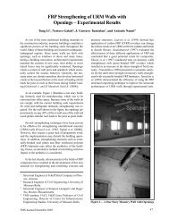
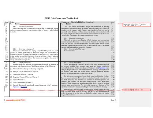
<strong>MSJC</strong> <strong>Code</strong>/<strong>Commentary</strong> <strong>Working</strong> <strong>Draft</strong>C1C21.5 — NotationA b = cross-sectional area of an anchor bolt, in. 2 (mm 2 )1.5 — NotationNotations used in this <strong>Code</strong> are summarized here.CC1CC2C3C4C5A br = bearing area, in. 2 (mm 2 )A g = gross cross-sectional area of a member, in. 2 (mm 2 )A n = net cross-sectional area of a member, in. 2 (mm 2 )<strong>The</strong> thickness of the infill, t inf , is the specified thickness of the infill. <strong>The</strong>net thickness of the infill, t netinf , is the minimum total thickness of the netcross-sectional area. <strong>The</strong>se values are shown in Figure CC-1.5-1.CC3CC4CC5C6C7C8C9C10C11C12C13C14C15C16C174C18C19C20C21C22C23C24A ps = area of prestressing steel, in. 2 (mm 2 )A pt = projected tension area on masonry surface of a right circular cone,in. 2 (mm 2 )A pv = projected shear area on masonry surface of one-half of a rightcircular cone, in. 2 (mm 2 )A s = area of nonprestressed longitudinal tension reinforcementeffectivecross-sectional area of reinforcement, in. 2 (mm 2 )A scA sf= Aarea of confinement reinforcement placed within the lap, neareach end of the lapped reinforcing bars and transverse to thelapped reinforcing barsthem, in 2= cross-sectional area of outermost layer of flexural reinforcementin a wall, in. 2 (mm 2 )A st = total area of laterally tied longitudinal reinforcing steel, in. 2 (mm 2 )A v = cross-sectional area of shear reinforcement, in. 2 (mm 2 )A 1 = loaded area, in. 2 (mm 2 )A 2 = supporting bearing area, in. 2 (mm 2 )a = depth of an equivalent compression stress block at nominalstrength, in. (mm)= allowable axial load on an anchor bolt, lb (N)B at infVertical Cross-Section Through InfillFigure CC-1.5-1 — Thickness and net thickness of an infillt 2t 1t net inf = t 1 + t 2CC6CC7CC8CC9CC10CC11CC12CC13CC15CC15CC16CC17CC18CC19CC20CC21CC22Comment [PJS10]: 09-F-022Comment [ER11]: Ballot 08-R-020 and revisedby 09-R-030.Comment [ER12]: Ballot 08-F-017BComment [PJS13]: 09-F-022Comment [PJS30]: Ballot 10-I-035BC25C26B ab= allowable axial tensile load on an anchor bolt when governed bymasonry breakout, lb (N)C27C28C29B anB anb= nominal axial strength of an anchor bolt, lb (N)= nominal axial tensile strength of an anchor bolt when governed bymasonry breakout, lb (N)C30C31B anp = nominal axial tensile strength of an anchor bolt when governed byanchor pullout, lb (N)11/23/201011/16/20109/7/2010 Page C7
C1C2C3C4C5C6C7C8C9C10C11C12C13C14C15C16C17C18C19C20C21C22C23C24C25C26C27C28C29C30cDdd bd v= distance from the fiber of maximum compressive strain to theneutral axis, in. (mm)= dead load or related internal moments and forces= distance from extreme compression fiber to centroid of tensionreinforcement, in. (mm)= nominal diameter of reinforcement or anchor bolt, in. (mm)= actual depth of a member in direction of shear considered, in. (mm)E = load effects of earthquake or related internal moments and forcesE AAC = modulus of elasticity of AAC masonry in compression, psi (MPa)E bb = modulus of elasticity of bounding beams, psi (MPa)E bc = modulus of elasticity of bounding columns, psi (MPa)E m = modulus of elasticity of masonry in compression, psi (MPa)E ps = modulus of elasticity of prestressing steel, psi (MPa)E sE vee be uFF aF bF sF vF vmF vs= modulus of elasticity of steel, psi (MPa)= modulus of rigidity (shear modulus) of masonry, psi (MPa)= eccentricity of axial load, in. (mm)= projected leg extension of bent-bar anchor, measured from insideedge of anchor at bend to farthest point of anchor in the plane ofthe hook, in. (mm)= eccentricity of P uf , in. (mm)= lateral pressure of liquids or related internal moments and forces= allowable compressive stress available to resist axial load only,psi (MPa)= allowable compressive stress available to resist flexure only, psi(MPa)= allowable tensile or compressive stress in reinforcement, psi(MPa)= allowable shear stress in masonry, psi (MPa)= allowable shear stress resisted by the masonry, psi (MPa)= allowable shear stress resisted by the shear reinforcement, psi(MPa)<strong>MSJC</strong> <strong>Code</strong>/<strong>Commentary</strong> <strong>Working</strong> <strong>Draft</strong>Formatted: Indent: Left: 0"Comment [PJS15]: Ballot 10-I-035BComment [ER16]: Ballot 08-P-001Comment [ER17]: Ballot 07A-X-001Comment [ER18]: Ballot 07A-X-00111/23/201011/16/20109/7/2010 Page C9
C1C2C3C4C5C6C7C8C9C10C11C12C13C14C15C16C17C18C19C20C21C22C23C24C25C26C27C28C29C30C31f a= calculated compressive stress in masonry due to axial load only,psi (MPa)f b = calculated compressive stress in masonry due to flexure only, psi(MPa)f ′ AAC = specified compressive strength of AAC masonry, psi (MPa)f' g = specified compressive strength of grout, psi (MPa)f' m = specified compressive strength of masonry, psi (MPa)f ' mi = specified compressive strength of masonry at the time of prestresstransfer, psi (MPa)f ps = stress in prestressing tendon at nominal strength, psi (MPa)f pu = specified tensile strength of prestressing tendon, psi (MPa)f py = specified yield strength of prestressing tendon, psi (MPa)f r = modulus of rupture, psi (MPa)f rAAC = modulus of rupture of AAC, psi (MPa)f s = calculated tensile or compressive stress in reinforcement, psi (MPa)f se = effective stress in prestressing tendon after all prestress losseshave occurred, psi (MPa)f t AAC = splitting tensile strength of AAC as determined in accordancewith ASTM C1006, psi (MPa)f v = calculated shear stress in masonry, psi (MPa)f y = specified yield strength of steel for reinforcement and anchors, psi(MPa)H = lateral pressure of soil or related internal moments and forcesh = effective height of column, wall, or pilaster, in. (mm)h infh wI bbI bc= vertical dimension of infill, in. (mm)= height of entire wall or of the segment of wall considered, in.(mm)= moment of inertia of bounding beam for bending in the plane ofthe infill, in. 4 (mm 4 )= moment of inertia of bounding column for bending in the plane ofthe infill, in. 4 (mm 4 )<strong>MSJC</strong> <strong>Code</strong>/<strong>Commentary</strong> <strong>Working</strong> <strong>Draft</strong>Comment [PJS19]: Ballot 10-I-035B11/23/201011/16/20109/7/2010 Page C10
C1C2C3C4C5C6C7C8C9C10C11C12C13C14C15C16C17C18C19C20C21C22C23C24C25C26C27C28C29C30C31I cr = moment of inertia of cracked cross-sectional area of a member,in. 4 (mm 4 )I eff = effective moment of inertia, in. 4 (mm 4 )I g = moment of inertia of gross cross-sectional area of a member, in. 4(mm 4 )I n = moment of inertia of net cross-sectional area of a member , in. 4(mm 4 )j = ratio of distance between centroid of flexural compressive forcesand centroid of tensile forces to depth, dK = Dimension used to calculate reinforcement development, in. (mm)K AAC = Dimension used to calculate reinforcement development for AACmasonry, in. (mm)k c = coefficient of creep of masonry, per psi (MPa)k e = coefficient of irreversible moisture expansion of clay masonryk m = coefficient of shrinkage of concrete masonryk t = coefficient of thermal expansion of masonry per degreeFahrenheit (degree Celsius)L = live load or related internal moments and forcesl = clear span between supports, in. (mm)l b = effective embedment length of headed or bent anchor bolts, in. (mm)l be = anchor bolt edge distance, in. (mm)l d = development length or lap length of straight reinforcement, in.(mm)l e = equivalent embedment length provided by standard hooksmeasured from the start of the hook (point of tangency), in. (mm)l effl infl pl w= effective span length for a deep beam, in. (mm)= plan length of infill, in. (mm)= clear span of the prestressed member in the direction of theprestressing tendon, in. (mm)= length of entire wall or of the segment of wall considered indirection of shear force, in. (mm)<strong>MSJC</strong> <strong>Code</strong>/<strong>Commentary</strong> <strong>Working</strong> <strong>Draft</strong>Formatted: SuperscriptFormatted: SuperscriptComment [ER21]: Ballot 08-F-014BComment [PJS22]: Ballot 10-I-035B11/23/201011/16/20109/7/2010 Page C11
C1C2C3C4C5C6C7C8C9C10C11C12C13C14C15C16C17C18C19C20C21C22C23C24C25C26C27C28C29C30C31M = maximum moment at the section under consideration, in.-lb (N-mm)M a = maximum moment in member due to the applied loading forwhich deflection is computed, in.-lb (N-mm)M c = factored moment magnified for the effects of member curvature,in.-lb (N-mm)M cr = nominal cracking moment strength, in.-lb (N-mm)M n = nominal moment strength, in.-lb (N-mm)M ser = service moment at midheight of a member, including P-deltaeffects, in.-lb (N-mm)M u = factored moment, in.-lb (N-mm)n = modular ratio, E s /E mN u = factored compressive force acting normal to shear surface that isassociated with the V u loading combination case underconsideration, lb (N)N v = compressive force acting normal to shear surface, lb (N)P = axial load, lb (N)P a = allowable axial compressive force in a reinforced member, lb (N)P e = Euler buckling load, lb (N)P n = nominal axial strength, lb (N)P ps = prestressing tendon force at time and location relevant for design,lb (N)P u = factored axial load, lb (N)P uf = factored load from tributary floor or roof areas, lb (N)P uw = factored weight of wall area tributary to wall section underconsideration, lb (N)Q = first moment about the neutral axis of an area between theextreme fiber and the plane at which the shear stress is beingcalculated, in. 3 (mm 3 )= the effect of horizontal seismic (earthquake-induced) forcesQ Eq n inf = nominal out-of-plane flexural capacity of infill per unit area, psf(Pa)<strong>MSJC</strong> <strong>Code</strong>/<strong>Commentary</strong> <strong>Working</strong> <strong>Draft</strong>Comment [PJS23]: Ballot 10-I-035B11/23/201011/16/20109/7/2010 Page C12
C1C2C3C4C5C6C7C8C9C10C11C12C13C14C15C16C17C18C19C20C21C22C23C24C25C26C27C28C29R = response modification coefficientr = radius of gyration, in. (mm)S n = section modulus of the net cross-sectional area of a member, in. 3(mm 3 )s = spacing of reinforcement, in. (mm)s l = total linear drying shrinkage of concrete masonry units determined inaccordance with ASTM C426T = forces and moments caused by restraint of temperature, shrinkage,and creep strains or differential movementst = nominal thickness of member, in. (mm)t inf= specified thickness of infill, in. (mm)t net inf = net thickness of infill, in. (mm)t sp= specified thickness of member, in. (mm)v = shear stress, psi (MPa)V = shear force, lb (N)V nAAC = nominal shear strength provided by AAC masonry, lb (N)= nominal shear strength, lb (N)V nV n inf = nominal horizontal in-plane shear strength of infill, lb (N)V nmV nsV u= nominal shear strength provided by masonry, lb (N)= nominal shear strength provided by shear reinforcement, lb (N)= factored shear force, lb (N)W = wind load or related internal moments and forcesW S = dimension of the structural wall strip defined in Section 5.5.1 andshown in Figure 5.5.1-1.W T = dimension of the tributary length of wall, defined in Section 5.5.1and shown in Figure 5.5.1-1.w inf= width of equivalent strut, in. (mm)w strut = horizontal projection of the width of the diagonal strut, in. (mm)= out-of-plane factored uniformly distributed load, lb/in. (N/mm)w u<strong>MSJC</strong> <strong>Code</strong>/<strong>Commentary</strong> <strong>Working</strong> <strong>Draft</strong>Comment [PJS24]: Ballot 10-I-035BComment [ER25]: Ballot 08-F-017B11/23/201011/16/20109/7/2010 Page C13
C2C3C4C5C6C7C8C9C10C11C12C13C14C15C16C17C18C19C20C21C22C23C24C25C26C27C28C29C30C31C32C33C34C1imparted to it from the bounding frame.Infill, participating – Infill designed to resist in-plane loads imparted to itby the bounding frame.Inspection, continuous — <strong>The</strong> Inspection Agency’s full-time observationof work by being present in the area where the work is being performed.Inspection, periodic — <strong>The</strong> Inspection Agency’s part-time or intermittentobservation of work during construction by being present in the area wherethe work has been or is being performed, and observation upon completionof the work.Laterally restrained prestressing tendon — Prestressing tendon that is notfree to move laterally within the cross section of the member.Laterally unrestrained prestressing tendon — Prestressing tendon that isfree to move laterally within the cross section of the member.Licensed design professional — An individual who is licensed to practicedesign as defined by the statutory requirements of the professional licensinglaws of the state or jurisdiction in which the project is to be constructed and whois in responsible charge of the design; in other documents, also referred to asregistered design professional.Load, dead — Dead weight supported by a member, as defined by thelegally adopted building code.Load, live — Live load specified by the legally adopted building code.Load, service — Load specified by the legally adopted building code.Longitudinal reinforcement — Reinforcement placed parallel to thelongitudinal axis of the member.<strong>Masonry</strong> breakout — Anchor failure defined by the separation of avolume of masonry, approximately conical in shape, from the member.<strong>Masonry</strong> unit, hollow — A masonry unit with net cross-sectional area ofless than 75 percent of its gross cross-sectional area when measured in anyplane parallel to the surface containing voids.<strong>Masonry</strong> unit, solid — A masonry unit with net cross-sectional area of 75percent or more of its gross cross-sectional area when measured in everyplane parallel to the surface containing voids.Modulus of elasticity — Ratio of normal stress to corresponding strain fortensile or compressive stresses below proportional limit of material.<strong>MSJC</strong> <strong>Code</strong>/<strong>Commentary</strong> <strong>Working</strong> <strong>Draft</strong>Comment [PJS41]: Ballot 10-I-035BComment [ER42]: Ballot 05-Q-016Comment [ER43]: Ballot 07-Q-3511/23/201011/16/20109/7/2010 Page C18
C2C3C4C5C6C7C8C9C10C11C12C13C14C15C16C17C18C19C20C21C22C23C24C25C26C27C28C29C30C31C32C33C34C35C36C1Shear wall, special reinforced prestressed masonry — A prestressedmasonry shear wall designed to resist lateral forces while consideringstresses in reinforcement and to satisfy special reinforcement andconnection requirements.Slump flow — <strong>The</strong> circular spread of plastic self-consolidating grout,which is evaluated in accordance with ASTM C1611/C1611M.Special boundary elements — In walls that are designed to resist in-planeload, end regions that are strengthened by reinforcement and are detailed tomeet specific requirements, and may or may not be thicker than the wall.Specified compressive strength of AAC masonry, f ' AAC — Minimumcompressive strength, expressed as force per unit of net cross-sectional area,required of the AAC masonry used in construction by the contract documents,and upon which the project design is based. Whenever the quantity f AAC isunder the radical sign, the square root of numerical value only is intended andthe result has units of psi (MPa).Specified compressive strength of masonry, f ' m — Minimum compressivestrength, expressed as force per unit of net cross-sectional area, required ofthe masonry used in construction by the contract documents, and upon whichthe project design is based. Whenever the quantity f m is under the radicalsign, the square root of numerical value only is intended and the result hasunits of psi (MPa).Stack bond — For the purpose of this <strong>Code</strong>, stack bond is other thanrunning bond. Usually the placement of units is so that the head joints insuccessive courses are vertically aligned.Stirrup — Reinforcement used to resist shear in a flexural member.Stone masonry — <strong>Masonry</strong> composed of field, quarried, or cast stone unitsbonded by mortar.Stone masonry, ashlar — Stone masonry composed of rectangular unitshaving sawed, dressed, or squared bed surfaces and bonded by mortar.Stone masonry, rubble — Stone masonry composed of irregular-shapedunits bonded by mortar.Strength-reduction factor, — <strong>The</strong> factor by which the nominal strength ismultiplied to obtain the design strength.Tendon anchorage — In post-tensioning, a device used to anchor theprestressing tendon to the masonry or concrete member; in pretensioning, adevice used to anchor the prestressing tendon during hardening of masonry<strong>MSJC</strong> <strong>Code</strong>/<strong>Commentary</strong> <strong>Working</strong> <strong>Draft</strong>Comment [ER46]: Ballot 05-Q-01411/23/201011/16/20109/7/2010 Page C21
C2C3C4C5C6C7C8C9C10C11C12C13C14C15C16C17C18C19C20C21C22C23C24C25C26C27C28C29C30C31C32C33C34C35mortar, grout, prestressing grout, or concrete.Tendon coupler — A device for connecting two tendon ends, therebytransferring the prestressing force from end to end.Tendon jacking force — Temporary force exerted by a device thatintroduces tension into prestressing tendons.Thin-bed mortar — Mortar for use in construction of AAC unit masonrywhose joints are 0.06 in. (1.5 mm) or less.Tie, lateral — Loop of reinforcing bar or wire enclosing longitudinalreinforcement.Tie, wall — Metal connector that connects wythes of masonry wallstogether.Transfer — Act of applying to the masonry member the force in theprestressing tendons.Transverse reinforcement — Reinforcement placed perpendicular to thelongitudinal axis of the member.Unbonded prestressing tendon — Prestressing tendon that is not bonded tomasonry.Unreinforced (plain) masonry — <strong>Masonry</strong> in which the tensile resistance ofmasonry is taken into consideration and the resistance of the reinforcing steel, ifpresent, is neglected.Veneer, adhered — <strong>Masonry</strong> veneer secured to and supported by thebacking through adhesion.Veneer, anchored — <strong>Masonry</strong> veneer secured to and supportedlaterally by the backing through anchors and supported vertically by thefoundation or other structural elements.Veneer, masonry — A masonry wythe that provides the exterior finish of awall system and transfers out-of-plane load directly to a backing, but is notconsidered to add load resisting -–capacitystrength or stiffness to the wallsystem.Visual stability index (VSI) — An index, defined in ASTMC1611/C1611M, that qualitatively indicates the stability of selfconsolidatinggroutWall — A vertical element with a horizontal length to thickness ratiogreater than 3, used to enclose space.<strong>MSJC</strong> <strong>Code</strong>/<strong>Commentary</strong> <strong>Working</strong> <strong>Draft</strong>Comment [ER47]: Ballot 05-Q-016Comment [ER48]: Hyphen added per Ballot 04-Q-019Comment [ER49]: Ballot 07-Q-018B and furtherrevised by 09-Q-05611/23/201011/16/20109/7/2010 Page C22
<strong>MSJC</strong> <strong>Code</strong>/<strong>Commentary</strong> <strong>Working</strong> <strong>Draft</strong>C1C2C3C4C5C6C7C8C9C10C11C12C13C14C15C16C17C18C19C20C21C22C23C24C25C26C27C28C29C30C31C32C33C34C35C36Wall, load-bearing — Wall supporting vertical loads greater than 200 lb/linealft (2919 N/m) in addition to its own weight.Wall, masonry bonded hollow — A multiwythe wall built with masonryunits arranged to provide an air space between the wythes and with thewythes bonded together with masonry units.Width — <strong>The</strong> dimension of a member measured in the plane of a crosssection parallel to the neutral axis.Wythe — Each continuous vertical section of a wall, one masonry unit inthickness.1.7 — Loading 1.7 — Loading1.7.1 General<strong>Masonry</strong> shall be designed to resist applicable loads. A continuous loadpath or paths, with adequate strength and stiffness, shall be provided totransfer forces from the point of application to the final point of resistance.1.7.2 Load provisionsDesign loads shall be in accordance with the legally adopted buildingcode of which this <strong>Code</strong> forms a part, with such live load reductions as arepermitted in the legally adopted building code. In the absence of designloads in the legally adopted building code, the load provisions of ASCE 7shall be used, except as noted in this <strong>Code</strong>.1.7.3 Lateral load resistanceBuildings shall be provided with a structural system designed to resistwind and earthquake loads and to accommodate the effect of the resultingdeformations.1.7.4 Load transfer at horizontal connections1.7.4.1 Walls, columns, and pilasters shall be designed to resistloads, moments, and shears applied at intersections with horizontalmembers.1.7.4.2 Effect of lateral deflection and translation of members<strong>The</strong> provisions establish design load requirements. If the design loadsspecified by the legally adopted building code differ from those of ASCE 7,the legally adopted building code governs. <strong>The</strong> designer may decide to usethe more stringent requirements.1.7.1 GeneralNo additional commentary1.7.2 Load provisionsNo additional commentary1.7.3 Lateral load resistanceLateral load resistance must be provided by a braced structural system.Partitions, infill panels, and similar elements may not be a part of thelateral- force-resisting system if isolated. However, when they resist lateralforces due to their rigidity, they should be considered in analysis.1.7.4 Load transfer at horizontal connections<strong>Masonry</strong> walls, pilasters, and columns may be connected to horizontalelements of the structure and may rely on the latter for lateral support andstability. <strong>The</strong> mechanism through which the interconnecting forces aretransmitted may involve bond, mechanical anchorage, friction, bearing, or acombination thereof. <strong>The</strong> designer must assure that, regardless of the typeCC11CC12CC13CC14CC15CC16CC17CC18CC19CC20CC21CC22CC23CC24CC25CC26CC27CC28CC29CC30CC31CC32CC33CC34CC35CC3611/23/201011/16/20109/7/2010 Page C23
<strong>MSJC</strong> <strong>Code</strong>/<strong>Commentary</strong> <strong>Working</strong> <strong>Draft</strong>C1C2C3C4providing lateral support shall be considered.1.7.4.3 Devices used for transferring lateral support frommembers that intersect walls, columns, or pilasters shall be designed toresist the forces involved.of connection, the interacting forces are safely resisted.CC1In flexible frame construction, the relative movement (drift) betweenfloors may generate forces within the members and the connections. This<strong>Code</strong> requires the effects of these movements to be considered in design.CC2CC3CC4C5C6C7C8C91.7.5 Other effectsConsideration shall be given to effects of forces and deformations dueto prestressing, vibrations, impact, shrinkage, expansion, temperaturechanges, creep, unequal settlement of supports, and differential movement.1.7.5 Other effectsService loads are not the sole source of stresses. <strong>The</strong> structure must alsoresist forces from the sources listed. <strong>The</strong> nature and extent of some of theseforces may be greatly influenced by the choice of materials, structuralconnections, and geometric configuration.CC5CC6CC7CC8CC9C10C11C12C13C14C15C16C17C18C19C20C21C22C23C24C25C26C27C28C29C30C31C321.7.6 Lateral load distributionLateral loads shall be distributed to the structural system in accordancewith member stiffnesses and shall comply with the requirements of thissection.1.7.6.1 Flanges of intersecting walls designed in accordance withSection 1.9.4.2 shall be included in stiffness determination.1.7.6.2 Distribution of load shall be consistent with the forcesresisted by foundations.1.7.6.3 Distribution of load shall include the effect of horizontaltorsion of the structure due to eccentricity of wind or seismic loads resultingfrom the non-uniform distribution of mass.1.7.6 Lateral load distribution<strong>The</strong> design assumptions for masonry buildings include the use of alateral -loadforce-resisting system. <strong>The</strong> distribution of lateral loads to themembers of the lateral -force-resisting structural system is a function of therigidities of the structural system and of the horizontal diaphragms. <strong>The</strong>method of connection at intersecting walls and between walls and floor androof diaphragms determines if the wall participates in the lateral -forceresistingstructural system. Lateral loads from wind and seismic forces arenormally considered to act in the direction of the principal axes of thestructure. Lateral loads may cause forces in walls both perpendicular andparallel to the direction of the load. Horizontal torsion can be developed dueto eccentricity of the applied load with respect to the center of rigidity.<strong>The</strong> analysis of lateral load distribution should be in accordance withaccepted engineering procedures. <strong>The</strong> analysis should rationally considerthe effects of openings in shear walls and whether the masonry above theopenings allows them to act as coupled shear walls. See Figure CC-1.7-1.<strong>The</strong> interaction of coupled shear walls is complex and further informationmay be obtained from Reference 1.4.Computation of the stiffness of shear walls should consider shearingand flexural deformations. A guide for solid shear walls (that is, with noopenings) is given in Figure CC-1.7-2. For nongrouted hollow unit shearwalls, the use of equivalent solid thickness of wall in computing webstiffness is acceptable.CC10CC11CC12CC13CC14CC15CC16CC17CC18CC19CC20CC21CC22CC23CC24CC25CC26CC27CC28CC29CC30CC31CC32Comment [ER54]: Ballot 05-Q-01711/23/201011/16/20109/7/2010 Page C24
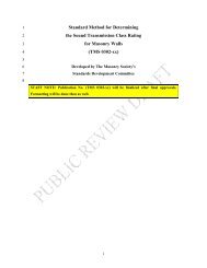
<strong>MSJC</strong> <strong>Code</strong>/<strong>Commentary</strong> <strong>Working</strong> <strong>Draft</strong>dCC1CC2Comment [PJS55]: 09-G-038Formatted: Font: 10 pt, ItalicdCC3CC4dhhCC5CC6hh/d < 0.25 0.25 ≤ h/d ≤ 4.0 h/d > 4(a) Shear Stiffness(b) Both Shear Stiffness(c) Bending StiffnessPredominatesand Bending StiffnessPredominatesare ImportantFigure CC-1.7-2 — Shear wall stiffnessCC7CC8CC9CC10CC11CC1211/23/201011/16/20109/7/2010 Page C26
<strong>MSJC</strong> <strong>Code</strong>/<strong>Commentary</strong> <strong>Working</strong> <strong>Draft</strong>C1C2C3C4C5C6C7C8C9C10C111.8 — Material properties1.8.1 GeneralUnless otherwise determined by test, the following moduli andcoefficients shall be used in determining the effects of elasticity,temperature, moisture expansion, shrinkage, and creep.1.8 — Material propertiesCC11.8.1 GeneralProper evaluation of the building material movement from all sourcesis an important element of masonry design. Clay masonry and concretemasonry may behave quite differently under normal loading and weatherconditions. <strong>The</strong> committee has extensively studied available researchinformation in the development of these material properties. However, theCommittee recognizes the need for further research on this subject. <strong>The</strong>designer is encouraged to review industry standards for further designinformation and movement joint locations. Material properties can bedetermined by appropriate tests of the materials to be used.CC2CC3CC4CC5CC6CC7CC8CC9CC10CC11C12C13C14C15C16C17C18C19C20C21C22C23C24C25C26C27C28C29C30C31C32C33C11.8.2 Elastic moduli1.8.2.1 Steel reinforcement — Modulus of elasticity of steelreinforcement shall be taken as:E s = 29,000,000 psi (200,000 MPa)1.8.2.2 Clay and concrete masonry1.8.2.2.1 <strong>The</strong> design of clay and concrete masonry shallbe based on the following modulus of elasticity values:E m = 700 f ' m for clay masonry;E m = 900 f ' m for concrete masonry;or the chord modulus of elasticity taken between 0.05 and 0.33 of themaximum compressive strength of each prism determined by test inaccordance with the prism test method, Article 1.4 B.3 of TMS 602/ACI530.1/ASCE 6, and ASTM E111.1.8.2.2.2 Modulus of rigidity of clay masonry andconcrete masonry shall be taken as:E v = 0.4E m1.8.2.3 AAC masonrytaken as:1.8.2.3.1 Modulus of elasticity of AAC masonry shall beE AAC = 6500 (f ' AAC ) 0.61.8.2.3.2 Modulus of rigidity of AAC masonry shall betaken as:E V = 0.4 E AAC1.8.2 Elastic moduliModulus of elasticity for clay and concrete masonry has traditionally1.5, 1.6been taken as 1000 f ' m in previous masonry codes. Research hasindicated, however, that there is a large variation in the relationship of elasticmodulus versus compressive strength of masonry, and that lower values maybe more typical. However, differences in procedures between one researchinvestigation and another may account for much of the indicated variation.Furthermore, the type of elastic moduli being reported (for example, secantmodulus, tangent modulus, or chord modulus) is not always identified. <strong>The</strong>committee decided the most appropriate elastic modulus forworkingallowable-stress design purposes is the slope of the stress-strain curvebelow a stress value of 0.33 f m ,. the allowable flexural compressivestress.<strong>The</strong> value of 0.33 f m was originally chosen because it was theallowable compressive stress prior to the 2011 <strong>Code</strong>. <strong>The</strong> committee did notsee the need to change the modulus with the increase in allowablecompressive stress to 0.45 f m in the 2011 <strong>Code</strong> because previous codeeditions also allowed the allowable compressive stress to be increased by onethirdfor load combinations including wind or seismic loads and the allowablemoment capacity using allowable stress design is not significantly affected bythe value of the masonry modulus of elasticity. Data at the bottom of thestress strain curve may be questionable due to the seating effect of thespecimen during the initial loading phase if measurements are made on thetesting machine platens. <strong>The</strong> committee therefore decided that the mostappropriate elastic modulus for design purposes is the chord modulus from astress value of 5 to 33 percent of the compressive strength of masonry (seeFigure CC-1.8-1). <strong>The</strong> terms chord modulus and secant modulus have beenused interchangeably in the past. <strong>The</strong> chord modulus, as used here, is definedas the slope of a line intersecting the stress-strain curve at two points, neitherof which is the origin of the curve.CC12CC13CC14CC15CC16CC17CC18CC19CC20CC21CC22CC23CC24CC25CC26CC27CC28CC29CC30CC31CC32CC33CC34CC35CC36CC37CC38CC39Comment [PJS56]: 09-F-04011/23/201011/16/20109/7/2010 Page C27
<strong>MSJC</strong> <strong>Code</strong>/<strong>Commentary</strong> <strong>Working</strong> <strong>Draft</strong>C2C3C1500 f ' g .1.8.2.4 Grout — Modulus of elasticity of grout shall be taken asFor clay and concrete masonry, the elastic modulus is determined as afunction of masonry compressive strength using the relations developed froman extensive survey of modulus data by Wolde-Tinsae et al. 1.5 and results of atest program by Colville et al 1.6 . <strong>Code</strong> values for E m are higher than indicatedby a best fit of data relating E m to the compressive strength of masonry. <strong>The</strong>higher <strong>Code</strong> values are based on the fact that actual compressive strengthsignificantly exceeds the specified compressive strength of masonry, f m ,particularly for clay masonry.Figure CC-1.8-1 — Chord modulus of elasticityBy using the <strong>Code</strong> values, the contribution of each wythe to compositeaction is more accurately accounted for in design calculations than would bethe case if the elastic modulus of each part of a composite wall were basedon one specified compressive strength of masonry.<strong>The</strong> modulus of elasticity of autoclaved aerated concrete (AAC)masonry depends almost entirely on the modulus of elasticity of the AACmaterial itself. <strong>The</strong> relationship between modulus of elasticity and compressivestrength is given in References A.8.3 and A.8.4.<strong>The</strong> modulus of elasticity of a grouted assemblage of clay or concretemasonry can usually be taken as a factor multiplied by the specifiedcompressive strength, regardless of the extent of grouting, because themodulus of elasticity of the grout is usually close to that of the clay orconcrete masonry. However, grout is usually much stiffer than the AACmaterial. While it is permissible and conservative to compute the modulusof elasticity of a grouted assemblage of AAC masonry assuming that themodulus of elasticity of the grout is the same as that of the AAC material, itCC1CC2CC3CC4CC5CC6CC7CC8CC9CC10CC11CC12CC13CC14CC15CC16CC17CC18CC19CC20CC21CC22CC23CC24CC25CC26CC27CC28CC29CC30CC31CC32CC33CC34CC35CC36CC37CC38CC39CC40CC41Formatted: Font: 10 pt11/23/201011/16/20109/7/2010 Page C28
C2C3C4C5C6C7C8C9C10C11C12C13C14C15C16C17<strong>MSJC</strong> <strong>Code</strong>/<strong>Commentary</strong> <strong>Working</strong> <strong>Draft</strong>is also possible to recognize the greater modulus of elasticity of the grout bytransforming the cross-sectional area of grout into an equivalent crosssectionalarea of AAC, using the modular ratio between the two materials.Because the inelastic stress-strain behavior of grout is generallysimilar to that of clay or concrete masonry, calculations of elementresistance (whether based on allowable-stress or strength design) usuallyneglect possible differences in strength between grout and the surroundingmasonry. For the same reasons noted above, the stress-strain behavior ofgrout usually differs considerably from that of the surrounding AACmaterial. It is possible that these differences in stress-strain behavior couldalso be considered in computing element resistances. Research is ongoing toresolve this issue.<strong>The</strong> relationship between the modulus of rigidity and the modulus ofelasticity has historically been given as 0.4 E m . No experimental evidence existsto support this relationship.CC1CC2CC3CC4CC5CC6CC7CC8CC9CC10CC11CC12CC13CC14CC15CC16CC17C18C19C20C21C22C23C241.8.3 Coefficients of thermal expansion1.8.3.1 Clay masonryk t = 4 x 10 -6 in./in./°F (7.2 x 10 -6 mm/mm/°C)1.8.3.2 Concrete masonryk t = 4.5 x 10 -6 in./in./ °F (8.1 x 10 -6 mm/mm/°C)1.8.3.3 AAC masonryk t = 4.5 x 10 -6 in./in./ °F (8.1 x 10 -6 mm/mm/°C)1.8.3 Coefficients of thermal expansionTemperature changes cause material expansion and contraction. Thismaterial movement is theoretically reversible. <strong>The</strong>se thermal expansioncoefficients are slightly higher than mean values for the assemblage 1.7, 1.8, 1.9 .<strong>The</strong>rmal expansion for concrete masonry varies with aggregate type 1.7, 1.10 .CC18CC19CC20CC21CC22<strong>The</strong>rmal expansion coefficients are given for AAC masonry inReference 1.11 .CC23CC24C25C26C27C28C29C301.8.4 Coefficient of moisture expansion for clay masonryk e = 3 x 10 -4 in./in. (3 x 10 -4 mm/mm)1.8.4 Coefficient of moisture expansion for clay masonryFired clay products expand upon contact with moisture and the materialdoes not return to its original size upon drying 1.8, 1.9 . This is a long-termexpansion as clay particles react with atmospheric moisture. Continuedmoisture expansion of clay masonry units has been reported for 7½ years 1.12 .Moisture expansion is not a design consideration for concrete masonry.CC25CC26CC27CC28CC29CC30C31C32C331.8.5 Coefficients of shrinkage1.8.5.1 Concrete masonryk m = 0.5 s l1.8.5 Coefficients of shrinkage1.8.5.1 Concrete masonry — Concrete masonry is a cementbasedmaterial that shrinks due to moisture loss and carbonation 1.10 . <strong>The</strong>CC31CC32CC3311/23/201011/16/20109/7/2010 Page C29
<strong>MSJC</strong> <strong>Code</strong>/<strong>Commentary</strong> <strong>Working</strong> <strong>Draft</strong>C1C2C3C4C5C6C7C8C9C10C11C12C13C14C151.8.5.2 AAC masonryk m = 0.8 cs /100where cs is determined in accordance with ASTM C1386.total linear drying shrinkage is determined in accordance with ASTMC426. <strong>The</strong> maximum shrinkage allowed by ASTM specifications forconcrete masonry units (for example, ASTM C90), other than calciumsilicate units, is 0.065%. Further design guidance for estimating theshrinkage due to moisture loss and carbonation is available 1.13, 1.14, 1.15 . <strong>The</strong>shrinkage of clay masonry is negligible.1.8.5.2 AAC <strong>Masonry</strong> — At time of production, AAC masonrytypically has a moisture content of about 30%. That value typicallydecreases to 15% or less within two to three months, regardless of ambientrelative humidity. This process can take place during construction or priorto delivery. ASTM C1386 evaluates AAC material characteristics atmoisture contents between 5% and 15%, a range that typifies AAC inservice. <strong>The</strong> shrinkage coefficient of this section reflects the change instrain likely to be encountered within the extremes of moisture contenttypically encountered in service.CC1CC2CC3CC4CC5CC6CC7CC8CC9CC10CC11CC12CC13CC14CC15C16C17C18C19C20C21C221.8.6 Coefficients of creep1.8.6.1 Clay masonryk c = 0.7 x 10 -7 , per psi (0.1 x 10 -4 , per MPa)1.8.6.2 Concrete masonryk c = 2.5 x 10 -7 , per psi (0.36 x 10 -4 , per MPa)1.8.6.3 AAC masonryk c = 5.0 x 10 -7 , per psi (0.72 x 10 -4 , per MPa)1.8.6 Coefficients of creepWhen continuously stressed, these materials gradually deform in thedirection of stress application. This movement is referred to as creep and is loadand time dependent 1.10, 1.16, 1.11 . <strong>The</strong> values given are maximum values.CC16CC17CC18CC19CC20CC21CC22C23C24C25C26C27C28C29C30C31C32C331.8.7 Prestressing steelModulus of elasticity shall be determined by tests. For prestressing steels notspecifically listed in ASTM A416/A416M, A421/A421M, or A722/A722M,tensile strength and relaxation losses shall be determined by tests.1.8.7 Prestressing steel<strong>The</strong> material and section properties of prestressing steels may vary with eachmanufacturer. Most significant for design are the prestressing tendon’s crosssection, modulus of elasticity, tensile strength, and stress-relaxationproperties. Values for these properties for various manufacturers’ wire, strand,and bar systems are given elsewhere 1.17 . <strong>The</strong> modulus of elasticity ofprestressing steel is often taken equal to 28,000 ksi (193,000 MPa) for design,but can vary and should be verified by the manufacturer. Stress-straincharacteristics and stress-relaxation properties of prestressing steels must bedetermined by test, because these properties may vary between different steelforms (bar, wire, or strand) and types (mild, high strength, or stainless)CC23CC24CC25CC26CC27CC28CC29CC30CC31CC32CC33Formatted: SuperscriptC34C35C36C371.9 — Section properties1.9.1 Stress computations1.9.1.1 Members shall be designed using section properties basedon the minimum net cross-sectional area of the member under1.9 — Section propertiesCC341.9.1 Stress computationsMinimum net section is often difficult to establish in hollow unitmasonry. <strong>The</strong> designer may choose to use the minimum thickness of theCC35CC36CC3711/23/201011/16/20109/7/2010 Page C30
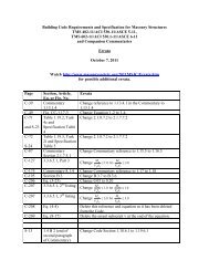
<strong>MSJC</strong> <strong>Code</strong>/<strong>Commentary</strong> <strong>Working</strong> <strong>Draft</strong>C1C2C3C4C5C6C7C8C9C10C11C12C13C14C15C16C17C18C19C20C21consideration. Section properties shall be based on specified dimensions.1.9.1.2 In members designed for composite action, stresses shallbe computed using section properties based on the minimum transformednet cross-sectional area of the composite member. <strong>The</strong> transformed areaconcept for elastic analysis, in which areas of dissimilar materials aretransformed in accordance with relative elastic moduli ratios, shall apply.face shells of the units as the minimum net section. <strong>The</strong> minimum netsection may not be the same in the vertical and horizontal directions.For masonry of hollow units, the minimum cross-sectional area in bothdirections may conservatively be based on the minimum face-shellthickness 1.18 .Solid clay masonry units are permitted to have coring up to a maximumof 25 percent of their gross cross-sectional area. For such units, the net crosssectionalarea may be taken as equal to the gross cross-sectional area, exceptas provided in Section 2.1.5.2.2(c) for masonry headers. Several conditions ofnet area are shown in Figure CC-1.9-1.Since the elastic properties of the materials used in members designedfor composite action differ, equal strains produce different levels of stressesin the components. To compute these stresses, a convenient transformedsection with respect to the axis of resistance is considered. <strong>The</strong> resultingstresses developed in each fiber are related to the actual stresses by the ratioE 1 / E x between the moduli of elasticity of the most deformable material inthe member and of the materials in the fiber considered. Thus, to obtain thetransformed section, fibers of the actual section are conceptually widenedby the ratio E x /E 1 . Stresses computed based on the section properties of thetransformed section, with respect to the axis of resistance considered, arethen multiplied by E x /E 1 to obtain actual stresses.CC1CC2CC3CC4CC5CC6CC7CC8CC9CC10CC11CC12CC13CC14CC15CC16CC17CC18CC19CC20CC2111/23/201011/16/20109/7/2010 Page C31
<strong>MSJC</strong> <strong>Code</strong>/<strong>Commentary</strong> <strong>Working</strong> <strong>Draft</strong>CC1CC2Comment [PJS57]: Ballot 11-G-026Formatted: Font: 10 ptBrick More than 75% SolidNet Area Equals Gross AreaHollow Unit Full Mortar Bedding(Requires Alignment of Crosswebs)CC3CC4CC5CC6CC7CC8CC9CC10CC11Hollow Unit Full Mortar BeddingCC12CC1311/23/201011/16/20109/7/2010 Page C32
<strong>MSJC</strong> <strong>Code</strong>/<strong>Commentary</strong> <strong>Working</strong> <strong>Draft</strong>Formatted: Font: 10 ptBrick More than 75% SolidNet Area Equals Gross AreaHollow Un it Full Mo rtar Bedding(Requires Alignment of Crosswebs)Hollow Unit Face Shell Mortar BeddingFigure CC-1.9-1 — Net cross-sectional areasC14C15C16C17C18C19C20C21C22C23C24C25C26C27C11.9.2 StiffnessComputation of stiffness based on uncracked section is permissible. Use ofthe average net cross-sectional area of the member considered in stiffnesscomputations is permitted.1.9.2 StiffnessStiffness is a function of the extent of cracking. <strong>The</strong> <strong>Code</strong> equations fordesign in Section 2.2, however, are based on the member’s uncrackedmoment of inertia. Also, since the extent of tension cracking in shear wallsis not known in advance, this <strong>Code</strong> allows the determination of stiffness tobe based on uncracked section properties. For reinforced masonry, moreaccurate estimates may result if stiffness approximations are based on thecracked section.<strong>The</strong> section properties of masonry members may vary from point topoint. For example, in a single-wythe concrete masonry wall made ofhollow ungrouted units, the cross-sectional area varies through the unitheight. Also, the distribution of material varies along the length of the wallor unit. For stiffness computations, an average value of the appropriatesection property (cross-sectional area or moment of inertia) is consideredadequate for design. <strong>The</strong> average net cross-sectional area of the memberCC14CC15CC16CC17CC18CC19CC20CC21CC22CC23CC24CC25CC26CC27CC111/23/201011/16/20109/7/2010 Page C33
C2C3<strong>MSJC</strong> <strong>Code</strong>/<strong>Commentary</strong> <strong>Working</strong> <strong>Draft</strong>would in turn be based on average net cross-sectional area values of themasonry units and the mortar joints composing the member.CC2CC3C4C5C6C7C81.9.3 Radius of gyrationRadius of gyration shall be computed using average net cross-sectionalarea of the member considered.1.9.3 Radius of gyration<strong>The</strong> radius of gyration is the square root of the ratio of bending momentof inertia to cross-sectional area. Since stiffness is based on the average netcross-sectional area of the member considered, this same area should beused in the computation of radius of gyration.CC4CC5CC6CC7CC8C9C10C11C12C131.9.4 Intersecting walls1.9.4.1 Wall intersections shall meet one of the followingrequirements:(a) Design shall conform to the provisions of Section 1.9.4.2.(b) Transfer of shear between walls shall be prevented.1.9.4 Intersecting wallsConnections of webs to flanges of walls may be accomplished byrunning bond, metal connectors, or bond beams. Achieving stress transfer ata T intersection with running bond only is difficult. A running bondconnection should be as shown in Figure CC-1.9-2 with a “T” geometryover their intersection.CC9CC10CC11CC12CC13CC14C14C15C16C17C18C19C20C21C22C23C24C25C26C27C28C29C30C31C32C33C341.9.4.2 Design of wall intersection1.9.4.2.1 <strong>Masonry</strong> shall be in running bond.1.9.4.2.2 Flanges shall be considered effective in resistingapplied loads.1.9.4.2.3 <strong>The</strong> width of flange considered effective on eachside of the web shall be the smaller of the actual flange on either sideof the web wall or the following:(a) 6 multiplied by the nominal flange thickness for unreinforced andreinforced masonry, when the flange is in compression(b) 6 multiplied by the nominal flange thickness for unreinforced masonry,when the flange is in flexural tension(c) 0.75 multiplied by the floor-to-floor wall height for reinforcedmasonry, when the flange is in flexural tension.<strong>The</strong> effective flange width shall not extend past a movement joint.1.9.4.2.4 Design for shear, including the transfer of shear atinterfaces, shall conform to the requirements of Section 2.2.5; or Section2.3.52.3.6; or Sections 3.1.3 and 3.3.4.1.2; or Sections 3.1.3 and 3.2.4; orSection 4.6; or Section A.8.1.3 and A.8.3.4.1.2.1.9.4.2.5 <strong>The</strong> connection of intersecting walls shall conform toone of the following requirements:(a) At least fifty percent of the masonry units at the interface shallinterlock.<strong>The</strong> alternate method, using metal strap connectors, is shown in FigureCC-1.9-3. Bond beams, shown in Figure CC-1.9-4, are the third means ofconnecting webs to flanges.When the flanges are connected at the intersection, they are required tobe included in the design.<strong>The</strong> effective width of the flange for compression and unreinforcedmasonry in flexural tension is based on shear-lag effects and is a traditionalrequirement. <strong>The</strong> effective width of the flange for reinforced masonry inflexural tension is based on the experimental and analytical work of He andPriestley 1.19 . <strong>The</strong>y showed that the shear-lag effects are significant foruncracked walls, but become less severe after cracking. He and Priestley 1.19proposed that the effective width of the flange be determined as:lefl e l f 0.75h 0.5l2.5h l 0.75h 0.5l 2.5hfl1.5 llffl / h 1.51.5 l / h 3.5l / h 3.5/ h 1.5f/ h 3.5/ h 3.5where l ef is the effective flange width, l f is the width of the flange, and h isheight of the wall. <strong>The</strong>se equations can result in effective flange widthsgreater than 1.5 times the height of the wall. However, a limit of theeffective flange width of 1.5 times the wall height, or ¾ of the wall heightCC15CC16CC17CC18CC19CC20CC21CC22CC23CC24CC25CC26CC27CC28CC29CC30CC31CC32CC33CC34CC35CC36CC37CC38CC1Comment [ER58]: Ballot 08-F-029Field <strong>Code</strong> Changed11/23/201011/16/20109/7/2010 Page C34
<strong>MSJC</strong> <strong>Code</strong>/<strong>Commentary</strong> <strong>Working</strong> <strong>Draft</strong>C1C2C3C4C5C6C7C8C9C10C11C12(b) Walls shall be anchored by steel connectors grouted into the wall andmeeting the following requirements:(1) Minimum size: 1 / 4 in. x 1 1 / 2 in. x 28 in. (6.4 mm x 38.1 mm x711 mm) including 2-in. (50.8-mm) long, 90-degree bend ateach end to form a U or Z shape.(2) Maximum spacing: 48 in. (1219 mm).(c) Intersecting reinforced bond beams shall be provided at a maximumspacing of 48 in. (1219 mm) on center. <strong>The</strong> area of reinforcement ineach bond beam shall not be less than 0.1 in. 2 per ft (211 mm 2 /m)multiplied by the vertical spacing of the bond beams in feet (meters).Reinforcement shall be developed on each side of the intersection.on either side of the web, is provided in the code. This limit was chosensince the testing by He and Priestley 1.19 was limited to a flange width of 1.4times the wall height. Designers are cautioned that longitudinalreinforcement just outside the effective flange width specified by the codecan affect the ductility and behavior of the wall. Any participation by thereinforcement in resisting the load can lead to other, more brittle, failuremodes such as shear or crushing of the compression toe.CC2CC3CC4CC5CC6CC7CC8CC9CC10CC11CC12Shear WallShear WallFlangeOrFigure CC-1.9-2 — Running bond lap at intersectionCC13CC14CC15CC16CC17CC18CC19CC20CC22CC2311/23/201011/16/20109/7/2010 Page C35
<strong>MSJC</strong> <strong>Code</strong>/<strong>Commentary</strong> <strong>Working</strong> <strong>Draft</strong>Maximum Bond Beam Spacing48 in (1219 mm) on CenterFigure CC-1.9-4 — Bond beam at wall intersectionReinforcement in accordancewith <strong>Code</strong> Section 1.9.4.2.5(c)Either open cell bond beamunits or solid bottom lintel unitsmay be used.CC1CC2CC3CC4CC5CC6CC7CC8CC9CC10CC11CC12CC13CC14CC15CC16CC17CC18CC19CC20CC21CC2211/23/201011/16/20109/7/2010 Page C37
<strong>MSJC</strong> <strong>Code</strong>/<strong>Commentary</strong> <strong>Working</strong> <strong>Draft</strong>C1C2C3C4C5C6C7C8C9C101.9.5 Bearing area<strong>The</strong> bearing area, A br , for concentrated loads shall not exceed thefollowing:(a) A1A2/ A1(b) 2 A 1<strong>The</strong> area, A 2, is the area of the lower base of the largest frustum of aright pyramid or cone that has the loaded area, A 1, as its upper base, slopesat 45 degrees from the horizontal, and is wholly contained within thesupport. For walls in other thannot laid in running bond, area A 2 shallterminate at head joints.1.9.5 Bearing areaWhen the supporting masonry area, A 2 , is larger on all sides than theloaded area, A 1 , this <strong>Code</strong> allows distribution of concentrated loads over abearing area A br , larger than A 1 . <strong>The</strong> area A 2 is determined as illustrated inFigure CC-1.9-5. This is permissible because the confinement of thebearing area by surrounding masonry increases the bearing capacity of themasonry under the concentrated loads. When the edge of the loaded area,A 1 , coincides with the face or edge of the masonry, the area A 2 is equal tothe loaded area A 1 .CC1CC2CC3CC4CC5CC6CC7CC8CC9CC10Comment [ER59]: Ballot 05-Q-014Loaded Area, A 145 DegreesCC11CC12CC13AAA 2 is Measured on this PlaneCC14CC15PlanThis Perimeter of AreaA 2 is Geometricallysimilar to andConcentric with theLoaded Area, A 1Section A-AFigure CC-1.9-5 — Bearing areasCC16CC17CC18CC19CC20CC2111/23/201011/16/20109/7/2010 Page C38
t<strong>MSJC</strong> <strong>Code</strong>/<strong>Commentary</strong> <strong>Working</strong> <strong>Draft</strong>C1C2C3C4C5C6C7C8C9C10C11C12C131.9.6 Effective compressive width per bar1.9.6.1 For running bond masonry, and masonry in other thannotlaid in running bond with and having bond beams spaced not more than 48in. (1219 mm) center-to-center, and for masonry laid in running bond, thewidth of the compression area used to calculate element capacity shall notexceed the least of:(a) Center-to-center bar spacing.(b) Six multiplied by the nominal wall thickness.(c) 72 in. (1829 mm).1.9.6.2 For masonry in other thannot laid in running bond, withand having bond beams spaced more than 48 in. (1219 mm) center-tocenter,the width of the compression area used to calculate element capacityshall not exceed the length of the masonry unit.1.9.6 Effective compressive width per bar<strong>The</strong> effective width of the compressive area for each reinforcing barmust be established. Figure CC-1.9-6 depicts the limits for the conditionsstated. Limited research 1.20 is available on this subject.<strong>The</strong> limited ability of head joints to transfer stress when the masonry isnot laid in stackrunning bond is recognized by the requirements for bondbeams. Open end m<strong>Masonry</strong> units with open ends that are solidlyfullygrouted are assumed to transfer stress as indicated in Section 2.2.5.2(d), asfor running bond.<strong>The</strong> center-to-center bar spacing maximum is a limit to keep fromoverlapping areas of compressive stress. <strong>The</strong> 72-in. (1829-mm) maximumis an empirical choice of the committee.CC1CC2CC3CC4CC5CC6CC7CC8CC9CC10CC11CC12CC13Comment [ER60]: Ballot 05-Q-014Comment [PJS61]: Ballot 11-Q-058sCC14CC15CC16CC17Length of UnitFor masonry in other thannot laid in running bond with bond beams spaced less than or equalto 48 in. (1219 mm) and running bond masonry, b equals the lesser of:b = sb = 6tb = 72 in. (1829 mm)For masonry in other thannot laid in running bond with bond beams spaced greater than 48 in.(1219 mm), b equals the lesser of:b = sb = length of unitFigure CC-1.9-6 — Width of compression areaCC18CC19CC20CC21CC22CC23CC24CC25CC26CC2711/23/201011/16/20109/7/2010 Page C39
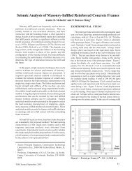
<strong>MSJC</strong> <strong>Code</strong>/<strong>Commentary</strong> <strong>Working</strong> <strong>Draft</strong>C1C2C3C4C5C6C7C8C9C10C11C12C13C14C15C16C17C18C19C201.9.7 Concentrated loads1.9.7.1 Concentrated loads shall not be distributed over a lengthgreater than the minimum of the following:(a) the length of bearing area plus the length determined by considering theconcentrated load to be dispersed along a 2 vertical: 1 horizontal line.<strong>The</strong> dispersion shall terminate at half the wall height, a movement joint,the end of the wall, or an opening, whichever provides the smallestlength.(b) <strong>The</strong> center-to-center distance between concentrated loads.1.9.7.2 For walls laid in other than not laid in running bond,concentrated loads shall not be distributed across head joints. Whereconcentrated loads acting on such walls are applied to a bond beam, theconcentrated load is permitted to be distributed through the bond beam, butshall not be distributed across head joints below the bond beams.1.9.7 Concentrated loadsReference 1.21 reports the results of tests of a wide variety ofspecimens under concentrated loads, including AAC masonry, concreteblock masonry, and clay brick masonry specimens. Reference 1.21 suggeststhat a concentrated load can be distributed at a 2:1 slope, terminating at halfthe wall height, where the wall height is from the point of application of theload to the foundation. Tests on the load dispersion through a bond beam ontop of hollow masonry reported in Reference 1.22 resulted in an angle fromthe horizontal of 59º for a 1-course CMU bond beam, 65º for a 2-courseCMU bond beam, and 58º for a 2-course clay bond beam, or approximatelya 2:1 slope. For simplicity in design, a 2:1 slope is used for all cases of loaddispersion of a concentrated load.<strong>Code</strong> provisions are illustrated in Figure CC-1.9-7. Figure CC-1.9-7a illustrates the dispersion of a concentrated load through a bond beam forboth running bond and stack bond. A hollow wall would be checked forbearing under the bond beam using the effective length. Figure CC-1.9-7billustrates the dispersion of a concentrated load in the wall. <strong>The</strong> effectivelength would be used for checking the wall under the axial force. A wallmay have to be checked at several locations, such as under a bond beam andat midheight.CC1CC2CC3CC4CC5CC6CC7CC8CC9CC10CC11CC12CC13CC14CC15CC16CC17CC18CC19CC20Comment [PJS62]: TAC Comment 4811/23/201011/16/20109/7/2010 Page C40
<strong>MSJC</strong> <strong>Code</strong>/<strong>Commentary</strong> <strong>Working</strong> <strong>Draft</strong>Bearing PlateLoadCheck bearing onhollow wallLoadBearing PlateBond BeamBond BeamLoad isdispersedat a 2:1slopeRunning bondStack bondLoad dispersionterminates at headjoint in stack bondBearing PlateLoadCheck bearing onhollow wallLoadBearing PlateBond BeamBond BeamLoad isdispersedat a 2:1slopeRunning bondLoad dispersionterminates at headjoints for masonry notlaid in running bondNot laid in running bond(a) Distribution of concentrated load through bond beamCC1CC2CC3CC4CC5CC6CC7CC8CC9CC10CC11CC12CC13CC14CC15CC16CC17CC18CC19CC20Formatted: Font: 10 ptCC111/23/201011/16/20109/7/2010 Page C41
C21C22C23C24C25C26C27C28C29C30C11.10 — Connection to structural frames<strong>Masonry</strong> walls shall not be connected to structural frames unless theconnections and walls are designed to resist design interconnecting forcesand to accommodate calculated deflections.<strong>MSJC</strong> <strong>Code</strong>/<strong>Commentary</strong> <strong>Working</strong> <strong>Draft</strong>LoadLoadEffective LengthEffectiveLength1212h / 2hLoadEffectiveLength(b) Distribution of concentrated load in wallLoad12EffectiveLengthLoad12EffectiveLengthFigure CC-1.9-7. Distribution of concentrated loads1.10 —Connection to structural framesExterior masonry walls connected to structural frames are usedprimarily as nonbearing curtain walls. Regardless of the structural systemused for support, there are differential movements between the structure andthe wall. <strong>The</strong>se differential movements may occur separately or incombination and may be due to the following:1) Temperature increase or decrease of either the structural frame or themasonry wall.2) Moisture and freezing expansion of brick or shrinkage of concreteblock walls.3) Elastic shortening of columns from axial loads, shrinkage, or creep.CC2CC3CC4CC5CC6CC7CC8CC9CC10CC11CC12CC13CC14CC15CC16CC17CC18CC19CC20CC21CC22CC23CC24CC25CC26CC27CC28CC29CC30CC111/23/201011/16/20109/7/2010 Page C42
<strong>MSJC</strong> <strong>Code</strong>/<strong>Commentary</strong> <strong>Working</strong> <strong>Draft</strong>C2C3C4C5C6C7C8C9C10C11C12C13C14C15C16C17C18C19C20C214) Deflection of supporting beams.5) Sidesway in multiple-story buildings.6) Foundation movement.Since the tensile strength of masonry is low, these differentialmovements must be accommodated by sufficient clearance between theframe and masonry and flexible or slip-type connections.Structural frames and bracing should not be infilled with masonry toincrease resistance to in-plane lateral forces without considering thedifferential movements listed above.Wood, steel, or concrete columns may be surrounded by masonry servingas a decorative element. <strong>Masonry</strong> walls may be subject to forces as a result oftheir interaction with other structural components. Since the masonry elementis often much stiffer, the load will be carried primarily by the masonry. <strong>The</strong>seforces, if transmitted to the surrounding masonry, should not exceed theallowable stresses of the masonry. Alternately, there should be sufficientclearance between the frame and masonry. Flexible ties should be used toallow for the deformations.Beams or trusses supporting masonry walls are essentially embedded, andtheir deflections should be limited to the allowable deflections for themasonry being supported. See Section 1.13.31.13.1.4 for requirements.CC2CC3CC4CC5CC6CC7CC8CC9CC10CC11CC12CC13CC14CC15CC16CC17CC18CC19CC20CC21C22C23C24C25C26C27C28C29C30C311.11 — Stack bond m<strong>Masonry</strong> not laid in running bond1.11 — Stack bond m<strong>Masonry</strong> not laid in running bondCC22For masonry not laid in other than running bond, the minimum area ofhorizontal reinforcement shall be 0.00028 multiplied by the gross verticalcross-sectional area of the wall using specified dimensions. Horizontalreinforcement shall be placed at a maximum spacing of 48 in. (1219 mm)on center in horizontal mortar joints or in bond beams.<strong>The</strong> requirements separating for masonry laid in running bond fromstack bond are shown in Figure CC-1.11-1. <strong>The</strong> amount of horizontalreinforcementsteel required in masonry not laid in running bondthis sectionis a prescriptive amount to provide continuity across the head joints. Thisreinforcement can be also used to resist load.Although continuity across head joints in masonry not laid in otherthanrunning bond is a concern for AAC masonry as well as masonry of clayor concrete, the use of horizontal reinforcement to enhance continuity inAAC masonry is generally practical only by the use of bond beams.CC23CC24CC25CC26CC27CC28CC29CC30CC31Comment [ER63]: Ballot 06-Q-023C and 09-Q-039Comment [PS64]: Editorally revised 2009-05-19Comment [PJS65]: TAC Comment 5311/23/201011/16/20109/7/2010 Page C43
<strong>MSJC</strong> <strong>Code</strong>/<strong>Commentary</strong> <strong>Working</strong> <strong>Draft</strong>CC1CC2CC3CC4Typical Running BondBrick UnitsTypical Running BondConcrete <strong>Masonry</strong> UnitsCC5CC6CC7CC8Unit Length1/4 UnitUnit LengthOverlap<strong>Masonry</strong> not overlapped a minimum of 1/4of the unit length is considered to be laidIn Other than Running Bond1/4 UnitOverlapCC9CC10CC11CC12CC13CC14CC15Typical Running BondBrick UnitsTypical Running BondConcrete <strong>Masonry</strong> UnitsCC16CC17CC18CC19CC20CC21Unit Length1/4 UnitUnit LengthOverlap<strong>Masonry</strong> is considered to be laid in running bondwhen units overlap a minimum of ¼ of the unit length1/4 UnitOverlapCC22CC23CC24Figure CC-1.11-1 — Running bond masonryCC25CC2611/23/201011/16/20109/7/2010 Page C44
<strong>MSJC</strong> <strong>Code</strong>/<strong>Commentary</strong> <strong>Working</strong> <strong>Draft</strong>C11.12 — Corbels1.12 — CorbelsCC1C2C3C4C5C6C7C8C9C10C11C12C13C14C15C161.12.1 Load-bearing corbelsLoad-bearing corbels shall be designed in accordance with Chapter 2, 3or 4.1.12.2 Non-load-bearing corbelsNon-load-bearing corbels shall be designed in accordance withChapters 2, 3 or 4 or detailed as follows:(a) Solid masonry units or hollow units filled with mortar or grout shall beused.(b) <strong>The</strong> maximum projection beyond the face of the wall shall not exceed:(1) one-half the wall thickness for multiwythe walls bonded by mortaror grout and wall ties or masonry headers, or(2) one-half the wythe thickness for single wythe walls, masonrybonded hollow walls, multiwythe walls with open collar joints, andveneer walls.(c) <strong>The</strong> maximum projection of one unit shall not exceed:<strong>The</strong> provision for corbelling up to one-half of the wall or wythe thickness istheoretically valid only if the opposite side of the wall remains in its sameplane. <strong>The</strong> addition of the 1-in. (25-mm) intrusion into the plane recognizesthe impracticality of keeping the back surface plane. See Figure CC-1.12-1and CC-1.12-2 for maximum permissible unit projection.CC2CC3CC4CC5CC6CC7CC8CC9CC10CC11CC12CC13CC14CC15CC16CC17CC19CC20Comment [ER66]: Hyphen added per Ballot 04-Q-012Comment [ER67]: Hyphen added per Ballot 04-Q-020C17(1) one-half the nominal unit height.C18(2) one-third the nominal thickness of the unit or wythe.C19C20(d) <strong>The</strong> back surface of the corbelled section shall remain within 1 in.(25.4 mm) of plane.11/23/201011/16/20109/7/2010 Page C45
<strong>MSJC</strong> <strong>Code</strong>/<strong>Commentary</strong> <strong>Working</strong> <strong>Draft</strong>dLimitations on Corbelling:P c ≤ t/2p ≤ h/2p ≤ d/3Where:P c = Allowable total horizontal projection of corbellinghp = Allowable projection of one unitpt = nominal wall thicknessd = nominal unit thickness (specified thickness plus the thicknessof one mortar joint)h = nominal unit height (specified height plus the thickness of onemortar jointNote: Neither ties nor headers shown.t P cFigure CC-1.12-1 — Limits on corbelling in solid wallsCC1CC2CC3CC4CC5CC6CC7CC8CC9CC10CC11CC12CC13CC14CC15CC16CC1711/23/201011/16/20109/7/2010 Page C46
a + 1 in. (25 mm)ad<strong>MSJC</strong> <strong>Code</strong>/<strong>Commentary</strong> <strong>Working</strong> <strong>Draft</strong>Limitations on Corbelling:P C d / 2p h / 2p d / 3Where:P C = Allowable total horizontal projection of corbellingp = Allowable projection of one unithd = Nominal unit thickness (specified thickness plusthe thickness of one mortar joint)h= Nominal unit height (specified height plus thepthickness of one mortar joint)P Ca= Air space thicknessTies shown for illustration onlyFigure CC-1.12-2 – Limits on corbelling in walls with air spaceCC1CC2CC3CC4CC5CC6CC7CC8CC9CC10CC11CC12CC13CC14CC15CC16CC17CC18CC19C20C21C22C23C24C25C26C27C28C29C30C31C321.13 — BeamsDesign of beams shall meet the requirements of Section 1.13.1through 1.13.4or Section 1.13.2 and Section 2.3.3.3, 3.3.4.2, or A.3.4.2.Design of beams shall also meet the requirements of Section 2.3, Section 3.3or Section 8.3. Design requirements for masonry beams shall apply tomasonry lintels.1.13.1 General beam design1.13.1.1 Span length — Span lengths shall be in accordance with thefollowing:1.13.1.1.1 Span length of members beams not builtintegrally with supports shall be taken as the clear span plus depth ofmemberbeam, but need not exceed the distance between centers of supports.1.13.1.1.2 For determination of moments in1.13 — Beams1.13.1 General beam design1.13.1.1 Span length — No <strong>Commentary</strong>.CC20CC21CC22CC23CC24CC25CC26CC27CC28CC29CC30CC31CC32Comment [PS68]: Ballot Item 03-F-003B andfurther revised by 09-F-054 and Bennet 5/26/10 E-mail with concurrence from Chair.Comment [ER69]: Ballot 07-G-002Formatted: None, Indent: Left: 0", SpaceBefore: 0 pt, After: 0 pt, Don't keep with nextFormatted: Space After: 0 ptComment [ER70]: Ballot 07-Q-03411/23/201011/16/20109/7/2010 Page C47
<strong>MSJC</strong> <strong>Code</strong>/<strong>Commentary</strong> <strong>Working</strong> <strong>Draft</strong>C1C2members beams that are continuous over supports, span length shall betaken as the distance between centers of supports.11/23/201011/16/20109/7/2010 Page C48
<strong>MSJC</strong> <strong>Code</strong>/<strong>Commentary</strong> <strong>Working</strong> <strong>Draft</strong>C1C2C3C4C51.13.1.2 Lateral support — <strong>The</strong> compression face of beams shallbe laterally supported at a maximum spacing based on the smaller of:(a) of 32 multiplied by the beam thicknesswidth, b.(b) 120b 2 /d1.13.1.2 Lateral support — To minimize lateral torsional buckling,the <strong>Code</strong> requires lateral bracing of the compression face. Hansell andWinter 1.23 suggest that the slenderness ratios should be given in terms ofLd/b 2 . Revathi and Menon 1.24 report on tests of seven under-reinforcedslender concrete beams. In Figure CC-1.13-1, a straight line is fitted to theW test /W u ratio vs. Ld/b 2 , where W test is the experimental capacity and W u isthe calculated capacity based on the full cross-sectional moment strength.W test /W u equals 1 where Ld/b 2 equals 146. Based on this, the <strong>Code</strong> limit of120Ld/b 2 is reasonable and slightly conservative.CC1CC2CC3CC4CC5CC6CC7CC8CC9Comment [PS71]: Ballot Item 03-F-007BComment [ER72]: Ballot 06-F024 andcommentary editorially revised.Comment [ER73]: Ballot 08-F-028 andeditorially revised.10.9W test /W u = -0.00177(Ld/b 2 )+1.25CC10CC11Formatted: Font: 10 pt, UnderlineWtest/Wu0.80.7CC12CC13CC140.6CC150.5100 150 200 250 300 350Ld/b 2CC16CC17CC18C23C24C25C26C27C28C29C30C31C11.13.1.3 Bearing length — Length of bearing of beams on theirsupports shall be a minimum of 4 in. (102 mm) in the direction of span.1.13.31.13.1.4 Deflections — <strong>Masonry</strong> beams and lintels shallbe designed to have adequate stiffness to limit deflections that adverselyaffect strength or serviceability.1.13.31.13.1.4.1 <strong>The</strong> computed deflection of beams andlintels providing vertical support to masonry designed in accordance withSection 2.2, Section 3.2, Chapter 5, or Section A.8.2, shall not exceed l/600Figure CC-1.13-1 Beam capacity vs. beam slenderness<strong>The</strong> requirement applies to simply supported beams. With continuous orfixed beams, the spacing may be increased.1.13.1.3 Bearing length— <strong>The</strong> minimum bearing length of 4 in.(102 mm) in the direction of span is considered a reasonable minimum formasonry beams over door and window openings to prevent reduceconcentrated compressive stresses at the edge of the openingsupport.1.13.31.13.1.4 Deflections — <strong>The</strong> provisions of Section1.13.31.13.4.1 address deflections that may occur at service load levels.1.13.31.13.1.4.1 <strong>The</strong> deflection limits apply to beams and lintelsof all materials that support unreinforced masonry. <strong>The</strong> deflectionrequirements may also be applicable to supported reinforced masonry thathas vertical reinforcement only.CC19CC20CC21CC22CC23CC24CC25CC26CC27CC28CC29CC30CC31CC3Comment [PJS74]: Revised by 10-F-056B11/23/201011/16/20109/7/2010 Page C49
C2C3C4C5C6C7C8C9C10<strong>MSJC</strong> <strong>Code</strong>/<strong>Commentary</strong> <strong>Working</strong> <strong>Draft</strong>under unfactored dead plus live loads. <strong>The</strong> deflection limit of l/600 should prevent long-term visibledeflections and serviceability problems. In most cases, deflections ofapproximately twice this amount, or l/300, are required before thedeflection becomes visible 1.2325 . This deflection limit is for immediatedeflections. Creep will cause additional long-term deflections. A largerdeflection limit of l/480 has been used when considering long-termdeflections 1.2426 .CC4CC5CC6CC7CC8CC9CC10C11C12C13C14C15C16C17C18C19C20C21C22C23C24C25C26C27C28C29C301.13.31.13.1.4.2 Deflection of masonry beams and lintels shall becomputed using the appropriate load-deflection relationship considering theactual end conditions. Unless stiffness values are obtained by a morecomprehensive analysis, immediate deflections shall be computed with aneffective moment of inertia, I eff , as follows.Ieff M cr I n M a 3 Icr3 M cr 1 I nM(Equation 1-1)a For continuous members beams, I eff shall be permitted to be taken asthe average of values obtained from Eq.Equation (1-1) for the criticalpositive and negative moment regions.For beamsmembers of uniform cross-section, I eff shall be permitted tobe taken as the value obtained from Equation. (1-1) at midspan for simplespans and at the support for cantilevers. For masonry designed inaccordance with Chapter 2, the cracking moment, M cr , shall be computedusing the allowable flexural tensile stress taken from Table 2.2.3.2multiplied by a factor of 2.5. For masonry designed in accordance withChapter 3, the cracking moment, M cr , shall be computed using the value forthe modulus of rupture, f r , taken from Table 3.1.8.2.1. For masonrydesigned in accordance with Appendix AChapter 8, the cracking moment,M cr , shall be computed using the value for the modulus of rupture, f rAAC , asgiven by Section A.8.1.8.3.1.13.31.13.1.4.2 <strong>The</strong> effective moment of inertia was developedto provide a transition between the upper and lower bounds of I g and I cr as afunction of the ratio M cr /M a 1.2527 . This procedure was selected as beingsufficiently accurate for use to control deflections 1.2628 . Calculating a moreaccurate effective moment of inertia using a moment-curvature analysismay be desirable for some circumstances.Most masonry beams have some end restraint due to being builtintegrally with a wall. Tests have shown that the end restraint from beamsbeing built integrally with walls reduces the deflections from 20 to 45percent of those of the simply supported specimens 1.2729 .CC11CC12CC13CC14CC15CC16CC17CC18CC19CC20CC21CC22CC23CC24CC25CC26CC27CC28CC29CC30Comment [ER75]: Ballot 07-Q-034 andeditorially revised to delete “and lintels” since this isaddressed in Section 1.13.Comment [ER76]: Ballot 07-Q-034 andeditorially revised to delete “and lintels” since this isaddressed in Section 1.13.Comment [ER77]: ErrataC31C32C33C34C351.13.31.13.1.4.3 Deflections of reinforced masonry beams andlintels need not be checked when the span length does not exceed 8multiplied by the effective depth to the reinforcement, d, in the masonrybeam or lintel.1.13.31.13.1.4.3 Reinforced masonry beams and lintels with spanlengths of 8 times d have immediate deflections of approximately 1/600 ofthe span length 1.30Bennett, et al, 2007 . <strong>Masonry</strong> beams and lintels with shorterspans should have sufficient stiffness to prevent serviceability problemsand, therefore, deflections do not need to be checked.CC31CC32CC33CC34CC35Comment [ER78]: Ballot 2011-01, Item 01-F-001. Staff will number references consecutively priorto publicationC1 1.13.52 Deep beams 1.13.25 Deep beams CC1Comment [ER79]: Ballot 08-F-014B11/23/201011/16/20109/7/2010 Page C50
<strong>MSJC</strong> <strong>Code</strong>/<strong>Commentary</strong> <strong>Working</strong> <strong>Draft</strong>C2C3C4C5C6C7C8C9C10Design of deep beams shall meet the requirements of Section 1.13.1.2and 1.13.1.3 in addition to the requirements of 1.13.25.1 through 1.13.25.5and the requirements of Chapter 2, Chapter 3, or Chapter 8.1.13.52.1 Effective span length — <strong>The</strong> effective span length, l eff ,shall be taken as the center-to-center distance between supports or 1.151.16multiplied by the clear span, whichever is smaller.Shear warping of the deep beam cross section and a combination ofdiagonal tension stress and flexural tension stress in the body of the deepbeam require that these members be designed using deep beam theory whenthe span-to-depth ratio is within the limits given in the definition of deepbeams. <strong>The</strong> provisions for deep beams were developed based onrequirements and suggestionsrecommendations in other codes and in theliterature 1.26, 1.31-1.37 .CC2CC3CC4CC5CC6CC71.13.2.1 Effective span length — No <strong>Commentary</strong>. CC8CC9CC10Comment [PJS80]: 09-Q-050C11C12C13C14C15C16C17C181.13.52.2 Internal lever arm — Unless the internal lever arm, z,between the compressive and tensile forces is determined by a morecomprehensive analysis, it shall be taken as:(a) For simply supported spans.leff(1) When 1 2dleff(2) When 1dvz 0.2l eff 2d v(Equation 1-2a)vz 0. 6l eff(Equation 1-2b)1.13.54.2 Internal lever arm — <strong>The</strong> theory used for design ofbeams has limited applicability to deep beams. Specifically, there will be anonlinear distribution of strain in deep beams. <strong>The</strong> internal lever arm, z,between the centroid of the internal compressive forces and the internaltensile forces will be less than that calculated assuming a linear straindistribution. <strong>The</strong> <strong>Code</strong> specifiedequations for internal lever arm, z, can beused with either allowable stress design or strength design. For allowablestress design, z is commonly known as jd, and for strength design, z iscommonly known as d-(a/2). <strong>The</strong> internal lever arm provisions in the <strong>Code</strong>are based on Ref. 1.33.CC11CC12CC13CC14CC15CC16CC17CC18CC19CC20CC21CC22CC23Comment [PJS81]: 09-Q-049C19(b) For continuous spansC20C21leff(1) When 1 3dvz 0.2l eff 1. 5d v(Equation 1-3a)C22C23leff(2) When 1dvz 0. 5l eff3b(Equation 1-3b)11/23/201011/16/20109/7/2010 Page C51
<strong>MSJC</strong> <strong>Code</strong>/<strong>Commentary</strong> <strong>Working</strong> <strong>Draft</strong>C1C2C3C4C5C6C7C81.13.25.3 Flexural reinforcement — Distributed horizontal flexuralreinforcement shall be provided in the tension facezone of the beam for adepth equal to half of the total depth of the beam, d v . <strong>The</strong> maximum spacingof distributed horizontal flexural reinforcement shall not exceed one-fifth ofthe total depth of the beam, d v , nor 16 in. (305406 mm). Joint reinforcementshall be permitted to be used as distributed horizontal flexural reinforcementin deep beams. Horizontal flexural reinforcement shall be anchored todevelop the yield strength of the reinforcement at the face of supports.1.13.52.3 Flexural reinforcement — <strong>The</strong> distribution of tensilestress in a deep beam is generally such that the lower one-half of the beamis required to have distributed flexural reinforcement. However, otherloading conditions, such as uplift, and support conditions, such ascontinuous and fixed ends, should be considered in determining the portionof the deep beam that is subjected to tension. Distributed horizontalreinforcement resists tensile stress caused by shear as well as by flexure.CC1CC2CC3CC4CC5CC6CC7CC8Comment [PJS82]: 09-F-057C9C10C11C12C13C14C15C16C17C18C191.13.25.4 Minimum shear reinforcement – <strong>The</strong> following provisionsshall apply when shear reinforcement is required in accordance with Section2.3.6, Section 3.3.4.1.2, or Section 8.3.4.1.2.(a) <strong>The</strong> minimum area of vertical shear reinforcement shall be 0.0007 bd v .(b) Horizontal shear reinforcement shall have cross-sectional area equal toor greater than one half the area of the vertical shear reinforcement.Such reinforcement shall be equally distributed on both side faces ofthe beam when the nominal width of the beam is greater than 8 inches(203 mm).(c) <strong>The</strong> maximum spacing of shear reinforcement shall not exceed onefifththe total depth of the beam, d v , nor 16 in. (406305 mm).1.13.52.4 Minimum shear reinforcement – Distributed flexuralreinforcement may be included as part of the provided shear reinforcementto meet the minimum distributed shear reinforcement ratio. <strong>The</strong> spacing ofshear reinforcement is limited to restrain the width of the cracks.CC9CC10CC11CC12CC13CC14CC15CC16CC17CC18CC19C20C21C22C231.13.25.5 Total reinforcement – <strong>The</strong> sum of the cross-sectional areas oftotal horizontal and vertical reinforcement shall be at least 0.001 multipliedby the gross cross-sectional area, bd v , of the deep beam, using specifieddimensions.1.13.25.5 Total reinforcement – Load applied along the top surfaceof a deep beam is transferred to supports mainly by arch action. Typically,deep beams do not need transverse reinforcement and it is sufficient toprovide distributed flexural reinforcement 1.31 .CC20CC21CC22CC2311/23/201011/16/20109/7/2010 Page C52
<strong>MSJC</strong> <strong>Code</strong>/<strong>Commentary</strong> <strong>Working</strong> <strong>Draft</strong>C1C2C3C4C5C6C7C8C9C10C111.14 — ColumnsDesign of columns shall meet the requirements of Section 1.14.1 orSection 1.14.2. Design of columns shall also meet the requirements ofSection 2.3, or Section 3.3, or Section 8.3., and the requirements of Section2.1.6, 3.3.4.4, or A.8.3.4.4.1.14.1 General column design1.14.1.1 Dimensional limits — Dimensions shall be in accordancewith the following:(a) <strong>The</strong> distance between lateral supports of a column shall not exceed 99multiplied by the least radius of gyration, r.(b) Minimum side dimension shall be 8 in. (203 mm) nominal.1.14 — ColumnsColumns are defined in Section 1.6. <strong>The</strong>y are isolated members usuallyunder axial compressive loads and flexure. If damaged, columns may causethe collapse of other members; sometimes of an entire structure. <strong>The</strong>secritical structural elements warrant the special requirements of this section.1.14.1 General column design1.14.1.1 Dimensional limits — <strong>The</strong> limit of 99 for the slendernessratio, h/r, is judgment based. See Figure CC-1.14-1 for effective heightdetermination.<strong>The</strong> minimum nominal side dimension of 8 in. (203 mm)results from practical considerations.C12 1.14.1.2 Construction —Columns shall be solidlyfully grouted. CC12C13C14C15C16C17C18C19C20C21C22C23C24C25C26C27C28C29C30C31C32C33C34C351.14.1.21.14.1.3 Vertical reinforcement — Vertical reinforcement incolumns shall not be less than 0.0025A n nor exceed 0.04A n . <strong>The</strong> minimumnumber of bars shall be four.1.14.1.31.14.1.4 Lateral ties — Lateral ties shall conform to thefollowing:(a) Vertical reinforcement shall be enclosed by lateral ties at least 1 / 4 in.(6.4 mm) in diameter.(b) Vertical spacing of lateral ties shall not exceed 16 longitudinal bar diameters,48 lateral tie bar or wire diameters, or least cross-sectional dimension of themember.(c) Lateral ties shall be arranged so that every corner and alternate longitudinalbar shall have lateral support provided by the corner of a lateral tie with anincluded angle of not more than 135 degrees. No bar shall be farther than 6in. (152 mm) clear on each side along the lateral tie from such a laterallysupported bar. Lateral ties shall be placed in either a mortar joint or ingrout. Where longitudinal bars are located around the perimeter of a circle,a complete circular lateral tie is permitted. Lap length for circular ties shallbe 48 tie diameters.(d) Lateral ties shall be located vertically not more than one-half lateral tiespacing above the top of footing or slab in any story, and shall be spacednot more than one-half a lateral tie spacing below the lowest horizontal1.14.1.21.14.1.3 Vertical reinforcement — Minimum verticalreinforcement is required in masonry columns to prevent brittle failure. <strong>The</strong>maximum percentage limit in column vertical reinforcement wasestablished based on the committee's experience. Four bars are required soties can be used to provide a confined core of masonry.1.14.1.31.14.1.4 Lateral ties — Lateral reinforcement in columnsperforms two functions. It provides the required support to prevent bucklingof longitudinal column reinforcing bars acting in compression and providesresistance to diagonal tension for columns acting in shear 1.2838 . Ties may belocated in the mortar joint, when the tie diameter does not exceed ½ thespecified mortar joint thickness. For example, ¼ in. (6.4 mm) diameter tiesmay be placed in ½ in. (12.7 mm) thick mortar joints.<strong>The</strong> requirements of this <strong>Code</strong> are modeled on those for reinforcedconcrete columns. Except for permitting ¼-in. (6.4-mm) ties in SeismicDesign Category A, B, and C , they reflect the applicable provisions of thereinforced concrete code.CC1CC2CC3CC4CC5CC6CC7CC8CC9CC10CC11CC13CC14CC15CC16CC17CC18CC19CC20CC21CC22CC23CC24CC25CC26CC27CC28CC29CC30CC31CC32CC33CC34CC34Comment [PJS83]: Ballotn09-F-112A and 10-F-065B and further revised by bennet 5/26/10 e-mailwith concurrence of the the ChairComment [PS84]: Ballot item 03-F-004Comment [PJS85]: Ballot 11-Q-058Comment [ER86]: Ballot 05-F-02011/23/201011/16/20109/7/2010 Page C53
<strong>MSJC</strong> <strong>Code</strong>/<strong>Commentary</strong> <strong>Working</strong> <strong>Draft</strong>C1C2C3C4reinforcement in beam, girder, slab, or drop panel above.(e) Where beams or brackets frame into a column from four directions, lateralties shall be permitted to be terminated not more than 3 in. (76.2 mm) belowthe lowest reinforcement in the shallowest of such beams or brackets.Column,Wall orPilasterFloor or RoofCantilevered Column,Wall or PilasterCC1CC2Comment [PS87]: Moved from CC-2.1.5 per 03-F-004 and further revised by 05-F-019Formatted: Font: 10 pth = ClearHeightColumn,Wall orPilasterClear HeightBetween SupportsBraced at SupportsFloor or Roofh = 2 HeightHeightFloor or RoofFixed at BaseCantilevered Column,Wall or PilasterCC3CC4CC5CC6CC7CC8h =ClearHeightClear HeightBetween SupportsBraced at Supportsh≥ 2 HeightHeightFloor or RoofFixed or Continuous at BaseCC9CC10CC11CC12If data (see Section 1.3) shows that there is reliable restraint against translationand rotation at the supports the “effective height” may be taken as low as the distancebetween points of inflection for the loading case under consideration.Figure CC-1.14-1 — Effective height, h, of column, wall, or pilasterCC13CC14CC15CC1611/23/201011/16/20109/7/2010 Page C54
<strong>MSJC</strong> <strong>Code</strong>/<strong>Commentary</strong> <strong>Working</strong> <strong>Draft</strong>C1C2C3C4C5C6C7C8C9C10C111.14.2 Lightly loaded columns<strong>Masonry</strong> columns used only to support light frame roofs of carports,porches, sheds or similar structures assigned to Seismic Design Category A,B, or C, which are subject to unfactored gravity loads not exceeding 2,000 lbs(8,900 N) acting within the cross-sectional dimensions of the column arepermitted to be constructed as follows:(a) Minimum side dimension shall be 8 in. (203 mm) nominal.(b) Height shall not exceed 12 ft (3.66 m).(c) Cross-sectional area of longitudinal reinforcement shall not be less than0.2 in. 2 (129 mm 2 ) centered in the column.(d) Columns shall be fully grouted solid.1.14.2 Lightly loaded columns<strong>Masonry</strong> columns are often used to support roofs of carports, porches,sheds or similar light structures. <strong>The</strong>se columns do not need to meet thedetailing requirements of Section 1.14.1. <strong>The</strong> axial load limit of2,000 pounds (8,900 N) was developed based on the flexural strength of anominal 8 in. (203 mm) by 8 in. (203 mm) by 12 ft high (3.66 m) columnwith one No. 4 (M#13) reinforcing bar in the center and f’ m of 1350 psi(9.31 MPa). An axial load of 2,000 pounds (8,900 N) at the edge of themember will result in a moment that is approximately equal to the nominalflexural strength of this member.CC1CC2CC3CC4CC5CC6CC7CC8CC9CC10CC11Comment [PJS89]: Editorial per Throop andTAC comments on 2/4/10Comment [PJS88]: Ballot 11-Q-0581.15 — Pilasters1.15 — PilastersWalls interfacing with pilasters shall not be considered as flanges, unlessthe construction requirements of Sections 1.9.4.2.1 and 1.9.4.2.5 are met.When these construction requirements are met, the pilaster’s flanges shallbe designed in accordance with Sections 1.9.4.2.2 through 1.9.4.2.4.Pilasters are masonry members that can serve one of several purposes. <strong>The</strong>ymay project from one or both sides of the wall, as shown in Figure CC-1.15-1. Pilasters contribute to the lateral load resistance of masonry wallsand may resist vertical loads.Formatted: Font: (Default) Arial, 10 pt, Bold,Condensed by 0.4 ptAlternate CoursesTies EmbeddedIn Mortar JointsAlternate Courses(a) Single Face(b) Double FaceBrick PilastersFormatted: Centered11/23/201011/16/20109/7/2010 Page C55
<strong>MSJC</strong> <strong>Code</strong>/<strong>Commentary</strong> <strong>Working</strong> <strong>Draft</strong>Formatted: Font: (Default) Arial, 10 pt, Bold,Condensed by 0.4 ptAlternate CoursesTies EmbeddedIn Mortar JointsAlternate Courses(a) Single Face(b) Double FaceBlock PilastersFormatted: CenteredFigure CC-1.15-1 — Typical pilastersComment [PJS90]: Ballot 11-F-049C121.151.16 — Details of reinforcement and metal accessories1.151.16 — Details of reinforcement and metal accessoriesCC12Formatted: CenteredC13C14C15C16C17C181.151.16.1 EmbedmentReinforcing bars shall be embedded in grout.When the provisions of this section were originally developed in thelate 1980s, the Committee used the then current ACI 318 <strong>Code</strong> 1.2939 as aguide. Some of the requirements were simplified and others dropped,depending on their suitability for application to masonry.1.151.16.1 EmbedmentNo <strong>Commentary</strong>.CC13CC14CC15CC16CC17CC18C19C20C21C22C23C241.151.16.2 Size of reinforcement1.151.16.2.1 <strong>The</strong> maximum size of reinforcement used inmasonry shall be No. 11 (M #36).1.151.16.2 Size of reinforcement1.151.16.2.1 Limits on size of reinforcement are based onaccepted practice and successful performance in construction. <strong>The</strong> No. 11(M#36) limit is arbitrary, but Reference 2.461.40 shows that distributedsmall bars provide better performance than fewer large bars. Properties ofreinforcement are given in Table CC-1.151.16.2.CC19CC20CC21CC22CC23CC24C25C26C271.151.16.2.2 <strong>The</strong> diameter of reinforcement shall not exceedone-half the least clear dimension of the cell, bond beam, or collar joint inwhich it is placed.1.151.16.2.2 Adequate flow of grout necessary for good bondis achieved with this limitation. It also limits the size of reinforcement whencombined with Section 1.191.20.1.C28 1.151.16.2.3 Longitudinal and cross wires of joint reinforcement 1.151.16.2.3 <strong>The</strong> function of joint reinforcement is to control CC28CC25CC26CC2711/23/201011/16/20109/7/2010 Page C56
<strong>MSJC</strong> <strong>Code</strong>/<strong>Commentary</strong> <strong>Working</strong> <strong>Draft</strong>C29C30C31C32C33C34shall have a minimum wire size of W1.1 (MW7) and a maximum wire size ofone-half the joint thickness.the size and spacing of cracks caused by volume changes in masonry aswell as to resist tension. 1.3041 Joint reinforcement is commonly used inconcrete masonry to minimize shrinkage cracking. <strong>The</strong> restriction on wiresize ensures adequate performance. <strong>The</strong> maximum wire size of one-half thejoint thickness allows free flow of mortar around joint reinforcement. Thus,a 3 / 16 -in. (4.8-mm) diameter wire can be placed in a 3 / 8 -in. (9.5-mm) joint.CC29CC30CC31CC32CC33CC3411/23/201011/16/20109/7/2010 Page C57
<strong>MSJC</strong> <strong>Code</strong>/<strong>Commentary</strong> <strong>Working</strong> <strong>Draft</strong>Table CC-1.151.16.2 — Physical properties of steel reinforcing wire and barsDesignationDiameter, in.(mm)Area, in. 2(mm 2 )Perimeter, in.(mm)WireW1.1 (11 gage) (MW7)W1.7 (9 gage) (MW11)W2.1 (8 gage) (MW13)W2.8 (3/16 wire)(MW18)W4.9 ( 1 / 4 wire) (MW32)BarsNo. 3 (M#10)No. 4 (M#13)No. 5 (M#16)No. 6 (M#19)No. 7 (M#22)No. 8 (M#25)No. 9 (M#29)No. 10 (M#32)No. 11 (M#36)0.121 (3.1)0.148 (3.8)0.162 (4.1)0.187 (4.8)0.250 (6.4)0.375 (9.5)0.500 (12.7)0.625 (15.9)0.750 (19.1)0.875 (22.2)1.000 (25.4)1.128 (28.7)1.270 (32.3)1.410 (35.8)0.011 (7.1)0.017 (11.0)0.020 (12.9)0.027 (17.4)0.049 (31.6)0.11 (71.0)0.20 (129)0.31 (200)0.44 (284)0.60 (387)0.79 (510)1.00 (645)1.27 (819)1.56 (1006)0.380 (9.7)0.465 (11.8)0.509 (12.9)0.587 (14.9)0.785 (19.9)1.178 (29.9)1.571 (39.9)1.963 (49.9)2.356 (59.8)2.749 (69.8)3.142 (79.8)3.544 (90.0)3.990 (101)4.430 (113)CC1CC2CC3CC4CC5CC6CC7CC8CC9CC10CC11CC12CC13CC14CC15CC16CC17CC18CC19CC20C21C22C23C24C25C26C27C28C29C30C31C32C33C34C35C361.151.16.3 Placement of reinforcement1.151.16.3.1 <strong>The</strong> clear distance between parallel bars shall notbe less than the nominal diameter of the bars, nor less than 1 in. (25.4 mm).1.151.16.3.2 In columns and pilasters, the clear distancebetween vertical bars shall not be less than one and one-half multiplied bythe nominal bar diameter, nor less than 1 1 / 2 in. (38.1 mm).1.151.16.3.3 <strong>The</strong> clear distance limitations between barsrequired in Sections 1.151.16.3.1 and 1.151.16.3.2 shall also apply to theclear distance between a contact lap splice and adjacent splices or bars.1.151.16.3.4 Groups of parallel reinforcing bars bundled incontact to act as a unit shall be limited to two in any one bundle.Individual bars in a bundle cut off within the span of a member shallterminate at points at least 40 bar diameters apart.1.151.16.3.5 Reinforcement embedded in grout shall have athickness of grout between the reinforcement and masonry units not lessthan 1 / 4 in. (6.4 mm) for fine grout or 1 / 2 in. (12.7 mm) for coarse grout.1.151.16.3 Placement of reinforcementPlacement limits for reinforcement are based on successful construction practiceover many years. <strong>The</strong> limits are intended to facilitate the flow of grout betweenbars. A minimum spacing between bars in a layer prevents longitudinal splittingof the masonry in the plane of the bars. Use of bundled bars in masonryconstruction is rarely required. Two bars per bundle is considered a practicalmaximum. It is important that bars be placed accurately. Reinforcing barpositioners are available to control bar position.CC21CC22CC23CC24CC25CC26CC27CC28CC29CC30CC31CC32CC33CC34CC35CC3611/23/201011/16/20109/7/2010 Page C58
<strong>MSJC</strong> <strong>Code</strong>/<strong>Commentary</strong> <strong>Working</strong> <strong>Draft</strong>C1C2C3C4C5C6C7C8C9C10C11C12C13C14C15C16C17C18C19C20C211.151.16.4 Protection of reinforcement and metal accessories1.151.16.4.1 Reinforcing bars shall have a masonry cover notless than the following:(a) <strong>Masonry</strong> face exposed to earth or weather: 2 in. (50.8 mm) for barslarger than No. 5 (M #16); 1 1 / 2 in. (38.1 mm) for No. 5 (M #16) bars orsmaller.(b) <strong>Masonry</strong> not exposed to earth or weather: 1 1 / 2 in. (38.1 mm).1.151.16.4.2 Longitudinal wires of joint reinforcement shall befully embedded in mortar or grout with a minimum cover of 5 / 8 in. (15.9 mm)when exposed to earth or weather and 1 / 2 in. (12.7 mm) when not exposed toearth or weather. Joint reinforcement shall be stainless steel or protected fromcorrosion by hot-dipped galvanized coating or epoxy coating when used inmasonry exposed to earth or weather and in interior walls exposed to a meanrelative humidity exceeding 75 percent. All other joint reinforcement shall bemill galvanized, hot-dip galvanized, or stainless steel.1.151.16.4 Protection of reinforcement and metal accessories1.151.16.4.1 Reinforcing bars are traditionally not coated forcorrosion resistance. <strong>The</strong> masonry cover retards corrosion of the steel.Cover is measured from the exterior masonry surface to the outermostsurface of the reinforcement to which the cover requirement applies. It ismeasured to the outer edge of stirrups or ties, if transverse reinforcementencloses main bars. <strong>Masonry</strong> cover includes the thickness of masonry units,mortar, and grout. At bed joints, the protection for reinforcement is the totalthickness of mortar and grout from the exterior of the mortar joint surface toouter-most surface of the reinforcement andor metal accessoryiessteel.<strong>The</strong> condition “masonry face exposed to earth or weather” refers todirect exposure to moisture changes (alternate wetting and drying) and notjust temperature changes.1.151.16.4.2 Since masonry cover protection for jointreinforcement is minimal, the protection of joint reinforcement in masonryis required in accordance with the Specification. Examples of interior wallsexposed to a mean relative humidity exceeding 75 percent are natatoria andfood processing plants.CC1CC2CC3CC4CC5CC6CC7CC8CC9CC10CC11CC12CC13CC14CC15CC16CC17CC18CC19CC20CC21Comment [ER91]: Ballot 06-Q-023CC22C23C24C25C26C27C281.151.16.4.3 Wall ties, sheet-metal anchors, steel plates and bars,and inserts exposed to earth or weather, or exposed to a mean relative humidityexceeding 75 percent shall be stainless steel or protected from corrosion by hotdipgalvanized coating or epoxy coating. Wall ties, anchors, and inserts shall bemill galvanized, hot-dip galvanized, or stainless steel for all other cases. Anchorbolts, steel plates, and bars not exposed to earth, weather, nor exposed to a meanrelative humidity exceeding 75 percent, need not be coated.1.151.16.4.3 Corrosion resistance requirements are includedsince masonry cover varies considerably for these items. <strong>The</strong> exception foranchor bolts is based on current industry practice.CC22CC23CC24CC25CC26CC27CC28C29C30C31C32C33C34C351.151.16.5 Standard hooksStandard hooks shall consist of the following:(a) 180-degree bend plus a minimum 4d b extension, but not less than 2-1/2in. (64 mm) at free end of bar;(b) 90-degree bend plus a minimum 12d b extension at free end of bar; or(c) for stirrup and tie hooks for a No. 5 bar and smaller, either a 90-degreeor 135-degree bend plus a minimum 6 d b extension, but not less than2-1/2 in. (64 mm) at free end of bar.1.151.16.5 Standard hooksStandard hooks are shown in Figure CC-1.151.16-1.CC29CC30C36C111/23/201011/16/20109/7/2010 Page C59
<strong>MSJC</strong> <strong>Code</strong>/<strong>Commentary</strong> <strong>Working</strong> <strong>Draft</strong>4 d b but not lessthan 2 ½ in. (63.5 mm)Point of Tangency(a)180 degree Bend6d b12d bPoint of Tangency(c)Point of TangencyPoint of Tangency6d bd b(b)90 degree Bendd bd bStirrup and Tie Anchorage with 90 degree or 135 degree BendCC1CC2CC3CC4CC5CC6CC7CC8CC9CC10CC11CC12CC13CC14CC15CC16CC17CC18CC19CC20CC21CC22CC23Formatted: Font: 10 ptCC111/23/201011/16/20109/7/2010 Page C60
<strong>MSJC</strong> <strong>Code</strong>/<strong>Commentary</strong> <strong>Working</strong> <strong>Draft</strong>Figure CC-1.151.16-1 — Standard hooksCC2CC3CC4CC5CC6CC7CC8CC9CC10CC11CC12CC13CC14CC15CC16CC17CC18CC19CC20CC21CC22CC23Comment [PJS92]: Editorially revised 63.5 mmto 64 mm per Throop and TAC comment on 2/4/1011/23/201011/16/20109/7/2010 Page C61
<strong>MSJC</strong> <strong>Code</strong>/<strong>Commentary</strong> <strong>Working</strong> <strong>Draft</strong>C1C2C3C4C5C6C7C8C9C10C11C121.151.16.6 Minimum bend diameter for reinforcing bars<strong>The</strong> diameter of bend measured on the inside of reinforcing bars, otherthan for stirrups and ties, shall not be less than values specified in Table1.151.16.6.Table 1.151.16.6 — Minimum diameters of bendBar size and typeNo. 3 through No. 7 (M #10through #22) Grade 40 (Grade280300)No. 3 through No. 8 (M #10through #25) Grade 50 or 60(Grade 350 or 420)Minimum diameter5 bar diameters6 bar diameters1.151.16.6 Minimum bend diameter for reinforcing barsStandard bends in reinforcing bars are described in terms of the insidediameter of bend since this is easier to measure than the radius of bend.A broad survey of bending practices, a study of ASTM bend testrequirements, and a pilot study of and experience with bending Grade 60(413.7 MPaGrade 420) bars were considered in establishing the minimumdiameter of bend. <strong>The</strong> primary consideration was feasibility of bendingwithout breakage. Experience has since established that these minimumbend diameters are satisfactory for general use without detrimental crushingof grout.CC1CC2CC3CC4CC5CC6CC7CC8CC9CC10CC11CC12CC13CC14CC15Comment [PJS93]: Editorially corrected perTAc Comment and Throop, 2/4/10C13C14C15No. 9, No. 10, and No. 11 (M #29,#32, and #36) Grade 50 or 60(Grade 350 or 420)8 bar diameters11/23/201011/16/20109/7/2010 Page C62
<strong>MSJC</strong> <strong>Code</strong>/<strong>Commentary</strong> <strong>Working</strong> <strong>Draft</strong>C1C2C3C4C5C6C7C8C9C10C11C12C13C14C15C16C17C18C19C20C21C22C231.161.17 — Anchor bolts1.161.17 — Anchor boltsCC1Headed and bent-bar anchor bolts shall conform to the provisions ofSections 1.161.17.1 through 1.161.17.7.<strong>The</strong>se design values apply only to the specific types of bolts mentioned.<strong>The</strong>se bolts are readily available and are depicted in Figure CC-1.161.17-1.CC2CC31.161.17.1 PlacementHeaded and bent-bar anchor bolts shall be embedded in grout. Anchorbolts of ¼ in. (6.4 mm) diameter are permitted to be placed in mortar bedjoints that are at least ½ in. (12.7 mm) in thickness and, for purposes ofapplication of the provisions of Sections 1.161.17, 2.1.4 and 3.1.6, arepermitted to be considered as if they are embedded in grout.When aAnchor bolts are placed in the top of grouted cells and bondbeamsin fine grout, there shall be positioned to maintain a minimum of ¼in. (6.4 mm) of fine grout between the bolts and the masonry unit; whenanchor bolts are placed in coarse grout, there shall be a minimum of or ½ in.(12.7 mm) of coaurse grout between the bolts and the masonry unit. Anchorbolts placed in drilled holes in the face shells of hollow masonry units shallbe permitted to contact the masonry unit where the bolt passes through theface shell, but the portion of the bolt that is within the grouted cell shall bepositioned to maintain a minimum of ¼ in. (6.4 mm) of fine grout betweenthe head or bent leg of theeach bolt and the masonry units or ½ in. (12.7mm) of coaurse grout between the head or bent leg of theeach bolt and themasonry unit.1.161.17.1 PlacementMost tests on anchor bolts in masonry have been performed on anchorbolts embedded in grout. Placement limits for anchor bolts are based onsuccessful construction practice over many years. <strong>The</strong> limits are intended tofacilitate the flow of grout between bolts and between bolts and themasonry unit.CC4CC5CC6CC7CC8CC9<strong>The</strong> clear distance between parallel anchor bolts shall not be lessthan the nominal diameter of the anchor bolt, nor less than 1 in. (25.4 mm).Research at Portland State University 1.42 and at Washington StateUniversity 1.43 has established that there is no difference in the performanceof an anchor bolt installed through a tight-fitting hole in the face shell of agrouted hollow masonry unit and in an over-sized hole in the face shell of agrouted hollow masonry unit. <strong>The</strong>refore, the clear distance requirement forgrout to surround an anchor bolt is not needed where the bolt passes throughthe face shell. See Figure CC-1.161.17-2.Quality/assurance/control (QA) procedures should ensure that there issufficient clearance around the bolts prior to grout placement. <strong>The</strong>seprocedures should also require observation during grout placement toensure that grout completely surrounds the bolts, as required by the QATables in Section 1.181.19.CC10CC11CC12CC13CC14CC15CC16CC17CC18CC19CC20CC21CC22CC23Comment [ER94]: Ballot 05-R-004 and furthermodified editorially in response to TAC Comment73 and 2010-02-12 email from DT“L” BoltsHex Head“J” BoltsSquare Head(a)Headed Anchor Bolts(b)Figure CC-1.161.17-1 — Anchor boltsBent-Bar Anchor BoltsCC24CC25CC26CC27CC28CC29CC30CC31CC3211/23/201011/16/20109/7/2010 Page C63
<strong>MSJC</strong> <strong>Code</strong>/<strong>Commentary</strong> <strong>Working</strong> <strong>Draft</strong>Minimum12 in. (12.7 mm) for coarse groutor 1 4 in.(6.4 mm) for fine groutAnchor boltAnchor boltBond beamFigure CC-1.161.17-2 — Anchor bolt clearance requrirements for headed anchor bolts -– bent- bars are similarCC1CC2CC3CC4CC5CC6CC7CC8CC9CC10CC11CC12CC13CC14CC15CC1611/23/201011/16/20109/7/2010 Page C64
<strong>MSJC</strong> <strong>Code</strong>/<strong>Commentary</strong> <strong>Working</strong> <strong>Draft</strong>C1C2C3C4C5C6C7C8C9C101.161.17.2 Projected area for axial tension<strong>The</strong> projected area of headed and bent-bar anchor bolts loaded in axialtension, A pt , shall be determined by Equation. (1-21-4).A2pt l b(Equation 1-21-4)<strong>The</strong> portion of projected area overlapping an open cell, or open headjoint, or that lies outside the masonry shall be deducted from the valueof A pt calculated using EquationEq. (1-21-4). Where the projected areasof anchor bolts overlap, the value of A pt calculated using EquationEq. (1-21-4) shall be adjusted so that no portion of masonry is included morethan once.1.161.17.2 Projected area for axial tensionResults of tests 1.3144, 1.4532 on headed anchor bolts in tension showed thatanchor bolts often failed by breakout of a conically shaped section ofmasonry. <strong>The</strong> area, A pt , is the projected area of the assumed failure cone.<strong>The</strong> cone originates at the compression bearing point of the embedment andradiates at 45º in the direction of the pull (See Figure CC-1.161.17-23).Other modes of tensile failure are possible. <strong>The</strong>se modes include pullout(straightening of J- or L-bolts) and yield / fracture of the anchor steel.When anchor bolts are closely spaced, stresses within the masonry beginto become additive, as shown in Figure CC-1.161.17-34. <strong>The</strong> <strong>Code</strong> requiresthat when projected areas of anchor bolts overlap, an adjustment be made sothat the masonry is not overloaded. When the projected areas of two or moreanchors overlap, the anchors with overlapping projected areas should betreated as an anchor group. <strong>The</strong> projected areas of the anchors in the group aresummed, this area is adjusted for overlapping areas, and the capacity of theanchor group is calculated using the adjusted area in place of A pt . See FigureCC-1.161.17-4 5 for examples of calculating adjusted values of A pt .CC1CC2CC3CC4CC5CC6CC7CC8CC9CC10CC11CC12CC13CC14CC15CC16CC17l bP (failure)P (failure)Assumed Cone forCalculation of A pt ,Equation 1-245° Conicallb45° ConicalFailureSurfaceFigure CC-1.161.17-2 3 — Anchor bolt tensile breakout coneFailureSurfaceCC18CC19CC20CC21CC22CC23CC24CC25CC2611/23/201011/16/20109/7/2010 Page C65
<strong>MSJC</strong> <strong>Code</strong>/<strong>Commentary</strong> <strong>Working</strong> <strong>Draft</strong>l b45°45°l bl bA bA ptFigure CC-1.161.17-3 4 — Overlapping anchor bolt breakout conesxsxsCC1CC2CC3CC4CC5CC6CC7CC8CC9CC10CC11CC12CC13CC1411/23/201011/16/20109/7/2010 Page C66
tttX 12Y l AAAptptptbYl4 X lYY<strong>MSJC</strong> <strong>Code</strong>/<strong>Commentary</strong> <strong>Working</strong> <strong>Draft</strong>2b tb212A pt at Top of Wall for UpliftXZ XYl b Zl bl42b 180 t2 t/ 2 lb22X Zt l sin where 2arcsin in degreesb 180XZ/2 Z/2XYl b Z t/ 2 lb22X Ztl sin where 2arcsinindegreesb 180XZ/2 Z/2XYl b Zl b t/ 2 lb22X Ztl sin where 2arcsinindegreesbl bCC1CC2CC3CC4CC5CC6CC7CC8CC9CC10CC11CC12CC13CC14CC15CC16CC17CC18CC19CC20CC21CC22CC23CC24CC25CC26CC27CC28Comment [PJS95]: 09-R-022Formatted: Font: (Default) Arial, 10 pt11/23/201011/16/20109/7/2010 Page C67
<strong>MSJC</strong> <strong>Code</strong>/<strong>Commentary</strong> <strong>Working</strong> <strong>Draft</strong>Figure CC-1.161.17-4 5 Calculation of Adjusted Values of A pt (Plan Views)11/23/201011/16/20109/7/2010 Page C68
<strong>MSJC</strong> <strong>Code</strong>/<strong>Commentary</strong> <strong>Working</strong> <strong>Draft</strong>C1C2C3C4C5C6C7C8C9C10C111.161.17.3 Projected area for shear<strong>The</strong> projected area of headed and bent-bar anchor bolts loaded in shear,A pv , shall be determined from EquationEq. (1-31-5).Apv2 lbe (Equation 1-31-5)2<strong>The</strong> portion of projected area overlapping an open cell, or open headjoint, or that lies outside the masonry shall be deducted from the valueof A pv calculated using EquationEq. (1-31-5). Where the projected areasof anchor bolts overlap, the value of A pv calculated using EquationEq.(1-31-5) shall be adjusted so that no portion of masonry is includedmore than once.Formatted: Indent: Left: 0"1.161.17.3 Projected area for shearCC1Results of tests 1.3144, 1.3245 on anchor bolts in shear showed that anchorbolts often failed by breakout of a conically shaped section of masonry. <strong>The</strong>area A pv is the projected area of the assumed failure cone. <strong>The</strong> cone originatesat the compression bearing point of the embedment and radiates at 45º in theCC2CC3CC4CC5A pv CC1945 ol CC15beCC16CC17l beCC18direction of the pull towards the free edge of the masonry (See Figure CC-1.161.17-56). Pryout (See Figure CC-1.161.17-67), masonry crushing, andyielding / fracture of the anchor steel are other possible failure modes.When the projected areas of two or more anchors overlap, the shear designof these anchors should follow the same procedure as for the tension designof overlapping anchors. See <strong>Commentary</strong> Section 1.161.17.2.CC6CC7CC8CC9CC10CC11CC12CC13CC14Figure CC-1.161.17-56- Anchor bolt shear breakoutCC20CC21CC2211/23/201011/16/20109/7/2010 Page C69
<strong>MSJC</strong> <strong>Code</strong>/<strong>Commentary</strong> <strong>Working</strong> <strong>Draft</strong>VFigure CC-1.161.17-67 - Anchor bolt shear pryoutCC1CC2CC3CC4CC5CC6CC7CC8CC9CC10CC11CC12C13C14C15C16C17C18C19C20C211.161.17.4 Effective embedment length for headed anchor bolts<strong>The</strong> effective embedment length for a headed anchor bolt, l b , shall be thelength of the embedment measured perpendicular from the masonry surfaceto the compression bearing surface of the anchor head.1.161.17.5 Effective embedment length of bent-bar anchor bolts<strong>The</strong> effective embedment for a bent-bar anchor bolt, l b , shall be the lengthof embedment measured perpendicular from the masonry surface to thecompression bearing surface of the bent end, minus one anchor boltdiameter.1.161.17.4 Effective embedment length for headed anchor boltsNo commentary.1.161.17.5 Effective embedment length for bent-bar anchor boltsTests 1.3144 have shown that the pullout strength of bent-bar anchor boltscorrelated best with a reduced embedment length. This may be explained withreference to Figure CC-1.161.17-78. Due to the radius of the bend, stressesare concentrated at a point less than the full embedment length.CC13CC14CC15CC16CC17CC18CC19CC20CC2111/23/201011/16/20109/7/2010 Page C70
C15C16C17C18C19C20C21C22C23Bolt Diameter, d bResultantBolt Diameter, d bFrictional Resistance1.161.17.6 Minimum permissible effective embedment length<strong>The</strong> minimum permissible effective embedment length for headed andbent-bar anchor bolts shall be the greater of 4 bolt diameters or 2 in. (50.8 mm).1.161.17.7 Anchor bolt edge distanceAnchor bolt edge distance, l be , shall be measured in the direction ofload from the edge of masonry to center of the cross section of anchor bolt.l bNormalStresses<strong>MSJC</strong> <strong>Code</strong>/<strong>Commentary</strong> <strong>Working</strong> <strong>Draft</strong>Bolt Diameter, d bResultantBolt Diameter, d bFigure CC-1.161.17-78 — Stress distribution on bent anchor barsFrictional Resistancel bNormalStresses1.161.17.6 Minimum permissible effective embedment length<strong>The</strong> minimum embedment length requirement is considered a practicalminimum based on typical construction methods for embedding anchorbolts in masonry. <strong>The</strong> validity of <strong>Code</strong> equations for shear and tensioncapacities of anchor bolts have not been verified by testing of anchor boltswith embedment lengths less than four bolt diameters.1.161.17.7 Anchor bolt edge distanceNo commentary.Tension ForceCC1CC2CC3CC4CC5CC6CC7CC8CC9CC10CC11CC12CC13CC14CC15CC16CC17CC18CC19CC20CC21CC22CC2311/23/201011/16/20109/7/2010 Page C71
<strong>MSJC</strong> <strong>Code</strong>/<strong>Commentary</strong> <strong>Working</strong> <strong>Draft</strong>C1C2C3C4C5C6C7C8C9C10C11C12C13C14C15C16C17C18C19C20C21C22C23C24C25C26C27C28C29C30C31C32C33C34C35C36C37C38C39C401.171.18 — Seismic design requirements1.171.18 — Seismic design requirementsCC11.171.18.1 Scope<strong>The</strong> seismic design requirements of Section 1.171.18 shall apply to thedesign and construction of masonry, except glass unit masonry and masonryveneer.1.171.18.1 Scope<strong>The</strong> requirements in this section have been devised to improveperformance of masonry construction when subjected to earthquake loads.Minimum seismic loading requirements are drawn from the legally adoptedbuilding code. In the event that the legally adopted building code does notcontain appropriate criteria for the determination of seismic forces, the<strong>Code</strong> requires the use of ASCE 7, which represented the state-of-the-art inseismic design at the time these requirements were developed. Obviously,the seismic design provisions of this section may not be compatible withevery edition of every building code that could be used in conjunction withthese requirements. As with other aspects of structural design, the designershould understand the implications and limits of combining the minimumloading requirements of other documents with the resistance provisions ofthis <strong>Code</strong>. <strong>The</strong> designer should be aware that the use of “strength” levelloads should not be used in conjunction with allowable stress designprocedures as overly conservative design can result. Similarly, the use of“allowable stress” level loads in conjunction with strength designprocedures could result in unconservative designs.Seismic design is not optional, regardless of the assigned Seismic DesignCategory, the absolute value of the seismic design loads, or relative differencebetween the seismic loads and other lateral forces such as wind. Unlike otherdesign loads, seismic design of reinforced masonry elements permits inelasticresponse of the system, which in turn reduces the seismic design load. Thisreduction in load presumes an inherent level of inelastic ductility that may nototherwise be present if seismic design was neglected. When nonlinearresponse is assumed by reducing the seismic loading by an R factor greaterthan 1.5, the resulting seismic design load may be less than other loadingconditions that assume a linear elastic model of the system. This is oftenmisinterpreted by some to mean that the seismic loads do not ‘control’ thedesign and can be neglected. For the masonry system to be capable ofachieving the ductility-related lower seismic loads, however, the minimumseismic design and detailing requirements of this section must be met.<strong>The</strong> seismic design requirements are presented in a cumulative format.Thus, the provisions for Seismic Design Categories E and F includeprovisions for Seismic Design Category D, which include provisions forSeismic Design Category C, and so on.This section does not apply to the design or detailing of masonry veneersor glass unit masonry systems. Seismic requirements for masonry veneers areprovided in Chapter 6, Veneers. Glass unit masonry systems, by definitionCC2CC3CC4CC5CC6CC7CC8CC9CC10CC11CC12CC13CC14CC15CC16CC17CC18CC19CC20CC21CC22CC23CC24CC25CC26CC27CC28CC29CC30CC31CC32CC33CC34CC35CC36CC37CC38CC39CC4011/23/201011/16/20109/7/2010 Page C72
<strong>MSJC</strong> <strong>Code</strong>/<strong>Commentary</strong> <strong>Working</strong> <strong>Draft</strong>C1C2and design, are isolated, non-load-bearing elements and therefore cannot beused to resist seismic loads other than those induced by their own mass.CC1CC2C3C4C5C6C7C8C9C10C11C12C13C14C15C161.171.18.2 General analysis1.171.18.2.1 Element interaction — <strong>The</strong> interaction ofstructural and nonstructural elements that affect the linear and nonlinearresponse of the structure to earthquake motions shall be considered in theanalysis.1.171.18.2 General analysis<strong>The</strong> designer is permitted to use any of the structural design methodspresented in this <strong>Code</strong> to design to resist seismic loads. <strong>The</strong>re are, however,limitations on some of the design methods and systems based upon thestructure’s assigned Seismic Design Category. For instance, empirical designprocedures are not permitted to be used in structures assigned to SeismicDesign Categories D, E, or F. Further, empirically designed masonryelements can only be used as part of the seismic- force-resisting system inSeismic Design Category A.1.171.18.2.1 Element interaction – Even if a nonstructuralelement is not part of the seismic -force-resisting system, it is possible for it toinfluence the structural response of the system during a seismic event. This maybe particularly apparent due to the interaction of structural and nonstructuralelements at displacements larger than those determined by linear elastic analysis.CC3CC4CC5CC6CC7CC8CC9CC10CC11CC12CC13CC14CC15CC16C17C18C191.171.18.2.2 Load path — Structural masonry elements thattransmit forces resulting from seismic events to the foundation shall complywith the requirements of Section 1.171.18.1.171.18.2.2 Load path – This section clarifies load pathrequirements and alerts the designer that the base of the structure as defined inanalysis may not necessarily correspond to the ground level.CC17CC18CC19C20C21C22C23C24C25C26C27C28C29C30C311.171.18.2.3 Anchorage design — Load path connections andminimum anchorage forces shall comply with the requirements of the legallyadopted building code. When the legally adopted building code does notprovide minimum load path connection requirements and anchorage designforces, the requirements of ASCE 7 shall be used.1.171.18.2.3 Anchorage design – Previous editions of the <strong>Code</strong>contained minimum anchorage and connection design forces based uponantiquated service-level earthquake loads and velocity-related accelerationparameters. As these are minimum design loads, their values should bedetermined using load standards.Experience has demonstrated that one of the chief causes of failure ofmasonry construction during earthquakes is inadequate anchorage of masonrywalls to floors and roofs. For this reason, an arbitrary minimum anchoragebased upon previously established practice has been set as noted in thereferenced documents. When anchorage is between masonry walls and woodframed floors or roofs, the designer should avoid the use of wood ledgers incross-grain bending.CC20CC21CC22CC23CC24CC25CC26CC27CC28CC29CC30CC31C32C33C34C35C36C37C381.171.18.2.4 Drift limits — Under loading combinations thatinclude earthquake, masonry structures shall be designed so the calculated storydrift, Δ, does not exceed the allowable story drift, Δ a , obtained from the legallyadopted building code. When the legally adopted building code does notprovide allowable story drifts, structures shall be designed so the calculatedstory drift, Δ, does not exceed the allowable story drift, Δ a , obtained from ASCE7.1.171.18.2.4 Drift limits – Excessive deformation, particularlyresulting from inelastic displacements, can potentially result in instability of theseismic -force-resisting system. This section provides procedures for thelimitation of story drift. <strong>The</strong> term “drift” has two connotations:1. “Story drift” is the maximum calculated lateral displacement within astory (the calculated displacement of one level relative to the levelbelow caused by the effects of design seismic loads).CC32CC33CC34CC35CC36CC37CC3811/23/201011/16/20109/7/2010 Page C73
<strong>MSJC</strong> <strong>Code</strong>/<strong>Commentary</strong> <strong>Working</strong> <strong>Draft</strong>C1C2C3C4C5C6C7C8C9C10C11C12C13C14C15C16C17C18C19C20C21C22C23C24C25C26C27C28C29C30C31C32C33C34C35C36C37C38C39It shall be permitted to assume that the following shear wall types complywith the story drift limits of ASCE 7: empirical, ordinary plain (unreinforced),detailed plain (unreinforced), ordinary reinforced, intermediate reinforced,ordinary plain (unreinforced) AAC masonry shear walls, and detailed plain(unreinforced) AAC masonry shear walls.2. <strong>The</strong> calculated lateral displacement or deflection due to designseismic loads is the absolute displacement of any point in thestructure relative to the base. This is not "story drift" and is not tobe used for drift control or stability considerations since it maygive a false impression of the effects in critical stories. However, itis important when considering seismic separation requirements.Overall or total drift is the lateral displacement of the top of a buildingrelative to the base. <strong>The</strong> overall drift ratio is the total drift divided by thebuilding height. Story drift is the lateral displacement of one story relativeto an adjacent story. <strong>The</strong> story drift ratio is the story drift divided by thecorresponding story height. <strong>The</strong> overall drift ratio is usually an indication ofmoments in a structure and is also related to seismic separation demands.<strong>The</strong> story drift ratio is an indication of local seismic deformation, whichrelates to seismic separation demands within a story. <strong>The</strong> maximum storydrift ratio could exceed the overall drift ratio.<strong>The</strong>re are many reasons for controlling drift in seismic design:(a) To control the inelastic strain within the affected elements.Although the relationship between lateral drift and maximumnonlinear strain is imprecise, so is the current state of knowledgeof what strain limitations should be.(b) Under small lateral deformations, secondary stresses are normallywithin tolerable limits. However, larger deformations with heavyvertical loads can lead to significant secondary moments from P-delta effects in the design. <strong>The</strong> drift limits indirectly provide upperbounds for these effects.(c) Buildings subjected to earthquakes need drift control to restrictdamage to partitions, shaft and stair enclosures, glass, and other fragilenonstructural elements and, more importantly, to minimize differentialmovement demands on the seismic -force-resisting elements.<strong>The</strong> designer must keep in mind that the allowable drift limits, a ,correspond to story drifts and, therefore, are applicable to each story. <strong>The</strong>ymust not be exceeded in any story even though the drift in other stories maybe well below the limit.Although the provisions of this <strong>Code</strong> do not give equations forcomputing building separations, the distance should be sufficient to avoiddamaging contact under total calculated deflection for the design loading inorder to avoid interference and possible destructive hammering betweenbuildings. <strong>The</strong> distance should be equal to the total of the lateral deflectionsof the two units assumed deflecting toward each other (this involvesCC1CC2CC3CC4CC5CC6CC7CC8CC9CC10CC11CC12CC13CC14CC15CC16CC17CC18CC19CC20CC21CC22CC23CC24CC25CC26CC27CC28CC29CC30CC31CC32CC33CC34CC35CC36CC37CC38CC3911/23/201011/16/20109/7/2010 Page C74
<strong>MSJC</strong> <strong>Code</strong>/<strong>Commentary</strong> <strong>Working</strong> <strong>Draft</strong>C1C2C3C4C5C6C7C8C9C10C11C12increasing the separation with height). If the effects of hammering can beshown not to be detrimental, these distances may be reduced. For very rigidshear wall structures with rigid diaphragms whose lateral deflections aredifficult to estimate, older code requirements for structural separations of atleast 1 in. (25.4 mm) plus ½ in. (12.7 mm) for each 10 ft (3.1 m) of heightabove 20 ft (6.1 m) could be used as a guide.Empirical, ordinary plain (unreinforced), detailed plain (unreinforced),ordinary reinforced, intermediate reinforced, ordinary plain (unreinforced)AAC, and detailed plain (unreinforced) AAC masonry shear walls areinherently designed to have relatively low inelastic deformations underseismic loads. As such, the Committee felt that requiring designers to checkstory drifts for these systems of low and moderate ductility was superfluous.CC1CC2CC3CC4CC5CC6CC7CC8CC9CC10CC11CC12C13C14C15C16C17C18C19C201.171.18.3 Element classification<strong>Masonry</strong> elements shall be classified in accordance with Section 1.171.18.3.1and 1.171.18.3.2 as either participating or nonparticipating elements of the seismic-force-resisting system.1.171.18.3 Element classificationClassifying masonry elements as either participating or nonparticipating inthe seismic -force-resisting system is largely a function of design intent.Participating elements are those that are designed and detailed to actively resistseismic forces, including such elements as shear walls, columns, piers, pilasters,beams, and coupling elements. Nonparticipating elements can be any masonryassembly, but are not designed to collect and resist earthquake loads from otherportions of the structure.CC13CC14CC15CC16CC17CC18CC19CC20C21C22C23C24C25C26C27C28C29C30C31C321.171.18.3.1 Nonparticipating elements — <strong>Masonry</strong> elementsthat are not part of the seismic- force-resisting system shall be classified asnonparticipating elements and shall be isolated in their own plane from theseismic -force-resisting system except as required for gravity support.Isolation joints and connectors shall be designed to accommodate the designstory drift.1.171.18.3.1 Nonparticipating elements – In previous editions ofthe <strong>Code</strong>, isolation of elements that were not part of the seismic- forceresistingsystem was not required in Seismic Design Categories A and B,rationalized, in part, due to the low hazard associated with these SeismicDesign Categories. Non-isolated, nonparticipating elements, however, caninfluence a structure’s strength and stiffness, and as a result the distribution oflateral loads. In considering the influence nonparticipating elements caninadvertently have on the performance of a structural system, the Committeeopted to require that all nonparticipating elements be isolated from theseismic- force-resisting system. <strong>The</strong> Committee is continuing to discussalternative design options that would allow non-isolated, nonparticipatingelements with corresponding checks for strength, stiffness, and compatibility.CC21CC22CC23CC24CC25CC26CC27CC28CC29CC30CC31CC32C33C34C35C36C37C38C391.171.18.3.2 Participating elements — <strong>Masonry</strong> walls that arepart of the seismic- force-resisting system shall be classified as participatingelements and shall comply with the requirements of Section 1.171.18.3.2.1,1.171.18.3.2.2, 1.171.18.3.2.3, 1.171.18.3.2.4, 1.171.18.3.2.5, 1.171.18.3.2.6,1.171.18.3.2.7, 1.171.18.3.2.8, 1.171.18.3.2.9, 1.171.18.3.2.10, 1.171.18.3.2.11or 1.171.18.3.2.12.1.171.18.3.2 Participating elements – A seismic- force-resistingsystem must be defined for every structure. Most masonry buildings use masonryshear walls to serve as the seismic- force-resisting system, although other systemsare sometimes used (such as concrete or steel frames with masonry infill). Suchshear walls must be designed by the engineered methods in Chapter 2, 3, or 4 orAppendix A8, unless the structure is assigned to Seismic Design Category A, inwhich case empirical provisions of Chapter 5 may be used.CC33CC34CC35CC36CC37CC38CC3911/23/201011/16/20109/7/2010 Page C75
<strong>MSJC</strong> <strong>Code</strong>/<strong>Commentary</strong> <strong>Working</strong> <strong>Draft</strong>Twelve shear wall types are defined by the <strong>Code</strong>. Depending upon the masonrymaterial and detailing method used to design the shear wall, each wall type isintended to have a different capacity for inelastic response and energy dissipation inthe event of a seismic event. <strong>The</strong>se twelve shear wall types are assigned systemdesign parameters such as response modification factors, R, based on their expectedperformance and ductility. Certain shear wall types are permitted in each seismicdesign category, and unreinforced shear wall types are not permitted in regions ofintermediate and high seismic risk. Table CC-1.171.18.3.2 summarizes therequirements of each of the twelve types of masonry shear walls.TABLE CC-1.171.18.3.2 Requirements for <strong>Masonry</strong> Shear Walls Based on Shear Wall Designation 1Shear wall DesignationEmpirical Design of <strong>Masonry</strong>Shear WallsOrdinary Plain (Unreinforced)<strong>Masonry</strong> Shear WallsDetailed Plain (Unreinforced)<strong>Masonry</strong> Shear WallsOrdinary Reinforced <strong>Masonry</strong>Shear WallsIntermediate Reinforced<strong>Masonry</strong> Shear WallsSpecial Reinforced <strong>Masonry</strong>Shear WallsOrdinary Plain (Unreinforced)AAC <strong>Masonry</strong> Shear WallsDetailed Plain (Unreinforced)AAC <strong>Masonry</strong> Shear WallsOrdinary Reinforced AAC<strong>Masonry</strong> Shear WallsOrdinary Plain (Unreinforced)Prestressed <strong>Masonry</strong> ShearWallsIntermediate ReinforcedPrestressed <strong>Masonry</strong> ShearWallsSpecial Reinforced Prestressed<strong>Masonry</strong> Shear WallsDesign MethodsReinforcementRequirementsPermitted InSection 5.3 None SDC ASection 2.2 orSection 3.2Section 2.2 orSection 3.2Section 2.3 orSection 3.3Section 2.3 orSection 3.3Section 2.3 orSection 3.31 Section and Chapter regerences references in this table refer to <strong>Code</strong> Sections and Chapters.NoneSection 1.171.18.3.2.3.1Section 1.171.18.3.2.3.1Section 1.171.18.3.2.5Section 1.171.18.3.2.6SDC A and BSDC A and BSDC A, B, and CSDC A, B, and CSDC A, B, C, D, E, and FSection A.8.2 Section 1.171.18.3.2.7.1 SDC A and BSection A.8.2 Section 1.171.18.3.2.8.1 SDC A and BSection A.8.3 Section 1.171.18.3.2.9 SDC A, B, C, D, E, and FChapter 4 None SDC A and BChapter 4 Section 1.171.18.3.2.11 SDC A, B, and CChapter 4 Section 1.171.18.3.2.12 SDC A, B, C, D, E, and FCC1CC2CC3CC4CC5CC6CC7CC8CC9CC10CC11CC12CC13CC14CC15CC16CC17CC18CC19CC20CC21CC22CC23Comment [ER96]: Errata11/23/201011/16/20109/7/2010 Page C76
<strong>MSJC</strong> <strong>Code</strong>/<strong>Commentary</strong> <strong>Working</strong> <strong>Draft</strong>C1C2C3C41.171.18.3.2.1 Empirical design of masonry shearwalls — Empirical design of shear walls shall comply with the requirementsof Section 5.3.1.171.18.3.2.1 Empirical design of masonry shear walls– <strong>The</strong>se shear walls are permitted to be used only in Seismic Design CategoryA. Empirical masonry shear walls are not designed or required to containreinforcement.CC1CC2CC3CC4C5C6C7C81.171.18.3.2.2 Ordinary plain (unreinforced) masonryshear walls — Design of ordinary plain (unreinforced) masonry shear wallsshall comply with the requirements of Section 2.2 or Section 3.2.1.171.18.3.2.2 Ordinary plain (unreinforced) masonryshear walls — <strong>The</strong>se shear walls are permitted to be used only in SeismicDesign Categories A and B. Plain masonry walls are designed asunreinforced masonry, although they may in fact contain reinforcement.CC5CC6CC7CC8C9C10C11C12C13C14C151.171.18.3.2.3 Detailed plain (unreinforced) masonryshear walls — Design of detailed plain (unreinforced) masonry shear wallsshall comply with the requirements of Section 2.2 or Section 3.2, and shallcomply with the requirements of Section 1.171.18.3.2.3.1.1.171.18.3.2.3 Detailed plain (unreinforced) masonryshear walls — <strong>The</strong>se shear walls are designed as plain (unreinforced))masonry in accordance with the sections noted, but contain minimumreinforcement in the horizontal and vertical directions. Walls that aredesigned as unreinforced, but that contain minimum prescriptivereinforcement, have more favorable seismic design parameters, includinghigher response modification coefficients, R, than ordinary plain(unreinforced) masonry shear walls.CC9CC10CC11CC12CC13CC14CC15C16C17C18C19C20C21C22C23C24C25C26C27C28C29C30C31C32C33C34C35C36C37C381.171.18.3.2.3.1 Minimum reinforcementrequirements — Vertical reinforcement of at least 0.2 in. 2 (129 mm 2 ) incross-sectional area shall be provided at corners, within 16 in. (406 mm) ofeach side of openings, within 8 in. (203 mm) of each side of movementjoints, within 8 in. (203 mm) of the ends of walls, and at a maximumspacing of 120 in. (3048 mm) on center.Vertical reinforcement adjacent to openings need not be provided foropenings smaller than 16 in. (406 mm), unless the distributed reinforcementis interrupted by such openings.1.171.18.3.2.3.1 Minimum reinforcementrequirements — <strong>The</strong> provisions of this section require a judgment-basedminimum amount of reinforcement to be included in reinforced masonrywall construction. Tests reported in Reference 1.291.46 have confirmed thatmasonry construction, reinforced as indicated, performs adequatelyconsidering the highest Seismic Design Category permitted for this shearwall type. This minimum required reinforcement may also be used to resistdesign loads.CC16CC17CC18CC19CC20CC21CC22CC23Comment [PS97]: Ballot 05-E-010Reinforcement adjacent to openings need not be provided for openingssmaller than 16 in. (406 mm) in either the horizontal or vertical direction,unless the distributed reinforcement is interrupted by such openings.Horizontal reinforcement shall consist of at least two longitudinal wiresof W1.7 (MW11) joint reinforcement spaced not more than 16 in. (406 mm)on center, or at least 0.2 in. 2 (129 mm 2 ) in cross-sectional area of bondbeam reinforcement spaced not more than 120 in. (3048 mm) on center.Horizontal reinforcement shall also be provided at the bottom and top ofwall openings and shall extend not less than 24 in. (610 mm) nor less than40 bar diameters past the opening, continuously at structurally connectedroof and floor levels, and within 16 in. (406 mm) of the top of walls.Horizontal reinforcement adjacent to openings need not be provided foropenings smaller than 16 in. (406 mm), unless the distributed reinforcement11/23/201011/16/20109/7/2010 Page C77
<strong>MSJC</strong> <strong>Code</strong>/<strong>Commentary</strong> <strong>Working</strong> <strong>Draft</strong>is interrupted by such openings.Comment [PS98]: Ballot 05-E-010C1C2C3C4C5C6C7C8C9C101.171.18.3.2.4 Ordinary reinforced masonry shearwalls — Design of ordinary reinforced masonry shear walls shall complywith the requirements of Section 2.3 or Section 3.3, and shall comply withthe requirements of Section 1.171.18.3.2.3.1.1.171.18.3.2.4 Ordinary reinforced masonry shear walls— <strong>The</strong>se shear walls are required to meet minimum requirements for reinforcedmasonry as noted in the referenced sections. Because they containreinforcement, these walls can generally accommodate larger deformations andexhibit higher capacities than similarly configured plain (unreinforced) masonrywalls. Hence, they are permitted in both areas of low and moderate seismic risk.Additionally, these walls have more favorable seismic design parameters,including higher response modification factors, R, than plain (unreinforced)masonry shear walls. To provide the minimum level of assumed inelasticductility, however, minimum reinforcement is required as noted in Section1.171.18.3.2.3.1.CC1CC2CC3CC4CC5CC6CC7CC8CC9CC10C11C12C13C14C15C16C17C18C191.171.18.3.2.5 Intermediate reinforced masonry shearwalls — Design of intermediate reinforced masonry shear walls shallcomply with the requirements of Section 2.3 or Section 3.3. Reinforcementdetailing shall also comply with the requirements of Section1.171.18.3.2.3.1, except that the spacing of vertical reinforcement shall notexceed 48 in. (1219 mm).1.171.18.3.2.5 Intermediate reinforced masonry shearwalls — <strong>The</strong>se shear walls are designed as reinforced masonry as noted in thereferenced sections, and are also required to contain a minimum amount ofprescriptive reinforcement. Because they contain reinforcement, their seismicperformance is better than that of plain (unreinforced) masonry shear walls,and they are accordingly permitted in both areas of low and moderate seismicrisk. Additionally, these walls have more favorable seismic design parametersincluding higher response modification factors, R, than plain (unreinforced)masonry shear walls and ordinary reinforced masonry shear walls.CC11CC12CC13CC14CC15CC16CC17CC18CC19C20C21C22C23C24C25C26C27C28C29C30C31C32C33C34C35C36C371.171.18.3.2.6 Special reinforced masonry shear walls— Design of special reinforced masonry shear walls shall comply with therequirements of Section 2.3 or Section 3.3. Reinforcement detailing shall alsocomply with the requirements of Section 1.171.18.3.2.3.1 and the following:(a) <strong>The</strong> maximum spacing of vertical reinforcement shall be the smallest ofone-third the length of the shear wall, one-third the height of the shearwall, and 48 in. (1219 mm) for masonry laid in running bond and 24 in.(610 mm) for masonry not laid in other than running bond.(b) <strong>The</strong> maximum spacing of horizontal reinforcement required to resist inplaneshear shall be uniformly distributed, shall be the smaller of onethirdthe length of the shear wall and one-third the height of the shearwall, and shall be embedded in grout. <strong>The</strong> maximum spacing ofhorizontal reinforcement shall not exceed 48 in. (1219 mm) formasonry laid in running bond and 24 in. (610 mm) for masonry not laidin other than running bond.1.171.18.3.2.6 Special reinforced masonry shear walls— <strong>The</strong>se shear walls are designed as reinforced masonry as noted in thereferenced sections and are also required to meet restrictive reinforcementand material requirements. Accordingly, they are permitted to be used aspart of the seismic- force-resisting system in any Seismic Design Category.Additionally, these walls have the most favorable seismic designparameters, including the highest response modification factor, R, of any ofthe masonry shear wall types. <strong>The</strong> intent of Sections 1.171.18.3.2.6(a)through 1.171.18.3.2.6(e) is to provide a minimum level of in-plane shearreinforcement to improve ductility.CC20CC21CC22CC23CC24CC25CC26CC27CC28CC29Comment [ER99]: Ballot 05-Q-014(c) <strong>The</strong> minimum cross-sectional area of vertical reinforcement shall beone-third of the required shear reinforcement. <strong>The</strong> sum of the crosssectionalarea of horizontal and vertical reinforcement shall be at least11/23/201011/16/20109/7/2010 Page C78
C38C39C1C2C3C4C5C6C7C8C9C10C11C12C13C140.002 multiplied by the gross cross-sectional area of the wall, usingspecified dimensions.1. For masonry laid in running bond, the minimum cross-sectional area ofreinforcement in each direction shall be not less than 0.0007 multipliedby the gross cross-sectional area of the wall, using specified dimensions.2. For masonry not laid in other than running bond, the minimum crosssectionalarea of vertical reinforcement shall be not less than 0.0007multiplied by the gross cross-sectional area of the wall, using specifieddimensions. <strong>The</strong> minimum cross-sectional area of horizontalreinforcement shall be not less than 0.0015 multiplied by the grosscross-sectional area of the wall, using specified dimensions.(d) Shear reinforcement shall be anchored around vertical reinforcing barswith a standard hook.(e) <strong>Masonry</strong> not laid in other than running bond shall be solidly fullygrouted and shall be constructed of hollow open-end units or twowythes of solid units.<strong>MSJC</strong> <strong>Code</strong>/<strong>Commentary</strong> <strong>Working</strong> <strong>Draft</strong>C15 1.171.18.3.2.6.1 Shear capacity design 1.171.18.3.2.6.1 Shear capacity design —While different concepts and applications, the requirements of <strong>Code</strong> Section1.171.18.3.2.6.1.1 and 1.171.18.3.2.6.1.2 are different methods ofattempting to limit shear failures prior to nonlinear flexural behavior – or ifone prefers – increase element ductility. <strong>The</strong> <strong>MSJC</strong> recognizes the slightdiscrepancy between the 2.5 design cap in <strong>Code</strong> Section 1.171.18.3.2.6.1.1and the 1.5 load factor in <strong>Code</strong> Section 1.171.18.3.2.6.1.2, which amount toan approximate 7 percent difference when load factors and safety factorsbetween the allowable stress and strength design methods are considered..Given the historical precedence of each of these values, and the resultingsmall difference that currently exist between the two, the Committee optedto maintain the two distinct values. When all factors and requirements forspecial reinforced masonry shear walls are considered, the resultingdifference between the two requirements is small.C29C30C31C32C33C341.171.18.3.2.6.1.1 When designingspecial reinforced masonry shear walls in accordance with Section 3.3 orA.8.3 or Chapter 4, the design shear strength, V n , shall exceed the shearcorresponding to the development of 1.25 times the nominal flexuralstrength, M n , of the element, except that the nominal shear strength, V n ,need not exceed 2.5 times required shear strength, V u .1.171.18.3.2.6.1.1 In previous editionsof the <strong>Code</strong>, this design requirement was applied to all masonry elementsdesigned by the strength design method (elements participating in theseismic- force-resisting system as well as those not participating in theseismic- force-resisting system, reinforced masonry elements, andunreinforced masonry elements) as well as all loading conditions. Uponfurther review, this design check was considered by the Committee to berelated to inelastic ductility demand for seismic resistance and was thereforespecifically applied to the seismic design requirements. Further, becauseCC15CC16CC17CC18CC19CC20CC21CC22CC23CC24CC25CC26CC27CC28CC29CC30CC31CC32CC33CC34CC35CC36CC37Comment [PJS100]: Ballot 11-Q-058Comment [ER101]: Ballot 07A-X-001Comment [PJS102]: Editorial Change as aresult of Ballot 11-A-00111/23/201011/16/20109/7/2010 Page C79
<strong>MSJC</strong> <strong>Code</strong>/<strong>Commentary</strong> <strong>Working</strong> <strong>Draft</strong>unreinforced masonry systems by nature exhibit limited ductility, this checkis required only for special reinforced masonry shear walls.CC38CC39C1C2C3C4C5C8C9C10C111.171.18.3.2.6.1.2 When designingspecial reinforced masonry shear walls in accordance with Section 2.3, theshear or diagonal tension stress resulting from in-plane seismic forces shallbe increased by a factor of 1.5. <strong>The</strong> 1.5 multiplier need not be applied to theoverturning moment.1.171.18.3.2.7 Ordinary plain (unreinforced) AACmasonry shear walls — Design of ordinary plain (unreinforced) AACmasonry shear walls shall comply with the requirements of AppendixAChapterSection 8.2 and Section 1.171.18.3.2.7.1.1.171.18.3.2.6.1.2 <strong>The</strong> 1.5 load factorfor reinforced masonry elements shear walls that are part of the seismicforce-resistingsystem designed by allowable stress design procedures isapplied only to in-plane shear forces. It is not intended to be used for thedesign of in-plane overturning moments or out-of-plane overturningmoments or shear. Increasing the design seismic load is intended to makethe flexure mode of failure more dominant, resulting in better ductileperformance.1.171.18.3.2.7 Ordinary plain (unreinforced) AAC masonry shearwalls – <strong>The</strong>se shear walls are philosophically similar in concept to ordinaryplain (unreinforced) masonry shear walls. As such, prescriptive mildreinforcement is not required, but may actually be present.C1C2C3C4C5C6C7C8C9C10C11C12C13C14C15C16C17C18C19C20C29C30C31C32C33C34C35C36C37C381.171.18.3.2.7.1 Anchorage of floor and roofdiaphragms in AAC masonry structures — Floor and roof diaphragms inAAC masonry structures shall be anchored to a continuous grouted bondbeam reinforced with at least two longitudinal reinforcing bars, having atotal cross-sectional area of at least 0.4 in. 2 (260 mm 2 ).1.171.18.3.2.8 Detailed plain (unreinforced) AACmasonry shear walls — Design of detailed plain (unreinforced) AACmasonry shear walls shall comply with the requirements of AppendixSection A8.2 and Sections 1.171.18.3.2.7.1 and 1.171.18.3.2.8.1.1.171.18.3.2.8.1 Minimum reinforcementrequirements — Vertical reinforcement of at least 0.2 in. 2 (129 mm 2 ) shallbe provided within 24 in. (610 mm) of each side of openings, within 8 in.(203 mm) of movement joints, and within 24 in. (610 mm) of the ends ofwalls. Vertical rReinforcement adjacent to openings need not be providedfor openings smaller than 16 in. (406 mm), unless the distributedreinforcement is interrupted by such openingsminimum reinforcementrequirements are interrupted by such openings. Horizontal reinforcementshall be provided at the bottom and top of wall openings and shall extendnot less than 24 in. (610 mm) nor less than 40 bar diameters past the1.171.18.3.2.8 Detailed plain (unreinforced) AACmasonry shear walls – Prescriptive seismic requirements for AAC masonry shearwalls are less severe than for conventional masonry shear walls, and arecounterbalanced by more restrictive <strong>Code</strong> requirements for bond beams andadditional requirements for floor diaphragms, contained in evaluation servicereports and other documents dealing with floor diaphragms of various materials.AAC masonry shear walls and a full-scale, two-story assemblage specimen withprescriptive reinforcement meeting the requirements of this section haveperformed satisfactorily under reversed cyclic loads representing seismicexcitation (References A.8.3 and A.8.1). <strong>The</strong> maximum distance from the edge ofan opening or end of a wall to the vertical reinforcement is set at 24 in. (610 mm)since the typical length of an AAC unit is 24 in. (610 mm).C17C18C19C20C21C22C23C24C25C26C27C28C2911/23/201011/16/20109/7/2010 Page C80
C39C40C41opening. Horizontal reinforcement adjacent to openings need not beprovided for openings smaller than 16 in. (406 mm), unless the distributedreinforcement is interrupted by such openings.<strong>MSJC</strong> <strong>Code</strong>/<strong>Commentary</strong> <strong>Working</strong> <strong>Draft</strong>Comment [PS103]: Ballot 05-E-011C1C2C3C41.171.18.3.2.9 Ordinary reinforced AAC masonryshear walls — Design of ordinary reinforced AAC masonry shear wallsshall comply with the requirements of Appendix Section 8A.3 and Sections1.171.18.3.2.7.1 and 1.171.18.3.2.8.1.1.171.18.3.2.9 Ordinary reinforced AAC masonryshear walls — No <strong>Commentary</strong>.CC1CC2C5C6C7C81.18.3.2.9.1 Shear capacity design— <strong>The</strong> designshear strength, V n , shall exceed the shear corresponding to thedevelopment of 1.25 times the nominal flexural strength, M n , of theelement, except that the nominal shear strength, V n , need not exceed 2.5times required shear strength, V u .1.171.18.3.2.10 Ordinary plain (unreinforced)prestressed masonry shear walls — Design of ordinary plain (unreinforced)prestressed masonry shear walls shall comply with the requirements ofChapter 4.1.171.18.3.2.10 Ordinary plain (unreinforced) prestressedmasonry shear walls – <strong>The</strong>se shear walls are philosophically similar in concept toordinary plain (unreinforced) masonry shear walls. As such, prescriptive mildreinforcement is not required, but may actually be present.CC5CC6CC7CC8Comment [PJS104]: Ballot 2011-A-001 aseditorially revised from the October 2010 Meeting.C9C10C11C12C13C14C15C16C17C18C19C20C21C22C23C24C251.171.18.3.2.11 Intermediate reinforced prestressedmasonry shear walls — Intermediate reinforced prestressed masonry shearwalls shall comply with the requirements of Chapter 4, the reinforcementdetailing requirements of Section 1.171.18.3.2.3.1, and the following:(a) Reinforcement shall be provided in accordance with Sections1.171.18.3.2.6(a) and 1.171.18.3.2.6(b).(b) <strong>The</strong> minimum area of horizontal reinforcement shall be 0.0007bd v .(c) Flexural elementsShear walls subjected to load reversals shall besymmetrically reinforced.(d) <strong>The</strong> nominal moment strength at any section along an element shalltheshear wall shall not be less than one-fourth the maximum momentstrength.(e) <strong>The</strong> cross-sectional area of bonded tendons shall be considered tocontribute to the minimum reinforcement in Sections 1.171.18.3.2.3.1,1.171.18.3.2.6(a), and 1.171.18.3.2.6(b).(f) Tendons shall be located in cells that are grouted the full height of thewall.1.171.18.3.2.11 Intermediate reinforced prestressedmasonry shear walls – <strong>The</strong>se shear walls are philosophically similar in conceptto intermediate reinforced masonry shear walls. To provide the intended level ofinelastic ductility, prescriptive mild reinforcement is required. For consistencywith 2003 IBC, intermediate reinforced prestressed masonry shear walls shouldinclude the detailing requirements from Section 1.18.3.2.6 (a) as well asSections 3.2.3.5 and 3.2.4.3.2 (c) from the 2002 <strong>MSJC</strong>.ASCE 7, Tables 12.2-.1 and 12.14-1 conservatively combine allprestressed masonry shear walls into one category for seismic coefficientsand structural system limitations on seismic design categories and height.<strong>The</strong> design limitations included in those tables are representative ofordinary plain (unreinforced) prestressed masonry shear walls. <strong>The</strong> criteriaspecific to intermediate reinforced prestressed shear walls have not yet beenincluded from IBC 2003, Table 1617.6.2. To utilize the seismic criteriafrom IBC 2003, the structure would have to be accepted under 1.3Approval of special systems of design and construction.<strong>The</strong> seismic coefficients from IBC 2003, Table 1617.6.2 and the buildingheight limitations based upon seismic design category include:<strong>The</strong> data in this table is similar to ASCE 7, Table 12.2-1. Users that preferto use the Simplified Design Procedure in ASCE 7 should interpret the tablefor use in lieu of ASCE 7, Table 12.14-1.CC9CC10CC11CC12CC13CC14CC15CC16CC17CC18CC19CC20CC21CC22CC23CC24CC25Comment [PJS105]: Ballot 2011-P-00111/23/201011/16/20109/7/2010 Page C81
<strong>MSJC</strong> <strong>Code</strong>/<strong>Commentary</strong> <strong>Working</strong> <strong>Draft</strong>Ordinary PlainPrestressedIntermediateReinforcedPrestressedSpecialReinforcedPrestressedResponseModificationCoefficient,RSystemOverstrengthFactor,Ω oDeflectionAmplificationFactor,C dSYSTEM LIMITATIONS ANDBUILDING HEIGHTLIMITATIONS (FEET) BYSEISMIC DESIGNCATEGORYA or C D E F&B1-1/2 2-1/2 1-1/4 NL NP NP NP NP3 for BuildingFrame Systemand 2-1/2 forBearing WallSystem2-1/2 2-1/2 NL 35 NP NP NP4-1/2 2-1/2 4 for Building NL 35 35 35 35Frame System and3-1/2 for BearingWall SystemCC26CC27CC28CC29CC30CC31Formatted TableNL = no limitNP = not permittedComment [PJS107]: Ballot 09-P-001<strong>The</strong> data in this table is similar to ASCE 7, Table 12.2-1. Users that prefer to use the Simplified Design Procedure in ASCE 7 should interpret the table for usein lieu of ASCE 7, Table 12.14-1.11/23/201011/16/20109/7/2010 Page C82
<strong>MSJC</strong> <strong>Code</strong>/<strong>Commentary</strong> <strong>Working</strong> <strong>Draft</strong>C1C2C3C4C5C6C7C8C9C10C11C121.171.18.3.2.12 Special reinforced prestressed masonryshear walls — Special reinforced prestressed masonry shear walls shallcomply with the requirements of Chapter 4, the reinforcement detailingrequirements of Sections 1.171.18.3.2.3.1 and 1.171.18.3.2.11 and thefollowing:(a) <strong>The</strong> cross-sectional area of bonded tendons shall be considered tocontribute to the minimum reinforcement in Sections 1.171.18.3.2.3.1 and1.171.18.3.2.11.(b) Prestressing tendons shall consist of bars conforming to ASTMA722/A722M.(c) All cells of the masonry wall shall be grouted.(d) <strong>The</strong> requirements of Section 3.3.3.5 or 3.3.6.5 shall be met. Dead load axialforces shall include the effective prestress force, A ps f se .(e) <strong>The</strong> design shear strength, V n , shall exceed the shear correspondingto the development of 1.25 times the nominal flexural strength, M n , ofthe element, except that the nominal shear strength, V n , need notexceed 2.5 times required shear strength, V u .1.171.18.3.2.12 Special reinforced prestressed masonryshear walls – <strong>The</strong>se shear walls are philosophically similar in concept tospecial reinforced masonry shear walls. To provide the intended level ofinelastic ductility, prescriptive mild reinforcement is required. Forconsistency with 2003 IBC, special reinforced prestressed masonry shearwalls should include the detailing requirements from Sections 3.2.3.5 and3.2.4.3.2 (c) from the 2002 <strong>MSJC</strong>.ASCE 7, Table 12.2-1 and ASCE 7, Table 12.14-1 conservatively combine allprestressed masonry shear walls into one category for seismic coefficients andstructural system limitations on seismic design categories and height. <strong>The</strong>design limitations included in those tables are representative of ordinary plain(unreinforced) prestressed masonry shear walls. <strong>The</strong> criteria specific tospecial reinforced prestressed shear walls have not yet been included fromIBC 2003, Table 1617.6.2. To utilize the seismic criteria from IBC 2003, thestructure would have to be accepted under 1.3 Approval of special systems ofdesign and construction.See Table in Section 1.18.3.2.11. <strong>The</strong> data in this table is similar to ASCE 7,Table 12.2-1. Users that prefer to use the Simplified Design Procedure inASCE 7 should interpret the table for use in lieu of ASCE 7, Table 12.14-1.See <strong>Commentary</strong> Section 1.7.3.2.11.CC1CC2CC3CC4CC5CC6CC7CC8CC9CC10CC11CC12Comment [PJS108]: 09-P-003Comment [PJS109]: Ballot 2011-A-001 aseditorially revised from the October 2010 Meeting.Formatted: StrikethroughComment [PJS110]: Ballot 09-P-001C13C14C15C16C17C18C19C20C21C22C23C24C25C26C27C28C29C301.171.18.4 Seismic Design Category requirements<strong>The</strong> design of masonry elements shall comply with the requirements ofSections 1.171.18.4.1 through 1.171.18.4.5 based on the Seismic DesignCategory as defined in the legally adopted building code. When the legallyadopted building code does not define Seismic Design Categories, theprovisions of ASCE 7 shall be used.1.171.18.4.1 Seismic Design Category A requirements —<strong>Masonry</strong> elements in structures assigned to Seismic Design Category Ashall comply with the requirements of Sections 1.171.18.1, 1.171.18.2, and1.171.18.4.1.1, and 1.171.18.4.1.21.17.4.1.1.171.18.4.1.1 Design of nonparticipating elements —Nonparticipating masonry elements shall comply with the requirements ofSection 1.171.18.3.1 and Chapter 2, 3, 4, or 5 or Appendix A8.1.171.18.4.1.2 Design of participating elements —Participating masonry elements shall be designed to comply with therequirements of Chapter 2, 3, 4, or 5 or Appendix A8. <strong>Masonry</strong> shear wallsshall be designed to comply with the requirements of Section 1.171.18.3.2.1,1.171.18.3.2.2, 1.171.18.3.2.3, 1.171.18.3.2.4, 1.171.18.3.2.5, 1.171.18.3.2.6,1.171.18.4 Seismic Design Category requirementsEvery structure is assigned to a Seismic Design Category (SDC) in accordancewith the legally adopted building code or per the requirements of ASCE 7,whichever govern for the specific project under consideration. Previous editionsof the <strong>Code</strong> included requirements for Seismic Performance Categories andSeismic Zones, each of which is different that than a Seismic Design Category.1.171.18.4.1 Seismic Design Category A requirements — <strong>The</strong>general requirements of this <strong>Code</strong> provide for adequate performance ofmasonry construction assigned to Seismic Design Category A structures.CC13CC14CC15CC16CC17CC18CC19CC20CC21CC22CC23CC24CC25CC26CC27CC28CC29CC30Comment [PJS111]: Ballot 2011-P-001Formatted: StrikethroughFormatted: StrikethroughComment [ER112]: Editorial, 6/24/08 andfurther revised by Ballot 06-Q-02611/23/201011/16/20109/7/2010 Page C83
<strong>MSJC</strong> <strong>Code</strong>/<strong>Commentary</strong> <strong>Working</strong> <strong>Draft</strong>C31 1.171.18.3.2.7, 1.171.18.3.2.8, 1.171.18.3.2.9, 1.171.18.3.2.10, 1.171.18.3.2.11,or 1.171.18.3.2.12.CC3111/23/201011/16/20109/7/2010 Page C84
<strong>MSJC</strong> <strong>Code</strong>/<strong>Commentary</strong> <strong>Working</strong> <strong>Draft</strong>C1C2C3C4C11C12C13C14C15C16C17C18C19C20C211.171.18.4.2 Seismic Design Category B requirements —<strong>Masonry</strong> elements in structures assigned to Seismic Design Category B shallcomply with the requirements of Section 1.171.18.4.1Seismic Design Category Aand with the additional requirements of Section 1.171.18.4.2.1.1.171.18.4.2.1 Design of participating elements —Participating masonry elements shall be designed to comply with therequirements of Chapter 2, 3, or 4 or Appendix A8. <strong>Masonry</strong> shear walls shallbe designed to comply with the requirements of Section 1.171.18.3.2.2,1.171.18.3.2.3, 1.171.18.3.2.4, 1.171.18.3.2.5, 1.171.18.3.2.6, 1.171.18.3.2.7,1.171.18.3.2.8, 1.171.18.3.2.9, 1.171.18.3.2.10, 1.171.18.3.2.11, or1.171.18.3.2.12.1.171.18.4.3 Seismic Design Category C requirements —<strong>Masonry</strong> elements in structures assigned to Seismic Design Category Cshall comply with the requirements of Section 1.171.18.4.2Seismic DesignCategory B and with the additional requirements of Section 1.171.18.4.3.1and 1.171.18.4.3.21.17.4.3.1.171.18.4.2 Seismic Design Category B requirements —Although masonry may be designed by the provisions of Chapter 2,Allowable Stress Design of <strong>Masonry</strong>; Chapter 3, Strength Design of<strong>Masonry</strong>; Chapter 4, Prestressed <strong>Masonry</strong>; Chapter 5, Empirical Design of<strong>Masonry</strong>; or Appendix AChapter 8, Strength Design of Autoclave AeratedConcrete (AAC) <strong>Masonry</strong>, the seismic- force-resisting system for structuresassigned to Seismic Design Category B must be designed based on astructural analysis in accordance with Chapter 2, 3, or 4 or Appendix A8.<strong>The</strong> provisions of Chapter 5 cannot be used to design the seismic- forceresistingsystem of buildings assigned to Seismic Design Category B orhigher.1.171.18.4.3 Seismic Design Category C requirements — Inaddition to the requirements of Seismic Design Category B, minimum levelsof reinforcement and detailing are required. <strong>The</strong> minimum provisions forimproved performance of masonry construction in Seismic Design CategoryC must be met regardless of the method of design. Shear walls designed aspart of the seismic- force-resisting system in Seismic Design Category C andhigher must be designed using reinforced masonry methods because of theincreased risk and expected intensity of seismic activity. Ordinary reinforcedmasonry shear walls, ordinary reinforced AAC masonry shear walls,intermediate reinforced masonry shear walls, or special reinforced masonryshear walls are required to be usedCC1CC2CC3CC4CC5CC6CC7CC8CC9CC10CC17CC18CC19CC20CC21CC22CC23CC24CC25CC26CC27Comment [ER113]: Ballot 06-Q-02611/23/201011/16/20109/7/2010 Page C85
<strong>MSJC</strong> <strong>Code</strong>/<strong>Commentary</strong> <strong>Working</strong> <strong>Draft</strong>C1C2C3C4C5C6C7C8C9C10C11C12C13C14C15C16C17C18C19C20C211.171.18.4.3.1 Design of nonparticipating elements —Nonparticipating masonry elements shall comply with the requirements ofSection 1.171.18.3.1 and Chapter 2, Chapter 3, or Chapter 4, Chapter 5 orAppendix AChapter 8. Nonparticipating masonry elements, except thoseconstructed of AAC masonry, shall be reinforced in either the horizontal orvertical direction in accordance with the following:(a) Horizontal reinforcement — Horizontal reinforcement shall consist of atleast two longitudinal wires of W1.7 (MW11) bed joint reinforcementspaced not more than 16 in. (406 mm) on center for walls greater than 4in. (102 mm) in width and at least one longitudinal W1.7 (MW11) wirespaced not more 16 in. (406 mm) on center for walls not exceeding 4 in.(102 mm) in width or at least one No. 4 (M #13) bar spaced not morethan 48 in. (1219 mm) on center. Where two longitudinal wires of jointreinforcement are used, the space between these wires shall be the widestthat the mortar joint will accommodate. Horizontal reinforcement shallbe provided within 16 in. (406 mm) of the top and bottom of thesemasonry walls.(b) Vertical reinforcement — Vertical reinforcement shall consist of atleast one No. 4 (M #13) bar spaced not more than 120 in. (3048 mm).Vertical reinforcement shall be located within 16 in. (406 mm) of theends of masonry walls.1.171.18.4.3.1 Design of nonparticipating elements —Reinforcement requirements of Section 1.171.18.4.3.1 are traditional forconventional concrete and clay masonry. <strong>The</strong>y are prescriptive in nature.<strong>The</strong> intent of this requirement is to provide structural integrity fornonparticipating masonry walls. AAC masonry walls differ from concretemasonry walls and clay masonry walls in that the thin-bed mortar strengthand associated bond strength is typically greater than that of the AAC units.Also, the unit weight of AAC masonry is typically less than one-third of theunit weight of clay or concrete masonry, reducing seismic inertial forces.This reduced load, combined with a tensile bond strength that is higher thanthe strength of the AAC material itself, provides a minimum level ofstructural integrity and prescriptive reinforcement is not required. Allmasonry walls, including non-participating AAC masonry walls, arerequired to be designed to resist out-of-plane forces. If reinforcement isrequired, it must be provided in the direction of the span.No <strong>Commentary</strong>.CC1CC2CC3CC4CC5CC6CC7CC8CC9CC10CC11CC12CC13CC14CC15Comment [ER114]: Ballot 2011-05-E-009And further revised by TAC Comment 93Comment [ER115]: Ballot 07-A-003BC22C23C24C25C26C27C28C29C30C31C32C33C341.171.18.4.3.2 Design of participating elements —Participating masonry elements shall be designed to comply with therequirements of Section 2.3, 3.3, or A.8.3. <strong>Masonry</strong> shear walls shall bedesigned to comply with the requirements of Section 1.171.18.3.2.4,1.171.18.3.2.5, 1.171.18.3.2.6, 1.171.18.3.2.9, 1.171.18.3.2.11, or1.171.18.3.2.12.1.171.18.4.3.2.1 Connections to masonrycolumns — Connections shall be designed to transfer forces betweenmasonry columns and horizontal elements in accordance with therequirements of Section 1.7.4. Where anchor bolts are used to connecthorizontal elements to the tops of columns, anchor bolts shall be placedwithin lateral ties. Lateral ties shall enclose both the vertical bars in thecolumn and the anchor bolts. <strong>The</strong>re shall be a minimum of two No. 4(M #13) lateral ties provided in the top 5 in. (127 mm) of the column.1.171.18.4.3.2 Design of participating elements CC221.171.18.4.3.2.1 Connections to masonry columns— Experience has demonstrated that connections of structural members tomasonry columns are vulnerable to damage during earthquakes unless properlyanchored. Requirements are adapted from previously established practicedeveloped as a result of the 1971 San Fernando earthquake.CC27CC28CC29CC30CC31CC3211/23/201011/16/20109/7/2010 Page C86
<strong>MSJC</strong> <strong>Code</strong>/<strong>Commentary</strong> <strong>Working</strong> <strong>Draft</strong>C1C2C3C41.171.18.4.3.2.2 Anchorage of floor and roofdiaphragms in AAC masonry structures — Seismic load between floor androof diaphragms and AAC masonry shear walls shall be transferred throughconnectors embedded in grout and designed in accordance with Section 1.7.4.1.171.18.4.3.2.2 Anchorage of floor and roofdiaphragms in AAC masonry structures –– In Seismic Design Categories Cand D additional connectors are required, with the intention of ensuringductile behavior.CC1CC2CC3CC4C5C6C71.171.18.4.3.2.3 Material requirements —ASTM C34, structural clay load-bearing wall tiles, shall not be used as partof the seismic- force-resisting system.1.171.18.4.3.2.3 Material requirements — <strong>The</strong>limitation on the use of ASTM C34 structural clay tile units in the seismicforce-resistingsystem is based on these units’ limited ability to provideinelastic strength.CC5CC6CC7CC8C9C10C11C12C13C14C15C161.171.18.4.3.2.4 Lateral stiffness — At eachstory level, at least 80 percent of the lateral stiffness shall be provided bylateral-seismic- force-resisting walls. Along each line of lateral resistance ata particular story level, at least 80 percent of the lateral stiffness shall beprovided by lateral- seismic -force-resisting walls. Where seismic loads aredetermined based on a seismic response modification factor, R, not greaterthan 1.5, piers and columns shall be permitted to be used to provide seismicload resistance.1.171.18.4.3.2.4 Lateral stiffness — In order toaccurately distribute loads in a structure subjected to lateral loading, thelateral stiffness of all structural members should be considered. Althoughstructures may be designed to use shear walls for lateral-load resistance,columns may also be incorporated for vertical capacity. <strong>The</strong> stipulation thatlateral loadseismic- force-resisting elements provide at least 80 percent ofthe lateral stiffness helps ensure that additional elements do notsignificantly contribute to the lateral stiffness. Based on typical designassumptions, the lateral stiffness of structural elements should be based oncracked section properties for reinforced masonry and uncracked sectionproperties for unreinforced masonry.CC9CC10CC11CC12CC13CC14CC15CC16CC17CC18CC19Comment [ER116]: Ballot 05-Q-017Comment [ER117]: Ballot 05-Q-017<strong>The</strong> designer may opt to increase the percentage of lateral stiffnessprovided by piers and columns if the structure is designed to performelastically under seismic loads.CC20CC21CC22C23C24C25C26C27C28C29C30C31C321.171.18.4.3.2.5 Design of columns, pilasters,and beams supporting discontinuous elements — Columns and pilasters thatare part of the seismic- force-resisting system and that support reactionsfrom discontinuous stiff elements shall be provided with transversereinforcement spaced at no more than one-fourth of the least nominaldimension of the column or pilaster. <strong>The</strong> minimum transversereinforcement ratio shall be 0.0015. Beams supporting reactions fromdiscontinuous walls shall be provided with transverse reinforcement spacedat no more than one-half of the nominal depth of the beam. <strong>The</strong> minimumtransverse reinforcement ratio shall be 0.0015.1.171.18.4.3.2.5 Design of columns, pilasters,and beams supporting discontinuous elements — Discontinuous stiffmembers such as shear walls have global overturning forces at their edgesthat may be supported by columns, pilasters and beams. <strong>The</strong>se verticalsupport elements are required to have a minimum level of confinement andshear detailing at the discontinuity level. <strong>The</strong> minimum detailingrequirements in this section may be in excess of those requirements that arebased on calculations using full-height relative stiffnesses of the elements ofthe seismic- force-resisting system.A common example is a building with internal shear walls, such asinterior corridor walls, that are discontinuous at the first story above gradeor in a basement level. If this structure has a rigid diaphragm at all floor androof levels; the global (full height) relative stiffnesses of the discontinuouselements is minor in comparison to the relative stiffnesses of the continuouselements at the perimeter of the structure. All shear walls above thediscontinuity, however, have a forced common interstory displacement.This forced interstory displacement induces overturning forces in thediscontinuous shear walls at all levels having this forced story displacement.CC23CC24CC25CC26CC27CC28CC29CC30CC31CC32CC33CC34CC35CC36CC37CC38CC1CC211/23/201011/16/20109/7/2010 Page C87
<strong>MSJC</strong> <strong>Code</strong>/<strong>Commentary</strong> <strong>Working</strong> <strong>Draft</strong><strong>The</strong> accumulated overturning forces at the ends of the walls above thediscontinuity in turn are likely to be supported by columns and pilasters inthe discontinuous levels and the beams at the level above the discontinuity.This section specifies minimum detailing requirements for these columns,pilasters, and beams.CC3CC4CC5CC6CC7C16C17C18C19C20C21C22C29C30C31C32C33C34C35C36C37C38C39C401.171.18.4.4 Seismic Design Category D requirements —<strong>Masonry</strong> elements in structures assigned to Seismic Design Category Dshall comply with the requirements of Seismic Design Category CSection1.171.18.4.3 and with the additional requirements of Sections1.171.18.4.4.1 and 1.171.18.4.4.21.17.4.4.Exception: Design of participating elements of AAC masonry shallcomply with the requirements of 1.171.18.4.3.1.171.18.4.4.1 Minimum reinforcement requirements forDesign ofnonparticipating elements — Nonparticipating masonry elements shallcomply with the requirements of Chapter 2, Chapter 3, Chapter 4, orChapter 8. Nonparticipating masonry walls and pierselements, except thoseconstructed of AAC masonry, shall be reinforced in either the horizontal orvertical direction in accordance with the following:(a) Horizontal reinforcement — Horizontal reinforcement shall complywith Section 1.171.18.4.3.1(a).<strong>The</strong> determining of the stiffness of the discontinuous element should bebased on the relative stiffness of the discontinuous members above andbelow the discontinuity. Guidance as to the definition of stiff can be basedon the relative interstory stiffness of the discontinuous member above andbelow the discontinuity is given in <strong>Code</strong> Sections 1.171.18.4.3.2.5, 3.1.3,and A.8.1.3. If the interstory stiffness of the discontinuous wall below thediscontinuity is less than 20% of the interstory stiffness above thediscontinuity; the discontinuous member should be considered stiff.1.171.18.4.4 Seismic Design Category D requirements —<strong>Masonry</strong> shear walls for structures assigned to Seismic Design Category Dare required to meet the requirements of special reinforced masonry shearwalls or ordinary reinforced AAC masonry shear walls because of theincreased risk and expected intensity of seismic activity. <strong>The</strong> minimumamount of wall reinforcement for special reinforced masonry shear wallshas been a long-standing, standard empirical requirement in areas of highseismic loading. It is expressed as a percentage of gross cross-sectional areaof the wall. It is intended to improve the ductile behavior of the wall underearthquake loading and assist in crack control. Since the minimum requiredreinforcement may be used to satisfy design requirements, at least 1 / 3 of theminimum amount is reserved for the lesser stressed direction in order toensure an appropriate distribution of loads in both directions.1.171.18.4.4.1 Minimum reinforcement requirementsforDesign of nonparticipating elements — No <strong>Commentary</strong>.CC8CC9CC10CC11CC12CC13CC14CC15CC16CC17CC18CC19CC20CC21CC22CC23CC24CC25CC26CC27CC28CC29CC30Comment [ER118]: Ballot 08-E-013 and furtherrevised by TAC Comment 95(b) Vertical reinforcement — Vertical reinforcement shall consist of atleast one No. 4 (M #13) bar spaced not more than 48 in. (1219 mm).Vertical reinforcement shall be located within 16 in. (406 mm) of theends of masonry walls.11/23/201011/16/20109/7/2010 Page C88
<strong>MSJC</strong> <strong>Code</strong>/<strong>Commentary</strong> <strong>Working</strong> <strong>Draft</strong>C1C2C31.171.18.4.4.2 Design of participating elements — <strong>Masonry</strong> shearwalls shall be designed to comply with the requirements of Section1.171.18.3.2.6, 1.171.18.3.2.9, or 1.171.18.3.2.12.1.171.18.4.4.2 Design of participating elements CC1C4C5C6C7C13C14C15C16C17C18C19C201.171.18.4.4.2.1 Minimum reinforcement formasonry columns — Lateral ties in masonry columns shall be spaced notmore than 8 in. (203 mm) on center and shall be at least 3/8 in. (9.5 mm)diameter. Lateral ties shall be embedded in grout.1.171.18.4.4.2.2 Material requirements —Neither Type N mortar nor masonry cement mortar shall be used toconstruct participating elements. Participating elements shall be designedand specified with Type S or Type M cement-lime mortar or mortar cementmortar.1.171.18.4.4.2.3 Lateral tie anchorage —Standard hooks for lateral tie anchorage shall be either a 135- degreestandard hook or a 180-degree standard hook.1.171.18.4.4.2.1 Minimum reinforcement formasonry columns — Adequate lateral restraint is important for columnreinforcement subjected to overturning forces due to earthquakes. Manycolumn failures during earthquakes have been attributed to inadequatelateral tying. For this reason, closer spacing of ties than might otherwise berequired is prudent. An arbitrary minimum spacing has been establishedthrough experience. Columns not involved in the lateral seismic- forceresistingsystem should also be more heavily tied at the tops and bottoms formore ductile performance and better resistance to shear.CC4CC5CC6CC7CC8CC9CC10CC11CC121.171.18.4.4.2.2 — No <strong>Commentary</strong>. CC13CC141.171.18.4.4.2.3 — No <strong>Commentary</strong>. CC18CC19CC20Comment [ER119]: Ballot 05-Q-017Comment [ER120]: Ballot 2011-03, Item 03-E-001C21C22C23C24C25C26C27C28C29C30C31C321.171.18.4.5 Seismic Design Categories E and F requirements— <strong>Masonry</strong> elements in structures assigned to Seismic Design Category Eor F shall comply with the requirements of Seismic Design CategoryDSection 1.171.18.4.4 and with the additional requirements of Section1.171.18.4.5.1.1.171.18.4.5.1 Minimum reinforcement fornonparticipating masonry elements not laid in other than running bond —<strong>Masonry</strong> not laid in other than running bond in nonparticipating elementsshall have a cross-sectional area of horizontal reinforcement of at least0.0015 multiplied by the gross cross-sectional area of masonry, usingspecified dimensions. <strong>The</strong> maximum spacing of horizontal reinforcementshall be 24 in. (610 mm). <strong>The</strong>se elements shall be solidly fully grouted andshall be constructed of hollow open-end units or two wythes of solid units.1.171.18.4.5 Seismic Design Categories E and F requirements —See <strong>Commentary</strong> Sections 1.171.18.3.2.3.1 and 1.171.18.4.4. <strong>The</strong> ratio ofminimum horizontal reinforcement is increased to reflect the possibility ofhigher seismic loads. Where solidly fully grouted open end hollow units areused, part of the need for horizontal reinforcement is satisfied by themechanical continuity provided by the grout core.CC21CC22CC23CC24CC25CC26Comment [PJS121]: Ballot 11-Q-05811/23/201011/16/20109/7/2010 Page C89
<strong>MSJC</strong> <strong>Code</strong>/<strong>Commentary</strong> <strong>Working</strong> <strong>Draft</strong>C1C2C3C4C5C6C71.181.19 — Quality Assurance program1.181.19 — Quality Assurance programCC1<strong>The</strong> quality assurance program shall comply with the requirementsof this section, depending on the facility functionRisk Category, as definedin ASCE 7 or the legally adopted building code or ASCE 7. <strong>The</strong> qualityassurance program shall itemize the requirements for verifying conformanceof material composition, quality, storage, handling, preparation, andplacement with the requirements of TMS 602/ACI 530.1/ASCE 6.<strong>The</strong> allowable values for masonry design permitted by <strong>Masonry</strong> designprovisions in this <strong>Code</strong> are valid when the quality of masonry constructionmeets or exceeds that described in the Specification. <strong>The</strong>refore, in order todesign masonry by this <strong>Code</strong>, verification of good quality construction isrequired. <strong>The</strong> means by which the quality of construction is monitored is thequality assurance program.CC2CC3CC4CC5CC6CC7Comment [PJS122]: Ballot 09-C-099Comment [PJS123]: Ballot 10-C-101BA quality assurance program must be defined in the contractdocuments, to answer questions such as “how to”, “what method”, “howoften”, and “who determines acceptance”. This information is part of theadministrative and procedural requirements. Typical requirements of aquality assurance program include review of material certifications, fieldinspection, and testing. <strong>The</strong> acts of providing submittals, inspecting, andtesting are part of the quality assurance program.CC8CC9CC10CC11CC12CC13CC14Since the design and the complexity of masonry construction variesvary from project to project, so must the extent of the quality assuranceprogram. <strong>The</strong> contract documents must indicate the testing, inspection, andother measures that are required to assure that the Work is in conformancewith the project requirements.CC15CC16CC17CC18CC19Comment [PJS124]: Editorial perThroop/Chrysler on 4/12/10Section 1.181.19 establishes the minimum criteria required to assurethat the quality of masonry construction conforms to the quality upon whichthe <strong>Code</strong>-permissible values are based. <strong>The</strong> scope of the quality assuranceprogram depends on whether the structure is an essential facilityRiskCategory IV structure or not, as defined by ASCE 7 or the legally adoptedbuilding code. Because of their importance, essential facilitiesRiskCategory IV structures are subjected to more extensive quality assurancemeasures.CC20CC21CC22CC23CC24CC25CC26CC27<strong>The</strong> level of required quality assurance depends on whether themasonry was designed in accordance with Chapters 2, 3, or 4 orAppendix A8 (engineered) or in accordance with Chapters 5, 6, or 7(empirical or prescriptive).CC28CC29CC30CC31C32C33C34C351.181.19.1 Level A Quality Assurance<strong>The</strong> minimum quality assurance program for masonry in non-essentialfacilitiesRisk Category I, II, or III structures and designed in accordancewith Chapter 5, 6, or 7 shall comply with Table 1.181.19.1.1.181.19.1 Level A Quality AssuranceNo <strong>Commentary</strong>.CC32CC3311/23/201011/16/20109/7/2010 Page C90
<strong>MSJC</strong> <strong>Code</strong>/<strong>Commentary</strong> <strong>Working</strong> <strong>Draft</strong>C1C2C3C4C5C6Table 1.181.19.1 — Level A Quality AssuranceMINIMUM TESTSNoneMINIMUM INSPECTIONVerify compliance with the approved submittalsC7C8C9C10C11C12C13C141.181.19.2 Level B Quality Assurance1.181.19.2.1 <strong>The</strong> minimum quality assurance program formasonry in essential facilitiesRisk Category IV structures and designed inaccordance with Chapter 5, 6, or 7 shall comply with Table 1.181.19.2.1.181.19.2.2 <strong>The</strong> minimum quality assurance program formasonry in non-essential facilities Risk Category I, II, or III structures anddesigned in accordance with chapters other than Chapter 5, 6, or 7 shallcomply with Table 1.181.19.2.1.181.19.2 Level B Quality AssuranceImplementation of testing and inspection requirements contained inTable 1.19.2 requires detailed knowledge of the appropriate procedures.Comprehensive testing and inspection procedures are available fromrecognized industry sources 1.47, 1.48, 1.49, 1.50 , which may be referenced forassistance in developing and implementing a Quality Assurance program.Installation techniques for AAC masonry and thin-bed mortar differfrom concrete and clay masonry. Once it has been demonstrated in the fieldthat compliance is attained for the installation of AAC masonry and thinbedmortar, the frequency of inspection may be revised from continuous toperiodic. However, the frequency of inspection should revert to continuousfor the prescribed period whenever new AAC masonry installers work onthe project.No <strong>Commentary</strong>.CC7CC8CC9CC10CC11CC12CC13CC14CC15CC16CC17CC18CC19Comment [PJS125]: Ballot 10-C-105BComment [ER126]: Ballot 07-A-001BC20C21C22C23C24C25C26C27C28C29C30C31C32C33C1Table 1.181.19.2 — Level B Quality AssuranceMINIMUM TESTSVerification of Slump flow and Visual stability index (VSI) as delivered to the project site in accordance withSpecification Article 1.5 B.1.b.3 for self-consolidating groutVerification of f ' m and f ' AAC in accordance with Specification Article 1.4 B prior to construction, except where specifically exempted by this <strong>Code</strong>MINIMUM INSPECTIONInspection Task Frequency (a) Reference for CriteriaContinuous Periodic TMS402/ACI530/ ASCE5TMS602/ACI530.1/ASCE61. Verify compliance with the approved submittals X Art. 1.52. As masonry construction begins, verify that the following are in compliance:a. Proportions of site-prepared mortar X Art. 2.1, 2.6AComment [PJS127]: TAC Comment 119Comment [ER128]: Ballot Item 05-Q-022Comment [PJS129]: 09-C-084 and editoriallyrevised.Comment [PJS130]: Ballot 11-C-116A11/23/201011/16/20109/7/2010 Page C91
C2C3C4C5C6C7C8C9C10C11C12C13C14C15C16C17C18C19C20C21C22C23C24C25C26<strong>MSJC</strong> <strong>Code</strong>/<strong>Commentary</strong> <strong>Working</strong> <strong>Draft</strong>b. Construction of mortar joints X Art. 3.3 Bc. Grade and size of prestressing tendons and anchorages X Art. 2.4 B,2.4 Hd. Location of reinforcement, connectors, and prestressing tendons and anchorages X Art. 3.4, 3.6Ae. Prestressing technique X Art. 3.6 Bf. Properties of thin-bed mortar for AAC masonry X (b) X (c) Art. 2.1 C3. Prior to grouting, verify that the following are in compliance:a. Grout space X Art. 3.2 D,3.2 Fb. Grade, type, and size of reinforcement and anchor bolts, and prestressing tendons,and anchoragesX Sec. 1.16 Art. 2.4, 3.4c. Placement of reinforcement, connectors, and prestressing tendons and anchorages X Sec. 1.16 Art. 3.2 E,3.4, 3.6 Ad. Proportions of site-prepared grout and prestressing grout for bonded tendons X Art. 2.6 B,2.4 G.1.be. Construction of mortar joints X Art. 3.3 B4. Verify during construction:a. Size and location of structural elements X Art. 3.3 Fb. Type, size, and location of anchors, including other details of anchorage ofmasonry to structural members, frames, or other constructionX Sec. 1.17.1c. Welding of reinforcement X Sec.2.1.8.7.2, 3.3.3.4 (c)d. Preparation, construction, and protection of masonry during cold weather(temperature below 40F (4.4C)) or hot weather (temperature above 90F (32.2C))X Sec.2.1.8.7.2, 3.3.3.4 (c)e. Application and measurement of prestressing force X Art. 3.6 Bf. Placement of grout and prestressing grout for bonded tendons is in compliance X Art. 3.5, 3.6Cg. Placement of AAC masonry units and construction of thin-bed mortar joints X (b) X (c) Art. 3.3 B.85. Observe preparation of grout specimens, mortar specimens, and/or prisms X Art. 1.4(a) Frequency refers to the frequency of inspection, which may be continuous during the task listed or periodically during the listed task, as defined in the table.Comment [ER131]: Ballot 07-A-001BFormatted: Left, None, Indent: Left: 0",Space Before: 0 pt, After: 0 pt, Don't keepwith next, Don't adjust space between Latin andAsian text, Don't adjust space between Asiantext and numbersFormatted: Left, None, Indent: Left: 0",Space Before: 0 pt, After: 0 pt, Don't keepwith next, Don't adjust space between Latin andAsian text, Don't adjust space between Asiantext and numbersFormatted: Left, None, Indent: Left: 0",Space Before: 0 pt, After: 0 pt, Don't keepwith next, Don't adjust space between Latin andAsian text, Don't adjust space between Asiantext and numbersFormatted: Font: (Default) Times NewRoman, Not Bold, Font color: Red11/23/201011/16/20109/7/2010 Page C92
<strong>MSJC</strong> <strong>Code</strong>/<strong>Commentary</strong> <strong>Working</strong> <strong>Draft</strong>(b) Required for the first 5000 square fettfeet (465 square meters) of AAC masonry.(c) Required after the first 5000 square feet (465 square meters) of AAC masonry.11/23/201011/16/20109/7/2010 Page C93
<strong>MSJC</strong> <strong>Code</strong>/<strong>Commentary</strong> <strong>Working</strong> <strong>Draft</strong>C1C2C3C41.181.19.3 Level C Quality Assurance<strong>The</strong> minimum quality assurance program for masonry in essentialfacilities Risk Category IV structures and designed in accordance withchapters other than Chapter 5, 6, or 7 shall comply with Table 1.181.19.3.1.181.19.3 Level C Quality AssurancePremixed mortars and grouts are delivered to the project site as “trowelready” or “pourable” materials, respectively. Preblended mortars and groutsare dry combined materials that are mixed with water at the project site.Verification of proportions of premixed or preblended mortars and groutscan be accomplished by review of manufacture’s batch tickets (ifapplicable), a combination of preconstruction and construction testing, orother acceptable documentation.CC1CC2CC3CC4CC5CC6CC7CC8C9C10C11C12C13C14C15C16C17C18C19C20C21C22C23C24C25C26C27C28C29C30C31C32Table 1.181.19.3 — Level C Quality AssuranceMINIMUM TESTSVerification of f ' m and f ' AAC in accordance with Article 1.4 B prior to construction and for every 5,000 sq. ft (464.5 m 2 )during constructionVerification of proportions of materials in premixed or preblended mortar, prestressing grout, and grout other than selfconsolidatinggrout, as delivered to the project siteVerification of Slump flow and VSI as delivered to the project site in accordance withArticle 1.5 B.1.b.3 for self-consolidating groutMINIMUM INSPECTIONInspection Task Frequency (a) Reference for CriteriaContinuous Periodic TMS402/ACI530/ ASCE5TMS602/ACI530.1/ASCE 61. Verify compliance with the approved submittals X Art. 1.52. Verify that the following are in compliance:a. Proportions of site-prepared mixed mortar, grout and prestressing grout for bondedtendonsb. Grade, type, and size of reinforcement and anchor bolts, and prestressing tendonsand anchoragesX Art. 2.1,2.6 A,2.6 B, 2.6C,2.4 G.1.bX Sec. 1.16 Art. 2.4,3.4c. Placement of masonry units and construction of mortar joints X Art. 3.3 Bd. Placement of reinforcement, connectors, and prestressing tendons and anchorages X Sec. 1.16 Art. 3.2 E,3.4,3.6 AComment [PJS132]: Ballot 11-C-116BFormatted: Left, Indent: Left: 0", SpaceAfter: 0 pt, Don't adjust space between Latinand Asian text, Don't adjust space betweenAsian text and numbersComment [PS133]: Errata approved 2009-05-1511/23/201011/16/20109/7/2010 Page C94
<strong>MSJC</strong> <strong>Code</strong>/<strong>Commentary</strong> <strong>Working</strong> <strong>Draft</strong>C1C2C3C4C5C6C7C8e. Grout space prior to grouting X Art. 3.2 D,3.2 Ff. Placement of grout and prestressing grout for bonded tendons X Art. 3.5,3.6 Cg. Size and location of structural elements X Art. 3.3 Fh. Type, size, and location of anchors including other details of anchorage of masonryto structural members, frames, or other constructionX Sec. 1.17.1i. Welding of reinforcement X Sec.2.1.8.7.2,3.3.3.4 (c)j. Preparation, construction, and protection of masonry during cold weather (temperaturebelow 40F (4.4C)) or hot weather (temperature above 90F (32.2C))X Art. 1.8 C,1.8Dk. Application and measurement of prestressing force X Art. 3.6 Bl. Placement of AAC masonry units and construction of thin-bed mortar joints X Art. 3.3B.8.bm. Properties of thin-bed mortar for AAC masonry X Art. 2.1C.13. Observe preparation of grout specimens, mortar specimens, and/or prisms X Art. 1.4(a) Frequency refers to the frequency of inspection, which may be continuous during the task listed or periodically during the listed task, as defined in the table.C9C10C11C121.181.19.4 Procedures<strong>The</strong> quality assurance program shall set forth the procedures forreporting and review. <strong>The</strong> quality assurance program shall also includeprocedures for resolution of noncompliances.1.181.19.4 ProceduresIn addition to specifying testing and inspection requirements, thequality assurance program must define the procedures for submitting thetesting and inspection reports (that is, how many copies and to whom) anddefine the process by which those reports are to be reviewed.Testing and evaluation should be addressed in the quality assuranceprogram. <strong>The</strong> program should allow for the selection and approval of atesting agency, which agency should be provided with prequalification testinformation and the rights for sampling and testing of specific masonryconstruction materials in accordance with referenced standards. <strong>The</strong>evaluation of test results by the testing agency should indicate complianceor noncompliance with a referenced standard.Further quality assurance evaluation should allow an appraisal of theCC9CC10CC11CC12CC13CC14CC15CC16CC17CC18CC19CC20CC2111/23/201011/16/20109/7/2010 Page C95
<strong>MSJC</strong> <strong>Code</strong>/<strong>Commentary</strong> <strong>Working</strong> <strong>Draft</strong>testing program and the handling of nonconformance. Acceptable values forall test methods should be given in the contract documents.Identification and resolution of noncomplying conditions should beaddressed in the contract documents. A responsible person should beidentified to allow resolution of nonconformances. In agreement with othersin the design/construct team, the resolutions should be repaired, reworked,accepted as is, or rejected. Repaired and reworked conditions should initiatea reinspection.Records control should be addressed in the contract documents. <strong>The</strong>distribution of documents during and after construction should be delineated.<strong>The</strong> review of documents should persist throughout the construction period sothat that each party is informed and that records for documenting constructionCC22CC23CC24CC25CC26CC27CC28CC29CC30CC31CC32CC33C1C2C31.19.5 Qualifications<strong>The</strong> quality assurance program shall define the qualifications for testinglaboratories and for inspection agencies.occurrences are available and correct after construction has been completed.1.181.19.5 Qualifications<strong>The</strong> entities verifying compliance must be competent andknowledgeable of masonry construction and the requirements of this <strong>Code</strong>.<strong>The</strong>refore, minimum qualifications for those individuals must also beestablished by the quality assurance program in the contract documents.CC34CC1CC2CC3CC4CC5<strong>The</strong> responsible party performing the quality control measures shoulddocument the organizational representatives who will be a part of thequality control segment, their qualifications, and their precise conductduring the performance of the quality assurance phase.Laboratories that comply with the requirements of ASTM C1093 1.345147are more likely to be familiar with masonry materials and testing.Specifying that the testing agencies comply with the requirements of ASTMC1093 should improve the quality of the resulting masonry.CC6CC7CC8CC9CC10CC11CC12CC13C14C15C16C17C18C19C201.181.19.6 Acceptance relative to strength requirements1.181.19.6.1 Compliance with f ' m — Compressive strength ofmasonry shall be considered satisfactory if the compressive strength of eachmasonry wythe and grouted collar joint equals or exceeds the value of f ' m .1.181.19.6.2 Determination of compressive strength —Compressive strength of masonry shall be determined in accordance withthe provisions of TMS 602/ACI 530.1/ASCE 6.1.181.19.6 Acceptance relative to strength requirementsFundamental to the structural adequacy of masonry construction is the necessitythat the compressive strength of masonry equals or exceeds the specifiedstrength. Rather than mandating design based on different values of f m for eachwythe of a multiwythe wall construction made of differing material, this <strong>Code</strong>requires the strength of each wythe and of grouted collar joints to equal orexceed f m for the portion of the structure considered. If a multiwythe wall isdesigned as a composite wall, the compressive strength of each wythe orgrouted collar joint should equal or exceed f m .CC14CC15CC16CC17CC18CC19CC20CC21CC2211/23/201011/16/20109/7/2010 Page C96
<strong>MSJC</strong> <strong>Code</strong>/<strong>Commentary</strong> <strong>Working</strong> <strong>Draft</strong>C1 1.191.20 — Construction 1.191.20 — Construction<strong>The</strong> TMS 602/ACI 530.1/ASCE 6 Specification covers material andconstruction requirements. It is an integral part of the <strong>Code</strong> in terms ofminimum requirements relative to the composition, quality, storage,handling, and placement of materials for masonry structures. <strong>The</strong>Specification also includes provisions requiring verification thatconstruction achieves the quality specified. <strong>The</strong> construction must conformto these requirements in order for the <strong>Code</strong> provisions to be valid.CC1CC2CC3CC4CC5CC6CC7CC8C9C10C11C12C13C14C15C16C17C18C19C201.191.20.1 Grouting, minimum spaces<strong>The</strong> minimum dimensions of spaces provided for the placement ofgrout shall be in accordance with Table 1.191.20.1. Grout pours withheights exceeding those shown in Table 1.191.20.1, cavity widths, or cellsizes smaller than those permitted in Table 1.191.20.1 or grout lift heightsexceeding those permitted by Article 3.5 D of TMS 602/ACI 530.1/ASCE 6are permitted if the results of a grout demonstration panel show that thegrout spaces are filled and adequately consolidated. In that case, theprocedures used in constructing the grout demonstration panel shall be theminimum acceptable standard for grouting, and the quality assuranceprogram shall include inspection during construction to verify groutplacement.1.191.20.1 Grouting, minimum spaces<strong>Code</strong> Table 1.191.20.1 contains the least clear dimension for groutingbetween wythes and the minimum cell dimensions when grouting hollowunits. Selection of units and bonding pattern should be coordinated toachieve these requirements. Vertical alignment of cells must also beconsidered. Projections or obstructions into the grout space and the diameterof horizontal reinforcement must be considered when calculating theminimum dimensions. See Figure CC-1.191.20-1.Coarse grout and fine grout are differentiated by aggregate size inASTM C476.<strong>The</strong> grout space requirements of <strong>Code</strong> Table 1.191.20.1 are based onusual grout aggregate size and cleaning practice to permit the completefilling of grout spaces and adequate consolidation using typical methods ofconstruction. Grout spaces smaller than specified in Table 1.191.20.1 havebeen used successfully in some areas. When the designer is requested toaccept a grouting procedure that exceeds the limits in Table 1.191.20.1,construction of a grout demonstration panel is required. Destructive or nondestructiveevaluation can confirm that filling and adequate consolidationhave been achieved. <strong>The</strong> designer should establish criteria for the groutdemonstration panel to assure that critical masonry elements included in theconstruction will be represented in the demonstration panel. Because asingle grout demonstration panel erected prior to masonry constructioncannot account for all conditions that may be encountered duringconstruction, the designer should establish inspection procedures to verifygrout placement during construction. <strong>The</strong>se inspection procedures shouldinclude destructive or non-destructive evaluation to confirm that filling andadequate consolidation have been achieved.CC9CC10CC11CC12CC13CC14CC15CC16CC17CC18CC19CC20CC21CC22CC23CC24CC25CC26CC27CC28CC29CC30CC31CC32CC33CC34CC3511/23/201011/16/20109/7/2010 Page C97
<strong>MSJC</strong> <strong>Code</strong>/<strong>Commentary</strong> <strong>Working</strong> <strong>Draft</strong>C1Table 1.191.20.1 — Grout space requirementsC2C3C4Grout type 1Maximum groutpour height,ft (m)Minimum clear widthof grout space, 2,3in. (mm)Minimum clear grout space dimensions forgrouting cells of hollow units, 3,4, 5in. x in. (mm x mm)Comment [ER134]: Ballot 08-C-068BC5C6C7C8FineFineFineFine1 (0.30)5.33 (1.5263)12.67 (3.686)24 (7.32)3 / 4 (19.1)2 (50.8)2 1 / 2 (63.5)3 (76.2)1 1 / 2 x 2 (38.1 x 50.8)2 x 3 (50.8 x 76.2)2 1 / 2 x 3 (63.5 x 76.2)3 x 3 (76.2 x 76.2)Comment [ER135]: Ballot 2001-05-C-037BC9C10C11C12CoarseCoarseCoarseCoarse1 (0.30)5.33 (1.5263)12.67 (3.686)24 (7.32)1 1 / 2 (38.1)2 (50.8)2 1 / 2 (63.5)3 (76.2)1 1 / 2 x 3 (38.1 x 76.2)2 1 / 2 x 3 (63.5 x 76.2)3 x 3 (76.2 x 76.2)3 x 4 (76.2 x 10²)C13C14C15C16C17C18C191 Fine and coarse grouts are defined in ASTM C476.2 For grouting between masonry wythes.3 Minimum clear width of grout space and minimum clear Ggrout space dimension isare the netclear dimension of the space determined bysubtracting between any masonry protrusions and shall be increased by the diameters of the horizontal bars withinfrom the as-designed cross -section of the grout space. Grout type and maximum grout pour height shall be specified based on the minimum clear space.4 Area of vertical reinforcement shall not exceed 6 percent of the area of the grout space.5 Minimum grout space dimension for AAC masonry units shall be 3 in. (76.2 mm) x 3 in. (76.2 mm) or a 3- in. (76.2 mm) diameter cell.Comment [ER136]: Ballot Item 03-C-026 and aseditorially revised11/23/201011/16/20109/7/2010 Page C98
<strong>MSJC</strong> <strong>Code</strong>/<strong>Commentary</strong> <strong>Working</strong> <strong>Draft</strong>AaProtrusionProtrusionCC1CC2CC3Formatted: Font: 12 ptbWebCC4CC5ACC6a > Minimum Grout Space Dimensionb > Minimum Grout Space DimensionPlus Horizontal Bar DiameterPlus Horizontal ProtrusionsSection A-ACC7CC8CC9CC10CC11BCC12aProtrusionCC13CC14Ba > Minimum Grout Space DimensionPlus Horizontal Bar DiameterPlus Horizontal ProtrusionsSection B-BProtrusionProtrusionCC15CC16CC17CC18CC1911/23/201011/16/20109/7/2010 Page C99
<strong>MSJC</strong> <strong>Code</strong>/<strong>Commentary</strong> <strong>Working</strong> <strong>Draft</strong>AFormatted: Font: 10 ptabProtrusionsAa > Minimum Grout Space Dimensionb > Minimum Grout Space DimensionPlus Horizontal Bar DiameterPlus Horizontal ProtrusionsSection A-ACC1BProtrusionaBProtrusionProtrusiona > Minimum Grout Space DimensionPlus Horizontal Bar DiameterPlus Horizontal ProtrusionsSection B-BFigure CC-1.191.20-1 — Grout space requirementsCC211/23/201011/16/20109/7/2010 Page C100
<strong>MSJC</strong> <strong>Code</strong>/<strong>Commentary</strong> <strong>Working</strong> <strong>Draft</strong>C1C2C3C41.191.20.2 Embedded conduits, pipes, and sleevesConduits, pipes, and sleeves of any material to be embedded inmasonry shall be compatible with masonry and shall comply with thefollowing requirements.1.191.20.2 Embedded conduits, pipes, and sleeves CC1CC2C5C6C7C8C91.191.20.2.1 Design shall not consider conduits, pipes, orsleeves as structurally replacing the displaced masonry.Conduits, pipes, andsleeves shall not be considered to be structural replacements for the displacedmasonry. <strong>The</strong> masonry design shall consider the structural effects of thisdisplaced masonry.1.191.20.2.1 Conduits, pipes, and sleeves not harmful tomortar and grout may be embedded within the masonry, but the masonrymember strength should not be less than that required by design. Effects ofreduction in section properties in the areas of conduit, pipe, or sleeveembedment should be considered.CC5CC6CC7CC8CC9Comment [PJS137]: 10-Q-042BFor the integrity of the structure, conduit and pipe fittings within themasonry should be carefully positioned and assembled. <strong>The</strong> coupling sizeshould be considered when determining sleeve size.CC10CC11CC12Aluminum should not be used in masonry unless it is effectively coatedor covered. Aluminum reacts with ions, and may also react electrolyticallywith steel, causing cracking and/or spalling of the masonry. Aluminumelectrical conduits present a special problem since stray electric currentaccelerates the adverse reaction.CC13CC14CC15CC16CC17Pipes and conduits placed in masonry, whether surrounded by mortar orgrout or placed in unfilled spaces, need to allow unrestrained movement.CC18CC19C20C21C22C23C24C25C26C27C28C29C30C31C32C331.19.2.2 Design shall consider the structural effects resulting fromthe removal of masonry to allow for the placement of pipes or conduits.1.191.20.2.2 - 1.191.20.2.5 4 — No additional <strong>Commentary</strong>.CC201.19.2.31.20.2.2 Conduits, pipes, and sleeves in masonry shall beno closer than 3 diameters on center. Minimum spacing of conduits, pipesor sleeves of different diameters shall be determined using the largerdiameter.Comment [PJS138]: 09-C-0811.19.2.41.20.2.3 Vertical conduits, pipes, or sleeves placed inmasonry columns or pilasters shall not displace more than 2 percent of thenet cross section.1.19.2.51.20.2.4 Pipes shall not be embedded in masonry when:(a) Containing liquid, gas, or vapors at temperature higher than 150º F(66ºC).(b) Under pressure in excess of 55 psi (379 kPa).(c) Containing water or other liquids subject to freezing.References11/23/201011/16/20109/7/2010 Page C101
<strong>MSJC</strong> <strong>Code</strong>/<strong>Commentary</strong> <strong>Working</strong> <strong>Draft</strong>1.1. ”Glossary of Terms Relating to Brick <strong>Masonry</strong>,” Technical Notes onBrick Construction, No. 2 (Revised), Brick Industry Association, Reston,VA, 1999, 4 pp.1.2.“Glossary of Concrete <strong>Masonry</strong> Terms,” NCMA TEK Bulletin No.145, National Concrete <strong>Masonry</strong> Association, Herndon, VA, 1985, 4 pp.1.3. “<strong>The</strong> <strong>Masonry</strong> Glossary,” International <strong>Masonry</strong> Institute,Washington, DC, 1981, 144 pp.1.4. Structural Design of Tall Concrete and <strong>Masonry</strong> Buildings,Monograph on Planning and Design of Tall Buildings, V. CB, Council onTall Buildings and Urban Habitat/American <strong>Society</strong> of Civil Engineers,New York, NY, 1978, 960 pp.1.5. Wolde-Tinsae, A.M., Atkinson, R.H. and Hamid, A.A., “Stateof-the-Art:Modulus of Elasticity,” 6th North American <strong>Masonry</strong>Conference. Philadelphia, PA, June 1993, pp. 1209-1220, <strong>The</strong> <strong>Masonry</strong><strong>Society</strong>, Boulder, CO.1.6. Colville, J., Miltenberger, M.A., and Wolde-Tinsae (Amde),A.M. “Hollow Concrete <strong>Masonry</strong> Modulus of Elasticity,” 6th NorthAmerican <strong>Masonry</strong> Conference, Philadelphia, PA, June 1993, pp. 1195-1208, <strong>The</strong> <strong>Masonry</strong> <strong>Society</strong>, Boulder, CO.1.7. Copeland, R.E., “Shrinkage and Temperature Stresses in<strong>Masonry</strong>,” ACI Journal, Proceedings V. 53, No. 8, American ConcreteInstitute, Detroit MI, Feb. 1957, pp. 769-780.1.8. Plummer, H.C., Brick and Tile Engineering, Brick Institute ofAmerica (now Brick Industry Association), Reston, VA, 1962, 736 pp.1.9. Grimm, C.T., “Probabilistic Design of Expansion Joints in BrickCladding,” Proceedings, V.1, 4th Canadian <strong>Masonry</strong> Symposium,University of Fredericton, 1986, pp. 553-568.1.10. Kalouseb, L., “Relation of Shrinkage to Moisture Content inConcrete <strong>Masonry</strong> Units,” Paper No. 25, Housing and Home Finance Agency,Washington, DC, 1954.1.11. “Autoclaved Aerated Concrete Properties, Testing and Design,”RILEM Recommended Practice, RILEM Technical Committees 78-MCA and51-ALC. Edited by: S. Aroni, G.J. de Grood, M.F. Robinson, G. Svanholm andF.H. Wittman, E & FN SPON, London, 1993.1.12. Smith, R.G., “Moisture Expansion of Structural Ceramics –Long Term Unrestrained Expansion of Test Bricks,” Journal of the BritishCeramic <strong>Society</strong>, Stoke-on-Trent, England, Jan. 1973, pp. 1-5.1.13. “Crack Control in Concrete <strong>Masonry</strong> Walls,” NCMA TEK 10-CC1CC2CC3CC4CC5CC6CC7CC8CC9CC10CC11CC12CC13CC14CC15CC16CC17CC18CC19CC20CC21CC22CC23CC24CC25CC26CC27CC28CC29CC30CC31CC32CC33CC34CC35CC36CC37CC111/23/201011/16/20109/7/2010 Page C102
<strong>MSJC</strong> <strong>Code</strong>/<strong>Commentary</strong> <strong>Working</strong> <strong>Draft</strong>1A, National Concrete <strong>Masonry</strong> Association, Herndon, VA, 2001, 4 pp.1.14. “Control Joints for Concrete <strong>Masonry</strong> Walls,” NCMA TEK 10-2A, National Concrete <strong>Masonry</strong> Association, Herndon, VA, 1998, 6 pp.1.15. “All Weather Concrete <strong>Masonry</strong> Construction,” NCMA TEK 3-1C, National Concrete <strong>Masonry</strong> Association, Herndon, VA, 2002, 4 pp.1.16 Lenczner, D., and Salahuddin, J., “Creep and MoistureMovements in <strong>Masonry</strong> Piers and Walls,” Proceedings, 1st Canadian<strong>Masonry</strong> Symposium, University of Calgary, June 1976, pp. 72-86.1.17 Post-Tensioning Institute. “Chapter 2-Post-TensioningSystems,” Post-Tensioning Manual, 5th Edition, Phoenix, AZ, 1990, pp.51-206.1.18. “Section Properties for Concrete <strong>Masonry</strong>,” NCMA-TEK 14-1,National Concrete <strong>Masonry</strong> Association, Herndon, VA, 1990.1.19 He, L., and Priestley, M.J.N., Seismic Behavior of Flanged<strong>Masonry</strong> Shear Walls -Final Report, TCCMAR Report No. 4.1-2,November 1992, 279 pgspp.1.20. Dickey, W. and MacIntosh, A., “Results of Variation of b' orEffective Width in Flexure in Concrete Block Panels,” <strong>Masonry</strong> Institute ofAmerica, Los Angeles, CA, 1971.1.21. Arora, S.K. (1988). “Performance of masonry walls underconcentrated load.” Proceedings of the British <strong>Masonry</strong> <strong>Society</strong>, (2), 50-55.1.22. Page, A.W., and Shrive, N.G. (1987). “Concentrated loads onhollow masonry – load dispersion through bond beams.” <strong>The</strong> <strong>Masonry</strong><strong>Society</strong> Journal, 6(2), T45-T51.1.23. Hansell, W. and Winter, G. (1959). “Lateral Stability ofReinforced Concrete Beams.” ACI Journal, Proceedings V. 56, No. 5, pp.193-214.1.24 Revanthi, P. and Menon, D. (2006). “Estimation of CriticalBuckling Moments in Slender Reinforced Concrete Beams.” ACI StructuralJournal, V. 103, No. 2, pp. 296-303.1.253 Galambos, T.V., and Ellingwood, B. (1986). “Serviceabilitylimit states: deflection.” Journal of Structural Engineering, ASCE, 112(1),67-84.1.264 Design of <strong>Masonry</strong> Structures, CSA S304.1-04, CanadianStandards Association, 2004.<strong>Masonry</strong> Design for Buildings (Limit StatesCC2CC3CC4CC5CC6CC7CC8CC9CC10CC11CC12CC13CC14CC15CC16CC17CC18CC19CC20CC21CC22CC23CC24CC25CC26CC27CC28CC29CC30CC31CC32CC33CC34CC35CC3611/23/201011/16/20109/7/2010 Page C103
<strong>MSJC</strong> <strong>Code</strong>/<strong>Commentary</strong> <strong>Working</strong> <strong>Draft</strong>Design). (1994). Canadian Standards Organization, S304.1-94.1.275 Branson, D.E., “Instantaneous and Time-Dependent Deflectionson Simple and Continuous Reinforced Concrete Beams.” HPR Report No.7, Part 1, Alabama Highway Department, Bureau of Public Roads, August,1965, pp. 1-78.1.286 Horton, R.T., and Tadros, M.K. (1990). “Deflection ofreinforced masonry members.” ACI Structural Journal, 87(4), 453-463.1.297 Lee, R., Longworth, J., Warwaruk, J. (1983). “Behavior ofrestrained masonry beams.” 3rd Canadian <strong>Masonry</strong> Symposium, Edmonton,Alberta, 37/1-16.1.30xx Bennett, R.M., McGinley, W.M., and Bryja, J. (2007).“Deflection Criteria for <strong>Masonry</strong> Beams.” Journal of ASTM International, 4(1), Paper ID: JAI100442.1.31. Park , Robert and Paulay, Thomas. Reinforced ConcreteStructures, John Wiley & Sons, 1975.1.32 ACI Committee 318, Building <strong>Code</strong> Requirements for StructuralConcrete (ACI 318-08) and <strong>Commentary</strong> (ACI 318R-08), AmericanConcrete Institute, Farmington Hills, MI, 2008.1.33 CEB-FIP Model <strong>Code</strong> 1990: Design <strong>Code</strong>. Comité Euro-International du Béton (Euro-International Committee for Concrete, CEB)and the Fédération International de la Précontrainte (InternationalFederation for Prestressing, FIP), Thomas Telford Ltd, 1993.1.34 Minimum Design Loads for Building and Other Structures, ASCEStandard ASCE/SEI 7-05, American <strong>Society</strong> of Civil Engineers, Reston,VA, 2005.1.35. Roark, Raymond J. and Young, Warren C.. Formulas for Stressand Strain, 5th ed. McGraw- Hill Companies, 1985.1.36. Drysdale, Robert G. and Hamid, Ahmad A., <strong>Masonry</strong> Structures:Behavior and Design, Third Edition, Boulder, CO: <strong>The</strong> <strong>Masonry</strong> <strong>Society</strong>,2008.1.37. <strong>Code</strong> of practice for the use of masonry. Structural use ofreinforced and prestressed masonry. BS 5628-2:2005, British StandardsInstitution, 2005.1.2838. Pfister, J.F., “Influence of Ties on the Behavior ofReinforced Concrete Columns,” ACI Journal, Proceedings V. 61, No. 5,American Concrete Institute, Detroit, MI, May 1964, pp. 521-537.CC1CC2CC3CC4CC5CC6CC7CC8CC9CC10CC11CC12CC13CC14CC15CC16CC17CC18CC19CC20CC21CC22CC23CC24CC25CC26CC27CC28CC29CC30CC31CC32CC33CC34CC35CC36Comment [ER139]: Ballot 2011-01, Item 01-F-001. Staff will update reference numbers prior topublicationComment [ER140]: Ballot 08-F-014B11/23/201011/16/20109/7/2010 Page C104
<strong>MSJC</strong> <strong>Code</strong>/<strong>Commentary</strong> <strong>Working</strong> <strong>Draft</strong>1.2939 ACI Committee 318, “Building <strong>Code</strong> Requirements forReinforced Concrete (ACI 318-83),” American Concrete Institute, Detroit,MI 1983, 111 pp.1.40. Priestley, M.J.N., and Bridgeman, D.O., “Seismic Resistance ofBrick <strong>Masonry</strong> Walls,” Bulletin, New Zealand National <strong>Society</strong> forEarthquake Engineering (Wellington), V. 7, No. 4, Dec. 1974, pp. 167-187.1.3041. Dickey, W.L., “Joint Reinforcement and <strong>Masonry</strong>,”Proceedings, 2nd North American <strong>Masonry</strong> Conference, College Park, MD,Aug. 1982, <strong>The</strong> <strong>Masonry</strong> <strong>Society</strong>, Boulder, CO.1.X42 Rad, F. N, Winnen, J., M., and Mueller, W. H., “An ExperimentalStudy on the Strength of Grouted Anchors in <strong>Masonry</strong> Walls,” Reportsubmitted to the <strong>Masonry</strong> & Ceramic Tile Institute of Oregon, Portland StateUniversity, 1998.1.XX43 Tubbs, J. B., Pollock, D. G. and McLean, D. I., “Testing ofAnchor Bolts in Concrete Block <strong>Masonry</strong>,” TMS Journal, <strong>The</strong> <strong>Masonry</strong><strong>Society</strong>, Dec. 2000, pp. 75-88.1.3144 Brown, R.H. and Whitlock, A.R., “Strength of Anchor Bolts inConcrete <strong>Masonry</strong>,” Journal of the Structural Division, American <strong>Society</strong> ofCivil Engineers, New York, NY, Vol. 109, No. 6, June, 1983, pp. 1362-1374.1.3245 Allen, R., Borchelt, J. G., Klingner, R. E. and Zobel, R.,“Proposed Provisions for Design of Anchorage to <strong>Masonry</strong>,” <strong>The</strong> <strong>Masonry</strong><strong>Society</strong> Journal, Vol. 18, No. 2, Dec. 2000, pp. 35-59.1.4633. Gulkan, P., Mayes, R.L., and Clough, R.W., “ShakingTable Study of Single-Story <strong>Masonry</strong> Houses Volumes 1 and 2,” ReportNo. UCB/EERC-79/23 and 24, Earthquake Engineering Research Center,University of California, Berkeley, CA, Sept. 1979.1.3447 Chrysler, J., "Reinforced Concrete <strong>Masonry</strong> ConstructionInspector's Handbook", 7 th Edition, <strong>Masonry</strong> Institute of America andInternational <strong>Code</strong> Council, Torrance, CA, 2010.1.48 "Inspection and Testing of Concrete <strong>Masonry</strong> Construction",National Concrete <strong>Masonry</strong> Association and International <strong>Code</strong> Council,Herndon, VA, 2008.1.49 “Technical Notes 39, “Testing for Engineered Brick <strong>Masonry</strong>—Brick and Mortar”, Brick Industry Association, Reston, VA, Nov. 2001.1.50 “Technical Notes 39B, “Testing for Engineered Brick<strong>Masonry</strong>—Quality Control”, Brick Industry Association, Reston, VA, Mar.CC1CC2CC3CC4CC5CC6CC7CC8CC9CC10CC11CC12CC13CC14CC15CC16CC17CC18CC19CC20CC21CC22CC23CC24CC25CC26CC27CC28CC29CC30CC31CC32CC33CC34CC35CC3611/23/201011/16/20109/7/2010 Page C105
<strong>MSJC</strong> <strong>Code</strong>/<strong>Commentary</strong> <strong>Working</strong> <strong>Draft</strong>1988.1.51 ASTM C1093-95 (reapproved 2001), "Standard Practice forAccreditation of Testing Agencies for Unit <strong>Masonry</strong>," ASTM, WestConshohocken, Pennsylvania.CC1CC2CC3CC4Comment [PJS141]: 10-C-105B11/23/201011/16/20109/7/2010 Page C106
<strong>MSJC</strong> <strong>Code</strong>/<strong>Commentary</strong> <strong>Working</strong> <strong>Draft</strong>C1C2C3C4C5C6C7C82.1 — GeneralCHAPTER 2ALLOWABLE STRESS DESIGN OF MASONRY2.1 — GeneralCC1CC2CC3CC4CC5CC6CC7CC8CC9CC10CC11CC122.1.1 ScopeThis chapter provides requirements for allowable stress design ofmasonry. <strong>Masonry</strong> design in accordance with this chapter shall comply withthe requirements of Chapter 1, this sSections 2.1.2 through 2.1.92.1.7, andeither Section 2.2 or 2.3.2.1.1 ScopeNo <strong>Commentary</strong>Historically, a one-third increase in allowable stresshas been permitted for load combinations that include wind or seismicloads. <strong>The</strong> origin and the reason for the one-third stress increase are unclear2.1 2.1 (Ellifrit). From a structural reliability standpoint, the one-third stressincrease is a poor way to handle load combination effects. <strong>The</strong>refore, theone-third stress increase is no longer permitted in this <strong>Code</strong>. <strong>The</strong> allowablestresses of this Chapter should not be increased by one-third for wind andload combinations.Comment [PJS142]: PHIL REFERENCESComment [ER143]: Ballot 06-Q-27Comment [PJS144]: Ballot 10-F-115BC13 2.1.2 Load combinations 2.1.2 Load combinationsWhen there is no legally adopted building code or the legally adoptedbuilding code does not have allowable stress load combinations, possiblesources of allowable stress load combinations are ASCE 7 2.1 and IBC 2.2 .<strong>The</strong> load combinations were selected by the committee and apply only if thelegally adopted building code has none. Nine load combinations are to beconsidered and the structure must be designed to resist the maximumstresses resulting from the action of any load combination at any point ofthe structure. This <strong>Code</strong> requires that when simultaneous loading isroutinely expected, as in the case of dead and live loads, the structure mustbe designed to fully resist the combined action of the loads prescribed bythe legally adopted building code.C25C26C27C28C29C30C31C32C33C34C35C36C372.1.2.1 When the legally adopted building code does not provideallowable stress load combinations, structures and members shall bedesigned to resist the combinations of load specified by the buildingofficial,most restrictive of the following combination of loads:(a) D(b) D + L(c) D + L + (W or E)(d) D + W(e) 0.9 D + E(f) D + L + (H or F)(g) D + (H or F)(h) D + L + TCC13CC14CC15CC16CC17CC18CC19CC20CC21CC22CC23CC242.1.2.1 and 2.1.2.2 No <strong>Commentary</strong>. CC25(i) D + TC38 2.1.2.2 For prestressed masonry members, the prestressing forceshall be added to load combinations.C1 2.1.2.3 Unless prohibited by the legally adopted building code, 2.1.2.3 Previous editions of building codes have prescribed CC1Comment [PJS145]: Further revised by Ballot11-F-001Comment [PJS146]: Ballot 09-F-113Comment [PJS147]: 10-P00511/23/201011/16/20109/7/2010 Page C107
C2C3C4allowable stresses and allowable loads in Chapters 2 and 4 shall bepermitted to be increased by one-third when considering Load Combination(c), (d), or (e) of Section 2.1.2.1.<strong>MSJC</strong> <strong>Code</strong>/<strong>Commentary</strong> <strong>Working</strong> <strong>Draft</strong>higher allowable stresses when loads combinations including wind orearthquake effects are considered. Despite favorable historic performance,this increase has been questioned, and there are different opinions as to therationale for permitting the increase 2.1 . <strong>The</strong> committee has opted to continueto use the allowable stress increase in the traditional manner untildocumentation is available to warrant a change.C8 2.1.3 Design strength 2.1.3 Design strength<strong>The</strong> structural adequacy of masonry construction requires that thecompressive strength of masonry equal or exceed the specified strength.<strong>The</strong> specified compressive strength f ' m on which design is based for eachpart of the structure must be shown on the project drawings.C23C24C25C26C27C28C29C30C31C32C33C34C35C352.1.3.1 Project drawings shall show the specified compressivestrength of masonry, f ' m , for each part of the structure.2.1.3.2 Each portion of the structure shall be designed based on thespecified compressive strength of masonry, f ' m , for that part of the work.2.1.3.3 Computed stresses shall not exceed the allowable stressrequirements of this Chapter.2.1.4 Anchor bolts embedded in grout2.1.4.1 Design requirements — Anchor bolts shall be designedusing either the provisions of Section 2.1.4.2 or, for headed and bent-baranchor bolts, by the provisions of Section 2.1.4.3.2.1.4.2 Allowable loads determined by test2.1.4.2.1 Anchor bolts shall be tested in accordance with ASTME488, except that a minimum of five tests shall be performed. Loadingconditions of the test shall be representative of intended use of the anchor bolt.<strong>The</strong> 1995, 1999, 2002, and 2005 editions of the <strong>Code</strong> containedprovisions to permit use of strength-level load combinations in allowablestress design, to compensate for lack of service-level load combinations inpreviously referenced load standards. This procedure, which enabled thecalculation of ‘pseudo-strengths’ on the basis of allowable stresses, is nolonger included in the <strong>Code</strong> because recent editions of ASCE 7 include bothservice-level and strength-level load combinations. <strong>The</strong> 2005 edition of the<strong>Code</strong> provides guidance for using strength-level load combinationswhenever the legally adopted building code does not provide service-levelload combinations.2.1.4 Anchor bolts embedded in groutAllowable Stress Design anchor bolt provisions were obtained bycalibrating corresponding Strength Design provisions to produce similarresults. See <strong>Code</strong> <strong>Commentary</strong> 3.1.6.CC2CC3CC4CC5CC6CC7CC8CC9CC10CC11CC12CC13CC14CC15CC16CC17CC18CC19CC20CC21CC22CC29CC30CC31CC32Comment [ER148]: Ballot 07A-X-001C12.1.4.2.2 Anchor bolt allowable loads used for design shall CC111/23/201011/16/20109/7/2010 Page C108
<strong>MSJC</strong> <strong>Code</strong>/<strong>Commentary</strong> <strong>Working</strong> <strong>Draft</strong>C2C3C4C5C6C7C8C9C10C11C12C13C14C15C16C17C18not exceed 20 percent of the average failure load from the tests.2.1.4.3 Allowable loads determined by calculation for headedand bent-bar anchor bolts — Allowable loads for headed and bent-baranchor bolts embedded in grout shall be determined in accordance with theprovisions of Sections 2.1.4.3.1 through 2.1.4.3.3.2.1.4.3.1 Allowable axial tensile load of headed and bent-baranchor bolts — <strong>The</strong> allowable axial tensile load of headed anchor boltsshall be computed using the provisions of Sections 2.1.4.3.1.1. <strong>The</strong>allowable axial tensile load of bent-bar anchor bolts shall be computedusing the provisions of Section 2.1.4.3.1.2.2.1.4.3.1.1 Allowable axial tensile load ofheaded anchor bolts –– <strong>The</strong> allowable axial tensile load, B a , of headed anchorbolts embedded in grout shall be the smaller of the values determined byEquation Eq. (2-1) (allowable axial tensile load governed by masonrybreakout) orand EquationEq. (2-2) (allowable axial tensile load governed bysteel yielding). <strong>The</strong> allowable axial tensile load, B a , shall be the smaller of thevalues obtained from Eqs. (2-1) and (2-2).2.1.4.3.1 Allowable axial tensile load ofheaded and bent-bar anchor bolts — Equation 2-1 defines the allowableaxial tensile load governed by masonry breakout. Equation 2-2 defines theallowable axial tensile load governed by steel yielding. <strong>The</strong> lower of theseloads is the allowable axial tensile load on the anchor.CC2CC3CC4CC5CC6CC7CC8CC9CC10CC11CC12CC13CC14CC15CC16Comment [PJS149]: 09-R-023Comment [PJS152]: Revised by Ballot 10-R-047 and editorially revised.C19ab'1.25Aptf mB (Equation 2-1)C20B 0. 6 A f(Equation 2-2)asbyC21C22C23C24C25C26C27C282.1.4.3.1.2 Allowable axial tensile load ofbent-bar anchor bolts –– <strong>The</strong> allowable axial tensile load, B a , for bent-baranchor bolts embedded in grout shall be the smallest of the values determinedby EquationEq. (2-3) (allowable axial tensile load governed by masonrybreakout), EquationEq. (2-4) (allowable axial tensile load governed by anchorbolt pullout), or, and EquationEq. (2-5) (allowable axial tensile load governedby steel yielding). <strong>The</strong> allowable axial tensile load, B a , shall be the smallest ofthe values obtained from Eqs. (2-3), (2-4) and (2-5).2.1.4.3.1.2 Allowable axial tensile load ofbent-bar anchor bolts –– Equation 2-3 defines the allowable axial tensileload governed by masonry breakout. Equation 2-4 defines the allowableaxial tensile load governed by anchor pullout. Equation 2-5 defines theallowable axial tensile load governed by steel yielding. <strong>The</strong> lower of theseloads is the allowable axial tensile load on the anchor.CC17CC18CC19CC20CC21CC22Comment [PJS150]: 09-R-024Comment [PJS153]: Revised by Ballot 10-R-047 and editorially revised.C29C30C31ab'1.25Aptf mB (Equation 2-3)Bapas0 .6 f ' e d 120 l e d d(Equation 2-4)bmybbbbb bB 0. 6 A f(Equation 2-5)C1C22.1.4.3.2 Allowable shear load of headed andbent-bar anchor bolts — <strong>The</strong> allowable shear load, B v , of headed and bentbaranchor bolts embedded in grout shall be the smallest of the values2.1.4.3.2 Allowable shear load of headed andbent-bar anchor bolts — Equation 2-6 defines the allowable shear loadCC1CC211/23/201011/16/20109/7/2010 Page C109
<strong>MSJC</strong> <strong>Code</strong>/<strong>Commentary</strong> <strong>Working</strong> <strong>Draft</strong>C3C4C5C6C7C8C9C10C11determined by EquationEq. (2-6) (allowable shear load governed bymasonry breakout), Eq. Equation (2-7) (allowable shear load governed bymasonry crushing), EquationEq. (2-8), and (allowable shear load governedby anchor bolt pryout) or EquationEq. (2-9) (allowable shear load governedby steel yielding). <strong>The</strong> allowable shear load, B v , shall be the smallest of thevalues obtained from Eqs. (2-6), (2-7), (2-8) and (2-9).vb'1.25Apvf mB (Equation 2-6)B 3504 vc f ' m Ab(Equation 2-7)governed by masonry breakout. Equation 2-7 defines the allowable shearload governed by masonry crushing. Equation 2-8 defines the allowableshear load governed by anchor pryout. Equation 2-9 defines the allowableshear load governed by steel yielding. <strong>The</strong> lower of these loads is theallowable shear load on the anchor.CC3CC4CC5CC6CC7Comment [PJS154]: Revised by Ballot 10-R-047 and editorially revised.Formatted: Font: BoldC12Bvpry'2.0Bab 2.5Aptf m (Equation 2-8)C13B 0. 36 A f(Equation 2-9)vsbyC14C15C16C17C18C19C20C212.1.4.3.3 Combined axial tension and shear — Anchor boltssubjected to axial tension in combination with shear shall satisfyEquationEq. (2-10).b bv 1B Baav(Equation 2-10)2.1.5 Multiwythe walls2.1.5.1 Design of walls composed of more than one wythe shallcomply with the provisions of this section.2.1.5 Multiwythe walls2.1.5.1 No <strong>Commentary</strong>.CC19CC20CC21C22C23C24C26C27C28C29C30C31C32C33C1C22.1.5.2 Composite action2.1.5.2.1 Multiwythe walls designed for composite actionshall have collar joints either:(a) crossed by connecting headers, or(b) filled with mortar or grout and connected by wall ties.2.1.5.2.2 Shear stresses developed in the planes ofinterfaces between wythes and collar joints or within headers shall notexceed the following:(a) mortared collar joints, 5 7 psi (34.548.3 kPa).(b) grouted collar joints, 10 13 psi (69.089.6 kPa).(c) headers, 1.3 multiplied by1 .3 specifiedunit compressiv estrengthof header, psi (MPa)2.1.5.2 Composite action — Multiwythe walls act monolithicallyif sufficient shear transfer can occur across the interface between thewythes. See Figure CC-2.1-1. Shear transfer is achieved with headerscrossing the collar joint or with mortar- or grout-filled collar joints. Whenmortar- or grout-filled collar joints are relied upon to transfer shear, wallties are required to ensure structural integrity of the collar joint. Compositeaction requires that the stresses occurring at the interfaces are within theallowable limits prescribed.Composite masonry walls generally consist of brick-to-brick, block-toblock,or brick-to-block wythes. <strong>The</strong> collar joint can be filled with mortar orgrout, or the wythes can be connected with metal ties. <strong>The</strong> collar jointthickness ranges from 3 / 8 to 4 in. (9.5 to 102 mm). <strong>The</strong> joint may containeither vertical or horizontal reinforcement, or reinforcement may be placedin either the brick or block wythe. Composite walls are particularlyadvantageous for resisting high loads, both in-plane and out-of-plane.Limited test data 2.21, 2..32, 2.4 3 are available to document shear strength ofCC22CC23CC24CC25CC26CC27CC28CC29CC30CC31CC32CC33CC34CC35CC1CC2Comment [ER155]: Ballot 07A-X-001Comment [PJS156]: TAC Comment 11911/23/201011/16/20109/7/2010 Page C110
<strong>MSJC</strong> <strong>Code</strong>/<strong>Commentary</strong> <strong>Working</strong> <strong>Draft</strong>C3C4C5C6C7C8C9C10C11C12C13C14C15C16C17C18C19C20C21C22(over net area of header).2.1.5.2.3 Headers used to bond adjacent wythes of wythesbonded by headers shall meet the requirements of Section 2.1.5.2.2 andshall be provided as follows:(a) Headers shall be uniformly distributed and the sum of their crosssectionalareas shall be at least 4 percent of the wall surface area.(b) Headers connecting adjacent wythes shall be embedded a minimum of 3 in.(76.2 mm) in each wythe.2.1.5.2.4 Wythes not bonded by headers shall meet therequirements of Section 2.1.5.2.2 and shall be bonded by wall ties providedas follows:Wire size Minimum number of wall ties requiredW1.7 (MW11) one per 2 2 / 3 ft 2 (0.25 m 2 ) of wallW2.8 (MW18) one per 4 1 / 2 ft 2 (0.42 m 2 ) of wall<strong>The</strong> maximum spacing between ties shall be 36 in. (914 mm)horizontally and 24 in. (610 mm) vertically.<strong>The</strong> use of rectangular wall ties to tie walls made with any type ofmasonry units is permitted. <strong>The</strong> use of Z wall ties to tie walls made withother than hollow masonry units is permitted. Cross wires of jointreinforcement are permitted to be used instead of wall ties.collar joints in masonry.Test results 2.21, 2.32 show that shear bond strength of collar joints couldvary from as low as 5 psi (34.5 kPa) to as high as 100 psi (690 kPa),depending on type and condition of the interface, consolidation of the joint,and type of loading. McCarthy et al. 2.21 reported an average value of 52 psi(359 kPa) with a coefficient of variation of 21.6 percent. An allowable shearstress value of 7 psi ( 48.3 kPa), which is four standard deviations below theaverage, A low bound allowable shear value of 5 psi (34.5 kPa) isconsidered to account for the expected high variability of the interface bond.With some units, Type S mortar slushed collar joints may have better shearbond characteristics than Type N mortar. Results show that thickness ofjoints, unit absorption, and reinforcement have a negligible effect on shearbond strength. Grouted collar joints have higher allowable shear bond stressthan the mortared collar joints 2.32 . Requirements for masonry headers(Figure CC-5.7-1) are empirical and taken from prior codes. <strong>The</strong> net area ofthe header should be used in calculating the stress even if a solid unit, whichallows up to 25 percent coring, is used. Headers do not provide as muchductility as metal tied wythes with filled collar joints. <strong>The</strong> influence ofdifferential movement is especially critical when headers are used. <strong>The</strong>committee does not encourage the use of headers.A strength analysis has been demonstrated by Porter and Wolde-Tinsae 2.54, 2.62.5 for composite walls subjected to combined in-plane shearand gravity loads. In addition, these authors have shown adequatebehavioral characteristics for both brick-to-brick and brick-to-blockcomposite walls with a grouted collar joint 2.76 - 2.102.9 . Finite element modelsfor analyzing the interlaminar shearing stresses in collar joints of compositewalls have been investigated by Anand et al. 2.112.10 - 2.142.13 . <strong>The</strong>y found thatthe shear stresses were principally transferred in the upper portion of thewall near the point of load application for the in-plane loads. Thus, below acertain distance, the overall strength of the composite is controlled by theglobal strength of the wall, providing that the wythes are actingcompositely.CC3CC4CC5CC6CC7CC8CC9CC10CC11CC12CC13CC14CC15CC16CC17CC18CC19CC20CC21CC22CC23CC24CC25CC26CC27CC28CC29CC30CC31CC32CC33CC34Comment [PJS157]: 09-F-121<strong>The</strong> size, number, and spacing of wall ties, shown in Figure CC-2.1-2,has been determined from past experience. <strong>The</strong> limitation of Z-ties to wallsof other than hollow units is also based on past experience.CC35CC36CC3711/23/201011/16/20109/7/2010 Page C111
Comp.Tens.<strong>MSJC</strong> <strong>Code</strong>/<strong>Commentary</strong> <strong>Working</strong> <strong>Draft</strong>Collar Joint FilledLateralLateralLoadLoadComp.Vertical BendingHorizontal BendingTension Perpendicular to Bed JointsTension Parallel to Bed JointsFigure CC-2.1-1 — Stress distribution in multiwythe walls of composite masonryTensCC1CC2CC3CC4CC5CC6CC7CC8CC9CC10CC11CC12CC13CC14CC15CC16CC17CC18CC1911/23/201011/16/20109/7/2010 Page C112
C14C15C16C17C18C19C20C21C22C23C24C25C26C27C28C29C30C31C322 2/3 Sq. Ft. (0.25 m 2 )Maximum Wall SurfaceArea Per Tie2.1.5.3 Non-composite action — <strong>Masonry</strong> designed for noncompositeaction shall comply with the following provisions:2.1.5.3.1 Each wythe shall be designed to resistindividually the effects of loads imposed on it.Unless a more detailed analysis is performed, the followingrequirements shall be satisfied:(a) Collar joints shall not contain headers, grout, or mortar.(b) Gravity loads from supported horizontal members shall be resisted by thewythe nearest to the center of span of the supported member. Any resultingbending moment about the weak axis of the wall shall be distributed toeach wythe in proportion to its relative stiffness.(c) Loads acting parallel to the plane of a wall shall be carried only by thewythe on which they are applied. Transfer of stresses from such loadsbetween wythes shall be neglected.(d) Loads acting transverse to the plane of a wall shall be resisted by allwythes in proportion to their relative flexural stiffnesses.(e) Specified distances between wythes shall not exceed of 4.5 in. (114mm) unless a detailed wall-tie analysis is performed.2.1.5.3.2 Wythes of walls designed for non-composite<strong>MSJC</strong> <strong>Code</strong>/<strong>Commentary</strong> <strong>Working</strong> <strong>Draft</strong>36 in. (914 mm)Max. Horiz. Spacing24 in. (610 mm)Max. Vert. SpacingTie LocationFigure CC-2.1-2 — Wall tie spacing for multiwythe walls4 1/2 Sq. Ft. (0.42 m 2 )Maximum Wall SurfaceArea Per Tie36 in. (914 mm)Max. Horiz. SpacingSpacing of Metal Ties (W 1.7 (MW 11)) Spacing of Metal Ties (W 2.8 (MW 18))2.1.5.3 Non-composite action — Multiwythe walls maybe constructed so that each wythe is separated from the others by a space thatmay be crossed only by ties. <strong>The</strong> ties force compatible lateral deflection, butno composite action exists in the design. Weak axis bending moments causedby either gravity loads or lateral loads are assumed to be distributed to eachwythe in proportion to its relative stiffness. See Figure CC-2.1-3 for stressdistribution in non-composite walls. Loads due to supported horizontalmembers are to be resisted by the wythe closest to center of span as a result ofthe deflection of the horizontal member.<strong>The</strong> size, number, and spacing of metal ties (Figure CC-2.1-2) have beendetermined from past experience. Ladder-type or tab-type joint reinforcementis required because truss-type joint reinforcement restricts in-planedifferential movement between wythes. However, the use of cavity wall tieswith drips (bends in ties to prevent moisture migration) has been eliminatedbecause of their reduced strength. In cavity walls, this <strong>Code</strong> limits thethickness of the cavity to 4½ in. (114 mm) to assure adequate performance. Ifcavity width exceeds 4½ in. (114 mm), the ties must be designed to resist theloads imposed upon them based on a rational analysis that takes into accountbuckling, tension, pullout, and load distribution.<strong>The</strong> NCMA 2.152.14 and Canadian Standards Association (CSA) 2.162.15 haverecommendations for use in the design of ties for walls with wide cavities.<strong>The</strong> term cavity is used when the net thickness is 2 in. (51 mm) or greater.CC1CC2CC3CC4CC5CC6CC7CC8CC9CC10CC11CC12CC13CC14CC15CC16CC17CC18CC19CC20CC21CC22CC23CC24CC25CC26CC27CC28CC29CC30CC31CC32CC33CC34CC3511/23/201011/16/20109/7/2010 Page C113
C1C2C3C4C5C6C7C8C9C10C11C12action shall be connected by wall ties meeting the requirements of Section2.1.5.2.4 or by adjustable ties. Where the cross wires of joint reinforcementare used as ties, the joint reinforcement shall be ladder-type or tab-type.Wall ties shall be without cavity drips.Adjustable ties shall meet the following requirements:(a) One tie shall be provided for each 1.77 ft 2 (0.16 m 2 ) of wall area.(b) Horizontal and vertical spacing shall not exceed 16 in. (406 mm).(c) Adjustable ties shall not be used when the misalignment of bed jointsfrom one wythe to the other exceeds 1 1 / 4 in. (31.8 mm).(d) Maximum clearance between connecting parts of the tie shall be 1 / 16 in.(1.6 mm).(e) Pintle ties shall have at least two pintle legs of wire size W2.8 (MW18).LateralLoadComp.Tens.Comp.Tens.<strong>MSJC</strong> <strong>Code</strong>/<strong>Commentary</strong> <strong>Working</strong> <strong>Draft</strong>Collar Joint OpenVertical BendingTension Perpendicular to Bed JointsTwo inches. (51 mm) is considered the minimum space required forresistance to water penetration. A continuous air space of lesser thickness isreferred to as a void (unfilled) collar joint. Requirements for adjustable tiesare shown in Figure CC-2.1-4. <strong>The</strong>y are based on the results in Reference2.172.16.LateralLoadHorizontal BendingTension Parallel to Bed JointsFigure CC-2.1-3 — Stress distribution in multiwythe walls of non-composite masonryComp.Tens.Comp.Tens.CC1CC2CC3CC4CC5CC13CC14CC15CC16CC17CC18CC19CC20CC21CC22CC23CC24CC25CC26CC27CC28CC29CC3011/23/201011/16/20109/7/2010 Page C114
<strong>MSJC</strong> <strong>Code</strong>/<strong>Commentary</strong> <strong>Working</strong> <strong>Draft</strong>16 in. (406 mm) Max. Vert. Spacing1.77 Sq. Ft. (0.16 m 2 )Maximum Wall SurfaceArea Per TieTie Location16 in. (406 mm) Max.Horiz. SpacingSpacing of Adjustable TiesMax. 1¼ in. (31.8 mm)Vertical Section3/ 16 in. (4.8 mm) WireEye UnitPintle UnitPlan ViewFigure CC-2.1-4 — Adjustable tiesMax. Clear.1/ 16 in. (1.6 mm)CC1CC2CC3CC4CC5CC6CC7CC8CC9CC10CC11CC12CC13CC14CC15CC16CC17C18C19C202.1.6 ColumnsDesign of columns shall meet the requirements of Section 1.14 and theadditional requirements of Section 2.1.6.2.1.6 Columns CC18Comment [PS158]: Ballot item 03-F-004 andfurther revised by item 05-F-018C21C222.1.6.1 <strong>The</strong> ratio between the effective height and leastnominal dimension shall not eceed 25.2.1.6.1 <strong>The</strong> limit of 25 for the effective height-to-least nominaldimension ratio is based on experience. Data are currently lacking to justifya larger ratio. See Figure CC-2.1-5 for effective height determination.CC11CC22CC23Formatted: Space After: 0 pt11/23/201011/16/20109/7/2010 Page C115
<strong>MSJC</strong> <strong>Code</strong>/<strong>Commentary</strong> <strong>Working</strong> <strong>Draft</strong>Column,Wall orPilasterFloor or RoofCantilevered Column,Wall or PilasterFormatted: Font: 10 pth = ClearHeightClear HeightBetween SupportsBraced at Supportsh = 2 HeightHeightFloor or RoofFixed at BaseCC1If data (see Section 1.3) shows that there is reliable restraint against translationand rotation at the supports the “effective height” may be taken as low as the distancebetween points of inflection for the loading case under consideration.Figure CC-2.1-5 — Effective height, h, of column, wall, or pilasterC2C3C4C5C62.1.6.2 Columns shall be designed to resist appliedloadsDesign axial loads shall be assumed to act at . As a minimum, columnsshall be designed to resist loads with an eccentricity at least equal to 0.1multiplied by each side dimension. Consider eEach axis shall be consideredindependently.2.1.6.2 <strong>The</strong> minimum eccentricity of axial load (Figure CC-2.1-65) results from construction imperfections not otherwise anticipated byanalysis.In the event that actual eccentricity exceeds the minimumeccentricity required by this <strong>Code</strong>, the actual eccentricity should be used.This <strong>Code</strong> requires that stresses be checked independently about eachprincipal axis of the member (Figure CC-2.1-65).CC2CC3CC4CC5CC6CC7CC8Comment [PJS159]: Existing Section 2.1.6moved to Section 2.3.4.3 per Ballot 09-F-112ACC9Load = Py0.1aCC10CC11Formatted: Font: 10 ptx x b0.1bCC12CC13ayCC14CC15CC16Load Acting at CentroidFigure CC-2.1-65 — Minimum design eccentricity in columnsCC17CC18CC1911/23/201011/16/20109/7/2010 Page C116
<strong>MSJC</strong> <strong>Code</strong>/<strong>Commentary</strong> <strong>Working</strong> <strong>Draft</strong>11/23/201011/16/20109/7/2010 Page C117
<strong>MSJC</strong> <strong>Code</strong>/<strong>Commentary</strong> <strong>Working</strong> <strong>Draft</strong>C1C2C3C4C5C62.1.7 Pilasters2.1.7.1 Walls interfacing with pilasters shall not be considered asflanges, unless the provisions of Section 1.9.4.2 are met.2.1.7.2 Where vertical reinforcement is provided to resist axialcompressive stress, lateral ties shall meet all applicable requirements ofSection 1.14.1.31.14.1.4.2.1.7 PilastersPilasters are masonry members that can serve one of several purposes.<strong>The</strong>y may be visible, projecting from one or both sides of the wall, orhidden within the thickness of the wall as shown in Figure CC-2.1-76.Pilasters contribute to the lateral load resistance of masonry walls and mayresist vertical loads.CC1CC2CC3CC4CC5CC6CC7CC8CC9Formatted: Font: 12 ptCC10Alternate CoursesTies EmbeddedIn Mortar JointsAlternate CoursesCC11CC12CC13CC14(a) Single Face(b) Double FaceCC15CC16(c) HiddenBrick PilastersCONTINUEDCC17CC18CC1911/23/201011/16/20109/7/2010 Page C118
<strong>MSJC</strong> <strong>Code</strong>/<strong>Commentary</strong> <strong>Working</strong> <strong>Draft</strong>CC1CC2Formatted: Font: 12 ptCC3CC4Alternate CoursesTies EmbeddedIn Mortar JointsAlternate CoursesCC5CC6CC7CC8CC9CC10(a) Single Face(b) Double FaceCC11CC12CC13Alternate CoursesCC14CC15(c) HiddenBlock PilastersCC16CC17CC18C21C22C23C24C21C22C23C24C25C262.1.82.1.6 Concentrated loadsBearing stressBearing stresses on masonry shall not exceed 0.250.33 f ' m and shall becomputed over the bearing area, A br , as defined in Section 1.9.5, shall notexceed 0.25 f ' m .2.1.92.1.7 Development of reinforcement embedded in grout2.1.92.1.7.1 General — <strong>The</strong> calculated tension orcompression in the reinforcement at each section shall be developed on eachside of the section by development length, hook, mechanical device, orcombination thereof. Hooks shall not be used to develop bars incompression.Figure CC-2.1-7 6 — Typical pilasters2.1.82.1.6 Concentrated loadsBearing stressNo <strong>Commentary</strong>.2.1.92.1.7 Development of reinforcement embedded in grout2.1.92.1.7.1 General — From a point of peak stress inreinforcement, some length of reinforcement or anchorage is necessarythrough which to develop the stress. This development length or anchorageis necessary on both sides of such peak stress points, on one side to transferstress into and on the other to transfer stress out of the reinforcement. Oftenthe reinforcement continues for a considerable distance on one side of acritical stress point so that calculations need involve only the other side; forCC19CC20CC21CC22CC23CC24CC21CC22CC23CC24CC25CC26CC27CC28Formatted: Centered, Indent: First line: 0",Tab stops: Not at 0.69"Comment [PS160]: Ballot 2011-04, Item 04-F-012Comment [PJS161]: Ballot 11-F-013Comment [ER162]: Ballot 06-Q-03111/23/201011/16/20109/7/2010 Page C119
<strong>MSJC</strong> <strong>Code</strong>/<strong>Commentary</strong> <strong>Working</strong> <strong>Draft</strong>example, the negative moment reinforcement continuing through a supportto the middle of the next span.CC1CC2Bars and longitudinal wires must be deformed.CC3C4C5C6C7C8C9C15C16C17C18C19C20C21C222.1.92.1.7.2 Development of wires in tension — <strong>The</strong>development length of wire shall be determined by Eq.Equation (2-11), butshall not be less than 6 in. (152 mm).l = 0.0015 d F(Equation 2-11)dbsDevelopment length of epoxy-coated wire shall be taken as 150 percent of thelength determined by Eq.Equation (2-11).2.1.92.1.7.3 Development of bars in tension and compression— <strong>The</strong> required development length of reinforcing bars shall be determinedby Eq.Equation (2-12), but shall not be less than 12 in. (305 mm).2b0.13 d f yldK f'm(Equation 2-12)K shall not exceed the smallest of the following: the minimum masonryclear cover, the clear spacing between adjacent reinforcement splices, and95d b .2.1.92.1.7.2 Development of wires in tension — EquationEq.(2-11) can be derived from the basic development length expression and anallowable bond stress u for deformed bars in grout of 160 psi(1103 kPa) 2.182.17, 2.192.18 . Research 2.202.19 has shown that epoxy-coatedreinforcing bars require longer development length than uncoatedreinforcing bars. <strong>The</strong> 50 percent increase in development length isconsistent with the increase required in the ACI 318 provisions 1.2932 forepoxy-coated bars and wires, and does not apply to the 6 in. (152 mm)minimum..l d = d b F s / 4u = d b F s /4(160) = 0.0015d b F s( l d = 0.22d b F s in SI units)2.1.92.1.7.3 Development of bars in tension or compression— See the discussion in <strong>Code</strong> <strong>Commentary</strong> 3.3.3.4. <strong>The</strong> 50 percent increasein development length is consistent with the increase required in the ACI318 provision 1.32 for epoxy-coated bars, and does not apply to the 12 in.(305 mm) minimum.CC4CC5CC6CC7CC8CC9CC10CC11CC12CC13CC14CC15CC16CC17CC18CC19Comment [PJS163]: 09-R-026Comment [PJS165]: 09-R-036Comment [ER164]: Ballot 07-Q-037C23 = 1.0 for No. 3 (M#10) through No. 5 (M#16) bars;C24 = 1.3 for No. 6 (M#19) through No. 7 (M#22) bars;C25andC26 = 1.5 for No. 8 (M#25) through No. 11 (M#36) bars.C27C28Development length of epoxy-coated bars shall be taken as 150 percentof the length determined by EquationEq. (2-12).C29C30C31C32C33C342.1.92.1.7.4 Embedment of flexural reinforcement2.1.92.1.7.4.1 General2.1.92.1.7.4.1.1 Tension reinforcement is permitted tobe developed by bending across the neutral axis of the member to beanchored or made continuous with reinforcement on the opposite face of themember.2.1.92.1.7.4 Embedment of flexural reinforcement — FigureCC-2.1-8 7-5 illustrates the embedment requirements of flexuralreinforcement in a typical continuous beam. Figure CC-2.1-689 illustratesthe embedment requirements in a typical continuous wall that is not part ofthe lateral -loadforce-resisting system.2.1.92.1.7.4.1 GeneralCC26CC27CC28CC29CC30CC31Comment [ER166]: Ballot 05-Q-01711/23/201011/16/20109/7/2010 Page C120
<strong>MSJC</strong> <strong>Code</strong>/<strong>Commentary</strong> <strong>Working</strong> <strong>Draft</strong>2.1.92.1.7.4.1.1 No <strong>Commentary</strong>. CC1cxMoment Capacityof Bars aPoints of Inflection (P.I.)Moment Capacityof Bars bxMoment Curvec l d d, 12d b l d d, l n16 Bars bBars aP.I. l d, 12d db d, 12d bFigure CC-2.1-8 75 — Development of flexural reinforcement in a typical continuous beamCC2CC3CC4CC5CC6CC7CC8CC9CC10CC11CC12CC13CC14CC15CC16CC17CC18CC19CC20CC21CC22CC2311/23/201011/16/20109/7/2010 Page C121
<strong>MSJC</strong> <strong>Code</strong>/<strong>Commentary</strong> <strong>Working</strong> <strong>Draft</strong>CC1CC2Formatted: Font: 10 ptCC3MomentCurveSpanPoints of d,Inflection (P.I.)16 d, 12d b12d bCC4CC5CC6CC7cCC8Zero MomentCC9CC10dTypical IntermediateFloorCC11CC12CC13CC14CC15CC16CC17CC18CC1911/23/201011/16/20109/7/2010 Page C122
<strong>MSJC</strong> <strong>Code</strong>/<strong>Commentary</strong> <strong>Working</strong> <strong>Draft</strong>CC1Comment [PJS167]: Ballot 10-R-045BCC2Formatted: Font: 10 ptCC3MomentCurvePoints ofInflection (P.I.)12d b,d, h/16CC4CC5CC6l d d, 12d bCC7cZero MomentCC8CC9CC10CC11dTypical IntermediateFloorCC12CC13CC14CC15CC16CC17CC18CC19Figure CC-2.18-96 — Development of flexural reinforcement in a typical wallC20C21C22C232.1.92.1.7.4.1.2 Critical sections fordevelopment of reinforcement in flexural members are at points ofmaximum steel stress and at points within the span where adjacentreinforcement terminates or is bent.2.1.92.1.7.4.1.3 Reinforcement shall extendbeyond the point at which it is no longer required to resist flexure for adistance equal to the effective depth of the member or 12d b , whichever isgreater, except at supports of simple spans and at the free end of cantilevers.2.1.92.1.7.4.1.2 Critical sections for a typical continuousbeam are indicated with a “c” or an “x” in Figure CC-2.1-875. Criticalsections for a typical continuous wall are indicated with a “c” in Figure CC-2.1-92.1-86.2.1.92.1.7.4.1.3 <strong>The</strong> moment diagrams customarily usedin design are approximate. Some shifting of the location of maximummoments may occur due to changes in loading, settlement of supports,lateral loads, or other causes. A diagonal tension crack in a flexural memberCC20CC21CC22CC23CC24CC25CC26CC2711/23/201011/16/20109/7/2010 Page C123
<strong>MSJC</strong> <strong>Code</strong>/<strong>Commentary</strong> <strong>Working</strong> <strong>Draft</strong>without stirrups may shift the location of the calculated tensile stressapproximately a distance d toward a point of zero moment. When stirrupsare provided, this effect is less severe, although still present.CC1CC2CC3To provide for shifts in the location of maximum moments, this <strong>Code</strong>requires the extension of reinforcement a distance d or 12d b beyond thepoint at which it is theoretically no longer required to resist flexure, exceptas noted.CC4CC5CC6CC7Cutoff points of bars to meet this requirement are illustrated in FigureCC-2.1-785.CC8CC9When bars of different sizes are used, the extension should be inaccordance with the diameter of bar being terminated. A bar bent to the farface of a beam and continued there may logically be considered effective insatisfying this section, to the point where the bar crosses the middepth ofthe member.CC10CC11CC12CC13CC14C15C16C17C182.1.92.1.7.4.1.4 Continuing reinforcement shallextend a distance l d beyond the point where bent or terminated tensionreinforcement is no longer required to resist flexure as required by Section2.1.92.1.7.2 or 2.1.92.1.7.3.2.1.92.1.7.4.1.4 Peak stresses exist in the remaining barswherever adjacent bars are cut off or bent in tension regions. In Figure CC-2.1-785 an “x” mark is used to indicate the peak stress points remaining incontinuing bars after part of the bars have been cut off. If bars are cut off asshort as the moment diagrams allow, these stresses become the full F s ,which requires a full embedment length as indicated. This extension mayexceed the length required for flexure.CC15CC16CC17CC18CC19CC20CC212.1.92.1.7.4.1.5 Evidence of reduced shear strength andloss of ductility when bars are cut off in a tension zone has been reported inReference 2.212.20. As a result, this <strong>Code</strong> does not permit flexuralreinforcement to be terminated in a tension zone, unless special conditionsare satisfied. Flexure cracks tend to open early wherever any reinforcementis terminated in a tension zone. If the stress in the continuing reinforcementand the shear strength are each near their limiting values, diagonal tensioncracking tends to develop prematurely from these flexure cracks. Diagonalcracks are less likely to form where shear stress is low. A lower steel stressreduces the probability of such diagonal cracking.CC22CC23CC24CC25CC26CC27CC28CC29CC30CC31C22C23C24C25C26C27C28C29C30C31C32C33C34C35C36C37C382.1.92.1.7.4.1.5 Flexural reinforcement shallnot be terminated in a tension zone unless one of the following conditions issatisfied:(a) Shear at the cutoff point does not exceed two-thirds of the allowableshear at the section considered.(b) Stirrup area in excess of that required for shear is provided along eachterminated bar or wire over a distance from the termination point equalto three-fourths the effective depth of the member. Excess stirrup area,A v , shall not be less than 60 b w s/f y . Spacing s shall not exceed d/(8 ß b ).(c) Continuous reinforcement provides double the area required for flexureat the cutoff point and shear does not exceed three-fourths theallowable shear at the section considered.2.1.92.1.7.4.1.6 Anchorage complying withSection 2.1.92.1.7.2 or 2.1.92.1.7.3 shall be provided for tensionreinforcement in corbels, deep flexural members, variable-depth arches,members where flexural reinforcement is not parallel with the compressionface, and in other cases where the stress in flexural reinforcement does not vary2.1.92.1.7.4.1.6 In corbels, deep flexural members,variable-depth arches, members where the tension reinforcement is notparallel with the compression face, or other instances where the steel stress,f s , in flexural reinforcement does not vary linearly in proportion to themoment, special means of analysis should be used to determine the peakCC34CC35CC36CC37CC3811/23/201011/16/20109/7/2010 Page C124
<strong>MSJC</strong> <strong>Code</strong>/<strong>Commentary</strong> <strong>Working</strong> <strong>Draft</strong>C1 linearly through the depth of the sectionin proportion to the moment. stress for proper development of the flexural reinforcement. CC1C22.1.92.1.7.4.2 Development of positive moment2.1.92.1.7.4.2 Development of positive moment reinforcement CC2C3C4C5C6C7C8reinforcement — When a wall or other flexural member is part of aprimarythe lateral- force-resisting system, at least 25 percent of the positivemoment reinforcement shall extend into the support and be anchored todevelop a stress equal to the F s in tension.— When a flexural member is part of a primarythe lateral -loadforceresistingsystem, loads greater than those anticipated in design may causereversal of moment at supports. As a consequence, some positivereinforcement is required to be anchored into the support. This anchorageassures ductility of response in the event of serious overstress, such as fromblast or earthquake. <strong>The</strong> use of more reinforcement at lower stresses is notCC3CC4CC5CC6CC7CC8C9sufficient. <strong>The</strong> full anchorage requirement does not apply to excess CC9C10C11C12C13C14C15C16C17C18C19C20C21C29C30C31C32C33C34C35C36C372.1.92.1.7.4.3 Development of negative momentreinforcement2.1.92.1.7.4.3.1 Negative moment reinforcementin a continuous, restrained, or cantilever member shall be anchored in orthrough the supporting member in accordance with the provisions ofSection 2.1.92.1.7.1.2.1.92.1.7.4.3.2 At least one-third of the totalreinforcement provided for moment at a support shall extend beyond thepoint of inflection the greater distance of the effective depth of the memberor one-sixteenth of the span.2.1.92.1.7.5 Hooks2.1.92.1.7.5.1 Standard hooks in tension shall beconsidered to develop an equivalent embedment length, l e , equal to 11.2513 d b .2.1.92.1.7.5.2 <strong>The</strong> effect of hooks for bars incompression shall be neglected in design computations.2.1.92.1.7.6 Development of shear reinforcement2.1.92.1.7.6.1 Bar and wire reinforcement2.1.92.1.7.6.1.1 Shear reinforcement shall extend to adistance d from the extreme compression face and shall be carried as closeto the compression and tension surfaces of the member as coverrequirements and the proximity of other reinforcement permit. Shearreinforcement shall be anchored at both ends for its calculated stress.reinforcement provided at the support.2.1.92.1.7.4.3 Development of negative momentreinforcement — Negative reinforcement must be properly anchoredbeyond the support faces by extending the reinforcement l d into the support.Other methods of anchoring include the use of a standard hook or suitablemechanical device.Section 2.1.92.1.7.4.3.2 provides for possible shifting of the momentdiagram at a point of inflection, as discussed under <strong>Commentary</strong> Section2.1.92.1.7.4.1.3. This requirement may exceed that of Section2.1.92.1.7.4.1.3 and the more restrictive governs.2.1.92.1.7.5 Hooks2.1.92.1.7.5.1 In earlier versions of the <strong>Code</strong>, Ttheallowable stress developed by a standard hook, 7,500 psi (51.7 MPa), iswasthe accepted permissible value in masonry design. Substituting this valueinto EquationEq. (2-11) resultsed in thean equivalent embedment length of11.25 d b .given. This value is was less than half that given in Reference1.141.39. However, since the provisions for development length are nowthe same for Chapters 2 and 3, the hook provisions were also changed to bethe same because the hooks must achieve the same level of performance.Refer to <strong>Commentary</strong> Section 1.15.5 for more information on hooks.2.1.92.1.7.5.2 In compression, hooks are ineffectiveand cannot be used as anchorage.2.1.92.1.7.6 Development of shear reinforcement2.1.92.1.7.6.1 Bar and wire reinforcement2.1.92.1.7.6.1.1 Stirrups must be carried asclose to the compression face of the member as possible because nearultimate load, flexural tension cracks penetrate deeply.C38 2.1.92.1.7.6.1.2 <strong>The</strong> ends of single-leg or U-stirrups shall 2.1.92.1.7.6.1.2 <strong>The</strong> requirements for anchorage of CC38CC10CC11CC12CC13CC14CC15CC16CC17CC18CC19CC20CC21CC22CC23CC24CC25CC26CC27CC28CC29CC30CC31CC32CC33CC34CC35Comment [ER168]: Ballot Item 05-Q-015Comment [ER169]: Ballot 07-Q-018BComment [ER170]: Ballot 05-Q-017Comment [PJS171]: Ballot 10-R-043B andeditorially revised11/23/201011/16/20109/7/2010 Page C125
<strong>MSJC</strong> <strong>Code</strong>/<strong>Commentary</strong> <strong>Working</strong> <strong>Draft</strong>C1C2C3C4C5C6C7C8C9C10be anchored by one of the following means:(a) A standard hook plus an effective embedment of 0.5 l d . <strong>The</strong> effectiveembedment of a stirrup leg shall be taken as the distance between themiddepth of the member, d/2, and the start of the hook (point oftangency).(b) For No. 5 bar (M #16) and D31 (MD200) wire and smaller, bendingaround longitudinal reinforcement through at least 135 degrees plus anembedment of 0.33 l d . <strong>The</strong> 0.33 l d embedment of a stirrup leg shall betaken as the distance between middepth of member, d/2, and start ofhook (point of tangency).U-stirrups for deformed reinforcing bars and deformed wire are illustratedin Figure CC-2.1-92.1-107.2.1.92.1.7.6.1.2(a) When a standard hook is used,0.5 l d must be provided between d/2 and the point of tangency of the hook.This provision may require a reduction in size and spacing of webreinforcement, or an increase in the effective depth of the beam, for webreinforcement to be fully effective.CC39CC1CC2CC3CC4CC5CC611/23/201011/16/20109/7/2010 Page C126
C14C15C16C17C18C19C20C21C22C23C24C25C26C27C28C29C30C31C32C33C34C1Point of Tangency<strong>MSJC</strong> <strong>Code</strong>/<strong>Commentary</strong> <strong>Working</strong> <strong>Draft</strong>See Section2.1.9.6.1.1Section2.1.9.6.1.2(a)Figure CC-2.1-10 97 — Anchorage of U-stirrups (deformed reinforcing bars and deformed wire)2.1.92.1.7.6.1.3 Between the anchored ends, each bend inthe continuous portion of a transverse U-stirrup shall enclose a longitudinal bar.2.1.92.1.7.6.1.4 Longitudinal bars bent to act as shearreinforcement, where extended into a region of tension, shall be continuouswith longitudinal reinforcement and, where extended into a region ofcompression, shall be developed beyond middepth of the member, d/2.2.1.92.1.7.6.1.5 Pairs of U-stirrups or ties placed to forma closed unit shall be considered properly spliced when length of laps are1.7 l d . In grout at least 18 in. (457 mm) deep, such splices with A v f y notmore than 9,000 lb (40 032 N) per leg shall be permitted to be consideredadequate if legs extend the full available depth of grout.2.1.92.1.7.6.2 Welded wire reinforcement2.1.92.1.7.6.2.1 For each leg of welded wirereinforcement forming simple U-stirrups, there shall be either:(a) Two longitudinal wires at a 2-in. (50.8-mm) spacing along the memberat the top of the U, or(b) One longitudinal wire located not more than d/4 from the compressionface and a second wire closer to the compression face and spaced not lessthan 2 in. (50.8 mm) from the first wire. <strong>The</strong> second wire shall be locatedon the stirrup leg beyond a bend, or on a bend with an inside diameter ofbend not less than 8d b2.1.92.1.7.6.2.2 For each end of a single-leg stirrup of0.5 l d Minimum 0.33 l d Minimumd 2dPoint of TangencyLongitudinal Bard 2Section2.1.9.6.1.2(b)2.1.92.1.7.6.1.3 and 2.1.92.1.7.6.1.5 U-stirrupsthat enclose a longitudinal bar obviously have sufficient resistance in thetension zone of the masonry.2.1.92.1.7.6.2 Welded wire reinforcement — Althoughnot often used in masonry construction, welded wire reinforcement providesa convenient means of placing reinforcement in a filled collar joint. SeeReference 2.222.21 for more information.dCC1CC2CC3CC4CC5CC6CC7CC8CC9CC10CC11CC12CC13CC14CC15CC25CC26CC27CC28CC29CC30CC31CC32CC33CC3411/23/201011/16/20109/7/2010 Page C127
<strong>MSJC</strong> <strong>Code</strong>/<strong>Commentary</strong> <strong>Working</strong> <strong>Draft</strong>C2C3C4C5C6plain or deformed welded wire reinforcement, there shall be two longitudinalwires spaced a minimum of 2 in. (50.8 mm) with the inner wire placed at adistance at least d/4 or 2 in. (50.8 mm) from middepth of member, d/2. Outerlongitudinal wire at tension face shall not be farther from the face than theportion of primary flexural reinforcement closest to the face.C7C8C9C10C11C12C13C14C15C16C17C18C29C20C21C22C23C242.1.92.1.7.7 Splices of reinforcement — Lap splices, weldedsplices, or mechanical splices are permitted in accordance with theprovisions of this section. Welding shall conform to AWS D1.4.2.1.92.1.7.7.1 Lap splices2.1.92.1.7.7.1.1 <strong>The</strong> minimum length of lap for bars intension or compression shall be determined by EquationEq. (2-12), but notless than 12 in. (305 mm).2.1.92.1.7.7.1.2 Where confinement reinforcementconsisting of No. 3 (M#10M) or larger bars, or larger, is placed transverselywithin the lap, with at least one bar 8 inches (203 mm) or less from eachend of the lap, and is fully developed in grouted masonry, the minimumlength of lap for bars in tension or compression shall be determined byEquationEq. (2-12) shall be permitted to be reduced by multipliedying bythe confinement factor, ξ. <strong>The</strong> clear space between the transverse bars andthe lapped bars shall not exceed 1.5 in. (38 mm) and the transverse barsshall be fully developed in grouted masonry. t<strong>The</strong> reduced lap splice lengthshall not be less than 36d b .2.3A 1.0 (Equation 2-13)dsc2.5b2.3AscWhere : 1. 02.5dbA sc is the area of the transervse bars at each end of the lap splice andshall not be taken greater than 0.35 in 2 (226 mm 2 ).2.1.92.1.7.7 Splices of reinforcement — <strong>The</strong> importance ofcontinuity in the reinforcement through proper splices is emphasized by thedifferent requirements for the stress level to be transferred in the various typesof splices 2.232.22 .2.1.92.1.7.7.1 Lap splices2.1.92.1.7.7.1.21 No <strong>Commentary</strong>.2.1.7.7.1.2 An extensive testing program conducted by the NationalConcrete <strong>Masonry</strong> Association 3.20 and additional testing done byWashington State University 3.21 show that reinforcement providedtransverse to lapped bars controls longitudinal tensile splitting of themasonry assembly. <strong>The</strong>se tranverse bars increase the lap performancesignificantly, as long as there is at least one No. 3 (M#10) transversereinforcing bar placed within 8 in. (203 mm) of each end of the splice.<strong>The</strong>se bars must be fully developed and have a clear spacing between thetransverse bars and the lapped bars not exceeding 1.5 in. (38 mm). Testingalso indicated that the lap length must be at least 36d b or the effect of thetransverse reinforcement is minimal. As a result, this limit was applied tothe lap length. <strong>The</strong> testing also showed that even when more transversereinforcement area is provided, it becomes significantly less effective inquantities above 0.35 in 2 (226 mm 2 ). Thus, the transervse reinforcementarea at each of the lap, A sc , is limited to 0.35 in. 2 (226 mm 2 ), even if more isprovided.CC7CC8CC9CC10CC11CC12CC13Comment [ER172]: ErrataComment [ER173]: Ballot 08-R-020 andeditorially revised and further revised by TACComment 135 and Ballot 10-R-044BField <strong>Code</strong> ChangedComment [ER174]: Ballot 08-R-020 andeditorially revisedC25C26C27C282.1.92.1.7.7.1.23 Bars spliced by noncontact lap splicesshall not be spaced transversely farther apart than one-fifth the requiredlength of lap nor more than 8 in. (203 mm).2.1.92.1.7.7.1.23 If individual bars in noncontact lapsplices are too widely spaced, an unreinforced section is created, whichforces a potential crack to follow a zigzag line. Lap splices may occur withthe bars in adjacent grouted cells if the requirements of this section are met.CC25CC26CC27CC28C29C30C31C12.1.92.1.7.7.2 Welded splices — Welded splices shallhave the bars butted and welded to develop in tension at least 125 percent ofthe specified yield strength of the bar.2.1.92.1.7.7.2 Welded splices — A full welded spliceis primarily intended for large bars (No. 6 [M#19] and larger) in mainmembers. <strong>The</strong> tensile strength requirement of 125 percent of specified yieldstrength is intended to ensure sound welding, adequate also forcompression. It is desirable that splices be capable of developing theCC29CC30CC31CC1CC211/23/201011/16/20109/7/2010 Page C128
<strong>MSJC</strong> <strong>Code</strong>/<strong>Commentary</strong> <strong>Working</strong> <strong>Draft</strong>C2C3C4C9C10C112.1.92.1.7.7.3 Mechanical splices — Mechanicalsplices shall have the bars connected to develop in tension or compression,as required, at least 125 percent of the specified yield strength of the bar.ultimate tensile strength of the bars spliced, but practical limitations makethis ideal condition difficult to attain. <strong>The</strong> maximum reinforcement stressused in design under this <strong>Code</strong> is based upon yield strength. To ensuresufficient strength in splices so that brittle failure can be avoided, the 25percent increase above the specified yield strength was selected as both anadequate minimum for safety and a practicable maximum for economy.2.1.92.1.7.7.3 Mechanical splices — Full mechanical splices arealso required to develop 125 percent of the yield strength in tension orcompression as required, for the same reasons discussed for full welded splices.CC3CC4CC5CC6CC7CC8CC9CC10CC11C12C13C14C15C16C17C18C19C202.1.92.1.7.7.4 End-bearing splices2.1.92.1.7.7.4.1 In bars required for compression only,the transmission of compressive stress by bearing of square cut ends held inconcentric contact by a suitable device is permitted.2.1.92.1.7.7.4.2 Bar ends shall terminate in flat surfaceswithin 1 1 / 2 degree of a right angle to the axis of the bars and shall be fittedwithin 3 degrees of full bearing after assembly.2.1.92.1.7.7.4.3 End-bearing splices shall be used onlyin members containing closed ties, closed stirrups, or spirals.2.1.92.1.7.7.4 End-bearing splices — Experience withend-bearing splices has been almost exclusively with vertical bars incolumns. If bars are significantly inclined from the vertical, specialattention is required to ensure that adequate end-bearing contact can beachieved and maintained. <strong>The</strong> lateral tie requirements prevent end-bearingsplices from sliding.CC12CC13CC14CC15CC16CC1711/23/201011/16/20109/7/2010 Page C129
<strong>MSJC</strong> <strong>Code</strong>/<strong>Commentary</strong> <strong>Working</strong> <strong>Draft</strong>C12.2 — Unreinforced masonry2.2 — Unreinforced masonryCC1C2C3C42.2.1 ScopeThis section provides requirements for unreinforced masonry asdefined in Section 1.6, except as otherwise indicated in Section 2.2.4.2.2.1 ScopeThis section provides for the design of masonry members in whichtensile stresses, not exceeding allowable limits, are resisted by the masonry.This has previously been referred to as unreinforced or plain masonry.Flexural tensile stresses may result from bending moments, from eccentricvertical loads, or from lateral loads.CC2CC3CC4CC5CC6CC7C14C152.2.2 Stresses in reinforcement<strong>The</strong> effect of stresses in reinforcement shall be neglected.A fundamental premise is that under the effects of design loads, masonryremains uncracked. Stresses due to restraint against differential movement,temperature change, moisture expansion, and shrinkage combine with thedesign load stresses. Stresses due to restraint should be controlled by joints orother construction techniques to ensure that the combined stresses do notexceed the allowable.2.2.2 Stresses in reinforcementReinforcement may be placed in masonry walls to control the effects ofmovements from temperature changes or shrinkage.CC8CC9CC10CC11CC12CC13CC14CC15CC16C17C18C19C20C21C22C23C24C25C26C27C282.2.3 Axial compression and flexure2.2.3.1 Members subjected to axial compression, flexure, or tocombined axial compression and flexure shall be designed to satisfyEquationEq. (2-132-14) and Equation Eq. (2-142-15).f fb 1F Faa bP 14Pe(Equation 2-132-14) (Equation 2-142-15)where:(a) For members having an h/r ratio not greater than 99:2 h F 1 4f 1 (Equation 2-152-16)a m 140r (b) For members having an h/r ratio greater than 99:Fa(c) F br fm 70 h 1 42fm(Equation 2-162-17)1 3 (Equation 2-172-18)2.2.3 Axial compression and flexure2.2.3.1 For a member solely subjected to axial load, the resultingcompressive stress f a should not exceed the allowable compressive stressF a ; in other words, f a /F a should not exceed 1. Similarly, in a membersubjected solely to bending, the resulting compressive stress f b in theextreme compression fiber should not exceed the allowable compressivestress F b , or again, f b / F b should not exceed 1.This <strong>Code</strong> requires that under combined axial and flexure loads, the sumof the quotients of the resulting compression stresses to the allowable ( f a /F a+ f b /F b ) does not exceed 1. This unity interaction equation is a simpleportioning of the available allowable stresses to the applied loads, and is usedto design masonry for compressive stresses. <strong>The</strong> unity formula can beextended when biaxial bending is present by replacing the bending stressquotients with the quotients of the calculated bending stress over theallowable bending stress for both axes.In this interaction equation, secondary bending effects resulting fromthe axial load are ignored. A more accurate equation would include the useof a moment magnifier applied to the flexure term, f b /F b . Althoughavoidance of a moment magnifier term can produce unconservative resultsin some cases, the committee decided not to include this term in EquationEq. (2-132-14) for the following reasons:• At larger h/r values, where moment magnification is more critical, theallowable axial load on the member is limited by <strong>Code</strong> Equation Eq. (2-CC17CC18CC19CC20CC21CC22CC23CC24CC25CC26CC27CC28CC29CC30CC31CC32CC33CC34CC35CC36CC37CC3811/23/201011/16/20109/7/2010 Page C130
<strong>MSJC</strong> <strong>Code</strong>/<strong>Commentary</strong> <strong>Working</strong> <strong>Draft</strong> EmIn e C1 (d) Pe = 1 0.577 2h r 23(2-182-19)142-15).• For the practical range of h/r values, errors induced by ignoring themoment magnifier is relatively small, less than 15 percent.CC1CC2CC3• <strong>The</strong> overall safety factor of 4 included in the allowable stress equationsis sufficiently large to allow this simplification in the design procedure.CC4CC5<strong>The</strong> requirement of Equation Eq. (2-142-15) that the axial compressiveload P not exceed 1 / 4 of the buckling load P e replaces the arbitrary upperlimits on slenderness used in ACI 531 2.242.23 .CC6CC7CC8<strong>The</strong> purpose of Equation Eq. (2-142-15) is to safeguard against apremature stability failure caused by eccentrically applied axial load. <strong>The</strong>equation is not intended to be used to check adequacy for combined axialcompression and flexure. <strong>The</strong>refore, in Equation Eq. (2-182-19), the value ofthe eccentricity “e” that is to be used to calculate P e is the actual eccentricity ofthe applied compressive load. <strong>The</strong> value of “e” is not to be calculated as M maxdivided by P where M max is a moment caused by other than eccentric load.CC9CC10CC11CC12CC13CC14CC15Equation Eq. (2-142-15) is an essential check because the allowablecompressive stress for members with an h/r ratio in excess of 99 has beendeveloped assuming only a nominal eccentricity of the compressive load.Thus, when the eccentricity of the compressive load exceeds the minimumeccentricity of 0.1t, Equation Eq. (2-162-17) will overestimate theallowable compressive stress and Equation Eq. (2-142-15) may control.CC16CC17CC18CC19CC20CC21<strong>The</strong> allowable stress values for F a presented in Equations Eqs. (2-152-16) and (2-162-17) are based on an analysis of the results of axial load testsperformed on clay and concrete masonry elements. A fit of an empiricalcurve to this test data, Figure CC-2.2-1, indicates that members having anh/r ratio not exceeding 99 fail under loads below the Euler buckling load ata stress level equal to:'2f m 1 h/140r(same with SI units)Thus, for members having an h/r ratio not exceeding 99, this <strong>Code</strong> allowsaxial load stresses not exceeding 1 / 4 of the aforementioned failure stress.Applying the Euler theory of buckling to members having resistance incompression but not in tension, References 2.252.24, 2.262.25, and2.272.26 show that for a solid section, the critical compressive load forthese members can be expressed by the formulaCC22CC23CC24CC25CC26CC27CC28CC29CC30CC31CC32CC33CC34223e ( E m I n / h )(1 2e/ t)(same with SI units)PCC35CC3611/23/201011/16/20109/7/2010 Page C131
<strong>MSJC</strong> <strong>Code</strong>/<strong>Commentary</strong> <strong>Working</strong> <strong>Draft</strong>in whichI n = uncracked moment of inertiae = eccentricity of axial compressive load with respect to themember longitudinal centroidal axis.In the derivation of this buckling load equation, tension cracking isassumed to occur prior to failure.For h/r values in excess of 99, the limited test data is approximated bythe buckling load.For a solid rectangular section, r = t 2 / 12 . Making this substitutioninto the buckling load equation gives2EmIn2 e Pe 1 0.577 (2-182-19)h r 3Transforming the buckling equation using a minimum eccentricity of0.1t (from Section 2.1.6.22.3.4.2) and an elastic modulus equal to 1000 f m ,the axial compressive stress at buckling failure amounts approximately to70( r/ h)2f m . At the time of the development of this equation, thecommittee had not developed a relationship between E m and f ′ m so thetraditional relationship of E m = 1000 f ′ m was used (Colville, 1992). <strong>The</strong>same equation can be developed using E m = 667 f ′ m and an eccentricity of0.05t. Thus, for members having an h/r ratio in excess of 99, this <strong>Code</strong>allows an axial load compressive stress not exceeding 1 / 4 of this failurestress ([Equation Eq. (2-162-17)].Flexure tests of masonry to failure have2.282.27, 2.292.28, 2.302.29, 2.312.30shown that the compressive stress at failurecomputed by the straight-line theory exceeds that of masonry failing underaxial load. This phenomenon is attributed to the restraining effect of lesshighly strained compressive fibers on the fibers of maximum compressivestrain. This effect is less pronounced in hollow masonry than solid masonry;however, the test data indicate that, computed by the straight-line theory,the compressive stress at failure in hollow masonry subjected to flexureexceeds by 1 / 3 that of the masonry under axial load. Thus, to maintain afactor of safety of 4 in design, the committee considered it conservative toestablish the allowable compressive stress in flexure as:f 1 fm 1fmb 4 34 3CC1CC2CC3CC4CC5CC6CC7CC8CC9CC10CC11CC12CC13CC14CC15CC16CC17CC18CC19CC20CC21CC22CC23CC24CC25CC26CC27CC28CC29Comment [PJS175]: 09-F-13711/23/201011/16/20109/7/2010 Page C132
<strong>MSJC</strong> <strong>Code</strong>/<strong>Commentary</strong> <strong>Working</strong> <strong>Draft</strong>1.2Test ResultsCC1CC2Ratio of Wall Strength toCompressive Strength of <strong>Masonry</strong>1.00.80.60.40.22 h l 140r Fit toTest DataStabilityFailure2 70r h CC3CC4CC5CC6CC7CC8CC9CC1000 5 10 15 20 25 30 35 40 45h tCC11CC12CC130 25 50 75 99 125 150CC14h rCC15Figure CC-2.2-1 — Slenderness effects on axial compressive strengthCC16C17C18C19C20C21C222.2.3.2 Bending — Allowable tensile stresses for masonryelements subjected to out-of-plane or in-plane bending shall be inaccordance with the values in Table 2.2.3.2. For grouted stack bondmasonry not laid in running bond, tension parallel to the bed joints shall beassumed to be resisted only by the minimum cross-sectional area ofcontinuous grout that is parallel to the bed joints.2.2.3.2 Bending —Allowable flexural tensile stresses forPortland-cement lime mortar are traditional values. Prior to the 2011 editionof the <strong>Code</strong>, allowable stresses were permitted to be increased by one-thirdwhen considering load combinations including wind or seismic loads.Unreinforced masonry walls designed under codes that permitted the onethirdstress increase have had acceptable performance. However, rather thanarbitrarily increasing the allowable flexural tensile stresses by one-third, theCommittee assessed the allowable flexural tensile stresses using areliability-based approach to see if an increase in allowable stresses isjustified. With the removal of the permitted one-third stress increase, theallowable flexural tensile stress values were examined. Kim and Bennett 2.31performed a reliability analysis in which the flexural tensile stress wasassumed to follow a lognormal distribution. <strong>The</strong> mean value of 5.1multiplied by <strong>The</strong>y used a mean flexural tensile strength of the allowableflexural tensile stress in the 2008 <strong>Code</strong> multiplied by 5.1 based on theexamination of was determined by examining 327 327 full-scale testsreported in the literature. Coefficients of variations for different data setsCC17CC18CC19CC20CC21CC22CC23CC24CC25CC26CC27CC28CC29CC30CC31CC32CC33CC34Comment [ER177]: Ballot 07A-X-001Comment [ER176]: Ballot 05-Q-014 and furthermodified by 09-F-138 and editorially revised.Further revisions by 09-F-139 and 09-F-14111/23/201011/16/20109/7/2010 Page C133
<strong>MSJC</strong> <strong>Code</strong>/<strong>Commentary</strong> <strong>Working</strong> <strong>Draft</strong>(e.g specific mortar type and direction of loading) ranged from 0.10 to 0.51,with a weighted average of 0.42. <strong>The</strong> coefficient of variation of 0.50 usedby Kim and Bennett 2.31 is greater than used in previous studies. Forexample, Ellingwood et al 2.32 used a coefficient of variation of 0.24 andStewart and Lawrence 2.33 used a coefficient of variation of 0.30. Kim andBennett felt, though, that a coefficient of variation of 0.50 is morerepresentative of field conditions. <strong>The</strong> lognormal distribution wasdetermined by comparing the Anderson-Darling statistic for normal,lognormal, and Weibull probability distributions. A reliability index of 2.66was determined fFor unreinforced masonry walls subjected to wind loadingand designed using the one-third stress increase, for design the reliabilityindex was determined to be 2.66. This is slightly greater than the value of2.5 that is typical for the design of reliability inherent with other materials,which typically have a reliability index of 2.5 (Ellingwood et al 2.32 ). <strong>The</strong>reliability analysis by Kim and Bennett assumed the axial load was zero,which is the worst case. With increasing axial load (which has a lowercoefficient of variation than 0.50), the reliability index would increase.Based on this reliability analysis, the <strong>Code</strong> committee felt justified inincreasing the allowable flexural tensile stresses by a factor of 4/3 tocompensate for the elimination of the previously permitted one-third stressincrease.Mortar cement is a product that has bond strength requirements thathave been established to provide comparable flexural bond strength to that2.322.34, 2.332.35, 2.342.36achieved using portland cement-lime mortar.For masonry cement and air entrained portland-cement lime mortar,there are no conclusive research data and, hence, flexural tensile stresses arebased on existing requirements in other codes.<strong>The</strong> tensile stresses listed are for tension due to flexure under out-ofplaneor in-plane loading. While it is recognized that in-plane and out-ofplanestrain gradients are different, at these low stress levels this effectshould be small. Flexural tensile stresses can be offset by axial compressivestress, but the resultant tensile stress due to combined bending and axialcompression cannot exceed the allowable flexural tensile stress. Variablesaffecting tensile bond strength of brick masonry normal to bed jointsinclude mortar properties, unit initial rate of absorption, surface condition,workmanship, and curing condition. For tension parallel to bed joints, thestrength and geometry of the units also affect tensile strength.Stack bondHistorically, masonry not laid in running bond hashistorically been assumed to have no flexural bond strength across mortaredhead joints; thus the grout area alone is used to resist bending. Examples ofCC1CC2CC3CC4CC5CC6CC7CC8CC9CC10CC11CC12CC13CC14CC15CC16CC17CC18CC19CC20CC21CC22CC23CC24CC25CC26CC27CC28CC29CC30CC31CC32CC33CC34CC35CC36CC37CC38CC39Comment [PJS178]: 09-Q-052 and furtherupdated by 10-Q-052Comment [PJS179]: 09-Q-052 and furtherupdated by 10-Q-052 and editorial changes.11/23/201011/16/20109/7/2010 Page C134
<strong>MSJC</strong> <strong>Code</strong>/<strong>Commentary</strong> <strong>Working</strong> <strong>Draft</strong>continuous grout parallel to the bed joints are shown in Figure CC-2.2-2.2.352.37, 2.362.38Test data using a bond wrench revealed tensile bondstrength normal to bed joints ranging from 30 psi (207 kPa) to 190 psi(1,310 kPa). This wide range is attributed to the multitude of parametersaffecting tensile bond strength.Test results 2.362.38, 2.372.39 show that masonry cement mortars and mortarswith high air content generally have lower bond strength than portlandcement-lime mortars.Tests conducted by Hamid 2.382.40 show the significant effect of theaspect ratio (height to least dimension) of the brick unit on the flexuraltensile strength. <strong>The</strong> increase in the aspect ratio of the unit results in anincrease in strength parallel to bed joints and a decrease in strength normalto bed joints.Research work 2.392.41 on flexural strength of concrete masonry has shownthat grouting has a significant effect in increasing tensile strength overungrouted masonry. A three-fold increase in tensile strength normal to bedjoints was achieved using fine grout as compared to ungrouted masonry. <strong>The</strong>results also show that, within a practical range of strength, the actual strengthof grout is not of major importance. For tension parallel to bed joints, a 133percent increase in flexural strength was achieved by grouting the cells. Groutcores change the failure mode from stepped-wise cracking along the bed andhead joints for hollow walls to a straight line path along the head joints andunit for grouted walls.Research 2.402.42 has shown that flexural strength of unreinforced groutedconcrete and clay masonry is largely independent of mortar type orcementitious materials.For partial grouting, the footnote permits interpolation between the fullygrouted value and the hollow unit value based on the percentage of grouting. Aconcrete masonry wall with Type S portland cement-lime mortar grouted50 percent and stressed normal to the bed joints would have an allowable stressmidway between 65 86 psi (448 593 kPa) and 25 33 psi (172 228 kPa), hencean allowable stress of 45 59.5 psi (310 410 kPa).<strong>The</strong> presence of flashing and other conditions at the base of the wall cansignificantly reduce the flexural bond. <strong>The</strong> values in this Table apply only to theflexural tensile stresses developed between masonry units, mortar, and grout.CC1CC2CC3CC4CC5CC6CC7CC8CC9CC10CC11CC12CC13CC14CC15CC16CC17CC18CC19CC20CC21CC22CC23CC24CC25CC2611/23/201011/16/20109/7/2010 Page C135
<strong>MSJC</strong> <strong>Code</strong>/<strong>Commentary</strong> <strong>Working</strong> <strong>Draft</strong>C13C14C152.2.4 Axial tension<strong>The</strong> tensile strength of unreinforced masonry shall be neglected indesign when the masonry is subjected to axial tension forces.Figure CC-2.2-2 — Continuous grout sections parallel to the bed joints2.2.4 Axial tensionNet axial tension in unreinforced masonry walls due to axially applied loadare not permitted. If axial tension develops in walls due to uplift ofconnected roofs or floors, the walls must be reinforced to resist the tension.Compressive stress from dead load can be used to offset axial tension.C17 2.2.5 Shear 2.2.5 ShearThree modes of shear failure in unreinforced masonry are possible:C26C27C28C292.2.5.1 Shear stresses due to forces acting in the directionconsidered shall be computed in accordance with Section 1.9.1 anddetermined by Equation Eq. (2-192-20).VQfv=(Equation 2-192-20)I bnMinimum cross-sectionalarea of continuous groutTop portion ofweb removed(a) Diagonal tension cracks form through the mortar and masonry units.(b) Sliding occurs along a straight crack at horizontal bed joints.(c) Stepped cracks form, alternating from head joint to bed joint.In the absence of suitable research data, the committee recommends that theallowable shear stress values given in <strong>Code</strong> Section 2.2.5.2 be used forlimiting out-of-plane shear stresses.2.2.5.1 <strong>The</strong> theoretical parabolic stress distribution is used tocalculate shear stress rather than the average stress. Many other codes useaverage shear stress so direct comparison of allowable values is not valid.Effective area requirements are given in Section 1.9.1. For rectangularsections, this equates to 3 / 2 × V/A. This equation is also used to calculateshear stresses for composite action.CC1CC2CC3CC4CC5CC6CC7CC8CC9CC10CC11CC12CC13CC14CC15CC16CC17CC18CC19CC20CC21CC22CC23CC24CC25CC26CC27CC28CC29CC30CC3111/23/201011/16/20109/7/2010 Page C136
<strong>MSJC</strong> <strong>Code</strong>/<strong>Commentary</strong> <strong>Working</strong> <strong>Draft</strong>C1C2C3C4C5C6C7C8C9C10C11C12C132.2.5.2 In-plane shear stresses shall not exceed any of:(a) 1.5 f m(b) 120 psi (827 kPa)(c) For running bond masonry not fully grouted solid;37 psi + 0.45 N v /A n(d) For stack bond masonry not laid in running bond, constructed ofwithopen end units, and fully grouted solid;37 psi + 0.45 N v /A n(e) For running bond masonry fully grouted solid;60 psi + 0.45 N v /A n(f) For stack bond masonry not laid in running bond, constructed of otherthan open end units, and fully grouted solid;15 psi (103 kPa)2.2.5.2 Shear stress allowable values are applicable to shear wallswithout reinforcement. <strong>The</strong> values given are based on recent research 2.412.43— 2.442.46 . <strong>The</strong> 0.45 coefficient of friction, increased from 0.20, is shown inthese tests. N v is normally based on dead load.CC1CC2CC3CC4Comment [PJS180]: Ballot 11-Q-05811/23/201011/16/20109/7/2010 Page C137
<strong>MSJC</strong> <strong>Code</strong>/<strong>Commentary</strong> <strong>Working</strong> <strong>Draft</strong>C1Table 2.2.3.2 — Allowable flexural tensile stresses for clay and concrete masonry, psi (kPa)C2C3C4C5C6Direction of flexural tensilestress and masonry typePortland cement/lime ormortar cementMortar types<strong>Masonry</strong> cement or air entrainedportland cement/limeM or S N M or S NC7C8C9C10C11C12Normal to bed jointsSolid unitsHollow units 1UngroutedFully grouted40 (276)53 (366)25 (172)33 (228)65 (448)86 (593)30 (207)40 (276)19 (131)25 (172)63 (434)84 (579)24 (166)32 (221)15 (103)20 (138)61 (420)81 (559)15 (103)20 (138)9 (62)12 (83)58 (400)77 (531)Comment [ER181]: Ballot 07A-X-001C13C14C15C16C17C18C19C20C21C22C23C24C25C26C27Parallel to bed joints in runningbondSolid unitsHollow unitsUngrouted and partiallygroutedFully grouted80 (552)106 (731)50 (345)66 (455)80 (552)106 (731)60 (414)80 (552)38 (262)50 (345)60 (414)80 (552)48 (331)64 (441)30 (207)40 (276)48 (331)64 (441)30 (207)40 (276)19 (131)25 (172)30 (207) 40 (276)Parallel to bed joints in stackmasonry not laid in running bondContinuous grout sectionparallel to bed jointsOther100 (690)133 (917)0 (0)100 (690)133 (917)0 (0)100 (690) 133 (917)0 (0)100 (690) 133 (917)0 (0)1 For partially grouted masonry, allowable stresses shall be determined on the basis of linear interpolation between fully grouted hollow units andungrouted hollow units based on amount (percentage) of grouting.2Comment [ER182]: Ballot 05-Q-014Comment [ER183]:Formatted: Indent: Left: 0", Space After: 0ptComment [ER184]:Formatted: None, Space Before: 3 pt, After:0 pt, Don't keep with next11/23/201011/16/20109/7/2010 Page C138
<strong>MSJC</strong> <strong>Code</strong>/<strong>Commentary</strong> <strong>Working</strong> <strong>Draft</strong>C1C2C3C4C5C6C7C8C9C10C11C12C13C14C15C16C17C19C20C21C22C23C24C25C26C27C28C292.3 — Reinforced masonry2.3.1 ScopeThis section provides requirements for the design of structuresneglecting the contribution of tensile strength of masonry, except asprovided in Section 2.3.52.3.6.2.3.2 Design Assumptions<strong>The</strong> following assumptions shall be used in the design of reinforcedmasonry:(a) Strain compatibility exists between the reinforcement, grout, andmasonry.(b) Strains in reinforcement and masonry are directly proportional to thedistances from the neutral axis.(c) Stress is linearly proportional to the strain.(d) Stresses remain in the elastic range.(e) <strong>Masonry</strong> in tension does not contribute to axial and flexural strength.2.3.22.3.3 Steel reinforcement — Allowable stresses2.3.22.3.3.1 Tension — Tensile and compressive stresses inbar reinforcement shall not exceed the following:(a) Grade 40 or Grade 50 reinforcement:20,000 psi (137.9 MPa)(b) Grade 60 reinforcement: 24,00032,000 psi (165.5220.7 MPa)(c)Wire joint reinforcement 30,000 psi (206.9 MPa)2.3.22.3.3.2 CompressionTensile stress in wire jointreinforcement shall not exceed 30,000 psi (206.9 MPa).2.3.22.3.3.2.13 <strong>The</strong> compressive resistance of steelreinforcement shall be neglected unless When lateral reinforcement isprovided in compliance with the requirements of Section 1.14.1.31.14.1.4,the compressive stress in bar reinforcement shall not exceed the valuesgiven in Section 2.3.3.1. Otherwise, the compressive resistance of steelreinforcement shall be neglected..2.3 — Reinforced masonry2.3.1 Scope<strong>The</strong> requirements covered in this section pertain to the design of masonry inwhich flexural tension is assumed to be resisted by reinforcement alone, andthe flexural tensile strength of masonry is neglected. Tension still developsin the masonry, but it is not considered to be effective in resisting designloads.2.3.2 Design assumptions<strong>The</strong> design assumptions listed have traditionally been used for allowablestress design of reinforced masonry members.Although tension may develop in the masonry of a reinforced element,it is not considered effective in resisting axial and flexural design loads.2.3.22.3.3 Steel reinforcement - Allowable stresses — <strong>The</strong> allowablesteel stresses have a sufficiently large factor of safety that second-ordereffects do not need to be considered in allowable stress design.<strong>The</strong>se valueshave been in use for many years.C302.3.22.3.3.2.2 Compressive stress in reinforcement shallCC30C31 not exceed the lesser of 0.4 f y or 24,000 psi (165.5 MPa).CC31C31 2.3.32.3.4 Axial compression and flexure 2.3.32.3.4 Axial compression and flexureCC31C32See <strong>Commentary</strong> for 2.2.3.1.CC32C332.3.32.3.4.1 Members subjected to axial compression, flexure, or2.3.32.3.4.1 No <strong>Commentary</strong>. CC33C34C35combined axial compression and flexure shall be designed in compliancewith Sections 2.3.32.3.4.2 through 2.3.3.4 andthrough 2.3. 32.3.4.32.3.4.4.CC34CC35C1 2.3.32.3.4.2 Allowable forces and stresses 2.3.32.3.4.2 Allowable forces and stresses — This <strong>Code</strong> limits the CC1CC1CC2CC3CC4CC5CC6CC7CC8CC9CC10CC11CC12CC13CC14CC15CC16CC17CC19CC20CC21CC22CC23CC24CC25CC26CC27CC28CC29Comment [ER185]: Ballot 07A-X-001Comment [PJS186]: 09-Q-043Comment [PJS187]: Ballot 11-F-010Comment [PS188]: Changed as a result of 03-F-003B11/23/201011/16/20109/7/2010 Page C139
<strong>MSJC</strong> <strong>Code</strong>/<strong>Commentary</strong> <strong>Working</strong> <strong>Draft</strong>C14C15C16C17C18C192.3.32.3.4.2.1 <strong>The</strong> compressive force in reinforcedmasonry due to axial load only shall not exceed that given by Equation Eq.(2-202-21) or Equation Eq. (2-212-22):(a) For members having an h/r ratio not greater than 99:2 h Pa 0.25f mAn 0.65AstFs1 (Equation 2-202-21)140r (b) For members having an h/r ratio greater than 99:compressive stress in masonry members based on the type of load acting onthe member. <strong>The</strong> compressive force at the section resulting from axial loadsor from the axial component of combined loads is calculated separately, andis limited to the values permitted in Section 2.3.32.3.4.2.1. Equation (2-202-21) or (2-212-22) controls the capacity of columns with large axialloads. <strong>The</strong> coefficient of 0.25 provides a factor of safety of about 4.0against crushing of masonry. <strong>The</strong> coefficient of 0.65 was determined fromtests of reinforced masonry columns and is taken from previous masonrycodes 2.242.23, 2.452.47 . A second compressive stress calculation must beperformed considering the combined effects of the axial load componentand flexure at the section and should be limited to the values permitted inSection 2.3.32.3.4.2.2. (See <strong>Commentary</strong> for Section 2.2.3.)CC2CC3CC4CC5CC6CC7CC8CC9CC10CC11CC12CC132.3.32.3.4.2.1 No <strong>Commentary</strong>. CC14C20 70rPa= 0.25 fmAn+ 0.65AstFs (Equation 2-212-22) h 2C21C22C23C242.3.32.3.4.2.2 <strong>The</strong> compressive stress in masonry dueto flexure or due to flexure in combination with axial load shall not exceed( 1 / 3 )0.45 f ' m provided the calculated compressive stress due to the axial loadcomponent, f a , does not exceed the allowable stress, F a , in Section 2.2.3.1.2.3.32.3.4.2.2 Figure CC-2.3-1 shows the allowablemoment (independent of member size and material strength) versus the ratioof steel reinforcement (Grade 60) multiplied by the steel yield stress anddivided by the specified compressive strength of masonry (modified steelreinforcement ratio) for both clay and concrete masonry members subjectedto pure flexure. When the masonry compressive stress controls the design,there is little increase in moment capacity with increasing steelreinforcement. This creates a limit on the amount of reinforcementing thatis practical to use in allowable stress design of masonry. Even when themasonry allowable compressive stress controls the design, the failure of themember will still be ductile. For clay masonry, the masonry stress begins tocontrol the design at 0.39ρ bal and for concrete masonry, the masonry stressbegins to control the design at 0.38ρ bal , where ρ bal is the reinforcement ratioat which the masonry would crush simultaneously with yielding of thereinforcement. <strong>The</strong> reinforcement ratio as a fraction of the balancedreinforcement ratio, ρ bal , is also shown in Figure CC-2.3-1.CC21CC22CC23CC24CC25CC26CC27CC28CC29CC30CC31CC32CC33CC34CC35CC1Comment [ER189]: Ballot 07A-X-00111/23/201011/16/20109/7/2010 Page C140
<strong>MSJC</strong> <strong>Code</strong>/<strong>Commentary</strong> <strong>Working</strong> <strong>Draft</strong>See <strong>Commentary</strong> for Section 2.2.3.1 for information on F b .CC2<strong>The</strong> interaction equation used in Section 2.2.3 is not applicable forreinforced masonry and is therefore not included in Section 2.3.CC3CC4CC5M/(bd 2 f'm)0.10.090.080.070.060.050.040.030.020.01ClayCMUGrade 60 ReinforcementCC6CC7CC8CC9CC10CC11CC12CC13CC14CC15CC16Formatted: Font: 12 pt00 0.05 0.1 0.15 0.2 0.25 0.3 (f y /f' m )CC17CC180 0.125 0.25 0.375 0.50 0.625 0.75 (ρ/ρ bal ) clay0 0.125 0.25 0.375 0.50 0.625 0.75 0.825 (ρ/ρ bal ) CMUCC19CC20CC21Figure CC-2.3-1 Allowable moment vs. modified steel reinforcement ratioCC22CC23C24C252.3.3.3 Beams — Length of bearing of beams on their supportsshall be a minimum of 4 in. (102 mm) in the direction of span.C24C26C27C28C29C30C12.3.3.3 Beams — <strong>The</strong> requirements for masonry membersoutlined are relatively straightforward and follow generally acceptedengineering practice.<strong>The</strong> minimum bearing length of 4 in. (102 mm) in the direction of spanis considered a reasonable minimum for masonry beams over door andwindow openings to prevent concentrated compressive stresses at the edge11/23/201011/16/20109/7/2010 Page C141
<strong>MSJC</strong> <strong>Code</strong>/<strong>Commentary</strong> <strong>Working</strong> <strong>Draft</strong>C2C3of the opening. This requirement should also apply to beams and lintels inthe plane of the wall.Comment [PS190]: Ballot Item 03-F-003BC4C5C6C72.1.62.3.4.3 ColumnsDesign axial loads shall be assumed to act at an eccentricity at leastequal to 0.1 multiplied by each side dimension. Each axis shall beconsidered independently.2.3.4.3 Columns<strong>The</strong> minimum eccentricity of axial load (Figure CC-2.3-2) results fromconstruction imperfections not otherwise anticipated by analysis.In the event that actual eccentricity exceeds the minimum eccentricityrequired by this <strong>Code</strong>, the actual eccentricity should be used. This <strong>Code</strong>requires that stresses be checked independently about each principal axis ofthe member (Figure CC-2.3-2).CC4CC5CC6CC7CC8CC9CC10Comment [PJS191]: Section moved from 2.1.6to new 2.3.4.3 by Ballot 09-F-112AAdditional column design and detailing requirements are given inSection 1.14.CC11CC12Comment [PJS192]: 09-F-124Load = Pye x,min. = 0.1aCC13Comment [PJS193]: 09-F-125Formatted: Font: 10 pte y,min. = 0.1bx x bCC14ayCC15CC16Load Acting at CentroidCC17C19C20C21C22C232.3.3.42.3.32.3.4.32.3.4.4 Walls — Special reinforced masonryshear walls having a shear span ratio, M/(Vd), equal to or greater than 1.0and having an axial load, P, greater than 0.05f m A n , which are subjected toin-plane forces, shall have a maximum ratio of flexural tensilereinforcement, ρ max , not greater than that computed as follows:Figure CC-2.3-2 — Minimum design eccentricity in columns2.3.3.42.3.32.3.4.32.3.4.4 Walls — <strong>The</strong> balanced reinforcementratio for a masonry element with a single layer of reinforcement designed byallowable stress design can be derived usingby applying principles ofengineering mechanics of to a cracked, transformed section. <strong>The</strong> resultingequation is:CC18CC19CC20CC21CC22CC23Comment [ER194]: Ballot 2011-02-F-002BC24C25nf m max (2-222-23) f y 2 f yn f m<strong>The</strong> maximum reinforcement ratio does not apply in the out-of-plane direction.nFb b Fs2Fs n Fbwhere b is the balanced reinforcement ratio resulting in a conditionwhereby both in which the reinforcement and the masonry simultaneouslyCC24CC25CC26CC111/23/201011/16/20109/7/2010 Page C142
<strong>MSJC</strong> <strong>Code</strong>/<strong>Commentary</strong> <strong>Working</strong> <strong>Draft</strong>C16C17C182.3.42.3.5 Axial tension and flexural tensionAxial tension and flexural tension shall be resisted entirely by steelreach their specified allowable stresses. Because the difference betweenspecified design stresses and specified allowable stresses is not constantbetween reinforcement and masonry However, the ratio of allowable steeltensile stress to the specified yield strength of the reinforcement, and theratio of allowable masonry compressive stress to the specified compressivestrength of the masonry are not consistent (F s can range from 40 percent to50 53 percent of f y and while F b is taken equal to 1/30.45f m ), the committeeagreed a more consistent application of this upper limit on thereinforcement ratio would be to replace the. <strong>The</strong>refore, allowable stresses inthe equation above are replaced with the corresponding specifiedstrengthsstresses, as shown in <strong>Code</strong> Equation 2-222-23.<strong>The</strong> equation is directly applicable for reinforcement concentrated atthe end of the shear wall. For distributed reinforcement, the reinforcementratio is obtained as the total area of tension reinforcement divided by bd.2.3.42.3.5 Axial tension and flexural tensionNo <strong>Commentary</strong>.reinforcement.C19 2.3.52.3.6 Shear 2.3.52.3.6 ShearPrior to the 2011 edition of the <strong>Code</strong>, the shear resistance provided by themasonry was not added to the shear resistance provided by the shearreinforcement (in allowable stress design). A recent study 2.48 examined eightdifferent methods for predicting the in-plane shear capacity of masonry walls.<strong>The</strong> design provisions of Chapter 3 (strength design) of this <strong>Code</strong> were foundto be the best predictor of shear strength. <strong>The</strong> 2008 Chapter 2 (allowablestress design) provisions had a greater amount of scatter. <strong>The</strong>refore, theprovisions of Chapter 3, which allow for the shear resistance provided by themasonry to be added to the shear resistance provided by the shearreinforcement, were appropriately modified and adopted for Chapter 2.Tocompensate for a simplified method of analysis and unknowns inconstruction, the shear stresses allowed by this <strong>Code</strong> are conservative. Whenreinforcement is added to masonry, the shear resistance of the member isincreased. Priestley and Bridgemen 2.46 concluded from a series of tests thatshear reinforcement is effective in providing resistance only if it is designedto resist the full shear load. Thus, most codes do not add the shear resistanceprovided by the masonry to that provided by the shear reinforcement. <strong>The</strong>shear reinforcement is required to resist one hundred percent of the appliedshear. See Conmentary Section 2.2.5 and the flow chart for design of masonrymembers resisting shear shown in Figure CC-2.3-32.CC2CC3CC4CC5CC6CC7CC8CC9CC10CC11CC12CC13CC14CC15CC16CC17CC18CC19CC20CC21CC22CC23CC24CC25CC26CC27CC28CC29CC30CC31CC32CC33CC34CC35CC36CC37CC38CC3911/23/201011/16/20109/7/2010 Page C143
Identify Critical Section,Determine Design Forces,Compute Maximum Stressesfrom Combined ForcesCalculate f vby Eq. 2-24See Fig. 2.3-4(a)<strong>MSJC</strong> <strong>Code</strong>/<strong>Commentary</strong> <strong>Working</strong> <strong>Draft</strong>CC1CC2CC3CC4CC5CC6CC7CC8CC9CC10Comment [PJS195]: Ballot 09-S-149Comment [PJS196]: Revised per WalkowiczPC27Formatted: Font: 12 ptIsf v FvFrom2.3.6.1.2?NoReproportionandRedesign.CC11CC12CC13CC14CC15CC16YesCC17Isf v FvmFrom 2.3.6.1.3 or2.3.6.1.4?YesShearRequirementSatisfied.NoProvide ShearReinforcementto supplementF vm asnecessary per2.3.4.4,2.3.6.1.5 and2.3.6.2.ShearRequirementSatisfied.CC18CC19CC20CC21CC22CC23CC24CC25CC26CC27Comment [PJS197]: 09-S-148A and revised by09-S-154Formatted: Font: 12 ptComment [PJS198]: 09-S-148AComment [PJS199]: 09-S-148AFormatted: Font: 12 pt11/23/201011/16/20109/7/2010 Page C144Identify Critical Section,Determine Desin Forces,Compute Maximum Stresses
<strong>MSJC</strong> <strong>Code</strong>/<strong>Commentary</strong> <strong>Working</strong> <strong>Draft</strong>CC1CC2CC3CC4CC5CC6CC7CC8CC9CC10CC11CC12CC13CC14CC15CC16P VMMP VFlexureAxialCombined Flexureand AxialShear f v= V A nFlexureAxialCombined Flexureand AxialShear f v=VA nCC1CC2CC3CC4CC5CC6CC7CC8CC9CC10CC11CC12CC13CC14CC15CC16Comment [PJS203]: Ballot 09-S-149Formatted: Font: 10 pt, ItalicFormatted: Font: 10 ptShear f v= V Comment [PJS200]: 09-S-148BCC17CC1711/23/201011/16/20109/7/2010 Page C145
<strong>MSJC</strong> <strong>Code</strong>/<strong>Commentary</strong> <strong>Working</strong> <strong>Draft</strong>P VMP VMComment [PJS201]:Comment [PJS202]: 09-S-148BFormatted: Font: 12 ptFormatted: Font: 12 ptFlexureFlexureAxialAxialCombined Flexureand AxialCombined Flexureand AxialShear f v =VbdShear f v= VQI n bC18C19C20Figure CC-2.3-43(a) — Illustration of designsection that is subjected to tension2.3.52.3.6.1 Members that are not subjected to flexuraltension shall be designed in accordance with the requirements of Section2.2.5 or shall be designed in accordance with the following:Section 2.3.6.2.Figure CC-2.3-34(b) — Illustration of designsection that is not subjected to tension2.3.52.3.6.1 No <strong>Commentary</strong>. CC18Comment [PJS204]: Ballot 09-S-149C21C22C23C24C25C26C272.3.52.3.6.1.1 Reinforcement shall be provided inaccordance with the requirements of Section 2.3.52.3.6.3.2.3.52.3.6.1.2 <strong>The</strong> calculated shear stress, f v , shall not exceedF v , where F v is determined in accordance with Section 2.3.52.3.6.2.3.2.3.6.12.3.52.3.6.2 Members subjected to flexural tensionshall be reinforced to resist the tension and shall be designed in accordancewith the following:Sections 2.3.6.1.1 through 2.3.6.1.5.2.3.6.12.3.52.3.6.2 Eqs. (2-23) through (2-29) in <strong>Code</strong>Section 2.3.52.3.6.2 are derived from previous masonry codes 2.24, 2.47, 2.48 .No<strong>Commentary</strong>CC25CC26CC27Comment [ER205]: Ballot 07A-X-001Comment [PJS206]: Ballot 09-S-149Comment [PJS207]: Ballot 11-S-009C28C29C30C31C322.3.6.1.12.3.52.3.6.2.1 Calculated shear stress in themasonry shall be determined by the relationship:Vf v =bdfv=VAnVfv=(2-232-24)b dnv2.3.6.1.12.3.52.3.6.2.1 Shear forces can act bothvertically and horizontally under wind and seismic conditions in shearwalls. Because the beams are designed as reinforced and are assumed tocrack in flexure, the classical shear stress calculation used in Section 2.2 isreplaced with an approximation of the maximum shear stress below theCC28CC29CC30CC31CC32Comment [PJS208]: Ballot 2011-S-011Field <strong>Code</strong> Changed11/23/201011/16/20109/7/2010 Page C146
<strong>MSJC</strong> <strong>Code</strong>/<strong>Commentary</strong> <strong>Working</strong> <strong>Draft</strong>C3C4C5C6C7C8C9C10C11C122.3.6.1.22.3.52.3.6.2.2 Where reinforcement is notprovided to resist all of t<strong>The</strong> calculated shear stress, f v shall not exceed theallowable shear stress, F v , where:F v shall beis computed using Equation Eq. (2-25) and either EquationEq. (2-26) or Equation Eq. (2-27), as appropriate.:F F F(Equation 2-25)vvmF v shall not exceed the following:(a) Where M/(Vd) ≤ 0.25:Fvsv 3 f m(Equation 2-26)(b) Where M/(Vd) ≥ 1.00neutral axis. <strong>The</strong> approximation results from deleting the term “j ” in theequation f v = V/bjd.No <strong>Commentary</strong>2.3.6.1.22.3.52.3.6.2.2 No <strong>Commentary</strong>. Allowableshear stress equations Equations Eqs. (2-25) through (2-27) are based onstrength design provisions, but reduced by a factor of safety of 2 to obtainallowable stress values. <strong>The</strong> provisions of this Section were developedthrough the study of and calibrated to cantilevered shear walls. <strong>The</strong> ratioM/(Vd), can be difficult to interpret or apply consistently for otherconditions such as for a uniformly loaded, simply supported beam.Concurrent values of M and Vd must be considered at appropriate locationsalong shear members, such as beams, to determine the critical M/(Vd) ratio.To simplify the analytical process, designers are permitted to use M/(Vd) =1. <strong>Commentary</strong> Section 3.3.4.1.2 provides additional information.CC33CC1CC2CC3CC4CC5CC6Field <strong>Code</strong> ChangedComment [PJS209]: Ballot 10-S-153B andeditorially revisedC13Fv 2 f m(Equation 2-27)C14C15C16(c) <strong>The</strong> maximum value of F v for M/(Vd) between 0.25 and 1.0 shall bepermitted to be linearly interpolated.(a) for flexural membersC17C18C19C20C21C22C23C24C25C26C27F = fv m (2-24)but shall not exceed 50 psi (345 kPa).(b) for shear walls,where, M/Vd < 1,v 4 ( M /Vd) fmF = 1 (2-25)3but shall not exceed 80 – 45(M/Vd) psiwhere, M/Vd 1,Fv= fm (2-26)but shall not exceed 35 psi (241 kPa).2.3.6.1.32.3.6.2.3 <strong>The</strong> allowable shear stress resisted bythe masonry, F vm , shall be computed using Equation Eq. (2-28):2.3.6.1.3 2.3.52.3.6.2.3 Equation Eq. (2-28) is based onstrength design provisions with the masonry shear strength reduced by afactor of safety of 2 and service loads used instead of factored loads.CC26CC27CC2811/23/201011/16/20109/7/2010 Page C147
<strong>MSJC</strong> <strong>Code</strong>/<strong>Commentary</strong> <strong>Working</strong> <strong>Draft</strong>C1C21 M PFvm 4.01.75f m 0. 25(2-28)2 Vd AnM/(Vd) shall always be taken as a positive number and need not be takengreater than 1.0.Field <strong>Code</strong> ChangedComment [PJS210]: 09-S-154C3C4C5C6C7C8C9C102.3.6.1.42.3.6.2.4 For special reinforced masonry shearwalls, the allowable shear stress resisted by the masonry, F vm , shall becomputed using Eq. (2-29):1 M PFvm 4.01.75f m 0. 25(2-29)4 Vd AnM/(Vd) shall always be taken as a positive number and need not betaken greater than 1.0. 2.3.52.3.6.2.3 Where shear reinforcement isprovided in accordance with Section 2.3.52.3.6.3 to resist the entirecalculated shear, f v shall not exceed F v , where:2.3.6.1.42.3.6.2.4 A reduced value is used for theallowable masonry shear stress in special reinforced masonry shear walls toaccount for degradation of masonry shear strength in plastic hingingregions. Davis 2.48 proposed a factor with a value of 1.0 for wall ductilityratios of 2.0 or less, and a linear decrease to zero as the ductility ratioincreases from 2.0 to 4.0. <strong>The</strong> committee chose a constant value of 0.5,resulting in the allowable stress being reduced by a factor of 2, for designconvenience.CC3CC4CC5CC6CC7CC8CC9C11(a) for flexural members:C12Fv = 3.0 f m(2-27)C13C14C15but shall not exceed 150 psi (1034 kPa).(b) for shear walls:where, M/Vd < 1,C16C17C18v 4 ( M /Vd) fmF = 1 (2-28)2but shall not exceed 120 – 45(M/Vd) psiwhere M/Vd 1,C19Fv = f m 1.5 (2-29)C20C21C22C23C24but shall not exceed 75 psi (517 kPa).2.3.52.3.6.2.45 <strong>The</strong> ratio M/Vd shall always be taken asa positive number.2.3.6.1.52.3.6.2.6 <strong>The</strong> allowable shear stress resisted bythe steel reinforcement, F vs , shall be computed using Equation Eq. (2-30):2.3.6.2.5 No <strong>Commentary</strong>. CC212.3.6.1.52.3.6.2.6 <strong>Commentary</strong> Section 3.3.4.1.2.32provides additional information.CC23CC24Comment [PJS211]: Revised as a result ofBallot 10-S-180B11/23/201011/16/20109/7/2010 Page C148
<strong>MSJC</strong> <strong>Code</strong>/<strong>Commentary</strong> <strong>Working</strong> <strong>Draft</strong>C1F AvFsd 0 . (2-30) Ans vs 5C2C3C4C52.3.52.3.6.3 Minimum area of shearreinforcement required by Section 2.3.52.3.6.1 or 2.3.52.3.6.2.3 shallbe determined by the following:V sAv =(2-30)F dsC6C7C8C25C26C272.3.6.22.3.6.3 Shear reinforcement shall be provided when f vexceeds F vm . When shear reinforcement is required, the provisions ofSection 2.3.6.2.1 2.3.6.2.12.3.6.3.1 and 2.3.6.2.2 2.3.6.2.22.3.6.3.2 shallapply:.2.3.6.2.12.3.52.3.6.3.1 Shear reinforcement shall beprovided parallel to the direction of applied shear force. Spacing of shearreinforcement shall not exceed the lesser of d/2 or 48 in. (1219 mm).2.3.6.22.3.52.3.6.3 No <strong>Commentary</strong>.Eq. (2-30) may be derived by assuming a 45-degree shear crackextended from the extreme compression fiber to the centroid of the tensionsteel, which is the distance d. Forces are summed in the direction of theshear reinforcement and the doweling resistance of the longitudinalreinforcement is neglected. In Eq. (2-30), for shear walls without shearreinforcement and for shear parallel to the plane of the wall, d v may besubstituted for d. Notice that for such shear walls, d v may be eitherhorizontal or vertical, depending on the direction of the shear and resultingreinforcement.For shear walls, the longitudinal reinforcement is normally vertical anddistributed along the length of the wall. <strong>The</strong> shear reinforcement is normallyhorizontal. In the development of the equation for shear walls, the 45-degree crack extends through more horizontal reinforcement than thatobtained by using the depth to the centroid of the reinforcement, d. Thus,the use of d v is justified. However, the designer must be cautioned that thisis not always the case. For example, in a 10-ft (3.05-m) shear wall withvertical reinforcement located 2 ft (0.61 m) from each end (with no othervertical reinforcement), it would be unconservative to use d v and themaximum reinforced length may be used in place of d v .2.3.6.2.12.3.52.3.6.3.1 <strong>The</strong> assumed shear crack is at45 degrees to the longitudinal reinforcement. Thus, a maximum spacing ofd/2 is specified to assure that each crack is crossed by at least one bar. <strong>The</strong>48-in. (1219-mm) maximum spacing is an arbitrary choice that has been incodes for many years.CC6CC7CC8CC9CC10CC11CC12CC13CC14CC15CC16CC17CC18CC19CC20CC21CC22CC23CC24CC25CC26CC27CC28CC29Comment [ER212]: Editorially revised perBennett August 11, 2009 e-mailFormatted: No underlineFormatted: No underlineFormatted: No underline, StrikethroughFormatted: No underlineFormatted: No underlineFormatted: No underline, StrikethroughFormatted: No underlineFormatted: None, Indent: Left: 0", SpaceBefore: 0 pt, After: 0 pt, Don't keep with nextComment [PJS213]: Ballot 2007A-X-001C30C31C32C332.3.6.2.22.3.52.3.6.3.2 Reinforcement shall beprovided perpendicular to the shear reinforcement and shall be at least equalto one-third A v . <strong>The</strong> reinforcement shall be uniformly distributed and shallnot exceed a spacing of 8 ft (2.44 m).CC3011/23/201011/16/20109/7/2010 Page C149
<strong>MSJC</strong> <strong>Code</strong>/<strong>Commentary</strong> <strong>Working</strong> <strong>Draft</strong>C1C2C3C32.3.6.32.3.52.3.6.4 In composite masonry walls, shearstresses developed in the planes of interfaces between wythes and filledcollar joints or between wythes and headers shall meet the requirements ofSection 2.1.5.2.2.2.3.6.32.3.52.3.6.4 Shear across collar joints in compositemasonry walls is transferred by the mortar or grout in the collar joint. Shearstress in the collar joint or at the interface between the wythe and the collarjoint is limited to the allowable stresses in Section 2.1.5.2.2. Shear transferby wall ties or other reinforcement across the collar joint is not considered.CC1CC2CC3CC4CC5C6C7C8C9C10C11C12C13C142.3.6.42.3.52.3.6.5 In cantilever beams, the maximumshear shall be used. In noncantilever beams, the maximum shear shall beused except that sections located within a distance d/2 from the face ofsupport shall be designed for the same shear as that computed at a distanced/2 from the face of support when the following conditions are met:(a) support reaction, in direction of applied shear force, introducescompression into the end regions of memberthe beam, and2.3.6.42.3.52.3.6.5 <strong>The</strong> beam or wall loading within d/2 ofthe support is assumed to be transferred in direct compression or tension tothe support without increasing the shear load, provided no concentrated loadoccurs within the d/2 distance.CC6CC7CC8CC9(b) no concentrated load occurs between face of support and a distance d/2from face.ReferencesCC152.1. Ellifrit, D.S., “<strong>The</strong> Mysterious 1 / 3 Stress Increase,” EngineeringJournal, ASIC, 4th Quarter, 1977.STAFF TO RENUMBERCC16CC17Minimum Design Loads for Buildings and Other Structures, ASCEStandard ASCE/SEI 7-10, American <strong>Society</strong> of Civil Engineers, Reston, VA.CC18CC19International Building <strong>Code</strong> 2012, International <strong>Code</strong> Council,Washington, DC.2.21. McCarthy, J.A., Brown, R.H., and Cousins, T.E., “AnExperimental Study of the Shear Strength of Collar Joints in Grouted andSlushed Composite <strong>Masonry</strong> Walls,” Proceedings, 3rd North American<strong>Masonry</strong> Conference, Arlington, TX, June 1985, pp. 39-1 through 39-16,<strong>The</strong> <strong>Masonry</strong> <strong>Society</strong>, Boulder, CO.CC20CC21CC22CC23CC24CC25CC26Comment [PJS214]: Ballot 09-F-1132.32. Williams, R. and Geschwinder, L., “Shear Stress Across CollarJoints in Composite <strong>Masonry</strong>,” presented at Proceedings, 2nd NorthAmerican <strong>Masonry</strong> Conference, College Park, MD, 1982, Paper No. 8, <strong>The</strong><strong>Masonry</strong> <strong>Society</strong>, Boulder, CO.CC27CC28CC29CC302.43. Colville, J., Matty, S.A., and Wolde-Tinsae, A.M., “ShearCapacity of Mortared Collar Joints,” Proceedings, 4th North American<strong>Masonry</strong> Conference, Los Angeles, CA, Aug. 1987, V. 2 pp. 60-1 through60-15, <strong>The</strong> <strong>Masonry</strong> <strong>Society</strong>, Boulder, CO.CC31CC32CC33CC342.45. Porter, M.L., Wolde-Tinsae, A.M., and Ahmed, M.H., “StrengthAnalysis of Composite Walls,” Advances in Analysis of Structural <strong>Masonry</strong>,Proceedings of Structures Congress '86, American <strong>Society</strong> of CivilCC35CC36CC3711/23/201011/16/20109/7/2010 Page C150
<strong>MSJC</strong> <strong>Code</strong>/<strong>Commentary</strong> <strong>Working</strong> <strong>Draft</strong>Engineers, New York, NY, 1986.2.56. Porter, M.L., Wolde-Tinsae, A.M., and Ahmed, M.H., “StrengthDesign Method for Brick Composite Walls,” Proceedings, 4th International<strong>Masonry</strong> Conference, London, Aug. 1987.2.67. Wolde-Tinsae, A.M., Porter, M.L., and Ahmed, M.H., “ShearStrength of Composite Brick-to-Brick Panels,” Proceedings, 3rd NorthAmerican <strong>Masonry</strong> Conference, Arlington, TX, June 1985, pp. 40-1through 40-13, <strong>The</strong> <strong>Masonry</strong> <strong>Society</strong>, Boulder, CO.2.78. Wolde-Tinsae, A.M., Porter, M.L., and Ahmed, M.H., “Behaviorof Composite Brick Walls,” Proceedings, 7th International Brick <strong>Masonry</strong>Conference, Melbourne, New South Wales, Feb. 1985, V. 2, pp. 877-888.2.89. Ahmed, M.H., Porter, M.L., and Wolde-Tinsae, A.M., “Behaviorof Reinforced Brick-to-Block Walls,” Ph.D. dissertation, M. H. Ahmed,Iowa State University, Ames, IA, 1983, Part 2A.2.910. Ahmed, M.H., Porter, M.L., and Wolde-Tinsae, A.M.,“Behavior of Reinforced Brick-to-Block Walls,” Ph.D. dissertation, M. H.Ahmed, Iowa State University, Ames, IA, 1983, Part 2B.2.110. Anand, S.C. and Young, D.T., “A Finite Element Modelfor Composite <strong>Masonry</strong>,” Proceedings, American <strong>Society</strong> of CivilEngineers, V. 108, ST12, New York, NY, Dec. 1982, pp. 2637-2651.2.121. Anand, S.C., “Shear Stresses in Composite <strong>Masonry</strong>Walls,” New Analysis Techniques for Structural <strong>Masonry</strong>, American<strong>Society</strong> of Civil Engineers, New York, NY, Sept. 1985, pp. 106-127.2.132. Stevens, D.J. and Anand, S.C., “Shear Stresses inComposite <strong>Masonry</strong> Walls Using a 2-D Modes,” Proceedings, 3rd NorthAmerican <strong>Masonry</strong> Conference, Arlington, TX, June 1985, p. 41-1 through40-15, <strong>The</strong> <strong>Masonry</strong> <strong>Society</strong>, Boulder, CO.2.143. Anand, S.C. and Rahman, M.A., “Temperature and CreepStresses in Composite <strong>Masonry</strong> Walls,” Advances in Analysis of Structural<strong>Masonry</strong>, American <strong>Society</strong> of Civil Engineers, New York, NY, 1986, pp.111-133.2.154. “Anchors and Ties for <strong>Masonry</strong>,” NCMA TEK 12-1,National Concrete <strong>Masonry</strong> Association, Herndon, VA, 1995, 6 pp.2.165. “Connectors for <strong>Masonry</strong>,” (CAN 3-A370-M84),Canadian Standards Association, Rexdale, Ontario, 1984.2.176. “Development of Adjustable Wall Ties,” ARF Project No.CC1CC2CC3CC4CC5CC6CC7CC8CC9CC10CC11CC12CC13CC14CC15CC16CC17CC18CC19CC20CC21CC22CC23CC24CC25CC26CC27CC28CC29CC30CC31CC32CC33CC34CC35CC36CC3711/23/201011/16/20109/7/2010 Page C151
<strong>MSJC</strong> <strong>Code</strong>/<strong>Commentary</strong> <strong>Working</strong> <strong>Draft</strong>B869, Illinois Institute of Technology, Chicago, IL, Mar. 1963.2.187. Gallagher, E.F., “Bond Between Reinforcing Steel andBrick <strong>Masonry</strong>,” Brick and Clay Record, V. 5, Cahners Publishing Co.,Chicago, IL, Mar. 1935, pp. 86-87.2.198. Richart, F.E., “Bond Tests Between Steel and Mortar,”Structural Clay Products Institute (now Brick Industry Association), Reston,VA, 1949.2.2019. Treece, R.A., “Bond Strength of Epoxy-Coated ReinforcingBars,” Masters <strong>The</strong>sis, Department of Civil Engineering, University ofTexas at Austin, Austin, TX, May, 1987.2.210. Ferguson, P. M., and Matloob, F. N., “Effect of Bar Cutoff onBond and Shear Strength of Reinforced Concrete Beams,” ACI JOURNAL,Proceedings V. 56, No. 1, American Concrete Institute, Detroit, MI, July1959, pp. 5-24.2.221. Joint PCI/WRI Ad Hoc Committee on Welded Wire Fabric forShear Reinforcement, “Welded Wire Fabric for Shear Reinforcement,”Journal, Prestressed Concrete Institute, V. 25, No. 4, Chicago, IL, July-Aug. 1980, pp. 32-36.2.232. ACI Committee 318, “<strong>Commentary</strong> on Building <strong>Code</strong>Requirements for Reinforced Concrete (ACI 318-83),” American ConcreteInstitute, Detroit, MI, 1983, 155 pp.2.243. ACI Committee 531, “Building <strong>Code</strong> Requirements forConcrete <strong>Masonry</strong> Structures (ACI 531-79) (Revised 1983),” AmericanConcrete Institute, Detroit, MI, 1983, 20 pp.2.254. Colville, J., “Simplified Design of Load Bearing <strong>Masonry</strong>Walls,” Proceedings, 5th International Symposium on Loadbearing Brickwork,Publication No. 27, British Ceramic <strong>Society</strong>, London, Dec. 1978, pp. 2171-2234.2.265. Colville, J., “Stress Reduction Design Factors for <strong>Masonry</strong>Walls,” Proceedings, American <strong>Society</strong> of Civil Engineers, V. 105, ST10,New York, NY, Oct. 1979, pp. 2035-2051.2.276. Yokel, F.Y., “Stability and Load Capacity of Members withno Tensile Strength,” Proceedings, American <strong>Society</strong> of Civil Engineers, V.97, ST7, New York, NY, July 1971, pp. 1913-1926.2.xx. Colville, J., “Service Load Design Equations for Unreinforced<strong>Masonry</strong> Construction.” <strong>The</strong> <strong>Masonry</strong> <strong>Society</strong> Journal, 11 (1), 9-20. 1992.CC1CC2CC3CC4CC5CC6CC7CC8CC9CC10CC11CC12CC13CC14CC15CC16CC17CC18CC19CC20CC21CC22CC23CC24CC25CC26CC27CC28CC29CC30CC31CC32CC32CC34CC35CC36CC37Comment [PJS215]: 09-F-13711/23/201011/16/20109/7/2010 Page C152
<strong>MSJC</strong> <strong>Code</strong>/<strong>Commentary</strong> <strong>Working</strong> <strong>Draft</strong>2.287. Hatzinikolas, M., Longworth, J., and Warwaruk, J., “Concrete<strong>Masonry</strong> Walls,” Structural Engineering Report No. 70, Department ofCivil Engineering, University of Alberta, Canada, Sept. 1978.2.298. Fattal, S.G. and Cattaneo, L.E., “Structural Performance of<strong>Masonry</strong> Walls Under Compression and Flexure,” Building Science SeriesNo. 73, National Bureau of Standards, Washington, DC, 1976, 57 pp.2.3029. Yokel, F.Y., and Dikkers, R.D., “Strength of Load-Bearing<strong>Masonry</strong> Walls,” Proceedings, American <strong>Society</strong> of Engineers, V. 97, ST5,New York, NY, `May 1971, pp. 1593-1609.2.3130. Yokel, F.Y., and Dikkers, R.D., Closure to “Strength ofLoad-Be3aring <strong>Masonry</strong> Walls,” Proceedings, American <strong>Society</strong> ofEngineers, V. 99, ST5, New York, NY, May 1973, pp. 948-950.2.31 Kim, Y.S. and Bennett, R.M., “Flexural Tension in Unreinforced<strong>Masonry</strong>: Evaluation of Current Specifications.” <strong>The</strong> <strong>Masonry</strong> <strong>Society</strong>Journal, 20(1), 23-30, 2002.2.32 Ellingwood, B., Galambos, T.V., MacGregor, J.G., and Cornell,C.A., “Development of a Probability Based Load Criteria for AmericanNational Standard A58,” NBS Special Publication 577, National Bureau ofStandards, 1980.2.33 Stewart, M. G. and Lawrence, S., “Bond Strength Variability andStructural Reliability of <strong>Masonry</strong> Walls in Flexure,” Proc. 12thInternational Brick/Block <strong>Masonry</strong> Conf., Madrid, Spain, 2000.2.3234. Melander, J.M. and Ghosh, S.K., “Development ofSpecifications for Mortar Cement,” <strong>Masonry</strong>: Esthetics, Engineering andEconomy, STP 1246, D. H. Taubert and J.T. Conway, Ed., American<strong>Society</strong> for Testing and Materials, Philadelphia, 1996.2.33635. Hedstrom, E.G., Tarhini, K.M., Thomas, R.D., Dubovoy, V.S.,Klingner, R.E., and Cook, R.A., “Flexural Bond Strength of Concrete <strong>Masonry</strong>Prisms using Portland Cement and Hydrated Lime Mortars.” <strong>The</strong> <strong>Masonry</strong><strong>Society</strong> Journal, Vol. 9 No. 2, February 1991, Boulder, CO, pp. 8-23.2.3436. Borchelt, J.G. and J.A. Tann. “Bond Strength and WaterPenetration of Low IRA Brick and Mortar,” Proceedings of the SeventhNorth American <strong>Masonry</strong> Conference, 1996, South Bend, IN, pp. 206-216,<strong>The</strong> <strong>Masonry</strong> <strong>Society</strong>, Boulder, CO.2.3537. Brown, R. and Palm, B., “Flexural Strength of Brick <strong>Masonry</strong>Using the Bond Wrench,” Proceedings, 2nd North American <strong>Masonry</strong>Conference, College Park, MD, Aug. 1982, <strong>The</strong> <strong>Masonry</strong> <strong>Society</strong>, Boulder, CO.CC1CC2CC3CC4CC5CC6CC7CC8CC9CC10CC11CC12CC13CC14CC15CC16CC17CC18CC19CC20CC21CC22CC23CC24CC25CC26CC27CC28CC29CC30CC31CC32CC33CC34CC35CC36CC3711/23/201011/16/20109/7/2010 Page C153
<strong>MSJC</strong> <strong>Code</strong>/<strong>Commentary</strong> <strong>Working</strong> <strong>Draft</strong>2.3638. Hamid, A.A., “Bond Characteristics of Sand-Molded Brick<strong>Masonry</strong>,” <strong>The</strong> <strong>Masonry</strong> <strong>Society</strong> Journal, V. 4, No. 1, Boulder, CO,Jan.-June 1985, pp. T-18,T-22.2.3739. Ribar, J., “Water Permeance of <strong>Masonry</strong>: A LaboratoryStudy,” <strong>Masonry</strong>: Properties and Performance, STP-778, ASTM,Philadelphia, PA, 1982.2.3840. Hamid, A.A., “Effect of Aspect Ratio of the Unit on theFlexural Tensile Strength of Brick <strong>Masonry</strong>,” <strong>The</strong> <strong>Masonry</strong> <strong>Society</strong> Journal,Boulder, CO, V. 1, Jan.-June 1981.2.3941. Drysdale, R.G. and Hamid, A.A., “Effect of Grouting on theFlexural Tensile Strength of Concrete Block <strong>Masonry</strong>,” <strong>The</strong> <strong>Masonry</strong><strong>Society</strong> Journal, V. 3, No. 2, Boulder, CO, July-Dec. 1984, pp. T-1,T-9.2.4042. Brown, R.H. and Melander, J.M., “Flexural Bond Strength ofUnreinforced Grouted <strong>Masonry</strong> using PCL and MC Mortars,” Proceedings ofthe 8 th North American <strong>Masonry</strong> Conference, <strong>The</strong> <strong>Masonry</strong> <strong>Society</strong>, 1999.2.4143 Woodward, K. and Ranking, F., “Influence of VerticalCompressive Stress on Shear Resistance of Concrete Block <strong>Masonry</strong>Walls,” U.S. Department of Commerce, National Bureau of Standards,Washington, D.C., Oct. 1984, 62 pp.2.4244. Pook, L.L., Stylianou, M.A., and Dawe, J.L., “ExperimentalInvestigation of the Influence of Compression on the Shear Strength of<strong>Masonry</strong> Joints,” Proceedings, 4th Canadian <strong>Masonry</strong> Symposium,Fredericton, New Brunswick, June 1986, pp. 1053-1062.2.4345. Nuss, L.K., Noland, J.L., and Chinn, J., “<strong>The</strong> ParametersInfluencing Shear Strength Between Clay <strong>Masonry</strong> Units and Mortar,”Proceedings, North American <strong>Masonry</strong> Conference, University ofColorado, Boulder, CO, Aug. 1978.2.4446. Hamid, A.A., Drysdale, R.G., and Heidebrecht, A.C., “ShearStrength of Concrete <strong>Masonry</strong> Joints,” Proceedings, American <strong>Society</strong> ofCivil Engineers, V. 105, ST7, New York, NY, July 1979, pp. 1227-1240.2.4547 “Recommended Practices for Engineered Brick <strong>Masonry</strong>,”Brick Institute of America (now Brick Industry Association), Reston, VA,pp. 337, 1969.2.48 Davis, C.L. Evaluation of Design Provisions for In-Plane Shear in<strong>Masonry</strong> Walls. Master of Science <strong>The</strong>sis, Washington State University, 2008.2.46. Priestley, M.J.N., and Bridgeman, D.O., “Seismic Resistance ofBrick <strong>Masonry</strong> Walls,” Bulletin, New Zealand National <strong>Society</strong> forCC1CC2CC3CC4CC5CC6CC7CC8CC9CC10CC11CC12CC13CC14CC15CC16CC17CC18CC19CC20CC21CC22CC23CC24CC25CC26CC27CC28CC29CC30CC31CC32CC33CC34CC35CC36CC3711/23/201011/16/20109/7/2010 Page C154
<strong>MSJC</strong> <strong>Code</strong>/<strong>Commentary</strong> <strong>Working</strong> <strong>Draft</strong>Earthquake Engineering (Wellington), V. 7, No. 4, Dec. 1974, pp. 167-187.2.47. “Specification for the Design and Construction of Load BearingConcrete <strong>Masonry</strong>,” (TR-75B), National Concrete <strong>Masonry</strong> Association,Herndon, VA, 1979.2.48. “Building <strong>Code</strong> Requirements for Engineered Brick <strong>Masonry</strong>,” BrickInstitute of America (now Brick Industry Association), Reston, VA, 1969, 36 pp.CC1CC2CC3CC4CC5CC6CC711/23/201011/16/20109/7/2010 Page C155
C1C2<strong>MSJC</strong> <strong>Code</strong>/<strong>Commentary</strong> <strong>Working</strong> <strong>Draft</strong>CHAPTER 3STRENGTH DESIGN OF MASONRYCC1CC2C3C4C5C6C7C8C8C9C10C11C12C13C14C15C163.1 — General3.1.1 ScopeThis Chapter provides minimum requirements for strength design ofmasonry. <strong>Masonry</strong> design by the strength design method shall comply withthe requirements of Chapter 1, Sections 3.1.2 through 3.1.8, and eitherSection 3.2 or 3.3.3.1.2 Required strengthRequired strength shall be determined in accordance with the strengthdesign load combinations of the legally adopted building code. When thelegally adopted building code does not provide factored load combinations,structures and members shall be designed to resist the combination of loadsspecified in ASCE 7 for strength design. Members subject to compressiveaxial load shall be designed for the factored moment accompanying thefactored axial load. <strong>The</strong> factored moment, M u , shall include the momentinduced by relative lateral displacement.3.1 — GeneralCC33.1.1 ScopeNo <strong>Commentary</strong>.3.1.2 Required strengthNo <strong>Commentary</strong>.CC4CC5CC8CC9Comment [ER216]: Ballot 06-Q-028C17C18C19C20C213.1.3 Design strength<strong>Masonry</strong> members shall be proportioned so that the design strengthequals or exceeds the required strength. Design strength is the nominalstrength multiplied by the strength-reduction factor, , as specified inSection 3.1.4.3.1.3 Design strengthNo <strong>Commentary</strong>.C22 3.1.4 Strength-reduction factors 3.1.4 Strength-reduction factors<strong>The</strong> strength-reduction factor incorporates the difference betweenthe nominal strength provided in accordance with the provisions of Chapter3 and the expected strength of the as-built masonry. <strong>The</strong> strength-reductionfactor also accounts for the uncertainties in construction, materialproperties, calculated versus actual member strengths, as well as anticipatedmode of failure.C28C29C30C31C32C33C34C353.1.4.43.1.4.1 Anchor bolts — For cases where the nominalstrength of an anchor bolt is controlled by masonry breakout, by masonrycrushing, or by anchor bolt pryout, shall be taken as 0.50. For cases wherethe nominal strength of an anchor bolt is controlled by anchor bolt steel, shall be taken as 0.90. For cases where the nominal strength of an anchorbolt is controlled by anchor pullout, shall be taken as 0.65.3.1.4.53.1.4.2 Bearing — For cases involving bearing onmasonry, shall be taken as 0.60.3.1.4.43.1.4.1 Anchor bolts –– Because of the general similaritybetween the behavior of anchor bolts embedded in grout and in concrete, andbecause available research data for anchor bolts in grout indicate similarity,the strength-reduction values associated with various controlling anchor boltfailures are derived from expressions based on research into the performanceof anchor bolts embedded in concrete.3.1.4.53.1.4.2 Bearing –– <strong>The</strong> value of the strength-reductionfactor used in bearing assumes that some degradation has occurred withinthe masonry material.C1 3.1.4.23 Combinations of flexure and axial load in unreinforced 3.1.4.23 Combinations of flexure and axial load in unreinforced CC1CC17CC18CC22CC23CC24CC25CC25CC26CC27CC28CC29CC30CC31CC32CC33CC34CC35CC36Comment [ER217]: Section 3.1.4.1 through3.1.4.5 reorganized per Ballot 07-Q-03211/23/201011/16/20109/7/2010 Page C156
<strong>MSJC</strong> <strong>Code</strong>/<strong>Commentary</strong> <strong>Working</strong> <strong>Draft</strong>C2C3masonry — <strong>The</strong> value of shall be taken as 0.60 for unreinforced masonrysubjected to flexure, axial load, or combinations thereof.masonry –– <strong>The</strong> same strength-reduction factor is used for the axial loadand the flexural tension or compression induced by bending moment inunreinforced masonry elements. <strong>The</strong> lower strength-reduction factorassociated with unreinforced elements (in comparison to reinforcedelements) reflects an increase in the coefficient of variation of the measuredstrengths of unreinforced elements when compared to similarly configuredreinforced elements.CC2CC3CC4CC5CC6CC7CC8C9C10C11C17C18C23C24C25C263.1.4.14 Combinations of flexure and axial load in reinforcedmasonry — <strong>The</strong> value of shall be taken as 0.90 for reinforced masonrysubjected to flexure, axial load, or combinations thereof.3.1.4.35 Shear — <strong>The</strong> value of shall be taken as 0.80 formasonry subjected to shear.3.1.5 Deformation requirements3.1.5.1 Deflection of unreinforced (plain) masonry — Deflectioncalculations for unreinforced (plain) masonry members shall be based onuncracked section properties.3.1.4.14 Combinations of flexure and axial load in reinforcedmasonry –– <strong>The</strong> same strength-reduction factor is used for the axial loadand the flexural tension or compression induced by bending moment inreinforced masonry elements. <strong>The</strong> higher strength-reduction factorassociated with reinforced elements (in comparison to unreinforcedelements) reflects a decrease in the coefficient of variation of the measuredstrengths of reinforced elements when compared to similarly configuredunreinforced elements.3.1.4.35 Shear –– Strength-reduction factors for calculating thedesign shear strength are commonly more conservative than thoseassociated with the design flexural strength. However, the strength designprovisions of Chapter 3 require that shear strength considerably exceedflexural strength. Hence, the strength-reduction factor for shear is taken as0.80, a value 33 percent larger than the historical value.3.1.5 Deformation requirements3.1.5.1 Deflection of unreinforced (plain) masonry — <strong>The</strong> deflectioncalculations of unreinforced masonry are based on elastic performance of themasonry assemblage as outlined in the design criteria of Section 3.2.1.3.CC9CC10CC11CC12CC13CC14CC15CC16CC17CC18CC19CC20CC21CC22CC23CC24CC25CC26C27C28C29C30C31C323.1.5.2 Deflection of reinforced masonry — Deflectioncalculations for reinforced masonry members shall consider the effects ofcracking and reinforcement on member stiffness. <strong>The</strong> flexural and shearstiffness properties assumed for deflection calculations shall not exceedone-half of the gross section properties, unless a cracked-section analysis isperformed.3.1.5.2 Deflection of reinforced masonry –– Values of I eff aretypically about one-half of I g for common solid grouted elementconfigurations of elements that are fully grouted. Calculating a moreaccurate value using the cracked transformed section may be desirable forsome circumstances.CC27CC28CC29CC30CC31Comment [PJS218]: Ballot 11-Q-05811/23/201011/16/20109/7/2010 Page C157
<strong>MSJC</strong> <strong>Code</strong>/<strong>Commentary</strong> <strong>Working</strong> <strong>Draft</strong>C1 3.1.6 Anchor bolts embedded in grout 3.1.6 Anchor bolts embedded in groutDesign of anchor bolts embedded in grout may be based on physicaltesting or, for headed and bent-bar anchor bolts, by calculation. Due to thewide variation in configurations of post-installed anchors, designers arereferred to product literature published by manufacturers for these anchors.C6C7C8C9C10C11C12C13C14C21C22C23C24C25C26C27C28C29C30C31C32C33C34C35C36C373.1.6.1 Design requirements – Anchor bolts shall be designedusing either the provisions of 3.1.6.2 or, for headed and bent-bar anchorbolts, by the provisions of Section 3.1.6.3.3.1.6.2 Nominal strengths determined by test3.1.6.2.1 Anchor bolts shall be tested in accordance with ASTME488, except that a minimum of five tests shall be performed. Loadingconditions of the test shall be representative of intended use of the anchor bolt.3.1.6.2.2 Anchor bolt nominal strengths used for design shallnot exceed 65 percent of the average failure load from the tests.3.1.6.3 Nominal strengths determined by calculation for headed andbent-bar anchor bolts — Nominal strengths of headed and bent-bar anchorbolts embedded in grout shall be determined in accordance with the provisionsof Sections 3.1.6.3.1 through 3.1.6.3.3.3.1.6.3.1 Nominal tensile strength of headed and bent-baranchor bolts — <strong>The</strong> nominal axial tensile strength of headed anchor boltsshall be computed using the provisions of Sections 3.1.6.3.1.1. <strong>The</strong> nominalaxial tensile strength of bent-bar anchor bolts shall be computed using theprovisions of Section 3.1.6.3.1.2.3.1.6.3.1.1 Nominal aAxial tensile strength of headedanchor bolts –– <strong>The</strong> nominal axial tensile strength, B an , of headed anchor boltsembedded in grout shall be determined by Equation Eq. (3-1) (nominal axialtensile strength governed by masonry breakout) or Equation Eq. (3-2) (nominalaxial tensile strength governed by steel yielding). <strong>The</strong> nominal design axial tensilestrength, B an , shall be the smaller of the values obtained from Equations Eqs. (3-1) and (3-2) multiplied by the applicable value.'4AptfmB (Equation 3-1)anbCC1CC2CC3CC4CC53.1.6.1 Design requirements – No <strong>Commentary</strong>. CC63.1.6.2 Nominal strengths determined by test – Many types ofanchor bolts, such as expansion anchors, toggle bolts, sleeve anchors, etc., arenot covered by <strong>Code</strong> Section 3.1.6.3 and, therefore, such anchors must bedesigned using test data. Testing may also be used to establish higher strengthsthan those calculated by <strong>Code</strong> Section 3.1.6.3. ASTM E448 requires only threetests. <strong>The</strong> variability of anchor bolt strength in masonry and the possibility thatanchor bolts may be used in a non-redundant manner warrants an increase to theminimum of five tests stipulated by the <strong>Code</strong>. Assuming a normal distributionand a coefficient of variation of 20 percent for the test data, a fifth-percentilevalue for nominal strength is approximately obtained as 65 percent of theaverage strength value. Failure modes obtained from testing should be reportedand appropriate factors used when establishing design strengths.3.1.6.3 Nominal strength determined by calculation for headedand bent-bar anchor bolts – Design equations provided in the <strong>Code</strong> stemfrom research 3.1-3.7 conducted on headed anchor bolts and bent-bar anchorbolts (J- or L-bolts) embedded in grout.3.1.6.3.1 Nominal tensile strength of headed and bent-baranchor bolts — No <strong>Commentary</strong>3.1.6.3.1.1 Nominal aAxial tensile strength of headedanchor bolts –– Tensile strength of a headed anchor bolt is governed byyield and fracture of the anchor steel, Equation 3-2, or by breakout of anapproximately conical volume of masonry starting at the anchor head andhaving a fracture surface oriented at approximately 45 degrees to themasonry surface, Equation 3-1. Steel strength is calculated using theeffective tensile stress area of the anchor (that is, including the reduction inarea of the anchor shank due to threads).CC9CC10CC11CC12CC13CC14CC15CC16CC17CC18CC19CC20CC21CC22CC23CC24CC25CC26CC30CC31CC32CC33CC34CC35CC36Comment [ER219]: Ballot 08-R-021C38B A f(Equation 3-2)ansby11/23/201011/16/20109/7/2010 Page C158
<strong>MSJC</strong> <strong>Code</strong>/<strong>Commentary</strong> <strong>Working</strong> <strong>Draft</strong>C1C2C3C4C5C6C7C8CC9C10C113.1.6.3.1.2 Nominal aAxial tensilestrength of bent-bar anchor bolts – <strong>The</strong> nominal axial tensile strength, B an ,for bent-bar anchor bolts embedded in grout shall be determined byEquation Eq. (3-3) (nominal axial tensile strength governed by masonrybreakout), Equation Eq. (3-4) (nominal axial tensile strength governed byanchor bolt pullout), or Equation Eq. (3-5) (nominal axial tensile strengthgoverned by steel yielding). <strong>The</strong> nominal design axial tensile strength, B an ,shall be the smallest of the values obtained from Equations Eqs. (3-3), (3-4)and (3-5) multiplied by the applicable value.anb'4AptfmB (Equation 3-3)'anp 1.5 mebb 300 b ebb bB f d l d d (Equation 3-4)B A f(Equation 3-5)ansby3.1.6.3.1.2 Nominal aAxial tensilestrength of bent-bar anchor bolts –- <strong>The</strong> tensile strength of a bent-baranchor bolt (J- or L-bolt) is governed by yield and fracture of the anchorsteel, Equation 3-5, by tensile cone breakout of the masonry, Equation 3-3,or by straightening and pullout of the anchor bolt from the masonry,Equation 3-4. Capacities corresponding to the first two failure modes arecalculated as for headed anchor bolts. <strong>Code</strong> eEquation (3-4) corresponds toanchor bolt pullout. <strong>The</strong> second term in Eequation (3-4) is the portion of theanchor bolt capacity due to bond between bolt and grout. Accordingly,Specification Article 3.2B requires that precautions be taken to ensure thatthe shanks of the bent-bar anchor bolts are clean and free of debris thatwould otherwise interfere with the bond between anchor bolt and grout.CC1CC2CC3CC4CC5CC6CC7CC8CC9CC10CC11Comment [ER220]: Ballot 08-R-021C12C13C14C15C16C17C18C19C20C213.1.6.3.2 Nominal sShear strength of headed and bent-baranchor bolts — <strong>The</strong> nominal shear strength, B vn , of headed and bent-baranchor bolts shall be determined by Equation Eq. (3-6) (nominal shearstrength governed by masonry breakout), Equation Eq. (3-7) (nominal shearstrength governed by masonry crushing), Equation Eq. (3-8) (nominal shearstrength governed by anchor bolt pryout) or Equation Eq. (3-9) (nominalshear strength governed by steel yielding). <strong>The</strong> nominal design shearstrength B vn , shall be the smallest of the values obtained from EquationsEqs. (3-6), (3-7), (3-8) and (3-9) multiplied by the applicable value.vnb'4Apvf mB (Equation 3-6)3.1.6.3.2 Nominal sShear strength of headed and bent-baranchor bolts -- Shear strength of a headed or bent-bar anchor bolt is governedby yield and fracture of the anchor steel, Equation 3-9, by masonry crushing,Equation 3-7, or by masonry shear breakout, Equation 3-6. Steel strength iscalculated using the effective tensile stress area (that is, threads areconservatively assumed to lie in the critical shear plane). Pryout (see FigureCC-1.161.17-67) is also a possible failure mode. <strong>The</strong> pryout equation(Equation 3-8) is adapted from ACI-318 3.8 .Under static shear loading, bent-bar anchor bolts do not exhibitstraightening and pullout. Under reversed cyclic shear, however, availableresearch 3.9 suggests that straightening and pullout may occur.CC12CC13CC14CC15CC16CC17CC18CC19CC20CC21Comment [ER221]: Ballot 08-R-021C22B 10504 vnc f ' m Ab(Equation 3-7)C23Bvpry'2.0Banb 8Aptf m (Equation 3-8)C24B 0. 6 A f(Equation 3-9)vnsbyC25C26C273.1.6.3.3 Combined axial tension and shear – Anchor boltssubjected to axial tension in combination with shear shall satisfy EquationEq. (3-10).bafBanbvf Bvn 1(Equation 3-10)3.1.6.3.3 Combined axial tension and shear -- Anchor boltssubjected to combined axial tension and shear must satisfy the linearinteraction equation given by Equation 3-10.CC25CC26CC2711/23/201011/16/20109/7/2010 Page C159
<strong>MSJC</strong> <strong>Code</strong>/<strong>Commentary</strong> <strong>Working</strong> <strong>Draft</strong>11/23/201011/16/20109/7/2010 Page C160
<strong>MSJC</strong> <strong>Code</strong>/<strong>Commentary</strong> <strong>Working</strong> <strong>Draft</strong>C1C2C3C4C5C6C7C8C9C10C11C12C133.1.7 Nominal bearing strength<strong>The</strong> nominal bearing strength of masonry shall be computed as 0.60(f m /1.67) 0.8 f’ m multiplied by the bearing area, A br , as defined in Section1.9.5.3.1.7 Nominal bearing strength<strong>Commentary</strong> Section 1.9.5 provides further information.3.1.8 Material properties 3.1.8 Material properties<strong>Commentary</strong> Section 1.8 provides additional information.3.1.8.1 Compressive strength3.1.8.1 Compressive strength3.1.8.1.1 <strong>Masonry</strong> compressive strength — <strong>The</strong> specified3.1.8.1.1 <strong>Masonry</strong> compressive strength –– Design criteriacompressive strength of masonry, f m , shall equal or exceed 1,500 psi are based on research 3.103.11 conducted on structural masonry components(10.34 MPa). <strong>The</strong> value of f m used to determine nominal strength values in having compressive strengths from 1,500 to 6,000 psi (10.34 to 41.37 MPa).this chapter shall not exceed 4,000 psi (27.58 MPa) for concrete masonry Design criteria are based on these research results. Design values thereforeand shall not exceed 6,000 psi (41.37 MPa) for clay masonry.are limited to compressive strengths in the range of 1,500 to 4,000 psi(10.34 to 27.58 MPa) for concrete masonry and 1,500 to 6,000 psi (10.34 to41.37 MPa) for clay masonry.CC1CC2CC3CC4CC5CC6CC7CC8CC9CC10CC11CC12CC13Comment [PS222]: Ballot Item 03-F-011Comment [PJS223]: Ballot 11-F-013Formatted: Font: 10 pt, ItalicFormatted: Font: 10 pt, Italic, SubscriptC14C15C16C17C183.1.8.1.2 Grout compressive strength — For concretemasonry, the specified compressive strength of grout, f ' g , shall equal orexceed the specified compressive strength of masonry, f ' m , but shall notexceed 5,000 psi (34.47 MPa). For clay masonry, the specified compressivestrength of grout, f ' g , shall not exceed 6,000 psi (41.37 MPa).3.1.8.1.2 Grout compressive strength –– Since mostempirically derived design equations calculate nominal strength as a functionof the specified compressive strength of the masonry, the specifiedcompressive strength of the grout is required to be at least equal to thespecified compressive strength for concrete masonry. This requirement is anattempt to ensure that where the grout compressive strength may significantlycontrol the design (such as anchors embedded in grout), the nominal strengthwill not be affected. <strong>The</strong> limitation on the maximum grout compressivestrength is due to the lack of available research using higher materialstrengths.CC14CC15CC16CC17CC18CC19CC20CC21CC22CC23C24C25C26C27C28C293.1.8.2 <strong>Masonry</strong> modulus of rupture— <strong>The</strong> modulus of rupture,f r , for masonry elements subjected to out-of-plane or in-plane bending shallbe in accordance with the values in Table 3.1.8.2. For grouted stack bondmasonry not laid in running bond, tension parallel to the bed joints shall beassumed to be resisted only by the minimum cross-sectional area ofcontinuous grout that is parallel to the bed joints.3.1.8.2 <strong>Masonry</strong> modulus of rupture –– <strong>The</strong> modulus of rupturevalues provided in <strong>Code</strong> Table 3.1.8.2 are directly proportional to theallowable stress values for flexural tension multiplied by a factor of 2.5 togive nominal strength values. While it is recognized that in-plane and outof-planestrain gradients are different, at these low stress levels this effectshould be small.CC24CC25CC26CC27CC28CC29Comment [ER224]: Ballot 05-Q-014Comment [ER225]: Ballot 07A-X-001Historically, Stack bond masonry not laid in running bond hashistorically been assumed to have no flexural bond strength across mortaredhead joints; thus, the grout area alone is used to resist bending. Examples ofa continuous grout section parallel to the bed joints are shown in Figure CC-2.2-2.CC30CC31CC32CC33CC34<strong>The</strong> presence of flashing and other conditions at the base of the wall cansignificantly reduce the flexural bond. <strong>The</strong> values in this Table apply only to theflexural tensile stresses developed between masonry units, mortar, and grout.CC35CC36CC3711/23/201011/16/20109/7/2010 Page C161
<strong>MSJC</strong> <strong>Code</strong>/<strong>Commentary</strong> <strong>Working</strong> <strong>Draft</strong>C1C2C3C4C5C6C7C8C9C10C11C12C13C14C15C16C17C18C19C20C21C22C23C24C25Table 3.1.8.2 — Modulus of rupture, f r , psi (kPa)Direction of flexural tensile stressand masonry typeNormal to bed joints in running orstack bondSolid unitsHollow units 1UngroutedFully groutedParallel to bed joints in running bondSolid unitsHollow unitsUngrouted and partially groutedFully groutedPortland cement/lime or mortarcementMortar types<strong>Masonry</strong> cement or airentrained portland cement/limeM or S N M or S N100 (689)63 (431)163 (1124)200 (1379)125 (862)200 (1379)75 (517)48 (331)158 (1089)150 (1033)95 (655)150 (1033)60 (413)38 (262)153 (1055)120 (827)75 (517)120 (827)38 (262)23 (158)145 (1000)75 (517)48 (331)75 (517)Parallel to bed joints in stackbondmasonry not laid in running250 (1734)bond250 (1734) 250 (1734) 250 (1734)Continuous grout section parallel0 (0)to bed joints0 (0)0 (0)0 (0)Other1For partially grouted masonry, modulus of rupture values shall be determined on the basis of linear interpolation between fully grouted hollow unitsand ungrouted hollow units based on amount (percentage) of grouting.C26C27C28C29C30C31C333.1.8.3 Reinforcement strength — <strong>Masonry</strong> design shall be basedon a reinforcement strength equal to the specified yield strength ofreinforcement, f y , which shall not exceed 60,000 psi (413.7 MPa). <strong>The</strong>actual yield strength shall not exceed 1.3 multiplied by the specified yieldstrength. <strong>The</strong> compressive resistance of steel reinforcement shall beneglected unless lateral reinforcement is provided in compliance with therequirements of Section 1.14.1.31.14.1.4.3.1.8.3 Reinforcement strength –– Research 3.103.11 conducted onreinforced masonry components used Grade 60 steelreinforcement. To beconsistent with laboratory documented investigations, design is based on anominal steel yield strength of 60,000 psi (413.7 MPa). <strong>The</strong> limitation onthe steel yield strength of 130 percent of the nominal yield strength is tominimize the over-strength unintentionally incorporated into a design.CC26CC27CC28CC29CC30CC31Comment [ER227]: Ballot 06-Q-023CComment [ER226]: Ballot 07-R-01311/23/201011/16/20109/7/2010 Page C162
<strong>MSJC</strong> <strong>Code</strong>/<strong>Commentary</strong> <strong>Working</strong> <strong>Draft</strong>C1C2C3C4C5C6C7C8C9C10C11C12C13C14C15C16C17C18C19C20C21C22C23C24C25C26C27C283.2 —Unreinforced (plain) masonry3.2.1 Scope<strong>The</strong> requirements of Section 3.2 are in addition to the requirements ofChapter 1 and Section 3.1 and govern masonry design in which masonry is usedto resist tensile forces.3.2.1.1 Strength for resisting loads — Unreinforced (plain)masonry members shall be designed using the strength of masonry units,mortar, and grout in resisting design loads.3.2.1.2 Strength contribution from reinforcement — Stresses inreinforcement shall not be considered effective in resisting design loads.3.2.1.3 Design criteria — Unreinforced (plain) masonrymembers shall be designed to remain uncracked.3.2.2 Flexural and axial strength of unreinforced (plain)masonry members3.2.2.1 Design assumptions — <strong>The</strong> followingassumptions shall apply when determining the flexural and axial strength ofunreinforced (plain) masonry members:(a) Strength design of members for factored flexure and axial load shall bein accordance with principles of engineering mechanics.(b) Strain in masonry shall be directly proportional to the distance from theneutral axis.(c) Flexural tension in masonry shall be assumed to be directlyproportional to strain.(d) Flexural compressive stress in combination with axial compressivestress in masonry shall be assumed to be directly proportional to strain.3.2 –– Unreinforced (plain) masonry3.2.1 ScopeNo <strong>Commentary</strong>.CC1CC2CC33.2.1.1 Strength for resisting loads — No <strong>Commentary</strong> CC63.2.1.2 Strength contribution from reinforcement –– Althoughreinforcement may still be present in unreinforced masonry, it is notconsidered in calculating design strength.3.2.1.3 Design criteria –– <strong>The</strong> design of unreinforced masonryrequires that the structure performs elastically under design loads. <strong>The</strong>system response factors used in the design of unreinforced masonry assumean elastic response.3.2.2 Flexure and axial strength of unreinforced (plain) masonrymembers3.2.2.1 Design assumptions –– No <strong>Commentary</strong>.CC9CC10CC11CC12CC13CC14CC15CC16CC17CC1811/23/201011/16/20109/7/2010 Page C163
C1C2C3C4C5C6C22C23C24C25C26C13.2.2.2 Nominal strength — <strong>The</strong> nominal strength ofunreinforced (plain) masonry cross-sections for combined flexure and axialloads shall be determined so that:(a) the compressive stress does not exceed 0.80 f ' m .(b) the tensile stress does not exceed the modulus of rupture determinedfrom Section 3.1.8.2.Axial Strength3.2.2.3 Nominal axial strength — <strong>The</strong> nominal axial strength, P n ,shall not be taken greater than the following:(a) For members having an h/r ratio not greater than 99: 2 h Pn 0.800.80Anfm1 (Equation 3-11)140r (b) For members having an h/r ratio greater than 99:2 70 r Pn 0.80 0.80Anf m (Equation 3-12) h <strong>MSJC</strong> <strong>Code</strong>/<strong>Commentary</strong> <strong>Working</strong> <strong>Draft</strong>Axial strength limit, Section 3.2.2.3Figure CC-3.2-1 Interaction diagram for unreinforced masonry members3.2.2.2 Nominal strength –– This section gives requirements forconstructing an interaction diagram for unreinforced masonry memberssubjected to combined flexure and axial loads. <strong>The</strong> requirements areillustrated in Figure CC-3.2-1. Also shown in Figure CC-3.2-1 are therequirements of Section 3.2.2.3, which give a maximum axial force.Moment StrengthCompression controlled:Compression stress does notexceed 0.80 f mTension controlled:Tension stress does not exceedmodulus of rupture, Table 3.1.8.23.2.2.3 Nominal axial strength –– <strong>Commentary</strong> Section 3.3.4.1.1.gives additional information.CC1CC2CC3CC4CC5CC6CC7CC8CC9CC10CC11CC12CC13CC14CC15CC16CC17CC18CC19CC20CC21CC22CC2311/23/201011/16/20109/7/2010 Page C164
<strong>MSJC</strong> <strong>Code</strong>/<strong>Commentary</strong> <strong>Working</strong> <strong>Draft</strong>C2C3C4C5C6C7C8C9C10C11C12C13C14C153.2.2.4 P-Delta effects3.2.2.4.1 Members shall be designed for the factored axialload, P u , and the moment magnified for the effects of member curvature,M c .3.2.2.4.2 <strong>The</strong> magnified moment, M c , shall be determinedeither by a second-order analysis, or by a first-order analysis andEquationsEqs. (3-13) and (3-14).M (Equation 3-13)c M u 1P(Equation 3-14)u12 70rAnf ' m h 3.2.2.4.3 It shall be permitted to take δ = 1 for members inwhich h / r 45.3.2.2.4.4 It shall be permitted to take δ = 1 for members inwhich 45 h / r 60 , provided the nominal strength defined in Section3.2.2.2 is reduced by 10 percent.3.2.2.4 P-delta effects – P-delta effects are either determined by asecond-order analysis, which includes P-delta effects, or a first-order analysis,which excludes P-delta effects and the use of moment magnifier. <strong>The</strong> momentmagnifier is determined as:C m Pu1 Pkeulerwhere k is a stiffness reduction factor or a resistance factor to account forvariability in stiffness, C m is a factor relating the actual moment diagram to anequivalent uniform moment diagram, and P euler is Euler’s buckling load. Forreinforced concrete design, a value of k = 0.75 is used 3.113.12 .22 2Euler’s buckling load is obtained as Peuler E m Anr / h . Using'E m 700 f m, which is the lower value of clay and concrete masonry,Euler’s buckling load becomes:Peuler2 2EmAnr22h2 700 f ' m Anr 83.1r A f ' 2n mh h Current design provisions calculate the axial strength of walls withh/r>99 as A f ' 70r/ h 2n m . Section 2.2.3.1 of the <strong>Commentary</strong> gives thebackground of this equation. It is based on using E m =1000f’ m , neglecting thetensile strength of the masonry, and considering an accidental eccentricityof 0.10t. In spite of the fact that this equation was developed using a highermodulus than in the current code, the equation gives a strength of(70/83.1) 2 =0.71 of Euler’s buckling load for clay masonry. <strong>The</strong> value of0.71 is approximately the value of k that has been used as a stiffnessreduction factor. For ease of use and because of designer’s familiarity, avalue of (70 r / h) is used for Euler’s buckling load instead of an explicitstiffness reduction factor. For most walls, C m = 1. <strong>The</strong> moment magnifiercan thus be determined as:2CC2CC3CC4CC5CC6CC7CC8CC9CC10CC11CC12CC13CC14CC15CC16CC17CC18CC19CC20CC21CC22CC23CC24CC25CC26CC27CC28Comment [ER228]: Equation corrected in erratato delete extra f'mField <strong>Code</strong> Changed 1P.u12 70rAnf ' m h CC111/23/201011/16/20109/7/2010 Page C165
<strong>MSJC</strong> <strong>Code</strong>/<strong>Commentary</strong> <strong>Working</strong> <strong>Draft</strong>Figure CC-3.2-2 shows the ratio of the second-order stress,divided by the first-order stress,PA Mu u ,n SnPuM u , when the second-order stress isAnSnat the strength design limit 0.8 f ' m . Typically slenderness effects areignored if they contribute less than 5 percent 3.123.13 . From Figure CC-3.2-2,slenderness effects contribute less than 5 percent for values of h / r 45 .An intermediate wall is one with a slenderness h/r greater than 45 but notgreater than 60. Slenderness effects contribute about 10 percent to thedesign at h/r = 60. Intermediate walls can be designed using either themoment magnifier approach or a simplified method in which the nominalstresses are reduced by 10 percent. Tall walls are those with h/r > 60 andmust be designed using the moment magnifier approach.CC2CC3CC4CC5CC6CC7CC8CC9CC10CC11CC121.4CC13Second-order stress / first-order stress1.351.31.251.21.151.11.051P u = 0.35 f m A nP u = 0.30 f m A nP u = 0.25 f m A nP u = 0.20 f m A nP u = 0.15 f m A nP u = 0.10 f m A nP u = 0.05 f m A nCC14CC15CC16CC17CC18CC19CC20CC21CC22CC23C1C2C33.2.3 Axial tension — <strong>The</strong> tensile strength of unreinforced masonryshall be neglected in design when the masonry is subjected to axial tensionforces.0 20 40 60 80 100 120 140Figure CC-3.2-2 Ratio of second-order stress to first-order stressh/r3.2.3 Axial tension<strong>Commentary</strong> Section 2.2.4 provides further information.CC24CC25CC26CC1CC211/23/201011/16/20109/7/2010 Page C166
<strong>MSJC</strong> <strong>Code</strong>/<strong>Commentary</strong> <strong>Working</strong> <strong>Draft</strong>C4C5C6C7C8C9C10C11C12C13C14C15C16C173.2.4 Nominal shear strength — Nominal shear strength, V n , shallbe the smallest of (a), (b) and the applicable condition of (c) through (f):(a)(b)3 .8A f n300 Anm(c) For running bond masonry not solidly fully grouted;56A 0. 45n N u(d) For stack bond masonry not laid in running bond, constructed with ofopen end units, and fully grouted solid;56A 0. 45n N u(e) For running bond masonry fully grouted solid;90A 0. 45n N u(f) For stack bondmasonry not laid in running bond, constructed of otherthan open end units, and fully grouted solid;23 A nComment [PJS229]: Ballot 11-Q-058Comment [ER230]: Ballot 05-Q-01411/23/201011/16/20109/7/2010 Page C167
<strong>MSJC</strong> <strong>Code</strong>/<strong>Commentary</strong> <strong>Working</strong> <strong>Draft</strong>C1C2C3C4C53.3 — Reinforced masonry3.3.1 Scope<strong>The</strong> requirements of this Section are in addition to the requirements ofChapter 1 and Section 3.1 and govern masonry design in whichreinforcement is used to resist tensile forces.3.3 –– Reinforced masonryCC13.3.1 ScopeReinforcement complements the high compressive strength of masonrywith high tensile strength. Increased strength and greater ductility resultfrom the use of reinforcement in masonry structures.CC2CC3CC4CC5C6C7C8C9C10C11C12C13C14C15C16C17C18C19C20C21C22C23C24C25C26C27C28C29C30C31C32C33CC34CC35CC36C13.3.2 Design assumptions<strong>The</strong> following assumptions apply to the design of reinforced masonry:(a) <strong>The</strong>re is strain continuity compatability between the reinforcement,grout, and masonry so that loads are resisted in a composite manner.(b) <strong>The</strong> nominal strength of reinforced masonry cross-sections forcombined flexure and axial load shall be based on applicable conditionsof equilibrium.(c) <strong>The</strong> maximum usable strain, mu , at the extreme masonry compressionfiber shall be assumed to be 0.0035 for clay masonry and 0.0025 forconcrete masonry.(d) Strain in reinforcement and masonry shall be assumed to be directlyproportional to the distance from the neutral axis.(e) Compression and tension stress in reinforcement shall be taken as E smultiplied by the steel strain, but not greater than f y . Except aspermitted in Section 3.3.3.5.1 (e) for determination of maximum areaof flexural reinforcement, the compressive stress of steel reinforcementshall be neglected unless lateral restraining reinforcement is provided incompliance with the requirements of Section 1.14.1.4.3.3.2 Design assumptions<strong>The</strong> design principles listed are those that traditionally have been usedfor reinforced masonry members.<strong>The</strong> values for the maximum usable strain are based onresearch 3.133.12,3.143.15 on masonry materials. Concern has been raised as tothe implied precision of the values. However, the Committee agrees that thereported values for the maximum usable strain reasonably represent thoseobserved during testing.While tension may still develop in the masonry of a reinforced element,itthe tensile strength of the masonry is not considered effective incalculating axial and flexural strengthresisting design loads, but isconsidered to contribute to the overall stiffness of a masonry element.CC6CC7CC8CC9CC10CC11CC12CC13CC14CC15CC16CC17Comment [ER231]: Ballot 2011-02, Item 02-F-09Comment [PS234]: Ballot 03-F-010(f) <strong>The</strong> tensile strength of masonry shall be neglected in calculating axialand flexural strength but shall be considered in calculating deflection.(g) <strong>The</strong> relationship between masonry compressive stress and masonrystrain shall be assumed to be defined by the following:<strong>Masonry</strong> stress of 0.80 f m shall be assumed uniformly distributed over anequivalent compression stress block bounded by edges of the cross sectionand a straight line located parallel to the neutral axis and located at adistance a = 0.80 c from the fiber of maximum compressive strain. <strong>The</strong>distance c from the fiber of maximum strain to the neutral axis shall beComment [ER232]: Ballot 07-R-013Comment [PS233]: Ballot 03-F-010measured perpendicular to the neutral axis.3.3.3 Reinforcement requirements and details3.3.3.1 Reinforcing bar size limitations — Reinforcing bars used inmasonry shall not be larger than No. 9 (M#29). <strong>The</strong> nominal bar diameter shallnot exceed one-eighth of the nominal member thickness and shall not exceed3.3.3 Reinforcement requirements and details3.3.3.1 Reinforcing bar size limitations –– <strong>The</strong> limit of using aNo. 9 (M #29) bar is motivated by the goal of having a larger number ofsmaller diameter bars to transfer stresses rather than a fewer number ofCC34CC35CC36CC111/23/201011/16/20109/7/2010 Page C168
<strong>MSJC</strong> <strong>Code</strong>/<strong>Commentary</strong> <strong>Working</strong> <strong>Draft</strong>C2C3C4one-quarter of the least clear dimension of the cell, course, or collar joint inwhich the bar is placed. <strong>The</strong> area of reinforcing bars placed in a cell or in acourse of hollow unit construction shall not exceed 4 percent of the cell area.larger diameter bars. Some research investigations 3.2 10 have concluded thatin certain applications masonry reinforced with more uniformly distributedsmaller diameter bars performs better than similarly configured masonryelements using fewer larger diameter bars. While not every investigation isconclusive, the Committee does agree that incorporating larger diameterreinforcement may dictate unreasonable cover distances or developmentlengths. <strong>The</strong> limitations on clear spacing and percentage of cell area areindirect methods of preventing problems associated with over-reinforcingand grout consolidation. At sections containing lap splices, the maximumarea of reinforcement should not exceed 8 percent of the cell area.CC2CC3CC4CC5CC6CC7CC8CC9CC10CC11C12C13C143.3.3.2 Standard hooks — <strong>The</strong> equivalent embedment length todevelop sStandard hooks in tension shall be considered to develop anequivalent emedment length, l e , shall beas determined by Equation Eq. (3-15):3.3.3.2 Standard hooks –– Refer to <strong>Commentary</strong> Section1.151.16.5 for further information.CC12CC13Comment [PJS235]: Ballot 11-R-048le 13d b(Equation 3-15)C15C16C17C18C193.3.3.3 Development — <strong>The</strong> required tension or compressionreinforcement shall be developed in accordance with the followingprovisions:<strong>The</strong> required development length of reinforcement shall be determinedby Equation Eq. (3-16), but shall not be less than 12 in. (305 mm).3.3.3.3 Development –– <strong>The</strong> clear spacing between adjacentreinforcement does not apply to the reinforcing bars being spliced together.Refer to <strong>Commentary</strong> 3.3.3.4 for further information.CC15CC16CC17C20C21C22C23C24C25C26C27C28C29C30C31ld2b0.13 d f y (Equation 3-16)K f'mK shall not exceed the smallest of the following: the minimum masonry clearcover, the clear spacing between adjacent reinforcement splices, and 59 d b . = 1.0 for No. 3 (M#10) through No. 5 (M#16) bars; = 1.3 for No. 6 (M#19) through No. 7 (M#22) bars;and = 1.5 for No. 8 (M#25) through No. 9 (M#29) bars.Development length of epoxy-coated reinforcing bars shall be taken as150 percent of the length determined by Equation Eq. (3-16).3.3.3.3.1 Bars spliced by noncontact lap splices shall not be spaced fartherapart than one-fifth the required length of lap nor more than 8 in. (203 mm).Schultz 3.22 studied the performance of the 2005 <strong>MSJC</strong> formula forsplice lengths in masonry relative to a database of splice tests conducted inthe US 3.15, 3.16, 3.17,, 3.24, 3.25, 3.26, 3.27 , and Canada 3.28 . Schultz 3.23,3.22 found thatfor clear cover in excess of 5d b , the 2005 <strong>MSJC</strong> lap splice formula gainsaccuracy, relative to the experimental database, when a 5d b limit is notimposed on the coefficient. Additional testing and subsequent analysis bythe National Concrete <strong>Masonry</strong> Association 3.29 also found the 5d b overlyconservative and recommended that the limit on K be increased to 8.8which is rounded to the current 9d b limit.<strong>The</strong> 50 percent increase in development length is consistent with theincrease required in the ACI 318 provision 1.32 for epoxy-coated bars, anddoes not apply to the 12 in. (305 mm) minimum.3.3.3.3.1 If individual bars in noncontact lap splices are toowidely spaced, an unreinforced section is created, which forces a potentialcrack to follow a zigzag line. Lap splices may occur with the bars in adjacentgrouted cells if the requirements of this section are met.CC18CC19CC20CC21CC22CC23CC24CC25CC26CC27CC28CC29CC30CC31CC32CC33Comment [ER236]: Ballot 07-Q-037Comment [ER237]: Ballot 08-R-018Comment [ER238]: Ballot 08-R-018 andeditorially revised.Comment [PJS239]: 09-R-03611/23/201011/16/20109/7/2010 Page C169
<strong>MSJC</strong> <strong>Code</strong>/<strong>Commentary</strong> <strong>Working</strong> <strong>Draft</strong>11/23/201011/16/20109/7/2010 Page C170
<strong>MSJC</strong> <strong>Code</strong>/<strong>Commentary</strong> <strong>Working</strong> <strong>Draft</strong>C1C23.3.3.3.2 Shear reinforcement shall extend the depth of themember less cover distances.C1C2C3C4C5C6C7C8C9C10C11C12C13C14C15C163.3.3.3.2.1 Except at wall intersections,the end of a horizontal reinforcing bar needed to satisfy shear strengthrequirements of Section 3.3.4.1.2 shall be bent around the edge verticalreinforcing bar with a 180-degree hook. <strong>The</strong> ends of single-leg or U-stirrupsshall be anchored by one of the following means:(a) A standard hook plus an effective embedment of l d /2. <strong>The</strong> effectiveembedment of a stirrup leg shall be taken as the distance between themid-depth of the member, d/2, and the start of the hook (point oftangency).(b) For No. 5 (M #16) bars and smaller, bending around longitudinalreinforcement through at least 135 degrees plus an embedment of l d /3.<strong>The</strong> l d /3 embedment of a stirrup leg shall be taken as the distancebetween mid-depth of the member, d/2, and the start of the hook (pointof tangency).(c) Between the anchored ends, each bend in the continuous portion of atransverse U-stirrup shall enclose a longitudinal bar.3.3.3.3.2.1 <strong>The</strong> edge vertical bar is the lastreinforcing bar in walls without intersecting walls and is the bar at theintersection of walls that intersect. Hooking the horizontal reinforcementaround a vertical bar located within the wall running parallel to thehorizontal reinforcement would cause the reinforcement to protrude fromthe wall.CC1CC2CC3CC4CC5CC6C17C18C19C20C21C22C23C24C25C26C27C28C29C30C31C32C33C34C353.3.3.3.2.2 At wall intersections, horizontalreinforcing bars needed to satisfy shear strength requirements of Section3.3.4.1.2 shall be bent around the edge vertical reinforcing bar with a 90-degree standard hook and shall extend horizontally into the intersecting wall aminimum distance at least equal to the development length.3.3.3.4 Splices — Reinforcement splices shall comply with oneof the following:(a) <strong>The</strong> minimum length of lap for bars shall be 12 in. (305 mm) or thedevelopment length determined by Equation Eq. (3-16), whichever isgreater.(b) Where confinement reinforcement consisting of No. 3 (M#10M) orlarger bars, or larger, is placed within the lap, with at least one bar 8in.ches (203 mm) or less from each end of the lap, and is fullydeveloped in grouted masonry, the minimum length of lap for bars intension or compression shall be determined by Equation Eq. (2-12)shall be permitted to be reduced by multiplyingied the confinementreinforcement factor, ξ. <strong>The</strong> clear space between the transverse barsand the lapped bars shall not exceed 1.5 in. (38 mm) and the transversebars shall be fully developed in grouted masonry. <strong>The</strong> reduced lap3.3.3.4 Splices –– <strong>The</strong> required length of the lap splice is based ondeveloping a minimum reinforcing steel stress of 1.25 f y . This requirementprovides adequate strength while maintaining consistent requirementsbetween lap, mechanical, and welded splices. Historically, the length of laphas been based on the bond stress that is capable of being developed between3.156, 3.167, 3.178, 3.189, 3.1920the reinforcing steel and the surrounding grout. Testinghas shown that bond stress failure (or pull-out of the reinforcing steel) is onlyone possible mode of failure for lap splices. Other failure modes includerupture of the reinforcing steel and longitudinal splitting of masonry along thelength of the lap. Experimental results of several independent researchprograms 3.156, 3.167, 3.178, 3.189, 3.3.3019 were combined and analyzed to provideinsight into predicting the necessary lap lengths for reinforcement splices inmasonry construction.To develop a reasonable design equation, multiple regression analysiswas used to find the form of a good predictive model. <strong>The</strong> following equationresulted in the best prediction of measured capacities of the testedCC22CC23CC24CC24CC25CC26CC27CC28CC29CC30CC31CC32CC33CC34CC35CC1Comment [ER240]: Ballot 08-R-020 and furtherrevised by TAC Comment 135Formatted: Font: 10 pt, Not Highlight11/23/201011/16/20109/7/2010 Page C171
<strong>MSJC</strong> <strong>Code</strong>/<strong>Commentary</strong> <strong>Working</strong> <strong>Draft</strong>C1splice length shall not be less than 36d b .splices 3.153.16 :C2C3C4C5C6C7C8C9C10C11C122.3A 1.0 (Equation 3-17)dsc2.5b2.3AscWhere : 1. 02.5dbA sc is the area of the transverse bars at each end of the lap splice and shallnot be taken greater than 0.35 in 2 (226 mm 2 ).(c) A welded splice shall have the bars butted and welded to develop atleast 125 percent of the yield strength, f y , of the bar in tension orcompression, as required.(dc) Mechanical splices shall have the bars connected to develop at least125 percent of the yield strength, f y , of the bar in tension orcompression, as required.rs2bT 17624.0305.3l 25204.3d 321.7f 3331.7cWhere:T r = predicted tensile strength of the splice, lb (N);l s = tested length of lap splice, in. (mm);f mt = tested compressive strength of masonry,psi (MPa); andc cl = clear cover of structural reinforcement,in. (mm).<strong>The</strong> square of the Pearson product moment correlation coefficient ofthis equation is 0.932, showing excellent correlation between the measuredand predicted strength of the splices. Figure CC-3.3-1 graphically shows theequation predictions compared to results of the individual test programs.Next, after replacing the predicted strength of the splice with 1.25A b f y(imposing the same requirement on lap splices as required for mechanicaland welded splices) and solving for the resulting splice length, thefollowing equation is generated:1.25Abf yl s17624.0 25204.3d305.32b 321.7 f'mtmt 3331.7cSince the form of this equation is impractical for design applications, <strong>Code</strong>Eequation (3-16) was fitted to the equation shown above.clclCC2CC3CC4CC5CC6CC7CC8CC9CC10CC11CC12CC13CC14CC15CC16CC17CC18CC19CC20CC21Field <strong>Code</strong> ChangedField <strong>Code</strong> ChangedAn extensive testing program conducted by the National Concrete<strong>Masonry</strong> Association 3.20 and additional testing done by Washington StateUniversity 3.21 both show that reinforcement provided transverse to lappedbars controls the longitudinal tensile splitting of the masonry assembly.<strong>The</strong>se confining bars increase the lap performance significantly, as long asthere is at least one No. 3 (M#10) transverse reinforcing bars placed within8 in. (203 mm) of are located near each end of the splice. <strong>The</strong>se bars mustbe , are large enough, fully developed, and have a clear spacing between thetransverseconfining bars and the lapped bars not exceeding 1.5 in.ches (38mm). Testing also indicated that, and the lap length must beis at least 36d bor the effect of the transverse reinforcement is minimal. As a result, thislimit was applied to the lap length. <strong>The</strong> testing also showed that even whenmore confiningtransverse reinforcement area is provided, it becomessignificantly less effective in quantities above 0.35 in 2 (226 mm 2 ). Thus, thetransverse reinforcement area at each end of the lap, A sc , is limited to 0.35in 2 (226 mm 2 ), even if more is provided.CC22CC23CC24CC25CC26CC27CC28CC29CC30CC31CC32CC33CC34CC35CC36CC37Comment [ER241]: Ballot 08-R-020 andeditorially revised and revised by 10-R-044B11/23/201011/16/20109/7/2010 Page C172
<strong>MSJC</strong> <strong>Code</strong>/<strong>Commentary</strong> <strong>Working</strong> <strong>Draft</strong>Measured Capacity (lb)Multiple Linear Regression of Splice CapacitiesPredicted Capacity = -17624.0 + 305.3 l s+ 25204.3 d b2+ 321.7 (f mt) 1/2 + 3331.7 c cl100,00090,00080,00070,00060,00050,00040,00030,00020,00010,00000 10,000 20,000 30,000 40,000 50,000 60,000 70,000 80,000 90,000 100,000Predicted Capacity (lb)WSU CPAR NCMA I NCMA II NCMA III NCMA IV Linear (Best Fit)Figure CC-3.3-1 –– Relationship between measured and predicted splice capacitiesCC1CC2CC3CC4CC5CC6CC7CC8CC9CC10CC11CC12CC13CC14CC15CC16CC17CC18CC1911/23/201011/16/20109/7/2010 Page C173
<strong>MSJC</strong> <strong>Code</strong>/<strong>Commentary</strong> <strong>Working</strong> <strong>Draft</strong>C1C2C3C4C5C6C7C8C9C10C11C12C13C14C15C16C17C18C19C20C21C22C23C24C25C26C27C28C29C30C31C323.3.3.5 Maximum area of flexural tensile reinforcement3.3.3.5.1 For masonry members where M u /(V u d v ) 1, thecross-sectional area of flexural tensile reinforcement shall not exceed thearea required to maintain axial equilibrium under the following conditions:(a) A strain gradient shall be assumed, corresponding to a strain in theextreme tensile reinforcement equal to 1.5 multiplied by the yield strainand a maximum strain in the masonry as given by Section 3.3.2(c).(b) <strong>The</strong> design assumptions of Section 3.3.2 shall apply.(c) <strong>The</strong> stress in the tension reinforcement shall be taken as the product ofthe modulus of elasticity of the steel and the strain in the reinforcement,and need not be taken as greater than f y .(d) Axial forces shall be taken from the loading combination given byD + 0.75L + 0.525Q E .(e) <strong>The</strong> effect of compression reinforcement, with or without lateralrestraining reinforcement, shall be permitted to be included forpurposes of calculating maximum flexural tensile reinforcement.3.3.3.5.2 For intermediate reinforced masonry shear wallssubject to in-plane loads where M u /(V u d v ) 1, a strain gradientcorresponding to a strain in the extreme tensile reinforcement equal to 3multiplied by the yield strain and a maximum strain in the masonry as givenby Section 3.3.2(c) shall be used. For intermediate reinforced masonry shearwalls subject to out-of-plane loads, the provisions of Section 3.3.3.5.1 shallapply.3.3.3.5.3 For special reinforced masonry shear walls subjectto in-plane loads where M u /(V u d v ) 1, a strain gradient corresponding to astrain in the extreme tensile reinforcement equal to 4 multiplied by the yieldstrain and a maximum strain in the masonry as given by Section 3.3.2(c)shall be used. For special reinforced masonry shear walls subject to out-ofplaneloads, the provisions of Section 3.3.3.5.1 shall apply.3.3.3.5.4 For masonry members where M u /(V u d v ) ≤ 1 andwhen designed using R ≤ 1.5, there is no upper limit to the maximum flexuraltensile reinforcement. For masonry members where M u /(V u d v ) ≤ 1 and whendesigned using R 1.5, the provisions of Section 3.3.3.5.1 shall apply.3.3.3.5 Maximum area of flexural tensile reinforcement ––Longitudinal reinforcement in flexural members is limited to a maximumamount to ensure that masonry compressive strains will not exceed ultimatevalues. In other words, the compressive zone of the member will not crushbefore the tensile reinforcement develops the inelastic strain consistent withthe curvature ductility implied by the R value used in design.For masonry components that are part of the lateral- force-resistingsystem, maximum reinforcement is limited in accordance with a prescribedstrain distribution based on a tensile strain equal to a factor times the yieldstrain for the reinforcing bar closest to the edge of the member, and amaximum masonry compressive strain equal to 0.0025 for concretemasonry or 0.0035 for clay-unit masonry. By limiting longitudinalreinforcement in this manner, inelastic curvature capacity is directly relatedto the strain gradient.<strong>The</strong> tensile strain factor varies in accordance with the amount ofcurvature ductility expected, and ranges from 1.5 to 4 for speciallyreinforced masonry shear walls. Expected curvature ductility, controlled bythe factor on tensile yield strain, is assumed to be associated directly withthe displacement ductility, or the value of C d as given for the type ofcomponent. For example, a strain factor of 3 for intermediate reinforcedmasonry shear walls corresponds to the slightly smaller C d factor of 2.5, anda strain factor of 4 for specially reinforced walls corresponds to the slightlysmaller C d factor of 3.5.<strong>The</strong> maximum reinforcement is determined by considering theprescribed strain distribution, determining the corresponding stress andforce distribution, and using statics to sum axial forces. For example,consider a solidly fully grouted shear wall subjected to in-plane loads withuniformly distributed reinforcement. <strong>The</strong> strain distribution is shown inFigure CC-3.3-2, where y is the yield strain and is a tensionreinforcement strain factor (3 for intermediate reinforced shear walls, 4 forspecial reinforced shear walls, and 1.5 for other masonry elements). <strong>The</strong>masonry force, C m , the steel tension force, T s , and the steel compressionforce, C s , are determined as:Cm mu 0 .8 f m0.8mu ydv bCC1CC2CC3CC4CC5CC6CC7CC8CC9CC10CC11CC12CC13CC14CC15CC16CC17CC18CC19CC20CC21CC22CC23CC24CC25CC26CC27CC28CC29CC30CC31CC32CC33CC34Comment [PJS242]: Ballot 11-Q-058T fsy yy y 1 yAs mu y y 2 y 11/23/201011/16/20109/7/2010 Page C174
<strong>MSJC</strong> <strong>Code</strong>/<strong>Commentary</strong> <strong>Working</strong> <strong>Draft</strong>C fsyA s mu muy 1 y y mu 2 mumuBy statics, P = C s + C m -T s , where:P = D + 0.75L + 0.525Q E .<strong>The</strong> maximum area of reinforementreinforcement per unit length ofwall is determined as:Adsv mu0.64 fmb mu y y mu f y mu y PdFor a solidly fully grouted member with only concentrated tensionreinforcement, the maximum reinforcement is: muf 0.64 m As mu y bdfyvPbdCC1CC2CC3CC4CC5CC6CC7CC8CC9CC10Comment [PJS243]: 09-F-175 y yStrain muf y0.8f’ mSteel in tensionStressf ySteel incompressionCC111/23/201011/16/20109/7/2010 Page C175
<strong>MSJC</strong> <strong>Code</strong>/<strong>Commentary</strong> <strong>Working</strong> <strong>Draft</strong>Figure CC-3.3-2 – Prescribed strain distribution and corresponding stressdistribution.If there is concentrated compression steel reinforcement with an areaequal to the concentrated tension reinforcement, A s , the maximumreinforcement is:As bdfy muf 0.64 m mu y 'd minmu dPbdmu y , y Eswhere d is the distance from the extreme compression fiber to thecentroid of the compression reinforcement.For partially grouted cross-sections subjected to out-of-plane loads,the maximum reinforcement is determined based on a solidly fully groutedmember with tension steel reinforcement only, provided that the neutral axisis in the flange. If the neutral axis is in the web, the maximumreinforcement is determined as:As bd0.64 f m mu bw y bmu fy0.80 f tmfs b b bdwhere b w is the width of the compression section minus the sum of thelength of ungrouted cells, and t fs is the specified face-shell thickness forhollow masonry units.Because axial force is implicitly considered in the determination ofmaximum longitudinal reinforcement, inelastic curvature capacity can berelied on no matter what the level of axial compressive force. Thus, thestrength-reduction factors, , for axial load and flexure can be the same as forflexure alone. Also, confinement reinforcement is not required because themaximum masonry compressive strain will be less than ultimate values.<strong>The</strong> axial force is the expected load at the time of the designearthquake. It is derived from ASCE 7 Allowable Stress Load Combination6 and consideration of the horizontal component of the seismic loading.<strong>The</strong>vertical component of the earthquake load, E v , should not be included inw PbdCC2CC3CC4CC5CC6CC7CC8CC9CC10CC11CC12CC13CC14CC15CC16CC17CC18CC19CC20CC21CC22CC23CC1Comment [PJS244]: 09-F-175Comment [PJS245]: Editorial consistent with09-F-175 and TAC commentComment [PJS246]: 09-F-175Comment [PJS247]: Ballot 11-Q-05811/23/201011/16/20109/7/2010 Page C176
<strong>MSJC</strong> <strong>Code</strong>/<strong>Commentary</strong> <strong>Working</strong> <strong>Draft</strong>calculating the axial force for purposes of determining maximum area offlexural tensile reinforcement.For structures expected to respond inelastically, the masonrycompressive force is estimated using a rectangular stress block defined withparameters based on research carried out through the TechnicalCoordinating Committee for <strong>Masonry</strong> Research (TCCMaR). For structuresintended to undergo significant inelastic response, Sections 3.3.3.5.1,3.3.3.5.2 and 3.3.3.5.3 are technically sound ways of achieving the designobjective of inelastic deformation capacity. <strong>The</strong>y are, however,unnecessarily restrictive for those structures not required to undergosignificant inelastic deformation under the design earthquake and Section3.3.3.5.4 addresses a relaxation of the maximum reinforcement limits.For further discussion, see Reference 3.210, Report Nos. 3.1(a)-2, 3.1(c)-1,3.1(c)-12, 4.1.-1, 4.1-2, and 9.2-4.CC2CC3CC4CC5CC6CC7CC8CC9CC10CC11CC12CC13CC14CC15CC16CC17CC18CC19CC20CC21CC22CC23CC24CC25CC26CC27CC28CC29Comment [ER248]: ErrataC30C313.3.3.6 Bundling of reinforcing bars — Reinforcing bars shall notbe bundled.3.3.3.6 Bundling of reinforcing bars –– This requirement stemsfrom the lack of research on masonry with bundled bars.CC30CC3111/23/201011/16/20109/7/2010 Page C177
<strong>MSJC</strong> <strong>Code</strong>/<strong>Commentary</strong> <strong>Working</strong> <strong>Draft</strong>C1C2C3C4C5C6C7C8C9C10C11C12C13C14C15C16C17C18C193.3.4 Design of beams, piers, and columnsMember design forces shall be based on an analysis that considersthe relative stiffness of structural members. <strong>The</strong> calculation of lateral stiffnessshall include the contribution of all beams, piers, and columns. <strong>The</strong> effects ofcracking on member stiffness shall be considered.3.3.4.1 Nominal strength3.3.4.1.1 Nominal axial and flexural strength — <strong>The</strong> nominalaxial strength, P n , and the nominal flexural strength, M n , of a cross section shallbe determined in accordance with the design assumptions of Section 3.3.2 andthe provisions of this Section 3.3.4.1. Using the slenderness-dependentmodification factors of Eq. (3-173-18) [1-(h/140r) 2 )] and Eq. (3-183-19)(70r/h) 2 , as appropriate, the nominal axial strength shall be modified for theeffects of slenderness. <strong>The</strong> nominal flexural strength at any section along amember shall not be less than one-fourth of the maximum nominal flexuralstrength at the critical section.<strong>The</strong> nominal axial compressive strength shall not exceed Eq. (3-173-18) or Eq. (3-183-19), as appropriate.(a) For members having an h/r ratio not greater than 99:2 h Pn 0.800.80fmAn Astf y Ast 1 (Equation 3-173-18)140r 3.3.4 Design of beams, piers, and columns CC13.3.4.1 Nominal strength3.3.4.1.1 Nominal axial and flexural strength –– <strong>The</strong> nominalflexural strength of a member may be calculated using the assumption of anequivalent rectangular stress block as outlined in Section 3.3.2.<strong>Commentary</strong> Section 2.2.3 gives further information regarding slendernesseffects on axial load strength as taken into account with the use of EquationEq. (3-173-18) and Equation Eq. (3-183-19). Equation Eq. (3-173-18) andEquation Eq. (3-183-19) apply to simply supported end conditions andtransverse loading which results in a symmetric deflection (curvature) aboutthe midheight of the element, if present. Where other support conditions orloading scenarios are known to exist, Equation Eq. (3-173-18) and EquationEq. (3-183-19) should be modified accordingly to account for the effectiveheight of the element or shape of the bending moment diagram over theclear span of the element. <strong>The</strong> weak-axis radius of gyration should be usedin calculating slenderness-dependent reduction factors. <strong>The</strong> first coefficient,0.80, in Equation Eq. (3-173-18) and Equation Eq. (3-183-19) accounts forunavoidable minimum eccentricity in the axial load.CC6CC7CC8CC9CC10CC11CC12CC13CC14CC15CC16CC17CC18CC19CC20CC21Comment [PJS249]: 09-F-177C20C21C22C23C24C25C26C27C28C29C30C31C32C33C34C1(b) For members having an h/r ratio greater than 99:2 70rPn 0.800.80f mAn Astf y Ast (Equation 3-183-19) h 3.3.4.1.2 Nominal shear strength — Nominal shear strength,V n , shall be computed using Equation Eq. (3-193-20) and either EquationEq. (3-203-21) or Equation Eq. (3-213-22), as appropriate.Vn V V(Equation 3-193-20)nmnswhere V n shall not exceed the following:(a) Where M u /(V u d v ) 0.25:V 6Annf V(b) Where M u /(V u d v ) 1.00V 4Annmmnf Vn 6 b d f (Equation 3-203-21)nnvvm 4 b d f (Equation 3-213-22)m3.3.4.1.2 Nominal shear strength –– <strong>The</strong> shear strengthequations in Section 3.3.4.1.2 are derived from research 3.10 . <strong>The</strong> equationshave been compared with results from fifty-six tests of masonry wallsfailing in in-plane shear (Davis, 2008). <strong>The</strong> test data encompassed bothconcrete masonry walls and clay masonry walls, all of which were fullygrouted. <strong>The</strong> average ratio of the test capacity to the calculated capacitywas 1.161.17 with a coefficient of variation of 0.15.<strong>The</strong> limitations on maximum nominal shear strength are included topreclude critical (brittle) shear-related failures.<strong>The</strong> provisions of this Section were developed through the study of andcalibrated to cantilevered shear walls. <strong>The</strong> ratio M u /(V u d v ) can be difficult tointerpret or apply consistently for other conditions such as for a uniformlyloaded, simply supported beam. Concurrent values of M u and V u d v must beconsidered at appropriate locations along shear members, such as beams, toCC22CC23CC24CC25CC26CC27CC28CC29CC30CC31CC32CC33CC1CC2Comment [ER253]: Ballot 07A-X-001Comment [PJS250]: 2011-S-011Field <strong>Code</strong> ChangedComment [PJS251]: 2011-S-011Field <strong>Code</strong> Changed11/23/201011/16/20109/7/2010 Page C178
<strong>MSJC</strong> <strong>Code</strong>/<strong>Commentary</strong> <strong>Working</strong> <strong>Draft</strong>C2C3C4C5C6(c) <strong>The</strong> maximum value of V n for M u /(V u d v ) between 0.25 and 1.0 shall bepermitted to be linearly interpolated.(d) M u /(V u d v ) shall be taken as a positive numer and need not be takegreater than 1.0.3.3.4.1.2.1 Nominal masonry shear strength — Shearstrength provided by the masonry, V nm , shall be computed usingEquationEq. (3-223-23):determine the critical M u /(V u d v ) ratio. To simplify the analytical process,designers are permitted to use M u /(V u d v ) = 1.3.3.4.1.2.1 Nominal masonry shear strength –– EquationEq. (3-223-23) is empirically derived from research. 3.210CC3CC4CC4CC5Comment [PJS254]: Ballot 10-S-153B andeditorially revisedComment [PJS252]: Ballot 10-S-180BC7C8 Mu'Vnm 4.01.75Anfm0.25PuVud v Mu'Vnm 4.01.75 bndv fm 0. 25PuVud(Equation 3-223-23) v Comment [PJS255]: 2011-S-011Field <strong>Code</strong> ChangedC9C10C11C12C13C14C18C19C20C21C22C23C24C25C26C27C28C29C30C31C32M u /(V u d v ) need not be taken greater than 1.0.3.3.4.1.2.2 <strong>The</strong> value of M u /(V u d v ) shall be taken as apositive number.3.3.4.1.2.32 Nominal shear strength provided byreinforcement — Nominal shear strength provided by shear reinforcement,V ns , shall be computed as follows:Vns A s v0 f y d v(Equation 3-233-24) . 53.3.4.2 Beams — Design of beams and other members designedto resist flexure shall meet the requirements of Section 1.13 and theadditional requirements of Sections 3.3.4.2.1 through 3.3.4.2.5. .3.3.4.2.1 Members designed primarily to resist flexureshall comply with the requirements of Section 3.3.4.2. <strong>The</strong> factored axialcompressive force on a beam shall not exceed 0.05 A n f ' m .3.3.4.2.2 Longitudinal reinforcement3.3.4.2.2.1 <strong>The</strong> variation in longitudinal reinforcing barsin a beam shall not be greater than one bar size. Not more than two bar sizesshall be used in a beam.3.3.4.2.2.2 <strong>The</strong> nominal flexural strength of a beam shallnot be less than 1.3 multiplied by the nominal cracking moment of thebeam, M cr . <strong>The</strong> modulus of rupture, f r , for this calculation shall be3.3.4.1.2.2 No <strong>Commentary</strong> CC93.3.4.1.2.32 Nominal shear strength provided byreinforcement –– Equation Eq. (3-233-24) is empirically derived fromresearch. 3.210 <strong>The</strong> nominal shear strength provided by shear reinforcement,EquationEq. 3-24, represents half the theoretical contribution. In other words,the nominal shear strength is determined as the full masonry contribution plusone-half the contribution from the shear reinforcement. Other coefficients wereevaluated (0.6, 0.8, and 1.0), but the best fit to the experimental data wasobtained using the 0.5 factor.3.3.4.2 Beams –– This section applies to the design of lintels andbeams.CC11CC12CC13CC14CC15CC16CC17CC18CC193.3.4.2.1 No <strong>Commentary</strong>. CC213.3.4.2.2 Longitudinal reinforcement3.3.4.2.2.1 Restricting the variation of barsizes in a beam is included to increase the depth of the member compressionzone and to increase member ductility. When incorporating two bars ofsignificantly different sizes in a single beam, the larger bar requires a muchhigher load to reach yield strain, in effect “stiffening” the beam.3.3.4.2.2.2 <strong>The</strong> requirement that thenominal flexural strength of a beam not be less than 1.3 multiplied by thenominal cracking moment is imposed to prevent brittle failures. This situationmay occur where a beam is so lightly reinforced that the bending momentCC24CC25CC26CC27CC28CC29CC29CC30CC31CC32Comment [ER256]: Ballot 07A-X-001Comment [ER257]: Ballot 06-Q-028 and furtherrevised by 08-F-02711/23/201011/16/20109/7/2010 Page C179
<strong>MSJC</strong> <strong>Code</strong>/<strong>Commentary</strong> <strong>Working</strong> <strong>Draft</strong>C33C34determined in accordance with Section 3.1.8.2.required to cause yielding of the reinforcement is less than the bendingmoment required to cause cracking.CC33CC3411/23/201011/16/20109/7/2010 Page C180
C1C2C3C4C5C6C7C8C9C10C11C12C13C14C15C163.3.4.2.2.3 <strong>The</strong> requirements of Section 3.3.4.2.2.2need not be applied if at every section the area of tensile reinforcementprovided is at least one-third greater than that required by analysis.3.3.4.2.3 Transverse reinforcement — Transversereinforcement shall be provided where V u exceeds V nm . <strong>The</strong> factored shear,V u , shall include the effects of lateral load. When transverse reinforcement isrequired, the following provisions shall apply:(a) Transverse reinforcement shall be a single bar with a 180-degree hookat each end.(b) Transverse reinforcement shall be hooked around the longitudinalreinforcement.(c) <strong>The</strong> minimum area of transverse reinforcement shall be 0.0007 bd v .(d) <strong>The</strong> first transverse bar shall not be located more than one-fourth of the beamdepth, d v , from the end of the beam.(e) <strong>The</strong> maximum spacing shall not exceed one-half the depth of the beamnor 48 in. (1219 mm).<strong>MSJC</strong> <strong>Code</strong>/<strong>Commentary</strong> <strong>Working</strong> <strong>Draft</strong>3.3.4.2.2.3 This exception providessufficient additional reinforcement in members in which the amount ofreinforcement required by Section 3.3.4.2.2.2 would be excessive.3.3.4.2.3 Transverse reinforcement –– Beams recognized in thissection of the <strong>Code</strong> are often designed to resist only shear forces due to gravityloads. Flexural elementsBeams that are controlled by high seismic forces andlateral drift should be designed as ductile elements.(a) Although some concerns have been raised regarding the difficultyin constructing beams containing a single bar stirrup, the Committee feelssuch spacing limitations within beams inhibits the construction of necessarylap lengths required for two-bar stirrups. Furthermore, the added volume ofreinforcing steel as a result of lap splicing stirrups may prevent adequateconsolidation of the grout.(b) <strong>The</strong> requirement that shear reinforcement be hooked around thelongitudinal reinforcement not only facilitates construction but alsoconfines the longitudinal reinforcement and helps ensure the developmentof the shear reinforcement.(c) A minimum area of transverse reinforcement is established toprevent brittle shear failures.(d) Although different codes contain different spacing requirementsfor the placement of transverse reinforcement, the Committee hasconservatively established this requirement.(e) <strong>The</strong> reinforcement requirements of this section establishlimitations on the spacing and placement of steel reinforcement in order toincrease member ductility.C26 3.3.4.2.4 Construction — Beams shall be fully grouted solid. 3.3.4.2.4 Construction –– Although beams can physically beconstructed of partially grouted masonry, the lack of research supporting theperformance of partially grouted beams combined with the increasedprobability of brittle failure dictates this requirement.C303.3.4.2.5 Dimensional limits — <strong>The</strong> nominal depth of a3.3.4.2.5 Dimensional limits –– Insufficient research has beenC31C32C33C34C36C37C38beam shall not be less than 8 in. (203 mm).3.3.4.3 Piers3.3.4.3.1 <strong>The</strong> factored axial compression force on piers shallnot exceed 0.3 A n f ' m .3.3.4.3.2 Longitudinal reinforcement — A pier subjected to inplanestress reversals shall be reinforced symmetrically about the neutral axis ofthe pier. Longitudinal reinforcement of piers shall comply with the following:conducted on beams of nominal depth less than 8 in. (203 mm).3.3.4.3 Piers3.3.4.3.1 Due to the less severe requirements imposed for thedesign of piers with respect to similar requirements for columns, themaximum axial force is arbitrarily limited to a relatively lower value.3.3.4.3.2 Longitudinal reinforcement –– <strong>The</strong>se provisions arepredominantly seismic-related and are intended to provide the greatestductility for the least cost. Piers elements not subject to in-plane stressCC1CC2CC3CC4CC5CC6CC7CC8CC9CC10CC11CC12CC13CC14CC15CC16CC17CC18CC19CC20CC21CC22CC23CC24CC25CC26CC27CC28CC29CC30CC31CC32CC33CC34CC35CC36CC37CC38Comment [ER258]: Ballot 07-Q-034Formatted: Indent: Left: 0.03", Space After:0 ptComment [ER259]: Ballot 06-Q-023C11/23/201011/16/20109/7/2010 Page C181
<strong>MSJC</strong> <strong>Code</strong>/<strong>Commentary</strong> <strong>Working</strong> <strong>Draft</strong>C1C2C3C1C2C3C4C5C6C7C8C9C10C11C12C13C14C15C16C17C18C19(a) At least, one bar shall be provided in each end cell.(b) <strong>The</strong> minimum area of longitudinal reinforcement shall be 0.0007 bd.reversals are not required to comply with this section.CC13.3.4.3.3 Dimensional limits –– Judgment-based dimensionallimits are established for piers elements to distinguish their design fromwalls and to prevent local instability or buckling modes.CC4CC5CC63.3.4.3.3 Dimensional limits — Dimensions shall be inaccordance with the following:(a) <strong>The</strong> nominal thickness of a pier shall not exceed 16 in. (406 mm).(b) <strong>The</strong> distance between lateral supports of a pier shall not exceed 25multiplied by the nominal thickness of a pier except as provided for inSection 3.3.4.3.3(c).(c) When the distance between lateral supports of a pier exceeds 25multiplied by the nominal thickness of the pier, design shall be basedon the provisions of Section 3.3.5.(d) <strong>The</strong> nominal length of a pier shall not be less than three multiplied byits nominal thickness nor greater than six multiplied by its nominalthickness. <strong>The</strong> clear height of a pier shall not exceed five multiplied byits nominal length.Exception: When the factored axial force at the location of maximummoment is less than 0.05 f ' m A g , the length of a pier shall be permitted to beequal to the thickness of the pier.3.3.4.4 Columns — Columns shall be solid grouted Design ofcolumns shall meet the requirements of Section 1.14 and the additionalrequirements of Section 3.3.4.4.3.3.4.4 Columns CC17Comment [PS260]: Ballot Item 03-F-004 andfurther revised by Ballot 05-F-20C20 3.3.4.4.1 Construction — Columns shall be solid grouted. 3.3.4.4.1 Construction — No <strong>Commentary</strong>. CC20C21C22C23C24C25C263.3.4.4.2 Dimensional limits — Dimensions shall be inaccordance with the following:(a) <strong>The</strong> distance between lateral supports of a column shall not exceed 30multiplied by its nominal width.(b) <strong>The</strong> nominal depth of a column shall not be less than 8 in. (203mm) and not be greater than three multiplied by its nominal width.3.3.4.4.2 Dimensional limits –– <strong>The</strong>se limitations arejudgment-based. <strong>The</strong>y are intended to prevent local instability or bucklingmodes.CC21CC21CC2211/23/201011/16/20109/7/2010 Page C182
<strong>MSJC</strong> <strong>Code</strong>/<strong>Commentary</strong> <strong>Working</strong> <strong>Draft</strong>C1C2C33.3.5 Wall design for out-of-plane loads3.3.5.1 Scope — <strong>The</strong> requirements of Section 3.3.5 are for thedesign of walls for out-of-plane loads.3.3.5 Wall design for out-of-plane loads3.3.5.1 Scope — No <strong>Commentary</strong>.CC1CC2CC3C4C5C6C7C8C15C16C17C18C19C20C21C22C23C24C25C26C273.3.5.2 Moment and deflection calculations — Moment anddeflection calculations in Sections 3.3.5.3 and 3.3.5.45 are based on simplesupport conditions top and bottom. For other support and fixity conditions,moments and deflections shall be calculated using established principles ofmechanics.3.3.5.3 Walls with factored axial stress of 0.20 f ' m or less — <strong>The</strong>procedures set forth in this Section shall be used when the factored axialload stress at the location of maximum moment satisfies the requirementcomputed by Equation Eq. (3-243-25). P u 0 .20 f m(Equation 3-243-25)A g When the slenderness ratio of effective height to nominal thickness, h/t,exceeds 30, the factored axial stress shall not exceed 0.05f ' m .Factored moment and axial force shall be determined at the midheightof the wall and shall be used for design. <strong>The</strong> factored moment, M u , at themidheight of the wall shall be computed using Equation Eq. (3-253-26).MuWhere:uwuh8uw2 Pufufeu Pu u (Equation 3-253-26)2P P P(Equation 3-263-27)3.3.5.2 Moment and deflection calculations –– <strong>The</strong> provisions ofthis section are derived from results of tests on simply supported specimens.Because the maximum bending moment and deflection occur near the midheightof those specimens, this section includes only design equations forthat condition. When actual conditions are not simple supports, thecurvature of a wall under out-of-plane lateral loading will be different thanthat assumed by these equations. Using the principles of mechanics, thepoints of inflection can be determined and actual moments and deflectionscan be calculated under different support conditions. <strong>The</strong> designer shouldexamine all moment and deflection conditions to locate the critical sectionusing the assumptions outlined in Section 3.3.5.3.3.5.3 Walls with factored axial stress of 0.20 f m or less –– <strong>The</strong>criterion to limit vertical load on a cross section was included because theslender wall design method was based on data from testing with typical roofloads. For h/t slenderness ratios greater than 30, there is an additional limitationon the axial stress. <strong>The</strong>re are currently no strength design provisions for axialstress greater than 0.20 f m .<strong>The</strong> required moment due to lateral loads, eccentricity of axial load,and lateral deformations are assumed maximum at mid-height of the wall.In certain design conditions, such as large eccentricities actingsimultaneously with small lateral loads, the design maximum moment mayoccur elsewhere. When this occurs, the designer should use the maximummoment at the critical section rather than the moment determined fromEquation Eq. (3-253-26).<strong>The</strong> design formulas provide procedures for determining the nominalmoment strength. <strong>The</strong>se formulas take into account the effect of verticalloads in increasing the flexural strength of the section.CC4CC5CC6CC7CC8CC9CC10CC11CC12CC13CC14CC15CC16CC17CC18CC19CC20CC21CC22CC23CC24CC25CC26CC27CC28CC29CC30Comment [ER261]: Ballot 07-F-016C28C29C30C31C1<strong>The</strong> deflection due to factored loads (δ u ) shall be obtained usingEquationEq. (3-31298) and (3-323029) and replacing M ser with M u and s with u .<strong>The</strong> design strength for out-of-plane wall loading shall be inaccordance with Eq. (3-27).11/23/201011/16/20109/7/2010 Page C183
<strong>MSJC</strong> <strong>Code</strong>/<strong>Commentary</strong> <strong>Working</strong> <strong>Draft</strong>C2C3C4C5C6C7C8C9C10C11M u M n(3-27)<strong>The</strong> nominal moment shall be calculated using Eqs. (3-28) and (3-29)if the reinforcing steel is placed in the center of the wall. a M n Asf y Pud (3-28) 2 Pu Asf y a (3-29)0.80 fmb<strong>The</strong> nominal shear strength shall be determined by Section 3.3.4.1.2.3.3.5.4 Nominal axial and flexural strength — <strong>The</strong> nominal axialstrength, P n , and the nominal flexural strength, M n , of a cross-section shallbe determined in accordance with the design assumptions of Section 3.3.2.<strong>The</strong> nominal axial compressive strength shall not exceed that determined byEquation Eq. (3-18) or Equation Eq. (3-19), as appropriate.3.3.5.4 Nominal axial and flexural strength — For a solidlygrouted wall or a partially grouted wall withWhen the depth of theequivalent stress block is in the face shell of a wall that is fully or partiallygrouted, the nominal moment may be approximated as:M t a spsp n Pu/ Asff y Asff y d 2 2 tsp a tsp Pu/ Asf y Asf yd 22 M nAsff y Pu/ Asf y Pu/a a 0.80f b 0.80 f bmmtCC7CC8CC9CC10CC11CC12CC13CC14Comment [PJS262]: Ballot 11-Q-058<strong>The</strong> above formulas are valid for both centered and noncenteredflexural reinforcement. For centered flexural reinforcement, d = t sp /2 and A sf= A s . This results in the nominal moment, M n , being obtained as: a P/ A f d M n u sy2CC15CC16CC17CC18Comment [ER263]: Editorially revised per10/19/09 E-MailsCC19CC20CC21CC22CC23CC24CC253.3.5.45 Deflections — <strong>The</strong> horizontal midheight deflection, s ,under service lateralallowable stress design load combinations and serviceaxial loads (without load factors) shall be limited by the relation: s 0. 007 h(Equation 3-3028)P-delta effects shall be included in deflection calculation. <strong>The</strong>midheight deflection shall be computed using either Equation Eq. (3-3129)<strong>The</strong>se formulas take into account the effect of compressive verticalloads increasing the flexural strength of the section. In the case of axialtension, the flexural strength is decreased.3.3.5.45 Deflections –– Historically, the recommendationhas been to limit the service load deflection under allowable stress loadcombinationsto 0.01h. <strong>The</strong> committee has chosen a more stringent value of0.007h.<strong>The</strong> <strong>Code</strong> limits the lateral deflection under service loadsallowablestress load combinations. A wall loaded in this range returns to its originalvertical position when the lateral load is removed, because the stress in theCC19CC20CC21CC22CC23CC24CC25Comment [PJS264]: 09-F-01511/23/201011/16/20109/7/2010 Page C184
<strong>MSJC</strong> <strong>Code</strong>/<strong>Commentary</strong> <strong>Working</strong> <strong>Draft</strong>C1C2C3C4C5C6C7C8C9C10C11C12C13C14C15C16C26C27C28C29C30C31C32C33or Equation Eq. (3-323-30), as applicable.(a) Where M ser < M cr25Mser h s (3-3129)48EImg(b) Where M cr < M ser < M n225Mcrh5Mser M cr h s (3-3230)48EI 48EIm gm cr<strong>The</strong> cracking moment of the wall shall be computed using the modulus ofrupture, f r , taken from Table 3.1.8.2.<strong>The</strong> neutral axis for determining the cracked moment of inertia, I cr ,shall be determined in accordance with the design assumptions of Section3.3.2. <strong>The</strong> effects of axial load shall be permitted to be included whencalculating I cr .Unless stiffness values are obtained by a more comprehensive analysis,the cracked moment of inertia for a solidly grouted wall that is partially orfully grouted or a partially grouted wall with theand whose neutral axis is inthe face shell shall be obtained from Equation. (3-31) and Equation. (3-32).3P tspu2 bcI cr nAs d cf y 2d 3Icr3P t spu2 bc nAsf d c(Equation 3-31)f y 2d3Asf y Puc 0.64 f ' bmAsff y Puc (Equation 3-32)0.64 f ' bm3.3.6 Wall design for in-plane loads3.3.6.1 Scope — <strong>The</strong> requirements of Section 3.3.6 are for thedesign of walls to resist in-plane loads.3.3.6.2 Reinforcement — Reinforcement shall be providedperpendicular to the shear reinforcement and shall be at least equal to onethirdA v . <strong>The</strong> reinforcement shall be uniformly distributed and shall notexceed a spacing of 8 ft (2.44 m).3.3.6.3 Flexural and axial strength — <strong>The</strong> nominal flexural andreinforcement is within its elastic limit.Equation Eq. (3-3129) is for mid-height deflection for an uncrackedsection, and Equation Eq. (3-3230) is for mid-height deflection for a crackedsection. A wall is assumed to deflect as an uncracked section until themodulus of rupture is reached, after which it is assumed to deflect as acracked section. <strong>The</strong> cracked moment of inertia is conservatively assumed toapply over the entire height of the wall. <strong>The</strong> cracked moment of inertia, I cr ,for a solidfully grouted or partially grouted cross section is usually the sameas that for a hollow section becausesince the compression stress block isgenerally within the thickness of the face shell.<strong>The</strong>se formulas represent good approximations to test results, assumingthat the wall is simply supported top and bottom, and is subjected to auniformly distributed lateral load. If the wall is fixed at top, bottom, or both,other formulas should be developed considering the support conditions at thetop or bottom and considering the possible deflection or rotation of thefoundation, roof, or floor diaphragm.<strong>The</strong> cracking moment, M cr , is the calculated moment corresponding tofirst cracking. <strong>The</strong> cracking moment was previously given in the <strong>Code</strong> as thesection modulus multiplied by the modulus of rupture. <strong>The</strong> <strong>Code</strong> has beenchanged so it is now permissible to include the applied axial force in thecalculation of the cracking moment.<strong>The</strong> <strong>Code</strong> requires that the neutral axis used to calculate the crackedmoment of inertia be determined using the strain distribution at ultimatecapacity. Amrhein and Lee (1984) 3.31 used this condition to develop theoriginal slender wall design provisions.Equation Eq. (3-31) and (3-32) are valid for both centered and noncenteredvertical reinforcement. <strong>The</strong> modification term of (t sp /2d) in EquationEq (3-31) accounts for a reduction in the contribution of the axial load to thecracked moment of inertia when the reinforcement is near the face of the wall.3.3.6 Wall design for in-plane loads3.3.6.1 — 3.3.6.4 — No <strong>Commentary</strong>.CC26CC1CC2CC3CC4CC5CC6CC7CC8CC9CC10CC11CC12CC13CC14CC15CC16CC17CC18CC19CC20CC21CC22CC23CC24CC25CC26CC27Comment [PJS266]: Ballot 11-Q-058Comment [ER265]: Ballot 08-F-017B amdfirther revised by 09-F-022Field <strong>Code</strong> ChangedComment [ER267]: Ballot 08-F-017B andeditorially revisedField <strong>Code</strong> Changed11/23/201011/16/20109/7/2010 Page C185
<strong>MSJC</strong> <strong>Code</strong>/<strong>Commentary</strong> <strong>Working</strong> <strong>Draft</strong>C34C35C1C2C3axial strength shall be determined in accordance with Section 3.3.4.1.1.3.3.6.4 Shear strength — <strong>The</strong> nominal shear strength shall becomputed in accordance with Section 3.3.4.1.2.3.3.6.5 <strong>The</strong> maximum reinforcement requirements of Section3.3.3.5 shall not apply if a shear wall is designed to satisfy the requirementsof 3.3.6.5.1 through 3.3.6.5.5.3.3.6.5 <strong>The</strong> maximum reinforcement requirements of Section3.3.3.5 are intended to ensure that an intermediate or a special reinforcedmasonry shear wall has sufficient inelastic deformation capacity under thedesign-basis earthquake of ASCE 7 or the model building codes. Inelasticdeformability is the ability of a structure or structural element to continue tosustain gravity loads as it deforms laterally under earthquake (or some othertype of) excitation beyond the stage where the response of the structure orthe structural element to that excitation is elastic (that is, associated with noresidual displacement or damage). In the alternative shear wall designapproach given in Sections 3.3.6.5.1 through 3.3.6.5.5, such inelasticdeformability is sought to be ensured by means of specially confinedboundary elements, making it unnecessary to comply with the maximumreinforcement requirements. <strong>The</strong>se requirements are therefore waived.CC1CC2CC3CC4CC5CC6CC7CC8CC9CC10CC11CC12CC13Formatted: Indent: Left: 0"C14C15C16C17C18C19C21C223.3.6.5.1 Special boundary elements need not be provided inshear walls meeting the following conditions:1. P u 0.10 A g f m for geometrically symmetrical wall sectionsP u 0.05 A g f m for geometrically unsymmetrical wall sections; andeitherM u2. 1. 0V l3.oru w' M uVu 3Anf m and 3. 0V lu w3.3.6.5.1 This subsection sets up some “screens” with theexpectation that many, if not most, shear walls will go through the screens,in which case no special boundary elements would be required. This will bethe case when a shear wall is lightly axially loaded and it is either short or ismoderate in height and is subject to only moderate shear stresses.<strong>The</strong> threshold values are adapted from the design procedure for specialreinforced concrete shear walls in the 1997 Uniform Building <strong>Code</strong> (UBC). Inthe early 1990s, when this procedure of the 1997 UBC was first beingdeveloped, an ad hoc subcommittee within the Seismology Committee of theStructural Engineers Association of California had limited, unpublishedparametric studies done, showing that a reinforced concrete shear wallpassing through the “screens” could not develop sufficiently highcompressive strains in the concrete to warrant special confinement. In the caseof masonry, strains requiring special confinement would be values exceedingthe maximum usable strains of Section 3.3.2 (c).CC14CC15CC16CC17CC18CC19CC20CC21CC22CC23CC24CC25CC26CC27CC28C29C30C313.3.6.5.2 <strong>The</strong> need for special boundary elements at the edges ofshear walls shall be evaluated in accordance with Section 3.3.6.5.3 or3.3.6.5.4. <strong>The</strong> requirements of Section 3.3.6.5.5 shall also be satisfied.3.3.6.5.2 Two approaches for evaluating detailingrequirements at wall boundaries are included in Section 3.3.6.5.2. Section3.3.6.5.3 allows the use of displacement-based design of walls, in which thestructural details are determined directly on the basis of the expected lateraldisplacements of the wall under the design-basis earthquake. This approachwas first introduced in ACI 318-99 for the design of special reinforcedconcrete shear walls. <strong>The</strong> provisions of Section 3.3.6.5.4 are similar to thoseof 1995 and earlier editions of ACI 318 (retained in ACI 318-99 andCC29CC30CC31CC32CC33CC34CC35CC3611/23/201011/16/20109/7/2010 Page C186
<strong>MSJC</strong> <strong>Code</strong>/<strong>Commentary</strong> <strong>Working</strong> <strong>Draft</strong>C1C2C3C43.3.6.5.3 This Section applies to walls bending in singlecurvature in which the flexural limit state response is governed by yieldingat the base of the wall. Walls not satisfying those requirements shall bedesigned in accordance with Section 3.3.6.5.4318-02), and have been included because they are conservative forassessing required transverse reinforcement at wall boundaries for manywalls. <strong>The</strong> requirements of Section 3.3.6.5.5 apply to shear walls designedby either Section 3.3.6.5.3 or 3.3.6.5.4.3.3.6.5.3 Section 3.3.6.5.3 is based on the assumption thatinelastic response of the wall is dominated by flexural action at a critical,yielding section – typically at the base. <strong>The</strong> wall should be proportioned so thatthe critical section occurs where intended (at the base).CC37CC38CC39CC40CC1CC2CC3CC4C5C6C7C8C9C10C11C12C13(a) Special boundary elements shall be provided over portions ofcompression zones where:lwc 600 Cd ne / hwand c is calculated for the P u given by ASCE 7 Strength Design LoadCombination 5 (1.2D + 1.0E + L + 0.2S) or the corresponding strengthdesign load combination of the legally adopted building code, and thecorresponding nominal moment strength, M n , at the base criticalsection. <strong>The</strong> load factor on L in Combination 5 is reducible to 0.5, asper exceptions to Section 2.3.2 of ASCE 7.(a) <strong>The</strong> following explanation, including Figure CC-3.3-3, is adaptedfrom a paper by Wallace 3.203.32 , which provides background to the designprovisions for special reinforced shear walls of ACI 318-99 (retainedunchanged in ACI 318-05). <strong>The</strong> relationship between the wall topdisplacement and wall curvature for a wall of uniform cross-section with asingle critical section at the base is presented in Figure CC-3.3-3. <strong>The</strong> ACI318 provisions as well as the provisions of this <strong>Code</strong> are based on a simplifiedversion of the model presented in Figure CC-3.3-3(a). <strong>The</strong> simplified model,shown in Figure CC-3.3-3(b), neglects the contribution of elasticdeformations to the top displacement, and moves the center of the plastichinge to the base of the wall. Based on the model of Figure CC-3.3-3, therelationship between the top displacement and the curvature at the base of thewall is:CC5CC6CC7CC8CC9CC10CC11CC12CC13CC14CC15CC16CC17C 2 wd ne p hw ( u p ) hw u hw(Equation 1)CC18UBC,assuming that / 2 , as is permitted to be assumed by the 1997p wCC19CC20where u = ultimate curvature, and p= plastic rotation at the base of the wall.CC21CC22If at the stage where the top deflection of the wall is δ ne , the extremefiber compressive strain at the critical section at the base does not exceedε mu , no special confinement would be required anywhere in the wall. FigureCC-3.3-4 illustrates such a strain distribution at the critical section. <strong>The</strong>neutral axis depth corresponding to this strain distribution is c cr , and thecorresponding ultimate curvature is / c . From Equation Eq. (1),umucrCC23CC24CC25CC26CC27CC28 mu w Cd ne hwc(2a) cr 2 CC2911/23/201011/16/20109/7/2010 Page C187
<strong>MSJC</strong> <strong>Code</strong>/<strong>Commentary</strong> <strong>Working</strong> <strong>Draft</strong>2b)or, ccr mu w (Equation( C / h )2 d ne wIt follows from the above (see Figure CC-3.3-4) that special detailingwould be required if:c 2mu( C w667 ( C ddnenew/ h/ hww0.003 w) 2 ( C / h ) w) 600 ( C ddbecause if the neutral axis depth exceeded the critical value, the extremefiber compressive strain would exceed the maximum usable strain ε mu . Forpurposes of this derivation, and to avoid having separate sets of drift-relatedrequirements for clay and concrete masonry, a single useful strain of 0.003is used, representing an average of the design values of 0.0025 for concretemasonry and 0.0035 for clay masonry. In ACI 318-99, the term( Cd ne / hw)must equal or exceed 0.007. According to Wallace 3.203.32 ,“This lower limit on the mean drift ratio is included to ensure that wallscontrolled by flexure have modest deformation capacities, as well as toguard against modeling errors that might underestimate the designdisplacement.” This lower limit on ( Cd ne / hw)has not been adopted forreinforced masonry walls because: 0.007 is arbitrary and appears to be too high for a system with amaximum drift of 0.01;andnene/ h1997 UBC concrete provisions do not include this requirement; many designs are already stiff, since masonry has never hadboundary elements. Furthermore, stiffening the structure is a reasonabledesign alternative that should not be precluded (or limited). Furtherbackground related to concrete masonry shear walls is provided in References3.2133, 3.2234, and 3.2335.w)wCC30CC31CC1CC2CC3CC4CC5CC6CC7CC8CC9CC10CC11CC12CC13CC14CC15CC16CC17CC18CC19CC20CC21CC22CC23CC2411/23/201011/16/20109/7/2010 Page C188
<strong>MSJC</strong> <strong>Code</strong>/<strong>Commentary</strong> <strong>Working</strong> <strong>Draft</strong>LOAD WALL ELASTIC CURVATUREINELASTIC CURVATUREINELASTIC CURVATURE& DISPLACEMENT& DISPLACEMENT& DISPLACEMENTd Y h w q p l f u -f y l f u w f yd inelasticp l pMd inelasticq pCC1CC2CC3CC4CC5CC6CC7(a) <strong>The</strong>oretical ModelFigure CC-3.3-3− Wall curvature and displacement(b) Simplified ModelCC8CC9CC10CC11c cr muCC12 mmC16C17C18C19(b) Where special boundary elements are required by Section 3.3.6.5.3 (a),the special boundary element reinforcement shall extend verticallyfrom the critical section a distance not less than the larger of l w orM u /4V u .ccFigure CC-3.3-4 −Strain distribution at critical section(b) Where special detailing is required at the wall boundary, it must beextended vertically a distance not less than the larger of l w and M u /4V ufrom the critical section. <strong>The</strong>se lengths, also specified in ACI 318-99,where intended to be an upper-bound estimate of the plastic hinge lengthfor special reinforced concrete shear walls. <strong>The</strong> same lengths havebeen adopted for intermediate and special masonry shear walls.CC13CC14CC15CC16CC17CC18CC19CC20CC2111/23/201011/16/20109/7/2010 Page C189
<strong>MSJC</strong> <strong>Code</strong>/<strong>Commentary</strong> <strong>Working</strong> <strong>Draft</strong>C1C2C3C4C5C6C7C8C93.3.6.5.4 Shear walls not designed by Section 3.3.6.5.3 shall havespecial boundary elements at boundaries and edges around openings inshear walls where the maximum extreme fiber compressive stress,corresponding to factored forces including earthquake effect, exceeds 0.2f ' m . <strong>The</strong> special boundary element shall be permitted to be discontinuedwhere the calculated compressive stress is less than 0.15 f m . Stresses shallbe calculated for the factored forces using a linearly elastic model and grosssection properties. For walls with flanges, an effective flange width asdefined in Section 1.9.4.2.3 shall be used.3.3.6.5.4 A stress-based approach was included in ACI 318-99 to address wall configurations to which the application of displacementbasedapproach is not appropriate (for example, walls with openings, wallswith setbacks, walls not controlled by flexure). Maintaining the stress-basedapproach also provided continuity between ACI 318-99 and earlier editionsof ACI 318; however, modifications were introduced to address majorshortcomings of the design approach in pre-1999 editions of ACI 318.<strong>The</strong> stress limit at which special detailing is required at the boundariesof reinforced concrete shear walls was left unchanged in ACI 318-99 at 0.2f c , a value carried over from prior editions of the <strong>Code</strong>. <strong>The</strong> specialdetailing, where required, must be extended over the height of the wall fromthe critical section until the calculated stress drops below 0.15 f c , onceagain the same value as in prior editions of ACI 318.A major difference between ACI 318-99 and prior editions of ACI 318is in the way a shear wall requiring specially detailed boundary elements isto be designed for flexure and axial loads. ACI 318-95 required that theboundary elements be designed to resist (as short columns) the tributarygravity load plus the compressive resultant associated with the overturningmoment at the base of the wall (both taken at factored values). <strong>The</strong>application of this requirement typically resulted in safe boundary elementscontaining high percentages of reinforcement, resulting in a substantialincrease in wall flexural strength. Constructability suffered as a result, butmore importantly, brittle shear failure preceding ductile flexural failurebecame more likely, because walls having excessive flexural strength woulddraw larger shear forces in an earthquake event, and the <strong>Code</strong> did notrequire shear strength to be increased proportionally with the increase inflexural strength. ACI 318-99 does not require the boundary elements toresist the entire P u and M u even when the stress-based approach is used. Infact, a shear wall is designed in exactly the same way for flexure and axialload, irrespective of whether the displacement-based approach or the stressbasedapproach is used to trigger special boundary elements.<strong>The</strong> <strong>Code</strong> has adopted the stress-based triggers of ACI 318-99 for caseswhere the displacement-based approach is not applicable, simply changingthe threshold values of 0.2 f c to and 0.15 f c for reinforced concrete wallsto 0.2 f m to and 0.15 f m , respectively, for reinforced masonry walls. Otheraspects of the ACI 318-99 approach are retained. Design for flexure andaxial loads does not change depending on whether the neutral axis-basedtrigger or the stress-based trigger is used.CC1CC2CC3CC4CC5CC6CC7CC8CC9CC10CC11CC12CC13CC14CC15CC16CC17CC18CC19CC20CC21CC22CC23CC24CC25CC26CC27CC28CC29CC30CC31CC32CC33CC34CC35CC36CC37CC38Comment [PJS268]: 09-F-18211/23/201011/16/20109/7/2010 Page C190
<strong>MSJC</strong> <strong>Code</strong>/<strong>Commentary</strong> <strong>Working</strong> <strong>Draft</strong>C1C2C3C43.3.6.5.5 Where special boundary elements are required bySection 3.3.6.5.3 or 3.3.6.5.4, requirements (a) through (d) in this section shallbe satisfied and tests shall be performed to verify the strain capacity of theelement:3.3.6.5.5 Unlike in the case of concrete, where prescriptivedetailing requirements for the specially confined boundary element are givenin ACI 318-99, this <strong>Code</strong> requires that testing be done to verify that thedetailing provided shall be capable of developing a strain capacity in theboundary element that would be in excess of the maximum imposed strain. Itis hoped that reasonably extensive tests will be conducted in the near future,leading to the development of prescriptive detailing requirements for speciallyconfined boundary elements of intermediate as well as special reinforcedmasonry shear walls.CC1CC2CC3CC4CC5CC6CC7CC8CC9C10C11C12(a) <strong>The</strong> special boundary element shall extend horizontally from theextreme compression fiber a distance not less than the larger of (c -0.1l w ) and c/2.(a) Figure CC-3.3-4 shows that when the neutral axis depth c exceedsthe critical neutral axis depth c cr , the extreme compression fiber strain inthe masonry reaches a value ε mm in excess of the maximum usable strainε mu . <strong>The</strong> corresponding ultimate curvature is ε mu / c. Based on the modelof Figure CC-3.3-3(b),CC10CC11CC12CC13CC14C c 2 mm wd ne phw ( up ) hw hw(Equation 3)CC15From Equation Eq. (3):CC16 C dne c mm 2 (Equation 4) hw w CC17<strong>The</strong> wall length over which the strains exceed the limiting value of ε mu ,denoted as c'', can be determined using similar triangles from Figure CC-3.3-4: muc c 1 (Equation 5) mm CC18CC19CC20CC21An expression for the required length of confinement can be developedby combining Equations Eqs. (2) and (3):cc wwC mu / 2 / hdnew(Equation 6)CC22CC23CC24<strong>The</strong> term c / w in Equation Eq. (4) accounts for the influence ofmaterial properties ( f m , f y ), axial load, geometry, and quantities anddistribution of reinforcement, whereas the term mu / 2/C dne/ hwaccounts for the influence of system response (roof displacement) and themaximum usable strain of masonry.<strong>The</strong> wall length over which special transverse reinforcement must beCC25CC26CC27CC28CC29CC30CC111/23/201011/16/20109/7/2010 Page C191
<strong>MSJC</strong> <strong>Code</strong>/<strong>Commentary</strong> <strong>Working</strong> <strong>Draft</strong>provided is based on Equation Eq. (6), with a value of C / h = 0.015:c wc 0.003/2 c c 0.1 0.015 2wwd(Equation 7)newCC2CC3C10C11C12C15C16C17C18C19C20(b) In flanged sections, the special boundary element shall include theeffective flange width in compression and shall extend at least 12 in.(305 mm) into the web.(c) Special boundary element transverse reinforcement at the wall baseshall extend into the support a minimum of the development length ofthe largest longitudinal reinforcement in the boundary element unlessthe special boundary element terminates on a footing or mat, wherespecial boundary element transverse reinforcement shall extend at least12 in. (305 mm) into the footing or mat.<strong>The</strong> value of C d ne / hwwas selected to provide an upper-bound estimateof the mean drift ratio of typical shear wall buildings constructed in theUnited States of America 3.233.35 . Thus, the length of the wall that must beconfined is conservative for many buildings. <strong>The</strong> value of c/2 represents aminimum length of confinement, is adopted from ACI 318-99, and isarbitrary.(b) This requirement originated in the 1997 UBC and has been carriedover into ACI 318-99 and -02. Where flanges are heavily stressed incompression, the web-to-flange interface is likely to be heavily stressed andmay sustain local crushing failure unless special boundary elementreinforcement extends into the web.(c) <strong>The</strong> same extension is required for special boundary elementtransverse reinforcement in special reinforced concrete shear walls and forspecial transverse reinforcement in reinforced concrete columns supportingreactions from discontinued stiff members in buildings assigned to highseismic design categories.CC4CC5CC6CC7CC8CC9CC10CC11CC12CC13CC14CC15CC16CC17CC18CC19CC20C21C22C23(d) Horizontal shear reinforcement in the wall web shall be anchored todevelop the specified yield strength, f y , within the confined core of theboundary element.(d) Because horizontal reinforcement is likely to act as webreinforcement in walls requiring boundary elements, it needs to be fullyanchored in boundary elements that act as flanges. According to the<strong>Commentary</strong> to ACI 318, achievement of this anchorage is difficult whenlarge transverse cracks occur in the boundary elements. That <strong>Commentary</strong>recommends the use of standard 90-degree hooks or mechanical anchorageschemes, instead of straight bar development.CC21CC22CC23CC24CC25CC26CC2711/23/201011/16/20109/7/2010 Page C192
<strong>MSJC</strong> <strong>Code</strong>/<strong>Commentary</strong> <strong>Working</strong> <strong>Draft</strong>References3.1. Brown, R.H. and Whitlock, A.R., “Strength of Anchor Bolts inConcrete <strong>Masonry</strong>,” Journal of the Structural Division, American <strong>Society</strong> ofCivil Engineers, New York, NY, Vol. 109, No. 6, June, 1983, pp. 1362-1374.3.2. Hatzinikolos, M., Longworth, J., and Warwaruk, J., “Strength andBehavior of Anchor Bolts Embedded in Concrete <strong>Masonry</strong>,” Proceedings,2nd Canadian <strong>Masonry</strong> Conference, Carleton University, Ottawa, Ontario,June, 1980. pp. 549-563.3.3. Rad, F.N., Muller, W.H. and Winnen, J.M., "An ExperimentalStudy on the Strength of Grouted Anchors in <strong>Masonry</strong> Walls,” Report to the<strong>Masonry</strong> & Ceramic Tile Institute of Oregon, Portland State University,Portland, Oregon, October 1998.3.4. Tubbs, J.B., Pollock, D.G., Jr., McLean, D.I. and Young, T.C.(1999), "Performance of Anchor Bolts in Concrete Block <strong>Masonry</strong>",Proceedings, 8th North American <strong>Masonry</strong> Conference, Austin, Texas, June 6-9, 1999.3.5. Allen, R., Borchelt, J.G., Klingner, R.E. and Zobel, R., “ProposedProvisions for Design of Anchorage to <strong>Masonry</strong>,” <strong>The</strong> <strong>Masonry</strong> <strong>Society</strong>Journal, Vol. 18, No. 2, Dec. 2000, pp. 35-59.3.6. Brown, R. H., Borchelt, J. G., and Burgess, R. E., “Strength of AnchorBolts in the Top of Clay <strong>Masonry</strong> Walls,” Proceedings of the 9th Canadian<strong>Masonry</strong> Symposium, Fredericton, New Brunswick, Canada, June 2001.3.7. Weigel, T.A., Mohsen, J.P., Burke, A., Erdmann, K. and Schad,A., “Tensile Strength of Headed Anchor Bolts in Tops of CMU Walls,” <strong>The</strong><strong>Masonry</strong> <strong>Society</strong> Journal, Vol. 20, No. 1, December 2002, pp 61-70.3.8. ACI Committee 318, “Building <strong>Code</strong> Requirements for StructuralConcrete (ACI 318-05) and <strong>Commentary</strong> (ACI 318R-05)”, AmericanConcrete Institute, Farmington Hills, MI.3.9. Malik, J.B., Mendonca, J.A., and Klingner, R.E., “Effect ofReinforcing Details on the Shear Resistance of Short Anchor Bolts underReversed Cyclic Loading,” Journal of the American Concrete Institute,Proceedings Vol. 79, No. 1, January-February 1982, pp. 3-11.3.10 Davis, C.L., “ Evaluation of Design Provisions for In-Plane Shearin <strong>Masonry</strong> Walls,”. Master of Science <strong>The</strong>sis, Washington StateUniversity, 2008.3.110. <strong>The</strong> following Technical Coordinating Committee for<strong>Masonry</strong> Research (TCCMaR) task reports not specifically cited in this ChapterCC1CC2CC3CC4CC5CC6CC7CC8CC9CC10CC11CC12CC13CC14CC15CC16CC17CC18CC19CC20CC21CC22CC23CC24CC25CC26CC27CC28CC29CC30CC31CC32CC33CC34CC35CC36CC111/23/201011/16/20109/7/2010 Page C193
<strong>MSJC</strong> <strong>Code</strong>/<strong>Commentary</strong> <strong>Working</strong> <strong>Draft</strong>provide the substantiating data for the strength design criteria presented.Report No. 1.1-1: Atkinson and Kingsley, Comparison of theBehavior of Clay & Concrete <strong>Masonry</strong> in Compression, September1985, 151 pgspp.Report No. 1.2(a)-l: Hamid, A. A., Assis, G.F., and Harris,H.G., Material Models for Grouted Block <strong>Masonry</strong>, August 1988, 67pgspp.Report No. 1.2(a)-2: Assis, G. F., Hamid, A.A., and Harris,H.G., Material Models for Grouted Block <strong>Masonry</strong>, August 1989, 134 pp.Report No. 1.2(b)-l: Young, J. M., and Brown, R.H.,Compressive Stress Distribution of Grouted Hollow Clay <strong>Masonry</strong>Under Strain Gradient, May 1988, 170 pgspp.Report No. 1.3-1: Atkinson, R.H., An Assessment of CurrentMaterial Test Standards for <strong>Masonry</strong> Limit States Design Methods,June 1991, 38 pgspp.Report No. 2.1-1: Hart, G., and Basharkhah, M., Slender WallStructural Engineering Analysis Computer Program (Shwall, Version1. 01), September 1987. 68 pgspp.Report No. 2.1-2: Hart, G., and Basharkhah, M., ShearWall Structural Engineering Analysis Computer Program (Shwall,Version 1.01), September 1987, 75 pgspp.Report No. 2.1-3: Nakaki, D., and G. Hart, Uplifting Response ofStructures Subjected to Earthquake Motions, August 1987, 200 pgspp.Report No. 2.1-4: Hart, G., Sajjad, N., and Basharkhah, M.,Inelastic Column Analysis Computer Program (INCAP, Version 1.01),March 1988.Report No. 2.1-5: Hong, W.K., Hart, G.C., and Englekirk, R.E.,Force-Deflection Evaluation and Models for University of ColoradoFlexural Walls, December 1989.Report No. 2.1-6: Hart, G. C., Jaw, J.W., and Low, Y.K., SCM Modelfor University of Colorado Flexural Walls, December 1989, 31 pp.Report No. 2.1-7: Hart, G.C., Sajjad, N., and Basharkhah,M., Inelastic <strong>Masonry</strong> Flexural Shear Wall Analysis ComputerProgram, February 1990, 41 pgspp.Report No. 2.1-8: Hart, G.C., Englekirk, R.E.,Srinivasan, M., Huang, S.C., and Drag, D.J., Seismic PerformanceCC2CC3CC4CC5CC6CC7CC8CC9CC10CC11CC12CC13CC14CC15CC16CC17CC18CC19CC20CC21CC23CC23CC24CC25CC26CC27CC28CC29CC30CC31CC32CC33CC34CC35CC36CC111/23/201011/16/20109/7/2010 Page C194
<strong>MSJC</strong> <strong>Code</strong>/<strong>Commentary</strong> <strong>Working</strong> <strong>Draft</strong>Study, DPC Gymnasium, Elastic Time History Analysis Using SAP90,February 1992, 41 pgspp.Report No. 2.1-9: Hart, G.C., Englekirk, R.E., Srinivasan, M.,Huang, S.C., and Drag, D.J., Seismic Performance Study, TMSShopping Center, Elastic Time History Analysis Using SAP90,February 1992, 42 pgspp.Report No. 2.1-10: Hart, G.C., Englekirk, R.E., Jaw, J.W.,Srinivasan, M., Huang, S.C., and Drag, D.J., Seismic PerformanceStudy, RCJ Hotel, February 1992, 51 pgspp.Report No. 2.1-11: Hart, G.C., Englekirk, R.E., Srinivasan, M.,Huang, S.C., and Drag, D.J., Performance Study, 2-Story <strong>Masonry</strong>Wall-Frame Building, February 1992, 112 pgspp.Report No. 2.1-12: Hart, G.C., Englekirk, R.E., Jaw, J.W.,Srinivasan, M., Huang, S.C., and Drag, D.J., Seismic PerformanceStudy, Designed by Tentative Limit Sates Design Standard, February1992, 75 pgspp.Report No. 2.2-1: Ewing, R.D., A. El-Mustapha, and Kariotis, J.,FEM/I - A Finite Element Computer Program for the Nonlinear StaticAnalysis of Reinforced <strong>Masonry</strong> Building Components, December 1987(Revised June 1990), 124 pgspp.Report No. 2.2-2: Ewing, R. D., Parametric Studies on Reinforced<strong>Masonry</strong> Shear Walls Using FEM/I, A Nonlinear Finite ElementAnalysis Program, March 1992.Report No. 2.2-3: Ewing, R.D., Finite Element Analysis ofReinforced <strong>Masonry</strong> Building Components Designed by a Tentative<strong>Masonry</strong> Limit States Design Standard, March 1992, 48 pgspp.Report No. 2.3-1: Ewing, R., J. Kariotis, and A. El-Mustapha,LPM/I, A Computer Program for the Nonlinear, Dynamic Analysis ofLumped Parameter Models, August 1987, 200 pgspp.Report No. 2.3-2: Kariotis, J., El-Mustapha, A., and Ewing, R.,Influence of Foundation Model on the Uplifting of Structures, July1988, 50 pgspp.Report No. 2.3-3: Kariotis, J., Rahman, A., and El-Mustapha, A.,Investigation of Current Seismic Design Provisions for Reinforced<strong>Masonry</strong> Shear Walls, January 1990, 48 pgspp.Report No. 2.3-4: Kariotis, J., Rahman, A., Waqfi, O., and Ewing,R., Version 1.03 LPM/I - A Computer Program for the Nonlinear,CC2CC3CC4CC5CC6CC7CC8CC9CC10CC11CC12CC13CC14CC15CC16CC17CC18CC19CC20CC21CC22CC23CC24CC25CC26CC27CC28CC29CC30CC31CC32CC33CC34CC35CC36CC37CC111/23/201011/16/20109/7/2010 Page C195
<strong>MSJC</strong> <strong>Code</strong>/<strong>Commentary</strong> <strong>Working</strong> <strong>Draft</strong>Dynamic Analysis of Lumped Parameter Models, February 1992, 227pgspp.Report No. 2.3-5: Kariotis, J., Waqfi, O., and Ewing, R., AComputer Program Using Beam Elements for the Nonlinear, DynamicAnalysis of Lumped Parameter Models, February 1992, 96 pgspp.Report No. 2.3-6: Kariotis, J., and Waqfi, O., Comparison of theDynamic Response of a Damped MDOF Nonlinear Beam Model withan Equivalent SDOF Hysteretic Model, April 1992, 88 pgspp.Report No. 2.3-7: Kariotis, J., and Waqfi, O., RecommendedProcedure for Calculation of the Balanced Reinforcement Ratio,February 1992, 73 pgspp.Report No. 2.4(b)-1: Button, M.R., and Mayes, R.L., Out-of-Plane Seismic Response of Reinforced <strong>Masonry</strong> Walls: Correlation ofFull-Scale Test and Analytical Model Results, March 1991, 65 pgspp.Report No. 3.1(a)-1: Scrivener, J., Summary of Findings ofCyclic Tests on <strong>Masonry</strong> Piers, June 1986, 7 pgspp.Report No. 3.1(a)-2: Shing, P.B., Noland, J., Spaeh, H.,Klamerus, E., and Schuller, M., Response of Single-Story Reinforced<strong>Masonry</strong> Shear Walls to In-Plane Lateral Loads, January 1991, 136pgspp.Report No. 3.1(b)-1: Seible, F., and LaRovere, H., Summary ofPseudo Dynamic Testing, February 1987, 46 pgspp.Report No. 3.1(b)-2: Igarashi, A., Seible, F., and Hegemier, G.,Development of the Generated Sequential displacement Procedure and theSimulated Seismic Testing of the TCCMaR Three-Story In-Plane Walls,June 1993.Report No. 3.1(c)-1: Merryman, K., Leiva, G., Antrobus, B.,and Klingner, R., In-Plane Seismic Resistance of Two-Story Concrete<strong>Masonry</strong> Coupled Shear Walls, September 1989, 176 pgspp.Report No. 3.1(c)-2: Leiva, G., and Klingner, R., In-planeSeismic Resistance of Two-story Concrete <strong>Masonry</strong> Shear Walls withOpenings, August 1991, 326 pgspp.Report No. 3.2(a)-1: Hamid, A., Abboud, B., Farah, M.,Hatem, K., and Harris, H., Response of Reinforced Block <strong>Masonry</strong>Walls to Out-of-Plane Static Loads, September 1989, 120 pgspp.Report No. 3.2(b)-1:Agbabian, M., Adham, S., Masri, S.,CC2CC3CC4CC5CC6CC7CC8CC9CC10CC11CC12CC13CC14CC15CC16CC17CC18CC19CC20CC21CC22CC23CC24CC25CC26CC27CC28CC29CC30CC31CC32CC33CC34CC35CC36CC111/23/201011/16/20109/7/2010 Page C196
<strong>MSJC</strong> <strong>Code</strong>/<strong>Commentary</strong> <strong>Working</strong> <strong>Draft</strong>Avanessian, V., and Traina, V., Out-of-Plane Dynamic Testing ofConcrete <strong>Masonry</strong> Walls, Vol. 1 and 2, July 1989, 220 pgspp.Report No. 3.2(b)-2: Blondet, M., and Mayes, R.L., <strong>The</strong>Transverse Response of Clay <strong>Masonry</strong> Walls Subjected to Strong MotionEarthquakes, Vol. 1: General Information, April 1991, 172 pp.Report No. 3.2(b)-2: Blondet, M., and Mayes, R.L., <strong>The</strong>Transverse Response of Clay <strong>Masonry</strong> Walls Subjected to StrongMotion Earthquakes, Vol. 2: Walls No. 4 and 6 (Group 1), April 1991,267 pgspp.Report No. 3.2(b)-2: Blondet, M., and Mayes, R.L., <strong>The</strong>Transverse Response of Clay <strong>Masonry</strong> Walls Subjected to StrongMotion Earthquakes, Vol. 3: Walls No. 8, 9, 10 and 11 (Group 2), April1991, 310 pgspp.Report No. 3.2(b)-2: Blondet, M., and Mayes, R.L., <strong>The</strong>Transverse Response of Clay <strong>Masonry</strong> Walls Subjected to Strong MotionEarthquakes, Vol. 4: Walls No. 3, 5, and 7 (Group 3), April 1991, 256 pp.Report No. 4.1-1: He, L., and Priestley, M.J.N., SeismicBehavior of Flanged <strong>Masonry</strong> Shear Walls, May 1988, 119 pgspp.Report No. 4.1-2: He, L., and Priestley, M.J.N., Seismic Behaviorof Flanged <strong>Masonry</strong> Shear Walls -Final Report, November 1992, 279pgspp.Report No. 4.2-1: Hegemier, G., and Murakami, H., On theBehavior of Floor-to-Wall Intersections in Concrete <strong>Masonry</strong>Construction: Part I: Experimental.Report No. 4.2-2: Hegemier, G., and Murakami, H., On theBehavior of Floor-to-Wall Intersections in Concrete <strong>Masonry</strong>Construction: Part II: <strong>The</strong>oretical.Report No. 5.1-1: Porter, M., and Sabri, A., Plank DiaphragmCharacteristics, July 1990, 226 pgspp.Report No. 5.2-1: Porter, M., Yeomans, F., and Johns, A., Assembly ofExisting Diaphragm Data, July 1990, 142 pgspp.Report No. 6.2-1: Scrivener, J., Bond of Reinforcement in GroutedHollow Unit <strong>Masonry</strong>: A State-of-the-Art, June 1986, 53 pgspp.Report No. 6.2-2: Soric, Z., and Tulin, L., Bond Splices inReinforced <strong>Masonry</strong>, August 1987, 296 pgspp.Report No. 7.1-1: Paulson, T., and Abrams, D., Measured InelasticCC2CC3CC4CC5CC6CC7CC8CC9CC10CC11CC12CC13CC14CC15CC16CC17CC18CC19CC20CC21CC22CC23CC24CC25CC26CC27CC28CC29CC30CC31CC32CC33CC34CC35CC111/23/201011/16/20109/7/2010 Page C197
<strong>MSJC</strong> <strong>Code</strong>/<strong>Commentary</strong> <strong>Working</strong> <strong>Draft</strong>Response of Reinforced <strong>Masonry</strong> Building Structures to EarthquakeMotions, October 1990, 294 pgspp.Report No. 8.1-1: Hart, G., A Limit State Design Method forReinforced <strong>Masonry</strong>, June 1988.Report No. 8.1-2: Hart, G., Expected Value Design in the Contextof a Limit Sate Design Methodology, February 1990.Report No. 8.2-1: Hart, G., and Zorapapel, G.T., Reliability ofConcrete <strong>Masonry</strong> Wall Structures, December 1991, 229 pgspp.Report No. 8.2-2: Hart, G., and Sajjad, N., Confinement inConcrete <strong>Masonry</strong>, December 1990.Report No. 8.2-3: Hart, G., and Jang, J., SeismicPerformance of <strong>Masonry</strong> Wall Frames, December 1991.Report No. 9.1-1: Kariotis, J.C., and Johnson, A.W., Design ofReinforced <strong>Masonry</strong> Research Building, September 1987, 42 pgspp.Report No. 9.1-2: Kariotis, J.C., and Waqfi, O.M., Trial DesignsMade in Accordance with Tentative Limit States Design Standards forReinforced <strong>Masonry</strong> Buildings, February 1992, 184 pgspp.Report No. 9.2-1: Seible, F., Report on Large Structures TestingFacilities in Japan, September 1985, 120 pgspp.Report No. 9.2-2: Seible, F., Design and Construction ofthe Charles Lee Powell Structural Systems Laboratory, November1986, 65 pgspp.Report No. 9.2-3: Seible, F., <strong>The</strong> Japanese Five-story Full ScaleReinforced <strong>Masonry</strong> Building Test, January 1988, 100 pgspp.Report No. 9.2-4: Seible, F., Hegemier, G.A., Priestley, M.J.N.,Kingsley, G.R., Kurkchubasche, A., and Igarashi, A. <strong>The</strong> U.S. -TCCMAR Five-story Full Scale <strong>Masonry</strong> Research Building Test -Preliminary Report, October 1992, 58 pgspp.Report No. 11.1-1: TCCMaR, Summary Report: U. S.Coordinated Program for <strong>Masonry</strong> Building Research, September1985 to August 1986, 190 pgspp.Report No. 11.1-2: TCCMaR, Status Report - U.S.Coordinated Program for <strong>Masonry</strong> Building Research, November1988, 170 pgspp.3.121. Mirza, S.A., Lee, P.M., and Morgan, D.L. (1987). “ACI stabilityCC2CC3CC4CC5CC6CC7CC8CC9CC10CC11CC12CC13CC14CC15CC16CC17CC18CC19CC20CC21CC22CC23CC24CC25CC26CC27CC28CC29CC30CC31CC32CC33CC34CC35CC3611/23/201011/16/20109/7/2010 Page C198
<strong>MSJC</strong> <strong>Code</strong>/<strong>Commentary</strong> <strong>Working</strong> <strong>Draft</strong>resistance factor for RC columns.” Journal of Structural Engineering, ASCE,113(9), 1963-1976.3.132. MacGregor, J.G., Breen, J.E., and Pfrang, E.O. (1970). “Designof slender concrete columns.” ACI Journal, 67(1), 6-28.3.143. Assis, G.F. and Hamid, A.A., Compression Behavior ofConcrete <strong>Masonry</strong> Prisms Under Strain Gradient, <strong>The</strong> <strong>Masonry</strong> <strong>Society</strong>Journal, 1990.3.154. Brown, R.H., Compressive Stress Distribution of GroutedHollow Clay <strong>Masonry</strong> Under Strain Gradient, <strong>The</strong> <strong>Masonry</strong> <strong>Society</strong>Journal, 1987.3.165. National Concrete <strong>Masonry</strong> Association, “Evaluation ofReinforcing Bar Splice Criteria for Hollow Clay Brick and HollowConcrete Block <strong>Masonry</strong>,” Herndon, VA, May, 1999.3.176. Thompson, J.J., “Behavior and Design of Tension Lap Splices inReinforced Concrete <strong>Masonry</strong>,” Masters <strong>The</strong>sis, Department of Civil andEnvironmental Engineering, Washington State University, Pullman,Washington, 1997.3.187. Hammons, M.I., Atkinson, R.H., Schuller, M.P., Tikalsky, P.J.,“<strong>Masonry</strong> Research for Limit-States Design,” Construction ProductivityAdvancement Research Program Technical Report, CPAR-SL-94-1,October 1994, 136 pp.3.198. Borchelt, J.G. and J.L. Elder, “Reinforcing Bar Splices in HollowBrick <strong>Masonry</strong>,” Proceedings of the 11 th International Brick/Block <strong>Masonry</strong>Conference, Tongji University, Shanghai, China, October 1997, pp. 306-316.3.20 National Concrete <strong>Masonry</strong> Association, “Effects of ConfinementReinforcement on Bar Splice Performance – Summary of Research and DesignRecommendations”, MR33, Research Report, Herndon VA, July, 2009.3.21 Mjelde, Z., McLean, D.I., Thompson, J. J. and McGinley, W. M.,“Performance of Lap Splices in Concrete <strong>Masonry</strong> Shear Walls,” <strong>The</strong> <strong>Masonry</strong><strong>Society</strong> Journal, July, 2009.3.22. Schultz, A. E. , “An Evaluation of Reinforcing Bar SpliceRequirements for Strength Design of <strong>Masonry</strong> Structures,” Council for<strong>Masonry</strong> Research, Herndon, VA, December, 2005, 94 pp.3.23. Schultz, A. E. (2004). “A Reevaluation of Reinforcing BarSplice Requirements for <strong>Masonry</strong> Structures according to the 2002 <strong>MSJC</strong>Strength Design Provisions,” International <strong>Masonry</strong> Institute, Annapolis,CC1CC2CC3CC4CC5CC6CC7CC8CC9CC10CC11CC12CC13CC14CC15CC16CC17CC18CC19CC20CC21CC22CC23CC24CC25CC26CC27CC28CC29CC30CC31CC32CC33CC34CC35CC36CC37Comment [ER269]: Ballot 08-R-020Comment [ER270]: Ballot 08-R-01811/23/201011/16/20109/7/2010 Page C199
<strong>MSJC</strong> <strong>Code</strong>/<strong>Commentary</strong> <strong>Working</strong> <strong>Draft</strong>MD, May, 2004, 37 pp.3.24. Blake, J. D. , “Lap Splice Behavior in Concrete <strong>Masonry</strong> Wallsunder Flexural Loading,” M.S. thesis, Department of Civil andEnvironmental Engineering, Washington State University, Pullman, WA,1993, 160 pp.3.25. Blake, J. D., Marsh, M. L., and McLean, D. I.. “Lap Splices inFlexurally Loaded <strong>Masonry</strong> Walls.” TMS Journal, <strong>The</strong> <strong>Masonry</strong> <strong>Society</strong>,Feb., 1995, pp. 22-36.3.26. National Concrete <strong>Masonry</strong> Association . “Evaluation of theEffects of Concrete <strong>Masonry</strong> Structural Cover over Spliced ReinforcingBars,” Herndon, VA, December, 1995, 65 pp.3.27. Soric, Z., Tulin, L. G.. “Bond Stress and Slip in <strong>Masonry</strong>Reinforced with Spliced Reinforcement.” TMS Journal, <strong>The</strong> <strong>Masonry</strong><strong>Society</strong>, Vol. 6, No. 1, 1987, pp. T13-T27.3.28. Suter, G. T., Fenton, G. A.. “Splice Length Tests of ReinforcedConcrete <strong>Masonry</strong> Walls.” <strong>The</strong> <strong>Masonry</strong> <strong>Society</strong>, June 1985, p. 14.3.29. National Concrete <strong>Masonry</strong> Association, “Effects ofConfinement Reinforcement on Bar Splice Performance – Summary ofResearch and Design Recommendations”, Research Report, Herndon VA,February, 2009.3.193.30. Hogan, M.B., Samblanet, P.J., and Thomas, R.D.,“Research Evaluation of Reinforcing Bar Splices in Concrete <strong>Masonry</strong>,”Proceedings of the 11 th International Brick/Block <strong>Masonry</strong> Conference,Tongji University, Shanghai, China, October 1997, pp. 227-2383.203.31. Amrhein, J.E., and Lee, D.E., “Design of Reinforced<strong>Masonry</strong> Tall Slender Walls”, 1984, Western States Clay ProductsAssociation, 46 ppgs.3.32. Wallace, J.W. and Orakcal, K., “ACI 318-99 Provisions forSeismic Design of Structural Walls,” ACI Structural Journal, Vol. 99, No.4, July-August 2002.3.2133. Paulay, T., “<strong>The</strong> Design of Ductile Reinforced ConcreteStructural Walls for Earthquake Resistance,” Earthquake Spectra, EERI, Vol. 2,No. 4, 1986, pp. 783-823.3.2234. Wallace, J.W., “A New Methodology for Seismic Designof RC Shear Walls,” Journal of Structural Engineering, ASCE, Vol. 120,No. 3, 1994, pp. 863-884.CC1CC2CC3CC4CC5CC6CC7CC8CC9CC10CC11CC12CC13CC14CC15CC16CC17CC18CC19CC20CC21CC22CC23CC24CC25CC26CC27CC28CC29CC30CC31CC32CC33CC34CC35CC36Comment [ER271]: Ballot 08-F-017BComment [ER272]: Are these references usedand cited?Comment [ER273]: Are these references usedand cited?11/23/201011/16/20109/7/2010 Page C200
<strong>MSJC</strong> <strong>Code</strong>/<strong>Commentary</strong> <strong>Working</strong> <strong>Draft</strong>3.2335. Wallace, J.W. and Moehle, J.P., “Ductility and DetailingRequirements of Bearing Wall Buildings,” Journal of StructuralEngineering, ASCE, Vol. 118, No. 6, 1992, pp. 1625-1644.CC1CC2CC3CC411/23/201011/16/20109/7/2010 Page C201
C1C2C3C4C5C6C33C34C35C36C37C38C14.1 — General4.1.1 ScopeThis chapter provides requirements for design of masonry walls that areprestressed with bonded or unbonded prestressing tendons.4.1.2 Walls shall be designed for strength requirements and checkedfor service load requirements.4.1.3 <strong>The</strong> wall provisions of Chapter 1 and Section 2.1 shallapply to prestressed masonry walls.4.1.4 <strong>The</strong> provisions of Section 4.4.3 shall apply for thecomputation of nominal moment strength.<strong>MSJC</strong> <strong>Code</strong>/<strong>Commentary</strong> <strong>Working</strong> <strong>Draft</strong>CHAPTER 4PRESTRESSED MASONRY4.1 — General4.1.1 ScopePrestressing forces are used in masonry walls to reduce or eliminatetensile stresses due to externally applied loads by using controlledprecompression. <strong>The</strong> precompression is generated by prestressing tendons,either bars, wires, or strands, that are contained in openings in the masonry,which may be grouted. <strong>The</strong> prestressing tendons can be pre-tensioned(stressed against external abutments prior to placing the masonry), or posttensioned(stressed against the masonry after it has been placed). Since mostresearch and applications to date have focused on walls, the chapter appliesonly to walls, not columns, beams, nor lintels. (Provisions for columns,beams, and lintels will be developed in future editions of the <strong>Code</strong>.)Most construction applications to date have involved post-tensioned,ungrouted masonry for its ease of construction and overall economy.Consequently, these code provisions primarily focus on post-tensionedmasonry. Although not very common, pre-tensioning has been used toconstruct prefabricated masonry panels. A more detailed review ofprestressed masonry systems and applications is given elsewhere 4.1 .Throughout this <strong>Code</strong> and Specification, references to “reinforcement”apply to non-prestressed reinforcement. <strong>The</strong>se references do not apply toprestressing tendons, except as explicitly noted in Chapter 4. Requirementsfor prestressing tendons use the terms “prestressing tendon” or “tendon.”<strong>The</strong> provisions of Chapter 4 do not require a mandatory quantity ofreinforcement or bonded prestressing tendons for prestressed masonrywalls.Anchorage forces are distributed within a wall similar to the way inwhich concentrated loads are distributed (as described in Section 1.9.7; seeFigure CC-1.9-7). However, research 4.24 has indicated that prestress lossescan distribute to adjacent tendons as far laterally from the anchorage as theheight of the wall.CC1CC2CC3CC4CC5CC6CC7CC8CC9CC10CC11CC12CC13CC14CC15CC16CC17CC18CC19CC20CC21CC22CC23CC24CC25CC26CC27CC28CC29CC30CC31CC3211/23/201011/16/20109/7/2010 Page C202
<strong>MSJC</strong> <strong>Code</strong>/<strong>Commentary</strong> <strong>Working</strong> <strong>Draft</strong>C2C3C4C5C6C7C8C9C104.1.5 <strong>Masonry</strong> shall be laid in running bond unless a bond beam orother technique is used to distribute anchorage forces.4.1.6 For prestressed masonry members, the prestressing force shall beadded to load combinations, except as modified by Section 4.4.2.4.2 — Design methods4.2.1 GeneralPrestressed masonry members shall be designed by elastic analysisusing loading and load combinations in accordance with the provisions ofSections 1.7 and 2.1.2, except as noted in Section 4.4.3.4.2.2 After transferImmediately after the transfer of prestressing force to the masonry, limitationson masonry stresses given in this chapter shall be based upon f ' mi.4.2 — Design methodsOriginally, prestressed masonry was designed using allowable stressdesign with a moment strength check for walls with laterally restrained4.23, 4.34tendons. <strong>The</strong> British code for prestressed masonry and extensiveresearch on the behavior of prestressed masonry were considered.Summaries of prestressed masonry research and proposed design criteria areavailable in the literature 4.45 - 4.89 . Design methods are now based uponstrength provisions with serviceability checks.Often, a masonry wall is prestressed prior to 28 days after construction.<strong>The</strong> specified compressive strength of the masonry at the time of prestressing(f ' mi ) is used to determine allowable prestressing levels. This strength willlikely be a fraction of the 28-day specified compressive strength. Assessmentof masonry compressive strength immediately before the transfer of prestressshould be by testing of masonry prisms or by a record of strength gain overtime of masonry prisms constructed of similar masonry units, mortar, andgrout, when subjected to similar curing conditions.C20 4.3 — Permissible stresses in prestressing tendons 4.3 — Permissible stresses in prestressing tendonsC21C22C23C24C25C26C27C28C294.3.1 Jacking force<strong>The</strong> stress in prestressing tendons due to the jacking force shall notexceed 0.94 f py , nor 0.80 f pu , nor the maximum value recommended by themanufacturer of the prestressing tendons or anchorages.4.3.2 Immediately after transfer<strong>The</strong> stress in the prestressing tendons immediately after transfer of theprestressing force to the masonry shall not exceed 0.82 f py nor 0.74 f pu .4.3.3 Post-tensioned masonry membersAt the time of application of prestress, the stress in prestressing tendons atanchorages and couplers shall not exceed 0.78 f py nor 0.70 f pu .Allowable, prestressing-tendon stresses are based on criteriaestablished for prestressed concrete 4.910 . Allowable, prestressing-tendonstresses are for jacking forces and for the state of stress in the prestressingtendon immediately after the prestressing has been applied, or transferred,to the masonry. When computing the prestressing-tendon stressimmediately after transfer of prestress, consider all sources of short termprestress losses. <strong>The</strong>se sources include such items as anchorage seating loss,elastic shortening of masonry, and friction losses.CC3CC4CC5CC6CC7CC8CC9CC10CC11CC12CC13CC14CC15CC16CC17CC18CC19CC20CC21CC22CC23CC24CC25CC26CC27CC28CC294.3.1 — 4.3.3 — No additional <strong>Commentary</strong>. CC30Comment [PJS274]: Ballot 10-P-00511/23/201011/16/20109/7/2010 Page C203
<strong>MSJC</strong> <strong>Code</strong>/<strong>Commentary</strong> <strong>Working</strong> <strong>Draft</strong>11/23/201011/16/20109/7/2010 Page C204
<strong>MSJC</strong> <strong>Code</strong>/<strong>Commentary</strong> <strong>Working</strong> <strong>Draft</strong>C1C2C3C4C5C6C7C8C9C10C114.3.4 Effective prestress<strong>The</strong> computed effective stress in the prestressing tendons under serviceloads, f se , shall include the effects of the following:(a) anchorage seating losses,(b) elastic shortening of masonry,(c) creep of masonry,(d) shrinkage of concrete masonry,(e) relaxation of prestressing tendon stress,(f) friction losses,(g) irreversible moisture expansion of clay masonry, and(h) thermal effects.4.3.4 Effective prestress<strong>The</strong> state of stress in a prestressed masonry wall must be checked foreach stage of loading. For each loading condition, the effective level ofprestress should be used in the computation of stresses and wall strength.Effective prestress is not a fixed quantity over time. Research on the lossand gain of prestress in prestressed masonry is extensive and includestesting of time-dependent phenomena such as creep, shrinkage, moistureexpansion, and prestressing-tendon stress relaxation 4.101 - 4.134 .Instantaneous deformation of masonry due to the application of prestressmay be computed by the modulus of elasticity of masonry given in Section 1.8.2.Creep, shrinkage, and moisture expansion of masonry may be computed by thecoefficients given in Section 1.8. Change in effective prestress due to elasticdeformation, creep, shrinkage, and moisture expansion should be based onrelative modulus of elasticity of masonry and prestressing steel.CC1CC2CC3CC4CC5CC6CC7CC8CC9CC10CC11CC12CC13CC14<strong>The</strong> stressing operation and relative placement of prestressing tendonsshould be considered in calculating losses. Elastic shortening during posttensioningcan reduce the stress in adjacent tendons that have already beenstressed. Consequently, elastic shortening of the wall should be calculatedconsidering the incremental application of post-tensioning. That elasticshortening should then be used to estimate the total loss of prestress.Alternatively, post-tensioning tendons can be prestressed to compensate forthe elastic shortening caused by the incremental stressing operation.CC15CC16CC17CC18CC19CC20CC21CC22Prestressing steel that is stressed to a large fraction of its yield stressand held at a constant strain will relax, requiring less stress to maintain aconstant strain. <strong>The</strong> phenomenon of stress relaxation is associated withplastic deformation and its magnitude increases with steel stress as a4.145, 4.156,fraction of steel strength. ASTM A416, A421, and A722 4.167 prestressing steels are stabilized for low relaxation losses duringproduction. Other steel types that do not have this stabilization treatmentmay exhibit considerably higher relaxation losses. <strong>The</strong>ir relaxation lossesmust be carefully assessed by testing. <strong>The</strong> loss of effective prestress due tostress relaxation of the prestressing tendon is dependent upon the level ofprestress, which changes with time-dependent phenomenon such as creep,shrinkage, and moisture expansion of the masonry. An appropriate formulafor predicting prestress loss due to relaxation has been developed 4.112 — 4.134 .Alternately, direct addition of the steel stress-relaxation value provided bythe manufacturer can be used to compute prestress losses and gains.CC23CC24CC25CC26CC27CC28CC29CC30CC31CC32CC33CC34CC35CC36CC37Friction losses are minimal or nonexistent for most post-tensionedmasonry applications, because prestressing tendons are usually straight andcontained in cavities. For anchorage losses, manufacturers' informationCC38CC29CC111/23/201011/16/20109/7/2010 Page C205
<strong>MSJC</strong> <strong>Code</strong>/<strong>Commentary</strong> <strong>Working</strong> <strong>Draft</strong>should be used to compute prestress losses. Changes in prestress due tothermal fluctuations may be neglected if masonry is prestressed with highstrengthprestressing steels. Loss of prestressing should be calculated foreach design to determine effective prestress. Calculations should be basedon the particular construction materials and methods as well as the climateand environmental conditions. Committee experience, research, and fieldexperience with post-tensioned wall designs from Switzerland, GreatBritain, Australia, and New Zealand has indicated that prestress losses areexpected to be in the following ranges 4.22, 4.2418-4.206 :(a) Initial loss after jacking –5% to 10%(b) Total losses after long-term service for concrete masonry – 30% to35%(c) Total losses after long-term service for clay masonry – 20% to25%<strong>The</strong> values in (b) and (c) include both the short-term and long-termlosses expected for post-tensioning. <strong>The</strong> Committee believes these rangesprovide reasonable estimates for typical wall applications, unlesscalculations, experience, or construction techniques indicate different lossesare expected.CC2CC3CC4CC5CC6CC7CC8CC9CC10CC11CC12CC13CC14CC15CC16CC17CC18CC19CC2011/23/201011/16/20109/7/2010 Page C206
<strong>MSJC</strong> <strong>Code</strong>/<strong>Commentary</strong> <strong>Working</strong> <strong>Draft</strong>C1C2C3C4C5C6C7C8C9C10C11C124.4 — Axial compression and flexure4.4.1 General4.4.1.1 Walls subjected to axial compression, flexure, or tocombined axial compression and flexure shall be designed according to theprovisions of Section 2.2.3, except as noted in Section 4.4.1.2, 4.4.1.3,4.4.2, and 4.4.3.4.4.1.2 <strong>The</strong> allowable compressive stresses due to axial loads, F a ,and flexure, F b , and the allowable axial force in Equation Eq. (2-142-15)shall be permitted to be increased by 20 percent for the stress conditionimmediately after transfer of prestress.4.4.1.3 <strong>Masonry</strong> shall not be subjected to flexural tensile stressfrom the combination of prestressing force and dead load.4.4 — Axial compression and flexureCC14.4.1 General<strong>The</strong> requirements for prestressed masonry walls subjected to axial compressionand flexure are separated into those with laterally unrestrained prestressing tendonsand those with laterally restrained prestressing tendons. This separation wasnecessary because the flexural behavior of a prestressed masonry wall significantlydepends upon the lateral restraint of the prestressing tendon. Lateral restraint of aprestressing tendon is typically provided by grouting the cell or void containing thetendon before or after transfer of prestressing force to the masonry. Alternatively,lateral restraint may be provided by building the masonry into contact with thetendon or the protective sheathing of the tendon at periodic intervals along the lengthof the prestressing tendon.Allowable compressive stresses for prestressed masonry address twodistinct loading stages; stresses immediately after transfer of prestressingforce to the masonry wall and stresses after all prestress losses and gainshave taken place. <strong>The</strong> magnitude of allowable axial compressive stress andbending compressive stress after all prestress losses and gains are consistentwith those for unreinforced and reinforced masonry in Sections 2.2 and 2.3,respectively. Immediately after transfer of prestressing, allowablecompressive stresses and applied axial load should be based upon f mi andmay be increased by 20 percent. This means that the factors of safety at thetime of the transfer of prestress may be lower than those after prestresslosses and gains occur. <strong>The</strong> first reason for this is that the effectiveprecompression stress at the time of transfer of prestressing almost certainlydecreases over time and masonry compressive strength most likelyincreases over time. Second, loads at the time of transfer of prestressing,namely prestress force and dead loads, are known more precisely than loadsthroughout the remainder of service life.CC2CC3CC4CC5CC6CC7CC8CC9CC10CC11CC12CC13CC14CC15CC16CC17CC18CC19CC20CC21CC22CC23CC24CC25CC26CC27CC28Comment [ER275]: Ballot 06-Q-029Comment [ER276]: Ballot 07A-X-001Cracking of prestressed masonry under permanent loads is to be avoided.<strong>The</strong> prestressing force and the dead weight of the wall are permanent loads.Cracking under permanent loading conditions is not desirable due to thepotential for significant water penetration, which may precipitate corrosionof the prestressing tendons and accessories and damage to interior finishes.<strong>Masonry</strong> provides a significant flexural tensile resistance to cracking, asreflected by the allowable flexural tensile stress values stated in Section 2.2.Consequently, elimination of tensile stress under prestressing force anddead loads alone is a conservative measure, but one the committee deemedreasonable and reflective of current practice for prestressed masonrymembers.CC29CC30CC31CC32CC33CC34CC35CC36CC37CC38CC3911/23/201011/16/20109/7/2010 Page C207
<strong>MSJC</strong> <strong>Code</strong>/<strong>Commentary</strong> <strong>Working</strong> <strong>Draft</strong>C1C2C3C4C5C6C7C8C9C104.4.2 Service load requirements4.4.2.1 For walls with laterally unrestrained prestressing tendons,the prestressing force, P ps , shall be included in the computation of the axialload, P, in Equation Eq. (2-142-15) and in the computation of theeccentricity of the axial load, e, in Equation Eq. (2-182-19).4.4.2.2 For walls with laterally restrained prestressing tendons,the prestressing force, P ps , shall not be considered for the computation ofthe axial load, P, in Equation Eq. (2-142-15). <strong>The</strong> prestressing force, P ps ,shall be considered for the computation of the eccentricity of the axialresultant load, e, in Equation Eq. (2-182-19).4.4.2 Service load requirementsSince masonry walls with laterally unrestrained prestressing tendonsare equivalent to masonry walls subjected to applied axial loads, the designapproach for unreinforced masonry in Section 2.2 has been adopted forconvenience and consistency. Buckling of masonry walls under prestressingforce must be avoided for walls with laterally unrestrained prestressingtendons. <strong>The</strong> prestressing force, P ps , is to be added to the design axial load,P, for stress and load computations and in the computation of theeccentricity of the axial resultant, e.Lateral restraint of a prestressing tendon is typically provided bygrouting the cell or void containing the tendon before or after transfer ofprestressing force to the masonry. Alternatively, lateral restraint may beprovided by building the masonry into contact with the tendon or thetendon’s protective sheath at periodic intervals along the length of theprestressing tendon 4.21 . In general, three intermediate contacts within alaterally unsupported wall length or height can be considered to provide fulllateral support of the tendon.CC1CC2CC3CC4CC5CC6CC7CC8CC9CC10CC11CC12CC13CC14CC15CC16CC17Prestressed masonry walls with laterally restrained prestressing tendonsrequire a modified design approach from the criteria in Section 2.2. If theprestressing tendon is laterally restrained, the wall cannot buckle under itsown prestressing force. Any tendency to buckle under prestressing forceinduces a lateral deformation that is resisted by an equal and oppositerestraining force provided by the prestressing tendon. Such walls aresusceptible to buckling under axial loads other than prestressing, however,and this loading condition must be checked. 4.17 22 For this condition, withboth concentrically and eccentrically prestressed masonry walls, theprestressing force must be considered in the computation of the eccentricityof this axial resultant, e, in Equation Eq. (2-182-19) of the <strong>Code</strong>. <strong>The</strong>flexural stress induced by eccentric prestressing causes an increase ordecrease in the axial buckling load, depending upon the location andmagnitude of the applied axial load relative to the prestressing force.CC18CC19CC20CC21CC22CC23CC24CC25CC26CC27CC28CC29CC30CC3111/23/201011/16/20109/7/2010 Page C208
<strong>MSJC</strong> <strong>Code</strong>/<strong>Commentary</strong> <strong>Working</strong> <strong>Draft</strong>C1C2C3C4C5C6C7C8C9C10C11C12C13C14C15C16C17C18C19C21C22C23C24C25C26C274.4.3 Strength requirements4.4.3.1 Required strength shall be determined inaccordance with the factored load combinations of the legally adopted buildingcode. When the legally adopted building code does not provide factored loadcombinations, structures and members shall be designed to resist thecombination of loads specified in ASCE 7 for strength design. Walls subject tocompressive axial load shall be designed for the factored design moment andthe accompanying factored axial load. <strong>The</strong> factored moment, M u , shall includethe moment induced by relative lateral displacement.4.4.3.2 Values of the response modification coefficient (R) and thedeflection amplification factor (C d ), indicated in ASCE 7 Table 12.2-1 forordinary plain (unreinforced) masonry shear walls shall be used indetermining base shear and design story drift.4.4.3.3 <strong>The</strong> design moment strength shall be taken as the nominalmoment strength, M n , multiplied by a strength-reduction factor () of 0.8.4.4.3.4 For cross sections with uniform width, b, over the depthof the compression zone, the depth of the equivalent compression stressblock, a, shall be determined by the following equation:a =fpsAps+ fymA0.80 f bs+ Pu(Equation 4-1)For other cross sections, Eq. (4-1) shall be modified to consider the variablewidth of compression zone.4.4.3.5 For walls with (a) uniform width, b, (b) concentricreinforcement and prestressing tendons, and (c) concentric axial load, thenominal moment strength, M n , shall be computed by the followingequation: a fA + f A + P d 2 M n = ps ps y s u (Equation 4-2)4.4.3 Strength requirementsComputation of the moment strength of prestressed masonry walls issimilar to the method for prestressed concrete. 4.910 For bonded tendons, thesimplification of taking the tendon stress at nominal moment strength equal tothe yield stress can be more conservative for bars than for strands because theyield stress of a prestressing bar is a smaller percentage of the ultimatestrength of the tendon.<strong>The</strong> response modification coefficient (R) and deflectionamplification factor (C d ) used for unreinforced masonry are also used in thedesign of prestressed masonry. This requirement ensures that the structuralresponse of prestressed masonry structures, designed in accordance withthese provisions, will essentially remain in the elastic range. When moreexperimental and field data are available on the ductility of both unbondedand bonded systems, R and C d factors can be reviewed.<strong>The</strong> equations for the unbonded prestressing tendon stress, f ps , at themoment strength condition (Equation Eq. 4-3 and 4-4) areis based on testsof prestressed masonry walls, which were primarily loaded out-of-plane.Equation (4-3) is used for calculating unbonded tendon stress at nominalmoment capacity for members loaded out-of-plane and which containingeither laterally restrained or laterally unrestrained tendons. Equation (4-4) isprovided for calculating stresses at moment strength for unbonded,unrestrained tendons, when the wall is loaded out-of-plane. <strong>The</strong>se Thisequations provides improved estimates of the tendon stresses at ultimatecapacity over previous equations in the <strong>Code</strong> 4.20, 4.214.23-4.26 . Equation 4-3 canbe solved iteratively for f ps . For the first iteration, f ps in the parenthesisparenthetical term can be taken equal to f se .<strong>The</strong> equation for the nominal moment strength, M n , is for the generalcase of a masonry wall with concentrically applied axial load and concentrictendons and reinforcement. This is representative of most prestressedmasonry applications to date. For other conditions, the designer should referto first principles of structural mechanics to determine the nominal momentstrength of the wall.CC1CC2CC3CC4CC5CC6CC7CC8CC9CC10CC11CC12CC13CC14CC15CC16CC17CC18CC19CC20CC21CC22CC23CC24CC25CC26CC27CC28CC29CC30CC31CC32Comment [ER282]: Ballot 08-P-001C28C29C30C31C32C33C14.4.3.5.1 <strong>The</strong> quantity a shall be computed according toSection 4.4.3.4 and f ps shall be computed according to Section 4.4.3.7.4.4.3.5.2 <strong>The</strong> nominal moment strength for other conditionsshall be based on static moment equilibrium principles.4.4.3.5.3 <strong>The</strong> distance d shall be computed as the actualdistance from the centerline of the tendon to the compression face of themember. For walls with laterally unrestrained prestressing tendons and<strong>The</strong> depth of the equivalent compression stress block must bedetermined with consideration of the cross section of the wall, the tensileresistance of tendons and reinforcement, and the factored design axial load,P u . P u is an additive quantity in <strong>Code</strong> Equations Eqs. (4-1) and (4-2).Prestressing adds to the resistance for ultimate strength evaluations and isused with a load factor of 1.0. Equation (4-1) defining the depth of theequivalent compression stress block, a, is modified to match the value forthe equivalent uniform stress parameter specified in Chapter 3 (StrengthCC33CC34CC35CC36CC37CC38CC39CC111/23/201011/16/20109/7/2010 Page C209
<strong>MSJC</strong> <strong>Code</strong>/<strong>Commentary</strong> <strong>Working</strong> <strong>Draft</strong>C2C3C4C5C6C7C8C9C10C11C12C13C14C15C16C17C18C19C20C21C22C23C24C25C26loaded out of plane, d shall not exceed the face-shell thickness plus one-halfthe tendon diameter plus 0.50.375 in. (12 9.5 mm).4.4.3.5.4 When tendons are not placed in the center of thewall, d shall be computed in each direction for out-of-plane bending.4.4.3.6 <strong>The</strong> ratio a/d shall not exceed 0.4250.38.4.4.3.7 Computation of f ps for out-of-plane bending4.4.3.7.1 For walls with bonded prestressing tendons, f ps shallbe computed based on strain compatibility or shall be taken equal to f py .Instead of a more accurate determination of f ps for members with unbondedprestressing tendons, the following equation shall be used:4.4.3.7.2 For walls with laterally restrained, or laterallyunrestrained unbonded prestressing tendons, the following equation shall bepermitted to be used instead of a more accurate determination of f ps :f E 0.03ld 11.psps fse56pApsf ps P f bdm d f pu Apsf ps= fse+ (1,000,000 ) 1 1.4(Equation 4-3)' l p bd f m 4.4.3.7.3 For walls with laterally unrestrained, unbondedprestressing tendons, d f pu Apsf ps= fse+ (700,000) 1 1.4(4-4)' l p bd f m 4.4.3.7.243 In Equation Eq. (4-3) and (4-4), the value of f psshall be not less than f se , and not larger than f py .4.4.3.8 Computation of f ps for shear walls — For walls withbonded prestressing tendons, f ps shall be computed based on straincompatibility or shall be taken equal to f py . Instead of a more accuratedetermination, f ps for members with unbonded prestressing tendons shall bef se .Design of <strong>Masonry</strong>) of the <strong>Code</strong> (0.80 f m ). A review of existing tests ofpost-tensioned masonry walls indicates that the flexural strength of thewalls is more accurately calculated using uniform stresses smaller than thevalue specified in Chapter 4 in previous editions of the <strong>Code</strong> (0.85 f m ) 4.203,4.214 .<strong>The</strong> ratio, a/d, is limited to assuremust be less than 0.425 to promote ductileperformance in flexure when using tendons fabricated from steel with yieldstrengths between 60 ksi (420 MPa) and 270 ksi (1865 MPa). As withreinforced masonry designed in accordance with Chapters 2 and 3, thecalculated depth in compression should be compared to the depth availableto resist compressive stresses. For sections with uniform width, the value ofthe compression block depth, a, should be compared to the solid bearingdepth available to resist compressive stresses. For hollow sections that areungrouted or partially-grouted, the available depth may be limited to theface shell thickness of the masonry units, particularly if the webs are notmortared. This <strong>The</strong> a/d limitation is intended to ensure significant yieldingof the prestressing tendons prior to masonry compression failure. In such asituation, the nominal moment strength is determined by the strength of theprestressing tendon, which is the basis for a strength-reduction factor equalto 0.8. This ductility limit was determined for sections with bonded tendons,and when more experimental and field data are available on the ductility ofboth unbonded and bonded systems, this limit will again be reviewed.<strong>The</strong> calculation of this limit assumes that the effective prestressing stress isequivalent to 0.65 f y . If the magnitude of the initial effective prestress (i.e.,f se ) is less than 0.65 f y , then the strain in the steel at ultimate strength ε sshould be compared to the yield strain (i.e., ε y = f y / E s ). <strong>The</strong> steel strain atultimate strength ε s can be approximated by assuming the strain in the steelis equal to an initial strain due to the effective prestressing (ε s,i = f se /E s )plus additional strain due to flexure (ε s,flex = 0.003×((d – 1.25a)/1.25a).CC2CC3CC4CC5CC6CC7CC8CC9CC10CC11CC12CC13CC14CC15CC16CC17CC18CC19CC20CC21CC22CC23CC24CC25CC26CC27CC28CC29CC30Comment [ER277]: Ballot 08-P-001Comment [ER278]: Ballot 07_P-001 and furthereditorially revised per 7/28/09 e-mails and furthermodified by 07-P-002.Comment [ER283]: Ballot Item 05-P-002Comment [ER279]: Ballot 08-P-001Field <strong>Code</strong> ChangedComment [ER280]: Ballot 08-P-001Comment [ER284]: Ballot 07-P-001Comment [ER281]: Errata11/23/201011/16/20109/7/2010 Page C210
<strong>MSJC</strong> <strong>Code</strong>/<strong>Commentary</strong> <strong>Working</strong> <strong>Draft</strong>C1C2C34.5— Axial tension4.5 — Axial tensionCC1C7C8C9C10C11C12C13C14C15C16C17C18Axial tension shall be resisted by reinforcement, prestressing tendons, orboth.4.6 — Shear4.6.1 For walls without bonded mild reinforcement, nominalshear strength, V n , shall be computed in accordance with Sections 3.2.4a,3.2.4b, 3.2.4c, and 3.2.4e. N u shall include the effective prestress force,A ps f se .<strong>The</strong> axial tensile strength of masonry in a prestressed masonry wall isto be neglected, which is a conservative measure. This requirement isconsistent with that of Section 2.3. If axial tension develops, for exampledue to wind uplift on the roof structure, the axial tension must be resisted byreinforcement, tendons, or both.4.6 — ShearCC2CC3CC4CC5CC6CC7C21C22C23C31C32C33C34C35C36C37C1C24.6.2 For walls with bonded mild reinforcement, nominal shearstrength, V n , shall be computed in accordance with Section 3.3.4.1.2.4.6.2.1 Nominal masonry shear strength, V nm , shall be computedin accordance with Sections 3.3.4.1.2.1 and 3.3.4.1.2.2. P u shall include theeffective prestress force, A ps f se .4.6.2.2 Nominal shear strength provided by reinforcement, V ns ,shall be computed in accordance with Section 3.3.4.1.2.3.4.7 — DeflectionComputation of member deflection shall include camber, the effects oftime-dependent phenomena, and P-delta effects.4.8 — Prestressing tendon anchorages, couplers, and endblocks4.8.1 Prestressing tendons in masonry construction shall beanchored by either:(a) mechanical anchorage devices bearing directly on masonry or placedinside an end block of concrete or fully grouted masonry, or(b) bond in reinforced concrete end blocks or members.4.8.2 Anchorages and couplers for prestressing tendons shallThis section applies to both in-plane and out-of-plane shear.<strong>The</strong> shear capacity of prestressed walls is calculated using theprovisions of the Chapter 3. Calculation of shear capacity is dictated by thepresence or absence of bonded mild reinforcement. While the <strong>MSJC</strong>acknowledges that prestressed masonry walls are reinforced, for wallswithout bonded mild reinforcement, the unreinforced (plain) masonry shearprovisions of Chapter 3 are used to calculate shear capacity. When bondedmild reinforcement is provided, then the reinforced masonry shearprovisions of Chapter 3 are used to calculate shear capacity.No shear strength enhancement due to arching action of the masonry isrecognized in this <strong>Code</strong> for prestressed masonry walls. <strong>The</strong> formation ofcompression struts and tension ties in prestressed masonry is possible, butthis phenomenon has not been considered.4.7 — DeflectionIn accordance with Chapter 1, prestressed masonry wall deflectionshould be computed based on uncracked section properties. Computation ofwall deflection must include the effect of time-dependent phenomenon suchas creep and shrinkage of masonry and relaxation of prestressing tendons.<strong>The</strong>re are no limits for the out-of-plane deflection of prestressed masonrywalls. This is because appropriate out-of-plane deflection limits are projectspecific.<strong>The</strong> designer should consider the potential for damage to interiorfinishes, and should limit deflections accordingly.4.8 — Prestressing tendon anchorages, couplers, and endblocksCC8CC9CC10CC11CC12CC13CC14CC15CC16CC17CC18CC19CC20CC21CC22CC23CC24CC25CC26CC27CC28CC29CC30CC31CC32Comment [PJS285]: Changed as a result ofBallot 10-S-180B<strong>The</strong> provisions of this section of the <strong>Code</strong> are used to design the tendonanchorages, couplers, and end blocks to withstand the prestressing operationand effectively transfer prestress force to the masonry wall without distressto the masonry or the prestressing accessories. Anchorages are designed foradequate pull-out strength from their foundations.Because the actual stresses are quite complicated around post-tensioninganchorages, experimental data, or a refined analysis should be used wheneverCC33CC34CC35CC36CC37CC38CC111/23/201011/16/20109/7/2010 Page C211
<strong>MSJC</strong> <strong>Code</strong>/<strong>Commentary</strong> <strong>Working</strong> <strong>Draft</strong>C3C4C5C6C7C8C9C10C11C12C13C14C15C16C17C18C19C20C21C22C23C24develop at least 95 percent of the specified tensile strength of theprestressing tendons when tested in an unbonded condition, withoutexceeding anticipated set.4.8.3 Reinforcement shall be provided in masonry membersnear anchorages if tensile stresses created by bursting, splitting, and spallingforces induced by the prestressing tendon exceed the capacity of themasonry.4.8.4 Bearing stresses4.8.4.1 In prestressing tendon anchorage zones, localbearing stress on the masonry shall be computed based on the contactsurface between masonry and the mechanical anchorage device or betweenmasonry and the end block.4.8.4.2 Bearing stresses due to maximum jacking forceof the prestressing tendon shall not exceed 0.50 f mi .4.9 — Protection of prestressing tendons and accessories4.9.1 Prestressing tendons, anchorages, couplers, and endfittings in exterior walls exposed to earth or weather, or walls exposed to amean relative humidity exceeding 75 percent, shall be corrosion-protected.4.9.2 Corrosion protection of prestressing tendons shall not relysolely on masonry cover.possible. Appropriate formulas from the references 4.1827 should be used as aguide to size prestressing tendon anchorages when experimental data or morerefined analysis are not available. Additional guidance on design and detailsfor post-tensioning anchorage zones is given in the references 4.1928 .4.9 — Protection of prestressing tendons and accessoriesCC2CC3CC4CC5CC164.9.3 Parts of prestressing tendons not embedded in masonry shallbe provided with mechanical and fire protection equivalent to that of theembedded parts of the tendon.Corrosion protection of the prestressing tendon and accessories isrequired in masonry walls subject to a moist and corrosive environment.Methods of corrosion protection are addressed in the Specification.<strong>Masonry</strong> and grout cover is not considered adequate protection due tovariable permeability and the sensitivity of prestressing tendons tocorrosion. <strong>The</strong> methods of corrosion protection given in the Specificationprovide a minimum level of corrosion protection. <strong>The</strong> designer may wish toimpose more substantial corrosion protection requirements, especially inhighly corrosive environments.CC17CC18CC19CC20CC21CC22CC23CC24CC25C25C26C27C284.10 — Development of bonded tendons4.10 — Development of bonded tendonsConsistent with design practice in prestressed concrete, development ofpost-tensioned tendons away from the anchorage does not need to becalculated.CC26Development of bonded prestressing tendons in grouted corrugatedducts, anchored in accordance with Section 4.8.1, does not need to becalculated.CC27CC2811/23/201011/16/20109/7/2010 Page C212
<strong>MSJC</strong> <strong>Code</strong>/<strong>Commentary</strong> <strong>Working</strong> <strong>Draft</strong>References4.1. Schultz, A.E. and Scolforo, M.J., "An Overview of Prestressed<strong>Masonry</strong>," <strong>The</strong> <strong>Masonry</strong> <strong>Society</strong> Journal, V. 10, No. 1, <strong>The</strong> <strong>Masonry</strong><strong>Society</strong>, Boulder, CO, August 1991, pp. 6-21.4.2 Woodham, D.B. and Hamilton III, H.R., “Monitoring PrestressLosses in Post-Tensioned Concrete <strong>Masonry</strong>,” Proceedings, 9th NorthAmerican <strong>Masonry</strong> Conference, Clemson, South Carolina, June 2003.4.32. <strong>Code</strong> of Practice for the Use of <strong>Masonry</strong>, Part 2: Reinforced andPrestressed <strong>Masonry</strong>, BS 5628, British Standards Institution, London,England, 1985.4.43. Phipps, M.E., "<strong>The</strong> Codification of Prestressed <strong>Masonry</strong> Design,"Proceedings, Sixth Canadian <strong>Masonry</strong> Symposium, Saskatoon,Saskatchewan, Canada, June 1992, pp. 561-572.4.54. Schultz, A.E. and Scolforo, M.J., "Engineering Design Provisionsfor Prestressed <strong>Masonry</strong>, Part 1: <strong>Masonry</strong> Stresses," <strong>The</strong> <strong>Masonry</strong> <strong>Society</strong>Journal, V. 10, No. 2, <strong>The</strong> <strong>Masonry</strong> <strong>Society</strong>, Boulder, CO, February 1992,pp. 29-47.4.65. Schultz, A.E., and Scolforo, M.J., "Engineering DesignProvisions for Prestressed <strong>Masonry</strong>, Part 2: Steel Stresses and OtherConsiderations," <strong>The</strong> <strong>Masonry</strong> <strong>Society</strong> Journal, V. 10, No. 2, <strong>The</strong> <strong>Masonry</strong><strong>Society</strong>, Boulder, CO, February 1992, pp. 48-64.4.76. Post-Tensioned <strong>Masonry</strong> Structures, VSL InternationalLtd., VSL Report Series, Berne, Switzerland, 1990, 35 pp.4.87. Curtin, W.G., Shaw, G., and Beck, J.K., Design ofReinforced and Prestressed <strong>Masonry</strong>, Thomas Telford Ltd., London,England, 1988, 244 pp.4.98. Phipps, M.E. and Montague, T.I., "<strong>The</strong> Design of Prestressed ConcreteBlockwork Diaphragm Walls," Aggregate Concrete Block Association, England,1976, 18 pp.4.109. Building <strong>Code</strong> Requirements for Reinforced Concrete,ACI 318-9508, American Concrete Institute, DetroitFarmington Hills, MI,19952008.4.101. "Recommendations for Estimating Prestress Losses,"Report of PCI Committee on Prestress Losses, Journal of the PrestressedConcrete Institute, V. 20, No. 4, Chicago, IL, July-August 1975, pp. 43-75.4.121. Lenczner, D., "Creep and Stress Relaxation in Stack-CC1CC2CC3CC4CC5CC6CC7CC8CC9CC10CC11CC12CC13CC14CC15CC16CC17CC18CC19CC20CC21CC22CC23CC24CC25CC26CC27CC28CC29CC30CC31CC32CC33CC34CC35CC36Comment [PJS286]: 09-P-00411/23/201011/16/20109/7/2010 Page C213
<strong>MSJC</strong> <strong>Code</strong>/<strong>Commentary</strong> <strong>Working</strong> <strong>Draft</strong>Bonded Brick <strong>Masonry</strong> Prisms, A Pilot Study," Department of CivilEngineering, Clemson University, Clemson, SC, May 1985, 28 pp.4.132. Lenczner, D., "Creep and Loss of Prestress in Stack BondedBrick <strong>Masonry</strong> Prisms, Pilot Study - Stage II," Department of Civil Engineering,University of Illinois, Urbana-Champaign, IL, August 1987, 29 pp.4.143. Shrive, N.G., "Effects of Time Dependent Movements inComposite and Post-Tensioned <strong>Masonry</strong>," <strong>Masonry</strong> International, V. 2, No.1, British <strong>Masonry</strong> <strong>Society</strong>, London, England, Spring 1988, pp. 1-34.4.154. ASTM A416-9606, Standard Specification for SteelStrand, Uncoated Seven-Wire for Prestressed Concrete, American <strong>Society</strong>for Materials and Testing, West Conshohocken, PA.4.165. ASTM A421-0591, Standard Specification for UncoatedStress-Relieved Steel Wire for Prestressed Concrete, American <strong>Society</strong> forMaterials and Testing, West Conshohocken, PA.4.176. ASTM A722-9607, Standard Specification for UncoatedHigh-Strength Steel Bars for Prestressing Concrete, American <strong>Society</strong> forMaterials and Testing, West Conshohocken, PA.4.18 Hamilton III, H.R. and Badger, C.C.R., “Creep Losses in Post-Tensioned Concrete <strong>Masonry</strong>,” TMS Journal, Vol. 18, No. 1, July 2000, pp.19-30.4.19 Biggs, D.T. and Ganz, H.R., “<strong>The</strong> Codification of Prestressed<strong>Masonry</strong> in the United States”, Proceedings, Fifth International <strong>Masonry</strong>Conference, London, UK, October 1998, pp. 363-366.4.20 NCMA TEK-14-20A, “Post-tensioned Concrete <strong>Masonry</strong> WallDesign”, National Concrete <strong>Masonry</strong> Association.4.21 Stierwalt, D.D. and Hamilton III, H.R., “Restraint Effectivenessin Unbonded Tendons for Post-tensioned <strong>Masonry</strong>,” ACI StructuralJournal, Nov/Dec 2000, Vol. 97, No. 6, pp. 840-848.4.2217. Scolforo, M.J. and Borchelt, J.G., "Design of Reinforcedand Prestressed Slender <strong>Masonry</strong> Walls," Proceedings, Innovative LargeSpan Structures, <strong>The</strong> Canadian <strong>Society</strong> of Civil Engineers, Montreal,Canada, July 1992, pp. 709-720.4.23. Schultz, A.E., Bean, J.R., and Stolarski, H. K., “Resistance ofSlender Post-Tensioned <strong>Masonry</strong> Walls with Unbonded Tendons toTransverse Loading”, Proceedings, 9th North American <strong>Masonry</strong>Conference, Clemson, South Carolina, June 2003.CC1CC2CC3CC4CC5CC6CC7CC8CC9CC10CC11CC12CC13CC14CC15CC16CC17CC18CC19CC20CC21CC22CC23CC24CC25CC26CC27CC28CC29CC30CC31CC32CC33CC34CC35CC111/23/201011/16/20109/7/2010 Page C214
<strong>MSJC</strong> <strong>Code</strong>/<strong>Commentary</strong> <strong>Working</strong> <strong>Draft</strong>4.24 Bean, J.R. and Schultz A.E., “Flexural Capacity of Post-Tensioned <strong>Masonry</strong> Walls:<strong>Code</strong> Review and Recommended Procedure”,PTI Journal, Vol. 1, No. 1, January 2003, pp. 28-44.4.25. Bean Popehn, J.ennifer R. and Schultz, A.E., “Design Provisionsfor Post-Tensioned <strong>Masonry</strong> Walls Subject to Lateral Loading”,Proceedings, 14th International Brick and Block <strong>Masonry</strong> Conference,Sydney, Australia, February 2008.4.26 Bean Popehn, Jennifer R. “Mechanics and Behavior of Slender,Post-Tensioned <strong>Masonry</strong> Walls to Transverse Loading”, Ph.D. dissertation,University of Minnesota, 2007.4.2718. "Guide Specifications for Post-Tensioning Materials,"Post-Tensioning Manual, 5th Edition, Post-Tensioning Institute, Phoenix,AZ, 1990, pp. 208-216.4.1928. Sanders, D.H., Breen, J.E., and Duncan, R.R. III,"Strength and Behavior of Closely Spaced Post-Tensioned MonostrandAnchorages," Post-Tensioning Institute, Phoenix, AZ, 1987, 49 pp.4.20. Schultz, A.E., Bean, J.R., and Stolarski, H. K., “Resistance ofSlender Post-Tensioned <strong>Masonry</strong> Walls with Unbonded Tendons toTransverse Loading”, Proceedings, 9th North American <strong>Masonry</strong>Conference, Clemson, South Carolina, June 2003.4.21 Bean, J.R. and Schultz A.E., “Flexural Capacity of Post-Tensioned <strong>Masonry</strong> Walls:<strong>Code</strong> Review and Recommended Procedure”,PTI Journal, Vol. 1, No. 1, January 2003, pp. 28-44.4.22 Stierwalt, D.D. and Hamilton III, H.R., “Restraint Effectivenessin Unbonded Tendons for Post-tensioned <strong>Masonry</strong>,” ACI StructuralJournal, Nov/Dec 2000, Vol. 97, No. 6, pp. 840-848.4.23 Hamilton III, H.R. and Badger, C.C.R., “Creep Losses in Post-TensionedConcrete <strong>Masonry</strong>,” TMS Journal, Vol. 18, No. 1, July 2000, pp. 19-30.4.24 Woodham, D.B. and Hamilton III, H.R., “Monitoring PrestressLosses in Post-Tensioned Concrete <strong>Masonry</strong>,” Proceedings, 9th NorthAmerican <strong>Masonry</strong> Conference, Clemson, South Carolina, June 2003.4.25 Biggs, D.T. and Ganz, H.R., “<strong>The</strong> Codification of Prestressed<strong>Masonry</strong> in the United States”, Proceedings, Fifth International <strong>Masonry</strong>Conference, London, UK, October 1998, pp. 363-366.4.26 NCMA TEK-14-20A, “Post-tensioned Concrete <strong>Masonry</strong> WallDesign”, National Concrete <strong>Masonry</strong> Association.CC2CC3CC4CC5CC6CC7CC8CC9CC10CC11CC12CC13CC14CC15CC16CC17CC18CC19CC20CC21CC22CC23CC24CC25CC26CC27CC28CC29CC3011/23/201011/16/20109/7/2010 Page C215
<strong>MSJC</strong> <strong>Code</strong>/<strong>Commentary</strong> <strong>Working</strong> <strong>Draft</strong>C1C2C3C4C5C6C7C8C9C10C11C12C13C14C15C16C17C18C19C20C21C22C23C24C25C26C27C28C29C30C315.1 — GeneralCHAPTER 5EMPIRICAL DESIGN OF MASONRY5.1 — GeneralCC1CC2CC35.1.1 ScopeThis chapter provides requirements for empirical design of masonry.5.1.1.1 <strong>The</strong> provisions of Chapter 1, excluding Sections 1.2.2(c),1.7, 1.8, and 1.9, shall apply to empirical design, except as specificallystated here.5.1.1.2 Article 1.4 of TMS 602/ACI 530.1/ASCE 6 shall not apply toempirically designed masonry.5.1.2 Limitations5.1.2.1 Gravity Loads — <strong>The</strong> resultant of gravity loads shall beplaced within the center third of the wall thickness and within the centralarea bounded by lines at one-third of each cross-sectional dimension offoundation piers.Empirical rules and formulas for the design of masonry structures weredeveloped by experience. <strong>The</strong>se are part of the legacy of masonry's longuse, predating engineering analysis. Design is based on the condition thatgravity loads are reasonably centered on the bearing walls and foundationpiers. Figure CC-5.1-1 illustrates the location of the resultant of gravityloads on foundation piers. <strong>The</strong> effect of any steel reinforcement, if used, isneglected. <strong>The</strong> masonry should be laid in running bond. Specific limitationson building height, seismic, wind, and horizontal loads exist. Buildings areof limited height. Members not participating in the lateral- force-resistingsystem of a building may be empirically designed even though the lateral -force-resisting system is designed under Chapter 2.<strong>The</strong>se procedures have been compiled through the years 5.1-5.5 . <strong>The</strong> mostrecent of these documents 5.5 is the basis for this chapter.CC4CC5CC6CC7CC8CC9CC10CC11CC12CC13CC14CC15CC165.1.2.2 Seismic — Empirical requirements shall not apply to thedesign or construction of masonry for buildings, parts of buildings or otherstructures in Seismic Design Categories D, E, or F as defined in ASCE 7,and shall not apply to the design of the seismic -force-resisting system forstructures in Seismic Design Categories B or C.Empirical design is a procedure of sizing and proportioning masonryelements. It is not design analysis. This procedure is conservative for mostmasonry construction. Empirical design of masonry was developed forbuildings of smaller scale, with more masonry interior walls and stifferfloor systems than built today. Thus, the limits imposed are valid.CC17CC18CC19CC20CC215.1.2.3 Wind — Empirical requirements shall be permitted to beapplied to the design and construction of masonry elements defined byTable 5.1.1, based on building height and basic wind speed that areapplicable to the building.Since empirically designed masonry is based on the gross compressivestrength of the units, there is no need to specify the compressive strength ofmasonry.CC22CC23CC245.1.2.4 Other horizontal loads — Empirical requirements shallnot apply to structures resisting horizontal loads other than permitted windor seismic loads or foundation walls as provided in Section 5.6.3.5.1.2.5 Glass unit masonry — <strong>The</strong> provisions of Chapter 5 shallnot apply to glass unit masonry.5.1.2.6 AAC masonry — <strong>The</strong> provisions of Chapter 5 shall notapply to AAC masonry.5.1.2.3 Wind — Empirical requirements shall be permitted to beapplied to the design and construction of masonry elements defined byTable 5.1.1, based on building height and basic wind speed that areapplicable to the building.5.1.2.4 Buildings and other structures in Risk Category IV —5.1.2.3 Wind — <strong>The</strong>re is a change in the wind speed values listed inthe table from previous versions of the <strong>Code</strong>. <strong>The</strong> values listed wereadjusted to strength levels for use with ASCE 7-10 wind speed maps andare designed to maintain the strength level velocity pressures belowapproximately 40 psf (1.92 kPa) for a wide range of buildingFormatted: Font: BoldFormatted: Font: Italic11/23/201011/16/20109/7/2010 Page C216
<strong>MSJC</strong> <strong>Code</strong>/<strong>Commentary</strong> <strong>Working</strong> <strong>Draft</strong>Empirical requirements shall not apply to the design or construction ofmasonry for buildings, parts of buildings or other structures in RiskCategory IV as defined in ASCE 7.5.1.2.45.1.2.5 Other horizontal loads — Empiricalrequirements shall not apply to structures resisting horizontal loads otherthan permitted wind or seismic loads or foundation walls as provided inSection 5.6.3.5.1.2.55.1.2.6 Glass unit masonry — <strong>The</strong> provisions of Chapter5 shall not apply to glass unit masonry.5.1.2.65.1.2.7 AAC masonry — <strong>The</strong> provisions of Chapter 5shall not apply to AAC masonry.configurations.Comment [PJS288]: Ballot 2010-V-005Comment [PJS287]: Ballot 2011-V-00111/23/201011/16/20109/7/2010 Page C217
C1C2C3C4C5C6C7C8C9C10C11C12C13C14C15C16C17C18C19C20C21C22C23C24C25C26C27<strong>MSJC</strong> <strong>Code</strong>/<strong>Commentary</strong> <strong>Working</strong> <strong>Draft</strong>Table 5.1.1 Limitations based on building height and basic wind speedElement Description<strong>Masonry</strong> elements that are part ofthe lateral- force-resisting systemInterior masonry elements that arenot part of the lateral -forceresistingsystem in buildings otherthan enclosed as defined by ASCE7Exterior masonry elements that arenot part of the lateral- forceresistingsystemBuildingHeight, ft (m)Less than orequal to 90(40)115 (51)Basic Wind Speed, mph (mps) 1Over 115(51)90 (40)and less thanor equal to-100 (45)120(54)35 (11) and less PermittedOver 180 (55)Over 60 (18) andless than or equalto 180 (55)Over 35 (11) andless than or equalto 60 (18)PermittedPermittedNot PermittedOver 120(54)100 (45)and less thanor equal to110 (49)125(56)Not PermittedNot PermittedOver 110(49)125 (56)NotPermitted35 (11) and less Permitted Not PermittedOver 180 (55)Over 60 (18) andless than or equalto 180 (55)Over 35 (11) andless than or equalto 60 (18)PermittedPermittedNot PermittedNot PermittedNot PermittedExterior masonry elements 35 (11) and less Permitted Not Permitted1Basic wind speed as given in ASCE 7Comment [PJS289]: Ballot 2010-V-00511/23/201011/16/20109/7/2010 Page C218
<strong>MSJC</strong> <strong>Code</strong>/<strong>Commentary</strong> <strong>Working</strong> <strong>Draft</strong>CC1T/3CC2CC3T/3Thickness, TCC4CC5T/3CC6CC7CC8W/3 W/3Width, WW/3Permitted area foraxial load resultantFigure CC-5.1-1 - Area for gravity loads applied to foundation piersCC9CC10CC11CC12C135.2 — Height5.2 — HeightCC13C14C15Buildings relying on masonry walls as part of their lateral -loadforceresistingsystem shall not exceed 35 ft (10.67 m) in height.No commentary.CC14CC15Comment [ER290]: Ballot 05-Q-017C165.3 — Lateral stability5.3 — Lateral stabilityCC16C17C18C19C20C21C22C23C24C25C265.3.1 Shear wallsWhere the structure depends upon masonry walls for lateral stability, shearwalls shall be provided parallel to the direction of the lateral forces resisted.5.3.1.1 In each direction in which shear walls are required forlateral stability, shear walls shall be positioned in at least two separateplanes parallel with the direction of the lateral force. <strong>The</strong> minimumcumulative length of shear walls provided along each plane shall be 0.2multiplied by the long dimension of the building. Cumulative length ofshear walls shall not include openings or any element whose length is lessthan one-half its height.Lateral stability requirements are a key provision of empirical design.Obviously, shear walls must be in two directions to provide stability.Bearing walls can serve as shear walls. <strong>The</strong> height of an elementa wallrefers to the shortest unsupported height in the plane of the wall such as theshorter of a window jamb on one side and a door jamb on the other. SeeFigure CC-5.3-1 for cumulative length of shear walls. See Figure CC-5.3-2for diaphragm panel length to width ratio determination.CC17CC18CC19CC20CC21CC22CC23Comment [ER291]: Ballot 07-Q-034C27C28C295.3.1.2 Shear walls shall be spaced so that the length-to-widthratio of each diaphragm transferring lateral forces to the shear walls doesnot exceed values given in Table 5.3.1.C30C31C325.3.2 Roofs<strong>The</strong> roof construction shall be designed so as not to impart out-of-planelateral thrust to the walls under roof gravity load.11/23/201011/16/20109/7/2010 Page C219
<strong>MSJC</strong> <strong>Code</strong>/<strong>Commentary</strong> <strong>Working</strong> <strong>Draft</strong>C1C2C3C4C5C6C7C8Table 5.3.1 — Diaphragm length-to-width ratiosFloor or roof diaphragm constructionCast-in-place concretePrecast concreteMetal deck with concrete fillMetal deck with no fillWoodMaximum length-to-width ratio ofdiaphragm panel5:14:13:12:12:111/23/201011/16/20109/7/2010 Page C220
<strong>MSJC</strong> <strong>Code</strong>/<strong>Commentary</strong> <strong>Working</strong> <strong>Draft</strong>Minimum Cumulative Shear Wall Length Along Each Plane = 0.2 x Long DimensionMin. l = 0.2(50.67') = 10.13' (3.09 m)Wall line 1: l = (24.67 + 7.33) = 32.0´ > 10.13´ OKl = (7.52 m + 2.23 m) = 9.75 m > 3.09 m OKWall line 2: l = (6.0´ + 6.0´ + 6.0´ + 6.0') = 24.0´ > 10.13´ OKl = (1.83 m + 1.83 m + 1.83 m + 1.83 m) = 7.32 m > 3.09 m OKWall line A: Note, 5'-4"(1.62 m) wall segments not included as they are less than ½ of 12' (3.66 m) wall heightl = (6.67´ + 6.67´) = 13.33´ > 10.13´ OKl = (2.03 m + 2.03 m) = 4.06 m > 3.09 m OKCC1CC2CC3CC4CC5CC6CC7CC8CC9CC10CC11CC12CC13CC14CC15CC16CC17CC18CC19CC20CC21CC22CC23CC24CC25CC26CC27CC28Formatted: Font: Bold11/23/201011/16/20109/7/2010 Page C221
<strong>MSJC</strong> <strong>Code</strong>/<strong>Commentary</strong> <strong>Working</strong> <strong>Draft</strong>Wall line B: l = (6.67´ + 6.67´ + 6.67´ + 6.67') = 26.67´ > 10.13´ OKl = (2.03 m + 2.03 m + 2.03 m + 2.03 m) = 8.13 m > 3.09 m OKFigure CC-5.3-1 — Cumulative length of shear wallsDiaphragm Panel Length = Dimension perpendicular to the resisting shear wallDiaphragm Panel Width = Dimension parallel to the resisting shear wallFor example:Shear Wall AShear Wall DShear Wall FFor Shear Walls A and B, the diaphragm panel length to width ratio is X 1/YFor Shear Walls D and F, the diaphragm panel length to width ratio is Y/X 1Shear Wall EDiaphragm Panel 1 Diaphragm Panel 2Shear Wall GNote: Shear walls should be placed on all four sides of the diaphragm panel or the resulting torsion should be accounted for.Shear Wall BX 1 X 2Figure CC-5.3-2 — Diaphragm panel length to width ratio determination for shear wall spacingShear Wall CYCC1CC2CC3CC4CC5CC6CC7CC8CC9CC10CC11CC12CC13CC14CC15CC16CC17CC18CC19CC20CC21CC22CC23CC2411/23/201011/16/20109/7/2010 Page C222
<strong>MSJC</strong> <strong>Code</strong>/<strong>Commentary</strong> <strong>Working</strong> <strong>Draft</strong>C1C2C3C4C5C6C7C8C9C10C11C12C13C14C15C16C17C185.4 — Compressive stress requirements5.4.1 CalculationsDead and live loads shall be in accordance with the legally adoptedbuilding code of which this <strong>Code</strong> forms a part, with such live loadreductions as are permitted in the legally adopted building code.Compressive stresses in masonry due to vertical dead plus live loads(excluding wind or seismic loads) shall be determined in accordance withthe following:(a) Stresses shall be calculated based on specified dimensions.(b) Calculated compressive stresses for single wythe walls and formultiwythe composite masonry walls shall be determined by dividingthe design load by the gross cross-sectional area of the member. <strong>The</strong>area of openings, chases, or recesses in walls shall not be included inthe gross cross-sectional area of the wall.5.4 — Compressive stress requirementsCC1<strong>The</strong>se are average compressive stresses based on gross area usingspecified dimensions. <strong>The</strong> following conditions should be used asguidelines when concentrated loads are placed on masonry:For concentrated loads acting on the full wall thickness, theallowable stresses under the load may be increased by 25 percent.For concentrated loads acting on concentrically placed bearingplates greater than one-half but less than full area, the allowablestress under the bearing plate may be increased by 50 percent.<strong>The</strong> course immediately under the point of bearing should be a solid unit orfully filled solid with mortar or grout.CC2CC3CC4CC5CC6CC7CC8CC9CC10CC11Comment [PJS292]: Ballot 11-Q-0585.4.2 Allowable compressive stresses<strong>The</strong> compressive stresses in masonry shall not exceed the values given inTable 5.4.2. In multiwythe walls, the allowable stresses shall be based onthe weakest combination of the units and mortar used in each wythe.11/23/201011/16/20109/7/2010 Page C223
<strong>MSJC</strong> <strong>Code</strong>/<strong>Commentary</strong> <strong>Working</strong> <strong>Draft</strong>C1C2C3C4C5C6C7C8C9C10C11C12C13C14C15C16C17C18C19C20C21C22C23C24C25C26C27C28C29C30C31C32C33C34C35C36C37C38C1Table 5.4.2 — Allowable compressive stresses for empirical design of masonryConstruction; compressive strength of masonry unit,gross area, psi (MPa)Solid masonry of brick and other solid units of clay orshale; sand-lime or concrete brick:8,000 (55.16) or greater4,500 (31.03)2,500 (17.23)1,500 (10.34)Grouted masonry of clay or shale; sand-lime or concrete:4,500 (31.03) or greater2,500 (17.23)1,500 (10.34)Solid masonry of solid concrete masonry units:3,000 (20.69) or greater2,000 (13.79)1,200 (8.27)<strong>Masonry</strong> of hollow load-bearing units of clay or shale 2 :2,000 (13.79) or greater1,500 (10.34)1,000 (6.90)700 (4.83)<strong>Masonry</strong> of hollow load-bearing concrete masonry units,up to and including 8 in. (203 mm) nominal thickness:2,000 (13.79) or greater1,500 (10.34)1,000 (6.90)700 (4.83)<strong>Masonry</strong> of hollow load-bearing concrete masonry units,greater than 8 and up to 12 in. (203 to 305 mm) nominalthickness:2,000 (13.79) or greater1,500 (10.34)1,000 (6.90)700 (4.83)Allowable compressive stresses 1 basedon gross cross-sectional area,psi (MPa)Type M or Smortar350 (2.41)225 (1.55)160 (1.10)115 (0.79)225 (1.55)160 (1.10)115 (0.79)225 (1.55)160 (1.10)115 (0.79)140 (0.97)115 (0.79)75 (0.52)60 (0.41)140 (0.97)115 (0.79)75 (0.52)60 (0.41)125 (0.86)105 (0.72)65 (0.49)55 (0.38Type Nmortar300 (2.07)200 (1.38)140 (0.97)100 (0.69)200 (1.38)140 (0.97)100 (0.69)200 (1.38)140 (0.97)100 (0.69)120 (0.83)100 (0.69)70 (0.48)55 (0.38)120 (0.83)100 (0.69)70 (0.48)55 (0.38)110 (0.76)90 (0.62)60 (0.41)50 (0.35)Table 5.4.2 (continued) — Allowable compressive stresses for empirical design11/23/201011/16/20109/7/2010 Page C224
<strong>MSJC</strong> <strong>Code</strong>/<strong>Commentary</strong> <strong>Working</strong> <strong>Draft</strong>C2C3C4C5C6C7C8C9C10C11C12C13C14C15C16C17C18C19C20C21C22C23C24C25C26C27C28C29C30C31C32C33C34C35C36C37of masonryConstruction; compressive strength of masonry unit,gross area, psi (MPa)<strong>Masonry</strong> of hollow load-bearing concrete masonry units,12 in. (305 mm) nominal thickness and greater:2,000 (13.79) or greater1,500 (10.34)1,000 (6.90)700 (4.83)Hollow Multiwythe non-composite walls 2 (non-compositemasonry bonded 2 ):Solid units:2500 (17.23) or greater1500 (10.34)Hollow units of clay or shaleHollow units of concrete masonry of nominalthickness,up to and including 8 in. (203 mm):greater than 8 and up to 12 in. (203-305 mm):12 in. (305 mm) and greater:Stone ashlar masonry:GraniteLimestone or marbleSandstone or cast stoneAllowable compressive stresses 1 basedon gross cross-sectional area,psi (MPa)Type M or Smortar115 (0.79)95 (0.66)60 (0.41)50 (0.35)160 (1.10)115 (0.79)75 (0.52)75 (0.52)70 (0.48)60 (0.41)720 (4.96)450 (3.10)360 (2.48)Type Nmortar100 (0,69)85 (0.59)55 (0.38)45 (0.31))140 (0.97)100 (0.69)70 (0.48)70 (0.48)65 (0.45)55(0.38)640 (4.41)400 (2.76)320 (2.21)Rubble stone masonry:Coursed, rough, or random 120 (0.83) 100 (0.69)1 Linear interpolation shall be permitted for determining allowable stresses for masonry units havingcompressive strengths which are intermediate between those given in the table.2 In non-composite walls, wWhere floor and roof loads are carried upon one wythe, the gross crosssectionalarea is that of the wythe under load; if both wythes are loaded, the gross cross-sectionalarea is that of the wall minus the area of the cavity between the wythes. Walls bonded with metalties shall be considered as non-composite walls, unless collar joints are filled with mortar or grout.Comment [ER293]: Ballot 05-V-00411/23/201011/16/20109/7/2010 Page C225
<strong>MSJC</strong> <strong>Code</strong>/<strong>Commentary</strong> <strong>Working</strong> <strong>Draft</strong>C1C2C3C4C5C6C7C85.5 — Lateral support5.5.1 Maximum l/t and h/t<strong>Masonry</strong> walls without openings shall be laterally supported in either thehorizontal or the vertical direction so that l/t or h/t does not exceed the valuesgiven in Table 5.5.1.<strong>Masonry</strong> walls with single or multiple openings shall be laterallysupported in either the horizontal or vertical direction so that l/t or h/t doesnot exceed the values given in Table 5.5.1 divided by W / W .5.5 — Lateral supportCC1C9C10C11C12C13C14C15C16C17C18C19C20C21C22C23C24C25C26C27C28C29W S is the dimension of the structural wall strip measured perpendicularto the span of the wall strip and perpendicular to the thickness as shown inFigure 5.5.1-1. W S is measured from the edge of the opening. W S shall be noless than 3t on each side of each opening. <strong>The</strong>refore, at walls with multipleopenings, jambs shall be no less than 6t between openings. For designpurposes, the effective W S shall not be assumed to be greater than 6t. Atnon-masonry lintels, the edge of the opening shall be considered the edge ofthe non-masonry lintel. W S shall occur uninterrupted over the full span ofthe wall.W T is the dimension, parallel to W S , from the center of the opening tothe opposite end of W S as shown in Figure 5.5.1-1. Where there are multipleopenings perpendicular to W S , W T shall be measured from the center of avirtual opening that encompasses such openings. <strong>Masonry</strong> elements withinthe virtual opening must be designed in accordance with Chapter 2 or 3.For walls with openings that span no more than 4 feet, parallel to W S , ifW S is no less than 4 feet, then it shall be permitted to ignore the effect ofthose openings.<strong>The</strong> span of openings, parallel to W S , shall be limited so that the spandivided by t does not exceed the values given in Table 5.5.1.In addition to these limitations, lintels shall be designed for gravity loadsin accordance with Section 5.9.2.TSLateral support requirements are included to limit the flexural tensilestress due to out-of-plane loads. <strong>Masonry</strong> headers resist shear stress andpermit the entire cross-section to perform as a single element. This is notthe case for non-composite walls connected with wall ties. For such noncompositewalls, the use of the sum of the thicknesses of the wythes has beenused successfully for a long time and is a traditional approach that isacceptable within the limits imposed by <strong>Code</strong> Table 5.5.1. Requirements wereadded in the 2008 edition to provide relative out-of-plane resistance that limitthe maximum width of opening and provide sufficient masonry sectionsbetween the openings.CC2CC3CC4CC5CC6CC7CC8CC9CC10CC1111/23/201011/16/20109/7/2010 Page C226
<strong>MSJC</strong> <strong>Code</strong>/<strong>Commentary</strong> <strong>Working</strong> <strong>Draft</strong>C1C2C3C4C5C6C7C8C9C10C11C12C13C14Table 5.5.1 — Wall lateral support requirementsConstructionMaximum l/t or h/tBearing wallsSolid units or fully grouted20Other than solid units or fully grouted18Nonbearing wallsExterior18Interior36In computing the ratio for multiwythe walls, use the following thickness:1. <strong>The</strong> nominal wall thicknesses for solid walls and for hollow walls bonded with masonryheaders (Section 5.7.2).2. <strong>The</strong> sum of the nominal thicknesses of the wythes for non-composite walls connected withwall ties (Section 5.7.3).C15C16Length of Span, lC17C18C19C20C21C22C23C24C25C26C27C28W T W T W T W TSupport LineNon-masonryLintelW SW SW SOpen<strong>Masonry</strong>LintelEqualEqualOpenW SHeight, hW T W T W T W TSupport LineW S W S W S W SNon-masonryLintelOpen<strong>Masonry</strong>LintelOpenEqual EqualSupport LineC29Support LineC30C31W S and W T for Walls Spanning VerticallyW S and W T for Walls Spanning HorizontallyFigure 5.5.1-1 — Graphical representation of W S and W T11/23/201011/16/20109/7/2010 Page C227
C1C2C3C4C5C6C7C8C9C10C11C12C13C15C16C17C18C19C20C21C22C23C24C255.5.2 Cantilever wallsExcept for parapets, the ratio of height-to-nominal-thickness forcantilever walls shall not exceed 6 for solid masonry or 4 for hollowmasonry. For parapets see Section 5.6.4.5.5.3 Support elementsLateral support shall be provided by cross walls, pilasters, buttresses, orstructural frame members when the limiting distance is taken horizontally;or by floors, roofs acting as diaphragms, or structural frame members whenthe limiting distance is taken vertically.5.6 — Thickness of masonry5.6.1 GeneralMinimum thickness requirements shall be based on nominaldimensions of masonry.<strong>MSJC</strong> <strong>Code</strong>/<strong>Commentary</strong> <strong>Working</strong> <strong>Draft</strong>5.6 — Thickness of masonry5.6.2 Minimum thickness 5.6.2 Minimum thicknessNo <strong>Commentary</strong>5.6.2.1 Bearing Walls — <strong>The</strong> minimum thickness of bearing wallsof one story buildings shall be 6 in. (152 mm). <strong>The</strong> minimum thickness ofbearing walls of buildings more than one story high shall be 8 in. (203 mm).5.6.2.2 Rubble stone walls — <strong>The</strong> minimum thickness of rough,random, or coursed rubble stone walls shall be 16 in. (406 mm).5.6.2.3 Shear walls — <strong>The</strong> minimum thickness of masonry shearwalls shall be 8 in. (203 mm).5.6.2.4 Foundation walls — <strong>The</strong> minimum thickness offoundation walls shall be 8 in. (203 mm).5.6.1 GeneralExperience of the committee has shown that the present ANSI A 41.1 5.5thickness ratios are not always conservative. <strong>The</strong>se requirements representthe consensus of the committee for more conservative design.CC10CC11CC12CC13CC14CC15CC165.6.2.1 – 5.6.2.4 — No <strong>Commentary</strong> CC17Comment [ER294]: Ballot 05-V-001C26C275.6.2.5 Foundation piers — <strong>The</strong> minimum thickness offoundation piers shall be 8 in. (203 mm).5.6.2.5 Foundation piers — Use of empirically designed foundationpiers has been common practice in many areas of the country for many years.ANSI A 41.1 5.5 provisions for empirically designed piers (Section 5.3) includes arequirement for a maximum h/t ratio of 4. <strong>The</strong> minimum height-to-thickness ratioof greater than 4 for columns is required to clearly differentiate a column from apier.CC26CC27CC28CC29CC30CC31CC32CC335.6.2.6 Parapet walls — <strong>The</strong> minimum thickness of parapet wallsshall be 8 in. (203 mm).CC34C15.6.2.7 Change in thickness — Where walls of masonry of hollowunits or masonry bonded hollow walls are decreased in thickness, a course11/23/201011/16/20109/7/2010 Page C228
<strong>MSJC</strong> <strong>Code</strong>/<strong>Commentary</strong> <strong>Working</strong> <strong>Draft</strong>C2C3C4C5C6C7C8C9C10C11C12C13C14C15or courses of solid masonry units or solidlyfully grouted hollow masonryunits shall be interposed between the wall below and the thinner wall above,or special units or construction shall be used to transmit the loads from faceshells or wythes above to those below.5.6.3 Foundation walls5.6.3.1 Foundation walls shall comply with the requirements ofTable 5.6.3.1, which are applicable when:(a) the foundation wall does not exceed 8 ft (2.44 m) in height betweenlateral supports,(b) the terrain surrounding foundation walls is graded to drain surfacewater away from foundation walls,(c) backfill is drained to remove ground water away from foundation walls,(d) lateral support is provided at the top of foundation walls prior tobackfilling,5.6.3 Foundation wallsEmpirical criteria for masonry foundation wall thickness related to thedepth of unbalanced fill have been contained in building codes and federalgovernment standards for many years. <strong>The</strong> use of <strong>Code</strong> Table 5.6.3.1,which lists the traditional allowable backfill depths, is limited by a numberof requirements that were not specified in previous codes and standards.<strong>The</strong>se restrictions are enumerated in Section 5.6.3.1. Further precautions arerecommended to guard against allowing heavy earth-moving or otherequipment near enough to the foundation wall to develop high earthpressures. Experience with local conditions should be used to modify thevalues in Table 5.6.3.1 when appropriate.CC6CC7CC8CC9CC10CC11CC12CC13CC14CC15CC16Comment [PJS295]: Ballot 11-Q-058Comment [ER296]: Ballot 06-Q-013C16C17(e) the length of foundation walls between perpendicular masonry walls orpilasters is a maximum of 3 multiplied by the basement wall height,C18C19(f) the backfill is granular and soil conditions in the area are nonexpansive,andC20(g) masonry is laid in running bond using Type M or S mortar.C21C22C235.6.3.2 Where the requirements of Section 5.6.3.1 are not met,foundation walls shall be designed in accordance with Chapter 1 andChapter 2, 3, or 4.C24C25C26C27C28C29C30C31C32C33C34C35C36Table 5.6.3.1 — Foundation wall constructionWall constructionNominal wallthickness, in. (mm)Hollow unit masonry 8 (203)10 (254)12 (305)Solid unit masonry 8 (203)10 (254)12 (305)Fully grouted masonry 8 (203)10 (254)12 (305)Maximum depth ofunbalanced backfill, ft (m)5 (1.52)6 (1.83)7 (2.13)5 (1.52)7 (2.13)7 (2.13)7 (2.13)8 (2.44)8 (2.44)11/23/201011/16/20109/7/2010 Page C229
<strong>MSJC</strong> <strong>Code</strong>/<strong>Commentary</strong> <strong>Working</strong> <strong>Draft</strong>C1C25.6.4 Parapet walls<strong>The</strong> height of parapet walls shall not exceed 3 multiplied by their thickness.C3C4C5C6C7C8C9C10C11C12C13C14C15C16C17C18C19C20C21C22C23C24C25C26C27C28C29C30C31C32C33C34C35C36C37C38C15.7 — Bond5.7.1 GeneralWythes of multiple wythe masonry walls shall be bonded in accordancewith the requirements of Section 5.7.2, Section 5.7.3, or Section 5.7.4.5.7 — BondCC3Figure CC-5.7-1 depicts the requirements listed. Wall ties with dripsare not permitted because of their reduced load capacity.CC4CC55.7.2 Bonding with masonry headers5.7.2.1 Solid units — Where adjacent wythes of solidmasonry walls are bonded by means of masonry headers, no less than 4percent of the wall surface area of each face shall be composed of headersextending not less than 3 in. (76.2 mm) into each wythe. <strong>The</strong> distancebetween adjacent full-length headers shall not exceed 24 in. (610 mm)either vertically or horizontally. In walls in which a single header does notextend through the wall, headers from the opposite sides shall overlap atleast 3 in. (76.2 mm), or headers from opposite sides shall be covered withanother header course overlapping the header below at least 3 in.(76.2 mm).5.7.2.2 Hollow units — Where two or more wythes areconstructed using hollow units, the stretcher courses shall be bonded atvertical intervals not exceeding 34 in. (864 mm) by lapping at least 3 in.(76.2 mm) over the unit below, or by lapping at vertical intervals notexceeding 17 in. (432 mm) with units which are at least 50 percent greaterin thickness than the units below.5.7.3 Bonding with wall ties or joint reinforcement5.7.3.1 Where adjacent wythes of masonry walls arebonded with wire size W2.8 (MW18) wall ties or metal wire of equivalentstiffness embedded in the horizontal mortar joints, there shall be at least onemetal tie for each 4 1 / 2 ft 2 (0.42 m 2 ) of wall area. <strong>The</strong> maximum verticaldistance between ties shall not exceed 24 in. (610 mm), and the maximumhorizontal distance shall not exceed 36 in. (914 mm). Rods or ties bent torectangular shape shall be used with hollow masonry units laid with thecells vertical. In other walls, the ends of ties shall be bent to 90-degreeangles to provide hooks no less than 2 in. (50.8 mm) long. Wall ties shall bewithout drips. Additional bonding ties shall be provided at openings, spacednot more than 3 ft (0.91 m) apart around the perimeter and within 12 in.(305 mm) of the opening.5.7.3.2 Where adjacent wythes of masonry are bonded withprefabricated joint reinforcement, there shall be at least one cross wire servingas a tie for each 2 2 / 3 ft 2 (0.25 m 2 ) of wall area. <strong>The</strong> vertical spacing of the joint11/23/201011/16/20109/7/2010 Page C230
<strong>MSJC</strong> <strong>Code</strong>/<strong>Commentary</strong> <strong>Working</strong> <strong>Draft</strong>C2C3C4C5C6C7C8C9C10C11C12C13C14C15reinforcement shall not exceed 24 in. (610 mm). Cross wires on prefabricatedjoint reinforcement shall be not smaller than wire size W1.7 (MW11) and shallbe without drips. <strong>The</strong> longitudinal wires shall be embedded in the mortar.5.7.4 Natural or cast stone5.7.4.1 Ashlar masonry — In ashlar masonry, uniformlydistributed bonder units shall be provided to the extent of not less than 10percent of the wall area. Such bonder units shall extend not less than 4 in.(102 mm) into the backing wall.5.7.4.2 Rubble stone masonry — Rubble stone masonry 24 in.(610 mm) or less in thickness shall have bonder units with a maximumspacing of 3 ft (0.91 m) vertically and 3 ft (0.91 m) horizontally, and if themasonry is of greater thickness than 24 in. (610 mm), shall have one bonderunit for each 6 ft 2 (0.56 m 2 ) of wall surface on both sides.Header (4% ofwall area)Not More than 24 in.(610 mm) Vert. & Horiz.Not More than24 in. (610 mm)Vert. & Horiz.Header (4% ofwall area)HeaderLapping with Units at Least 3 in.Lapping with Units at Least 3 in.(76.2 mm) over Units Below(76.2 mm) over Units Belowa. Solid Units b. Solid UnitsCC1CC2CC3CC4CC5CC6CC7CC8CC9CC10CC11CC12CC13CC14CC15CC16CC1711/23/201011/16/20109/7/2010 Page C231
<strong>MSJC</strong> <strong>Code</strong>/<strong>Commentary</strong> <strong>Working</strong> <strong>Draft</strong>Not More than17 in. (432 mm)Header CourseHeader CourseLapping with Unit atLeast 50% GreaterLapping with Unitsthan Units Belowc. Hollow Unitsd. Hollow UnitsFigure CC-5.7-1 — Cross section of wall elevationsHeader CourseNot More than 17 in. (432 mm)Header CourseCC1CC2CC3CC4CC5CC6CC7CC8CC9CC10CC11CC12CC13CC14CC15CC16CC17CC18CC19CC20CC21C225.8 — Anchorage5.8 — AnchorageCC22C23C24C25C26C27C285.8.1 General<strong>Masonry</strong> elements shall be anchored in accordance with this section.5.8.2 Intersecting walls<strong>Masonry</strong> walls depending upon one another for lateral support shall beanchored or bonded at locations where they meet or intersect by one of thefollowing methods:<strong>The</strong> requirements of Sections 5.8.2.2 through 5.8.2.5 are less stringent thanthose of Section 1.9.4.2.5. Anchorage requirements in Section 5.8.3.3 areintended to comply with the Steel Joist Institute’s Standard Specification 5.6for end anchorage of steel joists.CC23CC24CC25CC2611/23/201011/16/20109/7/2010 Page C232
C1C2C3C4C5C6C7C8C9C10C11C12C13C14C15C16C17C18C19C20C21C22C23C24C25C26C27C28C29C30C31C32C33C34C35C36C37C385.8.2.1 Fifty percent of the units at the intersection shall be laid inan overlapping masonry bonding pattern, with alternate units having abearing of not less than 3 in. (76.2 mm) on the unit below.5.8.2.2 Walls shall be anchored by steel connectors having aminimum section of 1 / 4 in. (6.4 mm) by 1 1 / 2 in. (38.1 mm) with ends bent upat least 2 in. (50.8 mm), or with cross pins to form anchorage. Such anchorsshall be at least 24 in. (610 mm) long and the maximum spacing shall be4 ft (1.22 m).5.8.2.3 Walls shall be anchored by joint reinforcement spaced ata maximum distance of 8 in. (203 mm). Longitudinal wires of suchreinforcement shall be at least wire size W1.7 (MW11) and shall extend atleast 30 in. (762 mm) in each direction at the intersection.5.8.2.4 Interior non-load-bearing walls shall be anchored at theirintersection at vertical intervals of not more than 16 in. (406 mm) with jointreinforcement or 1 / 4 in. (6.4 mm) mesh galvanized hardware cloth.5.8.2.5 Other metal ties, joint reinforcement or anchors, if used,shall be spaced to provide equivalent area of anchorage to that required bythis sSections 5.8.2.2 through 5.8.2.4.5.8.3 Floor and roof anchorageFloor and roof diaphragms providing lateral support to masonry shallbe connected to the masonry by one of the following methods:5.8.3.1 Roof loading shall be determined by the provisions ofSection 1.7.2 and, where net uplift occurs, uplift shall be resisted entirely byan anchorage system designed in accordance with the provisions of Sections2.1 and 2.3, Sections 3.1 and 3.3, or Chapter 4.5.8.3.2 Wood floor joists bearing on masonry walls shall beanchored to the wall at intervals not to exceed 6 ft (1.83 m) by metal strapanchors. Joists parallel to the wall shall be anchored with metal strapsspaced not more than 6 ft (1.83 m) on centers extending over or under andsecured to at least 3 joists. Blocking shall be provided between joists at eachstrap anchor.5.8.3.3 Steel joists that are supported by masonry wallsshall bear on and be connected to steel bearing plates. Maximum joistspacing shall be 6 ft (1.83 m) on center. Each bearing plate shall beanchored to the wall with a minimum of two ½ in. (12.7 mm) diameterbolts, or their equivalent. Where steel joists are parallel to the wall, anchorsshall be located where joist bridging terminates at the wall and additionalanchorage shall be provided to comply with Section 5.8.3.4.<strong>MSJC</strong> <strong>Code</strong>/<strong>Commentary</strong> <strong>Working</strong> <strong>Draft</strong>Comment [ER297]: Hyphen added per Ballot04-Q-020Comment [ER298]: Ballot 06-Q-02911/23/201011/16/20109/7/2010 Page C233
<strong>MSJC</strong> <strong>Code</strong>/<strong>Commentary</strong> <strong>Working</strong> <strong>Draft</strong>C1C2C3C4C5C6C7C8C9C10C11C12C13C14C15C16C17C18C19C20C21C22C23C24C25C26C27C28C29C30C315.8.3.4 Roof and floor diaphragms shall be anchored to masonrywalls with a minimum of ½ in. (12.7 mm) diameter bolts at a maximumspacing of 6 ft (1.83 m) on center or their equivalent.5.8.3.5 Bolts and anchors required by Sections 5.8.3.3 and 5.8.3.4shall comply with the following:(a) Bolts and anchors at steel floor joists and floor diaphragms shall beembedded in the masonry at least 6 in. (152 mm) or shall comply withSection 5.8.3.5 (c).(b) Bolts at steel roof joists and roof diaphragms shall be embedded in themasonry at least 15 in. (381 mm) or shall comply with Section5.8.3.5(c).(c) In lieu of the embedment lengths listed in Sections 5.8.3.5(a) and5.8.3.5(b), bolts shall be permitted to be hooked or welded to not less than0.20 in. 2 (129 mm 2 ) of bond beam reinforcement placed not less than 6 in.(152 mm) below joist bearing or bottom of diaphragm.5.8.4 Walls adjoining structural framingWhere walls are dependent upon the structural frame for lateral support, theyshall be anchored to the structural members with metal anchors or otherwisekeyed to the structural members. Metal anchors shall consist of 1 / 2 -in. (12.7-mm) bolts spaced at 4 ft (1.22 m) on center embedded 4 in. (102 mm) into themasonry, or their equivalent area.5.9 — Miscellaneous requirements5.9.1 Chases and recesses<strong>Masonry</strong> directly above chases or recesses wider than 12 in. (305 mm)shall be supported on lintels.5.9.2 Lintels<strong>The</strong> design of masonry lintels shall be in accordance with theprovisions of Section 2.3.32.3.4.31.13 or Section 3.3.4.2.5.9.3 Support on woodNo masonry shall be supported on wood girders or other forms of woodconstruction.11/23/201011/16/20109/7/2010 Page C234
<strong>MSJC</strong> <strong>Code</strong>/<strong>Commentary</strong> <strong>Working</strong> <strong>Draft</strong>References5.1. Baker, I.O., A Treatise on <strong>Masonry</strong> Construction, University ofIllinois, Champaign, IL, 1889, 1899, 1903. Also, 10th Edition, John Wiley& Sons, New York, NY, 1909, 745 pp.5.2. “Recommended Minimum Requirements for <strong>Masonry</strong> WallConstruction,” Publication No. BH6, National Bureau of Standards,Washington, DC, 1924.5.3. “Modifications in Recommended Minimum Requirements for<strong>Masonry</strong> Wall Construction,” National Bureau of Standards, Washington,DC, 1931.5.4. “American Standard Building <strong>Code</strong> Requirements for <strong>Masonry</strong>,”(ASA A 41.1), American Standards Association, New York, NY, 1944.5.5. “American Standard Building <strong>Code</strong> Requirements for <strong>Masonry</strong>,”(ANSI A 41.1), American National Standards Institute, New York, NY,1953 (1970).5.6 “Standard Specifications and Load Tables for Steel Joists and JoistGirders”, Steel Joist Institute, Myrtle Beach, SC, 2002.CC1CC2CC3CC4CC5CC6CC7CC8CC9CC10CC11CC12CC13CC14CC15CC16CC1711/23/201011/16/20109/7/2010 Page C235
<strong>MSJC</strong> <strong>Code</strong>/<strong>Commentary</strong> <strong>Working</strong> <strong>Draft</strong>C36.1 — GeneralCHAPTER 6VENEER6.1 — GeneralCC1CC2CC3C4C5C66.1.1 ScopeThis chapter provides requirements for design and detailing ofanchored masonry veneer and adhered masonry veneer.6.1.1 ScopeAdhered and anchored veneer definitions given in Section 1.6 arestraightforward adaptations of existing definitions. See Figures. CC-6.1-1and CC-6.1-2 for typical examples of anchored and adhered veneer,respectively.CC4CC5CC6CC7CC8<strong>The</strong> traditional definition of veneer as an element without resistance toimposed load is adopted. <strong>The</strong> definition given is a variation of that used inmodel building codes. Modifications have been made to the definitions toclearly state how the veneer is handled in design.CC9CC10CC11CC12<strong>The</strong> design of the backing should be in compliance with the appropriatestandard for that material.CC13CC14Suggested standards are:concrete ACI 318, Building <strong>Code</strong> Requirements for ReinforcedConcrete 6.1 , American Concrete InstitutemasonryChapters 1 through 5 of this <strong>Code</strong>steel Design for Cold-formed Steel Structural Members 6.2 ,American Iron and Steel Institutewood National Design Specification for Wood Construction 6.3 ,American Forest and Paper AssociationCC15CC16CC17CC18CC19CC20CC21Comment [PJS299]: Ballot 09-V-00311/23/201011/16/20109/7/2010 Page C236
<strong>MSJC</strong> <strong>Code</strong>/<strong>Commentary</strong> <strong>Working</strong> <strong>Draft</strong>Figure CC-6.1-1 — Anchored veneerCC1CC2CC3CC4CC5CC6CC7CC8CC9CC10CC11CC12CC13CC14CC15CC16CC17Formatted: Font: 12 pt11/23/201011/16/20109/7/2010 Page C237
<strong>MSJC</strong> <strong>Code</strong>/<strong>Commentary</strong> <strong>Working</strong> <strong>Draft</strong>Concrete <strong>Masonry</strong> WallType S MortarNeat Portland Cement PasteVeneer Unit withNeat Portland Cement PasteType S MortarApplied to Unit3/8 to 1-1/2 in. (9.5 to 38.1 mm)Figure CC-6.1-2 — Adhered veneerCC1CC2CC3CC4CC5CC6CC7CC8CC9CC10CC11CC12CC13CC14CC15CC16CC17C17C18C196.1.1.1 <strong>The</strong> provisions of Chapter 1, excluding Sections 1.2.2(c), 1.7,and 1.9, shall apply to design of anchored and adhered veneer except asspecifically stated here.6.1.1.1 Since there is no consideration of stress in the veneer,there is no need to specify the compressive strength of masonry.CC17CC18CC19C20 6.1.1.2 Section 1.11 shall not apply to adhered veneer. 6.1.1.2 No <strong>Commentary</strong> CC20C21C22C23C24C25C266.1.1.3 Articles 1.4 A and B and 3.4 C of TMS 602/ACI530.1/ASCE 6 shall not apply to any veneer. Articles 3.4 B and F shall notapply to anchored veneer. Articles 3.3 B and 3.4 A, B, E and F shall notapply to adhered veneer.6.1.1.3 <strong>The</strong> Specification was written for construction of masonrysubjected to design stresses in accordance with the other chapters of this <strong>Code</strong>.<strong>Masonry</strong> veneer, as defined by this <strong>Code</strong>, is not subject to those designprovisions. <strong>The</strong> Specification articles that are excluded cover materials andrequirements that are not applicable to veneer construction or are items coveredby specific requirements in this Chapter and are put here to be inclusive.CC21CC22CC23CC24CC25CC2611/23/201011/16/20109/7/2010 Page C238
<strong>MSJC</strong> <strong>Code</strong>/<strong>Commentary</strong> <strong>Working</strong> <strong>Draft</strong>C1C2C3C46.1.2 Design of anchored veneerAnchored veneer shall meet the requirements of Section 6.1.6 and shallbe designed rationally by Section 6.2.1 or detailed by the prescriptiverequirements of Section 6.2.2.6.1.2 Design of anchored veneerImplicit within these requirements is the knowledge that the veneertransfers out-of-plane loads through the veneer anchors to the backing. <strong>The</strong>backing accepts and resists the anchor loads and is designed to resist the outof-planeloads.CC1CC2CC3CC4CC5When utilizing anchored masonry veneer, the designer should considerthe following conditions and assumptions:CC6CC7a) <strong>The</strong> veneer may crack in flexure under service load.CC8b) Deflection of the backing should be limited to control crack widthin the veneer and to provide veneer stability.CC9CC10c) Connections of the anchor to the veneer and to the backing should besufficient to transfer applied loads.CC11CC12d) Differential movement should be considered in the design,detailing, and construction.CC13CC14e) Water will penetrate the veneer, and the wall system should bedesigned, detailed, and constructed to prevent water penetration into thebuilding.CC15CC16CC17f) Requirements for corrosion protection and fire resistance must beincluded.CC18CC19If the backing is masonry and the exterior masonry wythe is not consideredto add to the strength of the wall in resisting out-of-plane load resistingperformance of the wall, the exterior wythe is masonry veneer. However, if theexterior wythe is considered to add to the strength of the wall in resisting out-ofplaneloadload-resisting performance of the wall, the wall is properly termed amultiwythe, non-composite wall rather than a veneer wall.CC20CC21CC22CC23CC24CC25Comment [ER300]: Ballot 07-Q-018BManufacturers of steel studs and sheathing materials have publishedliterature on the design of steel stud backing for anchored masonry veneer.Some recommendations have included composite action between the stud andthe sheathing and load carrying participation by the veneer. <strong>The</strong> MetalLath/Steel Framing Association has promoted a deflection limit of stud spanlength divided by 360 6.46.1 . <strong>The</strong> Brick Industry Association has held that anappropriate deflection limit should be in the range of stud span length dividedby 600 to 720. <strong>The</strong> deflection is computed assuming that all of the load isresisted by the studs 6.5 . Neither set of assumptions will necessarily ensure thatthe veneer remains uncracked at service load. In fact, the probability ofcracking may be high 6.66.3 . However, post-cracking performance issatisfactory if the wall is properly designed, constructed and maintained withappropriate materials 6.76.4 . Plane frame computer programs are available forCC26CC27CC28CC29CC30CC31CC32CC33CC34CC35CC36CC1CC211/23/201011/16/20109/7/2010 Page C239
<strong>MSJC</strong> <strong>Code</strong>/<strong>Commentary</strong> <strong>Working</strong> <strong>Draft</strong>the rational structural design of anchored masonry veneer 6.66.3 .CC3A deflection limit of stud span length divided by 200 multiplied by thespecified veneer thickness provides a maximum uniform crack width forvarious heights and various veneer thicknesses. Deflection limits do notreflect the actual distribution of load. <strong>The</strong>y are simply a means of obtaininga minimum backing stiffness. <strong>The</strong> National Concrete <strong>Masonry</strong> Associationprovides a design methodology by which the stiffness properties of themasonry veneer and its backing are proportioned to achievecompatibility 6.86.5 .<strong>Masonry</strong> veneer with wood frame backing has been used successfullyon one- and two-family residential construction for many years. Most ofthese applications are installed without a deflection analysis.CC4CC5CC6CC7CC8CC9CC10CC11CC12CC13C14C15C16C176.1.3 Design of adhered veneerAdhered veneer shall meet the requirements of Section 6.1.6, and shallbe designed rationally by Section 6.3.1 or detailed by the prescriptiverequirements of Section 6.3.2.6.1.3 Design of adhered veneerAdhered veneer differs from anchored veneer in its means ofattachment. <strong>The</strong> designer should consider conditions and assumptions givenin <strong>Code</strong> Section 6.3.1 when designing adhered veneer.CC14CC15CC16CC17C18C19C20C21C22C23C24C25C26C27C286.1.4 Dimension stone<strong>The</strong> provisions of Sections 6.1.1, 6.1.3 and 6.3 shall apply to design ofadhered dimension stone veneer. Anchored Ddimension stone veneer is notcovered under this <strong>Code</strong>. Such a veneer system shall be considered aSpecial System, and consideration for approval of its use shall be submittedto the Building Official.6.1.5 Autoclaved aerated concrete masonry veneerAutoclaved aerated concrete masonry as a veneer wythe is not coveredby this Chapter. Such a veneer system shall be considered a Special System,and consideration for approval of its use shall be submitted to the BuildingOfficial.6.1.4 Dimension stoneAnchored dDimension stone veneer should be covered as a SpecialSystem of Construction, under <strong>Code</strong> Section 1.3.6.1.5 Autoclaved aerated concrete masonry veneerVeneer anchors described in Chapter 6 are not suitable for use in AACmasonry because of the narrow joints. No testing of such anchors has beenperformed for AAC masonry. <strong>The</strong>refore AAC masonry anchored veneermust be considered a Special System. <strong>The</strong> method of adhering veneer, asdescribed in Specification Article 3.3 C, has not been evaluated with AACmasonry and shear strength requirements for adhesion of AAC masonryveneer have not been established. <strong>The</strong>refore, AAC masonry adhered veneermust be considered a Special System.CC18CC19CC20CC21CC22CC23CC24CC25CC26CC27CC28CC29CC30CC31CC32Comment [ER301]: Ballot 06-V-00111/23/201011/16/20109/7/2010 Page C240
<strong>MSJC</strong> <strong>Code</strong>/<strong>Commentary</strong> <strong>Working</strong> <strong>Draft</strong>C1C2C3C4C5C6C7C8C9C10C116.1.6 General design requirements6.1.6.1 Design and detail the backing system of exterior veneer toresist water penetration. Exterior sheathing shall be covered with a waterresistantmembrane, unless the sheathing is water resistant and the joints aresealed.6.1.6.2 Design and detail flashing and weep holes in exteriorveneer wall systems to resist water penetration into the building interior.Weepholes shall be at least 3 / 16 in. (4.8 mm) in diameter and spaced lessthan 33 in. (838 mm) on center.6.1.6.3 Design and detail the veneer to accommodate differentialmovement.6.1.6 General design requirementsWater penetration through the exterior veneer is expected. <strong>The</strong> wallsystem must be designed and constructed to prevent water from entering thebuilding.<strong>The</strong> requirements given here and the minimum air space dimensions ofSections 6.2.2.6.3, 6.2.2.7.4, and 6.2.2.8.2 are those required for a drainagewall system. Proper drainage requires weep holes and a clear air space. It maybe difficult to keep a 1-in. (25-mm) air space free from mortar bridging. Otheroptions are to provide a wider air space, a vented air space, or to use the rainscreen principle. <strong>Masonry</strong> veneer can be designed with horizontal and verticalbands of different materials. <strong>The</strong> dissimilar physical properties of thematerials should be considered when deciding how to accommodatedifferential movement.CC1CC2CC3CC4CC5CC6CC7CC8CC9CC10CC11CC12CC13Industry recommendations are available regarding horizontal bands of clayand concrete masonry, and address such items as joint reinforcement, slipjoints, and sealant joints 6.96.6, 6.106.7, 6.116.8 . Vertical movement joints can beused to accommodate differential movement between vertical bands ofdissimilar materials.CC14CC15CC16CC17CC1811/23/201011/16/20109/7/2010 Page C241
<strong>MSJC</strong> <strong>Code</strong>/<strong>Commentary</strong> <strong>Working</strong> <strong>Draft</strong>C1C2C3C4C5C6C7C8C9C10C11C12C13C14C15C166.2 — Anchored veneer6.2.1 Alternative design of anchored masonry veneer<strong>The</strong> alternative design of anchored veneer, which is permitted under Section 1.3,shall satisfy the following conditions:(a) Loads shall be distributed through the veneer to the anchors and thebacking using principles of mechanics.(b) Out-of-plane deflection of the backing shall be limited to maintainveneer stability.(c) <strong>Masonry</strong>, other than veneer, shall meet the provisions of Section 1.1.3,excluding subparagraphs (e) and (f).(d) <strong>The</strong> veneer is not subject to the flexural tensile stress provisions ofSection 2.2 or the nominal flexural tensile strength provisions ofSection 3.2.2.(e) <strong>The</strong> provisions of Chapter 1, excluding Section 1.2.2(c), Section 6.1,excluding Section 6.1.1.1, Section 6.2.2.9, and Section 6.2.2.10 shallapply.6.2 — Anchored veneerCC16.2.1 Alternative design of anchored masonry veneer<strong>The</strong>re are no rational design provisions for anchored veneer in any codeor standard. <strong>The</strong> intent of Section 6.2.1 is to permit the designer to usealternative means of supporting and anchoring masonry veneer. See<strong>Commentary</strong> Section 6.1.1 for conditions and assumptions to consider. <strong>The</strong>designer may choose to not consider stresses in the veneer or may limitthem to a selected value, such as the allowable stresses of Section 2.2, theanticipated cracking stress, or some other limiting condition. <strong>The</strong> rationalanalysis used to distribute the loads must be consistent with the assumptionsmade. See <strong>Commentary</strong> Section 6.2.2.5 for information on anchors.<strong>The</strong> designer should provide support of the veneer; control deflectionof the backing; consider anchor loads, stiffness, strength and corrosion;water penetration; and air and vapor transmission.CC2CC3CC4CC5CC6CC7CC8CC9CC10CC11CC12CC13CC14C17 6.2.2 Prescriptive requirements for anchored masonry veneer 6.2.2 Prescriptive requirements for anchored masonry veneer<strong>The</strong> provisions are based on the successful performance of anchoredmasonry veneer. <strong>The</strong>se have been collected from a variety of sources andreflect current industry practices. Changes result from logical conclusionsbased on engineering consideration of the backing, anchor, and veneerperformance.CC17CC18CC19CC20CC21CC22C23C24C25C26C27C286.2.2.1 Except as provided in Section 6.2.2.11, prescriptiverequirements for anchored masonry veneer shall not be used in areas wherethe basic windvelocity pressure, q z , speed exceeds 110 mph (177 km/hr)40psf (1.92 kPa) as given in ASCE 7.6.2.2.1and 6.2.2.2 — No <strong>Commentary</strong><strong>The</strong> wind speed triggersused in the 2008 <strong>MSJC</strong> were replaced with strength level velocity pressuresin the 2011 edition. <strong>The</strong>se velocity pressure triggers were based on the 25psf (1.20 kPa) veolicity pressure that had been used in previous editions ofthis <strong>Code</strong>. <strong>The</strong> working stress level pressure was multiplied by 1.6 toconvert to strength levels.CC23Comment [PJS302]: 10-V-0036.2.2.2 Connect anchored veneer to the backing with anchors thatcomply with Section 6.2.2.5 and Article 2.4 of TMS 602/ACI 530.1/ASCE 6.6.2.2.2 — No <strong>Commentary</strong>.11/23/201011/16/20109/7/2010 Page C242
<strong>MSJC</strong> <strong>Code</strong>/<strong>Commentary</strong> <strong>Working</strong> <strong>Draft</strong>C1C2C3C4C5C6C7C8C9C10C11C12C13C14C15C16C17C18C19C20C21C22C23C24C25C26C27C28C29C30C31C32C33C34C35C36C376.2.2.3 Vertical support of anchored masonry veneer6.2.2.3.1 <strong>The</strong> weight of anchored veneer shall be supportedvertically on concrete or masonry foundations or other noncombustible structuralsupports, except as permitted in Sections 6.2.2.3.1.1, 6.2.2.3.1.4, and 6.2.2.3.1.5.6.2.2.3 Vertical support of anchored masonry veneer — <strong>The</strong>serequirements are based on current industry practice and current modelbuilding codes. Support does not need to occur at the floor level; it canoccur at a window head or other convenient location.CC1CC2CC3CC46.2.2.3.1.1 Anchored veneer is permitted to be supportedvertically by preservative-treated wood foundations. <strong>The</strong> height of veneersupported by wood foundations shall not exceed 18 ft (5.49 m) above the support.6.2.2.3.1.2 Anchored veneer with a backing of woodframing shall not exceed the height above the noncombustible foundation givenin Table 6.2.2.3.1.Table 6.2.2.3.1 — Height limit from foundationHeight at plate, ft (m) Height at gable, ft (m)30 (9.14) 38 (11.58)6.2.2.3.1.3 If anchored veneer with a backing of coldformedsteel framing exceeds the height above the noncombustible foundationgiven in Table 6.2.2.3.1, the weight of the veneer shall be supported bynoncombustible construction for each story above the height limit given inTable 6.2.2.3.1.<strong>The</strong> full provisions for preservative-treated wood foundations are givenin the National Forest Products Association Technical Report 7 6.126.9 .<strong>The</strong>re are no restrictions on the height limit of veneer backed bymasonry or concrete, nor are there any requirements that the veneer weightbe carried by intermediate supports. <strong>The</strong> designer should consider theeffects of differential movement on the anchors and connection of theveneer to other building components.Support of anchored veneer on wood is permitted in previous modelbuilding codes. <strong>The</strong> vertical movement joint between the veneer ondifferent supports reduces the possibility of cracking due to differentialsettlement, <strong>The</strong> height limit of 12 ft (3.7 m) was considered to be themaximum single story height and is considered to be a reasonable firesafety risk.CC5CC6CC7CC8CC9CC10CC11CC12CC13CC14CC15CC16CC176.2.2.3.1.4 When anchored veneer is used as an interiorfinish on wood framing, it shall have a weight of 40 lb/ft 2 psf (1915Pa195 kg/m 2 ) or less and be installed in conformance with the provisions of thisChapter.6.2.2.3.1.5 Exterior masonry veneer having an installedweight of 40 psf (195 kg/m 2 ) or less and height of no more than 12 ft (3.7 m) shallbe permitted to be supported on wood construction. A vertical movement joint in themasonry veneer shall be used to isolate the veneer supported by wood constructionfrom that supported by the foundation. <strong>Masonry</strong> shall be designed and constructedso that masonry is not in direct contact with wood. <strong>The</strong> horizontally spanningelement supporting the masonry veneer shall be designed so that deflection due todead plus live loads does not exceed l/600 or 0.3 in. (7.6 mm).6.2.2.3.2 When anchored veneer is supported by floorconstruction, the floor shall be designed to limit deflection as required inSection 1.13.31.13.1.4.1.6.2.2.3.3 Provide noncombustible lintels or supportsattached to noncombustible framing over openings where the anchored veneeris not self-supporting. Lintels shall have a length of bearing not less than 4 in.11/23/201011/16/20109/7/2010 Page C243
<strong>MSJC</strong> <strong>Code</strong>/<strong>Commentary</strong> <strong>Working</strong> <strong>Draft</strong>C1(102 mm). <strong>The</strong> deflection of such lintels or supports shall conform to therequirements of Section 1.13.31.13.1.4.1.Comment [PJS303]: 10-V-002BC2C3C4C5C6C7C8C9C10C11C12C13C14C15C16C17C18C19C20C21C22C23C24C25C26C27C28C29C30C31C32C33C34C356.2.2.4 <strong>Masonry</strong> units - <strong>Masonry</strong> units shall be at least 2 5 / 8 in.(66.7 mm) in actual thickness.6.2.2.5 Anchor requirements6.2.2.5.1 Corrugated sheet-metal anchors6.2.2.5.1.1 Corrugated sheet-metal anchors shall be at least7 / 8 in. (22.2 mm) wide, have a base metal thickness of at least 0.03 in. (0.8 mm),and shall have corrugations with a wavelength of 0.3 to 0.5 in. (7.6 to 12.7 mm)and an amplitude of 0.06 to 0.10 in. (1.5 to 2.5 mm).6.2.2.5 Anchor requirements — It could be argued that the devicebetween the veneer and its backing is not an anchor as defined in the <strong>Code</strong>.That device is often referred to as a tie. However, the term anchor is usedbecause of the widespread use of anchored veneer in model building codesand industry publications, and the desire to differentiate from tie as used inother chapters.CC4CC5CC6CC7CC8CC96.2.2.5.1.2 Corrugated sheet-metal anchors shall be placed asfollows:(a) With solid units, embed anchors in the mortar joint and extend into theveneer a minimum of 1 1 / 2 in. (38.1 mm), with at least 5 / 8 -in. (15.9-mm)mortar cover to the outside face.(b) With hollow units, embed anchors in mortar or grout and extend intothe veneer a minimum of 1 1 / 2 in. (38.1 mm), with at least 5 / 8 -in.(15.9-mm) mortar or grout cover to the outside face.6.2.2.5.2 Sheet-metal anchors6.2.2.5.2.1 Sheet-metal anchors shall be at least 7 / 8 in.(22.2 mm) wide, shall have a base metal thickness of at least 0.06 in.(1.5 mm), and shall:(a) have corrugations as given in Section 6.2.2.5.1.1, or(b) be bent, notched, or punched to provide equivalent performance in pulloutor push-through.6.2.2.5.2.2 Sheet-metal anchors shall be placed asfollows:(a) With solid units, embed anchors in the mortar joint and extend into theveneer a minimum of 1 1 / 2 in. (38.1 mm), with at least 5 / 8 -in. (15.9-mm)mortar cover to the outside face.(b) With hollow units, embed anchors in mortar or grout and extend intothe veneer a minimum of 1 1 / 2 in. (38.1 mm), with at least 5 / 8 -in.(15.9-mm) mortar or grout cover to the outside face.6.2.2.5.3 Wire anchors6.2.2.5.3.1 Wire anchors shall be at least wire size W1.7(MW11) and have ends bent to form an extension from the bend at least 2When first introduced in 1995, U.S. industry practice washas beencombined with the requirements of the Canadian Standards Association 6.136.10to produce the requirements given at that time. Each anchor type has physicalrequirements that must be met. Minimum embedment requirements have beenset for each of the anchor types to ensure load resistance against push-throughor pull-out of the mortar joint. Maximum air space dimensions are set inSections 6.2.2.6 through 6.2.2.8.<strong>The</strong>re are no performance requirements for veneer anchors in previouscodes. Indeed, there are none in the industry. Tests on anchors have beenreported 6.4, 6.146.11 . Many anchor manufacturers have strength and stiffnessdata for their proprietary anchors.Veneer anchors typically allow for movement in the plane of the wall butresist movement perpendicular to the veneer. <strong>The</strong> mechanical play in adjustableanchors and the stiffness of the anchor influence load transfer between the veneerand the backing. Stiff anchors with minimal mechanical play provide moreuniform transfer of load, increase the stress in the veneer, and reduce veneerdeflection.Veneer anchors of wire with drips are not permitted because of theirreduced load capacity. <strong>The</strong> anchors listed in Section 6.2.2.5.6.1 are thoughtto have lower strength or stiffness than the more rigid plate-type anchors.Thus fewer plate-type anchors are required. <strong>The</strong>se provisions may result inan increase in the number of anchors required when compared to theeditions of the BOCA and SBCCI model building codes published in 1993and 1991, respectively 6.156.12, 6.166.13 . <strong>The</strong> number of anchors required by this<strong>Code</strong> is based on the requirements of the 1991 UBC 6.176.14 . <strong>The</strong> number ofrequired anchors is increased in the higher Seismic Design Categories.Anchor spacing is independent of backing type.Anchor frequency should be calculated independently for the wallsurface in each plane. That is, horizontal spacing of veneer anchors shouldCC10CC11CC12CC13CC14CC15CC16CC17CC18CC19CC20CC21CC22CC23CC24CC25CC26CC27CC28CC29CC30CC31CC32CC33CC34CC35CC36CC37CC38Comment [PJS307]: 09-V-003Comment [ER308]: Ballot 06-R-00711/23/201011/16/20109/7/2010 Page C244
<strong>MSJC</strong> <strong>Code</strong>/<strong>Commentary</strong> <strong>Working</strong> <strong>Draft</strong>C36C1C2C3C4C5C6C7C8C9C10C11C12C13C14C15C16C17C18C19C20C21C22C23C24C25C26C27C28C29C30C31C32C33C34C35C36in. (50.8 mm) long. Wire anchors shall be without drips.6.2.2.5.3.2 Wire anchors shall be placed as follows:(a) With solid units, embed anchors in the mortar joint and extend into theveneer a minimum of 1 1 / 2 in. (38.1 mm), with at least 5 / 8 -in. (15.9-mm)mortar cover to the outside face.(b) With hollow units, embed anchors in mortar or grout and extend intothe veneer a minimum of 1 1 / 2 in. (38.1 mm), with at least 5 / 8 -in.(15.9-mm) mortar or grout cover to the outside face.6.2.2.5.4 Joint reinforcement6.2.2.5.4.1 Ladder-type or tab-type joint reinforcement ispermitted. Cross wires used to anchor masonry veneer shall be at least wiresize W1.7 (MW11) and shall be spaced at a maximum of 16 in. (406 mm) oncenter. Cross wires shall be welded to longitudinal wires, which shall be atleast wire size W1.7 (MW11). Cross wires and tabs shall be without drips.6.2.2.5.4.2 Embed longitudinal wires of jointreinforcement in the mortar joint with at least 5 / 8 -in. (15.9-mm) mortarcover on each side.6.2.2.5.5 Adjustable anchors6.2.2.5.5.1 Sheet-metal and wire components ofadjustable anchors shall conform to the requirements of Section 6.2.2.5.1,6.2.2.5.2, or 6.2.2.5.3. Adjustable anchors with joint reinforcement shallalso meet the requirements of Section 6.2.2.5.4.6.2.2.5.5.2 Maximum clearance between connecting partsof the tie shall be 1 / 16 in. (1.6 mm).6.2.2.5.5.3 Adjustable anchors shall be detailed toprevent disengagement.6.2.2.5.5.4 Pintle anchors shall have one or moreat leasttwo pintle legs of wire size W2.8 (MW18) each and shall have an offset notexceeding 1 1 / 4 in. (31.8 mm).6.2.2.5.5.5 Adjustable anchors of equivalent strength andstiffness to those specified in Sections 6.2.2.5.5.1 through 6.2.2.5.5.4 arepermitted.6.2.2.5.6 Anchor spacing6.2.2.5.6.1 For adjustable two-piece anchors, anchors ofwire size W1.7 (MW11), and 22 gage (0.8 mm) corrugated sheet-metalanchors, provide at least one anchor for each 2.67 ft 2 (0.25 m 2 ) of wall area.not be continued from one plane of the veneer to another.<strong>The</strong> term “offset” in <strong>Code</strong> Section 6.2.2.5.5.4 refers to the verticaldistance between a wire eye and the horizontal leg of a bent wire tie insertedinto that eye, or the vertical distance between functionally similarcomponents of a pintel anchor.Comment [ER304]: Ballot 06-R-007Comment [PJS309]: 09-V-005BComment [ER305]: Ballot 0R-007Comment [ER306]: Ballot 08-V-00111/23/201011/16/20109/7/2010 Page C245
<strong>MSJC</strong> <strong>Code</strong>/<strong>Commentary</strong> <strong>Working</strong> <strong>Draft</strong>C1C2C3C4C5C6C7C8C9C106.2.2.5.6.2 For other anchors, provide at least one anchorfor each 3.5 ft 2 (0.33 m 2 ) of wall area.6.2.2.5.6.3 Space anchors at a maximum of 32 in. (813mm) horizontally and 25 in. (635 mm) vertically, but not to exceed theapplicable requirements of Section 6.2.2.5.6.1 or 6.2.2.5.6.2.6.2.2.5.6.4 Provide additional anchors around openingslarger than 16 in. (406 mm) in either dimension. Space anchors aroundperimeter of opening at a maximum of 3 ft (0.91 m) on center. Placeanchors within 12 in. (305 mm) of openings.6.2.2.5.7 Joint thickness for anchors — Mortar bed jointthickness shall be at least twice the thickness of the embedded anchor.C11C12C13C14C15C16C17C18C19C20C21C22C23C24C25C26C27C28C29C30C31C32C33C34C356.2.2.6 <strong>Masonry</strong> veneer anchored to wood backing6.2.2.6 <strong>Masonry</strong> veneer anchored to wood backing — <strong>The</strong>serequirements are similar to those used by industry and given in modelbuilding codes for years. <strong>The</strong> limitation on fastening corrugated anchors at amaximum distance from the bend is new. It is added to achieve betterperformance. <strong>The</strong> maximum distances between the veneer and the sheathingor wood stud is provided in order to obtain minimum compression capacityof anchors.CC11CC12CC13CC14CC15CC16CC176.2.2.6.1 Veneer shall be attached with any anchor permittedin Section 6.2.2.5.6.2.2.6.2 Attach each anchor to wood studs or wood framingwith a corrosion-resistant 8d common nail, or with a fastener havingequivalent or greater pullout strength. For corrugated sheet-metal anchors,locate the nail or fastener within 1 / 2 in. (12.7 mm) of the 90-degree bend inthe anchor.6.2.2.6.3 When corrugated sheet metal anchors are used, amaximum distance between the inside face of the veneer and outside face ofthe solid sheathing of 1 in. (25.4 mm) shall be specified. When otheranchors are used, a maximum distance between the inside face of the veneerand the wood stud or wood framing of 4½ in. (114 mm) shall be specified.A 1-in. (25.4-mm) minimum air space shall be specified.6.2.2.7 <strong>Masonry</strong> veneer anchored to steel backing6.2.2.7.1 Attach veneer with adjustable anchors.6.2.2.7.2 Attach each anchor to steel framing with at least aNo. 10 corrosion-resistant screws that have a minimum (nominal shankdiameter of 0.190 in. (4.8 mm)), or with a fastener having equivalent orgreater pullout strength.6.2.2.7.3 Cold-formed steel framing shall be corrosionresistant and have a minimum base metal thickness of 0.043 in. (1.1 mm).6.2.2.7 <strong>Masonry</strong> veneer anchored to steel backing — Most ofthese requirements are new, but they generally follow recommendations incurrent use 6.56.2, 6.18 . <strong>The</strong> minimum base metal thickness is given to providesufficient pull-out resistance of screws.CC25CC26CC27CC28Comment [ER310]: Ballot 08-R-019 andeditorially revised6.2.2.7.4 A 4½ in. (114-mm) maximum distance betweenthe inside face of the veneer and the steel framing shall be specified. A 1-in.(25.4-mm) minimum air space shall be specified.11/23/201011/16/20109/7/2010 Page C246
<strong>MSJC</strong> <strong>Code</strong>/<strong>Commentary</strong> <strong>Working</strong> <strong>Draft</strong>11/23/201011/16/20109/7/2010 Page C247
<strong>MSJC</strong> <strong>Code</strong>/<strong>Commentary</strong> <strong>Working</strong> <strong>Draft</strong>6.2.2.8 <strong>Masonry</strong> veneer anchored to masonry or concrete backing6.2.2.8.1 Attach veneer to masonry backing with wireanchors, adjustable anchors, or joint reinforcement. Attach veneer toconcrete backing with adjustable anchors.6.2.2.8 <strong>Masonry</strong> veneer anchored to masonry or concrete backing— <strong>The</strong>se requirements are similar to those used by industry and have beengiven in model building codes for many years.CC1CC2CC3C1C2C3C4C5C6C7C8C9C10C11C12C13C14C15C16C17C18C19C20C21C22C23C24C25C26C27C28C29C30C31C32C33C34C35C36C376.2.2.8.2 A 4½ in. (114-mm) maximum distance between theinside face of the veneer and the outside face of the masonry or concretebacking shall be specified. A 1-in. (25.4-mm) minimum air space shall bespecified.6.2.2.9 Veneer not laid in other than running bond — Anchoredveneer not laid in other than running bond shall have joint reinforcement ofat least one wire, of size W1.7 (MW11), spaced at a maximum of 18 in.(457 mm) on center vertically.6.2.2.10 Requirements in seismic areas6.2.2.10.1 Seismic Design Category C6.2.2.10.1.1 <strong>The</strong> requirements of this section apply toanchored veneer for buildings in Seismic Design Category C.6.2.2.10.1.2 Isolate the sides and top of anchored veneerfrom the structure so that vertical and lateral seismic forces resisted by thestructure are not imparted to the veneer.6.2.2.10.2 Seismic Design Category D6.2.2.10.2.1 <strong>The</strong> requirements for SeismicDesign Category C and the requirements of this section apply to anchoredveneer for buildings in Seismic Design Category D.6.2.2.10.2.2 Reduce the maximum wall areasupported by each anchor to 75 percent of that required in Sections 6.2.2.5.6.1and 6.2.2.5.6.2. Maximum horizontal and vertical spacings are unchanged.6.2.2.10.2.3 For masonry veneer anchoredto wood backing, attach each veneer anchor to wood studs or wood framingwith a corrosion-resistant 8d ring-shank nail, a No. 10 corrosion-resistantscrew with a minimum nominal shank diameter of 0.190 in. (4.8 mm) orwith a fastener having equivalent or greater pullout strength.6.2.2.9 Veneer not laid in other than running bond — <strong>Masonry</strong>not laid in other than running bond has similar requirements in Section 1.11.<strong>The</strong> area of steel joint reinforcement required in Section 6.2.2.9 isequivalent to that in Section 1.11 for a nominal 4-in. (102-mm) wythe.6.2.2.10 Requirements in seismic areas — <strong>The</strong>se requirementsprovide several cumulative effects to improve veneer performance underseismic load. Many of them are based on similar requirements given inChapter 30 of the Uniform Building <strong>Code</strong> 6.176.14 . <strong>The</strong> isolation from thestructure reduces accidental loading and permits larger building deflectionsto occur without veneer damage. Support at each floor articulates the veneerand reduces the size of potentially damaged areas. An increased number ofanchors increases veneer stability and reduces the possibility of fallingdebris. Joint reinforcement provides ductility and post-cracking strength.Added expansion joints further articulate the veneer, permit greater buildingdeflection without veneer damage and limit stress development in theveneer.Shake table tests of panel 6.16 and full-scale wood frame/brick veneerbuildings 6.17 have demonstrated that 8d nails are not sufficient to resistseismic loading under certain conditions. Ring-shank nails or #10 screwswere recommended by the researchers for use in areas of significant seismicloading.CC9CC10CC11CC12CC13CC14CC15CC16CC17CC18CC19CC20CC21CC22CC23CC24CC25CC26CC27CC28CC29CC30Comment [ER311]: Ballot 05-Q-014Comment [ER312]: Ballot 06-Q-023CComment [PJS313]: 09-R-0416.2.2.10.3 Seismic Design Categories E and F6.2.2.10.3.1 <strong>The</strong> requirements for SeismicDesign Category D and the requirements of this section apply to anchoredveneer for buildings in Seismic Design Categories E and F.6.2.2.10.3.2 Support the weight of anchoredveneer for each story independent of other stories.6.2.2.10.3.3 Provide continuous single wireC111/23/201011/16/20109/7/2010 Page C248
<strong>MSJC</strong> <strong>Code</strong>/<strong>Commentary</strong> <strong>Working</strong> <strong>Draft</strong>C2C3C4C1C2C3C4C5C6C7C8C9C10C11C12joint reinforcement of wire size W1.7 (MW11) at a maximum spacing of 18in. (457 mm) on center vertically. Mechanically attach anchors to the jointreinforcement with clips or hooks.6.2.2.11 Requirements in areas of high winds — <strong>The</strong>following requirements apply in areas where the basic wind speed velocitypressure, q z , exceeds 110 mph (177 km/hr)40 psf (1.92 kPa) but does notexceed 130 mph (209 km/hr)55 psf (2.63 kPa) and the building’s mean roofheight is less than or equal to 60 ft (18.3 m):(a) Reduce the maximum wall area supported by each anchor to 70 percentof that required in Sections 6.2.2.5.6.1 and 6.2.2.5.6.2.(b) Space anchors at a maximum 18 in. (457 mm) horizontally andvertically.(c) Provide additional anchors around openings larger than 16 in. (406mm) in either direction. Space anchors around perimeter of opening ata maximum of 24 in. (610 mm) on center. Place anchors within 12 in.(305 mm) of openings.6.2.2.11 Requirements in areas of high winds — <strong>The</strong>se reductions arewere historically based on the ratio of (110/130) 2 , the square of the ratio of windspeed in the two locations. <strong>The</strong> provisions in this section in the 2011 edition arebased on a reduction in tributary area by 30%. <strong>The</strong> velocity pressure trigger wastherefore raised by 1/0.7, and rounded to 55 psf (2.63 kPa).CC1CC2CC3Comment [PJS314]: 10-V-003C13C14C15C16C17C18C19C20C21C22C23C24C25C26C276.3 — Adhered veneer6.3.1 Alternative design of adhered masonry veneer<strong>The</strong> alternative design of adhered veneer, which is permitted underSection 1.3, shall satisfy the following conditions:(a) Loads shall be distributed through the veneer to the backing usingprinciples of mechanics.(b) Out-of-plane curvature shall be limited to prevent veneer unitseparation from the backing.(c) <strong>Masonry</strong>, other than veneer, shall meet the provisions of Section 1.1.3,excluding subparagraphs (e) and (f).(d) <strong>The</strong> veneer is not subject to the flexural tensile stress provisions ofSection 2.2 or the nominal flexural tensile strength provisions ofSection 3.2.2.(e) <strong>The</strong> provisions of Chapter 1, excluding Section 1.2.2(c), and Section6.1, excluding Section 6.1.1, shall apply.6.3 — Adhered veneerCC136.3.1 Alternative design of adhered masonry veneer<strong>The</strong>re are no rational design provisions for adhered veneer in any codeor standard. <strong>The</strong> intent of Section 6.3.1 is to permit the designer to usealternative unit thicknesses and areas for adhered veneer. <strong>The</strong> designershould provide for adhesion of the units, control curvature of the backing,and consider freeze-thaw cycling, water penetration, and air and vaportransmission. <strong>The</strong> Tile Council of America limits the deflection of thebacking supporting ceramic tiles to span length divided by 360 6.196.18 .CC14CC15CC16CC17CC18CC19CC20CC2111/23/201011/16/20109/7/2010 Page C249
<strong>MSJC</strong> <strong>Code</strong>/<strong>Commentary</strong> <strong>Working</strong> <strong>Draft</strong>C1 6.3.2 Prescriptive requirements for adhered masonry veneer 6.3.2 Prescriptive requirements for adhered masonry veneerSimilar requirements for adhered veneer have been in the UniformBuilding <strong>Code</strong> 6.176.14 since 1967. <strong>The</strong> construction requirements for adheredveneer in the Specification have performed successfully 6.206.19 .C5C6C7C86.3.2.1 Unit sizes — Adhered veneer units shall not exceed2 5 / 8 in. (66.7 mm) in specified thickness, 36 in. (914 mm) in any facedimension, nor more than 5 ft 2 (0.46 m 2 ) in total face area, and shall notweigh more than 15 lb/ft 2 psf (73 kg/m 2 718 Pa).6.3.2.1 Unit sizes — <strong>The</strong> dimension, area, and weight limits areimposed to reduce the difficulties of handling and installing large units and toassure good bond.CC1CC2CC3CC4CC5CC6CC711/23/201011/16/20109/7/2010 Page C250
<strong>MSJC</strong> <strong>Code</strong>/<strong>Commentary</strong> <strong>Working</strong> <strong>Draft</strong>C1C2C3C46.3.2.2 Wall area limitations — <strong>The</strong> height, length, and area ofadhered veneer shall not be limited except as required to control restraineddifferential movement stresses between veneer and backing.6.3.2.2 Wall area limitations — Selecting proper location formovement joints involves many variables. <strong>The</strong>se include: changes in moisturecontent, inherent movement of materials, temperature exposure, temperaturedifferentials, strength of units, and stiffness of the backing.CC1CC2CC3CC4C5C6C7C86.3.2.3 Backing — Backing shall provide a continuous, moistureresistantsurface to receive the adhered veneer. Backing is permitted to bemasonry, concrete, or metal lath and portland cement plaster applied tomasonry, concrete, steel framing, or wood framing.6.3.2.3 Backing — <strong>The</strong>se surfaces have demonstrated the abilityto provide the necessary adhesion when using the construction methoddescribed in the Specification. Model building codes contain provisions formetal lath and portland cement plaster. For masonry or concrete backing, itmay be desirable to apply metal lath and plaster. Also, refer to ACI 524R,“Guide to Portland Cement Plastering” 6.216.20 for metal lath, accessories, and theirinstallation. <strong>The</strong>se publications also contain recommendations for control ofcracking.CC5CC6CC7CC8CC9CC10CC11CC12C13C14C15C16C176.3.2.4 Adhesion developed between adhered veneer units andbacking shall have a shear strength of at least 50 psi (345 kPa) based ongross unit surface area when tested in accordance with ASTM C482, orshall be adhered in compliance with Article 3.3 C of TMS 602/ACI530.1/ASCE 6.6.3.2.4 <strong>The</strong> required shear strength of 50 psi (345 kPa) is anempirical value based on judgment derived from historical use of adheredveneer systems similar to those permitted by Article 3.3 C of TMS 602/ACI530.1/ASCE 6. This value is easily obtained with workmanship complying withthe Specification. It is anticipated that the 50 psi (345 kPa) will account fordifferential shear stress between the veneer and its backing in adhered veneersystems permitted by this <strong>Code</strong> and Specification.CC13CC14CC15CC16CC17CC18CC19<strong>The</strong> test method is used to verify shear strength of adhered veneersystems that do not comply with the construction requirements of theSpecification or as a quality assurance test for systems that do comply.CC20CC21CC22References6.1.Building <strong>Code</strong> Requirements for Reinforced Concrete, ACI 318-95,American Concrete Institute, Detroit, MI, 1995.6.2. Specification for the Design of Cold-Formed Steel StructuralMembers, American Iron and Steel Institute, August 10, 1986 Edition withDecember 11, 1989 Addendum, American Iron and Steel Institute,Washington, D.C., 1989.6.3. ANSI/NFPA National Design Specification for Wood Construction,American Forest & Paper Association, Washington, D.C., 1991.6.4. Brown, R.H. and Arumula, J.O., “Brick Veneer with Metal StudBackup - An Experimental and Analytical Study,” Proceedings SecondNorth American <strong>Masonry</strong> Conference, <strong>The</strong> <strong>Masonry</strong> <strong>Society</strong>, Boulder, CO,CC23CC24CC25CC26CC27CC28CC29CC30CC31CC32CC33CC34CC35CC1Comment [PJS315]: 09-V-00311/23/201011/16/20109/7/2010 Page C251
<strong>MSJC</strong> <strong>Code</strong>/<strong>Commentary</strong> <strong>Working</strong> <strong>Draft</strong>August 1982, pp. 13-1 to 13-20.6.52. “Brick Veneer / Steel Stud Walls,” Technical Note on BrickConstruction No. 28B, Brick Industry Association, Reston, VA, December 2005.6.63. Grimm, C.T. and Klingner, R.E., “Crack Probability in BrickVeneer over Steel Studs,” Proceedings Fifth North American <strong>Masonry</strong>Conference, <strong>The</strong> <strong>Masonry</strong> <strong>Society</strong>, Boulder, CO, June 1990, pp. 1323-1334.6.74. Kelly, T., Goodson, M., Mayes, R., and Asher, J., “Analysis of theBehavior of Anchored Brick Veneer on Metal Stud Systems Subjected to Wind andEarthquake Forces,” Proceedings Fifth North American <strong>Masonry</strong> Conference, <strong>The</strong><strong>Masonry</strong> <strong>Society</strong>, Boulder, CO, June 1990, pp. 1359-1370.6.85. “Structural Backup Systems for Concrete <strong>Masonry</strong> Veneers,”NCMA TEK 16-3A, National Concrete <strong>Masonry</strong> Association, Herndon,VA, 1995.6.96. NCMA TEK 5-2A: Clay and Concrete <strong>Masonry</strong> Banding Details,National Concrete <strong>Masonry</strong> Association, Herndon, VA, 2002.6.107. BIA E&R Digest on Combinations of Materials, BrickIndustry Association, Reston, VA.6.118. BIA Technical Notes 18A Accommodating BrickworkExpansion, Brick Industry Association, Reston, VA, November 2006.6.129. “<strong>The</strong> Permanent Wood Foundation System,” TechnicalReport No. 7, National Forest Products Association (now the AmericanForest and Paper Association), Washington, DC, January 1987.6.1310. “Connectors for <strong>Masonry</strong>,” CAN3-A370-M84, CanadianStandards Association, Rexdale, Ontario, Canada, 1984.6.1411. “Brick Veneer - New Frame Construction, Existing FrameConstruction,” Technical Notes on Brick and Tile Construction Number 28,Structural Clay Products Institute (now Brick Industry Association), Reston,VA, August 1966.6.125. National Building <strong>Code</strong>, Building Officials and <strong>Code</strong>Administrators, Country Club Hills, IL, 1993.6.163. Standard Building <strong>Code</strong>, Southern Building <strong>Code</strong>Congress International, Birmingham, AL, 1991.6.174. Uniform Building <strong>Code</strong>, International Conference ofBuilding Officials, Whittier, CA, 1991.6.185. Drysdale, R.G. and Suter, G.T., “Exterior WallCC2CC3CC4CC5CC6CC7CC8CC9CC10CC11CC12CC13CC14CC15CC16CC17CC18CC19CC20CC21CC22CC23CC24CC25CC26CC27CC28CC29CC30CC31CC32CC33CC34CC35CC3611/23/201011/16/20109/7/2010 Page C252
<strong>MSJC</strong> <strong>Code</strong>/<strong>Commentary</strong> <strong>Working</strong> <strong>Draft</strong>Construction in High-Rise Buildings: Brick Veneer on Concrete, <strong>Masonry</strong>or Steel Stud Wall System,” Canada Mortgage and Housing Corporation,Ottawa, Ontario, Canada, 1991.6.1916. Klingner, R. E., Shing, P. B., McGinley, W, M., McLean, D.M., Okail, H. and Jo, S., “Seismic Performance Tests of <strong>Masonry</strong> and<strong>Masonry</strong> Veneer”, ASTM <strong>Masonry</strong> Symposium, June 2010.6.17 Reneckis, D., and LaFave, J. M., "Seismic Performance ofAnchored Brick Veneer," Newmark Structural Laboratory Report SeriesNo. NSEL-016, University of Illinois, Urbana, IL, August 2009.6.18. “Handbook for Ceramic Tile Installation,” Tile Council ofAmerica, Anderson, SC, January 1996.6.2019. Dickey, W.L., “Adhered Veneer in Earthquake, Storm, andPrefabrication,” Proceedings, 2nd North American <strong>Masonry</strong> Conference,College Park, MD, <strong>The</strong> <strong>Masonry</strong> <strong>Society</strong>, Boulder, CO, August 1982.6.2120. Guide to Portland Cement Plastering, ACI 524R-93,American Concrete Institute, Farmington Hills, MI, 1993.CC1CC2CC3CC4CC5CC6CC7CC8CC9CC10CC11CC12CC13CC14CC15CC16CC17Comment [PJS316]: 09-R-04111/23/201011/16/20109/7/2010 Page C253
<strong>MSJC</strong> <strong>Code</strong>/<strong>Commentary</strong> <strong>Working</strong> <strong>Draft</strong>C1C2C37.1 — GeneralCHAPTER 7GLASS UNIT MASONRY7.1 — GeneralCC1CC2CC3C4C5C6C77.1.1 ScopeThis chapter provides requirements for empirical design of glass unitmasonry as non-load-bearing elements in exterior or interior walls.7.1.1 ScopeGlass unit masonry is used as a non-load-bearing element in interiorand exterior walls, partitions, window openings, and as an architecturalfeature. Design provisions in the <strong>Code</strong> are empirical. <strong>The</strong>se provisions arecited in previous codes, are based on successful performance, and arerecommended by manufacturers.CC4CC5CC6CC7CC8CC9Comment [ER317]: Hyphen added per Ballot04-Q-020C10C11C127.1.1.1 <strong>The</strong> provisions of Chapter 1, excluding Sections 1.2.2(c),1.7, 1.8, and 1.9, shall apply to design of glass unit masonry, except asstated herein this Chapter.7.1.1.1 Since there is no consideration of stress in glass unitmasonry, there is no need to specify the compressive strength of masonry.CC10CC11Comment [ER318]: Ballot 06-Q-029C13C14CC157.1.1.2 Article 1.4 of TMS 602/ACI 530.1/ASCE 6 shall notapply to glass unit masonry.CC12CC13CC14CC15C16C17C187.1.2 General design requirementsDesign and detail glass unit masonry to accommodate differentialmovement.C19C20C217.1.3 Units7.1.3.1 Hollow or solid glass block units shall be standard or thinunits.C22C237.1.3.2 <strong>The</strong> specified thickness of standard units shall be at least3 7 / 8 in. (98.4 mm).C24C257.1.3.3 <strong>The</strong> specified thickness of thin units shall be 3 1 / 8 in.(79.4 mm) for hollow units or 3 in. (76.2 mm) for solid units.11/23/201011/16/20109/7/2010 Page C254
<strong>MSJC</strong> <strong>Code</strong>/<strong>Commentary</strong> <strong>Working</strong> <strong>Draft</strong>C1 7.2 — Panel size 7.2 — Panel sizeC9C10C11C12C137.2.1 Exterior standard-unit panels<strong>The</strong> maximum area of each individual standard-unit panel shall bebased on the design wind pressure, in accordance with Figure 7.2-1. <strong>The</strong>maximum dimension between structural supports shall be 25 ft (7.62 m)horizontally or 20 ft (6.10 m) vertically.<strong>The</strong> <strong>Code</strong> limitations on panel size are based on structural and performanceconsiderations. Height limits are more restrictive than length limits based onhistorical requirements rather than actual field experience or engineeringprinciples. Fire resistance rating tests of assemblies may also establishlimitations on panel size. Contact glass block manufacturers for technical dataon the fire resistance ratings of panels, or refer to the latest issue of UL FireResistance Directory – Volume 3 7.1 and the local building code.7.2.1 Exterior standard-unit panels<strong>The</strong> wind load resistance curve 7.2,7.3, 7.5 (Figure CC-7.2-1) isrepresentative of the ultimate load limits for a variety of panel conditions.Historically, a 144-ft 2 (13.37-m 2 ) area limit has been referenced in buildingcodes as the maximum area permitted in exterior applications, withoutreference to any safety factor or design wind pressure. <strong>The</strong> 144-ft 2 (13.37-m 2 )area also reflects the size of panels tested by the National Concrete <strong>Masonry</strong>Association 7.5 . <strong>The</strong> 144-ft 2 (13.37-m 2 ) area limitation provides a safety factorof 2.7 when the design wind pressure is 20 psf 7.4 (958 Pa).ASCE 7-10 wind speed maps were changed from those in ASCE 7-05.ASCE 7-10 wind speed maps incorporate a strength design approach wherethe 1.6 load factor is included in the maps. <strong>The</strong> 2011 <strong>MSJC</strong> applied a 1.6factor to the wind provisions in the 2008 <strong>MSJC</strong> edition to convert servicelevel design wind pressure to factored level design wind pressure. In the2011 <strong>Code</strong> edition, the referenced wind speeds from ASCE 7-10 are strengthlevels, thus to use Figure CC.7.2-1, the factored design wind pressures wouldhave to be divided by 1.6 to determine an effective factor of safety.CC1CC2CC3CC4CC5CC6CC7CC8CC9CC10CC11CC12CC13CC14CC15CC16CC17CC18CC19CC20Comment [PJS319]: Moved as a Result ofPublic Comment 8 and Jaffee’s Comment per10/2010 MeetingComment [PJS320]: Ballot 10-V-004 andEditorially revised11/23/201011/16/20109/7/2010 Page C255
<strong>MSJC</strong> <strong>Code</strong>/<strong>Commentary</strong> <strong>Working</strong> <strong>Draft</strong>C18C19C20C21C22C23C24C25C26C27C28C29C30C31C32Formatted: Font: 12 pt11/23/201011/16/20109/7/2010 Page C256
<strong>MSJC</strong> <strong>Code</strong>/<strong>Commentary</strong> <strong>Working</strong> <strong>Draft</strong>C1112(5.8)Formatted: Font: 10 pt, ItalicC2C3C4C5C6Factored Design Wind Pressure, psf (kPa)96(4.6)80(3.8)64(3.0)48(2.2)32(1.5)16(0.8)C700 504.61009.315013.920018.625023.230027.9(ft 2 )(m 2 )C8Area of PanelC9Figure 7.2-1 — Factored Ddesign wind pressure for glass unit masonry11/23/201011/16/20109/7/2010 Page C257
Ultimate Wind Pressure, psi (kPa)160(7.7)140(6.7)120(5.7)100(4.8)80(3.8)60(2.9)40(1.9)20(.96)00 201.9403.7<strong>MSJC</strong> <strong>Code</strong>/<strong>Commentary</strong> <strong>Working</strong> <strong>Draft</strong>5’ x 10’605.610’ x 10’807.41009.314’ x 7’ -4”12011.1Example of how to use wind-load resistance curve: If using a factored strength level design wind pressure of 2032 psf (9581,532 Pa), divide this by 1.6 togive 20 psf (958 Pa), then multiply by a safety factor of 2.7. and lLocate 54 psf (2586 Pa) wind pressure (on vertical axis), read across to curve and readcorresponding 144 -ft 2 (13.37-m 2 ) maximum area per panel (on horizontal axis).14013.012’ x 12’16014.9Area of Panel, ft 2 (m 2 )10’ x 20’18016.720018.622020.4Figure CC-7.2-1 — Glass masonry ultimate wind load resistance16’ x 16’24022.3260 (ft 2 )24.2 (m 2 )CC1CC2CC3CC4CC5CC6CC7CC8CC9CC10CC11CC12CC13CC14CC15CC16CC17CC18CC19Formatted: Font: 12 ptC25C26C27C28C29C30C31C32C33C34C357.2.2 Exterior thin-unit panels<strong>The</strong> maximum area of each individual thin-unit panel shall be 85 100 ft 2(7.909.29 m 2 ). <strong>The</strong> maximum dimension between structural supports shallbe 15 ft (4.57 m) wide or 10 ft (3.05 m) high. Thin units shall not be used inapplications where the factored design wind pressure per ASCE 7exceeds 2032 psflb/ft 2 (9581,533 Pa).7.2.3 Interior panels7.2.3.1 When the factored wind pressure does not exceed 10 16 psf(480 768 Pa), the maximum area of each individual standard-unit panel shallbe 250 ft 2 (23.22 m 2 ) and the maximum area of each thin-unit panel shall be150 ft 2 (13.94 m 2 ). <strong>The</strong> maximum dimension between structural supportsshall be 25 ft (7.62 m) wide or 20 ft (6.10 m) high.7.2.2 Exterior thin-unit panels<strong>The</strong>re is no limited historical data for developing a curve for thin units. <strong>The</strong>Committee recommends limiting the exterior use of thin units to areaswhere the factored design wind pressure does not exceed 20 32 psf(9581,533 Pa).CC25CC26CC27CC28CC29CC30CC31CC32CC33CC34CC35Comment [PS321]: Ballot 06-V-002Comment [PJS322]: Ballot 10-V-00411/23/201011/16/20109/7/2010 Page C258
<strong>MSJC</strong> <strong>Code</strong>/<strong>Commentary</strong> <strong>Working</strong> <strong>Draft</strong>C1C2C37.2.3.2 When the factored wind pressure exceeds 10 16 psf(480768 Pa), standard-unit panels shall be designed in accordance withSection 7.2.1 and thin-unit panels shall be designed in accordance withSection 7.2.2.C4C5C6C7C87.2.4 Curved panels<strong>The</strong> width of curved panels shall conform to the requirements ofSections 7.2.1, 7.2.2, and 7.2.3, except additional structural supports shallbe provided at locations where a curved section joins a straight section andat inflection points in multi-curved walls.C9C10C11C12C13C14C15C16C17C18C19C20C217.3 — Support7.3.1 General requirementsGlass unit masonry panels shall be isolated so that in-plane loads are notimparted to the panel.7.3.2 Vertical7.3.2.1 Maximum total deflection of structural memberssupporting glass unit masonry shall not exceed l/600.7.3 —SupportC97.3.2.2 Glass unit masonry having an installed weight of 40 psf(195 kg/m 2 ) or less and a maximum height of 12 ft (3.7 m) shall bepermitted to be supported on wood construction.7.3.2.3 A vertical expansion joint in the glass unit masonry shallbe used to isolate the glass unit masonry supported by wood constructionfrom that supported by other types of construction.7.3.1 General requirementsNo <strong>Commentary</strong>.7.3.2 VerticalSupport of glass unit masonry on wood has historically been permittedin model building codes. <strong>The</strong> <strong>Code</strong> requirements for expansion joints andfor asphalt emulsion at the sill isolate the glass unit masonry within thewood framing. <strong>The</strong>se requirements also reduce the possibility of contact ofthe glass units and mortar with the wood framing. <strong>The</strong> height limit of 12 ft.(3.7 m) was considered to be the maximum single story height.C10C11C12CC13CC14CC15CC16CC17CC18CC19C22C23C24C25C26C27C28C29C30C31C32C33C34C357.3.3 Lateral7.3.3.1 Glass unit masonry panels, more than one unit wide or oneunit high, shall be laterally supported along the top and sides of the panel. Lateralsupport shall be provided by panel anchors along the top and sides spaced notmore than 16 in. (406 mm) on center or by channel-type restraints. Glass unitmasonry panels shall be recessed at least 1 in. (25.4 mm) within channels andchases. Channel-type restraints must be oversized to accommodate expansionmaterial in the opening, and packing and sealant between the framing restraintsand the glass unit masonry perimeter units. Lateral supports for glass unit masonrypanels shall be designed to resist applied loads, or a minimum of 200 lb perlineal ft (2919 N/m) of panel, whichever is greater.7.3.3.2 Glass unit masonry panels that are no more than one unitwide shall conform to the requirements of Section 7.3.3.1, except thatlateral support at the top of the panel is not required.7.3.3 Lateral<strong>The</strong> <strong>Code</strong> requires glass unit masonry panels to be laterally supportedby panel anchors or channel-type restraints. See Figures CC-7.3-1 and CC-7.3-2 for panel anchor construction and channel-type restraint construction,respectively. Glass unit masonry panels may be laterally supported by eitherconstruction type or by a combination of construction types. <strong>The</strong> channeltyperestraint construction can be made of any channel-shaped concrete,masonry, metal, or wood elements so long as they provide the requiredlateral support.CC22CC23CC24CC25CC26CC27CC28CC29CC3011/23/201011/16/20109/7/2010 Page C259
C1C2C3C4C5C67.3.3.3 Glass unit masonry panels that are no more than one unithigh shall conform to the requirements of Section 7.3.3.1, except that lateralsupport at the sides of the panels is not required.7.3.3.4 Glass unit masonry panels that are a single glass masonryunit shall conform to the requirements of Section 7.3.3.1, except that lateralsupport shall not be provided by panel anchors.Expansion StripTwo fasteners perPanel AnchorSealant (both sides)Expansion stripPanel Anchor with 12-in.(305-mm) MinimumEmbedment into MortarJoint<strong>MSJC</strong> <strong>Code</strong>/<strong>Commentary</strong> <strong>Working</strong> <strong>Draft</strong>Mortar16 in. (406 mm) o. c. max.spacing at head and jambGlass Unit<strong>Masonry</strong>Figure CC-7.3-1 — Panel anchor constructionSealant (both sides)Panel Reinforcement at16 in. o. c. (406 mm)Maximum SpacingAsphalt EmulsionCC7CC8CC9CC10CC11CC12CC13CC14CC15CC16CC17CC18CC19CC20CC21CC22CC23CC24CC25CC26CC2711/23/201011/16/20109/7/2010 Page C260
<strong>MSJC</strong> <strong>Code</strong>/<strong>Commentary</strong> <strong>Working</strong> <strong>Draft</strong>Expansion stripRecess unit 1 in. (25.4 mm)Channel-typeMinimum into RestraintRestraintPacking and Sealant(Both Sides)Packing and Sealant(Both Sides)Joint Reinforcementat 16 in. (406 mm)Maximum SpacingExpansion stripChannel fastenerAsphalt emulsionMortarFigure CC-7.3-2 — Channel-type restraint constructionCC1CC2CC3CC4CC5CC6CC7CC8CC9CC10CC11CC12CC13CC14CC15CC16CC17C187.4 — Expansion joints7.4 — Expansion jointsCC18C19C20C21C22C23C24Glass unit masonry panels shall be provided with expansion jointsalong the top and sides at structural supports. Expansion joints shall havesufficient thickness to accommodate displacements of the supportingstructure, but shall not be less than 3 / 8 in. (9.5 mm) in thickness. Expansionjoints shall be entirely free of mortar or other debris and shall be filled withresilient material.No <strong>Commentary</strong>.CC1911/23/201011/16/20109/7/2010 Page C261
<strong>MSJC</strong> <strong>Code</strong>/<strong>Commentary</strong> <strong>Working</strong> <strong>Draft</strong>C1C2C3C47.5 — Base surface treatment<strong>The</strong> surface on which glass unit masonry panels are placed shall becoated with a water-based asphaltic emulsion or other elastic waterproofingmaterial prior to laying the first course.7.5 — Base surface treatmentCC1Current industry practice and recommendations by glass blockmanufacturers state that surfaces on which glass unit masonry is placed becoated with an asphalt emulsion 7.2, 7.3 . <strong>The</strong> asphalt emulsion provides a slipplane at the panel base. This is in addition to the expansion provisions at headand jamb locations. <strong>The</strong> asphalt emulsion also waterproofs porous panel bases.CC2CC3CC4CC5CC6C12C137.6 — MortarGlass unit masonry panels subjected to structural investigation tests by theNational Concrete <strong>Masonry</strong> Association 7.5 to confirm the validity and use of theGlass Unit <strong>Masonry</strong> Design Wind Load Resistance chart (Figure CC-7.2-1) of the<strong>Code</strong>, were constructed on bases coated with asphalt emulsion. Asphalt emulsionon glass unit masonry panel bases is needed to be consistent with these tests.CC7CC8CC9CC10CC11Glass unit masonry shall be laid with Type S or N mortar.C14C15C12C13C14C15C16C17C187.7 — ReinforcementGlass unit masonry panels shall have horizontal joint reinforcement spacednot more than 16 in. (406 mm) on center, located in the mortar bed joint,and extending the entire length of the panel but not across expansion joints.Longitudinal wires shall be lapped a minimum of 6 in. (152 mm) at splices.Joint reinforcement shall be placed in the bed joint immediately below andabove openings in the panel. <strong>The</strong> reinforcement shall have not less than twoparallel longitudinal wires of size W1.7 (MW11) and have welded crosswires of size W1.7 (MW11).References7.1. “Fire Resistance Directory – Volume 3,” File No. R2556, UnderwritersLaboratories, Inc., Northbrook, IL, 1995.CC19CC20CC217.2. “PC Glass Block Products,” Installation Brochure (GB-185),Pittsburgh Corning Corp., Pittsburgh, PA, 1992.CC22CC237.3. “WECK Glass Blocks,” Glashaus Inc., Arlington Heights, IL,1992.CC24CC257.4. Smolenski, Chester P., “A Study of Mortared PCC Glass BlockPanel Lateral Load Resistance (Historical Perspective and DesignImplications),” Pittsburgh Corning Corporation, Pittsburgh, PA, 1992.CC26CC27CC287.5. Structural Investigation of Pittsburgh Corning Glass Block<strong>Masonry</strong>, National Concrete <strong>Masonry</strong> Association Research andDevelopment Laboratory, Herndon, VA, August 1992.CC29CC30CC3111/23/201011/16/20109/7/2010 Page C262
<strong>MSJC</strong> <strong>Code</strong>/<strong>Commentary</strong> <strong>Working</strong> <strong>Draft</strong>C1C2C3C4C5C6C7C8C9C10C11C12C13C14C15C16C17C18C19C20APPENDIX ACHAPTER 8STRENGTH DESIGN OF AUTOCLAVED AERATED CONCRETE (AAC) MASONRYA.8.1 —GeneralCC1CC2CC3Comment [ER323]: Changed from Appendix Ato Chapter 8 per Ballot Item 03-A-001A.8.1 — GeneralA.8.1.1 ScopeThis Appendix Chapter provides minimum requirements for design ofAAC masonry. AAC masonry shall comply with the requirements ofChapter 1, Sections A.8.1.2 through 8.1.9, and either Section A.8.2 orA.8.3.8.1.1.1 Except as stated elsewhere in this Chapter, design of AACmasonry shall comply with the requirements of Chapter 1, excludingSections 1.12.1, 1.12.2(d) and 1.14.2.8.1.1.2 Design of AAC masonry shall comply with Sections 8.1.2through 8.1.9, and either Section 8.2 or 8.3.A.8.1.2 Required strengthRequired strength shall be determined in accordance with the strengthdesign load combinations of the legally adopted building code. When thelegally adopted building code does not provide load combinations, structuresand members shall be designed to resist the combination of loads specified inASCE 7. Members subject to compressive axial load shall be designed for themaximum design moment accompanying the axial load. <strong>The</strong> factored moment,M u , shall include the moment induced by relative lateral displacement.8.1.1 — Refer to Section 8.1.10 for requirements for corbelsconstructed of AAC masonry.A.8.1.12 — A.8.1.3 — No <strong>Commentary</strong>.CC4Comment [ER324]: Ballot 06-Q-030Formatted: None, Indent: First line: 0.46",Space Before: 6 pt, After: 0 pt, Don't keepwith nextComment [PJS325]: Ballot 09-A-001A.8.1.3 Design strengthAAC masonry members shall be proportioned so that the designstrength equals or exceeds the required strength. Design strength is thenominal strength multiplied by the strength-reduction factor, , as specifiedin Section A.8.1.5.C21C22C23C24C25C26C27C28C29C30A.8.1.4 Strength of jointsAAC masonry members shall be made of AAC masonry units. <strong>The</strong> tensilebond strength of AAC masonry joints shall not be taken greater than the limitsof Section A.8.1.8.3. When AAC masonry units with a maximum height of 8in. (2030 mm) (nominal) are used, head joints shall be permitted to be leftunfilled between AAC masonry units laid in running bond, provided thatshear capacity is calculated using the formulas of this <strong>Code</strong> corresponding tothat condition. Open head joints areshall not be permitted in AAC masonrynot laid in other than running bond.A.8.1.4 Strength of jointsDesign provisions of Appendix AChapter 8 and prescriptive seismicreinforcement requirements of Section 1.161.17 are based on monolithicbehavior of AAC masonry. <strong>The</strong> reduction in shear strength of AACmasonry shear walls laid in running bond with unfilled head joints isaccounted for in Equation Eq. (A-8-132b). AAC masonry walls constructedwith AAC masonry units greater in height than 8 in. (2003 mm) (nominal)with unfilled head joints and AAC masonry walls not laid in other thanrunning bond with unfilled head joints do not have sufficient test data todevelop design provisions and thus are not permitted at this time.CC21CC22CC23CC24CC25CC26CC27CC28CC29CC30Comment [PJS327]: Editorially changed perTAC comment, Throop and Itzler approval per2/5/10 e-mailComment [ER326]: Ballot 05-Q-01411/23/201011/16/20109/7/2010 Page C263
<strong>MSJC</strong> <strong>Code</strong>/<strong>Commentary</strong> <strong>Working</strong> <strong>Draft</strong>C1 A.8.1.5 Strength-reduction factors A.8.1.5 Strength-reduction factors<strong>The</strong> strength-reduction factor incorporates the difference between thenominal strength provided in accordance with the provisions of AppendixAChapter 8 and the expected strength of the as-built AAC masonry. <strong>The</strong>strength-reduction factor also accounts for the uncertainties in construction,material properties, calculated versus actual member strengths, andanticipated mode of failure.CC1CC2CC3CC4CC5CC6CC7CC811/23/201011/16/20109/7/2010 Page C264
<strong>MSJC</strong> <strong>Code</strong>/<strong>Commentary</strong> <strong>Working</strong> <strong>Draft</strong>C1C2C3C4C5C68.1.5.48.1.5.1 Anchor bolts — For cases where the nominalstrength of an anchor bolt is controlled by AAC masonry breakout, shallbe taken as 0.50. For cases where the nominal strength of an anchor bolt iscontrolled by anchor bolt steel, shall be taken as 0.90. For cases where thenominal strength of an anchor bolt is controlled by anchor pullout, shallbe taken as 0.65.8.1.5.48.1.5.1 Anchor bolts — Anchor bolts embedded in groutin AAC masonry behave like those addressed in Chapter 3 and are designedidentically. Anchors for use in AAC masonry units are available from avariety of manufacturers, and nominal resistance should be based on testedcapacities.CC1CC2CC3CC4CC5CC6Comment [ER328]: Sections 8.1.5.1 through8.1.5.5 reorganized by Ballot 07-A-032C7C8C9C10C11C12C13C18C19C20C218.1.5.58.1.5.2 Bearing — For cases involving bearing on AACmasonry, shall be taken as 0.60.8.1.5.28.1.5.3 Combinations of flexure and axial load inunreinforced AAC masonry — <strong>The</strong> value of shall be taken as 0.60 forunreinforced AAC masonry designed to resist flexure, axial load, orcombinations thereof.A.8.1.5.14 Combinations of flexure and axial load inreinforced AAC masonry — <strong>The</strong> value of shall be taken as 0.90 forreinforced AAC masonry designed to resist flexure, axial load, orcombinations thereof.8.1.5.58.1.5.2 Bearing — <strong>The</strong> value of the strength-reductionfactor used in bearing assumes that some degradation has occurred withinthe masonry material.8.1.5.28.1.5.3 Combinations of flexure and axial load inunreinforced AAC masonry — <strong>The</strong> same strength-reduction factor is usedfor the axial load and the flexural tension or compression induced bybending moment in unreinforced masonry elements. <strong>The</strong> lower strengthreductionfactor associated with unreinforced elements (in comparison toreinforced elements) reflects an increase in the coefficient of variation ofthe measured strengths of unreinforced elements when compared tosimilarly configured reinforced elements.A.8.1.5.14 Combinations of flexure and axial load inreinforced AAC masonry — <strong>The</strong> same strength-reduction factor is used forthe axial load and the flexural tension or compression induced by bendingmoment in reinforced AAC masonry elements. <strong>The</strong> higher strengthreductionfactor associated with reinforced elements (in comparison tounreinforced elements) reflects a decrease in the coefficient of variation ofthe measured strengths of reinforced elements when compared to similarlyconfigured unreinforced elements.CC7CC8CC9CC10CC11CC12CC13CC14CC15CC16CC17CC18CC19CC20CC21CC22CC23CC24CC25C26C27C32C33C34C35A.8.1.5.35 Shear — <strong>The</strong> value of shall be taken as 0.80for AAC masonry designed to resist shear.A.8.1.6 Deformation requirementsA.8.1.6.1 Deflection of unreinforced (plain) AAC masonry— Deflection calculations for unreinforced (plain) AAC masonry membersshall be based on uncracked section properties.A.8.1.5.35 Shear — Strength-reduction factors forcalculating the design shear strength are commonly more conservative thanthose associated with the design flexural strength. However, the capacitydesign provisions of Appendix AChapter 8 require that shear capacitysignificantly exceed flexural capacity. Hence, the strength-reduction factorfor shear is taken as 0.80, a value 33 percent larger than the historical value.A.8.1.6 Deformation requirementsA.8.1.6.1 Deflection of unreinforced (plain) AAC masonry —<strong>The</strong> deflection calculations of unreinforced masonry are based on elasticperformance of the masonry assemblage as outlined in the design criteria ofSection 3.2.1.3.CC26CC27CC28CC29CC30CC31CC32CC33CC34CC35CC3611/23/201011/16/20109/7/2010 Page C265
<strong>MSJC</strong> <strong>Code</strong>/<strong>Commentary</strong> <strong>Working</strong> <strong>Draft</strong>C1C2C3C4C5C6A.8.1.6.2 Deflection of reinforced AAC masonry —Deflection calculations for reinforced AAC masonry members shall bebased on cracked section properties including the reinforcement and grout.<strong>The</strong> flexural and shear stiffness properties assumed for deflectioncalculations shall not exceed one-half of the gross section properties unlessa cracked-section analysis is performed.A.8.1.6.2 Deflection of reinforced AAC masonry — Valuesof I eff are typically about one-half of I g for common solid grouted elementconfigurations of elements that are fully grouted. Calculating a moreaccurate effective moment of inertia using a moment curvature analysis maybe desirable for some circumstances. Historically, an effective moment ofinertia has been calculated using net cross-sectional area properties and theratio of the cracking moment strength based on appropriate modulus ofrupture values to the applied moment resulting from unfactored loads asshown in the following equation. This equation has successfully been usedfor estimating the post-cracking flexural stiffness of both concrete andmasonry.CC1CC2CC3CC4CC5CC6CC7CC8CC9CC10Comment [PJS329]: Ballot 11-Q-058C12C13C14C15C16C17C18C19C20C21C22C23C24A.8.1.7 Anchor boltsHeaded and bent-bar anchor bolts shall be embedded in grout, and shallbe designed in accordance with Section 3.1.6 using f g instead of f m andneglecting the contribution of AAC to the edge distance and embedmentdepth. Anchors embedded in AAC without grout shall be designed usingnominal capacities provided by the anchor manufacturer and verified by anindependent testing agency.A.8.1.8 Material propertiesA.8.1.8.1 Compressive strengthA.8.1.8.1.1 <strong>Masonry</strong> compressive strength — <strong>The</strong> specifiedcompressive strength of AAC masonry, f AAC , shall equal or exceed 290 psi(3.45 MPa).33 M cr M cr I eff I nI cr 1 I n 0. 5IgM a M a A.8.1.7 Anchor boltsHeaded and bent-bar anchor bolts embedded in grout in AAC masonrybehave like those addressed in Chapter 3 and are designed identically.Anchors for use in AAC masonry units are available from a variety ofmanufacturers.A.8.1.8 Material propertiesA.8.1.8.1 Compressive strengthA.8.1.8.1.1 <strong>Masonry</strong> compressive strength — Research A.8.1,A.8.2, A.8.3, A.8.4 has been conducted on structural components of AAC masonrywith a compressive strength of 290 to 1,500 psi (2.00 to 10.34 MPa). Designcriteria are based on these research results.CC11CC12CC13CC14CC15CC16CC19CC20CC21CC22CC23CC24C25C26C27A.8.1.8.1.2 Grout compressive strength — <strong>The</strong> specifiedcompressive strength of grout, f g , shall equal or exceed 2,000 psi(13.8 MPa) and shall not exceed 5,000 psi (34.5 MPa).A.8.1.8.1.2 Grout compressive strength — Since mostempirically derived design equations relate the calculated nominal strengthas a function of the specified compressive strength of the masonry, thespecified compressive strength of the grout is required to be at least equal tothe specified compressive strength. Additionally, due to the hydrophilicnature of AAC masonry, care should be taken to control grout shrinkage bypre-wetting cells to be grouted or by using other means, such as non-shrinkadmixtures. Bond between grout and AAC units is equivalent to bondbetween grout and other masonry units A.8.2, A.8.3, A.8.4 .CC25CC26CC27CC28CC29CC30CC31CC32CC33C34C35C36A.8.1.8.2 <strong>Masonry</strong> splitting tensile strength – <strong>The</strong> splitting tensilestrength f t AAC shall be determined by EquationEq. A-8-1.A.8.1.8.2 <strong>Masonry</strong> splitting tensile strength — <strong>The</strong> equation forsplitting tensile strength is based on ASTM C1006 tests A.8.2, A.8.4 .CC34CC35CC3611/23/201011/16/20109/7/2010 Page C266
<strong>MSJC</strong> <strong>Code</strong>/<strong>Commentary</strong> <strong>Working</strong> <strong>Draft</strong>C1ft AAC 2.4 f '(Equation A-8-1)AACC1C2C3C4C5C6C7A.8.1.8.3 <strong>Masonry</strong> modulus of rupture — <strong>The</strong> modulus ofrupture, f rAAC , for AAC masonry elements shall be taken as twice themasonry splitting tensile strength, f tAAC . If a section of AAC masonrycontains a Type M or Type S horizontal leveling bed of mortar, the value off rAAC shall not exceed 50 psi (345 kPa) at that section. If a section of AACmasonry contains a horizontal bed joint of thin-bed mortar and AAC, thevalue of f rAAC shall not exceed 80 psi (552 kPa) at that section.A.8.1.8.3 <strong>Masonry</strong> modulus of rupture —<strong>The</strong> modulus of ruptureis based on tests conducted in accordance with ASTM C78 A.8.5 on AACmasonry with different compressive strengths A.8.2,A.8.4,A.8.6 . Modulus ofrupture tests show that a thin-bed mortar joint can fail before the AACmaterial indicating that the tensile-bond strength of the thin-bed mortar isless than the modulus of rupture of the AAC. This critical value is 80 psi(552 kPa). <strong>The</strong> data are consistent with the formation of cracks in thin-bedmortar joints observed in AAC shear wall tests A.8.2,A.8.4 . Shear wall tests A.8.2show that when a leveling bed is present, flexural cracking capacity may becontrolled by the tensile bond strength across the interface between theAAC and the leveling mortar, which is usually less than the modulus ofrupture of the AAC material itself.CC2CC3CC4CC5CC6CC7CC8CC9CC10CC11CC12CC13C14C15C16C17C18C19C20C21A.8.1.8.4 <strong>Masonry</strong> direct shear strength – <strong>The</strong> direct shearstrength, f v , across an interface of AAC material shall be determined byEquationEq. A-8-2, and shall be taken as 37 psi (255 kPa) across aninterface between grout and AAC material.v'0.15f AACf (Equation A-8-2)A.8.1.8.4 <strong>Masonry</strong> direct shear strength — <strong>The</strong> equation fordirect shear strength is based on shear tests A.8.2,A.8.4 . Based on tests byKingsley et al A.8.7 , interface shear strength between grout and conventionalmasonry units varies from 100 to 250 psi (689 to 1,723 kPA). Based ontests by Tanner A.8.2 , interface shear strength between grout and AACmaterial had a 5% fractile (lower characteristic) value of 37 psi (255 kPa).Based on Kingsley’s work, the value of 37 psi (255 kPa) is probably aconservative bound to the actual value; it can safely and appropriately beused for AAC masonry.CC14CC15CC16CC17CC18CC19CC20CC21Comment [PJS330]: Editoriall added calculatedSI values per TAc comment and Throop approval,2/4/10C22C23C24C25C27C28C29C30C31C32C33A.8.1.8.5 Coefficient of friction – <strong>The</strong> coefficient of frictionbetween AAC and AAC shall be 0.75. <strong>The</strong> coefficient of friction betweenAAC and thin-bed mortar or between AAC and leveling-bed mortar shall be1.0.A.8.1.8.6 Reinforcement strength — <strong>Masonry</strong> design shall bebased on a reinforcement strength equal to the specified yield strength ofreinforcement, f y , which shall not exceed 60,000 psi (413.7 MPa). <strong>The</strong>actual yield strength shall not exceed 1.3 multiplied by the specified yieldstrength. <strong>The</strong> compressive resistance of steel reinforcement shall beneglected, unless lateral reinforcement is provided in compliance with therequirements of Section 1.14.1.31.14.1.4.A.8.1.8.5 Coefficient of friction — <strong>The</strong> coefficient of frictionbetween AAC and AAC was determinedis based on direct shear testsperformed at <strong>The</strong> University of Texas at Austin and. Tthe coefficient offriction between AAC and leveling mortar was determinedis based on testson shear walls at <strong>The</strong> University of Texas at Austinthe same institution.A.8.1.8.6 Reinforcement strength — Research 3.211 conducted onreinforced masonry components used Grade 60 steel. To be consistent withlaboratory documented investigations, design is based on a nominal steel yieldstrength of 60,000 psi (413.7 MPa). <strong>The</strong> limitation on the steel yield strength of130 percent of the nominal yield strength limits the over-strength that may bepresent in the construction.CC22CC23CC24CC25CC26CC27CC28CC29CC30CC31CC32CC33Comment [PJS331]: Editorial Change per TACcomment 216.Comment [ER332]: Ballot 07-R-013C34C35C36C37A.8.1.9 Concentrated loadsNominal bearing strengthA.8.1.9.1 Design <strong>The</strong> nominal bearing strength of AAC masonryshall be computed as equal f ′ AAC multiplied by the bearing area, A br , asdefined in Section 1.9.5A.8.1.9 Concentrated loadsNominal bearing strengthA.8.1.9.21 <strong>Commentary</strong> Section 1.9.5 gives further information.CC34CC35CC36CC37Comment [ER334]: Ballot 2011-02, Item 02-A-01Comment [ER333]: Ballot 06-Q-03111/23/201011/16/20109/7/2010 Page C267
<strong>MSJC</strong> <strong>Code</strong>/<strong>Commentary</strong> <strong>Working</strong> <strong>Draft</strong>11/23/201011/16/20109/7/2010 Page C268
<strong>MSJC</strong> <strong>Code</strong>/<strong>Commentary</strong> <strong>Working</strong> <strong>Draft</strong>C1C2C3C4C5A.8.1.9.2 Bearing for simply supported precast floor androof members on AAC masonry shear walls — <strong>The</strong> following minimumrequirements shall apply so that after the consideration of tolerances, thedistance from the edge of the supporting wall to the end of the precastmember in the direction of the span is not less than:A.8.1.9.24 Bearing for simply supported precastfloor and roof members on AAC shear walls — Bearing should be checkedwherever floor or roof elements rest on AAC walls. <strong>The</strong> critical edgedistance for bearing and the critical section for shear to be used in thiscalculation are shown in Figure CC-A.8.1-1.CC1CC2CC3CC4CC5C6For AAC floor panels2 in. (51 mm)A.1.9.3No <strong>Commentary</strong>CC6C7For solid or hollow-core slabs2 in. (51 mm)C8For beams or stemmed members3 in. (76 mm)CriticalsectionFigure CC-A.8.1-1AAC floor or roof panelAAC wallcritical edge distance for bearingR uV uV nu45 o angleCritical section at bearing of AAC floor or roof panel on AAC wallCC9CC10CC11CC12CC13CC14CC15CC16CC17CC18CC19C20C21C22C23C24C268. 1.10 Corbels— Load bearing corbels of AAC masonry shallnot be permitted. Non-loadbearing corbels of AAC masonry shall conformto the requirements of Section 1.12.2(a) through 1.12.2(c). <strong>The</strong> back sectionof the corbelled section shall remain within ¼ inch of plane.8.1.10 Corbels— L Load bearing corbels of AAC masonry arenot permitted due to the possibility of a brittle shear failure. Non-loadbearing corbels of AAC masonry are permitted, provided the back sectionof the corbelled wall remains plane within the code limits. <strong>The</strong> relative easein which AAC masonry can be cut and shaped makes this requirementpractical.CC20CC21CC22CC23CC24CC26Comment [PJS335]: Ballot 09-A-001Formatted: Font: (Default) Times NewRoman, Not Bold11/23/201011/16/20109/7/2010 Page C269
<strong>MSJC</strong> <strong>Code</strong>/<strong>Commentary</strong> <strong>Working</strong> <strong>Draft</strong>C1A.8.2 —Unreinforced (plain) AAC masonryA.8.2 —Unreinforced (plain) AAC masonryCC1C2C3C4C5A.8.2.1 Scope<strong>The</strong> requirements of Section A.8.2 are in addition to the requirementsof Chapter 1 and Section A.8.1, and govern masonry design in which AACmasonry is used to resist tensile forces.A.8.2.1 — A.8.2.3No <strong>Commentary</strong>CC2CC3C6C7C8A.8.2.1.1 Strength for resisting loads — Unreinforced(plain) AAC masonry members shall be designed using the strength ofmasonry units, mortar, and grout in resisting design loads.C9C10C11A.8.2.1.2 Strength contribution from reinforcement —Stresses in reinforcement shall not be considered effective in resistingdesign loads.C12C13A.8.2.1.3 Design criteria — Unreinforced (plain) AAC masonrymembers shall be designed to remain uncracked.C14C15C16C17A.8.2.2 Flexural strength of unreinforced (plain) AAC masonrymembers<strong>The</strong> following assumptions shall apply when determining the flexuralstrength of unreinforced (plain) AAC masonry members:C18C19(a) Strength design of members for factored flexure and axial load shall bein accordance with principles of engineering mechanics.C20C21(b) Strain in masonry shall be directly proportional to the distance from theneutral axis.C22C23(c) Flexural tension in masonry shall be assumed to be directlyproportional to strain.C24C25C26C27(d) Flexural compressive stress in combination with axial compressivestress in masonry shall be assumed to be directly proportional to strain.Nominal compressive strength shall not exceed a stress correspondingto 0.85 f AAC .C28C29(e) <strong>The</strong> nominal flexural tensile strength of AAC masonry shall bedetermined from Section A.8.1.8.3.C30C31C32C33A.8.2.3 Nominal axial strength of unreinforced (plain) AAC masonrymembersNominal axial strength, P n , shall be computed using Equation Eq. (A-8-3) or Equation Eq. (A-8-4).C34C35C1(a) For members having an h/r ratio not greater than 99:11/23/201011/16/20109/7/2010 Page C270
<strong>MSJC</strong> <strong>Code</strong>/<strong>Commentary</strong> <strong>Working</strong> <strong>Draft</strong>C2Pn 0.800.85Anf AAC h 1 140 r 2(Equation A-8-3)(b) For members having an h/r ratio greater than 99:C3C42 70 r Pn 0.80 0.85Anf AAC (Equation A-8-4) h C5C6C7A.8.2.4 Axial tension<strong>The</strong> tensile strength of unreinforced AAC masonry shall be neglectedin design when the masonry is subjected to axial tension forces.A.8.2.4 Axial tension<strong>Commentary</strong> Section 2.2.4 provides further information.CC5CC6C8C9C10C11C12C13C14A.8.2.5 Nominal shear strength of unreinforced (plain) AAC masonrymembers<strong>The</strong> nominal shear strength of AAC masonry, V nAAC , shall be the leastof the values computed by Sections A.8.3.4.1.2.1 through A.8.3.4.1.2.3. Inevaluating nominal shear strength by Section A.8.3.4.1.2.3, effects ofreinforcement shall be neglected. <strong>The</strong> provisions of A.8.3.4.1.2 shall applyto AAC shear walls not laid in other than running bond.C15C16C17A.8.2.6 Flexural cracking<strong>The</strong> flexural cracking strength shall be computed in accordancewith Section A.8.3.6.5.11/23/201011/16/20109/7/2010 Page C271
<strong>MSJC</strong> <strong>Code</strong>/<strong>Commentary</strong> <strong>Working</strong> <strong>Draft</strong>C1 A.8.3 — Reinforced AAC masonry A.8.3 — Reinforced AAC masonryC4C5C6C7C8C9C10C11C12C13C14C15C16C17C18C19C20C21C22C23C24C25C26C27C28C29C30C31C32C33C34C35C36C1A.8.3.1 Scope<strong>The</strong> requirements of this section are in addition to the requirementsof Chapter 1 and Section A.8.1 and govern AAC masonry design in whichreinforcement is used to resist tensile forces.A.8.3.2 Design assumptions<strong>The</strong> following assumptions apply to the design of reinforced AACmasonry:(a) <strong>The</strong>re is strain continuity compatability between the reinforcement,grout, and AAC masonry so that applicable loads are resisted in acomposite manner.(b) <strong>The</strong> nominal strength of reinforced AAC masonry cross sections forcombined flexure and axial load shall be based on applicable conditionsof equilibrium.(c) <strong>The</strong> maximum usable strain, mu , at the extreme AAC masonrycompression fiber shall be assumed to be 0.003.(d) Strain in reinforcement and AAC masonry shall be assumed to bedirectly proportional to the distance from the neutral axis.(e) Tension and compression stresses in reinforcement shall be calculatedas the product of steel modulus of elasticity, E s , and steel strain, s , butshall not be greater than f y . Except as permitted in Section 8.3.3.5 fordetermination of maximum area of flexural reinforcement, thecompressive stress of steel reinforcement shall be neglected unlesslateral restraining reinforcement is provided in compliance with therequirements of Section 1.14.1.4.(f) <strong>The</strong> tensile strength of AAC masonry shall be neglected in calculatingaxial and flexural strength but shall be considered in calculatingdeflection.(g) <strong>The</strong> relationship between AAC masonry compressive stress and masonrystrain shall be assumed to be defined by the following: AAC masonrystress of 0.85 f AAC shall be assumed uniformly distributed over anequivalent compression stress block bounded by edges of the cross sectionand a straight line parallel to the neutral axis and located at a distancea = 0.67 c from the fiber of maximum compressive strain. <strong>The</strong> distance cfrom the fiber of maximum strain to the neutral axis shall be measuredProvisions are identical to those of concrete or clay masonry, with afew exceptions. Only those exceptions are addressed in this <strong>Commentary</strong>.A.8.3.1 ScopeNo <strong>Commentary</strong>A.8.3.2 Design assumptionsFor AAC, test results indicate that mu for Class 4 AAC masonry andhigher is 0.003 and the value of the stress in the equivalent rectangularstress block is 0.85 f AAC with a = 0.67c. A.8.2, A.8.3, A.8.4 Additional testing 8.8has indicated a ε mu of 0.0012 for Class 2 AAC masonry.CC1CC2CC3CC4CC5CC8CC9CC10CC11CC12Comment [ER339]: Staff to update referencesaccordinglyComment [ER340]: Ballot 007-A-004BComment [ER336]: Ballot 2011-02, Item 02-F-09Comment [ER337]: Ballot 07-R-013Comment [PS338]: Ballot Item 03-F-01011/23/201011/16/20109/7/2010 Page C272
<strong>MSJC</strong> <strong>Code</strong>/<strong>Commentary</strong> <strong>Working</strong> <strong>Draft</strong>C2perpendicular to the neutral axis.C3C4C5C6C7C8C9C10C11A.8.3.3 Reinforcement requirements and detailsA.8.3.3.1 Reinforcing bar size limitations — Reinforcing bars used inAAC masonry shall not be larger than No. 9 (M#29). <strong>The</strong> nominal bar diametershall not exceed one-eighth of the nominal member thickness and shall notexceed one-quarter of the least clear dimension of the grout space in which it isplaced. In plastic hinge zones, the area of reinforcing bars placed in a groutspace shall not exceed 3 percent of the grout space area. In other than plastichinge zones, the area of reinforcing bars placed in a grout space shall not exceed4.5 percent of the grout space area.A.8.3.3 Reinforcement requirements and detailsA.8.3.3.1 Reinforcing bar size limitations — Grout spacesmay include, but are not limited to, cores, bond beams, and collar joints. Atsections containing lap splices, the maximum area of reinforcementspecified in the <strong>Code</strong> may be doubled.CC3CC4CC5CC6CC7C12C13C14A.8.3.3.2 Standard hooks — <strong>The</strong> equivalent embedment lengthto develop standard hooks in tension, l e , shall be determined by EquationEq. (A-8-5):C15le 13d b(Equation A-8-5)C16 A.8.3.3.3 DevelopmentC17C18C19C20C21C22A.8.3.3.3.1 Development of tension and compressionreinforcement — <strong>The</strong> required tension or compression reinforcement shallbe developed in accordance with the following provisions:<strong>The</strong> required development length of reinforcement shall be determinedby Equation Eq. (A-8-6), but shall not be less than 12 in. (305 mm).ld2b0.13 d f y (Equation A-8-6)K fAAC'gA.8.3.3.3.1Development of tension and compressionreinforcement — Development and lap splice detailing provisions forconventional masonry are calibrated to the masonry assembly strength, f ′ m ,which includes the contribution of each constituent material (unit, grout,and mortar). Due to the low compressive strength of AAC, however, theAAC masonry component is ignored and the calibration is based on f ′ g .CC17CC18CC19CC19CC20CC21C23C24C25C26C27C28K AAC shall not exceed the smallest of the following: the minimum groutclear cover, the clear spacing between adjacent reinforcement splices, and95d b . = 1.0 for No. 3 (M#10) through No. 5 (M#16) bars; = 1.3 for No. 6 (M#19) through No. 7 (M#22) bars;andComment [ER341]: Ballot 08-R-018C29 = 1.5 for No. 8 (M#25) through No. 9 (M#29) bars.11/23/201011/16/20109/7/2010 Page C273
<strong>MSJC</strong> <strong>Code</strong>/<strong>Commentary</strong> <strong>Working</strong> <strong>Draft</strong>C1C2C3C4C5C6C7C8C9C10C11C12C13C14C15C16C17C18C19C20C21C22C23C24C25C26C27C28C29C30C31C32C33A.8.3.3.3.2 Development of shear reinforcement — Shearreinforcement shall extend the depth of the member less cover distances.A.8.3.3.3.2.1 Except at wall intersections, theend of a horizontal reinforcing bar needed to satisfy shear strength requirementsof Section A.8.3.4.1.2, shall be bent around the edge vertical reinforcing barwith a 180-degree hook. <strong>The</strong> ends of single-leg or U-stirrups shall be anchoredby one of the following means:(a) A standard hook plus an effective embedment of l d /2. <strong>The</strong> effectiveembedment of a stirrup leg shall be taken as the distance between themid-depth of the member, d/2, and the start of the hook (point oftangency).(b) For No. 5 (M #16) bars and smaller, bending around longitudinalreinforcement through at least 135 degrees plus an embedment of l d /3.<strong>The</strong> l d /3 embedment of a stirrup leg shall be taken as the distancebetween mid-depth of the member, d/2, and the start of the hook (pointof tangency).(c) Between the anchored ends, each bend in the continuous portion of atransverse U-stirrup shall enclose a longitudinal bar.A.8.3.3.3.2.2 At wall intersections,horizontal reinforcing bars needed to satisfy shear strength requirements ofSection A.8.3.4.1.2 shall be bent around the edge vertical reinforcing bar witha 90-degree standard hook and shall extend horizontally into the intersectingwall a minimum distance at least equal to the development length.A.8.3.3.4 Splices — Reinforcement splices shall complywith one of the following:(a) <strong>The</strong> minimum length of lap for bars shall be 12 in. (305 mm) or thedevelopment length determined by Equation Eq. (A-8-6), whichever isgreater.(b) A welded splice shall have the bars butted and welded to develop atleast 125 percent of the yield strength, f y , of the bar in tension orcompression, as required.(c) Mechanical splices shall have the bars connected to develop at least125 percent of the yield strength, f y , of the bar in tension orcompression, as required.11/23/201011/16/20109/7/2010 Page C274
C1C2C3C4C5C6C7C8A.8.3.3.5 Maximum reinforcement percentages — <strong>The</strong> ratio ofreinforcement, , shall be calculated in accordance with Section 3.3.3.5 with thefollowing exceptions:<strong>The</strong> maximum usable strain, mu , at the extreme masonry compressionfiber shall be assumed to be 0.0012 for Class 2 AAC masonry and0.003 for Class 4 AAC masonry and higher.<strong>The</strong> strength of the compression zone shall be calculated as 85 percentof f AAC multiplied by 67 percent of the area of the compression zone.<strong>MSJC</strong> <strong>Code</strong>/<strong>Commentary</strong> <strong>Working</strong> <strong>Draft</strong>Comment [ER342]: Ballot 07-A-004BC9C10A.8.3.3.6 Bundling of reinforcing bars —Reinforcing bars shall not be bundled.C11C12C13C14C15A.8.3.4 Design of beams, piers, and columnsMember design forces shall be based on an analysis that considersthe relative stiffness of structural members. <strong>The</strong> calculation of lateralstiffness shall include the contribution of beams, piers, and columns. <strong>The</strong>effects of cracking on member stiffness shall be considered.A.8.3.4 Design of beams, piers, and columnsCC11C16C17C18C19C20C21C22C23C24C25C26C27C28C29C30C31A.8.3.4.1 Nominal strengthA.8.3.4.1.1 Nominal axial and flexural strength — <strong>The</strong>nominal axial strength, P n , and the nominal flexural strength, M n , of a crosssection shall be determined in accordance with the design assumptions ofSection A.8.3.2 and the provisions of Section A.8.3.4.1. For any value ofnominal flexural strength, the corresponding calculated nominal axial strengthcalculated in accordance with Sections A.3.2 and A.3.4.1 shall be modifiedfor the effects of slenderness in accordance with Equation Eq. (8-7) or (8-8).<strong>The</strong> nominal flexural strength at any section along a member shall not be lessthan one-fourth of the maximum nominal flexural strength at the criticalsection.<strong>The</strong> nominal axial compressive strength shall not exceed EquationEq. (A-8-7) or Eq. (A-8-8), as appropriate.(a) For members having an h/r ratio not greater than 99:P 0.80 0.85 f nAACP 0.80 0.85 f nAACA AnsA Anst hf y As1 140 r hf y Ast1 140 r2 2 (Equation A-8-7) A.8.3.4.1A.8.3.4.1.1<strong>Commentary</strong>.Nominal strengthNominal axial and flexural strength — NoCC16CC17CC18Comment [ER343]: Ballot 06-Q-030Comment [PJS344]: 09-F-022Field <strong>Code</strong> Changed(b) For members having an h/r ratio greater than 99:11/23/201011/16/20109/7/2010 Page C275
<strong>MSJC</strong> <strong>Code</strong>/<strong>Commentary</strong> <strong>Working</strong> <strong>Draft</strong> 70 r Pn 0.800.85 f AAC An Asf y As h P 70 r 0 h n .80 0.85 f AAC An A st f y A st (Equation A-8-8)22Field <strong>Code</strong> Changed11/23/201011/16/20109/7/2010 Page C276
<strong>MSJC</strong> <strong>Code</strong>/<strong>Commentary</strong> <strong>Working</strong> <strong>Draft</strong>C1C2C3C4C5C6C7C8C9C10C11C12C13C14C15C16C17C18C19C20A.8.3.4.1.2 Nominal shear strength — Nominal shearstrength, V n , shall be computed using Equation Eq. (A-8-9) and either Eq.(A-10) orthrough Equation Eq. (A-8-112), as appropriate.(a)V VnnAACVVsn V V(Equation A-8-9)nAACwhere V n shall not exceed the following:V P(Equation A-8-10)nAACunsAt an interface of AAC and thin-bed mortar or leveling-bed mortar, thenominal sliding shear capacitystrength shall be calculated using Eq. A-8-10and using the coefficient of friction from Section A.8.1.8.5.(b) Where M u /(V u d v ) 0.25:V 6 A f (Equation A-8-101)nnAAC(cb) Where M u /(V u d v ) 1.00V 4 A f (Equation A-8-121)nnAAC(dc) <strong>The</strong> maximum value of V n for M u /(V u d v ) between 0.25 and 1.0 shall bepermitted to be linearly interpolated.<strong>The</strong> nominal masonry shear strength shall be taken as the least ofthe values computed using Section A.8.3.4.1.2.1 through andA.8.3.4.1.2.32. Nominal shear strength provided by reinforcement, V ns ,shall include only deformed reinforcement embedded in grout for AACshear walls.A.8.3.4.1.2 Nominal shear strength Shear strength providedby reinforcement, V ns — <strong>The</strong> nominal shear strength of AAC walls is basedon testing at UT Austin A.8.2, A.8.4 . Test results at UT Austin A.2, A.4 show thatfactory-installed, welded-wire reinforcement is developed primarily bybearing of the cross-wires on the AAC material, which normally crushesbefore the longitudinal wires develop significant stress. <strong>The</strong>refore, theadditional shear strength provided by the horizontal reinforcement shouldbe neglected. Joint-type reinforcement will probably behave similarly and isnot recommended. In contrast, deformed reinforcement placed in groutedbond beams is effective and should be included in computing V ns .<strong>The</strong> upper limit on V n , defined by Equation A-8-10, is based on slidingshear. Flexural cracking can result in an unbonded interface, which typicallyoccurs at a horizontal joint in a shear wall. For this reason, the shearcapacity of an AAC bed joint is conservatively limited to the frictionalresistance, without considering initial adhesion. <strong>The</strong> sliding shear capacityshould be based on the frictional capacity consistent with the perpendicularforce on the compressive stress block, including the compressive forcerequired to equilibrate the tensile force in the flexural reinforcement. Dowelaction should not be included.CC1CC2CC3CC4CC5CC6CC7CC8CC9CC10CC11CC12CC13CC14CC15CC16CC17CC18CC19Comment [PS345]: Ballot Item 03-A-003Bfurther revised by 05-A-002Comment [ER346]: Ballot Item 05-A-00111/23/201011/16/20109/7/2010 Page C277
<strong>MSJC</strong> <strong>Code</strong>/<strong>Commentary</strong> <strong>Working</strong> <strong>Draft</strong>C1C2C3C4C5C6C7C8C9C10C11C12C13A.8.3.4.1.2.1 Nominal masonry shear strength asgoverned by web-shear cracking — Nominal masonry shear strength asgoverned by web-shear cracking, V nAAC , shall be computed using EquationEq. (A-8-132a) for AAC masonry with mortared head joints, and Eq. (A-8-132b) for masonry with unmortared head joints:VVVVnAACnAACnAACnAAC 0.95l w t f AAC 12.4'fPu'AAC'Pu 0.95 w t f AAC 1(Equation A-8-132a)'2.4 f t 0.66l w t f AAC 12.4 0.66 w t f AAC 12.4''fPAACu'AACfPul'AAClwwtwtw(Equation A-8-132b)tFor AAC masonry in other thannot laid in running bond, nominal masonryshear strength as governed by web-shear cracking, V nAAC , shall be computedusing Equation Eq. (A-8-12c13c):nAAC'AACV 0.9 f A 0. 05P(Equation A-8-132c)nuA.8.3.4.1.2.1 Nominal masonry shear strength asgoverned by web-shear cracking Nominal masonry shear strength —Thisequation wasEquations (8-123a) and (8-123b) were developed based onobserved web shear cracking in shear walls tested at the University of Texasat Austin A.8.2, A.8.4 and Hebel AG 8.9 in Germany. During testing at theUniversity of Texas at Austin, fFlexural -shear cracking of AAC shear wallswas observed, as predicted, in 6 shear wall tests at <strong>The</strong> University of Texasat Austin A.8.1, A.8.2, A.8.3 . <strong>The</strong> presence of flexural--shear cracks did not reducethe strength or stiffness of tested AAC shear walls. Another AAC shear walltested by Cancino 8.8 (2003) performed in a similar manner. <strong>The</strong> results inboth testing efforts indicate the hysteretic behavior was not changed afterthe formation of flexure-shear cracks. Thus, flexural -shear cracking doesnot constitute a limit state in AAC masonry and design equations are notprovided.Although flexural shear cracking can be predicted, it does notcorrespond to a significant decrease in strength or stiffness and, for thatreason design limits are not proposed.<strong>Masonry</strong> units not laid in other than running bond may exhibitdiscontinuities at head joints. <strong>The</strong> nominal masonry shear strengthcalculation for AAC masonry not laid in other than running bond considersthe likelihood of vertical discontinuities at head joints and is based on testresults for AAC walls made of vertical panels with open vertical jointsbetween some panels.CC1CC2CC3CC4CC5CC6CC7CC8CC9CC10CC11CC12CC13CC14CC15CC16CC17CC18CC19CC20CC21Comment [ER347]: <strong>MSJC</strong> Ballot Item 03-A-004Comment [ER348]: TAC Comment 220 and asdirected by EditorialComment [ER349]: BFormatted: SuperscriptComment [PJS350]: 09-C-02Comment [ER351]: Staff to format prior toprinting 8.xComment [ER352]: Ballot 05-Q-014C22C23C24C25C26A.8.3.4.1.2.2 Nominal shear strength as governed bycrushing of diagonal compressive strut — For walls with M u /(V u d v ) < 1.5,nominal shear strength, V nAAC , as governed by crushing of a diagonal strut,shall be computed as follows:VnAAC2lw3 2l )4 w' h 0.17 f AACt(Equation A-8-134)2h (A.8.3.4.1.2.2 Nominal shear strength as governed bycrushing of diagonal compressive strut Nominal shear strength provided bydiagonal strut— This mechanism limits the shear strength at large levels ofaxial load. It was based on test results A.8.2 , using a diagonal strut width of0.25l w based on test observations.CC22CC23CC24CC25Comment [ER353]: TAC Comment 220 and asdirected by the Editorial SubcommitteeC27C28For walls with M u /(V u d v ) equal to or exceeding 1.5, capacity as governed bycrushing of the diagonal compressive strut need not be calculated.11/23/201011/16/20109/7/2010 Page C278
<strong>MSJC</strong> <strong>Code</strong>/<strong>Commentary</strong> <strong>Working</strong> <strong>Draft</strong>C1C2C3A.3.4.1.2.3 Nominal shear strength as governed bysliding shear — At an unbonded interface, nominal shear strength governedby sliding shear, V nAAC , shall be as follows:A.3.4.1.2.3 Nominal shear strength provided bysliding shear resistance — This equation was based on test results from theUniversity of Texas at Austin A.2, A.3 .CC1CC2CC3C4C5C6C7C14C15C16C17C18C19VnAAC P(A-14)AACuAt an interface where thin-bed mortar or leveling-bed mortar are present,the nominal sliding shear capacity shall be calculated by Eq. A-14 using thecoefficient of friction from Section A.1.8.5.A.8.3.4.1.2.43 Nominal shear strength provided byshear reinforcement — Nominal shear strength provided by reinforcement,V ns , shall be computed as follows:Vns A 5 s v0 . f y d v(Equation A-8-15)Nominal shear strength provided by reinforcement, V ns , shall includeonly deformed reinforcement embedded in grout for AAC shear walls.At an unbonded interface, nominal sliding shear capacity should bebased on friction only. At an interface where thin-bed mortar is present, thenominal sliding shear capacity should be based on the greater of thecapacity based on initial adhesion, and the frictional capacity after thatinitial adhesion is overcome. At an interface where leveling-bed mortar ispresent, the interface is probably cracked due to in-plane flexure, and initialadhesion should not be counted on. <strong>The</strong> nominal sliding shear capacityshould be based on the frictional capacity consistent with the total force onthe compressive stress block, including the compressive force required toequilibrate the tensile force in the longitudinal reinforcement.A.8.3.4.1.2.43 Nominal shear strength provided byshear reinforcement — Equation 8-15 is based on Equation 3-24. Equation3-223-243 was developed based on results of reversed cyclic load tests onmasonry wall segments with horizontal reinforcement distributed over theirheights. <strong>The</strong> reason for the 0.5 efficiency factor is the non-uniformdistribution of tensile strain in the horizontal reinforcement over the heightof the element. <strong>The</strong> formation of an inclined diagonal compressive strutfrom one corner of the wall segment to the diagonally opposite cornercreates a strain field in which the horizontal shear reinforcement at the topand bottom of the segment may not yield. For that reason, not all of thehorizontal shear reinforcement in the wall may be fully effective or efficientin resisting shear forces.AAC masonry walls differ from concrete masonry walls and claymasonry walls in that horizontal joint reinforcement is not used forhorizontal shear reinforcement. For reasons of constructability, AAC wallsare traditionally reinforced horizontally with deformed steel reinforcing barsin grout-filled bond beams. In addition, the strength of the thin set AACmortar exceeds the strength of the AAC masonry units, which wouldsuggest that AAC walls will behave in a manner similar to reinforcedconcrete. Assemblage testing conducted on AAC masonry walls alsosuggested that horizontal joint reinforcement provided in concrete bondbeams could be fully effective in resisting shear. For this reason, earlieradditions of the <strong>Code</strong> presented Equation 8-15 without the 0.5 efficiencyfactor, mimicking the reinforced concrete design equation for strengthprovided by shear reinforcement.CC4CC5CC6CC7CC8CC9CC10CC11CC12CC13CC14CC15CC16CC17CC18CC19CC20CC21CC22CC23CC24CC25CC26CC27CC28CC29CC30CC31CC32CC33CC34CC35CC36CC37CC38Comment [PS354]: Deleted by Ballot Item 03-A-003BComment [PJS357]: Ballot 09-A-03Comment [ER358]: Staff Comment: Editoriallywe should add the section title, provided thecommentary is properly location. Also is this thecorrect Eq. Reference?Comment [ER355]: Ballot Item 05-A-001Comment [ER356]: Ballot 05-A-001Comment [ER359]: Ballot 06-Q-023CAlthough this appeared reasonable in the original judgment of thecommittee,While no tests have been performed with AAC masonry walls11/23/201011/16/20109/7/2010 Page C279
<strong>MSJC</strong> <strong>Code</strong>/<strong>Commentary</strong> <strong>Working</strong> <strong>Draft</strong>C28C29C30A.8.3.4.1.2.54 Nominal shear strength governed by outof-planeloading shall be computed as follows:VnAAC 0.8 f ' bd (Equation A-8-16)AAChaving deformed horizontal reinforcement in concrete bond beams, to usethe efficiency factor of 0.5 would be inconsistent with current provisions forreinforced concrete, which do not use the factor. Also, including theefficiency factor would require the use of more shear reinforcement, whichin the case of AAC shear walls would increase the probability of brittlefailure of the diagonal compression strut. Until such testing is performed,the 0.5 efficiency factor is being included in Equation 8-15 to be consistentwith design procedures associated with concrete masonry and clay masonry,and to provide a conservative design approach.11/23/201011/16/20109/7/2010 Page C280
C1C2C3C4C5C6C7C8C9C10C11C12C13C14C15C16C17C18C19C20C21C22C23C24C25C26C27C28C29C30A.8.3.4.2 Beams — Design of beams and other membersdesigned primarily to resist flexure shall meet the requirements of Section1.13 and the additional requirements of Sections A.8.3.4.2.1 through8.3.4.2.5.A.8.3.4.2.1 Members designed primarily to resist flexure shallcomply with the requirements of Section A.3.4.2. <strong>The</strong> factored axialcompressive force on a beam shall not exceed 0.05 A n f AAC .A.8.3.4.2.2 Longitudinal reinforcementA.8.3.4.2.2.1 <strong>The</strong> variation in longitudinalreinforcing bars shall not be greater than one bar size. Not more than two barsizes shall be used in a beam.A.8.3.4.2.2.2 <strong>The</strong> nominal flexural strengthof a beam shall not be less than 1.3 multiplied by the nominal crackingmoment of the beam, M cr . <strong>The</strong> modulus of rupture, f rAAC , for thiscalculation shall be determined in accordance with Section A.8.1.8.3.A.8.3.4.2.3 Transverse reinforcement — Transversereinforcement shall be provided where V u exceeds V nAAC . <strong>The</strong> factoredshear, V u , shall include the effects of lateral load. When transversereinforcement is required, the following provisions shall apply:(a) Transverse reinforcement shall be a single bar with a 180-degree hookat each end.(b) Transverse reinforcement shall be hooked around the longitudinalreinforcement.(c) <strong>The</strong> minimum area of transverse reinforcement shall be 0.0007 bd v .(d) <strong>The</strong> first transverse bar shall not be located more than one-fourth of thebeam depth, d v , from the end of the beam.(e) <strong>The</strong> maximum spacing shall not exceed the lesser of one-half the depthof the beam or 48 in. (1219 mm).A.8.3.4.2.4 Construction — Beams shall be fully grouted solid.A.8.3.4.2.5 Dimensional limits — <strong>The</strong> nominal depth of a beamshall not be less than 8 in. (203 mm).<strong>MSJC</strong> <strong>Code</strong>/<strong>Commentary</strong> <strong>Working</strong> <strong>Draft</strong>Comment [ER360]: Ballot 06-Q-030 and furtherrevised by 08-F-027Comment [PJS361]: Ballot 11-Q-05811/23/201011/16/20109/7/2010 Page C281
<strong>MSJC</strong> <strong>Code</strong>/<strong>Commentary</strong> <strong>Working</strong> <strong>Draft</strong>C1C2C3C4C5C6C7C8C9C10C11C12C13C14C15C16C17C18C19C20C21C22C23C24C25C26A.8.3.4.3 PiersA.8.3.4.3.1 <strong>The</strong> factored axial compression force on the piersshall not exceed 0.3 A n f AAC .A.8.3.4.3.2 Longitudinal reinforcement — A pier subjected toin-plane stress reversals shall be reinforced symmetrically about thegeometric center of the pier. <strong>The</strong> longitudinal reinforcement of piers shallcomply with the following:(a) At least one bar shall be provided in each end cell.(b) <strong>The</strong> minimum area of longitudinal reinforcement shall be 0.0007 bd.A.8.3.4.3.3 Dimensional limits — Dimensions shall be inaccordance with the following:(a) <strong>The</strong> nominal thickness of a pier shall not be less than 6 in. (152 mm)and shall not exceed 16 in. (406 mm).(b) <strong>The</strong> distance between lateral supports of a pier shall not exceed 25multiplied by the nominal thickness of a pier except as provided for inSection A.8.3.4.3.3(c).(c) When the distance between lateral supports of a pier exceeds 25multiplied by the nominal thickness of the pier, design shall be basedon the provisions of Section A.8.3.5.(d) <strong>The</strong> nominal length of a pier shall not be less than three multiplied byits nominal thickness nor greater than six multiplied by its nominalthickness. <strong>The</strong> clear height of a pier shall not exceed five multiplied byits nominal length.Exception: When the factored axial force at the location of maximummoment is less than 0.05 f AAC A g , the length of a pier shall bepermitted to be taken equal to the thickness of the pier.11/23/201011/16/20109/7/2010 Page C282
<strong>MSJC</strong> <strong>Code</strong>/<strong>Commentary</strong> <strong>Working</strong> <strong>Draft</strong>C1C2C3A.3.4.4 Columns — Design of columns shall meet therequirements of Section 1.14 and the additional requirements of SectionA.3.4.4.Comment [PS362]: Ballot Item 03-F-004C4A.3.4.4.1 Construction — Columns shall be solid grouted.Comment [ER363]: Ballot 05-F-020C5C6A.3.4.4.2 Dimensional limits — Dimensions shall be inaccordance with the following:C7C8(a) <strong>The</strong> distance between lateral supports of a column shall not exceed 30multiplied by its nominal width.C9C10(b) <strong>The</strong> nominal depth of a column shall not be less than 8 in.(203 mm) and not greater than three multiplied by its nominal width.C11C12C13A.8.3.5 Wall design for out-of-plane loadsA.8.3.5.1 Scope — <strong>The</strong> requirements of SectionA.8.3.5 are for the design of walls for out-of-plane loads.A.8.3.5 Wall design for out-of-plane loadsA.8.3.5.1 and A.8.3.5.2 — No <strong>Commentary</strong>CC11CC12C14C15A.8.3.5.2 Maximum reinforcement — <strong>The</strong> maximumreinforcement ratio shall be determined by Section A.8.3.3.5.C16C17C18C19C20A.8.3.5.3 Moment and deflection calculations — Momentand deflection calculations in Section A.8.3.5.4 and A.8.3.5.5 are based onsimple support conditions top and bottom. For other support and fixityconditions, moments, and deflections shall be calculated using establishedprinciples of mechanics.A.8.3.5.3 Moment and deflection calculations — Thissection only includes design equations based on walls having simplesupport conditions at the top and bottom of the walls. In actual design andconstruction, there may be varying support conditions, thus changing thecurvature of the wall under lateral loading. Through proper calculation andusing the principles of mechanics, the points of inflection can be determinedand actual moments and deflection can be calculated under different supportconditions. <strong>The</strong> designer should examine moment and deflection conditionsto locate the critical section using the assumptions outlined in SectionA.8.3.5.CC16CC17CC18CC19CC20CC21CC22CC23CC24CC2511/23/201011/16/20109/7/2010 Page C283
<strong>MSJC</strong> <strong>Code</strong>/<strong>Commentary</strong> <strong>Working</strong> <strong>Draft</strong>C1C2C3C4C5C6C7C8C9C10A.8.3.5.4 Walls with factored axial stress of 0.20 f AAC orless — <strong>The</strong> procedures set forth in this section shall be used when thefactored axial load stress at the location of maximum moment satisfies therequirement computed by Equation Eq. (A-8-17).PAug 0 .20 f AAC(Equation A-8-17)When the slenderness ratio of effective height to nominal thickness,h/t, exceeds 30, the factored axial stress shall not exceed 0.05 f AAC Factored moment and axial force shall be determined at the midheightof the wall and shall be used for design. <strong>The</strong> factored moment, M u , at themidheight of the wall shall be computed using Equation Eq. (A-8-18).A.8.3.5.4 Walls with factored axial stress of 0.20 f ′ AAC orless –– For h/tslenderness ratios greater than 30, there is an additionallimitation on the axial stress. <strong>The</strong>re are currently no strength designprovisions for axial stress greater than 0.20 f ′ AAC . <strong>The</strong> required moment dueto lateral loads, eccentricity of axial load, and lateral deformations areassumed maximum at mid-height of the wall. In certain design conditions,such as large eccentricities acting simultaneously with small lateral loads,the design maximum moment may occur elsewhere. When this occurs, thedesigner should use the maximum moment at the critical section rather thanthe moment determined from Equation Eq. (A-8-18). <strong>The</strong> design formulasprovide procedures for determining the nominal moment strength. <strong>The</strong>seformulas take into account the effect of vertical loads increasing thecapacity of the section.CC1CC2CC3CC4CC5CC6CC7CC8CC9CC10CC11CC12CC13C11Muwuh82 Pufeu Pu u2(Equation A-8-18)C12Where:C13P P P(Equation A-8-19)uuwufC14C15C16C17C18C19C20C21C22C23C24C25<strong>The</strong> deflection due to factored loads ( u ) shall be obtained usingEquations Eq. (A-8-24) and (A-8-25) and replacing M ser with M u and swith u .<strong>The</strong> design strength for out-of-plane wall loading shall be inaccordance with Equation Eq. (A-8-20).M (Equation A-8-20)u M n<strong>The</strong> nominal moment shall be calculated using Equations Eqs. (A-8-21)and (A-8-22) if the reinforcing steel is placed in the center of the wall. a Af P d M n s y u(Equation A-8-21) 2Pu Asf ya (Equation A-8-22)0 . 85 f bAAC<strong>The</strong> nominal shear strength for out-of-plane loads shall be determinedby Section A.8.3.4.1.2.54.C1 A.8.3.5.5 Deflections — <strong>The</strong> horizontal midheightdeflection, s , under service lateral and service axial loads (without load11/23/201011/16/20109/7/2010 Page C284
<strong>MSJC</strong> <strong>Code</strong>/<strong>Commentary</strong> <strong>Working</strong> <strong>Draft</strong>C2factors) shall be limited by the relation:C3C4C5C6C7C8 s 0. 007 h(Equation A-8-23)P-delta effects shall be included in deflection calculation. <strong>The</strong>midheight deflection shall be computed using either Equation Eq. (A-8-24)or Equation Eq. (A-8-25), as applicable.(a) Where M ser < M cr5Mser h s (Equation A-8-24)48EIAAC2gC9C10(b) Where M cr < M ser < M nAAC2g5Mcrh5 M ser M cr h s (Equation A-8-25)48EI 48EIAACcr2C11C12C13<strong>The</strong> cracking moment of the wall shall be computed using Equation Eq.(A-8-26), where f rAAC is given by Section A.8.1.8.3: P M cr Sn f rAAC (Equation A-8-26) AnC14C15C16C17C18If the section of AAC masonry contains a horizontal leveling bed,the value of f rAAC shall not exceed 50 psi (345 kPa).A.8.3.6 Wall design for in-plane loadsA.8.3.6.1 Scope — <strong>The</strong> requirements of Section A.8.3.6are for the design of walls to resist in-plane loads.A.8.3.6 Wall design for in-plane loadsA.8.3.6.1 — A.8.3.6.5 — No <strong>Commentary</strong>CC16CC17C19C20A.8.3.6.2 Reinforcement — Reinforcement shall be inaccordance with the following:C21C22C23(a) Reinforcement shall be provided perpendicular to the shear reinforcementand shall be at least equal to one-third A v . <strong>The</strong> reinforcement shall beuniformly distributed and shall not exceed a spacing of 8 ft (2.44 m).C24C25(b) <strong>The</strong> maximum reinforcement ratio shall be determined in accordancewith Section A.8.3.3.5.C26C27C28A.8.3.6.3 Flexural and axial strength — <strong>The</strong> nominalflexural and axial strength shall be determined in accordance with SectionA.8.3.4.1.1.C1A.8.3.6.4Shear strength — <strong>The</strong> nominal shear strength11/23/201011/16/20109/7/2010 Page C285
<strong>MSJC</strong> <strong>Code</strong>/<strong>Commentary</strong> <strong>Working</strong> <strong>Draft</strong>C2C3C4C5C6C7C8C9C10C11C14C15C16C17C18C19C20C21C22C23C24C25C26C27C28C29C30C31C32C33shall be computed in accordance with Section A.8.3.4.1.2.A.8.3.6.5 Flexural cracking strength — <strong>The</strong> flexuralcracking strength shall be computed in accordance with Equation Eq. (A-8-27), where f rAAC is given by Section A.8.1.8.3:Sn P V cr frAAC (Equation A-8-27)h AnIf the section of AAC masonry contains a horizontal leveling bed, thevalue of f rAAC shall not exceed 50 psi (345 kPa).A.8.3.6.6 <strong>The</strong> maximum reinforcement requirements ofSection A.8.3.3.5 shall not apply if a shear wall is designed to satisfy therequirements of Sections A.8.3.6.6.1 through A.8.3.6.6.4.A.8.3.6.6.1 <strong>The</strong> need for special boundary elements at theedges of shear walls shall be evaluated in accordance with SectionA.8.3.6.6.2 or A.8.3.6.6.3. <strong>The</strong> requirements of Section A.8.3.6.6.4 shallalso be satisfied.A.8.3.6.6.2 This Section applies to walls bending in singlecurvature in which the flexural limit state response is governed by yieldingat the base of the wall. Walls not satisfying those requirements shall bedesigned in accordance with Section A.8.3.6.6.3.(a) Special boundary elements shall be provided over portions ofcompression zones where:lwc 600 Cd ne / hwand c is calculated for the P u given by ASCE 7 Load Combination 5(1.2D + 1.0E + L + 0.2S) or the corresponding strength design loadcombination of the legally adopted building code, and thecorresponding nominal moment strength, M n , at the base criticalsection. <strong>The</strong> load factor on L in Load Combination 5 is reducible to 0.5,as per exceptions to Section 2.3.2 of ASCE 7.(b) Where special boundary elements are required by Section A.8.3.6.6.2 (a),the special boundary element reinforcement shall extend vertically fromthe critical section a distance not less than the larger of l w or M u /4V u .A.8.3.6.6 While requirements for confined boundaryelements have not been developed for AAC shear walls, they have not beendeveloped for conventional masonry shear walls either, and the monolithicnature of AAC shear walls favors possible applications involving boundaryelements. Also see <strong>Commentary</strong> Section 3.3.6.5.CC9CC10CC11CC12CC13A.8.3.6.6.1 See <strong>Commentary</strong> Section 3.3.6.5.2. CC14A.8.3.6.6.2See <strong>Commentary</strong> Section 3.3.6.5.3.CC1811/23/201011/16/20109/7/2010 Page C286
<strong>MSJC</strong> <strong>Code</strong>/<strong>Commentary</strong> <strong>Working</strong> <strong>Draft</strong>C1C2C3C4C5C6C7C8C9C10C11C12C13C14C15C16C17C18C19C20C21C22C23C24C25C26C27A.8.3.6.6.3 Shear walls not designed to the provisions of SectionA.8.3.6.6.2 shall have special boundary elements at boundaries and edgesaround openings in shear walls where the maximum extreme fibercompressive stress, corresponding to factored forces including earthquakeeffect, exceeds 0.2 f ′ AAC . <strong>The</strong> special boundary element shall be permittedto be discontinued where the calculated compressive stress is less than0.15 f AAC . Stresses shall be calculated for the factored forces using alinearly elastic model and gross section properties. For walls with flanges,an effective flange width as defined in Section 1.9.4.2.3 shall be used.A.8.3.6.6.4 Where special boundary elements are required bySection A.8.3.6.6.2 or A.8.3.6.6.3, (a) through (d) shall be satisfied and testsshall be performed to verify the strain capacity of the element:(a) <strong>The</strong> special boundary element shall extend horizontally from theextreme compression fiber a distance not less than the larger of(c - 0.1l w ) and c/2.(b) In flanged sections, the special boundary element shall include theeffective flange width in compression and shall extend at least 12 in.(305 mm) into the web.(c) Special boundary element transverse reinforcement at the wall baseshall extend into the support at least the development length of thelargest longitudinal reinforcement in the boundary element unless thespecial boundary element terminates on a footing or mat, where specialboundary element transverse reinforcement shall extend at least 12 in.(305 mm) into the footing or mat.(d) Horizontal shear reinforcement in the wall web shall be anchored todevelop the specified yield strength, f y , within the confined core of theboundary element.A.8.3.6.6.3 See <strong>Commentary</strong> Section 3.3.6.5.4. CC1A.8.3.6.6.4 See <strong>Commentary</strong> Section 3.3.6.5.5. CC10ReferencesA.8.1. Varela, J.L., Tanner, J.E. and Klingner, R.E.,“Development of Seismic Force-Reduction and Displacement AmplificationFactors for AAC Structures,” EERI Spectra, Vol. 22, No. 1, February 2006,pp. 267-286.A.8.2. Tanner, J.E., Varela, J.L., Klingner, R.E., Brightman M. J. andCancino, U., “Seismic Testing of Autoclaved Aerated Concrete (AAC)Shear Walls: A Comprehensive Review,” Structures Journal, AmericanConcrete Institute, Farmington Hills, Michigan, Vol. 102, No. 3, May - June2005, pp. 374-382.CC1CC2CC3CC4CC5CC6CC7CC8CC9CC1011/23/201011/16/20109/7/2010 Page C287
<strong>MSJC</strong> <strong>Code</strong>/<strong>Commentary</strong> <strong>Working</strong> <strong>Draft</strong>A.8.3. Tanner, J.E., Varela, J.L., Klingner, R.E., “Design andSeismic Testing of a Two-story Full-scale Autoclaved Aerated Concrete(AAC) Assemblage Specimen,” Structures Journal, American ConcreteInstitute, Farmington Hills, Michigan, Vol. 102, No. 1, January - February2005, pp. 114-119.A.8.4. Argudo, Jaime, “Evaluation and Synthesis ofExperimental Data for Autoclaved Aerated Concrete,” MS <strong>The</strong>sis,Department of Civil Engineering, <strong>The</strong> University of Texas at Austin,August 2003.A.8.5. ASTM C78-02 Test Method for Flexural Strength ofConcrete (Using Simple Beam with Third-Point Loading), American<strong>Society</strong> for Materials and Testing, West Conshohocken, PA.A.8.6. Fouad, Fouad; Dembowski, Joel; Newman, David,“Material Properties and Structural Behavior of Plain and ReinforcedComponents,” Department of Civil and Environmental Engineering at <strong>The</strong>University of Alabama at Birmingham, February 28, 2002.A.8.7. Kingsley, G.R., Tulin, L. G. and Noland, J.L., “<strong>The</strong> Influenceof Water Content and Unit Absorption Properties on Grout CompressiveStrength and Bond Strength in Hollow Clay Unit <strong>Masonry</strong>,” Proceedings,Third North American <strong>Masonry</strong> Conference, Arlington, Texas, 1985.8.8 Cancino, Ulises, “Behavior of Autoclaved Aerated Concrete ShearWalls with Low-Strength AAC,” MS <strong>The</strong>sis, Department of CivilEngineering, <strong>The</strong> University of Texas at Austin, December, 2003.8.9 Vratsanou, V., Langer, P., “Untersuchung des Schubtragverhaltensvon Wänden aus Porenbeton-Plansteinmauerwerk” (Research on ShearBehavior of Aerated Concrete <strong>Masonry</strong> Walls), Mauerwerk, V. 5, No. 6,2001, pp. 210-215.CC1CC2CC3CC4CC5CC6CC7CC8CC9CC10CC11CC12CC13CC14CC15CC16CC17CC18CC19CC20CC21CC22CC23CC24CC25CC26CC27Comment [PJS364]: Added in response to TACComment 22111/23/201011/16/20109/7/2010 Page C288
<strong>MSJC</strong> <strong>Code</strong>/<strong>Commentary</strong> <strong>Working</strong> <strong>Draft</strong>APPENDIX AAppendix A is intentionally left blank.In the previous edition of this standard, provisions for the design of AAC <strong>Masonry</strong> were included in Appendix A.Those provisions have been moved into Chapter 8 in this edition.As such, this Appendix has been maintained to redirect users to Chapter 8 for AAC <strong>Masonry</strong> provision.11/23/201011/16/20109/7/2010 Page C289
<strong>MSJC</strong> <strong>Code</strong>/<strong>Commentary</strong> <strong>Working</strong> <strong>Draft</strong>C1B.1 – GeneralAPPENDIX BDESIGN OF MASONRY INFILLB.1 - GeneralCC1Comment [PJS365]: Ballot 10-I-035B andeditorially revised to Change Appendix A to B toavoid confusion with references to old Appendix A.C2C3C4C5C6B.1.1 ScopeThis chapter provides minimum requirements for the structural designof concrete and clay masonry infills, either non-participating orparticipating. Infills shall comply with the requirements of Chapter 1,Section B.1, and either Section B.2 or B.3.B.1.1.1 Except as stated elsewhere in this Appendix, design ofmasonry infill shall comply with the requirements of Chapter 1, excludingSections 1.12, 1.13, 1.14 and 1.15.B.1.1.2 Design of masonry infill shall comply with Section B.1and either Section B.2 or B.3.B.1.1 Scope<strong>The</strong> provisions of Appendix B outline a basic set of design provisionsfor masonry infill based upon experimental research and anecdotalperformance of these masonry assemblies. <strong>The</strong> provisions address bothnon-participating infills, which are structurally isolated from the lateralforce-resisting system, as well as participating infills, which are used toresist in-plane forces due to wind and earthquake. While masonry infillshave been a part of contemporary construction for nearly a century, researchinvestigations into their performance, particularly during seismic events, isstill ongoing. A comprehensive review of available research data on theperformance of masonry infills is provided by Tucker B.11 .CC2CC3CC4CC5CC6CC7CC8CC9CC10CC11CC12Comment [PJS366]: Ballot 11-I-056Comment [PJS367]: Ballot 11-I-050 andeditorially revised by Borchelt’s comment.As with masonry systems designed by other chapters of the <strong>Code</strong>,masonry infill must also be designed per the applicable requirements ofChapter 1. By reference to Chapter 1, masonry infill must comply with theprescriptive requirements of Section 1.18 for seismic design and detailing.This includes the prescriptive detailing requirements of Section 1.18.3.1 fornon-participating infills and Section 1.18.3.2 for participating infills.Properly detailed masonry infills have shown considerable systemductility B.12 . When participating infills are used to resist in-plane loads aspart of a concrete or steel frame structure, a hybrid system is effectivelycreated that may not otherwise be defined in Table 12.2-1 of ASCE 7 forseismic force-resistance. Until further research is completed, theCommittee recommends using the smallest R and C d value for thecombination of the frame and masonry infill be used to design the system.CC13CC14CC15CC16CC17CC18CC19CC20CC21CC22CC23CC24CC25Over time, masonry materials expand and contract due to fluctuations intemperature and moisture content as discussed in <strong>Code</strong> <strong>Commentary</strong>Sections 1.8.3, 1.8.4, and 1.8.5. Volumetric changes in the masonry infillwill open and close the gap between the infill and the bounding frame,which can have a significant impact on the strength and performance of theinfill assembly. Such volumetric changes must be considered as requiredby Section 1.7.5.CC26CC27CC28CC29CC30CC31CC32<strong>The</strong> provisions and design equations of this Appendix are applicableonly to clay and concrete mmasonry infill. <strong>The</strong>se requirements have notbeen verified for their applicability to other infill materials, including AACmasonry.Comment [PJS368]: Ballot 11-I-05611/23/201011/16/20109/7/2010 Page C290
<strong>MSJC</strong> <strong>Code</strong>/<strong>Commentary</strong> <strong>Working</strong> <strong>Draft</strong>C33C34C35C36C1C2C3C4C5C6C7C8C9C10C11C12C13C15C15C15C16C17C18C19C20C21C22C23C24C25C26C27C28C29C30C31C32C33C34C35C36B.1.2 Required strengthRequired strength shall be determined in accordance with the strengthdesign load combinations of the legally adopted building code. When thelegally adopted building code does not provide load combinations,structures and members shall be designed to resist the combination of loadsspecified in ASCE 7 for strength design.B.1.3 Design strengthInfills shall be proportioned so that the design strength equals orexceeds the required strength. Design strength is the nominal strengthmultiplied by the strength-reduction factor,, as specified in Section B.1.4.B.1.4 Strength-reduction factors<strong>The</strong> value of shall be taken as 0.60 for masonry infills.B.1.5 LimitationsPartial infills and infills with openings shall not be considered as part ofthe lateral force- resisting system. <strong>The</strong>ir effect on the bounding frame,however, shall be considered.B.2 – Non-participating infillsNon-participating infills shall comply with the requirements of SectionsB.2.1 and B.2.2.B.2.1 In-plane isolation joints for non-participating infillsB.2.1.1 In-plane isolation joints shall be designed between theinfill and the sides and top of the bounding frame.B.2.1.2 In-plane isolation joints shall be specified to be at least3/8 in. (9.5 mm) wide in the plane of the infill, and shall be sized toaccommodate the design displacements of the bounding frame.B.2.1.3 In-plane isolation joints shall be free of mortar, debris,and other rigid materials, and shall be permitted to contain resilientmaterial, provided that the compressibility of that material is considered inestablishing the required size of the joint.B.2.2 Design of non-participating infills for out-of-plane loadsConnectors supporting non-participating infills against out-of-planeloads shall be designed to meet the requirements of Sections B.2.2.1through B.2.2.4. <strong>The</strong> infill shall be designed to meet the requirements ofSection B.2.2.5.B.2.2.1 <strong>The</strong> connectors shall be attached to the bounding frame.B.2.2.2 <strong>The</strong> connectors shall not transfer in-plane forces.B.2.2.3 <strong>The</strong> connectors shall be designed to satisfy therequirements of ASCE 7.B.1.2 Required strengthNo <strong>Commentary</strong>.B.1.3 Design strengthNo <strong>Commentary</strong>.B.1.4 Strength-reduction factorsSee <strong>Code</strong> <strong>Commentary</strong> Section 3.1.4.B.1.5 LimitationsStructures with partial-height infills have generally performed verypoorly during seismic events. Partial-height infills create short columns,which attract additional load due to their increased stiffness. This has led topremature column failure. Concrete columns bounding partial-height infillsare particularly vulnerable to shear failure. B.1CC33CC34CC3CC4CC7CC8CC9CC10CC11CC12CC13CC14B.2 – Non-participating infills CC15B.2.1 In-plane isolation joints for non-participating infillsTo preclude the unintentional transfer of in-plane loads from thebounding frame to the non-participating infill, gaps are required betweenthe top and sides of the masonry infill assembly. <strong>The</strong>se gaps must be freeof materials that could transfer loads between the infill and bounding frameand must be capable of accommodating frame displacements, includinginelastic deformation during seismic events.B.2.2 Design of non-participating infills for out-of-plane loadsMechanical connection between the infill and bounding frame is requiredfor out-of-plane support of the masonry. <strong>Masonry</strong> infill can be modeled asspanning vertically, horizontally, or both. Connectors are required onlyalong the perimeter of the infill parallel to the direction of the design span.CC18CC19CC20CC21CC22CC23CC24CC28CC29CC30CC31CC3211/23/201011/16/20109/7/2010 Page C291
<strong>MSJC</strong> <strong>Code</strong>/<strong>Commentary</strong> <strong>Working</strong> <strong>Draft</strong>C37C38C39C40C1B.2.2.4 <strong>The</strong> connectors shall be spaced at a maximum of 4 ft(1.22 m) along the supported perimeter of the infill.B.2.2.5 <strong>The</strong> infill shall be designed in accordance withChapter 3 to resist out-of-plane bending between connectors.B.3 – Participating infillsB.3 – Participating infills CC1C2C3C4C5C6C7C8C9C10C11Participating infills shall comply with the requirements of SectionsB.3.1 through B.3.7.B.3.1 GeneralInfills with in-plane isolation joints not meeting the requirements ofSection B.2.1 shall be considered as participating infills. For such infills thedisplacement shall be taken as the bounding frame displacement minus thespecified width of the gap between the bounding column and infill.B.3.1.1 <strong>The</strong> maximum ratio of the nominal verticaldimension to nominal thickness of participating infills shall not exceed 30.B.3.1 GeneralFlanagan and Bennett (1999a) B.2 tested an infilled frame with a 1.0-inchgap between the infill and column. Once the gap was closed, the specimenperformed like an infilled frame with no gap.B.3.1.1 <strong>The</strong> maximum permitted ratio of height to thickness isbased on practical conditions for stability.CC4CC5CC6CC7CC8CC9CC10CC11C12C13C14C15C16C16C17C18C19C20C26C27C28C29C31C32C33C34B.3.1.2 Participating infills that are not constructed in contactwith the bounding beam or slab adjacent to their upper edge shall bedesigned in accordance with Section B.3.1.2.1 or B.3.1.2.2.B.3.1.2.1 Where the specified gap between thebounding beam or slab at the top of the infill is less than 3/8 in. (9.5 mm) orthe gap is not sized to accommodate design displacements, the infill shallbe designed in accordance with Sections B.3.4 and B.3.5, except that thecalculated stiffness and strength shall be multiplied by a factor of 0.5.B.3.1.2.2 If the gap between the infill and theoverlying bounding beam or slab is sized such that in-plane forces can notbe transferred between the bounding beam or slab and the infill, the infillshall be considered a partial infill and shall comply with Section B.1.5.B.3.2 In-plane connection requirements for participating infillsMechanical connections between the infill and the bounding frameshall be permitted provided that they do not transfer in-plane forces betweenthe infill and the bounding frame.B.3.1.2 No <strong>Commentary</strong>.B.3.1.2.1 Dawe and Seah (1989a) B.3 noted a slight decreasein stiffness and strength when a bond breaker (a polyethylene sheet) wasused at the top interface. Riddington (1984) B.4 showed an approximate50% decrease in stiffness but little reduction in peak load with a top gapthat was 0.1% of the height of the infill. Dawe and Seah (1989a) B.3 showedan approximate 50% reduction in stiffness and a 60% reduction in strengthwith a top gap that was 0.8% of the height of the infill. A top gap that is incompliance with Section B.2.1.2 is generally less than 0.5% of the infillheight. Thus, a 50% reduction in strength and stiffness seems appropriate.B.3.1.2.2 In cases where the gap at the top of the infill issufficiently large so that forces cannot be transferred between the boundingframe or beam and the masonry infill, the infill is considered to be partialinfill and not permitted to considered part of the lateral force-resistingsystem.B.3.2 In-plane connection requirements for participating infills<strong>The</strong> modeling provisions of Appendix B for participating infills assumethat in-plane loads are resisted by the infill by a diagonal compression strut,which does not rely upon mechanical connectors to transfer in-plane load.While mechanical connections, including the use of reinforcement, arepermitted, they must be detailed to preclude load transfer between the infillCC12CC16CC18CC19CC20CC21CC22CC23CC24CC25CC26CC27CC28CC29CC30CC31CC32CC33CC34CC35CC3611/23/201011/16/20109/7/2010 Page C292
<strong>MSJC</strong> <strong>Code</strong>/<strong>Commentary</strong> <strong>Working</strong> <strong>Draft</strong>and bounding frame. This is because mechanical connectors between theinfill and frame can cause premature damage along the boundaries of theinfill under in-plane loading B.3 . This damage actually reduces the out-ofplanecapacity of the infill, as the ability of the infill to have arching actionis reduced.CC37CC38CC1CC2CC311/23/201011/16/20109/7/2010 Page C293
<strong>MSJC</strong> <strong>Code</strong>/<strong>Commentary</strong> <strong>Working</strong> <strong>Draft</strong>C1 B.3.3 Out-of-plane connection requirements for participating infills B.3.3 Out-of-plane connection requirements for participating infillsC5B.3.3.1 Participating infills shall be supported out-of-plane by No <strong>Commentary</strong>.C6 connectors attached to the bounding frame.C7B.3.3.2 Connectors providing out-of-plane support shall beC8 designed to satisfy the requirements of ASCE 7.C9B.3.3.3 Connectors providing out-of-plane support shall beC10C11spaced at a maximum of 4 ft (1.22m) along the supported perimeter of theinfill.C12 B.3.4 Design of participating infills for in-plane forces B.3.4 Design of participating infills for in-plane forcesNo <strong>Commentary</strong>.C14B.3.4.1 Unless the stiffness of the infill is obtained by a moreB.3.4.1 In analytical modeling of masonry infill panels, the infill isC15 comprehensive analysis, a participating infill shall be analyzed as an typically replaced with an equivalent diagonal strut. <strong>The</strong> strut area is notC16 equivalent strut, capable of resisting compression only; whose width is constant, but rather is a nonlinear function of the displacement. <strong>The</strong> strutC17 calculated using Equation B-1; whose thickness is the specified thickness of width given in the code is an average of strut width values for differentC18 the infill; and whose elastic modulus is the elastic modulus of the infill. types of masonry, and is based on a horizontal racking displacement ofC190.3winf (Equation B-1)approximately 0.5 in. (13 mm). Further details are given in Flanagan andC20strutcos Bennett (2001) B.5 .strutC21C22C23C24Emtnetinf sin 2strut4C25strut4 EbcIbchinfC26(Equation B-2)CC4CC5CC12CC13CC14CC15CC16CC17CC18CC19CC20C27C28C29B.3.4.2 Design forces in equivalent struts, as defined inSection B.3.4.1, shall be determined from an elastic analysis of a bracedframe including such equivalent struts.B.3.4.2 No <strong>Commentary</strong>.CC27C30C31C32C33C34C35C36C37C38C39C40B.3.4.3 V n inf shall be the smallest of (a), (b), and (c):6 .0 in. t f (Equation B-3)(a) net inf m(b) the calculated horizontal component of the force in the equivalent strutat a horizontal racking displacement of 1.0 in. (25 mm)(c)V n1.5(Equation B-4)where V n is the smallest nominal shear strength from Section 3.2.4,calculated along a bed joint of the equivalent frame.B.3.4.3 <strong>The</strong> capacity of the infill material is often referred to ascorner crushing, although the failure may occur elsewhere as well.Flanagan and Bennett (1999a) B.2 compared six methods for determining thestrength of the infill material to experimental results of structural clay tileinfills in steel frames. <strong>The</strong> method given in the <strong>Code</strong> is the simplestmethod, and also quite accurate, with a coefficient of variation of the ratioof the measured strength to the predicted strength of the infill of 24%.Flanagan and Bennett (2001) B.5 examined the performance of this methodfor predicting the strength of 58 infill tests reported in the literature. Claytile, clay brick, and concrete masonry infills in both steel and concretebounding frames were examined. For the 58 tests considered, thecoefficient of variation of the ratio of measured to predicted strength of theinfill was 21%.CC30CC31CC32CC33CC34CC35CC36CC37CC38CC39CC40CC41CC42CC111/23/201011/16/20109/7/2010 Page C294
<strong>MSJC</strong> <strong>Code</strong>/<strong>Commentary</strong> <strong>Working</strong> <strong>Draft</strong>C18C19C20C21C22C23C24C25C26C27C28C29C30C31C32C33C34C35C36C37C38C39C40C41C1B.3.5 Design of frame elements with participating infills for in-planeloadsB.3.5.1 Design each frame member not in contact with aninfill for shear, moment, and axial force not less than the results from theequivalent strut frame analysis.B.3.5.2 Design each bounding column and beam or slab incontact with an infill for shear and moment equal to not less than 1.1 timesthe results from the equivalent strut frame analysis, and for axial force notless than the results from that analysis. In addition, augment the designshear at each end of the column by the horizontal component of theequivalent strut force acting on that end under design loads.B.3.5.3 Design each beam in contact with an infill for shearand moment equal to not less than 1.1 times the results from the equivalentstrut frame analysis, and for an axial force not less than the results from thatanalysis. In addition, augment the design shear at each end of the beam bythe vertical component of the equivalent strut force acting on that end underdesign loads.B.3.6 Design of participating infills for out-of-plane forces<strong>The</strong> nominal out-of-plane flexural capacity to resist out-of-plane forcesof the infill per unit area shall be determined as:0.75 2 arch archq ninf 105 f m tinf(Equation B-5)2.5 2.5 linfhinfwhere:Flanagan and Bennett (1999a) B.2 determined that in-plane displacementis a better indicator of infill performance than in-plane drift (displacementdivided by height). This was based on comparing the results ofapproximately 8-ft high (2.4 m) infill tests to 24-ft (7.3 m) high infill testson similar material. Thus, a displacement limit rather than a drift limit isgiven in the <strong>Code</strong>. As a general rule, the strength of the infill is reached atsmaller displacements for stiffer columns. For more flexible columns, thestrength of the infill is controlled by the displacement limit of 1.0 inch(25 mm).Equation B-4 is intended to address shear failure along a bed joint. <strong>The</strong>use of a formula from Section 3.2 is not intended to imply that infills arenecessarily unreinforced. Shear resistance along a bed joint is similar forthe equations of Section 3.2 and Section 3.3, and the former are moreclearly related to failure along a bed joint.B.3.5 Design of frame elements with participating infills for in-planeloadsNo <strong>Commentary</strong>.B.3.6 Design of participating infills for out-of-plane forcesIt is not appropriate to calculate the out-of-plane flexural capacity ofunreinforced masonry infills using values for flexural tensile capacity. <strong>The</strong>predominant out-of-plane resisting mechanism for masonry infills isarching. Even infills with dry-stacked block have been shown to havesignificant out-of-plane strength (Dawe and Seah, 1989b) B.7 .<strong>The</strong> thickness used in computations of out-of-plane flexural resistance isCC2CC3CC4CC5CC6CC7CC8CC9CC10CC11CC12CC13CC14CC15CC16CC17CC18CC19CC20CC35CC36CC37CC38CC39CC40CC111/23/201011/16/20109/7/2010 Page C295
<strong>MSJC</strong> <strong>Code</strong>/<strong>Commentary</strong> <strong>Working</strong> <strong>Draft</strong>C2C3C4C5C6C7C8C9C10C11C12C13C14C15C16C17C181 2 0. 25 arch ( EbcIbchinf) 35(Equation B-6)hinf1 2 0. 25 arch ( EbbIbblinf) 35(Equation B-7)linfIn Equation B-5, t inf shall not be taken greater than 1/8 h inf . Whencolumns of different cross-sectional properties are used on either side of theinfill, average properties shall be used to calculate this capacity. Whenbeams of different cross-sectional properties are used above and below theinfill, average properties shall be used to calculate this capacity. In the caseof a single story frame, the cross-sectional properties of the bounding beamabove the infill shall be used to calculate this capacity. When a side gap ispresent, α arch shall be taken as zero. When a top gap is present, β arch shallbe taken as zero.limited because infills with low height-to-thickness ratios are lessinfluenced by membrane compression and more influenced by platebending.<strong>The</strong> out-of-plane flexural capacity of the masonry infill is determinedbased on the work of Dawe and Seah B.7 . <strong>The</strong>y first developed a computerprogram based on a modified yield line analysis that included the flexibilityof the bounding frame. <strong>The</strong> program coincided quite well with theirexperimental results, with an average ratio of observed to predicted capacityof 0.98 and a coefficient of variation of 6%. Dawe and Seah then used theprogram for an extensive parametric study that resulted in the empiricalequation given here.Two other equations are available. <strong>The</strong> first, proposed by Abrams et al.(1993) B.6 , is used in ASCE 41 B.10 . <strong>The</strong> second was proposed by Klingner etal. (1997) B.9 . In Flanagan and Bennett (1999b) B.8 , each of these threeproposed equations is checked against the results of 31 experimental testsfrom seven different test programs including clay brick infills in concreteframes, clay tile infills in steel frames, clay brick infills in steel frames, andconcrete masonry infills in steel frames. Flanagan and Bennett (1999b) B.8determined that Dawe and Seah’s equation is the best predictor of out-ofplanestrength, with an average ratio of observed to predicted strength of0.92, and a coefficient of variation of 0.28. <strong>The</strong> coefficient of variation ofobserved to predicted capacity was 28%. Results are summarized in FigureCC-B.3-1. <strong>The</strong> experimental tests involved infills with height-to-thicknessratios ranging from 6.8 to 35.3. Some infills had joint reinforcement, butthis did not affect the results. Two of the specimens had a top gap. Archingstill occurred, but was one-way arching. <strong>The</strong> code equation is thus quiterobust.CC2CC3CC4CC5CC6CC7CC8CC9CC10CC11CC12CC13CC14CC15CC16CC17CC18CC19CC20CC21CC22CC23CC24CC25CC26CC27CC2811/23/201011/16/20109/7/2010 Page C296
<strong>MSJC</strong> <strong>Code</strong>/<strong>Commentary</strong> <strong>Working</strong> <strong>Draft</strong>C1C2C3C4C5C6C7C8C9C10C11C12C13C14Observed/Predicted21.81.61.41.210.80.60.40.201 3 5 7 9 11 13 15 17 19 21 23 25 27 29 31Test NumberFigure CC-B.3-1: Ratios of observed to predicted strengths for infills loaded out-of-plane (Flanagan and Bennett 1999b) B.8Formatted: Font: 10 ptReferencesB.1 Chiou, Y., Tzeng, J., and Liou, Y., (1999). “Experimental andAnalytical Study of <strong>Masonry</strong> Infilled Frames.” Journal of StructuralEngineering, 125(10), 1109-1117.B.2 Flanagan, R.D., and Bennett, R.M. (1999a). “In-plane behavior ofstructural clay tile infilled frames.” J. Struct. Engrg., ASCE, 125(6), 590-599.B.3 Dawe, J.L, and Seah, C.K. (1989a). “Behavior of masonry infilledsteel frames.” Can. J. Civ. Engrg., Ottawa, 16, 865-876.B.4 Riddington, J.R. (1984). “<strong>The</strong> influence of initial gaps on infilledframe behavior.” Proc. Instn. Civ. Engrs., 77, 295-310.B.5 Flanagan, R.D., and Bennett, R.M. (2001). “In-plane analysis ofmasonry infill materials.” Practice Periodical on Structural Design andConstruction, ASCE, 6(4), 176-182.B.6 Abrams, D. P., Angel, R., and Uzarski, J. (1993), TransverseStrength of Damaged URM Infills,” Proceedings of the Sixth NorthCC15CC16CC17CC18CC19CC20CC21CC22CC23CC24CC25CC26CC27CC28CC29CC3011/23/201011/16/20109/7/2010 Page C297
<strong>MSJC</strong> <strong>Code</strong>/<strong>Commentary</strong> <strong>Working</strong> <strong>Draft</strong>American <strong>Masonry</strong> Conference, Philadelphia, PA, 347-358.B.7 Dawe, J.L., and Seah, C.K. (1989b). “Out-of-plane resistance ofconcrete masonry infilled panels.” Can. J. Civ. Engrg., Ottawa, 16, 854-864.B.8 Flanagan, R.D., and Bennett, R.M. (1999b). “Arching of masonryinfilled frames: comparison of analytical methods.” Practice Periodical onStructural Design and Construction, ASCE, 4(3), 105-110.B.9 Klingner, R. E., Rubiano, N. R., Bashandy, T. and Sweeney, S.,“Evaluation and Analytical Verification of Infilled Frame Test Data,” <strong>The</strong><strong>Masonry</strong> <strong>Society</strong> Journal, Boulder, Colorado, vol. 15,no. 2, December1997.B.10 ASCE 41-06, Seismic Rehabilitation of Existing Buildings,Structural Engineering Institute of the American <strong>Society</strong> of Civil Engineers,Reston, VA, 2006.B.11 Tucker, C. (2007). “Predicting the In-plane Capacity of <strong>Masonry</strong>Infilled Frames.” Ph.D. Dissertation, Tennessee Technological University.B.12 Henderson, R. C., Porter, M.L., Jones, W.D., Burdette, E.G.(2006). “Prior Out-of-plane Damage on the In-plane Behavior of <strong>Masonry</strong>Infilled Frames” <strong>The</strong> <strong>Masonry</strong> <strong>Society</strong> Journal, TMS, 24 (1), 71-82.CC1CC2CC3CC4CC5CC6CC7CC8CC9CC10CC11CC12CC13CC14CC15CC16CC17CC18CC1911/23/201011/16/20109/7/2010 Page C298
<strong>MSJC</strong> <strong>Code</strong>/<strong>Commentary</strong> <strong>Working</strong> <strong>Draft</strong>CONVERSION OF INCH-POUND UNITS TO SI UNITS<strong>The</strong> equations in this <strong>Code</strong> are for use with the specified inch-poundunits only. <strong>The</strong> equivalent units for use with SI units follow.<strong>Code</strong> Equation.No.or Section. No.SI UnitEquivalent Equation1.8.2.2.1E m = 700 f ' m for clay masonryE m = 900 f ' m for concrete masonryf ' m in MPa1.8.2.3.1 E AAC = 887.8 (f ' AAC ) 0.6 f AAC in MPa1.8.2.4 500 f g f ' g in MPaI eff in mm 4(1-1)3M 3I n in mm 4cr M cr II cr in mm 4eff I n I cr I nM 1a M a M cr in N-mmM a in N-mmleff(1-2a) (1) When 1 2 z 0.2l deff 2d vv ,leff(1-2b) (2) When 1z 0. 6ldeffv ,l eff in mmd v in mmz in mml eff in mmd v in mmz in mmUnitsField <strong>Code</strong> ChangedField <strong>Code</strong> ChangedField <strong>Code</strong> ChangedField <strong>Code</strong> Changed(1-3a)leff(1) When 1 3dv,leff(1-3b) (2) When 1d v ,(1-21-4)(1-31-5)AA2pt l bpvz 0.2l eff 1. 5d v2be l2z 0. 5l effl eff in mmd v in mmz in mml eff in mmd v in mmz in mmA pt in mm 2l b in mmA pv in mm 2l be in mmFormatted: Justified, Indent: Left: 0"Field <strong>Code</strong> ChangedField <strong>Code</strong> ChangedField <strong>Code</strong> ChangedField <strong>Code</strong> Changed11/23/201011/16/20109/7/2010 Page C299
<strong>MSJC</strong> <strong>Code</strong>/<strong>Commentary</strong> <strong>Working</strong> <strong>Draft</strong><strong>Code</strong> Equation.No.or Section. No.SI UnitEquivalent Equation(2-1) 'B .11Afab0 pt mA pt in mm 2B ab in Newtons f m in MPa(2-2) Bas 0. 6 Abf yA b in mm 2B as in Newtonsf y in MPa(2-3) 'ABab 0.11Aptfpt in mm 2mB ab in Newtonsf m in MPa(2-4)Bap0 .6 f 'me dbb 0.83lb e dbb dbf ' m in MPae b in mmd b in mml b in mmB ap in Newtons(2-5) Bas 0. 6 Abf yA b in mm 2B as in Newtonsf y in MPa(2-6) 'ABab 0.11Apvfpv in mm 2mB ab in Newtonsf m in MPa(2-7) 4 'Bab 1072 fmAb(2-8) 'B .0B 2.5Afvpry2 ab pt mB ab in Newtons4 'f m A b in NewtonsA pt in mm 2B ab in NewtonsB vpry in Newtonsf m in MPa(2-9) Bvs 0. 36 Abf yA b in mm 2B as in Newtonsf y in MPa(2-10)babbva in Newtons 1BaBb v in NewtonsvB a in NewtonsB v in NewtonsUnits11/23/201011/16/20109/7/2010 Page C300
<strong>Code</strong> Equation.No.or Section. No.<strong>MSJC</strong> <strong>Code</strong>/<strong>Commentary</strong> <strong>Working</strong> <strong>Draft</strong>SI UnitEquivalent EquationUnits2.1.5.2.2(c)0.108specifiedunit compressive strengthofheaderspecified unitcompressiv e strengthof header in MPa(2-11)2.1.82.1.7.4.1.5(b)(2-12)lld= 0.22 ddFdsb in mmF s in MPal d in mm bwsA v 0 . 41f y d d s 8b1.5dK2b f y'f m11.59 Asc11.59 Asc(2-13) 1.0 where 1. 02. 52.5dd(2-132-14)bfaFa+ fbFb 1bA v in mm 2b w in mms in mmf y in MPad in mm b is dimensionlessd b in mmf m in MPaf y in MPaK in mml d in mmA sc in mm 2d b in mmF a in MPaF b in MPaf a in MPaf b in MPa(2-142-15)P 1 4 P eP in NewtonsP e in NewtonsF =a (2-152-16)(2-162-17)F =ah1 f 4 m 2 F a in MPa1 f '140rm in MPah in mmr in mm2r1 4 fm 70 F a in MPah f ' m in MPah in mmr in mmFormatted: Indent: Left: 0", Space After: 0pt, Widow/Orphan controlFormatted: Font: Not Italic, German(Germany)11/23/201011/16/20109/7/2010 Page C301
<strong>Code</strong> Equation.No.or Section. No.<strong>MSJC</strong> <strong>Code</strong>/<strong>Commentary</strong> <strong>Working</strong> <strong>Draft</strong>SI UnitEquivalent Equation(2-172-18)Fb= (2-182-19)(2-192-20)2 EPe=hm n21 3 f mF b in MPaf ' m in MPa3I e 1 0.577 r VQf v =I bnE m in MPae in mmh in mmI in mm 4P e in Newtonsr in mmb in mmf v in MPaI in mm 4Q in mm 3V in Newtons2.2.5.2(a)0.125 fmf m in MPaAnswer in MPa2.2.5.2(c) 255 + 0.45 N v /A n A n in mm 2N V in NewtonsAnswer in kPa2.2.5.2(d) 255 + 0.45 N v /A n A n in mm 2N V in NewtonsAnswer in kPa2.2.5.2(e) 414 + 0.45 N v /A n A n in mm 2N V in NewtonsAnswer in kPahP f A A Fa m 2n st s(2-202-21) A n in mm 2 h in mm(. 025 065 . ) 1 A140rst in mm 2 P a in NewtonsF s in MPa r in mmf ' m in MPa(2-212-22)(2-222-23) 70rPa= (0.25fm An+ 0.65AstFs) h max2 fynf m f y n f m211/23/201011/16/20109/7/2010 Page C302UnitsA n in mm 2 h in mmA st in mm 2 P a in NewtonsF s in MPa r in mmf ' m in MPaf y in MPaf ' m in MPa
<strong>MSJC</strong> <strong>Code</strong>/<strong>Commentary</strong> <strong>Working</strong> <strong>Draft</strong><strong>Code</strong> Equation.No.or Section. No.Vfv=(2-232-24)bndvSI UnitEquivalent EquationVf v = f =vAF(2-242-25) v Fvm FvsFv= 0.083(2-252-26)(2-262-27)(2-272-28)Fv f mnVbdf 0 . 25 For M/(Vd) ≤ 0.25F = 0.028[4 ( M/Vd)]fvbut shall not exceed0.55 – 0.31 (M/Vd) in MPaFv = 0.083 f m Fv= 0.18 fmFor M/(Vd) ≥≤ 0.1.0 M Fvm 0.0424.01.75 f m 0. 25 Vd F = 0.25v f mmmPAnb n in mmd v in mmA n in mm 2f v in MPaV in NewtonsF v in MPaF vm in MPaF vs in MPad in mmF v in MPaM in Newton-mmV in Newtonsf m in MPad in mmF v in MPaM in Newton-mmV in Newtonsf m in MPaA n in mm 2d in mmF vm in MPaM in Newton-mmP in NewtonsV in NewtonsUnitsComment [PJS369]: 2011-S-011Field <strong>Code</strong> ChangedField <strong>Code</strong> ChangedField <strong>Code</strong> ChangedField <strong>Code</strong> ChangedField <strong>Code</strong> ChangedFormatted: German (Germany)Formatted: German (Germany)Formatted: German (Germany)Formatted: German (Germany)Field <strong>Code</strong> Changed(2-282-29) M Fvm 0.0214.01.75 f m 0. 25 Vd F = 0.042[4 ( M/Vd)]fvbut shall not exceed0.82 – 0.31 (M/Vd) in MPamPAnf m in MPaA n in mm 2d in mmF vm in MPaM in Newton-mmP in NewtonsV in Newtonsf m in MPa11/23/201011/16/20109/7/2010 Page C303
<strong>Code</strong> Equation.No.or Section. No.(2-292-30)(2-30)F = 0.125<strong>MSJC</strong> <strong>Code</strong>/<strong>Commentary</strong> <strong>Working</strong> <strong>Draft</strong>SI UnitEquivalent Equationv f mA =v AvFsd Fvs = 0.5 Ans VsFd(3-1) 'B .33Afanbs0 pt m(3-2) Bans Abf y(3-3) 'B .33Afanb0 pt m(3-4) B ap .5 f ' m e b d b 2.07lb e b d b db(3-5)A n in mm 2A v in mm 2d in mmF s in MPaF vs in MPas in mmF v in MPaf m in MPaA v in mm 2d in mmF s in MPas in mmV in NewtonsA pt in mm 2f m in MPaB anb in NewtonsA b in mm 2f y in MPaB ans in NewtonsA pt in mm 2f m in MPaB anb in Newtons1 f ' m in MPae b in mmd b in mml b in mmB anp in NewtonsB A fans(3-6) 'B .33Afanbby0 pv mA b in mm 2f y in MPaB ans in NewtonsA pv in mm 2f m in MPaB anb in NewtonsUnitsField <strong>Code</strong> Changed11/23/201011/16/20109/7/2010 Page C304
<strong>MSJC</strong> <strong>Code</strong>/<strong>Commentary</strong> <strong>Working</strong> <strong>Draft</strong><strong>Code</strong> Equation.No.or Section. No.SI UnitEquivalent Equation(3-7)B 3216 4vnc f ' m Ab(3-8) 'B .0B 0.67 A fvpry2 anbpt mA b in mm 2B ab in Newtonsf ' m in MPaf in Newtons4 'm A bA pt in mm 2fm in MPaB vpry in Newtons(3-9) Bvns 0. 6 Abf yA b in mm 2f y in MPaB vns in Newtons(3-10)bafbvfb af in Newtons 1 Ban Bb vf in NewtonsvnB an in NewtonsB vn in Newtons(3-11)(3-12)Pn 0.80 0.80AnP 0.80 n 0.80 An h f m1 140 r 22 70 r f m h ForForh 99rh 99rP n in NewtonsA n in mm 2f ' m in MPah in mmr in mmP n in NewtonsA n in mm 2f ' m in MPah in mmr in mm(3-13)M c M uM c in N-mmM u in N-mm(3-14)1A n in mm 2Pf ' m in MPau12P u in Newtons 70rAnf 'm h in mm h r in mm3.2.4(a)0 .33An f m in NA n in mm 2f ' m in MPa3.2.4(b)0 .83A n in N A n in mm 23.2.4(c)0.26An 0. 45N u in NA n in mm 2N u in NewtonsUnits11/23/201011/16/20109/7/2010 Page C305
<strong>MSJC</strong> <strong>Code</strong>/<strong>Commentary</strong> <strong>Working</strong> <strong>Draft</strong><strong>Code</strong> Equation.No.or Section. No.SI UnitEquivalent Equation3.2.4(d)0.26An 0. 45N u in NA n in mm 2N vu in Newtons3.2.4(e)0.414An 0. 45N u in NA n in mm 2N vu in Newtons3.2.4(f)0 .103A n in N A n in mm 2(3-15)le 13d bl e in mmd b in mm(3-16)21.5dbf yd b in mmldK fmf m in MPaf y in MPaK in mml d in mm(3-17)11.59 Asc11.59 Asc 1.0 where 1. 0 A sc in mm 22. 52.5d bddbb in mm2 A h e in mm Pn 0.80 0.80 f mAn Ast f y Ast1 A st in mm 2 140r f ' m in MPa(3-173-18)f y in MPaP n in Newtonsh in mmr in mm2 A 70re in mm 0.800.80 Pnf m AnAstf y Ast A st in mm 2 h f ' m in MPa(3-183-19)f y in MPaP n in Newtonsh in mmr in mmVn VnmVVnsnm in Newtons(3-193-20)V ns in NewtonsV n in NewtonsUnits11/23/201011/16/20109/7/2010 Page C306
<strong>Code</strong> Equation.No.or Section. No.(3-203-21)(3-213-22)(3-223-23)(3-233-24)Vn<strong>MSJC</strong> <strong>Code</strong>/<strong>Commentary</strong> <strong>Working</strong> <strong>Draft</strong>SI UnitEquivalent EquationM u 0.5Anf mFor 0.25V dM uV n 0.5bndv f mFor 0.25V dM uVn 0.33bndv f mFor 1.00V dM uV n 0.33Anf mFor 1.00V d M uVnm 0.0834.0 1.75 Anf m 0. 25PuVud v M uVnm 0.0834.01.75 bndv f m 0. 25PuVud v Vns Av 0 . 5 f y s uduuvuvvvvbA n in mm 2M u in N-mmV u in Newtonsd v in mmV n in Newtonsf m in MPabA n in mm 2M u in N-mmV u in Newtonsd v in mmV n in Newtonsf m in MPabA n in mm 2M u in N-mmV u in Newtonsd v in mmP u in NewtonsV nm in Newtonsf m in MPaA v in mm 2f y in MPad v in mms in mmV ns in NewtonsP u in NewtonsA g in mm 2f ' m in MPa P u(3-243-25) 0 .05 fm A g 2wuheh in mmuM u Puf Pu u8 2(3-253-26)w u in N/mmP uf in Newtonse u in mmP u in Newtons u in mm u in mmM u in N-mmUnitsComment [PJS370]: 2011-S-011Field <strong>Code</strong> ChangedField <strong>Code</strong> ChangedComment [PJS371]: 2011-S-011Comment [PJS372]: 2011-S-011Field <strong>Code</strong> Changed11/23/201011/16/20109/7/2010 Page C307
<strong>MSJC</strong> <strong>Code</strong>/<strong>Commentary</strong> <strong>Working</strong> <strong>Draft</strong><strong>Code</strong> Equation.No.or Section. No.(3-263-27)SI UnitEquivalent EquationP Puuw P(3-27)M u M n(3-28)(3-29)(3-3-2830)(3-3-2931)(3-3-3032)Mnuf a Af P d a syuP A fus0.80 f bmy2P u in NewtonsP uf in NewtonsP uw in NewtonsM u in N-mmM n in N-mmM n in N-mmA s in mm 2f y in MPad in mma in mmP u in Newtonsa in mmf ' m in MPaA s in mm 2P u in Newtonsf y in MPab in mm s 0. 007 h s in mmh in mm25Mserh s in mm s For M ser M crh in mm48EmIgE m in MPaI g in mm 4M ser in N-mmM cr in N-mm225Mcrh5 Mser M cr h s in mm s h in mm48EmIg 48EmI crE m in MPaI g in mm 4For M cr M ser M nM ser in N-mmM cr in N-mmM n in N-mmI cr in mm 4Units11/23/201011/16/20109/7/2010 Page C308
<strong>Code</strong> Equation.No.or Section. No.(3-31)(3-32)3.3.6.65.1<strong>MSJC</strong> <strong>Code</strong>/<strong>Commentary</strong> <strong>Working</strong> <strong>Draft</strong>SI UnitEquivalent Equation3P t u act 2 bcI cr nAsf d cf y 2d33P tspu2 bcIcr nAs d c f y 2d 3Asff y Puc 0.64 f ' bmAsf y Puc 0.64 f ' bP u 0.10 A g f mP u 0.05 A g f mM u3.3.6.65.1 1. 0V l3.3.6.65.1u w3.3.6.8 5.3 (a) 600 Cdne / hw(4-1)mI cr in mm 4A sf in mm 2P u in Newtonst act in mmf y in MPad in mmc in mmb in mmc in mmA sf in mm 2f y in MPaP u in Newtonsf’ m in MPab in mmP u in NewtonsA g in mm 2f ' m in MPaM u in N-mmV u in Newtonsl w in mm' M uA n in mm 2Vu 0.25Anf m and 3. 0Vulf ' m in MPawl w in mmM u in N-mmV u in Newtonsa =c fpsApslw+ fyA0.8 f bms+ Puc in mmh w in mml w in mm ne in mma in mmf ps in MPaA ps in mm 2f y in MPaA s in mm 2P u in Newtonsf ' m in MPab in mmUnitsComment [PJS373]: 09-F-02211/23/201011/16/20109/7/2010 Page C309
<strong>MSJC</strong> <strong>Code</strong>/<strong>Commentary</strong> <strong>Working</strong> <strong>Draft</strong><strong>Code</strong> Equation.No.or Section. No.(4-2)(4-3)(4-4)(A-8-1)(A-8-2)(A-8-3)SI UnitEquivalent Equationa M n in N-mmM = (f A + f A + P )(d n ps ps y s u ) 2 f ps in MPaA ps in mm 2f y in MPaA s in mm 2P u in Newtonsd in mma in mm f pu A fdps in MPapsf (6,900) 1 1.4ps= fse+f 'se in MPa l p bdf m d in mml p in mmf pu in MPaA ps in mm 2b in mmf ' m in MPa f pu A f ps in MPadpsf (4,830) 1 1.4ps= fse+f 'se in MPa l p bdf m d in mml p in mmf pu in MPaA ps in mm 2b in mmf ' m in MPa'ff .2 ft in MPat0 AAC'f AAC in MPa'f v 0.15ffAACv in MPaf ′ AAC in MPa2 h Pn 0.800.85Anf AAC 1 140 r 2' h Pn 0.800.85f AAC(An As) f y As1 140r h in mmr in mmA n in mm 2A s in mm 2f y in MPaf AAC in MPaP n in NewtonsUnitsField <strong>Code</strong> Changed11/23/201011/16/20109/7/2010 Page C310
<strong>Code</strong> Equation.No.or Section. No.(A-8-4)(A-8-5)(A-8-6)(A-8-7)(A-8-8)(A-8-9)(A-8-10)(A-8-110)<strong>MSJC</strong> <strong>Code</strong>/<strong>Commentary</strong> <strong>Working</strong> <strong>Draft</strong>SI UnitEquivalent EquationPn 0.80 0.85Anf AAC2 70 r h ' 70rPn 0.80 0.85 f AAC ( An As) f y As h P 0.80 0.85 fnP 0.80 0.85 fnld'AAC'AAC2h in mmr in mmA n in mm 2A s in mm 2f y in MPaf ′ AAC in MPaP n in Newtonsle 13dlbe in mmd b in mm21.5db f yl d , in mm=d b in mm'K AAC f gK AAC in mmf y in MPa( A( Ann A ) f Asst) fyy2 h As1 140r 2 h Ast1 140r ' 70rPn 0.80 0.85 f AAC ( An As) f y As h ' 70rPn 0.800.85f AAC ( An Ast) f y Ast h V22f ' gin MPaUnitsh in mmr in mmA n in mm 2A st in mm 2f y in MPaf ′ AAC in MPaP n in Newtonsh in mmr in mmA n in mm 2A st in mm 2f y in MPaf ′ AAC in MPaP n in NewtonsVn VnAACVV n in NewtonsV nAAC in NewtonsV ns in Newtonsn VnAACVnsnsVn AACPVun in NewtonsP u in Newtons'VVn 0.5Anfn in NewtonsAAC'f AAC in MPaA n in mm 2Field <strong>Code</strong> ChangedField <strong>Code</strong> ChangedField <strong>Code</strong> ChangedFormatted: Font: ItalicFormatted: Font: Italic, Subscript11/23/201011/16/20109/7/2010 Page C311
<strong>MSJC</strong> <strong>Code</strong>/<strong>Commentary</strong> <strong>Working</strong> <strong>Draft</strong><strong>Code</strong> Equation.No.or Section. No.(A-8-121)(A-8-132a)(A-8-132b)(A-8-132c)(A-8-143)(A-14)(A-8-15)(A-8-16)VVnAACnAACSI UnitEquivalent EquationV n'0.33Anf AAC 0.08lwt f AAC 10.2 0.055lwt f AAC 10.2nAAC'''AACnfPu'AACfPu'AACV 0.075 f A 0.05PVnAAC2' h lw 170000 f AAC t2 2 3lw h 4 VnAAC AACPuVVnsnAAC Av 0 . 5 f y d s 0.066fv'AACbdulwlwttV n in Newtons'f AAC in MPaA n in mm 2V nAAC in NewtonsP u in Newtons'f AAC in MPal w in mmt in mmV nAAC in NewtonsP u in Newtons'f AAC in MPal w in mmt in mmV nAAC in NewtonsP u in Newtons'f AAC in MPaA n in mm 2V nAAC in Newtonsf ′ AAC in MPat in m in mh in mml w in mmV ns in Newtonsf y in MPas in mmd v in mmA v in mm 2V nAAC in Newtons'f AAC in MPab in mmd in mmUnitsComment [PJS374]: Ballot 09-A-0311/23/201011/16/20109/7/2010 Page C312
<strong>Code</strong> Equation.No.or Section. No.(A-8-17)(A-8-18)(A-8-19)(A-8-20)(A-8-21)(A-8-22)(A-8-23)(A-8-24)<strong>MSJC</strong> <strong>Code</strong>/<strong>Commentary</strong> <strong>Working</strong> <strong>Draft</strong>SI UnitEquivalent EquationPu'P u in Newtons 0.2f AACAf ′ AAC in MPagA g in mm 22wuh eP u in NewtonsuM u Puf Pu uP8 2uf in Newtonsh in mme u in mm u in mmw u in N/mmM u in N-mmPu Puw PufP u , in NewtonsP uw in NewtonsP uf in NewtonsMu MMnu in Newton-mmN-mmM n in Newton-mmN-mm a P u in NewtonsM n Asf y Pu d 2h in mma in mmd in mmA s in mm 2f y in MPaM un in N-mm( Asf y Pu)a in mma 'P u in Newtons0.85 f AAC bh in mmb in mmA s in mm 2f ′ AAC in MPaf y in MPa s 0. 0007h s in mmh in mm25Mcrh s in mm s I48EAACIg in mm 4gh in mmE AAC in MPaM cr in N-mmUnits11/23/201011/16/20109/7/2010 Page C313
<strong>Code</strong> Equation.No.or Section. No.<strong>MSJC</strong> <strong>Code</strong>/<strong>Commentary</strong> <strong>Working</strong> <strong>Draft</strong>SI UnitEquivalent Equation225Mcr h 5 M ser M cr h s in mm s I48EAAC I g 48EAAC Ig in mm 4crI cr in mm 4(A-8-25)h in mmE AAC in MPaM cr in N-mmM ser in N-mm P S n in mm 3M cr S n f rAAC A(A-8-26) An in mm 2n f rAAC in MPaP in NewtonsM cr in N-mm.S n P S n in mm 3V cr f rAAC hA An in mm 2n h in mm(A-8-27)f rAAC in MPaP in NewtonsV cr in Newtonsc lc in mmwh w in mml w in mm ne in mm(B-1)winf0.3w inf in. mmstrutcos strut in degreesstrut strut = mm -1 strut = mm -1E bb in MPaE bc in MPaE m in MPa(B-2)Emtnetinf sin 2f’strutm in MPastrut 4h inf in mm4 EbcIbchinfI bb in mm 4I bc in mm 4l inf in mmt net inf in mm strut in degrees(B-3) 150 mm tnetinf f mf’ m in MPat net inf in mmA.8.3.6.8 6.2 (a) 600 Cdne / hwUnitsComment [ER377]: Ballot 07-F-016Comment [ER378]: Ballot 08-F-17B, Editorialrequest by Staff. Provided by Bennett 2009-10-05Comment [PS379]: Ballot Item 03-A-003B11/23/201011/16/20109/7/2010 Page C314
<strong>Code</strong> Equation.No.or Section. No.<strong>MSJC</strong> <strong>Code</strong>/<strong>Commentary</strong> <strong>Working</strong> <strong>Draft</strong>SI UnitEquivalent EquationUnits(B-4)(B-5) qninf 729100fmV n1.50.75 2tinf linfarch2.5harch2.5inf1 2 0.(B-6) (inf )25arch EbcIbch 50hinf1 2 0.(B-7) ( inf )25arch EbbIbbl 50linfV n in Nq n inf in Paf’ m in MPah inf in mml inf in mmt inf in mm arch in N 0.25 arch in N 0.25 arch in N 0.25E bc in MPah inf in mmI bc in mm 4 arch in N 0.25E bb in MPal inf in mmI bb in mm 411/23/201011/16/20109/7/2010 Page C315
<strong>MSJC</strong> Specification/<strong>Commentary</strong> <strong>Working</strong> <strong>Draft</strong>SpecLine#S1S2S3S4S5S6S7S8S9S10S11S12S13S14S15S16S17S18S19S20S21S22S23S24S25S26S27S28S29S30Specification Specification <strong>Commentary</strong> SCLine#PREFACESC1P1. This Preface is included for explanatory purposes only; it does notform a part of Specification TMS 602-0811/ACI 530.1-0811/ASCE 6-0811.P2. Specification TMS 602-0811/ACI 530.1-0811/ASCE 6-0811 is areference standard which the Architect/Engineer may cite in the contractdocuments for any project, together with supplementary requirements for thespecific project.P3. Specification TMS 602-0811/ACI 530.1-0811/ASCE 6-0811 iswritten in the three-part section format of the Construction SpecificationsInstitute, as adapted by ACI. <strong>The</strong> language is generally imperative andterse.P4. Specification TMS 602-0811 /ACI 530.1-0811/ASCE 6-0811 isintended to be used in its entirety by reference in the project specifications.Individual sections, articles, or paragraphs should not be copied into theproject specifications since taking them out of context may change theirmeaning.P5. <strong>The</strong>se mandatory requirements should designate the specificqualities, procedures, materials, and performance criteria for whichalternatives are permitted or for which provisions were not made in thisSpecification. Exceptions to this Specification should be made in the projectspecifications, if required.P6. A statement such as the following will serve to make SpecificationTMS 602-0811/ACI 530.1-0811/ASCE 6-0811 an official part of the projectspecifications:<strong>Masonry</strong> construction and materials shall conform to the requirements of"Specification for <strong>Masonry</strong> Structures (TMS 602-0811/ACI 530.1-0811/ASCE 6-0811)," published by <strong>The</strong> <strong>Masonry</strong> <strong>Society</strong>, Boulder,Colorado; the American Concrete Institute, Farmington Hills, Michigan; andthe American <strong>Society</strong> of Civil Engineers, Reston, Virginia, except asmodified by the requirements of these contract documents.11/23/20108/17/2010 Page S1
<strong>MSJC</strong> Specification/<strong>Commentary</strong> <strong>Working</strong> <strong>Draft</strong>S1 INTRODUCTIONChapter 1 of the Building <strong>Code</strong> Requirements for <strong>Masonry</strong> Structures(TMS 402-0811/ACI 530-0811/ASCE 5-0811) makes the Specification for<strong>Masonry</strong> Structures (TMS 602-0811/ACI 530.1-0811/ASCE 6-0811) anintegral part of the <strong>Code</strong>. TMS 602-0811/ACI 530.1-0811/ASCE 6-0811Specification sets minimum construction requirements regarding thematerials used in and the erection of masonry structures. Specifications arewritten to set minimum acceptable levels of performance for the contractor.This commentary is directed to the Architect/Engineer writing the projectspecifications.This <strong>Commentary</strong> covers some of the points that the <strong>Masonry</strong>Standards Joint Committee (<strong>MSJC</strong>) considered in developing the provisionsof the <strong>Code</strong>, which are written into this Specification. Further explanationand documentation of some of the provisions of this Specification areincluded. Comments on specific provisions are made under thecorresponding part or section and article numbers of this <strong>Code</strong> andSpecification.As stated in the Preface, Specification TMS 602-0811/ACI 530.1-0811/ASCE 6-0811 is a reference standard which the Architect/Engineermay cite in the contract documents for any project. Owners, through theirrepresentatives (Architect/Engineer), may write requirements into contractdocuments that are more stringent than those of TMS 602-0811/ACI 530.1-0811/ASCE 6-0811. This can be accomplished with supplementalspecifications to this Specification.<strong>The</strong> contractor should not be required through contract documents tocomply with the <strong>Code</strong> or to assume responsibility regarding design (<strong>Code</strong>)requirements. <strong>The</strong> <strong>Code</strong> is not intended to be made a part of the contractdocuments.<strong>The</strong> Preface and the Foreword to Specification Checklists containinformation that explains the function and use of this Specification. <strong>The</strong>Checklists are a summary of the Articles that require a decision by theArchitect/Engineer preparing the contract documents. Project specificationsshould include the information that relates to those Checklist items that arepertinent to the project. Each project requires response to the mandatoryrequirements.SC1SC2SC3SC4SC5SC6SC7SC8SC9SC10SC11SC12SC13SC14SC15SC16SC17SC18SC19SC20SC21SC22SC23SC24SC25SC26SC27SC28SC29SC30SC31SC32SC33SC34SC3511/23/20108/17/2010 Page S2
<strong>MSJC</strong> Specification/<strong>Commentary</strong> <strong>Working</strong> <strong>Draft</strong>S11.1 — SummaryPART 1 — GENERAL1.1 — SummarySC1S2S3S41.1 A. This Specification covers requirements for materials andconstruction of masonry structures. SI values shown in parentheses areprovided for information only and are not part of this Specification.1.1 A. and B. No <strong>Commentary</strong>SC2S5S6S7S8S9S101.1 B. <strong>The</strong> Specification supplements the legally adopted building code andgoverns the construction of masonry elements designed in accordance withthe <strong>Code</strong>, except where this Specification is in conflict with requirements inthe legally adopted building code. In areas without a legally adopted buildingcode, tThis Specification defines the minimum acceptable standards ofconstruction practice.Comment [ER1]: Ballot 07-C-047BS11S121.1 C. This article covers the furnishing and construction of masonryincluding the following:1.1 C. <strong>The</strong> scope of the work is outlined in this article. All ofthese tasks and materials will not appear in every project.SC11SC12S13S141. Furnishing and placing masonry units, grout, mortar, masonry lintels,sills, copings, through-wall flashing, and connectors.S15S162. Furnishing, erecting and maintaining of bracing, forming,scaffolding, rigging, and shoring.S173. Furnishing and installing other equipment for constructing masonry.S184. Cleaning masonry and removing surplus material and waste.S19S20S21S225. Installing lintels, nailing blocks, inserts, window and door frames,connectors, and construction items to be built into the masonry, andbuilding in vent pipes, conduits and other items furnished and locatedby other trades.11/23/20108/17/2010 Page S3
<strong>MSJC</strong> Specification/<strong>Commentary</strong> <strong>Working</strong> <strong>Draft</strong>S1S2S3S4S5S6S7S8S9S10S11S12S13S14S15S16S17S18S19S20S21S22S23S24S25S26S27S28S29S30S31S32S33S34S35S361.2 — DefinitionsBA. Acceptable, accepted — Acceptable to or accepted by theArchitect/Engineer.CB. Architect/Engineer — <strong>The</strong> architect, engineer, architectural firm,engineering firm, or architectural and engineering firm, issuing drawingsand specifications, or administering the work under project specificationsand project drawings, or both.DC. Area, gross cross-sectional — <strong>The</strong> area delineated by the out-tooutdimensions of masonry in the plane under consideration.ED. Area, net cross-sectional — <strong>The</strong> area of masonry units, grout, andmortar crossed by the plane under consideration based on out-to-outdimensions.FE. Autoclaved aerated concrete -- low-density cementitious product ofcalcium silicate hydrates.AF. Autoclaved aerated concrete (AAC) masonry – masonry made ofaAutoclaved aerated concrete (AAC) units, manufactured without internalreinforcement, set on a mortar leveling bed, and bonded together using withthin- or thick-bed mortar, placed with or without grout, and placed with orwithout reinforcement.1.2 — DefinitionsSC1For consistent application of this Specification, it is necessary todefine terms that have particular meaning in this Specification. <strong>The</strong>definitions given are for use in application of this Specification only and donot always correspond to ordinary usage. Definitions have been coordinatedbetween the <strong>Code</strong> and Specification.<strong>The</strong> permitted tolerances for units are given in the appropriatematerials standards. Permitted tolerances for joints and masonryconstruction are given in this Specification. Nominal dimensions are usuallyused to identify the size of a masonry unit. <strong>The</strong> thickness or width is givenfirst, followed by height and length. Nominal dimensions are normallygiven in whole numbers nearest to the specified dimensions. Specifieddimensions are most often used for design calculations.SC2SC3SC4SC5SC6SC7SC8SC9SC10SC11SC12SC13G. Bond Beam — A horizontal, or nearly horizontal,sloped elementthat is solidlyfully grouted, has longitudinal bar reinforcement, and isconstructed within a masonry wall.H. Bonded prestressing tendon — Prestressing tendon that is encapsulatedby prestressing grout in a corrugated duct that is bonded to the surroundingmasonry through grouting.IH. Cleanouts — Openings that are sized and spaced to allow removal ofdebris from the bottom of the grout space.<strong>The</strong> Inspection Agency is required to be on-siteon the project sitewhenever masonry tasks requiring continuous inspection are in progress.During construction requiring periodic inspection, the Inspection Agency isonly required to be on the project site intermittently, and is required toobserve completed work. <strong>The</strong> frequency of periodic inspections should bedefined by the Architect/Engineer as part of the quality assurance plan, andshould be consistent with the complexity and size of the project.G. Bond beam – This reinforced member is usually contructedhorizontally, but may be sloped to match an adjacent roof, for example.SC14SC15SC16SC17SC18SC19SC20SC21SC22Comment [ER12]:Comment [ER2]: Ballot 06-Q-11DComment [PJS13]: Ballot 10-Q-040BComment [PJS3]: Ballot 11-Q-058Comment [ER4]: Ballot 08-Q-004 and editoriallyrevised to change reinforcing bars to barreinforcement. and further revised by Ballot 10-Q-040BJI. Collar joint — Vertical longitudinal space between wythes ofmasonry or between masonry and back up construction, which is permittedto be filled with mortar or grout.KJ. Compressive strength of masonry — Maximum compressive forceresisted per unit of net cross-sectional area of masonry, determined bytesting masonry prisms; or a function of individual masonry units, mortarand grout in accordance with the provisions of this Specification.LK. Contract Documents — Documents establishing the required Work,and including in particular, the Project Drawings and Project Specifications.11/23/20108/17/2010 Page S4
<strong>MSJC</strong> Specification/<strong>Commentary</strong> <strong>Working</strong> <strong>Draft</strong>S1S2S3S4S5S6S7S8S9S10S11ML. Contractor — <strong>The</strong> person, firm, or corporation with whom theOwner enters into an agreement for construction of the Work.NM. Cover, grout — thickness of grout surrounding the outer surface ofembedded reinforcement, anchor, or tie.SC1Comment [ER5]: Ballot 07-Q-36 and revised byBallot 08-Q-036F and 08-Q-036GO. Cover, masonry — thickness of masonry units, mortar, and groutsurrounding the outer surface of embedded reinforcement, anchor, or tie.Comment [ER6]: Ballot 08-Q-036FP. Cover, mortar — thickness of mortar surrounding the outer surfaceof embedded reinforcement, anchor, or tie.MQ. Dimension, nominal — <strong>The</strong> specified dimension plus an allowancefor the joints with which the units are to be laid. Nominal dimensions areusually stated in whole numbers. Thickness is given first, followed by heightand then length.NR. Dimensions, specified — Dimensions specified for the manufactureor construction of a unit, joint, or element.SO. Glass unit masonry — Non-load-bearing masonry composed of glassunits bonded by mortar.TP. Grout — (1) A plastic mixture of cementitious materials, aggregates,and water, with or without admixtures, initially produced to pouringconsistency without segregation of the constituents during placement. (2)<strong>The</strong> hardened equivalent of such mixtures.UQ. Grout, self-consolidating — A highly fluid and stable grout typicallywith admixtures, that remains homogeneous when placed and does notrequire puddling or vibration for consolidation.VR. Grout lift — An increment of grout height within a total grout pour. Agrout pour consists of one or more grout lifts.WS. Grout pour — <strong>The</strong> total height of masonry to be grouted prior to erectionof additional masonry. A grout pour consists of one or more grout lifts.XT. Inspection, continuous — <strong>The</strong> Inspection Agency’s full-timeobservation of work by being present in the area where the work is beingperformed.YU. Inspection, periodic — <strong>The</strong> Inspection Agency’s part-time orintermittent observation of work during construction by being present in thearea where the work has been or is being performed, and observation uponcompletion of the work.ZV. <strong>Masonry</strong> unit, hollow – A masonry unit with net cross-sectional areaof less than 75 percent of its gross cross-sectional area when measured inS12S13S14S15S16S17S18S19Comment [ER7]: Hyphen added per Ballot 04-Q-020S20S21S22S23S24S25S26S27S28S29S30S31S32S33S34S35Comment [ER8]: Ballot 2007-Q-03511/23/20108/17/2010 Page S5
S1S2S3S4S5S6S7S8S9S10S11S12S13S14S15S16S17S18S19S20S21S22S23S24S25S26S27S28S29S30S31S32S33S34S35S36any plane parallel to the surface containing voids.AA. <strong>Masonry</strong> unit, solid – A masonry unit with net cross-sectional area of75 percent or more of its gross cross-sectional area when measured in everyplane parallel to the surface containing voids.AB. Mean daily temperature — <strong>The</strong> average daily temperature oftemperature extremes predicted by a local weather bureau for the next 24hours.WAC. Minimum daily temperature — <strong>The</strong> low temperature forecast by alocal weather bureau to occur within the next 24 hours.XAD. Minimum/maximum (not less than . . . not more than) — Minimumor maximum values given in this Specification are absolute. Do not construethat tolerances allow lowering a minimum or increasing a maximum.YAE. Otherwise required — Specified differently in requirementssupplemental to this Specification.ZAF. Owner — <strong>The</strong> public body or authority, corporation, association,partnership, or individual for whom the Work is provided.AAAG. Partition wall — An interior wall without structuralfunction.AHB. Post-tensioning — Method of prestressing in which prestressingtendons are tensioned after the masonry has been placed.AIC. Prestressed masonry — <strong>Masonry</strong> in which internal compressivestresses have been introduced by prestressed tendons to counteract potentialtensile stresses in masonry resulting from applied loads.AJD. Pretensioning — Method of prestressing in which prestressingtendons are tensioned before the transfer of stress into the masonry.AKE. Prestressing grout — A cementitious mixture used to encapsulatebonded prestressing tendons.ALF. Prestressing tendon — Steel element such as wire, bar, or strand, ora bundle of such elements, used to impart prestress to masonry.AMG. Prism — An assemblage of masonry units and mortar, with orwithout grout, used as a test specimen for determining properties of themasonry.ANH. Project Drawings — <strong>The</strong> Drawings that, along with the ProjectSpecifications, complete the descriptive information for constructing theWork required or referred to in the Contract Documents.<strong>MSJC</strong> Specification/<strong>Commentary</strong> <strong>Working</strong> <strong>Draft</strong>SC1Comment [ER9]: Ballot 06-Q-10BComment [ER10]: Ballot 04-Q-01211/23/20108/17/2010 Page S6
S1S2S3S4S5S6S7S8S9S10S11S12S13S14S15S16S17S18S19S20S21S22S23S24S25S26S27S28S29S30S31S32S33S34S35AOH. Project Specifications — <strong>The</strong> written documents that specifyrequirements for a project in accordance with the service parameters andother specific criteria established by the Owner or his agent.AIAP. Quality assurance — <strong>The</strong> administrative and proceduralrequirements established by the Contract Documents to assure thatconstructed masonry is in compliance with the Contract Documents.AJAQ. Reinforcement — Nonprestressed steel reinforcement.AKAR. Running bond — <strong>The</strong> placement of masonry units suchthat head joints in successive courses are horizontally offset at least onequarterthe unit length.ALAS. Slump flow — <strong>The</strong> circular spread of plastic self-consolidatinggrout, which is evaluated in accordance with ASTM C1611/C1611M.AMAT. Specified compressive strength of masonry, f m —Minimum compressive strength, expressed as force per unit of net crosssectionalarea, required of the masonry used in construction by the ProjectSpecifications or Project Drawings, and upon which the project design isbased.AN. Stack bond — For the purpose of this Specification, stackbond is other than running bond. Usually the placement of masonry units issuch that head joints in successive courses are vertically aligned.AUO. Stone masonry — <strong>Masonry</strong> composed of field, quarried, or caststone units bonded by mortar.1. Stone masonry, ashlar — Stone masonry composed ofrectangular units having sawed, dressed, or squared bed surfaces andbonded by mortar.2. Stone masonry, rubble — Stone masonry composed of irregularshaped units bonded by mortar.AV. Submit, submitted — Submit, submitted to the Architect/Engineerfor review.AWQ. Tendon anchorage — In post-tensioning, a device used toanchor the prestressing tendon to the masonry or concrete member; inpretensioning, a device used to anchor the prestressing tendon duringhardening of masonry mortar, grout, prestressing grout, or concrete.AXR. Tendon coupler — A device for connecting two tendon ends,thereby transferring the prestressing force from end to end.AYS. Tendon jacking force — Temporary force exerted by device thatintroduces tension into prestressing tendons.<strong>MSJC</strong> Specification/<strong>Commentary</strong> <strong>Working</strong> <strong>Draft</strong>SC111/23/20108/17/2010 Page S7
S1S2S3S4S5S6S7S8S9S10S11S12S13S14S15S16S17S18S19S20S21S22S23S24S25S26AZT. Unbonded prestressing tendon — Prestressing tendon that is notbonded to masonry.AUBA. Veneer, adhered — <strong>Masonry</strong> veneer secured to andsupported by the backing through adhesion.BBAV. Visual stability index (VSI) — An index, defined inASTM C1611/C1611M, that qualitatively indicates the stability of selfconsolidatinggroutBCAW. Wall — A vertical element with a horizontal length tothickness ratio greater than 3, used to enclose space.ABDX. Wall, load-bearing — A wall supporting vertical loadsgreater than 200 lb per lineal foot (2919 N/m) in addition to its own weight.AYBE. Wall, masonry bonded hollow — A multiwythe wall builtwith masonry units arranged to provide an air space between the wythes andwith the wythes bonded together with masonry units.AZBF. When required — Specified in requirements supplementalto this Specification.BAG. Work — <strong>The</strong> furnishing and performance of equipment, services,labor, and materials required by the Contract Documents for theconstruction of masonry for the project or part of project underconsideration.BHB. Wythe — Each continuous vertical section of a wall, one masonryunit in thickness.<strong>MSJC</strong> Specification/<strong>Commentary</strong> <strong>Working</strong> <strong>Draft</strong>SC1Comment [ER11]: Hyphen added per 04-Q-01911/23/20108/17/2010 Page S8
<strong>MSJC</strong> Specification/<strong>Commentary</strong> <strong>Working</strong> <strong>Draft</strong>S11.3 — Reference standards1.3 — Reference standardsSC1S2S3S4S5S6S7S8Standards referred to in this Specification are listed below with theirserial designations, including year of adoption or revision, and are declaredto be part of this Specification as if fully set forth in this document except asmodified here.American Concrete InstituteA. ACI 117-90 06 Standard Specifications for Tolerances forConcrete Construction and Materials (Reapproved 2002)This list of standards includes material specifications, sampling,test methods, detailing requirements, design procedures, and classifications.Standards produced by ASTM International (ASTM) are referencedwhenever possible. Material manufacturers and testing laboratories arefamiliar with ASTM standards that are the result of a consensus process. Inthe few cases not covered by existing standards, the committee generated itsown requirements. Specific dates are given since changes to the standardsalter this Specification. Many of these standards require compliance withadditional standards.SC2SC3SC4SC5SC6SC7SC8SC9SC10Comment [ER14]: Ballot 08-C-064S9S10S11American National Standards InstituteB. ANSI A 137.1-88 08 Standard Specification for Ceramic TileASTM InternationalContact information for these organizations is given below:American Concrete Institute38800 Country Club DriveFarmington Hills, MI 48331www.aci-int.orgSC11SC12SC13SC14SC15S12S13S14S15S16S17S18S19S20S21S22S23S24S25S26S27S28C. ASTM A36/A36M-05 08 Standard Specification for CarbonStructural SteelD. ASTM A82/A82M-05a 07 Standard Specification for Steel Wire,Plain, for Concrete ReinforcementE. ASTM A123/A123M-02 09 Standard Specification for Zinc (Hot-Dip Galvanized) Coatings on Iron and Steel ProductsF. ASTM A153/A153M-05 09 Standard Specification for ZincCoating (Hot-Dip) on Iron and Steel HardwareG. ASTM A185/A185M-0607 Standard Specification forSteel Welded Wire Reinforcement, Plain, for ConcreteH. ASTM A240/A240M-06 09a Standard Specification for Chromiumand Chromium-Nickel Stainless Steel Plate, Sheet, and Strip for PressureVessels and for General ApplicationsI. ASTM A307-04 07b Standard Specification for Carbon Steel Boltsand Studs, 60,000 PSIpsi Tensile StrengthJ. ASTM A416/A416M-0506 Standard Specification for Steel Strand,Uncoated Seven-Wire for Prestressed ConcreteAmerican National Standards Institute25 West 43rd Street,New York, NY 10036www.ansi.orgASTM, Inc. International100 Barr Harbor DriveWest Conshohocken, PA 19428-2959www.astm.orgAmerican Welding <strong>Society</strong>550 N.W. LeJeune RoadMiami, Florida 33126www.aws.orgFederal Test Method Standard from:U.S. Army General Material and Parts CenterPetroleum Field Office (East)New Cumberland Army DepotNew Cumberland, PA 17070SC16SC17SC18SC19SC20SC21SC22SC23SC24SC25SC26SC27SC28SC29SC30SC31SC32S29S30K. ASTM A421/A421M-05 Standard Specification for UncoatedStress-Relieved Steel Wire for Prestressed ConcreteS0L. ASTM A480/A480M-05 09 Standard Specification for General11/23/20108/17/2010 Page S9
S1S2S3S4S5S6S7S8S9S10S11S12S13S14S15S16S17S18S19S20S21S22S23S24S25S26S27S28S29S30S31S32S33S0Requirements for Flat-Rolled Stainless and Heat-Resisting Steel Plate,Sheet, and StripM. ASTM A496/A496M-05 07 Standard Specification for Steel Wire,Deformed, for Concrete ReinforcementN. ASTM A497/A497M-0607 Standard Specification forSteel Welded Wire Reinforcement, Deformed, for ConcreteO. ASTM A510-03 08 Standard Specification for GeneralRequirements for Wire Rods and Coarse Round Wire, Carbon SteelP. ASTM A580/A580M-06 08 Standard Specification for StainlessSteel WireQ. ASTM A615/A615M-06 09 Standard Specification for Deformed andPlain Carbon-Steel Bars for Concrete ReinforcementR. ASTM A641/A641M-03 09a Standard Specification forZinc-Coated (Galvanized) Carbon Steel WireS. ASTM A653/A653M-05a 08 Standard Specification for SteelSheet, Zinc-Coated (Galvanized) or Zinc-Iron Alloy-Coated (Galvanealed)by the Hot-Dip ProcessT. ASTM A666-03 Standard Specification for Annealed or Cold-Worked Austenitic Stainless Steel, Sheet, Strip, Plate, and Flat BarU. ASTM A706/A706M-06 08a Standard Specification for Low-Alloy Steel Deformed and Plain Bars for Concrete ReinforcementV. ASTM A722/A722M-00 (2005)07 Standard Specification forUncoated High-Strength Steel Bars for Prestressing ConcreteW. ASTM A767/A767M-05 Standard Specification for Zinc-Coated(Galvanized) Steel Bars for Concrete ReinforcementX. ASTM A775/A775M-01 07b Standard Specification for Epoxy-Coated Steel Reinforcing BarsY. ASTM A884/A884M-04 06 Standard Specification forEpoxy-Coated Steel Wire and Welded Wire Fabric for ReinforcementZ. ASTM A899-91(20072) Standard Specification for Steel Wire,Epoxy-CoatedAA. ASTM A951/A951M-0206 Standard Specification for SteelWire <strong>Masonry</strong> Joint ReinforcementAB. ASTM A996/A996M-06 09 Standard Specification for Rail-<strong>MSJC</strong> Specification/<strong>Commentary</strong> <strong>Working</strong> <strong>Draft</strong>SC111/23/20108/17/2010 Page S10
S1S2S3S4S5S6S7S8S9S10S11S12S13S14S15S16S17S18S19S20S21S22S23S24S25S26S27S28S29S30S31S32S33S0Steel and Axle-Steel Deformed Bars for Concrete ReinforcementAC. ASTM A1008/A1008M-05b 09 Standard Specification for Steel,Sheet, Cold-Rolled, Carbon, Structural, High-Strength Low-Alloy, High-Strength Low-Alloy with Improved Formability, Solution Hardened, and BakedHardenableAD. ASTM B117-03 07 Standard Practice for Operating SaltSpray (Fog) Testing ApparatusAE. ASTM C34-03 Standard Specification for Structural Clay Load-Bearing Wall TileAF. ASTM C55-03 06e1 Standard Specification for Concrete BuildingBrickAG. ASTM C56-05 Standard Specification for Structural Clay Non-Load-Bearing Nonloadbearing TileAH. ASTM C62-05 08 Standard Specification for Building Brick (Solid<strong>Masonry</strong> Units Made from Clay or Shale)AI. ASTM C67-0508 Standard Test Methods for Sampling and TestingBrick and Structural Clay TileAJ. ASTM C73-05 Standard Specification for Calcium Silicate FaceBrick (Sand-Lime Brick)AK. ASTM C90-06 08 Standard Specification for Load-BearingLoadbearing Concrete <strong>Masonry</strong> UnitsAL. ASTM C109/C109M-05 08 Standard Test Method forCompressive Strength of Hydraulic Cement Mortars (Using 2-in. or[50-mm] Cube Specimens)AM. ASTM C126-99 (2005)09 Standard Specification for CeramicGlazed Structural Clay Facing Tile, Facing Brick, and Solid <strong>Masonry</strong> UnitsAN. ASTM C129-05 06 Standard Specification for NonloadbearingConcrete <strong>Masonry</strong> UnitsAO. ASTM C143/C143M-05a 08 Standard Test Method for Slump ofHydraulic-Cement ConcreteAP.MortarAQ.ASTM C144-04 Standard Specification for Aggregate for <strong>Masonry</strong>ASTM C150-005 7 Standard Specification for Portland CementAR. ASTM C212-00 (2006) Standard Specification for Structural<strong>MSJC</strong> Specification/<strong>Commentary</strong> <strong>Working</strong> <strong>Draft</strong>SC111/23/20108/17/2010 Page S11
S1S2S3S4S5S6S7S8S9S10S11S12S13S14S15S16S17S18S19S20S21S22S23S24S25S26S27S28S29S30S31S32S33S0Clay Facing TileAS. ASTM C216-05a 07a Standard Specification for Facing Brick(Solid <strong>Masonry</strong> Units Made from Clay or Shale)AT. ASTM C270-05a 08 Standard Specification for Mortar forUnit <strong>Masonry</strong>AU. ASTM C476-02 09 Standard Specification for Grout for <strong>Masonry</strong>AV. ASTM C482-02 (2009) Standard Test Method for Bond Strengthof Ceramic Tile to Portland Cement PasteAW. ASTM C503-05 08a Standard Specification for Marble DimensionStone (Exterior)AX. ASTM C568-03 08 Standard Specification for LimestoneDimension StoneAY. ASTM C615-03 Standard Specification for Granite DimensionStoneAZ. ASTM C616-03 08 Standard Specification for Quartz-BasedDimension StoneBA. ASTM C629-99 08 Standard Specification for Slate DimensionStoneBB. ASTM C652-05a 09 Standard Specification for Hollow Brick(Hollow <strong>Masonry</strong> Units Made from Clay or Shale)BC. ASTM C744-05 08 Standard Specification for Prefaced Concreteand Calcium Silicate <strong>Masonry</strong> UnitsBD. ASTM C901-01 04 Standard Specification for Prefabricated<strong>Masonry</strong> PanelsBE. ASTM C920-05 08 Standard Specification for ElastomericJoint SealantsBF. ASTM C1006-84 (2001)07 Standard Test Method for SplittingTensile Strength of <strong>Masonry</strong> UnitsBG. ASTM C1019-05 09 Standard Test Method for Sampling andTesting GroutBH. ASTM C1072-05b 06 Standard Standard Test Method forMeasurement of <strong>Masonry</strong> Flexural Bond StrengthBI. ASTM C1088-05a 09 Standard Specification for Thin VeneerBrick Units Made from Clay or Shale<strong>MSJC</strong> Specification/<strong>Commentary</strong> <strong>Working</strong> <strong>Draft</strong>SC111/23/20108/17/2010 Page S12
S1S2S3S4S5S6S7S8S9S10S11S12S13S14S15S16S17S18S19S20S21S22S23S24S25S26S27S28S29S30S31S32S33S0BJ. ASTM C1314-03b 07 Standard Test Method for CompressiveStrength of <strong>Masonry</strong> PrismsBK. ASTM C1386-98 07 Standard Specification for Precast AutoclavedAerated Concrete (PAAC) Wall Construction UnitsBL. ASTM C1405-05a 08 Standard Specification for Glazed Brick(Single Fired, Brick Units)BM. ASTM C1532-06 Standard Practice for Selection, Removal andShipment of <strong>Masonry</strong> Assemblage Specimens from Existing ConstructionBN. ASTM C1611/C1611M-05 09 Standard Test Method for Slump Flow ofSelf-Consolidating ConcreteBNO. ASTM D92-05a Standard Test Method for Flash and Fire Points byCleveland Open Cup TesterBPO. ASTM D95-05 05e1 1 Standard Test Method for Water in PetroleumProducts and Bituminous Materials by DistillationBQP. ASTM D512-04 Standard Test Methods for Chloride Ion inWaterBRQ. ASTM D566-02(2009) Standard Test Method for DroppingPoint of Lubricating GreaseBSR. ASTM D610-01 08 Standard Test MethodPractice for EvaluatingDegree of Rusting on Painted Steel SurfacesBTS. ASTM D638-03 08 Standard Test Method for TensileProperties of PlasticsBUT. ASTM D994-98 (2003) Standard Specification for PreformedExpansion Joint Filler for Concrete (Bituminous Type)BVU. ASTM D1056-0007 Standard Specification for Flexible CellularMaterials — Sponge or Expanded RubberBWV. ASTM D1187-97 (2002)e1 1 Standard Specification for Asphalt-BaseEmulsions for Use as Protective Coatings for MetalBXW. ASTM D1227-95 (20002007) Standard Specification for EmulsifiedAsphalt Used as a Protective Coating for RoofingBYX. ASTM D2000-05 08 Standard Classification System for RubberProducts in Automotive ApplicationsBZY. ASTM D2265-00 06 Standard Test Method for Dropping Point ofLubricating Grease Over Wide Temperature Range<strong>MSJC</strong> Specification/<strong>Commentary</strong> <strong>Working</strong> <strong>Draft</strong>SC1Comment [ER15]: Ballot 08-C-05911/23/20108/17/2010 Page S13
S1S2S3S4S5S6S7S8S9S10S11S12S13S14S15S16CABZ. ASTM D2287-96 (2001) Standard Specification forNonrigid Vinyl Chloride Polymer and Copolymer Molding and ExtrusionCompoundsCBA. ASTM D4289-03 (2008) Standard Test Method for ElastomerCompatibility of Lubricating Greases and FluidsCCB. ASTM E72-05 Standard Test Methods of Conducting Strength Tests ofPanels for Building ConstructionCDC. ASTM E328-02 (2008) Standard Test Methods for StressRelaxation Tests for Materials and StructuresCED. ASTM E518 -03 09 Standard Test Methods for Flexural BondStrength of <strong>Masonry</strong>CFE. ASTM E519-02 07 Standard Test Method for Diagonal Tension(Shear) in <strong>Masonry</strong> AssemblagesCGF. ASTM F959M-04 07 Standard Specification for Compressible-Washer-Type Direct Tension Indicators for Use with Structural Fasteners[Metric]<strong>MSJC</strong> Specification/<strong>Commentary</strong> <strong>Working</strong> <strong>Draft</strong>SC1S17S18American Welding <strong>Society</strong>CHG. AWS D 1.4-05 Structural Welding <strong>Code</strong> – Reinforcing SteelS19S20S21S22S23Federal Test Method StandardCIH. FTMS 791B (1974) Oil Separation from Lubricating Grease (StaticTechnique). Federal Test Method Standard from the U.S. Army GeneralMaterial and Parts Center, Petroleum Field Office (East), New CumberlandArmy Depot, New Cumberland, PA 1707011/23/20108/17/2010 Page S14
<strong>MSJC</strong> Specification/<strong>Commentary</strong> <strong>Working</strong> <strong>Draft</strong>S11.4 — System description1.4 — System descriptionSC1S2S3S4S5S6S71.4 A. Compressive strength requirements — Compressive strength ofmasonry in each masonry wythe and grouted collar joint shall equal orexceed the applicable f m or f AAC . For partially grouted masonry, thecompressive strength of both the grouted and ungrouted masonry shallequal or exceed the applicable f m . At the transfer of prestress, thecompressive strength of the masonry shall equal or exceed f mi .1.4 A. Compressive strength requirements — Design is based on acertain f m or f AAC and this compressive strength value must be achieved orexceeded. In a multiwythe wall designed as a composite wall, thecompressive strength of masonry for each wythe or grouted collar joint mustequal or exceed f m or f AAC .SC2SC3SC4SC5SC6S8S9S10S11S12S13S14S151.4 B. Compressive strength determination1. Alternatives for determination of compressive strength — Determinethe compressive strength for each wythe by the unit strength methodor by the prism test method as specified here.1.4 B. Compressive strength determination1.4 B.1 <strong>The</strong>re are two separate methods to determine compressivestrength of masonry. <strong>The</strong> unit strength method eliminates the expense of prismtests but is more conservative than the prism test method. <strong>The</strong> unit strengthmethod was generated by using prism test data as shown in Figures SC-1 andSC-2. <strong>The</strong> Specification permits the contractor to select the method ofdetermining the compressive strength of masonry unless a method is stipulatedin the Project Specifications or Project Drawings.SC8SC9SC10SC11SC12SC13SC14SC15Brick Compressive Strength, f u , MPa0 14 28 41 55 69 83 97 110 124 138748Brick Compressive Strength, f u , MPa0 14 28 41 55 69 83 97 110 124 138748SC16Prism Compressive Strength f ’ m , ksi654321Assumed f’ m41342821147Prism Compressive Strength MPaPrism Compressive Strength f ’ m , ksi654321Assumed f’ m41342821147Prism Compressive Strength MPaSC17000 2 4 6 8 10 12 14 16 18 20Brick Compressive Strength, f u , ksi(a)Prism Strength vs. Brick Strength(Type S Mortar, Commercial Laboratories)000 2 4 6 8 10 12 14 16 18 20Brick Compressive Strength, f u , ksi(b)Prism Strength vs. Brick Strength(Type S Mortar, SCPI Laboratory)SC18SC19SC20Figure SC-1 — Compressive strength of masonry versus clay masonry unit strengthSC2111/23/20108/17/2010 Page S15
5000<strong>MSJC</strong> Specification/<strong>Commentary</strong> <strong>Working</strong> <strong>Draft</strong>Compressive Strength of Concrete <strong>Masonry</strong> Units, MPa7 14 21 28 344134SC1Type M or S Mortar4000Type N MortarGrouted28Compressive Strength of <strong>Masonry</strong>, psi30002000Type M or S MortarType N Mortar2114Compressive Strength of <strong>Masonry</strong>, MPaSC21000 70 00 1000 2000 3000 4000 5000 6000Compressive Strength of Concrete <strong>Masonry</strong> Units, psiFigure SC-2 — Compressive strength of concrete masonry versus compressive strength of concrete masonry unitsS5 2. Unit strength method 1.4 B.2 Unit strength method — Compliance with therequirement for f m , based on the compressive strength of masonry units,grout, and mortar type, is permitted instead of prism testing.<strong>The</strong> influence of mortar joint thickness is noted by the maximumjoint thickness. Grout strength greater than or equal to f m fulfills therequirements of Specification Article 1.4 A and <strong>Code</strong> Section 1.18.6.1.SC3SC4SC5SC6SC7SC8SC9SC1011/23/20108/17/2010 Page S16
<strong>MSJC</strong> Specification/<strong>Commentary</strong> <strong>Working</strong> <strong>Draft</strong>S1S2S3a. Clay masonry — Use Table 1 to determine the compressive strength ofclay masonry based on the strength of the units and the type of mortarspecified. <strong>The</strong> following requirements apply to masonry:1.4 B.2.a Clay masonry — <strong>The</strong> values of net area compressivestrength of clay masonry in Table 1 were derived using the following equationtaken from Reference 1.1:SC1SC2SC3S4S5S6S7S8S9S10S11S12S131) Units are sampled and tested to verify conformance withASTM C62, ASTM C216, or ASTM C652.2) Thickness of bed joints does not exceed 5 / 8 in. (15.9 mm).3) For grouted masonry, the grout meets one of the followingrequirements:a) Grout conforms to Article 2.2.b) Grout compressive strength equals or exceeds f ' m butcompressive strength is not less than 2,000 psi (13.79 MPa).Determine compressive strength of grout in accordance withASTM C1019.whereABf u= 1 (inspected masonry)f A( 400 Bf )m= 0.2 for Type N portland cement-lime mortar, 0.25 for Type S or Mportland cement-lime mortar= average compressive strength of clay masonry units, psif m = specified compressive strength of masonryRearranging terms and letting A = 1.0uSC4SC5SC6SC7SC8SC9SC10SC11SC12SC13SC14fufm 400B(<strong>The</strong>se equations are for inch-pound units only.)SC15SC16<strong>The</strong>se values were based on testing of solid clay masonry units 1.1 and portlandcement-lime mortar. Further testing 1.2 has shown that the values are applicablefor hollow clay masonry units and for both types of clay masonry units withall mortar types. A plot of the data is shown in Figure SC-1.SC17SC18SC19SC20Reference 1.1 uses a height-to-thickness ratio of five as a basis toestablish prism compressive strength. <strong>The</strong> <strong>Code</strong> uses a different method todesign for axial stress so it was necessary to change the basic prism h/t ratioto two. This corresponds to the h/t ratio used for concrete masonry in the<strong>Code</strong> and for all masonry in other codes. <strong>The</strong> net effect is to increase the netarea compressive strength of brick masonry by 22 percent over that inReference 1.1.SC21SC22SC23SC24SC25SC26SC2711/23/20108/17/2010 Page S17
<strong>MSJC</strong> Specification/<strong>Commentary</strong> <strong>Working</strong> <strong>Draft</strong>S1S2S3S4S5S6S7S8S9S10S11S12S13S14Table 1 — Compressive strength of masonry based on the compressive strengthof clay masonry units and type of mortar used in constructionNet area compressive strength ofclay masonry units, psi (MPa)Type M or S mortar Type N mortar1,700 (11.72)2,100 (14.48)3,350 (23.10)4,150 (28.61)4,950 (34.13)6,200 (42.75)6,600 (45.51)8,250 (56.88)8,250 (56.88)10,300 (71.02)9,900 (68.26)—11,500 (79.29)—Net area compressivestrength of masonry,psi (MPa)1,000 (6.90)1,500 (10.34)2,000 (13.79)2,500 (17.24)3,000 (20.69)3,500 (24.13)4000 (27.58)S15S16S17S18S19S20S21S22S23S24S25S26S27b. Concrete masonry — Use Table 2 to determine the compressivestrength of concrete masonry based on the strength of the unit andtype of mortar specified. <strong>The</strong> following Articles must be met:1) Units are sampled and tested to verify conformance with ASTMC55 or ASTM C90.2) Thickness of bed joints does not exceed 5 / 8 in. (15.9 mm).3) For grouted masonry, the grout meets one of the followingrequirements:a) Grout conforms to Article 2.2.b) Grout compressive strength equals or exceeds f ' m butcompressive strength is not less than 2,000 psi (13.79 MPa).Determine compressive strength of grout in accordance withASTM C1019.1.4 B.2.b Concrete masonry — In building codes 1.3, 1.4 prior tothe this <strong>Code</strong>, the compressive strength of concrete masonry was based onthe net cross-sectional area of the masonry unit, regardless of whether theprism was constructed using full or face shell mortar bedding. Furthermore,in those previous codes, the designer was required to base axial stresscalculations on the net area of the unit regardless of the type of mortarbedding. This <strong>Code</strong>, in contrast, computes the compressive strength ofmasonry based on the minimum cross-sectional area of that masonry. If themasonry is fully grouted, the masonry strength is based on the specifiedcross-sectional area, including the grouted area; if it is ungrouted but fullybedded, themasonry strength is based on the specified net cross-sectionalarea of the unit; and if it is ungrouted and face-shell bedded only,themasonry strength is based on the specified net area of the face shellsonly.According to ASTM C1314, compliance with the specified compressivestrength of masonry is now determined using a fully bedded prism eithergrouted or ungrouted to match the specified construction. While each of thesechanges makes thethis <strong>Code</strong> and this Specification easier to use, thesechanges required a recalibration of earlier hollow unit prism test data wasrequired to account for the differences between the compressive strength ofhollow unit prisms with full bedding, and the compressive strength ofprismsthose with face-shell bedding.SC15SC16SC17SC18SC19SC20SC21SC22SC23SC24SC25SC26SC27SC28SC29SC30SC31SC32SC33SC34SC35SC36Comment [ER16]: Ballot o8-C-089Comment [ER17]: Ballot 02-C-05Table 2 lists compressive strength of masonry as related to concretemasonry unit strength and mortar type. <strong>The</strong>se relationships are plotted inFigure SC-2 along with data from 329 tests 1.5 - 1.11 . <strong>The</strong> curves in FigureSC37SC38SC3911/23/20108/17/2010 Page S18
S1S17S18S19S20S21S22S23S24S25S26S27S28S29S30S31S32S33S34S35S36S37<strong>MSJC</strong> Specification/<strong>Commentary</strong> <strong>Working</strong> <strong>Draft</strong>SC-2 are shown to be conservative when masonry strength is based on unitstrength and mortar type. In order to use face shell bedded prism data indetermining the unit strength to masonry compressive strength relationshipused in the Specification, a correlation factor between face shell prisms andfull bedded prisms was developed. Based on 125 specimens tested with fullmortar bedding and face shell mortar bedding, the correlation factor wasdetermined to be 1.29 1.5 - 1.7, 1.12 . <strong>The</strong> face shell bedded prism strengthmultiplied by this correlation factor determines the full mortar bedded prismstrength which is used in the <strong>Code</strong>.<strong>The</strong> unit height will affect the compressive strength of masonry. <strong>The</strong>lateral expansion of the unit due to unit and mortar incompatibility increaseswith reduced unit height 1.13 . A reduction factor in the compressive strengthof masonry is required for masonry constructed of units less than 4 in.(102 mm) in height, but need not be applied tomasonry in which occasionalunits are cut to fit.Table 2 — Compressive strength of masonry based on the compressive strength ofconcrete masonry units and type of mortar used in constructionNet area compressive strength ofconcrete masonry units, psi (MPa)Type M or S mortar Type N mortar—1,900 (13.10)1,900 (13.10)2,150 (14.82)2,800 (19.31)3,050 (21.03)3,750 (25.86)4,050 (27.92)4,800 (33.10)5,250 (36.20)Net area compressivestrength of masonry,psi 1 (MPa)1,350 (9.31)1,500 (10.34)2,000 (13.79)2,500 (17.24)3,000 (20.69)1 For units of less than 4 in. (102 mm) height, 85 percent of the values listed.c. AAC masonry — Determine the compressive strength of masonry basedon the strength of the AAC masonry unit only. <strong>The</strong> followingrequirements apply to the masonry:1) Units conform to Article 2.3 E.2) Thickness of bed joints does not exceed 1/8 in. (3.2 mm).3) For grouted masonry, the grout meets one of the followingrequirements:a) Grout conforms to Article 2.2.1.4 B.2.c AAC masonry – <strong>The</strong> strength of AAC masonry,f AAC , is controlled by the strength class of the AAC unit as defined byASTM C1386. <strong>The</strong> strength of the thin-bed mortar and its bond incompression and shear will exceed the strength of the unit.SC1SC2SC3SC4SC5SC6SC7SC8SC9SC10SC11SC12SC13SC14SC15SC16SC31SC32SC33SC3411/23/20108/17/2010 Page S19
S1S2S3S4S5b) Grout compressive strength equals or exceeds f ' AAC butcompressive strength is not less than 2,000 psi (13.79 MPa).Determine compressive strength of grout in accordance withASTM C1019.<strong>MSJC</strong> Specification/<strong>Commentary</strong> <strong>Working</strong> <strong>Draft</strong>SC1S6S7S83. Prism test method — Determine the compressive strength of claymasonry and concrete masonry by the prism test method inaccordance with ASTM C1314.1.4 B.3 Prism test method — <strong>The</strong> prism test method described inASTM C1314 was selected as a uniform method of testing clay masonryand concrete masonry to determine their compressive strengths. <strong>Masonry</strong>design is based on the compressive strength established at 28 days. <strong>The</strong>prism test method is used as an alternative to the unit strength method.SC6SC7SC8SC9SC10Comment [ER18]: Ballot 08-C-065BASTM C 1314 provides for testing masonry prisms at 28 days or atany designated test age. <strong>The</strong>refore, a shorter time period, such as a 7-daytest, could be used to estimate the 28-day strength based on a previouslyestablished relationship between the results of tests conducted at the shortertime period and results of the 28 day tests. Materials and workmanship ofthe previously established relationship must be representative of the prismsbeing tested.SC11SC12SC13SC14SC15SC16SC17Compliance with the specified compressive strength of masonry canbe determined by the prism method instead of the unit strength method.ASTM C1314 uses the same materials and workmanship to construct theprisms as those to be used in the structure. References 1.14 through 1.18discuss prism testing. Many more references on the prism test methodparameters and results could be added. <strong>The</strong> adoption of ASTM C1314alleviates most of the concerns stated in the above references. ASTM C1314replaced ASTM E447, which was referenced in editions of the Specificationprior to 1999.SC18SC19SC20SC21SC22SC23SC24SC25SC26S27S28S29S304. Testing prisms from constructed masonry — When approved by thebuilding official, acceptance of masonry that does not meet therequirements of Article 1.4 B.2 or 1.4 B.3 is permitted to be based ontests of prisms cut from the masonry construction.1.4 B.4Testing prisms from constructed masonry — Whileuncommon, there are times when the compressive strength of masonrydetermined by the unit strength method or prism test method may bequestioned or may be lower than the specified strength. Since low strengthscould be a result of inappropriate testing procedures or unintentionaldamage to the test specimens, prisms may be saw-cut from the completedmasonry wall and tested. This section prescribes procedures for such tests.SC27SC28SC29SC30SC31SC32SC33Comment [ER19]: Ballot 08-C-059Such testing is difficult, requires masonry walls to be constructedat least 28 days before the test, and requires replacement of the sampledwall area. <strong>The</strong>refore, concerted efforts should be taken so that strengthsdetermined by the unit strength method or prism test method are adequate.SC34SC35SC36SC3711/23/20108/17/2010 Page S20
<strong>MSJC</strong> Specification/<strong>Commentary</strong> <strong>Working</strong> <strong>Draft</strong>S1S2S3S4S5S6S7a. Prism sampling and removal — For each 5,000 square feet(465 m 2 ) of wall area in question, saw-cut three prisms frommasonry that is at least 28 days old. Obtain a minimum ofthree prisms from the project. Select, remove and transportprisms in accordance with ASTM C1532. Determine thelength, width and height dimensions of the prism and test inaccordance with ASTM C1314.1.4 B.4.a. Prism sampling and removal — — Removalof prisms from a constructed wall requires care so that the prism is notdamaged and that damage to the wall is minimal. Prisms must berepresentative of the wall, yet not contain any reinforcing steel, whichwould bias the results. As with a prism test taken during construction, aprism test from existing masonry requires three prism specimens.SC1SC2SC3SC4SC5SC6S8S9S10b. Compressive strength calculations — Calculate thecompressive strength of prisms in accordance with ASTMC1314.1.4 B.4.b. Compressive strength calculations —Compressive strength calculations from saw-cut specimens must be basedon the net mortar bedded area, or the net mortar bedded area plus thegrouted area for grouted prisms. <strong>The</strong> net area must be determined by thetesting agency before the prism is tested.SC8SC9SC10SC11SC12S13S14S15S16c. Compliance — Strengths determined from saw-cut prismsshall equal or exceed the specified compressive strength ofmasonry. Additional testing of specimens cut fromconstruction in question is permitted.S17S18S191.4 C. Adhered veneer requirements — When adhered veneer is notplaced in accordance with Article 3.3 C, determine the adhesion of adheredveneer unit to backing in accordance with ASTM C482.1.4 C. Adhered veneer requirements — Adhesion should be verified if aform release agent, an applied coating, or a smooth surface is present on thebacking.SC17SC18SC19S20S21S22S23S24S25S26S27S28S29S30S31S32S33S341.5 — Submittals1.5 A. Obtain written acceptance of submittals prior to the use of thematerials or methods requiring acceptance.1.5 B. Submit the following:1. Mix designs and test resultsa. One of the following for each mortar mix, excluding thin-bedmortar for AAC:1) Mix designs indicating type and proportions of ingredients incompliance with the proportion specification of ASTM C270, or2) Mix designs and mortar tests performed in accordance with theproperty specification of ASTM C270.b. One of the following for each grout mix:1) Mix designs indicating type and proportions of the ingredientsaccording to the proportion requirements of ASTM C476, or2) Mix designs and grout strength test performed in accordance1.5 — SubmittalsSC20Submittals and their subsequent acceptance or rejection on a timelybasis will keep the project moving smoothly. If the specifier wishes torequire a higher level of quality assurance than the minimum required bythis Specification, submittals may be required for one or more of thefollowing: shop drawings for reinforced masonry and lintels; samplespecimens of masonry units, colored mortar, each type of movement jointaccessory, anchor, tie, fastener, and metal accessory; and test results formasonry units, mortar, and grout.SC21SC22SC23SC24SC25SC26SC27SC2811/23/20108/17/2010 Page S21
S1S2S3S4S5S6S7S8S9S10S11S12S13S14with ASTM C476, or3) Compressive strength tests performed in accordance with ASTMC1019, and slump flow and visual stability index (VSI) asdetermined by ASTM C1611/C1611M.2. Material certificates — Material certificates for the following,certifying that each material is in compliance.a. Reinforcementb. Anchors, ties, fasteners, and metal accessoriesc. <strong>Masonry</strong> unitsd. Mortar, thin-bed mortar for AAC, and grout materialse. Self-consolidating grout3. Construction proceduresa. Cold weather construction proceduresb. Hot weather construction procedures<strong>MSJC</strong> Specification/<strong>Commentary</strong> <strong>Working</strong> <strong>Draft</strong>SC1S15 1.6 — Quality assurance 1.6 — Quality AssuranceQuality assurance consists of the actions taken by an owner or owner’srepresentative, including establishing the quality assurance requirements, toprovide assurance that materials and workmanship are in accordance withthe contract documents. Quality assurance includes quality control measuresas well as testing and inspection to verify compliance. <strong>The</strong> term qualitycontrol was not used in the Specification because its meaning varies withthe perspective of the parties involved in the project.<strong>The</strong> owner and Architect/Engineer may require a testing laboratory toprovide some or all of the tests mentioned in Specification Tables 3, 4, and 5.<strong>The</strong> quality objectives are met when the building is properly designed,completed using materials complying with product specifications usingadequate construction practices, and is adequately maintained. Inspectionand testing are important components of the quality assurance program,which is used to meet the objective of quality in construction.Laboratories that comply with the requirements of ASTM C1093 aremore likely to be familiar with masonry materials and testing. Specifying thatthe testing agencies comply with the requirements of ASTM C1093 issuggested.SC15SC16SC17SC18SC19SC20SC21SC22SC23SC24SC25SC26SC27SC28SC29SC30SC31SC32SC3311/23/20108/17/2010 Page S22
<strong>MSJC</strong> Specification/<strong>Commentary</strong> <strong>Working</strong> <strong>Draft</strong>S1S2S3S4S5S6S7S8S9S10S11S12S131.6 A. Testing Agency’s services and duties1. Sample and test in accordance with Table 3, 4, or 5, as specified forthe project.2. Unless otherwise required, report test results to theArchitect/Engineer, Inspection Agency, and Contractor promptlyafter they are performed. Include in test reports a summary ofconditions under which test specimens were stored prior to testingand state what portion of the construction is represented by each test.3. When there is reason to believe that any material furnished or workperformed by the Contractor fails to fulfill the requirements of theContract Documents, report such deficiency discrepancy to theArchitect/Engineer, Inspection Agency, and Contractor.4. Unless otherwise required, the Owner will retain the Testing Agency.1.6 A. Testing Agency’s services and duties — Implementation of testingand inspection requirements contained in the Quality Assurance Tablesrequires detailed knowledge of the appropriate procedures. Comprehensive1XA, 1.XB, 1.XC, 1.XD and summary 1.XE, 1.XF testing and inspection procedures areavailable from recognized industry sources which may be referenced forassistance in complying with the specified Quality Assurance program.SC1Comment [PJS21]: Ballot 10-C-105BComment [ER20]: Ballot 2001-05-C-030S14S15S16S17S18S19S20S21S22S23S24S25S26S27S28S29S30S31S32S33S34S35S36Table 3 — Level A Quality AssuranceMINIMUM TESTSNoneMINIMUM INSPECTIONVerify compliance with the approved submittalsTable 4 — Level B Quality AssuranceMINIMUM TESTSVerification of Slump flow and VSI as delivered to the project site in accordance with Article 1.5 B.1.b.3 for selfconsolidatinggroutExcept for masonry that is exempt, pre-construction vVerification of f ' m and f ' AAC in accordance with Article 1.4 B prior to construction, except wherespecifically exempted by the <strong>Code</strong>.MINIMUM INSPECTIONInspection Task Frequency (a) Reference for CriteriaContinuous Periodic TMS402/ACI530/ ASCE 5TMS602/ACI530.1/ASCE61. Verify compliance with the approved submittals X Art. 1.5Comment [ER22]: Ballot Iten 05-Q-022Comment [PJS23]: 09-A-084 & EditoriallyrevisedComment [PJS24]: Ballot 11-C-116A11/23/20108/17/2010 Page S23
S1S2S3S4S5S6S7S8S9S10S11S12S13S14S15S16S17S18S19S20S21S22S23S24S25S26S27S28<strong>MSJC</strong> Specification/<strong>Commentary</strong> <strong>Working</strong> <strong>Draft</strong>2. As masonry construction begins, verify that the following are in compliance:a. Proportions of site-prepared mortar X Art. 2.1, 2.6Ab. Construction of mortar joints X Art. 3.3 Bc. Grade and size of prestressing tendons and anchorages X Art. 2.4 B,2.4 Hd. Location of reinforcement, connectors, and prestressing tendons and anchorages X Art. 3.4, 3.6Ae. Prestressing technique X Art. 3.6 Bf. Properties of thin-bed mortar for AAC masonry X (b) X (c) Art. 2.1 C3. Prior to grouting, verify that the following are in compliance:a. Grout space X Art. 3.2 D,3.2 Fb. Grade, type, and size of reinforcement and anchor bolts, and prestressing tendons,and anchoragesX Sec. 1.16 Art. 2.4, 3.4c. Placement of reinforcement, connectors, and prestressing tendons and anchorages X Sec. 1.16 Art. 3.2 E,3.4, 3.6 Ad. Proportions of site-prepared grout and prestressing grout for bonded tendons X Art. 2.6 B,2.4 G.1.be. Construction of mortar joints X Art. 3.3 B4. Verify during construction:a. Size and location of structural elements X Art. 3.3 Fb. Type, size, and location of anchors, including other details of anchorage ofmasonry to structural members, frames, or other constructionX Sec. 1.17.1c. Welding of reinforcement X Sec.2.1.8.7.2,3.3.3.4 (c)d. Preparation, construction, and protection of masonry during cold weather (temperaturebelow 40F (4.4C)) or hot weather (temperature above 90F (32.2C))X Sec.2.1.8.7.2,3.3.3.4 (c)e. Application and measurement of prestressing force X Art. 3.6 Bf. Placement of grout and prestressing grout for bonded tendons is in compliance X Art. 3.5, 3.6CComment [ER25]: Ballot 07-A-001B11/23/20108/17/2010 Page S24
<strong>MSJC</strong> Specification/<strong>Commentary</strong> <strong>Working</strong> <strong>Draft</strong>g. Placement of AAC masonry units and construction of thin-bed mortar joints X (b) X (c) Art. 3.3 B.85. Observe preparation of grout specimens, mortar specimens, and/or prisms X Art. 1.4(a) Frequency refers to the frequency of inspection, which may be continuous during the task listed or periodically during the listed task, as defined in thetable.(b) Required for the first 5000 square feet (465 square meters) of AAC masonry.(c) Required after the first 5000 square feet (465 square meters) of AAC masonry.11/23/20108/17/2010 Page S25
<strong>MSJC</strong> Specification/<strong>Commentary</strong> <strong>Working</strong> <strong>Draft</strong>S1S2S3S4S5S6S7S8S9S10S11S12S13S14S15S16S17S18S19S20S21S22S23S24S25S26S27S28S29S30Table 5 — Level C Quality AssuranceMINIMUM TESTSVerification of f ' m and f ' AAC in accordance with Article 1.4 B prior to construction and for every 5,000 sq. ft (464.5m 2 ) during constructionVerification of proportions of materials in premixed or preblended mortar, prestressing grout, and grout other thanself-consolidating grout as delivered to the project siteVerification of Slump flow and VSI as delivered to the project site in accordance withArticle 1.5 B.1.b.3 for self-consolidating groutMINIMUM INSPECTIONInspection Task Frequency (a) Reference for CriteriaContinuous Periodic TMS402/ACI530/ ASCE5TMS602/ACI530.1/ASCE61. Verify compliance with the approved submittals X Art. 1.52. Verify that the following are in compliance:a. Proportions of site-prepared mixed mortar, grout, and prestressing grout for bondedtendonsb. Grade, type, and size of reinforcement and anchor bolts, and prestressing tendonsand anchoragesX Art. 2.1, 2.6A,2.6 B, 2.6 C,2.4 G.1.bX Sec. 1.16 Art. 2.4, 3.4c. Placement of masonry units and construction of mortar joints X Art. 3.3 Bd. Placement of reinforcement, connectors, and prestressing tendons and anchorages X Sec. 1.16 Art. 3.2 E,3.4,3.6 Ae. Grout space prior to grouting X Art. 3.2 D,3.2 Ff. Placement of grout and prestressing grout for bonded tendons X Art. 3.5, 3.6Cg. Size and location of structural elements X Art. 3.3 Fh. Type, size, and location of anchors including other details of anchorage of masonryto structural members, frames, or other constructionX Sec. 1.17.1Comment [PJS26]: Ballot 11-C-116BComment [PS27]: Errata approved 2009-05-1511/23/20108/17/2010 Page S26
<strong>MSJC</strong> Specification/<strong>Commentary</strong> <strong>Working</strong> <strong>Draft</strong>S1S2S3i. Welding of reinforcement X Sec.2.1.8.7.2,3.3.3.4 (c)j. Preparation, construction, and protection of masonry during cold weather (temperaturebelow 40F (4.4C)) or hot weather (temperature above 90F (32.2C))X Art. 1.8 C,1.8Dk. Application and measurement of prestressing force X Art. 3.6 Bl. Placement of AAC masonry units and construction of thin-bed mortar joints X Art. 3.3B.8.bm. Properties of thin-bed mortar for AAC masonry X Art. 2.1 C.13. Observe preparation of grout specimens, mortar specimens, and/or prisms X Art. 1.4(a) Frequency refers to the frequency of inspection, which may be continuous during the task listed or periodically during the listed task, as defined in the table.S4S5S6S7S8S9S10S11S12S13S14S15S16S17S18S19S20S211.6 B. Inspection Agency’s services and duties1. Inspect and evaluate in accordance with Table 3, 4, or 5, as specifiedfor the project.2. Unless otherwise required, report inspection results to theArchitect/Engineer, and Contractor promptly after they areperformed. Include in inspection reports a summary of conditionsunder which the inspections were made and state what portion of theconstruction is represented by each inspection.3. Furnish inspection reports to the Architect/Engineer and Contractor.4. When there is reason to believe that any material furnished or workperformed by the Contractor fails to fulfill the requirements of theContract Documents, report such discrepancydeficiency to theArchitect/Engineer and to the Contractor.5. Submit a final signed report stating whether the Work requiringinspection was, to the best of the Inspection Agency's knowledge, inconformance. Submit the final report to the Architect/Engineer andContractor.6. Unless otherwise required, the Owner will retain the Inspection Agency.1.6 B. Inspection Agency’s services and duties — <strong>The</strong> <strong>Code</strong> and thisSpecification require that masonry be inspected. <strong>The</strong> allowable stresses usedin the <strong>Code</strong> are based on the premise that the work will be inspected, and thatquality assurance measures will be implemented. Minimum testing andminimum inspection requirements are given in Specification Tables 3, 4, and5. <strong>The</strong> Architect/Engineer may increase the amount of testing and inspectionrequired. <strong>The</strong> method of payment for inspection services is usually addressedin general conditions or other contract documents and usually is not governedby this article.S4S5S6S7S8S9S10S11S12Comment [PJS28]: Ballot 05-C-030S22S23S241.6 C. Contractor’s services and duties1. Permit and facilitate access to the construction sites and theperformance of activities for quality assurance by the Testing and1.6 C. Contractor’s services and duties — <strong>The</strong> contractor establishes mixdesigns, the source for supply of materials, and suggests change orders.<strong>The</strong> listing of duties of the inspection agency, testing agency, andcontractor provide for a coordination of their tasks and a means of reportingSC22SC23SC24SC2511/23/20108/17/2010 Page S27
<strong>MSJC</strong> Specification/<strong>Commentary</strong> <strong>Working</strong> <strong>Draft</strong>S25S26S27S28S29S30S31S32S33S1S2S3S4S5S6S7S8Inspection Agencies.2. <strong>The</strong> use of testing and inspection services does not relieve theContractor of the responsibility to furnish materials and construction infull compliance.3. To facilitate testing and inspection, comply with the following:a. Furnish necessary labor to assist the designated testing agency inobtaining and handling samples at the Project.b. Advise the designated Testing Agency and Inspection Agencysufficiently in advance of operations to allow for completion of qualityassurance measures and for the assignment of personnel.c. Provide masonry materials required for preconstruction andconstruction testing.4. Provide and maintain adequate facilities for the sole use of the testingagency for safe storage and proper curing of test specimens on theProject Site.results. <strong>The</strong> contractor is bound by contract to supply and place the materialsrequired by the contract documents. Perfection is obviously the goal, butfactors of safety included in the design method recognize that some deviationfrom perfection will exist. Engineering judgment must be used to evaluatereported discrepanciesdeficiencies. Tolerances listed in Specification Article3.3 F were established to assure structural performance and were not based onaesthetic criteria.SC26SC27SC28SC29SC30SC31SC32SC15. In the submittals, include the results of testing performed to qualifythe materials and to establish mix designs.S9S10S11S12S13S14S15S16S171.6 D. Sample panels1. For masonry governed by Level B or C Quality Assurance (Table4 or Table 5), construct sample panels of masonry walls.a. Use materials and procedures accepted for the Work.b. <strong>The</strong> minimum sample panel size isdimensions are 4 ft by 4 ft(1.22 m by 1.22 m) square.2. <strong>The</strong> acceptable standard for the Work is established by theaccepted panel.3. Retain sample panels at the project site until Work has beenaccepted.1.6 D. Sample panels — Sample panels should contain the full range ofunit and mortar color. Each procedure, including cleaning and application ofcoatings and sealants, should be demonstrated on the sample panel. <strong>The</strong> effectof these materials and procedures on the masonry can then be determined beforelarge areas are treated. Since it serves as a comparison of the finished work, thesample panel should be maintained until the work has been accepted. <strong>The</strong>specifier has the option of permitting a segment of the masonry construction toserve as a sample panel or requiring a separate stand-alone panel.SC9SC10SC11SC12SC13SC14SC15SC16Comment [PJS29]: 09-C-085S18S19S20S21S22S23S241.6 E. Grout demonstration panel — Prior to masonryconstruction, construct a grout demonstration panel if proposed groutingprocedures, construction techniques, and or grout space geometry do notconform to the applicable requirements of Articles 3.5 C, 3.5 D, and 3.5 E.1.7 — Delivery, storage, and handling1.7 A. Do not use damaged masonry units, damaged components ofstructure, or damaged packaged material.1.7 — Delivery, storage, and handling<strong>The</strong> performance of masonry materials can be reduced bycontamination by dirt, water, and other materials during delivery or at theSC22SC23SC24Comment [PJS30]: 09-Q-05511/23/20108/17/2010 Page S28
<strong>MSJC</strong> Specification/<strong>Commentary</strong> <strong>Working</strong> <strong>Draft</strong>S25S26S27S28S29S301.7 B. Protect cementitious materials for mortar and grout fromprecipitation and groundwater.1.7 C. Do not use masonry materials that are contaminated.1.7 D. Store different aggregates separately.1.7 E. Protect reinforcement, ties, and metal accessories from permanentdistortions and store them off the ground.jobsiteproject site.Reinforcement and metal accessories are less prone than masonrymaterials to problemsdamage from handling than masonry materials.SC25SC26SC27Comment [ER31]: Ballot 05-Q-022Comment [ER32]: Ballot Item 05-Q-024S31S32S0S1S21.8 — Project conditions1.8 A. Construction loads — Do not apply construction loads that exceedthe safe superimposed load capacity of the masonry and shores, if used.1.8 B. <strong>Masonry</strong> protection — Cover top of unfinished masonry work toprotect it from the weather.1.8 — Project conditionsSC311.8 A and B. — No <strong>Commentary</strong>SC32SC1S3S4S5S6S7S8S9S10S11S12S13S14S15S16S17S18S19S20S21S22S23S24S251.8 C. Cold weather construction — When ambient air temperature isbelow 40F (4.4C), implement cold weather procedures and comply withthe following:1. Do not lay glass unit masonry.2. Preparation — Comply with the following requirements prior toconducting masonry work:a. Do not lay masonry units having either a temperature below 20F(-6.7C) or containing frozen moisture, visible ice, or snow on theirsurface.b. Remove visible ice and snow from the top surface of existingfoundations and masonry to receive new construction. Heat thesesurfaces above freezing, using methods that do not result in damage.3. Construction — <strong>The</strong>se requirements apply to work in progress andare based on ambient air temperature. Do not heat water oraggregates used in mortar or grout above 140F (60C). Comply withthe following requirements when the following ambient airtemperatures exist:a. 40F to 32F (4.4C to 0C):1) Heat sand or mixing water to produce mortar temperaturebetween 40F (4.4C) and 120F (48.9C) at the time ofmixing.2) Grout does not require heated materials, unlessHeat grout materialswhen the temperature of the materials is below 32F (0C).1.8 C. Cold weather construction — <strong>The</strong> procedure described in thisarticle represents the committee’s consensus of current good constructionpractice and has been framed to generally agree with masonry industryrecommendations 1.1925 .<strong>The</strong> provisions of Article 1.8 C are mandatory, even if the proceduressubmitted under Article 1.5 B.3.a are not required. <strong>The</strong> contractor has severaloptions to achieve the results required in Article 1.8 C. <strong>The</strong> options areavailable because of the climatic extremes and their duration. When the airtemperature at the jobsite project site or unit temperatures fall below 40 F(4.4 C), the cold weather protection plan submitted becomes mandatory.Work stoppage may be justified if a short cold spell is anticipated. Enclosuresand heaters can be used as necessary.Temperature of the masonry mortar may be measured using a metal tipimmersion thermometer inserted into a sample of the mortar. <strong>The</strong> mortarsample may be mortar as contained in the mixer, in hoppers for transfer to theworking face of the masonry or as available on mortar boards currently beingused. <strong>The</strong> critical mortar temperatures are the temperatures at the mixer andmortar board locations. <strong>The</strong> ideal mortar temperature is 60 F to 80 F (15.6 Cto 26.7 C).Temperature of the masonry unit may be measured using a metallicsurface contact thermometer. Temperature of the units may be below theambient temperature if the requirements of Article 1.8 C.2.a are met.<strong>The</strong> contractor may choose to enclose the entire area rather than make thesequential materials conditioning and protection modifications. Ambienttemperature conditions apply while work is in progress. Minimum dailytemperatures apply to the time after grouted masonry is placed. Mean dailySC3SC4SC5SC6SC7SC8SC9SC10SC11SC12SC13SC14SC15SC16SC17SC18SC19SC20SC21SC22SC23SC24SC25SC26SC27SC28Comment [ER33]: Ballot 08-C-05211/23/20108/17/2010 Page S29
<strong>MSJC</strong> Specification/<strong>Commentary</strong> <strong>Working</strong> <strong>Draft</strong>S26S27S28S29S30S31S32S33S34S35S0b. Below 32F to 25F (0C to -3.9C):1) Heat sand and mixing water to produce mortar temperaturebetween 40F (4.4C) and 120F (48.9C) at the time ofmixing. Maintain mortar temperature above freezing untilused in masonry.temperatures apply to the time after ungrouted masonry is placed.Grout made with Type III portland cement gains strength more quicklythan grout mixed with Type I portland cement. This faster strength gaineliminates the need to protect masonry for the additional 24 hr period.SC29S1S2S3S4S5S6S7S8S9S10S11S12S13S14S15S16S17S18S19S20S21S22S23S24S252) Heat grout aggregates and mixing water to produce grouttemperature between 70F (21.1C) and 120F (48.9C) at thetime of mixing. Maintain grout temperature above 70F(21.1C) at the time of grout placement.3) Heat AAC units to a minimum temperature of 40F (4.4C)before installing thin-bed mortar.c. Below 25F to 20F (-3.9C to –6.7C): Comply with Article 1.8C.3.b and the following:1) Heat masonry surfaces under construction to 40F (4.4C) anduse wind breaks or enclosures when the wind velocity exceeds15 mph (24 km/h).2) Heat masonry to a minimum temperature of 40F (4.4C)prior to grouting.d. Below 20F (-6.7C) and below: Comply with Article 1.8 C.3.c and thefollowing: Provide an enclosure and auxiliary heat to maintain airtemperature above 32F (0C) within the enclosure.4. Protection — <strong>The</strong>se requirements apply after masonry is placed andare based on anticipated minimum daily temperature for groutedmasonry and anticipated mean daily temperature for ungroutedmasonry. Protect completed masonry in the following manner:a. Maintain the temperature of glass unit masonry above 40F(4.4C ) for the first 48 hr after construction.b. Maintain the temperature of AAC masonry above 32F (0C )for the first 4 hr after thin-bed mortar application.c. 40F to 25F (4.4C to -3.9C): Protect newly constructedmasonry by covering with a weather-resistive membrane for 24hr after being completed.d. Below 25F to 20F (-3.9C to –6.7C): Cover newly constructedmasonry completely with weather-resistive insulating blankets, orequal protection, for 24 hr after completion of work. Extend timeConstruction experience, though not formally documented, suggests thatAAC thin-bed mortar reaches full strength significantly faster than masonrymortar; however, it is more sensitive to cold weather applications. AACmasonry also holds heat considerably longer than concrete masonry. Coldweather requirements are therefore different for thin-bed mortar applications ascompared to conventional mortar. Cold weather requirements for levelingcourse mortar and grout remain the same as for other masonry products.SC30SC31SC32SC33SC34SC35SC36SC37SC0SC1SC211/23/20108/17/2010 Page S30
<strong>MSJC</strong> Specification/<strong>Commentary</strong> <strong>Working</strong> <strong>Draft</strong>S26S27S28S29S30S31S32S33S34S35period to 48 hr for grouted masonry, unless the only cement in thegrout is Type III portland cement.e. Below 20F (-6.7C) and below: Maintain newly constructedmasonry temperature above 32F (0C) for at least 24 hr afterbeing completed by using heated enclosures, electric heatingblankets, infared lamps, or other acceptable methods. Extendtime period to 48 hr for grouted masonry, unless the only cementin the grout is Type III portland cement.11/23/20108/17/2010 Page S31
<strong>MSJC</strong> Specification/<strong>Commentary</strong> <strong>Working</strong> <strong>Draft</strong>S1S2S3S4S5S6S7S8S9S10S11S12S13S14S15S16S17S18S19S20S21S22S23S24S25S26S27S28S29S30S31S32S33S34S351.8 D. Hot weather construction — Implement approved hot weatherprocedures and comply with the following provisions:1. Preparation — Prior to conducting masonry work:a. When the ambient air temperature exceeds 100F (37.8C), orexceeds 90F (32.2C) with a wind velocity greater than 8 mph(12.9 km/hr):1) Maintain sand piles in a damp, loose condition.2) Provide necessary conditions and equipment to producemortar having a temperature below 120F (48.9C).b. When the ambient temperature exceeds 115F (46.1C), orexceeds 105F (40.6C) with a wind velocity greater than 8 mph(12.9 km/hr), implement the requirements of Article 1.8 D.1.aand shade materials and mixing equipment from direct sunlight.2. Construction — While masonry work is in progress:a. When the ambient air temperature exceeds 100F (37.8C), orexceeds 90F (32.2C) with a wind velocity greater than 8 mph(12.9 km/hr):1) Maintain temperature of mortar and grout below 120F(48.9C).2) Flush mixer, mortar transport container, and mortar boardswith cool water before they come into contact with mortaringredients or mortar.3) Maintain mortar consistency by retempering with cool water.4) Use mortar within 2 hr of initial mixing.5) Spread thin-bed mortar no more than four feet ahead of AACmasonry units.6) Set AAC masonry units within one minute after spreadingthin-bed mortar.b. When the ambient temperature exceeds 115F (46.1C), orexceeds 105F (40.6C) with a wind velocity greater than 8 mph(12.9 km/hr), implement the requirements of Article 1.8 D.2.a anduse cool mixing water for mortar and grout. Ice is permitted in themixing water prior to use. Do not permit ice in the mixing waterwhen added to the other mortar or grout materials.1.8 D. Hot weather construction —High temperature and low relativehumidity increase the rate of moisture evaporation. <strong>The</strong>se conditions can leadto “dryout” (drying of the mortar or grout before sufficient hydration hastaken place) of the mortar and grout. 1.2026 Dryout adversely affects theproperties of mortar and grout because dryout signals improper curing andassociated reduction of masonry strength development. <strong>The</strong> preparation,construction, and protection requirements in the Specification are minimumrequirements to avoid dryout of mortar and grout and to allow for propercuring. <strong>The</strong>y are based on industry practice 1.2127 - 1.2329 . More stringent andextensive hot weather practices may be prudent where temperatures are high,winds are strong, and humidity is low.During hot weather, shading masonry materials and equipment reducesmortar and grout temperatures. Scheduling construction to avoid hotterperiods of the day should be considered.See Specification <strong>Commentary</strong> Article 2.1 for considerations in selectingmortar materials. <strong>The</strong> most effective way of reducing mortar and grout batchtemperatures is by using cool mixing water. Small batches of mortar arepreferred over larger batches to minimize drying time on mortar boards.Mortar should not be used after a maximum of 2 hr after initial mixing in hotweather conditions. Use of cool water to retemper, when tempering is1.1925, 1.2127,permitted, restores plasticity and reduces the mortar temperature1.2228 .Most mason’s sand is delivered to the project in a damp, loosecondition with a moisture content of about 4 to 6 percent. Sand piles shouldbe kept cool and in a damp, loose condition by sprinkling and by coveringwith a plastic sheet to limit evaporation.Research suggests that covering and moist curing of concrete masonrywalls dramatically improves flexural bond strength compared to walls notcovered or moist cured 1.2430 .SC1SC2SC3SC4SC5SC6SC7SC8SC9SC10SC11SC12SC13SC14SC15SC16SC17SC18SC19SC20SC21SC22SC23SC24SC25SC26SC27SC2811/23/20108/17/2010 Page S32
<strong>MSJC</strong> Specification/<strong>Commentary</strong> <strong>Working</strong> <strong>Draft</strong>S1S2S3S43. Protection — When the mean daily temperature exceeds 100F(37.8C) or exceeds 90F (32.2C) with a wind velocity greater than 8 mph(12.9 km/hr), fog spray newly constructed masonry until damp, at leastthree times a day until the masonry is three days old.ReferencesSC1SC51.1. “Recommended Practice for Engineered Brick <strong>Masonry</strong>,” BrickInstitute of America (formerly Structural Clay Products Association), Reston,VA, 1969.SC6SC7SC81.2. Brown, R.H., and Borchelt, J.G., “Compression Tests of HollowBrick Units and Prisms,” <strong>Masonry</strong> Components to Assemblages, ASTMSTP 1063, J.H. Matthys, editor, American <strong>Society</strong> for Testing andMaterials, Philadelphia, PA, 1990, pp. 263 - 278.SC9SC10SC11SC121.3. ACI Committee 531, Building <strong>Code</strong> Requirements for Concrete<strong>Masonry</strong> Structures (ACI 531-79) (Revised 1983)," American ConcreteInstitute, Detroit, MI, 1983, 20 pp.SC13SC14SC151.4. “Specification for the Design and Construction of Load BearingConcrete <strong>Masonry</strong>,” (TR-75B), National Concrete <strong>Masonry</strong> Association,Herndon, VA, 1976.SC16SC17SC181.5. Redmond, T.B., “Compressive Strength of Load BearingConcrete <strong>Masonry</strong> Prisms,” National Concrete <strong>Masonry</strong> AssociationLaboratory Tests, Herndon, VA, 1970, Unpublished.SC19SC20SC211.6. Nacos, C.J., “Comparison of Fully Bedded and Face-ShellBedded Concrete Block,” Report No. CE-495, Colorado State University,Fort Collins, CO, 1980, Appendix p. A-3.SC22SC23SC241.7. Maurenbrecher, A.H.P., “Effect of Test Procedures onCompressive Strength of <strong>Masonry</strong> Prisms,” Proceedings, 2nd Canadian<strong>Masonry</strong> Symposium, Carleton University, Ottawa, June 1980, pp. 119-132.SC25SC26SC271.8. Self, M.W., “Structural Properties of Loading Bearing Concrete<strong>Masonry</strong>,” <strong>Masonry</strong>: Past and Present, STP-589, ASTM, Philadelphia, PA,1975, Table 8, p. 245.SC28SC29SC301.9. Baussan, R., and Meyer, C., “Concrete Block <strong>Masonry</strong> TestProgram,” Columbia University, New York, NY, 1985.SC31SC321.10. Seaman, J.C., “Investigation of the Structural Properties ofReinforced Concrete <strong>Masonry</strong>,” National Concrete <strong>Masonry</strong> Association,Herndon, VA, 1955.SC33SC34SC351.11. Hamid, A.A., Drysdale, R.G., and Heidebrecht, A.C., “Effect ofGrouting on the Strength Characteristics of Concrete Block <strong>Masonry</strong>,”SC36SC3711/23/20108/17/2010 Page S33
<strong>MSJC</strong> Specification/<strong>Commentary</strong> <strong>Working</strong> <strong>Draft</strong>Proceedings, North American <strong>Masonry</strong> Conference, University ofColorado, Boulder, CO, Aug. 1978, pp. 11-1 through 11-17.1.12. Hatzinikolas, M., Longworth, J., and Warwaruk, J., “<strong>The</strong> Effectof Joint Reinforcement on Vertical Load Carrying Capacity of HollowConcrete Block <strong>Masonry</strong>,” Proceedings, North American <strong>Masonry</strong>Conference, University of Colorado, Boulder, CO, Aug. 1978.1.13. Drysdale, R.G., Hamid, A.A., and Baker, L.R. “<strong>Masonry</strong>Structures: Behavior and Design.” 2 nd edition, <strong>The</strong> <strong>Masonry</strong> <strong>Society</strong>,Boulder, CO 1999.1.14 Atkinson, R.H., and Kingsley, G.R., “A Comparison of theBehavior of Clay and Concrete <strong>Masonry</strong> in Compression,” Atkinson-Noland & Associates, Inc., Boulder, CO, Sept. 1985.1.15. Priestley, M.J.N., and Elder, D.M., “Stress-Strain Curves forUnconfined and Confined Concrete <strong>Masonry</strong>,” ACI JOURNAL,Proceedings V. 80, No. 3, Detroit, MI, May-June 1983, pp. 192-201.1.16. Miller, D.E.; Noland, J.L.; and Feng, C.C., “Factors Influencingthe Compressive Strength of Hollow Clay Unit Prisms,” Proceedings, 5thInternational Brick <strong>Masonry</strong> Conference, Washington DC, 1979.1.17. Noland, J.L., “Proposed Test Method for Determining CompressiveStrength of Clay-Unit Prisms,” Atkinson-Noland & Associates, Inc., Boulder,CO, June 1982.1.18. Hegemier, G.A., Krishnamoorthy, G., Nunn, R.O., andMoorthy, T.V., “Prism Tests for the Compressive Strength of Concrete<strong>Masonry</strong>,” Proceedings, North American <strong>Masonry</strong> Conference, Universityof Colorado, Boulder, CO, Aug. 1978, pp. 18-1 through 18-17.1.19. Chrysler, J., "Reinforced Concrete <strong>Masonry</strong> ConstructionInspector's Handbook", 7 th Edition, <strong>Masonry</strong> Institute of America andInternational <strong>Code</strong> Council, Torrance, CA, 2010.1.20. "Inspection and Testing of Concrete <strong>Masonry</strong> Construction",National Concrete <strong>Masonry</strong> Association and International <strong>Code</strong> Council,Herndon, VA, 2008.1.21. “Technical Notes 39, “Testing for Engineered Brick <strong>Masonry</strong>—Brick and Mortar”, Brick Industry Association, Reston, VA, Nov. 2001.1.22. “Technical Notes 39B, “Testing for Engineered Brick<strong>Masonry</strong>—Quality Control”, Brick Industry Association, Reston, VA, Mar.1988.SC1SC2SC3SC4SC5SC6SC7SC8SC9SC10SC11SC12SC13SC14SC15SC16SC17SC18SC19SC20SC21SC22SC23SC24SC25SC26SC27SC28SC29SC30SC31SC32SC33SC34SC35Formatted: Indent: First line: 0.27", SpaceAfter: 6 pt, Adjust space between Latin andAsian text, Adjust space between Asian text andnumbers, Tab stops: 0.65", Left11/23/20108/17/2010 Page S34
<strong>MSJC</strong> Specification/<strong>Commentary</strong> <strong>Working</strong> <strong>Draft</strong>1.23. "<strong>Code</strong>Master, Special Inspection for <strong>Masonry</strong>", Structures &<strong>Code</strong>s Institute and <strong>Masonry</strong> Institute of America, Torrance, CA, 20061.24. "<strong>Code</strong>Master, <strong>Masonry</strong> Materials", Structures & <strong>Code</strong>sInstitute and <strong>Masonry</strong> Institute of America, Torrance, CA, 2006.1.25. “Recommended Practices and Guide Specifications for ColdWeather <strong>Masonry</strong> Construction,” International <strong>Masonry</strong> Industry All-Weather Council, Washington, DC, 1973.1.260. Tomasetti, A.A., “Problems and Cures in <strong>Masonry</strong>”ASTM STP 1063, <strong>Masonry</strong> Components to Assemblages, ASTM,Philadelphia. PA ,1990, 324-338.1.271. “All Weather Construction” Technical Notes on BrickConstruction Number 1 Revised, Brick Institute of America, Reston, VA,March 19921.282. “Hot Weather <strong>Masonry</strong> Construction,” Trowel Tips,Portland Cement Association, Skokie, IL, 19931.239. Panarese, W.C., S.H. Kosmatka, and F.A. Randall Jr“Concrete <strong>Masonry</strong> Handbook for Architects, Engineers, and Builders,”Portland Cement Association, Skokie, IL, 1991, pp. 121-123.1.3024. “Research Evaluation of Flexural Tensile Strength ofConcrete <strong>Masonry</strong>,” National Concrete <strong>Masonry</strong> Association, Herndon,VA, 1994.SC1SC2SC3SC4SC5SC6SC7SC8SC9SC10SC11SC12SC13SC14SC15SC16SC17SC18SC19SC20SC21Comment [PJS34]: 10-C-105B11/23/20108/17/2010 Page S35
<strong>MSJC</strong> Specification/<strong>Commentary</strong> <strong>Working</strong> <strong>Draft</strong>S1 PART 2 — PRODUCTS SC1S2 2.1 — Mortar materials 2.1 — Mortar materialsSC2ASTM C270 contains standards for materials used to make mortar.Thus, component material specifications need not be listed. <strong>The</strong>Architect/Engineer may wish to include only certain types of materials, orexclude others, to gain better control.<strong>The</strong>re are two methods of specifying mortar under ASTM C270:proportions and propertyies. <strong>The</strong> proportions specification directs thecontractor to mix the materials in the volumetric proportions given inASTM C270. <strong>The</strong>se are repeated in Table SC-1. <strong>The</strong> propertyiesspecification instructs the contractor to develop a mortar mix that will yieldthe specified properties under laboratory testing conditions. Table SC-2contains the required results outlined in ASTM C270. <strong>The</strong> results aresubmitted to the owner’s representativeArchitect/Engineer and the mixproportions developed in the laboratory are maintained in the field. Wateradded in the field is determined by the mason for both methods ofspecifying mortar. A mortar mixed in accordance with the proportionrequirements of Table SC-1 may have different physical properties than of amortar of the same type (i.e. Type M, S, N, or O) mixed in accordance withproportions established by laboratory testing to meet the propertyspecification requirements of Table SC-2. Higher lime content increasesworkability and water retentivity. ASTM C270 has an Appendix withinformation that can be useful in selecting mortar.Either proportions or properties, but not both, should be specified. Agood rule of thumb is to specify the weakest mortar that will performadequately, not the strongest. Excessive amounts of pigments used toachieve mortar color may reduce both the compressive and bond strength ofthe masonry. Conformance to the maximum percentages indicated will limitthe loss of strength to acceptable amounts. Due to the fine particle size, thewater demand of the mortar increases when coloring pigments are used.Admixtures containing excessive amounts of chloride ions are detrimentalto steel items placed in mortar or grout.ASTM C270 specifies mortar testing under laboratory conditions onlyfor acceptance of mortar mixes under the property specifications. Fieldsampling and testing of mortar is conducted under ASTM C780 and is usedto verify consistency of materials and procedures, not mortar strength.ASTM C1586 provides guidance on appropriate testing of mortar forquality assurance.SC3SC4SC5SC6SC7SC8SC9SC10SC11SC12SC13SC14SC15SC16SC17SC18SC19SC20SC21SC22SC23SC24SC25SC26SC27SC28SC29SC30SC31SC32SC33SC34SC35SC36SC37SC38Comment [PJS35]: 09-Q-045 and furthereditorially revised11/23/20108/17/2010 Page S36
Table SC-1 — ASTM C270 mortar proportion specification requirements<strong>MSJC</strong> Specification/<strong>Commentary</strong> <strong>Working</strong> <strong>Draft</strong>Proportions by volume (cementitious materials)Type Portland Mortar <strong>Masonry</strong> Hydrated limecement or cement cement or lime puttyMortarblended M S N M S NcementCement-lime M 1 - - - - - - ¼S 1 - - - - - - over ¼ to ½N 1 - - - - - - over ½ to 1¼O 1 - - - - - - over 1¼ to 2½Mortar cement M 1 - - 1 - - - -M - 1 - - - - - -S ½ - - 1 - - - -S - - 1 - - - - -N - - - 1 - - - -O - - - 1 - - - -<strong>Masonry</strong> cement M 1 - - - - - 1 -M - - - - 1 - - -S ½ - - - - - 1 -S - - - - - 1 - -N - - - - - - 1 -O - - - - - - 1 -Two air entraining materials shall not be combined in mortar.Aggregate ratio(measured in damp,loose conditions)Not less than 2 ¼and not more than3 times the sum ofthe separatevolumes ofcementitiousmaterials.SC1SC2SC3SC4SC5SC6SC7SC8SC9SC10SC11SC12SC13SC14SC15SC16SC17SC18SC19SC20SC21SC22SC23SC24SC25SC26SC2711/23/20108/17/2010 Page S37
<strong>MSJC</strong> Specification/<strong>Commentary</strong> <strong>Working</strong> <strong>Draft</strong>Table SC-2 — ASTM C270 property specification requirements for laboratory prepared mortarMortarTypeAveragecompressivestrength at 28days, psi (MPa)Water retentionmin, percentAir content max,percentCement-lime M 2500 (17.2) 75 12S 1800 (12.4) 75 12N 750 (5.2) 75 14 1O 350 (2.4) 75 14 1Mortar cement M 2500 (17.2) 75 12S 1800 (12.4) 75 12N 750 (5.2) 75 14 1O 350 (2.4) 75 14 1<strong>Masonry</strong> cement M 2500 (17.2) 75 18S 1800 (12.4) 75 18N 750 (5.2) 75 20 2O 350 (2.4) 75 20 2Aggregate ratio (measuredin damp, loose conditions)Not less than 2¼ and notmore than 3½ times thesum of theseparate volumes ofcementitious materials1 When structural reinforcement is incorporated in cement-lime or mortar cement mortar, the maximum air content shall be 12 percent.2 When structural reinforcement is incorporated in masonry cement mortar, the maximum air content shall be 18 percent.SC1SC2SC3SC4SC5SC6SC7SC8SC9SC10SC11SC12SC13SC14SC15SC16SC17SC18SC19SC20SC21SC22SC23S24S252.1 A. Provide mortar of the type and color specified, and conformingwith ASTM C270.2.1 A. No <strong>Commentary</strong>. SC24SC25S26S272.1 B. Glass unit masonry — For glass unit masonry, provide Type Sor N mortar that conforms to Article 2.1A.2.1 B. Glass unit masonry — In exterior applications, certain exposureconditions or panel sizes may warrant the use of mortar type with high bondstrength. Type S mortar has a higher bond strength than Type N mortar.Portland cement-lime mortars and mortar-cement mortars have a higher bondstrength than some masonry cement mortars of the same type. <strong>The</strong>performance of locally available materials and the size and exposureconditions of the panel should be considered when specifying the type ofmortar. Manufacturers of glass units recommend using mortar containing awater-repellent admixture or a cement containing a water-repellent addition. 2.12.3A workable, highly water-retentive mortar is recommended for use whenconditions of high heat and low relative humidity exist during construction.SC26SC27SC28SC29SC30SC31SC32SC33SC34SC35SC3611/23/20108/17/2010 Page S38
<strong>MSJC</strong> Specification/<strong>Commentary</strong> <strong>Working</strong> <strong>Draft</strong>S1S2S3S4S5S6S7S8S9S10S11S12S13S14S15S16S17S18S19S20S21S22S23S24S25S26S27S28S29S30S312.1 C. AAC <strong>Masonry</strong>1. Provide thin-bed mortar specifically manufactured for use withAAC masonry. Testing to verify mortar properties shall beconducted by the thin-bed mortar manufacturer and confirmed by anindependent testing agency.a. Provide thin-bed mortar with compressive strength that meets orexceeds the strength of the AAC masonry units. Conductcompressive strength tests in accordance with ASTMC109/C109M.b. Provide thin-bed mortar with shear strength that meets or exceedsthe strength of the AAC masonry units. Conduct shear strengthtests in accordance with ASTM E519. Cure the gypsum cappingfor at least 6 hours prior to testing.c. For each specified strength class, provide thin-bed mortar withflexural tensile strength that is not less than the smaller of: themaximum value specified in the governing building code; andthe modulus of rupture of the masonry units. Conduct flexuralstrength tests in accordance with ASTM E72, ASTM E518Method A or ASTM C1072.1) For conducting flexural strength tests in accordance withASTM E518, construct at least five test specimens as stackbondedprisms at least 32 in. (810 mm) high. Use the type ofmortar specified by the AAC unit manufacturer.2) For flexural strength tests in accordance with ASTM C1072,construct test specimens as stack-bonded prisms comprised ofat least 3 bed joints. Test a total of at least 5 joints. Use thetype of mortar specified by the AAC unit manufacturer.d. Perform splitting tensile strength tests in accordance with ASTMC1006.2. Mortar for leveling course shall be Type M or S. Conform to therequirements of Article 2.1A.2.1 C. AAC masonry — ASTM E72 measures the flexural strength of afull-sized panel, whereas ASTM E518 and ASTM C1072 measure theflexural strength of small scale test specimens. ASTM E72 was developedto provide the most realistic assessment of a wall’s performance underflexural loading.SC1SC2SC3SC4SC511/23/20108/17/2010 Page S39
<strong>MSJC</strong> Specification/<strong>Commentary</strong> <strong>Working</strong> <strong>Draft</strong>S1S2S3S4S5S6S7S8S9S10S11S12S13S14S152.2 — Grout materials2.2 A. Unless otherwise required, provide grout that conforms to:1. the requirements of ASTM C476, or2. the material requirements of ASTM C476; attains the specifiedcompressive strength or 2,000 psi (13.79 MPa), whichever isgreater, at 28 days when tested in accordance with ASTM C1019;has a slump flow of 24 in to 30in. (610 to 762 mm) as determinedby ASTM C1611/C1611M; and has a Visual Stability Index (VSI)less than or equal to 1 as determined in accordance with ASTMC1611/C1611M, Appendix X.1.2.2 B. Provide a grout demonstration panel, meeting the requirementsof Article 1.6 E, when grout conforming to article 2.2 A.2 will be used withAAC masonry.2.2 C. Do not use admixtures unless acceptable. Field addition ofadmixtures is not permitted in self-consolidating grout.2.2 — Grout materialsSC1ASTM C476 contains standards for materials used to make grout. Thus,component material specifications need not be listed.Admixtures for grout include those to increase flow and to reduceshrinkage. Since self-consolidating grouts include admixtures and aredelivered to the project site premixed or preblended and certified by themanufacturer, the addition of admixtures in the field is not permitted.Self-consolidating grout meets the material requirements in ASTMC476. Because the mix is highly fluid, traditional slump cone tests formasonry grout are not applicable. <strong>The</strong> material is qualified by measuring itsslump flow and determining its visual stability index using ASTMC1611/C1611 M.This article does not apply to prestressing grout; see Article 2.4 G.1.bSC2SC3SC4SC5SC6SC7SC8SC9SC10SC11SC12SC13S16S17S182.3 — <strong>Masonry</strong> unit materials2.3 A. Provide concrete masonry units that conform to ASTM C55, C73,C90, C129, or C744 as specified.2.3 — <strong>Masonry</strong> unit materialsSC162.3 A. Concrete masonry units are made from lightweight and normalweight aggregate, water, and cement. <strong>The</strong> units are available in a variety ofshapes, sizes, colors, and strengths. Since the properties of the concrete varywith the aggregate type and mix proportions, there is a range of physicalproperties and weights available in concrete masonry units.SC17SC18SC19SC20SC21<strong>Masonry</strong> units are selected for the use and appearance desired, withminimum requirements addressed by each respective ASTM standard.When particular features are desired such as surface textures for appearanceor bond, finish, color, or particular properties such as weight classification,higher compressive strength, fire resistance, thermal or acousticalperformance, these features should be specified separately by the purchaser.Local suppliers should be consulted as to the availability of units having thedesired features.SC22SC23SC24SC25SC26SC27SC28SC29Concrete brick specified in ASTM C55 and sand-lime brick specifiedin ASTM C73 are specified by grade. ASTM C55 designates two grades:Grade N and Grade S. Grade N units are for general use, such as in exteriorwalls above or below grade, which may or may not be exposed to theweather. Grade S units are limited to use above grade in exterior walls withweather-protective coatings and in walls not exposed to weather.SC30SC31SC32SC33SC34SC3511/23/20108/17/2010 Page S40
<strong>MSJC</strong> Specification/<strong>Commentary</strong> <strong>Working</strong> <strong>Draft</strong>ASTM C73 designates sand-lime brick as either Grade SW or GradeMW. Grade SW brick are intended for use where they will be exposed tofreezing temperatures in the presence of moisture. Grade MW brick arelimited to applications in which they may be subjected to freezingtemperature but in which they are unlikely to be saturated with water.Table SC-3 summarizes the requirements for various concrete masonryunits given in the referenced standards.ASTM C744 covers the properties of units that have a resin facing onthem. <strong>The</strong> units must meet the requirements of one of the other referencedstandards.SC1SC2SC3SC4SC5SC6SC7SC8SC9SC10Table SC-3 — Concrete masonry unit requirementsASTMSpecification Unit name Strength Weight Type GradeC55C 73C90C129C744Concrete brickSand-lime brickLoad-bearing unitsNon-load-bearing unitsPrefaced unitsyesyesyesyes—yesnoyesyes—yesnoyesyes—yesyesnono—SC11SC12SC13SC14SC15SC16SC17SC18SC19SC20SC21SC22Formatted TableComment [ER36]: Ballot 06-Q-021S23S24S252.3 B. Provide clay or shale masonry units that conform to ASTM C34,C56, C62, C126, C212, C216, C652, C1088, or C1405 or to ANSI A 137.1,as specified.2.3 B. Clay or shale masonry units are formed from those materialsand referred to as brick or tile. Clay masonry units may be molded, pressed,or extruded into the desired shape. Physical properties depend upon the rawmaterials, the method of forming, and the firing temperature. Incipientfusion, a melting and joining of the clay particles, is necessary to developthe strength and durability of clay masonry units. A wide variety of unitshapes, sizes, colors, and strengths is available.SC23SC24SC25SC26SC27SC28SC29<strong>The</strong> intended use determines which standard specification is applicable.Generally, brick units are smaller than tile, tile is always cored, and brickmay be solid or cored. Brick is normally exposed in use and most tile iscovered. Grade or class is determined by exposure condition and hasrequirements for durability, usually given by compressive strength andabsorption. Dimensional variations and allowable chips and cracks arecontrolled by type.SC30SC31SC32SC33SC34SC35SC36Table SC-4 summarizes the requirements given in the referenced standards.SC3711/23/20108/17/2010 Page S41
<strong>MSJC</strong> Specification/<strong>Commentary</strong> <strong>Working</strong> <strong>Draft</strong>S20S21Table SC-4 — Clay brick and tile requirementsASTMMinimum% GradeSpecification Unit name solid Strength Weight TypeC34C56C62C126C212C216C652Load-bearing wall tileNon-load-bearing wall tileBuilding brick (solid)Ceramic glazed unitsStructural facing tileFacing brick (solid)Hollow brickab75cb75ayesnoyesyesyesyesyesyesyesyesnonoyesyesnononoyesyesyesyesNotes:a A minimum percent is given in this specification. <strong>The</strong> percent solid is a function of the requirements for size and/or number of cellsas well as the minimum shell and web thicknesses.b No minimum percent solid is given in this specification. <strong>The</strong> percent solid is a function of the requirements for the number of cellsand weights per square foot.c Solid masonry units minimum percent solid is 75 percent. Hollow masonry units — no minimum percent solid is given in thisspecification. <strong>The</strong>ir percent solid is a function of the requirements for number of cells and the minimum shell and web thicknesses.2.3 C. Provide stone masonry units that conform to ASTM C503, C568,C615, C616, or C629, as specified.2.3 C. Stone masonry units are typically selected by color and appearance.<strong>The</strong> referenced standards classify building stones by the properties shown inTable SC-5. <strong>The</strong> values given in the standards serve as minimumrequirements. Stone is often ordered by a particular quarry or color rather thanthe classification method in the standard.SC1SC2SC3SC4SC5SC6SC7SC8SC9SC10SC11SC12SC13SC14SC15SC16SC17SC18SC19SC20SC21SC22SC23SC24SC25Comment [ER37]: Ballot 06-Q-021Table SC-5 — Stone requirementsASTMSpecification Stone Absorption DensityC503C568C615C616C629MarbleLimestoneGraniteSandstoneSlateminimumrangeminimumrangerangerangerangeminimumrangenoneCompressivestrengthminimumrangeminimumrangenoneModulusof ruptureminimumrangeminimumrangeminimumAbrasionresistanceminimumrangeminimumrangeminimumAcid resistancenonenonenonenonerangeSC26SC27SC28SC29SC30SC31SC32SC33SC3411/23/20108/17/2010 Page S42
<strong>MSJC</strong> Specification/<strong>Commentary</strong> <strong>Working</strong> <strong>Draft</strong>S1S2S3S4S52.3 D. Provide hollow glass units that are partially evacuated and have aminimum average glass face thickness of 3 / 16 in. (4.8 mm). Provide solidglass block units when required. Provide units in which the surfacesintended to be in contact with mortar are treated with polyvinyl butyralcoating or latex-based paint. Do not use reclaimed units.2.3 D. Hollow glass masonry units are formed by fusing two moldedhalves of glass together to produce a partial vacuum in the resulting cavity.<strong>The</strong> resulting glass block units are available in a variety of shapes, sizes,and patterns. Underwriters Laboratories inspects the manufacturing andquality control operations of glass block production on a regular basis forUL-approved units. <strong>The</strong> minimum face thickness is part of thatinspection 2.4 .SC1SC2SC3SC4SC5SC6SC7<strong>The</strong> block edges are usually treated in the factory with a coating thatcan be clear or opaque. <strong>The</strong> primary purpose of the coating is to provide anexpansion/contraction mechanism to reduce stress cracking and to improvethe mortar bond.SC8SC9SC10SC11S12S132.3 E. Provide AAC masonry units that conform to ASTM C1386 for thestrength class specified in the Contract Documents.2.3 E. AAC masonry units are specified by both compressive strength anddensity. Various density ranges are given in ASTM C1386 for specificcompressive strengths. Generally, the density is specified based onconsideration of thermal, acoustical, and weight requirements. While ASTMC1386 provides both minimum compressive strength and correspondingaverage compressive strength values, AAC masonry is structurally designedbased on the specific minimum compressive strength of the AAC material asdetermined by ASTM C1386.SC12SC13SC14SC15SC16SC17SC18SC19S20S212.4 — Reinforcement, prestressing tendons, and metalaccessories2.4 — Reinforcement, prestressing tendons, and metalaccessoriesSC20SC21See Table SC-6 for a summary of properties.SC2211/23/20108/17/2010 Page S43
<strong>MSJC</strong> Specification/<strong>Commentary</strong> <strong>Working</strong> <strong>Draft</strong>S20S21S22S23S24S25S26Table SC-6 — Reinforcement and metal accessoriesASTMspecification Material UseYield strength,ksi (MPa)A36/A36M Structural steel Connectors 36 (248.2) 250A82/ A82 M Steel wire Joint reinforcement, ties 70 (482.7) 485A167 Stainless steel Bolts, reinforcement, ties 30 (206.9) 205Yield stress,MPaA185/A185 M Steel welded wire Welded wire reinforcement 75 (517.1) 485reinforcementA307 Carbon steel Connectors a —A366/A366M Carbon steel Connectors — —A496/ A496 M Steel wire Reinforcement 75 (517.1) 485A497/A497 M Steel welded wire Reinforcement, welded70 (482.7) 485reinforcement wire reinforcementA615/A615M Carbon-steel Reinforcement 40, 60 (275.8, 413.7) 300, 420A996/A996M Rail and axle steel Reinforcement 40, 50, 60 (275.8, 344. 0, 350, 30420 8, 413.7)A706/A706M Low-alloy steel Reinforcement 60 (413.7) —a ASTM does not define a yield strength value for ASTM A 307, Grade A anchor bolts.2.4 A. Reinforcing steel — Provide deformed reinforcing bars that conformto one of the following as specified:1. ASTM A615/A615M2. ASTM A706/A706M3. ASTM A767/A767M4. ASTM A775/A775M5. ASTM A996/A996MSC1SC2SC3SC4SC5SC6SC7SC8SC9SC10SC11SC12SC13SC14SC15SC16SC17SC18SC192.4 A. Reinforcing steel — No <strong>Commentary</strong> SC2011/23/20108/17/2010 Page S44
<strong>MSJC</strong> Specification/<strong>Commentary</strong> <strong>Working</strong> <strong>Draft</strong>S1S2S3S4S5S6S7S8S9S10S11S12S13S14S15S16S17S18S192.4 B. Prestressing tendons1. Provide prestressing tendons that conform to one of the followingstandards, except for those permitted in Articles 2.4 B.2 and 2.4 B.3:a. Wire .................................. ASTM A421/A421Mb. Low-relaxation wire ......... ASTM A421/A421Mc. Strand ............................... ASTM A416/A416Md. Low-relaxation strand ..... ASTM A416/A416 Me. Bar ................................... ASTM A722/A722 M2. Wire, strands, and bars not specifically listed in ASTMA416/A416M, A421/A421M, or A722/A722M are permitted,provided they conform to the minimum requirements in ASTMA416/A/416M, A421/A421M, or A722/A722M and are approved bythe Architect/Engineer.3. Bars and wires of less than 150 ksi (1034 MPa) tensile strength andconforming to ASTM A82/A82M, A510/A510M, A615/A615M,A996/A996M, or A706/A706M are permitted to be used asprestressed tendons, provided that the stress relaxation propertieshave been assessed by tests according to ASTM E328 for themaximum permissible stress in the tendon.2.4 B. Prestressing tendons — <strong>The</strong> constructability constructibilityaspects of prestressed masonry favor the use of rods or rigid strands withmechanical anchorage in ungrouted construction. Mild strength steel barshave been used in prestressed masonry installations in the United States 2.5 .If<strong>The</strong> stress-relaxation characteristics of mild strength bars (of less than 150ksi [1034 MPa]) are used, determine the stress-relaxationcharacteristicsshould be determined by tests and those results should bedocumented the results.SC1SC2SC3SC4SC5SC6SC7SC8Comment [PS38]: Ballot Item 04-Q-025S20S21S22S23S24S25S26S27S28S29S30S31S32S33S342.4 C. Joint reinforcement1. Provide joint reinforcement that conforms to ASTM A951.Maximum spacing of cross wires in ladder-type joint reinforcementand of points of connection of cross wires to longitudinal wires oftruss-type joint reinforcement shall be 16 in. (400 mm).2. Deformed reinforcing wire — Provide deformed reinforcing wire thatconforms to ASTM A496/A496M.3. Welded wire reinforcement — Provide welded wire reinforcementthat conforms to one of the following specifications:a. Plain ................................ ASTM A185/A185Mb. Deformed ........................ ASTM A497/A497 M2.4 D. Anchors, ties, and accessories — Provide anchors, ties, andaccessories that conform to the following specifications, except asotherwise specified:2.4 C and D. — No <strong>Commentary</strong> SC2011/23/20108/17/2010 Page S45
<strong>MSJC</strong> Specification/<strong>Commentary</strong> <strong>Working</strong> <strong>Draft</strong>S11. Plate and bent-bar anchors ..... ASTM A 36/A 36MS2S32. Sheet-metal anchors and ties ........................................................................... ASTM A1008/A1008 MS43. Wire mesh ties .................... ASTM A185/A185 MS54. Wire ties and anchors ................ ASTM A82A82MS65. Headed anchor bolts .......... ASTM A307, Grade AS7S8S96. Panel anchors (for glass unit masonry) — Provide 1 3 / 4 -in. (44.5-mm)wide, 24-in. (610-mm) long, 20-gage steel strips, punched with threestaggered rows of elongated holes, galvanized after fabrication.S10S11S122.4 E. Stainless steel —Stainless steel items shall be AISI Type 304 orType 316, and shall conform to the following:1. Joint reinforcement .............. ASTM A580/A580M2.4 E. Stainless steel — Corrosion resistance of stainless steel is greaterthan that of the other steels listed. Thus, it does not have to be coated forcorrosion resistance.SC10SC11SC12S13S142. Plate and bent-bar anchors ....................................................... ASTM A480/A480M and ASTM A666S15S163. Sheet-metal anchors and ties ...................................... ASTM A480/A480M and ASTM A240/A240MS174. Wire ties and anchors ........... ASTM A580/A580MS18S19S20S21S22S23S24S25S26S27S28S29S30S31S32S33S34S35S362.4 F. Coatings for corrosion protection — Unless otherwise required,protect carbon steel joint reinforcement, ties, and anchors, and steel platesand bars from corrosion by galvanizing or epoxy coating in conformancewith the following minimums:1. Galvanized coatings:a. Mill galvanized coatings:1) Joint reinforcement ........................................ASTM A641/A641M (0.1 oz/ft 2 ) (0.031 kg/m 2 )2) Sheet-metal ties and sheet-metal anchors ......ASTM A653/A653M Coating Designation G60b. Hot-dip galvanized coatings:1) Joint reinforcement, wire ties, and wire anchorsASTM A153/A153M (1.50 oz/ft 2 ) (458 g/m 2 )2) Sheet-metal ties and sheet-metal anchors ......2.4 F. Coatings for corrosion protection — Amount of galvanizingrequired increases with severity of exposure 2.6 – 2.8 . Project documents shouldspecify the level of corrosion protection as required by <strong>Code</strong> Section 1.15.4.SC18SC19SC20Comment [PJS39]: Ballot 2011-C-114 witheditorial revisions11/23/20108/17/2010 Page S46
S1S2S3S4S5S6S7S8S9S10S11....................... ASTM A153/A153M Class B3) Steel plates and bars (as applicable to size and form indicated) ....or ASTM A153/A153M, Class B2. Epoxy coatings:a. Joint reinforcement.......................................................................... ASTM A884/A884M Class AType 1 —≥ 7 mils (175 m)b. Wire ties and anchors ..........................................ASTM A899/A899M Class C — 20 mils (508 m)c. Sheet-metal ties and anchors ............................................................ 20 mils (508 m) per surfaceor manufacturer’s specification<strong>MSJC</strong> Specification/<strong>Commentary</strong> <strong>Working</strong> <strong>Draft</strong>Comment [ER40]: Ballot 2011-03, Item 03-C-016S12S13S14S15S16S17S18S19S20S21S22S23S24S25S26S27S28S29S30S31S32S332.4 G. Corrosion protection for tendons — Protect tendons fromcorrosion when they are in exterior walls exposed to earth or weather orwalls exposed to a mean relative humidity exceeding 75 percent (corrosiveenvironment). Select corrosion protection methods for bonded andunbonded tendons from one of the following:1. Bonded tendons — Encapsulate bonded tendons in corrosionresistant and watertight corrugated ducts complying with Article2.4 G.1.a. Fill ducts with prestressing grout complying with Article2.4 G.1.b.a. Ducts — High-density polyethylene or polypropylene.1) Use ducts that are mortar-tight and non-reactive withmasonry, tendons, and grout.2) Provide ducts with an inside diameter at least 1/4 in.(6.4 mm) larger than the tendon diameter.3) Maintain ducts free of water if members to be grouted areexposed to temperatures below freezing prior to grouting.4) Provide openings at both ends of ducts for grout injection.b. Prestressing grout1) Select proportions of materials for prestressing grout usingeither of the following methods as accepted by theArchitect/Engineer:a) Results of tests on fresh and hardened prestressing grout2.4 G. Corrosion protection for tendons — <strong>The</strong> specified methods ofcorrosion protection for unbonded prestressing tendons are consistent withcorrosion protection requirements developed for single-strand prestressingtendons in concrete 2.9 . Unit, mortar, and<strong>Masonry</strong> grout cover is notsufficient corrosion protection for bonded prestressing tendons in acorrosive environment. <strong>The</strong>refore, complete encapsulation into plastic ductsis required. This requirement is consistent with corrosion protection forunbonded tendons. Alternative methods of corrosion protection, such as theuse of stainless steel tendons or galvanized tendons, are permitted. Evidenceshould be provided that the galvanizing used on the tendons does not causehydrogen embrittlement of the prestressing tendon.SC12SC13SC14SC15SC16SC17SC18SC19SC20SC21SC22Comment [ER41]: Ballot 08-Q-036EProtection of prestressing tendons against corrosion is provided by anumber of measures. Typically, a proprietary system is used that includessheathing the prestressing tendon with a waterproof plastic tape or duct.Discussion of the various corrosion- protection systems used for prestressedmasonry is available in the literature 2.10 . One example of a corrosionprotectionsystem for the prestressing tendon is shown in Figure SC-3.Chlorides, fluorides, sulfites, nitrates, or other chemicals in theprestressing grout may harm prestressing tendons and should not be used inharmful concentrations.Historically, aggregates have not been used in grouts for bonded, posttensionedconcrete construction.SC23SC24SC25SC26SC27SC28SC29SC30SC31SC32SC3311/23/20108/17/2010 Page S47
<strong>MSJC</strong> Specification/<strong>Commentary</strong> <strong>Working</strong> <strong>Draft</strong>S34— prior to beginning grouting operations, orS1S2S3S4S5S6S7S8S9S10S11S12S13S14S15S16S17S18S19S20S21S22S23S24S25S26S27S28S29S30S31S32S33S34b) Prior documented experience with similar materials andequipment and under comparable field conditions.2) Use portland cement conforming to ASTM C150, Type I, II, orIII, that corresponds to the type upon which selection ofprestressing grout was based.3) Use the minimum water content necessary for proper pumping ofprestressing grout; however, limit the water-cement ratio to amaximum of 0.45 by weight.4) Discard prestressing grout that has begun to set due to delayed use.5) Do not use admixtures, unless acceptable to theArchitect/Engineer.6) Use water that is potable and free of materials known to beharmful to masonry materials and reinforcement.2. Unbonded tendons — Coat unbonded tendons with a material complyingwith Article 2.4 G.2b and covered with a sheathing complying with Article2.4 G.2a. Acceptable materials include a corrosion-inhibiting coatingmaterial with a tendon covering (sheathing).a. Provide continuous tendon sheathing over the entire tendon lengthto prevent loss of coating materials during tendon installation andstressing procedures. Provide a sheathing of medium-density orhigh-density polyethylene or polypropylene with the followingproperties:1) Sufficient strength to withstand damage during fabrication,transport, installation, and tensioning.2) Water-tightness over the entire sheathing length.3) Chemical stability without embrittlement or softening over theanticipated exposure temperature range and service life of thestructure.4) Non-reactive with masonry and the tendon corrosion-inhibitingcoating.5) In normal (non-corrosive) environments, a sheathing thickness ofnot less than 0.025 in. (0.6 mm). In corrosive environments, asheathing thickness of not less than 0.040 in. (1.0 mm).6) An inside diameter at least 0.010 in. (0.3 mm) greater thanPrestressing TendonPermanent CorrosionPreventive GreasePlastic SheathGalvanized Steel orPlastic PipeFigure SC-3 — An example of a corrosion- protection system for anunbonded tendonSC1SC2SC3SC4SC5SC6SC7SC8SC9SC10SC11SC12SC13SC14SC15SC16SC17SC18SC19SC20SC21SC22SC23SC2411/23/20108/17/2010 Page S48
<strong>MSJC</strong> Specification/<strong>Commentary</strong> <strong>Working</strong> <strong>Draft</strong>S35S1S2S3S4S5S6S7S8S9S10S11S12S13S14S15S16S17S18S19S20S21S22S23S24S25S26S27S28S29the maximum diameter of the tendon.7) For applications in corrosive environments, connect the sheathingto intermediate and fixed anchorages in a watertight fashion, thusproviding a complete encapsulation of the tendon.b. Provide a corrosion-inhibiting coating material with the followingproperties:1) Lubrication between the tendon and the sheathing.2) Resist flow from the sheathing within the anticipatedtemperature range of exposure.3) A continuous non-brittle film at the lowest anticipatedtemperature of exposure.4) Chemically stable and non-reactive with the tendon, sheathingmaterial, and masonry.5) An organic coating with appropriate polar-moisture displacing andcorrosion-preventive additives.6) A minimum weight not less than 2.5 lb of coating material per100 ft (37.2 g of coating material per m) of 0.5-in. (12.7-mm)diameter tendon and 3.0 lb of coating material per 100 ft (44.6 gof coating material per m) of 0.6-in. (15.2-mm) diametertendon. Use a sufficient amount of coating material to ensurefilling of the annular space between tendon and sheathing.7) Extend the coating over the entire tendon length.8) Provide test results in accordance with Table 6 for thecorrosion-inhibiting coating material.3. Alternative methods of corrosion protection that provide a protectionlevel equivalent to Articles 2.4 G.1 and 2.4 G.2 are permitted. Stainlesssteel prestressing tendons or tendons galvanized according to ASTMA153/A153M, Class B, are acceptable alternative methods. Ifgalvanized, further evidence must be provided that the coating will notproduce hydrogen embrittlement of the steel.11/23/20108/17/2010 Page S49
<strong>MSJC</strong> Specification/<strong>Commentary</strong> <strong>Working</strong> <strong>Draft</strong>S1Table 6 — Performance specification for corrosion-inhibiting coatingS2Test Test Method Acceptance CriteriaS3S4Dropping Point, F (C)ASTM D566 orASTM D2265Minimum 300 (148.9)S5S6Oil Separation @ 160 F (71.1C)% by weightFTMS 791BMethod 321.2Maximum 0.5S7Water, % maximum ASTM D95 0.1S8S9Flash Point, F (C)(Refers to oil component)ASTM D92 Minimum 300 (148.9)S10S11S12S13Corrosion Test5 % Salt Fog @ 100F (37.8C)5 mils (0.13 mm), minimum hours(Q Panel type S)ASTM B117For normal environments: Rust Grade 7 or better after720 hr of exposure according to ASTM D610. Forcorrosive environments : Rust Grade 7 or better after1000 hr of exposure according to ASTM D610. 1S14S15S16S17Water Soluble Ions 2a. Chlorides, ppm maximumb. Nitrates, ppm maximumc. Sulfides, ppm maximumASTM D512 101010S18S19S20S21S22Soak Test5% Salt Fog at 100F (37.8C)5 mils (0.13 mm) coating, Q panels,type S. Immerse panels 50% in a 5%salt solution and expose to salt fogASTM B117(Modified)No emulsification of the coating after 720 hr of exposureS23S24Compatibility with Sheathinga. Hardness and volume change of ASTM D4289 Permissible change in hardness 15%11/23/20108/17/2010 Page S50
<strong>MSJC</strong> Specification/<strong>Commentary</strong> <strong>Working</strong> <strong>Draft</strong>S1S2S3S4S5S6polymer after exposure to grease,40 days @ 150F (65.6C).b. Tensile strength change of polymerafter exposure to grease, 40 days @150F (65.6C).ASTM D638Permissible change in volume 10%Permissible change in tensile strength 30%S7S8S9S10S111Extension of exposure time to 1000 hours for greases used in corrosive environments requires use of more or better corrosion-inhibiting additives.2Procedure: <strong>The</strong> inside (bottom and sides) of a 33.8 oz (1L) Pyrex beaker, approximate O.D. 4.1 in. (105 mm), height 5.7 in. (145 mm), is thoroughlycoated with 35.3 ± 3.5 oz (100 ± 10 g) corrosion-inhibiting coating material. <strong>The</strong> coated beaker is filled with approximately 30.4 oz (900 cc) of distilled waterand heated in an oven at a controlled temperature of 100F ± 2F (37.8C ± 1C) for 4 hours. <strong>The</strong> water extraction is tested by the noted test procedures for theappropriate water soluble ions. Results are reported as ppm in the extracted water.11/23/20108/17/2010 Page S51
S1S2S3S4S5S6S7S8S9S10S11S122.4 H. Prestressing anchorages, couplers, and end blocks1. Provide anchorages and couplers that develop at least 95 percent of thespecified breaking strength of the tendons or prestressing steel whentested in an unbonded condition, without exceeding anticipated set.2. Place couplers where accepted by Architect/Engineer. Enclose withhousing that permits anticipated movements of the couplers duringstressing.3. Protect anchorages, couplers, and end fittings against corrosion4. Protect exposed anchorages, couplers, and end fittings to achievethe required mechanical protection and fire-resistance ratingrequired for the element by the legally adopted as specified by localbuilding codes.<strong>MSJC</strong> Specification/<strong>Commentary</strong> <strong>Working</strong> <strong>Draft</strong>STRESSING ANCHORAGEPrefabricated ReinforcedConcrete Capping ElementGalvanized Steel orPlastic PipeThreaded SleeveTendon Cavity Grouted Solidwith Lateral Restraints RequiredReinforced ConcreteFoundation as RequiredPrestressing Tendon inPlastic SheathSELF-ACTIVATINGDEAD END ANCHORAGEFigure SC-4 — Typical anchorage and coupling devices for prestressed masonry2.4 H. Prestressing anchorages, couplers, and end blocks — Typicalanchorage and coupling devices are shown in Figure SC-4. Strength ofanchorage and coupling devices should be provided by the manufacturer.Protection of anchorage devices typically includes filling the opening ofbearing pads with grease, grouting the recess in bearing pads, and providingdrainage of cavities housing prestressing tendons with base flashing and weepholes.When anchorages and end fittings are exposed, additional precautions toachieve the required fire ratings and mechanical protection for these elementsmust be taken.Threaded PrestressingTendonLoad Indicator WasherSteel Bearing PlateSpecial Bearing<strong>Masonry</strong> UnitCorrosion Protection forPrestressing TendonNot ShownTendon CouplerReinforced ConcreteFoundation as RequiredSC1SC2SC3SC4SC5SC6SC7SC8SC9SC10SC11SC12SC13SC14SC15SC16SC17SC18SC19SC20SC21SC22SC23SC24SC25SC26SC27SC28SC29SC30SC31SC32SC33Comment [PS42]: Ballot Item 03-P-001, andEditorial Revisions11/23/20108/17/2010 Page S52
<strong>MSJC</strong> Specification/<strong>Commentary</strong> <strong>Working</strong> <strong>Draft</strong>S12.5 — Accessories2.5 — AccessoriesSC1S2S3S4S5S6S7S8S9S10S11S12S132.5 A. Unless otherwise required, provide contraction (shrinkage) jointmaterial that conforms to one of the following standards:1. ASTM D2000, M2AA-805 Rubber shear keys with a minimumdurometer hardness of 80.2. ASTM D2287, Type PVC 654-4 PVC shear keys with a minimumdurometer hardness of 85.3. ASTM C920.2.5 B. Unless otherwise required, provide expansion joint material thatconforms to one of the following standards:1. ASTM C920.2. ASTM D994.3. ASTM D1056, Class 2A2.5 A. and B. Movement joints are used to allow dimensional changesin masonry, minimize random wall cracks, and other distress. Contractionjoints (also called control joints or shrinkage joints) are used in concretemasonry to accommodate shrinkage. <strong>The</strong>se joints are free to open asshrinkage occurs. Expansion joints permit clay brick masonry to expand.Material used in expansion joints must be compressible.Placement of movement joints is recommended by severalpublications 2.11 - 2.14 . Typical movement joints are illustrated in Figure SC-5.Shear keys keep the wall sections on either side of the movement joint frommoving out of plane. Proper configuration must be available to fit properly.ASTM C920 covers elastomeric joint sealants, either single ormulti-component. Grade NS, Class 25, Use M is applicable to masonryconstruction. Expansion joint fillers must be compressible so the anticipatedexpansion of the masonry can occur without imposing stress.SC2SC3SC4SC5SC6SC7SC8SC9SC10SC11SC12SC13SC14SC1511/23/20108/17/2010 Page S53
<strong>MSJC</strong> Specification/<strong>Commentary</strong> <strong>Working</strong> <strong>Draft</strong>BuildingPaperCore Filledwith MortarCaulkCaulkControl Joint UnitOut-of-Plane RestraintControl BlockPreformed GasketSash Block UnitsCaulkRake Joint Approx.¾ in. (19 mm) and CaulkGasket TypeRaked JointContraction JointContraction JointCompressiveCompressible MaterialMaterialsDouble Wythe <strong>Masonry</strong>Single Wythe <strong>Masonry</strong>Expansion JointCompressible MaterialGrouted Multiwythe <strong>Masonry</strong>Figure SC-5 — Movement jointsSC1SC2SC3SC4SC5SC6SC7SC8SC9SC10SC11SC12SC13SC14SC15SC16SC17SC18SC19SC20SC21SC22SC23SC24SC25SC26SC27SC2811/23/20108/17/2010 Page S54
<strong>MSJC</strong> Specification/<strong>Commentary</strong> <strong>Working</strong> <strong>Draft</strong>S1S2S32.5 C. Asphalt emulsion — Provide asphalt emulsion as follows:1. Metal surfaces .................... ASTM D1187, Type II2. Porous surfaces ... ASTM D1227, Type III, Class 12.5 C. No <strong>Commentary</strong>. SC1SC2SC3S4S5S6S72.5 D. <strong>Masonry</strong> cleaner1. Use potable water and detergents to clean masonry unless otherwiseacceptable.2. Unless otherwise required, do not use acid or caustic solutions.2.5 D. <strong>Masonry</strong> cleaner — Adverse reactions can occur between certaincleaning agents and masonry units. Hydrochloric acid has been observed tocause corrosion of metal ties. Care should be exercised in its use tominimize this potential problem. Manganese staining, efflorescence,“burning” of the units, white scum removal of the cement paste from thesurface of the joints, and damage to metals can occur through impropercleaning. <strong>The</strong> manufacturers of the masonry units should be consulted forrecommended cleaning agents.SC4SC5SC6SC7SC8SC9SC10SC11S12 2.5 E. Joint fillers — Use the size and shape of joint fillers specified.11/23/20108/17/2010 Page S55
<strong>MSJC</strong> Specification/<strong>Commentary</strong> <strong>Working</strong> <strong>Draft</strong>S12.6 — Mixing2.6 — MixingSC1S2S3S4S5S6S7S82.6 A. Mortar1. Mix cementitious materials and aggregates between 3 and 5minutes in a mechanical batch mixer with a sufficient amount ofwater to produce a workable consistency. Unless acceptable, donot hand mix mortar. Maintain workability of mortar by remixingor retempering. Discard mortar which has begun to stiffen or is notused within 2 1 / 2 hr after initial mixing.2.6 A. Mortar — No <strong>Commentary</strong>Caution must be exercised whenadding color pigment in field-prepared mortar so that the proportionscomply with the Specification requirements.SC2Comment [PJS44]: 10-C-106BS9S10S11S12S13S14S15S16S17S18S19S20S21S22S23S242. Limit the maximum percentageweight of mineral oxide or carbonblack job-site pigments added toat the project- site preparedmortar to the following maximum percentages by weight ofcement as follows:a. Pigmented portland cement-lime mortar1) Mineral oxide pigment 10 percent2) Carbon black pigment 2 percentb. Pigmented mortar cement mortar1) Mineral oxide pigment 5 percent2) Carbon black pigment 1 percentc. Pigmented masonry cement mortar1) Mineral oxide pigment 5 percent2) Carbon black pigment 1 percentDo not add mineral oxide or carbon black pigment to preblendedcolored mortar or colored cement without the approval of theArchitect/Engineer.Preblended products are typically certified to the applicable ASTMStandard and the addition of color at the project site may impact mortarperformance.SC22SC23SC24Comment [ER43]: Ballot Iten 05-Q-022S253. Do not use admixtures containing more than 0.2 percent chloride ions.S26S27S284. Glass unit masonry — Reduce the amount of water to account forthe lack of absorption. Do not retemper mortar after initial set.Discard unused mortar within 1 1 / 2 hr after initial mixing.11/23/20108/17/2010 Page S56
<strong>MSJC</strong> Specification/<strong>Commentary</strong> <strong>Working</strong> <strong>Draft</strong>S1S2S3S4S5S6S7S8S9S10S112.6 B. Grout1. Unless otherwise requiredExcept for self-consolidating grout,proportion and mix grout other than self-consolidating grout inaccordance with the requirements of ASTM C476.2. Unless otherwise required, mix grout other than self-consolidatinggrout to a consistency that has a slump between 8 and 11 in. (203 and279 mm).3. Job-site pProportioning of self-consolidating grout at the project siteis not permitted. Do not add water at the projectjob site except inaccordance with the self-consolidating grout manufacturer’srecommendations.2.6 B. Grout — <strong>The</strong> two types of grout are fine grout and coarse grout,which are defined by aggregate size. ASTM C476 permitsrequires the grouttype to be specified by proportion or strength requirements, but not by bothmethods. with fine grout and coarse grout as the two types. ASTM proportionrequirements are given in Table SC-7. Specified grout compressive strengthrequirements are based on a mix design that provides the required strength at 28days, where the required strength must be at least 2,000 psi (14.4 MPa).<strong>The</strong> permitted ranges in the required proportions of fine and coarseaggregates are intended to accommodate variations in aggregate type andgradation. As noted in Specification Table 7, the selection of the grout typedepends on the size of the space to be grouted. Fine grout is selected forgrout spaces with restricted openings. Coarse grout specified under ASTMC476 has a maximum aggregate size that will pass through a 3/8 in. (9.5mm) opening. Larger aggregate, conforming to ASTM C33, can bespecified if the grout is placed in areas of unobstructed dimensions greaterthan 6 in. (152 mm).SC1SC2SC3SC4SC5SC6SC7SC8SC9SC10SC11SC12SC13SC14SC15SC16Comment [ER45]: Ballot 05-C-032BComment [ER47]: Ballot 2011-01, Item 01-C-02, Editorially revised (2-12-08)Comment [ER46]: Ballot Item 05-Q-022Grout meeting the proportion specifications of ASTM C476 typically hascompressive strength ranges shown in Table SC-8 when measured by ASTMC1019. Grout compressive strength is influenced by the water cement ratio,aggregate content, and the type of units used.SC17SC18SC19SC20Since grout is placed in an absorptive form made of masonry units, ahigh water content is required. A slump of at least 8 in. (203 mm) providesa mix fluid enough to be properly placed and supplies sufficient water tosatisfy the water demand of the masonry units.SC21SC22SC23SC24Small cavities or cells require grout with a higher slump than largercavities or cells. As the surface area and unit shell thickness in contactwith the grout decrease in relation to the volume of the grout, the slump ofthe grout should be reduced. Segregation of materials should not occur.SC25SC26SC27SC28<strong>The</strong> grout in place will have a lower water-cement ratio than whenmixed. This concept of high slump and absorptive forms is different fromthat of concrete.SC29SC30SC31Job site pProportioning of self-consolidating grout at the project site isnot permitted since the mixes can be sensitive to variations in proportions,and tighter quality control on the mix is required than can be achieved in thefield. Typically, self-consolidating grout comes ready mixed from themanufacturer. Self-consolidating grout may also be available as apreblended dry mix requiring the addition of water at the job project site.Manufacturers provide instructions on proper mixing techniques andamount of water to be added. Slump values for self-consolidating grout areSC32SC33SC34SC35SC36SC37SC38SC39Comment [ER48]: Ballot 05-Q-02211/23/20108/17/2010 Page S57
<strong>MSJC</strong> Specification/<strong>Commentary</strong> <strong>Working</strong> <strong>Draft</strong>expressed as a slump flow because they exceed the 8 in. to 11 in. (203 to279 mm) slump range for non-self-consolidating grouts.Table SC-7 — Grout proportions by volumeAggregate damp, loose 1Grout type Cement Lime Fine CoarseFine 1 0 to 1/10 2¼ to 3 —Coarse 1 0 to 1/10 2¼ to 3 1 to 21 Times the sum of the volumes of the cementitious materialsSC1SC2SC3SC4SC5SC6SC7SC8SC9Comment [ER49]: Hyphen added per Ballot 04-Q-020Table SC-8 — Grout strengthsCompressive strength, psi (MPa)Grout type Location Low Mean High ReferenceCoarse Lab 1,965 (13.55) 3,106 (21.41) 4,000 (27.58) 2.156Coarse Lab 3,611 (24.90) 4,145 (28.58) 4,510 (31.10) 2.167Coarse Lab 5,060 (34.89) 5,455 (37.61) 5,940 (40.96) 2.178SC10SC11SC12SC13SC14SC15SC16Comment [PJS50]: 09-C-088S17S182.6 C. Thin-bed mortar for AAC – Mix thin-bed mortar for AAC masonryas specified by the thin-bed mortar manufacturer.SC17SC18S192.7 — Fabrication2.7 — FabricationSC19S20S21S22S23S24S252.7 A. Reinforcement1. Fabricate reinforcing bars in accordance with the fabricatingtolerances of ACI 117.2. Unless otherwise required, bend bars cold and do not heat bars.3. <strong>The</strong> minimum inside diameter of bend for stirrups shall be five bardiameters.2.7 A. Reinforcement — ACI 117 Specifications for Tolerances forConcrete Construction and Materials and <strong>Commentary</strong> contains fabricationtolerances for steel reinforcement. Recommended methods and standards forpreparing design drawings, typical details, and drawings for the fabricationsand placing of reinforcing steel in reinforced concrete structures are given inACI 315 2.158 and may be used as a reference in masonry design andconstruction.SC20SC21SC22SC23SC24SC25SC26S26S274. Do not bend Grade 40 bars in excess of 180 degrees. <strong>The</strong> minimuminside diameter of bend is five bar diameters.S285. <strong>The</strong> minimum inside bend diameter for other bars is as follows:S29S30a. No. 3 through No. 8 (M#10 through 25) ............................................................... 6 bar diametersS31S32b. No. 9 through No. 11 (M#29 through 36) ............................................................. 8 bar diameters11/23/20108/17/2010 Page S58
<strong>MSJC</strong> Specification/<strong>Commentary</strong> <strong>Working</strong> <strong>Draft</strong>S16. Provide standard hooks that conform to the following:S2S3S4a. A standard 180-degree hook: 180-degree bend plus a minimumextension of 4 bar diameters or 2 1 / 2 in. (64 mm), whichever isgreater.S5S6b. A standard 90-degree hook: 90-degree bend plus a minimumextension of 12 bar diameters.S7S8S9c. For stirrups and tie hooks for a No. 5 (M#16)bar and smaller: a 90-or 135-degree bend plus a minimum of 6 bar diameters or 2 1 / 2 in.(64 mm), whichever is greater.S10S11S12S13S14S152.7 B. Prefabricated masonry1. Unless otherwise required, provide prefabricated masonry thatconforms to the provisions of ASTM C901.2. Unless otherwise required, provide prefabricated masonry lintels thathave an appearance similar to the masonry units used in the wallsurrounding each lintel.2.7 B. Prefabricated masonry — ASTM C901 covers the requirementsfor prefabricated masonry panels, including materials, structural design,dimensions and variations, workmanship, quality control, identification,shop drawings, and handling.SC10SC11SC12SC13S163. Mark prefabricated masonry for proper location and orientation.ReferencesSC182.1. “PC Glass Block Products,” (GB 185), Pittsburgh CorningCorp., Pittsburgh, PA, 1992.SC19SC202.2. “WECK Glass Blocks,” Glashaus Inc., Arlington Heights, IL,1992.SC21SC222.3. Beall, C., "Tips on Designing, Detailing, and Specifying GlassBlock Panels,” <strong>The</strong> Magazine of <strong>Masonry</strong> Construction, 3-89, Addison, IL,pp 92 - 99.SC23SC24SC252.4. “Follow up Service Procedure,” (File R2556), UnderwritersLaboratories, Inc., Northbrook, IL, Ill.1, Sec. 1, Vol. 1.SC26SC272.5 Schultz, A.E. and Scolforo, M.J., ‘An Overview of Prestressed<strong>Masonry</strong>,” <strong>The</strong> <strong>Masonry</strong> <strong>Society</strong> Journal, V. 10, No. 1, <strong>The</strong> <strong>Masonry</strong><strong>Society</strong>, Boulder, CO, August 1991, pp. 6-21.SC28SC29SC302.6. Grimm, C.T., “Corrosion of Steel in Brick <strong>Masonry</strong>,” <strong>Masonry</strong>:Research, Application, and Problems, STP-871, ASTM, Philadelphia, PA,1985, pp. 67-87.SC31SC32SC3311/23/20108/17/2010 Page S59
<strong>MSJC</strong> Specification/<strong>Commentary</strong> <strong>Working</strong> <strong>Draft</strong>2.7. Catani, M.J., “Protection of Embedded Steel in <strong>Masonry</strong>,”Construction Specifier, V. 38, No. 1, Construction Specifications Institute,Alexandria, VA, Jan. 1985, p. 62.2.8. “Steel for Concrete <strong>Masonry</strong> Reinforcement,” NCMA TEK 12-4A, National Concrete <strong>Masonry</strong> Association, Herndon, VA, 1995, 6 pp.2.9. “Specifications for Unbonded Single Strand Tendons,” Post-Tensioning Manual, 5th Edition, Post-Tensioning Institute, Phoenix, AZ,1990, pp. 217-229.2.10. Garrity, S.W., "Corrosion Protection of Prestressing Tendons for<strong>Masonry</strong>,” Proceedings, Seventh Canadian <strong>Masonry</strong> Symposium, McMasterUniversity, Hamilton, Ontario, June 1995, pp. 736-750.2.11. Grimm, C.T., "<strong>Masonry</strong> Cracks: A Review of the Literature,”<strong>Masonry</strong>: Materials, Design, Construction, and Maintenance, STP-992,ASTM, Philadelphia, PA, 1988.2.12. “Volume Changes – Analysis and Effects of Movement,”Technical Notes on Brick Construction 18, Brick Industry Association,Reston, VA, Oct. 2006, 9 pp.2.13. “Accommodating Expansion of Brickwork”, Technical Notes onBrick Construction 18A, Brick Industry Association, Reston, VA, Oct.2006, 11 pp.2.14. “Control Joints for Concrete <strong>Masonry</strong> Walls-Empirical Method,”NCMA TEK 10-2B, National Concrete <strong>Masonry</strong> Association, Herndon, VA,2005, 4 pp.2.14. “Details and Detailing of Concrete Reinforcement, ACI 315-99,American Concrete Institute, Farmington Hills, MI.2.15. ACI-SEASC Task Committee on Slender Walls, "Test Report onSlender Walls,” ACI Southern California Chapter/Structural EngineersAssociation of Southern California, Los Angeles, CA, 1982, 125 pp.2.16. Li, D., and Neis, V.V., “<strong>The</strong> Performance of Reinforced <strong>Masonry</strong>Beams Subjected to Reversal Cyclic Loadings,” Proceedings, 4th Canadian<strong>Masonry</strong> Symposium, Fredericton, New Brunswick, Canada, June 1986, V.1, pp. 351-365.2.187. Unpublished Field Test Report, File 80-617, B'Nai B'RithHousing, Associated Testing Laboratories, Houston, TX, 1981.2.18. "Details and Detailing of Concrete Reinforcement", ACI 315-99,American Concrete Institute, Farmington Hills, MI`.SC1SC2SC3SC4SC5SC6SC7SC8SC9SC10SC11SC12SC13SC14SC15SC16SC17SC18SC19SC20SC21SC22SC23SC24SC25SC26SC27SC28SC29SC30SC31SC32SC33SC34SC33SC34Comment [PJS51]: 09-C-08811/23/20108/17/2010 Page S60
<strong>MSJC</strong> Specification/<strong>Commentary</strong> <strong>Working</strong> <strong>Draft</strong>11/23/20108/17/2010 Page S61
<strong>MSJC</strong> Specification/<strong>Commentary</strong> <strong>Working</strong> <strong>Draft</strong>S1 PART 3 — EXECUTION SC1S2 3.1 — Inspection3.1 — InspectionSC2S3S4S5S6S7S83.1 A. Prior to the start of masonry construction, the Contractor shallverify:1. That foundations are constructed with tolerances conforming to therequirements of ACI 117.2. That reinforcing dowels are positioned in accordance with theProject Drawings.3.1 A. <strong>The</strong> tolerances in this Article are taken from Reference 3.1. <strong>The</strong>dimensional tolerances of the supporting concrete are important since theycontrol such aspects as mortar joint thickness and bearing area dimensions,which influence the performance of the masonry. Tolerances for variation ingrade or elevation are shown in Figure SC-6. <strong>The</strong> specified width of thefoundation is obviously more critical than its specified length. A foundationwider than specified will not normally cause structural problems.SC3SC4SC5SC6SC7SC8SC910 ft ( 3 m) 10 ft ( 3 m) 10 ft ( 3 m) 10 ft ( 3 m) 10 ft ( 3 m)MaximumVariation (+)MaximumTop of FoundationVariation (-)¼ in. (6.4 mm) MaximumSpecified GradeVariation fromor ElevationLevel or GradeScale: Horizontal 1 in. (25.4 mm) = 10 ft (3.0 m)Vertical 1 in. (25.4 mm) = 1 in. (25.4 mm)Figure SC-6 — Tolerance for variation in grade or elevationSC10SC11SC12SC13SC14SC15SC16SC17SC18SC19SC20SC21SC22SC23SC24SC25S263.1 B. If stated conditions are not met, notify the Architect/Engineer.11/23/20108/17/2010 Page S62
<strong>MSJC</strong> Specification/<strong>Commentary</strong> <strong>Working</strong> <strong>Draft</strong>S1S2S3S4S5S6S7S8S93.2 — Preparation3.2 A. Clean reinforcement and shanks of anchor bolts by removing mud, oil,or other materials that will adversely affect or reduce bond at the time mortar orgrout is placed. Reinforcement with rust, mill scale, or a combination of both areacceptable without cleaning or brushing provided the dimensions and weights,including heights of deformations, of a cleaned sample are not less than requiredby the ASTM specification covering this reinforcement in this Specification.3.2 B. Prior to placing masonry, remove laitance, loose aggregate, andanything else that would prevent mortar from bonding to the foundation.3.2 — PreparationSC13.2 A and B. — No <strong>Commentary</strong>SC2S10S11S12S13S14S15S16S17S18S19S20S213.2 C. Wetting masonry units1. Concrete masonry — Unless otherwise required, do not wet concretemasonry or AAC masonry units before laying. Wet cutting ispermitted.2. Clay or shale masonry — Wet clay or shale masonry units havinginitial absorption rates in excess of 1 g per min. per in. 2 (0.0016 gper min. per mm 2 ), when measured in accordance with ASTM C67,so the initial rate of absorption will not exceed 1 g per min. per in. 2(0.0016 g per min. per mm 2 ) when the units are used. Lay wettedunits when surface dry. Do not wet clay or shale masonry unitshaving an initial absorption rate less than 0.2 g per min. per in. 2(0.00031 g per min. per mm 2 ).3.2 C. Wetting masonry units — Concrete masonry units increase involume when wetted and shrink upon subsequent drying. Water introducedduring wet cutting is localized and does not significantly affect theshrinkage potential of concrete masonry. Clay masonry units with highabsorption rates dry the mortar/unit interface. This may result in a lowerextent of bond between the units and mortar, which may create paths formoisture intrusion. Selection of compatible units and mortar can mitigatethis effect.SC10SC11SC12SC13SC14SC15SC16SC17S22S233.2 D. Debris — Construct grout spaces free of mortar dropping, debris,loose aggregates, and any material deleterious to masonry grout.3.2 D. Debris — Continuity in the grout is critical for uniform stressdistribution. A reasonably clean space to receive the grout is necessary forthis continuity. Cells need not be vacuumed to achieve substantialcleanliness. Inspection of the bottom of the space prior to grouting is criticalto ensure that it is substantially clean and does not have accumulations ofdeleterious materials that would prevent continuity of the grout.SC22SC23SC24SC25SC26Comment [PJS52]: Ballot 11-C-112S27S283.2 E. Reinforcement — Place reinforcement and ties in grout spacesprior to grouting.3.2 E. Reinforcement — Loss of bond and misalignment of thereinforcement can occur if it is not placed prior to grouting.SC27SC28S29S30S31S32S33S34S353.2 F. Cleanouts — Provide cleanouts in the bottom course of masonry foreach grout pour when the grout pour height exceeds 5 ft 4 in. (1.5263 m).1. Construct cleanouts so that the space to be grouted can be cleanedand inspected. In solid grouted masonry, space cleanoutshorizontally a maximum of 32 in. (813 mm) on center.2. Construct cleanouts with an opening of sufficient size to permit removalof debris. <strong>The</strong> minimum opening dimension shall be 3 in. (76.2 mm).3.2 F. Cleanouts — Cleanouts can be constructed by removing theexposed face shell of units in hollow unit grouted masonry or individualunits when grouting between wythes. <strong>The</strong> purpose of cleanouts is to allowthe grout space to be adequately cleaned prior to grouting. <strong>The</strong>y can also beused to verify reinforcement placement and tying.SC29SC30SC31SC32SC33SC34Comment [ER53]: Ballot 2011-05-C-037B11/23/20108/17/2010 Page S63
S36 3. After cleaning, close cleanouts with closures braced to resist grout pressure.<strong>MSJC</strong> Specification/<strong>Commentary</strong> <strong>Working</strong> <strong>Draft</strong>S1 3.3 — <strong>Masonry</strong> erection 3.3 — <strong>Masonry</strong> erection SC1S2S3S4S5S6S7S8S9S10S11S12S13S14S15S16S17S18S19S20S21S22S23S24S25S26S27S28S29S30S31S323.3 A. Bond pattern — Unless otherwise required, lay masonry in runningbond.3.3 B. Placing mortar and units1. Bed and head joints — Unless otherwise required, construct 3 / 8 -in.(9.5-mm) thick bed and head joints, except at foundation or withglass unit masonry. Construct bed joint of the starting course offoundation with a thickness not less than 1 / 4 in. (6.4 mm) and notmore than 3 / 4 in. (19.1 mm). Provide glass unit masonry bed andhead joint thicknesses in accordance with Article 3.3 B.56.c.Construct joints that also conform to the following:a. Fill holes not specified in exposed and below grade masonry withmortar.b. Unless otherwise required, tool joint with a round jointer whenthe mortar is thumbprint hard.c. Remove masonry protrusions extending 1 / 2 in. (12.7 mm) or more intocells or cavities to be grouted.2. Collar joints — Unless otherwise required, solidly fill collar jointsless than 3 / 4 in. (19.1 mm) wide with mortar as the jobprojectprogresses.3. Hollow units — Place hollow units so:a. Face shells of bed joints are fully mortared.b. Webs are fully mortared in:1) all courses of piers, columns and pilasters;,2) in the starting course on foundations, and when necessary toconfine grout or loose-fill insulation.c. Head joints are mortared, a minimum distance from each faceequal to the face shell thickness of the unit.d. Vertical cells to be grouted are aligned and unobstructedopenings for grout are provided in accordance with the ProjectDrawings.4. Solid units — Unless otherwise required, solidly fill bed and head3.3 A — B.6 — No <strong>Commentary</strong> SC2SC33.3 B Placing mortar and units — Article 3.3 B applies to masonryconstruction in which the units support their own weight. Face shell mortarbedding of hollow units is standard, except in locations detailed in ArticleSpecification 3.3 B.3.b. Figure SC-7X shows the typical placement ofmortar for hollow-unit masonry walls. In partially grouted walls, however,cross webs next to cells that are to be grouted are usually mortared. If fullmortar beds throughout are required for structural capacity, for example, thespecifier must so stipulate in the Project Specifications or Project Drawings.Figure SC-7X—Mortar placement of hollow units in wallsSC4SC5SC6SC7SC8SC9SC10SC11SC12SC13SC14SC15SC16SC17SC18SC19SC20Comment [ER57]: Ballot 03-C-015Comment [ER58]: Ballot Item 03-C-015 andrevised by 09-C-090Comment [ER54]: Ballot Item 05-Q-022Comment [ER59]: Ballot 03-C-015Comment [ER55]: Ballot 03-C-01511/23/20108/17/2010 Page S64
<strong>MSJC</strong> Specification/<strong>Commentary</strong> <strong>Working</strong> <strong>Draft</strong>S33S1S2S3S4S5S6S7S8S9S10S11S12S13S14S15S16S17S18S19S20S21S22S23S24S25S26S27S28S29S30joints with mortar and:a. Do not fill head joints by slushing with mortar.b. Construct head joints by shoving mortar tight against theadjoining unit.c. Do not deeply furrow bed joints.5. Open-end units with beveled ends — Fully grout open- end units withbeveled ends. Head joints of open-end units with beveled ends neednot be mortared. At the beveled ends, form a grout key that permitsgrout within 5/8 inch (15.9 mm) of the face of the unit. Tightly buttthe units to prevent leakage of grout.65. Glass unitsa. Apply a complete coat of asphalt emulsion, not exceeding 1 / 8 in.(3.2 mm) in thickness, to panel bases.b. Lay units so head and bed joints are filled solidly. Do not furrowmortar.c. Unless otherwise required, construct head and bed joints ofglass unit masonry 1 / 4 -in. (6.4-mm) thick, except that verticaljoint thickness of radial panels shall not be less than 1 / 8 in.(3.2 mm). <strong>The</strong> bed-joint thickness tolerance shall be minus 1 / 16in. (1.6 mm) and plus 1 / 8 in. (3.2 mm). <strong>The</strong> head-joint thicknesstolerance shall be plus or minus 1 / 8 in. (3.2 mm).d. Do not cut glass units.76. All unitsa. Place clean units while the mortar is soft and plastic. Removeand re-lay in fresh mortar any unit disturbed to the extent thatinitial bond is broken after initial positioning.b. Except for glass units, cut exposed edges or faces of masonryunits smooth, or position so that exposed faces or edges areunaltered manufactured surfaces.c. When the bearing of a masonry wythe on its support is less thantwo-thirds of the wythe thickness, notify the Architect/Engineer.Comment [PJS56]: 09-C-089 and editoriallyrevisedS31S32S3387. AAC masonrya. Place mortar for leveling bed joint in accordance with therequirements of Article 3.3 B.1.3.3 B.78 AAC <strong>Masonry</strong> — AAC masonry can be cut,shaped and drilled with tools that are capable of cutting wood; however,saws, sanding boards, and rasps manufactured for use with AAC arerecommended for field use. Since thin-bed mortar joints do not readilySC31SC32SC33SC3411/23/20108/17/2010 Page S65
<strong>MSJC</strong> Specification/<strong>Commentary</strong> <strong>Working</strong> <strong>Draft</strong>S34S35S1S2S3S4S5S6S7S8S9S10S11S12S13S14S15S15S16S17S18S19S20S11S22S23S24S25S26S27S28S29S30S31S32S33S34b. Lay subsequent courses using thin-bed mortar. Use specialnotched trowels manufactured for use with thin-bed mortar tospread thin-bed mortar so that it completely fills the bed joints.Unless otherwise specified in the Contract Documents, similarlyfill the head joints. Spread mortar and place the next unit beforethe mortar dries. Place each AAC unit as close to head joint aspossible before lowering the block onto the bed joint. Avoidexcessive movement along bed joint. Make adjustments whilethin-bed mortar is still soft and plastic by tapping to plumb andbring units into alignment. Set units into final position, in mortarjoints approximately 1/16-in. (1.5-mm) thick, by striking on theend and top with a rubber mallet.c. Lay units in alignment with the plane of the wall. Alignvertically and plumb using the first course for reference. Makeminor adjustments by sanding the exposed faces of the units andthe bed joint surface with a sanding board manufactured for usewith AAC masonry.3.3 C. Placing adhered veneer1. Brush a paste of neat portland cement on the backing and on theback of the veneer unit.2. Apply Type S mortar to the backing and to the veneer unit.3. Tap the veneer unit into place, completely filling the space betweenthe veneer unit and the backing. Sufficient mortar shall be used tocreate a slight excess to be forced out between the edges of theveneer units. <strong>The</strong> resulting thickness of the mortar in back of theveneer unit shall not be less than 3 / 8 in. (9.5 mm) nor more than 1¼in. (31.8 mm).4. Tool the mortar joint with a round jointer when the mortar isthumbprint hard.3.3 D. Embedded items and accessories — Install embedded items andaccessories as follows:1. Construct chases as masonry units are laid.2. Install pipes and conduits passing horizontally through nonbearingmasonry partitions.3. Place pipes and conduits passing horizontally through piers, pilasters,or columns.4. Place horizontal pipes and conduits in and parallel to plane of walls.allow for plumbing of a wall, the ability of AAC masonry to be easily cutand shaped allows for field adjustment to attain required tolerances.3.3 C Placing adhered veneer — Article 3.3 C applies to adhered veneerin which the backing supports the weight of the units. This basic methodhas served satisfactorily since the early 1950s. Properly filled and tooledjoints (3.3 C.4) are essential for proper performance of adhered veneer.SC35SC1SC15SC16SC17SC183.3 C and D — No <strong>Commentary</strong> SC2711/23/20108/17/2010 Page S66
<strong>MSJC</strong> Specification/<strong>Commentary</strong> <strong>Working</strong> <strong>Draft</strong>S35S1S2S3S4S5S65. Install and secure connectors, flashing, weep holes, weep vents,nailing blocks, and other accessories.6. Install movement joints.7. Aluminum — Do not embed aluminum conduits, pipes, andaccessories in masonry, grout, or mortar, unless effectively coated orcovered to prevent chemical reaction between aluminum and cementor electrolytic action between aluminum and steel.S7S83.3 E. Bracing of masonry — Design, provide, and install bracing that will assurestability of masonry during construction.3.3 E For guidance on bracing of masonry walls for wind, consultStandard Practice for Bracing <strong>Masonry</strong> Walls Under Construction 3.3 .SC7SC8S9S10S11S12S13S14S15S16S17S18S19S20S21S22S23S24S25S26S27S28S29S30S31S323.3 F. Site tolerances — Erect masonry within the following tolerancesfrom the specified dimensions.1. Dimension of elementsa. In cross section or elevation........................ - 1 / 4 in. (6.4 mm), + 1 / 2 in. (12.7 mm)b. Mortar joint thicknessbed ............................................ ± 1 / 8 in. (3.2 mm)head ............ - 1 / 4 in. (6.4 mm), + 3 / 8 in. (9.5 mm)collar ........... - 1 / 4 in. (6.4 mm), + 3 / 8 in. (9.5 mm)glass unit masonry ................. see Article 3.3 B.56.c3.3 F. Site tolerances — Tolerances are established to limit eccentricityof applied load. Since masonry is usually used as an exposed material, it issubjected to tighter dimensional tolerances than those for structural frames.<strong>The</strong> tolerances given are based on structural performance, not aesthetics.<strong>The</strong> provisions for cavity width shown are for the space betweenwythes of non-composite masonry. <strong>The</strong> provisions do not apply tosituations where masonry extends past floor slabs, spandrel beams, or otherstructural elements.<strong>The</strong> remaining provisions set the standard for quality of workmanshipand ensure that the structure is not overloaded during construction.SC9SC10SC11SC12SC13SC14SC15SC16SC17SC18Comment [ER60]: Staff Comment - This sectionhas been relocated in discussion with theConstruction Requirements Subcommittee Chair andCommittee Chair. It formerly was located in 3.3.With the addition of new commentary, this sectionwas moved to where it applies.c. Grout space or cavity width, except for masonry walls passingframed construction.................. - 1 / 4 in. (6.4 mm), + 3 / 8 in. (9.5 mm)2. Elementsa. Variation from level:bed joints.................... ± 1 / 4 in. (6.4 mm) in 10 ft (3.05 m)............................ ± 1 / 2 in. (12.7 mm) maximumtop surface of bearing walls.................... ± 1 / 4 in. (6.4 mm) in 10 ft (3.05 m)............................ ± 1 / 2 in. (12.7 mm) maximumb. Variation from plumb.................... ± 1 / 4 in. (6.4 mm) in 10 ft (3.05 m).................... ± 3 / 8 in. (9.5 mm) in 20 ft (6.10 m)11/23/20108/17/2010 Page S67
<strong>MSJC</strong> Specification/<strong>Commentary</strong> <strong>Working</strong> <strong>Draft</strong>S33S1S2S3S4S5S6S7S8S9S10S11S12S13S14S15S16S17.......................... ± 1 / 2 in. (12.73 mm) maximumc. True to a line.................... ± 1 / 4 in. (6.4 mm) in 10 ft (3.05 m).................... ± 3 / 8 in. (9.5 mm) in 20 ft (6.10 m)............................ ± 1 / 2 in. (12.7 mm) maximumd. Alignment of columns and walls(bottom versus top)± 1 / 2 in. (12.7 mm) for bearing walls and columns± 3 / 4 in. (19.1 mm) for nonbearing walls3. Location of elementsa. Indicated in plan.................. ± 1 / 2 in. (12.7 mm) in 20 ft (6.10 m)............................ ± 3 / 4 in. (19.1 mm) maximumb. Indicated in elevation....................... ± 1 / 4 in. (6.4 mm) in story height............................ ± 3 / 4 in. (19.1 mm) maximum4. If the above conditions cannot be met due to previous construction, notifythe Architect/ Engineer.11/23/20108/17/2010 Page S68
<strong>MSJC</strong> Specification/<strong>Commentary</strong> <strong>Working</strong> <strong>Draft</strong>S1 3.4 — Reinforcement, tie, and anchor installation 3.4 — Reinforcement, tie, and anchor installation<strong>The</strong> requirements given ensure that:a. galvanic action is inhibited,b. location is as assumed in the design,c. there is sufficient clearance for grout and mortar to surroundreinforcement, ties, and anchors so stresses are properly transferred,d. corrosion is delayed, ande. compatible lateral deflection of wythes is achieved.Tolerances for placement of reinforcement in masonry first appeared in the1985 Uniform Building <strong>Code</strong> 3.2 . Reinforcement location obviouslyinfluences structural performance of the member. Figure SC-7SC-8illustrates several devices used to secure reinforcement.Figure SC-7SC-8 — Typical reinforcing bar positionersSC1SC2SC3SC4SC5SC6SC7SC8SC9SC10SC11SC12SC13SC14SC15SC16SC17SC18SC19SC20SC21SC22SC23SC24SC25SC26SC27SC28SC29SC3011/23/20108/17/2010 Page S69
<strong>MSJC</strong> Specification/<strong>Commentary</strong> <strong>Working</strong> <strong>Draft</strong>S1S2S3S4S5S6S7S8S9S10S11S12S13S14S15S16S17S18S19S20S21S22S23S24S25S26S27S28S29S30S31S323.4 A. Basic requirements — Place reinforcement, wall ties, and anchorsin accordance with the sizes, types, and locations indicated on the ProjectDrawings and as specified. Do not place dissimilar metals in contact witheach other.3.4 B. Reinforcement1. Support and fasten reinforcement together to prevent displacementcaused , by construction loads or by placement of grout or mortar,beyond the permitted allowable tolerances. allowed by constructionloads or by placement of grout or mortar.3.4.A — B.85 — No <strong>Commentary</strong>SC12. Completely embed reinforcing bars in grout in accordance withArticle 3.5.3. Maintain clear distance between reinforcing bars and any facetheinterior of masonry unit or formed surface of at least, but not lessthan 1 / 4 in. (6.4 mm) for fine grout or and 1 / 2 in. (12.7 mm) forcoarse grout, except where. Ccross webs of hollow units may beareused as supports for horizontal reinforcement.Comment [ER61]: Modified by Ballot 07-C-048B4. Place reinforcing bars maintaining the following minimumprotective cover:a. <strong>Masonry</strong> face exposed to earth or weather: 2 in. (50.8 mm) forbars larger than No. 5 (M #16); 1½ in. (38.1 mm) for No. 5(M #16) bars or smaller.Comment [ER62]: Ballot 07-C-049Comment [ER63]: Ballot Item 03-C-020 and aseditorially revised per JC/DT/RJ via 10/23/08 E-Mail and responsesb. <strong>Masonry</strong> not exposed to earth or weather: 1½ in. (38.1 mm).5. Maintain minimum clear distance between parallel bars of thenominal bar size or 1 in. (25.4 mm), whichever is greater.6. In columns and pilasters, maintain minimum clear distance betweenvertical bars of one and one-half times the nominal bar size or1½ in. (38.1 mm), whichever is greater.47. Splice only where indicated on the Project Drawings, unlessotherwise acceptable. When splicing by welding, provide welds inconformance with the provisions of AWS D 1.4.58. Unless accepted by the Architect/Engineer, do not bend reinforcementafter it is embedded in grout or mortar.Comment [PJS64]: Ballot 09-C-078 revised pereditorially persuasive comments from Jaffe.S33S34S3596. Noncontact lap splices — Position bars spliced by noncontact lapsplice no farther apart transversely than one-fifth the specifiedlength of lap nor more than 8 in. (203 mm)3.4 B.6 Noncontact lap splices — Lap splices may be constructedwith the bars in adjacent grouted cells if the requirements of this section aremet.SC33SC34SC3511/23/20108/17/2010 Page S70
<strong>MSJC</strong> Specification/<strong>Commentary</strong> <strong>Working</strong> <strong>Draft</strong>S1S2S3S4S5S6S7S8S9S10S11S12S13S14S15S16S17S18S19S20S21S22S23S24S25S26S27S28107. Joint reinforcement3.4 B.107 — B.811(c) — No <strong>Commentary</strong> SC1a. Place joint reinforcement so that longitudinal wires are embeddedin mortar with a minimum cover of 1 / 2 in. (12.7 mm) when notexposed to weather or earth and 5 / 8 in. (15.9 mm) when exposedto weather or earth.b. Provide minimum 6-in. (152.4-mm) lap splices for jointreinforcement.c. Ensure that all ends of longitudinal wires of joint reinforcement areembedded in mortar at laps.118. Placement tolerancesa. PlaceTolerances for the placement of reinforcing bars in wallsand flexural elements within a tolerance of shall be ± 1 / 2 in. (12.7mm) when the distance from the centerline of reinforcing bars tothe opposite face of masonry, d, is equal to 8 in. (203 mm) or less,± 1 in. (25.4 mm) for d equal to 24 in. (610 mm) or less butgreater than 8 in. (203 mm), and ± 1 1 / 4 in. (31.8 mm) for d greaterthan 24 in. (610 mm).b. Place vertical bars within:Comment [ER65]: Ballot 2011-01, Item 01-C-031) 2 in. (50.8 mm) of the required location along the length of thewall. when the wall segment length exceeds 24 in. (610 mm).2) 1 in. (25.4 mm) of the required location along the length of thewall when the wall segment length does not exceed 24 in.(610 mm)c. If it is necessary to move bars more than one bar diameter or adistance exceeding the tolerance stated above to avoid interferencewith other reinforcing steel, conduits, or embedded items, notifythe Architect/Engineer for acceptance of the resulting arrangementof bars.Comment [PJS66]: 09-C-091S29S30S31d. Foundation dowels that interfere with unit webs are permitted tobe bent to a maximum of 1 in. (25.4 mm) horizontally for every 6in. (152 mm) of vertical height.3.4 B.811 (d) Misaligned foundation dowels may interferewith placement of the masonry units. Interfering dowels may be bent inaccordance with this provision (see Figure SC-8SC-9) 3.4, 3.5 . Removing aportion of the web to better accommodate the dowel may also be acceptableas long as the dowel is fully encapsulated in grout and masonry cover ismaintained.SC29SC30SC31SC32SC33SC3411/23/20108/17/2010 Page S71
<strong>MSJC</strong> Specification/<strong>Commentary</strong> <strong>Working</strong> <strong>Draft</strong>16Figure SC-8SC-9 – Permitted Bending of Foundation DowelsSC1SC2SC3SC4SC5SC6SC7SC8SC9SC10SC11SC1211/23/20108/17/2010 Page S72
<strong>MSJC</strong> Specification/<strong>Commentary</strong> <strong>Working</strong> <strong>Draft</strong>S1S2S3S4S53.4 C. Wall ties1. Embed the ends of wall ties in mortar joints. Embed wall tieends at least 1 / 2 in. (12.73 mm) into the outer face shell ofhollow units. Embed wire wall ties at least 1 1 / 2 in. (38.1 mm)into the mortar bed of solid masonry units or solid groutedhollow units.2. Unless otherwise required, bond wythes not bonded by headerswith wall ties as follows:WireMinimum number ofsize wall ties requiredW1.7 (MW11) One per 2.67 ft 2 (0.25 m 2 )W2.8 (MW18) One per 4.50 ft 2 (0.42 m 2 )<strong>The</strong> maximum spacing between ties is 36 in. (914 mm)horizontally and 24 in. (610 mm) vertically.3. Unless accepted by the Architect/Engineer, do not bend wall tiesafter being embedded in grout or mortar.4. Unless otherwise required, install adjustable ties in accordancewith the following requirements:a. One tie for each 1.77 ft 2 (0.16 m 2 ) of wall area.b. Do not exceed 16 in. (406 mm) horizontal or verticalspacing.c. <strong>The</strong> maximum misalignment of bed joints from one wytheto the other is 1 1 / 4 in. (31.8 mm).d. <strong>The</strong> maximum clearance between connecting parts of theties is 1 / 16 in. (1.6 mm).e. When pintle legs anchors are used, provide ties with oneor more pintleat least two legs made of wire size W2.8(MW18).5. Install wire ties perpendicular to a vertical line on the face ofthe wythe from which they protrude. Where one-piece ties orjoint reinforcement are used, the bed joints of adjacent wythesshall align.6. Unless otherwise required, provide additional unit ties aroundopenings larger than 16 in. (406 mm) in either dimension.Space ties around perimeter of opening at a maximum of 3 ft3.4 C. Wall ties — <strong>The</strong> <strong>Code</strong> does not permit the use of cavity wall ties with drips, northe use of Z-ties in ungrouted, hollow unit masonry. <strong>The</strong> requirements for adjustable tiesare shown in Figure SC-9SC-10.SC1SC2SC3S6S7S8S9S10S11S12S13S14S15S16S17S18S20S21S22S23S24S25S26S27S28S29S30S31S32S33S34S35Comment [ER67]: Ballot 08-V-00111/23/20108/17/2010 Page S73
S1S2S3S4S5(0.91 m) on center. Place ties within 12 in. (305 mm) ofopening.7. Unless otherwise required, provide unit ties within 12 in. (305mm) of unsupported edges at horizontal or vertical spacinggiven in Article 3.4 C.2.<strong>MSJC</strong> Specification/<strong>Commentary</strong> <strong>Working</strong> <strong>Draft</strong>SC616 in. (406 mm) Max. Vert. Spacing1.77 Sq. Ft. (0.16 m 2 )Maximum Wall SurfaceArea Per TieTie Location16 in. (406 mm) Max.Horiz. SpacingSpacing of Adjustable TiesMax. 1¼ in. (31.8 mm)Vertical Section3 / 16 in. (4.8 mm) WireEye UnitPintle UnitPlan ViewFigure SC-9SC-10 — Adjustable tiesMax. Clear.1 / 16 in. (1.6 mm)SC7SC8SC9SC10SC11SC12SC13SC14SC15SC16SC1711/23/20108/17/2010 Page S74
<strong>MSJC</strong> Specification/<strong>Commentary</strong> <strong>Working</strong> <strong>Draft</strong>S13.4 D. Anchor bolts1. Embed headed and bent-bar anchor bolts larger than ¼ in. (6.4mm) diameter in grout that is placed in accordance with Article3.5 A and Article 3.5 B. Anchor bolts of ¼ in. (6.4 mm) diameteror less are permitted to be placed in grout or mortar bed joints thathave a specified thickness of at least ½ in. (12.7 mm) thickness.2. Maintain clear distance between anchor bolts and any face ofmasonry unit or formed surface of at least ¼ in. (6.4 mm)when using fine grout, and of at least ½ in. (12.7 mm) whenusing coarse grout. For anchor bolts placed in the top ofgrouted cells and bond beams, maintain a clear distancebetween the bolt and the face of masonry unit of at least ¼ in.(6.4 mm) when using fine grout and at least ½ in. (12.7 mm)when using coarse grout.3.4 D. Anchor bolts —SC1S2S3S4S5S6S7S8S9S10S11S12S13S14S15S16S17S18S19S20S21S22S23S24S25S261. No <strong>Commentary</strong>.SC2SC3SC4SC5SC62.3. For anchor bolts placed through the face shell of a hollowmasonry unit, drill a hole that is tight-fitting to the bolt orprovide minimum clear distance that conforms to Article 3.4D.2 around the bolt and through the face shell. For the portionof the bolt that is within the grouted cell, maintain a cleardistance between the bolt and the face of masonry unit andbetween the head or bent leg of the bolt and the formed surfaceof grout of at least ¼ in. (6.4 mm) when using fine grout and atleast ½ in. (12.7 mm) when using coarse grout.3.4. Place anchor bolts with a clear distance between parallelanchor bolts not less than the nominal diameter of the anchorbolt, nor less than 1 in. (25.4 mm).2. No <strong>Commentary</strong>3.4 D.3 Quality assurance/control (QA/QC) procedures should assure that there issufficient clearance around the bolts prior to grout placement. <strong>The</strong>se procedures shouldalso include observation during grout placement to assure that grout completelysurrounds the bolts, as required by the QA Tables in Article 1.6.A<strong>The</strong> clear distance requirement for grout to surround an anchor bolt does not applywhere bolt fits tightly in the hole of the face shell, but is required where the bolt is placedin an oversized hole in the face shell and where grout surrounds the anchor bolt in agrouted cell or cavity. See Figure SC-11.SC7SC8SC9SC10SC11SC12SC13SC14SC15SC16SC17SC18SC19SC20SC21SC22SC23Formatted: Bullets and NumberingComment [PJS69]: 09-C-094 and editoriallyrevisedFormatted: Indent: First line: 0.24"Comment [ER68]: Ballot 05-R-004 and furtherrevised by 09-C-09311/23/20108/17/2010 Page S75
<strong>MSJC</strong> Specification/<strong>Commentary</strong> <strong>Working</strong> <strong>Draft</strong>Minimum12 in. (12.7 mm) for coarse groutor 1 4 in.(6.4 mm) for fine groutAnchor boltAnchor boltBond beamSC1SC2SC3SC4SC5SC6SC7SC8SC9SC10Figure SC-11 — Anchor bolt clearance requrirements for headed anchor bolts – bentbarsare similarSC11SC12Comment [PJS70]: Ballot 10-C-109B11/23/20108/17/2010 Page S76
<strong>MSJC</strong> Specification/<strong>Commentary</strong> <strong>Working</strong> <strong>Draft</strong>S1S2S3S4S5S6S7S8S9S10S11S12S13S14S15S16S17S18S19S20S21S223.4 E. Veneer anchors — Place corrugated sheet-metal anchors, sheetmetalanchors, and wire anchors as follows:1. With solid units, embed anchors in mortar joint and extend into theveneer a minimum of 1½ in. (38.1 mm), with at least 5 / 8 in.(15.9 mm) mortar cover to the outside face.3.4 E. Veneer anchors — Minimum embedment requirements havebeen established for each of the anchor types to ensure load resistanceagainst push-through or pullout of the mortar joint.SC1SC2SC3Comment [ER71]: Ballot 08-Q-36D2. With hollow units, embed anchors in mortar or grout and extend intothe veneer a minimum of 1 ½ in. (38.1 mm), with at least 5 / 8 in.(15.9 mm) mortar or grout cover to outside face.3. Install adjustable anchors in accordance with the requirements ofArticles 3.4 C.4.c, d, and e.4. Provide at least one adjustable two-piece anchor, anchor of wire sizeW 1.7 (MW11), or 22 gage (0.8 mm) corrugated sheet-metal anchorfor each 2.67 ft 2 (0.25 m 2 ) of wall area.5. Provide at least one anchor of other types for each 3.5 ft 2 (0.33 m 2 ) ofwall area.6. Space anchors at a maximum of 32 in. (813 mm) horizontally and25 in. (635 mm) vertically, but not to exceed the applicablerequirement of Article 3.4 D.4 or 3.4 D.53.4 E.4 or 3.4 E.5.Comment [PJS72]: Errata7. Provide additional anchors around openings larger than 16 in.(406 mm) in either dimension. Space anchors around the perimeter ofopening at a maximum of 3 ft (0.9 m) on center. Place anchors within12 in. (305 mm) of opening.S23S24S25S26S27S28S29S30S31S32S333.4 F. Glass unit masonry panel anchors — When used instead of channeltyperestraints, install panel anchors as follows:1. Unless otherwise required, space panel anchors at 16 in. (406 mm) in boththe jambs and across the head.2. Embed panel anchors a minimum of 12 in. (305 mm), except forpanels less than 2 ft (0.61 m) in the direction of embedment. When apanel dimension is less than 2 ft (0.61 m), embed panel anchors inthe short direction a minimum of 6 in. (152 mm), unless otherwiserequired.3. Provide two fasteners, capable of resisting the required loads, perpanel anchor.11/23/20108/17/2010 Page S77
<strong>MSJC</strong> Specification/<strong>Commentary</strong> <strong>Working</strong> <strong>Draft</strong>S1 3.5 — Grout placement 3.5 — Grout placementS6S7S8S9S10S11S12S13S14S15S16S17S18S19S20S23S243.5 A. Placing time — Place grout within 1 1 / 2 hr from introducing waterin the mixture and prior to initial set.1. Discard field site-mixed grout that does not meet the specifiedslump without adding water after initial mixing.2. For transitready-mixed grout:a. Addition of water is permitted at the time of initial discharge toadjust slump to conform to Article 2.6 B.2.b. Discard readytransmit-mixed grout that does not meet thespecified slump without adding water, other than the water thatwas added at the time of initial discharge.c. <strong>The</strong> time limitation is waived as long as the transitready-mixedgrout meets the specified slump.3.5 B. Confinement — Confine grout to the areas indicated on the ProjectDrawings. Use material to confine grout that permits bond betweenmasonry units and mortar.3.5 C. Grout pour height — Do not exceed the maximum grout pourheight given in Table 7.Grout may be placed by pumping or pouring from large or smallbuckets. <strong>The</strong> amount of grout to be placed and contractor experienceinfluence the choice of placement method.<strong>The</strong> requirements of this Article do not apply to prestressing grout.3.5 A. Placing time — Grout placement is often limited to1½ hoursafter initial mixing, but this time period may be too long in hot weather(initial set may occur) and may be unduly restrictive in cooler weather. Oneindicator that the grout has not reached initial set is a stable and reasonablegrout temperature. However, sophisticated equipment and experiencedpersonnel are required to determine initial set with absolute certainty.3.5 B. Confinement — Certain locations in the wall may not be grouted inorder to reduce dead loads or allow placement of other materials such asinsulation or wiring. Cross webs adjacent to cells to be grouted can bebedded with mortar to confine the grout. Metal lath, plastic screening, orother items can be used to plug cells below bond beams.3.5 C. Grout pour height — Table 7 in the Specification has beendeveloped as a guide for grouting procedures. <strong>The</strong> designer can impose morestringent requirements if so desired. <strong>The</strong> recommended maximum height ofgrout pour (see Figure SC-10SC-121) corresponds with the least cleardimension of the grout space. <strong>The</strong> minimum width of grout space is used whenthe grout is placed between wythes. <strong>The</strong> minimum cell dimensions are usedwhen grouting cells of hollow masonry units. As the height of the pourincreases, the minimum grout space increases. <strong>The</strong> grout space dimensions areclear dimensions. See the <strong>Commentary</strong> for Section 1.19.1 of the <strong>Code</strong> foradditional information.Grout pour heights and minimum dimensions that meet therequirements of Table 7 do not automatically mean that the grout space willbe filled.Grout spaces smaller than specified in Table 7 have been usedsuccessfully in some areas. When the contractor asks for acceptance of aSC1SC2SC3SC4SC5SC6SC7SC8SC9SC10SC11SC18SC19SC20SC21SC22SC23SC24SC25SC26SC27SC28SC29SC30SC31SC32SC33SC34SC35SC36SC37Comment [ER73]: Ballot 2011 02-C-14 andfurther revised by Ballot Iten 05-Q-022Comment [ER74]: Ballot 2011-05-C-031Comment [ER75]: Ballot 05-C-032BComment [ER76]: Staff will editorially correctto Table 7 of the Specification11/23/20108/17/2010 Page S78
<strong>MSJC</strong> Specification/<strong>Commentary</strong> <strong>Working</strong> <strong>Draft</strong>grouting procedure that does not meet the limits in Table 7, construction of agrout demonstration panel is required. Destructive or non-destructiveevaluation can confirm that filling and adequate consolidation have beenachieved. <strong>The</strong> Architect/Engineer should establish criteria for the groutdemonstration panel to assure that critical masonry elements included in theconstruction will be represented in the demonstration panel. Because a singlegrout demonstration panel erected prior to masonry construction cannotaccount for all conditions that may be encountered during construction, theArchitect/Engineer should establish inspection procedures to verify groutplacement during construction. <strong>The</strong>se inspection procedures should includedestructive or non-destructive evaluation to confirm that filling and adequateconsolidation have been achieved.SC1SC2SC3SC4SC5SC6SC7SC8SC9SC10SC11SC12S13S14S15S16S17Table 7 — Grout space requirementsGrout type 1 Maximum groutpour height,ft (m)Minimum clearwidth of grout space, 2,3in. (mm)Minimum clear grout spacedimensions for groutingcells of hollow units, 3,4,5in. x in. (mm x mm)Comment [ER77]: Ballot 08-C-068BS18S19S20S21S22S23S24S25S26S27S28S29S30S31S32FineFineFineFineCoarseCoarseCoarseCoarse1 (0.30)5.33 (1.5263)12.67 (3.6686)24 (7.32)1 (0.30)5.33 (1.5263)12.67 (3.6686)24 (7.32)3 / 4 (19.1)2 (50.8)2 1 / 2 (63.5)3 (76.2)1 1 / 2 (38.1)2 (50.8)2 1 / 2 (63.5)3 (76.2)1 1 / 2 x 2 (38.1 x 50.8)2 x 3 (50.8 x 76.2)2 1 / 2 x 3 (63.5 x 76.2)3 x 3 (76.2 x 76.2)1 1 / 2 x 3 (38.1 x 76.2)2 1 / 2 x 3 (63.5 x 76.2)3 x 3 (76.2 x 76.2)3 x 4 (76 .2x 102)1 Fine and coarse grouts are defined in ASTM C476.2 For grouting between masonry wythes.3 Minimum clear width of grout space and minimum clear gGrout space dimension isare the netclear dimension of the space determined bysubtractingbetween any masonry protrusions and shall be increased by the diameters of the horizontal bars fromwithin the as-built cross -section of the grout space. Select the grout type and maximum grout pour height based on the minimum clear space.4 Area of vertical reinforcement shall not exceed 6 percent of the area of the grout space.5 Minimum grout space dimension for AAC masonry units shall be 3-in. (76.2 mm) x 3- in. (76.2 mm) or a 3-- in. (76.2 mm) diameter cell. 5 .Comment [ER78]: Ballot 2011-05-C-037BComment [ER79]: Ballot Item 03-C-026 and aseditorially revised11/23/20108/17/2010 Page S79
<strong>MSJC</strong> Specification/<strong>Commentary</strong> <strong>Working</strong> <strong>Draft</strong>S1S2S3S4S5S6S7S8S9S10S11S12S13S14S15S16S17S18S19S20S213.5 D. Grout lift height1. For grout conforming to Article 2.2 A.1:a. Where the following conditions are met, place grout in lifts notexceeding 12.67 ft 8 in. (3.86 m).i. <strong>The</strong> masonry has cured for at least 4 hours.ii. <strong>The</strong> grout slump is maintained between 10 and 11 in. (254 and279 mm).iii. No intermediate reinforced bond beams are placed between thetop and the bottom of the pour height.b. When the conditions of Articles 3.5 D.1.a.i and 3.5 D.1.a.ii are metbut there are intermediate bond beams within the grout pour, limitthe grout lift height to the bottom of the lowest bond beam that ismore than 5 ft 4 in. (1.5263 m) above the bottom of the lift, but donot exceed a grout lift height of 12.67 ft 8 in. (3.86 m).c. When the conditions of Article 3.5 D.1.a.i or Article 3.5 D.1.a.ii arenot met, place grout in lifts not exceeding 5 ft 4 in. (1.5263 m).2. For self-consolidating grout conforming to Article 2.2:a. When placed in masonry that has cured for at least 4 hours, place inlifts not exceeding the grout pour height.b. When placed in masonry that has not cured for at least 4 hours,place in lifts not exceeding 5 ft 4 in. (1.5263 m)3.5 D. Grout lift height — A lift is the height to which grout is placed intomasonry in one continuous operation (see Figure SC-10SC-121). Afterplacement of a grout lift, water is absorbed by the masonry units. Followingthis water loss, a subsequent lift may be placed on top of the still plastic grout.Grouted construction develops fluid pressure in the grout space. Groutpours composed of several lifts may develop this fluid pressure for the fullpour height. <strong>The</strong> faces of hollow units with unbraced ends can break out.Wythes may separate. <strong>The</strong> wire ties between wythes may not be sufficient toprevent this from occurring. Higher lifts may be used with self-consolidatinggrout because its fluidity and its lower initial water-cement ratio result inreduced potential for fluid pressure problems.SC1<strong>The</strong> 4-hour time period is stipulated for grout lifts over 5 ft 4 in.(1.5263 m) to provide sufficient curing time to minimize potentialdisplacement of units during the consolidation and reconsolidation process.<strong>The</strong> 4 hours is based on typical curing conditions and may be increasedbased on local climatic conditions at the time of construction. For example,during cold weather construction, consider increasing the 4-hour curingperiod. Cleanouts are required for pours over 5 ft (1.52 m). When a wall isto be grouted with self-consolidating grout, the grout lift height is notrestricted by intermediate, reinforced bond beam locations because selfconsolidatinggrout easily flows around reinforcing3.6, 3.7barsSC2SC3SC4SC5SC6SC7SC8SC9SC10SC11SC12SC13SC14SC15SC16SC17SC18SC19SC20SC21Comment [ER80]: Ballot 2011-05-C-038Comment [ER81]: Ballot 2011-05-C-037B11/23/20108/17/2010 Page S80
Cleanout (required when the grout pourheight is greater than 5 ft 4 in. (1.63 m)) typ.Dowels if required by design<strong>MSJC</strong> Specification/<strong>Commentary</strong> <strong>Working</strong> <strong>Draft</strong>Cleanout (required when the grout pourGrout (typ.)height is greater than 5 ft 4 in. (1.53 m)) typ.Figure SC-10SC-112 — Grout pour height and grout lift heightGrout lift 1C Grout lift 1D Grout lift 1E Grout lift 2AGrout lift 1BGrout lift 1AGrout pour 2Grout pour 1<strong>Masonry</strong> constructed to the heightof Pour 1 and then grouted in liftsNotes:1. After completing grouting for Pour 1,construct masonry to the height of Pour 2and then grout in lifts.2. Adhere to the pour height limitationsshown in Specification Table 7 and the liftheight limitations of Specification Article3.5 D unless other construction proceduresare documented as producing acceptableresults via an approved groutdemonstration panel.SC1SC2SC3SC4SC5SC6SC7SC8SC9SC10SC11SC12SC13SC14SC15SC16SC17SC18SC19SC20SC21SC22Comment [ER82]: Ballot 2011-05-C-037BS23S24S25S263.5 E. Consolidation1. Consolidate grout at the time of placement.a. Consolidate grout pours 12 in. (305 mm) or less in height bymechanical vibration or by puddling.3.5 E. Consolidation — Except for self-consolidating grout,consolidation is necessary to achieve complete filling of the grout space.Reconsolidation returns the grout to a plastic state and eliminates the voidsresulting from the water loss from the grout by the masonry units. It ispossible to have a height loss of 8 in. (203 mm) in 8 ft (2.44 m).SC23SC24SC25SC26SC27S27S28S29b. Consolidate pours exceeding 12 in. (305 mm) in height bymechanical vibration, and reconsolidate by mechanical vibrationafter initial water loss and settlement has occurred.Consolidation and reconsolidation are normally achieved with amechanical vibrator. A low velocity vibrator with a ¾ in. (19.1 mm) head isused. <strong>The</strong> vibrator is activated for one to two seconds in each grouted cell ofhollow unit masonry. When double open-end units are used, one cell isSC28SC29SC30SC3111/23/20108/17/2010 Page S81
<strong>MSJC</strong> Specification/<strong>Commentary</strong> <strong>Working</strong> <strong>Draft</strong>S1S22. Consolidation or reconsolidation is not required for self-consolidatinggrout.considered to be formed by the two open ends placed together. Whengrouting between wythes, the vibrator is placed in the grout at points spaced12 to 16 in. (305 to 406 mm) apart. Excess vibration does not improveconsolidation and may blow out the face shells of hollow units or separatethe wythes when grouting between wythes.SC1SC2SC3SC4SC5S6S7S8S9S10S11S12S133.5 F. Grout key — When grouting, form grout keys between grout pours.Form grout keys between grout lifts when the first lift is permitted to set priorto placement of the subsequent lift1. Form a grout key by terminating the grout a minimum of 1½ in. (38.1 mm)below a mortar joint.2. Do not form grout keys within beams.3. At beams or lintels laid with closed bottom units, terminate the groutpour at the bottom of the beam or lintel without forming a grout key.3.5 F. Grout key — <strong>The</strong> top of a grout pour should not be located atthe top of a unit, but at a minimum of 1½ in. (38 mm) below the bed joint.If a lift of grout is permitted to set prior to placing the subsequent lift, agrout key is required within the grout pour. This setting normally occurs ifthe grouting is stopped for more than one hour.SC6SC7SC8SC9SC10S14S153.5 G. Alternate grout placement — Place masonry units and grout usingconstruction procedures employed in the accepted grout demonstration panel.S16S17S18S19S203.5 H. Grout for AAC masonry -- Use grout conforming to ASTM C476.Wet AAC masonry thoroughly before grouting to ensure that the grout flows tocompletely fill the space to be grouted. Grout slump shall be between 8 in. and11 in. (203 and 279 mm) when determined in accordance with ASTMC143/C143M.S21S22S23S24S25S26S27S28S29S30S31S32S33S343.6 — Prestressing tendon installation and stressing procedure3.6 A. Site tolerances1. Tolerance for prestressing tendon placement in the out-of-planedirection in beams, columns, pilasters, and walls shall be ± 1 / 4 in. (6.4mm) for masonry cross-sectional dimensions less than nominal 8 in.(203 mm) and ± 3 / 8 in. (9.5 mm) for masonry cross-sectionaldimensions equal to or greater than nominal 8 in. (203 mm).2. Tolerance for prestressing tendon placement in the in-plane directionof walls shall be ± 1 in. (25.4 mm).3. If prestressing tendons are moved more than one tendon diameter or adistance exceeding the tolerances stated in Articles 3.6 A.1 and 3.6A.2 to avoid interference with other tendons, reinforcement, conduits,or embedded items, notify the Architect/Engineer for acceptance of theresulting arrangement of prestressing tendons.3.6 — Prestressing tendon installation and stressing procedureSC21Installation of tendons with the specified tolerances is commonpractice. <strong>The</strong> methods of application and measurement of prestressing forceare common techniques for prestressed concrete and masonry members.Designer, contractor, and inspector should be experienced with prestressingand should consult the Post-Tensioning Institute’s Field Procedures Manualfor Unbonded Single Strand Tendons 3.8 or similar literature beforeconducting the Work. Critical aspects of the prestressing operation thatrequire inspection include handling and storage of the prestressing tendonsand anchorages, installation of the anchorage hardware into the foundationand capping members, integrity and continuity of the corrosion- protectionsystem for the prestressing tendons and anchorages, and the prestressingtendon stressing and grouting procedures.<strong>The</strong> design method in <strong>Code</strong> Chapter 4 is based on an accurateassessment of the level of prestress. Tendon elongation and tendon forceSC22SC23SC24SC25SC26SC27SC28SC29SC30SC31SC32SC33SC34SC35Comment [PJS83]: 09-C-09711/23/20108/17/2010 Page S82
<strong>MSJC</strong> Specification/<strong>Commentary</strong> <strong>Working</strong> <strong>Draft</strong>S1S2S3S4S5S6S7S8S9S10S11S12S13S14S15S16S17S18S19S20S21S22S23S24S25S26S27S28S29S30S313.6 B. Application and measurement of prestressing force1. Determine the prestressing force by both of the following methods:a. Measure the prestressing tendon elongation and compare it with therequired elongation based on average load-elongation curves forthe prestressing tendons.b. Observe the jacking force on a calibrated gage or load cell or byuse of a calibrated dynamometer. For prestressing tendons usingbars of less than 150 ksi (1034 MPa) tensile strength, DirectTension Indicator (DTI) washers complying with ASTM F959Mare acceptable.2. Ascertain the cause of the difference in force determined by the twomethods described in Article 3.6 B.1. when the difference exceeds 5percent for pretensioned elements or 7 percent for post-tensionedelements, and correct the cause of the difference.3. When the total loss of prestress due to unreplaced broken prestressingtendons exceeds 2 percent of total prestress, notify theArchitect/Engineer.3.6 C. Grouting bonded tendons1. Mix prestressing grout in equipment capable of continuous mechanicalmixing and agitation so as to produce uniform distribution ofmaterials, pass through screens, and pump in a manner that willcompletely fill tendon ducts.2. Maintain temperature of masonry above 35F (1.7C) at time of groutingand until field-cured 2 in. (50.8 mm) cubes of prestressing grout reach aminimum compressive strength of 800 psi (5.52 MPa).3. Keep prestressing grout temperatures below 90F (32.2C) duringmixing and pumping.3.6 D. Burning and welding operations — Carefully perform burning andwelding operations in the vicinity of prestressing tendons so that tendons andsheathings, if used, are not subjected to excessive temperatures, weldingsparks, or grounding currents.measurements with a calibrated gauge or load cell or by use of a calibrateddynamometer have proven to provide the required accuracy. For tendonsusing steels of less than 150 ksi (1034 MPa) strength, Direct TensionIndicator (DTI) washers also provide adequate accuracy. <strong>The</strong>se washershave dimples that are intended to compress once a predetermined force isapplied on them by the prestressing force. <strong>The</strong>se washers were firstdeveloped by the steel industry for use with high-strength bolts and havebeen modified for use with prestressed masonry. <strong>The</strong> designer should verifythe actual accuracy of DTI washers and document it in the design.Burning and welding operations in the vicinity of prestressing tendons mustbe carefully performed since the heat may lower the tendon strength andcause failure of the stressed tendon.SC1SC2SC3SC4SC5SC6SC7SC8SC9SC10SC11SC12S32S333.7 — Field quality control3.7 A. Verify f ' m and f ' AAC in accordance with Article 1.6.3.7 — Field quality controlSC323.7 A. <strong>The</strong> specified frequency of testing must equal or exceed theminimum requirements of the quality assurance tables.SC33SC3411/23/20108/17/2010 Page S83
<strong>MSJC</strong> Specification/<strong>Commentary</strong> <strong>Working</strong> <strong>Draft</strong>S1 3.7 B. Sample and test grout as required by Articles 1.4 B and 1.6. 3.7 B. ASTM C1019 requires a mold for the grout specimens made fromthe masonry units that will be in contact with the grout. Thus, the waterabsorption from the grout by the masonry units is simulated. Sampling andtesting frequency may be based on the volume of grout to be placed ratherthan the wall area.S6S7S83.8 — CleaningClean exposed masonry surfaces of stains, efflorescence, mortar or groutdroppings, and debris.References3.1. ACI Committee 117, "Standard Specifications for Tolerances forConcrete Construction and Materials (ACI 117-90)," American ConcreteInstitute, Detroit, MI, 1981, 10 pp.3.2. Uniform Building <strong>Code</strong>, International Conference of BuildingOfficials, Whittier, CA, 1985.3.3 Council for <strong>Masonry</strong> Wall Bracing, Standard Practice for Bracing<strong>Masonry</strong> Walls Under Construction, Mason Contractors Association ofAmerica, 2001, 52 pgs.3.4. Stecich, J.P, Hanson, John M. and Rice, Paul F., “Bending andStraightening of Grade 60 Reinforcing Bars” Concrete International,August 1984, Volume 6, Issue 8, Pagespp. 14-23.3.5. “Grouting Concrete <strong>Masonry</strong> Walls”, NCMA TEK 3-2A, NationalConcrete <strong>Masonry</strong> Association, Herndon, VA, 2005, 6 pp.3.6 “Self-Consolidating Grout Investigation: Compressive Strength,Shear Bond, Consolidation and Flow, (MR29)”. National Concrete <strong>Masonry</strong>Association, 2006, 82 pp.3.7 “Self-Consolidating Grout Investigation: Making and TestingPrototype SCG Mix Designs – Report of Phase II Research, (MR31)”.National Concrete <strong>Masonry</strong> Association, 2007, 224 pp.3.8. Field Procedures Manual for Unbonded Single Strand Tendons,2nd Edition, Post-Tensioning Institute, Phoenix, AZ, 1994, 62 pp.SC1SC2SC3SC4SC5SC 9SC10SC11SC12SC13SC14SC15SC16SC17SC18SC19SC20SC21SC22SC23SC24SC25SC26SC27SC28SC29SC3011/23/20108/17/2010 Page S84
<strong>MSJC</strong> Specification/<strong>Commentary</strong> <strong>Working</strong> <strong>Draft</strong>S1 FOREWORD TO SPECIFICATION CHECKLISTS SC1S2S3F1. This Foreword is included for explanatory purposes only; it does notform a part of Specification TMS 602-0811/ACI 530.1-0811/ASCE 6-0811.F1. No <strong>Commentary</strong> SC2S4S5S6S7S8F2. Specification TMS 602-0811/ACI 530.1-0811/ASCE 6-0811 may bereferenced by the Architect/Engineer in the Project Specification for anybuilding project, together with supplementary requirements for the specificproject. Responsibilities for project participants must be defined in theProject Specification.F2. Building codes (of which this standard is a part by reference) setminimum requirements necessary to protect the public. Project specificationsmay stipulate requirements more restrictive than the minimum. Adjustmentsto the needs of a particular project are intended to be made by theArchitect/Engineer by reviewing each of the items in the Checklists and thenincluding the Architect/Engineer’s decision on each item as a mandatoryrequirement in the project specifications.SC4SC5SC6SC7SC8SC9SC10S11S12S13S14S15F3. Checklists do not form a part of Specification TMS 602-0811/ACI530.1-0811/ASCE 6-0811. Checklists assist the Architect/Engineer inselecting and specifying project requirements in the Project Specification.<strong>The</strong> checklists identify the Sections, Parts, and Articles of the referenceSpecification and the action required or available to the Architect/Engineer.F3 <strong>The</strong> Checklists are addressed to each item of this Specificationwhere the Architect/Engineer must or may make a choice of alternatives; mayadd provisions if not indicated; or may take exceptions. <strong>The</strong> Checklistsconsist of two columns; the first identifies the sections, parts, and articles ofthe Specification, and the second column contains notes to theArchitect/Engineer to indicate the type of action required by theArchitect/Engineer.SC11SC12SC13SC14SC15SC16S16S17S18S19S20S21S22S23S24S25S26S27S28F4. <strong>The</strong> Architect/Engineer must make adjustments to the Specificationbased on the needs of a particular project by reviewing each of the items inthe checklists and including the items the Architect/Engineer selects asmandatory requirements in the Project Specification.F5. <strong>The</strong> Mandatory Requirements Checklist indicates work requirementsregarding specific qualities, procedures, materials, and performance criteriathat are not defined in Specification TMS 602-0811/ACI 530.1-0811/ASCE6-0811 or requirements for which the Architect/Engineer must define whichof the choices apply to the project.F6. <strong>The</strong> Optional Requirements Checklist identifies Architect/Engineerchoices and alternatives.11/23/20108/17/2010 Page S85
<strong>MSJC</strong> Specification/<strong>Commentary</strong> <strong>Working</strong> <strong>Draft</strong>S1MANDATORY REQUIREMENTS CHECKLISTSC1Formatted TableS2Section/Part/Article Notes to the Architect/EngineerSC2S3PART 1 — GENERALSC3S4S51.4 A Compressive strength requirements Specify f m and f AAC , except for veneer, glass unit masonry, andempirically designed masonry. Specify f mi for prestressed masonry.SC4SC5S61.4 B.2 Unit strength method Specify when strength of grout is to be determined by test.SC6S71.6 Quality assurance Define the submittal reporting and review procedure.SC7Formatted TableS8S9S10S11S12S13S14S151.6 A.1 Testing Agency’s services and duties Specify which of Tables 3, 4, or 5 applies to the project. Specify whichportions of the masonry were designed in accordance with theempirical, veneer, or glass unit masonry provisions of this <strong>Code</strong> andare, therefore, exempt from verification of f m .1.6 B.1 Inspection Agency’s services and duties Specify which of Tables 3, 4, or 5 applies to the project. Specify whichportions of the masonry were designed in accordance with theempirical, veneer, or glass unit masonry provisions of this <strong>Code</strong> andare, therefore, exempt from verification of f m .SC8SC9SC10SC11SC12SC13SC14SC15S16S17S18S19S20PART 2 — PRODUCTS2.1 Mortar materials Specify type, color, and cementitious materials to be used in mortar andmortar to be used for the various parts of the project and the type ofmortar to be used with each type of masonry unit.2.3 <strong>Masonry</strong> unit materials Specify the masonry units to be used for the various parts of the projects.SC16SC17SC18SC19SC20S21S22S23S242.4 Reinforcement, prestressing tendons,and metal accessoriesSpecify type and grade of reinforcement, tendons, connectors, andaccessories.2.4 C.3 Welded wire reinforcement Specify when welded wire reinforcement is to be plain.2.4 E Stainless steel Specify when stainless steel joint reinforcement, anchors, ties, and/orSC21SC22SC23SC2411/23/20108/17/2010 Page S86
S1S2S3S4S5S6S7S8S9S10S11S12S13S14<strong>MSJC</strong> Specification/<strong>Commentary</strong> <strong>Working</strong> <strong>Draft</strong>accessories are required.2.4 F Coating for corrosion protection Specify the types of corrosion protection that are required for eachportion of the masonry construction.2.4 G Corrosion protection for tendons Specify the corrosion protection method.2.4 H Prestressing anchorages, couplers, and Specify the anchorages and couplers and their corrosion protection.end blocks2.5 E Joint fillers Specify size and shape of joint fillers.2.7 B Prefabricated masonry Specify prefabricated masonry and requirements in supplement of thoseof ASTM C901.PART 3 — EXECUTION3.3 F.2D.2-4 Pipes and conduits Specify sleeve sizes and spacing.3.3 F.6D.5 Accessories Specify accessories not indicated on the project drawings.3.3 F.7D.6 Movement joints Indicate type and location of movement joints on the project drawings.SC1SC2SC3SC4SC5SC6SC7SC8SC9SC10SC11SC12SC13SC1411/23/20108/17/2010 Page S87
S1S2S3S4S5S6S7<strong>MSJC</strong> Specification/<strong>Commentary</strong> <strong>Working</strong> <strong>Draft</strong>OPTIONAL REQUIREMENTS CHECKLISTSection/Part/Article Notes to the Architect/EngineerPART 1 — GENERAL1.5 B Specify required submittals.1.6 Quality assurance Define who will retain the Testing Agency and Inspection Agency, ifother than the Owner.SC1SC2SC3SC4SC5SC6SC7Formatted TableS8S9S10S11S12S13S14S15S16S17S18S19S20S21S22S23S24S25S26PART 2 — PRODUCTS2.2 Specify grout requirements at variance with TMS 602/ACI 530.1/ASCE6. Specify admixtures.2.5 A Movement jointand2.5 BSpecify requirements at variance with TMS 602/ACI 530.1/ASCE 6.2.5 D <strong>Masonry</strong> cleaner Specify where acid or caustic solutions are allowed and how to neutralizethem.2.6 A Mortar Specify if hand mixing is allowed and the method of measurement ofmaterial.2.6 B.1 Grout proportioning and mixing Specify requirements at variance with TMS 602/ACI 530.1/ASCE 62.6 B.2 Grout consistency Specify requirements at variance with TMS 602/ACI 530.1/ASCE 6PART 3 — EXECUTION3.2 C Wetting masonry units Specify when units are to be wetted.3.3 A Bond pattern Specify bond pattern other thanif not running bond.3.3 B.1 Bed and head joints Specify thickness and tooling differing from TMS 602/ACI 530.1/ASCE 6.3.3 B.2 Collar joints Specify the filling of collar joints less than 3 / 4 in. (19.1 mm) thickdiffering from TMS 602/ACI 530.1/ASCE 6.SC8SC9SC10SC11SC12SC13SC14SC15SC16SC17SC18SC19SC20SC21SC22SC23SC24SC25SC26Comment [ER84]: Ballot 05-C-032BComment [ER85]: Ballot 05-Q-01411/23/20108/17/2010 Page S88
S1S2S3S4S5S6S7S8<strong>MSJC</strong> Specification/<strong>Commentary</strong> <strong>Working</strong> <strong>Draft</strong>3.3 B.3 Hollow units Specify when cross webs are to be mortar bedded.3.3 B.4 Solid units Specify mortar bedding at variance with TMS 602/ACI 530.1/ASCE 6.3.3 B.56 Glass unitsSpecify mortar bedding at variance with TMS 602/ACI 530.1/ASCE 6.3.3 B.78.b AAC <strong>Masonry</strong>Specify when mortar may be omitted from AAC running bond masonry headjoints that are less than 8 in. (200 mm) (nominal) tall.3.3 E.2 Embedded items and accessories Specify locations where sleeves are required for pipes or conduits.3.4 C.2, 3, and 4 Specify requirements at variance with TMS 602/ACI 530.1/ASCE 6.SC1SC2SC3SC4SC5SC6SC7SC811/23/20108/17/2010 Page S89