SCIENCEWORKSHOP® 750 INTERFACE
SCIENCEWORKSHOP® 750 INTERFACE
SCIENCEWORKSHOP® 750 INTERFACE

Create successful ePaper yourself
Turn your PDF publications into a flip-book with our unique Google optimized e-Paper software.
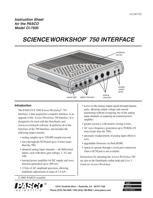
Instruction Sheetfor the PASCOModel CI-<strong>750</strong>0SCIENCEWORKSHOP ®<strong>750</strong> <strong>INTERFACE</strong>012-06772CventilationlouvresPOWERpower lightScienceWorkshop® <strong>750</strong>1 2 3 4A B CDIGITAL CHANNELS ANALOG CHANNELS (–10V MAX INPUT)digital channelsanalogchannelsOUTPUT(–5V / 300mA)analogoutputjacksIntroductionThe PASCO CI-<strong>750</strong>0 ScienceWorkshop ® <strong>750</strong>Interface, a data acquisition computer interface, is anupgrade of the ScienceWorkshop 700 Interface. It isdesigned to be used with the DataStudio andScienceworkshop® software. It performs all of thefunctions of the 700 Interface, and includes thefollowing improvements:• analog samples up to 250,000 samples/second;• rates through the SCSI port up to 4 times fasterthan the 700;• identical analog input channels—all differentialinputs, each with three gain settings: 1, 10, and100;• internal power amplifier for DC supply and wavefunction generation up to 300 mA;• 12 bits of AC amplitude precision, allowingamplitude adjustments in steps of 2.4 mV;• access to the analog output signal through bananajacks, allowing output voltage and currentmonitoring without occupying one of the analoginput channels or requiring an external poweramplifer.• greater accuracy with motion sensing events;• AC wave frequency generation up to 50 KHz (10times faster than the 700);• automatic readjustments of analog input offset tozero;• upgradable firmware via flash ROM;• option to operate through a serial port connectionwhen a SCSI port is not available.Instructions for operating the ScienceWorkshop 700are also in the DataStudio online help and User’sGuide for ScienceWorkshop.© 2001 PASCO scientific
Science Workshop ® <strong>750</strong> Interface 012-06772CEquipment Included:• ScienceWorkshop <strong>750</strong> Interface box (1)• 12 V, 2 A power supply (1)• Connecting cable with a DB25 connector for thecomputer SCSI port (1) and a MDB50 connector (highdensity 50-pin) for the <strong>750</strong> interface box (1)• Adaptec SCSI card (1) for some configurations (i.e.PCs with a PCI Bus, ISA Bus, or PCMCIA card)Optional Equipment: (not included)An optional cable for connecting the <strong>750</strong> Interface to aserial port is available. Note that the maximum data ratethrough a serial port is much less than that through aSCSI port.• Cable with an 8-pin MDIN on each end for theMacintosh (part no. 514-002)• Cable with an 8-pin MDIN connector for connectingwith the <strong>750</strong> interface and a DB9 for connecting with aWindows serial port (part no. 514-07159.)Description of OperationOperation with DataStudio or ScienceWorkshopon a Windows computer: The <strong>750</strong> Interface must beturned on before the computer is powered up—Windows will only recognize SCSI devices during theboot process.Power SupplyThe <strong>750</strong> derives its main power from an external tabletop power supply. All of the operating voltages aregenerated inside the <strong>750</strong> Interface.The SCSI ID number is preset to 2 at the factory. Tochange the ID number, simply change the switchsetting on the back panel and cycle the power. Theinterface reads the switch only at powerup.➤ Note: To avoid conflicting with other SCSIdevices on your system, be sure to check for free IDnumbers before changing the SCSI ID number.Optional Serial Port ConnectionWhen a SCSI port is not available, the <strong>750</strong> can beconnected via the serial (COM) port. However, themaximum data transfer rate is much less than for theSCSI port. For the part number for the connectingcable, refer to the optional equipment list.Flash MemoryThe <strong>750</strong> stores its operating system (also waveformpatterns) in flash memory. Therefore, shortly afterpowerup, the interface is running the operating system(OS) without requiring initialization from DataStudioor Science Workshop. ScienceWorkshop can upgradethe resident OS and waveforms in flash memory whena new revision is available.Analog Input ChannelsThe <strong>750</strong> has three identical analog input channels.During operation, do not block the louvres onthe top and bottom of the interface box.SCSI ConnectionThe main connection to the computer is through theSCSI port. The <strong>750</strong> has an improved SCSI datatransfer rate which can be about 4 times that of the700 interface, depending on the computer speed. TheSCSI cable has a DB25 connector for the computerand a MDB50 connector (high density 50-pin) for the<strong>750</strong> interface. The <strong>750</strong> has only one connector on theback panel, and therefore it must be the last SCSIdevice in the chain. The SCSI bus is activelyterminated inside the <strong>750</strong>; there is no need forexternal termination of the SCSI bus. All devices inthe SCSI chain (CD-ROMs, scanners, etc.) must bepowered up during operation of the <strong>750</strong> Interface.2power ON/OFF switchjack for 12V powersupplyFigure 1Back panel of the <strong>750</strong> Interface8-pin DINjack foroptionalconnectionto serialportSCSI portSCSI IDnumber switch
012-06772C Science Workshop ® <strong>750</strong> InterfaceEach has differential inputs; in other words, they are likethe inputs to a volt meter where neither lead is connectedto ground. The voltage measured is the voltage differencebetween the inputs. Each channel has three softwareaccessiblegain settings: 1, 10, and 100.The maximum sample rate depends on which channelsare selected for measurement. For the higher rates,ScienceWorkshop samples a block of 2000 bytes andthen transfers the block. Once transfer of bytes to the hosthas begun, the interface starts sampling a new block.This is called burst mode, since there is a small timeinterval when data is not being sampled. The main usefor this mode is for the virtual oscilloscope. Table 1shows the sampling constraints while using a fastcomputer to record the data.Table 1. Sampling Rate ConstraintsSample Rate # of Channels Comment250 KHz 1 analog Burst mode100 KHz 3 analog Burst mode50 KHz 5 analog Burst mode20 KHz 1 analog (5 analog) Continuous* (burst)10 KHz 1 analog + digital Continuous* (burst)(5 analog)< 100 Hz 5 analog Continuous 8xoversample(improved accuracyat < 100 Hz)*Note: Continuous sampling with 5 channels selected isnot possible to sustain for more than a few seconds.There are five analog channels from which to choose:channels A–C, analog output voltage (at banana jacks),and the analog output current. Please note that forcontinuous sampling, the speed of the computer is asignificant factor, especially if ScienceWorkshop is busywith many displays.Built-in Function Generator-AmplifierThe <strong>750</strong> has a built-in function generator that is used tooutput analog signals. These can be either AC signals,such as sine and triangle waveforms, or a DC signalranging between +/- 5 V. For the AC waveforms, ofwhich there are 8 resident in Flash, the frequency canrange from 1 mHz (0.001 Hz) to 50 KHz and the peakto-peakamplitude can be adjusted from 0 V to +/-5 Vwith increments of 2.44 mV. The output voltage iscalibrated at the factory to null the offset voltage and setthe full scale voltage.Accessing Analog OutputThere are two different ways in which to access theanalog output signal. The first (the default method inScienceWorkshop) is to connect test leads to the bananajacks. The signal produced is a power amplified (unityvoltage gain) version of the signal present at the DINconnectors and can supply nearly 300 mA at +/-5 V. Theoutput current can be monitored along with the outputvoltage. The second is to use a CI-6552A PowerAmplifier (which has a voltage gain of 2 and delivers 10W) and connect its DIN plug to one of the analogchannels, A–C.Digital Event SamplingThe <strong>750</strong> can sample digital events for photogate timing.The <strong>750</strong> uses hardware edge detection so that it cancapture either edge or both as events, a feature that isuseful for setting trigger conditions. It can count digitalevents from devices such as a Geiger tube or a RotaryMotion Sensor. Each channel has an independent 16-bitcounter. For motion sensing, either single or dual, theinternal counters and edge detectors provide improvedperformance with less noise in the measurement.Operation PrecautionsDo not block the ventilating louvres on the topand bottom of the interface box duringoperation.➤ Note: When a digital sensor has been selected, thesampling rate does not depend on the number of digitalchannels as they are sampled simultaneously at 10 KHz.3
Science Workshop ® <strong>750</strong> Interface 012-06772CSetup ProceduresConnecting the ScienceWorkshop <strong>750</strong> interfaceto an IBM-Compatible PC or Macintosh (with DB25SCSI port)The ScienceWorkshop <strong>750</strong> interface connects to the SCSIport on an adapter card installed in a PC or Mac.PCs: If you do not have a SCSI card installed in yourcomputer, see thedocuments includedwith the SCSI card forinstructions oninstalling a SCSIadapter card. Do NOTinstall the EZ-SCSILite software.1. With your computerSCSI portturned off, locate theSCSI port on the back ofyour computer. This port has 25 small holes in twoparallel rows. (For laptop Macintosh computers, suchas the Powerbook, the port has 30 small holes in a gridpattern. For Powerbooks, you need to buy an adapterfrom a commercial supplier.2. Squeeze the tabs on both sides of the HP DB 50 pinplug (at the end of the cable) and connect the plug intothe SCSI port on the back of the interface box. Releasethe tabs on the sides of the plug to ‘lock’ the plug ontothe interface box.3. Connect the 25-pin end of the SCSI cable (includedwith the <strong>750</strong> interface) to the port on your computer.The cable is keyed so that you cannot plug it inincorrectly.Back panel of the <strong>750</strong> InterfaceNote: You can connect the <strong>750</strong> interface to the serial port inthe same way as described for the 500 interface, but thespeed of data collection will be much slower than for theSCSI connection.4. Connect the AC adapter plug of the interface power supplyinto the “Power” port on the back of the interface box.Plug the power supply cord into a grounded electricalreceptacle.5. Located on the back of your computer is a SCSI ID switchlabeled 0-6. The interface is set to SCSI ID 2. You don’tneed to change this, unless another device is assigned toSCSI ID 2. You can use the ID selector switch on theback of the <strong>750</strong> interface to change the ID number.Remember, each SCSI device must have a unique SCSIID number. The <strong>750</strong> interface has a built-in terminator.The <strong>750</strong> interface must be the last SCSI device in your“chain.”Note: Each SCSI device connected to your computermust have its own unique ID number between 1 and 6, sothe computer can distinguish it from other attached SCSIdevices. The SCSI ID of an internal hard drive andcomputer are 0 and 7, respectively. It is always importantto check for the uniqueness of the SCSI ID, if more thanone SCSI device is connected. For more informationabout installing a SCSI adaper card, see the DataStudioonline help.4
012-06772C Science Workshop ® <strong>750</strong> InterfaceSetup Procedures (continued)Follow the instructions below according to your computer’soperating system.Macintosh:1. Turn on the interface (with the power switch on the back).A green light-emitting diode (LED) on the front panelwill light. (If it doesn’t, check the power connections.)2. Turn on the computer and start DataStudio.3. In the “Welcome to DataStudio TM window, select “CreateExperiment.”4. When DataStudio asks you whether you want the programto scan for an interface or pick one to use for setup, click“Scan.” If the program finds the interface, theExperiment Setup window opens and you havecompleted the installation procedure.Windows 95/981. Turn on the interface (with the power switch on the back).A green light-emitting diode (LED) on the front panelshould light. (If it doesn’t, check the power connections.)2. Turn on the computer and wait for Windows to start.Because the AVA-2906 SCSI card is a Plug-and-Playdevice, the Add New Hardware Wizard should find thecard and install drivers for it. Once the Wizard hasfinished, it tells you there is a new device (the SCSI card)but that there is no driver for it. It will ask you to look fora driver.3. Follow the on-screen instructions. When the Wizard saysthat the computer can’t find the driver, click Finish.Note: There is no driver for the interface box. If youlook under ‘Other Devices’ in the ‘Device Manager,’you’ll see the interface listed with a yellow exclamationpoint.Note: If the Add New Hardware Wizard can’t find thecard, then click Start-> Settings-> Control Panel, anddouble-click Add New Hardware. Follow the onscreeninstructions. If you are asked to make aselection, choose Adaptec AHA-294x/AHA-2940 orAIC-78XX PCI SCSI Controller and then follow theon-screen instructions.4. If the driver for the SCSI card is not on your computer,you will be asked to provide it. Put the Adaptec EZ-SCSI diskette for Windows 95/98 and NT into the floppy5drive. Click Browse, and find the file Aic78xx.mpd onthe floppy drive. Click OK, and follow the on-screeninstructions.5. Start DataStudio. In the “Welcome to DataStudio”window, select “Create Experiment.”Result: A DataStudio window will ask whether youwant the program to scan for an interface or to pickone to use for setup.6. Click “Scan” to continue. When the program finds theinterface, the Experiment Setup window opens and youhave completed the installation process.Windows NT1. Turn on the interface (with the power switch on theback). Result: A green light-emitting diode (LED) onthe front panel should light. (Note: If the LED doesn’tlight, check the power connections.)2. Next, turn on the computer and wait for it to startWindows NT. Click Start-> Settings-> Control Panel,and double-click SCSI Adapters.3. In SCSI Adapters, click “Drivers” and then click “Add.”Select Adaptec AHA-294x/AHA-2940 or AIC-78XXPCI SCSI Controller, click OK, and follow the on-screeninstructions.4. If the driver for the SCSI card is not on your computer,you will be asked to provide it. Put the Adaptec EZ-SCSI Standard Edition v5.0 Disk 1 for Windows 95 andNT 3.51 and 4.0 into the floppy drive. Click Browse,and find the file Aic78xx.mpd on the floppy drive. ClickOK and follow the on-screen instructions.5. When finished, ensure that the interface is turned on.Click OK to reboot the computer. After rebooting,click Start-> Settings-> Control Panel, and doubleclickSCSI Adapters. Result: If the installation wassuccessful, an entry for the selected host adapterappears.6. Click the selected host adapter. Result: An entry forthe PASCO interface will appear.7. Start DataStudio. In the “Welcome to DataStudio”window, select “Create Experiment.” Result: ADataStudio window will ask whether you want theprogram to scan for an interface or to pick one to usefor setup.8. Click Scan to continue. If the program finds the interface,the Experiment Setup window opens, and you havecompleted the installation process.
CScience Workshop ® <strong>750</strong> Interface 012-06772C(Setup procedures continued)Windows 20001. If your system does not have a SCSI card, install theSCSI card on your computer. Use the SCSI driver thatWindows 2000 suggests instead of a driver on theAdaptec disk.2. After installing the SCSI card, update the Windows ASPIcommunications layer by running the programASPI32.EXE. You can download this program fromthe Adaptec website (http:/www.adaptec.com) On themain page, search for “ASPI.” (Note that Adaptec hasrecently added a warning to not install this programunder Windows 2000. Despite this warning, we havenot encountered any problems doing this installation.)3. When you boot up the computer, the Windows AddNew Hardware Wizard will ask for a driver for theinterface. Step through the wizard, allowingwindows to search for a driver. Windows does notfind one, but gives you an option to “Disable theDevice.” Note: You should select “Disable theDevice.” Windows will place the interface under the“Other Devices” category. In most cases, Windowsdoes not ask for a driver again.Using a ScienceWorkshop <strong>750</strong> Interfacewith DataStudioNote: Before you can use the interface with DataStudio,you must have DataStudio installed on your computer,the interface connected to a power supply, and the powersupply to the interface turned on.1. Connect a sensor to the ScienceWorkshop® interface.2. Start DataStudio. In the Sensors list, double-click thesensor to associate the sensor with the interfacechannel. Result: The sensor becomes associated withthe analog channel on the picture of the interface box.3. In the Displays list, double-click the display’s iconto open a display window.4. To collect some data, click the Start button( ) on the main toolbar. Result: Dataappears in real-time on the Graph display.5. To stop collecting data, go to the main toolbar andclick the Stop button ( ).For more information about operating the interface withDataStudio, see the DataStudio online help.New Features of the Signal Generator• Two new wave forms: positive-only up rampand positive only down ramp➤ Note: When operated with DataStudiosoftware (or Science Workshop version 2.3 orhigher), the 700 Interface also generates thesepositive-only up and down ramp signals.• Expanded frequency range: 0.001 Hz to 50KHz• Greater resolution for adjusting the ACamplitude (steps of 2.44 mV)AC amplitudeadjusted in 2.44mV stepsfrequency range:0.001 Hz to 50KHznew wave forms:positive only up rampand positive onlydown rampExample: Connecting a Temperature Sensor toanalog channel A.➤ For detailed instructions concerningthe Signal Generator, see theDataStudio online help or User’s Guidefor ScienceWorkshop.6
012-06772C Science Workshop ® <strong>750</strong> InterfaceSpecificationsPower:• 12 VDC to 20 VDC at 2 A, 2.1 mm jackPrimary computer connection:• SCSI, 8-bit data width and a MDB50 female connector• Internal active termination providedAlternate computer connection:• Serial RS-232 with an 8-pin MDIN female connector• 19.2K bits/s, 1 start bit, 8 data bits, 1 stop bitDigital Channels:• 4 identical digital input/output channels• TTL compatible input/output levels with 8 mAmaximum drive current• Maximum input logic transition time: 500 ns• Electrostatic Discharge (ESD) protected inputsassuming the human body model standard, Mil-Std-3015.7• Edge sensitive and sampled at 10 KHz (100 µs). (1 µsresolution for the Motion Sensor)Analog Input Channels:• 3 identical channels with differential inputs and1 M ohm impedance• +/-10 V maximum usable input voltage range(+/-12 V absolute input voltage range)• ESD protected input similar to that of the digitalchannels• 3 voltage gain settings on each analog channel:1, 10, and 100• Small signal bandwidth up to the ADC: 1 MHz for again of 1, 800 KHz for a gain of 10, and 120 KHz for again of 100; input amplifier slew rate: 1.2 V/µs (Theactual bandwidth is determined by the sampling rate ofthe ADC.)Analog-to-Digital Conversion:• 5 input sources for the 12-bit ADC: channels A–C andanalog output voltage and current.• Voltage resolution at the ADC input: 4.88 mV(.488 mV at a gain of 10; 0.049 mV at a gain of 100)• Current measurement resolution: 244 µA, where eachvolt measured represents 50 mA• Offset voltage accuracy < +/-3 mV. (For measuringfull-scale voltages (or 1 V with a gain of 10, etc.) thetotal error will be less than +/-15 mV, accounting forthe gain error in the input amplifier.)• Sample rate range: once every 3600 seconds – 250KHz (The conversion time between consecutivechannels in a burst is 2.9 µs.)• 8X oversampling for improved accuracy for samplerates < 100 Hz.Analog Output:• DC value ranges: -4.9976 V to +5.0000 V in steps of2.44 mV• Accuracy at the DIN connector: (+/-3.6 mV +/-0.1%full scale)• Peak-to peak amplitude adjustment ranges for ACwaveform: 0 V to +/-5 V in steps of 2.44 mV• AC waveform frequency ranges: 1 mHz (0.001 Hz)–50 KHz, +/-0.01%• Maximum amplified output at the banana jacks: about300 mA at +/-5 V, current limited at 300 mA +/-12 mALimited WarrantyPASCO scientific warrants the product to be free fromdefects in materials and workmanship for a period ofone year from the date of shipment to the customer.PASCO will repair or replace, at its option, any part ofthe product which is deemed to be defective inmaterial or workmanship. The warranty does notcover damage to the product caused by abuse orimproper use. Determination of whether a productfailure is the result of a manufacturing defect orimproper use by the customer shall be made solely byPASCO scientific. Responsibility for the return ofequipment for warranty repair belongs to thecustomer. Equipment must be properly packed toprevent damage and shipped postage or freightprepaid. (Damage caused by improper packing of theequipment for return shipment will not be covered bythe warranty.) Shipping costs for returning theequipment after repair will be paid by PASCOscientific.Address:PASCO scientific10101 Foothills Blvd.Roseville, CA 95747-7100Phone: (916) 786-3800Or 1-800-772-8700 (toll free in U.S.)7
Science Workshop ® <strong>750</strong> Interface 012-06772CElectromagnetic Complianceof theScienceWorkshop <strong>750</strong> Interface.➤ Note: This equipment has been tested and found tocomply with the limits for a Class A digital device,pursuant to part 15 of the FCC Rules. These limits aredesigned to provide reasonable protection against harmfulinterference when the equipment is operated in acommercial environment. This equipment generates, uses,and can radiate radio frequency energy and, if notinstalled and used in accordance with the instructionmanual, may cause harmful interference to radiocommunications. Operation of this equipment in aresidential area is likely to cause harmful interference, inwhich case the user will be required to correct theinterference at his own expense.<strong>750</strong> Interface CI-<strong>750</strong>0Tested To ComplyWith FCC StandardsDIGITAL CHANNELS1, 2, 3, 4GNDSIGNAL+ 5 V+12 V- 12 V+5VPOWER 300 mA TotalPOWER 75 mA TotalPOWER 75 mA Total<strong>750</strong> <strong>INTERFACE</strong>Model CI-<strong>750</strong>010101 Foothills Blvd.Roseville, CA 95747-7100(916) 786-3800 U.S.: (800) 772-8700http://www.pasco.comANALOG CHANNELSA, B, CPIN12345678FUNCTIONANALOG INPUT +ANALOG INPUT -N/C+5 V POWERPOWER GROUND+12 V POWER-12 V POWERANALOG OUTPUTRECEPTACLE7 63 85 4 21The label on thebottom of theinterface boxdetails thechannel powerspecifications.FOR HOME OR OFFICE USEThe PASCO Model CI-<strong>750</strong>0 <strong>750</strong>ScienceWorkshop Computer Interface has beentested and complies with the essential protectionrequirements of Council Directive 89/336/EEC onthe approximation of the laws of the MemberStates relating to electromagnetic compatibility.Assessment of compliance of the product with therequirements relating to electromagneticcompatibility was based on the followingDirectives and Standards:• EN 50081-1 Electromagnetic compatibilitygeneric emission standard• EN 55022, CISPR 22 Class A Limits andmethods of measurements of radiointerference characteristics of informationtechnology equipment.• EN 50082-1 Electromagnetic compatibilitygeneric immunity standard.• IEC 801-2 Electrostatic dischargerequirements• IEC 801-3 Radiated electromagnetic fieldrequirements• IEC 801-4 Electrical fast transient/burstThe exclamation point within an equilateraltriangle is intended to alert the user ofimportant operating and safety instructionsthat will help prevent damage to theequipment or injury to the user.8
012-06772C Science Workshop ® <strong>750</strong> InterfaceTroubleshootingRoutine checks on the <strong>750</strong> Interface box1. Is the green LED on the front of the interface litwhen the power is turned on? If not try one or allof the following:Check the AC adapter. Is it providing the propervoltage for your interface?2. Make sure that all your cable connections aresecure. Verify that there are no bent pins at eitherend of the cable. Check the SCSI termination.Remember, the termination on the <strong>750</strong>, which isbuilt into the interface, is active while the box ispowered (it must be the last device in the SCSIchain).3. Located on the back of your interface is a SCSIswitch labeled 0-6. By default, the SCSI ID of thisinterface is 2. You don’t need to change this unlessanother device is assigned SCSI ID 2. If a seconddevice is connected to your computer, please checkfor a SCSI ID conflict.IRQ Conflict (Windows)Note: The Adaptec AVA 2906 SCSI card must have afree IRQ between 9 – 15. Do not allow the 2906 SCSIcard to share the same IRQ with another card.To check IRQ settings in Windows 95/981. Click Start-> Settings-> Control Panel, and doubleclickSystem.2. Click the Device Manager tab and double-clickComputer. In the ‘Computer Properties’ windowunder ‘View Resources’ is a list of all of your deviceswith their IRQ settings.To check for an available IRQ in Windows NT 4.01. Select Start-> Programs-> Administrative Tools->Windows NT Diagnostics.2. Click the Resources tab. You will see a list of thedrivers and the IRQ settings for your devices.3. Check that the Adaptec AVA-2906 SCSI card isrecognized under Device Manager. If there is aresource conflict (indicated by a yellow exclamationpoint next to the SCSI driver listed under SCSIControllers in the Device Manager), you have toresolve the resource conflict.To resolve a resource conflict:1. Remove the driver, and turn off the computer.2. Remove the SCSI card, and turn on the computer.3. Allocate resources for the card, and turn the computeroff again.4. Reinstall the card into the PCI slot, and turn on thecomputer,5. Reinstall the driver.To remove a driver in Windows 95/98:1. Select Start->Settings->Control Panel, and double-clickSystem.2. Double-click SCSI Controllers, click the driver for theSCSI card, and click Remove.To remove a driver in Windows NT:1. Select Start->Setting->Control Panel, and double-clickSCSI Adapters.2. Click the Drivers tab, click the selected driver for theAVA-2906 card, and click Remove.To remove a driver in Windows 2000:1. Select Start>Settings>Control Panel>Add/RemoveHardware.2. When the Add/Remove Hardware Wizard opens, clickthe Next button and choose “Uninstall/Unplug a device.”3. Click the Next button. Select the Adaptec SCSIcontroller.4. Click the Next button again. At the prompt to uninstallthe SCSI device, click “yes.”SCSI Driver (Windows)If the program can’t find the ScienceWorkshop <strong>750</strong> Interfacein Windows, you may need to update the SCSI driver.The names of the driver files for the Adaptec AVA-2906Adapter card are:• 7800W95.EXE (for the AVA-2906 on Windows 95 or98)• 7800WNT.EXE (for the AVA-2906 on Windows NT)Download these files from the Adaptec Web site at http://www.adaptec.com [To update the ASPI layer, downloadand run ASPI32.EXE from the Adaptec web site (http://www.adaptec.com/support/faqs/aspilayer.html)].9
Science Workshop ® <strong>750</strong> Interface 012-06772CTechnical SupportFeedbackIf you have any comments about this product or thismanual, please let us know. If you have any suggestionson alternate experiments or find a problem in the manual,please tell us. PASCO appreciates any customerfeedback. Your input helps us evaluate and improve ourproduct.To reach PASCOFor Technical Support:Fax:(916) 786-3292E-Mail: techsupp@pasco.comWeb: www.pasco.comPhone: 1-800-772-8700 (toll-free in U.S.)or (916)786-3800Contacting Technical SupportBefore you call the PASCO Technical Support staff,prepare the following information:• If your problem is computer/software related, note:-Title and revision date of software-Type of computer (Make, Model, Speed)-Type of external cables/peripheralsIf your problem is with the PASCO apparatus, note:-Title and Model number (usually listed on thelabel)-Approximate age of apparatus-A detailed description of the problem/sequenceof events. (In case you can't call PASCOright away, you won't lose valuable data.)-If possible, have the apparatus within reach whencalling. This makes descriptions of individual partsmuch easier.• If your problem relates to the instruction manual, note:-Part number and revision (listed by month andyearon the front cover)-Have the manual at hand to discuss your questions.10