Valve and Valve Actuator Selection Guide - Staefa Control System
Valve and Valve Actuator Selection Guide - Staefa Control System
Valve and Valve Actuator Selection Guide - Staefa Control System

Create successful ePaper yourself
Turn your PDF publications into a flip-book with our unique Google optimized e-Paper software.
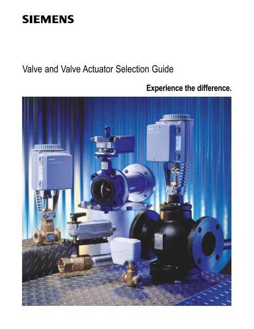
<strong>Valve</strong> <strong>and</strong> <strong>Valve</strong> <strong>Actuator</strong> <strong>Selection</strong> <strong>Guide</strong>Experience the difference.
Table of Contents<strong>Valve</strong>s <strong>and</strong><strong>Valve</strong> <strong>Actuator</strong>sExperience Counts............................................................................................... 4Siemens Delivers ................................................................................................. 5<strong>Valve</strong> <strong>and</strong> <strong>Valve</strong> <strong>Actuator</strong> <strong>Selection</strong> ChartsGlobe ........................................................................................................... 6–15Ball ................................................................................................................... 16Butterfly ..................................................................................................... 17–24Accessories .................................................................................................. 25–28Submittal SummariesQuick Reference .............................................................................................. 291/2 to 1-inch Powermite 599 Series MZ SeriesZone <strong>Control</strong> <strong>Valve</strong>s <strong>and</strong> <strong>Actuator</strong>s ........................................................... 30–331/2 to 1-1/2 inch Powermite 599 Series MT Series TerminalUnit <strong>Valve</strong>s <strong>and</strong> <strong>Actuator</strong>s .......................................................................... 34–451/2 to 2-inch Flowrite 599 Series <strong>Valve</strong>s <strong>and</strong> <strong>Actuator</strong>s ............................ 46–651/2 to 6-inch Flowrite 599 Series Flanged Iron Body,ANSI Class 125/250 <strong>Valve</strong>s <strong>and</strong> <strong>Actuator</strong>s ................................................ 48–651/2 to 2-inch Powermite 599 Series Ball <strong>Valve</strong>s ........................................ 66–692 to 20-inch Resilient Seat Butterfly <strong>Valve</strong>swith Electronic <strong>Actuator</strong>s ........................................................................... 70–752 to 20-inch Resilient Seat Butterfly <strong>Valve</strong>swith Pneumatic <strong>Actuator</strong>s .......................................................................... 76–79Features/Functions/BenefitsGlobe <strong>Valve</strong>sPowermite 599 Series .................................................................................. 80Flowrite 599 Series ...................................................................................... 81Flowrite 599 Series Flanged Iron ................................................................. 82Ball <strong>Valve</strong>sPowermite 599 Series .................................................................................. 83Butterfly <strong>Valve</strong>sSiemens ....................................................................................................... 84ReferenceGlossary .......................................................................................................... 85<strong>Selection</strong> <strong>and</strong> Sizing of <strong>Control</strong> <strong>Valve</strong>s ...................................................... 86–91<strong>Selection</strong> <strong>and</strong> Sizing of Butterfly <strong>Valve</strong>s .................................................... 92–94Tech Tips ................................................................................................... 95–97Terminal Designations ............................................................................... 98–99For More Information ..................................................................................... 1003
Experience Counts150 years of industry innovationsA leader in the Heating, Ventilation <strong>and</strong> AirConditioning (HVAC) industry, Siemens BuildingTechnology delivers the products <strong>and</strong> services thatyou depend on for outst<strong>and</strong>ing quality, reliability<strong>and</strong> performance.Need it fast? Same day shipping is no problem forrush orders. Helpful customer service representativescan input your order <strong>and</strong> ship st<strong>and</strong>ard delivery withinthree business days.Locate information fast online. Technicaldocumentation <strong>and</strong> installation instructions areat your fingertips as well as helpful tools <strong>and</strong>order tracking.Quality first. All Siemens valves <strong>and</strong> valve actuatorsare 100% factory-assembled <strong>and</strong> tested for quality<strong>and</strong> reliability in our state-of-the-art, ISO9002manufacturing facility.Delivered ready to install. Designed for flexibleconfigurations <strong>and</strong> fast installation, the Powermite<strong>and</strong> Flowrite Globe <strong>Valve</strong>s <strong>and</strong> <strong>Valve</strong> <strong>Actuator</strong>smeet most application needs. Ball <strong>and</strong> Butterfly<strong>Valve</strong>s address specific control challenges with thesame reliability <strong>and</strong> performance. <strong>Valve</strong>s areassembled <strong>and</strong> tagged for delivery direct to locationat job-site free of charge.Customer Care is a phone call away. For technicalsupport, ordering <strong>and</strong> pricing, call 1.888.593.7876.4
Siemens DeliversMeet your toughest control challenges head onGlobe Ball ButterflyBr<strong>and</strong> Powermite 599 Series Flowrite 599 Series Powermite 599 Series SiemensSize 1/2 to 1-1/2” 1/2 to 6” 1/2 to 2” 2 to 20”Applications • VAV Reheat • Air H<strong>and</strong>ling Units • Small Air H<strong>and</strong>ling Units • Tower Bypass• Small Terminal Units • Central Plant Equipment • Large Terminal Units • Isolation• Steam to 15 psi • High Temp. Steam • Central Plant Equipment • Central Plant EquipmentActuation Electronic Electronic Electronic ElectronicPneumatic Pneumatic Pneumatic5
globe2- <strong>and</strong> 3-way Assemblies 1/2 to 1”To build a complete assembly:1. Under <strong>Valve</strong> Body, work left-torightto select:• Action• Flow Rate (Cv)• Line Size2. For the <strong>Actuator</strong>, work from top-tobottomto select:• Fail-in-Place/Fail Safe• Signal3. At the intersection of the <strong>Valve</strong> row<strong>and</strong> the <strong>Actuator</strong> column locate thedesired close-off value <strong>and</strong> price.4. Create the assembly part numberby combining the <strong>Actuator</strong> PrefixCode (APC) in the <strong>Actuator</strong> columnwith the Part No. in the close-offrow.These selection tables only containFXF end connections with brass trim<strong>and</strong> equal percentage flowcharacterics.For complete selection, refer to thecurrent edition of Master HVACProducts Catalog.3-way 2-wayElectronicActionNormally ClosedNormally OpenMixing<strong>Valve</strong> Body<strong>Actuator</strong>Fail-in-Place3P0-10 VSSB81USSB61UPartNo.FlowRateLineSizeAPC254APC255Cv (Kvs) in. (mm)Close-off psi (kPa)0.4 (0.24) 1/2 (15) 70 (482) 70 (482) _ _ _ 011000.63 (0.54) 1/2 (15) 70 (482) 70 (482) _ _ _ 011021 (0.85) 1/2 (15) 70 (482) 70 (482) _ _ _ 011041.6 (1.37) 1/2 (15) 70 (482) 70 (482) _ _ _ 011062.5 (2.14) 1/2 (15) 40 (276) 40 (276) _ _ _ 011084 (3.42) 1/2 (15) 40 (276) 40 (276) _ _ _ 011106.3 (5.38) 3/4 (20) 30 (207) 30 (207) _ _ _ 0111210 (8.55) 1 (25) 30 (207) 30 (207) _ _ _ 011140.4 (0.24) 1/2 (15) 60 (414) 60 (414) _ _ _ 011150.63 (0.54) 1/2 (15) 60 (414) 60 (414) _ _ _ 011171 (0.85) 1/2 (15) 60 (414) 60 (414) _ _ _ 011191.6 (1.37) 1/2 (15) 60 (414) 60 (414) _ _ _ 011212.5 (2.14) 1/2 (15) 35 (241) 35 (241) _ _ _ 011234 (3.42) 1/2 (15) 35 (241) 35 (241) _ _ _ 011266.3 (5.38) 3/4 (20) 30 (207) 30 (207) _ _ _ 0112910 (8.55) 1 (25) 30 (207) 30 (207) _ _ _ 011310.4 (0.24) 1/2 (15) 70 (482) 70 (482) _ _ _ 011320.63 (0.54) 1/2 (15) 70 (482) 70 (482) _ _ _ 011331 (0.85) 1/2 (15) 70 (482) 70 (482) _ _ _ 011341.6 (1.37) 1/2 (15) 70 (482) 70 (482) _ _ _ 011352.5 (2.14) 1/2 (15) 40 (276) 40 (276) _ _ _ 011364 (3.42) 1/2 (15) 40 (276) 40 (276) _ _ _ 011376.3 (5.38) 3/4 (20) 30 (207) 30 (207) _ _ _ 0113810 (8.55) 1 (25) 30 (207) 30 (207) _ _ _ 01139Complete Assembly <strong>Valve</strong> Body OnlyAPC + Part No. 599 + Part No.Prices are subject to change without notice.6
globe2- <strong>and</strong> 3-way Assemblies 1/2 to 1”PneumaticFail-Safe3-8 psi (21-55 kPa) 8-13 psi (55-90 kPa) 10-15 psi (69-103 kPa)<strong>Actuator</strong>3-way 2-wayActionNormally ClosedNormally OpenMixing*<strong>Valve</strong> Body599-01088PartNo.Flow Line APC APC APCRate Size 257258256Cv (Kvs) in. (mm)Close-off psi (kPa)0.4 (0.34) 1/2 (15)0.63 (0.54) 1/2 (15)1 (0.85) 1/2 (15)1.6 (1.37) 1/2 (15)2.5 (2.14) 1/2 (15)4 (3.42) 1/2 (15)6.3 (5.38) 3/4 (20)10 (8.55) 1 (25)40 (276)40 (276)40 (276)40 (276)28 (193)28 (193)18 (124)18 (124)25702000B25702002B25702004B25702006B25702008B25702010B25702012B25702014B599-0108895 (655)95 (655)95 (655)95 (655)50 (345)50 (345)40 (276)40 (276)PartNo.25802000C25802002C25802004C25802006C25802008C25802010C25802012C25802014C599-01088120 (827)120 (827)120 (827)120 (827)65 (448)65 (448)50 (345)50 (345)PartNo.25602000256020022560200425602006256020082560201025602012256020140.4 (0.34) 1/2 (15) 95 (655) 25702030 45 (310) 25802030C 20 (138) 25602030A0.63 (0.54) 1/2 (15) 95 (655) 25702032 45 (310) 25802032C 20 (138) 25602032A1 (0.85) 1/2 (15) 95 (655) 25702034 45 (310) 25802034C 20 (138) 25602034A1.6 (1.37) 1/2 (15) 95 (655) 25702036 45 (310) 25802036C 20 (138) 25602036A2.5 (2.14) 1/2 (15) 45 (310) 25702038 25 (172) 25802038C 10 (69) 25602038A4 (3.42) 1/2 (15) 45 (310) 25702041 25 (172) 25802041C 10 (69) 25602041A6.3 (5.38) 3/4 (20) 35 (241) 25702044 10 (69) 25802044C — —10 (8.55) 1 (25) 35 (241) 25702046 10 (69) 25802046C — —0.4 (0.34) 1/2 (15) 40 (276) 25702064B 95 (655) 25802064 120 (827) 25602064A0.63 (0.54) 1/2 (15) 40 (276) 25702065B 95 (655) 25802065 120 (827) 25602065A1 (0.85) 1/2 (15) 40 (276) 25702066B 95 (655) 25802066 120 (827) 25602066A1.6 (1.37) 1/2 (15) 40 (276) 25702067B 95 (655) 25802067 120 (827) 25602067A2.5 (2.14) 1/2 (15) 28 (193) 25702068B 50 (345) 25802068 65 (448) 25602068A4 (3.42) 1/2 (15) 28 (193) 25702069B 50 (345) 25802069 65 (448) 25602069A6.3 (5.38) 3/4 (20) 18 (124) 25702070B 40 (276) 25802070 50 (345) 25602070A10 (8.55) 1 (25) 18 (124) 25702071B 40 (276) 25802071 50 (345) 25602071A*Values are for the upper port NC.Values in chart are for 15 psi supplied to the actuator.These selection tables only containFXF end connections with brass trim<strong>and</strong> equal percentage flowcharacterics.For complete selection, refer to thecurrent edition of Master HVACProducts Catalog.Complete AssemblyAPC + Part No.<strong>Valve</strong> Body Only599 + Part No.Prices are subject to change without notice.7
globe2- <strong>and</strong> 3-way Assemblies 1/2 to 1-1/2”ElectronicFail-in-PlaceFail-Safe3P 0-10 V 3P 0-10 V<strong>Actuator</strong>3-way 2-wayActionNormally Closed<strong>Valve</strong> BodyNormally OpenMixing*SSC81USSC61U SQS65U SSC81.5U SQS85.53U SSC61.5U SQS65.5UFlow Line APCAPC APC APC APCAPCAPCRate Size 259 261 264 260 266 262 265Cv (Kvs) in. (mm)Close-off psi (kPa)0.4 (0.24) 1/2 (15) 95 (655) 95 (655) 95 (655) 95 (655) 95 (655) 95 (655) 95 (655) _ _ _ 020000.63 (0.54) 1/2 (15) 95 (655) 95 (655) 95 (655) 95 (655) 95 (655) 95 (655) 95 (655) _ _ _ 020021 (0.85) 1/2 (15) 95 (655) 95 (655) 95 (655) 95 (655) 95 (655) 95 (655) 95 (655) _ _ _ 020041.6 (1.37) 1/2 (15) 95 (655) 95 (655) 95 (655) 95 (655) 95 (655) 95 (655) 95 (655) _ _ _ 020062.5 (2.14) 1/2 (15) 50 (345) 50 (345) 50 (345) 50 (345) 50 (345) 50 (345) 50 (345) _ _ _ 020084 (3.42) 1/2 (15) 50 (345) 50 (345) 50 (345) 50 (345) 50 (345) 50 (345) 50 (345) _ _ _ 020106.3 (5.38) 3/4 (20) 40 (276) 40 (276) 40 (276) 40 (276) 40 (276) 40 (276) 40 (276) _ _ _ 0201210 (8.55) 1 (25) 40 (276) 40 (276) 40 (276) 40 (276) 40 (276) 40 (276) 40 (276) _ _ _ 0201416 (13.8) 1-1/4 (32) 21 (145) 21 (145) 21 (145) 21 (145) 21 (145) 21 (145) 21 (145) _ _ _ 0208525 (21.5) 1-1/2 (40) — — 13 (90) — 13 (90) —13 (90) _ _ _ 020880.4 (0.34) 1/2 (15) 120 (828) 120 (828) 160 (1103) 120 (828) 160 (1103) 120 (828) 160 (1103) _ _ _ 020300.63 (0.54) 1/2 (15) 120 (828) 120 (828) 160 (1103) 120 (828) 160 (1103) 120 (828) 160 (1103) _ _ _ 020321 (0.85) 1/2 (15) 120 (828) 120 (828) 160 (1103) 120 (828) 160 (1103) 120 (828) 160 (1103) _ _ _ 020341.6 (1.37) 1/2 (15) 120 (828) 120 (828) 160 (1103) 120 (828) 160 (1103) 120 (828) 160 (1103) _ _ _ 020362.5 (2.14) 1/2 (15) 65 (448) 65 (448) 85 (586) 65 (448) 85 (586) 65 (448) 85 (586) _ _ _ 020384 (3.42) 1/2 (15) 65 (448) 65 (448) 85 (586) 65 (448) 85 (586) 65 (448) 85 (586) _ _ _ 020416.3 (5.38) 3/4 (20) 55 (379) 55 (379) 70 (482) 55 (379) 70 (482) 55 (379) 70 (482) _ _ _ 0204410 (8.55) 1 (25) 55 (379) 55 (379) 70 (482) 55 (379) 70 (482) 55 (379) 70 (482) _ _ _ 0204616 (13.8) 1-1/4 (30) 20 (138) 20 (138) 28 (193) 20 (138) 28 (193) 20 (138) 28 (193) _ _ _ 0208425 (21.5) 1-1/2 (40) 10 (68) 10 (68) 14 (96) 10 (68) 14 (96) 10 (68) 14 (96) _ _ _ 020870.4 (0.34) 1/2 (15) 95 (655) 95 (655) 95 (655) 95 (655) 95 (655) 95 (655) 95 (655) _ _ _ 020640.63 (0.54) 1/2 (15) 95 (655) 95 (655) 95 (655) 95 (655) 95 (655) 95 (655) 95 (655) _ _ _ 020651 (0.85) 1/2 (15) 95 (655) 95 (655) 95 (655) 95 (655) 95 (655) 95 (655) 95 (655) _ _ _ 020661.6 (1.37) 1/2 (15) 95 (655) 95 (655) 95 (655) 95 (655) 95 (655) 95 (655) 95 (655) _ _ _ 020672.5 (2.14) 1/2 (15) 50 (345) 50 (345) 50 (345) 55 (379) 50 (345) 50 (345) 50 (345) _ _ _ 020684 (3.42) 1/2 (15) 50 (345) 50 (345) 50 (345) 55 (379) 50 (345) 50 (345) 50 (345) _ _ _ 020696.3 (5.38) 3/4 (20) 40 (276) 40 (276) 40 (276) 40 (276) 40 (276) 40 (276) 40 (276) _ _ _ 0207010 (8.55) 1 (25) 40 (276) 40 (276) 40 (276) 40 (276) 40 (276) 40 (276) 40 (276) _ _ _ 0207116 (13.8) 1-1/4 (32) 10 (69) 10 (69) 10 (69) 10 (69) 10 (69) 10 (69) 10 (69) _ _ _ 0208625 (21.5) 1-1/2 (40) ——7(48) — 7 (48) —7(48) _ _ _ 02089PartNo.*Values are for the upper port NC.Values in chart are for 15 psi supplied to the actuator.For Fail-in-Place actuators at 0V valve is closed.Complete AssemblyAPC + Part No.<strong>Valve</strong> Body Only599 + Part No.These selection tables only containFXF end connections with brass trim<strong>and</strong> equal percentage flowcharacterics.For complete selection, refer to thecurrent edition of Master HVACProducts Catalog.Prices are subject to change without notice.8
globe2- <strong>and</strong> 3-way Assemblies 1/2 to 2”Pneumatic<strong>Actuator</strong>4” 3-8 psi(21-55 kPa)4” 5-10 psi(34-69 kPa)4” 10-15 psi(69-103 kPa)Spring Return8”8”High Temp.8”with Positioner8” High Temp.with Positioner3-way 2-way<strong>Valve</strong> BodyPart599-01081 599-01082 599-01083 599-01050 599-01051 599-01050 599-01051 No.Flow Line APC APC APC APC APC APC APCRate Size 268 269 270 277 278 283 284Cv (Kvs) in. (mm)Close-off psi (kPa)1 (0.9) 1/2 (15) * * 236 (1627) 250 (1724) * 250 (1724) * _ _ _ 031801.6 (1.4) 1/2 (15) * * 236 (1627) 250 (1724) * 250 (1724) * _ _ _ 031812.5 (2.2) 1/2 (15) * * 236 (1627) 250 (1724) * 250 (1724) * _ _ _ 031824 (3.4) 1/2 (15) * * 236 (1627) 250 (1724) * 250 (1724) * _ _ _ 031836.3 (5.4) 3/4 (20) * * 155 (1069) 250 (1724) * 250 (1724) * _ _ _ 0318410 (8.6) 1 (25) * * 91 (627) 250 (1724) * 250 (1724) * _ _ _ 0318516 (14) 1-1/4 (32) * * 52 (359) 148 (1020) * 148 (1020) * _ _ _ 0318625 (22) 1-1/2 (40) * * 32 (331) 92 (634) * 92 (634) * _ _ _ 0318740 (34) 2 (50) * * 20 (138) 55 (379) * 55 (379) * _ _ _ 031881 (0.9) 1/2 (15) 142 (979) * * 250 (1724) — 250 (1724) — _ _ _ 031621.6 (1.4) 1/2 (15) 142 (979) * * 250 (1724) — 250 (1724) — _ _ _ 031632.5 (2.2) 1/2 (15) 142 (979) * * 250 (1724) — 250 (1724) — _ _ _ 031644 (3.4) 1/2 (15) 142 (979) * * 250 (1724) — 250 (1724) — _ _ _ 031656.3 (5.4) 3/4 (20) 80 (552) * * 231 (1593) — 231 (1593) — _ _ _ 0316610 (8.6) 1 (25) 52 (359) * * 150 (1034) — 150 (1034) — _ _ _ 0316716 (14) 1-1/4 (32) 32 (221) * * 93 (641) — 93 (641) — _ _ _ 0316825 (22) 1-1/2 (40) 20 (138) * * 60 (414) — 60 (414) — _ _ _ 0316940 (34) 2 (50) 12 (83) * * 37(255) — 37 (255) — _ _ _ 031701 (0.9) 1/2 (15) * 236 (1627) *250 (1724) — 250 (1724) — _ _ _ 031981.6 (1.4) 1/2 (15) * 236 (1627) *250 (1724) — 250 (1724) — _ _ _ 031992.5 (2.2) 1/2 (15) * 236 (1627) *250 (1724) — 250 (1724) — _ _ _ 032004 (3.4) 1/2 (15) * 236 (1627) *250 (1724) — 250 (1724) — _ _ _ 032016.3 (5.4) 3/4 (20) * 155 (1069) *250 (1724) — 250 (1724) — _ _ _ 0320210 (8.6) 1 (25) * 91 (627) *250 (1724) — 250 (1724) — _ _ _ 0320316 (14) 1-1/4 (32) * 52 (359) *148 (1020) — 148 (1020) — _ _ _ 0320425 (22) 1-1/2 (40) * 32 (331) *92 (634) — 92 (634) — _ _ _ 0320540 (34) 2 (50) * 20 (138) *55 (379) — 55 (379) — _ _ _ 03206ActionNormally ClosedNormally OpenMixing*Order valve <strong>and</strong> actuator separately.These selection tables only containFXF end connections with brass trim<strong>and</strong> equal percentage flowcharacterics.For complete selection, refer to thecurrent edition of Master HVACProducts Catalog.Complete AssemblyAPC + Part No.<strong>Valve</strong> Body Only599 + Part No.Prices are subject to change without notice.9
globe2- <strong>and</strong> 3-way Assemblies 1/2 to 2”ElectronicNon-Spring Return<strong>Actuator</strong>3P 30 sec.3P 120 sec.3P0-10 V/4-20 mA 0-10 V3-way 2-wayActionNormally Open Normally ClosedMixing<strong>Valve</strong> BodySQX82.03U SQX82.00U SKD82.50U SQX62U 599-10022Flow Line APC APC APC APC APCRate Size 273 272 275 271 295Cv (Kvs) in. (mm)Close-off psi (kPa)1 (0.9) 1/2 (15) 250 (1724) 250 (1724) 250 (1724) 250 (1724) 250 (1724) _ _ _ 031801.6 (1.4) 1/2 (15) 250 (1724) 250 (1724) 250 (1724) 250 (1724) 250 (1724) _ _ _ 031812.5 (2.2) 1/2 (15) 250 (1724) 250 (1724) 250 (1724) 250 (1724) 250 (1724) _ _ _ 031824 (3.4) 1/2 (15) 250 (1724) 250 (1724) 250 (1724) 250 (1724) 250 (1724) _ _ _ 031836.3 (5.4) 3/4 (20) 221 (1524) 221 (1524) 250 (1724) 221 (1524) 238 (1640) _ _ _ 0318410 (8.6) 1 (25) 130 (896) 130 (896) 203 (1400) 130 (896) 140 (965) _ _ _ 0318516 (14) 1-1/4 (32) 75 (517) 75 (517) 117 (807) 75 (517) 81 (558) _ _ _ 0318625 (22) 1-1/2 (40) 46 (317) 46 (317) 73 (503) 46 (317) 50 (345) _ _ _ 0318740 (34) 2 (50) 28 (193) 28 (193) 44 (303) 28 (193) 31 (214) _ _ _ 031881 (0.9) 1/2 (15) 250 (1724) 250 (1724) 250 (1724) 250 (1724) 250 (1724) _ _ _ 031621.6 (1.4) 1/2 (15) 250 (1724) 250 (1724) 250 (1724) 250 (1724) 250 (1724) _ _ _ 031632.5 (2.2) 1/2 (15) 250 (1724) 250 (1724) 250 (1724) 250 (1724) 250 (1724) _ _ _ 031644 (3.4) 1/2 (15) 250 (1724) 250 (1724) 250 (1724) 250 (1724) 250 (1724) _ _ _ 031656.3 (5.4) 3/4 (20) 173 (1193) 173 (1193) 250 (1724) 173 (1193) 186 (1282) _ _ _ 0316610 (8.6) 1 (25) 112 (772) 112 (772) 201 (1386) 112 (772) 121 (834) _ _ _ 0316716 (14) 1-1/4 (32) 69 (476) 69 (476) 124 (855) 69 (476) 75 (517) _ _ _ 0316825 (22) 1-1/2 (40) 44 (303) 44 (303) 80 (552) 44 (303) 48 (331) _ _ _ 0316940 (34) 2 (50) 27(186) 27(186) 49 (338) 27(186) 30 (207) _ _ _ 031701 (0.9) 1/2 (15) 250 (1724) 250 (1724) 250 (1724) 250 (1724) 250 (1724) _ _ _ 031981.6 (1.4) 1/2 (15) 250 (1724) 250 (1724) 250 (1724) 250 (1724) 250 (1724) _ _ _ 031992.5 (2.2) 1/2 (15) 250 (1724) 250 (1724) 250 (1724) 250 (1724) 250 (1724) _ _ _ 032004 (3.4) 1/2 (15) 250 (1724) 250 (1724) 250 (1724) 250 (1724) 250 (1724) _ _ _ 032016.3 (5.4) 3/4 (20) 221 (1524) 221 (1524) 250 (1724) 221 (1524) 238 (1640) _ _ _ 0320210 (8.6) 1 (25) 130 (896) 130 (896) 203 (1400) 130 (896) 140 (965) _ _ _ 0320316 (14) 1-1/4 (32) 75 (517) 75 (517) 117 (807) 75 (517) 81 (558) _ _ _ 0320425 (22) 1-1/2 (40) 46 (317) 46 (317) 73 (503) 46 (317) 50 (345) _ _ _ 0320540 (34) 2 (50) 28 (193) 28 (193) 44 (303) 28 (193) 31 (214) _ _ _ 03206PartNo.These selection tables only containFXF end connections with brass trim<strong>and</strong> equal percentage flowcharacterics.For complete selection, refer to thecurrent edition of Master HVACProducts Catalog.Complete AssemblyAPC + Part No.<strong>Valve</strong> Body Only599 + Part No.Prices are subject to change without notice.10
globe2- <strong>and</strong> 3-way Assemblies 1/2 to 2”ElectronicSpring Return2P3P0-10 V0-10 V/4-20 mA 0-10 V<strong>Actuator</strong>3-way 2-way<strong>Valve</strong> BodyActionNormally ClosedNormally OpenMixing599-03611 SKD82.51U 599-03609 SKD62U 599-10022Flow Line APC APC APC APC APCRate Size 299 276 298 274 296Cv (Kvs) in. (mm)Close-off psi (kPa)1 (0.9) 1/2 (15) 250 (1724) 250 (1724) 250 (1724) 250 (1724) 250 (1724) _ _ _ 031801.6 (1.4) 1/2 (15) 250 (1724) 250 (1724) 250 (1724) 250 (1724) 250 (1724) _ _ _ 031812.5 (2.2) 1/2 (15) 250 (1724) 250 (1724) 250 (1724) 250 (1724) 250 (1724) _ _ _ 031824 (3.4) 1/2 (15) 250 (1724) 250 (1724) 250 (1724) 250 (1724) 250 (1724) _ _ _ 031836.3 (5.4) 3/4 (20) 221 (1524) 221 (1524) 221 (1524) 221 (1524) 238 (1640) _ _ _ 0318410 (8.6) 1 (25) 130 (896) 130 (896) 130 (896) 130 (896) 140 (965) _ _ _ 0318516 (14) 1-1/4 (32) 75 (517) 75 (517) 75 (517) 75 (517) 81 (558) _ _ _ 0318625 (22) 1-1/2 (40) 46 (317) 46 (317) 46 (317) 46 (317) 50 (345) _ _ _ 0318740 (34) 2 (50) 28 (193) 28 (193) 28 (193) 28 (193) 31 (214) _ _ _ 031881 (0.9) 1/2 (15) 250 (1724) 250 (1724) 250 (1724) 250 (1724) 250 (1724) _ _ _ 031621.6 (1.4) 1/2 (15) 250 (1724) 250 (1724) 250 (1724) 250 (1724) 250 (1724) _ _ _ 031632.5 (2.2) 1/2 (15) 250 (1724) 250 (1724) 250 (1724) 250 (1724) 250 (1724) _ _ _ 031644 (3.4) 1/2 (15) 250 (1724) 250 (1724) 250 (1724) 250 (1724) 250 (1724) _ _ _ 031656.3 (5.4) 3/4 (20) 173 (1193) 250 (1724) 173 (1193) 250 (1724) 186 (1282) _ _ _ 0316610 (8.6) 1 (25) 112 (772) 201 (1386) 112 (772) 201 (1386) 121 (834) _ _ _ 0316716 (14) 1-1/4 (32) 69 (476) 124 (855) 69 (476) 124 (855) 75 (517) _ _ _ 0316825 (22) 1-1/2 (40) 44 (303) 80 (552) 44 (303) 80 (552) 48 (331) _ _ _ 0316940 (34) 2 (50) 27(186) 49 (338) 27(186) 49 (338) 30 (207) _ _ _ 031701 (0.9) 1/2 (15) 250 (1724) 250 (1724) 250 (1724) 250 (1724) 250 (1724) _ _ _ 031981.6 (1.4) 1/2 (15) 250 (1724) 250 (1724) 250 (1724) 250 (1724) 250 (1724) _ _ _ 031992.5 (2.2) 1/2 (15) 250 (1724) 250 (1724) 250 (1724) 250 (1724) 250 (1724) _ _ _ 032004 (3.4) 1/2 (15) 250 (1724) 250 (1724) 250 (1724) 250 (1724) 250 (1724) _ _ _ 032016.3 (5.4) 3/4 (20) 221 (1524) 250 (1724) 221 (1524) 250 (1724) 238 (1640) _ _ _ 0320210 (8.6) 1 (25) 130 (896) 203 (1400) 130 (896) 203 (1400) 140 (965) _ _ _ 0320316 (14) 1-1/4 (32) 75 (517) 117 (807) 75 (517) 117 (807) 81 (558) _ _ _ 0320425 (22) 1-1/2 (40) 46 (317) 73 (503) 46 (317) 73 (503) 50 (345) _ _ _ 0320540 (34) 2 (50) 28 (193) 44 (303) 28 (193) 44 (303) 31 (214) _ _ _ 03206PartNo.These selection tables only containFXF end connections with brass trim<strong>and</strong> equal percentage flowcharacterics.For complete selection, refer to thecurrent edition of Master HVACProducts Catalog.Complete AssemblyAPC + Part No.<strong>Valve</strong> Body Only599 + Part No.Prices are subject to change without notice.11
globe2- <strong>and</strong> 3-way ANSI Class 125 2-1/2 to 6”3-way 2-wayPneumatic<strong>Valve</strong> Body<strong>Actuator</strong>Flow LineAction Rate SizeCv (Kvs) in. (mm)NormallyClosedNormallyOpenMixing8”8” Hi-Temp.Spring Return20 mm Stroke 40 mm Stroke599-01050 599-01051 599-01010APC APC APC277 278 279PartNo.63 (54) 2-1/2 (65) 36 (248) * 114 (786) — _ _ _ 05990100 (86) 3 (80) 23 (158) * 74 (610) — _ _ _ 05991160 (140) 4 (100) — — — 46 (317) _ _ _ 05992250 (215) 5 (125) — — — 29 (199) _ _ _ 05993400 (340) 6 (150) — — — 20 (137) _ _ _ 0599463 (54) 2-1/2 (65) 31 (213) * 95 (655) — _ _ _ 05980100 (86) 3 (80) 20 (138) * 63 (434) — _ _ _ 05981160 (140) 4 (100) — — — 40 (275) _ _ _ 05982250 (215) 5 (125) — — — 26 (179) _ _ _ 05983400 (340) 6 (150) — — — 18 (124) _ _ _ 0598463 (54) 2-1/2 (65) 36 (248) * 114 (786) — _ _ _ 06160100 (86) 3 (80) 23 (158) * 74 (610) — _ _ _ 06161160 (140) 4 (100) — — — 46 (317) _ _ _ 06162250 (215) 5 (125) — — — 29 (199) _ _ _ 06163400 (340) 6 (150) — — — 20 (137) _ _ _ 06164*Order valve <strong>and</strong> actuator separately.12”Close-off psi (kPa)12”599-01000APC281These selection tables only containflange end connections withst<strong>and</strong>ard trim <strong>and</strong> equalpercentage flow characterics.For complete selection, refer to thecurrent edition of Master HVACProducts Catalog.Complete AssemblyAPC + Part No.<strong>Valve</strong> Body Only599 + Part No.Pneumatic w/ Factory-Mounted Positioner<strong>Actuator</strong>8”with positionerSpring Return20 mm Stroke 40 mm Stroke8” Hi-Temp.with positioner12” withpositioner12” withpositioner<strong>Valve</strong> Body599-01050 599-01051 599-01010599-01000PartNo.3-way 2-wayFlow LineAction Rate SizeCv (Kvs) in. (mm)NormallyClosedNormallyOpenMixingAPC APC APC283 284 285Close-off psi (kPa)APC28763 (54) 2-1/2 (65) 36 (248) * 114 (786) — _ _ _ 05990100 (86) 3 (80) 23 (158) * 74 (610) — _ _ _ 05991160 (140) 4 (100) — — — 46 (317) _ _ _ 05992250 (215) 5 (125) — — — 29 (199) _ _ _ 05993400 (340) 6 (150) — — — 20 (137) _ _ _ 0599463 (54) 2-1/2 (65) 31 (213) * 95 (655) — _ _ _ 05980100 (86) 3 (80) 20 (138) * 63 (434) — _ _ _ 05981160 (140) 4 (100) — — — 40 (275) _ _ _ 05982250 (215) 5 (125) — — — 26 (179) _ _ _ 05983400 (340) 6 (150) — — — 18 (124) _ _ _ 0598463 (54) 2-1/2 (65) 36 (248) * 114 (786) — _ _ _ 06160100 (86) 3 (80) 23 (158) * 74 (610) — _ _ _ 06161160 (140) 4 (100) — — — 46 (317) _ _ _ 06162250 (215) 5 (125) — — — 29 (199) _ _ _ 06163400 (340) 6 (150) — — — 20 (137) _ _ _ 06164Complete AssemblyAPC + Part No.<strong>Valve</strong> Body Only599 + Part No.*Order valve <strong>and</strong> actuator separately.Prices are subject to change without notice.12
globe2- <strong>and</strong> 3-way ANSI Class 125 2-1/2 to 6”3-way 2-wayElectronic<strong>Valve</strong> Body<strong>Actuator</strong>Flow LineAction Rate SizeCv (Kvs) in. (mm)NormallyClosedNormallyOpenMixing3PNon-Spring ReturnSKD82.50U SKB82.50U SKC82.60UAPC APC APC275 290 293Close-off psi (kPa)599-10021APC295599-1002363 (54) 2-1/2 (65) 34 (234) 97(668) — 50 (344) — _ _ _ 05990100 (86) 3 (80) 22 (152) 63 (434) — 32 (220) — _ _ _ 05991160 (140) 4 (100) — — 39 (268) — 20 (137) _ _ _ 05992250 (215) 5 (125) — — 25 (172) — — _ _ _ 05993400 (340) 6 (150) — — 17(117) — — _ _ _ 0599463 (54) 2-1/2 (65) 38 (262) 153 (518) — 48 (330) — _ _ _ 05980100 (86) 3 (80) 25 (172) 101 (342) — 32 (220) — _ _ _ 05981160 (140) 4 (100) — — 65 (448) — 21 (144) _ _ _ 05982250 (215) 5 (125) — — 42 (289) — — _ _ _ 05983400 (340) 6 (150) — — 29 (199) — — _ _ _ 0598463 (54) 2-1/2 (65) 34 (234) 34 (234) — 50 (344) — _ _ _ 06160100 (86) 3 (80) 22 (152) 22 (152) — 32 (220) — _ _ _ 06161160 (140) 4 (100) — — 39 (268) — 20 (137) _ _ _ 06162250 (215) 5 (125) — — 25 (172) — — _ _ _ 06163400 (340) 6 (150) — — 17(117) — — _ _ _ 06164Lo0-10 VHiAPC297PartNo.These selection tablesonly contain flangeend connections withst<strong>and</strong>ard trim <strong>and</strong>equal percentage flowcharacterics.For completeselection, refer to thecurrent edition ofMaster HVACProducts Catalog.Complete AssemblyAPC + Part No.<strong>Valve</strong> Body Only599 + Part No.ElectronicSpring Return<strong>Actuator</strong>3P0-10 V/4-20 mA 0-10 V 0-10 V/4-20 mA<strong>Valve</strong> BodySKD82.51U SKB82.51U SKC82.61USKD62USKB62U 599-10022 SKC62UPartNo.3-way 2-wayFlow LineAction Rate SizeCv (Kvs) in. (mm)NormallyClosedNormallyOpenMixingAPC APC APC276 289 29263 (54) 2-1/2 (65) 34 (234) 97(668) — 34 (234) 97(668) 24 (165) — _ _ _ 05990100 (86) 3 (80) 22 (152) 63 (434) — 22 (152) 63 (434) 15 (103) — _ _ _ 05991160 (140) 4 (100) — — 39 (268) — — — 39 (268) _ _ _ 05992250 (215) 5 (125) — — 25 (172) — — — 25 (172) _ _ _ 05993400 (340) 6 (150) — — 17 (117) — — — 17 (117) _ _ _ 0599463 (54) 2-1/2 (65) 38 (262) 153 (518) — 38 (262) 153 (518) 23 (158) — _ _ _ 05980100 (86) 3 (80) 25 (172) 101 (342) — 25 (172) 101 (342) 16 (110) — _ _ _ 05981160 (140) 4 (100) — — 65 (448) — — — 65 (448) _ _ _ 05982250 (215) 5 (125) — — 42 (289) — — — 42 (289) _ _ _ 05983400 (340) 6 (150) — — 29 (199) — — — 29 (199) _ _ _ 0598463 (54) 2-1/2 (65) 34 (234) 97(668) — 34 (234) 97(668) 24 (165) — _ _ _ 06160100 (86) 3 (80) 22 (152) 63 (434) — 22 (152) 63 (434) 15 (103) — _ _ _ 06161160 (140) 4 (100) — — 39 (268) — — — 39 (268) _ _ _ 06162250 (215) 5 (125) — — 25 (172) — — — 25 (172) _ _ _ 06163400 (340) 6 (150) — — 17 (117) — — — 17 (117) _ _ _ 06164APC274Close-off psi (kPa)APC291APC296APC294Prices are subject to change without notice.13
globe2- <strong>and</strong> 3-way ANSI Class 250 2-1/2 to 6”3-way 2-wayPneumatic<strong>Valve</strong> Body<strong>Actuator</strong>Flow LineAction Rate SizeCv (Kvs) in. (mm)NormallyClosedNormallyOpenMixing8”8” Hi-Temp.Spring Return20 mm Stroke 40 mm Stroke599-01050 599-01051 599-01010APC APC APC277 278 279PartNo.63 (54) 2-1/2 (65) 36 (248) * 114 (786) — _ _ _ 05950100 (86) 3 (80) 23 (158) * 74 (610) — _ _ _ 05951160 (140) 4 (100) — — — 46 (317) _ _ _ 05952250 (215) 5 (125) — — — 29 (199) _ _ _ 05953400 (340) 6 (150) — — — 20 (137) _ _ _ 0595463 (54) 2-1/2 (65) 31 (213) * 95 (655) — _ _ _ 05940100 (86) 3 (80) 20 (138) * 63 (434) — _ _ _ 05941160 (140) 4 (100) — — — 40 (275) _ _ _ 05942250 (215) 5 (125) — — — 26 (179) _ _ _ 05943400 (340) 6 (150) — — — 18 (124) _ _ _ 0594463 (54) 2-1/2 (65) 36 (248) * 114 (786) — _ _ _ 06170100 (86) 3 (80) 23 (158) * 74 (610) — _ _ _ 06171160 (140) 4 (100) — — — 46 (317) _ _ _ 06172250 (215) 5 (125) — — — 29 (199) _ _ _ 06173400 (340) 6 (150) — — — 20 (137) _ _ _ 06174*Order valve <strong>and</strong> actuator separately.Pneumatic w/ FactoryMounted Positioner<strong>Actuator</strong>8”with positioner12”Close-off psi (kPa)12”599-01000APC281Spring Return20 mm Stroke 40 mm Stroke8” Hi-Temp.with positioner12” withpositioner12” withpositionerThese selection tables only containflange end connections with st<strong>and</strong>ardtrim <strong>and</strong> equal percentage flowcharacterics.For complete selection, refer to thecurrent edition of Master HVACProducts Catalog.Complete AssemblyAPC + Part No.<strong>Valve</strong> Body Only599 + Part No.<strong>Valve</strong> Body599-01050 599-01051 599-01010599-01000PartNo.3-way 2-wayActionNormallyClosedNormallyOpenMixingAPC APC APCAPCFlow LineRate Size283 284 285 287Cv (Kvs) in. (mm)Close-off psi (kPa)63 (54) 2-1/2 (65) 36 (248) * 114 (786) — _ _ _ 05950100 (86) 3 (80) 23 (158) * 74 (610) — _ _ _ 05951160 (140) 4 (100) — — — 46 (317) _ _ _ 05952250 (215) 5 (125) — — — 29 (199) _ _ _ 05953400 (340) 6 (150) — — — 20 (137) _ _ _ 0595463 (54) 2-1/2 (65) 31 (213) * 95 (655) — _ _ _ 05940100 (86) 3 (80) 20 (138) * 63 (434) — _ _ _ 05941160 (140) 4 (100) — — — 40 (275) _ _ _ 05942250 (215) 5 (125) — — — 26 (179) _ _ _ 05943400 (340) 6 (150) — — — 18 (124) _ _ _ 0594463 (54) 2-1/2 (65) 36 (248) * 114 (786) — _ _ _ 06170100 (86) 3 (80) 23 (158) * 74 (610) — _ _ _ 06171160 (140) 4 (100) — — — 46 (317) _ _ _ 06172250 (215) 5 (125) — — — 29 (199) _ _ _ 06173400 (340) 6 (150) — — — 20 (137) _ _ _ 06174*Order valve <strong>and</strong> actuator separately.Prices are subject to change without notice.14
globe2- <strong>and</strong> 3-way ANSI Class 250 2-1/2 to 6”3-way 2-wayElectronic<strong>Valve</strong> Body<strong>Actuator</strong>Flow LineAction Rate SizeCv (Kvs) in. (mm)NormallyClosedNormallyOpenMixing3PNon-Spring ReturnSKD82.50U SKB82.50U SKC82.60UAPC APC APC275 290 293Close-off psi (kPa)599-10021APC295599-1002363 (54) 2-1/2 (65) 34 (234) 97(668) — 50 (344) — _ _ _ 05950100 (86) 3 (80) 22 (152) 63 (434) — 32 (220) — _ _ _ 05951160 (140) 4 (100) — — 39 (268) — 20 (137) _ _ _ 05952250 (215) 5 (125) — — 25 (172) — — _ _ _ 05953400 (340) 6 (150) — — 17(117) — — _ _ _ 0595463 (54) 2-1/2 (65) 38 (262 153 (518) — 48 (330) — _ _ _ 05940100 (86) 3 (80) 25 (172) 101 (342) — 32 (220) — _ _ _ 05941160 (140) 4 (100) — — 65 (448) — 21 (144) _ _ _ 05942250 (215) 5 (125) — — 42 (289) — — _ _ _ 05943400 (340) 6 (150) — — 29 (199) — — _ _ _ 0594463 (54) 2-1/2 (65) 34 (234) 97(688) — 50 (344) — _ _ _ 06170100 (86) 3 (80) 22 (152) 63 (434) — 32 (220) — _ _ _ 06171160 (140) 4 (100) — — 39 (268) — 20 (137) _ _ _ 06172250 (215) 5 (125) — — 25 (172) — — _ _ _ 06173400 (340) 6 (150) — — 17(117) — — _ _ _ 06174Lo0-10 VHiAPC297PartNo.These selection tablesonly contain flange endconnections withst<strong>and</strong>ard trim <strong>and</strong> equalpercentage flowcharacterics.For complete selection,refer to the currentedition of Master HVACProducts Catalog.Complete AssemblyAPC + Part No.<strong>Valve</strong> Body Only599 + Part No.ElectronicSpring Return<strong>Actuator</strong>3P0-10 V/4-20 mA0-10 V0-10 V/4-20 mA<strong>Valve</strong> BodySKD82.51U SKB82.51U SKC82.61USKD62USKB62U599-10022 SKC62UPartNo.3-way 2-wayFlow LineAction Rate SizeCv (Kvs) in. (mm)NormallyClosedNormallyOpenMixingAPC APC APC276 289 29263 (54) 2-1/2 (65) 34 (234) 97(668) — 34 (234) 97(668) 24 (165) — _ _ _ 05950100 (86) 3 (80) 22 (152) 63 (434) — 22 (152) 63 (434) 15 (103) — _ _ _ 05951160 (140) 4 (100) — — 39 (268) — — — 39 (268) _ _ _ 05952250 (215) 5 (125) — — 25 (172) — — — 25 (172) _ _ _ 05953400 (340) 6 (150) — — 17 (117) — — — 17 (117) _ _ _ 0595463 (54) 2-1/2 (65) 38 (262) 153 (518) — 38 (262) 153 (518) 23 (158) — _ _ _ 05940100 (86) 3 (80) 25 (172) 101 (342) — 25 (172) 101 (342) 16 (110) — _ _ _ 05941160 (140) 4 (100) — — 65 (448) — — — 65 (448) _ _ _ 05942250 (215) 5 (125) — — 42 (289) — — — 42 (289) _ _ _ 05943400 (340) 6 (150) — — 29 (199) — — — 29 (199) _ _ _ 0594463 (54) 2-1/2 (65) 34 (234) 97(668) — 34 (234) 97(668) 24 (165) — _ _ _ 06170100 (86) 3 (80) 22 (152) 63 (434) — 22 (152) 63 (434) 15 (103) — _ _ _ 06171160 (140) 4 (100) — — 39 (268) — — — 39 (268) _ _ _ 06172250 (215) 5 (125) — — 25 (172) — — — 25 (172) _ _ _ 06173400 (340) 6 (150) — — 17 (117) — — — 17 (117) _ _ _ 06174APC274Close-off psi (kPa)APC291APC296APC294Prices are subject to change without notice.15
2-way Assemblies 1/2 to 2”ballElectronic<strong>Actuator</strong>Fail-in-PlaceFail-Safe3P 0-10 Vdc 2P 3P0-10 Vdc<strong>Valve</strong> BodyActionNormallyOpenGDE131.1P GLB131.1P GDE161.1P GLB161.1P GMA121.1P GMA131.1U GMA161.1PLine Flow APC APC APC APC APC APC APCSize Rate 171A 171B 171C 171D 171E 171F 171Gin. (mm) Cv (Kvs)Close-off psi (kPa)1/2 (15) 0.4 (0.34) 130 (869) — 130 (869) — 130 (869) 130 (869) 130 (869) _ _ _ _ 102031/2 (15) 0.63 (0.54) 130 (869) — 130 (869) — 130 (869) 130 (869) 130 (869) _ _ _ _ 102041/2 (15) 1.6 (1.4) 130 (869) — 130 (869) — 130 (869) 130 (869) 130 (869) _ _ _ _ 102051/2 (15) 2.5 (2.2) 130 (869) — 130 (869) — 130 (869) 130 (869) 130 (869) _ _ _ _ 102061/2 (15) 4 (3.5) 130 (869) — 130 (869) — 130 (869) 130 (869) 130 (869) _ _ _ _ 102071/2 * (15) 10 (8.6) 130 (869) — 130 (869) — 130 (869) 130 (869) 130 (869) _ _ _ _ 102083/4 (20) 10 (8.6) 130 (869) — 130 (869) — 130 (869) 130 (869) 130 (869) _ _ _ _ 102093/4 * (20) 25 (22) 130 (869) — 130 (869) — 130 (869) 130 (869) 130 (869) _ _ _ _ 102101 (25) 10 (8.6) 100 (689) — 100 (689) — 100 (689) 100 (689) 100 (689) _ _ _ _ 102111 (25) 25 (22) 100 (689) — 100 (689) — 100 (689) 100 (689) 100 (689) _ _ _ _ 102121 (25) 16 (14) 100 (689) — 100 (689) — 100 (689) 100 (689) 100 (689) _ _ _ _ 102131 * (25) 63 (54) 100 (689) — 100 (689) — 100 (689) 100 (689) 100 (689) _ _ _ _ 102141-1/4 (30) 16 (14) 100 (689) — 100 (689) — 100 (689) 100 (689) 100 (689) _ _ _ _ 102151-1/4 (30) 40 (35) 100 (689) — 100 (689) — 100 (689) 100 (689) 100 (689) _ _ _ _ 102161-1/4 * (30) 100 (86) 100 (689) — 100 (689) — 100 (689) 100 (689) 100 (689) _ _ _ _ 102171-1/2 (40) 25 (22) — 70 (482) — 70 (482) 70 (482) 70 (482) 70 (482) _ _ _ _ 102181-1/2 * (40) 63 (54) — 70 (482) — 70 (482) 70 (482) 70 (482) 70 (482) _ _ _ _ 102191-1/2 (40) 40 (35) — 70 (482) — 70 (482) 70 (482) 70 (482) 70 (482) _ _ _ _ 102201-1/2 * (40) 160 (138) — 70 (482) — 70 (482) 70 (482) 70 (482) 70 (482) _ _ _ _ 102212 (50) 40 (35) — 70 (482) — 70 (482) 70 (482) 70 (482) 70 (482) _ _ _ _ 102222 * (50) 100 (86) — 70 (482) — 70 (482) 70 (482) 70 (482) 70 (482) _ _ _ _ 102232 (50) 63 (54) — 70 (482) — 70 (482) 70 (482) 70 (482) 70 (482) _ _ _ _ 102242 * (50) 250 (214) — 70 (482) — 70 (482) 70 (482) 70 (482) 70 (482) _ _ _ _ 10225PartNo.* Denotes a full-port valve with no flow optimizer insert.These selection tables only containFXF end connections with st<strong>and</strong>ardtrim <strong>and</strong> equal percentage flowcharacterics.For complete selection, refer to thecurrent edition of Master HVACProducts Catalog.Complete AssemblyAPC + Part No.<strong>Valve</strong> Body Only599 + Part No.Prices are subject to change without notice.16
utterfly2-way Assemblies 2 to 12”Base Model Positioner120 V E/P <strong>Valve</strong>24 V E/P <strong>Valve</strong>Pneumatic Spring ReturnNormally Closed (Fail Closed)Normally Open (Fail Open)150 psi Close-off 100 psi Close-off - 4-6 150 psi Close-off 100 psi Close-off - 4-6Cv 50 psi Close-off - 8-12 50 psi Close-off - 8-12Size Part No. Part No. Part No. Part No.60 2" BV2W02FS2LCXXXX —BV2W02FS2LOXXXX—151 2-1/2" BV2W25FS2LCXXXX —BV2W25FS2LOXXXX—262 3" BV2W03FS2LCXXXX —BV2W03FS2LOXXXX—6474" BV2W04FS2LCXXXX BV2W04US2LCXXXX BV2W04FS2LOXXXX BV2W04US2LOXXXX1141 5" BV2W05FS2LCXXXX BV2W05US2LCXXXX BV2W05FS2LOXXXX BV2W05US2LOXXXX1160*/1580 6" BV2W06FS2LCXXXX BV2W06US2LCXXXX BV2W06FS2LOXXXX BV2W06US2LOXXXX1754* 8" —BV2W08US2LCXXXX —BV2W08US2LOXXXX2524* 10" —BV2W10US2LCXXXX —BV2W10US2LOXXXX3470* 12" —BV2W12US2LCXXXX —BV2W12US2LOXXXX60 2" BV2W02FS2LCPXXX —BV2W02FS2LOPXXX—151 2-1/2" BV2W25FS2LCPXXX —BV2W25FS2LOPXXX—262 3" BV2W03FS2LCPXXX —BV2W03FS2LOPXXX—6474" BV2W04FS2LCPXXX BV2W04US2LCPXXX BV2W04FS2LOPXXX BV2W04US2LOPXXX1141 5" BV2W05FS2LCPXXX BV2W05US2LCPXXX BV2W05FS2LOPXXX BV2W05US2LOPXXX1160*/1580 6" BV2W06FS2LCPXXX BV2W06US2LCPXXX BV2W06FS2LOPXXX BV2W06US2LOPXXX1754* 8" —BV2W08US2LCPXXX —BV2W08US2LOPXXX2524* 10" —BV2W10US2LCPXXX —BV2W10US2LOPXXX3470* 12" —BV2W12US2LCPXXX —BV2W12US2LOPXXX60 2" BV2W02FS2LCTXXX —BV2W02FS2LOTXXX—151 2-1/2" BV2W25FS2LCTXXX —BV2W25FS2LOTXXX—262 3" BV2W03FS2LCTXXX —BV2W03FS2LOTXXX—6474" BV2W04FS2LCTXXX BV2W04US2LCTXXX BV2W04FS2LOTXXX BV2W04US2LOTXXX1141 5" BV2W05FS2LCTXXX BV2W05US2LCTXXX BV2W05FS2LOTXXX BV2W05US2LOTXXX1160*/1580 6" BV2W06FS2LCTXXX BV2W06US2LCTXXX BV2W06FS2LOTXXX BV2W06US2LOTXXX1754* 8" —BV2W08US2LCTXXX —BV2W08US2LOTXXX2524* 10" —BV2W10US2LCTXXX —BV2W10US2LOTXXX3470* 12" —BV2W12US2LCTXXX —BV2W12US2LOTXXX60 2" BV2W02FS2LCUXXX —BV2W02FS2LOUXXX—151 2-1/2" BV2W25FS2LCUXXX —BV2W25FS2LOUXXX—262 3" BV2W03FS2LCUXXX —BV2W03FS2LOUXXX—6474" BV2W04FS2LCUXXX BV2W04US2LCUXXX BV2W04FS2LOUXXX BV2W04US2LOUXXX1141 5" BV2W05FS2LCUXXX BV2W05US2LCUXXX BV2W05FS2LOUXXX BV2W05US2LOUXXX1580 6" BV2W06FS2LCUXXX BV2W06US2LCUXXX BV2W06FS2LOUXXX BV2W06US2LOUXXX1754 8" —BV2W08US2LCUXXX —BV2W08US2LOUXXX2524 10" —BV2W10US2LCUXXX —BV2W10US2LOUXXX3470 12" —BV2W12US2LCUXXX —BV2W12US2LOUXXX*6-inch 150 psi <strong>and</strong> 8-, 10- <strong>and</strong> 12-inch only rotate to 70° max.These selection tables only contain lugend connections with st<strong>and</strong>ard trim.For complete selection, refer to thecurrent edition of Master HVACProducts Catalog.Prices are subject to change without notice.17
utterfly3-way Assemblies 2 to 12”Base ModelPositionerPneumatic Spring ReturnCvRun Branch58 54135 114165 148*419 348*740 600*1051 867*1661 1424*2439 2132*3401 3019*58 54135 114165 148*419 348*740 600*1051 867*1661 1424*2439 2132*3401 3019*58 54135 114165 148*419 348*740 600*1051 867*1661 1424*2439 2132*3401 3019*58 54135 114165 148*419 348*740 600*1051 867*1661 1424*2439 2132*3401 3019*Assembly A Assembly A Assembly B Assembly B150 psi Close-off 100 psi Close-off - 4-6 150 psi Close-off 100 psi Close-off - 4-650 psi Close-off - 8-12 50 psi Close-off - 8-12Size Part No. Part No. Part No. Part No.2" BV3W02FS2LAXXXX —BV3W02FS2LBXXXX—2-1/2" BV3W25FS2LAXXXX —BV3W25FS2LBXXXX—3" BV3W03FS2LAXXXX —BV3W03FS2LBXXXX—4" BV3W04FS2LAXXXX BV3W04US2LAXXXX BV3W04FS2LBXXXX BV3W04US2LBXXXX5" BV3W05FS2LAXXXX BV3W05US2LAXXXX BV3W05FS2LBXXXX BV3W05US2LBXXXX6" BV3W06FS2LAXXXX BV3W06US2LAXXXX BV3W06FS2LBXXXX BV3W06US2LBXXXX8" —BV3W08US2LAXXXX —BV3W08US2LBXXXX10" —BV3W10US2LAXXXX —BV3W10US2LBXXXX12" —BV3W12US2LAXXXX —BV3W12US2LBXXXXAssembly C Assembly C Assembly D Assembly D2" BV3W02FS2LCXXXX —BV3W02FS2LDXXXX—2-1/2” BV3W25FS2LCXXXX —BV3W25FS2LDXXXX—3” BV3W03FS2LCXXXX —BV3W03FS2LDXXXX—4” BV3W04FS2LCXXXX BV3W04US2LCXXXX BV3W04FS2LDXXXX BV3W04US2LDXXXX5” BV3W05FS2LCXXXX BV3W05US2LCXXXX BV3W05FS2LDXXXX BV3W05US2LDXXXX6” BV3W06FS2LCXXXX BV3W06US2LCXXXX BV3W06FS2LDXXXX BV3W06US2LDXXXX8” —BV3W08US2LCXXXX —BV3W08US2LDXXXX10” —BV3W10US2LCXXXX —BV3W10US2LDXXXX12” —BV3W12US2LCXXXX —BV3W12US2LDXXXXAssembly A Assembly A Assembly B Assembly B2" BV3W02FS2LAPXXX —BV3W02FS2LBPXXX—2-1/2" BV3W25FS2LAPXXX —BV3W25FS2LBPXXX—3" BV3W03FS2LAPXXX —BV3W03FS2LBPXXX—4" BV3W04FS2LAPXXX BV3W04US2LAPXXX BV3W04FS2LBPXXX BV3W04US2LBPXXX5" BV3W05FS2LAPXXX BV3W05US2LAPXXX BV3W05FS2LBPXXX BV3W05US2LBPXXX6" BV3W06FS2LAPXXX BV3W06US2LAPXXX BV3W06FS2LBPXXX BV3W06US2LBPXXX8" —BV3W08US2LAPXXX —BV3W08US2LBPXXX10" —BV3W10US2LAPXXX —BV3W10US2LBPXXX12" —BV3W12US2LAPXXX —BV3W12US2LBPXXXAssembly C Assembly C Assembly D Assembly D2" BV3W02FS2LCPXXX —BV3W02FS2LDPXXX—2-1/2” BV3W25FS2LCPXXX —BV3W25FS2LDPXXX—3” BV3W03FS2LCPXXX —BV3W03FS2LDPXXX—4” BV3W04FS2LCPXXX BV3W04US2LCPXXX BV3W04FS2LDPXXX BV3W04US2LDPXXX5” BV3W05FS2LCPXXX BV3W05US2LCPXXX BV3W05FS2LDPXXX BV3W05US2LDPXXX6” BV3W06FS2LCPXXX BV3W06US2LCPXXX BV3W06FS2LDPXXX BV3W06US2LDPXXX8” —BV3W08US2LCPXXX —BV3W08US2LDPXXX10” —BV3W10US2LCPXXX —BV3W10US2LDPXXX12” —BV3W12US2LCPXXX —BV3W12US2LDPXXX*3- through 12-inch valves only rotate 70° max.3-way Assembly ConfigurationsKeyF.C.F.O.ACTFail ClosedFail Open<strong>Actuator</strong> Location18
120 V EP <strong>Valve</strong>24 V EP <strong>Valve</strong>butterfly3-way Assemblies 2 to 12”Pneumatic Spring ReturnCvRun Branch58 54135 114165 148*419 348*740 600*1051 867*1661 1424*2439 2132*3401 3019*Assembly A Assembly A Assembly B Assembly B150 psi Close-off 100 psi Close-off - 4-6 150 psi Close-off 100 psi Close-off - 4-650 psi Close-off - 8-12 50 psi Close-off - 8-12Size Part No. Part No. Part No. Part No.2" BV3W02FS2LATXXX —BV3W02FS2LBTXXX—2-1/2" BV3W25FS2LATXXX —BV3W25FS2LBTXXX—3" BV3W03FS2LATXXX —BV3W03FS2LBTXXX—4" BV3W04FS2LATXXX BV3W04US2LATXXX BV3W04FS2LBTXXX BV3W04US2LBTXXX5" BV3W05FS2LATXXX BV3W05US2LATXXX BV3W05FS2LBTXXX BV3W05US2LBTXXX6" BV3W06FS2LATXXX BV3W06US2LATXXX BV3W06FS2LBTXXX BV3W06US2LBTXXX8" —BV3W08US2LATXXX —BV3W08US2LBTXXX10" —BV3W10US2LATXXX —BV3W10US2LBTXXX12" —BV3W12US2LATXXX —BV3W12US2LBTXXX58 54135 114165 148*419 348*740 6001051 867*1661 1424*2439 2132*3401 3019*58 54135 114165 148*419 348*740 600*1051 867*1661 1424*2439 2132*3401 3019*58 54135 114165 148*419 348*740 6001051 867*1661 1424*2439 2132*3401 3019*Assembly C Assembly C Assembly D Assembly D2" BV3W02FS2LCTXXX —BV3W02FS2LDTXXX—2-1/2" BV3W25FS2LCTXXX —BV3W25FS2LDTXXX—3” BV3W03FS2LCTXXX —BV3W03FS2LDTXXX—4” BV3W04FS2LCTXXX BV3W04US2LCTXXX BV3W04FS2LDTXXX BV3W04US2LDTXXX5” BV3W05FS2LCTXXX BV3W05US2LCTXXX BV3W05FS2LDTXXX BV3W05US2LDTXXX6” BV3W06FS2LCTXXX BV3W06US2LCTXXX BV3W06FS2LDTXXX BV3W06US2LDTXXX8” —BV3W08US2LCTXXX —BV3W08US2LDTXXX10” —BV3W10US2LCTXXX —BV3W10US2LDTXXX12” —BV3W12US2LCTXXX —BV3W12US2LDTXXXAssembly A Assembly A Assembly B Assembly B2" BV3W02FS2LAUXXX —BV3W02FS2LBUXXX—2-1/2" BV3W25FS2LAUXXX —BV3W25FS2LBUXXX—3" BV3W03FS2LAUXXX —BV3W03FS2LBUXXX—4" BV3W04FS2LAUXXX BV3W04US2LAUXXX BV3W04FS2LBUXXX BV3W04US2LBUXXX5" BV3W05FS2LAUXXX BV3W05US2LAUXXX BV3W05FS2LBUXXX BV3W05US2LBUXXX6" BV3W06FS2LAUXXX BV3W06US2LAUXXX BV3W06FS2LBUXXX BV3W06US2LBUXXX8" —BV3W08US2LAUXXX —BV3W08US2LBUXXX10" —BV3W10US2LAUXXX —BV3W10US2LBUXXX12" —BV3W12US2LAUXXX —BV3W12US2LBUXXXAssembly C Assembly C Assembly D Assembly D2" BV3W02FS2LCUXXX —BV3W02FS2LDUXXX—2-1/2" BV3W25FS2LCUXXX —BV3W25FS2LDUXXX—3” BV3W03FS2LCUXXX —BV3W03FS2LDUXXX—4” BV3W04FS2LCUXXX BV3W04US2LCUXXX BV3W04FS2LDUXXX BV3W04US2LDUXXX5” BV3W05FS2LCUXXX BV3W05US2LCUXXX BV3W05FS2LDUXXX BV3W05US2LDUXXX6” BV3W06FS2LCUXXX BV3W06US2LCUXXX BV3W06FS2LDUXXX BV3W06US2LDUXXX8” —BV3W08US2LCUXXX —BV3W08US2LDUXXX10” —BV3W10US2LCUXXX —BV3W10US2LDUXXX12” —BV3W12US2LCUXXX —BV3W12US2LDUXXX*3- through 12-inch valves only rotate 70° max.These selection tables only contain lug end connections withst<strong>and</strong>ard trim.For complete selection, refer to the current edition of MasterHVAC Products Catalog.Prices are subject to change without notice.19
utterfly2-way Assemblies 2 to 12”24 VacFloating24 VacMod. 0-10 V24 VacOn/Off120 VacOn/Off24 VacMod. 4-20 mAElectric Spring ReturnNormally ClosedNormally Open(Fail Closed)(Fail Open)100 psi Close-off 100 psi Close-offCv Size Part No. Part No.60 2" BV2W02UG1LCXXXX BV2W02UG1LOXXXX151 2-1/2" BV2W25UG1LCXXXX BV2W25UG1LOXXXX262 3" BV2W03UG1LCXXXX BV2W03UG1LOXXXX6474" BV2W04UG1LCXXXX BV2W04UG1LOXXXX60 2" BV2W02UG2LCXXXX BV2W02UG2LOXXXX151 2-1/2" BV2W25UG2LCXXXX BV2W25UG2LOXXXX262 3" BV2W03UG2LCXXXX BV2W03UG2LOXXXX6474" BV2W04UG2LCXXXX BV2W04UG2LOXXXX60 2" BV2W02UG3LCXXXX BV2W02UG3LOXXXX151 2-1/2" BV2W25UG3LCXXXX BV2W25UG3LOXXXX262 3" BV2W03UG3LCXXXX BV2W03UG3LOXXXX6474" BV2W04UG3LCXXXX BV2W04UG3LOXXXX60 2" BV2W02UG4LCXXXX BV2W02UG4LOXXXX151 2-1/2" BV2W25UG4LCXXXX BV2W25UG4LOXXXX262 3" BV2W03UG4LCXXXX BV2W03UG4LOXXXX6474" BV2W04UG4LCXXXX BV2W04UG4LOXXXX60 2" BV2W02UG5LCXXXX BV2W02UG5LOXXXX151 2-1/2" BV2W25UG5LCXXXX BV2W25UG5LOXXXX262 3" BV2W03UG5LCXXXX BV2W03UG5LOXXXX6474" BV2W04UG5LCXXXX BV2W04UG5LOXXXXThese selection tables only contain lugend connections with st<strong>and</strong>ard trim.For complete selection, refer to thecurrent edition of Master HVACProducts Catalog.Prices are subject to change without notice.20
utterfly3-way Assemblies 2 to 12”24 VacOn/Off24 VacMod. 0-10 V120 VacOn/Off24 VacFloating24 VacMod. 4-20 mAElectric Spring ReturnAssembly A Assembly B Assembly C Assembly DCv 100 psi Close-off 100 psi Close-off 100 psi Close-off 100 psi Close-offRun Branch Size Part No. Part No. Part No. Part No.58 54 2" BV3W02UG1LAXXXX BV3W02UG1LBXXXX BV3W02UG1LCXXXX BV3W02UG1LDXXXX135 114 2-1/2" BV3W25UG1LAXXXX BV3W25UG1LBXXXX BV3W25UG1LCXXXX BV3W25UG1LDXXXX229 188 3" BV3W03UG1LAXXXX BV3W03UG1LBXXXX BV3W03UG1LCXXXX BV3W03UG1LDXXXX511 385 4" BV3W04UG1LAXXXX BV3W04UG1LBXXXX BV3W04UG1LCXXXX BV3W04UG1LDXXXX58 54 2" BV3W02UG2LAXXXX BV3W02UG2LBXXXX BV3W02UG2LCXXXX BV3W02UG2LDXXXX135 114 2-1/2" BV3W25UG2LAXXXX BV3W25UG2LBXXXX BV3W25UG2LCXXXX BV3W25UG2LDXXXX229 188 3" BV3W03UG2LAXXXX BV3W03UG2LBXXXX BV3W03UG2LCXXXX BV3W03UG2LDXXXX511 385 4" BV3W04UG2LAXXXX BV3W04UG2LBXXXX BV3W04UG2LCXXXX BV3W04UG2LDXXXX58 54 2" BV3W02UG3LAXXXX BV3W02UG3LBXXXX BV3W02UG3LCXXXX BV3W02UG3LDXXXX135 114 2-1/2" BV3W25UG3LAXXXX BV3W25UG3LBXXXX BV3W25UG3LCXXXX BV3W25UG3LDXXXX229 188 3" BV3W03UG3LAXXXX BV3W03UG3LBXXXX BV3W03UG3LCXXXX BV3W03UG3LDXXXX511 385 4" BV3W04UG3LAXXXX BV3W04UG3LBXXXX BV3W04UG3LCXXXX BV3W04UG3LDXXXX58 54 2" BV3W02UG4LAXXXX BV3W02UG4LBXXXX BV3W02UG4LCXXXX BV3W02UG4LDXXXX135 114 2-1/2" BV3W25UG4LAXXXX BV3W25UG4LBXXXX BV3W25UG4LCXXXX BV3W25UG4LDXXXX229 188 3" BV3W03UG4LAXXXX BV3W03UG4LBXXXX BV3W03UG4LCXXXX BV3W03UG4LDXXXX511 385 4" BV3W04UG4LAXXXX BV3W04UG4LBXXXX BV3W04UG4LCXXXX BV3W04UG4LDXXXX58 54 2" BV3W02UG5LAXXXX BV3W02UG5LBXXXX BV3W02UG5LCXXXX BV3W02UG5LDXXXX135 114 2-1/2" BV3W25UG5LAXXXX BV3W25UG5LBXXXX BV3W25UG5LCXXXX BV3W25UG5LDXXXX229 188 3" BV3W03UG5LAXXXX BV3W03UG5LBXXXX BV3W03UG5LCXXXX BV3W03UG5LDXXXX511 385 4" BV3W04UG5LAXXXX BV3W04UG5LBXXXX BV3W04UG5LCXXXX BV3W04UG5LDXXXX3-way Assembly ConfigurationsKeyF.C.F.O.ACTFail ClosedFail Open<strong>Actuator</strong> LocationThese selection tables only contain lugend connections with st<strong>and</strong>ard trim.For complete selection, refer to thecurrent edition of Master HVACProducts Catalog.Prices are subject to change without notice.21
utterfly2-way Assemblies 2 to 12”Modulating 0-10 VElectric Non-Spring ReturnNon-Fail SafeNon-Fail Safe150 psi Close-off, 2-6 100 psi Close-off, 24 Vac120 Vac 8-12 50 psi Close-off, 120 VacCv Size Part No. Part No.60 2" BV2W02FE2LNXXXX BV2W02UG6LNXXXX151 2-1/2" BV2W25FE2LNXXXX BV2W25UG6LNXXXX262 3" BV2W03FE2LNXXXX BV2W03UG6LNXXXX6474" BV2W04FE2LNXXXX BV2W04UG6LNXXXX1141 5" BV2W05FE2LNXXXX BV2W05UG6LNXXXX1580 6" BV2W06FE2LNXXXX BV2W06UG6LNXXXX2892 8" BV2W08FE2LNXXXX BV2W08UE2LNXXXX4593 10" BV2W10FE2LNXXXX BV2W10UE2LNXXXX6682 12" BV2W12FE2LNXXXX BV2W12UE2LNXXXX60 2" BV2W02FEMLNXXHX BV2W02UG7LNXXXX151 2-1/2" BV2W25FEMLNXXHX BV2W25UG7LNXXXX262 3" BV2W03FEMLNXXHX BV2W03UG7LNXXXX6474" BV2W04FEMLNXXHX BV2W04UG7LNXXXX1141 5" BV2W05FEMLNXXHX BV2W05UG7LNXXXX1580 6" BV2W06FEMLNXXHX BV2W06UG7LNXXXX2892 8" BV2W08FEMLNXXHX BV2W08UEMLNXXHX4593 10" BV2W10FEMLNXXHX BV2W10UEMLNXXHX6682 12" BV2W12FEMLNXXHX BV2W12UEMLNXXHX60 2" BV2W02FEPLNXXHX BV2W02UG8LNXXXX151 2-1/2" BV2W25FEPLNXXHX BV2W25UG8LNXXXX262 3" BV2W03FEPLNXXHX BV2W03UG8LNXXXX6474" BV2W04FEPLNXXHX BV2W04UG8LNXXXX1141 5" BV2W05FEPLNXXHX BV2W05UG8LNXXXX1580 6" BV2W06FEPLNXXHX BV2W06UG8LNXXXX2892 8" BV2W08FEPLNXXHX BV2W08UEPLNXXHX4593 10" BV2W10FEPLNXXHX BV2W10UEPLNXXHX6682 12" BV2W12FEPLNXXHX BV2W12UEPLNXXHXFloating/2-position Modulating 4-20 mAThese selection tables only contain lugend connections with st<strong>and</strong>ard trim.For complete selection, refer to thecurrent edition of Master HVACProducts Catalog.Prices are subject to change without notice.22
utterfly3-way Assemblies 2 to 12”Floating 2-positionElectric Non-Spring ReturnAssembly A Assembly A Assembly B Assembly B150 psi Close-off, 100 psi Close-off, 24 Vac 150 psi Close-off, 120 Vac 100 psi Close-off, 24 VacCv120 Vac 50 psi Close-off, 120 Vac 50 psi Close-off, 120 VacRun Branch Size Part No. Part No. Part No. Part No.58 54 2" BV3W02FE2LAXXXX BV3W02UG6LAXXXX BV3W02FE2LBXXXX BV3W02UG6LBXXXX135 114 2-1/2" BV3W25FE2LAXXXX BV3W25UG6LAXXXX BV3W25FE2LBXXXX BV3W25UG6LBXXXX229 188 3" BV3W03FE2LAXXXX BV3W03UG6LAXXXX BV3W03FE2LBXXXX BV3W03UG6LBXXXX511 385 4" BV3W04FE2LAXXXX BV3W04UG6LAXXXX BV3W04FE2LBXXXX BV3W04UG6LBXXXX870 642 5" BV3W05FE2LAXXXX BV3W05UG6LAXXXX BV3W05FE2LBXXXX BV3W05UG6LBXXXX1242 935 6" BV3W06FE2LAXXXX BV3W06UG6LAXXXX BV3W06FE2LBXXXX BV3W06UG6LBXXXX2254 1688 8" BV3W08FE2LAXXXX BV3W08UE2LAXXXX BV3W08FE2LBXXXX BV3W08UE2LBXXXX3570 2667 10" BV3W10FE2LAXXXX BV3W10UE2LAXXXX BV3W10FE2LBXXXX BV3W10UE2LBXXXX5240 3938 12" BV3W12FE2LAXXXX BV3W12UE2LAXXXX BV3W12FE2LBXXXX BV3W12UE2LBXXXXAssembly C Assembly C Assembly D Assembly D58 54 2" BV3W02FE2LCXXXX BV3W02UG6LCXXXX BV3W02FE2LDXXXX BV3W02UG6LDXXXX135 114 2-1/2" BV3W25FE2LCXXXX BV3W25UG6LCXXXX BV3W25FE2LDXXXX BV3W25UG6LDXXXX229 188 3” BV3W03FE2LCXXXX BV3W03UG6LCXXXX BV3W03FE2LDXXXX BV3W03UG6LDXXXX511 385 4” BV3W04FE2LCXXXX BV3W04UG6LCXXXX BV3W04FE2LDXXXX BV3W04UG6LDXXXX870 642 5” BV3W05FE2LCXXXX BV3W05UG6LCXXXX BV3W05FE2LDXXXX BV3W05UG6LDXXXX1242 935 6” BV3W06FE2LCXXXX BV3W06UG6LCXXXX BV3W06FE2LDXXXX BV3W06UG6LDXXXX2254 1688 8” BV3W08FE2LCXXXX BV3W08UE2LCXXXX BV3W08FE2LDXXXX BV3W08UE2LDXXXX3570 2667 10” BV3W10FE2LCXXXX BV3W10UE2LCXXXX BV3W10FE2LDXXXX BV3W10UE2LDXXXX5240 3938 12” BV3W12FE2LCXXXX BV3W12UE2LCXXXX BV3W12FE2LDXXXX BV3W12UE2LDXXXX3-way Assembly ConfigurationsKeyF.C.F.O.ACTFail ClosedFail Open<strong>Actuator</strong> LocationThese selection tables only contain lugend connections with st<strong>and</strong>ard trim.For complete selection, refer to thecurrent edition of Master HVACProducts Catalog.Prices are subject to change without notice.23
utterfly3-way Assemblies 2 to 12”Modulating 4-20 mAModulating 0-10 VElectric Non-Spring ReturnAssembly A Assembly A Assembly B Assembly B150 psi Close-off, 120 Vac 100 psi Close-off, 24 Vac 150 psi Close-off, 120 Vac 100 psi Close-off, 24 VacCv50 psi Close-off, 120 Vac 50 psi Close-off, 120 VacRun Branch Size Part No. Part No. Part No. Part No.58 54 2" BV3W02FEMLAXXHX BV3W02UG7LAXXXX BV3W02FEMLBXXHX BV3W02UG7LBXXXX135 114 2-1/2" BV3W25FEMLAXXHX BV3W25UG7LAXXXX BV3W25FEMLBXXHX BV3W25UG7LBXXXX229 188 3" BV3W03FEMLAXXHX BV3W03UG7LAXXXX BV3W03FEMLBXXHX BV3W03UG7LBXXXX511 385 4" BV3W04FEMLAXXHX BV3W04UG7LAXXXX BV3W04FEMLBXXHX BV3W04UG7LBXXXX870 642 5" BV3W05FEMLAXXHX BV3W05UG7LAXXXX BV3W05FEMLBXXHX BV3W05UG7LBXXXX1242 935 6" BV3W06FEMLAXXHX BV3W06UG7LAXXXX BV3W06FEMLBXXHX BV3W06UG7LBXXXX2254 1688 8" BV3W08FEMLAXXHX BV3W08UEMLAXXHX BV3W08FEMLBXXHX BV3W08UEMLBXXHX3570 2667 10" BV3W10FEMLAXXHX BV3W10UEMLAXXHX BV3W10FEMLBXXHX BV3W10UEMLBXXHX5240 3938 12" BV3W12FEMLAXXHX BV3W12UEMLAXXHX BV3W12FEMLBXXHX BV3W12UEMLBXXHXAssembly C Assembly C Assembly D Assembly D58 54 2" BV3W02FEMLCXXHX BV3W02UG7LCXXXX BV3W02FEMLDXXHX BV3W02UG7LDXXXX135 114 2-1/2" BV3W25FEMLCXXHX BV3W25UG7LCXXXX BV3W25FEMLDXXHX BV3W25UG7LDXXXX229 188 3” BV3W03FEMLCXXHX BV3W03UG7LCXXXX BV3W03FEMLDXXHX BV3W03UG7LDXXXX511 385 4” BV3W04FEMLCXXHX BV3W04UG7LCXXXX BV3W04FEMLDXXHX BV3W04UG7LDXXXX870 642 5” BV3W05FEMLCXXHX BV3W05UG7LCXXXX BV3W05FEMLDXXHX BV3W05UG7LDXXXX1242 935 6” BV3W06FEMLCXXHX BV3W06UG7LCXXXX BV3W06FEMLDXXHX BV3W06UG7LDXXXX2254 1688 8” BV3W08FEMLCXXHX BV3W08UEMLCXXHX BV3W08FEMLDXXHX BV3W08UEMLDXXHX3570 2667 10” BV3W10FEMLCXXHX BV3W10UEMLCXXHX BV3W10FEMLDXXHX BV3W10UEMLDXXHX5240 3938 12” BV3W12FEMLCXXHX BV3W12UEMLCXXHX BV3W12FEMLDXXHX BV3W12UEMLDXXHXAssembly A Assembly A Assembly B Assembly B58 54 2" BV3W02FEPLAXXHX BV3W02UG8LAXXXX BV3W02FEPLBXXHX BV3W02UG8LBXXXX135 114 2-1/2" BV3W25FEPLAXXHX BV3W25UG8LAXXXX BV3W25FEPLBXXHX BV3W25UG8LBXXXX229 188 3" BV3W03FEPLAXXHX BV3W03UG8LAXXXX BV3W03FEPLBXXHX BV3W03UG8LBXXXX511 385 4" BV3W04FEPLAXXHX BV3W04UG8LAXXXX BV3W04FEPLBXXHX BV3W04UG8LBXXXX870 642 5" BV3W05FEPLAXXHX BV3W05UG8LAXXXX BV3W05FEPLBXXHX BV3W05UG8LBXXXX1242 935 6" BV3W06FEPLAXXHX BV3W06UG8LAXXXX BV3W06FEPLBXXHX BV3W06UG8LBXXXX2254 1688 8" BV3W08FEPLAXXHX BV3W08UEPLAXXHX BV3W08FEPLBXXHX BV3W08UEPLBXXHX3570 2667 10" BV3W10FEPLAXXHX BV3W10UEPLAXXHX BV3W10FEPLBXXHX BV3W10UEPLBXXHX5240 3938 12" BV3W12FEPLAXXHX BV3W12UEPLAXXHX BV3W12FEPLBXXHX BV3W12UEPLBXXHXAssembly C Assembly C Assembly D Assembly D58 54 2" BV3W02FEPLCXXHX BV3W02UG8LCXXXX BV3W02FEPLDXXHX BV3W02UG8LDXXXX135 114 2-1/2" BV3W25FEPLCXXHX BV3W25UG8LCXXXX BV3W25FEPLDXXHX BV3W25UG8LDXXXX229 188 3” BV3W03FEPLCXXHX BV3W03UG8LCXXXX BV3W03FEPLDXXHX BV3W03UG8LDXXXX511 385 4” BV3W04FEPLCXXHX BV3W04UG8LCXXXX BV3W04FEPLDXXHX BV3W04UG8LDXXXX870 642 5” BV3W05FEPLCXXHX BV3W05UG8LCXXXX BV3W05FEPLDXXHX BV3W05UG8LDXXXX1242 935 6” BV3W06FEPLCXXHX BV3W06UG8LCXXXX BV3W06FEPLDXXHX BV3W06UG8LDXXXX2254 1688 8” BV3W08FEPLCXXHX BV3W08UEPLCXXHX BV3W08FEPLDXXHX BV3W08UEPLDXXHX3570 2667 10” BV3W10FEPLCXXHX BV3W10UEPLCXXHX BV3W10FEPLDXXHX BV3W10UEPLDXXHX5240 3938 12” BV3W12FEPLCXXHX BV3W12UEPLCXXHX BV3W12FEPLDXXHX BV3W12UEPLDXXHXThese selection tables only contain lug endconnections with st<strong>and</strong>ard trim.3-way Assembly ConfigurationsFor complete selection, refer to the currentedition of Master HVAC Products Catalog.Prices are subject to change without notice.KeyF.C.F.O.ACTFail ClosedFail Open<strong>Actuator</strong> Location24
AccessoriesDescription Product Group Quantity Part No.1/2” Conduit Adaptor Powermite 599 Series 1 544-023For use when a plenum-rated SQS, SQX, SKDconnection is required.& SKB/CConduit Connectors Powermite 599 Series 1 ASY97For use when a plenum-ratedSSB61U/81Uconnection is required.Terminal Plug Powermite 599 Series 1 ASY99Labeled Y1-G-Y2.SSB81UTerminal Plug Powermite 599 Series 1 ASY100Labeled G-G0-Y.SSB61UReplacement Screws Powermite 599 Series 1 ASY98For use with conduitSSB61U/81Uor terminal connectors.Protective Black Knob. Powermite 599 Series MT 1 4 268 8895 0Protects bonnet <strong>and</strong> threads.Allows manual operation prior toactuator mounting.Diaphragm Kit Powermite 599 Series MT Package of 5 656-736Contains five diaphragms <strong>and</strong>mounting screws.Auxiliary Switch Flowrite 599 Series SKD, 1 ASC1.6Sends a signal to indicate that SKB/C62the valve is in the 0% strokeposition; switching point is fixedat the 0% stroke position.These accessories are for new installations. For complete selection, refer to the current edition of the Master HVAC Products Catalog.Prices are subject to change without notice.25
Accessories (continued)Description Product Group Quantity Part No.Double Auxiliary Switch Flowrite 599 Series 1Adjustable cams can be set toprovide a signal at a desiredstroke position.• SKB/C62• SKDASC9.3BCUASC9.3DUDouble Auxiliary Switch Flowrite 599 Series SQX 1 ASC9.4UAdjustable cams can be set toprovide a signal at a desiredstroke position.Manual High Signal Flowrite 599 Series SQX 1 FZA61.11<strong>Selection</strong> Unit.Used for manual control or remotesetting of minimum positions ofcontrolled devices; for flush panelmounting only/0 to 10 Vdc.Remote Setting Unit. Flowrite 599 Series 1 FZA21.11<strong>Control</strong> Input-R; 0 to 1,000 Ohms. SKD & SKB/CAuxiliary Potentiometer Flowrite 599 Series 1 ASZ7.3Used for remote indication of SKD & SKB/Cvalve stem position.Positioning Relay <strong>and</strong> Flowrite 599 Series 1Mounting Kit.• 8-inch 599-00426• 12-inch 599-00423These accessories are for new installations. For complete selection, refer to the current edition of the Master HVAC Products Catalog.Prices are subject to change without notice.26
Description Product Group Quantity Part No.Positioning Relay Pneumatic <strong>Valve</strong> <strong>Actuator</strong>s 1 147-2000Provides positive positioning of apneumatic valve actuator.Rack <strong>and</strong> Pinion Bracket Flowrite 599 Series 1 599-03610for OpenAir ActuationWeathershield Flowrite 599 Series SKB/C 1 599-10065Weathershield Flowrite 599 Series 1 599-10071SKD, SQXPacking Heating Element Flowrite 599 Series SKB/C 1 599-00418Packing Heating Element Flowrite 599 Series 1 599-00417SKD/SQXThese accessories are for new installations. For complete selection, refer to the current edition of the Master HVAC Products Catalog.Prices are subject to change without notice.27
Accessories (continued)Description Product Group Quantity Part No.3-way <strong>Valve</strong> Service Flange Flowrite 599 Series 1 See tableAllows easy access to the stem 2-1/2 to 6” <strong>Valve</strong> Bodies below.<strong>and</strong> plug assembly withoutremoving the valve.ANSI Class 125ANSI Class 2502-1/2” 599-05011 599-050163” 599-05012 599-050174” 599-05013 599-050185” 599-05014 599-050196” 599-05015 599-05020Flange GasketsANSI Class 125ANSI Class 2502-1/2” 599-09100 599-091053” 599-09101 599-091064” 599-09102 599-091075” 599-09103 599-091086” 599-09104 599-09109Flange Bolts Description Part No.Refer to page 91 for2-1/2” 5/8” -11 x 1-1/2” cap screw 035-175Kbolt quantities <strong>and</strong>3” 5/8” -11 x 1-3/4” cap screw 035-177Kbolt hole specifications.4” 5/8” -11 x 2” cap screw 035-176K5 & 6” 3/4” -10 x 2” cap screw 035-182K2-1/2” 3/4” -10 x 2” cap screw 035-182K3 & 4” 3/4” -10 x 2-1/2” cap screw 035-183K5 & 6” 3/4” -10 x 2-3/4” cap screw 035-184KANSI Class 125ANSI Class 250These accessories are for new installations. For complete selection, refer to the current edition of the Master HVAC Products Catalog.Prices are subject to change without notice.28
29 MBUROJA.net“Allahu nuk ju ndalon të silleni mirë dhe të jeni të drejtë ndaj atyre që nuk luftojnëkundër jush për shkak të fesë dhe që nuk ju dëbojnë prej shtëpive tuaja.” (El-Mumtehine, 8)Përgjigjja ndaj këtij gabimi të madh, në të cilën doktor Kardavi ka rënë, është se ky ajetnuk është argument për atë që pretendon Kardavi në aspektin e dashurisë ndaj dikujtprej jobesimtarëve, mirëpo këtu ka lehtësim për t'i mbajtur marrëdhëniet e mira ndaj njëlloji të jobesimtarëve dhe t'i trajtosh me mirësi dhe bamirësi, si shpërblim për veprimin etyre. Kjo nuk obligon që ata të jenë të dashur në zemër.Hafidh Ibn Haxheri ka thënë në Fet'hul Bari [5/233]: “Mirësia dhe mbajtja e lidhjeve nuke kërkojnë dashurinë e ndërsjellë, e cila është e ndaluar me fjalët e të Lartësuarit:“Nuk gjen njerëz, që besojnë në Allahun dhe në Ditën e Fundit, që të ushqejnë dashurindaj atyre, të cilët kundërshtojnë Allahun dhe të Dërguarin e tij, edhe në qofshin ataetërit e tyre ose bijtë e tyre, ose vëllezërit e tyre, ose farefisi i tyre.” (El-Muxhadele, 22)Ky ajet është i përgjithshëm për të gjithë, luftoi ai apo nuk luftoi. Allahu e di më së miri”(Ibn Haxher, Fet'hul-Bari, 5/233)Kardavi i respekton fetë e tyre të devijuaraNga lëshimet e Kardavit me ta është edhe fjala e tij: “Ne biem dakord me ta – dmth mesekularistët - në prosperitetin e domosdoshëm të atdheut tonë dhe ne përputhemi rrethkrenarisë së Islamit, pasi kjo fe është e shumicës dhe respektuese e feve qiellore tëjomuslimanët. Islami për qytetarët e tyre është kulturë dhe civilizim, edhe nëse nukështë feja dhe besim i tyre.” (El-Islamu vel-ilmanijje,101)Kemi thënë më parë se nuk ekziston diçka që quhet Islam sipas kulturës dhe civilizimit,se Islam është feja e Allahut që ne e manifestojmë, kurse gjithçka tjetër jashtë saj ështëpabesim e mashtrim dhe nuk quhet Islam.Ai thotë këtu se ne i respektojmë fetë qiellore te jomuslimanëve, dhe ne e dimë se në tëgjitha këto fetë janë futur shumë shtrembërime. Atëherë, si t'i respektojnështrembërimet/devijimet e ithtarëve të Librit, të cilët ata shpikën gënjeshtra ndajAllahut?!Ne besojnë në të gjitha librat e Allahut dhe të Dërguarit i respektojnë, mirëpo jemi tëbindur se Islami i anuloi/abrogoi të gjitha. Për këtë shkak, nuk i është lejuar njeriut tëqëndrojë në to dhe ta lërë Islamin, ose të besojë në to dhe të veprojë sipas tyre kundrejtbesimit dhe praktikimit të islamit, pasi ato janë të anuluara.
Submittal Summary1/2 to 1-inch Zone <strong>Control</strong>Two- <strong>and</strong> Three-wayGlobe <strong>Valve</strong>sThe Powermite 599 Series ANSI Class 250 MZ Series <strong>Valve</strong>bodies work with any MZ Series electronic actuator with a7/32-inch (5.5 mm) stroke. Typical applications includecontrol of hot or chilled water, glycol solutions up to 50%,or steam up to 15 psi (103 kPa). Compatible actuatorsdeliver a minimum of 45 lbs. (200 N) of force.Features• Direct-coupled universal bonnet• Female NPT connections <strong>and</strong> brass trim• ANSI Class IV Leakage (0.01% of Cv)• Steam to 15 psiSpecificationsLine Size ......................................................... 1/2 to 1-inch (15 to 25 mm)Body ........................... Globe style, UNS CA 844 bronze, ANSI Class 250Trim ................................................................................................... BrassStem .............................................. Stainless steel ASTM A582 Type 303,7/32-inch (5.5-mm) strokeSeat ..................................................................................... Metal-to-metalPacking ............................................................ Ethylene propylene O-ringMounting Location ................................................... NEMA 1 (interior only)Flow CharacteristicsTwo-way ...................................................... Modified Equal PercentageThree-way ................................................... Modified Equal PercentageClose-off Ratings ........................................... According to ANSI/FCI 70-2<strong>Control</strong>led MediumTwo-way ..................................... Water, steam, glycol solutions to 50%Three-way .............................................. Water, glycol solutions to 50%Medium Temperature .......................................... 35 to 250°F (2 to 120°C)Max. Differential Pressure for Modulating ServiceLiquid 2w <strong>and</strong> 3w ......................................................... 25 psi (173 kPa)Steam 2w only ............................................................. 15 psi (103 kPa)Rangeability .............................................. Cv 50:1, Cv >1 = >100:1Leakage Rate ......................................................... Class IV (0.01% of Cv)30
Electro-MechanicalBCAABC2-way3-waySizeDimensions in. (mm)Weightin. (mm) A B C lb. (kg)1/2 (15) 1-3/8 (35) 2-1/4 (57) 1-5/16 (33) 1.3 (0.6)3/4 (20) 1-5/8 (41) 2-3/8 (59) 1-5/16 (33) 1.8 (0.8)1 (25) 1-15/16 (49) 2-3/4 (69) 1-9/16 (39) 2.6 (1.2)1/2 (15) 2-3/4 (69) 2-1/4 (74) 1-5/16 (33) 1.5 (0.7)3/4 (20) 3-1/4 (83) 3-9/16 (90) 1-5/16 (33) 2.3 (1.05)1 (25) 3-7/8 (98) 3-15/16 (99) 1-9/16 (39) 3.3 (1.5)A2-way3-wayMZ Series <strong>Valve</strong> BodiesMZ Series <strong>Valve</strong> <strong>Actuator</strong>s2-way3-wayAction/TrimWater Mix Normally Open (NO) Normally Closed (NO)Flow RateCv (Kvs)Line Sizein. (mm)PartNo.0.4 (0.34) 1/2 (15) 599-011000.63 (0.54) 1/2 (15) 599-011021 (0.85) 1/2 (15) 599-011041.6 (1.37) 1/2 (15) 599-011062.5 (2.14) 1/2 (15) 599-011084 (3.42) 1/2 (15) 599-011106.3 (5.38) 3/4 (20) 599-0111210(8.55) 1 (25) 599-011140.4 (0.34) 1/2 (15) 599-011150.63 (0.54) 1/2 (15) 599-011171 (0.85) 1/2 (15) 599-011191.6 (1.37) 1/2 (15) 599-011212.5 (2.14) 1/2 (15) 599-011234 (3.42) 1/2 (15) 599-011266.3 (5.38) 3/4 (20) 599-0112910(8.55) 1 (25) 599-011310.4 (0.34) 1/2 (15) 599-011320.63 (0.54) 1/2 (15) 599-011331 (0.85) 1/2 (15) 599-011341.6 (1.37) 1/2 (15) 599-011352.5 (2.14) 1/2 (15) 599-011364 (3.42) 1/2 (15) 599-011376.3 (5.38) 3/4 (20) 599-0113810(8.55) 1 (25) 599-01139<strong>Actuator</strong>PrefixDescription Part No. CodeThere are no repair parts for thisproduct. Replace the entire valvebody if inoperative.24 V, 3P NSR SSB81U 25424 V, 0-10V NSR SSB61U 255Complete AssemblyAPC + Part No.These selection tables only contain FXF endconnections with brass trim <strong>and</strong> equal percentage flowcharacterics.For complete selection, refer to the current edition ofMaster HVAC Products Catalog.spage6<strong>Valve</strong> Body Only599 + Part No.e31
Submittal SummarySSB <strong>Valve</strong> <strong>Actuator</strong>,24 Vac Proportional <strong>Control</strong>The Powermite SSB61U Electronic <strong>Valve</strong> <strong>Actuator</strong> requiresa 24 Vac supply <strong>and</strong> receives a 0 to 10 Vdc control signalto proportionally control a valve. This actuator is designedto work with Powermite 599 MZ Series <strong>Valve</strong>s with a7/32-inch (5.5 mm) stroke <strong>and</strong> a threaded valve bonnetthat fits the actuator.Wiring Diagram+-YG0Neut24VacGEarth GroundIsolating Class 2Transformer for24 Vac PowerPart No.<strong>Actuator</strong>PrefixDescription Part No. Code0 to 10 V SSB61U 255A0-V Board120 VacSpecificationsOperating Voltage .................................... 24 Vac ± 20% or 24 Vdc ± 25%Frequency .................................................................................... 50/60 HzPower Consumption ........................................................................ 2.0 VAFunctionRunning Time ............................................................................. 75 sec.Nominal Stroke .............................................................. 7/32” (5.5 mm)Nominal Force ................................................................. 45 lb. (200 N)Agency Approvals ............................................................................ UL873CSA C22.2 No. 24-93Ambient TemperatureOperation .......................................................... 34 to 122°F (1 to 50°C)Transport <strong>and</strong> Storage ............................. -13 to +158°F (-25 to +70°C)Medium Temperature .......................................... 34 to 230°F (1 to 110°C)Mounting Location ................................................... NEMA 1 (interior only)Dimensions<strong>Valve</strong> Center LineLine to Top of Service Actual ServiceSize <strong>Actuator</strong> Height Width WidthH 1 H W 1 W1/2” 4-1/2” 12” 3-1/4” 11”(15 mm) (115 mm) (300 mm) (83 mm) (275 mm)3/4” 4-1/2” 12” 3-1/4” 11”(20 mm) (115 mm) (300 mm) (83 mm) (275 mm)1” 4-3/4” 12” 3-1/4” 11”(25 mm) (121 mm) (300 mm) (83 mm) (275 mm)32
Submittal SummarySSB <strong>Valve</strong> <strong>Actuator</strong>,24 Vac 3-position(floating) <strong>Control</strong>The Powermite SSB81U Electronic <strong>Valve</strong> <strong>Actuator</strong> requires a24 Vac supply floating control signal to provide three-positioncontrol. This actuator is designed to work with Powermite599 MZ Series <strong>Valve</strong>s with a 7/32-inch (5.5 mm) stroke <strong>and</strong>a threaded valve bonnet that fits the actuator.Wiring Diagram0 Y21Y1G<strong>Actuator</strong>PrefixDescription Part No. Code24VacNeutEarth GroundIsolating Class 2Transformer for24 Vac PowerPart No.3-position SSB81U 254Specifications120 VacOperating Voltage ................................................................. 24 Vac ±20%Frequency .................................................................................... 50/60 HzPower Consumption ........................................................................ 0.8 VAFunctionRunning Time ........................................................................... 150 sec.Nominal Stroke .............................................................. 7/32” (5.5 mm)Nominal Force ................................................................. 45 lb. (200 N)Agency Approvals ............................................................................ UL873CSA C22.2 No. 24-93Ambient TemperatureOperation .......................................................... 34 to 122°F (1 to 50°C)Transport <strong>and</strong> Storage ............................. -13 to +158°F (-25 to +70°C)Medium Temperature .......................................... 34 to 230°F (1 to 110°C)Mounting Location ................................................... NEMA 1 (interior only)Dimensions<strong>Valve</strong> Center LineLine to Top of Service Actual ServiceSize <strong>Actuator</strong> Height Width WidthH 1 H W 1 W1/2” 4-1/2” 12” 3-1/4” 11”(15 mm) (115 mm) (300 mm) (83 mm) (275 mm)3/4” 4-1/2” 12” 3-1/4” 11”(20 mm) (115 mm) (300 mm) (83 mm) (275 mm)1” 4-3/4” 12” 3-1/4” 11”(25 mm) (121 mm) (300 mm) (83 mm) (275 mm)33
Submittal Summary1/2 to 1-1/2 inchTerminal Unit Two- <strong>and</strong>Three-way Globe <strong>Valve</strong>sThe Powermite 599 Series ANSI Class 250 MT SeriesTwo- <strong>and</strong> Three-way <strong>Valve</strong> bodies work with any MT Seriespneumatic or electronic actuator with a 7/32-inch (5.5-mm)stroke. They are suitable for normally open or normallyclosed control. Typical applications include control of hot orchilled water, glycol solutions up to 50%, or steam up to15 psi (103 kPa). Compatible actuators deliver a minimumof 67 lbs. (300 N) of force.Features• Higher close-offs than MZ Series• Direct-coupled universal bonnet• Female NPT end connections <strong>and</strong> brass trim• ANSI Class IV Leakage (0.01% of Cv)SpecificationsLine Size ................................................... 1/2 to 1-1/2-inch (15 to 25 mm)Body .......................... Globe style, UNS CA 844 bronze, ANSI Class 250Trim ................................................................................................. BrassStem .............................................. Stainless steel ASTM A582 Type 303,7/32-inch (5.5-mm) strokeSeat ................................................................................... Metal-to-metalPacking ............................................................ Ethylene propylene O-ringClose-off Ratings ........................................... According to ANSI/FCI 70-2<strong>Control</strong>led Medium ......................... Water, steam, glycol solutions to 50%Medium Temperature .......................................... 35 to 250°F (2 to 120°C)Max. Differential Pressure for Modulating ServiceLiquid ........................................................................... 25 psi (173 kPa)Steam .......................................................................... 15 psi (103 kPa)Rangeability .............................................. Cv 50:1, Cv >1 = >100:1Leakage Rate ......................................................... Class IV (0.01% of Cv)Flow Characteristics ......................................... Modified equal percentageMounting Location ................................................... NEMA 1 (interior only)These selection tables only contain FXF endconnections with brass trim <strong>and</strong> equal percentage flowcharacterics.For complete selection, refer to the current edition ofMaster HVAC Products Catalog.spage7e34
Electro-MechanicalPneumaticBMT Series <strong>Valve</strong> Bodies2-way3-wayCActionNormally Closed (NC)Normally Open (NO)MixingA2-wayFlow RateCv (Kvs)ALine Sizein. (mm)PartNo.0.4 (0.34) 1/2 (15) 599-020000.63 (0.54) 1/2 (15) 599-020021 (0.85) 1/2 (15) 599-020041.6 (1.37) 1/2 (15) 599-020062.5 (2.14) 1/2 (15) 599-020084 (3.42) 1/2 (15) 599-020106.3 (5.38) 3/4 (20) 599-0201210 (8.55) 1 (25) 599-0201416 (13.8) 1-1/4 (32) 599-02085*25 (21.5) 1-1/2 (40) 599-02088*0.4 (0.34) 1/2 (15) 599-020300.63 (0.54) 1/2 (15) 599-020321 (0.85) 1/2 (15) 599-020341.6 (1.37) 1/2 (15) 599-020362.5 (2.14) 1/2 (15) 599-020384 (3.42) 1/2 (15) 599-020416.3 (5.38) 3/4 (20) 599-0204410 (8.55) 1 (25) 599-0204616 (13.8) 1-1/4 (32) 599-02084*25 (21.5) 1-1/2 (40) 599-02087*0.4 (0.34) 1/2 (15) 599-020640.63 (0.54) 1/2 (15) 599-020651 (0.85) 1/2 (15) 599-020661.6 (1.37) 1/2 (15) 599-020672.5 (2.14) 1/2 (15) 599-020684 (3.42) 1/2 (15) 599-020696.3 (5.38) 3/4 (20) 599-0207010 (8.55) 1 (25) 599-0207116 (13.8) 1-1/4 (32) 599-02086*25 (21.5) 1-1/2 (40) 599-02089**Can only be assembled withelectro-mechanical actuators.BCA3-wayThere are norepair parts forthis product.Replace theentire valve bodyif inoperative.2-way (NC)2-way (NO)3-waySizeDimensions in. (mm)Weightin. (mm) A B C lb. (kg)1/2 (15) 1-3/8 (35) 2-1/4 (57) 1-5/16 (33) 1.3 (0.6)3/4 (20) 1-5/8 (41) 2-3/8 (59) 1-5/16 (33) 1.8 (0.8)1 (25) 1-15/16 (49) 2-3/4 (69) 1-9/16 (39) 2.6 (1.2)1-1/4 (32) 2-1/2 (64) 3-7/8 (98) 1-11/16 (43) 4 (1.8)1-1/2 (40) 2-9/16 (65) 3-7/8 (98) 1-5/8 (41) 5 (2.3)1/2 (15) 1-3/8 (35) 2-1/4 (57) 1-5/16 (33) 1.3 (0.6)3/4 (20) 1-5/8 (41) 2-3/8 (59) 1-5/16 (33) 1.8 (0.8)1 (25) 1-15/16 (49) 2-3/4 (69) 1-9/16 (39) 2.6 (1.2)1-1/4 (32) 2-1/2 (64) 4-1/4 (108) 2-3/16 (56) 4 (1.8)1-1/2 (40) 2-9/16 (65) 4-1/4 (108) 2-1/4 (57) 5 (2.3)1/2 (15) 2-3/4 (70) 2-15/16 (74) 1-5/16 (33) 1.5 (0.7)3/4 (20) 3-1/4 (83) 3-9/16 (90) 1-5/16 (33) 2.3 (1.05)1 (25) 3-7/8 (98) 3-15/16 (99) 1-9/16 (39) 3.3 (1.5)1-1/4 (32) 4-15/16 (125) 4-1/4 (109) 1-11/16 (43) 4.0 (1.8)1-1/2 (40) 5-1/8 (130) 4-1/2 (114) 1-5/8 (41) 5.0 (2.3)MT Series <strong>Valve</strong> <strong>Actuator</strong>s2”<strong>Actuator</strong>Part PrefixDescription No. Code10-15 psi 599-01088 256(69-103 kPa)3-8 psi 599-01088 257(21-55 kPa)8-13 psi 599-01088 258(55-90 kPa)24 V SSC61U 261SSC61.5U 26224 V SSC81U 259SSC81.5U 26024 V 0-10 V SQS65U 264NSR24 V 0-10 V SQS65.5U 265SR24 V 3P SQS85.53U 266SR35
Submittal Summary2-inch Pneumatic<strong>Valve</strong> <strong>Actuator</strong>The Powermite Two-inch Pneumatic <strong>Valve</strong> <strong>Actuator</strong> isdesigned for use with the 1/2 to 1-inch Powermite 599 MTSeries Terminal Unit <strong>Valve</strong>s with a 7/32-inch (5.5 mm) stroke.SpecificationsEffective Diaphragm Area ................................................. 3.4 in. 2 (22 cm 2 )Diaphragm Material ....................................................................... SiliconeNominal Spring Range .................................................... <strong>Valve</strong> dependentSpan ................................................................................... 5 psi (34 kPa)Nominal Stroke .................................................................. 7/32” (5.5 mm)Max. Diaphragm Pressure ............................................... 35 psi (241 kPa)Air Connection ................................................................... 1/8” NPT fittingfor 1/4” (6 mm) OD polyethylene tubingAmbient TemperatureTransportation .......................................... -40 to +180°F (-40 to +82°C)Mounting Location ................................................... NEMA 1 (interior only)Shipping Weight ................................................................ 0.43 lb. (0.2 kg)Part Nos.<strong>Actuator</strong>PrefixDescription Part No. Code8-13 psi (55-90 kPa) SR 599-01088 25810-15 psi (69-103 kPa) SR 599-01088 2563-8 psi (21-55 kPa) SR 599-01088 257Ordering NoteSpring is inside bonnet assembly of valve body. Use the<strong>Valve</strong> <strong>Selection</strong> Charts in the Powermite ReferenceSection to determine spring range.Dimensions<strong>Valve</strong> Center Line ActualLine to Top of Service Width of ServiceSize <strong>Actuator</strong> Height <strong>Actuator</strong> WidthH 1 H W 1 W1/2” 3-1/16” 11” 4” 10”(15 mm) (78 mm) (280 mm) (100 mm) (250 mm)3/4” 3-1/16” 11” 4” 10”(20 mm) (78 mm) (280 mm) (100 mm) (250 mm)1” 3-5/16” 11-1/4” 4” 10”(25 mm) (84 mm) (285 mm) (100 mm) (250 mm)36
Capabilities CornerSmart-engineered for better solutionsSiemens HVAC products are designed to provide installerswith timesaving features such as quick-connect valves <strong>and</strong>actuators <strong>and</strong> convenient services such as free assembly<strong>and</strong> tagging of valve assemblies for direct shipping to job sitelocation. The result is improved efficiency, labor savings <strong>and</strong>lower installation costs.Support systemsFor assistance in sizing <strong>and</strong> selection for any of our HVACproducts or for technical support assistance, call CustomerCare for fast, helpful answers to your questions at:1.888.593.7876.Need to place an order? Our Customer Service Group isavailable from 7 a.m. to 6 p.m., Central St<strong>and</strong>ard Time byphone <strong>and</strong> 24/7 by via fax or email. St<strong>and</strong>ard orders shipwithin three business days <strong>and</strong> rush orders can beprocessed <strong>and</strong> shipped on the same day.Tools that make your job easierFrom the in-depth Master HVAC Products Catalog to onlineaccess to sizing tools <strong>and</strong> technical documentation onwww.valves-actuators.com, find the information you needquickly <strong>and</strong> easily.Other tools include: Target CD-ROM, product selectionguides <strong>and</strong> online Order Tracker. For more information,contact your Siemens representative.37
Submittal SummarySSC Electronic <strong>Valve</strong> <strong>Actuator</strong>,24 Vac Proportional <strong>Control</strong>The Powermite 599 Series MT Series SSC61U <strong>and</strong>SSC61.5U Electronic <strong>Valve</strong> <strong>Actuator</strong>s require a 24 Vacsupply <strong>and</strong> provide a 0 to 10 Vdc control signal to proportionallycontrol Powermite 599 MT series valves with a 7/32-inch(5.5 mm) stroke <strong>and</strong> a threaded valve bonnet that fits theactuators.SpecificationsOperating Voltage ................................................................ 24 Vac + 20%Frequency ........................................................................ 50/60 Hz + 2 HzPower Supply .......... Earth Ground, isolating Class 2, 24 Vac TransformerPower Consumption ........................................................................... 2 VA<strong>Control</strong> Signal (Y)Voltage ............................................ 0 to 10 Vdc (default) or 0 to 20 mAwith external 500 ohm, 0.2W resistorCurrent ........................................................................................ 0.1 mARunning Timeat 560 Hz ............................................................................. 30 s + 10%Fail-safe (SSC61.5U only) ....................................................... ~25 sec.Nominal Stoke .................................................................... 7/32” (5.5 mm)Nominal Force ................................................. 67 lbs. (300 N), +20%, -0%Stroke/Signal Relationship ............................................................... LinearFail-safe (SSC61.5U only) .............................. Non-mechanical, electronicreturn fails to stem up (0 position)Agency Certification .......................................... UL873 Listed, Certified toCanadian St<strong>and</strong>ard C22.2 No. 24-93Ambient TemperatureOperation .................. 41 to 122°F (5 to 50°C) with 15 psi steam mediaTransport <strong>and</strong> Storage ............................... -13 to 158°F (-25 to +70°C)Ambient Humidity ....................................... 0 to 90% RH, non-condensingMedium Temperature .......................................... 41 to 248°F (5 to 120°C)Wiring Connection ........................... Plenum cable or 3/8-inch flex conduitShipping WeightsSSC61U .......................................................................... 1.1 lb. (0.5 kg)SSC61.5U ....................................................................... 1.3 lb. (0.6 kg)Part Nos.<strong>Actuator</strong>PrefixDescription Part No. CodeFail-in-Place SSC61U 261Fail-Safe SSC61.5U 262If inoperative, replace the unit.38
SSC61USSC61.5UWiring Diagram<strong>Actuator</strong>+-YGR1G0Neut24VacEarth GroundIsolating Class 2Transformer for24 Vac PowerElectronic<strong>Control</strong>ler120 VacDimensions<strong>Valve</strong> Center Line ActualLine to Top of Service Width of ServiceSize <strong>Actuator</strong> Height <strong>Actuator</strong> WidthH 1 H W 1 WNO NC NO NC1/2” 5-1/8” 13-1/8” 4-3/4” 12-3/4”(15 mm) (130 mm) (333 mm) (121 mm) (324 mm)3/4” 5-1/8” 13-1/8” 4-3/4” 12-3/4”(20 mm) (130 mm) (333 mm) (121 mm) (324 mm)1” 5-3/8” 13-3/8” 4-3/4” 12-3/4”(25 mm) (137 mm) (340 mm) (121 mm) (324 mm)1-1/4” 6-7/8” 6-3/8” 15” 14-1/2” 4-3/4” 12-3/4”(32 mm) (175 mm) (162 mm) (380 mm) (368 mm) (121 mm) (324 mm)1-1/2” 6-15/16” — 15” — 4-3/4” 12-3/4”(40 mm) (176 mm) (380 mm) (121 mm) (324 mm)1/2” 5-1/8” 13-1/8” 4-3/4” 12-3/4”(15 mm) (130 mm) (333 mm) (121 mm) (324 mm)3/4” 5-1/8” 13-1/8” 4-3/4” 12-3/4”(20 mm) (130 mm) (333 mm) (121 mm) (324 mm)1” 5-3/8” 13-3/8” 4-3/4” 12-3/4”(25 mm) (137 mm) (333 mm) (121 mm) (324 mm)1-1/4” 6-7/8” 6-3/8” 15” 14-1/2” 4-3/4” 12-3/4”(32 mm) (175 mm) (162 mm) (380 mm) (370 mm) (121 mm) (324 mm)1-1/2” 6-15/16” — 15” — 4-3/4” 12-3/4”(40 mm) (176 mm) (380 mm) (121 mm) (324 mm)39
Submittal SummarySSC Electronic <strong>Valve</strong> <strong>Actuator</strong>24 Vac 3-position(floating) <strong>Control</strong>The Powermite 599 Series MT Series SSC81U <strong>and</strong>SSC81.5U Electronic <strong>Valve</strong> <strong>Actuator</strong>s require a 24 Vacsupply <strong>and</strong> provide a 3-position (floating) control signal.These actuators control Powermite 599 MT Series <strong>Valve</strong>swith a 7/32-inch (5.5 mm) stroke <strong>and</strong> a threaded valvebonnet that fits the actuators.SpecificationsOperating Voltage ................................................................ 24 Vac + 20%Frequency ........................................................................ 50/60 Hz + 2 HzPower Supply .......... Earth Ground, isolating Class 2, 24 Vac TransformerNote: Do not power more than 10 actuators with one transformer.Power ConsumptionSSC81U ...................................................................................... 0.8 VASSC81.5U ............................ 3 VA at ultra cap load, 2 VA at normal drift<strong>Control</strong> SignalY2 ................................................................. Retracts actuator shaftY1 ................................................................. Extends actuator shaftG .......................................................................... <strong>System</strong> potentialG0 (SSC81.5U only) ..................................................... <strong>System</strong> NeutralRunning TimeSSC81U ............................................................. 150 sec. +2% at 50 Hz125 sec. +2% at 60 HzSSC81.5U ..................................................... 125 sec. +2% at 50/60 HzFail-safe (SSC81.5U only) ....................................................... ~30 sec.Nominal Stoke .............................................................. 7/32-inch (5.5 mm)Nominal Force ................................................... 67 lbs. (300N) +20%, -0%Stroke/Signal Relationship ............................................................... LinearFail-safe (SSC81.5U only) ................... Non-mechanical, electronic returnfails to stem up (0 position)Agency Certification .......................................... UL873 Listed, Certified toCanadian St<strong>and</strong>ard C22.2 No. 24-93Ambient TemperatureOperation .................. 41 to 122°F (5 to 50°C) with 15 psi steam mediaTransport <strong>and</strong> Storage ............................... -13 to 158°F (-25 to +70°C)Ambient Humidity ....................................... 0 to 90% RH, non-condensingMedium Temperature .......................................... 41 to 248°F (5 to 120°C)Wiring Connection ........................... Plenum cable or 3/8-inch flex conduitShipping WeightsSSC81U ........................................................................ 1.1 lbs. (0.5 kg)SSC81.5U ..................................................................... 1.3 lbs. (0.6 kg)Part Nos.<strong>Actuator</strong>PrefixDescription Part No. CodeFail-in-Place SSC81U 259Fail-Safe SSC81.5U 260If inoperative, replace the unit.40
SSC81USSC81.5UWiring Diagrams<strong>Control</strong>ler01<strong>Actuator</strong>Y2Y1G<strong>Control</strong>ler<strong>Actuator</strong>Y2Y1GG0010KeyY2Y1GG0Retractsactuator shaftExtendsactuator shaft<strong>System</strong> Potential<strong>System</strong> NeutralNeut24 Vac24 VacNeutEarth GroundIsolating Class 224 Vac TransformerEarth GroundIsolating Class 224 Vac Transformer120 Vac120 VacSSC81USSC81.5UDimensions<strong>Valve</strong> Center Line ActualLine to Top of Service Width of ServiceSize <strong>Actuator</strong> Height <strong>Actuator</strong> WidthH 1 H W 1 WNO NC NO NC1/2” 5-1/8” 13-1/8” 4-3/4” 12-3/4”(15 mm) (130 mm) (333 mm) (121 mm) (324 mm)3/4” 5-1/8” 13-1/8” 4-3/4” 12-3/4”(20 mm) (130 mm) (333 mm) (121 mm) (324 mm)1” 5-3/8” 13-3/8” 4-3/4” 12-3/4”(25 mm) (137 mm) (340 mm) (121 mm) (324 mm)1-1/4” 6-7/8” 6-3/8” 15” 14-1/2” 4-3/4” 12-3/4”(32 mm) (175 mm) (162 mm) (380 mm) (370 mm) (121 mm) (324 mm)1-1/2” 6-15/16” — 15” — 4-3/4” 12-3/4”(40 mm) (176 mm) (380 mm) (121 mm) (324 mm)1/2” 5-1/8” 13-1/8” 4-3/4” 12-3/4”(15 mm) (130 mm) (333 mm) (121 mm) (324 mm)3/4” 5-1/8” 13-1/8” 4-3/4” 12-3/4”(20 mm) (130 mm) (333 mm) (121 mm) (324 mm)1” 5-3/8” 13-3/8” 4-3/4” 12-3/4”(25 mm) (137 mm) (333 mm) (121 mm) (324 mm)1-1/4” 6-7/8” 6-3/8” 15” 15” 4-3/4” 12-3/4”(32 mm) (175 mm) (162 mm) (380 mm) (380 mm) (121 mm) (324 mm)1-1/2” 6-15/16” — 15” — 4-3/4” 12-3/4”(40 mm) (176 mm) (380 mm) (121 mm) (324 mm)41
Submittal SummarySQS Electronic <strong>Valve</strong> <strong>Actuator</strong>,24 Vac Proportional <strong>Control</strong>The Powermite SQS65 <strong>and</strong> SQS65.5 Electronic <strong>Valve</strong><strong>Actuator</strong>s require a 24 Vac supply <strong>and</strong> receive a 0 to 10 Vdcor a 0 to 1000 Ohm control signal to proportionally control avalve. This actuator is designed to work with Powermite 599MT Series <strong>Valve</strong>s with a 7/32-inch (5.5 mm) stroke.SpecificationsOperating Voltage60 Hz ..................................................................... 24 Vac, +20%, -15%50 Hz ................................................................................ 24 Vac, ±20%Frequency .................................................................................... 50/60 HzPower ConsumptionSQS65 ........................................................................................ 4.5 VASQS65.5 ........................................................................................ 7 VA<strong>Control</strong> Signal (Y)Voltage ................................................................................. 0 to 10 VdcCurrent ........................................................................................ 0.1 mAInput Impedance .................................................................... 100 K Ohms<strong>Control</strong> Signal (R)Resistance ................................................................... 0 to 1000 OhmsPosition Output (U)Voltage ................................................................................. 0 to 10 VdcCurrent .......................................................... 0.5 mA max. running timeRunning Timeat 60 Hz ..................................................................................... 30 sec.at 50 Hz ..................................................................................... 35 sec.Fail-safe (SQS65.5 only) ........................................................... 8 sec.Nominal Stroke .................................................................. 7/32” (5.5 mm)Nominal Force ...................................................................... 90 lb. (400 N)Agency Approvals ............................................................................ UL873CSA C22.2 No. 24-93Ambient TemperatureOperation ....................................................... 5 to 122°F (-15 to +50°C)Transport <strong>and</strong> Storage ............................. -13 to +149°F (-25 to +65°C)Ambient Humidity ....................................... 0 to 90% RH, non-condensingMedium Temperature .......................................... 41 to 248°F (5 to 120°C)Mounting Location ................................................... NEMA 1 (interior only)Shipping WeightsSQS65 ............................................................................ 1.1 lb. (0.5 kg)SQS65.5 ......................................................................... 1.3 lb. (0.6 kg)Part Nos.<strong>Actuator</strong>PrefixDescription Part No. CodeFail-in-Place SQS65U 264Fail-Safe SQS65.5U 265There are no repair parts for this product.Replace the entire actuator if inoperative.42
SQS65SQS65.5Wiring DiagramKeyG0YRMU<strong>System</strong> NeutralG <strong>System</strong> PotentialG0 <strong>System</strong> Potential0 to 10 Vdc <strong>Control</strong> SignalInput for 0 to 100 Ohm remote setting unit orlow temperature detection unitMeasuring neutralOutput for 0 to 10 Vdc postion indicationDimensions<strong>Valve</strong> Center Line ActualLine to Top of Service Width of ServiceSize <strong>Actuator</strong> Height <strong>Actuator</strong> WidthH 1 H W 1 WNO NC NO NC1/2” 6-5/8” 14-1/2” 5-1/16” 9”(15 mm) (167 mm) (370 mm) (128 mm) (225 mm)3/4” 6-5/8” 14-1/2” 5-1/16” 9”(20 mm) (167 mm) (370 mm) (128 mm) (225 mm)1” 6-7/8” 15” 5-1/16” 9”(25 mm) (173 mm) (380 mm) (128 mm) (225 mm)1-1/4” 8-1/4” 7-3/4” 16” 9” 5-1/16” 13”(32 mm) (210 mm) (195 mm) (406 mm) (225 mm) (128 mm) (225 mm)1-1/2” 8-15/16” 7-11/16” 16” 9” 5-1/16” 13”(40 mm) (211 mm) (195 mm) (406 mm) (225 mm) (128 mm) (225 mm)1/2” 6-1/16” 14” 5-1/16” 9”(15 mm) (153 mm) (355 mm) (128 mm) (225 mm)3/4” 6-1/16” 14” 5-1/16” 9”(20 mm) (153 mm) (355 mm) (128 mm) (225 mm)1” 6-5/16” 14-1/2” 5-1/16” 9”(25 mm) (159 mm) (370 mm) (128 mm) (225 mm)1-1/4” 7-11/16” 7-3/16” 15-1/2” 9” 5-1/16” 13”(32 mm) (195 mm) (183 mm) (394 mm) (225 mm) (128 mm) (225 mm)1-1/2” 7-3/4” 7-1/8” 15-1/2” 9” 5-1/16” 13”(40 mm) (197 mm) (181 mm) (406 mm) (225 mm) (128 mm) (225 mm)43
Submittal SummarySQS Electronic <strong>Valve</strong> <strong>Actuator</strong>,24 Vac, 3-position (floating)<strong>Control</strong>The Powermite 599 Series MT Series SQS electronic valveactuator requires a 24 Vac supply <strong>and</strong> receives a floatingcontrol signal to provide three-position control. This actuatorworks with Powermite 599 Series MT Series terminal unitvalves with a 7/32-inch (5.5 mm) stroke.SpecificationsOperating Voltage60 Hz ................................................................... 24 Vac, + 20%, -15%50 Hz .............................................................................. 24 Vac, ± 20%Frequency .................................................................................... 50/60 HzPower Supply ........................................... Earth ground, isolating Class 2,24 Vac transformerDo not power more than 10 actuators with one transformer.Power Consumption ........................................................................... 5 VA<strong>Control</strong> Signal ................................................................ 3-position, floatingY1 ................................................ Power extends actuator shaft (0 to 1)Y2 ................................................. Power retracts actuator shaft (1 to 0)G ....................................... 24 Vac operating voltage, system potential21 ......................................... 24 Vac operating voltage, system neutralRunning Timeat 60 Hz ..................................................................................... 30 sec.at 50 Hz ..................................................................................... 35 sec.Nominal Stroke .................................................................. 7/32” (5.5 mm)Nominal Force .................................................................... 90 lbs. (400 N)Fail Safe ........................................................................ Mechanical springFail Safe Return Time ..................................................................... 8 sec.Agency Approvals ........................................................................... UL873CSA C22.2 No. 2A-93Ambient TemperatureOperation ....................................................... 5 to 122°F (-15 to +50°C)Transport <strong>and</strong> Storage ............................. -13 to +149°F (-25 to +65°C)Ambient Humidity ....................................... 0 to 90% RH, non-condensingMedium Temperature .......................................... 41 to 248°F (5 to 120°C)Mounting Location ................................................... NEMA 1 (interior only)Shipping Weight .................................................................. 1.3 lb. (0.6 kg)Part No.<strong>Actuator</strong>PrefixDescription Part No. Code3-position SQS85.53U 26644
Wiring Diagram<strong>Control</strong>lerSQS85.53U21Y200KeyG, 21 24 Vac operating voltageG <strong>System</strong> Potential21 <strong>System</strong> NeutralY11Y1Extends actuator shaftGY2Retracts actuator shaftNeut 24VacEarth GroundIsolating Class 224 Vac Transformer120 VacDimensions<strong>Valve</strong> Center Line ActualLine to Top of Service Width of ServiceSize <strong>Actuator</strong> Height <strong>Actuator</strong> WidthH 1 H W 1 WNO NC NO NC1/2” 6-1/16” 14” 5-1/16” 9”(15 mm) (153 mm) (355 mm) (128 mm) (225 mm)3/4” 6-1/16” 14” 5-1/16” 9”(20 mm) (153 mm) (355 mm) (128 mm) (225 mm)1” 6-5/16” 14-1/2” 5-1/16” 9”(25 mm) (159 mm) (370 mm) (128 mm) (225 mm)1-1/4” 7-11/16” 7-3/16” 15-1/2” 9” 5-1/16” 9”(32 mm) (195 mm) (183 mm) (394 mm) (225 mm) (128 mm) (225 mm)1-1/2” 7-3/4” 7-1/8” 15-1/2” 9” 5-1/16” 9”(38 mm) (197 mm) (181 mm) (394 mm) (225 mm) (128 mm) (225 mm)45
Submittal Summary1/2 to 2-inch, Two- <strong>and</strong> Three-wayGlobe <strong>Valve</strong>sThe Flowrite 599 Series ANSI Class 250 Two- <strong>and</strong> Threeway<strong>Valve</strong> bodies work with a Flowrite Series actuator with a3/4-inch (20 mm) stroke. They are suitable for normally openor normally closed control. Typical applications includecontrol of hot or chilled water, glycol solutions up to 50%, orsteam up to 15 psi (103 kPa).Features• High pressure, high temperature• Direct-coupled universal bonnet• Equal percentage flow characteristics <strong>and</strong> brass trim• ANSI Class IV Leakage (0.01% of Cv)2-way (NC)2-way (NO)3-waySizeDimensions in. (mm)Weightin. (mm) A B C lb. (kg)1/2 (15) 1-7/16 (36) 3-13/16 (97) 2-13/16 (55) 3 (1.4)3/4 (20) 1-11/16 (43) 3-13/16 (97) 2-13/16 (55) 4 (1.8)1 (25) 2 (50) 3-13/16 (97) 2-13/16 (55) 5 (2.3)1-1/4 (32) 2-1/2 (62) 3-13/16 (97) 2-13/16 (55) 7 (3.2)1-1/2 (40) 2-9/16 (65) 3-7/8 (99) 2-1/4 (58) 8 (3.6)2 (50) 3-1/8 (79) 4-3/16 (106) 2-9/16 (65) 16 (7.3)1/2 (15) 1-7/16 (36) 2-15/16 (74) 1-1/4 (32) 3 (1.4)3/4 (20) 1-11/16 (43) 3-15/16 (99) 1-7/16 (36) 4 (1.8)1 (25) 2 (50) 3-3/4 (96) 1-1/4 (32) 5 (2.3)1-1/4 (32) 2-1/2 (62) 4-1/8 (104) 1-5/8 (40) 7 (3.2)1-1/2 (40) 2-9/16 (65) 4-1/4 (109) 1-3/4 (44) 9 (4.1)2 (50) 3-1/8 (79) 4-9/16 (116) 2 (50) 13 (5.9)1/2 (15) 2-7/8 (72) 4-5/16 (110) 2-11/16 (68) 3 (1.4)3/4 (20) 3-3/8 (85) 4-5/16 (110) 2-3/4 (69) 4 (1.8)1 (25) 3-15/16 (100) 4-1/2 (114) 2-7/8 (72) 5 (2.3)1-1/4 (32) 4-15/16 (125) 4-5/8 (116) 2-15/16 (74) 7 (3.2)1-1/2 (40) 5-1/8 (130) 4-5/8 (116) 3 (76) 9 (4.1)2 (50) 6-1/4 (158) 4-3/4 (121) 3-3/16 (81) 13 (5.9)BCA2-wayABCA3-way46
Pneumatic w/ PositionerElectro-HydraulicSpecificationsLine Size ......................................................... 1/2 to 2-inch (15 to 50 mm)Body .......................... Globe style, UNS CA 844 bronze, ANSI Class 250Trim ............................................................................................... BronzeStem .............................................. Stainless steel ASTM A582 Type 303,3/4-inch (20-mm) strokeSeat ............................................................... Single seat, metal-to-metalPackingNormal duty ................................................. Ethylene propylene O-ringClose-off Ratings ........................................... According to ANSI/FCI 70-2<strong>Control</strong>led Medium ..................... Water, steam, glycol solutions to 50%Medium Temperature .................................................................................Normal Duty ................................................. 20 to 250°F (-7 to +120°C)Max. Differential Pressure for Modulating ServiceLiquid ........................................................................... 25 psi (173 kPa)Steam .......................................................................... 15 psi (103 kPa)Rangeability .................................................................................... >100:1Leakage Rate ......................................................... Class IV (0.01% of Cv)Flow Characteristics ...................................................... Equal PercentageMounting Location ................................................... NEMA 1 (interior only)Flowrite 599 Series <strong>Valve</strong> Bodies2-way3-wayFlow RateCv (Kvs)Line Sizein. (mm)Stroke (in.)NormallyOpenPart No.NormallyClosedPart No.1 (0.9) 1/2 (15) 3/4 599-03162 599-031801.6 (1.4) 1/2 (15) 3/4 599-03163 599-031812.5 (2.2) 1/2 (15) 3/4 599-03164 599-031824 (3.4) 1/2 (15) 3/4 599-03165 599-031836.3 (5.4) 3/4 (20) 3/4 599-03166 599-0318410 (8.6) 1 (25) 3/4 599-03167 599-0318516 (14) 1-1/4 (32) 3/4 599-03168 599-0318625 (22) 1-1/2 (40) 3/4 599-03169 599-0318740 (34) 2 (50) 3/4 599-03170 599-031881 (0.9) 1/2 (15) 3/4 — 599-031981.6 (1.4) 1/2 (15) 3/4 — 599-031992.5 (2.2) 1/2 (15) 3/4 — 599-032004 (3.4) 1/2 (15) 3/4 — 599-032016.3 (5.4) 3/4 (20) 3/4 — 599-0320210 (8.6) 1 (25) 3/4 — 599-0320316 (14) 1-1/4 (32) 3/4 — 599-0320425 (22) 1-1/2 (40) 3/4 — 599-0320540 (34) 2 (50) 3/4 — 599-03206These selection tables only contain FXF end connections withbrass trim <strong>and</strong> equal percentage flow characterics.For complete selection, refer to the current edition ofMaster HVAC Products Catalog.Flowrite 599 Series <strong>Valve</strong> <strong>Actuator</strong>s4”8”8”<strong>Actuator</strong>Part PrefixDescription No. Code3-8 psi (21-55 kPa) 599-01081 2685-10 psi (34-69 kPa) 599-01082 26910-15 psi (69 -103 kPa) 599-01083 270Normal Temp. 599-01050 277High-Temp. 599-01051 278Normal Temp. 599-01050 283+599-00426High-Temp. 599-01051 284+599-0042624 V, 0-10 V 4-20 mA SR SKD62U 27424 V, 3P NSR SKD82.50U 27524 V, 3P SR SKD82.51U 27624 V, 0-10 V 4-20 mA NSR SQX62U 27124 V, 3P 120 sec. NSR SQX82.00U 27224 V, 3P 30 sec. NSR SQX82.03U 27324 V, 0-10 V Lo NSR 599-10021 29524 V, 0-10 V Lo SR 599-10022 29624 V, 0-10 V SR 599-03609 29824 V, 2P SR 599-03611 299spage10ePneumatic Electro-MechanicalComplete AssemblyAPC + Part No.<strong>Valve</strong> Body Only599 + Part No.47
Submittal Summary2-1/2 to 6-inch, Flanged Iron ANSIClass 125/250 Two- <strong>and</strong> Three-way<strong>Valve</strong>sThe Flowrite VF 599 Series ANSI Class 125/250 <strong>Valve</strong>bodies work with a Flowrite Series actuator with a 3/4-inch(20 mm) or 1-1/2 inch (40 mm) stoke. Typical applicationsinclude control of hot or chilled water, glycol solutions up to50%, or steam up to 15 psi (103 kPa).Features• Direct-coupled universal bonnet• Equal percentage flow characteristic <strong>and</strong> bronze trim• ANSI Class IV Leakage (0.01% of Cv)SpecificationsLine Size .................................................... 2-1/2 to 6-inch (65 to 150 mm)Body ................................... Flanged style, cast iron ASTM A126 Class B,ANSI Class 125Trim ............................................................................................... BronzeStem ............................................... Stainless steel ASTM A582 Type 303Stem Travel2-1/2 <strong>and</strong> 3-inch............................................... 3/4-inch (20 mm) stroke4, 5, <strong>and</strong> 6-inch............................................. 1-1/2 inch(40 mm) strokeSeat ................................................................................... Metal-to-metalPackingNormal duty ...................................................................... EDPM O-ringClose-off Ratings ....................................... According to ANSI/FCI 70-2<strong>Control</strong>led Medium ......................... Water, steam, glycol solutions to 50%Medium TemperatureNormal Duty ................................................. 20 to 250°F (-7 to +120°C)Max. Differential Pressure for Modulating Service ........... 25 psi (173 kPa)Rangeability .................................................................................... >100:1Leakage Rate ......................................................... Class IV (0.01% of Cv)Flow Characteristic .......................................... Equal percentage or linearMounting Location ................................................... NEMA 1 (interior only)Service FlangesLine ANSI ANSISize Class 125 Class 2502-1/2” 599-05011 599-050163” 599-05012 599-050174” 599-05013 599-050185” 599-05014 599-050196” 599-05015 599-05020Service Flange GasketsLine ANSI ANSISize Class 125 Class 2502-1/2” 599-09100 599-091053” 599-09101 599-091064” 599-09102 599-091075” 599-09103 599-091086” 599-09104 599-09109Flanged Iron <strong>Valve</strong> Bodies2-way3-wayActionNormallyClosedNormallyOpenMixingFlow RateCv (Kvs)Line Sizein. (mm)Stroke (in.)ANSIClass 250Part No.ANSIClass 125Part No.63 (54) 2-1/2 (65) 3/4 599-05950 599-05990100 (86) 3 (80) 3/4 599-05951 599-05991160 (140) 4 (100) 1-1/2 599-05952 599-05992250 (215) 5 (125) 1-1/2 599-05953 599-05993400 (340) 6 (150) 1-1/2 599-05954 599-0599463 (54) 2-1/2 (65) 3/4 599-05940 599-05980100 (86) 3 (80) 3/4 599-05941 599-05981160 (140) 4 (100) 1-1/2 599-05942 599-05982250 (215) 5 (125) 1-1/2 599-05943 599-05983400 (340) 6 (150) 1-1/2 599-05944 599-0598463 (54) 2-1/2 (65) 3/4 599-06170 599-06160100 (86) 3 (80) 3/4 599-06171 599-06161160 (140) 4 (100) 1-1/2 599-06172 599-06162250 (215) 5 (125) 1-1/2 599-06173 599-06163400 (340) 6 (150) 1-1/2 599-06174 599-0616448
Pneumatic Pneumatic w/ PositionerElectro-HydraulicNormallyClosedNormallyOpenTwo-way <strong>Valve</strong><strong>Valve</strong> ANSI Class 125 ANSI Class 250Size Dimensions in. (mm) WeightDimensions in. (mm)Weightin. (mm) A B C lb. (kg) A B C lb. (kg)2-1/2 65 10-7/8 (276) 10-5/8 (269) 4-7/8 (125) 58 (26) 11-1/2 (292) 11 (279) 5-3/8 (135) 74 (34)3 (80) 11-3/4 (299) 11-15/16 (303) 5-5/8 (142) 75 (34) 12-1/2 (318) 12-7/16 (315) 6 (154) 98 (44)4 (100) 13-7/8 (352) 13-15/16 (354) 6-5/8 (168) 123 (56) 14-1/2 (368) 14-3/8 (364) 7 (178) 159 (72)5 (125) 15-3/4 (400) 15-1/4 (338) 7-1/2 (185) 153 (69) 16-5/8 (422) 15-3/4 (399) 7-3/4 (196) 207 (94)6 (150) 17-3/4 (451) 17-1/16 (433) 8-3/16 (207) 209 (95) 18-5/8 (473) 17-1/2 (444) 8-5/8 (218) 299 (136)2-1/2 (65) 10-7/8 (276) 11 (281) 4-7/8 (123) 60 (27) 11-1/2 (292) 11 (281) 4-7/8 (123) 76 (34)3 (80) 11-3/4 (299) 12-1/4 (312) 5-5/16 (135) 76 (34) 12-1/2 (318) 12-1/4 (312) 5-5/16 (135) 99 (45)4 (100) 13-7/8 (352) 13-9/16 (345) 6-5/16 (160) 124 (56) 14-1/2 (368) 13-5/8 (345) 6-5/16 (160) 160 (73)5 (125) 15-3/4 (400) 15-3/16 (385) 7 (177) 155 (70) 16-5/8 (422) 15-3/16 (385) 7 (177) 208 (94)6 (150) 17-3/4 (451) 16-3/4 (426) 7-7/8 (200) 212 (96) 18-5/8 (473) 16-3/4 (426) 7-7/8 (200) 302 (137)Flowrite Series 599 <strong>Valve</strong> <strong>Actuator</strong>s<strong>Actuator</strong>Part PrefixDescription No. Code20 mm Stroke 599-01050 27720 mm Stroke/Hi-Temp. 599-01051 2788”12”8”12”20 mm Stroke 599-01010 27940 mm Stroke/Hi-Temp. 599-01000 28120 mm Stroke 599-01050 283+599-0042620 mm Stroke/Hi-Temp. 599-01051 284+599-0042620 mm Stroke 599-01010 285+599-0042340 mm Stroke/Hi-Temp. 599-01000 287+599-0042324 V, 3P SR SKD82.51U 27624V, 3P NSR SKD82.50U 27524 V, 0-10 V 4-20 mA SR SKD62U 27424 V, 3P SR SKB82.51U 28924V, 3P NSR SKB82.50U 29024 V, 0-10 V 4-20 mA SR SKB62U 29124 V, 3P SR SKC82.61U 29224V, 3P NSR SKC82.60U 29324 V, 0-10 V 4-20 mA SR SKC62U 29424 V, 0-10 V Lo NSR 599-10021 29524 V, 0-10 V Lo SR 599-10022 29624 V, 0-10 V Hi NSR 599-10023 2972-wayThree-way <strong>Valve</strong>Dimensions in. (mm)<strong>Valve</strong> A* B C DSize ANSI ANSI Servicein. (mm) Class 125 Class 250 Flange2-1/2 (65) 10-7/8 (276) 11-1/2 (292) 9-3/8 (239) 3-3/4 (95) 6.5 (165)3 (80) 11-3/4 (299) 12-1/2 (318) 10-3/4 (272) 4-3/8 (111) 7 (178)4 (100) 13-7/8 (352) 14-1/2 (368) 12-1/2 (317) 5-1/8 (131) 7.5 (191)5 (125) 15-3/4 (400) 16-5/8 (422) 13-3/4 (349) 5-3/4 (146) 8.5 (216)6 (150) 17-3/4 (451) 18-5/8 (473) 15-1/2 (393) 6-5/8 (167) 9.5 (241)*Optional service flange.Weight lb. (kg)<strong>Valve</strong>Size ANSI ANSIin. (mm) Class 125 Class 2502-1/2 (65) 50(23) 63 (29)3 (80) 65 (30) 82 (37)4 (100) 110 (50) 134 (61)5 (125) 136 (62) 176 (80)6 (150) 141 (64) 258 (117)3-wayspage12Complete AssemblyAPC + Part No.<strong>Valve</strong> Body Only599 + Part No.e49
Submittal Summary4-inch Pneumatic<strong>Valve</strong> <strong>Actuator</strong>Designed for use with the Flowrite 599 Series valves, theFlowrite 599 4-inch Pneumatic <strong>Valve</strong> <strong>Actuator</strong> has a 3/4-inch(20 mm) stroke <strong>and</strong> is available in three spring ranges.SpecificationsEffective Diaphragm Area ................................................... 11in. 2 (71 cm 2 )Diaphragm Material ....................................................................... SiliconeNominal Stroke ..................................................................... 3/4” (20 mm)Max. Diaphragm Pressure ............................................... 35 psi (241 kPa)Air Connection ............................................................................. 1/8” NPTAmbient Operating <strong>and</strong>Storage Temperature ......................................... 0 to 180°F (-18 to +85°C)Mounting Location ................................................... NEMA 1 (interior only)Shipping Weight .................................................................. 2.5 lb. (1.1 kg)Part Nos.<strong>Actuator</strong>PrefixNominal Spring Range Part No. Code3 to 8 psi (21 to 55 kPa) 599-01081 2685 to 10 psi (34 to 69 kPa) 599-01082 26910 to 15 psi (69 to 103 kPa) 599-01083 270Dimensions in. (mm)Height of Service Width/Diameter Service<strong>Actuator</strong> <strong>Actuator</strong> H 1 Height H of <strong>Actuator</strong> W 1 Width W4 (100) 5-3/4 (146) 14 (350) 5-1/2 (134) Dia. 18 (450)Table Note1. Recommended service dimensions to allow access to the product.50
Normal Duty High Temp.Submittal Summary8-inch Pneumatic<strong>Valve</strong> <strong>Actuator</strong>Designed for use with the Flowrite 599 Series valves,the Flowrite 599 Series 8-inch Pneumatic <strong>Valve</strong> <strong>Actuator</strong> hasa 3/4-inch (20 mm) stroke <strong>and</strong> is available with two diaphragmoptions for normal duty <strong>and</strong> high temperatureservice.SpecificationsEffective Diaphragm Area ................................................ 28 in. 2 (180 cm 2 )Diaphragm Material ........................................................................ Buna-NTemperature RangeNormal Duty Service .................................... 25 to 300°F (-4 to +149°C)High Temperature Service .......................... 200 to 366°F (93 to 186°C)Nominal Spring RangeFixed Span ....................................................................... 5 psi (34 kPa)Adjustable Start Point .................................... 3 to 10 psi (21 to 69 kPa)Factory Setting ................................................. 3 to 8 psi (21 to 55 kPa)Nominal Stroke ..................................................................... 3/4” (20 mm)Max. Diaphragm Pressure ............................................... 35 psi (241 kPa)Air Connection ............................................................................. 1/8” NPTAmbient Operating <strong>and</strong>Storage Temperature ............................................ 35 to 180°F (2 to 85°C)Mounting Location .................................................. NEMA 1 (interior only))Shipping Weight ..................................................................... 8.7 lb. (4 kg)Part Nos.<strong>Actuator</strong>PrefixDescription Part No. Code<strong>Actuator</strong> 599-01050 277<strong>Actuator</strong> with 599-01050 283factory-mounted+599- 00426positioner<strong>Actuator</strong> 599-01051 278<strong>Actuator</strong> with 599-01051 284factory-mounted+599-00426positionerDimensions in. (mm)Height of Service Width/Diameter Service<strong>Actuator</strong> <strong>Actuator</strong> H 1 Height H of <strong>Actuator</strong> W 1 Width W8 (171) 14-1/8 (359) 26 (660) 8-3/4 (222) Dia. 21 (450)Table Note1. Recommended service dimensions to allow access to the product.51
Normal Duty High Temp.Submittal Summary12-inch Pneumatic<strong>Valve</strong> <strong>Actuator</strong>Designed for use with the Flowrite 599 Series valves, theFlowrite 599 Series 12-inch Pneumatic <strong>Valve</strong> <strong>Actuator</strong> isavailable with two stem strokes, 3/4-inch (20 mm) stroke <strong>and</strong>1-1/2-inch (40 mm).SpecificationsEffective Diaphragm Area ................................................ 90 in. 2 (580 cm 2 )Diaphragm Material ........................................................................ Buna-NNominal Spring RangeFixed Span ....................................................................... 5 psi (34 kPa)Adjustable Start Point ................................... 3 to 10 psi (21 to 69 kPa)Factory Setting .............................................. 3 to 8 psig (21 to 55 kPa)Nominal Stroke ............................................... 3/4 or 1-1/2” (20 or 40 mm)Max. Diaphragm Pressure ............................................... 35 psi (241 kPa)Air Connection ............................................................................. 1/4” NPTMedium Temperature ....................................... 25 to 386°F (-4 to +186°C)Ambient Operating <strong>and</strong>Storage Temperature ............................................ 35 to 180°F (2 to 85°C)Mounting Location ................................................... NEMA 1 (interior only)Shipping Weight .............................................................. 53.0 lb. (24.0 kg)Part Nos.<strong>Actuator</strong>PrefixDescription Part No. Code<strong>Actuator</strong> 599-01010 279<strong>Actuator</strong> with 599-01010 285factory-mounted+599-00423positioner<strong>Actuator</strong> 599-01000 281<strong>Actuator</strong> with 599-01000 287factory-mounted+599-00423positionerDimensions in. (mm)Height of Service Width/Diameter Service<strong>Actuator</strong> <strong>Actuator</strong> H 1 Height H of <strong>Actuator</strong> W 1 Width W12 (305) 17-7/8 (454) 30 (762) 15-1/8 (384) Dia. 27 (686)Table Note1. Recommended service dimensions to allow access to the product.52
Submittal SummarySQX <strong>Valve</strong> <strong>Actuator</strong>,24 Vac Proportional <strong>Control</strong>Designed for use with the Flowrite 599 Series with a3/4-inch (20 mm) stroke, the Flowrite 599 Series SQXElectronic <strong>Actuator</strong> requires a 24 Vac supply, <strong>and</strong> receives a0 to 10 Vdc or 4 to 20 mA control signal to proportionallycontrol the valve; available as fail-in-place only.SpecificationsOperating Voltage ................................................................. 24 Vac ±20%Frequency .................................................................................... 50/60 HzPower Consumption ......................................................................... 18 VA<strong>Control</strong> Signals<strong>Control</strong> Input (Y)Voltage ............................................................................ 0 to 10 VdcCurrent .......................................................................... 0.1 mA max.<strong>Control</strong> Input (R)Current ............................................................................. 4 to 20 mAMax. Impedance .............................................................. 250 Ohms<strong>Control</strong> Output (U)Voltage ............................................................................ 0 to 10 VdcCurrent .......................................................................... 0.5 mA max.<strong>Control</strong> Output (U)Current ............................................................................. 4 to 20 mAMax. Impedance .............................................................. 250 OhmsFunctionNominal Stroke ................................................................. 3/4” (20 mm)Run Time ................................................................................... 35 sec.Nominal Force ............................................................... 150 lb. (700 N)Agency Approvals ............................................................................ UL873CSA C22.2 No. 24-93OperatingOperating Temperature ................................... 5 to 131°F (-15 to +55°C)Transport <strong>and</strong> StorageTemperature .............................................. -22 to +149°F (-30 to +65°C)Ambient Humidity .................................... 0 to 90% RH, non-condensingMedia Temperature ...................................................... to 285°F (140°C)Conduit Opening ........................................................ 1/2” (13 mm) NPSMMounting Location ................................................... NEMA 1 (interior only)Shipping Weight ................................................................... 3.5 lb. (1.6 kg)Part No.<strong>Actuator</strong>PrefixDescription Part No. Code24 Vac Proportional SQX62U 271Wiring DiagramKeyG0<strong>System</strong> NeutralG <strong>System</strong> PotentialG0 <strong>System</strong> PotentialY <strong>Control</strong> Input 0 to 10VdcR Input for 4-20 mAM Measuring neutralUOutput for 0 to 10 Vdcor 4 to 20 mAmeasuring voltage(matches input signal)Dimensions in. (mm)Height of Service Width/Diameter Service<strong>Actuator</strong> H 1 Height H of <strong>Actuator</strong> W 1 Width W 18-7/8 (226) 17 (430) 5-17/32 (140) Width13-1/2 (340)x 4-3/8 (111) DepthTable Note1. Recommended service dimensions to allow access to the product.53
Submittal SummarySQX <strong>Valve</strong> <strong>Actuator</strong>, 24 Vac3-position (floating) <strong>Control</strong>Designed for use with the Flowrite 599 Series <strong>and</strong> otherst<strong>and</strong>ard valves with a 3/4-inch (20 mm) stroke, the Flowrite599 Series SQX Electronic <strong>Valve</strong> <strong>Actuator</strong> receives a3-position control signal to proportionally control the valve;available with fail-in-place only.SpecificationsOperating Voltage .................................................................. 24 Vac ±20%Frequency ..................................................................................... 50/60 HzPower Consumption ......................................................................... 6.5 VA<strong>Control</strong> Signal .............................................................. 3-position (floating)FunctionNominal Stroke ................................................................. 3/4” (20 mm)Run TimeSQX82.00U@ 60 Hz ......................................................................... 120 sec.@ 50 Hz ......................................................................... 150 sec.SQX82.03U@ 60 Hz ........................................................................... 30 sec.@ 50 Hz ........................................................................... 35 sec.Nominal Force ............................................................... 150 lb. (700 N)Agency Approvals ............................................................................ UL873CSA C22.2 No. 24-93OperatingOperating Temperature ................................... 5 to 131°F (-15 to +55°C)Transport <strong>and</strong> StorageTemperature .............................................. -22 to +149°F (-30 to +65°C)Ambient Humidity .................................... 0 to 90% RH, non-condensingMedia Temperature ...................................................... to 285°F (140°C)Conduit Opening ......................................................... 1/2” (13 mm) NPSMMounting Location .................................................... NEMA 1 (interior only)Shipping Weight .................................................................. 3.5 lb. (1.6 kg)Wiring Diagram<strong>Control</strong>lerNeut24Vac120 VacY2Y1GEarth GroundIsolating Class 2Transformer for24 Vac PowerPart Nos.<strong>Actuator</strong>Run TimePrefix(@ 60 Hz) Part No. Code120 seconds SQX82.00U 27230 seconds SQX82.03U 273Dimensions in. (mm)Height of Service Width/Diameter Service<strong>Actuator</strong> H 1 Height H of <strong>Actuator</strong> W 1 Width W 18-7/8 (226) 17 (430) 5-17/32 (140) Width13-1/2 (340)x 4-3/8 (111) DepthTable Note Recommended service dimensions to allow access to the product.54
Submittal SummarySKD <strong>Valve</strong> <strong>Actuator</strong>,24 Vac Proportional <strong>Control</strong>Designed for use with the Flowrite 599 Series <strong>and</strong> otherst<strong>and</strong>ard valves with a 3/4-inch (20 mm) stroke, the Flowrite599 Series SKD Electronic <strong>Valve</strong> <strong>Actuator</strong> receives a0 to 10 Vdc or 4 to 20 mA control signal to proportionallycontrol the valve.SpecificationsOperating Voltage .................................................................. 24 Vac ±20%Frequency ..................................................................................... 50/60 HzPower Consumption .......................................................................... 18 VA<strong>Control</strong> Signals<strong>Control</strong> Input (Y)Voltage ............................................................................. 0 to 10 VdcCurrent ........................................................................... 0.1 mA max.<strong>Control</strong> Input (R)Resistance ............................................................... 0 to 1000 OhmsVoltage ................................................................................ 0 to 1.6 V<strong>Control</strong> Input (R)Current .............................................................................. 4 to 20 mAMax. Impedance ............................................................... 250 Ohms<strong>Control</strong> Output (U)Voltage ............................................................................. 0 to 10 VdcCurrent ........................................................................... 0.5 mA max.<strong>Control</strong> Output (U)Current .............................................................................. 4 to 20 mAMax. Impedance ............................................................... 250 OhmsFunctionNominal Stroke .................................................................. 3/4” (20 mm)Run Time with <strong>Control</strong> Operation (Full Stroke)Power Stroke, 0 to 100% ....................................................... 30 sec.Return Stroke, 100 to 0% ....................................................... 15 sec.Nominal ForceNC <strong>and</strong> 3-way UpperStroke ....................................................................................... 0%Force ................................................................. 225 lbs. (1000 N)NO <strong>and</strong> 3-way By PassStroke ....................................................................................... 0%Force .................................................................. 258 lbs. (1150 N)Agency Approvals ............................................................................ UL873CSA C22.2 No. 24-93OperatingAmbient Temperature ..................................... 5 to 130°F (-15 to +55°C)Media Temperature ..................................... 14 to 300°F (-10 to +150°C)Conduit Opening ......................................................... 1/2” (13 mm) NPSMMounting Location .................................................... NEMA 1 (interior only)Shipping Weight ................................................................... 7.5 lb. (3.4 kg)Part No.<strong>Actuator</strong>PrefixDescription Part No. Code24 Vac Proportional SKD62U 274<strong>Control</strong>Wiring DiagramKeyG0<strong>System</strong> NeutralG <strong>System</strong> PotentialG0 <strong>System</strong> PotentialTable Note1. Recommended service dimensions toallow access to the product.Dimensions in. (mm)Height of Service Width/Diameter Service<strong>Actuator</strong> H 1 Height H of <strong>Actuator</strong> W 1 Width W 1YRMU<strong>Control</strong> Input 0 to 10 VdcInput for 4-20 mAMeasuring neutralOutput for 0 to 10 Vdc or4 to 20 mA measuringvoltage (matches inputsignal)11-13/16 19-3/4 6-5/8 14-1/2(300) (430) (170) (360)55
Submittal SummarySKD <strong>Valve</strong> <strong>Actuator</strong>,24 Vac 3-position (floating) <strong>Control</strong>Designed for use with the Flowrite 599 Series <strong>and</strong> otherst<strong>and</strong>ard valves with a 3/4-inch (20 mm) stroke, the Flowrite599 Series SKD Electronic <strong>Valve</strong> <strong>Actuator</strong> requires 24 Vacsupply to provide three-position (floating) control of a valve.SpecificationsOperating Voltage .................................................................. 24 Vac ±20%Frequency ..................................................................................... 50/60 HzPower ConsumptionSKD82.50U ................................................................................... 10 VASKD82.51U ................................................................................... 15 VA<strong>Control</strong> Signal .......................................................... 3-position (floating)FunctionNominal Stroke ................................................................. 3/4” (20 mm)Run Time with <strong>Control</strong> Operation (full stroke)SKD82.50UPower Stroke, 0 to 100% @ 50 Hz ................................ 144 sec.Return Stroke, 100 to 0% @ 50 Hz ................................ 144 sec.Power Stroke, 0 to 100% @ 60 Hz .................................. 90 sec.Return Stroke, 100 to 0% @ 60 Hz .................................. 90 sec.Fail Safe ............................................................................. 8 sec.SKD82.51UPower Stroke, 0 to 100% @ 50 Hz ................................ 144 sec.Return Stroke, 100 to 0% @ 50 Hz ................................ 144 sec.Fail Safe ....................................................................................... 8 sec.Nominal ForceNC <strong>and</strong> 3-way UpperStroke ...................................................................................... 0%Force ................................................................ 225 lbs. (1000 N)NO <strong>and</strong> 3-way By PassStroke .................................................................................. 100%Force ................................................................ 258 lbs. (1150 N)Agency Approvals ............................................................................ UL873CSA C22.2 No. 24-93OperatingAmbient Temperature ..................................... 5 to 130°F (-15 to +55°C)Media Temperature ..................................... 14 to 300°F (-10 to +150°C)Conduit Opening ......................................................... 1/2” (13 mm) NPSMMounting Location .................................................... NEMA 1 (interior only)Shipping Weight ................................................................... 7.5 lb. (3.4 kg)Part Nos.<strong>Actuator</strong>PrefixDescription Part No. CodeFail-in-Place/NSR SKD82.50U 275Fail-Safe/SR SKD82.51U 27656
Wiring Diagrams<strong>Control</strong>lerY2<strong>Control</strong>ler21Y200Y1Y11GGNeut24VacNeut24VacEarth GroundIsolating Class 2Transformer for24 Vac PowerEarth GroundIsolating Class 2Transformer for24 Vac Power120 Vac120 VacNon-Spring ReturnSpring ReturnDimensions in. (mm)Height of Service Width/Diameter Service<strong>Actuator</strong> H 1 Height H of <strong>Actuator</strong> W 1 Width W11-13/16 (300) 19-3/4 (430) 6-5/8 (170) Width14-1/2 (360)Table Note1. Recommended service dimensions to allow access to the product.57
Submittal SummarySKB/SKC <strong>Valve</strong> <strong>Actuator</strong>,24 Vac Proportional <strong>Control</strong>Designed for use with the Flowrite 599 Series <strong>and</strong> otherst<strong>and</strong>ard valves with a 3/4-inch <strong>and</strong> 1-1/2-inch (20 <strong>and</strong>40 mm) strokes, the Flowrite 599 Series SKB/SKC Electronic<strong>Valve</strong> <strong>Actuator</strong> receives a 0 to 10 Vdc or 4 to 20 mA controlsignal to proportionally control the valve.SpecificationsNominal StrokeSKB62U ............................................................................. 3/4” (20 mm)SKC62U .......................................................................... 1-1/2” (40 mm)Operating Voltage .................................................................. 24 Vac ±20%Frequency ..................................................................................... 50/60 HzPower ConsumptionSKB62U ........................................................................................ 18 VASKC62U ........................................................................................ 28 VA<strong>Control</strong> Signals<strong>Control</strong> Input (Y)Voltage ............................................................................ 0 to 10 VdcCurrent .......................................................................... 0.1 mA max.<strong>Control</strong> Input (R)Resistance .............................................................. 0 to 1000 OhmsVoltage ............................................................................... 0 to 1.6 V<strong>Control</strong> Input (R)Current ............................................................................. 4 to 20 mAMax. Impedance .............................................................. 250 Ohms<strong>Control</strong> Output (U)Voltage ............................................................................ 0 to 10 VdcCurrent .......................................................................... 0.5 mA max.<strong>Control</strong> Output (U)Current ............................................................................. 4 to 20 mAMax. Impedance .............................................................. 250 OhmsRun Time with <strong>Control</strong> Operation (full stroke)Opening .................................................................................. 2 min.Closing with SpringSKB62U ........................................................................... 15 sec.SKC62U ........................................................................... 20 sec.Conduit Opening ........................................................ 1/2” (13 mm) NPSMNominal ForceNC <strong>and</strong> 3-way UpperStroke ........................................................................................... 0%Force ..................................................................... 610 lbs. (2684 N)NO <strong>and</strong> 3-way By PassStroke ....................................................................................... 100%Force ................................................................... 1000 lbs. (4400 N)Agency Approvals ........................................................................... UL873CSA C22.2 No. 24-93Enclosure ................................................................ NEMA 1 (interior only)OperatingAmbient Temperature .................................... 5 to 130°F (-15 to +55°C)Media Temperature .................................... 14 to 300°F (-10 to +150°C)Mounting Location ................................................... NEMA 1 (interior only)Shipping WeightSKB62U ........................................................................ 18.5 lb. (8.4 kg)SKC62U ........................................................................ 21.4 lb. (9.7 kg)Part Nos.<strong>Actuator</strong>PrefixDescription Part No. Code3/4” Stroke SKB62U 2911-1/2” Stroke SKC62U 29458
Wiring DiagramKeyG0 24 Vac Operating VoltageG <strong>System</strong> PotentialG0 <strong>System</strong> NeutralY 0 to 10 Vdc <strong>Control</strong> SignalR Input for 4 to 20 mA or 0 to 1000M Measuring neutralU Output for 0 to 10 Vdc or 4 to 20 mAmeasuring voltage; matches input signal typeDimensions in. (mm)Height of Service Width/Diameter Service<strong>Actuator</strong> H 1 Height H of <strong>Actuator</strong> W 1 Width W14-3/4 (375) 22-3/4 (578) 7 (178) Width x 25 (635)8-15/16 (226) DepthTable Note1. Recommended service dimensions to allow access to the product.59
SpringReturnNon-SpringReturnSubmittal SummarySKB/SKC <strong>Valve</strong> <strong>Actuator</strong>,24 Vac 3-position (floating) <strong>Control</strong>Designed for use with the Flowrite 599 Series <strong>and</strong> otherst<strong>and</strong>ard valves with 3/4-inch <strong>and</strong> 1-1/2-inch (20 mm <strong>and</strong>40 mm) strokes, the Flowrite 599 Series SKB/C Electronic<strong>Valve</strong> <strong>Actuator</strong> requires a 24 Vac supply to control the valve.SpecificationsOperating Voltage .................................................................. 24 Vac ±20%Frequency ..................................................................................... 50/60 HzPower ConsumptionSKB82.50U ................................................................................... 10 VASKB82.51U ................................................................................... 15 VASKC82.60U ................................................................................... 19 VASKC82.61U ................................................................................... 20 VA<strong>Control</strong> Signal .............................................................. 3-position (floating)Nominal StrokeSKB... ................................................................................. 3/4” (20 mm)SKC... ............................................................................. 1-1/2” (40 mm)Run Time with <strong>Control</strong>Operation (full stroke) ...................................... 2 min. opening <strong>and</strong> closingFail-safe Time (on power failure)SKB82.51U ................................................................................. 10 sec.SKB82.61U ................................................................................. 18 sec.Nominal ForceNC <strong>and</strong> 3-way UpperStroke ........................................................................................... 0%Force ..................................................................... 610 lbs. (2684 N)NO <strong>and</strong> 3-way By PassStroke ....................................................................................... Dimensions 100%Force ................................................................... 1000 lbs. (4400 N)Agency Approvals ........................................................................... UL873CSA C22.2 No. 24-93Enclosure ................................................................ NEMA 1 (interior only)OperatingAmbient Temperature .................................... 5 to 130°F (-15 to +55°C)Media Temperature .................................... 14 to 300°F (-10 to +150°C)Mounting Location .................................................... NEMA 1 (interior only)Shipping WeightSKB82 ............................................................................ 18.5 lb. (8.4 kg)SKC82 ........................................................................... 21.4 lb. (9.7 kg)Part Nos.<strong>Actuator</strong>PrefixStroke Part Nos. Code3/4” (20 mm) SKB82.51U 2891-1/2” (40 mm) SKC82.61U 2923/4” (20 mm) SKB82.50U 2901-1/2” (40 mm) SKC82.60U 29360
Wiring Diagrams<strong>Control</strong>ler21Y200<strong>Control</strong>lerY20Y11Y11GGNeut24VacEarth GroundIsolating Class 2Transformer for24 Vac PowerNeut24VacEarth GroundIsolating Class 2Transformer for24 Vac Power120 Vac120 VacSpring ReturnNon-Spring ReturnDimensions in. (mm)Height of Service Width/Diameter Service<strong>Actuator</strong> H 1 Height H of <strong>Actuator</strong> W 1 Width W14-3/4 (375) 22-3/4 (578) 7 (178) Width x 25 (635)8-15/16 (226) DepthTable Note1. Recommended service dimensions to allow access to the product.61
Non-SpringReturnSpring ReturnSubmittal SummaryElectro-mechanical <strong>Valve</strong> <strong>Actuator</strong>,0-10 V Linkage CoupledThe Flowrite 599 Electro-mechanical <strong>Valve</strong> <strong>Actuator</strong> isdesigned for use with the Flowrite 599 Series <strong>Valve</strong>s from1/2-inch through 4-inch (18 mm to 100 mm) line sizes.The linkage fastens the valve body <strong>and</strong> actuator together<strong>and</strong> transforms the angular movement of the actuator outputshaft to the straight-line motion required to control the valve.SpecificationsOperating Voltage .................................................................. 24 Vac ±10%Frequency ..................................................................................... 50/60 HzPower Consumption .......................................................................... 20 VARun Time Full StrokeFail-safe60 Hz ...................................................................................... 60 sec.50 Hz ...................................................................................... 75 sec.Fail-in-place60 Hz .................................................................................... 120 sec.50 Hz .................................................................................... 144 sec.Input Signal (as shipped) .......................................................... 0 to 10 VdcAdjustable Start V ................................................................. 0 to 10 VdcAdjustable Span V ............................................................ 3 to 16 VdcInput Impedance ................................................................... 100 K OhmPosition Resolution ................................................................................ 70°Enclosure ................................................................... Die-cast MagnesiumNominal ForceFail-safe ......................................................................... 160 lb. (712 N)Fail-in-place3/4” (20 mm) Stroke .................................................. 160 lb. (712 N)1-1/2” (40 mm) Stroke ............................................. 320 lb. (1424 N)OperatingAmbient Temperature .................................... 0 to 120°F (-18 to +49°C)Storage .................................................... -40 to +150°F (-40 to +66°C)Conduit Opening (4) ............................................................... 7/8” (22 mm)Mounting Location .................................................... NEMA 1 (interior only)Shipping WeightsSpring Return ................................................................. 13.0 lb. (5.9 kg)Non-Spring Return ............................................................ 11.0 lb. (5 kg)Part Nos.<strong>Actuator</strong><strong>Actuator</strong> Linkage <strong>Actuator</strong> & PrefixNominal Stroke Only Only Linkage Code3/4” (20 mm) 338-001 599-10030 599-10022 296Part Nos.3/4” (20 mm) 338-012 599-10030 599-10021 2951-1/2” (40 mm) 338-014 599-10031 599-10023 29762
Wiring DiagramG GO M X YP1Start AdjustP2Span AdjustKeyG, G0 24 Vac Operating VoltageG <strong>System</strong> PotentialG0 <strong>System</strong> NeutralX Full stroke for 2-position (On/Off) controlY 0 to 10 Vdc control signal (+)M <strong>Control</strong> signal (-)min. max. min. max.Dimensions in. (mm)Height of Service Width/Diameter Service<strong>Actuator</strong> H 1 Height H of <strong>Actuator</strong> W 1 Width W11 (280) 22 (559) 5-3/4 (144) Width x 25-3/4 (654)8-7/8 (235) DepthTable Note1. Recommended service dimensions to allow access to the product.63
Submittal SummaryElectronic Rack <strong>and</strong> Pinion,24 Vac Proportional <strong>Control</strong>The Flowrite Electronic Rack <strong>and</strong> Pinion is designed for usewith 1/2- to 3-inch Flowrite 599 Series two- <strong>and</strong> three-wayvalves with a 3/4-inch stroke. A linkage fastens the actuator<strong>and</strong> the valve body together <strong>and</strong> transforms the angularmovement of the actuator output shaft to the linear motionrequired to position the valve.SpecificationsPower SupplyOperating Voltage ................................................. 24 Vac, +20%, -15%Frequency ................................................................................ 50/60 HzPower Consumption599-03609 assembly(with GCA161.1U actuator) ..................... 9 VA running, 5 VA holding599-03611 assembly(with GCA121.1U actuator) ..................... 8 VA running, 3 VA holdingEquipment Rating ........................ Class 2, in accordance with UL/CSA<strong>Control</strong> Signal ................. 599-03609 assembly with GCA161.1U actuatorInput SignalVoltage Input ........................................... 0 to 10 Vdc (max. 35 Vdc)Input Resistance ....................................................... 100K OhmsCurrent Input .................................................................... 4 to 20 mAInput Resistance ......................................................... 500 OhmsPosition Output Feedback Signal ........... 0 to 10 Vdc, ±1 mA maximumMountingNominal Angle of Rotation ................................................................ 90°Maximum Angular Rotation ............................................................... 95°Noise Level ...............................................................
DimensionsMin. 10 (245)From TopMin.4(102)FromEachSideMin.12(305)FromFrontMin.8(203)FromBackDimensions shown in inches (mm).Normal Duty Application as Shipped from FactoryMin. 10 (245)From TopMin.4(102)FromEachSideMin.12(305)FromFrontMin.8(203)FromBackDimensions shown in inches (mm).High Temperature/Field Adjusted for Steam Applications >15psi65
Submittal Summary1/2 to 2-inch, Two-way Ball <strong>Valve</strong>sThe Powermite 599 Series Two-way Characterized Ball<strong>Valve</strong>s are coupled with OpenAir <strong>Actuator</strong>s to providemodified equal percentage flow control. The Ball <strong>Valve</strong>s are1/4-turn rotary control valves.Features• Universal mounting plate• Leak-proof shutoff with characterized ball• Blow-out proof stem withst<strong>and</strong>s high pressure• St<strong>and</strong>offs provide a thermal barrier between the actuator<strong>and</strong> the mounting plateSpecificationsStatic Pressure ............................................................. 360 psi (2482 kPa)Media Temperature ............................................. 35 to 250°F (2 to 120°C)<strong>Control</strong>led Medium ..................................... Water, glycol solutions to 50%Body ................................................................ Forged Brass ASTM B283Ball ..................................................................... Nickel-plated brass ballFlow Optimizer ........................................................... Glass-filled polymerBall Seals ............................ Reinforced Teflon ® seals with EPDM O-ringsEnd Connections .................................................................... Female NPTStem ................................................................................................. BrassStem Seals .......................................................................... EDPM O-ringsAngle of Rotation ........................................................................... 0 to 90°66
Part Nos.Fail-in-Place<strong>Valve</strong> Line Close-OffPart Size ∆P in psiNo. Inches(Kvs) <strong>Control</strong> & <strong>Actuator</strong> Prefix Codein. (mm) Cv (Kvs) Cv (Kvs)3-position 0-10 Vdc 2-position 3-position 0-10 Vdc171A & 171B 171C & 171D 171E 171F 171G599-10203 1/2 (15) 130 (896) 0.4 (0.34) 171A-10203 171C-10203 171E-10203 171F-10203 171G-10203599-10204 1/2 (15) 130 (896) 0.63 (0.54) 171A-10204 171C-10204 171E-10204 171F-10204 171G-10204599-10205 1/2 (15) 130 (896) 1.6 (1.4) 171A-10205 171C-10205 171E-10205 171F-10205 171G-10205599-10206 1/2 (15) 130 (896) 2.5 (2.2) 171A-10206 171C-10206 171E-10206 171F-10206 171G-10206599-10207 1/2 (15) 130 (896) 4 (3.5) 171A-10207 171C-10207 171E-10207 171F-10207 171G-10207599-10208* 1/2 (15) 130 (896) 10 (8.6) 171A-10208 171C-10208 171E-10208 171F-10208 171G-10208599-10209 3/4 (20) 130 (896) 10 (8.6) 171A-10209 171C-10209 171E-10209 171F-10209 171G-10209599-10210* 3/4 (20) 130 (896) 25 (22) 171A-10210 171C-10210 171E-10210 171F-10210 171G-10210599-10211 1 (25) 100 (689) 10 (8.6) 171A-10211 171C-10211 171E-10211 171F-10211 171G-10211599-10212 1 (25) 100 (689) 25 (22) 171A-10212 171C-10212 171E-10212 171F-10212 171G-10212599-10213 1 (25) 100 (689) 16 (14) 171A-10213 171C-10213 171E-10213 171F-10213 171G-10213599-10214* 1 (25) 100 (689) 63 (54) 171A-10214 171C-10214 171E-10214 171F-10214 171G-10214599-10215 1-1/4 (30) 100 (689) 16 (14) 171A-10215 171C-10215 171E-10215 171F-10215 171G-10215599-10216 1-1/4 (30) 100 (689) 40 (35) 171A-10216 171C-10216 171E-10216 171F-10216 171G-10216599-10217* 1-1/4 (30) 100 (689) 100 (86) 171A-10217 171C-10217 171E-10217 171F-10217 171G-10217599-10218 1-1/2 (40) 70 (482) 25 (22) 171B-10218 171D-10218 171E-10218 171F-10218 171G-10218599-10219* 1-1/2 (40) 70 (482) 63 (54) 171B-10219 171D-10219 171E-10219 171F-10219 171G-10219599-10220 1-1/2 (40) 70 (482) 40 (35) 171B-10220 171D-10220 171E-10220 171F-10220 171G-10220599-10221* 1-1/2 (40) 70 (482) 160 (138) 171B-10221 171D-10221 171E-10221 171F-10221 171G-10221599-10222 2 (50) 70 (482) 40 (35) 171B-10222 171D-10222 171E-10222 171F-10222 171G-10222599-10223* 2 (50) 70 (482) 100 (86) 171B-10223 171D-10223 171E-10223 171F-10223 171G-10223599-10224 2 (50) 70 (482) 63 (54) 171B-10224 171D-10224 171E-10224 171F-10224 171G-10224599-10225* 2 (50) 70 (482) 250 (215) 171B-10225 171D-10225 171E-10225 171F-10225 171G-10225* Denotes a full-port valve with no flow optimizer insert.Fail-Safe67
1/2 to 2-inch, Two-way Ball <strong>Valve</strong>s (continued)0.5 in. Round or8 mm Square ShaftEnd View8 in. (200 mm)Service EnvelopeSide View2-1/2 in. (60 mm)Service EnvelopeNSRSRTop View1 in. (25 mm)Service Envelopeat Sides4 in. (100 mm)Service EnvelopeDimensions in. (mm)Line Ball Part A NSR/C1 SR/C2 B F D E WeightSize Size Nos. Length Length* Length* Height Height Depth H<strong>and</strong>le lb. (kg)1/2 (15) 1/2 (15) 599-10203 2-3/8 (60) 7-3/4 (196) 11-13/16 (300) 3-7/16 (87) 8-1/8 (206) 3.00 (76) 4.04 (103) 1.0 (0.45)to 102083/4 (20) 3/4 (20) 599-10209 2-11/16 (67) 7-3/4 (196) 11-13/16 (300) 3-11/16 (94) 8-5/16 (211) 3.00 (76) 4.04 (103) 1.0 (0.45)to 102101 (25) 3/4 (20) 599-10211 3-3/8 (95) 7-7/8 (199) 11-13/16 (300) 3-11/16 (94) 8-5/16 (211) 3.00 (76) 4.04 (103) 1.0 (0.45)to 102251 (25) 1 (25) 599-10213 3 (77) 7-3/4 (196) 11-13/16 (300) 4 (100) 8-11/16 (220) 3.00 (76) 4.04 (103) 1.4 (0.64)to 102141 (25) 1-1/4 (30) 599-10212 4-7/16 (112) 8-3/16 (207) 11-13/16 (300) 4-1/2 (113) 8-7/8 (226) 3.00 (76) 4.04 (103) 2.4 (1.1)1-1/4 (30) 1 (25) 599-10215 3 (76) 7-3/4 (196) 11-13/16 (300) 4 (100) 8-11/16 (220) 3.00 (76) 4.04 (103) 1.4 (0.64)1-1/4 (30) 1-1/4 (30) 599-10216 3-5/8 (91) 7-3/4 (197) 11-13/16 (300) 4-1/2 (113) 9-1/8 (231) 3.00 (76) 4.04 (103) 2.4 (1.1)to 102171-1/2 (40) 1-1/4 (30) 599-10218 4-11/16 (119) 8-5/16 (211) 11-13/16 (300) 4 (100) 9-1/8 (231) 3.00 (76) 4.04 (103) 2.4 (1.1)to 102191-1/2 (40) 1-1/2 (40) 599-1022 4-11/16 (119) 8-1/4 (210) 11-13/16 (300) 5-3/16 (132) 8-7/8 (226) 3.00 (76) 4.04 (103) 3.2 (1.5)to 102212 (50) 1-1/2 (40) 599-10222 4-11/16 (118) 8-1/4 (210) 11-13/16 (300) 5-3/16 (132) 8-7/8 (226) 3.00 (76) 4.04 (103) 3.2 (1.5)to 102232 (50) 2 (50) 599-10224 4-7/8 (124) 8-7/16 (213) 11-13/16 (300) 5-3/4 (146) 10-1/2 (266) 3.00 (76) 4.04 (103) 5.0 (2.3)to 10225Table Note Dimension “C” is maximum length, measured from the actuator, end fitting, or mounting plate, whichever extends further.68
Wiring DiagramsInput Output8 9Dual AuxiliarySwitchesCommon CommonS1 S4Supply1Dual AuxiliarySwitchesCommon CommonS1 S4MSwitchASwitchBEA0860R1MSwitchSwitchEA0862R1*GND 1SupplyS2 S3 S5 S62 N.C. N.O. N.C. N.O.NeutralS2 S3 S5 S62 *GNDNeutral N.C. N.O. N.C. N.O.Modulating (0 to 10 Vdc), 24 Vac2-position, 24 VacDual Auxiliary SwitchesLine3Dual AuxiliarySwitchesCommon CommonS1 S4CW CCW6 7Switch ACommonN.C. N.O.S2 S1 S3Switch BCommonN.C. N.O.S5 S4 S6MSwitchASwitchBEA0861R1M1000 OHMS0% 100%4NeutralGNDS2 S3 S5 S6N.C. N.O. N.C. N.O.*GND 1SupplyP1 P220 TO 100%Neutral P1 TO P2 CommonFeedback PotentiometerP3100 TO 0%P2 TO P32-position, 120 Vac3-position, 24 Vac–SRCW CCW6 7DUAL AUXILIARY SWITCHESSWITCH ACOMMONN.C. N.O.S2 S1 S3SWITCH BCOMMONN.C. N.O.S5 S4 S6M1000 OHMS0% 100%EA0866R11P10 TO 100%P1 TO P2P2COMMONFEEDBACK POTENTIOMETER3-position, 24 Vac–NSRP3100 TO 0%P2 TO P369
Submittal SummaryResilient Seat Butterfly <strong>Valve</strong>swith Electric <strong>Actuator</strong>sButterfly <strong>Valve</strong> assemblies provide excellent flow controlof hot water, chilled water, condenser water, thermal storagesystems, <strong>and</strong> steam applications. <strong>Valve</strong>s are available intwo-way <strong>and</strong> three-way arrangements for two-position(On/Off) <strong>and</strong> modulating control.Features• Molded-in resilient seat provides bubble-tight shutoffto 150 psi.• Temperature rating for st<strong>and</strong>ard EPDM seat:-40 to +250°F.• Lugged body is drilled <strong>and</strong> tapped for isolation <strong>and</strong>removal of downstream piping at full rated pressure.• Round, polished disc <strong>and</strong> hub edge provides 360°concentric seating, minimum flow restriction, lowertorques <strong>and</strong> longer seat life.• Upper <strong>and</strong> lower inboard bronze bearings ensure longerservice life with low operating torques.• Thru-stem design provides high strength <strong>and</strong> positivedisc control with st<strong>and</strong>ardized end connection foroperator interchangeability.• Extended neck allows adequate clearance for flanges<strong>and</strong> insulation.• Bi-directional, select adjusting stem seat is suitablefor vacuum <strong>and</strong> pressure while preventing externalcontamination of the stem area.• Heavy-duty corrosion resistant top bushing absorbsactuator side thrust.• Cast-in top plate is an integral part of the body <strong>and</strong> isst<strong>and</strong>ardized to allow direct mounting of actuators.• Each valve is factory tested to 110 percent of specifiedpressure rating.• Available in multiple configurations to match jobsiteneeds.• Modulating <strong>and</strong> two-position actuators.70
Specifications<strong>Valve</strong> BodyBody ........................................................ Cast Iron, ASTM-A 126 Class BDisc ................... Aluminum Bronze, ASTM-A 148 UNS C95100 Grade AStem ................................................. Stainless Steel, ASTM-A 743 CF8MMolded-In Liner ................................................................................ EPDMInboard Bearings ............................................................................. BronzeUpper Brushings ......................................................................... PolyesterUpper Stem Seal ................................................................................ NBRElectronic <strong>Actuator</strong>Operating VoltageOpenAir GCA121/161 ........................................................ 24 Vac±20%EPI ................................................................................... 120 Vac±10%FrequencyOpenAir .................................................................................... 50/60 HzEPI ........................................................................................... 50/60 HzPower ConsumptionRunning Max.OpenAir GCA161 ...................................................................... 9 VAOpenAir GCA121 ...................................................................... 8 VAEPI3 ........................................................................................ 60 VAEPI151 .................................................................................. 300 VAHolding Max.OpenAir GCA161 ...................................................................... 5 VAOpenAir GCA121 ...................................................................... 3 VAPositive Input SignalOpenAir ........................................................ 0 to 10 Vdc (max. 35 Vdc)EPI .............................................................................. 4-20 mA (Option)Equipment Rating: Operating VoltageOpenAir GCA ............................................................................. Class 2EPI ............................................................................................. Class 1Equipment Rating: Input & Output SignalOpenAir ...................................................................................... Class 2EPI ............................................................................................. Class 2Auxiliary Limit SwitchesEPI ................................. 2 SPDT Switches/10A @ 125 Vac (St<strong>and</strong>ard)Feedback PotentiometerOpenAir ....................................................................................... OptionRuntime for 90°OpenAir ................................................................................ 90 secondsEPI3 ..................................................................................... 17 secondsEPI151 ................................................................................. 60 secondsNominal Angle of RotationOpenAir ............................................................................................. 90°EPI .................................................................................................... 90°Ambient TemperatureOperatingOpenAir GCA ...................................... -25 to +130°F (-32 to +55°C)EPI ...................................................... -20 to +140°F (-32 to +55°C)StorageOpenAir ................................................ -40 to 158°F (-40° to +70°C)EPI ..................................................... -40 to +185°F (-40° to +85°C)Ambient HumidityOpenAir ..................................................................................... 95% RHEPI ................................................................... 0-90%, non-condensingHousing EnclosureOpenAir ..................................................................................... NEMA 1EPI ............................................................................................ NEMA 4Agency ApprovalsOpenAir ............................................... UL873, C-UL (C22.2 No. 24-93)EPI .......................................................... FM, CSA Approvals (optional)OpenAir Wiring DiagramsInput Output8 9Dual AuxiliarySwitchesCommon CommonS1 S4Supply1Dual AuxiliarySwitchesCommon CommonS1 S4Line3Dual AuxiliarySwitchesCommon CommonS1 S4CW CCW6 7Dual Auxiliary SwitchesSwitch ACommonN.C. N.O.S2 S1 S3Switch BCommonN.C. N.O.S5 S4 S6MSwitchASwitchBEA0860R1MSwitchSwitchMSwitchASwitchBEA0861R1M1000 OHMS0% 100%EA0862R1*GND 1Supply2NeutralS2 S3 S5 S6N.C. N.O.N.C. N.O.S2 S3 S5 S62 *GNDNeutral N.C. N.O. N.C. N.O.4 GNDNeutralS2 S3 S5 S6N.C. N.O. N.C. N.O.*GND 1SupplyP1 P220 TO 100%Neutral P1 TO P2 CommonFeedback PotentiometerP3100 TO 0%P2 TO P3Modulating (0 to 10 Vdc),24 Vac2-position, 24 Vac 2-position, 120 Vac 3-position, 24 Vac71
Resilient Seat Butterfly <strong>Valve</strong>s with Electric <strong>Actuator</strong> (continued)Non-Spring Return Electronic <strong>Actuator</strong>OpenAir Spring Return Electronic <strong>Actuator</strong>72
2-way OpenAir Electric <strong>Actuator</strong> <strong>Valve</strong> AssembliesA B C D E F G H H1 H2 J K LSize Tap Bolt # NotesSize Circle Bolts2” 8.5” 6” 5.31” 1.69” 0.625-11 4.75” 4 3.25” 5.25” – 4.00” 10.35” 8.35” 1, 2, 4, 5(216 mm) (153 mm) (135 mm) (43 mm) UNC-2B (121 mm) (83 mm) (133 mm) (102 mm) (263 mm) (212 mm)2.5” 9.31” 6.75” 5.98” 1.81” 0.625-11 5.50” 4 3.25” 5.25” – 4.00” 10.35” 8.35” 1, 2, 4, 5(236 mm) (172 mm) (135 mm) (46 mm) UNC-2B (140 mm) (83 mm) (133 mm) (102 mm) (263 mm) (212 mm)3” 10” 7.25” 6.31” 1.81” 0.625-11 6.00” 4 3.25” 5.25” – 4.00” 10.35” 8.35” 1, 2, 4, 5(254 mm) (184 mm) (160 mm) (46 mm) UNC-2B (152 mm) (83 mm) (133 mm) (102 mm) (263 mm) (212 mm)4” 11.38” 8.81” 7.14” 2.06” 0.625-11 6.00” 4 3.25” 5.25” – 4.00” 10.35” 8.35” 1, 2, 5(288 mm) (223 mm) (180 mm) (52 mm) UNC-2B (152 mm) (83 mm) (133 mm) (102 mm) (263 mm) (212 mm)4” 11.13” 8.75” 7.00” 2.00” 0.625-11 7.50” 8 3.25” 9.00” 7.00” 4.00” 14.84” 12.84” 1, 2, 3, 4(283 mm) (222 mm) (178 mm) (51 mm) UNC-2B (191 mm) (83 mm) (229 mm) (178 mm) (102 mm) (377 mm) (327 mm)5” 12.13” 19” 7.50” 2.13” 0.625-11 8.50” 8 3.25” 9.00” 7.00” 4.00” 14.84” 12.84” 1, 2, 3, 5(337 mm) (254 mm) (191 mm) (54 mm) UNC-2B (216 mm) (83 mm) (229 mm) (178 mm) (102 mm) (377 mm) (3.270 mm)6” 13.25” 11.00” 8.00” 2.13” 0.625-11 9.50” 8 3.25” 9.00” 7.00” 4.00” 14.84” 12.84” 1, 2 ,3 ,5(337 mm) (279 mm) (203 mm) (54 mm) UNC-2B (241 mm) (83 mm) (229 mm) (178 mm) (102 mm) (377 mm) (3.270 mm)Table Notes1. 100 psi shutoff pressure2. Undercut assemblies3. T<strong>and</strong>em actuators4. Spring return5. Non-spring returnJJLKLKDDHH1Minimum AllowableClearance For<strong>Actuator</strong> RemovalHH1Minimum AllowableClearance For<strong>Actuator</strong> RemovalACE - Tap Size OnF - DIA. BoltCircle,G - PlacesACE - Tap Size OnF - DIA. BoltCircle,G - PlacesEA0968R1B DIA.EA0991R1B DIA.2-way <strong>Valve</strong> Application with One OpenAir <strong>Actuator</strong>.2-way <strong>Valve</strong> Application with Two OpenAir <strong>Actuator</strong>s.73
Resilient Seat Butterfly <strong>Valve</strong>s with Electric <strong>Actuator</strong> (continued)3-way OpenAir Electric <strong>Actuator</strong> <strong>Valve</strong> AssembliesA B C D E F G H H1 H2 J K L MSize Tap Bolt #Size Circle Bolts2” 8.50” 6.00” 5.31” 1.69” 0.625-11 4.75” 4 3.25” 5.25” – 4.00” 11.84” 8.35” 7.25”(216 mm) (153 mm) (135 mm) (43 mm) UNC-2B (121 mm) (83 mm) (133 mm) (102 mm) (301 mm) (212 mm) (184 mm)2.5” 9.31” 6.75” 5.94” 1.81” 0.625-11 5.50” 4 3.25” 5.25” – 4.00” 13.41” 8.35” 7.25”(236 mm) (172 mm) (150 mm) (46 mm) UNC-2B (140 mm) (83 mm) (133 mm) (102 mm) (341 mm) (212 mm) (184 mm)3” 10.00” 7.25” 6.31” 1.81” 0.625-11 6.0” 4 3.25” 5.25” – 4.00” 13.98” 8.35” 7.25”(254) mm (184 mm) (160 mm) (46 mm) UNC-2B (152 mm) (83 mm) (133 mm) (102 mm) (355 mm) (212 mm) (184 mm)3” 10.00” 7.25” 6.31” 1.81” 0.625-11 6.00” 4 3.25” 9.00” 7.00 4.00” 13.98” 8.35” 7.25”(254 mm) (184 mm) (160 mm) (46 mm) UNC-2B (1.52 mm) (83 mm) (229 mm) (178 mm) (102 mm) (355 mm) (212 mm) (184 mm)4” 11.38” 8.81” 7.13” 2.06” 0.625-11 7.50” 8 3.25” 5.25” – 4.00” 16.06” 8.35” 7.25”(288 mm) (223 mm) (180 mm) (52 mm) UNC-2B (191 mm) (83 mm) (133 mm) (102 mm) (408 mm) (212 mm) (184 mm)4” 11.13” 8.75” 7.00” 2.00” 0.625-11 7.50” 8 3.25” 9.00” 7.00” 4.00” 16.06” 16.0” 6.36”(283 mm) (222 mm) (178 mm) (51 mm) UNC-2B (191 mm) (83 mm) (229 mm) (178 mm) (102 mm) (408 mm) (212 mm) (184 mm)5” 12.19” 10.00” 7.50” 2.13” 0.750-10 8.50” 8 3.25” 9.00” 7.00” 4.00” 18.06” 8.35” 7.25”(310 mm) (254 mm) (191 mm) (54 mm) UNC-2B (216 mm) (83 mm) (229 mm) (178 mm) (102 mm) (459 mm) (212 mm) (184 mm)6” 13.25” 11.00” 8.00” 2.13” 0.750-10 9.50” 8 3.25” 9.00” 7.00” 4.00” 4.00” 19.06” 7.25”(337 mm) (279 mm) (203 mm) (54 mm) UNC-2B (241 mm) (83 mm) (229 mm) (178 mm) (102 mm) (102 mm) (484 mm) (184 mm)Size2”2.5”3”3”4”4”5”6”NPNotes9.22” 10.69”(234 mm) (272 mm) 1, 2, 4, 510.31” 12.31”(236 mm) (313 mm) 1, 2, 4, 511.44” 12.88”(291) mm (327 mm) 1, 2, 511.44” 12.88”(291) mm (327 mm) 1, 2, 3, 413.06” 15.06”(332 mm) (383 mm) 1, 2, 513.06” 15.06”(332 mm) (383 mm) 1, 2, 3, 414.44” 17.13”(367 mm) (435 mm) 1, 2, 3, 515.38” 18.13”(391 mm) (460 mm) 1, 2, 3, 5MMinimum AllowableClearance ForArm StrokeNDKLHJTable Notes1. 100 psi shutoff pressure2. Undercut assemblies3. T<strong>and</strong>em actuators4. Spring return5. Non-spring returnB DIA.CAH1Minimum ClearanceRequired For<strong>Actuator</strong> RemovalEA0972R1E -TAP SIZE ONF -DIA. BOLTCIRCLE,G -PLACESP3-way <strong>Valve</strong> Application with One OpenAir <strong>Actuator</strong>.Drawings shown are for Assemblies A & B. For Assemblies C & D,the valve <strong>and</strong> actuator are on the left-h<strong>and</strong> side of the run of tee.74
KLJMMinimum AllowableClearance forArm StrokeNDDrawings shown are for AssembliesA & B. For Assemblies C & D, thevalve <strong>and</strong> actuator are on the righth<strong>and</strong>side of the run of tee.H2HH1Minimum ClearanceRequired for<strong>Actuator</strong> RemovalACB DIA.EA0973R1PE - Tap Size OnF - DIA. BoltCircle,G - Places3-way <strong>Valve</strong> Application with Two OpenAir <strong>Actuator</strong>s.75
Submittal SummaryResilient Seat Butterfly <strong>Valve</strong>swith Pneumatic <strong>Actuator</strong>sButterfly <strong>Valve</strong> assemblies provide excellent flow control ofhot water, chilled water, condenser water, thermal storagesystems, <strong>and</strong> steam applications. <strong>Valve</strong>s are available intwo-way <strong>and</strong> three-way arrangements for two-position(On/Off) <strong>and</strong> modulating control.Features• Molded-in resilient seat provides bubble-tight shutoff to150 psi.• Temperature rating for st<strong>and</strong>ard EPDM seat:-40 to +250°F.• Lugged body is drilled <strong>and</strong> tapped for isolation <strong>and</strong>removal of downstream piping at full rated pressure.• Round, polished disc <strong>and</strong> hub edge provides 360°concentric seating, minimum flow restriction, lowertorques <strong>and</strong> longer seat life.• Upper <strong>and</strong> lower inboard bronze bearings ensure longerservice life with low operating torques.• Thru-stem design provides high strength <strong>and</strong> positive disccontrol with st<strong>and</strong>ardized end connection for operatorinterchangeability.• Extended neck allows adequate clearance for flanges<strong>and</strong> insulation.• Bi-directional, select adjusting stem seat is suitablefor vacuum <strong>and</strong> pressure while preventing externalcontamination of the stem area.• Heavy-duty corrosion resistant top bushing absorbsactuator side thrust.• Cast-in top plate is an integral part of the body <strong>and</strong> isst<strong>and</strong>ardized to allow direct mounting of actuators.• Each valve is factory tested to 110 percent of specifiedpressure rating.Specifications<strong>Valve</strong> BodyBody ........................................................ Cast Iron, ASTM-A 126 Class BDisc ............. Aluminum Bronze/SS, ASTM-A 148 UNS C95100 Grade AStem ............................................................. 416/SS, ASTM-A 743 CF8MMolded-In Liner ................................................................................ EPDMInboard Bearings ............................................................................. BronzeUpper Brushings ......................................................................... PolyesterUpper Stem Seal ................................................................................ NBRPneumatic <strong>Actuator</strong>Effective DiaphragmModel 331-2792 ........................................................ 17.9 in. 2 (115 cm 2 )Model MP920 ............................................................ 24.8 in. 2 (160 cm 2 )StrokeModel 331-2792 .............................................................. 4 in. (102 mm)Model MP920 .................................................................. 6 in. (150 mm)Max. Air PressureModel 331-2792 ......................................................... 39 psig (207 kPa)Model MP920 ............................................................. 29 psig (200 kPa)Ambient Temperature RangeOperating ................................................. -20 to +160°F (-29 to +71°C)Storage .................................................... -20 to +160°F (-29 to +71°C)MaterialsHousingModel 331-2792 ................................................................ AluminumModel MP920 ................................................. Enamel Painted SteelDiaphragmModel 331-2792 ........................................... Ozone resistant rubberModel MP920 .................................................................... NeopreneSpring ............................................................................................ SteelAir ConnectionModel 331-2792 ...................................................... 1/8-in. NPT FemaleModel MP920 ....................................................................... 1/4-in. barbType of Mounting ............................................................................... PivotNominal Spring Rating ....................................... 8 to 13 psi (55 to 90 kPa)76
Non-Spring Return Pneumatic <strong>Actuator</strong>Spring Return Pneumatic <strong>Actuator</strong>77
Resilient Seat Butterfly <strong>Valve</strong>s with Pneumatic <strong>Actuator</strong> (continued)2-way <strong>Valve</strong> Assemblies with Pneumatic <strong>Actuator</strong>sA B C D E F G H H1 J L MC L Pipe<strong>Actuator</strong><strong>Valve</strong> <strong>Valve</strong> Body To Top Face/ Tap Bolt # <strong>Actuator</strong> Removal <strong>Actuator</strong> C L Stroke NotesSize Height O.D. Plate Face Size Circle BoltsHeight Clearance Width Length Clearance2” 8.50” 6.00” 5.31” 1.69” 0.625-11 4.75 ” 4 7.75” 9.75” 7.13” 18.00” 5.0” 3, 4(216 mm) (153) (135 mm) (43 mm) UNC-2B (121 mm) (197 mm) (248 mm) (181 mm) (457 mm) (127 mm)2.5” 9.31” 6.75” 5.98 1.81 0.625-11 5.50” 4 7.75 9.75” 7.13 18.00 5.0 3, 4(236 mm) (172 mm) (150 mm) (46 mm) UNC-2B (140 mm) (197 mm) (248 mm) (181 mm) (457 mm) (127 mm)3” 10.00” 7.25” 6.31” 1.81” 0.625-11 6.00” 4 7.75” 9.75” 7.13” 18.00” 5.0” 3, 4(254 mm) (184 mm) (160 mm) (46 mm) UNC-2B (152 mm) (197 mm) (248 mm) (181 mm) (457 mm) (127 mm)4” 11.38” 8.81” 7.13” 2.06” 0.625-11 7.50” 8 7.75” 9.75” 7.13” 18.00” 5.0” 3, 4(288 mm) (223 mm) (180 mm) (52 mm) UNC-2B (191 mm) (197 mm) (248 mm) (181 mm) (457 mm) (127 mm)5” 12.81” 10.00” 7.69” 2.25” 0.750-10 8.50” 8 7.75” 9.75” 7.13” 18.00” 5.0” 3, 5(325 mm) (254 mm) (195 mm) (56 mm) UNC-2B (216 mm) (197 mm) (248 mm) (181 mm) (457 mm) (127 mm)5” 12.81” 10.00” 7.69” 2.25” 0.750-10 8.50” 8 7.75” 9.75” 7.13” 18.00” 5.0” 4(325 mm) (254 mm) (195 mm) (56 mm) UNC-2B (216 mm) (197 mm) (248 mm) (181 mm) (457 mm) (127 mm)6” 13.94” 11.00” 8.31” 2.25” 0.750-10 9.50” 8 7.75” 9.75” 7.13” 18.00” 5.0” 3, 5, 6(354 mm) (279 mm) (210 mm) (56 mm) UNC-2B (241 mm) (197 mm) (248 mm) (181 mm) (457 mm) (127 mm)6” 13.94” 11.00” 8.31” 2.25” 0.750-10 9.50” 8 7.75” 9.75” 7.13” 18.00” 5.0” 4(354 mm) (279 mm) (210 mm) (56 mm) UNC-2B (241 mm) (197 mm) (248 mm) (181 mm) (457 mm) (127 mm)8” 16.19” 13.25” 9.50” 2.50” 0.750-10 11.75” 8 7.75” 9.75” 7.13” 18.00” 7.5” 1, 4, 5, 6(411 mm) (336 mm) (249 mm) (64 mm) UNC-2B (298 mm) (197 mm) (248 mm) (181 mm) (457 mm) (191 mm)10” 19.00” 15.88” 10.75” 2.50” 0.875-9- 14.25” 12 7.75” 9.75” 7.13” 18.00” 7.5” 1, 4, 5, 6(483 mm) (403 mm) (273 mm) (64 mm) UNC-2B (362 mm) (197 mm) (248 mm) (181 mm) (457 mm) (191 mm)12” 21.63” 18.63” 12.25” 3.00” 0.875-9- 17.00” 12 9.25” 11.25” 8.25” 17.75” 7.5” 1, 4, 5, 6(549 mm) (473 mm) (311 mm) (76 mm) UNC-2B (432 mm) (235 mm) (286 mm) (210 mm) (451 mm) (191 mm)Table Notes1. 50 psi shutoff pressure2. For complete assembly details, consultMaster HVAC catalog.3. Fullcut assemblies (150 psi shutoff)4. Undercut assemblies (100 psi shutoff) 2-6 inches;(50 psi shutoff) 8-12 inches5. Two actuators included in assembly6. Maximum angle of disc opening is 70°JJLLDDMMinimum AllowableClearance ForArm StrokeMMINIMUM ALLOWABLECLEARANCE FORARM STROKEHH1Minimum AllowableClearance For<strong>Actuator</strong> RemovalHH1MINIMUM ALLOWABLECLEARANCE FORACTUATOR REMOVALACE -TAP SIZE ONF -DIA. BOLTCIRCLE,G -PLACESACE-TAP SIZE ONF-DIA. BOLTCIRCLE,G-PLACESVP0157R1B DIA.VP0155R1B DIA.2-way <strong>Valve</strong> Application with One <strong>Actuator</strong>.2-way <strong>Valve</strong> Application with Two <strong>Actuator</strong>s.78
3-way <strong>Valve</strong> Assemblies with Pneumatic <strong>Actuator</strong>sA B C D E F G H H1 J L M N PC L Pipe<strong>Actuator</strong><strong>Valve</strong> <strong>Valve</strong> Body To Top Face/ Tap Bolt # <strong>Actuator</strong> Removal <strong>Actuator</strong> C L Stroke Tee Run NotesSize Height O.D. Plate Face Size Circle BoltsHeight Clearance Width Length Clearance Width Length2” 8.50” 6.00” 5.31” 1.69” 0.625-11 4.75” 4 7.75” 9.75” 7.13” 18.00” 8.38” 9.22” 10.69” 3, 4(216 mm) (153 mm) (135 mm) (43) UNC-2B (121 mm) (197 mm) (248 mm) (181 mm) (457 mm) (213 mm) (234 mm) (272 mm)2.5” 9.31” 6.75” 5.94” 1.81” 0.625-11 5.50” 4 7.75” 9.75” 7.13” 18.00” 8.38” 10.31” 12.31” 3, 4(236 mm) (172 mm) (150 mm) (46 mm) UNC-2B (140 mm) (197 mm) (248 mm) (181 mm) (457 mm) (213 mm) (262 mm) (313 mm)3” 10.00” 7.25” 6.31” 1.81” 0.625-11 6.00” 4 7.75” 9.75” 7.13” 18.00” 10.38” 11.44” 12.88” 3, 4, 6(254 mm) (184 mm) (160 mm) (46 mm) UNC-2B (152 mm) (197 mm) (248 mm) (181 mm) (457 mm) (265 mm) (291 mm) (327 mm)4” 11.38” 8.81” 7.13” 2.06” 0.625-11 7.50” 8 7.75” 9.75” 7.13” 18.00” 7.25” 13.13” 15.13” 3, 4, 5, 6(288 mm) (223 mm) (180 mm) (52 mm) UNC-2B (191 mm) (197 mm) (248 mm) (181 mm) (457 mm) (184 mm) (333 mm) (384 mm)5” 12.19” 10.00” 7.69” 2.25” 0.750-10 8.50” 8 7.75” 9.75” 7.13” 18.00” 8.69” 14.56” 17.25” 3, 4, 5, 6(310 mm) (254 mm) (195 mm) (56 mm) UNC-2B (216 mm) (197 mm) (248 mm) (181 mm) (457 mm) (221 mm) (370 mm) (438 mm)6” 13.94” 11.00” 8.31” 2.25” 0.750-10 9.50” 8 7.75” 9.75” 7.13” 18.00” 10.38” 15.50” 18.25” 4, 5, 6(354 mm) (279 mm) (210 mm) (56 mm) UNC-2B (241 mm) (197 mm) (248 mm) (181 mm) (457 mm) (264) (394 mm) (464 mm)6” 13.94” 13.25” 8.31” 2.25” 0.750-10 9.50” 8 9.25” 11.25” 8.25” 20.00” 15.00” 15.50” 18.25” 3, 5, 6(354 mm) (337 mm) (210 mm) (56 mm) UNC-2B (241 mm) (235 mm) (286 mm) (210 mm) (508 mm) (381) (394 mm) (464 mm)8” 16.19” 13.25” 9.50” 2.50” 0.750-10 11.75” 8 9.25” 11.25” 8.25” 20.00” 15.00” 17.81” 20.50” 4, 5, 6(411 mm) (337 mm) (241 mm) (64 mm) UNC-2B (298 mm) (235 mm) (286 mm) (210 mm) (508 mm) (381) (452 mm) (521 mm)10” 19.00” 15.88” 10.75” 2.50” 0.875-9- 14.25” 12 9.25” 11.25” 8.25” 20.00” 15.00” 21.38” 24.25” 4, 5, 6(483 mm) (403 mm) (273 mm) (64 mm) UNC-2B (362 mm) (235 mm) (286 mm) (210 mm) (508 mm) (381) (543 mm) (622 mm)12” 21.63” 18.63” 12.25” 3.00” 0.875-9- 17.00” 12 9.25” 11.25” 8.25” 20.00” 15.00” 23.41” 27.00” 4, 5, 6(549 mm) (473 mm) (311 mm) (76 mm) UNC-2B (432 mm) (235 mm) (286 mm) (210 mm) (508 mm) (381) (595 mm) (686 mm)Table Notes1. 50 psi shutoff pressure2. For complete assembly details, consult master catalog3. Full cut assemblies (150 psi shutoff)4. Undercut assemblies (100 psi shutoff) 2-6 inches; (50 psi shutoff) 8-12 inches5. Two actuators included in assembly6. Maximum angle of disc opening is 70°LLJJNMMINIMUM ALLOWABLECLEARANCE FORARM STROKEDNMMINIMUM ALLOWABLECLEARANCE FORARM STROKEDH1MINIMUM CLEARANCEREQUIRED FORACTUATOR REMOVALH1MINIMUM CLEARANCEREQUIRED FORACTUATOR REMOVALHHACB DIA.ACB DIA.VP0161R1PE -TAP SIZE ONF -DIA. BOLTCIRCLE,G -PLACESVP0162R1PE -TAP SIZE ONF -DIA. BOLTCIRCLE,G -PLACES3-way <strong>Valve</strong> Application with One <strong>Actuator</strong>.3-way <strong>Valve</strong> Application with Two <strong>Actuator</strong>s.Drawings shown are for Assemblies A & B. For Assemblies C & D, the valve <strong>and</strong> actuator are on right-h<strong>and</strong> side of the run of tee.79
Powermite 599 Series Globe <strong>Valve</strong>sSpecify, configure, install — simple!• 2-way Normally Open/Normally Closed/3-way Mixing• Applications include: hot water, chilled water or lowpressure steam up to 15 psig• Cv values from 0.4 to 25Available with electronicor pneumatic actuationQuick wiring connection forreduced installed time <strong>and</strong> costSimple, direct connect to valvebody for reduced installed time<strong>and</strong> costMetal-to-metal seating surfacesfor tightest seal possible <strong>and</strong>quality performance over timeFlexibility of end connectionsto meet your applicationsneeds.Compact housing design for easeof installation, even in tight spacesClose-off up to 160 psiANSI Class 250 valve body for quality,performance100:1 resolution with
Flowrite 599 Series Globe <strong>Valve</strong>sIndustrial quality at a commercial price• 2-way Normally Open/Normally Closed/3-way Mixing• Applications include: chilled water, hot water <strong>and</strong> steam control• Cv values from 1.0 to 40St<strong>and</strong>ardized bonnet, stem <strong>and</strong> stroke on allvalve bodies with over 2,600 combinationsavailableSimple, direct connect to valve bodyfor reduced installed time <strong>and</strong> costCartridge-type packaging for quick,easy servicingUnique throttling plug provides100:1 high rangeabilityLow leakage 0.01 percentof flow, ANSI Class IV,reduces operating costsExtensive choice of endconnections <strong>and</strong> trimUnique basket trim design ofplug precisely aligns plug forsmooth, quiet operationAvailable with electronic or pneumaticactuationQuick wiring connections for reducedinstalled time <strong>and</strong> costMix <strong>and</strong> match valve assemblies tomeet jobsite needsDirect-coupled valves/valve actuatorsfor quick installation with st<strong>and</strong>ard hexwrenchFactory-assembled to jobsitespecifications at no additional chargefor reduced installation time100% factory testing on all valves <strong>and</strong>valve actuators for quality assurance81
Flowrite 599 Series Flanged Iron Globe <strong>Valve</strong>sRugged performance, competitively priced• 2-way Normally Open/Normally Closed/3-way Mixing• Applications include: chilled water, hot water <strong>and</strong>steam control• Cv values from 63 to 400Cartridge-type packaging for quick,easy servicingDirect-connect valves/valve actuators forquick install with st<strong>and</strong>ard hex wrenchCast iron body <strong>and</strong>flanged end connection forrugged performanceUnique throttling plugprovides greater than100:1 rangeability<strong>Guide</strong>d throttling plug designreduces noise for quietoperationANSI 125 flange shown.Mix <strong>and</strong> match valve assembliesto meet jobsite needsLow leakage 0.01 percent of flow,ANSI Class IV, reduces operatingcosts100% factory testing on all valves <strong>and</strong>valve actuators for quality assuranceFactory-assembled to jobsite specificationsat no additional charge forreduced installation timeAvailable with electronic or pneumaticactuationOver 2,600 electronic <strong>and</strong> pneumaticvalve <strong>and</strong> valve actuator combinationsto meet every application need82
Powermite 599 Series Ball <strong>Valve</strong>sMore close-off force• 2-way Normally Open• Applications include: water to water/glycol solutions wheretight shutoff is required• Excellent for or two-position or modulating controlIntegral flow insert is designedinto the valve ensures reliability,less noise <strong>and</strong> vibration <strong>and</strong>extended life.Globe quality with high performance,OpenAir actuationBuilt-in conduitconnection for lowerinstalled costUniversal mountingbracket rotates for ease ofinstallation <strong>and</strong> servicePatented flow optimizerprovides “equal percentage”flow characteristicfor accurate controlCompact housing design easy installation,even in tight spacesAvailable factory-assembled withOpenAir Electronic <strong>Actuator</strong>s forprecise control100% factory testing on all valves <strong>and</strong>valve actuators for quality assuranceFactory-assembled to jobsitespecifications at no additional chargefor reduced installation time83
Resilient Seat Butterfly <strong>Valve</strong>sHigh torque for extreme control• 2-way/3-way• Applications include: flow control of hot or chilled water,condenser water, thermal storage systems or steam• Operating temperatures up to 250°F (120°C)• Up to 20-inch <strong>and</strong> Cv of 15,000Available with electronic orpneumatic actuationIntegral, cast-in top plateis st<strong>and</strong>ardized for directmounting of actuatorsExtended neck allows additionalclearance for flanges <strong>and</strong> insulationPolished disc <strong>and</strong> hub edgeprovides 360 degrees concentricseating for minimum flowrestriction, lower torques <strong>and</strong>longer seat lifeThru-stem design provides high strength <strong>and</strong>positive disc control with st<strong>and</strong>ardized endconnection for interchangeabilityBi-directional, select adjusting stem seat issuitable for vacuum <strong>and</strong> pressure; preventsexternal contamination of stem areaMolded-in, resilient seatprovides bubble-tight shutoff to 150 psiLugged body is drilled <strong>and</strong>tapped for isolation <strong>and</strong> removalof downstream piping at full-ratedpressureUpper <strong>and</strong> lower inboard bronzebearings ensure longer service lifewith low operating torquesHeavy-duty corrosion resistant topbushing absorbs actuator side thrustHigh torque in all pipe sizes from2 to 20-inchesFactory-tested to 110% of specifiedpressure ratingFactory-assembled to jobsitespecifications at no additional chargefor reduced installation time84
eferenceGlossaryANSI ClassANSI or American National St<strong>and</strong>ards Institute coordinatesst<strong>and</strong>ards development, publishes st<strong>and</strong>ards <strong>and</strong> operates avoluntary certification program. The ANSI class is thetemperature <strong>and</strong> pressure rating of a valve.Characterized PortA valve port that modifies the flow characteristic for modulation;usually an equal percentage characteristic is produced.Close-off PressureThe maximum differential pressure that an actuator will holda valve closed against allowing only the publish leakage rateto pass through.CvFlow coefficient. Flow rate in gallons of 60°F water thatpasses through a valve in one minute at a one poundpressure drop.Differential PressureDifferential Pressure is the difference between the pressuresimmediately upstream <strong>and</strong> downstream of a valve.Direct ActingDirect Acting is a valve that increases flow with an increasein signal.Equal PercentageIn valves, this usually refers to a deep logarithmic responsecurve. Globe valves <strong>and</strong> characterized ball valves haveequal percentage curves. St<strong>and</strong>ard ball valves <strong>and</strong> butterflyvalves have shallow logarithmic curves, not normallyconsidered to be equal percentage.Linear CharacteristicA valve response curve is linear if an equal amount of lift,rotation, or signal change always produces the same changein flow quantity.Normally Closed (NC)A valve that is closed when the signal to the actuator is lowor when power is lost.Normally Open (NO)A valve that is open when the signal to the actuator is low orwhen power is lost.RangeabilityUsed to compare the control quality of any two valves,Rangeability is the ratio of maximum controllable flow tominimum controllable flow at a constant pressure drop forequal percentage valve bodies. The term, rangeability, is notapplicable to valves with a linear flow characteristic. Arangeability of 100:1 means that the valve controls equallywell when flow is 100 times the minimum controllable flow asit does at the minimum controllable flow, plus the flow followsthe equal percentage curve +/- a 10% tolerance. With thisratio, the minimum flow rate at which a valve’s flow controlremains on the equal percentage curve can be calculated.Siemens ball valve bodies have a ranageability of 500:1.For example, a valve with 100:1 rangeability, a Cv of 10, <strong>and</strong>at a 1 psi pressure drop across the valve, the minimum flowthrough the valve that still follows the equal percentagecurve within 10% tolerance is 0.1 GPM. Below 0.1 GPM, thevalve will still control. Flow, however, will not follow the equalpercentage curve.ResolutionResolution is the least interval between two adjacentdiscrete positions that can be distinguished from oneanother. This gives the number of discrete positions anactuator can achieve within a given control signal. It isusually expressed as a percentage of span.For example, an actuator with 100 discrete positions acrossits 0 to 10 Volt control signal has a resolution of 100:1 or1%. An actuator with a 50 discrete positions has a resolutionof 50:1 or 2%. Powermite, Flowrite <strong>and</strong> OpenAir actuationsall have a resolution of 100:1 or 1%. Other actuators thatoperate over on a 2 to 10 Volt signal may have an overallresolution that is smaller, due to the smaller operating signalrange. The term resolution only applies to the actuator.Reverse ActingReverse acting is a valve that decreases flow with anincrease in signal. This is a function of the actuator.Static PressureStatic pressure refers to the system pressure in a closedloop.Turndown RatioA ratio of maximum usable flow to minimum controllable flowat a constant pressure drop. This is the ratio that takes bothvalve <strong>and</strong> valve actuator into account when installed in asystem. The key is maximum usable flow. This may differfrom the maximum controllable flow used to calculate therangeability. The maximum usable flow is the maximum flowthat generally occurs in a given system. It will vary fromapplication to application. When selecting a valve, selectvalves <strong>and</strong> actuators that provide the greatest turndown ratiofor a given application.For example, if a valve has a maximum controllable flow of50 GPM, maximum usable flow of 30 GPM <strong>and</strong> a minimumcontrollable flow of 1 GPM, then the rangeability is 50:1 <strong>and</strong>the turndown ratio is 30:1 at a given pressure drop.85
Sizing <strong>and</strong> <strong>Selection</strong> of <strong>Control</strong> <strong>Valve</strong>sGlobe vs. BallThe control valve is the most important single element inany fluid h<strong>and</strong>ling system, because it regulates the flow offluid to the process. To properly select a control valve, ageneral knowledge of the process <strong>and</strong> components isusually necessary. This reference section can help youselect <strong>and</strong> size the control valve that most closely matchesthe process requirements.The sizing of a valve is very important if it is to rendergood service. If it is undersized, it will not have sufficientcapacity. If it is oversized, the controlled variable maycycle, <strong>and</strong> the seat, <strong>and</strong> disc will be subject to wiredrawing because of the restricted opening.<strong>System</strong>s are designed for the most adverse conditionsexpected (i.e., coldest weather, greatest load, etc.). Inaddition, system components (boiler, chiller, pumps, coils,etc.) are limited to sizes available <strong>and</strong> frequently have agreater capacity than system requirements. Correct sizingof the control valve for actual expected conditions isconsidered essential for good control.Technical Comparison BetweenGlobe <strong>and</strong> Ball <strong>Valve</strong>sTechnically, the globe valve has a stem <strong>and</strong> plug, whichstrokes linearly, commonly referred to as “stroke” valves.The ball valve has a stem <strong>and</strong> ball, which turns horizontally,commonly referred to as “rotational” valves.Early ball valves used a full port opening, allowing largeamounts of water to pass through the valve. This gaveHVAC controls contractors the ability to select a ball valvetwo to three pipe sizes smaller than the piping line size.Compared to traditional globe valves that would be onlyone pipe size smaller than the line size, this was often amore cost-effective, device-level solution. In addition, theball valve could be actuated by a damper actuator, ratherthan expensive box-style modulating motors.Pricing ComparisonToday, with equivalent pricing between ball <strong>and</strong> globevalves, the full port ball valve is falling out of favor for mostHVAC control applications. This is also due to its poorinstalled flow characteristic that leads to its inability tomaintain proper control. New “flow optimized” or characterizedball valves, specifically designed for modulatingapplications, have been developed. Characterized ballvalves are sized the same way as globe valves. Theyprovide an equal percentage flow characteristic, enablingstable control of fluids. Additionally, there are more costeffectivevalve actuators now available for globe valves.Better control <strong>and</strong> more-competitive pricing now puts globevalves on the same playing field as characterized ballvalves.Most Cost-effective by ApplicationLet’s look at a cost comparison as it relates to the decision toselect ball or globe valves. For terminal unit applicationsrequiring less than 25 GPM, the globe valve is a more costeffectivechoice. However, on larger coils the characterizedball valve is the more cost-effective solution.From a practical st<strong>and</strong>point, many jobs will use mostly onetype or the other. If the majority of valves on a project tend tobe terminal unit valves, then globe valves would offer bettercontrol at a lower price. If the majority of the valves are forAHU’s (1-1/4”or larger) characterized Ball <strong>Valve</strong>s are thepreferred solution from a pure cost st<strong>and</strong>point.Different tolerances to temperature, pressure <strong>and</strong> steamshould also be considered in the selection process.<strong>Selection</strong> <strong>Guide</strong>linesGlobe <strong>Valve</strong>• Lower cost• Close off of 50 psi or less (typical for most HVACapplications)• High differential pressure across valve• Rebuilding of the valve is desired• Better control performance• Better low flow (partial load) performance• Use for steam, water or water/glycol media• Smaller physical profile than a comparable ball valveCharacterized Ball <strong>Valve</strong>• Tight shutoff or high close offs of around 100 psi* arerequired• Isolation or two position control**• Cv ranges from 16 to 250(equates to line sizes 1-1/4” to 2”)• Use for water or water/glycol solution only* This equates to a pump head pressure of approximately 230 ft. Not very common HVAC applications** <strong>Valve</strong> can be line sized to minimize pressure losses; butterfly valves are also used for these applications.86
eferenceSizingPressure Drop for Water FlowA pressure drop must exist across a control valve if flow isto occur. The greater the drop, the greater the flow at anyfixed opening. The pressure drop across a valve alsovaries with the disc position–from minimum when fullyopen, to 100% of the system drop when fully closed.To size a valve properly, it is necessary to know the fullflow pressure drop across it. The pressure drop across avalve is the difference in pressure between the inlet <strong>and</strong>outlet under flow conditions. When it is specified by theengineer <strong>and</strong> the required flow is known, the selection of avalve is simplified. When this pressure drop is not known,it must be computed or assumed.If the pressure drop across the valve when fully open isnot a large enough percentage of the total system drop,there will be little change in fluid flow until the valveactually closes, forcing the valve’s characteristic toward aquick opening form.Figure 1 shows flow-lift curves for a linear valve withvarious percentages of design pressure drop. Note theimproved characteristic as pressure drop approaches100% of system pressure drop at full flow.It is important to realize that the flow characteristic for anyparticular valve, such as the linear characteristic shown inFigure 1 is applicable only if the pressure drop remainsnearly constant across the valve for full stem travel. Inmost systems, however, it is impractical to take 100% ofthe system drop across the valve.A good working rule is, “at maximum flow, 25 to 50% of thetotal system pressure drop should be absorbed by thecontrol valve.” Although this generally results in largerpump sizes, it should be pointed out that the initialequipment cost is offset by a reduction in control valvesize, <strong>and</strong> results in improved controllability of the system.Reasonably good control can be accomplished withpressure drops of 15 to 30% of total system pressures. Adrop of 15% can be used if the variation in flow is small.Recommended Pressure Dropsfor <strong>Valve</strong> Sizing — Water1. With a differential pressure less than 20 psig, use apressure drop equal to 5 psi.2. With a differential pressure greater than 20 psig, use apressure drop equal to 25% of total system pressuredrop (maximum pump head), but not exceeding themaximum rating of the valve.Pressure Drop for SteamThe same methodology should be applied for selecting avalve for steam where the most important consideration isthe pressure drop.First, the correct maximum capacity of the coil must bedetermined. Ideally, there should be no safety factor in thisdetermination <strong>and</strong> it should be based on the actual BTUheating requirements. The valve size must be based onthe actual supply pressure at the valve. When the valve isfully open, the outlet pressure will assume a value suchthat the valve capacity <strong>and</strong> coil condensing rate are inbalance. If this outlet valve pressure is relatively large(small pressure drop), then as the valve closes, there willbe no appreciable reduction in flow until the valve is nearlyclosed. To achieve better controllability, the smallest valve(largest pressure drop) should be selected. With the valveoutlet pressure much less than the inlet pressure, a largepressure drop results. There will now be an immediatereduction in capacity as the valve throttles. For steamvalves, generally the largest possible pressure dropshould be taken, without exceeding the critical pressureratio. Therefore, the steam pressure drop should approach50% of the absolute inlet pressure.Examining the pressure drops under “RecommendedPressure Drops for <strong>Valve</strong> Sizing — Steam”, you might beconcerned about the steam entering the coil at 0 psigwhen a large drop is taken across the control valve. Steamflow through the coil will still drop to vacuum pressuresdue to condensation of the steam. Consequently, apressure differential will still exist. In this case, propersteam trapping <strong>and</strong> condensation piping is essential.Figure 1.87
Sizing <strong>and</strong> <strong>Selection</strong> of <strong>Control</strong> <strong>Valve</strong>s (continued)Recommended Pressure Drops for <strong>Valve</strong> Sizing — Steam1. With gravity flow condensate removal <strong>and</strong> inlet pressureless than 15 psig, use a pressure drop equal to the inletgauge pressure.2. With vacuum return system up to 7” Hg vacuum <strong>and</strong> aninlet pressure less than 2 psig, a pressure drop of 2 psigshould be used. With an inlet pressure of 2 to 15 psig,use a pressure drop equal to the inlet gauge pressure.3. With an inlet pressure greater than 15 psig, use apressure drop equal to 50% of inlet absolute pressure.Example: Inlet pressure is 20 psig (35 psia). Use apressure drop of 17.5 psi.4. When a coil size is selected on the basis that linepressure <strong>and</strong> temperature is available in the coil of aheating <strong>and</strong> ventilating application, a very minimumpressure drop is desired. In this case, use the followingpressure drop:Initial PressurePressure Drop15 psi 5 psi50 psi 7.5 psi100 psi 10 psiOver 100 psi 10% of line pressureThe Most Important Variables to ConsiderWhen Sizing a <strong>Valve</strong>:1. What medium will the valve control? Water? Air? Steam?What effects will specific gravity <strong>and</strong> viscosity have on thevalve size?2. What will the inlet pressure be under maximum loaddem<strong>and</strong>? What is the inlet temperature?3. What pressure drop (differential) will exist across thevalve under maximum load dem<strong>and</strong>?4. What maximum capacity should the valve h<strong>and</strong>le?5. What is the maximum pressure differential the valve topmust close against?When these are known, a valve can be selected by formula(Cv method) or water <strong>and</strong> steam capacity tables which canbe found in the <strong>Valve</strong>s section of the Master HVAC ProductsCatalog. The valve size should not exceed the line size,<strong>and</strong> after proper sizing should preferably be one to twosizes smaller.<strong>Valve</strong> Sizing <strong>and</strong> <strong>Selection</strong> ExampleSelect a valve to control a chilled water coil that must have aflow of 35 GPM with a valve differential pressure ( P) of 5psi.Determine the valve C vusing the formula for liquids.C v= Q = 35 GPM = 15.6Select a valve that is suitable for this application <strong>and</strong> has aC vas close as possible to the calculated value.One choice is 277-03186: a 1-1/4” NC valve with a C vof 16.Refer to Flowrite <strong>Valve</strong>s Reference section.<strong>Valve</strong> <strong>Selection</strong> Criteria1. Flow characteristic—Modified Equal Percentage whichprovides good control for a water coil.2. Body rating <strong>and</strong> material—Suitable for water plus a metaldisc which provides tight shut-off.3. <strong>Valve</strong> type <strong>and</strong> action—A single seat NC valve with anadjustable spring range which can be sequenced with aNO valve used for heating.4. <strong>Valve</strong> actuator—<strong>Actuator</strong> close-off rating is higher thanthe system P.5. <strong>Valve</strong> line size—Its C vis close to <strong>and</strong> slightly larger thanthe calculated C v(15.6).6. For Ball <strong>Valve</strong>s—Select a full port valve the same size asthe line size for isolation.88
eferenceFull-Port (no flow optimizer) Ball <strong>Valve</strong> Part Nos. <strong>and</strong> Flow Coefficients<strong>Valve</strong>LineSizein. (mm)<strong>Valve</strong>PartNo.Effective (Installed) Cv (Kvs)Supply Line Size in Inches (mm)1/2 3/4 1 1-1/4 1-1/2 2 2-1/2 3 4 5 6(13) (20) (25) (32) (38) (51) (63) (76) (102) (127) (152)1/2 (15) 599-10208 10.0 7.44 6.54(8.62) (6.41) (5.64)3/4 (20) 599-10210 25.00 20.02 16.08(21.55) (17.26) (13.86)1 (25) 599-10214 63.00 37.25 32.01(54.31) (32.11) (27.59)1-1/4 (30) 599-10217 100.00 69.84 51.72(86.21) (60.21) (44.59)1-1/2 (40) 599-10219 63.00 62.29 56.29(54.31) (53.70) (48.53)1-1/2 (40) 599-10221 160.00 95.87 77.45(137.93) (82.65) (66.77)2 (50) 599-10223 100.00 100.00 91.07(86.21) (86.21) (78.51)2 (50) 599-10225 250.00 193.94 142.91(215.52) (167.19) (123.20)Key<strong>Valve</strong> may be oversized.Optimal valve size.<strong>Valve</strong> may be undersized.The temperature-pressure ratings for ANSI Classes 125 <strong>and</strong> 250 valve bodies made of bronze or cast ironare shown below.PressureDescription Temperature ANSI Class 125 ANSI Class 250Bronze Screwed BodiesSpecification #B16.15-1978ANSI Amer. Std.;USA; ASMECast Iron Flanged BodiesClass A-sizes 1 to 12Specification #B16.1 1975ANSI Amer. Std.;USA; ASME-20 to + 150°F (-30 to + 66°C) 200 psig (1378 kPa) 400 psig (2758 kPa)-20 to + 200°F (-30 to + 93°C) 190 psig (1310 kPa) 385 psig (2655 kPa)-20 to + 250°F (-30 to + 121°C) 180 psig (1241 kPa) 265 psig (2586 kPa)-20 to + 300°F (-30 to + 149°C) 165 psig (1138 kPa) 335 psig (2300 kPa)-20 to + 350°F (-30 to + 177°C) 150 psig (1034 kPa) 300 psig (2068 kPa)-20 to + 400°F (-30 to + 204°C) 125 psig (862 kPa) 250 psig (1724 kPa)-20 to + 150°F (-30 to + 66°C) 175 psig (1206 kPa) 400 psig (2758 kPa)-20 to + 200°F (-30 to + 93°C) 165 psig (1138 kPa) 370 psig (2551 kPa)-20 to + 225°F (-30 to + 106°C) 155 psig (1069kPa) 355 psig (2448 kPa)-20 to + 250°F (-30 to + 121°C) 150 psig (1034 kPa) 340 psig (2344 kPa)-20 to + 275°F (-30 to + 135°C) 145 psig (1000 kPa) 325 psig (2241 kPa)-20 to + 300°F (-30 to + 149°C) 140 psig (965 kPa) 310 psig (2137 kPa)-20 to + 325°F (-30 to + 163°C) 130 psig (896 kPa) 295 psig (2034 kPa)-20 to + 350°F (-30 to + 177°C) 125 psig (862 kPa) 280 psig (1931 kPa)-20 to + 375°F (-30 to + 191°C) — 265 psig (1827 kPa)-20 to + 400°F (-30 to + 204°C) — 250 psig (1734 kPa)89
Sizing <strong>and</strong> <strong>Selection</strong> of <strong>Control</strong> <strong>Valve</strong>s (continued)<strong>Valve</strong> Sizing FormulasThe following definitions apply in the following formulas:C vP 1P 2Q<strong>Valve</strong> flow coefficient, U.S. GPM with P = 1 psiInlet pressure at maximum flow, psia (abs.)Outlet pressure at maximum flow, psia (abs.)P 1— P 2at maximum flow, psiFluid flow, U.S. GPMQa Air or gas flow, st<strong>and</strong>ard cubic feet per hour (SCFH)at 14.7 psig <strong>and</strong> 60°FWSteam flow, pounds per hour (lb./hr.)S Specific gravity of fluid relative to water @ 60°FG Specific gravity of gas relative to air at 14.7 psig <strong>and</strong> 60°FTKV 2K rPFlowing air or gas temperature (°F)1 + (0.0007 x °F superheat), for steamSpecific volume, cubic feet per pound, at outletpressure P 2<strong>and</strong> absolute temperature (T + 460)Viscosity correction factor for fluids (See Page I-4)Viscosity FactorsThe relationship between kinematic <strong>and</strong> absolute viscosity:Centistoke =CentipoiseSpecific Gravity1. For liquids (water, oil, etc.): Remarks:C v=QC v=K rQ2. For gases (air, natural gas,propane, etc.):C v= Qa G(T+460)1360 P(P 2)C v=Qa G(T+460)660 P 13. For steam (saturated orsuperheated):C v= WK2.1 P (P 1+ P 2)C v= WK1.82 P 14. For vapors other thansteam:C v= WK63.4Specific gravity correction isnegligible for water below200°F (use S=1.0). Useactual specific gravity S ofother liquids at actual flowtemperature.Use this for fluids withviscosity correction fact.Use actual specific gravityS for fluids at actual flowtemperature.Use this when P 2is greaterthan 1/2P 1.Use this when P 2is lessthan or equal to 1/2P 1.Use this when P 2is greaterthan 1/2P 1.Use this when P2 is lessthan or equal to 1/2P 1.When P 2is less than orequal to 1/2P 1, use thevalue of 1/2P 1in place of P<strong>and</strong> use P 2correspondingto 1/2P 1when determiningspecific volume V 2.Sizing Formulas <strong>and</strong> TablesProcess FormulasFor Heating or Cooling Water:GPM =Btu/hr.(°F water temp. rise or drop x 500)formulasGPM =CFM x .009 x H°F water temperature change(H = change in enthalpy of air expressed in Btu/lb. of air)For Heating Water with Steam:lbs. steam/hr. = 0.50 x GPM x (°F water temp. rise)& tablesFor Heating or Cooling Water:GPM 1= GPM 2x (°F water 2temp. rise or drop)°F water 1temp. dropFor Heating Air with Steam Coils:lbs. steam/hr. = 1.08 x (°F air temp. rise) x CFM1000For Heating Air with Water Coils:GPM = 2.16 xCFM x (°F air temp. rise)1000 x (°F water 1temp. drop)For Radiation:lbs. steam/hr. = 0.24 x ft. 2 EDR (Low pressure steam)EDR = Equivalent Direct Radiation1 EDR (steam) = 240 BTU/Hr. (Coil Temp. = 215°F)1 EDR (water) = 200 BTU/Hr. (Coil Temp. = 197°F)GPM = ft. 2 EDR50 (Assume 20°F water TD)90
eferenceCast Iron Flanges2-1/2 to 8-inch Cast Iron Flange Dimensions (as defined by ANSI st<strong>and</strong>ard B16.1)ANSI Class 125. ANSI Class 250.ANSI Class 125Flanges Drilling BoltingNominalLength ofPipe Flange Flange Diameter of Diameter of Number of Diameter of MachineSize Diameter Thickness Bolt Circle Bolt Holes Bolts Bolts BoltsA B D E F2-1/2” 7” 11/16” 5-1/2” 3/4” 4 5/8” 2-1/2”3” 7-1/2” 3/4” 6” 3/4” 4 5/8” 2-1/2”4” 9” 15/16” 7-1/2” 3/4” 8 5/8” 3”5” 10” 15/16” 8-1/2” 7/8” 8 3/4” 3”6” 11” 1” 9-1/2” 7/8” 8 3/4” 3-1/4”8” 13-1/2” 1-1/8” 11-3/4” 7/8” 8 7/8” 3-1/2”ANSI Class 250Flanges Drilling BoltingNominalLength ofPipe Flange Flange Diameter of Diameter of Diameter of Number of Diameter of MachineSize Diameter Thickness Raised Face Bolt Circle Bolt Holes Bolts Bolts BoltsA B C D E F2-1/2” 7-1/2” 1” 4-15/16” 5-7/8” 7/8” 8 3/4” 3-1/4”3” 8-1/4” 1-1/8” 5-11/16” 6-5/8” 7/8” 8 3/4” 3-1/5”4” 10” 1-1/4” 6-15/16” 7-7/8” 7/8” 8 3/4” 3-3/4”5” 11” 1-3/8” 8-5/16” 9-1/4” 7/8” 8 3/4” 4”6” 12-1/2” 1-7/16” 9-11/16” 10-5/8” 7/8” 12 3/4” 4”8” 15” 1-5/8” 11-15/16” 13” 1” 12 7/8” 4-1/2”91
Sizing <strong>and</strong> <strong>Selection</strong> of Butterfly <strong>Valve</strong>sIntroductionWhen selecting a butterfly valve for water applications youmust first determine the requirements of the valve assembly.The first question to ask is, “Will the valve be used for“Isolation” or “Proportional <strong>Control</strong>” of the fluid?” <strong>and</strong> “Doesthe application require a 2-way or 3-way assembly?”2-way <strong>and</strong> 3-way Isolation <strong>Valve</strong>sWhen selecting a valve for isolation purposes, it is seldomnecessary to calculate flow requirements beyond thepublished C v’s (flow coefficients)* of the valve. These valvesare typically line size <strong>and</strong> require the lowest pressure dropavailable in the full open position. It may be possible tosupply a valve smaller than the actual line size <strong>and</strong> stillobtain a low-pressure drop. However, the cost of reducingflanges will typically offset any savings incurred by reducingthe valve size. The following charts, Tables 1& 2, provide flow coefficients for the Keystone Figure 222<strong>and</strong> AR2 valve assemblies.2-Way <strong>and</strong> 3-Way Proportional <strong>Control</strong> <strong>Valve</strong>s<strong>Control</strong> <strong>Valve</strong>s are the most important element of a fluidh<strong>and</strong>ling system <strong>and</strong> proper selection of these valves iscrucial for efficient operation of the process. When sizingbutterfly valves for control, it is imperative to have certainrequirements of the system.You must have:• Maximum flow requirement: This would be equivalent tothe design flow <strong>and</strong> provided or converted to gallons perminute.• Maximum pressure drop allowed: The ConsultingEngineer usually provides this factor <strong>and</strong> are typically 3 to5 pounds max. However, the pressure drop should neverexceed one half of the inlet pressure.Without these two factors, selection of a control valve wouldbe simply a guess.Sizing ExampleWith this information <strong>and</strong> assuming the media is water or asimilar media (glycol/water mix), a control valve can beproperly sized for the application by following these steps:1. Calculate the required Cv: Using the following formula<strong>and</strong> the information required above, you could calculatethe flow coefficient (Cv) of the control valve.C v=GPMWhereas: GPM = The maximum flow requirementP = The maximum pressure drop (5 psi)ExampleThe line size is 6” <strong>and</strong> the required flow is 600 GPM with amaximum pressure drop of 5 psi. The square root of 5 isequal to 2.236. When divided into 600, the required Cv forthis application is: 268.336.2. Select your valve size: Using the Flow Coefficients(Cv’s), select the appropriate valve size. If your requiredCv is in between valve sizes, choose the larger sizevalve. When selecting a 3–way assembly, the Cv of therun should be selected.ExampleThe line size is 6” <strong>and</strong> the calculated required Cv is 268.336.The valve selected is a 4” with a rated Cv of 647.Butterfly valves are high capacity valves <strong>and</strong> require verylittle pressure drop to control flow, which allows for reductionfrom the line size when sizing valves. This pipe reductionaffects the flow characteristics <strong>and</strong> will reduce the effectiveCv of the valve. This phenomenon is known as the pipinggeometry factor (Fp), which brings us to the final step invalves sizing.92
eference2-way Flow Coefficients (Cv’s)Degrees OpenSize 10° 20° 30° 40° 50° 60° 70° 80° 90°2" 0 1.3 5 14 26 40 52 59 602-1/2" 0 1.4 6 21 44 74 107 138 1513" 0.7 1.5 8 29 67 115 175 234 2624" 1.7 15 48 107 196 318 463 589 6475" 3 32 99 206 362 579 832 1045 11416" 4 47 145 295 510 810 1160 1450 15808" 6 84 239 450 751 1190 1754 2385 289210" 9 133 360 652 1064 1683 2524 3596 459312" 12 192 509 899 1449 2288 3470 5085 668214" 75 340 770 1400 2200 3400 5600 7900 1000016" 100 440 1000 1800 2800 4500 7400 10800 1300018" 130 570 1300 2300 3600 5800 9600 15000 1800020" 150 710 1600 2900 4600 7200 12000 18400 22000Table Note• Flow Coefficients (Cv) = The amount of water in gallons per minute, at 60°F that will pass througha given orifice with a one pound pressure drop.3- way Flow Coefficients (Cv’s)SizeDegrees OpenRun 0° 10° 20° 30° 40° 50° 60° 70° 80° 90°Branch 90° 80° 70° 60° 50° 40° 30° 20° 10° 0°2" 54 53 49 43 38 40 44 52 57 582-1/2" 114 108 93 74 52 64 78 102 126 1353" 188 178 148 114 55 95 120 165 210 2294" 385 374 348 313 150 295 345 419 482 5115" 642 627 600 563 270 549 630 740 829 8706" 935 909 867 809 483 780 895 1051 1180 12428" 1688 1573 1424 1271 796 1175 1367 1661 1994 225410" 2667 2430 2132 1856 1142 1685 1971 2439 3046 357012" 3938 3531 3019 2579 1629 2312 2715 3401 4368 524014" 5109 4825 4416 3719 2433 3514 3992 5259 6342 717316" 6735 6462 5832 4904 3213 4498 5265 6943 8567 941018" 9060 8724 7650 6372 4433 5778 6815 9056 11695 1278520" 11229 10799 9545 7901 5619 7339 8449 11309 14423 15770Table Notes• Three-way valve assemblies Cv’s are corrected from published two-way Cv’s to account for line losses generated bythe tee, <strong>and</strong> are calculated values only. The pipe friction losses are a function of fluid velocity through the pipe <strong>and</strong> thethree-way Cv’s listed are apparent for full flow through the pipe. Operation at less than full capacity (lower velocity)will increase the actual Cv’s93
Sizing <strong>and</strong> <strong>Selection</strong> of Butterfly <strong>Valve</strong>s (continued)3. Piping Geometry Factor: Reducing pipe sizes forinstallation of a smaller than pipe size valves will reducethe effective Cv of the valve. The greater the pipereduction, the greater loss of Cv. Using the AdjustedCv’s for Piping Geometry Factors chart, verify that thecorrected Cv, for the valve size selected, meets orexceeds the required Cv calculated in step 2.Note: 3-way Cv’s have already been adjusted.Adjusted Cv’s for Piping Geometry FactorsPipe SizeSize 2-1/2" 3" 4" 5" 6" 8" 10" 12" 14" 16" 18" 20" 22" 24"2" 47 382-1/2" 125 793" 189 1494" 505 4085" 947 6856" 1138 9168" 2256 182210" 3812 312312" 5747 481114" 8900 760016" 11830 1014018" 16560 1458020" 20460 182606-inch 3-way Assembly at Constant <strong>Valve</strong> Differential Pressure(corrected for tee loss)94
eferenceTech TipsManual Override FeaturesDesigned for flexibility, use the manual override feature on Powermite <strong>and</strong> Flowrite599 Series <strong>Valve</strong>s to quickly <strong>and</strong> easily commission jobs in the field.Powermite Globe <strong>Valve</strong>sUse a 3 mm hex wrench in the centerof the position indicator.Turn counter clockwise.Powermite Ball <strong>Valve</strong>s withOpenAir <strong>Actuator</strong>Use a 3 mm hex wrench in the centerof the position indicator.Turn counter clockwise.Flowrite Globe <strong>Valve</strong>sTurn the manual setting knob clockwisefor manual operation. Whileturning, a red indicator will becomevisable as shown above.Each complete revolution (360°) isequal to 3/32” (2.5 mm) stroke. Returnto the full counterclockwise position forautomatic operation.Ground LoopsWhen powering an actuator from a different source than thedevice that is generating the control signal, an earth-groundisolating transformer or a loop isolator should be used.Using an earth-ground isolating transformer or loop isolatoreliminates the potential for ground loops or stray voltage thatcan cause erratic actuator behavior.DDC PanelSignalCommon<strong>Actuator</strong>24 VoltsCommonEarth-Ground-IsolatingTransformerDDC PanelSignalLoopIsolator<strong>Actuator</strong>24 VoltsNon-Earth-Ground-IsolatingTransformerCommonCommon95
Tech Tips (continued)Service Flange for Globe <strong>Valve</strong>The service flange for the 3-way Flowrite Globe <strong>Valve</strong> allowsservicing of a stem <strong>and</strong> plug on flange valves—withoutremoving the valve.Service Flange Installed on Three-way Iron BodyService Flange Being Removed for Service on <strong>Valve</strong>Refer to page 28 for Service Flange selection.96
eferenceChanging a Ball <strong>Valve</strong> from Normally Open to Normally ClosedSpring Return <strong>Valve</strong>sNon-spring Return <strong>Valve</strong>s904590MANUALAUTOAll spring return ball valve ship from the factory normallyopen. A spring return actuated ball valve can be changed toa normally closed valve by loosening the shaft adapter,rotating the actuator manually 90 degrees, removing <strong>and</strong>flipping over the actuator, <strong>and</strong> tightening the shaft adaptor tothe stem. You can manually position the valve furtherthrough the use of a hex key <strong>and</strong> locking pin for commissioningif needed.All of our non-spring return ball valves ship from our factoryfull open at full CCW (for three position actuators) or 0 V(modulating actuators). A non-spring return actuator can bechanged to be fully closed at CCW or by adjusting the wiringfrom the controller.Resetting an <strong>Actuator</strong> that hasbeen Powered off of a <strong>Valve</strong>Conduit Adaptors3 mmSSBSSCSSB, SSC, <strong>and</strong> the SQX62U actuators incorporate a featurethat allows them to precisely calibrate themselves to theparticular valve body they are attached to. If applying powerto the actuator when a valve body is not connected, theactuator will respond to the control signal <strong>and</strong> the shaft willextend until it reached its maximum end stop. Subsequently,it will not respond to any signal. If this occurs, recalibrateby following the directions on the technical instructions forthe actuator.SSB <strong>and</strong> SSC actuators can accommodate 3/8” flexibleconduit where local codes dictate. Accessory ASY97 can beordered for the SSB model, while the connection is st<strong>and</strong>ardon the SSC actuator.97
Terminal DesignationsOpenAir <strong>Actuator</strong>sSwitches<strong>and</strong>Feedback98
eferenceElectronic <strong>Actuator</strong>s<strong>Control</strong> Type Part No. FunctionTerminalDesignation3-position SKB82.50U Supply (SP) G24 Vac SKC82.60U Drive Inward Y1SKD82.50U Drive Outward Y2SQX82.00USQX82.03USSC81USSB81U3-position SKB82.51U <strong>System</strong> Potential - 24 Vac (+) G24 Vac SKC82.61U Drive Inward Y1SKD82.51U Drive Outward Y2SQS85.53U Neutral (SN) 21SSC81.5UModulating SSB61U Supply (SP) G0-10 V SSC61.5U Neutral (SN) G0SSC61U 0 to 10 Vdc <strong>Control</strong> signal YModulating 599-10021 <strong>System</strong> Potential - 24 Vac (+) G0 to 10 V 599-10022 Neutral (SN) G0599-10023 0 to 10 Vdc <strong>Control</strong> signal YFeedback - 0 to 10 VMModulating SKB62U <strong>System</strong> Potential - 24 Vac (+) G0 to 10 V SKC62U Neutral (SN) G04 to 20 mA SKD62U 0 to 10 Vdc <strong>Control</strong> signal YSQS65.5U Feedback MSQS65U 4 to 20 mA <strong>Control</strong> signal RSQX62U Feedback - 0 to 10 V or 4 to 20 mA U99
For More InformationYou need it – we’ve got it.Talk to your sales representative about signing you up for these advanced supportsales tools for your business.Master HVAC Products CatalogThe Master HVAC Products Catalog provides in-depth information on all ofSiemens HVAC products, technical training <strong>and</strong> engineering information. Forordering information for all Siemens <strong>Valve</strong>s <strong>and</strong> <strong>Valve</strong> <strong>Actuator</strong>s, refer to theMaster HVAC Products Catalog.OpenAir <strong>Selection</strong> <strong>Guide</strong>This guide contains complete information for easy look-up when preparingsubmittals <strong>and</strong> selecting OpenAir products.Target CD-ROMThis easy-to-use software tool provides sizing <strong>and</strong> look-up tools for all of SiemensHVAC products. Also includes pricing <strong>and</strong> Technical instructions in pdf format.<strong>Valve</strong>s-<strong>Actuator</strong>s.comMore information is available for sizing, selection <strong>and</strong> ordering Siemens valves <strong>and</strong>valve actuators. For your convenience, you can also view <strong>and</strong> print the MasterHVAC Products Catalog <strong>and</strong> technical <strong>and</strong> installation instructions.On-line Subscription Service provides you with automatic updates via email onproducts, software, pricing <strong>and</strong> more.Pricing Documentation for convenient <strong>and</strong> regular updates on pricing.Order TrackerSecurely track your shipments, <strong>and</strong> verify delivery quickly <strong>and</strong> easily. Contact yoursales representative for more details.100
101
Siemens Building Technologies, Inc.HVAC Products1000 Deerfield ParkwayBuffalo Grove, IL 60089-4513USATel. (847) 215-1000www.valves-actuators.comSiemens Building Technologies, Ltd.HVAC Products2 Kenview BoulevardBrampton, Ontario, Canada L6T 5E4Tel. (905) 799-9937www.valves-actuators.com© Copyright 2002. Siemens Building Technologies, Inc. Flowrite <strong>and</strong> OpenAir are trademarks of Siemens Building Technologies, Inc.All other trademarks are the property of their respective owners.102All rights reserved. Printed in the USA. 153-701 (1/02)