Heavy Duty Encoder - Hengstler Encoders
Heavy Duty Encoder - Hengstler Encoders
Heavy Duty Encoder - Hengstler Encoders

Create successful ePaper yourself
Turn your PDF publications into a flip-book with our unique Google optimized e-Paper software.
Technology overviewThe cover insures that the encoder is protected from the outsideelements of the application. This could be washdown for thefood industry, stainless for marine applications, or heavy duty forvolatile environments.The Multi turn PCB and gear train keeps an accurate countof the amount times the shaft has made a full rotation. On thePCB, there are three opto asics cascaded and transmittingposition down the line using the BiSS protocol. Each opto asicis reading a transparent gear that is coded with an absoluteposition. The last ASIC transmits a complete 12 bit turn countto the single turn PCB. It is important to note that this is donewithout the use of a battery, so the count will be valid for the lifeof the encoder.The single turn PCB has a single opto asic reading from a diskthat is coded similar to the gears above it. The exception is thatthe disk has more tracks plus an incremental sinusoidal trackthat is used for a secondary output or for interpolating up to22 bits.The spindle primarily contains the bearing, flange, and shaft thatmeet the mechanical demands of the application. The spindleguarantees that the encoder will stand up to the specified shockand vibration, but proper assembly also insures that the encodermeets the specified accuracy.Absolute encoders are typically used in CNC, medical, androbot applications where high resolution is required and absolutefeedback reduces power up sequences.Figure 3: Coded GearFigure 4: Absolute Disk Section2048 cycles/360˚A-A*O° 360°/2048B-B*Figure 5: Incremental Sinusoidal OutputA.05
Technology overviewIncRementAl encodeR oveRvIewIncremental encoders provide a specifiedamount of pulses in one rotation of the encoder.The output can be a single line of pulses(an“A” channel) or two lines of pulses(an “A” and“B” channel) that are offset in order to determinerotation. This phasing between the twosignals is called quadrature.The typical assembly of incremental encodersA-A*is reduced to a spindle assembly, PCB, andcover. Each component bears a similar purpose as the in the absoluteencoders with the exception that the PCB contains a sensor arraythat creates just two primary signals for the purpose of position andB-B*speed.Optionally, additional signals can be provided:An index or ‘Z’ channel can be provided as one pulse per revolutionsignal for homing and pulse count verification on the A and/or B channels.This index can be gated to either A or B in their various states. Itcan also be un-gated and vary in width.Commutation(U,V,W) channels can also be provided on some encoders.These signals are aligned to the commutation windings found onservo motors. They also ensure that the drive or amplifier for thosemotors apply current to each winding in the correct sequence and atthe correct level.ResolveR oveRvIewA resolver functions as an electro-mechanicalposition transducer which is essentially a variablecouplingor rotary transformer.Like all transformers, the resolver requires an ACcarrier or reference signal (input excitation) to beapplied to the primary winding, contained in therotor. The resulting changing magnetic field in theprimary winding induces a voltage in the secondarystator windings.The secondary of the resolver stator consists oftwo sets of windings that are at right angles to each other.The magnitude of the magnetic coupling between the primary andthe secondary varies according to the position of the rotating element(rotor) which then varies the amplitude of the output voltage. The amplitudeof the reference or input signal is modulated by the sine andthe cosine of the rotor angle to produce the sine and cosine outputsignals on the two secondary windings as shown in Figure 7.Typically, there is one sine and one cosine wave per mechanicalrevolution which provides absolute position. A multi-speed resolvercreates multiple sine and cosine waves throughout a revolution, whichincreases accuracy but at the expense of absolute position.ABZFigure 6: Incremental O° <strong>Encoder</strong> Signal 360°/2048180°eCH. A90°eCH. B180°eCH. Z±1°mCCW Shaft Rotation180°eCH. U120°eCH. V120°eCH. WFigure 7: Commutation ChannelsFigure 7: Resolver SignalA.06
Technology overviewencodeR engInesThe engine in encoders is theinternal technology used to providethe signal required by the customer.Engine in its more familiar usewould be gas, hybrid, or electric.Engines in encoder technologywould typically be optical with amask, optical phased array, andmagnetic.Traditional optical absolute and incremental encoders have fourmain components: LED, disk, mask, and sensor. The disk willhave as many tracks as signals (A, B, Z, etc.), and the mask willhave windows for each track. The windows on the mask willalso have a size proportionate to the window size on the disk.In manufacturing, the mask is fastened directly to the sensor.This allows for one sensor to be used with several resolutionoptions.Phased array technology essentially averages several signals toincreases signal stability. Users can easily install these moduleswithout the need of precision fixtures and align disks without theuse of microscopes. Figure 8 shows the cross sectional sideview of the disk, and how the components are used to providea proper signal.This technology provides stable output during heavy shock andvibration, and opens up its use to oil rig, heavy vehicle, andmilitary applications.Magnetic encoders consist of a magnetized wheel, magnetoresistive sensors, and a signal conditioning electrical circuit.The wheel is magnetized mainly with 480, 512, and 600 polepairs. The amount of sensors and the signal conditioning circuitlogic combine to multiply or divide the number of pole pairs toresult in several different resolution options using only the threedifferent wheels.In absolute magnetic technology, there is a single pole pairrotating above a sensing element. The resolution is dependantupon the ability of the sensing element or ASIC (applicationspecific integrated circuit)In both absolute and incremental magnetic encoders, theengine allows for use in applications that are equal to or moredemanding than the phased array engine capabilities.Figure 8: Traditional Optical <strong>Encoder</strong> EngineCH. ACH. BCH. ZCH. UCH. VCH. WASensorA0B0A1An 120°e180°e90°e±1°m180°e120°eSensor Array180°eDiskMaskCCW Shaft RotationFigure 9: Phased Array TechnologyElectric SignalLEDDiskLEDSensing Circuit(Thin Film,Non-ContactingRotary Drum(Injection MoldedPlastic)Multipoles(PermanentlyMagnetized)Figure 10: Incremental Magnetic TechnologyIMIU MA.07Figure 11: Absolute Magnetic Technology
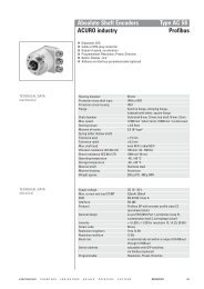
EncodEr Mounting configurationshollow-shaft<strong>Encoder</strong>s are applied to measure speed and position in a wide variety of applicationsand are therefore available with numerous mounting styles. The mounting style shouldbe selected carefully to best fit the application at hand.The motor or machine shaft extends through the hollow encoder shaft and is affixedby a concentric clamp. A flexible tether or torque arm attaches to the motor ormachine surface to prevent the encoder body from rotating with the shaft.concEnTric clampNOTE: Eliminates the need for a coupling, and allows the encoder to be moved tothe correct position for tethering without shaft modifications.Product Examples: HS35 (page 2.40), HS20 (page 2.36), AC110 (2.84)flExiblE TEThErhub-shaftA hub shaft encoder is similar to the hollow-shaft configuration, except the shaft doesnot extend through the encoder.concEnTric clampNOTE: Eliminates the need for a coupling, but may require a more precise shaft lengthto properly locate the encoder for tethering. This type provides improved sealing, as there isno opening on the back of the encoder.Product Examples: AI25 (2.64 - 2.80), HSD25 (page 1.08), E14 (page 4.04)flExiblE TEThErshafted with couplingThe original encoder configuration, a shafted encoder requires two special interfaces toproperly mount the unit. The first is an encoder mount, which is typically either a mountingflange or a foot mount. The second is a flexible coupling, which compensates forshaft misalignment while providing little or no backlash.flangE mounTNOTE: This solution is typically used when a hollow or hub-shafted solution cannotwork. It requires care in aligning the encoder and driven shafts.fooT mounTProduct Examples: E14IC (page 4.12), HR26 (page 2.54)flExiblE couplingshafted with beltA shafted encoder can be interfaced to a driven shaft by a belt. This is oftendone when the driven shaft is too large for coupling, or the application is spaceconstrained and the encoder must be located to the side.NOTE: The additional mechanical hardware adds cost and complexity to the system.Product Examples: H56 (page 1.32), RIM6200 (page 1.56)a.08
EncodEr Mounting configurationsc-faceNEMA motor come with standard interface dimensions on the face for mounting analigning accessories. Common face mount dimensions are 4.5”, 8.5”, and 12.5”.C-face encoders mount the housing to the motor face, and mount a wheel to themotor shaft separately. These are bearing-less.NOTE: Bearing-less solution eliminates a wear component.Product Examples: SL56 (page 1.42), SL85 (page 1.46)gEarrEducErmoTorframeless resolvermachinEDesigned for standard resolver motor mounts, the resolver rotor mounts to the shaft,and the resolver housing mounts to the motor face. A clip secures the resolver housingvia a groove, as shown.NOTE: A frameless resolver mount is a bearing-less solution that makes a ruggedresolver technology even more rugged.Product Examples: HAROMAx 15 (page 3.42), HAROMAx 21 (page 3.43)sErvo groovE mounTingservo flex-mountThis style of encoder mount is designed as a drop-in replacement for frameless resolvers.The encoder quickly clips into place. Flex mount designs include the ability tomake fine adjustments to align for motor commutation.NOTE: The rigid encoder design incorporates bearings, which allows it to be used onmotors that have higher shaft axial play and radial run-out.Product Examples: F14 (page 3.30), F18 (page 3.34)sET scrEwsconcEnTricclampflExiblE TEThErservo kitThe encoder is a modular assembly, eliminating the bearings, similar to the framelessresolver. The encoder housing affixes to the face of the motor, and the encoder diskis fastened to the motor shaft.NOTE: Ideal for motors with tight tolerance on axial and radial shaft run-out. Bearing-lessdesign eliminates a wear component.Product Examples: M53 (page 3.26), M15 (page 3.24),ET Module (page 3.12)a.09
EncodEr duty classificationEncodEr/rEsolvEr duty classificationHEavy duty<strong>Heavy</strong> <strong>Duty</strong> encoders and resolvers are designed to survive some of the toughest environments. Paper and steelmills, aerospace applications, and food and beverage processing machinery are all areas that benefit from heavyduty encoders. Using magnetic, inductive, or specially designed optical technology, their tight sealing, heavy-dutybearings (where applicable), and high temperature range all suit them for use in harsh environments.HeAvy duTy geneRAl PeRfoRMAnce dATAGOOD BETTER BESTSPEEDSEALINGTEMPERATURESHOCK/VIBRATIONRIMTach 8500 Pictured.industrial dutySPEEDSEALINGOften considered the “workhorse” of the encoder world, industrial duty encoders achieve a good compromisebetween ruggedness and performance. These encoders are typically used in factory environments where contaminantslike dust and moisture are common. The hollow-shaft variety of industrial duty encoders is often the preferredTEMPERATUREchoice of vector motor OEM’s for speed feedback.SHOCK/VIBRATIONIndusTRIAl duTy geneRAl PeRfoRMAnce dATAGOOD BETTER BESTSPEEDSEALINGTEMPERATURESHOCK/VIBRATIONHA25 Pictured.a.10
SEALINGEncodEr duty classificationsErvo dutyThis class of encoders and resolvers is specifically suited to use on small-to mid-size stepper and servo motors. Theytypically have limited sealing due to their use inside motor housings, but are capable of very high speeds and hightemperatures, a benefit due to being in such close proximity to motor windings. These encoders typically come fromthe factory ready to mount to common motor back shafts.seRvo duTy geneRAl PeRfoRMAnce dATAGOOD BETTER BESTSPEEDSEALINGTEMPERATURESHOCK/VIBRATIONAd35 Pictured.ligHt dutySPEEDLight duty encoders are commonly referred to as “commercial duty” due to their frequent use in commercialSEALINGor office automation products. Copiers, fax machines, lab equipment, and medical equipment are commonapplications for light duty encoders. Typically these TEMPERATURE devices reside in fairly benign environments with littletemperature variation, are fairly clean, and not generally subjected to high shock loading or moisture.SHOCK/VIBRATIONlIgHT duTy geneRAl PeRfoRMAnce dATAGOOD BETTER BESTSPEEDSEALINGTEMPERATURESHOCK/VIBRATIONe14 Pictured.SPEEDa.11
selection guideSelection GuideIncrementalShaftedLight <strong>Duty</strong>E12E14E23EC23Ultra-compact 1.2" Diameter - 5, 12, or 15VDC - Metal housing1.44" Diameter - 5, 12, or 15VDC - Metal Housing - Line driver outputs.2.31" Diameter - 5-26VDC - Terminal Strip connections2.31" Diameter - 5-26VDC - Up to 5000PPRPage4.024.044.064.08Industrial <strong>Duty</strong>22 Qube Series 2.25" Anodized Qube - Dual shaft option - 5-26VDCH20Industry Standard 2.0" size - Multiple output options - Metal disc optionHA25Industry Standard 2.5" size - Multiple housing options - Wide range of resolutionsHR25Same as HA25 with metal discHC25Same as HA25 up to 5000PPRH58Industry standard 58mm metric - 5-26VDC - Wide selection of optionsH42Economical 2.5" design - Unbreakable disc - 5- 26VDCHA725Industry Standard 2.5" size - Up to 10,000PPR direct-read - 5V or 10-30VDC2.042.082.122.162.202.242.282.30Hubshaft<strong>Heavy</strong> <strong>Duty</strong>HD 20HD25H56RIMTach 6200X252.0" square flange mounting - IP67 seals - up to 3600 PPR - Phased Array sensor2.5" square flange mounting - Dual output option - up to 5000 PPR - ATEX optionFoot- or face-mount - 5/8" shaft - M/S or Field serviceable connectorsFoot or face mount - 5/8” single or dual shaft - Magneto-resistive technology - Removable sensor modulesUL rating for Hazardous Locations - Conduit entry - up to 5000PPR1.041.061.321.561.34Light <strong>Duty</strong>E14H1.44" Diameter - Up to 5/8" hub bore including metric - 5, 12, or 15VDC4.10Industrial <strong>Duty</strong><strong>Heavy</strong> <strong>Duty</strong>H20HSD25HSD44Industry Standard 2.0" size - Up to 5/8" hub bore - Metal disc option2.3" diameter housing - IP67 sealing - Nickel, stainless, or anodized housing4.4" diameter housing - isolated hub compensates for motor endplay - metal disc2.321.081.26HollowshaftIndustrial <strong>Duty</strong>HS20HS35HS35RRi80E2.0" size - Up to 5/8" hollowshaft including metric - 5-26VDC3.5" diameter - up to 1.25" electrically isolated hollowshaft - 5-26VDCNEW PRODUCT - Phased Array ASIC - Unbreakable discs - Up to 5000 PPR - Up to 1.25" hollowshaft100mm diameter - large 45mm hollowshaft capability - up to 4096 PPR - 5-30VDC2.362.402.442.48<strong>Heavy</strong> <strong>Duty</strong>HSD35HSD37HSD38DWD38SLIMTach HS56SLIMTach HS60RIMTach HS85Up to 1.25" electrically isolated hollowshaft - Field-serviceable connectors - dual isolated output option3.75" housing - Phased Array Sensor - Up to 5000 PPR - Nickel, stainless & dual output housing optionFinned 3.8" housing - Phased Array Sensor - Up to 5000 PPR - Ideal for vector motor duty3.75" housing - draw works threaded shaft - ATEX certification available - NAMUR output availableMagneto-resistive sensor - Up to 1-1/8" hollowshaft - Up to 2048 PPR - Field serviceable connectorNEW PRODUCT - Up to 2-7/8" stainless hollowshaft - Magneto-reisistive sensor - Field serviceable connectorRemoveable Magneto-resistive sensors - Up to 4.5" hollowshaft - Dual isolated output option1.121.161.201.241.581.601.62Servo <strong>Duty</strong>F10F14F15F18F21HC20Compact 1.25" diameter - direct-fit for Size 10 resolver - 5VDC - Up to 2048 PPR & commutation channels1.55" Diameter - Flex tether mounting - 5VDC - Up to 5000 PPR & commutation channels1.45" Diameter - direct-fit for size 15 resolver - 5VDC - Up to 2048 PPR & commutation channels1.96" Diameter - Flex tether mounting - 5VDC - Up to 10,000 PPR & Commutation channels2.06" Diameter - direct-fit for size 21 resolver - 5VDC - Up to 2048 PPR & commutation channelsNEW PRODUCT - 1.97" diameter - multiple shaft mounting options - Up to 2500 PPR - 5VDC or 5-26VDC3.283.303.323.343.363.38Bearingless<strong>Heavy</strong> <strong>Duty</strong>SLIMTach SL56 56C-face mounting. 5-15VDC or 5-26VDC. Magneto-resistive technology. Up to 2048 PPR.SLIMTach RL67 56C-face mounting or Reliance RPM rabbet mounting. Magneto-resistive technology.SLIMTach SL85 180C-face mounting. 5-15VDC or 5-26VDC. Magneto-resistive technology. Up to 2048 PPR.SLIMTach SL1250 250C-face mounting. 5-15VDC or 5-26VDC. Magneto-resistive technology. Up to 2048 PPR.RIMTach 8500 180C-face mounting. Removeable sensor modules. Magneto-resistive technology. Up to 1200 PPR.RIMTach 1250 250C-face mounting. 5-15VDC or 5-26VDC. Magneto-resistive technology. Up to 2048 PPR.1.421.441.461.501.521.54Kit/ModularServo <strong>Duty</strong>M602 & M832LM & LAMM9 & E9M14M15M53Component-level kit. 5VDC input. Unbreakable discsComponent-Level Linear encoder kit. Digital or Analog output. 5VDC input..9" diameter. Up to 512PPR. 5VDC input.1.496" diameter (38mm). Short mounting depth. Up to 1024PPR. 5VDC input.1.5" diameter. Up to 1024PPR with commutation channels. Phased-Array sensor technology.2.0" diameter. Up to 2500PPR with commutation channels. 5VDC or 12VDC input.3.123.153.183.223.243.26A.12
selection guideAbsoluteShaftedIndustrial <strong>Duty</strong>AI252.5" size. Multiple fieldbus options. Up to 22 bit singleturn, 12 bit multiturn resolution.Page2.64Servo <strong>Duty</strong>AD34AD2537.5mm diameter. Unique one-step shaft mounting. Up to 19 bit singleturn resolution.58mm diameter. Up to 22 bit singleturn resolution. Unique conical shaft for concentric mounting.3.043.10<strong>Heavy</strong> <strong>Duty</strong>AR62/63AX70/7158mm size. Oversized bearings. Magnetic sensor. 12 bit singleturn resolution.70mm diameter. ATEX certified explosion-proof. Aluminum or stainless steel housing.1.641.66HubshaftIndustrial <strong>Duty</strong>AI252.5" size. Multiple fieldbus options. IP64 protection rating.2.64Servo <strong>Duty</strong>AD35AD3637.5mm diameter. Up to 22 bit singleturn resolution. 5VDC or 7-30VDC.37.5mm diameter. Up to 22 bit singleturn, 12 bit multiturn resolution. 5VDC or 7-30VDC.3.063.08HollowshaftIndustrial <strong>Duty</strong>AC36AC11037.5mm diameter. Up to 22 bit singleturn, 12 bit multiturn resolution. 5VDC or 7-30VDC.110mm diameter. Up to 50mm hollowshaft bore. Up to 22 bit singleturn resolution. 10-30VDC.2.622.84Servo <strong>Duty</strong>AD3637.5mm diameter. Up to 22 bit singleturn, 12 bit multiturn resolution. 5VDC or 7-30VDC.3.08ResolverHousedServo <strong>Duty</strong>R11Size 11 housing - unique shaft pinion for pulley mounting - Up to 155C temperature rating11 Size 11 housing - Up to 5X multi-speed available - High 3 arc-min accuracy3.403.40<strong>Heavy</strong> <strong>Duty</strong>R25Industry standard 2.5" housing - Up to 125C temperature rating - Up to 200g shock rating1.70FramelessServo <strong>Duty</strong>10 Size 10 bearingless - Brushless construction - Up to 200C temperature rating15 Size 15 bearingless - Brushless construction - Multi-speed available21 Size 21 bearingless - Brushless construction - Multi-speed available31 Size 31 bearingless - Brushless construction - Up to 8X multi-speed available55 Size 55 bearingless - Up to 3.65" rotor I.D. bore - Up to 32X multi-speed availableHaroMax 15 Size 15 bearingless - High-accuracy - Light weight aluminum housing - Brushless constructionHaroMax 21 Size 21 bearingless - High-accuracy - Light weight aluminum housing - Brushless construction3.413.413.413.413.413.423.43liGHt dutyServo dutyinduStrial duty<strong>Heavy</strong> dutyA.13
<strong>Heavy</strong> <strong>Duty</strong>HEAVy DuTy ENCODERS & RESOLVERS GuIDEDyNAPAR 2010Dynapar has been designing and manufacturing tough, reliable encoders for over 5 decades. LeadingDynapar’s <strong>Heavy</strong> <strong>Duty</strong> line up is the NorthStar TM brand of heavy duty Magnetic and Optical encoders.The NorthStar line of MAGNETO-RESISTIVE (MR) encoders uses state-of-the-art “direct read” sensingtechnology to precisely track machine speed for optimum control. It is resistant to common mill contaminantssuch as water, oil, grease, dirt, and designed to operate in hostile environments where shock and vibrationare the norm. This provides the customer with reliable digital output for the life of the encoder and is why itis the most requested Magneto-resistive encoder today. It is also the standard by which other MR encodermanufactures strive to match.NorthStar SLIMTach and RIMTach encoders have proven themselves in tough steel and paper mill applicationsand other hostile environments where downtime is not an option. These tough tachs are offered in C-facebearingless, hollow shaft with oversized bearings, and foot-mounted configurations.The new NorthStar line of OPTICAL encoders incorporates patented phased array opto-ASIC technologythat is setting the standard for future tough and reliable optical designs. This technology, along with otherinnovations from NorthStar, drastically improves the reliability of optical encoders. It is the reason major oil & gascompanies specify NorthStar HD Optical <strong>Encoder</strong>s for their demanding applications in extreme temperaturesand hazardous environments.The product is also well suited for use in other demanding applications as heavy rail traction drives, windturbines, and severe wash down processing equipment. These applications benefit from• High resolution unbreakable code discs• Phased array ASIC that eliminates potentiometers and manufacturing error• Seals and housings that provide IP67 rating• ATEX certification for Intrinsically Safe application requirements• Oversized bearings for increased life• PCB designs for high shock and vibration resistance• Industrial grade components rated for -40 to 100+ CRegardless of the NorthStar encoder used, you can rely on Dynapar for reliable feedback in toughenvironments. NorthStar encoders are made right here in the USA using the advanced cellular manufacturingconcept, ensuring Just-In-Time delivery to meet your needs.1.00
<strong>Heavy</strong> <strong>Duty</strong><strong>Heavy</strong> <strong>Duty</strong> encoders and resolvers are designed to survive some of the toughest environments. Paper andsteel mills, aerospace applications, and food and beverage processing machinery are all areas that benefitfrom heavy duty encoders. Using magnetic, inductive, or specially designed optical technology, their tightsealing, heavy-duty bearings (where applicable), and high temperature range all suit them for use in harshenvironments.heavy duTy encodeR geneRal PeRfoRMance daTaGOOD BETTER BESTSPEEDSEALINGTEMPERATURESHOCK/VIBRATIONRIMTach 8500 PicturedSPEEDSEALINGTEMPERATURESHOCK/VIBRATION1.01
<strong>Heavy</strong> <strong>Duty</strong>Optical - incrementalNEWNEWNEWNEWNEWNEWNEWproduct HD20 HD25 HSD25 HSD37 HSD38 DWD38 HSD44Shaft/Bore Sizes3/8˝ or 10mmShaft3/8˝ or 10mmShaft3/8" to 3/4"Shaft12mm to 1"hollow shaft6mm to 1-1/4"hollow shaft1˝-14UNS x5/8˝-18 ThreadedShaft or 1˝-14UNSThreaded Shaft5/8" / 16mmisolated hub shaftavailableresolutions (ppr)1 to 3600 1 to 5000 1 to 3600 15 to 5000 15 to 5000 15 to 5000 1024 or 2048input Voltage (VDc) 5-26 or 7-26 5-26 or 7-26 5-26 or 7-26 5-26 5-15 or 5-26 5-26 or 7-26 5-30Operatingtemperature (°c)-40 to +100(40 to +80 ATEX)-40 to +100(40 to +80ATEX)-40 to +100(40 to +80 CATEX)-40 to +100(40 to +80 CATEX)-40 to +100-40 to +100(40 to +80 ATEX)–40 to +100enclosure rating IP67 IP67 IP67 IP67 IP67 IP67 IP67Special FeaturesATEX certificationavailableDual isolatedoutputs availableCompact hubshaft designATEX certificationavailableRugged bearingstructureDraw worksthreaded shaftIsolated couplingcompensates formotor shaft endplaypage number 1.04 1.06 1.08 1.16 1.20 1.24 1.26magnetic - incrementalproduct Slim tach ® Sl56 Slim tach ® rl67 Slim tach ® Sl85 Slim tach ® Sl1250 rim tach ® 8500 rim tach ® 1250Shaft/Bore Sizes5/8˝ to 2-7/8˝ Standard,Up to 3.75˝ Available5/8˝ to 2-7/8˝Standard, Up to 3.75˝Available5/8˝ to 2-7/8˝Standard, Up to 3.75˝Available5/8˝ to 2-7/8˝Standard, Up to 3.75˝Available5/8˝ to 2-7/8˝Standard, Up to3.75˝ Available5/8˝ to 2-7/8˝Standard, Up to 8˝Availableavailableresolutions (ppr)64 to 2048 64 to 2048 64 to 2048 64 to 2048 60 to 1200 60 to 2048input Voltage (VDc) 5 to 15 or 5 to 26 5 to 15 or 5 to 26 5 to 15 or 5 to 26 5 to 15 or 5 to 26 5 to 15 or 15 to 26 5 to 15 or 15 to 26Operatingtemperature (°c)–40 to +90(opt to +120)–40 to +90(opt to +120)–40 to +90(opt to +120)–40 to +90(opt to +120)–40 to +80 –40 to +80enclosure ratingResistant to grease,salt water, dustResistant to grease,salt water, dustResistant to grease,salt water, dustResistant to grease,salt water, dustResistant to grease,salt water, dustResistant to grease,salt water, dustSpecial Features Bearingless design Bearingless design Bearingless design Bearingless designBearingless designwith removablesensorsBearingless designwith removablesensorspage number 1.42 1.44 1.46 1.50 1.52 1.541.02
<strong>Heavy</strong> <strong>Duty</strong>Optical - incremental Optical - aBSOlute inDuctiVe - reSOlVerNEWNEWNEWNEWHSD35 en42 en44H56rotopulser ®X25aX70/71r25 resolverproduct6mm to 1-1/4"hollow shaft5/8" to 1",15mm, 16mm5/8" / 16 mmIntegral coupling5/8” 1/4˝ or 3/8˝10mm shaftShaft Size:0.3745˝ (9.51mm)Shaft/Bore Sizes1 to 5000 15 to 5000 1024 or 2048 1 to 2500 1 to 5000Up to 16 bit ST, 12bit MTSingle speed orMulti-Speedavailableresolutions (ppr)5-15 or 5-26 5-15 or 5-26 5-15 or 5-26 5-26 5 -2610-302 to 8 Vrms input Voltage (VDc)-40 to +100 -50 to +100 -50 to +100 -40 to +85 0 to +70-40 to +60 or -40to +40Up to 125Operatingtemperature (°c)IP65 IP67 IP67 NEMA 4/ IP66 NEMA 4/ IP66IP64 or IP67IP65enclosure ratingField serviceableconnectorBarrier-lessATEX Zone 1CertificationBarrier-lessATEX Zone 1Certification<strong>Encoder</strong> withinencoder designNEC Class 1&2, Div1&2, Groups C,D,E,F,GExplosion proofShock resistant to200gSpecial Features1.12 1.28 1.30 1.32 1.341.661.70 page numberNEWmagnetic - incrementalmagnetic aBSOluteNEWrim tach ® 6200 (4) Slim tach ® HS56 Slim tach ® HS60 rim tach ® HS85 r45 rotopulser ®ar62/63product5/8˝ 5/8˝ to 1-1/8˝1-1/8" to2-7/8" hollowshaft5/8˝ to 2-7/8˝Standard, Up to 4.5˝Available5/8˝ or 7/8˝3/8" or 10mmshaftShaft/Bore Sizes60 to 2048 64 to 2048 64 to 2048 60 to 2048 6012 bitavailableresolutions (ppr)5 to 15 or 15 to 26 5-15 or 5-26 5-15 or 5-26 5-15 or 5-26 5 to 2610-30 input Voltage (VDc)–40 to +70 –20 to +80 –20 to +80 –20 to +70 –40 to +85-40 to +100Operatingtemperature (°c)Immune to grease, saltwater, dustResistant to grease,dustImmune to grease, saltwater, dustImmune to grease, saltwater, dustImmune to grease,water, dustIP67 or IP69kenclosure ratingShafted foot-mount orface mountHollowshaft designLarge bore HollowshaftdesignHollow shaft designwith removable sensors56C-face mountingShock resistantto 200gSpecial Features1.56 1.58 1.60 1.62 1.401.64 page number1.03
HEAVY DUTYSERIES HD20NorthStar brandHarsh <strong>Duty</strong> Optical <strong>Encoder</strong>Key Features• Size 20 <strong>Heavy</strong>-<strong>Duty</strong> <strong>Encoder</strong> with Single orDual Isolated Outputs• ATEX Certification Available for IntrinsicallySafe Applications• Unbreakable Code Disc up to 3600PPR• Special Housing and Seals for IP67 Rating• Anodized Aluminum, Stainless Steel, orNickel Plated HousingE Ex ia IIB T41.04SPECIFICATIONSSTANDARD OPERATING CHARACTERISTICSDATA AND INDEXCode: IncrementalNot all complements shown.Resolution: 1 to 3600 PPR (pulses/revolution)A shown for referenceFormat: Two channel quadrature (AB) withoptional Index (Z), and complementary outputso(180 ELEC)Phase Sense: A leads B for CCW shaft rotationo(90 ELEC)viewing the shaft clamp end of the encoderQuadrature Phasing: For resolutions to 625PPR: Data A90° ± 15° electrical; For resolutions over625 PPR: 90° ± 30° electricalData ASymmetry:For resolutions to 1024PPR: 180° ±18° electrical Data BFor resolutions over 1024PPR: 180° ±25° electricalWaveforms: Squarewave with rise and fall times Indexless than 1 microsecond into a load capacitanceof 1000 pfA Leads B CCWELECTRICAL CONNECTIONS6, 7 & 10 Pin MS Connectors and CablesConnector & mate/accessory cable assembly pin numbers and wire color information is provided here forreference. Models with direct cable exit carry the color coding as shown in the right hand column.Cable # 1400635-<strong>Encoder</strong> Cable # 108594- Cable # 108595- Cable # 108596- or 109209- (NEMA4) Cable ExitFunction 6 Pin Single Ended 7 Pin Single Ended 7 Pin Dif Line Drv w/o Idx 10 Pin Dif Line Drv w/ Idx with SealPin Wire Color Pin Wire Color Pin Wire Color Pin Wire Color Wire ColorSig. A E BRN A BRN A BRN A BRN GREENSig. B D ORG B ORG B ORG B ORG BLUESig. Z C YEL C YEL — — C YEL ORANGEPower +V B RED D RED D RED D RED REDCom A BLK F BLK F BLK F BLK BLACKCase — — G GRN G GRN G GRN WHITEN/C F — E — — — E — —Sig. ASig. BSig. Z— — — — C BRN/WHT H BRN/WHT VIOLET— — — — E ORG/WHT I ORG/WHT BROWN— — — — — — J YEL/WHT YELLOWNote: “MS” type mating connectors and prebuilt cables are rated NEMA 12.For watertight applications, use NEMA4 10 pin cable & connector 109209-XXXX.ELECTRICALInput Power: 5-26VDC; 50 mA max., notincluding output loads. ATEX: 5VDC, 7-26VDCOutputs: 2N2222, ET7272, ET7273Frequency Response: 125 kHz (data & index)Termination: 6, 7, or 10 pin MS Connector; 18”cable exit w/sealMating Connector:6 pin, style MS3106A-14S-6S (MCN-N4)7 pin, style MS3106A-16S-1S (MCN-N5)10 pin, style MS3106A-18-1S (MCN-N6)10 pin, NEMA 4 style (604505 & 604506)MECHANICALShaft Material: 303 stainless steel (passivated)Shaft speed: 6000 RPM, maximumShaft loading: Up to 100 lbs axial and radialShaft runout: 0.0005 TIR at midpointStarting torque: 2.5 in-oz. maximum (at 25°C)Bearings: 5200 ZZ double rowBearing life: 5 x 10 8 revs at rated shaftLoading,5 x 10 11 revs at 10% of rated shaft loading.(manufacturers’ specs)Housing and cover: Hard Anodized Aluminum.Also available in Electroless Nickel finish andStainless Steel.Disc material: Metal or plasticWeight: 14 ounces, typicalENVIRONMENTALOperating Temperature: -40 to 100°COperating Temperature ATEX: -40 to 80°CStorage temperature: -40 to 100°CShock: 50G’s for 11msec durationVibration: 5 to 2000Hz @ 20 G’sHumidity: 100%Enclosure Rating: IP67
yHEAVY DUTYSERIES HD20Code 1: ModelHD20Size 20Extreme<strong>Heavy</strong> <strong>Duty</strong><strong>Encoder</strong>1 Unidirectional2 Bidirectional3 Bidirectional withIndexOrdering InformationTo order, complete the model number with code numbers from the table below:Code 2: PPR00010010002400250035004000600100012001920200024002500256030003600500051206000625072010001024120012501440200020482500254026003600Code 3: Shaft0 3/8" Dia.Shaft withflat4 10mmDia. Shaft,no flatNotes:10 foot Cable Assemblies with MS Connector108594-0010 6 Pin MS, Cable Assy. For Use with Single EndedOutputs108595-0010 7 Pin MS, Cable Assy. For Use with Single EndedOutputs108596-0010 7 Pin MS, Cable Assy. For Use with DifferentialLine Driver w/o Index Outputs1400635-0010 10 Pin MS, Cable Assy. For Use with DifferentialLine Driver with Index Outputs109209-0010 NEMA4 10 pin MS, Cable Assy. For use withdifferential line driver with index outputsMating Connectors (no cable)6 pin, style MS3106A-14S-6S (MCN-N4)7 pin, style MS3106A-16S-1S (MCN-N5)10 pin, style MS3106A-18-1S (MCN-N6)10 pin, NEMA 4 style (604505 & 604506)Code 4: ElectricalOrdering Information0 5-26V in, 5-26VOpen Collector out(7273)2 5-26V in, 5-26VPush-Pull outF 5-26V in, 5-26VOpen Collector out(2222)G 5-26V in, 5-26VOpen Collector outwith 2.2 kΩ Pullups(2222)available when: Code 1is 1,2 and Code 5 is 3through H, or Code 1is 3 and Code 5 is 5through H:3 5-26V in, 5-26VDifferential LineDriver out (7272)4 5-26V in, 5VDifferential LineDriver out (7272)Code 5: Termination1 6 Pin Connector3 7 Pin Connector5 10 Pin ConnectorDEFGH18" Sealed Cable3’ Sealed Cable6’ Sealed Cable10’ Sealed Cable15’ Sealed Cable*Note: Available ATEX CertifiedOptionsATEX Type 1: ATEXCertified; 5V in, 5V out onlyATEX Type 2: ATEX Certified;7-26V in, 7-26V outATEX Type 3: ATEX Certified;7-26V in, 5V outNOTE:ATEX voltages replacethose shown in Code 4.Code 6: Options0 No Options1 Nickel Finish Housing2 Stainless Steel HousingA Same as "0" w/ ATEX Type 1B Same as "1" w/ ATEX Type 1C Same as "2" w/ ATEX Type 1Available when Code 4 is 0, 2, 3, F or GG Same as "0" w/ ATEX Type 2H Same as "1" w/ ATEX Type 2I Same as "2" w/ ATEX Type 2Available when Code 4 is 4M Same as "0" w/ ATEX Type 3N Same as "1" w/ ATEX Type 3O Same as "2" w/ ATEX Type 3Available when Code 4 is 0, 2, F or G3 Redundant Outputs (Dual ConnectorHousing). See † NOTE4 Nickel Finish Housing with RedundantOutputs. See † NOTE5 Stainless Steel Housing withRedundant Outputs. See † NOTED Same as "3" " w/ ATEX Type 1. See †NOTEE Same as "4" w/ ATEX Type 1. See †NOTEF Same as "5" w/ ATEX Type 1. See †NOTEJ Same as "3" w/ ATEX Type 2. See †NOTEK Same as "4" w/ ATEX Type 2. See †NOTEL Same as "5" w/ ATEX Type 2. See †NOTEP Same as "3" w/ ATEX Type 3. See †NOTEQ Same as "4" w/ ATEX Type 3. See †NOTER Same as "5" w/ ATEX Type 3. See †NOTE† NOTE: Simultaneous use ofredundant outputs may voidATEX certification. Consultfactory for details.DIMENSIONSinches [mm]0.60[15.2]0.018 [0.46]FLAT0.86 [21.8]Ø1.25[31.8]2.81[71.4]2.06[52.3]1.03[26.2]4XØ 0.173 x 150THRU HOLEFOR 8-324XR .162X1.75 [44.5]Ø 0.173[4.4]4X1.78[45.2]0.86[21.8]0.86[21.8]1.78[45.2]2.78[70.6]0.60[15.2]0.018 [0.46]FLAT1.50[38.1]1.87[47.5]0.12[3.1]SHAFTStandard HousingØ.3747.37451.03[26.2]2.06[52.3]Ø.3747.3745Dual Redundant Outputs1.50[38.1]1.87[47.5]Cable Exit0.12[3.1]1.05
yHEAVY DUTYSERIES HD25Ordering InformationTo order, complete the model number with code numbers from the table below:Code 1: ModelHD25Size 25Extreme<strong>Heavy</strong> <strong>Duty</strong><strong>Encoder</strong>1 Unidirectional2 Bidirectional3 Bidirectional withIndexCode 2: PPR00010024002500350040005000600100012001920200024002500256030003600500051206000625072009001000102412001250144015241600180020002048250025402600360040965000Code 3: Shaft0 3/8" Dia.Shaft withflat4 10mmDia. Shaft,with flat6 12mm Dia.Shaft7 Same asoption 0with 4 hole2.00” B.C.Note:10 foot Cable Assemblies with MS Connector108594-0010 6 Pin MS, Cable Assy. For Use with Single Ended Outputs108595-0010 7 Pin MS, Cable Assy. For Use with Single Ended Outputs108596-0010 7 Pin MS, Cable Assy. For Use with DifferentialLine Driver w/o Index Outputs1400635-0010 10 Pin MS, Cable Assy. For Use with DifferentialLine Driver with Index Outputs109209-0010 NEMA4 10 pin MS, Cable Assy. For use withdifferential line driver with index outputsMating Connectors (no cable)6 pin, style MS3106A-14S-6S (MCN-N4)7 pin, style MS3106A-16S-1S (MCN-N5)10 pin, style MS3106A-18-1S (MCN-N6)10 pin, NEMA 4 style (604505 & 604506)Code 4: ElectricalOrdering Information0 5-26V in, 5-26V 1 6 Pin ConnectorOpen Collector out 3 7 Pin Connector(7273)5 10 Pin Connector2 5-26V in, 5-26VPush-Pull out9 5 Pin M12 ConnectorF 5-26V in, 5-26VD 18" Sealed CableOpen Collector out E 3’ Sealed Cable(2222)F 6’ Sealed CableG 5-26V in, 5-26V G 10’ Sealed CableOpen Collector outwith 2.2 kΩ PullupsH 15’ Sealed Cable(2222)P 5m Sealed CableAvailable when: Code1 is 1, 2 and Code 5is 3,5 or D through P,or Code 1 is 3 andcode 5 is 5 or Dthrough P:3 5-26V in, 5-26VDifferential LineDriver out (7272)4 5-26V in, 5VDifferential LineDriver out (7272)6 5-15V in, 5-15VDifferential LineDriver out (4469)Code 5: Termination*Note: Available ATEX CertifiedOptionsATEX Type 1: ATEX Certified;5V in, 5V out onlyATEX Type 2: ATEX Certified;7-26V in, 7-26V outATEX Type 3: ATEX Certified;7-26V in, 5V outATEX Type 4: ATEX Certified;5-15V in, 5-15V outNOTE: ATEX voltages replacethose shown in Code 4.† NOTE: Simultaneous useof redundant outputs mayvoid ATEX certification.Consult factory fordetails.Code 6: Options0 No Options1 Nickel Finish Housing2 Stainless Steel Housing3 Redundant Outputs (Dual ConnectorHousing). See † NOTE4 Nickel Finish Housing with RedundantOutputs. See † NOTE5 Stainless Steel Housing withRedundant Outputs. See † NOTEA Same as "0" w/ ATEX Type 1B Same as "1" w/ ATEX Type 1C Same as "2" w/ ATEX Type 1D Same as "3" w/ ATEX Type 1. See †NOTEE Same as "4" w/ ATEX Type 1. See †NOTEF Same as "5" w/ ATEX Type 1. See †NOTEAvailable when Code 4 is 0-3, F or GG Same as "0" w/ ATEX Type 2H Same as "1" w/ ATEX Type 2I Same as "2" w/ ATEX Type 2J Same as "3" w/ ATEX Type 2. See †NOTEK Same as "4" w/ ATEX Type 2. See †NOTEL Same as "5" w/ ATEX Type 2. See †NOTEAvailable when Code 4 is 4M Same as "0" w/ ATEX Type 3N Same as "1" w/ ATEX Type 3O Same as "2" w/ ATEX Type 3P Same as "3" w/ ATEX Type 3. See †NOTEQ Same as "4" w/ ATEX Type 3. See †NOTER Same as "5" w/ ATEX Type 3. See †NOTEAvailable when Code 4 is 6:S Same as 0, w/ATEX Type 4T Same as 1, W/ATEX Type 4U Same as 2, w/ATEX Type 4V Same as 3, w/ATEX Type 4. See †NOTEW Same as 4, w/ATEX Type 4. See †NOTEY Same as 5, w/ATEX Type 4. See †NOTEDIMENSIONS inches [mm]Standard Housing0.54 [13.7]0.30 [7.6]2.65 [67.3]2XDual Redundant Outputs1.95[49.5]Cable Exit0.86 [21.8]1.95[49.5]Flat 0.70 x 0.018[17.8 x 0.46]ShaftØ0.37 [9.5]1.95[49.5]2.95[74.9]0.70 [17.8]0.018 [.46]FlatØ1.25[31.8]2.064 [52.4]2X1.54[39.1]1.91[48.5]0.91 max.[23]4x R0.21[5.3]4x Ø0.22[5.6]10-32 UNF 2B x 0.38" deepon 1.875" bolt circleShaftØ0.37 [9.5]4x R0.21[5.3]4x Ø0.22[5.6]1.54[39.1]1.95[49.5]0.30 [7.6]4X #4-40 X .250 MIN.Ø2.00 B.CWith 4 hole 2.00” B.C.1.07
HEAVY DUTYSERIES HSD25NorthStar brandHarsh <strong>Duty</strong> Optical <strong>Encoder</strong>Key Features• Compact Hubshaft Design with FieldReplaceable Shaft Isolators• Unbreakable Code Disc up to 3600PPR• ATEX Certification Available for IntrinsicallySafe Applications• IP67 Sealing• Anodized Aluminum, Stainless Steel, orNickel Plated HousingE Ex ia IIB T4SPECIFICATIONSSTANDARD OPERATING CHARACTERISTICSCode: IncrementalResolution: 1 to 3600 PPR (pulses/revolution)Format: Two channel quadrature (AB) withoptional Index (Z), and complementary outputsPhase Sense: A leads B for CCW shaft rotationviewing the shaft clamp end of the encoderQuadrature Phasing: For resolutions to 625PPR:90° ± 15° electrical; For resolutions over625 PPR: 90° ± 30° electricalSymmetry:For resolutions to 1024PPR: 180° ±18° electricalFor resolutions over 1024PPR: 180° ±25° electricalWaveforms: Squarewave with rise and fall timesless than 1 microsecond into a load capacitanceof 1000 pfELECTRICALInput Power: 5-26VDC. 50 mA max., notincluding output loads. ATEX: 5VDC, 7-26VDCOutputs: 2N2222. ET7272, ET7273Frequency Response: 125 kHz (data & index)Termination: 6, 7, or 10 pin MS Connector;5 or 8 Pin M12 Connector; Cable exit w/sealMating Connector:6 pin, style MS3106A-14S-6S (MCN-N4)7 pin, style MS3106A-16S-1S (MCN-N5)10 pin, style MS3106A-18-1S (MCN-N6)10 pin, NEMA 4 style (604505 & 604506)MECHANICALShaft Material: 303 stainless steel (passivated)Bore Diameter: 3/8”, 10mm, 1/2”, 5/8”, 3/4”.Insulated inserts providedBore runout: 0.0005 TIR at midpointStarting torque: 6.5 in-oz. maximum (at 25°C)DATA AND INDEXNot all complements shown.A shown for referenceo(180 ELEC)Data AData AData BIndexA Leads B CCWo(90 ELEC)Bearings: 61805-2RZBearing life: 5 x 10 8 revs at rated shaftLoading,5 x 10 11 revs at 10% of rated shaft loading.(manufacturers’ specs)Housing and cover: Hard AnodizedAluminum. Also available in ElectrolessNickel finish and Stainless Steel. TetherAvailableDisc material: Metal or plasticWeight: 20 ounces, typicalENVIRONMENTALOperating Temperature: -40 to 100°COperating Temperature ATEX: -40 to 80°CStorage temperature: -40 to 100°CShock: 50G’s for 11msec durationVibration: 5 to 2000Hz @ 20 G’sHumidity: 100%Enclosure Rating: IP671.08
yHEAVY DUTYSERIES HSD25Code 1: Model25HSD25 <strong>Heavy</strong> <strong>Duty</strong>Hub Shaft<strong>Encoder</strong>ISD25 ATEXIntrinsicallySafe HubShaft<strong>Encoder</strong>0001001000240025003500400060010001200192020002400250025603000360Ordering InformationTo order, complete the model number with code numbers from the table below:Code 2: PPR0500051206000625072010001024120012501440200020482500254026003600Code 3: Bore Size0 6mm1 1/4"2 5/16"3 8mm4 3/8"5 10mm6 12mm7 1/2"8 5/8"9 15mmA 16mmC 19mmD 3/4"**Note: Tether may be required forproper encoder operation and may besupplied by the customer or orderedas the following accessories:113764-0001 Single Point Tether Kit113766-0001 Slotted Tether Kit† NOTE: Simultaneous use ofredundant outputs may void ATEXcertification. Consult factory fordetails.Code 4: Output FormatOrdering Information0 Single Ended ABZ, 5-26VDC push-pull1 Single Ended ABZ, 5-26VDC Open collector (7273)2 Single Ended ABZ, 5-26VDC Open collector (2222)3 Single Ended ABZ, 5-26VDC Open collector (2222)w/2.2kOhmOptions 4 & 5 not available when Code 5 is H; andCode 6 is 3, 4, 54 Differential AB only, 5-26 in, 5-26 out (7272)5 Differential AB only, 5-26 in, 5V out (7272)Options 6 & 7 not available when Code 5 is 0, 1, 5, 6, H; andCode 6 is 3, 4, 56 Differential ABZ, 5-26 in, 5V out (7272)7 Differential ABZ, 5-26 in, 5-26 out (7272)Following options are only available whenCode 1 is ISD25A Single Ended ABZ, 7-26 in, 7-26 out push-pull (7272)C Single Ended ABZ, 5V in, 5V out push-pull (7272)D Single Ended ABZ, 7-26V in, 7-26V out Open Collector (7273)E Single Ended ABZ, 7-26V in, 7-26V out Open Collector (2222)F Single Ended ABZ, 7-26V in, 7-26V out Open Collectorw/2.2kOhm pullup (2222)Options G, H & J not available when Code 5 is H andCode 6 is 3, 4, 5G Differential AB only, 5V in, 5V out (7272)H Differential AB only, 7-26 in, 7-26 out (7272)J Differential AB only, 7-26 in, 5V out (7272)Options K, L & M not available when Code 5 is 0, 1, 5, 6, Hand Code 6 is 3, 4, 5K Differential ABZ, 5V in, 5V out (7272)L Differential ABZ, 7-26 in, 7-26 out (7272)M Differential ABZ, 7-26 in, 5V out (7272)Code 5: Termination0 6 pin1 7 pin2 10 pin5 6 pin+mating6 7 pin+mating7 10 pin+mating8 12 CW pin+matingA .5m (18") cableC 1m (36") cableD 2m (72") cableE 3m (120") cableL 4m (144") cableH 5 pin M12J 8 pin M12K 1.5 ft (18") cable w/ inline 10pin connectorM 5 ft (60") cableN 10 ft (120") cableCode6: Options0 No Options1 Slotted Tether2 Single pointtether3 No tether, Dualisolated outputs4 Slotted Tether,Dual isolatedOutputs5 Single PointTether, Dualisolated OutputsCode 7: Special OptionsBlank None01 Nickel Plated02 Stainless SteelNote:10 foot Cable Assemblies with MS Connector108594-0010 6 Pin MS, Cable Assy. For Use with Single Ended Outputs108595-0010 7 Pin MS, Cable Assy. For Use with Single Ended Outputs108596-0010 7 Pin MS, Cable Assy. For Use with Differential Line Driver w/oIndex Outputs1400635-0010 10 Pin MS, Cable Assy. For Use with Differential Line Driver withIndex Outputs109209-0010 NEMA4 10 pin MS, Cable Assy. For use with differentialline driver with index outputs15 foot Cable Assemblies with M12 Connector112859-0015 5 Pin M12, Cable Assy. For Use with Single Ended Outputs112860-0015 8 Pin M12, Cable Assy. For Use with Single Ended Outputs112860-0015 8 Pin M12, Cable Assy. For Use with Differential LineDriver OutputsMating Connectors (no cable)6 pin, style MS3106A-14S-6S (MCN-N4);7 pin, style MS3106A-16S-1S (MCN-N5)10 pin, style MS3106A-18-1S (MCN-N6)10 pin, NEMA 4 style (604505 & 604506)1.09
HEAVY DUTYSERIES HSD25NorthStar brandELECTRICAL CONNECTIONS6, 7 & 10 Pin MS Connectors and CablesConnector & mate/accessory cable assembly pin numbers and wire colorinformation is provided here for reference. Models with direct cable exitcarry the color coding as shown in the right hand column.<strong>Encoder</strong> Cable # 108594- Cable # 108595-Cable # 108596- Cable # 1400635-7 Pin Dif Line or 109209- (NEMA4)Function 6 Pin Single Ended 7 Pin Single Ended Drv w/o Idx 10 Pin Dif Line Drv w/IdxPin Wire Color Pin Wire Color Pin Wire Color Pin Wire ColorSig. A E BRN A BRN A BRN A BRNSig. B D ORG B ORG B ORG B ORGSig. Z C YEL C YEL — — C YELPower +V B RED D RED D RED D REDCom A BLK F BLK F BLK F BLKCase — — G GRN G GRN G GRNN/C-SLD F — E — — — E —Sig. ⎺ A — — — — C BRN/WHT H BRN/WHTSig. ⎺ B — — — — E ORG/WHT I ORG/WHTSig. ⎺ Z — — — — — — J YEL/WHT0 VoltSense— — — — — — — —5 VoltSense— — — — — — — —Cable #108615-*12 Pin CCWPin Wire Color5 BRN8 ORNNote: “MS” type mating connectors and prebuilt cables are rated NEMA 12.“M12” Cable assemblies are rated IP67For watertight applications,use NEMA4 10 pin cable &connector 109209-XXXX.DIMENSIONS inches [mm]3121097614211YELREDBLK——BRN/WHTORN/WHTYEL/WHTGRNBLK/WHTCable Exitwith SealWire ColorBRNORGYELREDBLACK——BRN / WHTORG /WHTYEL / WHT——5 & 8 Pin M12 Accessory Cables when Code 5= H or JConnector pin numbers and cable assembly wire colorinformation is provided here for reference.<strong>Encoder</strong> Cable # 112859- Cable # 112860- Cable # 112860-Function 5 Pin Single Ended 8 Pin Single Ended 8 Pin DifferentialPin Wire Color Pin Wire Color Pin Wire ColorSig. ASig. B*Sig. ZPower +VComSig. A–Sig. B–*Sig. Z– 42513–––BLKWHTGRYBRNBLU–––14627–––BRNORGYELREDBLK–––14627358BRNORGYELREDBLKBRN/WHTORG/WHTYEL/WHT* Index not provided on all models. Seeordering informationCable Configuration: PVC jacket, 105 °C rated,overall foil shield; 24 AWG conductors, minimumØ2.32 [58.93]HUB SHAFT CAVITYMAXIMUM DEPTH1.41 [35.81]0.86 [21.84]0.60[15.24]BOREDIAMETER3.84[97.54]2.99[75.95].30APARTØ2.00 [50.80]2.40[60.96]Dual RedundantOutputsCable ExitStandard Housing45°8X1.87[47.5]1.0 8[27.4]45.0¡8X2.94fl1.730fl2.300R.410.526[13.4].81Ø1.73[43.9]Ø 2.30[58.4]8X Ø 0.172 [43.7] ON Ø 2.00 [50.8] B.C.[13.0] 0.03 0.30 [0.8] [7.6].51fl2.0008Xfl.172ON fl2.000 B.C.2.122.272REFR.125fl.530.102XR.04 .030Slotted TetherSingle Point Tether1.10
yHEAVY DUTY1.11
HEAVY DUTYSERIES HSD35<strong>Heavy</strong> <strong>Duty</strong> Optical <strong>Encoder</strong>NEW for 2010!NorthStar brandKey Features• Rugged Design Resists up to 400g Shock• Stainless Steel Clamp and Hub Shaft for Mill<strong>Duty</strong>• Compact Design with Field ServiceableConnector for Solder-Less Connections• Accommodates Shaft Sizes up to 1.25”(Electrically Isolated up to 1.125”)• Dual Isolated Output Option for Redundancy1.12SPECIFICATIONSPRELIMINARY SPECIFICATIONSSTANDARD OPERATING CHARACTERISTICSCode: IncrementalResolution: to 5000 PPR (pulses/revolution) SeeOrdering InformationFormat: Two channel quadrature (AB) withoptional Index (Z), and complementary outputsPhase Sense: A leads B for CW shaft rotationviewing the shaft clamp end of the encoderQuadrature Phasing: For resolutions to1200 PPR: 90° ± 15° electrical; For resolutionsover 1250 PPR: 90° ± 30° electricalSymmetry:For resolutions to 1024PPR: 180° ±18° electricalFor resolutions over 1024PPR: 180° ±25° electricalWaveforms: Squarewave with rise and fall timesless than 1 microsecond into a load capacitanceof 1000 pfELECTRICAL CONNECTIONSSignalCommonBAZ *Case (optional)Vcc 5-26 VDC—B—A—Z *No ConnectionConnector Pin12345678910* Index (Z) optional. See Ordering InformationELECTRICALInput Power: 5-26VDC, 5-15VDC. 50 mA max., notincluding output loads.Outputs: ET7272, ET7273, 4469Frequency Response: 125 kHz (data & index)Termination: MS Connector; M12 Connector;cable exit w/seal. See Ordering InformationMating Connector: 10 pin style HA-10DATA AND INDEXNot all complements shownA shown for reference(180° ELECData AData AData BIndexA leads B, CW (from clamp end)(90° ELEC)MECHANICALShaft Material: Stainless SteelBore Diameter: 6mm to 28mm, 1.4" to 1.25",electrically isolatedMating Shaft Length: 1.25", Minimum,1.60", RecommendedShaft Speed: 6000 RPM, Maximum (EnclosureRating is IP64 at speed over 5000 RPM)Starting torque: 8.0 in-oz. maximum (at 25°C)Running torque: 5.0 in-oz. maximum (at ambient)Bearings: ABEC 3Housing and cover: Hard Anodized and PowderCoated AluminumDisc material: Plastic or metal (unbreakable)Weight: 1.76lb (28 Oz) TypicalENVIRONMENTALStandard Operating Temperature: -40 to +85°C(0 to +70°C with 4469 line driver, see “OrderingInformation”). At shaft speed above 3000 RPM,derate 10°C per 1000 RPMExtended Temperature Range: -40 to +100°C(See ordering information)Storage temperature: -40 to +100°CShock: 400g, 6mSecVibration: 5 to 3000 Hz, 20gHumidity: 100%Enclosure Rating: IP67 (IP64 at shaft speedsabove 5000RPM)Connector Rating: IP65Replaces the Magcoder HS35M (shown below)Contact Customer Service for appropriatereplacement model. +1.800.873.8731
yHEAVY DUTYSERIES HSD35Ordering InformationTo order, complete the model number with code numbers from the table below:Code 1: ModelHSD35HSD35 <strong>Heavy</strong>-duty,hollowshaftencoderCode 2: PPR0001000300100012001500320050006001000120020002400250030003600500051206000900100010241200150020002048240025003072400040965000Code 3: Bore Size0 6mm1 1/4"2 5/16"3 8mm4 3/8"5 10mm6 12mm7 1/2"8 5/8"9 15mmA 16mmC 19mmD 3/4"E 20mmF 7/8"G 24mmH 1"J 1-1/8"K 1-1/4"M 14mmN 18mmP 25mmR 28mmStamped Metal0 None1 4.5" C-Face tether2 8.5" C-Face tether3 Slotted tether4 Same as 1 w/cover5 Same as 3 w/coverCode 4: Fixing Code 5: Output FormatOrdering InformationSwivel RodA AC motor fan covertether with T-boltB 4.5" C-face tetherwith 3/8" boltC 8.5" C-face tetherwith 1/2" boltD Same as "A" w/cover kitE Same as "B" w/cover kit0 Single Ended ABZ, 5-26VDC push-pull1 Single Ended ABZ, 5-26VDC O/C2 Single Ended ABZ, 5-26VDC O/C w2.2kOhm4 Differential AB only, 5-26, 5-26 out (7272)5 Differential AB only, 5-26 in, 5V out (7272A Differential AB, 5-26V in, 5V out (4469)C Differential AB, 5-15V in, 5-15V out (4469)6 Differential ABZ, 5-26 in, 5V out (7272)7 Differential ABZ, 5-26 in, 5-26 out (7272)8 Differential ABZ, 5-26 in, 5V out (4469)9 Differential ABZ, 5-15 in, 5-15 out (4469)D Dual isolated outputs, same as "6"E Dual isolated outputs, same as "7"F Dual isolated outputs, same as "8"G Dual isolated outputs, same as "9"H Same as "0" with Extended temp rangeJ Same as "1" with Extended temp rangeK Same as "2" with Extended temp rangeL Same as "4" with Extended temp rangeM Same as "5" with Extended temp rangeN Same as "6" with Extended temp rangeP Same as "7" with Extended temp rangeQ Same as "D" with Extended temp rangeR Same as "E" with Extended temp rangeCode 6: OptionsBlank NoneAccessory Kits:114573-0001 Tether Kit, 4.5" C-face single point with 3/8" bolt114574-0001 Tether Kit for Standard AC motor fan covers with T-bolt114575-0001 Tether Kit, 8.5" C-face single point with 1/2" bolt756-042-01 Rod Tether, AC motor fan cover with T-bolts756-043-01 Rod Tether Kit, 4.5" C Face with 3/8" bolt756-044-01 Rod Tether Kit, 8.5" C Face with 1/2" bolt114622-0001 Cover Kit, 56C face (single or dual output)114623-0001 Cover Kit, Fan cover (single or dual output)1.13
HEAVY DUTYSERIES HSD35NorthStar brandDIMENSIONS inch[mm]5.64[143.3]1.250 I.D. COMPLETELY THRU THE SHAFTFOR DIA. 1.250 +.000, -.003" SHAFT2.12[54.0]5.64[143.3]2X 10-32 UNC-2B (X) .38 DEEPFOR SWIVEL ROD TETHER3.23[82.1]2X1.25[31.8]3X 10-32 UNC-2B (X) .19 DEEPON DIA. 3.000 BOLT CIRCLEØ3.00[76.2]3.21[81.6]Ø 1.25[31.8]Ø[63.5]2.50 PILOTØ 3.80[ 96.5 ]4.86[123.4]OPTIONAL DUALOUTPUT CONNECTOR3.21[81.6]2X10-32 CLAMP SCREWTORQUE TO 50 - 55 IN/LBSWITH LOCTITE ON THREADS.06[1.5]PILOT.57[14.5].40[10.3]1.16[29.5].381.95[9.7]1.54 [49.5][39.2]SWIVEL ROD TETHER0.300" TYP0.48 THRUHOLES ON5.875 B.C.(6 PLACES)3.30[83.8]6.38[162.1]OPTIONAL SAFETY COVER(S)1.14
yHEAVY DUTYSERIES HSD35DIMENSIONS inch[mm]Ø.20[.51] (24X)ON 3.000 [76.2] B.C.D15˚ (24X)114573-0001 Tether Kit,(24X) Ø.20[5.08]ON 3.000 B.C[76.2]15° (24X)114575-0001 Tether Kit.625[15.88]1.25 [31.75]1.25 [31.75]Ø2.506[63.65]Ø3.500[88.9]2.94[74.68]Ø.82 [20.83]Ø.53 [13.46].530 [13.46]Ø2.510[63.75]Ø3.500[88.9]3.525[89.54].25 [6.35].75[19.05]2.14[54.36]2.350[59.7]90.0˚90.0°.530[13.46]15˚ (24X)24X Ø.200 [5.08]ON A Ø3.000 [76.2] B.C.DØ2.506[63.65]Ø3.50 [89]4.50[114.3]2.50[63.5].500 [12.7]114574-0001 Tether Kit1.25 [31.75].63 [16](2X) 45˚ X .125[3.17]2.30[58.42] .53 [13.46]90.0˚1.15
HEAVY DUTYSERIES HSD37NorthStar brandHarsh <strong>Duty</strong> Optical <strong>Encoder</strong>Key Features• Unbreakable Code Disc up to 5000PPR• ATEX Certification Available for IntrinsicallySafe Applications• Dual Isolated Outputs Available forRedundancy• Anodized Aluminum, Stainless Steel, orNickel Plated Housing• IP67 SealingE Ex ia IIB T4SPECIFICATIONSSTANDARD OPERATING CHARACTERISTICSCode: IncrementalResolution: to 5000 PPR (pulses/revolution) SeeOrdering InformationFormat: Two channel quadrature (AB) withoptional Index (Z), and complementary outputsPhase Sense: A leads B for CCW shaft rotationviewing the shaft clamp end of the encoderQuadrature Phasing: For resolutions to1200 PPR: 90° ± 15° electrical; For resolutionsover 1250 PPR: 90° ± 30° electricalSymmetry:For resolutions to 1024PPR: 180° ± 18° electricalFor resolutions over 1024PPR: 180° ± 25° electricalWaveforms: Squarewave with rise and fall timesless than 1 microsecond into a load capacitanceof 1000 pfELECTRICALInput Power: 5-26VDC. 50 mA max., notincluding output loads. ATEX: 5VDC, 7-26VDCOutputs: ET7272, ET7273Frequency Response: 125 kHz (data & index)Termination: MS Connector; M12 Connector;cable exit w/seal. See Ordering InformationMating Connector:6 pin MS, style MS3106A-14S-6S (MCN-N4);7 pin MS, style MS3106A-16S-1S (MCN-N5);10 pin MS, style MS3106A-18-1S (MCN-N6);10 pin Bayonet, MS3116-F12-10S (607545-0001)10 pin, NEMA 4 style (604505 & 604506)Cable w/ 5 pin M12 connector, p/n 112859-xxxCable w/ 8 pin M12 connector, p/n 112860-xxxDATA AND INDEXNot all complements shownA shown for reference(180° ELECData AData AData BIndex(90° ELEC)A leads B, CCW (From Clamp End)MECHANICALShaft Material: Stainless Steel (Anodized 6061aluminum for 1" isolated bore option)Bore Diameter: 1.00", 0.875, 0.750", 0.625",0.500", 16mm, 15mm, 12mm. Insulatedinserts provided for bores under 1 inch (1”bore not electrically isolated for stainless shaftoption)Bore runout: ±0.0005 TIR at midpointMin. Shaft Engagement: 1.60" (Recommended)Starting torque: 4.5 in-oz. maximum (at 25°C)Running torque: 4.0 in-oz. maximum (atambient)Bearings: 61806-ZZBearing life: 5 x 10 8 revs at rated shaftLoading,5 x 10 11 revs at 10% of rated shaft loading.(manufacturers’ specs)Housing and cover: Hard Anodized Aluminum.Also available in Stainless Steel.Disc material: Metal or plasticWeight: 35 ounces, typicalENVIRONMENTALOperating Temperature: -40 to 100°COperating Temperature ATEX: -40 to 80°CStorage temperature: -40 to 100°CShock: 400g for 6msec durationVibration: 5 to 3000Hz @ 20gHumidity: 100%Enclosure Rating: IP67Note: “MS” type mating connectors andprebuilt cables are rated NEMA 12. “M12”Cable assemblies are rated IP671.16
yCode 1: ModelSD37HSD37<strong>Heavy</strong> <strong>Duty</strong>Hollowshaft<strong>Encoder</strong>ISD37ATEXIntrinsicallySafe00150032005000600100020002400250050005120600100010241200200020483072400040965000Ordering Information0 Single Ended ABZ, 5-26VDC push-pull1 Single Ended ABZ, 5-26VDC open collector (7273)2 Single Ended ABZ, 5-26VDC open collector (2222)3 Single Ended ABZ, 5-26VDC open collectorw/1kOhm (2222)Options 4 & 5 not available when Code 5 is H4 Differential AB only, 5-26, 5-26 out (7272)5 Differential AB only, 5-26 in, 5V out (7272)Options 6 & 7 not available when Code 5 is 0, 1, 5, 6, H6 Differential ABZ, 5-26 in, 5V out (7272)7 Differential ABZ, 5-26 in, 5-26 out (7272)HEAVY DUTYSERIES HSD37Ordering InformationTo order, complete the model number with code numbers from the table below:Code 2: PPR Code 3: Shaft Code 4: Output FormatCode 5: Termination Code 6: Options Code 7: Special Option0 6mm1 1/4"2 5/16"3 8mm4 3/8"5 10mm6 12mm7 1/2"8 5/8"9 15mmA 16mmC 19mmD 3/4"E 20mmF 7/8"G 24mmH 1" NonIsolatedP 25mmNonIsolatedR 1" IsolatedFollowing options are only availablewhen Code 1 is ISD37A Single Ended ABZ, 7-26V in, 7-26V out push-pull (7272)C Single Ended ABZ, 5V in, 5V out push-pull (7272)D Single Ended ABZ, 7-26V in, 7-26 out push-pull (7272)E Single Ended ABZ, 7-26V in, 7-26V out Open Collector (2222)F Single Ended ABZ, 7-26V in, 7-26V out Open Collector with1kOhm (2222)Options G , H & J not available when Code 5 is HG Differential AB only, 5V in, 5V out (7272)H Differential AB only, 7-26 in, 7-26 out (7272)J Differential AB only, 7-26 in, 5V out (7272)Options K, L, M not available when Code 5 is 0, 1, 5, 6, HK Differential ABZ, 5V in, 5V out (7272)L Differential ABZ, 7-26 in, 7-26 out (7272)M Differential ABZ, 7-26 in, 5V out (7272)0 6 pin connector1 7 pin connector2 10 pin connector4 10 pin Bayonet connector5 6 pin+mating connector6 7 pin+mating connector7 10 pin+mating connector8 12 CW pin+mating connector9 10 pin Bayonet+matingconnectorA .5m (18") cableC 1m (36") cableD 2m (72") cableH 5 pin M12 connectorJ 8 pin M12 connectorK 1.5 ft (18") cable w/ inline 10pin connectorM 5 ft (60") cableN 10 ft (120") cableT Terminal box w/conduitentry0 No options1 Slotted Tether2 Single point 4.5"C-face tether3 Single point 8.5"C-face tether4 Dual IsolatedOutputs, Notether5 Dual IsolatedOutputs, SlottedTether6 Dual IsolatedOutputs, 4.5" c-face tether7 Dual IsolatedOutputs, 8.5" c-face tetherA Swivel RodtetherC Metric SwivelRod tetherD Dual IsolatedOutputs, SwivelRod TetherE Dual IsolatedOutputs, MetricSwivel RodTetherBlank None01 Nickel Plated02 StainlessSteelAccessories114573-0001 Tether Kit, 4.5" C-face single point with 3/8" bolt114574-0001 Tether Kit for Standard AC motor fan covers with T-bolt114575-0001 Tether Kit, 8.5" C-face single point with 1/2" boltThe following Cover Kits are not compatible when Code 5 is T114591-0001 Cover Kit, 56C face114592-0001 Cover Kit, fan cover114593-0001 Dual Cover Kit, 56C face114594-0001 Dual Cover Kit, fan cover10 foot Cable Assemblies with MS Connector108594-0010 6 Pin MS, Cable Assy. For Use with Single Ended Outputs108595-0010 7 Pin MS, Cable Assy. For Use with Single Ended Outputs108596-0010 7 Pin MS, Cable Assy. For Use with Differential Line Driver w/o Index Outputs1400635-0010 10 Pin MS, Cable Assy. For Use with Differential Line Driver with Index Outputs109209-0010 NEMA4 10 pin MS, Cable Assy. For use with differential line driver with indexoutputs15 foot Cable Assemblies with M12 Connector112859-0015 5 Pin M12, Cable Assy. For Use with Single Ended Outputs112860-0015 8 Pin M12, Cable Assy. For Use with Single Ended Outputs112860-0015 8 Pin M12, Cable Assy. For Use with Differential Line DriverOutputsMating Connectors (no cable)6 pin, style MS3106A-14S-6S (MCN-N4);7 pin, style MS3106A-16S-1S (MCN-N5);10 pin, style MS3106A-18-1S (MCN-N6)10 pin bayonet, style MS3116-F12-10S (607545-0001)10 pin, NEMA 4 style (604505 & 604506)1.17
HEAVY DUTYSERIES HSD37NorthStar brandELECTRICAL CONNECTIONS6, 7 & 10 Pin MS Connectors and CablesConnector & mate/accessory cable assembly pin numbers and wire color information is provided here forreference. HSD37 models with direct cable exit carry the color coding as shown in the right hand column.<strong>Encoder</strong>FunctionCable # 108594- Cable # 108595- Cable # 108596- Cable # 1400635-6 Pin Single Ended 7 Pin Single Ended 7 Pin Dif Line or 109209- (NEMA4)Driver with Index 10 Pin Dif Line Drv w/IdxPin Wire Color Pin Wire Color Pin Wire Color Pin Wire ColorSig. A E BRN A BRN A BRN A BRNSig. B D ORN B ORG B ORG B ORGSig. Z C YEL C YEL — — C YELPower +V B RED D RED D RED D REDCom A BLK F BLK F BLK F BLKCase — — G GRN G GRN G GRNN/C-Shield F — E — — — E —Sig. ⎺ A — — — — C BRN/WHT H BRN/WHTSig. ⎺ B — — — — E ORG/WHT I ORG/WHTSig. ⎺ Z — — — — — — J YEL/WHTFor watertight applications,use NEMA4 10 pin cable &connector 109209-XXXX.Cable # 114448-*10 Pin BayonetPin Wire ColorA BRNB ORGC YELD REDE —F BLKG GRNH BRN/WHTJ ORG/WHTK YEL/WHTCable Exitwith SealWire ColorBRNORNYELREDBLACK——BRN / WHTORG / WHTYEL / WHT5 & 8 Pin M12 Accessory Cables when Code 5= H or JConnector pin numbers and cable assembly wire color informationis provided here for reference.<strong>Encoder</strong> Cable # 112859- Cable # 112860- Cable # 112860-Function 5 Pin Single Ended 8 Pin Single Ended 8 Pin DifferentialPin Wire Color Pin Wire Color Pin Wire ColorSig. ASig. B*Sig. ZPower +VComSig. A–Sig. B–*Sig. Z– 42513–––BLKWHTGRYBRNBLU–––14627–––BRNORGYELREDBLK–––14627358BRNORGYELREDBLKBRN/WHTORG/WHTYEL/WHT* Index not provided on all models. See ordering informationCable Configuration: PVC jacket, 105 °C rated, overall foilshield; 24 AWG conductors, minimumDIMENSIONS (inches [mm])3X 10-32 UNF x .38 DEEPON fl 3.000 BOLT CIRCL3X10-32 UNF x .38 DEEPON A fl 3.000 BOLT CIRCLE2.70[68.6]10 -32 CLAMP SCREW4.58 [116.3]Ø2.06[52.32]2.78[70.61]4.58[116.33]1.00[25.4]fl2.06[52.32]fl3.75[95.25]3X3.10Standard Housing3X10-32 UNF x .38 DEEPON fl3.000 BOLT CIRCLE0.03[0.76]0.08 [2.03]1.70[43.18]0.81 [20.57]2.00fl2.06[52.32]fl3.75[95.25]Dual Redundant Outputs1/2" NPT - TYPICAL BOTH SIDESSUPPLIED WITH REMOVABLE PLUGS3.09WIRED END1.18fl1.88SHAFT CLAMPfl3.754.96+.005-.000fl1.000 THRUO 2.25Terminal Box Exit.12.811.70 .08A A B B Z Z V+ COM1 2 3 4 5 6 7 81 2 3 4 5 6 7 8A A B B Z Z V+ COMCUSTOMER ENDA - GREENA - VIOLETB - BLUEB - BROWNZ - ORANGEZ - YELLOWV+ - REDCOM - BLACK
yHEAVY DUTYSERIES HSD37DIMENSIONS (inches [mm])114574-0001 Tether KitØ.20[.51] (24X)ON 3.000 [76.2] B.C.D15˚ (24X)114573-0001 Tether Kit,24X Ø.200 [5.08] (24X)ON A Ø3.000 [76.2] B.C.DØ2.506 +.005 [.13][63.65] -.000Ø3.50 [89]Ø3.000 [76.2]4.50[114.3]2.50[63.5].500 [12.7]Ø2.506+.005 [0.13][63.65] -.000Ø3.500[88.9]R.06 [1.52] (2X)2.94[74.68]R.13 [3.3].015[0.38]2.350[59.7]SINGLE POINT TETHERSSUPPLIED WITH ADAPTOR BUSHINGSFROM O.25 TO O.37590.0˚Ø.82 [20.83]Ø.53 [13.46].530 [13.46]1.25 [31.75].015 +.001 -.001.015[0.38]15˚ R.06Ø.25[6.35]R.06 [1.52]R.258[6.55]SLOTTED TETHERSUPPLIED WITH ADAPTOR BUSHINGSFROM O.25 TO O.3751.25 [31.75].63 [16]2.30[58.42] .53 [13.46]90.0˚[1.52](2X) 45˚ X .125[3.17](24X) Ø.20[5.08]ON 3.000 B.C[76.2]15° (24X)114575-0001 Tether Kit.625[15.88]1.25 [31.75]Ø2.510[63.75]Ø3.500[88.9]3.525[89.54]2.14[54.36].25 [6.35].75[19.05]90.0°.530[13.46]0.300" TYP0.48 THRUHOLES ON5.875 B.C.(6 PLACES)3.30[83.8]6.38[162.1]OPTIONAL SAFETY COVER(S)1.19
HEAVY DUTYSERIES HSD38NorthStar brandELECTRICAL CONNECTIONS6, 7 & 10 Pin MS Connectors and CablesConnector & mate/accessory cable assembly pin numbers and wire color information is provided here forreference. HSD37 models with direct cable exit carry the color coding as shown in the right hand column.<strong>Encoder</strong>FunctionCable # 108596-Cable # 108594- Cable # 108595-7 Pin Dif Line6 Pin Single Ended 7 Pin Single Ended Driver with IndexCable # 1400635-;Cable # 109209-10 Pin Dif LineDriver with IndexPin Wire Color Pin Wire Color Pin Wire Color Pin Wire ColorSig. A E BRN A BRN A BRN A BRNSig. B D ORN B ORG B ORG B ORGSig. Z C YEL C YEL — — C YELPower +V B RED D RED D RED D REDCom A BLK F BLK F BLK F BLKCase — — G GRN G GRN G GRNN/C-Shield F — E — — — E —Sig. A — — — — C BRN/WHT H BRN/WHTSig. B — — — — E ORG/WHT I ORG/WHTSig. Z — — — — — — J YEL/WHTCable # 14448-10 Pin BayonetPinABCDEFGHJKWire ColorBRNORGYELRED—BLKGRNBRN/WHTORG/WHTYEL/WHT12 Pin (CW)(if used)Pin583121097614Cable Exitwith SealWire ColorGREENBLUEORANGEREDBLACKWHITE—VIOLETBROWNYELLOW5 & 8 Pin M12 Accessory Cables when Code 6= H or JConnector pin numbers and cable assembly wire color informationis provided here for reference.<strong>Encoder</strong> Cable # 112859- Cable # 112860- Cable # 112860-Function 5 Pin Single Ended 8 Pin Single Ended 8 Pin DifferentialPin Wire Color Pin Wire Color Pin Wire ColorSig. ASig. B*Sig. ZPower +VComSig. A–Sig. B–*Sig. Z– 42513–––BLKWHTGRYBRNBLU–––14627–––BRNORGYELREDBLK–––14627358BRNORGYELREDBLKBRN/WHTORG/WHTYEL/WHT* Index not provided on all models. See ordering informationCable Configuration: PVC jacket, 105 °C rated, overall foilshield; 24 AWG conductors, minimum* Note: 1) Standard cable length is 10 feet but may be ordered in any length in 5 foot increment. For example, -0020 is a 20 foot cable.2) “MS” type mating connectors and prebuilt cables are rated NEMA 12. “M12” Cable assemblies are rated IP673) For watertight applications,use NEMA4 10 pin cable &connector 109209-XXXX.DIMENSIONSinch[mm]10 -32 CLAMP SCREWTORQUE TO 50 - 55 IN/LBSWITH LOCTITE ON THREADS0.86 [21.84]1.000 I.D. COMPLETELY THRU THE SHAFTFOR Ø 1.000 , +000 , -.003 SHAFT3X8 -32 x .2 2 DEEPON 3.000 B.C.2.50 [63.5]120˚3X3.20 [81.2]4.40[111.76]Ø1.60[40.64]Ø2.06 [52.32]CABLE EXIT0.03 [0.76]0.23 [5.84] 1.77[44.9]STANDARD HOUSING0.56[14.22]Ø1.00[25.4]PILOTØ2.50[63.5]Ø3.80[96.52]1.22
yDIMENSIONSinch[mm]HEAVY DUTYSERIES HSD3815˚ (24X)24X Ø.172 [4.37]ON A Ø3.000 [76.2] B.C.DØ2.506[63.65]Ø3.50 [89]4.50[114.3]2.50[63.5].500 [12.7]1.25 [31.75].63 [16](2X) 45˚ X .125[3.17]Slotted Tether2.30[58.42] .53 [13.46]90.0˚(24X) Ø.172[4.37]ON 3.000 B.C[76.2]15° (24X).625[15.88]1.25 [31.75]Ø2.510[63.75]Ø.172[4.37](24X)ON 3.000 [76.2] B.C.D15˚ (24X)Ø3.500[88.9]3.525[89.54].25 [6.35].75[19.05]Ø2.506[63.65]Ø3.500[88.9]2.94[74.68]1.25 [31.75]Ø.82 [20.83]Ø.53 [13.46]2.14[54.36]90.0°Single Point Tether for 8-1/2” C-Face.530[13.46].530 [13.46]2.350[59.7]90.0˚Single Point Tether for 4-1/2” C-Face1.23
HEAVY DUTYSERIES DWD38NorthStar brandHarsh <strong>Duty</strong> Optical <strong>Encoder</strong>Key Features• Draw Works Threaded Shaft with FieldReplaceable Adapters for Reduced Downtime• ATEX Certification Available for IntrinsicallySafe Requirements• Dual Isolated Outputs Available for Redundancy• Anodized Aluminum or Stainless SteelHousing• NAMUR Sensor Output AvailableE Ex ia IIB T41.24SPECIFICATIONSSTANDARD OPERATING CHARACTERISTICSCode: IncrementalResolution: 1 to 5000 PPR (pulses/revolution)Format: Two channel quadrature (AB) withoptional Index (Z), and complementary outputsPhase Sense: A leads B for CCW shaft rotationviewing the shaft clamp end of the encoderQuadrature Phasing: For resolutions to1200 PPR: 90° ± 15° electrical; For resolutionsover 1250 PPR: 90° ± 30° electricalSymmetry:For resolutions to 1024PPR: 180° ±18° electricalFor resolutions over 1024PPR: 180° ±25°electricalWaveforms: Squarewave with rise and fall timesless than 1 microsecond into a load capacitanceof 1000 pfELECTRICAL CONNECTIONSo(180 ELEC)Data AData AData BIndexNote: “MS” type mating connectors and prebuilt cables are rated NEMA 12.For watertight applications,use NEMA4 10 pin cable &connector 109209-XXXX.DATA AND INDEXNot all complements shown.A shown for referenceA Leads B CCW6, 7 & 10 Pin MS Connectors and CablesConnector & mate/accessory cable assembly pin numbers and wire color information is provided here forreference. Models with direct cable exit carry the color coding as shown in the right hand column.<strong>Encoder</strong> Cable # 108594- Cable # 108595- Cable # 108596- Cable # 1400635- or 109209- Cable ExitFunction 6 Pin Single Ended 7 Pin Single Ended 7 Pin Dif Line Drv w/o Idx (NEMA4) 10 Pin Dif Line Drv w/Idx with SealPin Wire Color Pin Wire Color Pin Wire Color Pin Wire Color Wire ColorSig. A E BRN A BRN A BRN A BRNBRNSig. B D ORG B ORG B ORG B ORGSig. Z C YEL C YEL — — C YELPower +V B RED D RED D RED D REDCom A BLK F BLK F BLK F BLKCase — — G GRN G GRN G GRNN/C F — E — — — E —Sig. ASig. BSig. Z— — — — C BRN/WHT H BRN/WHT— — — — E ORG/WHT I ORG/WHT— — — — — — J YEL/WHTORGYELREDBLK——BRN/WHTORG/WHTYEL/WHTo(90 ELEC)ELECTRICALInput Power: 5-26VDC; 50 mA max., notincluding output loads. ATEX: 5VDC, 5-26VDCOutputs: 2N2222, ET7272, ET7273Frequency Response: 125 kHz (data & index)Termination: 6, 7, or 10 pin MS Connector;18” cable exit w/sealMating Connector:6 pin, style MS3106A-14S-6S (MCN-N4);7 pin, style MS3106A-16S-1S (MCN-N5);10 pin, style MS3106A-18-1S (MCN-N6);10 pin, NEMA 4 style (604505 & 604506)MECHANICALShaft Sizes:1”-14 UNS x 5/8” - 18 UNF Threaded Shaft;1”-14 UNS Threaded Shaft;1”-14 UNS x 5/8” - 18 UNF Field ReplaceableThreaded ShaftShaft Material: 300 series stainless steelBore loading: Up to 20 lbs axial and radialBore runout: 0.0005 TIR at midpointStarting/Running torque: 4.5/4.0 in-oz.maximum (at 25°C)Bearings: 61806-ZZBearing life: 5 x 10 8 revs at rated shaftLoading,5 x 10 11 revs at 10% of rated shaftloading.(manufacturers’ specs)Housing and cover: Hard Anodized Aluminum.Also available in Electroless Nickel finish andStainless Steel.Disc material: Metal or plasticWeight: 35 ounces, typicalENVIRONMENTALOperating Temperature: -40 to 100°COperating Temperature ATEX: -40 to 80°CStorage temperature: -40 to 100°CShock: 400g for 6msec durationVibration: 5 to 3000Hz @ 20gHumidity: 100%Enclosure Rating: IP67
yHEAVY DUTYSERIES DWD38Code 1: Model38DWD38Draw Works <strong>Encoder</strong>ISW38ATEX IntrinsicallySafeOrdering InformationTo order, complete the model number with code numbers from the table below:Code 2: PPR0015003200500060010002000240025005000512060010001024120020002048400040965000Code 3: Shaft0 1”-14UNSx 5/8” - 18UNFThreadedShaft1 1”-14UNSThreadedShaft2 1”-14 UNSx 5/8” - 18UNF FieldReplaceableThreadedShaftNote:10 foot Cable Assemblies with MS Connector108594-0010 6 Pin MS, Cable Assy. For Use with SingleEnded Outputs108595-0010 7 Pin MS, Cable Assy. For Use with SingleEnded Outputs108596-0010 7 Pin MS, Cable Assy. For Use withDifferential Line Driver w/o Index Outputs1400635-0010 10 Pin MS, Cable Assy. For Use withDifferential Line Driver with Index Outputs109209-0010 NEMA4 10 pin MS, Cable Assy. For usewith differential line driver with indexoutputsMating Connectors (no cable)6 pin, style MS3106A-14S-6S (MCN-N4)7 pin, style MS3106A-16S-1S (MCN-N5)10 pin, style MS3106A-18-1S (MCN-N6)10 pin, NEMA 4 style (604505 & 604506)Code 4: Output FormatOrdering Information0 Single Ended ABZ, 5-26VDC push-pull1 Single Ended ABZ, 5-26VDC open collector (7273)2 Single Ended ABZ, 5-26VDC open collector (2222)3 Single Ended ABZ, 5-26VDC open collectorw/1kOhm (2222)Options 4 & 5 not available when Code 5 is H4 Differential AB only, 5-26, 5-26 out (7272)5 Differential AB only, 5-26 in, 5V out (7272)Options 6 & 7 not available when Code 5 is 0, 1, 5, 6, H6 Differential ABZ, 5-26 in, 5V out (7272)7 Differential ABZ, 5-26 in, 5-26 out (7272)Following options are only availablewhen Code 1 is ISW38A Single Ended ABZ, 7-26V in, 7-26V out push-pull (7272)C Single Ended ABZ, 5V in, 5V out push-pull (7272)D Single Ended ABZ, 7-26V in, 5V out push-pull (7272)E Single Ended ABZ, 7-26V in, 7-26V out Open Collector (7273)F Single Ended ABZ, 7-26V in, 7-26V out Open Collector (2222)G Single Ended ABZ, 7-26V in, 7-26V out OpenCollector w/ 1kOhm (2222)Options H, J &K not available when Code 5 is HH Differential AB only, 5V in, 5V out (7272)J Differential AB only, 7-26 in, 7-26 out (7272)K Differential AB only, 7-26 in, 5V out (7272)Options L, M, P not available when Code 5 is 0, 1, 5, 6, HL Differential ABZ, 5V in, 5V out (7272)M Differential ABZ, 7-26 in, 7-26 out (7272)P Differential ABZ, 7-26 in, 5V out (7272)N Namur output, 15mA max† NOTE: Simultaneous use ofredundant outputs may voidATEX certification. Consultfactory for details.Code 5: Termination0 6 pin connector1 7 pin connector2 10 pin connector5 6 pin+mating connector6 7 pin+mating connector7 10 pin+mating connector8 12 CW pin+mating connectorA .5m (18") cableC 1m (36") cableD 2m (72") cableH 5 pin M12 connectorJ 8 pin M12 connectorK 1.5 ft (18") cable w/ inline 10pin connectorM 5 ft (60") cableN 10 ft (120") cableCode 6: Options0 Aluminum housing1 Nickel finish housing2 Stainless Steel housing3 Dual Isolated Outputs,Aluminum Housing4 Dual Isolated Outputs,Nickel Housing5 Dual Isolated Outputs,Stainless Steel HousingDIMENSIONSinches [mm]3X10-32 UNF x .38 DEEPON A fl 3.000 BOLT CIRCLE2.704.585/8-18 UNFMALE THREAD1"-14 UNS FEMALEINTERNAL THREADO-RING SEALED1"-14 UNS MALE THREADREMOVEABLE HOLLOWSHAFT EXTENSIONINCLUDED WITH ENCODER1"-14 UNS FEMALEINTERNAL THREADO-RING SEALED3X 10-32 UNF x .38 DEEPON fl 3.000 BOLT CIRCL2.784.581.00fl 1.11fl 2.25fl 3.75.121"-14 UNS MALE.12.75 .08THREADS1.25.691.12 1.70.08fl 2.251.70fl 3.75With Convertable Shaft With Non-Convertable Shaft Redundant Version1.25
HEAVY DUTYSERIES HSD44NorthStar brandExtreme <strong>Heavy</strong> <strong>Duty</strong> <strong>Encoder</strong>Key Features• O-Ring Housing with Pilot Seals AgainstMotor for the Ultimate in Protection• Isolated Coupling Compensates for MotorShaft Runout and Endplay• Perfect for Off-Highway Vehicle Applicationswith High Shock and Vibration• Unbreakable Code DiscSPECIFICATIONSSTANDARD OPERATING CHARACTERISTICSCode: IncrementalResolution: 1024 PPR (pulses/revolution),Others at special orderFormat: Two channel quadrature (AB) withIndex (Z), and complementary outputsPhase Sense: A leads B for CCW shaft rotationviewing the shaft clamp end of the encoderQuadrature Phasing: 90° ± 15° electricalSymmetry: 180° ± 18° electricalWaveforms: Squarewave with rise and fall timesless than 1 microsecond into a load capacitanceof 1000 pfElectrical Immunity: 50 Meg ohm minimumencoder shaft/frame to all connector pinsDATA AND INDEXNot all complements shownA shown for reference(180° ELECData AData AData BIndex(90° ELEC)A leads B, CCW (From Clamp End)ELECTRICALInput Power: 5-30VDC. 50 mA max., not includingoutput loads.Outputs: 5 -30 Volts DC, TTLFrequency Response: 125 kHz (data & index)Termination: 18” pigtail or 18” pigtail with MSConnector. See Ordering InformationMating Connector:10 pin MS, style MS3106A-18-1S (MCN-N6)ELECTRICAL CONNECTIONSFunctionSig. ASig. BSig. ZPower +VCom.CaseN/CSig. ASig. BSig. ZPinABCDFGEHIJWire ColorBRNORGYELREDBLKGRN—BRN/WHTORG/WHTYEL/WHTMECHANICALMechanical Interface: Electrically isolatedstainless steel shaft flex couplingMating Shaft Length: 0.47” to 0.625” (11.9mmto 15.9mm)Coupling: 16mm or 5/8”, flexibleShaft Speed: 6000 RPM, max.Bearings: 6107Bearing life: 5 x 10 8 revs at rated shaft Loading,5 x 10 11 revs at 10% of rated shaft loading.(manufacturers’ specs)Housing Material: Aluminum Alloy, BlackAnodizedDisc material: Stainless steelWeight: 4 lbs.ENVIRONMENTALOperating Temperature: -40 to 100°CStorage temperature: -40 to 100°CShock: 400g, 6mSecVibration: 5-3000 Hz, 20gHumidity: 98%, non-condensingEnclosure Rating: NEMA 61.26
yHEAVY DUTYSERIES HSD44Ordering InformationPart Number DescriptionHSD44T1024A3A Extreme <strong>Heavy</strong> <strong>Duty</strong> <strong>Encoder</strong> with 18 inch pigtail wire connectionsHSD44T1024A3A-01 Extreme <strong>Heavy</strong> <strong>Duty</strong> <strong>Encoder</strong> with 18 inch pigtail wire connections and extended pilot (.156”)HSD44T1024A3K Extreme <strong>Heavy</strong> <strong>Duty</strong> <strong>Encoder</strong> with 18 inch pigtail with 10 pin MS connectorHSD44T1024A3K-01 Extreme <strong>Heavy</strong> <strong>Duty</strong> <strong>Encoder</strong> with 18 inch pigtail with 10 pin MS connector and extended pilot (.156”)AccessoriesPart NumberHSD44ADAPTER45HSD44ADAPTER85Description4-1/2” NEMA Motor Adapter Plate8-1/2” NEMA Motor Adapter PlateDIMENSIONS (in. [mm])CLEARANCE FOR 1/4-20 SHCS (6)ON Ø3.937 [100.0] BC EQUALLY SPACEDCOLLAR: 10-32 x 1/2 SS SHCSTIGHTENED WITH A 5/32 BALLDRIVER ALLEN WRENCHSHAFT INSERTION LIMIT: .625 [15.88].600+.200 [5.08]-.050 [1.27]CABLE EXITO RINGPILOT3.343[84.91]4.40[111.76]PILOT CAVITYØ3.346[84.99]16 MM SHAFT EXTENSIONI.D. .6295 +.0/-.0005.93[23.62].107 [2.72]SHAFT CLAMPACCESS PLUG1/4-20 x 1 SS SHCSSUPPLIED WITH THEENCODERMS3101A-18-1P2.4[60.96]1.27
HEAVY DUTYSERIES EN42NorthStar brandZone 1 <strong>Heavy</strong> <strong>Duty</strong> <strong>Encoder</strong>Key Features• Encapsulated Electronics with IncreasedSafety Interface for Zone 1 Use• Innovative Design Eliminates Need forI.S. Barriers• Industry-leading -50 to +100°C TemperatureRange• High current line driver for long cable runs• Perfect for use in Oilfield Drilling MotorApplicationsEx ia mb e IIC T4 GbSPECIFICATIONSSTANDARD OPERATING CHARACTERISTICSCode: IncrementalResolution: to 5000 PPR (pulses/revolution) SeeOrdering InformationFormat: Two channel quadrature (AB) with optionalIndex (Z, ungated), and complementary outputsIndex: 180 degrees ±18 degrees (electrical),ungatedPhase Sense: A leads B for CCW shaft rotationviewing the shaft clamp end of the encoderQuadrature Phasing: For resolutions to1200 PPR: 90° ± 15° electrical; For resolutionsover 1250 PPR: 90° ± 30° electricalSymmetry: 180° ± 18° electricalWaveforms: Squarewave with rise and fall timesless than 1 microsecond into a load capacitance of1000 pfELECTRICALInput Voltage: 5-15VDC, 5-26VDC (see orderinginformation)Input Current: 65mA max., not including outputloadsOutputs: TC4428, 125mA Max per channel W/ATEX output format 0, 2 (See ordering information);10mA max per channel @100C,15mA max per channel @95C w/ATEX outputformat 1, 3 (See ordering information)Frequency Response: 125 kHz (data & index)Termination: Terminal block - Ex screwless w/spring cage-clamp; Optional Ex gland with "S" sealfor armored or non-armored cables .33" to .53"O.D. (See ordering information)DATA AND INDEXNot all complements shownA shown for reference(180° ELECData AData AData BIndex(90° ELEC)A leads B, CCW (From Clamp End)ELECTRICAL CONNECTIONS<strong>Encoder</strong>FunctionSig. ASig. ASig. BSig. BSig. ZSig. ZPower +VComTerminal BoxConnection12345678MECHANICALShaft Material: Stainless steel or anodizedaluminum (See ordering information)Bore Diameter: 1.00", 0.875, 0.750", 0.625",16mm, 15mm. Insulated inserts providedfor bores under 1 inchMating Shaft length: 2.0", Minimum;2.5", RecommendedShaft Speed: 3600RPM Maximum continuous;6000RPM PeakStarting torque: 8.0 in-oz. maximum (at 25°C)Running Torque: 5.0 in-oz. maximum (atambient)Bearings: 61806-ZZBearing Life: 5 x 10 8 revs at rated shaftLoading,5 x 10 11 revs at 10% of rated shaft loading.(manufacturers’ specs)Housing and Cover: Hard AnodizedAluminum.Disc Material: Metal or PlasticWeight: 6.5 lb, typicalENVIRONMENTALOperating Temperature: -50 to 100°CStorage temperature: -50 to 100°CShock: 50G’s for 11msec durationVibration: 5 to 2000Hz @ 20 G’sHumidity: 100%Enclosure Rating: IP671.28
yHEAVY DUTYSERIES EN42Code 1: ModelEN42EN42ATEX Zone 1Barrier-LessHollowshaft<strong>Encoder</strong>Code 2: PPR00150032010002000240025005000512060010001024120020002048250040005000Ordering InformationTo order, complete the model number with code numbers from the table below:Code 3: Bore Size8 5/8"9 15 mmA 16mmD 3/4"F 7/8"H 1"Non-IsolatedR 1" IsolatedCode 4: ATEX Output FormatOrdering Information0 Differential AB, 5-15V in,5-15V out1 Differential AB, 5-26V in,5V out2 Differential ABZ, 5-15V in,5-15V out3 Differential ABZ, 5-26V in,5V outCode 5: Termination0 Dual Exit Terminalblock, no gland1 Dual Exit Terminalblock, 3/4" NPT,with Ex glandincluding S sealfor .33" to .53"o.d. non-armoredcables2 Dual Exit Terminalblock, 3/4" NPT,with Ex glandincluding S sealfor .33" to .53"o.d. armoredcablesCode 6: Tether0 None1 <strong>Heavy</strong> <strong>Duty</strong> 5/16"Swivel RodTetherCode 7: Cover0 Standard FlatcoverDIMENSIONS (Inch [metric])3/4 NPT PLUG7.75[ 196.85 ]2.00[ 50.8 ]5/16-24 x 0.70 LGMOUNTING STUD/JAM NUT12 MAX"+/- 1/2"TETHER MOUNTING BRACKETOPTIONAL 180¡ MOUNTINGADJUSTABLE ARM ASSEMBLY5.12[ 130.048 ]COVER(CAN BE REMOVEDFOR EXTENDEDSHAFT LENGTHS)SHAFT COLLARCLAMP3.29[ 83.566 ]CABLE GLAND ENTRYOPTIONAL LOCATION-TOP OR BOTTOMFOR ARMOURED OR NON-ARMOURED CABLE1.29
HEAVY DUTYSERIES EN44NorthStar brandExtreme <strong>Heavy</strong> <strong>Duty</strong> <strong>Encoder</strong>Key Features• Encapsulated Electronics with IncreasedSafety Interface for Zone 1 Use• Innovative Design Eliminates Need forI.S. Barriers• Industry-leading -50 to +100°C TemperatureRange• High current line driver for long cable runs• Perfect for use in Oilfield Drilling MotorApplicationsEx ia mb e IIC T4 GbSPECIFICATIONSSTANDARD OPERATING CHARACTERISTICSCode: IncrementalResolution: 1024, 2048 PPRFormat: Two channel quadrature (AB) with optionalIndex (Z, ungated), and complementary outputsPhase Sense: A leads B for CCW shaft rotationviewing the shaft clamp end of the encoderQuadrature Phasing: For resolutions to1200 PPR: 90° ± 15° electrical; For resolutionsover 1250 PPR: 90° ± 30° electricalSymmetry: 180° ± 18° electricalWaveforms: Squarewave with rise and fall timesless than 1 microsecond into a load capacitance of1000 pfElectrical Immunity: 500VAC hypot from encodershaft/frame to all connector pinsELECTRICALInput Voltage: 5-15VDC, 5-26VDC (see orderinginformation)Input Current: 65mA max., not including outputloadsOutputs: TC4428, 125mA Max per channel W/ATEX output format 0, 2 (See ordering information);10mA max per channel @100C,15mA max per channel @95C w/ATEX outputformat 1, 3 (See Ordering Information)Frequency Response: 125 kHz (data & index)Termination: Terminal block - Ex screwless w/spring cage-clamp; Optional Ex gland with "S" sealfor armored or non-armored cables .33" to .53"O.D. (See ordering information)DATA AND INDEXNot all complements shownA shown for reference(180° ELECData AData AData BIndex(90° ELEC)A leads B, CCW (From Clamp End)ELECTRICAL CONNECTIONS<strong>Encoder</strong>FunctionSig. ASig. ASig. BSig. BSig. ZSig. ZPower +VComTerminal BoxConnection12345678MECHANICALMechanical Interface: Stainless steel shaftclampMating Shaft Length: 0.47” to 0.625”(11.9mm to 15.9mm)Coupling: 16mm or 5/8", flexibleShaft Speed: 6000 RPM, max.Bearings: 6107Bearing life: 5 x 10 8 revs at rated shaftLoading, 5 x 10 11 revs at 10% of rated shaftloading. (manufacturers’ specs)Housing Material: Aluminum Alloy, BlackAnodizedDisc material: Stainless steelWeight: 6 lb. 6 oz, typicalENVIRONMENTALOperating Temperature: -50 to 100°CStorage temperature: -50 to 100°CShock: 50G’s for 11msec durationVibration: 5 to 2000Hz @ 20 G’sHumidity: 100%Enclosure Rating: IP67* Specifications are for base models with standardfeatures only unless otherwise noted.Specifications subject to change without noticein accordance with our DBS policy of continuousimprovement. All product and brand namesare trademarks of their respective owners. Allrights reserved.NorthStar brand is a trademark of Dynapar.All rights reserved. © 2009 Dynapar1.30
yCode 1: ModelEN44EN44ATEX Zone 1Barrier-LessHubshaft <strong>Encoder</strong>Ordering InformationTo order, complete the model number with code numbers from the table below:Code 2: PPR10242048Code 3: Bore SizeA 16mm (5/8")Code 4: ATEX Output FormatOrdering Information0 Differential AB, 5-15V in,5-15V out1 Differential AB, 5-26V in,5V out2 Differential ABZ, 5-15V in,5-15V out3 Differential ABZ, 5-26V in,5V outHEAVY DUTYSERIES EN44Code 5: Termination0 Dual Exit Terminalblock, no gland1 Dual Exit Terminalblock, 3/4" NPT,with Ex glandincluding S seal for.33" to .53" o.d.non-armoredcables2 Dual Exit Terminalblock, 3/4" NPT,with Ex glandincluding S seal for.33" to .53" o.d.armored cablesDIMENSIONS (Inch [metric])Mating shaft insertion:0.47" (11.9mm) minimum,0.625" (15.9mm) maximum1.31
HEAVY DUTYSERIES H56Dynapar brand<strong>Heavy</strong> <strong>Duty</strong> <strong>Encoder</strong>Key Features• <strong>Encoder</strong>-Within-<strong>Encoder</strong> Design• Large Outer Bearings Isolate Shaft Loads• Foot Mount or 56C Mace Mount EasilyReplaces BC42 and 46 Tachs1.32SPECIFICATIONSSTANDARD OPERATING CHARACTERISTICSCode: IncrementalResolution: 1 to 2500 PPR (pulses/revolution)Accuracy: (Worst case any edge to any other edge)±7.5 arc-min.Format: Two channel quadrature (AB) with optionalIndex (Z) and complementary outputsPhase Sense: A leads B for CW shaft rotation asviewed from the C-face of the encoderQuadrature Phasing: 90° ± 22.5° electricalSymmetry: 180° ± 18° electricalIndex: 180° ± 18° electrical (gated with B low)Waveforms: Squarewave with rise and fall timesless than 1 microsecond into a load capacitance of1000 pfELECTRICALInput Power: (each output)4.5 min. to 26 VDC max. at 100 mA max., notincluding output loadsOutputs:7273 Open Collector: 30 VDC max., 40 mA sinkmax.7272 Push-Pull and Differential Line Driver: 40 mAsink or source4469 Differential Line Driver: 100 mA, sink orsourceFrequency Response: 100 kHz min.Electrical Protection: Overvoltage, reverse voltageand output short circuit protectedNoise Immunity: Tested to EN50082-2 (<strong>Heavy</strong>Industrial) for Electro Static Discharge, RadioFrequency Interference, Electrical Fast Transients,Conducted and Magnetic InterferenceMating Connector:6 pin, style MS3106A-14S-6S (MCN-N4);10 pin, style MS3106A-18-1S (MCN-N6)Pluggable Screw-Terminal (110532-0001)ELECTRICAL CONNECTIONS* This is a mating connector/cable assembly describedin the <strong>Encoder</strong> Accessories section of this catalog.Color-coding information is provided here for reference.Function(IfSig. A_Sig. ASig. B_Sig. BSig. Z_Sig. Z+VCommonShieldCable Twisted Pairs#14002090010* Cable6 Pin #14004190010*Single 10 PinEnded DifferentialPinB—D—A—ECFWireColorRED—BLU—GRN—WHTBLKSHIELDPinBGDHAIECFWireColorREDBLKBLUBLKGRNBLKWHTBLKSHIELDPluggableScrewTerminalPinNumber3872496110MECHANICALBearing Life: see table, belowShaft Loading: 100 lbs. radial, 50 lbs. axialShaft Speed: 3600 RPM max.Starting Torque: 15 oz-in max.;Moment of Inertia: 7.9 x 10 -4 oz–in–sec 2Weight: 144 oz. (9 lbs.)ENVIRONMENTALOperating Temperature: –40 to +80 °CStorage Temperature: –40 to +80 °CShock: 50 G’s for 11 milliseconds durationVibration: 5 to 2000 Hz at 2.5 G’sHumidity: to 98% without condensationEnclosure Rating: NEMA4/IP66 (dust proof,washdown)Bearing Life versus LoadRadial7575100100Axial15252550Revolutions1.3 x 10 106.4 x 10 94.1 x 10 91.3 x 10 9
yHEAVY DUTYSERIES H56Ordering InformationTo order, complete the model number with code numbers from the table below:Code 1: ModelH56Code 2: PPRCode 3: ShaftCode 4: FormatCode 5: ElectricalCode 6: TerminationCode 7: OptionsOrdering InformationH56 Mill <strong>Duty</strong>,56C-Face orFoot MountRotopulser ®00010002000300050006001000120025005000600064010001200128018002000240025003000360040005000512060006250720090010001024120012701500180020002048240025001 Single2 DoubleCompliments available whenCode 5 is 3 or 42 Single, bidirectionalquadrature (AB)3 Single, bidirectionalquadrature with index(ABZ)4 Dual, isolatedbidirectionalquadrature (dual AB)6 Dual, isolatedbidirectionalquadrature with index(dual ABZ)0 5-26V in, 5-26Vopen collector out1 5-26V in, 5-26Vopen collector outw/ 2.2kΩ pullups2 5-26V in, 5-26Vsingle endedpush-pull out3 5-26V in, 5Vdifferential linedriver out (7272)4 5-26V in, 5-26Vdifferential linedriver out (7272)5 5-26V in, 5VDifferential LineDriver out (4469)6 5-15V in, 5-15VDifferential LineDriver out (4469)0 MS Connector(s)1 MS Connector(s), plusmating connector(s)2 Pluggable screwterminal connector(s)3 Pluggable screwterminal(s), plusmating connector(s)available whenCode 6 is 0 or 1:PS LEDOutputIndicatorDIMENSIONS inches [mm]Code 3: ShaftPurge Plug Location1.18"(30 mm)0.59"(15 mm)1.62"(41.2 mm)PURGE PLUGS(2) 1/4 - 18 NPT2: DOUBLE(OPTIONAL)DOUBLE SHAFT8.69"(220.5 mm)1: SINGLEKEYWAY1.84" 1.50" x 0.188" x 0.094"(46.7 mm) (38.3 x 4.8 x 2.4 mm)4.50"(114.3mm)PURGE PLUGS(2) 1/4 - 18 NPT3.50 ± 0.003"(88.8 ± 0.8 mm)0.6246 + 0.0 - 0.0004" DIA.(15.9 + 0.0 - .01 mm)1.50"(38.1 mm)3.00"(76.1 mm)1.00"(25.4 mm)4 SLOTS0.34" WIDE x 0.90" LG.(8.6 mm WIDE x 22.9 mm LG.)Code 6: Termination0,1: MS ConnectorsShown with LED Output Indicator OptionCode 9: PS2,3: Pluggable Screw TerminalsCode 4: Format2,3: Single 4,6: Dual, Isolated0.54"(13.7 mm)8.98"(227.9 mm)6.0"(152.3 mm)0.54"(13.7 mm)PRIMARY6.5"(164.9mm)1/2" NPTPIPETHREADS3/8-16" x 0.62"DEEP(4) MTG. HOLESON 5-7/8" B.C.6.45"(163.7 mm)9.58"(515.1 mm)SECONDARY12.11"(307.3 mm)PRIMARY6.5"(164.9mm)SECONDARY3.5"(88.8 mm)3.5"(88.8 mm)3.5"(88.8 mm)2.50" 2.50"(63.4 mm) (63.4 mm)1/2" NPT PIPE THREADS1.33
HEAVY DUTYSERIES X25Dynapar brandFor Hazardous Location ApplicationKey Features• Approved for NEC Class 1&2, Div 1&2,Groups C,D,E,F,G• Rugged Enclosure with 1/2” Conduit Entry• High 5000 PPR CapabilityFile No. E116133,Control No. 11X6SPECIFICATIONSSTANDARD OPERATING CHARACTERISTICSCode: IncrementalResolution: 1 to 5000 PPR (pulses/revolution)Accuracy: (Worst case any edge to any otheredge) ≤1024 PPR (metal disk): ±7.5 arc-min.>1024 PPR (glass disk): ±2.5 arc-min.Format: Two channel quadrature (AB) withoptional Index (Z) and complementary outputsPhase Sense: A leads B for CCW shaft rotationas viewed from the shaft end of the encoderQuadrature Phasing: 90° ± 25° electricalSymmetry: 90° ± 25° electricalIndex: 2540 PPR and below: 180° ± 25°electrical; Greater than 2540 PPR: 90° ± 25°electricalWaveforms: Squarewave with rise and fall timesless than 1 microsecond into a load capacitanceof 1000 pfELECTRICALInput Power:4.5 min. to 26 VDC max. at 80 mA max., notincluding output loadsOutputs:7273 Open Collector: 30 VDC max., 40 mA sinkmax.7272 Push-Pull and Differential Line Driver: 40mA sink or sourceFrequency Response: 100 kHz min.Electrical Protection: Overvoltage, reversevoltage and output short circuit protectedNoise Immunity: Tested to EN50082-2 (<strong>Heavy</strong>Industrial) for Electro Static Discharge, RadioFrequency Interference, Electrical FastTransients, Conducted and MagneticInterferenceMECHANICALShaft Loading: 40 lbs. radial, 40 lbs. axialShaft Speed: 5,000 RPM max.Shaft Runout: 0.001" max. TIRStarting Torque: (max at 25 °C) 2.0 oz.-inMoment of Inertia: 9.0 x 10 -4 oz–in–sec 2OUTPUT FORMATCCWABZCWABZBelow 2540PPRFormat AFormat CENVIRONMENTALOperating Temperature: 0 to +70 °C;Storage Temperature: –40 to +90 °CShock: 50 G’s for 11 milliseconds durationVibration: 5 to 2000 Hz at 2 G’sHumidity: to 98% without condensationWeight: 4.5 lbs. (2.0 kg)Enclosure Rating: NEMA4X/IP56 (dust proof,washdown)CCWABZCWABZ2540PPR and AboveFormat AFormat C1.34
yHEAVY DUTYSERIES X25Code 1: ModelX25Ordering InformationTo order, complete the model number with code numbers from the table below:Code 2: Pulses/Rev Code 3: Mechanical Code 4: OutputCode 5: ElectricalX25ExplosionProof,ShieldedBearings withShaft Seal00010005001000120025005000600086010001200180020002400250025402560300036004000500051206000635072007680800090010001024120012501270150016001800196820002048240025002540300034003600375040004096480050000 3/8" Shaft1 1/4" Shaft0 Single Ended, no index,Format C1 Single Ended, with index,Format C2 Differential, no Index,Format C3 Differential, with index,Format C4 Single Ended, with index,Format A5 Differential, with index,Format A0 5-26V in; 5-26V OpenCollector with 2.2kΩPullup out1 5-26V in; 5-26V OpenCollector out2 5-26V in; 5V TotemPole out3 5-26V in; 5V LineDriver out4 5-26V in; 5-26V LineDriver outDIMENSIONSApproximate Dimensions (in inches)1.272 0.295 DIA.(4) HOLESFLAT1.125 1/2–14 NPTF(5 THREADS MIN.)2.371.25001.24950.75 SQ.0.3747SHAFT3.3751.6870.200.300.301.854" SQ.1.1954.805.65Terminal Board ConnectionsZ Z C +VTB1B B A A GScrew terminals with pressure plates thataccept #14 AWG to #22 AWG.TB21.35
HEAVY DUTYSERIES 60Dynapar brand<strong>Heavy</strong> <strong>Duty</strong> Rotopulser ©Key Features• <strong>Heavy</strong>-duty bearings with 1/2" diameter shaft• LED optical light source• Unbreakable disk• Wide selection of resolutions available up to2500 PPR• Servo ring and face mount optionsSPECIFICATIONSELECTRICALPower Requirements: 5 to 15 VDC max.115 mA max. plus load requirementsFrequency Response: 50 kHzMinimum Free Path: Between any A and Btransition, will not be less than 12.5% of one fullelectrical cycle. This includes effects of jitter,phase and symmetry shifts.ABCClockwiseDNote: Signal C (Marker) is lowfor the first 180˚ of shaftrotation clockwise (asviewed from shaft end),and is high for the next180˚. Distance D equalsthe minimum clear path.Differential Output: 7272, 40 mA sink/source;connectionsMating Connector: Style MS3106A-18-1S; DynaparPart No. MCN-N6Single-Ended Output: 7272, 40 mA sink/source;Mating Connector: Style MS3106A-14S-6S;Dynapar Part No. MCN-N4ELECTRICAL CONNECTIONSSingle-Ended Output (6-pin)Function(If Used)Signal ASignal BSignal C (Marker)+VCommonShieldFunction(If Used)Signal A–Signal ASignal BSignal–BSignal C (Marker)–Signal C+VCommonShieldNot UsedMSPin No.BDAECF#14002090010*Cable AccessoryColor CodeREDBLUEGREENWHITEBLACKSHIELDDifferential Line Driver (10-pin)MSPin No.BGDHAIECFJ#14004190010*Cable AccessoryColor CodeREDBLACKBLUEBLACKGREENBLACKWHITEBLACKSHIELD*This is a mating connector/cable assemblydescribed in the <strong>Encoder</strong> Accessories section ofthis catalog. Color-coding information is providedhere for reference.MECHANICALWeight: 26 oz.Speed Range: Up to 3600 RPMShaft Loading: Radial: 15 lbs. overhung; Axial:5 lbs.Inertia: 170 gm-cm 2Starting Torque: 0.45 oz-in (0.30 oz-in for 1/4in. dia. shaft)Running Torque: 0.35 oz-in (0.15 oz-in for 1/4in. dia. shaft)Shaft Diameters: 1/4", 1/2" (-0.0003"/-0.0007")ENVIRONMENTALEnclosure Rating: NEMA 12 / IP54;Temperature Range: 0-54°C1.36
yHEAVY DUTYSERIES 60Ordering InformationTo order, complete the model number with code numbers from the table below:Code 1: Model6Code 2: HousingCode 3: ShaftCode 4: OutputCode 5: VoltageFCode 6: Pulses/RevCode 7: WiringACode 8: Misc2 Bidirectional,<strong>Heavy</strong> <strong>Duty</strong>3 Bidirectionalwith Marker,<strong>Heavy</strong> <strong>Duty</strong>A StandardHousing forSingle ShaftC StandardHousing forDouble ShaftH Hand-HeldHousing withDouble Shaftand two 12"CircumferenceMeasuringWheelsA 1/2" Dia, 1.0"Len with FlatB 1/2" Dia, 1.0"Len withoutFlatC 1/2" Dia, 1.5"Len with FlatD 1/2" Dia, 1.5"Len withoutFlatAvailable when Code2 = A or C:G 1/4" Dia, 1.0"Len withoutFlatH 1/4" Dia, 1.0"Len with FlatE SingleEndedAvailable whenCode 2 = A or C:D DifferentialF 5 to 15VDC0001000200040005000600100012001500180020002500400045005000600064009000960100012001250127012801500180019202000203024002500256030003060315036003750382038403900400040204300450050005080512053005500600062507200750080008050833090010001024120012701500180020002160225024002500A MSConnector0 No ShaftSealsAvailable whenCode 3 = A, B,C, or D:B ShaftSealsDIMENSIONS inches [mm]#5-40 x .31 (7.8 mm) DEEP – 6 HOLESSPACED 60° – FACE SIDE ONLYHand-Held Speed Monitor(Includes a Series 60and dual 12" measuringwheels)2.625"67.3 mm3.156"80.2 mm DIA.3.300" ±.00583.9 mm ±.127 DIA..001"WITHIN.025 mm T.I.R.SHAFTDIAMETER2.000" - 1.998"DIA.50.8 mm - 50.7 mmMOUNTING SHOULDER3.500"DIA.88.9 mm.45"11.4 mm1.000"25.4 mm.090" ±.0052.3 mm ±.127.100" ±.0052.5 mm ±.127.090" ±.0052.3 mm ±.1272.128"54.1 mmA Series 60H hand-held speed monitor isavailable as an accessory for web or rollcalibration of steel, rubber, or paper continuousprocesses. These units are typically used asaccessories for occasional calibration of asystem speed, draw, or readout.These hand-held monitors may be ordered withany PPR from the Series 60 code table.However, typical calibration applications with12" measuring wheels use 60 PPR or 120 PPR,and provide excellent calibration resolution fromzero up to full speeds. Refer to electricalconnections 6-pin chart for pin-out functions ofSeries 62H.Order Model No. 62H-AEF-_ _ _ _-AO.1.37
HEAVY DUTYSERIES 60PDynapar brand<strong>Heavy</strong> <strong>Duty</strong> Rotopulser ©Key Features• Classic Mill-<strong>Duty</strong> Foot or Face Mount Design• MS Connector or 1/2” Conduit Entry• Unbreakable Code DiscSPECIFICATIONSELECTRICALPower Requirements: 5 to 15 VDC max.115 mA max. plus load requirementsOutput: TC1428 Differential Line Driver,40 mA Sink/ SourceFrequency Response: 50 kHzMinimum Free Path: Between any A and Btransition (Distance D) will not be less than12.5% of one full electrical cycle. Thisincludes effects of jitter, phase andsymmetry shifts.Mating Connector: 10- pin: style MS3106A- 18- 1S,Dynapar Part No. MCN- N6ELECTRICAL OUTPUTELECTRICAL CONNECTIONSFunction(If Used)Signal ASignal ASignal BSignal BSignal C (Marker)Signal C+VCommonShieldNot UsedSingle-Ended OutputCable#14002090010*6 PINSingle-EndedPin ColorB RED- -D BLU- -A GRN- -E WHTC BLKF SHIELD- —Twisted PairsCable#14004190010*10 PINDifferentialPinBGDHAIECFJColorREDBLKBLUBLKGRNBLKWHTBLKSHIELD—TerminalStripConnectorNo.1123114105267, 8, 9*This is a mating connector/cable assembly described in the<strong>Encoder</strong> Accessories section of this catalog. Color-codinginformation is provided here for reference.Dual Isolated OutputCode 4 is K or L Code 4 is M*Function(If Used)Signal ASignal ASignal BSignal BSignal CSignal CPrimary PowerPrimary CommonSecondary PowerSecondary CommonShieldNot Used6 PINPrimaryB-D-A-EC--F-10 PINPrimaryBGDHAIEC--FJ7 PINSecondaryACBE(No Marker)(No Marker)DF--G-10 PINPrimaryBGDH--EC--FA,I,J10 PINSecondaryBGDH(No Marker)(No Marker)ECJIFA*To provide quick backup, jumper cable assembly pins E & J and C & I;then, if the primary output fails, move the connection from the primary tosecondary connector.MECHANICALSlew Speed: 3600 RPMShaft Diameter: 5/ 8"Inertia: 285 gm- cm 2 max.Typical Starting Torque: 15 oz- inBearings: Motor <strong>Duty</strong> BearingsWeight: 10 lbs.Shaft Loading: Radial: 45 lbs. overhung;Axial: 15 lbs.ENVIRONMENTALOperating Temp. Range: 0 to 54 °CEnclosure Rating: NEMA 12 / IP54;NEMA 4 / IP66 with optional shaft seals1.38
yHEAVY DUTYSERIES 60POrdering InformationTo order, complete the model number with code numbers from the table below:Code 1: ModelCode 2: HousingCode 3: ShaftCode 4: OutputCode 5: VoltageCode 6: Pulses/RevCode 7: WiringCode 8: Misc6PF2 Bidirectional,<strong>Heavy</strong> <strong>Duty</strong>3 Bidirectionalwith Marker,<strong>Heavy</strong> <strong>Duty</strong>PMill <strong>Duty</strong>MN5/8" Dia,Single Shaftwith Keyway5/8" Dia,Double Shaftwith KeywayD DifferentialE Single EndedK Single Ended,Dual Isolated,6 and 7 pinconnectorsL Differential,Dual Isolated,10 and 7 PinConnectorsAvailable whenCode 1 is 62:M Differential,Dual Isolated,10 and 10 PinConnectorsF 5 to 15VDC00010002000400050006001000120015001800200025004000450050006000640090009601000120012501270128015001800192020002030240025002560300030603150360037503820384039004000402043004500500050805120530055006000625072007500800080508330900100010241200125012701500180020002160225024002500AMSConnectorAvailable whenCode 4 is D or E:TTerminalStrip0 No PurgePlugs, NoShaft SealsA PurgePlugs, NoShaft SealsB No PurgePlugs,Shaft SealsC PurgePlugs andShaft SealsDIMENSIONS inches [mm]Purge Plug LocationApproximate Dimensions1.5"38.1 mm.75"19.05 mmPURGE PLUGS2 HOLES, 1/4 - 18 NPT2.12"53.85 mm8.43"214.1 mm1/2" PIPE TAP FOR LEAD OUTLET –STANDARD ON ALL UNITS.188" x .094"/4.8 x 2.4 mmKEYWAYSECONDARYOUTPUT.6246" +.0000 -.0004 DIA.15.9 mm +.0000 -.0102MS3102A-18-1P CONNECTOR(Mates with MS3106-18-1S)PRIMARYOUTPUT3/8-16 x .62"/15.7 mmDEEP 4 MTG. HOLES ON5-7/8"/149.2 mm DIA.CENTER.44"11.2 mm4.50"DIA.114.3 mm3.50" +.00388.9 mm +.076Compatible withNEMA 56 and 56Chardware1.50"38.1 mm2.66"67.5 mm1.69"42.9 mm2.50"63.5 mm1.50"38.1 mm1.84"46.7 mm4 SLOTS.34"/8.6 mm WIDE x .90"/22.9 mm LONG2.50" 2.50"63.5 mm 63.5 mm6.66"169.2 mm1.39
HEAVY DUTYSERIES R45Dynapar brandBearingless Ring KitKey Features• 56C-face Ring Kit Motor Mounting• Dependable Gear Tooth & Pickup Design• Field-Replaceable Readhead for Easy Service• Thin 5/8” Profile Saves Valuable SpaceSPECIFICATIONSSTANDARD OPERATING CHARACTERISTICSCode: IncrementalResolution: 60 PPR (pulses/revolution),optional 120 PPR with X2 outputFormat: Single channel unidirectional (A), ortwo channel quadrature (AB) outputsQuadrature Phasing: 90° ± 45° electricalSymmetry: 180° ± 36° electricalELECTRICALInput Power: (not including output loads)Single ended 4.5 min. to 16.5 VDC max. at 50mA max.;Open collector and differential line driver: 4.5min. to 26 VDC max. at 75 mA max.Outputs:Single ended with 2 kΩ pullup: 16.5 VDC max.,20 mA sink at 0.5 V max.;Open Collector: 30 VDC max., 40 mA sink max.;7272 Differential Line Driver: 40 mA sink orsourceFrequency Response: 10 kHz min.Electrical Protection: Overvoltage and reversevoltage to 30 VDC; output short circuitprotected to Common or other outputs, to +V(differential line driver only)Noise Immunity: Tested to EN50082-2 (<strong>Heavy</strong>Industrial) for Electro Static Discharge, RadioFrequency Interference, Electrical FastTransients, Conducted and Magnetic InterferenceTerminations:Wire leads: 7" long min., 18 AWG;Screw terminals: accept 22 to 14 AWG solid orstranded wiresELECTRICAL CONNECTIONSFunction(If Used)WireColorTerminalSignal X2 ORG 1Signal B BRN 2Signal A YEL 3+V in RED 4Common BLK 5Signal⎺A WHT 6Signal⎺B GRN 7Signal⎺X⎺2 BLU 8MECHANICALMotor frame sizes: 56C, 143TC, 145TC, 182Cand 184CMotor shaft/hub sizes: 5/8", 7/8" nominalHousing: Cast Aluminum, chromate finishGear: 1010 SteelMoment of Inertia: 0.0035 in-lb-sec 2Shaft Speed: 5,000 RPM max.Readhead to gear gap: 0.020" nominal, 0.030max.Allowable Endplay: ±0.060ENVIRONMENTALOperating Temperature: –40 to +85 °CStorage Temperature: –40 to +90 °CShock: 20 G’s for 11 milliseconds durationVibration: 5 to 2000 Hz at 2.5 G’sHumidity: to 98% without condensationGear Reducer56CFlange SpacerMotorLargeMotorMotorDCTach1.40
yHEAVY DUTYSERIES R45Ordering InformationTo order, complete the model number with code numbers from the table below:Code 1: ModelR45Code 2: PPRCode 3: Gear, BoreCode 4: OutputCode 5: ElectricalCode 6: TerminationOrdering InformationR45 Motor MountRing, for NEMA4-1/2" C-FaceMotorsR00 No Ring (gear orreadhead only)00600 no gear, readheadonly1 5/8" bore (56C)2 7/8" bore (143TC,145TC, 182C,184C)0 no readhead, gearonly1 single channel(A), unidirectional2 dual channel (AB),bidirectional3 dual channel (AB),bidirectional withunidirectional(X2) speed output0 no readhead, gearonlyAvailable when Code 4is 1, 2 or 3:1 5-15V in, 5-15Vsingle ended out2 5-26V in, 5-26Vdifferential linedriver out3 5-26V in, 5-26Vopen collector out0 no readhead, gearonlyAvailable when Code 4is 1, 2 or 3:1 wire leads2 screw terminalsA Same as 1, withprotective coverB Same as 2, wtihprotective cover112122-0001 R45 protective shaft cover accessoryExample Model number: 5/8” bore, gear only = R00 0060 1000DIMENSIONS1.34"4.00"1.60"1/2" - NPTEach Side3.75" R.5.19"Shaft Cover(Optional)Code 6: A,B6.00"3.25"R.9.25"4.499" Dia.4.495" Dia.0.625"0.125"2.13"(4) 0.406" Dia.on 5.875" Dia.Bolt Circle1.41
HEAVY DUTYSERIES SL56NorthStar brandBearingless <strong>Encoder</strong>Key Features• Bearingless Design Mounts to 56 and 140C-Face Motors• Thin 3/4” Profile Saves Space and Can be“Sandwiched” Between Motor & Reducer• Magneto-Resisitve Technology Resists Dust,Dirt, Oil, Water and Other Contaminants• Anodized Aluminum Housing with Field-Serviceable Connector• Single or Dual Isolated Outputs AvailableSPECIFICATIONSSTANDARD OPERATING CHARACTERISTICSCode: IncrementalPulses per Revolution: 64-2048Phasing Sense: A leads B for Counter-Clockwiserotation (CCW) viewing encoder-mounted endQuadrature Phasing: 90° ± 22°Symmetry: 180° ± 54°Index: 270°, ungated (optional gated tofalling B edge)Number of Output Modules: Single or DualRedundantELECTRICALInput Voltage Requirement: 5-15 or 5-26 VoltsDCCurrent Requirement:With Electrical Option L or H: 45 mA typical persensor module plus line driver loadWith Electrical Option V or 5: 65 mA typical persensor module plus line driver loadOutput Signals:With Elec Option L or H: 5-15 V Line Driver,150mAWith Elec Option V: 5-26 V Line Driver, 100mAWith Elec Option 5: 5V Line Driver, 150mAFrequency Response: 0 - 120kHz Data & IndexElectrical Immunity: 2kV ESD, Reverse Polarity,Short CircuitConnector: 10 pin industrial duty latching, sealedNEMA 4 &12, IP65; MS connector or pig-tailEN 61326MECHANICALMax. Shaft Speed: 5,000 RPMMounting Configuration: 4.5” 56C face mountfor NEMA MG1 standardsHousing Material: Cast Aluminum (StainlessSteel optional)Acceleration Rate: 12,000 rpm/sec maxShaft Length Required: 0.7” minAllowable Shaft End-Play: ± 0.045”Allowable Shaft Runout: 0.002” TIRWeight: Aluminum: 1.7 lbs (0.77 kg);Stainless: 3 lbs (1.36 kg)ELECTRICAL CONNECTIONSSignal Connector Pin Pigtail Cable MS 3102E18-IT# Conduit BoxCommonBAZ *No ConnectionVcc (5-15 VDC)—B—A—Z *Shield12345678910BlackGreenBlueViolet—RedYellowGrayOrangeBraid* Index (Z) optional. See Ordering InformationENVIRONMENTALOperating Temperature Range:Standard: -40°C to +90°CExtended: -40°C to +120°CStorage Temperature Range: -40°C to +120°CHumidity: to 98% RH (non-condensing)Shock (Sensor Module): 1 meter drop test,30 G’s MinVibration: 18 G’s @ 5-2000 Hz spectrumFBACEDIHJG1537—2648—1.42
yCode 1: Model5S5 MotorMountRing, for4 1/2"C-FaceMotors(56C)SingleOutputD5 MotorMountRing, for4 1/2"C-FaceMotors(56C)DualOutputOrdering InformationTo order, complete the model number with code numbers from the table below:Code 2: PPR Code 3: Index Code 4: Wheel Bore Code 5: Termination Code 6: Electrical006401280256051210242048LNo IndexAvailable whenCode 2 is 0512,1024 or 2048G Gated Index(Z, — Z)ZDifferentialIndex (Z, — Z)Ordering Information5/8" bore B Conduit box7/8" bore C Latching Industrial1.00" bore Connector with1-1/8" bore1/2” NPT1-3/8" bore E 3” extended heightLatching Industrial1-1/2" boreConnector with1-5/8" bore1/2” NPT1-3/4" bore M 10 pin MS1-7/8" boreConnector2.00" bore P 18” pigtail cable2-1/8" bore Q Latching Industrial2-1/4" boreConnector on2-3/8" bore18” pigtail cable2-1/2" bore Available when Code 12-7/8" bore is S5 and Code 4 is J04thru J07:J04J05J06J07K09K10K11K12K13K14K15K16K17K18K19Additional ShaftSizes AvailableUp to 3.75"MaximumS 18” pigtail cablewith stainlesssteel housingL 5-15V in, 5-15VLine Driver (4428) outH Same as L withextended temp. to120°CV 5-26V in, 5-26VLine Driver (IC-WE)out5 5-15V in, 5VLine Driver (4428) outDifferential,bidirectional signals(A, — A, B, — B)HEAVY DUTYSERIES SL56Code 7: Cover/AdapterC Standard CoverE Extra heavy dutysteel coverF Flat Thru-hole coverS Double 56 C-FaceSandwich AdapterT Flat No Hole CoverNote: See ACCESSORIES Section For Connectors, Spare Parts and Pulse WheelsDIMENSIONS inch[mm]C-DECODE:INDUSTRIALLATCHING CONNECTORE-DECODE:INDUSTRIALLATCHING CONNECTOR2.08 [52.9]M-DECODE:10 PINMS CONNECTOR(MS-3102)P-DECODE:18" PIGTAILSEE "Q"OPTION BELOWB-DECODE:CONDUITBOX11.10[282.0]6.88[174.8]45°8.12[206.2]2.75 [69.9]10.87[276.1]13.87[352.3]9.05[229.9]6.88[174.8]Ø4.500DIAMETERMOUNTING8.63[219.3]PLEASE REFER TONORTHSTAR PULSEWHEEL PAGE ("J" SERIESWHEEL IS SHOWN)PLEASE REFER TONORTHSTARCOVER PAGE4X 3/8-16 UNC ONØ5.88 BOLT CIRCLE0.84 [21.3]1.91 [48.5]2.72 [69.0]5.50[139.8]0.75 [19.1]3.47[88.2]"Q" OPTION1.50[38.1]3.50[88.9]4X COUNTERBOREFOR 1/4 SHCS2.17[55.1]1.25[31.8]CONDUIT BOXMS-3102 10 PINCONNECTOR 3.80 1.75[96.5] [44.5]1.43
HEAVY DUTYSERIES RL67NorthStar brandBearingless <strong>Encoder</strong>Key Features• Designed for Reliance Motors (6.75" fit and 56and 140 C-Face)• Magneto-Resistive Technology Resists Dust,Dirt, Oil, Water and Other Contaminants• Anodized Aluminum Housing WithField-Serviceable ConnectorSPECIFICATIONSSTANDARD OPERATING CHARACTERISTICSCode: IncrementalPulses per Revolution: 64-2048Phasing Sense: A leads B for Counter-Clockwiserotation (CCW) viewing encoder-mounted endQuadrature Phasing: 90° ± 22°Symmetry: 180° ± 54°Index: 270°, ungated (optional gated tofalling B edge)ELECTRICALInput Voltage Requirement: 5-15 or 5-26 VoltsDCCurrent Requirement:With Electrical Option L or H: 45 mA typical persensor module plus line driver loadWith Electrical Option V or 5: 65 mA typical persensor module plus line driver loadOutput Signals:With Elec Option L or H: 5-15 V Line Driver,150mAWith Elec Option V: 5-26 V Line Driver, 100mAWith Elec Option 5: 5V Line Driver, 150mAFrequency Response: 0 - 120kHz Data & IndexElectrical Immunity: 2kV ESD, Reverse Polarity,Short CircuitConnector: 10 pin industrial duty latching, sealedNEMA 4 &12, IP65EN 61326MECHANICALShaft Speed: 7,000 RPMMounting Configuration: 4.5” diameter, 56 Cmotor face or accessory flange to meet NEMAMG1-4 standards or mounts directly in the 6.75”machined accessory recess of the 4.5”accessory flange found on Reliance RPMmotorsHousing Material: Cast AluminumAcceleration Rate: 12,000 rpm/sec maxShaft Length Required: 2.5” minAllowable Shaft End-Play: ± 0.045”Allowable Shaft Runout: 0.003” TIRELECTRICAL CONNECTIONSSignal Connector Pin Pigtail Cable MS 3102E18-IT#CommonBAZ *No ConnectionVcc (+ VDC)—B—A—Z *Shield12345678910* Index (Z) optional. See Ordering InformationBlackGreenBlueViolet—RedYellowGrayOrangeBraidENVIRONMENTALOperating Temperature Range: -40°C to +90°CStorage Temperature Range: -40°C to +120°CHumidity: to 98% RH (non-condensing)Shock (Sensor Module): 1 meter drop test,30 G’s MinVibration: 18 G’s @ 5-2000 Hz spectrumFBACEDIHJG1.44
yCode 1: ModelS6S6 MotorMount Ring, for4 1/2" NEMA56-C C-FaceMotors orReliance ElectricStyle 6.75"RecessOrdering InformationTo order, complete the model number with code numbers from the table below:Code 2: PPR Code 3: Index Code 4: Wheel Bore Code 5: Termination Code 6: Electrical006401280256051210242048LNo IndexAvailable whenCode 2 is 0512,1024 or 2048GZGatedIndex (Z, — Z)DifferentialIndex (Z, — Z)Ordering Information5/8" bore C Latching7/8" boreIndustrialConnector with1.00" bore1/2” NPT1-1/8" boreM 10 pin MS1-3/8" boreConnector1-1/2" boreP 18” pigtail cable1-5/8" bore1-3/4" bore Q LatchingIndustrial1-7/8" boreConnector on 18”2.00" borepigtail cable2-1/8" bore2-1/4" bore2-3/8" bore2-1/2" bore2-7/8" boreJ04J05J06J07K09K10K11K12K13K14K15K16K17K18K19Additional ShaftSizes AvailableUp to 3.75"MaximumL 5-15V in, 5-15VLine Driver(4428) outH Same as L withextended temp. to120°CV 5-26V in, 5-26VLine Driver (IC-WE) out5 5-15V in, 5V LineDriver (4428) outDifferential,bidirectional signals(A, — A, B, — B)HEAVY DUTYSERIES RL67Code 7: CoverC Standard coverF Flat Thru-hole coverNote: See ACCESSORIES Section For Connectors, Spare Parts and Pulse WheelsDIMENSIONS inch[mm]2.08[52.9]C-DECODE:INDUSTRIALLATCHING CONNECTORP-DECODE:18" PIGTAILSEE "Q"OPTION BELOW7.36 [187.1]45°10.86 [275.8]2X 1/4-20 UNCCOVER SCREWSØ 4.500[114.30] Ø 6.75[171.4]Ø 4X 3/8-16 UNCON 5.88 [149.2]BOLT CIRCLE3.50[88.8]PLEASE REFER TO NORTHSTARPULSE WHEEL PAGE("J" SERIES WHEEL IS SHOWN)3.50[88.8]PLEASE REFER TONORTHSTARCOVER PAGE1.92[48.7]0.38 [9.5]1.27 [32.3]1.33 [33.9]"Q" OPTION3.50 [88.9]3.47 [88.2]1.50 [38.1]0.75 [19.1]4X COUNTERBOREFOR 1/4 SHCS1.45
HEAVY DUTYSERIES SL85NorthStar brandBearingless <strong>Encoder</strong>Key Features• Bearingless Design Mounts to 180 C-FaceMotors• Magneto-Resistive Technology Resists Dust,Dirt, Oil, Water, and Other Contaminants• Dual-C-Face Versions Available for“Sandwich” Mounting• Single or Dual Isolated Outputs AvailableSPECIFICATIONSSTANDARD OPERATING CHARACTERISTICSCode: IncrementalPulses per Revolution: 64-2048Phasing Sense: A leads B for Counter-Clockwiserotation (CCW) viewing encoder-mounted endQuadrature Phasing: 90° ± 22°Symmetry: 180° ± 54°Index: 270°, ungated (optional gated tofalling B edge)Number of Output Modules: Single or DualRedundantELECTRICALInput Power Requirements: 5-15 Volts DC, 45mA typical per sensor module plus line driverloadOutput Signals: Line Driver, 150mA source/sinkFrequency Response: 0 - 120kHz Data & IndexElectrical Immunity: 2kV ESD, Reverse Polarity,Short CircuitConnector: 10 pin industrial duty latching, sealedNEMA 4 &12, IP65EN 61326MECHANICALMax: Shaft Speed: 5,000 RPMMounting Configuration: 8.5” 180C face mountfor NEMA MG1 standardsHousing Material: Cast AluminumAcceleration Rate: 3600 rpm/sec maxShaft Length Required: 1.0” minAllowable Shaft End-Play: ± 0.050”Allowable Shaft Runout: 0.003” TIRELECTRICAL CONNECTIONSENVIRONMENTALOperating Temperature Range: -40°C to +90°CStorage Temperature Range: -40°C to +120°CHumidity: to 98% RH (non-condensing)Shock (Sensor Module): 1 meter drop test,30 G’s MinVibration: 18 G’s @ 5-2000 Hz spectrumSignal Connector Pin Pigtail Cable MS 3102E18-IT#CommonBAZ *No ConnectionVcc (5-15 VDC)—B—A—Z *Shield12345678910* Index (Z) optional. See Ordering InformationBlackGreenBlueViolet—RedYellowGrayOrangeBraidFBACEDIHJG1.46
yHEAVY DUTYSERIES SL85Ordering InformationTo order, complete the model number with code numbers from the table below:Code 1: Model8S8 MotorMountRing, for8 1/2"C-FaceMotors(180C)SingleOutputD8 MotorMountRing, for8 1/2"C-FaceMotors(180C)DualOutputCode 2: PPR006401280256051210242048DIMENSIONS inch[mm]Code 3: IndexLNo IndexAvailable whenCode 2 is 0512,1024 or 2048GZGatedIndex (Z, — Z)DifferentialIndex (Z, — Z)Code 4: Wheel BoreCode 5: TerminationOrdering Information5/8" bore C Latching7/8" boreIndustrial1.00" boreConnector with1-1/8" bore1/2” NPT1-3/8" bore1-1/2" bore1-5/8" bore1-3/4" bore1-7/8" bore2.00" boreM 10 pin MSConnectorDouble C-faceSandwich Version2-1/8" bore2-1/4" bore2-3/8" boreD 1" Extendedheight connector2-1/2" bore2-7/8" bore EJ04J05J06J07K09K10K11K12K13K14K15K16K17K18K19Additional ShaftSizes AvailableUp to 3.75"MaximumEnd of Shaft Mountingfor GE & EmersonMotorsN01 1.125" EOSN06 2.375" EOSN08 2.625" EOSN10 2.875" EOSNote: See ACCESSORIES Section For Connectors, Spare Parts and Pulse WheelsPQ3” extendedheight connector18” pigtail cableLatchingIndustrialConnector on 18”pigtail cableCode 6: ElectricalL 5-15V in, 5-15VLine Driver(4428) outH Same as L withextended temp. to120°CV 5-26V in, 5-26VLine Driver (IC-WE) out5 5-15V in, 5V LineDriver (4428) outDifferential,bidirectional signals(A, — A, B, — B)STANDARD HOUSING – SINGLE C-FACECode 7: Cover/AdapterC Standard Flat CoverE Extra heavy duty steelpie pan coverF Flat Thru-hole coverGrounding brush kitsavailable for End ofShaft Mounting,Consult Factory forordering2.08[52.9]C DECODE:LATCHINGINDUSTRIALCONNECTORP DECODE:18" PIGTAILCABLEFOR "Q" OPTIONSEE BELOWM DECODE:10 PIN MS-3102CONNECTOR4X 1/2-13 UNC ON7.250 BOLT CIRCLT12.21[310.1]45°7.61[193.3]8.74[221.9]Ø8.500[215.90]8.74[221.9]10.65[270.6]4.37[110.9]PLEASE REFER TO NORTHSTARPULSE WHEEL PAGE("J" SERIES WHEEL IS SHOWN)8.73[221.8]PLEASE REFER TONORTHSTARCOVER PAGE1.35 [34.3]2.00 [50.7]2.15 [54.6]"Q" OPTION3.47 [88.2]3.24 [82.3]3.50[88.9]4X COUNTERBOREFOR 1/4 SHCS1.50 [38.1]0.75 [19.1]1.47
HEAVY DUTYSERIES SL85NorthStar brandDIMENSIONS inch[mm]DOUBLE C-FACE HOUSING2.08 [52.9]D-DECODE:DOUBLE C-FACEINDUSTRIAL1" EXTENDED HEIGHTLATCHING CONNECTOR8.82[224.0]5.35[135.8]4.37[111.0]8.58 [218.1]12.95[328.9]4.37[111.0]8.500[215.90]1/2-13 UNC ON 45°7.25 BOLT CIRCLEPLEASE REFER TONORTHSTAR PULSEWHEEL PAGE ("J" SERIESWHEEL IS SHOWN)0.19 [4.8]PLEASE REFER TONORTHSTARCOVER PAGE1.90 [48.3]1.10 [27.9]P-DECODE:DOUBLE C-FACE18" PIGTAILSEE "Q"OPTION BELOWE-DECODE:DOUBLE C-FACE3" EXTENDED HEIGHTINDUSTRIALLATCHING CONNECTOR14.98[380.4]0.75 [19.1]3.47 [88.2] 3.24[82.3]"Q" OPTION3.50[88.9]1.50 4X COUNTERBORE[38.1] FOR 1/4 SHCS8.74[221.9]1.48
yHEAVY DUTYSERIES SL85DIMENSIONS inch[mm]DUAL OUTPUT HOUSING4.37[111.0]4.37[111.0]4.37[111.0]PLEASE REFER TO NORTHSTARPULSE WHEEL PAGE("J" SERIES WHEEL IS SHOWN)4.36E DECODE: [110.9]DOUBLE C-FACE3" EXTENDED HEIGHTINDUSTRIALLATCHING CONNECTOR2.08 [52.9] 2.08 [52.9]45°2.10 [53.3]0.19[4.8]10.61[269.5]PLEASE REFER TONORTHSTARCOVER PAGE1/3-13 UNC ONØ7.25 BOLT CIRCLE10.61[269.5]1.10 [27.9]D DECODE:DOUBLE C-FACE1" EXTENDED HEIGHTINDUSTRIALLATCHING CONNECTOR8.58[218.1]8.58[218.1]P DECODE:DOUBLE C-FACE18" PIGTAILSEE "Q" OPTIONAT RIGHT4.37[111.0]4.37[111.0]"Q" OPTION3.50[88.9]4X COUNTERBOREFOR 1/4 SHCS1.50 [38.1]3.47[88.2]0.75[19.1]1.49
HEAVY DUTYSERIES SL1250NorthStar brandBearingless <strong>Encoder</strong>Key Features• Bearingless Design Mounts to 250-C FaceMotors and Requires only 1.4” of Motor Shaft• Magneto-Resistive Technology Resists Dust,Dirt, Oil, Water and Other Common Contaminants• Single or Dual Isolated Outputs AvailableSPECIFICATIONSSTANDARD OPERATING CHARACTERISTICSCode: IncrementalPulses per Revolution: 64-1024Phasing Sense: A leads B for Counter-Clockwiserotation (CCW) viewing encoder-mounted endQuadrature Phasing: 90° ± 22°Symmetry: 180° ± 54°Index: 270°, ungated (optional gated tofalling B edge)ELECTRICALInput Voltage Requirement: 5-15 or 5-26 VoltsDCCurrent Requirement:With Electrical Option L or H: 45 mA typical persensor module plus line driver loadWith Electrical Option V or 5: 65 mA typical persensor module plus line driver loadOutput Signals:With Elec Option L or H: 5-15 V Line Driver,150mAWith Elec Option V: 5-26 V Line Driver, 100mAWith Elec Option 5: 5V Line Driver, 150mAFrequency Response: 0 - 120kHz Data & IndexElectrical Immunity: 2kV ESD, Reverse Polarity,Short CircuitConnector: 10 pin industrial duty latching, sealedNEMA 4 &12, IP65; MS connector or pig-tailEN 61326MECHANICALShaft Speed: 5,000 RPMMounting Configuration: 12.5” C face mount forNEMA MG1-4 standards (excluding C-Facerunout)Housing Material: Cast AluminumAcceleration Rate: 12,000 rpm/sec maxShaft Length Required: 1.1” minAllowable Shaft End-Play: ± 0.045”Allowable Shaft Runout: 0.003” TIRWeight: 11 lbs.ELECTRICAL CONNECTIONSSignal Connector Pin Pigtail Cable MS 3102E18-IT#CommonBAZ *No ConnectionVcc (5-15 VDC)—B—A—Z *Shield12345678910* Index (Z) optional. See Ordering InformationBlackGreenBlueViolet—RedYellowGrayOrangeBraidENVIRONMENTALOperating Temperature Range:Standard: -40°C to +90°CExtended: -40°C to +120°CStorage Temperature Range: -40°C to +120°CHumidity: to 98% RH (non-condensing)Shock (Sensor Module): 1 meter drop test,30 G’s MinVibration: 18 G’s @ 5-2000 Hz spectrumFBACEDIHJG1.50
yHEAVY DUTYSERIES SL1250Code 1: Model1S1 MotorMountRing, for12 1/2"NEMAC-FaceMotorsSingleOutputD1 MotorMountRing, for12 1/2"NEMAC-FaceMotorsDualOutputOrdering InformationTo order, complete the model number with code numbers from the table below:Code 2: PPR Code 3: Index Code 4: Wheel Bore Code 5: Termination Code 6: Electrical00640128025605121024LNo IndexAvailable whenCode 2 is 0512or 1024GZGatedIndex (Z, — Z)DifferentialIndex (Z, — Z)Ordering Information5/8" bore7/8" bore1.00" bore1-1/8" bore1-3/8" bore1-1/2" bore1-5/8" bore1-3/4" bore1-7/8" bore2.00" bore2-1/8" bore2-1/4" bore2-3/8" bore2-1/2" bore2-7/8" boreJ04J05J06J07K09K10K11K12K13K14K15K16K17K18K19Additional ShaftSizes AvailableUp to 3.75"MaximumC LatchingIndustrialConnector with1/2” NPTD 1" extendedheight Latchingindustrialconnector with1/2" NPTM 10 pin MSConnectorP 18” pigtail cableQ LatchingIndustrialConnector on 18”pigtail cableL 5-15V in, 5-15VLine Driver(4428) outH Same as L withextended temp. to120°CV 5-26V in, 5-26VLine Driver (IC-WE) out5 5-15V in, 5V LineDriver (4428) outDifferential,bidirectional signals(A, — A, B, — B)Code 7: Cover/AdapterC No CoverF Flat Thru-hole coverNote: See ACCESSORIES Section For Connectors, Spare Parts and Pulse WheelsDIMENSIONS inch[mm]C-DECODE:INDUSTRIALLATCHING CONNEECTOR2.08 [52.9]P-DECODE:18" PIGTAILSEE "Q"OPTION BELOWM-DECODE:10 PINMS CONNECTOR(MS-3102)9.78[248.5]9.55[242.6]6.31[160.3]Ø13.13[333.4]Ø12.50[317.5]Ø12.50[317.5]12.63[320.7]16.46[418.1]6.31[160.3]9.78[248.5]9.55[242.6]4X 5/8-11 UNC ONØ11.00 BOLT CIRCLE1.35 [34.3]PLEASE REFER TO NORTHSTARPULSE WHEEL PAGE1.60 [40.6]2.08 [52.9]("J" SERIES WHEEL IS SHOWN) 2.00 [50.7]"Q" OPTION3.47 [88.2]3.24 [82.3]3.50[88.9]4X COUNTERBOREFOR 1/4 SHCS1.50 [38.1]0.75 [19.1]1.51
HEAVY DUTYSERIES RIM8500NorthStar brandBearingless <strong>Encoder</strong>Key Features• Compact, Bearingless Design Mounts to180-C Face Motors• Sensor Modules are Removable On-The-Flyand Require No Gapping• Stainless Steel and Ductile Cast IronConstruction for Harsh Mill Environments• Magneto-Resistive Technology Resists Dust,Dirt, Oil, Water and Other CommonContaminantsSPECIFICATIONSSTANDARD OPERATING CHARACTERISTICSCode: IncrementalPulses per Revolution: 60-1200Phasing Sense: A leads B for Counter-Clockwiserotation (CCW) viewing encoder-mounted endQuadrature Phasing: 90° ± 22°Symmetry: 180° ± 54°Index: 270°, ungated (optional gated tofalling B edge)ELECTRICALInput Power Requirements: 5-15 Volts DC, 45mA typical per sensor module plus line driverloadOutput Signals: Line Driver, 150mA source/sinkFrequency Response: 0 - 120kHz Data & IndexElectrical Immunity: 2kV ESD, Reverse Polarity,Short CircuitConnector: 10 pin industrial duty latching, sealedNEMA 4 &12, IP65EN 61326MECHANICALShaft Speed: 7,000 RPMMounting Configuration: 8.5” 180C face mountfor NEMA MG1 standardsHousing Material: Cast Iron/Stainless SteelAcceleration Rate: 3600 rpm/sec maxShaft Length Required: 2.5” minAllowable Shaft End-Play: ± 0.050”Allowable Shaft Runout: 0.003” TIRELECTRICAL CONNECTIONSENVIRONMENTALOperating Temperature Range: -40°C to +80°CStorage Temperature Range: -40°C to +120°CHumidity: to 98% RH (non-condensing)Shock (Sensor Module): 1 meter drop test,30 G’s MinVibration: 18 G’s @ 5-2000 Hz spectrumSignal Connector Pin Pigtail Cable MS 3102E18-IT#CommonBAZ *No ConnectionVcc (5-15 VDC)—B—A—Z *Shield12345678910* Index (Z) optional. See Ordering InformationBlackGreenBlueViolet—RedYellowGrayOrangeBraidAEDC—BHGIJ1.52
yCode 1: ModelR8R8 MotorMountRing, forNema 81/2" C-FaceMotors(180C)Code 2: PPR0060 03000064 04800075 05120120 06000128 09600150 10240240 12000256HEAVY DUTYSERIES RIM8500Ordering InformationTo order, complete the model number with code numbers from the table below:Code 3: Index Code 4: Wheel Bore Code 5: Output Code 6: Electrical Code 7: TerminationLNo IndexAvailable whenCode 2 is 0480,0512, 0600, 09601024 or 1200GZGatedIndex (Z, — Z)DifferentialIndex (Z, — Z)Ordering Information5/8" bore 1 Single7/8" bore 2 Dual (Isolated)1.00" boreDifferential,1-1/8" borebidirectional1-3/8" bore signals1-1/2" bore (A, — A, B, — B)1-5/8" bore1-3/4" bore1-7/8" bore2" bore2-1/8" bore2-1/4" bore2-3/8" bore2-1/2" bore2-7/8" boreJ04J05J06J07K09K10K11K12K13K14K15K16K17K18K19Additional ShaftSizes AvailableUp to 3.75"MaximumEnd of shaftmounting for GE &Emerson MotorsE01 1.125" EOSE06 2.125" EOSE08 2.375" EOSE10 2.875" EOSL 5-15V in, 5-15VLine Driver (4428) outH Same as L withextended temp. to 120°CR 15-26V in, 15VLine Driver (4428) out5 5-15V in, 5VLine Driver (4428) outC Latching IndustrialConnector with 1/2"NPTM 10 pin MSConnectorP 18" PigtailQ Latching industrialconnector on 18"cableNote: See ACCESSORIES Section For Connectors, SpareParts and Pulse WheelsDIMENSIONS inch[mm]REFER TO NORTHSTARPULSE WHEEL PAGE FORWHEEL OPTIONS4.35[110.49]8.70[220.98]7.25 [184.15]BOLT CIRCLE1/2" NPTCONDUIT CONNECTION3.24[82.3]2.31[58.67]1.69 [42.93]1.10 [27.94]45°4.48 [113.79]8.95 [227.33]8.50 [215.9]NEMA C-FACE8.50 [215.9]NEMA C-FACESECOND OUTPUT(OPTIONAL)FOR USE WITH(4) 1/2"-13UNC X 4.37 STUDS(FOR 8.5" C-FACE MOUNTING)12.19[309.63]7.97[202.44]PIE PAN COVER SHOWN(SEE OPTIONAL COVERSIN CATALOG)0.87[22.1].25 [6.35](DEPTH OFC-FACE)1.53
HEAVY DUTYSERIES RIM 1250NorthStar brandBearingless <strong>Encoder</strong>Key Features• Bearingless Design Mounts to 250-C FaceMotors (12.5" Diameter Mounting Flange)• Sensor Modules are Removable On-The-Flyand Require No Gapping• Stainless Steel and Ductile Cast Iron Constructionfor Harsh Mill Environments• Magneto-Resistive Technology Resists Dust,Dirt, Oil, Water and Other Common ContaminantsSPECIFICATIONSSTANDARD OPERATING CHARACTERISTICSCode: IncrementalPulses per Revolution: 60-2048Phasing Sense: A leads B for Counter-Clockwiserotation (CCW) viewing encoder-mounted endQuadrature Phasing: 90° ± 22°Symmetry: 180° ± 54°Index: 270°, ungated (optional gated tofalling B edge)ELECTRICALInput Power Requirements: 5-15 Volts DC, 45 mAtypical per sensor module plus line driver loadOutput Signals: Line Driver, 150mA source/sinkFrequency Response: 0 - 120kHz Data & IndexElectrical Immunity: 2kV ESD, Reverse Polarity,Short CircuitConnector: 10 pin industrial duty latching, sealedNEMA 4 &12, IP65EN 61326MECHANICALShaft Speed: 7,000 RPM (J or K wheels); 3600RPM (TL wheels)Mounting Configuration: 12.5” face mount forNEMA MG1 standardsHousing Material: Cast Iron/Stainless SteelAcceleration Rate: 3600 rpm/sec maxShaft Length Required: 3.0” minAllowable Shaft End-Play: ± 0.050”Allowable Shaft Runout: 0.003” TIRELECTRICAL CONNECTIONSENVIRONMENTALOperating Temperature Range: -40°C to +80°CStorage Temperature Range: -40°C to +120°CHumidity: to 98% RH (non-condensing)Shock (Sensor Module): 1 meter drop test,30 G’s MinVibration: 18 G’s @ 5-2000 Hz spectrumSignal Connector Pin Pigtail Cable MS 3102E18-IT#CommonBAZ *No ConnectionVcc—B—A—Z *Shield12345678910* Index (Z) optional. See Ordering InformationBlackGreenBlueViolet—RedYellowGrayOrangeBraidAEDC—BHGIJ1.54
yOrdering InformationTo order, complete the model number with code numbers from the table below:HEAVY DUTYSERIES RIM 1250Code 1: ModelR1Code 2: PPRCode 3: IndexCode 4: Wheel BoreCode 5: OutputCode 6: ElectricalCode 7: TerminationR1 MotorMountRing, for12-1/2"C-FaceMotors0060006400750120012801500240025603000480051206000960102412002048LNo IndexAvailable whenCode 2 is 0480,0512, 0600,0960, 1024,1200 or 2048GZGatedIndex (Z, — Z)DifferentialIndex (Z, — Z)Ordering InformationJ04J055/8" bore7/8" bore1 Single2 Dual (Isolated)J06 1.00" boreDifferential,J07 1-1/8" borebidirectionalK09 1-3/8" bore signalsK10 1-1/2" bore (A, — A, B, — B)K11 1-5/8" boreK12 1-3/4" boreK13 1-7/8" boreK14 2" boreK15 2-1/8" boreK16 2-1/4" boreK17 2-3/8" boreK18 2-1/2" boreK19 2-7/8" boreAdditional ShaftSizes AvailableUp to 8.00"MaximumL 5-15V in, 5-15VLine Driver (4428) outR 15-26V in, 15VLine Driver (4428) out5 5-15V in, 5VLine Driver (4428) outC Latching IndustrialConnector with 1/2" NPTM 10 pin MS ConnectorP 18" PigtailDIMENSIONS inch[mm]1.55
HEAVY DUTYSERIES RIM 6200NorthStar brandSevere <strong>Duty</strong> <strong>Encoder</strong>Key Features• Foot-Mount or 56-C Face Mount Ideal for“Flower Pot” or Belt Drive Applications• Extra <strong>Heavy</strong> <strong>Duty</strong> Bearings for Long Life• Stainless Steel and Ductile Cast IronConstruction• Sensor Modules are Removable On-The-Flyand Provide up to 2048PPRSPECIFICATIONSSTANDARD OPERATING CHARACTERISTICSCode: IncrementalPulses per Revolution: 60-2048Phasing Sense: A leads B for Counter-Clockwiserotation (CCW) viewing encoder-mounted endQuadrature Phasing: 90° ± 22°Symmetry: 180° ± 54°Index: 270°, ungated (optional gated tofalling B edge)ELECTRICALInput Voltage Requirement: 5-15 or 15-26 VoltsDCCurrent Requirement:With Electrical Option L: 45 mA typical per sensormodule plus line driver loadWith Electrical Option R: 65 mA typical per sensormodule plus line driver loadWith Electrical Option 5: 65 mA typical per sensormodule plus line driver loadEN 61326Output Signals:With Elec Option L: 5-15 V Line Driver, 150mAWith Elec Option R: 15 V Line Driver, 150mAWith Elec Option 5: 5V Line Driver, 150mAFrequency Response: 0 - 120kHz Data & IndexElectrical Immunity: 2kV ESD, Reverse Polarity,Short CircuitConnector: 10 pin industrial duty latching, sealedNEMA 4 &12, IP65MECHANICALShaft Speed: 7,000 RPMMounting Configuration: 4.5” [115mm]diameter, 56 C motor face or accessory flange tomeet NEMA MG1-4 standards; foot mount with 4slotted bolt holesHousing Material: Cast Iron/Stainless SteelAcceleration Rate: 3600 rpm/sec maxShaft : 0.625” (16mm) diameter with standardkey, single or double endedShaft Material Options: Hot Rolled CarbonSteel or Stainless steelShaft Axial/Radial Loading:Hot Rolled Steel: 50 lbf axial, 50 lbf radialStainless Steel: 35 lbf axial, 35 lbf radialENVIRONMENTALOperating Temperature Range: -40°C to +70°CStorage Temperature Range: -40°C to +120°CHumidity: to 98% RH (non-condensing)Shock (Sensor Module): 1 meter drop test,30 G’s MinVibration: 18 G’s @ 5-2000 Hz spectrumELECTRICAL CONNECTIONSSignal Connector Pin Pigtail Cable MS 3102E18-IT#CommonBAZ *No ConnectionVcc—B—A—Z *Shield12345678910* Index (Z) optional. See Ordering InformationBlackGreenBlueViolet—RedYellowGrayOrangeBraidAEDC—BHGIJ1.56
yCode 1: ModelR6R6 FootMountor CloseCoupledCode 2: PPR0060006400750120012801500240025603000480051206000960102412002048HEAVY DUTYSERIES RIM 6200Ordering InformationTo order, complete the model number with code numbers from the table below:Code 3: IndexLNo IndexAvailable whenCode 2 is 0480,0512, 0600,0960 1024,1200 or 2048G GatedIndex (Z, — Z)Z DifferentialIndex (Z, — Z)Code 4: ShaftABSDCode 5: OutputOrdering InformationSingle Shaft, 1 Single OutputStainless Steel 2 Dual Output,Dual Shaft,IsolatedStainless SteelSingle Shaft, Steel Differential,Dual Shaft, Steelbidirectionalsignals(A, — A, B, — B)Code 6: ElectricalL 5-15V in, 5-15VLine Driver (4428) outR 15-26V in, 15VLine Driver (4428) out5 5-15V in, 5VLine Driver (4428) outCode 7: TerminationC Latching IndustrialConnector with 1/2" NPTM 10 pin MS ConnectorP 18" PigtailNote: See ACCESSORIES Section For Connectors, Spare Parts and Pulse WheelsDIMENSIONS inch[mm]4 SLOTS.90X.34[22.86X8.64]5.00[127.0]4.24 [107.7]3.00 [76.2]0.88 [22.35]2.00 [50.8]0.16 [4.06].188 X1.87[4.78X47.5]ø.625 [15.88]4 HOLES3/8X16 UNCON 5.875 BC.625 [15.88]8.08[205.23]6.98 [177.29]4.50 [114.3]NEMA C-FACE0.40 [10.16]3.49 [88.65]7.97[202.44]12.32[312.93]1/2" NPTCONDUIT CONNECTIONSECOND OUTPUT(OPTIONAL)4.21[106.93]6.24[158.5]1.57
HEAVY DUTYSERIES HS56NorthStar brandHollow Shaft <strong>Encoder</strong>Key Features• Hollowshaft Design with <strong>Heavy</strong>-<strong>Duty</strong>Bearings Ideal for TEFC AC Motor Mounting• Magneto-Resistive Technology• Accommodates Shaft Sizes from 5/8" to 1-1/8"• Stainless Steel and Anodized AluminumConstruction• Dual Isolated Outputs Available for RedundancySPECIFICATIONSSTANDARD OPERATING CHARACTERISTICSCode: IncrementalPulses per Revolution: 64-2048Phasing Sense: A leads B for Counter-Clockwiserotation (CCW) viewing encoder-mounted endQuadrature Phasing: 90° ± 22°Symmetry: 180° ± 54°Index: 270°, ungated (optional gated to falling B edge)ELECTRICALInput Voltage Requirement: 5-15 or 5-26 Volts DCCurrent Requirement:With Electrical Option L: 45 mA typical per sensormodule plus line driver loadWith Electrical Option V or 5: 65 mA typical persensor module plus line driver loadOutput Signals:With Elec Option L: 5-15 V Line Driver, 150mAWith Elec Option V: 5-26 V Line Driver, 100mAWith Elec Option 5: 5V Line Driver, 150mAFrequency Response: 0 - 120kHz Data & IndexElectrical Immunity: 2kV ESD, Reverse Polarity,Short CircuitConnector: 10 pin industrial duty latching, sealedNEMA 4 &12, IP65; MS connector or pig-tailEN 61326MECHANICALMating Shaft Sizes: 5/8” to 1-1/8”Shaft Speed: 3,600 RPMMounting Configuration: Hollow Shaft mount withAnti-Rotation TetherHousing Material: Hard Anodized AluminumW/Stainless Steel HubAcceleration Rate: 3,600 rpm/sec maxShaft Length Required: 2.0” minAllowable Shaft End-Play: ± 0.150” (tether limit)Allowable Shaft Runout: 0.015” TIR typical (rpmdependent)ELECTRICAL CONNECTIONSENVIRONMENTALOperating Temperature Range: -20°C to+80°CStorage Temperature Range: -40°C to +120°CHumidity: to 98% RH (non-condensing)Shock (Sensor Module): 1 meter drop test,30 G’s MinVibration: 18 G’s @ 5-2000 Hz spectrumSignal Connector Pin Pigtail Cable MS 3102E18-IT#CommonBAZ *No ConnectionVcc +—B—A—Z *Shield12345678910* Index (Z) optional. See Ordering InformationBlackGreenBlueViolet—RedYellowGrayOrangeBraidFBACEDIHJG1.58
yCode 1: ModelHH5 HollowShaftMountHD HollowShaftMountDualOutputCode 2: PPR006401280256051210242048Ordering InformationTo order, complete the model number with code numbers from the table below:Code 3: Index Code 4: Wheel Bore Code 5: Termination Code 6: ElectricalLNo IndexAvailable whenCode 2 is 0512,1024 or 2048GZGatedIndex (Z, — Z)DifferentialIndex (Z, — Z)Ordering InformationJ04 5/8" boreJ05 7/8" boreJ06 1.00" boreJ07 1-1/8" boreC Latching IndustrialConnector with1/2” NPTM 10 pin MSConnectorP 18” pigtail cableQ Latching IndustrialConnector on 18”pigtail cableHEAVY DUTYSERIES HS56L 5-15V in, 5-15V LineDriver (4428) outV 5-26V in, 5-26VLine Driver (IC-WE)out5 5-15V in, 5VLine Driver (4428)outDifferential,bidirectional signals(A, — A, B, — B)Note: See ACCESSORIES Section For Connectors, Spare Parts and Pulse WheelsDIMENSIONS inch[mm]4.62 [117.4]1.89[48.0]3.15 [80.0]0.61[15.5]1.33 [33.8]2 x 1/4"-20 set10.85 [275.6]2.75 [69.9]4.15 [105.4]5.50 [139.9]1.11[28.2]2.75[69.9]1.59
HEAVY DUTYSERIES HS60NorthStar brandHollowshaft <strong>Encoder</strong>Key Features• Industry-Leading 2-7/8” Hollowshaft Capability• Multi-Stage Sealing for Wash-Down Applications• Stainless Steel Shaft for CorrosionResistance• Dual-Split Clamping Collar for Positive ShaftEngagement• Oversized Bearings for Long Service Life• Magnetic Sensor Technology and EncapsulatedElectronics Resist Moisture and ContaminationEN 61326SPECIFICATIONSSTANDARD OPERATING CHARACTERISTICSCode: IncrementalPulses per Revolution: 64-2048Phasing Sense: A leads B for Counter-Clockwiserotation (CCW) viewing encoder-mounted endQuadrature Phasing: 90° ± 22°Symmetry: 180° ± 54°Index: Once per revolutionELECTRICALInput Voltage Requirement: 5-15 or 5-26 VoltsDCCurrent Requirement:With Electrical Option L: 45 mA typical persensor module plus line driver loadWith Electrical Option V or 5: 65 mA typical persensor module plus line driver loadOutput Signals:With Elec Option L: 5-15 V Line Driver, 150mAWith Elec Option V: 5-26 V Line Driver, 100mAWith Elec Option 5: 5V Line Driver, 150mAFrequency Response: 0 - 120kHz Data & IndexElectrical Immunity: 2kV ESD, Reverse Polarity,Short CircuitConnector: 10 pin industrial duty latching, sealedNEMA 4 &12, IP65; MS connector or pig-tailELECTRICAL CONNECTIONSSignal Connector Pin Pigtail Cable MS 3102E18-IT#CommonBAZ *No ConnectionVcc +—B—A—Z *Shield12345678910BlackGreenBlueViolet—RedYellowGrayOrangeBraidMECHANICALMating Shaft Sizes: 1-1/8” to 2-7/8”Shaft Speed: Labyrinth Shaft Seal: 3,600 RPM;V-Ring Shaft Seal: 1,000 RPMMounting Configuration: Hollow Shaft mount withAnti-Rotation TetherHousing Material: Hard Anodized AluminumW/Stainless Steel HubAcceleration Rate: 3,600 rpm/sec maxShaft Length Required: 2.36” minAllowable Shaft End-Play: ± 0.150” (tether limit)Allowable Shaft Runout: 0.015” TIR typical (rpmdependent)ENVIRONMENTALOperating Temperature Range: -20°C to +80°CStorage Temperature Range: -40°C to +120°CHumidity: to 98% RH (non-condensing)Shock (Sensor Module): 1 meter drop test,30 G’s MinVibration: 18 G’s @ 5-2000 Hz spectrumFBACEDIHJG* Index (Z) optional. See Ordering Information1.60
yHEAVY DUTYSERIES HS60Ordering InformationTo order, complete the model number with code numbers from the table below:Code 1: Model6H6 HS60Hollowshaft,single outputD6 Dual outputCode 2: PPR006401280256051210242048Code 3: IndexL No indexavailablewhen code 2is 0512, 1024,or 2048G WithGated,differentialindexZ WithdifferentialindexCode 4: Wheel BoreTT01 1-1/8"T02 1-3/8"T03 1-5/8"T04 1-7/8"T05 2.00"T06 2-1/8"T07 2-1/4"T08 2-3/8"T09 2-1/2"T10 2-7/8"Metric bore sizesavailable. Consultfactory for details.Code 5: TerminationOrdering InformationC Latching Industrial Connector with 1/2" NPTM 10 pin MS ConnectorP 18" pigtail cableQ Latching industrial connector on 18" pigtailcableCode 6: ElectricalL 5-15VDC in, 5-15VLine driver (4428)outV 5-26VDC in, 5-26VLine driver(IC-WE) out5 5-15VDC in, 5VLine driver (4428)outDifferential, bidirectionalsignalsCode 7: SealL Labyrinth sealV V-ring sealNote: See ACCESSORIES Section For Connectors, Spare Parts and Pulse WheelsDIMENSIONS inch[mm]3.66[93.0]3.36[85.3]8.09[205.5]4.88[123.9] 4.55[115.6][127][76.2] R5.003.0025˚50˚0.17[4.32]2.75[69.9]1.745.50 [44.2][140]2.66 [67.6]MINIMUM SHAFTENGAGEMENT1.61
HEAVY DUTYSERIES HS85NorthStar brandHollow Shaft <strong>Encoder</strong>Key Features• Hollowshaft Design Mounts Easily to LargeMotor Shafts, up to 4.5” in Diameter• Magneto-Resistive Technology withRemovable On-The-Fly Sensor Modules• Multiple Bore Sizes Available, IncludingTapered Shafts• Stainless Steel and Ductile Cast IronConstructionSPECIFICATIONSSTANDARD OPERATING CHARACTERISTICSCode: IncrementalPulses per Revolution: 60-2048Phasing Sense: A leads B for Counter-Clockwiserotation (CCW) viewing encoder-mounted endQuadrature Phasing: 90° ± 22°Symmetry: 180° ± 54°Index: 270°, ungated (optional gated to falling B edge)ELECTRICALInput Voltage Requirement: 5-15 or 15-26 VoltsDCCurrent Requirement:With Electrical Option L: 45mA typical per sensormodule plus line driver loadWith Electrical Option R: 65mA typical per sensormodule plus line driver loadWith Electrical Option 5: 65mA typical per sensormodule plus line driver loadOutput Signals:With Elec Option L: 5-15 V Line Driver, 150mAWith Elec Option R: 15 V Line Driver, 150mAWith Elec Option 5: 5V Line Driver, 150mAElectrical Immunity: 2kV ESD, Reverse Polarity,Short CircuitConnector: 10 pin industrial duty latching, sealedNEMA 4 &12, IP65; MS connector or pig-tailEN 61326MECHANICALMating shaft sizes: 1-1/8" to 4-1/2", straight ortapered boreShaft Speed: 3,600 RPMMounting Configuration: Hollow Shaft mountwith Anti-Rotation TetherHousing Material: Cast Iron/Stainless SteelAcceleration Rate: 3,600 rpm/sec maxAllowable Shaft End-Play: 0.25” (Subject toRPM Limitation)Allowable Shaft Runout: 0.010” TIR (Subject toRPM Limitation)ELECTRICAL CONNECTIONSENVIRONMENTALOperating Temperature Range: -20°C to +70°CStorage Temperature Range: -40°C to +120°CHumidity: to 98% RH (non-condensing)Shock (Sensor Module): 1 meter drop test,30 G’s MinVibration: 18 G’s @ 5-2000 Hz spectrumSignal Connector Pin Pigtail Cable MS 3102E18-IT#CommonBAZ *No ConnectionVcc—B—A—Z *Shield12345678910* Index (Z) optional. See Ordering InformationBlackGreenBlueViolet—RedYellowGrayOrangeBraidAEDC—BHGIJ1.62
yHEAVY DUTYSERIES HS85Ordering InformationTo order, complete the model number with code numbers from the table below:Code 1: ModelH8Code 2: PPRCode 3: IndexCode 4: Wheel BoreCode 5: OutputCode 6: ElectricalCode 7: TerminationH8 HollowShaft0060006400750120012801500240025603000480051206000960102412002048LNo IndexAvailable whenCode 2 is 0480,0512, 0600,0960, 1024,1200 or 2048GZGatedIndex (Z, — Z)DifferentialIndex (Z, — Z)Ordering InformationThru-bores1 SingleT01 1-1/8" bore 2 Dual (Isolated)T02 1-3/8" boreT03 1-5/8" bore Differential,T04 1-7/8" bore bidirectionalT05 2.00" bore signalsT06 2-1/8" bore (A, — A, B, — B)T07 2-1/4" boreT08 2-3/8" boreT09 2-1/2" boreT10 2-7/8" boreL 5-15V in, 5-15VLine Driver (4428) outR 15-26V in, 15VLine Driver (4428) out5 5-15V in, 5VLine Driver (4428) outC Latching IndustrialConnector with 1/2" NPTM 10 pin MS ConnectorP 18" PigtailNote: See ACCESSORIES Section ForConnectors, Spare Parts and Pulse WheelsDIMENSIONS inch[mm]Bores with 1.25" perfoot taperP01 1-1/8" boreP02 1-3/8" boreP03 1-5/8" boreP04 1-7/8" boreP05 2.00" boreP06 2-1/8" boreP07 2-1/4" boreP08 2-3/8" boreP09 2-1/2" boreP10 2-7/8" boreAdditional Shaft SizesUp to 4.50" MaximumAvailable (thru andtaper shaft)Call factory for details7.75±.25[196.85±6.35].375X24 UNFTIGHTEN TO 20FT-LBS (REF)0.87 [22.1]8X M4-0.7X20 SOCKET HEAD SCREWTIGHTEN TO 15IN-LBF (REF)ANTI-ROTATIONAL ARM1/2" NPTCONDUIT CONNECTION2.13 [54.1]8.71 [221.23]SECOND OUTPUT(OPTIONAL)15.92[404.37]12.31[312.67]7.96[202.18]2.62[66.55]0.16[4.06]REFER TO ORDERING INFORMATIONFOR AVAILABLE BORE SIZES.1.63
HEAVY DUTYSERIES AR62/AR63ACURO brandMagnetic Absolute <strong>Encoder</strong>NEW!Key Features• 12 Bit Single-Turn Resolution, up to 16 BitMulti-Turn• Oversized Bearings for up to 3x Life ofStandard Absolute <strong>Encoder</strong>s• Wide –40° to 100°C Temperature Range• Submersible — IP69k Sealing Available• Rated to 200g Shock, 20g Vibration forHarsh Environments• Stainless Steel or Aluminum HousingEN 61326SPECIFICATIONSELECTRICALSupply voltage: 5VDC, 10-30VDC, or 17-30VDC (see"Ordering Information")EMC: EN 61326 (external protective circuit required)Resolution singleturn: 12 BitResolution multiturn: 12, 13, 16 BitAbsolute accuracy: ±0.6°Repeatability: ±0.2°Parametrization: PresetMECHANICALHousing diameter: 58 mmMounting depth: 32 mmShaft diameter: 3/8”, 10 mmFlange: Synchro clamping or 2.5” Square flangeProtection Class (EN 60529): Housing & Shaft,IP67 or IP69kShaft load: axial 300 N max.; radial 300 N max.ENVIRONMENTALShaft speed (maximum): 5000 rpmVibration resistance: (DIN EN 60068-2-6)200 m/s 2Shock resistance: (DIN EN 60068-2-27) 2000 m/s 2(6 ms)Operating temperature: -40 °C to +100 °CConnection: Cable, radial; M12 connector, radialELECTRICAL CONNECTIONS – BiSS / SSICable Color PIN SignalYellow 6 ClockPink 5 DataGreen 4 ClockGrey 8 DataWhite 1 UBBrown 2 0VRed 3 Preset (set to 0)Screen Screen ScreenELECTRICAL CONNECTIONS – CANopenColor cable PIN SignalYellow 6 CAN in+Green 4 CAN in-Pink 3 CAN out+Grey 7 CAN out-Bue n.c. n.c.Red n.c. n.c.White 1 UBBrown 2 0 VScreen Screen Screen ScreenELECTRICAL CONNECTIONS – AnalogCable Color PIN SignalPink 6 0 to 10 V(max. 5mA)Blue 7 0 to 20 mAor 4 to 20 mA(current ouput)Grey 5 AGNDRed 8 preset (set to 0)White 1 UBBrown 2 0 VYellow 1 4 Diagnostic 1Green 1 3 Diagnostic 2Screen Screen Screen1. Diagnostic signals only for service purposes. The cablewires have to be isolated.1.64
yHEAVY DUTYSERIES AR62/AR63Ordering InformationTo order, complete the model number with code numbers from the table below:Code 1:ModelCode 2:ResolutionCode 3:VoltageCode 4:MountingCode 5:ProtectionCode 6:Shaft SizeCode 7:InterfaceCode 8:ConnectionCode 9:Cable LengthOrdering InformationAR621 2AR62AluminumAR63Stainless001212 bit single-turn121212 bit single turn, 12 bit multi-turn131212 bit single turn, 13 bit multi-turn161212 bit single turn, 16 bit multi-turnA 5 VDCE 10-30VDC“F” isavailableonly whenCode 7 is AVor A4F 17-30VDCL Synchro,ClampingQ SquareFlange7 IP679 IP69k2 10mm“2” isavailableonly whenCode 4 is L6 3/8”“6” isavailableonly whenCode 4 is QBI BiSSSG SSI-GraySB SSI-BinaryOL CAN OpenAvailable only whenCode 2 is 0012,1212, or 1612AV Analog, 0-10VA4 Analog, 4-20mAB Radial CableAvailable whenCode 1 isAR62 andcode 5 is 78 M12 radialconnector,8-pinBlank 1.5mD0 3mF0 5mK0 10mP0 15mU0 20mV0 25mW0 30mX0 40mY0 50mDIMENSIONS inch[mm]Synchro Clamping0.77 0.39[19.5] [10.0]1.26[32.0]0.12[3.0]ØA: See “OrderingInformation”Code 620°Ø2.28[58.0]Ø2.13[54.0]ØA0.12[3.0]M4 x6Ø1.89[48.0]Ø1.42[36.0]3x 120°0.12[3.0]0.59[15.0]Radial Cable0.69[17.4]0.51[13.0]M12 x1M12 Connector0.47[12.0]Square Flange0.28[7.0]1.57[39.9]Ø0.22[5.6]2.5 ±0.004[63.5 ±0.1]2.06 ±0.004[52.4 ±0.1]Ø1.25[31.75]Ø0.37[9.52]2.06 ±0.004[52.4 ±0.1]1.61[41.0]2.5 ±0.004[63.5 ±0.1]0.77[19.5]0.3[7.5]0.89[22.5]M121.65
HEAVY DUTYSERIES AX70/AX71ACURO brandMagnetic Absolute <strong>Encoder</strong>NEW!Key Features• Up to 17 bit of Singleturn, 12 bit of TrueMultiturn Absolute Positioning• ATEX Certification for Explosion ProofRequirements• Stainless Steel or Aluminum Housing• Multiple Communication OptionsEN 61326E Ex d II C T6/T4SPECIFICATIONSELECTRICAL - DeviceNet / CANopenParameter DeviceNet CANopenSupply voltage: DC 10-30 V DC 10-30 VCurrent consumption ST/MT: max.250 mA max.250 mAProfile/ Protocol: DeviceNet according to Rev. 2.0, CANopen according DS 301programmable encoder with encoder profile DSP 406Output code: Binary BinaryResolution Singleturn: 10 - 14 Bit 10 - 16 BitResolution Multiturn: 12 Bit 12 BitBaud rate: set via Bus set via BusBus termination: External resistor External resistorMAC-ID: set via Bus –Node ID: – set via BusIntegrated special functions: – Speed, acceleration, round axis,limit valuesProgrammable: Resolution, Preset, Direction Resolution, Preset, Limits value, DirectionConnection: Cable axial Cable axialELECTRICAL CONNECTIONS - DeviceNet / CANopenColor DeviceNet CANopenYellow CAN in+ CAN in+Green CAN in - CAN in -Pink CAN out+ CAN out+Grey CAN out - CAN out -Blue DRAIN CAN GND inBlack DRAIN CAN GND outWhite UB in UB inBrown 0 V in 0 V inScreen Screen connected to encoder housing1.66
yHEAVY DUTYSERIES AX70/AX71ELECTRICAL - SSI/ SSI-PParameter SSI SSI-PSupply voltageMax.current w/o loadResolution singleturnResolution multiturnOutput codeDrivesControl inputsAlarm outputParametrizationDC 10-30 V220 mA (ST), 250 mA (MT)10 -17 Bit12 BitBinary,GrayClock and Data /RS422DirectionAlarm bit (SSI Option)N/ADC 10-30 V250 mA (ST /MT)10 -17 Bit12 BitBinary,GrayClock and Data /RS422Direction, Preset 1, Preset 2Alarm bitResolution, Code type,Direction, Warning,Outputformat, Alarm, Preset valuesNote: Parameterization is programmable with WIN SSI softwareSSI / SSI-P RECOMMENDED DATATRANSFER RATE (bei SSI)Cable length Frequency
HEAVY DUTYSERIES AX70/AX71ACURO brandOrdering InformationTo order, complete the model number with code numbers from the table below:Code 1:ModelCode 2:ResolutionCode 3:VoltageCode 4:MountingCode 5:Protection ClassCode 6:Shaft SizeCode 7: InterfaceCode 8:ConnectionCode 9:Cable LengthOrdering InformationAX70Acuro SeriesAX70<strong>Heavy</strong> <strong>Duty</strong>Absoluteencoder,AluminumHousingAX71Stainless SteelHousingSSI OnlySingleTurn00100012001300140017MultiTurn1212121312141217CAN,Profibus,DeviceNetSingleTurn0014MultiTurn1214A 5 VDCE 10-30VDCK ClampingFlange4 IP647 IP672 10mmSB SSI-BinarySG SSI-GraySP SSI-ProgrammableDP Profibus DPVD DeviceNetCL CAN-L2OL CAN-OpenA Axial CableF0K0P0U0V05m10m15m20m25mDIMENSIONS inch[mm]3.43SSI: [87.2]DeviceNetProfibus 4.28CANopenSSI-P: [108.7]Ø1.42 [36.0]0.04[1]0.12[3]IP64-0.004-0.008Ø.39-0.01[10 ]-0.020.59[15]0.76[19.25]0.39[10]Ø2.72[69]Ø1.89 ±0.004[48 ±0.1]Ø1.42 [36.0]-0.004-0.008Ø.39[10-0.01]0.12[3]M16x 12-0.02IP670.67 ±0.3[17 ±0.3]0.49[12.5]120°3x 120°1.68
yHEAVY DUTYNOTES1.69
HEAVY DUTYSERIES R25Harowe brand<strong>Heavy</strong> <strong>Duty</strong> ResolverKey Features• Rugged Housing with IP65 Rating• Spaced Bearings for up to 10x the Life ofTraditional Duplex Bearings• Withstands 200g Shock and 40g VibrationSPECIFICATIONSSTANDARD OPERATING CHARACTERISTICSElecrical Speed Transformer Input Max. Current Reference Phase Shift PrimaryKit (Number of Ratio Voltage Input Frequency (nominal) WindingPoles) (V in/V out) (Vrms) (mA) (Hz)1A 1 (2) 0.500 5.3 3 4000 -3 Stator1B 1 (2) 0.500 4.0 25 5000 -6 Rotor1C 1 (2) 0.470 4.25 55 7000 +4 Rotor1D 1 (2) 0.500 7.0 25 2500 +6 Rotor1E 1 (2) 0.950 7.0 12 5000 -8 Rotor1F 1 (2) 1.000 2.0 10 5000 -8 Rotor1H 1 (2) 1.069 8 17 2600 8 Rotor1J 1 (2) 0.454 26 22 2400 6 Rotor1K 1 (2) 0.454 26 65 2400 8 Rotor1M * 1 (2) 0.5 4 25 5000 -6 Rotor2A 2 (4) 0.250 8.0 20 4000 +5.5 Rotor3A 3 (6) 0.470 4.25 55 7000 +5.5 Rotor3B 3 (6) 0.95 7 12 5000 4 Rotor*Radiation HardenedMost ModelsMECHANICALELECTRICAL CONNECTIONSInertia: 0.0040 oz-in-sec 2Connector: MS3106F- 16S-1S 18-1SFriction: 2 oz-in (5 oz-in w/shaft seal) SignalPin PinShaft Load: 40 lb (axial), 60 lb (radial) R1 (Rotor Hi) A A(max.)R2 (Rotor Lo) B HShaft #416 S/SMaterial:S1 (Cos Hi) C BPlay: Radial: .0015 in @ 1 lb load;S3 (Cos Lo) D I(max.) End: .005 in @ 5 lb loadS4 (Sin Lo) F CBearingLife: 2 x 10 8 revs at rated shaft loadingS2 (Sin Hi)N/CEGJGCable ColorWhiteBlack w/WhiteGreenBlack w/GreenBlueBlack w/Blue—1.70
yHEAVY DUTYSERIES R25Ordering InformationTo order, complete the model number with code numbers from the table below:Code 1: ModelR25R25 <strong>Heavy</strong>-duty,resolverCode 2: MountingF FlangeS ServoCode 3: Connector TypeB MS3102E-16S-1PC MS3102E-18-1PF FLYING LEADSG MS3112E-10-6PL MS3112-18-11PP PT02E-14-19-PCode 4: Conn. Exit Code 5: ShaftOrdering InformationR Rear Exit R RoundS Side Exit F Roundwith flatW Roundwith 2flats @ 90degreesCode 6: SealY ShaftSealN No ShaftSealCode 7: Elec. Parts KitAvailable whenCode 8 is 07 to 201A 1E 1J1B 1F 1K1C 1H 1M1DAvailable whenCode 8 is 04 to 102AAvailable whenCode 8 is 02 to 103A 3BCode 8: Accuracy02 2 arc min03 3 arc min04 4 arc min05 5 arc min07 7 arc min10 10 arc min2S 20 arc minSpread15 15 arc min20 20 arc minCode 9: Special0 000 FactoryAssignedDesignatorDIMENSIONS inches [mm] MS3106F-16S-1S Connector2.51[63.75]Max.Ø 2.53[64.3]2.55 [64.8] Max.3.75 [95.25] Max.Note: Dimensions are dependent on Connector type - Shown with B = MS3102E-16S-1PMS3106F-18-1S ConnectorAccessories:CA-18-R-0010 10 ft.cable with MS3106F-18-1S ConnectorCA-16-R-0010 10 ft.cable with MS3106F-16S-1S ConnectorNote: Part numbers listed with -0010 are for 10 Foot Cable;use -0050 for 50 Foot Cable, etc1.71
IndustrIal dutyIndustrIal duty EncodErs GuIdEdynapar 2010Dynapar’s Industrial duty encoders are well-suited for general purpose use in today’s factories andmanufacturing environments. Applications such as vector motor feedback, machine tool positioning, printingequipment, medical equipment, material handling machinery, and elevators all benefit from such features as:• Dual-row ball bearings for long life• Optional shaft seals for environmental protection• Unbreakable code disks on select models• High resolution capability to 10,000PPR on select models• Variety of communication options on absolute encoders• True battery-less multi-turn positioning on absolute modelsHigh performance feedback in industry standard sizes with some of the shortest lead times in the industry isthe benchmark of the Dynapar product line. Most models are manufactured right here in the USA in Gurnee, ILusing the advanced cellular manufacturing concept, ensuring Just-In-Time delivery to meet your needs.2.00
IndustrIal dutyOften considered the “workhorse” of the encoder world, industrial duty encoders achieve a good compromisebetween ruggedness and performance. These encoders are typically used in factory environments wherecontaminants like dust and moisture are common. The hollow-shaft variety of industrial duty encoders is oftenthe preferred choice of vector motor OEM’s for speed feedback.industriAl duty encoder generAl PerformAnce dAtAGOOD BETTER BESTSPEEDSEALINGTEMPERATURESHOCK/VIBRATIONHA25 PicturedSPEEDSEALING2.01
IndustrIal dutyoPticAl - incrementAlProduct Qube 22 H20 HA25 HR25 HC25 H58 H42 HA725Shaft/Bore Sizes 1/4˝ or 3/8" 1/4˝ or 3/8" 1/4˝ or 3/8" 1/4˝ or 3/8" 1/4˝ or 3/8" 6 or 10mm 3/8” 3/8”Available Resolutions(PPR)1 to 1270 1 to 2540 1 to 2540 1 to 1024 3000 to 5000 1 to 2540 1 to 6008192 to10000Input Voltage (VDC) 5-26 5-26 5-26 5-26 5 to 26 5-26 5-26 5 or 10 to 30Operating Temperature(°C)0 to +700 to +70 (-40to +85 opt.)0 to +70 (-40to +85 opt.)0 to +70 (-40to +85 opt.)0 to +70 (-40to +85 opt.)0 to +70 (-40to +85 opt.)0 to +70 -10 to +70Enclosure RatingNEMA 12/IP54NEMA 12/IP54(NEMA 4/IP66opt.)NEMA 12/IP54 (NEMA4/IP66 opt.)NEMA 12/IP54(NEMA 4/IP66opt.)NEMA 12/IP54(NEMA 4/IP66opt.)NEMA 12/IP54(NEMA 4/IP66opt.)NEMA 12/IP54NEMA 4/IP66Key FeaturesEconomicalanodizedhousingReliable dualrowbearingdesignWide rangeof resolutionsavailableUnbreakablecode discHigh5000PPRcapabilityEuro-Standard58mmmountingSimplifiedeconomicaldesignDirect-readresolution upto 10,000PPRPage Number 2.04 2.08 2.12 2.16 2.20 2.24 2.28 2.30oPticAl - AbsoluteNEWNEWProduct AI25 (DeviceNet) AI25 (Profibus) AI25 (Interbus) AI25 (CANBus) AI25 (CANLayer2)Shaft/Bore SizesShaft: 6 & 10mm, 3/8˝Bore: 10 & 12mm, 3/8˝Shaft: 6 & 10mm, 3/8˝Bore: 10 & 12mm, 3/8˝Shaft: 6 & 10mm, 3/8˝Bore: 10 & 12mm, 3/8˝Shaft: 6 & 10mm, 3/8˝Bore: 10 & 12mm, 3/8˝Shaft: 6 & 10mm, 3/8˝Bore: 10 & 12mm, 3/8˝Available Resolutions(Bits)Up to 14 bit SingleTurn,12 bit MultiturnUp to 14 bit SingleTurn,12 bit MultiturnUp to 12 bit SingleTurn,12 bit MultiturnUp to 14 bit SingleTurn,12 bit MultiturnUp to 14 bit SingleTurn,12 bit MultiturnInput Voltage (VDC) 10 to 30 10 to 30 10 to 30 10 to 30 10 to 30Operating Temperature(°C)–40 to +85 –40 to +85 –40 to +85 –40 to +85 –40 to +85Enclosure Rating IP64 or IP67 IP64 or IP67 IP64 or IP67 IP64 or IP67 IP64 or IP67Key Features DeviceNet interface Profibus interface Interbus interface CANBus interface CANLayer 2 interfacePage Number 2.64 2.70 2.72 2.66 2.682.02
IndustrIal dutyNEWNEWoPticAl - incrementAlH20 Hub HS20 HS35 HS35R RI80E HA26 HR26 HC26 Product3/8˝ or 5/8"1/4˝ to 5/8"6mm to 16mm1/4˝ to 1 1/8"6mm to 24mmup to 1-1/4”hollow shaftMax 45mm1/4", 3/8" or1/2"1/4", 3/8" or1/2"1/4", 3/8" or1/2"Shaft/Bore Sizes1 to 2540 1 to 2540 1 to 2500 1 to 50001024, 2048,40961 to 2540 1 to 1024 3000 to 5000AvailableResolutions (PPR)5-26 5-26 5-26 5-26 5-30 5-26 5-26 5-26Input Voltage(VDC)0 to +70 (-40 to+85 opt.)0 to +70 (-40 to+85 opt.)-40 to +70(0 to +100)-40 to +70(0 to +100)–20 to +700 to +70 (-40 to+85 opt.)0 to +70 (-40 to+85 opt.)0 to +70 (-40 to+85 opt.)OperatingTemperature (°C)NEMA 12/IP54(NEMA 4/IP66opt.)NEMA 4/IP65 NEMA 4/IP65 IP67 NEMA 1/IP50 NEMA 12/IP54 NEMA 12/IP54 NEMA 12/IP54 Enclosure RatingHubshaft withspring tetherElectricallyisolated hollowshaftElectricallyisolated hollowshaft sizes upto 1.25”New ruggedizeddesignFaultdetectionIntegral couplingUnbreakablecode discHigh 5000PPRresolutioncapabilityKey Features2.32 2.36 2.40 2.44 2.48 2.50 2.54 2.58 Page NumberoPticAl - AbsoluteNEWAI25 (Parallel) AI25 (SSI) AI25 (BiSS) AC36 AC110 ProductShaft: 6 & 10mm, 3/8˝Bore: 10 & 12mm, 3/8˝Shaft: 6 & 10mm, 3/8˝Bore: 10 & 12mm, 3/8˝Shaft: 6 & 10mm, 3/8˝Bore: 10 & 12mm, 3/8˝8mm 50mm Shaft/Bore SizesUp to 14 bit SingleTurn,12 bit MultiturnUp to 17 bit SingleTurn,12 bit MultiturnUp to 22 bit SingleTurn,12 bit MultiturnUp to 22 bit SingleTurn12 bit MultiturnUp to 22 bit SingleTurn12 bit MultiturnAvailable Resolutions(Bits)5 or 10-30 5 or 10-30 5 or 10-30 5 or 7-30 5 or 10-30 Input Voltage (VDC)–40 to +100 –40 to +100 –40 to +100 –15 to +120 –20 to +70Operating Temperature(°C)IP64 or IP67 IP64 or IP67 IP64 or IP67 IP64 IP40 Enclosure RatingParallel output SSI output BiSS interfaceMulti-turn positioning incompact sizeLarge 50mm hollow shaftKey Features2.80 2.76 2.74 2.62 2.84 Page Number2.03
INDUSTRIAL DUTYSERIES 22Dynapar brand“QUBE” <strong>Encoder</strong>Key Features• Economical Anodized Housing• Dual Shaft Output Option• Up to 1270PPR with Optional IndexSPECIFICATIONSSTANDARD OPERATING CHARACTERISTICSCode: IncrementalResolution: 1 to 1270 PPR (pulses/revolution)Accuracy: (Worst case any edge to any other edge)±2.5 arc-min.Format: Two channel quadrature (AB) withoptional Index (Z) and complementary outputsPhase Sense: A leads B for CW shaft rotation asviewed from the shaft end of the encoder farthestfrom the connector or cableQuadrature Phasing: 90° ± 18° electricalSymmetry: 180° ± 18° electricalIndex: 225° ± 90° electrical (active high)Waveforms: Squarewave with rise and fall timesless than 1 microsecond into a load capacitance of1000 pfELECTRICALInput Power:4.5 min. to 26 VDC max. at 110 mA max., notincluding output loadsOutputs:7273 Open Collector: 30 VDC max., 40 mA sinkmax.7272 Push-Pull and Differential Line Driver: 40 mAsink or sourceFrequency Response: 120 kHz min. data, 50 kHzmin. IndexCONNECTIONSMating Connector:6 pin, style MS3106A-14S-6S (MCN-N4)7 pin, style MS3106A-16S-1S (MCN-N5)5 pin, style M12: Cable with connector available8 pin, style M12: Cable with connector availableMechanicalShaft Loading: 40 lbs. radial, 30 lbs. axialShaft Speed: 6,000 RPM max.Shaft Tolerance: Nominal -0.0003"/-0.0007"Starting Torque: 2.5 oz-in max.Moment of Inertia: 1.3 x 10 -4 oz–in–sec 2Weight: 14 oz. max.ENVIRONMENTALOperating Temperature: 0 to +70 °C;Storage Temperature: –40 to +90 °C2.04
ySERIES 22INDUSTRIAL DUTYOrdering InformationTo order, complete the model number with code numbers from the table below:Code 1: ModelCode 2: Pulses/RevCode 3: MechanicalCode 4: OutputCode 5: ElectricalCode 6: TerminationOrdering Information22 Qube<strong>Encoder</strong>,Bidirectional22M Metric Qube<strong>Encoder</strong>,Bidirectional00010010005000600100012001250150018001920200025002560300036004000480050005120600072008000900100010241200125012700 3/8" DoubleEnded Shaft1 3/8" SingleEnded Shaft2 1/4" DoubleEnded Shaft3 1/4" SingleEnded Shaftavailable when Code1 = 22M:4 6mm DoubleEnded Shaft5 6mm SingleEnded Shaft0 Single Ended, Table 12 Differential, Table 2available only whencode 6 is 0:4 Differential, Table 4available only whenCode 1 is 22 or 22M:1 Single Ended, withIndex, Table 3available only whenCode 6 is 1 to 5:3 Differential, withIndex, Table 5available only whenCode 6 is 6:5 5 pin M12 connector,single ended, noindex, Table 66 5 pin M12 connector,single ended, withindex, Table 67 8 pin M12 connector,single ended, noindex, Table 78 8 pin M12 connector,single ended, withindex, Table 79 8 pin M12 connector,differential, no index,Table 8A 8 pin M12 connector,differential, withindex, Table 8available when Code4 =0, 1, 5, 6, 7 or 8:0 5-26 VDC in, 5-26VDC Open Collectorw/2.2k pull-ups out1 5-26 VDC in, 5-26VDC Open Collectorw/o pull-up out2 5-26 VDC in, 5VTotem Pole outavailable when Code4 =2, 3, 4, 9 or A:3 5-26 VDC in, 5VLine Driver out4 5-26 VDC in, 5-26VDC CMOS LineDriver0 MS Connector1 18" Cable2 3' Cable3 6' Cable4 10' Cable5 15' Cableavailable when Code 4= 5, 6, 7, 8, 9 or A:6 M12 Connector10 foot Cable Assemblies with MS Connector1400607-0010 6 Pin MS, Cable Assy. For Use with Single Ended Outputs108241-0010 6 Pin MS, Cable Assy. For Use with Single Ended w/Index Outputs1400664-0010 6 Pin MS, Cable Assy. For Use with Differential Line Driver Outputs1400431-0010 7 Pin MS, Cable Assy. For Use with Differential Line Driver Outputs15 foot Cable Assemblies with M12 Connector112859-0015 5 Pin M12, Cable Assy. For Use with Single Ended Outputs112860-0015 8 Pin M12, Cable Assy. For Use with Single Ended Outputs112860-0015 8 Pin M12, Cable Assy. For Use with Differential Line Driver OutputsMating Connectors (no cable)6 pin, style MS3106A-14S-6S (MCN-N4)7 pin, style MS3106A-16S-1S (MCN-N5)2.05
INDUSTRIAL DUTYSERIES 22Dynapar brandELECTRICAL CONNECTIONSMS Connector Accessory Cables - when Code 4= 0 to 4PinABCDEFTable 1 – Current Sink OutputFunctionCommonPower SourceCase (Ground)Signal ASignal BSupply CommonWire ColorCodeBLKREDGRN/BLKGRNORNBLKCable Acc’y#14006070010Color CodeBLKREDGRNBRNORNBLKPinABCDEFGTable 2 – 7 Pin Line Driver OutputFunctionSignal ASignal BSignal⎺ APower SourceSignal⎺ BCommonCase (Ground)Wire ColorCodeGRNORNRED/BLKREDWHT/BLKBLKGRN/BLKCable Acc’y#14004310010Color CodeREDBLUYELWHTGRNBLKTable 3 – Current Sink Output w/MarkerPinABCDEFFunctionCommonPower SourceSignal ZSignal ASignal BCommonWire ColorCodeBLKREDWHTGRNORNBLKCable Acc’y#108241-0010Color CodeBLKREDGRNBRNORNBLKPinABCDEFTable 4 – 6-Pin Line DriverFunctionCommonPower SourceSignal ASignal⎺ ASignal BSignal⎺ BWire ColorCodeBLKREDGRNRED/BLKORNWHT/BLKCable Acc’y#14006640010Color CodeBLKREDBRNBRN/WHTORNORN/WHTCable Configuration: PVC jacket, 105 °C rated, overall foil shield; 3 twisted pairs 26 AWG (output signals), plus2 twisted pairs 24 AWG (input power)Table 5 – Cable termination LineDriver Output with MarkerFunctionSignal ASignal BSignal ZPower SourceSupply CommonCase (Ground)Signal⎺ ASignal⎺ BSignal⎺ ZWire ColorCodeGRNORNWHTREDBLKGRN/BLKRED/BLKWHT/BLKBLU5 & 8 Pin M12 Accessory Cables - when Code 4= 5 to 9 and AConnector pin numbers and cable assembly wire color information isprovided here for reference.Table 6 Table 7 Table 85 Pin Single Ended 8 Pin Single Ended 8 Pin Differential<strong>Encoder</strong>Function Cable # 112859- Cable # 112860- Cable # 112860-Sig. ASig. B*Sig. ZPower +VComSig. A–Sig. B–*Sig. Z–Pin Wire Color Pin Wire Color Pin Wire Color4 BLK 1 BRN 1 BRN2 WHT 4 ORG 4 ORG5 GRY 6 YEL 6 YEL1 BRN 2 RED 2 RED3 BLU 7 BLK 7 BLK– – – – 3 BRN/WHT– – – – 5 ORG/WHT– – – – 8 YEL/WHT* Index not provided on all models. See ordering informationCable Configuration: PVC jacket, 105 °C rated, overall foilshield; 24 AWG conductors, minimumSee “Accessories” Section for Connectors and Cable Assemblies Ordering Information2.06
yINDUSTRIAL DUTYSERIES 22DIMENSIONSMS Connector ModelsApproximate Dimensions (in inches)Prewired Cable Models2.250.750 2.250.81.750 2.250.81MS CONNECTOR.94.66.63.06.15.06.1545°TYP.FLATFLAT2.250.969.9691.1256-32 UNC-2B THREADS x .187 DEEPON 2.00 DIA. B.C., 4 HOLES ON 3FACES (FRONT, REAR & BOTTOM).FOR MODELS 22M ONLY: M3 x 0.5-6HTHREADS x 5mm DEEP ON A 50.8mmDIA. B.C. ON (3) FACESSHAFTA .2497B .3747C 6 mmOPTIONALDOUBLE-ENDEDSHAFTSHAFTA .2497B .3747C 6 mmOPTIONALDOUBLE-ENDEDSHAFTM12 Connector Models0.582.2502.07
INDUSTRIAL DUTYSERIES H20Dynapar brandShafted <strong>Encoder</strong>Key Features• Reliable Dual-Row Bearing Design• IP66 Sealing Option• Optional Unbreakable Code DiscSPECIFICATIONSSTANDARD OPERATING CHARACTERISTICSCode: IncrementalResolution: 1 to 2540 PPR (pulses/revolution)Accuracy: (Worst case any edge to any otheredge) ≤1024 PPR (metal disk): ±7.5 arc-min.>1024 PPR (glass disk): ±2.5 arc-min.Format: Two channel quadrature (AB) withoptional Index (Z) and complementary outputsPhase Sense: A leads B for CCW shaft rotation asviewed from the shaft end of the encoderQuadrature Phasing: 90° ± 22.5° electricalSymmetry: 180° ± 18° electricalIndex: 180° ± 18° electrical (gated with B low)Waveforms: Squarewave with rise and fall timesless than 1 microsecond into a load capacitanceof 1000 pfELECTRICALInput Power:4.5 min. to 26 VDC max. at 80 mA max., notincluding output loadsOutputs:7273 Open Collector: 30 VDC max., 40 mA sink7272 Push-Pull and Differential Line Driver: 40mA sink or source4469 Differential Line Driver: 100 mA, sink orsourceFrequency Response: 100 kHz min.Electrical Protection: Overvoltage, reversevoltage and output short circuit protectedNoise Immunity: Tested to EN61326 (Industrial)for Electro Static Discharge, Radio FrequencyInterference, Electrical Fast Transients.CONNECTIONSMating Connector:6 pin, style MS3106A-14S-6S (MCN-N4);7 pin, style MS3106A-16S-1S (MCN-N5);10 pin, style MS3106A-18-1S (MCN-N6)5 pin, style M12: Cable with connector available8 pin, style M12: Cable with connector availableMECHANICALShaft Loading: (at 0.25" from encoder face)Resolutions ≤1024 PPR: 80 lbs. radial, axialResolutions >1024 PPR: 40 lbs. radial, axialShaft Speed:Resolutions ≤1024 PPR: 10,000 RPM max.Resolutions >1024 PPR: 5,000 RPM max.Starting Torque: (max at 25 °C)without shaft seal: 1.0 oz-in;with shaft seal: 2.0 oz.-inMoment of Inertia: 3.0 x 10 -4 oz–in–sec 2Disk Material: Glass or plastic based on PPRWeight: 10 oz. max.ENVIRONMENTALOperating Temperature:Standard: 0 to +70 °C;Extended: –40 to +85 °CStorage Temperature: –40 to +90 °CShock: 50 G’s for 11 milliseconds durationVibration: 5 to 2000 Hz at 20 G’sHumidity: to 98% without condensationEnclosure Rating: NEMA12/IP54 (dirt tight,splashproof); NEMA4/IP66 (dust proof,washdown) when ordered with shaft seal andeither MS connector or watertight cale exit2.08
yINDUSTRIAL DUTYSERIES H20Ordering InformationTo order, complete the model number with code numbers from the table below:Code 1: ModelH2Code 2: PPRCode 3: HousingCode 4: ShaftCode 5: Face MountCode 6:Pilot, SealCode 7: ElectricalCode 8: TerminationCode 9: OptionsOrdering Information1 Unidirectional2 Bidirectional3 Bidirectionalwith Index000100050010001200500060008601000120012501800200024002500254025603000360040005000512060008000900100010241200125012701500160018001968200020482400250025400 ServoMount1 FlangeMount0 3/8" Dia.Shaft withflat1 1/4" Dia.Shaft, noflat4 10mmDia. Shaft,no flat0 no facemountavailable whenCode 3 is 0:1 (4) #10-32@ 1.63" BC2 (3) #4-40@ 1.50" BC3 (3) #6-32@ 1.75" BCavailable whenCode 3 is 1:4 (4) #6-32@ 2.00" BC0 1.18" Dia.FemalePilot1 1.25" Dia.Male Pilot2 1.25" Dia.Male Pilotwith ShaftSeal3 0.69" Dia.Male Pilot4 0.69" Dia.Male Pilotwith ShaftSeal0 5-26V in, 5-26V OpenCollector out1 5-26V in, 5-26V OpenCollector out with 2.2kΩ Pullups2 5-26V in, 5-26VPush-Pull outA Same as "0" withextend. temp rangeB Same as "1" withextend. temp rangeC Same as "2" withextend. temp rangeavailable when: Code 1 is 1or 2 and Code 8 is 2through M, Q or R; or Code1 is 3 and Code 8 is 4 thruM, Q or R:3 5-26V in, 5-26VDifferential Line Driverout (7272)4 5-26V in, 5V DifferentialLine Driver out (7272)5 5-26V in, 5 V DifferentialLine Driver out (4469)6 5-15V in, 5-15VDifferential Line Driverout (4469)D Same as "3" with extend.temp rangeE Same as "4" with extend.temp range0 6 Pin Conn, End Mount1 6 Pin Conn, Side Mount2 7 Pin Conn, End Mount3 7 Pin Conn, Side Mount4 10 Pin Conn, EndMount5 10 Pin Conn, SideMount6 18" Cable, End Exit7 18" Cable, Side Exit8 36" Cable, End Exit9 36" Cable, Side ExitA 10' Cable, End ExitB 10' Cable, Side ExitJ 25' Cable, End ExitK 25' Cable, Side ExitNPQR5 Pin M12 Connector,End Mount5 Pin M12 Connector,Side Mount8 Pin M12 Connector,End Mount8 Pin M12 Connector,Side Mountavailable when Code 6 is 2or 4:C 18" Sealed Cbl, End ExitD 18" Sealed Cbl, Side ExitE 36" Sealed Cbl, End ExitF 36" Sealed Cbl, Side ExitG 10' Sealed Cbl, End ExitH 10' Sealed Cbl, Side ExitL 25' Sealed Cbl, End Exitavailable whenCode 8 is 0 to 5:PS LEDOutputIndicatorM25' Sealed Cbl, Side ExitSee “Accessories” Section for Connectors and Cable Assemblies Ordering Information10 foot Cable Assemblies with MS Connector108594-0010 6 Pin MS, Cable Assy. For Use with Single Ended Outputs108595-0010 7 Pin MS, Cable Assy. For Use with Single Ended Outputs108596-0010 7 Pin MS, Cable Assy. For Use with Differential Line Driver w/o Index Outputs1400635-0010 10 Pin MS, Cable Assy. For Use with Differential Line Driver with Index Outputs15 foot Cable Assemblies with M12 Connector112859-0015 5 Pin M12, Cable Assy. For Use with Single Ended Outputs112860-0015 8 Pin M12, Cable Assy. For Use with Single Ended Outputs112860-0015 8 Pin M12, Cable Assy. For Use with Differential Line Driver OutputsMating Connectors (no cable)6 pin, style MS3106A-14S-6S (MCN-N4)7 pin, style MS3106A-16S-1S (MCN-N5)10 pin, style MS3106A-18-1S (MCN-N6)2.09
INDUSTRIAL DUTYSERIES H20Dynapar brandCONNECTIONS6, 7 & 10 Pin MS Connectors and Cables - Code 8= 0 to 9, A to MConnector & mate/accessory cable assembly pin numbers and wire color information is provided here forreference. H20 models with direct cable exit carry the same color coding as shown for each output configuration.<strong>Encoder</strong> Cable # 108594- Cable # 108595- Cable # 108596- Cable # 1400635-Function 6 Pin Single Ended 7 Pin Single Ended 7 Pin Dif Line Drv w/o Idx 10 Pin Dif Line Drv w/ IdxPin Wire Color Pin Wire Color Pin Wire Color Pin Wire ColorSig. A E BRN A BRN A BRN A BRNSig. B D ORN B ORG B ORG B ORGSig. Z C YEL C YEL — — C YELPower +V B RED D RED D RED D REDCom A BLK F BLK F BLK F BLKCase — — G GRN G GRN G GRNN/C F — E — — — E —Sig. ⎺A — — — — C BRN/WHT H BRN/WHTSig. ⎺B — — — — E ORG/WHT I ORG/WHTSig. ⎺Z — — — — — — J YEL/WHTCable Configuration: PVC jacket, 105 °C rated, overall foilshield; 3 twisted pairs 26 AWG (output signals), plus 2 twistedpairs 24 AWG (input power)5 & 8 Pin M12 Accessory Cables when Code 8= N to RConnector pin numbers and cable assembly wire color informationis provided here for reference.<strong>Encoder</strong> Cable # 112859- Cable # 112860- Cable # 112860-Function 5 Pin Single Ended 8 Pin Single Ended 8 Pin DifferentialPin Wire Color Pin Wire Color Pin Wire ColorSig. ASig. B*Sig. ZPower +VCom42513BLKWHTGRYBRNBLU14627BRNORGYELREDBLK14627BRNORGYELREDBLKSig. A– – – – – 3 BRN/WHTSig. B– – – – – 5 ORG/WHT*Sig. Z– – – – – 8 YEL/WHT* Index not provided on all models. See ordering informationCable Configuration: PVC jacket, 105 °C rated, overall foilshield; 24 AWG conductors, minimumSee “Accessories” Section for Connectors and Cable Assemblies Ordering Information2.10
yINDUSTRIAL DUTYSERIES H20DIMENSIONSCode 3: Housings0 Servo Mount 1 Flange Mount1.75"0.3747"/0.3743" DIA.,0.70" L. x 0.16" W. FLAT;OR0.2500"/0.2496" DIA.OR10mm/9.98mm DIA.1.85"DIA.2.00"DIA.0.3747"/0.3743" DIA.,0.70" L. x 0.16" W. FLAT;OR0.2500"/0.2496" DIA.OR10mm/9.98mm DIA.(4) 0.156" DIA.1.03"2.06"0.20"0.10"0.750"1.75"0.30"0.750"0.875"1.750"0.16" R.Code 5: Face Mounts1 2 3 4Code 6: Pilots0 Female 1, 2 Male 3, 4 Male1.183"1.181"DIA.1.249"1.247"DIA.0.6875"0.6865"DIA.(4) #10-32 UNF-2Bx 0.25" DEEP@ 1.625" B.C.(3) #4-40 UNC-2Bx 0.25" DEEP@ 1.500" B.C.(3) #6-32 UNC-2Bx 0.25" DEEP@ 1.750" B.C.(4) #6-32 UNC-2Bx 0.25" DEEP@ 2.00" B.C.0.18"0.12"0.12"Code 8: Terminations0, 2 1, 3 4 5 N, Q P, R6, 7 Pin End Conn 6, 7 Pin Side Conn 10 Pin End Conn 10 Pin Side Conn M12 End Conn M12 Side Conn1.21"0.54"ABZABZ0.54"1.05"1.43"ABZABZ0.54" 0.54"1.05".58"1.97"1.23"2.06"2.69"2.13"3.28"1.80"1.75"1.75"Code 8: 0-5 dimensions shown with LED Output Indicator Option (Code 9: PS)1.75"6, 8, A, C, E, G 7, 9, B, D, F, HEnd Exit Cable Side Exit Cable1.23"0.85"2.19"1.80"1.75"2.11
INDUSTRIAL DUTYSERIES HA25Dynapar brandShafted <strong>Encoder</strong>Key Features• Industry Standard Size 25 (2.5”)• Wide Range of Resolutions Available• Optional Extended Temperature Range of–40° to +85°CSPECIFICATIONSSTANDARD OPERATING CHARACTERISTICSCode: IncrementalResolution: 1 to 2540 PPR (pulses/revolution)Accuracy: (Worst case any edge to any otheredge) ±2.5 arc-min.Format: Two channel quadrature (AB) withoptional Index (Z) and complementary outputsPhase Sense: A leads B for CW or CCW shaftrotation as viewed from the shaft end of theencoder; see Ordering InformationQuadrature Phasing: 90° ± 22.5° electricalSymmetry: 180° ± 18° electricalIndex: 180° ± 18° electrical (gated with B low)Waveforms: Squarewave with rise and fall timesless than 1 microsecond into a load capacitance of1000 pfELECTRICALInput Power:4.5 min. to 26 VDC max. at 80 mA max., notincluding output loadsOutputs:7273 Open Collector: 30 VDC max., 40 mA sinkmax.7272 Push-Pull and Differential Line Driver:40 mA sink or source4469 Differential Line Driver: 100 mA, sink orsourceFrequency Response: 100 kHz min.Electrical Protection: Overvoltage, reverse voltageand output short circuit protectedNoise Immunity: Tested to EN61326 (Industrial)for Electro Static Discharge, Radio FrequencyInterference, Electrical Fast Transients, Conductedand Magnetic InterferenceCONNECTIONSMating Connector:7 pin, style MS3106A-16S-1S (MCN-N5);10 pin, style MS3106A-18-1S (MCN-N6)5 pin, style M12: Cable with connector available8 pin, style M12: Cable with connector availableMECHANICALShaft Loading: (at 0.25" from encoder face) 35lbs. radial, 40 lbs. axialShaft Speed: 5,000 RPM max.Starting Torque: (max at 25 °C)HA525: 1.0 oz-in;HA625: 2.5 oz.-inMoment of Inertia: 3.0 x 10 -4 oz–in–sec 2ENVIRONMENTALOperating Temperature:Standard: 0 to +70 °C;Extended: –40 to +85 °CStorage Temperature: –40 to +90 °CShock: 50 G’s for 11 milliseconds durationVibration: 5 to 2000 Hz at 20 G’sHumidity: to 98% without condensationEnclosure Rating:HA525: NEMA12/IP54 (dirt tight, splashproof);HA625: NEMA4/IP66 (dust proof, washdown)2.12
yINDUSTRIAL DUTYSERIES HA25Ordering InformationTo order, complete the model number with code numbers from the table below:Code 1: ModelHA 25HA525Size 25Enclosed,ShieldedBearings,Glass DiskHA625Size 25Enclosed,with ShaftSeal, GlassDiskCode 2: PPR000100050010001200500060010001200150018002000240025002560300036004000500051206000625063507200800090010001024120012501270150016001800196820002048240025002540Code 3: Mechanical0 Flange Mount,3/8" Shaft1 2.50" ServoMount/ 4 Hole,2.00" BC FaceMount, 3/8"Shaft2 Flange Mount,1/4" Shaft3 2.50" ServoMount/4 Hole 2.00" BCFace Mount,1/4" Shaft4 2.50" ServoMount/ 3 Hole,2.00" BC FaceMount, 3/8"Shaft5 2.50" ServoMount/ 3 Hole,2.00" BC FaceMount, 1/4"Shaft6 2.50" ServoMount/ 3 Hole,1.88" BC FaceMount, 3/8"Shaft7 2.50" ServoMount/ 3 Hole,1.88" BC FaceMount, 1/4"Shaft8 2.62" ServoMount/ 3 Hole,1.88" BC FaceMount, 3/8"Shaft9 2.62" ServoMount/3 Hole, 1.88"BC Face Mount,1/4" ShaftCode 4: OutputOrdering Information7 Pin MS Connector or Cable0 Single Ended, no Index, Format A, Table 21 Single Ended, with Index, Format A, Table 24 Single Ended, with Index, Format B, Table 26 Differential, no Index, Format C, Table 3A Single Ended, with Index, Format C, Table 2C Single Ended, no Index, Format C, Table 2G Single Ended, with Index, Format D, Table 210 Pin MS Connector or Cable2 Differential, no Index, Format A, Table 13 Differential, with Index, Format A, Table 15 Differential, with Index, Format B, Table 1B Differential, with Index Format C, Table 1D Differential, no Index, Format C, Table 15 Pin M12 ConnectorH Single ended, no index, Format A, Table 4J Single ended, with index, Format A, Table 4K Single ended, with index, Format B, Table 4L Single ended, with index, Format C, Table 4M Single ended, no index, Format C, Table 4N Single ended, with index, Format D, Table 48 Pin M12 ConnectorP Single ended, no index, Format A, Table 5Q Single ended, with index, Format A, Table 5R Single ended, with index, Format B, Table 5S Single ended, with index, Format C, Table 5T Single ended, no index, Format C, Table 5U Single ended, with index, Format D, Table 5V Differential, no index, Format A, Table 6W Differential, with index, Format A, Table 6X Differential, with index, Format B, Table 6Y Differential, with index, Format C, Table 6Z Differential, no index, Format C, Table 6Code 5: Electrical0 5-26V in; 5-26VOpen Collectorwith 2.2kΩ Pullupout1 5-26V in; 5-26VOpen Collectorout2 5-26V in; 5VTotem Pole out3 5-26V in; 5V LineDriver out (7272)4 5-26V in; 5-26VLine Driver out(7272)5 5-26V in, 5VDifferential LineDriver out(4469)6 5-15V in, 5-15VDifferential LineDriver out(4469)A Same as "0" withextend. temprangeB Same as "1" withextend. temprangeC Same as "2" withextend. temprangeD Same as "3" withextend. temprangeE Same as "4" withextend. temprangeCode 6: Termination0 End Mount Connector1 Side Mount Connector2 18" Cable, Side3 3' Cable, Side4 6' Cable, Side5 10' Cable, Side6 15' Cable, SideJKLMN18" Cable, End3' Cable, End6' Cable, End10' Cable, End15' Cable, Endavailable when Code 1 isHA625:A 18" Watertight, SideB 3' Watertight, SideC 6' Watertight, SideD 10' Watertight, SideF 15' Watertight, SideP 18" Watertight, EndQ 3' Watertight, EndR 6' Watertight, EndS 10' Watertight, EndT 15' Watertight, EndCode 7: Optionsavailable whenCode 4 is 0 thruG, and Code 6 is0 or 1:PS LEDOutputIndicator10 foot Cable Assemblies with MS Connector1400431-0010 7 Pin MS, Cable Assy. For Use with Single Ended w/Index Outputs108596-0010 7 Pin MS, Cable Assy. For Use with Differential Line Driver w/o Index Outputs1400635-0010 10 Pin MS, Cable Assy. For Use with Differential Line Driver with Index Outputs15 foot Cable Assemblies with M12 Connector112859-0015 5 Pin M12, Cable Assy. For Use with Single Ended Outputs112860-0015 8 Pin M12, Cable Assy. For Use with Single Ended Outputs112860-0015 8 Pin M12, Cable Assy. For Use with Differential Line Driver OutputsMating Connectors (no cable)7 pin, style MS3106A-16S-1S (MCN-N5)10 pin, style MS3106A-18-1S (MCN-N6)2.13
INDUSTRIAL DUTYSERIES HA25ELECTRICAL CONNECTIONSPrewired Cable or Accessory Cables with 7 or 10 Pin MS Connector - when Code 4= 0 to 6, or A, B, C, D or GTable 1 – DifferentialWirePinFunction Color(If Used) CodeA Signal A BRNB Signal B ORNC Signal Z YELD Power Source REDE No Connection —F Common BLKG Case GRNH Signal A BRN/WHI Signal B ORN/WHJ Signal Z YEL/WH*Cable Accessory: P/N 14006350010Cable*AccessoryColor CodeBRNORNYELRED—BLKGRNBRN/WHORN/WHYEL/WHNote: Wire color codes are referenced here for models that are specified with pre-wired cable.Connector/cables are described in the <strong>Encoder</strong> Accessories section of this catalog and color-codinginformation is provided here for reference.Table 2 – Single EndedWireFunction ColorPin (If Used) CodeA Signal A BRNB Signal B ORNC Signal Z YELD Power Source REDE No Connection —F Common BLKG Case GRNCable*AccessoryColor CodeREDBLUEYELWHTGRNBLKSHIELD*Cable Accessory: P/N 14004310010Cable Configuration: PVC jacket, 105 °C rated, overall foil shield; 3 twistedpairs 26 AWG (output signals), plus 2 twisted pairs 24 AWG (input power)PinABCDEFGTable 3 – DifferentialFunction(If Used)Signal ASignal B–Signal APower Source–Signal BCommonCaseCableAccessoryColor CodeBRNORNBRN/WHTREDORN/WHTBLKGRN*Cable Accessory: P/N 1085965 & 8 Pin M12 Accessory Cables - when Code 4= H to ZConnector pin numbers and cable assembly wire color information isprovided here for reference.Table 4 Table 5 Table 65 Pin Single Ended 8 Pin Single Ended 8 Pin Differential<strong>Encoder</strong>Function Cable # 112859- Cable # 112860- Cable # 112860-Pin Wire Color Pin Wire Color Pin Wire ColorSig. ASig. B*Sig. ZPower +VComSig. A–Sig. B–*Sig. Z– 42513–––BLKWHTGRYBRNBLU–––14627–––BRNORGYELREDBLK–––14627358BRNORGYELREDBLKBRN/WHTORG/WHTYEL/WHT* Index not provided on all models. See ordering informationCable Configuration: PVC jacket, 105 °C rated, overall foilshield; 24 AWG conductors, minimumSee “Accessories” Section for Connectors and Cable Assemblies Ordering Information2.14
yINDUSTRIAL DUTYSERIES HA25DIMENSIONSCode 3: Mechanical0,2: Flange 1,3: 2.5" Servo 4,5: 2.5" Servo 6,7: 2.5" Servo 8,9: 2.62" Servo1.2500"1.2495"2.064"+ +0.30"3/8" Dia.(.03" Dp x .80" Lg Flat)or1/4" Dia. Round2.500"2.500"2.500"2.625"(4) 0.22"+ +2.66" SQ0.28"1.21"Note: Flat provided on 3/8" shaft(4) #4-40 UNC-2Bx 0.19" DEEP@ 2.000" B.C.(3) #6-32 UNC-2Bx 0.19" DEEP@ 2.000" B.C.(3) #10-32 UNC-2Bx 0.19" DEEP@ 1.875" B.C.(3) #10-32 UNC-2Bx 0.19" DEEP@ 1.875" B.C.0.30"3/8" Dia.(.03" Dp x .80" Lg Flat)or1/4" Dia. Round.91"2.50" 2.31"Code 4: Output0 - 3: Format A 4,5: Format B 6 - D: Format C G: Format DCCWABZCCWABZCWABZCCWABZ0: End MS Connector 1: Side MS ConnectorWhen Code 5 is 0 to 6 or A to G3/8" Dia.1.2500"1.2495"Code 6: Termination0.27"0: End M12 Connector 1: Side M12 ConnectorWhen Code 5 is H to Z1.49"0.30"0.10"0.10"1.21"2.500"2.498"3/8" Dia.(.03" Dp x .80" Lg Flat)or1/4" Dia. Round0.125"0.125"Note: Flat provided on 3/8" shaft2.625"1.45"0.54"0.58"0.58"0.54"ABZABZ3.30"1.91"1.75"1.91"1.66"Code 6: 0 & 1 dimensions shown withLED Output Indicator Option (Code 7: PS)1.66"2 - 6: Side Cable J - N: End Cable1.25"0.11"A - F: Side W.T. Cable0.80"1.49"P -T: End W.T. Cable0.80"1.66"1.91"1.50"1.75"1.91"1.66"2.15
INDUSTRIAL DUTYSERIES HR25Dynapar brandShafted <strong>Encoder</strong>Key Features• Reliable Dual Row Bearing Design• Unbreakable Code Disc• Industry Standard Size 25 (2.5”)SPECIFICATIONSSTANDARD OPERATING CHARACTERISTICSCode: IncrementalResolution: 1 to 1024 PPR (pulses/revolution)Accuracy: (Worst case any edge to any otheredge) ±7.5 arc-min.Format: Two channel quadrature (AB) withoptional Index (Z) and complementary outputsPhase Sense: A leads B for CW or CCW shaftrotation as viewed from the shaft end of theencoder; see Ordering InformationQuadrature Phasing: 90° ± 22.5° electricalSymmetry: 180° ± 18° electricalIndex: 180° ± 18° electrical (gated with B low)Waveforms: Squarewave with rise and fall timesless than 1 microsecond into a load capacitance of1000 pfELECTRICALInput Power:4.5 min. to 26 VDC max. at 80 mA max., notincluding output loadsOutputs:7273 Open Collector: 30 VDC max., 40 mA sinkmax.7272 Push-Pull and Differential Line Driver: 40mA sink or source4469 Differential Line Driver: 100 mA, sink orsourceFrequency Response: 100 kHz min.Electrical Protection: Overvoltage, reverse voltageand output short circuit protectedNoise Immunity: Tested to EN61326 (Industrial)for Electro Static Discharge, Radio FrequencyInterference, Electrical Fast Transients, Conductedand Magnetic InterferenceCONNECTIONSMating Connector:7 pin, style MS3106A-16S-1S (MCN-N5);10 pin, style MS3106A-18-1S (MCN-N6)5 pin, style M12: Cable with connector available8 pin, style M12: Cable with connector availableMECHANICALShaft Loading: (at 0.25" from encoder face) 80lbs. radial, 80 lbs. axialShaft Speed: 10,000 RPM max.Shaft Runout: 0.001" max. TIRMoment of Inertia: 3.0 x 10 -4 oz–in–sec 2ENVIRONMENTALOperating Temperature:Standard: 0 to +70 °C;Extended: –40 to +85 °CStorage Temperature: –40 to +90 °CShock: 50 G’s for 11 milliseconds durationVibration: 5 to 2000 Hz at 20 G’sHumidity: to 98% without condensationEnclosure Rating:HR525: NEMA12/IP54 (dirt tight, splashproof);HR625: NEMA4/IP66 (dust proof, washdown)2.16
yINDUSTRIAL DUTYSERIES HR25Ordering InformationTo order, complete the model number with code numbers from the table below:Code 1: ModelHR 25Code 2: PPRCode 3: MechanicalCode 4: OutputCode 5: ElectricalCode 6: TerminationCode 7: OptionsHR525Size 25Enclosed,ShieldedBearingsHR625Size 25Enclosed,with ShaftSeal000100050010001200500060008601000120012501800200024002500256030003600400050005120600063508000900100010240 Flange Mount,3/8" Shaft1 2.50" ServoMount/ 4 Hole,2.00" BC FaceMount, 3/8"Shaft2 Flange Mount,1/4" Shaft3 2.50" ServoMount/4 Hole 2.00" BCFace Mount,1/4" Shaft4 2.50" ServoMount/ 3 Hole,2.00" BC FaceMount, 3/8"Shaft5 2.50" ServoMount/ 3 Hole,2.00" BC FaceMount, 1/4"Shaft6 2.50" ServoMount/ 3 Hole,1.88" BC FaceMount, 3/8"Shaft7 2.50" ServoMount/ 3 Hole,1.88" BC FaceMount, 1/4"Shaft8 2.62" ServoMount/ 3 Hole,1.88" BC FaceMount, 3/8"Shaft9 2.62" ServoMount/3 Hole, 1.88"BC Face Mount,1/4" ShaftOrdering Information7 Pin Connector or Cable0 Single Ended, no Index, Format A, Table 21 Single Ended, with Index, Format A, Table 24 Single Ended, with Index, Format B, Table 26 Differential, no Index, Format C, Table 3A Single Ended, with Index, Format C, Table 2C Single Ended, no Index, Format C, Table 2G Single Ended, with Index, Format D, Table 210 Pin Connector or Cable2 Differential, no Index, Format A, Table 13 Differential, with Index, Format A, Table 15 Differential, with Index, Format B, Table 1B Differential, with Index Format C, Table 1D Differential, no Index, Format C, Table 15 Pin M12 ConnectorH Single ended, no index, Format A, Table 4J Single ended, with index, Format A, Table 4K Single ended, with index, Format B, Table 4L Single ended, with index, Format C, Table 4M Single ended, no index, Format C, Table 4N Single ended, with index, Format D, Table 48 Pin M12 ConnectorP Single ended, no index, Format A, Table 5Q Single ended, with index, Format A, Table 5R Single ended, with index, Format B, Table 5S Single ended, with index, Format C, Table 5T Single ended, no index, Format C, Table 5U Single ended, with index, Format D, Table 5V Differential, no index, Format A, Table 6W Differential, with index, Format A, Table 6X Differential, with index, Format B, Table 6Y Differential, with index, Format C, Table 6Z Differential, no index, Format C, Table 60 5-26V in; 5-26VOpen Collectorwith 2.2kΩ Pullupout1 5-26V in; 5-26VOpen Collectorout2 5-26V in; 5VTotem Pole out3 5-26V in; 5V LineDriver out(7272)4 5-26V in; 5-26VLine Driver out(7272)5 5-26V in, 5VDifferentialLine Driver out(4469)6 5-15V in, 5-15V DifferentialLine Driver out(4469)A Same as "0" withextend. temprangeB Same as "1" withextend. temprangeC Same as "2" withextend. temprangeD Same as "3" withextend. temprangeE Same as "4" withextend. temprange0 End Mount Connector1 Side Mount Connector2 18" Cable, Side3 3' Cable, Side4 6' Cable, Side5 10' Cable, Side6 15' Cable, SideJ 18" Cable, EndK 3' Cable, EndL 6' Cable, EndM 10' Cable, EndN 15' Cable, Endavailable when Code 1 isHR625:A 18" Watertight, SideB 3' Watertight, SideC 6' Watertight, SideD 10' Watertight, SideF 15' Watertight, SideP 18" Watertight, EndQ 3' Watertight, EndR 6' Watertight, EndS 10' Watertight, EndT 15' Watertight, Endavailable whenCode 4 is 0 thruG, and Code 6 is0 or 1:PS LEDOutputIndicator10 foot Cable Assemblies with MS Connector1400431-0010 7 Pin MS, Cable Assy. For Use with Single Ended w/Index Outputs108596-0010 7 Pin MS, Cable Assy. For Use with Differential Line Driver w/o Index Outputs1400635-0010 10 Pin MS, Cable Assy. For Use with Differential Line Driver with Index Outputs15 foot Cable Assemblies with M12 Connector112859-0015 5 Pin M12, Cable Assy. For Use with Single Ended Outputs112860-0015 8 Pin M12, Cable Assy. For Use with Single Ended Outputs112860-0015 8 Pin M12, Cable Assy. For Use with Differential Line Driver OutputsMating Connectors (no cable)7 pin, style MS3106A-16S-1S (MCN-N5)10 pin, style MS3106A-18-1S (MCN-N6)2.17
INDUSTRIAL DUTYSERIES HR25Dynapar brandELECTRICAL CONNECTIONSPrewired Cable or Accessory Cables with 7 or 10 Pin MS Connector - when Code 4= 0 to 6, or A, B, C, D or GNote: Wire color codes are referenced here for models that are specified with pre-wired cable. Connector/cables are describedin the <strong>Encoder</strong> Accessories section of this catalog and color-coding information is provided here for reference.Table 1 – DifferentialWirePinFunction Color(If Used) CodeA Signal A BRNB Signal B ORNC Signal Z YELD Power Source REDE No Connection —F Common BLKG Case GRNH Signal A BRN/WHI Signal B ORN/WHJ Signal Z YEL/WH*Cable Accessory: P/N 14006350010Cable*AccessoryColor CodeBRNORNYELRED—BLKGRNBRN/WHORN/WHYEL/WHTable 2 – Single EndedWireFunction ColorPin (If Used) CodeA Signal A BRNB Signal B ORNC Signal Z YELD Power Source REDE No Connection —F Common BLKG Case GRNCable*AccessoryColor CodeREDBLUEYELWHTGRNBLKSHIELD*Cable Accessory: P/N 14004310010Cable Configuration: PVC jacket, 105 °C rated, overall foil shield; 3twisted pairs 26 AWG (output signals), plus 2 twisted pairs 24 AWG(input power)PinABCDEFGTable 3 – DifferentialFunction(If Used)Signal ASignal B–Signal APower Source–Signal BCommonCaseCableAccessoryColor CodeBRNORNBRN/WHTREDORN/WHTBLKGRN*Cable Accessory: P/N 10859600105 & 8 Pin M12 Accessory Cables - when Code 4= H to ZConnector pin numbers and cable assembly wire color information is provided herefor reference.Table 4 Table 5 Table 65 Pin Single Ended 8 Pin Single Ended 8 Pin Differential<strong>Encoder</strong>Function Cable # 112859- Cable # 112860- Cable # 112860-Pin Wire Color Pin Wire Color Pin Wire ColorSig. ASig. B*Sig. ZPower +VComSig. A–Sig. B–*Sig. Z– 42513–––BLKWHTGRYBRNBLU–––14627–––BRNORGYELREDBLK–––14627358BRNORGYELREDBLKBRN/WHTORG/WHTYEL/WHT* Index not provided on all models. See ordering informationCable Configuration: PVC jacket, 105 °C rated, overall foilshield; 24 AWG conductors, minimumSee “Accessories” Section for Connectors and Cable Assemblies Ordering Information2.18
yINDUSTRIAL DUTYSERIES HR25DIMENSIONSCode 3: Mechanical0,2: Flange 1,3: 2.5" Servo 4,5: 2.5" Servo 6,7: 2.5" Servo 8,9: 2.62" Servo1.2500"1.2495"2.064"+ +0.30"3/8" Dia.(.03" Dp x .80" Lg Flat)or1/4" Dia. Round2.500"2.500"2.500"2.625"(4) 0.22"+ +2.66" SQ0.28"1.21"Note: Flat provided on 3/8" shaft(4) #4-40 UNC-2Bx 0.19" DEEP@ 2.000" B.C.(3) #6-32 UNC-2Bx 0.19" DEEP@ 2.000" B.C.(3) #10-32 UNC-2Bx 0.19" DEEP@ 1.875" B.C.(3) #10-32 UNC-2Bx 0.19" DEEP@ 1.875" B.C.0.30"3/8" Dia.(.03" Dp x .80" Lg Flat)or1/4" Dia. Round.91"2.50" 2.31"Code 4: Output0 - 3: Format A 4,5: Format B 6 - D: Format C G: Format DCCWABZCCWABZCWABZCCWABZ3/8" Dia.1.2500"1.2495"0.27"0.30"0.10"0.10"1.21"0.125"0.125"2.500"2.498"3/8" Dia.(.03" Dp x .80" Lg Flat)or1/4" Dia. RoundNote: Flat provided on 3/8" shaft2.625"Code 6: Termination0: End MS Connector 1: Side MS ConnectorWhen Code 5 is 0 to 6 or A to G0: End M12 Connector 1: Side M12 ConnectorWhen Code 5 is H to Z1.49"1.45"0.54"0.58"0.58"0.54"ABZABZ3.30"1.91"1.75"1.91"1.66"Code 6: 0 & 1 dimensions shown withLED Output Indicator Option (Code 7:PS)1.66"2 - 6: Side Cable J - N: End Cable1.25"0.11"A - F: Side W.T. Cable0.80"1.49"P -T: End W.T. Cable0.80"1.66"1.91"1.50"1.75"1.91"1.66"2.19
INDUSTRIAL DUTYSERIES HC25Dynapar brandShafted <strong>Encoder</strong>Key Features• Optional Extended Temperature Range of–40° to +85°C• High 5000PPR Resolution Available• Industry Standard Size 25 (2.5”)SPECIFICATIONSSTANDARD OPERATING CHARACTERISTICSCode: IncrementalResolution: 3000 to 5000 PPR (pulses/revolution)Accuracy: (Worst case any edge to any otheredge) ±10.8°/PPRFormat: Two channel quadrature (AB) withoptional Index (Z) and complementary outputsPhase Sense: A leads B for CW or CCW shaftrotation as viewed from the shaft end of theencoder; see Ordering InformationQuadrature Phasing: 90° ± 25° electricalSymmetry: 180° ± 25° electricalIndex: 90° ± 25° electrical (gated with B low)Waveforms: Squarewave with rise and fall timesless than 1 microsecond into a load capacitance of1000 pfELECTRICALInput Power:4.5 min. to 26 VDC max. at 80 mA max., notincluding output loadsOutputs:7273 Open Collector: 30 VDC max., 40 mA sinkmax.7272 Push-Pull and Differential Line Driver: 40mA sink or sourceFrequency Response: 250 kHzElectrical Protection: Overvoltage, reversevoltage and output short circuit protectedNoise Immunity: Tested to EN61326 (Industrial)for Electro Static Discharge, Radio FrequencyInterference, Electrical Fast Transients,Conducted and MagneticInterferenceCONNECTIONSMating Connector:7 pin, style MS3106A-16S-1S (MCN-N5);10 pin, style MS3106A-18-1S (MCN-N6)5 pin, style M12: Cable with connector available8 pin, style M12: Cable with connector availableMECHANICALShaft Loading: 40 lbs. radial, 30 lbs. axialShaft Speed: 10,000 RPM max. (See FrequencyResponse)Starting Torque: (max at 25 °C)HC525: 1.0 oz-in;HC625: 2.5 oz.-inMoment of Inertia: 2.83 x 10 -4 oz–in–sec 2ENVIRONMENTALOperating Temperature:Standard: 0 to +70 °C;Extended: –40 to +85 °CStorage Temperature: –40 to +90 °CShock: 50 G’s for 11 milliseconds durationVibration: 5 to 2000 Hz at 20 G’sHumidity: to 98% without condensationEnclosure Rating:HC525: NEMA12/IP54 (dirt tight, splashproof);HC625: NEMA4/IP66 (dust proof, washdown)2.20
yINDUSTRIAL DUTYSERIES HC25Ordering InformationTo order, complete the model number with code numbers from the table below:Code 1: ModelHC 25HC525 Size 25Enclosed,ShieldedBearingsHC625 Size 25Enclosed,withShaftSealCode 2: PPR30003600409650003,0003,6004,0965,000Code 3: Mechanical0 Flange Mount,3/8" Shaft1 2.50" ServoMount/ 4 Hole,2.00" BC FaceMount, 3/8"Shaft2 Flange Mount,1/4" Shaft3 2.50" ServoMount/4 Hole 2.00" BCFace Mount,1/4" Shaft4 2.50" ServoMount/ 3 Hole,2.00" BC FaceMount, 3/8"Shaft5 2.50" ServoMount/ 3 Hole,2.00" BC FaceMount, 1/4"Shaft6 2.50" ServoMount/ 3 Hole,1.88" BC FaceMount, 3/8"Shaft7 2.50" ServoMount/ 3 Hole,1.88" BC FaceMount, 1/4"Shaft8 2.62" ServoMount/ 3 Hole,1.88" BC FaceMount, 3/8"Shaft9 2.62" ServoMount/3 Hole, 1.88"BC Face Mount,1/4" ShaftCode 4: OutputOrdering Information7 Pin Connector or Cable0 Single Ended, no Index, Format A, Table 21 Single Ended, with Index, Format A, Table 24 Single Ended, with Index, Format B, Table 26 Differential, no Index, Format C, Table 3A Single Ended, with Index, Format C, Table 2C Single Ended, no Index, Format C, Table 2G Single Ended, with Index, Format D, Table 210 Pin Connector or Cable2 Differential, no Index, Format A, Table 13 Differential, with Index, Format A, Table 15 Differential, with Index, Format B, Table 1B Differential, with Index Format C, Table 1D Differential, no Index, Format C, Table 15 Pin M12 ConnectorH Single ended, no index, Format A, Table 4J Single ended, with index, Format A, Table 4K Single ended, with index, Format B, Table 4L Single ended, with index, Format C, Table 4M Single ended, no index, Format C, Table 4N Single ended, with index, Format D, Table 48 Pin M12 ConnectorP Single ended, no index, Format A, Table 5Q Single ended, with index, Format A, Table 5R Single ended, with index, Format B, Table 5S Single ended, with index, Format C, Table 5T Single ended, no index, Format C, Table 5U Single ended, with index, Format D, Table 5V Differential, no index, Format A, Table 6W Differential, with index, Format A, Table 6X Differential, with index, Format B, Table 6Y Differential, with index, Format C, Table 6Z Differential, no index, Format C, Table 6Code 5: Electrical0 5-26V in; 5-26VOpen Collectorwith 2.2kΩ Pullupout1 5-26V in; 5-26VOpen Collector out2 5-26V in; 5VTotem Pole out3 5-26V in; 5V LineDriver out4 5-26V in; 5-26VLine Driver outABCDESame as "0" withextend. temprangeSame as "1" withextend. temprangeSame as "2" withextend. temprangeSame as "3" withextend. temprangeSame as "4" withextend. temprangeCode 6: Termination0 End MountConnector1 Side MountConnectorAvailable whenCode 1is HC525:2 18" Cable, Side3 3' Cable, Side4 6' Cable, Side5 10' Cable, Side6 15' Cable, SideJ 18" Cable, EndK 3' Cable, EndL 6' Cable, EndM 10' Cable, EndN 15' Cable, EndAvailable whenCode 1is HC625:A 18" Watertight, SideB 3' Watertight, SideC 6' Watertight, SideD 10' Watertight, SideF 15' Watertight, SideP 18" Watertight, EndQ 3' Watertight, EndR 6' Watertight, EndS 10' Watertight, EndT 15' Watertight, EndCode 7: OptionsBlank Noneavailable whenCode 4 is 0 thruG, and Code 6 is0 or 1:PSLEDOutputIndicator10 foot Cable Assemblies with MS Connector1400431-0010 7 Pin MS, Cable Assy. For Use with Single Ended w/Index Outputs108596-0010 7 Pin MS, Cable Assy. For Use with Differential Line Driver w/o Index Outputs1400635-0010 10 Pin MS, Cable Assy. For Use with Differential Line Driver with Index Outputs15 foot Cable Assemblies with M12 Connector112859-0015 5 Pin M12, Cable Assy. For Use with Single Ended Outputs112860-0015 8 Pin M12, Cable Assy. For Use with Single Ended Outputs112860-0015 8 Pin M12, Cable Assy. For Use with Differential Line Driver Outputs2.21
INDUSTRIAL DUTYSERIES HC25Dynapar brandELECTRICAL CONNECTIONSPrewired Cable or Accessory Cables with 7 or 10 Pin MS Connector - when Code 4= 0 to 6, or A, B, C, D or GNote: Wire color codes are referenced here for models that are specified with pre-wired cable. Connector/cables are describedin the <strong>Encoder</strong> Accessories section of this catalog and color-coding information is provided here for reference.Table 1 – DifferentialWirePinFunction(If Used)ColorCodeA Signal A BRNB Signal B ORNC Signal Z YELD Power Source REDE No Connection —F Common BLKG Case GRNH Signal A BRN/WHI Signal B ORN/WHJ Signal Z YEL/WHCable*AccessoryColor CodeBRNORNYELRED—BLKGRNBRN/WHORN/WHYEL/WHTable 2 – Single EndedWireFunction ColorPin (If Used) CodeA Signal A BRNB Signal B ORNC Signal Z YELD Power Source REDE No Connection —F Common BLKG Case GRNCable*AccessoryColor CodeREDBLUEYELWHTGRNBLKSHIELD*Cable Accessory: P/N 14004310010*Cable Accessory: P/N 14006350010Cable Configuration: PVC jacket, 105 °C rated, overall foil shield; 3 twistedpairs 26 AWG (output signals), plus 2 twisted pairs 24 AWG (input power)PinABCDEFGTable 3 – DifferentialFunction(If Used)Signal ASignal B–Signal APower Source–Signal BCommonCaseCableAccessoryColor CodeBRNORNBRN/WHTREDORN/WHTBLKGRN*Cable Accessory: P/N 10859600105 & 8 Pin M12 Accessory Cables - when Code 4= H to ZConnector pin numbers and cable assembly wire color information isprovided here for reference.Table 4 Table 5 Table 65 Pin Single Ended 8 Pin Single Ended 8 Pin Differential<strong>Encoder</strong>Function Cable # 112859- Cable # 112860- Cable # 112860-Pin Wire Color Pin Wire Color Pin Wire ColorSig. ASig. B*Sig. ZPower +VComSig. – ASig. B–*Sig. Z– 42513–––BLKWHT2GRYBRNBLU–––14627–––BRNORGYELREDBLK–––14627358BRNORGYELREDBLKBRN/WHTORG/WHTYEL/WHT* Index not provided on all models. See ordering informationCable Configuration: PVC jacket, 105 °C rated, overall foilshield; 24 AWG conductors, minimumSee “Accessories” Section for Connectors and Cable Assemblies Ordering Information2.22
yINDUSTRIAL DUTYSERIES HC25DIMENSIONSCode 3: Mechanical0,2: Flange 1,3: 2.5" Servo 4,5: 2.5" Servo 6,7: 2.5" Servo 8,9: 2.62" Servo1.2500"1.2495"2.064"+ +0.30"3/8" Dia.(.03" Dp x .80" Lg Flat)or1/4" Dia. Round2.500"2.500"2.500"2.625"(4) 0.22"+ +2.66" SQ0.28"1.21"Note: Flat provided on 3/8" shaft(4) #4-40 UNC-2Bx 0.19" DEEP@ 2.000" B.C.(3) #6-32 UNC-2Bx 0.19" DEEP@ 2.000" B.C.(3) #10-32 UNC-2Bx 0.19" DEEP@ 1.875" B.C.0.30"(3) #10-32 UNC-2Bx 0.19" DEEP@ 1.875" B.C.3/8" Dia.(.03" Dp x .80" Lg Flat)or1/4" Dia. Round.91"2.50" 2.31"3/8" Dia.1.2500"1.2495"Code 4: Output0 - 3: Format A 4,5: Format B 6 - D: Format C G: Format DCCWCCWCWCCWAAAABBBBZZZZCode 6: Termination0.27"0.30"0.10"0.10"1.21"2.500"2.498"3/8" Dia.(.03" Dp x .80" Lg Flat)or1/4" Dia. Round0.125"0.125"Note: Flat provided on 3/8" shaft2.625"0: End MS Connector 1: Side MS ConnectorWhen Code 5 is 0 to 6 or A to G0: End M12 Connector 1: Side M12 ConnectorWhen Code 5 is H to Z1.49"1.45"0.54"0.58"0.58"0.54"ABZABZ3.30"1.91"1.75"1.91"1.66"Code 6: 0 & 1 dimensions shown withLED Output Indicator Option (Code 7: PS)1.66"2 - 6: Side Cable J - N: End Cable1.25"0.11"A - F: Side W.T. Cable0.80"1.49"P -T: End W.T. Cable0.80"1.66"1.91"1.50"1.75"1.91"1.66"2.23
INDUSTRIAL DUTYSERIES H58Dynapar brandShafted <strong>Encoder</strong>Key Features• Industry Standard 58mm Mounting• Multiple Connection Options• Rugged Design with Long-Life Bearings2.24SPECIFICATIONSSTANDARD OPERATING CHARACTERISTICSCode: IncrementalResolution: 1 to 2540 PPR (pulses/revolution)Accuracy: (Worst case any edge to any otheredge) ≤1024 PPR (metal disk): ±7.5 arc-min.>1024 PPR (glass disk): ±2.5 arc-min.Format: Two channel quadrature (AB) withoptional Index (Z) and complementary outputsPhase Sense: A leads B for CCW shaft rotationas viewed from the shaft end of the encoderQuadrature Phasing: 90° ± 22.5° electricalSymmetry: 180° ± 18° electricalIndex: 180° ± 18° electrical (gated with B low)Waveforms: Squarewave with rise and fall timesless than 1 microsecond into a load capacitanceof 1000 pfELECTRICALInput Power:4.5 min. to 26 VDC max. at 80 mA max., notincluding output loadsOutputs:7272 Push-Pull and Differential Line Driver: 40mA sink or source4469 Differential Line Driver: 100 mA, sink orsourceFrequency Response: 100 kHz min.Electrical Protection: Overvoltage, reversevoltage and output short circuit protectedNoise Immunity: Tested to EN61326 (Industrial)for Electro Static Discharge, Radio FrequencyInterference, Electrical Fast Transients,Conducted and Magnetic InterferenceCONNECTIONSMating Connector:7 pin, style MS3106A-16S-1S (MCN-N5);10 pin, style MS3106A-18-1S (MCN-N6)12 pin style M23, CW (605560-0001)12 pin style M23, CCW (605560-0002)5 pin, style M12: Cable with connector available8 pin, style M12: Cable with connector availableMECHANICALShaft Loading: (at 6 mm from encoder face)Resolutions ≤1024 PPR: 356 N radial, axialResolutions >1024 PPR: 178 N radial, axialShaft Speed:Resolutions ≤1024 PPR: 10,000 RPM max.Resolutions >1024 PPR: 5,000 RPM max.Starting Torque: (max at 25 °C)without shaft seal: 0.007 N-m;with shaft seal: 0.014 N-mMoment of Inertia: 21.2 g-cm 2Weight: 283 g. (10 oz.) max.ENVIRONMENTALOperating Temperature:Standard: 0 to +70 °C;Extended: –40 to +85 °CStorage Temperature: –40 to +90 °CShock: 50 G’s for 11 milliseconds durationVibration: 5 to 2000 Hz at 20 G’sHumidity: to 98% without condensationEnclosure Rating: NEMA12/IP54 (dirt tight,splashproof); NEMA4/IP66 (dust proof,washdown) when ordered with shaft seal andeither MS connector or watertight cable exit
yINDUSTRIAL DUTYSERIES H58Ordering InformationTo order, complete the model number with code numbers from the table below:Code 1: ModelH58Code 2: PPRCode 3: Pilot, FaceCode 4: ShaftCode 5: Shaft SealCode 6: ElectricalCode 7: TerminationCode 8: ConnectorOrdering InformationH58 BidirectionalwithIndex(ChannelsA, B and Z)000100050010001200500060008601000120012501800200024002500254025603000360040005000512060008000900100010241200125012701500160018001968200020482400250025400 (3) M4 @42mmBC, noPilot1 (3) M3 @48mmBC,36mmDia. Pilot0 6mmDia.Shaft1 10mmDia.Shaft0 no ShaftSeal1 Shaft Seal0 5-26V in, 5-26V Push-Pull outavailable when Code 7 is 2thru B, E or F:1 5-26V in, 5-26V DifferentialLine Driver out (7272)2 5-26V in, 5V Differential LineDriver out (7272)3 5-26V in, 5V Differential LineDriver out (4469)4 5-15V in, 5-15V DifferentialLine Driver out (4469)ABCSame as "0" with extend. temprangeSame as "1" with extend. temprangeSame as "2" with extend. temprange0 7 Pin Conn, End Mount1 7 Pin Conn, Side Mount2 10 Pin Conn, End Mount3 10 Pin Conn, Side Mount4 12 Pin CCW Conn, EndMount5 12 Pin CCW Conn, SideMount6 12 Pin CW Conn, EndMount7 12 Pin CW Conn, SideMountC 5 pin M12 Conn, EndMountD 5 pin M12 Conn, SideMountE 8 pin M12 Conn, EndMountF 8 pin M12 Conn, SideMount0 no MatingConnector1 7 PinMatingConnector2 10 PinMatingConnector3 12 PinCCWMatingConnector4 12 PinCW MatingConnectoravailable when Code5 is 1:8 1m Sealed Cbl, End Exit9 1m Sealed Cbl, Side ExitA 3m Sealed Cbl, End ExitB 3m Sealed Cbl, Side Exit10 foot Cable Assemblies with MS Connector108595-0010 7 Pin MS, Cable Assy. For Use with Single Ended w/Index Outputs1400635-0010 10 Pin MS, Cable Assy. For Use with Differential Line Driver with Index Outputs108615-0010 12 Pin CCW (if used) MS, Cable Assy. For Use with Differential Line Driver with Index Outputs108616-0010 12 Pin CW (if used) MS, Cable Assy. For Use with Differential Line Driver with Index Outputs15 foot Cable Assemblies with M12 Connector112859-0015 5 Pin M12, Cable Assy. For Use with Single Ended Outputs112860-0015 8 Pin M12, Cable Assy. For Use with Single Ended Outputs112860-0015 8 Pin M12, Cable Assy. For Use with Differential Line Driver Outputs2.25
INDUSTRIAL DUTYSERIES H58Dynapar brandELECTRICAL CONNECTIONS7, 10 and 12 Pin Connectors and Cables - Code 7= 0 to 7Connector & mate/accessory cable assembly pin numbers and wire color information is provided here forreference. Models with direct cable exit carry the same color coding as shown for each output configuration.<strong>Encoder</strong> Cable # 108595- Cable # 1400635- Cable # 108615- Cable # 108616-Function 7 Pin (If Used) 10 Pin (If Used) 12 Pin CCW (If Used) 12 Pin CW (If Used)Pin Wire Color Pin Wire Color Pin Wire Color Pin Wire ColorSig. A A BRN A BRN 5 BRN 3 BRNSig. B B ORN B ORG 8 ORG 4 ORGSig. Z C YEL C YEL 3 YEL 7 YELPower +V D RED D RED 12 RED 2 REDN/C E — E — 7 — — —Com F BLK F BLK 10 BLK 1 BLKCase G GRN G GRN 9 — — —Sig. ⎺A — — H BRN/WHT 6 BRN/WHT 5 BRN/WHTSig. ⎺B — — I ORG/WHT 1 ORG/WHT 6 ORG/WHTSig. ⎺Z — — J YEL/WHT 4 YEL/WHT 8 YEL/WHT5V Sense — — — — 2 GRN — —0V Sense — — — — 11 BLK/WHT — —Mating connector/cable assembly wire color information is provided here for reference. H58 models with directcable exit carry the same color coding as shown for each output configuration.Cable Configuration: PVC jacket, 105 °C rated, overall foil shield; 3 twisted pairs 26 AWG (outputsignals), plus 2 twisted pairs 24 AWG (input power)5 & 8 Pin M12 Accessory Cables when Code 7= C to FConnector pin numbers and cable assembly wire color informationis provided here for reference.<strong>Encoder</strong> Cable # 112859- Cable # 112860- Cable # 112860-Function 5 Pin Single Ended 8 Pin Single Ended 8 Pin DifferentialSig. ASig. BSig. ZPower +VComSig. – ASig. – BSig. – ZPin Wire Color Pin Wire Color Pin Wire Color4 BLK 1 BRN 1 BRN2 WHT 4 ORG 4 ORG5 GRY 6 YEL 6 YEL1 BRN 2 RED 2 RED3 BLU 7 BLK 7 BLK– – – – 3 BRN/WHT– – – – 5 ORG/WHT– – – – 8 YEL/WHTCable Configuration: PVC jacket, 105 °C rated, overall foilshield; 24 AWG conductors, minimumSee “Accessories” Section for Connectors and Cable Assemblies Ordering Information2.26
yINDUSTRIAL DUTYSERIES H58DIMENSIONSCode 3: Pilot, Face Mounts0 no Pilot, 42mm B.C. 1 36mm Pilot, 48mm B.C.66.0 mm(2.62")6 mm DIA. x 10 mm L.or10 mm DIA. x 19,5 mm L.67.0 mm(2.64")6 mm DIA. x 10 mm L.or10 mm DIA. x 19,5 mm L.50.0 mm(1.97")58.0 mm(2.28")58.0 mm(2.28")36.0 mm(1.42")4.0 mm(0.16")46.0 mm(1.81")3.0 mm(0.12")(3) M4 x 5 mm@ 42 mm B.C.6.35 mm(0.25")43.2 mm(1.70")10.0 mm(0.39")(3) M3 x 5 mm@ 48 mm B.C.Code 7: Terminations4, 6 5, 7 8, A 9, B12 Pin End Conn 12 Pin Side Conn End Exit Cable Side Exit Cable21.0 mm(0.81")30 mm(1.18")35 mm(1.23")21 mm(0.83")48.8 mm(1.92")55.6 mm(2.19")46.0 mm(1.81")46.0 mm(1.81")43.2 mm(1.70")43.2 mm(1.70")C, E D, FM12 End Conn M12 Side Conn35 mm(1.23")Code 7: Terminations4, 5 CCW 6, 7 CW(when looking at encoder)19889114.7 mm(0.58")2 10 12 7311 64 57 12 10 2611 35 450.0 mm(1.97")46.0 mm(1.81")43.2 mm(1.70")2.27
INDUSTRIAL DUTYSERIES H42Dynapar brandShafted <strong>Encoder</strong>Key Features• Simplified Economical Design• Unbreakable Code Disc• Rugged Cast Aluminum HousingSPECIFICATIONSSTANDARD OPERATING CHARACTERISTICSCode: IncrementalResolution: 1 to 600 PPR (pulses/revolution)Accuracy: (Worst case any edge to any otheredge) ±7.5 arc-min.Format: Two channel quadrature (AB) withcomplementary outputsPhase Sense: A leads B for CW shaft rotation asviewed from the shaft end of the encoder; seeOrdering InformationQuadrature Phasing: 90° ± 20° electricalSymmetry: 180° ± 18° electricalWaveforms: Squarewave with rise and fall timesless than 1 microsecond into a load capacitanceof 1000 pfELECTRICALInput Power:4.5 min. to 26 VDC max. at 90 mA max., notincluding output loadsOutputs:7272 Push-Pull and Differential Line Driver: 40mA sink or sourceFrequency Response: 100 kHz min.Electrical Protection: Overvoltage, reverse voltageand output short circuit protectedNoise Immunity: Tested to EN61326 (Industrial)for Electro Static Discharge, Radio FrequencyInterference, Electrical Fast Transients,Conducted and MagneticInterferenceELECTRICAL CONNECTIONSPinABCDEFGWith Line Driver OutputFunction(If Used)Signal ASignal BSignal APower SourceSignal BCommonCase#14004310010*Cable AccessoryColor CodeREDBLUEYELLOWWHITEGREENBLACKSHIELD*This is a mating connector/cable assembly describedin the <strong>Encoder</strong> Accessories section of this catalog.Color-coding information is provided here forreference.CONNECTIONSConnector Termination:7 pin, style MS3102E-16S-1PMating Connector:7 pin, style MS3106A-16S-1S (MCN-N5);MECHANICALShaft Loading: (at 0.25" from encoder face) 80lbs. radial, 80 lbs. axialShaft Speed: 7200 RPM max.Shaft Runout: 0.001" max. TIRMoment of Inertia: 3.0 x 10 -4 oz–in–sec 2Weight: 13 oz.ENVIRONMENTALOperating Temperature: 0 to +70 °CStorage Temperature: –40 to +90 °CShock: 50 G’s for 11 milliseconds durationVibration: 5 to 2000 Hz at 20 G’sHumidity: to 98% without condensationEnclosure Rating: NEMA12/IP54 (dirt tight,splashproof)2.28
yINDUSTRIAL DUTYSERIES H42Ordering InformationTo order, complete the model number with code numbers from the table below:Code 1: ModelH42H42 Size 25,EconomicalCode 2: Pulses/Rev000100120060010001200500060010 foot Cable Assembly with MS Connector1400635-0010 7 Pin MS, Cable Assy. For Use withDifferential Line Driver OutputsDIMENSIONS.218 DIA. 4 HOLESON A 2.919 DIA. .21 R.B.C. (REF.) .905FLAT.85 LG. x.03 DP.MS3102ASERIES CONN.1.2500DIA.1.24952.50DIA.1.032TYP.TYP.2.064SQ.2.663/8" DIA..300.2751.205 2.50.662.29
INDUSTRIAL DUTYSERIES HA725Dynapar brandShafted <strong>Encoder</strong>Key Features• High, direct-read resolutions up to10,000PPR• Industry Standard size 25 (2.5”)• IP66 SealingSPECIFICATIONSSTANDARD OPERATING CHARACTERISTICSCode: IncrementalResolution: 8192 to 10,000 PPR (pulses/revolution)Accuracy:Any edge to any like edge of the same channel:±10.8°/PPR (±3.9 arc-sec at 10,000 PPR)Any edge to any edge of the opposite channel:±40°/PPR (±14 arc-sec at 10,000 PPR)Format: Two channel quadrature (AB) withoptional Index (Z) and complementary outputsPhase Sense: A leads B for CCW shaft rotation asviewed from the shaft end of the encoderQuadrature Phasing: 90° ± 25° electricalSymmetry: 180° ± 25° electricalIndex: 90° ± 25° electrical (gated with A and Bhigh)Waveforms: Squarewave with rise and fall timesless than 1 microsecond into a load capacitance of1000 pfELECTRICALInput Power: (not including output loads)Push-pull: 10 min. to 30 VDC max. at 60 mA max.Line driver: 5 VDC ±10% at 40 mA max.Outputs:Push-pull: ±30 mA, short circuit protectedLine Driver: ±20 mAFrequency Response:Push-pull: 200 kHz minLine Driver: 300 kHz min.Noise Immunity: Tested to EN61326 (Industrial)for Electro Static Discharge, Radio FrequencyInterference, Electrical Fast Transients, Conductedand Magnetic InterferenceCONNECTIONSMating Connector:7 pin, style MS3106A-16S-1S (MCN-N5);10 pin, style MS3106A-18-1S (MCN-N6)MECHANICALShaft Loading: 35 lbs. radial, 24 lbs. axialShaft Speed: 10,000 RPM max.mechanicalBearing Life:10 9 revolutions at 35% of rated load10 8 revolutions at 75% of rated load10 7 revolutions at 100% of rated loadELECTRICAL CONNECTIONS*Mating connector/cable assembly wire color information is providedhere for reference.<strong>Encoder</strong>FunctionSig. ASig. BSig. ZPower +VComCaseN/C_Sig. A_Sig. B_Sig. ZCable #108595-*7 Pin Single EndedPinABCDFGE———Wire ColorBRNORGYELREDBLKGRN————Cable #1400635-*10 Pin Dif Line Drv w/InxPinABCDFGEHIJMoment of Inertia: 2.83 x 10 -4 oz–in–sec 2ENVIRONMENTALOperating Temperature: 0 to +70 °C;Storage Temperature: –25 to +90 °CShock: 50 G’s for 11 milliseconds durationVibration: 5 to 2000 Hz at 2 G’sHumidity: to 98% without condensationEnclosure Rating: NEMA4/IP66 (dust proof,washdown)Wire ColorBRNORGYELREDBLKGRN—BRN/WHTORG/WHTYEL/WHT2.30
yINDUSTRIAL DUTYSERIES HA725Ordering InformationTo order, complete the model number with code numbers from the table below:Code 1: ModelHA725Code 2: PPRCode 3: MechanicalCode 4: OutputCode 5: ElectricalCode 6: TerminationHA725 Size 25, HighResolution0819209000100000 Flange Mount,3/8" Shaft0 Single Ended2 DifferentialAvailable when Code 4 = 0:0 10-30V in; 10-30VPush-Pull out0 Connector, End Mount1 Connector, Side MountAvailable when Code 4 = 2:4 5V in; 5V Line Driverout10 foot Cable Assemblies with MS Connector108595-0010 7 Pin MS, Cable Assy. For Use with Single Ended w/Index Outputs1400635-0010 10 Pin MS, Cable Assy. For Use with Differential Line Driver with Index OutputsDIMENSIONS.30"7.5 mm.77"19.5 mm2.7"68.5 mm(END)2.17"55 mm(SIDE)Code 6: Termination: 0.91"23 mm2.5"63.5 mm2.06"52.4 mm1.25"31.8 mm.37"9.5 mm.04"1 mm.59"15 mm.18"4.5 mm2.5"63.5 mm2.06"52.4 mm.10"2.5 mm0.28"7 mm.217"5.5 mm.30"7.5 mm2.7"68.5 mm(END)2.17"55 mm(SIDE)Code 6: Termination: 12.5"63.5 mm2.06"52.4 mm.77"19.5 mm1.25"31.8 mm.37"9.5 mm.04"1 mm.59"15 mm.61"15.5 mm.10"2.5 mm2.5"63.5 mm2.06"52.4 mm0.28"7 mm1.65"42 mm.217"5.5 mm2.31
INDUSTRIAL DUTYSERIES H20 HubshaftDynapar brandShafted <strong>Encoder</strong>Key Features• Hubshaft with Spring Tether for SimplifiedInstallation• Industry Standard 2.0" Size• IP66 Sealing OptionSPECIFICATIONSSTANDARD OPERATING CHARACTERISTICSCode: IncrementalResolution: 1 to 2540 PPR (pulses/revolution)Accuracy: (worst case any edge to any otheredge) ≤1024 PPR (metal disk): ±7.5 arc-min.>1024 PPR (glass disk): ±2.5 arc-min.Format: Two channel quadrature (AB) withoptional Index (Z) and complementary outputsPhase Sense: A leads B for CCW shaft rotationas viewed from the shaft end of the encoderQuadrature Phasing: 90° ± 22.5° electricalSymmetry: 180° ± 18° electricalIndex: 180° ± 18° electrical (gated with B low)Waveforms: Squarewave with rise and fall timesless than 1 microsecond into a load capacitanceof 1000 pfELECTRICALInput Power:4.5 min. to 26 VDC max. at 80 mA max., notincluding output loadsOutputs:7273 Open Collector: 30 VDC max., 40 mA sinkmax.7272 Push-Pull and Differential Line Driver:40 mA sink or source4469 Differential Line Driver: 100 mA sink orsourceFrequency Response: 100 kHz min.Electrical Protection: Overvoltage, reversevoltage and output short circuit protectedNoise Immunity: Tested to EN61326 (Industrial)for Electro Static Discharge, Radio FrequencyInterference, Electrical Fast Transients,Conducted and Magnetic InterferenceMating Connector:6 pin, style MS3106A-14S-6S (MCN-N4);7 pin, style MS3106A-16S-1S (MCN-N5);10 pin, style MS3106A-18-1S (MCN-N6)5 pin, style M12: Cable with connector available8 pin, style M12: Cable with connector availableMECHANICALMating Shaft Requirements:Length: 0.38" min., 0.50" max.Runout: 0.010" max. TIREndplay: ±0.025" max.Shaft Speed:Resolutions ≤1024 PPR: 10,000 RPM max.Resolutions >1024 PPR: 5,000 RPM max.Starting Torque: (max at 25 °C)without shaft seal: 1.0 oz-in;with shaft seal: 3.0 oz.-inMoment of Inertia: 3.0 x 10 -4 oz–in–sec 2Weight: 10 oz. max.ENVIRONMENTALOperating Temperature:Standard: 0 to +70 °C;Extended: –40 to +85 °CStorage Temperature: –40 to +90 °CShock: 50 G’s for 11 milliseconds durationVibration: 5 to 2000 Hz at 20 G’sHumidity: to 98% without condensationEnclosure Rating: NEMA12/IP54 (dirt tight,splashproof); NEMA4/IP66 (dust proof,washdown) when ordered with shaft seal andeither MS connector or watertight cale exit2.32
yINDUSTRIAL DUTYSERIES H20 HubshaftOrdering InformationTo order, complete the model number with code numbers from the table below:Code 1: ModelH21 Unidirectional(ChannelA only)2 Bidirectional(ChannelsA and B)3 BidirectionalwithIndex(ChannelsA, B andZ)Code 2: PPR00010005001000120050006000860100012001250180020002400250025402560300036004000500051206000800090010001024120012501270150016001800196820002048240025002540Code 3: Housing00 ServoMountC Same as"0" aboveincludesprotectivecover kitformountingon 4 1/2"C-faceF Same as"0" aboveincludesprotectivecover kitformountingon fancoverCode 4: Shaft2 5/8" Dia.HubShaft andflexcoupling3 3/8" Dia.HubShaft andflexcoupling5 1/2" Dia.HubShaft andflexcoupling6 1/4" Dia.HubShaft andflexcouplingCode5:FaceMount22 (3) #4-40@ 1.50"BCCode 6: Shaft SealOrdering Information0 no ShaftSeal5 Shaft SealCode 7: Electrical0 5-26V in, 5-26V OpenCollector out1 5-26V in, 5-26V OpenCollector out with 2.2kΩ Pullups2 5-26V in, 5-26V Push-Pull outA Same as "0" withextend. temp rangeB Same as "1" withextend. temp rangeC Same as "2" withextend. temp rangeavailable when: Code 1 is 1or 2 and Code 8 is 2through M, Q or R; or Code1 is 3 and Code 8 is 4 thruM, Q or R:3 5-26V in, 5-26VDifferential Line Driverout (7272)4 5-26V in, 5VDifferential Line Driverout (7272)5 5-26V in, 5 VDifferential Line Driverout (4469)6 5-15V in, 5-15 VDifferential Line Driverout (4469)D Same as "3" withextend. temp rangeE Same as "4" withextend. temp rangeCode 8: Termination0 6 Pin Conn, EndMount1 6 Pin Conn, SideMount2 7 Pin Conn, EndMount3 7 Pin Conn, SideMount4 10 Pin Conn, EndMount5 10 Pin Conn, SideMount7 18" Cable, SideExit9 36" Cable, SideExitB 10' Cable, SideExitK 25' Cable, SideExitN 5 Pin M12Connector, EndMountP 5 Pin M12Connector, SideMountQ 8 Pin M12Connector, EndMountR 8 Pin M12Connector, SideMountavailable whenCode 6 is 5:D 18" Sealed Cbl,Side ExitF 36" Sealed Cbl,Side ExitH 10' Sealed Cbl,Side ExitM 25' Sealed Cbl.,Side ExitCode 9: Optionsavailable whenCode 8 is 0 to5:PSLED OutputIndicatorOption109296-0001 Replacement flexible mount for Series H20 Hub Shaft10 foot Cable Assemblies with MS Connector108594-0010 6 Pin MS, Cable Assy. For Use with Single Ended Outputs108595-0010 7 Pin MS, Cable Assy. For Use with Single Ended Outputs108596-0010 7 Pin MS, Cable Assy. For Use with Differential Line Driver w/o Index Outputs1400635-0010 10 Pin MS, Cable Assy. For Use with Differential Line Driver with Index Outputs15 foot Cable Assemblies with M12 Connector112859-0015 5 Pin M12, Cable Assy. For Use with Single Ended Outputs112860-0015 8 Pin M12, Cable Assy. For Use with Single Ended Outputs112860-0015 8 Pin M12, Cable Assy. For Use with Differential Line Driver OutputsMating Connectors (no cable)6 pin, style MS3106A-14S-6S (MCN-N4)7 pin, style MS3106A-16S-1S (MCN-N5)10 pin, style MS3106A-18-1S (MCN-N6)2.33
INDUSTRIAL DUTYSERIES H20 HubshaftDynapar brandELECTRICAL CONNECTIONS6, 7 & 10 Pin MS Connectors and Cables - Code 8= 0 to 9, B to MConnector & mate/accessory cable assembly pin numbers and wire color information is provided here forreference. H20 models with direct cable exit carry the same color coding as shown for each output configuration.<strong>Encoder</strong> Cable # 108594- Cable # 108595- Cable # 108596- Cable # 1400635-Function 6 Pin Single Ended 7 Pin Single Ended 7 Pin Dif Line Drv w/o Idx 10 Pin Dif Line Drv w/ IdxPin Wire Color Pin Wire Color Pin Wire Color Pin Wire ColorSig. A E BRN A BRN A BRN A BRNSig. B D ORN B ORG B ORG B ORGSig. Z C YEL C YEL — — C YELPower +V B RED D RED D RED D REDCom A BLK F BLK F BLK F BLKCase — — G GRN G GRN G GRNN/C F — E — — — E —Sig. ⎺A — — — — C BRN/WHT H BRN/WHTSig. ⎺B — — — — E ORG/WHT I ORG/WHTSig. ⎺Z — — — — — — J YEL/WHTCable Configuration: PVC jacket, 105 °C rated, overall foilshield; 3 twisted pairs 26 AWG (output signals), plus 2 twistedpairs 24 AWG (input power)5 & 8 Pin M12 Accessory Cables when Code 8= N to RConnector pin numbers and cable assembly wire color informationis provided here for reference.<strong>Encoder</strong> Cable # 112859- Cable # 112860- Cable # 112860-Function 5 Pin Single Ended 8 Pin Single Ended 8 Pin DifferentialPin Wire Color Pin Wire Color Pin Wire ColorSig. ASig. B*Sig. ZPower +VComSig. – ASig. B–*Sig. Z– 42513–––BLKWHTGRYBRNBLU–––14627–––BRNORGYELREDBLK–––14627358BRNORGYELREDBLKBRN/WHTORG/WHTYEL/WHT* Index not provided on all models. See ordering informationCable Configuration: PVC jacket, 105 °C rated, overall foilshield; 24 AWG conductors, minimumSee “Accessories” Section for Connectors and Cable Assemblies Ordering Information2.34
yINDUSTRIAL DUTYSERIES H20 HubshaftDIMENSIONSCodes 3-5: Housing, Shafts, Face Mount2.0"0.35" MIN.0.50" MAX.SHAFT LENGTH0.22"(3) 0.12" DIAHUB I.D.NOM. +0.001"-0.000"(3) 0.95"(3)0.87"(3)0.55"2.54" DIA MAX.(FORMED)0.300" TYPCover Option: C, F0.48 THRUHOLES ON5.875 B.C.3.30(6 PLACES)[83.8]0.43"2 SET SCREWS.90 DIA THRUCLEARANCEFOR (3) 4-40@ 2.25" B.C.Code 8: Terminations0, 2 1, 3 4 5 7, 9, B, D, F, H6, 7 Pin End MS Conn 6, 7 Pin Side MS Conn 10 Pin End MS Conn 10 Pin Side MS Conn Side Exit Cable60 °1.50"6.38[162.1]OPTIONAL SAFETY COVER(S)1.68"0.67"1.50"0.89"2.15"2.74"2.19"2.51"2.58"2.25"2.25"2.25"N, Q P, REnd M12 Conn Side M12 Conn1.23".58"1.97"2.35
INDUSTRIAL DUTYSERIES HS20Dynapar brandSealed Hollowshaft <strong>Encoder</strong>Key Features• Hollowshaft Design Eliminates Brackets andCouplings• Electrically Isolated Shaft Design• Compact Size for Tight MountingConstraintsSPECIFICATIONSSTANDARD OPERATING CHARACTERISTICSCode: IncrementalResolution: 1 to 2540 PPR (pulses/revolution)Accuracy: (worst case any edge to any otheredge) ≤1024 PPR (metal disk): ±7.5 arc-min.>1024 PPR (glass disk): ±2.5 arc-min.Format: Two channel quadrature (AB) withoptional Index (Z) and complementary outputsPhase Sense: A leads B for CCW shaft rotationviewing the hub clamp end of the encoderQuadrature Phasing: 90° ± 22.5° electricalSymmetry: 180° ±18° electricalIndex: 180° +18°/-135° electrical (gated with Blow)Waveforms: Squarewave with rise and fall timesless than 1 microsecond into a load capacitanceof 1000 pfELECTRICALInput Power:4.5 min. to 26 VDC max. at 100 mA max., notincluding output loadsOutputs:7273 Open Collector: 30 VDC max., 40 mA sinkmax.7272 Push-Pull and Differential Line Driver: 40mA sink or sourceFrequency Response: 100 kHz min.Electrical Protection: Overvoltage, reversevoltage and output short circuit protectedNoise Immunity: Tested to EN61326 (Industrial)for Electro Static Discharge, Radio FrequencyInterference, Electrical Fast Transients,Conducted and Magnetic InterferenceMating Connector:6 pin, style MS3106A-14S-6S (MCN-N4);7 pin, style MS3106A-16S-1S (MCN-N5);10 pin, style MS3106A-18-1S (MCN-N6);5 pin, style M12: Cable with connector available8 pin, style M12: Cable with connector availableMECHANICALBearing Life: (at maximum tether loading)Standard tether: 5x10 9 revolutionsSlotted tether: 8x10 9 revolutionsShaft Speed: 6000 RPM max.Shaft Bore Tolerance: Nominal +0.0002"/+0.0008" (+0.005/+0.020 mm)Mating Shaft Requirements:Runout: ±0.005" (±0.13mm) radial, max.Endplay: ±0.050" (±1.27 mm) axial, max.Length: 0.80" (20 mm), minimumStarting Torque: 3.0 oz-in max.Moment of Inertia: 5.1 x 10 -4 oz–in–sec 2Weight: 10 oz. max.ENVIRONMENTALOperating Temperature:Standard: 0 to +70° CExtended: –40 to +85° CStorage Temperature: –40 to +85° CShock: 50 G’s for 11 milliseconds durationVibration: 5 to 2000 Hz at 2.5 G’sHumidity: to 98% without condensationEnclosure Rating: NEMA4/IP65 (dust proof,washdown)2.36
yINDUSTRIAL DUTYSERIES HS20Ordering InformationTo order, complete the model number with code numbers from the table below:Code 1: ModelHS20Code 2: PPRCode 3: Bore SizeCode 4: FixingCode 5: FormatCode 6: OutputCode 7: TerminationCode 8: OptionsHS20 Size 20heavy-duty,sealedhollowshaftencoderMetal Disk:0001000500100012005000600100012001800200024002500256030003600400050005120600072007680800090010001024Glass Disk:1200125012701500160018001968200020482400250025400 6 mm1 1/4"2 5/16"3 8 mm4 3/8"5 10 mm6 12 mm7 1/2"8 5/8"9 15 mmA 16 mm0 None - customersupplied1 Clearance hole for3/8" bolt on 5.88"dia. bolt circle(to fit 4-1/2" NEMAC-face)3 Slotted hole forbolt on 1.87" to 2.95"radius4 Same as '1', w/protective cover kit5 Same as '3', w/Protective cover kitOrdering Information0 single ended,undirectional (A)1 single ended,bidirectional (AB)2 single ended,bidirectional withindex (ABZ)available when Code 6is 3, 4, A or B:3 differential,bidirectional ( AABB)available when Code 6is 3, 4, A or B andcode 7 is 2, or7 thru G:4 differential,bidirectional withindex ( AA BB ZZ)112096-0001 Tether Kit (clearance hole for 3/8" bolt on 5.88" diameter bolt-circle)112096-0002 Tether Kit (slotted hole for bolt on 1.87" to 2.75" radius)112105-0001 Protective Cover Accessory0 5-26V in, 5-26Vopen collector out1 5-26V in, 5-26Vopen collector outw/ 2.2kΩ pullups2 5-26V in, 5-26Vpush-pull outavailable when Code 5 is3 or 4:3 5-26V in, 5V linedriver out4 5-26V in, 5-26Vline driver outA same as '3' withextended temp.B–40˚ to 85˚Csame as '4' withextended temp.–40˚ to 85˚C0 6 pin connector1 7 pin connector2 10 pin connector5 6 pin connector,plus matingconnector6 7 pin connector,plus matingconnector7 10 pin connector,plus matingconnectorA 18" (.5m) cableB 36" (1m) cableC 72" (2m) cableD 10' (3m) cableF 13" (.3m) cablewith 10 pinconnector plusmating connectorG 13" (.3m) cableJ 8 Pin M12Connectoravailable when Code 5is 0 thru 2H 5 Pin M12Connectoravailable whenCode 7 is 0 or 5and Code 5 is 0-2,or Code 7 is 1, 2,6, 7:PS LEDOutputIndicator10 foot Cable Assemblies with MS Connector108594-0010 6 Pin MS, Cable Assy. For Use with Single Ended Outputs108595-0010 7 Pin MS, Cable Assy. For Use with Single Ended Outputs108596-0010 7 Pin MS, Cable Assy. For Use with Differential Line Driver w/o Index Outputs1400635-0010 10 Pin MS, Cable Assy. For Use with Differential Line Driver with Index Outputs15 foot Cable Assemblies with M12 Connector112859-0015 5 Pin M12, Cable Assy. For Use with Single Ended Outputs112860-0015 8 Pin M12, Cable Assy. For Use with Single Ended Outputs112860-0015 8 Pin M12, Cable Assy. For Use with Differential Line Driver OutputsMating Connectors (no cable)6 pin, style MS3106A-14S-6S (MCN-N4)7 pin, style MS3106A-16S-1S (MCN-N5)10 pin, style MS3106A-18-1S (MCN-N6)2.37
INDUSTRIAL DUTYSERIES HS20Dynapar brandELECTRICAL CONNECTIONS6, 7 & 10 Pin MS Connectors and Cables - Code 7= 0 to 7, A to GConnector & mate/accessory cable assembly pin numbers and wire color information is provided here forreference. HS20 models with direct cable exit carry the same color coding as shown for each output configuration.<strong>Encoder</strong>FunctionSig. ASig. BSig. ZPower +VN/CComCase_Sig. A_Sig. B_Sig. ZCable#108594-*6 PinSingle EndedPinEDCBFA————WireColorBRNORNYELRED—BLK————Cable#112123-*6 Pin Dif LineDrv w/o IdxPinED—B—A—CF—WireColorBRNORN—RED—BLK—BRN/WHTORN/WHT—Cable#108596-*7 Pin Dif LineDrv w/o IdxPinAB—D—FGCE—WireColorBRNORN—RED—BLKGRNBRN/WHTORN/WHT—Cable Configuration: PVC jacket, 105 °C rated, overall foilshield; 3 twisted pairs 26 AWG (output signals), plus 2 twistedpairs 24 AWG (input power)Cable#108595-*7 Pin(If Used)PinABCDEFG———WireColorBRNORNYELRED—BLKGRN———Cable#1400635-*10 Pin(If Used)PinABCDEFGHIJWireColorBRNORNYELRED—BLKGRNBRN/WHTORN/WHTYEL/WHT5 & 8 Pin M12 Accessory Cables when Code 7= H or JConnector pin numbers and cable assembly wire color informationis provided here for reference.<strong>Encoder</strong> Cable # 112859-* Cable # 112860-* Cable # 112860-*Function 5 Pin Single Ended 8 Pin Single Ended 8 Pin DifferentialPin Wire Color Pin Wire Color Pin Wire ColorSig. ASig. B†Sig. ZPower +VComSig. – ASig. B–†Sig. Z– 42513–––BLKWHTGRYBRNBLU–––14627–––BRNORGYELREDBLK–––14627358BRNORGYELREDBLKBRN/WHTORG/WHTYEL/WHTCable Configuration: PVC jacket, 105 °C rated, overall foil shield; 24 AWG conductors, minimum*Note: Standard cable length is 10 feet but may be ordered in any length in5 foot increment. For example, -0020 is a 20 foot cable.†Note: Index not provided on all models. See ordering informationSee “Accessories” Section for Connectors and Cable Assemblies Ordering Information2.38
yINDUSTRIAL DUTYSERIES HS20DIMENSIONSMS CONNMS CONNH, JM12 CONN1.97"[50.0]0.300" TYP6.60"0.48 THRUHOLES ON5.875 B.C.(6 PLACES)3.300"2.39
INDUSTRIAL DUTYSERIES HS35Dynapar brandSealed Hollowshaft <strong>Encoder</strong>Key Features• The Original Vector-<strong>Duty</strong>Hollowshaft Size 35 <strong>Encoder</strong>• Electrically Isolated ShaftSizes up to 1.25”• Multitude of Configurationsand Accessories Available• Hazardous LocationCertification Available2.40SPECIFICATIONSSTANDARD OPERATING CHARACTERISTICSCode: IncrementalResolution: 1 to 2500 PPR (pulses/revolution)Accuracy: (worst case any edge to any otheredge) ±7.5 arc-min.Format: Two channel quadrature (AB) withoptional Index (Z) and complementary outputsPhase Sense: A leads B for CW shaft rotationviewing the shaft clamp end of the encoderQuadrature Phasing: 90° ± 22.5° electricalSymmetry: 180° ± 18° electricalIndex: 180° ± 18° electrical (gated with B low )Waveforms: Squarewave with rise and fall timesless than 1 microsecond into a load capacitanceof 1000 pfELECTRICALInput Power: (each output)4.5 min. to 26 VDC max. at 100 mA max., notincluding output loadsOutputs:7273 Open Collector: 30 VDC max., 40 mA sinkmax.7272 Push-Pull and Differential Line Driver: 40mA sink or source4469 Differential Line Driver: 100 mA sink orsourceFrequency Response: 100 kHz min.Electrical Protection: Overvoltage, reversevoltage and output short circuit protectedNoise Immunity: Tested to EN61326 (Industrial)for Electro Static Discharge, RadioFrequency Interference, Electrical FastTransients, Conducted and Magnetic InterferenceDATA AND INDEXNot all complements shown.A shown for referenceo(180 ELEC)o(90 ELEC)Data AData AData BIndexA Leads B CWMating Connector:6 pin, style MS3106A-14S-6S (MCN-N4);7 pin, style MS3106A-16S-1S (MCN-N5);10 pin, style MS3106A-18-1S (MCN-N6)5 pin, style M12: Cable with connector available8 pin, style M12: Cable with connector availableMECHANICALBearing Life: 80,000 hours at 3600 RPM; 128,000hours at 1800 RPMShaft Loading: 40 lbs. radial, 30 lbs. axialShaft Speed: 3600 RPM max. (Important: seeOperating Temperature derating for >1800 RPM)Shaft Bore Tolerance: Nominal +0.0003” +0.0005”(+0.008/+0.013 mm)Mating Shaft Requirements:Runout: ±0.025" (063 mm) radial typical ;Endplay: ±0.050" (1.27 mm) axial typical ;Minimum: 1.25" (32 mm) recommended;Maximum: 2.0" (51 mm) to fit inside cover;Solid shaft recommended; keyway allowed; flattedshaft should not be usedStarting Torque: 5.0 oz-in max.Running Torque: 4.5 oz.-in max.Moment of Inertia:≤ 5/8" bore: 7.9 x 10 -4 oz–in–sec 2> 5/8" bore: 25.6 x 10 -4 oz–in–sec 2Weight: 16 oz. max.ENVIRONMENTALOperating Temperature:Standard: –40 to +70 °C;Extended: –40 to +100 °C;≤ 5/8" bore: Derate 5 °C per 1000 RPM above1800 RPM;> 5/8" bore: Derate 10 °C per 1000 RPM above1800 RPM.Storage Temperature: –40 to +90 °CShock: 50 Gís for 11 milliseconds durationVibration: 5 to 2000 Hz at 20 GsHumidity: to 98% without condensationEnclosure Rating: NEMA4/IP67Hazardous Location Certification:Available as Optional Feature. Class I, Division2, Group A, B, C & D. CSA File No. LR86404
yINDUSTRIAL DUTYSERIES HS35Code 1: ModelHS35HS35 Size 35heavy-duty,sealedhollowshaftencoderOrdering InformationTo order, complete the model number with code numbers from the table below:Code 2: PPR Code 3: Bore Size Code 4: Fixing Code 5: Format Code 6: Output0001000300100012005000600064010001200240025003000360050005120600090010001024120012701500180020002048240025000 6 mm1 1/4"2 5/16"3 8 mm4 3/8"5 10 mm6 12 mm7 1/2"8 5/8"9 15 mmA 16 mmB 19 mmC 3/4"D 20 mmE 7/8"F 24 mmG 1"H 1-1/8"P 1-1/4"0 None - customersupplied1 Clearance hole for3/8" bolt on 5.88"dia. bolt circle(to fit 4-1/2" NEMAC-face)2 Clearance hole for1/2" bolt on 7.25" dia.bolt circle(to fit 8-1/2" NEMAC-face)3 Slotted hole forbolt on 2.5" to 4.0"radius (to fitstandard AC motorfan cover slots)Available when Code 5 is0-4:4 Same as '1', w/cover kit5 Same as '3', w/cover kitAvailable when Code 5 is5:6 Same as '1' w/ dualcover kit7 Same as '3' w/ dualcover kitOrdering Information0 single ended,undirectional (A)1 single ended,bidirectional (AB)2 single ended,bidirectional withindex (ABZ)available when Code 6is 3, 4, 5, 6, A or B:3 differential,bidirectional ( AABB)available when Code 6is 3, 4, 5, 6, A or Band Code 7 is 2, 3,or 7 thru G, J:4 differential,bidirectional withindex ( AA BB ZZ)available when Code 6is 3, 4, 5, 6, A or B,and Code 7 is 2, 7,A thru G, J:5 Dual isolateddifferential, bidirectionalw/index(AABBZZ)0 5-26V in, 5-26Vopen collector out1 5-26V in, 5-26Vopen collector outw/ 2.2kΩ pullups2 5-26V in, 5-26Vpush-pull outavailable when Code 5is 3, 4 or 5:3 5-26V in, 5V linedriver out (7272)4 5-26V in, 5-26V linedriver out (7272)5 5-26V in, 5 VDifferential LineDriver out (4469)6 5-15V in, 5-15 VDifferential LineDriver out (4469)A same as '3' withextended temp. to100˚CB same as '4' withextended temp. to100˚CCode 7: Termination0 6 pin connector1 7 pin connector2 10 pin connector3 12 pin connector5 6 pin connector,plus matingconnector6 7 pin connector,plus matingconnector7 10 pin connector,plus matingconnector8 12 pin connector,plus matingconnectorA 18" (.5m) cableB 36" (1m) cableC 72" (2m) cableD 10' (3m) cableF 13" (.3m) cablewith 10 pinconnector plusmating connectorG 13" (.3m) cableJ 8 Pin M12Connectoravailable when Code 5is 0 thru 2H 5 Pin M12ConnectorD2Code 8: OptionsHazardousLocationCertifiedavailable whenCode 7 is 2D3 Same as D2includingadapter forCSA Div. 2,Group F & GCertification(see specifications)Note: Requiresuse of MatingCable Assembly114074-XXXXavailable when Code 7is 0 or 5 and Code 5is 0-2, or Code 7 is1, 2, 6, 7:PS LED OutputIndicatorNot provided with“HazardousLocation Certified”OptionLeave Blank : NoOption109473-0001 Tether kit (clearance hole for 3/8" bolt on 5.88" dia. bolt circle)109473-0002 Tether kit (clearance hole for 1/2" bolt on 7.25" dia. bolt circle)109473-0003 Tether kit (slotted hole for bolt on 2.5" to 4.0" radius)112121-0001 Spare Hub Clamp (Bore size Code 3: 0 - 9)112121-0002 Spare Hub Clamp (Bore size Code 3: A - H)110533-0001 Cover Kit, 56C face110533-0002 Cover Kit, fan cover110533-0003 Dual Cover Kit, 56C face110533-0004 Dual Cover Kit, fan cover114064-0001 Adapter Kit, CSA Division 2, Group F & G, Cert.114074-XXXX D3 Mating Cable Assembly. “-XXXX” denotes length infeet; example -0010 equals 10 feet.10 foot Cable Assemblies with MS Connector108594-0010 6 Pin MS, Cable Assy. For Use with Single Ended Outputs108595-0010 7 Pin MS, Cable Assy. For Use with Single Ended Outputs108596-0010 7 Pin MS, Cable Assy. For Use with Differential Line Driver w/o Index Outputs1400635-0010 10 Pin MS, Cable Assy. For Use with Differential Line Driver with Index Outputs112123-0010 6 Pin MS, Cable Assy. For Use with Differential Line Driver without Index Outputs108615-0010 12 Pin CCW MS, Cable Assy.15 foot Cable Assemblies with M12 Connector112859-0015 5 Pin M12, Cable Assy. For Use with Single Ended Outputs112860-0015 8 Pin M12, Cable Assy. For Use with Single Ended Outputs112860-0015 8 Pin M12, Cable Assy. For Use with Differential Line Driver OutputsMating Connectors (no cable)6 pin, style MS3106A-14S-6S (MCN-N4)7 pin, style MS3106A-16S-1S (MCN-N5)10 pin, style MS3106A-18-1S (MCN-N6)2.41
INDUSTRIAL DUTYSERIES HS35Dynapar brandELECTRICAL CONNECTIONS6, 7 & 10 Pin MS Connectors and Cables - Code 7= 0 to 8, A to GConnector & mate/accessory cable assembly pin numbers and wire color information is provided here foreference. HS35 models with direct cable exit carry the same color coding as shown for each output configuration..<strong>Encoder</strong>FunctionSig. ASig. BSig. ZPower +VN/CComCase_Sig. A_Sig. B_Sig. Z0V Sense5V Sense5 & 8 Pin M12 Accessory Cables when Code 7= H or JConnector pin numbers and cable assembly wire color informationis provided here for reference.<strong>Encoder</strong> Cable # 112859-* Cable # 112860-* Cable # 112860-*Function 5 Pin Single Ended 8 Pin Single Ended 8 Pin DifferentialSig. ASig. B†Sig. ZPower +VComSig. A–Sig. B–†Sig. Z–Cable#108594-*6 PinSingle EndedPinEDCBFA——————WireColorBRNORNYELRED—BLK——————Cable#112123-*6 Pin Dif LineDrv w/o Id xWirePin ColorED—B—A—CF———BRNORN—RED—BLK—BRN/WHTORN/WHT———Cable#108596-*7 Pin Dif Line Drvw/o Id xPinAB—D—FGCE———WireColorBRNORN—RED—BLKGRNBRN/WHTORN/WHT———Cable#108595-*7 Pin(If Used)PinABCDEFG—————WireColor PinBRN AORN BYEL CRED D— EBLK FGRN G— H— I— J— —— —Cable#1400635-*10 Pin(If Used)WireColorBRNORNYELRED—BLKGRNBRN/WHTORN/WHTYEL/WHT——Pin Wire Color Pin Wire Color Pin Wire Color4 BLK 1 BRN 1 BRN2 WHT 4 ORG 4 ORG5 GRY 6 YEL 6 YEL1 BRN 2 RED 2 RED3 BLU 7 BLK 7 BLK– – – – 3 BRN/WHT– – – – 5 ORG/WHT– – – – 8 YEL/WHTCable#108615-*12 Pin CCW(If Used)Pin583127109614211WireColorBRNORNYELRED—BLK—BRN/WHTORN/WHTYEL/WHTGRNBLK/WHTEncoFuncSigSig*SiPoweCoSigSig*Sig* InCsCable Configuration: PVC jacket, 105 °C rated, overall foil shield; 24 AWG conductors, minimum*Note: Standard cable length is 10 feet but may be ordered in any length in5 foot increment. For example, -0020 is a 20 foot cable.†Note: Index not provided on all models. See ordering informationSee “Accessories” Section for Connectors and Cable Assemblies Ordering Information2.42
yINDUSTRIAL DUTYSERIES HS35DIMENSIONSDUST COVER(INCLUDED)MOUNTS ONEITHER SIDETETHERMOUNTS ONEITHER SIDE3.54" DIA.89.9 mm1.93" DIA. MAX.49.0 mm2.25"57.2 mmMAX..48"12.2 mm1.45"36.8 mm1.8"45.7 mmTETHER MOUNTING HOLES2x #6-32 x .25" dp. on Ø2.437" B.C.BOTH SIDESCode 4: Fixing3Fan Cover Motor Mount1, 3Machine Mount4, 5, 6, 7Cover Option2.5"63.5 mm[SEE CODE 4]4.0"101.6 mm[SEE CODE 4]2.93" or 3.63"74.4 mm or92.17 mm[SEE CODE 4]0.300" TYP6.60"SLOTTED HOLE FOR1/4", 5/16", OR 3/8" BOLT0.48 THRUHOLES ON5.875 B.C.(6 PLACES)3.300"0, 16 & 7 Pin MS210 Pin MSCode 7: Termination312 Pin MSH, J5 & 8 Pin M12A-GCables0.54"13.7 mm3.54"89.9 mm3.92"99.6 mm 2.87"72.9 mm0.54"13.7 mm3.10" max.78.7mm3.0"76.2 mm6 & 7 Pin and 10 Pin shown withLED Output Indicator Option - Code 8: PS2.43
INDUSTRIAL DUTYSERIES HS35RNEW for 2010!Dynapar brandSealed Hollowshaft <strong>Encoder</strong>Key Features• Phased Array Sensor for Reliable SignalOutput• Rugged Design Withstands up to 400g Shock• Unbreakable Code Disc up to 5000PPR• Improved Seal Design for Increased MoistureResistanceSPECIFICATIONSSTANDARD OPERATING CHARACTERISTICSCode: IncrementalResolution: to 5000 PPR (pulses/revolution) SeeOrdering InformationFormat: Two channel quadrature (AB) withoptional Index (Z), and complementary outputsPhase Sense: A leads B for CW shaft rotationviewing the shaft clamp end of the encoderQuadrature Phasing: For resolutions to1200 PPR: 90° ± 15° electrical; For resolutionsover 1250 PPR: 90° ± 30° electricalSymmetry:For resolutions to 1024PPR: 180° ±18° electricalFor resolutions over 1024PPR: 180° ±25° electricalWaveforms: Squarewave with rise and fall timesless than 1 microsecond into a load capacitanceof 1000 pfELECTRICALInput Power: 5-26VDC, 5-15VDC. 50 mA max., notincluding output loads.Outputs: ET7272, ET7273, 4469Frequency Response: 125 kHz (data & index)Noise Immunity: Tested to EN61326-1 EMCTermination: MS Connector; M12 Connector;cable exit w/seal. See Ordering InformationMating Connector:6 pin MS, style MS3106A-14S-6S (MCN-N4)7 pin MS, style MS3106A-16S-1S (MCN-N5)10 pin MS, style MS3106A-18-1S (MCN-N6)10 pin Bayonet, MS3116-F12-10S (607545-0001)Cable w/ 5 pin M12 connector, p/n 112859-xxxCable w/ 8 pin M12 connector, p/n 112860-xxxDATA AND INDEXNot all complements shownA shown for reference(180° ELECData AData AData BIndex(90° ELEC)A leads B, CW (from clamp end)(Reverse Phasing, A leads B for CCW alsoavailable: See Code 7 in OrderingInformation)MECHANICALShaft Material: 6061-T6 AluminumBore Diameter: 6mm to 28mm, 1.4" to 1.25",electrically isolatedMating Shaft Length: 1.25", Minimum,1.60", RecommendedShaft Speed: 6000 RPM, Maximum (EnclosureRating is IP64 at speed over 5000 RPM)Starting torque: 8.0 in-oz. maximum (at 25°C)Running torque: 5.0 in-oz. maximum (at ambient)Bearings: ABEC 1Housing and cover: Hard Anodized and PowderCoated AluminumDisc material: Plastic or metal (unbreakable)Weight: 1.76lb (28 Oz) TypicalENVIRONMENTALStandard Operating Temperature: -40 to +85°C(0 to +70°C with 4469 line driver, see “OrderingInformation”). At shaft speed above 3000 RPM,derate 10°C per 1000 RPMExtended Temperature Range: -40 to +100°C(See ordering information)Storage temperature: -40 to +100°CShock: 400g, 6mSecVibration: 5 to 3000 Hz, 20gHumidity: 100%Enclosure Rating: IP67 (IP64 at shaft speedabove 5000 RPM)Note: “MS” type mating connectors andprebuilt cables are rated NEMA 12. “M12”Cable assemblies are rated IP672.44
yINDUSTRIAL DUTYSERIES HS35RCode 1: ModelHS35RHS35R Industrialduty,hollowshaftencoderOrdering InformationTo order, complete the model number with code numbers from the table below:Code 2: PPR Code 3: Bore Size Code 4: Fixing Code 5: Output Format00010003001000120015003200500060010001200200024002500300036005000512060009001000102412001500200020482400250030724000409650000 6mm1 1/4"2 5/16"3 8mm4 3/8"5 10mm6 12mm7 1/2"8 5/8"9 15mmA 16mmC 19mmD 3/4"E 20mmF 7/8"G 24mmH 1"J 1-1/8"K 1-1/4"M 14mmN 18mmP 25mmR 28mm0 None1 4.5" C-face tether2 8.5" C-face tether3 Slotted tether (to fitstandard AC motorfan cover)Not available whenCode 5 is D,E,F,G, Q, R4 Same as 1 w/cover5 Same as 3 w/coverNot available whenCode 5 is 0 through Cor H through P6 Same as 1 w/dualcover7 Same as 3 w/dualcoverOrdering Information0 ABZ, 5-26VDC push-pull1 ABZ, 5-26VDC O/C2 ABZ, 5-26VDC O/C w2.2kOhmH Same as "0" with Extended temp rangeJ Same as "1" with Extended temp rangeK Same as "2" with Extended temp rangeNot available when Code 6 is H4 Differential AB only, 5-26VDC, 5-26VDC out (7272)5 Differential AB only, 5-26VDC in, 5VDC out (7272)A Differential AB only, 5-26VDC in, 5VDC out (4469)C Differential AB only, 5-15VDC in, 5-15VDC out (4469)L Same as "4" with Extended temp rangeM Same as "5" with Extended temp rangeNot available when Code 6 is 0, 1, 5, 6, or H6 Differential ABZ, 5-26VDC in, 5VDC out (7272)7 Differential ABZ, 5-26VDC in, 5-26VDC out (7272)8 Differential ABZ, 5-26VDC in, 5VDC out (4469)9 Differential ABZ, 5-15VDC in, 5-15VDC out (4469)D Dual isolated outputs, same as "6"E Dual isolated outputs, same as "7"F Dual isolated outputs, same as "8"G Dual isolated outputs, same as "9"N Same as "6" with Extended temp rangeP Same as "7" with Extended temp rangeQ Same as "D" with Extended temp rangeR Same as "E" with Extended temp rangeCode 6: Termination0 6 pin1 7 pin2 10 pin3 12 pin4 10 pin bayonet5 6 pin+mating6 7 pin+mating7 10 pin+mating8 12 pin+mating9 10pinbayonet+matingA 0.5m (18") cableC 1m (36") cableD 2m (72") cableE 3m (120”) cableF 0.3m (13") cable with 10pin connector and mateG 0.3m (13") cableH 5 pin M12J 8 pin M12Code 7: Options01 ReversePhasing (A leadsB, CCW)Not available whenCode 6 is 3, 8, Athrough J or whenCode 5 is 4, 5, 6, 7,8, 9, A, C, D, E, F,G, L, M, N, P, Q, Rand Code 6 is 0 or 5PS LED Output10 foot Cable Assemblies with MS Connector108594-0010 6 Pin MS, Cable Assy. For Use with Single Ended Outputs108595-0010 7 Pin MS, Cable Assy. For Use with Single Ended Outputs108596-0010 7 Pin MS, Cable Assy. For Use with Differential Line Driver w/o Index Outputs112123-0010 6 Pin MS, Cable Assy. For Use with Differential Line Driver w/o Index Outputs1400635-0010 10 Pin MS, Cable Assy. For Use with Differential Line Driver with Index Outputs114448-0010 10 Bayonet, Cable Assy. For Use with Differential Line Driver with Index Outputs109209-0010 NEMA4 10 pin MS, Cable Assy. For Use with Differential Lne Driver with Index Outputs10 foot Cable Assemblies with M23 Connector108615-0010 12 M23, Cable Assy. For Use with Differential Line Driver with Index Outputs, CCW15 foot Cable Assemblies with M12 Connector112859-0015 5 Pin M12, Cable Assy. For Use with Single Ended Outputs112860-0015 8 Pin M12, Cable Assy. For Use with Single Ended Outputs112860-0015 8 Pin M12, Cable Assy. For Use with Differential Line Driver OutputsMating Connectors (no cable)6 pin, style MS3106A-14S-6S (MCN-N4)7 pin, style MS3106A-16S-1S (MCN-N5)10 pin, style MS3106A-18-1S (MCN-N6)10 pin bayonet, style MS3116-F12-10S (607545-0001)Accessory Kits:114573-0001 Tether Kit, 4.5" C-face single point with 3/8" bolt114574-0001 Tether Kit, Slotted with T-bolts for standardAC motor fan covers114575-0001 Tether Kit, 8.5" C-face single point with 1/2" bolt114591-0001 Cover Kit, 56C face114592-0001 Cover Kit, fan cover114593-0001 Dual Cover Kit, 56C face114594-0001 Dual Cover Kit, fan cover2.45
INDUSTRIAL DUTYSERIES HS35RELECTRICAL CONNECTIONS6, 7 & 10 Pin MS Connectors and Cables - Code 6 = 0 to 9, A to GConnector & mate/accessory cable assembly pin numbers and wire color information is provided here forreference. Models with direct cable exit carry the same color coding as shown for each output configuration.<strong>Encoder</strong>FunctionSig. ASig. BSig. ZPower +VN/CComCase_Sig. A_Sig. _ BSig. Z0V Sense5V SenseCable#108594-*6 PinSingle EndedPinEDCBFA——————WireColorBRNORNYELRED—BLK——————Cable#112123-*6 Pin Dif LineDrv w/o Id xPinED—B—A—CF———WireColorBRNORN—RED—BLK—BRN/WHTORN/WHT———Cable#108596-*7 Pin Dif Line Drvw/o Id xWirePin ColorAB—D—FGCE———BRNORN—RED—BLKGRNBRN/WHTORN/WHT———Cable#108595-*7 Pin(If Used)PinABCDEFG—————WireColor PinBRN AORN BYEL CRED D— EBLK FGRN G— H— I— J— —— —Cable # 1400635-or 109209-(NEMA4)10 Pin DifLine Drv w/Idx(If Used)WireColorBRNORNYELRED—BLKGRNBRN/WHTORN/WHTYEL/WHT——Cable#108615-*12 Pin CCW(If Used)WirePin583127109614211ColorBRNORNYELRED—BLK—BRN/WHTORN/WHTYEL/WHTGRNBLK/WHTCable # 114448-*10 Pin BayonetPinABCDEFGHJK——WireColorBRNORNYELRED—BLKGRNBRN/WHTORN/WHTYEL/WHT——* 1) Note: Standard cable length is 10 feet but may be ordered in any length in 5 foot increment. For example, -0020 is a 20 foot cable.2) “MS” type mating connectors and prebuilt cables are rated NEMA 12. “M12” Cable assemblies are rated IP673) For watertight applications,use NEMA4 10 pin cable &connector 109209-XXXX.DIMENSIONS inch[mm]Dynapar brand5 & 8 Pin M12 Accessory Cables when Code 6 = H or JConnector pin numbers and cable assembly wire color informationis provided here for reference.<strong>Encoder</strong> Cable # 112859- Cable # 112860- Cable # 112860-Function 5 Pin Single Ended 8 Pin Single Ended 8 Pin DifferentialPin Wire Color Pin Wire Color Pin Wire ColorSig. ASig. B†Sig. ZPower +VComSig. A–Sig. B–†Sig. Z– 42513–––BLKWHTGRYBRNBLU–––14627–––BRNORGYELREDBLK–––14627358BRNORGYELREDBLKBRN/WHTORG/WHTYEL/WHT† Index not provided on all models. See ordering informationCable Configuration: PVC jacket, 105 °C rated, overall foilshield; 24 AWG conductors, minimum10-32 CLAMP SCREWTORQUE TO 50 - 55 IN/LBSWITH LOCTITE ON THREADS2X.86[ 21.84]1.250 I.D. COMPLETELY THRU THE SHAFTFOR DIA. 1.250 +.000, -.003" SHAFT3.02[ 76.80]40˚2.25[57.15 ]3.36[85.34]2.50[63.50]120˚3X3X 10-32 UNC-2B (X) .19 DEEPON DIA. 3.000 BOLT CIRCLEø[76.20]3.000ø[76.20]3.00010-32 UNC-2B (X) .19 DEEPON 3.000 BOLT CIRCLE3X15˚2.50[ 63.50]2.02[ 51.35].061.95 [1.52[49.53]SHOWN WITH 10 PIN CONNECTORFOR REFERENCE.57[14.48 ]ø [31.75]1.25ø 2.50[63.45] PILOTø[96.52]3.80ø 3.00[ 76.20]120˚3XOPTIONAL DUAL OUTPUT COVER.67[17.07].75[19.05].89[22.61].85[21.59].75[ 19.05]6 & 7 PIN MS 10 PIN MS12 PIN5 & 8 PIN M12 CABLES2.46
INDUSTRIAL DUTYbySERIES HS35RDIMENSIONS inch[mm]Ø.20[.51] (24X)ON 3.000 [76.2] B.C.D15˚ (24X)15˚ (24X)24X Ø.200 [5.08]ON A Ø3.000 [76.2] B.C.DØ2.506[63.65]Ø3.50 [89]4.50[114.3]2.50[63.5].500 [12.7]1.25 [31.75].63 [16]Ø2.506[63.65]Ø3.500[88.9]2.94[74.68]1.25 [31.75]Ø.82 [20.83]Ø.53 [13.46](2X) 45˚ X .125[3.17]2.30[58.42] .53 [13.46]90.0˚114574-0001 Slotted Tether Kit.530 [13.46]114573-0001 Tether Kit2.350[59.7]90.0˚(24X) Ø.20[5.08]ON 3.000 B.C[76.2]15° (24X).625[15.88]1.25 [31.75]Ø2.510[63.75]Ø3.500[88.9]3.525[89.54].25 [6.35].75[19.05]0.300" TYP0.48 THRUHOLES ON5.875 B.C.(6 PLACES)3.30[83.8]2.14[54.36]90.0°.530[13.46]6.38[162.1]OPTIONAL SAFETY COVER(S)114575-0001 Tether Kit2.47
INDUSTRIAL DUTYSERIES RI80E<strong>Hengstler</strong> brandHollowshaft <strong>Encoder</strong>Key Features• Advanced Opto-ASIC Provides FaultDetection• Oversized Bearings for Long Life• Unbreakable Code Disc• Specifically Designed for Elevator GearedTraction DrivesSPECIFICATIONSMECHANICALShaft fixation: Keyway,set screwCoupling: Spring tether (single,double)Protection: IP50, IP64Max.Speed: 3600 min -1 (IP50); 1500 min -1(IP64)Moment of inertia: 240 kgmm 2Max.parallel shaft misalignment:Axial: ± 0.5 mmRadial: ± 0.05 mmOperating temperature: -20 ...+70 °CStorage temperature: -40 ...+70 °CHousing Material: Glass fiber-reinforced plastic/aluminumWeight: 1000 gELECTRICALGeneral design: As per DIN EN 61010,protectionclass III, Contamination level 2 ,over voltage class IISupply voltage: DC 5V ±10% or DC 5-30V 1Max. current: w/o load max 60mA (DC 5V), 60mA(DC 10V),35mA (DC 24V)Standard output versions:With RS 422 (R): A,B,N, A, B, N, Alarm, SenseWith push-pull (K): A,B,N, AlarmWith push-pull (I): A,B,N, A, B, N, Alarm, SenseConnection: Sub-D 15-pole,cable radial1Pole protection with supply voltage DC 5 …30 VColor RS 422 Push-pull (K) Push-pull+ Alarm + Sense (R) Complement. (I)brown Channel A Channel A Channel Agreen Channel A ChannelAgrey Channel B Channel B Channel Bpink Channel B ChannelBred Channel N Channel N Channel Nblack Channel N ChannelNvioletAlarmAlarmAlarmwhite Sense GND Sense GNDblue Sense V cc Sense V ccbrown/green DC 5 - 30 V DC 5 - 30 V DC 5 - 30 Vwhite/green GND GND GNDscreen 1 screen 1 screen 1 screen 11 connected with encoder housingELECTRICAL CONNECTIONSPin123456789101112131415Signal15 poleBBAAGND+Ubn.c.screenNNn.c.n.c.n.c.n.c.n.c.Signal9 poleGND+UbABNABN2.48
yINDUSTRIAL DUTYSERIES RI80EOrdering InformationTo order, complete the model number with code numbers from the table below:Code 1:ModelCode 2:ResolutionCode 3:VoltageCode 4:MountingCode 5:ProtectionCode 6:Shaft FixingCode 7:Shaft SizeCode 8:OutputCode 9:ConnectionCode 10:Cable LengthOrdering InformationRI80ERI80E 1024204840965000A 5 VDCB 5-30VDCO No TetherA Single TetherB Dual Tether014IP40IP50IP64K KeywayG Setscrew30 30mm32 32mm38 38mm45 45mmI Push-Pull,Diff+Alarm withVoltage BK Push-Pull + Alarmwith Voltage BR RS422 + Alarm withVoltage A or BF Radial Cable3 9 pin d-SubConnector4 15 pin d-SubConnectorBlank 1.5m(standard)D0 3mF0 5mK0 10mP0 15mU0 20mV0 25mDIMENSIONSCodes 4, 6: Tether, Mounting/Shaft62.5mm2.46"30mm1.18"20mm0.79"Ø90mmØ3.54"11mm0.43" 6mm0.24"6mm0.24"5mm0.2"43mm1.69"Ø45mmØ1.77"Ø53mmØ2.09"Ø100mmØ3.94"31.2mm1.23"Ø30mmØ1.18"Ø40mmØ1.57"50mm1.97"3x120°M4Set Screw2 placesSet Screw Mounting46.5mm1.83"Keyway Mounting40mm1.57"Code 8: Connections50mm1.97"13.0mm0.51"32mm1.26"26mm1.02"Radial CableSUB-D Connector2.49
INDUSTRIAL DUTYSERIES HA26Dynapar brandIntegral Coupling <strong>Encoder</strong>Key Features• Industry Standard 2.5" Rugged <strong>Encoder</strong> Size• Integral Coupling and Flange ProvideThermal and Electrical Isolation• Field Replaceable CouplingSPECIFICATIONSSTANDARD OPERATING CHARACTERISTICSCode: IncrementalResolution: 1 to 2540 PPR (pulses/revolution)Accuracy: (worst case any edge to any otheredge) ±2.5 arc-min.Format: Two channel quadrature (AB) withoptional Index (Z) and complementary outputsPhase Sense: A leads B for CW or CCW shaftrotation as viewed from the shaft end of theencoder; see Ordering InformationQuadrature Phasing: 90° ± 22.5° electricalSymmetry: 180° ± 18° electricalIndex: 180° ± 18° electrical (gated with B low)Waveforms: Squarewave with rise and fall timesless than 1 microsecond into a load capacitanceof 1000 pfELECTRICALInput Power:4.5 min. to 26 VDC max. at 80 mA max., notincluding output loadsOutputs:7273 Open Collector: 30 VDC max., 40 mA sinkmax.7272 Push-Pull and Differential Line Driver: 40mA sink or source4469 Differential Line Driver: 100 mA sink orsourceFrequency Response: 100 kHz min.Electrical Protection: Overvoltage, reversevoltage and output short circuit protectedNoise Immunity: Tested to EN61326 (Industrial)for Electro Static Discharge, Radio FrequencyInterference, Electrical Fast Transients,Conducted and Magnetic InterferenceMating Connector:7 pin, style MS3106A-16S-1S (MCN-N5);10 pin, style MS3106A-18-1S (MCN-N6)5 pin, style M12: Cable with connector available8 pin, style M12: Cable with connector availableMECHANICALShafts coupling: accepts 1/4", 3/8" and 1/2"motor or machinery shaftsShafts alignment: 0.002" max. TIR runout;0.005" max. radial offset; 3° max. angularShaft Speed: 5,000 RPM max.Starting Torque: (max at 25 °C) 1.0 oz-in;Moment of Inertia: 4.3 x 10 -4 oz–in–sec 2ENVIRONMENTALOperating Temperature:Standard: 0 to +70 °C;Extended: –40 to +85 °CStorage Temperature: –40 to +90 °CShock: 50 G’s for 11 milliseconds durationVibration: 5 to 2000 Hz at 20 G’sHumidity: to 98% without condensationEnclosure Rating: NEMA12/IP54 (dirt tight,splashproof)2.50
yINDUSTRIAL DUTYSERIES HA26Ordering InformationTo order, complete the model number with code numbers from the table below:Code 1: ModelHA526Code 2: PPRCode 3: MechanicalCode 4: OutputCode 5: ElectricalCode 6: TerminationCode 7: OptionsOrdering InformationHA526Size 25 withIntegralCouplingand FlangeAdapter,Glass CodeDisk000100050010001200500060010001200150018002000240025002560300036004000500051206000625063507200800090010001024120012501270150016001800196820002048240025002540ForResolutionsabove 2540,see SeriesHC526A Flange Adapterwith PilotB Flange Adapterwithout PilotC Flange Adapterfor NEMA Size42 Motors7 Pin Connector or Cable0 Single Ended, no Index, Format A, Table 11 Single Ended, with Index, Format A, Table 14 Single Ended, with Index, Format B, Table 1A Single Ended, with Index, Format C, Table 1C Single Ended, no Index, Format C, Table 1G Single Ended, with Index, Format D, Table 110 Pin Connector or Cable2 Differential, no Index, Format A, Table 23 Differential, with Index, Format A, Table 25 Differential, with Index, Format B, Table 2B Differential, with Index Format C, Table 2D Differential, no Index, Format C, Table 25 Pin M12 ConnectorH Single ended, no index, Format A, Table 4J Single ended, with index, Format A, Table 4K Single ended, with index, Format B, Table 4L Single ended, with index, Format C, Table 4M Single ended, no index, Format C, Table 4N Single ended, with index, Format D, Table 48 Pin M12 ConnectorP Single ended, no index, Format A, Table 5Q Single ended, with index, Format A, Table 5R Single ended, with index, Format B, Table 5S Single ended, with index, Format C, Table 5T Single ended, no index, Format C, Table 5U Single ended, with index, Format D, Table 5V Differential, no index, Format A, Table 6W Differential, with index, Format A, Table 6X Differential, with index, Format B, Table 6Y Differential, with index, Format C, Table 6Z Differential, no index, Format C, Table 60 5-26V in; 5-26VOpen Collectorwith 2.2kΩPullup out1 5-26V in;5-26V OpenCollector out2 5-26V in; 5VTotem Poleout3 5-26V in; 5VDifferentialLine Driver out(7272)4 5-26V in;5-26VDifferentialLine Driver out(7272)5 5-26V in, 5 VDifferentialLine Driver out(4469)6 5-15V in, 5-15V DifferentialLine Driver out(4469)A Same as "0"with extend.temp rangeB Same as "1"with extend.temp rangeC Same as "2"with extend.temp rangeD Same as "3"with extend.temp rangeE Same as "4"with extend.temp range0 End MountConnector1 Side MountConnector2 18" Cable, Side3 3' Cable, Side4 6' Cable, Side5 10' Cable, Side6 15' Cable, Sideavailable whenCode 4 is 0 thruG, and Code 6 is0 or 1:PS LED OutputIndicator605512-0020 Flexible Coupling 3/8"; 1/4", 3/8", 1/2"10 foot Cable Assemblies with MS Connector1400431-0010 7 Pin MS, Cable Assy. For Use with Single Ended w/Index Outputs1400635-0010 10 Pin MS, Cable Assy. For Use with Differential Line Driver with Index Outputs15 foot Cable Assemblies with M12 Connector112859-0015 5 Pin M12, Cable Assy. For Use with Single Ended Outputs112860-0015 8 Pin M12, Cable Assy. For Use with Single Ended Outputs112860-0015 8 Pin M12, Cable Assy. For Use with Differential Line Driver OutputsMating Connectors (no cable)7 pin, style MS3106A-16S-1S (MCN-N5)10 pin, style MS3106A-18-1S (MCN-N6)2.51
INDUSTRIAL DUTYSERIES HA26Dynapar brandELECTRICAL CONNECTIONSPrewired Cable or Accessory Cables with 7 or 10 Pin MS Connector - when Code 4= 0 to 5, or A, B, C, D or GNote: Wire color codes are referenced here for models that are specified with pre-wired cable. Connector/cables are describedin the <strong>Encoder</strong> Accessories section of this catalog and color-coding information is provided here for reference.Table 1 – Single EndedWireFunction ColorPin (If Used) CodeA Signal A BRNB Signal B ORNC Signal Z YELD Power Source REDE No Connection —F Common BLKG Case GRNCable*AccessoryColor CodeREDBLUEYELWHTGRNBLKSHIELD*Cable Accessory: P/N 14004310010PinTable 2 – DifferentialWireFunction Color(If Used) CodeA Signal A BRNB Signal B ORNC Signal Z YELD Power Source REDE No Connection —F Common BLKG Case GRNH Signal A BRN/WHI Signal B ORN/WHJ Signal Z YEL/WH*Cable Accessory: P/N 14006350010Cable*AccessoryColor CodeBRNORNYELRED—BLKGRNBRN/WHORN/WHYEL/WHCable Configuration: PVC jacket, 105 °C rated, overall foil shield; 3 twistedpairs 26 AWG (output signals), plus 2 twisted pairs 24 AWG (input power)Connector pin numbers and cable assembly wire color information isprovided here for reference.Table 4 Table 5 Table 65 Pin Single Ended 8 Pin Single Ended 8 Pin Differential<strong>Encoder</strong>Function Cable # 112859- Cable # 112860- Cable # 112860-Pin Wire Color Pin Wire Color Pin Wire ColorSig. ASig. B*Sig. ZPower +VComSig. A–Sig. B–*Sig. Z– 42513–––BLKWHTGRYBRNBLU–––14627–––BRNORGYELREDBLK–––14627358BRNORGYELREDBLKBRN/WHTORG/WHTYEL/WHT* Index not provided on all models. See ordering informationCable Configuration: PVC jacket, 105 °C rated, overall foilshield; 24 AWG conductors, minimumSee “Accessories” Section for Connectors and Cable Assemblies Ordering Information2.52
yINDUSTRIAL DUTYSERIES HA26DIMENSIONSCode 3: MechanicalA: Flange with Pilot B: Flange without Pilot C: NEMA 42 FlangeMOUNTING SURFACE4 HOLES, .181 DIA.EQUALLY SPACED 90°APART ON A 2.952" DIA. B.C..120.27MOUNTING SURFACE4 HOLES, .181 DIA.EQUALLY SPACED 90°APART ON A 2.952" DIA. B.C..27MOUNTING SURFACE4 HOLES, .181 DIA.EQUALLY SPACED 90°APART ON A 2.952" DIA. B.C..2002.4392.4360.733.251.94REF.3.25 1.94REF.3.25 1.94REF.3.940 MAX3.940 MAX4.740 MAXMating shaft lengths: Typically: 0.5" max. available into the coupling as measured from the A/B mounting surface.1.3" max. available into the coupling as measured from the C mounting surface.Code 4: Output0 - 3: Format A 4 - 5: Format B6 - D: Format CG: Format DCCWCCWCWCCWAAAABBBBZZZZCode 6: Termination0: End MS Connector 1: Side MS Connector 2 - A: Side CableWhen Code 5 is 0 to 5 or A to GWhen Code 5 is 0 to 5 or A to G1.32"0.91"Max.2.18"2.18"2.76"Max.1.78"1.93"0: End M12 ConnectorWhen Code 5 is H to Z1: Side M12 ConnectorWhen Code 5 is H to Z0.58"0.58"2.18"1.75"1.93"2.53
INDUSTRIAL DUTYSERIES HR26Dynapar brandIntegral Coupling <strong>Encoder</strong>Key Features• Unbreakable Code Disc with RuggedDual Row Bearings• Integral Coupling and Flange ProvideThermal and Electrical Isolation• Field Replaceable CouplingSPECIFICATIONSSTANDARD OPERATING CHARACTERISTICSCode: IncrementalResolution: 1 to 1024 PPR (pulses/revolution)Accuracy: (worst case any edge to any otheredge) ±7.5 arc-min.Format: Two channel quadrature (AB) withoptional Index (Z) and complementary outputsPhase Sense: A leads B for CW or CCW shaftrotation as viewed from the shaft end of theencoder; see Ordering InformationQuadrature Phasing: 90° ± 22.5° electricalSymmetry: 180° ± 18° electricalIndex: 180° ± 18° electrical (gated with B low)Waveforms: Squarewave with rise and fall timesless than 1 microsecond into a load capacitanceof 1000 pfELECTRICALInput Power:4.5 min. to 26 VDC max. at 80 mA max., notincluding output loadsOutputs:7273 Open Collector: 30 VDC max., 40 mA sinkmax.7272 Push-Pull and Differential Line Driver: 40mA sink or source4469 Differential Line Driver: 100 mA sink orsourceFrequency Response: 100 kHz min.Electrical Protection: Overvoltage, reversevoltage and output short circuit protectedNoise Immunity: Tested to EN61326 (Industrial)for Electro Static Discharge, RadioFrequency Interference, Electrical FastTransients, Conducted and Magnetic InterferenceMating Connector:7 pin, style MS3106A-16S-1S (MCN-N5)10 pin, style MS3106A-18-1S (MCN-N6)5 pin, style M12: Cable with connector available8 pin, style M12: Cable with connector availableMECHANICALShaft coupling: accepts 1/4", 3/8" and 1/2"motor or machinery shaftsShafts alignment: 0.002" max. TIR runout;0.005" max. radial offset; 3° max. angularShaft Speed: 10,000 RPM max.Starting Torque: (max at 25 °C) 1.0 oz-inMoment of Inertia: 4.3 x 10 -4 oz–in–sec 2ENVIRONMENTALOperating Temperature:Standard: 0 to +70 °C;Extended: –40 to +85 °CStorage Temperature: –40 to +90 °CShock: 50 G’s for 11 milliseconds durationVibration: 5 to 2000 Hz at 20 G’sHumidity: to 98% without condensationEnclosure Rating: NEMA12/IP54 (dirt tight,splashproof)2.54
yINDUSTRIAL DUTYSERIES HR26Ordering InformationTo order, complete the model number with code numbers from the table below:Code 1: ModelHR526Code 2: PPRCode 3: MechanicalCode 4: OutputCode 5: ElectricalCode 6: TerminationCode 7: OptionsOrdering InformationHR526Size 25 withIntegralCouplingand FlangeAdapter00010005001000120050006000860100012001250180020002400250025603000360040005000512060006350800090010001024A Flange Adapterwith PilotB Flange Adapterwithout PilotC Flange Adapterfor NEMA Size42 Motors7 Pin Connector or Cable0 Single Ended, no Index, Format A, Table 11 Single Ended, with Index, Format A, Table 14 Single Ended, with Index, Format B, Table 1A Single Ended, with Index, Format C, Table 1C Single Ended, no Index, Format C, Table 1G Single Ended, with Index, Format D, Table 110 Pin Connector or Cable2 Differential, no Index, Format A, Table 23 Differential, with Index, Format A, Table 25 Differential, with Index, Format B, Table 2B Differential, with Index Format C, Table 2D Differential, no Index, Format C, Table 25 Pin M12 ConnectorH Single ended, no index, Format A, Table 4J Single ended, with index, Format A, Table 4K Single ended, with index, Format B, Table 4L Single ended, with index, Format C, Table 4M Single ended, no index, Format C, Table 4N Single ended, with index, Format D, Table 48 Pin M12 ConnectorP Single ended, no index, Format A, Table 5Q Single ended, with index, Format A, Table 5R Single ended, with index, Format B, Table 5S Single ended, with index, Format C, Table 5T Single ended, no index, Format C, Table 5U Single ended, with index, Format D, Table 5V Differential, no index, Format A, Table 6W Differential, with index, Format A, Table 6X Differential, with index, Format B, Table 6Y Differential, with index, Format C, Table 6Z Differential, no index, Format C, Table 60 5-26V in; 5-26VOpen Collectorwith 2.2kΩPullup out1 5-26V in;5-26V OpenCollector out2 5-26V in; 5VTotem Poleout3 5-26V in; 5VDifferentialLine Driver out(7272)4 5-26V in;5-26VDifferentialLine Driver out(7272)5 5-26V in, 5 VDifferentialLine Driver out(4469)6 5-15V in, 5-15V DifferentialLine Driver out(4469)A Same as "0"with extend.temp rangeB Same as "1"with extend.temp rangeC Same as "2"with extend.temp rangeD Same as "3"with extend.temp rangeE Same as "4"with extend.temp range0 End MountConnector1 Side MountConnector2 18" Cable, Side3 3' Cable, Side4 6' Cable, Side5 10' Cable, Side6 15' Cable, Sideavailable whenCode 4 is 0 thruG, and Code 6 is0 or 1:PS LED OutputIndicator605512-0020 Flexible Coupling 3/8"; 1/4", 3/8", 1/2"10 foot Cable Assemblies with MS Connector1400431-0010 7 Pin MS, Cable Assy. For Use with Single Ended w/Index Outputs1400635-0010 10 Pin MS, Cable Assy. For Use with Differential Line Driver with Index Outputs15 foot Cable Assemblies with M12 Connector112859-0015 5 Pin M12, Cable Assy. For Use with Single Ended Outputs112860-0015 8 Pin M12, Cable Assy. For Use with Single Ended Outputs112860-0015 8 Pin M12, Cable Assy. For Use with Differential Line Driver OutputsMating Connectors (no cable)7 pin, style MS3106A-16S-1S (MCN-N5)10 pin, style MS3106A-18-1S (MCN-N6)2.55
INDUSTRIAL DUTYSERIES HR26Dynapar brandELECTRICAL CONNECTIONSPrewired Cable or Accessory Cables with 7 or 10 Pin MS Connector - when Code 4= 0 to 5, or A, B, C, D or GNote: Wire color codes are referenced here for models that are specified with pre-wired cable. Connector/cables are describedin the <strong>Encoder</strong> Accessories section of this catalog and color-coding information is provided here for reference.Table 1 – Single EndedWireFunction ColorPin (If Used) CodeA Signal A BRNB Signal B ORNC Signal Z YELD Power Source REDE No Connection —F Common BLKG Case GRNCableAccessoryColor CodeREDBLUEYELWHTGRNBLKSHIELDCable Accessory: P/N 14004310010PinTable 2 – DifferentialWireFunction Color(If Used) CodeA Signal A BRNB Signal B ORNC Signal Z YELD Power Source REDE No Connection —F Common BLKG Case GRNH Signal A BRN/WHI Signal B ORN/WHJ Signal Z YEL/WHCable Accessory: P/N 14006350010CableAccessoryColor CodeBRNORNYELRED—BLKGRNBRN/WHORN/WHYEL/WHCable Configuration: PVC jacket, 105 °C rated, overall foil shield; 3 twistedpairs 26 AWG (output signals), plus 2 twisted pairs 24 AWG (input power)Connector pin numbers and cable assembly wire color information isprovided here for reference.Table 4 Table 5 Table 65 Pin Single Ended 8 Pin Single Ended 8 Pin Differential<strong>Encoder</strong>Function Cable # 112859-* Cable # 112860-* Cable # 112860-*Pin Wire Color Pin Wire Color Pin Wire ColorSig. ASig. B†Sig. ZPower +VComSig. A–Sig. B–†Sig. Z– 42513–––BLKWHTGRYBRNBLU–––14627–––BRNORGYELREDBLK–––14627358BRNORGYELREDBLKBRN/WHTORG/WHTYEL/WHTCable Configuration: PVC jacket, 105 °C rated, overall foilshield; 24 AWG conductors, minimum*Note: Standard cable length is 10 feet but may be ordered in any length in5 foot increment. For example, -0020 is a 20 foot cable.†Note: Index not provided on all models. See ordering informationSee “Accessories” Section for Connectors and Cable Assemblies Ordering Information2.56
yINDUSTRIAL DUTYSERIES HR26DIMENSIONSCode 3: MechanicalA: Flange with Pilot B: Flange without Pilot C: NEMA 42 FlangeMOUNTING SURFACE4 HOLES, .181 DIA.EQUALLY SPACED 90°APART ON A 2.952" DIA. B.C..120.27MOUNTING SURFACE4 HOLES, .181 DIA.EQUALLY SPACED 90°APART ON A 2.952" DIA. B.C..27MOUNTING SURFACE4 HOLES, .181 DIA.EQUALLY SPACED 90°APART ON A 2.952" DIA. B.C..2002.4392.4360.733.251.94REF.3.25 1.94REF.3.25 1.94REF.3.940 MAX3.940 MAX4.740 MAXMating shaft lengths: Typically: 0.5" max. available into the coupling as measured from the A/B mounting surface.1.3" max. available into the coupling as measured from the C mounting surface.Code 4: Output0 - 3: Format A 4 - 5: Format B6 - D: Format CG: Format DCCWCCWCWCCWAAAABBBBZZZZCode 6: Termination0: End MS Connector 1: Side MS Connector 2 - A: Side CableWhen Code 5 is 0 to 5 or A to GWhen Code 5 is 0 to 5 or A to G1.32"0.91"Max.2.18"2.18"2.76"Max.1.78"1.93"0: End M12 ConnectorWhen Code 5 is H to Z1: Side M12 ConnectorWhen Code 5 is H to Z0.58"0.58"2.18"1.75"1.93"2.57
INDUSTRIAL DUTYSERIES HC26Dynapar brandIntegral Coupling <strong>Encoder</strong>Key Features• High 5000PPR Resolution Available• Integral Coupling and Flange ProvideThermal and Electrical Isolation• Field Replaceable CouplingSPECIFICATIONSSTANDARD OPERATING CHARACTERISTICSCode: IncrementalResolution: 3000 to 5000 PPR (pulses/revolution)Accuracy: (worst case any edge to any otheredge) ±10.8°/PPRFormat: Two channel quadrature (AB) withoptional Index (Z) and complementary outputsPhase Sense: A leads B for CW or CCW shaftrotation as viewed from the shaft end of theencoder; see Ordering InformationQuadrature Phasing: 90° ± 25° electricalSymmetry: 180° ± 25° electricalIndex: 90° ± 25° electrical (gated with B low)Waveforms: Squarewave with rise and fall timesless than 1 microsecond into a load capacitanceof 1000 pfELECTRICALInput Power:4.5 min. to 26 VDC max. at 80 mA max., notincluding output loadsOutputs:7273 Open Collector: 30 VDC max., 40 mA sinkmax.7272 Push-Pull and Differential Line Driver: 40 mAsink or sourceFrequency Response: 250 kHz min.Electrical Protection: Overvoltage, reverse voltageand output short circuit protectedNoise Immunity: Tested to EN61326 (Industrial)for Electro Static Discharge, Radio FrequencyInterference, Electrical Fast Transients, Conductedand Magnetic InterferenceMating Connector:7 pin, style MS3106A-16S-1S (MCN-N5);10 pin, style MS3106A-18-1S (MCN-N6)5 pin, style M12: Cable with connector available8 pin, style M12: Cable with connector availableMECHANICALShafts coupling: accepts 1/4", 3/8" and 1/2"motor or machinery shaftsShafts alignment: 0.002" max. TIR runout;0.005" max. radial offset; 3° max. angularShaft Speed: 10,000 RPM max.Starting Torque: (max at 25 °C) 1.0 oz-inMoment of Inertia: 4.3 x 10 -4 oz–in–sec 2ENVIRONMENTALOperating Temperature:Standard: 0 to +70 °C;Extended: –40 to +85 °CStorage Temperature: –40 to +90 °CShock: 50 G’s for 11 milliseconds durationVibration: 5 to 2000 Hz at 20 G’sHumidity: to 98% without condensationEnclosure Rating: NEMA12/IP54 (dirt tight,splashproof)2.58
yINDUSTRIAL DUTYSERIES HC26Ordering InformationTo order, complete the model number with code numbers from the table below:Code 1: ModelHC526Code 2: PPRCode 3: MechanicalCode 4: OutputCode 5: ElectricalCode 6: TerminationCode 7: OptionsOrdering InformationHC526Size 25 Enclosedwith IntegralCouplingand FlangeAdapter30003600409650003,0003,6004,0965,000A Flange Adapterwith PilotB Flange Adapterwithout PilotC Flange Adapterfor NEMA Size42 Motors7 Pin Connector or Cable0 Single Ended, no Index, Format A, Table 11 Single Ended, with Index, Format A, Table 14 Single Ended, with Index, Format B, Table 1A Single Ended, with Index, Format C, Table 1C Single Ended, no Index, Format C, Table 1G Single Ended, with Index, Format D, Table 110 Pin Connector or Cable2 Differential, no Index, Format A, Table 23 Differential, with Index, Format A, Table 25 Differential, with Index, Format B, Table 2B Differential, with Index Format C, Table 2D Differential, no Index, Format C, Table 25 Pin M12 ConnectorH Single ended, no index, Format A, Table 40 5-26V in; 5-26VOpen Collectorwith 2.2kΩPullup out1 5-26V in;5-26V OpenCollector out2 5-26V in; 5VTotem Poleout3 5-26V in; 5VDifferentialLine Driver out(7272)4 5-26V in;5-26VDifferentialLine Driver out(7272)0 End MountConnector1 Side MountConnector2 18" Cable, Side3 3' Cable, Side4 6' Cable, Side5 10' Cable, Side6 15' Cable, Sideavailable whenCode 4 is 0 thruG, and Code 6 is0 or 1:PS LED OutputIndicatorJ Single ended, with index, Format A, Table 4K Single ended, with index, Format B, Table 4L Single ended, with index, Format C, Table 4M Single ended, no index, Format C, Table 4N Single ended, with index, Format D, Table 48 Pin M12 ConnectorP Single ended, no index, Format A, Table 5Q Single ended, with index, Format A, Table 5R Single ended, with index, Format B, Table 5S Single ended, with index, Format C, Table 5T Single ended, no index, Format C, Table 5U Single ended, with index, Format D, Table 5V Differential, no index, Format A, Table 6W Differential, with index, Format A, Table 6A Same as "0"with extend.temp rangeB Same as "1"with extend.temp rangeC Same as "2"with extend.temp rangeD Same as "3"with extend.temp rangeE Same as "4"with extend.temp rangeX Differential, with index, Format B, Table 6Y Differential, with index, Format C, Table 6Z Differential, no index, Format C, Table 6CPLX1250375 Flexible Coupling 3/8" to 1/4", 3/8" or 1/2"10 foot Cable Assemblies with MS Connector1400431-0010 7 Pin MS, Cable Assy. For Use with Single Ended w/Index Outputs1400635-0010 10 Pin MS, Cable Assy. For Use with Differential Line Driver with Index Outputs15 foot Cable Assemblies with M12 Connector112859-0015 5 Pin M12, Cable Assy. For Use with Single Ended Outputs112860-0015 8 Pin M12, Cable Assy. For Use with Single Ended Outputs112860-0015 8 Pin M12, Cable Assy. For Use with Differential Line Driver OutputsMating Connectors (no cable)7 pin, style MS3106A-16S-1S (MCN-N5)10 pin, style MS3106A-18-1S (MCN-N6)2.59
INDUSTRIAL DUTYSERIES HC26Dynapar brandELECTRICAL CONNECTIONSPrewired Cable or Accessory Cables with 7 or 10 Pin MS Connector - when Code 4= 0 to 5, or A, B, C, D or GNote: Wire color codes are referenced here for models that are specified with pre-wired cable. Connector/cables are describedin the <strong>Encoder</strong> Accessories section of this catalog and color-coding information is provided here for reference.Table 1 – Single EndedWireFunction ColorPin (If Used) CodeA Signal A BRNB Signal B ORNC Signal Z YELD Power Source REDE No Connection —F Common BLKG Case GRNCable*AccessoryColor CodeREDBLUEYELWHTGRNBLKSHIELD*Cable Accessory: P/N 14004310010PinTable 2 – DifferentialWireFunction Color(If Used) CodeA Signal A BRNB Signal B ORNC Signal Z YELD Power Source REDE No Connection —F Common BLKG Case GRNH Signal A BRN/WHI Signal B ORN/WHJ Signal Z YEL/WH*Cable Accessory: P/N 14006350010Cable*AccessoryColor CodeBRNORNYELRED—BLKGRNBRN/WHORN/WHYEL/WHCable Configuration: PVC jacket, 105 °C rated, overall foil shield; 3 twistedpairs 26 AWG (output signals), plus 2 twisted pairs 24 AWG (input power)Connector pin numbers and cable assembly wire color information isprovided here for reference.Table 4 Table 5 Table 65 Pin Single Ended 8 Pin Single Ended 8 Pin Differential<strong>Encoder</strong>Function Cable # 112859-* Cable # 112860-* Cable # 112860-*Pin Wire Color Pin Wire Color Pin Wire ColorSig. ASig. B†Sig. ZPower +VComSig. A–Sig. B–†Sig. Z– 42513–––BLKWHTGRYBRNBLU–––14627–––BRNORGYELREDBLK–––14627358BRNORGYELREDBLKBRN/WHTORG/WHTYEL/WHTCable Configuration: PVC jacket, 105 °C rated, overall foilshield; 24 AWG conductors, minimum*Note: Standard cable length is 10 feet but may be ordered in any length in5 foot increment. For example, -0020 is a 20 foot cable.†Note: Index not provided on all models. See ordering informationSee “Accessories” Section for Connectors and Cable Assemblies Ordering Information2.60
yINDUSTRIAL DUTYSERIES HC26DIMENSIONSCode 3: MechanicalA: Flange with Pilot B: Flange without Pilot C: NEMA 42 FlangeMOUNTING SURFACE4 HOLES, .181 DIA.EQUALLY SPACED 90°APART ON A 2.952" DIA. B.C..120.27MOUNTING SURFACE4 HOLES, .181 DIA.EQUALLY SPACED 90°APART ON A 2.952" DIA. B.C..27MOUNTING SURFACE4 HOLES, .181 DIA.EQUALLY SPACED 90°APART ON A 2.952" DIA. B.C..2002.4392.4360.733.251.94REF.3.25 1.94REF.3.25 1.94REF.3.940 MAX3.940 MAX4.740 MAXMating shaft lengths: Typically: 0.5" max. available into the coupling as measured from the A/B mounting surface.1.3" max. available into the coupling as measured from the C mounting surface.Code 4: Output0 - 3: Format A 4 - 5: Format B6 - D: Format CG: Format DCCWCCWCWCCWAAAABBBBZZZZCode 6: Termination0: End MS Connector 1: Side MS Connector 2 - A: Side CableWhen Code 5 is 0 to 5 or A to GWhen Code 5 is 0 to 5 or A to G1.32"0.91"Max.2.18"2.18"2.76"Max.1.78"1.93"0: End M12 ConnectorWhen Code 5 is H to Z1: Side M12 ConnectorWhen Code 5 is H to Z0.58"0.58"2.18"1.75"1.93"2.61
INDUSTRIAL DUTYSERIES AC36Absolute <strong>Encoder</strong>Key Features• Up to 22 bit Singleturn and 12 bit multiturntrue absolute positioning• Small 38mm diameter housing• Wide -15 to +100C temperature rangeSPECIFICATIONSELECTRICALSupply Voltage: -5%/ 10% DC 5 V; DC 7-30 VMax. Current: w/o load 50 mA (ST), 100 mA (MT)Resolution: singleturn 12 -17 Bit; multiturn 12 BitOutput Code: Gray, BinaryDrives: Clock and Data / RS422Incremental signals: Optional Sine-Cosine 1 VppNumber of Pulses: 20483dB Limiting Frequency: 500 kHzAlarm Output: Alarm bit (SSI Option), warning andalarm bit (BiSS)ELECTRICAL CONNECTIONSSIGNALCABLE COLOR5 / 7-30 V (U B) White0 V (U N) BrownClockYellowClockGreenDataPinkDataGreyA White/Green 1A Brown/Green 1B Red/Blue 1B Grey/Pink 15V Sensor Violet 10V Sensor Black 11only with “SC”MECHANICALHousing Diameter: 37.5 mmShaft Diameter: 6 mm (Solid shaft)Flange (Mounting of housing): Pilot flangeProtection Class Shaft Input (EN 60529): IP64Protection Class Housing (EN 60529):IP64Max. Shaft Speed: 10 000 rpm (continuous),12 000 rpm (short term)Torque: 0.01 NmMoment of Inertia: ca. 2.5 x 10 -6 kgm 2ENVIRONMENTALVibration Resistance (DIN EN 60068-2-6):100 m/s 2 (10 to 2000 Hz)Shock resistance (DIN EN 60068-2-27):1000 m/s 2 (6 ms)Operating Temperature: -40°C to +100°CStorageTemperature: -15°C to +85°CWeight: approx. 80 g (ST) / 130 g (MT)Connection: Cable, axial or radial2.62
yINDUSTRIAL DUTYSERIES AC36Ordering InformationTo order, complete the model number with code numbers from the table below:Code 1:ModelAC36/Code 2:ResolutionCode 3:Supply VoltageCode 4:MountingCode 5:Protection Class.Code 6:Shaft SizeCode 7:InterfaceCode 8:ConnectionOrdering InformationACUROSeries AC36Absolute<strong>Encoder</strong>Single Turn0012001300140017Availablewhen Code 7is BI00190022A 5 VDCE 7-30VDCRRoundFlange4 IP 641 6mmBISBSCSGBISSSSI BinarySSI Gray+ sin/cos1VppSSI GrayABCable, axial, 1.5m, 12 poleCable, radial, 1.5m, 12 poleMultiturn1212121312141217Availablewhen Code 7is BI12191222DIMENSIONSAxialRadial2.63
INDUSTRIAL DUTYSERIES AI25 DeviceNetAbsolute <strong>Encoder</strong>Key Features• Up to 14 Bit of Singleturn and 12 Bits ofTrue Multiturn Absolute Positioning• Onboard Diagnostics• DeviceNet InterfaceE321846SPECIFICATIONSSTANDARD OPERATING CHARACTERISTICSSingle-turn Resolution: 10, 12, 13, 14 BitMulti-turn Resolution: 12 bitLinearity: +/- 1/2 LSBAbsolute Accuracy: ± 0.01° mechanical (36 arcsec.)Repeatability: ± 0.002° mechanical (7.2 arcsec.)Code format: BinaryElectricalConnection: Bus Cover with spring terminalclampsSupply voltage: 10-30 VDCIntrinsic current consumption: 200 mA (ST),220 mA (MT)Baud Rate: 125, 250, 500 kBaudInterface: CAN Highspeed according to ISO/DIS 11898,CAN Specification 2.0 B (11 and 29bit identifier)Protocol: According to DeviceNet V2.0Transfer mode:Poll modeBit strobe (time-synchronous for all devices)Change of State (automatic after change ofvalues) Cyclic, with adjustable cycle timerMECHANICALShaft diameter:Shaft: 6 mm (Servo Mount), 10 mm (ClampingMount), 3/8" (Square Flange Mount)Hubshaft: 10mm, 12 mm, 3/8", 1/2"Maximum shaft load:6 mm shaft: 13 lb axial, 24 lb radial10 mm shaft: 24 lb axial, 35 lb radialMaximum shaft speed: 10,000 RPM (continuous),12,000 RPM (peak)Starting torque: < 1.4 in-ozBody Diameter: 58 mm, nominalWeight (approx.): 350 g ST, 400 g MTShaft tolerance (hubshaft only): +/- 1.5 mmaxial, +/- 0.2 mm radialFlange configurations: Square, Clamp, Servo,Hubshaft with flexible tetherBearing life:1 x 10 10 revolutions at 35% full rated shaft load1 x 10 9 revolutions at 75% full rated shaft load1 x 10 8 revolutions at 100% full rated shaft loadENVIRONMENTALOperating Temperature: -40 to 85° CStorage Temperature: -40 to 100° CEnclosure Rating: IP64 or IP67Shock: 1,000 m/s 2 (6 ms)Vibration: 100 m/s 2 (10 to 2,000 Hz)2.64
yINDUSTRIAL DUTYSERIES AI25AI25Size25AcuroAbsolute<strong>Encoder</strong>DIMENSIONSOrdering InformationTo order, complete the model number with code numbers from the table below:Code 1: Model Code 2: Bits Code 3 :Mounting Code 4: Shaft Size Code 5: Protocol Code 6: Electrical Code 7: ConnectorAI25Single-Turn0010 10 Bit0012 12 Bit0013 13 Bit0014 14 BitMulti-Turn1212 12 Bit Multi-Turn, 12 BitSingle-Turn1213 12 Bit Multi-Turn, 13 BitSingle-Turn1214 12 Bit Multi-Turn, 14 BitSingle-TurnAvailable whenCode 4 is 0 or A0 Servo*Available whenCode 4 is 2 or C1 Clamping*Available whenCode 4 is 1 or B2 Squareflange**Available whenCode 4 is 3, 4,5 or 63 Hubshaftw/tether†* 58mm Dia.** 2.5" Square† 63mm BCw/o shaft seal (IP64)0 6 mm1 3/8"2 10 mm3 3/8" Hub Shaft4 12 mm Hubshaft5 1/2" Hubshaft6 10 mm Hub Shaftw/ shaft seal (IP67)A 6 mmB 3/8"C 10 mmCode 3: Mounting9 Devicenet 2 10-30 VDCFGLBus Cover1 M12, 5-PoleConnectorBus Cover2 Strain Relief Exitsand 1 M12, 5-PoleConnector (for Ticodisplay). InternalT-coupler includedBus Cover2 Strain Relief Exits.Internal T-couplerincludedØ42 ±0.1mm1.650.004in120°58mm2.28in10mm0.39inMountingSurfaceØ48±0.1mmØ1.89 ±0.004in45°20°120 °10mmDiameter10mm0.39in19.27mm0.76in9mm0.35inM4x50Servo6mm4mm0.16in3mm0.12in3mm0.12in1Clamping120 °M4x5M3x53mm0.12in15mm0.59inØ36mmØ1.42inMountingSurfaceØ31.75mm1.25inMountingSurface63.5mm2.5in52.4mm2.06in19.5mm ±0.30.77in ±0.013/8in Dia. Shaft7.5mm0.30in2Square Flange7mm0.28in63.5mm2.5in52.4mm2.06inØ5.6mm0.22inNote: two M3set screws in colararound hub shaft(will not mar shaft)MountingSurfaceHubshaft Shaft Engagement3 HubShaft Min. Shaft Max. ShaftHubshaft 3 w/Tether Diameter Length LengthHubshaft w/Tether 10mm, 3/8" 15mm (0.59") 20mm (0.79")12mm, 1/2" 18mm (0.71") 20mm (0.79")Radial ConnectorArea (if used). SeeConnection Diag.Code 7: ConnectorLength (L)58.5mm2.3in58.5mm2.3in58.5mm2.3in76.5mm3.01in76.5mm3.01in76.5mm3.01inMountingSurfaceL2 Strain Relief ExitsLength (L) Mounting Surface to RearFor connector types L, F and GMount (Code 3) Single-Turn Multi-Turn(0) Servo 63.3/2.49 72.3/2.85(1) Clamping 62.3/2.45 71.3/2.81(2) Square Flng 64.8/2.55 73.8/2.91(3) Hubshaft 72.2/2.84 81.2/3.2F1 M12, 5-Pole ConnectorG2 Strain Relief Exits1 M12, 5-Pole Connector**M12, 5-Pole Connector usedto interface <strong>Hengstler</strong> Tico 731LCD display2.65
INDUSTRIAL DUTYSERIES AI25 CAN OpenAbsolute <strong>Encoder</strong>Key Features• Up to 14 Bit of Singleturn and 12 Bits ofTrue Multiturn Absolute Positioning• Onboard Diagnostics• CAN Open InterfaceE321846SPECIFICATIONSSTANDARD OPERATING CHARACTERISTICSSingle-turn Resolution: 10, 12, 13, 14 BitMulti-turn Resolution: 12 bitLinearity: +/- 1/2 LSBAbsolute Accuracy: ± 0.01° mechanical (36 arcsec.)Repeatability: ± 0.002° mechanical (7.2 arcsec.)Code format: BinaryElectricalConnection: Bus Cover with spring terminalclamps; 12 pin Conin CW; Cable with PigtailSupply voltage: 10-30 VDCIntrinsic current consumption: 200 mA (ST),220 mA (MT)Baud Rate: 125, 250, 500 kBaudInterface: CAN High-Speed according to ISO/DIS 11898.Protocol: CANopen according to DS 301 withprofile DSP 406, programmable encoderaccording to C2Transfer mode:Poll modeBit strobe (time-synchronous for all devices)Change of State (automatic after change ofvalues) Cyclic, with adjustable cycle timerMECHANICALShaft diameter:Shaft: 6 mm (Servo Mount), 10 mm (ClampingMount), 3/8" (Square Flange Mount)Hubshaft: 10mm, 12 mm, 3/8", 1/2"Maximum shaft load:6 mm shaft: 13 lb axial, 24 lb radial10 mm shaft: 24 lb axial, 35 lb radialMaximum shaft speed: 10,000 RPM (continuous),12,000 RPM (peak)Starting torque: < 1.4 in-ozBody Diameter: 58 mm, nominalWeight (approx.): 350 g ST, 400 g MTShaft tolerance (hubshaft only): +/- 1.5 mmaxial, +/- 0.2 mm radialFlange configurations: Square, Clamp, Servo,Hubshaft with flexible tetherBearing life:1 x 10 10 revolutions at 35% full rated shaft load1 x 10 9 revolutions at 75% full rated shaft load1 x 10 8 revolutions at 100% full rated shaft loadENVIRONMENTALOperating Temperature: -40 to 85° CStorage Temperature: -40 to 100° CEnclosure Rating: IP64 or IP67Shock: 1,000 m/s 2 (6 ms)Vibration: 100 m/s 2 (10 to 2,000 Hz)2.66
yINDUSTRIAL DUTYSERIES AI25AI25Size25AcuroAbsolute<strong>Encoder</strong>DIMENSIONSOrdering InformationTo order, complete the model number with code numbers from the table below:Code 1: Model Code 2: Bits Code 3 :Mounting Code 4: Shaft Size Code 5: Protocol Code 6: Electrical Code 7: ConnectorAI25Single-Turn0010 10 Bit0012 12 Bit0013 13 Bit0014 14 BitMulti-Turn1212 12 Bit Multi-Turn, 12 BitSingle-Turn1213 12 Bit Multi-Turn, 13 BitSingle-Turn1214 12 Bit Multi-Turn, 14 BitSingle-TurnAvailable whenCode 4 is 0 or A0 Servo*Available whenCode 4 is 2 or C1 Clamping*Available whenCode 4 is 1 or B2 Squareflange**Available whenCode 4 is 3, 4,5 or 63 Hubshaftw/tether†* 58mm Dia.** 2.5" Square† 63mm BCw/o shaft seal (IP64)0 6 mm1 3/8"2 10 mm3 3/8" Hub Shaft4 12 mm Hubshaft5 1/2" Hubshaft6 10 mm Hub Shaftw/ shaft seal (IP67)A 6 mmB 3/8"C 10 mmCode 3: Mounting8 CANopen 2 10-30 VDC0 1.5m Axial Cable1 1.5m Radial Cable2 M23 Conin 12 pin Axial CW3 M23 Conin 12 pin Radial CWF Bus Cover1 M12, 5-Pole ConnectorL Bus Cover2 Strain Relief Exits. InternalT-coupler includedØ42 ±0.1mm1.650.004in120°58mm2.28in10mm0.39inMountingSurfaceØ48±0.1mmØ1.89 ±0.004in45°20°120 °10mmDiameter10mm0.39in19.27mm0.76in9mm0.35inM4x50Servo6mm4mm0.16in3mm0.12in3mm0.12in1Clamping120 °M4x5M3x53mm0.12in15mm0.59inØ36mmØ1.42inMountingSurfaceØ31.75mm1.25inMountingSurface63.5mm2.5in52.4mm2.06in19.5mm ±0.30.77in ±0.013/8in Dia. Shaft7.5mm0.30in2Square Flange7mm0.28in63.5mm2.5in52.4mm2.06inØ5.6mm0.22inNote: two M3set screws in colararound hub shaft(will not mar shaft)MountingSurfaceHubshaft Shaft Engagement3 HubShaft Min. Shaft Max. ShaftHubshaft 3 w/Tether Diameter Length LengthHubshaft w/Tether 10mm, 3/8" 15mm (0.59") 20mm (0.79")12mm, 1/2" 18mm (0.71") 20mm (0.79")Radial ConnectorArea (if used). SeeConnection Diag.Code 7: ConnectorLength (L)58.5mm2.3inLength (L) Mounting Surface to RearFor connector types L, and F76.5mm3.01inMount (Code 3) Single-Turn Multi-Turn(0) Servo 63.3/2.49 72.3/2.85(1) Clamping 62.3/2.45 71.3/2.81(2) Square Flng 64.8/2.55 73.8/2.91(3) Hubshaft 72.2/2.84 81.2/3.2MountingSurfaceL2 Strain Relief Exits2.67
INDUSTRIAL DUTYSERIES AI25 CANLayer 2Absolute <strong>Encoder</strong>Key Features• Up to 14 Bit of Singleturn and 12 Bits ofTrue Multiturn Absolute Positioning• Onboard Diagnostics• CANbus CAN Layer 2 InterfaceE321846SPECIFICATIONSSTANDARD OPERATING CHARACTERISTICSSingle-turn Resolution: 10, 12, 13, 14 BitMulti-turn Resolution: 12 bitLinearity: +/- 1/2 LSBAbsolute Accuracy: ± 0.01° mechanical (36 arcsec.)Repeatability: ± 0.002° mechanical (7.2 arcsec.)Code format: BinaryElectricalConnection: Bus Cover with spring terminalclamps; 12 pin Conin CW; Cable with PigtailSupply voltage: 10-30 VDCIntrinsic current consumption: 220 mA (ST),250 mA (MT)Baud Rate: Range of 10 through 1000 Kbits/sInterface: CAN High-Speed according to ISO/DIS 11898Protocol: CAN 2.0AMECHANICALShaft diameter:Shaft: 6 mm (Servo Mount), 10 mm (ClampingMount), 3/8" (Square Flange Mount)Hubshaft: 10mm, 12 mm, 3/8", 1/2"Maximum shaft load:6 mm shaft: 13 lb axial, 24 lb radial10 mm shaft: 24 lb axial, 35 lb radialMaximum shaft speed: 10,000 RPM (continuous),12,000 RPM (peak)Starting torque: < 1.4 in-ozBody Diameter: 58 mm, nominalWeight (approx.): 350 g ST, 400 g MTShaft tolerance (hubshaft only): +/- 1.5 mmaxial, +/- 0.2 mm radialFlange configurations: Square, Clamp, Servo,Hubshaft with flexible tetherBearing life:1 x 10 10 revolutions at 35% full rated shaft load1 x 10 9 revolutions at 75% full rated shaft load1 x 10 8 revolutions at 100% full rated shaft loadENVIRONMENTALOperating Temperature: -40 to 85° CStorage Temperature: -40 to 100° CEnclosure Rating: IP64 or IP67Shock: 1,000 m/s 2 (6 ms)Vibration: 100 m/s 2 (10 to 2,000 Hz)2.68
yINDUSTRIAL DUTYSERIES AI25AI25Size25AcuroAbsolute<strong>Encoder</strong>DIMENSIONSOrdering InformationTo order, complete the model number with code numbers from the table below:Code 1: Model Code 2: Bits Code 3 :Mounting Code 4: Shaft Size Code 5: Protocol Code 6: Electrical Code 7: ConnectorAI25Single-Turn0010 10 Bit0012 12 Bit0013 13 Bit0014 14 BitMulti-Turn1212 12 Bit Multi-Turn, 12 BitSingle-Turn1213 12 Bit Multi-Turn, 13 BitSingle-Turn1214 12 Bit Multi-Turn, 14 BitSingle-TurnAvailable whenCode 4 is 0 or A0 Servo*Available whenCode 4 is 2 or C1 Clamping*Available whenCode 4 is 1 or B2 Squareflange**Available whenCode 4 is 3, 4,5 or 63 Hubshaftw/tether†* 58mm Dia.** 2.5" Square† 63mm BCw/o shaft seal (IP64)0 6 mm1 3/8"2 10 mm3 3/8" Hub Shaft4 12 mm Hubshaft5 1/2" Hubshaft6 10 mm Hub Shaftw/ shaft seal (IP67)A 6 mmB 3/8"C 10 mmCode 3: Mounting7 CAN L2 2 10-30 VDC0 1.5m Axial Cable1 1.5m Radial Cable2 M23 Conin 12 pin Axial CW3 M23 Conin 12 pin Radial CWF Bus Cover1 M12, 5-Pole ConnectorL Bus Cover2 Strain Relief Exits. InternalT-coupler includedØ42 ±0.1mm1.650.004in120°58mm2.28in10mm0.39inMountingSurfaceØ48±0.1mmØ1.89 ±0.004in45°20°120 °10mmDiameter10mm0.39in19.27mm0.76in9mm0.35inM4x50Servo6mm4mm0.16in3mm0.12in3mm0.12in1Clamping120 °M4x5M3x53mm0.12in15mm0.59inØ36mmØ1.42inMountingSurfaceØ31.75mm1.25inMountingSurface63.5mm2.5in52.4mm2.06in19.5mm ±0.30.77in ±0.013/8in Dia. Shaft7.5mm0.30in2Square Flange7mm0.28in63.5mm2.5in52.4mm2.06inØ5.6mm0.22inNote: two M3set screws in colararound hub shaft(will not mar shaft)MountingSurfaceHubshaft Shaft Engagement3 HubShaft Min. Shaft Max. ShaftHubshaft 3 w/Tether Diameter Length LengthHubshaft w/Tether 10mm, 3/8" 15mm (0.59") 20mm (0.79")12mm, 1/2" 18mm (0.71") 20mm (0.79")Radial ConnectorArea (if used). SeeConnection Diag.Code 7: ConnectorLength (L)58.5mm2.3inLength (L) Mounting Surface to RearFor connector types L, and F76.5mm3.01inMount (Code 3) Single-Turn Multi-Turn(0) Servo 63.3/2.49 72.3/2.85(1) Clamping 62.3/2.45 71.3/2.81(2) Square Flng 64.8/2.55 73.8/2.91(3) Hubshaft 72.2/2.84 81.2/3.2MountingSurfaceL2 Strain Relief Exits2.69
INDUSTRIAL DUTYSERIES AI25 ProfibusAbsolute <strong>Encoder</strong>Key Features• Up to 14 Bit of Singleturn and 12 Bits ofTrue Multiturn Absolute Positioning• Onboard Diagnostics• Profibus InterfaceE321846SPECIFICATIONSSTANDARD OPERATING CHARACTERISTICSSingle-turn Resolution: 10, 12, 13, 14 BitMulti-turn Resolution: 12 bitLinearity: +/- 1/2 LSBAbsolute Accuracy: ± 0.01° mechanical (36 arcsec.)Repeatability: ± 0.002° mechanical (7.2 arcsec.)Code format: BinaryElectricalConnection: Bus Cover with spring terminalclampsSupply voltage: 10-30 VDCIntrinsic current consumption: 200 mA (ST),220 mA (MT)Baud Rate: 12 MbaudInterface: Profibus-DP, <strong>Encoder</strong> ProfileProgrammable: According to Class 2Special Functions: Speed, AccelerationMECHANICALShaft diameter:Shaft: 6 mm (Servo Mount), 10 mm (ClampingMount), 3/8" (Square Flange Mount)Hubshaft: 10mm, 12 mm, 3/8", 1/2"Maximum shaft load:6 mm shaft: 13 lb axial, 24 lb radial10 mm shaft: 24 lb axial, 35 lb radialMaximum shaft speed: 10,000 RPM (continuous),12,000 RPM (peak)Starting torque: < 1.4 in-ozWeight (approx.): 350 g ST, 400 g MTShaft tolerance (hubshaft only): +/- 1.5 mmaxial, +/- 0.2 mm radialFlange configurations: Square, Clamp, Servo,Hubshaft with flexible tetherBearing life:1 x 10 10 revolutions at 35% full rated shaft load1 x 10 9 revolutions at 75% full rated shaft load1 x 10 8 revolutions at 100% full rated shaft loadENVIRONMENTALOperating Temperature: -40 to 85° CStorage Temperature: -40 to 100° CEnclosure Rating: IP64 or IP67Shock: 1,000 m/s 2 (6 ms)Vibration: 100 m/s 2 (10 to 2,000 Hz)2.70
yINDUSTRIAL DUTYSERIES AI25DIMENSIONSOrdering InformationTo order, complete the model number with code numbers from the table below:Code 1: Model Code 2: Bits Code 3 :Mounting Code 4: Shaft Size Code 5: Protocol Code 6: Electrical Code 7: ConnectorAI25AI25Size25AcuroAbsolute<strong>Encoder</strong>Single-Turn0010 10 Bit0012 12 Bit0013 13 Bit0014 14 BitMulti-Turn1212 12 Bit Multi-Turn, 12 BitSingle-Turn1213 12 Bit Multi-Turn, 13 BitSingle-Turn1214 12 Bit Multi-Turn, 14 BitSingle-TurnAvailable whenCode 4 is 0 or A0 Servo*Available whenCode 4 is 2 or C1 Clamping*Available whenCode 4 is 1 or B2 Squareflange**Available whenCode 4 is 3, 4,5 or 63 Hubshaftw/tether†* 58mm Dia.** 2.5" Square† 63mm BCw/o shaft seal (IP64)0 6 mm1 3/8"2 10 mm3 3/8" Hub Shaft4 12 mm Hubshaft5 1/2" Hubshaft6 10 mm Hub Shaftw/ shaft seal (IP67)A 6 mmB 3/8"C 10 mm6 Profibus 2 10-30 VDCEGHBus Cover3 Strain Relief Exits.Internal T-couplerincludedBus Cover2 Strain Relief Exitsand 1 M12, 5-PoleConnector (for Ticodisplay). InternalT-coupler includedBus Cover DoubleConin. InternalT-coupler includedCode 3: MountingØ42 ±0.1mm1.650.004in120°58mm2.28in10mm0.39inMountingSurfaceØ48±0.1mmØ1.89 ±0.004in45°20°120 °10mmDiameter10mm0.39in19.27mm0.76in9mm0.35inM4x50Servo6mm4mm0.16in3mm0.12in3mm0.12in1Clamping120 °M4x5M3x53mm0.12in15mm0.59inØ36mmØ1.42inMountingSurfaceØ31.75mm1.25inMountingSurface63.5mm2.5in52.4mm2.06in19.5mm ±0.30.77in ±0.013/8in Dia. Shaft7.5mm0.30in2Square Flange7mm0.28in63.5mm2.5in52.4mm2.06inØ5.6mm0.22inNote: two M3set screws in colararound hub shaft(will not mar shaft)MountingSurfaceHubshaft Shaft Engagement3 HubShaft Min. Shaft Max. ShaftHubshaft 3 w/Tether Diameter Length LengthHubshaft w/Tether 10mm, 3/8" 15mm (0.59") 20mm (0.79")12mm, 1/2" 18mm (0.71") 20mm (0.79")Radial ConnectorArea (if used). SeeConnection Diag.Length (L)58.5mm2.3inCode 7: Connector58.5mm2.3inLength (L)58.5mm2.3in76.5mm3.01inMountingSurfaceE3 Strain Relief Exits76.5mm3.01in*M12, 5-Pole Connector usedto interface <strong>Hengstler</strong> Tico 731GLCD display2 Strain Relief Exits1 M12, 5-pole Connector*MountingSurfaceHDouble Conin85.3mm3.36inLength (L) Mounting Surface to RearFor connector types E, and HMount (Code 3) Single-Turn Multi-Turn(0) Servo 63.3/2.49 72.3/2.85(1) Clamping 62.3/2.45 71.3/2.81(2) Square Flng 64.8/2.55 73.8/2.91(3) Hubshaft 72.2/2.84 81.2/3.22.71
INDUSTRIAL DUTYSERIES AI25 InterbusAbsolute <strong>Encoder</strong>Key Features• Up to 14 Bit of Singleturn and 12 Bits of TrueMultiturn Absolute Positioning• Onboard Diagnostics• Interbus InterfaceE321846SPECIFICATIONSSTANDARD OPERATING CHARACTERISTICSSingle-turn Resolution: 10, 12 BitMulti-turn Resolution: 12 bit (only available with12 bit ST resolution)Linearity: +/- 1/2 LSBAbsolute Accuracy: ± 0.01° mechanical (36 arcsec.)Repeatability: ± 0.002° mechanical (7.2 arc-sec.)Code format: 32 Bit BinaryElectricalConnection: Bus Cover with spring terminalclamps; cable with connectorSupply voltage: 10-30 VDCIntrinsic current consumption: 220 mA (ST), 250mA (MT)Baud Rate: 500 kBaud according to ENCOMInterface: Interbus, ENCOM Profile K3(parameterizable)Programmable: Direction, scaling factor, preset,offsetMECHANICALShaft diameter:Shaft: 6 mm (Servo Mount), 10 mm (ClampingMount), 3/8" (Square Flange Mount)Hubshaft: 10mm, 12 mm, 3/8", 1/2"Maximum shaft load:6 mm shaft: 13 lb axial, 24 lb radial10 mm shaft: 24 lb axial, 35 lb radialMaximum shaft speed: 10,000 RPM (continuous),12,000 RPM (peak)Starting torque: < 1.4 in-ozWeight (approx.): 350 g ST, 400 g MTShaft tolerance (hubshaft only): +/- 1.5 mm axial,+/- 0.2 mm radialFlange configurations: Square, Clamp, Servo,Hubshaft with flexible tetherBearing life:1 x 10 10 revolutions at 35% full rated shaft load1 x 10 9 revolutions at 75% full rated shaft load1 x 10 8 revolutions at 100% full rated shaft loadENVIRONMENTALOperating Temperature: -40 to 85° CStorage Temperature: -40 to 100° CEnclosure Rating: IP64 or IP67Shock: 1,000 m/s 2 (6 ms)Vibration: 100 m/s 2 (10 to 2,000 Hz)2.72
yINDUSTRIAL DUTYSERIES AI25Ordering InformationTo order, complete the model number with code numbers from the table below:Code 1: Model Code 2: Bits Code 3 :Mounting Code 4: Shaft Size Code 5: Protocol Code 6: Electrical Code 7: ConnectorAI25AI25Size25AcuroAbsolute<strong>Encoder</strong>Single-Turn0010 10 Bit0012 12 BitMulti-Turn1212 12 Bit Multi-Turn, 12 BitSingle-TurnAvailable whenCode 4 is 0 or A0 Servo*Available whenCode 4 is 2 or C1 Clamping*Available whenCode 4 is 1 or B2 Squareflange**Available whenCode 4 is 3, 4,5 or 63 Hubshaftw/tether†* 58mm Dia.** 2.5" Square† 63mm BCw/o shaft seal (IP64)0 6 mm1 3/8"2 10 mm3 3/8" Hub Shaft4 12 mm Hubshaft5 1/2" Hubshaft6 10 mm Hub Shaftw/ shaft seal (IP67)A 6 mmB 3/8"C 10 mm5 Interbus K3 2 10-30 VDCEGHBus Cover3 Strain Relief Exits.Internal T-couplerincludedBus Cover2 Strain Relief Exitsand 1 M12, 5-PoleConnector (for Ticodisplay). InternalT-coupler includedDouble Conin.Internal T-couplerincludedDIMENSIONSCode 3: MountingØ42 ±0.1mm1.650.004in120°58mm2.28in10mm0.39inMountingSurfaceØ48±0.1mmØ1.89 ±0.004in45°20°120 °10mmDiameter10mm0.39in19.27mm0.76in9mm0.35inM4x50Servo6mm4mm0.16in3mm0.12in3mm0.12in1Clamping120 °M4x5M3x53mm0.12in15mm0.59inØ36mmØ1.42inMountingSurfaceØ31.75mm1.25inMountingSurface63.5mm2.5in52.4mm2.06in19.5mm ±0.30.77in ±0.013/8in Dia. Shaft7.5mm0.30in2Square Flange7mm0.28in63.5mm2.5in52.4mm2.06inØ5.6mm0.22inNote: two M3set screws in colararound hub shaft(will not mar shaft)MountingSurfaceHubshaft Shaft Engagement3 HubShaft Min. Shaft Max. ShaftHubshaft 3 w/Tether Diameter Length LengthHubshaft w/Tether 10mm, 3/8" 15mm (0.59") 20mm (0.79")12mm, 1/2" 18mm (0.71") 20mm (0.79")Radial ConnectorArea (if used). SeeConnection Diag.Length (L)58.5mm2.3inCode 7: Connector58.5mm2.3inLength (L)58.5mm2.3in76.5mm3.01inMountingSurfaceE3 Strain Relief Exits76.5mm3.01in*M12, 5-Pole Connector usedto interface <strong>Hengstler</strong> Tico 731GLCD display2 Strain Relief Exits1 M12, 5-pole Connector*MountingSurfaceHDouble Conin85.3mm3.36inLength (L) Mounting Surface to RearFor connector types E, and HMount (Code 3) Single-Turn Multi-Turn(0) Servo 63.3/2.49 72.3/2.85(1) Clamping 62.3/2.45 71.3/2.81(2) Square Flng 64.8/2.55 73.8/2.91(3) Hubshaft 72.2/2.84 81.2/3.22.73
INDUSTRIAL DUTYSERIES AI25 BiSSAbsolute <strong>Encoder</strong>Key Features• Up to 22 Bit True Singleturn Positioning• Onboard Diagnostics• BiSS InterfaceE321846SPECIFICATIONSSTANDARD OPERATING CHARACTERISTICSSingle-turn Resolution: 10, 12, 13, 14, 17 BitMulti-turn Resolution: 12 bit (only availablewith 12, 13, 14 or 17 bit ST resolution)Linearity: +/- 1/2 LSBAbsolute Accuracy: ± 0.01° mechanical (36 arcsec.)Repeatability: ± 0.002° mechanical (7.2 arc-sec.)Code format: Binary, Gray, Gray Excess,parameterization through AcuroSoftParameterization: Resolution code type, sense ofrotation, warning, alarmElectricalConnection: Cable, M23 - 12 pole Coninconnector, M12 - 8-pole connectorSupply voltage: 5 VDC -5%/+10% or 10-30 VDCIntrinsic current consumption: 50 mA (ST),100 mA (MT) not including output currentOutput current: 60 mA per bit, short circuitprotectedFrequency response: 500 kHzMaximum cable length: 400 mControl Inputs: DirectionAlarm output: Warning and Alarm bitsStatus LED: Green = OK, Red = Alarm (IP64 only)Preset Switch: Sets encoder to zero output atpresent mechanical position (IP64 only)MECHANICALShaft diameter:Shaft: 6 mm (Servo Mount), 10 mm (ClampingMount), 3/8" (Square Flange Mount)Hubshaft: 10mm, 12 mm, 3/8", 1/2"Maximum shaft load:6 mm shaft: 13 lb axial, 24 lb radial10 mm shaft: 24 lb axial, 35 lb radialMaximum shaft speed: 10,000 RPM (continuous),12,000 RPM (peak)Starting torque: < 1.4 in-ozWeight (approx.): 350 g ST, 400 g MTShaft tolerance (hubshaft only): +/- 1.5 mmaxial, +/- 0.2 mm radialFlange configurations: Square, Clamp, Servo,Hubshaft with flexible tetherBearing life:1 x 10 10 revolutions at 35% full rated shaft load1 x 10 9 revolutions at 75% full rated shaft load1 x 10 8 revolutions at 100% full rated shaft loadENVIRONMENTALOperating Temperature: -40 to 100° CStorage Temperature: -40 to 100° CEnclosure Rating: IP64 or IP67Shock: 1,000 m/s 2 (6 ms)Vibration: 100 m/s 2 (10 to 2,000 Hz)2.74
yINDUSTRIAL DUTYSERIES AI25Ordering InformationTo order, complete the model number with code numbers from the table below:Code 1: Model Code 2: Bits Code 3 :Mounting Code 4: Shaft Size Code 5: Protocol Code 6: Electrical Code 7: ConnectorAI25AI25Size25AcuroAbsolute<strong>Encoder</strong>DIMENSIONSSingle-Turn0010 10 Bit0012 12 Bit0013 13 Bit0014 14 Bit0017 17 BitMulti-Turn1212 12 Bit Multi-Turn, 12 BitSingle-Turn1213 12 Bit Multi-Turn, 13 BitSingle-Turn1214 12 Bit Multi-Turn, 14 BitSingle-Turn1217 12 Bit Multi-Turn, 17 BitSingle-TurnAvailable whenCode 4 is 0 or A0 Servo*Available whenCode 4 is 2 or C1 Clamping*Available whenCode 4 is 1 or B2 Squareflange**Available whenCode 4 is 3, 4,5 or 63 Hubshaftw/tether†* 58mm Dia.** 2.5" Square† 63mm BCCode 3: Mountingw/o shaft seal (IP64)0 6 mm1 3/8"2 10 mm3 3/8" Hub Shaft4 12 mm Hubshaft5 1/2" Hubshaft6 10 mm Hub Shaftw/ shaft seal (IP67)A 6 mmB 3/8"C 10 mmA BiSS 0 5 VDC2 10-30 VDC0 1.5m axial cable1 1.5m radial cable2 M23 Conin12 pin axial CW3 M23 Conin12 pin radial CWCDM12 , 8-poleconnector axialM12 , 8-poleconnector radialØ42 ±0.1mm1.650.004in120°58mm2.28in10mm0.39inMountingSurfaceØ48±0.1mmØ1.89 ±0.004in45°20°120 °10mmDiameter10mm0.39in19.27mm0.76in9mm0.35inM4x50Servo6mm4mm0.16in3mm0.12in3mm0.12in1Clamping120 °M4x5M3x53mm0.12in15mm0.59inØ36mmØ1.42inMountingSurfaceØ31.75mm1.25inMountingSurface63.5mm2.5in52.4mm2.06in19.5mm ±0.30.77in ±0.013/8in Dia. Shaft7.5mm0.30in2Square Flange7mm0.28in63.5mm2.5in52.4mm2.06inØ5.6mm0.22inNote: two M3set screws in colararound hub shaft(will not mar shaft)MountingSurfaceHubshaft Shaft Engagement3 HubShaft Min. Shaft Max. ShaftHubshaft 3 w/Tether Diameter Length LengthHubshaft w/Tether 10mm, 3/8" 15mm (0.59") 20mm (0.79")12mm, 1/2" 18mm (0.71") 20mm (0.79")Radial ConnectorArea (if used). SeeConnection Diag.Code 7: ConnectorLength (L)MountingSurfaceØ57mmØ2.24in0, 12 1,5M Cables2.1mm0.08inLocation ofStatus LED andPreset Switch onmodels with IP64 sealing15mm0.59in13mm0.51inRØ8.5mmØ0.33in14.8mm0.58inCables shown inAxial and RadialPlacementMountingSurfaceLength (L)Ø57mm2.24in2.1mm0.08inLocation of Status LEDand Preset Sw on modelswith IP64 sealing23mm0.91in17.5mm0.69in2, 3Conin 12 Pin Connector9.0mm0.35inConnectors shownin Axial and RadialPlacementMountingSurfaceLength (L)Ø57mmØ2.24in17.5mm0.69inLocation of Status LEDand Preset Sw on modelswith IP64 sealing19.9mm0.78inC, DM12, 8-pole Connector9.0mm0.35inConnectors shownin Axial and RadialPlacementLength (L) Mounting Surface toRearFor connector and cable typesMount (Code 3) Single-Turn Multi-Turn(0) Servo 46.5/1.83 46.5/1.83(1) Clamping 45.5/1.79 45.5/1.79(2) Square Flng 45.5/1.79 45.5/1.79(3) Hubshaft 53.4/2.1 53.4/2.12.75
INDUSTRIAL DUTYSERIES AI25 SSIAbsolute <strong>Encoder</strong>Key Features• Up to 17 Bit True Singleturn Positioning• Onboard Diagnostics• SSI InterfaceE321846SPECIFICATIONSSTANDARD OPERATING CHARACTERISTICSSingle-turn Resolution: 10, 12, 13, 14, 17 BitMulti-turn Resolution: 12 bit (only available with12 or 13 bit ST resolution)Linearity: +/- 1/2 LSBAbsolute Accuracy: ± 0.01° mechanical (36 arcsec.)Repeatability: ± 0.002° mechanical (7.2 arc-sec.)Code format: Binary, Gray, Gray Excess,parameterization through AcuroSoftParameterization: Resolution code type, sense ofrotation, warning, alarmElectricalConnection: Cable, M23 - 12 pole Coninconnector, M12- 8-pole connectorSupply voltage: 5 VDC -5%/+10% or 10-30 VDCIntrinsic current consumption: 50 mA (ST),100 mA (MT) not including output currentOutput current: 60 mA per bit, short circuitprotectedFrequency response: 500 kHzMaximum cable length: 400 mControl Inputs: DirectionAlarm output: Alarm bitStatus LED: Green = OK, Red = Alarm (IP64 only)Preset Switch: Sets encoder to zero output atpresent mechanical position (IP64 only)MECHANICALShaft diameter:Shaft: 6 mm (Servo Mount), 10 mm (ClampingMount), 3/8" (Square Flange Mount)Hubshaft: 10mm, 12 mm, 3/8", 1/2"Maximum shaft load:6 mm shaft: 13 lb axial, 24 lb radial10 mm shaft: 24 lb axial, 35 lb radialMaximum shaft speed: 10,000 RPM (continuous),12,000 RPM (peak)Starting torque: < 1.4 in-ozWeight (approx.): 350 g ST, 400 g MTShaft tolerance (hubshaft only): +/- 1.5 mmaxial, +/- 0.2 mm radialFlange configurations: Square, Clamp, Servo,Hubshaft with flexible tetherBearing life:1 x 10 10 revolutions at 35% full rated shaft load1 x 10 9 revolutions at 75% full rated shaft load1 x 10 8 revolutions at 100% full rated shaft loadENVIRONMENTALOperating Temperature: -40 to 100° CStorage Temperature: -40 to 100° CEnclosure Rating: IP64 or IP67Shock: 1,000 m/s 2 (6 ms)Vibration: 100 m/s 2 (10 to 2,000 Hz)2.76
yINDUSTRIAL DUTYSERIES AI25AI25Size25AcuroAbsolute<strong>Encoder</strong>Single-Turn0010 10 Bit0012 12 Bit0013 13 Bit0014 14 Bit0017 17 BitOrdering InformationTo order, complete the model number with code numbers from the table below:Code 1: Model Code 2: Bits Code 3 :Mounting Code 4: Shaft Size Code 5: Protocol Code 6: Electrical Code 7: ConnectorAI25Multi-Turn1212 12 Bit Multi-Turn, 12 BitSingle-Turn1213 12 Bit Multi-Turn, 13 BitSingle-TurnAvailable whenCode 4 is 0 or A0 Servo*Available whenCode 4 is 2 or C1 Clamping*Available whenCode 4 is 1 or B2 Squareflange**Available whenCode 4 is 3, 4,5 or 63 Hubshaftw/tether†* 58mm Dia.** 2.5" Square† 63mm BCw/o shaft seal (IP64)0 6 mm1 3/8"2 10 mm3 3/8" Hub Shaft4 12 mm Hubshaft5 1/2" Hubshaft6 10 mm Hub Shaftw/ shaft seal (IP67)A 6 mmB 3/8"C 10 mm2 SSI Gray3 SSI Binary0 5 VDC2 10-30 VDC0 1.5m axial cable1 1.5m radial cable2 M23 Conin12 pin axial CW3 M23 Conin12 pin radial CW4 M23 CCW axial5 M23 CCW RadialCDM12 , 8-poleconnector axialM12 , 8-poleconnector radialDIMENSIONSCode 3: MountingØ42 ±0.1mm1.650.004in120°58mm2.28in10mm0.39inMountingSurfaceØ48±0.1mmØ1.89 ±0.004in45°20°120 °10mmDiameter10mm0.39in19.27mm0.76in9mm0.35inM4x50Servo6mm4mm0.16in3mm0.12in3mm0.12in1Clamping120 °M4x5M3x53mm0.12in15mm0.59inØ36mmØ1.42inMountingSurfaceØ31.75mm1.25inMountingSurface63.5mm2.5in52.4mm2.06in19.5mm ±0.30.77in ±0.013/8in Dia. Shaft7.5mm0.30in2Square Flange7mm0.28in63.5mm2.5in52.4mm2.06inØ5.6mm0.22inNote: two M3set screws in colararound hub shaft(will not mar shaft)MountingSurfaceHubshaft Shaft Engagement3 HubShaft Min. Shaft Max. ShaftHubshaft 3 w/Tether Diameter Length LengthHubshaft w/Tether 10mm, 3/8" 15mm (0.59") 20mm (0.79")12mm, 1/2" 18mm (0.71") 20mm (0.79")Radial ConnectorArea (if used). SeeConnection Diag.Code 7: ConnectorLength (L)MountingSurfaceØ57mmØ2.24in0, 12 1,5M Cables2.1mm0.08inLocation ofStatus LED andPreset Switch onmodels with IP64 sealing15mm0.59in13mm0.51inRØ8.5mmØ0.33in14.8mm0.58inCables shown inAxial and RadialPlacementMountingSurfaceLength (L)Ø57mm2.24in2.1mm0.08inLocation of Status LEDand Preset Sw on modelswith IP64 sealing23mm0.91in17.5mm0.69in2, 3Conin 12 Pin Connector9.0mm0.35inConnectors shownin Axial and RadialPlacementMountingSurfaceLength (L)Ø57mmØ2.24in17.5mm0.69inLocation of Status LEDand Preset Sw on modelswith IP64 sealing19.9mm0.78inC, DM12, 8-pole Connector9.0mm0.35inConnectors shownin Axial and RadialPlacementLength (L) Mounting Surface toRearFor connector and cable typesMount (Code 3) Single-Turn Multi-Turn(0) Servo 46.5/1.83 46.5/1.83(1) Clamping 45.5/1.79 45.5/1.79(2) Square Flng 45.5/1.79 45.5/1.79(3) Hubshaft 53.4/2.1 53.4/2.12.77
INDUSTRIAL DUTYSERIES AI25 SSISSI Data FormatBits T1 - T10 T11 T12 T13 T14 T15 T16 T17 T18 T1910 S9 - S0 0 0 0 0 S9 S8 S7 S6 S512 S11 - S2 S1 S0 0 0 S11 S10 S9 S8 S713 S12 - S3 S2 S1 S0 0 S12 S11 S10 S9 S814 S13 - S4 S3 S2 S1 S0 0 S13 S12 S11 S1017 S16 - S7 S6 S5 S4 S3 S2 S1 S0 0 S16Bits T1 - T12 T13 - T21 T22 T23 T24 T25 T26 T27 T28 T291212 M11 - M0 S11 - S3 S2 S1 S0 0 0 M11 M10 M91213 M11 - M0 S12 - S4 S3 S2 S1 S0 0 M11 M10 M9S9, S8 Data Bits for resolution per turn.M11, M10 Data Bits for number of turns.T1, T2 SSI Clock numberS9 - S0 Data Bits S9, S8, S7, S6, S5, S4, S3 Etc.M11- M0 Turn Data Bits M11, M10, M9, M8, Etc.ELECTRICAL CONNECTIONSElectrical Connections 12 pin CONINWire Color Pin FunctionBrown 1 0VPink 2 DataYellow 3 Clock4 N.C.Blue 5 DirectionRed 6 N.C.Violet 7 N.C.White 8 5V/10-30V9 N.C.Gray 10 DataGreen 11 ClockBlack 12 0 V Data12 pin CONIN Connector Part Number: G3 539 202Bulk Cable (sold by the meter) Part Number: 113101-0001Cable Assembly (with Connector)3 meters Part Number: G1 542 0035 meters Part Number G1 542 00410 meters Part Number: G1 542 005Electrical Connections 8 pin M12Wire Color Pin FunctionWhite 1 5/10-30 VoltBrown 2 0 Volt3 N.C.Green 4 ClockPink 5 DataYellow 6 ClockBlue 7 DirectionGray 8 Data8 pin M12 Connector Part Number: G3 539 597Bulk Cable (sold by the meter) Part Number: G3 280 220Cable Assembly (with Connector)3 meters Part Number: G1 565 3295 meters Part Number G1 565 33010 meters Part Number: G1 565 3312.78
yINDUSTRIAL DUTYNOTES2.79
INDUSTRIAL DUTYSERIES AI25 ParallelAbsolute <strong>Encoder</strong>Key Features• Up to 14 Bit of Singleturn and 12 Bits of TrueMultiturn Absolute Positioning• Onboard Diagnostics• Parallel InterfaceE3218462.80SPECIFICATIONSSTANDARD OPERATING CHARACTERISTICSSingle-turn Resolution: 10, 12, 13, 14 Bit, 360PPR, 720 PPRMulti-turn Resolution: 12 bit (only available with12 bit ST resolution)Absolute Accuracy: ± 0.01° mechanical (36 arcsec.)Repeatability: ± 0.002° mechanical (7.2 arc-sec.)Code format: Binary, Gray, Gray ExcessElectricalConnection: Cable, Conin Connector,MS Connector, Cable with Sub-D Connector (MTonly)Supply voltage: 5 VDC -5%/+10%, or 10-30 VDCIntrinsic current consumption: 200 mA (ST), 300mA (MT)Output current: 30 mA per bit, short circuitprotectedFrequency response: 500 kHz on single-turn,1.5m cable.Update Rate: 1mHz for Single-turn; 100kHz forMulti-turnLatch Delay: 20µSec.Alarm output: NPN open collector max 5 mAMaximum cable length: 100 mStatus LED: Green = OK, Red = Alarm (IP64 only,not available on connector type J)Preset Switch: Sets encoder to zero output atpresent mechanical position (Multi-turn IP64Control InputsInput Logic FunctionLevelDirection 1 Ascending code valueswhen turning clockwise0 Descending code valueswhen turning clockwiseLatch 1 <strong>Encoder</strong> data continuouslychanging at output0 <strong>Encoder</strong> data stored andconstant at outputTristate (ST) 1 Outputs active0 Outputs at high impedence(Tristate mode)Tristate (MT) 1 Outputs at high impedence(Tristate mode)0 Outputs activeonly, not available on connector type J)Control Inputs: Latch, Direction, Tri-state (seetable below)MECHANICALShaft diameter:Shaft: 6 mm (Servo Mount), 10 mm (ClampingMount), 3/8" (Square Flange Mount)Hubshaft: 10mm, 12 mm, 3/8", 1/2"Maximum shaft load:6 mm shaft: 13 lb axial, 24 lb radial10 mm shaft: 24 lb axial, 35 lb radialMaximum shaft speed: 10,000 RPM (continuous),12,000 RPM (peak)Starting torque: < 1.4 in-ozWeight (approx.): 350 g ST, 400 g MTShaft tolerance (hubshaft only): +/- 1.5 mmaxial, +/- 0.2 mm radialFlange configurations: Square, Clamp, Servo,Hubshaft with flexible tetherBearing life:1 x 10 10 revolutions at 35% full rated shaft load1 x 10 9 revolutions at 75% full rated shaft load1 x 10 8 revolutions at 100% full rated shaftloadENVIRONMENTALOperating Temperature: -40 to 100° CStorage Temperature: -40 to 100° CEnclosure Rating: IP64 or IP67Shock: 1,000 m/s 2 (6 ms)Vibration: 100 m/s 2 (10 to 2,000 Hz)
yINDUSTRIAL DUTYSERIES AI25Ordering InformationTo order, complete the model number with code numbers from the table below:Code 1: Model Code 2: Bits Code 3 :Mounting Code 4: Shaft Size Code 5: Protocol Code 6: Electrical Code 7: ConnectorAI25AI25Size25AcuroAbsolute<strong>Encoder</strong>DIMENSIONSØ42 ±0.1mm1.650.004inSingle-Turn0010 10 Bit0012 12 Bit0013 13 Bit0014 14 Bit0360 360 PPR(Gray excess)0720 720 PPR(Gray excess)Available when Code 6is 2Multi-Turn1212 12 Bit Multi-Turn, 12 BitSingle-Turn120°58mm2.28in10mm0.39inAvailable whenCode 4 is 0 or A0 Servo*Available whenCode 4 is 2 or C1 Clamping*Available whenCode 4 is 1 or B2 Squareflange**Available whenCode 4 is 3, 4,5 or 63 Hubshaftw/tether†* 58mm Dia.** 2.5" Square† 63mm BCCode 3: MountingMountingSurfacew/o shaft seal (IP64)0 6 mm1 3/8"2 10 mm3 3/8" Hub Shaft4 12 mm Hubshaft5 1/2" Hubshaft6 10 mm Hub Shaftw/ shaft seal (IP67)A 6 mmB 3/8"C 10 mmØ48±0.1mmØ1.89 ±0.004in45°20°0 ParallelBinary1 ParallelGray120 °120 °10mmDiameter0 5 VDC2 10-30 VDC10mm0.39in19.27mm0.76in9mm0.35in0 1.5m axial cable1 1.5m radial cableAvailable when Code 2 is00XX, 0360 or 07206 M23 Conin17 pin axial CW7 M23 Conin17 pin radial CW8 17 pin Conin axialCCW9 17 pin Conin radialJ 17 pin MS axial *K 19 pin Bayonet radialAvailable when Code 2is 1212A Cable 1.5m radial w/37 pin sub-DB Cable 1.5m axialw/37 pin sub-D* Status LED and Preset Switchfeatures not available with "J"M4x50Servo6mm4mm0.16in3mm0.12in3mm0.12in1ClampingM4x5M3x53mm0.12in15mm0.59inØ36mmØ1.42inMountingSurfaceØ31.75mm1.25inMountingSurface63.5mm2.5in52.4mm2.06in19.5mm ±0.30.77in ±0.013/8in Dia. Shaft7.5mm0.30in2Square Flange7mm0.28in63.5mm2.5in52.4mm2.06inØ5.6mm0.22inNote: two M3set screws in colararound hub shaft(will not mar shaft)MountingSurface3Hubshaft Shaft EngagementHubShaft Min. Shaft Max. ShaftHubshaft 3 w/Tether Diameter Length LengthHubshaft w/Tether 10mm, 3/8" 15mm (0.59") 20mm (0.79")12mm, 1/2" 18mm (0.71") 20mm (0.79")Radial ConnectorArea (if used). SeeConnection Diag.Code 7: ConnectorMountingSurfaceLength (L)Ø57mmØ2.24in0, 1, A, B1.5M Cable2.1mm0.08inLocation ofLocation ofStatus LED andPreset Switch on models withon models withIP64 sealing (multi-turn andPreset Switch only)15mm0.59in13mm0.51inRØ8.5mmØ0.33in14.8mm0.58inCables shown inAxial and RadialPlacementMountingSurfaceLength (L)Ø57mm2.24in2.1mm0.08inLocation ofLocation ofStatus Status LED LED andPreset Switch on models withon models withIP64 IP64 sealing sealing (multi-turn andPreset Switch only)23mm0.91in17.5mm0.69in9.0mm0.35in6, 7Conin 12/17 Pin ConnectorLength (L) Mounting Surface to RearMount (Code 3) Single-Turn Multi-Turn(0) Servo 46.5/1.83 60.2/2.37(1) Clamping 45.5/1.79 59.2/2.33(2) Square Flng 45.5/1.79 59.2/2.33(3) Hubshaft 49.9/1.96 67.1/2.64Cables shown in Axial andRadial PlacementMountingSurfaceMountingSurfaceLength (L)Ø57mm2.24inLength (L)Ø57mm2.24inJ17 Pin MS Connector, Axial9.0mm0.35in2.1mm0.08inLocation ofStatus LED andPreset Switch on models withIP64 sealing (multi-turn andPreset Switch only)K19 Pin BayonetConnector, Axial17.5mm0.69in2.81
INDUSTRIAL DUTYSERIES AI25 Parallel2.82Explanation of TermsTristate +UB = Outputs at high impedance (Tristate mode)0 V 2) = Outputs activeTristate +UB 2) = Outputs active0 V = Outputs at high impedance (Tristate-Mode)Latch +UB 2) = <strong>Encoder</strong> data continuously changing at output0 V = <strong>Encoder</strong> data stored and constant at outputDirection +UB 2) = Ascending code value when turning cw0 V = Descending code value when turning cwN.C. = Not ConnectedLSB = Least Significant BitMSB = Most Significant BitS0, S1, ... = Data bits for resolution per turnM0, M1, ...(Multiturn)= Data bits for number of turns2) Or unattached (floating)PVC-cable (Singleturn) 9-12 BitColor 9 Bit / 360 3) 10 Bit/720 3) 12 Bitbrn/gry N.C. N.C. S0 (LSB)red/blu N.C. N.C. S1vio N.C. S0 (LSB) S2wht/brn S0 (LSB) S1 S3wht/grn S1 S2 S4wht/yel S2 S3 S5wht/gry S3 S4 S6wht/pnk S4 S5 S7wht/blu S5 S6 S8wht/red S6 S7 S9wht/blk S7 S8 S10brn/grn S8 (MSB) S9 (MSB) S11 (MSB)yel Tristate D0...D8 Tristate D0...D9 Tristate D0.. D11pnk Latch 4) Latch 4) Latch 4)grn Direction Direction Directionblk 0 V 0 V 0 Vred 5/10...30VDC 5/10...30VDC 5/10...30VDCbrn Alarm Alarm Alarm3) Increments 4) Binary OnlyConnector 17pol. (CONIN) 9-12 BitPin 9 Bit / 360 3) 10 Bit / 720 3) 12 Bit1 S0 (LSB) S0 (LSB) S0 (LSB)2 S1 S1 S13 S2 S2 S24 S3 S3 S35 S4 S4 S46 S5 S5 S57 S6 S6 S68 S7 S7 S79 S8 (MSB) S8 S810 N.C. S9 (MSB) S911 N.C. N.C. S1012 Tristate S0...S8 Tristate S0...S9 S11 (MSB)13 Latch 4) Latch 4) Latch 4)14 Direction Direction Direction15 0 V 0 V 0 V16 5/10...30VDC 5/10...30VDC 5/10...30VDC17 Alarm Alarm Alarm3) Increments 4) Binary OnlyCONNECTOR WIRINGConnector 17pol. (CONIN) 13-14 BitPin 13 Bit 14 Bit1 S12 (MSB) S13 (MSB)2 S11 S123 S10 S114 S9 S105 S8 S96 S7 S87 S6 S78 S5 S69 S4 S510 S3 S411 S2 S312 S1 S213 S0 (LSB) S114 Direction S0 (LSB)15 0 V 0 V16 5/10...30VDC 5/10...30VDC17 Latch (Binarycode) Latch (Binarycode)Alarm (Graycode) Alarm (Graycode)TPE-cable (Multiturn 13-14 Bit) 37 pol. Sub-DColor Pinbrn 2 S0grn 21 S1yel 3 S2gry 22 S3pnk 4 S4vio 23 S5gry/pnk 5 S6red/blu 24 S7wht/grn 6 S8brn/grn 25 S9wht/yel 7 S10yel/brn 26 S11wht/gry 8 M0gry/brn 27 M1wht/pnk 9 M2pnk/brn 28 M3wht/blu 14 M4brn/blu 33 M5wht/red 15 M6brn/red 34 M7wht/blk 16 M8brn/blk 35 M9gry/grn 17 M10yel/gry 36 M11pnk/grn 18 Alarmyel/pnk 10 Directiongrn/blu 30 Latchyel/blu 12 Tristatered 13 10...30 VDCwht 31 10...30 VDCblu 1 0 Vblk 20 0 V
yMS style 17 pin connectorsFunction107865Cable12 Bit 10 Bit Accessory*Pin 4096 CPR 1024 CPR Color Code 14 BIT 13 BITA Vin Red D13 (MSB) D12 (MSB)B N.C. Violet D12 D11C Latch (binary only) Green D11 D10D Direction Orange D10 D9E S1 N.C. White D9 D8F S3 S1 White/Brown D8 D7G S5 S3 White/Orange D7 D6H S7 S5 White/Green D6 D5J S8 S6 White/Blue D5 D4K S9 S7 White/Violet D4 D3L S11 (MSB) S9 (MSB) White/Black/Brown D3 D2M GND Black D2 D1N S4 S2 White/Red D1 D0 (LSB)P S0 (LSB) N.C. Gray D0 (LSB) DirectionR S2 S0 (LSB) White/Black GND GNDS S6 S4 White/Yellow Latch LatchT S10 S8 White/Grey Vin Vin10ft Cable # 107865-0010NAMating Connector: MS 17 pin styleMS3106A-20-29S part # MCN-N8*This is a mating connector/cable assembly.Color coding information is provides here for referenceINDUSTRIAL DUTYPVC-cable (Singleturn 13-14 Bit)Color 13 Bit 14 Bitgry/pnk N.C S0 (LSB)brn/yel S0 (LSB) S1brn/gry S1 S2red/blu S2 S3vio S3 S4wht/brn S4 S5wht/grn S5 S6wht/yel S6 S7wht/gry S7 S8wht/pnk S8 S9wht/blu S9 S10wht/red S10 S11wht/blk S11 S12brn/grn S12 (MSB) S13 (MSB)yel Tristate S0...S12 Tristate S0...S13pnk Latch 4) Latch 4)grn Direction Directionblk 0 V 0 Vred 5/10...30VDC 5/10...30VDCbrn Alarm Alarm4) Binary OnlySERIES AI25CONNECTOR WIRINGBayonet style 19 pin connectorsPinABCDEFGHJKLMNPRSTUVFunction14 Bit16384 CPRS13 (MSB)S12S11S10S9S8S7S6S5S4S3S2S1S0 (LSB)DirectionCaseGNDLatchVin112077 CableAccessory*Color CodeWhite/Black/BrownWhite/GreyWhite/VioletWhite/BlueWhite/GreenWhite/OrangeWhite/YellowWhite/RedWhite/BrownWhite/BlackBrownBlueWhiteGreyOrangeVioletBlackGreenRedFunction13 it8192 CPRS12S11S10S9S8S7S6S5S4S3S2S1S0 (LSB)GNDDirectionCaseGNDLatchVin112076 CableFunctionAccessory* 12 Bit 10 BitColor Code 4096 CPR 1024 CPRWhite/Black/Brown S11 (MSB) S9 (MSBWhite/Grey S10S8White/Violet S9S7White/Blue S8S6White/Green S7S5White/Orange S6S4White/Yellow S5S3White/Red S4S2White/Brown S3S1White/Black S2S0 (LSB)BlueS1N.C.WhiteS0 (LSB) N.C.GreyN.CN.C.BlackOrangeVioletYellowGreenRedGNDDirectionCaseGNDLatch (binary only)Vin110158 CableAccessory*Color CodeWhite/Black/BrownWhite/GreyWhite/VioletWhite/BlueWhite/GreenWhite/OrangeWhite/YellowWhite/RedWhite/BrownWhite/BlackWhiteGreyBlackOrangeVioletYellowGreenRed10ft Cable # 112077-0010 10ft Cable # 112076-0010 10ft Cable # 110158-0010Mating Connector: 19 pin Bayonet style PT06E-14-19S part # 606219-0001*This is a mating connector/cable assembly. Color coding information is provided here for reference2.83
INDUSTRIAL DUTYSERIES AC110Absolute <strong>Encoder</strong>Key Features• Large 50mm Hollowshaft Available• Integrated Diagnostic System• Up to 22 bits of True Singleturn AbsolutePositioning2.84SPECIFICATIONSELECTRICALSupply Voltage: -5%/ +10% DC 5 V; DC 10-30 VMax. Current w/o Load: 120 mAEMC: EN 61326 Class AResolution: Singleturn 11 - 19 Bit (22 Bit onrequest); Multiturn: 16 BitOutput Code: Binary, GrayDrives: Clock and Data / RS422Incremental Signals: Optional Sine-Cosine 1 VppNumber of Pulses: 40963dB Limiting Frequency: 500 kHzAlarm Output: Alarm bit (SSI Option), Warning andAlarm bit (BiSS)ELECTRICAL CONNECTIONSCableColorbrown 4pinkyellow—blue——white 4—greygreenblackScreenCableConnector123456789101112Signal0 V (supply voltage)DataClockN.C.Direction 1N.C.N.C.DC 5 V 3 / DC 10 - 30 VN.C.DataClock0 V-signal output 2Shielded with housing1 Direction: + UB or unconnected = ascending code values withrotation cw0 V = descending code values with rotation cw2 Connected with 0 V in the encoder. Use this output to layDirection on logical “0” if required.3 Notice: when supply voltage = 5VDC or more, max. cablelength is 10 m4 Use only thin wires 0.14mm 2MECHANICALHousing Diameter: 110 mmShaft Diameter: 50 mm (Hub shaft)Mounting of Shaft: Keyway, Rear clampingringHubshaft Axial Endplay: ± 0.5 mmHubshaft Radial Runout: ± 0.05 mmMax. Speed: IP40: 3600 rpm; IP50: 2000 rpm;IP64: 1500 rpmTorque: 15 NcmShaft Material: Stainless Steel / Aluminum,ceramic coatedHousing Material: AluminumWeight approx.: 1000g (2.2lbs.)Connection: Cable, radial; Cable 1.5 m withM23 connector (Conin), 12 pole, axial orradialRecommended DataTransfer Rate bei SSICable Length< 50 m< 100 m< 200 m< 400 mFrequency< 400 kHz< 300 kHz< 200 kHz< 100 kHzMaximum data transfer ratedepends on cable length. ForClock / Clock and Data / Data.Use cable with twisted pairs inshield.ENVIRONMENTALOperating Temperature: -20°C to +100°C (-20°Fto 212°F)Storage Temperature: -50°C to +80°C (-58°F to176°F)Vibration (DIN EN 60068-2-6): 100 m/s 2 (10 to500 Hz)Shock (DIN EN 60068-2-27):1000 m/s 2 (6 ms)Enclosure Rating: (EN 60529) IP40 or IP64Shaft Rating: (EN 60529) IP50 or IP64—
yINDUSTRIAL DUTYSERIES AC110Ordering InformationTo order, complete the model number with code numbers from the table below:Code 1:ModelAC110/Code 2:ResolutionCode 3:Supply VoltageCode 4:Spring TetherCode 5:Protection Class.Code 6:Shaft MountingCode7:Shaft SizeCode 8:InterfaceCode 9:ConnectionCode 10:Cable Length-Ordering InformationACUROSeries AC110Absolute<strong>Encoder</strong>00110012001300140017A 5 VDCE 10-30VDC0 NoneBWithSpringTether0 IP 401 IP 504 IP 64K Keyway4 x 1.2H ClampingRing50 50mmSBSGBISSI BinarySSI GrayBISSBCable,radial,1.5mB5 1.5mD0 3mF0 5mK0 10m00190022DIMENSIONS2.85
Servo dutyServo <strong>Duty</strong> FeeDback GuiDeDynapar 2010Rotary encoders designed for servomotor duty face special challenges such as high temperatures, high peakspeeds, and commutation chores. Ease of installation is equally important, so Dynapar offers “One Size FitsAll” mounting— Our size 15 frameless resolvers, absolute encoders, and commutation encoders are physicallyinterchangeable. This gives the brushless motor customer unlimited flexibility in feedback options, while usingthe same motor shaft and endbell.Dynapar’s Servo Motor <strong>Duty</strong> encoders offer:• High 120°C operating temperatures that won’t downgrade motor ratings• Up to 10,000PPR and commutation tracks up to 32 pole at 12,000 rpm• Drop-in replacement for all mounting configurationsTo meet the lightning-quick communication response brushless servomotors require, Dynapar offers theAcuro TM absolute encoder family designed especially for high-performance servo feedback. These encodersprovide features such as:• Fast response with either SSI or BiSS communication protocol• High 22 bit resolution for the ultimate in low-speed smoothness• Integrated diagnostics that monitor temperature and other safety parameters to monitor systemperformanceDynapar also provides Harowe brand ultra-performance resolvers, long recognized as the benchmark in thebrushless motor industry. Harowe resolvers provide reliable analog output in some of the harshest conditionswhere shock, vibration, temperature extremes, and even radiation are present. The new HaroMax line offrameless resolvers combine traditional resolver reliability with:• Machine-wound stators for unparalleled accuracy• Tough anodized aluminum housings with low mass for weight savings• Ultra-high 155°C temperature rating for the toughest servo applicationsFor those OEM customers with special requirements, Dynapar has an engineering team ready to tackle custommodifications whether electrical, mechanical, or environmental. With these custom products manufacturedacross the globe, Dynapar supports today’s servomotor manufacturer by combining high performance with fastdelivery.3.00
Servo dutyThis class of encoders and resolvers is specifically suited to use on small-to mid-size stepper and servo motors.They typically have limited sealing due to their use inside motor housings, but are capable of very high speedsand high temperatures, a benefit due to being in such close proximity to motor windings. These encoders typicallycome from the factory ready to mount to common motor back shafts.servo duty encoder general performance dataGOOD BETTER BESTSPEEDSEALINGTEMPERATURESHOCK/VIBRATIONad35 pictured.SPEEDSEALINGTEMPERATURESHOCK/VIBRATION3.01
Servo dutyopTICal - absolUTENEWNEWINDUCTIVE - rEsolVErproduct aD34 aD35 aD36 aD2511 r11shaft/bore sizes 6mm 8mm 8mm 10mm0.120"(3.05mm)0.120"(3.05mm)availableresolutions (bits)Up to 19 bitSingleturnUp to 22 bitSingleturnUp to 22 bitSingleturn, 12 bitmultiturnUp to 22 bitSingleturn, 12 bitmultiturn+/- 3 arcmin +/- 6 arcminInput Voltage (VDC) 5 or 7 to 30 5 or 7 to 30 5 or 7 to 30 52 to 26 2 to 6operatingTemperature (°C)-15 to +120 -15 to +120 -15 to +120 -15 to +120Up to 155 Up to 155Enclosure rating IP40 IP40 IP40 IP40N/AN/AKey FeaturesUnique one-stepnotched shaftmountingShort mountingdepthUp to 22 bitsingleturnresolutionUnique conical shaftfor concentric motormountingBrushlessconstructionBrushlessconstructionpage Number 3.04 3.06 3.08 3.103.40 3.40NEWopTICal - INCrEMENTalNEWproduct M602/M832 Module lM/laM E9 M9 M14 M15shaft/bore sizes 1/4˝ to 10mm N/A1.5 to 4mm,.125", .156"1.5 to 4mm,.125", .156"3 to 8mm,.1248", .375"1/8˝ or 3/8˝6 to 10mmavailableresolutions (ppr)1 to 5000 (M832)1 to 3600 (M602)Up to 720 CPI/500CPI100 to 512 100 to 512 200 to 1024 200 to 1024Input Voltage (VDC) 5 5 5 5 5 5 or 12operatingTemperature (°C)-40 to +100 -40 to +100 -20 to +100 -20 to +100 -20 to +100 -20 to +120Enclosure rating IP00 IP00 N/A N/A N/ANEMA 1/ IP50(w/cover)Key FeaturesTool-less gappingChoice of Digital orAnalog OutputSuper-compact sizefor small motorsUp to 512 PPRresolutionShort mounting depthEasy installationwithout special toolspage Number 3.12 3.15 3.18 3.20 3.22 3.243.02
Servo dutyINDUCTIVE - rEsolVErFrameless 10 Frameless 15 Frameless 21 Frameless 31 Frameless 55 HaroMax ® 15 HaroMax ® 21 product0.25"(6mm)0.472"(12mm)0.800"(20mm)1.576"(40mm)3.651"(93mm)0.472"(12mm)0.800"(20mm)shaft size/Max bore size+/- 15 arcmin +/- 10 arcmin +/- 7 arcmin +/- 20 arcmin +/- 30 arcmin +/- 5 arcmin +/- 5 arcminaccuracy (singlespeed only)2 to 12 2 to 12 2 to 12 2 to 12 2 to 12 2 to 12 2 to 12 Input Voltage (Vrms)Up to 200 Up to 200 Up to 200 Up to 200 Up to 200 Up to 200 Up to 200operatingTemperature (°C)N/A N/A N/A N/A N/A N/A N/A Enclosure ratingCompactmounting depthCompactmounting depthCompactmounting depthCompactmounting depthCompactmounting depthMachine woundstator for highaccuracyMachine wound statorfor high accuracyKey Features3.41 3.41 3.41 3.41 3.41 3.42 3.43 page NumberNEWopTICal - INCrEMENTalNEWM53 F10 F14 F15 F18 F21 HC20 product1/4˝ to 1/2˝6 to 12mm6mm 1/4", 6mm, 8mm 3/8"1/4˝ to 1/2˝6 to 12mm1/2"6mm, 8mm hubor hollow, 9mmtapered500 to 2500 1024 to 2048 200 to 5000 1024 to 2048 500 to 1000 1024 to 2048 500 to 2500shaft/bore sizesavailableresolutions (ppr)5 or 12 5 5 5 5 5 5 or 5 to 26 Input Voltage (VDC)0 to +120 0 to +120 0 to +120 0 to +120 0 to +120 0 to +120 0 to +120operatingTemperature (°C)NEMA 1/ IP50(w/cover)N/ANEMA 1/ IP40(w/cover)N/ANEMA 1/ IP40(w/cover)N/A IP51 Enclosure ratingUp to 2500PPR withcommutation tracksCompact 1.0”diameter servoring mountNon-marringhollow shaftIndustrystandard size 15servo mountingUnder 2.0” diapackage with high10,000PPR capabilityIndustry standardsize 21 servomountingEconomicalservomotorfeedbackKey Features3.26 3.28 3.30 3.32 3.34 3.36 3.38 page Number3.03
SERVO DUTYSERIES AD34ACURO brandSingle Turn Absolute <strong>Encoder</strong>NEW!Key Features• Special Notched Shaft Installs Easily inOne Step and Eliminates Coupling Issues• Up to 19 bits of Singleturn AbsolutePositioning• Wide -15° to +120°C Operating TemperatureCovers Majority of ServomotorApplicationsSPECIFICATIONSELECTRICALSupply Voltage: 5 VDC -5 %/+10 % or 7 - 30 VDCMax. Current w/o Load: 50 mAResolution Singleturn: 12 -17 BitOutput Code: GrayDrives: Clock and Data / RS422Incremental signals: Optional Sinus-Cosinus 1 VppNumber of Pulses: 2,0483dB Lmiting Frequency: 500 kHzAbsolute Accuracy: ±35"Repeatability: ±7"Alarm Output: Alarm bit (SSI-Option), warning bitand alarm bit (BiSS)MECHANICALHousing Diameter: 37.5 mm (1.48”)Shaft Diameter: 6 mm (Notched Shaft)Mounting: Spring TetherProtection Class (EN 60529): IP40 Housing & ShaftShaft Speed (maximum): 10,000 RPM (continuous), 12,000 RPM (peak)Torque: 0.01 NcmMoment of Inertia: approx. 2.5 x 10 -6 kgm 2Weight: approx. 80g (2.8 oz.)Connections: Cable, radial; PCB connector, 12 poleENVIRONMENTALVibration: 100 m/s 2 (10 to 2,000 Hz)(DIN EN 60068-2-6)Shock: 1,000 m/s 2 for 6 msec duration(DIN EN 60068-2-27)Operating Temperature: -15°C to +120°CStorage temperature: -15°C to +85°C (due topackaging)CONNECTIONSPIN 1b 2b 3b 4b 5b 6bFunction DC 5V / 7-30V (U p) Clock B - 0 V (U n) A - DataColor White Yellow Gray/Pink Brown Brown/Green PinkPIN 1a 2a 3a 4a 5a 6aFunction Data A + 0 V -Sen B + Clock 5V SensorColor Gray White/Green Black Red/Blue Green VioletU p = power SupplySensor is connected to Power Supply and 0 V (U n)Shield connected to case3.04
ySERVO DUTYSERIES AD34Code 1: Model Code 2: Resolution Code 3: Voltage Code 4: Flange/Protection/Shaft Code 5: Output Code 6: ConnectionAD34 .AD34ACUROAbsolute<strong>Encoder</strong>Dimensions (mm)0012 12 Bit ST0013 13 Bit ST0014 14 Bit ST0017 17 Bit ST0019 19 Bit STOrdering InformationTo order, complete the model number with code numbers from the table below:AE5 VDC*7-30 VDC*Note: No inversepolarity protectionU.0N Spring Tether, IP40,8mm Notched ShaftBI BiSSSG SSI GraySC SSI Gray(+SinCos 1Vpp)0 PCB Connector, axial,12 pole2 PCB Connector, radial,12 poleA PCB Connector, axial,12 pole, with matingconnector and 0.5 mcableB PCB Connector, radial,12 pole, with matingconnector and 0.5 mcable12 pin PCB connectormanufacture Berg, type Minitek3.05
SERVO DUTYSERIES AD35ACURO brandSingle Turn Absolute <strong>Encoder</strong>NEW!Key Features• Short Mounting Depth Allows Installation inTight Motor Endbells• Up to 10,000RPM Speed Capability for Majorityof Servomotor Applications• 8mm Hubshaft Mount for Easy InstallationSPECIFICATIONSELECTRICALSupply Voltage: 5 VDC -5 %/+10 % or 10 - 30VDCMax. Current w/o Load: 50 mAResolution Singleturn: 17 BitOutput Code: GrayLines/Drives: Clock and Data / RS422Incremental signals: Sine-Cosine 1 VppNumber of Increments: 2,0483dB Lmiting Frequency: 500 kHzAbsolute Accuracy: ±35"Repeatability: ±7"Alarm Output: Alarm bit (SSI); Warning bit andalarm bit (BiSS)CONNECTIONSMECHANICALHousing Diameter: 37.5 mm (1.48”)Material Shaft/ Flange/ Housing: Stainless steel/aluminum/ plasticShaft Diameter: 6 mm solid shaft (8 mm hub shaftoptional)Mounting: Spring Tether (Hub Shaft)Protection Class: IP40 Housing & ShaftShaft Speed (maximum): 10,000 RPM(continuous), 12,000 RPM (peak)Torque: ≤1 NcmMoment of Inertia: approx. 25 gcm 2Shaft Load (solid-shaft): Axial ≤5 N; Radial ≤10 NShaft Load (hubshaft): Spring Tether Tolerance:Axial ±0.5mm; Radial ±0.05mmWeight: Aprox. 80g (2.8 oz.)Connections: Cable, PCB connector, 12 poleENVIRONMENTALVibration: 100 m/s 2 (10 to 500 Hz)(IEC 68-2-6)Shock: 1,000 m/s 2 for 6 msec duration(IEC 68-2-27)Operating Temperature: -15°C to +100°CStorage temperature: -15°C to +85°C (due topackaging)PIN 1b 2b 3b 4b 5b 6bFunction DC 5V / 7-30V (U p) Clock B - 0 V (U n) A - DataColor Yellow/Black White Red White/Green Yellow BlackPIN 1a 2a 3a 4a 5a 6aFunction Data A + 0 V -Sen B + Clock 5V SensorColor Violet Green Brown/Green Blue Brown Red/BlackU p = power SupplySensor is connected to Power Supply and 0 V (U n)Shield connected to case3.06
ySERVO DUTYSERIES AD35Code 1: Model Code 2: Resolution Code 3: Voltage Code 4: Flange/Protection/Shaft Code 5: Output Code 6: ConnectionAD35ACUROAbsolute<strong>Encoder</strong>0012 12 Bit ST0013 13 Bit ST0014 14 Bit ST0017 17 Bit ST0019 19 Bit ST0022 22 Bit STOrdering InformationTo order, complete the model number with code numbers from the table below:AD35 .AE5 VDC*7-30 VDC* No InversepolarityprotectionF.OC Optional, SpringTether, IP40, 8mm HubShaftBI BiSSSC SSI Gray +1Vpp0 PCB Connector, 12 poleB Cable Radial, 0.5 mDimensions (mm)HUB SHAFT12 pin PCB connectormanufacture Berg, type Minitek3.07
SERVO DUTYSERIES AD36ACURO brandSingle- / Multi- Turn Absolute <strong>Encoder</strong>NEW!Key Features• Compact Dimensions Compatible withSize 15 Resolvers• Up to 22 Bit Singleturn and 12 Bit TrueMultiturn Absolute Positioning• Optional Sinewave 1Vp-p Output for EasyIntegration Into Older ControlsSPECIFICATIONSELECTRICALSupply Voltage: 5 VDC -5 %/+10 % or 10 - 30VDCMax. Current w/o Load: Single-Turn: 50 mA;Multi-Turn: 100 mAResolution Singleturn: SSI: 13 Bit; Biss: 19 BitOutput Code: GrayLines/Drives: Clock and Data / RS422Incremental Signals: Sine-Cosine 1 VppNumber of Increments: 2,0483dB Lmiting Frequency: 500 kHzAbsolute Accuracy: ±35"Repeatability: ±7"Alarm Output: Alarm bit (SSI); Warning bit andalarm bit (BiSS)CONNECTIONSMECHANICALHousing Diameter: 37.5 mm (1.48”)Material Shaft/ Flange/ Housing: Stainless steel/aluminum/ plasticShaft Diameter: 8 mm solid shaftMounting: Spring Tether (Hollow Shaft)Protection Class: IP40 Housing & ShaftShaft Speed (maximum): 10,000 RPM (continuous), 12,000 RPM (peak)Torque: 0.01 NcmMoment of Inertia: approx. 25 gcm 2Shaft Load (solid-shaft): Axial ≤5 N; Radial ≤10 NShaft Load (hollowshaft): Spring Tether Tolerance:Axial ±0.5mm; Radial ±0.05mmWeight ST/MT: 80g (2.8 oz.) / 130g (4.6 oz.)Connections: Cable, PCB connector, 12 poleENVIRONMENTALVibration: 100 m/s 2 (10 to 500 Hz)(IEC 68-2-6)Shock: 1,000 m/s 2 for 6 msec duration(IEC 68-2-27)Operating Temperature: -15°C to +120°CStorage temperature: -15°C to +85°C (due topackaging)PIN 1b 2b 3b 4b 5b 6bFunction DC 5V / 7-30V (U p) Clock B - 0 V (U n) A - DataColor Yellow/Black White Red White/Green Yellow BlackPIN 1a 2a 3a 4a 5a 6aFunction Data A + 0 V -Sen B + Clock 5V SensorColor Violet Green Brown/Green Blue Brown Red/BlackU p = power SupplySensor is connected to Power Supply and 0 V (U n)Shield connected to case3.08
ySERVO DUTYSERIES AD36Code 1: Model Code 2: Resolution Code 3: Voltage Code 4: Flange/Protection/Shaft Code 5: Output Code 6: ConnectionAD36 .AD36ACUROAbsolute<strong>Encoder</strong>Dimensions (mm)0012 12 Bit ST0013 13 Bit ST0014 14 Bit ST0017 17 Bit ST0019 19 Bit ST (Biss)0022 22 Bit ST1213 12 Bit MT+13 Bit ST1217 12 Bit MT+17 Bit ST1219 12 Bit MT+19 Bit ST (Biss)1222 12 Bit MT+22 Bit STTHROUGH HOLLOW SHAFTOrdering InformationTo order, complete the model number with code numbers from the table below:AE5 VDC*7-30 VDC* No InversepolarityprotectionF.OC Optional, SpringTether, IP40, 8mmThrough Hollow ShaftF.OR Spring Tether, IP40,8mm Hub ShaftBI BiSS (1 Vssredundant,optional)SC SSI Gray+1Vpp0 PCB Connector, 12 poleB Cable Radial, 0.5 m12 pin PCB connectormanufacture Berg, type Minitek3.09
SERVO DUTYSERIES AD25ACURO brandSingle- / Multi- Turn Absolute <strong>Encoder</strong>Key Features• Special Conical Shaft for Concentric MotorMounting• Up to 22 Bits of Singleturn AbsolutePositioning for Smooth Low Speed MotorPerformance• Integrated On-Board Diagnostics toMonitor <strong>Encoder</strong> HealthSPECIFICATIONSSTANDARD OPERATING CHARACTERISTICSSupply Voltage: 5 VDC, +10% / –5%Current Consumption (w/o output current):Single-turn: £ 45 mA (at 5V)Multi-turn: £ 85 mA (at 5V)Absolute Accuracy: ± 0.01° mechanical (36 arc-sec.)Repeatability: ± 0.002° mechanical (7.2 arc-sec.)Connection: 1 ft. Cable (30 cm)Incremental Signals (SSI models only)Resolution: 2048Format: A, B Quadrature,1 Vpp Sine waveSSI InterfaceResolution:Single-turn: 13 BitsMulti-turn resolution: 12 BitsInterface:Number of lines: 4 unidirectional (2 for clock; 2 for data)Electrical Interface: RS 422Transmission speed: 70 kHz to 2 MHz per SSI definitionBiSS InterfaceResolution:CONNECTIONSSingle-turn resolution: 22 BitsMulti-turn resolution: 12 BitsInterface:Signals: Clock unidirectional (from master to encoder);Data unidirectional (from encoder to master)Electrical Interface: RS 422Number of lines: 4 unidirectional (2 for clock and 2 fordata)Transmission speed: 70 kHz – 10 MHzTransmission security: 1 start bit, 1 stop bit, 6 Bit CRCDiagnostic functions: possible failure modes areconstantly checked with the following functionsLED current sensing: Pollution, condensation, overtemperatureSingle-step check: Disk pollution or damage,condensation, mechanical overloadTemperature monitoring: Warning message if the userdefinedlimits have been reached/exceededFor further information on the BiSS interface pleaseconsult: http://www.biss-ic.de/MECHANICALShaft Size:Tapered solid shaft: 10 mm diameter;Cone 1:10Tapered hub shaft: 10 mm diameter;Cone 1:10Shaft Loading: 5 lb axial, 20 lb radialShaft Speed: 10,000 RPM (continuous), 12,000 RPM(peak-ST only)Starting Torque: < 1.4 in-ozWeight: 6.2 oz.Diameter: 2.28”Length: 1.85”ENVIRONMENTALOperating Temperature: -15 to +120° CStorage Temperature: -25 to +85° C (due topackaging)Enclosure Rating: IP40Shock: 100 g’s for 6 msec durationVibration: 10 g’s (10 to 2000 Hz)PIN 1b 2b 3b 4b 5b 6bName Power Supply (U p) Clock B - 0 V (U n) A - DataColor Gray/Pink White Red White/Green Yellow BlackPIN 1a 2a 3a 4a 5a 6aName Data A + 0 V -Sen B + Clock U p SensorColor Violet Green Brown/Green Blue Brown Blue/Red3.10U p = power SupplySensor is connected to Power Supply and 0 V (U n)Shield connected to case
ySERVO DUTYSERIES AD25Ordering InformationTo order, complete the model number with code numbers from the table below:Code 1: Model Code 2: Bits Code 3 :Mounting Code 4: Shaft Size Code 5: Protocol Code 6: Electrical Code 7: ConnectorAD25AD25Size25AcuroAbsolute<strong>Encoder</strong>Single-Turn0013 13 Bit0022 22 BitMulti-Turn1213 12 Bit Multi-Turn, 13 BitSingle-Turn1222 12 Bit Multi-Turn, 22 BitSingle-Turn4 SpringTetherY 10mm Shaft(10:1 Taper)Z 10mm Hub Shaft(10:1 Taper)Available whenCode 2 is 0022or 1222A BiSSAvailable whenCode 2 is 0013or 1213F SSI-GrayCode,+ 1Vpp0 5 VDCM Drive cable, 1 foot(30 cm)Dimensions (mm)Code 4: Shaft SizeY10mm (10:1 taper) ShaftZ10mm Hub Shaft12 pin PCB connectormanufacture Berg, type Minitek3.11
SERVO DUTYSERIES M602 & M832Dynapar brandKit <strong>Encoder</strong>NEW!Key Features• Compact Size for Easy Integration• Advanced Phased-Array Sensor Technologywith Digital or Analog Output• Available with Unbreakable Plastic orStainless Code Discs• Commutation Tracks Available for BrushlessMotor Commutation• Line Driver Output Board AvailableSPECIFICATIONS3.12ELECTRICALCode: IncrementalResolution: See ordering informationfor standard resolutionsSupply Voltage: 5Vdc + 10% at 60mA maximumOutput Format: Dual channel quadratureOutput Format Options: Index and commutation.ComTracks available on Digital version onlyOutput Type – Digital: Square wave, TTL andCMOS compatible, 10mA sinkOutput Type – Analog: Current SourceFrequency Response: 125 kHz (data and index)MECHANICALDimensions: See module outline dimensionsWeight:
ySERVO DUTYSERIES M602 & M832ORDERING INFORMATIONTo order, complete the model number with code numbers from the table below:<strong>Encoder</strong> Module (Rotary)Code Disc and HubDigitalMAnalogAMSee602 – 1000 – 3T – Note DH 602 – 1000 – 0 – 251. 2. 3.602 – 2000 – 6T1. 2. 3.1. 2. 3. 4.Code Disc Only (no Hub)D 602 – 1000 – 01. 2. 3.1. Optical Radius0.602 inches ........................................ 6020.832 inches............................................. 8322. Standard ResolutionsDigital 602 ModuleResolutions from 35 to 3600.See “Current Resolutions” list.Digital 832 ModuleResolutions from 360 to 5000See “Current Resolutions” list.Analog 602 ModuleAvailable Resolutions: 1000 & 1024Analog 832 ModuleAvailable Resolutions: 2000 & 20483. Lead PositionsDigitalSide ExitTop ExitA ...................1S A..........................1TAB.................2S AB........................2TABZ...............3S ABZ .....................3TABZ + COMS ......6TAnalogTop ExitABZ ........................................................6T1. Disc Outside Diameter1.30 inches ............................................ 6021.75........................................................ 8322. Standard ResolutionsSee “Current Resolutions: list.3. Commutation Tracks (Option)(Available on 6T digital module only)Not required ............................................... 0Specify 2, 3, 4, 6 or 8 motor pole pairs4. Hub Bore Size*1/4 inch ..............25 6mm ................ 6M3/8 inch................38 8mm ................ 8M10mm ............ 10M*Consult factory for other sizesNOTE: When ordering Modules with Index adda “G” to the end of the part number forGATED INDEX or “U” for UNGATED INDEX.When ordering Modules in 1000 or 1024PPR tospecify DOUBLER CIRCUIT add a “D” to the lastdigit. Example: M602-1000-3T-UDRESOLUTIONSM602 Digital Modules1, 24, 25, 35, 40, 60, 100, 120, 192, 200,240, 250, 256, 300, 360, 500, 512, 600,625, 720, 1000*, 1024** Available as direct read or doublerDoubler: 1000, 1024, 1200, 1250, 1440, 2000,2048, 2500, 2540, 2600 3600With Commutation for Brushless Motors:CPR Pole Pairs500 5 or 6512 3 or 6M832 Digital ModulesDirect Read: 360, 1000, 1024Doubler: 2000, 2048, 3600, 4096, 5000With Commutation for Brushless Motors:CPR Pole Pairs1000 2, 3, 4, 6 or 81024 6AM602/AM832 Analog ModulesAM602 AM8321000, 1024 2000, 2048Analog Modules available in –6T configuration onlyFor new Disc resolutions or radii please consult factoryfor availability and NRE. We are constantlyadding new resolutions so if the one you require is notlisted please call the factory for availability3.13
SERVO DUTYSERIES M602 & M832byCIRCUIT INTERCONNECT.10 4XGnd Z A Vcc B .055Gnd C3 C2 C1 + 5VDC.05.2X.103.14
SERIES LM & LAMSERVO DUTYDynapar brandKit <strong>Encoder</strong>NEW!Key Features• Compact Size for Easy Integration• Advanced Phased-Array Sensor Technologywith Digital or Analog Output• Rugged Plastic or Metal Scale MaterialSPECIFICATIONSELECTRICALCode: IncrementalResolution: See ordering informationfor standard resolutionsSupply Voltage: 5Vdc + 10% at 60mA maximumOutput Format: Dual channel quadratureOutput Format Options: IndexOutput Type – Digital: Square wave, TTL andCMOS compatible, 10mA sinkOutput Type – Analog: Output from diode arrayFrequency Response: 125 kHz (data and index)MECHANICALDimensions: See module outline dimensionsWeight:
SERVO DUTYSERIES LM & LAMORDERING INFORMATIONTo order, complete the model number with code numbers from the table below:<strong>Encoder</strong> Module (Linear)DigitalLMAnalogLAM720CPI – – 3T –1.500CPI2.1.Linear Digital Module (LM)12CPMM.......................12 cycles/mm25CPMM.......................25 cycles/mm720CPI..........................720 cycles/inchSee “Current Resolutions List” for ScaleLengths.2. Linear Analog Module (LAM)250CPI........................250 cycles /inch500 cycles/inch...........500CPISee “Current Resolutions List” for ScaleLengths.3.Lead PositionsDigitalSide ExitA.......................1SAB.....................2SABZ...................3S3.6T3.SeeNoteTop ExitA...................1TAB.................2TABZ...............3TScale CharacteristicsStandard Resolution - Digitalafter 4x edge multiplication.12 cycles/mm = 0.0008 InchAvailable Scale Length: 1.5 inches25 cycles/mm = 0.01mmAvailable Scale Length: Up to 600mm720 cycles per inch = 0.00035 inchAvailable Scale Length: 0.75, 1.0, 1.26,1.70, 2.03, 3.255 or 4.8 inchesStandard Resolution – AnalogAvailable in custom lengths to 6 feet.Consult factory.250 cycles per inch = 1.6 micronsafter16x interpolate and 4x edgemultiplication.500 cycles per inch = .8 micronsafter16X interpolate and 4x edgemultiplication.Length & Index PositioningPer customer requirementConsult factory for availability, partnumbers and pricing.AnalogTop ExitABZ...................................................6TNote: When ordering Moduleswith a Gated Index, add a “G”.For Ungated Index, add a “U”.3.16
ySERVO DUTYSERIES LM & LAMModule Outline DimensionsRecommended Mounting Configurations.540.420.7902X R.152X53.0°.4502X.031.230.5912X NO. 2 OR M2 THREAD2X No.2 or M2 THD.005 A B .005 A B.5910.591.375.070.2602X Ø.0792X Ø0.130.230.2302X 10.0°.05 min2X Ø.079 +0.002-0.000Slot Optional2X Ø0.080 ± 0.0005Clearance Holes.00 A B.00 A B2X (Ø 0.110)2X 0.040 min2X 0.02/0.402X Ø0.129 +0.000-0.002-B--B-PILOT MOUNTBUSHING MOUNTPin LayoutsThe Optical <strong>Encoder</strong> Modules come standard in either top mount or sidemount with A, B, and Index Channels.ANALOG CONFIGURATIONS (-6T)8X .025 square pins.20.025.050 .3925X .1052XABZ CONFIGURATION5X .025 square pinsSIDE MOUNT (-1S,-2S,-3S)TOP MOUNT (-1T, -2T, -3T).205X.28.20.050 .3922X2X5X.380.025.035 MAX. 2X.0504X .105X .1054X .105X .23.025.035MAXGndRefCIRCUIT INTERCONNECTGnd Z.10 4XB Vcc B .055Gnd Z A A +5VDC.052x.10Analog Pinouts8X .234X .10.035MAXGnd Z A Vcc BGnd RefGnd+5VDCCIRCUIT INTERCONNECTDigital PinoutsB Vcc A Z GndGnd Z A Vcc BGnd Ref+5VDC GndGnd +5VDCCIRCUIT INTERCONNECTCIRCUIT INTERCONNECT3.17
SERVO DUTYSERIES E9Dynapar brandMiniature <strong>Encoder</strong>Key Features• Super-Compact Modular <strong>Encoder</strong> for SmallServo and Stepper Motor Feedback• Differential Outputs Available• Low-Power Standby Mode is Ideal forBattery Powered ApplicationsSPECIFICATIONSSTANDARD OPERATING CHARACTERISTICSCode: Incremental, OpticalResolution: Incremental pulses per revolution; 100to 512Phasing: 90° ±18° electrical degreesSymmetry: 180° ±18° electricalIndex Pulse Width: 90° ±36° electricalELECTRICALSupply Voltage: 5 VDC ±10%Supply Current: 10 mA, typ.Standby Current: 50 µA, max.Output Signals: 2.5 V min. high (V OH);0.5 V max. low (V OL). 3 mA sink/source (25°C), 2mA (100°C)Frequency Response: 200 kHzTermination: 10 pin header (accessory connector/12" ribbon cable,part no. CA0040012)Reccomended Mating Connector:Thomas & Betts part number 622-1030MECHANICALWeight: 0.18 oz (5.07 g)Moment of Inertia: 0.28 x 10 -5 oz-in-sec 2(0.20 gm-cm 2 )Hub Bore: 1.5, 2.0, 2.5, 3.0, 4.0 mm;0.125, 0.156 inchHub Dia. Tolerance: +0.0004"/-0.0000" (+0.010mm/-0.000 mm)Mating Shaft Length: See tableMating Shaft Runout: 0.001 TIRMating Shaft Endplay: >256 ppr: ±0.003"(±0.076mm); 250, 256 ppr: +0.005/-0.003"(+0.127/-0.076mm);
ySERIES E9SERVO DUTYDIMENSIONS/INSTALLATIONOverall Height Motor Shaft Lengthinch (MM) inch (MM)Base (Code 3) Max. MinA 0.795 (20.20) 0.479 (12.16) 0.467 (11.86)C, D, E 0.929 (23.60) 0.613 (15.56) 0.581 (14.76)Bases C and D provide clearance for motor-bosses with maximum dimensions of 0.5 in,Dia. x 0.15 in. high. Base E provides clearance for motor-bosses with maximumdimensions of 1.0 in. x 0.15 in. highORDERING INFORMATIONTo order, complete the model number with code numbers from the table below:Code 1: ModelE9Code 2: PPRCode 3: Hub Bore DescriptionCode 4: Output DescriptionCode 5: Mounting DescriptionOrdering InformationE90.9" DiameterIncrementalModular<strong>Encoder</strong>010001440200025603000360050005121.5 1.5 mm2.0 2.0 mm2.5 2.5 mm3.0 3.0 mm4.0 4.0 mm125 0.125 in156 0.156 in00 See Figure 101 See Figure 202 See Figure 30 No mounting baseA 4x M1.6 on 0.728" BCC 2x #2-56 on 0.75" BCD 3x #0-80 on 0.823" BCE 2x #2-56 0n 1.812" BCIMPORTANT: To properly install Series E9, a specialized mounting kit must be purchased. Onlyone kit is required to install any number of encoders with the same hub bore size.Kit Part Number: MK E9Code 3 (from Models Table, above) designatingHub Bore requirement.Example: Kit for installing encoders with 3.0 mm hub Bore= MK E9 3.03.19
SERVO DUTYSERIES M9Dynapar brandMiniature <strong>Encoder</strong>Key Features• Super-Compact Modular <strong>Encoder</strong> for SmallServo and Stepper Motor Feedback• Integrated ASIC for Enhanced Reliability andAccuracy• Up to 512 PPR ResolutionSPECIFICATIONSSTANDARD OPERATING CHARACTERISTICSCode: Incremental, OpticalResolution: Incremental pulses per revolution; 100to 512Phasing: 90° ±18° electricalSymmetry: 180° ±18° electricalIndex Pulse Width: 90° ±36° electricalELECTRICALSupply Voltage: 5 VDC ±10%Supply Current: 10 mA, typ.Output Signals: 2.5 V min. high (V OH);0.5 V max. low (V OL). 6 mA sink/source (25°C),4 mA (100°C)Frequency Response: 200 kHzTermination: 5 pin header (accessory 12" wiresw/connector, part no. CA0050012) or flying leadsRecommended Mating Connector: AMP partnumber 103675-4MECHANICALWeight: 0.15 oz (4.14 g)Moment of Inertia: 0.15 x 10 -5 oz-in-sec 2(0.11 gm-cm 2 )Hub Bore: 1.5, 2.0, 2.5, 3.0, 4.0 mm;0.125, 0.156 inchHub Dia. Tolerance: +0.0004"/-0.0000"(+0.010 mm/-0.000 mm)Mating Shaft Length: See tableMating Shaft Runout: 0.001 TIRMating Shaft Endplay: >256 ppr: ±0.003"(±0.076mm); 250, 256 ppr: +0.005/-0.003"(+0.127/-0.076mm);
ySERVO DUTYSERIES M9DIMENSIONS/INSTALLATIONOverall Height Motor Shaft Lengthinch (MM)inch (MM)Base (Code 3) Max. MinA 0.583 (14.80) 0.437 (11.10) 0.377 (9.57)C, D, E 0.717 (18.20) 0.571 (14.50) 0.511 (12.97)Bases C and D provide clearance for motor-bosses with maximum dimensions of 0.5 in, Dia. x 0.15 in.high. Base E provides clearance for motor-bosses with maximum dimensions of 1.0 in. x 0.15 in. highORDERING INFORMATIONTo order, complete the model number with code numbers from the table below:Code 1: ModelM9Code 2: PPR0Code 3: Mounting DescriptionCode 4: Hub Bore DescriptionCode 5: Termination DescriptionOrdering InformationM90.9" DiameterIncrementalModular<strong>Encoder</strong>0100/00144/00200/00256/00300/00360/00500/00512/00 No mounting baseA 4x M1.6 on 0.728" BC,C 2x #2-56 on 0.75" BCD 3x #0-80 on 0.823" BCE 2x #2-56 0n 1.812" BC1.5 1.5 mm2.0 2.0 mm2.5 2.5 mm3.0 3.0 mm4.0 4.0 mm125 0.125 in156 0.156 in1 5 pin header2 flying leadsIMPORTANT: To properly install Series M9, a specialized mounting kit must be purchased. Onlyone kit is required to install any number of encoders with the same hub bore size.Kit Part Number: MK M9Code 4 (from Models Table, above) designatingHub Bore requirement.Example: Kit for installing encoders with 3.0 mm hub Bore= MK M9 3.03.21
SERVO DUTYSERIES M14Dynapar brandMiniature <strong>Encoder</strong>Key Features• Ideal Economical Choice for Stepper andServo Motor Feedback• Short .678” Mounting Depth and 1.5”Diameter• Up to 1024PPR Resolution with IndexSPECIFICATIONSSTANDARD OPERATING CHARACTERISTICSCode: Incremental, OpticalResolution: Incremental pulses per revolution; 200to 1024Phasing: 90° ±18° electricalSymmetry: 180° ±18° electricalIndex Pulse Width: 90° ±36° electricalELECTRICALSupply Voltage: 5 VDC ±10%Supply Current: 10 mA, typ.Output Signals: 2.5 V min. high (V OH);0.5 V max. low (V OL). 6 mA sink/source (25°C), 4mA (100°C)Frequency Response: 200 kHzTermination: 5 pin connector (accessoryconnector w/12" wires,part no. CA0060012)Recommended Mating Connector:Amp Part Number 103969-4MECHANICALWeight: 0.22 oz (6.2 g)Moment of Inertia: 0.16 x 10 -5 oz-in-sec 2(0.13 gm-cm 2 )Hub Bore: 3.0, to 8.0 mm; 0.125, to 0.375inchHub Dia. Tolerance: +0.0004"/-0.0000"(+0.010 mm/-0.000 mm)Mating Shaft Length: 0.525" (13.3 mm) max.;0.436" (11.07 mm) min.Mating Shaft Runout: 0.001 TIROUTPUT WAVEFORM AND CONNECTIONSMating Shaft Endplay: >512 ppr: ±0.003"(±0.076mm); 500, 512 ppr: +0.005/-0.003"(+0.127/-0.076mm);
ySERVO DUTYSERIES M14Dimensions/InstallationOrdering InformationTo order, complete the model number with code numbers from the table below:Code 1: ModelM14Code 2: PPR0Code 3: Mounting DescriptionCode 4: Hub Bore DescriptionOrdering InformationM141.5" DiameterIncrementalModular<strong>Encoder</strong>0200/00400/00500/00512/01000/01024/00 No mounting baseA 2x #2-56 on1.28" BCB 3x #0-80 on 0.823" BCC 2x #2-56 on 0.75" BC3.0 3.0 mm4.0 4.0 mm5.0 5.0 mm6.0 6.0 mm8.0 8.0 mm125 0.1248 in187 0.1873 in249 0.2498 in250 0.2501 in312 0.3123 in374 0.3748 in375 0.3750 inIMPORTANT: To properly install Series M14, a specialized mounting kit must be purchased. Onlyone kit is required to install any number of encoders with the same hub bore size.Kit Part Number: MK M14Code 4 (from Models Table, above) designatingHub Bore requirement.Example: Kit for installing encoders with 0.1248" hub Bore= MK M14 1253.23
SERVO DUTYSERIES M15Dynapar brandFor Stepper & Small Servo MotorsKey Features• Modular <strong>Encoder</strong> with Easy InstallationRequiring No Special Gapping Tools orParts• Phased Array Sensor Technology Allowing.030” Axial Shaft Play• Wide -20 to 120C Operating TemperatureRange3.24SPECIFICATIONSSTANDARD OPERATING CHARACTERISTICSCode: IncrementalResolution: (pulses/revolution)Incremental: 200 to 1024 PPR;Commutation: 4, 6, or 8 poleAccuracy:Incremental: ±5 arc-mins. max. edge to edge;Commutation: ±6 arc-mins. max.Sense: (viewing encoder mounting surface)Incremental: A leads B by 90° for CCW rotation ofmotor shaft;Commutation: U leads V, V leads W by 120° forCW rotation of motor shaftPhasing:Incremental: 90° ±18° electricalCommutation: 8 Pole: 30°; 6 Pole: 40°; 4 Pole: 60°mechanicalIndex to U Channel: ±1° mechanical - Index centerto U channel edgeSymmetry:Incremental: 180° ±18° electricalCommutation: 8 Pole: 45°; 6 Pole: 60°; 4 Pole: 90°mechanicalIndex Pulse Width: 180° ±36° electrical (Gatedwith B low) standardELECTRICALInput Power Requirements:Incremental: 5 or 12 VDC ±10% at 100 mA max.(excluding output load);Incremental w/Commutation: 5 or 12 VDC ±10%at 120 mA max. (excluding output load)Output Signals:7272 Line Driver: 40 mA sink/source max.;Open Collector w/2.0 kΩ pull-ups: 16 mA sinkmax.Frequency Response: 200 kHz min.Termination:Connector: PCB mounted dual row head with 0.1" x0.1" pin spacing, 10 pins (incremental only), 14pins (w/commutation);Cable: conductors - 28 AWG, stranded (7/36),insulation - black, PVC; Shield: aluminum/polyesterfoil plus tinned, copper drain wire (28 AWG, 7/36)Noise Immunity: Conforms to EN50082-1 LightIndustrial for Electro-Static Discharge, RadioFrequency Interference, Electrical Fast Transients,and Magnetic Fields (for models or applicationswith shielded cable)MECHANICALWeight:Connector: 0.8 oz. (23 gm) typ.Connector w/cover: 1.0 oz. (28 gm) typ.Cable: 1.3 oz (37 gm) typ.Cable w/cover: 1.5 oz. (43 gm) typ.Dimensions:Outside Diameter: 1.60" (40.7 mm) max. w/cover,1.50" (38.2 mm) max. without cover;Height: 1.27" (32.3 mm) max. (w/cover, excludingconnector);Emitter to Detector Gap: 0.070" (1.8 mm) min.Material:Base, Housing, & Cover: high temperature, glassfilled polymer;Hub: Aluminum; Disk: 0.030" thick glassFinish:Base & Housing: black;Cover: RAL 7010 (dark grey)Moment of Inertia: 3.40 x 10 -5 in-oz sec. 2 (2.4 gmcm2 )Hub Diameters: 1/8”, 1/4", 3/8", 3/16", 6 mm,8 mm, 10 mm nominalHub Dia. Tolerance: +0.001"/-0.000" (+0.026 mm/-0.000 mm)Mating Shaft Length: 0.45" (12 mm) min.; 0.85"(22 mm) max. inside coverMating Shaft Runout: 0.002" (0.05 mm) max.(Includes shaft perpendicularity to mountingsurface)Mating Shaft Endplay: +0.015"/-0.015" (+0.38mm/-0.38 mm) nominal ("+" indicates away frommounting face)Mounting:Base: (2) #4-40 (M2.5) #1 Phillips fillister headcap screw on 1.812" (46 mm) B.C., or (2) #2-56(M2.0) hex socket cap screw on 1.28” (32.5 mm)B.C.; 0.01" (0.254 mm) true position to shaft.Shaft: split hub w/collar clamp, #2-56 hex socketcap screw (5/64" hex wrench included)Electrical/Mechanical Alignment Range: ±15°mechanicalAcceleration: 100,000 rad/sec. 2 max.Velocity: 12,000 RPM max.ENVIRONMENTALOperating Temperature: 0° to 120°CStorage Temperature: -40° to 85°CShock: 50 G’s for 11 msec durationVibration: 2.5 G's at 5 to 2000 HzRelative Humidity: 90% non-condensingEnclosure Rating: NEMA 1 / IP40 dirt-tight (formodels with cover)
y0.95"(24.1 mm)2.09"(53.1 mm)0.36"(9.1 mm)Dimensions/Installation1.50" DIA.(38.2 mm)5/64"HEX KEYMOUNTING HOLEAXIS#1 PHILLIPSALIGNMENTSCREWCCWSHAFTROTATIONINDEX MARKON HUB2 x 0.100" DIA.(2.5 mm) on1.28" DIA. B.C.(32.5 mm)Installation Instructions:Incremental only models: Drawing #200638-0001Commutation models: Drawing #200638-00022 x 0.125" DIA.(3.2 mm) on1.81" DIA. B.C.(46 mm).TABS MAY BE REMOVEDIF UNUSED5/64"HEX KEYINDEX SENSORLOCATIONALIGN INDEX MARK ONHUB WITH SYMBOL ONPCB TO PROPERLYORIENT HUB CLAMPSCREW TO HEX KEYACCESS HOLE THRUSIDE OF HOUSINGSERVO DUTYSERIES M15Output Waveforms (For clarity, compliments are not shown.)CCW SHAFT ROTATION180°eCH. A90°eCH. B180°eCH. Z±1°mCH. UCW SHAFT ROTATIONCH. Z180°eCH. U120°eCH. V120°eCH. WPin12345678910111213140: Pin HeaderCode 6: Terminations (Not all signals present on all models)1-8: Ribbon CableA-H: Shielded Cable10 Pin 14 PinWire ColorO.C. L.D. ————Incr. &A — VccFunction Incr. Only Comm.0.85"Vcc Vcc UVcc com — RED/WHT0.40"(21.6 mm)GND GND U' (10.2 mm)Vcc Inc RED RED— — VGND Inc BLK BLK— A' V'GND com — BLK/WHTPin #2 Pin #1— A WA' RED/BLK BLU/BLK— B' W'A GRN BLUB B A'B' WHT/BLK GRN/BLK— Z' AB ORN GRN10 Pin Header 28°Z Z BZ' BLU VIO/BLK— — B'Z WHT VIO— — Z0.40"U' — BRN/BLK(10.2 mm)— — GNDU — BRN— — Z'V' — GRY/BLK14 Pin HeaderV — GRYW' — WHT/BLKW — WHTMating Cable Assembly:10 pin, 109524-000x14 pin, 110527-000xx= length in feet1.60"(40.7 mm)MOUNTINGHOLEAXIS1.10"(27.9 mm)Pin #276°1.10"(27.9 mm)1.27"(32.3 mm)88°Pin #1Code 1: ModelM151.60" DIA.(40.7 mm)M15 Size 15CommutatingModularOrdering InformationTo order, complete the model number with code numbers from the table below:Code 2: PPR, Poles/Incremental channels only0200/0 1000/00400/0 1024/00500/0Incremental plusCommutation channels0500/61000/41000/61000/81024/41024/61024/8Code 3: Cover0 No cover1 Enclosed,end-of-shaftmount2 ThroughshaftOrdering InformationCode 4: Electrical0 5V in, open collector outincremental only1 12V in, open collector outincremental only3 5V in, line driver outincremental onlyAvailable when Code 2 is XXXX/4,XXXX/6, or XXXX/86 5V in, line driver out incr.; 5Vin, open collector out comm.7 5V in, line driver out incr.; 12Vin, open collector out comm.9 5V in, line driver out incr.; 5Vin, line driver out comm.Code 5: Hub0 1/4 in.1 3/8 in.4 6 mm5 8 mm6 10 mm8 3/16 in.9 1/8 in.Code 6: TerminationAvailable when Code 4=0,1,3,6 or 90 Pin Header1-8 Mating ribboncable included;1=1 ft., 2=2 ft.,etc.Available when Code 4=0 – 9A-H Shielded cable;A=1 ft., B=2 ft.,etc.3.25
SERVO DUTYSERIES M53Dynapar brandFor Stepper & Small Servo MotorsNEW!Key Features• 2.0” Diameter Modular <strong>Encoder</strong> with EasyInstallation Requiring No Special GappingTools or Parts• Phased Array Sensor Technology Allowing.020” Axial Shaft Play• Up to 2048 PPR with Commutation TracksSPECIFICATIONS3.26STANDARD OPERATING CHARACTERISTICSCode: IncrementalResolution: (pulses/revolution)Incremental: 500 to 2048 PPRCommutation: 4, 6 or 8 poleAccuracy:Incremental: ±5 arc-mins. max. edge to edge;Sense: (viewing encoder mounting surface)Incremental: A leads B by 90° for CCW rotationof motor shaft;Commutation: U leads V, V leads W by 120° forCW rotation of motor shaftPhasing:Incremental: 90° ±18° electricalCommutation: 8 Pole: 30°; 6 Pole: 40°; 4 Pole:60° mechanicalIndex to U Channel: ±1° mechanical - Indexcenter to U channel edgeSymmetry:Incremental: 180° ±18° electricalCommutation: 8 Pole: 45°;6 Pole: 60°; 4 Pole: 90° mechanicalIndex Pulse Width: 90° ±36° electrical (Gatedwith A and B highELECTRICALInput Power Requirements:Incremental: 5 VDC or 12 VDC ±10% at100 mA max. (excluding output load);Commutation: 5 VDC or 12 VDC ±10% at 75 mAmax. (excluding output load)Output Signals:7272 Line Driver: 40 mA sink/source max.;Open Collector w/2.0 kΩ pull-ups: 16 mA sink max.Frequency Response: 200 kHz min.Termination:Connector: PCB mounted dual row head with 0.1" x0.1" pin spacing, 10 pins (incremental only), 16pins (w/commutation); Cable: conductors - 28AWG, stranded (7/36), insulation - black, PVC;Shield: aluminum/polyester foil plus tinned, copperdrain wire (28 AWG, 7/36)Noise Immunity: Conforms to EN50082-1 LightIndustrial for Electro-Static Discharge, RadioFrequency Interference, Electrical Fast Transients,Conducted Interference, and Magnetic Fields (formodels or applications with shielded cable)MECHANICALWeight:Connector: 1 oz. (28 gm) typ.Connector w/cover: 1.5 oz. (43 gm) typ.Cable: 2.5 oz (71 gm) typ.Cable w/cover: 3 oz. (85 gm) typ.Dimensions:Outside Diameter: 2.1" (53 mm) max. w/cover, 2.0"(51 mm) max. without cover; Height: 0.8" (20.3mm) (w/cover, excluding connector);Emitter to Detector Gap: 0.070" (1.8 mm) min.Material:Base, Housing, & Cover: high temperature, glassfilled polymer;Hub: Aluminum; Disk: 0.030" thick glassFinish:Base & Housing: black;Cover: RAL 7010 (dark grey)Moment of Inertia: 6.64 x 10 -5 in-oz sec. 2 (4.7 gmcm2 )Hub Diameters: 1/4", 3/8", 7/16", 1/2", 6 mm, 8mm, 10 mm, 12 mm nominalHub Dia. Tolerance: +0.001"/-0.000" (+0.026mm/-0.000 mm)Mating Shaft Length: 0.45" (12 mm) min. blindhub clamp screw, 0.65" (16.5 mm) exposed hubclamp screw; 0.75" (19 mm) max. inside coverMating Shaft Runout: 0.002" (0.05 mm) max.(Includes shaft perpendicularity to mountingsurface)Mating Shaft Endplay: +0.011"/-0.008" (+0.30mm/-0.21 mm) nominal ("+" indicates away frommounting face)Mounting:Base: (2) #4-40 (M2.5) #1 Phillips fillister headcap screw on 1.812" (46 mm) B.C., 0.01" (0.254mm) true position to shaft; Shaft: split hub w/collar clamp, #2-56 hex socket cap screw (5/64"hex wrench included)Electrical/Mechanical Alignment Range: ±15°mechanicalAcceleration: 100,000 rad/sec. 2 max.Velocity: 12,000 RPM max.ENVIRONMENTALOperating Temperature: 0° to 120°CStorage Temperature: -40° to 85°CShock: 50 G’s for 11 msec durationVibration: 2.5 G's at 5 to 2000 HzRelative Humidity: 90% non-condensingEnclosure Rating: NEMA 1 / IP50 dirt-tight (formodels with cover)
ySERVO DUTYSERIES M53Dimensions/InstallationOutput Waveforms (For clarity, compliments are not shown.)CCW SHAFT ROTATION2.0" DIA.(51 mm).787"(19.98 mm)5/64"HEX KEYCW SHAFTROTATIONCCW SHAFTROTATION2 x 0.125" DIA.(3.2 mm) on1.812" DIA. B.C.(46 mm)(MOUNTINGHOLE AXIS)#1 PHILLIPSALIGNMENT SCREWINDEX MARK ON HUBINDEXSENSORPOSITION80 OFFSET BETWEENMOUNTING HOLE AXIS ANDACTIVE INDEX OUTPUT(CENTERED IN ADJUSTMENTRANGE)(FOR BLIND HUB CLAMP SCREW:ALIGN INDEX MARK ONHUB WITH VERTICAL EDGE ONHOUSING TO PROPERLYORIENT HUB CLAMP SCREWTO HEX KEY ACCESS HOLETHRU SIDE OF HOUSING)CH. ACH. BCH. ZCH. UCH. ZCH. UCH. VCH. W180°e90°e90°e± 1°mCW SHAFT ROTATION180 °e120°e120°e12345678910111213141516Code 6: Terminations (Not all signals present on all models)0: 16 Pin JST connector 1-8: Shielded Cable with JST connector16 PinPin ———VccUGNDVAWA'NCBU'B'V'ZW'Z'NC0.114" TYP.(2.9 mm)0.831" TYP.(21.1 mm)0.60"(15.24 mm)(10 & 16 PIN)16 PIN: 0.55"(13.97 mm)80° NOM.( ±15 ADJ.)2.10" DIA.(53.3 mm)PIN #1PIN #2(MOUNTINGHOLE AXIS)FunctionVccGNDAA'BB'ZZ'UU'VV'WW'Wire ColorIncr. &Incr. Only Comm.RED REDBLK BLKGRN BLURED/BLK BLU/BLKORN GRNWHT/BLK GRN/BLKWHT VIOBLU VIO/BLK– BRN– BRN/BLK– GRY– GRY/BLK– WHT– WHT/BLKA-H: Shielded Cable0.25" TYP.(6.4 mm)0.65" TYP.(16.5 mm)(MOUNTINGHOLE AXIS)2.10" DIA.(53.3 mm)115° NOM.( ±15°ADJ.)0.90" TYP.(22.9 mm)Ordering InformationTo order, complete the model number with code numbers from the table below:Code 1: Model Code 2: PPR, Poles Code3:Cover Code 4: Electrical Code5:Hub Code6:TerminationM53M53 Size 20CommutatingModularIncremental channels only0500/0 1024/00512/0 2000/01000/0 2048/0Incremental plusCommutation channels0500/4 1024/40500/6 1024/60500/8 1024/80512/81000/41000/61000/82000/42000/62000/82048/42048/62048/82048/80 No cover1 Radial exitcover(forshieldedcable)2 Axial exit(forshielded cablewith JSTconnector)Ordering Information0 5V in, open collector outincremental only1 12V in, open collector outincremental only3 5V in, line driver outincremental onlyA 12V in, 5V line driver outincremental onlyB 12V in,12V line driver outincremental onlyAvailable when Code 2 is XXXX/4,XXXX/6, or XXXX/86 5V in,line driver out incrementalopen collector out Comm9 5V in,line driver out incrementalline driver out CommC 12V in,5Vline driver outincremental,open collectorD 12V in,12Vline driver outincremental,open collectorE 12V in,5V line driver outincremental,5Vline driver outComm out Comm out CommF 12V in,12Vline driver outincremental,12Vline driver outCommExposed hub clampscrew:A 1/4 in.B 3/8 in.C 7/16 in.D 1/2 in.E 6 mmF 8 mmG 10 mmH 12 mm0 JST connector1-8 Shielded cablewith connector;1=1 ft., 2=2 ft.,etc.Available when Code4 is 3 or higher:A-H Shielded cable;A=1 ft., B=2 ft.,etc.3.27
SERVO DUTYSERIES F10Dynapar brandFor Stepper & Small Servo MotorsKey Features• Digital <strong>Encoder</strong> Replaces size 10 PancakeResolver• Up to 2048PPR with Commutation Tracks• Up to 120C Temperature Range Doesn’tLimit Motor PerformanceSPECIFICATIONSSTANDARD OPERATING CHARACTERISTICSCode: Incremental with commutation option,OpticalResolution: 1024 or 2048 PPR incremental with 6pole commutation channelsAccuracy: Incremental: ±2.5 arc-mins. max.edge to any edge; Commutation: ±6 arc-mins. max.Phasing for CCW rotation of motor shaft :A leads B by 90° and U leads V leads Wby 120 °.Minimum edge separation A to B is 45°.Index to U channel: +/- 1 °mech. index pulsecenter to U channel edge.Index Pulse Width: 90° gated A and B highELECTRICALInput Power Requirements: 5±10% VDC at 100mA max (incremental and commutation),excluding output loadOutput Signals:Incremental: 26LS31 Differential Line Driver, sink /source 40 mA max.Commutation: Open Collector w/2.0 kΩ pull-ups,8 mA sink max.; or 26LS31 Differential Line Driver,sink / source 40 mA max.Frequency Response: 300 kHz, max.Termination: Flying leads, stranded 26 AWG,twisted pair, PVC insulation, 6.5” length ±0.5”MECHANICALWeight: 1.6 oz. (45 gm) typ.Dimensions: Outside Diameter : 1.25" (31.7mm),max.; Height: 0.89” (24.1mm), max.Material: Housing: cast-aluminum;Servo Ring: glass reinforced engineering resin;Hub: Brass; Disk: 0.030" (0.76mm) thick glassMoment of Inertia: 2.22X10 -5 in-oz-sec. 2(1.6 gm-cm 2 )Bore Diameter: 6mmBore Dia. Tolerance: +0.001"/-0.000" (+0.025 mm/-0.000 mm)Mating Shaft Runout: 0.002" (0.05 mm) max.(Includes shaft perpendicularity to mountingsurface)Mating Shaft Axial movement: ±0.010" (±0.25mm)Mounting: 1.030” (26.16mm) servo ring withintegral flexure (size 10 pancake resolverequivalent)Acceleration: 100,000 rad/sec. 2 max.Velocity: 5,000 RPM continuous; 12,000 RPMpeakBearing Life:[(3.6 X 10 9 ) / RPM] Hours ;e.g. 605,000 hours @6,000 RPMENVIRONMENTALOperating Temperature: 0° to +120°CStorage Temperature: 0° to +120°CShock: 50 Gs for 6 msec durationVibration: 2.5 Gs at 5 to 2000 HzRelative Humidity: 90% non-condensingServo ring mounting with integralflexure is size 10 pancakeresolver equivalent3.28
ySERVO DUTYSERIES F10DimensionsØ1.031 26.181.029 26.14ConnectionsWaveformsFunction*VCCGNDA –AB –BZ –ZU –UV –VW –WCable Wire ColorREDBLACKBLUE/BLACKBLUEGREEN/BLACKGREENVIOLET/BLACKVIOLETBROWN/BLACKBROWNGRAY/BLACKGRAYWHITE/BLACKWHITE* Function availability dependant on ModelWaveforms below show relationship betweenCH. Z, U, V & W (scale differs from above)F10Code 1: ModelF10Size 1OCommutating<strong>Encoder</strong>Ordering InformationTo order, complete the model number with code numbers from the table below:Code 2: PPR, Poles/Incremental channels only1024/02048/0Incremental plusCommutation channels1024/62048/6Code 3: Mount00 Servo mount1.030Diameter x.095 thickOrdering InformationCode 4: ElectricalAvailable when Code 2 is XXXX/03 5V in, line driver outincremental onlyAvailable when Code 2 is XXXX/66 5V in, line driver out forincremental; 5V in, opencollector out for commutation9 5V in, line driver out forincremental; 5V in, line driverout for commutationCode 5: Shaft/Bore44 6mm thru boreCode 6: Termination00 6.5" ±0.5”Twisted PairFlying Leads3.29
SERVO DUTYSERIES F14Dynapar brandFor Stepper & Small Servo MotorsKey Features• Easy to install non-marring hollowshaftdesign with flex tether• Up to 5000PPR for smooth low-speed motorcontrol• Up to 120C temperature range doesn’t limitmotor performanceSPECIFICATIONSSTANDARD OPERATING CHARACTERISTICSCode: Incremental with commutation option,OpticalResolution: 200, 400, 500, 1000, 1024, 2000,2048, 2500, 4096, 5000 PPR incremental with 4, 6and 8 pole commutation channelsAccuracy: Incremental: ±2.5 arc-mins. max.edge to any edge; Commutation: ±6 arc-mins. max.Phasing for CCW rotation of motor shaft (viewingencoder cover): A leads B by 90° and U leads Vleads W by 120 °.Minimum edge separation A to B is 45°.Index to U channel: +/- 1 °mech. index pulsecenter to U channel edge.Index Pulse Width: 90° gated A and B high; (180°gated B high gating options available - consultfactory)ELECTRICALInput Power Requirements: 5±10% VDC at 150mA max (incremental only); 175 mA max.(incremental and commutation), excluding outputloadOutput Signals:Line Driver: sink / source 40 mA max.,Open Collector Incremental ( ≤ 1024 PPR): 16 mAsink max.Open Collector Commutation: 30 mA sink max.(2.0 kΩ pull-ups in encoder)Frequency Response:PPR ≤ 1024: 250 kHz; PPR > 1024: 500 kHzTermination: 16 pin, fully shielded, 2mm pitch,double row header. Accessory mating cableassembly available: 26 AWG twisted pair, jacketedand shielded with copper drain wireMECHANICALWeight: 1.6 oz. (45gm) typ.Dimensions: Outside Diameter with cover: 1.55"(39.8mm), without cover 1.45" (36.8mm); Outsidecollar height 1.36" (34.6mm), inside collar height1.28" (32.4mm)Material: Bearing housing: aluminum;Cover: high temperature, glass filled polymer;Hub: Brass; Disk: 0.030" thick glassFinish: Cover: RAL 7010 (dark grey)Moment of Inertia: 8.2X10 -5 in-oz sec. 2 (5.8 gmcm2 )Hub Diameters: 1/4", 6mm, 8mm standardBore Dia. Tolerance: +0.001"/-0.000" (+0.025 mm/-0.000 mm)Mating Shaft Length: 1.35" (34.3 mm) minimumfor outside shaft collar. 0.50 inch minimum forinside shaft collarMating Shaft Runout: 0.002" (0.05 mm) max.(Includes shaft perpendicularity to mountingsurface)Mating Shaft Axial movement: ±0.060"(±1.52 mm)Mounting: Two standard configurations areavailable for tethers. A choice of U.S. or Metricscrews are included. Mounting holes should be0.01" (0.254 mm) true position to shaft for bestencoder operation.Shaft clamp: 2 #6-32 set screws in collararound hub shaft (will not mar shaft)Electrical/Mechanical Alignment Range:±15° mechanical typical (see tether options)Acceleration: 100,000 rad/sec. 2 max.Max. Velocity: RPM= (Frequency / PPR)x 60; or12,000 RPM, whichever is less;Bearing Life: [(1.4 X 10 9 ) / RPM] Hours ; e.g.230,000 hours @6,000 RPM(Based on bearing manufacturer's suggestedcalculation for 6801ZZ with 44N equivalentdynamic load - including preload and tetherreaction loads - at 6000 RPM continuous withadequate lubrication)ENVIRONMENTALOperating Temperature: 0° to +120°CStorage Temperature: -40° to +120°CShock: 100 Gs for 6 msec durationVibration: 2.5 Gs at 5 to 2000 HzRelative Humidity: 90% non-condensingEnclosure Rating: NEMA 1 / IP40 (for modelswith cover)3.30
ySERVO DUTYSERIES F14DimensionsCode 3: TethersCode 5: A to FOutside CollarCode 5: 0 to 5Inside Collar0.12(3mm)0.11(2.8mm)Electrical ConnectionsPin12345678910111213141516Function* Cable Wire ColorVCC REDU BrownGND BLACKV GRAYA BLUEW WHITEA – BLUE/BLACKNONE NONEB GREENU – BROWN/BLACKB – GREEN/BLACKV – GRAY/BLACKZ VIOLETW – WHITE/BLACKZ – VIOLET/BLACKNONE NONE* Function availability dependant on ModelMating Cable Assembly:Incremental only, 111752-000xIncremental + Comm., 111753-000xx= length in feetCode 1: ModelF14F14 Size 14Commutating<strong>Encoder</strong>0.20(5.1mm)1: 1.142" (29mm)BC 3: 1.811" (46mm) BCCH. ACH. BCH. Z±1°mCH. UCH. VCH. WOutput WaveformsSignal Format A180°e90°e180°eCCW SHAFT ROTATION180°e120°e120°eCode 3: Tether0 No Tether1 2 #2 on1.181"Diameter3 2 #4 on1.811"Diameter6 2 M2.5 on30 mmDiameter8 2 M3 on46 mmDiameterCode 4: ElectricalAvailable when Code 2 is ≤ 1024/00 5V in, open collector outincremental only - Formzat AC 5V in, open collector outincremental only - Format BAvailable when Code 2 is XXXX/03 5V in, line driver outincremental only - Format AD 5V in, line driver outincremental only - Format BAvailable when Code 2 is XXXX/4,XXXX/6, or XXXX/86 5V in, line driver out incr.; 5Vin, open collector out comm.Format AE 5V in, line driver out incr.; 5Vin, open collector out comm. -Format B9 5V in, line driver out incr.; 5Vin, line driver out comm.Format AF 5V in, line driver out incr.; 5Vin, line driver out comm. -Format B0, 1, 2Axial ConnectorJST #B16B-PHDSSOrdering InformationTo order, complete the model number with code numbers from the table below:Code 2: PPR, Poles/Incremental channels only0200/00400/00500/01000/01024/00500/†1000/†1024/†2000/†CH. ACH. BCH. ZCH. UCH. VCH. W2000/02048/02500/04096/05000/0Incremental plusCommutation channels2048/†2500/†4096/†5000/†† Available with 4,6 or 8 pole.e.g. 1000/6 is1000PPR with6 polesSignal Format B180°e1 m°60°e60°e180°e90°e180°eCCW SHAFT ROTATIONOrdering InformationCode 5: Shaft/BoreInside Collar:0 1/4 in.4 6 mm5 8 mmOutside Collar:AEF1/4 in.6 mm8 mmSlot on hollow shaftalligned with molded markwill approximatelyalign indexCode 6: TerminationCodeConnector/Cable Wire LengthAxial Radial Pigtail0 Z N/A None1 A J 1 Ft.2 B K 2 Ft.3 C L 3 Ft.4 D M 4 Ft.5 E N 5 Ft.6 F P 6 Ft.7 G Q 7 Ft.8 H R 8 Ft.CONNECTION OPTIONSYou may choose an integralconnector mounted in axialor radial position. Availablewith or without matingconnector/cable.Alternativly, a direct-solderpigtail cable is offered.Z, A, BRadial ConnectorJST #S16B-PHDSS3.31
SERVO DUTYSERIES F15Dynapar brandFor Stepper & Small Servo MotorsKey Features• Digital <strong>Encoder</strong> with Flex Servo Ring EasilyReplaces Size 15 Resolver• Short 0.88” Mounting Depth with Jam NutShaft Fixing Makes Installation Easy• Superior +/-2.5° Arc-Min AccuracySPECIFICATIONSSTANDARD OPERATING CHARACTERISTICSCode: Incremental with commutation option,OpticalResolution: 1024 or 2048 PPR incremental with6 or 8 pole commutation channelsAccuracy: Incremental: ±2.5 arc-mins. max.edge to any edge; Commutation: ±6 arc-mins.max.Phasing for CCW rotation of motor shaft :A leads B by 90° and U leads V leads Wby 120 °.Minimum edge separation A to B is 45°.Index to U channel: +/- 1 °mech. index pulsecenter to U channel edge.Index Pulse Width: 90° gated A and B highELECTRICALInput Power Requirements: 5±10% VDC at 100mA max (incremental and commutation),excluding output loadOutput Signals:Incremental: 26LS31 Differential Line Driver,sink / source 40 mA max.Commutation: Open Collector w/2.0 kΩ pullups,8 mA sink max.; or 26LS31 Differential LineDriver, sink / source 40 mA max.Frequency Response: 300 kHz, max.Termination: Flying leads, stranded 26 AWG,twisted pair, PVC insulation, 6.5” length ±0.5”MECHANICALWeight: 1.6 oz. (45 gm) typ.Dimensions: Outside Diameter : 1.45"(36.8mm), max.; Height: 0.87” (22.1mm), max.Material: Housing: cast-aluminum;Servo Ring: glass reinforced engineering resin;Hub: Brass; Disk: 0.030" (0.76mm) thick glassMoment of Inertia: 3.59X10 -5 in-oz-sec. 2(2.5 gm-cm 2 )Bore Diameter: 0.375” (9.53mm)Bore Dia. Tolerance: +0.001"/-0.000" (+0.025mm/-0.000 mm)Mating Shaft Runout: 0.002" (0.05 mm) max.(Includes shaft perpendicularity to mountingsurface)Mating Shaft Axial movement: ±0.010" (±0.25mm), max.Mounting: 1.435” (36.45mm) servo ring withintegral flexure (size 15 pancake resolverequivalent)Acceleration: 100,000 rad/sec. 2 max.Velocity: 5,000 RPM continuous; 12,000 RPMpeakBearing Life:[(3.6 X 10 9 ) / RPM] Hours ;e.g. 605,000 hours @6,000 RPMENVIRONMENTALOperating Temperature: 0° to +120°CStorage Temperature: 0° to +120°CShock: 50 Gs for 6 msec durationVibration: 2.5 Gs at 5 to 2000 HzRelative Humidity: 90% non-condensingServo ring mounting with integralflexure is size 15 pancake resolver3.32
ySERVO DUTYSERIES F15DimensionsØ1.436 36.471.434 36.43ConnectionsWaveformsFunction*VCCGNDA –AB –BZ –ZU –UV –VW –WCable Wire ColorREDBLACKBLUE/BLACKBLUEGREEN/BLACKGREENVIOLET/BLACKVIOLETBROWN/BLACKBROWNGRAY/BLACKGRAYWHITE/BLACKWHITE* Function availability dependant on ModelWaveforms below show relationship betweenCH. Z, U, V & W (scale differs from above)Code 1: ModelF15F15 Size 15Commutating<strong>Encoder</strong>Ordering InformationTo order, complete the model number with code numbers from the table below:Code 2: PPR, Poles/Incremental channels only1024/02048/0Incremental plusCommutation channels1024/62048/61024/82048/8Consult factoryfor otherconfigurationsCode 3: Mount00 Servo mount1.435Diameter x.095 thickOrdering InformationCode 4: ElectricalAvailable when Code 2 is XXXX/03 5V in, line driver outincremental onlyAvailable when Code 2 is XXXX/6 or 86 5V in, line driver out forincremental; 5V in, opencollector out for commutation9 5V in, line driver out forincremental; 5V in, line driverout for commutationCode 5: Shaft/Bore11 3/8 in. thru boreCode 6: Termination00 6.5" ±0.5”Twisted PairFlying Leads3.33
SERVO DUTYSERIES F18Dynapar brandFor Stepper & Small Servo MotorsKey Features• Under 2.0” Diameter Package with High10,000PPR Capability• Easy to Install Hollowshaft and Spring TetherDesign• Up to 120°C Temperature Range Doesn’tLimit Motor PerformanceSPECIFICATIONS3.34STANDARD OPERATING CHARACTERISTICSCode: Incremental with commutation option,OpticalResolution: 500, 512, 1000, 1024, 2000, 2048,2500, 4096, 5000, 8192, 10,000 PPR incrementalwith 4, 6, 8 or 12 pole commutation channelsAccuracy: Incremental: ±2.5 arc-mins. max.edge to any edge; Commutation: ±6 arc-mins.max.Phasing for CCW rotation of motor shaft(viewing encoder cover): A leads B by 90° and Uleads V leads W by 120 °.Minimum edge separation A to B is 45°.Index to U channel: +/- 1 °mech. index pulsecenter to U channel edge.Index Pulse Width: 90° gated A and B high;(180° gated B high gating options available -consult factory)ELECTRICALInput Power Requirements: 5±10% VDC at 150mA max (incremental only); 175 mA max.(incremental and commutation), excluding outputloadOutput Signals:Line Driver: sink / source 40 mA max.,Open Collector Incremental ( ≤ 2048 PPR): 16mA sink max.Open Collector Commutation: 30 mA sink max.(2.0 kΩ pull-ups in encoder)Frequency Response:PPR ≤ 2048: 250 kHz; PPR > 2048: 500 kHzTermination: 16 pin, fully shielded, 2mm pitch,double row header. Accessory mating cableassembly available: 26 AWG twisted pair, jacketedand shielded with copper drain wireMECHANICALWeight: 4 oz. (110 gm) typ.Dimensions: Outside Diameter with cover: 1.96"(49.8mm), without cover 1.85" (47.0mm); Outsidecollar height 1.71" (43.4mm), inside collar height1.50" (38.1mm)Material: Bearing housing: aluminum;Cover: high temperature, glass filled polymer;Hub: Brass; Disk: 0.030" thick glassFinish: Cover: RAL 7010 (dark grey)Moment of Inertia: 5.3X10 -4 in-oz sec. 2 (37.3 gmcm2 )Hub Diameters: 1/4", 3/8", 7/16", 1/2", 6mm,8mm,10mm ,12mm standardBore Dia. Tolerance: +0.001"/-0.000" (+0.025 mm/-0.000 mm)Mating Shaft Length: 1.62" (41 mm) minimum foroutside shaft collar. 0.50 inch minimum for insideshaft collarMating Shaft Runout: 0.002" (0.05 mm) max.(Includes shaft perpendicularity to mountingsurface)Mating Shaft Axial movement: ±0.060"(±1.52 mm)Mounting: Four standard configurations areavailable for tethers. A choice of U.S. and Metricscrews are included. Mounting holes should be0.01" (0.254 mm) true position to shaft for bestencoder operation.Shaft clamp: 2 #6-32 set screws in collararound hub shaft (will not mar shaft)Electrical/Mechanical Alignment Range:±15° mechanical typical (see tether options)Acceleration: 100,000 rad/sec. 2 max.Max. Velocity: RPM= (Frequency / PPR)x 60; or12,000 RPM, whichever is less;Bearing Life:[(3.6 X 10 9 ) / RPM] Hours ; e.g.605,000 hours @6,000 RPM(Based on bearing manufacturer's suggestedcalculation for 6803ZZ with 37N equivalentdynamic load - including preload and tetherreaction loads - at 6000 RPM continuous withadequate lubrication)ENVIRONMENTALOperating Temperature: 0° to +120°CStorage Temperature: -40° to +120°CShock: 100 Gs for 6 msec durationVibration: 2.5 Gs at 5 to 2000 HzRelative Humidity: 90% non-condensingEnclosure Rating: NEMA 1 / IP40 (for modelswith cover)
ySERVO DUTYSERIES F18Dimensions2 #6-32 set screwsWith Cover: φ1.96 (49.7mm)Less Cover: φ1.85 (47.0mm)1.50(38.1mm)1.71(43.4mm) 0.70(17.8mm)1.27(32.3mm)Code 3: TethersCode 5: A to HOutside Collar0.25(6.3mm)Code 5: 0 to 7Inside Collar0.05(1.3mm)0.19(4.8mm)φ1.90(48.3mm) 0.19(4.8mm)φ2.20(55.6mm)φ2.68(68.0mm)0.157(4mm)0.1250.1250.125(3.2mm)(3.2mm)(3.2mm)φ3.002: 1.575" (40mm)BC 3: 1.811" (46mm) BC 4: 2.376" (60mm)BC(76.2mm)5: 2.60" (66mm)BCElectrical ConnectionsPin Function* Cable Wire Color1 VCC RED2 U Brown3 GND BLACK4 V GRAY5 A BLUE6 W WHITE7 A – BLUE/BLACK8 NONE NONE9 B GREEN10 U – BROWN/BLACK11 B – GREEN/BLACK12 V – GRAY/BLACK13 Z VIOLET14 W – WHITE/BLACK15 Z – VIOLET/BLACK16 NONE NONE* Function availability dependant on ModelMating Cable Assembly:Incremental only, 111752-000xIncremental + Comm., 111753-000xx= length in feetCode 1: ModelF18F18 Size 18Commutating<strong>Encoder</strong>† Available with 4, 6,8 or 12 pole. (12 poleis designated bycharacter "C")CH. ACH. BCH. Z±1°mCH. UCH. VCH. WCH. ACH. BCH. ZCH. UCH. VCH. WOutput WaveformsSignal Format A180°e90°e180°eCCW SHAFT ROTATION180°e120°e120°eSignal Format B180°e1 m°60°e60°e180°e90°e180°eCode 3: Tether0 No Tether2 2 #2 on1.575"Diameter3 2 #4 on1.811"Diameter4 2 #4 on2.376"Diameter5 3 #4 on2.60"Diameter7 2 M2.5 on40 mmDiameter8 2 M3 on46 mmDiameter9 2 M3 on60 mmDiameterA 3 M3 on66 mmDiameterCCW SHAFT ROTATIONCode 4: ElectricalCode 6: TerminationPin 1Pin 2Available when Code 2 is ≤ 2048/00 5V in, open collector outincremental onlyC5V in, open collector outincremental only - reversephaseAvailable when Code 2 is XXXX/03 5V in, line driver outincremental onlyD5V in, line driver outincremental only - reversephaseAvailable when Code 2 is XXXX/4,XXXX/6, XXXX/8 or XXXX/C6 5V in, line driver out forincremental; 5V in, opencollector out for commutationE5V in, line driver out forincremental; 5V in, opencollector out for commutation- reverse phase9 5V in, line driver out forincremental; 5V in, line driverout for commutationF5V in, line driver out forincremental; 5V in, line driverout for commutation - reversephase0, 1, 2Axial ConnectorJST #B16B-PHDSSOrdering InformationTo order, complete the model number with code numbers from the table below:Code 2: PPR, Poles/Incremental channels only0500/00512/01000/01024/02000/02048/00500/†0512/81000/†1024/†2000/†2048/†2500/04096/05000/08192/010E3/0**= 10000/0Incremental plusCommutation channels2500/†4096/†5000/†8192/†10E3/†**= 10000/†Examples: 1024/8 is1024PPR, 8 pole;2000/C is 2000PPR,12 poleOrdering InformationCode 5: Shaft/BoreInside Collar:0 1/4 in.1 3/8 in.2 7/16 in.3 1/2 in.4 6 mm5 8 mm6 10 mm7 12 mmOutside Collar:A 1/4 in.B 3/8 in.C 7/16 in.D 1/2 in.E 6 mmF 8 mmG 10 mmH 12 mmSlot on hollow shaftalligned with molded markwill approximatelyalign indexPin 1Pin 2Z, A, BRadial ConnectorJST #S16B-PHDSSCode 6: TerminationCodeConnector/Cable Wire LengthAxial Radial Pigtail0 Z N/A None1 A J 1 Ft.2 B K 2 Ft.3 C L 3 Ft.4 D M 4 Ft.5 E N 5 Ft.6 F P 6 Ft.7 G Q 7 Ft.8 H R 8 Ft.CONNECTION OPTIONSYou may choose an integralconnector mounted in axialor radial position. Availablewith or without matingconnector/cable.Alternativly, a direct-solderpigtail cable is offered.3.35
SERVO DUTYSERIES F21Dynapar brandFor Stepper & Small Servo MotorsKey Features• Digital <strong>Encoder</strong> with Flex Servo Ring easilyReplaces Size 21 Resolver• Short Mounting Depth with Jam Nut ShaftFixing makes Installation Easy• Up to 2048PPR with Commutation ChannelsSPECIFICATIONSSTANDARD OPERATING CHARACTERISTICSCode: Incremental with commutation option,OpticalResolution: 1024 or 2048 PPR incremental with8 or 10 pole commutation channelsAccuracy: Incremental: ±2.5 arc-mins. max.edge to any edge; Commutation: ±6 arc-mins.max.Phasing for CCW rotation of motor shaft :A leads B by 90° and U leads V leads Wby 120 °.Minimum edge separation A to B is 45°.Index to U channel: +/- 1° mech. index pulsecenter to U channel rising edge.Index Pulse Width: 90° gated A and B highELECTRICALInput Power Requirements: 5±10% VDC at 100mA max (incremental and commutation),excluding output loadOutput Signals:Incremental: 26LS31 Differential Line Driver,sink / source 40 mA max.Commutation: Open Collector w/2.0 kΩ pullups,8 mA sink max.; or 26LS31 DifferentialLine Driver, sink / source 40 mA max.Frequency Response: 300 kHz, max.Termination: Flying leads, stranded 26 AWG,twisted pair, PVC insulation, 6.5” length ±0.5”MECHANICALWeight: 3.5 oz. (90 gm) typ.Dimensions: Outside Diameter : 2.062"(52.4mm), max.; Height: 1.01” (25.65mm), max.Material: Housing: cast-aluminum;Servo Ring: glass reinforced engineering resin;Hub: Brass; Disk: 0.030" (0.76mm) thick glassMoment of Inertia: 2.66X10 -4 in-oz-sec. 2(18.8 gm-cm 2 )Bore Diameter: 0.50” (12.7mm)Bore Dia. Tolerance: +0.001"/-0.000" (+0.025mm/-0.000 mm)Mating Shaft Runout: 0.002" (0.05 mm) max.(Includes shaft perpendicularity to mountingsurface)Mating Shaft Axial movement: ±0.010" (±0.25mm), max.Mounting: 2.047” (51.99mm) servo ring withintegral flexure (size 21 pancake resolverequivalent)Acceleration: 100,000 rad/sec. 2 max.Velocity: 5,000 RPM continuous; 12,000 RPMpeakBearing Life:[(3.6 X 10 9 ) / RPM] Hours ; e.g.ENVIRONMENTALOperating Temperature: 0° to +120°CStorage Temperature: 0° to +120°CShock: 50 Gs for 6 msec durationVibration: 2.5 Gs at 5 to 2000 HzRelative Humidity: 90% non-condensing605,000 hours @6,000 RPM Servo ring mounting with integral flexureis size 21 pancake resolver equivalent3.36
ySERVO DUTYSERIES F21DimensionsØ2.049 52.042.045 51.94ConnectionsWaveformsFunction*VCCGNDA –AB –BZ –ZU –UV –VW –WCable Wire ColorREDBLACKBLUE/BLACKBLUEGREEN/BLACKGREENVIOLET/BLACKVIOLETBROWN/BLACKBROWNGRAY/BLACKGRAYWHITE/BLACKWHITE* Function availability dependant on ModelWaveforms below show relationship betweenCH. Z, U, V & W (scale differs from above)Code 1: ModelF21F21 Size 21Commutating<strong>Encoder</strong>Ordering InformationTo order, complete the model number with code numbers from the table below:Code 2: PPR, Poles/Incremental channels only1024/02048/0Incremental plusCommutation channels1024/82048/81024/C2048/CNote: “C”= 10 poles.Consult factory forother configurationsCode 3: Mount00 Servo mount2.047Diameterx.090 thickOrdering InformationCode 4: ElectricalAvailable when Code 2 is XXXX/03 5V in, line driver outincremental onlyAvailable when Code 2 is XXXX/8 or C6 5V in, line driver out forincremental; 5V in, opencollector out for commutation9 5V in, line driver out forincremental; 5V in, line driverout for commutationCode 5: Shaft/Bore33 1/2 in. thru boreCode 6: Termination00 6.5" ±0.5”Twisted PairFlying Leads3.37
SERVO DUTYSERIES HC20Dynapar brandFor Stepper & Small Servo MotorsNEW!Key Features• Economical Servomotor Feedback with NewPhased Array ASIC• High 120°C Operating Temperature Won’tLimit Motor Performance• Up to 2500PPR Direct-Read with CommutationChannels3.38SPECIFICATIONSSTANDARD OPERATING CHARACTERISTICSCode: IncrementalResolution: 500 to 2500 PPRCommutation: 4/6/8 poleFormat: Two channel quadrature (AB) withoptional Index (Z) and complementary outputsPhase Sense: Phasing for CCW rotation of motorshaft (viewing from encoder cover side): A leads Bby 90° ± 22.5° electrical, and U leads V leads W by120°Accuracy:• Incremental: 40 arc-sec. max. edge to any edge;• Commutation: ±6 arc minutes max.Index: 90° electrical (gated A and B high)Waveforms: Squarewave with rise and fall timesless than 1 microsecond into a load capacitance of1000 pfConnection:Pin Signal Color1 Vcc Red2 U Brown3 GND Black4 V Gray5 A Blue6 W White7 A Blue/Black8 N.C. —9 B Green10 U Brown/Black11 B Green/Black12 V Gray/Black13 Z Violet14 W White/Black15 Z Violet/Black16 N.C. —ELECTRICALSupply Voltage: DC 5V ±10% (SELV)Max. Current (w/o load):• Incremental: 150mA• Incremental + Commutation: 175mAMax. Output Frequency:• 250 kHz (up to1024 ppr)• 500 kHz (> 1024 ppr)Signal Level:• NPN: Open Collector• Differential Line Driver: RS 422Output Current: RS422: ±40 mA(26LS31); NPN O.C.: 16mA (2k. int. pull up)Connection: Axial or Raidal cable availableCH. A90°eCH. BCH. ZCH. UCH. VCH. W±1°mSignal FormatCCW SHAFT ROTATION180°e180°e ±20°120°e ±10°120°e180°eMECHANICALWeight: 120g typicalDimensions:• Outside Diameter with Cover: 50 mm• Mounting Depth: 36mmMaterial:• Bearing Housing: Aluminium;• Cover: Aluminium;• Shaft: Brass: 699477-0001Shaft Style (dependant on model):• Blind Hole Shaft: 8.00mm dia; 20mmdepth• Hollow Shaft: 6.00 or 8.00mm dia• Taper Shaft: 9.00mm dia. nominal;2.8624°+0.2289/- 0 TaperMating Shaft Runout: ±0.2mm max. (Includesshaft perpendicularity to mounting surface)Mating Shaft Axial Movement: max. ±0.8mm.Max. Velocity: RPM= (Frequency/PPR) x 60or 2000 min- 1 , whichever is lessENVIRONMENTALOperating Temperature: 0...+120°CStorage Temperature: -40...+120°CShock Resistance: 1000 m/s 2 (6 ms)Vibration Resistance: 25 m/s 2 (5...2000 Hz)Protection Class: IP51(cable must be orienteddownwards)
25¡25¡20¡byCode 1: ModelCode 1: ModelHC20HC20CompactHollowshaft<strong>Encoder</strong>Code 2: PPRIncremental 20500051210001024200020482500Code 3: PolesCommutation 20 None4 4 Pole6 6 Pole8 8 PoleNumber of PolesIncrementalPPR 0 4 6 80500 x x x x0512 x1000 x x x x1024 x x x x2000 x x x x2048 x x x x2500 x x x xOrdering InformationTo order, complete the model number with code numbers from the table below:Available Combinations (PPR/Poles)Code 4:Mounting0 No tetherTether1 1.575”(40mm) TK2 2.166”(55mm) TKCode 5: Electrical 1Ordering Informationincremental only,
SERVO DUTYSERIES 11/R11Harowe brand<strong>Heavy</strong> <strong>Duty</strong> Brushless ResolversKey Features• Brushless Construction is Ideal forBrushless Servo Motors• Shortest Mounting Depth in the Industry forEasy Mounting• Up to 125°C Temperature Range• Radiation-Hardened Models AvailablebyMost ModelsSPECIFICATIONS- MODELS & DIMENSIONSMaximum TransformationPrimary Accuracy Input Voltage Frequency Input Current Ratio (V out / V in) Phase Shift Total NullFamily Model Speed* Winding ± Arc-Min (Vrms) (Hz) (mA) ± 10% (degrees) Voltage (mV)11BR W -300-B 1 Stator 10 12.0 400 10.9 1.75 12 3011BR W -300-F 1 Stator 7 12.0 2,500 3.1 0.50 -2 3011BR W -300-M 1 Stator 7 10.0 5,000 8.3 0.50 -5 3011BRCT -300-F 2 Stator 10 12.0 2,500 8.3 0.50 0 1511BRCT -300-M 2 Stator 10 11.8 2,500 70.0 1.02 -1 3011BRCT -300-T 4 Stator 5 12.0 2,500 6.0 0.53 -2 1511BRCT -300-P 5 Stator 4 12.0 2,500 1.4 0.39 -7 1511BRCX-300-A 1 Rotor 7 7.5 4,000 13.5 0.54 -2 2011BRCX-300-B 1 Rotor 7 7.5 4,000 40.0 1.07 -2 1511BRCX-300-C 1 Rotor 7 6.0 1,000 15 0.45 4 1511BRCX-300-G 1 Rotor 7 26.0 400 40.0 0.45 12 3011BRCX-300-J 1 Rotor 7 7.0 5,000 10.9 0.95 -6 1511BRCX-300-N 1 Rotor 7 8.5 1,000 14.0 1.00 3 3011BRCX-300-M 2 Rotor 7 7.0 5,000 10.9 0.95 -2 3011BRCX-300-T 4 Rotor 7 7.0 5,000 11.0 0.84 7 2011BRCX-300-P 5 Rotor 6 10.0 5,000 5.0 0.55 -3 20R11-S01F-1A 1 Rotor 20 1.88 2,250 21.0 1.40 11 15R11-S01F-1B 1 Rotor 206.00 2,000 12.0 0.454 8.5 15R11-S01F-1A 1 Rotor 6 1.88 2,250 21.0 1.40 11 15*Speeds are defined as follows: 1 = single speed; 2 = 2-speed; etc.3.40
FRAMELESS SERIESSERVO DUTYHarowe brand<strong>Heavy</strong> <strong>Duty</strong> Brushless ResolversKey Features• Wide Range of Sizes from 10 to 55• Multi-Speed Available• Up to 200°C Temperature Range• Radiation-Hardened Models AvailablebyMost ModelsSPECIFICATIONS- MODELS & DIMENSIONSTypical Thickness Minimum OD Maximum IDModel* in (mm) in (mm) in (mm)10BRCX .65 (16.5) 1.05 (26.5) .237 (6.0)15BRCX 1.00 (25.4) 1.45 (36.8) .472 (12.0)21BRCX 1.25 (31.8) 2.06 (52.4) .8007 (20.34)31BRCX 1.25 (31.8) 3.05 (77.5) 1.5763 (40.04)55BRCX 1.25 (31.8) 5.50 (139.7) 3.6515 (92.75)*Available as transmitter and control transformer types.Max. IDMin. ODServo-groovemountingshownTyp.Thickness3.41
SERVO DUTYHaroMax Series 15Harowe brand<strong>Heavy</strong> <strong>Duty</strong> Brushless ResolversKey Features• Frameless size 15 Servo Mounting• Anodized Aluminum Housing with Low Mass• Machine Wound Stator for High AccuracybyMost ModelsSPECIFICATIONS- MODELS & DIMENSIONSInput Input TransferPart Number Volts Khz Ratio Speed Mounting Bore Connections15BRX700-B04AB 5.0 10.0 0.42 1 Servo 3/8 in 40 in leads15BRX700-B10AA 2.0 10.0 0.98 1 Servo 3/8 in 2 in leads15BRX700-B10AA 2.0 6.0 0.90 1 Servo 3/8 in 2 in leads15BRX700-D10AA 8.0 8.0 0.50 1 Servo 3/8 in 12 in leads15BRX700-D10AA 4.0 5.0 0.50 1 Servo 3/8 in 12 in leads15BRX700-D10AA 7.0 10.0 0.48 1 Servo 3/8 in 12 in leads15BRX700-D10AC 8.0 8.0 0.50 1 Servo 3/8 in 21 in cable15BRX700-D10AD 8.0 8.0 0.50 1 Servo 3/8 in 4.25 in leads15BRX700-D10AE 8.0 8.0 0.50 1 Servo 3/8 in 18 in cable15BRX700-F10AA 4.0 5.0 0.50 1 Servo 3/8 in 12 in leads3.42
HaroMax Series 21SERVO DUTYHarowe brand<strong>Heavy</strong> <strong>Duty</strong> Brushless ResolversKey Features• Frameless size 21 Servo Mounting• Anodized Aluminum Housing with Low Mass• Machine Wound Stator for High AccuracybyMost ModelsSPECIFICATIONS- MODELS & DIMENSIONSInput Input TransferPart Number Volts Khz Ratio Speed Mounting Bore Connections21BRX700-B42AA 2.0 10.0 1.00 1 Servo 1/2 in 6.5 in leads21BRX700-B42AA 2.0 6.0 1.00 1 Servo 1/2 in 6.5 in leads21BRX700-B42AA 3.5 10.0 1.03 1 Servo 1/2 in 6.5 in leads21BRX700-D11AC 11.3 8.0 0.52 1 Servo 17 mm 12 in leads21BRX700-D42AA 8.0 8.0 0.50 1 Servo 1/2 in 6.5 in leads21BRX700-D42AA 10.0 10.0 0.50 1 Servo 1/2 in 6.5 in leads21BRX700-D42AA 4.0 4.0 0.50 1 Servo 1/2 in 6.5 in leads21BRX708-H06AA 4.0 4.0 0.45 1 Flange 16 mm 12 in leads21BRX708-H06AA 6.0 6.0 0.45 1 Flange 16 mm 12 in leads21BRX709-E03AA 6.0 6.0 0.31 1 Flange 8 mm 9 in leads3.43
Light dutyLight <strong>Duty</strong> EncoDErs guiDEDynapar 2010Light duty encoders are commonly referred to as “commercial duty” due to their frequent use in commercial oroffice automation products. Typically these devices reside in fairly benign environments with little temperaturevariation, are fairly clean, and not generally subjected to high shock loading or moisture.Dynapar light duty encoders are especially suited for applications using small motors and actuators in relativelyclean environments such as office printers, copiers, and laboratory equipment. Although intended for use incommercial applications, these encoders are manufactured with industrial features such as:• Metal housings• O-ring seals• Precision bearingsTheir compact dimensions and advanced circuitry make them well-suited for many applications too small toaccept “standard” encoders such as desk top and bench top testing equipment and precision actuators.High performance feedback with some of the shortest lead times in the industry is the benchmark of theDynapar product line. Most models are manufactured right here in the USA in Gurnee, IL using the advancedcellular manufacturing concept, ensuring Just-In-Time delivery to meet your needs.4.00
Light dutyOptical - incrementalproduct e12 e14 e23 ec23 e14H (Hubshaft)e14ic(integral coupling)Shaft/Bore Sizes 1/8˝ 1/8˝ or 1/4" 1/4" 1/4"available resolutions(ppr)1/4" to 5/8",6mm to 14mm1/4" or 3/8"100 to 1024 100 to 2540 1 to 2540 3000 to 5000 100 to 2540 100 to 2540input Voltage (VDc) 5, 12, 15 5, 12, 15 5-26 5-26 5, 12, 15 5, 12, 15Operating temperature(°c)0 to +70 0 to +70 0 to +70 0 to +70 0 to +70 0 to +70enclosure rating NEMA 12/IP54 NEMA 12/IP54 NEMA 12/IP54 NEMA 12/IP54 NEMA 12/IP54 NEMA 12/IP54Special FeaturesSub-Compact 1.2”diameterRugged Metal HousingScrew terminalconnectionsHigh 5000PPRcapabilityHubshaft with flextetherIntegrated couplingpage number 4.02 4.04 4.06 4.08 4.10 4.12light duty encoder general performance dataGOOD BETTER BESTSPEEDSEALINGTEMPERATURESHOCK/VIBRATIONe14 picturedSPEEDSEALINGTEMPERATURESHOCK/VIBRATION4.01
LIGHT DUTYSERIES E12Dynapar brandMiniature <strong>Encoder</strong>Key Features• Rugged Metal Housing• Sub-Compact 1.2” Diameter• Up to 1024PPR with Optional IndexSPECIFICATIONSSTANDARD OPERATING CHARACTERISTICSCode: IncrementalResolution: 100 to 1024 PPR (pulses/ revolution)Format: Two channel quadrature (AB)with optionalIndex (Z) outputsPhase Sense: A leads B for CW shaft rotation asviewed from the shaft end of the encoderAccuracy: ±3 x (360 ° ÷PPR)or ± 2.5 arc-minworst case pulse to any other pulse, whichever islessQuadrature Phasing: 90 ° ± 36 ° electricalSymmetry: 180 ° ± 18 ° electricalIndex: 90 ° ± 25 ° (gated with A and B high)Waveforms: Squarewave with rise and fall timesless than 1 microsecond into a load capacitance of1000 pfELECTRICALInput Power: 5 VDC ± 5% at 80 mA max.; 12 or 15VDC ± 10% at 80 mA max.; not including outputloadsOutputs: 7272 line driver (or equivalent), 40 mAsink and sourceFrequency Response: 100 kHz min.Electrical ConnectionsFunction(If Used)SupplyCommonSignal ASignal BSignal ZFloatingWireColor CodeRedBlackWhiteGreenOrangeShieldENVIRONMENTALOperating Temperature: 0 to +70 °CStorage Temperature: –25 to +70 °CHumidity: to 98% without condensationEnclosure Rating: NEMA12/IP54 (dirt tight,splashproof)4.02MECHANICALMechanical Bearing Life: 16 x 10 6 revolutions atmax. loadShaft Loading: 1 lb. radial,1 lb.axial max.Shaft Speed: 5,000 RPM max.Starting Torque:Shielded Bearing: 0.1 oz-in max. at 25 °CSealed Bearing: 0.3 oz-in max.at 25 °CRunning Torque:Shielded Bearing: 0.08 oz-in max.at 25 °C;Sealed Bearing: 0.2 oz-in max. at 25 °CMoment of Inertia: 1.13 x 10 – 5 oz –in –sec 2Weight: 3.0 oz.max.
yLIGHT DUTYSERIES E12Code 1: ModelE12E12 Size 12, Light<strong>Duty</strong>EnclosedOrdering InformationTo order, complete the model number with code numbers from the table below:Code 2: Pulses/Rev Code 3: Mechanical Code 4: Output Code 5: Voltage010002500256036005000600100010240 SealedBearing1 ShieldedBearing0 Unidirectional2 Bidirectional,no Index3 Bidirectional,with Index0 5 VDC1 12 VDC2 15 VDCCode 6: Termination0 18" Cable1 3' Cable2 6' Cable3 10' Cable4 15' CableDimensions (inches/mm)1.22 DIA31.0 mm1.062 MAX DIA26.97 mm1.000 MAX(-.0005) DIA25.4 mm.1247 MAX(-.0004) DIA3.167 mm.0932.36 mm1.20 MAX30.5 mm.1403.55 mm.437 MAX(-.001) DIA11.1 mm#2-56 TAPPED HOLES, .200 DEEP (5.08 mm)EQUALLY SPACED ON A .750 (19.0 mm)DIA B.C., 90° APART, 4 PLACES.425 MIN10.8 mm.094 REF2.39 mm.030.762 mmCABLE 18 in. TYP., OTHERLENGTHS AVAILABLE4.03
LIGHT DUTYSERIES E14Dynapar brandMiniature <strong>Encoder</strong>Key Features• Rugged Metal Housing• Optional Differential Line Driver Outputs• Up to 2540PPR with Optional IndexSPECIFICATIONSSTANDARD OPERATING CHARACTERISTICSCode: IncrementalResolution: 100 to 2540 PPR (pulses/revolution)Format: Two channel quadrature (AB) withoptional Index (Z)outputsPhase Sense: A leads B for CW shaft rotation asviewed from the shaft end of the encoderAccuracy: ±3 x (360 ° ÷PPR) or ± 2.5 arc-minworst case pulse to any other pulse,whichever islessQuadrature Phasing: 90 ° ± 36 ° electricalSymmetry: 180 ° ± 18 ° electricalIndex: 90 ° ± 25 ° (gated with A and B high)Waveforms: Squarewave with rise and fall timesless than 1 microsecond into a load capacitanceof 1000 pfElectrical ConnectionsFunctionWirew/ Line Driver OutputsColor Code Unidirectional BidirectionalRedBlackWhiteGreenOrangeBlueShieldWhite/BlackRed/BlackStandard Outputs5, 12, or 15 VDCPower SourceCommonSignal ASignal B (if used)Signal Z (if used)No ConnectionFloating————ELECTRICALInput Power: 5 VDC ± 5% at 80 mA max.;12 or 15 VDC ± 10% at 80 mA max.; not includingoutput loadsOutputs: 7272 (or equivalent) line driver,40 mAsink and sourceFrequency Response: 100 kHz min.MECHANICALBearing Life: (16 x 10 6 ÷ RPM) hours at max.loadShaft Loading: 5 lb. radial, 3 lb. axial max.Shaft Speed: 5,000 RPM max.Starting Torque:Shielded Bearing: 0.1 oz-in max. at 25 °CSealed Bearing: 0.43 oz-in max. at 25 °CPower SourceCommonSignal A_Signal ANo ConnectionNo ConnectionFloating————Power SourceCommonSignal ASignal B_Signal B_Signal AFloatingSignal Z _ (if used)Signal Z (if used)Running Torque:Shielded Bearing: 0.08 oz-in max. at 25 °CSealed Bearing: 0.42 oz-in max. at 25 °CMoment of Inertia: 3.8 x 10 – 5 oz –in –sec 2Weight: 3.0 oz. max.ENVIRONMENTALOperating Temperature: 0 to +70 °CStorage Temperature: –25 to +70 °CHumidity: to 98% without condensationEnclosure Rating: NEMA12/IP54 (dirt tight,splashproof)4.04
yLIGHT DUTYSERIES E14Code 1: ModelE14Ordering InformationTo order, complete the model number with code numbers from the table below:Code 2: Pulses/Rev Code 3: Mounting Code 4: Mechanical Code 5: OutputCode 6: ElectricalCode 7: TerminationE14 Size 14, Light<strong>Duty</strong>Enclosed0100020002400250025603000360040005000600072007500900100010241250150020002048250025400 Size E141 Size E20Servo2 Size E20FlangeAvailable whencode 4 is 23 Size EC80Flange0 1/4" Shaft,SealedBearing1 1/8" Shaft,SealedBearing2 1/4" Shaft,ShieldedBearing3 1/8" Shaft,ShieldedBearing0 Single Ended,Unidirectional2 Single Ended,Bidirectional,no Index3 Single Ended,Bidirectional,with Index4 Differential,Unidirectional6 Differential,Bidirectional,no Index7 Differential,Bidirectional,with Index0 5 VDC1 12 VDC2 15 VDC0 18" Cable1 3' Cable2 6' Cable3 10' Cable4 15' CableDimensions (inches/mm)Code 3: 0Code 3: 11.4536.8mm.8750 MAX(-.0005) DIA22.22 mm4-40 X .25 DEEP TAPLOCATED ON A 1.100 DIA B.C.1.437 MAX(-.005) DIA36.5 mm1.3120 MAX(-.0005) DIA33.3248 mm.040 MAX (-.005)1.016 mm.093/2.362 mm.1247 or .2497MAX (-.0004)DIA.50012.7 mmCABLE 18 in. TYP., OTHER LENGTHSAVAILABLE, CONSULT FACTORY1.45MAX36.8 mm.132/3.353 mm.078 MAX (-.005)1.981 mm2.06 DIA52.32mm#4-40 TAPPED HOLES,EQUALLY SPACED ON A1.250 DIA (31.75mm) B.C.90° APART, 4 PLACES.175/4.45mm.750 MAX(-.001) DIA .54/13.7mm19.05mm.75019.05mm.042/1.07mm.1247 OR .2497 MAX(-.0004) DIA3.17 OR 6.342mm (-.01)CABLE 18 in. TYP.,OTHER LENGTHSAVAILABLE1.4536.8mm1.45 DIA36.8mmCode 3: 2Code 3: 3.87522.23mm.87522.23mm2.06 SQUARE52.32mm.875 .87522.23mm 22.23mm.750 MAX(-.001) DIA19.05mm.120 DIA3.05mm4 PLCS..050/1.27mm.5413.7mm.75019.05mm.1247 OR .2497 MAX(-.0004) DIA3.17 OR 6.342mm (-.01)CABLE 18 in. TYP., OTHERLENGTHS AVAILABLE1.45 MAX.36.8mm1.45 DIA36.8mm4.05
LIGHT DUTYSERIES E23Dynapar brandMiniature <strong>Encoder</strong>Key Features• Up to 2540PPR with Optional Index• Optional Screw Terminal Connections• Standard Size 23 (2.3” diameter)SPECIFICATIONSSTANDARD OPERATING CHARACTERISTICSCode: IncrementalResolution: 1 to 2540 PPR (pulses/revolution)Accuracy: (Worst case any edge to any otheredge) ±2.5 arc-min.Format: Two channel quadrature (AB) withoptional Index (Z) outputsPhase Sense: A leads B for CW or CCW shaftrotation as viewed from the shaft end of theencoder, see Ordering InformationQuadrature Phasing: 90° ± 18° electricalSymmetry: 180° ± 9° electricalIndex: 180° ± 9° electrical, gated with BWaveforms: Squarewave with rise and fall timesless than 1 microsecond into a load capacitanceof 1000 pfELECTRICALInput Power:Open Collector or Totem Pole outputs: 4.5 VDCmin. to 26 VDC max. at 200 mA max.;Line Driver: 4.5 VDC min. to 26 VDC max. at 80mA max.Outputs:Open Collector 7273:V OH: 30 V max.; V OL: 0.4 V max. at 20 mA sinkTotem Pole, Line Driver 7272:40 mA min. sink or source4469 Differential Line Driver: 100 mA, sink orsourceFrequency Response: 100 kHz min.MECHANICALShaft Loading: 5 lbs. max. radial and axialShaft Speed: 5,000 RPM max.Starting Torque: 0.2 oz-in max. at 25 °CMoment of Inertia: 3.7 x 10 –4 oz–in–sec 2Weight: 13 oz. max.ENVIRONMENTALOperating Temperature: 0 to +70 °CStorage Temperature: –40 to +80 °CHumidity: to 98% without condensationShock: 50 G’s for 11 msec durationVibration: 5 to 2000 Hz at 2 G’sEnclosure Rating: NEMA12/IP54 (dirt tight,splashproof)4.06ELECTRICAL CONNECTIONSNote: Wire color codes are referencedhere for models that are specified withpre-wired cable.Single EndedFunction Wire ColorTerm. (If Used) CodeA Signal A BRNB Signal B ORNC Signal Z YELD Power Source REDE No Connection —F Common BLKG Case GRNDifferentialFunction Wire ColorTerm. (If Used) CodeA Signal A BRNB Signal B ORNC Signal Z YELD Power Source REDE No Connection —F Common BLKG Case GRNH Signal A BRN/WHI Signal B ORN/WHJ Signal Z YEL/WH
yLIGHT DUTYSERIES E23Ordering InformationTo order, complete the model number with code numbers from the table below:Code 1: ModelE23Code 2: Pulses/RevCode 3: MechanicalCode 4: OutputCode 5: ElectricalCode 6: TerminationE23 Size 23Enclosed000100050010001200500060010001200150018002000240025002560300034403600400050005120600062506350720080009001000For Resolutionsabove 2540, seeSeries EC2310241200125012701500160018001968200020482400250025400 1/4" Shaft,ShieldedBearings1 1/4" Shaft,SealedBearings4 Single Ended, withIndex, Format C5 Differential, withIndex, Format C6 Single Ended, withIndex, Format D7 Differential, withIndex, Format D8 Single Ended, noIndex, Format C9 Differential, no Index,Format C0 5-26V in; 5-26V OpenCollector w/2.2kΩPullup out1 5-26V in; 5-26V OpenCollector out2 5-26V in; 5V TTLTotem Pole out3 5-26V in; 5V LineDriver out (7272)4 5-26V in; 5-26V LineDriver out (7272)5 5-26V in, 5V DifferentialLine Driver out (4469)6 5-15V in, 5-15VDifferential Line Driverout (4469)0 18" Cable1 3' Cable2 6' Cable3 10' Cable4 15' Cable8 ScrewTerminalsDimensions (inches/mm)(4) #4-40 UNC-2B THD.3/16" DP. MIN. EQUALLYSPACED ON A 1.000 DIA.B.C. (REF.).100.100Code 6: Termination0 - 4: Cable 8: Terminals1.25JACKETED CABLE.275 DIA. SHIELDEDCable ClampProvisions2.125 DIA. .6875DIA.(GROOVE) .68701/4" DIA.2.31 DIA..120.640 1.650 1.81JAIBHCG DF E(10) #2 SCREW TERMINALSFOR WIRE CONNECTIONSCode 4: Output4,5,8,9: Format CCWABZCCWABZ6,7: Format D4.07
LIGHT DUTYSERIES EC23Dynapar brandMiniature <strong>Encoder</strong>Key Features• High 5000PPR Capability• Optional Screw Terminal Connections• Standard Size 23 (2.3” diameter)4.08SPECIFICATIONSSTANDARD OPERATING CHARACTERISTICSCode: IncrementalResolution: 3000 to 5000 PPR (pulses/revolution)Accuracy: (Worst case any edge to any otheredge) ±10.8°/PPRFormat: Two channel quadrature (AB) withoptional Index (Z) and complementary outputsPhase Sense: A leads B for CW or CCW shaftrotation as viewed from the shaft end of theencoder; see Ordering InformationQuadrature Phasing: 90° ± 25° electricalSymmetry: 180° ± 25° electricalIndex: 90° ± 25° electrical, gated with BWaveforms: Squarewave with rise and fall timesless than 1 microsecond into a load capacitanceof 1000 pfELECTRICAL CONNECTIONSNote: Wire color codes are referenced here formodels that are specified with pre-wired cable.Single EndedFunction Wire ColorTerm. (If Used) CodeA Signal A BRNB Signal B ORNC Signal Z YELD Power Source REDE No Connection —F Common BLKG Case GRNELECTRICALInput Power:4.5 min. to 26 VDC max. at 80 mA max., notincluding output loadsOutputs:7273 Open Collector: 30 VDC max., 40 mA sinkmax.7272 Push-Pull and Differential Line Driver: 40 mAsink or sourceFrequency Response: 250 kHz min.Electrical Protection: Overvoltage, reverse voltageand output short circuit protectedNoise Immunity: Tested to EN50082-2 (<strong>Heavy</strong>Industrial) for Electro Static Discharge, RadioFrequency Interference, Electrical Fast Transients,Conducted and Magnetic InterferenceCable: PVC jacket, 105 °C rated, overall foil shield;3 twisted pairs 26 AWG (output signals), plus 2twisted pairs 24 AWG (input power)DifferentialFunction Wire ColorTerm. (If Used) CodeA Signal A BRNB Signal B ORNC Signal Z YELD Power Source REDE No Connection —F Common BLKG Case GRNH Signal A BRN/WHI Signal B ORN/WHJ Signal Z YEL/WHMECHANICALBearing Life: 1 x 10 9 revolutions at max. loadShaft Loading: 5 lbs. max radial and axialShaft Runout: 0.001" max. TIRShaft Speed: 10,000 RPM max. mechanicalShaft Tolerance: Nominal -0.0004"/-0.0007"Starting Torque:Shielded bearings: 0.1 oz-in max.;Sealed bearings: 0.2 oz.-in max.Moment of Inertia: 2.83 x 10 -4 oz–in–sec 2Weight: 13 oz. max.ENVIRONMENTALOperating Temperature:Standard: 0 to +70 °CStorage Temperature: –40 to +90 °CShock: 50 G’s for 11 milliseconds durationVibration: 5 to 2000 Hz at 20 G’sHumidity: to 98% without condensationEnclosure Rating: NEMA12/IP54 (dirt tight,splashproof)
yLIGHT DUTYSERIES EC23Ordering InformationTo order, complete the model number with code numbers from the table below:Code 1: ModelEC23EC23 Size 23EnclosedCode 2: Pulses/Rev30003600409650003,0003,6004,0965,000Code 3: Mechanical0 1/4" Shaft,ShieldedBearings,2.31” Dia.Servo Mountw/ 4-HoleFace Mount1 1/4" Shaft,SealedBearings,2.31” Dia.Servo Mountw/ 4-HoleFace MountCode 4: OutputOrdering Information4 Single Ended, withIndex, Format C5 Differential, withIndex, Format C6 Single Ended, withIndex, Format D7 Differential, with Index,Format D8 Single Ended, NoIndex, Format C9 Differential, No Index,Format CCode 5: Electrical0 5-26V in, 5-26V OpenCollector w/2.2kΩPullups out1 5-26V in, 5-26V OpenCollector out2 5-26V in; 5V out, Push-Pull out3 5-26V in; 5V LineDriver out4 5-26V in, 5-26V LineDriver outCode 6: Termination0 18” Cable,Side Exit1 3' Cable, SideExit2 6' Cable, SideExit3 10' Cable,Side Exit4 15' Cable,Side Exit8 ScrewTerminalsDimensions (inches/mm)Code 6: Termination(4) #4-40 UNC-2B THD.3/16" DP. MIN. EQUALLYSPACED ON A 1.000 DIA.B.C. (REF.)0 - 4: Cable 8: Terminals.100.1001.25JACKETED CABLE.275 DIA. SHIELDEDCable ClampProvisions2.125 DIA. .6875DIA.(GROOVE) .68701/4" DIA.2.31 DIA..120.640 2.065 2.315JAIBHCG DF E(10) #2 SCREW TERMINALSFOR WIRE CONNECTIONSCode 4: Output4,5,8,9: Format C 6,7: Format DCWCCWAABBZZ4.09
LIGHT DUTYSERIES E14HDynapar brandMiniature <strong>Encoder</strong>Key Features• Hubshaft with flex tether for simplifiedinstallation• Up to 2540PPR with optional index• Rugged metal housingSPECIFICATIONSSTANDARD OPERATING CHARACTERISTICSCode: IncrementalResolution: 100 to 2540 PPR (pulses/revolution)Format: Two channel quadrature (AB) withoptional Index (Z) outputsPhase Sense: A leads B for CW shaft rotation asviewed from the shaft end of the encoderAccuracy: ±3 x (360° ÷ PPR) or ± 2.5 arc-minworst case pulse to any other pulse, whichever islessQuadrature Phasing: 90° ± 36° electricalSymmetry: 180° ± 18° electricalIndex: 90° ± 25° (gated with A and B high)Waveforms: Squarewave with rise and fall timesless than 1 microsecond into a load capacitance of1000 pfElectrical ConnectionsWireColor CodeRedBlackWhiteGreenOrangeBlueShieldWhite/BlackRed/BlackSingle-EndedOutputsPower SourceCommonSignal ASignal B (if used)Signal Z (if used)No ConnectionFloating————ELECTRICALInput Power:5 VDC ± 5% at 80 mA max.;12 or 15 VDC ± 10% at 80 mA max.; notincluding output loadsOutputs:7272 line driver (or equivalent), 40 mA sinkand sourceFrequency Response: 100 kHz min.MECHANICALBearing Life: (16 x 10 6 ÷ RPM) hours at max.loadShaft Speed: 5,000 RPM max.Hub Dia. Tolerance: nominal -0/+0.0005"(0.013mm)Mating Shaft Length: 0.25" (6 mm) min.;0.50" (12 mm) max.FunctionDifferential OutputsUnidirectional BidirectionalPower Source Power SourceCommonCommonSignal ASignal A_Signal ASignal B_No ConnectionSignal B_No ConnectionSignal AFloatingFloating——Signal Z (if used)_——Signal Z (if used)Mating Shaft Runout: 0.008" (0.2 mm) max.TIRMating Shaft Endplay: ±0.010" (0.25 mm) max.Starting Torque: 0.9 oz-in max.at 25 °CRunning Torque: 0.8 oz-in max.at 25 °CMoment of Inertia:6 to 10 mm hub: 6.03 x 10 –5 oz–in–sec 212 mm to 5/8” hub: 2.4 x 10 –4 oz–in–sec 2Weight:6 to 10 mm hub: 3.5 oz. max.12 mm to 5/8” hub: 4.5 oz. max.ENVIRONMENTALOperating Temperature: 0 to +70 °CStorage Temperature: –25 to +70 °CHumidity: to 98% without condensationEnclosure Rating: NEMA12/IP54 (dirt tight,splashproof)4.10
yLIGHT DUTYSERIES E14HCode 1: ModelE14Ordering InformationTo order, complete the model number with code numbers from the table below:Code 2: Pulses/Rev Code 3: Mounting Code 4: Mechanical Code 5: OutputCode 6: ElectricalCode 7: TerminationE14 Size 14, HubShaft0100020002400250025603000360040005000600072007500900100010241250150020002048250025400 Size E14Hub I.D.D 6 mmE 1/4"F 5/16"G 3/8"H 10 mmJ 12 mmK 1/2"L 14 mmM 5/8"N 8 mm0 Single Ended,Unidirectional2 Single Ended,Bidirectional,no Index3 Single Ended,Bidirectional,with Index4 Differential,Unidirectional6 Differential,Bidirectional,no Index7 Differential,Bidirectional,with Index0 5 VDC1 12 VDC2 15 VDC0 18" Cable1 3' Cable2 6' Cable3 10' Cable4 15' CableDimensions (inches/mm)0.14"3.6 mm0.25"6.35 mm1.41"35.8 mmCode 4: Mechanical0.14"3.6 mm0.25"6.35 mm1.81"46.0 mm#4 SET SCREW1 PLACE#4 SET SCREW2 PLACES0.62" DIA.15.75 mm1.50" DIA.38.1 mm0.87" DIA.22.1 mm1.50" DIA.38.1 mm0.04"1.02 mm1.00"25.4 mmD - H: 1/4" to 10 mm J - M: 12 mm to 5/8"0.04"1.02 mm1.40"35.59 mm0.13" DIA.MOUNTING HOLES2 PLACES90°1.79"2.11" 45.5 mm53.6 mmCABLE LENGTH18" MIN.4.11
LIGHT DUTYSERIES E14ICDynapar brandMiniature <strong>Encoder</strong>Key Features• Integrated coupling and “top-hat” forsimple installation• Compatible with NEMA size 23 and 24motors• Optional differential line driver outputsSPECIFICATIONSSTANDARD OPERATING CHARACTERISTICSCode: IncrementalResolution: 100 to 2540 PPR (pulses/revolution)Format: Two channel quadrature (AB) withoptional Index (Z) outputsPhase Sense: A leads B for CW shaft rotation asviewed from the shaft end of the encoder;Reverse phasing available, see Ordering InformationAccuracy: ±3 x (360° ÷ PPR) or ± 2.5 arc-minworst case pulse to any other pulse, whichever islessQuadrature Phasing: 90° ± 36° electricalSymmetry: 180° ± 18° electricalIndex: 90° ± 25° (gated with A and B high)Waveforms: Squarewave with rise and fall timesless than 1 microsecond into a load capacitance of1000 pfElectrical ConnectionsWireColor CodeRedBlackWhiteGreenOrangeBlueShieldWhite/BlackRed/BlackSingle EndedOutputsPower SourceCommonSignal ASignal B (if used)Signal Z (if used)No ConnectionFloating————ELECTRICALInput Power:5 VDC ± 5% at 80 mA max.;12 or 15 VDC ± 10% at 80 mA max.; not includingoutput loadsOutputs:7272 line driver (or equivalent), 40 mA sink andsourceFrequency Response: 100 kHz min.FunctionDifferential OutputsUnidirectional BidirectionalPower Source Power SourceCommonCommonSignal A_Signal ASignal ASignal_BNo ConnectionSignal B_No ConnectionSignal AFloatingFloating——Signal Z_(if used)——Signal Z (if used)DB 25ConnectorPin Number23141342856MECHANICALBearing Life: (16 x 10 6 ÷ RPM) hours min.Shaft Speed: 5,000 RPM max.Starting Torque: 0.1 oz-in max. at 25 °CRunning Torque: 0.08 oz-in max. at 25 °CMoment of Inertia: 3.8 x 10 –5 oz–in–sec 2Weight: 7.0 oz. max.ENVIRONMENTALOperating Temperature: 0 to +70 °CStorage Temperature: –25 to +70 °CHumidity: to 98% without condensationEnclosure Rating: NEMA12/IP54 (dirt tight,splashproof)4.12
yLIGHT DUTYSERIES E14ICCode 1: ModelE14Ordering InformationTo order, complete the model number with code numbers from the table below:Code 2: Pulses/Rev Code 3: Mounting Code 4: Mechanical Code 5: Output0Code 6: ElectricalCode 7: TerminationE14Size 14, withIntegral ShaftCoupling0100020002400250025603000360040005000600072007500900100010241250150020002048250025400 Size E14A NEMA Size 23Flange Mountwith 1/4"Motor ShaftCouplingB NEMA Size 23Flange Mountwith 3/8"Motor ShaftCouplingC NEMA Size 34Flange Mountwith 3/8"Motor ShaftCoupling0 Single Ended,Unidirectional2 Single Ended,Bidirectional,no Index3 Single Ended,Bidirectional,with Index4 Differential,Unidirectional6 Differential,Bidirectional,no Index7 Differential,Bidirectional,with Index8 Differential,Bidirectional,with Index,ReversedPhasing0 5 VDC1 12 VDC2 15 VDC0 18" Cable1 3' Cable2 6' Cable3 10' Cable4 15' Cableavailable when Code5 = 7 or 8:5 10' Cable,DB25Connector7 25' Cable,DB25ConnectorFlange Adapter Ordering CodesFactoryOptionCodeMotorFrameSizeMotorShaftDiameterModel No. ofCouplingOnlyA 23 1/4" 605106-1B 23 3/8" 605106-3C 34 3/8" 605106-3Other couplings available; consult factory.Field Installed Kit:Field installed kits are available by ordering either ModelNo. E14-N1 (integral housing and mounting hardware forNEMA size 23 motors) or Model No. E14-N2 (integralhousing & mounting hardware for NEMA size 34 motors),and the appropriate coupling listed in the table left.Dimensions (inches/mm)E14 for NEMA Size 23 MotorsE14 for NEMA Size 34 Motors0.182 DIA/4.6 mm THREE HOLESEQUALLY SPACEDON A 1.865/47.4 mm DIAMETER BOLT CIRCLE(CLEARANCE FOR #6 SCREWS).75/19.1 mmCOUPLINGO.D.1.0025.4 mm.410.2 mm1.37635 mmDIA.2.1053.3 mmDIA.1.25"31.8 mm.1874.8 mmØ1/4" NATIVEENCODER SHAFT1.6341.4 mm0.182 DIA/4.6 mm FOUR HOLESEQUALLY SPACED ON A2.952/75 mm DIAMETER BOLT CIRCLE(CLEARANCE FOR #6 SCREWS)1.00/25.4 mmCOUPLINGO.D.1.0025.4 mm1.37635 mmDIA.3.2582.5 mmDIA.1.7544.5 mm0.256.4 mm0.922.9 mmØ1/4" NATIVEENCODER SHAFT1.6341.4 mm2.79 MAX70.9 mmMOUNTING SURFACEUSER SHAFT LENGTH:0.58 -0.85 AVAILABLE INTO THE COUPLING AS MEASURED FROM THE SERIESE14 MOUNTING SURFACEUSER SHAFT LENGTH:1.08-1.35 AVAILABLE INTO THECOUPLING AS MEASURED FROMTHE SERIES E14 MOUNTING SURFACEMOUNTING SURFACE3.29 MAX83.6 mm4.13
Accessories - WheelsNorthStar replacemeNt Wheel SelectioN GuideNorthStar has several wheel choices. The wheel choices range from "Good" basic wheel designs comparable tocompetitive choices, to "Better" and "Best" wheel choices that eliminate shaft damage and aid in wheel installation.NortHStar PulSe wHeel StyleSPhotographs are representative of each wheel styleProduct J Wheel K Wheel E Wheel T WheelDescriptionCommonly known as a "SpokeWheel" configuration..675" - 1.25" IDCommonly known as a "Clamp Wheel"configuration.This wheel consists of three componentsand the assembly is different for RIMstyle and SLIM style.Refer to next page for more detaileddescription.Commonly known as "End of Shaft"wheel configuration used on GE designmotors.1.125", 2.125", 2.375", 2.875" IDCommonly known as a "Set Screw Wheel"configuration.Other than for some larger size motorshafts, the T wheel has been replaced byeither J and or K Wheel.3.256" - 4.50" ID1.375" - 3.25" IDHow to SelectStep 1Confirm the pulse count being used inyour application. Refer to the PPR listedon your RIM Tach housing or SLIM tachproductsStep 2Find your encoder resolution in the partnumber decode table in either columnsB, C, D or EStep 3Then choose your base resolution incolumn A and order the appropriate sizeand family of pulse wheelExamples• If using 1024PPR, order 1024PPRpulse wheel• If using 600PPR, order 600PPRpulse wheel• If using 240PPR, order 480PPRpulse wheelPart Number DecoDeNS0600ZJ04Code 1 Code 2 Code 3 Code 4 Code 5Family Resolution Index Wheel Type & Bore Size For K Wheel OnlyNS NorthStar A B C D E Z Differential Index J04 5/8" bore R RIM Tach (Pressure0480 0060 J05 7/8" boreplate on outside)0512 0064 0120 J06 1.00" bore S SLIM Tach (Pressure0600 0075 0128 0240 J07 1-1/8" boreplate on inside)1024 1024 0150 0256 0480 K09 1-3/8" bore2048 0300 0512 0960 K10 1-1/2" bore0600 1024 K11 1-5/8" bore1200 K12 1-3/4" boreK13 1-7/8" boreK14 2.00" boreK15 2-1/8" boreK16 2-1/4" boreK17 2-3/8" boreK18 2-1/2" boreK19 2-7/8" boreE01 1-1/8" EOSE06 2-1/8" EOSE08 2-3/8" EOSNote: For 2048 consult application engineeringE10 2-7/8" EOS5.00
Accessories - sensor ModulesSeNSor module replacemeNt SelectioN GuideDynapar offers three different sensor modules for both "Z" and "non Z". The difference between the threesensors lies in the length of each sensor nose. They follow in length from largest to smallest, 480, 512, 600.2.107" 1.955"1.542"NortHStar - SeNSor moDule SerieSrim tacH SeNSorS (NoN Z)480 PPR Family 512 PPR Family 600 PPR FamilyNSRS0060LC NSRS0064LC NSRS0075LCNSRS0120LLC NSRS0128LLC NSRS0150LLCNSRS0240LLC NSRS0256LLC NSRS0300LLCNSRS0480LLC NSRS0512LLC NSRS0600LLCNSRS0960LLC NSRS1024LLC NSRS1200LLCrim tacH SeNSorS (Z)480 PPR Family 512 PPR Family 600 PPR FamilyNSRS0060ZLC NSRS0064ZLC NSRS0075ZLCNSRS0120ZLC NSRS0128ZLC NSRS0150ZLCNSRS0240ZLC NSRS0256ZLC NSRS0300ZLCNSRS0480ZLC NSRS0512ZLC NSRS0600ZLCNSRS0960ZLC NSRS1024ZLC NSRS1200ZLCSensors fit all RIM8500, RIM6200, HS85, and RIM1250 models except large boreTo identify and order replacement sensor modules follow the steps below:1. Identify the pulse count (which can be found on the label attached to the sensor see above)2. Locate whether or not you want Z or Non Z3. Locate the corresponding PPR in the chart below4. Order using the complete part numberPart Number DecoDeNSR10480ZLCCode 1 Code 2 Code 3 Code 4 Code 5 Code 6Family Model Resolution Index Electrical TerminationNS NorthStar RS 0480 0060 L No Index L 5-15VDC in, 5-15V Line driver (4428) out C Latching Industrial ConnectorCovers all previousR1 RIM Tach 1250R6 RIM Tach 6200R8 RIM Tach 8500H8 RIM Tach HS85Except Large BoreRIM 12500512 0064 0120 Z Differential Index R 15-26VDC in, 15V Line driver (4428) out M 10 Pin MS Connector0600 0075 0128 0240 G Gated Index 5 5-15VDC in, 5V Line driver (4428) out P 18" pigtail0150 0256 0480 H Same as "L" with extended temperature Q 18" pigtail with latching0300 0512 0960to 120°Cindustrial connector0600 10241200Note: For 2048 PPr contact application engineering5.01
Accessories - cAbles And connectorsmatiNg coNNectorScable aSSemblieSPins Model # <strong>Encoder</strong> SeriesIndustrialNEMA 4Industrial<strong>Heavy</strong> <strong>Duty</strong>*<strong>Heavy</strong> <strong>Duty</strong>5.022 MCN-N1 52BH3 MCN-N2 53Z, 53ZK, 71Z6 MCN-N4 H20, 21/22, 60 Single ended7 MCN-N5H20, H25, H26, 525, 625, H42, 21/22 Fulldifferential10 (MS) MCN-N6H20, H25, H26, 525, 526, 60, 60P, 625 Fulldifferential, HS35, HD20, HD25, HSD25,HSD37, HSD38, DWD38, HSD44, H5610 (Bayonet) MCN-B1Typically a Baldor spec on HS20, HS35,HSD37, HSD3812 MCN-C1 H58 (CW)12 MCN-C2 H58 (CCW)17 MCN-N8 AI2519 MCN-N9 AI257 MCN-N5N4 H20, H25, H26, 525, 625, (H42, 21/22 Fulldifferential10 (MS) MCN-N6N4 H20, H25, H26, 525, 526, 60, 60P, 625 Fulldifferential, HS35, HD20, HD25, HSD25,HSD37, HSD38, DWD38, HSD44, H5610 (Bayonet) MCN-B1N4 Typically a Baldor spec on HS20, HS35,HSD37, HSD38bulk cableModel # Description16002160022 3 wire, 22 gage cable for Model 53Z pickup16002160024 6 wire, 22 gage cable for series: X25, HA25, HR25, HA26,HR26, HC25, HC526, 21/22, 60 and H56107312 (Special) 10 wire special cable for series: X25, H20, HA25, HR25,HR26, HC25, HC526, H58 with Full differential options16002160029 4 pair 24 gage for 60/H56 DIF, H42RIM Cable DB1XPatcH corD aSSemblieSModel #RIM 5 foot interface cableDescription* The final digit is length in 5ft increments114414-0001 10 PIN MS to RIM / Electrical Connection Patch Cords114413-0001 10 PIN MS to SLIM / Electrical Connection Patch CordsNEMA 4 Cable AssembliesUse with <strong>Encoder</strong> Series Cable Part # <strong>Encoder</strong> Output TypePins7 Pin MS Consult Factory 7 Differential10 Pin Bayonet Consult Factory 10 Differential10 Pin Bayonete Consult Factory 10 DifferentialStandard Cable AssembliesUse with <strong>Encoder</strong> Series Cable Part # <strong>Encoder</strong> Output TypePins52 Pick Up 14002030010 2 Variable reluctance1400203002053Z Pick Up, 71Z 14003340010 3 Current Sink OpenCollector60, 60P, H56, Armoured Cable 14002090010 6 Sngle Ended1400209002560, 60P, H56, Full Differential 14004190010 10 Differential1400419002521/22 without marker 14006070010 6 Single Ended, CurrentSink, Open Collector21/22, 525, 526, 625, HA25,HR25, HC526, H42, HC25,HA26, HR26, without marker14004310010 7 7 Pin Line DriverDifferential21/22 14006640010 6 6 Pin Line DriverDifferential22 with marker 108241-0010 6 Single Ended, CurrentSink, Open Collector525, 526, 625, HA25, 14006350010 10 DifferentialHR25,H26, HC25, HA26,HA725, HR26, HC526, HS35H20, HS35 108594-0010 6 Single Ended, CurrentSink, Open CollectorH20, H58, HS35, HA725 108595-0010 7 Open Collector, Push Pull,Single EndedH20, HA25, HC25, HR25,HS35, 525, 625108596-0010 7 Differential 7 Pin LineDriver w/out idxH58, HS35 (CCW) 108615-0010 12 Any Output with 12 PinCCW ConnectorH58 (CW) 108616-0010 12 Any Output with 12 PinCW ConnectorAI25 110158-0010 19 Parallel Push-PullAI25 107865-0010 17 Parallel Push-Pull107865-0020HS20, HS35 112123-0010 6 Differential 6 Pin Differentialline Driver w/out index21/22, H20, H58, HA25, HR25,HC25, HA26, HR26, HC26,HS20, HS35, HSD37, HSD3821/22, H20, H58, HA25, HR25,HC25, HA26, HR26, HC26,HS20, HS35, HSD37, HSD38112859-0015112859-0030112860-0015112860-00305 PinM128 PinM12Single EndedSingle Ended or Differential
CPL COUPLINGSACCESSORIESDynapar brandFlexible Shaft CouplingsKey Features• Maximum Mechanical, Thermal, and ElectricalProtection for <strong>Encoder</strong> Shaft Connections• Three-Beam Helical Design Restricts Torque"Windup"• Clamp Attachment. No Setscrews to Score orPit Shafts• Full Range of Models Designed To MatchSpecific <strong>Encoder</strong>s are Supplied with ShaftSize AdaptorsSPECIFICATIONSSTANDARD OPERATING CHARACTERISTICSPredicted life: Tested in accordance with MIL-HDBK-5A for infinite life.Material: 2024-T3.5 QQA225/6 aluminum withMIL A8625 Type II black anodize.Insert/insulator: G10 glass filled phenolic. Sizesprovided per Models table, Secondary Bore.Clamps: Integral at each end, with black oxidefinish hex socket cap screws. Grip is secure topeak torque rating of the coupling per Modelstable, Peak Torque.Peak Torque: Per Models table, Peak Torque.Safety factor should be determined consideringacceleration and deceleration loads, etc.APPROXIMATE DIMENSIONSRefer to Models Table for dimensions of specificmodels.DPrimaryBoreGLInsertSecondaryBoreShafts may extend beyond the clamp-grip-areato within the flexure area, but must not butt.5.03
ACCESSORIESDynapar brandCPL COUPLINGSAngular MisalignmentWhen the center lines of the shafts extend andform an obtuse angle. The intersection of thisobtuse angle should be at the center of theflexible beam area.Proper shaft couplingprotects precision encoders from allof these common hazards. Use of awell engineered coupling can savemany times its cost by eliminatingfailures due to excessive shaftloading, electrical leakage, andthermal stress.Skewed MisalignmentThe shafts are not in the same plane. Center lineextension is not parallel or intersecting. There can betwo obtuse angles of varying degrees. These anglesshould be centered within the coupling.Parallel MisalignmentThe shaft's center lines are parallel but offset.When the coupling is installed there should betwo equal obtuse angles within the coupling.Electrical and Thermal StressThe supplied insulator insert blocks transfer ofstatic charges, leakage currents, and heat to theencoder. These stresses have been proven to becontributory to bearing damage as well aselectrical failures.Axial MotionMotion in the direction of the center lines of theshafts, such as motor shaft "thrust". Usuallycreated by loose bearings or other elements thatdo not restrain the motion.ORDERING INFORMATIONCoupling Model Numbers should be selected first by <strong>Encoder</strong> Application duty, then by specific encoder shaft size and drive shaft size. Mostapplications will use the Primary Bore as the encoder end, but it is permissible to reverse the coupling to accommodate specific shaftcombinations. Each coupling is supplied with Secondary Bore insulator inserts as listed.Model Primary Secondary Dimensions Maximum Misalignment Peak TorqueNumber Bore Bore D= Dia. L= Len. G= Grip Angular Parallel Axial (lb. - in.)<strong>Encoder</strong> Application(Series)CPL00750125 1/8 1/8, 3/16 Very Light <strong>Duty</strong>CPL00750187 3/16 3/16, 1/4 0.750 0.875 0.230 3° 0.020 0.035 35 E11, E15,CPL00750250 1/4 1/8, 1/4CPL01000187 3/16 3/16, 1/4 Light <strong>Duty</strong>CPL01000250 1/4 1/4, 3/8 1.000 1.250 0.290 5° 0.025 0.060 45 E20, EC80, 523, 42,CPL01000375 3/8 3/16, 3/8 525, 21/22, 31/32CPL01250250 1/4 1/4, 3/8 Medium <strong>Duty</strong>CPL01250375 3/8 3/8, 1/2 1.250 1.250 0.348 7° 0.038 0.060 75 42, 525, 625,CPL01250500 1/2 1/4, 1/2 21/22, 60CPL01500375 3/8 3/8, 1/2 <strong>Heavy</strong> <strong>Duty</strong>CPL01500500 1/2 1/2, 5/8 1.500 1.500 0.400 10° 0.035 0.060 100 625, EX625,CPL01500625 5/8 3/8, 5/8 60, 60PCPL02000875 7/8 3/8, 5/8 Extra <strong>Heavy</strong> <strong>Duty</strong>CPL02001000 1 3/8, 5/8 2.000 2.000 0.450 10° 0.040 0.060 300 625, 60PCPL02001125 1 1/8 3/8, 5/8Light <strong>Duty</strong>CPLM1000250 1/4 4, 5, 6 mm 1.000 1.250 0.290 5° 0.025 0.060 45 E20, EC80, 523,525, 21/22Medium <strong>Duty</strong>CPLM1250375 3/8 6, 8, 10 mm 1.250 1.250 0.348 7° 0.038 0.060 75 42, 525, 625,21/22<strong>Heavy</strong> <strong>Duty</strong>CPLM1500500 1/2 6, 8, 10 mm 1.500 1.500 0.400 10° 0.035 0.060 100 60, 60P5.04Note:1. For extremely high acceleration rates, consider using the next larger coupling size.2. When coupling an encoder to a shaft which is stepped down from a larger size, always use a heavy-duty or extra-heavy-dutycoupling.3. For maximum life, encoders must be installed and aligned such that the encoder shaft to driving shaft alignment is within the0.003" TIR NEMA standard despite the maximum misalignment specified.
SERIES FV2ACCESSORIESDynapar brandBrushless Digital FeedbackKey Features• Bidirectional Frequency/Voltage orFrequency/Current Converter• An FV2 and an <strong>Encoder</strong> Replace a DC Tachometerwhen Precision Feedback is Required.SPECIFICATIONSSTANDARD OPERATING CHARACTERISTICSElectricalInput Power Requirements: 115/230 VAC ±10%,50/60 Hz; 120 mA @ 115 VAC, 60 mA @ 230 VACAvailable Power for the Transducer: 12 VDC ±5%,200 mA max.Input Signal: (Field-Selectable) 4 to 15Vdifferential; or 8 to 15V single-ended; or magnetic1.5 to 15V peak-to-peakInput Frequency Range: (Field-Selectable)Bidirectional: 0-500 Hz to 0-100 kHz;Unidirectional: 0-1 kHz to 0-100 kHz;Analog Output: ±10V bidirectional; 0-10Vunidirectional @ 25 mAOutput Linearity: ±.01% of spanTemperature Stability: ±.02% per °FCurrent Range: 4-20 mACurrent Linearity: ±0.2% max.Compliance: +16V min.Response Time:
ACCESSORIESSERIES FV3Dynapar brandFrequency to Voltage ConverterKey Features• Delivers 0 to +10 VDC or 4-20 mA OutputsProportional to Input Pulse Rate (frequency).• Accepts Variable Pulse Rate Inputs from aVariety of Sensors.• Linearity ±0.2% Maximum.• An FV3 and an <strong>Encoder</strong> Replace a DC Tachometerwhen Precision Feedback is Required.5.06SPECIFICATIONSSTANDARD OPERATING CHARACTERISTICSElectricalInput Power Requirements: 115/230 VAC±10%, 50/60 Hz; 120 mA @ 115 VAC,60 mA @ 230 VAC;Externally fuse with Slo-Blo type 1/8 A for 115VAC or 1/16 A for 230 VACAvailable Power for the Transducer:12 VDC ±5%, 75 mA max.Input Signal: (Field-Selectable) 2.5 to 15Vsingle-ended; or magnetic 1.5 to 15V peak-topeakInput Frequency Range: (Adjustable)Unidirectional: 0.03 to 0.1 kHz; 0.1 to0.3 kHz; 0.3 to 1 kHz; 1-3 kHz; 3-10 kHz;10-30 kHz; 20-60 kHzAnalog Output: 0 to +10V unidirectional@ 25 mAVoltage Output Linearity: ±0.1% of full scaleCurrent Range: 4-20 mA into load resistancerange of 0-800 ohmsCurrent Linearity: ±0.2% max.Output Overrange: 10% min. (volt. or current)Output Offset: AdjustableSpeed Detector/Alarm Output (Optional)This feature monitors transducer speed and canbe adjusted—5% to100%—from a front panelpotentiometer to trip at a specific speed. Theoutput is a relay contact, field selectable via aninternal jumper as N.O. or N.C. Contact rating is1.25 Amp AC/DC, 125 Volts.EnvironmentalOperating Temperature: 0 to 60°CStorage Temperature: -18° to +85°CRelative Humidity: to 90% non-condensingAPPLICATION CONSIDERATIONSTransducer Selection: The FV3 operates on thefrequency content of a sinusoidal, triangular, orsquare waveform. Typical transducers include:1) A magnetic pick-up detecting a passingkeyway, gear teeth, etc.2) A photo eye which scans alternating opaqueand transparent slots.3) A digital tachometer or encoder.For fast response of FV3 outputs, it is importantthat the transducer be located toward the highspeed end of the drive train. For slow shaftspeeds, the transducer must be capable ofdelivering a high number of cycles or pulses perrevolution. The transducer should also be capableof delivering a usable output for the entire speedrange through maximum speed.The following formula is convenient for relatingmachine speeds and sensor frequency output:FRQ (CPS or Hz) = RPM ¥ PPR60Where:RPM is the speed of the shaft wherethe sensor is located in revolutionsper minute.PPR is the number of pulses (orcycles) produced by the sensor forone shaft revolution.FV3 Performance: The FV3 range adjustmentallows the unit to deliver full-scale output for anyinput frequency within the limits of each rangerating. It will provide a better combination of fastresponse and low ripple when input frequenciesfor full scale output are at least 3 kHz and above.The FV3 is provided with the capability for fieldinstalledcapacitance to optimize response timevs. ripple if required (see the technical manual).Full-Scale RangeAdjustment 1ResponseTime 2Min.30 Hz100 Hz300 Hz1 kHz3 kHz10 kHz20 kHzMax.100 hZ300 hZ1 kHz3 kHz10 kHz30 kHz60 kHz5.1 sec.1.7 sec.0.52 sec.13 msec.10 msec.6 msec.6 msec.1Field-selectable range adjustment via jumpers (referto technical manual).2Response time is time required for the output toreach 99% of final value when the input frequencyinstantly changes from 0 to full scale.Typical ApplicationUnidirectional with 0 to +10V outputTransducer(Unidirectional<strong>Encoder</strong>)AFV3115 V50/60 HzTransducer Power + 12VModel No.FV3-0-S-00FV3-1-S-00845-26*0 to +10V25 mAAnalogOutputOrdering InformationElectronicDriveStripChartRecorderDescriptionFrequency-to-Voltage ConverterFrequency-to-Voltage Converterwith Speed Detection OptionTechnical Manual*A technical manual is automatically shippedwith each FV3. Use this publication number toorder extra copies.
MOUNTING BRACKETACCESSORIESDynapar brand“L” Mounting BracketKey Features• Precision Machined Aluminum (6061-T6)• Drilled and Tapped Where Required• Mounting Hardware Included• <strong>Encoder</strong> can be Mounted from Either Side• Allows Servo-Ring Mount for PhasingAdjust<strong>Encoder</strong> and couplingnot includedSPECIFICATIONSDIMENSIONSCOMPATIBLE ENCODERSThe mounting bracket may be used with the listed seriesencoders having the specified mounting configurations.1.25"2.50"MountingHole Circle forSpecified <strong>Encoder</strong>3.50"5.25"0.25" (REF.)(4) 0.281" Dia. Holes0.41" (REF.)1.50"<strong>Encoder</strong> Series60A60CH42H25H25AI25HA725Mounting Configuration14005730000AllAll2.5" Flange2.5" Flange2.5" Servo2.5" Flange2.5" Flange108680-0001H20Servo with 1.25" Male PilotH20FlangeH202" BC Face21/22 Except metric1.60"3.20"2.50"108680-0002AI25H58Face36 mm PilotORDERING INFORMATIONModel No.Description14005730000 Mounting Bracket for 60 Rotopulser, 2.5" <strong>Encoder</strong>s108680-0001 Mounting Bracket for QUBE <strong>Encoder</strong>s108680-0002 Mounting Bracket for 58mm Face Mount <strong>Encoder</strong>s5.07
ACCESSORIESPIVOT MOUNTDynapar brandPivot Mounting BracketKey Features• Complete Pre-assembled Mounting Systemwith Hardware Included• Single or Dual Wheel uses Same Mount• Easy Machine Attachment• Built-in Spring Tension for Accurate Tracking<strong>Encoder</strong> andmeasuring wheelsnot includedSPECIFICATIONSDIMENSIONS7.75"Allow 7.000" to clearConnector and CableMay be mounted to 2" O.D.Tube using (2) standardautomotive "U" clamps11/32" (0.343) Dia.Thru (4) Holes4.25"2.44"REAR VIEWMTG. DIMENSIONS1.97" (Ref.)0.38"MATERIAL FLOW3/8" NOMINAL **** SETTING OF 3/8" ALLOWS PROPER TRACKING PRESSURE0.75"C L1.25"2.50"4.00" (Ref.)COMPATIBLE ENCODERSThe mounting bracket may be used with the listed seriesencoders having the specified mounting configurations.ORDERING INFORMATIONModel No.Description14005740000 Pivot Mounting Base<strong>Encoder</strong> Series60A60CH42H25H25HA725Mounting ConfigurationAllAll2.5" Flange2.5" Flange2.5" Servo2.5" Flange5.08
UNIVERSAL MOUNTACCESSORIESDynapar brandUniversal Mounting BracketKey Features• Complete, Pre-assembled Mounting Systemwith Hardware Included• Single or Dual Wheel uses Same Mount• Easy Machine Attachment• Built-in Spring Tension with Two Degrees ofFreedom for Accurate Tracking<strong>Encoder</strong> and measuringwheels not includedSPECIFICATIONSDIMENSIONS9.125"Allow 7.000" to clearConnector and CableMay be mounted to 2" O.D.Tube using (2) standardautomotive "U" clamps11/32" (.343) Dia.Thru (4) Holes4.250"2.437"REAR VIEWMTG. DIMENSIONS1.968"(Ref.).375"MATERIAL FLOW (ONLY!)3/8" NOMINAL **** SETTING OF 3/8" ALLOWS PROPER TRACKING PRESSURE.750"C L1.250"2.500"4.000" (Ref.)COMPATIBLE ENCODERSThe mount may be used with the listed series encoders havingthe specified mounting configurations.ORDERING INFORMATIONModel No.Description14005750000 Universal Tracking Mounting Base<strong>Encoder</strong> Series60A60CH42H25H25HA725Mounting ConfigurationAllAll2.5" Flange2.5" Flange2.5" Servo2.5" Flange5.09
ACCESSORIESQUBE PIVOT MOUNT Dynapar brandQube Pivot Mounting BracketKey Features• Complete Mounting System with HardwareIncluded• Single or Dual Wheel uses Same Mount• Easy Machine Attachment• Accepts Series 22 Qube <strong>Encoder</strong>s<strong>Encoder</strong>, cable and measuringwheels not includedSPECIFICATIONSDIMENSIONSORDERING INFORMATIONSlot, 1.66 x 0.45"(42.16 x 11.43mm)Model No.Description111328-0001 Qube Pivot Mounting Base3.80"(96.52mm )3.34"(84.84mm )MATERIAL FLOW 0.44"(11.18mm )2.75"(69.85mm )1.75"(44.45mm )0.375"(9.52mm )0.281"(7.14mm ).80"52mm )2.65"(67.31mm )1.375"(34.92mm )0.281"(7.14mm )0.875"(22.23mm )2.38"(60.45mm )4.69"(119.93mm )4 holes, 0.156" dia.Match Qube <strong>Encoder</strong>s2 Set-screws forlateral adjustmentclamp5.106.56"(166.62mm )
C-FACE ADAPTERACCESSORIESDynapar brandNEMA C-Face AdapterKey Features• “Flower Pot” Style Adapter Kit• Provides Spacer, Coupling and all NecessaryHardware• 5/8" I.D. Coupling for 56C Motor Shafts withExtensions from 1.1" to 1.8" LongShown with encodermounted (not included)SPECIFICATIONSDIMENSIONSCustomerMotorCustomer Motor Mounting Surface1.71AlternateConnectorLocation1.5Max.2.50(Cover)COMPATIBLE ENCODERSThe adapter may be used with the listed seriesencoders having the specified mountingconfigurations.<strong>Encoder</strong> SeriesH42H25HA725Mounting Configuration2.5" Flange2.5" Flange2.5" FlangeMotor ShaftLength:1.100 1.24" to 1.800 1.94"3.180 +.010 2.506.640 Max.ORDERING INFORMATIONModel No.DescriptionFPA1 NEMA C Face Adapter, 5/8" Motor ShaftFPA2 NEMA C Face Adapter, 7/8" Motor ShaftFPA3 NEMA C Face Adapter, 1" Motor Shaft5.11
ACCESSORIES5PY ADAPTERDynapar brand5PY Adapter for 2-1/2” <strong>Encoder</strong>sKey Features• Kits Include Mounting Plate and Hardware• Makes Servo Mount 2.5" or 60A <strong>Encoder</strong>sInterchangeable with 5PY DC TachGenerators.<strong>Encoder</strong> not includedSPECIFICATIONSDIMENSIONS.188.06045°4 places15°2.5" <strong>Encoder</strong> Pilot1.2571.252 Dia.2.5002.498 Dia.COMPATIBLE ENCODERSThe adapter may be used with the listed series encodershaving the specified mounting configurations.<strong>Encoder</strong> SeriesMounting Configuration5PY1.1052.5" Flange Mount.159 Dia. (#21) thru#10-32 UNC-2B th’d.on a 2.91 B.C. (4) pl.equally spaced60A Pilot2.0032.001 Dia.FPY1.290 Dia. thru (4) holeson a 3.978 Dia. B.C.4.610 Dia.H42H25AI25HA72560C5PY22.5" Flange2.5" Flange2.5" Flange2.5" FlangeAll45°4 places2.5002.498 Dia.H255PY32.5" Servo45°4 placesFPY260A Face Mount.136 Dia.thru 82 ctsk. to .295/.305 dia.on 3.156 dia. B.C.(60° apart).290 Dia. thru (4) holeson a 3.978 Dia. B.C.4.610 Dia.2.5" <strong>Encoder</strong> Pilot1.2571.252 Dia.2.5002.498 Dia.2.5" Servo Mount.089 Dia. (#43) thru#4-40 UNC-2B th’d.on a 2.77 B.C. (3) pl.120° apartORDERING INFORMATIONModel No. Description5PY15PY Adapter Kit for 2.5" flange encoders5PY25PY Adapter Kit for 60A Rotopulers5PY35PY Adapter Kit for 2.5" servo encoders.290 Dia. thru (4) holeson a 3.978 Dia. B.C.4.610 Dia.5.12FPY3
ACCESSORIES5PY ADAPTERDynapar brand5PY Adapter for X25 <strong>Encoder</strong>sKey Features• Kits include Mounting Plate and Hardware• Makes Servo X25 <strong>Encoder</strong>s Interchangeablewith 5PY DC Tach Generators.<strong>Encoder</strong> not included.(Hardware to mountencoder to adapter isincluded.)SPECIFICATIONSDIMENSIONS.188.0601.257Dia. thru1.25245°4 Places2.5002.498 Dia.1/4-20 X 1"Flush headstuds 4 places5.505.45 Dia..249 Min. (+.003)dia., 4 holesequally spacedon a 4.773 dia. B.C..290 dia. thru holes4 places equallyspaced on a 3.978max. (-.006) dia. B.C.countersunkORDERING INFORMATIONModel No.MPAEX5PYDescription5PY Adapter Kit for X25 encoder5.13
ACCESSORIESRIM M100NorthStar brandRIM M100 <strong>Encoder</strong> TesterKey Features• Performs up to 18 Tests of Signal OutputQuality; Simple One Keystroke Access toTests• Interfaces with Most Major Brands of DigitalTachometers and <strong>Encoder</strong>s• Fast <strong>Encoder</strong> Checkout with Numeric ValueDisplaySPECIFICATIONSELECTRICAL SPECIFICATIONSController: 68HC11 microcomputerFrequency Response: 10Hz - 10kHzSignal Input: 5-15 VDC digital line driver signalPower: 110 VDC power pack or 9 VDC batteryKeyboard power on/offMECHANICAL SPECIFICATIONSSize: 7.50”(191mm) x 4.00”(102mm) x3.00”(77mm)Weight: 0.94 lbs. (0.43 kg)Display: 4 line x 16 character LCDKeyboard: 24 key membrane sealed, contaminationresistant*Specifications subject to change without notice.ORDERING INFORMATIONPart Number:RIMM100RCRIMM100SCRIMM100MS18DRIM M100 RSCRIM TEST KITRIMETEUROCONRIMETCABLE-RIMRIMETCABLE-SLRIMETCERTDescriptionM100 system with RIM Tach® connectorM100 system with SLIM Tach® connectorM100 system with standard 10 PIN DifferentialM100 system with RIM & SLIMM100 system with 4 Connectors:RIM; SLIM; MS-10 PIN; Avtron 10 PINOptionsSpare Eurostyle connector with strain reliefCable harness, RIM Tach® connectorCable harness, SLIM Tach® connectorRecalibration and certification serviceTESTS PERFORMEDTestFunctionFunction Signal Pulse State Continuous display of high/low signal state(A,B,Z)ComplementaryDisplay high/low state of complementarysignalsPulses Per Second Count number of pulses detected each sec-ond(100 kHz maximum)Pulse CounterDisplay a continuous bidirectional count ofdetected pulses (10 digits)Phase Quadrature Phase Display actual phase angle (±1% accuracy,derated at higher speeds)Min & Max Phase Detects and holds the extreme quadraturephase anglesPulse <strong>Duty</strong> CycleContinuous update display (±1% accuracy,derated at higher speeds)Min & Max <strong>Duty</strong>Detects and holds the extreme duty cyclesRPM RPM Calculates RPM (100 kHz maximum)Min & Max RPM Detects and holds the extreme RPM (100kHz maximum)Direction of Rotation Displays + or - to indicate direction of signalinputMarker Number of Pulses Display number of pulses detected betweenmarkers (10,000 PPR max)Marker Pulse Presence Display signal when marker is receivedCount ErrorDetects and displays the number of pulsecounts different from input countRevolution Counter Display a continuous bidirectional count ofrevolution (10,000 revolutions)5.14
RIM SS2ACCESSORIESNorthStar brandRIM SS2 Signal SplitterKey Features• Eliminates the Expense and Maintenance ofTwo Separate <strong>Encoder</strong>s• Optically Isolated Outputs can be Sent to aMotor Drive and a Display at the Same Time• Compatible with Virtually Every IncrementalDigital <strong>Encoder</strong>• Combats Long Distance and ElectricalInterference ProblemsSPECIFICATIONSSTANDARD OPERATING CHARACTERISTICSInput Signal: 2 or 3 channel quadrature signal,sine or square wave, open collector, differential, orsingle ended line driverDIMENSIONSELECTRICALInput Signal Voltage: 4 - 26 VDCInput Signal Current: 2.2 mA minimum, 3.5 mAtypicalInput Impedance: Optically isolated, 1 kOhm at4V, 6.8 kOhms at 24V typical. Current limited.Frequency Range: 0 - 120 kHzOutput Signal: Two independent, isolated linedriver output sets (A/A, B/B)Supply Voltage: 5 - 26 VDCOutput Current: 150 mA (maximum per channel)Wire Gauge Accepted: 26 -16 AWGOutput Protection: ESD to MIL-STD-883 and shortcircuit protectedMECHANICALEnclosure Material: PVCMounting Options: DIN 32 or 35ENVIRONMENTALOperating Temperature: 0°C to 50°CStorage Temperature: -20°C to 70°COperational Humidity: 98% non-condensingORDERING INFORMATIONPart Number: RIM SS25.15
ACCESSORIESRIM SSWNorthStar brandRIM SSW Signal SwitcherKey Features• Eliminates Need for Two PLCs or InputDevices• Accepts A, B, and Z Inputs from TwoSeparate <strong>Encoder</strong>s• May Switch Two <strong>Encoder</strong>s of DifferentResolutions for Coarse and Fine PositionControl• Can Select Spare <strong>Encoder</strong> that Acts asBackup of First• Input Voltage Range from 4 to 26 VDCSPECIFICATIONSSTANDARD OPERATING CHARACTERISTICSInput Signal: 2 or 3 channel quadrature signal,sine or square wave, open collector, differential, orsingle ended line driverELECTRICALInput Signal Voltage: 4 - 26 VDCInput Signal Current: 2.2 mA minimum, 3.5 mAtypicalInput Signal Impedance: Optically isolated, 1 kOhm at 4V, 6.8 k Ohms at 24V typical. Currentlimited.Operating Frequency Range: 0 - 100 kHzOutput Signal: Differential driven square wave,signal level approximately equivalent to inputsupply voltage.Error Output Signal: Sinking normally open,closes on error. 5V, 20 mA maximum loadSupply Voltage: 5 - 26 VDCCurrent Consumption: Less than 150 mA at 100kHz and 26 VDC typical with no output driver loadOutput Current: 150 mA (maximum)Power Up Time: Less than 10 ms<strong>Encoder</strong> Switching Time: Less than 8 µsConnector Wire Gauge: 26 -16 AWGElectrical Protection: Reverse polarity protectedOutput Protection: Under voltage, short circuit,and thermally protectedFail Safe Feature: Fail safe mode connectsdevice’s ENCODER 1 INPUT directly to device’sOUTPUT terminalsMECHANICALEnclosure Material: PVCSide Element Material: Polyamide PA nonreinforcedMounting Options: DIN 35 or 32DIMENSIONS inches [mm]ENVIRONMENTALOperating Temperature: 0°C to 50°CStorage Temperature: -20°C to 70°COperational Humidity: 98% non-condensing*Specifications subject to change without noticeORDERING INFORMATIONPart Number: RIMSSW5.16
Dynapar's Global presenCeDynapar has been manufacturing encoders forover fifty years, and our breadth of productoffering has served us well in industries such as:Oil exploration and drilling, Paper and Steelproduction, Industrial Servomotor manufacturing,Renewable Wind Energy, and Elevatormanufacturing.The NorthStar TM brand of harsh duty opticalencoders is a recognized name in Oilexploration and drilling. Oil & gas applicationsrequire reliable, intrinsically safe feedback, soATEX-certified units are in service across theglobe in some of the most hostile environmentsknown. Environments such as Paper and SteelMills are tough on encoders, and downtime isnot an option. These production facilities rely onDynapar’s NorthStar TM brand of MagnetoResistive encoders to provide reliable digitaltachometer feedback needed to control criticalprocesses and eliminate the risk of waste andinjury.Dynapar supplies the world’s Servomotormanufacturers with the broadest range offeedback available. Whether it is an absoluteencoder, commutation encoder, or framelessresolver, Dynapar has a suitable feedback solutionat the ready. Dynapar’s Acuro TM brand encodersand Harowe TM brand resolvers are tough, reliable,and in many cases interchangeable for a “One SizeFits All” solution.The world of Renewable Wind Energy iscurrently growing at a global rate of 25%. As theworld continues to look for renewable energysources, Dynapar’s products continue to evolve tomeet this demand. Dynapar’s Acuro and NorthStarencoders are constantly being looked to for reliablefeedback in critical pitch, yaw, and generator axes.Dynapar encoders can be found busy at workwithin elevators around the world performing ahost of functions, including governor positioning,door positioning, and traction drive speed andposition control. Dynapar offers a range ofindustrial duty encoders designed to meet theElevator Industry’s complex manufacturing andmaintenance requirements.Dynapar is proud to be a member of the following industrial organizations:Dynapar CertifiCations:Many products contained in this resource are certified to the following standards, where noted:
For additional information, contact your Dynapar representative at1.800.873.8731 or visit our web site at: www.dynapar.comHeadquarters: 1675 Delany Road • Gurnee, IL 60031-1282 • USAPhone: 1.847.662.2666 • Fax: 1.847.662.6633Email: custserv@dynapar.com, dynapar.techsupport@dynapar.com or northstar.techsupport@dynapar.comSatellite Locations:North America: North Carolina, South Carolina, Connecticut, Massachusetts, New York, Canada, British Virgin IslandsWest Indies: St. KittsEurope: United Kingdom, Italy, France, Germany, Spain, SlovakiaSouth America: BrazilAsia: China, Japan, Korea, Singapore© 2010 Dynapar Corp. Printed in U.S.A. • Dynapar 2010 <strong>Encoder</strong> & Resolver Catalog