ENG Truck Systems - Broadcast Microwave Services
ENG Truck Systems - Broadcast Microwave Services
ENG Truck Systems - Broadcast Microwave Services

You also want an ePaper? Increase the reach of your titles
YUMPU automatically turns print PDFs into web optimized ePapers that Google loves.
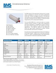
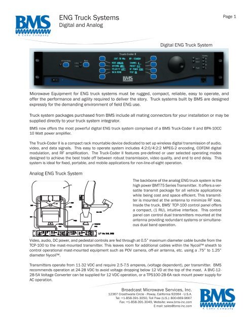
Digital <strong>ENG</strong> <strong>Truck</strong> SystemSpecificationsPage 2<strong>Truck</strong>-Coder II (TCII) SystemFrequency Range(250 KHz Resolution)Power Output Digital(All Mod Modes)Power Output AnalogChannel Plans1.99-2.5 GHz 6.425-6.525 GHz2.3-2.7 GHz 6.875-7.125 GHz1.99-2.7 GHz (6 W HI, 1 W LO)6.425-7.125 GHz (2.5 W HI)1.99-2.7 GHz (12 W Max)6.425-7.125 GHz (6 W Max)User Selectable & Configurable(Pre-programmed for 12 & 17 MHz)Below -65 dBcSpuriousSystem Power RequirementsPower Input 105-260 VAC 50/60 Hz StandardConsumption 150 W Max.Environmental CharacteristicsTemperature -20 to +55°C (Oper.); -30 to +70°C (Stor.)Relative Humidity 98% NCAltitude15,000’ ASL (Oper.); 50,000’ ASL (Stor.)Control Unit Physical CharacteristicsDimension/Weight 2 RU: 3.5” x 19” x 16” deep / < 12 lbs.MPEG EncoderMPEG-2 4:2:0 SP@ML 1.5-15 Mb/s; 0.1 Mb/s ResolutionMPEG-2 4:2:2 MP@ML 1.5-32 Mb/s; 0.1 Mb/s ResolutionAudio Sampling Rates 32, 64, 128, or 192 kb/s per ChannelGOP StructureVariable GOPSystem Delay80 mS (Lowest End to End)Video PerformanceReturn Loss26 dB (10 Hz to 5 MHz)VSNR (FM AnalogOperation at 12 MHz)VSNR (COFDM Digital at8 MHz)Outdoor RF UnitRF Output ConnectorOperating VoltagePowerCoolingTemperature2 GHz 63 dB Typical (60 dB Min.)7 GHz 63 dB Typical (61 dB Min.)2, 7 GHz; 67 dB Typical50 ohm, N(f)48 VDC≤ 4A @ Max. OutputIntegral Heat Sink-20 to +55°C (Oper.); -40 to +80°C (Stor.)Relative Humidity 100%Dimension/Weight 14” x 9” x 3.5” / 12 lbs.Altitude15,000’ ASL (Oper.)Control Unit InterfaceDigital Video InAnalog Composite Video InAnalog ComponentVideo InAudio (Analog) InASI InASI OutRS-232 Side Data CH.IF InMain Out to RF HeadSDI with Embedded Audio(SMPTE 259C CCIR 601)NTSC or PALYUV (Optional)2 Channels, +9 dBm into 600 ohm Bal.75 ohm (HD Capable)Encoder Output, 75 ohm, BNC (f)1200, 4800, 9600 Baud Selectable70 MHz, 0 dBm, 75 ohm70 MHz IF Output w/ Control & Power70 MHz Aux. Out IF Output, 0 dBm, 75 ohm, BNC (f)Serial PortEthernet (Front & Rear)COFDM ModulatorBandwidthConstellationRS-232 for External Control, 1200 BaudSupport for External Web Control6, 7, 8 MHz SelectableQPSK 16 QAM, 64 QAMParametersSelectable Data Rate, Guard Interval,and FEC RateCarriers 2k Per DVB-T (ETSI EN 300744)EncryptionFECFM ModulatorVideo Deviation (MHz)Proprietary 6 Digit PIN Code(BISS-E Optional)Reed-Soloman, Viterbi4.0/17 MHz Ch.; 3.5/12 MHz Ch.Video Pre-Emphasis Per CCIR Recommendation 405Audio Pre-Emphasis(FM Only)Audio Subcarriers(NTSC)Audio DeviationChannelizationChannel PlanSourceFreq. Stability ± 0.0005%75 Micro-seconds, 50 Micro-seconds,OptionalMenu Selectable:17 MHz = 4.83, 5.8, 6.2, 6.8, 7.5 MHz12 MHz = 4.83, 5.5 MHz± 75 kHzp30 Ch. per BAS Relocation PlanUser Selectable & ProgrammableDigital Frequency Synthesizer<strong>Broadcast</strong> <strong>Microwave</strong> <strong>Services</strong>, Inc.12367 Crosthwaite Circle - Poway, California 92064 - U.S.A.Tel: +1-858-391-3050, Toll Free (U.S.): 800-669-9667Fax: +1-858-391-3049, Website: www.bms-inc.comE-mail: sales@bms-inc.com
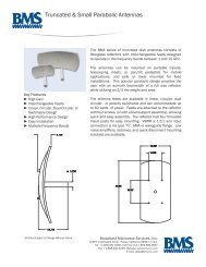
<strong>ENG</strong> <strong>Truck</strong> SystemDigital (cont.) & Analog SpecificationsPage 3Technical Characteristics BPA-10CC Outline DrawingsFrequencyPowerInput VoltageGainGain FlatnessGain vs. TempOperating TemperatureStorage TemperatureDimensionsWeightRF InputRF OutputShock Mount Pate1.99-2.5 GHz10W Average COFDM28 VDC, 8 Amps at 10W with Fans52 dB (-13 dBm input for Po=10W) (Can Be Factory SetFrom 40 to 55 dB)± 1 dB Over 500 MHz± 1 dB Over Temperature-20° to +50°C-40° to +90°C~9.5” x 5” x 4” (Includes Heatsink & Fan)(~24 x 12.7 x 10 cm)~8 lbs (includes Heatsink & Fan)(~3.6 kg)Type “N”Type “N” Isolator Protected9.85” x 7.50”, Drilled for Easy Installation(25.019 x 19.05 cm)Antenna Selection (Analog)BMS offers a family of antennas to suit your requirements which are available in single polarity, dual polarity, 4-polarity, and dualband operation. The most popular are the BMA-20/30 Offset Feed Antenna and the BMA-2/4 Truncated Parabolic Antenna.In choosing the right antenna, characteristics must be considered regarding gain and beamwidth versus size/weight and aerodynamicloading. Higher gain is desirable to maximize distance. However, with higher gain comes larger size. Beamwidth is importantin determining required aiming accuracy. Beamwidths narrow with larger size antennas and higher frequencies. Low-profilestowage for transport must also be considered. All BMS antenna mounts allow stowage at 90 degrees.Options include SMPTE color bar generator with 16 character ID, dual audio tone generators and a video detector that will remotelyturn the transmitter on when video is present.Antenna Transmitter Frequency Az HPBW EL HPBW Gain AccessoriesBMA-15/30 BMT75-9PFixed 6W2.0-2.5 GHZ7.0 GHz14°4°28°8°19 dBi24 dBi•TPS-100-28-6A (AC to 28 VDc Converter)•HS-75 Heatsink•Custom Nycoil AssembliesBMA-20/30OffsetBMA-2/4BMT75-7P3/12W Hi/LowBMT75-5P3/12 W Hi/Low2.0-2.5 GHz7.0 GHz2.0-2.5 GHz7.0 GHz15°4°9°2.5°24°7°19°5°20 dBi30 dBi23 dBi34 dBi•BVC-12-28-5A (12 to 28 VDC Converter)•TCP-100 (Custom Control Panel)•Nose Guard to Protect Feed•Options: Color Bar Generator, Dual AudioTone Generator, Auto-Tx with Video Detect<strong>Broadcast</strong> <strong>Microwave</strong> <strong>Services</strong>, Inc.12367 Crosthwaite Circle - Poway, California 92064 - U.S.A.Tel: +1-858-391-3050, Toll Free (U.S.): 800-669-9667Fax: +1-858-391-3049, Website: www.bms-inc.comE-mail: sales@bms-inc.com
Analog <strong>ENG</strong> <strong>Truck</strong> SystemSpecificationsPage 4BMT75 Series Transmitter SpecificationsRF Characteristics - For Frequency Rangeand Number of Channels See Ordering InformationFreq, Stability - Standard ± 0.002%Freq. Stability - Optional ± 0.001%RF Output PowerRF Output ImpedanceRF Output ProtectionSpurious OutputSee Ordering Information50Ω, SMA ConnectorOpen/Short/Indefinitely-53 dBc MaxModulation CharacteristicsModulation TypesFMModulation Response - NTSC, 525 LinesStandardModulation Response - PAL, SECAM, or FLATOptionalPre-emphasis - Standard CCIR 405, 525 LinesPre-emphasis - Optional 625 Lines or NoneModulation Sensitivity ± 4 MHz/1 VPP @ CrossoverFrequencyModulation Input Impedance 75Ω UnbalancedBaseband Input1 VppSubcarrier CharacteristicsSubcarrier Frequencies 4.83 to 8.59 MHz, FactorySetSubcarrier Injection Level -25 dBc to -30 dBcSignal to Noise65 dBHarmonic Distortion1% MaxModulation TypeFMModulation Response - 50 Hz to 15 kHzStandardModulation Response - 75 µsecStandard, Pre-emphasisModulation Response - 75 kHzpStandard, Sub. DeviationModulation Response - 50 Hz to 50 kHzOptionalModulation Response - 50 µsec, NoneOptional, Pre-emphasisModulation Response - 100 kHzp, 125 kHzpOptional - Sub. DeviationOrdering Info BMT75-5P BMT75-7P BMT75-9PFreq. Range 1.9-2.11 GHz 1.99-2.5 GHz 6.4-7.2 GHzNo. Channels 21 30 (64 Int’l) 42RF Power Out 12/3W 12/3W 6WFCC Identifier: CNV75K-BMT75-5P, -7P, -9P•Part 21.801 (b) - Common Carrier•Part 74 - Auxiliary <strong>Broadcast</strong> <strong>Services</strong>•Part 78 - CARS <strong>Services</strong>Available Accessories:•TCB-100 Control Box for Remote Channel Select•TCP-100 <strong>Truck</strong> Control Panel•HS-75 Heatsink for all Series 75 Models•HSF-75 Heatsink/Fan for all Series 75 Models•HCP-50/HCP-100 Helicopter Control Panels forRemote Channel SelectPackage size and connectors may vary.All Data Subject to Change Without Notice4/21/2006<strong>Broadcast</strong> <strong>Microwave</strong> <strong>Services</strong>, Inc.12367 Crosthwaite Circle - Poway, California 92064 - U.S.A.Tel: +1-858-391-3050, Toll Free (U.S.): 800-669-9667Fax: +1-858-391-3049, Website: www.bms-inc.comE-mail: sales@bms-inc.com