General Products - ALP Industries Inc.
General Products - ALP Industries Inc.
General Products - ALP Industries Inc.
- No tags were found...

You also want an ePaper? Increase the reach of your titles
YUMPU automatically turns print PDFs into web optimized ePapers that Google loves.
Corporate HistoryIn 1981 Reitzel Swaim and Ron Space formed American Lifting <strong>Products</strong>, <strong>Inc</strong>. (the forerunner of <strong>ALP</strong> <strong>Industries</strong>, <strong>Inc</strong>.) inParkesburg, PA. The company was relocated to Coatesville, PA in 1993.The first major expansion occurred in 1983 when the acquisition of Pennsylvania Sling Company and Cobb Wire Rope andSling Company added locations in Harrisburg and Pittsburgh, PA, and Atlanta, GA.During the 1980’s and 90’s, Carolina Chain and Cable Company, The Harding Company, Wayland <strong>Inc</strong>orporated, FloridaWire Rope & Supply, and others were purchased. During this time <strong>ALP</strong> started new businesses in Aberdeen, NC, Parkesburg,PA, and Duncan, SC. Acquisitions were made in Tampa, FL (2000) and Tacoma, WA (2001). Another start-up location wasopened in Las Vegas, NV in 2006.<strong>ALP</strong>’s registered trademarks include Penco®, Saf-T-Grip®, Grip-Tite®, Redi-Grip®, Mulox®, and Tufskin®. PMSBlue is the trademarked color of <strong>ALP</strong>’s ratchet and lever type load binders. In addition, the combination of “orange andwhite” colored strands in wire rope is a registered trademark of <strong>ALP</strong> <strong>Industries</strong>, <strong>Inc</strong>.2011 marks <strong>ALP</strong> <strong>Industries</strong> 30th Anniversary. Our 140+ Employees and 15 Sales/Warehouse locations are dedicated to“LIFTING AMERICA: Yesterday - Today - Tomorrow”MISSION STATEMENT<strong>ALP</strong> <strong>Industries</strong>, <strong>Inc</strong>. is dedicated to its growth, customers, employees, and the concept of linked prosperity. Our mission consistsof three interrelated parts:Product Mission:To distribute and sell the finest quality industrial lifting products in the indusry.To ensure both safety and customer satisfaction.Growth Mission:To take a proactive growth strategy which include an internal growth rate of sales and an external growth strategy to addadditional locations in the Americas to better serve our customers and diversify our product line and customer base.Economic Mission:To operate the company on a sound financial basis of profitable growth and create career opportunities and financial rewardsfor our employees.Underlying the mission of <strong>ALP</strong> <strong>Industries</strong> is the determination to seek new and creative ways of addressing all three parts,while holding a deep respect for individuals, inside and outside the company, and for the communities of which they are a part.
This catalog has been assembled to assist you in finding the products you need. It is impossible toillustrate all the products available through <strong>ALP</strong> <strong>Industries</strong> and the manufacturers we represent. Wehave listed the more common items. If the item you require is not in the catalog, contact your sales representativefor more information.In addition, it is difficult to present all the instructions and conditions for safe use of these products.We have included many statements regarding safety and useful information. Consult the applicablefederal, state, industry, and manufacturer’s standards and recommendations before using theseproducts. In many instances we have enclosed important information in a rectangular box - Blue forsafety/warning or Black for additional notes.We have applied for copyright protection for the cover and contents of this publication. Any reproductionof this catalog, in whole or in part, without the expressed written consent of the management of<strong>ALP</strong> <strong>Industries</strong>, <strong>Inc</strong>. is strictly prohibited.
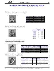
TABLE OF CONTENTSWIRE ROPE<strong>General</strong> InformationTerminology & Properties . . . . . . . . . . . . . . .1Wire Rope Inspection . . . . . . . . . . . . . . . . . .4Troubleshooting Checklist . . . . . . . . . . . . . . .7Suggested Wire Rope Construction . . . . . . . .9Wire Rope Definitions . . . . . . . . . . . . . . . . .11<strong>General</strong> Purpose Wire RopesSix Strand Ropes . . . . . . . . . . . . . . . . . . 13Rotation Resistant Ropes . . . . . . . . . . . . . 15Galvanized & Stainless . . . . . . . . . . . . . . . . 17Specialty RopesBethlehem . . . . . . . . . . . . . . . . . . . . . . . 18 - 20Bridon . . . . . . . . . . . . . . . . . . . . . . . 21 - 23Wireco . . . . . . . . . . . . . . . . . . . . . . . . .24 - 25Wire Rope Slings<strong>General</strong> Information . . . . . . . . . . . . . . . . . . . 26Sling Capacities- 6x19 & 6x37 Class . . . . . ..27Sling Capacities - Special Slings . . . . . . . . . 29Common Terminations . .. . . . . . . . . . . . . . . . .30Pendant Socket Arrangements . . . . . . . . . .30Terminal Efficiencies . . . . . . . . . . . . . . . . . . 31ELEVATOR PRODUCTSBethlehem Elevator Wire RopeWire Rope Specification . . . . . . . . . . . . . . . 32Short Service Life . . . . . . . . . . . . . . . . . . . . . 32Technical Bulletins . . . . . . . . . . . . . . . . . . . .32Related MRO <strong>Products</strong>: . . . . . . . . . . . . . . . .32Bethlehem 8&6 Strand Elevator Ropes . . . . . 33Bethlehem Liftpac Elevator Rope . . . . . . . .34Bethlehem 8&9 Strand IWRC ElevatorRopes35Usha Martin Elevator Wire RopeRelated Elevator <strong>Products</strong>Reeving Splices . . . . . . . . . . . . . . . . . . . . . . .37Elevator Shackles . . . . . . . . . . . . . . . . . . . . . 38Elevator Rope Tools . . . . . . . . . . . . . . . . . . .40CHAINAlloy Chain SlingsTypes of Chain Slings . . . . . . . . . . . . . . . . . 43Alloy Chain Sling Working Load Limits . . 44Alloy Chain Attachments . . . . . . . . . . . . . . 48Magnet Chains . . . . . . . . . . . . . . . . . . . . . . . 58Recommended Chain Sling Use . . . . . . . . . 59Chain Sling Inspection . . . . . . . . . . . . . . . . .60Carbon ChainGrade 30 Proof Coil Chain . . . . . . . . . . . . . .62Grade 43 High Test Chain . .. . . . . . . . . . . . 62Grade 70 Transport Chain . . . . . . . . . . . . . .63Machine Chain . . . . . . . . . . . . . . . . . . . . . . .63Jack Chain . . . . . . . . . . . . . . . . . . . . . . . . . . .64Double Lock Link Chain . . . . . . . . . . . . . . 64Binders & Chains . . . . . . . . . . . . . . . . . . . . 65MESH SLINGSCambridge Gripper ® Slings . . . . . . . . . . . . .66Alloy Chain Mesh Sling . . . . . . . . . . . . . . . .67SYNTHETIC SLINGSSynthetic Web SlingsStandard Web Sling Types . . . . . . . . . . . . . 68Considerations When Ordering . . . . . . . . . 69Saf-T-Grip ® Light Duty Nylon Slings . . . . 71Mulox ® Heavy Duty Nylon Slings . . . . . . .72Penco Tufskin ® Abrasion Resistant Slings. . .74Web Sling Hardware . . . . . . . . . . . . . . . . . . 75Web Sling Inspection . . . . . . . . . . . . . . . . . 81Polyester RoundslingsPenco ® Polyester Roundslings . . . . . . . . . 82Braided Roundup Roundslings . . . . . . . . . .83Roundsling Inspection . . . . . . . . . . . . . . . . .84CARGO CONTROLStrap AssembliesLogistic & Utility Strap Assemblies . . . . . . 85Safety Considerations . . . . . . . . . . . . . . . . . 87Part Number Identification . . . . . . . . . . . . . 88Buckle & Ratchet Specifications . . . . . . . . 89Winches & Bars . . . . . . . . . . . . . . . . . . . . . . 91End Fitting Hardware . . . . . . . . . . . . . . . . . . 92Interior Bars . . . . . . . . . . . . . . . . . . . . . . . . . .94FITTINGSClips, Links, Shackles, Hooks & LatchesForged Wire Rope Clips . . . . . . . . . . . . . . . .96Links & Rings . . . . . . . . . . . . . . . . . . . . . . . 100Shackles . . . . . . . . . . . . . . . . . . . . . . . . . . . 102Hoist Hooks . . . . . . . . . . . . . . . . . . . . . . . . 108Specialty Hooks . . . . . . . . . . . . . . . . . . . . . 119Thimbles & TerminationsThimbles . . . . . . . . . . . . . . . . . . . . . . . . . . . 121Spelter Sockets . . . . . . . . . . . . . . . . . . . . . .126Swage Sockets . . . . . . . . . . . . . . . . . . . . . . 128Sling Saddle . . . . . . . . . . . . . . . . . . . . . . . . 130Turnbuckles, Swivels, & Hoist RingsTurnbuckles . . . . . . . . . . . . . . . . . . . . . . . . .131Hoist Rings . . . . . . . . . . . . . . . . . . . . . . . . . 139Electroline Fittings . . . . . . . . . . . . . . . . . . . 145Stainless Steel Fittings & Specialty Chain
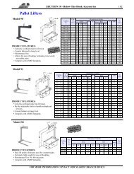
BLOCKSWire Rope BlocksSnatch Block . . . . . . . . . . . . . . . . . . . . . . . . 155Diamond & Oval Wire Rope Block . . . . . .157Manila Rope Blocks . . . . . . . . . . . . . . . . . . 158Crane Blocks . . . . . . . . . . . . . . . . . . . . . . . .159Overhaul BallsUB500 Top Swiveling Overhaul Ball . . . . 161UB500 Non Swiveling Overhaul Ball . . . .162Split Overhaul Ball . . . . . . . . . . . . . . . . . . . 162Tackle Block ReevingHOISTS, PULLERS & WINCHESHoists & PullersElectric Chain Hoists . . . . . . . . . . . . . . . . . 164Rail Power- Light Rail Systems . . . . . . . . .167Manual Hoists . . . . . . . . . . . . . . . . . . . . . . .168Economy Hoists . . . . . . . . . . . . . . . . . . . . . 171Trolleys & Other Accessories . . . . . . . . . . 172WinchesHand Winches . . . . . . . . . . . . . . . . . . . . . . .175Power Winches . . . . . . . . . . . . . . . . . . . . . . 176Special Purpose Winches . . . . . . . . . . . . . 177BELOW-THE-HOOKLiftingLifting Beams . . . . . . . . . . . . . . . . . . . . . . . 178Pallet Lifters . . . . . . . . . . . . . . . . . . . . . . . . 182Coil Lifters . . . . . . . . . . . . . . . . . . . . . . . . . .183Sheet Lifters . . . . . . . . . . . . . . . . . . . . . . . . 184Pipe & Manhole Lifters . . . . . . . . . . . . . . .186Grabs . . . . . . . . . . . . . . . . . . . . . . . . . . . . . . 189Magnetic Lift Devices . . . . . . . . . . . . . . . .194Concrete Bucket . . . . . . . . . . . . . . . . . . . . .197Load Positioner . . . . . . . . . . . . . . . . . . . . . 198Lifting Clamps & Beam GrabsLifting Clamps . . . . . . . . . . . . . . . . . . . . . . 201MARINE PRODUCTSAnchor SelectionStockless Type Anchors . . . . . . . . . . . . . . .216Lightweight Type Anchors . . . . . . . . . . . 217Anchor Chain & AttachmentsStud Link Chain . . . . . . . . . . . . . . . . . . . . . 218Anchor Chain Attachments . . . . . . . . . . . . .220U.S.C.G. Approved LaddersDJM Series . . . . . . . . . . . . . . . . . . . . . . . . 223Pilot Ladders . . . . . . . . . . . . . . . . . . . . . . . .223Erik Series . . . . . . . . . . . . . . . . . . . . . . . . . . 223Debarkation Ladders . . . . . . . . . . . . . . . . .223Clamp . . . . . . . . . . . . . . . . . . . . . . . . . . . . . .223Mooring BuoysCleats-Chocks-Bollards . . . . . . . . . . . . . . . 225Snap Hooks . . . . . . . . . . . . . . . . . . . . . . . . 226Patterson TensorsTM . . . . . . . . . . . . . . . . 227Ratchet Turnbuckles . . . . . . . . . . . . . . . . . 227AnodesHull Zinc Anodes . . . . . . . . . . . . . . . . . . . 228TOOLS & MISCELLANEOUSCable CuttersImpact Type . . . . . . . . . . . . . . . . . . . . . . . . 229Hydraulic Cutters . . . . . . . . . . . . . . . . . . . .230Manual Cutters . . . . . . . . . . . . . . . . . . . . . 231Corrosion Protective Coating . . . . . . . . . . 232Wire Rope GripsWire Mesh Grips . . . . . . . . . . . . . . . . . . . . 233Haven Grips . . . . . . . . . . . . . . . . . . . . . . . . 234Klein Hand ToolsLineman Tools . . . . . . . . . . . . . . . . . . . . . . 234Conversion TablesCORDAGETwisted Ropes . . . . . . . . . . . . . . . . . . . . . . 206Braided Ropes . . . . . . . . . . . . . . . . . . . . . . 208Rope Use Reference . . . . . . . . . . . . . . . . .209FALL RESTRAINTBeamer Fall Arrester . . . . . . . . . . . . . . . . . .210Harnesses . . . . . . . . . . . . . . . . . . . . . . . . . . 210Retractables Lifelines . . . . . . . . . . . . . . . . .211Lanyards . . . . . . . . . . . . . . . . . . . . . . . . . . . 212Carabineers & Hooks . . . . . . . . . . . . . . . . . . 212Suspended Personnel Platform . . . . . . . . . . .213
1 SECTION 1 - Wire RopeWIRE ROPE<strong>General</strong> InformationTerminology & PropertiesTerminologyWith precise, moving parts, designed and manufactured tobear definite relationship toone another, Wire Rope canbe a complex mechanism.Wire rope is generally composedof wires, strands andthe core (See Fig.). Thewires are helically laidtogether in a precise geometricpattern to form the strand.The strands helically laidabout the core to form thewire rope. The process ofpositioning the strands aboutthe core is called “closing”.The process of positioningthe wires within the strand iscalled “stranding”.the extreme outer dimensions of the strands. (See Fig.). Newwire rope is manufactured to an oversized diameter ofapproximately 2-1/2%. This allows for the normal reductionof diameter experienced when a new rope is placed underload because of constructional stretch.Wire rope varies:• By Diameter• The grade of steel utilized• The direction of stranding and closing• The finish on the wire (Bright, Galvanized, etc.)• The core materialEach variation changes the performance characteristics ofthe wire rope.The first differentiation of wire rope is by diameter. Thediameter is measured at the diameter of the circle formed byThe RIGHT WayThe WRONG WayCAUTION: At NO time should the measured diameterbe less than the nominal diameter of the wire rope.The grade of steel (or other material) utilized in the constructionof the wire rope has a major influence upon theultimate break strength. <strong>General</strong>ly most steel wire ropetoday is at Improved Plow Steel Grade or IPS. In recentyears Extra Improved Plow Steel (EIPS) wire rope hasgained in popularity and is approximately 10% stronger thanIPS. Manufacturers have begun producing limited constructionsof Extra Extra Improved Plow Steel (EEIPS), which is10% higher than EIPS grade. Some special constructionsexceed EEIPS grade.The “Lay” of the wire rope (the direction of stranding andclosing) directly affects the operating properties. In RegularLay wire rope, the direction of the wires are twisted in anopposite direction than the direction of the strands. RegularLay may be Right Regular Lay or Left Regular Laydepending upon the direction of the strands. (See Fig.).FOR MORE INFORMATION CONTACT OUR NEAREST BRANCH OFFICE
SECTION 1 - Wire Rope 2In Lang Lay wire ropes the direction of the wires aretwisted in the same direction as the strands. Lang Lay maybe Right Lang Lay or Left Lang Lay depending upon thedirection of the strands. The wires of a regular wire ropeseem to travel parallel and along the length of the rope whilethose of a lang lay rope appear to travel around the rope.In addition, the Lay Length, the length of the rope necessaryfor one strand to travel completely around the rope (SeeFig.) may be varied slightly by manufacturer.Most wire rope has a Bright, self-colored finish and acoating of lubricant. However, many wire ropes are galvanized,stainless steel, or plastic/vinyl/urethane coated.Most wire ropes are supplied with either a fiber or steelcore. The core’s primary function is to support the wirestrands of the rope, maintaining the corrective relative positionsduring the operating life. Fiber Cores are composed ofnatural Vegetable Fiber Core (VFC - sisal, etc.) or SyntheticFiber Core (PFC- polypropylene, etc.) which havebeen formed into yarns and twisted into strands. Steel coresmay be Independent WireRope Core (IWRC) or WireStrand Core (WSC). Thesesteel cores provide more supportthan fiber cores to theouter strands during the rope’soperating life. Steel coresresist crushing, are more resistantto heat, reduce the amountof stretch, and increase thestrength of the rope. The Right WayUnreeling & UncoilingThe Right Way to Unreel. To unreel wire rope from aheavy reel, place a shaft through the center and jack up thereel far enough to clear the floor and revolve easily. Oneperson holds the end of the rope and walks a straight lineaway from the reel, taking the wire rope off the top of thereel. A second person regulates the speed of the turning reelby holding a wood block against the flange as a brake, takingcare to keep slack from developing on the reel, as this caneasily cause a kink in the rope. Lightweight reels can beproperly unreeled using a vertical shaft; the same careshould be taken to keep the rope taut.The Wrong Way to Unreel. If a reel of wire rope is laidon its flange with it’s axis vertical to the floor and the ropeunreeled by throwing off the turns, spirals will occur andkinks are likely to form in the rope. Wire rope alwaysshould be handled in a way that neither twists nor unlays it.If handled in a careless manner, reverse bends and kinks caneasily occur.The Right WayThe Right Way to Uncoil.There is only one way to uncoilwire rope. One person musthold the end of the rope while asecond person rolls the coilalong the floor, backing away.The rope is allowed to uncoilnaturally with the lay, withoutspiraling or twisting. Alwaysuncoil wire rope as shown.The Wrong Way to Uncoil. If a coil of wire rope is laid flaton the floor and uncoiled by pulling it straight off, spiralswill occur and kinking is likely. Torsions are put into therope by every loop that is pulled off, and the rope becomestwisted and unmanageable. Also, wire rope cannot beuncoiled like hemp rope. Pulling one end through the middleof the coil will only result in kinking.KinksGreat stress has been placed on the care that should betaken to avoid kinks in wire rope. Kinks are places wherethe rope has been unintentionally bent to a permanent set.This happens where loops are pulled through by tension onthe rope until the diameter of the loop is only a few inches.They are also caused by bending a rope around a sheave havingtoo severe a radius. Wires in the strands at the kink arepermanently damaged and will not give normal service,even after apparent “restraightening.”Drum Winding. When wire rope is wound onto a sheaveor drum, it should bend in the manner in which it was originallywound. This will avoid causing a reverse bend in therope. Always wind wire rope from the top of the one reelonto the top of the other. Also acceptable, but less so, is rereelingfrom the bottom of one reel to the bottom of another.Re-reeling may also be done with reels having their shaftsvertical, but extreme care must be taken to ensure that therope always remains taut. It should never be allowed to dropbelow the lower flange on the reel. A reel resting on thefloor with its axis horizontal may also be rolled along thefloor to unreel the rope.Wire rope should be attached at the correct location on aflat or smooth-faced drum, so that the rope will spool evenly,with the turns lying snugly against each other in even layers.If wire rope is wound on a smooth-face drum in the wrongdirection, the turns in the first layer of rope will tend tospread apart on the drum. This results in the second layer ofrope wedging between the open coils, crushing and flatteningthe rope as successive layers are spooled.FOR MORE INFORMATION CONTACT OUR NEAREST BRANCH OFFICE
3 SECTION 1 - Wire Ropebeen applied. Twist the two ends of the wire together, andby alternately pulling and twisting, draw the seizing tight.Method No. 2: Twist the two ends of the seizing wiretogether, alternately twisting and pulling until the propertightness is achieved.A simple method of determining how a wire rope should bestarted on a drum is shown in the above diagram. Theobserver stands behind the drum, with the rope comingtowards him. Using the right hand for right-lay wire rope,and the left hand for left lay wire rope, the clenched fistdenotes the drum, the extended index finger the oncomingrope.Seizing Wire RopeProper seizing and cutting operations are not difficult toperform, and they ensure that the wire rope will meet theuser’s performance expectations. Proper seizings must beapplied on both sides of the place where the cut is to bemade. In a wire rope, carelessly or inadequately seized endsmay become distorted and flattened, and the strands mayloosen. Subsequently, when the rope is operated, there maybe an uneven distribution of loads to the strands; a conditionthat will significantly shorten the life of the rope.Either of the following seizing methods is acceptable.Method No. 1 is usually used on wire ropes over one inch indiameter. Method No. 2 applies to ropes one inch and under.Method No. 1Method No. 2Method No. 1: Place one end of the seizing wire in thevalley between two strands. Then turn its long end at rightangles to the rope and closely and tightly wind the wire backover itself and the rope until the proper length of seizing hasThe Seizing Wire. The seizing wire should be soft orannealed wire or strand. Seizing wire diameter and thelength of the seize will depend on the diameter of the wirerope. The length of the seizing should never be less than thediameter of the rope being seized.Proper end seizing while cutting and installing, particularlyon rotation- resistant ropes, is critical. Failure toadhere to simple precautionary measures may cause coreslippage and loose strands, resulting in serious rope damage.Refer to the table for established guidelines. If core protrusionoccurs beyond the outer strands, or core retractionwithin the outer strands, cut the rope flush to allow forproper seizing of both the core and outer strands.In the absence of proper seizing wire or tools, the use ofsufficiently- sized hose clamps is acceptable.Rope DesignEnd PreparationAll standard preformed wire rope6x26 Reverse LaySingle Seizing6-Pac, 6-Pac RV, Flex-X, Endurance Dyform ® 6 & 8/8PIAll standard non-preformed wire ropeDouble Seizing19x7 & 8x19 Class Rotation ResistantSFP19, Endurance Dyform ® 18/18PI, Endurance Constructex ® , (Fused EndsTriple-PAC, Endurance 35x7 ® , Endurance 34LR/PI/MAX ® Recommended)Double SeizingSFP 35AND FusedEndsInstallationThe majority of wire rope problems occurring during operationactually begin during installation, when the rope is atgreatest risk of being damaged. Proper installation proceduresare vital in the protection and performance of wirerope products.• Provide Proper Storage- Avoid damage and moisture• Check the Rope Diameter Prior to Installation• Use Proper Unreeling/Uncoiling Procedures• Keep the Wraps Tight• Treat Rotation-Resistant Ropes with Extra Care• Secure the Ends Before Cutting• Use a Wire Mesh Grip or Chinese Finger (to PreventTorque from the old rope transferring to the new rope)• Always Perform a Break-In Procedure to Maximize ServiceLife• Avoid Slack in the Rope• Slowly Lift or Release the Load• Use the Wire Rope ONLY for the Job it was Intended.FOR MORE INFORMATION CONTACT OUR NEAREST BRANCH OFFICE
SECTION 1 - Wire Rope 4Wire Rope InspectionThe most widely used wire rope replacement, inspectionand maintenance standard for mobile-type cranes is ASMEB30.5, section 5-2.4. The following is an excerpt from thatstandard.All running ropes in service should be visually inspectedonce each working day. A visual inspection shall consist ofobservation of all rope which can reasonably be expected tobe in use during the day’s operations. These visual observationsshould be concerned with discovering gross damage,such as listed below which may be an immediate hazard:[A] Distortion of the rope such as kinking, crushing,unstranding, birdcaging, main strand displacement, or coreprotrusion. Loss of rope diameter in a short rope length orunevenness of outer strands should provide evidence that therope must be replaced.[B] <strong>General</strong> Corrosion[C] Broken or Cut strands[D] Number, distribution, and type of visible broken wires[E] Core failure in rotation resistant ropes: when suchdamage is discovered, the rope shall be either removed fromservice or given an inspection (further detail per S-2.4.2).The frequency of detailed and thorough inspections shouldbe determined by a qualified person, who takes into accountthe following factors:• Expected rope life as determined by [a] maintenancerecords, and [b] experience on the particular installationor similar installations• Severity of environment• Percentage of capacity lifts• Frequency rates of operation, and exposure to shock loadsInspect the entire length of the rope. Some areas of thewire rope such as around the core are more difficult toinspect. To inspect the core, examine the rope as it passesover the sheaves. The strands have a tendency to open upslightly which will afford the inspector a better view of thecore. Also regularly inspect for any reduction in diameterand lengthening of rope lay as both conditions indicate coredamage.Basic GuidelinesAbrasion Abrasion damage may occur when the rope contactsan abrasive medium or simply when it passes over thedrum and sheaves. Therefore it is vital that all componentsbe in proper working order and of the appropriate diameterof the rope. A badly corrugated or worn sheave or drum willseriously damage a new rope, resulting in premature ropereplacement.Corrosion Corrosion is very difficult to evaluate but is amore serious cause of degradation than abrasion. Usuallysignifying a lack of lubrication, corrosion will often occurinternally before there is any visible external evidence on therope’s surface. A slight discoloration caused by rusting usuallyindicates a need for lubrication which should be tendedto immediately. If this condition persists, it will lead tosevere corrosion which promotes premature fatigue failuresin the wires and strands, necessitating the rope’s immediateremoval from service.Wire Breaks The table below shows the number of allowablewire breaks per crane type. The inspector must knowthe ASME standard for the equipment being inspected. Thenumber of broken wires on the outside of the wire rope is anindication of its general condition and whether or not it mustbe considered for replacement. The inspector may use a typeof spike to gently probe the strands for any wire breaks thatdo not protrude. Check as the rope runs at a slow speed overthe sheaves, where crown (surface) wire breaks may be easierto see. Also examine the rope near the end connections.Keeping a detailed inspection record of the wire breaks andother types of damage will help the inspector determine theelapsed time between breaks. Note the area of the breaksand carefully inspect these areas in the future. Replace therope when the wire breaks reach the total number allowableby ASME or other applicable specifications.ASMENo.EquipmentNo. BrokenWries in RunningRopes inOne RopeLayOneStrandNo. BrokenWries in StandingRopes inOneRopeLayOneStrandB30.2 Overhead and Gantry Cranes 12* 4 N/A N/AB30.4 Portal, Tower and Pillar Cranes 6* 3 3* 2B30.5 Crawler, Locomotive & Truck Cranes 6* 3 3* 2B30.6 Derricks 6* 3 3* 2B30.7 Base-Mounted drum Hoists 6* 3 3* 2B30.8 Floating Cranes & Derricks 6* 3 3* 2A10.4 Personnel Hoists 6* 3 2* 2A10.5 Material Hoists 6* N/A N/A N/A* Also remove for ONE valley break. OSHA require monthly record keeping of wirerope conditions. NOTE: current industry recommendations and OSHA standards arebased upon steel sheaves. The manufacturer of plastic and synthetic sheaves or linersshould be consulted for its recommendation on the safe application of the product andinspection criteria.Valley breaks, or breaks in between strands, must be takenvery seriously at all times! When two or more valleybreaks are found in one lay-length, immediately replacethe rope. Valley breaks are difficult to see; however, if yousee one you can be assured that there are a few more hiddenin the same area. Crown breaks are signs of normal deterioration,but valley breaks indicate an abnormal condition suchas fatigue or breakage of other wires such as those in thecore.Once crown and valley breaks appear, their number willsteadily and quickly increase as time goes on. The brokenwires should be removed as soon as possible by bending thebroken wire back and forth with a pair of pliers. In this waythe wire is more likely to break inside the rope where theFOR MORE INFORMATION CONTACT OUR NEAREST BRANCH OFFICE
5 SECTION 1 - Wire Ropeends will be tucked away. If the broken wires are notremoved they may cause further damage.The inspector must obey the broken wire standard; pushingthe rope for more life will create a dangerous situation.Diameter Reduction. Diameter reduction is critical deteriorationfactor and can be caused by:• Excessive abrasion of the outside wires• Loss of core diameter/support• Internal or external corrosion damage• Inner wire failure• A lengthening of rope layIt is important to check and record a new rope’s actualdiameter when under normal load conditions. During the lifeof the rope the inspector should periodically measure theactual diameter of the rope at the same location under equivalentloading conditions. This procedure if followed carefullyreveals a common rope characteristic--after an initialreduction, the overall diameter will stabilize and slowlydecrease in diameter during the course of the rope’s life.This condition is normal. However, if diameter reduction isisolated to one area or happens quickly, the inspector mustimmediately determine (and correct, if necessary) the causeof the diameter loss, and schedule the rope for replacement.Crushing. Crushing or flattening of the strands can becaused by a number of different factors. These problemsusually occur on multilayer spooling conditions but canoccur by simply using the wrong wire rope construction.Most premature crushing and/or flattening conditions occurbecause of improper installation of the wire rope. In manycases failure to obtain a very tight first layer (the foundation)will cause loose or “gappy” conditions in the wire ropewhich will cause rapid deterioration. Failure to properlybreak- in the new rope, or worse, to have no break-in procedureat all, will cause similar poor spooling conditions.Therefore, it is imperative that the inspector knows how toinspect the wire rope as well as how that rope was installed.Shock loading. Shock loading (birdcaging) of the rope isanother reason for replacement of the rope. Shock loading iscaused by the sudden release of tension on the wire rope andits resultant rebound from being overloaded. The damagethat occurs can never be corrected and the rope must bereplaced.High Stranding. High stranding may occur for a numberof reasons such as failure to properly seize the rope prior toinstallation or maintain seizing during wedge socket installation.Sometimes wavy rope occurs due to kinks or a verytight grooving problem. Another possibility is simply introducingtorque or twist into a new rope during poor installationprocedures. This condition requires the inspector toevaluate the continued use of the rope or increase the frequencyof inspection.Inspection Guidelines - Specialty RopesPlastic-Infused Rope. Plastic-infused rope was developedto provide better fatigue, abrasion and crushing resistancederived from the cushioning and dampening effect of theplastic. However great the benefits, the plastic becomes atthe very least an inconvenience when trying to inspect thewire rope. Because of the plastic coating, some operatorschoose to forego inspection and run the ropes to failure.Other operators may just visually inspect the plastic coating.Both practices are wrong and carry equally the potential fordisaster.Abrasion and Crushing. In inspecting plastic-infusedropes, the basic inspection guidelines still apply and shouldbe followed. Abrasion and crushing damage may still occur,so it is imperative to inspect flanges, sheaves, bearings, rollersand fairleads. Look for unusual wear patterns in the plastic--a key indicator that damage to the wire rope isoccurring.Wire Breaks. Wire breaks will still occur in a plasticinfusedrope, but are sometimes extremely difficult to detect,though occasionally a broken wire will protrude through theplastic. Every effort must be made to determine the overallcondition of the rope. The plastic covering the crown (surface)wires is generally applied in a thin coat and tends towear quickly in areas which pass over sheaves and drums.As the rope runs at a slow speed, inspect the rope in theseareas. As the rope and plastic open up the inspector will beafforded a look at not only the surface area but also the interstrandcontact points. If a valley break is detected, immediatelypull the ropes from service. Also inspect areas whereplastic has peeled, regardless of the location of the “window.”Remove as much plastic from these areas as possibleto allow for efficient and effective inspection techniques.Remember, due to the nature of plastic-infused ropes, thereis no way to clearly determine the number of valley breaks.Corrosion. Plastic-infused ropes provide only improvedcorrosion resistance. Regardless of manufacturers’ claims, aplastic-infused rope can corrode, and rope failure due to corrosionis still possible. Moisture is sometimes trapped in therope and as with all machines, the lubricant may becomeineffective over time. The inspector must visually check forany signs of corrosion damage as evidenced by rope bleedingor rouging. In addition, the diameter must be frequentlymeasured. If there is any damage to the core, it will bedetected by a reduction in diameter. Also inspect the lay ofthe rope. As the plastic is thinner over the crown wires, athorough inspection may be able to determine a lengtheningof lay, also a sign of rope deterioration. Especially when tryingto determine lengthening of lay, watch for and inspectareas where the plastic pulls away from the rope. Whilepeeling in and of itself is not an indication of rope deteriorationand is a factor of normal wear, peeling in areas where noabrasion exists may signify a problem.FOR MORE INFORMATION CONTACT OUR NEAREST BRANCH OFFICE
SECTION 1 - Wire Rope 6Maintenance Records. Equally important in inspectingplastic-infused ropes is maintaining accurate service records.The service records of previous ropes will provide a guidelineas to the expected life of the rope. However, they shouldnot be used alone or only in conjunction with visual inspectionsdue to the number of variables which exist, includinginstallation, spooling and manufacturinng practices. Maintenancerecords must be used in combination with both visualand physical inspection techniques to be truly of value indetermining the remaining life of the rope.Overall, perhaps the most important inspection techniqueis recognizing the limits of wire rope. While it’s true thatcompacted and plastic infused ropes are more durable,neglect and abuse will still quickly end the rope’s life. Thereis no substitute for proper installation, handling and inspectiontechniques in combination with a preventative maintenanceprogram.Compacted Rope. Die drawn and swaged ropes fall intothe compacted category. Compacting serves several purposes.By flattening the outer wires, metallic area increasesallowing for a higher breaking strength as well as improvedcrushing and abrasion resistance. In addition, the compactionminimizes interstrand nicking and thereby improvesfatigue resistance.In the inspection of compacted rope designs, again it isimperative to follow the basic inspection guidelines and useboth visual and actual measuring techniques to determine theremaining life of the rope. In fact, actual measuring techniquesare very important when inspecting these ropes.While corrosion is relatively easy to visually determine,diameter reduction may not be due to the compacted rope’sappearance. Therefore the inspector must regularly measurefor diameter reduction and closely examine the rope for laylengthening. Measurements must be recorded and the ropemonitored for sudden variations.By and large the most difficult retirement criteria to determinein compacted ropes is wire breaks. These breaks maynot protrude from the rope due to the compaction and can beeasily overlooked. Because of this, the inspector mustslowly and carefully examine the rope, especially in thoseareas passing over drums and sheaves or in areas whereproblems existed in previous ropes.A wire break may appear as nothing more than a crack inthe wire, and again can be easily overlooked. If the inspectornotes a “flaw” in a wire, it should be carefully checked. Theinspector should carry some type of magnifying device todetermine if a flaw is actually a break. If a break hasoccurred, thoroughly check the area for additional breaks,both on the crown and in the valleys. Remember, valleybreaks in round strand ropes are difficult to determine; compactiononly increases the difficulty. The inspector must beslow and methodical in inspecting compacted ropes; a quickcheck will reveal nothing.FOR MORE INFORMATION CONTACT OUR NEAREST BRANCH OFFICE
7 SECTION 1 - Wire RopeTroubleshooting ChecklistTension (Cone) Tension (Cup) Tension & WearTension BreakWire break shows one end of broken wire coned, theother cupped. Necking down of the broken ends is typicalof this type break. Where tension breaks are found,the rope has been subjected to overloading, either for itsoriginal strength (new rope) or for its remaining strength inthe case of a used rope. Tension breaks frequently arecaused by the sudden application of a load to a slack rope,thereby setting up incalcuable impact stress.AbrasionFatigue Fatigue Fatigue & Wear Fatigue & NickingAbrasion BreakWire break shows broken ends worn to a knife-edgethinness. Abrasive wear obviously is concentrated atpoints, where the rope contacts an abrasive medium, suchas the grooves of sheaves and drums, or other objects withwhich the rope comes into contact. Unwarranted abrasivewear indicates improperly grooved sheaves and drums,incorrect fleet angle, or other localized abrasive conditions.Fatigue BreakWire breaks are usually transverse or square showinggranular structure. Often these breaks will develop ashattered or jagged fracture, depending on the type ofoperation. Where fatigue breaks occur, the rope hasrepeatedly been bent around too small a radius. Whipping,vibration, slapping and torsional stresses will also causefatique. Fatigue breaks are accelerated by abrasion andnicking.Corrosion BreakEasily noted by the wire’s pitted surface, wire breaksusually show evidence of tension, abrasion and/orfatigue. Corrosion usually indicates improper lubrication.The extent of the damage to the interior of the rope isextremely difficult to determine; consequently corrosion isone of the most dangerous causes of rope deterioration.CorrosionCut or ShearWire will be pinched down and cut at broken ends, orwill show evidence of shear-like cut.This condition is evidence of mechanical abuse caused byagents outside the installation, or by something abnormalon the installation itself, such as a broken flange.Cut or ShearFOR MORE INFORMATION CONTACT OUR NEAREST BRANCH OFFICE
SECTION 1 - Wire Rope 8ABRASIONCORE PROTRUSIONAND SLIPPAGECORROSIONFrozen sheaves or rollersTight groovesExcessive fleet angleOversized or undersized ropeCorrugated sheave or drumSheave overspinRope jumping the sheavePoor spoolingMisaligned sheavesShockloadingPoor seizing techniquesPoor installation techniquesLack of lubricationEnvironmental damage, e.g. acidicFume exposureAbrasionCore Protrusion (Shockloading)CRUSHINGDIAMETERREDUCTIONPoor installation techniquesCrosswindingPoor Spooling<strong>Inc</strong>orrect wire rope constructionPoor break-in procedureExcessive fleet angleLack of lubrication (fiber core)Excessive abrasionCorrosion, internal and/or externalCorrosionFATIGUEHIGH STRANDINGJUMPING THESHEAVEKINKINGLAY LENGTHENING& TIGHTENINGOut of round sheavesTight groovesMisaligned sheavesUndersized sheavesWorn bearingsVibrationSlappingWhippingPoor seizing techniquesTight groovesUndersized sheavesPoor spoolingExcessive rope lengthPoor unreeling proceduresPoor installation techniquesUndersized sheavesPoor installation techniquesPoor unreeling proceduresCorrosionCrushingFatigue (Reverse Bend)Fatigue (Undersized Sheave)LOOPED WIRESUNBALANCEDROPEPoor installation techniquesOversized sheavesFOR MORE INFORMATION CONTACT OUR NEAREST BRANCH OFFICE
9 SECTION 1 - Wire RopeSuggested Wire Rope ConstructionAPPLICATIONS GENERAL CONDITIONS SEVERE CONDITIONSCRANESDROP BALLSLoad Lines 6x25 RR IWRC 6-PACGANTRY CRANESMain Hoist 6x25 RR IWRC;6x36 Class RR IWRC 6-PAC;8-PAC;SFP19Auxiliary Hoist 6x25 RR IWRC 6-PAC;8-PAC;SFP19Gantry crane types include: P& H. Demag, Kone and KrancoCONTAINER CRANESHoist Lines 6x36 RR IWRC 8-PACTrolley Lines 6x36 RR IWRC 8-PACLOCOMOTIVE CRANESMain Hoists 6x25 RR IWRC 6-PAC; TRIPLE PACAuxiliary Hoist 6x25 RR IWRC 6-PAC; TRIPLE PACBoom Hoist 6x25 RR IWRC 6-PAC; TRIPLE PACTag Lines 6x33 Warrington Seale RR FC n/aOFFSHORE PEDESTAL CRANES (DRILLING RIGS, PLATFORMS AND BARGES)Boom Hoist 6x25 RR IWRC 6-PAC;6-PAC RV; SUPER-PACHoist Lines 8x19 RR IWRC;19X7 SFP 19Auxiliary Lines 8x19 RR IWRC;19X7 SFP 19Offshore pedestal crane types include: Applied Hydraulics, Titan, Offshore crane, Unit Mariner, Link-Belt, National, Weatherford, Manitowac, Manitex,Bucyrus-Errie, SeaKing, FAVCO, Liebherr, Le Toureau, Nautilus, Clyde, American, Baker Marine and Skagit.OVERHEAD TRAVELING CRANESHoist Lines 6x19 Class RR IWRC;6X36 Class RR IWRC 6-PAC;8-PAC;SFP 19ROUGH TERRAIN, ALL TERAIN, TELESCOPIC AND LATTICE BOOM TRUCK CRANES,LATTICE BOOM HYDRAULIC CRAWLERS AND LATTICE BOOM FRICTION CRAWLERSBoom Hoist 6x25 RR IWRC;6X36 Class RR IWRC 6-PAC;6-PAC RV; SUPER-PACHoist Lines 6x25 RR IWRC;6X36 Class RR IWRC 6-PAC;8-PAC;TRIPLE-PAC;SFP19Auxiliary Lines 8x19 RR IWRC;19x7 SFP 19Boom Pendants 6x25 RR IWRC 6-PAC;TRIPLE-PACRough terrain et al crane types include: Galion, Grove, Link-Belt, Lorain, Koehring, P&H, PPM, Tadano, Liebherr, Demag, American, Manitowac,Manitex, National, and ClarkSIDE BOOM TRACTORSHoist Lines 6x25 RR IWRC 6-PAC; TRIPLE-PACBoom Lines 6x25 RR IWRC 6-PAC; TRIPLE-PACSTILL LEG DERRICKS AND REVOLVING DERRICK CRANESHoist Lines 6x25 RR IWRC 6-PAC;TRIPLE-PACAuxiliary Lines 6x25 RR IWRC 6-PAC; TRIPLE-PAC;SFP 19Boom Lines 6x25 RR IWRC 6-PAC; TRIPLE PAC;SFP 19Derrick crane types include: AMCLYDE, American, Clyde and ManitowacTOWER CRANESLoad Lines SFP 19;SFP 35 SFP 35Trolley Lines 6x25 RR IWRC n/aWHIRLEY CRANESMain Hoist 6x25 RR IWRC 6-PAC;SFP 19Auxiliary Hoist 6x25 RR IWRC 6-PAC;SFP 19Boom Hoist 6x25 RR IWRC 6-PAC;SUPER-PACWhirley crane types include: AMCLYDE, American, FAVCO and ClydeDREDGINGDIPPER DREDGESHoist Lines 6x19 Class RR IWRC;6X36 Class RR IWRC 6-PAC;6-PAC RVSwinging and Backing Lines 6x19 Class RR IWRC;6X36 Class RR IWRC 6-PACSpud Lines 6x19 Class RR IWRC; 6X36 Class RR IWRC 6-PACCLAMSHELL DREDGESHolding and Closing Lines 6x19 Class RR IWRC 6-PACSwing Lines 6x19 Class RR IWRC;6X36 Class RR IWRC 6-PACBoom Hoist Lines 6x19 Class RR IWRC 6-PAC;6-PAC RV;SUPER-PACStern or Anchor Lines 6x19 Class RR IWRC 6-PACSpud Lines 6x19 Class RG IWRC;6X36 Class RR IWRC 6-PACLADDER OR CHAIN BUCKET DREDGESLadder Lines 6x19 Class RR or RG IWRC 6-PACBow and Stern Lines 6x19 Class RR IWRC;6X36 Class RR IWRC 6-PACSpud Lines 6x19 Class RG IWRC;6X36 Class RR IWRC 6-PACSUCTION DREDGESLadder Lines 6x19 Class RR or RG IWRC 6-PACSwing Lines 6x19 Class RR IWRC 6-PACSpud Lines 6x19 Class RR IWRC; 6X36 Class RR IWRC 6-PACPontoon Lines 6x19 Class RR IWRC 6-PACFOR MORE INFORMATION CONTACT OUR NEAREST BRANCH OFFICE
SECTION 1 - Wire Rope 10APPLICATION GENERAL CONDITIONS SEVERE CONDITIONSEXCAVATINGPOWER SHOVELSHoist Lines 6x25 RR or RG IWRC;6X36 Class RG IWRC 6-PACCrowd and Retract Lines 6x25 RR or RG IWRC;6X36 Class RG IWRC 6-PAC;6-PAC RVBoom Lines 6x25 RR or RG IWRC; 6x36 Class RG IWRC 6-PAC;6-PAC RVTrip Lines 6x19 Warrington RR FC;6x33 Warrington Seale RR FC n/aDRAGLINE EXCAVATORSDraglines 6x19 Class RG IWRC 6-PACHoist Lines 6x19 Class RR or RG IWRC 6-PAC;6-PAC RVBoom Lines 6x19 Class RR or RG IWRC;6X36 Class RG IWRC 6-PAC;6-PAC RVDump Lines 6x25 RR or RG IWRC 6-PAC;6-PAC RVCLAMSHELLSHoist Lines 6x19 Class RR IWRC;19x7 6-PAC;TRIPLE-PAC;SFP19Holding and Closing Lines 6x19 Class RR or RG IWRC;6x37 Class RR IWRC or FC 6-PAC;6-PAC RVBoom Lines 6x25 RR IWRC;6x26 RV IWRC 6-PAC;6-PAC RV;SUPER-PACTag Lines 6x33 Warrington Seale RR FC n/aCARRY-ALL SCRAPERS AND WAGONSHoist and Dump Lines 6x25 RR or RG IWRC;6x36 Class RR or RG IWRC 6-PACTRENCH HOES, DITCHERS AND PULL SHOVELSDigging Lines 6x19 Class RG IWRC 6-PACHoist Lines 6x25 RR IWRC;6x26 Warrington Seale RR IWRC 6-PACBoom Lines or Shear-Leg Lines 6x26 RR IWRC 6-PACSLACKLINE EXCAVATORSTrack Lines 6x19 Class RG FC; flattened strand RG FC 6-PAC;6-PAC RVLoad or Unhaul Lines 6x19 Class RR IWRC 6-PACTension or Track Adjusting Lines 6x25 RR IWRC 6-PACHOISTS AND WINCHESConstruction Hoists 6x19 Class RR IWRC;6x36 Class RR IWRC 6-PACElectric and Air Hoists 6x19 Warrington RR FC;6x36 Class RR FC;19x7;SFP 19 N/AWinches 6x19 Class RR IWRC;6x36 Class RR IWRC 6-PACLOGGINGEASTERNWinch Lines 6x26 Warrington Seale RR IWRC SUPER-BChokers 6x26 Warrington Seale RR IWRC n/aWESTERNArchlines 6x26 Warrington Seale RR IWRC SUPER-B, SUPER-PACBoom Loaders 6x26 Warrington Seale RR IWRC SUPER-B, SUPER-PACChokers 6x26 Warrington Seale RR IWRC SUPER-B, SUPER-PACHaulbacks 6x19 Seale RR IWRC;6x26 Warrington Seale RR IWRC SUPER-B, SUPER-PACHelicopter Chokers SKYBRITE n/aMainlines 6x26 Warrington Seale RR IWRC SUPER-B, SUPER-PACSawmill Carriage 6x25 RR IWRC SUPER-B, SUPER-PACSkylines 6x19 Seale RR IWRC;6x26 Warrington Seale RR IWRC SUPER-B, SUPER-PACStrawlines 6x19 Seale RR IWRC SUPER-B, SUPER-PACTriple Drum Lines 6x26 Warrington Seale RR IWRC SUPER-B, SUPER-PACWinch Lines 6x26 Warrington Seale RR IWRC SUPER-B, SUPER-PACOILFIELD AND MARINEAnchor Lines 6x19 Class RR IWRC; 6x36 Class RR IWRC Galvanized, Bethpac, Z-nodesCoring, Sand& Swabbing Lines 6x7 FC GalvanizedDiving Bells 19x7;SFP 19 SFP 35Marcellus Shale Drill Lines6x21 LR FCMooring Lines 6x19 and 6x36 Classes RR IWRC; Galvanized Strand Galvanized Rope, Bethpac, Z-nodesRiser Tensioner Lines 6x36 Class RR IWRC BethpacRotary Drill Lines 6x19 Seale RR IWRC;6x26 Warrington Seale RR IWRC BethpacTow Lines 6x36 Class RR IWRC GalvanizedTubing Lines 6x26 Warrington Seale RR IWRC SUPER-BWork Wire, Chain Chasers 6x19 Class RR IWRC;6x36 Class RR IWRC GalvanizedSTEEL MILLBell Ropes 6x25 RR IWRC 6-PACCar Puller, Spotter, Retarder Rope 6x19 Class RR IWRC or FC 6-PACLadle Cranes 6x36 Class RR IWRC 6-PAC;TRIPLE-PACOre Bridges and Unloaders 6x19 Class RR IWRC 6-PACSkip Hoists 6x19 Class RR or RG FC, flattened strand RG FC TRIPLE-PACStripper and Soaking Pit Cranes 6x36 Class RR IWRC 6-PAC;TRIPLE-PACRR= Right regular lay LR= Left Regular Lay RG= Right Lang lay LG= Left Lang LayRV=Right reverse lay FC= Fiber Core IWRC= Independent wire rope coreBXL, or plastic-infusion, may be added to many standard and specialty wire rope constructions, and is therefore not listed as a recommendation under Severe Conditions. Refer toSpecialty Applications: BXL for further information.In some instances, WWW specifies class and not a specific construction. This is due to multiple diameters used on a particular application, and /or multiple constructions suitablefor the application. For more information, please contact WWW’s sales or engineering department.FOR MORE INFORMATION CONTACT OUR NEAREST BRANCH OFFICE
11 SECTION 1 - Wire RopeRopesWire Rope DefinitionsSpiral Rope: An assembly of two or more layers of shapedand/or round wires laid helically over a center, usually asingle round wire. There are three categories of spiral rope,i.e. spiral strand, half locked coil and full-locked coil.Spiral Strand: An assembly of two or more layers of roundwires laid helically over a center, usually a single roundwire.Half-locked coil Rope: A spiral rope type having an outerlayer of wires containing alternate half lock and round wires.Full-locked Coil Rope: A spiral rope having an outer layerof full lock wires.Stranded Rope: An assembly of several strands laid helicallyin one or more layers around a core or center. Thereare three categories of stranded rope, i.e. single layer,multi-layer and parallel-closed.Single Layer Rope: Stranded rope consisting of one layer ofstrands laid helically over a core.Note: Stranded ropes consisting of three of four outer strandsmay, or may not, have a core. Some three and four strand singlelayer ropes are designed to generate torque levels equivalentto those generated by Rotation-Resistant ropes.Rotation-Resistant rope: Stranded rope designed to generatereduced levels of torque and rotation when loaded andcomprising an assembly of two or more layers of strands laidhelically around the center, the direction of lay of the outersstrands being opposite to that of the underlying layer.Rotation-Resistant rope: category 1:Stranded rope constructed in such a manner that it displayslittle or no tendency to rotate, or, if guided, transmitslittle or no torque, has at least fifteen outer strands and comprisingan assembly of at least three layers of strands laidhelically over a center in two or three operations, the directionof lay of the outer strands being opposite to that of theunderlying layer.Rotation-Resistant rope: category 2:Stranded rope constructed in such a manner that it has significantresistance to rotation, has at least ten out strands andcomprising an assembly of two or more layers of strandslaid helically over a centre in two or three operations, thedirection of lay of the outer strands being opposite to that ofthe underlying layer.Rotation-Resistant rope: category 3:Stranded rope constructed in such a manner that it has limitedresistance to rotation, has no more than nine outerstrands and comprising an assembly of two layers of strandslaid helically over a center in two operations, the direction oflay of the outer strands being opposite to that of the underlyinglayer.Compacted Strand Rope: Rope in which the outer strands,prior to closing of the rope, are subjected to a compactingprocess such as drawing, rolling or swaging.Compacted Swaged Rope: Rope which is subjected to acompacting process after closing, thus reducing its diameter.Plastic (Solid Polymer) Filled Rope: Rope in which the freeinternal spaces are filled with a solid polymer. The polymerextends to, or slightly beyond, the outer circumference of therope.Cushioned Rope: Stranded rope in which the inner layers,inner strands or core strands are covered with solid polymersor fibers to form a cushion between adjacent strands orlayers of strands.Cushion Core Rope: Stranded rope in which the core iscovered (coated) or filled and covered (coated) with a solidpolymer.Solid Polymer Covered Rope: Rope which is covered(coated) with a solid polymer.Solid Polymer Covered and Filled Rope: Rope which iscovered (coated) and filled with a solid polymer.Rope Grade (Rr): A number corresponding to a wire tensilestrength grade on which the minimum breaking force of arope is calculated.Note: It does not imply that the actual tensile strength grades ofthe wires in a rope are necessarily the same as the rope grade.Preformed Rope: Stranded rope in which the wires in thestrands and the strands in the rope have their internal stressesreduced resulting in a rope in which, after removal of anyserving, the wires and the strands will not spring out of therope formation.Note: Rotation Resistant stranded ropes should be regarded asnon-performed rope even though the strands may have beenpartially (lightly) preformed during the closing process.Rope Class: A grouping of rope constructions where thenumber of outer strands and the number of wires and howthey are laid up are within defined limits, resulting in ropeswithin the class having similar strength and rotationalproperties.Rope Construction: System which denotes the arrangementof the strands and wires within a rope, e.g. 6x19S; 6x36WS;18x7; 34x7.Cable-laid Rope: An assembly of several (usually six) singlelayer stranded ropes (referred to as unit ropes) laid helicallyover a core (usually a seventh single layer stranded rope).Braided Rope: An assembly of several round strands braidedin pairs.Electro-mechanical Rope: A stranded or spiral containingelectrical conductors.Strand and Rope LaysLay direction of strand: The direction right (z) or left (s)corresponding to the direction of lay of the outer layer ofwires in relation to the longitudinal axis of the strand.Lay direction of rope: The direction right (Z) or left (S)corresponding to the direction of lay of the outer strands inrelation to the longitudinal axis of a stranded rope or thedirection of lay of the outer wires in relation to thelongitudinal axis of a spiral rope.Regular Lay: Stranded rope in which the direction of lay ofthe wires in the outer strands is in the opposite direction toFOR MORE INFORMATION CONTACT OUR NEAREST BRANCH OFFICE
SECTION 1 - Wire Rope 12the lay of the outer strands in the rope. Right Regular Lay isdesignated zZ and Left Regular Lay is designated zS.Note: This type of lay is sometimes referred to as 'ordinary' lay.Lang Lay: Stranded rope in which the direction of lay of thewires in the outer strands is the same as that of the outerstrands in the rope. Right Lang Lay is designated zZ andLeft Lang lay is designated sS.Alternate Lay: Stranded rope in which the lay of the outerstrands is alternatively Lang's lay and regular lay. Righthand alternate lay is designated AZ and left hand alternatelay is designated AS.Contra-Lay: Rope in which at least one layer of wires in aspiral rope or one layer of strands in a stranded rope is laid inthe opposite direction to the other layer(s) of wire or strandsrespectively.Note: Contra-lay is only possible in spiral ropes havingmore than one layer of wires in, multi-layer stranded ropes.Rope Lay Length (Stranded Rope): That distance parallel tothe axis of the rope in which the outer strands make onecomplete turn (or helix) about the axis of the rope.to the amount of rotation when one end of the rope is free torotate and the rope is subjected to tensile loading.Initial extension: Amount of extension which is attributed tothe initial bedding down of the wires within the strands andthe strands within the rope due to tensile loading.Note: This is sometimes referred to as constructional stretch.Elastic extension: Amount of extension which followsHooke's Law within certain limits due to application of atensile load.Permanent rope extension: Non-elastic extension.CoresCore: Central element, usually of fiber or steel, of a singlelayer stranded rope, around which are laid helically the outerstrands of a stranded rope or the outer unit ropes of acable-laid rope.Fiber core: Core made from either natural (e.g. hemp, sisal)or synthetic fibers (e.g. polypropylene) and designated by itsdiameter and runnage.Steel Core: Core produced either as an independent wirerope (e.g. 7x7) or wire strand (e.g. 1x7).Solid polymer core: Core produced as a single element ofsolid polymer having a round or grooved shaped. It mayalso contain internal elements of wire or fiber.Insert: Element of fiber or solid polymer so positioned as toseparate adjacent strands or wires in the same or overlyinglayers and fill, or partly fill, some of the interstices in therope.Rope Characteristics and PropertiesFill factor: The ratio between the sum of the nominalcross-sectional areas of all the load bearing wires in the ropeand the circumscribed area of the rope based on its nominaldiameter.Spinning loss factor: The ratio between the calculatedminimum breaking force of the rope and the calculatedminimum aggregate breaking force of the rope.Minimum breaking force (T min): Specified value, in tonsor kN, below which the measured breaking force is notallowed to fall in a prescribed test.Rope torque: Value, usually expressed in ft pounds or N.m,resulting from either test or calculation, relating to the torquegenerated when both ends of the rope are fixed and the ropeis subjected to tensile loading.Rope turn: Value, usually expressed in degrees perfoot/meter, resulting from either test or calculation, relatingFOR MORE INFORMATION CONTACT OUR NEAREST BRANCH OFFICE
13 SECTION 1 - Wire RopeSix Strand Ropes<strong>General</strong> Purpose Wire Ropes6 x 19 ClassStrands: 6Wires per strand: 19 to 26Core: IWRC or fiber coreStandard Grade: EIPSLay: Regular or LangFinish: Bright or galvanizedThe 6x19 Classification of wire ropeis the most widely used. With its goodcombination of flexibility and wear resistance,rope in this class can be suited tothe specific needs of diverse kinds ofmachinery and equipment.The 6 x 19 Seale construction, with itslarge outer wires, provides great ruggednessand resistance to abrasion and crushing.However, its resistance to fatigue issomewhat less than that offered by a 6x25construction. The 6x25 possesses the bestcombination of flexibility and wear resistancein the 6x19 Class due to the fillerwires providing support and imparting stabilityto the strand. The 6x26 WarringtonSeale construction has high resistance tocrushing. This construction is a goodchoice where the end user needs the wearresistance of a 6x19 Class Rope and theflexibility midway between a 6x19 Classand 6x37 Class rope.6 x 36 ClassStrands: 6Wires per strand: 27 to 49Core: IWRC or fiber coreStandard Grade: EIPSLay: Regular or LangFinish: Bright or galvanizedThe 6x36 Class of wire rope ischaracterized by the relatively largenumber of wires used in each strand.Ropes of this class are among the mostflexible available due to the greaternumber of wires per strand, howevertheir resistance to abrasion is less thanropes in the 6x19 Class.The designation 6x36 is onlynominal, as in the case with the 6x19Class. The ropes may not actually have36 wires per strand. Improvements inwire rope design, as well as changingmachine designs, have resulted in theuse of strands with widely varyingnumbers of wires and a smaller numberof available constructions. Typical6x36 Class constructions include 6x33for diameters under 1/2”, 6x36 WarringtonSeale (the most common 6x37Class construction) offered in diameters1/2” through 1-5/8”, and 6x49Filler Wire Seale over 1-3/4” diameter.FOR MORE INFORMATION CONTACT OUR NEAREST BRANCH OFFICE
SECTION 1 - Wire Rope 146x19 And 6x36 ClassesTechnical Data6x19 Class6x19 Seale6x19 Warrington6x21 Filler Wire6x21 Seale6x25 Filler Wire6x25 Seale6x26 Warrington SealeRope DiameterApproximateWeightNominal Strength - tons*(Bright or Drawn Galvanized**)(lbs./ft.)EIPSEEIPSinches mm. Fiber Core IWRC Fiber Core IWRC IWRC1/4 6.5 0.105 0.116 3.02 3.40 3.745/16 8.0 0.164 0.18 4.69 5.27 5.803/8 9.5 0.236 0.26 6.71 7.55 8.317/16 11.0 0.32 0.35 9.09 10.2 11.21/2 13.0 0.42 0.46 11.8 13.3 14.69/16 14.5 0.53 0.59 14.9 16.8 18.55/8 16.0 0.66 0.72 18.3 20.6 22.73/4 19.0 0.95 1.04 26.2 29.4 32.37/8 22.0 1.29 1.42 35.4 39.8 43.81 26.0 1.68 1.85 46.0 51.7 56.91-1/8 29.0 2.13 2.34 57.9 65.0 71.51-1/4 32.0 2.63 2.89 71.0 79.9 87.91-3/8 35.0 3.18 3.50 85.4 96.0 106.01-1/2 38.0 3.78 4.16 101.0 114.0 125.01-5/8 42.0 4.44 4.88 118.0 132.0 146.01-3/4 45.0 5.15 5.67 136.0 153.0 169.01-7/8 48.0 5.91 6.50 155.0 174.0 192.02 52.0 6.72 7.39 176.0 198.0 217.02-1/8 54.0 7.59 8.35 197.0 221.0 243.02-1/4 58.0 8.51 9.36 220.0 247.0 272.02-3/8 60.0 9.48 10.4 244.0 274.0 301.02-1/2 64.0 10.5 11.6 269.0 302.0 332.02-3/4 70.0 12.7 14.0 321.0 361.0 397.0*tons of 2,000 lbs.** Reduced values for coated galvanizing. For Class A coatingdeduct 10% from EIP Grade. For other coating thicknesses consultthe manufacturer.Technical data for the above listedconstructions are the same anddetailed in the table.6x36 Class6x31 Warrington Seale6x336x36 Warrington Seale6x41 Warrington Seale6x43 Filler Wire Seale6x49 Filler Wire SealeFor further information on additionalconstructions and diameters, contactyour <strong>ALP</strong> Sales Representative.Note: The picture at the top depicts a Right LangLay IWRC wire rope. The picture at the bottomdepicts a Right Regular Lay IWRC wire rope.FOR MORE INFORMATION CONTACT OUR NEAREST BRANCH OFFICE
15 SECTION 1 - Wire RopeRotation Resistant RopesIn certain instances the use of rotation-resistant wire rope is necessary to provide rotational stability to thelifted load. In general, the use of these wire ropes is limited to those situations where it is impractical to:1. Use a tag line2. Relocate rope dead end.3. <strong>Inc</strong>rease sheave sizes.4. Eliminate “odd-part” reeving.5. Significantly reduce rope loading and rope fall length.Rotation-resistant wire ropes have less of a tendency to unlay when loaded than do conventional wire ropes.This results in improved rotational stability to the lifted load. Rotation-resistant wire ropes are designed in sucha way that the rotational force of the outer strands is partially counteracted by the rotational force of the innerstrands or core when the rope is subjected to a load.The chart compares the rotational properties of rotation-resistant ropes with a standard 6x25 wire rope. Therotation-resistant ropes far surpass the rotational stability of a conventional 6x25 IWRC wire rope on both shortand long falls.SAFETY DESIGN FACTORSASME B30.5 specifies that rotation-resistant ropes have a safety design factor of five or greater. The required strengthdesign factor of rotation-resistant rope becomes very important from the standpoint of maintaining the inherent low rotationof the rope and eliminating any tendency to overload the inner core, thereby causing a reduction in rope strength.HANDLING & INSTALLATIONPrecautions should be followed when using rotation-resistant wire rope. The rope ends must be properly seized andsecured (refer to Handling and Installation: Seizing Wire Rope) and cut with a saw or impact hammer to prevent unlaying ofthe strands.Attachment of end fittings must be done with care to prevent kinking or unlaying of rope, which harms the rotationalbalance of the rope.Operation of rotation-resistant wire ropes (excluding SFP 35 ) with a swivel is generally not recommended. Theuse of a swivel allows the inner core to twist tighter, resulting in a significant reduction in rope strength, possibly leading topremature rope failure. A swivel may be used as a temporary device only during the initial installation period to help eliminateany installation-induced twisting or cabling.The swivel must be removed from the reeving after the rope installation is completed and before the crane beginsoperation.Due to the opposite lay direction of the inner core and outer strand layers in rotation-resistant ropes, care should betaken to avoid shock loading. Shock loading will result in distortion of the rope structure, causing birdcaging, core protrusion,etc. Due to the potential for complete rope failure, shockloaded wire ropes must be immediately removed from service.FOR MORE INFORMATION CONTACT OUR NEAREST BRANCH OFFICE
SECTION 1 - Wire Rope 16CAUTIONThe rated strengths of the 19 x7 class and 8 x19 class wire ropes are less than wire ropes in the 6x19 and 6x36 Classes.Larger sheaves are required in order to achieve comparable fatigue life. Refer to Technical Information: Effect of SheaveSize for further information on proper sheave sizes.19x7 Rotation-Resistant8x19 Rotation-ResistantStrands: 19Wires per strand:7Core: WSCStandard grade(s):EIPSLay: RegularFinish: BrightStrands: 8Wires per strand: 19Core: IWRCStandard grade(s):EIPSLay: RegularFinish: Bright19x7 is recommended for hoistingunguided loads with a single-part line.The rotation-resistant properties of thisrope are secured by two layers of strands. Theinner strands are left lay, while the 12 outerstrands are right lay, which enables one layer tocounteract the other layer’s rotation.The rotation-resistant characteristics ofthe 19x7 wire ropes are superior to those of the8x19 Class wire ropes.The 8x19 Classification rotation-resistantropes are recommended for hoisting unguidedloads with a single-part or multi-part line.The eight outer strands are manufactured inright lay, with the inner strands being left lay.These ropes are slightly stronger and significantlymore rugged than the 19x7 construction.However, the rotation-resistant properties of the8x19 rotation- resistant ropes are much less thanthose of the 19x7 construction.These ropes are manufactured in right regularlay in the 8x19 Seale and 8x25 Filler Wireconstructions.Rope Diameter Approx. Weight(lb./ft.)NominalStrength(tons*)inches mm. EIPS3/16 4.8 0.064 1.571/4 6.5 0.113 2.775/16 8.0 0.177 4.303/8 9.5 0.250 6.157/16 11.0 0.350 8.331/2 13.0 0.450 10.809/16 14.5 0.580 13.605/8 16.0 0.710 16.803/4 19.0 1.020 24.007/8 22.0 1.390 32.501 26.0 1.820 42.201-1/8 29.0 2.300 53.101-1/4 32.0 2.840 65.101-3/8 35.0 3.430 78.401-1/2 38.0 4.080 92.80Rope DiameterApprox.Weight (lb./NominalStrength(tons*)inches mm. ft.) EIPS1/2 13.0 0.47 11.79/16 14.5 0.60 14.75/8 16.0 0.73 18.13/4 19.0 1.06 25.97/8 22.0 1.44 35.01 26.0 1.88 45.51-1/8 29.0 2.39 57.31-1/4 32.0 2.94 70.51-3/8 35.0 3.56 84.91-1/2 38.0 4.24 100.0FOR MORE INFORMATION CONTACT OUR NEAREST BRANCH OFFICE
17 SECTION 1 - Wire RopeGalvanized & StainlessGalvanized GalvanizedSmall diameter galvanized wirerope, sometimes called GalvanizedAircord, has many applications. Theseinclude small winches & hoists, overheaddoors, yacht rigging and clothesline. This rope may also be coatedwith vinyl, plastic, or urethane. Whenused as an operating rope they shouldbe lubricated. <strong>ALP</strong> has both domesticand imported sources for these products.In some applications, these ropes arerequired to conform to MIL-W-83420.Diam<strong>Inc</strong>hes7x7 GalvanizedNominal StrengthLbs.Approx. Wt.Lbs/ 100 FtNominalStrengthLbs.7x19 GalvanizedApprox. Wt.Lbs/ 100 Ft3/64 270 0.42 - -1/16 480 0.75 480 0.753/32 920 1.6 1,000 1.741/8 1,700 2.8 2,000 2.905/32 2,600 4.3 2,800 4.503/16 3,700 6.2 4,200 6.507/32 4,800 8.3 5,600 8.601/4 6,100 10.6 7,000 11.05/16 9,200 16.7 9,800 17.33/8 13,100 23.6 14,400 24.3Made to commercial practice. Available in other diameters.Stainless(Corrosion Resistant)Stainless ropes are used in enviromentswhich would quickly degradebright or galvanized ropes. The term“Corrosion Resistant” is technicallypreferable to “Stainless” because theseproducts are not stainless in all atmospheres.Types 302/304 are offered in allcommon sizes. Types 305/316 are availableon special order. All operatingropes should be lubricated.In some applications, these ropes arerequired to conform to MIL-W-83420.These items will require special order.Diam<strong>Inc</strong>hes7x7 StainlessNominal StrengthLbs.StainlessApprox. Wt.Lbs/ 100 Ft7x19 StainlessNominal StrengthLbs.Approx. Wt.Lbs/ 100 Ft3/64 270 0.42 270* 0.361/16 480 0.75 480 0.753/32 920 1.6 920 1.741/8 1,700 2.8 1,760 2.905/32 2,400 4.3 2,400 4.503/16 3,700 6.2 3,700 6.507/32 4,800 8.3 5,000 8.601/4 6,100 10.6 6,400 11.009/32 7,600 13.4 7,800 13.905/16 9,000 16.7 9,000 17.303/8 12,000 23.6 12,000 24.30* Commercial practice- no published standard. Available in other diameters.1/16 and 3/16 strengths are from MIL-W-83420B.Strand <strong>Products</strong><strong>ALP</strong> stocks many common diametersof small strand products. Strandproducts generally have constructionslike 1x7, 1x19, etc.Both galvanized and stainless strandproducts are available. Various gradesof strand are available including aircraftquality, common grade, utility gradeand EHS. In addition, larger diameterproducts are available for pendants andsupport lines.Consult the nearest <strong>ALP</strong> branch formore information.Diam (in.)6x19 IWRC & 6x37 IWRC - StainlessNominalB/S lbs.Approx. lbs./100 ft.Diam. (in)Nominal B/Slbs.Approx.lbs./100 ft.1/4 5,400 11.6 3/4 49,600 1045/16 8,300 18.0 7/8 66,500 1423/8 11,700 26.0 1 85,400 1857/16 16,300 35.0 1-1/8 106,400 2341/2 22,800 46.0 1-1/4 129,400 2899/16 28,500 59.0 1-3/8 153,600 3505/8 35,000 72.0 1-1/2 180,500 416Manufactured to RRW-410D where applicable.FOR MORE INFORMATION CONTACT OUR NEAREST BRANCH OFFICE
SECTION 1 - Wire Rope 18Specialty RopesBethlehemSuper Flex Pac 19 Rotation- ResistantStrands: 19Wires per strand: 19Core: WSCStandard grade(s):EEIPSLay: Right RegularFinish: BrightSFP 19 is recommended for both multipart loadand single-part fast line applications where rotationalstability of the lifted load is needed, such as for use aslong fall on offshore pedestal cranes, rough and all terraincranes, and crawler cranes.SFP 19 provides:Fatigue Resistance. Improved fatigue properties arederived through the combination of the flexible 19x19construction and die drawn strands. The drawn strandsurfaces minimize the interstrand and interlayer nickingthat take place in round rotation-resistant ropes.Abrasion Resistance. Die drawn ropes provide improvedabrasion resistance as compared with round wire ropesbecause of the greater wire and strand bearing surfacescontacting sheaves and drum.Resistance to Drum Crushing. SFP 19 wire ropes areresistant to the effects of drum crushing due to the compactedstrands and smoothness of the rope surface.Flexibility. With 19 strands of 19 wires in all diameters,SFP 19 remains extremely flexible and easy to handleduring both the installation process and under theextremely harsh conditions from fast line speeds duringspooling.Rope DiameterApproximateNominal Strength(tons)*inches mm Weight(lb./ft.)Royal Purple(EEIPS)7/16 11.0 0.42 11.21/2 13.0 0.54 14.69/16 14.5 0.69 18.55/8 16.0 0.83 22.73/4 19.0 1.19 32.37/8 22.0 1.62 43.81 26.0 2.12 56.91-1/8 29.0 2.68 71.51-1/4 32.0 3.31 87.91-3/8 35.0 4.01 106.01-1/2 38.0 4.77 125.06-PAC Strands: 6Wires per strand: 19 to 36Core: IWRCStandard grade(s): EEIPSLay: Right RegularFinish: Bright6-PAC is recommended for use where the rope issubjected to heavy use or where conditions areextremely abusive, such as offshore pedestal, crawlerand lattice boom equipped truck crane boom hoistapplications. 6-PAC is also recommended for winchlines, overhead cranes, multipart hoist lines where rotation-resistantropes are not required, and other applicationswhere flexibility, high strength and resistance tocrushing are important, and a cost-effective 6-strandrope is desired.6-PAC provides:Fatigue Resistance. Improved fatigue properties arederived from the combination of 6-PAC’s flexible constructionsand the compacted strand surface minimizesthe interstrand and interlayer nicking that take place instandard 6-strand ropes.Abrasion Resistance. 6-PAC’s compacted strand designprovides improved abrasion resistance as compared tostandard 6-strand ropes because of the increased wireand strand surfaces contacting sheaves and drums.Flexibility. 6-PAC’s design provides increased flexibility,making it easy to install, and 6-PAC also offers betterspooling at high line speeds.Resistance To Multilayer Drum Crushing. 6-PAC dramaticallyincreases the amount of wire contact with thedrums and sheaves, reducing the wire rope, sheave anddrum wear normally associated with standard wirerope. Damage at the crossover points is also reduced.Rope Diameter StandardApprox.WeightNominal Strength(tons*)inches mm. Constructions (lb./ft.) Royal Purple(EEIPS)3/8 9.5 6x19 Seale 0.285 8.317/16 11.0 6x19 Seale 0.388 11.201/2 13.0 6x26 0.503 15.509/16 14.5 6x26 0.642 18.505/8 16.0 6x26 0.795 22.703/4 19.0 6x31 1.143 32.207/8 22.0 6x31 1.547 43.801 26.0 6x31 2.075 56.901-1/8 29.0 6x31 2.575 71.501-1/4 32.0 6x36 3.169 87.901-3/8 35.0 6x36 3.758 106.001-1/2 38.0 6x36 4.564 125.001-5/8 41.3 6x36 5.356 146.001-3/4 45.5 6x36 6.212 169.00FOR MORE INFORMATION CONTACT OUR NEAREST BRANCH OFFICE
19 SECTION 1 - Wire RopeBethlehem8-PACSuper Flex Pac 35Strands: 35Wires per Strand: 7Core: WSCStandard Grade: 2160 N/mm 2Lay: Right RegularFinish: BrightSFP 35 is a rotation-resistant rope of high strength thatcan resist block twist in long falls.SFP 35 provides: Superior Rotation Resistance - theSFP 35 rope is the most rotation resistant rope manufacturedby WW. Due to its rotation-resistant properties, SFP 35may be used with a swivel in both single part and multiplepart reeving.SFP 35 provides: High Strength -WW’s compactionprocess provides a high strength rope which exceeds EEIPnominal break strength.Application: SFP 35 excels in crawler and truck-typecrane load lines, and tower crane ropes.Flexibility: SFP 35’s multiple strand construction providesincreased flexibility which improves service life andhigh speed spooling. The compacted multiple strand constructionalso reduces sheave and drum abrasion and providesexcellent resistance to drum crushing.Super Flex Pac 35 (SFP 35)Rope Diameter Approx. Wt. Nominal Strengthmm inches (kg/m) (lbs/ft) (kN) (tons)19 1.79 3443/4 1.21 38.7022 2.4 4667/8 1.65 53.001 2.15 70.0026 3.36 66028 3.90 7581-1/8 2.73 86.90Strands: 8Wires per Strand: 19 to 36Core: Plastic Filled (BXL)Standard Grade: Royal PurpleLay: RightFinish: Bright8-PAC is recommended for hoist ropes for steel mill ladlecranes and hoist and trolley ropes for container cranes, orother hoisting applications with heavy duty cycles or whereversevere bending occurs.Superior Performance: 8-PAC has higher breakingstrength and gives superior performance in difficult hoistingapplications compared to 6-strand and 6-strand compactedropes.Abrasion Resistance: 8-Pac’s compacted strand designprovides improved abrasion resistance as compared to standard6-strand and 8-strand ropes because of the increasedwire and strand surfaces contacting the sheaves and drums.Superior Flexibility: 8-Pac is significantly more flexiblethan standard 6-strand and compacted 6-strand ropes withbetter spooling and longer service life.Resistance to Multilayer Drum Crushing: 8-PAC’splastic filled (BXL) core offers increased resistance to crushingthrough better support of the outer strands.8-PACRope Diameter Standard Approx. Wt. Minimum Breakinginches Construction (lb/ft) Strength (net tons)5/8 8x26 WS 0.80 25.03/4 8x26 WS 1.17 36.07/8 8x26 WS 1.60 48.31 8x26 WS 2.10 62.81-1/8 8x26 WS 2.63 79.01-1/4 8x31 WS 3.26 98.0Other Sizes are AvailableFOR MORE INFORMATION CONTACT OUR NEAREST BRANCH OFFICE
SECTION 1 - Wire Rope 20BethlehemBXL Triple-PAC TRIPLE-PAC was developed for the most demandinghoist applications. TRIPLE- PAC offers the extra highstrength and crushing resistance needed for applicationssuch as boom hoist ropes, boom pendants and multipartload lines.TRIPLE-PAC provides:Superior abrasion and fatigue resistance as comparedwith most compacted ropes due to WWW’s uniquedesign of compacting the IWRC, individual strands andthe rope itself. Other benefits include:High strength. TRIPLE-PAC is designed to provide a nominalstrength of 35% above EIP. WWW achieves thisstrength through selected grades of steel and TRIPLE-PAC’s unique design and manufacturing processes.Superior Resistance to Multilayer Drum Crushing.TRIPLE-PAC provides superior resistance to crushingthrough its design. Its triple compaction provides adenser cross section, enabling the rope to withstand therigors of multilayer spooling. Damage at the cross overpoints is also significantly reduced. In addition, TRI-PLE-PAC’s design increases the amount of wire contactwith sheaves and drums, reducing wire rope, drum andsheave wear.Triple-PACStrands: 6Wires per strand:31 to 36Core: IWRCStandard grade(s):EEIPSLay: Right RegularFinish: BrightRope Diameter Approx. WeightNominalStrength (tons)*inches mm (lbs./ft.) Royal PurplePlus (EEIPS)7/16 11.0 0.412 13.81/2 13.0 0.543 18.09/16 14.5 0.680 22.75/8 16.0 0.840 27.83/4 19.0 1.297 39.77/8 22.0 1.646 53.71 26.0 2.147 69.81-1/8 29.0 2.722 87.81-1/4 32.0 3.297 107.91-3/8 35.0 3.997 129.61-1/2 38.0 4.839 153.9BXL is infused with a special polymer, creating a wellbalancedmatrix. BXL is recommended for numerous hoist,marine, and logging rope applications.BXL provides:• Fatigue Resistance - Improved fatigue resistance is derivedfrom the cushioning and dampening effect of the polymer onthe wires and strands. BXL also evenly distributes stresseswhich may lead to fatigue breaks.• Abrasion Resistance - The polymer acts as a barrier betweenthe individual strands, preventing penetration of any adversematerial. BXL distributes and reduces contact stressesbetween the rope and sheave, reducing wire rope wear.• Resistance To Multilayer Drum Crushing - BXL’ssmooth profile evenly distributes crushing pressures from theoverlying layers of rope in multilayer drum winding applications.• Extended Sheave and Drum Service Life - BXL minimizescorrugation and wear normally associated with standardrope usage by restricting water and dirt penetration and eliminatingpickup of abrasive materials.• Clean Handling - The exterior rope surface is free from theBXLRope Diameter Approx. Wt. Nominal Strength*inches mm (lb/ft) Tons (2000 Lbs)3/8 9.5 0.27 7.57/16 11.0 0.37 10.21/2 13.0 0.49 13.39/16 14.5 0.61 16.85/8 16.0 0.76 20.63/4 19.0 1.09 29.47/8 22.0 1.49 39.81 26.0 1.94 51.71-1/8 29.0 2.46 65.01-1/4 32.0 3.03 79.91-3/8 35.0 3.67 96.01-1/2 38.0 4.37 114.0Strands: 6Wires per Strand: 19 to 36Core: IWRCStandard Grade(s): Purple Plus (EIPS)Lay: Regular or LangFinish: Plastic-InfusedNote: The strengths listed in the table reflect only the 6x19 and6x36 classes. BXL, or plastic-infused, may be added to manyproducts, excluding rope designs in which the rope itself is compacted.FOR MORE INFORMATION CONTACT OUR NEAREST BRANCH OFFICE
21 SECTION 1 - Wire RopeBridonEndurance Dyform ® 6/6 PIEndurance Dyform ® 18/18PIHigh strength Rotation Resistant rope incorporating Dyformstrands- confirmed by Bridon’s “Powercheck” testing of asample from each production length.Good resistance to rotation confirmed by Bridon’s unique“Twistcheck” type testing program.Superior bending fatigue life when compared with conventionalmultistrand ropes- confirmed by laboratory testingand extensive field experience.Excellent resistance to crushing and abrasion resulting fromthe overall compactness and robustness of the rope and theDyform strands- recommended when multi-layer spooling isinvolved.Reduced elongation results from increased steel content andthe Dyform process.Optional plastic coating of IWRC to further extend fatiguelife, improve structural stability and resistance to corrosion.Endurance Dyform ® 18PI has a full plastic coating of thesteel core.DiameterApprox. massWSCMin. breaking forceRope Grade Dyform ®in mm lb./ft. kg/m tons kN3/8 0.310 .0.449 8.3 73.910 0.342 0.509 9.5 84.311 0.414 0.616 11.8 105.07/16 0.420 0.608 11.2 99.712 0.493 0.733 13.6 121.01/2 0.550 0.796 146 129.913 0.578 0.860 16.5 147.014 0.670 1.445 18.8 167.09/16 0.700 1.014 19.2 170.95/8 0.860 1.245 22.7 202.016 0.876 1.303 24.6 219.018 1.108 1.649 31.2 278.019 1.234 1.837 34.2 304.03/4 1.240 1.796 32.4 288.420 1.368 2.036 37.7 335.022 1.656 2.464 45.5 405.07/8 1.690 2.447 43.8 389.824 1.970 2.932 54.2 482.01 2.210 3.200 57.5 511.626 2.312 3.441 64.3 572.028 2.682 3.991 74.4 662.01-1/8 2.790 4.040 71.5 636.41-1/4 3.450 4.996 87.9 782.332 3.502 5.212 96.6 859.01-3/8 4.170 6.039 106.0 943.91-1/2 4.970 7.197 125.0 1112.5Note: All sizes powercheckedStrongest of all ropes in the six strand product range- confirmedby Bridon’s “Powercheck” testing of a sample fromeach production length.Superior bending fatigue life when compared with conventionalsix strand ropes- confirmed by laboratory testing andextensive field experience.Excellent resistance to crushing and abrasion resulting fromthe overall compactness and robustness of the rope and theDyform strands- recommended when multi-layer spoolingis involved.Reduced elongation results from increased steel content andthe Dyform process.Optional plastic coating of IWRC to further extend fatiguelife, improve structural stability and resistance to corrosion.Endurance Dyform ® 6PI has a full plastic coating of thesteel core.Diameter Approx mass WSCMin. breaking forceRope gradeDyformin mm lb./ft. kg/m tons kN3/8 0.282 0.408 8.8 78.310 0.316 0.470 9.6 85.311 0.386 0.575 11.0 98.17/16 0.383 0.555 11.9 105.912 0.436 0.649 12.8 114.01/2 0.501 0.725 15.3 136.213 0.540 0.803 16.5 147.014 0.632 0.940 19.0 169.09/16 0.634 0.918 19.3 171.85/8 0.782 1.132 22.7 202.016 0.786 1.170 24.4 217.018 1.028 1.530 30.9 275.019 1.116 1.660 33.9 302.03/4 1.127 1.632 32.4 288.420 1.223 1.820 37.4 333.022 1.458 2.170 44.7 398.07/8 1.534 2.221 43.8 389.824 1.788 2.660 54.7 487.01 2.003 2.901 57.5 511.826 2.103 3.130 64.7 576.028 2.412 3.590 74.7 665.01-1/8 2.535 3.671 71.5 636.41-1/4 3.130 4.533 87.9 782.332 3.152 4.690 94.9 844.01-3/8 3.787 5.484 106.0 943.436 3.978 5.920 119.1 1060.01-1/2 4.507 6.527 125.0 1112.5Note: All sizes powercheckedFOR MORE INFORMATION CONTACT OUR NEAREST BRANCH OFFICE
SECTION 1 - Wire Rope 22BridonEndurance Dyform ® 8/8PIConstructex ®High breaking force confirmed by Bridon’s “Powercheck”testing of a sample from each production length.Superior bending fatigue life when compared with otherconventional eight strand ropes- confirmed by laboratorytesting and extensive field experience.Excellent resistance to crushing and abrasion resultingfrom the overall compactness and robustness of the ropeand the Dyform strands- recommended when multi-layerspooling is involved.Reduced elongation results from increased steel contentand the Dyform process.Optional plastic coating of IWRC to further extend fatiguelife, improve structural stability and resistance to corrosion.Endurance Dyform ® 8PIhas a full plastic coating ofthe steel core.Diameter Approx mass WSCMin. breaking forceRope gradeDyformin mm lb./ft. kg/m tons kN3/8 0.32 0.46 9.7 86.310 0.30 0.45 9.8 87.311 0.38 0.56 11.8 105.07/16 0.40 0.58 12.4 110.412 0.44 0.65 14.2 126.01/2 0.51 0.74 16.2 143.713 0.52 0.77 16.5 147.014 0.60 0.89 19.2 171.09/16 0.65 0.94 20.3 180.75/8 0.80 1.16 25.0 222.516 0.78 1.16 25.2 224.018 1.01 1.50 31.8 283.019 1.12 1.67 35.5 316.03/4 1.16 1.68 36.0 320.420 1.24 1.84 39.3 350.022 1.49 2.22 47.7 424.07/8 1.58 2.29 48.3 429.424 1.78 2.65 56.8 505.01 2.05 2.97 62.8 558.526 2.12 3.15 66.5 592.028 2.47 3.67 77.2 687.01-1/8 2.60 3.77 79.0 703.11-1/4 3.22 4.66 98.0 872.232 3.26 4.85 100.8 897.01-3/8 3.90 5.65 117.0 1041.336 4.07 6.06 127.9 1138.01-1/2 4.62 6.69 138.0 1228.2Note: All sizes powercheckedNine strand rope made up of three different strand constructions.Each outside strand manufactured with a softplastic center.High strength confirmed by Bridon’s “Powercheck” testingof a sample.Excellent resistance to crushing and wear resulting fromthe overall compactness and robustness of the rope.Flexible construction with good fatigue life in most applications.Diameter Approx. mass Minimum breaking forcein lb./ft. kg/m tons kN5/8 0.9 1.28 25.5 226.93/4 1.1 1.64 36.5 324.77/8 1.5 2.23 48.5 431.51 2.0 2.98 62.5 556.01-1/8 2.6 3.87 79.5 707.31-1/4 3.2 4.76 97.6 868.31-3/8 3.8 5.65 119 1058.71-1/2 4.6 6.85 139 1236.71-5/8 5.3 7.89 162 1441.31-3/4 6.2 9.23 185 1645.9Note: All sizes powercheckedFOR MORE INFORMATION CONTACT OUR NEAREST BRANCH OFFICE
23 SECTION 1 - Wire RopeBridonEndurance Dyform ® 34 LR/PI/MAXStrongest of all ropes in the Rotation Resistant productrange- confirmed by Bridon’s “Powercheck” testing of asample from each production length.Greatest resistance to rotation of all ropes in the RotationResistant product range- confirmed by Bridon’s unique“Twistcheck” type testing program.Superior bending fatigue life when compared with conventionalRotation Resistant ropes- confirmed by laboratorytesting and extensive field experience.Excellent resistance to crushing and abrasion resultingfrom the overall compactness and robustness of the ropeand the Dyform strands- recommended when multi-layerspooling is involved.Reduced elongation results from increased steel contentand the Dyform process.Optional plastic coating of IWRC to further extendfatigue life, improve structural stability and resistance tocorrosion. PI signifies full plastic coating of the steelcore.34 Max signifies superior breaking force.34x734 LRPIDiameterEndurance Dyform ® 34LRApprox. MassWSCMinimum breaking forceRope grade1960 2160in mm lb./ft. kg/m tons kN tons kN1/2 0.54 0.24 16.5 147.0 18.0 160.013 0.57 0.26 17.3 154.0 18.7 166.014 0.65 0.30 20.1 179.0 21.5 191.09/16 0.68 0.30 20.8 185.0 22.7 201.05/8 16 0.84 0.37 26.1 232.0 28.2 251.018 1.07 0.48 33.5 298.0 35.9 319.03/4 19 1.21 0.53 37.0 329.0 40.0 356.020 1.32 0.60 41.6 370.0 44.6 397.022 1.61 0.73 49.7 442.0 54.2 482.07/8 1.65 0.73 50.4 448.0 54.8 487.024 1.92 0.87 59.3 528.0 64.0 569.01 2.15 0.95 62.4 555.0 71.7 638.026 2.28 1.04 69.5 618.0 74.0 658.028 2.63 1.19 76.0 676.0 82.6 735.01-1/8 2.73 1.20 79.5 689.0 83.6 744.030 3.07 1.36 92.2 820.0 94.0 836.01-1/4 32 3.37 1.49 98.2 874.0 110.2 980.0DiameterDiameterEndurance Dyform ® 34MAXApprox. MassWSCEndurance Dyform ® 34XLApprox. MassWSCMinimum breaking forceRope grade34MAXin mm lb./ft. kg/m tons kN1 2.26 0.99 76.9 68426 2.39 1.09 78.2 69628 2.76 1.25 89.7 7981-1/8 2.86 1.25 91.5 8141-1/4 32 3.74 1.64 122.0 1085NOTE: All sizes PowercheckedMinimum breaking forceRope grade34XLin mm lb./ft. kg/m tons kN5/8 16 0.84 0.37 28.2 2513/4 19 1.21 0.53 40.0 35622 1.61 0.71 54.2 4827/8 1.65 0.73 54.8 48725 2.10 0.93 69.7 6201 2.15 0.95 71.7 63826 2.28 1.04 74.0 65828 2.63 1.19 84.4 7511-1/8 2.73 1.20 86.9 77329 2.94 1.30 93.2 8291-1/4 32 3.37 1.49 110.2 9801-1/2 38 4.92 2.17 165.4 1472NOTE: All sizes PowercheckedFOR MORE INFORMATION CONTACT OUR NEAREST BRANCH OFFICE
SECTION 1 - Wire Rope 24WirecoFlex-X ® 626Flex-X ® 19Exclusive Flex-X ® 19 construction gives you a smoothand extremely compact wire rope with more steel in thecross-section than ordinary ropes. The result is a higherstrength-to-diameter ratio, along with improved rope handling,operating and spooling characteristics. Flex-X 19reduces wear to sheaves and drums.Flex-X 19 is an incredibly stable single part hoist line. Itreduces problems caused by drum scrubbing, abrasion, fastline speeds, block twisting or birdcaging.Other benefits include:• 10% higher strength than comparable 6x19 EIP IWRC• <strong>Inc</strong>reased resistance to bending fatigue• <strong>Inc</strong>reased resistance to drum scrubbing and abrasion.• <strong>Inc</strong>reased resistance to crushing makes this an idealrope for multi-part hoists when rotation is a problem.• Rotation resistance.Most applications for wire rope are extremely demanding.Wire rope must resist crushing, bending fatigue andabrasion. For example, clamshell closing lines must resistbending fatigue and boom hoists are subject to pressuresthat cause crushing. Overhead hoists test the stability andstrength of a wire rope. All drum-related applicationsdemand a rope that will spool and operate smoothly anddependably.If you recognize these typical conditions, then Flex-X 6 isfor you. Flex-X 6 users receive superior performance andincreased service life in many applications compared to theropes they previously employed.When compared to conventional 6 strand ropes, Flex-X 6provides greater surface area and more steel per given diameter,which increases stability and strength. This results inlonger service life and less sheave and drum wear. It alsolowers your cost of operation.Minimum BreakingForceTons (2000 lbs)Approimate WeightPer FootLbsDiameter<strong>Inc</strong>hes3/8 8.8 0.327/16 11.9 0.411/2 15.3 0.559/16 19.3 0.705/8 22.7 0.863/4 32.4 1.257/8 43.8 1.671 56.9 2.181-1/8 71.5 2.711-1/4 87.9 3.431-3/8 106 4.251-1/2 125 5.01Flex-X ® 19 - Class BrightDiameter<strong>Inc</strong>hesApprox. Wt/FtLbsNominal StrengthTons (2000 lbs)3/8 .31 8.37/16 .40 11.21/2 .54 14.69/16 .69 18.55/8 .85 22.73/4 1.25 32.47/8 1.68 43.81 2.17 56.91-1/8 2.75 71.51-1/4 3.45 87.91-3/8 4.33 106.01-1/2 5.11 125.0TUF-KOTE ® / PFV ®TUF-KOTE ® /PFV ® was developed to deliverextra long service life in wire rope. Standard, lubricatedwire rope is used in the extrusion process. The gaps, or valleys,between the individual rope strands are impregnatedwith a sealing thermoplastic material. Valleys between thefinished ropes are also plastic filled, resulting in an encapsulatedwire rope.TUF-KOTE ® /PFV ®Rope is totally encapsulated inthermoplastic materialFOR MORE INFORMATION CONTACT OUR NEAREST BRANCH OFFICE
25 SECTION 1 - Wire RopeWireco7-FLEX TUF-KOTE ® /PFV ®7-FLEX7-FLEX, a true 7-strand rope, is a wire rope capable ofdelivering excellent performance in a variety of demandingapplications.• Abrasion resistance capabilities approaching those of6x19 rope• Bendability comparable to an 8-strand• Fatigue resistance nearly equal to 6x36 class• Improved spooling and traction properties whencompared to conventional 6-strand ropes• Greater resistance to drum crushing than 8-strand• Smoother wearing and greater bearing surfaces onsheaves than 6-strand ropes7-Flex TUF-KOTE ® /PFV ® Wire Rope - A high-gradethermoplastic material is extruded into a 7-FLEX lubricatedrope. The finished rope has the strand valleys betweenstrands and interstices equally filled with plastic, which sealsthe lubricant and assures a balanced rope when finished.In addition to the advantages of 7-FLEX, the TUF-KOTE ® /PFV ® material extends service life by:• Reducing wire-contact stress which increases fatigue lifeand reduces interstrand nicking• Keeping the lubrication inside• Providing smoother wearing surfaces, closer tolerances,and minimal bend stresses over sheaves to increasefatigue life• Reducing internal abrasion by shielding against infiltrationof solid abrasivesDiameter7-FLEX7-FLEX TUF-KOTE ® /PFV ® Minimum breaking force<strong>Inc</strong>hesApprox. Wt. - Lbs/FtApprox. Wt - Lbs/FtTons (2000 Lbs)1/4 .116 N/A 3.405/16 .18 .19 5.273/8 .26 .27 7.557/16 .35 .37 10.21/2 .46 .49 13.39/16 .59 .61 16.85/8 .72 .76 20.63/4 1.04 1.09 29.47/8 1.42 1.49 39.81 1.85 1.94 51.71-1/8 2.34 2.46 65.01-1/4 2.89 3.03 79.91-3/8 3.50 3.67 96.01-1/2 4.16 4.31 114Larger diameters are available upon request. Diameters greater than 2-1/4” are only available in specific lengths.Recommended UsesLogging - Tractor arch lines, tractor winch or drum lines, choker ropes, main lines, heel boom type track loader, jammer andtractor drum type loader, fall line for tight skyline decking and loading, sawmill carriage lines, dozer blade hoist rope, andgrapple crane hoist lines.Industrial - Overhead hoists, shop hoists, winch lines, material hoists, container crane trolley and load lines, towing hawsers,car pullers and positioners, skip hoists, and slings.FOR MORE INFORMATION CONTACT OUR NEAREST BRANCH OFFICE
SECTION 1 - Wire Rope 26Wire Rope Slings<strong>General</strong> InformationPenco® slings are constructed to meet nearly everyneed. Of course, there are many special situations whichrequire the use of a specialty sling. These are also available.When ordering a specialty sling, be sure to consider:• Maximum load• Type of material to be handled• Condition of material• Lifting attachments• Dimensions of load• Height of lift• Headroom and working space available• Distribution of load weight• Load center of gravity• Number of sling legs requiredOrdering Wire Rope SlingsWhen ordering slings shown in this catalog, the sling number,diameter, and length are required. Unless otherwise specified,the dimensions and fittings indicated will be supplied. Whenvariations are necessary, full dimensions must be specified. Forexample, alloy oblong links are standard for most bridle slings,and these will be supplied unless otherwise specified. If oblongor pear-shaped carbon links are desired, full link dimensionsshould be included. In applications where corrosion is a factor,your nrearest <strong>ALP</strong> branch office should be consulted before wirerope is ordered.Rated CapacitiesRated capacities suggested for <strong>ALP</strong> slings are based on sound engineeringpractices and ample design factors, and are in accordancewith Occupation Safety and Health Administration standards.Rated capacities are only applicable for new slingsunder normal conditions. As a standard practice toavoid confusion, all sling angles in this catalog aremeasured from the horizontal.Wire Rope ConstructionWire ropes which are regularly used in Lifting slings are either6x19 Class or 6x37 Class. <strong>General</strong>ly, ropes with diameters up to1-1/8 in. inclusive are 6x19 Class and ropes with larger diametersare 6x37 Class. The choice between the two classes may alsodepend upon the application of the sling, and the characteristicsthat are most desirable in the sling. For example, if resistance toabrasion is of prime importance, the 6x19 Class is chosen becausewires of large diameter provide a high degree of wear resistance.On the other hand, if flexibility is desired, the 6x37 Class is moresatisfactory because of the large number of smaller wires in therope. Other constructions may be available, but they are rarelyused and will not be supplied unless specified.Effects On Sling AngleSling Angle Degrees (A)Load Angle Factor90 1.00075 .96660 .86645 .70730 .500The rated capacity of a multiple leg sling is directly affected bythe angle of the sling leg with the horizontal. As this angledecreases, the stress on each leg increases for the same load. Ifthe sling angle is known, the capacity can be readily determinedby multiplying the vertical capacity of the sling leg by the appropriateload angle factor from the table above. Then multiply theresulting capacity by the number of legs to the find the assembly’srated capacity. When more than one angle is involved use thesmallest angle for calculating rated capacity.Wire Rope Sling InspectionConditions such as the following should be sufficient reasons forconsideration of sling replacement:1. For strand laid and single part slings, ten (10) randomlydistributed broken wires in one rope lay, or five (5) brokenwires in one strand in one rope lay.2. For cable laid and braided slings of less than 8 parts,twenty (20) randomly distributed broken wires in one lay orbraid, or one (1) broken strand per sling.3. For braided slings of 8 parts or more, forty (40) randomlydistributed broken wires in one braid, or two (2) brokenstrands per sling.4. Severe localized abrasion or scraping.5.Kinking, crushing, birdcaging or any other damage resultingin distortion of the wire rope structure.6. Evidence of heat damage or if a wire rope sling having afiber core is exposed to temperatures in excess to 200degrees F, or if a wire rope sling having a steel core is used attemperatures above 400 degrees F or below minus 60degrees F.7.End attachments that are cracked, deformed, or worn.8. Hooks that have been opened more than 15% of the normalthroat openings measured at the narrows point or twistedmore than 10 degrees from the plane of the unbent hook.9.Corrosion of the rope or end attachments.10. Unlaying or opening up of a tucked splice.All Wire Rope Slings must be identified bymanufacturer, diameter or size, rated capacityFOR MORE INFORMATION CONTACT OUR NEAREST BRANCH OFFICE
27 SECTION 1 - Wire RopeSling Capacities- 6x19 &6x37 ClassSingle Leg Redi-Grip ® SlingDiam ofRopeIn.Min.Length (SL)of slingFt.-in.LoopDimensionsWinLin.Single Leg Flemish Eye SlingsSingle LegVerticalRated Capacities in Tons (2000 lbs.) - 6x19 & 6x37 ClassEIPS-IWRCChokerHitchVertical BasketHitchSingle LegVerticalEEIPS-IWRCChokerHitchVertical BasketHItch1/4 1-6 2 4 .65 .48 1.3 .71 052 1.43/8 2 3 6 1.4 1.1 2.9 1.6 1.2 3.21/2 2-6 4 8 2.5 1.9 5.1 2.8 2.0 5.55/8 3 5 10 3.9 2.9 7.8 4.3 3.2 8.63/4 3-6 6 12 5.6 4.1 11 6.2 4.5 127/8 4 7 14 7.6 5.6 15 8.3 6.1 171 4-6 8 16 9.8 7.2 20 11 8.0 221-1/8 5 9 18 12 9.1 241-1/4 5-6 10 20 15 11 301-3/8 6 11 22 18 13 361-1/2 7 12 24 21 16 421-3/4 8 14 28 28 21 572 9 16 32 37 28 73For other sizes & capacities, contact thenearest <strong>ALP</strong> branch locationGENERAL NOTES• Rated loads based op minimum D/d ratio of 25/1.• Rated loads based on pin diameter no larger thannatural eye width or less the nominal slingdiameter.• For choker hitch, the angle of choke shall be 120degrees or greater.Sling Angles are measuredfrom Horizontal.2 Leg Flemish Eye SlingDiam of RopeIn.Rated Capacities in Tons (2000 lb.) IWRC (6x19 & 6x37)Min. Length(SL) of SlingFt. in.EIP IWRC - Rated CapacitiesHorz. AngleEEIP IWRC - Rated CapacitiesHorz. Angle60 0 45 0 30 0 60 0 45 0 30 01/4 1-3 1.1 .91 .65 1.2 1.0 .713/8 1-8 2.5 2.0 1.4 2.7 2.2 1.61/2 2-0 4.4 3.6 2.5 4.8 3.9 2.85/8 2-4 6.8 5.5 3.9 7.5 3.1 4.33/4 2-9 9.7 7.9 5.6 11 8.7 6.27/8 3-3 13 11 7.6 14 12 8.31 3-6 17 14 9.8 19 15 111-1/8 4-0 21 17 121-1/4 4-6 26 21 151-3/8 5-0 31 25 18For other sizes & capacities,1-1/2 5-6 37 30 21contact the nearest <strong>ALP</strong> branchlocation1-3/4 6-6 49 40 282 8-0 63 52 372 Leg Redi-Grip ® SlingFOR MORE INFORMATION CONTACT OUR NEAREST BRANCH OFFICE
SECTION 1 - Wire Rope 283 Leg Flemish Eye Sling3 Leg Redi-Grip ® SlingDiam of RopeIn.Min.Length(SL) ofSlingFt. in.Rated Capacities in Tons (2000 lb.) IWRC (6x19 & 6x37)EIP IWRC - Rated CapacitiesHorz. AngleEEIP IWRC - Rated CapacitiesHorz. Angle60 0 45 0 30 0 60 0 45 0 30 01/4 1-3 1.7 1.4 .97 1.8 1.5 1.13/8 1-8 3.7 3.0 2.2 4.1 3.3 2.41/2 2-0 6.6 5.4 3.8 7.2 5.9 4.25/8 2-4 10 8.3 5.9 11 9.1 6.53/4 2-9 15 12 8.4 16 13 9.27/8 3-3 20 16 11 22 18 121 3-6 26 21 15 28 23 161-1/8 4-0 31 26 181-1/4 4-6 38 31 221-3/8 5-0 46 38 27 For other sizes & capacities, contact1-1/2 5-6 55 45 32 the nearest <strong>ALP</strong> branch location1-3/4 6-6 74 60 422 8-0 95 78 55GENERAL NOTES• Rated loads based op minimum D/d ratio of 25/1.• Rated loads based on pin diameter no larger thannatural eye width or less the nominal slingdiameter.• For choker hitch, the angle of choke shall be 120degrees or greater.Sling Angles are measuredfrom Horizontal.4 Leg Flemish Eye Sling4 Leg Redi-Grip ® SlingDiam ofRopeIn.Min. Length(SL) ofSlingFt. in.Rated Capacities in Tons (2000 lb.) IWRC (6x19 & 6x37)EIP IWRC - Rated CapacitiesHorz. AngleEEIP IWRC - Rated CapacitiesHorz. Angle60 0 45 0 30 0 60 0 45 0 30 01/4 1-3 2.2 1.8 1.3 2.4 2.0 1.43/8 1-8 5.0 4.1 2.9 5.5 4.5 3.21/2 2-0 8.8 7.1 5.1 9.6 7.8 5.55/8 2-4 14 11 7.8 15 12 8.63/4 2-6 19 16 11 21 17‘ 127/8 3-3 26 21 15 29 24 171 3-6 34 28 20 37 31 221-1/8 4-0 42 34 241-1/4 4-6 51 42 301-3/8 5-0 62 50 361-1/2 5-6 73 60 421-3/4 6-6 98 80 572 8-0 127 104 73For other sizes & capacities, contact thenearest <strong>ALP</strong> branch locationFOR MORE INFORMATION CONTACT OUR NEAREST BRANCH OFFICE
29 SECTION 1 - Wire RopeSling Capacities - Special SlingsGalvanized CablelaidGalvanized Cablelaid Flemish Eye SlingMin. Length Inside Loop Dimensions Rated Capacities in Tons (2000 lbs.)Diam of RopeIn.(SL) of Slingft.-in.Win.Lin.Single PartVerticalChokerHitchVerticalBasketHitch3/8 2 3 6 1.1 0.80 2.21/2 2-6 4 8 1.9 1.3 3.75/8 3 5 10 2.8 1.9 5.53/4 3-6 6 12 4.1 2.8 8.17/8 4 7 14 5.4 3.8 111 4-6 8 16 6.9 4.8 141-1/8 5 9 18 8.3 5.8 171-1/4 5-6 10 20 9.9 6.9 201-1/2 7 12 24 13 9 26.0Constructions: 3/8”-5/8” 7x7x73/4”- 1 1/4” 7x7x191-1/2” 7x6x19 or 7x6x37 IWRCGENERAL NOTES• Rated loads based op minimum D/d ratio of 25/1.• Rated loads based on pin diameter no larger thannatural eye width or less the nominal slingdiameter.• For choker hitch, the angle of choke shall be 120degrees or greater.Sling Angles are measuredfrom Horizontal.Hand SplicedBurnt EndsConcealed EndsWARNINGHand-spliced slings should not beused in lifts where the sling mayrotate and cause the wire rope toNOTE: Additional charge forConcealed EndsDiam. ofRopeIn.Min. Length(SL) ofslingft.-in.Hand-Spliced SlingLoopDimensionsW. L.in. in.Rated Capacities in Tons (2000 lb)EIPS FC & IWRCSingle Leg Choker VerticalVertical Hitch BasketHitch3/8 2-6 3 6 1.2 .94 2.47/16 2-9 3-1/2 7 1.6 1.3 3.21/2 3 4 8 2.0 1.6 4.09/16 3-6 4-1/2 9 2.5 2.1 5.05/8 4 5 10 3.1 2.6 6.23/4 4-6 6 12 4.3 3.7 8.67/8 5-6 7 14 5.7 5.0 111 6 8 16 7.4 6.4 151-1/8 6-6 9 18 9.3 8.1 191-1/4 7 10 20 11 9.9 23Other Special Assemblies:• Logging Chokers• Roll off Cables• Winch Lines• Pendants• Braided Slings- 6&8 Part• GrommetsFOR MORE INFORMATION CONTACT OUR NEAREST BRANCH OFFICE
Common Terminations*SECTION 1 - Wire Rope 30* Reprinted from the Wire Rope Users ManualPendant Socket ArrangementsNote: A proper relationship between the socket ends of a pendant is critical to avoid a half-twist in the assemblyduring installation. Various terms are used to desribe this relationship:Top Row: Pins Parallel or Pins in the Same PlaneBottom Row: Pins Opposed or Pins in Opposite Planes or Pins at Right AnglesFOR MORE INFORMATION CONTACT OUR NEAREST BRANCH OFFICE
31 SECTION 1 - Wire RopeTerminal Efficiencies*Type of TerminationWire Rope SocketTerminal Efficiencies (Approximate)*EfficiencyRope with IWRC* Rope with FC**(Spelter or Resin) 100% 100%Swaged Socket(Regular Lay Ropes only) 100% (Not recommended)Mechanical Spliced Sleeve(Flemish Eye)1” diameter and smaller 95% 92-1/2%Greater than 1” diameter through 2” 92-1/2% 90%Greater than 2” diameter through 3-1/2” 90% (Not established)Hand Spliced (Loop or Thimble)(Tucked w/ Carbon Steel Rope)1/4” 90% 90%5/16” 89% 89%3/8” 88% 88%7/16” 87% 87%1/2” 86% 86%5/8” 84% 84%3/4” 82% 82%7/8” thru 2-1/2” 80% 80%Hand Spliced (Loop or Thimble)(Tucked w/ Stainless Steel Rope)1/4” 80%5/16” 79%3/8” 78%7/16” 77%1/2” 76%5/8” 74%3/4” 72%7/8” 70%Wedge Sockets***Clips***(Depending on Design) 75% to 80% 75% to 80%(Number of clips varies with size of rope) 80% 80%* IWRC= Independent Wire Rope Core** FC= Fiber Core*** Typical values when applied properly. Refer to fittings manufacturers for exact valuesand method.* Reprinted from the Wire Rope Users ManualNOTE: Efficiencies are applicable to nominal wire rope strengthsFOR MORE INFORMATION CONTACT OUR NEAREST BRANCH OFFICE
SECTION 2 - Elevator <strong>Products</strong> 32ELEVATOR PRODUCTSBethlehem Elevator Wire RopeWire Rope SpecificationElevator Wire Rope is specified by its diameter,finish, grade, lay, preforming, and core. ABright finish, Right RegularLay, and Fiber Coreare understood to be specifiedunless otherwisestated.Prestretching, galvanizedfinish, left lay, langlay, special fiber core, nonpreformedwire rope, andindependent wire rope coreare all available for specialordering.Short Service LifeMajor contributors of premature retirementof elevator ropes are:1 Improper Lubrication2 Lack of Equalization3 Excessive Acceleration4 Improperly Adjusted Brakes5 Worn Sheave Grooves6 Use of <strong>Inc</strong>orrect Construction7 Worn Sheave Bushings & Bushings8 Light Loading of Compensating and GovernorRopes9 Damage During Installation10 Damage Prior to InstallationTechnical BulletinsContact your <strong>ALP</strong> Sales Representative formore information.Technical bulletins are available on RopeNomenclature, Lubrication, Rouging, Stretch,Slippage, Lubricant Build-up, Traction SheaveHardness, Tensioning, Fatigue, and Vibration.Related MRO <strong>Products</strong>:• Cable Cutters• Electric Chain Hoists• Electric Wire Rope Hoists• Chain Falls• Lever Chain Pullers• Lever Wire Rope Pullers• Trolleys• Fall Restraint Equipment• Lifting Clamps• Beam Clamps• Chain Slings• Wire Rope Assemblies• Synthetic Web & Round Slings• Wire Mesh Slings• Turnbuckles• Shackles• Crosby Clips• Load Binders• Snatch Blocks• Manila & Synthetic Ropes• SheavesSection1399999912109315477738118FOR MORE INFORMATION CONTACT OUR NEAREST BRANCH OFFICE
33 SECTION 2 - Elevator <strong>Products</strong>Bethlehem 8-Strand & 6-Strand Elevator RopesWilliamsport Wirerope Works, <strong>Inc</strong>. manufactures Bethlehem standard elevator rope in a variety ofdiameters, constructions, lays, and grades.8 x 19 Standard Elevator Rope Technical Data8 x 19 ClassDiameter(8x19 Warrington, 8x19 Seale, 8x19 Filler Wire, 8x25 Filler Wire)8 x 19 Warringtonthrough 7/16” diameterApprox. Wt.Nominal Strength (Lbs)<strong>Inc</strong>hes mm (Lbs/Ft.) Iron Traction EHS Traction1/4 6.5 0.09 1800 3600 45005/16 8.0 0.14 2900 5600 70003/8 9.5 0.20 4200 8200 9,9007/16 11.0 0.28 5600 11,000 13,6001/2 13.0 0.36 7200 14,600 17,6009/16 14.5 0.46 9200 18,500 22,0005/8 16.0 0.57 11,200 23,000 27,20011/16 17.5 0.69 - 27,000 32,8003/4 19.0 0.82 16,000 32,000 39,00013/16 20.6 0.96 - 37,000 46,0007/8 22.0 1.11 21,400 42,000 52,60015/16 23.5 1.27 - 48,000 60,0001 26.0 1.45 28,000 54,000 68,4001-1/16 27.0 1.64 - 61,000 77,000For information about sizes larger than 1-1/16”,contact your <strong>ALP</strong> Sales Representative.8 x 19 Seale3/8” diameter and larger8 x 25 Filler Wire1/2” diameter and larger8 x 21 Filler Wire1/2” diameter and larger6 x 19 Standard Elevator Rope Technical Data6 x25 Filler Wire3/8” diameter and larger6 x19 Warringtonthrough 5/16” diameterDiameter6 x 19 Class(6x19 Warrington, 6x25 Filler Wire)Nominal Strength (Tons)<strong>Inc</strong>hes mmApprox. Wt.(Lbs/Ft.)EHSIron TractionTraction1/4 6.5 0.10 2200 3600 62005/16 8.0 0.16 3200 5600 81003/8 9.5 0.23 5000 8200 11,6007/16 11.0 0.31 6400 11,000 15,8001/2 13.0 0.40 8400 14,500 20,4009/16 14.5 0.51 10,600 18,500 25,7005/8 16.0 0.63 12,800 23,000 31,60011/16 17.5 0.76 - 27,000 38,2003/4 19.0 0.90 18,200 32,000 45,20013/16 20.6 1.06 - 37,000 52,9007/8 22.0 1.23 24,800 42,000 61,20015/16 23.5 1.41 - 48,000 70,0001 26.0 1.60 32,000 54,000 79,5001-1/16 27.0 1.81 - 61,000 89,400For information about sizes larger than 1-1/16”,contact your <strong>ALP</strong> Sales Representative.FOR MORE INFORMATION CONTACT OUR NEAREST BRANCH OFFICE
Bethlehem Liftpac Elevator RopeSECTION 2 - Elevator <strong>Products</strong> 34Liftpac Elevator Rope Technical DataLiftpacDiameterApprox. Wt. Nominal Strength (Lbs.)<strong>Inc</strong>hes mm (Lbs/Ft.) Traction EHS Traction3/8 9.5 0.23 9,000 11,0001/2 13.0 0.39 16,000 19,6005/8 16.0 0.62 25,400 30,800Liftpac is designed for use whereverelevator hoist ropes exhibit shortservice life. Liftpac is recommendedfor those applications where: (1)adverse operating conditions exist,such as where loads and groove pressuresare high; (2) reverse bends exist,and/or; (3) fatigue breakage with minimalsurface wear is the primary factorfor retirement.Liftpac is not designed to remedypoor rope performance due toworn sheaves and/or differentialgroove depths. Under these conditions,unsatisfactory rope performancewill still result.FEATURESFatigue Resistance. The compactedstrand surface minimizes theinterstrand and interlayer nicking thattakes place in elevator ropes, dramaticallydecreasing the amount of internalbreaks. This reduction of internal wirebreakage can also be expressed as anincrease in reserve strength. Bydecreasing internal breakage at theinterstrand contact points, Liftpacmaintains its strength longer than standardelevator rope in severe bendingapplications.Abrasion Resistance. Liftpac’scompacted strand design providesimproved abrasion resistance whencompared with 8-strand ropes becauseof the increased wire and strand surfacescontacting the sheaves anddrums.INSPECTIONDue to Liftpac’s compactedstrands, its slightly flattened crownappearance should not be misconstruedas wear. Two methods may be usedduring inspection to make a distinctionbetween Liftpac and a standard wornrope.(1) Check the outer wires in thestrand valleys. The crown wires of aworn standard rope will obviously beabraded or worn. As these wires travelinto the valleys, however, they resumetheir normal rounded shape. The wiresin a Liftpac rope retain their die drawnstate throughout the crown and valleys.(2) Check the ropes at the shackles.If Liftpac is being used, the ropewires at the shackles will have thesame flattened crown appearance. Ifthe standard rope is worn, the ropewires at the shackles will be rounded.Resistance To Diameter Reduction.Liftpac’s compacted designresists diameter reduction due to thehigher metallic content and less coredeterioration at the strand contact area.ASME and CAN/CSA inspectionand removal criteria apply.Noise Reduction. Liftpac’scompacted surface passes smoothlyover drums and sheaves, allowing foran extremely quiet running rope.FOR MORE INFORMATION CONTACT OUR NEAREST BRANCH OFFICE
35 SECTION 2 - Elevator <strong>Products</strong>Bethlehem 8-Strand & 9-Strand IWRC Elevator Hoist Ropes10 mm 8x19 WarrBRT EHS RR FS1/2” 9X21FBRT EHS RR FS16 MM 9X25FBRT EHS RR FS IWRCSteel Core elevator hoist ropes are used where additionalstrength is required without increasing the diameter of the wirerope. An additional benefit of the steel core is that these ropeswill exhibit somewhat reduced stretch when compared with thatof fiber core ropes.Equipment utilizing Steel Core elevator hoist ropes are specificallydesigned with the steel core in mind. Steel Core ropesshould not be used on equipment designed for fiber core ropes.Likewise fiber core ropes should not be used on equipmentdesigned for steel core ropes.Elevator Hoist Ropes with Steel Core (IWRC)DiameterApprox. Wt. NominalDiameter ToleranceConstructionLoad on Rope<strong>Inc</strong>hes mm (lb/ft) Strength (lbs)Min Max5/16 8 8x19 Warr BRT EHS RR FS IWRC 0.184 9,740 010%10 8x19 Warr BRT EHS RR FS IWRC 0.285 15,220 010%1/2 12.7 9x21F BRT EHS RR FS IWRC 0.473 23,820 010%13 9x21F BRT EHS RR FS IWRC 0.486 25,200 010%5/8 16 9x25F BRT EHS RR FS IWRC 0.729 39,120 010%3/4 19 9x25F BRT EHS RR FS IWRC 1.021 55,200 010%0%-1%0%-1%0%-1%0%-1%0%-1%0%-1%3%2%3%2%3%2%3%2%3%2%3%2%Out-0f-RoundTolerance2.5%1.5%2.5%1.5%2.5%1.5%2.5%1.5%2.5%1.5%2.5%1.5%FOR MORE INFORMATION CONTACT OUR NEAREST BRANCH OFFICE
Usha Martin Elevator Wire RopeSECTION 2 - Elevator <strong>Products</strong> 36• Manufactured by Usha Martin Ltd. - one of theworld’s largest producers of wire & wire ropeproducts.• Metric & Imperial diameters.• Manufactured to International Standards ISO 4344or EN 12385-5.• Dual Tensile design to reduce concerns of excessivesheave wear.8x19 Class Right Regular Lay Fiber CoreDiameter Approx. Wt. Min . Break Force - Traction (1370/1770) Min . Break Force - EHS (1570/1770)mm in. kg/100m lb./ft. kN lbs. kN lbs.8 5/16 21.8 0.15 28.1 6,320 30.8 6,9209.5 3/8 30.7 0.21 39.7 8,930 43.6 9,80010 - 34.0 - 44.0 - 48.1 -11 7/16 41.1 0.28 53.2 11,960 58.1 13,06012.7 1/2 54.8 0.37 70.9 15,940 77.5 17,42013 - 57.5 - 74.3 - 81.2 -14.3 9/16 69.5 0.47 82.1* 20,120 98.3 22,10016 5/8 87.0 0.58 113 25,400 123 27,65019 3/4 123 0.83 159 35,750 173 38,890* Available only as 1180/1770 Grade8x19 Class EHS Right Regular Lay IWRCDiameter Approx. Wt. Min . Break Force - EHS (1570/1770)mm in. kg/100m lb./ft. kN lbs.8 5/16 26.0 0.17 38.0 8,5409.5 3/8 36.7 0.25 53.7 12,07010 - 40.7 -- 59.5 -11 7/16 49.2 0.33 71.9 16,16012.7 1/2 65.6 0.44 95.9 21,56013 - 68.8 - 100 -9x19 Class EHS Right Regular Lay IWRCDiameter Approx. Wt. Min . Break Force - EHS (1570/1770)mm in. kg/100m lb./ft. kN lbs.11 7/16 52.6 0.35 79.6 17,90012.7 1/2 70.2 0.47 106 23,86013 - 73.5 - 111 -16 5/8 111 0.75 168 37,87019 3/4 157 1.06 238 53,400FOR MORE INFORMATION CONTACT OUR NEAREST BRANCH OFFICE
37 SECTION 2 - Elevator <strong>Products</strong>Reeving SplicesRelated Elevator <strong>Products</strong>Reeving Splice SpecificationsPIN # Wire Rope Size Units per Carton Wt. per Carton (Lbs) Length (IN) Color Code1119100012 3/8 10 5 22 Black1119100016 1/2 10 8 29 Black1119100020 5/8 10 13 36 BlackRS2108 11/16 10 17 40 RedRS2109 3/4 10 18 42 GreenRS2110 13/16 10 24 46 YellowRS2111 7/8 10 28 50 BlueApplication takes only seconds.Reeving splices eliminate much of thebother associated with the former methodof marrying rope endsPreformed Reeving Splices aredesigned to hold a minimum of 2,000pounds whether the working load be fromzero up to 2,000 pounds.For safe performance of the product,it is recommended that reeving splices beused for one application and then discarded.For proper performance and personalsafety, be sure to select the proper sizeReeving Splice before installation.FOR MORE INFORMATION CONTACT OUR NEAREST BRANCH OFFICE
SECTION 2 - Elevator <strong>Products</strong> 38Elevator ShacklesElevator Hoist Rope ShacklesEMCO Series 100, 200, 400 and 500 Wedge Rope Sockets are tested with IWRC INNER WIREROPE CORE TRACTION STEEL elevator rope and exceed ANSI A17.1 Sction 2.20-2000 SafetyCode. All rod threads are rolled for greater tensile strength in the thread area. Standard rod lengths arelisted below. Other rod and thread lengths are available. All standard wedge sockets are painted black.Special colors, finishes, or other non-standard features are available as are metric threads. All socketscome with cotter pin, washer and two (2) nuts as standard.EMCO Wedge Socket SpecificationsWedge Socket A B G (Nuts) HEM 100 (3/8” - 10mm) 6 12,18,24 1/2-13 UNC 17, 23,29EM 200 (7/16” - 13mm) 7.5 12,18,24,30,36,42 3/4-10 UNC 18.25,24.25,30.25,36.25,42.25,48.25EM 400 (11/16” - 19 mm) 9 12,18,24,30,36,42 7/8-9 UNC 19.5,25.5,31.5,37.5,43.5,49.5EM500 (13/16” - 22 mm) 12 24,30,36,42,48 1-3/8-6 UNC 34.5,40.5,46.5,52.5,58.5Wedge Insert SpecificationsWedge Insert L ColorEM 101 (3/8” - 10 mm) 3.74 BlackEM 201A (7/16” - 13 mm) 4.00 BlueEM 202 (9/16” - 16mm) 4.70 RedEM 401 (11/16” - 19 mm) 5.51 YellowEM501 (13/16” - 22 mm) 6.79 PurpleRetaining Clip SpecificationsRetaining Clip N O P Nut Size Bolt SizeEM 103 (3/8” - 10 mm) 7/8 1.61 0.7 M6 M6 x 35 mmEM 203 (7/16” - 16 mm) 7/8 1.88 0.94 M6 M6 x 35 mmEM 403 (11/16” - 19 mm) 1 2.25 1.06 M6 M6 x 40 mmEM503 (13/16” - 22 mm) 1-3/16 2.84 1.42 M6 M6 x 45 mmNOTE: Actual Dimensions and specifications of the products listed on this page and the followingpage may change without notice to conform with the most recent regulations and standards.EMCO Elevator Rope Sockets are:• Performance tested to exceed requirements ofANSI A17.1 Section 2.20-2000 using IWRCInner Wire Rope Core) Traction Steel ElevatorRope.• Safer than handling molten babbitt or chemicals• Installation methods are easier to teach• Proven in thousands of applications• Save over 50% on cost and labor versus babbittand resin socketing• Easy, consistent installation• Simple adjustment procedure for shorteningropes• Easy method of inspection to assure correctinstallationFOR MORE INFORMATION CONTACT OUR NEAREST BRANCH OFFICE
39 SECTION 2 - Elevator <strong>Products</strong>Governor Rope Wedge SocketsEM100G and EM200Gwedge rope sockets aredesigned for use on governorropes.The EM100G isdesigned for 3/8” - 10 mmropes and the EM200G isdesignedfor 7/16” - 16 mmropes. Governor rope socketsshould be purchased withwedge inserts and retainingclips as shown previously.In addition, Part NumberEM100/200G Bolt Assemblycan be ordered. Thisitem consists of bolt, nut andcotter pin to insert throughthe eye in casting and allowssecuring socket to the governor.EM100EM200GBabbit SocketsEMCO BABBIT SOCKETS are forged, normalizedand tempered. Standard units are painted black andcome with cotter pin, washer and two (2) nuts.Special colors, finishes and other non-standard featuresare available.Babbit Socket SpecificationsBabbitt Socket Size A B G (Nuts)Em 4 (1/2” Rope) 1/2 x 18 6 18 3/4-10 UNCEM 5 (1/2” Rope) 1/2 x 24 6 24 3/4-10 UNCEM 7 (5/8” Rope) 5/8 x 18 7 18 7/8-9 UNCEM 8 (5/8” Rope) 5/8 x 24 7 24 7/8-9 UNCSpring Isolation Bushing AssembliesSpring Isolation Bushing Assemblies provide:1. Equal tension on all wire ropes2. Isolation of all metal parts between sockets,springs and hitch plate for noiseless operation.Spring Isolation Bushing Assemblies are providedcomplete with springs, bushings, and washers specificallysized for the speed and capacity of theelevator.There are three basic models: EM 901,EM 1001, EM 1101. Other models are availablefor heavy duty and high rise cars.FOR MORE INFORMATION CONTACT OUR NEAREST BRANCH OFFICE
SECTION 2 - Elevator <strong>Products</strong> 40Elevator Rope ToolsTensionometer• Measures the relative tension in ropes• Allows adjustment to equal tension• Eliminates unequal sheave groovewear, slippage & vibration• Lengthens service lifeDynamometerRoebling Clamp• Used to measure Governorpull-through tensionor empty carweight• Accuracy at an affordableprice (Within2%)• Choice of 2000 lbs. or5000 lbs. gauge• Solid All Metal Construction• Made in U.S.A.Model #LM2-0900LM2-2000LM2-2200LM2-5000Range0 - 900 kg0 - 2000 lb0 - 2200 kg0 - 5000 lbThe Roebling Clamp utilizes spiral ridgeson one side of the groove to resist slippage.Properly appplied the clamp will allow two parallelropes to share the load during shortening ortensioning applications. The clamps aredesigned for either 1/2” or 5/8” diameter ropes.When the included bolts are torqued to 50 ft.lbs. the clamp maintains a maximum safe workingload of 600 lbs. per rope.FOR MORE INFORMATION CONTACT OUR NEAREST BRANCH OFFICE
41 SECTION 2 - Elevator <strong>Products</strong>Wire Rope CleanerThe WRC-2000 Wire Rope Cleanereliminates the need to clean elevator hoist ropesmanually thus saving labor costs and down-timeof the elevator. This assembly is designed toclean the elevator hoist ropes passively as thewire rope is used in the elevators everyday operation.The WRC-2000 maintains the cleanlinessof the wire rope without involving any movingmechanism, thereby increasing the durability andlongevity of the wire rope.Wire Rope LubricatorThe WRC-2000-LP Wire Rope Lubricatorreduces the friction between the elevatorropes and machine drive sheaves, minimizescorrosion due to atmospheric and/or operatingconditions, and reduces bending fatigue byallowing movement between the wires andstrands. Together with the WRC-2000 WireRope Cleaner, this is the ultimate in elevatorrope maintenance.Cable BandsCable Bands are made of pliablematerial indented with a groove and lockseam at one edge. Application of the bandis simple, requires no special tools andmay be made in seconds with an ordinarypair of pliers.Cable Bands are packaged 50 perbox and are designed to fit a particulardiameter of rope from 3/16” to 1-1/2”.FOR MORE INFORMATION CONTACT OUR NEAREST BRANCH OFFICE
Wire Rope Go-NoGo GaugeThe No-Go Gauge is designed for quick checks and is notmeant to replace accurate diameter measuring tecniques. To usethe No-Go Gauge, slip the elevator rope into the correspondingdiameter groove. If the rope slides in, the diameter has reducedand the rope should be retired under the criteria established byASME specifications for diameter reduction. Before final condemnation,use a caliper or other accurate diameter measuring toolto confirm the measurement.SECTION 2 - Elevator <strong>Products</strong> 42• Manufactured with annodized aluminum for lightweight, durableconstruction• More accurate than plastic models - diameter grooves will notwear as readily, nor will the grooves accomodate a rope whosediameter is still within acceptable limits under A17.6 specifications.• Nominal diameter provided on one side, ASME diameter reductioncriteria for rope retirement on the other side.• ATL001 is Red in color and has 7 slots designed to gauge wireropes from 3/8” to 3/4” in 1/16” increments• ATL00KM is Blue in color and has 8 slots designed to gauge wirerope of 6 mm, 8 mm, 9.5 mm, 10 mm, 11 mm, 13 mm, 16 mm,and 19 mm diameters.Wire Rope CaliperATL001 Wire Rope GaugeATL00KM Wire RopeGauge• Stainless Steel Digital Caliper with 30mm x 40 mm faces specifically designed to accuratelydetermine wire rope diameters.• Measuring range is 0 - 150 mm (up to 6 inches)• Accuracy is to within +/- 0.03 mm ( +/- 0.0012”)• Zero setting at any position• Convenient switch to change from inches to millimeters.• Uses SR 44 Watch Battery (included)FOR MORE INFORMATION CONTACT OUR NEAREST BRANCH OFFICE
43 SECTION 3 - ChainCHAINTypes of Chain SlingsAlloy Chain SlingsALLOY CHAIN - the components used in welded or mechanicalslings meet or exceed all existing OSHA, Federal NACM, ASTMand ISO chain specification requirements. Certificates for OSHAand internal record requirements are available upon request.The WORKING LOAD LIMITS are based on a 4 to 1 designfactor required by the International Standards Organization (ISO).Should an extreme load actually deform the chain, it will stretch(elongate) a minimum of 15% before breaking. An embossing ofthe chain link allow for easy identification of Alloy Chain.While Grade 80 is the more commonly used, Grade 100 usage isincreasing.WELDED CHAIN SLINGS:We maintain the specification of each welded sling on file under aunique registration serial number for inspection or should the chainrequire servicing. The rated capacity of a welded sling cannot bealtered since its welded construction prevents on site tampering.Welded slings can be fabricated to your specific needs and areavailable with a variety of special end attachments.MECHANICAL CHAIN SLINGS:This flexible system saves on costly down time, since they can berepaired or altered on site. Components are manufactured underrigid quality control standards and meet or exceed the capacity ofGrade 80 Chain.Every component has forged marking indicating the alloychain size to be used with it.How To OrderTYPE One End Other EndSingleChain SlingDoubleChainSlingsTripleChainSlingsQuadrupleChainSlingsSOS Oblong Link Sling HookSOG Oblong Link Grab HookSGS Grab Hook Sling HookSGG Grab Hook Grab HookSSS Sling Hook Sling HookSOF Oblong Link Foundry HookSOO Oblong Link Oblong LinkDOS Oblong Link Sling HooksDOG Oblong Link Grab HooksDOF Oblong Link Foundry HooksTOS Oblong Link Sling HooksTOG Oblong Link Grab HooksTOF Oblong Link Foundry HooksQOS Oblong Link Sling HooksQOG Oblong Link Grab HooksQOF Oblong Link Foundry HooksWARNING• ASME B30.9.1 requires all new components of alloylifting chain assemblies to be proofloaded prior totheir initial use.• ASME B30.9.1 requires all repaired alloy lifting chainassemblies incorporating previously used componentsto be proofloaded prior to their inital use.• When hot galvanized chain is specified, the recommendedwork load limits MUST be reduced.Please refer such inquiries to our nearest BranchManager.The following information is required to process an order or aninquiry:1 SIZE & GRADE: This is specified by the size of the material fromwhich the chain is made and is dependent upon the working loadlimit required.2 REACH: This is the length, including attachments, measured frombearing point to bearing point.3 TYPE: Select and specify the proper type of sling from the listbelow. (ex. S - Single O - Oblong Link S - Sling Hook)4 ATTACHMENTS: Unless otherwise specified standard master linksand hooks as given herein will be used. When other than standardattachments are required, we should be given a complete descriptionor a drawing of the requested substitute.FOR MORE INFORMATION CONTACT OUR NEAREST BRANCH OFFICE
SECTION 3 - Chain 44Alloy Chain Sling Working Load LimitsPeerless ACCO ® Grade 80 Alloy Chain Sling Working Load LimitsChain Size Single Chain atDouble (D) Chain Slings /Lbs.Triple (T) & Quadruple (Q) Chain Slings /Lbs.90 o<strong>Inc</strong>hes mmLbs.9/32 7 3,500 6,100 4,900 3,500 9,100 7,400 5,2003/8 10 7,100 12,300 10,000 7,100 18,400 15,100 10,6001/2 13 12,000 20,800 17,000 12,000 31,200 25,500 18,0005/8 16 18,100 31,300 25,600 18,100 47,000 38,400 27,1003/4 20 28,300 49,000 40,000 28,300 73,500 60,000 42,4007/8 22 34,200 59,200 48,400 34,200 88,900 72,500 51,3001 26 47,700 82,600 67,400 47,700 123,900 101,200 71,5001-1/4 32 72,300 125,200 102,200 72,300 187,800 153,400 108,400NOTE: Working Load Limit should not be exceededPeerless ACCO ® Grade 100 Alloy Chain Sling Working Load LimitsChain SizeSingle Chain atDouble (D) Chain Slings /Lbs.Triple (T) & Quadruple (Q) Chain Slings /Lbs.90 o<strong>Inc</strong>hes mmLbs.9/32 7 4,300 7,400 6,100 4,300 11,200 9,100 6,4003/8 10 8,800 15,200 12,400 8,800 22,900 18,700 13,2001/2 13 15,000 26,000 21,200 15,000 39,000 31,800 22,5005/8 16 22,600 39,100 32,000 22,600 58,700 47,900 33,900NOTE: Working Load Limit should not be exceeded.CAUTION: Do not use Grade 80 Fittings with Grade 100 Chain.Peerless ACCO ® Grade 80 & Grade 100 Alloy Chain - NACM SpecificationsGrade 80P8A (mm)& PA8(in.)*Size Working Load Limit ** Nominal Material Dia. Nominal Inside Length Nominal Inside Width Maximum WeightGrade 100PA10 (in.)Grade 80P8A & PA8(lbs.)Grade 100PA10(lbs.)Grade 80P8A & PA8(in)*Grade 100PA10(in)Grade 80P8A &PA8 (in)*Grade 100PA10 (in)Grade 80 P8A& PA8 (in)*Grade 100PA10 (in)Grade 80P8A & PA8(lbs/100 ft)*Grade 100PA10(lbs/100 ft)7mm 9/32” 3,500 4,300 0.274 0.279 0.827 0.870 0.405 71.2 77.08mm 5/16” 4,500 5,700 0.311 0.342 0.945 1.010 0.480 91.4 112.010mm 3/8” 7,100 8,800 0.392 0.404 1.182 1.226 0.560 147.4 152.013mm 1/2” 12,000 15,000 0.510 0.529 1.535 1.570 0.750 247.8 278.716mm 5/8” 18,100 22,600 0.630 0.625 1.890 1.930 0.865 362.3 374.020mm 3/4” 28,300 35,300 0.781 0.821 2.420 2.417 1.140 1.124 574.5 629.37/8” - 34,200 - 0.906 - 2.660 - 1.260 - 766.6 -1” - 47,700 - 1.032 - 2.900 - 1.420 - 1,010.0 -1-1/4” - 72,300 - 1.25 - 3.500 - 1.750 - 1,550.0 -* Grade 80 Alloy Chain sizes up to and including 20mm are stamped “P8A” and sizes 7/8” and above are stamped “PA8”.** CAUTION: Do not exceed Working Load Limits (WLL).Peerless Chain does not accept liability for damages which may result from chain used in excess of working load limits.To determine which chain size and leg style are best suitedto your requirements - use the working load limit table as aguide. The table gives the working load limits of 9/32”through 1-1/4” in 1, 2, 3, and 4 leg styles.Determine the maximum load you will lift and the angle ofthe lift involved. Always select a chain assembly that has ahigher working load limit and a lift angle greater than orequal to the desired load and angle.Working Load Limits of the chain and components areestablished as pounds applied at the indicated degrees fromhorizontal.FOR MORE INFORMATION CONTACT OUR NEAREST BRANCH OFFICE
45 SECTION 3 - ChainWelded Single Chain SlingsPeerless Welded Single Chain Sling SpecificationsSOO SOS SOG SOF SGPlain EndChain SizeSingle Chain at90 o Lbs.ADia.Mtl. In.BIns.Width InCIns.Length In.<strong>Inc</strong>hes mm Grade 80 Grade 1009/32 7 3,500 4,300 5/8 3 63/8 10 7,100 8,800 3/4 3 61/2 13 12,000 15,000 1 3-1/2 75/8 16 18,100 22,600 1 3-1/2 73/4 20 28,300 - 1-1/4 4 87/8 22 34,200 - 1-1/2 6 121 26 47,700 - 1-3/4 6 121-1/4 32 72,300 - 2 7 14Mechanical Single Chain SlingSOO SOS or SOSH SOG SOF SG Plain EndNote: Assemble using onlyKuplex ® II or other approvedalloy Mechanical ConnectorsMechanical Chain Sling SpecificationsSingle Chain at 90Chain SizeoSOO/CO SOS/SOSH Sling Hooks SOG Grab Hook SOF Foundry Hook(lbs.)KuplinkCut ChainCut ChainCut ChainCut Chain<strong>Inc</strong>hes mm Grade 80 Grade 100No.No.No.for 5’ Reachfor 5’ Reachfor 5’ Reachfor 5’ Reach9/32 7 3,500 4,300 K-11 3’-9” K-80 4’-1” K-72 4’-2” K-498 4’-0”3/8 10 7,100 8,800 K-12 3’-8” K-81 3’-11” K-73 4’-1” K-499 3’-11”1/2 13 12,000 15,000 K-13 3’-10” K-82 3’-10” K-75 4’-0” K-500 3’-10”5/8 16 18,100 22,600 K-14 3’-1” K-83 3’-5” K-76 3’-9” K-501 3’-4”3/4 20 28,300 - K-15 3’-1” K-84 3’-5” K-77 3’-5” K-502 3’-0”7/8 22 34,200 - - 2’-0” K-85 2’-8” K-78 3’-2” K-503 2’-8”1 26 47,700 - - 2’-2” K-86 * 2’-5” - - - -* K-86 1” Kuplex Sling Hook available only in Grade 63 - Working Load Limit is 35,900 lbs.Welded Double Chain SlingPeerless Welded Double Chain Slings SpecificationsChain SizeDouble ChainLbs at 60 oOblong Link<strong>Inc</strong>hesmmGrade 80 Grade 100ADia. Mtl.In.BIns. WidthInCIns. Length In.9/32 7 6,100 7,400 5/8 3 63/8 10 12,300 15,200 3/4 3 61/2 13 20,800 26,000 1 3-1/2 75/8 16 31,300 39,100 1-1/4 4 83/4 20 49,000 - 1-1/2 6 127/8 22 59,200 - 1-3/4 6 121 26 82,600 - 2 7 141-1/4 32 125,200 - 2-1/4 8 16DOSDOFDOGFOR MORE INFORMATION CONTACT OUR NEAREST BRANCH OFFICE
SECTION 3 - Chain 46Mechanical Double Chain SlingDOS or DOSH DOG DOFNote:Assemble using only Kuplex ® II or otherapproved alloy Mechanical Connectors<strong>Inc</strong>hesChain SizemmMechanical Double Chain Sling SpecificationsDouble ChainLbs at 60 oKuplok Kupler DOS/DOSH Sling Hooks DOG Grab Hooks DOF Foundry HooksMaster(Gr 80 (Gr 80LinksGrade 80 Grade 100Only) Only)Cut Chain forCut Chain forCut Chain forNo.No.No.5’ Reach5’ Reach5’ Reach9/32 7 6,100 7,400 K-1 9/32 K-20 K-80 4’-1” K-72 4’-2” K-498 4’-0”3/8 10 12,300 15,200 K-2 3/8 K-21 K-81 3’-11” K-73 4’-1” K-499 3’-11”1/2 13 20,800 26,000 K-3 1/2 K-22 K-82 3’-9” K-75 3’-11” K-500 3’-8”5/8 16 31,300 39,100 K-4 5/8 K-23 K-83 3’-3” K-76 3’-8” K-501 3’-3”3/4 20 49,000 - K-5 3/4 K-24 K-84 2’-10” K-77 3’-3” K-502 2-10”7/8 22 59,200 - K-6 - K-25 K-85 2’-8” K-78 3’-2” K-503 2’-8”1 26 82,600 - 2x7x14 - - K-86 2’-5” - - - -Welded Triple Chain SlingPeerless Welded Triple Chain Sling SpecificationsChain Size Triple Chain Lbs at 60 o Oblong LinkTOS (TOG & TOF are similar toabove with Grab Hooks &Foundry Hooks)<strong>Inc</strong>hesmmGrade 80 Grade 100ADia. Mtl.In.BIns. WidthInCIns. LengthIn.DDia. MtlIn.EIns. WidthInFIns. LengthIn.9/32 7 9,100 11,200 3/4 3 6 5/8 1-5/32 2-3/163/8 10 18,400 22,900 1 3-1/2 7 3/4 1-1/2 31/2 13 31,200 39,000 1-1/4 4 8 1-1/32 2 45/8 16 47,000 58,700 1-1/2 6 12 1-1/8 2-1/4 4-9/163/4 20 73,500 - 1-3/4 6 12 1-1/2 2-1/2 5-1/47/8 22 88,900 - 2 7 14 1-3/4 3 61 26 123,900 - 2-1/4 8 16 1-7/8 5 101-1/4 32 187,800 - 2-3/4 9 16 2-1/4 3-1/2 7Mechanical Triple Chain SlingTOS or TOSHTOFNote:Assemble using only Kuplex ®II or other approved alloyMechanical Connectors.Mechanical Triple Chain Sling SpecificationsTOG Similar withGrab HooksChain Size Triple Chain Lbs at 60 o Quad Kuplok Kupler TOS/TOSH Sling Hooks TOG Grab Hooks TOF Foundry Hooks<strong>Inc</strong>hes mm Grade 80 Grade 100Master (Gr 80 (Gr 80Cut Chain forCut Chain forCut Chain forLinks Only) Only) No.No.No.5’ Reach5’ Reach5’ Reach9/32 7 9,100 11,200 9/32 9/32 K-20 K-80 3’-11” K-72 4’-0” K-498 3’-10”3/8 10 18,400 22,900 3/8 3/8 K-21 K-81 3’-6” K-73 3’-10” K-499 3’-6”1/2 13 31,200 39,000 1/2 1/2 K-22 K-82 3’-4” K-75 3’-6” K-500 3’-4”5/8 16 47,000 58,700 5/8 5/8 K-23 K-83 2’-9” K-76 2’-9” K-501 2’-9”3/4 20 73,500 - 3/4 3/4 K-24 K-84 2’-3” K-77 2’-7” K-502 2’-8”7/8 22 88,900 - 7/8 - K-25 K-85 2’-0” K-78 2’-5” K-503 2’-4”1 26 123,900 - 1 - - K-86 1’-3” - - -FOR MORE INFORMATION CONTACT OUR NEAREST BRANCH OFFICE
47 SECTION 3 - ChainWelded Quadruple Chain SlingPeerless Welded Quadruple Chain Sling SpecificationsChain SizeQuadruple ChainLbs at 60 oOblong LinkQOS(QOG & QOF are similar to abovewith Grab Hooks and Foundry Hooks)<strong>Inc</strong>hesmmGrade 80 Grade 100ADia. Mtl.In.BIns. WidthInCIns. LengthIn.DDia. MtlIn.EIns. WidthInFIns. LengthIn.9/32 7 9,100 11,200 3/4 3 6 5/8 1-5/32 2-3/163/8 10 18,400 22,900 1 3-1/2 7 3/4 1-1/2 31/2 13 31,200 39,000 1-1/4 4 8 1-1/32 2 45/8 16 47,000 58,700 1-1/2 6 12 1-1/8 2-1/4 4-9/163/4 20 73,500 - 1-3/4 6 12 1-1/2 2-1/2 5-1/47/8 22 88,900 - 2 7 14 1-3/4 3 61 26 123,900 - 2-1/4 8 16 1-7/8 5 101-1/4 32 187,800 - 2-3/4 9 16 2-1/4 5 10Mechanical Quadruple Chain SlingQOS or QOSHQOFNote:Assemble using only Kuplex ® IIor other approved alloy MechanicalConnectors.(QOG similar)Chain Size<strong>Inc</strong>hesmmQuadruple ChainLbs at 60 oMechanical Quadruple Chain Sling SpecificationsQuadMasterLinksKuplokKuplerGrade 80 Grade 100 No.QOS/QOSH Sling Hooks QOG Grab Hooks QOF Foundry HooksCut Chain for5’ ReachNo.Cut Chainfor 5’ ReachNo.Cut Chain for5’ Reach9/32 7 9,100 11,200 9/32 9/32 K-20 K-80 3’-11” K-72 4’-0” K-498 3’-10”3/8 10 18,400 22,900 3/8 3/8 K-21 K-81 3’-6” K-73 3’-10” K-499 3’-6”1/2 13 31,200 39,000 1/2 1/2 K-22 K-82 3’-4” K-75 3’-6” K-500 3’-4”5/8 16 47,000 58,700 5/8 5/8 K-23 K-83 2’-9” K-76 2’-9” K-501 2’-9”3/4 20 73,500 - 3/4 3/4 K-24 K-84 2’-3” K-77 2’-7” K-502 2’-8”7/8 22 88,900 - 7/8 - K-25 K-85 2’-0” K-78 2’-5” K-503 2’-4”1 26 123,900 - 1 - - K-86 1’-3” - - - -Mechanical Adjustable Double SlingNote:Short Leg has one foot of chain and a GrabHook. Assemble using only Kuplex ® II orother approved mechanical connectorsChain SizeMechanical Adjustable Double Sling SpecificationsAdjustable DoubleChainLbs at 60 oQuadMasterLinksKuplok Kupler Grab HookSling/SafetyHookCut Chainfor 5’ Reach<strong>Inc</strong>hes mm Grade 80 Grade 1009/32 7 6,100 7,400 9/32 9/32 K-20 K-72 K-80 4’-0”3/8 10 12,300 15,200 3/8 3/8 K-21 K-73 K-81 3’-6”1/2 13 20,800 26,000 1/2 1/2 K-22 K-75 K-82 3’-3”5/8 16 31,300 39,100 5/8 5/8 K-23 K-76 K-83 2’-9”3/4 20 49,000 - 3/4 3/4 K-24 K-77 K-84 2’-3”7/8 22 59,200 - 7/8 - K-25 K-78 K-85 2’-0”FOR MORE INFORMATION CONTACT OUR NEAREST BRANCH OFFICE
Alloy Chain AttachmentsOblong Master LinkSECTION 3 - Chain 48Use Alloy Chain Attachments Only asIndicated. Do Not exceed WorkingLoad Limits.Oblong Master Link Specifications - 5:1 Design FactorLink Size A x B x CIn. **PaintedStockNumberLinkNo.BulkType:ForgedWeldedUnpaintedStockNumberType:ForgedWeldedWorkingLoadLimitLbs.SingleType SIn.Use with Chain SizesDoubleType DIn.Approx.WeightEachLbs.5/8 x 3 x 6 *598350001 K1 F 598300047 F 7,400 9/32 9/32 1.83/4 x 3 x 6 *598350002 K2 F 598300048 F 15,200 3/8 3/8 2.51 x 3-1/2 x 7 *598350003 K3 F 598300049 F 26,000 1/2 x 5/8 1/2 4.71-1/4 x 4 x 8 *598350004 K4 F 598300052 F 39,100 3/4 5/8 8.51-1/2 x 6 x 12 *598350005 K5 W 598300022 W 58,700 7/8 3/4 17.81-3/4 x 6 x 12 598310006 K6 W 598300025 W 73,500 1 7/8 24.82 x 7 x 14 598300030 W 88,900 1-1/4 1 37.62-1/2 x 8 x 16 598300038 W 135,000 68.1* Grade 100**Other sizes available upon requestQuadruple Master AssemblyQuadruple Master Assembly SpecificationsPIN #Chain Size<strong>Inc</strong>hesmmWorkingLoadLimit(lbs.)AMtl Dia.In.BIns WidthInCIns LengthInOblong LinkDMtl Dia.InEIns WidthInFIns LengthInApproxWt.Lbs599450401 9/32 7 11,200 3/4 3 6 5/8 1-5/32 2-3/16 3.8599450601 3/8 10 22,900 1 3-1/2 7 3/4 1-1/2 3 7.2599450801 1/2 13 39,000 1-1/4 4 8 1-1/32 2 4 15.0599451001 5/8 16 58,700 1-1/2 6 12 1-1/8 2-1/4 4-9/16 26.2599401201 3/4 20 73,500 1-3/4 6 12 1-1/2 2-1/2 5-1/4 42.3599401401 7/8 22 88,900 2 7 14 1-3/4 3 6 65.5599401601 1 26 123,900 2-1/4 8 16 1-7/8 5 10 102.6599402001 1-1/4 32 187,800 2-3/4 9 16 2-1/4 5 10 160.0Consult specifications for Oblong Master Link for proper configuration of chain assemblies using these fittings.Master KuplinkKuplex ® II Master Kuplink SpecificationsStockNumberKuplinkNo.Size ofChainIn.mmWorkingLoadLimit(lbs.)AIn.BIn.CIn.DIn.EIn.FIn.GIn.HIn.IIn.JIn.WeightLbs598350011 K-11 9/32 7 4,300** 3/4 3 6 1/2 7-1/8 1/8 5/16 13/32 11/32 5/8 2.5598350012 K-12 3/8 10 8,800** 3/4 3 6 1/2 7-1/4 5/32 7/16 9/16 15/32 7/8 2.7598350013 K-13 1/2 13 15,000** 15/16 3 6 11/16 7-9/16 3/16 9/16 3/4 21/32 1-1/8 4.4598350014 K-14 5/8 16 22,600** 1-1/8 4 8 7/8 9-15/16 1/4 11/16 15/16 13/16 1-1/2 8.2* 598300015 K-15 3/4 20 *28,300 1-1/4 4 8 7/8 10-3/16 5/16 13/16 1-7/32 1 1-3/4 11.6* Use for Grade 80 assembly - Not suitable for Grade 100 assembly** Values shown for these sizes are Grade 100.FOR MORE INFORMATION CONTACT OUR NEAREST BRANCH OFFICE
49 SECTION 3 - ChainCrosby ELIMINATOR ® FittingsA-1361The Crosby ELIMINATOR ® combines selected features and functionalityof a master link, connecting link, grab hook and adjuster legs to provideyou with one fitting that is suitable for applications that require an adjustablelength chain sling.• Forged Alloy Steel - Quenched and Tempered.• Innovative two piece design allows for maximum flexibility.• Individually Proof Tested with certification.• The Crosby ELIMINATOR ® , if properly installed and locked, can beused for personnel lifting applications and meets the intent of OSHARule 1926.550 (g) (4) (iv) (B).• Suitable for use with Grade 100 and Grade 80 chain.• Engineered to accomodate optional locking pins that can be inserted to“lock” the shortened chain legs into place.• Fatigue rated at 1-1/2 times the Working Load Limit at 20,000 cycles.• Use the A-1361 and A-1362 in combination to make 3 leg chain slings.• “Look for the platinum Color - Crosby Grade 100 Alloy <strong>Products</strong>.”• All sizes are RFID equippedA-1362Crosby ELIMINATOR ® FittingsA-1361 Single HookChain SizeDimensions(in.)<strong>Inc</strong>hes mm FrameSizeWorkingLoad Limit(lbs.)*A-1361Stock No.L-1361Stock No.WeightEach(lbs.)A B C D E AA G H1/4 7 2 4300 1049797 1049802 3.9 8.20 3.88 .90 3.00 .94 3.50 4.40 9.785/16 8 2 5700 1049804 1049809 3.9 8.18 3.88 .90 3.00 .94 3.50 4.40 9.783/8 10 3 8800 1049813 1049818 6.5 10.05 4.81 1.16 3.50 1.13 4.00 5.20 12.061/2 13 4 15000 1049822 1049827 13.5 12.88 6.00 1.63 4.13 1.31 5.00 6.39 15.575/8 16 5 22600 1049831 1049836 24.1 15.26 6.88 1.96 4.75 1.63 6.00 7.41 18.58* Proof tested at 2.5 times the Working Load Limit.Minimum Ultimate Load is 4 times the Working Load Limit.A-1362 Single HookChain SizeDimensions(in.)<strong>Inc</strong>hes mm FrameSizeWorkingLoad Limit(lbs.)*A-1362Stock No.L-1362Stock No.WeightEach(lbs.)A B C D E AA G H1/4 7 2 8600 1049859 1049913 4.7 8.20 3.88 .90 3.00 .94 3.50 4.40 10.105/16 8 2 11400 1049868 1049922 4.7 8.18 3.88 .90 3.00 .94 3.50 4.40 10.103/8 10 3 17600 1049877 1049931 8.1 10.05 4.81 1.16 3.50 1.13 4.00 5.20 12.561/2 13 4 30000 1049886 1049940 17.3 12.88 6.00 1.63 4.13 1.31 5.00 6.39 16.255/8 16 5 45200 1049895 1049949 31.5 15.26 6.88 1.96 4.75 1.63 6.00 7.41 19.33* Proof tested at 2.5 times the Working Load Limit.Minimum Ultimate Load is 4 times the Working Load Limit.FOR MORE INFORMATION CONTACT OUR NEAREST BRANCH OFFICE
SECTION 3 - Chain 50Crosby 8/10 TM LOK-A-LOY ® Alloy Connecting LinkA-1337 Alloy Connecting Link• Suitable for use with both Grade 80 and Grade100 Chain.• Individually Proof Tested at 2-1/2 timesWorking Load Limit with certification.• Locking system that provides for simpleassembly and disassembly - no special toolsneeded.• 25% stronger than Grade 80.• Meets ASTM A-952-96 standards for Grade100 chain fittings.• Forged Alloy Steel - Quenched and Tempered.• Fatigue rated.LOK-A-LOY ® 10 Alloy Connecting LinkChain SizeWeight WorkingDimensionsA-1337 Pkg. Each Load Limit(in.)(in.) (mm) Stock No. Qty. (lbs.) (lbs.)* A B C D E F9/32 (1/4) 7 1015109 60 .28 4300 .36 1.88 1.85 .78 .63 .565/16 8 1015118 50 .33 5700 .36 2.18 1.97 .91 .66 .633/8 10 1015127 40 .73 8800 .45 2.53 2.50 1.03 .85 .751/2 13 1015136 12 1.67 15000 .64 3.44 3.22 1.44 1.09 .945/8 16 1015145 10 2.86 22600 .75 4.13 3.78 1.73 1.38 1.133/4 20 1015154 1 5.00 35300 .93 4.62 4.62 2.03 1.62 1.287/8 22 1015163 1 7.50 42700 1.06 5.46 5.46 2.27 2.00 1.491 25 1015172 1 11.03 59700 1.22 5.98 6.13 2.44 2.25 1.761-1/4 32 1015181 1 20.38 90400 1.50 7.43 7.59 3.07 2.56 2.23* Ultimate Load is 4 times the Working Load Limit.FOR MORE INFORMATION CONTACT OUR NEAREST BRANCH OFFICE
51 SECTION 3 - ChainKuplex ® II Kuplers ®Kuplers ® are connection devices between MasterLinks and Chain on all multiple leg Kuplex ® IIChain Slings. On single leg assemblies Kuplers canbe used in lieu of the popular Kuplink. Resemblinga shackle in appearance the Kuplers ® provide ahigh strength, high integrity connection when usedto connect a special attachment to the alloy chainassembly.PIN #KuplerNo.Chain Size<strong>Inc</strong>hesmmGradeKuplers ® SpecificationsWorkingLoadLimitAIn.BIn.598150020 K-20 9/32 7 Gr 80 3,500 7/16 13/16 1-5/16 5/16 1/8 23/32 13/32 11/32 5/8 0.3598150021 K-21 3/8 10 Gr 80 7,100 19/32 1-1/16 1-13/16 7/16 5/32 7/8 9/16 15/32 7/8 0.7598150022 K-22 1/2 13 Gr 80 12,000 3/4 1-5/16 2-9/16 9/16 3/16 1-3/32 3/4 21/32 1-1/8 1.5598150023 K-23 5/8 16 Gr 80 18,100 15/16 1-5/8 3 11/16 1/4 1-11/32 15/16 13/16 1-1/2 3.0598100024 K-24 3/4 20 Gr 80 28,300 1 1-15/16 3-13/32 13/16 5/16 1-19/32 1-7/32 1 1-3/4 4.8598100025 K-25 7/8 22 Gr 80 34,200 1-1/8 2-1/4 3-7/8 15/16 3/8 1-27/32 1-9/32 1-1/16 2 6.1599100026 K-26 1 26 Gr 63 35,900* 1-1/4 2-11/16 4-1/4 1-1/16 - 2 1-7/32 1-3/32 2-3/8 8.4599100028 K-28 1-1/4 32 Gr 63 56,100* 1-1/2 3-1/2 5-1/8 1-15/16 - 2-9/32 1-1/2 1-11/32 2-7/8 14.8CIn.DIn.EIn.GIn.HIn.IIn.JIn.Wt.Lbs.Working Load Limits must not be exceeded.Kuplex ® II Kuplok ®Kuplok ® mechanical coupling links, an essential componentof mechanically coupled slings, are used to assembleChain Legs to the Master Links and/or attach eyetype fittings.Grade 80 FittingDo Not Use with Grade 100PIN #Chain Size<strong>Inc</strong>hesmmGradeWorkingLoadLimitsLbs.G80 Kuplok ® SpecificationsMaxWidthIn.Dia. Hole toAcceptMale LegIn.Wt.EachLbs.Qty perBoxAIn.BIn.CIn.DIn.ELargest Mtl.Diam. to be usedwith KuplokIn.594200400 9/32 7 Gr 80 3,500 1-13/16 35/64 0.3 5 3/8 11/16 5/8 1-13/16 1/2594200601 3/8 10 Gr 80 7,100 2-7/16 47/64 0.6 5 1/2 1 15/16 2-3/8 3/4594200801 1/2 13 Gr 80 12,000 3-11/32 59/64 1.5 5 5/8 1-1/4 1-3/8 3-11/32 1594201001 5/8 16 Gr 80 18,100 4-3/32 1-1/16 2.4 1 3/4 1-1/2 1-11/16 4 1-1/4594201201 3/4 20 Gr 80 28,300 4-13/16 1-1/4 3.6 1 15/16 1-3/4 2 4-3/4 1-5/8These fittings are not rated for Grade 100 chain assemblies.FOR MORE INFORMATION CONTACT OUR NEAREST BRANCH OFFICE
SECTION 3 - Chain 52Accoloy ® Eye Sling HookPIN #<strong>Inc</strong>hesChain SizemmGradeAccoloy ® Eye Sling Hook SpecificationsWorkingLoadLimitsLbs.Wt.Lbs.DIn.592353080 9/32 7 Gr 100 4,300 1.00 3-13/16 1-7/32 5/8 11/16 5-7/32 3-5/8 1-1/16592353081 3/8 10 Gr 100 8,800 2.5 5-3/8 1-5/8 13/16 15/16 7-1/4 4-13/16 1-3/8592353082 1/2 13 Gr 100 15,000 5.30 6-9/16 2 1-1/32 1-3/16 8-15/16 6-1/16 1-13/16592353083 5/8 16 Gr 100 22,600 7.90 7-3/4 2-7/16 1-1/4 1-5/16 10-3/8 7-5/32 2-1/8* 592303084 3/4 20 Gr 80 28,300 11.20 8-7/8 2-11/16 1-1/2 1-1/2 11-15/16 7-7/8 2-5/16* 592303085 7/8 22 Gr 80 34,200 19.60 10-1/8 3 1-3/4 1-3/4 13-3/4 9-5/32 2-3/4** 592303086 1 26 Gr 63 35,900* 21.80 11-1/16 3-3/8 2 1-7/8 15 10-1/16 3** 592303088 1-1/4 32 Gr 63 56,100* 44.40 13-1/8 4-1/16 2-1/4 2-5/16 18 12-5/16 3-3/4* Do Not Use with Grade 100 assemblies ** Do Not Use with Grade 80 or Grade 100 assembliesEIn.FIn.GIn.HIn.IIn.KIn.Working Load Limits must not be exceeded.Kuplex ® II Clevis Sling HookKuplex ® II Hooks are engineered to make a rapid,high integrity chain to hook connection with thesemajor advantages:• No bulky connection link is required - this permitseasy withdrawal of the hook from beneath the load.• All hooks are color coded ACCO orange to providemaximum visibility.Kuplex ® II Clevis Sling Hook SpecificationsPIN #Kuplink Chain SizeWorking A B C D E F G H I J Wt.GradeNo. <strong>Inc</strong>hes mmLoad Limit In. In. In. In. In. In. In. In. In. In. Lbs598850080 K-80 9/32 7 Gr 100 4,300 1 1-1/2 3-5/16 3-5/8 1-1/8 1/8 5/16 13/32 11/32 5/8 1.3598850081 K-81 3/8 10 Gr 100 8,800 1-9/32 2-1/32 4-25/32 4-13/16 1-5/8 5/32 7/16 9/16 15/32 7/8 3.1598850082 K-82 1/2 13 Gr 100 15,000 1-11/16 2-7/16 6-1/8 6-1/8 2 3/16 9/16 3/4 21/32 1-1/8 6.5598850083 K-83 5/8 16 Gr 100 22,600 1-15/16 2-7/8 6-13/16 7-7/32 2-7/16 1/4 11/16 15/16 13/16 1-1/2 10.7* 598800084 K-84 3/4 20 Gr 80 28,300 2-3/8 3-1/4 8-17/32 8-3/16 2-11/16 5/16 13/16 1-7/32 1 1-3/4 16.6* 598800085 K-85 7/8 22 Gr 80 34,200 2-3/4 3-21/32 9-5/8 9-15/32 3 3/8 15/16 1-9/32 1-1/16 2 25.9** 599800086 K-86 1 26 Gr 63 35,900* 3.0 4-1/16 10-1/16 10-1/16 3-3/8 - 1-3/8 1-7/32 1-3/32 1-7/8 26.9* Do Not Use with Grade 100 assemblies ** Do Not Use with Grade 80 or Grade 100 assembliesFOR MORE INFORMATION CONTACT OUR NEAREST BRANCH OFFICE
53 SECTION 3 - ChainCrosby ® Grade 100 SHUR-LOC ® HookS-1316 S-1317• Forged Alloy Steel - Quenched and Tempered• Recessed trigger design is flush with the hook body, whichprotects the trigger from potential damage.• Easy to operate with enlarged thumb access.• 25% stronger than Grade 80.• Individually Proof Tested to 2-1/2 times the Working LoadLimit with certification.• Positive Lock Latch is Self-Locking when hook is loaded.• Eye style is designed with “Engineered Flat” to connect toS-1325 chain coupler.• Suitable for use with Grade 100 and Grade 80 chain.• The SHUR-LOC ® hook, if properly installed and locked, canbe used for personnel lifting applications and meets theintent of OSHA Rule 1926.550 (g) (4) (iv) (B).• Fatigue rated at 1-1/2 times the Working Load Limit at20,000 cycles• “Look for the Platinum Color - Crosby Grade 100 Alloy<strong>Products</strong>.”S-1316 Eye HookSHUR-LOC ® Hook Series with Positive Locking LatchChain SIze WorkingWeightDimensionsS-1316Load LimitEach(in.)Stock No.<strong>Inc</strong>hes mm (lbs.)*(lbs.) A C D E J L AA- 6 3200 1022896 .85 .78 3.95 .79 2.60 .63 1.14 1.501/4-5/16 7 - 8 5700 1022914 1.80 1.08 5.31 1.10 3.50 .81 1.48 2.003/8 10 8800 1022923 3.40 1.30 6.57 1.17 4.39 .94 1.83 2.501/2 13 15000 1022932 6.00 1.65 8.23 1.67 5.45 1.16 2.22 3.005/8 16 22600 1022941 15.1 2.20 10.06 2.04 6.56 1.50 2.65 3.503/4 18-20 35300 1022942 19.0 2.60 10.77 2.22 7.76 2.03 3.527/8 22 42700 1022943 28.0 2.87 12.49 2.45 8.75 2.20 3.831 26 59700 1022944 49.5 3.15 14.60 3.21 9.87 2.68 4.09* Minimum Ultimate Load is 4 times the Working Load Limit.S-1317 Clevis HookChain SIze WorkingWeightDimensionsS-1317Load LimitEach(in.)Stock No.<strong>Inc</strong>hes mm (lbs.)*(lbs.) C D E G J L AA- 6 3200 1028991 .77 3.44 .79 2.60 4.75 .63 1.16 1.501/4 7 4300 1029000 1.79 4.48 1.10 3.51 6.25 .81 1.48 2.005/16 8 5700 1029009 1.79 4.47 1.10 3.51 6.25 .81 1.48 2.003/8 10 8800 1029018 3.19 5.53 1.17 4.39 7.54 .94 2.21 2.501/2 13 15000 1029027 6.75 6.81 1.67 5.49 9.52 1.16 2.22 3.005/8 16 22600 1029036 11.94 8.22 2.04 6.55 11.61 1.50 2.65 3.503/4 18-20 35300 1029071 15.0 9.42 2.22 7.76 13.21 2.03 3.527/8 22 42700 1029080 27.0 11.14 2.45 8.75 15.45 2.20 3.831 26 59700 1029089 50.0 12.56 3.21 9.87 18.44 2.68 4.09* Minimum Ultimate Load is 4 times the Working Load Limit.FOR MORE INFORMATION CONTACT OUR NEAREST BRANCH OFFICE
SECTION 3 - Chain 54Accoloy ® Eye Grab HookPIN #Chain Size<strong>Inc</strong>hesmmGradeWorkingLoadLimits(lbs).Accoloy ® Eye Grab Hook SpecificationsWt.Lbs.DIn.592252072 9/32 7 Gr 100 4,300 0.7 2-11/16 11/32 5/8 39/64 4-1/8 2-3/8592252073 3/8 10 Gr 100 8,800 1.2 3-3/8 31/64 13/16 47/64 5-1/32 2-27/32592252075 1/2 13 Gr 100 15,000 2.6 4-1/4 41/64 1-1/32 31/32 6-15/32 3-23/32592252076 5/8 16 Gr 100 22,600 4.9 5-9/32 25/32 1-1/4 1-3/16 8 4-9/16* 592202077 3/4 20 Gr 80 28,300 8.2 6-1/4 15/16 1-1/2 1-13/32 9-15/32 5-15/32* 592202078 7/8 22 Gr 80 34,200 12.1 7-1/4 1-3/32 1-3/4 1-5/8 11 6-3/8* 592202079 1 26 Gr 80 47,700 19.9 8 1-3/16 1-7/8 1-13/16 12-5/32 6-3/4* 592202051 1-1/4 32 Gr 80 72,300 40.0 10-1/2 1-1/2 2-1/4 2-1/2 15-9/16 8-1/4* Do Not Use with Grade 100 assembliesEIn.FIn.GIn.HIn.IIn.Working Load Limits must not be exceeded.Kuplex ® II Clevis GrabKuplex ® II Grab Hooks provide a chain to grab hook connection method thatcompletely eliminates the necessity for cumbersome mechanical connectiondevices. The Kuplex ® II Grab Hook needs no more clearance than the chainwith which it is used when being pulled from beneath a load.The Kuplex ® II Grab Hook is identified by hook number and chain size, permittingthe selection of the proper hook for the chain being used.Kuplex ® II Grab Hooks are made from premium alloy steel which is dropforged to precise tolerances.PIN #HookNo.Chain Size<strong>Inc</strong>hesmmGradeKuplex ® II Clevis Grab Hook SpecificationsWorkingLoadLimits(lbs.)AIn.BIn.598750072 K-72 9/32 7 Gr 100 4,300 1-1/16 1-1/4 2-1/8 2-1/8 3/8 1/8 5/16 13/32 11/32 5/8 0.6598750073 K-73 3/8 10 Gr 100 8,800 1-1/32 1-1/2 2-7/8 2-5/8 1/2 5/32 7/16 9/16 15/32 7/8 1.5598750075 K-75 1/2 13 Gr 100 15,000 1-1/4 2 3-9/16 3-11/32 5/8 3/16 9/16 3/4 21/32 1-1/8 3.4598750076 K-76 5/8 16 Gr 100 22,600 1-5/8 2-3/8 4-5/16 4-1/4 25/32 1/4 11/16 15/16 13/16 1-1/2 6.2* 598700077 K-77 3/4 20 Gr 80 28,300 1-7/8 2-15/16 5-3/32 5-1/16 7/8 5/16 13/16 1-7/32 1 1-3/4 10.1* 598700078 K-78 7/8 22 Gr 80 34,200 2-1/8 3-1/2 5-7/8 6-3/32 1-1/8 3/8 15/16 1-9/32 1-1/16 2 14.8* Do Not Use with Grade 100 assembliesCIn.DIn.EIn.FIn.GIn.HIn.IIn.JIn.Wt.Lbs.FOR MORE INFORMATION CONTACT OUR NEAREST BRANCH OFFICE
55 SECTION 3 - ChainCrosby 8/10 TM Alloy Cradle Grab Hook• Forged Alloy Steel - Quenched and Tempered.• Innovative cradle design allows for 100% efficiency ofGrade 100 chain.• Individually Proof Tested to 2-1/2 times the WorkingLoad Limit with certification.• Each hook has a Product Identification Code (PIC) formaterial traceability, along with the size and the nameCrosby & U.S.A. in raised letters.• Suitable for use with Grade 100 and Grade 80 chain inoverhead lifting applications as long as hook is ProofTested as part of the chain sling assembly or as anindividual component. Per ANSI B30.9-1.• The use of A-1338 Cradle Grab Hook will allow 100percent of the chain sling capacity. When used tohook back to chain leg to form a choker, the angle ofthe choke must be 120 degrees or greater. When usedas a chain shortener, minimize twist of chain andensure chain is fully engaged in hook.• Fatigue rated at 1-1/2 times the Working Load Limit at20,000 cycles.• “Look for the Platinum Color - Crosby Grade 100 Alloy<strong>Products</strong>.”A-1338A-1338 Cradle Grab HookChain SizeDimensions(in.)<strong>Inc</strong>hesmmWorking LoadLimit(lbs.)*A-1338Stock No.WeightEach(lbs.)A B C D E F1/4 7 4300 1049417 .45 1.72 2.54 2.20 3.88 1.50 .885/16 8 5700 1049426 .99 1.72 2.54 2.18 3.88 1.50 .883/8 10 8800 1049435 1.80 1.85 3.09 2.58 4.69 1.83 1.091/2 13 15000 1049444 3.92 2.39 3.83 3.28 5.88 2.25 1.425/8 16 22600 1049453 7.00 2.67 4.52 3.85 7.03 2.94 1.75* Ultimate Load is 4 times the Working Load Limit.FOR MORE INFORMATION CONTACT OUR NEAREST BRANCH OFFICE
SECTION 3 - Chain 56Accoloy ® Eye Foundry HookPIN #<strong>Inc</strong>hesChain SizemmGradeAccoloy ® Eye Foundry Hook SpecificationsWorkingLoadLimits(lbs.)Wt.Lbs.DIn.592454498 9/32 7 Gr 80/100 4,300 2.0 4-3/4 2-5/8 5/8 1 1-9/16 1-1/8 1/4592454499 3/8 10 Gr 80/100 8,800 4.1 5-3/4 3-1/8 13/16 1-1/4 1-7/8 1-3/8 5/16592454500 1/2 13 Gr 80/100 15,000 7.0 6-7/8 3-3/4 1-1/32 1-1/2 2-1/4 1-5/8 3/8592454501 5/8 16 Gr 80/100 22,600 10.5 8-1/16 4-1/4 1-1/4 1-3/4 2-5/8 1-7/8 7/16* 592404502 3/4 20 Gr 80 28,300 18.2 9-1/4 4-3/4 1-1/2 2 3 2-1/8 1/2* 592404503 7/8 22 Gr 80 34,200 26.0 10-3/8 5-1/4 1-3/4 2-1/4 3-3/8 2-3/8 9/16* 592404504 1 26 Gr 80 47,700 35.0 11-9/16 5-3/4 2 2-1/2 3-3/4 2-3/4 5/8* 592404505 1-1/4 32 Gr 80 72,300 50.0 12-3/4 6-3/8 2-1/4 3 4-1/4 3-1/4 3/4* Do Not Use with Grade 100 assembliesEIn.FIn.GIn.JIn.KIn.SphericalRadiusIn.Working Load Limits must not be exceeded.Kuplex ® II Clevis Foundry HookKuplex ® II Foundry Hooks when properly used are designed formaximum service such as those applications encountered infoundry work. The throat of the hook is designed to accommodatestandard trunnions. The tip of the hook is designed for easeof insertion into holes in the casing.PIN #HookNo.Chain Size<strong>Inc</strong>hesmmGradeKuplex ® II Clevis Foundry Hook SpecificationsWorkingLoadLimitAIn.BIn.598200498 K-498 9/32 7 Gr 100 4,300 1-1/8 1-9/16 4-7/16 4-7/8 2-5/8 1/8 5/16 13/32 11/32 7/8 2.1598200499 K-499 3/8 10 Gr 100 8,800 1-3/8 1-7/8 5-1/2 5-7/8 3 5/32 7/16 9/16 15/32 1-1/8 4.3598200500 K-500 1/2 13 Gr 100 15,000 1-1/2 2-1/4 6-5/8 6-7/8 3-7/8 3/16 9/16 3/4 21/32 1-1/2 8.2598200501 K-501 5/8 16 Gr 100 22,600 2-3/16 2-9/16 7-5/8 8-9/32 4-1/8 1/4 11/16 15/16 13/16 1-3/4 14.4* 598200502 K-502 3/4 20 Gr 80 28,300 2-3/4 3 8-13/16 9-5/8 4-13/16 5/16 13/16 1-7/32 1 2 24.5* 598200503 K-503 7/8 22 Gr 80 34,200 3 3-3/8 9-15/16 10-11/16 5-3/8 3/8 15/16 1-9/32 1-1/16 2-1/4 33.1* Do Not Use with Grade 100 assembliesCIn.DIn.EIn.FIn.GIn.HIn.IIn.JIn.Wt.Lbs.FOR MORE INFORMATION CONTACT OUR NEAREST BRANCH OFFICE
57 SECTION 3 - ChainA-1355 Chain Choker Hook• Forged Alloy Steel - Quenched and Tempered• Individually Proof Test with certification• Rated for Grade 100 chain in choker applications• Each hook has a Product identification Code (PIC) for materialTraceability, along with size and the name Crosby & U.S.A. inraised letters.• 25% stronger than Grade 80.• Fatigue rated at 1-1/2 times the Working Load Limit at 20,000cycles.• “Look for the Platinum Color - Crosby Grade 100 Alloy <strong>Products</strong>.”• For use with S-1325 Chain Coupler LinkA-1355 Chain Choker HookGrade 100 AlloyChain SizeWorkingLoad Limit(lbs.) *A-1355StockNo.WeightEach(lbs.)Dimensions (in.)(in.) (mm) B D E H P S1/4 - 5/16 7-8 5700 1015204 .77 2.05 1.18 4.83 .79 .69 .653/8 10 8800 1015213 1.65 2.66 1.57 6.07 .93 .93 .691/2 13 15000 1015222 3.14 3.35 2.03 7.61 1.18 1.26 .945/8 16 22600 1015231 6.97 4.21 2.52 9.68 1.54 1.12 1.18* Ultimate Load is 4 times the Working Load Limit..S-1325 Grade 100 Chain Coupler• Designed to connect Grade 100 chain fittings produced with“Engineered Flat” to Grade 100 chain.• Forged Alloy Steel - Quenched and Tempered.• Suitable for use with Grade 100 and Grade 80 chain.• Individually Proof Tested to 2-1/2 times the Working Load Limitwith certification.• Locking system that provides for simple assembly and disassembly- no special tools required.• Fatigue rated at 1-1/2 times the Working Load Limit at 20,000cycles.S-1325 Grade 100 Cahin CouplerChain Size S-1325 Working Load WeightDimensions (in.)(in.) (mm) Stock No. Limit (lbs.) * Each (lbs.) C F G- 6 1098496 3200 .25 1.03 .74 1.741/4 7 1098500 4300 .50 1.41 .88 2.325/16 8 1098504 5700 .50 1.40 .88 2.323/8 10 1098508 8800 .80 1.84 1.18 2.721/2 13 1098512 15000 1.70 2.12 1.50 3.625/8 16 1098516 22600 1.90 2.84 1.96 4.40* Minimum Ultimate Load is 4 times the Working Load Limit.FOR MORE INFORMATION CONTACT OUR NEAREST BRANCH OFFICE
SECTION 3 - Chain 58Magnet ChainsAccoloy ® Steady-Lift Magnet ChainEliminates Costly Down Time With Lift After Lift,Built-In Dependability.• Ease of Use - Designed so the bail stands up while the chainrests on the floor, there is no wrestling with the bail for hookup.• Balanced Loading - Three point suspension offers superiorstability.• Wearability - Engineered and built for increased service life,with heat treated bail, pins, alloy chain and end links.• Less Down Time - Easy Inspection, replaceable pins, legsand bail mean more time on the job and fewer off site repairs.Magnet Chain Size<strong>Inc</strong>hesSteady-Lift Replacement PartsPin Leg Yoke1 5371-01630 5371-01620 5731-016101-1/4 5371-02030 5371-02020 5371-02010PIN #ChainWork LoadSizeLimit<strong>Inc</strong>hesNo. ofLinksAccoloy ® Steady-Lift Magnet Chain SpecificationsAMtl Dia.BYokeWidthCYokeLengthDVert.ReachEEndLinkWidthFEndLinkLengthGEndLinkDia.CompleteAssy Wt.LbsYokeWt. Lbs.ChainLeg Wt.Lbs.Pin Wt.Lbs.MagnetDiameter In.5371-01600 1 100,000 5 2-1/4 7 12 3’-7” 3 7 1-1/4 235 125 31 5.0 Up to 605371-02000 1-1/4 150,000 7 2-1/2 7 12 4’-7” 3 7 1-1/2 375 180 60 5.5 60 and LargerAccoloy ® Standard Magnet ChainStandard “D”Master LinkPear Shape Master Link OptionalHandles OptionalPIN #<strong>Inc</strong>hesChain SizemmWork LoadLimitLbs @ 60oStandard Magnet Chain SpecificationsADia MtlIn.Master LinkBIns WidthIn.CIns LengthIn.ADia MtlIn.Oblong LinkBIns WidthIn.CIns LengthIn.5 Link ReachMagnetDiameterIn/In.5373-01000 5/8 16 47,000 1-3/4 6 10 7/8 2-1/4 5-1/2 30-5/8 Up to 405373-01200 3/4 20 73,500 2 6 10 1 2-1/2 6 34 Up to 455373-01400 7/8 22 88,900 2-1/8 6-1/2 11-1/2 1 2-1/2 6 36-7/8 Up to 485373-01600 1 26 123,900 2-1/4 6-1/2 11-1/2 1-1/4 3 7 40 Up to 605373-02000 1-1/4 32 187,800 2-1/2 6-1/2 12-3/4 1-1/2 3 7 45-1/2 60 and LargerFOR MORE INFORMATION CONTACT OUR NEAREST BRANCH OFFICE
59 SECTION 3 - ChainRecommended Chain Sling UseFollow these Recommendations for Safer Chain Sling Use1 Visually examine the slingbefore each use. Look forstretched, gouged, bent, ordamaged links and components,including hooks, withopened throats, cracks or distortion.If damaged, removefrom service.7 Protect the chainwith padding whenlifting sharp edgedloads.2 Know the load - determine theweight, center of gravity, angle of lift and select the propersize and type of sling.8 Lift and lower loadssmoothly, do not jerk.3 Never overload the sling - check the working load limit onthe identification tag. Always consider the effect of theAngle of Lift - the tension on each leg of the sling isincreased as the angle of lift, from horizontal, decreases.Consult the ACCO Chain Sling User’s Manual for moreinformation.9 Hands and fingers should not be placed between the slingand the load while the sling is being tightened around theload. When lifted, the load should not be pushed or guidedby employee’s hands directly on the load.4 Do not point load (tip load) hooks -load should bear on the bowl of thehook.10 Do not expose A8A alloy chain or slings to temperaturesabove 500 o F.5 Make sure the chain is not twisted,knotted or kinked before lifting theload.11 Protect chain slings from corrosion during storage.6 Slings should not be shortened withknots, bolts or other makeshiftdevices.12 Store slings properly onan A-Frame.FOR MORE INFORMATION CONTACT OUR NEAREST BRANCH OFFICE
Chain Sling InspectionSECTION 3 - Chain 60Daily Inspection - as shown in No. 1 - should be conducted by a competent person designated by the employer.Periodic Inspection - OSHA specifies that all alloy steel chain slings shall have a through periodic inspection,by a competent person, at least once every 12 months. These inspections must be recorded and maintainedfor each individual slingThe inspection schedule should be based on frequency of sling use, severity of service conditions, nature oflifts being made and experience gained on service life of slings used in similar circumstances.Inspection1 Clean Chain prior to inspection, tomore easily see damage or defects.3 Make a link-by-link inspection ofthe chain slings for:a. Excessive wear - If thewear on any portion of anylink exceeds the allowablewear shown in the Table ofWear remove from service.b. Twisted, bent, gouged,nicked, worn or elongatedlinks.2 Hang chain vertically, ifpractical, for preliminaryinspection. Measure reachaccurately (bearing point ofmaster link to bearing pointof hook). Check this lengthagainst reach shown on tag.If present length is greaterthan that shown on tag,there is a possibility that thesling has been subjected tooverloading or excessivewear.c. Cracks in the weld area ofany portion of the link. Transversemarkings are the mostdangerous.d. Severe corrosion4 Check master links and hooksfor all of the abovefaults - hooks especiallyfor excessivethroat opening.Slings showing any ofthe faults describedabove should immediatelybe removedfrom service andreturned to the manufacturerfor repair.<strong>ALP</strong> offers a chain inspection service performed byour own qualified chain inspectors.FOR MORE INFORMATION CONTACT OUR NEAREST BRANCH OFFICE
61 SECTION 3 - ChainTable of WearChain Size Material Diameter Minimum Safe Dimension at Worn Part of Link (C)<strong>Inc</strong>hes mm Grade 80 Grade 100 Grade 80 Grade 1009/32 7 mm 0.274 0.279 0.239 in. 0.239 in3/8 10 mm 0.392 0.404 0.342 in. 0.342 in.1/2 13 mm 0.510 0.529 0.443 in. 0.443 in.5/8 16 mm 0.630 0.625 0.546 in. 0.546 in.3/4 20 mm 0.781 0.821 0.687 in. 0.687 in.-7/8 22 mm 0.906 - 0.750 -1 26 mm 1.032 - 0.887 in. -1-1/4 32 mm 1.250 - 1.091 in. -If thickness at any location on the chain, master link and/or sublink is less than the minimum on this table, remove from service immediately.Effects of High Temperature on Working Load Limits of Grade 80 Alloy ChainMaximum Temperatureof Chain (degrees F)Reduction of working Load LimitWhile at TemperatureReduction of Working Load Limit AfterExposure to TemperatureBelow 400 None None400 10% None500 15% None600 20% 5%700 30% 10%800 40% 15%900 50% 20%1000 60% 25%Over 1000 * (See Below) * (See Below)* OSHA 1910.184 requires all slings exposed to temperature over 1000 F to be removed from service.Effects of High Temperature on Working Load Limits of Grade 100 AlloyChainMaximum Temperatureof Chain (degrees F)Reduction of working Load LimitWhile at TemperatureReduction of Working Load Limit AfterExposure to TemperatureBelow 400 None None400 15% None500 25% 5%600 30% 15%700 40% 20%800 50% 25%900 60% 30%1000 70% 35%Over 1000 * (See Below) * (See Below)* OSHA 1910.184 requires all slings exposed to temperature over 1000 F to be removed from service.FOR MORE INFORMATION CONTACT OUR NEAREST BRANCH OFFICE
Grade 30 Proof Coil ChainSECTION 3 - Chain 62Carbon Chain.A general utility chain for farm, industry and home applications such as; pulling stumps, log chain,cargo lashing, pipe line hanging, tailgate, guard rail, tow and switch chainGrade 30 Proof Coil Specifications - NACMSizeWorkingLoadLimitWire Diametermm<strong>Inc</strong>hesInsideLength<strong>Inc</strong>hes(Nominal)InsideWidth<strong>Inc</strong>hes(Min.)Lbs. per100 Ft.3/16 800 5.5 0.217 0.950 0.405 401/4 1,300 7 0.274 1.236 0.480 63.55/16 1,900 8 0.328 1.285 0.480 933/8 2,650 10 0.392 1.374 0.551 1361/2 4,500 13 0.509 1.782 0.750 2305/8 6,900 16 0.625 2.016 0.851 3693/4 10,600 20 0.781 2.610 1.020 5337/8 12,800 22 0.904 2.570 1.260 7751 17,900 26 1.032 2.900 1.435 1010Chain embossed “P3” or “P30”MATERIAL - Low Carbon SteelFINISH - Self-Colored, Bright Zinc, Hot Galvanized,and Yellow Polymer Color Clad ®ATTACHMENTS - Chain can be supplied with anystandard chain attachments such as rings, enlarged links,slip hooks, grab hooks, eye bolts, snaps, and S-hooksGrade 43 High Test ChainGrade 43 Chain features both high tensile strength and resistance to wear needed by modern hauling andheavy duty trucking, farm and construction firms. Working load limits exceed those of Grade 30 Chain.Grade 43 High Test Specifications - NACMSizeWorking LoadLimitWire Diametermm<strong>Inc</strong>hesInsideLength<strong>Inc</strong>hes(Nominal)Inside Width<strong>Inc</strong>hes(Min.)Lbs. per100 Ft.1/4 2600 7 0.274 1.236 0.480 63.55/16 3900 8 0.328 1.285 0.480 933/8 5400 10 0.392 1.374 0.551 1361/2 9200 13 0.509 1.782 0.750 2305/8 13000 16 0.625 2.016 0.851 3693/4 20200 20 0.781 2.610 1.020 5337/8 24500 22 0.904 2570 1.260 7751 30000 26 1.032 2870 1.420 1010Chain embossed “P4” or “P43”MATERIAL - Carbon SteelFINISH - Self-Colored, Bright (Matte Grey) and HotGalvanizedATTACHMENTS - Chain can be supplied inassemblies with any standard chain attachments suchas rings, slip hooks, grab hooks, eye bolts, snaps,enlarged links. Chain can also be furnished withspecial attachments for which detailed prints should besupplied with the inquiry or order.FOR MORE INFORMATION CONTACT OUR NEAREST BRANCH OFFICE
63 SECTION 3 - ChainGrade 70 Transport ChainGrade 70 Transport Chain is extremely strong for its light weight and is used primarily for load binding in thetransportation industry. However, it is also used extensively on farms, in lumbering, towing and construction.Grade 70’s high strength to weight ratio is achieved by special heat treating. It resists wear because of it exceptionalhardness properties.Grade 70 Transport Specifications - NACMChain embossed “P7” or “P70”SizeWorkingLoadLimitWire DiametermminchesInsideLength<strong>Inc</strong>hes(Nominal)InsideWidth<strong>Inc</strong>hes(Min)Lbs. per100 Ft.1/4 3,150 7 0.274 1.236 0.480 63.55/16 4,700 - 0.334 1.120 0.480 1003/8 6,600 10 0.392 1.374 0.551 1361/2 11,300 13 0.510 1.782 0.750 2305/8 15,800 - 0.625 2.016 0.851 347Machine ChainMATERIAL - Carbon SteelFINISH - Yellow DichromateATTACHMENTS - Chain can be supplied inassemblies with forged clevis grab hooks on eachend and other attachments as required.Machine Chain is a short link, welded chain for general use where compactness and extra flexibility are desired. It isavailable in both straight and twist link. It is generally used on tailgates, agricultural implements and industrialequipment.MATERIAL - Low Carbon SteelStraight LinkTwist LinkFINISH - Bright ZincATTACHMENTS - Machine Chain can be suppliedon assemblies with practically any standardchain attachments for which detailed prints shouldbe furnished with the inquiry or orderMachine Chain SpecificationsStraight Link - 100 FT CartonsTwist Link - 100 FT Cartons, ZincTradeSizeMaterialDiameterLengthInsideLinkLength<strong>Inc</strong>hesInsideLinkWidth<strong>Inc</strong>hesWorkingLoadLimitWt. per100 Ft.Lbs.Zinc StockNo.TradeSizeMaterialDiameterLengthInsideLinkLength<strong>Inc</strong>hesInsideLinkWidth<strong>Inc</strong>hesWorkingLoadLimitWt. per100 Ft.Lbs.Zinc StockNo.- - - - - - - 5 0.105 0.47 0.15 155 10 60205324 0.120 0.55 0.22 215 13 6010432 4 0.120 0.52 0.18 205 13 60204323 0.135 0.59 0.24 270 15 6010332 3 0.135 0.56 0.19 255 16 60203322 0.148 0.63 0.27 325 19 6010232 2 0.148 0.58 0.22 310 20 60202321/0 0.177 0.74 0.32 465 27 6011032 1/0 0.177 0.68 0.27 440 30 60210322/0 0.192 0.78 0.35 545 32 6012032 2/0 0.192 0.73 0.29 520 35 60220324/0 0.218 0.95 0.40 700 42 6014032 4/0 0.218 0.89 0.34 670 44 60240325/0 0.250 1.07 0.45 925 53 6015032 - - - - - - -FOR MORE INFORMATION CONTACT OUR NEAREST BRANCH OFFICE
SECTION 3 - Chain 64Coil ChainStraight Link Coil Chain has longer links thanMachine Chain. Uses include: tailgates, trailersafety chain and barrier chain.Coil Chain SpecificationsTradeSizeNo.MaterialDiameterInsideLinkLengthInsideLinkWidthWorkingLoadLimitWt. per100 Ft.4 0.119 1.12 .22 205 112 0.147 1.18 .27 310 161/0 0.175 1.24 .32 440 242/0 0.190 1.31 .34 520 284/0 0.217 1.39 .41 670 375/0 0.247 1.52 .48 880 467/0 0.311 1.85 .56 1375 75MATERIAL - Low Carbon SteelFINISH - Bright, Bright Zinc, Brass Plated, and YellowColor Clad (Hot Galvanized on application)Jack ChainA light duty wire chain for suchuses as suspending flower pots,scales, children’s toys, andelectrical light fixtures.FINISH - Bright Zinc, Brass Color,& Black PolymerJack Chain Specification - 100 FT Cartons, ZincTrade SizeNo.MaterialDiameterLength Per100 LinksWorkingLoadLimitWt. Per100 FeetZinc StockNo.16 0.062 50 10 3 750163214 0.080 63 16 5 750143212 0.105 75 29 9 750123210 0.135 93 43 14 75010328 0.162 109 60 21 75008326 0.192 124 88 30 7500632Double Lock Link ChainThe strongest weldless chain... heavierand stronger than other weldless chainof a given wire diameter. Links all facein the same direction making it ideal forpipe suspensions and operating overheaddoors and steam valves.MATERIAL - Low Carbon SteelFINISH - Bright Zinc and Hot GalvanizedTradeSizeNo.Lock Link Chain Specifications - 100 FT. Cartons and DrumsWireDiameter<strong>Inc</strong>hesInside DimensionsLength<strong>Inc</strong>hesWidth<strong>Inc</strong>hesWorkingLoadLimitWt. per100 Ft.Lbs.Ft. PerDrumHot Galv.DrumStock No.Ft. PerCartonZinc CartonStock No.2 0.091 1.09 0.35 155 10 100 2503202011/0 0.120 1.29 0.43 265 17 2,000 250341005 100 2503210012/0 0.135 1.48 0.45 340 24 100 70220324/0 0.162 1.78 0.52 485 29 1,000 250344005 100 2503240015/0 0.177 2.14 0.63 580 34 400 250345005 100 250325001FOR MORE INFORMATION CONTACT OUR NEAREST BRANCH OFFICE
65 SECTION 3 - ChainBinders & ChainsStock No.Chain GradeUsageRatchet Chain BinderMin.-MaxChain Size(in.)WorkingLoad Limit(lbs.)ProofLoad(lbs.)WeightEach(lbs.)HandleLength(in.)BarrelLength(in.)4410101221 Red4410101222 Blue Gr 43 & 70 5/16-3/8 6600 13200 11.23 14 10 8.04410121621 Red Gr 43 & 70 3/8-1/2 9200 18400 12.83 14 10 8.04410162021 Red Gr 43 & 70 1/2-5/8 13000 26000 14.55 14 10 8.01048404 (R-7) Gr 70, 80 & 100 5/16-3/8 8800 17600 12.11 14 10 8.01048422 (R-A) Gr 70, 80 & 100 3/8-1/2 15000 30000 14.70 14 10 8.01048440 (R-C) Gr 70, 80 & 100 1/2-5/8 16000 32000 14.55 14 10 8.0TakeUp(in.)Stock No.Std.Pkg.Lever Chain BinderMin.-MaxChainSize (in)WorkingLoadLimit(lbs.)ProofLoad(lbs.)WeightEach(lbs.)HandleLengthTake up(in.)4410101211 Red 4 5/16-3/8 5400 10800 7.02 16.00 4.504410101232 Blue4410121611 Red 4 3/8-1/2 9200 18400 12.47 18.69 4.504410162011 Red 4 1/2-5/8 13000 26000 19.68 21.00 4.75Grade 70 Transport Tiedown ChainSizeGrade 40 High Test Tiedown ChainWt. EachLbs.WorkingLoad LimitLbs. *WeldedHooks StockNo.Self ColoredClevis HooksStock No.3/8x14 23 5400 5069-10614 5069-116143/8x16 26 5400 5069-10616 5069-116163/8x20 32 5400 5069-10620 5069-116203/8x25 40 5400 5069-10625 5069-116255/16x20 228 3900 - 5069-11520Clevis HookSizeWorkingStock No.Wt. Each Load LimitYellowLbs. Lbs.*Dichromate5/16x14ft 16 4700 5265-215145/16x16ft 17 4700 5265-215165/16x20ft 22 4700 5265-215205/16x25ft 30 4700 5265-545253/8x14 ft. 23 6600 -3/8x16ft 25 6600 5265-216163/8x20ft 31 6600 5265-216203/8x25 ft. 38 6600 -FOR MORE INFORMATION CONTACT OUR NEAREST BRANCH OFFICE
SECTION 4 - Mesh Slings 66MESH SLINGSCambridge Gripper ® SlingsCambridge GRIPPER® Slings arestrong enough to handle anythingyou can wrap them around and theirflexible, wovenwire fabric gives youabsolute grip. They are simple to rigin either choke or basket hitch. Riggingand unhitching time arereduced...usually there’s no need fora two-legged sling.Lengths and widths are available forhandling a variety of loads with adesign factor of 5. GRIPPER®Slings out-tough heavy loads, sharpedges, rugged use. Sunlight won’tkill them. Most chemicals won’ttouch them.Flat flexible metal mesh weaveresists kinking, tangling and twisting,and the broad bearing surface is idealfor singlesling balance of loads.GRIPPER® Slings conform to contoursof loads. Machined or polishedsurfaces can be further protected withurethane coatings.Overall Sling LengthSpecificationsG-35 Heavy Duty(Standard Fittings)G-43 MediumDutyG-35 All Alloy(Alloy mesh &Alloy Fittings)Nominal Width Capacity (pounds)of Sling (inches)Choker Vertical Basket2 1,600 3,2003 3,000 6,0004 4,400 8,8006 6,600 13,2008 8,800 17,60010 11,000 22,00012 13,200 26,4002 1,450 2,9003 2,175 4,3504 2,900 5,8006 4,800 9,6008 6,400 12,80010 8,000 16,00012 9,600 19,2002 2,400 4,8003 4,500 9,0004 6,600 13,2006 9,900 19,8008 13,200 26,40010 16,500 39,60012 19,800 39,600FOR MORE INFORMATION CONTACT OUR NEAREST BRANCH OFFICE
67 SECTION 4 - Mesh SlingsAlloy Chain Mesh SlingLiftex PAC-FLEX Alloy Chain Mesh Slings are specified for multiplelifting uses in metalworking and other applications where the loads areabrasive, hot or will tend to cut other types of slings. PAC-FLEX isvastly superior in many respects to the wire mesh sling.Pac-Flex Slings Feature• Flat, smoother bearing surfaces.• High tensile strength alloy steel chain.• Flexibility to conform to irregular shapes.• Withstands temperatures to 550 degrees.• Excellent resistance to abrasion and cutting.• Easy to inspect- use the same inspection criteria used for other alloysling chains.Compare Liftex Pac-Flex Alloy Chain Mesh Slings to Wire MeshSlings.• More capacity per sling width• Our 2” wide sling is 260% stronger than 2” wide wire mesh slings.• Our 4” wide sling is 200% stronger than 4” wide wire mesh slings.• BI-DIRECTIONAL FLEXIBILITYPac-Flex Materials of ConstructionPAC-FLEX is a uniquely engineered and patentedarrangement of alloy steel chain and 1/8” wire rope.End Fittings are heat treated alloy steel.SlingTypePac-Flex Fitting Dimensions (in inches)A-1 A-2 B D ThicknessPAC-4 6.88 4.75 3.50 2.25 .75PAC-7 8.50 6.25 4.25 3.25 .75PAC-5HD 12.0 9.19 7.13 3.63 1.00PAC-8HD 12.75 9.75 6.82 4.75 1.00Part No.Pac-Flex Chain Mesh Sling SpecificationsNormalSlingwidthChokerhitch*Rated Capacity (lbs.)VerticalHitchBasketHitchApprox. Weight(lbs.)3” Sling 1 BodyType II PAC-4B 2” - 6000 12000 7.9 1.8Type I PAC-4C 2” 6000 6000 12000 9.4 1.8Type II PAC-7B 4” - 10000 20000 13.1 3.2Type I PAC-7C 4” 10000 10000 20000 15.2 3.2Type II PAC-5B/HD 4” - 18000 36000 18.6 4.3Type I PAC-5C/HD 4” 18000 18000 36000 22.1 4.3Type II PAC-8B/HD 6” - 30000 60000 26.8 6.3Type I PAC-8C/HD 6” 30000 30000 60000 31.9 6.3WARNING *DO NOT EXCEED RATED CAPACITYHow to OrderSpecify on Purchase Order• Sling Width• Sling Length (pull to pull- see illustration at right)• Part NumberFOR MORE INFORMATION CONTACT OUR NEAREST BRANCH OFFICE
SECTION 5 - Synthetic Slings 68SYNTHETIC SLINGSStandard Web Sling TypesSynthetic Web SlingsType 1 - TC (AL-1)CHOKER: Designed for use in choker, basket or verticalhitch. Available in forged Aluminum Alloy or flamecut Alloy SteelType 2 - TT (AL-2)TRIANGLE END: Application is limited to basket or verticalhitch only. Triangle fittings cannot be used inchoke hitch since they will not pass through one another.Available in forged Aluminum Alloy or flame cut AlloySteel.Type 3 - EEF (AL-3)FLAT EYE: The eye is formed by folding the webbingback and sewing it flat against the sling body. Availablein single or multiple thickness. Slings in widths 3”and wider are furnished with tapered eyes as standard.Type 4 - EET (AL-4)TWISTED EYE: The eye is formed by turning the fabric180 o before sewing to form an eye which lays 90 o to thesling body. This allows for easier choking. Slings inwidths 3” and wider are furnished with tapered eyes asstandard.Type 5 - EN (AL-5)ENDLESS: Fabric is overlapped and sewn to form an endlessgrommet. The most versatile of all slings. Used invertical, basket or choker hitch it provides the best grippingand holding power around the object to be lifted inthe upright position. It is also the easiest to use and lastslonger because there are no eyes to determine wearingpoints. Endless slings are furnished with “flat” ends andcan be supplied tapered.Type 6 - RE (AL-6)REVERSED EYE: Eye is formed by folding back the webbingand sewing it side by side. Designed primarily foruse in choker hitch, although it lends itself equally wellto basket and vertical hitch applications. This type ofconstruction results in eye openings which are in thesame plane as the sling body, and is best for choking.The sling body remains flat against the load.FOR MORE INFORMATION CONTACT OUR NEAREST BRANCH OFFICE
69 SECTION 5 - Synthetic SlingsConsiderations When OrderingEvery Order is Fabricated to Your Unique Specifications including multiple leg bridle assemblies.Many of our Web <strong>Products</strong> are stocked in the most commonly used sizes and constructionsto enhance our service to the customer.TYPICAL SLING IDENTIFICATION:EET2 - 904 X 10 Ft. Nylon SlingTYPE PLIES GRADE WIDTH LENGTHTC - Triangle-Choker Typically 6 - Safe-T-Grip ® Light Duty 1”, 2”, 3” As RequiredTT - Triangle-Triangle 1 - 4 7 - Tufskin ® Light Duty 4”, 5”,6”, In FeetEEF - Eye & Eye Flat Plies 9 - Mulox ® Heavy Duty 8”, 10”, 12”EET - Eye & Eye TwistedEN - EndlessRE - Reversed Eye13 - Tufskin ® Heavy DutyLengthLengthLengthNOTE: Nylon material is commonly used. If Polyester material is desired, please specify. Tufskin® material is a special order item.NOTE: When ordering, specify any Non-Standard End Fittings or Optional Wear Pads.Chemical Resistance of Web MaterialsWeb Material Acids AlcoholsStrongAlkalisBleachingAgentsDryCleaningSolventsEthersKetonesCrudeOilsAldehydesHalogenatedHydrocarbonsHydrocarbonsLubricatingOilsSoap &DetergentsWater &SeawaterNylon No OK OK OK No OK OK OK OK OK OK OK OK OK OKPolyester * OK No ** OK OK No OK OK OK OK OK OK OK OK* Good Resistance to weak and strong acids at room temperature. ** Degraded by strong alkalis at elevated temperaturesDisintegrated by concentrated sulfuric acid.WeakAlkalisStandard Eye Length Specifications**SlingWidthOne PlyTwo PlyThreePlyFour Ply1” 8-1/2” 8-1/2” 10” 10”2” 10” 10” 12” 12”3” 11” 11” 14” 14”4” 12” 12” 16” 16”5” 14” 14” 18” 18”6” 16” 16” 18” 18”8” 20” 20” 24” 24”10” 24” 24” 24” 24”12” 24” 24” 24” 24”** Non-Standard Eye Lengths must be specifiedat the time of order.CAUTIONAluminum Fitting are not recommendedwhere sprays, mists, fumes, vapors, orliquids of caustics are present.CAUTION: Do NotUse Slings BeyondRated CapacityFOR MORE INFORMATION CONTACT OUR NEAREST BRANCH OFFICE
SECTION 5 - Synthetic Slings 70Effects of Sling AngleSling capacity decreases as the anglefrom horizontal decreases. Sling Anglesof less than 30 o are not recommended.CAUTION: Do Not Use Slings Beyond Rated CapacityOptional Wear PadsSliding Sleeve wear pads protect bothsides of the sling. It provides theopportunity to shift the sleeve to anyarea where the sling may come intocontact with sharp edges.Edgeguard is a strip of webbing sewnalong the edges of the sling. This maybe desired for certain applicationswhere the edge of the sling is subject todamage.Regular wear pads are additional layersof material sewn to the sling at thepoint of expected wear. This can besewn to one or both sides and at anypoint of the sling and to any length.Regular wear material can be added tothe wear area of the eyes.FOR MORE INFORMATION CONTACT OUR NEAREST BRANCH OFFICE
71 SECTION 5 - Synthetic SlingsSaf-T-Grip ® Light Duty Nylon SlingsType 1 (TC)ONEPLYTWOPLYType 2 (TT)Type 1 (TC) & Type 2 (TT) Nylon SlingsTC TT Vertical Choke BasketTC1-602 TT1-602 2,200 1,760 4,400TC1-603 TT1-603 3,300 2,640 6,600TC1-604 TT1-604 4,400 3,520 8,800TC1-606 TT1-606 6,600 5,280 13,200TC2-602 TT2-602 4,400 3,520 8,800TC2-603 TT2-603 6,600 5,280 13,200TC2-604 TT2-604 8,200 6,560 16,400TC2-606 TT2-606 12,300 9,840 24,600One Ply - Steel & Aluminum FittingsFittings OnlyType 3 (EEF)Two Ply - SteelONEPLYType 5 (EN)Type 5 (EN) Nylon SlingsEN Vertical Choke BasketEN1-601 2,200 1,760 4,400EN1-602 4,400 3,520 8,800EN1-603 6,600 5,280 13,200EN1-604 8,600 6,900 17,200EN1-606 13,200 10,560 26,400T EN2-601 4,400 3,520 8,800WOPLY EN2-602 8,800 7,040 17,600EN2-603 13,200 10,560 26,400EN2-604 15,500 12,400 31,000EN2-606 24,600 19,680 49,200T EN3-601 6,200 4,900 12,400HREE EN3-602 12,500 10,000 25,000EN3-603 16,300 13,000 32,600PL EN3-604 20,600 16,400 41,200Y EN3-606 29,300 23,400 58,600F EN4-601 7,700 6,200 15,400OU EN4-602 15,500 12,400 31,000RP EN4-603 20,800 16,600 41,600LY EN4-604 26,600 21,200 53,200EN4-606 37,800 30,200 75,600Type 4 (EET)Type 3 (EEF) & Type 4 (EET) Nylon SlingsONEPLYTWOPLYTHREEPLYFOURPLYEEF EET Vertical Choke BasketEEF1-601 EET1-601 1,100 880 2,200EEF1-602 EET1-602 2,200 1,760 4,400EEF1-603 EET1-603 3,300 2,640 6,600EEF1-604 EET1-604 4,400 3,520 8,800EEF1-606 EET1-606 6,600 5,280 13,200EEF2-601 EET2-601 2,200 1,760 4,400EEF2-602 EET2-602 4,400 3,520 8,800EEF2-603 EET2-603 6,600 5,280 13,200EEF2-604 EET2-604 8,200 6,560 16,400EEF2-606 EET2-606 12,300 9,840 24,600EEF3-601 EET3-601 3,500 2,800 7,000EEF3-602 EET3-602 7,000 5,600 14,000EEF3-603 EET3-603 9,400 7,500 18,800EEF3-604 EET3-604 12,000 9,600 24,000EEF3-606 EET3-606 18,000 14,400 36,000EEF4-601 EET4-601 4,200 3,400 8,400EEF4-602 EET4-602 8,000 6,400 16,000EEF4-603 EET4-603 12,000 9,600 24,000EEF4-604 EET4-604 16,000 12,800 32,000EEF4-606 EET4-606 23,500 18,800 47,000ONEPLYTWOPLYTHREEPLYFOURPLYType 6 (RE)Type 6 (RE)RE Vertical Choke BasketRE1-602 3,600 2,900 7,200RE1-604 6,800 5,400 13,600RE1-606 8,000 6,400 16,000RE2-602 5,200 4,200 10,400RE2-604 10,500 8,400 21,000RE2-606 14,400 11,500 28,800RE3-604 14,000 11,200 28,000RE3-606 20,000 16,000 40,000RE4-606 26,000 21,300 52,000FOR MORE INFORMATION CONTACT OUR NEAREST BRANCH OFFICE
SECTION 5 - Synthetic Slings 72Mulox ® Heavy Duty Nylon SlingsType 1 (TC) & Type 2 (TC) Nylon SlingsONEPLY*TWOPLY**ONEPLYTWOPLYTHREEPLYFOURPLYTC TT Vertical Choke BasketTC1-902 TT1-902 3,100 2,480 6,200TC1-903 TT1-903 4,700 3,720 9,300TC1-904 TT1-904 6,900 4,160 12,400TC1-905 TT1-905 8,000 6,400 16,000TC1-906 TT1-906 9,300 7,440 18,600TC1-908 TT1-908 12,800 10,200 25,600TC2-902 TT2-902 6,200 4,960 12,400TC2-903 TT2-903 8,800 7,040 17,600TC2-904 TT2-904 11,000 8,000 22,000TC2-905 TT2-905 14,000 11,200 28,000TC2-906 TT2-906 16,500 13,400 33,000TC2-908 TT2-908 20,400 16,300 40,80010” & 12” Widths Available* Available with Aluminum or Steel Fittings** Available only with steel fittingsType 3 (EEF) & Type 4 (EET) NylonSlingsEEF EET Vertical Choke BasketEEF1-901 EET1-901 1,600 1,250 3,200EEF1-902 EET1-902 3,200 2,500 6,400EEF1-903 EET1-903 4,800 3,800 9,600EEF1-904 EET1-904 6,400 5,000 12,800EEF1-905 EET1-905 8,000 6,400 16,000EEF1-906 EET1-906 9,600 7,700 19,200EEF1-908 EET1-908 12,800 10,200 25,600EEF2-901 EET2-901 3,200 2,500 6,400EEF2-902 EET2-902 6,400 5,000 12,800EEF2-903 EET2-903 8,600 6,900 17,200EEF2-904 EET2-904 11,500 9,200 23,000EEF2-905 EET2-905 13,600 10,900 27,200EEF2-906 EET2-906 16,300 13,000 32,600EEF2-908 EET2-908 19,200 15,400 38,400EEF3-901 EET3-901 4,100 3,300 8,200EEF3-902 EET3-902 8,300 6,600 16,600EEF3-903 EET3-903 12,500 10,000 25,000EEF3-904 EET3-904 16,000 12,800 32,000EEF3-905 EET3-905 19,200 15,400 38,400EEF3-906 EET3-906 23,000 18,400 46,000EEF3-908 EET3-908 30,700 24,500 61,400EEF4-901 EET4-901 5,000 4,000 10,000EEF4-902 EET4-902 12,300 9,920 24,800EEF4-903 EET4-903 17,600 14,080 35,200EEF4-904 EET4-904 22,000 17,600 44,000EEF4-905 EET4-905 24,800 19,800 49,600EEF4-906 EET4-906 33,000 26,400 66,000EEF4-908 EET4-908 39,700 31,700 79,40010” & 12” Widths AvailableONEPLYTWOPLYONEPLYTWOPLYTHREEPLYFOURPLYTHREEPLYFOURPLYType 5 (EN) Nylon SlingsEEF Vertical Choke BasketEN1-901 3,200 2,500 6,400EN1-902 6,400 5,000 12,800EN1-903 8,600 6,900 17,200EN1-904 11,500 9,200 23,000EN1-905 13,600 10,900 27,200EN1-906 16,300 13,000 32,600EN1-908 19,200 15,400 38,400EN2-901 6,200 4,900 12,400EN2-902 12,200 9,800 24,400EN2-903 16,300 13,000 32,600EN2-904 20,700 16,500 41,400EN2-905 24,500 19,600 49,000EN2-906 28,600 23,000 57,200EN2-908 30,700 24,500 61,400EN3-901 8,000 6,400 16,000EN3-902 16,000 12,800 32,000EN3-903 21,500 17,200 43,000EN3-904 28,700 23,000 57,400EN3-905 34,000 27,200 68,000EN3-906 40,700 32,500 81,400EN3-908 46,000 36,800 92,000EN4-901 10,000 8,000 20,000EN4-902 19,800 15,800 39,600EN4-903 26,700 21,300 53,400EN4-904 35,600 28,400 71,200EN4-905 42,200 33,700 84,400EN4-906 50,500 40,400 101,000EN4-908 57,600 46,000 115,20010” & 12” Widths AvailableType 6 (RE)RE Vertical Choke BasketRE1-902 4,500 3,600 9,000RE1-904 7,700 6,200 15,400RE1-906 11,000 8,800 22,000RE2-902 6,500 5,200 13,000RE2-904 13,000 10,400 26,000RE2-906 20,000 16,000 40,000RE3-904 16,400 13,100 32,800RE3-906 25,500 20,400 51,000RE4-906 34,000 27,200 68,000FOR MORE INFORMATION CONTACT OUR NEAREST BRANCH OFFICE
73 SECTION 5 - Synthetic SlingsPenco ® Stone Handling SlingsWith natural untreated webbing, Penco ® Stone HandlingSlings are ideally suited for handling polished granite, concretepanels and marble blocks. Available in 4” width only.Penco ® Cargo Slings• Designed as a widebody sling where extra width iscritical.• Used only in a basket hitch.• It provides better balance and load distribution.Available in widths 6” thru 24”.• Special widebody slings above 24” are available uponrequest.Penco ® Standard Duty Cargo SlingsPIN #WebbingWidthIn.RatedCapacityLbsEyeLengthIn.EyeWidthIn.PCS1-906 6 18,600 9 1PCS1-908 8 25,000 10 1PCS1-910 10 29,500 12 1PCS1-912 12 37,200 12 1PCS1-916 16 44,000 16 2PCS1-920 20 49,500 20 2PCS1-924 24 66,000 24 2Part # Width Ply Vertical Choker BasketSTC1-904 4” 1 5,400 4,300 10,800STC2-904 4” 2 9,700 7,770 19,400STT1-904 4” 1 5,400 4,300 10,800STT2-904 4” 2 9,700 7,770 19,400SEE1-904 4” 1 5,400 4,300 10,800SEE2-904 4” 2 9,700 7,770 19,400SEN1-904 4” 1 10,800 8,600 21,600SEN2-904 4” 2 19,400 15,500 38,800STC - Triangle Choker STT - Triangle TriangleSEE - Eye & Eye SEN - EndlessPenco ® Heavy Duty Cargo SlingsPIN #Use only in a Basket HitchWebbingWidthIn.RatedCapacityLbsEyeLengthIn.EyeWidthIn.PCS2-906 6 30,350 9 1PCS2-908 8 42,500 10 1PCS2-910 10 51,500 12 1PCS2-912 12 59,300 12 1PCS2-916 16 66,000 16 2PCS2-920 20 76,000 20 2PCS2-924 24 79,000 24 2Penco ® Special SlingsLumber Sorter Slings• These slings are used specifically in saw mill operations.• The sling are fabricated with aluminum or flame cutfitting on one end.• The other end is a sewn pocket.Lumber Sorter SlingsPIN # Width PlyRatedCapacityLS1-904 4” 1 12,800 LbsAuger Slings• Designed to quick lift and secure the drilling auger tothe truck boom.• The auger sling, in swift wrap around action, lifts theauger to the boom where it is held securely intravel position.• The nylon webbing will hang straight from the boomwhen not in use, will not curl or kink.• Most common lengths 8’6” - 9’0” - 10’0” - 10’6”• Rated Capacity: Vertical 2,400 LbsChoker 1,900 Lbs.Basket 4,800 Lbs.FOR MORE INFORMATION CONTACT OUR NEAREST BRANCH OFFICE
SECTION 5 - Synthetic Slings 74Penco Tufskin ® Abrasion Resistant Nylon SlingsPenco Tufskin ® Slings are made from Latex Treated Cordura Jacketed Webbing with RedYarn Innerwear Indicators.It is the toughest, most abrasive resistant and durable webbing available. It’s like havingslings with built-in wear pads - resulting in appreciably greater sling life.TUFSKIN ® LIGHT DUTY NYLON SLINGSType 1 (TC) & Type 2 (TT) Tufskin ® Nylon SlingsPly Width TC TT Vertical Choker BasketOne 2” TC1-702 TT1-702 2,200 1,650 4,400Ply3” TC1-703 TT1-703 3,150 2,375 6,3004” TC1-704 TT1-704 4,500 3,375 9,000Two 2” TC2-702 TT2-702 4,350 3,275 8,700Ply3” TC2-703 TT2-703 6,450 4,850 12,9004” TC2-704 TT2-704 9,200 6,900 18,400TUFSKIN ® HEAVY DUTY NYLON SLINGSType 1 (TC) & Type 2 (TT) Tufskin ® Nylon SlingsPly Width TC TT Vertical Choker BasketOne 2” TC1-1302 TT1-1302 4,400 3,300 8,800Ply3” TC1-1303 TT1-1303 6,300 4,750 12,6004” TC1-1304 TT1-1304 9,000 6,750 18,000Two 2” TC2-1302 TT2-1302 8,700 6,550 17,400Ply3” TC2-1303 TT2-1303 12,900 9,700 25,8004” TC2-1304 TT2-1304 15,200 11,400 30,400Type 3 (EEF) & Type 4 (EET) Tufskin ® Nylon SlingsPly Width EEF EET Vertical Choker BasketOne 1” EEF1-701 EET1-701 1,100 825 2,200Ply2” EEF1-702 EET1-702 2,200 1,650 4,4003” EEF1-703 EET1-703 3,150 2,375 6,3004” EEF1=704 EET1-704 4,300 3,225 8,600Two 1” EEF2-701 EET2-701 2,200 1,650 4,400Ply2” EEF2-702 EET2-702 4,050 3,050 8,1003” EEF2-703 EET2-703 6,000 4,500 12,0004” EEF2-704 EET2-704 8,150 6,125 16,300Type 3 (EEF) & Type 4 (EET) Tufskin ® Nylon SlingsPly Width EEF EET Vertical Choker BasketOne 1” EEF1-1301 EET1-1301 2,200 1,650 4,400Ply2” EEF1-1302 EET1-1302 4,400 3,300 8,8003” EEF1-1303 EET1-1303 6,300 4,750 12,6004” EEF1=1304 EET1-1304 8,600 6,450 17,200Two 1” EEF2-1301 EET2-1301 4,400 3,300 8,800Ply2” EEF2-1302 EET2-1302 8,100 6,100 16,2003” EEF2-1303 EET2-1303 12,000 9,000 24,0004” EEF2-1304 EET2-1304 16,300 12,250 32,600Type 5 (EN) Tufskin ® Nylon SlingsPly Width EN Vertical Choker BasketOne 1” EN1-701 2,200 1,650 4,400Ply2” EN1-702 4,000 3,000 8,0003” EN1-703 5,550 4,175 11,1004” EN1-704 8,150 6,125 16,300Two 1” EN2-701 4,000 3,000 8,000Ply2” EN2-702 8,700 6,525 17,4003” EN2-703 10,450 7,850 20,9004” EN2-704 11,900 8,925 23,800Type 5 (EN) Tufskin ® Nylon SlingsPly Width TC Vertical Choker BasketOne 1” EN1-1301 4,400 3,300 8,800Ply2” EN1-1302 8,000 6,000 16,0003” EN1-1303 11,100 8,350 22,2004” EN1-1304 16,300 12,250 32,600Two 1” EN2-1301 8,000 6,000 16,000Ply2” EN2-1302 17,400 13,050 34,8003” EN2-1303 20,900 15,700 41,8004” EN2-1304 23,800 17,850 47,600Tufskin ® Light Duty Nylon Slings have:• Visible Single Stripe on the outside of thewebbing for easy identification• Eyes are tapered for 3” & 4” webbing widthsin single ply only.Tufskin ® Heavy Duty Nylon Slings have:• Visible Double Stripes on the outside of thewebbing for easy identification• Heavy Duty Tufskin ® Slings are 30% strongercompared with other sling webbing.• Eyes are not tapered in any webbing widthsFOR MORE INFORMATION CONTACT OUR NEAREST BRANCH OFFICE
75 SECTION 5 - Synthetic SlingsWeb Sling HardwareAluminum Triangles & ChokersAluminum Triangle Fitting SpecificationsSize A B C D E F GApproxWt. (Lbs)Max Rec.Safe LoadMin.BreakAT2 4 3-5/8 2-1/4 1-3/4 15/16 2-3/8 9/16 .75 3360 16,800AT3 5-1/4 5 3-1/4 2 1-1/8 3-5/16 5/8 1.2 5,000 25,000AT4 6-1/4 6-5/8 4-3/8 2-3/8 1-7/16 4 11/16 1.8 6,700 33,500AT6 8-15/16 8-7/8 6-3/8 3-1/8 1-3/4 5-1/2 15/16 5.1 9,700 48,500Aluminum Choker Fitting SpecificationsSize A B C D E F GApproxWt.(Lbs)Max Rec.Safe LoadMin.BreakAC2 6-1/8 5-1/4 2-1/8 1-3/4 15/16 2-3/8 9/16 .75 3360 16,800AC3 7-1/8 7-1/2 3-1/8 2 1-1/8 3-5/16 5/8 1.2 5,000 25,000AC4 8-3/4 8-3/4 4-1/8 2-3/8 1-7/16 4 11/16 1.8 6,700 33,500AC6 11-5/16 11-3/4 6-1/8 3-1/8 1-3/4 5-1/2 15/16 5.1 9,700 48,500Steel Triangles & ChokersPartNo.Steel Triangle Fitting SpecificationsRatedCapacity(lbs)Dimensions (in.)A B D T WWeight(lbs.)ST2 8,000 11/16 2-3/8 1-3/4 9/16 2 1ST3 8,600 13/16 3-7/16 2 9/16 3 2ST4 11,500 15/16 4 2-3/8 9/16 4 2.6ST6 16,800 1-1/16 5-9/16 3-1/8 3/4 6 6.3ST8 22,400 1-7/16 6-1/2 4 3/4 8 10.2ST10 28,000 1-1/2 8-1/4 5 1 10 17ST12 33,600 1-3/4 8-3/4 5-1/2 1 12 24PartNo.RatedCapacity(lbs)Steel Choker Fitting SpecificationsA B C D T WWeight(lbs.)SC2 8,000 11/16 2-7/16 5-1/8 1-3/4 9/16 2 1.9SC3 8,600 13/16 3-1/4 6-3/16 2 9/16 3 3.6SC4 11,500 15/16 3-3/4 6-15/16 2-3/8 9/16 4 5.1SC6 16,800 1-1/16 4-3/4 8-7/8 3-1/8 3/4 6 12SC8 22,400 1-7/16 5-5/8 10 4 3/4 8 25SC10 28,000 1-1/2 7 11-13/16 5 1 10 38SC12 33,600 1-3/4 7-3/4 12-13/16 5-1/2 1 12 54FOR MORE INFORMATION CONTACT OUR NEAREST BRANCH OFFICE
SECTION 5 - Synthetic Slings 76Sling Saver ® ConnectorS-237 Sling ConnectorHigh Performance Sling Connector is designed toconnect High Performance Synthetic Slings of allmaterials.S238 Sling Connector• Capabilities available:• Working Load Limit (5 to 1): 10,000 through 60,000 lbs.• Sling Body Widths: 3” through 6”.• Allows easy connection to master links or eye hooks, and is idealfor bridles.• <strong>Inc</strong>reased radius of bow gives wider sling bearing surfaceresulting in an increased area for load distribution, thus:• <strong>Inc</strong>reasing Synthetic Sling efficiency as compared to master links,shackle bows and conventional eye hooks. This allows 100% ofthe slings rated Working Load Limit to be achieved.• Individually Proof Tested at 2.5 times the Working Load Limit.• Each connector has a Product Identification Code (PIC) formaterial traceability, along with a frame size, and the nameCrosby and USA in raised letters.• Allows better load distribution on internal fibers.• All Alloy Construction.• Design Factor of 5 to 1.S-237 High Performance Sling ConnectorWorking LoadLimit4:1(lbs.)*5:1(lbs.)S-237 Web toLok-A-LoyAssy.Stock No.FrameNo.NominalSling BodyWidth (in.)Lok-A-LoySizeWeightEach(lbs.)Dimensions (in.) S-238Web to WebAssy.A B C E G H L N R S W Stock No.12500 10000 1020704 10 3” 5/8” 3.0 1.38 1.53 2.75 4.13 1.25 .98 5.68 1.71 3.95 .75 1.75 102042318750 15000 1020713 15 3” 3/4” 4.8 1.59 1.58 2.75 4.37 1.38 1.10 6.49 2.03 4.46 .93 1.88 102043231250 25000 1020722 25 4” 7/8” 8.6 1.97 2.33 3.75 6.00 1.75 1.40 7.97 2.26 5.51 1.06 2.25 102044137500 30000 1020731 30 4” 7/8” 8.6 1.97 2.20 3.75 6.19 1.75 1.40 7.84 2.26 5.38 1.06 2.36 102045050000 40000 1020740 40 5” 1” 14.6 2.22 2.91 4.75 7.07 2.25 1.78 9.45 2.44 6.45 1.22 3.09 102046975000 60000 1020759 60 6” 1-1/4” 26.0 2.53 3.37 5.75 9.13 2.31 1.86 11.0 3.07 7.73 1.50 3.16 10204789*Maximum Proof Load is 2 times the Working Load Limit at 4:1 design factor. Minimum Ultimate strength is 5 times the Working Load Limit.S238 High Performance Sling ConnectorWorkingLoad Limit(lbs.)S-238 Web toWeb Assy.Stock No.FrameNo.NominalSling BodyWidth (in.)Lok-A-LoySizeWeightEach(lbs.)Dimensions(in.)A B C E G H K M W5000 1020415 5 2 3/8 1.6 .88 1.42 2.00 3.18 1.00 .80 4.90 3.30 1.3810000 1020423 10 3” 5/8” 3.3 1.42 1.52 2.75 4.13 1.25 .98 5.72 3.76 1.7515000 1020432 15 3” 3/4” 4.9 1.63 1.58 2.75 4.37 1.38 1.10 6.16 3.96 1.8825000 1020441 25 4” 7/8” 10.1 2.00 2.33 3.75 6.00 1.75 1.41 8.40 5.58 2.2530000 1020450 30 4” 7/8” 11.4 2.00 2.20 3.75 6.19 1.75 1.41 8.14 5.32 2.3840000 1020469 40 5” 1” 20.7 2.25 2.91 4.75 7.25 2.25 1.78 10.48 6.92 3.0960000 1020478 60 6” 1-1/4” 32.0 2.56 3.36 5.75 9.13 2.31 1.86 11.72 8.00 3.16*Maximum Proof Load is 2.5 times the Working Load Limit. Minimum Ultimate strength is 5 times the Working Load Limit.Crosby Sling Saver hardware meets the requirements for minimum stock diameter or thickness, and effective contact with shown inthe Recommended Standards Specification for Synthetic Polyester Round Slings by the Web Sling & Tie Down Association. WSTDA-RS (revised 2001).FOR MORE INFORMATION CONTACT OUR NEAREST BRANCH OFFICE
77 SECTION 5 - Synthetic SlingsTypical ApplicationsThe S-237 ana S238 connectors have been designed to easily adapt to other Crosby fittings to develop complete systemsfor high performance Synthetic Slings.Use S238 to join two slingsUse S-237 to connect to other hardwareSling Saver Web ConnectorWeb Connectors are designed to connect Synthetic Web Slings and SyntheticRound Slings to conventional hardware• Connects to Alloy Eye Hooks, Grade 8 Fittings, Master Links, Rings & Shackles• Makes field assembled bridles quick and easy• No cotter pin to snag sling material• Durable vinyl cover correctly positions the sling on the spool and protects the sling eye• Design Factor of 5:1• <strong>Inc</strong>reased radius of spool gives wider sling bearing surface resulting in increased area ofload distribution - allows better load distribution of internal fibersRoundSlingSize(No.)WebWidth(In)Web Slings*EyeWidth(In)S-280 Crosby ® Web Connector SpecificationsWorkingDimensions (In)S-280LoadWt.StockPly Limit** (Lbs)Number A B C D E F G H I J(Tons)1 & 2 2 2 2 3-1/4 1021681 1.5 .75 .62 1.63 2.44 .63 .62 2.69 .56 1.19 2.023 3 1.5 2 4-1/2 1021690 1.9 .75 .69 1.10 2.01 .75 .69 2.19 .60 1.38 2.344 4 2 2 6-1/4 1021700 2.9 .75 .81 1.66 2.56 .88 .75 2.69 .69 1.62 2.465 & 6 6 3 2 8-1/2 1021709 5.1 1.0 .94 2.47 3.50 1.00 .88 3.69 .88 1.88 2.84* Designed for use with Type III (Eye & Eye), Class 7, 2 Ply Web Slings. For 3” and larger webbing width, tapered eye is required** Maximum Proof Load is 2-1/2 times the Working Load Limit. Minimum Ultimate Strength is 5 times the Working Load Limit.FOR MORE INFORMATION CONTACT OUR NEAREST BRANCH OFFICE
SECTION 5 - Synthetic Slings 78Sling Saver ® ShacklesS-252 Bolt-TypeSling Saver ® ShackleS-253 Screw PinSling Saver ® Shackle• Available in 3-1/4 to 50 Ton Capacities• Design Factor of 5:1• All Alloy Construction• <strong>Inc</strong>reased radius of bow gives wider sling bearing surface resultingin increased area of load distribution - allows better load distributionof internal fibers and Synthetic Sling efficiency increase ofat least 15%Web SlingEye Width(In)RoundSling Size(No)WorkLoadLimit*(Tons)S-252 Bolt-Type Screw Pin Sling Saver ® Shackle SpecificationsS-252Bolt-TypePIN#Wt(Lbs)Dimensions (In)A B C D E F G H J K L M N P R1 1 & 2 3-1/4 1020485011 1.4 1.06 .58 1.38 .75 1.50 .44 3.38 3.68 1.12 1.50 .75 2.69 3.22 .44 1.001.5 3 & 4 6-1/2 1020496 2.4 1.25 .75 1.75 .88 1.88 .50 4.15 4.25 1.31 1.81 1.00 3.38 4.03 .50 1.192 5 & 6 8-3/4 1020507 4.1 1.38 .88 2.25 1.00 2.81 .56 5.50 4.72 1.50 2.09 1.12 4.19 4.50 .50 1.443 7 & 8 12-1/2 1020518011 8.0 1.62 1.12 3.25 1.25 3.06 .75 6.34 5.88 1.88 2.62 1.38 5.62 5.59 .62 1.814 9 & 10 20-1/2 1020529011 16.9 2.12 1.38 4.50 1.50 5.25 .88 9.45 7.19 2.25 3.12 1.75 7.50 6.88 .75 2.135 11 & 12 35 1020540 35.0 2.50 1.75 5.50 2.00 6.34 1.12 11.50 9.31 3.00 4.19 2.25 9.19 8.66 1.00 2.886 13 50 1020551 57.5 3.00 2.12 6.50 2.25 7.70 1.25 13.75 10.38 3.38 4.75 2.75 11.00 10.22 1.22 3.19* Maximum Proof Load is 2-1/2 times the Working Load Limit. Minimum Ultimate Strength is 5 times the Working Load Limit.S-253 Screw Pin Sling Saver ® Shackle SpecificationsWeb SlingEye Width(In)RoundSling Size(No)WorkLoadLimit*(Tons)S-253Screw PinPIN#Wt.(Lbs)Dimensions (In)A B C D E F G H J K L M N P R1 1 & 2 3-1/4 1020575011 1.4 .88 .62 1.38 .75 1.50 .44 3.38 3.68 1.12 1.50 .75 2.69 3.22 .44 1.001.5 3 & 4 6-1/2 1020584 2.2 1.25 .75 1.75 .88 1.88 .50 4.15 4.25 1.31 1.81 1.00 3.38 4.03 .50 1.192 5 & 6 8-3/4 1020593 3.8 1.38 .88 2.25 1.00 2.81 .56 5.50 4.72 1.50 2.09 1.12 4.19 4.50 .50 1.443 7 & 8 12-1/2 1020602 7.3 1.62 1.12 3.25 1.25 3.06 .75 6.34 5.88 1.88 2.62 1.38 5.62 5.59 .62 1.814 9 & 10 20-1/2 1020611 15.2 2.12 1.38 4.50 1.50 5.25 .88 9.45 7.19 2.25 3.12 1.75 7.50 6.88 .75 2.135 11 & 12 35 1020620 30.8 2.50 1.75 5.50 2.00 6.34 1.12 11.50 9.31 3.00 4.19 2.25 9.19 8.66 1.00 2.886 13 50 1020629 52.0 3.00 2.12 6.50 2.25 7.70 1.25 13.75 10.38 3.38 4.75 2.75 11.00 10.22 1.22 3.19* Maximum Proof Load is 2-1/2 times the Working Load Limit. Minimum Ultimate Strength is 5 times the Working Load Limit.FOR MORE INFORMATION CONTACT OUR NEAREST BRANCH OFFICE
79 SECTION 5 - Synthetic SlingsWeb Sling HookWS-320A Web Sling Hook• Originally designed for 2-Ply Web Slings the Crosby ® Web Sling Hookcan also be used with Round Slings of compatible Working LoadLimits.• The eye is designed to eliminate bunching effects, reduce the sling’stendency to slide, and allow better load distribution on internalfibers.• All Alloy construction.• Design factor of 5 to 1.• Fatigue rated to 20,000 cycles at 1-1/2 times the Working Load Limit• Each hook features Crosby name, Product Identification Code (PIC),Working Load Limit, and patented QUIC-CHECK ® indicators.WS-320-AS.C.Web SlingEyeWidth(in.)RoundSling Size(Number)WorkingLoadLimit*(tons)WS-320A Web Sling Hook SpecificationsDimensions (in.)A B C D F G H J K L M N O P Q T AA1022701011 1” 1 1-1/2 5.25 2.26 3.98 3.11 1.38 .84 .94 .93 .71 1.50 .63 .75 .91 2.24 1.01 .98 2.00 1.101022712 2” 2 3 7.11 3.66 5.31 3.97 1.63 1.13 1.32 1.13 .94 2.50 .85 1.13 1.09 2.82 1.69 1.16 2.00 2.861022723 3” 3 5 9.33 5.13 7.06 4.81 2.00 1.44 1.63 1.47 1.31 3.75 1.13 1.63 1.36 3.51 2.59 1.53 2.50 6.60*Note: Proof load is 2-1/2 times Working Load Limit. Average straightening load (Ultimate Load) is 5 times Working Load Limit.WeightEach(lbs.)Web Choker HookS-287 Sliding Choker Hook for WebbingCrosby’s new S-287 is designed for web slingchoker applications.• 2 Sizes: 3-1/4 Tons (2”) & 4-1/2 Tons (3”)• Special hook design protects the synthetic slingwhen dropped or dragged.• Designed to reduce friction, fraying, and abrasionin the choker area.• Design factor of 5:1• Forged Alloy steel - Quenched & Tempered• Uses same spool and cover as the S-280 WebConnector.• Each hook features Crosby ® name, Product IdentificationCode (PIC), Working Load Limit.S-287 Sliding Round SlingChoker Hook PIN# Size (No.)WebbingWidth (in.)Web Sling*Eye Width(in.)S-287 Sliding Choker Hook For WebbingWorking LoadDimension (in.)PlyLimit(tons)** A B C D E F G H J AA1021909 1 & 2 2 2 2 3-1/4 2.13 2.50 3.32 .38 6.03 4.77 4.88 .34 1.50 1.50 3.71021918 3 3 1.5 2 4-1/2 1.63 3.50 3.67 .38 7.06 4.53 6.51 1.36 1.88 - 6.1*Designed for use with Type III (Eye & Eye), Class 7, 2 Ply web slings.** Maximum Proof Load is 2-1/2 times the Working Load Limit. Average straightening load (Ultimate Load) is 5 times the Working Load Limit.Weight(lbs.)FOR MORE INFORMATION CONTACT OUR NEAREST BRANCH OFFICE
SECTION 5 - Synthetic Slings 80Web/Chain Connector• Available in three sizes:3-1/4 ton Working Load Limit - 2” webbing to 3/8” (10 mm) chain.4-1/2 ton Working Load Limit - 1-1/2” (3” Tapered Webbing) to 1/ 2” (13mm) chain.6-1/4 ton Working Load Limit - 2” (4” Tapered Webbing) to 5/8” (16 mm) chain.• Alloy Steel (Quenched and Tempered)• Each Connector has a Product Identification Code (PIC) for material traceability along with aWorking Load Limit and the name Crosby forged into it.• Uses same spool and cover as S-280 Web Connector.Replacement Kit for Spool and Web Cover available.Designed around the same conceptas Crosby’s S-280 Web Connector,the S-282 Chain Connector makesthe connection from your web slingto existing chain quick and easy.S-282 Web/Chain ConnectorRoundSlingSize(No.)WebbingWidth (in.)Web Slings*Eye Width(in.)Dimensions (in.)WorkingWeightS-282Chain Size Load LimitEachPly Stock No.(Tons)**(lbs.) B C E F1 & 2 2 2 2 3/8 3-1/4 1021084 1.9 4.33 2.13 2.11 4.773 3 1.5 2 1/2 4-1/2 1021093 2.8 5.04 1.63 2.44 4.544 4 2 2 5/8 6-1/4 1021100 4.3 5.69 2.13 2.54 5.31* NOTE: Designed for use with Type III, (Eye & Eye), Class 7, 2 Ply web slings.** Maximum Proof Load is 2-1/2 times the Working Load Limit.Minimum Ultimate Strength is 4 times the Working Load Limit.Link Plate & SpoolS-255 SpoolS-255 SpoolThe “Spool” is designed to keep the load centered on the pin, thus keepingthe sling positioned correctly in the shackle bow.Working LoadLimit (Tons)*S-255 StockNo.WeightEach (lbs.)Dimensions (in.)A B C D3-1/4 1020903 .33 1.25 .81 .75 .196-1/2 1020912 .57 1.50 .94 1.00 .258-3/4 1020921 .89 1.75 1.05 1.19 .3112-1/2 1020930 1.45 2.00 1.31 1.50 .3820-1/2 1020939 2.79 2.50 1.63 1.88 .4435 1020948 2.40 3.25 2.13 2.25 .5050 1020957 4.06 3.75 2.38 2.75 .62*Maximum Proof Load is 2.5 times the Working Load Limit. Minumum Ultimate Strength is5 times the Working Load Limit.S-256 Link PlateThe “Link Plate” is designed to connect two (2) S-252 or S-253 “Sling Saver”Shackles together.Working LoadLimit (Tons)*S-256 StockNo.WeightEach (lbs.)Dimensions (in.)A B C D E3-1/4 1020785 .83 .75 1.50 3.38 .81 1.886-1/2 1020796 1.62 1.00 1.75 4.12 .94 2.258-3/4 1020807 2.71 1.25 2.00 4.75 1.06 2.6212-1/2 1020818 5.18 1.50 2.50 6.00 1.31 3.3720-1/2 1020829 8.19 1.75 3.00 7.00 1.62 3.7535 1020840 17.19 2.00 4.00 9.25 2.12 5.0050 1020851 37.40 3.00 5.00 10.50 2.38 5.75*Maximum Proof Load is 2.5 times the Working Load Limit. Minumum Ultimate Strength is5 times the Working Load LimitS-256 Link PlateFOR MORE INFORMATION CONTACT OUR NEAREST BRANCH OFFICE
81 SECTION 5 - Synthetic SlingsWeb Sling InspectionInspectionInitial Inspection - Before using any new, repaired, or modified sling, it shall be inspected to ensure that the correct sling is being used aswell as to determine that the sling meets the B30.9-5 Standard.Frequent Inspection - This inspection should be made by the person handling the sling each day the sling is used.Periodic Inspection - This inspection should be conducted by designated personnel. Frequency of inspection should be based on: Frequencyof Use, Severity of Service Conditions, and Experience gained on the Service Life of Slings Used in Similar Applications.Inspection Records - Written inspection records, utilizing the identification for each sling as established by the user, should be kept for allslings. These records should show a description of the new sling and its condition on each periodic inspection.Removal CriteriaA sling shall be removed from service if damage such as the following is visible and shall only be returned to servicewhen approved by a designated person:• missing or illegible sling identification.• acid or caustic burns• melting or charring of any part of the sling• holes, tears, cuts, or snags• broken or worn stitching in load bearing splices• excessive abrasive wear• knots in any part of the sling• excessive pitting or corrosion, or cracked, distorted or broken fittings• red warning yarns are visible in the body of the sling• other visible damage that causes doubt as to the strength of the slingOperating Practices1 Slings having suitable characteristics for the type of load, hitch, and environment shall be selected in accordance withappropriate tables.2 The weight of load shall be within the rated load of the sling. (Sling Angles have a dramatic affect on rated load)3 Slings shall be shortened, lengthened, or adjusted only by methods approved by the sling manufacturer.4 Slings shall not be shortened or lengthened by knotting.5 Slings that appear to be damaged shall not be used unless inspected and accepted as usable under the Inspection and RemovalCriteria.6 Slings shall be hitched in a manner providing control of the load.7 Sharp corners in contact with the sling should be padded with material of sufficient strength to minimize damage to the sling.8 All portions of the human body shall be kept from between the sling and the load, and from between the sling and the cranehook or hoist hook.9 Personnel should stand clear of the suspended load.10 Personnel should not ride the sling.11 Shock loading should be avoided.12 Slings should not be pulled from under a load when the load is resting on the sling.13 Slings should be stored in a cool, dry, and dark place to prevent environmental damage.14 Twisting and kinking the legs shall be avoided.15 Load applied to the hook should be centered in the base (bowl) of hook to prevent point loading on the hook.16 During lifting, with or without load, personnel shall be alert for possible snagging.17 In a basket hitch, the load should be balanced to prevent slippage.18 The sling’s legs should contain or support the load from the sides above the center of gravity when using a basket hitch.19 Slings should be long enough so that the rated load is adequate when the angle of the legs is taken into consideration.20 Slings should not be dragged on the floor or over an abrasive surface.21 In a choker hitch, slings shall be long enough so the choker fitting chokes on the webbing and never on another fitting.22 Nylon and polyester slings shall not be used in contact with object or at temperatures in excess of 194 o F (90 o C) or below -40 o F (-40 o C).23 When extensive exposure to sunlight or ultraviolet light is experienced by nylon or polyester web slings, the sling manufacturershould be consulted for recommended inspection procedure.24Additional information and safe operating practices are outlined in current OSHA and ANSI/ASME B30.9cStandards as applicable, pertaining to Lifting assemblies. Operating practices are outlined in current CommercialVehicle Safety Alliance (CVSA) guidelines for Federal, State, and Provincial practices pertaining toTiedown Assemblies.FOR MORE INFORMATION CONTACT OUR NEAREST BRANCH OFFICE
SECTION 5 - Synthetic Slings 82Polyester RoundslingsPenco ® Polyester RoundslingsPenco ® Polyester Roundslings have the following benefits and features:• Lightweight• Long Life• High Strength Flexibility• Gentle to the Load• By adding a cover sleeve, the Roundslingcan be utilized in an Eye & Eye configurationPenco ® Polyester RoundslingsSlingVertical Choke Vertical Basket 45 0 BasketColorSizeEnglish Metric English Metric English Metric English MetricPR-1 Purple 2,600 Lb. 1,200 kg 2,100 Lb. 1,000 kg 5,200 Lb. 2,400 kg 3,700 Lb. 1,700 kgPR-2 Green 5,300 Lb. 2,400 kg 4,200 Lb. 1,900 kg 10,600 Lb. 4,800 kg 7,500 Lb. 3,400 kgPR-3 Yellow 8,400 Lb. 3,800 kg 6,700 Lb. 3,000 kg 16,800 Lb. 7,600 kg 11,900 Lb. 5,400 kgPR-4 Tan 10,600 Lb. 4,800 kg 8,500 Lb. 3,800 kg 21,200 Lb. 9,600 kg 15,000 Lb. 6,800 kgPR-5 Red 13,200 Lb. 6,000 kg 10,600 Lb. 4,800 kg 26,400 Lb. 12,000 kg 18,700 Lb. 8,500 kgPR-6 White 16,800 Lb. 7,600 kg 13,400 Lb. 6,000 kg 33,600 Lb. 15,200 kg 23,800 Lb. 10,700 kgPR-7 Blue 21,200 Lb. 9,600 kg 17,000 Lb. 7,600 kg 42,400 Lb. 19,200 kg 30,000 Lb. 13,600 kgPR-8 Orange 25,000 Lb. 11,400 kg 20,000 Lb. 9,100 kg 50,000 Lb. 22,800 kg 35,400 Lb. 16,100 kgPR-9 Orange 31,000 Lb. 14,100 kg 24,800 Lb. 11,300 kg 62,000 Lb. 28,200 kg 43,800 Lb. 19,900 kgPR-10 Orange 40,000 Lb. 18,200 kg 32,000 Lb. 14,500 kg 80,000 Lb. 36,400 kg 56,600 Lb. 25,700 kgPR-11 Orange 53,000 Lb. 24,100 kg 42,400 Lb. 19,300 kg 106,000 Lb. 48,200 kg 74,900 Lb. 34,100 kgPR-12 Orange 66,000 Lb. 30,000 kg 52,800 Lb. 24,000 kg 132,000 Lb. 60,000 kg 93,000 Lb. 42,400 kgPR-13 Orange 90,000 Lb. 40,900 kg 72,000 Lb. 32,700 kg 180,000 Lb. 81,800 kg 127,300 Lb. 57,800 kgROUNDSLING FEATURES• High strength to weight ratio• Low elongation / Extreme flexibility• Double Cover for extra life• Endless style means wear pointschange with each lift• Polyester interior fibers do not contactthe load causing little wear aslong as the cover is intact• Long lasting leather tag indicatesworking load limits• Different colors indicate for sizes 1 to7, our most common sizesTECHNICAL DATA• Maximum working temperature100 o C (200 o F)• Oil and grease do not normally affectstrength• Resistant to most acids• Not resistant to concentrations ofAlkalis• Does not lose strength in water - willnot rot or mildew• Excellent resistance to ultravioletrays because the outer cover protectsthe inner fibers• Only 3% elongationROUNDSLING APPLICATIONS• Boat Handling• Cargo Handling• Construction• Drilling Equipment• Electrical Equipment• Heating Units• Industrial• Logging• Machined Parts• Flailed - Off Shore• Pipes• Transformers• Polished SurfacesFOR MORE INFORMATION CONTACT OUR NEAREST BRANCH OFFICE
83 SECTION 5 - Synthetic SlingsBraided Roundup RoundslingsBraided Roundslings providegreater security inhandling high-capacityloads, while maintainingthe qualities our otherroundslings offer.Braided Round-slings areconstructed using 3 (6-part) or 4 (8 part) EndlessRoundup roundslings.Braided Roundslings offersuperior performance in avertical, choker or baskethitch.• Eyes are covered withabrasion-resistant nylon.• Soft, flexible and easy tohandle.• Conform well to load• Excellent strength-toweight ratio• Capacities are color coded• Red Core Warning Fibersalert user to damage• Each sling is tagged foreasy identification.6-Part Braided RoundSlings*Capacity in lbs.Part No. Color Code Vertical ChokerVerticalBasketMin. LengthStandard EyeLengthApprox. Weightper FootWidth Under Load6BR1 Purple 6700 5300 13400 5’ 14” 1.1 lb. 3.25”6BRI2 Green 13500 10800 27000 5’ 15” 1.45 lb. 3.75”6BR3 Yellow 21400 17100 42800 6’ 18” 1.9 lb. 4.25”6BR4 Tan 27000 21600 54000 6’ 18” 2.25 lb. 4.50”6BR5 Red 33600 26800 67200 7’ 25” 3.0 lb. 5.25”6BR6 White 42800 34200 85600 7’ 25” 3.5 lb. 5.50”6BR7 Blue 54000 43200 10800 9’ 30” 4.95 lb. 6.63”6BR8 Orange 63700 50900 127400 10’ 33” 6.0 lb. 8.25”6BR9 Orange 79000 63200 158000 10’ 38” 7.75 lb. 11.0”WARNING *DO NOT EXCEED RATED CAPACITY8- Part Braided Roundslings *Capacity in lbs.Part No. Color Code Vertical ChokerVerticalBasketMin. LengthStandard EyeLengthApprox. Weightper footWidth UnderLoad.8BR1 Purple 9000 7200 18000 5’ 14” 1.4 lb. 3.50”8BR2 Green 18000 1400 36000 5’ 15” 1.85 lb. 4.00”8BR3 Yellow 28500 22800 57000 6’ 18” 2.40 lb. 4.75”8BR4 Tan 36000 2800 72000 6’ 18” 2.85 lb. 5.00”8BR5 Red 44900 35900 89800 7’ 25” 3.8 lb. 6.00”8BR6 White 57100 45600 114200 7’ 25” 4.4 lb. 6.25”8BR7 Blue 72000 57600 144000 9’ 30” 6.25 lb. 7.50”8BR8 Orange 85000 68000 170000 10’ 33” 7.6 lb. 9.50”8BR9 Orange 105300 84200 216000 10’ 38” 9.75 lb. 13”LARGER CAPACITIES AVAILABLE UPON REQUESTFOR MORE INFORMATION CONTACT OUR NEAREST BRANCH OFFICE
Roundsling InspectionSECTION 5 - Synthetic Slings 84INSPECTION OF POLYESTER ROUND SLINGS:WEB SLING AND TIE DOWN ASSOCIATIONType of Inspectiona. Initial Inspection - Before any polyester round sling is placed into service it shall be inspected by a designated person to ensure that thecorrect round sling is being used, as well as to determine that the round sling meets the requirements for this specification.b. Frequent Inspection - This inspection shall be made by a qualified person handling the polyester round sling each time the round slingis used.c. Periodic Inspection - This inspection shall be conducted by a designated person. Frequency of inspection of the round sling should bebased on:1. Frequency of use.2. Severity of service conditions.3. Experience gained on service life of polyester round slings in similar applications.4. Periodic Inspection should be conducted at least monthly.Removal from ServiceA polyester round sling shall be removed from service if any of the following is visible:a. If polyester round sling identification is missing or unreadable.b. Melting, charring or weld spatter on any part of the polyester round sling.c. Holes, tears, cuts, embedded particles, abrasive wear, or snags that expose the core fibers of the polyester round sling.d. Broken or worn stitching in the cover which exposes the core fibers.e. Fittings when damaged, stretched or distorted in any way.f. Polyester round slings that are knotted.g. Acid or alkali burns of the polyester round sling.h. Any conditions which causes doubt as to the strength of the polyester round sling• Determine weight of the load. The weight of the load shall bewithin the rated capacity of the polyester round sling(s).• Select a polyester round sling having suitable characteristics forthe type of load, hitch and environment.• Polyester round slings shall not be loaded in excess of the ratedcapacity. Consideration shall be given to the round sling to loadangle which affects rated capacities.• Polyester round slings with fittings which are used in a chokinghitch shall be sufficient length to assure that the choking action ison the round sling, and never on the fittings.• Polyester round slings used in a basket hitch shall have the loadbalanced to prevent slippage.• The openings in fittings shall be proper shape and size to ensurethat the fitting will seat properly on the polyester round sling,crane hook, or other attachments.• Polyester round slings shall always be protected from being cut bysharp corners, sharp edges, protrusions, or abrasive surfaces.• Polyester round slings shall not be dragged on the floor or over anabrasive surface.• Polyester round slings shall not be twisted, shortened, lengthened,tied in knots, or joined by knotting.• Polyester round slings shall not be pulled from under loads whenload is resting on the polyester round sling.• Do not drop polyester round slings equipped with metal fittings.OPERATION OF POLYESTER ROUND SLINGSWEB SLING AND TIE DOWN ASSOCIATION• Polyester round slings that appear to be damaged shall not be usedunless inspected and accepted as usable under Section 4.4 and4.5.• The polyester round sling shall be hitched in a manner providingcontrol of the load.• Personnel, including all portions of the human body, shall be keptfrom between the polyester round sling and the load, and frombetween the polyester round sling and the crane hook or hoisthook. Personnel shall stand clear of the suspended load.• Personnel shall not ride the polyester round sling.• Shock loading shall be avoided.• Twisting the legs (branches) shall be avoided.• Load applied to a hook shall be centered in the bowl of the hook toprevent point loading.• During lifting, with or without the load, personnel shall be alert forpossible snagging of the polyester round sling.• The polyester round sling shall be long enough so the rated capacityis adequate when the sling to load angle is taken into consideration.• Only Polyester round slings with legible identification tags shallbe used.• Tags and labels should be kept away from the load, hold and chokepoint.• The polyester round sling shall not be constricted or bunchedbetween the ears of a clevis or shackle, or in a hook. When apolyester round sling is used with a shackle, it is recommendedthat it be used (rigged) in the bowl of the shackle.Additional information and safe operating practices are outlined in current OSHA and ANSI/ASME B30.9cStandards as applicable, pertaining to Lifting assemblies. Operating practices are outlined in current CommercialVehicle Safety Alliance (CVSA) guidelines for Federal, State, Provincial practices pertaining toTiedown Assemblies.FOR MORE INFORMATION CONTACT OUR NEAREST BRANCH OFFICE
85 SECTION 6 - Cargo ControlCARGO CONTROLStrap AssembliesLogistic & Utility Strap Assemblies1” Ratchet Strap with Vinyl S-Hook2” Utility Ratchet w/ Spring FittingPart No. 20W4144000 (12 Ft.)Rated 1200 lbs.Working Load Limit 400 lbs.Part No. 17E2144000 (12 ft.)Rated 3500 lbs.Working Load Limit 1170 lbs.1” Ratchet Strap with Wire Hook2” Cam Buckle w/ Spring FittingPart No. 20W1180000 (15 Ft.)Rated 3000 lbs.Working Load Limit 1000 lbs.Part No. 14E2144000 (12 ft.)Rated 3000 lbs.Working Load Limit 1000 lbs.1” Endless Strap with Cam Buckle2” Cam Buckle w/ 3 PC. FittingPart No. 1300960000 (8 ft)Rated 1500 lbs.Working Load Limit 500 lbs.Part No. 14E1240000 (20 ft.)Rated 3000 lbs.Working Load Limit 1000 lbs.1-3/4” Series E Strap Overcenter Bucklew/ 3 PC. Fitting2” Rope Tie-Off (Shown w/ Spring Fitting)Part No. 23E1144000 (12 ft.)Rated 3500 lbs.Working Load Limit 1170 lbs.1” Ratchet Strap w/ Wire HookPart No. 07E26 (6 in w/ Spring Fitting)Part No. 07E16 (6 in. w/ 3 Pc. Fitting)Rated 3500 lbs.Working Load Limit 1165 lbs.2” Std. Short Handle Ratchetw/ Wire HooksPart No. 19W1120000 (10 ft.)Rated 1200 lbs.Working Load Limit 400 lbs.Part No. 18W1132400 (27 ft.)Rated 10,000 lbs. Working Load Limit 3300 lbs.FOR MORE INFORMATION CONTACT OUR NEAREST BRANCH OFFICE
SECTION 6 - Cargo Control 86Flat Hook AssemblyWidth Part No. (27’) (30’) Rating Working Load Limit2” 25H2324000 25H2360000 10,000 lbs 3,300 lbs3” 35H4324000 35H4360000 15,000 lbs 5,000 lbs4” 45H4324000 45H4360000 15,000 lbs 5,000 lbsChain Extension AssemblyWidth Part No. (27’) (30’) Rating Working Load Limit2” 25C2324000 25C2360000 10,000 lbs 3,300 lbs3” 35C2324000 35C2360000 15,000 lbs 5,000 lbs4” 45C2324000 45C2360000 16,200 lbs 5,400 lbsGrab Hook AssemblyWidth Part No. (27’) (30’) Rating Working Load Limit2” 25C1324000 25C1360000 10,000 lbs 3,300 lbs3” 35C1324000 35C1360000 15,000 lbs 5,000 lbs4” 45C1324000 45C1360000 16,200 lbs 5,400 lbsDelta Ring AssemblyWidth Part No. (27’) (30’) Rating Working Load Limit2” 25D3324000 25D3360000 10,000 lbs 3,300 lbs3” 35D4324000 35D4360000 15,000 lbs 5,000 lbs4” 45D4324000 45D4360000 20,000 lbs 6,666 lbs2” Standard Short Handle Ratchet with Flat HooksWidth Part No. (27’) (30’) Rating W. L. L.2” 16H2324000 16H2360000 10,000 lbs 3,300 lbs2” Long Wide Handle Ratchet with Flat HooksWidth Part No. (27’) (30’) Rating W.L.L.2” 18H2324000 18H2360000 10,000 lbs 3,300 lbs3” & 4” Long Handle Ratchet with Flat Hooks3” & 4” Long Handle Ratchet with Chain ExtensionsWidth Part No. (27’) (30’) Rating W.L.L.3” 22H4324000 22H4360000 15,000 lbs 5,000 lbs4” 24H4324000 24H4360000 15,000 lbs 5,000 lbs3” & 4” Long Handle Ratchet with Grab HooksWidth Part No. (27’) (30’) Rating W.L.L.3” 22C2324000 22C2360000 15,000 lbs 5,000 lbs4” 24C2324000 24C2360000 15,000 lbs 5,000 lbsWidth Part No. (27’) (30’) Rating W.L.L.3” 22C1324000 22C1360000 15,000 lbs 5,000 lbs4” 24C1324000 24C1360000 15,000 lbs 5,000 lbsFOR MORE INFORMATION CONTACT OUR NEAREST BRANCH OFFICE
87 SECTION 6 - Cargo ControlSafety ConsiderationsWorking Load Limit InformationThe Commercial Vehicle Safety Alliance (CVSA), an Association of State and Provincial Officials, is responsible for theadministration and enforcement of Motor Carrier Safety Laws in the United States, Canada, and Mexico.<strong>ALP</strong> Web <strong>Products</strong> Division has followed the recommendations of the CVSA - Cargo Securement Tie-Down Guidelines.These guidelines recommend that straps for securing loads on commercial vehicles are labeled to indicate a “Working LoadLimit” of 1/3 of the minimum breaking strength of the strap assembly. We have published the Working Load Limit of allassemblies, each meeting or exceeding the requirements of the CVSA.CAUTION: Cargo Assemblies are not designed for lifting purposes. Do Not UseCargo Assemblies for lifting applications (See Section 4 - Nylon Slings forlifting uses ). Do Not Use Cargo Assemblies beyond their Working LoadLimit.Inspection and Care of Synthetic Tie-Downs and ComponentsA good tie-down inspection program is based upon:• Consistent inspections prior to product use• Respect for the capabilities and limitations• Good judgement• Efficient recordkeepingStrap assemblies should be discarded if any of the following are present:• Exposure to temperature above 194 o F• Melting and charring of any part of the synthetic fabric• Snags, punctures, tears or cuts• Broken or worn stitches• Distortion of component hardware• Knot (which greatly reduce the strength of the strap assembly)To maintain the quality and life of tie-downs and components:• Avoid overloading strap assemblies and components• Keep strap assemblies from coming in contact with sharp edgesFOR MORE INFORMATION CONTACT OUR NEAREST BRANCH OFFICE
Part Number IdentificationSECTION 6 - Cargo Control 88TO AVOID ERRORS IN THE INTERPRETATION OF PRODUCT REQUIREMENTS WEURGE YOU TO USE THE PRODUCT CODES WHENEVER POSSIBLE.NOTE: If an end fitting is purchased by itself, the complete part number is used (i.e. 65-H2)as listed in the “Hardware”section. If the end fitting is used as part of the strap assembly, only the part number following the dash is used(i.e -H2).Part No. 18-H2-3241. The first two numbers of any ratchet assembly represent the main part of the strap assembly (webbing, ratchet orbuckle). See the codes below.2. The next two characters identify the end fitting (See the Hardware Section).3. The last group of digits indicate the overall length in inches.Thus, the above part number represents a 2x27 Ft. overall length Ratchet Strap Assembly with a Long Wide HandleRatchet and Flat Hooks each end.Webbing FabricPART NOColor6011 1” Nylon Treated 2500 lbs. Red6012 1” Nylon Treated 2500 lbs. Blue6013 1” Nylon Treated 4500 lbs Blue6019 2” Polyester Treated 6500 lbs. Gray6020 2” Polyester Treated 6500 lbs. Yellow6021 2” Polyester Treated 6500 lbs. Blue6025 2” Polyester Treated 10,000 lbs. Yellow6026 2” Polyester Treated 12,000 lbs. Yellow6035 3” Polyester Treated 15,000 lbs. Yellow6036 3” Polyester Treated 18,000 lbs. Yellow6045 4” Polyester Treated 20,000 lbs. Yellow6046 4” Polyester Treated 24,000 lbs. YellowBuckle & Ratchet IdentificationCODE WEB SIZE DESCRIPTION12 1 inch 22-B2 Cam Buckle Assembly13 1 inch 22-B4 Cam Buckle Assembly14 2 inches 22-B5 Cam Buckle Assembly15 2 inches 2000 Short Wide Handle Ratchet 11,000 lbs.16 2 inches 2001 Standard Short Handle Ratchet 11,000 lbs.17 2 inches 2011 Utility Ratchet 4,000 lbs.18 2 inches 2002 Long Wide Handle Ratchet 11,000 lbs.19 1 inch 2003 Mini Ratchet (Light Duty) 1,200 lbs.20 1 inch 2004 Mini Ratchet (Heavy Duty) 3,000 lbs.22 3 inches 2014 Heavy Duty Long Handle Ratchet 22,000 lbs.23 2 inches 2103 Overcenter Buckle (Series E/F Strap)24 4 inches 2015 Heavy Duty Long Handle Ratchet 24,000 lbs.FOR MORE INFORMATION CONTACT OUR NEAREST BRANCH OFFICE
89 SECTION 6 - Cargo ControlBuckle & Ratchet SpecificationsCam Buckles & Ratchets for 1” WebbingPart No. 22-B41500 lbs. RatedPart No. 20031200 lbs. RatedPart No. 20043000 lbs. RatedCam Buckles & Ratchets for 2” WebbingPart No. 22-B53000 lbs. RatedOVERCENTER BUCKLEPart No. 21031500 lbs. RatedSHORT WIDE HANDLEPart No. 200011,000 lbs. RatedSTANDARD HANDLEPart No. 200111,000 lbs. RatedFOR MORE INFORMATION CONTACT OUR NEAREST BRANCH OFFICE
Ratchets for 2” Webbing (con’t)SECTION 6 - Cargo Control 90LONG WIDE HANDLEPart No. 200211,000 lbs. RatedHOOK ENDSTANDARD HANDLEPart No. 20085,000 RatedUTILITY RATCHETPart No. 20114,000 lbs. RatedRatchet for 3” WebbingRatchet for 4” WebbingHEAVY DUTY LONG HANDLEPart No. 201422,000 lbs. RatedHEAVY DUTY LONG HANDLEPart No. 201524,000 lbs. RatedFOR MORE INFORMATION CONTACT OUR NEAREST BRANCH OFFICE
91 SECTION 6 - Cargo ControlWinches & BarsSTANDARDWELD IN PLACEPart No. 5510LOW PROFILEWELD IN PLACEPart No. 5511STANDARDPORTABLEPart No. 5513(2 set Screws)LOW PROFILEPORTABLEPart No. 5514STANDARDSLIDINGPart No. 5515DEEP STORABLESLIDINGPart No. 5516STEEL SLIDER TRACKFor use with 5515 & 5516Part No. 7514Length 6 FeetPAINTED & KNURLED HANDLEPart No. 5542CHROME COMBINATIONPart No. 5543CHROME WINCH BARPart No. 5544Winch DimensionsPart No. A B C D Wt. (lbs)5510 5-1/2” 7-7/8” 4-7/8” 2” 8.85511 4-1/8” 7-7/8” 4-7/8” 2” 7.85513 5-1/2” 7-7/8” 4-7/8” 2” 9.55514 4-1/8” 7-7/8” 4-7/8” 2” 9.25515 5-1/2” 7-7/8” 4-7/8” 2” 9.55516 6-7/8” 7-7/8” 4-7/8” 2” 10.5FOR MORE INFORMATION CONTACT OUR NEAREST BRANCH OFFICE
End Fitting HardwareSECTION 6 - Cargo Control 92Delta Ring 4”20,000lbs. RatedPart No.62-D4Wire Hook 1”Delta Ring 2”10,000 lbs.RatedPart No. 62-D3Wire Hook 1”“D” Ring1” 3000 lbs.Rated2” 10,000lbs. Rated1” Part No. 62-D12” Part No. 62-D6Wire Hook 2”3,000 lbs.RatedPart No. 63-W1Wire Hook 2”4,000lbs.RatedPart No. 63-W12Open Hook 1”10,000lbsRatedPart No. 63-W11Series F Track Fitting 2”5,000 lbsRated1,200 lbs.Rated1,500 lbs.RatedPart No. 63-W2Part No. 63-W3 (Plated)Part No. 63-W4 (Vinyl Coated)Part No. 66-E3Series E & A 2” Track Fitting(3 Pc)Series E & A 2” Track Fitting(Spring Activated)Series F Track Hook 2”3,500 lbsRated3,500 lbs.Rated1,000 lbs.RatedPart No. 66-E1Grab Hook Assembly16,200 lbs.RatedPart No. 70-C1Part No. 66-E2Chain Anchor Assembly16,200 lbs. RatedPart No. 70-C2Part No. 66-E6Cluster Hook (RTJ)R Hook<strong>General</strong> Motors &Chrysler (16,000lbs. Rated)T HookFord (25,000 lbs.Rated)Import(12,000 lbs. Rated)Part No.70-C5FOR MORE INFORMATION CONTACT OUR NEAREST BRANCH OFFICE
93 SECTION 6 - Cargo ControlFlat Hook 2”Flat Hook 3” & 4”Flat Hook 2”10,000 lbs.Rated15,000 lbs.Rated6,000 lbs.RatedPart No. 65-H2Snap Hook 1”Part No. 65-H4Snap Hook 2”Part No. 65-H3Twisted Snap Hook 2”3,000 lbs.RatedPart No. 64-S3Forged Snap Hook 2”5,000 lbs.RatedPart No. 64-S1Part No. 64-S8 Hook & SpacerBeam SocketUse with 2x4 or 2x6 Lumber10,000 lbs.RatedPart No. 64-S2Round Ring10,000 lbs.Rated5,000 lbs.RatedPart No. 64-S4Part No. 5834Part No. 62-D9Wire Hook 3”Vehicle Recovery Straps22,000 lbs.RatedPart No.63-W14Rolloff Container/Waste HooksMade from Heavy duty Nylon2”, 3”, 4” widths - 1 - 4 PliesCustom Lengths, Widths, and Capacities Available• Used with 4” wide straps.• Specially designed hook to fit yourcontainer.• Secure the container from movingand shifting during transitWHook - 1 WHook - 2FOR MORE INFORMATION CONTACT OUR NEAREST BRANCH OFFICE
SECTION 6 - Cargo Control 94Interior BarsSeries E & A Shoring/Decking Beam• “E” Bar made from 6061-T6heat-treated aluminum• Shoring & Decking position willsupport 2,000 lbs. uniformlydistributed• Sturdy & DurablePart No. 5811Part No. 5812Adjusts from 84.5” to 95.4” / 20.5 lbs. eachAdjusts from 90.8” to 101.7” / 21.0 lbs. eachShoring/Decking Replacement End w/ PinPart No. 5810For series E & A BeamsGRIP-TITE® Bar• Expands to fit tightly against the sides of the trailer• Rubber Foot Pad on each endPart No. 5814-S - Steel, Adjusts from 89” to 105” / 9.4 lbs. eachPart No. 5814-SR - Steel Ratcheting, Adjusts from 89” to 105” / 9.4 lbs. eachFOR MORE INFORMATION CONTACT OUR NEAREST BRANCH OFFICE
95 SECTION 6 - Cargo Control“E” TrackDesigned for uses with Shoring/DeckingBeams and Series “E” Fittings.Part No. 7501HORIZONTALFinish: GreenMaterial: 12 Gauge high-strength steelLength: Standard 10 FeetWeight: 17 lbs.Corner ProtectorRubber Tension TiesRubber Tension Tie SpecificationsPart No. Strap Length Overall LengthPart No. 70-C4Super Stron PolymerCorner protector forwebbing up to 4”7910000000 10” 14”7915000000 15” 20”7921000000 21” 25”7931000000 31” 35”7941000000 41” 45”FOR MORE INFORMATION CONTACT OUR NEAREST BRANCH OFFICE
SECTION 7 - Fittings 96FITTINGSClips, Links, Shackles, Hooks & LatchesForged Wire Rope ClipsCrosby ® G450 ® Wire Rope Clips• Each base has a Product Identification Code (PIC) formaterial traceability, the name CROSBY ® or “CG” ® ,and a size forged into it.• Sizes 1/8” through 2-1/2” have forged bases.• Entire Clip - Galvanized to resist corrosive andrusting action.• Only Genuine Crosby ® Clips have a Red U-Bolt ®for instant recognition.• All Clips are individually bagged or tagged withproper application instructions and warning information.• Clip sizes up through 1-1/2” have rolled threads.• Crosby ® Clips, all sizes 1/4” and larger, meet performancerequirements of Federal SpecificationFF-C-450 TYPE 1 CLASS 1, except for those provisionsrequired of the contractor.REFER TO WARNINGAND APPLICATIONINFORMATION ONTHE NEXT PAGERopeSize(in.)G-450 StockNo. Galv.Std.PackageQty.WeightPer 100(lbs.)G-450 Crosby® Clip SpecificationsDimensions (in.)A B C D E F G H*1/8 1010015011 100 6 .22 .72 .44 .47 .37 .38 .81 .99*3/16 1010033011 100 10 .25 .97 .56 .59 .50 .44 .94 1.181/4 1010051011 100 19 .31 1.03 .50 .75 .66 .56 1.19 1.435/16 1010079011 100 28 .38 1.38 .75 .88 .73 .69 1.31 1.663/8 1010097011 100 48 .44 1.50 .75 1.00 .91 .75 1.63 1.947/16 1010113011 50 78 .50 1.88 1.00 1.19 1.13 .88 1.91 2.281/2 1010131011 50 80 .50 1.88 1.00 1.19 1.13 .88 1.91 2.289/16 1010159011 50 109 .56 2.25 1.25 1.31 1.34 .94 2.06 2.505/8 1010177011 50 110 .56 2.25 1.25 1.31 1.34 .94 2.06 2.503/4 1010195011 25 142 .62 2.75 1.44 1.50 1.39 1.06 2.25 2.847/8 1010211011 25 212 .75 3.12 1.62 1.75 1.58 1.25 2.44 3.161 1010239011 10 252 .75 3.50 1.81 1.88 1.77 1.25 2.63 3.471 1/8 1010257011 10 283 .75 3.88 2.00 2.00 1.91 1.25 2.81 3.591 1/4 1010275011 10 438 .88 4.44 2.22 2.34 2.17 1.44 3.13 4.131 3/8 1010293011 10 442 .88 4.44 2.22 2.34 2.31 1.44 3.13 4.191 1/2 1010319011 10 544 .88 4.94 2.38 2.59 2.44 1.44 3.41 4.441 5/8 1010337011 Bulk 704 1.00 5.31 2.62 2.75 2.66 1.63 3.63 4.751 3/4 1010355011 Bulk 934 1.13 5.75 2.75 3.06 2.92 1.81 3.81 5.242 1010373011 Bulk 1300 1.25 6.44 3.00 3.38 3.03 2.00 4.44 5.882 1/4 1010391 Bulk 1600 1.25 7.13 3.19 3.88 3.19 2.00 4.56 6.382 1/2 1010417011 Bulk 1900 1.25 7.69 3.44 4.13 3.69 2.00 4.69 6.63**2 3/4 1010435 Bulk 2300 1.25 8.31 3.56 4.38 4.88 2.00 5.00 6.883 1010453 Bulk 3100 1.50 9.19 3.88 4.75 4.44 2.38 5.31 7.61**3 1/2 1010426 Bulk 4000 1.50 10.75 4.50 5.50 6.00 2.38 6.19 8.38* Electro-Plated U-Bolt and Nuts ** 2-3/4” and 3-1/2” base made of cast steelFOR MORE INFORMATION CONTACT OUR NEAREST BRANCH OFFICE
97 SECTION 7 - FittingsG-450 Crosby® Wire Rope ClipsWarnings & Application InstructionsWARNING• Failure to read, understand and follow these instructions maycause death or serious injury.• Read and understand these instructions before using clips.• Match the same size clip to the same size wire rope.• Prepare wire rope end termination only as instructed.• Do not use plastic coated wire rope.• Apply first load to test the assembly. This load should be ofequal or greater weight than loads expected in use. Next checkand retighten nuts to recommended torque. (See table below)Efficiency ratings for wire rope end terminations are based upon the catalogbreaking strength of wire rope. The efficiency rating of a properly preparedloop or thimble - eye termination for clip sizes 1/8” through 7/8” is 80%,and for sizes 1” through 3-1/2” is 90%.The number of clips shown (see Table 1) is based upon using RRL or RLLwire rope, 6 x 19 or 6 x 37 Class, FC or IWRC; IPS or XIP, XXIP. If Sealeconstruction or similar large outer wire type construction in the 6 x 19 Classis to be used for sizes 1 inch and larger, add one additional clip. If a pulley(sheave) is used for turning back the wire rope, add one additional clip.The number of clips shown also applies to rotation - resistant RRL wirerope, 8 x 19 Class, IPS, XIP, XXIP sizes 1-1/2 inch and smaller; and torotation-resistant RRL wire rope, 19 x 7 Class, IPS, XIP, XXIP sizes 1-3/4inch and smaller.For other classes of wire rope not mentioned above, we recommend contactingCrosby Engineering at the address or telephone number on the backcover to ensure the desired efficiency rating.For elevator, personnel hoist, and scaffold applications, refer to ANSIA17.1 and ANSI A10.4. These standards do not recommend U-Bolt stylewire rope clip terminations. The style wire rope termination used for anyapplication is the obligation of the user.For OSHA (Construction) applications, see OSHA 1926.251.1.Refer to Table 1 in following theseinstructions. Turn back specifiedamount of rope from thimble orloop. Apply first clip one base widthfrom dead end of rope. Apply U-Bolt over dead end of wire rope - live end rests in saddle (Never saddle adead horse!). Use torque wrench to tighten evenly, alternate from one nut tothe other until reaching the recommended torque.2.When two clips are required, applythe second clip as near the loop orthimble as possible. Use torquewrench to tighten evenly, alternating until reaching the recommendedtorque. When more than two clips are required, apply the second clip asnear the loop or thimble as possible, turn nuts on second clip firmly, but donot tighten. Proceed to Step 3.3.When three or more clips arerequired, space additional clipsequally between first two - take uprope slack - use torque wrench to tighten on each U-Bolt evenly, alternatingfrom one nut to the other until reaching recommended torque.4.If a pulley (sheave) isused, in place of athimble add one additionalclip. Clip spacingshould be asshown.5.WIRE ROPESPLICING PROCEDURES:The preferred method of splicing two wire ropes together is to use interlockingturnback eyes withthimbles, using the recommendednumber of clips oneach eye (See Figure 5).An alternate method is touse twice the number ofclips as used for a turnbacktermination. The rope endsare placed parallel to eachother, overlapping by twicethe turnback amount shownin the application instructions. The minimum number of clips should beinstalled on each dead end (See Figure 6). Spacing, installation torque, andother instructions still apply.6.IMPORTANTApply first load to test the assembly. This load should be of equal orgreater weight than loads expected in use. Next, check and use torquewrench to retighten to recommended torque.In accordance with good rigging and maintenance practices, the wire ropeend termination should be inspected periodically for wear, abuse, and generaladequacy.G450 Crosby® Wire Rope Clip SpecificationsClip Size (In) Rope Size (In) Minimum No. ofClipsRope Turnback(In)*Torque(Ft Lbs.)1/8 1/8 2 3-1/4 4.53/16 3/16 2 3-3/4 7.51/4 1/4 2 4-3/4 155/16 5/16 2 5-1/4 303/8 3/8 2 6-1/2 457/16 7/16 2 7 651/2 1/2 3 11-1/2 659/16 9/16 3 12 955/8 5/8 3 12 953/4 3/4 4 18 1307/8 7/8 4 19 2251 1 5 26 2251-1/8 1-1/8 6 34 2251-1/4 1-1/4 7 44 3601-3/8 1-3/8 7 44 3601-1/2 1-1/2 8 54 3601-5/8 1-5/8 8 58 4301-3/4 1-3/4 8 61 5902 2 8 71 7502-1/4 2-1/4 8 73 7502-1/2 2-1/2 9 84 7502-3/4 2-3/4 10 100 7503 3 10 106 12003-1/2 3-1/2 12 149 1200If a pulley (sheave) is used for turning back the wire rope, add one additional clip. See Figure 4.If a greater number of clips are used than shown in the table, the amount of turnback should beincreased proportionately.*The tightening torque values shown are based upon the threads being clean, dry, and free oflubrication.FOR MORE INFORMATION CONTACT OUR NEAREST BRANCH OFFICE
SECTION 7 - Fittings 98Fist Grip Clips3/16” - 5/8”New Style G4293/4” - 1-1/2”G429• Bolts are an intregal part of the saddle. Nuts can be installed in such away as to enable the operator to swing the wrench in a full arc for fastinstallation.• All sizes have forged steel saddles.• Entire clip is galvanized to resist corrosive and rusting action.• All clips are individually bagged or tagged with proper applicationinstructions and warning information.• Assembled with standard heavy hex nuts.• Fist Grip® wire clips meet or exceed the performance requirements ofFederal Specification FF-C-450 Type III, Class 1, except for thoseprovisions required of the Contractor.REFER TO THE APPLICATIONAND WARNING INFORMATIONON THE NEXT PAGERope Size(in.)*G-429 StockNo. Galv.G429 Fist Grip® Wire Rope Clip SpecificationsStd.PackageQty.Weight Per100 (lbs.)Dimensions (in.)C D E G N3/16-1/4 1010471011 100 23 .40 .94 .38 1.41 1.445/16 1010499011 100 28 .47 1.06 .38 1.50 1.543/8 1010514011 50 40 .51 1.06 .44 1.84 1.787/16-1/2 1010532011 50 62 .59 1.25 .50 2.21 2.159/16-5/8 1010550011 50 103 .72 1.50 .63 2.72 2.573/4 1010578011 25 175 .86 1.81 .75 2.94 2.677/8 1010596011 25 225 .97 2.12 .75 3.31 2.861 1010612011 10 300 1.13 2.25 .75 3.72 3.061-1/8 1010630011 10 400 1.28 2.38 .88 4.22 3.441-1/4 1010658011 10 400 1.34 2.50 .88 4.25 3.561-3/8 -1-1/2 1010676 Bulk 700 1.56 3.00 1.00 5.56 4.12* Sizes through 5/8” incorporate New Style design.FOR MORE INFORMATION CONTACT OUR NEAREST BRANCH OFFICE
99 SECTION 7 - FittingsG-429 Crosby® Fist Grip ClipWarnings & Application Instructions3.When three or more clips arerequired, space additional clipsequally between first two - take uprope slack - tighten nuts on each bolt evenly, alternating from one nut to theother until reaching recommended torque.4.If a pulley (sheave) isused, in place of athimble add one additionalFist Grip. FistGrip spacing shouldbe as shown.Efficiency ratings for wire rope end terminations are based upon the catalogbreaking strength of wire rope. The efficiency rating of a properly preparedloop or thimble-eye termination for clip sizes 1/8” through 7/8” is80%, and for sizes 1” through 3-1/2” is 90%.The number of clips shown (see Table 1) is based upon using RRL orRLL wire rope, 6 x 19 or 6 x 37 Class, FC or IWRC; IPS or XIP. If Sealeconstruction or similar large outer wire type construction in the 6 x 19 Classis to be used for sizes 1 inch and larger, add one additional clip. If a pulley(sheave) is used for turning back the wire rope, add one additional clip.The number of clips shown also applies to rotation - resistant RRL wirerope, 8 x 19 Class, IPS, XIP, sizes 1-1/2 inch and smaller; and to rotation -resistant RRL wire rope, 19 x 7 Class, IPS, XIP, sizes 1-1/2 inch andsmaller.For other classes of wire rope not mentioned above, we recommend contactingCrosby Engineering at the address or telephone number on the backcover to ensure the desired efficiency rating.The style of wire rope termination used for any application is the obligationof the user.For OSHA (Construction) applications,see OSHA 1926.251WARNING• Failure to read, understand and follow these instructions maycause death or serious injury.• Read and understand these instructions before using clips.• Match the same size clip to the same size wire rope.• Do not mismatch Crosby clips with other manufacturers clips.• Prepare wire rope end termination only as instructed.• Do not use plastic coated wire rope.• Apply first load to test the assembly. This load should be ofequal or greater weight than loads expected in use. Nextcheck and retighten nuts to recommended torque. (See tablebelow)1.Refer to Table 1 in following these instructions. Turn back specifiedamount of rope from thimble or loop. Apply first clip one base width fromdead end of rope. Tighten nuts evenly, alternating from one nut to the otheruntil reaching the recommendedtorque.2.When two clips are required, apply the second clip as near the loop or thimbleas possible. Tighten nuts evenly, alternating until reaching the recommendedtorque. When more than two clips are required, apply the secondclip as near the loop or thimble as possible, turn nuts on second clip firmly,but do not tighten. Proceed to Step 3.5.WIRE ROPE SPLICING PROCEDURES:The preferred method of splicing two wire ropes together is to use interlockingturnback eyes with thimbles, using the recommended number ofclips on each eye (See Figure 5).An alternate method is to use twice the number of clips as used for a turnbacktermination. The rope ends are placed parallel to each other, overlappingby twice the turnback amount shown in the application instructions.The minimum number of clips should be installed on each dead end (SeeFigure 6). Spacing, installation torque, and other instructions still apply.6.IMPORTANTApply first load to testthe assembly. This loadshould be of equal orgreater weight thanloads expected in use.Next, check andretighten nuts to recommendedtorque.In accordance with goodrigging and maintenancepractices, the wire rope end termination should be inspected periodically forwear, abuse, and general adequacy.G-429 Crosby® Fist Grip® - RecommendationsClip Size(<strong>Inc</strong>hes)Rope Size(<strong>Inc</strong>hes)Minimum No. ofClipsAmount ofRope to TurnBack in <strong>Inc</strong>he*Torque in Ft.Lbs.3/16 3/16 2 4 301/4 1/4 2 4 305/16 5/16 2 5 303/8 3/8 2 5-1/4 457/16 7/16 2 6-1/2 651/2 1/2 3 11 659/16 9/16 3 12-3/4 1305/8 5/8 3 13-1/2 1303/4 3/4 3 16 2257/8 7/8 4 26 2251 1 5 37 2251-1/8 1-1/8 5 41 3601-1/4 1-1/4 6 55 3601-3/8 1-3/8 6 62 5001-1/2 1-1/2 7 78 500If a pulley (sheave) is used for turning back the wire rope, add one additional clip. SeeFigure 4If a greater number of clips are used than show in the table, the amount of turnbackshould be increased proportionately.*The tightening torque values shown are based upon the threads being clean, dry, andfree of lubrication.FOR MORE INFORMATION CONTACT OUR NEAREST BRANCH OFFICE
SECTION 7 - Fittings 100Links & RingsA342 Master LinkSize• Alloy Steel - Quenched and Tempered.• Individually Proof Tested to values shown, with certification.• Proof Tested with fixture sized to prevent localized point loading per ASTM A952. Consult Crosby for appropriatefixture size.• Crosby A-342 products meet and exceed all requirements of ASME B30.26 inlcuding identification,ductility, design factor, proof load, and temperature requirements. Importantly, Crosby productsmeet other critical performace requirements including fatigue life, impact properties and materialtraceability, not addressed by ASME B30.26.• Sizes from 1/2” to 2” are drop forged and have a Product Identification Code (PIC) for material traceability,along with the size, the name Crosby and USA in raised lettering.• Selected sizes designated with “W” in the size column have enlarged inside dimensions to allow additionalroom for sling hardware and crane hook.• <strong>Inc</strong>orporates patented QUIC-CHECK® deformation indicators.A-342 &A-342WStock No.WorkingLoad Limit(lbs.)A-342 & A-342W Master Link SpecificationsProofLoad(lbs.)WeightEach(lbs.)Dimensions (in.)A B C D EDeformationIndicator** 1/2W 1014266 7400 17200 1.3 .63 2.80 5.00 3.80 6.00 3.50** 5/8 1014280 9000 18000 1.63 .63 3.00 6.00 4.25 7.25 3.50** 3/4W 1014285 9900 22800 2.0 .73 3.20 6.00 4.66 7.46 4.00** 7/8W 1014319 15200 35200 3.3 .88 3.75 6.38 5.50 8.14 4.50** 1W 1014331 26000 60000 6.1 1.10 4.30 7.50 6.50 9.70 5.50** 1-1/4W 1014348 39100 90400 12.0 1.33 5.50 9.50 8.16 12.16 7.00** 1-1/2W 1014365 61100 141200 18.6 1.61 5.90 10.50 9.12 12.72 7.50** 1-3/4 1014388 84900 169800 26.12 1.75 6.00 12.00 9.50 15.50 7.50** 2 1014404 102600 205200 41.12 2.00 7.00 14.00 11.00 18.00 9.00**^ 2-1/4 1014422 143100 289200 54.80 2.25 8.00 16.00 12.50 20.50 --^ 2-1/2 1014468 160000 320000 71.60 2.50 8.00 16.00 13.00 21.00 --** ^ 2-3/4 1014440 216900 433800 87.70 2.75 9.50 16.00 15.00 21.50 --^ 3 1014486 228000 -- 115.00 3.00 9.00 18.00 15.00 24.00 --^ 3-1/4 1014501 262200 -- 145.00 3.25 10.00 20.00 16.50 26.50 --^ 3-1/2 1014529 279000 -- 194.00 3.50 12.00 24.00 19.00 31.00 --^ 3-3/4 1015051 336000 -- 198.00 3.75 10.00 20.00 17.50 27.50 --^ 4 1015060 373000 -- 228.00 4.00 10.00 20.00 18.00 28.00 --^ 4-1/4 1015067 354000 -- 302.00 4.25 12.00 24.00 20.50 32.50 --^ 4-1/2 1015079 360000 -- 342.00 4.50 14.00 28.00 23.00 37.00 --^ 4-3/4 1015088 389000 -- 436.00 4.75 14.00 28.00 23.50 37.50 --^ 5 1015094 395000 -- 516.00 5.00 15.00 30.00 25.00 40.00 --*Minimum Ultimate Load is 5 times Working Load Limit.**Proof test load equals or exceeds the requirement of ASTM A952(8.1) and ASME B30.9-1.4 for the chain size and number of legs shown on page 178 ofthe Crosby Year 2000 Catalog.~Based on single leg sling (in-line load), or resultant load on multiple legs with an included angle less than or equal to 120 o . For use with chain slings, referto Section 3 of this catalog.^Welded Master Link.A-342 Master Links incorporate markings forged into the product which addresstwo (2) QUIC-CHECK® features:Deformation Indicators - Two strategically placed marks one on each side of the link,which allows for a QUIC-CHECK® measurement to determine if the link dimensionshave changed, thus indicating abuse or overload.To check, use a measuring device (i.e.,tape measure) to measure the distance between the marks. The marks should align toeither an inch or half-inch increment on the measuring device. If the measurement doesnot meet this criteria, the Master Link should be inspected further for possible damage.Angle Indicators - Forged at 45 degree angles at each end of the link, they are utilizedto quickly check the approximate included angles between the two sling legsFOR MORE INFORMATION CONTACT OUR NEAREST BRANCH OFFICE
101 SECTION 7 - FittingsG-340 & S-340 Weldless End• Self-Colored or Hot Dip Galvanized• Forged carbon steel - Quenched and Tempered• G340 from 5/8” thru 7/8” meet the performance requirements of Federal SpecificationRR-C-271D, TYPE XV, except for those provisions required of the contractorSize (A)(in.)G-340 & S-340 Crosby® Weldless End Link SpecificationsStock No.WorkingDimensions (in.)WeightLoad LimitG-340 Galv. S-340 S.C. (lbs.)*(lbs.)B C D5/16 1014057 1014066 2500 .15 .50 1.75 1.183/8 1014075 1014084 3800 .22 .56 1.88 1.381/2 1014093 1014100011 6500 .49 .75 2.38 1.815/8 1014119 1014128 9300 .97 1.00 3.25 2.323/4 1014137011 1014146011 14000 1.51 1.13 3.50 2.687/8 1014155011 1014164 12000 2.59 2.00 5.13 3.751 1014173 1014182 15200 3.95 2.25 5.75 4.251-1/4 1014191 1014208 26400 7.30 2.50 7.00 5.001-3/8 1014217 1014226 30000 10.38 2.75 7.75 5.50*Ultimate Load is 5 times the Working Load Limit.*Based on single leg sling (in-line load), or resultant load on multiple legs with anincluded angle less than or equal to 120 o .G-341 & S-341 Weldless Sling Link• Self-Colored or Hot Dip Galvanized• Forged carbon steel - Quenched and TemperedSize A(In)S-643PIN #Size(A)(in.)S-643 Weldless Ring SpecificationsWorkingLoad Limit*Single Pull(Lbs)WeightEach(Lbs)G-341 & S-341 Crosby® Weldless Sling LinksStock No. Working Load WeighDimensions (in.)Limit* Single t EachG-341 Galv. S-341 S.C. Pull (lbs.) (lbs.) B C D E F3/8 1013897011 1013904011 1800 .23 1.13 .75 3.00 2.25 .381/2 1013913011 1013922011 2900 .55 1.50 1.00 4.00 3.00 .505/8 1013931011 1013940011 4200 1.06 1.87 1.25 5.00 3.75 .633/4 1013959011 1013968011 6000 1.88 2.25 1.50 6.00 4.50 .757/8 1013977011 1013986011 8300 2.75 2.63 1.75 7.00 5.25 .881 1013995011 1014002011 10800 4.35 3.00 2.00 8.00 6.00 1.001-1/4 1014011011 1014020011 16750 7.60 4.00 2.50 10.25 7.50 1.251-3/8 1014039011 1014048011 20500 11.30 4.13 2.75 11.00 8.25 1.38*Based on single leg sling (in-line load), or resultant load on multiple legs with an included angleless than or equal to 120 o .Ultimate Load is 6 times the Working Load Limit.S-643 Weldless Ring• Self-Colored• Forged carbon steel - Quenched and Tempered• Weldless Rings meet the performance requirements of Federal Specification RR-C-271D,Type IV, except for those provisions required of the contractor.BDimensions7/8 x 4 1013780011 7200 2.72 4.00 5.757/8 x 5-1/2 1013806011 5600 3.47 5.50 7.251 x 4 1013824 10800 3.69 4.00 6.001-1/8 x 6 1013842011 10400 6.60 6.00 8.251-1/4 x 5 1013860011 17000 6.82 5.00 7.501-3/8 x 6 1013888011 19000 10.12 6.00 8.75* Ultimate Load is 6 times the Working Load LimitCFOR MORE INFORMATION CONTACT OUR NEAREST BRANCH OFFICE
SECTION 7 - Fittings 102ShacklesSafe Shackle UseQUIC-CHECK® InformationAll Crosby Shackles, except G-2160, incorporate markings forgedinto the product which address an easy QUIC-CHECK® feature.Angle indicators are forged into the shackle bow at 45 degrees anglesfrom vertical. These are utilized to quickly check the approximateangle of a two-legged hitch or quickly check the angle of a single leghitch when the shackle pin is secured and the pull of the load 0degrees off vertical or side loaded, thus requiring a reduction in theworking load limit of the shackle.Side Loading Reduction ChartFor Screw Pin and Bolt Type Shackles OnlyAngle of Side Load fromVertical In-Line of ShackleAdjusted Working Load Limit0 degrees In-Line 100% of Rated Working Load Limit45 degrees from In-Line 70% of Rated Working Load Limit90 degrees from In-Line 50% of Rated Working Load LimitIn-Line Load is applied perpendicular to pinDO NOT SIDE LOAD ROUND PIN SHACKLESNever exceed 120 degrees included angle. UseBolt Type and Screw Pin Shackles ONLYShackles symmetrically loaded withtwo leg slings having a maximumincluded angle of 120 o can be utilized tofull Working Load Limit.FOR MORE INFORMATION CONTACT OUR NEAREST BRANCH OFFICE
103 SECTION 7 - FittingsScrew Pin ShacklesG-209 S-209 Screw PinAnchor ShackleScrew pin anchor shackles meet the performancerequirements of Federal SpecificationRR-C-271D Type IVA, Grade A, Class 2,except for those provisions required of thecontractor.• Capacities 1/3 thru 55 metric tons.• Forged - Quenched and Tempered, with alloy pins.• Working Load Limit permanently shown on every shackle.• Hot Dip galvanized or Self Colored.• Fatigue Rated.• Shackles 25t and larger are RFID EQUIPPED.• Schackles can be furnished proof tested with certificates to designated standards, such asABS, DNV, Lloyds, or other certification. Charges for proof testing and certificationavailable when requested at the time of order.• Shackles are Quenched and Tempered and can meet DNV impact requirements of 42 joulesat -20 C.• Crosby products meet or exceed all requirements of ASME B30.26 including identification,ductility, design factor, proof load, and temperature requirements. Importantly, Crosbyproducts meet other critical performance requirements including fatigue life, impact propertiesand material traceability, not addressed by ASME B30.26.• Look for the Red Pin ® . . . the mark of genuine Crosby quality.• Type Approval and certification in aaccordance with ABS 2006 Steel Vessel Rules 1-1-17.7,and ABS Guide for Certfication of Cranes.G-209 & S-209 Screw Pin Anchor Shackle SpecificationsG-210 S-210 Screw PinChain ShackleScrew pin chain shackles meet the performancerequirements of Federal SpecificationRR-C 271D Type IVB, Grade A, Class 2,except for those provisions required of thecontractor.NominalSize (in.)WorkingLoad Limit(tons) *Stock No. WeightDimensions (in.) Tolerance +/-EachG-209 Galv. S-209 S.C. (lbs.) A B C D E F G H L M P C A3/16 1/3 1018357011 -- .06 .38 .25 .88 .19 .60 .56 .98 1.47 .16 1.14 .19 .06 .061/4 1/2 1018375011 1018384011 .10 .47 .31 1.13 .25 .78 .61 1.28 1.84 .19 1.43 .25 .06 .065/16 3/4 1018393011 1018400011 .19 .53 .38 1.22 .31 .84 .75 1.47 2.09 .22 1.71 .31 .06 .063/8 1 1018419011 1018428011 .31 .66 .44 1.44 .38 1.03 .91 1.78 2.49 .25 2.02 .38 .13 .067/16 1-1/2 1018437011 1018446011 .38 .75 .50 1.69 .44 1.16 1.06 2.03 2.91 .31 2.37 .44 .13 .061/2 2 1018455011 1018464011 .72 .81 .63 1.88 .50 1.31 1.19 2.31 3.28 .38 2.69 .50 .13 .065/8 3-1/4 1018473011 1018482011 1.37 1.06 .75 2.38 .63 1.69 1.50 2.94 4.19 .44 3.34 .69 .13 .063/4 4-3/4 1018491011 1018507011 2.35 1.25 .88 2.81 .75 2.00 1.81 3.50 4.97 .50 3.97 .81 .25 .067/8 6-1/2 1018516011 1018525011 3.62 1.44 1.00 3.31 .88 2.28 2.09 4.03 5.83 .50 4.50 .97 .25 .061 8-1/2 1018534011 1018543011 5.03 1.69 1.13 3.75 1.00 2.69 2.38 4.69 6.56 .56 5.13 1.06 .25 .061-1/8 9-1/2 1018552011 1018561011 7.41 1.81 1.25 4.25 1.16 291 2.69 5.16 7.47 .63 5.71 1.25 .25 .061-1/4 12 1018570011 1018589011 9.50 2.03 1.38 4.69 1.29 3.25 3.00 5.75 8.25. .69 6.25 1.38 .25 .061-3/8 13-1/2 1018598011 1018605011 13.53 2.25 1.50 5.25 1.42 3.63 3.31 6.38 9.16 .75 6.83 1.50 .25 .131-1/2 17 1018614011 1018623011 17.20 2.38 1.63 5.75 1.54 3.88 3.63 6.88 10.00 .81 7.33 1.62 .25 .131-3/4 25 1018632011 1018641011 27.78 2.88 2.00 7.00 1.84 5.00 4.19 8.86 12.34 1.00 9.06 2.25 .25 .132 35 1018650011 1018669011 45.00 3.25 2.25 7.75 2.08 5.75 4.81 9.97 13.68 1.22 10.35 2.40 .25 .132-1/2 55 1018678011 1018687011 85.75 4.13 2.75 10.50 2.71 7.25 5.69 12.87 17.84 1.38 13.00 3.13 .25 .25* Note: Maximum Proof Load is 2.0 times the Working Load Limit. Minimum Ultimate Strength is 6 times the Working Load Limit.For Working Load Limit reduction due to side loading applications, see section titled “Safe Shackle Use.”G-210 & S-210 Screw Pin Chain Shackle SpecificationsNominalSize (in.)WorkingLoadLimit(tons) *Stock No.WeightDimensions (in.) Tolerance +/-EachG-210 Galv. S-210 S.C. (ibs.) A B C D E F G K L M G A1/4 1/2 1019150011 1019169 .11 .47 .31 .25 .25 .97 .62 .97 1.59 .19 1.43 .06 .065/16 3/4 1019178011 1019187 .17 .53 .38 .31 .31 1.15 .75 1.07 1.91 .22 1.71 .06 .063/8 1 1019196011 1019203011 .28 .66 .44 .38 .38 1.42 .92 1.28 2.31 .25 2.02 .13 .067/16 1-1/2 1019212011 1019221011 .43 .75 .50 .44 .44 1.63 1.06 1.48 2.67 .31 2.37 .13 .061/2 2 1019230011 1019249 .59 .81 .63 .50 .50 1.81 1.18 1.66 3.03 .38 2.69 .13 .065/8 3-1/4 1019258011 1019267011 1.25 1.06 .75 .63 .63 2.32 1.50 2.04 3.76 .44 3.34 .13 .063/4 4-3/4 1019276011 1019285 2.63 1.25 .88 .81 .75 2.75 1.81 2.40 4.53 .50 3.97 .25 .067/8 6-1/2 1019294 1019301011 3.16 1.44 1.00 .97 .88 3.20 2.10 2.86 5.33 .50 4.50 .25 .061 8-1/2 1019310011 1019329 4.75 1.69 1.13 1.00 1.00 3.69 2.38 3.24 5.94 .56 5.13 .25 .061-1/8 9-1/2 1019338011 1019347011 6.75 1.81 1.25 1.25 1.13 4.07 2.69 3.61 6.78 .63 5.71 .25 .061-1/4 12 1019356011 1019365 9.06 2.03 1.38 1.38 1.25 4.53 3.00 3.97 7.50 .69 6.25 .25 .131-3/8 13-1/2 1019374 1019383 11.63 2.25 1.50 1.50 1.38 5.01 3.31 4.43 8.28 .75 6.83 .25 .131-1/2 17 1019392011 1019409011 15.95 2.38 1.63 1.62 1.50 5.38 3.62 4.84 9.05 .81 7.33 .25 .131-3/4 25 1019418 1019427 26.75 2.88 2.00 2.12 1.75 6.38 4.19 5.78 10.97 1.00 9.06 .25 .132 35 1019436 1019445 42.31 3.25 2.25 2.36 2.10 7.25 5.00 6.77 12.74 1.13 10.35 .25 .132-1/2 55 1019454 1019463 71.75 4.12 2.75 2.63 2.63 9.38 5.68 8.07 14.85 1.38 13.00 .25 .25* Note: Maximum Proof Load is 2.0 times the Working Load Limit. Minimum Ultimate Strength is 6 times the Working Load Limit.For Working Load Limit reduction due to side loading applications, see section titled “Safe Shackle Use.”FOR MORE INFORMATION CONTACT OUR NEAREST BRANCH OFFICE
Alloy Screw Pin Anchor ShackleSECTION 7 - Fittings 104• Capacities 2 thru 21 metric tons.• Forged Alloy Steel - Quenched and Tempered, with alloy pins.• Working Load Limit permanently shown on every shackle.• Hot Dip Galvanized.• Crosby products meet or exceed all requirements of ASME B30.26 includingidentification, ductility, design, factor, proof load, and temperature requirements.Importantly, Crosby products meet other critical performance requirementsincluding fatigue life, impact properties and material traceability, notaddressed by ASME B30.26.• Shackles can be furnished proof tested with certificates to designated standards,such as ABS, DNV, Lloyds, or other certification. Charges for proof testingand certification available when requested at the time of order.G-209A Alloy Screw Pin ShackleScrew pin anchor shackles meet the performance requirementsof Federal Specification RR-C-271D Type IVA,Grade B, Class 2, except for those provisions required of thecontractor.G-209A Alloy Screw Pin ShacklesNominalShackle Size(in.)WorkingLoad Limit *(tons)G-209-AStock No.WeightEach (lbs.)Dimensions (in.) Tolerance +/-A B C D E F G H L M P C A3/8 2 1017450 .31 .66 .44 1.44 .38 1.03 .91 1.78 2.49 .25 2.03 .38 .13 .067/16 2-2/3 1017472 .38 .75 .50 1.69 .44 1.16 1.06 2.03 2.91 .31 2.38 .44 .13 .061/2 3-1/3 1017494 .63 .81 .63 1.88 .50 1.31 1.19 2.31 3.28 .38 2.69 .50 .13 .065/8 5 1017516 1.38 1.06 .75 2.38 .63 1.69 1.50 2.94 4.19 .44 3.34 .69 .13 .063/4 7 1017538 2.25 1.25 .88 2.81 .75 2.00 1.81 3.50 4.97 .50 3.97 .81 .25 .067/8 9-1/2 1017560 3.61 1.44 1.00 3.31 .88 2.28 2.09 4.03 5.83 .50 4.50 .97 .25 .061 12-1/2 1017582 5.32 1.69 1.13 3.75 1.00 2.69 2.38 4.69 6.56 .56 5.07 1.06 .25 .061-1/8 15 1017604 7.25 1.81 1.25 4.25 1.16 2.91 2.69 5.16 7.47 .63 5.59 1.25 .25 .061-1/4 18 1017626 9.88 2.03 1.38 4.69 1.29 3.25 3.00 5.75 8.25 .69 6.16 1.38 .25 .061-3/8 21 1017648 13.25 2.25 1.50 5.25 1.42 3.63 3.31 6.38 9.16 .75 6.84 1.50 .25 .13* Note: Maximum Proof Load is 2.0 times the Working Load Limit (metric tons) and 2.2 times the Working Load Limit (short tons). Minimum Ultimate Strength is 4.5 times theWorking Load Limit for metric tons, and 5 times the Working Load Limit for short tons. For Working Load Limit reduction due to side loading applications,, see section titled“Safe Shackle Use.”S-209T Theatrical ShackleNominalShackleSize (in.)WorkingLoad Limit* (tons)S-209TStock No.• Sizes 3/8” through 3/4”.• Capacities: 1 through 4-3/4 metric tonnes.• Forged - Quenched and Tempered with alloy pins.• Working Load Limit permanently shown on every shackle.• Flat Black baked on powder coat finish.• Fatigue Rated.• Industry leading 6 to 1 design factor.• Screw pin anchor shackles meet the performance requirement of FederalSpecification RR-C-271D Type IV A, Grade A, Class 2, except for thoseprovisions required of the contractor.• Meets the performance requirements of EN13889:2003.• Crosby products meet or exceed all requirements of ASME B30.26 including identification, ductility, design factor,proof load and temperature requirements. Importantly, Crosby products meet other critical performance requirementsincluding fatigue life, impact properties and material traceability, not addressed by ASME B30.26.WeightEach (lbs.)S-209T Theatrical ShackleDimensions (in.) Tolerance +/-A B C D E F G H L M P C A3/8 1 10187061 .31 .66 .44 1.44 .38 1.03 .91 1.78 2.49 .25 2.02 .38 .13 .067/16 1-1/2 1018724 .38 .75 .50 1.69 .44 1.16 1.06 2.03 2.91 .31 2.37 .44 .13 .061/2 2 1018742 .72 .81 .63 1.88 .50 1.31 1.19 2.31 3.28 .38 2.69 .50 .13 .065/8 3-1/4 1018760 1.37 1.06 .75 2.38 .63 1.69 1.50 2.94 4.19 .44 3.34 .69 .13 .063/4 4-3/4 1018778 2.35 1.25 .88 2.81 .75 2.00 1.81 3.50 4.97 .50 3.97 .81 .25 .06NOTE: Maximum Proof Load is 2.0 times the Working Load Limit. Minimum Ultimate Strength is 6.0 times the Working Load Limit. For Working Load Limit reduction due toside loading applications, see Crosby general catalog.FOR MORE INFORMATION CONTACT OUR NEAREST BRANCH OFFICE
105 SECTION 7 - FittingsRound Pin ShacklesG-213 S-213 Round PinRound pin anchor shackles meet the performancerequirements of Federal Specification, RR-C 271DType IVA, Grade A, Class 1, except for those provisionsrequired of the contractor.• Shackles are Quenched and Tempered and can meet DNVimpact requirements of 42 joules at -20 o C.• Working Load Limit permanently shown on every shackle.• Forged - Quenched and Tempered, with alloy pins.• Capacities 1/2 thru 35 metric tons.• Shackles can be furnished proof tested with certificates todesignated standards, such as ABS, DNV, Lloyds, or othercertification.• Charges for proof testing and material certification availablewhen requested at time of order.• Hot Dip Galvanized or Self-Colored.• Fatigue Rated.• Shackles 25t and larger are RFID EQUIPPED• Look for the Red Pin® ... the mark of genuine Crosby quality.G-215 S-215Round pin chain shackles meet the performancerequirements of Federal Specification, RR-C 271DType IVB, Grade A, Class 1, except for those provisionsrequired of the contractor.G-213 & S-213 Round Pin Anchor Shackle SpecificationsNominalSize(in.)WorkingLoadLimit(tons) *Stock No.G-213 S-213WeightEach(lbs.)Dimensions (in.) Tolerance +/-A B C D E F G H N P C A1/4 1/2 1018017 1018026 .13 .47 .31 1.13 .25 .78 .61 1.28 1.84 1.34 .25 .06 .065/16 3/4 1018035 1018044 .18 .53 .38 1.22 .31 .84 .75 1.47 2.09 1.59 .31 .06 .063/8 1 1018053 1018062 .29 .66 .44 1.44 .38 1.03 .91 1.78 2.49 1.86 .38 .13 .067/16 1-1/2 1018071 1018080 .38 .75 .50 1.69 .44 1.16 1.06 2.03 2.91 2.13 .44 .13 .061/2 2 1018099 1018106 .71 .81 .63 1.88 .50 1.31 1.19 2.31 3.28 2.38 .50 .13 .065/8 3-1/4 1018115 1018124 1.50 1.06 .75 2.38 .63 1.69 1.50 2.94 4.19 2.91 .69 .13 .063/4 4-3/4 1018133 1018142 2.32 1.25 .88 2.81 .75 2.00 1.81 3.50 4.97 3.44 .81 .25 .067/8 6-1/2 1018151 1018160 3.49 1.44 1.00 3.31 .88 2.28 2.09 4.03 5.83 3.81 .97 .25 .061 8-1/2 1018179 1018188 5.00 1.69 1.13 3.75 1.00 2.69 2.38 4.69 6.56 4.53 1.06 .25 .061-1/8 9-1/2 1018197 1018204 6.97 1.81 1.25 4.25 1.13 2.91 2.69 5.16 7.47 5.13 1.25 .25 .061-1/4 12 1018213 1018222 9.75 2.03 1.38 4.69 1.29 3.25 3.00 5.75 8.25 5.50 1.38 .25 .061-3/8 13-1/2 1018231 1018240 13.25 2.25 1.50 5.25 1.42 3.63 3.31 6.38 9.16 6.13 1.50 .25 .131-1/2 17 1018259 1018268 17.25 2.38 1.63 5.75 1.54 3.88 3.63 6.88 10.00 6.50 1.62 .25 .131-3/4 25 1018277 1018286 29.46 2.88 2.00 7.00 1.84 5.00 4.19 8.86 12.34 7.75 2.25 .25 .132 35 1018295 1018302 45.75 3.25 2.25 7.75 2.08 5.75 4.81 9.97 13.68 8.75 2.40 .25 .13* Note: Maximum Proof Load is 2.0 times the Working Load Limit. Minimum Ultimate Strength is 6 times the Working Load Limit.For Working Load Limit reduction due to side loading applications, see section titled “Safe Shackle Use.”G-215 & S-215 Round Pin Anchor Shackle SpecificationsNominalSize(in.)WorkingLoadLimit(tons) *Stock No.G-215 S-215WeightEach(lbs.)Dimensions (in.) Tolerance +/-A B C D E F G K N G A1/4 1/2 1018810 1018829 .10 .47 .31 .25 .25 .97 .62 .91 1.59 1.34 .06 .065/16 3/4 1018838 1018847 .18 .53 .38 .31 .31 1.15 .75 1.07 1.91 1.63 .06 .063/8 1 1018856 1018865 .25 .66 .44 .38 .38 1.42 .92 1.28 2.31 1.86 .13 .067/16 1-1/2 1018856 1018865 .40 .75 .50 .44 .44 1.63 1.06 1.48 2.67 2.13 .13 .061/2 2 1018874 1018883 .50 .81 .63 .50 .50 1.81 1.18 1.66 3.03 2.38 .13 .065/8 3-1/4 1018892 1018909 1.21 1.06 .75 .63 .63 2.32 1.50 2.04 3.76 2.91 .13 .063/4 4-3/4 1018918 1018927 2.00 1.25 .88 .81 .75 2.75 1.81 2.40 4.53 3.44 .25 .067/8 6-1/2 1018936 1018945 3.28 1.44 1.00 .97 .88 3.20 2.10 2.86 5.33 3.81 .25 .061 8-1/2 1018954 1018963 4.75 1.69 1.13 1.00 1.00 3.69 2.38 3.24 5.94 4.53 .25 .061-1/8 9-1/2 1018972 1018981 6.30 1.81 1.25 1.25 1.13 4.07 2.68 3.61 6.78 5.13 .25 .061-1/4 12 1018990 1019007 9.00 2.03 1.38 1.38 1.25 4.53 3.00 3.97 7.50 5.50 .25 .131-3/8 13-1/2 1019016 1019025 12.00 2.25 1.50 1.50 1.38 5.01 3.31 4.43 8.28 6.13 .25 .131-1/2 17 1019034 1019043 16.15 2.38 1.63 1.62 1.50 5.38 3.62 4.87 9.05 6.50 .25 .131-3/4 25 1019052 1019061 29.96 2.88 2.00 2.12 1.75 6.38 4.19 5.82 10.97 7.75 .25 .132 35 1019070 1019105 43.25 3.25 2.25 2.36 2.10 7.25 5.00 6.82 12.74 8.75 .25 .13* Note: Maximum Proof Load is 2.0 times the Working Load Limit. Minimum Ultimate Strength is 6 times the Working Load Limit.For Working Load Limit reduction due to side loading applications, see section titled “Safe Shackle Use.”FOR MORE INFORMATION CONTACT OUR NEAREST BRANCH OFFICE
SECTION 7 - Fittings 106Bolt Type ShacklesBolt Type Anchor ShackleG-2130S-2130Bolt TypeAnchor shackleswith thin hexhead bolt - nutwith cotter pin.Meets the performancerequirements ofFederal SpecificationRR-C271D Type IVA, Grade A, Class3, except for those provisions required of thecontractors.• Working Load Limit permanently shown on every shackle• Forged - Quenched and Tempered, with Alloy pins• Capacities 1/3 thru 150 metric tons• Shackles 55 metric tons and smaller can be furnished prooftested with certificates to designated standards, such as ABS,Lloyds, or other certification• Certification must be requested at time of order• Shackles 85 metric tons and larger can be provided as follows:• Non Destructive Tested• Material Certification (Chemical)• Serialized Pin and Bow• Certification must be requested at time of order• Hot Dip Galvanized or Self-Colored• Fatigue RatedBolt Type Chain ShackleG-2150S-2150Bolt TypeChain shackles.Thinhexhead bolt - nutwith cotter pin.Meets the performancerequirements ofFederal SpecificationRR-C271D Type IVB, Grade A, Class3, except for those provisions required of thecontractors.Nominal WorkingStock No.2130 Weight 2150 WeightShackle Load Limit*Each (lbs.) Each (lbs.)Size (in.) (tons) G-2130 Galv S2130 S.C. G2150 Galv S2150 S.C.3/16 1/3^ 1019464 -- -- -- .06 --1/4 1/2 1019466011 -- 1019768 -- .11 .135/16 3/4 1019468011 -- 1019770 -- .22 .233/8 1 1019470011 -- 1019772 -- .33 .337/16 1-1/2 1019471011 -- 1019774 -- .49 .491/2 2 1019472011 1019481011 1019775 1019784 .79 .755/8 3-1/4 1019490011 1019506011 1019793 1019800 1.68 1.473/4 4-3/4 1019515011 1019524011 1019819011 1019828 2.72 2.527/8 6-1/2 1019533011 1019542011 1019837011 1019846 3.95 3.851 8-1/2 1019551011 1019560011 1019855011 1019864011 5.66 5.551-1/8 9-1/2 1019579011 1019588011 1019873011 1019882 8.27 7.601-1/4 12 1019597011 1019604011 1019891011 1019908 11.71 10.811-3/8 13-1/2 1019613 1019622011 1019917 1019926011 15.83 13.751-1/2 17 1019631011 1019640011 1019935 1019944 20.80 18.501-3/4 25 1019659011 1019668011 1019953 1019962 33.91 31.402 35 1019677011 1019686011 1019971 1019980 52.25 46.752-1/2 55 1019695 1019702011 1019999 1020004 98.25 85.003 ** 85 1019711 -- 1020013 -- 154.00 124.253-1/2 ** 120 ^ 1019739 -- -- -- 265.00 --4 ** 150 ^ 1019757 -- -- -- 338.00 --NominalShackle Size(in.)WorkingLoadLimit *(tons)Dimensions (in.) Tolerance +/-A B C D E F G H K L M N P R C&G A3/16 1/3^ .38 .25 .88 .19 .60 .56 -- 1.47 -- .98 -- .19 1.29 -- .06 .061/4 1/2 .47 .31 1.13 .25 .78 .61 .75 1.84 1.59 1.28 .97 .25 1.56 .25 .06 .065/16 3/4 .53 .38 1.22 .31 .84 .75 1.00 2.09 1.91 1.47 1.16 .31 1.82 .31 .06 .063/8 1 .66 .44 1.44 .38 1.03 .91 1.22 2.49 2.30 1.78 1.41 .38 2.17 .38 .13 .067/16 1-1/2 .75 .50 1.69 .44 1.16 1.06 1.42 2.91 2.66 2.03 1.62 .44 2.51 .44 .13 .061/2 2 .81 .63 1.88 .50 1.31 1.19 1.63 3.28 3.03 2.31 1.81 .50 2.80 .50 .13 .065/8 3-1/4 1.06 .75 2.38 .63 1.69 1.50 2.00 4.19 3.75 2.94 2.31 .69 3.53 .63 .13 .063/4 4-3/4 1.25 .88 2.81 .75 2.00 1.81 2.38 4.97 4.53 3.50 2.75 .81 4.07 .81 .25 .067/8 6-1/2 1.44 1.00 3.31 .88 2.28 2.09 2.81 5.83 5.33 4.03 3.19 .97 4.71 .97 .25 .061 8-1/2 1.69 1.13 3.75 1.00 2.69 2.38 3.19 6.56 5.94 4.69 3.69 1.06 5.31 1.00 .25 .061-1/8 9-1/2 1.81 1.25 4.25 1.13 2.91 2.69 3.58 7.47 6.78 5.16 4.06 1.25 5.90 1.25 .25 .061-1/4 12 2.03 1.38 4.69 1.25 3.25 3.00 3.94 8.25 7.50 5.75 4.53 1.38 6.51 1.38 .25 .061-3/8 13-1/2 2.25 1.50 5.25 1.38 3.63 3.31 4.38 9.16 8.28 6.38 5.00 1.50 7.21 1.50 .25 .131-1/2 17 2.38 1.63 5.75 1.50 3.88 3.63 4.81 10.00 9.06 6.88 5.38 1.62 7.73 1.62 .25 .131-3/4 25 2.88 2.00 7.00 1.75 5.00 4.19 5.75 12.34 10.97 8.86 6.38 2.25 9.05 2.12 .25 .132 35 3.25 2.25 7.75 2.00 5.75 4.81 6.75 13.68 12.28 9.97 7.25 2.40 10.41 2.00 .25 .132-1/2 55 4.13 2.75 10.50 2.62 7.25 5.69 8.00 17.84 14.84 12.87 9.38 3.13 13.56 2.62 .25 .253 ** 85 5.00 3.25 13.00 3.00 7.88 6.50 8.50 21.50 16.88 14.36 11.00 3.62 16.50 3.50 .25 .253-1/2 ** 120^ 5.25 3.75 14.63 3.62 9.00 8.00 -- 24.63 -- 16.50 -- 4.12 19.00 -- .25 .254 ** 150^ 5.50 4.25 14.50 4.10 10.00 9.00 -- 25.69 -- 18.42 -- 4.56 19.75 -- .25 .25* Note: Maximum Proof Load is 2.0 times the Working Load Limit. Minimum Ultimate Load is 6 times the Working Load Limit.For Working Load Limit reduction due to side loading applications, see section titled “Safe Shackle Use.”** Individually Proof Tested with certification and furnished with Round Head Bolts with welded handles. ^ Furnished in Anchor style only.FOR MORE INFORMATION CONTACT OUR NEAREST BRANCH OFFICE
107 SECTION 7 - FittingsLarge Bolt Type Anchor ShackleNOTICE: All 2140 shackles 200 Tonsand larger are magnetic particleinspected. Certification available uponrequest.• Shackles are Quenched and Tempered and can meet DNVimpact requirements of 42 joules at -20 o C.• Working Load Limit is permanently shown on everyshackle• Alloy bows, Alloy bolts• Quenched and Tempered• All sizes are individually proof tested to 2.0 time the WorkingLoad Limit• Shackles 200 metric tons and larger are provided as follows:• Non Destructive tested• Serialized pin and bow• Material Certification (Chemical)• Certification must be requested at time of order• Forged Alloy steel 30 thru 175 metric tons. Cast AlloySteel 200 thru 400 metric tons.• Pins are galvanized and painted red• G-2140 meets the requirements of Federal SpecificationRR-C-271D, Type IVA, Grade B, Class 3, except for thoseprovisions required of the contractor.G-2140/S-2140 Shackle SpecificationsNominalShackleSize (in.)WorkingLoadLimit (t)*G-2140Galv.Stock No.S-2140S.C.WeightEach (lbs.)1-1/2 30 1021110011 1021129 18.81-3/4 40 1021138 1021147 33.92 55 1021156 1021165 52.02-1/2 85 1021174 1021183 96.03 120 1021192 -- 178.03-1/2 ^150 1021218 -- 265.04 ^175 1021236 -- 338.04-3/4** ^200 1021414 -- 450.05** ^250 1021432 -- 600.06** ^300 1021450 -- 775.07** ^400 1021478 -- 1102.0NominalShackleSize (in.)WorkingLoadLimit* (t)Dimensions (in.) Tolerance +/-A B C D E F G H J K L A E1-1/2 30 2.38 3.62 1.62 1.63 5.75 1.39 6.88 7.73 10.00 3.88 1.53 .13 .251-3/4 40 2.88 4.19 2.25 2.00 7.00 1.75 8.81 9.33 12.34 5.00 1.84 .13 .252 55 3.25 4.81 2.40 2.25 7.75 2.00 10.16 10.41 13.68 5.75 2.08 .13 .252-1/2 85 4.12 5.81 3.12 2.75 10.50 2.62 12.75 13.58 17.90 7.25 2.71 .25 .253 120 5.00 6.50 3.63 3.25 13.00 3.00 14.62 15.13 21.50 7.88 3.12 .25 .253-1/2 ^150 5.25 8.00 4.38 3.75 14.63 3.75 17.02 17.62 24.88 9.00 3.62 .25 .254 ^175 5.50 9.00 4.56 4.25 14.50 4.00 18.00 20.37 25.68 10.00 4.00 .25 .254-3/4** ^200 7.25 10.50 6.00 4.75 15.63 3.75 21.00 21.21 29.25 11.00 4.50 .25 .255** ^250 8.50 12.00 6.50 5.00 20.00 3.88 24.50 22.68 35.00 13.00 4.50 .25 .256** ^300 8.38 12.00 6.75 6.00 19.50 4.75 25.00 25.06 35.25 13.00 5.00 .25 .257** ^400 8.25 14.00 7.25 7.00 22.50 6.50 26.00 28.68 40.25 13.00 6.00 .25 .25* Note: Maximum Proof Load is 2.0 times the Working Load Limit. Minimum Ultimate Load is 4 times the Working Load Limit on 200 thru 400 Metric Tons.For sizes 30 thru 175 Metric Tons, Minimum Ultimate Load is 5.4 times the Working Load Limit.** Cast Alloy Steel.^ Furnished with Round Head Bolts with welded handle.FOR MORE INFORMATION CONTACT OUR NEAREST BRANCH OFFICE
SECTION 7 - Fittings 108Hoist HooksHoist HooksWarnings and Application InstructionsS-3319 S-319 S-320 S-322 S-3322BSeries Series SeriesPositioning OnlyImportant Safety Information - Read and Follow• A visual periodic inspection for cracks, nicks, wear, gouges and deformationas part of a comprehensive documented inspection program,should be conducted by trained personnel in compliance with theschedule in ANSI B30. 10.• For hooks used in frequent load cycles or pulsating loads, the hookand threads should be periodically inspected by Magnetic Particle orDye Penetrant. (Note: Some disassembly may be required).• Never use a hook whose throat opening has been increased, or whosetip has been bent more than 10 degrees out of plane from the hookbody, or is in any other way distorted or bent. Note: A latch will notwork properly on a hook with a bent or worn tip.• Never use a hook that is worn beyond the limits shown in Figure 1.• Remove from service any hook with a crack, nick, or gouge. Hookswith a crack, nick, or gouge shall be repaired by grinding lengthwise,following the contour of the hook, provided that the reduced dimensionis within the limits shown in Figure 1.• Never repair, alter, rework, or reshape a hook by welding, heating,burning, or bending.• Never side load, back load, back load, or tip load a hook. (Side loading,back loading and tip loading are conditions that damage andreduce the capacity of the hook.) (See Figure 2.)• Eye hooks, shank hooks and swivel hooks are designed to be usedwith wire rope or chain. Efficiency of assembly may be reducedwhen used with synthetic material.• Do not swivel the S-322 swivel hook while it is supporting a load.The S-322 is distinguishable by hex nut and flat washers.• The S-3322 swivel hook is designed to rotate under load. The S-3322is distinguishable from the S-322 by use of a round nut designed toshield bearing.• The use of a latch may be mandatory by regulations or safety codes;e.g., OSHA, MSHA, ANSI/ASME B30, Insurance, etc. (Note: Whenusing latches, see instructions in “Understanding: The Crosby GroupWarnings” for further information.)• Always make sure the hook supports the load. (See Figure 3). Thelatch must never support the load (See Figure4).• When placing two (2) sling legs in hook, make sure the angle from thevertical to the outermost leg is not greater than 45 degrees, and theincluded angle between the legs does not exceed 90 degrees* (SeeFigure 5).• See ANSI/ASME B30.10 “Hooks” for additional informationWARNING• Loads may disengage from hook if proper procedures are notfollowed.• A falling load may cause serious injury or death.• See OSHA Rule 1926.550(g) for personnel hoisting by cranes orderricks, and OSHA Directive CPL 2-1.29-Interim InspectionProcedures During Communication Tower Construction Activities.A Crosby 319, 320, or 322 hook with a PL Latch attachedand secured with a bolt, nut and cotter pin (or toggle pin) maybe used for lifting personnel. A Crosby 319N, 320N or 322Nhook with a S-4320 Latch attached and secured with cotter pinor bolt, nut and pin; or a PL-N latch attached and secured withtoggle pin may be used for lifting personnel. A hook with aCrosby SS-4055 latch attached shall NOT be used for personnellifting.• See OSHA Directive CPL 2-1.29 - Crosby does not recommendthe placement of lanyards directly into the positive lockingCrosby hook when hoisting personnel. Crosby requires that allsuspension systems (vertical lifelines/lanyards) shall be gatheredat the positive locked load hook by use of a master link, ora bolt-type shackle secured with cotter pin• Threads may corrode and/or strip and drop the load.• Remove securement nut to inspect or to replace S-322, S-3316and S3319 bearing washers (2).• Hook must always support the load. The load must never besupported by the latch.• Never apply more force than the hook’s assigned WorkingLoad Limit (WLL) rating.• Read and understand these instructions before using hook.Figure 1Zone A: Repair Not RequiredZone B: 10% of Original DimensionZone C: 5% of Original DimensionZone D: Consult Minimum Thread Chart 2009 Crosby Catalog p. 125.Figure 2Figure 3 Figure 4 Figure 5For two legged slings with angles greater than 90 o , use an intermediatelink such as a master link or bolt type shackle to collect the legs of theslings. The intermediate link can then be placed over the hook to providean in-line load on the hook. This approach must also be usedwhen using slings with three or more legs.•RIGHT WRONG RIGHTFOR MORE INFORMATION CONTACT OUR NEAREST BRANCH OFFICE
109 SECTION 7 - FittingsS-320 & s-320N Eye HooksS-320All Crosby ® 320 Eye Hoist Hooks incorporate the following features:• The most complete line of Eye hoist hooks.• Available in carbon steel and alloy steel.• Designed with a 5:1 Design Factor for (Carbon Steel); 4:1 Design Factor for (Alloy Steel).• Eye hooks are load rated.• Proper design, careful forging and precision controlled quenched and tempering give maximumstrength without excessive weight and bulk.• Every Crosby® Eye Hook has a pre-drilled cam which can be equipped with a latch. Even yearsafter purchase of the original hook, latch assemblies can be added.• Chemical analysis and tensile tests performed on each PIC to verify chemistry and mechanicalproperties.• Type Approval and certification in accordance with ABS 2006 Steel Vessel Rules 1-1-17.7, andABS Guide for Certification of Cranes.• Hoists hooks incorporate two types of strategically placed markings forged into the productwhich address two (2) QUIC-CHECK ® features:• Deformation Indicators and Angle Indicators.The following additional features have been incorporated in the new Crosby S-320NEye Hoist Hooks. (Sizes 3/4 metric ton Carbon through 22 metric ton Alloy.)• Metric Rated at 5:1 Design Factor for (Carbon Steel); 4:1 Design Factor for (Alloy Steel).• Can be proof tested to 2-1/2 times the working Load Limit .• Low profile hook tip.• New integrated latch (S-4320) meets the World class standard for lifting.• Heavy duty stamped latch interlocks with the hook tip.• High cycle, long life spring.• When secured with proper cotter pin through the hole in the tip of hook, meets the intent ofOSHA Rule 1926.550(g) for personnel hoisting.• Fatigue rated at 1-1/2 times the Working Load Limit at 20,000 cycles.S-320NS320 HOOK IDENTIFICATIONWorking Load Limit* (tons)CarbonAlloyHook ID CodeCarbon SCS-320C S-320CNEye Hooh Stock No.Carbon GalvG-320N .Alloy SCS-320-A S-320ANWeight Each(lbs.)S-4320Stock No.Replacement Latch KitsPLStock No.3/4 1 ^D 1022200011 1022208 1022375011 .61 1096325 - -1 1-1/2 ^F 1022211011 1022219 1022386011 .89 1096374 - -1-1/2 2 ^G 1022222011 1022230 1022397011 1.44 1096421 - -2 3 ^H 1022233011 1022241011 1022406011 2.07 1096468 - -3 5 ^I 1022244011 1022249011 1022419011 4.30 1096515 1092000 -5 7 ^J 1022255011 1022262011 1022430011 8.30 1096562 1092001 -7-1/2 11 ^K 1022264011 1022274 1022441011 15.00 1096609 1092002 -10 15 ^L 1022277011 1022285 1022452011 20.77 1096657 1092003 -15 22 ^N 1022288011 1022296 1022465011 39.50 1096704 1092004 -SS-4055Stock No.20 30 O 1023289 -- 1023546 60.00 - 1093716 109016125 37 P 1023305 -- 1023564 105.00 - 1093717 109018930 45 S 1023323 -- 1023582 148.00 - 1093718 109018940 60 T 1023341 -- 1023608 228.00 - 1093719 1090205^ New 320N Style Hook.* Eye Hooks (3/4 TC - 22 TA), Proof load is 2.5 times Working Load Limit. Eye Hooks (20 TC - 60 TA), Proof Load is 2 times Working Load Limit. All carbon hooks - averagestraightening load (Ultimate Load) is 5 times Working Load Limit. Alloy eye hooks 1 ton through 22 ton - average straightening load (Ultimate Load) is 5 times Working LoadLimit. Alloy eye hooks 30 tons through 60 tons - average straightening load (Ultimate Load) is 4.5 times Working Load Limit.FOR MORE INFORMATION CONTACT OUR NEAREST BRANCH OFFICE
SECTION 7 - Fittings 110S-320 & S-320N Eye HooksHoist hooks incorporate markings forged into the product whichaddress two (2) QUICHECK ® features.• Deformation Indicators- Two strategically placed marks, one just below theshank or eye and the other on the hook tip, which allows for a QUICHECK ®measurement to determine if the throat opening has changed, thus indicatingabuse or overload. To check, use a measuring device (i.e., tape measure) to measurethe distance between the marks. The marks should align to either an inch orhalf-inch increment on the measuring device. If the measurement does not meetthis criteria, the hook should be inspected further for possible damage.• Angle Indicators - Indicates the maximum included angle which is allowedbetween two (2) sling legs in the hook. These indicators also provide the opportunityto approximate other included angles between two sling legs.S-320CNS320A, S320AN and S1320 are suitable for use with Grade 80 and Grade100 chain assemblies. Consult the table on the previous page.S320 HOOK SPECIFICATIONSWorking Load Limit*(tons) HookDimensions (in.)IDCarbon Alloy C D F G J K M N O* O2** T* T2** AA3/4 ^ 1 ^ D 3.34 2.83 1.25 .73 .90 .63 .63 .36 .89 - .87 - 1.501 ^ 1-1/2 ^ F 3.81 3.15 1.38 .84 .93 .71 .71 .42 .91 - .98 - 2.001-1/2 ^ 2 ^ G 4.14 3.53 1.50 1.00 1.00 .88 .88 .55 1.00 - 1.03 - 2.002 ^ 3 ^ H 4.69 3.97 1.63 1.13 1.13 .94 .94 .58 1.09 - 1.16 - 2.003 ^ 5 ^ I 5.77 4.81 2.00 1.44 1.47 1.31 1.31 .72 1.36 1.00 1.53 1.50 2.505 ^ 7 ^ J 7.37 6.27 2.50 1.81 1.75 1.66 1.66 .90 1.61 1.31 1.96 1.88 3.007-1/2 ^ 11 ^ K 9.07 7.45 3.00 2.25 2.29 1.88 1.63 1.11 2.08 1.81 2.47 2.25 4.0010 ^ 15 ^ L 10.08 8.30 3.25 2.59 2.62 2.19 1.94 1.27 2.27 2.00 2.62 2.31 4.0015 ^ 22 ^ N 12.53 10.30 4.25 3.00 3.30 2.69 2.38 1.56 3.02 2.75 2.83 2.56 5.0020 30 O 14.06 13.62 5.00 3.62 4.00 3.00 3.00 1.75 3.25 - 3.44 - 6.5025 37 P 18.19 14.06 5.38 4.56 4.25 4.00 3.19 2.00 3.00 - 3.88 - 7.0030 45 S 20.12 15.44 6.00 5.06 4.75 4.50 3.25 2.18 3.38 - 4.75 - 8.0040 60 T 23.72 18.50 7.00 6.00 5.75 5.50 3.91 2.53 4.12 - 5.69 - 10.00^ New 320N Style Hook.NOTE: Eye Hooks (3/4 TC-22TA), Proof load is 2.5 times Working Load Limit. Eye Hooks (20TC-60TA), Proof load is 2 times Working Load Limit. All carbon hooks - averagestraightening load (ultimate load) is 5 times Working Load Limit. Alloy eye hooks 1 ton through 22 ton - average straightening load (ultimate load) is 5 times Working Load Limit. Alloyeye hooks 30 tons through 60 tons - average straightening load (ultimate load) is 4.5 times Working Load Limit. All Alloy shank hooks - average straightening load (ultimate load) is 4.0times the Working Load Limit. All Bronze hooks - average straightening load (ultimate load) is 4 times Working Load Limit.* 3/4tC - 22tA dimensions shown are for S4320 Latch Kits. Dimensions for sizes 20 ton Carbon and larger are for PL Latch Kits.** Dimensions are for PL Latch Kits.FOR MORE INFORMATION CONTACT OUR NEAREST BRANCH OFFICE
111 SECTION 7 - FittingsShank HookS-319NS-319• Complete line of shank hoist hooks - (3/4 to300 tons).• Available in carbon steel, alloy steel, andbronze.• Quenched and Tempered.• Proper design, careful forging, and precisioncontrolled quenched and tempering givemaximum strength without excessiveweight and bulk.• Every Crosby shank hook has a pre-drilledcam which can be equipped with a latch.• Shank hooks have QUIC-CHECK ® AngleIndicators and Deformation Indicators.• Type Approval and certification in accoradancewith ABS 2006 Steel Vessel Rules 1-1-17.7, and ABS Guide for Certification ofCranes.• Chemical analysis and tensile tests performedon each PIC to verify chemistry andmechanical properties.Working Load Limit * t Shank Hooks Stock No. WeightEach(lbs.)CarbonAlloy BronzeCarbon S-319-C S-319-ANS.C.Alloy S-319-A S-319-ANS.C.S-319/S-319N Shank Hook SpecificationsDimensions (in.)D F G H J K L M O P R T^^ X Y Z.75 1 .5 ^1028505 ^1028701 .50 2.86 1.25 .73 .81 .93 ^.63 5.14 .63 .93 1.96 2.35 .97 .59 2.06 .69 1.501 1.5 .6 ^1028514 ^1028710 .75 3.16 1.38 .84 .94 .97 ^.71 5.68 .71 .97 2.22 2.59 .97 .66 2.25 .78 2.001.5 2 1 ^1028523 ^1028723 1.00 3.59 1.50 1.00 1.16 1.06 ^.88 6.35 .88 1.06 2.44 2.76 1.03 .72 2.59 .88 2.00DeformationIndicator AA2 3 1.4 ^1028532 ^1028732 1.82 4.00 1.62 1.14 1.31 1.19 ^.94 7.14 .94 1.16 2.78 3.16 1.16 .88 2.84 1.00 2.003 5 2 ^1028541011 ^1028741 3.69 4.84 2.00 1.44 1.63 1.50 1.31 8.63 1.13 1.41 3.47 3.85 1.53 1.16 3.34 1.25 2.505 7 3.5 ^1028550011 ^1028750011 7.25 6.28 2.50 1.82 2.06 1.78 1.66 10.43 1.44 1.69 4.59 4.77 1.94 1.41 3.84 1.56 3.007.5 11 5 ^1028563011 ^1028765 13.49 7.54 3.00 2.26 2.63 2.41 1.88 12.52 1.63 2.22 5.25 5.88 2.46 1.81 4.38 1.94 4.0010 15 6.5 ^1028572011 ^1028774 18.00 8.34 3.25 2.60 2.94 2.62 2.19 13.47 1.94 2.41 5.69 6.37 2.59 2.00 4.50 2.19 4.0015 22 10 ^1028581 ^1028783 35.33 10.34 4.25 3.01 3.50 3.41 2.69 16.65 2.38 3.19 6.88 8.14 2.81 2.56 5.50 2.63 5.0020 30 -- 1024386 1024803 72.00 13.62 5.00 3.62 4.62 4.00 3.00 23.09 -- 3.25 8.78 9.44 3.44 3.12 10.00 3.12 6.5020 30 -- 1024402 1024821 85.50 13.62 5.00 3.62 4.62 4.00 3.00 31.09 -- 3.25 8.78 9.44 3.44 3.12 18.00 3.12 6.5025 37 -- 1024420 1024849011 134.00 14.06 5.38 4.56 5.00 4.25 4.00 31.12 -- 3.00 11.38 12.56 3.88 4.00 15.00 4.00 7.0025 37 -- 1024448 1024867 172.00 14.06 5.38 4.56 5.00 4.25 4.00 41.12 -- 3.00 11.38 12.56 3.88 4.00 24.00 4.00 7.0030 45 -- 1024466011 1024885 182.00 15.44 6.00 5.06 5.50 4.75 4.50 34.12 -- 3.38 12.63 14.00 4.75 4.00 15.00 4.00 8.0030 45 -- 1024484 1024901 214.00 15.44 6.00 5.06 5.50 4.75 4.50 43.12 -- 3.38 12.63 14.00 4.75 4.00 24.00 4.00 8.0040 60 -- 1024509 1024929 268.00 18.50 7.00 6.00 6.50 5.75 5.50 36.06 -- 4.12 14.81 15.50 5.69 4.50 14.50 4.50 10.0040 60 -- 1024545 1024965 312.00 18.50 7.00 6.00 6.50 5.75 5.50 47.56 -- 4.12 14.81 15.50 5.69 4.50 26.00 4.50 10.0050 75 -- 1024563 1024983 390.00 20.62 7.75 6.69 7.25 6.50 6.25 41.16 -- 5.38 16.53 19.38 6.00 5.00 15.00 5.00 11.5050 75 -- 1024581 1025009 426.00 20.62 7.75 6.69 7.25 6.50 6.25 49.16 -- 5.38 16.53 19.38 6.00 5.00 23.00 5.00 11.50-- 100 -- -- 1025027 610.00 23.00 6.81 8.59 9.88 5.88 5.50 42.12 -- 4.50 17.38 18.41 7.00 7.00 15.00 7.00 12.00-- 100 -- -- 1025045 675.00 23.00 6.81 8.59 9.88 5.88 5.50 48.12 -- 4.50 17.38 18.41 7.00 7.00 21.00 7.00 12.00-- 150 -- -- 1025063 735.00 24.38 6.75 9.12 10.94 6.00 6.00 45.75 -- 4.50 18.00 18.38 7.00 7.25 18.00 7.25 13.00-- 200 -- -- 1025081 1020.00 26.69 7.50 9.75 11.81 6.60 7.00 50.50 -- 5.00 19.25 20.50 8.00 8.00 20.00 8.00 13.00-- 300 -- -- 1025090 1390.00 30.12 9.50 10.62 12.94 8.00 7.25 54.69 -- 6.25 22.69 23.50 8.25 9.50 20.00 9.50 15.00^ Dimensions shown are for S-4320 latch kits. Dimensions for sizes 20 ton carbon and larger are for PL Latch Kits.^^ Dimension before machining (as forged).NOTE: Proof load is 2 times Working Load Limit. All carbon hooks - average straightening load (ultimate load) is 5 times Working Load Limit. Alloy eye hooks 1 ton through 22 ton - average straighteningload (ultimate load) is 5 times Working Load Limit. Alloy eye hooks 30 tons through 60 tons - average straightening load (ultimate load) is 4.0 Working Load Limit. Alloy shank hooks 1 ton through 22 ton -average straightening load (ultimate load) is 4.0 times the Working Load Limit. Alloy shank hooks 30 ton through 300 ton (ultimate load) is 4.0 times the Working Load Limit. All Bronze Hooks - averagestraightening (ultimate load) is 4 times Working Load Limit.FOR MORE INFORMATION CONTACT OUR NEAREST BRANCH OFFICE
S-322CN / S-322AN Swivel HooksSECTION 7 - Fittings 112Hoist hooks incorporate markings forged into the productwhich address two (2) QUIC-CHECK ® features:Deformation Indicators - Two strategically placedmarks, one just below the shank or eye and the other onthe hook tip, which allows for a QUIC-CHECK ® measurementto determine if the throat opening has changed,thus indicating abuse or overload.To check, use a measuring device (i.e., tape measure) tomeasure the distance between the marks. The marksshould align to either an inch or half-inch increment onthe measuring device. If the measurement does not meetthis criteria, the hook should be inspected further for possibledamage.Angle Indicators - Indicates the maximum includedangle which is allowed between (2) sling legs in thehook. These indicators also provide the opportunity toapproximate other included angles between two slinglegs.S-322CN / S-322ANFeatures:• Forged - Quenched and Tempered• Proper design, careful forging, and precision controlled quench and temperinggive maximum strength without excessive weight and bulk.• Every Crosby ® Swivel Hook has a pre-drilled cam which can be equippedwith a latch assembly (S-4320).• Load Rating code stamped on each hook.This hook is a positioning device and is not intended to rotate under load. If rotation under load is desired useCrosby ® S-3322 & S-3326 Swivel Hooks with Bearings or Crosby ® Angular Contact Bearing Swivels.WorkingLoad Limit*(tons)S-322CNStock No.S-322ANStock No.WeightEach(lbs.)S-322CN / S-322AN Swivel Hook SpecificationsDimensions (in.)322C 322A A B C D F G H J K L M O^ R S AARep. LatchStock No.3/4 1 1048600011 1048804011 .75 2.00 .82 1.25 2.86 1.25 .73 .81 .93 .63 5.66 .63 .89 4.55 .38 1.50 10963251 1-1/2 1048609011 1048813011 1.25 2.50 1.31 1.50 3.15 1.38 .84 .94 .97 .71 6.71 .71 .91 5.37 .50 2.00 10963741-1/2 2 1048618011 1048822011 2.25 3.00 1.50 1.75 3.59 1.50 1.00 1.16 1.06 .88 7.75 .88 1.00 6.12 .63 2.00 10964212 3 1048627011 1048831011 2.30 3.00 1.50 1.75 4.00 1.62 1.13 1.31 1.19 .94 8.25 .94 1.09 6.50 .63 2.00 10964683 5 1048636011 1048837011 4.96 3.50 1.64 2.00 4.84 2.00 1.44 1.63 1.50 1.31 9.69 1.13 1.36 7.50 .75 2.50 10965155 7 1048645011 1048854011 10.29 4.56 2.29 2.50 6.28 2.50 1.81 2.06 1.78 1.66 12.47 1.44 1.61 9.63 1.00 3.00 10965627-1/2 11 1048654011 1048865011 19.40 5.00 2.53 2.75 7.54 3.00 2.25 2.63 2.41 1.88 14.75 1.63 2.08 11.37 1.13 4.00 109660910 15 1048663011 1048877011 23.25 5.62 2.48 3.12 8.34 3.25 2.59 2.94 2.62 2.19 16.40 1.94 2.27 12.25 1.25 4.00 109665715 22 1048672 1048886011 47.00 7.10 3.76 4.10 10.34 4.25 3.00 3.50 3.41 2.69 21.34 2.38 3.02 16.71 1.50 5.00 1096704-- 30 -- 1025688 70.50 7.10 3.76 4.10 13.62 5.00 3.61 4.63 4.00 3.00 23.25 3.00 3.25 18.01 1.50 6.50 1093716322C - Carbon Steel 322A - Hook and Bail-Alloy Steel^Dimensions for hooks 3/4 ton carbon thru 22 ton alloy are for 4320 latch kit. Dimensions for hooks 30 ton alloy and larger are for PL latch kit.*Note: Proof load is 2 times Working Load Limit. All carbon swivel hooks - average straightening load (ultimate load) is 5 times Working Load Limit. All Alloy swivel hooks - average straightening load(ultimate load) is 4.5 times the Working Load Limit.FOR MORE INFORMATION CONTACT OUR NEAREST BRANCH OFFICE
113 SECTION 7 - FittingsSHUR-LOC ® Hook with Positive Locking LatchAll SHUR-LOC ® hooks have the following features:• Positive Lock Latch is self-locking when hook is loaded• Forged Alloy Steel - Quenched and Tempered• The SHUR-LOC ® hook, if properly installed and locked. can be used for personnel l liftingapplications and meets the intent of OSHA Rule 1926.550 (g) (4) (iv) (B).S1316 & S1317 Styles incorporate these added features:• Individually proof tested to 2-1/12 time the Working Load Limit with certification.• Suitable for use with Grade 100 and Grade 80 chain.• Designed with “Engineered Flat” to connect to S-1325 chain coupler.• Fatigue rated at 1-1/2 times the Working Load Limit at 20,000 cycles.S-1316 Grade 100 SHUR-LOC ® Eye HookChain SIze WorkingWeightDimensionsS-1316Load LimitEach(in.)Stock No.<strong>Inc</strong>hes mm (lbs.)*(lbs.) A C D E J L AA- 6 3200 1022896 .85 .78 3.95 .79 2.60 .63 1.14 1.501/4-5/16 7 - 8 5700 1022914 1.80 1.08 5.31 1.10 3.50 .81 1.48 2.003/8 10 8800 1022923 3.40 1.30 6.57 1.17 4.39 .94 1.83 2.501/2 13 15000 1022932 6.00 1.65 8.23 1.67 5.45 1.16 2.22 3.005/8 16 22600 1022941 15.1 2.20 10.06 2.04 6.56 1.50 2.65 3.503/4 18-20 35300 1022942 19.0 2.60 10.77 2.22 7.76 2.03 3.527/8 22 42700 1022943 28.0 2.87 12.49 2.45 8.75 2.20 3.831 26 59700 1022944 49.5 3.15 14.60 3.21 9.87 2.68 4.09* Minimum Ultimate Load is 4 times the Working Load Limit.S-1317 SHUR-LOC ® Grade 100 SHUR-LOC ® Clevis HookChain SIze WorkingWeightDimensionsS-1317Load LimitEach(in.)Stock No.<strong>Inc</strong>hes mm (lbs.)*(lbs.) C D E G J L AA- 6 3200 1028991 .77 3.44 .79 2.60 4.75 .63 1.16 1.501/4 7 4300 1029000 1.79 4.48 1.10 3.51 6.25 .81 1.48 2.005/16 8 5700 1029009 1.79 4.47 1.10 3.51 6.25 .81 1.48 2.003/8 10 8800 1029018 3.19 5.53 1.17 4.39 7.54 .94 2.21 2.501/2 13 15000 1029027 6.75 6.81 1.67 5.49 9.52 1.16 2.22 3.005/8 16 22600 1029036 11.94 8.22 2.04 6.55 11.61 1.50 2.65 3.503/4 18-20 35300 1029071 15.0 9.42 2.22 7.76 13.21 2.03 3.527/8 22 42700 1029080 27.0 11.14 2.45 8.75 15.45 2.20 3.831 26 59700 1029089 50.0 12.56 3.21 9.87 18.44 2.68 4.09* Minimum Ultimate Load is 4 times the Working Load Limit.**S-326A SHUR-LOC ® Swivel HookChain SizeGrade 8 AlloyDimensions (in.)WeightS-326A ChainEach(in.) (mm) Stock No. Working Load(lbs.) A B C D E F H J L AALimit* (lbs.)-- 6 1004201 2500 1.26 1.50 1.32 6.13 .79 2.60 .67 .50 .63 1.13 1.501/4-5/16 7-8 1004210011 4500 2.62 1.75 1.59 7.60 1.10 3.50 .87 .63 .81 1.38 2.003/8 10 1004223011 7100 4.70 2.00 1.73 8.83 1.17 4.39 1.10 .75 .94 1.75 2.501/2 13 1004234011 12000 8.64 2.50 2.38 11.20 1.67 5.45 1.26 1.00 1.16 2.11 3.005/8 16 1004235011 18100 17.00 2.75 2.53 12.98 2.05 6.56 1.50 1.13 1.50 2.49 3.503/4 18-20 1004244 28300 24.00 2.83 2.52 17.42 2.22 7.76 2.01 1.10 2.03 3.52 5.007/8 22 1004254 34200 29.00 3.44 3.19 16.47 2.45 8.75 2.26 1.30 2.20 3.83 6.00* Ultimate load is 4 times the Working Load Limit based upon Grade 8 Chain.** Not for use with Grade 100 ChainNote: Suitable for infrequent, non-continuous rotation under load - if frequent rotation under load is required use S-3326 SHUR-LOC® Swivel Hook with Bearing.FOR MORE INFORMATION CONTACT OUR NEAREST BRANCH OFFICE
SECTION 7 - Fittings 114Crosby/Bullard® HookThe six (6) connector styles shown below make it possible for Crosby® to furnish aGolden Gate Hook to fit almost any make or model of hoisting equipment including:• American Engineering Lo-Head• ARO• Coffing• Electro-Lift• Ingersoll-Rand• P & H• Robbins and Myers• Shepherd Niles• CM• Shaw-Box• Wright• Yale & TowneCLOSED SWIVEL BAILStyle A - manual-closing gateStyle C - Self-closing gateUNIVERSAL TYPEStyle G - Manual-closing gateStyle E - Self-closing gateSTANDARD SHANK-TYPEStyle B - Manual-closing gateStyle D - Self-closing gateLONG SHANK-TYPEStyle I - Manual-closing gateStyle K - Self-closing gateLINK CHAIN NESTStyle P - Manual-closing gateStyle O - Self-closing GateROLLER CHAIN NESTStyle R - Manual-closing gateStyle S - Self-closing gateIn addition to the various hook connections illustrated above, Bullard Golden Gate Hooks are suppliedwith varying gate styles depending upon the hook size. For more information on these hooks please referencepp. 104 - 109 of the Crosby® Catalog - Year 2009 Edition or your <strong>ALP</strong> Sales Representative.FOR MORE INFORMATION CONTACT OUR NEAREST BRANCH OFFICE
115 SECTION 7 - FittingsS-4320 HOOK LATCH KIT( For Crosby® 319N,320N,322N,S-1320,A339Nand A1339 Hooks)WARNINGS & APPLICATION INSTRUCTIONSImportant Safety Information-Read & Follow• Always inspect hook and latch before using.• Never use a latch that is distorted or bent.• Always make sure springwill force the latch againstthe tip of the hook.• Always make surehook supports theload. The latch mustnever support theload. ( See figure1&2)• When placing two (2) sling legs in hook, make sure theangle between the legs is less than 90 o and if the hookor load is tilted, nothing bears against the bottom of thislatch. (See figure 3&4).• Latches are intended to retain any loose sling or devicesunder slack conditions.• Latches are not intended to be an anti-fouling device.• When using a latch for personnel lifting, select proper cotter pin(See figure5). See Step 7 below for proper installationinstructions.• Never reuse a bent cotter pin.• Never use a cotter pin with a smaller diameter or differentlength than recommended in Figure 5.• Never use a nail, a welding rod, wire, etc., in place of arecommended cotter pin.• Always ensure cotter pin is bent so as not to interferewith sling operation.• Periodically inspect cotter pin for corrosion and generaladequacy.Hook WorkingLoad Limit(tons)WARNING• Loads may disengage from hook if proper proceduresare not followed.• A falling load may cause serious injury or death.• Hook must always support the load. The load mustnever be supported by the latch.• See OSHA rule 1926.550(g) for personnel hoistingby crane or Derricks. A Crosby S-319N,S-320N,S-322N, S-1320, A-339 and A-1339 Hookwith an S-4320 latch attached (when secured withcotter pin) may be used for lifting personnel.• An S-4320 Latch is only to be used with a Crosby S-319N,S-320N, and S-322N, S-1320, A-339 and A-1339 Hook.• DO NOT use this latch in applications requiringnon sparking.HookIdentificationCodeRecommendedCotter Pin Dimensions(in.)Carbon Alloy Carbon Alloy Diameter Length3/4 1 DC DA 1/8 3/41 1-1/2 FC FA 1/8 3/41-1/2 2 GC GA 1/8 12 3 HC HA 3/16 1-1/43 5 IC IA 1/4 1-1/25 7 JC JA 5/16 27-1/2 11 KC KA 5/16 210 15 LC LA 3/8 315 22 NC NA 3/8 3The current SS-4055 latch kit and the PL latch will not fit new 319N,320N, 322N hooks. Theywill continue to be offered in both styles to service existing hooks. Important- The new S4320latch kit will not fit the old 319,320,322 hooks.Step 1Place hook at approximatelya 45 degreeangle with the cam up.Step 2Position coils of springover cam with legs ofspring pointing towardpoint of hook and loop ofspring positioned downand lying against thehook.Step 3Position latch to side ofhook points. Slide latchonto spring legs betweenlockplate and latch bodyuntil latch is partially overhook cam. Then depresslatch and spring until latchclears point of hook.Steps 4,5, &64. Line up holes in latchwith hook cam.5. Insert bolt throughlatch, spring, and cam.6. Tighten self-lockingnut on one end of bolt.Step 7- ForPersonnel LiftingWith latch in closedposition and riggingresting in bowl ofhook, insert cotter pinthrough hook tip andsecure by bendingprongs.FOR MORE INFORMATION CONTACT OUR NEAREST BRANCH OFFICE
SECTION 7 - Fittings 116Crosby S-4320 Latch KitReplacement Latch Kit for New 319N, 320N, and 322N Hooks• Heavy duty stamped latch interlocks with the hooktip.• High cycle, long life spring.• Can be made into a “Positive Locking” Hook whenproper cotter pin is utilized.• Latch kits shipped unassembled and individuallypackaged with instructions.S-4320 Replacement Latch Kit for New 319N, and 320N, 322N and 339N HooksHook Size(tons)Hook ID CodeS-4320StockSS-4320StockWeightEachDimensions(in.)Carbon Alloy Bronze No. No. * (lbs.) A B C D E3/4 1 .5 D 1096325011 1097100 .03 .94 .50 .20 .15 1.441 1-1/2 .6 F 1096374011 1097109 .04 1.00 .54 .22 .17 1.561-1/2 2 1 G 1096421011 1097118 .04 1.09 .63 .23 .17 1.662 3 1.4 H 1096468011 1097127 .06 1.21 .66 .28 .17 1.913 5 2 I 1096515011 1097136 .10 1.53 .83 .35 .20 2.315 7 3.5 J 1096562011 1097145 .15 1.88 1.04 .44 .20 2.887-1/2 11 5 K 1096609011 1097154 .28 2.50 1.25 .53 .27 3.5610 15 6.5 L 1096657011 1097163 .33 2.62 1.35 .59 .27 3.8115 22 10 N 1096704011 1097172 .84 3.44 1.66 .66 .39 5.18* SS-4320 is Stainless Steel construction with cad plated steel nuts.IMPORTANT: The new S-4320 Latch Kit willnot fit the old style 319,320, and322 hooks.SEE APPLICATION ANDWARNING INFORMA-TION ON THE PREVIOUSPAGE.FOR MORE INFORMATION CONTACT OUR NEAREST BRANCH OFFICE
117 SECTION 7 - FittingsSS-4055 Safety LatchesCAUTIONRead and Understand latch kit package before installing.These latches will not work on new “N” Style Hooks.Use with “old style” hook.Review the Warning and Application Information onpage 115 (except Step 7)• Stainless steel construction with cadmium plated steelnuts.• Shipped packaged and unassembled.• Instructions included for easy field assembly.SS-4055 Safety Latch SpecificationsHook SizeSS-4055 WeightDimensions(t)Hook IDStock Each(in.)CodeCarbon Alloy Bronze No. (lbs.) A B C D3/4 1 .5 D 1090027011 .02 .38 .16 1.44 .591 1-1/2 .6 F 1090045011 .02 .38 .16 1.60 .591-1/2 - 2 2-3 1.0-1.4 G/H 1090063011 .03 .47 .19 1.84 .823 4-1/2 2.0 I 1090081011 .06 .56 .17 2.41 1.005 7 3.5 J 1090107011 .11 .58 .20 2.97 1.217-1/2 - 10 11-15 5.0-6.5 K/L 1090125011 .17 .59 .27 3.66 1.5015 22 10.0 N 1090143011 .39 .83 .39 4.94 1.9020 30 -- O 1090161011 .63 .94 .52 5.88 2.5625-30 37-45 -- P/S 1090189011 1.12 2.19 .39 6.50 3.8440 60 -- T 1090205 1.77 3.31 .52 7.88 4.12LATCHORDERINGINSTRUCTIONS1. Specify latch kitstock number.2. Specify capacityof hook to whichlatch will beassembled.3. Specify hookmaterial (carbonor alloy).Universal Safety LatchUniversal Latch SpecificationsModelNo.Neck (N)Hook DimensionsThroat (T)A 9/16-5/8 1-1/16 to 1-1/8B 3/4 to 13/16 1-1/4C 7/8 to 1 1-3/8 to 1-1/2D 1-1/8 to 1-1/4 1-3/4 to 1-7/8E 1-3/8 to 1-1/2 2-1/16F 1-5/8 to 1-11/16 2-1/4G 1-3/4 to 1-13/16 2-1/2H 1-7/8 to 2 3J 2-1/16 to 2-1/8 3-3/8K 2-3/16 to 2-1/4 3-1/2L 2-5/16 to 2-3/8 3-3/4M 2-7/16 to 2-3/4 4O 3 to 3-3/4 4-1/2Special Latches Available Upon RequestFOR MORE INFORMATION CONTACT OUR NEAREST BRANCH OFFICE
Positive Flapper Latch - PL & PL-N/OSECTION 7 - Fittings 118PL Latch KitsPL-N/O Latch KitsLATCH ORDERING INSTRUCTIONS1. Specify PL latch kit stock number fromchart below.2. Specify capacity of hook to which latchwill be assembled.*NOTE: The PL latch will not work on 319N, 320N, or 322N HooksThe PL-N/O Latches, in the sizes available, will work on both the old style and new style hooks.PL Latch KitPL-N/O Latch Kits• Hot Dipped Galvanized.• Heavy duty latch with easy operating features.• Flapper lever indicates locked or unlocked position.• Assembly instructions included with each latch.• For additional dimensional data on eye, shank or swivel hooks refer to previous pages in this section.• Meets the intent of OSHA Rule 1926.550(g) ( when secured with the bolt, nut, and pin) for liftingpersonnel.Hook size(tons) Hook ID PL Latch Kit WeightDimensions (in.)Carbon AlloyCode Stock No. Each(lbs.)A B C D E F3 4-1/2 I 1093711 .54 2.57 2.34 1.94 .56 1.13 2.005 7 J 1093712 .66 3.00 2.34 2.00 .63 1.38 2.227-1/2 11 K 1093713 1.00 3.63 2.77 2.38 .63 1.63 2.3810 15 L 1093714 1.25 4.00 3.22 2.69 .63 1.88 3.3815 22 N 1093715 2.96 5.31 4.00 2.91 .84 2.38 3.4420 30 O 1093716 4.05 6.00 4.44 3.19 1.06 2.88 4.2525 37 P 1093717 8.63 7.00 6.63 4.06 2.24 4.50 6.1230 45 S 1093718 10.00 6.75 7.00 4.03 2.24 4.75 6.3840 60 T 1093719 14.30 8.00 7.66 4.38 3.46 5.50 7.2550 75 U 1093720 27.00 9.88 8.19 5.13 3.38 6.50 8.88- 100-150 W - X 1093721 33.25 10.88 11.06 6.38 3.38 7.50 10.00- 200 Y 1093723 45.00 11.88 11.19 6.38 3.38 8.75 11.25- 300 Z 1093724 55.00 12.50 12.19 8.00 3.38 9.75 13.00Patented in the US and Canada• Heavy Duty latch with easy operating features.• PL-N designed for Crosby 319N & 320N hooks, PL-O designed for Crosby 319 & 320 old styleHooks.• Flapper lever indicates locked or unlocked position.• Assembly instructions included with each latch.• For additional dimensional data on eye, shank or swivel hooks refer to previous pages in this section.Hook Size (t) Hook PL-NWeightDimension (in.)PL-OID StockEachCarbon AlloyStock No.Code No.(lbs.) A B C D E F3 4.5/5* I 1092000 1091900 .8 2.40 2.01 .83 2.13 2.71 3.445 7 J 1092001 1091901 1.3 2.94 2.50 1.00 2.52 3.19 3.837-1/2 11 K 1092002 1091902 2.0 3.63 3.02 1.19 2.75 3.44 4.3810 15 L 1092003 1091903 2.8 4.00 3.39 1.34 3.19 4.00 4.5015 22 N 1092004 1091904 4.9 5.19 4.32 1.61 3.86 4.81 5.13* “N” style hooks are rated at 5 tonnes.FOR MORE INFORMATION CONTACT OUR NEAREST BRANCH OFFICE
119 SECTION 7 - FittingsSpecialty HooksCrosby ® Model A-378 Sorting Hook• Forged Alloy Steel- Quenched and Tempered.• Deep straight throat permits efficient handling of flat plates or large cylindrical shapes.A-378Stock No.S.C.StyleWorking Load Limit*at tip of Hook (tons)Working Load Limit* atbottom of Hook (tons)Weight Each(lbs.)I.D. of EyeOverall LengthDimensions (in.)Opening at tip ofHookRadius at bottomof Hook1028024 No Handle 2 7-1/2 6.42 1.38 9.69 2.81 .6251028033 With Handle 2 7-1/2 6.42 1.38 9.69 2.81 .625* Ultimate Load is 4 times the Working Load Limit.Pipe HooksNewco Pipe Hooks are designed to ease the job of handling pipe.They speed up loading or unloading of pipe sections, or the movingof pipe when placing pipe in position for connecting or welding.For handling pipe with ease, select the pipe hook best suitedto your need from these six sizes.No. 2 Equipped with soft brass inserts to preventdamaging thin wall gas or oil pipe.No. 3 Same as No.2 with a longer throatopening. Has brass insert.No. 4 A flame cut 3/4” steel plate hookadaptable for lifting jobs requiring a widethroat opening.No. 5 A wide bearing surface pipe hook witha scuff resistant plastic insert for protectingepoxy lined pipe.No. 10 A versatile multi-purpose pipe hookfor lighter lifting jobs.No. 55 Same as No. 5 with a 8-1/2” widebearing surface and plastic insert.Number A B CDimensions & DataRope Size in<strong>Inc</strong>hesW.L.L.Weight(lbs.)2 1-1/4 1 3-1/4 3/8-5/8 8500 8-1/23 1-1/4 2 3-1/4 3/8-5/8 7500 10-1/24 1-3/8 4 5-1/2 3/8 2000 55 1-1/4 7/8 5-1/2 3/8-5/8 7000 1310 1-3/16 2-1/2 4-1/4 3/8-1/2 3500 7-1/255 1-1/4 7/8 5-1/2 3/8-5/8 7000 29FOR MORE INFORMATION CONTACT OUR NEAREST BRANCH OFFICE
SECTION 7 - Fittings 120A-350N Sliding Choker Hook• New style incorporates throat opening equal to or larger than old style hooks.• Each product has a Product Identification code (PIC) of material traceability, alongwith a Working Load Limit, and the name Crosby or “CG” forged on it.• All hooks incorporate Crosby’s patented QUIC-CHECK® marks to help in determiningif throat opening dimension has changed.• Each hook can be equipped with a Crosby S-4320 heavy duty stamped latch with thehigh cycle, long life spring.• Forged Alloy Steel - Quenched and Tempered• Design Factor of 5 to 1.Single PartRope Size(in.)Eight PartRope Size(in.)A-350 StockNo. S.C.WorkingLoad Limit*(lbs.)WeightEach(lbs.)Dimensions (in.)A B C D E F G H L P RHookFrameCodeReplacementLatch Kit3/8 - 1011707 2500 1.0 2.06 1.13 .63 2.41 .63 .38 .84 .91 4.28 2.59 .63 D 10963251/2 1/8 1011716 3800 1.4 2.25 1.31 .75 2.97 .78 .50 .97 1.06 4.97 3.09 .75 D 1096325+ 5/8 - 1011725 5800 3.0 3.06 1.63 .75 3.56 .94 .56 1.13 1.31 6.38 3.88 1.00 G 1096421+ 5/8 3/16 1011734 5800 2.7 3.06 1.63 1.00 3.56 .94 .56 1.13 1.31 6.38 4.00 1.13 G 1096421+ 3/4 - 1011743 8200 4.4 3.38 2.13 1.00 4.25 1.16 .63 1.44 1.63 7.66 4.56 1.13 H 1096468+ 3/4 1/4 1011752 8200 3.8 3.38 2.13 1.44 4.25 1.16 .63 1.44 1.63 7.66 4.78 1.13 H 1096468++ 7/8-1 - 1028177 15000 9.7 4.41 2.12 1.25 6.06 1.41 .88 2.00 2.33 9.55 5.72 1.5 I 1096515* Ultimate Load is 5 times the WorkingLoad Limit. + Determine EYE Diameter “C”, before ordering. ++ 7/8 - 1” is Cast Steel and furnished with latch attachedDual Choker HooksThe Dual Choker Hooks are adapted for endless slings givingmore friction to loads. Ideal for moving round billets and pipewhen choker type slings are desired.PartNo.Dimensions & DataRope Size A B C D E F G H J K Wt Lbs. W.L.L.DC-4 3/16-1/4 1-1/4 2-1/8 1-1/8 1-1/8 1-1/4 7/32 3/8 3/8 7/16 1 .4 1800DC-6 3/8-7/16 2-1/2 4-1/4 2-3/16 2-1/4 2-3/8 7/16 5/8 9/16 7/8 2-1/8 3.2 5200DC-8 1/2-5/8 2-3/4 4-7/8 2-1/2 2-7/8 2-1/2 1/2 3/4 3/4 1-1/8 2-1/2 5.1 10200DC-12 3/4 3-1/2 5-3/4 3 3-1/2 2-7/8 3/4 1 1 1-1/4 3-1/8 8.8 16000DC-14 7/8-1 4-1/4 7 3-3/4 4-5/8 3-1/2 7/8 1-1/4 1-1/4 1-3/8 3-5/16 15 30000DC-18 1-1/8-1-1/4 5-1/4 9-1/4 5 6 5 1-1/8 1-1/2 1-1/2 2 4-1/2 43 46000Roll Off Container HookNewco’s New High Strength Alloy Hook For Roll Off Containers IsTo Be used with 7/8” Diameter Wire Rope and 7/8” Steel ButtonStop. Weight Approximately 13 lbs.FOR MORE INFORMATION CONTACT OUR NEAREST BRANCH OFFICE
121 SECTION 7 - FittingsThimblesExtra Heavy Wire Rope ThimbleThimbles & Terminations• Available in Hot Dip Galvanized or Stainless Steel• Stainless Steel recommended for more corrosive environmentswhere greater protection is required.• Greater protection against wear and deformation of thewire rope eye.• Longer service life.G-414 and SS-414RopeDia(in.)G-414Galv.Stock No.SS-414StainlessG414 & SS414 Wire Rope Thimble SpecificationsWeightPer100(lbs.)Dimensions (in.)A B C D E F G H*1/4 1037639011 1037960 6.50 2.19 1.63 1.50 .88 .41 .28 .06 .23*5/16 1037657011 1037988011 11.80 2.50 1.88 1.81 1.06 .50 .34 .08 .28*3/8 1037675011 1038004011 21.60 2.88 2.13 2.13 1.13 .63 .41 .11 .347/16 1037693011 - 34.70 3.25 2.38 2.38 1.25 .72 .47 .13 .38*1/2 1037719011 1038022 51.00 3.63 2.75 2.75 1.50 .81 .53 .14 .419/16 1037737011 - 51.00 3.63 2.75 2.69 1.50 .88 .59 .14 .41*5/8 1037755011 1038040011 75.70 4.25 3.25 3.13 1.75 .97 .66 .16 .50*3/4 1037773011 1038068011 158.10 5.00 3.75 3.81 2.00 1.22 .78 .22 .667/8 1037791011 - 177.80 5.50 4.25 4.25 2.25 1.38 .94 .22 .751 1037817011 - 313.90 6.13 4.50 4.94 2.50 1.56 1.06 .25 .881-1/8-1-1/4 1037835011 - 400.00 7.00 5.13 5.88 2.88 1.81 1.31 .25 1.131-1/4-1-3/8 1037853011 - 811.00 9.06 6.50 6.81 3.50 2.19 1.44 .38 1.131-3/8-1-1/2 1037871011 - 1294.80 9.00 6.25 7.13 3.50 2.56 1.56 .50 1.131-5/8 1037899011 - 1700.00 11.25 8.00 8.13 4.00 2.72 1.72 .50 1.381-3/4 1037915011 - 1775.00 12.19 9.00 8.50 4.50 2.84 1.84 .50 1.311-7/8-2 1037933011 - 2775.00 15.13 12.00 10.38 6.00 3.09 2.09 .50 1.502-1/4 1037951011 - 3950.00 17.13 14.00 11.88 7.00 3.63 2.38 .63 1.63*SS-414 sizes available in stainless steel type 304.FOR MORE INFORMATION CONTACT OUR NEAREST BRANCH OFFICE
SECTION 7 - Fittings 122Solid Wire Rope Thimble• Fits pin for open wire rope socket, boom pendantclevis and wedge socket.• Cast Ductile IronS-412RopeDia(in)S-412Stock No.S.C.Weight Each(lbs.)S412 Solid Wire Rope Thimble SpecificationsDimensions (in.)A B C D E F G H J K L1/2 1037121011 .61 2.81 1.75 .25 1.06 .75 .56 .28 .88 2.13 1.63 1.565/8 1037149011 2.21 4.69 3.00 .38 1.31 1.06 .81 .41 1.13 3.38 2.25 2.563/4 1037167011 2.32 4.69 3.00 .38 1.50 1.06 .81 .41 1.38 3.38 2.25 2.567/8 1037185011 5.45 6.06 3.81 .50 1.75 1.38 1.06 .53 1.63 4.50 3.25 3.441 1037201011 5.25 6.06 3.81 .50 2.13 1.38 1.06 .53 1.81 4.50 3.25 3.441-1/8 1037229011 9.29 7.25 4.56 .63 2.38 1.75 1.31 .66 2.06 5.38 3.88 4.061-1/4-1-3/8 1037247011 9.81 7.25 4.56 .63 2.63 1.94 1.53 .78 2.31 5.38 3.88 4.13Cast Ductile IronStandard Wire Rope Thimble• The standard choice for light duty applications andloading conditions.• Hot Dip galvanized steel.• G-411 meets the performance requirements of FederalSpecification FF-T-276B Type II, except for thoseprovisions required of the contractor.Rope Dia.(in.)G-411Stock No.Galv.G-411 Standard Wire Rope Thimble SpecificationsWeightPer 100(lbs.)Dimensions (in.)A B C D E F G H1/8 1037256011 3.50 1.94 1.31 1.06 .69 .25 .16 .05 .133/16 1037274011 3.50 1.94 1.31 1.06 .69 .31 .22 .05 .131/4 1037292011 3.50 1.94 1.31 1.06 .69 .38 .28 .05 .135/16 1037318011 4.00 2.13 1.50 1.25 .81 .44 .34 .05 .133/8 1037336011 6.70 2.38 1.63 1.47 .94 .53 .41 .06 .161/2 1037354011 12.50 2.75 1.88 1.75 1.13 .69 .53 .08 .195/8 1037372011 34.50 3.50 2.25 2.38 1.38 .91 .66 .13 .343/4 1037390011 47.10 3.75 2.50 2.69 1.63 1.08 .78 .14 .347/8 1037416011 84.60 5.00 3.50 3.19 1.88 1.27 .94 .16 .441 1037434011 97.50 5.69 4.25 3.75 2.50 1.39 1.06 .16 .411-1/8-1-1/4 1037452011 175.00 6.25 4.50 4.31 2.75 1.75 1.31 .22 .50G-411 StandardFOR MORE INFORMATION CONTACT OUR NEAREST BRANCH OFFICE
123 SECTION 7 - FittingsSlip-Thru ThimbleNEWCO SLIP-THRU THIMBLES are designed to allow passage of an identical thimble through its eye. This is a necessitywhen a regular sling is used as a choker sling. SLIP-THRU THIMBLES also prevent the eye of the sling from mashingtogether and the top of the eye wearing excessively. The generous inside Dimensions allow the thimble to fit large cranehooks. Rope retention ears are tapered so they can be bent or peened over wire rope.NEWCONOSLING SIZEDIMENSIONS & DATADIMENSIONSSINGLE 8 PTS 6 PTS A B C D E F GW-2 5/16 - 3/8 3/32 - 1/8 3/32 - 1/8 2-1/8 4-1/8 7/16 13/16 9/16 3-1/4 5-1/4 1.3W-3 1/2 - 9/16 3/16 3/16 2 3/8 4-3/8 5/8 1 5/8 4 6 1.5W-4 5/8 - 3/4 1/4 1/4 - 5/16 3 3/8 6-5/8 13/16 1-5/16 5/8 5-3/8 8-1/2 3.4W-5 7/8 - 1 5/16 3/8 3 3/4 7-1/8 1-1/8 1-5/8 7/8 6-1/4 9-3/8 5.6W-6 1-1/8 - 1-1/4 3/8 7/16 4 3/8 8-3/8 1-3/8 1-7/8 1 7-1/8 11 8.6W-7 1-3/8 - 1-1/2 7/16 - 1/2 1/2 5 9-1/2 1-5/8 2-1/8 1-1/4 8-1/8 12-1/2 10W-8 1-5/8 - 1- 3/4 9/16 5/8 6 3/4 11-3/4 1-13/16 2- 9/16 1-7/16 9-3/8 14-3/4 17.6W-9 1-7/8 - 2 5/8 3/4 8 14-1/2 2-1/8 3-1/4 1-7/8 13 19-1/4 53W-10 2-1/8 - 2-1/4 3/4 7/8 - 1 8 15-1/2 2-1/2 3-3/4 2 13 20-3/8 65W-11 2-1/2 - 3 7/8 - 1 1-1/8 9 18-1/2 3-3/16 4- 11/16 2- 1/2 15 -3/4 24-3/4 126Combination Clamp and ThimbleWT LBS.The Newco Combination Clamp and Thimble provides a simple, efficient wire rope couplingwhich derives its extraordinary holding power from its basic design. Properly assembled andtorqued, this clamp develops 70 to 75 percent of catalog listing of wire rope strength. Recommendusage with 6 strand right lay wire rope only. Efficiences are based upon improvedplow steel wire rope. See working load limit on chart below. Rugged construction-made togive longer service reduces down time. Affording maximum protection to wire rope-hooksetc. cannot ride on rope. Easy to install.Rope Dia A B C D ENUMBERS &SIZES OF BOLTSTORQUEMEAS.WT INLBSW.L.L.1/8 2-1/2 1-1/16 1-1/8 9/16 5/16 2-1/4” x 3/4” 8 Ft.-Lbs. 0.2 3003/16 2-7/8 1-11/32 1-1/3/16 21/32 3/8 2-1/4” x 1” 12Ft.-Lbs. 0.3 6001/4 3-3/4 1-3/4 1-7/16 7/8 1/2 2-5/16”x1-1/4” 19Ft.-Lbs. 0.5 10005/16 4-5/8 2-1/8 1-9/16 1-1/16 5/8 2-5/16”x1-1/2” 19Ft.-Lbs. 0.7 16003/8 5-3/8 2-7/16 1-7/8 1-1/4 15/16 2-3/8”x1-3/4” 40Ft.-Lbs. 1.8 22007/16 6-1/2 2-15/32 2-1/4 1-7/16 1 2-7/16”x2” 80Ft.-Lbs. 2.3 30001/2 7-1/8 3-13/32 2-15/16 1-15/32 1 2-1/2’x2” 90Ft.-Lbs. 3.5 40009/16 8 3-3/4 2-5/8 1-7/8 1-1/8 2-1/2”x2-1/2” 90 Ft.-Lbs. 3.5 50005/8 8-1/4 4-1/4 2-3/4 2 1-1/8 2-5/8”x2-1/2” 130 Ft.-Lbs. 5.0 60003/4 11-5/8 5 3-3/16 2-1/2 1-3/8 4-5/8”x3’ 135Ft.-Lbs. 10.5 88007/8 13-3/16 5-7/8 3-3/8 2-7/8 1-9/16 4-5/8”x3-1/2” 140Ft.-Lbs. 14.0 120001 14-1/4 6-5/8 3-13/16 3-1/4 1-13/16 4-3/4”x3-1/2” 150Ft.-Lbs. 19.0 15500FOR MORE INFORMATION CONTACT OUR NEAREST BRANCH OFFICE
SECTION 7 - Fittings 124Wedge SocketsWireRopeSizeS-421T StockNo. CompleteAssembly*S-421TWeight Each(lbs.)S-421TW StockNo. Wedge onlyS-421TWWeight Each(lbs.)3/8 1035000011 3.18 1035555011 .501/2 1035009011 6.15 1035564011 1.055/8 1035018011 9.70 1035573011 1.793/4 1035027011 14.50 1035582011 2.607/8 1035036011 21.50 1035591011 4.021 1035045011 30.75 1035600011 5.371-1/8 1035054011 45.30 1035609011 7.84**1-1/4 1040448011 57.50 1040607011 6.81*Terminator Assembly includes Socket, Wedge, Pin, and Wire Rope Clip.**1-1/4” not available in TERMINATOR® style.Wedge Socket meets the performance requirements of Federal SpecificationRR-S-550D Type C, except those provisions required of the contractor.• Basket is cast steel.• Wedge Socket terminations have an efficiency rating of 80%based on the catalog strength of XXIP wire rope.• Crosby products meet or exceed all requirements of ASMEB30.26 including identification, ductility, design factor,proof load and temperature requirements.• Individually magnetic particle inspected.• Pin diameter and jaw opening allows wedge and socket to beused in conjunction with open swage and spelter sockets.• Secures the tail or “dead end” of the wire rope to the wedge,thus eliminates loss or “Punch out” of the wedge.• Eliminates the need for an extra piece or rope, and is easilyinstalled.• The TERMINATOR TM wedge eliminates the potential breakingoff of the tail due to fatigue.• The tail, which is secured by the base of the clip and thewedge, is left undeformed and available for reuse.• <strong>Inc</strong>orporates Crosby’s patented QUIC-CHECK ® “Go” and“No-Go” feature cast into the wedge. The proper size ropeis determined when the following criteria are met:1. The wire rope should pass thru the “Go” hole in thewedge.2. The wire rope should NOT pass thru the “No-Go” holein the wedge.• Utilizes standard Crosby ® Red-U-Bolt ® wire rope clip.• Standard S-421 wedge socket can be retrofitted with the newstyle TERMINATOR TM wedge.• Available with Bolt, Nut, and Cotter Pin.• U.S. patent 5,553,360 and foreign equivalents.Wire RopeDia.(in.) **Dimensions (in.)A B C D G H J* K* L P R S T U V3/8 5.63 2.66 .81 .81 1.38 3.12 7.38 1.60 .88 1.56 .44 2.13 .44 1.25 1.381/2 6.81 3.53 1.00 1.00 1.62 3.85 8.75 1.21 1.06 1.94 .50 2.56 .53 1.75 1.885/8 8.16 4.25 1.25 1.19 2.12 4.58 10.34 1.61 1.22 2.25 .56 3.25 .69 2.00 2.193/4 9.78 4.96 1.50 1.38 2.44 5.37 12.03 2.17 1.40 2.62 .66 3.63 .78 2.34 2.567/8 11.16 5.66 1.75 1.63 2.69 6.28 14.00 2.22 1.66 3.12 .75 4.31 .88 2.69 2.941 12-75 6.31 2.00 2.00 2.94 7.02 15.86 2.71 2.00 3.75 .88 4.70 1.03 2.88 3.281-1/8 14.38 6.94 2.25 2.25 3.31 7.76 17.70 2.50 2.25 4.25 1.00 5.44 1.10 3.25 3.561-1/4 16.00 7.53 2.50 2.50 3.56 N/A N/A 3.39 2.50 4.75 1.12 6.13 1.31 3.38 3.81* Nominal**For intermediate wire rope sizes use next larger size socket.FOR MORE INFORMATION CONTACT OUR NEAREST BRANCH OFFICE
125 SECTION 7 - FittingsWedge SocketWarnings and Application InstructionsS-421T / US-442T “Terminator” TMExtend Wedge Socket AssemblyU. S. Patent No. 5,553,360NOTE: Existing Crosby ® S-421 Wedge Sockets can be retrofitted withthe New Terminal Wedge. The only existing US-422 Wedge Sockets thatcan be retrofitted with terminator wedges are US4, US6, and US8. Seethe Crosby Catalog for additional information.New QUIC-CHECK ® “Go” and “No-Go” features cast into wedge. Theproper size wire rope is determined when the following criteria are met:1. The wire rope shall pass thru the “Go” hole in the wedge.2. The wire rope shall NOT pass thru the “No-Go” hole in the wedge.Important Safety Information- Read and Follow• Always inspect socket, wedge and pin before using.• Do not use part showing cracks.• Do not use modified or substitute parts.• Repair minor nicks or gouges to socket or pin by lightlygrinding until surfaces are smooth. Do not reduce originaldimension more than 10%. Do not repair by welding.• Inspect permanent assemblies annually, or more often insevere operating conditions.• Do not mix and match wedges or pins between models orsizes.• Always select the proper wedge and socket for the wire ropesize.Assembly Safety• Use only with standard 6 to 8 strand wire rope of designatedsize. For intermediate size rope, use next larger sizesocket. For example: when using 9/16” diameter wire ropeuse a 5/8” size Wedge Socket Assembly. Welding of thetail on standard wire rope is not recommended. The taillength of the dead end should be a minimum of 6 ropediameters but not less than 6” (See Figure 1)• To use with Rotation Resistant wire rope (special wire ropeconstruction with 8 or more outer strands) ensure that thedead end is welded, brazed or seized before inserting thewire rope into the wedge socket to prevent core slippage orloss of rope lay. The tail length of the dead end should be aminimum of 20 rope diameters but not less than 6” ( SeeFigure 1).• Properly match socket, wedge and clip ( See table 1) to wirerope size.• Align live end of rope, with center line of pin. (See Figure 1)• Secure deadend section of rope. (See Figure 1)• Tighten nuts on clip to recommend torque. ( Table 1)• Do not attach dead end to live end or install wedge backwards.(See Figure 2)• Use a hammer to seat Wedge and Rope as deep into socketWARNING• Loads may slip or fall if the Wedge Socket is not properlyinstalled.• A falling load can seriously injure or kill.• Read and understand these instructions before installingthe Wedge Socket.• Do not side load the Wedge Socket.• Apply first load to fully seat the Wedge and Wire Ropein the socket. This load should be of equal or greaterweight than loads expected in use.• Do not interchange wedges between S-421T and US-422T or between sizes.• Do not assemble an old style 1-1/4” S-421W wedge intoan S-421T 1-1/4” TERMINATOR TM basket.• Do not assemble an old style UWO-422 wedge into aUS-422T TERMINATOR TM basket.TABLE 1Rope Size 3/8 1/2 5/8 3/4 7/8 1 1-1/8 1-1/4Clip Size 3/8 1/2 5/5 3/4 7/8 1 1-1/8 1-1/4*Torque Ft./Lbs. 45 65 95 130 225 225 225 360*The tightening torque values shown are based upon the threads being clean, dry,and free of lubrication.Operating Safety• Apply first load to fully seat the Wedge and Wire Rope in thesocket. This load should be of equal or greater weightthan loads expected in use.• Efficiency rating of the Wedge Socket termination is basedupon the catalog breaking strength of Wire Rope. Theefficiency of a properly assembled Wedge Socket is 80%.• During use, do not strike the dead end section with any otherelements of the rigging (Called two blocking).FOR MORE INFORMATION CONTACT OUR NEAREST BRANCH OFFICE
SECTION 7 - Fittings 126Spelter SocketsOpen Spelter SocketNOTICE: All cast steel sockets 1-5/8” andlarger are magnetic particle inspected andultrasonic inspected. Proof testing availableon special order.G-416• Forged Steel Sockets thru 1-1/2”, cast alloy steel 1-5/8”thru 4”.• Spelter socket terminations have an efficiency rating of100%, based on the catalog strength of wire rope. Ratingsare based on recommended use with 6x7, 6x19, or6x37, IPS or XIP (EIP), XXIP (EEIP), RRL, FC, orIWRC wire rope.• Open Grooved Sockets meet the performance requirementsof Federal Specification RR-S-550D, Type A,except for those provisions required of the contractor.Note: Above drawing illustrates one groove used onsockets 1/4” thru 3/4”. Sizes 7/8” thru 1-1/2” use 2grooves. Sizes 1-5/8” and larger use 3 grooves.Rope Diameter(in.)(mm)Structural StrandDia(in.)G-416/S-416 Open Spelter Socket SpecificationsUltimateLoad(tons)G-416GalvStock No.S-416S.C.WeightEach(lbs.)DimensionsA C D F G H J L M N1/4 6 - 7 - 4.5 1039619 1039628011 1.10 4.56 .91 .69 .38 .69 1.56 2.25 1.56 1.31 .365/16-3/8 8 - 10 - 12 1039637011 1039646011 1.30 4.84 .81 .81 .50 .81 1.69 2.25 1.75 1.50 .447/16-1/2 11 - 13 - 20 1039655011 1039664011 2.25 5.56 1.00 1.00 .56 .94 1.88 2.50 2.00 1.88 .509/16-5/8 14 - 16 1/2 27 1039673011 1039682011 3.60 6.75 1.25 1.119 .69 1.13 2.25 3.00 2.50 2.25 .563/4 18 9/16-5/8 43 1039691011 1039708011 5.83 7.94 1.50 1.38 .81 1.25 2.62 3.50 3.00 2.62 .627/8 20 - 22 11/16-3/4 55 1039717011 1039726011 9.65 9.25 1.75 1.63 .94 1.50 3.25 4.00 3.50 3.13 .801 24 - 26 13/16 - 7/8 78 1039735011 1039744011 15.50 10.56 2.00 2.00 1.13 1.75 3.75 4.50 4.00 3.75 .881-1/8 28 - 30 15/16 - 1 92 1039753011 1039762011 21.50 11.81 2.25 2.25 1.25 2.00 4.12 5.00 4.62 4.12 1.001-1/4 to 1-3/8 32 - 35 1-1/16 to 1-1/8 136 1039771011 1039780011 31.00 13.19 2.50 2.50 150 2.25 4.75 5.50 5.00 4.75 1.131-1/2 38 1-13/16 to 1-1/4 170 1039799 1039806011 47.25 15.12 3.00 2.75 1.63 2.75 5.25 6.00 6.00 5.38 1.191-5/8 * 40 - 42 1- 5/16 to 1- 3/8 188 1039815011 1039824 55.00 16.25 3.00 3.00 1.75 3.00 5.50 6.50 6.50 5.75 1.31*1 -3/4 to 1-7/8 * 44 - 48 1 -7/16 to 1-5/8 268 1039833 1039842 82.00 18.25 3.50 3.50 2.00 3.13 6.38 7.50 7.00 6.50 1.56*2 to 2-1/8 * 50 - 54 1-11/16 to 1-3/4 291 1039851 1039860 129.00 21.50 4.00 3.75 2.25 3.75 7.38 8.50 9.00 7.00 1.81*2-1/4 to 2-3/8 * 56 - 60 1-13/16 to 1-7/8 360 1039879 1039888 167.00 23.50 4.50 4.25 2.50 4.00 8.25 9.00 10.00 7.75 2.13*2-1/2 to 2-5/8 * 64 - 67 1-15/16 to 2-1/8 424 1041633 1041642 252.00 25.50 5.00 4.75 2.88 4.50 9.25 9.75 10.75 8.50 2.38*2-3/4 to 2-7/8 * 70 - 73 2-3/16 to 2-7/16 511 1041651 1041660 315.00 27.25 5.25 5.00 3.12 4.88 10.50 11.00 11.00 9.00 2.88*3 to 3-1/8 * 75 - 80 2-1/2 to 2-5/8 563 1041679 1041688 380.00 29.00 5.75 5.25 3.38 5.25 11.12 12.00 11.25 9.50 3.00*3-1/4 to 3-3/8 * 82 - 86 2-3/4 to 2-7/8 722 1041697 1041704 434.00 30.88 6.25 5.50 3.62 5.75 11.88 13.00 11.75 10.00 3.12*3-1/2 to 3-5/8 * 88 - 92 3 to 3-1/8 779 1041713 1041722 563.00 33.25 6.75 6.00 3.88 6.50 12.38 14.00 12.50 10.75 3.25*3- 3/4 to 4 * 94 - 102 - 875 1041731 1041740 783.00 36.25 7.50 7.00 4.25 7.25 13.62 15.00 13.50 12.50 3.50* Cast Alloy SteelFOR MORE INFORMATION CONTACT OUR NEAREST BRANCH OFFICE
127 SECTION 7 - FittingsClosed Spelter SocketNOTICE: All cast steel sockets 1-5/8” and largerare magnetic particle inspected and ultrasonicinspected. Proof testing available on special order.G-417• Forged Steel Sockets thru 1-1/2”, cast alloy steel1-5/8” thru 4”.• Spelter socket terminations have an efficiency ratingof 100%, based on the catalog strength of wirerope. Ratings are based on the recommended usewith 6x7, 6x19 or 6x37, IPS or EIP, EEIP, RRL,FC or IWRC wire rope.• Closed grooved Sockets meet the performancerequirements of Federal Specification RR-S-550D, Type B, except for those provisionsrequired of the contractor.Note: Above drawing illustrates one groove used on sockets1/4” thru 3/4”. Sizes 7/8” thru 1-1/2” use 2 grooves.Sizes 1-5/8 and larger use 3 grooves.Rope Diameter(in.)(mm)StructuralStrandDia (in.)G-417/S-417 Closed Spelter Socket SpecificationsUltimateLoad(tons)G-417Galv.Stock No.S-417S.C.WeightEach(lbs.)DimensionsA B C D F G H J K L1/4 6 - 7 - 4.50 1039897011 1039904011 .50 4.50 .50 1.50 .88 .38 .69 1.56 2.25 .50 1.755/16-3/8 8 - 10 - 12.0 1039913011 1039922011 .75 4.88 .62 1.69 .97 .50 .81 1.69 2.25 .69 2.007/16-1/2 11 - 13 - 20.0 1039931011 1039940011 1.50 5.44 .69 2.00 1.16 .56 .94 1.88 2.50 .88 2.259/16-5/8 14 - 16 1/2 30.8 1039959011 1039968011 2.50 6.31 .81 2.63 1.41 .69 1.12 2.38 3.00 1.00 2.503/4 18 9/16-5/8 43.5 1039977011 1039986011 4.25 7.56 1.06 3.00 1.66 .81 1.25 2.75 3.56 1.25 3.007/8 20 - 22 11/16-3/4 65.3 1039995011 1040000011 7.25 8.75 1.25 3.63 1.88 .94 1.50 3.25 4.00 1.50 3.501 24 - 26 13/16 - 7/8 81.6 1040019011 1040028011 10.50 9.88 1.38 4.13 2.30 1.13 1.75 3.75 4.44 1.75 4.001-1/8 28 - 30 15/16 - 1 100 1040037011 1040046011 14.25 11.00 1.50 4.50 2.56 1.25 2.00 4.13 5.00 2.00 4.501-1/4 to 1-3/8 32 - 35 1-1/16 to 1-1/8 136 1040055011 1040064011 19.75 12.12 1.63 5.30 2.81 1.50 2.25 4.75 5.50 2.25 5.001-1/2 38 1-13/16 to 1-1/4 170 1040073 1040082 29.20 13.94 1.94 5.33 3.19 1.63 2.75 5.25 6.00 2.50 6.001-5/8 * 40 - 42 1- 5/16 to 1- 3/8 188 1040091 1040108 36.00 15.13 2.13 5.75 3.25 1.75 3.00 5.50 6.50 275 6.50*1 -3/4 to 1-7/8 * 44 - 48 1 -7/16 to 1-5/8 268 1040117 1040126 57.25 17.25 2.19 6.75 3.75 2.00 3.13 6.38 7.50 3.00 7.56*2 to 2-1/8 * 50 - 54 1-11/16 to 1-3/4 309 1040135 1040144 79.00 19.50 2.44 7.63 4.38 2.25 3.75 7.38 8.50 3.25 8.56*2-1/4 to 2-3/8 * 56 - 60 1-13/16 to 1-7/8 360 1040153 1040162 105.00 21.13 2.63 8.50 5.00 2.50 4.00 8.25 9.00 3.63 9.50*2-1/2 to 2-5/8 * 64 - 67 1-15/16 to 2-1/8 424 1041759 1041768 140.00 23.50 3.12 9.50 5.50 2.88 4.50 9.25 9.75 4.00 10.62*2-3/4 to 2-7/8 * 70 - 73 2-3/16 to 2-7/16 549 1041777 1041786 220.00 25.38 3.12 10.75 6.25 3.12 4.88 10.19 11.00 4.88 11.25*3 to 3-1/8 * 75 - 80 2-1/2 to 2-5/8 656 1041795 1041802 276.00 27.00 3.25 11.50 6.75 3.38 5.25 11.50 12.00 5.25 11.75*3-1/4 to 3-3/8 * 82 - 86 2-3/4 to 2-7/8 750 1041811 1041820 313.00 29.25 4.00 12.25 7.25 3.62 5.75 12.25 13.00 5.75 12.25*3-1/2 to 3-5/8 * 88 - 92 3 to 3-1/8 820 1041839 1041848 400.00 31.00 4.00 13.00 7.75 3.88 6.50 13.00 14.00 6.25 13.00*3- 3/4 to 4 * 94 - 102 - 1005 1041857 1041866 542.00 33.25 4.25 14.25 8.50 4.25 7.25 14.25 15.00 7.00 14.00* Cast Alloy SteelNote: Diameter of pin must not exceed pin used on companion 416 socket. Reference column “D” on previous page.FOR MORE INFORMATION CONTACT OUR NEAREST BRANCH OFFICE
SECTION 7 - Fittings 128Swage SocketsOpen Swage Socket• Forged from special bar quality carbon steel, suitable for coldforming.• Hardness controlled by spheroidize annealing.• Swage Socket terminations have an efficiency rating of 100%based on the catalog strength of wire rope.• Stamp for identification after swaging without concern for fractures(as per directions in National Swaging Brochure.)• In accordance with ANSI B30.9, all slings terminated withswage sockets shall be proof loaded.*NOTE: S-501 Swage Sockets are recommended for use with 6x19 or6x37, IPS or EIP, EEIP, RRL, FC, or IWRC wire rope.Before using any National Swage fitting with any other type lay, constructionor grade of wire rope, it is recommended that the terminationbe destructive tested and documented to prove the adequacy of theassembly to be manufactured.Swage sockets incorporate a reduced machined area ofthe shank which is equivalent to the proper after Swagedimension. Before swaging, this provides for an obviousvisual difference in the shank diameter. Afterswaging, a uniform shank diameter is created allowingfor a QUIC CHECK® and permanent visual inspectionopportunity.Designed to quickly determine whether the socket hasbeen through the swaging operation and assist in fieldinspections, it does not eliminate the need to performstandard production inspections which include gaugingfor the proper after swage dimensions or proof loading.U.S. Patent 5,152,630 and foreign equivalents.S-501 Open Swage Socket SpecificationsRope Size * WeightBefore Swage DimensionsMax AfterStockEachSwage DimNo. (in,) (mm) (lbs.) A B C D E F H L M N (in.)1039021011 1/4 6 .52 4.81 .50 1.38 .69 .27 2.13 .69 4.00 .38 1.50 .461039049011 5/16 8 1.12 6.25 .77 1.62 .81 .34 3.19 .81 5.31 .47 1.75 .711039067011 3/8 9-10 1.30 6.25 .77 1.62 .81 .41 3.19 .81 5.31 .47 1.75 .711039085011 7/16 11-12 2.08 7.81 .98 2.00 1.00 .48 4.25 1.00 6.69 .56 2.00 .911039101011 1/2 13 2.08 7.81 .98 2.00 1.00 .55 4.25 1.00 6.69 .56 2.00 .911039129011 9/16 14 4.67 9.50 1.25 2.38 1.19 .61 5.31 1.25 8.13 .68 2.25 1.161039147011 5/8 16 4.51 9.50 1.25 2.38 1.19 .67 5.31 1.25 8.13 .68 2.25 1.161039165011 3/4 18-20 7.97 11.56 1.55 2.75 1.38 .80 6.38 1.50 10.00 .78 2.75 1.421039183011 7/8 22 11.52 13.41 1.70 3.13 1.62 .94 7.44 1.75 11.63 .94 3.25 1.551039209011 1 24-26 17.80 15.47 1.98 3.69 2.00 1.06 8.50 2.00 13.38 1.06 3.75 1.801039227011 1-1/8 28 25.25 17.31 2.25 4.06 2.25 1.19 956 2.25 15.00 1.19 4.25 2.051039245011 1-1/4 32 35.56 19.06 2.53 4.50 2.50 1.33 10.63 2.50 16.50 1.22 4.75 2.301039263011 1-3/8 34-36 43.75 20.94 2.80 5.00 2.50 1.45 11.69 2.50 18.13 1.38 5.25 2.561039281011 1-1/2 38-40 58.50 22.88 3.08 5.50 2.75 1.58 12.75 3.00 19.75 1.69 5.75 2.811039307011 1-3/4 44 88.75 26.63 3.39 6.69 3.50 1.86 14.88 3.50 23.00 2.11 6.75 3.061042767 2 48-52 146.25 31.44 3.94 8.00 3.75 2.11 17.00 4.00 26.88 2.37 8.00 3.56*Maximum Proof Load shall not exceed 50% of XXIP rope catalog breaking strength.FOR MORE INFORMATION CONTACT OUR NEAREST BRANCH OFFICE
129 SECTION 7 - FittingsCLOSED SWAGE SOCKET• Forged from special bar quality carbon steel, suitablefor cold forming.• Hardness controlled by spheroidize annealing.• Swage Socket terminations have an efficiency ratingof 100% based on the catalog strength ofwire rope.• Stamp for identification after swaging withoutconcern for fractures (as per directions inNational Swaging Brochure).• In accordance with ANSI B30.9, all slings terminatedwith swage sockets shall be proof loaded.*NOTE:S-502 Swage Sockets are recommended for usewith 6 x19 or 6x37, IPS or EIP, EEIP, RRI, FC, orIWRC wire rope.Before using any National Swage fitting with any othertype lay, construction or grade of wire rope, it is recommendedthat the termination be destructive tested anddocumented to prove the adequacy of the assembly to bemanufactured.Swage sockets incorporate a reduced machined area of theshank which is equivalent to the proper after Swage dimension.Before swaging, this provides for an obvious visual differencein the shank diameter. After swaging, a uniformshank diameter is created allowing for a QUIC CHECK® andpermanent visual inspection opportunity.Designed to quickly determine whether the socket has beenthrough the swaging operation and assist in field inspections,it does not eliminate the need to perform standard productioninspections which include gauging for the proper after swagedimensions or proof loading.StockNo.S-502 Closed Swage Socket SpecificationsRope Size * WeightEachBefore Swage Dimensions(in,) (mm) (lbs.) A B C D E F H LMax. AfterSwage Dim.(in.)1039325011 1/4 6 .33 4.31 .50 1.38 .75 .27 2.12 .50 3.50 .461039343011 5/16 8 .75 5.44 .77 1.62 .88 .34 3.19 .67 4.50 .711039361011 3/8 9-10 .72 5.44 .77 1.62 .88 .41 3.19 .67 4.50 .711039389011 7/16 11-12 1.42 6.91 .98 2.00 1.06 .48 4.25 .86 5.75 .911039405011 1/2 13 1.42 6.91 .98 2.00 1.06 .55 4.25 .86 5.75 .911039423011 9/16 14 2.92 8.66 1.25 2.38 1.25 .61 5.31 1.13 7.25 1.161039441011 5/8 16 2.85 8.66 1.25 2.38 1.25 .67 5.31 1.13 7.25 1.161039469011 3/4 18-20 5.00 10.28 1.55 2.88 1.44 .80 6.38 1.31 8.63 1.421039487011 7/8 22 6.80 11.94 1.70 3.12 1.69 .94 7.44 1.50 10.13 1.551039502011 1 24-26 10.40 13.56 1.98 3.63 2.06 1.06 8.50 1.75 11.50 1.801039520011 1-1/8 28 14.82 15.03 2.25 4.00 2.31 1.19 9.56 2.00 12.75 2.051039548011 1-1/4 32 21.57 16.94 2.53 4.50 2.56 1.33 10.63 2.25 14.38 2.301039566011 1-3/8 34-36 28.54 18.63 2.80 5.00 2.56 1.45 11.69 2.25 15.75 2.561039584011 1-1/2 38-40 38.06 20.12 3.08 5.50 2.81 1.58 12.75 2.50 17.00 2.811039600011 1-3/4 44 51.00 23.56 3.39 6.25 3.56 1.86 14.88 3.00 20.00 3.061042589 2 48-52 89.25 27.62 3.94 7.25 3.81 2.11 17.00 3.25 23.00 3.56*Maximum Proof Load shall not exceed 50% of XXIP rope catalog breaking strength.FOR MORE INFORMATION CONTACT OUR NEAREST BRANCH OFFICE
SECTION 7 - Fittings 130Sling SaddleBottom Saddle Top SaddleNEWCO SLING SADDLES (type B and type T) were developed to protect square cornered loads and to extendthe life of expensive wire rope slings. Moved or adjusted easily by hand for various size loads. They protect thebody of the sling at all times and make certain that the strength of slings will not be lessened by the cutting of thewire rope. Gives more bearing area- eliminating rejected material. Lightweight-material, manganese bronze alloy.Bottom Saddle SpecificationsNO. ROPE SIZE A B C D E F G X5B 3/8 2-1/8 3 7/8 7/16 1-3/16 7/16 1-1/4 90 .55-1/2B 1/2 3-1/16 4-1/2 1-3/16 5/8 1-5/8 5/8 1-7/8 90 1.56B 5/8 3-7/16 5 1-5/16 3/4 1-3/4 3/4 2 90 1.757B 3/4 4-9/32 6-1/4 1-1/2 15/16 2-3/16 15/16 2-5/8 90 39B 7/8 &1 5-1/8 7-3/8 1-3/4 1-1/8 2-5/8 1-1/8 3-1/8 90 510B 1-1/8& 1-1/4 6-1/8 9 2-1/8 1-3/8 3-1/8 1-5/16 3-3/4 90 1012B 1-3/8& 1-1/2 6-7/8 10-1/4 2-3/8 1-11/16 3-1/2 1-5/8 4-1/8 90 11WTLBS.Top Saddle SpecificationsNO. ROPE SIZE A B C D E F G HWTLBS.5T 3/8 1-5/32 23/32 1-11/16 3-5/8 4-5/8 7/16 7/16 7/8 .55 1/2T 1/2 1-7/8 1-3/16 2-9/16 5-5/16 5-3/4 5/8 5/8 1-3/16 1.256T 5/8 2 1-3/8 2-15/16 5-7/8 8 3/4 3/4 1-5/16 1.57T 3/4 2-1/2 1-23/32 3-19/32 7-1/2 10 15/16 15/16 1-1/2 2.58T 7/8 &1 3 2-3/16 4-7/16 8-3/4 12 1-1/8 1-1/8 1-3/4 4.2510T 1-1/8 & 1-1/4 3-1/2 2-3/8 5 10-3/8 14 1-3/8 1-5/16 2-1/8 7.512T 1-3/8 &1-1/2 4-1/4 2-13/16 5-15/16 11-7/8 17 1-11/16 1-1/8 2-3/8 9FOR MORE INFORMATION CONTACT OUR NEAREST BRANCH OFFICE
131 SECTION 7 - FittingsTurnbuckles, Swivels, & Hoist RingsTurnbuckles<strong>General</strong> Turnbuckle InformationHG-228Jaw & JawMeets the requirements of FederalSpecificationsFF-T791, Type 1,Form 1- Class 7HG-226Eye & EyeMeets the requirements of FederalSpecificationsFF-T791b, Type 1Form 1- Class 4HG-225Hook & EyeMeets the requirements of FederalSpecificationsFF-T791b, Type 1,Form 1- Class 6• Hot Dip galvanized.• End fittings are Quenched and Tempered, bodiesheat treated by normalizing.• Hooks are forged with a greater cross sectionalarea that results in a stronger hook with betterfatigue properties.• Modified UNJ thread on end fittings forimproved fatigue properties. Body has UNCthreads.• Turnbuckle eyes are forged elongated, bydesign, to maximize easy attachment in systemand minimize stress in the eye.• Forged jaw ends are fitted with bolts and nutson sizes 1/4” through 5/8” and pins and cotterson sizes 3/4” through 2-3/4”.• TURNBUCKLES RECOMMENDED FORSTRAIGHT OR IN-LINE PULL ONLY.• Lock Nuts available for all sizes.• Crosby’s Quenched and Tempered end fittingsand normalized bodies have enhancedimpact properties for greater toughness at alltemperatures.• Typical hardness levels, Tensile Strengths andDuctility Properties are available for allsizes.• Turnbuckles can be furnished proof tested ormagnaflux inspected with certificates ifrequested at time of order.• Turnbuckle assembly combinations include:Eye and Eye, Hook and Hook, Hook andEye, Jaw and Jaw, Jaw and Eye.• Crosby products meet or exceed all the requirementsof ASME B30.26 including identification,ductility, design factor, proof load andtemperature requirements. Importantly,Crosby products meet other critical performancerequirements including fatigue life,impact properties and material traceability,not addressed by ASME B30.26.For Specifications for HG-223, HG-225, and HS-251Turnbuckles please consult the Crosby catalog.HG-227Jaw & EyeMeets the requirements of FederalSpecificationsFF-T791b,Type 1Form 1- Class 8HG-223Hook & HookMeets the requirements of FederalSpecificationsFF-T791b, Type1,Form 1 - Class 5HS-251 Stub End• Complete assembly is self-colored.• End fittings are Quenched andTempered, bodies heat treatedby normalizing.• Reference American WeldingSociety Specifications forproper welding procedures.FOR MORE INFORMATION CONTACT OUR NEAREST BRANCH OFFICE
SECTION 7 - Fittings 132Jaw & Jaw TurnbuckleHG-228JAW & JAWMeets the performance requirementsof Federal Specifications FF-T-971b, Type 1, Form 1- CLASS 7,and ASTM F-1145, except for thoseprovisions required of the contractor.• Hot dip galvanized steel.• End fittings are Quenched and Tempered, bodies heat treated by normalizing.• Crosby products meet or exceed all requirements of ASME B30.16 including identification,ductility, design factor, proof load and temperature requirements. Importantly,Crosby products meet other critical performance requirements including fatigue life,impact properties and material traceability, not addressed by ASME B30.26.• TURNBUCKLES RECOMMENDED FOR STRAIGHT OR IN-LINE PULL ONLY.• Forged jaw ends are fitted with bolts and nuts for 1/4” through 5/8”, and pins and cotterson 3/4” through 2-3/4” sizes.• Modified UNJ thread on end fittings for improved fatigue properties.• Body has UNC threads.• Lock Nuts available for all sizes ( see the Crosby Catalog).• Comprehensive end fitting data provided in the Crosby Catalog.• Fatigue Rated.ThreadDiameter &Take up(in.)StockNo.Galv.WorkingLoadLimit*(lbs.)WeightEach(lbs.)A B GJOpenDimensions (in.)**1/4x4 1032493011 500 .36 .25 .41 .62 10.90 6.90 11.90 7.90 4.00 1.58**5/16x4-1/2 1032518011 800 .52 .31 .47 .87 12.36 8.36 13.90 9.40 4.50 1.98**3/8x6 1032536011 1200 .81 .38 .50 .87 16.14 10.14 17.38 11.38 6.00 2.121/2x6 1032554011 2200 1.56 .50 .63 1.06 18.50 11.50 20.00 13.00 6.00 2.751/2x9 1032572011 2200 1.74 .50 .63 1.06 24.50 14.50 26.00 16.00 9.00 2.751/2x12 1032590011 2200 2.40 .50 .63 1.06 30.50 17.50 32.00 19.00 12.00 2.755/8x6 1032616011 3500 2.72 .63 .75 1.31 20.05 12.80 22.13 14.88 6.00 3.505/8x9 1032634011 3500 3.43 .63 .75 1.31 26.05 15.80 28.13 17.88 9.00 3.505/8x12 1032652011 3500 3.91 .63 .75 1.31 32.05 18.80 34.13 20.88 12.00 3.503/4x6 1032670011 5200 4.11 .75 .94 1.50 21.50 14.00 24.10 16.60 6.00 4.183/4x9 1032698011 5200 5.46 .75 .94 1.50 27.50 17.00 30.10 19.60 9.00 4.183/4x12 1032714011 5200 6.43 .75 .94 1.50 33.50 20.00 36.10 22.60 12.00 4.183/4x18 1032732 5200 8.07 .75 .94 1.50 45.50 26.00 48.10 28.60 18.00 4.187/8x12 1032750011 7200 8.17 .88 1.13 1.75 35.11 21.36 38.07 24.32 12.00 4.857/8x18 1032778011 7200 10.78 .88 1.13 1.75 47.11 27.36 50.07 30.32 18.00 4.851x6 1032796 10000 10.18 1.00 1.19 2.06 24.72 16.72 28.06 20.06 6.00 5.531x12 1032812011 10000 12.52 1.00 1.19 2.06 36.72 22.72 40.06 26.06 12.00 5.531x18 1032830 10000 15.14 1.00 1.19 2.06 48.72 28.72 52.06 32.06 18.00 5.531x24 1032858 10000 18.08 1.00 1.19 2.06 60.72 34.72 64.06 38.06 24.00 5.531-1/4x12 1032876011 15200 20.59 1.25 1.75 2.81 39.84 25.34 44.04 29.54 12.00 7.211-1/4x18 1032894 15200 24.68 1.25 1.75 2.81 51.84 31.34 56.04 35.54 18.00 7.211-1/4x24 1032910 15200 28.20 1.25 1.75 2.81 63.84 37.34 68.04 41.54 24.00 7.211-1/2x12 1032938 21400 30.69 1.50 2.06 2.81 41.50 26.50 46.50 31.50 12.00 7.881-1/2x18 1032956 21400 36.75 1.50 2.06 2.81 53.50 32.50 58.50 37.50 18.00 7.881-1/2x24 1032974 21400 40.67 1.50 2.06 2.81 65.50 38.50 70.50 43.50 24.00 7.881-3/4x18 1033018011 28000 54.00 1.75 2.38 3.38 53.38 35.38 59.18 41.18 18.00 9.401-3/4x24 1033036 28000 63.36 1.75 2.38 3.38 65.38 41.38 71.18 47.18 24.00 9.402x24 1033054 37000 94.25 2.00 2.50 3.69 69.54 45.54 76.72 52.72 24.00 11.862-1/2x24 1033072 60000 165.00 2.50 2.88 4.44 72.98 48.98 82.18 58.18 24.00 13.562-3/4x24 1033090 75000 198.00 2.75 3.50 4.19 74.75 50.75 85.50 61.50 24.00 15.22* Proof Load is 2.5 times Working Load Limit. Ultimate load is 5 times Working Load Limit.** Mechanical GalvanizedKClosedMOpenNClosedBBEClosedFOR MORE INFORMATION CONTACT OUR NEAREST BRANCH OFFICE
133 SECTION 7 - FittingsJaw & Eye Turnbuckle• Hot Dip galvanized steel.• End fittings are Quenched and Tempered, bodies heat treated by normalizing.• Turnbuckles eyes are forged and elongated, by design, to maximize easy attachment in systemand minimize stress in the eye. For turnbuckles size 1/4” through 2-1/2”, a shackle one sizesmaller can be reeved through eye.• Forged jaw ends are fitted with bolts and nuts for 1/4” through 5/8”, and pins and cotters on 3/4” through 2-3/4” sizes.• Modified UNJ thread on end fittings for improved fatigue properties. Body has UNC threads.• Crosby products meet or exceed all requirements of ASME B30.16 including identification,ductility, design factor, proof load and temperature requirements. Importantly, Crosbyproducts meet other critical performance requirements including fatigue life, impact propertiesand material traceability, not addressed by ASME B30.26.• TURNBUCKLES RECOMMENDED FOR STRAIGHT OR IN-LINE PULL ONLY.HG-227JAW& EYEMeets the performance requirementsof Federal SpecificationsFF-T791b,Type 1, Form 1- CLASS 8, andASTM F-1145, except for those provisionsrequired of the contractor.• Lock Nuts available for all sizes ( see page Crosby Catalog).• For Comprehensive end fitting data, see Crosby Catalog.• Fatigue Rated.ThreadDiameter &Take up(in.)Stock No.Galv.WorkingLoadLimit*(lbs.)WeightEach(lbs.)A B GJOpenKClosedDimensions (in.)**1/4x4 1031877011 500 .30 .25 .41 .62 11.35 7.35 12.07 8.07 .78 .34 1.75 4.00 1.58**5/16x4-1/2 1031895 800 .50 .31 .47 .87 13.71 8.71 14.01 9.51 .94 .44 2.09 4.50 1.98**3/8x6 1031911011 1200 .80 .38 .50 .87 16.81 10.81 17.77 11.77 1.12 .53 2.52 6.00 2.121/2x6 1031939011 2200 1.51 .50 .63 1.06 19.29. 12.29 20.48 13.48 1.44 .72 3.23 6.00 2.751/2x9 1031957011 2200 1.71 .50 .63 1.06 25.29 15.29 26.48 16.48 1.44 .72 3.23 9.00 2.751/2x12 1031975011 2200 2.08 .50 .63 1.06 31.29 18.29 32.48 19.48 1.44 .72 3.23 12.00 2.755/8x6 1031993011 3500 2.35 .63 .75 1.31 20.99 13.74 22.53 15.28 1.75 .88 3.90 6.00 3.505/8x9 1032019011 3500 3.17 .63 .75 1.31 26.99 16.74 28.53 18.28 1.75 .88 3.90 9.00 3.505/8x12 1032037 3500 3.61 .63 .75 1.31 32.99 19.74 34.53 21.28 1.75 .88 3.90 12.00 3.503/4x6 1032055 5200 4.00 .75 .94 1.50 22.69 15.19 24.61 17.11 2.09 1.00 4.69 6.00 4.183/4x9 1032073011 5200 4.75 .75 .94 1.50 28.69 18.19 30.61 20.11 2.09 1.00 4.69 9.00 4.183/4x12 1032091 5200 5.93 .75 .94 1.50 34.69 21.19 36.61 23.11 2.09 1.00 4.69 12.00 4.183/4x18 1032117 5200 7.00 .75 .94 1.50 46.69 27.19 48.61 29.11 2.09 1.00 4.69 18.00 4.187/8x12 1032135011 7200 8.36 .88 1.13 1.75 36.09 22.34 38.32 24.57 2.38 1.25 5.10 12.00 4.857/8x18 1032153011 7200 9.75 .88 1.13 1.75 48.09 28.34 50.32 30.57 2.38 1.25 5.10 18.00 4.851x6 1032171011 10000 8.92 1.00 1.19 2.06 26.34 18.34 28.89 20.89 3.00 1.44 6.36 6.00 5.531x12 1032199 10000 11.20 1.00 1.19 2.06 38.34 24.34 40.89 26.89 3.00 1.44 6.36 12.00 5.531x18 1032215 10000 13.30 1.00 1.19 2.06 50.34 30.34 52.89 32.89 3.00 1.44 6.36 18.00 5.531x24 1032233 10000 17.00 1.00 1.19 2.06 62.34 36.34 64.89 38.89 3.00 1.44 6.36 24.00 5.531-1/4x12 1032251011 15200 19.42 1.25 1.75 2.81 41.32 26.82 44.55 30.05 3.56 1.81 7.72 12.00 7.211-1/4x18 1032279 15200 24.18 1.25 1.75 2.81 53.32 32.82 56.05 36.05 3.56 1.81 7.72 18.00 7.211-1/4x24 1032297 15200 28.50 1.25 1.75 2.81 65.32 38.82 65.55 42.05 3.56 1.81 7.72 24.00 7.211-1/2x12 1032313 21400 28.99 1.50 2.06 2.81 43.50 28.50 47.25 32.25 4.06 2.12 8.62 12.00 7.881-1/2x18 1032331011 21400 35.00 1.50 2.06 2.81 55.50 34.50 59.25 38.25 4.06 2.12 8.62 18.00 7.881-1/2x24 1032359 21400 39.18 1.50 2.06 2.81 67.50 40.50 71.25 44.25 4.06 2.12 8.62 24.00 7.881-3/4-18 1032395011 28000 53.75 1.75 2.38 3.38 55.38 37.38 59.78 41.78 4.62 2.38 10.00 18.00 9.401-3/4x24 1032411 28000 60.68 1.75 2.38 3.38 67.38 43.38 71.78 47.78 4.62 2.38 10.00 24.00 9.402x24 1032439 37000 89.00 2.00 2.50 3.69 72.62 48.62 77.95 53.95 5.75 2.69 13.09 24.00 11.862-1/2x24 1032457 60000 150.00 2.50 2.88 4.44 75.80 51.80 82.40 58.40 6.50 3.12 13.78 24.00 13.562-3/4x24 1032475 75000 183.00 2.75 3.50 4.19 77.88 53.88 85.50 61.50 7.00 3.25 15.22 24.00 15.22*Proof Load is 2.5 times the Working Load Limit. Ultimate Load is 5 times Working Load Limit. ** Mechanical GalvanizedMOpenNClosedRSXClosedBBEClosedFOR MORE INFORMATION CONTACT OUR NEAREST BRANCH OFFICE
Eye & Eye TurnbuckleHG-226Eye& EyeMeets the performance requirementsof Federal Specifications FF-T-791b,Type 1, Form 1- CLASS 4, andASTM F-1145, except for those provisionsrequired of the contractor.SECTION 7 - Fittings 134• Hot dip galvanized steel.• End fittings are Quenched and Tempered, bodies heat treated by normalizing.• Turnbuckle eyes are forged and elongated, by design, to maximize easy attachment in systemand minimize stress in the eye. For turnbuckle sizes 1/4” through 2 1/2”, a shackle one sizesmaller can be reeved through eye.• Modified UNJ thread on end fittings for improved fatigue properties. Body UNC threads.• Crosby products meet or exceed all requirements of ASME B30.16 including identification,ductility, design factor, proof load and temperature requirements. Importantly, Crosbyproducts meet other critical performance requirements including fatigue life, impact propertiesand material traceability, not addressed by ASME B30.26.• TURNBUCKLES RECOMMENDED FOR STRAIGHT OR IN-LINE PULL ONLY.• Lock Nuts available for all sizes (see Crosby Catalog.)• For comprehensive end fitting data, see Crosby Catalog.• Fatigue Rated.Thread Diameter &Take up(in.)Stock No.Galv.WorkingLoadLimit*(lbs.)Weight Each(lbs.)AJOpenKClosedMOpenDimensions (in.)**1/4X4 1031252011 500 .26 .25 11.80 7.80 12.25 8.25 .78 .34 1.75 4.00**5/16X4-1/2 1031270011 800 .45 .31 13.56 9.06 14.12 9.62 .94 .44 2.09 4.50**3/8X6 1031298011 1200 .76 .38 17.47 11.47 18.16 12.16 1.12 .53 2.52 6.001/2X6 1031314011 2200 1.54 .50 20.08 13.08 20.96 13.96 1.44 .72 3.23 6.001/2X9 1031332011 2200 1.13 .50 26.08 16.08 26.96 16.96 1.44 .72 3.23 9.001/2x12 1031350011 2200 2.14 .50 32.08 19.08 32.93 19.96 1.44 .72 3.23 12.005/8x6 1031378 3500 3.28 .63 21.93 14.68 22.93 15.68 1.75 .88 3.90 6.005/8x9 1031396 3500 2.83 .63 27.93 17.68 28.93 18.68 1.75 .88 3.90 9.005/8x12 1031412 3500 3.42 .63 33.93 20.68 34.93 21.68 1.75 .88 3.90 12.003/4x6 1031430011 5200 3.79 .75 23.88 16.38 25.12 17.62 2.09 1.00 4.69 6.003/4x9 1031458011 5200 4.61 .75 29.88 19.38 31.12 20.62 2.09 1.00 4.69 9.003/4x12 1031476 5200 5.48 .75 35.88 22.38 37.12 23.62 2.09 1.00 4.69 12.003/4x18 1031494011 5200 7.19 .75 47.88 28.38 49.12 29.62 2.09 1.00 4.69 18.007/8x12 1031519011 7200 7.22 .88 37.07 23.32 38.57 24.82 2.38 1.25 5.10 12.007/8x18 1031537011 7200 9.95 .88 49.07 29.32 50.57 30.82 2.38 1.25 5.10 18.001x6 1031555 10000 9.04 1.00 27.97 19.97 29.72 21.72 3.00 1.44 6.36 6.001x12 1031573 10000 11.50 1.00 39.97 25.97 41.97 27.72 3.00 1.44 6.36 12.001x18 1031591 10000 14.00 1.00 51.97 31.97 53.72 33.72 3.00 1.44 6.36 18.001x24 1031617 10000 17.25 1.00 63.97 37.97 65.72 39.72 3.00 1.44 6.36 24.001-1/4x12 1031635 15200 19.00 1.25 42.81 28.31 45.06 30.56 3.56 1.81 7.72 12.001-1/4x18 1031653 15200 23.00 1.25 54.81 34.31 57.06 36.56 3.56 1.81 7.72 18.001-1/4x24 1031671011 15200 27.00 1.25 66.81 40.31 69.06 42.56 3.56 1.81 7.72 24.001-1/2x12 1031699 21400 27.50 1.50 45.50 30.50 48.00 33.00 4.06 2.12 8.62 12.001-1/2x18 1031715 21400 31.00 1.50 57.50 36.50 60.00 39.00 4.06 2.12 8.62 18.001-1/2x24 1031733 21400 37.50 1.50 69.50 42.50 72.00 45.00 4.06 2.12 8.62 24.001-3/4x18 1031779 28000 52.50 1.75 57.38 39.38 60.38 42.38 4.62 2.38 10.00 18.001-3/4x24 1031797 28000 58.00 1.75 69.38 45.38 72.38 48.38 4.62 2.38 10.00 24.002x24 1031813 37000 85.25 2.00 75.69 51.69 79.19 55.19 5.75 2.69 13.09 24.002-1/2x24 1031831 60000 144.25 2.50 78.62 54.62 82.62 58.62 6.50 3.12 13.78 24.002-3/4x24 1031859 75000 194.00 2.75 81.00 57.00 85.50 64.50 7.00 3.25 15.22 24.00* Proof Load is 2.5 times the Working Load Limit. Ultimate Load is 5 times Working Load Limit.** Mechanical GalvanizedNClosedRSXClosedBBFOR MORE INFORMATION CONTACT OUR NEAREST BRANCH OFFICE
135 SECTION 7 - FittingsHook & Eye TurnbuckleHG-225HOOK & EYEMeets the performance requirements ofFederal Specifications FF-T-791b, Type 1,Form 1 - Class 6, and ASTM F-1145except for those provisions required of thecontractor.• Hot Dip galvanized steel• End fittings are Quenched and Tempered, bodies heat treated by normalizing• Turnbuckle eyes are forged elongated, by design, to maximize easy attachment in systemand minimize stress in the eye. For turnbuckle sizes 1/4” through 2-1/2”, ashackle one size smaller can be reeved through the eye.• Turnbuckle hooks are forged with a greater cross sectional area that results in a strongerhook with better fatigue properties.• Crosby products meet or exceed all requirements of ASME B30.16 including identification,ductility, design factor, proof load and temperature requirements. Importantly,Crosby products meet other critical performance requirements including fatigue life,impact properties and material traceability, not addressed by ASME B30.26.• TURNBUCKLES RECOMMENDED FOR STRAIGHT OR IN-LINE PULL ONLY.• Modified UNJ thread on end fittings for improved fatigue properties.• Body has UNC threads.• Lock Nuts available for all sizes.• Comphrehensive end fitting data provided upon request.• Fatigue Rated.ThreadDiameter &Take up(in.)Stock No.Galv.WorkingLoadLimit*(lbs.)WeightEach(lbs.)ADEClosedFJOpenDimensions (in.)**1/4 x 4 1030636 400 .29 .25 .45 1.59 1.27 11.46 7.46 12.09 8.09 .78 .34 1.75 4.00**5/16 x 4-1/2 1030654 700 .49 .31 .50 1.94 1.50 13.19 8.69 13.47 9.47 .94 .44 2.09 4.50**3/8 x 6 1030672 1000 .78 .38 .56 2.30 1.77 16.98 10.98 17.94 11.94 1.12 .53 2.52 6.001/2 x 6 1030690 1500 1.61 .50 .66 2.94 2.28 19.45 12.45 20.67 13.67 1.42 .72 3.23 6.001/2 x 9 1030716 1500 1.85 .50 .66 2.94 2.28 25.45 15.45 26.67 16.67 1.42 .72 3.23 9.001/2 x 12 1030734 1500 2.26 .50 .66 2.94 2.28 31.45 18.45 32.67 19.67 1.42 .72 3.23 12.005/8 x 6 1030752 2250 2.70 .63 .90 3.69 2.81 21.96 13.96 22.72 15.47 1.80 .88 3.90 6.005/8 x 9 1030770 2250 3.13 .63 .90 3.69 2.81 27.96 16.96 28.72 18.47 1.80 .88 3.90 9.005/8 x 12 1030798 2250 3.78 .63 .90 3.69 2.81 33.21 19.96 34.72 21.47 1.80 .88 3.90 12.003/4 x 6 1030814 3000 3.89 .75 .98 4.52 3.33 23.13 15.63 24.95 17.45 2.09 1.00 4.69 6.003/4 x 9 1030832 3000 4.61 .75 .98 4.52 3.33 29.13 18.63 30.95 20.45 2.09 1.00 4.69 9.003/4 x 12 1030850 3000 5.83 .75 .98 4.52 3.33 35.13 21.63 36.95 23.45 2.09 1.00 4.69 12.003/4 x 18 1030878 3000 6.33 .75 .98 4.52 3.33 47.13 27.63 48.95 29.45 2.09 1.00 4.69 18.007/8 x 12 1030896 4000 8.10 .88 1.13 5.19 3.78 36.53 22.78 38.66 24.91 2.38 1.25 5.10 12.007/8 x 18 1030912 4000 9.95 .88 1.13 5.19 3.78 48.53 28.78 50.66 30.91 2.38 1.25 5.10 18.001 x 6 1030930 5000 9.33 1.00 1.25 5.84 4.25 26.80 18.80 29.20 21.20 3.00 1.44 6.36 6.001 x 12 1030958 5000 11.93 1.00 1.25 5.84 4.25 38.80 24.80 41.20 27.20 3.00 1.44 6.36 12.001 x 18 1030976 5000 14.00 1.00 1.25 5.84 4.25 50.80 30.80 53.20 33.20 3.00 1.44 6.36 18.001 x 24 1030994 5000 17.25 1.00 1.25 5.84 4.25 62.80 36.80 65.20 39.20 3.00 1.44 6.36 24.001-1/4 x 12 1031010 6500 19.00 1.25 1.50 7.22 5.13 41.63 27.13 44.56 30.06 3.56 1.81 7.72 12.001-1/4 x 18 1031038 6500 23.00 1.25 1.50 7.22 5.13 53.63 33.13 56.56 36.06 3.56 1.81 7.72 18.001-1/4 x 24 1031056 6500 24.00 1.25 1.50 7.22 5.13 65.63 39.13 68.56 42.06 3.56 1.81 7.72 24.001-1/2 x 12 1031074 7500 27.50 1.50 1.88 8.34 5.75 44.72 29.72 47.72 32.72 4.06 2.12 8.62 12.001-1/2 x 18 1031092 7500 31.00 1.50 1.88 8.34 5.75 56.72 35.72 59.72 38.72 4.06 2.12 8.62 18.001-1/2 x 24 1031118 7500 37.5 1.50 1.88 8.34 5.75 68.72 41.72 71.72 44.72 4.06 2.12 8.62 24.00* Proof Load is 2.5 times Working Load Limit. Ultimate Load is 5 times Working Load Limit.** Mechanical GalvanizedKClosedMOpenNClosedRSXClosedBBFOR MORE INFORMATION CONTACT OUR NEAREST BRANCH OFFICE
SECTION 7 - Fittings 136SwivelsG-402Hot Dip GalvanizedQuenched and TemperedMeets the performance requirementsof Federal SpecificationsRR-C-271D, Type VII Class 2,except for those provisionsrequired of the contractor.Size(in.)G-402Stock No.Galv.WorkingLoadLimit*(lbs.)WeightEach(lbs.)REGULAR SWIVELSDimensions (in.)A B C D J M R S T1/4 1016019011 850 .21 1.25 .69 .75 1.06 .69 .31 2.94 1.69 3.445/16 1016037011 1250 .39 1.63 .81 1.00 1.25 .81 .38 3.56 2.06 4.193/8 1016055011 2250 .71 2.00 .94 1.25 1.50 1.00 .50 4.31 2.50 5.061/2 1016073011 3600 1.32 2.50 1.31 1.50 2.00 1.31 .63 5.44 3.19 6.445/8 1016091011 5200 2.49 3.00 1.56 1.75 2.38 1.50 .75 5.56 3.88 7.813/4 1016117011 7200 4.02 3.50 1.75 2.00 2.63 1.88 .88 7.19 4.31 8.697/8 1016135011 10000 6.25 4.00 2.06 2.25 3.06 2.13 1.00 8.38 5.00 10.131 1016153011 12500 8.95 4.50 2.31 2.50 3.50 2.38 1.13 9.63 5.75 11.631-1/4 1016199 18000 16.37 5.63 2.69 3.13 3.69 3.00 1.38 11.1 6.75 13.361-1/2 1016215011 45200 45.79 7.00 4.19 4.00 4.19 4.00 2.25 17.13 10.00 20.13*Ultimate Load is 5 times the Working Load Limit. U.S. Patent 5,381,650 and foreign equivalents.Jaw End SwivelsSize(in.)G-403 StockNo.Galv.WorkingLoadLimit*(lbs.)WeightEach(lbs.)Dimensions (in.)A B C G J K L M N P R T U V1/4 1016395011 850 .21 1.25 .69 .75 .69 .69 .47 1.03 .31 .88 .25 2.63 3.38 1.69 1.695/16 1016411011 1250 .34 1.63 .81 1.00 .81 .81 .50 1.13 .38 .88 .31 2.94 3.88 2.06 1.813/8 1016439011 2250 .66 2.00 .94 1.25 1.00 1.00 .63 1.41 .50 1.06 .38 3.63 4.75 2.50 2.251/2 1016457011 3600 1.34 2.50 1.31 1.50 1.31 1.31 .75 1.75 .63 1.31 .50 4.50 6.06 3.19 2.885/8 1016475011 5200 2.48 3.00 1.56 1.75 1.63 1.50 .94 2.06 .75 1.50 .63 5.31 7.31 3.88 3.443/4 1016493011 7200 3.88 3.50 1.75 2.00 1.88 1.88 1.13 2.53 .88 1.75 .75 6.06 8.31 4.31 4.007/8 1016518011 10000 5.87 4.00 2.06 2.25 2.13 2.13 1.19 2.75 1.00 2.06 .88 7.00 9.53 5.00 4.531 1016536 12500 9.84 4.50 2.31 2.50 2.63 2.38 1.75 3.72 1.13 2.81 1.13 8.56 11.69 5.75 5.941-1/4 1016572 18000 15.75 5.69 2.69 3.13 3.13 3.00 2.06 4.31 1.50 2.81 1.38 9.44 13.13 6.75 6.381-1/2 1016590 45200 54.75 7.00 4.19 4.00 5.63 4.00 2.88 6.00 2.25 4.44 2.25 14.74 20.84 10.00 10.84*Ultimate Load is 5 times the Working Load Limit. U.S. Patent 5,381,650 and foreign equivalents.G-403Hot Dip GalvanizedQuenched & TemperedMeets the performancerequirements of FederalSpecifications RR-C-271D,Type VII, Class 3, except forthose provisions required ofthe contractor.These swivels are a positioning device and are not intended to rotate under load. For load swivels designed to rotate under load see swivels equippedwith tapered roller thrust bearing. Use in salt water requires shank and nut inspection in accordance with A.S.M.E., B10-1.2.1.1-(b0-2(c) 1996.FOR MORE INFORMATION CONTACT OUR NEAREST BRANCH OFFICE
137 SECTION 7 - FittingsSwivelsEquipped with tapered roller thrust bearing• Suitable for frequent rotation under load.• All swivels individually proof tested with certification.• All hooks furnished with latches assembled.• All jaws complete with bolts, nuts and cotter pins.• Pressure lube fitting provided.• NOT TO BE USED ON DEMOLITION ( WRECKING) BALLS.• Other types and capacities up to 600 tons, available to meet your requirements.Important- Crosby ® Swivels should only be used with the recommended wire rope. Contactthe wire rope manufacturer for the proper wire rope to be used with Crosby ® Swivels.S-1JAW & HOOKS-2JAW & JAWS-3JAW & EYES-4EYE & JAWS-5EYE & EYES-6EYE & HOOKWorkingLoad Limit*(metric tons)Dimensions (in.)A B C D E F G H J K L M N P Q R S T V O3 11.44 9.28 9.34 9.41 11.50 4.84 2.75 .75 .88 1.62 1.53 1.41 1.31 1.44 .75 1.03 1.12 1.25 1.13 1.005 13.34 10.31 10.06 9.81 13.09 6.28 3.00 .88 1.00 2.25 1.94 1.69 1.62 1.82 1.00 1.28 1.25 1.25 1.44 1.128-1/2 16.45 12.62 12.25 11.88 16.07 7.54 4.00 1.00 1.56 2.81 2.46 2.22 2.12 2.26 1.25 1.41 1.62 1.50 1.63 1.3810 19.75 16.75 16.12 15.50 19.12 8.34 4.50 1.50 1.75 3.38 2.59 2.41 3.50 2.60 1.69 1.69 2.75 1.88 1.94 1.7515 22.24 17.12 16.75 16.38 11.24 10.34 5.00 1.50 1.75 3.38 2.81 3.19 3.50 3.01 1.94 2.03 2.75 2.12 2.38 1.7525 26.78 20.75 21.50 22.25 27.53 13.62 6.00 2.00 2.00 4.62 3.44 3.62 3.69 3.66 2.25 2.31 3.88 2.38 3.00 2.3835 29.94 20.75 21.50 22.25 30.69 14.06 6.50 2.00 2.00 4.62 3.88 3.75 3.69 4.56 2.25 2.31 3.88 2.38 3.19 2.3845 35.06 25.25 25.88 26.50 35.69 15.44 7.00 2.25 2.50 5.00 4.75 4.25 4.00 5.06 2.50 2.53 4.00 3.00 3.25 3.00*Individually Proof tested to 2 times the Working Load Limit. Ultimate load is 5 times the Working Load Limit.FOR MORE INFORMATION CONTACT OUR NEAREST BRANCH OFFICE
SECTION 7 - Fittings 138SwivelsEquipped with tapered roller thrust bearing.(For swiveling under loads.)S-1JAW & HOOKSwivelNumber(Type)Stock No.S.C.Working LoadLimit*(metric tons)Wire RopeSize(in.)Weight Each(lbs.)3-S-1 297011 3 1/2 9.813-S-2 297020 3 1/2 9.633-S-3 297039 3 1/2 9.123-S-4 2970480011 3 1/2 9.003-S-5 2970570011 3 1/2 8.503-S-6 297066 3 1/2 9.325-S-1 297217 5 5/8 15.515-S-2 297226 5 5/8 13.695-S-3 297235 5 5/8 13.505-S-4 297244 5 5/8 12.335-S-5 2972530011 5 5/8 11.305-S-6 297262 5 5/8 14.248-1/2-S-1 2974130011 8-1/2 3/4 29.428-1/2-S-2 297422 8-1/2 3/4 26.168-1/2-S-3 297431 8-1/2 3/4 24.908-1/2-S-4 297440 8-1/2 3/4 29.008-1/2-S-5 2974590011 8-1/2 3/4 29.258-1/2-S-6 297468 8-1/2 3/4 32.0010-S-1 2976180011 10 7/8 46.7510-S-2 297627 10 7/8 45.7510-S-3 297636 10 7/8 43.5010-S-4 297645 10 7/8 44.0010-S-5 297654 10 7/8 42.0010-S-6 297663 10 7/8 45.5015-S-1 297814 15 1 73.7515-S-2 297823 15 1 62.7515-S-3 297832 15 1 61.0015-S-4 297841 15 1 61.0015-S-5 2978500011 15 1 49.0015-S-6 297869 15 1 63.0025-S-1 298118 25 - 140.0025-S-2 298127 25 - 140.0025-S-3 298136 25 - 135.0025-S-4 298145 25 - 135.0025-S-5 298154 25 - 130.0025-S-6 298163 25 - 135.0035-S-1 298216 35 - 220.0035-S-2- 298225 35 - 155.0035-S-3 298234 35 - 150.0035-S-4 298243 35 - 150.0035-S-5 298252 35 - 145.0035-S-6 298261 35 - 215.0045-S-1 298314 45 - 251.0045-S-2 28323 45 - 235.0045-S-3 298332 45 - 225.0045-S-4 298341 45 - 225.0045-S-5 298350 45 - 215.0045-S-6 298369 45 - 270.00Individually Proof tested to 2 times the Working Load Limit. Ultimate Load is 5 timesthe Working Load Limit.S-2JAW & JAWS-3JAW & EYE S-4EYE & JAWS-5EYE & EYES-6EYE & HOOKFOR MORE INFORMATION CONTACT OUR NEAREST BRANCH OFFICE
139 SECTION 7 - FittingsHoist RingsAmerican Safety Engineered Hoist RingsCompetitive products are assembled by drilling a holethrough the shoulder pin and securing it to the body with a“roll pin”.ADB uses shoulder pin retainers instead of roll pins tocaptivate the shoulder pins, on sizes up to 10,000 lbs. loadrating. On the larger sizes, we use shoulder pin retainingdowels.What you see below, IS NOT WHAT YOU GET FROMCOMPETITIVE HOIST RINGS!This is ADB’s original patented improved Safety EngineeredHoist Ring.These processes DO NOT require putting a hole throughthe shoulder pin, we use an OD groove. This allows the pinto rotate if necessary without shearing the dowel or clip.ADB uses only hardened dowel pins for assembly of hoistrings. If the shoulder pin should bind against the bail forany reason (accumulation of dirt, rust, improper loadingetc.) the shoulder pin installed with a roll pin is likely toshear, allowing the shoulder pin to come out. This is not thecase with ADB hoist rings.This patented design allows the ADB hoist ring to be disassembled,tested for compliance with safety standardsAND reassembled easily. This is a requirement by somegovernmental agencies. ADB provides the EXTRAS youexpect, at no added cost to you, from the leader of qualitylifting devices. ADB the “original” Safety Hoist Ring.ADB & ONLY ADB CAN OFFER YOU THIS SAFETYADVANTAGE.DON’T ACCEPT LOOK ALIKE IMITATIONS!40 years without a single claim.No other manufacturer can make that statement.American’s Safety Hoist Rings have been design tested.Certified Test Reports are available upon request.SAFETY ENGINEERED HOIST RINGS:• Pivot and swivel to compensate for pitch, roll and swaywhen lifting heavy, unbalanced loads.• Prevent lifting hooks from disengaging.• Made of highest quality alloy steel with certified heat treatment.• Available in 550, 800, 1,000, 2,500, 4,000, 5,000, 7,000,8,000, 10,000, 15,000, 24,000, 30,000, 50,000, 75,000,100,000, 150,000, 200,000 and 250,000 pound safe-loadcapacities ( in any direction).PATENT NO. 3,297,293, 4,705,422 5,848,815FOR MORE INFORMATION CONTACT OUR NEAREST BRANCH OFFICE
SECTION 7 - Fittings 140Safety Engineered Hoist RingsTECHNICAL INFORMATIONHOIST RING MATERIAL: Alloy steel (Certified heat treatment). BlackOxide*.SAFETY FACTORS: 5:1RANGE OF MOVEMENT: 360 o Swivel, 180 o Pivot.INSTALLATION: Tap workpiece for hoist ring screw with axis vertical tomounting surface. Work surface should be flat and smooth to provide full360 degrees flush seating for the bushing flange. (SAFETY NOTE : Someloosening may develop after prolonged service in a permanent installation.It is advisable to periodically re-tighten the mounting screw to maintain thespecified torque value.) The use of free fit spacers between the bushingflange and mounting surface is not recommended as this will reduce the safeload rating on angularly applied loads. Hoist Ring must be free to swivel360 degrees and pivot 180 degrees at all times.*Also available in Nickel or Cad Plated. ( Price per Factory Quotation)All dimensions approximate- variations do not affect use or safety factor.Part Number Rated A B C D E F G H J K L M TL* WeightLoadFoot- Lbs.23050 550 .43 1.61 .71 3/8 .54 2.67 1/4-20 1.84 1.00 .75 .17 1.33 5 5 oz.2305100051 800 .43 1.61 .71 3/8 .29 2.67 5/16-18 1.84 1.00 .75 .17 1.27 7 5 oz.2305200051 800 .43 1.61 .71 3/8 .54 2.67 5/16-18 1.84 1.00 .75 .17 1.27 7 5 oz.2305300051 1000 .43 1.61 .71 3/8 .54 2.67 3/8-16 1.84 1.00 .75 .17 1.21 12 5 oz.2330100051 2500 .70 2.40 .93 1/2 1.07 3.77 1/2-13 2.58 1.49 1.25 .20 1.84 28 1 lb.2300400051 2500 .88 3.25 1.22 3/4 .78 4.78 1/2-13 3.52 1.99 1.50 .16 2.31 28 2 lb. 5 oz.2332200051 2500 .88 3.25 1.22 3/4 .78 6.72 1/2-13 3.52 1.99 1.50 .16 4.25 28 2 lb. 12 oz.2300500051 2500 .88 3.25 1.22 3/4 1.03 4.78 1/2-13 3.52 1.99 1.50 .16 2.31 28 2lb. 5 oz.2332300051 2500 .88 3.25 1.22 3/4 1.03 6.72 1/2-13 3.52 1.99 1.50 .16 4.25 28 2 lb.2300600051 2500 .88 3.25 1.22 3/4 1.28 4.78 1/2-13 3.52 1.99 1.50 .16 2.31 28 2lb. 5 oz.2332400051 2500 .88 3.25 1.22 3/4 1.28 6.72 1/2-13 3.52 1.99 1.50 .16 4.25 28 2 lb. 12 oz.2300100051 4000 .88 3.25 1.22 3/4 .78 4.78 5/8-11 3.52 1.99 1.50 .16 2.18 60 2 lb. 7 oz.2300200051 4000 .88 3.25 1.22 3/4 1.03 4.78 5/8-11 3.52 1.99 1.50 .16 2.18 60 2 lb. 7 oz.2332000051 4000 .88 3.25 1.22 3/4 1.03 6.72 5/8-11 3.52 1.99 1.50 .16 4.12 60 2 lb. 14 oz.2300300051 4000 .88 3.25 1.22 3/4 1.28 4.78 5/8-11 3.52 1.99 1.50 .16 2.18 60 2 lb. 7 oz.2332100051 4000 .88 3.25 1.22 3/4 1.28 6.72 5/8-11 3.52 1.99 1.50 .16 4.12 60 2 lb. 14 oz.2300700051 5000 .88 3.25 1.22 3/4 1.03 4.78 3/4-10 3.52 1.99 1.50 .16 2.06 100 2 lb. 9 oz2332500051 5000 .88 3.25 1.22 3/4 1.03 6.72 3/4-10 3.52 1.99 1.50 .16 4.00 100 3 lb2300900051 5000 .88 3.25 1.22 3/4 1.53 4.78 3/4-10 3.52 1.99 1.50 .16 2.06 100 2 lb. 9 oz2332700051 5000 .88 3.25 1.22 3/4 1.53 6.72 3/4-10 3.52 1.99 1.50 .16 4.00 100 3 lb2310200051 7000 1.40 4.80 1.71 1” 1.04 6.52 3/4-10 5.14 3.00 2.37 .24 3.06 100 6 lb. 10 oz.23329 7000 1.40 4.80 1.71 1” 1.04 8.11 3/4-10 5.14 3.00 2.37 .24 4.65 100 7 lb. 4 oz.2310300051 7000 1.40 4.80 1.71 1” 1.54 6.52 3/4-10 514 3.00 2.37 .24 3.06 100 6 lb. 10 oz23330 7000 1.40 4.80 1.71 1” 1.54 8.11 3/4-10 5.14 3.00 2.37 .24 4.65 100 6 lb. 10 oz.2310100051 8000 1.40 4.80 1.71 1” 1.04 6.52 7/8-9 5.14 3.00 2.37 .24 2.93 160 6 lb. 12 oz.2332800051 8000 1.40 4.80 1.71 1” 1.04 8.11 7/8-9 5.14 3.00 2.37 .24 4.52 160 6 lb. 12 oz2310500051 10000 1.40 4.80 1.71 1” 1.29 6.52 1”-8 5.14 3.00 2.37 .24 2.81 230 7 lb.2333100051 10000 1.40 4.80 1.71 1” 1.29 8.11 1”-8 5.14 3.00 2.37 .24 4.40 230 7 lb.2310600051 10000 1.40 4.80 1.71 1” 1.54 6.52 1”-8 5.14 3.00 2.37 .24 2.81 230 7 lb.2333200051 10000 1.40 4.80 1.71 1” 1.54 8.11 1”-8 5.14 3.00 2.37 .24 4.40 230 7 lb.2310700051 10000 1.40 4.80 1.71 1” 2.29 6.52 1”-8 5.14 3.00 2.37 .24 2.81 230 7 lb.2333300051 10000 1.40 4.80 1.71 1” 2.29 8.11 1”-8 5.14 3.00 2.37 .24 4.40 230 7 lb.23401 15000 1.75 6.00 2.11 1-1/4 1.89 8.73 1-1/4”-7 6.50 3.76 3.20 .35 4.12 470 14 lb.23202 24000 2.25 8.00 2.81 1-3/4 2.70 12.47 1-1/2”-6 8.55 4.87 4.20 .47 6.41 800 33 lb. 12 oz23200 30000 2.25 8.00 2.81 1-3/4 2.96 12.47 2”-4-1/2 8.55 4.87 4.20 .47 5.41 800 36 lb23501 50000 3.00 10.50 4.09 2-1/4 4.00 16.87 2-1/2”-8 11.67 6.52 5.75 1.12 8.03 2100 87 lb. 8 oz23503 50000 3.00 10.50 4.09 2-1/4 4.00 16.87 2-1/2”-4 11.67 6.52 5.75 1.12 8.03 2100 87 lb. 8 oz23600 75000 3.75 13.00 5.27 2-3/4 5.20 19.50 3”-4 14.15 8.10 7.25 1.00 8.48 4300 166 lb23701 100000 4.00 14.50 6.06 3-1/4 7.00 22.09 3-1/2”-4 15.90 8.60 7.75 1.09 9.28 6600 240 lbFOR MORE INFORMATION CONTACT OUR NEAREST BRANCH OFFICE
141 SECTION 7 - FittingsHeavy Duty ® Hoist RingsCOMPLETE LINE THROUGH 30,000POUNDS LOAD RANGE• MATERIAL: Forged Alloy Steel with MinimumTensile Strength of 180,000 psi.• Range of movement: Pivot 180 degrees,Swivel 360 degrees• MINIMUM SAFETY FACTOR =5:1• Meets Military Specification No. MIL-STD1365(11) or MIL-STD 209C• Meets ANSI/ASME B30.20 section 20-1.2.2• American HEAVY DUTY ® Hoist Rings arespecified and used in Nuclear EnergyEquipment.• 100% Magnetic Particle Inspected• Meets OSHA Standards• Destructive testing by outside independentPatent No. 4,570,987. 4,641,986. 5,405,210, Other Patents PendingPART NO.RATEDLOAD A B C D E F G K L MTL*ft/lbWTlbs33112 550 .65 2.29 .96 .44 .56 3.23 1/4-20 1.25 .15 1.57 5 .503321200051 800 .65 2.29 .96 .44 .56 3.23 5/16-18 1.25 .15 1.51 7 .5233214 800 .65 2.29 .96 .44 1.06 3.23 5/16-18 1.25 .15 1.51 7 .543331200051 1000 .65 2.29 .96 .44 .56 3.23 3/8-16 1.25 .15 1.45 12 .563331400051 1000 .65 2.29 .96 .44 1.06 3.23 3/8-16 1.25 .15 1.45 12 .5833316 2250 .65 2.29 .96 .44 1.06 3.23 1/2-13 1.25 .15 1.45 25 .6033512 2500 1.00 3.50 1.50 .75 .75 5.31 1/2-13 1.89 .17 2.56 28 1.71+33513 2500 1.00 3.50 1.50 .75 .75 6.87 1/2-13 1.89 .17 4.12 28 2.0433515 2500 1.00 3.50 1.50 .75 1.00 5.31 1/2-13 1.89 .17 2.56 28 1.72+33505 2500 1.00 3.50 1.50 .75 1.00 6.87 1/2-13 1.89 .17 4.12 28 2.053351600051 2500 1.00 3.50 1.50 .75 1.25 5.31 1/2-13 1.89 .17 2.56 28 1.82+33517 2500 1.00 3.50 1.50 .75 1.25 6.87 1/2-13 1.89 .17 4.12 28 2.1533612 4000 1.00 3.50 1.50 .75 .75 5.31 5/8-11 1.89 .17 2.44 60 1.76+33613 4000 1.00 3.50 1.50 .75 .75 6.87 5/8-11 1.89 .17 4 60 2.093361400051 4000 1.00 3.50 1.50 .75 1.00 5.31 5/8-11 1.89 .17 2.44 60 1.78+33604 4000 1.00 3.50 1.50 .75 1.00 6.87 5/8-11 1.89 .17 4 60 2.113361500051 4000 1.00 3.50 1.50 .75 1.25 5.31 5/8-11 1.89 .17 2.44 60 1.88+33616 4000 1.00 3.50 1.50 .75 1.25 6.87 5/8-11 1.89 .17 4 60 2.213371400051 5000 1.00 3.50 1.50 .75 1.00 5.31 3/4-10 1.89 .17 2.31 100 1.89+33715 5000 1.00 3.50 1.50 .75 1.00 6.87 3/4-10 1.89 .17 3.87 100 2.223371600051 5000 1.00 3.50 1.50 .75 1.50 5.31 3/4-10 1.89 .17 2.31 100 2.02+33717 5000 1.00 3.50 1.50 .75 1.50 6.87 3/4-10 1.89 .17 3.87 100 2.3533108 7000 1.40 5.10 2.05 1.00 .95 7.37 3/4-10 2.81 .18 3.57 100 7.20+33168 7000 1.40 5.10 2.05 1.00 .95 9.00 3/4-10 2.81 .18 5.20 100 7.933310200051 7000 1.40 5.10 2.05 1.00 1.20 7.37 3/4-10 2.81 .18 3.57 100 7.23+33162 7000 1.40 5.10 2.05 1.00 1.20 9.00 3/4-10 2.81 .18 5.20 100 7.963310300051 7000 1.40 5.10 2.05 1.00 1.45 7.37 3/4-10 2.81 .18 3.57 100 7.25+33163 7000 1.40 5.10 2.05 1.00 1.45 9.00 3/4-10 2.81 .18 5.20 100 7.9833104 8000 1.40 5.10 2.05 1.00 .95 7.37 7/8-9 2.81 .18 3.32 160 7.33+33164 8000 1.40 5.10 2.05 1.00 .95 9.00 7/8-9 2.81 .18 4.95 160 8.063310100051 8000 1.40 5.10 2.05 1.00 1.20 7.37 7/8-9 2.81 .18 3.32 160 7.33+33161 8000 1.40 5.10 2.05 1.00 1.20 9.00 7/8-9 2.81 .18 4.95 160 8.063310500051 10000 1.40 5.10 2.05 1.00 1.45 7.37 1-8 2.81 .18 3.20 230 7.57+33165 10000 1.40 5.10 2.05 1.00 1.45 9.00 1-8 2.81 .18 4.82 230 8.303310600051 10000 1.40 5.10 2.05 1.00 1.20 7.37 1-8 2.81 .18 3.20 230 7.63+33166 10000 1.40 5.10 2.05 1.00 1.20 9.00 1-8 2.81 .18 4.82 230 8.3633107 10000 1.40 5.10 2.05 1.00 2.20 7.37 1-8 2.81 .18 3.20 230 7.81+33167 10000 1.40 5.10 2.05 1.00 2.20 9.00 1-8 2.81 .18 4.82 230 8.5433402 15000 2.00 6.75 2.87 1.25 1.88 9.22 1 1/4-7 3.88 .18 3.74 470 15.743340100051 15000 2.00 6.75 2.87 1.25 2.63 9.22 1 1/4-7 3.88 .18 3.74 470 16.033420 20000 2.00 6.75 2.87 1.25 2.63 9.22 1 3/8-6 3.88 .32 3.62 670 17.23342400051 24000 2.00 6.75 2.87 1.25 2.63 9.22 1 1/2-6 3.88 .32 3.49 800 18.133427 30000 2.00 6.75 2.87 1.25 2.96 9.22 2-4 1/2 3.88 .32 3.49 800 22.933432 30000 2.00 6.75 2.87 1.25 2.96 9.22 2-8 3.88 .32 3.49 800 22.9+ Long Bar Models * Recommended Torque LoadFOR MORE INFORMATION CONTACT OUR NEAREST BRANCH OFFICE
Heavy Duty Hoist Rings - METRICSECTION 7 - Fittings 142• MATERIAL: Forged Alloy Steel WithMinimum Tensile Strength of1200 N/mm.• Range of movement: Pivot 180 degrees,Swivel 360 degrees.• Minimum SAFETY FACTOR=5:1• Meets Military Specification No. MIL-STD 1365(11) or MIL-STD 209 C• Meets ANSI/ASME B30.20 section20-1.2.2• American HEAVY DUTY ® Hoist Ringsare specified and used in NuclearEnergy Equipment.• 100% magnetic particle inspected.• Meets OSHA Standards.Patent No. 4,570,987. 4,641,986. 5,405,210, Other Patents PendingPARTNO.RATEDLOAD(kg) A B C D E F G K L MTL*(Nm)WT(kg)34212 400 16.5 58.2 24.4 11.1 16 82.0 M8x1.25 31.8 4.0 38.5 9.5 .2434214 400 16.5 58.2 24.4 11.1 21 82.0 M8x1.25 31.8 4.0 38.5 9.5 .2534312 450 16.5 58.2 24.4 11.1 16 82.0 M10x1.5 31.8 4.0 36.5 16.0 .2534314 450 16.5 58.2 24.4 11.1 26 82.0 M10x1.5 31.8 4.0 36.5 16.0 .2634515 1050 25.4 88.9 38.1 19.1 25 134.9 M12x1.75 48.0 4.4 65.0 37.0 .78+ 34505 1050 25.4 88.9 38.1 19.1 25 174.6 M12x1.75 48.0 4.4 104.7 37.0 .9334516 1050 25.4 88.9 38.1 19.1 32 134.9 M12x1.75 48.0 4.4 65.0 37.0 .83+ 34517 1050 25.4 88.9 38.1 19.1 32 174.6 M12x1.75 48.0 4.4 104.7 37.0 .9834614 1900 25.4 88.9 38.1 19.1 25 134.9 M16x2.0 48.0 4.4 62.0 80.0 .81+ 34604 1900 25.4 88.9 38.1 19.1 25 174.6 M16x2.0 48.0 4.4 101.7 80.0 .9634615 1900 25.4 88.9 38.1 19.1 32 134.9 M16x2.0 48.0 4.4 62.0 80.0 .85+ 34616 1900 25.4 88.9 38.1 19.1 32 174.6 M16 x 2.0 48.0 4.4 101.7 80.0 1.0034714 2200 25.4 88.9 38.1 19.1 25 134.9 M20x2.5 48.0 4.4 58.7 135.0 .86+ 34715 2200 25.4 88.9 38.1 19.1 25 174.6 M20x2.5 48.0 4.4 98.4 135.0 1.0134716 2200 25.4 88.9 38.1 19.1 38 134.9 M20x2.5 48.0 4.4 58.7 135.0 .92+ 34717 2200 25.4 88.9 38.1 19.1 38 174.6 M20x2.5 48.0 4.4 98.4 135.0 1.0734101 3000 35.6 129.5 52.1 25.4 28 187.2 M20x2.5 71.4 4.6 89.7 135.0 3.14+ 34161 3000 35.6 129.5 52.1 25.4 28 228.6 M20x2.5 71.4 4.6 131.1 135.0 3.4734102 4200 35.6 129.5 52.1 25.4 28 187.2 M24x3.0 71.4 4.6 85.7 311.0 3.29+ 34162 4200 35.6 129.5 52.1 25.4 28 228.6 M24x3.0 71.4 4.6 127.1 311.0 3.6234103 4200 35.6 129.5 52.1 25.4 38 187.2 M24x3.0 71.4 4.6 85.7 311.0 3.30+ 34163 4200 35.6 129.5 52.1 25.4 38 228.6 M24x3.0 71.4 4.6 127.1 311.0 3.6334105 4500 35.6 129.5 52.1 25.4 38 187.2 M30x3.5 71.4 4.6 79.7 311.0 3.44+ 34165 4500 35.6 129.5 52.1 25.4 38 228.6 M30x3.5 71.4 4.6 121.2 311.0 3.7734107 4500 35.6 129.5 52.1 25.4 48 187.2 M30x3.5 71.4 4.6 79.7 311.0 3.55+34167 4500 35.6 129.5 52.1 25.4 48 228.6 M30x3.5 71.4 4.6 121.1 311.0 3.8834401 7000 50.8 171.5 72.9 31.8 67 234.2 M30x3.5 98.5 8.2 95.0 637.2 7.2634402 11000 50.8 171.5 72.9 31.8 67 234.2 M36x4.0 98.5 8.2 88.6 1085.5 8.2134403 12500 50.8 171.5 72.9 31.81 80 234.2 M42x4.5 98.5 8.2 88.6 1085.5 10.1434404 13500 50.8 171.5 72.9 31.8 80 234.2 M48x5.0 98.5 8.2 88.6 1085.5 10.59+ Long Bar Models * Recommended Torque LoadFOR MORE INFORMATION CONTACT OUR NEAREST BRANCH OFFICE
143 SECTION 7 - FittingsEZ-Torque TM Hoist Ring• ADB, the originator and leader in safety hoist rings, introducesanother time and money saving innovation.• ADB’s new EZ-Torque TM Hoist Ring eliminates the need oflocating and installing hydraulic torque multipliers for largehoist ring installations.• A 75,000 lb. rated load hoist ring requires the mounting screwto be torqued to 4,300 ft. lbs. Using ADB’s EZ-TorqueHoist Ring requires only a standard torque wrench and 92ft.lbs. of torque per bolt!• Hoist Ring Material: Alloy steel (certified heat treatment)• Black Oxide*• Safety Factor 5:1• Range of Movement: 360 o Swivel, 180 o Pivot* Also available in a wide range of plating- e.g. Cadmium,Titanium-Cadmium, Nickel, etc.Patent 6,199,925PartNo.RatedLoad A B C DEZ-Torque TM Hoist Ring DimensionsE+/- .12F+/- .12 GH+/- .12 J K L M*TLft-lb** Easy-Torque ft-lb23490 15,000 1.75 6.0 2.11 1 1/4 1.89 8.73 1-1/4”-7 6.50 3.76 3.20 0.35 3.88 470 1023494 24,000 2.25 8.0 2.81 1 3/4 2.70 12.47 1-1/2”-6 8.55 4.87 4.20 0.47 6.12 800 1823290 30,000 2.25 8.0 2.81 1 3/4 2.96 12.47 2”-4-1/2 8.55 4.87 4.20 0.47 6.12 800 2323590 50,000 3.00 10.5 4.09 2 1/4 4.00 16.87 2-1/2”-8 11.67 6.52 5.75 1.12 7.73 2100 4923592 50,000 3.00 10.5 4.09 2 1/4 4.00 16.87 2-1/2”-4 11.67 6.52 5.75 1.12 7.73 2100 4923690 75,000 3.75 13.0 5.27 2 3/4 5.20 19.50 3”-4 14.15 8.10 7.25 1.00 8.53 4300 9223790 100,000 4.00 14.5 6.06 3 1/4 7.00 22.09 3-1/2”-4 15.90 8.60 7.75 1.09 9.28 6600 9823792 150,000 5.00 18.0 7.50 4 8.50 27.38 4 1/4”-4 19.69 10.75 9.87 1.33 12.93 12000 12323794 200,000 6.00 22.0 9.00 5 9.00 33.00 5”-4 24.00 13.00 12.38 1.88 15.00 19800 19323798 250,000 6.00 22.0 9.00 5 9.00 33.00 6”-4 24.00 13.00 12.38 1.88 15.00 29000 207* Standard Torque Load** EZ-Torque TMAll dimensions approximate - variations do not effect use or safety factor.FOR MORE INFORMATION CONTACT OUR NEAREST BRANCH OFFICE
SECTION 7 - Fittings 144Trench Plate Lifting RingsTRENCH PLATE LIFTING SYSTEMS OFFER THE FASTESTAND SAFEST METHOD OF HANDLING TRENCH PLATES.These trench plate lifting rings enable faster and safer handling of heavysteel plates commonly used to cover trenches and excavations in streetsand roadways during construction repair. Because these rings can swivel360 degrees and pivot 180 degrees, the rigger can leave the rings on thehook while attaching it into the steel plate, and the operator can pull at anyangle without compromising the strength. They are designed for quick,simple attachment with the star-shaped drive lugs for easy tightening andremoval; no tools are required. There are no loose pins or clips to break orfall out.• Magnetic Particle Inspected• Certified Heat Treated• Swivels 360 degrees- Pivots 180 degrees• Material: Alloy Certified Aircraft Quality• Safety Factor: 5:1• Finish: Phosphate per DOD-P-16232F• 200% Proof-Load Tested• Patented - File #6,161,884PartNo.Rated Load(lbs) A B C D E F GThreadTypeThreadSizeTorqueFt/Lbs38215 10000 5.40 3.20 2.62 1 1 7.48 7 Coil 1-1/4 23038225 10000 5.40 3.20 2.62 1 1-1/2 7.48 7 Coil 1-1/2 47038235 10000 5.40 3.20 2.62 1 1 7.48 7 Acme 1-1/4 23038245 10000 5.40 3.20 2.62 1 1-1/2 7.48 7 Acme 1-1/2 47038865 15000 6.75 4 3.28 1-1/4 1 9.35 9 Coil 1-1/4 23038875 15000 6.75 4 3.28 1-1/4 1-1/2 9.35 9 Coil 1-1/2 47038885 15000 6.75 4 3.28 1-1/4 1 9.35 9 Acme 1-1/4 23038895 15000 6.75 4 3.28 1-1/4 1-1/2 9.35 9 Acme 1-1/2 470FOR MORE INFORMATION CONTACT OUR NEAREST BRANCH OFFICE
145 SECTION 7 - FittingsElectroline FittingsOpen Forged SocketForged Series: Clevis Socket SpecificationsRopeSizeSelf- ColoredSteel PIN#GalvanizedSteelA B C D E F1/4 GD-125-N GD-125-X 11/16 1-1/4 4-1/2 1-23/32 17/32 1/25/16 GD-131-N GD-131-X 13/16 1-1/2 5-3/8 2-1/32 11/16 9/163/8 GD-137-N GD-137-X 13/16 1-1/2 5-1/2 2-5/32 11/16 5/87/16 GD-143-N BD-143-X 1-1/16 2 7-3/16 2-29/32 1 3/41/2 GD-150-N GD-150-X 1-1/16 2 7-3/16 2-31/32 1 7/89/16 GD-156-N GD-156-X 1-1/4 2-1/2 8-5/8 3-7/16 1-1/4 15/8 20-GD-162N-O1 GD-162-X 1-1/4 2-1/2 8-5/8 3-7/16 1-1/4 13/4 24-GD-175-N-01 GD-175-X 1-7/16 3 10-3/16 4 1-1/2 1-1/87/8 GD187-N GD-187-X 1-5/8 2-5/8 11 4-3/8 1-9/16 1-1/41 GD-199-N GD-199-X 1-13/16 2-7/8 12-11/16 4-7/8 1-7/8 1-1/21-1/8 GD-1112-N GD-1112-X 2-3/16 3-5/16 17 5-5/8 1-15/16 1-13/161-1/4 GD-1125-N GD1125-X 2-3/16 3-5/16 17 5-5/8 1-15/16 1-13/16Open Machined SocketMachined Series:Clevis Socket SpecificationsRope Self Colored Zinc Plated Stainless SteelSize Steel PIN # SteelBronze A B C D E F G1/16 ID-106-N ID-106-V IS-106 IZ-106 17/64 3/8 2-1/16 43/64 3/16 3/16 1/23/32 ID-109-N ID-109-V IS-109 IZ-109 5/16 1/2 2-7/16 13/16 1/4 1/4 5/81/8 ID-112-N ID-112-V IS-112 IZ-112 5/16 1/2 2-7/16 13/16 1/4 1/4 5/85/32 ID-115-N ID-115-V IS-115 IZ-115 3/8 5/8 2-31/32 63/64 5/16 5/16 3/43/16 ID-118-N ID-118-V IS-118 IZ-118 3/8 5/8 2-31/32 63/64 5/16 5/16 3/47/32 ID-121-N ID-121-V IS-121 IZ-121 15/32 3/4 3-23/32 1-9/64 3/8 3/8 15/161/4 ID-125-N ID-125-V IS-125 IZ-125 15/32 3/4 3-23/32 1-9/64 3/8 3/8 15/169/32 ID-128-N ID-128-V IS-128 IZ-128 17/32 7/8 4-1/4 1-19/64 3/8 7/16 1-1/165/16 ID-131-N ID-131-V IS-131 IZ-131 17/32 7/8 4-1/4 1-19/64 3/8 7/16 1-1/163/8 ID-137-N ID-137-V IS13700031 IZ-137 5/8 1 4-27/32 1-31/64 7/16 1/2 1-3/167/16 ID-143-N ID-143-V IS-143 IZ-143 23/32 1-1/4 5-5/8 1-11/16 7/16 5/8 1-3/81/2 ID-150-N ID-150-V IS15000031 IZ-150 51/64 1-3/8 6-11/32 1-59/64 1/2 11/16 1-9/169/16 ID-156-N ID-156-V IS-156 IZ-156 1-3/64 1-17/32 7-19/32 2-5/32 11/16 15/16 25/8 ID-162-N ID-162-V IS-162 IZ-162 1-3/64 1-17/32 7-19/32 2-5/32 11/16 15/16 23/4 ID-175-N ID-175-V IS-175 IZ-175 1-15/64 1-27/32 8-29/32 2-7/16 3/4 1-1/8 2-5/167/8 ID-187-N ID-187-V IS-187 IZ-187 1-7/16 1-7/8 10-3/16 2-47/64 13/16 1-1/4 2-5/81 ID-199-N ID-199-V IS-199 IZ-199 1-3/4 2-1/4 12 3-7/64 15-16 1-1/2 3Extra-Strength Open Forged SocketRopeSizeExtra Strength Series: Clevis Socket with Pin and Cotter Pin SpecificationsSelfColoredSteel PIN#GalvanizedSteelA B C D E F7/16 PD-143-N PD-143X 1-1/16 2 7-3/16 2-19/32 1 11/2 PD-150-N PD-150-X 1-1/16 2 7-3/16 2-19/32 1 19/16 PD-156-N PD-156-X 1-1/4 2-21/2 8-5/8 3-11/64 1-1/4 1-13/165/8 PD-162-N PD-162-X 1-14 2-1/2 8-5/8 3-1164 1-1/4 1-3/163/4 PD-175-N PD-175-X 1-7/16 3 10-3/16 3-11/16 1-1/2 1-3/87/8 PD-187-N PD187-X 1-15/16 2-7/8 12-11/16 4-7/8 1-7/8 1-1/21 PD-199-N PD-199-X 2-3/16 3-5/16 17 5-5/8 1-15/16 1-13/16NOTE: Extra Strength Fittings rated at 100% RBS of Extra- Improved Plow Steel Wire Rope.LARGER SIZES AVAILABLE-PLEASE CONTACT FACTORY.FOR MORE INFORMATION CONTACT OUR NEAREST BRANCH OFFICE
SECTION 7 - Fittings 146Closed Forged SocketRopeSizeSelf ColoredSteelPIN#Forged Series: Eye Socket SpecificationsGalvanizedSteelA B C D E F1/4 GD-225-N GD-225-X 13/16 1-3/16 4-3/8 1-5/32 1/2 17/325/16 GD-231-N GD-231-X 1-1/16 1-3/8 5-3/8 1-5/16 9/16 19/323/8 GD-237-N GD-237-X 1-1/16 1-3/8 5-1/2 1-5/16 9/16 19/327/16 GD-243-N GD-243-X 1-5/16 1-11/16 6-7/8 1-3/4 3/4 25/321/2 GD-250-N GD-250-X 1-5/16 1-11/16 6-7/8 1-3/4 3/4 29/329/16 GD-256-N GD-256-X 1-11/16 2-3/8 9-1/2 2-1/4 1-1/16 1-5/325/8 GD-262-N GD-262-X 1-11/16 2-3/8 9-1/2 2-1/4 1-1/16 1-5/323/4 GD-275-N 24GD275X01 1-11/16 2-3/8 9-1/2 2-1/4 1-1/16 1-5/327/8 GD-287-N GD-287-X 1-7/8 2-13/16 11-1/8 2-5/8 1-5/16 1-9/321 GD-299-N GD-299-X 2-1/4 3-1/4 12-7/8 3 1-9/16 1-17/32Forged Threaded StudForged Series: Stud Socket SpecificationsRopeSizeSelf Colored SteelPIN#Forged Series: Stud Socket AssemblyGalvanizedSteel A CCoarseThread1/4 GD-325-N GD-325-X 4-3/16 7-3/8 1/2-13 15/16 GD-331-N GD-331-X 4-3/16 7-9/16 1/2-13 13/8 GD-337-N GD-337-X 4-1/2 8-1/4 5/8-11 1-1/87/16 GD-343-N GD-343-X 6-3/8 10-15/16 3/4-10 1-1/21/2 GD-350-N 16GD350X01 6-3/8 10-15/16 3/4-10 1-1/29/16 GD-356-N GD-356-X 8-1/8 13-7/8 7/8-9 1-13/165/8 GD-362-N GD-362-X 8-1/8 13-7/8 7/8-9 1-13/163/4 GD-375-N GD-375-X 8-5/8 15-1/4 1-1/8-7 2-1/47/8 GD-387-N GD-387-X 9 16-5/8 1-1/4-7 2-5/81 GD-399-N GD-399-X 12-1/8 21-5/16 1-1/2-6 3NOTE:* For all other stud dimensions, consult factory.DMachined Threaded StudMachined Series: Stud SpecificationsRopeSizeSelf ColoredSteel PIN#Zinc PlatedSteelStainlessSteel Bronze A CFineThreadD1/16 ID-306-N ID-306-V IS-306 IZ-306 1-19/32 3-1/32 10-32 1/23/32 ID-309-N ID-309-V IS-309- IZ-309 1-7/8 3-1/2 1/4-28 9/161/8 ID-312-N ID-312-V IS-312 IZ-312 1-7/8 3-1/2 1/4-28 9/165/32 ID-315-N ID-315-V IS-315 IZ-315 2-3/16 4-3/16 3/8-24 11/163/16 ID-318-N ID-318-V IS-318 IZ-318 2-3/16 4-3/16 3/8-24 11/167/32 ID-321-N ID-321-V IS-321 IZ-321 4-9/16 7-1/16 1/2-20 7/81/4 ID-325-N ID-325-V IS-325 IZ-325 4-9/16 7-1/16 1/2-20 7/89/32 ID-328-N ID-328-V IS-328 IZ-328 4-9/16 7-1/2 5/8-18 15/16 ID-331-N ID-331-V IS-331 IZ-331 4-9/16 7-1/2 5/8-18 13/8 ID-337-N ID-337-V IS-337 IZ-337 4-15/16 8-3/16 3/4-16 1-1/87/16 ID-343-N ID-343-V IS-343 IZ-343 6-15/16 11 7/8-14 1-5/161/2 ID-350-N ID-350-V IS-350 IZ-350 6-15/16 11 7/8-14 1-1/29/16 ID-356-N ID-356-V IS-356 IZ-356 8-5/8 15-5/64 1-1/8-7 1-1/165/8 ID-362-N ID-362-V IS-362 IZ-362 8-5/8 15-5/64 1-1/8-7 1-11/163/4 ID-375-N ID-375-V IS-375 IZ-375 9-1/4 16-3/4 1-1/4-7 27/8 ID-387-N ID-387-V IS-387 IZ-387 9-3/4 18-35/64 1-1/2-6 2-1/41 ID-399-N ID-399-V IS-399 IZ-399 12-3/4 23-7/64 1-3/4-5 2-5/81-1/8 IGD-3112-N IGD-3112-V IGS-3312 IGZ-3112 13-1/8 25-1/16 1-3/4-5 31-1/4 IGD-3125-N IGD-3125-V IGS-3125 IGZ-3125 13-1/8 26-11/16 1-3/4-5 3-1/21-3/8 IGD-3137-N IGS-3137-V IGS-3137 IGZ-3137 16-5/8 34-7/16 2-4-1/2 41-1/2 IGD-3150-V IGS-3150-V IGS-3150 IGZ-3150 16-5/8 34-7/16 2-4-1/2 4NOTE: *For other stud dimensions, consult factory.FOR MORE INFORMATION CONTACT OUR NEAREST BRANCH OFFICE
147 SECTION 7 - FittingsTYPICAL ASSEMBLYVibrationDamping ZoneSleeveSocketPlugInspectionHoleElectroline fittings are the first realadvance in connecting practices since thedevelopment of wire rope. These fittingsare remarkably compact assemblies ofthree basic units:1. The SLEEVE, which slips overthe end of the rope.2. The PLUG, which is inserted toseparate and hold the rope strandsin the sleeve.3. The covering SOCKETThe combination of these three unitsliterally locks the rope into a strong,solid assembly.SAFE WORKING LOADSElectroline terminations, when properly assembled,will hold the “normal” or “rated” breakingstrength of IPS wire rope. They are certified by the“Underwriters Laboratory, <strong>Inc</strong>.” ( Safety ApplianceNo. 799). Fittings are designed for linear loads only.Electroline terminations are NOT marked withsafe working load (SWL) as the termination is a componentof an assembly which includes the wire rope.Due to the many different types of ropes with whichour termination may be used, the safe working load isdependent upon the type of rope and the usage. Pleasecontact our engineering department to answer anyquestions regarding the suitability of Electroline <strong>Products</strong>for your use.Electroline terminations are designed to have abreaking strength greater than 6 x 19 IPS IWRC wirerope of the corresponding size. Our safety factor is 1.3for the steel machined fittings, and 2.0 for the forgedsteel clevis and eye assemblies. However, the rope isthe weakest component of the assembly, and thesesafety factors cannot be used to determine the SWL ofthe assembly.FOR MORE INFORMATION CONTACT OUR NEAREST BRANCH OFFICE
Terminations - Small Diameter Wire RopesSECTION 7 - Fittings 148Cable Size1/32” 17-1-BNicopress Oval Sleeve Stock No.Plain CopperZinc-platted Copper27-1-BCopper Oval SleevesHand ToolStock No.17-BA 0117BA0006(Formerly 17-1 Tool)Approx. weightper 1000 sleeveslbs.Sleeve length beforecompressed approx.Sleeve length aftercompressed approx.0.6 1/4” 5/16”3/64” 18-11-B4 28-11-B4 0112811006 51-B4-887 0151B48876 2 3/8” 7/16”1/16” 18-1-C 0218100006 28-1-C 0228100006 51-C-887 0251C88706 3 3/8” 7/16”3/32” 18-2-G 28-2-G 0328200006 51-G-887 0351G88706 5 3/8” 7/16”1/8” 18-3-M 28-3-M 0428300006 51-M-850 0451M85006 17 9/16” 3/4”5/32” 18-4-P 28-4-P 0528400006 51-P-850 0551P85006 23 5/8” 7/8”3/16” 18-6-X 0618600006 28-6-X 0628600006 51-X-850 0651085006 49 15/16” 1-3/16”7/32” 18-8-F2 28-8-F2 0728800006 51-F2-850 0751F28506 56 7/8” 1-1/16”1/4” 18-10-F6 0818100020 28-10-F6 0828100006 3-F6-950 083F695006 80 1-1/8” 1-1/2”5/16” 18-13-G9 28-13-G9 1028130006 3-G9-950 103G995006 114 1-1/16” 1-3/8”No. 635 HYDRAULIC TOOL DIES3/8” 18-23-H5 1218130006 28-23-H5 1228230006 Oval H5 153 1-1/4” 1-5/8”7/16” 18-24-J8 28-24-J8 Oval J8 302 1-3/4” 2-5/16”1/2” 18-25-K8 28-24-K8 Oval K8 410 1-7/8” 2-1/2”9/16” 18-27-M1 28-27-M1 1828270006 Oval M1 551 2” 2-5/8”5/8” 18-28-N5 28-28-N5 Oval N5 802 2-3/8” 3-1/8”Cable SizeNicopress Stop SleeveStock No.Nicopress Hand ToolStock No.Copper Stop SleevesOutside Diameterof SleeveApprox. weight per1000 Sleeve lbs.Sleeve length beforecompressed approx.**Typical Holdingstrength stop sleeve lbs.1/32” 871-32-B 0187132006 17-BA * 0117BA0006 1/8” 3/4 1/4” 1203/64” 871-12-B4 0018742006 51-B4-887 0151B48816 11/64” 1-1/2 7/32” 2401/16” 871-1-C 0287110006 51-C-887 0251C88706 13/64” 2 7/32” 4301/16” ***871-1-Q 51-Q-929 1/4” 2 5/32” 4253/32” 871-17-J 0387117006 51-MJ 0251MJ0006 21/64” 8 5/16” 600(Yellow)3/32” ***871-3-Q 51-Q-929 1/4” 2 5/32” 5501/8” 871-18-J 0487118006 51-MJ 0251MJ0006 21/64” 8 5/16” 900(Red)5/32” 871-19-M 0587119006 51-MJ 0251MJ0006 27/64’ 8 5/16” 12003/16” 871-20-M 0687120006 51-MJ 0251MJ0006 27/64” 12 5/16” 1600(Black)7/32” 871-22-M 078122006 51-MJ 0251MJ0006 7/16” 20 5/8” 25001/4” 871-23-F6 0887123006 3-F6-950 083F695006 21/32” 60 11/16” 35005/16” 871-26-F6 1087126006 3-F6-950 083F695006 21/32” 60 11/16” 4000* Formerly 17-1 Tool.** Holding strengths shown are based on use of galvanized aircraft cable.*** Electro Galvanized Steel Sleeves.FOR MORE INFORMATION CONTACT OUR NEAREST BRANCH OFFICE
149 SECTION 7 - FittingsCable SizeNicopressOval SleeveStock NumberOval Sleeves for Stainless Steel Aircraft CableSingle Groove Hand ToolStock Number* Nicopress ToolsMulti-Groovehand toolstock numberNumber 635hydraulic tool dieWeight (Lbs.)per 1000 sleevesapprox.Sleeve Lengthbefore compressionApprox.Sleeve length aftercompressionapprox.3/64” 428-1.5-VB4 51-B4-887 0151B48876 33V-CGB4 Oval B4 2 3/8” 7/16”1/16” 428-2-VC 0242882006 51-C-887 0251C88706 33V-CGB464-CGMP3/32” 428-3-VG 0342830006 51-G-887 0351G88706 33V-CGB464-CGMP1/8” 428-4-VM 0442840006 51-M-850 0451M85006 64-CGMP63V-XPM5/32” 428-5-VP 0542850006 51-P-850 0551P850006 64-CGMP63V-XPMOVAL C 3 3/8” 7/16”OVAL G 6 3/8” 7/16”OVAL M 17 9/16” 3/4”OVAL P 23 5/8” 7/8”3/16” 428-6-VX 0642870006 51-X-850 06510850006 63V-XPM OVAL X 49 15/16” 1-3/16”7/32” 428-7-VF2 51-F2-850 0751F28506 OVAL F2 59 7/8” 1-1/16”1/4” 428-8-VF6 0842880006 3-F6-950 083F695006 OVAL F6 81 1” 1-3/8”5/16” 428-10-VG9 1042810006 3-G9-950 103G995006 OVAL G9 120 1-1/16” 1-3/8”3/8” 428-12-VH5 1242812006 OVAL H5 155 1-3/16” 1-1/2”7/16” 428-14-VJ8 OVAL J8 310 1-3/4” 2-5/16”1/2” 428-16-VK8 1642816006 OVAL K8 420 1-7/8” 2-9/169/16” 428-18-VM1 OVAL M1 565 2” 2-13/16”5/8” 128-20-VN5 OVAL N5 822 2-3/8” 3-1/4”The 428 Series oval sleeves are made from special materials and are specifically designed for use with stainless steel aircraft cable. The tin plating gives this Nicopresssleeve a distinctive appearance.Stainless Steel Oval Sleeves for Eye Splicing Stainless Steel Aircraft cableNicopress Oval SleevesNicopress Tool SelectionCable SizeSleeve Stock NumberApprox. Weight(Lbs.) per 1000sleevesApprox. LengthbeforeCompressionHand toolNumber 635 Hydraulictool die1/32” 168-1-VB 1/2 1/4” 31-B3/64” 168-1.5-VB4 1-1/2 3/8” 51-B4-887 OVAL B41/16” 168-2-VB4 1-1/2 3/8” 51-B4-887 OVAL B43/32” 168-3-VC 2-1/4 3/8” 51-C887 OVAL C1/8” 168-4-VG 3-3/4 3/8” 51-G-887 OVAL G5/32” 168-5-VM 14 23/32” 51-M-850 OVAL M3/16” 168-6-VP 17 1” 51-P-850 OVAL 168-6-VP7/32” 168-7-VX 31 7/8” OVAL X1/4” 168-8-VF2 44 1-1/8” OVAL F2Conform to millitary standard (MS-51844).*Information on power press dies for high speed production will be furnished upon request.FOR MORE INFORMATION CONTACT OUR NEAREST BRANCH OFFICE
SECTION 7 - Fittings 150Size ofCableNicopress Oval SleevesStock No.Aluminum Oval Sleeves For Wire RopeNicopress Hand ToolsStock No.Approx. weight per1000 sleeves- lbs.Nicopress Oval SleevesSleeve Length beforecompressed approx.Sleeve length aftercompressed1/16” 188-2-VC 51-C-887 1 3/8” 7/16”3/32” 188-3-VG 51-G-887 0351G88706 2.8 9/16” 5/8”1/8” 188-4-VM 51-M-850 0451M85006 6.1 5/8” 13/16”5/32” 188-5-VP 51-P-850 0551P85006 9 3/4” 1-1/32”3/16” 188-6-VX 51-X-850 0651085006 15 7/8” 1-3/16”1/4” 188-8-VF6 3-F6-950 083F695006 27 1-1/8” 1-7/16”No. 635 Hydraulic Tool Dies5/16” 188-10-VG92 VG 92 48 1-3/8” 1-11/16”3/8” 188-12-VJ8 OVAL J8 104 1-7/8” 2-3/8”7/16” 188-14-VK8 OVAL K8 115 1-7/8” 2-3/8”1/2” 188-16-VM1 OVAL M1 169 2-1/8” 2-3/4”Size of RopeAluminum Oval Sleeves For Fiber RopesNicopress oval SleevesStock No.Nicopress Hand ToolsStock No.Approx. Weight per1000 Sleeves- lbs.Nicopress Oval SleevesSleeve Length beforecompressed Approx.1/16” 1700-C 51-C-887 0251C88706 1 3/8”1/8” 1700-M 51-M-850 0451M85006 7 11/16”3/16” 1582-P 51-P-850 0551P85006 9 1”1/4” 1700-X 51-X-850 0651085006 20 1-1/4”No. 635 Hyraulic Tool Dies5/16” 1700-G3 1700-G3 30 1-1/8”3/8” 1700-H5 1700-H5 63 1-9/16”1/2” 1700-J8 1700-J8 110 2”NOTE: Mechanical hand tools and bench tools are available for compressing sleeves onto cable 1/32” to 5/16”. Larger cable sizesrequire use of the Nicopress #635 hydraulic tool with pressing dies. Information on power press dies for high speed productionwill be furnished upon request.FOR MORE INFORMATION CONTACT OUR NEAREST BRANCH OFFICE
151 SECTION 7 - FittingsNicopress Tools32-VC: VG ToolTool Length..................11-1/2”Shipping weight...2-1/2 poundsA small hand tool with twosleevepressing grooves in the head.It is used for splicing with NicopressOval and Stop Sleeves having“C” or “G” letters in their stockNumbers.32-VC:VG64-CGMP/Cutter ToolThe 64-CGMP/Cutter Tool pressesNicopress Oval Sleeves 1/16” (C), 3/32”(G), 1/8” (M), and 5/32” (P).In addition the 1/16” stop button canbe pressed with the C groove.This tool is designed to cut steel cableas large as 7/32”. The cable is cut cleanand round avoiding frayed ends.64-CGMP3512 Hydraulic Compression ToolThe 3512 Hand Compression Tool is precisionengineered for trouble-free application of Nicopresssleeves on 1/32” to 1/2” diameter cable.The swivel head pivots 180 o for the hard to reachsplices.The 3512 Tool uses Quick-Change compressiondies to efficiently move from one splice to another.The 13 lb. tool is only 23 inches long but generates12 tons of output.3512FOR MORE INFORMATION CONTACT OUR NEAREST BRANCH OFFICE
SECTION 7 - Fittings 152Stainless Steel Fittings & Specialty Chain316 Stainless Steel Forged Anchor ShackleItem Stock Dia. Pin Dia. WLL WT1021600182 1/4” 5/16” 1000 lb. 0.06S0116-FS10 3/8” 7/16” 2000 lb. 0.251021636182 1/2” 5/8” 4000 lb. 0.561021645182 5/8” 3/4” 6000 lb. 1.00S0116-FS16 3/4” 7/8” 8000 lb. 1.67Stainless Steel Forged Wire Rope ClipItemWire RopeDia.WT1011250182 1/8” 0.04 lb.1011261182 3/16” 0.10 lb.1011272182 1/4” 0.18 lb.1011292182 5/16” 0.35 lb.1011283182 3/8” 0.52 lb.S0122-0013 1/2” 0.89 lb.S0122-0016 5/8” 1.05 lb.S0122-0020 3/4” 1.60 lb.304 Stainless Steel Standard ThimbleItemSizeGrooveWidthEye WidthEye LengthMat’lThicknessS0123-0003 1/8” 0.12” 0.34” 0.75” 0.04” 0.01 lb.1500800182 1/4” 0.25” 0.68” 1.06” 0.05” 0.03 lb.S0123-FS10 3/8” 0.43” 1.00” 1.62” 0.06” 0.06 lb.1501400182 1/2” 0.56” 1.25” 1.87” 0.07” 0.09 lb.1501600182 5/8” 0.68” 1.43” 2.37” 0.08” 0.18 lb.WT304 Stainless Steel Heavy ThimbleItemSizeGrooveWidthEye WidthEye LengthMat’lThickness1037945182 1/8” 0.12” 0.36” 0.66” 0.03” 0.01 lb.1037960182 1/4” 0.25” 0.59” 1.06” 0.06” 0.03 lb.S0124-FS10 3/8” 0.40” 1.00” 1.61” 0.08” 0.06 lb.1038022182 1/2” 0.56” 1.14” 2.08” 0.10” 0.12 lb.1501600182 5/8” 0.63” 1.25” 2.24” 0.12” 0.24 lb.WTFOR MORE INFORMATION CONTACT OUR NEAREST BRANCH OFFICE
153 SECTION 7 - FittingsStainless Steel Jaw & Jaw TurnbuckleForged - 316 Stainless SteelITEM Size Adjust CDimensionsD E WLL WTS0108-JJ07 1/4” 4.00” 7.75” 0.25” 0.44” 500 lb. 0.45 lb.S0108-JJ08 5/16” 4.50” 9.00” 0.25” 0.50” 800 lb. 0.65 lb.S0108-JJ10 3/8” 6.00” 10.63” 0.31” 0.56” 1200 lb. 0.90 lb.S0108-JJ13 1/2” 6.00” 12.00” 0.38” 0.63” 2200 lb. 1.60 lb.S0108-JJ16 5/8” 6.00” 13.50” 0.50” 0.75” 3500 lb. 3.05 lb.S0108-JJ20 3/4” 6.00” 15.00” 0.63” 1.00” 5200 lb. 4.25 lb.S0108-JJ25 1” 6.00” 18.00” 0.88” 1.25” 8000 lb. 10.59 lb.S0108-JJ25-1 1” 12.00” 24.00” 0.88” 1.25” 8000 lb. 12.66 lb.S0108-JJ32-1 1-1/4” 12.00” 26.630” 1.13” 1.88” 12500 lb. 22.32 lb.Note: Meets WLL and Dimensions of ASTM Specification F1145-92 Type 1, Class G.Stainless Steel Eye & Eye TurnbuckleForged - 316 Stainless SteelStainless Steel Jaw & Eye TurnbuckleDimensionsITEM Size Adjust C D WLL WTS0107-EE07 1/4” 4.00” 8.00” 0.33” 500 lb. 0.30 lb.S0107-EE08 5/16” 4.50” 9.25” 0.41” 800 lb. 0.50 lb.S0107-EE10 3/8” 6.00” 11.50” 0.50” 1200 lb. 0.85 lb.S0107-EE13 1/2” 6.00” 13.00” 0.75” 2200 lb. 1.30 lb.S0107-EE16 5/8” 6.00” 14.50” 0.87” 3500 lb. 2.30 lb.S0107-EE20 3/4” 6.00” 16.25” 1.00” 5200 lb. 3.50 lb.S0107-EE25 1” 6.00” 20.00” 1.38” 8000 lb. 8.85 lb.S0107-EE32-1 1” 12.00” 25.50” 1.38” 8000 lb. 10.91 lb.S0107-EE32-1 1-1/4” 12.00” 28.38” 1.71” 12500 lb. 17.60 lb.Note: Meets WLL and Dimensions of ASTM Specification F1145-92 Type 1, Class D.Forged - 316 Stainless SteelItem Size Adjust CDimensionsD E WLL WTS0109-JE07 1/4” 4.00” 7.88” 0.33” 0.44” 500 lb. 0.35 lb.S0109-JE08 5/16” 4.50” 9.25” 0.41” 0.50” 800 lb. 0.60 lb.S0109-JE10 3/8” 6.00’ 11.00” 0.50” 0.56” 1200 lb. 0.80 lb.S0109-JE13 1/2” 6.00” 12.50” 0.75” 0.63” 2200 lb 1.55 lb.S0109-JE16 5/8” 6.00” 14.00” 0.87” 0.75” 3500 lb. 2.69 lb.S0109-JE20 3/4” 6.00” 15.63” 1.00” 1.00” 5200 lb. 4.00 lb.S0109-JE25 1” 6.00” 19.00” 1.38” 1.25” 8000 lb. 9.66 lb.S0109-JE25-1 1” 12.00” 25.00” 1.38” 1.25” 8000 lb. 11.79 lb.S0109-JE32-1 1-1/4” 12.00” 27.50” 1.71” 1.88” 12,500 lb. 19.96 lb.Note: Meets WLL and Dimensions of ASTM Specification F1145-92 Type 1, Class HStainless Steel Forged Shoulder Eye BoltForged - 316 Stainless SteelItemSizeThreadLengthLength UnderShoulderEye Dia.D Thread WLLS0314-0750 1/4” 1.50” 2.00” 0.51” 1/4-20 500 lb.S0314-0710 1/4” 2.25” 4.00” 0.51” 1/4-20 500 lb.S0314-0855 5/16” 1.50” 2.25” 0.63” 5/16-18 800 lb.S0314-0810 5/16” 2.50” 4.25” 0.63” 5/16-18 800 lb.S0314-1065 3/8” 1.25” 2.50” 0.75” 3/8-16 1200 lb.S0314-1012 3/8” 2.25” 4.50” 0.54” 3/8-16 1200 lb.S0314-1380 1/2” 1.50” 3.25” 1.02” 1/2-13 2200 lb.S0314-1315 1/2” 3.00” 6.00” 1.02” 1/2-13 2200 lb.S0314-1615 5/8” 3.00” 6.00” 1.25” 5/8-11 3500 lb.S0314-2015 3/4” 3.00” 6.00” 1.50” 3/4-10 5200 lb.S0314-2523 1” 4.00” 9.00” 1.75” 1-8 9400 lb.FOR MORE INFORMATION CONTACT OUR NEAREST BRANCH OFFICE
316L Stainless Anchor Chain (S1)SECTION 7 - Fittings 154316L Stainless High Test Chain (S4)Item Size Dia. Ins. Len. Ins. Wid. WLL BL WTS0601-0007 1/4” 0.28” 0.87” 0.36” 2000 lb. 8000 lb. 0.76 lb.S0601-0008 5/16” 0.32” 0.95” 0.41” 2400 lb. 9600 lb. 0.94 lb.S0601-0010 3/8” 0.39” 1.10” 0.54” 3750 lb. 15000 lb. 1.60 lb.S0601-0013 1/2” 0.51” 1.38” 0.74” 6500 lb. 26000 lb. 2.74 lb.NOTE: This chain has dimensions of “BBB” chain and fits most standard windlasses, it also complieswith all requirements of Din 766. Other types such as G4 available on special order.316L Stainless Lifting Chain (S5)Item Size Dia. Ins. Len. Ins. Wid. WLL BL WTS0602-0004 5/32” 0.16” 0.77 0.28” 500 lb. 2000 lb. 0.23 lb.S0602-0005 3/16” 0.20” 0.92” 0.34” 930 lb. 3720 lb. 0.32 lb.S0602-0007 1/4” 0.25” 1.00” 0.43” 1570 lb. 6280 lb. 0.57 lb.S0602-0008 5/16” 0.32” 1.03” 0.49” 2400 lb. 9600 lb. 0.92 lb.S0602-0010 3/8” 0.39” 1.22” 0.61” 3550 lb. 14200 lb. 1.50 lb.S0602-0012 7/16” 0.47” 1.50” 0.78” 5400 lb. 21600 lb. 2.00 lb.S0602-0016 5/8” 0.63” 1.91” 0.90” 9800 lb. 39200 lb. 3.31 lb.S0602-0020 3/4” 0.75” 2.75” 1.75” 15000 lb. 60000 lb. 5.00 lb.S0602-0025 1” 1.00” 3.53” 1.61” 23250 lb. 73000 lb. 9.00 lb.NOTE: Most economic & commonly used chain for commercial and marine applications, madeto “proof coil” dimensions.Item Size Dia. Ins. Len. Ins. Wid. WLL BL WTS0603-0005 3/16” 0.19” 0.58” 0.25” 1100 lb. 4400 lb. 0.36 lb.S0603-0007 9/32 0.28” 0.85” 0.38” 2200 lb. 8800 lb. 0.97 lb.S0603-0008 5/16” 0.32” 0.95” 0.45” 2700 lb. 10800 lb. 0.98 lb.S0603-0010 3/8” 0.39” 1.18” 0.55” 4400 lb. 17600 lb. 1.41 lb.S0603-0013 1/2” 0.51” 1.55” 0.75” 7300 lb. 29200 lb. 2.60 lb.CAUTIONNOTE: Suncor Grade 50 lifting chain is made to “grade 80” dimensions, never exceed workingload limit. Working loads are based on gradual pull and NOT shock loads. Make sure all componentsin your assembly are overhead lifting rated and have the same working loads.304L Stainless Long Link Chain (S6)Item Size Dia. Ins. Len. Ins. Wid. WLL BL WTS0606-0001 5/64” 0.08” 0.48” 0.14” 180 lb. 720 lb. 0.06 lb.S0606-0002 3/32”-7/64” 0.10” 0.69” 0.16” 300 lb. 1200 lb. 0.10 lb.S0606-0003 1/8” 0.12” 1.03” 0.20” 380 lb. 1520 lb. 0.11 lb.S0606-0004 5/32” 0.15 1.26” 0.35” 500 lb. 2000 lb. 0.18 lb.S0606-0005 3/16” 0.20” 1.42” 0.39” 900 lb. 3600 lb. 0.28 lb.S0606-0006 1/4” 0.24” 1.62” 0.47” 1200 lb. 4800 lb. 0.42 lb.NOTE: Long Link Chain is the least expensive stainless chain. The links on average are 1.5times longer than standard chain links. This chain complies with all requirements ofDin 5685-C.FOR MORE INFORMATION CONTACT OUR NEAREST BRANCH OFFICE
155 SECTION 8 - BlocksBLOCKSWire Rope Blocks418WITH HOOKSnatch Block419WITH SHACKLE404TAIL BOARD• Forged alloy heat treated hooks.• Forged steel swivel tees, yokes and shackles.• Hook and shackle assemblies on 4-1/2” through 14” sizescan be interchanged.• Can be furnished with bronze bushings or roller bearings.• Opening feature permits insertion of rope while block issuspended from gin-pole.• 3” thru 18” 418 and 419 blocks have exclusive bolt retainingspring to assure no lost bolts.• Can be furnished with S-4320 hook latch.• Pressure lube fittings.• 3”-10” feature dual rated wireline sheaves.• Fatigue Rated.• 4-1/2” and larger are RFID Equipped.SheaveDiameter(in.)BearingCode418 withHookStock No.419 withShackle404 TailBoardWire RopeSize (in.)Working LoadLimit* (metricton)418 with HookWeight Each (lbs.)419 withShackle404 TailBoardReplacementSheaveStock No.ReplacementLatchStock No.*3 BB - 1090910011 - 5/16-3/8 2 - 4 - 460147 ---**3 BB 1080380011 1090370011 102016 5/16-3/8 2 5 4 3 460147 1096421**4-1/2 BB 1080650011 1090640011 102025 3/8-1/2 4 12 12 7 2000232 10964686 BB 1081270011 1091260011 102098 5/8-3/4 8 27 28 15 460815 1096562RB 108154 109153 102114 472688 10965628 BB 1082250011 1092240011 102169 5/8-3/4 8 33 34 21 461164 1096562RB 108252 109251 102187 473277 109656210 BB 108323 109322 102230 5/8-3/4 8 41 42 29 461805 1096562RB 108350 109359 102258 473776 109656212 BB 169169 202961 178890 5/8 8 48 49 36 462270 1096562RB 199911 169347 178934 474141 109656212 BB 108421 109420 102301 3/4 8 48 49 36 462284 1096562RB 108458 109457 102329 474150 109656214 BB 194920 169356 - 5/8 8 55 56 - 463625 1096562RB 199948 167857 - 474766 109656214 BB 108528011 109527 - 3/4 8 55 56 - 463634 1096562RB 108546 109545 - 474775 109656216 BB 199975 203041 - 3/4 15 130 135 - 4100056 1096609RB 200008 203087 - 4200028 109660916 BB 108608 109607 - 7/8 48 130 135 - 4100056 1096609RB 108626 109625 - 4200028 109660918 BB 200099 203130 - 7/8 15 150 155 - 464571 1096609RB 200151 203176 - 475792 109660918 BB 108644 109643 - 1 15 150 155 - 4104640 1096609RB 108662 109661 - 6000000 1096609*Ultimate Load is 4 times the Working Load Limit** Available in Bronze Bushed only.3” and 4-1/2” have self lubricating Bronze Bushing.NOTE: When ordering, please specify: size,block number, hook or shackle, bronzebushed or roller bearing, and wire rope size.See Application and Warning Information on Pages342-349 of the 2009 The Crosby Group CatalogFOR MORE INFORMATION CONTACT OUR NEAREST BRANCH OFFICE
SECTION 8 - Blocks 156Double Snatch Block408DOUBLE WITH HOOK409DOUBLE WITH SHACKLE• Light champion snatch block as a double sheave block• Drop forged swivel hook or swivel shackle• Can be furnished with bronze bushings or roller bearings• Opening feature permits easy insertion of wire rope in bothsheaves with removal of one bolt.• Can be furnished with S-4320 hook latch.• Pressure lube fittings.• Fatigue rated.• 4-1/2” to 10” models furnished with dual rated wirelinesheaves.• All sizes are RFID Equipped.SheaveDiameter(in.)BearingCode408 withHookStock No.109 withShackleWire RopeSize (in.)WorkingLoad Limit*(metrictons)Weight Each (lbs.)408 with Hook409 withShackleReplacementSheave StockNo.ReplacementLatchStock No.4-1/2 BB 104023 105022 3/8-1/2 4 18 18 2000232 10964686 BB 104103 105102 5/8-3/4 12 45 50 460815 1096609RB 104121 105120 472688 10966098 BB 104185 105184 5/8-3/4 12 53 58 461164 1096609RB 104201 105200 473277 109660910 BB 104265 105264 5/8-3/4 12 70 75 461805 1096609RB 104283 105282 473776 109660912 BB 194578 195185 5/8 12 90 95 462289 1096609RB 168044 195229 474141 109660912 BB 104345 105344 3/4 12 90 95 462270 1096609RB 104363 105362 474150 109660914 BB 194621 195247 5/8 12 100 105 463625 1096609RB 194649 195265 474766 109660914 BB 104425 105424 3/4 12 100 105 463634 1096609RB 104443 105442 474775 1096609*Ultimate Load is 4 times the Working Load Limit.NOTE: When ordering, please specify: size, block number, hook or shackle, bronze bushed or roller bearing and wirerope size.See Application and Warning Information on Pages 342-349 of the 2009 The Crosby Group CatalogFOR MORE INFORMATION CONTACT OUR NEAREST BRANCH OFFICE
157 SECTION 8 - BlocksDiamond & Oval Wire Rope Block• Laser cut painted side plates (can be furnished in galvanized upon request).• Grade 5 bolts secured with lock washers and staked nuts.• All sizes feature bronze bushed steel sheaves with larger bearing diameterfor extended block life.• New style hanger for fitting attachment.• Available with hanger only (no fitting).• For reeving information consult page 163.WARNINGConsult Application and Warning Information onpages 342-349 of the 2009 The Crosby Group CatalogT-641-BSINGLEBlockSize(in.)FittingDiamond Pattern w/ BronzeBushed Steel Sheaves641-BSingle Painted642-BDouble PaintedOval Pattern w/ Bronze BushedSteel Sheaves661-BSingle Painted662-BDouble Painted4 T 781586 782193 791183 7915936 T 781611 782219 791218 79161908 T 781639 782237 791236 79163710 T 781657 782255 791254 7916554 S 785886 785199 795884 7961976 S 785902 786206 795900 7962048 S 785920 786224 795928 79622210 S 785948 786242 795946 7962406 J * 782102 782503 791502 7919048 *J 782120 782521 791520 79192210 *J 782148 782549 791548 7919406 **E 782004 782406 791307 7917088 **E 782022 782424 791325 79172610 E ** 782040 782442 791343 791744* J - Yoke & Oblong Swivel Eye ** E - Yoke & Swivel Shackle EyeS-642-BDOUBLEBlockSize(in.)Sheave Size (in.)OutsideDiam.RimThicknessWireRopeSize (in.)Working Load Limit*(tons)641661Single642662DoubleWeight Each (lbs.)641661Single642662Double4 4 3/4 3/8 1 2 8 116 6 1 3/8 3 4 15 218 8 1-1/4 5/8 4 6 28 4110 10 1-1/4 5/8 4 7 38 60Ultimate Load is 4 times the Working Load LimitFOR MORE INFORMATION CONTACT OUR NEAREST BRANCH OFFICE
SECTION 8 - Blocks 158Manila Rope BlocksWood Blocks for Manila RopeBlockSize(in.)FittingSingle Sheave Double Sheave Triple Sheave21 B Stock No.Galv.22 B Stock No.Galv.23 B Stock No.Galv.4 HS 6038310 6046340 60543805 HS 603859 6046520 60545606 HS 6038770 6046700 60547408 HS 603911 604714 6055174 N 606437 606838 6072305 N 606455 606856 6072586 N 606473 606874 60727608 N 606516 606918 6073104 S 610039 611635 6132325 S 610057 611653 6132506 S 610075 611671 6132788 S 610119 611715 613312WARNINGConsult Application and WarningInformation on pages 342-349 of the2009 The Crosby Group Catalog• Laser cut side plates.• Grade 5 bolts secured with lock washersand staked nuts.• Bronze bushed sheaves with larger bearingdiameter for extended block life.• Beckets furnished on all blocks.• Consult page 163 for reeving information.HS-21-BSINGLEBlockSize(in.)OutsideDiam.Sheave Diameter (in.)RimThicknessCenter PinDiam.Manila RopeSize (in.)Working Load Limit* (lbs.)Weight Each (lbs.)21 Single 22 Double 23 Triple 21 Single 22 Double 23 Triple4 2.25 .63 .38 1/2 1000 1400 1800 1.75 3.00 4.005 3.00 .75 .38 5/8 1200 1800 2400 3.25 5.60 6.506 3.50 1.00 .50 3/4 1800 2500 3200 5.00 8.50 11.508 4.75 1.13 .63 7/8-1 2800 3800 4800 9.00 14.00 21.50*Ultimate Load is 4 times the Working Load Limit.Loose Side Hooks with Latch for Manila Rope• Laser cut side plates.• Grade 5 bolts secured with lock washers and staked nuts.• Bronze bushed sheaves with larger bearing diameter forextended block life.• Consult page 163 for reeving information.WARNINGConsult Application andWarning Information onpages 342-349 of the 2009The Crosby Group CatalogHS-262DOUBLEBlockSize(in.)FittingManilaRopeSize(in.)OutsideDiameter(in.)Sheave SizeRimThickness(in.)SingleSheave261 BStock No.DoubleSheave262 BStaock No.TripleSheave263 BStock No.Working Load Limit (lbs.)261 BSingle262 BDouble263 BTriple261 BSingleWeight Each (lbs.)262 BDouble4 HS 1/2 2.25 .63 666826 666229 667424 900 1400 1800 1.38 3.21 3.255 HS 5/8 3.00 .75 666844 666247 - 1200 1800 - 2.25 3.88 -6 HS 3/4 3.50 1.00 666862 666265 - 1800 2500 - 3.75 6.00 -8 HS 7/8 - 1 4.75 1.13 666906 666309 667503 2800 3800 4800 7.13 10.75 14.75Ultimate Load is 3 time the Working Load Limit.263 BTripleFOR MORE INFORMATION CONTACT OUR NEAREST BRANCH OFFICE
159 SECTION 8 - BlocksCrane Blocks#380 Series Easy Reeve Hook BlocksSee Application and Warning Informationon Pages 342 - 349 of the 2009 The CrosbyGroup Catalog.• Wide range of product available• Capacity: 5 to 80 tons- Larger Models Available.• Sheave Sizes: 10” to 20”.• Wire Line Sizes:7/16 to 1-1/4”.• Manufactured by an ISO 9001 and API QI certifiedfacility.• All single point shank hooks are genuineCrosby ® , forged alloy steel, Quenched andTempered, and have the patented QUIC-CHECK ® markings (Duplex hooks are availableon most sizes).• All Easy Reeve ® Blocks are furnished standardwith Roller Bearings.• Reeving Guides Standard -All Models.• Blocks thru 25 tons use 319N hooks with S-4320latches.• Heavy Duty Positive Locking (PL) Latch- Models:25 tons and larger.• Sheave lubrication through center pin- Separatelube channel to each bearing.• Sheaves fully protected by side plates.• Dual action hook (Swings and Rotates).• Repair parts available through world wide distributionnetwork.• Design Factor of 4 to 1 (unless otherwise noted).• All Easy Reeve ® blocks, 16” and larger, are furnishedwith McKissick ® Roll- Forged TMsheaves with flame hardened grooves.• Look for the Orange Hook... the mark of genuineMcKissick ® quality.OPTIONS AVAILABLE• Duplex Hooks (75 tons & larger)• Swivel Tee and Shackle Assemblies• Sheave Shrouds• Anti Rotation- Locking Device (75 tons & larger)• Plate Steel Cheek Weights• Third party testing with Certification availableupon request.FOR MORE INFORMATION CONTACT OUR NEAREST BRANCH OFFICE
#380 Series Easy Reeve® Hook BlocksSECTION 8 - Blocks 160For applications that require EASY, fast & efficient reeving, no crane block offers you the advantages ofEASY REEVE®. Designed to meet your needs, the new McKissick® EASY REEVE® Crane Blockscan be reeved without removing the rope end fitting.Center “Dead End” to promotebetter block travel under variousreeving configurations.Sheave Guards that open toallow block reeving withoutremoving the rope end fitting.Flat Bottom side plates for selfstanding during reeving process.Forged Crosby® alloy steel hooks with patented QUIC-CHECK® markings and Heavy Duty Positive locking hooklatch.Another Value Added feature of the McKissick® EASY REEVE® Crane Block is the illustratedreplacement part list and exploded view diagram that is shipped with every block ordered. This way,even years after purchase, it’s easy to buy repair parts for your specific block.FOR MORE INFORMATION CONTACT OUR NEAREST BRANCH OFFICE
161 SECTION 8 - BlocksOverhaul BallsUB500 Top Swiveling Overhaul BallS320 or S320NEye HookS1316A SHUR-LOC ®Eye Hook• The top swiveled design on the UB500 assures the ball remainsstationary if the wire line spins.• The swivel incorporates a sealed roller thrust bearing togetherwith a grease fitting for easy lubrication.• Each ball can be equipped with the new McKissick US422TWedge Socket which can be easily adjusted to fit various sizesof wire rope by changing the wedge (Ensure that correctwedge is used for selected wire rope size).• Design Factor 4:1.McKissickUB500Model No.UB500“E”Eye HookStock No.Overhaul Ball AssemblyUB500 “S”SHUR-LOCStock No.WorkingLoad Limit(tons)WeightEach (lbs.)Wire RopeSize (in.)• All hooks used on UB500 Overhaul Balls (S320, S320N &S1316A) are forged from alloy steel. The S320 and S320Nhooks come complete with latches.• Sizes 4 tons through 10 tons available with Crosby’s S1316A“Positive Locking” SHUR-LOC® hook which may be usedfor lifting personnel. Meets OSHA Rule 1926.550(g).• The S320 hook (PL latch) and the S320N hook (S4320 latch),with the proper latch attached, may be used for personnel liftingwhen secured with proper device (Bolt, nut and pin for thePL latch; Cotter pin for the S4320 latch). Meets OSHA Rule1926.550 (g).Optional US-422T / US 422 Wedge SocketsModel No. Wedge Socket Weight Each Wedge OnlyAssy Stock No. (lbs.) Stock No.Weight Each(lbs.)MB4T35 1036000* 1036005 4 58 3/8 US4T 1044300 4.6 1047310 0.6MB4T85 1036009* 1036018 4 102 7/16 US4T 1044309 4.6 1047301 0.6MB4T150 1036027* 1036032 4 162 1/2 US4T 1044318 4.6 1047329 0.6MB4T200 1036036* 1036041 4 201 1/2 US5T 1044327 8.5 1047338 1.0MB7T85 1036045* 1036050 7 109 9/16 US5T 1044336 8.5 1047347 1.0MB7T150 1036054* 1036063 7 170 5/8 US5T 1044345 8.5 1047356 1.0MB7T200 1036072* 1036077 7 210 5/8 US6T 1044354 9.4 1047365 1.4MB7T285 1036081* 1036086 7 321 3/4 US6T 1044363 9.4 1047374 1.4MB10T150 1036090* 1036095 10 216MB10T200 1036099* 1036108 10 260MB10T285 1036117* 1036122 10 365 5/8 US6T 1044354 9.4 1047365 1.4MB10T350 1036126* 1036131 10 403 3/4 US6T 1044363 9.4 1047374 1.4MB10T650 1036135* 1036140 10 748 7/8 US8T 1044404 20.8 1047425 7.6MB12T150 1036144* - 12 216 1 US8T 1044417 20.8 1047431 8.6MB12T200 1036153 - 12 258 1-1/8 US10T 1044426 46.5 1047440 12.5MB12T285 1036171* - 12 365 1-1/4 US10T 1044435 46.5 1047459 15.0MB12T350 1036180* - 12 403MB12T650 1036189* - 12 718MB15T200 1036198* - 15 298MB15T350 1036207* - 15 456MB15T650 1036216* - 15 753MB15T1150 1036225* - 15 1311 5/8 US8AT 1044372 17.5 1047383 4.3MB20T200 1036234* - 20 298 3/4 US8AT 1044381 17.5 1047392 4.8MB20T350 1036243* - 20 456 7/8 US8T 1044404 20.8 1047425 7.6MB20T650 1036252* - 20 753 1 US8T 1044417 20.8 1047431 8.6MB20T1150 1036261* - 20 1311 1-1/8 US10T 1044426 46.5 1047440 12.5MB25T350 1036270* - 25 533 1-1/4 US10T 1044435 46.5 1047459 15.0MB25T650 1036279* - 25 865MB25T1150 1036288* - 25 1421MB30T650 1036297* - 30 865MB30T1150 1036306* - 30 1421* Hook is New S-320N style. Replacement latch kit is S-4320. PL latch and S-4055 latch will not fit.FOR MORE INFORMATION CONTACT OUR NEAREST BRANCH OFFICE
SECTION 8 - Blocks 162UB500 Non Swiveling Overhaul BallS320 or S320NEye HookS1316A SHUR-LOC®Eye hook• Each ball can be equipped with the new McKissick® US422TWedge & Socket which can be easily adjusted to fit varioussizes of wire rope by changing the wedge (Ensure that the correctwedge is used for selected wire rope size).• All hooks used on UB500 Overhaul Balls (S320, S320N &S1316A) are forged from alloy steel. The S320 and S320Nhooks come complete with latches.• Design Factor 4:1.• Sizes 4 tons through 10 tons available with Crosby’s S1316A“Positive Locking” SHUR-LOC® hook which may be used forlifting personnel. Meets OSHA Rule 1926.550 (g).• The S320 hook (PL latch) and the S320N hook (S4320 latch), withthe proper latch attached, may be used for personnel liftingwhen secured with proper device (Bolt, nut and pin for the PLlatch; Cotter pin for the S4320 latch). Meets OSHA Rule1926.550(g).McKissick UB500Model No.UB500 “E”Eye HookStock No.Overhaul AssemblyUB500 “S”SHUR-LOCStock No.WorkingLoad Limit(tons)WeightEach (lbs.)Wire RopeSize (In.)Optional US-422T/ US-422 Wedge SocketModel No. Wedge Socket Weight Each Wedge OnlyAssy. Stock No. (lbs.) Stock No.MB4NS35 1036402* 1036407 4 54MB4NS85 1036411* 1036416 4 983/8 US4T 1044300 4.6 1047310 0.67/16 US4T 1044309 4.6 1047301 0.6MB4NS150 1036420* 1036425 4 158 1/2 US4T 1044318 4.6 1047329 0.6MB4NS200 1036429* 1036434 4 200 1/2 US5T 1044327 8.5 1047338 1.0MS7NS85 1036438* 1036443 7 1049/16 US5T 1044336 8.5 1047347 1.05/8 US5T 1044345 8.5 1047356 1.0MS7NS150 1036447* 1036452 7 165 5/8 US6T 1044354 9.4 1047365 1.4MS7NS200 1036456* 1036461 7 205 3/4 US6T 1044363 9.4 1047374 1.4MS7NS285 1036465* 1036470 7 316MB10NS150 1036474* 1036479 10 198MB10NS200 1036483* 1036488 10 242MB10NS285 1036492* 1036497 10 347MB10NS350 1036501* 1036506 10 385 5/8 US6T 1044354 9.4 1047365 1.4MB10NS650 1036510* 1036511 10 7003/4 US6T 1044363 9.4 1047374 1.47/8 US8T 1044404 20.8 1047425 7.6MB10NS150 1036519* - 12 198 1 US8T 1044417 20.8 1047431 8.6MB10NS200 1036528* - 12 240 1-1/8 US10T 1044426 46.5 1047440 12.51-1/4 US10T 1044435 46.5 1047459 15.0MB10NS285 1036537* - 12 347MB12NS350 1036546* - 12 385MB12NS650 1036555* - 12 700MB12NS200 1036564* - 15 267 5/8 US8AT 1044372 17.5 1047383 4.3MB12NS350 1036573* - 15 4253/4 US8AT 1044381 17.5 1047392 4.87/8 US8T 1044404 20.8 1047425 7.6MB15NS650 1036582* - 15 722 1 US8T 1044417 20.8 1047431 8.6MB15NS1150 1036591* - 15 1280 1-1/8 US10T 1044426 46.5 1047440 12.51-1/4 US10T 1044435 46.5 1047459 15.0* Hook is New S-32N style. Replacement latch kit is S-4320. PL latch and S-4055 latch will not fit.Split Overhaul BallWeight Each(lbs.)Catalog No.Stock No.Wire RopeSize (in.)Weight Each(lbs.)A Ball Diameter(in.)SHB-15 2003822 1/4 - 5/16 15 5.06SHB-20 2003830 3/8 20 5.38SHB-50 2003831 1/2 - 5/8 50 7.12SHB-100 2003832 5/8 - 3/4 - 7/8 100 9.19FOR MORE INFORMATION CONTACT OUR NEAREST BRANCH OFFICE
163 SECTION 8 - BlocksTackle Block ReevingTHE REEVING OF TACKLE BLOCKSIn reeving tackle blocks, there are many methods. Themethod discussed below is referred to as “Right Angle” reeving.Please consult your rigging manual for other methods ofreeving.RIGHT ANGLE REEVINGIn reeving a pair of tackle blocks, one of which has morethan two sheaves, the hoisting rope should lead from one ofthe center sheaves of the upper block to prevent toppling andavoid injury to the rope. The two blocks should be placed sothat the sheaves in the upper block are at right angles to thosein the lower one, as shown in the following illustrations.Start reeving with the becket, or dead end, of the rope. Usea shackle block as the upper one of a pair and a hookblock as the lower one as seen below.Sheaves in a set of blocks revolve at different rates ofspeed. Those nearest the lead line, revolve at the highest rateof speed and wear out more rapidly.All sheaves should be kept well lubricated when in operationto reduce friction and wear.Ratio A BronzeBushed SheavesRatio B Anti-Friction BearingNumber of Partsof Line.96 .98 11.87 1.94 22.75 2.88 33.59 3.81 44.39 4.71 55.16 5.60 65.90 6.47 76.60 7.32 87.27 8.16 97.91 8.98 108.52 9.79 119.11 10.6 129.68 11.4 1310.2 12.1 1410.7 12.9 1511.2 13.6 1611.7 14.3 1712.2 15.0 1812.6 15.7 1913.0 16.4 20Ratio A or B =Total Load to be LiftedSingle Line Pull (lbs.)After calculating Ratio A or B, consult the table to determinenumber of parts of line.Examples:To find the number of parts of line needed when weight loadand single line pull are known and using Bronze BushedSheaves.72,180 lbs. (load to be lifted) = 9.02 (Ratio A)8,000 lbs. (single line pull)Refer to ratio 9.02 in table or number nearest to it, then check columnunder heading “Number of Parts of Line”... 12 parts of line tobe used for this load.-----------------------------------------------------------------------------To find the single line pull needed when weight of load andnumber of parts of lines are known and using Anti-FrictionBearing Sheaves.68,000 lbs. (load to be lifted) = 9,290 lbs.7.32 (ratio B of 8 part line) (Single Line Pull)HOW TO FIGURE LINE PARTSSheaves in a system of blocks rotate at different rates ofspeed, and have different loads. When raising and lowering,the line tension is not equal throughout the system. To helpfigure the number of parts of line to be used for a given load,or the line pull required for a given load, the following ratiotable is provided with examples of how to use it.:9,290 lbs. single line pull required to lift this load on 8 parts of aline.-----------------------------------------------------------------------------To find the lift capacity when the parts of line and single linepull are known, and using Anti-Friction Bearing Sheaves.10,000 lbs. (Single Line Pull)x 4.71 (Ratio B of 5 parts of line)=47,100 lbs. (Lift Capacity)10,000 lbs. single line pull with 5 parts of line will accommodate47,100 lbs. lift capacity.FOR MORE INFORMATION CONTACT OUR NEAREST BRANCH OFFICE
SECTION 9 - Hoists, Pullers & Winches 164HOISTS, PULLERS & WINCHESElectric Chain HoistsEC Hook & Lug Suspension ModelsHoists & PullersCOFFING EC Models - High performance hoists engineered for heavyduty industrial service. Designed for safety, the EC incorporates mechanicalload brake, motor brake, and overload clutch as standard.• CAPACITIES & LIFTS- Rated loads from 1/4 to 5 Tons, with 10,15, and 20- foot standardlifts. Other lifts available. Standard push button drop is 4-feet less than lift.• VOLTAGE & MOTOR OPTIONS- 115/230, 208- single phase; 230/460, 208, 220/380,575- three phase. 60 hertz standard, 50 hertz available. Two-speed motors available (3 to1 speed ratio).• SUSPENSION OPTIONS- Rigid or swivel top hook, lug, plain, geared, and motorized trollyavailable.• STANDARD FEATURES- Mechanical Load Brake, Multiple Disc Motor Brake, ErgonomicDesigned Push Button Station, Five-Pocket Load Sheave, Limit switches, Solid StateStarting Switch, Panel Plate, Chain End Stop assembly, Overload Clutch, Helical Gearingand Oil-Bathed Transmission.• SMALL FRAME DESIGN-Features housings of cast aluminum alloy construction for minimumweight. Engineered and designed for use with motors up to 1 HP.• LARGE FRAME DESIGN- Features load bearing housings of ductile iron construction formaximum strength. Non-load bearing housings of cast aluminum alloy for minimumweight. Engineered and designed for use with higher torque 2 and 3 HP three phasemotors• DURABLE CONSTRUCTION- Built in compliance with ASME/ANSIB30.16 and CSAstandards.• ACCESSORIES & OPTIONS- Full line available to meet a variety of applications.• LIFETIME WARRANTYEC Electric Chain Hoist SpecificationsCapacity Model Frame* No. of Motor Lift Speed (FPM) HeadroomHousing DimensionsNet Wt.**(Lb.) (Ton) Number Size Chains HP Single Two (In.) H W L(Lb.)500 1/4 EC-0516 S 1 1/4 16 5.3 16 7/8 8 11 5/8 23 3/8 100500 1/4 EC-0532 S 1 1/2 32 10.7 16 7/8 8 11 5/8 23 3/8 108500 1/4 EC-0564 S 1 1 64 21.3 16 7/8 8 11 5/8 23 3/8 1161000 1/2 EC-1009 S 1 1/4 9 3 16 7/8 8 11 5/8 2 3/8 1041000 1/2 EC-1016 S 1 1/2 16 5.3 16 7/8 8 11 5/8 23 3/8 1061000 1/2 EC-1032 S 1 1 32 10.7 16 7/8 8 11 5/8 23 3/8 1182000 1 EC-2004 S 1 1/4 4 1.3 18 1/4 8 11 5/8 23 3/8 1162000 1 EC-2008 S 2 1/2 8 2.7 18 1/4 8 11 5/8 23 3/8 1162000 1 EC-2012 S 1 3/4 12 4 16 7/8 8 11 5/8 23 3/8 1142000 1 EC-2016 S 1 1 16 5.3 16 7/8 8 11 5/8 23 3/8 1182000 1 EC-2032 L 1 2 32 10.7 23 10 7/8 14 13/16 31 3/16 2954000 2 EC-4006 S 2 3/4 6 2 18 15/16 8 11 5/8 23 3/8 1274000 2 EC-4008 S 2 1 8 2.7 18 15/16 8 11 5/8 23 3/8 1334000 2 EC-4016 L 1 2 16 5.3 23 10 7/8 14 13/16 31 3/16 2954000 2 EC-4024 L 1 3 24 8 23 10 7/8 14 13/16 31 3/16 3026000 3 EC-6005 S 3 1 5 1.7 23 1/4 8 12 26 3/8 2006000 3 EC-6010 L 2 2 10 3.3 27 3/8 10 7/8 14 13/16 31 3/16 3406000 3 EC-6016 L 2 3 16 5.3 27 3/8 10 7/8 14 13/16 31 3/16 3478000 4 EC-8008 L 2 2 8 2.7 27 3/8 10 7/8 14 13/16 31 3/16 3458000 4 EC-8012 L 2 3 12 4 27 3/8 10 7/8 14 13/16 31 3/16 35210,000 5 EC-10005 L 3 2 5 1.7 27 7/8 10 7/8 14 13/16 31 3/16 39310,000 5 EC-10008 L 3 3 8 2.7 27 7/8 10 7/8 14 13/16 31 3/16 393* S=Small frame hoist, parallel mounted, single or three phase. L= Large frame hoist, cross mounted, three phase only.** For 10 ft. lift, top hook suspension and lug suspension units.NOTE: For complete dimensional data, refer to Coffing Dimensional Data bookFOR MORE INFORMATION CONTACT OUR NEAREST BRANCH OFFICE
165 SECTION 9 - Hoists, Pullers & WinchesJLC Top Hook and Lug SuspensionCOFFING JLC Models - Designed for industrialduty performance. Compact in size, the JLCfeatures a multiple disc motor brake, overloadclutch, and chain end stop for safety.• CAPACITIES AND LIFTS-Rated loads from 1/8 to 2Tons, with 10,15, and 20-foot standard lifts. Other liftsavailable. Standard push button drop is 4-feet less thanlift. CSA approved.• VOLTAGES- 115/230 - single phase; 230/460, 208, 380,415, 575- three phase, 60 hertz standard, 50 hertz available.• TWO-SPEED HOIST MODELS- Optional with 3 to 1speed ratio, three-phase, single voltage only.• STANDARD FEATURES - Panel plate foreasy accessto controls and motor leads, Five-pocket load sheave providessmoother operation and less chain wear, Mechanicaloverload protection device protects operator, hoist andsupport structures from damaging overloads, chain jamming,and reverse phasing, and chain end stop assemblyfor added safety.• LIMIT SWITCHES- Adjustable to regulate upper andlower load travel. Brass nuts standard for improvedrepeatability and chain positioning.• OIL BATH TRANSMISSION- Precision machinedalloy steel gears run in oil bath for longer, quieteroperation.• NEMA 3R PUSH BUTTON STATION- Ergonomicdesign fits operator’s hand for thumb or two-handedoperation. 24 Volt Control for operator’s safety. 115Volt Control available upon request.• FRAME- Compact aluminum housing for portability andease of installation.• ACCESSORIES - Full line of accessories available.• CHAIN CONTAINER - Standard on lifts up to 20 ft.single chain / 10 ft. double chain. Chain containers availablefor longer lifts.• LIFETIME WARRANTYJLC Hoist SpecificationsCapacityModel No. of Motor Lift Speed (FPM)Headroom *Housing DimensionsNet Wt. **(Lb.) (Kg.) + (Ton) Number Chains HP Single Two (In.)H W L(Lb.)250 125 1/8 JLC-0232 1 1/4 32 10.7 18-1/8 8-11/16 8-11/16 24-1/8 63500 250 1/4 JLC-0516 1 1/2 16 5.3 18-1/8 8-11/16 8-11/16 24-1/8 63500 250 1/4 JLC-0532 1 1/2 32 10.7 18-1/8 8-11/16 8-11/16 24-1/8 751000 500 1/2 JLC-1016 1 1/2 16 5.3 18-1/8 8-11/16 8-11/16 24-1/8 751000 500 1/2 JLC-1032 1 1 32 10.7 18-1/8 8-11/16 8-11/16 24-1/8 882000 1000 1 JLC-2016 1 1 16 5.3 18-1/8 8-11/16 8-11/16 24-1/8 904000 2000 2 JLC-4008 2 1 8 2.7 20-13/16 8-11/16 8-11/16 24-1/8 100+ Metric rated option available. * For hook and lug models only.** Weight and dimensions for 10 ft. lift, single phase, top hook and lug suspension units.NOTE: For complete dimensional data, refer to Coffing Dimensional Databook.FOR MORE INFORMATION CONTACT OUR NEAREST BRANCH OFFICE
Model SLCEasy to Use• Small, compact design-commercial & industrial applications.• Lightweight and portable. Easy installation and maintenance.• H4 duty cycle (300 motor starts /hour).Special Mode Features• Friction-type overload device prevents lifting excessive overloads.• 10-pocket oblique lay liftwheel provides longer chain life and extended service.• NEMA 4 industrial-rated pendant control.• Lifetime, grease-lubricated gear train-less maintenance.• Alloy load chain (zinc plated optional.)• Thermally protected motor prevents damage from possible overheating.• D.C. braking system for positive load control.• Durability - Epoxy powder-coat finish on rugged cast aluminum alloy frame.SECTION 9 - Hoists, Pullers & Winches 166ModelNumberCapacity(Lbs.)Number ofChainsLifting Speed(FPM)SLC Hoist SpecificationsVoltage Headroom (In.) Housing Dimensions (In.) Ship Wt.(Lbs.)Standard Optional H W LSLC-0216 250 1 16 230/460-3-60 115-1-60 11-1/16 4-1/16 5-15/16 12-1/2 28SLC-0224 250 1 24 230/460-3-60 11-1/16 4-1/16 5-15/16 12-1/2 28SLC-0240 250 1 40 230/460-3-60 11-1/16 4-1/16 5-15/16 12-1/2 28SLC-0316 300 1 16 230/460-3-60 115-1-60 11-1/16 4-1/16 5-15/16 12-1/2 28SLC-0324 300 1 24 230/460-3-60 11-1/16 4-1/16 5-15/16 12-1/2 28SLC-0340 300 1 40 230/460-3-60 11-1/16 4-1/16 5-15/16 12-1/2 28SLC-0508 500 2 8 230/460-3-60 115-1-60 11-1/16 4-1/16 5-15/16 12-1/2 34SLC-0512 500 1 12 230/460-3-60 115-1-60 11-1/16 4-1/16 5-15/16 12-1/2 28SLC-0516 500 1 16 230/460-3-60 11-1/16 4-1/16 5-15/16 12-1/2 28SLC-0520 500 2 20 230/460-3-60 11-1/16 4-1/16 5-15/16 12-1/2 34SLC-0524 500 1 24 230/460-3-60 11-1/16 4-1/16 5-15/16 12-1/2 28SLC-0608 600 2 8 230/460-3-60 115-1-60 11-1/16 4-1/16 5-15/16 12-1/2 34SLC-0612 600 2 12 230/460-3-60 11-1/16 4-1/16 5-15/16 12-1/2 34SLC-0620 600 2 20 230/460-3-60 11-1/16 4-1/16 5-15/16 12-1/2 34SLC-1006 1000 2 6 230/460-3-60 11-1/16 4-1/16 5-15/16 12-1/2 34SLC-1008 1000 2 8 230/460-3-60 115-1-60 11-1/16 4-1/16 5-15/16 12-1/2 32SLC-1012 1000 2 12 230/460-3-60 11-1/16 4-1/16 5-15/16 12-1/2 32NOTE: Standard lifts 10 ft. Other lifts available.Standard push button drop is 4 ft. less than lift.EMC and EMW Models300 & 500 Lb.Capacity(Lb.)500 lb.Model Number No. of ChainsStandardLift (Ft.)Motor HPCOFFING EMC & EMW Models- Compact chain and wire rope hoistsdesigned for a variety of light duty applications. These models feature thermallyprotected motors.• CAPACITIES & LIFT-Rated loads 300 and 500 pounds. 10-foot lift with6-foot push button cord standard.• VOLTAGES- 115V, single phase motors only.• SUSPENSION- Swivel top and bottom hooks with safety latches standard.• POWER CORD-Provided with grounded 3-prong plug for easy installationin any standard 115v outlet.• ALUMINUM HOUSING- Lightweight and compact to provide strengthand portability. Weighs less than 25 lb.• LIMIT SWITCHES- Upper and lower limit switches on chain models andupper paddle limit switch on wire rope model regulates load travel.• ELECTROMAGNETIC BRAKE- Quick acting for positive load control.• THERMAL MOTOR PROTECTION- Standard to prevent overheating.• LIGHT DUTY OPERATION- Rated for intermittent duty applications(10-minute run time per hour maximum).• ACCESSORIES- LCC-05 chain container (shown) available for EMCmodels.• UL LISTED• LIFETIME WARRANTYLift Speed(FPM)Headroom(In.)Housing Dimensions (In.)H W LNet Wt. (Lb.)300 EMC-300B 1 10 1/6 16 14 1/2 4 3/8 6 3/8 14 1/4 21500 EMC-500B 2 10 1/6 8 16 4 3/8 6 3/8 14 1/4 24500 EMW-500B 2- part wire rope 10 1/6 16 13 3/4 4 3/8 6 3/8 14 1/4 19NOTE: For complete dimensional data, refer to Coffing Dimensional Databook.FOR MORE INFORMATION CONTACT OUR NEAREST BRANCH OFFICE
167 SECTION 9 - Hoists, Pullers & WinchesRail Power- Light Rail SystemsLODERAIL is a true, freestanding light rail system, sold as a complete package-even the floor bolts areincluded. With capacities up to 2 tons, bridge spans up to 34 feet, and unlimited runway length, LodeRail iswidely used in workstation or material transport systems. Modular design provides efficient assembly or relocation,unique mitered corners provide added strength, and smooth rolling trolleys have sealed bearings with lifetimelubrication. Featuring a productivity ratio of 100:1, an operator can safely start a 500 lb. load moving withonly 5 lbs. of force. Another outstanding benefit of a LodeRail system is its Seismic Zone 4 rating. Overheadmounted and powered systems are available.Your Turn-Key Source For Coffing Ergonomic Handling SolutionsConsider the great benefits of this floor supported, complete system, work area crane. Available with manual,electric, or air powered hoisting unit, configured to accommodate your particular applications.Smooth-RollingTrolleyRigid RunwaysFree Moving End TrucksFestoon ElectrificationEnclosed Steel Track• Pre-Engineered yet Versatile• Self-Supporting• Complete System• <strong>Inc</strong>reased Floor Space• <strong>Inc</strong>reased Productivity• Relocatable/Extendable• Ergonomic Benefits• Seismic Benefits• Modular Design• Easy to Install• Ceiling Systems Available• Smart Investment• ANSI Compliance - LodeRail complies withthe American National Standard ASME B30.11 titled Safety Standard for Monorailsand Underhung Cranes.FOR MORE INFORMATION CONTACT OUR NEAREST BRANCH OFFICE
SECTION 9 - Hoists, Pullers & Winches 168Manual HoistsLHH Hand Chain HoistCoffing LHH Models - Stamped steel hand chain hoists are an excellent lowcost option in the Coffing line. The compact, lightweight design is ideal for constructionand contractor applications where portability and easy rigging are critical.• Capacities & Lift - Rated loads from 1/2 to 20 Tons in stock with standard liftsof 10,15, and 20 feet. Standard hand chain drop is 2 feet less than lift. Other liftsand hand chain drops, and 25-50 Ton models are available - consult the factory.• Compact and Lightweight - Designed for portability and easy installation.Compact gear housing provides low headroom.• Easy To Operate - Lubricated bearings and bushings, bearing-mounted pinions,and heat-treated spur gearing ensure smooth and efficient operation withminimal effort.• Safety & Load Control - Mechanical load brake engages instantly for preciseload holding and positioning. 360 o swivel hooks with safety latches for positiveload engagement.• Durable - Through hardened load chain provides added strength and wear resistancefor greater chain life. Stamped steel housing withstands rugged conditions.• Easy To Maintain - Designed for easy inspection and maintenance. Hoist canbe dismantled easily with simple hand tools.• Lifetime WarrantyLHH Hand Chain HoistLHH Hand Chain Hoist SpecificationsCapacityPIN #PIN #PIN # Strands of Min. HeadroomHand Chain Over-Avg. Pull to Lift Net WeightLbs. Tons Model 10 Ft. Lift ** 15 Ft. Lift ** 20 Ft. Lift ** Load Chain(in.) haul /1 ft. Lift Rated Load (lbs.) (lbs.)1000 1/2 LHH-1/2 LHH0101001 - - 1 10-1/4 32 55 192000 1 LHH-1 LHH0201001 LHH0201501 LHH0202001 1 11-13/16 56 53 253000 1-1/2 LHH-1-1/2 LHH0301001 LHH0301501 LHH0302001 1 13-9/16 75 65 364000 2 LHH-2 LHH0401001 LHH0401501 LHH0402001 1 15 75 74 456000 3 LHH-3 LHH0601001 LHH0601501 - 1 17-1/8 95 84 6610000 5 LHH-5 - - - 3 22-5/8 203 79 7516000 8 LHH-8 - - - 3 32-1/2 312.5 77 15820000 10 LHH-10 - - - 3 32-1/2 312.5 95 15824000 12 LHH-12 - - - 5 50-5/8 526 84 32830000 15 LHH-15 - - - 5 50-5/8 526 103 32840000 20 LHH-20 - - - 6 52-3/8 312.5x2 99x2 53550000 25* LHH-25 - - - 8 52-7/8 416.7x2 97x2 68060000 30* LHH-30 - - - 10 65 526.3x2 104x2 94580000 40* LHH-40 - - - 14 73-5/16 714.3x2 101x2 1400100000 50* LHH-50 - - - 20 77-5/8 1000x2 104x2 1840* 25,30,40, and 50 Ton Models available by Special Order** Standard lifts shown - Other lifts availableLHH-20 through LHH-50 models have two hand chainsFOR MORE INFORMATION CONTACT OUR NEAREST BRANCH OFFICE
169 SECTION 9 - Hoists, Pullers & WinchesLSB-A Ratchet Lever HoistCoffing LSB-A Model - Stamped steel ratchet lever hoists are lightweight and durable.The LSB-A’s low handle effort and 360 o rotating handle make it easy to operate, and the onehandedfree chaining mechanism provides easy rigging. The LSB-A is ideal for constructionand commercial applications.• Capacities & Lift - Rated loads of 3/4, 1-1/2, 3, and 6 Tons, with 5, 10, 15, and 20 footstandard lifts. Other lifts available.• Rugged and Lightweight - Impact resistant stamped steel housing withstands rigoroususe. Compact design is portable and easy to rig.• Low Handle Effort - Double reduction gearing and short handle with cushioned gripprovide easy operation with minimal handle effort.• 360 o Rotating Handle - Provides versatile rigging options when used in confinedspaces.• Easy Free Chaining - State-of-the-art free wheeling mechanism allows quick and easyone-handed take-up and positioning of slack chain. Unconditional lifetime warranty onfree-chain knob.• Positive Load Control - Enclosed screw-and-disc brake type load brake stays clean anddry for positive load positioning. Safety latches on hooks for positive load engagement.• Longer Chain Life - Through-hardened load chain provides high strength and resistswater.• Lifetime WarrantyCapacity Model Lift (ft.) * Strands of Min. Distance Handle Length Average Handle Net WeightLbs. Tons Number *Load Chain between Hooks (in) (in)Effort (lbs) (lbs) ^1500 3/4 LSB0150501 5 1 11-5/8 9-1/4 46 131500 3/4 LSB0151001 10 1 11-5/8 9-1/4 46 151500 3/4 LSB0151501 15 1 11-5/8 9-1/4 46 171500 3/4 LSB0152001 20 1 11-5/8 9-1/4 46 193000 1-1/2 LSB0300501 5 1 14-31/32 13-3/4 55 223000 1-1/2 LSB0301001 10 1 14-31/32 13-3/4 55 253000 1-1/2 LSB0301501 15 1 14-31/32 13-3/4 55 283000 1-1/2 LSB0302001 20 1 14-31/32 13-3/4 55 316000 3 LSB0600501 5 1 16-9/16 13-3/4 77 346000 3 LSB0601001 10 1 16-9/16 13-3/4 77 396000 3 LSB0601501 15 1 16-9/16 13-3/4 77 446000 3 LSB-6000A-20 20 1 16-9/16 13-3/4 77 4912000 6 LSB-12000A-5 5 2 22-7/16 13-3/4 84 6412000 6 LSB-12000A-10 10 2 22-7/16 13-3/4 84 7512000 6 LSB-12000A-15 15 2 22-7/16 13-3/4 84 8612000 6 LSB-12000A-20 20 2 22-7/16 13-3/4 84 97* Standard Lifts shown. Other lifts availableTB-602 Mini-Hoist• 550 Lbs. Capacity• 5 Ft. Standard Lift• Plated Load Chain• Weston-type Load Brake• Rubber Hand Grip for bettercomfort and security• Lightweight Design (only 6Lbs.)for ease of Portability• Use in confined conditionswith one-hand operation• Forged Upper and LowerHooks with Latches• Impact Resistant, all-steelframe, gear case and cover• Hardened link-type steel loadchain for strength and longwear• Free Wheeling feature servesto quickly attach the load• Metric Rated550 Lbs. Capacityin a 6Lbs. Hoist !!FOR MORE INFORMATION CONTACT OUR NEAREST BRANCH OFFICE
SECTION 9 - Hoists, Pullers & Winches 170Wire Rope Lever ToolGT-1300-32COFFING GT MODELS - Designed for heavydutypulling, rigging, dragging stretching and liftingapplications. Its versatility and ability makes it perfectfor use in the construction and transportationindustries, as well as hundreds of other industrialapplications. Coffing GT Models are lightweight,compact and built tough for long life and trouble-freeservice.CAPACITIES - Rated loads from 1 to 3 Tons. 32 ft.of wire rope on 1 and 3 Ton models / 65 ft. of wirerope on 2 Ton models.SMOOTH OPERATION - Large surface area of dualclamping jaws provide an evenly distributed grip forsmooth operation and low wear.GT-2000-65LIFETIME WARRANTYGT-3500-32ModelRated Capacity(Tons)ProductCodeGT Wire Rope Lever Tool SpecificationsStandardWire RopeLength (ft.)Wire RopeDiameter(in.)Lever LengthExtended(in.)Lever LengthRetracted(in.)RopeAdvance +(in.)Overall Dimensions(in.)NetWeight*(lb.)Net Weight **(lb.)GT-1300-32 1 0013 32 5/16 29.1 21.3 1.30 19.7 x 9.1 x 4.0 35 18GT-2000-65 2 0020 65 7/16 29.1 21.3 1.45 24.8 x 13.0 x 5.9 79 40GT-3500-32 3 0035 32 5/8 29.1 21.3 0.78 28.6 x 12.8 x 7.0 94 66+ Per full stroke at rated load* Wire Rope included .** Less Wire RopeFOR MORE INFORMATION CONTACT OUR NEAREST BRANCH OFFICE
171 SECTION 9 - Hoists, Pullers & WinchesEconomy HoistsManual Chain HoistAMH Hand Chain Hoists offer the ideallifting solution from 1/4 to 30 metric toncapacity for construction and maintenanceapplications where portability andeasy rigging are critical.• <strong>Inc</strong>reased efficiency on MA series by sealedball bearings on the chain wheel, additionalpinion shaft bearing and close tolerances.• Bolted Hook blocks allowing completehook inspection per ASME B30 safetycodes (Except MM003 is riveted)• Lightweight and Durable all steel constructionwith powder coated finish and platedexternal components to resist corrosion.• Zinc plated load chains are premium Grade80 alloy manufactured in EU or Japan.• Operation from any angle below due toradius hand chain cover.• Double pawl disc type mechanical load brake is Self adjustingand insures positive load control (MM003 has single pawl)• Double roller chain guide insures tracking and is open for inspectionand cleaning of debris• Optional Overload Protection (V) is by one directional clutchthat will only slip in the lift direction insuring that any loadlifted can be lowered. (Not available on MM003)• Meets: ASME/ANSI B30.16, OSHA, NASA-STD-8719.9, EUDirectives: 98/37/EC and ATEX rated II 3 GD c IIB 50 C Xfor limited use in Hazardous EnvironmentsCapacity Model/Pin #Manual Chain HoistsHeadroomMin.(In.)Pull @ WLLAvg.(Lbs)Net Weight (Lbs)Extra 8/10FtLift/Ft LiftLbs. Tons 8 Ft. Lift Falls550 1/4t MM003-08-06 1 9.1 26 0.44 7.710 Ft Lift1100 1/2t MA005-10-08 1 13.8 56 0.74 202200 1t MA010-10-08 1 15.1 64 0.92 263300 1.5t MA015-10-08 1 17.4 69 1.12 364400 2t MA020-10-08 1 19.1 77 1.30 446600 3t MA030-10-08 1 21.8 84 1.88 728800 4t MA040-10-08 2 27.1 67 2.88 9311000 5t MA050-10-08 2 27.1 84 2.88 9313200 6t MA060-10-08 3 27.2 66 4.13 13616500 7.5t MA075-10-08 3 27.2 83 4.13 136*Notes: Additional lift and hand chain lengths can be specified. The standard hand chain drop is2 Ft. less than lift. 15 Ft. & 20 Ft. Lifts also standards.Lever Chain HoistAMH Hand Chain Hoists offer1/4 to 10 Ton capacities of ruggedconstruction having 360 handleoperation and free chaining for easyrigging and in tight places. Ideallysuited for lifting or pulling duringconstruction and maintenance operationswhere access is limited.• More Capacity for more work andbetter value• Bolted Hook blocks allowing completehook inspection per ASMEB30 safety code (ML003 andML005 are riveted)• Lightweight and Durable all steel construcion with powdercoated finish and plated external components to resist corrosion.• Zinc plated load chains are premium Grade 80 alloy made in EUor Japan• Horseshoe shape chain guide allows operation in any orientation• Double pawl disc type mechanical load brake is Self adjustingand insures positive load control (ML003 and ML005 are singlepawl)• Optional Overload Protection (V) is by one directional clutchthat will slip in the lift direction insuring that any load lifted canbe lowered. (Not avaialble on ML003 and ML005)• Meets: ASME/ANSI B30.21, OSHA, NASA-STD-8719.9 EUDirectives: 98/37/EC and ATEX rated Ex II 3 GD c IIB 50 oC X for limited use in Hazardous EnvironmentsLever Chain HoistsWLL Capacity Model/Pin # Model/Pin#HeadroomHandleLengthPull @WLLNet Weight(Lbs)Max US Metric Min.Falls Min. Lg. Avg. Extra 10 FtLbs. Tons Tons Lbs (1) 5 Ft. Lift 10 Ft. Lift (In.) (In.) (Lbs) Lift/Ft Lift550 1/4* 0.25 33 ML003-05 ML003-10 1 8.5 6.2 28 0.25 4.41100 1/2* 0.5 44 ML005-05 ML005-10 1 10.0 7.1 40 0.36 7.71760 3/4* 0.8 44 LA008-05 LA008-10 1 13.4 10.5 47 0.54 14.92200 1* 1.0 44 LA010-05 LA010-10 1 13.4 12.1 51 0.54 15.33750 1-3/4 1.6 70 LA016-05 LA016-10 1 15.7 14.0 66 0.74 24.14500 2-1/4 2.0 88 LA020-05 LA020-10 1 18.1 14.0 66 0.92 36.25500 2-3/4 2.5 110 LA025-05 LA025-10 1 19.1 14.0 74 1.25 37.97000 3-1/2 3.2 141 LA032-05 LA032-10 1 19.1 14.0 74 1.25 37.914000 7 6.3 278 LA063-05 LA063-10 2 25.2 16.5 74 3.00 66.320000 10 9.0 396 LA090-05 LA090-10 3 28.7 16.5 76 4.50 110.6Notes: 1. Min capacity is the load required to set the automatic brake.2. Additiona lifts are available. - 15 ft & 20 ft lifts are also considered standard.FOR MORE INFORMATION CONTACT OUR NEAREST BRANCH OFFICE
Trolleys & Other AccessoriesCTA Plain & Geared TrolleysSECTION 9 - Hoists, Pullers & Winches 172COFFING CT Model - Featuring enhanced design, and available in plain and geared models which can be modified to fit a wide range ofbeam sizes and styles. The CTA is designed to provide easy operation and superior performance in industrial lifting applications.• CAPACITIES -Rated loads from 1/4 to 5 Tons in plain and geared models. Geared trolleys have standard 6-foot hand chain drop. Other hand chain drops available.• RUGGED- Designed to provide superior performance and long, efficient service.• EASY OPERATION- Lowest rolling effort of Coffing trolley lines.• UNIVERSAL MOUNTING- Clevis accepts all Coffing hook-mounted hoists, or lug-mounted hoists attachdirectly to load pins.• ADJUSTABLE- Trolley easily adjusts to fit any beam flange within range of adjustment.• WRAP-AROUND SIDE PLATES- Act as safety lugs to increase operator safety act as bumpers to protectwheels.• DUAL TREAD WHEELS - Fully machined wheels fit any taper or flat flanged beams within the range ofadjustment. Wheels include permanently lubricated, shielded ball bearings for long life and low maintenance.• OPTIONS- Spark resistant and corrosion resistant wheels available. Track clamps available on 1/4 to 4 Tonmodels.• LIFETIME WARRANTYCapacityStandard I-Beam Minimum Net WeightLbs.TonsModelNumberBeamHeightWidth(In.)RadiusCurves (In.)Plain (P)(Lbs.)Geared (G)(Lbs.)500 1/4 CT-05P(G) 6-18 3.33-7.00 48 46 521000 1/2 CT-10P(G) 6-18 3.33-7.00 48 46 522000 1 CT-20P(G) 6-18 3.33-7.00 48 46 524000 2 CT-40P(G) 6-18 3.33-7.00 48 46 526000 3 CT-60P(G) 6-18 3.33-7.00 48 46 528000 4 CT-80P(G) 8-18 3.33-7.00 ** 125 13010000 5 CT-100P(G) 8-18 3.33-7.00 ** 125 130*When ordering, specify 'P” for plain trolley or “G” for geared trolley.** Standard model for straight track only. Articulating model for 4-foot minimum radius curve available- consult factory.CBT Plain & Geared TrolleysCapacity*COFFING CBT Models - Available in plain and geared models, the CBT is the economicalchoice for most applications. The trolley features steel wrap around side plates,dual tread wheels and lifetime lubricated shielded ball bearings. All CBT’s features combineto ensure you a trolley that is smooth rolling, versatile and reliable.• CAPACITES- Rated loads from 1/4 to 5 Tons (Metric Rated). In plain and geared models.• ECONOMICAL- Excellent low cost choice for most manual and light-duty powered applications.• RUGGED - Designed to provide superior performance and long, efficient service.• LOW ROLLING EFFORT - Geared models have standard 6-foot hand chain drop. Other handchain drops available.• UNIVERSAL HANGING CLEVIS- Accepts most hook-mounted hoists.• ADJUSTABLE- Trolley easily adjusts to fit any beam flange within range of adjustment, up to an8.7” flange width.• WRAP-AROUND SIDE PLATES- Lugs provide additional security to increase operatorsafety and act as bumpers to protect wheels.• DUAL TREAD WHEELS- Will fit any tapered or flat beam flange within range of adjustment.Wheels include permanently lubricated, shielded ball bearings for long life and low maintenance.• LIFETIME WARRANTYModelNumber**Beam Height (In.) I-Beam Width (In.) Minimum RadiusCurves (In.)Wheel TreadDiameter (In.)Net Weight(Lbs.)Lbs.Tons500 1/4 CBTP-0025 4 -24 2.0 - 8.7 27 2.36 191000 1/2 CBTP-0050 4 - 24 2.0 - 8.7 27 2.36 192000 1 CBTP(G)-0100 5 - 24 2.3 - 8.7 36 2.36 263000 1-1/2 CBTP(G)-0150 6 - 24 2.3 - 8.7 45 3.15 464000 2 CBTP(G)-0200 6 - 24 2.3 - 8.7 45 3.15 466000 3 CBTP(G)-0300 8 - 24 3.0 - 8.7 55 4.41 8610,000 5 CBTP(G)-0500 10 - 24 3.5 - 8.7 70 4.92 130* Metric Rated** When ordering, specify “P” for plain trolley or “G” for geared trolleyFOR MORE INFORMATION CONTACT OUR NEAREST BRANCH OFFICE
173 SECTION 9 - Hoists, Pullers & WinchesBeam ClampsPermanently Fixed Adjustable Girder Clamps• Designed for light industrial applications• Ideal for permanent overhead anchor point above machinery orequipment• Positive Grip on flange• Lightweight one piece adjustable design• For use at 0 degrees from verticalJaw GripAdjustmentinch min.-maxJawApertureinchInside ShackleCrown to Spacer<strong>Inc</strong>hAverageWeightLbsModel WLL at 0 oVerticalPFC1 2240 1016 3”-7-1/2” 7/8” 1-1/2” 4.6PFC2 4480 2032 3”-7-1/2” 7/8” 1-1/2” 5.5PFC3 6720 3048 3”-7-1/2” 7/8” 1-1/2” 8.5Swivel Jaw Adjustable Girder Clamps• One piece adjustable design• Used for lifting, pulling an anchor point• Added benefit of horizontal jaw adjustment• Full length/width of swivel jaw anchors on flange• Integrated lifting shackle• Positive Grip left/right threaded adjusting bar• For use at up to 15 degrees from vertical• Approved for Personnel tie-off useWLL at 0-15 o VerticalJaw GripadjustmentJawApertureInside ShackleCrown toAverageWeightModelLbs. Kginch min.-max inch Spacer <strong>Inc</strong>h Lbs.S5 6720 3048 3-1/2”-12” 1” 3-3/4” 22.0S5A 6720 3048 3-1/2”-12” 1” 4-1/2” 30.4S6 11200 5080 3-1/2”-12” 1” 4-1/2” 30.4S6A 11200 5080 3-1/2”-12” 1” 4-1/2” 33.5S11 22400 10160 3-1/2”-12” 1” 5-1/8” 45.4• One piece adjustable design• Used for lifting, pulling or as an anchor point• No tools required for mounting/removal• Integrated lifting shackle• Positive Grip left/right threaded adjusting bar• Designed with maximum safe jaw grip adjustment• For use at up to 15 degrees from, vertical• Approved for Personnel tie-off useModelFixed Jaw Adjustable Girder ClampsWLL at 0-15 oVerticalLbs kgJaw GripAdjustmentinchmin.-maxJawApertureinchInsideShackleCrown toSpacer <strong>Inc</strong>hAverageWeightLbsS1 4480 2032 3”-7-1/2” 7/8” 3-3/4” 8.8S2 6720 3048 3”-7-1/2” 7/8” 3-3/4” 11.3S2A 6720 3048 3”-7-1/2” 7/8” 3-3/4” 16.3S3 8960 4064 6”-10” 7/8” 3-9/10” 22.9S3X 11200 5080 3”-7-1/2” 7/8” 4-1/8” 19.9S3A 11200 5080 6”-12” 1-5/8” 4-1/8” 36S4S 13440 6096 8”-18” 1-5/8” 4-1/8” 41.5S4A 22400 10160 8”-18” 1-5/8” 5-1/8” 60.2S12 33601 15241 8”-18” 2” 5-7/8” 118.4S14 33601 15241 16”-24” 2-1/2” 5-7/8” 139• One piece adjustable design• Used for lifting, pulling as an anchor point• Enhanced by balanced distribution of side points• Maximum grip & hold and safety• No tools required• Positive Grip left/right threaded adjusting bar• For use at up to 15 degrees from vertical• Approved for Personnel tie-off useModelFixed Jaw Adjustable Girder DogWLL at 0-15 oVerticalLbs KgJaw GripAdjustmentinchmin.-maxJawApertureinchInsideShackleCrown toSpacer inchInsideShackleWidth<strong>Inc</strong>hAverageWeightLbs.S15 44800 20320 8”-18” 2” 8”-1/4” 4-1/2” 139.1S16 44800 20320 16”-24” 2-1/2” 8”-1/4” 4-1/2” 175.2S17 56000 25400 8”-18” 2” 8-1/8” 5” 156.6S18 56000 25400 16”-24” 2-1/2” 8-1/8” 5” 199.0S19 67200 30480 8”-18” 2-1/2” 8”-1/8” 5” 207.6S20 67200 30480 16”-24” 3” 8”-1/8” 5” 238.8FOR MORE INFORMATION CONTACT OUR NEAREST BRANCH OFFICE
SECTION 9 - Hoists, Pullers & Winches 174Adjustable Universal Rail Lifting Clamps• Designed to grip on all standard AREA Rail & Crane Rail• Positive Grip through left/right threaded adjusting bar• Lightweight & versatile adjustability• No tools required• Integrated lifting shackle• Ideal for construction, erection and maintenanceWLL at 0 o VerticalModelJaw GripLbs KgAdjustmentR1 6720 3048 STD AREARail & CraneRailInside ShackleCrown toSpacerAverageWeightLbs.3-3/4” 13.2R2 11200 5080 4-1/8” 17.0Adjustable Runway Beam Trolley w/ Anti-Drop Plates• One piece adjustable design• Hand push, easy to use, ball bearing wheels• Adapts to beam width by turning left/right hand threaded adjustingscrew• <strong>Inc</strong>ludes locking collar and wheel guard anti-drop plates for maximumsafety• Integrated lifting shackle• No tools required• Ideal for temporary and permanent installations requiring speedyinstallation and use• Approval for personnel tie-off use*ModelWLL at 0 oVerticalWidthAdjustment<strong>Inc</strong>hMin-MaxTo AccomodateBeam FlangeThickness (max)inchInsideShackleWidthinchAverageWeightLbsLbs KgB1 6720 3048 3”--8” 1”-1/8” 4” 50B2 13440 6096 4”-12” 1”-1/4” 4” 113B3 22400 10160 1”-1/2” 1”-1/2” 5 1/8” 158.7Adjustable Runway Beam Trolleys with Anti-Drop Plates• Lightweight hand push, easy to use ball bearing wheels• Developed for lighter industrial applications• Adapts to beam width by turning left and right hand adjusting bar• Fitted with width adjustment locking mechanism• Wheel guarding anti-drop plates• No additional width adjusting tools required• Positive Grip Clamps• Approval for personnel tie- off use*MODELWLL at 0 oVerticalLbs KgWidthAdjustmentinchmin.-maxTo AccommodateBeam FlangleThickness (max)inchInsideShackleCrown toSpacerinchAverageWeightLbs.BA1 2240 1016 2-1/2”-8” 1” 3-1/2” 14.3BA2 3360 1524 3”-8” 1” 3-1/2” 15.9BA3 4480 2032 3”-8” 1” 3-1/2” 15.9Geared Runway Beam Trolley w/Anti-Drop• One piece adjustable design• Hand geared for easy movement of heavy loads• Ball bearing wheel movement• Integrated lifting shackle• Adapts to beam width by turning left/right hand threaded adjustingscrew• <strong>Inc</strong>ludes locking collar and wheel guard anti-drop plates for maximumsafety• Ideal for temporary and permanent installations requiring speedyinstallation and use• Approval for personnel tie-off use*WLL at 0 oVerticalWidthAdj. <strong>Inc</strong>hTo Accomodate BeamFlange ThicknessInsideShackleAverageWeightMODELLbs KgMin-Max (max) inch Width (in.) LbsGBT1 6720 3048 3”-8” 1 1/8” 4” 70.5GBT2 13440 6096 4”-12” 1 1/4” 4” 122.3GBT3 22400 10160 4”-12” 1 1/2” 5 1/8” 168.7GBT4 33600 15270 8”-18” 3” 8” 300.0GBT5 44800 20363 8”-18” 3” 8 3/4” 358.0FOR MORE INFORMATION CONTACT OUR NEAREST BRANCH OFFICE
175 SECTION 9 - Hoists, Pullers & WinchesHand WinchesSpur Gear Hand WinchesWinchesIndustrial strength winches feature machine cut spur gears for accurate operation and long lastingservice. Automatic brake models provide positive load control for lifting and lowering operations.Zinc and iridescent dichromate plated finish protects against corrosion. Bronze and ball bearingsdeliver smooth operations. Wire rope sold separately.Spur Gear Hand Winch SpecificationsBase Model WithBrakeLoad Rating1st LayerLoad RatingFull DrumWire RopeDiameterFull DrumCapacityGearRatioForce to Lift1000 lb.Approx.Ship Wt.M401 - 500 lb 300 lb 3/16 in 60 ft. - - 8 lbM4022 M4022PB 1000 lb 500 lb 3/16 in 57 ft. 2.85:1 40 lb 12 lbM4032 M4032PB 1000 lb 500 lb 3/16 in 110 ft 2.85:1 40 lb 14 lbM4312 M4312PB 2000 lb 1200 lb 1/4 in 59 ft 14.7:1 20 lb 23lbM4412 M4412PB 2000 lb 1200 lb 1/4 in 120 ft 14.7:1 20 lb 25lbActual drum capacities may be 25-30% less, due to nonuniform winding. Tension in the wire rope will also affect drum capacity.Weight shown is for base model, add 5 lb. for brake on M4022PB, M4032B, M4312PB and M4412PBWorm Gear Hand WinchesMachine cut worm gears provide accurate operation and long lasting service. An enclosed oil bath provides continuous lubricationto minimize wear (except to Model 465). Automatic brake models provide positive load control for lifting and loweringoperations. A durable paint finish is combined with zinc and iridescent dichromate plating to protect against corrosion. Bronzeand ball bearings deliver smooth operation. Winches can be field or factory converted for vertical or wall mounting. Wire ropesold separately.Worm Gear Hand Winch SpecificationsBaseModelBrakeModelLoad Rating1st LayerLoad RatingFull DrumWire RopeDiameterFull DrumCapacityGear Ratio Force to Lift1000lbApprox. ShipWt.465 - 750lb 400lb 3/16 in. 59 ft 20:1 21 lb 12 lb462 4622PB 1000lb 500 lb 3/16 in 61ft 15:1 34lb 15 lb482 482B 4000lb 2500lb 3/8in 140ft 26:1 31lb 100 lbActual drum capacities may be 25-30% less, due to nonuniform winding. Tension in the wire rope will also affect drum capacity.Weight shown is for base model, add 6 lb for brake on 4622PB, add 13 lb. for brake on 482B.Series 4WM Worm Gear Hand WinchesMachine cut worm gearing delivers accurate operation and long lasting service. Hex drive and socket handle included. Winchcan also be driven with a maximum 400 rpm drill motor. Cast Aluminum gearbox and drum provide lightweight strength anddurability. An enclosed oil bath provides continuous lubrication. An internal mechanical brake provides positive load controlfor lifting and lowering operations. Bronze bearings deliver smooth operation. Wire rope sold separately.ModelLoadRating1st LayerSeries 4WM Worm Gear Hand Winch SpecificationsLoadRating FullDrumWireRopeDiameterFull DrumCapacityGearRatioForce to Lift1000lbApprox. Ship Wt.4WM2 2000lb 1200lb 1/4in 77ft 32:1 14lb 41lbED120BD electric drill-motor 400 rm drive kit-120VAC with 1-1/8” hex socket 12 lb.Actual drum capacities may be 25-30% less, due to nonuniform winding. Tension in the wire rope will also affect drumcapacity.FOR MORE INFORMATION CONTACT OUR NEAREST BRANCH OFFICE
SECTION 9 - Hoists, Pullers & Winches 176Power WinchesSeries 4HS Helical/Spur Gear Power WinchesThe 4HS Series combine helical/spur gearing for heavy duty pulling or lifting applicationsinvolving large loads and long distances. Winches are driven by 230/460 volt three phase, 60cycle, flange mounted, TEFC severe duty, reversible, class F insulated, continuous duty brakemotors. Controls are sold separately. Other models and custom modifications are available.ModelMotor HpHelical/Spur Gear Power Winch SpecificationLoadRating1stLayerLoadRating FullDrumWire RopeDiameterFull DrumCapacity1st Layer LineSpeedApprox. Ship Wt.4HS6M 7.5 6600 lb 4000 lb 1/2 in 500 ft 39 fpm 650 lb4HS11M 10 11,000 lb 5800 lb 5/8 in 760 ft 27 fpm 1160 lb4HS16M 10 16,000 lb 8300 lb 3/4 in 880 ft 20 fpm 1640 lb4HS26M 20 26,000 lb 15,000 lb 1 in 830 ft 26 fpm 3350 lb4HS40M 40 40,000 lb 22,900 lb 1-1/4 in 1030 ft 34 fpm 5800 lb4HS56M 50 56,200 lb 35,500 lb 1-1/2 in 1140 ft 30 fpm 9480 lbActual drum capacities may be 25-30% less, due to nonuniform winding.Tension in the wire rope will also affect drum capacity.Series 477 Helical/Worm Gear Power Winches• Helical/worm gearing delivers dependable operation.• Cast aluminum construction provides lightweightstrength and durability.• An enclosed oil bath provides continuous lubrication.• An internal mechanical brake provides positiveload control for lifting and lowering operations.• Ball bearings deliver smooth operation.• Wire rope sold separately.ModelSeries 477 Helical/Worm Gear Power Winch SpecificationsDescriptionLoad Rating1st LayerLoad RatingFull DrumWire RopeDiameter1st Layerline SpeedFull DrumCapacityApprox.Ship Wt.4771 115/1/60 VAC, with controls 2000 lb 1200 lb 5/16 in 13 fpm 90 ft 88 lb4771DC 12 VDC, with controls 2000 lb 1200 lb 5/16 in 13 fpm 90 ft 105 lb4771PN Pneumatic 80 cfm at 100psi 2000 lb 1200 lb 5/16 in 13 fpm 90 ft 70 lb4771HY Hydraulic 4 gpm at 1000psi 2000 lb 1200 lb 5/16 in 13 fpm 90 ft 72 lbActual drum capacities may be 25-30% less, due to nonuniform winding. Tension in the wire rope will also affect drum capacity.For all models except 4771, drum speed is based on rated load, actual speed will vary with load weight and power supply.For Model 4771PN, ratings are at 100 psi.For Model 4771HY, ratings are at 1000psi.Controls and hoses for models 4771PN and 4771HY sold separately.FOR MORE INFORMATION CONTACT OUR NEAREST BRANCH OFFICE
177 SECTION 9 - Hoists, Pullers & WinchesSpecial Purpose WinchesThe ATLAS Construction Winch• Machine cut worm gears provide accurate operation and long lasting service.• Enclosed oil bath provides continuous lubrication of gears to minimize wear. Oil seals keep oil in and dirt out.• Internal mechanical brake provides positive load control for lifting and lowering operations.• Ball bearings and self-aligning bronze bearings provide smooth, efficient operation.• Pressure plate applies pressure to drum and wire rope to help maintain uniform winding. Not available on clutch models.• Dual function cable anchor for quick disconnect of wire rope with swaged ball fitting, or recessed cable anchor with setscrew for wire rope with unfinished end.• Mounting options include floor, wall or ceiling.• Two-year limited warranty• Cast aluminum construction for lightweight strength.• Corrosion resistant durable paint finish protects against corrosion in harsh environments.• Large diameter drums minimize wear to the wire rope and help extend its life.• Clutch model allows operator to manually disengage the drum to rapidly unwind the wire rope. Clutch models do notinclude pressure plates.ModelDescriptionAtlas Construction Winch SpecificationsLoad Rating1st layerLoadRatingFull DrumWire RopeDiameter1st LayerLine SpeedFull DrumCapacityApprox.Ship Wt.4WP2T8 115/1/60 VAC- 16 ft. pendant 2000 lb 800 lb 1/4 in 8 fpm 280 ft 101 lb4WP2T8-PN Pneumatic- with controls 2000 lb 800 lb 1/4 lb 8 fpm 280 ft 95 lb4WP2D8 115/230/460 volts 1/3 phase 800/1500 lb 330/600 lb 1/4 in. 26/40 fpm 280/190 ft 100 lbActual drum capacities may be 25-30% less, due to nonuniform winding.Tension in the wire rope will also affect drum capacity.Portable Davit Cranes• Crane rotates 360 o• Adjustable Boom with 2 different positions for operation. Series 5110 and 5124 havebooms that telescope to 4 different lengths and adjust in height while under load withratchet style screw-jack.• Crane breaks down for storage and transport.• The models shown are Spur Gear Hand Winch Operated. Series 5110 and 5124 have wormgear hand winch or electric winch driven options.• Quick Disconnect Anchor for quickly attaching or removing wire rope equipped with aswaged ball fitting.• Independent bases are sold separately. Bases are available in Pedestal, Socket or Wallmount styles as well as Wheel bases. Base installation is the purchaser’s responsibility.Thern recommends consulting a civil engineer or other qualified professional.• Wire rope assemblies are sold separately and are avilable in galvanized or stainless steelwith the swaged ball fitting attached.Spur Gear Hand Winch Driven Portable Davit Crane SpecificationsModel DescriptionLoad RatingMax.Load RatingExtendedWire RopeDiameter Hook ReachApprox. ShipWeightLift below floor level(min - max)5122M1 Hand winch operated 500lb 500lb 3/16 in 35 - 42 in 68lb 9 - 35 ft5110M1 Hand winch operated 1000 lb 500 lb 1/4 in 36 - 66 in 160 lb 1 - 45 ft5124M1 Hand winch operated 2000 lb 1000 lb 1/4 or 5/16 in 28 - 81 in 253 lb 0 - 44 ftHook Reach and Lift Below Floor Level vary depending on boom position and base configuration.FOR MORE INFORMATION CONTACT OUR NEAREST BRANCH OFFICE
Lifting BeamsSECTION 10 - Below-The-Hook Accessories 178BELOW-THE-HOOKModel 16 Adjustable Spreader/ Lifting BeamLiftingPRODUCT FEATURES:• Adjustable Lifting Points• Handles both wide and unbalanced loads• Low Headroom capability• Shackles included• Add chain top rigging for additional stability• Optional swivel hooks available• Optional chain top rigging available• Complies with ASME StandardsPRODUCT OPTIONS:• Option S - Pair of swivel hooks• Option C - Chain top rigging• Cross beams (one or two) specify spread(s), contact Caldwell ApplicationsModelNumberRated Capacity(tons)Spread (in.) Bail Adjustment HR Headroom Bolt Type Anchor Shackle (tons)Max. Min. (in.)(in.)Top BottomWeight(lbs.)16-1/4-4 1/4 48 12 16 7.13 1.5 1.5 4016-1/2-4 1/2 48 12 16 7.13 1.5 1.5 4016-1/2-6 1/2 72 36 24 10.00 1.5 1.5 10016-1/2-8 1/2 96 48 32 10.00 1.5 1.5 13516-1/2-10 1/2 120 60 40 10.00 1.5 1.5 14516-1-6 1 72 36 24 10.00 1.5 1.5 10016-1-8 1 96 48 32 1.5 1.5 14016-1-10 1 120 60 40 11.00 1.5 1.5 17516-2-6 2 72 36 24 12.50 3.25 2 13016-2-8 2 96 48 32 13.50 3.25 2 20016-2-10 2 120 60 40 14.50 3.25 2 28016-4-8 4 96 48 32 16.75 4.75 4.75 29016-4-10 4 120 60 40 18.75 4.75 4.75 42016-4-12 4 144 72 48 18.75 4.75 4.75 50016-5-8 5 96 48 32 18.75 6.5 4.75 32016-5-10 5 120 60 40 20.25 6.5 4.75 46516-5-12 5 144 72 48 20.25 6.5 4.75 55016-7-12 7 144 72 48 23.75 8.5 6.5 790OperationStandard 2 Point LiftCustom 3 Point LiftCustom 4 Point LiftFOR MORE INFORMATION CONTACT OUR NEAREST BRANCH OFFICE
179 SECTION 10 - Below-the-Hook AccessoriesModel 20- Low Headroom Multiple Spread Lifting BeamPRODUCT FEATURES:• Beams over 4’ have 3 spreads (3’ & 4’ beams have 2spreads).• Swivel hooks with hook latches standard.• Wide range of sizes and capacities available.Standard Features• Three spreads to adjust to the load• Outside spread• Middle spread (outside less 1’)• Inside spread (outside less 2’)CapacityinTonsCatalog #HeadRoom(in) Weight(lbs.)Outside Spread in Feet3 4 6 8 10 12 14 16 18 20 24 30OtherDimensions(in.)1/2 CAT. 20-1/2-3 20-1/2-4 20-1/2-6 20-1/2-8 20-1/2-10 20-1/2-12 20-1/2-14 20-1/2-16 20-1/2-18 20-1/2-20 20-1/2-24 20-1/2-30 A= 7/8 T= 3/4H.R. 12-3/4 12-3/4 12-3/4 12-3/4 13-3/4 13-3/4 14-3/4 15-3/4 16-3/4 16-3/4 20-1/4 22-1/4 B = 3 O = 7/8WGT. 40 50 65 95 140 160 230 305 400 450 830 1340 C = 51 CAT. 20-1-3 20-1-4 20-1-6 20-1-8 20-1-10 20-1-12 20-1-14 20-1-16 20-1-18 20-1-20 20-1-24 A = 7/8 T = 3/4HR. 12-3/4 12-3/4 13-11/16 13-3/4 13-3/4 15-3/4 16-3/4 18-1/2 20-1/4 20-1/4 22-1/4 B = 3 O = 7/8WGT. 40 50 85 115 165 230 320 415 605 675 1095 C = 52 CAT. 20-2-3 20-2-4 20-2-6 20-2-8 20-2-10 20-2-12 20-2-14 20-2-16 20-2-18 20-2-20 20-2-24 A = 7/8 T = 3/4H.R. 13-3/4 13-3/4 14-3/4 16-1/2 17-1/2 18-1/4 20-1/4 20-1/4 24-3/4 24-3/4 27-3/4 B = 3 O = 7/8WGT. 50 65 100 165 230 315 480 540 800 900 1730 C = 53 CAT. 20-3-3 20-3-4 20-3-6 20-3-8 20-3-10 20-3-12 20-3-14 20-3-16 20-3-18 20-3-20 20-3-24 A = 1-1/2 T = 1H.R. 15-1/4 15-1/4 16-1/4 17-1/4 18-1/4 22-1/2 24-1/2 24-1/2 27-1/2 27-1/2 27-1/2 B = 3 O = 1WGT. 70 80 140 200 275 415 650 730 1295 1450 1765 C = 55 CAT. 20-5-3 20-5-4 20-5-6 20-5-8 20-5-10 20-5-12 20-5-14 20-5-16 20-5-18 20-5-20 20-5-24 A = 2 T = 1-1/4H.R. 19-1/2 20-1/2 21-1/2 25-1/2 25-1/2 27-1/2 27-1/2 30-1/4 30-1/4 30-1/4 33-1/4 B = 4 O = 1-15/16WGT. 115 145 205 325 390 580 690 1210 1340 1505 2275 C = 77-1/2 CAT. 20-7 1/2-3 20-7 1/2-4 20-7 1/2-6 20-7 1/2-8 20-7 1/2-10 20-7 1/2-12 20-7 1/2-14 20-7 1/2-16 20-7 1/2-18 A = 2 T = 1-1/4H.R. 20-1/2 23-1/2 25-1/4 27-1/4 27-1/4 30-1/4 30-1/4 30-1/4 33 B = 4 0 = 1-1/2WGT. 135 170 265 415 500 910 1070 1210 1665 C = 710 CAT. 20-10-3 20-10-4 20-10-6 20-10-8 20-10-10 20-10-12 20-10-14 20-10-16 20-10-18 A = 2 T = 1-1/4H.R. 23-1/2 25-1/4 27-1/4 27-1/4 30-1/4 30-1/4 30-1/4 33 33 B = 4 O = 1-9/16WGT. 150 205 335 420 775 910 1075 1500 1670 C = 715 CAT. 20-15-3 20-15-4 20-15-6 20-15-8 20-15-10 20-15-12 20-15-14 A = 2-1/2 T = 1-1/2H.R. 28-1/2 30-1/2 30-1/2 33-1/2 33-1/2 40-1/4 40-1/4 B = 5 O = 2-1/16WGT. 215 295 375 685 820 1180 1385 C = 920 CAT. 20-20-3 20-20-4 20-20-6 20-20-8 20-20-10 20-20-12 A = 2-1/2 T = 1-1/2H.R. 38-3/4 39-3/4 38-3/4 38-3/4 41-1/2 41-1/2 B = 5 O = 2-1/4WGT. 340 435 575 710 1070 1235 C = 925 CAT. 20-25-4 20-25-6 20-25-8 20-25-10 20-25-12Use Model 20H for larger sizesA = 3 T = 1-3/4H.R. 41-3/8 41-3/8 44-3/8 44-3/8 44-3/8 B = 6 0 = 2-1/4WGT. 470 590 925 1100 1650 C = 1230 CAT. 20-30-4 20-30-6 20-30-8 A = 3-1/2 T = 2H.R. 45-1/2 45-1/2 48-1/4 B = 7 O = 2-1/4WGT. 525 660 1010 C = 1640 CAT. 20-40-4 20-40-6 A = 3-1/2 T = 2-1/2H.R. 44-3/4 44-3/4 B = 7 O = 3WGT. 600 930 C = 16FOR MORE INFORMATION CONTACT OUR NEAREST BRANCH OFFICE
Model 20H - Low Headroom Multiple Spread Lifting BeamSECTION 10 - Below-The-Hook Accessories 180Shown with optional Built-In Standand different hole placementPRODUCT FEATURES:• “I” Beam construction• Three spreads to adjust to the load- Outside Spread- Middle Spread (outside less 1’)- Inside Spread (outside less 2’)• Swivel Hooks with hook latches standard• Wide range of sizes and capacities available• Complies with ASME StandardsSpecificationsCapacity(tons)12357-1/2101520253040Model NumberHeadroom (in)Outside Spread (feet)Weight (lbs) 8 10 12 14 16 18 20 24 30Other Dimensions(in)Model Number 20H-1-30 A=7/8 T=3/4HR Headroom 27.5 B=3 O=7/8Weight 1500 C=5Model Number 20H-2-30 A=7/8 T=3/4HR Headroom 27.5 B=3 O=7/8Weight 1600 C=5Model Number 20H-3-30 A=1-1/4 T=1HR HeadroomUse Model 16 or Model 20 for29.5 B=3 O=1Weight 1900 C=5Model Number these capacities and sizes20H-5-30 A=2 T=1-1/4HR Headroom 31.75 B=4 O=1-15/16Weight 2310 C=7Model Number 20H-7 1/2-20 20H-7 1/2-24 20H-7 1/2-30 A=2 T=1-1/4HR Headroom 34.75 34.75 35 B=4 O=1-1/2Weight 1325 1890 2790 C=7Model Number 20H-10-20 20H-10-24 20H-10-30 A=2 T=1-1/4HR Headroom 35.75 36 37.75 B=4 O=1-9/16Weight 1465 2075 3150 C=7Model Number 20H-15-16 20H-15-18 20H-15-20 20H-15-24 20H-15-30 A=2-1/2 T=1-1/2HR Headroom 41.5 41.75 42 43.5 42.25 B=5 O=2-1/16Weight 1361 1610 1915 2690 4255 C=9Model Number 20H-20-14 20H-20-16 20H-20-18 20H-20-20 20H-20-24 20H-20-30 A=2-1/2 T=1-1/2HR Headroom 45.75 46 46.25 48 48.5 49.25 B=5 O=2-1/4Weight 1210 1510 1885 2225 3155 5040 C=9Model Number 20H-25-14 20H-25-16 20H-25-18 20H-25-20 20H-25-24 20H-25-30 A=3 T=1-3/4HR Headroom 54.75 55 56.75 59.75 60 60.75 B=6 O=2-1/4Weight 1540 1900 2230 2725 3685 5530 C=12Model Number 20H-30-10 20H-30-12 20H-30-14 20H-30-16 20H-30-18 20H-30-20 20H-30-24 20H-30-30 A=3-1/2 T=2HR Headroom 54.5 56.5 56.5 56.75 62.25 62.5 63 68.75 B=7 O=2-1/4Weight 1150 1395 1695 2050 2380 2850 4040 5725 C=16Model Number 20H-40-8 20H-40-10 20H-40-12 20H-40-14 20H-40-16 20H-40-18 20H-40-20 20H-40-24 20H-40-30 A=3-1/2 T=2-1/2HR Headroom 65.75 66.25 66.25 66.25 68.75 69.25 72 75.25 78.5 B=7 O=3Weight 1200 1550 1840 2220 2400 3100 3680 4920 6810 C=16Other sizes available, Consult the factoryOPTION AExtra Holes or DifferentPlacement of HolesAllows multiple hook positioningbeyond standard 3 spreads. Specifynumber and spread(s) required.OPTION BExtra Shackles and Swivel HooksAllows for multiple pick points or eliminatesthe need to move hardware for differentsize loadsOPTION CBuilt-In StandKeeps beam upright for easy cranehook attachment (pictured above)FOR MORE INFORMATION CONTACT OUR NEAREST BRANCH OFFICE
181 SECTION 10 - Below-the-Hook AccessoriesModel 30 - Fixed Spreader BeamsPRODUCT FEATURES:• Ideal where headroom is not limited.• Adds stability to lift.• Available with standard chain or wire rope rigging.• Available with Adjust-A-Leg rigging for off center load adjustment (minimum liftingcapacity will be approximately 10-15% of beam rating.)• Wide range of additional sizes and capacities available.• Complies with ASME Standards.• Shown w/ Standard Chain - Other Top Rigging options not available on QuickShipProgram.Capacity Catalog # Head RoomSPREAD IN FEETOther Dimensionsin Tons (in.) Weight (lb.)4 6 8 10 12 16 20 24(in.)2 CAT. 30-2-4 30-2-6 30-2-8 30-2-10 30-2-12 30-2-16 30-2-20 30-2-24 A=1/2 F=4-1/4H.R. 34 46 58 70 82 106 132 156 B=2-1/2 O=31/32WGT. 45 60 82 95 115 225 408 445 C-55 CAT. 30-5-4 30-5-6 30-5-8 30-5-10 30-5-12 30-5-16 30-5-20 30-5-24 A = 1 F = 6H.R. 37 49 61 73 83 110 134 158 B = 3-1/2 O = 1-1/6WGT. 62 78 100 117 168 305 435 661 C = 710 CAT. 30-10-4 30-10-6 30-10-8 30-10-10 30-10-12 30-10-16 30-10-20 30-10-24 A = 1-1/4 F = 8-1/8H.R. 41 53 64 77 86 113 138 163 B=4-3/8 O=1-1/2WGT. 100 122 156 180 240 380 532 915 C = 8-3/415 CAT. 30-15-4 30-15-6 30-15-8 30-15-10 30-5-12 30-15-16 30-15-20 30-15-24 A = 1-1/2 F = 9-1/4H.R. 43 55 65 80 92 116 140 167 B = 5-1/4 O = 1-3/4WGT. 126 155 185 242 270 420 665 953 C = 10-1/220 CAT. 30-20-4 30-20-6 30-20-8 30-20-10 30-20-12 30-20-16 30-20-20 30-20-24 A = 1-3/4 F = 9-1/4H.R. 46 58 69 82 94 118 140 170 B = 6 O = 2WGT. 170 200 233 315 350 540 775 1341 C = 1230 CAT. 30-30-6 30-30-8 30-30-10 30-30-12 30-30-16 30-30-20 A = 1-3/4 F = 9-3/4H.R. 60 70 83 95 120 145 B = 6 O = 2WGT. 285 402 440 530 888 1390 C = 1240 CAT. 30-40-6 30-40-8 30-40-10 30-40-12 30-40-16 A = 2 F = 13H.R. 65 77 89 102 127 B = 7 O = 2-3/4WGT. 563 695 781 1058 1364 C = 14NOTE: Weight=Beam and hooks only- (no top rigging).Spreader Bar End FittingsPRODUCT FEATURES:• Build your own spreader beam.• Designed to work with a range of shackle sizes, both top and bottom.• Complies with ASME Standards when assembled to specifications usingSchedule 40 pipe.SpecificationsCapacity in TonsSpread (ft) 4 5 6 8 10 12 14 15 16 18 20 22 24 26 28 30 32 34 36BEF-2-1/2 7.5 7 6.5 5.5 4 2.9 2 1.8 - - - - - - - - - - - 8BEF-5 17 17 17 17 17 16 15 14 13 12 10 8 7 6 5 4.5 - - - 42BEF-8 39 39 39 39 39 38 36 36 35 33 31 29 27 25 23 21 19 16 15 144Note: Capacity based on minimum 45 o top rigging angle - Other sizes are available, consult the factory.FittingWeightFOR MORE INFORMATION CONTACT OUR NEAREST BRANCH OFFICE
SECTION 10 - Below-The-Hook Accessories 182Pallet LiftersModel 90PRODUCT FEATURES:• Converts overhead crane to lift truck.• Counter balanced to hang level.• Maintenance free.• Allows for ease of loading/ unloading in not easilyaccessible areas.• Complies with ASME Standards.Cap.Dimensions in <strong>Inc</strong>hesCatalog InForks W E Bail J HRWt.No. Tons(Lbs.)L M H A B C90-1-36 1 36 2 2 25 18 1 6 5 48 57-1/2 29290-1-42 1 42 2 2 25 21 1 6 5 48 57-1/2 31090-1-48 1 48 2 2 25 24 1 6 5 48 58-1/2 37190-1 1/2-36 1-1/2 36 3 2 25 18 1 6 5 48 58-1/2 38890-1 1/2-42 1-1/2 42 3 2 25 21 1 6 5 48 58-1/2 43290-1 1/2-48 1-1/2 48 3 2 25 24 1 6 5 48 58-1/2 45990-2-36 2 36 3 2 25 18 1 6 5 48 59-1/2 44890-2-42 2 42 4 2 25 21 1 6 5 48 59-1/2 53690-2-48 2 48 4 2 25 24 1 6 5 48 59-1/2 62790-3-42 3 42 4-1/2 2-1/2 25 21 1-1/2 6-1/8 7 48 61-1/2 76690-3-48 3 48 4-1/2 2-1/2 27 24 1-1/2 6-1/8 7 48 61-1/2 82390-3-54 3 54 4-1/2 2-1/2 30 27 1-1/2 6-1/8 7 48 61-1/2 96990-4-48 4 48 5 3 27 24 1-1/2 6-1/8 7 48 63-1/2 117690-4-60 4 60 5 3 30 30 1-1/2 6-1/8 7 60 75-1/2 139390-5-48 5 48 5 3 30 24 1-1/2 6-1/8 7 48 63-1/2 119390-5-60 5 60 4-1/2 2-1/2 38 30 1-1/2 6-1/8 7 60 75-1/2 1403Model 91PRODUCT FEATURES:• Converts overhead crane into lift truck.• Pry Bar adjustable forks to handle multiple palletsizes.• Counter balance to hang level.• Complies with ASME Standards.CapDimensions in <strong>Inc</strong>hesCatalog inForks W E Bail J HRWt.No. Tons(lbs.)L M N Min. Max A B C91-1-36 1 36 2 2 16 38 18 1 3 5 48 58 67091-1-42 1 42 2 2 16 38 21 1 3 5 48 58 76091-1-48 1 48 2 2 16 38 24 1 3 5 48 59 78091-1 1/2-36 1-1/2 36 3 2 16 38 18 1 3 5 48 59 84591-1 1/2-42 1-1/2 42 3 2 16 38 21 1 3 5 48 59 90091-1 1/2-48 1-1/2 48 3 2 16 38 24 1 3 5 48 60 95091-2-36 2 36 3 2 16 38 18 1 3 5 48 60 98091-2-42 2 42 4 2 16 38 21 1 3 5 48 60 106091-2-48 2 48 4 2 16 38 24 1 3 5 48 59-1/2 108091-3-42 3 42 5 2 16 38 21 1-1/2 4 7 48 61-1/2 125091-3-48 3 48 4-1/2 2-1/2 16 38 24 1-12 4 7 48 61-1/2 136891-3-54 3 54 4-1/2 2-1/2 16 38 27 1-1/2 4 7 48 63 200591-4-48 4 48 5 3 19 38 24 1-1/2 4 7 48 64 160091-4-60 4 60 5 3 19 38 30 1-1/2 4 7 60 76 224091-5-48 5 48 5 3 19 38 24 1-1/2 4 7 48 65 186591-5-60 5 60 4-1/2 2-1/2 19 38 30 1-1/2 4 7 60 77 2190Model 94PRODUCT FEATURES:• Dual lift points eliminates need for counterweight.• Extremely light weight for ease of handling.• Maintenance Free- No Moving parts.• Complies with ASME Standards.CatalogNo.Cap.InTonsDimensions in <strong>Inc</strong>hesForks Bail ReachKA B C D E F G H JWgt.(Lbs.)94-1-48 1 36 2 2 25 24 1/2 2-1/2 3-3/4 48 58 24594-2-48 2 36 4 2 25 24 3/4 2-3/4 4-1/2 48 62 42594-3-48 3 36 4-1/2 2-1/2 27 24 1 3-1/2 5 48 65 610FOR MORE INFORMATION CONTACT OUR NEAREST BRANCH OFFICE
183 SECTION 10 - Below-the-Hook AccessoriesModel 82Coil LiftersPRODUCT FEATURES:• Designed for heavy duty applications.• High tensile alloy steel plate reduces physical size andweight.• Counter balanced to hang level.• Inside radius on hooks avoid coil edge contact.• Curved coil saddle is standard.• Guide handles for ease of coil positioning.• Handles a wide range of coil widths.• Available with optional padding for additional coil protection.• Complies with ASME Standards.DIMENSIONS IN INCHESCatalog No.CAP IN TONSLIFTING ARMBAIL DIMENSIONSCOIL WIDTHTHROATHDRM HOPENINGLENGTH L DEPTH D WIDTH WMAX. MIN. A B CTHK. TWGT. (LBS.)82-5-36 5 36 24 24 30 5-5/16 4 37-3/8 1-1/2 4 7 1-1/4 42082-5-48 48 30 24 39 6-1/8 4 38 1-1/2 4 7 1-1/4 58482-5-60 60 36 24 48 6-9/16 4 38-1/2 1-1/2 4 7 1-1/4 68082-7 1/2-36 7-1/2 36 24 24 30 5-5/8 4 37-1/2 1-1/2 4 7 1-1/2 61582-7 1/2-48 48 30 24 39 6-5/16 4 38-1/4 1-1/2 4 7 1-1/2 77482-7 1/2-60 60 36 24 48 6-5/16 4 39 1-1/2 4 7 1-1/2 94282-10-48 10 48 30 24 39 7-1/4 4 41-1/4 2 5 9 1-3/4 92882-10-60 60 36 24 48 7-1/4 4 41-3/8 2 5 9 1-3/4 129582-10-72 72 42 24 57 7-1/4 4 42-1/4 2 5 9 1-3/4 161682-15-48 15 48 30 30 39 7-1/4 4 47-7/8 2 5 9 1-3/4 145082-15-60 60 36 30 48 8 4 48 2 5 9 1-3/4 182482-15-72 72 42 30 57 8-3/4 4 48-3/4 2 5 9 1-3/4 222782-20-60 20 60 36 30 48 9-1/8 4 52-1/8 2-1/4 6 12 2 217582-20-72 72 42 30 57 10 4 52-5/16 2-1/4 6 12 2 262582-25-60 25 60 36 34 48 9 4 57-3/4 2-1/2 6 14 2-1/4 282082-25-72 72 42 34 57 9-3/4 4 58-1/2 2-1/2 6 14 2-1/4 357082-30-60 30 60 36 34 48 9-7/8 4 58-3/4 2-3/4 6 14 2-1/2 318082-30-72 72 42 34 57 10-5/8 4 59-3/8 2-3/4 6 14 2-1/2 380082-40-72 40 72 42 38 57 11 5 68 3-1/4 7 18 3 535082-50-84 50 84 48 40 64-1/2 13 6 71-7/8 3-3/4 7 18 3 7470Model 82-NCPRODUCT FEATURES:• Handles narrow coils with less coil edge damage.• More durable than web slings.• Light weight for easier handling.• Built in guide handle for ease of coil positioning.• Available with optional curved coil saddle.• Inside radius on hooks avoid coil edge contact.• Complies with ASME Standards.Dimensions in <strong>Inc</strong>hesCapacityLifting ArmBail DimensionsCataloginWeightCoil Width ThroatPlate HeadroomNo.tonsLength DepthThicknessOpening(lbs.)Max.Thickness HLDATBC82NC-1/2-8 1/2 8 14-1/2 8 2-1/4 1/2 18-1/2 13/16 2 3-1/4 1482NC-1/2-12 12 14-1/2 12 2-5/8 1/2 18-1/2 13/16 2 3-1/4 1782NC-1-8 1 8 17-1/2 8 2 1/2 21-1/2 13/16 2 3-1/4 1582NC-1-16 16 17-1/2 16 2-1/2 1/2 21-1/2 13/16 2 3-1/4 2082NC-2-8 2 8 19-1/2 8 2-1/8 3/4 24-9/16 1 2-9/16 4-1/16 2282NC-2-16 16 19-1/2 16 3 3/4 24-9/16 1 2-9/16 4-1/16 4082NC-3 1/2-12 3-1/2 12 21-1/2 12 2-7/8 1 28-1/8 1-3/16 3-5/8 5-5/16 5082NC-3 1/2-16 16 21-1/2 16 3-3/8 1 28-1/8 1-3/16 3-5/8 5-5/16 6382NC-5-16 5 16 25-1/2 16 3-1/2 1-1/4 32-13/16 1-1/2 4 5-13/16 9482NC-5-20 20 25-1/2 20 4 1-1/4 32-13/16 1-1/2 4 5-13/16 110FOR MORE INFORMATION CONTACT OUR NEAREST BRANCH OFFICE
SECTION 10 - Below-The-Hook Accessories 184Sheet LiftersModel 60PRODUCT FEATURES:• Versatile handling of bundled, sheets, plates and othermaterials stacked horizontally.• Low headroom design for optimum lifting capabilities.• One person operation minimizes handling cost.• Self-locking worm-gear for leg adjustment drive is standard.• Easy adjustment for different sheet widths.• Rack and pinion leg drive.• Designed for ease of maintenance.• Designed for greater sheet width range.• Complies with ASME Standards.PRODUCT OPTIONS:• Hand Wheel lockout.• Motorized leg adjustment.• Chain-wheel leg adjustment.• Extended length hand wheel leg adjustment.• End chains with plate hooks (recommended for all widths72” and greater).• Extended grabshoe lengths available.• Additional bundle clearance available (longer legs).Catalog No.Cap inTonsDimensions In <strong>Inc</strong>hesBundle Width Hdrm.Min.Bail OpeningShoe D.Min. Max. HAisle A B C TWt. (lbs.)60-3-48 3 16 48 28 2.63 9 1-1/2 3 5 3/4 92060-3-60 16 60 28 2.63 9 1-1/2 3 5 3/4 95060-3-72 16 72 28 2.63 9 1-1/2 3 5 3/4 98060-5-48 5 16 48 29 2.63 9 2 4 6 1 112560-5-60 16 60 29 2.63 9 2 4 6 1 117060-5-72 16 72 29 2.63 9 2 4 6 1 122060-5-84 16 84 29 2.63 9 2 4 6 1 127060-5-96 16 96 29 2.63 9 2 4 6 1 155060-10-48 10 16 48 30 3.5 11 2 4 7 1-1/2 151060-10-60 16 60 30 3.5 11 2 4 7 1-1/2 157060-10-72 16 72 30 3.5 11 2 4 7 1-1/2 164060-10-84 16 84 30 3.5 11 2 4 7 1-1/2 170060-10-96 16 96 30 3.5 11 2 4 7 1-1/2 177060-15-48 15 16 48 32 3.5 12 2-1/2 5 9 1-1/2 157060-15-60 16 60 32 3.5 12 2-1/2 5 9 1-1/2 164060-15-72 16 72 32 3.5 12 2-1/2 5 9 1-1/2 170060-15-84 38 84 32 3.5 12 2-1-5 5 9 1-1/2 196060-15-96 38 96 32 3.5 12 2-1/2 5 9 1-1/2 2030FOR MORE INFORMATION CONTACT OUR NEAREST BRANCH OFFICE
185 SECTION 10 - Below-the-Hook AccessoriesAnver Vacuum LifterAnver Mechanical Vacuum Lifters increase productivity-- increase speed and efficiencyof handling-- increase safety to men and machinery-- decrease unnecessarylabor and product damage.-- Consult us for your next requirement-- Anver Lifters areprofit makers!UNIQUE ADVANTAGES• simple one person operation• hoist controls entire operation• no control buttons on lifter• no power or set-up required• no electrical cables or air lines• use it with any hoist or fork lift• not affected by power failures• no marking or scratching of surface• no damage to edges or corners• non-magnetizing- fast payback• lowest maintenance• handles non-magnetic metal• silent and clean operation• unique optional safety systemThe Anver Mechanical Vacuum Lifter isa unique product which can speed up horizontalhandling of sheet and plate, fabricationsand all types of nonporous materials.One man simply attaches the hook of acrane, hoist or boom truck to the AnverLifter, positions the unit on the load, and,alone, controls the entire handling operation.Anver Vacuum Lifters do not rely uponthe power, outside controls or complexaccessories- they are self-contained unitsthat create their own vacuum gripmechanically, without power source. Thisgives them unmatched mobility for use inmetal fabricating plants, service centers,warehouses and plate yards, on ferrousand non-ferrous metals - indoors and out -WHEREVER materials need to be loaded,unloaded, stored and stacked, handled ortransferred.FOR MORE INFORMATION CONTACT OUR NEAREST BRANCH OFFICE
Pipe & Manhole LiftersC-Hook Pipe LifterSECTION 10 - Below-The-Hook Accessories 186PRODUCT FEATURES:• Stand-up leveling ball adjusts for varying pipe length• Adjustable bail stop makes repetitive lifts easy to handle• Pipe stop helps drive the pipe into position• Built-in laser target holder allows operator to set & laserposition at the same time• Position handle• Complies with ASME StandardsModelMin PipeID(inches)Throat.DArmArmLengthHeadroomDimension in <strong>Inc</strong>hesBail DimensionsA B C TCapacity(lbs.)CPL-1.5 8” 8 6.62 53 33.8 1.5 3 5 0.75 3,000 300CPL-3 10” 8 6.87 53 35.63 1.5 3 5 1 6,000 500CPL-4.5 10” 8 7.44 54 37.31 2 4 7 1.25 9,000 700CPL-6 12” 8.5 8.38 54.5 39.25 2 4 7 1.25 12,000 750CPL-9 12” 10 8.25 55 41.63 2 4 7 1.25 18,000 1,100CPL-15 14” 12 10.75 58 48.12 2.5 4 7 1.5 30,000 1,550NOTE: For Bell & Spigot pipe only, other pipe designs consult the factory.Weight(lbs.)OPERATIONFOR MORE INFORMATION CONTACT OUR NEAREST BRANCH OFFICE
187 SECTION 10 - Below-the-Hook AccessoriesManhole Sleeve LifterPRODUCT FEATURES:• Quick and efficient way to place cast manhole sleeves• Easily attaches to and releases from the load• 2 and 3 leg models available• Complies with ASME StandardsSpecificationsModelNumberDescriptionCapacity(lbs)Wt.(lbs)MCL-1/2 2-Leg Version 1,000 30MCL-3/4 2-18” Legs, 1-30” Leg with Shortener 1,500 25MCL-C Clamps Only 500 6Concrete Housing LifterPRODUCT FEATURES:• Handle concrete pipe efficiently without damage to concreteseat• Legs can be quickly positioned to safely balance the load• Handles 4” - 6” concrete wall thickness• Requires constant tension to maintain positive load contact• Complies with ASME StandardsSpecificationsModel NumberDescriptionCapacity(lbs)Wt.(lbs)MHL-5 2-Leg Model - Two 42” Legs 10,000 95MHL-7 1/2 -72 3-Leg Model - Two 42” Legs - One 72” Leg 15,000 145MHL-C Clamp Only 5,000 36Note: Reverse cam action eliminates slippage tendencyFOR MORE INFORMATION CONTACT OUR NEAREST BRANCH OFFICE
SECTION 10 - Below-The-Hook Accessories 188Concrete Pipe Pick TMThe patented new concrete Pipe Pick TM is a quicker, safer andcleaner way of handling precast concrete pipe.Simply insert the Pipe Pick TM into the lifting hole in thepipe-tilt-to engage the beveled edge-and lift up! You cannow lift and set the pipe. Once the pipe is set, lower thePipe Pick TM ; the counter weighted lift arm automaticallyfalls straight and the Pipe Pick TM can be removed from thepipe.• Simple and fast.• No need to reach inside the pipe.• Worker remains above the pipe at all times.ModelCapacityin TonsMinimumPipe I.D.Dimensions in <strong>Inc</strong>hesD E F G A B C TWeight(lbs.)CPP-1.5 1-1/2 12 1.5 23.5 10.25 17.25 0.69 1.69 1.81 0.63 10CPP-3 3 14 2 28.5 12.00 22.5 .81 2.00 2.19 0.75 18CPP-5 5 16 2.75 43.75 13.5 38.75 1.06 2.69 2.75 1.00 46Patent Number 5,820,186FOR MORE INFORMATION CONTACT OUR NEAREST BRANCH OFFICE
189 SECTION 10 - Below-the-Hook AccessoriesBeam GrabGrabsPRODUCT FEATURES:• Heavy duty design.• These grabs provide an efficient method for handling wide flange beam sections and plategirders.• Clamps have a recessed base to accept studs welded to a beam’s surface.• Beam grabs eliminate the need for slings or chokers.• Use only for vertical lifting.• For longer beams or girders, use units in pairs in conjunction with a spreader/lifting beam.• Complies with ASME Standards.ModelNumberRatedCap. tonsA B CF-5 5 22.7 15.7 11.6F-15 15 30.1 25.1 17F-25 25 44.8 45.2 24.3F-35 35 52.9 61.6 28.5FlangeWidthFlange ThicknessMin.Dimensions in <strong>Inc</strong>hesMax.S C N T M L P4 1/4 1/45 1/4 3/83 11.6 3 2 4.6 .5 .5 686 -10 1/4 17 1/2 3/48 1/2 19 1/2 1-1/4 4 17 4 2.5 7.3 .9 .8 18210 1/2 1-1/211 -17 1/4 216 -17 1-1/418 - 24 13 5-1/2 24.3 6 4 9.8 1.3 .8 54116 - 18 2-1/4 420 - 22 2 424 1-3/4 4 6 28.5 9.3 4-1/2 8.5 .8 .8 8411-1/4 4 428 - 36 1 4Weight(lbs.)Pipe GrabPRODUCT FEATURES:• Heavy duty automatic clamping design• Outriggers stabilize the pipe during lift• No blocking is required• The operator only has to guide the clamp into place• Pipes are handled quickly and efficiently when properlybalanced• Excellent for cast iron, steel pipe, tubing, and other cylindricalobjects• Pipe grab sizes listed handle ASA cast iron pipe - standard,extra strong, and double strong (all have sameO.D.)RatedCapacity(lbs.)ModelNumberCast Iron Steel Dimensions in <strong>Inc</strong>hesPipe O.D.<strong>Inc</strong>hesModelNumberPipe O.D.<strong>Inc</strong>hesA B CWeight(lbs.)450 C-3 4.0 S-3 3.5 5 10 6 7600 C-4 4.8 S-4 4.5 8 14 7 91000 C-6 6.9 S-6 6.63 11 17 11 151400 C-8 9.05 S-8 8.63 13 22 14 252000 C-10 11.1 S-10 10.75 15 27 17 472500 C-12 13.2 S-12 12.75 18 32 20 723000 C-14 15.3 S-14 14.0 22 38 23 105FOR MORE INFORMATION CONTACT OUR NEAREST BRANCH OFFICE
SECTION 10 - Below-The-Hook Accessories 190Barrier GrabPRODUCT FEATURES:• Special Auto-Latch mechanism makes operation virtually hands free• No need to attach and secure lifting chains or slings• Barriers suffer far less damage resulting in longer life and reducedcost• The grab move barriers quicker and easier than manual methods,resulting in less man-hours• There is no need to drill holes in the barriers to accomodate chains orslings• Replaceable polyurethane lifting pads are designed for unpainted barriers• Replaceable steel “Dog Point” lifting pads are designed for paintedbarriers (typical in coastal areas)• Complies with ASME StandardsModelNumberRated Capacity(Lbs.)Wgt. (lbs.)74-4-1/4 8500 45074-7-1/4 14500 505Vertical Drum GrabPRODUCT FEATURES:• This vertical drum grab is ideal for handling closed or open steeldrums.• No fasteners, binders, or rings to put around drum.• Grab allows drum to be closely stored maximizing floor space.• Grab will not damage drum.• Complies with ASME Standards.ModelNumberRated Cap. inTonsWt. (lbs.)150-1 1 19FOR MORE INFORMATION CONTACT OUR NEAREST BRANCH OFFICE
191 SECTION 10 - Below-the-Hook Accessories“Tea Cup” Pipe CarrierPRODUCT FEATURES:• An efficient way to handle concrete water and sewer pipes.• The Caldwell “Tea Cup” Pipe Carrier will save you time and money• Three sizes available to handle from 3/4” to 1-1/2” cable, and lift up to 18 tons• Optional “Spoon Handle” allows the PC-3/4 “Tea Cup” to be guided into small diameterpipesModelNumberRatedCapacityTonsSlingDia. (in.)PC-3/4 6.6 3/47/8Dimensions in <strong>Inc</strong>hesA B C D E F GWt. (lbs.)5-9/16 2 2-1/8 1-1/8 4-11/16 1-3/4 1-1/8 9PC-1 13 1 6 2-1/2 2-5/8 1-3/8 5-5/8 1-3/4 1-3/8 121-1/81-1/4PC-1-1/2 18 1-1/2 8 3 3-1/4 1-5/8 7-5/8 2-3/4 1-5/8 22Use WithModelNumberRatedCapacityTonsSling Dia.(in.)StandardLength (ft)After Swage Dim. (in)ABWT. (lbs.)PC-3/4 LS-3/4 4.9 3/4 5 3.25 1.55 9LS-7/8 6.6 7/8 5 3.86 1.80 14PC-1 LS-1 8.5 1 5 4.36 2.05 19LS-1-1/8 10 1-1/8 5 4.81 2.30 26LS-1-1/4 13 1-1/4 5 5.42 2.56 33PC-1-1/2 L-1-1/2 18 1-1/2 5 6.52 3.00 52“Corky” Container Lifting LugsPRODUCT FEATURES:• An efficient way to lift containers from bottom liftingslot.• Color is identified to seperate left and right handed“Corky” lugs.• Handle indicator shows lug is engaged for lift.• Complies with ASME StandardsPRODUCT OPTIONS• 8-1/2 ton shackle code-S.ModelNumberRatedCapacityTonsCorky Hook Dimensions (in) Color Weight (lbs)A B C D E F Right Hand Left HandLL 8-1/2 3 1-3/4 4 2 2-7/8 12-3/4 Yellow Red 17FOR MORE INFORMATION CONTACT OUR NEAREST BRANCH OFFICE
Model RR - Manual Rig-Release TM HookSECTION 10 - Below-The-Hook Accessories 192Product Features• NEW - Rope Guide allows rigging to be releasedwhen hook is either above or beside the operator. If the hook is located below theoperator please request information on the Upward Pull option.• Designed for rugged, outdoor use.• Easy to use - simply rig, lift, set and release.• LOCK & CAPTURE feature engages with very little weight (see Minimum Chart below)• Rated load capacity can be lifted from either Lift Arm or the lower Strip Sling Hook. Donot exceed rated capacity of hook.• Oversized bail for easy mounting on crane hook - 5, 10 & 15 ton units provided withfixed bails.• Designed and manufactured to ASME Standards.(1 Ton Unit Shown)SPECIFICATIONS - Manual ReleaseModel No.Rated Cap.Dimensions (in.)Bail Dimensions (in)D E F G J K L O A B C TRR-1 1 1.15 0.75 1.25 2.77 4.25 23.10 19.75 0.89 0.63 3.00 6.00 0.63 14RR-2.5 2.5 1.75 1.00 1.50 4.25 9.56 31.67 26.88 1.09 0.63 3.00 6.00 0.63 45RR-5 5 1.83 1.50 1.50 5.00 11.13 36.40 30.75 1.36 2.00 4.00 7.00 1.25 110RR-10 10 2.25 1.75 2.00 6.31 11.00 41.16 32.13 2.08 2.00 4.00 7.00 1.25 200RR-15 15 3.00 2.50 2.50 6.31 15.00 49.25 39.25 2.27 2.50 5.00 9.00 1.50 325Larger Capacities AvailableWeight(lbs.)SPECIFICATIONSModelNumberRated Cap.(tons)Minimum Load (lbs)Rigging (Minimum Number of Springs)RecommendedLifting Slings** Maximum AllowableRigging Weight (lbs)Basket Choker Rope Dia. (in) Basket ChokerRR-1 1 30 15 3/8 14 7RR-2.5 2.5 80 40 5/8 28 14RR-5 5 230 115 7/8 60 30RR-10 10 230 115 1-1/4 100 50RR-15 15 400 200 1-1/2 100 50WARNING !!Lifting at less than minimum loadcan result in injury or deathIf minimum load weight is not met, safetymechanism will not engage into the LOCK &CAPTURE position**NOTE: If maximum allowable rigging weight is exceeded, unit will remain in the LOCK & CAPTURE position and cannot be released. If the maximum allowable rigging weight needs to be increased, additional springs can be added, refer tothe Instruction Manual.FOR MORE INFORMATION CONTACT OUR NEAREST BRANCH OFFICE
193 SECTION 10 - Below-the-Hook AccessoriesModel RR-R - Radio Controlled Release Unit(2-1/2 Ton Unit Shown)SPECIFICATIONS - Radio ReleaseModel No.Rated Cap.(tons)Dimensions (in.)Bail Dimensions (in)D E F G J K L O A B C TRR-2.5R 2.5 1.75 1.00 1.50 4.25 9.56 31.15 26.88 1.09 .063 3.00 6.00 0.63 50RR-5 5 1.83 1.50 1.50 5.00 11.13 36.40 30.75 1.36 2.00 4.00 7.00 1.25 115Weight(lbs.)SPECIFICATIONSModelNumberRated Cap.(tons)Minimum Load (lbs)Rigging (Minimum Number of Springs)RecommendedLifting Slings** Maximum AllowableRigging Weight (lbs)Basket Choker Rope Dia. (in) Basket ChokerRR-2.5R 2.5 80 40 5/8 28 14RR-5R 5 250 125 7/8 60 30WARNING !!Lifting at less than minimum loadcan result in injury or deathIf minimum load weight is not met, safetymechanism will not engage into the LOCK &CAPTURE positionNOTE: If maximum allowable rigging weight is exceeded, unit will remain in the LOCK & CAPTURE position and cannot be released. If the maximum allowable rigging weight needs to be increased, additional springs can be added, refer tothe Instruction Manual.FOR MORE INFORMATION CONTACT OUR NEAREST BRANCH OFFICE
Magnetic Lift DevicesCM Series - ToterThe TOTER is a compact, self-contained, lifting magnet whichuses permanent magnets that maintain holding power indefinitely.Within the steel housing are powerful ceramic magnets whose fieldis controlled by the “on-off” position of the handle.Because no electric power is required, TOTERs can operate completelyfree of the restriction of power cords, and can be used whereelectric power is not readily available.RECOMMENDED APPLICATIONSPermanent lifting magnets require good surface conditions toachieve maximum lifting.SECTION 10 - Below-The-Hook Accessories 194The TOTER is ideally suited for in-plant handling, loading andunloading machine tools, and is commonly found in industrial plants,machine shops and warehouses.When greater holding capacity is required, refer to our WBM, WBBattery Magnets, or Circular Electric Magnets also in this catalog.The maximum rated lift is based upon lifting clean, smooth, flat,low-carbon steel plate, 1-1/2” or thicker with the full area of the magnet’slifting surface in contact with the load.Derating is required for plates with rust or scale, plates thinnerthan 1-1/2”, and alloy steels.Please consult the OPERATOR’S MANUAL AND SAFETYINSTRUCTIONS for more detailed ratings.SPECIFICATIONSModel No. CM-400 CM-800Length 7.64”(194mm) 10.95”(278mm)Width 5.67”(144mm) 7.56”(192mm)Height to crane hook 12.4” (315mm) 15.55” (395mm)Net Weight 72.6 lbs. (33 kg) 169.4 lbs. (77kg)Shipping Weight 80 lbs. (36kg) 175 lbs.(80 kg)PERFORMANCE RATING ON AISI 1020 STEELModel CM-4000-880 lbs. (0-400 kg) Rated LiftModel CM-8000-1760 lbs. (0-800 kg) Rated LiftCER SeriesA CER, Circular Electric Lift, magnet is the least costly but most powerful magnet available.Due to deep penetration of its magnetic field, it is less susceptible to adverse surfaceconditions than any other self-contained magnet.RECOMMENDED APPLICATIONSCER magnets are ideally suited for in-plant handling of steel plate, flat stock,castings, forgings or machined components in all types of industrial plants, machineshops, fabricating shops, and steel warehouses. Handling of loose parts such as nuts orbolts is also a popular application.STANDARD FEATURES- Recessed “ON-OFF-RELEASE” switch is protected against accidental operation- Low-carbon steel body for maximum magnetic performance- Built-in solid state rectifier permits operation from 115 volt AC outletAn optional Remote Control with 10’ cable isavailable as an accessory but must be specifiedwith the original order.Maximum rated lift is based upon lifting clean,smooth, flat, low-carbon steel plate, 2” orthicker with the full area of the magnet’s liftingsurface in contact with the load.Model No. Power required at 115/1/60 supply (watts)SPECIFICATIONSNet Weight(lbs.)Dia. Height to hook Rated Lift(lbs.)CER-5 92 22 lbs. 5-1/8” 9-3/4” 0-600 lbs.CER-7 135 41 lbs. 6-3/4” 11-1/4” 0-1200 lbs.CER-9 208 90 lbs. 9” 11-3/4” 0-2400 lbs.CER-12 420 140 lbs. 12” 13-5/8” 0-4400 lbs.CER-16 495 340 lbs. 16” 14-1/2” 0-7250 lbs.CER-20 1050 575 lbs. 20” 15” 0-10500 lbs.FOR MORE INFORMATION CONTACT OUR NEAREST BRANCH OFFICE
195 SECTION 10 - Below-the-Hook AccessoriesNEO SeriesThe NEO Series Material Lifting Magnets are used in SteelSupply, Machine, and Die shops where heavy steel objects aremoved rapidly and safely.NEO magnets feature High Lift Capacity, Ease of Operation,and Ease of Movement due to low weight. Permanent magnetsallow for No Power Consumption. Yet the NEO magnet havehandles that lock in “ON & OFF” positions to prevent unintentionaloperation. These magnets meet all the requirements ofANSI/ASME B30.20 (Safety Standard) and are supplied with aoperating manual, pull test certificate, a video, and safety posters.Please consult the OPERATOR’S MANUAL AND SAFETY INSTRUCTIONS for more detailed ratingsModelNo.Length Width Height Weight Capacity CapcityLoad Rangein. mm in. mm in. mm lbs kg Rounds (lbs) Plate (lbs) Min. Thickness DiameterNEO-125 3.6 92 2.3 59 4 109 6 3 88 275 3/32 in. 2” - 4”NEO -250 5.9 151 4 100 4 103 22 10 0 - 275 0 - 550 1/4 in. 2-3/8” - 7”NEO-500 9.7 246 4.7 120 4 102 42 19 0 - 550 0 - 1,100 1/4 in. 2-3/4” - 10”NEO-1000 12.44 316 5.8 147 4.8 124 80 36 0 - 1,100 0 - 2,200 3/8 in. 3” - 11”NEO-2000 19 483 6.5 165 5.8 147 198 90 0 - 2,200 0 - 4,400 3/4 in. 6” - 13-3/4”Performance Rating on AISI 1021 Steel. Derating is required for plates with rust or scale, plates thinner than 1.5” and alloy steelsNEO-HV SeriesNEO-HV Series permanent lifting magnets are designed to lift loads from thehorizontal position into the vertical and vice-versa. NEOHV lifting magnets areadjustable to accomodate a range of flat plates and circular disks. Lifting arms, HV-250, HV-500 and HV-1000, can be purchased separately and retrofitted to a NEO-250, NEO-500 and NEO-1000 lifting magnets shown above.The three standard models (NEOHV-250, NEOHV-500 and NEOHV-1000) havemaximum lifting capacities of 550, 1100, and 2200 lbs. respectively. This maximumlifting capacity is based upon lifting clean, smooth, flat, low-carbon (AISI 1020)steel plate, 3 inches or thicker with the full area of the magnet’s plate in contact withthe load. Derating is required for plates or flat material with rust or scale, nonmachinedor uneven surface, plates thinner than 3 inches and alloy steels.Magnet AssemblyDescriptionNEO-HV250NEO-HV500NEO-HV1000Rated Lifting Capacity (lbs) 0-550 0-1100 0-2200Length (in.) 37.7 45.6 47.7Width (in.) 8.3 10.8 13.6Height (in.) 10 10 12.2Weight (lbs) 60 86 158Plate Width (min-max) 11.8” - 31.5” 11.8” - 39.4” 11.8” - 39.4”Plate Length (min-max) 8” - 60” 12” - 72” 12.5” - 79”Plate Thickness (min-max) 0.25” - 5.9” 0.31” - 9.8” 0.39” - 11.8”Refer to the Operator’s Manualfor more detailed workload lim-Lifting Capacities Based on flat AISI 1020 SteelFOR MORE INFORMATION CONTACT OUR NEAREST BRANCH OFFICE
SECTION 10 - Below-The-Hook Accessories 196WBP-15SPECIFICATIONSModel No. WBP-7 WBP-15Length 18-1/2” 30”Width 9-1/2” 10-1/2”Height to Hook 27.8” 30”Net Weight 370 lbs. 736 lbs.The maximum rated lift is based upon lifting clean, smooth,flat, low-carbon steel, 27” or thicker with the magnet’s liftingsurface in full contact with the load.Derating is required for plates or other loads with rust or scale,loads thinner than 2”, and alloy steels.Please consult the OPERATOR’S MANUAL AND SAFETYINSRUCTIONS for more detailed ratings.Rated Lift Capacity Rounds and Flats 0-1,665 lbs. (WBP-7) and 0-3,330 lbs. (WBP-15). The special feature of this BatterBi-Polar Magnet is the unique design of pole shoe which enables it to handle a wide variety of structural shapes and rounds.Powered by its own battery, it is free of restricting cords and wires, and can also operate in areas where electric power isnot readily accessible.RECOMMENDED APPLICATIONSThis unique magnet is ideally suited for handling pipe, tubing, bar stock, billets, I beams, H beams, angles, channels, Tees,Zees and piling.Although specially designed to handle structural shapes and rounds, the Bi-Polar configuration also lifts plate, forgingsand castings.WBMThese Walker Lift Magnets are compact,mobile, self-contained batterypowered units. Operating on their ownpower sources, they are free of restrictingcords and wires and have the furtheradvantage of being usable in areaswere electric power is not available.The WBM-13 is a new, compactmodel for general utility lifting. TheWBM-36 has a special shoe design forplate lifting. WBM-13, WBM-25 andWBM-36 are all single units. TheWBM-50 is two magnets on an adjustablespreader beam operated from asingle battery pack.RECOMMENDED APPLICATIONSThese versatile Walker magnets have widespreadapplication for handling of plates, die blocks,machined components, smooth castings and forgings.These Battery Powered Magnets are extremelyuseful throughout any plant, around the yard, receivingand shipping areas, storeroom, cut-off saws, burningand welding tables, and machine tools such asgrinders, millers, shapers, drill presses, etc.One IR Remote Transmitter Suppliedwith each WBM - WBP MAGNET.PERFORMANCE RATING ON AISI 1020 STEELModelWBM-13WBM-25WBM-36WBM-50SPECIFICATIONSRated Lift0-3000 lbs.0-5500 lbs.0-8000 lbs.0-11000 lbs.Model No. WBM-13 WBM-25 WBM-36 WBM-50Length 16.3” 21” 48” 60”Width 8.6” 9.6” 9.6” 12”Height to 22.4” 22.6” 22.8” 23”crane hookNet Weight 165 lbs. 295 lbs. 530 lbs. 640 lbs.ShippingWeight175 lbs. 310 lbs. 550 lbs. 690 lbs.FOR MORE INFORMATION CONTACT OUR NEAREST BRANCH OFFICE
197 SECTION 10 - Below-the-Hook AccessoriesConcrete BucketCamlever Standard BucketsThe industry standard features high strength, light weight tubular construction. A variable-leverage gate gives the operatorcomplete control from a trickle to one yard per second of one inch slump concrete.Width Width Load Overall Gate Weight CapModelOD ID Height Height Dia. Lbs. Yd.CL-050 46” 43” 35” 51” 21” 260 1/2CL-075 46” 43” 42” 60” 21” 325 3/4CL-100 56” 52” 46” 63” 24” 435 1Cl-150 64” 60” 52” 72” 24” 570 1-1/2CL-200 71” 65” 57” 80” 24” 645 2CL-300 71” 70” 67” 90” 24” 890 3CXL-200 71” 65” 56” 80” 32” 870 2CXL-300 76” 70” 67” 90” 32” 1125 3CXL-400 88” 82” 73” 108” 32” 1450 4CXL-500 88” 82” 82” 114” 32” 1500 5Optional Air Operated GatesCamlever Low Boy BucketsMinimum height for easy loading. Two yard model is seven inches lower than an ordinary bucket of the same capacity.Gate opening and handle are parallel to the direction of the form to aid pouring in narrow forms. Low Boys have all of theadvantages of the Standard Buckets but with a lower profile.Width Width Load Overall Gate Weight Cap.ModelOD ID Height Height Dia. lbs. Yd.LB-375 46” 43” 32” 42” 20” 214 3/8LB-050 46” 43” 36” 46” 20” 226 1/2LB-075 46” 43” 40” 54” 20” 300 3/4LB-100 56” 52” 41” 58” 24” 450 1LB-150 64” 60” 48” 68” 24” 625 1-1/2LB-200 71” 65” 55” 72” 24” 685 2LXB-150 64” 60 48” 68” 30” 625 1-1/2LXB-200 71” 65 55” 72” 30” 840 2LXB-300 76” 70 61” 86” 30” 1200 3LXB-400 88” 82” 65” 100” 30” 1500 4Optional Air Operated GatesTop Ring ExtensionsModel Bucket Added WeightSize Cap. Lbs.TR-050 1/2 1/4 Yd. 30TR-075 3/4 1/4 Yd. 45TR-100 1 1/4 Yd. 70TR-150 1-1/2 1/4 Yd. 80TR-200 2 1/2 Yd. 90TR-300 3 1/2 Yd. 155TR-400 4 5/8 Yd. 180Bucket BootsModel Length Disc. WeightDia. Lbs.RU-1 36” 8” 40RU-2 36” 12” 40RU-3 72” 8” 60RU-4 42” 16” 55Models Ru-1,2 and 3 fit 18”, 21” and 24” gate.Model RU-4 fits 32” gate.Side Dump ChutesModel Bucket Weight LengthSize Lbs.SCL-375 3/8 50 48”SCL-050 1/2 50 48”SCL-075 3/4 60 48”SCL-100 1 70 72”SCL-150 1-1/2 70 72”SCL-200 2 85 72”SCL-300 3 90 72”SCXL-232 2 90 82”SCXL-332 3 100 96”SCXL-432 4 105 96”Boot ExtensionsModel Length Dia. WeightLbs.RU-5 8’ 8” 40RU-6 10’ 12” 55FOR MORE INFORMATION CONTACT OUR NEAREST BRANCH OFFICE
Load PositionerSECTION 10 - Below- the- Hook Accessories 198Model AL-2PRODUCT FEATURES:• Allows crane hook to be directly over center of gravity in unbalancedor non-symmetrical two point lifts.• Quickly adjusts to center of gravity.• Can be locked into place for constant lifts.• Can be used in conjunction with spreader beams.• Ideal for use in rigging applications and machinery moving.• Designed and manufactured to ASME B30.20 and B30.9.Model No. Rated Capacity (Tons) with Legs @ 45 E StandardF RopeTop Assembly Dimensions Alloy Steel Hooks Anchor Wgt. Lbs.SizeShackledegrees off horizontalA B C D Size H (In.) G (In.)Reach(tons)52-1 1 3’-0” 5/16”D 3-1/8 5 1-1/8 5/8 1 1 3/4 3/8 7-1/252-2 2 4’-0” 5/16”D 3-1/8 5 1-1/8 5/8 1-1/2 1-1/16 27/32 1/2 2052-4 4 6’-0” 7/16”D 3-1/8 5 1-1/8 5/8 3 1-1/4 1-1/8 5/8 3252-6 6 9’-0” 9/16”D 5-1/4 8-3/8 1-3/4 13/16 4-1/2 1-1/2 1-3/8 3/4 7652-8 8 9’-0” 5/8”D 5-1/4 8-3/8 1-3/4 7/8 7 1-7/8 1-7/8 7/8 9052-12 12 9’-0” 3/4”D 5-5/8 8-3/4 2-3/8 1-1/16 11 2-1/4 2-1/8 1-1/8 15252-15 15 9’-0” 7/8”D 5-5/8 8-3/4 2-3/8 1-1/16 11 2-1/4 2-1/8 1-1/4 17552-15L 15 9’-0” 7/8”D 9 15 2-1/2 1-1/16 11 2-1/4 2-1/8 1-1/4 18852-22 22 9’-0” 1-1/8”D 9 15 3-1/2 1-1/2 NO HOOKS FURNISHED 1-1/2 35052-28 28 9’-0” 1-1/4”D 9 15 3-1/2 1-3/4 NO HOOKS FURNISHED 1-3/4 38552-36 36 9’-0” 1-1/2”D 9 15 3-1/2 2 NO HOOKS FURNISHED 2 45052-50 50 9’-0” 1-3/4”D 9 15 3-1/2 2-1/4 NO HOOKS FURNISHED 2 52552-62 62 12’-0” 2”D 9 15 6-1/4 3 NO HOOKS FURNISHED 2-1/2 120052-75 75 15’-0” 2-1/4”D 9 15 6-1/4 4 NO HOOKS FURNISHED 3 1500Reach calculation- approx. 70% distance between pick up points. * Unit must be loaded with at least 10% of rated load capacity.Model AL-4PRODUCT FEATURES:• Allows crane hook to be directly over center of gravity in unbalancedor non-symmetrical four point lifts.• Quickly adjusts to center of gravity.• Can be locked into place for constant lifts.• Can be used in conjuntion with box type spreader beams.• Ideal for use in rigging applications and machinery moving.• Designed and manufactured to ASME B30.20 and B30.9.Model No.Rated Capacity (Tons) withlegs of 45 degrees off horizontal*E StandardReachF RopeSizeTop Assembly Dimensions (<strong>Inc</strong>hes) Alloy Steel Hooks (Dimensions with SafetyLatches)A B C Size (Tons) H (In.) G(In.)54-2 2 4’ 5/16”S 3 6 5/8 1-1/2 1-1/16 27/32 1/2 1854-4 4 6’ 5/16”D 3-1/2 7 1 1-1/2 1-1/16 27/32 5/8 4554-8 8 9’ 7/16”D 3-1/2 7 1 4-1/2 1-1/2 1-3/8 7/8 7054-12 12 9’ 9/16”D 4-3/8 8-3/4 1-1/4 7 1-7/8 1-11/16 1-1/8 17054-16 16 9’ 5/8”D 5-1/2 10-1/2 1-1/2 7 1-7/8 1-11/16 1-1/8 21054-24 24 9’ 3/4”D 6 12 1-3/4 11 2-1/4 2-1/8 1-1/4 34554-30 30 9’ 7/8”D 7 14 2 NO HOOKS FURNISHED 1-1/4 41054-44 44 9’ 1-1/8”D 7 14 2 NO HOOKS FURNISHED 1-3/4 77054-56 56 9” 1-1/4”D 8 16 2-1/2 NO HOOKS FURNISHED 1-3/4 85054-72 72 12’ 1-1/2”D 9-1/2 16 2-3/4 NO HOOKS FURNISHED 2 98054-100 100 15’ 1-3/4”D 10 20 3-1/4 NO HOOKS FURNISHED 2 118054-150 150 20’ 2-1/4”D 14 22 4-1/2 NO HOOKS FURNISHED 3 3600Reach Calculation- approx. 70% distance between pick up points (diagonally). * Unit must be loaded with at least 10% of rated capacity.AnchorShackleWgt,Lbs.FOR MORE INFORMATION CONTACT OUR NEAREST BRANCH OFFICE
199 SECTION 10 - Below-the-Hook AccessoriesModel -88 Coil UpenderPRODUCT FEATURES:• Fast and convenient way to upend coils to 90degrees.• Heavy Duty disc brake will stop load in any position.• Reversing magnetic starter with 115 volt pendantcontrol.• Stop travel and over travel limit switches.PRODUCT OPTIONS:• Larger platforms available.• V Block, either standard or faced.• 180 degrees horizontal rotation which permitsloading, and unloading from same side.• Fork lift truck pick-up pockets.NOTE: If load is not acoil, specify center ofgravity of load beingrotated.Catalog No.Capacity inTonsPlatform Height BaseLength A Width B Platform C Overall D Length E Width F Overall GWgt, (Lbs.)88-1-36 1 36 36 24* 60 48 36 51 150088-2-36 2 36 36 24* 60 48 36 51 160088-3-42 3 42 42 24* 66 56 42 60 200088-4-42 4 42 42 24* 66 56 42 60 220088-5-48 5 48 48 30 78 61 48 66 275088-7 1/2-48 7-1/2 48 48 30 78 61 48 66 290088-10-54 10 54 54 30 84 60 55 74 370088-12 1/2-54 12-1/2 54 54 36 90 69 55 74 400088-15-60 15 60 60 36 96 73 60 80 450088-20-60 20 60 60 36 96 73 60 80 620088-25-72 25 72 72 43 115 88 72 96 1000088-30-72 30 72 72 48 120 88 72 96 12000*Platform over 42” x 42” will have height of 30”. Pallets must not extend over platform sides. Other sizes available, consult factory.FOR MORE INFORMATION CONTACT OUR NEAREST BRANCH OFFICE
SECTION 10 - Below- the- Hook Accessories 200Posi-Turner ®Rotates and Positions Your Product Safely, Efficiently, and Damage Free.The Posi-Turner ® :• Gently rotates virtually any object• Will suspend and rotate large, heavy odd-shaped objects- even those weighing more than 100 tons• Starts or stops the rotation instantly - 360 degrees ormore - at the push of a button• Improves working conditions by allowing workers toposition the work piece from a distance• Speeds the production process, improves efficiency,increases productivity and lowers manufacturingexpensesApplications include:• Transportation - frames, undercarriages, trailers, wheels,containers, tanks• Industrial Equipment - machine bases, panels,enclosures, weldments, frames• Heavy Equipment - agricultural, construction, mining,chassis, axles, assemblies, booms, buckets• Concrete - precast molds, vaults, pipes, basins, barriers,construction girders, panels, decks• Marine - decks, hulls, panels, molds• Plastics/Composites - injection molds, fiberglass products• Metal Forming - tooling, dies, coils castings, sheets• Materials Production - blocks, slabs, ingots, plates,bundles, stone, steel, aluminum, stainless, ceramics,copper, graphite, refractory, wood, paperFOR MORE INFORMATION CONTACT OUR NEAREST BRANCH OFFICE
201 SECTION 10 - Below-the-Hook AccessoriesLifting ClampsModel FR - Vertical Lifting, Lock ClosedLifting Clamps & Beam GrabsThe Model FR is a vertical lifting tool for relatively lightwork. It is small and easy to handle in capacities throughthree tons. It incorporates a “Lock Closed” feature whichfacilitates attaching the clamp to the plate.PIN #RatedCapacityTonsPlate ThicknessRangeWt.Lbs.FR05000004 1/2 0 - 3/4” 71/2 1/2 - 1 8FR10000004 1 0 - 3/4” 141 1/2 - 1” 15FR20000004 2 0 - 1” 212 3/4 - 1-1/2” 22FR30000004 3 0 - 1-1/4” 303 3/4 - 1-1/2” 31Available in other plate thicknesses for any of the above rated capacities.Model JPA - Turning, Lifting, Lock Open, Lock ClosedThe Model JPA is a vertical lifting clamp capable ofturning a single plate or member from horizontal to verticalto horizontal through a 180 degree arc. <strong>Inc</strong>orporates apush button auxillary lock. Permits side loading of liftingshackle to 90 degrees by derating of clamp’s rated capacity.(Consult your <strong>ALP</strong> representative for details)Model JPA incorporates a pivoting shackle that permitsside loading of the lifting shackle at 100 percent of ratedcapacity from vertical to 30 degrees, 75 percent of ratedcapacity between 30 and 45 degrees and 50 percent ofrated capacity between 45 and 90 degrees.Rated CapacityTonsPlate ThicknessRangeWt.Lbs.1/20 - 5/8”1/2 - 1” 1210 - 3/4”1/2 - 1” 2020 - 1”3/4 - 1-1/2” 4043/16 - 1-1/4”1 - 2” 5061/4 - 1-3/81 - 2-1/8 728 3/8 - 1-1/2”1 - 2-1/8” 93Other Plate Thicknesses Available for Above CapacitiesFOR MORE INFORMATION CONTACT OUR NEAREST BRANCH OFFICE
Model LJ - Vertical Lifting, Lock ClosedSECTION 10 - Below- the- Hook Accessories 202The Model LJ is a vertical lifting clamp capableof turning a plate from horizontal to vertical andback through the same ninety degree arc. It issmall and easy to handle in capacities through 3tons.The Model LJ incorporates a “Lock Closed”feature, which facilitates attaching the clamp tothe plate even with your gloves on!RatedCapacityTonsPlateThicnessA B CMax.D E F G H J1/2 0 - 3/4 2-5/8 6-5/8 10-1/4 2-1/4 5 2-3/8 1-7/8 1/2 5 91 0 - 3/4 3-3/16 8-1/4 13-7/16 2-5/8 5-7/8 2-7/8 2-1/16 5/8 6-7/16 152 0 - 1 3-5/8 9 15-13/16 3-5/8 7-1/4 3-1/4 2-7/8 3/4 7-5/8 263 - - 1-1/4 4-1/4 10-3/4 18 3-5/8 8-3/16 305/8 3 3/4 8-3/8 34Specifications are in inches and are subject to change without notice.Max.KWeight(Lbs.)Model LBS “Little Brute” - Vertical, Lock Open, Lock ClosedSmall - but- mighty, the Model LBS isdesigned specifically for those times when youneed a smaller, light-weight clamp to handle abig load.With a capacity rating of 1/2 Ton, the “LittleBrute” is a vertical lifting clamp incorporatinga “Lock Open,” “Lock Closed” feature makingit easier to attach and remove the clamp fromthe plate.RatedCapacityTonsPlateThicknessA B C D E F G H J1/2 0 - 5/8 2 5-1/16 8 1-1/8 4-1/4 2-1/8 1-1/4 3/8 4Specifications are in inches and are subject to change without noticeWeight(Lbs.)FOR MORE INFORMATION CONTACT OUR NEAREST BRANCH OFFICE
203 SECTION 10 - Below-the-Hook AccessoriesModel AST & ASTL - Non-LockingBoth the Model AST and ASTL were developed primarilyfor lifting, turning and stacking lightweight beams and structuralshapes while a constant tension is applied to the liftingshackle. The horizontal shackle permits a beam to be liftedwith the web in a near horizontal position by placing theclamp on the load with the shackle positioned over the web,and between the flanges. With a beam lying in a horizontalposition, and the clamp placed with the shackle overhangingthe flange, the beam can be lifted, turned 90 degrees, andraised in a vertical position.The Model ASTL includes all of the features of the ModelAST plus a linkage which permits the tool to be removedremotely by setting the load down with the sling slack, thenlifting the crane hook.Model ASTModel ASTLPIN #ModelRated CapacityTonsPlate ThicknessRangeWt.Lbs.AST0000054 AST 1/2 0 - 3/4” 10AST0000304 AST 1-1/2 0 - 3/4” 20AST0000604 AST 3 0 - 1-1/2” 50ASTL000054 ASTL 1/2 0 - 3/4” 10ASTL000304 ASTL 1-1/2 0 - 3/4” 24ASTL000604 ASTL 3 0 - 1-1/2” 61Model DWS - Horizontal, “Locked - Closed”Model DWS is a horizontal lifting clamp utilizingRefroe’s famous “lock-closed” feature. This clamp comesin four opening sizes as shown below.Clamps must be used in pairs or multiple pairs.Rated Cap.TonsJawOpeningB C DStd.EOptionEF G H J1/4 0-1/2 2-7/8 6-5/8 3-3/16 3/4 2 5-3/4 3-1/2 3/8 1/21/2 0-3/4 3 7 3-9/16 1 2-1/4 7-3/8 4 1/2 5/81-1/2 0 - 1 3-1/2 8-1/4 4-1/4 1 2-1/4 8-1/8 5 5/8 5/83 0 - 1-1/4 4-1/2 11-3/4 5-13/16 1-1/8 3-1/2 11-3/4 6-1/2 1 1Specifications in <strong>Inc</strong>hes and Subject to Change Without Notice.FOR MORE INFORMATION CONTACT OUR NEAREST BRANCH OFFICE
Model BC Screw Adjusting Beam ClampSECTION 10 - Below- the- Hook Accessories 204The Model BC clamp:• has a 5:1 design factor• is pull tested to twice its ratedcapacity• can be side loaded to 20degrees from the vertical in alldirections• is light-weight• can also be used as a liftingclamp.Working LoadLimit @ 0 o - 20 oTonsAFlange Width<strong>Inc</strong>hesBFlange Thickness<strong>Inc</strong>hesC<strong>Inc</strong>hesD<strong>Inc</strong>hesE<strong>Inc</strong>hesF<strong>Inc</strong>hesG<strong>Inc</strong>hesH<strong>Inc</strong>hesWeightLbs1-1/2 3 - 7-1/2 1/4 - 5/8 11-7/8 11-3/4 3 1/2 5-3/8 5-3/4 9.53 3 - 7-1/2 1/4 - 5/8 11-7/8 12 3 5/8 5-7/16 6-3/4 13-1/25 6 - 10 1/2 - 7/8 17 14-7/8 3-1/4 3/4 6-1/2 6-3/4 22-1/2SPECIFICATIONS ARE SUBJECT TO CHANGE WITHOUT NOTICEModel TL & TLA - Turning, Lifting, Lock Open, Lock ClosedThe Model TLA is a vertical lifting clamp incorporatinga “Lock Open” and a “Lock Closed” feature and anauxiliary lock. The clamp is capable of turning a steelplate from horizontal to vertical to horizontal through a180 o arc. The “Lock Open,” “lock Closed” feature facilitatesattaching and removing the clamp from the plate.The Model TL is identical to the Model TLA exceptthat it does not contain the auxiliary lock. The Model TLis capable of turning a plate from horizontal to vertical andback through the same 90 o arc.Model TL : Locking Model TLA :Auxiliary LockRated CapacityTonsPlate Thickness<strong>Inc</strong>hes1/2 0 - 5/81/2 - 11 0 - 3/41/2 - 12 0 - 13/4 - 1-1/24 3/16 - 1-1/41 - 26 1/4 - 1-3/81 - 2-1/88 3/8 - 1-1/21 - 2-1/812 1/2 - 2-1/22 - 4WeightLbs.91014153233363749517274142150Other Capacities and Plate Thicknesses Available Upon RequestLocked Open for easyplacement and removal.Locked Closed for LiftingFOR MORE INFORMATION CONTACT OUR NEAREST BRANCH OFFICE
205 SECTION 10 - Below-the-Hook AccessoriesModel SCP & SCPA Locking ScrewThe Model SCP and Model SCPA clamps arecapable of handling steel plate from the horizontalthrough a 180 o arc and may be used for handlingplate at rolling and forming machines. Theseclamps feature a spring loaded pivoting cam jawthat “cams in” when a load is applied to the liftingshackle.Model SCPModel SCPARated CapacityTonsPlate Thickness<strong>Inc</strong>hesSCPWeight (Lbs.)SCPAWeight (Lbs.)1/2 0 - 3/4 7 81-1/2 0 - 1-1/4 13 153 0 - 2 19 246 0 - 2-1/2 44 5710 0 - 3 93 13415 0 - 4 210 312Capacities through 150 Tons and various plate thicknessesavailable upon request.Model M - LockingThe Model M is a multipurpose clamp used for positioning,sorting, erection and handling of prefabricated sections. Thesplit lower jaw enables the clamp to be particularly useful inhandling structural shapes. The Model M incorporates a“Locked Closed” feature which facilitates attaching the clampto the member being lifted and makes it an ideal horizontallocking plate clamp. It is recommended for use in pairs andsets of pairs. Handles are available in the 8 Ton model only.Model MRated CapacityTonsJaw Opening<strong>Inc</strong>hes1/2 0 - 13/4 - 1-1/21 0 - 13/4 - 1-1/22 0 - 1-1/41 - 24 0 - 1-1/21-1/4 - 2-1/28 0 - 21-3/4 - 3-1/2WeightLbs.78111223243638107110Available with other jaw openings for any of the above ratedcapacities.FOR MORE INFORMATION CONTACT OUR NEAREST BRANCH OFFICE
SECTION 11 - Cordage 206CORDAGETwisted RopesManilaA good all-purpose rope, Manila is used extensively inmarine, agricultural, trucking, construction and oil exploration.Features:• Inexpensive• Strongest of the vegetable fibers - actually stronger whenwet• Low stretch - ideal for applications not requiring highstrength or great elasticity• Absorbs water - swells up to 100% of its weight makinghandling more difficult• Storage - if wet, dry throughly to prevent mildew, rot orloss of strength• Very poor chemical resistancePIN #Nominal Diameter<strong>Inc</strong>hesApprox. Wt/*Lbs / 100 FtMinimum TensileLbs08MANR0000 1/4 1.82 54010MANR0601 5/16 2.64 90012MANR0602 3/8 3.79 121516MANR0602 1/2 6.96 238020MANR0602 5/8 12.7 396024MANR0602 3/4 15.9 486028MANR0000 7/8 21.4 693032MANR0602 1 25.7 810040MANR0602 1-1/4 39.7 1215048MANR0601 1-1/2 57.0 16650* Weight will vary slightly.** Stocked in 600Ft. Cartons (some smaller sizes also in 1200 Ft. Cartons)*** Available in other diameters upon requestPIN #PolypropylenePolypropylene produces the lowest cost syntheticrope yet finds its way into some exacting uses. Not recommendedfor rendering, due to high friction and low meltingpoint. It is the lightest rope, floats, and is available in a varietyof colors (Yellow is standard). Leading uses are mooringlines, stringing lines, ski tow ropes, hand lines and potwarps.Features:• Tensile strengths - about twice those of Manila ropes• Stretch - about double manila for the same diameter butbetter than most other synthetics• Absorbs no water - resistant to rot - no loss of strengthwhen wet - floats• Sensitive to ultraviolet light - darker colors better thanyellow• Chemical resistance - best all-round resistance of thefiber ropes• Abraids easily - not recommended for rendering or highsurface friction applications.Nominal Diameter<strong>Inc</strong>hesApprox. Wt/*Lbs / 100 FtMinimum TensileLbs08PPR31601 1/4 1.15 112510PPR31601 5/16 1.80 171012PPR31601 3/8 2.60 244016PPR31601 1/2 4.60 378020PPR31601 5/8 7.20 560024PPR31601 3/4 10.4 765028PPR31601 7/8 14.2 1040032PPR31601 1 18.0 1260040PPR31601 1-1/4 27.6 1890048PPR31601 1-1/2 39.4 26800*Stocked in 600 Ft Cartons (Some smaller sizes also in 1200 Ft Cartons)** Available in other diametrs upon requestNote: Manila and Polypropylene ropes are soldonly in full cartons.Please refer to the Warning notice at the end of this sectionconcerning Working Load Limits.FOR MORE INFORMATION CONTACT OUR NEAREST BRANCH OFFICE
207 SECTION 11 -CordageNylonBlue SteelTM PolyNylon was the first of the synthetic fibers to be used inrope. It is still a dominant fiber and finds its greatest use inthe marine field. High energy absorbtion and strength makenylon ropes superior for: towing, mooring, pennants andanchoring.Features:• Strongest of the conventional ropes• Stretch is about 12 times that of manila and double thatof polyester.• Nylon is 10-15% weaker when wet than dry - strengthreturns when dry - will not rot• Sunlight degrades all synthetic fibers - second only topolyester in resistance but better than polypropylene -protect from sunlight whenever possible• Excellent resistance to alkalis and most solvents - resistanceto acids only fair, particularly sulphuric, hydrochloricand nitric• Good to excellent abrasion resistance when dry - lesswhen wet - avoid grit from penetrating into or betweenstrandsBlue SteelTM Poly is constructed from high strength, coextrudedhigh tenacity yarns. It has low elongation and is35-40% stronger than regular polypropylene. It also hassuperior ultra violet resistance compared to regular polypropylene.The rope is very strong, easy to handle and offerstwice the wear life compared to regular polypropylene.Blue SteelTM Poly rope has superior abrasion resistance,excellent resistance to most common chemicals, rot and mildew.The rope floats, does not absorb water and has a specificgravity of .91. The approximate melting point is165oF. Blue SteelTM Poly is an excellent cold weather rope.Possible Uses:• Barge Lines• Tow Boat Lines• Floating Hawsers• Containment Lines• Fishing Ropes• Tie-Up Lines• Rope Trawls• Cod Ends• Rib LinesPIN #Premium Nylon RopeNominalDiameter<strong>Inc</strong>hesApprox. Wt/*Lbs / 100 FtMinimumTensileLbs08NYR33601 1/4 1.57 149010NYR33601 5/16 2.45 230012NYR33601 3/8 3.55 334016NYR33601 1/2 6.3 575020NYR33601 5/8 9.9 900024NYR34601** 3/4 14.3 11300N/S 7/8 19.5 1800032NYR33601 1 25.3 2260040NYR33601 1-1/4 39.7 3380048NYR33601 1-1/2 57.0 47800*Stocked in 600 Ft Cartons (Some smaller sizes also in 1200 FtCartons)** PIN# for Black - other PIN#’s refer to white*** Available in other diameters upon request3 Strand8 BraidItem No. Diameter * Length Reel/CoilMin. TensileStrengthApprox. Wt.402011 3/16” 1200’ Reel 950 lbs. 8 lbs402020 1/4” 1200’ Coil 1,600 lbs 14 lbs402025 5/16” 1200’ Reel 3,100 lbs 24 lbs402040 3/8” 600’ Reel 3,800 lbs 15 lbs402050 1/2” 600’ Reel 6,600 lbs 27 lbs402082 5/8” 600’ Reel 11,000 lbs 46 lbs402097 3/4” 600’ Reel 13,900 lbs 59 lbs4020106 7/8” 600’ Reel 20,100 lbs 88 lbs402115 1” 600’ Coil 23,100 lbs 104 lbs402123 1-1/8” 600’ Coil 30,300 lbs 143 lbs402130 1-1/4” 600’ Coil 34,200 lbs 162 lbs402137 1-1/2” 600’ Coil 48,200 lbs 233 lbs402147 1-3/4” 600’ Reel 71,000 lbs 354 lbs402156 2” 600’ Reel 86,900 lbs 433 lbs402166 2-1/4” 600’ Reel 114,600 lbs 586 lbs402181 2-1/2” 600’ Reel 130,900 lbs 672 lbs402200 3” 600’ Coil 187,300 lbs 962 lbs402210 3-1/4” 600’ Coil 226,700 lbs 1,188 lbs402225 4” 600’ Coil 319,800 lbs 1,699 lbs* Additional sizes also availableNOTE: Nylon and Blue SteelTM Polyropes sold only in full cartonsPlease refer to the Warning notice at the end of this sectionconcerning Working Load Limits.FOR MORE INFORMATION CONTACT OUR NEAREST BRANCH OFFICE
SECTION 11 - Cordage 208Braided RopesD/S Composite Double BraidD/S Composite is a double braided rope with the innercore made of Spectra® and the outer sleeve of polyester. D/S Composite has very low elongation, high strength and thefeel and handling of polyester double braid.D/S Composite comes standard with an overlay marinefinish and is available on special order with a spliceablepolyurethane finish in clear or any of six colors.• High Strength• Low Stretch• Soft Hand• Torque Free• Easy SplicingPlasma 12® StrandPlasma® 12 Strand is the highest strength synthetic rope available.Plasma® 12 strand is manufactured from Honeywell Spectra®Fiber that has been enhanced by a patented recrystallizationprocess. This process is especially effective in medium to largediameter ropes where strengths are over 50% higher and creep issignificantly less that that of standard Spectra® 12 strand.Plasma® 12 Strand comes standard with a polyurethanefinish and is easily spliced using a simple lockstitch typesplice, 4-3-2 or 5-4-3 Tuck splice. Its soft, torque freebraided construction provides easy handling.• Highest Strength• Lowest Stretch• Low Creep• Soft Hand• Torque Free• Easy Splicing• FloatsD/S Composite Double BraidNom. Diameter *<strong>Inc</strong>hMMSizeNumber(Circ)Approx. Weight Min. Tensile Strength **Lbs/100ftKg/100 M Pounds kN1/2 12 1-1/2 8.3 12.3 13,950 62.05/8 16 2 12.5 18.6 24,600 109.43/4 18 2-1/4 15.9 23.7 31,500 140.17/8 22 2-3/4 24.9 37.1 44,800 199.31 24 3 30.8 45.8 51,600 229.51-1/8 28 3-1/2 36.8 54.8 65,500 291.41-1/4 30 3-3/4 42.6 63.4 72,700 323.41-1/2 36 4-1/2 64.0 95.2 100,000 444.82 48 6 107 159.2 165,000 734.0* Availible in other diameters.** Tensile Strengths are determined in accordance with Cordage Institute 1500, TestMethods for Fiber Rope. Weights are calculated at linear density under standardpreload (200d2) plus 4%.Plasma® 12 StrandABS and DNV Approved SizesNom. Diameter * Size Approx. Weight Min. Tensile Strength **Number<strong>Inc</strong>h MM (Circ) Lbs/100ft Kg/100 M Pounds kN1/2 12 1-1/2 6.4 9.5 31,300 139.25/8 16 2 10.6 15.8 51,400 228.63/4 18 2-1/4 13.3 19.8 68,500 304.77/8 22 2-3/4 19.6 29.2 92,600 411.91 24 3 23.4 34.8 110,000 489.31-1/8 28 3-1/2 31.9 47.5 147,000 653.91-1/4 30 3-3/4 36.2 53.9 165,000 734.01-1/2 36 4-1/2 51.7 76.9 221,000 983.12 48 6 91.4 136 355,000 1579.13 72 9 214 318.5 780,000 3469.64 96 12 394 586.4 1,520,000 6761.3* Availible in other diameters.** Tensile Strengths are determined in accordance with Cordage Institute 1500, TestMethods for Fiber Rope. Weights are calculated at linear density under standardpreload (200d2) plus 4%.Please refer to the Warning notice at the end of this section concerning Working Load Limits.FOR MORE INFORMATION CONTACT OUR NEAREST BRANCH OFFICE
209 SECTION 11 -CordageRope Use ReferenceRope Fiber Selection Guide: Fiber Properties- Typical ValuesManila Sisal Cotton Nylon Polyester Polypropylene Polyethylene Aramid1 UHMWPE2STRENGTH:Breaking Tenacity-Dry (grams/denier)Wet Strength vs. Dry StrengthShock-load Absorption AbilityWEIGHT:Specific GravityfloatsELONGATION:Percent at BreakCreep(extension under sustained load)EFFECTS OF MOISTURE:Water Absorption of Individual FibersDielectric PropertiesDEGRADATION:Resistance to UV in SunlightResistance to Rot and MildewStorage RequirementsROPE ABRASION RESISTANCE:SurfaceInternalTHERMAL PROPERTIES:Melts at (degrees)RESISTANCE3:Resistance to AcidsResistance to AlkalisResistance to Oils and Gas5.0-6.0Up to 120%Poor1.38No10-12%Very LowUp to 100%Very PoorGoodPoorDry onlyGoodFairDoes notmeltChars at350 o FPoorPoorPoor4.0-5.0Up to 120%Poor1.38No10-12%Very LowUp to 100%Very PoorGoodPoorDry onlyFairFairDoes notmeltChars at350 o FPoorPoorFair2.0-3.0Up to 120%Very Poor1.54No5-12%Very LowUp to 100%Very PoorGoodPoorDry onlyPoorFairDoes notmeltChars at300 o FPoorFairPoor7.0-9.585-90%Excellent1.14No18-25%Moderate2-8%PoorGoodExcellentDry onlyVery GoodExcellent7.0-9.5100%Good1.38No12-15%Low
Beamer Fall ArresterBeamer anchors provide a quick, easy-to-useway of attaching to I or H beam flanges in a varietyof different applications. Each Beameraccommodates a wide range of beam sizes. Meetall applicable OSHA and ANSI standards.Benefits:Glides easily in any directionSimple to useQuick installation without toolsDurable and lightweight constructionSECTION 12 - Fall Restraint 210FALL RESTRAINTItem ID Description Sales Description00101 BMR2000 BMR2000-Fits 3-1/2” to 14” beams up to 1-1/4” thick00103 BMR 2003 BMR2003-Fits 7-1/2” to 16” beams up to 1-1/4” thick00110 BMR12-1 BMR12-1-Fits 4-1/2” to 12” beams up to 1” thick00120 BMR 18-2 BRM 18-2-Fits 8” to 18” beams up to 2” thick. Top Flang Use Only.00125 BBC 18-2 BBC 18-2 Fits 8” to 18” beams up to 2” thick00127 BBC 18-4 BBC 18-4 Fits 8” to 18” beams up to 4: thick00130 BBC 24-2 BBC 24-2 Fits 12” to 24” beams up to 2-1/2” thick00133 BMR 24-2 BMR 24-2 Fits 12” to 24” beams up to 2-1/2” thick. For Top Use Only.00135 BBC 24-4 BBC 24-4 Fits 12” to 24” beams up to 4” thick00140 VBMR 12-1 VBMR 12-1 Stationary: Fits up to 12” wide up to 1” thickHarnessesTUX Vest Full Body HarnessComfortable and easy to wear!TUX vest combines the safety of a full-body harness with the comfort and practicalityof a worker’s vest. Available in a variety of styles and colors.Compliance is encouraged because workers will wear the vest even after they leavethe fall hazard area. Meets all applicalbe OSHA, ANSI, and CSA standards.HI-VIS meeting ANSI/ISEA 107.99 Class 2 Visibility Standards:Item ID Description Sales Description02105 Small HI-VIS Construction Tux02115 Medium HI-VIS Construciton Tux02125 Large HI-VIS Construction Tux02135 XL HI-VIS Construction Tux02145 XXL HI-VIS Construction TuxStandard Model Construction Tuxes:Orange MeshGreen MeshBlue Duck w/Fleece LineBlue Duckw/Mesh LineBlack Duck w/Mesh LineBlack MeshRed MeshSmall 02100 02200 02300 02305 02405 02600 02700Medium 02110 02210 02310 02315 02415 02610 02710Large 02120 02220 02320 02325 02425 02620 02720XL 02130 02230 02330 02335 02435 02630 02730XXL 02140 02240 02340 02345 02445 02640 02740FOR MORE INFORMATION CONTACT OUR NEAREST BRANCH OFFICE
211 SECTION 12 - Fall RestraintUniversal Fit HarnessesUniversal harnesses are lightweight, inexpensive, and simple to use.Size versatility makes the unit cost effective for multiple users.Each Guardian harness incorporates our Impact Indicator to makeinspection easier. Meets all applicable OSHA and ANSI standards.Standard Features:Impact Indicator shows if the product has been in a fallComfortable Nylon WebbingNotched Pass-Thru Chest BucklesSub-Pelvic Strap distributes the weight of a fallNo Loose Ends shoulder strap designMODELS01100 SM-LG Pass-Thru Leg Straps01105 XL Pass-Thru Leg Straps01110 SM-LG Pass-Thru Leg Straps with Side Positioning Rings01150 SM-LG Tongue Buckle Leg Straps01160 SM-LG Tongue Buckle Leg Straps with Side Pos. RingsRetractable LifelinesThe Guardian HD Retractable is designed to be used specifically for leading edge work. With anintergrated shock pack attached to the cable lifeline, the retractable will keep the arresting forces below900 lbs. while at the same time reducing the amount of impact forces on the cable lifeline itself. Theideal position of a retractable, when used as a part of a PFAS, is directly overhead. Often, contractorswill place a retractable on the deck and use it at foot level. Almost all retractables on the market are notallowed to be used in this manner if the worker is exposed to a leading egde hazard,Retractable LifelinesPart # Size Description Weight10900 11’ 1” Nylon Webbing w/ Caribineer, Swivel Top & Snap Hook 9 lbs.10901 11’ 1” Nylon Webbing w/ Caribineer, Swivel Top & Rebar Hook 11 lbs.10909 20’ 1” Nylon Webbing w// Swivel Top, Swivel Snap Hook, Carabineer & Tag Line 16 lbs.10910 20’ 3/16” Galvanized Cable w/ Swivel Top, Swivel Snap Hook, Carabineer & Tag Line 18 lbs.10930 20’ 3/16” Stainless Steel Cable w/ Swivel Top, Swivel Snap Hook, Carabineer & Tag Line 18 lbs.10912 25’ 3/16” Galvanized Cable w/ Swivel Top, Swivel Snap Hook, Carabineer & Tag Line 19 lbs.10932 25’ 3/16” Stainless Steel Cable w/ Swivel Top, Swivel Snap Hook, Carabineer & Tag Line 17 lbs.10915 30’ 3/16” Galvanized Cable w/ Swivel Top, Swivel Snap Hook, Carabineer & Tag Line 21 lbs.10935 30’ 3/16” Stainless Steel Cable w/ Swivel Top, Swivel Snap Hook, Carabineer & Tag Line 22 lbs10917 50’ 3/16” Galvanized Cable w/ Swivel Top & Swivel Snap Hook 22 lbs.10937 50’ 3/16” Stainless Steel Cable w/ Swivel Top & Swivel Snap Hook 22 lbs.10918 65” 3/16” Galvanized Cable w/ Swivel Top & Swivel Snap Hook 28 lbs.10938 65’ 3/16” Stainless Steel Cable w/ Swivel Top & Swivel Snap Hook 28 lbs.FOR MORE INFORMATION CONTACT OUR NEAREST BRANCH OFFICE
SECTION 12 - Fall Restraint 212LanyardsShock Absorbing LanyardsShock absorbing lanyards reduce the shock of a fall to the user. Durable andeasy to use. Lanyards meet all applicable OSHA and ANSI standards.Item ID Description Sales Description01220 SS72 6’ Single Leg Shock Absorbing Lanyard01221 SS72R 6’ Single Leg Shock Absorbing Lanyard w/Rebar Hook01230 SS72-2 6’ Double Leg Shock Absorbing Lanyard01231 SS72-2R 6’ Double Leg Shock Absorbing Lanyard w/Rebar Hook01215 SS48 4 ft. Single Leg Shock Absorbing Lanyard01218 SS48-2R 4 ft. Double Leg Shock Absorbing Lanyard w/Rebar Hook01205 SS18 Shock Absorbing Extention Lanyard01206 SS18R Shock Absorbing Extention Lanyard w/ Rebar HookStretch Shock Absorbing LanyardsStretch lanyards flex from 4.5 ft. to 6 ft., decreasing overall in-use lanyardlength to provide easier storage and carrying. Heavy duty lanyard withstandsjobsite wear with ease.Heavy Duty Shock Absorber system greatlyreduces arresting forces.Model Description Features01293 Stretch Lanyard with loop Loop one end01294* Stretch Lanyard with loop and rebar hook Loop one end; Rebar hook on other01295 Stretch Lanyard with Snap hooks Snap hooks both ends01296 Double Leg Stretch Lanyard Y-leg01297* Stretch Lanyard with Rebar hook one end Rebar hook one end01298* Double Leg Stretch Lanyard with Rebar hook ends Y-leg with Rebar hooks*rebar hooks cannot be used with Beamer anchorsItem ID Description Sales Description01200 SS60-HD 5 ft. Single Leg Shock Absorbing HD Lanyard01202 SS60HDR 5 ft. Single Leg Shock Absorbing HD Lanyard w/Rebar Hook01210 SS60-2HD 5 ft. Double Leg Shock Absorbing Lanyard01211 SS60-2RHD 5 ft. Double Leg Shock Absorbing Lanyard w/Rebar Hook*rebar hooks cannot be used with Beamer anchorsSnap Hooks & CarabineersA wide range of snap hooks and carabineers to meet your safety. Locking Carabineers come in both aluminum and steel(p/n 01813-S shown). Hooks styles include Rebar, Ansi Compliant High Strength Rebar Swivel Snap, Double LockingSnap, and Triple Locking Snap Hooks. Also included is the new ANSI Compliant Pincer Hook (p/n 01870 shown)• Easy to use one hand operation.• Securely attach lanyards or lifelines to anchorages.• Off maximum strength to 5,000 lbs.Part # Gate Description Weight01813-A 3/4” Locking Aluminum Carabineer 0.20 lbs.01813-S 3/4” Locking Steel Carabineer 0.50 lbs.01820 2-1/2” Rebar Hook 1.20 lbs.01822 1” ANSI Cimpliant High Strength Snap Hook 0.75 lbs.01823 2-3/8” ANSI Compliant High Strength Rebar Hook 1.55 lbs.01825 3/4” Swivel Snap Hook 0.90 lbs.01830 3/4” Double Lock Snap Hook 0.60 lbs.01835 3/4” Triple Locking Snap Hook 0.60 lbs.01850 2-1/4” Pompier Hook 1.60 lbs.01870 3/4” New ANSI Compliant Pincer Hook 0.65 lbs.01813-S 01870FOR MORE INFORMATION CONTACT OUR NEAREST BRANCH OFFICE
213 SECTION 12 - Fall RestraintSuspended Personnel PlatformMODEL S-16048”X 96”X 88”MODEL S-3636” X 36” X 88”MODEL S-10048”X 48” X 88”Shown with optional expanded metal roof & testweight assembly.MODEL S-R736” O.D. X 88”FOR MORE INFORMATION CONTACT OUR NEAREST BRANCH OFFICE
SECTION 12 - Fall Restraint 214Super Cage TMModels AvailableMODELDIMENSIONSL W H(SWL)*CAPAC-ITYSquare/Rectangular Personnel PlatformT.W. **LBSMODELDIMENSIONSL W H(SWL) *CAPAC-ITYDirect Fixed Attachment to Boom/JibS-30 30” 30” 44/88” 600 750 DFA-30 30” 30” 44” 600 750S-36 36” 36” 44/88” 900 1125 DFA-36 36” 36” 44” 900 1125S-50 36” 48” 44/88” 900 1125 DFA-50 36” 48” 44” 900 1125S-60 36” 60” 44/88” 900 1125 DFA-60 36” 60” 44” 900 1125S-75 51.5” 51.5” 44/88” 900 11125 DFA-75 51.5” 51.5” 44” 900 1125S-100 51.5” 51.5” 44/88” 1200 1500 DFA-100 51.5” 51.5” 44” 1200 1500S-125 51.5” 58” 44/88” 1500 1875 DFA110 51.5” 60” 44” 1200 1500S-150 51.5” 64” 44/88” 1800 2250 DFA-125 51.5” 58” 44” 1500 1875S-160 51.5” 96” 44/88” 1800 2250 DFA-150 51.5” 64” 44” 1800 2250S-170 51.5” 108” 44/88” 1800 2250 DFA-160 51.5” 96” 44” 1800 2250S-200 51.5” 72” 44/88” 2400 3000 DFA-170 51.5” 108” 44” 1800 2250S-400 72” 144” 44/88” 4800 6000 DFA-200 51.5” 72” 44” 2400 3000S-1000 84” 84” 96” 10000 12500 DFA-400 72” 144” 44” 4800 6000Round Personnel Platform DFA-1000 84” 84” 44” 10000 12500SR5-18 18” DIA 88” 300 750 Non-Personnel Material PlatformSR5-24 24” DIA 88” 300 750 Non-Personnel Material Platform sizes and capacitySR7-36 36” DIA 88” 900 1125 varies on customer specific needs.SR7-48 48” DIA 88” 1200 1500 SNP varies varies varies varies N/A* SWL - Safe Working Load** T.W. - Test WeightT.W. **LBSOther Styles of Personnel Cages are AvailableSuperCage TM products can be ordered in any size, shape, or material to meet your specific applications. We also manufacturenon-personnel, medical evacuation, and welding equipment SuperCages TM . Ask about our SuperCage TM DFA (Direct FixedAttached) Personnel Platforms (cages) which attach directly to the end of the boom on most cranes. DFA models do notrequire a bridle assembly or anti-two block device when used in this manner.ALL SUPERCAGE TM PRODUCTS WERE DESIGNED TOINCORPORATE THE FOLLOWING AS STANDARD EQUIPMENT:1. Removeable components for easy maintenance and repairs2. Construction- high strength steel 2” square tubing3. Door- inward swing, self-closing, self-latching (with outward stop plate)4. Grab rail on entire inside perimeter5. Anchors for personnel safety belts or body harness6. Toe plate- 6” steel ( entire inside perimeter)7. Expanded metal from floor deck to top of midrail8. Floor- non slip material9. Exterior pad eyes for anchoring and tagline use10.Twelve (12) upper reinforcing gussets at bail area(for added strength)11. Special warning decals and permanent metal ID plate.12. High durability paint, safety yellow13. Operating manual furnished14. One year manufactuer warranty15. Fully covered by product liability insuranceOPTIONS AVAILABLE AT ADDITIONAL COST1. Easily-detachable test weight assembly for loadtest procedure2. 4 or 5 part wire rope lifting attachment (bridle)3. Protective roof- expanded or solid metal4. Fixed crosshead with lifting eye (for directattach to hook)5. Forklift attachment with safety restraint6. Rubber bumpers on external perimeter7. Tool/storage shelf (inside)8. Video for safe operation9. Alternate paint colors and finishesCAUTIONPLATFORMS ARE TO BE USED ONLY IN COMPLIANCE WITH FEDERAL RULES AND REGULATIONS.SUPERCAGE TM products are designed, engineered, manufactured, and certified to meet or exceed all existing Federaland State codes, Title 29CR Part 1926.550(g). Crane and Derrick Suspended Personnel Platform. Inspection,load test and certification documents furnished.FOR MORE INFORMATION CONTACT OUR NEAREST BRANCH OFFICE
215 SECTION 13 - Marine <strong>Products</strong>MARINE PRODUCTSAnchor SelectionOptimum design of an anchor is influenced by the specificcomposition of the ocean floor. Basically, we categorize theocean bottoms into three groups:1. Mud, or silt, which varies the most in consistencyand offers little resistance to forces.2. Sand, ideally the most consistent, and where anchorsspecifically designed, reach excellent holding efficiency.3. Rock, or Marl, poor holding ground where ananchor’s dead weight is its only asset.The efficiency of an anchor in a given test is expressed interms of “Holding Power” per pound of its own weight, notin “Proof test” which indicates physical properties of thematerial.The fluke angle of an anchor has a definite effect upon the“Holding Power.” The flukes should enter the bottom at anangle that will allow the crown, or head, to penetrate to adepth which can produce maximum efficiency: Additionally,we have determined the following:1. The angle of fluke penetration in mud bottomsshould approximate 50 o .2. In sand the penetration angle should be in the area of30 o .3. For anchoring in various bottoms a compromiseapproximating 43 o is desirable.Other considerations in selecing an anchor should include:1. Convenience for handling and stowing.2. Aptitude for taking hold.3. Physical strength.4. Freedom from fouling, which all anchors do, butsome in lesser degrees.5. Influence developed by the chain’s catenary, whichabsorbs shock loads, and lowers the angle of pull atthe anchor by its weight.The anchor is the key to effective anchoring or mooring. Itis essential to know what to expect from various anchors.The resistance of an anchor to being dragged through a soilhas been considered as occurring in two stages: first, bitinginto the bottom due to the ploughing effect of the flukes, andsecondly, maintaining a continuous resistance to drag after itis planted into the bottom.Holding power is directly proportional to projected flukearea, and shear strength of the bottom materials, andinversely proportional to penetration-area resistance. Inmany cases a smaller anchor with favorable fluke area toweight ratio is more dependable than a heavier anchor.Holding Power for the two most widely used anchors areas follows:1. Stockless Type anchors in sand develop a holdingpower to weight ratio of seven to one. In mud itdevelops three to one. The angle of penetration inboth cases is 45 o .2. Lightweight type anchors in sand develop a holdingpower to weight ratio of twenty to one, with the angleof penetration being 30 o . In mud it develops nine toone with the angle of penetration being 50 o .The depth of penetration in all preceding cases is compiledfrom three to seven feet in sand, and from seventeen totwenty feet in mud. All calculations incorporate a 0 o scopeangle.FOR MORE INFORMATION CONTACT OUR NEAREST BRANCH OFFICE
Stockless Type AnchorsSECTION 13 - Marine <strong>Products</strong> 216AnchorWeightA B C D E F G H J200 27 18 9-1/2 15-1/8 5-1/8 5-1/2 1 5 4 8300300 32 23-1/4 11-11/16 17-3/16 6-11/16 5-1/2 1 5 4-1/2 10900400 32 25-3/4 13 19 7 5-1/2 1 5 4-1/2 13000500 35 26-1/2 14 20 7 7 1-1/4 6 5-1/2 15000700 38 29-1/2 15-5/8 23-1/2 8-1/8 7 1-1/4 6 5-3/4 18700775 38 32 16-7/8 24-3/4 8-5/8 7 1-1/4 6 5-3/4 20050900 42 32 17 24 9 7-1/2 1-1/2 6-1/2 6-1/2 223001000 42 33-5/8 18 25-1/8 9-3/4 7-1/2 1-1/2 6-1/2 6-1/2 241001260 46 36-3/8 18-3/4 28-3/8 9-7/8 8-1/2 1-3/4 7-1/2 6-3/4 288001430 49 39 20 28-7/8 10-3/4 9-3/4 2 8-1/2 7 317001540 49 40 20-1/2 30-1/2 11 9-3/4 2 8-1/2 7 336001600 49 40 20-1/2 30-1/2 11 9-3/4 2 8-1/2 7 346001750 52 41-1/2 21 33-1/4 11-3/8 9-3/4 2 8-1/2 7-1/4 371501875 52 43 22 34-3/4 12 9-3/4 2 8-1/2 7-1/4 384001950 52 43 22 34-3/4 12 9-3/4 2 8-1/2 7-1/4 405502100 58 44-3/4 23 33-3/8 12-1/8 9-3/4 2 8-1/8 7-1/2 430502500 58 44-3/4 23-1/4 33-3/8 12-1/8 9-3/4 2 8-1/2 7-1/2 496502800 58 48 25 35-7/8 13 9-3/4 2 8-1/2 7-1/2 545003000 64 47 25-1/2 36 12-3/4 12 2-1/2 10 8-3/4 577003500 64 52-3/4 27-1/2 39-1/2 14-1/4 12 2-1/2 10 8-3/4 652004000 70-5/8 53-1/4 27-1/2 39-1/4 14-1/2 12 2-1/2 10 9-1/2 726004500 70-5/8 56-3/4 29 42 15 12 2-1/2 10 9-1/2 797005000 76 57-1/2 30 42 15-5/8 15 3 12 10-1/4 865006000 76 63-1/2 33-1/4 47 17-1/4 15 3 12 10-1/4 99100ProofTestAnchorWeightA B C D E F G H J6300 76 63-1/2 33-1/4 47 17-1/4 15 3 12 10-1/4 1027006500 82 63-1/2 33 47-5/8 17-1/4 15 3 12 10-3/4 1051006750 82 65 33-3/4 48-3/4 17-5/8 15 3 12 10-3/4 1079007000 82 66-5/8 34-3/4 49-3/4 18 15 3 12 10-3/4 1107007600 82 67-1/2 34-3/4 49-3/4 18-3/8 15 3 12 10-3/4 1173008100 93-1/2 66-1/4 34-1/4 48-7/8 18-1/4 17 3-1/2 13-1/4 11-1/2 1225008600 93-1/2 68-1/2 35-3/4 50-1/2 18-1/2 17 3-1/2 13-1/4 11-1/2 1275009000 96 70-1/4 36-3/8 51-3/4 19-1/8 17 3-1/2 13-1/4 11-1/2 13140010000 96 75-1/2 39 58 21 19 4 14-3/4 12 14040011000 96 75-1/2 39 58 21 19 4 14-3/4 12 14850012000 96 76-3/4 40 58 20-3/4 19 4 14-3/4 12 15610013000 98 76-3/4 40 58 20-3/4 19 4 14-3/4 12 16350014000 103 80-1/2 44 60 22-1/4 19 4 14-3/4 13 17050015000 103 86 46 65 24 19 4 14-3/4 13 17680016000 108 86 46 65 24 19 4 14-3/4 13 18280018000 112 88-1/4 48-1/4 65-5/8 24-3/4 22 4-1/2 16-3/4 13 19420018900 112 88-1/4 48-1/4 65-5/8 24-3/4 22 4-1/2 16-3/4 13 19880020000 112 96 50 72 26 22 4-1/2 16-3/4 14 20430025000 120 103 53-3/4 77-1/2 28 22 4-1/2 16-3/4 15 22700030000 128 110 57-1/4 82-1/2 29-7/8 24 5 18-3/4 16 24760035000 135 116 60 87 31-1/2 25 5 19 17 26560040000 140 121 63 91 32 26 5-1/2 20 17-1/2 27820045000 147 126 65 94 34 27 5-1/2 21 18 28755050000 152 131 68 99 35 28 6 21-1/2 19 292600INTERMEDIATE SIZES AVAILABLEProofTestFOR MORE INFORMATION CONTACT OUR NEAREST BRANCH OFFICE
217 SECTION 13 - Marine <strong>Products</strong>Lightweight Type AnchorsAnchorWeightA B C D EProofTest8 20 19 11-1/2 1-1/2 3/8 30016 25 23-3/4 14-1/2 1-7/8 1/2 56030 30-1/4 28-3/4 17-1/2 1-7/8 1/2 100050 34-3/4 33 20 2-3/8 5/8 150075 38 36 22 2-1/2 3/4 2070100 41-1/2 39-1/2 24 3-3/8 7/8 2608150 46-3/4 44-1/2 27 4 7/8 4200200 52-1/2 45-1/2 33 6-1/8 7/8 10100300 56 48-1/2 36-3/4 13-1/2 1-1/8 13000500 63 54-1/2 39-3/4 15-1/8 1-1/2 18300750 67-1/2 58-1/2 44-11/16 16-1/2 1-1/2 241001000 72 62 45-3/8 18-3/4 2 300001500 77 70-7/8 51-3/16 19-3/8 2 410002000 83 71-3/4 52 22-5/8 2-1/2 525002500 89 84-1/2 59 13-7/8 2-1/2 625003000 94 89 59 14-3/8 3 725004000 104 98-3/4 65-1/2 15-3/8 3 905005000 112 106-1/2 70-1/2 18 3-3/8 1055006000 118 112 74 18-5/8 3-3/4 121500AnchorWeightA B C D EProofTest8000 129 122-1/2 77-3/8 20-1/4 4-1/8 14550010000 138 131 87 21-7/8 4-1/2 16550012000 145 145 91 23 4-3/4 18300014000 152 152 95-3/4 24 5 19800016000 160 160 101 25-1/4 5-1/4 21000020000 172 163 108-3/8 27-1/4 5-5/8 23300030000 197 187 112 31-1/4 6-1/2 27800035000 207 196 118 33 6-1/2 28950040000 216 205 123 34-1/2 7 29600050000 232 222 133 37-1/2 7-1/2 30950060000 246 235 141 40 7-1/2 32100070000 258 247 148 42 8 33600080000 271 259 156 44 8 34940090000 282 269 162 46 8-1/2 362900100000 293 280 168 48 8-1/2 376000FOR MORE INFORMATION CONTACT OUR NEAREST BRANCH OFFICE
Stud Link ChainSECTION 13 - Marine <strong>Products</strong> 218Anchor Chain & AttachmentsDimensions & Test RequirementsCHAIN SIZE DIMENSIONS TEST REQUIREMENTS<strong>Inc</strong>hes mm Link LengthALinkWidthBLength over5-LinksCWeight per 15FMshot(Appx.)Proof LoadGrade 1 Grade 2 Grade 3 OIL RIG QUALITYBreak LoadProofLoadBreak Load Proof Load Break Load Proof Load5/8 16 3-3/4 2-1/4 13-3/4 365 16620 23745 23745 33220 33220 47465 4323/4 19 4-1/2 2-5/8 16-1/2 480 23800 34000 34000 47600 47600 68000 35713-16 20 4-7/8 2-7/8 17-7/8 570 27800 39800 39800 55700 55700 79500 3297/8 22 5-1/4 3-1/8 19-1/4 660 32200 46000 46000 64400 64400 91800 30515-16 24 5-5/8 3-5/16 20-5/8 760 36800 52600 52600 73700 73700 105000 2851 25 6 3-9/16 22 860 41800 59700 59700 83600 83600 119500 84000 129000 2671-1/16 27 6-3/8 3-3/4 23-3/8 970 47000 67200 67200 94100 94100 135000 2511-1/8 29 6-3/4 4 24-3/4 1080 52600 75000 75000 105000 105000 150000 106000 161000 2371-3/16 30 7-1/8 4-1/4 26-1/8 1220 58400 83400 83400 116500 116500 167000 2251-1/4 32 7-1/2 4-1/2 27-1/2 1350 64500 92200 92200 129000 129000 184000 130000 198000 2131-5/16 33 7-7/8 4-3/4 28-7/8 1490 70900 101500 101500 142000 142000 203000 2031-3/8 34 8-1/4 4-15/16 30-1/4 1630 77500 111000 111000 155000 155000 222000 157000 235000 1791-7/16 36 8-5/8 5-3/16 31-5/8 1780 84500 120500 120500 169000 169000 241000 1871-1/2 38 9 5-3/8 33 1940 91700 131000 131000 183500 183500 262000 185000 280000 1951-9/16 40 9-3/8 5-5/8 34-3/8 2090 99200 142000 142000 198500 198500 284000 1711-5/8 42 9-3/4 5-7/8 35-3/4 2240 108000 153000 153000 214000 214000 306000 216000 325000 1651-11/16 43 10-1/8 6-1/16 37-1/8 2410 115000 166500 166500 229000 229000 327000 1591-3/4 44 10-1/2 6-5/16 38-1/2 2590 123500 176000 176000 247000 247000 352000 249000 380000 1531-13/16 46 10-7/8 6-1/2 39-7/8 2790 132000 188500 188500 264000 264000 377000 1471-7/8 48 11-1/4 6-3/4 41-1/4 2980 140500 201000 201000 281000 281000 402000 285000 432000 1431-15/16 50 11-5/8 7 42-5/8 3180 149500 214000 214000 299000 299000 427000 1392 51 12 7-3/16 44 3360 159000 227000 227000 318000 318000 454000 322000 488000 1332-1/16 52 12-3/8 7-7/16 45-3/8 3570 168500 241000 241000 337000 337000 482000 342000 518000 1292-1/8 54 12-3/4 7-5/8 46-3/4 3790 178500 255000 255000 357000 357000 510000 362000 548000 1252-3/16 56 13-1/8 7-7/8 48-1/8 4020 188500 269000 269000 377000 377000 538000 382500 579100 1232-1/4 58 13-1/2 8-1/8 49-1/2 4250 198500 284000 284000 369000 396000 570000 403000 610000 1192-5/16 59 13-7/8 8-5/16 50-7/8 4490 209000 299000 299000 418000 418000 598000 425000 642500 1172-3/8 60 14-1/4 8-9/16 52-1/4 4730 212000 314000 314000 440000 440000 628000 447000 675000 1132-7/16 62 14-5/8 8-3/4 53-5/8 4960 231000 330000 330000 462000 462000 660000 469500 709500 1112-1/2 64 15 9 55 5270 242000 346000 346000 484000 484000 629000 492000 744000 1072-9/16 66 15-3/8 9-1/4 56-3/8 5540 254000 363000 363000 507000 507000 726000 516000 778500 1052-5/8 67 15-3/4 9-7/16 57-3/4 5820 265000 379000 379000 530000 530000 758000 540000 813000 1032-11/16 68 16-1/8 9-11/16 59-1/8 6110 277000 396000 396000 554000 554000 792000 565000 849000 992-3/4 70 16-1/2 9-7/8 60-1/2 6410 289000 413000 413000 578000 578000 826000 590000 885000 972-13/16 71 16-7/8 10-1/8 61-7/8 6710 301000 431000 431000 603000 603000 861000 615000 925000 952-7/8 73 17-1/4 10-3/8 63-1/4 7020 314000 449000 449000 628000 628000 897000 640000 965000 932-15/16 75 17-5/8 10-9/16 64-5/8 7330 327000 467000 467000 654000 654000 934000 666500 1005000 913 76 18 10-13/16 66 7650 340000 485000 485000 679000 679000 970000 693000 1045000 893-1/16 78 18-3/8 11 67-3/8 7980 353000 504000 504000 705000 705000 1008000 720500 1086500 873-1/8 79 18-3/4 11-1/4 68-3/4 8320 366000 523000 523000 732000 732000 1046000 748000 1128000 853-3/16 81 19-1/8 11-1/2 70-1/8 8660 380000 542000 542000 759000 759000 1084000 776050 1169000 853-1/4 83 19-1/2 11-11/16 71-1/2 9010 393000 562000 562000 787000 787000 1124000 804100 1210000 833-5/16 84 19-7/8 11-15/16 72-7/8 9360 407000 582000 582000 814000 814000 1163000 833150 1253000 813-3/8 86 20-1/4 12-1/8 74-1/4 9730 421000 602000 602000 843000 843000 1204000 862200 1296000 793-7/16 87 20-5/8 12-3/8 75-5/8 10100 435000 622000 622000 871000 871000 1244000 892100 1339550 773-1/2 90 21 12-5/8 77 10500 450000 643000 643000 900000 900000 1285000 922000 1383100 773-5/8 92 21-3/4 12-15/16 79-3/4 11300 479000 685000 685000 958000 958000 1369000 1021000 1566000 733-3/4 95 22-1/2 13-3/8 82-1/2 12000 509000 728000 728000 1019000 1019000 1455000 1120000 1750000 713-7/8 98 23-1/4 14 85-1/4 12900 540000 772000 772000 1080000 1080000 1543000 1205000 1863000 694 102 24 14-3/8 88 13700 571000 816000 816000 1143000 1143000 1632000 1298000 1996500 67BreakLoadNo. ofLinks per15 Fm ShotFOR MORE INFORMATION CONTACT OUR NEAREST BRANCH OFFICE
219 SECTION 13 - Marine <strong>Products</strong>Chain Swivels<strong>Inc</strong>hesCHAIN SIZEmmA B C D E F G HWeightLbs.1/2 - 5/8 13 - 16 5-3/8 2-7/16 2-7/16 13-16 2-1/16 7-16 5/8 5/8 311/16 - 3/4 17 - 19 6-25/32 3 3 1-1/16 2-9/16 3/4 3/4 3/4 513/16 - 7/8 21 - 22 7-13/16 3-1/2 3-1/2 1-3/16 2-15/16 7/8 7/8 7/8 715/16 - 1-1/8 24 - 29 10-3/16 4 4 1-3/4 3-11/16 1 1 1-3/16 141-3/16 - 1-1/2 30 - 38 14-1/4 7-3/8 6-3/4 2-1/2 5-1/2 1-1/8 1-1/2 1-1/2 471-9/16 - 1-7/8 40 - 48 15-15/16 7-7/8 7-7/8 2-5/8 6-3/8 1-1/4 2 2 781-15/16 - 2-3/16 50 - 56 19-1/8 9-7/16 9-7/16 3-1/8 7-5/8 1-3/8 2-1/4 2-1/4 1262-1/4 - 2-3/8 58 - 60 21-11/16 10-13/32 9-1/4 4 8-3/4 1-1/2 2-3/8 2-7/16 1722-7/16 - 2-5/8 62 - 67 23-1/8 12-5/16 8-7/16 3-5/16 9-1/16 1-3/4 3-3/16 3-3/16 5272-11/16 - 2-7/8 68 - 73 25-5/16 13-1/2 9-3/16 3-5/8 9-15/16 1-15/16 3-7/16 3-7/16 5902-15/16 - 3-1/8 75 - 79 27-1/2 14-11/16 10 3-15/16 10-13/16 2-1/8 3-3/4 3-3/4 6563-3/16 - 3-3/8 81 - 86 29-3/4 15-13/16 10-3/4 4-1/4 11-11/16 2-1/4 4-1/16 4-1/16 7223-7/16 - 3-5/8 87 - 92 31-15/16 17-1/16 11-5/8 4-9/16 12-9/16 2-7/16 4-3/8 4-3/8 7983-11/16 - 3-7/8 97 - 98 34-1/8 18-1/4 12-7/16 4-7/8 13-3/8 2-5/8 4-11/16 4-11/16 8843-15/16 - 4 100 - 102 35-1/4 18-13/16 12-7/8 5 13-13/16 2-3/4 4-13/16 4-13/16 938Note: All swivels from 2-7/16”-4” will have a common link each end. Weights shown for these swivels include the weights of two common links.Ulster (Pawl) or Tongue Type Chain StoppersCast Steel Heavy Duty Construction Full Range of SizesMaximumChain Size D E M N SNumberand Sizeof BoltsNetWeightEach3/8 5-1/2 3 5/8 5/8 3 4--1/2 101/2 8 3-1/2 3/4 3/4 4-1/2 4--5/8 155/8 8-1/2 5 3/4 3/4 5 4--5/8 253/4 10 6 7/8 7/8 6 4--3/4 357/8 12 7 1 1-1/4 7-1/2 4--3/4 501-1/16 15 7-1/2 1-1/4 1 9-3/4 4--7/8 851-1/4 17 10 1 1 10 4--1-1/8 1401-7/16 19-1/8 10-1/8 2 1-3/8 13 4--1-1/4 2001-5/8 22 13 1-1/4 1-1/4 13 4--1-1/2 2801-13/16 21 15-1/2 1-1/2 1-1/2 13-1/2 6--1-1/4 3202-1/16 28 17 1-1/4 1-1/4 17 6--1-1/2 5602-5/16 27 19-1/4 1-5/8 1-5/8 18-7/8 6--1-3/4 7802-9/16 22-1/2 26-1/2 2-1/4 2-1/4 16-3/4 6--2 10402-13/16 38 23 23 8--1-3/4 13003-1/8 42 26 26 8--1-3/4 19003-7/16 45 27 1-3/4 1-3/4 27 8--2 2540Open-link and stud-link chain use the same size of stopper.The stopper should abutt a step of sufficient size and strength to withstand the breakingof the chain.FOR MORE INFORMATION CONTACT OUR NEAREST BRANCH OFFICE
Anchor Chain AttachmentsDetachable Anchor Connecting LinkSECTION 13 - Marine <strong>Products</strong> 220CHAIN SIZENo. <strong>Inc</strong>hes mm A B C D E F G H J K2 3/4 - 15/16 19 - 24 7-5/8 5-3/16 1-1/2 15-16 1-1/4 2-1/4 15-16 1-3/8 21/32 1-3/16 74000 113500 73 1 - 1-3/16 25 - 30 9-3/8 6-9/16 1-13/32 1-3/16 1-1/2 2-19/32 1-5-16 1-3/4 3/4 1-3/8 118000 179500 144 1-1/4 - 1-9/16 32 - 40 11-3/4 8-1/8 2-5/16 1-9/16 1-7/8 3-1/4 1-9/16 x 1-3/4 2-7/32 1-1/32 1-11/16 200500 302500 285 1-5/8 - 2 42 - 51 14-7/8 10-1/4 3 2 2-1/2 3-15/16 2-15/16 x 2-3/8 2-29/32 1-1/4 2-1/16 322000 488000 606 2-1/16 - 2-3/8 52 - 60 17-7/8 12-5/16 3-5/8 2-3/8 3 4-3/4 2-7/16 x 2-7/8 3-15/32 1-15/32 2-17/32 447000 675000 1077 2-7/16 - 3-1/8 62 - 79 22-1/8 14-13/16 4-5/8 3-1/8 3-3/4 5-7/8 3-3/8 x 3-1/8 4-3/8 1-29/32 3 748000 1128000 2088 3-3/16 - 3-5/8 81 - 92 25-3/4 16-1/2 5-1/4 3-5/8 4-7/8 5-7/8 4-3/8 x 4 5-1/8 x 5-1/4 2-1/8 3-1/8 1021000 1566000 3289 3-11/16 - 3-3/4 94 - 95 27-1/4 17-1/8 5-3/4 3-7/8 5-1/8 6-1/4 4-7/8 x 5-3/8 5-9/16 2-1/4 3-1/4 1120000 1750000 52010 3-13/16 - 4 97 - 102 35 22-1/2 7-1/2 4-3/4 6-1/2 7-1/2 4-7/8 x 5-13/16 7-1/8 2-7/8 4-1/4 1298000 1996500 85011 4-1/16 - 4-3/8 103 - 111 37 24 8 5 6-7/8 8 5-3/4 x 6-1/8 7-5/8 3 4-3/8 1569700 2398000 92512 4-5/16 - 4-1/2 109 - 114 39 25-1/2 8-1/2 5-1/4 7-1/4 8-1/2 6-1/2 x 6-7/8 8 4-1/8 4-1/2 1870000 2805000 1010ProofTest inPoundsBreakTest inPoundsWt.LbsOval Pin Joining ShacklesCHAIN SIZE<strong>Inc</strong>hes mm A B C D E F G HWt.Lbs1/2 - 5/8 13 - 16 5-3/16 3-1/4 2 13-16 2-7/8 1-5/8 1-1/8 1 311-16 - 3/4 17 - 19 6-1/4 4 2-3/8 1 3-1/8 2 1-3/8 1-1/8 513/16 - 7/8 21 - 22 7-1/4 4-1/2 2-5/8 1-1/8 3-5/8 2-1/4 1-9/16 1-1/4 7.515-16 - 1 24 - 25 7-7/8 4-7/8 3 1-1/4 3-7/8 2-3/8 1-3/4 1-3/8 101-1/16 - 1-1/8 27 - 29 8-5/8 5-3/8 3-3/8 1-3/8 4-1/4 2-5/8 1-15/16 1-1/2 141-3/16 - 1-1/4 30 - 32 9-3/8 5-7/8 3-5/8 1-1/2 4-5/8 2-7/8 2-1/8 1-3/4 191-5/16 - 1-3/8 33 - 34 10-3/4 6-1/2 4-1/4 1-3/4 5-1/8 3 2-1/2 2 271-7/16 - 1-1/2 37 - 38 11-1/2 6-7/8 4-5/8 1-7/8 5-3/8 3-1/8 2-3/4 2-1/4 341-9/16 - 1-5/8 40 - 41 12-1/4 7-3/8 5 2 5-3/4 3-3/8 2-15/16 2-3/8 401-11/16 - 1-3/4 43 - 44 13-1/8 8-1/8 5-1/4 2-1/4 6-1/8 3-5/8 3-1/8 2-1/2 521-13/16 - 1-7/8 46 - 48 14-5/8 8-3/4 6 2-1/2 6-3/4 3-3/4 3-1/2 2-7/8 761-15/16 - 2-1/8 49 - 54 15-7/8 9-1/2 6-5/8 2-3/4 7-1/8 4 3-7/8 3-1/8 1002-3/16 - 2-3/8 56 - 60 17-3/8 10-3/8 7-1/4 3 7-3/4 4-3/8 4-1/4 3-3/8 1312-7/16 - 2-5/8 62 - 67 19-1/8 11-1/8 8 3-1/4 8-3/4 4-5/8 4-5/8 3-3/4 1702-11/16 - 2-7/8 68- 73 20-1/2 12-3/8 8-5/8 3-5/8 9-1/8 5-1/8 5 4 2123 - 3-1/8 76 - 79 22-5/8 13-1/4 9-5/8 4 9-7/8 5-1/4 5-5/8 4-1/2 2933-1/4 - 3-3/8 83 - 86 24 13-7/8 10-1/4 4-1/4 10-1/2 5-3/8 6 4-7/8 3583-1/2 89 25-1/2 14-3/4 10-7/8 4-1/2 11-1/8 5-3/4 6-3/8 5-7/16 4273-3/4 95 27-5/8 16 11-3/4 4-7/8 12 6-1/4 6-15/16 5-3/4 552FOR MORE INFORMATION CONTACT OUR NEAREST BRANCH OFFICE
221 SECTION 13 - Marine <strong>Products</strong>Detachable Chain Connecting LinkCHAIN SIZE<strong>Inc</strong>hesmmA B C D E F GProof Testin PoundsBreak Testin Pounds3/4 19 4-1/2 2-29/32 15-16 3/4 7/8 15/16 1/2 48000 75000 213/16 - 7/8 21-22 5-1/4 3-3/8 1-3/32 7/8 1-1/8 1-3/32 19/32 64000 98000 3.515/16 - 1 24 - 25 6 3-7/8 1-1/4 1 1-5/32 1-1/4 21-32 84000 129000 4.51-1/16 - 1-1/8 27 - 29 6-3/4 4-3/8 1-13/32 1-1/8 1-1/4 1-13/32 3/4 106000 161000 61-3/16 - 1-1/4 30 - 32 7-1/2 4-27/32 1-9/16 1-1/4 1-15/32 1-9/16 27/32 130000 198000 8.51-5/16 - 1-3/8 33 - 34 8-1/4 6-5/16 1-23/32 1-3/8 1-5/8 1-23/32 29/32 157000 235000 111-7/16 - 1-1/2 36 - 38 9 5-13/16 1-7/8 1-1/2 1-3/4 1-7/8 1 185000 280000 151-9/16 - 1-5/8 40 - 42 9-3/4 5-5/16 2 1-5/8 1-32/32 2 1-1/16 216000 325000 201-11/16 - 1-3/4 43 - 44 10-1/2 6-25/32 2-1/4 1-3/4 2-1/16 2-3/16 1-5/32 249000 390000 241-11/16 - 1-7/8 46 - 48 11-1/4 7-1/4 2-1/2 1-7/8 2-5/32 2-11/32 1-15/64 285000 432000 321-15/16 - 2 50 - 51 12 7-3/4 2-1/2 2 2-5/16 2-1/2 1-5/16 322000 488000 362-1/16 - 2-1/8 52 - 54 12-3/4 8-1/4 2-21/32 2-1/8 2-1/2 2-21/32 1-13/32 362000 548000 442-3/16 - 2-1/4 56 - 58 13-1/2 8-23/32 2-13/16 2-1/4 2-5/8 2-13/16 1-1/2 403000 610000 522-5/16 - 2-3/8 59 - 60 14-1/4 9-7/32 3-1/16 2-3/8 2-3/4 2-15/16 1-9/16 447000 675000 612-7/16 - 2-1/2 62 - 64 15 9-11/16 3-1/8 2-1/2 2-7/8 3-1/8 1-21/32 492000 744000 712-9/16 - 2-5/8 66 - 67 15-3/4 10-3/16 3-1/4 2-5/8 3-1/16 3-1/16 1-3/4 540000 813000 822-11/16 - 2-3/4 68 - 70 16-1/2 10-5/8 3-7/16 2-3/4 3-3/16 3-7/16 1-13/16 590000 885000 952-13/16 - 2-7/8 71 - 73 17-1/4 11-1/8 3-19/32 2-7/8 3-11/16 3-3/8 1-29/32 640000 965000 1072-15/16 - 3 75 - 76 18 11-5/8 3-3/4 3 3-17/32 3-3/4 1-31/32 693000 1045000 1203-1/16 - 3-1/8 78 - 79 18-3/4 12-1/8 4 3-1/8 3-5/8 3-11/16 2-3/64 748000 1128000 1383-3/16 - 3-1/4 81 - 83 19-1/2 12-5/8 4-1/16 3-1/4 3-5/8 4-1/16 2-5/32 804100 1210000 1613-5/16 - 3-3/8 84 - 86 20-1/4 13-3/32 4-7/32 3-3/8 3-15/16 4-7/32 2-1/4 862200 1296000 1773-7/16 - 3-1/2 87 - 89 21 13-9/16 4-3/8 3-1/2 4-1/16 4-3/8 2-19/64 922000 1383100 1953-9/16 - 3-5/8 90 - 92 21-3/4 14 4-9/16 3-5/8 4-3/16 4-9/16 2-5/16 1021000 1566000 2153-11/16 - 3-3/4 94 - 95 22-1/2 14-1/2 4-11/16 3-3/4 4-11/16 4-11/16 2-7/16 1120000 1750000 2563-13/16 - 3-3/4 97 - 98 23-1/4 15 5 3-7/8 4-1/2 4-3/4 2-5/8 1205000 1863400 2713-15/16 - 4 100 - 102 24 15-1/2 5-3/16 4 4-5/8 4-15/16 2-11/16 1298000 1966000 288Wt.Lbs.Kenter Detachable Connecting LinksCHAIN SIZE<strong>Inc</strong>hes mmA B C D E F G H3/4 19 4-1/2 3-1/8 1-1/8 3/4 7/8 15-16 1/2 17/8 22 5-1/4 3-11/16 1-5/16 7/8 1 1-1/8 9/16 1-3/161 25 6 4-3/16 1-1/2 1 1-1/8 1-1/4 11-16 1-3/81-1/8 29 6-3/4 4-3/4 1-11/16 1-1/8 1-1/4 1-7/16 3/4 1-1/21-1/4 32 7-1/2 5-1/4 1-7/8 1-1/4 1-3/8 1-9/16 13/16 1-11/161-3/8 34 8-1/4 5-3/4 2-1/8 1-3/8 1-1/2 1-3/4 15/16 1-7/81-1/2 38 9 6-5/16 2-1/4 1-1/2 1-11/16 1-15/16 1 21-5/8 42 9-3/4 6-13/16 2-1/2 1-5/8 1-13/16 2-1/16 1-3/32 2-3/161-3/4 44 10-1/2 7-5/16 2-5/8 1-3/4 2 2-1/4 1-3/16 2-3/81-7/8 48 11-1/4 7-7/8 2-7/8 1-7/8 2-1/8 2-3/8 1-1/4 2-1/22 51 12 8-3/8 3-1/16 2 2-1/4 2-9/16 1-11/32 2-11/162-1/8 54 12-3/4 8-15/16 3-1/4 2-1/8 2-3/8 2-3/4 1-7/16 2-7/82-1/4 58 13-1/2 9-3/8 3-7/16 2-1/4 2-1/2 2-7/8 1-1/2 32-3/8 60 14-1/4 9-15/16 3-5/8 2-3/8 2-11/16 3-1/16 1-19/32 3-7/322-1/2 64 15 10-1/2 3-13/16 2-1/2 2-13/16 3-3/16 1-11/16 3-3/82-5/8 67 15-3/4 11-1/16 4 2-5/8 3 3-3/8 1-3/4 3-9/162-3/4 70 16-1/2 11-9/16 4-3/16 2-3/4 3-1/8 3-1/2 1-27/32 3-11/162-7/8 73 17-1/4 12-1/16 4-3/8 2-7/8 3-1/4 3-11/16 1-15/16 3-7/83 76 18 12-5/8 4-9/16 3 3-3/8 3-7/8 2 43-1/8 79 18-3/4 13-1/8 4-3/4 3-1/8 3-1/2 4 2-3/32 4-7/323-1/4 83 19-1/2 13-11/16 4-15/16 3-1/4 3-5/8 4-3/16 2-3/16 4-3/83-3/8 86 20-1/4 14-1/4 5-1/8 3-3/8 3-3/4 4-5/16 2-9/32 4-9/163-1/2 89 21 14-13/16 5-5/16 3-1/2 3-15/16 4-1/2 2-3/8 4-3/43-5/8 92 21-3/4 15-7/32 5-1/2 3-5/8 4-1/16 4-11/16 2-7/16 4-7/83-3/4 95 22-1/2 15-3/4 5-11/16 3-3/4 4-1/4 4-13/16 2-1/2 5-1/16FOR MORE INFORMATION CONTACT OUR NEAREST BRANCH OFFICE
Pelican Hook Type Chain StoppersSECTION 13 - Marine <strong>Products</strong> 222CHAIN SIZE<strong>Inc</strong>hesmmABMin.BMax.CDet.LinkSizeProofLoad Lbs.BreakLoadLbs.3/4 19 16 33-1/4 40-1/2 1 3/4 67500 911007/8 22 17-1/4 38-7/16 45-9/16 1-7/32 7/8 88200 1190001 - 1-1/8 25 - 29 19-1/2 46-7/8 55-1/2 1-17/32 1-1/8 145000 1950001-1/4 32 19-5/8 48 56-5/8 1-17/32 1-1/4 178200 2406001-1/4HS - 1-1/2 32HS -38 23-3/4 55-3/16 65-11/16 1-3/4 1-3/8 211500 2855001-3/8HS - 1-5/8 34HS - 42 23-3/4 55-3/16 65-11/16 2 1-3/8 211500 2855001-5/8HS - 2 42HS - 51 24-1/8 59-3/16 69-11/16 2-7/16 1-1/2 252000 3402002-1/8 - 2-3/8 54 - 60 26-1/4 65-5/8 76-1/8 2-9/16 1-1/2 252000 3402002-1/2 - 2-5/8 64 - 67 29-3/4 74-3/8 87-1/2 3-1/8 1-5/8 292500 3950002-3/4 - 2-3/4HD 70 - 70HD 29-3/4 86-5/8 89-3/4 3-1/8 1-3/4 352000 4760003HD - 3-1/4 76HD - 83 36 90-3/4 106-1/2 3-3/4 2-1/4 403000 6100003-3/8 - 3-1/2 86 - 89 38-5/8 97-7/16 113-3/16 3-7/8 2-1/2 492000 7440003-1/2HD - 3-3/4 89HD - 95 44-3/8 110 128-1/8 4-1/2 3 706000 1068000Devil’s Claw Type Chain Stoppers<strong>Inc</strong>hesCHAIN SIZEmmABMin.BMax.CDet.LinkSizeProofLoad Lbs.BreakLoad Lbs.3/4 - 3/4HS 19 - 19HS 16 35-1/2 42-3/4 10-1/2 3/4 67500 911007/8 -7/8HS 22 - 22HS 17-1/4 38-1/4 45-3/8 10-1/2 7/8 88200 1190001 - 1-1/8 25 - 29 19-1/2 43-1/16 51-11/16 10-1/2 1-1/8 145000 1950001-1/4 32 19-5/8 44-3/16 52-13/16 10-1/2 1-1/4 178200 2406001-1/4HS - 1/1/2 32HS - 38 23-3/4 50-1/4 60-3/4 10-1/2 1-3/8 211500 2855001-3/8HS - 1-5/8 34HS- 42 23-3/4 50-1/4 60-3/4 10-1/2 1-3/8 211500 2855001-5/8HS - 2 42HS - 51 24-1/8 53-1/8 63-5/8 12 1-1/2 252000 3402002-1/8 - 2-3/8 54 -60 26-1/4 56-1/4 66-3/4 12-1/2 1-1/2 252000 3402002-1/2 - 2-5/8 64 - 67 29-3/4 65 78-1/8 16 1-5/8 292500 3950002-3/4 - 2-3/4HD 70 - 70HD 29-3/4 67-1/4 80-1/4 16 1-3/4 352000 4760003HD - 3-1/4 76HD - 83 36 76-1/4 92-3/8 17-1/2 2-1/4 403000 6100003-3/8 - 3-1/2 86 - 89 38-3/8 8-1/2 102-1/4 19 2-1/2 492000 7440003-1/2HD - 3-3/4 89HD - 95 44-3/8 98-5/8 116-3/4 20-1/2 3 706000 1068000FOR MORE INFORMATION CONTACT OUR NEAREST BRANCH OFFICE
223 SECTION 13 - Marine <strong>Products</strong>DJM Series -Pilot LaddersU.S.C.G. ApprovedPilot Ladders.Two Modelsto Choose from:DJM I• All steps are Hardwood (except bottom 4 stepsthat are synthetic to withstand greater impact)• Painted International OrangeDJM II• All synthetic Pilot Ladder• All steps and clamps are made from Dupont RHigh Impact Strength Surlyn HPU.S.C.G. Approved LaddersErik Series -Debarkation LaddersU.S.C.G. ApprovedDebarkation Ladders.Your choice of two Models:ERIK I• All steps are Hardwood• Painted International OrangeERIK II• All synthetic Debarkation Ladder• All steps arend clamps are madefrom Dupont R High Impact StrengthSurlyn HPBoth Erik models replace old stylechain debarkation ladders to comply withU.S.C.G. regulation change of July, 1986ClampAll U.S.C.G. ladders have the A.L.Don Co. patented clamp that wasdesigned for quick step replacementwith no special tools.All U.S.C.G. Ladders tested to 2000 lbs. Steps tested to 700 lbs. with no more than 3/4” deflection. Side ropes ofblended polyester/polypro with orange inner safety core.FOR MORE INFORMATION CONTACT OUR NEAREST BRANCH OFFICE
SECTION 13 - Marine <strong>Products</strong> 224Mooring Buoys#4400#4401#4402#4403-T -Reevin Buoy#4403New and larger#4404 - 30” dia.Model Diam. Swivel & EyePremium Mark V Selection ChartBuoyancy(+ or - 5%)PackShip. Wt.4400 12” 1/2” 22 lb.s 4 26 lbs.4401 15” 1/2” 46 lbs. 4 42 lbs.4402 18” 1/2” 90 lbs. 1 20 lbs.4402-T 18” 2” tube 87 lbs. 1 23 lbs.4403 24” 5/8” 209 lbs. 1 27 lbs.4403-T 24” 2” tube 196 lbs. 1 24 lbs.4404 30” 5/8” 400 lbs. 1 47 lbs.4404-T 30” 2” tube 396 lbs. 1 47 lbs.FOR MORE INFORMATION CONTACT OUR NEAREST BRANCH OFFICE
225 SECTION 13 - Marine <strong>Products</strong>CleatsCleats-Chocks-BollardsOpen Base CleatsDock CleatsNo. 4010No. 4090SIZE(Length)3 1/2 4 5 6 8 10 12 14 18Finish Galv Galv Galv Galv Galv Galv Galv Galv GalvScrew No. 8 10 12 1/4 5/16 1/4 3/8 3/8 5/8Wt. Lbs. 3/16 1/4 3/8 1/2 1-1/4 2-1/4 3-1/4 6-1/4 11-1/2SIZE(Length)8 10 12 15 18 24Finish Galv Galv Galv Galv Galv GalvScrew No. 7/16 1/2 5/8 3/4 3/4 7/8Wt. Lbs. 3 5-3/4 10 14 21 35Welt Down CleatsKevel CleatsNo. 5010 No. 5090SIZE(Length)8 10 12 16 18 24 30 36Finish SC SC SC SC SC SC SC SCWt. Lbs. 6 8 17 25 36 84 145 226SIZE(Length)24 30 36 42 48Finish SC SC SC SC SCWt. Lbs. 50 70 91 117 166ChocksBollardsNo. 6010No. 6011SIZE 6 7 8 9 10 11 12 14 18OpeningLength<strong>Inc</strong>hes 8 9-1/4 10-3/4 12 13-1/4 14-3/4 16 18-3/4 24OpeningHeight<strong>Inc</strong>hes 4 4-3/8 5-3/8 6 6-5/8 7-3/8 8 9-3/8 12OverallLength<strong>Inc</strong>hes 19-3/4 22-3/8 25-1/4 27-3/4 30-3/8 33-1/4 36 42 54No. 7010A complete range of bollards is availableincluding: Doubles, singles, towing style,barge style, mooring style, bollards withhorns, straight or angular, four post towing,and others. Call with your requirements.FOR MORE INFORMATION CONTACT OUR NEAREST BRANCH OFFICE
SECTION 13 - Marine <strong>Products</strong> 226Snap HooksSnap HookSize in<strong>Inc</strong>hesWorkLoad/Lbs.Dimensions in inchesB D L O RWt.per100/Lbs.7/16 750 3/4 2-7/16 4-1/16 21/32 3-1/4 289/16 1000 1-1/8 2-13/16 4-7/8 1 4-1/32 45Notes: C1038 S.B.Q. forged carbon steel heat treated to ASTM A 235.Hot Dip galvanized to ASTM A 153.Work Load based on safety factor of 4 to 1.Open Eye Snap #251Size A B C3/8 3/8 3-1/2 3/8*1/2 1/2 4 3/8Cadmium plated cast malleable iron*#235 available in cast brassSwivel Eye Boat Snap#231Swivel Eye Snap #225Sizes A B C1/2 1/2 3-1/4 3/85/8 5/8 4 3/8*3/4 3/4 4-1/16 3/8*1 1 4-1/4 3/8Cadmium plated cast malleable iron*#227 available in cast bronzeSize A B C#1 5/8 3-1/4 7/16#2 3/4 3-3/4 9-16#3 3/4 4-7/16 5/8Galv and bronzeSwivel Eye Snap #333Type 316Stainless SteelQuickLinksNumberStockDia.LengthJaw OpensBreakingStrengthStd.Pack153003 1/8 1-3/81-1/4 3/16 2420 10153005 3/16 1-15/16 1/4 4950 10153006 1/4 2-1/4 5/16 7150 10153008 5/16 2-13/16 7/16 12000 10153110 3/8 4-1/8 13/16 17600 10153012 1/2 4-1/8 5/8 27500 10153014 9/16 4-3/4 5/8 38500 10153016 5/8 5-1/2 3/4 49500 10Type 316Stainless SteelSnaphookWith EyeInsertNumberStockDia.LengthSize A B C1 7/8 4-3/4 1/2Cadmium plated cast malleable ironEyeBreakingStrengthStd.Pack151565 1/4 2-3/8 1/4 700 10151585 5/16 3-1/8 3/8 1400 10151605 3/8 4 7/16 2000 10151625 7/16 4-11/16 5/8 2500 10FOR MORE INFORMATION CONTACT OUR NEAREST BRANCH OFFICE
227 SECTION 13 - Marine <strong>Products</strong>Patterson Tensors TMT-1T-2T-3Truck/RailroadModelNumberChainSizeStandardTake-UpWorkLoadLbs.MaxLoadLbs.Approx.Wt. Lbs.T-1 3/8” 8” 5400 19000 11.5T-2T-3Ro/Ro5-16”3/8”1/2”5/8”8”8”8”8”39005400920012750130001900033000440009.511.515.018.0T-7T-8T-4T-5ModelNumberChainSizeT-4 5/16”13/32”19/32”5/8”T-5T-6T-7StandardTake-Up8”8”8”8”WorkLoadLbs.25004250875011000Same as T-2, T-3(see above)MaxLoadLbs.10000170003500044000Approx.Wt. Lbs.11131720T-9T-10OperationApplication of either impact wrench or socketwrench telescopes the small tube inside thelarger tube pulling the anchoring pointstogether. All working parts are completelyenclosed making the Tensor almost indestructible.All Tensors are equipped withprotected grease fittings to insure easy operation.5-15,000 lbs. tension in a few seconds.ModelNumberT-8T-9ChainSize3/4”7/8”StandardTake-Up13”13”T-10 To customer specificationsWorkLoadLbs.1500021000MaxLoadLbs.6000082000Approx.Wt. Lbs.3540FeaturesManual operation with a socket wrench.Powered operation with impact wrenches.Elimination of loss of tension due to vibration.Easier manual tensioning than ratchet or levertypes.Effortless tensioning with power.Various end fittings for use with wire rope,webbing and chain.Ratchet TurnbucklesFOR MORE INFORMATION CONTACT OUR NEAREST BRANCH OFFICE
Core: Galvanized steel strap bolt or weld-on attachment.TypeDimensionsL x W x TApprox.Wt.ZSS-12 12” 3” 1-1/4” 12 lbs.SECTION 13 - Marine <strong>Products</strong> 228AnodesHull Zinc AnodesZSS-12*ZHS - With galvanized steel straps.Also available with brass straps.CORE: Two straps for weld-on installation.ZHS-23*TypeDimensionsL x W x TApproxWt.ZHS-23 12” 6” 1-1/4” 23 lbs.ZHS-50*CORE: Galvanized steel strap for weld-on or bolting to studs welded to structure.DimensionsType L x W x TApprox CoreWt.ZHS-50 25-1/2” 4-1/2” 2” 32-3/4” x 1-1/2” x 1/4” 48 lbs.ZHN*PLATE TYPE: ZHN series without cores.TypeDimensionsL x W x TApprox.Wt.ZHN-10 12” 6” 5/8” 10 lb.sZHN-20 12” 6” 1” 20 lbs.* Anodes meet MIL-A-18001HFOR MORE INFORMATION CONTACT OUR NEAREST BRANCH OFFICE
229 SECTION 14- Tools & MiscellaneousTOOLS & MISCELLANEOUSImpact TypeCable CuttersALWAYS DEPENDABLE-THE STANDARD TOOL USED THROUGHOUT THE WORLD.The Finest Quality Hammer-Type Cable CuttersHere are the original portable impact cutters, invented by Morse -Starrett,and designed for one purpose: to cut wire rope. Actuated by strikingwith a hammer, they are simple to operate, and do a superior cuttingjob with only a few blows. These cutters are precision engineered todeliver a cut without affecting the original roundness of the wire rope.The blades and dies are made of the best tool steel available, heattreated and ground to close tolerances. No other similar productmatches M-S quality of material and workmanship.Model No. 1 (light duty)Description Part No. Packed WeightCutter Complete 1010000201 8lbsCasting Base 102 4lbs.Plunger 103 3lbs.Die (Set) 1040000201 4oz.Blade (With Pin) 1050000201 2oz.Blade Pin Only 106 1oz.Plunger Guide Pin 107 1ozGuard 108 1 oz.Warning Decals 109Model No. 1A (Heavy Duty)Model 1SPECIFICATIONS: All are portable.Firm base required for operation.Model Capacity Height Base Weight1 5/8” 6” 3-1/2” 7 lbs.1A 1-1/4” 7” 6-1/4” 15lbs.2 1-1/2” 9” 7-3/4” 28lbs.Model 1A & Model 2For Cutting Wire Rope:Up to 3/4”- Model 1 designed for occasional on -the job-cutting.Up to 1-1/16” - use Model 1A.Up to 1-1/2” - use Model 2.Description Part No. Packed WeightCutter Complete 1210000201 17 lbs.Casting Base 122 12 lbs.Plunger 123 4 lbs.Die (Set) 1240000201 7 oz.Blade (With Pin) 125 2 oz.Blade Pin Only 126 1 oz.Plunger Guide Pin 127 1 oz.Guard 128 2 oz.Warning Decals 129Model No. 2 (Extra Heavy Duty)Description Part No. Packed WeightCutter Complete 1310000201 28 lbs.Cashing Base 132 21 lbsPlunger 133 7 lbs.Die (Set) 1340000201 10 oz.Blade (With Pin) 1350000201 5 oz.Blade Pin Only 136 1 oz.Plunger Guide Pin 137 1 oz.Guard 138 3 oz.Warning Decals 139WARNINGWear safety goggles, use cable bands and readinstruction sheet before using this tool.GUARANTEE: Morse Starrett guarantees to replace- free ofcharge- any tools or parts that do not meet its specificationsin material or workmanship. Performance guaranteed.FOR MORE INFORMATION CONTACT OUR NEAREST BRANCH OFFICE
Hydraulic CuttersManually Operated Hydraulic Wire Rope CuttersSECTION 14- Tools & Miscellaneous 230The self-contained hydraulic cable cutter isa precision engineered tool designed to give aclean cut with minimum effort. Just pump thehandle.... no outside power is required. Thisself-contained portable tool can easily be carriedand is used by contractors, rigging loftsand elevator repairmen. All three models willoperate underwater. The Pell Hydrashear isrecommended by wire rope manufacturers andused by industries throughout the world. Theblades and die sets are made of the finest toolsteel available, heat treated and ground toclose tolerances. This means a long life forthe blades as well as superior performance.Models W-075, P-1125, & C-1750The hydraulic cutters are available in threesizes and capacities:Model W-075 has a 3/4” capacityModel P-1125 has a 1 1/8” capacityModel C-1750 has a 1 3/4” capacityThe Power Operated Hydraulic Wire Rope CuttersThe power operated cutters require an externalhydraulic power source for operation. Thesemodels can be activated by any electric, gasoline,hand, battery or air operated hydraulic pumpcapable of developing 10,000 PSI and having freeflow return through the pressure line. The pumpsare hose-connected to the Hydrashear body.The power operated cutters are available inthree sizes and cutting capacities:Model POC-1125 has a 1-1/8” capacityModel POC-1750 has a 1-3/4” capacityModel POC-2500 has a 2-1/2” capacityModels POC-1750 & POC-1125Model POC-2500FOR MORE INFORMATION CONTACT OUR NEAREST BRANCH OFFICE
231 SECTION 14- Tools & MiscellaneousManual CuttersRequired under Category III Safety Regulations of the OffshoreRacing Rules, Swiss-made Felco cutters recognizedaround the world for their precision manufacture and cuttingcapabilities. Felco blades are designed with unique triangularjaws for quick, easy cable cutting without leaving a frayededge. Lighweight enough for overhead cutting, yet strongenough for underwater work, these cutters have plastic coatedhandles for a firm, comfortable grip. They’re an invaluabletool for any boat owner.All cutters are tested before leaving the factory. Replacementparts are available from stock.Type C7- The lightest Felco cable cutters available. Capacity:3/16” diameter and smaller. Length 8”. Weight:10 oz.C700000201Type CP- Indispensable for cutting steel strapping and banding.They are also especially good for cutting string, twine, rope, tinand many other materials with ease. The red plastic handle is fittedto the hand to make cutting comfortable. A thumb catch locks thecutter when not in use. Length:8”. Weight:10 oz.New! Type C-108- Simple construction, all parts protected againstrust and salt water. Designed as an indispensable part of boat equipment.Especially suited for quick easy cutting of shrouds, stays, halyards,and other rigging of hi-tensile wire rope or cable up to 5/16”diameter. Inexpensive insurance for that rare time when a mastbreaks. The C-108 will cut virtually any material including steelrods up to 5/16” diameter and tempered steel spring wires up to 1/4”diameter. Weight: 4.5lbs. Length: 22”.Type C12- Capacity:3/8” diameter and smaller.Length:19”. Weight 3 lbs. C120000201Type C16- Capacity:5/8” diameter and smaller.Length:23”. Weight:5 lbs. C160000201FOR MORE INFORMATION CONTACT OUR NEAREST BRANCH OFFICE
Corrosion Protective CoatingSECTION 14- Tools & Miscellaneous 232Fluid Film is classified as non-toxic and non-hazardous and contains less than one percent VOC content, helpingto eliminate the use of ozone-depleting chemicals in the atmosphere. Fluid Film contains no solvents, phenols,heavy metals, arsenic, pcb's, pc's, tcdd's or other dioxin related substances. It is manufactured using an all naturallanolin base. Once applied Fluid Film’s flash point is a high 405 F, compared to typical 125 F for solvent-based<strong>Products</strong>.While most products of its kind contain between seventy (70%) and ninety percennt (90%) solvent, Fluid Filmcontains none, except for the propellant in its aersol cans. This means that only ten (10%) to thirty percent (30%)of competing products are usable corrosion control material. The rest evaporates, contaminating the atmosphereand useless to the user.Fluid Film is composed of petroleum oils and wool wax to combat corrosion, metal wetting, and water displacement.Surface preparation is minimal. Applied in single coat and requiring no curing time. The high flash pointminimizes fire hazard.Available in liquid, aerosol, and gel formats and in spray cans, one gallon, five gallon and full drum containers.Marine• Anchor Chains• Rigging• Boat davits• Ballast Tanks• Hatch dogs• Chain lockers• Shaft Alleys• Pumps, etc.Industrial• Hand tools• Parts in storage• Machinery• Inaccessibleareas• Pipes• Tanks, etc.Logging• Standing rigging• Running lines• Tools• Machinery, etc.FOR MORE INFORMATION CONTACT OUR NEAREST BRANCH OFFICE
233 SECTION 14- Tools & MiscellaneousWire Mesh GripsFlexible Tube GripsWire Rope GripsFeatures and Specifications• Double weave mesh construction• High strength galvanized steel• Easy installation and removal• Reusable• Manufactured by Bryant ElectricCatalogNumbersCable DiameterRange (<strong>Inc</strong>hes)Approx.BreakingStrength Lbs.Mesh Length<strong>Inc</strong>hesFTD03718 .37-.49 3200 18FTD050X181 .50-.61 3500 18FTD050X241 .50-.61 3500 24FTD06218 .62-.74 4000 18FTD062X241 .62-.74 4400 24FTD062X361 .62-.74 4400 36FTD07524 .75-.99 6800 24FTD075X361 .75-.99 7500 36FTD075X481 .75-.99 7500 48FTD07572 .75-.99 6800 72FTD10024 1.00-1.49 9000 24FTD10036 1.00-1.38 9100 36FTD100X481 1.00-1.49 10000 48FTD100X721 1.00-1.49 10000 72FTD15036 1.50-1.99 14500 36FTD150X481 1.50-1.99 16000 48FTD150X721 1.50-1.99 16000 72Heavy Duty Grips with Flexible EyeFeatures and Specifications• Double weave variable mesh for greater strength and gripping power• High strength galvanized steel• Eye attaches easily to swivel• Longer- wearing reinforced tubular metal shoulder protects cable ends• Functional and dependable pulling tool• Pulls one or several cables• Reusable• Follows line of pull without bending• Manufactured by Bryant ElectricCatalogNumberCable DiameterRange <strong>Inc</strong>hesApprox. BreakingStrength Lbs.E <strong>Inc</strong>hesPH050 .50-.61 4500 8 21PH062 .62-.74 5600 8 24PHO75X2401 .75-.99 6800 9 24PH100X2401 1.00-1.49 9600 9 24PH150 1.50-1.99 16400 11 24PH200X2401 2.00-2.49 18500 12 24PH250 2.50-2.99 24500 12 24PH300 3.00-3.49 24500 14 24PH350 3.50-3.99 31000 14 26MFOR MORE INFORMATION CONTACT OUR NEAREST BRANCH OFFICE
SECTION 14- Tools & Miscellaneous 234Haven GripsDesigned for use when light, compact grip is desired and where conductordamage is not a factor. Gripping pressure of the knurled jaw isapplied to 1/4”(6.35mm) cable area. 1604-20L and 1625 series have aswing latch to help hold cable in the jaw.Cat. No.Minimum CableSize-<strong>Inc</strong>hes (MM.)Maximum Cable Size-<strong>Inc</strong>hes (MM.)WARNING: Do not exceed rated capacity.Maximum SafeLoad- lbs (kg)WARNING: Before each use clean jaw area andinspect grip for proper operation to avoidslippage.Approx. WeightEach- lbs (kg)1604-10 14 B&S.06 (1.52) 2 B&S.25 (6.35) 2500 (1136) 1 (.45)160420L000 8B&S.125 (3.18) Steel Strand.50 (12.70) 5000 (2272) 2-1/2 (1.14)Cat No.Minimum CableSize-<strong>Inc</strong>hes (MM.)MaximumCable Size-<strong>Inc</strong>hes (MM.)1604-20L 8 B&S.125 (3.18) Steel Strand.50(12.70)Cat. No.Minimum CableSize-<strong>Inc</strong>hes (MM.)Maximum Cable Size-<strong>Inc</strong>hes (MM.)Maximum SafeLoad- lbs (kg)Approx. WeightEach- lbs (kg)5000 (2272) 2-1/2 (1.14)Maximum SafeLoad- lbs (kg)Approx. WeightEach- lbs (kg)1625200000 1 B&S.28 (7.11) Wire Rope.75(19.05) 8000(3636) 3-1/2 (1.59)1625-20 7/8 .38 (9.65) Wire Rope.88 (22.35) 8000(3636) 3-1/2 (1.59)1625201000 .50 (12.70) Wire Rope 1.00(25.40)8000(3636) 3-1/2 (1.59)Diameters of American (AWG) of Brown &Sharpe (B&S) Wire GaugesNo. of WireGaugeAmerican(AWG) orBrown & Sharpe(B&S) -inchesNo. of WireGaugeAmerican(AWG) or Brown& Sharpe (B&S)-inches0000 .460 21 .028462000 .40964 22 .02534700 .3648 23 .225710 .32486 24 .020125 .01791 .28932 .25763 26 .015943 .22942 27 .0141954 .20431 28 .0126415 .18194 29 .01125730 .0100256 .162027 .14428 31 .0089288 .12849 32 .007959 .11443 33 .0070810 .10189 34 .00630435 .00561411 .09074212 .080808 36 .00513 .071961 37 .00445314 .064084 38 .00396515 .057068 39 .00353140 .00314416 .0508217 .04525718 .04030319 .0358920 .031961CAUTION:Proper maintenance and field inspection of allgrips is necessary before each use.• Check to be sure there is no accumulation offoreign material in the jaws which mightcause slippage. Use Cat. No. 25450 wirebrush set.• Check mechanical condition of entire grip.• Check grip to be sure it is the correct size andtype for the application.• Clean and lubricate. DO NOT lubricate grippingsurfaces of jaws.• Check all parts for distortion or misalignment.WARNING: Always match proper size and typegrip to application.WARNING: When used on/or near energized lines,ground, insulate, or isolate grip before pulling.FOR MORE INFORMATION CONTACT OUR NEAREST BRANCH OFFICE
235 SECTION 14- Tools & MiscellaneousKlein Hand ToolsBull-Pin and Bolt BagsBolt bag with bull-pin loop on each side. Madeof No. 4 canvas with double bottom. 3” (76mm)belt loops or tunnel loop. ALSO AVAILABLEIN LEATHER.Cat. No.5416T00000DescriptionCanvas, 5”x9”x10” deep(13x23x25 cm). Loops fitbelts up to 3” wide (76MM.). With tunnel loop.Standard Side Cutters for Rebar WorkSpecially designed and sharpened for cutting softannealed tie wire used on reinforcing rods. Special,heavy, knurled jaws. Hook bends in one handle for nonslipgrip. Coil spring holds jaws open.Cat. No. A B C D E2017CST000 8-3/4 1-9/32 1-5/32 1/2 5/8(222) (33) (29) (13) (16)With plain handles.Wide-Opening Straight-Wall Buckets• No. 6 Canvas.• Black molded polypropylene bottom.• Rope Handle.• 12” Diameter.• 15” High.Cat. No. Special Features Weight (lbs.)5109 - 2.065109P 8” x 8” Inside Pocket 2.125109S No. 2012 Swivel Snap 2.355109PS 8” x 8” Inside Pocket & No. 2012Swivel Snap2.40Erection Wrench HolderWrench holders have tool-slots for two erectionwrenches. No.5459-T has tunnel loop tofit belts up to 3-1/2” wide (89mm) or to slideover D-rings, buckles and other accessories.MADE OF LEATHER.Cat. No.Nominal Size5459T00000 6”x9-1/2” (15x24 cm)Snap LoopLoop with snap hook for carrying anadjustable wrench, welder’s igniter orother tool with hang hole. Slides on beltsup to 4” wide (102mm).MADE OF LEATHER.Cat. No.Nominal Size5458000000 1-1/4”x9” (3x23 cm)FOR MORE INFORMATION CONTACT OUR NEAREST BRANCH OFFICE
SECTION 14- Tools & Miscellaneous 236Erection WrenchesDrop-forged from select alloy steel to withstand highleverageand heavy loads. Extra-heavy-duty head areagives maximum strength and durability. Wrench handlefeatures an extra-deep offset to provide an additional handclearancewithout sacrificing tightening power. Continuoustaper of handle make lining-up bolt holes easy, allowsuse on a range of bolt-hole sizes without binding. Extralargehub area allows use on larger diameter holes than possiblewith most other wrenches. Available in heavy, regularand utility nut sizes. Catalog number, bolt size andnominal opening size are stamped on every wrench foreasy identification. American Bridge Design.Broad-Head Bull PinsA drop-forged, heat-treated bull pin which increases efficiencyby providing a larger striking surface. Design of the head alsoreduces chance of pin slipping from the hand when aligningholes. Angled head and smooth blending of radii increasestrength and reduce the danger of chipping. Below the head,squared-off shoulders have been forged to provide a surface forapplying wrench to loosen wedged bull pins. Long, even taperreduces binding and hang-up. Klein broad-head bull pins offeradded resistance to “mushrooming”, permitting much longeruse than is possible with conventional designs. Black finish.Note: OSHA specifically states that, “impact tools such asdrift pins, wedges, and chisels, shall be kept free of mushroomedheads.”Cat.No. Nut Type Bolt SizeNominalOpeningLength3212000000 U.S. Heavy 3/4” 1-1/4” 16-1/2”3213000000 U.S. Heavy 7/8” 1-7/16” 17-1/4”3214000000 U.S. Heavy 1” 1-5/8” 17 -11/16”Cat. No. Top Diameter Point Diameter Length1-1/4”3255000000 (31.8 MM.)1-1/16”3256000000 (27.0 MM.)All dimensions are nominal.5/16”(7.9 MM.)1/4(6.4 MM.)13”(330 MM.)10”(254mm)Extra Capacity DesignJaws open 3/16” (4mm) wider than standardwrenches, length for length. Extra capacity allowsuse of a smaller size wrench to handle bigger jobs.Ideal for use in confined spaces. Same rugged constructionas standard design. Chrome plated.Cat. No. Length Capacity507120000 12”(305mm) 1-1/2” (38mm)Adjustable-Head Construction WrenchVersatile wrench fits all nuts and bolts to 1-1/2” (38.1MM.). Eliminates the need for carrying several fixedsizewrenches. Drop-forged from select alloy steelwith continuous-taper handle. Industrial black finish.Cat. No. Max. Size Capacity Length3239000000 1-1/2”(38.1mm) 15”(381mm)Hexagonal BarsCat. No. Hex. Diameter Length3242000000 3/4” (19.1mm) 30”(76mm)3243000000 7/8”(22.2 MM.) 36” (91 cm)FOR MORE INFORMATION CONTACT OUR NEAREST BRANCH OFFICE
237 SECTION 14- Tools & MiscellaneousConversion TablesMetric ConversionsTo Convert Into Multiply ByBar Kilograms per centimeter squared (kg/cm 2 1.019716213Feet (ft.) Meters (m) 0.3048Gallons (U.S.) Liters (l) 3.7853<strong>Inc</strong>hes (in.) Millimeters (mm) 25.4Kilograms (kg) Pounds (lbs.) 2.2046Kilograms/Meters (kg/m) Pounds/Feet (lbs./ft.) 0.673Kilonewtons (kN) Puonds Force (lbf) 224.80915Liters (l) Gallon (gal) 0.2641720Megapascals (MPa) Newtons per square millimeter (N/mm2) 1.000Megapascals (MPa) Pounds per square inch (psi) 145.04Megapascals (MPa) Kilograms per square inch (ksi) 0.14504Meters (m) Feet (ft.) 3.2808Meters (m) <strong>Inc</strong>hes (in.) 39.37008Millimeters (mm) <strong>Inc</strong>hes (in.) 0.03937Newtons per square millimeter (N/mm2) Pounds per square inch (psi) 145.04Newtons per square millimeter (N/mm2) Megapascals (MPa) 1.000Pounds (lbs.) Kilograms (kg) 0.4536Pounds/Feet (lbs./ft.) Kilograms/Meters (kg/m) 1.4881Pounds per square inch (psi) Newtons per square millimeter (N/mm2) 0.006895Pounds per square inch (psi) Megapascals (MPa) 0.006895Pounds per square inch (psi) Kilograms per centimeter squared (kg/cm 2 0.07030695796Square millimeters (mm2) Square Feet (ft.2) 0.000010759Square inches (in.2) Square millimeters (mm2) 645.16Square meters (m2) Square feet (ft.2) 10.7639Square feet (ft.2) Square meters (m2) 0.0929Square inches (in.2) Square meters (m2) 0.00064516U.S. Tons Metric Tons .907185U.S Tons Pounds (lbs.) 2000Metric Tons U.S. Tons 1.10231Metrc Tons Pounds (lbs.) 2204.62Metric Tons Kilograms (kg) 1000Pounds (lbs.) Kilograms (kg) .453592Kilograms (kg) Pounds (lbs.) 2.20462Degree Fahrenheit Degree Celsius Tc=5/9 (Tf-32)Degree Celsius Degree Fahrenheit Tf=9/5 (Tc)+32Decimal and Metric Conversion TableEquivalentFraction (in.)EquivalentDecimal (in.)Equivalent Metric(mm)EquivalentFraction (in.)EquivalentDecimal (in.)EquivalentMetric (mm)1/32 .0312 .794 17/32 .5312 13.4941/16 .0625 1.588 9/16 .5625 14.2883/32 .0938 2.381 19/32 .5938 15.0811/8 .1250 3.175 5/8 .6250 15.8755/32 .1562 3.969 31/32 .6562 16.6693/16 .1875 4.762 11/16 .6875 17.4627/32 .2188 5.556 21/32 .7188 18.2561/4 .2500 6.350 3/4 .7500 19.0509/32 .2812 7.144 25/32 .7812 19.8445/16 .3125 7.938 13/16 .8125 20.63811/32 .3438 8.731 27/32 .8438 21.4313/8 .3750 9.525 7/8 .8750 22.22513/32 .4062 10.319 29/32 .9062 23.0197/16 .4375 11.112 15/16 .9375 23.81215/32 .4688 11.906 31/32 .9688 2.6061/2 .5000 12.700 1 1.0000 25.400FOR MORE INFORMATION CONTACT OUR NEAREST BRANCH OFFICE
TERMS & CONDITIONSINQUIRIES & QUOTATIONSPrompt response is given to all written or phonequotations. Our trained personnel will supplytechnical information, as well as price anddelivery to meet your needs.ORDERSContact <strong>ALP</strong> for all of your lifting needs.Every order, regardless of size, receives carefuland personal attention to ensure your satisfaction.Minimum order: $50.00PRICESUnfortunately, we cannot control price changesby our suppliers. Therefore, shipments will beinvoiced at the prices in effect on the date ofshipment. Prices, terms and conditions are subjectto change without notice.TAXESAll taxes required by law will be added toinvoices unless an exemption certificate is on filewith us.SERVICE & QUALITYOur aim is to build customer relations byoffering quality products and prompt service. Wewill make every effort to guarantee yoursatisfaction.RETURNSMaterial may only be returned with the writtenauthorization of <strong>ALP</strong>. Specially cut, ordered orfabricated material may not be returned. Freightand restocking charges may be assessed.TERMSNet 30 Days subject to credit approval. Wereserve the right to add a service charge on alloutstanding invoices.F.O.B. <strong>ALP</strong> warehouse or Customer Pick-Up atour dock.LIMITATION OF LIABILITY & ABSENCE OF WARRANTYWARRANTY: <strong>ALP</strong> <strong>Industries</strong> warrants that goods sold by written description, sample, model or partnumber shall substantially conform to such description, sample, model or part number and that the goodshave been made in conformance with the customer’s design or specifications, if any, which have beensupplied to <strong>ALP</strong> by the customer. This warranty shall be limited to repair or replacement of the goodssold and <strong>ALP</strong> shall not be liable for any consequential damage. THERE IS NO WARRANTY THATTHESE GOODS SHALL BE FIT FOR ANY PARTICULAR PURPOSE, NOR IS THERE ANYWARRANTY OF MERCHANTIBILITY WITH RESPECT TO THESE GOODS, EXCEPT ASEXPRESSLY SET FORTH IN THIS PARAGRAPH. THERE IS NO OTHER WARRANTY, EXPRESSOR IMPLIED, WITH RESPECT TO THESE GOODS.