

A New Generation of 2 Mbit/s Repeaters AXE 10 for Small Exchange ...
A New Generation of 2 Mbit/s Repeaters AXE 10 for Small Exchange ...
A New Generation of 2 Mbit/s Repeaters AXE 10 for Small Exchange ...
- No tags were found...

You also want an ePaper? Increase the reach of your titles
YUMPU automatically turns print PDFs into web optimized ePapers that Google loves.
ERICSSONREVIEW1986A <strong>New</strong> <strong>Generation</strong> <strong>of</strong> 2 <strong>Mbit</strong>/s <strong>Repeaters</strong><strong>AXE</strong> <strong>10</strong> <strong>for</strong> <strong>Small</strong> <strong>Exchange</strong> ApplicationsRPS 80, a Sophisticated Mobile Radio System <strong>for</strong> the PoliceDX 111 - A Digital Field <strong>Exchange</strong> <strong>for</strong> Tactical ApplicationsCommunications Computer APN 167 with ERIPASCALAutomatic Alignment <strong>for</strong> Optical Fibre Splicing
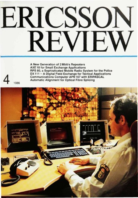
CoverAn operator's position in the new radio systemRPS80 <strong>for</strong> the National Swedish Police Board,developed <strong>for</strong> the cities Stockholm, Gothenburgand Malmb. The system was supplied by EricssonRadio Systems AB
ERICSSON REVIEWNumber 4 1986 Volume 63Responsible publisher Gosta LindbergEditor Goran NorrmanEditorial staff Martti ViitaniemiAddress S-126 25 Stockholm, SwedenSubscription one year $ 16Published in Swedish, English, French and Spanish with four issues per yearCopyright Telefonaktiebolaget LM EricssonContents134140149156165170A <strong>New</strong> <strong>Generation</strong> <strong>of</strong> 2<strong>Mbit</strong>/s <strong>Repeaters</strong><strong>AXE</strong> <strong>10</strong> <strong>for</strong> <strong>Small</strong> <strong>Exchange</strong> ApplicationsRPS 80, a Sophisticated Mobile Radio System <strong>for</strong> the PoliceDX111 - A Digital Field <strong>Exchange</strong> <strong>for</strong> Tactical ApplicationsCommunications Computer APN 167 with ERIPASCALAutomatic Alignment <strong>for</strong> Optical Fibre SplicingGOSTA NEOVIUSEditor 1980-1986Gosta Neovius retires aseditor <strong>of</strong> Ericsson ReviewWith this issue Gosta Neovius retiresfrom his job as the editor <strong>of</strong> EricssonReview. Goran Norrman has been appointedhis successor.Gosta Neovius joined LM Ericsson inJanuary 1953 and has served the companywell during his long career, notleast in his work on Ericsson Review.As the editor Gosta Neovius has participatedvery actively in the work on manuscripts,illustrations and layouts. Hehas also been responsible <strong>for</strong> engaginggood translators, illustrators, printersand distributors.The journal is published with four issuesayear in four languages, which requiresvery efficient editorial work. GostaNeovius' great technical knowledge andinterest in technology have been valuablequalities in this context.Ericsson Review introduces the newproducts that are continually being addedto the Ericsson range and thus affectsthe external image <strong>of</strong> the Group.During Gosta Neovius' editorship thecontents as well as the design have beengreatly appreciated, both by the readersand the publisher and management. Hiswide technical knowledge has enrichedthe journal.Gosta Neovius leaves Ericsson with thecompany's warmest thanks <strong>for</strong> his greatcontribution and our best wishes <strong>for</strong> thefuture.Bjorn SvedbergGosta Lindberg
A <strong>New</strong> <strong>Generation</strong> <strong>of</strong> 2 <strong>Mbit</strong>/s <strong>Repeaters</strong>Dagfinn Danielsen, Thomas Ifstrom and Christer LandbergEricsson Telecom has developed a new generation <strong>of</strong> 2<strong>Mbit</strong>/s intermediaterepeaters <strong>for</strong> paired cable. Much <strong>of</strong> the development work was carried out inclose collaboration with RIFAAB to produce a monolithic regenerator circuit,PBL3755.The authors describe the function, design and construction <strong>of</strong> the equipment.Ericsson Telecom now introduces itsfourth generation <strong>of</strong> 2 <strong>Mbit</strong>/s intermediaterepeater equipment, consisting <strong>of</strong>repeaters and containers. The main featuresthat distinguish the new systemfrom its predecessor are:- improved per<strong>for</strong>mance- reduced power consumption- smaller volume- easier handling.digital communication systemstelephone linestelecommunication equipmentLine systems <strong>for</strong> 2<strong>Mbit</strong>/s have long<strong>for</strong>med part <strong>of</strong> Ericssons product rangeand are mainly used <strong>for</strong> transmissionover balanced paired cable having aconductor diameter <strong>of</strong> 0.4-1 2mm anda line capacitance higher than 25nF/km.Digital transmission systems were introducedin urban and trunk networks inindustrialized countries at the beginning<strong>of</strong> the 1970's, Studies have shownthat 2<strong>Mbit</strong>/s line systems are very economical,particularly on routes up to approximately5 km, if existing paired cablecan be used, fig. 1. 2 <strong>Mbit</strong>/s line systemsare there<strong>for</strong>e now also being introducedin the subscriber networks whensuch transmission is needed <strong>for</strong> digitalPABXs etc.The intermediate repeater, which is fullycompatible with those <strong>of</strong> previous generations,is available in two versions.Both can be used together with the faultlocation system ZAN201. 2 One versionalso permits fault location by means <strong>of</strong>the loop method. 1Intermediate repeaterHigh reliability is a prerequisite <strong>for</strong> intermediaterepeaters, which are usually installedoutdoors and in places difficult<strong>of</strong> access. An MTBF <strong>of</strong> more than 400years can be achieved <strong>for</strong> a two-way intermediaterepeater. The physical andelectrical environment is <strong>of</strong>ten extreme,making stringent demands on the design.All these demands can only be metwith the aid <strong>of</strong> careful choice <strong>of</strong> componentsand meticulous testing in combinationwith unit burn-in. The exploitation<strong>of</strong> modern semiconductor technologyso as to integrate the largest possiblenumber <strong>of</strong> functions on a single si I -3 -Fig. 1Comparison <strong>of</strong> the relative costs <strong>of</strong> 2, 34 and140 <strong>Mbit</strong>/s line systems over a 5 km route withdifferent numbers <strong>of</strong> telephone channelsCNRelative costNumber <strong>of</strong> telephone channels— 2 <strong>Mbit</strong>/s over existing paired cable2 <strong>Mbit</strong>/s over new paired cable34 <strong>Mbit</strong>/s over new optical fibre cable140 <strong>Mbit</strong>/s over new optical fibre cable
THOMAS IFSTRoMRIFA ABDAGFINN DANIELSENCHRISTER LANDBERGEricsson TelecomTelefonaktiebolaget LM EricssonSignal/noise measurement dataSignal/noise ratio s 18 dBCable attenuation 5-45 dBReference signals Ones onlyTest signal, pseudorandom signal PSR 2 ,5 -1Error rate 1 x <strong>10</strong>~ 7Bit rate2048 kbit/s ± 50 ppmSupply current48mA±2mATemperature range -40 to +70°CTest instrument <strong>for</strong> the PRT-1 fromregeneratorWandel & Goltermanicon chip has also been <strong>of</strong> particular importancein the development <strong>of</strong> thisrepeater.The repeater works automaticallythroughout the equalization range Asignal/noise ratio <strong>of</strong> 18 dB is sufficient togive good quality at a cable attenuation<strong>of</strong> between 5 and 45dB. This makes itpossible to use long cable sections. Italso facilitates installation since there isno need <strong>for</strong> detailed attenuation measurementswhen the system is beingtaken into service.The new, low-current regenerator circuithelps to reduce the overall powerconsumption <strong>of</strong> a two-way intermediaterepeater, including overvoltage protection,to 5.5 V at 48 mA. Low power consumptionis essential in order to keepthe temperature in the compact containersas low as possible, especiallywhen they are fully equipped. Remotefeeding <strong>of</strong> many intermediate repeatersusing a low output voltage can also bearranged, which is an advantage fromthe point <strong>of</strong> view <strong>of</strong> safety during workon the cable.The ability <strong>of</strong> the equipment to withstandlightning strokes is better than requiredby CCITT Recommendation K.17,namely 5kV/200A with a pulse shape <strong>of</strong><strong>10</strong>/700 us. The ability to withstand 50 Hzcurrents caused by faults on power linesis <strong>10</strong>A rms <strong>for</strong> 0.5s. The efficient overvoltageprotector, which meets the severerequirements <strong>of</strong> the Nordic telecommunicationsadministrations, isparticularly important in systems thatuse cable mounted on poles.— I— TRFig. 2Block diagram <strong>of</strong> a two-way intermediate repeater.Blocks in the shaded areas are included in theregenerator circuitT Tank circuit <strong>for</strong> the clockREF Voltage regulation circuitKL Clock circuitALBO Automatic line building-out circuitOP Operational amplifierKOMP Comparator circuitUT1 Output stage 1UT2 Output stage 2TR Trans<strong>for</strong>mera, p Equalization networksP Power feeding strapsFD Fault detection outputs
136Fig. 3Functional diagram <strong>of</strong> the PBL3755. In spite <strong>of</strong>the fact that all active functions <strong>of</strong> the intermediaterepeater have been integrated it has still beenpossible to package the circuit in a 16-pin case,primarily because the external components are tobe found in well delimited functionsVoltage regulation circuit REF is equipped with inputs <strong>for</strong>P1 Input powerP2 Shunt terminalP3 Analog groundOperational amplifier OP has terminals <strong>for</strong>11 Input signal12 Inverted input signal13 Output signalComparator circuit KOMP contains a terminal <strong>for</strong>C1 Centre-voltageClock circuit KL has terminals <strong>for</strong>T1 Tank circuit or incoming clock signalT2 TrimmingT3 Phase adjustmentDrive circuits UT1 and UT2 contain terminals <strong>for</strong>U1 Positive pulseU2 Negative pulseU3 Digital groundAutomatic equalization circuit ALBO is equipped withterminals <strong>for</strong>A1 FilterA2 Diode 1A3 Diode 2Regenerator circuitIncorporating the largest possible number<strong>of</strong> functions in an integrated circuitusually minimizes the cost <strong>of</strong> the unitcontaining the circuit. However, not allfunctions are suitable <strong>for</strong> integration.The PBL3755 includes all the repeaterfunctions except filters and overvoltageprotectors.Low current consumption <strong>for</strong> all functionsis a prerequisite. It has been possibleto use the same supply voltage level,5.25 V, both <strong>for</strong> the output stages andother functional units, and with the exception<strong>of</strong> the output stage the circuitonly draws 8 mA. This is comparable tothe power consumption <strong>of</strong> a single ECLgate.Overvoltage protection cannot entirelyprevent disturbances caused by lightningstrokes or short circuits fromreaching the semiconductor circuit.However, the monolithic circuit hasbeen designed to withstand high voltage,25V, resulting in a reduction in thedemands made on the overvoltage protectors.The PBL3755 is manufactured usingRIFA's bipolar process No. 8. It is a reliableprocess <strong>for</strong> low-voltage applications(BV CEO =<strong>10</strong>V) which makes it possibleto combine high-per<strong>for</strong>mance digitaland analog functions. The conflict betweenthe need <strong>for</strong> the circuit to be ableto withstand high voltage transients andthe choice <strong>of</strong> process No. 8, which is afast and hence low-voltage process, hasbeen solved by designing protective circuitsin all parts <strong>of</strong> the PBL3755.The intermediate repeater consists <strong>of</strong>the functional blocks voltage regulation(REF), amplifier (OP), comparator(KOMP), latches and output stages(UT1, UT2), clock regenerator (KL) andimpedance elements <strong>for</strong> variable equalization(ALBO). Refer to the block diagram<strong>of</strong> the repeater, fig. 2, and thefunctionaldiagram <strong>of</strong> the regenerator circuit,fig. 3. Fig. 4 shows the block layout<strong>for</strong> the chip.Voltage regulationThe intermediate repeaters along a lineare powered in series over the phantomcircuit <strong>of</strong> the line. The feeding current isa constant direct current <strong>of</strong> 48 mA. Eachrepeater generates its own supply voltageby means <strong>of</strong> a voltage regulationcircuit, REF. This circuit was simplifiedconsiderably since the same voltage isnow used <strong>for</strong> all functions in the repeater.A shunt regulator, equipped with aband gap reference that gives a constantvoltage which is independent <strong>of</strong>the environment, is built into thePBL3755. Seen across the feeding currentinputs to the circuit, REF behaveslike a zener diode with low dynamic resistanceeven at low currents. The supplyvoltage can be kept within ±3% regardless<strong>of</strong> current and temperature.REF also supplies relatively temperature-independentoperating currents <strong>of</strong><strong>10</strong>u.A to other parts <strong>of</strong> the PBL3755. Inlow-current stages it is not suitable toset the operating point locally with theaid <strong>of</strong> resistors, since they would belarge and require expensive silicon area.PreamplifierThe possible complexity <strong>of</strong> the amplifier(OP) is limited by the fact that as an operationalamplifier it must be capable <strong>of</strong>high negative feedback. OP containstwo voltage amplifier stages, whichprovide a good margin <strong>of</strong> stability. Emit-
137PBL 3755- operates at a low voltage (5.25 V)- requires only low feeding current (8 mA)- has built-in voltage stabilization- is well able to withstand overvoltages- contains a preamplifier with large bandwidthand high gain- provides automatic line equalization in twosections- includes a fully integrated clock recoveryfunction- drives the line by means <strong>of</strong> output stages welladapted to the purpose- switches <strong>of</strong>f the output stages if the inputlevel is too low- facilitates trimming during production.Fig. 4The aluminium wiring pattern on the PBL3755and the integrated circuit layout <strong>for</strong> the differentfunctional blocks. The terminals are placed sothat interference between parts is avoidedter followers are used on inputs as wellas output <strong>for</strong> the sake <strong>of</strong> impedancetrans<strong>for</strong>mation. The asymmetrical outputstage with only one output is thedesign that requires the least current.The input stage, on the other hand, hasgood symmetry, which helps to ensurean accurate detection point. In spite <strong>of</strong>the fact that the amplifier is not allowedto draw more current than 1.4 mA it hasbeen possible, through maximum exploitation<strong>of</strong> the process, to achieve again bandwidth product <strong>of</strong> 2GHz. With60dB open loop gain the transfer function<strong>of</strong> the equalizer is determinedwholly by the external components inthe feedback network.Comparator bankThe detector part requires six comparators,KOMP, and the same number <strong>of</strong>reference voltages <strong>for</strong> their thresholds.The reference voltages are generatedquite separately from the signal pathand it has there<strong>for</strong>e been possible toproduce a low-current circuit which isaccurate and has good temperature stability.The high accuracy <strong>of</strong> the data andclock thresholds is in relation to thepeak level threshold. This is a desirablefeature <strong>of</strong> monolithic circuits, in whichrelative tolerances can be made smallwhereas absolute values vary fairlywidely and cannot be trimmed except ata prohibitive cost. KOMP also determinesthe amplitude <strong>of</strong> the current thatpumps the tank circuit and the currentconsumption <strong>of</strong> large parts <strong>of</strong> thePBL3755. This control is necessary inview <strong>of</strong> the large temperature range overwhich the amplifier has to be able tooperate.Latches and output stagesThe latches and output stages (UT1,UT2, two identical blocks), also includethe logic circuits that control the transmission<strong>of</strong> regenerated pulses. The logiccircuits are <strong>of</strong> the ECL type and havebeen dimensioned <strong>for</strong> the individual requirements<strong>for</strong> speed in each stage.The output stages are optimized <strong>for</strong> thedriving <strong>of</strong> a cable. They are equippedwith a negative feedback network so asto obtain ramps with well defined riseand fall times. The reason <strong>for</strong> choosingthis sophisticated method <strong>for</strong> digital
Fig. 5The printed board assembly <strong>for</strong> a two-way intermediaterepeater, which allows fault tracing usingfault location system ZAN201. All hole-mountedcomponents are placed on the side shownFig. 6The soldering side (secondary side) <strong>of</strong> the printedboard assembly in fig. 5. All surface-mountedcomponents are placed on this side and thus donot require extra spaceFig. 7Adapter ZHZ 34206 enables the intermediate repeatersand the associated units to be installed inany <strong>of</strong> Ericsson's containersoutputs is the desire to avoid problemscaused by stray capacitances and leakageinductance in the miniaturized outputtrans<strong>for</strong>mer. With rise and fall times<strong>of</strong> 40 ns, which is well within what is permittedby CCITT, the high-frequency energyis so low that ringing is avoided.The output transistor is <strong>of</strong> the Schottkytype, which with its low saturation voltageutilizes the supply voltage efficiently.Clock generatorIt has been assumed above that an internalclock (KL) is included in the circuit.The clock comparators give currentpulses at a frequency <strong>of</strong> 2048 kHz to theexternal LC tank circuit, which with itshigh Q value filters out the fundamentalfrequency. The functional block KL inthe PBL3755 then uses this sine wave,whose amplitude varies with the bit density<strong>of</strong> the signal, to generate a squarewave with sufficient driving capability.The data signal must be sensed at theinstants when it is at its peak. As thetiming recovery is based on the zerotransitions <strong>of</strong> the signal, a delay correspondingto a phase displacement <strong>of</strong> 90°must be generated. The delay is createdinternally in the integrated circuit inorder to keep the current consumptionlow. The dynamics <strong>of</strong> the clock recoveryis still controlled by the LC circuit becauseKL is not free-running like aphase-locked loop and there<strong>for</strong>e cannotbe put completely out <strong>of</strong> phase. Sufficientabsolute accuracy is difficult toachieve in a monolith, and a special circuitdesign has there<strong>for</strong>e been chosenwhich automatically regulates the delayto the correct value, 122 ns at 2048 kHz.The method <strong>of</strong> using complicated circuitdesigns to ensure that the processdependentdata <strong>of</strong> the monolithic componentsdo not affect the per<strong>for</strong>mance<strong>of</strong> the circuit has been employed in severalcases when designing thePBL3755. It is also a prerequisite <strong>for</strong> anacceptable yield from the manufacture.Another component-saving and practicalrefinement <strong>of</strong> KL is the rectifier,which facilitates the trimming <strong>of</strong> the resonantfrequency <strong>of</strong> the clock circuit.ALBOThe active elements consist <strong>of</strong> diodeconnectedtransistors, whose dynamicresistance is inversely proportional tothe direct current through them. Thecurrent is controlled by the peak-valuesensingcomparators via a buffer havingsuch high gain that the amplitude in thedetection point is made practically independent<strong>of</strong> the input level from the linewithin the regulation range.The ALBO control is used to automaticallyprevent the output transistors inthe output stage from conducting in thefollowing situations: when the feedingcurrent has just been switched on, whenthe input signal is lost and in the case <strong>of</strong>overvoltage. This prevents the transmission<strong>of</strong> erroneous data or locking <strong>of</strong> theintermediate repeater.The methods <strong>of</strong> developing monolithshave been described in a previous issue<strong>of</strong> Ericsson Review. 3 The developmentis based on careful computer simulationsin order to ensure that the design iscorrect be<strong>for</strong>e the expensive manufacturingprocess is started.Other applications <strong>for</strong> PBL3755The PBL3755 can <strong>of</strong> course also <strong>for</strong>mpart <strong>of</strong> the line terminal equipment <strong>of</strong>transmission systems. The demandsmade on the receiver parts are usuallysimilar <strong>for</strong> terminals and intermediaterepeaters. The terminal transmittersmeet the set requirements with a muchsimpler ALBO network than that includedin the intermediate repeaters. If adirect conversion between an S1 (or T1)interface and TTL loads is required in aPABX it is only necessary to add an extracomparator that generates an externalclock signal.Mechanical constructionThe printed board assembly <strong>for</strong> anintermediate repeater is placed in a plasticcassette, consisting <strong>of</strong> two equalhalves and designed so that it can beopened without tools. Adjustment to differenttypes <strong>of</strong> power feeding, which isby means <strong>of</strong> plug-in U-links, can there<strong>for</strong>ebe made quickly and easily, andalso the setting <strong>of</strong> addresses <strong>for</strong> faultlocation by means <strong>of</strong> the loop method.The dimensions <strong>of</strong> the cassette are157x75x19 mm, which means a volumereduction by 50% compared with theprevious generation. Most discretecomponents are surface mounted in
Fig. 8Containers <strong>for</strong> <strong>10</strong> and 20 systems fully equippedwith intermediary repeaters and a fault detectorunit <strong>for</strong> ZAN 201. A service line <strong>for</strong> communicationbetween the container and the line terminal isavailable in the fault detector unitVersions <strong>of</strong> the intermediaterepeater:- ZHH344 01, <strong>for</strong> fault location using ZAN 201or loop connection system- ZHH344 02, <strong>for</strong> fault location only by means<strong>of</strong> ZAN 201.Through-connection and side circuit loadingcoil units <strong>for</strong> temporary through-connection orreloading <strong>of</strong> unused pairs in a paired cable arealso available. The side circuit loading coil unitshave inductance values 88, 118, 132 and177mH.All units meet the stringent demands as regardsovervoltage and overcurrent.Technical dataIntermediate repeaterBit rate2048 kbit/sCodeHDB-3Impedance120 ohms bal.Pulse amplitude ±3.0 VEqualization range 5-45dB at <strong>10</strong>24 kHzPower consumption pertwo-way intermediaterepeater, typical value 5.5 V at 48 mATemperature range -40 to +70°CContainer ZDD ZDD ZDD ZDD54001 54<strong>10</strong>1 54201 54301Diameter, mm 190 270 370 450Height, mm 256 256 256 256Weight, kg, with6 m stub cable,fully equipped 7 13 21 33Stub cable, m 6 6 6 6or12 12 12 12Number <strong>of</strong> twowayintermediaterepeaters 4 <strong>10</strong> 20 40order to minimize the size <strong>of</strong> the unitwithout having to introduce hybrid circuitsetc. The components are placed onthe soldering side <strong>of</strong> the printed boardand thus do not require extra space,fig.6.A completely new series <strong>of</strong> containershas been developed which holds a faultdetection unit and 4, <strong>10</strong>, 20 and 40 intermediaterepeaters respectively, fig.8.The design is similar to that <strong>of</strong> the previousgeneration but much more compact.The weight has also been reducedconsiderably, partly by replacing thelead-sheathed stub cable by a plasticsheathedcable with a moisture barrier.The cable, which connects the repeatersto the fault detection unit, now <strong>for</strong>mspart <strong>of</strong> the container cabling, and eachrepeater is connected by means <strong>of</strong> a singledevice. The stub cable is also equippedwith an extra pair <strong>for</strong> special customerrequirements, <strong>for</strong> example pressuresupervision. The materials are thesame as in the previous generation,namely acidpro<strong>of</strong> stainless steel in thecontainer and lid and an insert <strong>of</strong> polystyrenewhich holds all the units. Theuse <strong>of</strong> an insert has simplified containerdesign. The materials have been chosenso as to eliminate the risk <strong>of</strong> flashoverbetween the electronic circuits and thecontainer, <strong>for</strong> example in the case <strong>of</strong>lightning strokes.The containers can be installed in manholes,concrete caissons or on poles.Installation kits are available <strong>for</strong> thesealternatives. The containers are equippedwith 6 or 12 m stub cable in order t<strong>of</strong>acilitate different types <strong>of</strong> installation.SummaryThe main features <strong>of</strong> the new 2<strong>Mbit</strong>/sintermediate repeater equipment are:- low power consumption, correspondingto only 5.5 V at a feeding current <strong>of</strong>48 mA <strong>for</strong> a two-way intermediate repeater- automatic equalization in one stepfrom 5dB to 45dB cable attenuationwith good signal/noise per<strong>for</strong>mancethroughout the equalization range- high reliability through careful choice<strong>of</strong> components, sophisticated testingand a high degree <strong>of</strong> integration,which minimizes the number <strong>of</strong> discretecomponents- a container that is optimized <strong>for</strong> bothsubscriber and trunk networks andcan withstand severe environmentalconditions- simple installation <strong>of</strong> containers aswell as repeaters.References1. Arras, J. and Danielsen, D.: 0.7 and2 <strong>Mbit</strong>/s Systems <strong>for</strong> Pair Cables. EricssonRev. 58 (1981 ):1, pp. 42-48.2. Silvergran, U. and Woldegiorgis, K.:Fault Location System ZAN 201. EricssonRev. 61 (1984):4, pp. 162-169.3. Bjorklund.G.,Johansson,J.,Ol<strong>of</strong>sson,L.-A. and Sundvall, J.: The Development<strong>of</strong> Custom Design Circuits. EricssonRev. 58 (1981):1, pp. 9-17.
<strong>AXE</strong> <strong>10</strong> <strong>for</strong> <strong>Small</strong> <strong>Exchange</strong> ApplicationsChris Fletcher, Erkki Heinonen and Agne JonssonThere is a need <strong>for</strong> small autonomous telephone exchanges in many markets. Inorder to meet this need Ericsson has developed a variant <strong>of</strong> <strong>AXE</strong> <strong>10</strong>. <strong>AXE</strong> <strong>10</strong>4,with a maximum capacity <strong>of</strong> 2048 subscriber lines. <strong>AXE</strong> <strong>10</strong>4 uses a part <strong>of</strong> thehardware in the larger system but is controlled by a smaller processor. APZ213,which has been developed as an economical solution to the small-capacityrequirement. There has been no reduction in the number <strong>of</strong> services andfunctions provided. One design prerequisite was that it should be possible totransfer standard <strong>AXE</strong> <strong>10</strong> s<strong>of</strong>tware direct at the object code level. The sames<strong>of</strong>tware and the same support systems, e.g. compilers, are thus used in APZ213and the processor <strong>for</strong> the larger systems. APZ211.The authors summarize the market requirements that have led to thedevelopment <strong>of</strong> <strong>AXE</strong> <strong>10</strong>4 and describe the switching system, control system andhardware structure.- When exchanges are extended bymeans <strong>of</strong> <strong>AXE</strong> <strong>10</strong> without older equipmentin different technology being removed,the <strong>AXE</strong> <strong>10</strong> extension must beable to route traffic to more than oneroute.- It is necessary that <strong>AXE</strong> <strong>10</strong> can handleoverlay network applications in orderto be able to provide some subscriberswith advanced services and functionswithout having to replace theolder exchange.In order to meet these requirements,Ericsson, together with TELECOM inAustralia, has adapted system <strong>AXE</strong> <strong>10</strong>and developed an autonomous <strong>AXE</strong> <strong>10</strong>variant, <strong>AXE</strong> <strong>10</strong>4, <strong>for</strong> the world market.<strong>AXE</strong> <strong>10</strong>4 can be used in an analog ordigital network and is competitive in therange 40-2048 subscribers.electronic switching systemstelephone exchangesFor many years <strong>AXE</strong> <strong>10</strong> has <strong>of</strong>fered thepossibility <strong>of</strong> connecting, via PCM links,remote subscriber stages, RSS, <strong>for</strong> 2048subscribers and remote subscriber multiplexers,RSM, <strong>for</strong> 30 subscribers to acentral <strong>AXE</strong> <strong>10</strong> node. This facility is particularlyattractive in places where digitaltransmission equipment is alreadyavailable or where multi-channel equipmenthas to be installed simultaneouslywith the telephone exchange. Digitalnetworks can thus be built up at once.However, experience has shown that acomplete changeover to a digital networkis not always economically justified<strong>for</strong> the following reasons:- Some administrations have investedheavily in carrier systems and mustcontinue to use them <strong>for</strong> financial reasons.<strong>AXE</strong> <strong>10</strong> must there<strong>for</strong>e be ableto work in an analog network.- The digitalization <strong>of</strong> the transmissionnetwork must be allowed to proceedregardless <strong>of</strong> the technology used inthe exchanges. <strong>AXE</strong> <strong>10</strong> must there<strong>for</strong>ebe able to operate in both analogand digital environments.- <strong>Small</strong> communities are sometimessituated along a main route, and astructure using the star-shaped networkthat is typical <strong>of</strong> the node/concentratormethod is then not suitable.- In the case <strong>of</strong> remote exchanges connectedvia transmission links that aresubject to breaks it is essential that<strong>AXE</strong> <strong>10</strong> work autonomously.Knowledge <strong>of</strong> the basic principles <strong>of</strong><strong>AXE</strong> <strong>10</strong>, which have been described previouslyin several articles in EricssonReview, is necessary in order to obtainthe greatest benefit from this article. 113Reduction <strong>of</strong> the hardware<strong>for</strong> <strong>AXE</strong> <strong>10</strong>4The basic aim when developing <strong>AXE</strong> <strong>10</strong>4was to retain all the characteristics <strong>of</strong><strong>AXE</strong> <strong>10</strong> and all the s<strong>of</strong>tware but to reducethe standard hardware in order toachieve good economy <strong>for</strong> the smallsize, i.e. a maximum <strong>of</strong> 2048 subscribersor 200 Erlangs.The following strategy was adopted <strong>for</strong>the hardware:- Since the subscriber subsystem, SSS,is modular and extended in steps <strong>of</strong>eight subscribers, and hence suitable<strong>for</strong> use in small exchanges, it was decidedthat no changes were to bemade to the hardware <strong>of</strong> SSS.- Since an <strong>AXE</strong> <strong>10</strong>4 exchange only requiresone 2048-group there is noneed <strong>for</strong> the group switching subsystem,GSS, in the small system. Inaddition all line modules, LSM, in a2048-subscriber group are already interconnectedin the present design bymeans <strong>of</strong> a time switch bus, TSB.having a width <strong>of</strong> 512 time slots,which can handle approximately 200Erlangs <strong>of</strong> traffic. Together with thedistributed time switches in LSM the
CHRIS FLETCHERLM Ericsson Pty. Ltd.AustraliaERKKI HEINONENAGNEJONSSONEricsson TelecomTelefonaktiebolaget LM EricssonFig. 1Hardware structure <strong>of</strong> <strong>AXE</strong> <strong>10</strong>4S55-D Subscriber switching subsystem, digitalLIC Subscriber line circuitSLCT Subscriber line test circuitMJC Multi-junctor circuitTS Time switchCRD MFC receiverCSD MFC senderKRD DTMF receiverETC <strong>Exchange</strong> terminal circuitEMRP Regional processorEMRPB EMRP busCP Central processorI/O Input/output devicestime switch bus can thus provide theGSS function in <strong>AXE</strong> <strong>10</strong>4, and the GSShardware has been omitted.- With the GSS hardware left out andfurther capacity available in the regionalprocessor in LSM it was decidedthat the hard ware <strong>for</strong> the trunk andsignalling subsystem, TSS, should beintegrated with the hardware <strong>for</strong> thesubscriber stage in LSM and that itwas to be modified <strong>for</strong> control from aregional processor, EMRP.- Without the GSS hardware and withTSS integrated with LSM the regionalcontrol is handled by EMRP. The centralprocessor has been provided witha serial EMRP bus interface and theRP hardware could there<strong>for</strong>e be omittedfrom <strong>AXE</strong> <strong>10</strong>4.-Central processor (CPS) APZ211 in<strong>AXE</strong> <strong>10</strong> can handle up to 40 calls persecond. As the traffic in the new smallexchange does not require processing<strong>of</strong> more than two calls per secondthe central processor in <strong>AXE</strong> <strong>10</strong>4could work slower than APZ211. Anew, small control system, APZ213,<strong>for</strong> <strong>AXE</strong> <strong>10</strong>4 has there<strong>for</strong>e been developed.The central processor in APZ213 is duplicatedand works non-synchronously.The dedicated hardware <strong>for</strong> processormaintenance (AMU) in APZ211 hasthere<strong>for</strong>e been omitted and the correspondingfunctions have been achievedby means <strong>of</strong> s<strong>of</strong>tware. This mode <strong>of</strong> operationmeansthatduring normal conditionsone processor is designated executive(EX) and handles the traffic inthe exchange. The other processor isdesignated standby (SB) and works withroutine tests and diagnostic programs.A fault in CP-EX results in a change <strong>of</strong>CP side, which means that calls in progressare disconnected. The lack <strong>of</strong>transparent recovery is made acceptableby the high reliability <strong>of</strong> the hardware.The standard I/O functions <strong>for</strong> <strong>AXE</strong> <strong>10</strong>,i.e. the support processor subsystem,SPS, file management subsystem, FMS,data communication subsystem, DCS,and man-machine subsystem, MCS,have been retained and implemented asnon-duplicated subsystems, since itwas not anticipated that there would beany demand <strong>for</strong> a duplicated system.The hardware structure <strong>of</strong> <strong>AXE</strong> <strong>10</strong>4, seefig. 1, is well suited <strong>for</strong> a small, autonomous<strong>AXE</strong> <strong>10</strong> exchange. The great similaritybetween <strong>AXE</strong> <strong>10</strong> and <strong>AXE</strong> <strong>10</strong>4 asregards hardware is illustrated by thesmall number <strong>of</strong> printed circuit boardtypes that are special to <strong>AXE</strong> <strong>10</strong>4 Onlyeight new boards have had to be designed.Switching system APT2<strong>10</strong>The functional modularity has been retained,in accordance with the basic requirementthat all <strong>AXE</strong> <strong>10</strong> characteristicsshould be preserved. At the highestlevel <strong>AXE</strong> <strong>10</strong>4 consists <strong>of</strong> switching systemAPT2<strong>10</strong> and control systemAPZ213. All subsystems and functionalblocks suitable <strong>for</strong> a small terminal exchangehave been retained and a part <strong>of</strong>the omitted hardware (GSS) has beensimulated in central s<strong>of</strong>tware in order toretain the general system structure.Switching system APT2<strong>10</strong> manages thetraffic handling functions. All switchingsystem hardware has been integratedwith the hardware <strong>for</strong> the subscriberpart. The latter contains up to 16 lineswitch modules, LSM, each with 128lines. Each LSM is controlled by a regionalprocessor, EMRP, <strong>of</strong> its own. Thesubscriber subsystem also includes:- Subscriber line circuits, LIC, <strong>for</strong> 128lines, with eight circuits per printedboard assembly. The LIC board is thesame as that used in <strong>AXE</strong> <strong>10</strong>.- MFCsignallingequipment, which canhave four digital code senders andfour code receivers (CSD, CRD) perLSM. This number is not divisiblewithin an LSM. Different types <strong>of</strong> signallingprocessing techniques areused to provide digital filtering in theMFC devices. The number <strong>of</strong> MFCboards in the LSM is based on theoverall taffic requirement since theCSD and CRD devices in an LSM canbe shared by the whole exchange.- Eight digital code receivers, KRD, aremounted on a board and use hardwaresimilar to the MFC equipmentabove. This number is sufficient tohandle, without any noticeable congestion,the calls from the 128 subscriberswith push-button telephonesthat are connected to one LSM. Thesame type <strong>of</strong> KSD unit is used in<strong>AXE</strong><strong>10</strong> and <strong>AXE</strong> <strong>10</strong>4.
Fig. 2The time switch bus as a group switchLSMETCLICCRDCSDTSTSBLine switch module<strong>Exchange</strong> terminal circuitSubscriber line circuitMFC receiverMFC senderTime switchTime switch busFig. 3Modifications in the APT hardwareSSSISMSLCTKRDJTCEMRPGSSCLMMJCT-S-TTSSEMRPBRPSRPRPBCRPBSubscriber switching subsystemLine switch moduleSubscriber line test circuitDTMF receiverConnection between SSS and GSSRegional processorGroup switching subsystemClock moduleMulti-junctor circuitTime-space-time switchTrunk and signalling subsystemEMRP busRegional processor subsystemRegional processorRP bus converterRP busModified hardware
143- One or two exchange terminal circuits<strong>for</strong> 1.5 or 2 <strong>Mbit</strong>/s PCM systemsmay be connected.- Testing equipment (SLCT) is provided<strong>for</strong> limited GO/NOGO tests on subscriberlines and line circuits and <strong>for</strong>setting up a connection to SULTD <strong>for</strong>more advanced testing. The equipmentis <strong>of</strong> the same type as used in<strong>AXE</strong> <strong>10</strong>.- The time switch, TS, is identical withthat in <strong>AXE</strong> <strong>10</strong>.- Multi-junctor circuit, MJC.TS has <strong>10</strong>24 positions, is congestionfreeand connects LIC, ETC, CRD, CSDand KRD to the time switch bus, TSB,which has 512 time slots. This gives fullaccessibility <strong>for</strong> all subscribers andjunction circuits and makes TS insensitiveto uneven loading, fig. 2.Special equipment, such as coin telephonesets and subscribers' privatemeters, are handled by the same type <strong>of</strong>SE equipment as in <strong>AXE</strong><strong>10</strong>.Fig. 3 shows the modifications made inthe hardware <strong>for</strong> APT2<strong>10</strong> in order toadapt it to <strong>AXE</strong> <strong>10</strong>4. As can be seen, n<strong>of</strong>unction has been sacrificed in spite <strong>of</strong>drastic hardware reductions. Thechanges made to APT2<strong>10</strong> can be summarizedas follows:- The GSS hardware is simulated to theremainder <strong>of</strong> the system by a new centrals<strong>of</strong>tware block, GSRX, which respondsto s<strong>of</strong>tware signals from otherblocks as if a normal group switchingstage existed. GSRX interacts withblocks TS, LI and CJ in order to set upconnections through the LSM timeswitch to the time switch bus (TSB).Fig. 4 shows the APT s<strong>of</strong>tware blocksthat have been modified.-Devices required in <strong>AXE</strong><strong>10</strong>4 butwhich have previously been controlledby regional processors are integratedinto LSM. These devices includecode transmitters (CSD), codereceivers (CRD), exchange terminalcircuits (ETC) and multi-junctor circuits(MJC). The regional s<strong>of</strong>twareparts <strong>of</strong> these blocks have beenmoved to EMRP.Control system APZ213The new duplicated central processor,APZ213, has been designed <strong>for</strong> smallapplications with a traffic handling capacity<strong>of</strong> 11 000 busy hour call attempts.Fig. 4Modifications in the APT s<strong>of</strong>twareLIKRCJMJGSRXET/BTCR/CSTCSRESCCHSSUSSubscriber line interfaceDTMF receiverJunctorMulti-junctorGroup switch (only s<strong>of</strong>tware)<strong>Exchange</strong> terminal/Both-way lineMFC sender/receiverTraffic control subsystemRegister functionsSubscriber category analysisCharging subsystemSubscriber services subsystemP$|%||Modified hardwareModified s<strong>of</strong>tware<strong>New</strong> s<strong>of</strong>tware
Hardware structure <strong>of</strong> APZ 213Fig. 6 shows a block diagram <strong>of</strong> theAPZ213 control system. Each CP sideconsists <strong>of</strong> a CPU with three printedboard assemblies and a single-boardEMRP handler, EPH, which is connectedto the serial EMRP bus. Each CPis connected to up to 32 EMRP via itsown bus, EMRPB. CPU and EPH areconnected to each other and to the mainstore, MS, via the central processor bus,CPB. MS and CPB from APZ211 havebeen retained in APZ 213, and by using a256 k DRAM chip as the memory componenta 16-bit memory with a capacity <strong>of</strong>1 Mwords is obtained per board. EMRP0-30 are standard processors which areused in LSM and SE equipment, andEMRP31 is a special interface processordesigned to interwork with SPShardware. This processor is designatedERBAand has been newly developed <strong>for</strong>APZ213. ERBA contains the interfacetowards the international interface bus<strong>for</strong> small computer systems, the SCSIbus, which in its turn constitutes the interfacetowards the hardware <strong>for</strong> SPS,FMS, DCS and MCS.rig. 5APZ213 emulates APZ211MSCOPl/FALUMain store <strong>for</strong> programs, references and dataControl programsInterlaceArithmetic-logic unitEmulationOne basic requirement was that standard<strong>AXE</strong> <strong>10</strong> s<strong>of</strong>tware structure shouldbe used in <strong>AXE</strong> <strong>10</strong>4. This was achievedby means <strong>of</strong> emulation, a method usedfairly <strong>of</strong>ten in industry to enable s<strong>of</strong>twaredesigned <strong>for</strong> one computer to beexecuted on another. Fig. 5 shows thebasic method. A special control program,COP, is used to translate the "<strong>for</strong>eign"code, which is ASA211C assemblercode, to the language <strong>of</strong> thenew machine, which is the assemblercode <strong>of</strong> the microprocessor. However,when using this method each "<strong>for</strong>eign"instruction requires a number <strong>of</strong> COPstages <strong>for</strong> the translation, and thismeans a reduction in speed. Processorcapacity has been sacrificed in order toreduce the hardware cost. The emulationmethod makes it possible to transferthe <strong>AXE</strong> <strong>10</strong> s<strong>of</strong>tware to APZ 213 withthe aid <strong>of</strong> the existing s<strong>of</strong>tware supportsystem APS.The three boards that <strong>for</strong>m a CPU areshown in fig. 6. The gate array circuitemployed <strong>for</strong> the addressing and handling<strong>of</strong> variables in the data store usingthe reference store is the same as thatdeveloped <strong>for</strong> APZ211. The gate arraycircuit also includes a base addressstore and parameter decoding circuits.Board CPU1 contains the actual microprocessor,the store <strong>for</strong> COP and theCPB interface. The interpreter COP isstored in a 32kword EPROM, but <strong>for</strong>quicker access the most frequently usedparts <strong>of</strong> COP are copied to a very fast(<strong>10</strong>0 ns access time) static RAM whenthe power is switched on. Board CPU2contains the CP bus arbitration logicand other circuits required <strong>for</strong> the operation<strong>of</strong> CPULike in APZ211 the EPH functions <strong>of</strong>APZ213 work as an autonomous processor,which scans subordinateEMRPs independently <strong>of</strong> CPU and transmitssignals received from EMRP to thecorrectjob buffers in the main store. In asimilar way signals sent from CPU todifferent EMRPs are read by EPH fromMS and transmitted over the EMRP bus.The RPH program in APZ213 is a modi-
145calculates the ECC and adds it to thememory contents. When reading theword from the memory this code makesit possible to correct single-bit errorsduring the passage through MSCE andto detect multi-bit errors (per word),which means that any memory errorsare harmless.The description above shows that theCPU and EPH hardware and also thecontrol program COP in APZ213 arenew products. However, as COP is theinterface between the high-level s<strong>of</strong>twareand the hardware it has been possibleto retain large parts <strong>of</strong> the operatingsystem CPS. Some very small modificationswere necessary but they wereincluded in the standard blocks <strong>for</strong>APZ211. Most changes are found in themaintenance subsystem MAS since it isprimarily dependent on the hardwaredesign and the EX/SB mode <strong>of</strong> operation.The regional processor subsystemRPS was not affected because theEMRP design was not changed.Fig. 6Control system APZ213CPS Central processor subsystemCP-A Central processor, part ACP-B Central processor, part BCPB Central processor busMS Main storeSTBE Memory boardMSCE Main store control unitCPU Central processorADC Address calculation unitEPH Bus handlerEMH EMRP handler boardRPS Regional processor subsystemEMRP Regional processorEMRPB-A EMRP bus AEMRPB-B EMRP bus BSPS Support processor subsystemERBA Bus interface unitSP Support processorMCS Man-machine communication subsystemDCS Data communication subsystemFMS File management subsystemtied versionAPZ211.<strong>of</strong> the RPH program inThe main store hardware, MS, is identicalwith that used in APZ211. A mainstore control board with functions <strong>for</strong>error correction, MSCE, is connected toCPB under the control <strong>of</strong> the bus arbitrationlogic on CPU2 and reads orwrites data at the appropriate address.Each <strong>of</strong> the memory boards, with errordetection code (ECC), STBE, contains1 Mwords <strong>of</strong> 22bits (16data + 6ECC).The combined volume <strong>of</strong> PS, RS and DSis not expected to exceed 2 Mwords, butathird memory board can be installed inthe present CP magazines if an extensionshould be required. The addressingcapacity is 16 Mwords. When a dataword is written into the memory, MSCEMaintenance <strong>of</strong> APZ213Like in other APZ systems the APZ213maintenance must facilitate:- Test <strong>of</strong> the central processor and initialstart- Automatic fault detection- Automatic recovery after faults- Good diagnosis <strong>for</strong> the identification<strong>of</strong> faulty boards after fault detection- Repair by replacing faulty boards.In APZ213 this is achieved by CP per<strong>for</strong>mingthe following actions:- Under normal conditions CP-EXhandles normal traffic and also regularlyexecutes routine test programsin order to detect hardware faultswhile CP-SB continuously executesroutine test programs.- When a fault is detected in a processorthe faulty processor is designatedstandby/faulty and is halted insuch a way that special diagnosticprograms can be initiated by means <strong>of</strong>commands in order to aid fault location.This means that an error interrupthas been masked, but maintenancecommunication with the rest <strong>of</strong>the system is still possible. Only whenthe fault has been located can a faultyCP be designated accordingly andisolated from the rest <strong>of</strong> the system <strong>for</strong>repair.
86Technical dataSize rangeCentral processorTraffic capacityTelephone setsSignallingTransmission interfaceNumber <strong>of</strong> junctionlinesNumber <strong>of</strong> routesSubscriber lineinterfaceRinging signalfeedingvoltagefrequencyInput and outputdevicesOperating voltagerangenominallyOperating conditionsTemperature rangelong-termshort-termRelative humiditylong-termshort-termCabinet packagingstructureheightwidthdepthInstallationceiling clearanceload on floor8-2048 linesDuplicated, with a capacity<strong>of</strong> 1<strong>10</strong>00BHCA,MTBF = 4 yearsMTBSF > <strong>10</strong>00 years200 Erlangsand 0.2Erlang/subscriberKeyset or dialCCITT R2 MFC, CCITTNo. 7Analog line systems:2-wire/4-wireLoop signalling or E&MDigital, <strong>for</strong> 30 or 24channels30 <strong>for</strong> one signallingsystemor60 <strong>for</strong> two different linesignalling systems perLSM.Can be incoming, outgoingor two-way.Number <strong>of</strong> LSM = 16, i.e.16x60 = 960 lines if atleast two different linesignalling systems areused.Not limited, i.e. a maximum<strong>of</strong> 960 routes <strong>of</strong>one circuit each2x250 ohms2x400 ohms2x800 ohmsConstant current2x400 ohms70, 80. 90 or <strong>10</strong>0 V25 HzUnduplicated or duplicated20 Mbyte hard discstore (Winchester).8 ports <strong>for</strong> terminals (remotelyconnected viamodems or local) or datalinks.30 inputs <strong>for</strong> externalalarms.Remotely connected orlocal audiovisual alarmpanel,-41.5V to -54V-48 VCabinets screened inorder to meet the EMCand ESD electromagneticenvironmental requirements5 to 40°C0 to 45"C20 to 80%5 to 90%2130 mm1200 mm400 mmSingle rowBack to backBack to wall400 mm above thecabinetsMax 4 kN/m 2CP states and fault markings are controlledby AMU s<strong>of</strong>tware functions,which are included in the programs <strong>of</strong>the ERBA processor. In APZ213 faultscan be detected by:- Supervisory circuits in hardware,such as parity checking and timecounter circuits- Time supervision <strong>of</strong> the whole programexecution time (program handlingcounter, PHC) which must bereset at regular intervals by certainprograms which write in PHC- Addressing checks during normalprogram execution- Acknowledgement errors, which aredetected by the AMU function.Fault signals generated by the hardwareinitiate the routine COP system restart,which sends AMU the signal that startsthe recovery. AMU then changes the CPstates so that recovery can take place.During the time both CPs work normally,the AMU program sends signals to differentCPUs periodically. These signalsmust be acknowledged within a certaintime. Even in cases where the signal isnot acknowledged by the CPU, the AMUprogram will initiate system recovery.Because <strong>of</strong> the system structure all detectedfaults are traced to one <strong>of</strong> the CPsides and the recovery method is alwaysa system restart The restart type andchange/no change <strong>of</strong> the CP state aredetermined by the AMU program andchosen according to the initial history <strong>of</strong>the fault. The restart types are, in risingorder <strong>of</strong> seriousness:- <strong>Small</strong> restart, during which existingcalls are preserved- Large restart, during which all callsare disconnected- Large restart with reloading- Side change with large restart and reloading.Input/output functionsThe I/O functions, which supply filemanagement and man-machine communicationthrough remote or local terminalsand alarm panels, consist <strong>of</strong> thefollowing subsystems:- A support processor subsystem, SPS,based on Ericssons general-purposecomputer APN 167. The subsystem isprogrammed in a variant <strong>of</strong> PASCALcalled ERIPASCAL. SPS also containsthe unit <strong>for</strong> communication betweenSPS and CPS, ERBA.- A file management subsystem, FMS,with hardware consisting <strong>of</strong> non-duplicatedor duplicated 20 MbyteWinchester (hard) disc stores and a1.2 Mbyte floppy disc unit. The discstores include system standby filesand periodically dumped data such ascharging data. S<strong>of</strong>tware can be loadedlocally from the floppy disc unit orvia an X.25 data link. In both cases thes<strong>of</strong>tware is first loaded into the discstore and then into the CP main store,MS. FMS also supports different filestructures, such as direct, keyed orsequential access files. A number <strong>of</strong>functions are provided, <strong>for</strong> example<strong>for</strong> creating, removing and copyingfiles.- A data communication subsystem,DCS, which provides different types<strong>of</strong> data communication services <strong>for</strong>the centralization <strong>of</strong> operation andmaintenance, transmission <strong>of</strong> dataetc. The DCS function is implementedin s<strong>of</strong>tware in SPS. The hardware inDCS, signalling terminals<strong>for</strong>differentprotocols, is connected to SPS. DCSis structured in accordance with theOSI model from ISO. Different protocolsare available, such as X.25 andSNA.- A man-machine communication subsystem,MCS, which provides interfaces<strong>for</strong> alphanumeric terminals andalarm panels. The man-machine languageis in accordance with CCITTrecommendations.Terminals can be placed centrally or locallyand can be interconnected viamodems or data channels.MCS contains a number <strong>of</strong> output routingfunctions, which permit rerouting toa certain terminal, to a number <strong>of</strong> parallelterminals or to a standby terminal ifthe normal terminal is out <strong>of</strong> operation.If no terminal is available the outputmessages can be retained in the discstore <strong>for</strong> output later. All or selected operatortransactions can be stored in anevent log <strong>for</strong> later retrieval.MCS also contains alarm functions. Forexample, MCS can be used to initiateoperator alarms, which result in directoutput to a terminal and an audio-visual
147Fig. 7BYB 202 cabinetFig. BAn example <strong>of</strong> cabinet layoutCP Central processorSLT-PRM Magazine <strong>for</strong> subscriber line testing and subscribers'private metersIOM Magazine <strong>for</strong> input and output devicesLSM Line switch moduleZAK 1/30 PCM multiplexer <strong>for</strong> the connection <strong>of</strong> <strong>AXE</strong> <strong>10</strong>4to an analog networkZAK01 Signalling conversion <strong>for</strong> E&M signallingSE Special equipment <strong>for</strong> subscribers' privatemeters, coin box telephones etc.indication on an alarm panel. Alarm in<strong>for</strong>mationis also stored in an alarm list<strong>for</strong> subsequent printout.The high-level man-machine communicationsubsystem, MMS, is an optionalfeature. The MMS function is controlledby a personal computer, PC, which isconnected to <strong>AXE</strong> <strong>10</strong> as a conventionalterminal. The operator does not use simplecommands but works at a higherlevel. Each procedure (job) is defined bymeans <strong>of</strong> a set <strong>of</strong> input <strong>for</strong>ms stored inthe PC. The operator is prompted to fillin a number <strong>of</strong> input fields and can continuethe procedure without having toconsult handbooks. Support texts maybe called up with the aid <strong>of</strong> keys, <strong>for</strong>each input field, each <strong>for</strong>m and generally<strong>for</strong> the whole procedure. Error messagesare displayed immediately in cleartext.Operation and maintenanceMany telephone networks are expensiveto maintain because <strong>of</strong> labour-intensivemethods. The costs tend to be particularlyheavy in rural networks.The basic guidelines <strong>for</strong> the design <strong>of</strong><strong>AXE</strong> <strong>10</strong>4, namely to reducethe hardwarewithout sacrificing services and functions,ensures that small exchanges canalso be maintained in the same way asother <strong>AXE</strong> <strong>10</strong> exchanges. The new hard-ware <strong>for</strong> APZ213 led to s<strong>of</strong>tware modificationsbut the functional content isunchanged. Centralization <strong>of</strong> operationand maintenance helps to reduce thetotal costs so that subscribers in ruralnetworks can be <strong>of</strong>fered the same serviceas the subscribers in urban networksat a reasonable cost.<strong>AXE</strong> <strong>10</strong>4 can be connected via an X.25link to a computerized operation andmaintenance centre or via modems toalphanumerical terminals. Operationand maintenance <strong>of</strong> <strong>AXE</strong> <strong>10</strong>4 exchangescan thus be administered from centres<strong>of</strong> type AOM<strong>10</strong>1, which Ericsson hasnow supplied to more than <strong>for</strong>ty <strong>AXE</strong> <strong>10</strong>networks around the world. Centralizedoperation and maintenance <strong>of</strong> a largenumber <strong>of</strong> <strong>AXE</strong> <strong>10</strong>4 exchanges fromAOM<strong>10</strong>1 can greatly reduce operatingcosts.Construction practiceThe construction practice <strong>for</strong> <strong>AXE</strong> <strong>10</strong>4,BYB202, ensures high flexibility, bothmechanically and electrically, and reflectsthe funcitonal modularity <strong>of</strong><strong>AXE</strong> <strong>10</strong>.The printed board assemblies areplaced in magazines, which in their turnare mounted in cabinets as shown infig.7. The cabinets are electricallyscreened in order to meet international
148Fig. 9A container <strong>for</strong> <strong>10</strong>24 subscribersISMLTMDFLine switch moduleLine terminalMain distribution framerequirements <strong>for</strong> disturbance-free operation.They are suitable <strong>for</strong> installationswhere the cabling is run either at theceiling or below the floor and can beinstalled in single rows, back to back orwith the back to the wall in order to makethe best use <strong>of</strong> available floor space.All interconnections are made via connectorson the fronts <strong>of</strong> the magazines,which greatly simplifies installation andmaintenance.<strong>AXE</strong> <strong>10</strong>4 allows many different cabinetlayouts. Fig.8 shows an alternative installation<strong>of</strong> equipment <strong>for</strong> 2048 subscribers,including analog junctionlines, in four BYB202 cabinets. Thepower unit and MDF are not placed inthe cabinets.The system is well suited to installationin a container, which can be mobile.Fig. 9 shows the layout <strong>for</strong> a <strong>10</strong>24-lineexchange complete with transmission,Main Distribution Frame, powerand batteryreserves <strong>for</strong> 8 hours in a <strong>10</strong>' container<strong>of</strong> ISO standard.SummaryThe development <strong>of</strong> <strong>AXE</strong> <strong>10</strong>4 means that<strong>AXE</strong> <strong>10</strong> now ranges overall applicationsfrom the smallest rural to the largestinternational exchanges, includingmobile telephony. The fact that the samebuilding blocks, hardware as well ass<strong>of</strong>tware, are used in <strong>AXE</strong> <strong>10</strong>4 as in other<strong>AXE</strong> <strong>10</strong> applications means that subscribersat small, autonomous exchangescan be <strong>of</strong>fered facilities thathave previously been available only tosubscribers in large communities. Notonly present-day functions but also future<strong>AXE</strong> <strong>10</strong> services and functions canbe introduced throughout the network.One aspect <strong>of</strong> particular interest is thepossibility <strong>of</strong> using CCITT signallingsystem No. 7 and ISDN. The development<strong>of</strong> <strong>AXE</strong> <strong>10</strong>4 is yet another pro<strong>of</strong> <strong>of</strong>how easily the <strong>AXE</strong> <strong>10</strong> system can beadapted <strong>for</strong> new applications.References1. Eklund, M. et al.: <strong>AXE</strong> <strong>10</strong> - SystemDescription. Ericsson Rev. 53(1976):2, pp. 70-89.2. Hemdal, G.: <strong>AXE</strong> <strong>10</strong> - S<strong>of</strong>tware Structureand Features. Ericsson Rev. 53(1976):2, pp. 90-99.3. Ericson, B. and Roos, S.: DigitalGroup Selector in the <strong>AXE</strong> <strong>10</strong> System.Ericsson Rev. 55 (1978):4, pp. 140-149.4. Persson, K. and Sundstrom, S.: DigitalLocal <strong>Exchange</strong>s <strong>AXE</strong> <strong>10</strong>. EricssonRev. 5S(1981):3, pp. <strong>10</strong>2-1<strong>10</strong>.5.Jonsson, I.: Control System <strong>for</strong><strong>AXE</strong> <strong>10</strong>. Ericsson Rev. 61 (1984):4, pp.146-155.6. Bjurel, G. et al.: Development <strong>of</strong> LineCircuits <strong>for</strong> <strong>AXE</strong> <strong>10</strong>. Ericsson Rev. 60(1983):4, pp. 181-185.7. Eriksson, G. and Svensson, T.: LineCircuit Component SLAC <strong>for</strong> <strong>AXE</strong> <strong>10</strong>.Ericsson Rev. 60 (1983):4, pp. 186-191.8. Rydin, A. and Lundvall, S.: LineCircuitComponent SLIC <strong>for</strong> <strong>AXE</strong> <strong>10</strong>. EricssonRev. 60(1983):4, pp. 192-200.9. Hagg, U. and Persson, K.: <strong>New</strong> Hardwarein <strong>AXE</strong> <strong>10</strong>. Ericsson Rev. 63(1986):2, pp. 86-92.<strong>10</strong>. Andersson, J.-E.,etal.: <strong>New</strong> Operationand Maintenance Functions in<strong>AXE</strong><strong>10</strong>. Ericsson Rev. 63(1986):3, pp.<strong>10</strong>4-111.11. Backstrom, T. and Lambert, J.: Man-Machine Communication in <strong>AXE</strong> <strong>10</strong>.Ericsson Rev. 62(1985):2, pp. 82-92.12.Hellstrom, B. and Ernmark, D.: CabinetConstruction Practice <strong>for</strong> ElectronicSystems. Ericsson Rev. 63(1986):2, pp. 42-48.13. Alexandersson, R. and Junborg, A.:ERICOOL Systems <strong>for</strong> Passive Cooling.Ericsson Rev. 63(1986):2, pp.58-62.
RPS 80, a Sophisticated Mobile RadioSystem <strong>for</strong> the PoliceLars-E. Freeman, Lennart Lundahl and Jan MelinIn 1982 the National Swedish Police Board ordered radio system RPS 80 <strong>for</strong> thecities <strong>of</strong> Stockholm, Gothenburg and Malmo from Ericsson Radio Systems AB.The RPS 80 operates in the UHF band and allows both individual and group calls.The system has 15 equivalent channels <strong>for</strong> radio traffic. A free channel isautomatically selected when a call is made. Calls are handled by a computercontrolledradio exchange. MTX80, with a digital switch. There are two types <strong>of</strong>mobile units: hand-held units and units <strong>for</strong> installation in vehicles. The systemwas taken into service in 1984.The authors describe the background <strong>for</strong> the change <strong>of</strong> system, the properties,structure and function <strong>of</strong> the new system and the training required <strong>for</strong> efficientutilization <strong>of</strong> the system.mobile radio systemspolicePolice radio was introduced in Swedenduring the 1930's, using the short-waveband. Frequency modulation in the lowVHF band (30-40 MHz) was first used atthe beginning <strong>of</strong> the 1940's. In bothcases the mobile equipment occupiedmost <strong>of</strong> the boot space in the police carand the aerials were long, unwieldy andvulnerable.<strong>New</strong>, smaller mobile radio stations weredeveloped during the 1950'sand 1960's.At the end <strong>of</strong> the 1950s the then NationalPolice Force introduced vibrationand drop tests <strong>of</strong> radio stations, whichresulted in a demand <strong>for</strong> higher qualityin new products.Soon after the nationalization <strong>of</strong> theSwedish police organization in 1965 aninvestigation was started concerning acoordinated country-wide police radiosystem. The system was designated System70 and was to use frequencies in theband 78-79 MHz in order to allow intercommunicationwith the civil defenceorganization. System 70 was put into operationin 1971. Stockholm and Gothenburghad been equipped with local systemsin the 160 MHz band be<strong>for</strong>e the nationalization.During the 1970s the National PoliceBoard adopted new ideas, partly fromthe US, <strong>for</strong> personal radios in order tosolve the problems particular to cities.The trend was <strong>for</strong> systems tailor-made<strong>for</strong> police use.The wave propagation <strong>of</strong> the frequenciesused by System 70 was not suitable<strong>for</strong> city environments and a trial wasthere<strong>for</strong>e started in Malmo in the mid-70s with a system using the UHF bandFig. 1The command centre <strong>of</strong> the Stockholm police<strong>for</strong>ce
LARS-E. FREEMANNational Swedish Police BoardLENNARTLUNDAHLJAN MELINEricsson Radio Systems AB(about 400 MHz). The tested frequenciesproved to be suitable and it was alsoconcluded that <strong>for</strong> financial reasons asystem should be constructed usingstandard products. The special functionsrequired by the police should beachieved by means <strong>of</strong> digital technologyand suitable programming.contribute towards increasing the individualpolice <strong>of</strong>ficer's safetygive good radio coverage and be economicalas regards frequenciesbe adaptable, <strong>for</strong> example to futureorganizational changes and requirementsbe financially efficient.Fig. 2This illustration summarizes the different usercategories in the National Police Board's systemRPS80. The staff at the command centre can setup calls, via the central equipment, betweenindividuals and mobile units, hand-held or installedin vehiclesAt the beginning <strong>of</strong> the 1980's the NationalPolice Board decided, after thoroughevaluation, to order new radio systemsfrom Ericsson Radio Systems <strong>for</strong>the three cities Stockholm, Gothenburgand Malmb.RequirementsThe National Police Board required thatthe new systems should:- facilitate operators' work and themanagement <strong>of</strong> the field work- be well suited to the existing workroutines and also be user-friendlyOrganizationIn Stockholm today the metropolitan policeis organized in seven districts. Eachdistrict operates in a specified geographicalarea. The traffic police and thedetective <strong>for</strong>ce each constitutes its owndistrict, covering the whole <strong>of</strong> the Stockholmmetropolitan area. In each district<strong>of</strong> the metropolitan police the personnelis allocated to different types <strong>of</strong> activities,such as surveillance, patrol, riotsquad and dog handler duty. There areseveral patrols <strong>for</strong> each activity, eachconsisting <strong>of</strong> one or more police <strong>of</strong>ficers.Anothercomputer systemCentral equipment
Fig. 3Block diagram showing the hierarchic structure<strong>of</strong> the computer controlOPPCPRPRTCRIOTEUOPBOperator processorCentral processorRegional processorRadio transmission controlRadio interface unitTelephone interface unitOperator interface unitThe organization is geared to routineactivities. When special events occur alateral division is made through the settingup <strong>of</strong> action groups. Normally thepersonnel work in their own metropolitandistricts, to which calls are directed.However, the boundaries mustbe flexible, particularly in the case <strong>of</strong> thetraffic and detective police patrols,which each operate over the whole <strong>of</strong>the Stockholm police district. It must bepossible to reach a patrol in approximatelythe correct geographical area.The Stockholm district has there<strong>for</strong>ebeen dividied into four areas, and callscan be made selectively to mobile unitsin each area.System structureThe system core is a computer-controlledradio exchange, MTX80, which handlesall traffic between users. The followinguser categories are connected tothe radio exchange:- Operators in the command centre- Mobile stations via fixed transmitters/receivers- Extensions at the police headquartersPABX- Subscribers at other exchanges- Subscribers with direct telephonelines, e.g. alarm and security companies- Another computer system.The radio exchange has automaticchannel selection and is built up aroundtwo main processors, one operator processor,OPP, and a central processor,CP. There are further processor levelsbelow these.OPP, a Data General Eclips S/140, handlesthe operators' VDUs and keyboardsand communication between the operatorterminals and the central processor.The CP is an Ericsson APN167. Bothprocessors are duplicated in order tomeet the National Police Board's stringentservice requirements <strong>for</strong> the system.Communication between the twoprocessors is by means <strong>of</strong> two-way serialtransmission.Below the highest processor levelsthere are a number <strong>of</strong> regional processors,RP, <strong>of</strong> type 6809, which in theirturn communicate with processors atthe lowest level, <strong>for</strong> example <strong>for</strong> eachtelephone interface unit (TEU) and <strong>for</strong>each radio channel (RIO).Each transmitter and receiver also containsa processor, RTC, which communicateswith RIO by means <strong>of</strong> two-wayserial transmission over the same dedicatedtwo-wire circuit that is used <strong>for</strong> thespeech signal between the controlequipment and the fixed transmittersand receivers.
152Fig. 4The radio exchange, MTX80, is installed in twocabinetsThe radio exchange switch is based on atime-multiplexed bus, which transmitsspeech and control signals betweensubscribers in digital <strong>for</strong>m. Like the centralprocessors the switch is duplicatedin order to meet the stringent requirements<strong>for</strong> operational reliability. A factorthat contributes to the high reliability isthat the system is divided into unitswhich handle different parts <strong>of</strong> the traffic,with individual control <strong>of</strong> the unitsvia different paths. In addition the exchangeand its connection paths are automaticallytested at regular intervals.The automatic channel selection in theradio exchange means that all channelscan be utilized <strong>for</strong> all activities. In theolder systems the activities were eachallocated certain channels, and it <strong>of</strong>tenhappened that some channels were freewhen others were subject to severe congestion.The automatic channel selectiongives more efficient utilization <strong>of</strong>the radio channels and hence fewerchannels are needed.Radio networkThe radio communication uses frequenciesaround 400 MHz. The system has 15duplex channels with 25kHz channelspacing. In a duplex channel, sendingand receiving are carried out at differentfrequencies, fig. 5. Semiduplex traffic isused between the fixed and mobile stations.This means that a mobile stationcannot receive and transmit simultaneously,i.e. it operates in simplexmode. The mobile stations can be installedin vehicles or hand-held.Each channel has a fixed transmitterand a number <strong>of</strong> fixed receivers Thehand-held stations have lower transmitpower and less efficient aerials than thevehicle stations. In order to ensure goodreception, above all from the hand-heldstations, it has been necessary to installstationary receivers in several places inthe police district.When a mobile station transmits, thesignal is received by several receivers.The receiver that at the moment obtainsthe strongest signal is automatically selected.This is a type <strong>of</strong> receiver diversity,<strong>of</strong>ten called voting.Stockholm has six receiver sites, eachequipped <strong>for</strong> all 15 radio channels. Thereceivers are connected via an aerialdistributor to a common aerial with6dBd gain.A single fixed transmitter per channel issufficient to cover Stockholm, but inorder to avoid the generation <strong>of</strong> undesirablefrequencies through intermodulationand <strong>for</strong> the sake <strong>of</strong> operationalreliability the 15 transmitters havebeen installed in three different places.Each transmitter has <strong>10</strong>0W outputpower and is connected via a combinerto a common aerial with 6dBd gain.In the case <strong>of</strong> a mains failure at the transmittera battery takes over the feeding.The transmitter output power is then automaticallyreduced to just under 7W.The receivers are also equipped withstandby batteries.All message, <strong>for</strong> example call attemptsor data, between mobile and stationarystations are transmitted over the radioroute with up to eleven sequential tones.Each tone has a duration <strong>of</strong> <strong>10</strong>0 ms andthe tone frequencies are in accordancewith the standard set by CCIR, with certainmodifications.The length <strong>of</strong> a message, i.e. the number<strong>of</strong> tones, depends on what has to betransmitted.Mobile stationsThere are three types <strong>of</strong> mobile stationsin system RPS80: C605 1 , which is installedin vehicles, and two types <strong>of</strong>hand-held stations, P 305 and P 305 Special.The vehicle station has a transmitpower <strong>of</strong> 20W, whereas the hand-heldstations give approximately 2.5W. Allstations are microprocessor-controlledand hence very flexible. They can beprogrammed <strong>for</strong> a number <strong>of</strong> specialfunctions.The stations consist <strong>of</strong> a transmitter, receiver,control unit and logic unit. Thelogic unit contains the microprocessorand a program developed especially <strong>for</strong>the system. The stations also include acode memory in the <strong>for</strong>m <strong>of</strong> a plug proqrammedwith the individual identity.
153channels, permitted calls etc. The controlunit contains buttons, indicatorlamps and digit indicators.The stations are equipped with automaticchannel selection, i.e. when a call ismade they automatically find a freechannel. All calls are acknowledged, sothat the callers know that they have gotthrough. When the station is switchedon it automatically transmits a statusmessage to the radio exchange, in<strong>for</strong>mingit that the station is in operation.The system is fully selective, but it is alsopossible to use a mobile station to listento all traffic on a certain channel.Command centreOperations in the metropolitan districtsare administered and supervised by thestaff at the command centre.The central equipment, with the exception<strong>of</strong> the operators' terminals, isplaced in an exchange room, in whichall leased lines from the fixed transmittersand receivers also terminate. Fromthe exchange room an extensive networkgoes out to the operators' controland display devices.Each operator's position is equippedwith Ericsson's colour VDU, SEMI-GRAF, a keyboard, handset, headset,microphone, s<strong>of</strong>t-speaker and loudspeakerand a pedal <strong>for</strong> switching betweensending and receiving.The operators always have an overallview <strong>of</strong> the current situation on their displayunits. All radio and telephone callsare shown on the VDU. Different coloursand flashing text are used <strong>for</strong> greaterclarity and to indicate changes in thesystem. The displays also show the op-Fig. 5The transmission from the hand-held unit in thepicture takes place at frequency f 2, and the signalreaching receiver 1 is stronger than that reachingreceiver 2. Receiver 1 is then automatically selectedand connected via the radio exchange toan operator or another user. The hand-held stationreceives at frequency f,
154*.*%., "I'IIF.Fig. 6A policeman equipped with the hand-held stationP305erators which units are available andwith whom they are in contact at themoment. Much more in<strong>for</strong>mation can becalled up on the VDU.A couple <strong>of</strong> operators are designatedchief operators and their positions arealso equipped with an alphanumericalSEMIGRAF keyboard and a printer each.The chief operators can thereby feedcontrol in<strong>for</strong>mation into the system.Changes are recorded on the printer,together with the required statisticsconcerning the radio and telephonetraffic in the system.Traffic handlingThe great flexibility <strong>of</strong> the radio exchangeenables it to handle many differenttypes <strong>of</strong> traffic and ensures achoice <strong>of</strong> routes.Each mobile station has a four-digitidentity number, which is programmedin the code plug. The first figure specifiesthe metropolitan district, the secondthe type <strong>of</strong> patrol, the third the patrolnumber and the fourth figure makesit possible to identify up to ten differentindividuals within the patrol. The figurezero is reserved <strong>for</strong> stations installed invehicles.Speech requestA mobile station can call the commandcentre in four different ways:- Normal call, which results in the callbeing placed in a queue to the operators'VDUs.- Query, which goes to a special operatorwho can answer questions withthe aid <strong>of</strong> vehicle or licence registersetc.- Urgent call, which is used <strong>for</strong> urgentmatters and gives the call top priortyin the queue.- Alarm call, which results in the callbeing retransmitted to all units overall channels. Existing calls are disconnectedtemporarily and automaticallyreestablished when the alarmcall has been completed.One <strong>of</strong> the advantages <strong>of</strong> duplex trafficis that it enables mobile units to calleach other via the base station, whichthen serves as a relay station. A mobilestation can then- make individual calls- make different types <strong>of</strong> group calls,i.e. call a certain patrol, action group,district etc.The command centre can call a mobilestation in the following ways:- Individual call- Different types <strong>of</strong> group calls, such asto a certain station, type <strong>of</strong> patrol, actiongroup or area- General call, which reaches all freestations- Alarm call, which uses all channelsand there<strong>for</strong>e also reaches busy stations.Special functionsMobile stations can- send a two-digit status message to theoperators' VDUs or to a separate computersystem <strong>for</strong> status processing- make automatic test calls without anyassistance from the operator- change their area allocation. Thehome area is encoded in the codeplug and always applies when the stationhas been switched on.
155Fig. 7An operator's position with VDUs, keyboard andcommunication equipmentThe staff in the command centre can- <strong>for</strong>m and disband action groups bytransmitting two-digit in<strong>for</strong>mation tothe mobile stations concerned- send another two-digit message <strong>for</strong>display on the indicator <strong>of</strong> the mobilestation.Telephone callsThe radio exchange handles all telephonecalls to and from the commandcentre and such calls can there<strong>for</strong>e easilybe connected up to the radio system.This means that mobile stations canmake automatic calls to extensions inthe police PABX.For operational reasons all calls to externalexchanges and calls from telephonesubscribers to the mobile stationsare set up by the operators.EncryptionSystem RPS80 includes digital encryptionequipment in order to ensure protectionagainst unauthorized interception<strong>of</strong> the radio traffic. An encryptedcall which is intercepted by an unauthorizedperson is heard as noise. It isnot even possible to detect any pausesin the speech. This masking <strong>of</strong> thespeech rhythm is achieved by addinglow background noise to the call be<strong>for</strong>eencryption is effected.TrainingWell planned and efficient training <strong>of</strong>the operators and users is equally importantto the customer and the supplier.Experience has shown that handling errorscause 70% <strong>of</strong> the problems that occurwhen a complicated system is takeninto service. This is far too expensive tobe acceptable. Great ef<strong>for</strong>t has goneinto the preparation <strong>of</strong> training material.It is important that staff at all levels in theuser organization understand the system.Some 5000 police <strong>of</strong>ficers and <strong>10</strong>0operators at the command centres havereceived training.SummaryMobile radio system RPS80 meets therequirements <strong>of</strong> today. It has helped toincrease the efficiency <strong>of</strong> the police<strong>for</strong>ce and at the same time increased thesafety <strong>of</strong> the individual police <strong>of</strong>ficer.The great flexibility <strong>of</strong> the system meansthat it should also be able to meet futurerequirements.References1. Andren, C. and Granell, L: Mobile RadioSystem C600. Ericsson Review 60(1983):3, pp. 151-158.
DX111 - A Digital Field <strong>Exchange</strong> <strong>for</strong>Tactical ApplicationsBengt Branzen and Freddie EkbergDX111 is a field exchange unit with switching functions, multiplexing and systemsupervision. It <strong>for</strong>ms part <strong>of</strong> Ericsson s communications system CONTACT. Anexchange may consist <strong>of</strong> several DX111 units, all placed at different sites. Allin<strong>for</strong>mation about the exchange is stored in each unit, so no part <strong>of</strong> the system isespecially vulnerable.The authors describe the design and operation <strong>of</strong> the exchange, and also thefacilities <strong>for</strong> system supervision and special functions <strong>for</strong> different applications.private telephone exchangesdigital communication systemsDX 111 is a digital field exchange intended<strong>for</strong> military and civil applicationswith stringent requirements as regardsenvironment and operation. The exchangeis suitable <strong>for</strong> installation inmobile units, <strong>for</strong> example vehicles.As far as possible, standard productsmanufactured by Ericsson have beenused in the design <strong>of</strong> the exchange. It iscontrolled by a simplified version <strong>of</strong> thegeneral-purpose computer APN167.The s<strong>of</strong>tware is stored in PROM and exchangedata in EEPROM. HCMOS circuitsare used generally.The language used <strong>for</strong> the s<strong>of</strong>tware isERIPASCAL. The operating system andprogram language are thus standardproducts.System designThe exchange system meets the capacityrequirements <strong>of</strong> local exchanges <strong>for</strong>different types <strong>of</strong> organizations. Thenumber <strong>of</strong> extensions in such applicationsvaries from about ten to a few hundred.The system has there<strong>for</strong>e beengiven a modular structure and is built up<strong>of</strong> exchange units <strong>for</strong> 16 extensionseach. The number <strong>of</strong> units required <strong>for</strong>each application is interconnected sothat a traffic loop is <strong>for</strong>med. Loop connectionhas several advantages, primarilythat the design <strong>of</strong> the individualunit is not affected by the number <strong>of</strong>units a system is capable <strong>of</strong> incorporating.In addition, traffic routing, signallingand synchronization are simplifiedsince each unit always sends out in<strong>for</strong>mationonly in one direction.Both analog and digital extensions canbe connected to DX 111. The exchangeis adapted to the relevant extension typeby means <strong>of</strong> appropriate interfaces.Telephone lines, data terminals etc. andalso junction lines are connected as extensions.Transmission network structureIn amilitary communicationssystem itisnaturally unacceptable that a break inone transmission link should incapacitatethe whole system. A system in whichthe units are loop connected in the simplestway would have this disadvantage.In system DX 111 each exchange unit isthere<strong>for</strong>e provided with three transmis-Fig. 1The front <strong>of</strong> DX 111 contains all control devicesand terminals <strong>for</strong> the unit
157BENGT BRANZENFREDDIE EKBERGEricsson Radio Systems ABsion ports. Hence a mesh-shaped transmissionnetwork can be built up, fig. 2.The exchange units automatically selecta suitable loop in this network <strong>for</strong> thetransmission <strong>of</strong> all traffic. It is thus possibleto build up a larger transmissionnetwork than would be necessary just t<strong>of</strong>orm a simple loop. This gives a redundancywhich the system can use automaticallyif the usual routes should bedamaged.Distributed exchange systemThe loop between the exchange units,which is unidirectional, is used to transmita number <strong>of</strong> time-multiplexed channels.Their number and speed may vary• but normally 32 channels at 16 kbit/s areused, which gives a total transmissionrate <strong>of</strong> 512 kbit/s.Channel 1 is used <strong>for</strong> synchronizationand channel 2 as a common channel(CC) <strong>for</strong> the exchange <strong>of</strong> in<strong>for</strong>mation betweenexchange units. The rest <strong>of</strong> thechannels are call channels. This multiplexedinterface is defined in EURO-COM/D1 <strong>for</strong> the connection <strong>of</strong> transmissionequipment in military delta modulatedcommunications networks.The choice <strong>of</strong> this standardized interfacehas the advantage that the interconnection<strong>of</strong> the DX111 units in an exchangecan be arranged using differenttypes <strong>of</strong> transmission media, such asopticalfibre links, radio links, microwavelinks, or cable when the distance isshort. The exchange units can there<strong>for</strong>ebe distributed over a large or small areadepending on the types <strong>of</strong> transmissionmedia chosen. The distribution, <strong>for</strong> examplewithin military HQs, is facilitatedif optical fibre links are used <strong>for</strong> the communicationsnetwork.Bulk encryptionBulk encryption is used to protect in<strong>for</strong>mationtransmitted over the links betweenexchange units. It must be possibleto connect encryption equipment toboth ends <strong>of</strong> each transmission linkused. In DX 111 only one encryptionequipment is connected to each exchangeunit. DX111 then automaticallyconnects the equipment to the transmissionpart used at the moment.<strong>Exchange</strong> functionsSystem functionsMaster functionsCertain functions in an exchange mustonly be controlled from one <strong>of</strong> the unitsthat <strong>for</strong>m the exchange. In each systemone exchange unit is there<strong>for</strong>e alwaysdesignated the MASTER unit. The masterfunctions include call channel allocation,choice <strong>of</strong> loop rate and connectionand disconnection <strong>of</strong> the en-Fig. 2A loop system with redundant transmission links,where three link breaks can occur simultaneouslywithout interrupting traffic over the loop
cryption equipment. Any exchange unitin the system can take over the masterfunctions at any time.Supervision <strong>of</strong> the transmission qualityThe quality <strong>of</strong> all transmission links iscontinuously monitored by means <strong>of</strong> biterror measurements on the synchronizationchannel. The results <strong>of</strong> the measurementsare distributed over the loopand are used by the master unit to selectthe links that give the best possibletransmission quality <strong>for</strong> the loop.Interconnection <strong>of</strong> DX111When a new exchange unit is connectedto an existing exchange a handshakeprocedure is initiated between the newunit and the exchange unit to which ithas been connected. The procedureconsists <strong>of</strong> an exchange <strong>of</strong> code wordsover CC. When the units have agreed onthe conditions <strong>of</strong> interconnection, themaster operator is asked to contact theoperator<strong>of</strong> the new unit be<strong>for</strong>e a manualacceptance <strong>of</strong> the interconnectiontakes place. This call is automatically setup over the channel used <strong>for</strong> the handshakeprocedure. When acceptance hastaken place the loop is automaticallychanged to include the new unit.TransmissionDX 111 is equipped with six ports. Three(PORTS 1 -3) are used <strong>for</strong> interconnectionwith other exchange units.Two portsare used <strong>for</strong>theconnection<strong>of</strong>the bulk encryption equipment, one <strong>for</strong>the encrypted side, CRY(RA), and one<strong>for</strong> the plain text side, CRY(MUX), seefigs. 1 and3.The sixth port makes it possible to extractan optional number <strong>of</strong> the unit'sextensions in multiplexed <strong>for</strong>m. Thisport, EXT.PORT in figs. 1 and3, is usedto connect the loop in the exchange unitto another DX 111 loop or alternativelyto a nodal exchange.Each port consists <strong>of</strong> a ten-wire AMI interfacewith inputs and outputs <strong>for</strong> data,clock and control wires <strong>for</strong> the encryptionequipment. The interface is specifiedas A in EUROCOM/D1.ExtensionsThe different types <strong>of</strong> extension areshown in fig.3.Fig. 3Old as well as modern subscriber equipment canbe connected to DX111
159Fig. 4Extensions are connected via an extension lineterminal, ELT. It contains overvoltage protectorsand there<strong>for</strong>e requires good earth connectionAnalog extensionsThe analog extensions can be terminatedwith:- Ordinary two-wire telephone setswith loop signalling and central battery(CB) feeding. DX 111 acceptsDTMF signals as well as dial pulses.- Magneto telephone sets with localbattery (LB) feeding. DTMF signallingcan be used.- A superior network, <strong>for</strong> example acivil or military telecommunicationsnetwork. DX 111 then simulates anordinary CB set. The number selectionis by means <strong>of</strong> DTMF signalling orpulses.- Magneto telephones with a push-totalkkey, which are intended particularly<strong>for</strong> conference networks and<strong>for</strong> remote control <strong>of</strong> radio.- Radio connections, which can becontrolled by magneto telephonesequipped with a push-to-talk key asmentioned above.Digital extensionsThe digital extensions can be terminatedwith:- Four-wire digital telephones, with signallingby means <strong>of</strong> code words inaccordance with EUROCOM/D1.- Four-wire data terminals, with signallingover current loops <strong>for</strong> single ordouble current.Connection to other networksAnalog connection to another networkis two-wire via an extension line terminal,ELT, fig.4. Such connection can bemade to both civil and military telecommunicationsnetworks since in this casethe DX 111 line unit simulates an ordinarytelephone. DTMF signalling isused, if possible, in order to shorten setting-uptime.Four-wire digital connection to anothernetwork, such as another DX 111 loop,can be made via ELT. However, it wouldbe better to use EXT.PORT, in which theextensions at the exchange are availablein time-multiplexed <strong>for</strong>m. In the lattercase the tie-line contains 4, 8, 12 or16 circuits. The interfaces towards ELT<strong>for</strong> the corresponding extensions willthen be blocked. Digital connection signallingis carried out using code wordsas mentioned above.HardwareThe interface equipment <strong>for</strong> the extensionsis placed in an extension subunit,ESU. One type <strong>of</strong> printed board assembly(AED) is used <strong>for</strong> the analog extensionsand another type (DED) <strong>for</strong> the digital.Matching <strong>of</strong> the exchange to theextensions is arranged by equippingESU with the appropriate boards. Otherselections and the setting <strong>of</strong> parametersare per<strong>for</strong>med by means <strong>of</strong> programs.Commands are given via menus.Different combinations <strong>of</strong> digital andanalog printed board assemblies arepossible, and hence variants <strong>of</strong> ESU areavailable. The system determines whichvariant is equipped, on the basis <strong>of</strong> theunique code <strong>of</strong> each type <strong>of</strong> printedboard assembly.The physical connection <strong>of</strong> the extensioninterface equipment to ELT is madewith a cable plugged into the front <strong>of</strong> theexchange unit. Extension and junctionlines are also connected to ELT, fig. 4.Ringing signals to analog extensionsare generated in a separate unit, RGSU.Traffic handlingThe traffic handling function block,THF, handles ordinary PABX functions,such as setting up and disconnection,signalling and subscriber services.ServicesThe subscriber facilities <strong>of</strong>fered byDX 111 are similar to those provided bymodern PABXs DX111 also <strong>of</strong>fers anumber <strong>of</strong> special services, some <strong>of</strong>which are summarized here:- It is possible to use an automaticqueuing system <strong>for</strong> all extensions.When a call is made to a busy extensionthe call is automatically put in aqueue until the extension becomesfree or the caller hangs up. The calleris continually in<strong>for</strong>med about his/herposition in the queue.- A warning tone <strong>for</strong> unprotected circuitis sent out to the subscribers ifany part <strong>of</strong> the route used <strong>for</strong> a callcan be monitored illegally.- The loop also provides facilities <strong>for</strong>conference and broadcast networkswith an optional number <strong>of</strong> participants.Each such network requiresonly one speech channel since thislatter passes through all extensionunits in the loop.
160Fig. 5The DX 111 hardwareThe space switch is a matrix switch in which eachinput can be connected to each output. Someinputs and outputs in the time switch are notshown in this figureSignal conversionTHF contains signalling interface towardsextensions and towards the THFs<strong>of</strong> other exchange units.The signalling interface towards otherexchange units consists <strong>of</strong> the masterand traffic control function block,MTCF, which includes the commonchannel device, CCD, used to transmitHDLC-<strong>for</strong>matted messages between theexchange units.The signalling interface towards extensionsconsists <strong>of</strong> the extension handlingfunction block, EHF. It comprises thehardware <strong>for</strong> extensions - AED <strong>for</strong> analogand DED <strong>for</strong> digital extensions - andthe subscriber control and signallingprogram unit, SCSP. The latter convertsthe signals from extensions to programsignals to the traffic handling programunit, THP. The interface THP-SCSP isoptimized <strong>for</strong> digital extensions. Thisensures high flexibility and facilitatesthe introduction <strong>of</strong> new line types andsignalling interfaces.DesignControl systemDX111 is controlled by a central processor.There are no regional processors.However, a couple <strong>of</strong> hardwareunits contain microprocessors. Thesimple processor structure is complementedby awell-balanced interruptsys-tern. External signals that the processormust handle with high priority are allowedto interrupt the processor work.Such interrupts, which can be made atany <strong>of</strong> three different priority levels, are<strong>for</strong> example dialling from an extension,characters from a terminal and a messagefrom CCD. External signals thatcan wait <strong>for</strong> a few milliseconds withoutinconvenience, <strong>for</strong> example a new callfrom an analog extension, are scannedregularly at the lowest priority level.APN167 is equipped with a time measurementfunction. In DX111 this is supplementedby a special time meter, e.g.<strong>for</strong> filtering extension signals.Space switchThe system automatically switches theloop to the configuration that gives thebest transmission quality, fig. 5. Thespace switch, SS, connects the currentlyused ports to the time switch. Aloop bypass <strong>of</strong> the exchange unit canalso be arranged by means <strong>of</strong> SS.Clock switchThe DX111 system is normally controlledby the clock in the master unit.However, there are no restrictions onthe use <strong>of</strong> clock signals from an optionalexchange unit or from another network.In the latter case the clock signals comein via EXT.PORT. Each exchange isequipped with a clock space switch,CLSS, which is used to connect thechosen clock to the system.
161Fig. 6The time switchThe switch contains inputs and outputs <strong>for</strong> theloop and the extensions and also terminals <strong>for</strong>the operator's telephone and CC transmitter/receiver (CCD)System clockEach exchange unit has its own clock.When the clock is not used as systemclock it is controlled by and phased in tothe system clock signal If the systemclock is lost because <strong>of</strong> a loop breakdownthe control is automatically transferredto the unit clock.A phase locking circuit controls thephasing procedure. The phase <strong>of</strong> the incomingclock is compared with thephase <strong>of</strong> the unit clock. The phase differencegives rise to an analog voltage,the error signal, which via an integratorputs the clock in phase with the systemclock. The integration factor and the remainder<strong>of</strong> the regulation circuit havebeen chosen so that any clock jitter onthe incoming signal is heavily attenuated.An A/D converter gives the error signaldigital <strong>for</strong>m so that it can be stored in theprocessor (EEPROM). If a unit clock is tobe used as system clock, <strong>for</strong> example ifthe master clock is lost, this value isused to set the clock frequency to thedesired value.The A/D converter can also be used tocalibrate the exchange unit clock to aprecision clock. The latter is then connectedvia EXT.PORT.Time switchThe time switch in DX 111 consists <strong>of</strong> aport and time switch interface, PTI, subscriberand time switch interfaces, STI,and a write/read memory, fig. 5 and 6.Both PTI and STI consist <strong>of</strong> gate arraycircuits.The time switch works in the conventionalway, i.e.:- All switch outputs are scanned ineach time frame.- For each output the write/read memoryspecifies from which input the in<strong>for</strong>mationis to be obtained.- In the time switch the equivalent <strong>of</strong>the setting up <strong>of</strong> a connection is theshifting <strong>of</strong> in<strong>for</strong>mation from an inputto an output.There is nothing to prevent an inputfrom being connected to several outputs.Broadcast facilities are thus easilyarranged.CC signallingThe exchange units exchange in<strong>for</strong>mationover a common signalling channel,CC, which uses bit2 in the frame <strong>for</strong>setting up connections.The basic principles <strong>for</strong> CC signalling insystem DX 111 are:- All messages include the identity <strong>of</strong>the sending and the receiving exchangeunit.- All messages are recorded by all exchangeunits so that an optional unitcan take over the master function if afault occurs.- The transmitting unit receives themessage when it has completed onecircuit <strong>of</strong> the loop and checks that it iscorrect. The message is retransmittedif it has been distorted.- No exchange unit is allowed to havemore than one message at a time circulatingin the loop during normaltraffic situations.The CC signalling is handled by hardware,the common channel device,CCD. When a message is received aninterrupt is made to the processor andCCD transmits the message. A HDLCprotocol is used <strong>for</strong> CC signalling. It includescheck summing <strong>of</strong> the messagesand in addition CCD is equipped with anerror correction circuit. The circuit insertsa redundant bit <strong>for</strong> each in<strong>for</strong>mationbit. Two bits in a stream <strong>of</strong> twelvecan be wrong and still be corrected. SystemDX 111 can thus with a good marginhandle a bit error rate <strong>of</strong> <strong>10</strong>% in the loop.Port interfaceA special gate array circuit, PI, has beendeveloped <strong>for</strong>the port interface. Its mainfunctions are:- Sensing the input signal to the port.- Scanning the input synchronizationpattern and synchronization, usingthe criteria <strong>of</strong> EUROCOM/D1.- Interrupting towards the processorwhen the synchronization pattern isaccepted as well as when it is lost.- Tapping the incoming and outgoingCC.- Measuring the bit error rate in the synchronizationpattern, which is used asa measure <strong>of</strong> the circuit quality.- Selecting the data rate, from among64, 128, 256, 512 and <strong>10</strong>24kbit/s.- Reading the input data rate.- Handling the synchronization whenencryption is used.
162Fig. 7Analog extension device, AEDThe printed board assembly <strong>for</strong> four analogextensions is used <strong>for</strong> the connection <strong>of</strong> bothtelephone sets and networksExtension interfaceThe printed board assembly <strong>for</strong> analogextensions, AED, contains equipment<strong>for</strong>fourlines. Such high packing densityhas been made possible by incorporatingthe line sensing and codec circuitsin hybrid circuits, fig. 7. Otherwise AEDis built up <strong>of</strong> conventional components.The two-wire/four-wire conversiontakes place in a trans<strong>for</strong>mer hybrid. Linesignalling is carried out using two relaysper unit. CB sets are fed resistively with24V across 2<strong>10</strong>ohms in both branches.However, the line current is limited to30 mA. The feeding voltage can be reducedto approximately 8 V by means <strong>of</strong>a strap in ELT.The DTMF transmitter and receiver, aswell as the tone sender, are placed onthe four-wire side <strong>of</strong> the hybrid. Eachline has its own DTMF receiver, but thetransmitter is common to the four lines.The tone sender can send 500 and<strong>10</strong>00Hz towards the subscriber at normaland reduced level. The tone-codedin<strong>for</strong>mation is in accordance with EU-ROCOM/D1.Mechanical construction andinstallationConstructionDX 111 is built up <strong>of</strong> a front unit andeight subunits. The subunits are pluggedinto the front and fixed with screws.Thus the front unit always constitutesboth the operator panel and the connectionunit <strong>for</strong> the subunits, fig. 8.All terminals in the front unit are protectedagainst electromagnetic pulses(EMP). Great ef<strong>for</strong>t has also been madeto avoid unintentional in<strong>for</strong>mative radiation.For example, encrypted and unencryptedports are separated as far aspossible in orderto avoid the superposition<strong>of</strong> plain text on encrypted circuits.The extension lines are connected viaELT which provides full protectionagainst overvoltages caused by lightningstrokes or short circuits to themains network. ELT also contributes tothe EMP protection.Installation in vehiclesWhen DX 111 is installed in a vehicle it iseither mounted at a special operator'sposition which ensures com<strong>for</strong>table operatingconditions or in a 19" rack togetherwith other communicationsequipment.ELT is installed in a connection compartmentin the side <strong>of</strong> the vehicle andthen connected to the exchange unit viaa 32-wire cable.Bulk encryption equipment and transmissionequipment, such as radio relays,are connected direct to the front <strong>of</strong>DX 111. Such equipment is usually installedin the same vehicle as DX 111.When optical fibre cable is used in thetransmission network it is connected toan optical line terminal, OLT, which isplaced in the connection compartmenttogether with ELT. OLT is connected tothe exchange unit via the internal cabling.Product structureFunction blocksDX111 comprises the following functionalblocks:- OMF, operation and maintenancefunction block, which contains thehardware and s<strong>of</strong>tware <strong>for</strong> operationand maintenance.- EHF, extension handling functionblock, which contains the hardwareand s<strong>of</strong>tware <strong>for</strong> extension interfaces.See "Signal conversion" above.- PHF, port handling function block,which contains hardware and s<strong>of</strong>tware<strong>for</strong> the handling <strong>of</strong> the port interfaces.- LAF, loop administration functionblock, which contains s<strong>of</strong>tware <strong>for</strong>loop administration and calculation<strong>of</strong> the best possible loop configuration.- MTCF, master and traffic controlfunction block, which contains s<strong>of</strong>tware<strong>for</strong> the master functions, e.g. allocation<strong>of</strong> time slots in the loop, andhardware and s<strong>of</strong>tware <strong>for</strong> CC signalling.- TNSF, transmission network signallingfunction block, which containss<strong>of</strong>tware <strong>for</strong> the signalling necessarybe<strong>for</strong>e a loop can be <strong>for</strong>med- THF, traffic handling function block,which contains hardware (timeswitch) and s<strong>of</strong>tware <strong>for</strong> connectionand supervision.
163Fig. 8DX111, hardware- SSPF, speech and signalling protectionfunction block, which containss<strong>of</strong>tware <strong>for</strong> the control <strong>of</strong> an externalencryption unit.- SCF, system control function block,which contains hardware <strong>for</strong> the processorand store and s<strong>of</strong>tware <strong>for</strong> theoperating system (ERIOS), EEPROMand program definitions etc.- SOSF, system operation supervisionfunction block, which contains s<strong>of</strong>tware<strong>for</strong> fault analysis, alarm initiationand traffic statistics.Physical constructionThe physical construction, see fig. 8,comprises:- The front unit, FTSU, which containsconnectors, power switches, display,keyboard, mother board <strong>for</strong> the connection<strong>of</strong> the subunits, powersupplyequipment (e.g. trans<strong>for</strong>mer and rectifier)and overvoltage protectors.- An operation and maintenance subunit,OMSU, which contains interfaceequipment <strong>for</strong> the operator's telephone,an external terminal, the keyboardand the display. It also includesequipment <strong>for</strong> remote control and CCsignalling.- A port subunit, PSU, which containsport interface equipment and logiccircuits.A subunit SCSU, which contains theprocessor and memory boards.A time switch subunit, TSSU, whichcontains the time switch, circuits <strong>for</strong>code word handling, clock etc.A power subunit, PWSU, which containsconverters from +24V to +5V,+ 12and -12V.Two extension subunits, ESU, whichcontain the interface equipment <strong>for</strong>extensions (analog AESU or digitalDESU).A ringing generator subunit, RGSU,which contains the ringing generatorand a converter from -24 V to +24 V.Operation and maintenanceOperator functionsThe two main tools provided <strong>for</strong> the operatorin system DX 111 are:- The operator's telephone- The display with its keyboard (an externalterminal can be connected).Operator's telephoneThe operator's telephone in DX 111functions like the other digital telephonesconnected to the system butalso allows the operator to monitorcalls.DisplayThe DX 111 display works with menus,which have a hierarchic structure:- The top level is the START MENU,from which one <strong>of</strong> three- BASE MENUS can be chosen, fromwhich a number <strong>of</strong>- FUNCTION MENUS can be chosen,from which a large number <strong>of</strong>- SPECIFICATION MENUS can be selected.Each menu shows the current state andrequests the desired action, in additionto which it specifies the available alternatives.The objective is that in a couple<strong>of</strong> hours an operator should be able tolearn the basics as regards the handling<strong>of</strong> the most common menus. On theother hand a skilled operator can usecodes to obtain the desired menu withouthaving to go through intermediarystages.The three basic menus are:- BASE MENU COMMANDThe command menus are used tospecify parameters <strong>for</strong> the exchange
Fault indicationA fault in an exchange unit gives rise toan alarm indication on its front. The operatorcan then obtain detailed in<strong>for</strong>mationregarding the cause <strong>of</strong> the alarm bycalling up the alarm menu on the display.Fig. 9The menu hierarchy in DX111From left to right: start menu, base menus andfunction menus. The lowest level, to the right <strong>of</strong>the function menus, which contains specificationmenus, is not shown in the figureunit, e.g. subscriber numbers andtypes <strong>of</strong> extensions. The menus arealso used to set the system parameters,but this can only be done fromthe master unit.- BASE MENU INFOrmationThe operator uses the in<strong>for</strong>mationmenus to obtain in<strong>for</strong>mation regardingsubscriber directory, transmissionquality, alarms etc.- BASE MENU STATisticsThe statistics menus give the operatora survey <strong>of</strong> the traffic during the last24 hours. See below.The capitals indicate the names shownon the display.All menu handling is by means <strong>of</strong> thekeyboard on the front unit. The masterunit can control the menus <strong>of</strong> all otherunits remotely.System supervisionThe system operation and supervisionfunction block, SOSF, handles alarmsignals from the other function blocks.The signals are analyzed and, if necessary,tests are per<strong>for</strong>med to determinethe cause <strong>of</strong> a fault. SOSF also collectsand compiles traffic measurement data.There are three alarm levels: A, B and C.A-alarm means a major operational faultthat affects the entire loop system. B-alarmmeans a fault that affects an exchangeunit or incapacitates an extension.C-alarm means a functional disturbance.Automatic indication <strong>of</strong> the physical unitthat has caused the alarm has been anobjective. However, in the case <strong>of</strong> complicatedfaults the system indicates theprobable cause <strong>of</strong> the fault. In some situationsit is possible to pinpoint individualboardsRepair in the field normally consists <strong>of</strong>subunit replacement. The removed subunitis repaired centrally.StatisticsThe system continually measures thetraffic load and the degree to which servicesare used. This data enables thesystem manager to dimension the communicationssystem correctly.The measurement values are collectedevery 15 minutes. They are then stored<strong>for</strong> 24 hours. The measurement valuesare displayed in the <strong>for</strong>m <strong>of</strong> statistics <strong>for</strong>any desired period within the last 24hours.The statistics in<strong>for</strong>mation is presentedon the exchange unit display or on anexternal terminal or printer connectedto the unit.
Communications ComputerAPN 167 with ERIPASCALPeter MagneliMany <strong>of</strong> Ericsson's products use the same technology and the same buildingblocks. One such common building block is APN 167, which is a communicationscomputer intended <strong>for</strong> use in different applications systems. The high-levellanguage ERIPASCAL and the operating system ERIOS enable APN 167 to work inreal time. The hardware is based on microprocessors in the 68000 family.The author describes the functions, structure and applications <strong>for</strong> computersystem APN 167 and its variant APR <strong>10</strong>1. which con<strong>for</strong>ms to industrial standards,together with some basic properties <strong>of</strong> the language ERIPASCAL and theoperating system ERIOS.special purpose computerscommunications computingpascalreal-time systemscomputer applicationsThe same technology is used in many <strong>of</strong>Ericssons products. The communicationscomputer APN 167 <strong>for</strong>ms part <strong>of</strong>systems <strong>for</strong> data communication, control<strong>of</strong> telephone exchanges, supervision,and operation and maintenance.APN 167 is used in what is called embeddedsystems.The computer is <strong>of</strong>fered to system designsections, which enter into an OEM(Original Equipment Manufacturing) relationshipwith the supplier <strong>of</strong> APN 167.The system designer adds the s<strong>of</strong>twareand hardware required <strong>for</strong> the specificapplication. Ericsson has developedseveral communications computers.APN 163, which was designed in themid-70's, now <strong>for</strong>ms part <strong>of</strong> many Ericssonsystems. It is manufactured in largeseries and is still used in new designs.APN 165 and APN 166 are single-boardcomputers, which have also found differenttypes <strong>of</strong> application.It was clear that a new generation <strong>of</strong>communications computers wasneeded <strong>for</strong> the 1980's if the demandsPETER MAGNELIEricsson In<strong>for</strong>mation Systems ABmade by designers <strong>of</strong> sophisticated systemswere to be met. As a result APN 167was developed.RequirementsThe basic requirement <strong>for</strong> the computeris that it should be easy to use in differentapplications. Both the s<strong>of</strong>twareand the hardware must be suitable <strong>for</strong>the embedded system.When developing APN 167 great demandswere made on the s<strong>of</strong>tware <strong>for</strong>operating systems and applications:- The programs must be executed inreal time, i.e. they must react quicklyto events in their environment. This isessential in communications systems.- A high-level language must be available.Experience <strong>of</strong> real-time programmingin assembler language hasshown that there are great problemsin the development and maintenance<strong>of</strong> such programs.- The s<strong>of</strong>tware must not be affected bythe number <strong>of</strong> computers in the system.The operating system, not theprogrammer, should keep track <strong>of</strong>which computer executes each programsegment. Such flexibility is anadvantage in sophisticated systems.- A modern file management system isnecessary. Different data storagemethods and different types <strong>of</strong> storagemedia must be handled in such amanner that they appear similar to theuser.- The programmers must be supportedby an efficient program developmentenvironment. For example, a debuggeris needed which works at thesame high level as the language. Previouslyfault location has had to becarried out at the assembler level.Fig. 1ERIPASCAL is an extended version <strong>of</strong> PascalThe requirements made on the hardwareare:- The system must be easy to extendand be in accordance with a standard.The first applications were in the telecommunicationsfield, and thus it wasnatural to choose Ericsson standard<strong>for</strong> printed boards and engineering. A
166later alternative is based on industrystandards and is described below underthe heading APP<strong>10</strong>1.- It must be possible to connect externalequipment via standard interfaces,such as SCSI- The system must have good per<strong>for</strong>manceand small volume. It shouldnot be expensive to manufacture. Thesystem is there<strong>for</strong>e based on a modernmicroprocessor in the 68 000 family.- It must be possible to connect modernstorage media with high capacity,such as floppy discs, hard discs andmagnetic tape.- It must be possible to connect severalcomputers together to a network withduplication facilities <strong>for</strong> the sake <strong>of</strong>reliability.S<strong>of</strong>tware: ERIPASCAL,ERIOSLanguage ERIPASCALThere are many languages, <strong>for</strong> examplePascal, which meet some <strong>of</strong> the requirementsgiven above. Pascal is a highlevellanguage, which is well suited tostructured programming. It is also wellknown and used at many universitiesand colleges.However, Pascal is not suitable <strong>for</strong> realtimeapplications. They need a languagewith low-level parts. It was not easy tomeet the set requirements. After a thoroughsurvey <strong>of</strong> existing languages andprogram development systems it wasdecided that an extended variant <strong>of</strong> Pascalshould be developed. Experiencefrom APN 163 and early versions <strong>of</strong> theprogram languages CHILL and ADAprovided a good basis. The result isERIPASCAL Three important conceptshave been introduced:- A module is a product handling concept.All s<strong>of</strong>tware is packaged in modules.Several modules <strong>for</strong>m a system.The interfaces between modules arevery strictly defined and hence it iseasy to change a module in the system<strong>for</strong> a new version.- A process contains the program codethat is to be executed when a certainevent occurs. Initially the process ispassive. When it is activated a socalledprocess instance is created,which startstheexecution. Several independentinstances <strong>of</strong> the same processcan be active at the same time.This enables the program to copewith situations where several external,similar events occur independently<strong>of</strong> each other. The process isthus the basic real-time concept.- A signal is a message exchanged betweenprocess instances. Thanks tothe support provided by the operatingsystem the sender and receiver can bein the same module, in different modulesin the same computer or even indifferent computers. The ERIPASCALsyntax is the same in all three cases.Operating system ERIOSThe Executive, which isthe kernel <strong>of</strong> theoperating system, controls the execution<strong>of</strong> the ERIPASCAL programs. A virtualERIPASCAL machine is created byFig. 2Block diagram <strong>of</strong> APN 167•MMIntercomputer busAPN 167 busI/O bus
167Fig. 3ERIPASCAL program development, flow chartthe operating system, so that the programmerneed not know any details regardingthe hardware structure. Withthe aid <strong>of</strong> ERIPASCAL the programmercan still reach the required real-timefunctions.The other parts <strong>of</strong> ERIOS are written inERIPASCAL and are treated by the computeras ordinary applications programs.They include modules <strong>for</strong> systemgeneration, loading and network communication.The file management systemFAS is another important part.HardwareCommunications computer APN 167was designed primarily <strong>for</strong> telecommunicationsapplications. It was there<strong>for</strong>enatural to use construction practiceBYB, which is normally used <strong>for</strong> telephoneexchanges. APN 167 is a tool boxfrom which the users pick the buildingblocks they need to achieve the desiredcomputer design. The blocks are combinedwith other hardware to build up amachine suitable <strong>for</strong> the application inquestion. The most important buildingblocks are:- The central processor unit, CPU,which contains a 16-bit microprocessor,68000, which works at afrequency <strong>of</strong> 8 MHz. A new CPU variantwith 68 0<strong>10</strong> <strong>for</strong> 12.5 MHz was introducedin 1986.-The main store consists <strong>of</strong> 256kbitmemory chips A printed board assemblyholds 2 Mbyte. The computercan address up to 16 Mbyte <strong>of</strong> mainstorage.- Secondary storage units, such asfloppy discs, hard (Winchester) discsand magnetic tapes, can be connectedto APN 167. The user can combinethem in the way best suited to theapplication. Standard interfaces,such as SCSI and SASI, enable othertypes <strong>of</strong> peripheral equipment to beconnected.- The basic version <strong>of</strong> APN 167 can handlea number <strong>of</strong> asynchronous communicationlines <strong>for</strong> serial communication.Within the framework <strong>of</strong> theapplications described in the section"Applications" APN 167 has beensupplemented with support <strong>for</strong> anumber <strong>of</strong> different asynchronousand synchronous communicationsprotocols.- Up to 32 computers APN 167 can beinterconnected to <strong>for</strong>m a network, viaan intercomputer bus which is a parallelbus with a transmission rate <strong>of</strong>8<strong>Mbit</strong>/s. Duplicated networks can bearranged <strong>for</strong> systems with high reliabilityrequirements. Very complexsystems can be built up in this waythanks to the unique supportprovided by ERIPASCAL/ERIOS <strong>for</strong>distributed systems. Such systemshave been in continuous commercialoperation <strong>for</strong> over a year now.- Units that do not require extremelyhigh speeds, such as printers, can beconnected to the system via an I/Obus. Two APN 167 computers canshare one I/O bus.Program developmentsystem EPDSOperating system ERIOS is optimized<strong>for</strong> communications applications anddoes not provide an efficient environment<strong>for</strong> program development Suchdevelopment is instead carried outusing a host computer, whose operatingsystem is designed to provide goodwork facilities <strong>for</strong> many programmers simultaneously.The ERIPASCAL programdevelopment system, EPDS, is todayavailable in VAX/VMS, Sun/Unix (Unix isthe trade mark <strong>of</strong> AT&T Bell Laboratories)and IBM/VM/CMS.The programs are written into the hostcomputer. The ERIPASCAL compilerchecks the syntax, generates an efficientmachine code <strong>for</strong> the target computerand creates symbol in<strong>for</strong>mation<strong>for</strong> use in fault tracing. When the compilationhas been completed the programmodule is transferred to the targetcomputer, where it is normally stored ona floppy or hard disc. A special communicationsprogram is used <strong>for</strong> thetransfer.On the target computer, APN 167, aids togenerate and install a system consisting<strong>of</strong> various ERIOS and application modulesare available. The programs mustthen be tested in theirtrue environment.With a high-level debugger it is possibleto make these tests at the ERIPASCALlevel. In addition to the ordinary faulttracing functions, such as inspectingand changing the values <strong>of</strong> variables,advanced commands are available. For
168Fig. 4Data communication system ERIPAXplication <strong>of</strong> APN167an ap-Fig. 5APP<strong>10</strong>1example, it is possible to send and receivesignals and to call procedures inorder to test them with different parametervalues. The fact that the debuggerdoes not require special compilation isan important feature. It manages withthe optimized code generated by thecompiler. Thus it is not necessary to recompilethe modules that have beentested with the aid <strong>of</strong> the debugger.ApplicationsAPN167 is widely used in the EricssonGroup, and several hundreds <strong>of</strong> programmersuse ERIPASCAL. Some <strong>of</strong> themost important applications are presentedbelow. Some have been describedin previous issues <strong>of</strong> EricssonReview.ERIPAX is a data communications systembased on the packet switchingmethod. 1 It is being further developedand marketed by the communicationsdivision <strong>of</strong> Ericsson In<strong>for</strong>mation Systems.The APN167 network has beenduplicated in many ERIPAX installations.The new I/O system 2 in <strong>AXE</strong> <strong>10</strong> usesAPN 167 in the following subsystems:SPS Support Processor SubsystemFMS File Management SubsystemMCS Man-Machine CommunicationSubsystemDCS Data Communication Subsystem.LPB1<strong>10</strong> is a system <strong>for</strong> generating testtraffic in telephone systems, developedby Ericsson Telecom. 3Elektrisk Bureau in Norway has developeda traffic route test system,TRTS, intended <strong>for</strong> telephone systems. 4ERICSSON ENERGYMASTER is a system<strong>for</strong> the supervision and maintenance<strong>of</strong> power supply systems. It ismarketed by RIFA AB, who also developedthe system.Ericsson Radio Systems has usedERIPASCAL and ERIOS on its own hardwarein several military and civilian controlsystems.In addition to these applications, whichare now being marketed, APN 167 isused in several projects now under development.<strong>New</strong> applications are continuallybeina arirffirl
169Fig. 6APP<strong>10</strong>1 with cover removedAPP<strong>10</strong>1A variant <strong>of</strong> APN 167 based on industrystandards has been developed. It hasbeen designated APP<strong>10</strong>1 and can beused as a "small APN 167" <strong>for</strong>- control and supervision- data communication- sophisticated business systems.APP<strong>10</strong>1 is fully s<strong>of</strong>tware compatiblewith APN 167. It is installed in a cabinetthat holds a board cage <strong>for</strong> the printedboard assemblies, a power unit, tw<strong>of</strong>loppy disc drives and a hard (Winchester)disc unit.A back plane bus, the VME bus, whichwas introduced as industry standard afew years ago and which has becomevery popular with system developers, isused in APP<strong>10</strong>1. Con<strong>for</strong>ming to industrystandards APP<strong>10</strong>1 can be equippedwith printed board assemblies purchasedfrom external manufacturers.The APP<strong>10</strong>1 board cage holds sevenprinted boards, and the basic version isequipped with two. The other fivespaces are intended <strong>for</strong> boards specifiedby the user. The CPU board, whichholds the microprocessor 68 000, hasthree serial outputs and a floppy discinterface. The memory board can beequipped with a main store <strong>of</strong> up to4 Mbyte.APP<strong>10</strong>1 has only recently been released<strong>for</strong> production but is already being usedin a number <strong>of</strong> projects within the EricssonGroup.References1. Logdberg, L.-E.: ERIPAX, a Data CommunicationSystem. Ericsson Rev. 60(1983):2, pp. 80-87.2. Hagg, U. and Persson, K.: <strong>New</strong> Hardwarein <strong>AXE</strong> <strong>10</strong>. Ericsson Rev. 63(1986):2, pp. 86-92.3. Jansson, B., Johansson, K. andOstlund, T.: LPB1<strong>10</strong>, a System <strong>for</strong>Controlled Test Traffic. Ericsson Rev.67(1984):1, pp. 32-37.4. Brinch, M., Haldorsen, P. and Huslende,R.: TRTS - a System <strong>for</strong> Verifyingthe Availability and Grade <strong>of</strong> Servicein Telecommunication Network.Ericsson Rev. 62 (1985):3, pp. 114—122.
Automatic Alignment <strong>for</strong> Optical FibreSplicingUwe BottcherWhen splicing optical fibres it is essential that the cores <strong>of</strong> the two fibres to bejoined are exactly aligned. The LCA 850 can align the fibres even if the core iseccentric in relation to the cladding <strong>of</strong> both fibres.The author describes the construction and use <strong>of</strong> the LCA 850.optical cablescable jointingoptical fibresToday the method most commonly used<strong>for</strong> splicing single-mode fibres is to fusethe fibre ends in an arc or gas flame.Fused joints have high long-term stabilityand low attenuation.Ericsson has been developing and manufacturingsplicing equipment since1979.' 2 The excellent technical properties<strong>of</strong> the latest model, the FSU850,have led to it being widely used. It is thestandard equipment used in Britain,Norway, Sweden and many other countries.Together with its accessory, theLCA850, the FSU850 constitutes an advancedsystem <strong>for</strong> automatic splicing <strong>of</strong>single-mode fibres.Splicing <strong>of</strong> single-modefibresThe attenuation in a fibre joint is partlycaused by the fibre (intrinsic losses) andpartly by the splicing method (extrinsiclosses). The biggest contribution to theextrinsic losses comes from core de<strong>for</strong>mationand incorrect alignment <strong>of</strong> thefibres in the radial direction, fig. 1. Theattenuation increases with the square <strong>of</strong>the alignment error. If the core is notexactly central in the cladding there willbe extra losses if the fibres are adjustedin relation to the outside <strong>of</strong> the cladding.Present-day single-mode fibres havevery low tolerance with regard to theconcentricity <strong>of</strong> core and cladding, butan earlier CCITT proposal permitted amaximum error <strong>of</strong> 3u.m, which correspondsto an attenuation <strong>of</strong> approximately1.5dB.F '9- 1 0.1Splice attenuation (D) as a function <strong>of</strong> transversaldisplacement (d). w = mode field radiusCladdingCore
171UWE BOTTCHEREricsson Fiber Optics ABFig. 2Fibre splicing machine FSU850 with the accessoryLCA 850Since radial alignment errors increasethe attenuation so drastically, equipmentwas needed that could automaticallyalign the fibre cores exactly be<strong>for</strong>efusing.LCA 850The local core alignment (LCA) instrument,which is connected to the splicingmachine via an RS232 interface, is controlledby a microprocessor. The programs<strong>for</strong> controlling the splicing machineare stored in the LCA unit. Hence itis possible to introduce new and improvedaccessories that are compatiblewith earlier splicing equipment.The LCA instrument consists <strong>of</strong> two separateunits, a transmitter and a receiver.They can be attached to the left-handand right-hand side <strong>of</strong> the splicing machinerespectively, fig 2.Both the transmitter and receiver containdevices which bend the fibre, sothat light can be fed into and out <strong>of</strong> thefibre core, fig. 3. The transmitted light ismodulated and the receiver is equippedwith a narrow-band filter. The receivercan detect very weak light signals.The light from an LED is injected into thefibre core via a system <strong>of</strong> lenses. Theprecision <strong>of</strong> the equipment whichplaces the fibre in the light beam mustbe very high since both the core andbeam are very small in size.The bend radius used when feeding thelight in and out must be small since thefibres are designed to withstand bending,<strong>for</strong> example during cable laying.The radius is approximately 4mm. Thefibre is kept bent only <strong>for</strong> a short time inorder to reduce the risk <strong>of</strong> damage to itsprimary coating. The fibres are bent withthe aid <strong>of</strong> servo motors, which are controlledby the microprocessor. Thefibres are straightened when splicing iscompleted or when the machine has notbeen used <strong>for</strong> approximately a minute.In<strong>for</strong>mation and measurement datafrom the LCA is shown on a display onthe splicing machine, which also containsthe controls <strong>for</strong> the LCA.A typical splicing sequenceThe fibre ends have to be carefully preparedto ensure that the splice has lowattenuation and high strength. The LCAonly works if the fibre end faces aresmooth and perpendicular to the axis <strong>of</strong>the fibre. A cutting tool developed especially<strong>for</strong> single-mode fibres, FCT850,is used to prepare the fibre ends, fig.4.The left-hand fibre is then positioned ina slot on the transmitter and thus guidedinto the left-hand vacuum clamp <strong>of</strong> thesplicing machine. Similarly the righthandfibre is inserted into the right-handvacuum clamp.With the aid <strong>of</strong> DC servo motors the operatoradjusts the fibres so that the endsare approximately in line. A built-in microscopegives the operator twoorthogonal pictures <strong>of</strong> the fibres. 1 TheLCA is started by depressing the buttonmarked *. The fibres are then bent towardsthe injector and detector respectively,and the display on the splicingmachine shows a four-digit number thatindicates the light level received by the
172Fig. 3The fibres are bent in the transmitter and receiverso that the light can be injected and detecteddetector. The indicator also shows #auto, which means that automatic alignment<strong>of</strong> the fibres will start as soon asthe button marked # is depressed.If the fibres are to be aligned manuallythey are adjusted by pressing the buttonsrepeatedly until the number on theindicator reaches a maximum. The displayalso shows a pi us when the signal isincreasing and a minus when it is decreasing,in order to simplify manualalignment.In the automatic alignment mode thefibres are moved in spiral paths withsuccessively smaller pitch. At the end <strong>of</strong>the spiral the fibres move in steps <strong>of</strong>0.1 urn. The equipment meets very stringentrequirements with regard to freedomfrom mechanical play and stability<strong>of</strong> the electronics. A normal alignmentprocess takes between 30 and 50 s.When the process has been completedthe operator can check that the automaticsystem really has found the lightmaximum, since the instrument automaticallyreverts to the manual stateandthe four-digit number is displayed.After fusion the display shows thechange in the received signal level, indB, that has taken placeduring splicing.The change can be used, together withmicroscope observation, to assess thequality <strong>of</strong> the splice. The received signalshould be higher after splicing than be<strong>for</strong>e.When the fibres are fused the airbetween the ends disappears, andhence also the Fresnel losses, whichmeans that the signal level should riseby approximately 0.35 dB. A very largesignal change indicates that the splicequality is bad. Splice measurements onidentical fibres have shown that if thesignal change is between +0.30 and+ 0.90dB the attenuation is less than0.20dB <strong>for</strong> all splices and less than0.<strong>10</strong>dB <strong>for</strong> approximately 80% <strong>of</strong> thesplices.Fig. 4The fibre cutter, FCT850, is designed <strong>for</strong> singlemodefibres and gives flat end facesReferencesBottcher, U.: Splicing Equipment <strong>for</strong>Single-mode Fibres. Ericsson Rev. 61(1984):F, pp. <strong>10</strong>-13.Bottcher, U.: Jointing <strong>of</strong> Optical FibreCables. Ericsson Rev. 57(1980):3, pp.92-96.
ERICSSONISSN 0014-0171 Telefonaktiebolaget LM Ericsson 08587 Ljung<strong>for</strong>etagen, 6rebroi987


