capex-wesco-installation
capex-wesco-installation
capex-wesco-installation

Create successful ePaper yourself
Turn your PDF publications into a flip-book with our unique Google optimized e-Paper software.
Western Electricity Supply Company of OdishaLimited (WESCO)TENDER NOTICE NO. CAPEX-WESCO/INSTALLATION / 35 Dt.01.03.2013FORTurnkey Contract (Supply & Erection)DATE OF OPENING OF TENDER: 23.03.2013TIME: 3.30 PMPLACE: Registered office, NESCO, WESCO & SOUTHCON1/22, Nayapalli, Bhubaneswar-15Page 1 of 449
Western Electricity Supply Company of Orissa Ltd.(WESCO)Registered Office:N 1/22, IRC Village, Nayapalli, Bhubaneswar – 751015Ph. No. 0674-2558737, Fax: 0674-2558343******************************************************************TENDER NOTICE NO: CAPEX-WESCO/INSTALLATION/ 35 Date:01.03.2013SECTION NO DESCRIPTION PAGE NOSECTION-I INVITATION FOR BIDS (IFB) 4 TO 10SECTION-II GENERAL TERMS & CONDITIONS OF CONTRACTS (GTCC) 11 TO 31SECTION-IIIANNEXURESANNEXURE-I BID PROPOSAL LETTER 33 TO 38ANNEXURE-II DECLARATION FORM 39ANNEXURE-III PBG FORMAT 40-42ANNEXURE-IV BANK GUARANTEE FOR ADVANCE PAYMENT 43-45ANNEXURE-V POWER OF ATTORNEY FOR JOINT VENTURE 46-47ANNEXURE-VI JOINT VENTURE AGREEMENT 48-53ANNEXURE-VII (A&B) LETTER OF COMPLIANCE 54-59ANNEXURE-VIII COMMERCIAL DEVIATIONS 60ANNEXURE-IX TECHNICAL DEVIATIONS 61ANNEXURE-X ADDITIONAL INFORMATION 62ANNEXURE-XI BOUGHT OUT AND SUB CONTRACT 63ANNEXURE-XII WORKS COMPLETION SCHEDULE 64ANNEXURE-XIII CHECK LIST 65-66ANNEXURE-XIV PROFORMA FOR INDEMENITY BOND 67-69ANNEXURE-XV SELF DECLARATION FORM 70SECTION - IVANNEXURE-XVI (A&B) PROFORMA FOR BG FOR EANEST BANKGUARANTEE & EXTENTION THEREOFF71-73TECHNICAL SPECIFICATIONS FOR CONSTRUCTION OF S/S, LINES &ASSCOSIATED MATERIALSVOLUME –I 75-162VOLUME – II 163 -397DRAWINGS 398-418Page 2 of 449
Western Electricity Supply Company of Orissa Ltd.(WESCO)Registered Office:N 1/22, IRC Village, Nayapalli, Bhubaneswar – 751015Ph. No. 0674-2558737, Fax: 0674-2558343******************************************************************TENDER NOTICE NO: CAPEX-WESCO/INSTALLATION/ 35 Date:01.03.2013For and on behalf of Western Electricity Supply Company of Orissa Ltd. (WESCO), theundersigned invites sealed bids in duplicate on two part bidding system from qualified andeligible bidders, who comply with the terms and conditions for the following works to beexecuted in the respective licensed area in the State of Odisha.Name of PackageEstimatedCost(` in Cr.)Roulkela Electrical Division 5.35 5.35Rajgangapur ElectricalDivisionSundergarh ElectricalDivisionJharsuguda ElectricalDivisionDeogarh ElectricalDivision3.86 3.861.39 1.396.25 6.250.99 0.99Earnest MoneyDeposit (inLakhs)Lastdate/timeforsubmission23.03.2013up to 2.00PMDate andtime ofopening ofbidNonrefundableCost of BiddocumentRs.23.03.2013 15,000.00+5at 3.30 PM % VAT =Rs.15,750/-The intending bidders can also download the tender document from our websitewww.<strong>wesco</strong>odisha.com. However the bidder has to furnish a Demand Draft drawn on anyScheduled Bank in favor of ―Western Electricity Supply Company of Orissa Ltd payable atBhubaneswar for the cost of the Tender Paper indicated above, along with his bid, failing ofwhich the bid will be rejected outright. In the event of any specified date for the sale, submissionor opening of bids being declared as holiday for WESCO, the bids will be sold / received /opened up at the appointed time on the next working day. WESCO also reserves the right toaccept or reject any or all tenders without assigning any reason thereof, if the situation sowarrants.For detail Tender Specification & Terms and Conditions, please visit our websitewww.<strong>wesco</strong>odisha.com-- (Authorized Signatory)--CAPEX CELLPage 3 of 449
SECTION – IINVITATION FOR BIDS (IFB)TENDER NOTICE NO:- CAPEX -WESCO/INSTALLATION/ 35 Date: 01.03.2013Page 4 of 449
1.0 WESCO invites sealed tenders from reputed Electrical Contractors with requiredlicense, either in individual capacity or as part of a joint venture agreement / consortiumfor carrying out various Electrical Installation works on ‗Turnkey‘ basis in thejurisdiction of their respective licensed area. The bidder must fulfill all the qualificationrequirements as specified in clause 2.0 stated below. The sealed envelopes shall be dulysuper scribed as ―TENDER NOTICE No: CAPEX–WESCO/INSTALLATION / 35 Due date of opening 23.03.2013.Name ofEarnest Last date/time Date and time Non refundableEstimated Money for submission of opening of Cost of BidPackagesCost Deposit of bids bid document*1 2 3 4 5 6As per tenderNotice aboveAs per tenderNotice aboveAs pertenderNoticeabove23.03.2013 upto 2.00 PMPage 5 of 44923.03.2013 at3.30 PMRs. 15,000.00 + 5%VAT =Rs. 15,750.002.0 Bidders to be considered as eligible (to bid) should meet the following qualifications;(a) Bidder may quote for any one package or for multiple packages; however, biddermust quote for the entire quantum of works specified under each such package(s).(b) The bidder should have installed and commissioned the quantum of work as specifiedwith respect to qualifying criteria (Work experience)(i) For construction/up-gradation of any no. of 33/11 KV Sub-Station(s), the bidder(s) shouldhave executed/up-graded at least one no. of 33/11 KV Sub-Station.(Note: This is applicable only where the scope involves forconstruction/up- gradation of 33/11 KV Sub-Station.)(ii) For construction/up-gradation/renovation of 33 KV & 11 KV OH Lines takentogether, the bidder(s) should have executed/upgraded/renovated at least 50% of the 11KV and higher voltage lines.(Note: Where the scope of works for said line works together exceeds 150 Kms inone package, the qualifying works experience shall be limited to 75 Km.)(iii) For construction/up-gradation/renovation of 11/0.4 KV S/S, the bidder (s) should haveexecuted/upgraded/renovated at least 5 no. of 11/0.4 KV S/S and higher voltage S/S.(iv) For construction/up-gradation of LT line, the bidder(s) should have executed/up-graded at least 10 Kms of LT Lines or 5 Kms of HT Line.
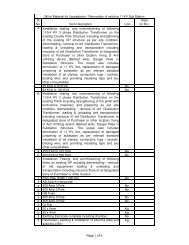
DivisionRoulkela ElectricalDivisionRajgangapur ElectricalDivisionSundergarh ElectricalDivisionJharsuguda ElectricalDivisionDeogarh ElectricalDivisionTABLE - APACKAGE WISE MINIMMUM QUALIFYING REQUIREMENTS - WESCOConstruction of Construction ofNew/Up- New/Up- gradation/Renovati LT Lines/ABConstruction ofgradation 33/11 on of 11 Kv Line or Cabling/Higher Voltage New/Up-gradation ofKv Sub-Station in higher Voltage inLines in Km 11 Kv Sub- Station inNos.KmNos.0 64.600 41.400 14.821 27.000 12.2010 Km. LT line or5 Km. HT Line10 Km. LT line or5 Km. HT Line10 Km. LT line or5 Km. HT Line10 Km. LT line or5 Km. HT Line10 Km. LT line or5 Km. HT Line5 No. 11/0.4KV S/S5 No. 11/0.4KV S/S5 No. 11/0.4KV S/S5 No. 11/0.4KV S/S5 No. 11/0.4KV S/S“The bidder must have executed the quantum of work as mentioned in the Table A aboveduring the last three financial years preceding to the year of tender notification and shouldhave successful operation of minimum period of one year. Bidder must enclose copies ofthe relevant work orders along with client certified copies of Final Invoices and/orPerformance Certificates dully signed by(c) If the bidder(s) participate in multiple packages, the qualifying requirement for workexperience shall be considered /evaluated independently/separately for each package.However, the qualifying requirement for Turn Over shall be added together toqualify the Turnover requirement for each package(s).No bidder shall be awarded work order for more than Five (5) Packagesirrespective of nos. of packages for which he has submitted the bid.(d) The minimum average Annual Turnover of the bidder in any best three financial yearsout of last five financial years should not be less than 50% of the estimated value of allthe package(s) quoted by the bidder(s).(e) Bidder shall be financially sound and stable having liquid assets as stated in theenclosed format and/or access to credit facility of not less than one fifth of estimated costPage 6 of 449
of the package(s) for which he has submitted the bid.NB:1) Only cash at bank / in hand & fixed deposit mentioned in the auditedbalance sheet of last FY shall be considered for accessing the Liquid Asset.2) The average unutilized credit limit during the month prior to the month ofbidding shall be considered to access the credit facility.(f) Two or more like minded contractor(s) and/or manufacturer(s) of electrical items,which are under scope of supply of the contractor as per this tender specification, mayform a joint venture/ consortium agreement amongst themselves and apply against thistender specification, provided they qualify the criteria. The sample format of joint venture/ consortium agreement is enclosed at Section – IV of this tender specification asAnnexure - VI.NOTE: 1) Joint Venture/Consortium Partner shall be limiting to 04 (Four) Members.2) One of the Members shall be an Electrical Contractor having valid HT License.3) Work Order shall be issued in favor of the Lead Partner onlyHowever, if the bidder is quoting against one or more package(s) in his individualcapacity, he cannot be a part of joint venture / consortium agreement to participate insame package(s) as notified against this tender specification & vice versa.(g) If the work experience of one partner is not meeting the entire qualifying criteria, thework experience of the other partner (s) specified in the scope of work shall be addedfor qualifying the bid in total.Lead Partner shall have minimum 50% of Turn Over & 50% of workexperience and other partner(s) together shall have balance 50% Turn over &Work experience.(h) One of the partners shall be nominated as Lead Partner and the lead partner shall beauthorized to incur liabilities and receive instructions for and on behalf of all partners ofthe joint venture / consortium and entire execution of the contract including receipt ofPage 7 of 449
payments shall be done exclusively through the lead partner. This authorization shall beevidenced by submitting by a Power of Attorney signed by legally authorized signatoriesof all partners.(i) All partners of joint venture / consortium shall be liable jointly and severally for theexecution of contract in accordance with the contract terms and a copy of the agreemententered into by the joint venture / consortium partners having such a provision shall besubmitted with the Bid. A statement to this effect shall be included in the authorizationmentioned as above as well as in the Bid form and in Contract form (in case of asuccessful bid).(J)a) In addition to above the bidder(s)/Lead Partner of the bidder(s) should submitthe following documents in part-I bid as qualifying terms.i. Valid electrical (HT) license for electrical works.ii. EPF registrationiii. PAN & TIN No.b) The bidder(s)/Lead Partner of the bidder(s) shall have to furnish service taxregistration, ESI and Labor license within 45 days of receipt of the order.(k)(l)The bidders who have earlier failed to execute the work order(s) of WESCO shall not beeligible to participate in this tender.WESCO reserves the right to waive minor deviation, if they do not materially affect thecapacity of the bidder to perform the contract.3.0 Bids specification document can be obtained from the office of the undersigned onpayment of Rs. 15,000/- towards non-refundable cost of bid documents plus 5 % VAT(Total Rs. 15,750/-) through Bank DD drawn in favour of ―Western Electricity SupplyCompany of Orissa Ltd. payable at Bhubaneswar, during office hours from 11.00 am to5.00 pm till 22.03.2013 .4.0 The tender documents can also be downloaded from any of the following websiteswww.<strong>wesco</strong>odisha.com. In case tender papers are downloaded from these websites,then the bidder has to enclose a Demand Draft, drawn on any Scheduled bank in favourof ―Western Electricity Supply Company of Orissa Ltd. payable at Bhubaneswar,Page 8 of 449
SECTION – IIGENERAL CONDITIONS OF CONTRACT(GCC)TENDER NOTICE NO: CAPEX-WESCO/INSTALLATION/ 35Date: 01.03.2013Page 10 of 449
1.0 GENERAL: -WESCO hereinafter referred to as the “Owner” is desirous of construction of variousSystem Improvement Works under the CAPEX Program, on ‘turnkey’ basis in theirlicensed area in the state of Odisha as described below:(i) Construction of HVDS Systems(ii) Construction of New 11 KV/ 33 KV HT Three Phase Line with AAA Conductor(iii) Up-gradation of Conductor size of existing 11 KV / 33 KV HT Three Phase Line(iv) Shifting of existing 11 KV/33 KV HT Three Phase Lines.(v) Dismantling of existing LT Bare Conductors and Installation of AB Cable(vi) Construction of new 33/11 KV Primary Substation.(vii) Other related works (if any).(viii) Up-gradation of transformer capacity and infrastructure development in existing33/11 KV Primary Substations including erection, commissioning and installedequipments.2.0 Scope of Work: -2.01 The scope shall include supply and <strong>installation</strong> of all materials & equipments to completethe works except the following materials/ equipments which shall be supplied by thePurchaser –a) Power & Distribution (including Station) Transformers.b) AAA Conductorc) AB Cables & Accessories (Suspension clamp, Tension Clamp, Piercing connector,neutral Connector, Eye Hook only)d) 11 KV & 33 KV VCB, CT, PT & CR Panelse) Transformer Distribution Boxes2.02 The detailed scope of the work shall include;i. Detailed survey of substation, line and preparation of SLD / BOQ to be done by thePage 11 of 449
idderii. Complete manufacture, including shop testing & supply of materials from the approvedvendor (materials which are to be supplied by the bidder) on subsequent approval ofthe owner.iii. Providing Engineering drawing, data, operational manual, etc for the Owner’sapproval;iv. Packing and transportation from the manufacturer’s works to the site.v. Receipt, storage, preservation and conservation of equipment at the site.vi. Pre-assembly, if any, erection testing and commissioning of all the equipment;vii. Reliability tests and performance and guarantee tests on completion of commissioning;viii. Loading, unloading and transportation as required.ix. Erection of equipments in Sub-station including civil works.x. Erection of lines of specified voltage.xi. Testing, Commissioning of substations and lines / <strong>installation</strong>sxii. Storing before erectionxiii. Getting the substations & lines inspected by Electrical Inspector after completion ofwork.xiv. Transportation and transit insurance of all free issue materials to be supplied fromOwner’s nearest stores to site and as well as all other required materials (under thescope of supply by bidder) from supplier’s premises to work site, construction of newelectrical / civil structures, etc.xv. Dismantling of existing electrical structures and return of these dismantled items at theOwner’s stores, safe custody of the items and return of unused Owner’s suppliedmaterials to the Owner’s stores.3.0 DEFINITION OF TERMS(i)(ii)The ‘Contract ’means the agreement entered into between the Owner and theContractor as per the Contract Agreement signed by the parties, including allattachments and appendices there to and all documents incorporated by referencetherein.‘Owner’ shall mean WESCO and shall include its legal representatives, successors andassigns.Page 12 of 449
(iii)(iv)(v)(vi)(vii)(viii)(ix)(x)(xi)(xii)(xiii)‘Contractor’ shall mean the Bidder whose bid will be accepted by the Owner for theaward of the Works and shall include such successful Bidder’s legal representatives,successors and permitted assigns.‘Sub-Contractor’ shall mean the person named in the Contract for any part of theworks or any person to whom any part of the Contract has been sublet by the contractorwith the consent in writing of the Owner and will include the legal representatives,successors and permitted assigns of such person.‘Engineer in Charge’ shall mean the officer appointed in writing by the Owner to actas Engineer from time to time for the purpose of the Contract.‘Specifications’ shall mean the specifications and Bidding Document forming a part ofthe Contract and such other schedules and drawings as may be mutually agreed upon.‘Site’ shall mean and include the land and other places on, into or through which theworks and the related facilities are to be erected or installed and any adjacent land,paths, street or reservoir which may be allocated or used by the Owner or Contractor inthe performance of the Contract.‘Inspector’ shall mean the Purchaser or any person nominated by the Owner from timeto time, to inspect the equipment; stores or Works under the Contract and/or the dulyauthorized representative of the Owner.‘Notice of Award of Contract’/ ‘Letter of Award’ shall mean the official noticeissued by the Owner notifying the Contractor that his bid has been accepted.‘Date of Contract’ shall mean the date on which notice of Award of Contract/ Letterof Award has been issued.‘Performance and Guarantee Tests’, shall mean all operational checks and testsrequired to determine and demonstrate capacity, efficiency, and operatingcharacteristics as specified in the Contract Documents.The term ‘Final Acceptance’/ ‘Taking Over’ shall mean the Owner’s writtenacceptance of the works performed under the Contract, after successful commissioning/completion of Performance and Guarantee Tests, as specified in the accompanyingTechnical Specifications or otherwise agreed in the contract.‘Commercial Operation’ shall mean the condition of operation in which the completeequipment covered under the Contract is officially declared by the Owner to beavailable for continuous operation at different loads up to and including rated capacity.Such declaration by the Owner, however, shall not relieve or prejudice the ContractorPage 13 of 449
(xiv)(xv)(xvi)of any of his obligations under the Contract.Words imparting ‘Person’ shall include firms, companies, corporations andassociations or bodies of individuals, whether incorporated or not.Terms and expressions not herein defined shall have the same meaning as are assignedto them in the Indian Sale of goods Act (1930), failing that in the Indian Contract Act(1872) and failing that in the General Clauses Act (1897) including amendmentsthereof, if any.In addition to the above the following definition shall also applya) ‘All equipment and materials’ to be supplied shall also mean ‘Goods’b) ‘Constructed’ shall also mean erected and installed.c) ‘Contract Performance Guarantee’ shall also mean ‘Contract PerformanceSecurity’.4.0 SUBMISSION OF TENDER: -4.01 Sealed tenders in Two parts each in duplicate, each complete in all respects in the mannerhereinafter specified are to be submitted at Regd. Office, NESCO, WESCO & SOUTHCO,N 1/22, IRC Village, Nayapalli, Bhubaneswar – 15 on or before the date and time specifiedin the notice inviting the tenders. Bids shall be submitted as per format provided in Section– III & IV. Each copy of the bids (original and duplicate) shall be submitted in separatedouble sealed envelopes superscripted on each of the covers the tender specificationnumber and the due date of opening of the bids on the right hand top side of the envelop.On the left top side original/ duplicate as is relevant shall be written.4.02 The tenders are required to be submitted in Two Parts each in separate double sealedcovers.‣ Part - I: Superscribed as “Technical and commercial bid” shall contain EMD, Cost of BidDocuments and Techno commercial documents.‣ Part - II, Superscribed as “Price Bid”. The Part - II should contain only Price bid.4.03 Fax and Telegraphic tenders shall not be accepted.Page 14 of 449
4.04 Receipt of bids/ revised bids after the cut off time and date as specified in the Tenderspecification shall not be permitted and such bids shall be rejected outright. The Ownershall not be responsible for any delay in transit in post / courier etc. in this regard.5.0 VALIDITY:-The offer shall be valid for a period not less than 180 days from the date of bid opening.6.0 PRICE: -Bidders are required to quote firm price as per the prescribed format enclosed inSection – III. The quoted price shall be firm and inclusive of all taxes, duties, freight &insurance and other levies, if any. Owner shall not be liable to pay anything extra over andabove the quoted price.7.0 RECEIPT AND OPENING OF THE BID: -7.01 Bids in duplicate as described under clause 4.0 shall be received in the office of the Ownerand shall be opened on the scheduled date and time. The Owner’s authorizedrepresentatives shall open bids in the presence of Bidders’ representatives on the date andtime for opening of bids as specified in the Invitation to Bid or in case any extension hasbeen given thereto, on the extended bid opening date and time notified.7.02 Maximum one representative for each bidder shall be allowed to witness the opening ofbids. The representative must produce suitable authorization in this regard to be eligible towitness the bid opening on behalf of the bidder. Bidders’ representatives who are presentshall sign in a register evidencing their attendance.7.03 The Bidders’ names, bid prices, modifications, bid withdrawals and the presence orabsence of the requisite bid guarantee and such other details as the Owner, at its discretion,may consider appropriate will be announced at the opening. No electronic recordingdevices will be permitted during bid opening.7.04 Information relating to the examination, clarification, evaluation and comparison of Bidsand recommendations for the award of a contract shall not be disclosed to Bidders or anyother persons not officially concerned with such process. Any effort by a Bidder toPage 15 of 449
influence the Owner’s processing of Bids or award decisions may result in the rejection ofthe Bidder's Bid.8.0 EVALUATION OF BIDS & AWARD OF CONTRACT:8.01 To assist in the examination, evaluation and comparison of Bids, the Owner may, at itsdiscretion, ask the Bidder for a clarification of its Bid. All responses to requests forclarification shall be in writing and no change in the price or substance of the Bid shall besought, offered or permitted.8.02 Owner will examine the Bids to determine whether they are complete, whether anycomputational errors have been made, whether required sureties have been furnished,whether the documents have been properly signed, and whether the Bids are generally inorder.8.03 Arithmetical errors will be rectified on the following basis. If there is a discrepancybetween the unit price and the total price per item that is obtained by multiplying the unitprice and quantity, the unit price shall prevail and the total price per item will be corrected.If there is a discrepancy between the Total Amount and the sum of the total price per item,the sum of the total price per item shall prevail and the Total Amount will be corrected.8.04 Prior to the detailed evaluation, Owner will determine the substantial responsiveness ofeach Bid to the Bidding Documents including production capability and acceptable qualityof the Goods offered. A substantially responsive Bid is one, which conforms to all theterms and conditions of the Bidding Documents without material deviation.8.05 The Owner’s evaluation of a Bid will take into account, in addition to the Bid price, thefollowing factors, in the manner and to the extent indicated in this Clause:(a) Work Schedule(b) Deviations from Bidding Documents8.06 The Owner will award the Contract to the successful Bidder whose Bid has beendetermined to be the lowest - evaluated responsive Bid,, when the lowest bidders is notready and/or capable to undertake the entire work envisaged, then the Owner may explorethe possibility of the execution of works through other bidders if they are willing to executePage 16 of 449
obligations to execute the contract by letter and spirit. The contractor shall give thepurchaser advance notice in writing of the Date and the Place at which the materialswill be ready for testing. The inspecting officer coordinating office for the entirework shall be the Owner’s authorized representative.12.0 COMPLETION AND COMPLETENESS OF THE EQUIPMENT:-12.01 Time being the essence of the contract; the work shall be completed within 12 (twelve)months from the date of issue of work order.12.02 The work shall be treated as complete item wise when one item shall be complete in allrespects with all mountings, fixtures and standard accessories which are normallysupplied even though not specifically detailed in the specification. No extra payment shallbe payable for such mounting, fittings, fixtures and accessories which are needed for safeoperations of the equipment as required by applicable code of the country though thismight not have included in the contract.12.03 All similar components and/or parts of similar equipment supplied shall be interchangeablewith one another. Various equipments supplied under this contract shall besubject to Owner’s approval.12.04 Purchaser however reserves the right to re-schedule the completion period, if required.13.0 REJECTION OF MATERIALS: -In the event of the materials supplied by the contractor and/or the <strong>installation</strong> works arefound to be defective in quality and the workmanship is poor or otherwise not inconformity with the requirements of the contract specification as per section-IV (Technicalspecification), Owner shall reject such materials / services and ask the contractor in writingto replace / rectify the defects. The contractor on receipt of such notification shall rectify orreplace the defective materials and/or re-install the work already executed, free of cost tothe Owner. If the contactor fails to do so the Purchaser may at his option take the followingactions which could be on concurrent basis.Page 19 of 449
deviation schedule, it will be presumed that the bidder has accepted all the conditionsstipulated in the tender specification, not withstanding any deviations mentioned elsewherein the Bid. However the acceptance of deviation is not binding on the Owner.16.0 CONTRACTOR TO INFORM HIMSELF FULLY: -The contractor shall examine the instructions, general conditions of the contract,specifications and the schedule of quantity and delivery to satisfy himself as to all the termsand conditions and circumstances affecting the contract price. He shall quote pricesaccording to his own judgment and shall understand that no additional cost except asquoted shall only be considered.17.0 PATENT RIGHT: -The contractor shall indemnify the Owner against all claims, actions, suits and proceedingsfor the alleged infringement any patent design or copy right protected either in country oforigin or in India by the use of any equipment supplied by the contractor but suchindemnity shall not cover any use of the equipment other than for the purpose indicated byor reasonable to be informed from the specification.18.0 GUARANTEE PERIOD: -18.01 The materials to be supplied by the contractor shall be guaranteed for satisfactory operationagainst defects in design and workmanship for a period of 24 months from the date ofhanding over the completed <strong>installation</strong>s after commercial operation at required voltagelevel.18.02 The above guarantee certificate shall be furnished in triplicate to the Owner for hisapproval. Any defects noticed during the above period should be rectified by the Contractorfree of cost to the Utility provided such defects are due to faulty design, bad workmanshipor bad materials used on receipt of written notice from the Owner. The Contractor asnotified by the Owner shall rectify any such defects within one month failing which theOwner will set right the defects through other agency and recover the cost so incurredeither from any pending Invoices or Bank Guarantee.19.0 PENALTY FOR DELAY IN COMPLETION OF CONTRACT: -Page 21 of 449
19.01 If the contractor fails to complete the works by the scheduled period or any extensiongranted thereby, the contractor shall be liable for payment of penalty amounting to 0.5%(half percent) of the contract price per week of un-finished works subject to the maximumof 5% (five percent) of the total contract price and subject to force majeure conditions.After receipt of LOA, the Contractor shall sign a contract agreement with the Owner within15 days along with the detail work plan through PERT chart/BAR chart. The penalty forliquidated damage as mentioned above will be levied if any deviation to be schedule on anyitem of work due to the fault of the contractor is observed.19.02 Penalty amount can be realized from the proceeds of the Contract Performance BankGuarantee, if the situation so warrants.19.03 Extension of delivery period could be with / without levy of penalty with the discretion ofOwner.20.0 RIGHT OF WAY:Right of way issues, if any, arising during execution of the works shall have no liability onthe Owner. These issues shall be settled at the sole discretion of the Contractor. The Ownershall however extend all possible help to the Contractor including discussion with the localauthorities for early resolution of these issues.21.0 CONTRACTOR’S DEFAULT:21.01 If the Contractor neglects to execute the works with due diligence and expedition or refusesor neglects to comply with any reasonable order given to him, in writing by the Engineer inconnection with the works or contravenes the provisions or the contract, the Owner maygive notice in writing to the Contractor to make good the failure, neglect or contraventioncomplained of. Should the Contractor fail to comply with the notice within thirty (30) daysfrom the date of serving the notice, the Owner shall be at liberty to employ other workmenand forthwith execute such part of the works as the contractor may have neglected to do orif the Owner thinks fit, without prejudice to any other right, he may have under theContract to take the work wholly or in part out of the Contractor’s hands and re-contractwith any other person or persons to complete the works or any part thereof and in thatevent the Owner shall have free use of all Contractor’s equipment that may have been atPage 22 of 449
the time on the Site in connection with the works without being responsible to theContractor for fair wear and tear thereof and to the exclusion of any right of the Contractorover the same, and the Owner shall be entitled to retain and apply any balance which mayotherwise be due on the Contract by him to the Contractor, or such part thereof as may benecessary, to the payment of the cost of executing the said part of works or of completingthe works as the case may be. If the cost of completing of works or executing part thereofas aforesaid shall exceed the balance due to the Contractor, the Contractor shall pay suchexcess. Such payment of excess amount shall be independent of the liquidated damages fordelay which the Contractor shall have to pay if the completion of works is delayed.21.02 In addition, such action by the Owner as aforesaid shall not relieve the Contractor of hisliability to pay liquidated damages for delay in completion of works.21.03 Such action by the Owner as aforesaid the termination of the Contract under this clauseshall not entitle the Contractor to reduce the value of the Contract Performance Guaranteenor the time thereof. The Contract Performance Guarantee shall be valid for the full valueand for the full period of the Contract including guarantee.22.0 TERMINATION OF CONTRACT ON OWNER’S INITIATIVE:22.01 Owner reserves the right to terminate the Contract either in part or in full due to reasonsother than those mentioned under clause entitled ‘Contractor’s Default’. The Owner shallin such an event give fifteen (15) days notice in writing to the Contractor of his decision todo so.22.02 The Contractor upon receipt of such notice shall discontinue the work on the date and tothe extent specified in the notice, make all reasonable efforts to obtain cancellation of allorders and Contracts to the extent they related to the work terminated and termssatisfactory or the Owner, stop all further sub-contracting or purchasing activity related tothe work terminated, and assist Owner in maintenance, protection, and disposition of theworks acquired under the Contract by the Purchaser. In the event of such a termination theContractor shall be paid compensation, equitable and reasonable, dictated by thecircumstance prevalent at the time of termination to be determined by the arbitrator withoutstopping the work but to carry out the left over work to other agency.Page 23 of 449
22.03 If the Contractor is an individual or a proprietary concern and the individual or theproprietor dies and if the Contractor is a partnership concern and one of the partners diesthen unless the Owner is satisfied that the legal representatives of the individual Contractoror of the proprietor of the propriety concern and in the case of partnership, the survivingpartners, are capable of carrying out and in the case of partnership, the surviving partners,are capable of carrying out and completing the Contract the Owner shall be entitled tocancel the Contract as to its uncompleted part without being in any way liable to paymentof any compensation to the estate of deceased Contractor and /or to the surviving partnersof the Contractor’s firm on account of the cancellation of the contract. The decision of theOwner that the legal representatives of the deceased Contractor or surviving partners of theContractor’s firm cannot carry out and complete the contract shall be final and binding onthe parties. In the event of such cancellation the Owner shall not hold the estate of thedeceased Contractor and/ or the surviving partners of the Contractor’s firm liable todamages for not completing the Contract.23.0 FORCE MAJEURE: -The Contractor shall not be liable for any penalty for delay or for failure to perform thecontract for reasons of Force Majeure such as “acts of God, acts of the Public enemy, actsof Govt., Fires, Flood, Epidemics, Quarantine restrictions, Strikes, Freight Embargos andprovided that the Contractor shall within ten (10) days from the beginning of such delaynotify the Owner in writing of the cause of delay. The Owner shall verify the facts andgrant extension as facts justify.24.0 EXTENSION OF TIME: -If the delivery of the equipments / materials is delayed due to reasons beyond the control ofthe Contractor, the Contractor shall immediately inform within 3 days to the Owner inwriting of his claim for an extension of time. The Owner on receipt of such notice mayagree to extend the contract period as may be reasonable but without prejudice to otherterms & conditions of the contract.25.0 SAFETY PRECAUTIONS:-The agency shall observe all applicable regulations regarding safety at the Site. Anycompensation due on account of accident at site shall be to the contractor’s account.Page 24 of 449
26.0 STORE:-Storing of materials from supply to erection shall be arranged by the contractor at his owncost. No compensation shall be made by the Owner for any damage or loss of materialsduring storing, transit transportation and at the time of erection.27.0 INSURANCE: -Contractor shall arrange adequate Transit-cum-storage-cum-erection policy andshall submit the copy of the same to the Owner. The policy shall initially remainvalid for a period of sixty days over & above of the contractual guarantee periodand shall be extended as required till handing over. Contractor shall be responsiblefor lodging of claim with the insurer as well as for all required follow up with theinsurer for settlement of claim in case of loss/damage/theft of material duringtransit/storage/erection till the completed works is handed over to the Purchaser andis accepted by the authorized representative of the Purchaser in writing.Contractor shall also arrange adequate cover for his employees / labourers engagedin the works as well as arrange third party insurance cover to indemnify anypossible damages to public at large not connected with the works process. Anyclaim(s) pertaining to this shall be the responsibility of the Contractor.The contractor shall undertake free replacement of the materials damaged or lost duringtransit, which will be intimated by the Consignee within 30 days of receipt of the materialsat Owner’s stores.28.0 ENGINEER IN CHARGE:-Concerned Divisional Head / authorized engineer of the Owner shall be theEngineer in charge for the Project.29.0 CONTRACT PERFORMANCE BANK GUARANTEE:-29.01 Within 15 days of issue of the Work Order or Letter of Award, whichever is earlier, theContractor shall submit Contract Performance Bank Guarantee issued by a scheduled Bank,in favour of the Owner, covering 10% of the total value of the work order,Page 25 of 449
29.02 The said Bank Guarantee shall be prepared in the prescribed proforma as attached inSection IV, Annexure - III. The Bank Guarantee furnished shall be executed on NonjudicialStamp paper worth of Rs 100/- (Rupees Hundred only), purchased in the name ofthe issuing bank, as per the prevalent rules. The Bank Guarantee so provided shall been-cashable on the Bhubaneswar branch of the issuing Bank.29.03 The Contract Performance Bank Guarantee shall remain valid for a period not less than 90days over and above the guarantee period, basing on stipulated completion period in theW.O. towards security and acceptance thereof, failing which the work orders (W.O) will beliable for cancellation without any further notice with forfeiture of E.M.D.29.04 No interest shall be allowed by the Owner on the above Performance Security Deposit.30.0 TERMS OF PAYMENT:30.01 An advance of 10% (ten percent) of total lump sum contract price shall be paid asMobilization Advance, subject to the following.(a)(b)(c)(d)(e)Submission of Invoice for payment of advance.Receipt and acceptance of unconditional irrevocable Contract Performance BankGuarantee in favour of Owner as mentioned in clause 29.01.Receipt and acceptance of unconditional and irrevocable Advance Payment BankGuarantee in favour of Owner for an amount equivalent to the amount of advance asper the prescribed format as provided in Section IV, Annexure - IV. The BankGuarantee so provided should be en-cashable on the Bhubaneswar branch of theissuing Bank.Establishment of contract site office and certification by the engineer that satisfactorymobilization for erection exists.All advance payment shall be interest bearing and recovery of advance along withthe interest component on the advance amount shall be as under:i) All advance payment made shall be recovered proportionately from each runningbill of the contractor.ii) The amount of interest to be recovered from a particular bill shall be calculated @10% per annum on the value of advance corresponding to the percentage of totalPage 26 of 449
progressive payment being released. The period for which the interest is to becalculated shall be reckoned from the date of release of the advance payment tothe actual date of release of the said progressive payment or the expiry of thestipulated time frame for release of such progressive payment. If any amountpayable under any interim bill is not sufficient to cover all deductions to be madefor interest on the advance payment and other sums deductible there from, thebalance outstanding shall be recovered from the next payments immediatelyfalling due.30.02 80% (Eighty percent) of contract price on pro-rata basis along with taxes and duties shallbe paid progressively (after necessary advance adjustment with interest as applicable) foreach completed items of work certified by the Jr. Manager, Asst. Manager/SDO concernedagainst each calendar month by first week of the succeeding months along with utilizationcertificate. No payment shall be released if the accounts for utilization of materials unlessfollow with proper certification by the concerned Jr. Manager, Asst. Manager/SDO within30 days of submission of claim subject to certification by Owner’s Engineer-in-charge onthe basis of check points involved in such items of work.30.03 Balance 20% (twenty percent) of contract price shall be paid after completion of all works,envisaged under this package including any additions and alterations, testing &commissioning, return of dismantled materials/ un-used free supply material, taking overcertificate and entire stretch is fully ready for commercial operation. The payments shallbe subjected to clearance from electrical inspectorate.Note: In case of joint venture/consortium Performance Bank Guarantee shall be providedby the Lead Partner @ 10% and additional 1% by each JV Partner(s).31.0 PAYING OFFICER:Owner shall notify the paying officer for the project.32.0 OWNER’S RIGHTS: -Page 27 of 449
The Owner reserves the right to accept any bid or reject any or all bids or cancel / withdrawinvitation of bid or to vary the quantity for placement of order without assigning any reasonto such decision. Such decision by the Owner shall bear no liability.33.0 DISTINCT MARK ON EQUIPMENT AND MATERIALS:All the equipments and materials required for the works shall have distinct mark of Ownereither by way of punching on metal part(s) and/or in built during casting and/or painting asper common practice and/or as mutually agreed. This should be clearly visible in day lightin naked eye.34.0 DISPUTE RESOLUTION AND JURISDICTION: -(a) Any disputes arising out of this contract shall be referred to the MD, OPTCL whoshall decide the case as sole Arbitrator.(b) For the purpose of dispute resolution, this agreement shall be governed by theprovision of Arbitration and Conciliation Act, 1996.(c) All disputes shall be subjected to exclusive jurisdiction of the Courts atBhubaneswar and the writ jurisdiction of Hon’ble High Court of Odisha at Cuttack.35.0 TRANSFER AND SUB-LETTINGThe Contractor shall not sublet, transfer, assign or otherwise part with the Contract orany part thereof, either directly or indirectly, without prior written permission of theOwner.36.0 FREE ISSUE OF MATERIALS36.01 Purchaser shall issue materials such as Transformer, VCB, Conductor, AB Cable &Accessories (Suspension Clamp, Dead End Clamp, Eye Hook, Piercing Connector, NeutralConnector), Transformer Distribution Boxes to the Contractor as per the works scheduleagreed at the time of award of works as stated in the scope of work. However, this shallbe subject to the actual progress of the work as certified by the Owner’s Engineer.Page 28 of 449
36.02 Before issue of the free issue materials the Contractor at its own cost shall arrangesuitable stores adjacent to the works site and shall offer the same for inspection to theOwner’s Engineer.36.03 The contractor shall furnish Indemnity bond for an amount equivalent to theestimated value of the free supply materials / dismantled materials returnable ascertified by Engineer in charge. The Contractor shall submit Indemnity Bond in theprescribed format.36.04 Subject to compliance of above clauses, the Contractor shall be permitted to draw thematerials from the designated stores of the Owner. The Contractor shall dulyacknowledge the materials along with copies of the notification to the Insurer regardingsuch transit of material from designated stores of the Owner to the stores of theContractor.36.05 After completion of the works all surplus materials shall be returned to the Purchaser’sstores. For any shortage with regard to materials supplied by the Purchaser, the Purchasershall be entitled to recover 125% of the purchase cost of such materials or present marketcost, whichever is higher, from the dues of the Contractor.37.0 SUBMITTALS REQUIRED AFTER AWARD OF CONTRACT37.01 Within 30 days of the effective date of contract the contractor shall provide three copies ofan outline program of production, inspection, testing, delivery, survey, erection, precommissioningand commissioning in chart form. Included in the program will be thedetailed schedule of drawing to be submitted.37.02 The periodic progress report as required by the Owner shall be submitted by the contractoras per the format prescribed by the Engineer in Charge.38.0 DRAWINGSWithin 15 days of contract commencement the contractor shall submit, for approval by theEngineer in Charge, a schedule of the drawings to be produced. The schedule shall alsoPage 29 of 449
provide a program of drawing submission, for approval by the Engineer in Charge. Alldrawings and design should be submitted to Engineer-In-Charge within the periodspecified above.39.0 APPROVAL PROCEDURE OF SUB VENDORS & DRAWINGS OF BOUGHTOUT MATERIALS39.01 The contractor shall submit all drawings, documents and type test reports, QAP, Name ofSub vendor, samples (as applicable) etc, to the engineer in charge within 15 days of awardof LOA for approval. If modifications to be made if such are deemed necessary, thecontractor has to resubmit them for approval without delaying the initial deliveries orcompletion of the contract work.39.02 Three copies of all drawings, GTP, QAP shall be submitted for approval and three copiesfor any subsequent revision.39.03 If the drawings will be as per the technical specifications, the competent authority of thePurchaser will return the drawings & documents to the contractor marked with “Approved”stamp.40.0 TAKING OVER40.1 Upon successful completion of all the tests to be performed at site on equipment / materialssupplied, erected and commissioned by the contractor, the supply engineer shall issue tothe contractor a taking over certificate as a proof of the final acceptance of the equipment /materials on a written request within 10 days of commercial operation. Such certificateshall not be un-reasonably withheld nor will the engineer delay the issuance thereof onaccount of minor omission or defects, which do not affect the commercial operation and /or cause any serious to the equipment/material. The conditional Taking over Certificate canbe issued if any minor omission or defects pointed by the Engineer-in-Charge/SupervisingOfficer/Electrical Inspector. The Contractor should rectify those defects within a month ofconditional T.O.C failing which Owner will rectify those by replacing those materials orengaging other agencies. The amount so involved will be fully recovered from theContractor’s bill. Such certificate shall, however, not relieve the contractor of any of hisPage 30 of 449
obligations which otherwise survive by the terms & conditions of the contract afterissuance of such certificate.40.2 For the satisfaction of Owner about quality, the Owner shall have unreserved right forarrangement of testing of equipment/ materials and the complete system independently byself or any other agency chosen by the Owner. The contractor is expected to agree andextend necessary help during such test if necessary.41.0 LATENT DEFECT WARRANTY41.1 The period of latent defect warranty in terms of this bidding documents, shall be limited tofive (05) years from the date of completion of Guarantee period.42.0 EMBOSSING / PUNCHING / CASTING / PAINTING42.1 The all equipments and materials supplied /erected under the CAPEX Programme shall beardistinct mark of “Name of the Purchaser, GoO, CAPEX Programme, PO Order No. & Date”by a way of embossing / punching / casting / painting etc. This should be clearly visible tonaked eye.43.0 INDEMNIFY43.1 The Contractor, its successor and assignee shall indemnify the Owner, its successor andassignee from all current & future liabilities that may arise out of Turn Key Contract(s)entered into between the Owner & the Contractor under this CAPEX Programme. TheOwner in term shall indemnify the GoO & GRIDCO.Page 31 of 449
SECTION - IIIANNEXUREPage 32 of 449
BID PROPOSAL LETTERElectrical Installation of Works under WESCOANNEXURE – IBidder‘s Name and Address:(in case of JV/Consortium, Name of JV/Consortium)Bid Proposal Reference:Person to be contacted:Designation:Telephone No. : E-mail: Fax No. :To,CAPEX CELLRegistered Office of NESCO, WESCO & WESCO:N 1/22, IRC Village, Nayapalli, Bhubaneswar – 751015Dear Sir,We the undersigned bidder have read and examined the detailed specification and biddingdocuments for execution of various electrical <strong>installation</strong>s works and do herewith submit ourbid for the following packages:Sl.No.Name of theOwnerName of thePackageEstimated Cost(Rs. in Cr.)We declare the following:1.0 PRICES AND VALIDITY:1.01 All the prices and price components stated in our bid proposal are firm and not subjectto any price adjustment, in line with the bidding documents. All the prices and otherterms and conditions of this proposal are valid for a period of 180 days from the date ofPage 33 of 449
opening of the bids. We further declare that prices stated in our proposal are inaccordance with ―Instructions to Bidders‖ of bidding documents.1.02 We do hereby confirm that our bid prices as quoted in attached Schedules include allimport duties and levies including license fees lawfully payable by us on imported itemsand other taxes, duties and levies applicable on bought – out components, materials,equipment and other items and confirm that any such taxes, duties and leviesadditionally payable shall be to our account.1.03 We confirm that the Sales tax on Works Contract, Turnover Tax or any other similartaxes under the Sales Tax Act, as applicable, are included in our quoted bid price andthere shall not be any liability on this account to the Purchasers. We understand thatOwner shall, deduct such taxes at source as per the rules and issue TDS Certificate tous.1.04 We confirm that, in our Bid Price, we have considered service tax in line with lawfulprevalent practice.1.05 Price components of various items are indicated in the B.O.Q. for the respective works.1.06 We further declare that while quoting the price, the due credit under MODVAT scheme,re-christened as CENVAT scheme, as per relevant Government policies whereverapplicable, have been taken into account.1.07 We, having studied the bidding document in three volumes relating to taxes & dutiesand hereby, declare that if any income tax, charge on income tax or any other corporatetax is attracted under the law, we agree to pay the same.1.08 We are aware that the Price schedules do not generally give a full description of thesupplies to be made and work to be performed under each item and we shall be deemedto have read the Technical Specifications and other bidding documents and drawings toascertain the full scope of work included in each item while filling in the related andprices. We agree that the entered rates and prices shall be deemed to include the fullscope as aforesaid, including overheads and profits.Page 34 of 449
1.09 We understand that in the price schedule, if there is discrepancy between the unit priceand total price, the same shall be corrected as per relevant provisions.1.10 We declare that prices for items left blank in the schedules will be deemed to have beenincluded in other items. The TOTAL for each schedule and the TOTAL of Grandsummary shall be deemed to be the total price for executing the facilities and sectionsthereof in complete accordance with the contract, whether or not each item has beenpriced.2.0 CONSTRUCTION OF THE CONTRACT2.01 We declare that we are making the offer on the basis of indivisible supply-cum-Erection contract on a single source responsibility basis.3.0 BID SECURITY (EMD)We are enclosing Bank Draft / Bank Guarantee No. dtd. amounting toRs.--------------------- (RupeesPage 35 of 449only) issued byBank ---------------------------branch, payable on Bhubaneswar towards Bid Securityagainst our above Bid. The Bid Security amount has been computed by adding theEstimated Cost of the package nos. ------------------- For which we are submitting ourbid.4.0 EQUIPMENT PERFORMANCE GURANTEEWe declare that the ratings and performance figures of the equipment to be furnishedand erected by us are guaranteed. The Guaranteed particulars of different equipmentsare enclosed along with our bid.5.0 BID PRICINGWe further declare that the prices stated in our proposal are in accordance with your‗Instruction of Bidders of Conditions of Contract, Volume-1 of the bid documents.6.0 PRICE ADJUSTMENTWe declare that all the prices and price components stated in our offer are on FIRMprice basis.
7.0 QUALIFICATIONWe confirm having submitted the Qualification Data in original plus one copy, asrequired by you under clause 6.0 ‗Invitation for Bids‘. Further we have filled in theinformation for qualification requirements. In case you require any furtherinformation in this regard, we agree to furnished the same in time .8.0 DEVIATIONS8.01 We declare that the contract shall be executed strictly in accordance with thespecifications and documents except for the variations and deviations all of whichhave been detailed out exhaustively in the following schedules, irrespective ofwhatever has been stated to the contrary anywhere else in our proposal.a) Commercial Deviations Scheduleb) Cost of withdrawal of Deviations on Criticalc) Technical Deviation Schedule8.02 We confirm that specified stipulation of following critical clauses is acceptable to usand no deviations/exceptions are taken on any account whatsoever in the followingclauses:(a) Payment Terms :(b) Bid Guarantee :(c) Contract Performance Guarantee :(d) Liquidated Damages for delay :(e) Prices and Price Adjustment :(f) Guarantee / Warrantees :8.03 Further, we agree that the additional conditions, deviations, if any, found in our bidproposal documents other than those stated in attached Deviation Schedules, save thatpertaining to any rebates offered, shall not be given effect to.9.0 ADDITIONAL INFORMATIONWe have included with this proposal additional information listed. We further confirmthat such additional information does not imply any additional deviation beyond thosecovered in appropriate schedules and in case of any contradiction between theseadditional information and other provisions of Bid, the latter prevail.10.0 GURANTEE DECLARATIONPage 36 of 449
We guarantee that the equipment offered shall meet the rating and performancerequirements stipulated in this specification. The Guarantee Declaration which shallattract levy of liquidated damages for non-performance is indicated in the relevantschedule.11.0 BOUGHT-OUT AND SUB-CONTRACTED ITEMWe are furnishing herewith at appropriate Schedule, the detail of all major item ofsupply amounting to more than 10% of our Bid Price, which were propose sublettinggiving detail of the name of sub-contractor/sub-vendor and quantity for each item.12.0 WORK SCHEDULEIf this proposal is accepted by you, we agree to submit engineering data, provideservices and complete the entire work from time to time, in accordance with scheduleindicated in the proposal. We fully understand that the time schedule stipulated in thisproposal is the essence of the contract, if awarded. The completion schedule of thevarious major key phases of the work is indicated in the designated schedule.13.0 CONTRACT PERFORMANCE GUARANTEEWe further agree that if our Bid is accepted we shall provide an irrevocable Bankguarantee towards Contract Performance Guarantee, of value equivalent to ten percent(10%) of the Contract Price initially valid up to the end of ninety (90) days after the endof the contract warranty period in the form of Bank Guarantee in your favour within 15(fifteen) days from the date of ‗Notice of Award of Contract‘ and enter into a formalagreement with you immediately thereafter.14.0 CHECK LISTWe have included a check list duly filled in Schedule. We understand that only thischeck list, commercial and technical deviation will be read out during the part-I bidopening before the bidders present.(For Joint Venture/consortium only) We, the Partners of joint venture/ consortiumsubmitting their Bid, do agree and confirm that in case of Award of the Contract on thejoint venture, we shall be jointly and severally responsible for the execution of thePage 37 of 449
ANNEXURE – IITo,DECLARATION FORMCAPEX CELLRegistered Office of NESCO, WESCO & WESCO: N1/22, IRC Village, Nayapalli,Bhubaneswar – 751015Sir,Having examined the above specifications together with the Tender terms and conditionsreferred to therein1 – I / We the undersigned do hereby offer to execute the contract covered there on in completeshape in all respects as per the rules entered in the attached contract schedule of prices in thetender.2 – I / We do hereby under take to have executed the contract within the time specified in thetender.3 – I / We do hereby guarantee the technical particulars given in the tender supported withnecessary reports from concerned authorities.4 – I / We do hereby certify to have purchased a copy of the tender specifications by remittingCash / Demand draft & this has been duly acknowledged by you in your letterNo…………Dt…………5 – I / We do hereby agree to furnish the composite Bank Guarantee in the manner specified /acceptable by WESCO (as the case may be) & for the sum as applicable to me / us as perclause No.13 of Annexure -V of this specification within fifteen days of issue of Letter of intent/ Work Order , in the event of Work order being decided in my / us favour , failing which I /We clearly understand that the said LOI / W.O. shall be liable to be withdrawn by the Owner.Signed this…………….Day of……………………20…Yours faithfully(Signature of Bidder with Seal of Company)Page 39 of 449
ANNEXURE – IIIPROFORMA FOR CONTRACT PERFORMANCE BANK GUARANTEE(To be executed on Rs. 100/- Non-judicial Stamp Paper purchased in the name of the BGIssuing Bank)This Guarantee Bond is executed this ____ day of ___________________________ by us,_____________________________________________________ Bank at ___________________P.O.__________ P.S. ____________Dist ________________ State __________Whereas Western Electricity Supply Company of Orissa Ltd.(WESCO) ,Regd. Office: N 1/22, IRC Village,Nayapalli, Bhubaneswar – 751015 registered under the Company Act 1956 (here in after called―Owner) has placed Work Order No. Dt. (hereinafter called ―Agreement‖) with M/s(hereinafter called the Contractor‖) for supply and <strong>installation</strong> of(description of the works) and whereas Owner has agreed (1) toexempt the Contractor from making payment of security deposit, (2) to release 100% payment ofthe cost of materials as per the said agreement and (3) to exempt from performance guarantee onfurnishing by the Contractor to Owner a composite Bank Guarantee of the value of 10% (tenpercent) of the Contract price of the said Agreement.1. Now, therefore, in consideration of Owner having agreed (1) to exempt the Contractor formaking payment of security deposit, (2) to release 100% payment to the Contractor and (3) toexempt from furnishing performance guarantee in terms of the said Agreement as aforesaid, wethe Bank, Address (code No. ) (hereinafter referred to as the Bank) do herebyundertake to pay to the Owner an amount not exceeding Rs. (Rupees ) only against anyloss or damage caused to or suffered by the Owner by reason of any breach by the saidContractor(s) of any of the terms or conditions contained in the said Agreement.2. We, the ____________________Bank do hereby undertake to pay theamounts due and payable under the guarantee without any demur, merely on a demand fromOwner stating that the amount claimed is due by way of loss or damage caused to or sufferedby Owner by reason of any breach by the said Contractor(s) of any of the terms or conditionscontained in the said Agreement or by the reason of any breach by the said Contractor‘s failureto perform the said Agreement. Any such demand made on the Bank shall be conclusive asregards the amount due and payable by the Bank under this Guarantee. However, our liabilityunder this guarantee shall be restricted to an amount not exceeding Rs. (Rupees) only.3. We, the Bank also undertake to pay to Owner any money so demandednot withstanding any dispute or dispute raised by the Contractor(s) in any suit or proceedinginstituted/ pending before any court or Tribunal relating thereto our liability under thisagreement being absolute and irrevocable. The payment so made by us under this bond shallbe valid discharge of our liability for payment there under and the Contractor(s) shall haveno claim against us for making such payment.Page 40 of 449
4. We, the _________________________ Bank further agree that the guarantee herein contain shallremain in full force and effect during the period that would be taken for the performance ofthe said Agreement and it shall continue to remain in force endorsable till all the dues ofOwner under by virtue of the said Agreement have been fully paid and its claim satisfied ordischarged or till Purchaser certifies that the terms and conditions of the said Agreementhave been fully and properly carried out by the said Contractor(s) and accordingly dischargethis guarantee and will not be revoked by us during the validity of the guarantee period.Unless a demand or claim under this guarantee is made on us or with our Bhubaneswarbranch atcode No.) in writing on or beforeall liability under this guarantee thereafter.(Name, address of the Bhubaneswar branch and(date) we shall be discharged from5. We, the Bank further agree that Owner shall have the fullest libertywithout our consent and without affecting in any manner our obligations hereunder tovary any of the terms and conditions of the said Agreement or to extend time of performanceby the said Contractor(s) and we shall not be relieved from our liability by reason of any suchvariation or extension being granted to the said Contractor(s) or for any forbearanceact or omission on part of Owner or any indulgence by Owner to the said Contractor(s)or by any such matter or thing whatsoever which under the law relating to sureties wouldbut for this provisions have effect of so relieving us.6. The Guarantee will not be discharged due to change in the name, style and constitutionof the Bank and or Contractor(s).7. We, the _________________________ Bank lastly undertake not to revoke this Guaranteeduring its currency except with the previous consent of the Owner in writing. Dated___________ the __________ day of Two thousand _________. Notwithstanding anythingcontained herein above. Our liability under this Bank Guarantee shall not exceedRs.______________(Rupees___________________________________________________________________________ ) only. The Bank Guarantee shall be valid up to_____________________ only. Our ………………………. branch at Bhubaneswar (Name &Address of the Bhubaneswar branch) is liable to pay the guaranteed amount depending on thefiling of claim and any part thereof under this Bank Guarantee only and only if you serve uponus at our Bhubaneswar branch a written claim or demand and received by us at ourBhubaneswar branch on or before Dt.__________ otherwise bank shall be discharged of allliabilities under this guarantee thereafter.For _____________________________________(Indicate the name of the Bank)Page 41 of 449
N.B.:(1) Name of the Contractor:(2) No. & date of the Work order/ agreement:(3) Amount of W.O:(4) Name of Work:(5) Name of the Bank:(6) Amount of the Bank Guarantee:(7) Name, Address and Code No. of the Bhubaneswar Branch of the Issuing Bank:(8) Validity period or date up to which the agreement is valid:(9) Signature of the Constituent Authority of the Bank with seal:(10) Name & addresses of the Witnesses with signature:(11) The Bank Guarantee shall be accepted only after getting confirmation from theissuing Branch & from main branch/specified branch at Bhubaneswar of issuing Bank.Page 42 of 449
ANNEXURE – IVPROFORMA OF BANK GUARANTEE FOR ADVANCE PAYMENT(To be stamped in accordance with Stamp Act)(To be executed on Rs. 100/- Non-judicial Stamp Paper purchased in the name of the BGIssuing Bank)Ref............................To,The Managing Director,WESCO, BurlaBank Guarantee No.................Date ............................Dear Sir,In consideration of Whereas Western Electricity Supply Company of Orissa Ltd. (WESCO)(hereinafter referred to as the ‗Owner‘, which expression shall, unless repugnant to the contextor meaning thereof include its successors, administrators and assigns) having awarded toM/s.................. (hereinafter referred to as the “Contractor which expression shall unlessrepugnant to the context or meaning thereof, include its successors, administrators, executorsand assigns), a Contract by issue of Owner‘s Letter of Award No.................. dated ...................and the same having been acknowledged by the Contractor, resulting in a Contract bearingNo....................... dated .................. valued at ...................... for.................................................................. (Scope of work)................................... (Hereinaftercalled the 'Contract‘) and the Owner having agreed to make an advance payment to theContractor for performance of the above Contract amounting................................. (in wordsand figures ) as an advance against Bank Guarantee to be furnished by the Contractor.We,................................................................................................................. (Name of the Bank)having its Head Office at .............................. (hereinafter referred to as the ‗Bank‘, whichexpression shall, unless repugnant to the context or meaning thereof , include its successors,administrators, executors and assigns ) do hereby guarantee and undertake to pay the Owner,immediately on demand any or, all monies payable by the Contractor to the extent of..................................... as aforesaid at any time up to ........ @ ............... without any demur,Page 43 of 449
eservation, contest, recourse or protest and / or without any reference to the Contractor. Anysuch demand made by the Owner on the Bank shall be conclusive and binding notwithstandingany difference between the Purchaser and the Contractor or any dispute pending before anyCourt, Tribunal, Arbitrator or any other authority. We agree that the guarantee herein containedshall be irrevocable and shall continue to be enforceable till the Owner discharges thisguarantee.The Owner shall have the fullest liberty without affecting in any way the liability of the Bankunder this guarantee, from time to time to vary the advance or to extend the time forperformance of the Contract by the Contractor. The Owner shall have the fullest liberty withoutaffecting this guarantee, to postpone from time to time the exercise of any powers vested inthem or of any right which they might have against the Contractor, and to exercise the same atany time in any manner, and either to enforce or to forbear to enforce any covenants, containedor implied, in the Contract between the Owner and the Contractor or any other course or remedyor security available to the Owner. The Bank shall not be released of its obligations under thesepresents by an exercise by the Owner of its liberty with reference to the matters aforesaid or anyof them or by reason of any other act or forbearance or other acts of omission or commission onthe part of the Owner or any other indulgence shown by the Owner or by another matter or thing,whatsoever, which under law would, but for this provision have the effect of relieving theBank.Bank also agrees that the Owner at its option shall be entitled to enforce this Guarantee againstthe Bank as a principal debtor, in the first instance without proceeding against the Contractorand notwithstanding any security or other guarantee that the Owner may have in relation to theContractor'‘ liabilities.Notwithstanding anything contained hereinabove our liability under this guarantee is limited to.................. and it shall remain in force up to and including ...........@ ........... and shall beextended from time to time for such period (not exceeding one year ), as may be desired byM/s. ........................ on whose behalf this guarantee has been given.The Guarantee will not be discharged due to change in the name, style and constitution of theBank and or Contractor(s).Page 44 of 449
All other contentions in B.G will safe guard the interest of Owner.We, theBank lastly undertake not to revoke this Guaranteeduring its currency except with the previous consent of Owner in writing.Dated ___________ the__________day of Two thousand _________Notwithstanding anything contained herein above.Our liability under this Bank Guarantee shall not exceed Rs.) only.The Bank Guarantee shall be valid up toonly.(RupeesOur ………………………. branch at Bhubaneswar (Name & Address of the Bhubaneswarbranch) is liable to pay the guaranteed amount depending on the filing of claim and any partthereof under this Bank Guarantee only and only if you serve upon us at our Bhubaneswarbranch a written claim or demand and received by us at our Bhubaneswar branch on or beforeDt.thereafter.For(indicate the name of the Bank )WITNESSotherwise bank shall be discharged of all liabilities under this guaranteeDated this .............. Day of .........20......... at ................................................................................................. ...............................................................................(Signature)(Signature)......................................................... ...............................................................................(Name)(Name).......................................................... ...............................................................................(Official Address)(Designation with Bank Stamp)Attorney as perPower of Attorney No...................Dated ...........................................@ This date shall be ninety (90) days after the schedule date of completion of theContract.Page 45 of 449
ANNEXURE – VFORM OF POWER OF ATTORNEY FOR JOINT VENTURE(On Non –Judicial Stamp Paper of Appropriate valueto be Purchased in the Name of Joint Venture)KNOW ALL MEN BY THESE PRESENTS THAT WE, the Members whose details are givenhereunder…………………………….. have formed a joint Venture/Consortium and having ourRegistered Office (s)/Head Office (s) at ……………………………….(hereinafter called the‗Joint Venture/Consortium‘ which expression shall unless repugnant to the context or meaningthereof, include its successors, administrators and assigns) do hereby constitute, nominate andappoint M/s…………………………………………….a company/Electrical Contractorincorporated under the laws of …………..and having its Registered/Head Office at…………….as our duly constituted lawful Attorney (hereinafter called ―Attorney‖ (hereinaftercalled Lead Member) to exercise all or any of the powers for and on behalf of the jointventure/Consortium in regard to Tender Notice No…………….. for construction of……………. (name of the package) of WESCO (hereinafter called the ―Owner‖) for whichbids have been invited by the Owner, to undertake the following acts :(i) To submit proposal, participate and negotiate in respect of the aforesaid Bid –Specification of the Owner on behalf of the ―Joint Venture / Consortium‖.(ii)(iii)To negotiate with Owner the terms and conditions for award of the contract pursuant tothe aforesaid Bid and to sign the contract with the Owner for and on behalf of the ―JointVenture / Consortium‖.To do any other act or submit any document related to the above.(iv) To receive, accept and execute the contract for and on behalf of the ―Joint Venture /Consortium‖.(v) To submit the Contract performance security in the form of an unconditionalirrecoverable Bank Guarantee in the prescribed format and as per terms of the contract.It is clearly understood that the Lead Member shall ensure performance of the contracts(s) andPage 46 of 449
if one or more Member fail to perform their respective portion of the contracts(s), the sameshall be deemed to be a default by all the Members.It is expressly understood that this power of Attorney shall remain valid, binding andirrevocable till completion of the Defect of liability period in terms of the contract.The Joint Venture / Consortium hereby agrees and undertakes to ratify and confirm all thewhatsoever the said Lead Member quotes in the bid, negotiates and signs the Contract with theOwner and / or proposes to act on behalf of the Joint Venture / Consortium by virtue of thisPower of Attorney and the same shall bind the Joint Venture / Consortium as if done by itself.IN WITNESS THEREOF the Members Constituting the Joint Venture / Consortium asaforesaid have executed these presents on this ………… day of …….. under the Common Seal(s) of their CompaniesThe Seal of the above Partners of the Joint Venture / Consortium:The Seal has been affixed there unto in the presence of:WITNESS1. Signature …………………………………Name …………………………………Designation …………………………………Occupation …………………………………for and on behalf ofthe members of Joint Ventures/Consortium………………………………………………………………………………………………………2. Signature …………………………………...Name ……………………………………….Designation …………………………………Occupation …………………………………Page 47 of 449
FORM OF JOINT VENTURE/ CONSORTIUM AGREEMENTANNEXURE – VI(To be executed on non-judicial stamp paper of appropriate value to be purchased in the name ofexecutants or as required by the Jurisdiction in which executed)THIS Joint Venture/Consortium Agreement executed on this ……….. day of …………… Twothousand …………………… by:M/s. …………….…………….a company/Partnership Firm/Sole Proprietorship Organizationincorporated under the …………….……………. Act/Laws and having its RegisteredOffice/Head Office at ……………. …………….……………. ……………. (hereinafter called the“Lead Member/First Member” which expression shall include its successors),andM/s. …………….…………….a company/Partnership Firm/Sole Proprietorship Organizationincorporated under the …………….……………. Act/Laws and having its RegisteredOffice/Head Office at ……………. …………….……………. ……………. (hereinafter called the“ Second Member” which expression shall include its successors),andM/s. …………….…………….a company/Partnership Firm/Sole Proprietorship Organizationincorporated under the …………….……………. Act/Laws and having its RegisteredOffice/Head Office at ……………. …………….……………. ……………. (hereinafter called the“Third Member” which expression shall include its successors),andM/s. …………….…………….a company/Partnership Firm/Sole Proprietorship Organizationincorporated under the …………….……………. Act/Laws and having its RegisteredOffice/Head Office at ……………. …………….……………. ……………. (hereinafter called the“Fourth Member” which expression shall include its successors).The Lead Member/First Member, Second Member, the Third Member and the Fourth Membershall collectively hereinafter be called as the ―Joint venture/Consortium Members‖ for thepurpose of submitting a bid proposal to Western Electricity Supply Company of Orissa Ltd.(hereinafter referred to as WESCO) being a company incorporated under the Companies Act.1956 having its. Registered Office at N 1/22, IRC Village, Bhubaneswar - 15 (hereinafter calledPage 48 of 449
the ―Owner) in response to the invitation of bids (hereinafter called as ―Tender NoticeNo……………. Document) dated…………….. for supply, erection, Testing &Commissioning as per the scope of work ……………….(hereinafter called as ―theTransaction‖)WHEREAS Clause-2 of the Invitation for Bids (IFB), stipulates that two or more bidder(s) mayform a joint venture/Consortium among them and apply against this tender specification,provided they fulfill the following eligible criteria;1. They should have legally valid Consortium agreement as per the prescribed format for thepurpose of participation in the bidding process. The total no of a Consortium shall belimited to four members.2. One of the Joint Venture/Consortium members should be a Electrical Contractor havingvalid HT License.3. Consortium as a whole shall meet the qualifying norms specified in the tender, theyparticipate.4. The lead member of the Consortium should meet at least 50% of the qualifying norms inrespect to the work experience & Turn Over requirement.5. Besides the lead member, other member(s) of the Consortium together shall meet thebalance 50% of the qualifying norms in respect to the work experience & Turn Overrequirement.6. All the Consortium member(s) shall authorize the lead partner by submitting a power ofAttorney as per the prescribed format duly signed by the authorized signatories. The leadpartner shall be authorized to receive instructions for and on behalf of all partners of theConsortium and entire execution of the contract.7. The Consortium and its members shall be jointly and severally responsible and be heldliable for the purpose of guaranteed obligation and any other matter as required under thecontract.8. Any member of the Consortium member(s) shall not be eligible either in an individualcapacity or part of any other Consortium to participate in the tender, where the saidConsortium participates.Page 49 of 449
9. Work Order(s) will be placed to lead members of the Consortium.10. In addition to the above the Lead Member of the bidder(s) should submit the followingdocuments in part-I bid as qualifying terms.i. Valid electrical (HT) license for Electrical Works.ii.PAN & TIN No.iii. EPF registration.11. The Lead Member of the Bidder(s) shall have to furnish service tax registration, ESI andLabour license within 45 days of receipt of the order.12. The prescribed format for Power of Attorney (Annexure-V) is provided in the tenderspecification as enclosures.AND WHEREAS the members of the Joint Venture/Consortium together shall strictly comply theeligible criteria of the Clause-2 of the Invitation for Bids (IFB).AND WHEREAS bid has been proposed to be submitted to the Owner by Lead Member based on thisJoint Venture/Consortium agreement all the members, signed by all the members.NOW THIS INDENTURE WITNESSETH AS UNDER:In consideration of the above premises, in the event of the selection of Joint Venture/Consortium assuccessful bidder, all the parties to this Joint Venture/Consortium Agreement do hereby agree abidethemselves as follows:1. M/s ……………………………. Shall act as Lead Member for and on behalf of JointVenture/Consortium Members. The said Joint Venture/Consortium members further declare andconfirm that they shall jointly and severally be bound and shall be fully responsible to the Ownerfor supply, erection, Testing & commissioning as per the scope of work and successfulperformance of the works, obligations under the same by the Lead Member are as follows:i) Despite any breach by the Lead Member or other Member(s) of the Joint Venture/Consortiumagreement, the Member(s) do hereby agree and undertake to ensure full and effectual andsuccessful performance of the contract with the Owner and to carry out all the obligations andPage 50 of 449
esponsibilities under the said Contract in accordance with the requirements of the Contract.ii) If the Owner suffers any loss or damage on account of any breach in the Contract or anyshortfall in the performance of the equipment in meeting the performance guaranteed as per thespecification in terms of the Contract, the Members (s) of these presents undertake to promptlymake good such loss or damages caused to the Owner, on its demand without any demur. It.shall not be necessary or obligatory for the Owner to proceed against Lead Member to thesepresents before proceeding against or dealing with the other Members(s). The obligation ofeach of the member is absolute and not independent of the Joint Venture/Consortium or anymember.iii) The financial liability of the Members of this Joint Venture/Consortium agreement to theOwner, with respect to any of the claims arising out of the performance of non- performance ofthe obligations set forth in the said Joint Venture/Consortium agreement, read in conjunctionwith the relevant conditions of the Contract shall, however, not be limited in any way so as torestrict or limit the liabilities of any of the Partners of the Joint Venture/Consortium agreement.The liability of each Member is absolute and not severable.iv) It is expressly understood and agreed between the Members to this Joint Venture/Consortiumagreement that the responsibilities inter se amongst the Members shall not in any way be alimitation of joint and several responsibilities and liabilities of the Members to the Owner. It isclearly understood that the Lead member shall ensure performance under the agreements and ifone or more Joint venture/Consortium Member(s) fail to perform its/their respective obligationsunder the agreement(s), the same shall be deemed to be a default by all the Jointventure/Consortium Members. It will be open for the Owner to take any steps, punitive andcorrective action including the termination of contract in case of such default also.v) This Joint Venture agreement shall be construed and interpreted in accordance with the laws ofIndia and the courts of Odisha shall have the exclusive jurisdiction within Bhubaneswar in allmatters arising there under.vi) In case of an award of a Contract, all the Members to the Joint Venture/Consortium agreementdo hereby agree that Lead Partner shall furnish Performance Bank Guarantee for value of 10%of the Contract Price and additional 1% by the other Joint Venture/Consortium Member in theform of an unconditional irrecoverable Bank Guarantee in the prescribed format and as perPage 51 of 449
terms of the contract.vii) It is further agreed that the Joint Venture/Consortium agreement shall be irrevocable and shallform an integral part of the Contract, and shall continue to be enforceable till the Ownerdischarges the same. It shall be effective from the date first mentioned above for all purposesand intents.viii) Capitalized terms used but not defined herein shall have same meaning as assigned to them inthe Tender Documents and/or the agreements.ix) In case of any dispute amongst the members of the Joint Venture/Consortium, Owner shall notbe in any way liable and also the Consortium members shall not be absolved from thecontractual obligation in any manner.IN WITNESS WHEREOF the Members to the Joint Venture/Consortium agreement have through theirauthorized representatives executed these presents and affixed Common Seals of their companies, onthe day, month and year first mentioned above.1. Common Seal …………….……of For Lead Member/First Memberhas been affixed in my/our presencepursuant to the Board of Director'sresolution dt.------------(Signature of authorized representative)Name... …………….…………….Signature.. ………….…………….Designation …….…………….Name …………….…………….…………… Common Seal of the companyDesignation…………….…………….…. …………….…………….…………….2. Common Seal of …………….…… For Second Memberhas been affixed in my/our presencepursuant to the Board of Director's(Signature of authorizedresolution datedrepresentative)Name... …………….…………….Signature.. ………….…………….Designation ……….…………….Name …………….…………….…………… Common Seal of the companyPage 52 of 449
Designation…………….…………….… …………….…………….………….2. Common Seal of …………….…… For Third Memberhas been affixed in my/our presencepursuant to the Board of Director's(Signature of authorizedresolution datedrepresentative)Name... …………….…………….Signature.. ………….…………….Designation ……….…………….Name …………….…………….…………… Common Seal of the companyDesignation…………….…………….… …………….…………….………….3. Common Seal of …………….……For Fourth Memberhas been affixed in my/our presencepursuant to the Board of Director's(Signature of authorizedresolution datedrepresentative)Name... …………….…………….Signature.. ………….…………….Designation……….……………. Name …………….…………….…………… CommonSeal of the companyDesignation…………….…………….……………….…………….………….WITNESSES:1.…………….…………….………….….(Signature)Name …………..…………….……2.…………….…………….………(Signature)Name …………….…………….…(Official address)(Official address)Page 53 of 449
ANNEXURE – VII (A)ToLETTER OF COMPLIANCE OF QUALIFYING REQUIREMENT(In case of Bidder being a Single Firm)CAPEX CELLRegistered Office of NESCO, WESCO & WESCO: N1/22, IRC Village, Nayapalli,Bhubaneswar – 751015Dear Sirs,I/We ……………. (Name of Bidder) are submitting the bid as a single firm. In support of ourmeeting the Qualifying requirements (QR) for bidders, stipulated in this tender specification,we furnish herewith the details/documents etc. as follows.Table – A: Previous Works Experience:PackageQuotedforDescriptionof ProposedWorksTenderQtySl.No.FYQty Installed & CommissionedNameofClientWO RefQtyInstalledDocumentsprovided inproof of havingexecuted theworks duringthe relevantFY.Table – B: Average Annual Turnover:Package Quoted forEstimatedCost of thePackage(Rs. in Lakh)Annual Turnover Data(Rs. in Lakh)Financial YearLast Three Year preceding tothe year of tenderTurnover(Rs. in Lakh)Total Estimated Cost ofthe packages quoted forAverage TurnoverPage 54 of 449
Table – C: Access to Credit Facility:Package Quoted forTotal Estimated Costof the packagesquoted forOne fifth of the totalEstimated Cost asabove.Estimated Costof the Package(Rs. in Lakh)Liquid Assets as on31.03.2012 Credit Facility(Rs. inLakh) DescriptionDescriptionCash inHandCash atBankFixedDepositsTotalLiquidAssetsCashCreditLCOthers (PlSpecify)TotalCreditFacility(Rs. inLakh)Note: Continuation sheets, of like size and format, may be used as per Bidder‘s requirements andannexed to this Schedule.I/We declare that we are fulfilling the qualifying requirements as per clause no. 2.0 of Section –I, Invitation for Bids (IFB).For & on behalf of ………… (Name of the Bidder).Page 55 of 449
ANNEXURE – VII (B)ToLETTER OF COMPLIANCE OF QUALIFYING REQUIREMENT(In case of Bidder being a Joint Venture / Consortium Firm)CAPEX CELLRegistered Office of NESCO, WESCO & WESCO: N1/22, IRC Village, Nayapalli,Bhubaneswar – 751015Dear Sirs,I/We ……………. (Name of Bidder) are submitting the bid as a single firm. In support of ourmeeting the Qualifying requirements (QR) for bidders, stipulated in this tender specification,we furnish herewith the details/documents etc. as follows.Name of the members of the JV / Consortium1.2.3.Table – A: Previous Works Experience: Name of the Member (any one member only)PackageQuotedforDescriptionof ProposedWorksTenderQtySl.No.FYQty Installed & CommissionedNameofClientWO RefQtyInstalledDocumentsprovided inproof ofhavingexecuted theworks duringthe relevantFY.Page 56 of 449
Table – B: Average Annual Turnover: (All the members of JV/Consortium takentogether)Package QuotedforTotal EstimatedCost of thepackages quotedforEstimatedCost ofthePackage(Rs. inLakh)Annual Turnover(Rs. in Lakh)Name ofMember 1Turnover(Rs. inLakh)Page 57 of 449Annual Turnover(Rs. in Lakh)Name ofMember 2Turnover(Rs. inLakh)Total AnnualTurnover(Rs. in Lakh)Name ofMember 2FinancialYearFinancialYearFinancialYearFY 2009 -10 FY 2009 -10 FY 2009 -10FY 2010 - 11 FY 2010 - 11 FY 2010 - 11FY 2011 - 12 FY 2011 - 12 FY 2011 - 12Total Total TotalAverageTurnoverTable – C: Access to Credit Facility: (All the members of JV/Consortium taken together)Package Quoted forEstimated Costof the Package(Rs. in Lakh)Liquid Assets as on31.03.2012 Credit FacilityMember 1 Member 1DescriptionCash inHandCash atBankFixedDepositsTotalLiquidAssets(Rs. inLakh)DescriptionCashCreditLCOthers (PlSpecify)TotalCreditFacilityTurnover(Rs.inLakh)(Rs. inLakh)Liquid Assets as on31.03.2012 Credit FacilityMember 2 Member 2Description(Rs. inLakh)Description(Rs. inLakh)
Cash inHandCash atBankFixedDepositsTotalLiquidAssetsCashCreditLCOthers (PlSpecify)TotalCreditFacilityTotal Estimated Cost ofthe packages quoted forOne fifth of the totalEstimated Cost as above.Liquid Assets as on31.03.2012 Credit FacilityTotal forTotal forJV 2JV 2(Rs. inLakh) DescriptionDescriptionCash inHandCash atBankFixedDepositsTotalLiquidAssetsCashCreditLCOthers (PlSpecify)TotalCreditFacility(Rs. inLakh)Note: Continuation sheets, of like size and format, may be used as per Bidder‘s requirementsand annexed to this Schedule.I/We declare that we are fulfilling the qualifying requirements as per clause no. 2.0 of Section –I, Invitation for Bids (IFB).For & on behalf of ………… (Name of the Bidder).(All members of JV / Consortium should sign).Details of qualification and experience of key personnel proposed for carrying out the worksPage 58 of 449
Sl.NoName ofPersonnelDegree/DiplomaBranchYear ofPassingFromToPast ExperienceName ofEmployerPositionHeldResponsibilities/ RelevantexperienceDate:Place:(Signature) …………………..(Printed Name) ……………….(Designation) …………………..(Common Seal) …………………Note: 1. Continuation sheets, of like size and format, may be used as per Bidder‘srequirements and annexed to this Schedule.2. In case of Joint Venture, separate sheet for each partner of Joint Ventureshould be used.Details for sub-contracting elements amounting to more than 10% of bid priceSl.No Item DescriptionQty. proposed to be bought-out/Sub- contractedSource of Supply1.2.3.4.Date:Place:(Signature) …………………..(Printed Name) ……………….(Designation) …………………..(Common Seal) …………………Page 59 of 449
ANNEXURE – VIIIBidder‘s Name & AddressToDETAILS OF COMMERCIAL DEVIATIONSCAPEX CELLRegistered Office of NESCO, WESCO & WESCO: N1/22, IRC Village, Nayapalli,Bhubaneswar – 751015Dear Sirs,Sub: Commercial Deviation for Construction of Name of the project.The following are the Commercial Deviations and variations from and exceptions to thespecifications and documents for the subject Project. These deviations and variations areexhaustive. Except for these deviations, the entire work shall be performed as per yourspecifications and documentsRef./PageAs specified in theCommercial deviation and variationVolume/ClauseNo.Specificationto the specificationDate:(Signature) …………………..Place:(Printed Name) ……………….(Designation) …………………..(Common Seal) …………………Note: 1. Continuation sheets, of like size and format, may be used as per Bidder‘srequirements and annexed to this Schedule.2. This will be read out during opening of Part-I Bid.Page 60 of 449
ANNEXURE – IXBidder‘s Name & AddressToDETAILS TECHNICAL DEVIATIONSCAPEX CELLRegistered Office of NESCO, WESCO & WESCO: N1/22, IRC Village, Nayapalli,Bhubaneswar – 751015Dear Sirs,Sub: Technical Deviation for Construction of ………………. (Name of the Project)The following are the Technical Deviations and variations from and exceptions to thespecifications and documents for the subject package. These deviations and variations areexhaustive. Except for these deviations, the entire work shall be performed as per yourspecifications and documentsVolume/ClauseRef./Page No.As specified in theSpecification / RelevantISSTechnical deviation andvariation to thespecificationDate:Place:(Signature) …………………..(Printed Name) ……………….(Designation) …………………..(Common Seal) …………………Note: 1. Continuation sheets, of like size and format, may be used as per Bidder‘srequirements and annexed to this Schedule.2. The deviations and variations, if any, shall be brought out separately for each of theequipment.Page 61 of 449
ADDITIONAL INFORMATIONANNEXURE – XBidder‘s Name & AddressToCAPEX CELLRegistered Office of NESCO, WESCO & WESCO: N1/22, IRC Village, Nayapalli,Bhubaneswar – 751015Dear Sirs,We have enclosed with our proposal the following additional information for the subject,package.Sl. No Brief description of Information Ref.& Page No.Date:(Signature) …………………..Place:(Printed Name) ……………….(Designation) …………………..(Common Seal) …………………Note: Continuation sheets, of like size and format, may be used as per Bidder‘s requirementsand annexed to this Schedule.Page 62 of 449
ANNEXURE – XIBOUGHT OUT & SUB CONTRACTED ITEMSBidder‘s Name & AddressToCAPEX CELLRegistered Office of NESCO, WESCO & WESCO: N1/22, IRC Village, Nayapalli,Bhubaneswar – 751015Dear Sirs,We hereby furnish the details of the items/sub-assemblies amounting to more than 10% of ourbid price, we propose to buy for the purpose of subject packageSl. No Item description Qty. Proposed Source of SupplyBe bought/Sub-contracted1. …………………… ………………………….. …………………………..2. ……………………. ……………………………. …………………………..3. …………………….. ……………………………. ……………………………4…………………….. ……………………………. …………………………….5. ……………………. …………………………….. …………………………….6. …………………… …………………………….. …………………………….7. …………………… …………………………….. …………………………….Date:Place:(Signature) …………………..( Printed Name) ……………….Page 63 of 449(Designation) …………………..(Common Seal)
ANNEXURE – XIIWORK COMPLETION SCHEDULEBidder‘s Name & AddressToCAPEX CELLRegistered Office of NESCO, WESCO & WESCO: N1/22, IRC Village, Nayapalli,Bhubaneswar – 751015Dear Sirs,We hereby declare that the following Work Completion Schedule shall be followed by us forthe purpose of subject packageSl. No Description of Work Period in Months( from the date of LOA)1 Completion of detailed engineering2 Procurement of raw materials3 Establishment of site office4 Erection(a) Commencement(b) Completion5 Testing & Pre-commissioning(a) Commencement(b) Completion6 CommissioningDate:Place:(Signature) …………………..(Printed Name) ……………….(Designation) …………………..(Common Seal) ………………..Page 64 of 449
CHECK LISTANNEXURE – XIIIBidder‘s Name & AddressToCAPEX CELLRegistered Office of NESCO, WESCO & WESCO: N1/22, IRC Village, Nayapalli,Bhubaneswar – 751015Dear Sirs,Sl. Item Description Status of theRemarksNo.Submissionof data1 2 3 41. Bid Guarantee Yes /No If yes please give details No, amount,validity & date of issue.2. Qualifying Data Yes /No3. Commercial Deviation Yes /No4. Technical Deviation Yes /No5. Cost of withdrawn ofYes /Nodeviations6. Bid validity Yes /No If yes state here the period.7. Period of completion Yes/No If, yes please state here the period ofcompletion.8. Additional informationoffered by bidderState here brieflyN.B.:- The contents of this schedule will be read out during opening of Part-I Bid.………………………Signature of BidderDate & Seal:Page 65 of 449
Page 2 of 2N.B:-1. The bid guarantee one original and one copy shall be furnished in two separatesealed envelope appropriately superscribed thereon.2. All Schedules pertaining to prices (originals) shall be furnished in a sealed envelopeduly superscribed thereon. Similarly one set of copies of such schedules shall begiven in a separate sealed envelope (these are not to be opened during opening ofPart –I ).3. All other schedules, one set original and another copy shall be submitted in twoseparate sealed envelope (these are to be opened during Part –I bid opening )Date:(Signature) …………………..Place:(Printed Name) ……………….(Designation) …………………..(Common Seal) ………………..Page 66 of 449
ANNEXURE – XIVPage 1 of 3PROFORMA OF INDEMNITY BOND TO BE EXECUTED BY THE CONTRACTOR FORTHE EQUIPMENT/MATERIAL HANDED OVER BY WESCO FOR PERFORMANCE OFITS CONTRACT(Entire Equipment consignment in one lot)(On non-Judicial stamp paper of appropriate Value)INDEMNITY BONDTHIS INDEMNITY BOND is made this ............. day of ...........20.............. by.................... a Companyregistered under the Companies Act, 1956/ Partnership Firm / ProprietaryConcern having itsRegistered Office at .........................(hereinafter called as “Contractor” or “Obligor” which expressionshall include its successors and permitted assigns ) in favour of Southern Electricity Supply Companyof Orissa Ltd.(WESCO) ,Regd. Office: N 1/22, IRC Village, Nayapalli, Bhubaneswar – 751015registered under the Company Act 1956 (here in after called “Owner”)”Which expression shall includeits successors and assigns ) :WHEREAS Owner has awarded to the Contractor a Contract for ............... vide its Letter of Award /Contract No.................... dated.................... and its Amendment No. .................. and AmendmentNo.................. (applicable when amendments have been issued) hereinafter called the “Contract”) interms of which Ownerthe Contract.is required to handover various equipment to the Contractor for execution ofAnd WHERAS by virtue of Clause No............. of the said Contract, the Contractor is required toexecutive an Indemnity Bond in favour of Ownerfor the Equipment/Material handed over to it byOwner for the purpose of performance of the Contract / Erection portion of the Contract (hereinaftercalled the “Equipment”)NOW THEREFORE, This Indemnity Bond witnessth as follows:1. That in consideration of various equipment as mentioned in the Contract, valued at Rs... ................(Rupees .....................) handed over to the Contractor for the purpose of performance of theContract, the Contractor hereby undertakes to indemnify and shall keep Owner indemnified, for thefull value of the Equipment. The Contractor hereby acknowledges receipt of the Equipment as perdispatch title documents handed over to the Contractor duly endorsed in their favour and detailed inthe Schedule appended hereto. It is expressly understood by the Contractor that handing over of thePage 67 of 449
dispatch title documents in respect of the said Equipment duly endorsed by Owner in favour of theContractor shall be construed as handing over of the Equipment purported to be covered by such titledocuments and the Contractor shall hold such Equipment is trust as a Trustee for and on behalf ofOwner.2. That the Contractor is obliged and shall remain absolutely responsible for the safe transit / protectionand custody of the Equipment at Owner project Site against all risks, whatsoever, till the Equipmentare duly used / erected in accordance with the terms of the Contract and the Plant / Package dulyerected and commissioned in accordance with the terms of the Contract, is taken over by Owner.The Contractor undertakes to keep Owner harmless against any loss or damage that may be causedto the Equipment.3. The Contractor undertakes that the Equipment shall be used exclusively for the performance /execution of the Contract strictly in accordance with its terms and conditions and no part of theequipment shall be utilized for any other work or purpose whatsoever. It is clearly understood by theContractor that non-observance of the obligations under this Indemnity Bond by the Contractor shallinter-alia constitute a criminal breach of trust on the part of the Contractor for all intents and purposeincluding legal / penal consequences .4. That WESCO (as the case may be) is and shall remain the exclusive Owner of the Equipmentfree from all encumbrances, charges or liens of any kind, whatsoever. The Equipment shall at alltimes be open to inspection and checking by Engineer in Charge / Engineer or otheremployees/agents authorized by him in this regard. Further, Owner shall always be free at all timesto take possession of the Equipment in whatever form the Equipment may be, if in its opinion theEquipment are likely to be endangered, misutilised or converted to uses other than those specifiedin the Contract, by any acts of omission or commission on the part of the Contractor binds himselfand undertakes to comply with the direction of demand of Owner to return the Equipment withoutany demur or reservation.5. That this indemnity Bond is irrevocable. If at any time any loss or damage occurs to the Equipmentor the same or any part thereof is misutilised in any manner whatsoever, then the Contractor herebyagrees that the decision of the Engineer-in-Charge/Engineer of Owner as to assessment of loss ordamage to the Equipment shall be final and binding on the Contractor. The Contractor binds itselfand undertakes to replace the lost and/or damaged Equipment at its own cost and/or shall pay theamount of loss of Owner without demur, reservation or protest. This is without prejudice to anyother right or remedy that may be available to Owner against the Contractor under the Contractand under this Indemnity Bond.Page 68 of 449
6. NOW THE CONDITION of this Bond is that if the Contractor shall duly and punctually comply withterms and conditions of this Bond to the satisfaction of Owner, THEN, the above Bond shall be void,but otherwise, it shall remain in full force and virtue.IN WITNESS WHEREOF, the Contractor has hereunto set its hand through its authorized representative underthe common seal of the Company, the day, month and year first above mentioned.SCHEDULEParticulars oftheEquipmenthanded overQuantityParticulars of Dispatch TitleDocumentsRR / GR / No. / CarrierDate of Bill ofLadingValue of theEquipmentSignature ofAttorney (authorisedrepresentative as atoken of receiptFor an on behalf of M/s..............................................WITNESS1. 1. Signature ...................................... Signature .....................................2. Name ........................................... Name ..........................................3. Address........................................ Designation ................................Authorised representative *2. 1. Signature .....................................2. Name ..........................................(Common Seal in case of Company)3. Address .......................................* Indemnity Bonds are to be executed by the authorised person and (i) in case of ContractingCompany under common seal of the Company or (ii) having the Power of Attorney issued undercommon seal of the company with authority to execute Indemnity Bonds, (iii) In case of (ii), theoriginal Power of Attorney if it is specifically for this Contract or a Photostat copy of the Power ofAttorney if it is General Power of Attorney and such documents should be attached to IndemnityBond.Page 69 of 449
ANNEXURE-XVSir,SELF DECLARATION FORMName of the Purchaser: -------------------------Tender Notice No: -----------------------------1. I / we, the undersigned do hereby declare that, I / we have never ever been blacklisted and/ or there were no debarring actions against us for any default in supply of material /equipments or in the performance of the contract entrusted to us in any of the ElectricityUtilities of India.2. In the event of any such information pertaining to the aforesaid matter found at anygiven point of time either during the course of the contract or at the bidding stage, mybid/contract shall be liable for truncation / cancellation / termination without any notice atthe sole discretion of the purchaser.Place-Date-Yours faithfully,Signature of the bidderWith seal(This form shall be duly filled-up and signed by the bidder & submitted along with theoriginal copy of the Bid.)Page 70 of 449
ANNEXURE – XVI (A)PROFORMA FOR BANK GUARANTEE FOR EARNEST MONEY DEPOSIT(ON NON-JUDICIAL STAMP PAPER OF Rs.100/-)Ref Date Bank Guarantee No:In accordance with invitation to Tender Notice No.--------- Dated ------------- of Southern ElectricitySupply Company of Orissa Ltd. [herein after referred to as the WESCO] for the execution of(name of package)M/sAddresswish/wished to participate in the saidtender and as the Bank Guarantee for the sum of Rs.[RupeesValid for a period of ………… days (inwords) is required to be submitted by the Bidder.1.We the[Indicate the Name of the Bank][Hereinafter referred to as ‗the Bank‘] at the request of M/S[Herein after referred to assupplier (s)] do hereby unequivocally and unconditionally guarantee and undertake to pay during theabove said period, on written request by WESCO an amount not exceedingRs.to the WESCO, without any reservation. The guarantee would remain valid upto 4.00 PM of[date] and if any further extension to this is required, the same will beextended on receiving instructions from M/son whosebehalf this guarantee has been issued.2. We the [Indicate the name of the bank] do herebyfurther undertake to pay the amounts due and payable under this guarantee without any demur, merelyon a demand from the WESCO stating that the amount claimed is due by way of loss or damagecaused to or would be caused to or suffered by the WESCO by reason of any breach by the saidsupplier [s] of any of the terms or conditions or failure to perform the said Bid. Any such demandmade on the Bank shall be conclusive as regards the amount due and payable by the Bank under thisguarantee. However, our liability under this guarantee shall be restricted to an amount not exceedingRs.(in wards)3. We, the Bank undertake to pay the WESCO any money so demanded notPage 71 of 449
withstanding any dispute or disputes so raised by the supplier [s] in any suit or proceedinginstituted/pending before any Court or Tribunal relating thereto, our liability under this agreement beingabsolute and unequivocal. The payment so made by us under this bond shall be a valid discharge of ourliability for payment there under and the supplier(s) shall have no claim against us for making suchpayment.4. We, the Bank [Indicate the name of the bank] or our local branch at Bhubaneswar further agreethat the guarantee herein contain shall remain in full force and effect during the aforesaid period of -------------- days and it shall continue to be so enforceable till all the dues of the WESCO under by virtue ofthe said Bid have been fully paid and its claims satisfied or discharged or till WESCO certifies that theterms and conditions of the said Bid have been fully and properly carried out by the said Supplier [s] andaccordingly discharges this guarantee. Unless a demand or claim under this guarantee is made on us inwriting on or before the(date) we shall be discharged from all liability under thisguarantee thereafter.5. We, the Bank [Indicate the name of the bank] or our local branch at Bhubaneswar furtheragree that the WESCO shall have the fullest liberty without our consent and without affecting in anymanner our obligations here under to vary any of the terms and conditions of the said Bid or to extend timeof performance by the said Supplier [s] from time to time or to postpone for any time or from time to timeany of the powers exercisable by the WESCO against the said supplier [s] and to forbear or enforce any ofthe terms and conditions relating to the said bid and we shall not be relieved from our liability by reason ofany such variation, postponement or extension being granted to the said Supplier [s] or for anyforbearance act or omission on the part of the WESCO or any indulgence by the WESCO to the saidSupplier[s] or by any such matter or thing whatsoever which under the law relating to sureties would butfor this provision, have effect of so relieving us.6. This guarantee will not be discharged due to the change in the name, style and constitution of the Bankor the supplier [s].7. We, the _Bank or our local branch at Bhubaneswar lastly undertake not revoke thisGuarantee during its currency except with the previous consent of the WESCO in writing.8. We, the Bank further agree that this guarantee shall also be invokable atour place of business at Bhubaneswar [Indicate address & Branch code of local branch atBhubaneswar] in the State of Orissa.Dated Day of 2012.Witness ((Signature, names & address) For [Indicate the name of Bank]1. Power of Attorney No.2 Date:SEAL OF BANKNote: The non-judicial stamp paper of worth Rs.100/- shall be purchased in the name of thebank, which has issued the bank guarantee.Page 72 of 449
ANNEXURE- XVI (B)FORM OF EXTENSION OF BANK GUARANTEE(ON NON-JUDICIAL STAMP PAPER OF Rs.100/-)Ref. No.Dated:NESCO Ltd.,Regd. Office: N1/22, IRC Village, NayapalliBhubaneswar - 751015Dear Sirs,Sub: Extension of Bank Guarantee No. for Rs. favouring yourselvesexpiring on account of M/s. in respect of contractNo. dated (hereinafter called original bank guarantee).At the request of M/s. we bank Branch office at having itshead office atdo hereby extend our liability under the above mentioned guarantee No.Dated for a further period of Years/months from toexpire onexcept as provided above, all other terms and conditions of the original bankguarantee No. _dated shall remain unaltered and binding.Please treat this as an integral part of the original guarantee to which it would be attached.Yours faithfully,ForManager/Agent/AccountantPower of Attorney No.Date:SEAL OF BANKNote: The non-judicial stamp paper of worth Rs.100/- shall be purchased in the name of the bank,which has issued the bank guarantee.Page 73 of 449
TECHNICAL SPECIFICATIONVOL-IFORCONSTRUCTION OF33 KV SC/DC SUB-TRANSMISSION&11 KV SC DISTRIBUTIONSLINESPage 74 of 449
TECHNICAL SPECIFICATION FOR CONSTRUCTION OF1) 33 KV AND 2) 11KV DISTRIBUTION LINES1.0 NATURE OF WORKThe work covered by this Specification is for 33kV and/or 11 kV distribution lines as specifiedherein and in the attached Schedules. The overhead distribution lines will form part of theWESCO‗s distribution System.1.1 GENERAL PARTICULARS OF THE SYSTEMThe following are the general particulars governing the design and working of the completesystem of which the Works will form a part —a) Electrical energy is transmitted from 132/33 KV or from 220/33 KV grid S/S of OPTCLto WESCO‘s Primary 33/11 KV sub-stations as three-phase supply at a frequency of50 Hz, and transmitted there from by means of overhead lines.b) The system will be in continuous operation during the varying atmospheric and climaticconditions occurring at all seasons.1.2 SCOPE-(A) Construction of 33 KV & 11 KV New Lines under various packages(B) Up gradation of 33 KV & 11 KV lines under various packages which includereplacement of damaged features like cross arms, insulators, hardwares, earthing device,induction of additional supports, rectification of joist poles and change of higher size ofconductors etc( C ) AB Cabling works.Important: The eligible Contractor has to obtain project license from the competentauthority in respect of the mentioned works prior to commencement of the works. All theexpenses towards the project license and inspection thereof have to be borne by thecontractor.The department will provide different size conductors and different size AB Cables alongwith AB Cable Accessories (Suspension clamp, Tension Clamp, Piercing connector,neutral Connector, Eye Hook only), which will be received from WESCO”s store. AllPage 75 of 449
other items required for construction of New lines, up gradation or replacement ofconductors, AB cabling works with inter posing of poles, repair of old damaged poles,replacement of damaged X-arms, Post insulators with GI pin, replacement of tensionfittings with Insulators(70KN or45 KN), Mid-span joint, Al. tape, H/W fittings armouredrods concreting materials etc, along with suspension clamp ,”Eye” hook with shackleinsulators, insulation piercing connector and dead end clamps required for AB Cables etcare to be supplied by contractor.DISCLAIMER:This Document includes statements, which reflect various assumptions, which may or may notbe correct. Each Bidder/Bidding Consortium should conduct its own estimation and analysisand should check the accuracy, reliability and completeness of the information in thisDocument and obtain independent advice from appropriate sources in their own interest.Neither Purchaser nor its employees will have any liability whatsoever to any Bidder or anyother person under the law or contract, the principle of restitution or unjust enrichment orotherwise for any loss, expense or damage whatsoever which may arise from or be incurred orsuffered in connection with anything contained in this Documents and mater deemed to formpart of this documents, provision of services and any other information supplied by or on behalfof purchaser or its employees, or otherwise arising in any way from the selection process forthe supply.Though adequate care has been take while issuing the Bid document, the Bid document, theBidder should satisfy itself that documents are complete in all respects. Intimation for anydiscrepancy shall be given to this office immediately.2.0 SURVEY (detail & check, estimating of quantities & spotting of towers / Poles)Walk over survey, Theodolite survey, profile survey (if required) shall have to be carried out toestablish the Route alignment by the contractor for new 33 KV, 11 KV lines. If the line ispassing in any Municipal/ NAC areas permission from local bodies has to be obtained prior toexecution of work. Suitable distance from the side of the road has to be made towardsplacement of line poles.Page 76 of 449
2.0.1 CHECK SURVEYThe contractor shall undertake the check survey during execution on the basis of the alignmentprofile drawing and tower schedule approved by the employer. If during check survey necessityarises for minor change in route to eliminate way leave or other unavoidable constraints, thecontractor may change the said alignment after obtaining prior approval from the employer2.0.2 GENERAL: Preliminary route alignment in respect of the proposed 33KV &11KVtransmission lines has been fixed by the employer subject to alteration of places due to wayleave or other unavoidable constraints. The Right of way shall be solved by the contractor andall expenses there of shall be borne by him. However, WESCO, WESCO & WESCO shallrender all helps in co-ordination with law and order department for solving the same.Involvement of Forest land should be restricted as far as possible.2.0.3 Provisional quantities/numbers of different types of tower structures/Joist poles/PSC poles havebeen estimated and indicated in the BOQ Schedule given. However final quantities for workshall be as determined by the successful bidder, on completion of the detail survey, preparationof route profile drawing and designing of the different types of tower structures/Joist poles/PSCpoles as elaborated in the specification and scope of work.2.0.4 The contractor shall undertake detailed survey on the basis of the tentative alignment fixed bythe employer. The said preliminary alignment may, however, change in the interest of economyto avoid forest and hazards in work. While surveying the alternative route the following pointsshall be taken care by the contractor.(a) The line is as near as possible to the available roads in the area.(b) The route is straight and short as far as possible.(c) Good farming areas, religious places, forest, civil and defense <strong>installation</strong>s, aerodromes,public and private premises, ponds, tanks, lakes, gardens, and plantations are avoided asfar as practicable.(d) The line should be far away from telecommunication lines as reasonably possible.Parallelism with these lines shall be avoided as far as practicable.(e) Crossing with permanent objects are minimum but where unavoidable preferably atright angles.(f) Difficult and unsafe approaches are avoided.Page 77 of 449
(g)(h)The survey shall be conducted along the approved alignment only.For river crossing/ Crossing of Nallas : Taking levels at 25 meter interval on bank ofriver and at 50 meter interval at bed of river so far as to show the true profile of theground and river bed railway/road bridge, road The levels shall be taken at least 100 m.on either side of the crossing alignment. Both longitudinal and cross sectional shall bedrawn preferably to a scale of 1:2000 at horizontal and 1:200 vertical.After completing the detailed survey, the contractor shall submit the final profile and towerschedule/ pole schedule (with no. of stay or struct) for final approval of the employer. Tofacilitate checking of the alignment, suitable reference marks shall be provided. For thispurpose, concrete pillars of suitable sizes shall be planted at all angle locations and suitablewooden/iron pegs shall be driven firmly at the intermediate points. The contractor shall quotehis rate covering these involved jobs.2.0.5 (a) Optimization of Pole LocationI. Pole SpottingTo optimize the line length, the contractor shall spot the poles in such a way so that the line isas close as possible to the straight line drawn between the start & end point of the line.II. CrossingsRoad Crossings:- At all road crossings, the double tension HW fittings should be used. Thereshould absolutely no joints in the conductors in all road, power line and all other majorcrossing. The ground clearance from the road surfaces under maximum sag condition shall benot less than 8.5mtr over roads. In National High way the minimum height of guarding at themaximum sagging point should be less than 8.5 mts.Railway Crossings- The railway crossing overhead or underground shall be carried out in themanner as approved & prescribed by the railway authorities from time to time.The crossing shall normally be at right angle to the railway track. In case crossing is required tobe done through underground cable, cost of the cable including laying and other accessoriesshall be in the scope of the contractor. During detailed engineering, the contractor shall submitPage 78 of 449
III.his proposed arrangement for each railway crossing to the owner. The approval for crossingrailway track shall be obtained by the owner from the Railway Authority.Power Line Crossings-Where the line is to cross over another line of the same voltage or lower voltage, provisions toprevent the possibility of their coming into contact with each shall be made in accordance withthe Indian Electricity Rules.Details En-routeAfter survey and finalization of route, the contractor shall submit detailed route map for eachline. This would be including following details:All poles on both sides of all the crossings shall be tension poles i.e. disc type insulators shallbe used on these poles. At all the crossing described above the contractor shall use protectiveguarding as per REC Construction Standard A-1 to fulfill statutory requirements for 11 kV &33 KV trunks & main spur line. 11kV & 33 KV branch spur line, being in the village,protective guarding shall be used wherever it will be required.Clearance from Ground, Building, Trees etc. – Clearance from ground, buildings, trees andtelephone lines shall be provided in conformity with the Indian Electricity Rules, 1956 asamended up to date. The vendor shall select the height of the poles in order to achieve theprescribed electrical clearances.IV.Final ScheduleThe final schedule including Bill of quantity indicating location of poles specifically markinglocations of failure containment pole/structure, DTs 11 KV line sectionalizes, line tappingpoints; angle of deviation at various tension pole locations, all type of crossings and otherdetails shall be submitted for the approval of the owner. After approval, the contractor shallsubmit six more sets of the approved documents along with one set in reproducible form topurchaser for record purpose.V. Danger BoardsPage 79 of 449
The vendor shall provide & install danger plates on all 33kv,11 kV DP structures , H polestructures and towers besides in all poles where DT is installed. The danger plates shallconform to REC specification No. 57/1993.VI.VII.Anti-climbing DevicesThe vendor shall provide and install anti-climbing device on all 33kv and 11 kV DP structures,towers and at all poles as per CEA guide line. This shall be done with G.I. Barbed wire ormodified spikes as specified. The barbed wire shall conform to IS-278 (Grade A1). The barbedwires shall be given chromatin dip as per procedure laid down in IS: 1340.Fittings Common to all LinePin Insulator Binding: The contractor shall use AL. Binding wire for binding shall be as perREC Construction Standards No. C-5 or better thereof.Mid Span Compression Joint & Repair Sleeves: The contractor shall supply & install the MidSpan Compression Joint and Repair Sleeves as per IS: 2121 (Part II).Guy/Stay wire Clamp: The contractor shall supply & install Guy/Stay wire Clamp as per RECConstruction Standard G-1 or better here of as specified..VIII. Stay/Guy Setsa) The Stay/Guys shall be used at the following pole locations;At all the tapping points & dead end polesAt all the points where DT is to be installedAt all the points as per REC construction dwg. No. A-10 ( for the diversion angle of 10-60 degree)At every alternative pole for 11 KV line ( two sets)Both side poles at all the crossing for road, nallaha, railway crossings etc.b) The arrangement and number of stay sets to be installed on different pole structuresshall be as per REC Construction Standards no. A-23 to A-27, G-5 & G-8. However,this shall be decided finally during erection, as per the advice of Engineer.c) The stay set to be installed complete in all respect and would broadly consist offollowing items:Page 80 of 449
IX.7/10 SWG G.I. Stay wire for 11 kV lines and 7/12 SWG for LT line as per RECSpecification No.46/1986Stay Insulator type A for LT line and type C for 11 kVline as per REC Specification No. 21/1981, Turn Buckle. Anchor rod and plate(Hot Dipped galvanized). Thimbles and Guy Grip Complete stay set shall be as per RECConstruction Standards no. G-1. The stay clamp is envisaged as GS structure along withother clamps brackets etc.Erection of stay setsThe contractor shall install the stay set complete in all respect. This includes excavation ofpit in all kinds of soil with PCC in the ratio 1:2:4 as specified which shall be placed in thebottom of the pit.The rest (upper half) of the pit shall be filled with excavated soil duly compacted layer bylayer. An angle between 30 to 45 degrees shall be maintained between stay wire and thepole. The stay wire shall be used with a stay insulator at a height of 5 mts. above groundlevel with F.I. turn buckle.X. Stringing and Installation of Line with Bare Conductors.GeneralThe scope of erection work shall include the cost of all labour, tools and plants such astension stringing equipment and all other incidental expenses in connection with erectionand stringing work. The Bidders shall indicate in the offer the sets of stringing equipmenthe would deploy exclusively for work under each package.The stringing equipments shall be of sufficient capacity to string AAA conductorACSRconductor.The Contractor shall be responsible for transportation to site of all the materials to beprovided by the Contractor as well as proper storage, insurance etc. at his own cost, tillsuch time the erected line is taken over by the owner.Contractor shall set up required number of stores along the line and the exact location ofsuch stores shall be discussed and agreed upon with the owner.InsulatorPage 81 of 449
FixingPin insulators shall be used on all poles while strain insulators shall be used on all angle &dead end poles. The special type Pin Insulators should be used for conductors more than100 mm 2. Damaged insulators and fittings, if any, shall not be used. Prior to fixing, allinsulators shall be cleaned in a manner that shall not spoil, injure or scratch the surface ofthe insulator, but in no case shall any oil be used for this purpose. Torque wrench shall beused for fixing various line materials and components, such as suspension clamp forconductor, whenever recommended by the manufacturer of the same.Running Out of the ConductorsThe contractor shall be entirely responsible for any damage to the pole or conductors duringstringing. The conductors shall be run out of the drums from the top in order to avoid damageto conductorA suitable braking device shall be provided to avoid damaging, loose running out and kinkingof the conductors. Care shall be taken to ensure that the conductor does not touch and rubagainst the ground or objects, which could scratch or damage the strands.The sequence of running out shall be from the top to down i.e. the top conductor shall be runout first, followed in succession by the side conductors. Unbalanced loads on poles shall beavoided as far as possible.Wherever applicable, inner phase off-line conductors shall be strung before the stringing of theouter phases is taken up.When lines being erected run parallel to existing energized power lines, the Contractor shalltake adequate safety precautions to protect personnel from the potentially dangerous voltagebuild up due to electromagnetic and electrostatic coupling in the pulling wire, conductors andearth wire during stringing operations.The Contractor shall also take adequate safety precautions to protect personnel from potentiallydangerous voltage build up due to distant electrical storms or any other reason.Repairs to ConductorsThe conductor shall be continuously observed for loose or broken strands or any other damageduring the running out operations. Repair to conductors, if necessary, shall be carried out withrepair sleeves and not more than one repair sleeve will be used in one span.Page 82 of 449
Repairing of the conductor surface shall be carried out free of cost only in case of minordamage, scuff marks, etc. The final conductor surface shall be clean, smooth and free fromprojections, sharp points, cuts, abrasions etc. After compression the sharp edges must besmoothened by filing.The Contractor shall be entirely responsible for any damage to the poles, insulators etc duringstringing.Stringing of ConductorThe stringing of the conductor shall be done by the standard stringing method.The Bidder shall submit complete details of the stringing method for owner‘s approval.Conductors shall not be allowed to hang in the stringing blocks for more than 96 hours beforebeing pulled to the specified sag.Derricks/ scaffoldings or other equivalent methods shall be used to ensure that normal servicesare not interrupted and any property is not damaged during stringing operations for roads,telecommunication lines, power lines and railway lines. However, shut-down shall be obtainedwhen working at crossings of overhead power lines. The contractor shall make specific requestfor the same to the owner.JointingWhen approaching the end of a drum length at least three coils shall be left in place when thestringing operations are stopped. These coils are to be removed carefully, and if another lengthis required to be run out, a joint shall be made as per the recommendations of the accessoriesmanufacturer.Conductor splices shall not crack or otherwise be susceptible to damage during stringingoperation. The Contractor shall use only such equipment/methods during conductor stringingwhich ensures complete compliance in this regard.All the joints on the conductor shall be of compression type, in accordance with therecommendations of the manufacturer, for which all necessary tools and equipment likecompressors, dies etc., shall be arranged by the contractor. Each part of the joint shall becleaned by wire brush till it is free of rust or dirt, etc. This shall be properly greased with anticorrosivecompound if recommended by the manufacturer, before the final compression iscarried out with the compressors.Page 83 of 449
All the joints or splices shall be made at least 30 meters away from the pole. No joints orsplices shall be made in spans crossing over main roads, railway line and Small River spans.Not more than one joint per conductor per span shall be allowed. The compression type fittingsshall be of the self centering type or care shall be taken to mark the conductors to indicate whenthe fitting is centered properly.During compression or splicing operation, the conductor shall be handled in such a manner asto prevent lateral or vertical bearing against the dies. After compressing the joint, theAluminium sleeve shall have all corners rounded; burrs and sharp edges removed andsmoothened.To avoid any damage to the joint, the contractor shall use a suitable protector for mid spancompression joints in case they are to be passed over pulley blocks/aerial rollers. The pulleygroove size shall be such that the joint along with protection can be passed over it smoothly.In case of ACSR conductors the filler compound should be used during compression. In caseAAAC is used each press should over lap 25% of the previous press.Tensioning and Sagging Operations:The tensioning and sagging shall be done in accordance with the approved stringing charts orsag tables.The sag shall be checked in the first and the last section span for sections up to eight spans andin one additional intermediate span for sections with more than eight spans Tensioning andsagging operations shall be carried out in calm weather when rapid changes in temperature arenot likely to occur.Clipping InClipping of the conductors into position shall be done in accordance with the manufacturer‘srecommendations.Jumpers at section and angle towers shall be formed to parabolic shape to ensure maximumclearance requirements. Pilot pin insulator shall be used, if found necessary, to restrict jumperswing & to ensure proper clearance to design values.Page 84 of 449
XI.Fasteners in all fittings and accessories shall be secured in position. The security clip shall beproperly opened and sprung into position.Fixing of Conductors and Earth wire AccessoriesConductor and earth wire accessories supplied by the Contractor shall be installed by theContractor as per the design requirements and manufacturer‘s instructions. While installing theconductor and earth wire accessories, proper care shall be taken to ensure that the surfaces areclean and smooth and that no damage occurs to any part of the accessories or of the conductors.Replacement:If any replacements are to be effected after stringing and tensioning or during maintenance e.g.replacement of cross arms, the conductor shall be suitably tied to the pole at tension points ortransferred to suitable roller pulleys at suspension points.Stringing of Aerial Bunched Cable (ABC)Fixing of Suspension & Tension/ Dead end fittings to the Poles.The suspension clamp is to be hung on eye hook/ suspension hook, which is fixed to the pole ata minimum distance of 0.15 mt. from top end of the pole. The messenger wire of bunched cableresting on a pulley is separated from the cable by separating wedges and inserted in theconductor groove of the suspension clamp.The bolt is tightened to a torque of 20 N after which the pulley and wedges are to be removed.The cable is tied to the messenger wire with nylon tie on both sides of clamps. Pole clamps 50x 8 mm flat shall be used. Eye hook of 20mm dia MS rod to be used as per the drawing. Thepole clamp shall be made to suite the pole width. This shall be installed as per Fig. No. 2 (a) ofREC Construction Standard. All ferrous items shall be hot dip galvanized with zinc coating of610gms / m 2 .Fittings & AccessoriesThe following hardware fittings and accessories shall be used to install, erect & join the aerialbunched cable.a) Suspension Clamp with Eye-Hook – The Contractor shall install the suspension clamp witheye hook. This hook shall be used to attach the AB cable on the pole by means of a dead endclamp in terminal poles and for attaching a suspension clamp suitable for holding AB cables ofsize 35mm 2 to 95mm 2 in straight lines and angle up to 90 Deg.-Page 85 of 449
) Suspension fittings & the corresponding eye hook shall be as per REC ConstructionStandard No. e – 34. The eye hooks shall be made from minimum 20mm dia MS rods with eye onone end and the other end being suitably flattened with two holes for M16 bolt & nut to fix withthe back clamps made from minimum 50x8mm flats as per drawing. The eye hook, back clampand bolts & nuts are to be hot dip galvanized.c) Dead End fittings shall be bolted type as per REC Construction Standard No. E-35 & thecorresponding eye hook shall be as specified above. The dead clamps are to be anchored with thepole with similar arrangement of eye hook & back clamp. In this case, the back clamp shall havetwo nos. of holes on both sides for M16 bolts. One side of the clamp shall be used for holdingthe eye hook with dead end clamp and the other side shall be used for anchoring the Stay.d) Nylon Tie- The contractor shall supply nylon ties. These ties shall be used for tying theconductors with the messenger wire to prevent the phase conductors from chatting againstsuspension clamp. The nylon tie is made of weather resistant black nylon.e) Connectors- The contractor shall supply connector. These shall be used as non-tensionaluminum to aluminum connections for conductor joints.f) Plastic Covers for Connectors- The contractor shall install Plastic Covers for Connectors.These covers shall be used with aluminum/aluminum connectors to protect connectors againstcorrosion caused by climatic conditions.Installation of CableThe contractor shall be fully responsible for all activities related to <strong>installation</strong> of AB cable. Hisresponsibilities consists of handling, pulling, stringing & jointing of the cable and effectingservice connection to consumers as per direction of the Engineer-in-charge. The total no. ofconsumers per KM in urban area and rural area is approximately 200 & 50 nos. respectively. Butpayment shall be made as per actual use of piercing connectors to effect service connection to theconsumers.Handling of AB CableThe contractor shall observe following precautions while handling the AB Cable: Thecable drums must be stored and transported in an upright position.While loading/unloading, the drums shall not be thrown from transport vehicles.Cable contact with sharp articles shall be avoided.In order to prevent damage to the insulation, the cable shall not be dragged on the ground.Page 86 of 449
Pulleys shall be used for this purpose.In order to prevent strands from spreading, always cut the cable with a cutter.Use nylon ties or electrical tape to prevent the cable from spreading away from messenger wireafter the cutting. Staple the end of the cable on to the drum in order to prevent loosening.Do not remove the protective boards from the cable drum before the cable is pulled off the drum.While moving the drum by rolling it on ground, always roll the drum in the direction indicated bythe arrow on the flange. When pulling the cable, the spinning direction must be opposite.Do not store the drums on wet soil, sandy or humid places.Store the accessories in good order for quick easy and correct handling.Pulling the CableThe principle is to pull the cable under mechanical tension so that contact with the ground or anyother obstacles is avoided. The cable drum should be perfectly in alignment with line to be strungand fixed about 15-20 mts.From the holding the first pulley. Open the cover of the drum to check and ensure that theinsulation is not damaged.The pulling which is sent up upto the cable drum is about 15-20 mts from the pole holding to thelast pulley. The pulleys are directly hung to such hook on the poles. The pulley tandem is to be usedon angle poles if the line is deviating more than 60º Pull the guiding rope through all the pulleys.Normal care shall be taken to assume a smooth passage of whole cable through the pulleys,especially in the first pole and on angle poles. One worker should act s brakeman at the cabledrum so that the cable is not loosened during the pulling. One worker should follow the cablegoing through the pulleys and stop the pulling if anything goes wrong.Stringing Operations.The contractor shall follow one of the following methods for stringing.1. Sag MethodFix a dead end clamp on the neutral messenger wire at the pole. The messenger shall be bentbehind the clamp to ensure sufficient friction between the messenger and the clamp in theinitial stays during stringing.Bind the conductor together beside the dead end clamp using a nylon tie.Hand the clamp on the hook at the end pole Rewind simultaneously the slack cable length on the cablePage 87 of 449
drum.Attach the come along‘ on the neutral messenger wire at the first pole of the line.Tighten the cable by the shackle or the winch when required sag is obtained. Hand the dead end clampon the hook and install it on the neutral messenger. Remove the come alongBind the conductors together on the messenger wire using a nylon tieCheck the length of the cable needed and cut it at an appropriate point.2. Dynamometer MethodsStart the operation as above up to the stage.Install the dynamo meter on the come-alongTighten the cable at the required value by reading the Dynamo meterFinish the stringing as in the sag method operation.Jointing of CablesJointing of cable shall be in accordance with clause 12.3.3 of IS 1255:1993 and manufacturersspecial instructions given hereunder. This joining is to be done by skilled personnel.Cable Damage and Repairs: If the cable is damaged for whatever reasons, it shall be brought to thenotice of the engineer and shall not be used without his approval.No joint or splice shall be made in spans crossings over main roads, small rivers or in tensionspans.Not more than on joint in the cable shall be allowed in one span.The stringing rate include rates for paving, stringing, clamping, jointing, tensioning and fitting ofall necessary accessories.Insulated piercing connectors suitable for AB cable size from 16mm 2 to 95mm 2 and serviceconnection cable of size 2.5mm 2 to 35mm 2 shall be used for effecting service connections to theconsumers.Final Checking, Testing and CommissioningAfter stringing have been done as approved by the engineer, to ensure that everything iscomplete in all respects, the works shall be thoroughly inspected keeping in view the followingmain points.All the bolts and nuts should be of hot dip galvanized materials as per relevant IS.The stringing of the cable has been done as per the approved sag and desired clearances areachieved.Page 88 of 449
No damage, minor or major to the cable, messenger wire and accessoriesThe contractor shall submit a report to the above effect to the Engineer in Charge, who shallinspect and verify the correctness of the report. In case it is noticed that some or any of theabove is not fulfilled, the engineer shall get such items rectified by the contractor no extra cost tothe purchaser.After final checking, the line shall be tested for insulation resistance in accordance with IS1255:1983.All arrangements for such testing or any other test desired by the Engineer-in-charge shall bedone by the contractor and necessary labour, transport and equipment shall be provided by him.Any defect found out as a result of such tests shall be rectified by the contractor, forthwith at noextra cost to the purchaser.In addition to the above, the contractor shall be responsible for testing and ensuring that thetotal and relative sags of the cable as within the specified tolerance. Such tests shall be carried outat selected points along the route as required by the Engineer-in-charge and the contractor shallprovide all necessary equipment and labour to enable the tests to be carried out. Aftersatisfactory test on the line and approval by the Engineer in Charge, the line shall be energized atfull operating voltage before handling over. The cable shall be megger tested before and afterjointing. The AB cable shall be tested for.i) Continuity of messenger wire and conductorsii) Absence of cross phasingiii) Insulation resistance to earthiv) Insulation resistance between conductorsv) DC Resistancevi) CapacitanceAs per IS 1255:1983 of the latest issue and as per manufacturer‘s instructions.Sufficient backfilled earth covers each foundation pit and is adequately compacted.All poles are used strictly according to final approved drawing and are free of any defect ordamage whatsoever.The stringing of the conductors and earth wire has been done as per the approved sag andtension charts and desired clearances as clearly available.All conductor and messenger wire accessories are properly installed.Page 89 of 449
All other requirements for completion of works such as fixing of danger plate and anti-climbingdevice have been fulfilled.The insulation of the line as a whole is tested by the Contractor through provision of his ownequipment, labour etc., to the satisfaction of the owner. Proper earthing of the poles.HT/LT/Road Crossing GuardingThe contractor shall provide & install protective guarding as per REC construction standard forboth 33 and 11 kV line, The guarding shall be provided at all the crossing i.e. road,telecommunication & power lines, railway line, nallaha etc.The contractor is required to follow local statutory regulations stipulated in Electricity (Supply)Act 1948, Indian Electricity Rules 1956 as amended and other local rules and regulationsreferred in these specifications.Reference StandardsThe codes and/or standards referred to in the specifications shall govern, in all cases whereversuch references are made. In case of a conflict between such codes and/or standards and thespecifications, latter shall govern. Such codes and/or standards, referred to shall mean the latestrevisions, amendments/changes adopted and published by the relevant agencies unlessotherwise indicated. Other internationally accepted standards which ensure equal or betterperformance than those specified shall also be accepted, subject to prior approval by the owner.In case no reference is given for any item in these specifications, latest REC specification &Construction Standards shall be referred to.2.0.6 SPAN1. The span should be as near as possible to the basic design span so that the minimumground clearance should not less than 7.0 mts in cross country at maximum sagcondition.(The span length should be applicable for both 33KV& 11 KV lines.)2. In urban areas minimum in every Half KM one angle tower (Cut point) has to beprovided.3. In other areas in every 1.5 KM one angle tower (Cut point) may be provided.2.0.7 WAY-LEAVE AND TREE CUTTINGWay-leave permission which may be required by the contractor shall be arranged at his cost.Page 90 of 449
While submitting final-survey report for approval, proposals for way-leave right of way shallbe submitted by the contractor. Employer may extend help to get the permission within areasonable time as mutually agreed upon for which due notice shall be given by the contractorin such a way so that obtaining permission from appropriate authority do not hinder thecontinued and smooth progress of the work.The employer shall not be held responsible for any claim on account of damage done by thecontractor or his personnel to trees, crops and other properties.The contractor shall take necessary precaution to avoid damage to any ripe and partially growncrops and in the case of unavoidable damage, the employer shall be informed and necessarycompensation shall be paid by the contractor.All the documents required for application to the statutory authorities must be prepared by thecontractor & submitted to the employer for submission of the application towards approval ofRailway Crossing etc. However, the responsibilities lie with the contractor to get the clearance.Trimming of tree branches or cutting of a few trees en-route during survey is within the scopeof survey to be done by the contractor. Contractor shall arrange for necessary way-leave andcompensation in this regard. During erection of the line, compensation for tree cutting, damagecaused to crops, actual cutting and falling of the trees including way-leave permission for suchroute clearance shall be arranged by the contractor at his cost. The contractor will identify thenumber of trees and detail of obstructions to be removed for erection of the line and intimatethe employer well in advance in case of any help. Other related works like construction oftemporary approach roads, etc. as required, shall be done by the contractor and the same will liewithin the scope of contractor‘s work and such cost shall be considered to be included in therates quoted by him.2.0.8 SUB-SOIL INVESTIGATION (In case of river crossing locations/other locations wherePILLING may be required)To ascertain soil parameters in locations where higher tower will be required in order to getadequate ground clearance (Either 220KV or 132 KV tower normally used in OPTCL) thecontractor shall carry out sub-soil investigation through reputed soil consultant as approved byPage 91 of 449
the employer.2.0.8.1 SCOPE OF WORKThe scope of sub-soil investigation covers execution of complete soil exploration for thetransmission line under this contract including boring, drilling, collection of undisturbed soilsample where possible, otherwise disturbed samples, conducting laboratory test of soil samplesto find out the various parameters as detailed in this specification and submission of detailedreports in 6 copies along with specific recommendation regarding suitable type of foundationfor each bore-hole along with recommendation for soil improvement where necessary.2.0.8.2 QUALIFYING REQUIREMENTS OF SOIL CONSULTANTSThe soil consultants shall provide satisfactory evidence concerning the following as and whenasked for.That, he/they has/have adequate technical knowledge and previous practical experience incarrying out complete soil investigation jobs in any kind of soil.That he/they has/have well equipped, modernized soil testing laboratory of his/their own. Ifasked for by the employer, the contractor shall arrange inspection of such laboratory of the soilconsultant by the representative of the employer.If in the opinion of the employer, the soil consultant (proposed by the contractor) is not wellequipped or capable to undertake the sub-soil investigation job relating to this contract, thensuch soil consultant shall not be engaged to undertake the job. In that case, they shall have toengage other agency as will be approved by the employer.2.0.8.3 TEST BORINGThe boring shall be done at the major locations / crossing of special towers. However, it isdesirable that all 132 KV and 220KV in river X-ing spans sub-soil investigation bore-hole willbe required.The test boring through different layers of all kinds of soil shall have to be carried outby the contractor through the approved soil consultant as briefed hereunder.(a)Method of boring, selection of sampling tubes, sampling, recording of boring, protection,handling, leveling of samples shall be done as specified in IS: 1892/1977, if any, after obtainingapproval from the employer. The contractor/consultant shall furnish in the soil report in details,Page 92 of 449
the equipment and method of boring actually adopted.(b)Depth of boring below ground level shall be normally 15 Mts to 25 Mts., in river crossinglocations.(c)(d)Undisturbed soil samples shall be obtained for the initial 4M depths at every 1.5M interval andat change of strata. After these initial 4M depths, samples shall be obtained preferably at every3M or where there is a change of strata, or as advised by the employer.In case collection of undisturbed samples becomes difficult/impossible detailed soil testing onremolded soil samples is to be considered and reported in the soil report.(e)Standard penetration test as per IS: 2131 with latest amendment shall have to be conducted indifferent strata and recorded properly.(f)The ground water table shall be recorded during boring operation and incorporated in the borelog. If possible, the position of the water table just after monsoon period be ascertained fromlocal people and indicated in the report.2.0.8.4 LABORATORY TESTS OF SOIL SAMPLESThe method and procedure of testing of soil sample to be followed shall be as per relevant IScodes. Adequate volume of test samples shall be collected from site. Sample shall be properlysealed immediately after recovery as specified in relevant IS code and transported carefully tolaboratory for carrying out necessary laboratory tests to find out the following parameters ofevery samples. Data and time of taking of the sample shall be recorded in the test report.(a)(b)(c)(d)Natural moisture content, Liquid limit, Plastic limit and Plasticity index.Bulk, dry and buoyant density of soil.Void ratio (e-long P curve shall be submitted)Specific gravity.Page 93 of 449
(e)(f)Grain size distribution (Sieve analysis and hydrometer analysis)Tri-axial and consolidation tests (consolidation un-drained and consolidated drained(g)as and when application in table, graph and drawing.Permeability tests(h) Chemical tests for both water and soil samples at different layers.(i) Evaluation of safe bearing capacity at different strata for square footings shall be donefor a maximum value of 25-mm. settlements.(j) At depts. From 3M to 25 different strata.(k) Factor of safety shall be considered as 3 for evaluation of safe bearing capacity of(l)soil.Unconfined compression test for cohesive soil (=0) if encountered.2.0.8.5 REPORT ON SUB-SOIL INVESTIGATIONThe contractor shall make analysis of soil samples as collected by him in the field and approvedby the employer. A comprehensive report shall have to be prepared by him, finallyincorporating all the data collected in proper tabular forms or otherwise along with the analysis.Three copies of report in the draft form shall be submitted for employer‘s approval. 6(six)copies of final report incorporating employer‘s comments, if any, shall be submitted within3(three) weeks after completion of this work.Recommendations shall include but not be limited to the following items (a) to (o)(a) Geological information of the region.(b) Past observations and historical data, if available, for the area or for other areas withsimilar profile or for similar structures in the nearby area.(c) Procedure of investigations employed at field as well as laboratory test results.(d) Net safe bearing capacity and settlement computation for different types offoundations for various widths and depths of tower and building.(e) Recommendations regarding stability of slopes, during excavations etc.(f) Selection of foundation types for towers, transformers and buildings etc.(g) Bore hole and trial pit logs on standard proforma showing the depths, extent of varioussoil strata etc.Page 94 of 449
(h) A set of longitudinal and transverse profiles connecting various boreholes shall bepresented in order to give a clear picture of the site, how the soil/rock strata are varyingvertically and horizontally.(i) Modulus of sub grade reaction from plate load test for pressure ranging up to 6 kg/cm².The recommended values shall include the effect of size, shape and depth offoundations.(j) Deformation modulus from plate load test in various test depth/stratification.(k) Coefficient of earth pressure at rest.(l) Depth of ground water table and its effect on foundation design parameters.(m) Recommendations regarding stability of slopes, during shallow excavation etc.(n) Whether piles are necessary or not. If piles are necessary, recommendation of depth,diameter and types of piles to be used.(o) Recommendations for the type of cement to be used and any treatment to theunderground concrete structure based on the chemical composition of soil and sub-soilwater.3.0 CONDUCTORIn normal practice AAA conductors of 80 Sq mm, 100 Sq mm will be used in 11 KV lines andthat of 232 sq. mm AAAC will be used in 33 KV lines. 55 sq. mm & 34 sq. mm size AAACof good quality after recovery from augmentation may be utilized in LT system.3.0.1 ROAD CROSSING (Cross country, Village pucca roads)At all major road crossings, the angle towers/ poles shall be provided. The ground clearanceabove the roads should not be less than 8.5 mts. Double tension fittings should be provided inevery road crossing span. Guarding should be provided in each road crossing.3.0.2 POWER LINE CROSSINGSWhere the lines cross over another line of the same voltage or lower voltage, provisions toprevent the possibility of its coming into contact with other overhead lines shall be made inaccordance with the Indian Electricity Rules, 1956 as amended from time to time. All theworks related to the above proposal shall be deemed to be included in the scope of theContractor.Page 95 of 449
3.0.3 TELECOMMUNICATION LINE CROSSINGSa) The angle of crossing shall be as near to 90 degree as possible. However, deviation tothe extent of 20 degree may be permitted under exceptionally difficult situations. Theexisting line route may be changed where required.b) HT line shall be routed with requisite suppression with parallel telecom line to avoidinductance during faults.3.0.4 DETAILS EN -ROUTEAll topographical details, permanent features, such as trees, telecommunication lines, buildingetc. 7.5 mtr (33 kV) and 3.5 mtr (11 kV) on either side of the alignment shall be detailed on theroute plan before execution of work. However, any problems arising out of Right of way, shallbe taken care of by the Contractor. The owner shall extend all possible Co-operation.3.0.5 CLEARANCE FROM GROUND, BUILDING, TREES ETC.3.0.5.1 Clearance from ground, buildings, trees and telephone lines shall be provided in conformitywith the Indian Electricity Rules, 1956 as amended up to date. The bidder shall select the heightof the poles such that all electrical clearances are maintained.3.0.5.2 Guarding mesh shall be used in all electric line / telecom line / road / drain / canal crossingand at all points as per statutory requirements. The bidder shall provide & install anti climbingdevices and danger plates on all poles and DT stations. Where there is no such provision in theexisting line.3.0.5.3 Pole accessories like danger plates, and number plates shall be provided.3.0.6. TOWERS/ POLESSupport Structures may be of lattice type or joist or PSC poles. Double Ckt. both suspensionand tension poles in case of all 33 KV lines and if required in case of 11 KV lines to bespecified individually in the packages. 2 to 3 mts. extension where ever necessary in case minibase tower is to be used. The total steel structures to be inducted to the existing or as additionalfeatures should be Galvanized with minimum zinc coating of 610 gms / Sq. Mts. Any newdesign (approved and tested in any approved test bed) as per the required parameters is alsoPage 96 of 449
acceptable. In case of 11KV and LT lines the conventional PSC poles may be used. No moreMS poles without Galvanization will be used. For easy transportation two pieces of galvanizedpoles with single splice joint using galvanized sections of channels/angles/plates of adequatesize along with required size GI bolt nuts & spring washers is to be adopted. Joist withminimum 150x150mm or 116x100 mm sections are to be considered for the supports (inaccordance to scope). 2 nos 450 mm long cleats with 65 x 65 x 5mm angle to be welded orbolted by providing minimum 2 nos 16 mm B&N, sp. washer. Full length welding is to bedone on either side in the base level. The materials must conform to IS: 800. All the test onmaterials and fabrication etc will be as per the relevant Indian standardsIn upgraded schemes all care must be taken to rectify the damaged steel supports especially inthe base level through adequate size and height of coping. In case, section size is corrodedsplices be provided with 2 numbers of channels on either side to suit to the joints for couplingas per the approved drawing. The splices to be supported with welding which are to beembedded in RCC concrete.In different crossings the contractor shall take into consideration the prevailing regulations ofthe respective authorities before finalizing type and location of the towers. While carrying outsurvey work, the contractor has to collect all relevant data, prepare and submit drawings inrequisite number for obtaining clearance from road, aviation, railways, river and forestauthorities.4.0 ERECTION WORKWhen the survey is approved, the contractor shall submit to the employer a complete detailschedule of all materials to be used in the line. Size and length of conductor etc. are also to begiven in the list. This schedule is very essential for finalizing the quantities of all line materials.The contractor shall furnish the same.4.1 SCHEDULE OF ERECTION PROGRAMMEAfter due approval of the detailed and check survey, the contractor shall submit to the employera complete detailed schedule of erection programme with a Bar-Chart for construction of thelines indicating there in the target date of completion.Page 97 of 449
4.2 DRAWINGS FOR TOWER AND FOUNDATIONSAll indicative drawings of towers, structures etc with foundation will be provided by WESCO.The final drawings which are actually to be used has to be submitted by contractor for approval by Hqs.Office.( I) Mini Base Towers :-In order to minimize the corridor width / difficulties, self supported Mini-based Towers can beused, having the base width varying from 0.5 mts to1.0 mts. Also it will be made double circuitwhich can carry 232 sq. mm. Conductor. No stay or strut will be allowed for towers. Theentire tower parts are to be from welded Galvanised structure having three nos of section. Thedetails of Mini Based Towers is furnished below (This is indicative, the dimension, volume etcmay vary according to soil data).A” Type Tower Details: Back To Back :- 500x500 mmTotal Wt : 850 kgNormalWBCConcrete Vol. : 1.75 cum - 2. 0 cumReinforcement : 50 kgs - 60 kgExcavation Vol : 6.97 cum - 7.21 cumLean Concrete : 0.15 cum - 0.17 cumB” Type Tower Details : Back To Back :- 770x770 mmTotal Wt :1760 kg -Concrete Vol. : 4.04 cum - 5.14 cumReinforcement : 175 kg - 220 kgsExcavation Vol : 25.2 cum - 36.35 cumLean Concrete: 0.39 cum - 0.58 cumC” Type Tower Details : Back To Back :- 1000x1000 mmConcrete Vol. : cum - cumReinforcement : kg - kgsExcavation Vol : cum - cumLean Concrete: cum - cum(II)GALVANISED “H “ POLE STRUCTURE.In Urban areas where power demand is very much but it is very much difficult to drawlines with higher conductors either through NBLS towers or through Mini Base Towersthe galvanized H pole structures can be used at tangent locations. It is preferably 148 sq.mm double ckt. Line can be drawn through these structures over PIN insulators. Thoughthe higher size conductors over pin insulators are comparatively less reliable inPage 98 of 449
comparison with suspension fitting, it can be made safe by fixing the conductors tightlyover the grooves of the pin insulator by using the good quality Aluminum binding tape.These joints should be checked regularly after availing shut down. In H pole structureline the angle locations can be made of by using RS Joist DP structure or Mini Base angleTowers can be utilized which should be decided as per the field condition, availability offree land for putting stay or struts, height of structures required etc. When H polestructures are to be used the span length may be kept within 50 mts. both for 33 KV & 11KV lines. Normally the back to back of H pole is around 250 mm. which is made up byusing two nos. 100x50 channels welded with plates. The total H pole structures is dividedin to two parts and jointed at the centre by using suitable clits and Bolt & Nuts.For better stability point of view the base of all structures Joist poles RCC (1:2:4)foundation is to be adopted, in case of PSC pole PCC (1:2:4) will be provided withoutcooping.5.0 CONSTRUCTION OF FOUNDATION FOR TOWER, G.I (RS Joist) POLES AND PSCPOLES5.0.1 ERECTION OF POLE, CONCRETING OF POLES AND COMPACTION OF SOILDrawing for the excavation of pits, Foundation of both wet and Black cotton soil is enclosedwhich are to be adopted. If better design with less volume approved or tested by any otherdistribution agencies will also be acceptable.5.0.2 Following arrangement shall be adopted for proper erection of poles wherever necessary andproperly compacting of the soil around the base / foot of the poles, under this package.(a) Excavation has to done as per the drawing to the required depth and size. After final excavationthe pit should be dressed properly so that uneven portion and loose soil should be removedbefore PCC (M-7.5) of thickness 75 mm is laid. The base footing of the pole concreting RCC(M-15) has to be done by proper alignment and verticality.(b) The verticality and leveling of pole/structure should be done by the help of plumbob or withtheodolite and leveling instrument.(c) In case of Joist pole Base clits and in case of PSC pole GI base plate (450x450x10) mm orPage 99 of 449
RCC Pre –cast slab of size (500 x 500 x 100) mm has to be provided over the Leanconcrete.5.0.3 CEMENT CONCRETE (PLAIN OR REINFORCED), STUB SETTING GROUNDINGAND BACK FILLING etc.A) MaterialsAll materials whether to be consumed in the work or used temporarily shall conform to relevantIS specification, unless stated otherwise, and shall be of the best approved quality.B) CementCement to be used in the work under the contract shall generally conform to IS:269/455-1989.Cement bags shall be stored by the contractor in a water tight well ventilated store sheds onraised wooden platform (raised at least 150 mm above ground level) in such a manner as toprevent deterioration due to moisture or intrusion of foreign matter. Cements to be used withinthree months from the date of manufacture. Sub-standard or partly set cement shall not be usedand shall be removed from the site by the contractor at his cost.C) Coarse Aggregates i.e Stone chips or stone ballast. For M15 concrete (mix 1:2:4) the aggregatewill be in the ranges from 12mm to 20mm.size and for M7.5 concrete (mix 1:4:8) these willbe from 25mm to 40mm size.D) Pole erection1. After proper alignment, checking of verticality and leveling, the pole or structure should beproperly tied before placing of base concrete of required height. Again the verticality andleveling should be checked.2. The RCC pedestal concrete (M-15) is to be done by providing good quality of shutters, sothat there will no leakage of cement slurry during concreting. The cooping height should be 450mm/750 mm above the existing ground level in urban area and in cultivated lands respectively.The top portion of the cooping should be made tapered.3. Above the cooping 450 mm of pole or structure should be painted with double layer of BlackBituminus paints.4. All the bolted joints should be tightened properly by providing suitable size GI Bolt Nuts andSpring washers. After completion of erection works all the bolts should be spot welded in orderPage 100 of 449
to avoid theft of members.5. The back filling of locations should be done by using the excavated soil only in layers (eachlayer should not be more than 500 mm) by putting water and ramming by using woodenrammers. In no case stone of size more than 75mm used for back filling. Back-filling has to bedone 75mm above ground level or as specified6. Curing of concrete should be done for 28 day continuously. Curing should not be done within24 Hours of concreting.7. All the excess excavated materials and other unused materials from the concreting site shouldbe disposed of to a suitable site by the contractor.a) Mixer (Running time-2 min.)b) In case of hand mixing, 10% extra cement has to be provided. Hand mixing should be doneon GI sheet platform only.c) Poking rod may be used for compacting in locations at PSC poles onlyd) Use of vibrator for compacting is mandatory.e) Clean water (free from saline and alkaline) should be used for concreting.f) Aggregates (both coarse and fine) used should be free from foreign materials.g) Shutters used should not be removed before 24hrs. of casting.h) In case of black cotton soil borrowed earth (morum soil mixed with sand is preferable) maybe used for back filling.i) Sufficient qty. of water should be sprinkled over backfilled earth and chimney kept wet byusing wet gunny bags.5.0.4 All the persons working on tower shall wear safety helmet, safety belt and safety shoes,Similarly all the persons working on ground shall wear safety helmet and safety shoes.5.0.4.1. If there is any LT/HT power line near the vicinity of tower erection, necessary shutdown ofthe power line shall be obtained in writing from the concerned Agency in order to avoidelectrical hazards caused by accidental touching of stay/Guy ropes with power line.5.0.4.2 Safety precaution Safety shall be given utmost importance during stringing. The followingneed to be ensured.5.0.4.3 Safe working conditions shall be provided at the stringing site.Page 101 of 449
5.0.4.4 Full proof communication through walky- talkie / mobile phones shall be used in order toavoid any damage to workmen or public on ground.5.0.5 In case of 11 KV and LT lines (PSC)5.0.5 (A) PSC Pole (9 mtr x 415 Kg, 9 Mtr x 300 Kg, 10mtr x 425Kg,11mtr x 330 Kg & 8 Mtr x 200 Kg)TECHNICAL SPECIFICATIONSI. Qualification Criteria of Sub Vendor / Manufacturer:-The prospective bidder may source PSC Poles from manufacturers who should have supplied atleast the following quantity of PSC Poles to Electricity Supply Utilities / PSUs. The biddershould enclose Performance Certificates from the above users, issued in favour of the SubVendor / manufacturer, as proof of successful operation in field.Applicable Standard:Sl. No. Size Minimum Past Supply Qty1 8 Mtr. X 200 Kg 10002 9 Mtr. X 300 Kg 10003 9 Mtr. X 415 Kg 2004 10 Mtr. X 425 Kg 2005 5 11 Mtr X 330 Kg 200The Poles shall comply with latest standards as under:REC Specification No. 15/1979, REC Specification No. 24/1983, IS 1678, IS 2905, IS 7321.II. Materials :CementCement to be used in the manufacture of pre-stressed concrete poles shall be ordinary for rapidhardening Portland cement confirming to IS: 269-1976 (Specification for ordinary and low heatPortland cement) or IS: 8041 E-1978 (Specification for rapid hardening Portland cement).AggregatesAggregates to be used for the manufacture of pre-stressed concrete poles shall confirm to IS:383 (Specification for coarse and fine aggregates from natural sources for concrete) .Thenominal maximum sizes of aggregates shall in no case exceed 12 mm.WaterWater should be free from chlorides, sulphates, other salts and organic matter. Potable waterwill be generally suitable.AdmixtureAdmixture should not contain Calcium Chloride or other chlorides and salts which are likely topromote corrosion of pre-stressing steel. The admixture shall conform to IS: 9103.Page 102 of 449
Pres-Stressing SteelPre-stressing steel wires including those used as un tensioned wires should conform to IS:1785(Part-I) (Specification for plain hard-drawn steel wire for pre-stressed concrete, Part-I colddrawn stress relieved wire).IS:1785 (Part-II)(Specification for plain hard-drawn steel wire) orIS:6003 (Specification for indented wire for pre-stressed concrete).The type design given in theannexure are for plain wires of 4 mm diameter with a guaranteed ultimate strength of 160kg/mm². All pre-stressing steel shall be free from splits, harmful scratches, surface flaw, rough,aged and imperfect edges and other defects likely to impair its use in pre-stressed concrete.Concrete MixConcrete mix shall be designed to the requirements laid down for controlled concrete (alsocalled design mix concrete) in IS: 1343-1980 (Code of practice for pre-stressed concrete) andIS: 456 – 1978 (Code of practice for plain and reinforced concrete) subject to the followingspecial conditions:Minimum works cube strength at 28 days should be at least 420 Kg/cm².The concrete strength at transfer should be at least 210 Kg/cm².The mix should contain at least 380 Kg of cement per cubic meter of concrete.The mix should contain as low water content as is consistent with adequate workability. Itbecomes necessary to add water to increase the workability the cement content also should beraised in such a way that the original value of water cement ratio is maintained.III.Design RequirementsThe poles shall be designed for the following requirements:The poles shall be planted directly in the ground with a planting depth as per IS: 1678.Wherever, planting depth is required to be increased beyond the specified limits or alternativearrangements are required to be made on account of ground conditions e.g. water logging etc.,the same shall be in the scope of the bidder at no extra cost to owner. The bidder shall furnishnecessary design calculations/details of alternative arrangements in this regard.The working load on the poles should correspond to those that are likely to come on the poleduring their service life.The factor of safety for all poles 9.0Mts. Shall not be less than 2.0 and for 8.0 M poles, thefactor of safety shall not be less than 2.5.The average permanent load shall be 40% of the working load.The F.O.S. against first load shall be 1.0.At average permanent load, permissible tensile stress in concrete shall be 30 kg/cm².At the design value of first crack load, the modulus of rupture shall not exceed 53.0kg/cm² forM-40.The ultimate moment capacity in the longitudinal direction should be at least one fourth of thatin the transverse direction.The maximum compressive stress in concrete at the time of transfer of pre-stress should notexceed 0.8 times the cube strength.Page 103 of 449
The concrete strength at transfer shall not be less than half, the 28 days strength ensured in thedesign, i.e. 420x0.5=210kg/cm². For model check calculations on the design of poles, referredto in the annexure, a reference may be made to the REC ―Manual on Manufacturing of solidPCC poles, Part-I-Design Aspects‖.IV.Dimensions and ReinforcementThe cross-sectional dimensions and the details of pre-stressing wires should conform to theparticulars given in the enclosed drawing. The provisions of holes for fixing cross-arms andother fixtures should conform to the REC specification No.15/1979.All pre-stressing wires and reinforcements shall be accurately fixed as shown in drawings andmaintained in position during manufacture. The un-tensioned reinforcement as indicated in thedrawings should be held in position by the use of stirrups which should go round all the wires.All wires shall be accurately stretched with uniform pre-stressed in each wire. Each wire orgroup of wires shall be anchored positively during casing. Care should be taken to see that theanchorages do not yield before the concrete attains the necessary strength.V. CoverThe cover of concrete measured from the outside of pre-stressing tendon shall be normally 20mm.VI.VII.Welding and Lapping of SteelThe high tensile steel wire shall be continuous over the entire length of the tendon. Weldingshall not be allowed in any case. However, joining or coupling may be permitted provided thestrength of the joint or coupling is not less than the strength of each individual wire.CompactingConcrete shall be compacted by spinning, vibrating, shocking or other suitable mechanicalmeans. Hand compacting shall not be permitted.VIII. CuringThe concrete shall be covered with a layer of sacking, canvass, Hessian or similar absorbentmaterial and kept constantly wet up to the time when the strength of concrete is at least equal tothe minimum strength of concrete at transfer of pre-stress. Thereafter, the pole may be removedfrom the mould and watered at intervals to prevent surface cracking of the unit the intervalshould depend on the atmospheric humidity and temperature. The pre-stressing wires shall bede-tensioned only after the concrete has attained the specified strength attransfer (i.e. 200 or 210 kg/cm² as applicable).The cubes cast for the purpose of determining thestrength at transfer should be coursed, a sear as possible, under condition similar to those underwhich the poles are cured. The transfer stage shall be determined based on the daily testscarried out on concrete cubes till the specified strength indicated above is reached. Thereafterthe test on concrete shall be carried out as detailed in IS: 1343(code of practice for pre-stressedconcrete). The manufacture shall supply, when required by theowner or his representative, result of compressive test conducted in accordance with IS: 456Page 104 of 449
(Code of practice for plain and reinforced concrete) on concrete cubes made from the concreteused for the poles. If the manufacture so desired, the manufacture shall supply cubes for testpurpose and such cubes shall be tested in accordance with IS: 456 (Code of practice for plainand reinforced concrete).IX. Lifting Eye-Hooks or HolesSeparate eye-hooks or hoes shall be provided for handling the transport, one each at a distanceof 0.15 times the overall length, from either end of the pole. Eye-hooks, if provided, should beproperly anchored and should be on the face that has the shorter dimension of the cross-section.Holes, if provided for lifting purpose, should be perpendicular to the broad face of the pole.X. Holes for Cross Arms etcSufficient number of holes shall be provided in the poles for attachment of cross arms and otherequipments.XI.XII.Stacking & TransportationStacking should be done in such a manner that the broad side of the pole is vertical. Each tier inthe stack should be supported on timber sleeper located as 0.15 times the overall length,measured from the end. The timber supported in the stack should be aligned in vertical line.Earthing(a) Earthing shall be provided by having length of 6 SWG GI wire embedded in Concreteduring manufacture and the ends of the wires left projecting from the pole to a length of100mm at 250 mm from top and 1000 mm below ground level.(b) Earth wire shall not be allowed to come in contract with the pre-stressing wiresPage 105 of 449
B. PSC Pole (9 Mtr x 415 Kg, 9 Mtr x 300 Kg, 10mtr x 425Kg,11mtr x 330 Kg & 8 Mtr x 200 Kg)GUARANTEED TECHNICALPARTICULARS(To be submitted along withoffer)SlNo.DescriptionUnit1 Type of pole2 Factor of Safety3 Overall Length ofPole Metersmeters4 Working Load Kg Kg5 OverallDimensionsA Bottom Depth mmB Top DepthC Breadth6 ReinforcementDetail:7 Diameter ofprestressing wire8 No. of Tensionedwires9 No. ofUntensioned wire10 Length of eachuntensioned wire11 Concrete DetailA Cement TypeB GradeCDTypeQuantityCubicmeter/poleE Standardconfirming to:12 Steel Quality Kg/PoleABUltimate TensileStrength (UTS)WeightKm/Cm²10mtr X425 Kg9 Mtr X300 KgBidder”s Offer9mtr X 8 Mtr X415 Kg 200 Kg11 Mtr X330 KgPage 106 of 449
5.0.5.1 All the poles shall be provided with a RCC block base or MS base platehaving dimensions as mentioned at 5.0.2 © as per the site requirement to be decidedby Engineer in Charge. The decision of Engineer in Charge will be Final.5.0.5.2 The poles shall then be lifted to the pit with the help of wooden supports. The pole shallthen be kept in the vertical position with the help of 25 mm (min.) manila ropes, whichwill act as the temporary anchor. The verticality of the pole shall be checked byspirit level in both longitudinal & transverse directions. The temporary anchor shall beremoved only when poles set properly in the pit for foundation concreting &backfilling with proper compacting the soil. The backfilling should be done inlayers(maxm. 0.5 mts at a time with sprinkling of water and by using wooden hammer. Nostone more than 75 mm should be used during back filling.5.0.5.3 Suspension type H/W fittings in all tangent locations and Four pair bolted type tensionH/W fittings should be used in all new 33&11 Kv lines.45 KN & 70 KN normal B&Sinsulators will be used in suspension & tension locations respectively.5.0.5.4 Concreting of foundation up to a minimum height of 1.8 mtrs from the bottom of the pitwith a circular cross-section of radius 0.25 mtrs. (volume of 0.3 cu.mtr. per pole) in theratio of 1:2:4 shall be done at the following locations: The depth has to be increased to2mtr or as required at site condition if poles more than 11 Mts. are to be used.i) At all the tapping points and dead end poles.ii) At all the points as per REC construction dwg. No. A-10 (for the diversion angle of 10-60 degree) or better there of as per the instruction of Engineer in charge. Thedecision of Engineer in charge will be final.iii) Both side poles at all the crossing for road, Nallaha railway crossings etc.iv) Where Rail poles, Joist poles, double pole and four pole structures are to be erected.6.0. Earthing of Support6.0.1 Each pole shall be earthed with coil type earthing as per REC Construction Standard J-1.6.0.2 All DP & Four pole structures & the poles on both sides of railway crossing shall beearthed by providing two nos. pipe earthing as per Drawing provided by WESCO.6.0.3 Each tower/structures should be earthed by providing 2.5 mts.50x6 GI flat and 40 x 3000mm heavy gauge ISI mark earthing pipe. The top of the earthing pipe should remain 600Page 107 of 449
mm below ground level. All railway X-ing locations two nos. earthing should be provided.In case the required footing resistance is not achieved on measurement, counterpoiseearthing has to be provided as per the standard.6.0.3 (A) EARHTING COILTECHNICALSPECIFICATIONI. Qualification Criteria of Manufacturer:-The prospective bidder may source Earthing Coil from manufacturers who must qualify allthe following requirements:a) The manufacturer must have successfully carried out Type Test of similar item fromanyNABL Accredited Laboratory within the last 5 years, prior to the date of submission of thebid.b) The manufacturer should have supplied at least 1000 no.s o electricity supplyutilities / PSUs. The bidder should enclose Performance Certificates from the above usersissued in the name of the manufacturer as proof of successful operation in field.II.SCOPEThe specification covers design, manufacture, testing and dispatch to the owner‘s storesofEarthing Coils for use in earthing of the HT & LTpoles.III.GENERAL REQUIREMENTSEarthing coils shall be fabricated from soft GI Wire Hot Dip Galvanized. The HotDip galvanized wire shall have clean surface and shall be free from paint enamel or anyother poor conducting material. The coil shall be made as per REC constructions standard.The Hot Dip galvanizing shall conform to IS: 2629/1966, 2633/1972 and 4826/1969 withlatest amendments.IV.TESTSGalvanizingPage 108 of 449
TestsMinimum Mass ofZincOn GI Wire used 280cm/m²After Coiling-266 gm/m².The certificate from recognized laboratory shall be submittedtowards mas of zinc.DipTestDip test shall stand 3 dips of 1 minute and one dip of ½ minute before coiling and 4 dipsof 1 minute after coiling as per IS: 4826/1979AdhesionTestAs per ISS 4826 –1979.V. DIMENSIONAL REQUIREMENTNominal dia of GI Wire -4 mm(Tolerance±2.5%) Minimum no. of turns –115 Nos.External dia of Coil (Min) – 50 mmLength of Coil (Min) – 460 mmFree length of GI Wire at one end coil (Min.) – 2500 mmThe turns should be closely bound. Weight of one finished Earthing Coils (min.) – 1.850 Kg.6.0.3(B)EARHTING COILGUARANTEED TECHNICALPARTICULARS(To be submitted along withOffer)Page 109 of 449
Sl. GENERAL TECHNICAL PARTICULARSNo.1 Nominal diameter of wire2 No. of turns3 External dia of Coil4 Length of Coil5 Mass of Zinc6 Total weight of Coil7 Whether drawing enclosed (yes)Bidder”sOffer6.0.4 EXTENSION POLEPole with pole extension arrangement up to two to three meters (in case of 33 KV newMini base GI tower structure) shall be used at low ground level locations for maintainingground clearance and for road crossings for HT Lines.7.0 PROVISION OF GUYS/STRUT POLES TO SUPPORTS7.0.1 The arrangement for guys shall be made wherever necessary. Strut poles/flying guyswherever required shall be installed on various pole locations as per REC constructionstandards. In order to avoid guys/ Strut self supported GI poles/ structures may be used.7.0.2 In this work anchor type guy sets are to be used. These guys shall be provided atfollowing locations where guys are damaged or not provided.(i) Anglelocations(ii) Dead endlocations(iii)pointsT-off(iv) Steep gradientlocations. (v) DoublePole, & four poleThe stay rod should be placed in a position so that the angle of rod with the vertical face ofthe pit is 30 0 to 45 0 as the case may be maximum movement for tightening or loosening.7.0.3 If the guy wire proves to be hazardous, it should be protected with suitable asbestos pipefilled with concrete of about 2 m length above the ground level, painted with white andPage 110 of 449black
strips so that, it may be visible at night.7.0.4 The guy insulator should have a minimum vertical clearance of 3.5 mtr from the ground.7.0.4 (A) HT & LT STAY SETSTECHNICALSPECIFICATIONI. Qualification Criteria of Manufacturer:-The prospective bidder may source Stay Sets from manufacturers only must qualify allthe following requirements:a) Manufacturer must have successfully carried out Type Test of similar item from anyNABL Accredited Laboratory within the last 5 years, prior to the date of submission of thebid.b) The manufacturer should have supplied at least 1000 sets (both HT & LT takentogether) to electricity supply utilities / PSUs. The bidder should enclose PerformanceCertificates from the above users issued in the name of the manufacturer as proof ofsuccessful operation in field.II.SCOPEThis specification covers design, manufacture, testing and dispatch of LT Stay Sets of 16mm and HT stay sets 20 mm dia.III.GENERAL REQUIREMENTS16 MM Dia Stay sets (Galvanized) – LT StaySetThis stay sets (Line Guy set) will consist of the followingcomponents:-Anchor Rod with one washer andNutOverall length of rod should be 1800 mm to be made out of 16 mm dia GI Rod, oneend threaded up to 40 mm length with a pitch of 5 threads per cm and provided with onesquare GI washer of size 40X40x1.6mm and one GI hexagonal nut conforming toIS:1367:1967 & IS:1363:1967. Both washer and nut to suit threaded rod of 16 mm dia.Page 111 of 449
The other end of the rod to be made into a round eye having an inner dia of 40mm withbest quality welding.Anchor Plate Size 200 x 200 x6 mmTo be made out of GI plate of 6 mm thickness. The anchor plate should have at its centre 18mm dia hole.Turn Buckle & Eye Bolt with 2 NutsTo be made of 16 mm dia GI Rod having an overall length of 450mm, one end of the rod to bethreaded up to 300 mm length with a pitch of 5 threads per cm and provided with two GIHexagonal nuts of suitable size conforming toIS:1363:1967 & IS:1367:1967. The other end ofrod shall be rounded into a circular eye of 40mm inner dia with proper and good qualitywelding.Bow with Welded AngleTo be made out of 16mm dia GI rod. The finished bow shall have an over all length of 995 mmand eight of 450 mm, the apex or top of the bow shall be bent at an angle of 10 R. The otherend shall be welded with proper and good quality welding to a GI angle 180 mm long having adimension of 50x50x6mm. The angle shall have 3 holes of 18 mm dia each.ThimbleTo be made on 1.5 mm thick GI sheet into a size of 75x22x40mm and shape as per standardshall be supplied.Average Weight of Finished 16mm Stay Sets shall be at least 7.702 KG (Minimum)(Excluding Nuts Thimbles and Washer) 8.445 Kg. (Maximum)20 mm Dia Stays Sets for 33 Kv,11 KV Lines (Galvanized) HT Stay SetThe Stay Set (Line Guy Set) will consist of the following components:Anchor Rod with one Washer and NutOverall length of Rod should be 1800mm to be made out of 20 mm dia GI rod one endthreaded up to 40 mm length with a pitch of threads per cm. And provided with one square G.IWasher of Size 50x50x1.6mm and one GI Hexagonal nut conforming to IS: 1363:1967 &IS:1367:1967. Both washer and nut to suit the threaded rod of 20mm. The other end of the rodto be made into a round eye having an inner dia of 40mm with best quality of welding.Dimensional and other details are indicated and submitted by bidders for owner‘s approvalbefore start of manufacturing.Page 112 of 449
Anchor Plate Size 300 x 300 x 8 mmTo be made out of G.S. Plate of 8 mm thickness. The anchor plate to have at its centre 22mmdia hole.Turn Buckle, Eye Bolt with 2 Nuts.To be made of 20 mm dia G.I Rod having an overall length of 450 mm. One end of the rod tobe threaded up to 300 mm length with a pitch of 4 threads per cm. The 20 mm dia bolt so madeshall be provided with two G.I Hexagonal nuts of suitable size conforming to IS: 1363:1967 &IS: 1367:1967.The other end of the rod shall be rounded into a circular eye of 40mm inner diawith proper and good quality of welding. Welding details are to be indicated by the bidderseparately for approval.Bow with Welded Channel:To be made out of 16mm dia G.I Rod. The finished bow shall have and overall length of 995mm ad height of 450 mm. The apex or top of the bow shall be bent at an angle of 10R. he otherend shall be welded with proper and good quality welding to a G.I Channel 200 mm longhaving a dimension of 100x50x4.7 mm. The Channel shall have 2 holes of 18 mm dia and 22dia hole at its centre as per drawing No.3 enclosed herewith.Thimble 2 Nos.To be made of 1.5 mm thick G.Isheet into a size of 75x22x40mm and shape as per standard.GalvanizingThe complete assembly shall be hot dip galvanized.WeldingThe minimum strength of welding provided on various components of 16mm and 20 mm diastay sets shall be 3100 kg & 4900 kg respectively. Minimum 6mm filet weld or its equivalentweld area should be deposited in all positions of the job i.e. at any point of the weld length. Thewelding shall be conforming to relevant IS: 823/1964 or its latest amendment.ThreadingThe threads on the Anchor Rods, Eye Bolts and Nuts shall be as per specification IS;4218:1967 (ISO Metric Screw Threads). The Nuts shall be conforming to the requirements ofIS: 1367:1967 and have dimension as per IS 1363:1967. The mechanical property requirementof fasteners shall confirm to the properly clause 4.6 each for anchor rods and Eye bolt andproperty clause 4 for nuts as per IS: 1367:1967.Average weight of finished 20 mm Stays Set: 14.523 Kg.(Min) (Excluding Nuts Thimble &Washer) :15.569 Kg.(Max.)Page 113 of 449
IV.TESTSThe contractor shall be required to conduct testing of materials at Govt./Recognized testinglaboratory during pre-dispatch inspection for Tensile Load of 3100 Kg/4900Kg. applied for oneminute on the welding and maintained for one minute for 16 mm and 20mm dia stay setsrespectively.V. IDENTIFICATION MARKAll stay sets should carry the identification mark of the Purchaser (WESCO) applicable.This should be engraved on the body of stay rods to ensure proper identification of thematerials. The nuts should be of a size compatible with threaded portion of rods and thereshould be not play or slippage of nuts.Welding wherever required should be perfect and should not give way after erection.VI.TOLERANCESThe tolerances for various components of the stay sets are indicated below subject to thecondition that the average weight of finished stay sets of 16mm dia excluding nuts, thimblesand washers shall not be less than the weight specified above:-B) HT /LT STAY SETGURANTEED TECHNICAL PARTICULARS(To be submitted along with Offer)SlNo.1ItemDescriptionAnchorPlateSectionTolerances6mm thick+2.5%-5%8mmthick+2.5%-5%Specified ParametersFabricationTolerances200x200mm+1%300x300mm+1%MaterialGI Plate 6 mmthickGI Plate 8 mmthickLT Stay SetHT Stay SetBidder”sOfferPage 114 of 449
2 Anchor Rod16mmdia+5%-3%20mm dia+3%-2%Length1800mm+0.5%Rounded Eye40 mminside dia + 3%Threading40mm+11%-5%Length1800mm+0.5% RoundEye40mm insidedia +GI Round16mm diaGI Round16mm diaGI Round20mm daiGI Round20mm diaLT Stay SetHT Stay SetPage 115 of 449
345ABCD67Turn BuckleBowEyeRodBoltGalvanisation thicknessAnchorPlateAnchor RodTurn BuckleEye BoltRodWeight ofcomplete setWhetherdrawingsubmitted16mm+5%-3%dia16mm dia+5%-3%20mm dia +3% -2%3%. Threading40mm+11%-5%Length 995mm+1%16mm diaLength180mm+1%50x50x6mmChannel length200mm + 1%Length 450mm+ 1%Threading300mm+1% RoundEye40mm insidedia+3%Length450mm+1%Threading300mm+1% RoundEye 40mm inside dia+3%GI Round16mm dia.GI AngleG I Channel100x50x4.7mmGI Round 16mm diaGI Round20mm dia.LT Stay SetHT Stay SetLT Stay SetHT Stay SetLT Stay SetHT Stay SetLT Stay SetHT Stay SetLT Stay SetHT Stay SetLT Stay SetHT Stay SetLT Stay SetHT Stay SetLT Stay SetHT Stay SetPage 116 of 449
(C)STAY WIRE (7/8SWG) / (7/10 SWG) & (7/12 SWG)I. Qualification Criteria of Manufacturer:-TECHNICAL SPECIFICATIONSThe prospective bidder may source Stay Wire from manufacturers only who must qualify allthe following requirements :a) The manufacturer must have successfully carried out Type Test of similar item from anyNABL Accredited Laboratory within the last 5 years, prior to the date of submission of the bid.b) The manufacturer should have supplied at least 1000 Kg (all sizes taken together) toelectricity supply utilities / PSUs. The bidder should enclose Performance Certificates from theabove users issued in the name of the manufacturer as proof of successful operation in field.II.Application StandardsExcept when they conflict with the specific requirements of this specification, the G.I StayStranded Wires shall comply with the specific requirements of IS: 2141-1979. IS: 4826-1979 &IS: 6594-1974 or the latest versions thereof.III.Application and SizesThe G.I. stranded wires covered in this Specification are intended for use on the overheadpower line poles, distribution transformer structures etc.The G.I stranded wires shall be of 7/8SWG7/4 mm for 33 kv lines, 7/10SWG (7/3.15 mm for11KV lines and 7/12 SWG 7/2.5 mm for LT lines standard sizes.IV.MaterialsThe wires shall be drawn from steel made by the open hearth basic oxygen or electric furnaceprocess and of such quality that when drawn to the size of wire specified and coated with zinc,the finished strand and the individual wires shall be of uniform quality and have the propertiesand characteristics as specified in this specification. The wires shall not contain sulphur andphosphorus exceeding 0.060% each.Tensile GradeThe wires shall be of tensile grade 4, having minimum tensile strength of 700 N/mm²conforming to 1S:2141.General RequirementsThe outer wire of strands shall have a right-hand lay.The lay length of wire strands shall be 12 to 18 times the strand diameter.Page 117 of 449
Minimum Breaking LoadThe minimum breaking load of the wires before and after stranding shall be as follows:No. of Wires& Const.V. ConstructionWire Dia(mm)Min. breaking loadof the Single wirebefore stranding(KN)Min. breaking loadof the standard wire(KN)7 (6/1) 2.5 3.44 21.407 (6/1) 3.15 5.46 34.007 (6/1) 4.0 8.80 54.9The galvanized stay wire shall be of 7-wire construction. The wires shall be so strandedtogether that when an evenly distributed pull is applied at the ends of completed strand, eachwire shall take an equal share of the pull. Joints are permitted in the individual wires duringstranding but such joints shall not be less than 15 meters apart in the finished strands.The wire shall be circular and free from scale, irregularities, imperfection, flaws, splits andother defects.VI.VII.TolerancesA tolerance of (+) 2.5% on the diameter of wires before stranding shall be permitted.Sampling CriteriaThe sampling criteria shall be in accordance with IS :2141.VIII. Tests on Wires before ManufactureThe wires shall be subjected to the following tests in accordance with IS :2141.Ductility Test Tolerance on Wire DiameterTests on Completed StrandThe completed strand shall be tested for the following tests in accordance with IS:2141. Tensileand Elongation Test: The percentage elongation of the stranded wire shall not be less than 6%.Chemical analysis Galvanizing TestThe Zinc Coating shall conform to “Heavy Coating” as laid down in 1S:4826IX.MarkingEach coil shall carry a metallic tag, securely attached to the inner part of the coil bearing thefollowing information:Page 118 of 449
a) Manufacturers name or trade markb) Lot number and coil numberc) Sized) Constructione) Tensile Designationf) Layg) Coatingh) Lengthi) Massj) ISI certification mark, if anyX. PackingThe wires shall be supplied in 75-100 Kg. coils. The packing should be done in accordancewith the provisions of IS:6594XI.(D)Other Items:For remaining items of stay sets mentioned in the enclosed drawing, relevant applicable Indianstandards shall be applicable.STAY WIRE (7/10 SWG) (7/10 SWG) & (7/12 SWG)GURANTEED TECHNICAL PARTICULARS(To be submitted along with offer)Sl.GENERAL TECHNICAL PARTICULARSNo.1 Nominal diameter of wire2 Tolerance in diameter3 Sectional Area (In Sq. mm.)4 Tensile strengthA Min. N/mm²B Max. N/mm²5 Minimum breaking load (KN)6 Type of coating Heavy/Medium/Light7 Variety Hard/Soft8 Weight of Zinc coating (Gms/Sq. Mtr.) Min.9 No. of dips the coating is able to withstand as18 ± 20ºC10 Adhesion Test (Wrap Test at 1 turn per secondcoiling while stress not exceeding % nominaltensile strength)A Min. complete turn of wrapB Dia of mandrel on which wrapped7/08SWG7/10SWG7/12SWGPage 119 of 449
11 Bend TestA AngleB Dia round a format to be bent12 Freedom from defect13 Chemical composition the MS Wire used shallnot exceedA Sulphur 0.060%B Phosphorous 0.065%(E) GI WIRE 6 SWG & GI WIRE 8SWG TECHNICALSPECIFICATIONSI. Qualification Criteria of Manufacturer:-The prospective bidder may source GI Wire from manufacturers only who must qualify allthe following requirements:a) The manufacturer must have successfully carried out Type Test of similar item from anyNABL Accredited Laboratory within the last 5 years, prior to the date of submission of thebid.b) The manufacturer should have supplied at least 1000 Kgs. (all sizes taken together) toelectricity supply utilities / PSUs. The bidder should enclose Performance Certificates fromthe above users issued in the name of the manufacturer as proof of successful operation infield.II.SCOPEThis specification covers manufacture, testing and supply of hot dip galvanized MS solidwire of sizes 6 SWG (5 MM) & 8 SWG (4 MM) diameters.III.APPLICABLESTANDARDS ZINCZinc shall conform to grade Zen 98 specified in IS 209& IS: 4826-1979 with up to dateamendments.ZINCCOATINGZinc coating shall be in accordance with IS: 4826-1979 for heavily coated hardquality.GALVANISINGPage 120 of 449
Galvanizing shall be as per IS: 2629-1966, IS 4826-1979 with up to dateamendmentsUNIFORMITY OF ZINC COATINGUniformity of zinc coating shall be as per IS: 2633-1972 with up to dateamendmentsTENSILE PROPERTIESThe tensile strength of the wire after galvanizing shall be between 55-95 Kg/sq.mmensuringMS wire mechanical properties as per IS-28:1972 8.1 to8.3.FREEDOM FROM DEFECTSAs per IS: 2629-1966 & 4826-1979 & with up to date amendments be ensuredIV.MATERIALThe mild steel wire shall have chemical composition maximum sulphur- 0.055%, phosphorous-0.055%, Carbon 0.25%.V. TESTSDuring the process of manufacturer/fabrication and all tests for chemical, mechanical,galvanizing as per IS- 280-1979, IS1521-1972, IS-1755-1961, IS: 6745-1972 & 4826-1979shall be carried out. The certificate towards, chemical composition shall be submitted for eachlot offered for inspection.The following tests shall be conducted in presence of the representative of the purchaser:Visual physical inspection and measurement of specified dimensionCoating test as per IS: 1755-1961, IS 2629-1966, IS: 2633-1972, IS: 4826-1969Adhesion test as per IS: 1755-1961, IS: 2629-1966, IS: 2633-1972, IS: 4826-1969,& IS:6745-1972Tensile strength and breaking load and elongation determined as per IS: 1521-1972 with up todate amendmentsVI.PACKING & MARKINGPacking shall be as per IS: 280-1979 and each coil shall be between 50-100 kg. marking shallbe as per IS:280-1972.(F)GI WIRE 6 SWG & GI WIRE 8 SWGGUARANTEED TECHNICAL PARTICULARS(To be submitted along with offer)Sl.GENERAL TECHNICAL PARTICULARSNo.1 Nominal diameter of wirePage 121 of 4496SWG8SWG
2 Tolerance in diameter3 Sectional Area (In Sq. mm.)4 Tensile strengthA Min. N/mm²B Max. N/mm²5 Minimum breaking load (KN)6 Type of coating Heavy/Medium/Light7 Variety Hard/Soft8 Weight of Zinc coating (Gms/Sq. Mtr.) Min.9 No. of dips the coating is able to withstand as 18 ± 20ºC10 Adhesion Test (Wrap Test at 1 turn per second coilingwhile stress not exceeding % nominal tensile strength)A Min. complete turn of wrapB Dia of mandrel on which wrapped11 Bend TestA AngleB Dia round a format to be bent12 Freedom from defect13 Chemical composition the MS Wire used shall notexceedA Sulphur 0.060%B Phosphorous 0.065%Page 122 of 449
(G)EYE BOLT FOR GUARDINGGENERAL REQUIREMENTS:TECHNICAL SPECIFICATIONSM20 eye bolts (120 mm long) shall preferably be of drop forged manufacture and shall besupplied complete with full thread and two full nuts.Eye bolt shall be manufactured from steel to ISO 272, 885, 888, 4759/1 and shall meet therequirements for mechanical properties detailed in ISO 272, 885, 888, 4759/1.Where a welding process is used in manufacture, each eye bolt shall be individually prooftested by the manufacture in accordance with ISO 272, 885, 888, 4759/1 to 125% of its safeworking tensile load that is to 48kN. The safe working tensile load shall be the ultimate axialtensile strength divided by the factor of safety of 2.5.The eye shall be permanently and legibly stamped with the letter METRIC in letters not lessthan 3mm high. The safe working load of any eye bolt is that load which may be safely carriedin an axial direction. If loaded in any other direction the safe working load is reduced andreference shall be made to the following table for safe working load of M20 eye bolts and eyenuts.(H)ALUMINIUM BINDING WIRETECHNICAL SPECIFICATIONSCOPE:Scope covers manufacture, testing and supply of 3.53 mm dia Aluminium Binding Wire as perIS 398.MATERIALS:The material comprising the wire shall have the following chemical composition:Page 123 of 449
Aluminium 99.5% minimum Copper, silicon and iron 0.5% maximumThe surface of the wire shall be smooth and free from all irregularities and imperfections. Itscross sections shall closely approximate that of true circle.Characteristics of Aluminium Binding wireDiameter of wireCross sectional areaof nominal dia.Wires(mm)Weight ofwirekg/kmBreakingLoad(kN)Minimum Nominal Maximum3.15 3.53 3.55 9.787 26.45 1.57Inspection and TestsThe following routine checks and tests shall be carried out on 10% of the coils of aluminiumbinding wire. If anyone sample fails to pass any one of the test nominated for that wire, thensamples shall be taken from every coil in the consignment and any coil from which a sampleproves defective shall be rejected. On no account shall any rejected material be presented for testagain unless with the written approval of, and under conditions determined by thePurchaser.Physical propertiesThe surface of the finished wires shall be checked to ensure that it is smooth , free from allirregularities, imperfections and inclusions and that its cross section approximates closely that oftrue circle.The wire shall be checked to ensure that its diameter and weight are within the values given Ithe table above characteristic of a aluminium binding wire.Ultimate tensile strengthWhen tested on a standard tensile testing machine, the value obtained for the ultimate tensilestress shall not be less than 1.57kNWrapping testThe wire shall withstand one cycle of a wrapping test as follows:The wire shall be closely wrapped round a wire of its own diameter form a close helix of eightturns. Six turns shall then be unwrapped and again closely rewrapped in the same direction as thefirst wrapping. The wire shall not break or crack when subjected to this test.Packing & DeliveryThe aluminium binding wire shall be delivered in 30m coils, with a permitted tolerance ofPage 124 of 449
+5%.Random or non standard lengths shall not be permitted.Each coil shall be adequately guarded against damage due to transportation and handling andshall have an outer layer of tightly wound polythene tape or be contained in a suitable,transparent plastic bag.The internal diameter of the wound coil shall not be such as to result in a permanent set in theconductor.The coils shall be contained in non returnable wooden cases, with a gross weight not in excessof 300 kg. The number of coils contained shall be marked on the outside of each case.(I)ALUMINIUM BINDING WIREGUARANTEED TECHNICAL PARTICULARFSItemDescriptionNo.1 Manufacturer Address2 Indian Standard No. IS 398 (Part-4) 19943 Material of Binding Wire4 Dia. Of Wire5 Maximum D.C. resistance at 20 degree centigrade6 Indivisual Aluminium Alloy Strandsa) Tensile breaking stressb) Elongation on 200 mm length in breaking7 Particulars of Raw Materials7.1 Aluminiuma) Minimum Purity of aluminimum7.2 Aluminium Alloya) Aluminium redraw rod conforming toElements(a) Si(b) Cu( c) Other Element (If any)8 Linear mass of Wire9 Modulus of Elasticity10 Coefficent of Linear Expansion (per deg. Cent.)Bidder”s Offer8.0 CROSS ARMSCross Arms should be made by using 100x50x6 mm GI. channel. For both 33 KV &11 KVsystem. Cross Arms made out of M.S. angle shall not be used.In tower type poles (GI) all the X-arms are part of the structure.Page 125 of 449
33 KV,11 KV “V” CROSS ARM, BACK CLAMP FOR “V”CROSS ARM & POLE TOP BRACKET (F CLAMP)8.0.1 Qualification Criteria of Manufacturer:-TECHNICAL SPECIFICATIONSThe prospective bidder may source the above items from manufacturers who must qualify thefollowing requirements:The manufacturer should have supplied at least 1000 no.s (of each item) to electricity supplyutilities / PSUs.The bidder should enclose Performance Certificates from the above users issued in the name ofthe manufacturer as proof of successful operation in field.a) Hot Dip Galvanised Cross arms and Pole Top Brackets for both 33 KV &11kV constructionat intermediate and light angle pole shall be fabricated from grade 43A mild steel of channelsection and for heavy angle poles, end poles and section poles fabricated from grade 43A mildsteel of angle section. The grades of structural steel shall conform to IS – 226: 1975.b) The 33 KV & 11 KV ‗ V ‘ Cross arm shall be made out of 100x 50x5.6. mm MS Channel of( 9.56 kg/mtr weight) .The Back Clamp for both 33 KV & 11 KV shall be made out of 75 x 10 MS Flat and shall besuitably designed to fit PSC Pole 9 Mtr x 300 Kg , 8 Mtr x 200 Kg.and 9 mtrx415kgc)The Pole Top Bracket (F Clamp) shall be made out of75 x 10 MS Flat suitably designed tofit PSC Pole 9 Mtr x 300 Kg ,10X Mtr x 425 Kg.& 9mtrx415 kg for both 33 KV & 11 KV.Except where otherwise indicated all dimensions are subject to the following tolerances:dimensions up to and including 50mm:+1mm: and dimensions greater than 50mm: +2%All steel members and other parts of fabricated material as delivered shall be free of warps,local deformation, unauthorized splices, or unauthorized bends. Bending of flat strap shall becarried out cold. Straightening shall be carried out by pressure and not by hammering.Straightness is of particular importance if the alignment of bolt holes along a member isreferred to its edges.Holes and other provisions for field assembly shall be properly marked and cross referenced.Where required, either by notations on the drawing or by the necessity of proper identificationand fittings for field assembly, the connection shall be match marked. A tolerance of not morethan 1mm shall be permitted in the distance between the center lines of bolt holes.Page 126 of 449
The holes may be either drilled or punched and, unless otherwise stated, shall be not more than2mm greater in diameter than the bolts. When assembling the components force may be used tobring the bolt holes together (provided neither members nor holes are thereby distorted) but allforce must be removed before the bolt is inserted. Otherwise strain shall be deemed to bepresent and the structure may be rejected even though it may be, in all other respects, inconformity with the specification.The back of the inner angle irons of lap joints shall be chamfered and the ends of the memberscut where necessary and such other measures taken as will ensure that all members can bebolted together without strain or distortion. In particular, steps shall be taken to relieve stress incold worked steel so as to prevent the onset of embitterment during galvanizing.Similar parts shall be interchangeable.Shapes and plates shall be fabricated and assembled in the shop to the greatest extentpracticable. Shearing flame cutting and chipping shall be done carefully, neatly and accurately.Holes shall be cut, drilled or punched at right angles to the surface and shall not be made orenlarged by burning. Holes shall be clean-cut without torn or ragged edges, and burrs resultingfrom drilling or reaming operations shall be removed with the proper tool.Shapes and plates shall be fabricated to the tolerance that will permit field erection withintolerance, except as otherwise specified. All fabrication shall be carried out in a neat andworkmanlike manner so as to facilitate cleaning, painting, galvanizing and inspection and toavoid areas in which water and other matter can lodge.Contact surfaces at all connections shall be free of loose scale, dirt, burrs, oil and other foreignmaterials that might prevent solid seating of the parts.8.0.2 Fabrication has to be made as per drg. of “ V “ X-arm, Back clamp & “ F “ clamp.GALVANISINGAll type of cross arms back clamps, F clamps & stay clamps shall be hot dip galvanized, are asfollowing:All galvanizing shall be carried out by the hot dip process, in accordance with Specification IS2629. However, high tensile steel nuts, bolts and spring washer shall be electro galvanized toService Condition 4. The zinc coating (610 gms per sq.mt) shall be smooth, continuous anduniform. It shall be free from acid spot and shall not scale, blister or be removable by handlingor packing.There shall be no impurities in the zinc or additives to the galvanic bath which could have adetrimental effect on the durability of the zinc coating.Before picking, all welding, drilling, cutting, grinding and other finishing operations must bePage 127 of 449
completed and all grease, paints, varnish, oil, welding slag and other foreign matter completelyremoved.All protuberances which would affect the life of galvanizing shall also be removed.The weight of zinc deposited shall be in accordance with that stated in Standard IS 2629and shall not less than 0.61kg/m² with a minimum thickness of 86 microns for items ofthickness more than 5mm, 0.46kg/m² (64 microns) for items of thickness between 2mmand 5mm and 0.33kg/m² (47 microns) for items less than 2mm thick.Parts shall not be galvanized if their shapes are such that the pickling solutions cannot beremoved with certainty or if galvanizing would be unsatisfactory or if their mechanical strengthwould be reduced. Surfaces in contact with oil shall not be galvanized unless they aresubsequently coated with an oil resistant varnish or paint.In the event of damage to the galvanizing the method used for repair shall be subject to theapproval of the Engineer in Charge or that of his representative.In no case the repair of galvanisation on site will be permitted.The threads of all galvanized bolts and screwed rods shall be cleared of spelter by spinning orbrushing. A die shall not be used for cleaning the threads unless specifically approved by theEngineer in Charge. All nuts shall be galvanized. The threads of nuts shall be cleaned with atap and the threads oiled.Partial immersion of the work shall not be permitted and the galvanizing tank must therefore besufficiently large to permit galvanizing to be carried out by one immersion.After galvanizing no drilling or welding shall be performed on the galvanized parts of theequipment excepting that nuts may be threaded after galvanizing. To avoid the formation ofwhite rust galvanized materials shall be stacked during transport and stored in such a manner asto permit adequate ventilation. Sodium dichromate treatment shall be provided to avoidformation of white rust after hot dip galvanization.The galvanized steel shall be subjected to test as per IS-2633.8.0.3 33 KV & 11 KV V CROSS ARMGURANTEED TECHNICAL PARTICULARS(To be submitted along with offer)Sl.No.Description Unit1 Type of crossarm2 Grade of steel3 Steel standardPage 128 of 449Bidder”s offer33 Kv 11 Kv
4 Fabrication Standard5 Dimensions Mm6 Steel section utilized7 Steel tensile strength N/cm²8 Working load Kg9 Details of galvanizing method utilized andstandard/specification conforming to?10 Weight of cross arm kg11 Whether drawing has been submitted with thebidPage 129 of 449
8.0.4 POLE TOP BRACKETS (F CLAMP)Sl.No.Description UnitGURANTEED TECHNICAL PARTICULARS(To be submitted along with offer)1 Type of crossarm2 Grade of steel3 Steel standard4 Fabrication Standard5 Dimensions Mm6 Steel section utilized7 Steel tensile strength N/cm²8 Working load Kg9 Details of galvanizing method utilized andstandard/specification conforming to?10 Weight of cross arm kg11 Whether drawing has been submitted with thebid8.0.5 BACK CLAMP FOR “V” CROSS ARMBidder”s offer33 Kv 11 KvGURANTEED TECHNICAL PARTICULARS(To be submitted along with offer)Sl.No.Description Unit1 Type of Clamp2 Grade of steel3 Steel standard4 Fabrication Standard5 Dimensions Mm6 Steel section utilized7 Steel tensile strength N/cm²8 Working load Kg9 Details of galvanizing method utilized andstandard/specification conforming to?10 Weight of back clamp kg11 Whether drawing has been submitted with thebidBidder”s offer33 Kv 11 KvPage 130 of 449
8.0.6 Fixing of Cross ArmsAfter the erection of supports and providing guys, the cross-arms are to be mounted on thesupport with necessary clamps, bolts and nuts. The practice of fixing the cross arms before thepole erection should be followed.9.0 INSTALLATION OF LINE MATERIALS9.0.1 Insulator and Bindings - These materials are to be procured from the approved vendors onlyafter type test subsequent to the design approval of CPIO,WESCO1. Suspension type H/W fittings (Single suspension normally to be used and in important X-ingsdouble suspension fittings to be used) in all tangent locations. In S/S fittings 3 nos. 45 KNnormal disc insulators, D/S fittings 6 nos. 45 KN normal disc insulators to be used in 33 KVline. In case of 11 KV line 2 nos & 4 nos 45 KN B&S normal insulators are to be used.2. In angle locations single tension fittings to be used with 4 nos. 70 KN disc insulators. In allroad X-ings and other important X-ings Double Tension H/W fittings 8 nos. 70 KN discinsulators to be used in case of 33 KV line & in 11 KV line it should be 45 KN insulators 2nos. & 4 nos. are to be used.3. Suitable pre formed armoured rods should be used in all suspension fittings in case of highersize Conductors.4. Guarding / pilot insulators at the sharp angle points has to be provided.5. Four pair bolted type (suitable for M-16 bolts) tension fittings for AAA conductors andcompression type tension fittings for ACSR conductors has to be used.6. The ―distribution tie ― meant for pin insulator binding should be of no. 6 size and that of softannealed wire having a minimum length of 3 mtr.7. Compression type jointing sleeves should be used for jointing of conductors only.9.0.2 Checking of Suspension Fittinga) It shall be checked that there is no damage to any component of hardware fittings.b) It shall be verified that all nuts and bolts are tightened properly.c) It shall be made sure that all the necessary security pins (split pins) are fixed properly as perapproved drawings.9.0.3 Insulator hoistingPage 131 of 449
a) Insulators shall be completely cleaned with soft and clean cloth.b) It shall be verified that there is no crack or any other damage to insulators.c) It is very important to ensure that ‗R‘ clips in insulator caps are fixed properly. This is asecurity measure to avoid disconnection of insulator discs.d) Both Arcing horns (both at top & bottom) of each insulators string has to be provided.Where change of insulators required, prior to fixing, all insulators shall be cleaned in amanner that will not spoil, injure or scratch surface of the insulator, but in no case shall any oilbe used for that purpose.OR ( If specified in areas where tower structures cannot be used)Pin insulators shall be used on all poles in straight line and disc insulators on angle and deadend poles. Damaged insulators and fittings, if any, shall not be used. The insulator and its pinshould be mechanically strong enough to withstand the resultant force due to combined effectof wind pressure and weight of the conductor in the span.The pins for insulators shall be fixed in the holes provided in the cross-arms and the pole topbrackets. The insulators shall be mounted in their places over the pins and tightened. In the caseof strain or angle supports, where strain fittings are provided for this purpose, one strap of thestrain fittings is placed over the cross-arm before placing the bolt in the hole of cross-arms. Thenut of the straps shall be so tightened that the strap can move freely in horizontal direction.All materials, which are to be supplied by the contractor should be procured from theapproved Manufactures of WESCO”s only. Procurement from any suppliers will not bepermitted. All the related drawings of materials have to be approved by department.All the materials has to be tested in presence of authorized representative of departmentas well as officers of third party engaged by Government if any also.10.0 Handling of ConductorThe Conductor will be supplied by the department from the designated stores of WESCOwhich the contractor has to lift for the work at their cost. All cares should be taken not todamage conductor surface during transit. Necessary tools and plants for the same have to beeffectively used by the agency.10.0.1 Running Out of the Conductors:Page 132 of 449
The contractor shall be entirely responsible for any damage to the pole or conductors duringstringing. Care shall be taken that the conductors do not touch and rub against the ground orobjects, which could scratch or damage the strands.10.0.2 The sequence of running out shall be from the top to down i.e. the top conductor shall be runout first, followed in succession by the side conductors. Unbalanced loads on poles shall beavoided as far as possible. When lines being erected run parallel to existing energized powerlines, the Contractor shall take adequate safety precautions to protect personnel from thepotentially dangerous condition.10.0.3 Monitoring of Conductors during Stringinga) The conductor shall be continuously observed for loose or broken strands or any other damageduring the running out operations. Repair to conductors, if necessary, shall be carried out withrepair sleeves. The final conductor surface shall be clean, smooth and free from projections,sharp points, cuts, abrasions, etc. The Contractor shall be entirely responsible for any damageto the poles during stringing.b) Conductor shall be checked constantly as it is unwound from Conductor drum for any broken,damage or loose strand. If any major defect is noticed then the defective portion has to beremoved and mid span joint provided. However if the defect is of minor nature i.e. number ofdamaged strands is not more than 1/6 th of the total strands in outer layer, a repair sleeve shall beprovided.c) M.S. (mid span) Joint shall be provided at least 15 meters away from 33 KV line tower. All MSjoints should be Compression type by providing suitable aluminium compression pipes. Thecompression joints should be continuous. In case of AAAC compression joints, minimum 25%over lapping with the previous compression should be done.d) There shall not be any Mid-Span joint over Rly / River / Main Road Crossing.e) Not more than one M.S. Joint shall be provided in one span for each conductor.Rough sagged conductors of one phase shall be simultaneously tightened by which machinefixed on tower till the desired final sag is achieved.N.B:- At some places single ckt. Line triangular fashion may be strung in double ckt. GI poles /GI structures with lower size conductors. Subsequently higher size conductors (Pantheror 232 sq.mm AAAC) will be replaced depending on load growth.Page 133 of 449
10.0.4 Stringing of AB Cables10.0.4.1 Fixing of Suspension & Tension/ Dead end fittings to the Poles.The suspension clamp is to be hung on eye hook/ suspension hook, which is fixed to the pole at aminimum distance of 0.15 mt. from top end of the pole. The messenger wire of bunched cable restingon a pulley is separated from the cable by separating wedges and inserted in the conductor groove ofthe suspension clamp. The bolt is tightened to a torque of 20 N after which the pulley and wedges areto be removed. The cable is tied to the messenger wire with nylon tie on both sides of clamps. A holeof minimum diameter is to be made through poles for erection of suspension clamp. In case, drilling isnot possible to make hole through poles, pole clamps/eye hook 50 x 6 mm flat shall be used. Eye/hookpole clamp shall be made to suite the pole width. This shall be installed as per Fig. No. 2 (a) & 2(b) ofREC Construction Standard No. E-34 for suspension clamps and as Fig. No. 2 (a) of REC ConstructionStandard No. E-35 for tension (Dead end)clamps.10.0.4.2 Fittings & AccessoriesThe following hardware fittings and accessories shall be used to install, erect & join the aerial bunchedcable.a) Suspension Hook (Eye-Hook) – The Contractor shall install the suspension hook (eye hook).This hook shall be used to attach the AB cable on the pole by means of a dead end clamp interminal poles and for attaching a suspension clamp in straight lines and angle up to 90 Deg.-b) Suspension fittings & the corresponding eye hook shall be as per REC Construction StandardNo. e –34.c) Dead End fittings shall be bolted type & the corresponding eye hook shall be as per RECConstruction Standard No. E-35.d) Nylon Tie- The contractor shall supply nylon ties. These ties shall be used for tying theconductors with the messenger wire to prevent the phase conductors from chatting againstsuspension clamp. The nylon tie is made of weather resistant black nylon.e) Connectors- The contractor shall supply connector. These shall be used as non-tensionaluminum to aluminum connections for conductor joints.Page 134 of 449
f) Plastic Covers for Connectors- The contractor shall install Plastic Covers for Connectors. Thesecovers shall be used with aluminum/aluminum connectors to protect connectors againstcorrosion caused by climatic conditions.10.0.4.3 Installation of CableThe contractor shall be fully responsible for all activities related to <strong>installation</strong> of AB cable. Hisresponsibilities consists of Handling of the cable Pulling of the cable Stringing of the cableJointing of the cableHandling of AB Cable.The contractor shall observe following precautions while handling the AB Cable:The cable drums must be stored and transported in an upright position. Whileloading/unloading, the drums shall not be thrown from transport vehicles. Cable contact withsharp articles shall be avoided. In order to prevent damage to the insulation, the cable shall notbe dragged on the ground. Pulleys shall be used for this purpose. In order to prevent strandsfrom spreading, always cut the cable with a cutter.Use nylon ties or electrical tape to prevent the cable from spreading away from messenger wireafter the cutting. Staple the end of the cable on to the drum in order to prevent loosening.Do not remove the protective boards from the cable drum before the cable is pulled off thedrum. While moving the drum by rolling it on ground, always roll the drum in the directionindicated by the arrow on the flange. When pulling the cable, the spinning direction must beopposite. Do not store the drums on wet soil, sandy or humid places. Store the accessories ingood order for quick easy and correct handling.b) Pulling the Cable.The principle is to pull the cable under mechanical tension so that contact with the ground orany other obstacles is avoided. The cable drum should be perfectly in alignment with line to bestrung and fixed about 15-20 mts. from the holding the first pulley. Open the cover of the drumto check and ensure that the insulation is not damaged .The pulling which is sent up up-to thecable drum is about 15-20 mts from the pole holding to the last pulley.The pulleys are directly hung to such hook on the poles. The pulley tandem is to be used onangle poles if the line is deviating more than 60º Pull the guiding rope through all the pulleys.Page 135 of 449
Normal care shall be taken to assume a smooth passage of whole cable through the pulleys,especially in the first pole and on angle poles. One worker should act s brakeman at the cabledrum so that the cable is not loosened during the pulling. One worker should follow the cablegoing through the pulleys and stop the pulling if anything goes wrong.c) Stringing Operations.The contractor shall follow one of the following methods for stringing.1. Sag MethodFix a dead end clamp on the neutral messenger wire at the pole. The messenger shall be bentbehind the clamp to ensure sufficient friction between the messenger and the clamp in theinitial stays during stringing. Bind the conductor together beside the dead end clamp using anylon tie. Hand the clamp on the hook at the end pole Rewind simultaneously the slack cablelength on the cable drum. Attach the ‗come along clamp‘ on the neutral messenger wire at thefirst pole of the line. Tighten the cable by the shackle or the winch when required sag/ GroundClearance is obtained. Hand the dead end clamp on the hook and install it on the neutralmessenger. Remove the come along Bind the conductors together on the messenger wire usinga nylon tie Check the length of the cable needed and cut it at an appropriate point.2. Dynamometer MethodsStart the operation as above up to the stage. Install the dynamo meter on the come-along clampTighten the cable at the required value by reading the Dynamo meter Finish the stringing as inthe sag method operation.d) Jointing of Cables.Jointing of cable shall be in accordance with clause 12.3.3 of IS 1255:1993 and manufacturersspecial instructions given hereunder. This joining is to be done by skilled personnel. CableDamage and Repairs: If the cable is damaged for whatever reasons, it shall be brought to thenotice of the Engineer in charge and shall not be used without his approval. No joint or spliceshall be made in spans crossings over main roads, small rivers or in tension spans. Not morethan on joint in the cable shall be allowed in one span.e) The stringing rate include rates for paving, stringing, clamping, jointing, tensioning and fittingof all necessary accessories.Page 136 of 449
Final Checking, Testing and CommissioningAfter stringing have been done as approved by the Engineer in charge, to ensure that everything iscomplete in all respects, the works shall be thoroughly inspected keeping in view thefollowing main points.All the bolts and nuts should be of GI materials s per relevant IS.The stringing of the cable has been done as per the approved sag and desired clearances areachieved. No damage, minor or major to the cable, messenger wire and accessoriesThe contractor shall submit a report to the above effect to the Engineer in Charge, who shallinspect and verify the correctness of the report. In case it is noticed that some or any of theabove is not fulfilled, the engineer shall get such items rectified by the contractor no extra cost tothe purchaser. After final checking, the line shall be tested for insulation resistance inaccordance with IS 1255:1983. All arrangements for such testing or any other test desired by theEngineer-in-charge shall be done by the contractor and necessary labour, transport andequipment shall be provided by him. Any defect found out as a result of such tests shall berectified by the contractor, forthwith at no extra cost to the purchaser.In addition to the above, the contractor shall be responsible for testing and ensuring that the totaland relative sags of the cable as within the specified tolerance. Such tests shall be carried out atselected points along the route as required by the Engineer-in-charge and the contractor shallprovide all necessary equipment and labour to enable the tests to be carried out. After satisfactorytest on the line and approval by the Engineer in Charge, the line shall be energized at full operatingvoltage before handling over. The cable shall be megger tested before and after jointing. The ABcable shall be tested for.i) Continuity of messenger wire and conductors ii)Absence of cross phasingiii) Insulation resistance to earthiv) Insulation resistance between conductors v)DC Resistancevi) CapacitanceAs per IS 1255:1983 of the latest issue and as per manufacturer‘s instructions. Sufficientbackfilled earth covers each foundation pit and is adequately compacted.Page 137 of 449
All poles are used strictly according to final approved drawing and are free of any defect ordamage whatsoever. The stringing of the conductors and earth wire has been done as per theapproved sag and tension charts and desired clearances as clearly available. All conductor andmessenger wire accessories are properly installed. All other requirements for completion of workssuch as fixing of danger plate and anti-climbing device have been fulfilled.GI Inter –posing RS joist (125x75) mm of length 8 mts may be provided wherever required(This will be decided by Engineer in charge) in all town areas with RCC concrete (M-15) of 1.4mts below existing ground level and RCC (M-15)cooping of 450 mm above the ground .as perthe drawing .11.0 CROSSINGSa) As far as possible all Railway line, telecommunication lines crossings shall be made at rightangles. Scaffolding to be used during stringing operations where roads, channels,telecommunication lines, power lines and railway lines are crossing. The contractor shall co -ordinate with WESCO for obtaining work permit and shut down of the concerned line. TheContractor shall be entirely responsible for the proper handling of the conductor andaccessories in the field.b) Guarding shall be provided at major crossings, if not provided. The Guarding shall consist ofGI guard cross arm of length 2.5 mtrs made out of 75x40 x6 mm channel & shall be hot dippedgalvanized generally conforming to IS:2633/72. The clamps shall also be hot dipped galvanizedgenerally conforming to IS: 2633/72. Guarding shall be erected with ground & line clearancesas per the I.E. rules. The guarding shall be provided with GI wire 8 SWG for 33 KV.12.0 PAINTING OF MATERIALSAll the metal parts except G.I. parts are to be painted with two coat of red oxide and one coatof aluminum paint.12.0.1 At least two coats of cold galvanized zinc rich paint having 90% zinc contents shall be appliedon the welding to avoid rusting.13.0 STRINGING OF CONDUCTOR13.0.1 The works include spreading of conductors without any damage and stringing with propertension without any kinks/ damage Jumpering at cut points by using two nos., three bolted, PGPage 138 of 449
claps has to be done. No binding of two conductors with aluminium wires will be allowed.In each and every joints three bolted very good quality PG clamps should be used wrapping ofsuitable aluminium tapes if required as per the decision of the EE/DE. The ground & lineclearances at road crossings along roads other crossings shall be as mentioned in thisspecification.( which also should not be less than the relevant clearances mentioned in I.E.rules.)13.0.2 While transporting conductors‘ drums to site, precautions are to be taken so that the conductordoes not get damaged. The drum shall be mounted on cable drum support. The direction ofrotation of the drum shall be according to the mark in the drum so that the conductor could bedrawn. While drawing the conductor, it shall not rub against surface causing damage. Theconductor shall be passed over poles on rubberized or aluminum snatch block (pulley) mountedon the poles for this purpose.13.0.3 The conductor shall be pulled through come-along clamps to string the conductor between thetension locations.13.0.4 Conductor splices shall not crack or otherwise be susceptible to damage in the stringingoperation. The Contractor shall use only such equipment / methods during conductor stringingwhich ensures complete compliance in this regard. All the joints including mid span joints onthe conductor shall be of the compression type, in accordance with the recommendations of themanufacturer.13.0.5 All the joints or splices shall be made at least 15 meters away from the pole. No joints orsplices shall be made in spans crossing over main roads, railways and small river spans. Notmore than one joint per sub-conductor per span. After compressing the joint, the aluminumsleeve shall have all corners rounded; burrs and sharp edges removed and smoothenedThe contractor shall remain fully responsible for the exact alignment of the line. If aftererection, any tower is found to be out of alignment, the same shall have to be dismantled andre-erected after correction by the contractor at his own cost, risk and responsibility, including<strong>installation</strong> of fresh foundation, if felt necessary by the employer.NB:- 0.5% is the non-accountable allowable wastage (for both sag & wastage) will bepermittedPage 139 of 449
14.0 SUPPLY OF TOWER STRUCTURES FOR THE TRANSMISSION LINES14.0.1 SCOPEThis specification provides for design, proto fabrication, galvanizing and delivery FOR(destination) of line towers, tower structures (Narrow base& Mini-base in Urban areas and incross country except special locations) / G.I (RS Joist) poles / PSC pole, stubs, towerextensions, stub-templates, tower accessories (Hangers, U-bolts, bird guards, anti-climbingdevices), bolts and nuts, step bolts, flat and spring washers etc. as described hereinafter in thisvolume. For easy in transportation all GI joist/ channels should be made into two pieces(6&4, 6&5, 7&6 mts) with jointing GI channels plates etc as per sample drawing (which isindicative)The preliminary survey work has already been done and the following towers have beendecided. The contractor shall design the tower foundation in accordance to the loadingparameters supplemented by WESCO and the concreting shall be done by M-15(1:2:4) grade concrete only.14.0.2 DESIGN PARAMETERSa) Wind effects:Tower shall be designed for reliability Level-I, Terrain category-I & Wind Zone-V Designwind pressure on towers, conductors, earth wire and insulator string in the range of 30.45 mt.And above 45 mt. Height shall be computed as per IS-802(Part/Sec-I) 1995 Bidder shall furnishthe maximum wind pressure adopted in their design against each component mentioned above.b) Design Temperatures:The following temperature range for the power conductor and ground wires shall be adoptedfor the line design:(i) Minimum temperature: 5 deg. C(ii) Everyday temperature of conductor: 32 deg. C(iii) Maximum temperature of Conductor: 85deg. C for 80 mm², 100 mm²,(iv) Ground wire exposed to sun. 53 deg. CPage 140 of 449& 232 mm². AAACThe above values are subject to latest revision if any made in IS-802 (part-I/Sec-I) 1995.c) Maximum Tension: (In case of River crossing span only)Maximum tension shall be based on either:i) at 5 deg. C with 2/3 rd . full wind pressure or Conform to IS 802-1995ii) at 32 deg. C with full wind pressure whichever Part-I/Sec-I-Clause No.10.3is more stringent.
d) Factors of Safety & Span details:Factor of Safety: Should conform to IS-802 Part-I-1995Normal span: The normal span of the line shall be 75 meters.Wind & Weight Span: The wind and weight span to be adopted in the design of the structuresshall be as follows:(i) Wind span: The wind span is the sum of the two half spans adjacent to the supportunder consideration. In case of towers located on a perfectly horizontal terrain, this shallbe the normal span. For design purpose the wind on conductor shall be calculated on a windspan of at least 1.1 times the normal span.14.0.3 STANDARDSExcept as modified in this specification, the material and work covered under this specification,shall conform to the latest revision with amendments thereof to the Indian Standards andequivalent International Standards.14.0.4 GENERAL TECHNICAL REQUIREMENTS14.0.5 Tower Design – GeneralThe employer is looking for a structurally safe design of transmission line towers in case ofspecial locations, narrow base & mini base tower structures to be installed on 33 Kv &11 Kvlines.The Bidder may offer economical designs with rational sections or offer towers of recentdesign, proven in service and accepted by other reputed Distribution companies.The technical particulars for vibration analysis and damping design of the system are asfollows:FOR 33 kV LINESSL. No. Description Technical Particulars1. Configuration Double Circuit(All three phases of each circuit invertical configuration on each side oftower).2 Span length in metersi) Ruling design(ii) Maximum span60 meters span75 metersPage 141 of 449
3 Tensile load in Wind Zone:5a) Each conductor for Ruling spanb) At temperature of 5 deg. C andstill air50 m/s.1791 Kgf.Page 142 of 449
c) At temperature of 5 deg. C and36% full windd) At temperature of 32 deg. C andfull wind2735 Kgf.4469 Kgf.14.0.6 PIN INSULATORS14.0.6.1 33 Kv Pin Insulators.-IS-731/77 (Porcelain Insulator for O/H power lines with nominalvoltage greater than 1000 volts.14.0.6.2 33 Kv GI Pin: - Confirming to IS-2486 Part-I/1971.14.0.6.3 11 Kv Pin Insulators: - IS-731/77 (Porcelain Insulator for O/H power lines with nominalvoltage greater than 1000 volts.14.0.6.4 11 Kv GI Pin: - Confirming to IS-2486 Part-I/1971.14.0.7 DISC –INSULATORS:14.0.7.1 Insulator StringsSl.No.1.ParticularsNo. of standard Discs(nos)1) 33 KV2) 11 kVSingleSuspensionstring1X31X2Doublesuspensionstring2X32X2SingleTensionstring1X41X3DoubleTensionstring2X42X32.Size of Disc(33 Kv/11 Kv)255X145 255X145 280x170 280x170All the above materials must conform to the schedules at C2 andC314.0.7.2 PORCELAIN GLAZE:Surfaces to come in contact with cement shall be made rough by stand glazing. All otherexposed surfaces shall be glazed with ceramic materials having the same temperaturecoefficient of expansion as that of the insulator shell. The thickness of the glaze shall beuniform throughout and the colour of the glaze shall be brown. The glaze shall have a visibleluster and smooth on surface and be capable of satisfactory performance under extreme tropicalclimatic weather conditions and prevent ageing of the porcelain. The glaze shall remain underPage 143 of 449
compression on the porcelain body throughout the working temperature range.Page 144 of 449
14.0.7.3 METAL PARTS:Cap and Ball pins:Twin Ball pins shall be made with drop forged steel and caps with malleable cast iron. Theyshall be in one single piece and duly hot dip g galvanized. They shall not contain parts or piecesjoined together, welded, shrink fitted or by any other process from more than one piece ofmaterial. The pins shall be of high tensile steel, drop forged and heat malleable cast iron andannealed. Galvanizing shall be by the hot dip process with a heavy coating of zinc of very highpurity with minimum of 6 dips. The bidder shall specify the grade, composition and mechanicalproperties of steel used for caps and pins.14.0.7.4 SECURITY CLIPS:The security clips shall be made of phosphor bronze or of stainless steel.14.0.7.5 FILLER MATERIAL:Cement to be used as a filler material shall be quick setting, for curing Portland cement. Itshall not cause fracture by expansion or loosening by contraction. Cement shall not reactchemically with metal parts in contract with it and its thickness shall be as small and asuniform as possible.14.0.7.6 MATERIAL DESIGN AND WORKMANSHIP:i) All raw materials to be used in the manufacture of these insulators shall be subject tostrict raw materials quality control and to stage testing quality control duringmanufacturing stage to ensure the quality of the final end product. Manufacturing shallconform to the best engineering practices adopted in the field of extra high voltagetransmission. Bidders shall therefore offer insulators as are guaranteed by them forsatisfactory performance on Transmission lines.ii) The design, manufacturing process and material control at various stages be such as togive maximum working load, highest mobility, best resistance to corrosion good finish,elimination of sharp edges and corners to limit corona and radio interference voltagePage 145 of 449
14.0.7.7 INSULATOR SHELL:The design of the insulator shell shall be such that stresses due to expansion and contraction inany part of the insulator shall not lead to deterioration. Shells with cracks shall be eliminated bytemperature cycle test followed by temperature cycle test followed by mallet test. Shells shallbe dried under controlled conditions of humidity and temperature.14.0.7.8 METAL PARTS:a) The twin ball pin and cap shall be designed to transmit the mechanical stresses to the shell bycompression and develop uniform mechanical strength in the insulator. The cap shall becircular with the inner and outer surfaces concentric and of such design that it will not yield ordistort under loaded conditions. The head portion of the insulator or is under tension thestresses are uniformly distributed over the pinhole portion of the shell. The pinball shall movefreely in the cap socket either during assembly of a string or during erection of a string or when astring is placed in position.b) Metal caps shall be free from cracks, seams, shrinks, air holes, blowholes and rough edges. Allmetal surfaces shall be perfectly smooth with no projecting parts or irregularities which maycause corona. All load bearing surfaces shall be smooth and uniform so as to distribute theloading stresses uniformly. Pins shall not show any macroscopically visible cracks, insulationsand voids.14.0.7.9 GALVANIZING:All ferrous parts shall be hot dip galvanized six times in accordance with IS: 2629. The zinc tobe used for galvanizing shall conform to grade Zn 99.5 as per IS: 209. The zinc coating shall beuniform, smoothly adherent, reasonably light, continuous and free from impurities such as fluxash, rust stains, bulky white deposits and blisters. Before ball fittings are galvanized, all dieflashing on the shank and on the bearing surface of the ball shall be carefully removed withoutreducing the designed dimensional requirements.14.0.7.10 CEMENTING:The insulator design shall be such that the insulating medium shall not directly engage withhard metal. The surfaces of porcelain and coated with resilient paint to offset the effect ofdifference in thermal expansions of these materials.14.0.7.10 (a) Specific Requirement for InsulatorsThe insulators shall confirm in the following specific conditions of respective IS given inPage 146 of 449
the table belowInsulator Designation Minimummechanicalfailing load11 KV Pin Type-B of IS73133 KV33KV/11KVMinimumCreepagedistance10 KN 320 mmPin Type-B of IS731 10 KN 580 mmStay Type-C of IS 1445 88 KN 57 mmLT Stay Type-C of IS 1445 44 KN 41 mm14.0.7.11 SECURITY CLIPS (LOCKING DEVICES)The security clips to be used as locking device for ball and socket coupling shall be ‗R‘ shapedhump type to provide for positive locking of the coupling as per IS: 2486 (Part-IV). The legs ofthe security clips shall allow for sore adding after <strong>installation</strong> to prevent complete withdrawalfrom the socket. The locking device shall be resilient corrosion resistant and of sufficientmechanical strength. There shall be no possibility of the locking device to be displaced or becapable of rotation when placed in position and under no circumstances shall it allowseparation of insulator units and fitting ‗W‘ type security clips are also acceptable. The hole forthe security clip shall be countersunk and the clip shall be of such design that the eye of the clipmay be engaged by a hot line clip puller to provide for disengagement under energizedconditions. The force required for pulling the clip into its unlocked position shall not be lessthan 50 N (5 Kgs.) or more than 500N (50 Kgs.)Sl.No.DISC INSULATORS (B & S Type)GURANTEED TECHNICAL PARTICULARS(To be submitted along with offer)Description1 Manufacturer‘s name2 Address of manufacturer3 Location of type testing4 Applicable standard5 Type of insulator (Porcelain or toughenedglass)6 Dry impulse withstand voltageWESCO”sApprovedStandardBidder”s OfferPage 147 of 449
7 Wet power frequency, 1 minute, withstandvoltage8 Dry, Critical Impulse Flashover Voltage9 Dry, power frequency, Critical FlashoverVoltage10 Wet, power frequency, Critical FlashoverVoltage11 Power frequency Puncture Voltage12 Mechanical Routine Test Load13 Mechanical Impact Strength14 Shattered Strength (Glass)15 Electromechanical Failing Load16 Safe Working Load17 Minimum Failing Load18 Creepage Distance19 Protected Creepage Distance20 Type and Grade of Materials : Insulator21 Type and Grade of Materials : Cap22 Type and Grade of Materials : Pin23 Type and Grade of Materials : Locking Pin24 Type and Grade of Materials : Cement25 Type of semi conducting Glaze26 Colour of Insulator27 Weight of Insulator28 Number of Insulators per Crate29 Gross Weight of Loaded Crate30 Whether drawing showing dimensionaldetails have been furnished along with BidPage 148 of 449
33 KV,11 KV PIN INSULATORSGURANTEED TECHNICAL PARTICULARS(To be submitted along with offer)Sl.No.Description1 Manufacturer‘s name2 Address of manufacturer3 Location of type testing4 Applicable standard5 Type of insulator (Porcelain or toughenedglass)6 Dry impulse withstand voltage7 Wet power frequency, 1 minute, withstandvoltage8 Dry, Critical Impulse Flashover Voltage9 Dry, power frequency, Critical FlashoverVoltage10 Wet, power frequency, Critical FlashoverVoltage11 Power frequency Puncture Voltage12 Safe Working Load13 Minimum Failing Load14 Creepage Distance15 Protected Creepage Distance16 Type and Grade of Materials : Insulator17 Type and Grade of Materials : Thimble18 Type and Grade of Materials : Cement19 Type of semi conducting Glaze20 Radius of conductor Groove21 Colour of Insulator22 Weight of Insulator23 Number of Insulators per Crate24 Gross Weight of Loaded Crate25 Whether drawing showing dimensionaldetails have been furnished along with Bid26 Whether Type Test Certificate have beenfurnished27 Other particulars (if any)WESCO”sApprovedStandardBidder”s OfferPage 149 of 449
Sl.No.HT STAY INSULATOR & LT STAY INSULATORSGURANTEED TECHNICAL PARTICULARS(To be submitted along with offer)Description1 Manufacturer‘s name2 Address of manufacturer3 Location of type testing4 Applicable standard & Type5 Type of insulator (Porcelain or toughenedglass)6 Dry impulse withstand voltage7 Wet power frequency, 1 minute, withstandvoltage8 Dry, Critical Impulse Flashover Voltage9 Dry, power frequency, Critical FlashoverVoltage10 Wet, power frequency, Critical FlashoverVoltage11 Power frequency Puncture Voltage12 Safe Working Load13 Minimum Failing Load14 Creepage Distance15 Protected Creepage Distance16 Type and Grade of Materials : Insulator17 Colour of Insulator18 Weight of Insulator19 Number of Insulators per Crate20 Type of semi conducting Glaze21 Minimum dia of Stay wire hole22 Whether drawing showing dimensional23 Whether Type Test Certificate have been24 Other particulars (if any)WESCO”sApprovedStandardBidder”s OfferPage 150 of 449
GURANTEED TECHNICAL PARTICULARS(To be submitted along with offer)Sl.No.Description1 Manufacturer‘s name Manufacturer‘s name &Address2 Standard applicable specification3 Minimum failing load4 Dimensions (mm)A Total lengthB Shank lengthC Stalk length5 Type of threads6 Threads per Inch7 Type of galvanization of pin & nuts8 Mass of zinc (minimum)9 Applicable specification10 No. of Nuts with each pin & its size11 No. of spring washer with each pin & its size12 Packing detailsA Type of packingB Weight of each pin approx, (with nut & washers)C No. of Pins in each packing (Kg)13 Tolerance in weight / dimensions, if any14 I.S.I. Certificate License number15 Any other relevant information the bidder wouldliketo indicate16 Manufacturer‘s Trade mark with each GS Pins17 Whether drawing has been submitted by the bidderBidder”s Offer33 KV GIPIN11 KV GIPINPage 151 of 449
14.0.8 LONG ROD INSULATOR33KV Long Rod Insulator in conformity to IS: 2486 , IEC:433 & IS:731 can be usedpreferably in Saline affected area. The technical requirements are as undera. minimum nominal creapage distance 850 mmb. Lightning impulse withstand voltage 170KVpc. Wet Power Frequency withstand voltage 75 KVd. Tensile load 70KNMILD STEEL CHANNEL & ANGLEClauseNo.TECHNICAL SPECIFICATIONS OF MILD STEEL CHANNEL & ANGLE1.00.00 SCOPEThis specification covers design, manufacture, testing and dispatch to owner‘s stores ofM.S. Channel & Angle for use in structures in distribution system.2.00.00 APPLICABLE STANDARDMaterials shall conform to the latest applicable Indian standards. In case bidders offersteel section and supports conforming to any other international specifications whichshall be equivalent or better than IS, the same is also acceptable.Sl.No. Standard No. Title1 IS: 2062 Grade ‗A‘ Quality Specification for M.S.Angles,M.S.Channel2 IS: 2062 Chemical and Physicalcomposition of material3 IS: 1852 Rolling and Cutting Tolerancesfor Hot Rolled Steel products3.00.00 GENERAL REQUIREMENTS3.01.00 Raw materialThe Steel Sections shall be re-rolled from the BILLETS/INGOTS of tested quality asper latest version of IS: 2830 or to any equivalent International Standard and shall bearranged by the bidder from their own sources.The Chemical composition and Physical properties of the finished material shall be asPage 152 of 449
per the equivalent standards.Chemical Composition and Physical Properties of M.S. Angles, M.S. Channels, andM.S. Flat conforming to IS: Conforming to IS: 2062/843.02.00 Chemical Composition3.02.01 Chemical composition For Fe 410 WA Grade1 C - 0.23% MAX2 Mn - 1.5% MAX3 S - 0.050% MAX4 P - 0.050% MAX5 SI - 0.40% MAX6 CE(Carbon Equivalent)- 0.42% MAX3.04.00 Mechanical Properties1. Tensile strength Kgf/mm²‾ - 4102. Yield stress Min. for thickness/diameter< 20 mm - 26 Kgf/mm² OR 250 N/ mm²20-40 mm - 24 Kgf/mm² OR 240 N/ mm²> 40 mm - 23 Kgf/mm² OR 230 N/ mm²3. Elongation % - 23%4. Bend Test (Internal Dia) - Min-3ţ(t–is the thickness of the material).3.05.00 ToleranceVariation in ordered quantity for any destination and overall ordered quantity be only tothe extent of ±2%.Rolling and weight tolerances shall be as per version of IS: 1852 or to any equivalentInternational Standard.4.00.00 TESTSteel Section shall be tested in IS approved Laboratory or Standard Laboratory theBidder country having all facilities available for conducting all the test prescribed inrelevant IS or IEC or to any equivalent International Standard or any recognized andreputable International Laboratory or Institutions.Page 153 of 449
5.00.00 MARKINGThe bidders are required to specifically indicate that; they hold valid IS (or equivalentIEC) License.Steel Section offered are bearing requisite IS certification or equivalent marks.The bidders are required to submit a copy of the valid IS (or equivalent IEC) Licenseclearly indicating size and range of product against respective ISS or any equivalentInternational Standards along with their offer.It is desirable that the bidder should put his identification marks on the finishedmaterial. The mark shall be in ―legible English letter‖ given with marking dies ofminimum 18 mm size.6.00.00 INSPECTION AND TEST CERTIFICATESThe material to be supplied will be subject to inspection and approval by thepurchaser‘s representative before dispatch and/or on arrival at the destination.Inspection before dispatch shall not however, relieve the bidder of his responsibility tosupply the Steel Sections strictly in accordance with the specification.The purchaser‘s representative shall be entitled at all reasonable time duringmanufacture to inspect, examine and test at the bidder‘s premises the materials andworkmanship of the steel section to be supplied.As soon as the steel Section are ready for testing, the bidder shall intimate the purchaserwell in advance , so that action may be taken for getting the material inspected. Thematerial shall not be dispatched unless waiver of inspection is obtained or inspected bythe purchaser‘s authorized representative.Test certificates shall be in accordance with latest version of the relevant IndianStandards or any equivalent International Standard.The acceptance of any batch/lot shall in no way relieve the bidder of any of hisresponsibilities for meeting all the requirements of the specification and shall notprevent subsequent rejection of any item if the same is later found defective.15.0 FLEXIBLE COPPER BONDAt suspension and tension towers,the earth wire suspension and tension clamps shall bePage 154 of 449
securely bonded to the tower steelwork by means of a multi-strand flexible copper bond wire.The copper bond shall be sufficiently flexible to allow movement of the suspension clampunder all operating conditions and terminated with compression lugs.The flexible copper bond shall be of nominal 34 sq.mm equivalent copper area and not lessthan 500 mm in length. It shall consist of 259 wires of 0.417 mm dia. tinned copper conductor.It shall be laid up as seven stranded ropes, each of 37 bunched wires. The tinning shall be asper IS 9567. Two tinned copper connecting lugs shall be press jointed to either ends of theflexible copper cable. One lug shall be suitable for 12 mm, dia. bolt and the other for 16 mmdia. bolt. The complete assembly shall also include one 16 mm dia., 40 mm long mild steel bolthot dip galvanized with nut and lock washers.16.0 TRANSMISSION TOWERS16.0.1 General Description (Special Towers)220 Kv or 132 Kv OPTCL‘s used towers in River Crossing, Narrow base Tower used inWESCO, Newly developed Mini base Tower structures are designed by WESCO which willbe provided to the bidders .However any lattice tower fitting to the base width ofWESCO prescribed mini base tower can be offered. If techno economically found suitablethis can also be considered.Types of TowersThe towers shall normally be of the following standard types, and as stated in Schedule C-1.Type of Tower Deviation Limit Typical Use(1) (2) (3)OA/PA 0deg- 2deg To be used as tangent tower withsuspension strings0B/PB 0 deg- 30 deg Angle towers with tension insulator stringOC/PC 30 deg to 60deg Angle tower with tension insulator stringsNote: The above towers can also be used for longer span with smaller angle of deviations. (To bedecided as per the tower spotting data to be submitted by the Contractor and approvedby Project Manager.)Page 155 of 449
16.0.2 The towers shall be of the self-supporting type, built up of lattice steel sections or members anddesigned to carry the power conductors with necessary insulators. Outline diagrams of thetowers required are to be furnished by the Bidder.16.0.3 The towers shall be fully galvanized structures built up of structural mild steel sections. Allmembers shall be connected with bolts, nuts and spring washers.16.0.4 TOWER HEIGHTHowever, for calculating the tower height, an allowance of 150mm shall be provided, over andabove the specified ground clearances, at still air and maximum conductor temperature, toaccount for any stringing error.SituationTABLEMinimum clearance(metres)System voltage (kV): 33 11Normal ground (open country) 85 deg. 6.10 6.10*Road crossings, road level 85 deg(Also in Urban Areas)8.50 8.50*Any road which is normally maintained by Government and/or other recognized public authority.16.0.5 STUBS AND SUPERSTRUCTURES:(i)(ii)(iii)The stub shall mean a set of four stub angles forming the foundation level steel section fullygalvanized and shall include cleats, gussets, bolts and nuts, etc. The stub being cast infoundation footings. Stub length shall correspond to foundation depth of 3-0 metres fromground level.Superstructure shall mean the galvanized tower assembly above the stubs which includesstructural members like angle sections, cross arms, ground wire peaks, accessories and fittingssuch as gusset plates, pack washers, spring, washers, ladders, step bolts, anti climbing devicesand such other items which are required for completing the towers in all respect. Steel and zincrequired for manufacturing these items will be arranged by the supplier.Supply of GI bolts and nuts and spring washers 3.5 mm thickness, hangers/D-shackles forattaching suspension strings and ‗U‘ bolts for attaching ground wire suspension assemblies arePage 156 of 449
(iv)(a)(b)(c)(d)included in the supply of tower.The following provisions shall apply in connection with the procurement of steel and zinc bythe supplier.The steel used for fabrication of tower parts extensions, templates etc. shall be of mild steel oftested quality as per IS: 2062 GRA.The Bidder shall take into account the fabrication wastage while quoting the rates. Theemployer will not accept any liability in connection with the wastage of steel during fabricationor otherwise.The Bidder shall indicate in his offer the sizes of steel sections which are proposed to be usedby him in the design of towers.Substitutions, if any, of steel sections of the tower parts by higher sizes, due to non-availabilityor otherwise shall be to the supplier‘s account. The employer will not accept any liability onthis account.(e) The steel shall be procured exclusively from the main steel producers. However, sections notrolled by main producers, can be procured from re-rollers provided.- Re-rolling of structural steel sections is done from billets/ingots of tested quality.- Re-rolled sections are duly tested as per relevant standard.(f) The zinc used for galvanizing fabricated material shall be of High Grade Electrolytic zinc.16.0.6 EXTENSIONS:The towers shall be designed so as to be suitable for adding 3 meters, 6 meters, 2 meters or 3meters extensions (in case of Mini based towers) for maintaining adequate ground clearanceswithout reducing the specified factor of safety in any manner.16.0.7 STUB SETTING TEMPLATES:Stub templates if required shall be designed and supplied by the supplier free of cost as perrequirement for all types of towers with or without extensions. Stub templates for standardtowers and towers with extension shall be fined type. The stub templates shall be painted andmembers marked clearly with anti-corrosive paints.Page 157 of 449
16.0.8 FASTENERS: BOLTS, NUTS & WASHERS16.0.8.1.1 All bolts shall be of property class 5.6 and nuts of property class 5.0 IS: 1367 (Part – 3)1991 and IS: 6639-1972 shall conform to IS: 12427, they shall be galvanized and shall havehexagonal heads and nuts, the heads being forged out of solid steel rods and shall be trulyconcentric and square with the shank. The shank shall be perfectly straight.16.0.8.1.2 Usually threaded bolts shall not be used, the length of bolts should be such that the threadedportion shall not extend into the place of contact of the members.16.0.8.1.3 All bolts shall be threaded to take the full depth of the nut and threaded far enough topermit firm gripping of the members, but not any further. It shall be ensured that thethreaded portion of each bolt protrudes not less than 3 mm and not more than 8 mm whenfully tightened. All nuts shall fit hand tight to the point where the shank of the bolt connectsto the head.16.0.8.1.4 Spring washers shall be provided for insertion under all nuts. These washers shall be ofelectro-galvanized steel and of the positive lock type. Their thickness shall be 2.5 mm for12 mm dia bolts, 3. 5 mm for 16 mm dia bolts and 4.5 mm for 20 mm dia bolts.16.0.8.1.5 The Bidder shall furnish bolt schedules giving thickness of members connected, size ofbolts and nuts, the length of the shank, the length of the threaded portion of bolts, sizes ofbolt holes, thickness of washers and any other special details of this nature.16.0.8.1.6 To obviate bending stress in bolts or to reduce it to a minimum, no bolt shall connectaggregate thickness of more than three (3) times its dia.16.0.8.1.7 Bolts at the joints shall be so staggered that nuts may be tightened with spanners withoutfouling.16.0.8.2 Step Bolt Ladders: These bolts shall be of property class 4.6 conform to IS: 6639-1972.16.0.8.2.1 Each tower shall be provided with step bolts on one of the main legs, of not less than 16mm diameter and 175 mm long, spaced not more than 400 mm apart and extending fromabout 2.5 metres above the ground level to the top of the tower. Each step bolt shall bePage 158 of 449
provided with two nuts on one end to fasten the bolt security to the tower and button head atthe other end to prevent the feet from slipping away. The step bolts shall be capable ofwithstanding a vertical load not less than 1.5 KN and shall be used as a ladder for climbing.17.0 TOWER DESIGNS SUPERSTRUCTURE (Mini base)17.0.1 Wind PressureThe wind pressure on towers, power conductors and earth wire shall be as per IS: 802 (Part-I/Sec-I) – 1995.17.0.2 Design TemperaturesThe following temperature range for the power conductor and ground wires shall be adoptedfor the line design confirming to IS: 802 (Part –I/Sec – I) – 1995.i) Minimum temperature: 50˚Cii) Every day temperature: 32˚Ciii)Maximum temperature of:a) Conductor: 75˚C for ACSRb) Ground wire exposed to Sun 53˚C90˚C for AAAC17.0.3 Factors of Safety & Span detailsa) Factor of safety.The factor of safety based on crippling strength of struts and elastic limit of tension membersshall not be less than 2(two) under normal condition and 1.5 (one and a half) under broken wireconditions for all the members of the towers and their cross arms.b) Broken Wire conditioni) Suspension TowerBreaking of any one power conductor in one phase only, resulting in instantaneous unbalancetension of 50% of conductor tension at 32˚C without wind. or breaking of one earth wireresulting in an unbalance tension equal to the maximum tension of the ground wire whicheveris more stringent is to be considered for design along with appropriate impact factor.Page 159 of 449
ii)Tension TowerBreakage of all the three phases on the same side and on the same span or breakage of twophases and any one ground wire on the same span, whichever combination is more stringentalong with appropriate impact factor for a particular member. Cross arms for angle tower shallbe of equal length for both sides.17.0.4 Design Load(i)Employer‘s requirement for design longitudinal and transverse loads shall confirm to IS:802(Part-I/Sec-I)-1995.The Bidder shall furnish the details of design loads proposed to be adopted in the tower designin accordance with this specification.The design criteria and other special requirements as stipulated for special towers shall beapplicable for river crossing/special towers.ii)Thickness of MembersThe minimum thickness of angle sections used ion the design of towers, shall be kept not lessthan the following values:a) Main corner leg members excluding the ground wire peak and main cross arm 6 mm.b) For all other main members 5 mm.c) Redundant members 4 mm.iii)Bolt ArrangementThe minimum bolt spacing and rolled edge distance and sheared edge distances of sectionsfrom the centers of the bolt holes shall be provided as furnished in Table-1.TABLE-1Dia ofBolts(mm)HoleDia(mm)Min. boltSpacing(mm)Min. rolledDistance(mm)Min. ShearedEdge distance(mm)Page 160 of 449
12 13.5 30 16 1916 17.5 40 20 2320 21.5 50 25 27Bolts sizes mentioned above shall only be used. The minimum width of flanges without boltholes shall be 30 mm.For the purpose of calculating stress and bearing stress for bolts refer clause 14.4 and 14.5 ofIS: 802 (Part-I/Sec-2)-1992.iv)Erection StressWhere erection stresses combined with other permissible co-existent stresses could produce aworking stress in any member appreciably above the specified working stress, then additionalmaterials shall be added to the member or such other provision made so as to bring the workingstress within the specified limit. For the purpose of this clause the specified working stress shallbe the ultimate stress divided by the factor of safety of 2.0.a) Detailed structural drawings indicating section size, length of member. Sizes of plate alongwith hole to hole distances, joint details etc.b) Bill of materials indicating cutting and bending details against each member.c) Shop floor drawings showing all details relevant to fabrication.17.0.5 PackingAngle sections shall be wire bundled, cleat angles, gusset plates, blackets, filler plates, hangerand similar other loose items shall be netted and bolted together in multiples or securely wiredtogether through holes.Bolts, nuts, washers and other attachments shall be packed in double gunny bags, accuratelytagged, in accordance with the contents.The packings shall be properly done to avoid losses/damages during transit. Each bundle orpackage shall be appropriately marked.Page 161 of 449
17.0.6 Test for GalvanizationGalvanization of the members of the tower shall withstand tests as per IS:2633.18.0 TOWER ACCESSORIES18.0.1 Anti-climbing devices: This shall conform to IS: 5613 (Part-I/Sec –I), 19085.Fully galvanized barbed wire type anti-climbing device shall be provided at a height ofapproximately 3 meters as an anti-climbing measure. Four layers of barbed wires will beprovided each inside and outside the tower in horizontal plane, spacing between the layersbeing 140 to 150 mm. The towers to be designed by the supplier shall have provision to fix thebarbed wire as indicated above. Thus the angle pieces with notches for accommodating barbedwire shall be designed and supplied with the towers along with provision for suitable bolt holeson leg members for fitting bolt holes on leg member for fitting the angles. The scheme of theanti-climbing device shall be submitted along with the tower drawing. Barbed wire shall beincluded in the scope of bidder. For Mini base towers the anti-climbing device shall be as perWESCO‘s design which shall be provided to the contractor along with the design drawings ofthe tower.18.0.2 INSULATOR STRINGS AND GROUND WIRE CLAMP ATTACHMENTFor the attachment of suspension insulator strings a suitable swinging hanger on the tower shallbe provided so as to obtain requisite clearance under extreme swinging conditions and freeswinging of the string. For Mini base towers ground wire stringing is not necessary.18.0.3 (a) For ground wires at suspension towers suitable ‗U‘ Bolts strong enough to withstand thefull designed loads shall be provided to accommodate the hook of the ground wire suspensionclamps.(b) At tension towers, horizontal strain plates of suitable dimensions on the underside of eachpower cross-arm tip and at the top ground wire peak shall be provided for taking the ‗D‘Shackles of the tension insulator strings or ground wire tension clamps, as the case may be. Fulldetails of the attachments shall be submitted by the supplier for the employer‘s approval beforecommencing with mass fabrication.18.0.4 PHASE PLATEPage 162 of 449
Phase plate shall be of mild steel of 16 gauge vitreous enameled at back and front, circular inshape and diameter 75 mm. One set of phase plate shall be consisting of 3 plate red, yellow andblue colour accordingly to indicate the phase of the conductor. There shall be one fixing bolt onthe plate. This shall conform to IS: 5613 (Part-II/Section01) of latest edition.18.0.5 NUMBER PLATEThe number plate shall be mild steel vitreous enameled at back and front, 200 mm x 150 mm, 2mm thick, rectangular shape and inscribed thereon shall be the number of the tower locationpreceded by letter corresponding to the short name of the line and the type of towers. Thereshall be two fixing bolts on both end of the plates. The dimension and details of the numberplate shall be as per IS: 5613 (Part-II/Section1 & Section-2), 1985.18.0.6 DANGER PLATEThese shall be of mild steel vitreous enameled at back and front 250 x 200 mm, 2mm thick,rectangular shape and inscribed thereon shall be in signal red the work ‗DANGER‘ with itsOdia and Hindi translation and also with the inscription of Bone and Scull and voltage of theline. There shall be two holes on the plates for fixing. This shall conform to IS: 2551 (latestedition). The fixing of the plate should be above 3 (three) meters from ground level.18.0.7 ERECTION MARK:Each individual member shall have an erection mark conforming to the component numbergiven to it in the fabrication drawings. This mark shall be done with marking dies of 16 mmsize before galvanizing and shall be legible after galvanizing.18.0.8 GALVANIZINGThe super structure shall be galvanized. Galvanizing of tower members and stub shall be inconformity with IS: 4759-1984 and shall be done after all fabrication work has been completedexcept that the nuts may be tapped or return after galvanizing. Threads of bolts and nuts aftergalvanizing shall have a neat fit and shall be such that they can be turned with fingersPage 163 of 449
throughout the length of the threads of bolts and they shall be capable of developing the fullstrength of the bolts. Spring washers shall be electro-galvanized as per Grade – 4 of IS: 1573 –1986. Galvanizing for fasteners shall conform to IS: 1367 (Part-XIII) – 1978.19.0 QUANTITIES AND WEIGHTS19.0.1 The quantities stated in Annexure – I are only provisional. Final quantities will be informed bythe employer to the supplier on completion of detailed survey. However, bids will be evaluatedbased on quantities indicated.19.0.2 The employer reserves the right to increase or decrease quantities at the rates quoted in the bid.19.0.3 The unit weight of each type of tower stubs, super structure and extension be furnished by theBidder.20.0 INSPECTION20.0.1 The supplier shall keep the employer informed well in advance of the commencement ofmanufacture, progress of manufacture thereof and fabrication of various tower parts at variousstages. So that arrangements could be made for inspection by the employer.20.0.2 The acceptance of any batch of items shall in no way relieve the supplier of any hisresponsibilities for meeting all the requirements and intent of this specification and shall notprevent subsequent rejection if any item of that batch is later found defective.20.0.3 The employer or his authorized representatives shall have free access at all reasonable time toall parts of the supplier‘s works connected with the fabrication of the material covered underthe contract for satisfying themselves that the fabrication is being done in accordance with theprovisions of this specification.20.0.4 Unless specified otherwise, inspection shall be made at the place of manufacture prior todispatch and shall be conducted so as not to interfere unnecessarily with the operation of thework.20.0.5 Should any member of the structure be found not to comply with the approved design, it shallbe liable for rejection. No member once rejected shall be resubmitted for inspection except incases where the employer or his authorized representative considers that the defects can bePage 164 of 449
ectified.20.0.6 Defects which occur during fabrication shall be made good with the consent of and accordingto the procedure to be laid down by the employer.20.0.7 All gauges and templates necessary to satisfy the employer for conducting tests shall be madeavailable at the test site by the supplier.The correct grade and quality of steel shall be used by the supplier. To ascertain the quality ofsteel the employer may at his discretion get the material tested at an approved laboratory.21.0 GENERAL TECHNICAL REQUIREMENTS FOR CIVIL WORKSDesign details -Line voltage -No. of circuits -foundation33kV / 11 KvDouble/ Singlea) Properties of soil for bidding purpose onlySl.No.Details Soft Loose(normal dry)Mud(Submerged)Hard Soft WBCRock Rock1. Angle of repose of 30 15 45 20-30 0soil(in degree)2. Ultimate bearing 11 5.5 87.0 50.0Page 165 of 449
strength of earth(T/M²)b) Properties of concreteWeight of foundation concrete 1:2:4 mix for design purpose shall be taken as 2400 kg/ cu.m indry location.c) Factor of safety for foundation against overturning due to up-lift and thrust.i) Normal condition 2.2ii) Broken wire condition 1.6522.0 FOUNDATION GENERAL DESCRIPTIONDesign, construction and other relevant drawings shall be furnished by the tower designer forall types of towers for Normal soil WBC soil.23.0 TAKING OVERTower and tower accessories received at site stores are to be stored item-wise and mark-wise tofacilitate joint inspection of the materials (with reference to packing list and detailed order).If the materials/equipment or any part thereof is damaged or lost during the transit, thereplacement of such materials shall be effected by the contractor timely so as to maintainprogramme of work. However, the line under erection shall be taken over by the purchaser onlywhen the entire line is completed in all respect and made ready for commissioning at ratedvoltage. Partly erected line will not be taken over.Taking over of the line shall be in no way relieving the contractor from his responsibility forsatisfactory operation of the erected line in terms of the guarantee clause of the specification.24.0 MATERIALS HANDLING AND INSURANCEThe contractor shall deliver all equipment/materials against this contract to his site stores undercover of Transit Insurance to be taken in his name. Cost of such insurance is to be borne by thecontractor.Cost of transportation of all materials from contractor‘s store to the site of work as well asPage 166 of 449
department supply items like Conductors, AB cables, Power cables, etc shall be borne by thecontractor irrespective of mode of transportation and site condition.The contractor has to bear the cost of premiums on insurance for all materials, toweraccessories and total erection cost of the line including cement, rods for foundation.It will be the responsibility of the contractor to report to the concerned Police Station about allincidents of thefts and lodge, pursue and settle all claims with Insurance Company in case ofdamage/loss due to theft, pilferage, flood and fire etc. and the employer of the work shall bekept informed promptly in writing about all such incidents. The loss, if any, on this accountshall be recoverable from the contractor if the claims are not lodged and properly pursued intime or if the claims are not settled by the insurance company due to lapses on the part of thecontractor. The contractor shall have to replenish promptly damaged, stolen tower membersand accessories conductors, earth wire, hardware‘s etc. and repair/re-erect the damaged lines,free of cost to the employer so as to maintain the programme of work. The employer will not beresponsible in any way for such loss of materials.25.0 Check ListBefore the line is offered for taking over and disbursement of final payment subsequent to thematerials reconciliations a comprehensive format in shape of check list as shown at schedule C-4 must be filled up and signed by the executing agency.Schedule C 1 - Earth Wire ( In River crossing Spans)Description(Complete earth conductor)UnitGSWAppropriate Indian Standard No398(Part-2)Appropriate British Standard No 183Material of earth conductorgalvanized steelNumber and diameter of wires No./mm 7/3.15Overall diameter of conductor mm 9.45Mass of conductor per kilometer kg 428Page 167 of 449
Ultimate strength of conductor Newton 56000Lay length mm 160 +/- 15Direction of the lay of the outer layerChemical composition of the steel wire %Right handCarbon not more than 0.55Manganese 0.4 to 0.9Phosphorous not more than 0.04Sulphur not more than 0.04Silicon 0.15 to 0.35Purity of Zinc for galvanizing % 99.95Galvanizing after strandinga) Minimum weight of Zinc coating per sq. gms 240m. of the uncoated wire surfaceb) Minimum no. of one minute dips that the3 and 1/2galvanized wire can withstand in StandardPreece TestMaximum length of conductor on drum # km 4 +/- 5%D.C. resistance at 20 o C ohms/km 3.375Page 168 of 449
Schedule C2 - Insulator Strings (Suspension Sets For 33 kV Lines)DescriptionMechanical strength ofthe complete insulatorstring along with allhardware fittingsMaximum voltage (inpercentage) across anydisc in the completeinsulator string underphase to earth voltage *Number of insulator unitsin each string **Purity of Zinc used forgalvanizingMinimum No. of oneminute dips the ferrousparts can withstand inStandard Preece TestUnitSingle “I”SuspensionStringsDouble “I”SuspensionStringsPilotSuspensionStringsKN 45 2x45 45% 20 20 203 2x3 3% 99.95 99.95 99.95No. 6 6 6Schedule C3 - Insulator Strings (Tension Sets For 33 kV Lines)DescriptionMechanical strength of thecomplete insulator stringalong with all hardwarefittingsMaximum voltage (inpercentage ) across any disc inthe complete insulator stringunder phase to earth voltage *Number of insulator units ineach string **Purity of Zinc used forgalvanizingUnitSingleTensionStringsDoubleTensionStringskN 70 2x70% 22 224 2x4% 99.95 99.95Page 169 of 449
Minimum No. of one minutedips the ferrous parts canwithstand in Standard PreeceTestNo. 6 6SCHEDULE C - 4CHECK FORMAT1. Excavation has been done as per approved drawing of Normal soil. Yes/ No2. PCC has been done as per approved drawing. Yes/ No3. RCC has been done as per approved drawing and as per required Qty.Rods has been provided.Yes/ No4. laping of rods has been done as per standard (Minimum 40 D). Yes/ No6. Good quality of shutters has been used. Yes/ No6. Is there any honey-combs after removal of shutters observed. Yes/ No7. If honey-combs observed, has been repaired by providing rich Concretemixture after removal of loose ingredients.Yes/ No8. Is there any deviation in alignment related to tangent tower. Yes/ No9. Is there any deviation in verticality after concreting.( If any deviationIn verticality of pole or tower, the contractor should re-cast theFoundation free of cost, otherwise it will not to be accepted)Yes/ No10. Is there any deviation in bi-section of angles of the Angle tower Yes/ NoPage 170 of 449
11.before taking up the concreting of pole or structure.All the GI bolts-nuts of required size with required spring washerhas been provided.12. All the bolts-nuts has been properly tightened ( after full tight 3 Nos.threads will be projected out)13. Cooping of required height ( in case of Urban area it is 30 cm, inCross country it is 75 cm) has been done.Yes/ NoYes/ NoYes/ No14. Painting of pole or structures has been done as per specification. Yes/ No15. Split pins & ―I‖ clips has been provided in each H/W fittings &Insulator strings.Yes/ No16. All the accessories in each locations has been fixed properly. Yes/ No17. Bird guard has been provided in each tangent towers. Yes/ No18. Anti climbing devices has been provided in each locations. Yes/ No19. All the jumpers has been properly tightened by providingRequired nos. of PG clamps( 2 nos. PG clamps has to beProvided per each side)Yes/ No20. All the insulators and H/W fittings used has been free from all Defects. Yes/ No21. Equal phase to phase clearance has been maintained. Yes/ No22. Minimum ground clearance from bottom most conductor(7 mts. in cross country & 9 mts. In road crossings) has beenmaintained in each span.Yes/ No23. Curing has been done for 28 days. Yes/ No24. Proper back filling has been done as per specification. Yes/ No25. Required earthing has done in every locations. Yes/ No26. Material utilization accounts has been furnished.( In each and everyBills should have material accounts of both departmental supply itemsAnd contractor‘s supply items, except civil items, otherwise the billsWill not accepted).Yes/ No27. Stay Yes/ No28. Guarding at Road Crossing. Yes/ No29. Clearance with intercepting lines. Yes/ No30. Proper Jumpering. Yes/ NoPage 171 of 449
TECHNICAL SPECIFICATIONVolume -IIConstruction of 33/11 KV PrimarySub-Stations.Page 172 of 449
1 GENERAL1.1 Scope of workA. SupplyIn the package materials have been classified as underi. Owner”s supply materials (OSM)33/11 KV Power Transformers, Station 33/0.4 KV Transformers & 11/.4 KV distributiontransformers), VCB, kiosk, CT, PT, CR panels, LT DB for Dist. Transformers, Lineconductors & AB Cable with accessories.ii. Contractor”s scopeAll other material except the items shown above such as Structures including bolts and nuts,Insulators with Hardware, Battery with battery charger, Air conditioners, reinforcements bars,cements, different type of aggregates, bricks, isolators, AB Switches (for 33 and 11 kV), HGfuses (for 33 and 11 kV), Control cables, Heat shrink type end connector (for all level),Lightning Arresters, earthing materials, building materials and other consumable required tocomplete the job.B. Construction of 33 / 11 KV Sub-StationsPackageNo.Package:Name of the SubStationNew Linking LinesLocation(Name of thedivision)Prior to the commencement of the supply / work all relevant drawings, designs must begot approved by GM, WESCOC. The scope of the proposal for the balance materials to be supplied by the bidder tocomplete the job shall be on the basis of a single Bidder”s responsibility, completelycovering supply and erection of all the equipment specified under the accompanyingTechnical Specifications including other services. It will include the following(i) Detailed investigation of substation and preparation of BOQ to be done by the bidder.(ii) Complete manufacture, including shops testing & supply of materials from the approvedvendor(materials which are to be supplied by the bidder)Page 173 of 449
(iii) Providing Engineering drawings related to foundation details, structural details ofboth line & Sub-station work, equipments data, operational manual, etc for theOwner”s approval;(iv) Packing and transportation from the manufacturer”s works to the site.(v) Receipt, storage, preservation and conservation of equipment at the site.(vi) Pre-assembly, if any, erection testing and commissioning of all the equipments;(vii) Reliability tests and performance and guarantee tests on completion of commissioning”(viii) Loading, unloading and transportation asrequired, (ix)Erection of <strong>installation</strong>s ofspecified voltages,(x) Testing, Commissioning of <strong>installation</strong>s of of the Sub-Station inclusive of all relatedCivil works.(xi) Storing before erection(xii) Getting the Sub-Stations (both new & Up-gradation of S/S) / lines inspected andcertified by Electrical Inspection after completion of work.Transportation of all above required materials from Purchaser”s nearest store to siteand all other required materials (to be supplied by bidder) from supplier”s premises towork site, construction of new electrical/civil structures, dismantling of existingelectrical structures and return of these dismantled items at the purchaser”s stores, safecustody of the items and return of unused purchaser supplied materials to thepurchaser”s stores.1.1.1 GENERAL CONDITIONS OFCONTRACTResponsibility of theContractorThe Contractor shall be responsible for the complete design and engineering, overallco-ordination with internal and external agencies, project management, training of Employer‘smanpower, loading, unloading, storage at site, inventory management including OSMmaterials at site during construction, dismantling, re-erection of <strong>installation</strong>s as perPage 174 of 449
Engineer. in charge (Divisional Engineer.)‘s advice, handling, moving to finaldestination, obtaining statutory clearances for successful erection, testing and commissioningof the substation.Specificexclusions:The following items of work are specifically excluded from the Contractors scope of workunless otherwise specifically brought out.a) Substation site selectionb) Land acquisitionLimit of contractThe scope of work shall also include all work incidentals for successful operation andcommissioning and handing over of works whether specifically mentioned or not. In general,works are to be carried out by the Contractor in accordance with the stipulations in Conditionsof Contract.Quantity variationThe Employer reserves the right to order and delete such works which may be necessary forhim within the quantity variation option laid down in the conditions of the contract. This shallinclude but not limited to the manufacture, supply, testing, and delivery to site, erection andcommissioning as may be required in accordance with the Conditions of Contract at the pricesstated in the Schedules.The Employer shall also be at liberty to delete Any Items from the Contractor‘s scope ofsupply at any time before commencement of supply of works under the detailed scope of work.1.1.2 GENERAL PARTICULARS OF SYSTEMSystem descriptionThe following are the general particulars governing the design and working of the completesystem of which the Contract Works will eventually form a part:The system is three phase, 50 Hz and power is to be distributed to consumers under WESCO atappropriate voltage level via distribution sub-stations, which operate at 33/ 11kV, 33/ 0.4 KV or11/0.4 KV.Page 175 of 449
1.2 SYSTEM DATASl.NoDescription of Technical Parameter Unit Data1 Nominal system voltage kV rms 33kV2 Maximum system voltage kV rms 36.kV3 Power frequency with stand voltage kV rms 70kV4 Lightning impulse withstand voltageKV pa) Line to earths)(for 1.2b) Across isolating gap/ 50 170kVpPage 176 of 449
195kV p5 One minute power frequency withstand valueDryWetkV rmskV rms70806 System frequency Hz 507 Variation in frequency % 2.5 8 Continuous current rating 800A9 Symmetrical short circuit current kA 2510 Duration of short circuit fault current Second 311 Dynamic short circuit current rating kAp 62.5kA12 Air clearancesPhase to groundPhase to phase13 Conductor spacing for AIS layoutsPhase to groundPhase to phasemetersmeters0.4800.530metersmeters1.51.514 Design ambient temperatureso C 5015 Pollution level as per IEC-815 and 71 III16 Creepage distance mm 90017 Maximum fault clearing time ms not150msexceeding18 Safety clearances1. Section clearance(a) Ground clearances( between ground andbottom most part of energised object)(b) Horizontal clearance between the fenceand energised object(c) Horizontal clearance between the roadcentre line and energised part of thenearby equipmentmetresmetresmetres44As per I.E.Rulesmetres As per I.E.Rules19 Bay width metres 5.520 Height of bus equipment interconnection from metres 4ground21 Height of strung busbar metres 5.51.3 DATA1.31.1 METEROLOGICALDescriptionDataPage 177 of 449
Annual mean of maximum monthlyaverage temperature.Annual mean of minimum monthly 550Page 178 of 449
temperature in o CAverage rain fall in mm 1500Average thunder storms days per year77daysDesign ambient temperature in o C 50Maximum wind velocity in meter/sec. 50Maximum relative humidity in % 100Average relative humidity in % 85Seismic co-efficient0.06g Horizontal0.01g Vertical1.3.2 Sub station PhilosophyWESCO has adopted the philosophy of installing open terminal air insulated substations.The bus bars may be of either rigid type or flexible strain type depending upon the choice of thedesigner considering the overall suitability and economy of the substation to be installed.a) Layout arrangementThe Contractor shall study the details of layout arrangements already indicated in the schedulesdetails for the existing substations. The bay width and height of the conductors for thesesubstations shall be achieved by the Contractor in case of extension substations. However theContractor shall finalize the layout arrangements in case of new substations in line with thisSpecification with the approval of the Engg- In-charge (Divisional Engr.) which shall bemeeting at least the basic minimum electrical clearances as specified in the schedules.b) Location and site descriptionThe details of the sub-substation locations, their approach, geography and topography etc are tobe collected from the respective divisions to the extent possible. The Bidder shall makenecessary visit to the substation sites and fully appraise himself before bidding. Deviations onaccount of inadequate data for substation works shall not be acceptable and the Bid shall not beconsidered for evaluation in such cases.c) Soil dataDetailed soil investigations in respect of various substations have not been made. However thePage 179 of 449
general characteristics of the soil are of laterite, Sandy, Hard soil WBC soil. The Contractorshall investigate the properties of the soil of the substations and measure the soil resistivity aspart of the scope of work.d) Completeness and accuracy of informationThe Contractor shall note that the information provided above and in the relevant schedulesmay not be complete or fully accurate at the time of bidding. For his own interest theContractor is advised to make site visits and fully satisfy himself regarding site conditions in allrespects, and shall be fully responsible for the complete design and engineering of thesubstations.1.4 GUARANTEDTECHNICAL PARTICULARSThe Contract Works shall comply with the guaranteed technical particulars specified or quotedin the bid. All plant and apparatus supplied under this Contract shall be to the approval of theEngg In-charge (Divisional Engr.).All plant and equipment supplied under this contract must have been type tested and have beenon satisfactory service at identical ratings for at least preceding three years. The bidder shallfurnish in his bid the necessary supporting data in this regard in specified formats forconsideration during bid evaluation. If during evaluation non compliance is identified, thesuccessful Contractor shall be bound to supply the equipment from manufacturers complyingwith the stipulated requirements under WESCO‖s approvalThe Contractor shall be responsible for any discrepancies, errors or omissions in the particularsand guarantees.The Bidder for his own interest, shall establish the technical responsiveness of his bid, shall provide alldata in appropriate technical data sheets, general/ technical information, literature, and leaflets etc. alongwith the bid.1.5 Compliance with SpecificationAll apparatus should comply with this Specification. Any departures from the requirements ofthis Specification shall be stated with reasons in the relevant Bid Proposal Schedules Bid willbe considered for evaluation if reasons shown are apparently justified. Unless brought outPage 180 of 449
clearly in the technical schedules, it will be presumed that the equipment is deemed to complywith the technical specification.In the event of there being any inconsistency between the provisions of the conditions ofcontract and the provisions of this Specification, in respect of commercial requirements, theprovisions of the conditions of contract shall take precedence for commercial matters and theprovisions of this Specification shall take precedence in respect of technical matters.In case of inconsistency between technical specification (TS) & bid proposal sheet, (BPS)quantities of various items as specified in the bid proposal sheet shall be considered forquoting. However the work shall be executed as specified in the technical specification. Onlybrief description is given in the BPS & the work shall be executed in line with the requirementgiven in the TS.The manufacturer and places of manufacture, testing and inspection of the various portions ofthe Contract Works shall be stated in the relevant Bid Proposal Schedules.1.6 Test and MAINTENANCE equipmentThe Contractor shall supply the type, quantity of test and maintenance equipment specified inthe Schedules as part of the contract works.1.7.1 SparesThe Contractor shall provide the mandatory spares detailed in the Schedules and shall, whereconsidered necessary, provide a list of recommended spare parts (optional spares) together withtheir individual prices. The Employer may order all or any of the spare parts listed at the timeof contract award and the spare parts so required by the Employer, shall be supplied as part ofthe Works under this specification. Additional spares may be ordered at any time during thecontract at the rates stated in the Price Schedule.a) Mandatory sparesThe Employer has indicated the requirement of mandatory spares as a percentage of thepopulation of main equipment together with proposed storage locations. The quantities shall bedetermined by the Contractor and indicated in the relevant Bid Price Schedules. Thesequantities shall be considered for evaluation of the bids.Page 181 of 449
) Optional sparesThe Contractor may recommend a list of optional spare parts together with the quantity andusage rates for their equipment in the relevant Bid Proposal Schedule. The Engg In-charge(Divisional Engr.) shall assess their requirement and place orders.The spares shall includeconsumable items sufficient for a plant operational period of five years after commissioning, aswell as essential replacement parts to cover the event of a break-down which would affect theavailability or safety of the plant. Spares shall be available during the life of the equipmentand the Contractor shall give 12 months notice of his, or any sub- contractor, intention tocease manufacture of any component used in the equipment.The Contractor shall ensure that sufficient spare parts and consumable items are available forhis own use during commissioning of the plant. Spares ordered by the Employer shall not beused by the Contractor without the written consent of the Engg In-charge (Divisional Engr.)and any spares so used by the Contractor during the commissioning of the plant shall bereplaced before the closure of contract by the Contractor at the Contractor‘s expense.Any spare apparatus, parts and tools shall be subject to the same specification, tests andconditions as similar material supplied under the Scope of Works of the Contract. They shall bestrictly interchangeable and suitable for use in place of the corresponding parts supplied withthe plant and must be suitably marked and numbered for identification and prepared for storageby greasing or painting to prevent deterioration.All spare apparatus or materials containing electrical insulation shall be packed and deliveredin cases suitable for storing such parts or material over a period of years without deterioration.Such cases shall have affixed to both the underside and topside of the lid a list detailing itscontents. The case will remain the property of the Employer.1.8 TrainingThe Contractor will be required to provide suitable training for selected staff both on site and atthe Contractor's place of work free of cost. The size of the training groups will be limited to 20.Details of the training considered appropriate shall be stated clearly, at the bidding stage, basedon the number of trainees specified. The cost of training including all course fees shall bePage 182 of 449
included.The areas in which it is considered training should be provided, and duration of the trainingcourses, are given in this section. Alternative arrangements, where considered appropriate,should be suggested.Four categories of training are considered appropriate namely:Hardware maintenance.Operator familiarisation.Software management.Installation and commissioning techniques.1.8.1 Hardware maintenanceCourses for hardware maintenance shall identify techniques for preventative physicalmaintenance and for identification, isolation and replacement of faulty components. Thiscourse shall take place before equipment is delivered to site.An essential part of the hardware maintenance course shall include highlighting the philosophyof computer based preventive maintenance and identification of the variousdiagnostic/interrogation facilities available. The Contractor shall supply adequate documentedinstructions to enable a detailed interrogation and analysis process to be carried out using thediagnostic software facilities. All items of hardware to be supplied shall be covered by thecourse.1.8.2 Operator familiarizationThis course is intended to familiarise the operators with the system and its use in operating andcontrolling the SCADA network. The course shall ensure that the control room staffs arecompletely familiar with all operational aspects of the equipment. The means of obtainingspecial data, report logs and all other facilities which would enable the operators to be fullyconversant with the system, shall also be incorporated.It is envisaged that it will be necessary for the Contractor to run operator familiarisationcourses each of approximately one week in duration at site for the training of the Employer'sPage 183 of 449
staff.A) Installation and commissioning techniquesThe Employer's staff will be present during the <strong>installation</strong> and commissioning period and it isessential that they are to be fully involved in any on-site corrections or modifications tohardware and software equipment.It is envisaged that it will be necessary for the Contractor to run <strong>installation</strong> and commissioningtechniques courses each of approximately one week in duration at site for the training of theEmployer's staff.B) Proposals for training and manningFor each course recommended the following information shall be provided:i) Course name and identification.ii)iii)Short description of the curriculum.Level of competency required for each course.a. Date and duration.b. Maximum number of staff that can attend.c. Location.d. Other important information.The times at which the various training courses will take place shall be stated, and fullydocumented notes shall be available to the Employer not later than two months before thecommencement of the course.All training course notes and documentation shall be in the English language.An estimate of the total number of the Employer's staff required to run, operate and service theworks covered by this Specification shall be given if this is different to the numbers specified.1.8.3 Erection at Site and accommodationThe Contractor shall provide, at his own cost and expense, all labors, plant and materialnecessary for unloading and erection at the Site and shall be entirely responsible for its efficientPage 184 of 449
and correct operation.The Contractor shall be responsible for arranging and providing all living accommodationservices and amenities required by his employees.Use of electrical energyThe Contractor shall arrange at his own cost and expense, any site supplies of electrical energywhich he may require for supplying power for heavy erection plant, welding plant or othertools, lighting and testing purposes.All wiring for such tackle and for lighting from the point of supply shall be provided by theContractor and all such <strong>installation</strong>s shall comply with all appropriate statutory regulations.Wiring shall be of the best quality double insulated flexible cable, suitably fixed, protected andmaintained. All necessary precautions shall be taken to ensure the safety of every personemployed or working on the Site and this shall include routine inspection of all temporary<strong>installation</strong>s and portable equipment.The Engg In-charge (Divisional Engr.) or his authorised representative may require thedisconnection or alteration of any parts which he may consider dangerous.As soon as any part or the whole of the Contractor‘s <strong>installation</strong> is no longer required for thecarrying out of the works, the Contractor shall disconnect and remove the same to thesatisfaction of the Engg In-charge (Divisional Engr.) or his authorised representative.The contractor shall be responsible for arranging construction water at his own cost besidesdrinking water at site1.9 SUPERVISION AND CHECKING OF WORK ON SITEAll work on site included in the contractor‘s scope of works shall be supervised by sufficientnumber of qualified representatives of the Contractor.Before putting any plant or apparatus into operation the Contractor shall satisfy himself as tothe correctness of all connections between the plant and apparatus supplied under this and othercontracts. The Contractor shall advise the Engg In-charge (Divisional Engr.) in writing, givingPage 185 of 449
the period of notice as specified in the General Conditions of Contract, when the plant orapparatus is ready for inspection or energisation.1.10 RESPONSIBILITY FOR THE RUNNING OF PLANT BY CONTRACTORUntil each Section of the Contract Works has been taken over or deemed to have been taken overunder the Conditions of Contract, the Contractor shall be entirely responsible for the ContractWorks, whether under construction, during tests, or in use for the Employer‘s service.The Contractor shall advise the Employer‘s operating staff in the recommended method ofoperation of the plant supplied. Such instruction shall commence prior to the commissioning of theplant and shall be followed by practical instruction for a period up to one month after the plant istaken over by the Employer. During this one month period the Contractor shall provide an engineer,on each site that is taken over, to assist with operation of the plant and to provide on-site trainingof the Employer‘s operating staff. The training schedule and programme for each substation shallbe submitted to the Engg In-charge (Divisional Engr.) for approval, three months prior to thesubstation‘s planned completion date.If the Employer shall so require, the Contractor shall provide the services of a skilled engineeracquainted with the running of the plant for any period required by the Employer betweencommencing of use of any portion of the plant (whether taken over or not) and the expiry of theperiod of maintenance, the wages for such services being paid by the Employer to theContractor, except in respect of the carrying out of any work already covered by theContractor‘s obligations under this Contract.When the Contractor ceases to be obliged to maintain a supervising engineer on the Site under theforegoing provisions of this clause, the Contractor shall, until the expiration of the period ofmaintenance, make such arrangements as to ensure the attendance on site within 24 hours ofbeing called upon by the Engg In-charge (Divisional Engr.), of a competent supervisingengineer for the purpose of carrying out any work of maintenance or repair for which theContractor shall be liable. During such part or parts of the said period as the Engg In-charge(Divisional Engr.) shall deem it necessary the said representative shall be continuouslyavailable on the Site.Any work which may be necessary for the Contractor to carry out in pursuance of hisPage 186 of 449
obligations under the Conditions of Contract shall be carried out with the minimum ofinterference to the normal operation of the substation. Work on the Site shall be carried out atsuch time and during such hours as the Engg In-charge (Divisional Engr.) may require.1.11 COMPLIANCE WITH REGULATIONSAll apparatus and material supplied, and all work carried out shall comply in all respects withsuch of the requirements of all Regulations and Acts in force in the country and state inparticular of the Employer as are applicable to the Contract Works and with any otherapplicable regulations to which the Employer is subjected to oblige.The Contractor shall fully inform himself of the requirements of the local Laws, Regulationsand rules in-force in the State of Odisha, especially with respect to local employment laws,licensing requirements, electrical safety rules and regulations, building regulations andplanning procedures.The Contractor shall be responsible for applying for all necessary licenses; including ElectricalContractors License, Workman‘s Permits and Certificates of Competency for Supervisors, andlocal government approvals required for the contract works and for the payment of allnecessary fees associated with such licenses and approvals.Correspondence with the Electrical Inspector shall be conducted through the Engg In-charge(Divisional Engr.), but the Contractor shall provide all necessary information, regarding thecontract works, as may be required by the Electrical Inspector.Additionally the Contractor shall also follow the adequate regulations on safety, environment,employee‘s welfare etc. as stipulated under the relevant Clause of this section.1.12 MAINTENANCE AND CLEARING OF SITEThe placing of materials and plant near the erection site prior to their being erected andinstalled shall be done in a neat, tidy and safe manner. The Contractor shall at his own expensekeep the site area allocated to him and also the erection area of the Contract Works reasonablyclean and shall remove all waste material as it accumulates and as directed by the Engg Incharge(Divisional Engr.) from time to time.1.13 InsurancePage 187 of 449
1.13.1 GeneralIn addition to the conditions covered under the Clause titled insurance in the Special Conditionsof Contract, the following provisions will also apply to the portion of works to be done beyondthe Suppliers own or his sub-Contractors manufacturing Works.1.13.2 Workmen's Compensation InsuranceThis insurance shall protect the Contractor against all claims applicable under the Workmen‘sCompensation Act, 1948 (Government of India). This policy shall also cover the Contractoragainst the claims for injury, disability, disease or death of his or his sub-contractor'semployees, which for any reason are not covered under the Workman‘s Compensation Act,1948. The liabilities shall not be less than;a Workmen”s” Compensation As per statutory provisionsb. Employee's liabilityAs per statutory provisions According to the Govt. rules.c. Comprehensive automobile insuranceThis insurance shall be in a such a form to protect the Contractor against all claims for injuries,disability, disease and death to members of public including the Employer's men and damage tothe property of others arising from the use of motor vehicles during on or off the Siteoperations, irrespective of the ownership of such vehicles. The minimum liability covered shallbe as herein indicated:1) Fatal Injury : Rs. 100,000/- each person2) Property : Rs. 200,000/- each occurrence3) Damage : Rs. 100,000/- each occurrenceAs per latest prevailing Govt. rules.d. Comprehensive General Liability InsuranceThis insurance shall protect the Contractor against all claims arising from injuries, disabilities,disease or death of members or public or damage to property of others, due to any act oromission on the part of the Contractor, its agents, its employees, its representatives and sub-Page 188 of 449
contractors or from riots, strikes and civil commotion.The hazards to be covered will pertain to all works and areas where the Contractor, its sub-contractors, agents and employees have to perform work pursuant to the Contracts.The above are only an illustrative list of insurance covers normally required and it will be theresponsibility of the Contractor to maintain all necessary insurance coverage to the extent bothin time and amount to take care of all its liabilities either direct or indirect, in pursuance of theContract.1.14 Protection of Monuments and Reference PointsThe Contractor shall ensure that any finds such as relics, antiques, coins, fossils, etc. which hemay come across during the course of performance of his works either during excavation orelsewhere, are properly protected and handed over to the Employer. Similarly, the Contractorshall ensure that the bench marks, reference points, etc. which are marked either with the helpof Employer or by the Employer shall not be disturbed in any way during the performance ofhis works. If any work is to be performed which disturbs such reference points, the same shallbe done only after these are transferred to other suitable locations under the direction of theEmployer. The Contractor shall provide all necessary materials and assistance for suchrelocation of reference points etc.1.15 Work and Safety RegulationsThe Contractor shall ensure safety of all the workmen, plant and equipment belonging to him orto others, working at the Site. The Contractor shall also provide for all safety notices and safetyequipment required by the relevant legislation and deemed necessary by the Engg In-charge(Divisional Engr.).The Contractor will notify, well in advance to the Engg In-charge (Divisional Engr.), hisintention to bring to the Site any container filled with liquid or gaseous fuel, explosive orpetroleum substance or such chemicals which may involve hazards. The Engg In-charge(Divisional Engr.) shall have the right to prescribe the conditions under which such a containeris to be stored, handled and used during the performance of the works and the Contractor shallstrictly adhere to and comply with such instructions. The Engg In-charge (Divisional Engr.)Page 189 of 449
shall also have the right, at his sole discretion, to inspect any such container or suchconstruction plant and equipment for which materials in the container is required to be used andif in his opinion, its use are not safe, he may forbid their use.No claim due to such prohibition or towards additional safety provisions called for by him shallbe entertained by the Employer.Further, any such decision of the Engg In-charge (Divisional Engr.) shall not, in any way,absolve the Contractor of his responsibilities and in case use of such a container or entrythereof into the Site areas is forbidden by the Engg In-charge (Divisional Engr.), the Contractorshall use alternative methods with the approval of the Engg In-charge (Divisional Engr.)without any cost implication to the Employer or extension of work schedule.Where it is necessary to provide and/or store petroleum products or petroleum mixtures andexplosives, the Contractor shall be responsible for carrying out such provision and/or storage inaccordance with the rules and regulations laid down in Petroleum Act 1934, Explosives Act1948 and amendments thereof, and Petroleum and Carbide of Calcium Manual published by theChief Inspector of Explosives of India. All such storage shall have prior approval of the Engg Incharge(Divisional Engr.). In case, any approval is necessary from the Chief Inspector(Explosives) or any statutory authorities, the Contractor shall be responsible for obtaining thesame.All equipment used in construction and erection by Contractor shall meet Indian orInternational Standards and where such standards do not exist, the Contractor shall ensure these tobe absolutely safe. All equipment shall be strictly operated and maintained by the Contractor inaccordance with manufacturers operation manual and safety instructions and as per any existingGuidelines/Rules in this regard.Periodical examinations and all tests for all lifting and hoisting equipment and tackle shall becarried out in accordance with the relevant provisions of Factories Act 1948, Indian Electricity(Supply) Act and associated Laws/Rules in force, from time to time. A register of suchexaminations and tests shall be properly maintained by the Contractor and will be promptlyproduced as and when desired by Engg In-charge (Divisional Engr.).Page 190 of 449
The Contractor shall provide suitable safety equipment of prescribed standard to all employees andworkmen according to the need, as may be directed by the Engg In-charge (Divisional Engr.)who will also have the right to examine such safety equipment to determine it‘s suitability,reliability, acceptability and adaptability.Where explosives are to be used, the same shall be used under the direct control andsupervision of an expert, experienced and qualified competent person, strictly in accordance withthe Code of Practices/Rules framed under Indian Explosives Act pertaining to handling, storageand use of explosive.In case any accident occurs during the construction, erection or other associated activitiesundertaken by the Contractor, thereby causing any minor or major or fatal injury to hisemployees due to any reason whatsoever, it shall be the responsibility of the Contractor topromptly inform the same to the Engg In-charge (Divisional Engr.) and also to all theauthorities envisaged under the applicable laws.The Engg In-charge (Divisional Engr.) shall have the right at his sole discretion to stop the work,if in his opinion the work is being carried out in such a way as may cause accidents or endangerthe safety of the persons and/or equipment. In such cases, the Contractor shall be informed inwriting about the nature of hazards and possible injury/accident and he shall removeshortcomings immediately. The Contractor, after stopping the specific work, can if felt necessaryappeal against the order of stoppage of work to the Engg In-charge (Divisional Engr.) withinthree days of such stoppage of work and the decision of the Engg In-charge (Divisional Engr.)in this respect shall be conclusive.The Contractor shall not be entitled for any damages or compensation for stoppage of work due tosafety reasons and the period of such stoppage of work will not be taken as an extension of timefor completion of work, nor will it be the grounds for waiver of any part of suppliers liability fortimely completion of the works.The Contractor shall follow and comply with all Safety Rules, relevant provisions of applicablelaws pertaining to the safety of workmen, employees, plant and equipment as may bePage 191 of 449
prescribed from time to time without any demur, protest or contest or reservation. In case of anyconflict between statutory requirement and Safety Rules referred above, the most stringent clauseshall be applicable.If the Contractor fails in providing safe working environment as per Safety Rules or continues theworks even after being instructed to stop work by the Engg In-charge (Divisional Engr.), theContractor shall promptly pay to the Employer on demand, compensation at the rate of Rs.5,000/- per day or part thereof till the instructions are complied with and so certified by theEmployer. However, in case of accident taking place causing injury to any individual, theprovision contained in subsequent paragraph as here below shall also apply in addition to thecompensation mentioned in this paragraph.If the Contractor does not take all safety precautions and comply with Safety Rules asprescribed by the Engg In-charge (Divisional Engr.) or as prescribed under the applicable law,to safeguard equipment, plant and personnel the Contractor shall be responsible for payment ofcompensation to the Employer as per the schedule given below.If the Contractor does not prevent hazardous conditions which may cause injury to his ownemployees, employees of other Contractors, or the Employer or any other person at Site oradjacent thereto, the Contractor shall be responsible for payment of compensation to theEmployer as per the following Schedule:Fatal injury oraccident causingdeath.Major injuries oraccident causing 25%or more permanentdisability.Rs. 100,000/- per personRs. 20,000/- per personApplicable for injury or death toany person whomsoever.Applicable for injury or death toany person whomsoever.As per prevailing Govt. rules.Permanent disability shall have the same meaning as indicated in Workmen'sCompensation Act. The compensation mentioned above shall be in addition to thePage 192 of 449
compensation payable to the workmen/employees under the relevant provisions of theWorkmen's Compensation Act and rules framed there under or any other applicable lawas applicable from time to time. In case the Employer is made to pay suchcompensation, the Contractor will reimburse the Employer such amount(s) in addition tothe compensation indicated above.1.16 Foreign PersonnelIf necessary for the execution of the works, the Contractor shall bring foreignsupervisors for the execution of the Contract at his own cost. The Contractor shall submitto the Employer data on all personnel he proposes to bring into India for the performanceof the works under the Contract, at least Sixty (60) days prior to their arrival in India. Suchdata shall include the name of each person, his present address, his assignment andresponsibility in connection with the works, and a short resume of his qualifications andexperience etc. in relation to the work to be performed by him.Any person unsuitable and unacceptable to the Employer, shall not be brought to India. Anyperson brought to India, and found unsuitable or unacceptable to the Employer shall beimmediately removed from Site and repatriated. If found necessary, he may be replaced byother personnel acceptable to the Employer.No person brought to India by the Contractor for the works shall be repatriated without theconsent of the Employer in writing, based on a written request from the Supplier for suchrepatriation giving reasons for such an action to the Employer. The Employer may givepermission for such repatriation provided the Employer is satisfied that the progress of workwill not suffer due to such repatriation.The cost of passports, visas and all other travel expenses to and from India, shall be to theContractor's account. The Employer will not provide any residential accommodation and/orfurniture for any of the Contractors personnel including foreign personnel. Contractor shallmake his own arrangements for such facilities.The Contractor and his expatriate personnel shall respect all Indian Acts, Laws, Rules andRegulations and shall not in any way, interfere with Indian political and religious affairs andPage 193 of 449
shall conform to any other rules and regulations which the Government of India, and theEmployer may establish on them. The Contractor‘s expatriate personnel shall work and live inclose co-operation and co-ordination with their co-workers and the community and shall notengage themselves in any other employment either part-time or full-time nor shall they takepart in any local politics.The Employer shall assist the Contractor, to the extent possible, in obtaining necessarycertificates and other information needed by the Government agencies.1.17 Project Manager- GM (RE & CAPEX) WESCO is the designated Project Manager forthe project. All the correspondence / communication will be addressed to him in hisoffice address.1.18 SUBMITTALS1.18.1 Submittals required with the bidThe following shall be required in duplicate:• completed technical data schedule;• descriptive literature giving full technical details of equipment offered;• type test certificates, where available, and sample routine test reports;• detailed reference list of customers already using equipment offered during the last 5years with particular emphasis on units of similar design and rating;• details of manufacturer's quality assurance standards and programme and ISO 9000 seriesorequivalent national certification;• deviations from this specification. Only deviations approved in writing before awardof contract shall be accepted;1.18.2 Submittals required after contract award1.18.2.1 Five copies of the programme for production and testing.1.18.2.2 Technical particularsWithin 15 days of contract award five bound folders with records of the technicalparticulars relating to the equipment. Each folder shall contain the following information• General description of the equipment and all components, including brochures;• Technical data schedule, with approved revisions;Page 194 of 449
• Calculations to substantiate choice of electrical and mechanical component size/ratings;• statement drawing attention to all exposed points in the equipment at whichcopper, aluminium or aluminium alloy parts are in contact with or in close proximity toother metals and stating clearly what protection is employed to prevent corrosion at eachpoint;• Detailed <strong>installation</strong> and commissioning instructions;At the final hold point for Project Manager approval prior to delivery of the equipmentthe following shall be submitted:• Inspection and test reports carried out in the manufacturer'sworks;• Installation and maintenanceinstructions.1.18.2.3 Operation and maintenance instructions.A copy of the detailed <strong>installation</strong> and commissioning instructions shall be supplied witheach type cable joint and termination equipment.1.18.2.4 DrawingsWithin 30 days of contract commencement the Contractor shall submit, for approval bythe Project Manager, a schedule of the drawings to be produced detailing which are to besubmitted for “Approval” and which are to be submitted “For Information Only”. Theschedule shall also provide a programme of drawing submission, for approval by theProject Manager that ensures that all drawings and calculations are submitted within theperiod specified above.All detail drawings submitted for approval shall be to scale not less than1:20.Lettering sizes and thickness of lettering and lines shall be selected so that if reduced bytwo stages to one quarter of their size, the alphanumeric characters and lines are stillperfectly legible so as to enable them to be microfilmed.For presentation of design drawings and circuit documents IEC Publication 617 orPage 195 of 449
equivalent standards for graphical symbols are to be followed.1.18.2.5 APPROVAL PROCEDUREThe Contractor shall submit all drawings, documents and type test reports for approvalin sufficient time to permit modifications to be made if such are deemed necessary and resubmitthem for approval without delaying the initial deliveries or completion of thecontract work. The Project Manager's representative shall endeavor to return them withina period of four weeks from the date of receipt.Three copies of all drawings shall be submitted for approval and three copies forany subsequent revision. The Project Manager reserves the right to request any furtheradditional information that may be considered necessary in order to fully review thedrawings. If the Project Manager is satisfied with the drawing, one copy will bereturned to the Contractor marked with “Approved” stamp. If the Project Manager is nottotally satisfied with the drawing, then “Approved Subject to Comment” status will begiven to it and a comment sheet will be sent to the Contractor. If the drawing submitteddoes not comply with the requirements of the specification then it will be given “NotApproved” status and a comment sheet will be sent to the Contractor. In both these casesthe Contractor will have to modify the drawing, update the revision column and resubmitfor final Approval. Following approval, twenty copies of the final drawings will berequired by the Project Manager.Any drawing or document submitted for information only should be indicated as such bythe Contractor. Drawings and documents submitted for information only will not bereturned to the Contractor unless the Project Manager considers that such drawing needsto be approved, in which case they will be returned suitably stamped with comments.The Contractor shall be responsible for any discrepancies or errors in or omissions fromthe drawings, whether such drawings have been approved or not by the Project Manager.Approval given by the Project Manager to any drawing shall not relieve the Contractorfrom his liability to complete contract works in accordance with this specification and thecondition of contract nor exonerate him from any of his guarantees.If the Contractor needs approval of any drawing within a period of less than 2 weeks inorder to avoid delay in the completion of supply, he shall advise the Project ManagerPage 196 of 449
when submitting the drawings and provide an explanation of the document's latesubmission. The Project Manager will endeavour to comply with the Contractorstimescale, but this cannot be guaranteed.1.19 ELECTRICAL WORKS1.19.1 GeneralThe following provisions shall supplement all the detailed technical specificationsand requirements brought out in accompanying Technical Specifications. The Contractor‘sproposal shall be based upon the use of equipment and materials complying fully with therequirements specified herein. It is recognized that the Contractor may havestandardized on the use of certain components, materials, processes or proceduresdifferent to those specified herein. Alternate proposals offering similar equipment basedon the manufacturers standard practice will also be considered, provided such proposalsmeet the specified design standard and performance requirement and are acceptable tothe Engg. Incharge (Divisional Engr.).1.19.2 DESIGN AND STANDARDISATIONThe Works covered by the specification shall be designed, manufactured, built, testedand commissioned in accordance with the Act, Rules, Laws and Regulations ofIndia. The Equipment(s) shall also conform to the requirements detailed in the referredstandards, which shall form an integral part of the Specification, in addition to meeting thespecific requirements called for elsewhere in the Specification.The Contract works shall be designed to facilitate inspection, cleaning and repairs, andfor operation where continuity of supply is the first consideration. Apparatus shall bedesigned to ensure satisfactory operation in all atmospheric conditions prevailing at theSite(s) and during such sudden variation of load and voltage as may be met with underworking conditions on the system.The design shall incorporate all reasonable precautions and provisions for the safety ofthose concerned in the operation and maintenance of the Contract Works and ofassociated works supplied under other contracts.Page 197 of 449
Where the Specification does not contain characteristics with reference toworkmanship, equipment, materials and components of the covered equipment, it isunderstood that the same must be new, of highest grade of the best quality of their kind,conforming to best engineering practice and suitable for the purpose for which they areintended.In case where the equipment, materials or components are indicated in the specificationas'similar' to any special standard, the Engg. Incharge (Divisional Engr.) shall decide uponthe question of similarity. When required by the Specification; or when required byEngg. in charge (Divisional Engr.) the Contractor shall submit, for approval, all theinformation concerning materials or components to be used in manufacture.Machinery, equipment, materials and components supplied, installed or used without suchapproval shall run the risk of sbsequent rejection, it being understood that the cost as wellas the time delay associated with the rejection shall be borne by the Contractor.The design of the Works shall be such that <strong>installation</strong>, future expansions, replacementsand general maintenance may be undertaken with a minimum of time and expense.Each component shall be designed to be consistent with its duty and suitable factors ofsafety, subject to mutual agreements and shall be used throughout the design. All joints andfastenings shall be so devised, constructed and documented that the component parts shallbe accurately positioned and restrained to fulfill their required function.All outdoor apparatus and fittings shall be designed so that water cannot accumulate atany point. Grease lubricators shall be fitted with nipples and where necessary foraccessibility, the nipples shall be placed at the end of extension piping.All water and oil pipe flanges shall be to IS 6392/BS 4504 or other equivalent standard,as regards both dimensions and drilling, unless otherwise approved.Cast iron shall not be used for chambers of oil filled apparatus or for any part of theequipment which is in tension or subject to impact stresses.Kiosks, cubicles and similar enclosed compartments shall be adequately ventilated torestrict condensation. All contactor or relay coils and other parts shall be suitablyPage 198 of 449
protected against corrosion.All apparatus shall be designed to obviate the risk of accidental short circuit due toanimals, birds, insects, mites, rodents or micro-organisms.Corresponding parts shall be interchangeable. Where required by the Engg.Incharge(Divisional Engr.) the Contractor shall demonstrate thisquality.1.20 Quality Assurance1.20.1 GeneralTo ensure that the supply and services under the scope of this Contract, whethermanufactured or performed within the Contractor‘s works or at his Sub-Contractor‘spremises or at Site or at any other place of work are in accordance with the Specification,with the Regulations and with relevant Indian or otherwise Authorised Standards theContractor shall adopt suitable Quality Assurance Programmes and Procedures to ensurethat all activities are being controlled as necessary.The quality assurance arrangements shall conform to the relevant requirements of ISO9001 orISO 9002 asappropriate.The systems and procedures which the Contractor will use to ensure that the Workscomplywith the Contract requirements shall be defined in the Contractor‘s Quality Plan for theWorks.The Contractor shall operate systems which implement thefollowing:Hold Point ―A stage in the material procurement or workmanship process beyondwhich work shall not proceed without the documented approval of designatedPage 199 of 449
individuals or organizations.‖The Engg. Incharge (Divisional Engr.) written approval is required to authorise workto progress beyond the Hold Points indicated in approved Quality Plans.Notification Point―A stage in material procurement or workmanship process forwhich advance notice of the activity is required to facilitate witness.‖If the Engg. Incharge (Divisional Engr.) does not attend after receiving documentednotification in accordance with the agreed procedures and with the correct period of noticethen work may proceed.1.20.2 Quality assurance programmeUnless the Contractor‘s Quality Assurance System has been audited and approved by theEngg. Incharge (Divisional Engr.), a Quality Assurance Program for the Works shall besubmitted to the Engg. Incharge (Divisional Engr.)for approval a minimum of onemonth prior to commencement of the works, or such other period as shall be agreed withthe Engg. Incharge (Divisional Engr.). The Quality Assurance Program shall give adescription of the Quality System for the Works and shall, unless advised otherwise,include details of the following:a) The structure of the Contractor‘s organizationb) The duties and responsibilities assigned to staff ensuring quality of workb) The system for purchasing, taking delivery and verification ofmaterials c) The system for ensuring quality of workmanshipd) The system for the control ofdocumentation e)The system for the retention ofrecordsf) The arrangements for the Contractor‘s internal auditingg) A list of the administration and work procedures required to achieve and verifyPage 200 of 449
the Contract‘s Quality requirements. These procedures shall be made readily available tothe Engg. Incharge (Divisional Engr.) for inspection on request.1.20.3 Quality plansThe Contractor shall draw up for each section of the work Quality Plans which shallbe submitted to the Engg. Incharge (Divisional Engr.) for approval at least two weeksprior to commencement of the particular section. Each Quality Plan shall set out theactivities in a logical sequence and, unless advised otherwise, shall include the following:a) An outline of the proposed work and program sequenceb) The structure of the Contractor‘s organisation for the Contractc) The duties and responsibilities assigned to staff ensuring quality of work forContract d) Hold and Notification pointse) Submission of engineering documents required by theSpecification f)The inspection of materials and components onreceiptg) Reference to the Contractor‘s work procedures appropriate to each activityh) Inspection duringfabrication/construction i) Final inspectionand test1.20.3 Inspection and testingThe prime responsibility for inspection and testing rests with the Contractor. Theinspection or its waiver by the Engg. Incharge (Divisional Engr.) does not relieve theContractor of any obligations or responsibilities to carry out the work in accordance withthe Contract.The inspection and testing shall be documented such that it is possible to verify that itwas performed. Records of inspection shall include as a minimum the contractPage 201 of 449
identity, operation/inspection, technique used, acceptance standard and acceptability,identity of inspector/tester and date of inspection/test.1.21 Non-conforming productThe Contractor shall retain responsibility for the disposition of non-conformingitems.1.22 Monitoring of quality arrangementsDuring the course of the Contract the Engg. Incharge (Divisional Engr.) may monitorthe implementation of the Quality Assurance arrangements. Monitoring will be bysurveillance of the activities at work locations and/or by formal audits of the adherence ofthe Contractor to the systems and procedures which constitute his Quality Assurancearrangements.deficienciesCorrective actions shall be agreed and implemented in respect of anyThe Contractor shall provide any facilities, including access, which may be required bytheEngg. Incharge (Divisional Engr.) for monitoringactivities.The Engg. Incharge (Divisional Engr.) may participate on an agreed basis in theContractor‘smonitoring of a sub-contractor‘s Quality Assurancearrangements.1.23 Sub-contractorsPrior approval should be taken from MD ,WESCO regarding engagement of anySub- contractor by giving detail Bio-data, past experience in handling suchtype of works, Financial capability, Quality of work done etc of the proposed Sub-Contractor.The Contractor shall ensure that the Quality Assurance requirements of this Specificationare followed by any sub-contractor appointed by him under the Contract.The Contractor shall assess the sub-contractor‘s Quality Assurance arrangements prior tohis appointment to ensure its compliance with the appropriate ISO 9000 standardand the Specification.Auditing of the sub-contractor‘s Quality Assurance arrangements shall be carried out bythe Contractor and recorded in such a manner that demonstrates to the Engg. InchargePage 202 of 449
(Divisional Engr.) the extent of the audits and their effectiveness.1.24 Method statementPrior to commencing work, the Contractor shall submit a method statement setting outfull details of his method of working. This is a Hold Point.Details of the Contractor‘s method of working shall also be submitted at the time ofBidding.1.25 Health, Safety and Environment (HSE) Plan1.25.1 GeneralWithin one month of award of contract the Contractor shall produce a HSE Plan forthe contract and submit for the approval of the Engg. Incharge (Divisional Engr.). The HSEPlan is described in the following sections.The primary objective of the HSE Plan is for the contractor to demonstrate that he hasthe capability to carry out the contract work in a cost effective manner, giving dueconsideration to the Health, Safety and Environmental management of both his ownemployees, those of the Employer and anyone who may be affected by his activities.1.25.2 Content of HSE PlanThe HSE Plan will comprise two parts i.e.:Part : I : general HSE management and controls.The following would be attached as appendices, where appropriate:1) Organisation chart showing the proposed Contractors HSE organizational structure2) The CV‘s, duties and responsibilities of the following personnel:3) Contract Manager4) Contractors Site Representatives5) Safety Officer6) Site Safety OfficersPart : II : Summary of hazards and controls.1.25.3 General structure of HSE PlanThe HSE Plan shall conform to the following general structure:Page 203 of 449
1. Contractors Policy Statement2. Health2.1 First Aid2.2 Primary health care2.3 Occupational health3. Safety3.1 Objectives and targets3.2 Organisation and responsibilities3.3 HSE meetings3.4 Motivation and communication3.5 HSE training3.6 Audits and inspections3.7 Emergency response3.8 Safety function3.9 Accident investigating and reporting3.10 Standards3.11 Personal protective equipment4. Environment4.1 Waste management4.2 Chemicals management4.3 Environmental impact5. Critical areas5.1 Subcontractors6. Summary of hazards and controls1.25.4 Section 6 of HSE PlanIn addition to general hazards and their controls, the following hazards have beenidentified as specific to this contract and therefore the contractor should demonstrate thathe is capable of providing the necessary controls for the work:1) Working within a Permit to Work systemPage 204 of 449
2) Working adjacent to live high voltage equipment3) Working adjacent to, and in the vicinity of, live high voltage overhead lines.4) Working at elevation5) Lifting operations6) Use of explosives7) Use of heavy machinery including cranage, pile rigs and concrete mixers8) Excavation works9) Work in confined spaces10) Working with insulating oil11) Working with compressed gas12) Rotating machineryThe Contractor should demonstrate his understanding of these hazards by eitherproposing specific controls for each of them or by giving supporting documentation whichdemonstrates that such controls already exist.1.25.5 Standards, Procedures and GuidelinesThe HSE Plan shall identify the Standards, Procedures and Guidelines that will beapplicable to the project. This will include the Indian Electricity Rules and will be subjectto the approval of the Engg. Incharge (Divisional Engr.).1.25.6 Supervision strategyThe Contractor will provide supervisors with a minimum of five years experience of thistype of work such that they are able to supervise the quality and standards of the workwithout intervention by the Employer. The role of the Employer will be to monitor andaudit the quality of the work to ensure that it is of adequate standard and that it is beingsafely and successfully managed.1.26 StandardsPage 205 of 449
Except where otherwise specified or implied, the Contract Works shall comply with thelatest edition of the relevant Indian Standards, International ElectrotechnicalCommission (IEC) standards and any other standards mentioned in this Specification. TheContractor may submit for approval, equipment or materials conforming to technicallyequivalent National Standards. In such cases copies of the relevant Standards or partthereof, in the English language shall be submitted with the Tender. In case of conflict theorder of precedence shall be (1) IEC, (2) IS and (3) other alternative standard.Reference to a particular standard or recommendation in this Specification does not relievethe Contractor of the necessity of providing the Contract Works complying with otherrelevant standards or recommendations.The list of standards provided in the schedules of this Specification is not to beconsidered exhaustive and the Contractor shall ensure that equipment supplied under thiscontract meets the requirements of the relevant standard whether or not it is mentionedtherein.1.27 Language and system of unitsThe English language shall be used in all written communications between the Employer,the Engg. Incharge (Divisional Engr.) and the Contractor with respect to the services to berendered and with respect to all documents and drawings procured or prepared bythe Contractor pertaining to the work, unless otherwise agreed by the Employer.It is required that danger plates, equipment designation labels or plates, instruction noticeson plant and general substation notices be written in English, Hindi and Oriya. Controlswitch and lamp labels, indicator lamp and enunciator inscriptions shall be in English only.The Contractor must furnish a schedule giving the English, Hindi and Oriya version ofall labels, notices, etc., for approval.The design features of all equipment shall be based on the MKS system ofunits.1.27 Correspondence, drawings, approval procedure and samples.Page 206 of 449
1.27.1 CorrespondenceAll correspondence shall be addressed to the GM (RE & CAPEX), WESCO, Burla.1.27.2 Drawings and samplesA list of the drawings to be submitted by the Contractor with his Bid and a list of drawingsand samples to be submitted after the Commencement Date are to be given in theSchedules. The Contractor shall also provide free of charge any additional drawingsand/or copies of any drawing required by the Engg. Incharge (Divisional Engr.).All design drawings and calculations shall be submitted for approval not later than 15days after commencement of the contract.Also the Contractor shall submit, for approval by the Engg. Incharge (Divisional Engr.),a schedule of the drawings to be produced detailing which are to be submitted for―Approval‖ and which are to be submitted ―For Information Only‖. The schedule shallalso provide a programme of drawing submission, for approval by the Engg. Incharge(Divisional Engr.), that ensures that all drawings and calculations are submitted within theperiod specified above.Details of the loads and fixing arrangements of the circuit breakers and transformers,supplied under a separate contract, shall be provided by the Engg. Incharge (DivisionalEngr.) in order to enable the Contractor to design the foundations for these items of plant.All drawings submitted by the Contractor including those submitted at the time of bidshall be in sufficient detail to indicate the type, size, arrangement, materialdescription, Bill of Materials, weight of each component, break-up for packing andshipment, the external connections, fixing arrangement, and the dimensions,required for <strong>installation</strong> and interconnections withother equipment and materials, clearances and spaces required for <strong>installation</strong> andinterconnections between various portions of equipment and any other informationspecifically requested in the specification.The Contractor shall submit samples of materials for approval as required from time to timeby the Engg. Incharge (Divisional Engr.).Page 207 of 449
All dimensions marked on drawings shall be considered correct although measurement byscale may differ from general arrangement drawings. Detailed drawings shall be workedto where they differ from general arrangement drawings.All detail drawings submitted for approval shall be to scale not less than 1 : 20. Allimportant dimensions shall be given and the material of which each part is to beconstructed shall be indicated on the drawings.All documents, drawings and samples shall be submitted in accordance with theprovisions of this Specification and shall become the property of the Employer.All drawings and calculations, submitted to the Engg. Incharge (Divisional Engr.), shall beon international standard size paper, either A0, A1, A2, A3 or A4. All suchdrawings and calculations shall be provided with a contract title block and shall beassigned a unique project drawing number; the contact title block and project numberingsystem shall be agreed with the Engg. Incharge (Divisional Engr.).All drawings for approval shall have WESCO-LOGO and the name of the Employer.Technical drawings must be shown, in such a form that the information necessary toconstruct an <strong>installation</strong> or part of an <strong>installation</strong> must be understandable by thetechnicians/skilled workmen responsible for construction and supervision. The drawingsmust therefore conform to following standards.1.28 Approval procedureThe Contractor shall submit all drawings and samples for approval in sufficient time topermit modifications to be made if such are deemed necessary, and the drawings andsamples to be re- submitted without delaying the initial deliveries or completion of theContract Works. The following schedule shall be adhered for submission, approval,re-submission and final distribution drawings/ documents.Page 208 of 449
a) Initial submission: All drawings, designs and documents requiring approval ofEngg. Incharge (Divisional Engr.)- not later than 30 daysfrom award of contract.b) Approval/comments of1st submission:c) Re-submission whererequired:d) Approval/comments ofre-submission:Within 15 days of receipt.Within 10 days of receipt including postal time both ways.Within 15 days of receipt.e) Submission of Within 15 days of approval.distribution copies:Three copies of all drawings shall be submitted for approval and three copies for anysubsequent revision. The Engg. Incharge (Divisional Engr.) reserves the right to request anyadditional information that may be considered necessary in order to fully review the drawings.Drawings for approval shall be submitted as paper prints and shall bear the approved contractreferences. Submittals should where possible be staggered to facilitate maintenance of theabove schedule.If the Engg. Incharge (Divisional Engr.) is satisfied with the drawing, one copy will be returned tothe Contractor marked with ―Approved‖ stamp. If the Engg. Incharge (Divisional Engr.) is nottotally satisfied with the drawing, then ―Approved subject to comment‖ status will be given to itand a comment sheet will be sent to the Contractor. If the drawing does not comply with therequirements of the specification then it will be given ―Not Approved‖ status and acomment sheet will be sent to the Contractor. In both the latter cases the Contractor will have tomodify the drawing, update the revision column and resubmit for final approval.Following approval copies of final drawings will be required as given below. a)Reproducible on Tracing Films or Papers : 3 copiesPage 209 of 449
) Hard Copies on paper (Blue print or Xerox) : 20 copies c)Computer CD ROM : 1 copyAny drawing or document submitted for information only should be indicated as such by theContractor. Drawings submitted for information only will not be returned to the Contractorunless the Engg. Incharge (Divisional Engr.) considers that such drawings do need to beapproved, in which case they will be returned suitably stamped with comments.Drawings, samples and models submitted by the Contractor and approved by the Engg.Incharge (Divisional Engr.) shall not be departed from without the instruction in writing of theEngg. Incharge (Divisional Engr.).The Contractor shall be responsible for any discrepancies or errors in or omissions from thedrawings, whether such drawings have been approved or not by the Engg. Incharge (DivisionalEngr.). Approval given by the Engg. Incharge (Divisional Engr.) to any drawing or sampleshall neither relieve the Contractor from his liability to complete the Contract Works inaccordance with this Specification and the conditions of contract nor exonerate him from any ofhis guarantees.If the Contractor needs approval of any drawing within a period of less than four weeks inorder to avoid delay in the completion of the Contract Works, he shall advise the Engg.Incharge (Divisional Engr.) when submitting the drawings and provide an explanation of thedocument‘s late submission. The Engg. Incharge (Divisional Engr.) will endeavour to complywith the Contractors time scale, but this cannot be guaranteed.1.29 Final as-built drawingsAfter completion of work on site all drawings shall be revised where necessary to show theequipment as installed and three copies submitted duly signed by site-in-charge. Followingapproval, two reproducible transparencies and twenty prints shall then be provided as requiredby the Engg. Incharge (Divisional Engr.), and shall be of sufficient detail to enable all parts tobe identified. The contractor shall also submit, where possible, digitally stored copies of all as-built drawings on disc or CD-ROM in a format compatible with the Employer‘s drawingsystem.1.30 Operation and Maintenance Manualsone months prior to the contractual completion date for each substation site the Contractor shallforward to the Engg. Incharge (Divisional Engr.), two copies of the Operation and MaintenancePage 210 of 449
Manual unique to the substation site being handed over.After approval by the Engg. Incharge (Divisional Engr.), the Contractor shall deliver ten (10)copies of the complete manual.The Taking over Certificate will not be issued until the required number of approved copies ofthe manuals has been provided by the Contractor.The manuals shall be as complete and as specific as possible and shall incorporatedocumentation that is specific to the materials and equipment used on the contract. Because thenature of the work varies from site to site the manuals will have to be tailored to the specificneeds of each site.All precautions and warnings relative to the safety of life and equipment shall be included inthe manuals.The manuals should also show exploded views wherever required.1.31 General Requirements1.31.1 Construction Management1.31.1.1 GeneralTime is the essence of the Contract and the Contractor shall be responsible for performance ofhis Works in accordance with the specified construction schedule. If at any time the Contractoris falling behind the schedule, he shall take necessary action to make good for such delays byincreasing his work force or by working overtime to accelerate the progress of the work and tocomply with schedule and shall communicate such actions in writing to the Engg. Incharge(Divisional Engr.), providing evidence that his action will compensate for the delay. TheContractor shall not be allowed any extra compensation for such action.1.31.1.2 Field office recordsThe Contractor shall maintain at his Site office up-to-date copies of all drawings, specificationsand other supplementary data complete with all the latest revisions thereto. The Contractorshall also maintain in addition the continuous record of all changes to the above contractdocuments, drawings, specifications, supplementary data, etc. effected at the field. Oncompletion of his total assignment under the Contract, such drawings and engineering datashall be submitted to the Engg. Incharge (Divisional Engr.)in the required number of copies.Page 211 of 449
1.31.1.3 Protection of property and Contractor's liabilityThe Contractor will ensure provision of necessary safety equipment such as barriers, signboards,warning light and alarms, personal protective equipment etc. to provide adequateprotection to persons and property. The Contractor shall be responsible for giving reasonablenotice to the Engg. Incharge (Divisional Engr.) and the owners of public or private propertyand utilities when such property and utilities are likely to be damaged or injured during theperformance of his works, and shall make all necessary arrangements with such owners, relatedto removal and/or replacement or protection of such property and utilities.1.32 Employer's SupervisionTo eliminate delays and avoid disputes and litigation, it is agreed between the Parties to theContracts that all matters and questions shall be referred to the Employer and without prejudicethe Contractor shall proceed to comply with the Employer's decision.The work shall be performed under the direction and supervision of the Engg. Incharge(Divisional Engr.). The scope of the duties of the Engg. Incharge (Divisional Engr.), pursuantto the contract, will include but not be limited to the following:a) Interpretation of all the terms and conditions of these documents and specifications.b) Review and interpretation of all the Contractors drawing, engineering data etc.c) Witness or authorise his representative to witness tests and trials either at the manufacturer'sworks or at site, or at any place where work is performed under the Contract.d) Inspect, accept or reject any equipment, material and work under Contract.e) Issue certificate of acceptance and/or progressive payment and final payment certificates.f) Review and suggest modification and improvements in completion schedules from time totime.g) Supervise the Quality Assurance program implementation at all stages of the Works.1.33 Testing and inspectionThe Contractor shall carry out the tests stated in accordance with the conditions of thisSpecification, without extra charge for such additional tests as in the opinion of the Engg.Page 212 of 449
Incharge (Divisional Engr.) are necessary to determine that the Contract Works comply withthis Specification. The tests shall be carried out generally in accordance with the relevant IEC‘sor IS or equivalent standards. The specific details of testing and inspection are given in theappropriate section of this Specification.The Contractor shall submit Type Test Reports for all equipment being supplied by him for theEngg. Incharge (Divisional Engr.)‘s approval. The Engg. Incharge (Divisional Engr.) may alsogive instruction to carry out Type Tests, routine tests or acceptance tests. Type Test Chargesshall be paid as per the rates indicated in the Price Schedules.All materials used shall be subjected to such routine tests as are customary in the manufacture ofthe types of plant included in the Contract Works. These materials shall withstandsatisfactorily all such tests.All tests shall be carried out to the satisfaction of the Engg. Incharge (Divisional Engr.), in hispresence, at such reasonable times as he may require, unless agreed otherwise. Not less thanthree weeks notice of all tests shall be given to the Engg. Incharge (Divisional Engr.) in order thathe may be represented if he so desires. As many tests as possible shall be arranged together.Six copies of the Contractor‘s test reports and test sheets shall be supplied to the Engg.Incharge (Divisional Engr.) for approval.Measuring apparatus shall be approved by the Engg. Incharge (Divisional Engr.) and ifrequired shall be recalibrated at the expense of the Contractor at an approved laboratory.The Contractor shall be responsible for the proper testing of the work completed or plant ormaterials supplied by a sub-contractor to the same extent as if the work, plant or materials werecompleted or supplied by the Contractor himself.All apparatus, instruments and connections required for the above tests shall be provided by theContractor, but the Engg. Incharge (Divisional Engr.) may permit the use for the tests on site, anyinstruments and apparatus which may be provided permanently on site as part of the contractworks conditional upon the Contractor accepting liability for any damage which may be sustainedby such equipment during the test.The contractor shall supply suitable test pieces of all materials as required by the Engg.Page 213 of 449
Incharge (Divisional Engr.). If required by the Engg. Incharge (Divisional Engr.), testspecimens shall be prepared for check testing and forwarded at the expense of the Contractor to anindependent testing authority selected by the Engg. Incharge (Divisional Engr.).Any costs incurred by the Employer in connection with inspection and re-testing as a result of afailure of the subject under test, or damage during transport, or erection on site before take-over bythe Employer, shall be to the account of the Contractor.No inspection or lack of inspection or passing by the Engg. Incharge (Divisional Engr.) ofwork, plant or materials, whether carried out or supplied by the Contractor or sub-contractor,shall relieve the Contractor from his liability to complete the Contract Works in accordancewith the Contract or exonerate him from any of his guarantees.1.34 Fire PrecautionsAll apparatus, connections and cabling shall be designed and arranged to minimise the risk offire and any damage which might be caused in the event of fire. When cabling is carried out aspart of this Contract the Contractor shall be responsible for sealing all holes in floors, walls,roofs etc. through which the cabling may pass.The work procedures that are to be used during the erection shall be those which minimise firehazards to the maximum extent practicable. Combustible materials, combustible waste andrubbish shall be collected and removed from the site at least once each day. Fuels, oils andvolatile or flammable materials shall be stored away from the construction site and equipmentand material stores in appropriate safe containers.All Contractors‘ supervisory personnel and at least ten percent all of workers shall be trainedfor fire-fighting and shall be assigned specific fire protection duties. At least ten percent of allpersonnel assigned to site at any one time shall be trained for fire fighting.The contractor shall provide sufficient fire protection equipment of the types and sizes for theware-houses, office temporary structures, labour colony area etc. Access to such fire protectionequipment shall be easy and kept open at all time.1.35 Packing, shipping and transportPage 214 of 449
The Contractor shall be responsible for the packing, loading and transport of the plant andequipment from the place of manufacture, whether this is at his own works or those of anyContractor, to Site, and for off-loading at site.All apparatus and equipment shall be carefully packed for transport by air, sea, rail and road asnecessary and in such a manner that it is protected against tropical climate conditions andtransport in rough terrain and cross country road conditions. The method of packing shallprovide complete protection to all apparatus and equipment during transport and storage atsitein heavy rain. The method of packing shall provide adequate protection to main items ofplant and those parts contained within and attached without, for transportation.Precautions shall be taken to protect parts containing electrical insulation against the ingress ofmoisture.All bright parts liable to rust shall receive a coat of anti-rusting composition and shall besuitably protected. The machined face of all flanges shall be protected by means of a blank discbolted to each face.Where appropriate all parts shall be boxed in substantial crates or containers to facilitatehandling in a safe and secure manner. Each crate or container shall be marked clearly on theoutside of the case to show ―TOP‖ and ―BOTTOM‖ positions with appropriate signs, andwhere the mass is bearing and the correct position for slings. Each crate or container shall also bemarked with the notation of the part or parts contained therein, contract number and port ofdestination. It shall be the Contractor‘s responsibility to dispose of all such packing.Any damage due to defective or insufficient packing shall be made good by the Contractor at hisown expense and within reasonable time when called upon by the Engg. Incharge(Divisional Engr.) to do so. Four (4) copies of complete packing lists showing the number, size,marks, mass and contents of each package shall be delivered to the Engg. Incharge (DivisionalEngr.)immediately the material is despatched.The Contractor shall inform himself fully as to all relevant transport facilities and requirements andloading gauges and ensure that the equipment as packed for transport shall conform to theselimitations. The Contractor shall also be responsible for verifying the access facilities specified.Page 215 of 449
The Contractor shall be responsible for all costs of repair or replacement of the equipment,including those incurred by the Employer, arising from damage during transport, off-loading orerection on site, until take-over by the Employer.The Contractor shall be responsible for the transportation of all loads associated with thecontract works and shall take all reasonable steps to prevent any highways or bridges frombeing damaged by his traffic and shall select routes, choose and use vehicles and restrict anddistribute loads so that the risk of damage shall be avoided. The Contractor shall immediatelyreport to the Engg. Incharge (Divisional Engr.) any claims made against the Contractor arising outof alleged damage to a highway or bridge.1.36 Erection marksBefore leaving the Contractor‘s Works all apparatus and fittings shall be painted or stamped intwo places with a distinguishing number and/or letter corresponding to the distinguishingnumber and/or letter on an approved drawing and material list. All markings shall be legible;weatherproof tags, where used, shall be durable, securely attached and duplicated.The erection marks on galvanized material shall be stamped before galvanizing and shall beclearly legible after galvanizing.1.37 Spanners and special toolsA complete set of each of Box, DE and Ring spanners shall be supplied for each station to fitevery nut and bolt head on the apparatus supplied under this Contract, together with all specialtools required for the adjustment and maintenance of the equipment. These tools shall bemounted in a lockable cabinet at each substation, also to be provided under this Contract. Eyebolts which have to be removed after use shall be accommodated in the cabinets.Spanners and other maintenance equipment provided under the Contract shall not be used forthe purpose of erection of the contract Works.Any special devices, slings or tackle necessary for the complete overhaul of the plant shall behanded over to the Engg. Incharge (Divisional Engr.) in working order on completion of theContract.Page 216 of 449
On delivering any or all of these tools to the Engg. Incharge (Divisional Engr.), a signatureshall be obtained from the Engg. Incharge (Divisional Engr.)‘s representative. Any tools notsigned for shall be deemed not to have been delivered.1.38 Eye bolts and lifting tackleAll slings, eye bolts and other lifting tackle provided shall be proof tested to twice the safeworking load and suitably marked with embossed labels to show clearly the safe working loads.Substation Structures2.0 Scope :This specification covers the supply of galvanized substation structures, as per the drawings.The scope also includes the testing of the steel sections before dispatch at the steelmanufacturer‘s works and galvanization tests at the fabrication works of the contractor.150X76x6.5 MM MS CHANNEL125X65x5.3 MM MS CHANNEL5.7 MM & 12 MM thick MS Plates2.1 Standards :The steel materials shall comply with the requirements of latest issue of I.S :808 & I.S: 2062for Gr – A except where specified otherwise.2.2 Climatic Conditions :The climatic conditions at site under which the store shall operate satisfactory, are as followsMaximum temperature of air in shade45 0 CMaximum temperature of air in shade0 0 CMaximum temperature of air in shade50 0 CMaximum rain fall per annum2000mmMaximum temperature of air in shade45 0 CMaximum ambient temperature45 0 CMaximum humidity 100%Av. No. of thunder storm days per annum 70%Av. No. of dust storm per annum 20Page 217 of 449
2.3 Column StructureThe T 1, T 2 , T 3 , T 4 , T 5 & T 5X type H Pole structures are constructed with two parallel run 7.5Meter/ 6.0 mts / 5.5 meter long 150 x 76 x 6.5 mm G.I. Channels. Both the channels areseparated by 150 mm distance (run through the entire length). The channels are furtherconnected with 22 No. stiffeners (11 on each side) of size 100 x 270 x 5.7mm G.I. Flats weldedto both the channels along 75 mm side (separated by 150 mm).At the bottom the column is fixed with a BASE Plate (i) 620 x 620 x 12 mm galvanized & 6Nos. of 33.5 mm dia holes for taking foundation bolts of size 32 mm dia 1400 mm long. Onboth sides of the channels (300 mm side) two nos. of stiffeners (ii) are welded with base plateand on 150 mm side two stiffeners (iii) are welded with base plate.2.4 Beams / Girders:The girders / beams shall be fabricated from galvanized 125 x 65 x 5.3mm channels as per thedrawings / field requirements.2.5 Dimensions and PropertiesMC DESIGNATION 150 x 76 mm MC 125 x 65 mm MCWeight kg/m ―M‖ 17.7 13.1Sectional Area (cm 2 ) ―a‖ 22.6 16.7Depth of Section (mm) ―D‖ 150 125Width of Flange (mm) ―B‖ 76 65Thickness of Flange (mm) ―t‖ 6.5 5.3Thickness of Web (mm) ‖T‖ 9.00 8.2Corner Radius (mm) ―R 1 ‖ 10.00 9.5Moment of Inertia (cm 4 )I xxI yyRadius of Gyration (cm)R xxR yyLength in Meter―T 1 ‖ & ―T 3 ‖―T 2 ‖ & ―T 4 ‖―T 5 & T 5X ‖813.001106.002.207500 mm6000 mm5500 mmPage 218 of 44942561.15.051.915000 (33Kv)4000 (11Kv)
* where MC refers to the classification of the channels as Indian Standard Medium WeightChannels.2.6 TestsHoles should be provided for fixing the foundation bolts as specified above and as perthe drawings for the above column structures.Page 219 of 449
2.6.1 Mild steel channels and other steel sections used in the manufacture of structures shall betype tested with respect to their calculated working and ultimate tensile failure loads utilizing themechanical properties as tabulated in this specification and IS –8081964. This shall be achieved asper the procedure in the Transverse Strength Test.2.6.2 Transverse Strength Test for Steel SectionsThe steel sections may be tested in either a horizontal or vertical position. If tested in thehorizontal position, provisions shall be made to compensate for the overhanging weightof the column.For this purpose the overhanging portion of the column shall be supported on amoveable trolley or similar device.The pole shall be rigidly supported at the butt end for a distance equal to the designeddepth of planting.The working load on the column should correspond to those that are likely to comeonto the column during it‘s working life. The offered designs shall meet systemrequirements with the point of application of the working loads as per the Bidder‘sdesign but not more than 600 mm from the top of the column.The steel column shall be deemed to have passed the test if no permanent deformation isvisible at the rigidly supported end and the permanent set at the point of loadapplication does not exceed 13 mm.The load shall then be reduced to zero and increased gradually to a load equal to thedesign working load plus 10% of the minimum ultimate transverse load, and held for2 minutes. The procedure shall be repeated until the load reaches a value of 80% of theminimum ultimate transverse load and thereafter increased in increments of 5% untilfailure occurs.Each time the load is applied, it shall be held from two minutes.The column shall be deemed not to have passed the test if the observed ultimatetransverse load is less than the design ultimate transverse load.The factor of safety (FOS) for steel sectionis 2.2.6.3 Anti- Corrosion TreatmentPage 220 of 449
All steel sections support structures shall be treated to prevent corrosion. Wherethe thickness of the steel section is less than 6 mm then it shall be galvanised asper the section on surface treatment in this specification.For steel sections of thickness greater than or equal to 6mm then alternativemeans of corrosion protection may be offered, but they shall not be less than therequirements for painting in the section on surface treatment of this specification.The corrosion prevention proposals offered by the Contractor shall be subject tothe approval of the owner.2.7.1 Bolts and nutsAll bolts, studs, screw threads, bolt heads and nuts shall comply with the appropriatenational standards for metric threads, or the technical equivalent.All nuts and pins shall be adequatelylocked.Head of the bolt in bolt and nut assembly in the horizontal plane must remain in the top.All bolts, nuts shall be treated to prevent corrosion, by hot dip galvanising and washersare to be electro galvanized.Each bolt or stud shall project minimum three threads through its nut, except whenotherwise approved for terminal board studs or relay stems.2.8 Galvanising2.8.1 GeneralAll machining, drilling, welding, engraving, scribing or other manufacturing activitieswhich would damage the final surface treatment shall be completed before thespecified surface treatment is carried out.2.8.2 GalvanisingAll steel sections including nuts, bolts & washers shall be subjected to treatment foranti- corrosion after fabrication i.e. hot dip galvanised. All steel conductors including thoseused for earthing and grounding shall also be galvanised according to IS 2629.All galvanising shall be applied by the hot dip process and shall comply with IS 2629, ISPage 221 of 449
2633, IS 4759, IS 1367 or IS 6745.All welds shall be de-scaled, all machining carried out and all parts shall be adequatelycleaned prior to galvanizing. The preparation for galvanising and the galvanisingitself shall not adversely affect the mechanical properties of the coated material.The threads of all galvanised bolts and screwed rods shall be cleared of spelter byspinning or brushing. A die shall not be used for cleaning the threads unless speciallyapproved by the Engg. Incharge (Divisional Engr.). All nuts shall be galvanised withthe exception of the threads which shall be oiled. Surfaces which are in contact with oilshall not be galvanised or cadmium plated.Partial immersion of the work will not be permitted and the galvanising tank musttherefore be sufficiently large to permit galvanising to be carried out by one immersion.Galvanising of wires shall be applied by the hot dip process and shall meet therequirements of IS 2141.The minimum weight of the zinc coating shall be 610 gm/sq.m and minimum thicknessof coating shall be 86 microns for all items thicker than 5 mm. For items of less than 5mm thickness requirement of coating thickness shall be as per BS 729. For surface whichshall be embedded in concrete, the zinc coating shall be a minimum of 800 gm/sq.m.The galvanised surfaces shall consist of a continuous and uniform thick coating of zinc,firmly adhering to the surface of steel. The finished surface shall be clean and smooth andshall be free from defects such as discoloured patches, bare spots, unevenness of coating,spelter which is loosely attached to the steel globules, spiky deposits, blistered surface,flaking or peeling off, etc. The presence of any of these defects noticed on visual ormicroscopic inspection shall render the material liable to rejection.After galvanising no drilling or welding shall be performed on the galvanised parts ofthe equipment excepting that nuts may be threaded after galvanising. Sodium dichromatetreatment shall be provided to avoid formation of white rust after hot dip galvanisation.The galvanised steel shall be subjected to six one minute dips in copper sulphate solution asper IS 2633.Sharp edges with radii less than 2.5 mm shall be able to withstand four immersions ofthe Standard Preece test. All other coatings shall withstand six immersions. ThePage 222 of 449
following galvanising tests should essentially be performed as per relevant IndianStandards.a) Coatingthickness b)Uniformity ofzinc c) Adhesion testd) Mass of zinccoatingGalvanised material must be transported properly to ensure that galvanised surfaces arenot damaged during transit. Application of zinc rich paint at site shall not be allowed.2.9 Labels andplatesAll columns shall be clearly labelled indicating, where necessary, its purpose andservice positions. The material of all labels and the dimensions, legend, and method ofprinting / embossing shall be as per approval.All labels and plates for outdoor use shall be of non corroding material. Where the useof enamelled iron plates is approved, the whole surface including the back and edges,shall be properly covered and resistant to corrosion. Protective washers of suitablematerial shall be provided front and back on the securing screws.Labels shall be engraved in English and Oriya. Name plates shall be white with blackengraved lettering and shall carry all the applicable information specified in theapplicable items of the Standards. Any other relevant information which may be requiredfor groups of smaller items for which this is not possible e.g. switch bays etc. a commonname plate in Oriya or English with the title and special instructions on it shall be provided.No scratching, corrections or changes will be allowed on name plates.Page 223 of 449
3.1 SCOPE.3.0 DISC INSULATORSThis specification provides for design, manufacture, engineering, inspection and testing beforedispatch packing and delivery FOR (destination) for Indian manufacturers of disc. Insulators &Post Insulators as per technical requirements furnished in this specification.These insulators are to be used in suspension and tension insulators strings for the suspensionand anchoring of the bus-bar conductors.Following is the list of documents constituting this package.(i) Technical specification.(ii) Technical data sheet.(iii) Drawings of insulatorsAll the above volumes along with amendments there of shall be read and interpreted together.However, in case of a contradiction between the ―Technical Specification‖ and any othervolume, the provisions of this volume will prevail.The insulators shall conform in all respects to high standards of engineering, designworkmanship and latest revisions of relevant standards at the time of offer and purchaser shallhave the power to reject any work or material which in his judgment, is not in full accordancetherewith.3.2 STANDARDS:3.2.1 Except as modified in this specification, the disc insulators shall conform to the followingIndian Standards, which shall mean latest revisions and amendments. Equivalent Internationaland Internally recognized standards to which some of these standards generally correspond arealso listed below.Sl. No.IndianStandardTitle.InternationalStandard1. IS: 206 Method for Chemical Analysis ofSlab Zinc.2. IS: 209 Specification for Zinc. BS: 34363. IS: 731 Porcelain insulators for overheadpower lines with a normal voltagegreater than 1000V4. IS: 2071 Method of High Voltage Testing.Part-(I)Part-(II)Part-(III)5. IS: 2121(Part-I)Specification of Conductors andEarth wire Accessories forOverhead Power lines. ArmourRods, Binding wires and tapesfor conductor.6. IS: 2486 Specification for Insulator fittingsfor overhead power lines with anominal voltage greater thanBS: 137(I&II);IEC 274 IEC 383Page 224 of 449
1000V.Part – I General Requirement and Tests. BS: 3288Part – II Dimensional Requirements. IEC: 120Part – III Locking devices. IEC: 3727. IS: 2629 Recommended practice for Hot DipGalvanisation for iron and steel.8. IS: 2633 Testing for Uniformity of Coatingof Zinc coated articles.9. IS: 3138 Hexagonal Bolts & Nuts. ISO/R 947 &ISO/R 27210. IS: 3188 Dimensions for Disc Insulators. IEC: 30511. IS: 4218 Metric Screw Threads ISO/R 68-1969R 26-1963,R 262-1969 &R965-196912. IS: 6745 Determination of weight of zinccoating on zinc coated iron andsteel articles.13.14.15.IS: 8263Methods of RIV Test of HVinsulators.IEC 437 NEMAPublication No.107/1964CISPRIS: 8269 Methods for switching impulse teston HV insulators.IEC: 506Thermal mechanical performance IEC: 575test and mechanical performancetest on string insulator units.IEC Long Rod Insulators IEC-43316.3.2.2 The standards mentioned above are available from:Reference. Abbreviation Name & Address:BSIEC /CISPRISISONEMABritish Standards, British StandardsInstitution, 101, Pentonvile Road, N-19ND,UInternational Electro technical commissionElectro Technique International. 1, Rue de verembeGeneva SWITZERLAND.Bureau of Indian Standards, Manak Bhavan,9 Bahadurshah Zafar Marg, New Delhi-110001International Organisation forStandardization. Danish Board of StandardizationDansk Standardizing Sraat Aurehoegvej-12 DK-2900Helleprup DENMARK.National Electric Manufacturers Association1`55, East 44 th . Street New York, NY 10017USAPage 225 of 449
3.3 (A) PRINCIPAL PARAMETERS.3.3.1 DETAILS OF DISC INSULATORS:The Insulator strings shall consist of standard discs for use in three phases, 50 Hz 33/11KV S/sof WESCO in a moderately polluted atmosphere. The discs shall be cap and pin, ball andsocket type, radio interference and have characteristics as shown in Table-I and all ferrous partsshall be hot dip galvanized as per the latest edition of IS 2629. The zinc to be used for makingsleeves shall be 99.95 % pure.The size of disc insulator, minimum creepage distance the number to be used in different typeof strings, their electromechanical strength and mechanical strength of insulator string alongwith hardware shall be as follows:Sl.NoType ofString.1. Singlesuspension2. Doublesuspension3. SingleTension4. DoubleTensionSize of disc.Insulator(mm)Minimumcreepagedistance ofeachdisc(mm)No. ofstandard discs33KVElectromechanicalstrength ofinsulator stringfittings (KN)255x145 430 1x3 45-do- -do- 2x3 2x45280x170 -do- 1x4 70-do- -do- 2x4 2x703.3.2 SPECIFICATION DRAWINGS:The specification in respect of the disc insulators are described. These specification forinformation and guidance of the Bidder only. The drawings to be furnished by the supplier shallbe as per his own design and manufacture and in line with the specification.3.3 (B) GENERAL TECHNICAL REQUIREMENTS:3.3.1 Porcelain:The porcelain used in the manufacture of the shells shall be ivory white nonporous of highdielectric, mechanical and thermal strength, free from internal stresses blisters, laminations,voids, forgone matter imperfections or other defects which might render it in any way unusablefor insulator shells. Porcelain shall remain unaffected by climatic conditions ozone, acid,alkalis, zinc or dust. The manufacturing shall be by the wet process and impervious characterobtained by through verification.The insulator shall be made of highest grade, dense, homogeneous, wet-process porcelain,completely and uniformly vitrified throughout to produce uniform mechanical and electricalstrength and long life service. The porcelain shall be free from warping, roughness, cracks,Page 226 of 449
listers, laminations, projecting points foreign particles and other defects, except those withinthe limits of standard accepted practice. Surfaces and grooves shall be shaped for easy cleaning.Shells shall be substantially symmetrical.3.3.2 Porcelain glaze:Surface to come in contact with cement shall be made rough by stand glazing. All otherexposed surfaces shall be glazed with ceramic materials having the same temperaturecoefficient of expansion as that of the insulator shell. The thickness of the glaze shall beuniform throughout and the colour of the glaze shall be down. The Glaze shall have a visibleluster and smooth on surface and be capable of satisfactory performance under extreme tropicalclimatic weather conditions and prevent ageing of the porcelain. The glaze shall remain undercompression on the porcelain body throughout the working temperature range.3.4 METAL PARTS:(i)Cap and Ball Pins:(ii)Ball pins shall be made with drop forged steel caps with malleable cast iron. They shall be inone single piece and duly hot dip galvanized. They shall not contain parts or pieces joinedtogether welded, shrink fitted or by any other process from more than one piece of materials.The pins shall be of high tensile steel, drop forged and heat-treated. The caps shall be cast withgood quality black heart malleable cast iron and annealed. Galvanizing shall be by the hot dipprocess with a heavy coating of zinc of very high purity. The bidder shall specify the gradecomposition and mechanical properties of steel used for caps and pins. The cap and pin shall beof such design that it will not yield or distort under the specified mechanical load in such amanner as to change the relative spacing of the insulators or add other stresses to the shells. Theinsulator caps shall be of the socket type provided with nonferrous metal or stainless steelcotter pins and shall provide positive locking of the coupling.Security Clips:The security clips shall be made of phosphor bronze or of stainless steel.3.5 FILLER MATERIAL:Cement to be used, as a filler material be quick setting, fast curing Portland cement. It shall notcause fracture by expansion or loosening by contraction. Cement shall not react chemicallywith metal parts in contact with it and its thickness shall be as small and as uniform as possible.3.6 MATERIALS DESIGN AND WORKMANSHIP:3.6.1 GENERAL:All raw materials to be used in the manufacture of these insulators shall be subject to strict rawmaterial quality control and to stage testing/ quality control during manufacturing stage toensure the quality of the final end product. Manufacturing shall conform to the best engineeringpractices adopted in the field of extra high voltage transmission. Bidders shall therefore offerinsulators as are guaranteed by them for satisfactory performance on Transmission lines.Page 227 of 449
The design, manufacturing process and material control at various stages be such as to givemaximum working load, highest mobility, best resistance to corrosion, good finish eliminationof sharp edges and corners to limit corona and radio interference voltages.3.6.2 INSULATOR SHELL:The design of the insulator shells shall be such that stresses due to expansion and contraction inany part of the insulator shall not lead to deterioration. Shells with cracks shall be eliminated bytemperature cycle test followed by mallet test. Shells shall be dried under controlled conditionsof humidity and temperature.3.6.3 METAL PARTS:1) The pin and cap shall be designed to transmit the mechanical stress to the shell by compressionand develop uniform mechanical strength in the insulator. The cap shall be circular with theinner and outer surfaces concentric and of such design that it will not yield or distort underloaded conditions. The head portion of the pinball shall be suitably designed so that when theinsulator is under tension the stresses are uniformly distributed over the pinhole portion of theshell. The pinball shall move freely in the cap socket either during assembly of a string orduring erection of a string or when a string is placed in position.ii)Metal caps shall be free from cracks, seams, shrinks, air holes, blowholes and rough edges.All metal surfaces shall be perfectly smooth with no projecting part or irregularities, which maycause corona. All load bearing surfaces shall be smooth and uniform so as to distribute theloading stress uniformly. Pins shall not show any microscopically visible cracks, inclusions andvoids.3.6.4 GALVANIZING:All ferrous parts, shall be hot dip galvanized in accordance with IS: 2629. The zinc to be usedfor galvanizing shall conform to grade Zn 99.5 as per IS: 209. The zinc coating shall beuniform, smoothly adherent, reasonably light, continuous and free from impurities such as flux,ash, rust stains, bulky white deposits and blisters. Before ball fittings are galvanized, all dieflashing on the shank and on the bearing surface of the ball shall be carefully removed withoutreducing the designed dimensional requirements.3.6.5 CEMENTING:The insulator design shall. Be such that the insulating medium shall not directly engaged withhard metal. The surface of porcelain and coated with resilient paint to offset the effect ofdifference in thermal expansions of these materials. High quality Portland cement shall be usedfor cementing the porcelain to the cap & pin.3.6.6 SECURITY CLIPS (LOCKING DEVICES)The security clips to be used as locking device for ball and socket coupling shall be ‗R‘ shapedhump type to provide for positive locking of the coupling as per IS: 2486 (Part-IV). The legs ofthe security clips shall allow for spreading after <strong>installation</strong> to prevent complete withdrawalfrom the socket. The locking device shall resilient corrosion resistant and of sufficientmechanical strength. There shall be no possibility of the locking device to be displaced or bePage 228 of 449
capable of rotation, which placed in position, and under no circumstances shall it allowseparation of insulator units and fittings. ‗W‘ type security clips are also acceptable. The holefor the security clip shall be counter sunk and the clip shall be of such design that the eye of theclip may be engaged by a hot line clip puller to provide for disengagement under energizedconditions. The force required for pulling the clip into its unlocked positions shall not be lessthan 50 N (5 kg.) or more than 500 N (50 kgs.).3.6.7 MARKING:Each insulator shall have the rated combined mechanical and electrical strength marked clearlyon the porcelain surface. Each insulator shall also bear symbols identifying the manufacturer,month, and year of manufacture. Marking on porcelain shall be printed, not impressed, andshall be applied before firing.3.6.8 BALL AND SOCKET DESIGNATION:The dimensions of the ball and sockets for 70 and 90 KN discs shall be of 16 mm and for 120KN and 160 KN discs shall be of 20 mm designation in accordance with the standarddimensions stated in IS: 2486 (Part-II).3.6.9 DIMENSIONAL TOLERANCE OF INSULATOR DISCS:It shall be ensured that the dimensions of the disc insulators are within the limits specifiedbelow:a) Diameter of Disc (mm)Standard Maximum Minimum45 KN Disc 255 266 24470 KN Disc 280 293 267b) Ball to Ball spacingBetween Discs (mm)Standard Maximum Minimum45 KN Disc 145 149 14170 KN Disc 170 175 1653.6.10 INTERCHANGEABILITY:The insulators inclusive of the ball and socket fittings shall be of standard design suitable foruse with hardware fittings of any make conforming to relevant Indian Standards.3.6.11 FREEDOM FROM DEFECTS:Insulators shall have none of the following defects:1) Ball pin shake.2) Cementing defects near the pin like small blow holes, small hair cracks lumps etc.3) Sand fall defects on the surface of the insulator.3.7. INSULATOR STRINGS:Page 229 of 449
3.7.1 TYPE AND RATING:The insulator strings shall be formed with standard discs described in this specification for useon 3 phases 33 KV 50 Hz effectively earthed systems in an atmosphere with pollution level asindicated in project synopsis. Suspension insulator strings for use with suspension/tangentsupports are to be fitted with discs 45 KN EMS rating while tension insulator strings for usewith Anchor / Tension towers are to be fitted with discs of 70 KN KN EMS level rating.3.7.2 STRING SIZE:The sizes of the disc insulator, the number to be used in different types of strings, their electromechanicalstrength and minimum nominal creep age distance shall be as given in thisspecification.3.7.3 Insulator units after assembly shall be concentric and coaxial within limits as permitted by IndianStandards.3.7.4 The strings design shall be such that when units are coupled together there shall be contactbetween the shell of one unit and metal of the adjacent unit.3.8 DIMENSIONAL TOLERANCE OF INSULATORS DISCSIt shall be ensured that the dimensions of the long rod insulators are within the limits as perrelevant IEC/ISS.3.9 TESTS (FOR DISC INSULATORS) :3.9.1 TYPE TEST:The following tests shall be carried out on the insulator string and disc insulators.This shall mean those tests, which are to be carried out to prove the design, process ofmanufacture and general conformity of the material and product with the intents of thisspecification. These tests shall be conducted on a representative number of samples prior tocommencement of commercial production. The Bidder shall indicate his schedule for carryingout these tests.3.9.2 ACCEPTANCE TESTS:This shall mean these tests, which are to be carried out on samples taken from each lot offeredfor pre-dispatch inspection for the purpose of acceptance of the lot.3.9.3 ROUTINE TESTS:This shall mean those tests, which are to be carried out on each insulator to check therequirements, which are likely to vary during production.3.9.4 TESTS DURING MANUFACTURE:Stage tests during manufacture shall mean those tests, which are to be carried out during theprocess of manufacture to ensure quality control such that the end product is of the designedPage 230 of 449
quality conforming to the intent of this specification.3.9.5 TEST VALUE:For all type and acceptance tests the acceptance values shall be the value guaranteed by thebidder in the guaranteed technical particulars of the acceptance value specified in thisspecification of the relevant standard whichever is more stringent for that particular test.3.9.6 TEST PROCEDURE AND SAMPLING NORMS:The norms and procedure of sampling for the above tests shall be as per the relevant IndianStandard or the internationally accepted standards. This will be discussed and mutually agreedto between the supplier and purchaser before placement of order. The standards and normalaccording to which these tests are to be carried out are listed against each test. Where aparticular test is a specific requirement of this specification, the norms land procedure for thesame shall be as mutually agreed to between the supplier and the purchaser in the qualityassurance programme.3.9.7 TYPE, ROUTINE & ACCEPTANCE TESTS:The following type test shall be conducted on a suitable number of individual unit components,materials or complete strings.1. On complete insulator string with hardwarefittingsStandardsa) Power frequency voltage withstand test withcorona control rings and under wet condition.BS:137(Part-I)b) Impulse voltage withstand test under dryIEC: 383condition.c) Mechanical strength test. As per this specification.2. On Insulators:a) Verification of dimensions. IS: 731b) Thermal mechanical performance test: IEC:575c) Power frequency voltage withstand and flashoverBS: 173(I) dry (ii) wet.d) Impulse voltage withstand flashover test (dry) : IEC: 383e) Visible discharge test (dry) : IS:731All the type tests given under clause No.5.14above shall be conducted on single suspensionand Double Tension insulator string along withhardware fittings.3. ACCEPTANCE TESTS:For insulator:a) Visual examination : IS:731b) Verification of dimensions. : IS:731c) Temperature cycle test. : IS:731d) Galvanizing test. : IS:731Page 231 of 449
e) Mechanical performance test. : IEC:575f) Test on locking device for ball and socket: IEC:372coupling.Page 232 of 449
g) Eccentricity test. As per this specification.h) Electro-mechanical strength test. :i) Puncture test. : IS:731j) Porosity test. : IS:7314. ROUTINE TESTS:For insulators:a) Visual inspection. : IS:731b) Mechanical routine test.c) Electrical routine test. : IEC:3835. TEST DURING MANUFACTURE:Chemical analysis, hardness test and magneticparticle inspection for forgings.: As per this specification.Page 233 of 449
3.9.8 ADDITIONAL TESTS:The purchaser reserves the right for carrying out any other tests of a reasonable nature at theworks of the supplier/ laboratory or at any other recognized laboratory/ research institute inaddition to the above mentioned type, acceptance and routine tests at the cost of the purchaserto satisfy that the material complies with the intent of this specification.3.9.9 CO-ORDINATION FOR TESTING:For insulator strings, the supplier shall arrange to conduct testing of their disc insulators withthe hardware fittings to be supplied to the purchaser by other suppliers. The supplier is alsorequired to guarantee overall satisfactory performance of the disc insulator with the hardwarefittings.NOTE:In respect of electrical tests on a complete string consisting of insulators and hardwareguarantee of values of responsibility of testing shall be with hardware manufacturer of RIVcorona and voltage distribution test and with insulator manufacturer for all other tests.3.10 TEST CHARGES AND TEST SCHEDULE:3.10.1 TYPE TEST:The insulator offered shall be fully type tested as per this specification. In case the equipmentof the type and design offered, has already been type tested in an independent test laboratory.The bidder shall furnish four sets of type test reports along with the offer. These tests must nothave been conducted earlier than five years. The purchaser reserves the right to demandrepetition of some or all type tests in the presence of purchasers‘ carrying representative. Forthis purpose the bidder may quote unit rates for carrying out each type test. These prices shallbe taken into consideration for bid evaluation. For any change in the design/type already typetested and the design/type offered against this specification, purchaser reserves the right todemand repetition of tests without any extra cost.3.10.2 ACCEPTANCE AND ROUTINE TEST:All acceptance and routine tests as stipulated herein shall be carried out by the supplier in thepresence of purchaser‘s representative.3.10.3 Immediately after finalization of the programme of type/ acceptance/ routine testing, thesupplier shall give sufficient advance intimation to the purchaser to enable him to depute hisrepresentative for witnessing the tests.3.10.4 For type tests involving tests on a complete insulator string with hardware fittings, thepurchaser will advice the supplier of the hardware fittings to provide the necessary fittings tothe place of the test.3.10.5 In case of failure of the complete string in any type tests, the supplier whose product has failedin the tests shall get the tests repeated at his cost. In case of any dispute, assessment of thePage 234 of 449
purchaser as to the items that has caused the failure in any of the type tests shall be final andbinding.3.10.6 VOLTAGE DISTRIBUTION TEST:a) The voltage across each insulator unit shall be measured by sphere gap method. The resultobtained shall be converted into percentage and proportionate correction be applied as to give atotal of 100% distribution.b) The complete insulator string along with its hardware fitting excluding arcing horn coronacontrolling/grading ring and suspension assembly/dead end assembly shall be subject to a loadequal to 50% of the specified minimum ultimate tensile strength (UTS) which shall beincreased already rate to 68% of the minimum UTS specified. The load shall be held for fiveminutes and then removed. After removal of the load, the string components shall not show anyvisual deformation and it shall be possible to disassemble them by hand,. Hand tools may beused to remove cotter pins and loosen the nuts initially. The string shall then be reassembledand loaded to 50% of UTS and the load shall be further increased at a steady rate till thespecified minimum UTS and held for one minute. No fracture should occur during this period.The applied load shall then be increased until the failing loads reached and the value recorded.3.10.7 VIBRATION TEST:The suspension string shall be tested in suspension mode, and tension string in tension modeitself in laboratory span of minimum 30 meters. In the case of suspensions string a load equal to600 Kg. shall be applied along with the axis of the suspensions string by means of turn buckle.The insulators string along with hardware fittings and two sub conductors throughout theduration of the test vibration dampers shall not be used on the test span. Both the subconductorsshall be vertically vibrated simultaneously at one of the resonance frequencies ofthe insulator string (more than 10Hz) by means of vibration inducing equipment. The amplitudeof vibration at the antipode point nearest to the string shall be measured and the same shall notbe less than 120.4 being the frequency of vibration. The insulator strings shall be vibrated forfive million cycles then rotated by 90 deg and again vibrated for 5 million cycles without anyfailure, after the test, the disc insulators shall be examined for looseness of pins and cap or anycrack in the cement. The hardware fittings shall be examined to fatigue fatter and mechanicalstrength test. There shall be no deterioration of properties of hardware components and discinsulators after the vibration test. The disc insulators shall be subjected to the following tests asper relevant standards.Test.Percentage of disc to be testeda) Temperature cycle test followed by 60Mechanical performance test. 40b) Puncture test (for porcelain insulator only)3.11 INSPECTION:i. Purchaser and its representative shall at all times be entitled to have access to the works and toall places of manufacturer where insulators are manufactured and the supplier shall afford allfacilities to them for unrestricted inspection of the works, inspection of materials, inspection ofmanufacturing process of insulators and for conducting necessary tests as specified herein.Page 235 of 449
ii. The supplier shall keep the purchaser informed in advance of the time of starting and ofprogress of manufacture of insulators in its various stages so that arrangements could be madefor inspection.iii.No material shall be dispatched from its point of manufacture unless the materials has beensatisfactorily inspected and tested.iv. The acceptance of any quantity of insulators shall in no way relieve the supplier of hisresponsibility for meeting all the requirement of this specification and shall not preventsubsequent rejection, if such insulators are later found to be defective.3.12 IDENTIFICATION MARKING:a) Each unit of insulator shall be legibly and indelibly marked with the trade mark of thesupplier, the year of manufacture, the guaranteed combined mechanical and electricalstrength in kilo-Newton abbreviated by ‗KN‘ to facilitate easy identification and properuse.b) The marking shall be on porcelain for porcelain insulators. The marking shall be printedand not impressed and the same shall be applied before firing.3.13 QUALITY ASSURANCE PLAN:The bidder hereunder shall invariably furnish following information along with his offer,failing which the offer shall be liable for rejection.a. Statement giving list of important raw materials, names of sub-suppliers for the rawmaterials, list of standards according to which the raw material are tested, list of testsnormally carried out on raw materials in presence of bidder‘s representative, copies oftest certificates.b. Informations and copies of test certificates as in (i) above in respect of bought outmaterials.c. List of manufacturing facilities available.d. Level of automation achieved and lists of area where manual processing exists.e. List of areas in manufacturing process, where stage inspections are normally carried outin quality control and details of such tests and inspection.f. Special features provided in the equipment to make it maintenance free.g. List of testing equipping available with the bidder for final testing of equipmentspecified and test plant limitation, if any, vis-à-vis the type, special, acceptance androutine tests specified in the relevant standards. These limitations shall be very clearlybrought out in schedule of deviations from specified test requirements.The supplier shall within 30 days of placement of order submit the following information to theowner.List of raw material and the names of sub-suppliers selected from those furnished along withthe offer.Page 236 of 449
3.14 CHEMICAL ANALYSIS OF ZINC USED FOR GALVANIZING.Samples taken from the zinc ingot shall be chemically analyzed as per IS: 209. The purity ofzinc shall not be less than 99.95%.3.15 TESTS FOR FORGINGS:The chemical analysis hardness tests and magnetic particle inspection for forgings will be asper the internationally recognized procedures for these tests. The sampling will be based onheat number and heat treatment batch. The details regarding test will be as discussed andmutually agreed to by the supplier and purchaser in quality assurance programme.3.16 TESTS ON CASTING:The chemical analysis mechanical and metallographic tests and magnetic particle inspection forcastings will be as per the internationally recognized procedures for these tests. The samplingswill be based on heat number and heat treatment batch. The details regarding test will be asdiscussed and mutually agreed to by the supplier and purchaser in quality assuranceprogramme.3.17 HYDRAULIC INTERNAL PRESSURE TEST ON SHELLS:The test shall be earned out on 100% shells before assembly. The details regarding test will beas discussed and mutually agreed to by the suppliers and purchaser in Quality AssuranceProgramme.3.18 THERMAL MECHANICAL PERFORMANCE TEST:The thermal mechanical performance test shall be carried out on minimum 15 number of discinsulators units as per the procedure given in IEC 575. The performance of the insulator unitshall be determined by the same standard.3.19 ECCENTRICITY TEST:The insulator shall be vertically mounted on a future using dummy pin and socket. A verticalscale with horizontal slider shall be used for the axial run out. The pointer shall be positioned incontact with the bottom of the outermost petticoat of the disc. The disc insulators shall berotated with reference to the fixture and the slider shall be allowed to move up and down on thescale but always maintaining contact with the bottom of the outer most petticoats. After one fullrotation of the disc the maximum and minimum position the slider has reached on the scale canbe found out. Difference between the above two readings shall satisfy the guaranteed value foraxial run out.Similarly using a horizontal scale with veridical slider the radial run out shall be measured. Theslider shall be positioned on the scale to establish contact with the circumstance of the discinsulator and disc insulator rotated on its future always maintaining the contact. After one fullrotation of the disc the maximum and minimum position the slider has reached on the scale canbe found out. Difference between the above two readings shall satisfy the guaranteed value foraxial run out.Page 237 of 449
3.20 CRACK DETECTION TEST:Crack detection test shall be carried out on each ball and pin before assembly of disc unit. Thesupplier shall maintain complete record of having conducted such tests on each and every pieceof ball pin The bidder shall furnish full details of the equipment available with him for cracktest and also indicate the test procedure in detail.POST INSULATORS4.0 Post insulator shall conform in general to IS 2544, IEC 168 and IEC 815.Technical ParametersSI No. Parameters 33kV1 TypeConfirming to IEC273 (solid core)2 Voltage class (kV) 363 Dry and wet one minute withstand voltage (kV rms) 704 Dry lightning impulse withstand voltage (kV p) 1705 Wet switching surge withstand voltage (kV p) NA6 Max. RIV at corona extinction voltage (micro volts) NA7 Corona extinction voltage (kV rms)9 Total minimum cantilever strength (kg) Not < 30010 Minimum torsion moment As per IEC 27311 Total height of insulator (mm) 32512 Minimum PCD (mm) top/bottom 127/ 25413 No. of bolts top/bottom 4/ 814 Diameter of bolt holes (mm) top/bottom M16/ 1815 Pollution level as per IEC 815 Heavy16 Minimum total creepage distance (mm) 9004.1 Constructional featuresPost type insulators shall consist of a porcelain part permanently secured in a metal base to bemounted on the supporting structures. They shall be capable of being mounted upright and bedesigned to with stand any shocks to which they may bed subjected to by the operation of theassociated equipment. Only solid core insulators will be acceptable.Porcelain used shall be homogeneous, free from lamination, cavities and other flaws orimperfections that might after the mechanical or dielectric quality and shall be thoroughlyvitrified, tough and impervious to moisture.Glazing of the porcelain shall be of uniform brown in colour, free from blisters, burrs and otherPage 238 of 449
similar defects.The insulator shall have alternate long and short sheds with aerodynamic profile. The shedprofile shall also meet the requirements of IEC 815 for the specified pollution level.When operated at normal rated voltage there shall be no electric discharge between conductorand insulators which would cause corrosion or injury to conductors or insulators by theformation of substance produced by chemical action.The design of the insulators shall be such that stresses due to expansion and contraction in anypart of the insulator shall not lead to deterioration.All ferrous parts shall be hot dip galvanized in accordance with the latest edition of IS: 2633,and IS: 4579. The zinc used for galvanizing shall be grade Zn 99.95 as per IS: 209. The zinccoating shall be uniform, adherent, smooth, reasonably bright, continuous and free fromimperfections such as flux ash, rust stains, bulky while deposits and blisters. The metal partsshall not produce any noise generating corona under the operating conditions. Flat washer shallbe circular of a diameter 2.5 times that of bolt and of suitable thickness. Where bolt heads/nutsbear upon the beveled surfaces they shall be provided with square tapered washers of suitablethickness to afford a seating square with the axis of the bolt.Bidder shall make available data on all the essential features of design including the method ofassembly of shells and metals parts, number of shells per insulator, the manner in whichmechanical stresses are transmitted through shells to adjacent parts, provision for meetingexpansion stresses, results of corona and thermal shock tests, recommended working strengthand any special design or arrangement employed to increase life under service conditions.4.2 TEST DETAILSThe following Type, acceptance and routine tests shall be carried out and results given alongwith certification as appropriate in the Technical Data Schedule and Test Certificates Scheduleof this specification.4.2.1 TYPE TESTS:The post insulators shall be subjected to the following type test :Visible discharge test4.2.2 Acceptance TestsImpulse voltage withstand testDry power frequency voltage withstand testWet power frequency voltage withstand testMechanical strength test for post insulators as per IEC 168 / IS: 2544.The test samples having withstood the routine tests shall be subjected to the following testsaccording to the sampling procedure of IEC 383 clause 23:Verification of dimensionsTemperature cycle testMechanical strength test for post insulators as per IEC 168/ IS 2544Porosity test on post insulatorsPage 239 of 449
Puncture testTest for galvanization of ferrous parts4.2.3 Routine TestsVisual examinationPower frequency voltage dry testTests to prove mechanical strength.HARDWARES5.0 TECHNICAL SPECIFICATION FOR HARDWARE FITTINGS5.1 SCOPEThis Specification covers design manufacture, testing at manufacturer‘s Works, supply anddelivery of power conductor accessories, insulator and hardware fittings for string insulatorssuitable for use in 33 KV Over-head transmission lines and sub-stations of WESCO. Thehard wares to be supplied shall be as per approved drawings of WESCO. Any change there ofshall be with due permission of GM, (RE&CAPEX), WESCO).The firm shall submit hisdrawings for approval of WESCO and only after which the manufacturing shall be started. Thematerials/equipment offered, shall be complete with all components, which are necessary orusual for the efficient performance and satisfactory maintenance. Such part shall be deemed tobe within the scope of contract.5.2 STANDARDSThe materials covered under this Specification shall comply with the requirement of the latestversion of the following standards as amended upto date, except where specified otherwise.i) IS;2486 Part-II & III Insulator fitting for overhead power lines with a nominalvoltage greater than 1,000 volts.ii) IS:2121 Part I & II Conductor & earth wire accessories for overhead powerlines.iii) IS:9708 Stock Bridge Vibration Dampers on overhead powerlines.iv) IS:2633 Method of testing of uniformity of coating on zinccoated articlesv) IS:209 Specification for Zinc.vi) BS:916 Specification for Hexagonal bolts and nuts.5.3 MATERIALS AND DESIGNPage 240 of 449
Aluminium and aluminium alloys, malleable iron and forget steel, having required mechanicalstrength, corrosion resistance and mach inability depending on the types of application forwhich accessories / fittings are needed, shall be employed.In manufacturer of the accessories / fittings, the composition of the aluminium alloys used shallbe made available to Employer if required for verification.The materials offered shall be of first class quality, workmanship, well finished and approveddesign. All castings shall be free from blow-holes, flaws, cracks of other defects and shall besmooth, close grained and true forms and dimensions. All machined surfaces should be free,smooth and well finished.Metal fittings of specified material for conductor and earth wire accessories and string insulatorfittings are required to have excellent mechanical properties such as strength, toughness andhigh resistance against corrosion. All current carrying parts shall be so designed andmanufactured that contact resistance is reduced to the minimum.All bolts, nuts, bolt-heads shall be the white worth‘s standard thread. Bolt heads and nuts shallbe hexagonal. Nuts shall be locked in an approved manner. The treads in nuts and tapped holesshall be cut after galvanizing an shall be well fabricated and greased. All other treads shall becut before galvanizing. The bolt treads shall be undercut to take care of increase in diameterdue to galvanizing.All nuts shall be made of materials to Clause 4.8 of IS:1367 (latest edition) with regard to itsmechanical properties.The general design conductor and earth wire accessories and insulator fittings shall be such asto ensure uniformity, high strength, free from corona formation and high resistance againstcorrosion even in case of high level of atmosphere pollution.All hooks, eyes, pins, bolts, suspension clamps and other fittings for attaching to the tower or tothe line conductor or to the earth wire shall be so designed that the effects of vibration, both onthe conductor and the fittings itself, are minimized.Special attention must be given to ensure smooth finished surface throughout. Adequatebearing area between fittings shall be provided and point or line contacts shall be avoided.All accessories and hard wares shall be free from cracks, shrinks, slender air holes, burrs orrough edges.The design of he accessories and hard wares shall be such as to avoid local corona formation ordischarge likely to cause interference to tele-transmission signals of any kind.5.4 GALVANISING :All ferrous parts of conductor and ground wire accessories and insulator hard wares shall bePage 241 of 449
galvanized in accordance with IS: 2629-Recommended Practice for hot dip galvanizing of ironand steel or any other equivalent authoritive standards. The weight of zinc coating shall bedetermined as per method stipulated in IS: 2633 for testing weights, thickness and uniformityof coating of hot dip galvanized articles or as per any other equivalent authoritative standards.The zinc used or galvanization shall conform to grade zn 98 of IS: 209. The galvanized partsshall withstand four (4) dips of 1 minute each time while testing uniformity of zinc coating asper IS: 2633.Spring washers shall be electro galvanized.5.5 INSULATOR HARDWARESThe insulator disc hardware and string assemblies to be offered by the bidder shall be suitableto meet the requirement given in the specific technical particulars as detailed hereinafter.Hardware for suspension and tension insulator shall be suitable for insulator with normal pinshank diameter of 20 mm. in case of tension string unit and 16mm. for suspension string unit.Each insulator string shall generally include the following hardware components.Single Suspension Set.Double Suspension Set.a) Ball Hook. i) Ball Hook.b) tower side arcing horn (i) Socket clevis with R-Type securityclip-3 Nos.c) Socket Eye with R-Type security (ii) Yoke Plate-2 Nos.clip.d) Line side arcing horn. (iii)Tower side arcing horns-2Nos.e) Suspension clamps (iv)Ball clevis – 2 Nos.(v) Line side arcing homs-2 Nos.(vi)Clevis Eye.(vii) Suspension Clamp.Single Tension Set : Double Tension Set :a) Anchor Shackle. a) Anchor Shackle.b) Ball Eye. b) Chain Link.c) Tower side arcing horn. c) Yoke Plate – 2 Nos.d) Socket Clevis with R-Type d) Tower side arching horn.security clip.Page 242 of 449
e) Line side arcing horn e) Ball Clevis – 2 Nos.f) Bolted type dead end clamp. f) Socket Clevis with R-Type securityclip – 2 Nos.g) Line side arcing horns.h) Bolted type dead end clamps.5.6 SUSPENSION CLAMPSThis clamp will be envelope type made out of aluminum alloy suitable for accommodatingpreformed armored rod.5.7 TENSION CLAMPSThe Tension Clamps shall be made out of aluminium alloy and of 4 pair bolted (M-16) typesuitable for 345 mm² AAA PANTHER –up conductor ( In case of lines it will be suitable for80mm²100 mm² 150 mm² )The tension clamps shall not permit slipping or damage to failureof the complete conductor or any part thereof at a load less than 90% of the ultimate strength ofconductor. The mechanical efficiency of tension / clamps shall not be affected by method oferection involving come / along or similar clamps or tension stringing operation during or afterassembly and erection of tension clamp itself. The tension clamp shall be of a design that willensure unrestricted flow of current without use of parallel groove clamps.The clamps shall be as light as possible.5.8 ARCING HORNSEach hardware assembly shall have provision for attaching arcing horns of both adjustable andnon/adjustable type across the suspension and tension strings or tower side. However eachhardware assembly shall be provided with arching horn of fixed type on line side only.5.9 TESTS, TEST CERTIFICATE AND PERFORMANCE REPORTSThe fittings and accessories for the power conductor, insulator and hardware shall be testedin accordance with IS:2121, IS:2486, BS:916 for hexagonal bolts and nuts or anyother authoritative equivalent standards. Six sets of type and routine test certificates andperformance reports are to be submitted by the bidder.The Employer however, reserves the right to get all the tests performed in accordance withthe relevant I.S. Specification as Acceptance Test in presence of Employer-s representatives.The bidder shall clearly state the testing facilities available in the laboratory at his Worksand his ability to carry out the tests in accordance with this Specification. All the specifiedtests shall be carried out without any extra cost.Acceptance Test for power conductoraccessories. a) Visual examinationb) Dimensionalverification c) Failingload testd) Slip strength test (forclamps)Page 243 of 449
e) Electrical resistancetestf) Fatigue test (for vibrationdampers)g) Mass pull off test (for vibrationdampers)h) Galvanizingtest.5.10 ACCEPTANCE TEST FOR HARDWARESi) Dimensionalverification.ii) Ultimate tensiletest. iii) Slip strengthtest.iv) Electrical resistancetest. v) Heating cycle testvi) Breaking strength of full stringassembly.vii) Galvanizing test.5.11BONDING PIECES:a) material : flexible copper bond (37/7/0.417 mm.tinned copper flexible stranded cable).b) Length : Not less than 750 mm.c) Bolt size : 16mm x 40 mm.d) Copper area. : 34 sq.mm.e) Thickness of long : 6 mm.f) Material for connecting socket : Tinned Brass5.12 FASTENERS: Bolts, Nuts & Washers1. All bolts and nuts shall conform to IS-6639 – 1972. All bolts and nuts shall be galvanized. Allbolts and nuts shall have hexagonal heads, the heads being truly concentric, and square withthe shank, which must be perfectly straight.2. Bolts up-to M16 and having length up-to ten times the diameter of the bolt should bemanufactured by cold forging and thread rolling process to obtain good and reliablemechanical properties and effective dimensional control. The shear strength of bolt for 5.6grades should be310 Mpa minimum as per IS-12427. Bolts should be provided with washer face inaccordance with IS-1363 Part-I to ensure proper bearing.3. Fully threaded bolts shall not be used. The length of the bolt shall be such that the threadedportion shall not extend into the place of contact of the component parts.4. All bolts shall be threaded to take the full depth of the nuts and threaded enough to permit thefirm gripping of the component parts but not further. It shall be ensured that the threadedportion of the bolt protrudes not less than 3 mm and not more than 8 mm when fully tightened.Page 244 of 449
All nuts shall fit and be tight to the point where shank of the bolt connects to the head.5. Flat washers and spring washers shall be provided wherever necessary and shall be of positivelock type. Spring washers shall be electro-galvanized. The thickness of washers shall conformto IS-2016-1967.6. The bidder shall furnish bolt schedules giving thickness of components connected, the nut andthe washer and the length of shank and the threaded portion of the bolts and size of holes andany other special details of this nature.7. To obviate bending stress in bolt, it shall not connect aggregate thickness more than three timeits diameter.8. Bolts at the joints shall be so staggered that nuts may be tightened with spanners withoutfouling.9. Fasteners of grade higher than 8.8 are not to be used and minimum grade for bolts shall be 5.6.5.13 GENERAL:1. All ferrous parts including fasteners shall be hot dip galvanized, after all machining has beencompleted. Nuts may however be tapped (threaded) after galvanizing and the threads oiled.Spring washers shall be electro-galvanized. The bolt threads shall be undercut to take care ofthe increase in diameter due to galvanizing. Galvanizing shall be done in accordance with IS-2629-1985 and shall satisfy the tests mentioned in IS: 2633-1986. Fasteners shall withstandfour dips while spring washers shall withstand three dips of one-minute duration in the standardPreece test. Other galvanized materials shall be guaranteed to withstand at least six successivedips each lasting one minute under the Standard Preece test for galvanizing.2. The zinc coating shall be perfectly adherent of uniform thickness, smooth, reasonably bright,continuous and free from imperfections such as flux, ash, rust stains, bulky white deposits andblisters. The zinc used for galvanizing shall be of grade Zn 99.95 as per IS 209-1979.3. Pin balls shall be checked with the applicable ―G‖ gauges in at least two directions, one ofwhich shall be across the line of die flashing and the other 90 deg. to this line. ‗NO GO‘ gaugesshall not pass in any direction.4. Socket ends, before galvanizing shall be of uniform contour. The bearing surface of socket endsshall be uniform about the entire circumference without depressions or high spots. The internalcontours of socket ends shall be concentric with the axis of the fittings as per IS 2486/IEC-120.The axis of the bearing surfaces of socket ends shall be coaxial with the axis of the fittings.There shall be no noticeable tilting of the bearing surfaces with the axis of the fittings.5. All current carrying parts shall be so designed and manufactured that contact resistance isreduced to minimum.6. Welding of aluminum shall be by inert gas shielded tungsten are or inert gas, shielded metal arcprocess. Welds shall be clean, sound, smooth, and uniform without overlaps, properly fusedand completely sealed. There shall be no cracks, voids incomplete penetration, incompletefusion, under-cutting or inclusions Porosity shall be minimized so that mechanical properties ofthe aluminum alloys are not affected. All welds shall be properly finished as per goodengineering practices.Page 245 of 449
5.14 Electrical Design:The normal duty and heavy duty suspension, light duty, normal duty and heavy dutytension insulator sets shall all comply with the technical requirements and satisfy the testrequirements5.15 Mechanical design:The mechanical strength of the insulators and corresponding insulator fittings must match.The design shall be such that stresses due to expansion and contraction in any part of theinsulator shall not lead to the development of defects.Insulating material shall not engage directly with hard metal. All fixing materials shallbe of approved quality, shall be applied in an approved manner and shall not enter intochemical action with the metal parts or cause fracture by expansion in service. Wherecement is used as a fixing medium, cement thickness shall be as small and even as possibleand proper care shall be taken to correctly centre and locate the individual parts duringcementing.5.16 Technical Specification for Design, Supply and Testing of Hard ware fittings.5.16.1 Type tests:The following type tests shall be conducted on hardwarefittings.A. On suspension hardware fittingsonly.(i) Magnetic power loss test.(ii) Clamp slip strength Vs torque(iii) Mechanical strengthtest. (iv) On one test onelastomer.B. On Tension hard ware fittingsonly.(i) Electrical resistance test for IS 2486 (Part-I) 1971Dead end assembly.(ii) Heating cycle test for-do- dead end assembly.(iii) Slip strength test for IS 2486 (Part-I)dead end assembly.(iv) Mechanical strength test.C. On both suspension and tension hardwarefittings.(i) Visual examination. IS-2486 (Part-I)1971 (ii) Verification of dimension. -do-Page 246 of 449
(iii ) Galvanizing / electroplating test.-do- (iv)Mechanical strength test of each component(including corona control ring/grading ring and arcinghorn) (v) Mechanical strength test of welded joint.(vi)Mechanical strength test for corona control ring/grading ring and arcing horn. BS-3288 (Part-I)(vii) Test on locking device for ball and socket coupling. IEC –3721984 (viii) Chemical analysis, hardness tests, grain size,inclusion rating and magnetic particle inspection for forging/casting.D. On suspension hardware fittings only.(i) Clamp slip strength ver as torque test for suspension clamp.(ii) Shore hardness test of elastomer cushion for AG suspension clamp.(iii) Bend test for armour rod set. IS-2121 (Part-I)(iv) Resilience test for armour rod set. -do-(v) Conductivity test for armour rod set. -do-All the acceptance tests stated at clause shall also be carried out on composite insulator unit,except the eccentricity test at clause. In addition to these, all the acceptance tests indicated inIEC 1109 shall also be carried out without any extra cost to the employer.E. For hardware fittings.(a) Visual examination.(b)Proof & test.IS-2121 (Part-I)F. Tests on conductor accessories.G. Type tests.H. Mid span compression joint for conductor and earth wire.(a) Chemical analysis of materials.(b) Electrical resistance tests. IS-2121 (Part-II) 1981 clause 6.5 & 6.6(c) Heating cycle test. -do-(d) Slip strength test. -do-Page 247 of 449
EQUIPMENT CLAMPS AND CONNECTORS6.0 TECHNICAL SPECIFICATION FOR EQUIPMET CLAMPS & CONNECTORS6.1 SCOPEThis specification covers design, manufacture, assembly, testing at manufacturer‘s works,supply and delivery at site of all terminal connectors of 33KV equipments (mainly breaker,isolator, CT,PT,CVT,BPI and LA) and all other clamps and dropper connectors required for theswitch yard as per approved lay out and system design.6.2 STANDARDSThe terminal connectors under this specification shall conform strictly to the requirements ofthe latest version of the following standards as amended up-to-date, except where specifiedotherwise.i) IS: 556 Power Connectors.ii) IS: 617 Aluminium & Aluminium Alloyiii) IS: 2629 Recommended Practice for hot dip galvanizing of iron and steel.iv) IS: 2633 Method of testing uniformity of coating of zinc coated articles.The materials conforming to any other authoritative standards which ensure equal or betterperformance shall also be acceptable. The salient point of these specifications and points ofdifference between these and the above specifications shall be clearly brought out in the bid.6.3 MATERIAL & WORKMANSHIPThe terminal connectors shall be manufactured from Aluminium Silicon Alloy and conform todesignation A6 of IS: 617 (latest edition)The connectors shall be of best quality and workmanship, well finished and of approved design.Specific materials for clamps and connectors should have high current carrying capacity, highcorrosion resistance and be free from corona formation.All connectors or its components to be connected with conductor shall be of bolted type havingaluminium purity not less than 99.5%.All bus bar clamps shall be made preferably from forged aluminium of purity not less than99.5%. The thickness and contact surface should be maintained in such a way that the clampshould conform to IS: 5561/1970 or any latest revision thereof.6.4 RATINGThe connector rating shall match with the rating of the respective equipments for the terminalconnectors and the connectors for bus bar and dropper should be of the following rating.Minimum thickness at any part of connector shall be 10(ten) mm. Indicative ratings are givenbelow:Sl No. Rating 33 KV1Main bus bar connectors high level andlow level (Amps)12502 High level bus sectionalisation Isolator (Amps) 12503 -do- for CT As per CT rating4 -do- for PI As per PI rating5 -do- for LA As per LA rating6 -do- for PT As per PT ratingPage 248 of 449
6.5 EQUIPMENT CONNECTORSBimetallic connectors shall be used to connect conductors of dissimilar metal. The followingbimetallic arrangement shall be preferred.i) Copper cladding of minimum 4 mm. thickness on the aluminium portion of connectorcoming in contact with the copper palm or stud of the equipment.ii) Alternatively, to provide cold rolled aluminium copper strip between the aluminiumportions of the connection, the sheet thickness shall not be less than 2 mm.Sufficient contact pressure should be maintained at the joint by the provision of the requirednumber of bolts or other fixing arrangements, but the contact pressure should not be so great asto clause relaxation of the joint by cold flow, the joint should be such that the pressure ismaintained within this range under all conditions of service, to avoid excessive local pressure,the contact pressure should be evenly distributed by use of pressure plates, washers or suitablesaddles of adequate area of thickness should be less than that of an equal length of conductorwhere measured individually test results showing the milli drop test and resistance should beenclosed with the bid.All connectors shall be so designed and manufactured as to offer ease of <strong>installation</strong> as theseare to be used in overhead <strong>installation</strong>s, design shall be such that full tightening of nuts andbolts should be possible with the use of double wrench.The connectors shall be such as to avoid local corona, sound or visible discharge.6.6 TEMPERATURE RISEThe temperature rise of connectors when carrying rated current shall not exceed 45˚ C abovereference design temperature of 50˚ C.i) Acceptance Tests(a) Tensile Test(b) Temperature rise test(c) Temperature rise testii) Routine Test(a)(b)Visual InspectionDimensional CheckType test reports from a recognized laboratory shall have to be submitted.6.7 WEIGHTSWeights of different materials uses in manufacture, such as aluminium, silicon, copper etc.should be clearly indicated in the bid.6.8 INTERCHANGE ABILITYCorresponding parts of similar clamps and connectors shall be made to gauge or jig and shallbe interchangeable in every respect.6.9 TECHNICAL SPECIFICATION FOR ACSR BUS-BARPage 249 of 449
6.9.1 SCOPEThe specification covers design, engineering, manufacture, testing at manufacturer‘s works,supply and delivery of heavy duty AAAC bus-bar for use in 33 kV sub-station.6.9.2 MATERIALSThe 345 sq. mm AAAC bus bar shall be drawn.The strung bus-bar shall be of heavy duty type and design to operate within set temperaturelimits and to withstand thermal and electromechanical forces developed due to short circuits.6.9.3 MECHANICAL CHARACTERISTICSThe mechanical strength of the strung bus-bar shall be limited to be maximum allowabletension for specific size of conductor as per ISS.6.9.4 DIMENSIONAL TOLERANCEDimensional tolerances shall be as per relevant ISS.Page 250 of 449
SURGE ARRESTERSTECHNICAL SPECIFICATION FOR SURGE ARRESTERS7.0 SCOPE7.1 This Specification provides for the design, manufacture, inspection and testing before dispatch,packing and delivery F.O.R. (destination) of metal oxide (gapless) Surge Arresters withdischarge counters, insulating base, terminal connectors and other accessories as specified herein.(i)Following is the list of documents constituting this Specification. :Technical Specification (TS)(ii) Check-List. Annexure-B(iii) Calibration Status of testing equipments and meters/ Instruments. Annexure-C(iv) Check-list towards Type Test Reports. Annexure-DNote :Annexure-B,C,& D are to be filled up by the Bidder.All the above along with amendments thereof shall be read and interpreted together. However,in case of a contradiction between the Technical Specification and any other volume, theprovisions of this volume will prevail.7.2 The Surge Arrester shall conform in all respects to high standards of engineering, design,workmanship and latest revisions of relevant standards at the time of offer and purchaser shallhave the power to reject any work or materials, which in his judgment is not in full accordancetherewith.7.3 STANDARDS:-Except to the extent modified in the Specification, the Surge Arrester shall conform to the latesteditions and amendments of the standards listed hereunder.Sl. No. StandardTitle.Ref. No.1 IEC-99-4 Specification for Surge Arresters without gap for ACSystem.2 IS:2147 Degree of protection, provided by enclosures for low voltageswitchgear and control.3 IS:2629 Recommended practice for hot dip galvanization of iron andsteel.4 IS:2633 Method for testing uniformity of coating on zinc coatedarticles.5 IS:3070 Specification for surge arresters for alternating currentsystem.6 IS:5621 Specification for large hollow porcelain for use in electricalPage 251 of 449
& IEC-621155 <strong>installation</strong>.7 IEC-60-1 High-Voltage Test technique.8 IEC-270 Partial discharge measurements.9 IEC-99-1 Non-linear resistor type gapped arresters for a.c. systems.10 Indian Electricity Rules, 1956.11 IEC-60815 Shed profile of hollow porcelain Insulator.7.4 Surge Arresters with the requirement of other authoritative standards, which ensure equal orbetter quality than the standards, mentioned above shall also be acceptable. Where theequipment offered by the supplier conforms to other standards, salient points of differencebetween the standards adopted and the specified standards shall be clearly brought out in theoffer. 4 (Four) copies of the reference standards in English language shall be furnished alongwith the offer.7.5 GENERAL TECHNICAL REQUIREMENTS:7.5.1 The Surge Arrester shall confirm the technical requirements7.5.2 The energy handling capability of each rating of Arrester offered, supported by calculations,shall be furnished with the offer.7.5.3 The Surge Arresters shall be fitted with pressure relief devices and arc diverting paths and shallbe tested as per the requirements of IEC for minimum prospective symmetrical fault current asspecified in Appendix-I.7.5.4 A grading ring shall be provided if required, (for attaining all the relevant technical parameters)on each complete Surge Arrester.7.6 PROTECTIVE LEVELS:Surge Arresters shall be capable of providing protection to sub-station equipments, designedfor the withstand levels, given in the following table.Sl.No.Equipment to be protected Insulation Level of 36KV SystemL.I. Level (KVP)1 Power Transformers. 170 2 Instrument Transformers. 170 3 Reactors 170 4 Circuit Breakers/Isolators.(i) Phase to ground. 170 Surge arrester shall be suitable for the following duty cycles of circuit breaker at the followingsystem voltages:36 KV Circuit Breaker 0-0.3 sec-co-3 min-co7.7 DUTY REQUIREMENT:Page 252 of 449
7.7.1 Surge Arresters shall be of heavy-duty station class and gapless type without any series orshunt gaps.i. Surge Arresters shall be capable of discharging over voltages occurring during switching of unloadedtransformers, lines, capacitors and reactors.ii.iii.The Surge Arresters shall be capable of discharging lightning and switching surges andtemporary power frequency over-voltages.The Surge Arresters shall be capable of discharging the energy equivalent to class 3 of IEC-99-4.7.7.2 The reference current of the arrester shall be high enough to eliminate the influence of gradingand stray capacitance on the measured reference voltage. The supplier shall submit values andthe supporting evidence along with calculations on above.7.7.3 Surge Arresters shall be fully stabilized thermally to give a life expectancy as per standardunder site conditions.7.7.4 Surge Arresters shall be able to withstand maximum wind load of 260 Kg./sq.m.7.7.5 Surge Arresters shall be capable of withstanding effects of direct solar radiation7.7.6 Surge arresters shall be capable of spark over on severe switching Surges and multiple strokes.7.7.7 The Surge Arrester should be adequately designed to operate satisfactorily under temporarypower frequency over-voltage as given in specific technical requirements, after discharging twoshots of respective long duration surges.7.7.8 Unless otherwise brought out separately by the Bidder in the schedule of deviations, the SurgeArresters, offered shall conform to the specification scrupulously. All deviations from thespecification shall be brought out in the schedule of deviations. The discrepancies between thespecification and the catalogues or literature, submitted as part of the offer shall not beconsidered as valid deviations unless specifically brought out in the schedule of deviations.7.8 CONSTRUCTION:7.8.1 Non linear blocks shall be sintered metal oxide material. These shall be provided in such a wayas to obtain robust construction with excellent electrical and mechanical properties even afterrepeated operations.7.8.2 All the units of arresters of same rating shall be inter-changeable without adversely affectingthe performance.7.8.3 The Surge Arresters shall be suitable for pedestal type mounting.7.8.4 All the necessary flanges, bolts, nuts, clamps etc. required for assembly of complete arresterwith accessories and mounting on support structure to be supplied by the purchaser, shall beincluded in supplier‘s scope of supply.7.8.5 The drilling details for mounting the Arrester on owner‘s support shall be supplied by thesupplier.7.8.6 The minimum permissible separation between the Surge Arrester and any earthed object shallPage 253 of 449
e indicated by the Bidder in his offer.7.8.7 Surge Arresters shall be designed to incorporate pressure relief devices and arc diverting pathsto prevent shattering of the blocks or the porcelain housing, following prolonged current flowor internal flash over and providing path for flow of rated fault currents in the event of arresterfailure.7.8.8 Surge Arresters shall incorporate anti-contamination feature to prevent arrester failure, causedby uneven voltage gradient across the stack, resulting from contamination of the arresterporcelain.7.8.9 Seals shall be provided in such a way that these are always effectively maintained even whendischarging rated lightning current.7.8.10 The heat treatment cycle details along with necessary quality checks used for individual blocksalong with insulation layer, formed across each block are to be furnished. Metalised coatingthickness for reduced resistance between adjacent discs is to be furnished along with theprocedure for checking the same. Details of thermal stability test for current distribution ofcurrent on individual disc is to be furnished.7.8.11 Each individual unit of Surge Arresters shall be hermetically sealed and fully protected againstingress of moisture. The hermetic seal shall be effective for the entire lifetime of the arresterand under the service conditions as specified. The supplier shall furnish sectional view of thearrester showing details of sealing employed.7.8.12 The Surge Arresters shall be suitable for hot line washing.7.9 PORCELAIN HOUSING :7.9.1 All porcelain Housings shall be free from lamination cavities or other flaws, affecting themaximum level of mechanical and electrical strengths.7.9.2 The porcelain shall be well vitrified and non-porous.7.9.3 The minimum creep age distance of the arrester housing shall be as per Cl 7.21 of the TS.7.9.4 The porcelain petticoat shall be preferably of self-cleaning type (Aerofoil design). The detailsof the porcelain housing such as height, angle of inclination, shape of petticoats, gap betweenthe petticoats, diameter (ID and OD) etc. shall be indicated by the Bidder in his offer in theform of detailed drawing.7.9.5 Porcelain housings shall be so co-coordinated that external flash over will not occur due toapplication of impulse or switching Surge voltages up to the maximum design value forarrester.7.10 GALVANISATION, NICKEL PLATING ETC.:7.10.1 All ferrous parts exposed to atmosphere shall be hot dip galvanized as per IS: 2629, asamended from time to time. Tinned copper/brass lugs shall be used for internal wiring ofdischarge counter. Screws used for electrical connections shall be either made of brass or shallbe nickel-plated.Page 254 of 449
7.10.2 Ground terminal pads and nameplate brackets shall be hot dip galvanized.7.10.3 The material shall be galvanized only after completing all shop operations7.11 ACCESSORIES AND FITTINGS:7.11.1 Surge Counters7.11.2 A self- contained Surge counter, suitably enclosed for outdoor use and requiring no auxiliary ofbattery supply for operation shall be provided for each unit. The surge counter shall be operatedby the discharge current, passed by the surge arrester and shall be suitable for mounting on thesupport structure of the Arrester.7.11.3 Surge counters shall be of the Electro-mechanical type and designed for continuous service.7.11.4 The cyclometer counter shall be visible through an inspection window from ground level. Thecounter terminals shall be robust and adequate size and shall be so located that the incomingand outgoing connections are made with minimum possible bends.7.11.5 Internal parts shall be unaffected by atmospheric conditions at site. Alternatively, a weatherproof housing to IP 55 shall be provided and this shall be designed to allow the recordingdevice to be read from ground level without exposing the internal parts to the atmosphere.7.11.6 The Surge Counter shall be connected in the main earth lead from the arrester in such a mannerthat the direction of the earth lead is not changed or its surge impedance materially altered. Abolted link shall be provided so that the surge counter may be short circuited and removedwithout taking the arrester out of service.7.11.7 All necessary accessories and earthing connection leads between the bottom of the Arrester anddischarge counter shall be in the supplier‘s scope of supply.7.12 LEAKAGE CURRENT METERS: ( In case of 33 Kv surge arrester only)7.12.1 Leakage current meters (suitable milli-ammeter) shall be connected in the earthing path of thesurge arresters to measure the resistor grading leakage current. Meters shall be designed forcontinuous service.7.12.2 The ammeter shall be suitable for mounting on the support structure of the arrester. The pushbuttons shall be mounted such that it can be operated from the ground level.7.12.3 The internal parts shall be fully weather - proof to IP 55 or better with a transparent cover toprovide an unobstructed view of the ammeter..7.12.4 Arresters shall be complete with insulating base having provision for bolting to flat surface ofthe structure.Page 255 of 449
7.12.5 The grounding terminals shall be suitable for accommodating purchaser‘s groundingconnection to steel earth mat.7.12.6 The Bidder has to quote unit rates of the insulting base and the surge counter separately. Thepurchaser reserves its option to procure insulting base and surge counter.7.12.7 Clamp type terminal connector, suitable for 33KV-AAA Panther-up Conductor shall beprovided having both horizontal and vertical take-off.7.12.8 Two clamp type ground terminal connectors, suitable for G. I. Strip (50 x 6) or (50 x 8) shouldbe provided.7.12.9 All interconnecting hardware such as nuts, bolts, spring washers etc. with 5% spares shall besupplied for different units7.12.10 Pollution Shunt (Copper braid) shall be supplied along with each surge Arrester for by-passingthe surface current..Other standard accessories, which are specifically not mentioned, but are usually provided withSurge Arrester of such type and rating for efficient and trouble free operation should besupplied.7.13 NAME PLATE:Each single pole Arrester shall be provided with non-corrosive legible name plate, at the basebearing thereon, voltage rating of the complete pole and the number of demountable sectionswith the following data, indelibly markedi) WESCOii) Purchase order No. & Date.iii) Name of device.iv) Manufacturer‘s name and trademark and identification no. of the arrester beingsupplied.v) Year of manufacturevi) Rated voltagevii) Rated Frequencyviii) Maximum continuous operating voltage.ix) TypePage 256 of 449
x) Nominal discharge current.xi) Long duration discharge class.xii) Pressure relief current in KA(rms)xiii) Energy discharge capability ( KJ / KV rating).7.14 TEST :7.14.1 Type Tests:The surge Arrester offered should have been subjected to the following type tests in anindependent Government approved test laboratory. The bidder shall furnish four sets of typetest reports along with the offer. These tests must not have been conducted earlier than fiveyears from the date of opening of technical bid. For any change in the design, type already typetested and the design type offered against this specification, the purchaser reserves the right todemand repetition of some or all type tests without any extra cost to WESCO in the presence ofPurchaser‘s representative at the cost of the supplier.1 Insulation withstands tests :(a)Lightning Impulse Voltage Test.2 Residual voltage tests.3 Long duration current impulse withstands tests.4 Operating duty tests.5 Pressure relief tests.(a)High current test.(b)Low current test.6 Power frequency voltage vs. time curve.(Temporary over voltage test)7 Contamination test. (Artificial pollution test).8 Seismic withstand test.9 IP-55 test on surge counter.10 Minimum current operation tests of the surge counter.11 Maximum current withstand test of the surge counter.12 Mechanical terminal load test on bushing.13 Partial discharge test.N.B. :-Even if the condition i.e. the dry arcing distance or the sum of the partial dry arcing distances islarger than the test voltage divided by 500 KV/m‘, the lightning impulse voltage test must havebeen conducted or is to be conducted without any financial liability to WESCO.Even if the type test reports are found to be valid as per this specification, the purchaserreserves the right to demand the repetition of some or all the type tests in the presence ofpurchaser‘s representative. For this purpose, the bidder shall quote unit rates for carrying outeach type test. These prices, if necessary, will be taken into consideration for bid evaluation.7.14.2 ROUTINE TESTS:The following routine tests shall be conducted at the supplier‘s cost on each surge arrester andPage 257 of 449
shall be submitted along with or before offering for inspection for purchaser‘s approval.(a)(b)(c)(d)Measurement of reference voltage.Residual voltage tests.Measurement for partial discharge and contact noise.Sealing test for units with sealed housings.7.14.3 ACCEPTANCE TESTS:The following tests, considered as acceptance tests, shall be conducted in the presence ofpurchasers representative for which no charges will be payable by WESCO. The acceptancetests, whenever possible shall be conducted on the complete arrester unit. The number ofsamples to be subjected to acceptance test shall be decided by the purchaser at the time ofactual testing.IIIIIIIVVVIVIIVIIIIXTemperature Cycle Test on Housing.Measurement of Power Frequency Voltage at the reference current.Measurement of leakage current and capacitive current at M.C.O.V.Lightning Impulse Residual Voltage Test at N.D.C., 50% of N.D.C. & 200% of N.D.C.Partial Discharge Tests on complete arresters/units at 1.05 times M.C.O.V.Special Thermal stability test.Porosity test on porcelain components.Galvanization test on metal parts.The functional (operational) test on the Surge Counter by way of checking its operation atfollowing nominal discharge currents :a) 100 Amps with 8/20 micro second wave shape.b) 10 KA with 8/20 micro second wave shape.XCheck of calibration of leakage current meters.7.15 INSPECTION:IIIThe purchaser shall have access at all time to the works and all other places of manufacture,where the Surge Arresters are being manufactured and the supplier shall provide all facilitiesfor unrestricted inspection of the supplier‘s works, raw materials, manufacture of all theaccessories and for conducting the necessary tests.The supplier shall keep the purchaser informed in advance of the time of starting and theprogress of manufacture of equipment in its various stages so that arrangements could be madePage 258 of 449
for inspection.IIIIVNo material shall be dispatched from its point of manufacture unless the material has beensatisfactorily inspected tested and dispatch schedule attached to this specification.The acceptance of any quantity of equipment shall in no way relieve the supplier of hisresponsibility for meeting all the requirements of this specification and shall not preventsubsequent rejection, if such equipments are later found to be defective.7.16 QUALITY ASSURANCE PLAN:7.16.1 The Bidder shall invariably furnish following information along with his offer, failing whichthe offer shall be liable for rejection.(i)(ii)(iii)(iv)(v)(vi)(vii)Statement giving list of important raw materials, names of sub-suppliers for the raw materials,list of standards according to which the raw materials are tested, list of tests, normally carriedout on raw materials in presence of Bidder‘s representative, copies of test certificates.Information and copies of test certificates as in (I) above in respect of bought-out items.List of manufacturing facilities available.Level of automation, achieved and list of areas where manual processing exists.List of areas in manufacturing process where stage inspections are normally carried out forquality control and details of such tests and inspections.Special features provided in the equipment to make it maintenance free.List of testing equipments, meters available with Bidder for final testing of equipment,specified and test plant limitation, if any, vis-à-vis the type, acceptance and routine tests,specified in the relevant standards and this specification. These limitations shall be very clearlybrought out in the offer.(viii) All the testing equipments, meters etc. should have been calibrated in a Government approvedlaboratory. The Bidder must submit the list of testing equipments and meters test-wise as perAnnexure-C of this Technical Specification.7.16.2 The suppliers, within 30 days of placement of order submit the following information to thepurchaser.(i)(ii)List of raw materials as well as bought out accessories and the names of the materials as well asbought-out accessories and the names of sub-suppliers, selected from those, furnished alongwith the offer.Type test certificates of the raw material and bought out accessories.Page 259 of 449
(iii)Quality Assurance Plan (QAP) with hold points for the purchaser‘s inspection. The QAP andhold points shall be discussed between the purchaser and the supplier before the QAP isfinalized.7.16.3 The supplier shall submit the routine test certificates of bought out item and raw martial at thetime of acceptance testing of the fully assembled equipment.7.17 DOCUMENTATION:7.17.1 All drawings shall conform to relevant Indian Standard as per relevant IS. All drawings shall bein ink and suitable for microfilming. All dimensions and data shall be in S.I. Units.7.17.2 The supplier shall furnish four sets of following drawings / documents along with his offer.(i)(ii)(iii)(iv)(v)(vi)(vii)General outline drawings of the complete Arrester with technical parameters.Drawings showing clearance from grounded and other line objects and between adjacent polesof Surge Arresters, required at various heights of Surge Arresters.Drawings showing details of pressure relief devices.Detailed drawing of discharge counters along with the wiring and schematic drawing ofdischarge counter and meter.Outline drawing of insulating base.Details of grading rings, if used.Mounting details of Surge Arresters.(viii) Details of line terminal and ground terminals.(ix)(x)(xi)Volt-time characteristics of Surge Arresters.Details of galvanization being provided on different ferrous parts.The detailed dimensional drawing of porcelain Housing such as ID, OD, thickness andinsulator details such as height, profile of petticoats, angle of inclination and gap betweensuccessive petticoats, total creepage distance etc.(xii) Cross-sectional view of the Surge Arrester Units showing all components.7.18 TEST REPORTS:(i)Four copies of type test reports shall be furnished to the purchaser with the tender specification.Copies of acceptance test reports and routine test reports shall be furnished to the purchaser.One copy will be returned duly certified by the purchaser and only thereafter shall the materialsPage 260 of 449
e dispatched.(ii)All records of routine test reports shall be maintained by the supplier at his works for periodicinspection by the purchaser.(iii)All test reports of tests, conducted during manufacture shall be maintained by the supplier.These shall be produced for verification as and when requested for by the purchaser.7.19 PACKING AND FORWARDING:7.19.1 The equipment shall be packed in suitable crates so as to withstand handling during transportand outdoor storage during transit. The supplier shall be responsible for any damage to theequipment during transit, due to improper and inadequate packing. The easily damageablematerial shall be carefully packed and marked with the appropriate caution symbols. Wherevernecessary, proper arrangement of lifting such as lifting hooks etc. shall be provided. Anymaterial found short inside the packing cases shall be supplied by the supplier without anyextra cost.7.19.2 Each consignment shall be accompanied by a detailed packing list containing the followinginformation:(a) Name of the consignee :(b) Details of consignment :(c) Destination :(d) Total weight of consignment :(e) Sign showing upper/lower side of the crate :(f) Handling and unpacking instructions :(g) Bill of materials indicating contents of each package :The supplier shall ensure that the bill of materials is approved by the purchaser before dispatch.7.20 QUANTITY AND DELIVERY REQUIREMENT:The scope of supply shall include a supply of 2.5% extra quantity of bolts, nuts, washers, splitpins, cotter pins and such other small loose items free of cost.Page 261 of 449
Sl.NoTECHNICAL REQUIREMENTS FOR METAL OXIDE (GAPLESS)7.21 SURGE ARRESTERS7.21.1 The Surge Arrester under this Specification shall conform to the parameters given below:-1Particulars.Nominal system voltage(phase to phase) (KV rms).Technical Parameters for Surge Arrestors30 KV 9 KV33 11Highest system voltage236 12(phase to phase) (KV rms).3 System Frequency (HZ). 50 ±5%4 System Neutral earthing. Effectively earthed5 Installation. Outdoor6 Class. Station class, 10 KA, heavy duty type.7Type of construction for 10 KArated arrester.Single column, single phase8 No. of phases. Three9Maximum duration of earth fault(Sec.)310Maximum prospective symmetrical faultcurrent at arrester location (KA rms.) 4011 Rated arrester voltage (KV rms) 30 912Nominal discharge current (KAP)Discharge current at which insulation coordinationwill be done10 KA of 8/20 µsec Wave.13141516Minimum energy dischargecapability (KJ/KV)Maximum continuous operating voltageat 50º C (KV rms)Maximum switching surge residual voltage(KVP)Maximum residual voltage at 8/20micro second(KVP)As per relevant ISS/IEC25 9.672 at 500A 28Page 262 of 449
(i) 5 KA. 85 32(ii) 10 KA Nominal discharge current.(iii) 20 KA. 100Page 263 of 44990 3517 Long duration discharge class 2 21819202122(a)High current short duration testvalue (KAP)(4/10 Micro-second wave).Current for pressure relief test(KA-rms)Minimum total creepage distance(mm).One minute dry and wet powerfrequency withstand voltage of Arresterhousing (KV-rms).Impulse withstand voltage ofarrester housing with 1.2/ 50 micro-secondwave (KVP). Switching Impulse Voltage(Wet) (KVP)100 10040900 38070 28110.5b)--23 Pressure relief class. A A24Corona extinction voltage (KVrms).25 RIV at 92 KV rms.26Partial discharge at 1.05 timescontinuous over-voltage.27 Seismic acceleration.2841.6- -Less than 500 microvoltsNor more than 50 PC0.3g horizontal 0.15gverticalReference ambient temperature. 50ºC29 (a) IR at MCOV.(b) IC at MCOV.Less than 400 microamperesLess than 1200 microamperes30 a) Reference Current (mA) 1 to 5 mAb) Reference voltage at reference current.Greater than rated voltage.
3132Maximum steep current ImpulseRDV (KVP). at KAPMaximum cantilever strength ofthe arresters (KGM).33 TOV(KVP).325(i) 0.1 sec. 53(ii) 1.0 sec. 51(iii) 10.0 sec. 49100(iv) 100.0 sec. 47ANNEXURE – BCHECK – LIST1 Whether calculation towards energy handling capability of the Surge Arrester furnished?2 Whether the heat treatment cycle details along with necessary quality checks used forindividual blocks furnished?3 Whether sectional view of arrester furnished showing details of sealing provided?4 Whether porcelain petticoat is of Aero foil design? Whether drawing of porcelain Housing asper Clause No.7.9 of TS furnished?5 Whether drawings and documents as per TS furnished?6 Whether special measures in the manufacture of Surge Arrester for operating at ambienttemperature of 50ºC (against 40 ºC as per IEC-99-4, Clause No.4.4.1) are to be taken?………………….. State the special measures in details ………………….Signature of the Bidder with Seal & DatePage 264 of 449
ANNEXURE –CCALIBRATION STATUS OF TESTING EQUIPMENTS AND INSTRUMENTS/METERS.Name ofthetest.Metersandequipmentsrequired forthecorrespondingtestwithrangeaccuracy makeand Sl.No.DateofCalibration.DuedateofCalibration.Nameof theCalibratingAgencyWhetherCalibratingAgencyis Govt.Approved.Whetherdocuments relatingto Govt.Approvalof thecalibratingAgencyfurnished?Whetherthemeters/equipment fulfilltheaccuracyclass aspercalibration reportWhetherthecalibrating agencyhas putanylimitationtowardsthe use oftheparticularmeter/equipment.If yes,state thelimitations.Whether greenstickeror bluestickeroryellowstickerhasbeenaffixedon thebody oftheparticularequipment/meter.Statethecolourof theaffixedsticker.Inspiteofimposedlimitations,whether theparticularmeter/equipmentcanstill beused?Justifyits useforcorrespondingtest(s).1 2 3 4 5 6 7 8 9 10 11 12RemarksSignature of the Bidder with seal and date.Page 265 of 449
Name oftheTypeTest.DateofTest.Nameof theLaboratorywherethe Testhasbeenconducted.ANNEXURE-DCHECK LIST TOWARDS TYPE TEST REPORTS.WhethertheLaboratory isGovernmentApproved.Whetherthe Testreportsare validas perClauseNo.7.21of T.S.Whetherthe copyof TestReportincomplete shapealongwithdrawings etc.furnished ornot ?Whetherthe TypeTestedSurgeArresterfulfillsthetechnicalrequirements asper TS.If the type testedsurge Arresterdoes not fulfill thetechnicalrequirements asper thisspecification,whether the bidderagrees to conductthe particular typetest again at theirown cost withoutany financialliability toWESCO in thepresence ofWESCO‘srepresentativewithin thespecified deliveryperiod.Remarks.1 2 3 4 5 6 7 8 9Signature of the Bidder with seal and date.Page 266 of 449
AB SWITCHESTECHNICAL SPECIFICATIONS FOR AB SWITCHES8 SCOPE:-This specification covers manufacturing testing and supply of 3 Pole, 400 AMP, 50 Hz,Single break, 33 KV & 11 KV class Air Break switches for outdoor <strong>installation</strong>s to beused at 33/11 KV Sub-stations and for incoming & outgoing Lines suitable for operationunder off load conditions.8.1 DESCRIPTION OF THE MATERIALS:-The A.B. Switch sets shall confirm to the following parameters:-Sl.No.DescriptionParameters of AB Switch33 KV 11 KVi) Number of poles 3ii) Number of Post insulator per pole 4 nos. 22/24 KV class 2 nos. 12 KV classiii) Nominal system voltage (KV) 33 11iv) Highest System Voltage (KV) 36 12v) Rated frequency 50HZvI) System earthing Effectively earthed.vII) Rated nominal current Amp. 400 630viii) Altitude of <strong>installation</strong>Not exceeding 1000 MThe post insulators used in the A.B. Switches shall have the following ratingsSl.Parameters P.I. of AB Switches forDescriptionNo.33 KV 11 KVi)Power frequency withstand voltage(dry) KV (RMS)95 35ii) Power frequency withstand voltage 75 35Page 267 of 449
iii)iv)(wet) KV (RMS)Impulse withstand voltage (dry) KV(Peak)Power frequency puncturewithstand voltage170 751.3 times the actual dry flashover voltage ofthe unit8.2 STANDARDS:- The AB Switch Set shall conform to the following standards:-i) IS-9920 (Part-I to V.)ii) IS-2544/1973 ( for porcelain post insulators)iii) Is-2633 (for galvanization of ferrous parts.) or its latest amendments if any.8.3 INSULATORS:-12 KV class (for 11 KV AB Switches) and 22 KV / 24 KV class (for 33 KV ABSwitches) Post Insulators complete with pedestal cap duly cemented to be used in the ABSwitch Set conforming to IS-2544/1973The bidder shall furnish the type test certificate of the post insulators from theirmanufacturer for reference.The bidder shall mention make, type of insulation materials, metal fittings, Creep agedistance, protected Creep age distance, tensile strength, compression strength, torsionstrength and cantilever strength.8.4 CLIMATIC CONDITIONS:-1.The A.B. Switch set shall be suitable for operation under the following climaticconditions.Maximum ambient air temperature.Page 268 of 44945 0 C2. Maximum daily average air temperature 35 0 C3. Maximum yearly average ambient air temperature 30 0 C4. Maximum temperature attainable by a bodyexposed to the sun.50 0 C5. Minimum ambient air temperature 0 0 C
6. Maximum relative humidity. 100%7. Minimum number of rainy days per annum 708. Average number of rainy days per annum 1209. Average annual rain fall. 150 cm.10. Number of months of tropical monsoon conditions 411. Maximum wind pressure. 260 Kg./ mm 212. Degree of exposure to atmospheric pollution. Normally pollutedatmosphere.8.5 TECHNICAL DETAILS:-8.5.1 The 33 KV A.B. Switch Set shall be gang operated (with double tandem pipe) single airbreak outdoor type horizontal mounting having 4 nos. 22/24 KV post insulator per phaseand the 11 KV A.B. Switch Set shall be gang operated single (with double tandem pipe)air break outdoor type horizontal mounting having 2 nos. 12 KV post insulator per phase.The operating mechanism shall be suitable for manual operation from the ground leveland shall be so designed that all the three phases shall open or close simultaneously. TheSwitches shall be robust in construction, easy in operation and shall be protected againstover travel or straining that might adversely affect any of its parts. The required baseM.S. Channel, phase coupling rod, operating rod with intermediate guide braided withflexible electrolytic copper, tail piece of required currentcarrying capacity andoperating mechanism with ‗ON‘ & ‗OFF‘ positions shall be provided. The operatingrod shall be medium gauge of 32mm diameter nominal bore G.I. pipe single piece 6meters. The phase coupling rod for gang operation shall medium gauge 25mm dianominal bore G.I. Pipe. Rotating post insulators shall be provided with suitable bearingmounted on a base channel with 6 mm thick thrust collar and 6mm split pin made out ofstainless steel. The operating down rod shall be coupled to the spindle (minimum dia -32mm) for gang operation through another suitable bearing by two numbers 10mm diathrough stainless steel bolts with double nuts. The post insulators should be fixed withthe base channel using Galvanized Nuts and Bolts.All the bearings shall be provided with grease nipple. All ferrous parts shall begalvanized and polished. The pipes shall be galvanized in accordance with IS-4736/1968.Page 269 of 449
8.5.2 Mounting: - The A.B. Switches shall be suitable for horizontal mounting in all type ofsub-station structures.8.5.3 Switching Blades: - It shall be made out of electrolytic copper with silver plated. Theapproximate size shall be 250mm x 50 x 8mm for 11 KV. The switch shall have such aspring mechanism so as to ensure that the speed of the opening of contact is independentof speed of manual operation8.5.4 Fixed Contracts:- The fixed jaw type female contracts (50x8x95 )mm for 11 KV shallbe made of electrolytic copper ( minimum 95 % copper composition) duly electroplatedcontrolled by Phosphor bronze high pressure spring housed in robust G.I. Cover.It is essential that provision shall be made in fixed female contracts to take the shockarising from the closing of moving contract blade without the same being transmitted tothe post insulator. The arrangement made in this regard shall be specifically shown in thedrawing.8.5.5 Arcing Horn:- As the switches are generally meant for isolating transmission line anddistribution transformers, suitable arcing horns shall be provided for breaking thecharging current horn shall be made of 10 mm dia G.I. Rod with spring assistedoperation.8.5.6 Terminal Connectors:- Terminal connectors shall be robust in design. The size of fixedconnector shall be ( 80 x 50 x8 mm) and size of movable connector shall be of ( 80 x50) x ( 80 x 50) x 8 mm of copper casting with uniform machine finishing duly silverplated made out of minimum 95 % copper composition with 2 nos. 12 mm dia holesprovided with suitable brass bolts and double nuts, flat washers & 2 nos. bimetallicsolderless sockets suitable up to ACSR Panther or AAAC 232 mm 2 conductor.8.5.7 Spacing:- The minimum clearance between phase to the switch shall be 1200 mm. Theoperating down rod shall be at a transverse distance of 300 mm from the outer limb of theswitch. The centre spacing between two post insulators of the same phase shall be 560mm. In the open position of the A.B. Switches the moving blade shall rotate through anPage 270 of 449
angle of 90 0 . This shall be exhibited in the drawing.8.5.8 Drawing & Literatures:- Drawings of each item i.e. 11 KV, 630 amp and 33 KV 400amp, 3 Pole, single break A.B. Switch shall be furnished along with the tender.The details of construction and materials of different parts of the A.B. Switches shallclearly be indicated in the tender and illustrative pamphlet / literature for the same shallbe submitted along with the tender.8.6 TESTS & TEST CERTIFICATE8.6.1 Type Test:- Certificates for the following type tests conducted within five yearsproceeding to the date of opening of tender on prototype set of A.B Switch in a Govt.Approved Testing Laboratory preferably at CPRI, Bhopal/ Bangalore shall have to besubmitted for reference and scrutiny.i. Impulse voltage dry testii.Power frequency voltage dry testiii.Power frequency voltage wet testiv.Temperature of resistance.v. Measurement of resistance.vi.Test to prove the capability of carrying the rated peak short circuitcurrent and the rated short time current.vii.Mainly active load breaking capacity test.viii.Transformer off-load breaking test.ix.Line charging breaking capacity test.x. Operation tests.xi.Mechanical endurance test.xii.Mechanical strength test for the post insulator as per IS-2544/1973.xiii.Test for galvanization of metal (ferrous) parts as perm IS-2633/1973.Besides, mechanical endurance test will have to be conduct on one set in the presence ofour authorized person who shall be deputed to carryout acceptance tests before deliveryof the materials.Page 271 of 449
8.6.2 Routine Tests: - The following routine tests shall have to be conducted on each sets andresults are to be furnished for consideration of deputing inspecting officer for inspectionand conducting testing of the materials.1. Power frequency voltage dry test2. Measurement of resistance of main circuit3. Tests to prove satisfactory operation.4. Dimension check5. Galvanization test.8.7 GUARANTEED TECHNICAL PARTICULARS:-The Bidder shall furnish the guaranteed technical particulars duly filled in the format atAppendix-I along with the tender.8.8 COMPLETENESS OF EQUIPMENT:-Any fittings, accessories for apparatus which may not have been specifically mentionedin this specification but which are usual or necessary in equipment of similar plant shallbe deemed to be included in the specification and shall be supplied by the Tender withoutextra charge. All plant and equipment shall be completed in all details whether suchdetails are mentioned in the specification or not.8.9 INSPECTION:-Routine and acceptance tests shall be conducted at the place of manufacturer. The bidderare requested to furnish details of equipment which will be used for testing along withtender. The bidder of those manufacturers who do not have adequate testing facilities forconducting routine and acceptance test are liable for cancellation. The successful bidderhas to furnish routine test certificate and guaranteed certificate for approval prior to offerof materials for inspection for each consignment of offer.Page 272 of 449
APPENDIX - IGUARANTEED TECHNICAL PARTICULARS FOR 33KV, 400A, 50 HZ,3 POLE, SINGLE BREAK TYPESl.Bidder‘sParticularsDesired valuesNooffer1 2 3 41.Maker‘s name and countryof originTo be specified by the tenderer2. Type of Switch Rotating type only3. Suitable for mounting Horizontal only4.Number of supporting postinsulators per phase5. Post Insulator.a)Maker‘s name and countryof originb) Type of cementing4 nos.22 KV / 24 KV Post Insulators perphase as per ISS-2544/1973.To be specified by the tendererTo be quoted for original cemented only &as per IS-2544-1973 & relevant IEC.c)d)One minute power frequencywithstand voltage DryOne minute power frequencywithstand voltage Wet95 KV RMS.75 KV RMS.e) Visible discharge voltage 27 KV RMS.f) Dry Flashover Voltage To be specified by the tendererg)h)Power frequency puncturewith stand voltageImpulse withstand voltage(switch in position)1.3 times of actual dry flash over voltage170 KV (peak)i) Creepage distance (mm)380 mm minimum. (actual creepagedistance for which type test have beenconducted is to be specified by the tendererPage 273 of 449
6.Impulse withstand voltagefor positive and negativepolarity 1.2 / 50 mircrosecondwavea) Across the isolating distance 195 KV (peak)b) To earth & between poles 170 KV (peak)7.One minute power frequencywithstand voltagea) Across the isolating distance 80 KV (RMS)b) To earth & between poles 70 KV (RMS)8.Rated normal current andrated frequency400 amps. 50 Hz9. Rated short time current. 16 KA ( RMS )10.Rated short circuit makingcapacity25 KA (RMS)11. Rated peak withstand current 40 KA ( Peak )12.13.14.15.a)b)Rated cable chargingbreaking capacityRated Transformer off loadbreaking capacityRated line charging breakingcapacityMinimum clearance betweenadjacent phasesSwitch Closed ( centre tocentre)Switch Opened ( centre toedge of blade)40 KA ( RMS )16 Amp (RMS)5.3 Amps ( RMS)1200 mm640 mm16. Temperature risePage 274 of 449
a)Temperature rise shall notexceed the maximum limit asspecified below at anambient temperature notexceeding in 40 0 Cb) Copper contacts in air 65 0 Cc)Terminal of switch intendedto be connected to externalconductor by bolts50 0 C17.Vertical Clearance from topof insulator cap to mountingchannel508 mm (minimum)18. Type of Contact: -a) Self aligned, high pressure jaw type fixedcontacts of electrolytic copper of size 80mm x 50 mm x 8 mm duly silver plated.Each contact should be revetted with threenos. Copper rivets with a bunch (minimum3 mm thick) consisting of copper foils, eachmay vary from 0.15 mm to 0.25 mm. Thesetotal thickness of copper foils per jawshould be 6 mm. Jaw assemblies are to bebolted through stainless steel bolts and nutswith stainless steel flat and spring washer.b) Solid rectangular blade type movingcontact of electrolytic copper size 250 mm x50 mm x 8 mm duly silver plated ensuring aminimum deposit of 10 micron of silver oncopper contacts or as may be prescribedunder relevant ISS / IEC.c) Pressure spring to be used in jaw contactsshall be Stainless Steel having 8 nos of turnx 28 mm height x 14.4 mm diameter with14 SWG wire (minimum six nos springsshall be used)Page 275 of 449
19. Connectors:-20. Moving Contacts:-21. GalvanizationTerminal connectors for both movable andfixed should be of copper flats of same sizesimilar to that of moving contact blades(minimum 95% copper composition). Thefixed connector shall of size 80 mm x 50 x 8mm and the size of movable connector shallbe size 80 x 50 x 8 mm with machinefinishing duly silver plated with 2 nos. of3/8‖ stainless steel bolts, nuts, plain washers& spring washers should be provided alongwith 2 nos solder less bimetallic sockets foreach connector suitable sockets for eachconnector suitable up to232 mm² AAA conductor.Movable contact is to be supported bygalvanized angle of 50 x 50 x 5 mm in eachphase and the moving contact are to bebolted through 2 no stainless steel bolts andnuts with suitable stainless steel flat andspring washers.a) Iron parts shall be dip galvanized as perIS-2633/1972.b) b) The pipe shall be galvanized as per IS-4736/1968.22. Details of Phasea) Coupling Rodb) Operating Rodc) Arcing Horns25 mm nominal bore G.I. pipe mediumgauge.32 mm nominal bore G.I. pipe mediumgauge single length 6 mtrs. The detaileddimension of the G. I. pipe as per IS-1239(Pt. I) as mentioned below :-Nominalbase (mm)Outsidediameter(mm)Max MinDiameterthickness (mm)25 34.2 33.3 3.2532 42.9 42 3.2510 mm dia G.I. rod with spring assistedoperation.Page 276 of 449
d) Force of Fixed contact spring To be specified by the tenderer.e)Copper braided flexibletapes:-f) Quick break device Lever mechanism.g) Bearingsh) Locking arrangement450 mm length of flexible electrolyticcopper tape or braided chord (with tincoated) having minimum weight 450 gmsper meter and both ends shall be crimpedwith copper sockets through brass bolts andnuts with brass flat washers. Two nos ofsuitable copper sockets shall be used at bothends. The minimum no. of flexible wiresshould be 1536 of 36 SWG for each flexiblechord.4 nos. self lubricated bearing to be providedwith grease nipple including 4th bearingbeing a thrust bearing.Pad Lock & Key arrangement at both ‗ON‘& ‗OFF‘ position.i) Earth Terminal: To be provided at base channels.23. Supporting Channels24.Sl.NoWeight of each polecomplete100 mm x 50 mm M.S. Channel hot dipgalvanized.To be specified by the tenderGUARANTEED TECHNICAL PARTICULARS FOR 11 KV, 630A,3 POLE, 50 HZ, SINGLE BREAK A.B. SWITCHESParticularsDesired valuesBidder‘soffer1 2 3 41.Maker‘s name and countryof originTo be specified by the tenderer2. Type of Switch Rotating type only3. Suitable for mounting Horizontal only4.Number of supporting postinsulators per phase5. Post Insulator.a)Maker‘s name and countryof origin2 nos.12 KV Post Insulators per phase as perISS-2544/1973.To be specified by the tendererPage 277 of 449
) Type of cementingTo be quoted original cemented only & asper IS-2544-1973 & relevant IEC.c)d)One minute powerfrequency withstand voltage DryOne minute powerfrequency withstand voltage Wet35 KV RMS.35 KV RMS.e) Visible discharge voltage 9 KV RMS.f) Dry Flashover Voltage To be specified by the tendererg)h)Power frequency puncture withstand voltageImpulse withstand voltage(switch in position)i) Creepage distance (mm)6.Impulse withstand voltage forpositive and negative polarity1.2 / 50 mircro- second wave1.3 times of actual dry flash over voltage75 KV (peak)320 mm minimum. (Confirming to ISS-2544 / 1973 & relevant IEC)a) Across the isolating distance 85 KV (peak)b) To earth & between poles 75 KV (peak)7.One minute powerfrequency withstand voltagea) Across the isolating distance 32 KV (RMS)b) To earth & between poles 28 KV (RMS)8.Rated normal current and ratedfrequency630 Amps. 50 Hz9.Rated short circuit makingcapacity.25 KA ( RMS )10. Rated short time current. 16 KA ( RMS )11.Rated peak withstand current40 KA ( Peak )Page 278 of 449
12.1314.15.a)b)Rated mainly active loadbreaking capacityRated Transformer off loadbreaking capacityRated line charging breakingcapacityMinimum clearance betweenadjacent phasesSwitch Closed ( centre tocentre)Switch Opened ( centre toedge of blade)630 Amp (RMS)6.3 Amp (RMS)2.5 Amps ( RMS)760 mm380 mm16 Temperature risea)Temperature rise shall notexceed the maximum limitas specified below at anambient temperature notexceeding in 40 0 C40º Cb) Copper contacts silver plated 65 0 Cc)Terminal of switch intendedto be connected to externalconductor by bolts50 0 C17.Vertical Clearance from topof insulator cap to mountingchannel18. Type of Contact: -254 mm (minimum)a) Self aligned, high pressure jaw type fixedcontacts of electrolytic copper of size 80 mmx 50 mm x 8 mm duly silver plated. Eachcontact should be revetted with three nos.Copper rivets with a bunch (minimum 3 mmthick) consisting of copper foils, each mayvary from 0.15 mm to 0.25 mm. This totalthickness of copper foils per jaw should be 6mm. Jaw assemblies are to be bolted throughstainless steel bolts and nuts with stainlesssteel flat and spring washer.Page 279 of 449
19. Connectors:-20. Moving Contacts:-21. Galvanizationb) Solid rectangular blade type movingcontact of electrolytic copper size 220 mm x50 mm x 8 mm duly silver plated ensuring aminimum deposit of 10 micron of silver oncopper contacts or as may be prescribedunder relevant ISS / IEC.c) Pressure spring to be used in jaw contactsshall be Stainless Steel having 8 nos of turnx 28 mm height x 14.4 mm diameter with 14SWG wire (minimum six nos springs shallbe used)Terminal connectors for both movable andfixed should be of copper flats of same sizesimilar to that of moving contact blades(minimum 95% copper composition). Thefixed connector shall of size 80 mm x 50mm x 8 mm and the size of movableconnector shall be size 80 x 50 x 8 mm withmachine finishing duly silver plated with 2nos. of 3/8‖ stainless steel bolts, nuts, plainwashers & spring washers should beprovided along with 2 nos solder lessbimetallic sockets for each connectorsuitable sockets for each connector suitableup to 80 Sq.mm conductor.Movable contact is to be supported bygalvanised angle of 50 x 50 x 5 mm in eachphase and the moving contact are to bebolted through 2 no stainless steel bolts andnuts with suitable stainless steel flat andspring washers.a) Iron parts shall be hot dip galvanised asper IS-2633/1972.b) The pipe shall be galvanised as per IS-4736/1968.22. Details of Phasea) Coupling Rodb) Operating Rod25 mm nominal bore G.I. pipe mediumgauge.32 mm nominal bore G.I. pipe mediumgauge single length 6 mtrs. The detaileddimension of the G. I. pipe as per IS-1239(Pt. I) as mentioned below :-Page 280 of 449
Nominalbase (mm)Outsidediameter(mm)Max MinDiameterthickness (mm)c) Arcing Hornsd)e)Force of Fixed contactspringCopper braided flexibletapes:-25 34.2 33.3 3.2532 42.9 42 3.2510 mm dia G.I. rod with spring assistedoperation.To be specified by the tenderer.f) Quick break device Lever mechanism.320 mm length of flexible electrolyticcopper tape or braided chord (with tincoated) having minimum weight 450 gmsper meter and both ends shall be crimpedwith copper sockets through brass bolts andnuts with brass flat washers. Two nos ofsuitable copper sockets shall be used at bothends. The minimum no. of flexible wiresshould be 1536 of 36 SWG for each flexiblechord.g) Bearingsh) Locking arrangement4 nos. self lubricated bearing to be providedwith grease nipple including 4th bearingbeing a thrust bearing.Pad Locker & Key arrangement at both‗ON‘ & ‗OFF‘ position.i) Earth Terminal: To be provided at base channels.23. Supporting Channels75 mm x 40 mm M.S. Channel hot dipgalvanized.24.Weight of each polecompleteTo be specified by the tenderPage 281 of 449
TECHNICAL SPECIFICATION FOR33KV & 11KV, 400A, 3 POLE HG FUSES9.0 SCOPEThis specification covers the design manufacture, shop testing, loading, transportationand delivery at sub-station site of 33KV, 400Amp, 3Pole & 11KV, 400Amp, 3Pole H.G.Fuse Sets for outdoor <strong>installation</strong>s to be used at 33/11KV Sub-stations suitable foroperation under off load conditions.9.1 DESCRIPTION OF THE MATERIALS:-9.1.1 The 33KV. 400Amps, 3 Pole H.G Fuse Sets shall confirm to the following parameters:-i) Number of Poles:- 3ii) No. of insulator per pole:-4nos. 22/24KV Post Insulator/ Phaseiii) Nominal system voltage33 KViv) Highest system voltage:-36KVv) Rated frequency:- 50 Hzvi) System earthing:-Effectively earthedvii) Rated normal current400 Ampsviii) Altitude of <strong>installation</strong> Not exceeding 1000 M.The post insulator used in the H.G. Fuse set shall have the following ratings:-i) Power frequency withstand voltage (dry) 95KV (RMS)ii) Power frequency withstand voltage ( wet) 75 KV (RMS)iii) Impulse withstand voltage (dry)170 KV (Peak)iv) Power frequency puncture withstand voltage 1.3 times the actual dryflashover voltage of the unit.9.1.2 The 11KV, 400Amps, 3 Pole H.G Fuse Sets shall confirm to the following parameters:-i) Number of Poles:- 3ii) No. of insulator per pole:-2nos. 12KV Post Insulator/ PhasePage 282 of 449
iii) Nominal system voltage11KViv) Highest system voltage:-12KVv) Rated frequency:- 50 Hzvi) System earthing:-Effectively earthedvii) Rated normal current400 Ampsviii) Altitude of <strong>installation</strong> Not exceeding 1000 M.The post insulator used in the H.G. Fuse set shall have the following ratings:-i) Power frequency withstand voltage (dry) 35KV (RMS)ii) Power frequency withstand voltage ( wet) 35 KV (RMS)iii) Impulse withstand voltage (dry)75 KV (Peak)iv) Power frequency puncture withstand voltage 1.3 times the actual dryflashover voltage of the unit.9.2. STANDARDS:- The H.G. Fuse Set shall conform to the following standards:-i) IS- 5792- 1973 (For high voltage expulsion fuses & similar fuses)ii) IS-2544-1973 ( for porcelain post insulators)iii) IS-9385-1979 or its latest amendments if any.iv) IS-2633-1979 ( For Galvanization of ferrous parts )9.3 INSULATORS:-The 12KV & 22KV/ 24KV post insulators complete with pedestal cap duly cemented tobe used in the H.G. Fuse sets confirming to IS-2544/1973.The bidder shall mention make, type of insulation materials, metal fittings, Creepagedistance, protected Creepage distance, tensile strength compression strength, torsionstrength and cantilever strength.The bidder shall furnish the type test certificate of the post insulators from theirmanufacturer for reference & scrutiny.9.4 CLIMATIC CONDITIONS: - The H.G. Fuse Set shall be suitable for operation underPage 283 of 449
the following climatic conditions:-i) Maximum ambient air temperature 49 0 Cii) Maximum daily average air temperatureiii) Maximum yearly average ambient air temperatureiv) Maximum temperature attainable by a bodyExposed to the sun.35 0 C30 0 C50 0 Cv) Minimum ambient air temperature 10 0 Cvi) Maximum relative humidity. 100%vii) Minimum number of rainy days per annum 70viii) Average number of rainy days per annum 120ix) Average annual rain fall.x) Number of months of tropical monsoon conditions 4150 cm.xi) Maximum wind pressure. 260 Kg./ mm 2xii) Degree of exposure to atmospheric pollution.Normally polluted atmosphere.9.5 TECHNICAL DETAILS:-The H.G. Fuses shall have adjustable arcing horns made of solid copper rod having 8.23mm dia. The horns shall be fitted with screwing devices with flynuts for fixing andtightening the fuse wire. It shall have robust terminal connector 5s of size 80mm x50mm x 8 mm made of copper casting ( 95% minimum copper composition) duly silverplated with two numbers of 12mm dia brass bolts and double nuts with flat brass washers.The connector should be capable of connecting crimp able conductor up to 232 Sq.mm.size (ACSR/ AAAC) with bimetallic solder less sockets .The H.G. Fuse Set shall suitablefor horizontal mounting on sub-station structures. The minimum clearance between theadjacent phases of the fuse set shall be 1200 mm and the centre to centre (distancebetween two post insulators of the same phase) shall be 760 mm. All metal (ferrous) partsshall be galvanized and polished. Only post insulator (original cemented and not pininsulators shall be used for the H.G. Fuse Set.9.6 DRAWIING & LITERATURES:-Page 284 of 449
Three copies of drawings of each item of 33KV & 11KV, 400Amp, 3 Pole H.G. Fuseshall be furnished along with the tender for reference. The details of construction andmaterials of different parts of the H.G Fuse shall clearly be indicated in the tender andillustrative pamplet/ literature for the same shall be submitted along with the tender.9.7 TESTS & TEST CERTIFICATE:-9.7.1 Type Test:- Certificates for the following type tests conducted within five yearsproceeding to the date of opening of tender on a prototype set of H.G. Fuse in a Govt.Approved Testing Laboratory preferably at CPRI Bangalore shall be submitted alongwith the tender.i) Impulse voltage dry testii) Power frequency voltage dry testiii) Power frequency voltage wet testiv) Temperate of resistance.v) Test to prove the capability of carrying the rated peak short circuit current and therated short time current.vi) Mainly active load braking capacity test.vii) Transformer off-load breaking test.viii) Line charging breaking capacity test.ix) Operation tests.x) Mechanical endurance test.xi) Mechanical strength test for the post insulator as per IS:2544/1973, 5350 (Pt-II)/1970 & relevant IEC.xii) Test for galvanization of metal (ferrous) parts as per IS- 2633/1973.Besides above, mechanical endurance test will have to be conducted on one set in thepresence of our authorized person who shall be deputed to carryout acceptance test beforedelivery of the materials.9.7.2 Routine Tests:-Page 285 of 449
The following routine tests shall have to be conducted on each sets and results are to befurnished for consideration for acceptance of deputing inspecting Officer for inspection& conducting testing of the materials.i) Power frequency voltage dry test.ii) Tests to prove satisfactory operation.iii) Dimension check.iv) Galvanisation test.9.8 GUARANTEED TECHNICAL PARTICULARS:-The bidders are required to furnish the guaranteed technical particulars at Schedulesattached to this specification duly filled in along with the tender.9.9 COMPLETENESS OF EQUIPMENT:-Any fittings accessories or apparatus which may not have been specifically mentioned inthis specification but which are usually necessary in equipment of similar plant shall bedeemed to be included in the specification and shall be supplied by the bidder withoutextra charge. All plant and equipment shall be complete in all details whether such detailsare mentioned in the specification or not.9.10 INSPECTION AND TESTING:-The Purchaser shall have free entry at all times, while work on the contract is beingperformed, to all parts of the manufacturer‘s works which concern the processing of theequipment ordered. The manufacturer shall afford the Purchaser without charge, allreasonable facilities to assure that the equipment being furnished is in accordance withthis specification.The equipment shall successfully pass all the type tests and routine tests referred to andthose listed in the most recent edition of the standards given in this specification.The Purchaser reserves the right to reject an item of equipment if the test results do notcomply with the values specified or with the data given in the technical data schedule.Page 286 of 449
Type tests shall have been / shall be carried out at CPRI / National Govt. approvedLaboratory and be witnessed by a representative of such laboratory or some otherrepresentative acceptable to the Purchaser. Routine tests shall be carried out by theSupplier at no extra charge at their works.Adequate facility with calibrated testing equipment must be provided by themanufacturer free of cost to carry out the tests. Type test certificates must be furnishedalong with the tender for reference of the Purchaser.All costs in connection with the testing, including any necessary re-testing, shall be borneby the Supplier who shall provide the Purchaser with all the test facilities which the lattermay require, free of charge. The Purchaser shall have the right to select the samples fortest and shall also have the right to assure that the testing apparatus is duly calibrated andcorrect. Measuring apparatus for routine tests shall be calibrated at the expense of theSupplier at an approved laboratory and shall be approved by the Purchaser.The Supplier shall be responsible for the proper testing of the plant or materials suppliedby sub-suppliers to the same extent as if the work, plant or materials were completed orsupplied by the Supplier.Any cost, incurred by the Purchaser in connection with inspection and re-testing as aresult of failure of the equipment under test or damage during transport or offloadingshall be to the account of the Supplier.The supplier shall submit to the Purchaser five signed copies of the test certificates,giving the results of the tests as required. No materials shall be despatched until the testcertificates have been received by the Purchaser and the Supplier has been informed thatthey are acceptable.The test certificates must show the actual values obtained from the tests, in the units usedin this specification, and not merely confirm that the requirements have been met.In the case of components for which specific type tests or routine tests are not given inthis specification, The Supplier shall include a list of the tests normally required for thesePage 287 of 449
components. All materials used in the Contract shall withstand and shall be certified tohave satisfactorily passed such tests.The Purchaser at his discretion may re-confirm the Test Results in his own laboratory orlaboratory of his choice.No inspection or lack of inspection or passing by the Purchaser‘s Representative ofequipment or materials whether supplied by the Supplier or sub-supplier, shall relieve theSupplier from his liability to complete the contract works in accordance with the contractor exonerate him from any of his guarantees.GURANTEED TECHNICAL PARTICULARSFOR 400 AMP, 3 POLE, H.G. FUSES.Sl.No.ParticularsDesired Values forBidder‘sOffer33 KV 11 KV1 2 3 4 512Maker's name andcountry or originSuitable formountingTo be specified by the bidder.Horizontal only.3Number ofsupporting postinsulator per phase4 nos. 22KV/24KV PostInsulator per phase as perISS - 2544/ 19732 nos. 12KV PostInsulator per phase as perISS -2544/ 19734 Post Insulator(a)Maker's name andcountry or originTo be specified by the bidder(b) Type of cementing To be quoted original cemented only.(c )(d)One minute powerfrequency withstandvoltage dryOne minute powerfrequency withstandvoltage wet.95KV RMSPage 288 of 44935KV RMS75 KV RMS. 35KV RMS
(e)Visiblevoltagedischarge27KV RMS9KV RMS(f)(g)(h)DryVoltageFlashoverPower frequencypuncture withstandvoltageImpulse withstandvoltage (switch inposition)To be specified by the bidder1.3 times of actual dry flash over voltage.170KV (peak)75KV (peak)(I ) Creepage distance380mm minimum. (actualcreepage distance forwhich type test have beenconducted is to bespecified by the bidder)230mm minimum.(actual creepage distancefor which type test havebeen conducted is to bespecified by the bidder)5(a)(b)6(a)(b)7Impulse withstandvoltage for positiveand negativepolarity (1.2/50micro second wave)Across the isolatingdistanceTo earth & betweenpolesOne minute powerfrequency withstandvoltageAcross the isolatingdistanceTo earth & betweenpolesRated normalcurrent and ratedfrequency.195 KV (peak) 85KV (peak)170 KV (peak) 75 KV (peak)100 KV (RMS) 32 KV (RMS)75 KV (RMS) 28 KV (RMS)400 amps, 50 Hz , 3 Pole8 Operating Voltage 33 KV 11 KVPage 289 of 449
910111213Vertical clearancefrom top of insulatorcap to mountingChannelHeight of the riserfor carrying thehorns.Details ofHornsRiser Unit(250mmheight).SupportingChannelsArcingtotal508 mm (minimum) 254 mm (minimum)250mm from the cap(top) of insulator.Copper rod having 8.32mm dia Silver-platedprovided with screwingarrangement for fixinguse wire made of coppercasting. (Total length995mm). All the bolts,nuts and washers shouldbe made out of brass.(a) The shape ofconnectors may be madeof straight copper Flat ofsize adequate enough tocarry a current density not2less than 1.5 Amp/ mm .2 Nos of 3/8‖ G.I. Bolts,double nuts, plain andspring washers and 2 nos.solder less bimetallicshockets per eachconnector suitable up to232 mm² AAAconductor.(b) 170mm height G.I.Riser made of 25mmnominal bore mediumgauge G.I. Pipe weldedwith 2 nos. G.I. Flat of 35x 5 mm at both ends fixedwith 10mm dia stainlesssteel, bolts and nuts withflat stainless steel springwashers.100 x 50 x 6 mm M.S.Channel (galvanized)Page 290 of 449150mm from the cap(top) of insulator.Copper rod having 7.62mm dia Silver-platedprovided with screwingarrangement for fixinguse wire made of coppercasting. (Total length635mm). All the bolts,nuts and washers shouldbe made out of brass.(a) The shape ofconnectors may be madeof straight copper Flat ofsize adequate enough tocarry a current densitynot less than 1.5 Amp/mm 2 . 2 Nos of 3/8‖ G.I.Bolts, double nuts, plainand spring washers and 2nos. solder lessbimetallic shockets pereach connector suitableup to 100 mm² AAAconductor.(b) 100mm height G.I.Riser made of 19mmnominal bore mediumgauge G.I. Pipe weldedwith 2 nos. G.I. Flat of30 x 5 mm at both endsfixed with 10mm diastainless steel, bolts andnuts with flat stainlesssteel spring washers.75 x 40 x 6 mm M.S.Channel (galvanized)
14 GalvanisationAll ferrous parts shouldbe galvanized as per IS-2633/1972 & all nonferrouspart should beduly electroplated withsilver.15Weight of each pole(complete)To be specified by thetenderder.11 KV 200 Amp 2/3 Pole HGFuseGUARANTEED TECHNICALPARTICULARSSl.No.Particulars (Desired Value) Values offered by theBidder1 Name of the manufacturerAnd country of originTo be specified by thebidder2 Operating voltage 11 KV3 No. of Insulators per Phase 2 no.s 12 KV PostInsulators per Phase4 Rated normal current and200 Amps. 50 HzNormal Frequency5 Vertical clearance from top254 mm (minimum)Of insulator cap to mounting channel6 Height of the riser for150 mm from the cap (top)carrying the Hornsof insulator7 Post Insulator(a) Name of the manufacturerAnd country of originTo be specified by thebidder(b) Type of cementing To be quoted originalcemented only(c) One minute power frequency35 KV RMSwithstand voltage – Dry(d) One minute power frequency35 KV RMSwithstand voltage – Wet(e) Visible discharge voltage 9 KV RMS(f) Dry Flashover voltage To be specified by thebidderPage 291 of 449
(g)Power frequency puncturewithstandVoltage1.3 times of actual dry flashover voltage(h) Creepage distance 300 mm minimum (actualcreepagedistance for which type testhas been conducted is to bespecified by thebidder).8 Impulse withstand voltage(1.2/50micro second wave positive& negative polarity)(a) Across the isolating distance 85 KV (peak)(b) To earth & between poles 75 KV (peak)9 One minute power frequencywithstand voltage(a) Across the isolating distance 32 KV (RMS)(b) To earth & between poles 28 KV (RMS)10 Details of Arching Horns 10 Solid cupper rod having7.62 mm diasilver plated provided withscrewingarrangement on the fusecarrier made ofcupper casting for fixingfuse wire. (Totallength 63.5 mm). All thebolts, nuts andwashers should be made outof brass11 Riser Unit (150 mm totalheight)Riser cum connector madeout of cuppercasting 9with minimum95% cuppercomposition) having risersize 50 mmheight x 30 mm width x 8mm thicknessand connector size 80x50x6mm dulysilver plated and machinefinishingprovided with 2 no.s 12 mmPage 292 of 449
dia brassbolts & brass double nutswith flat brasswasher and 2 no.ssolderless bimetallicschockets pereachconnector suitableupto 80 mm2 conductor12 Supporting Channels 12 75 x 40 x 6 mm MSChannel(Galvanized)13 Galvanization All ferrous parts should begalvanized asper IS-2633/1972 & allnon-ferrous partsshould be dulyelectroplated with silver.14 Weight of each pole To be specified by the(complete)bidder15 Sockets (Lugs) Shall be tinned cuppersholder lesscrimping type confirmingto IS : 8309 &8394 suitable foraluminium conductor.The cable lugs shall suit thetype ofterminals provided. Thecable lug shallbe of Dowel make.16 Detailed drawing submitted?Yes10.0 TECHNICAL SPECIFICATION FOR 33 KV & 11 KV ISOLATOR10.1 SCOPEThis specification provides for design, manufacturer, testing at manufacturer‘s Works anddelivery ,supervision of erection, commissioning(if required )of outdoor station type33KV& 11 KV, 3 phase triple pole double break gang operated centre rotating type (SingleIsolator with / without earth switches, with electrical inter lock, insulators and complete inall respect with bimetallic connectors arcing horns operating mechanism, auxiliary switches,indicating devices, fixing detail etc. as described hereinafter. The 25 mm dia. double tandempipes and 40 mm dia. down operating pipe should be providedPage 293 of 449
Main featuresType:33 KV & 11 KV1. Main switch Double end break centre post rotating,operated2. Service ---------------- Outdoor -------------------3. Applicable standard - IS : 9921 / IEC-129/IEC-62271-102.4. Pole : 3 pole gang operator ----------------5. Rated voltage nominal /maximum33/36 11/126. Rated Frequency ------------ 50 HZ + 5%---------------------7. System earthing ----------- effectively earthed -------8. Temperature rise As per relevant IS/IEC publication9. Insulation levelimpulse with stand voltage :ganga) Across Isolating distance(kV peak) 195 85b) To earthed & between poles(kV Peak) 170 7510. 1 minute power frequency withstand voltagea) Across Isolating distance(kV Peak) 80 32b) To earthed & between poles(kV Peak) 70 2811. Rated current 800 80012. Short time current for 3 sec. 25KA 25KA13. Operating mechanism Manual Manual14. Auxiliary voltage 33 KV 11 KVPage 294 of 449
a) Control & Inter lock ------- 24V DC 80% to 110% -------15. Safe duration of overloada) 150% of rated currentb) 120% of rated current-------- 5 minute --------------- 30 minute -------16. Minimum creepaye distance of support andRotating insulator 900mm 500mmi.ii.iii.Mounting structureTerminal connector typeControl-------- Upright on G.I structure ------Bimetallic clamp size as perRequirement---------------------Local -------------------REMARKS:The operating mechanism for earth switch of 33 KV & 11 KV shall be manual operated.10.2 STANDARDSDisconnecting switches covered by this specification shall conform to latest edition IEC-129/IEC 62271-102 I.S.1813 and IS: 9921,IS-325,and unless specifically stated otherwisein this specification.10.3 TYPEPage 295 of 449
The 33 KV & 11 KV Isolators shall be outdoor type with three phase double break centrerotating type [Single (SI) / Double (DI)] Isolators suitable for manual operation and localoperation. They shall have crank and reduction gear mechanism.All Isolators offered shall be suitable for horizontal upright mounting on steel structures.Each pole unit of the multiple Isolators shall be of identical construction andmechanically linked for gang operation.Each pole of the Isolator shall be provided with two sets of contacts to be operated inseries and the moving contact blades shall rotate in horizontal plane.The design shall be such that the operating mechanism with the linkages shall be suitablefor mounting on any of the outer pole ends without much difficulty and with minimumshifting of parts.Moving contacts of all isolators shall rotate through 90 deg from their ―fully closedposition‖ to ―fully open position so that the break is distinct and clearly visible fromground level.The 33KV & 11 KV Isolators offered by the Bidder shall be designed for Normal ratingcurrent for 800 amp It should suitable for continuous service at the system voltagesspecified herein.The Isolators shall be suitable to carry the rated current continuously and full short circuitcurrent of 25 KA for 33 KV & 11 KV respectively for 3 second at site condition withoutany appreciable rise in temperature. These shall also be suitable for operation at 110%rated (normal) voltage. The Isolators shall be suitable for Isolating low capacitive /inductive currents of 0.7amp at 0.15 power factor. The isolators shall be so constructedthat they don‘t open under the influence of short circuit conditions.The Isolators and earthing switches are required to be used on electrically exposed<strong>installation</strong> and this should be taken into account while fixing the clearance betweenphases and between phase and earth.10.3.1 MAIN CONTACTS & MOVING ARMAll Isolators shall have heavy duty, self aligning and high pressure line type contactsmade of high conductivity, corrosion resistant, hard-drawn electrolytic copper strips ofproper thickness and contact area. Fixed contact should consist of loops of above copperPage 296 of 449
strips suitable for 800 Amps ratings for 33 KV & 11 KV Isolators. The hard dawnelectrolytic copper strips should be silver plated 10 micron thickness or more as per therequirement and fixed contacts should be backed by powerful phosphor bronze/stainlesssteel springs of suitable numbers. However, the thickness and contact area of the contactshould conform to the drawing approved during type test.These fixed and moving contacts shall be able to carry the rated current continuously andthe maximum fault current of 25 KA for 33KV & 11 KV for 3 seconds without anyappreciable rise in temperature. The Isolator blades shall retain their form andstraightness under all conditions of operation including all mechanical stress arising outof operation as well as under rated short circuit condition.Fixed guides shall be provided so that even when the blades are out of alignment by oneinch (maximum), closing of the switches, proper seating of the blades in betweencontacts and adequate pressure to give enough contact surfaces is ensured. Whereverpossible, the blades shall be counter balanced by weights and springs. The contact shallbe self cleaning by the wiping action created by the movements of the blades. The surfaceof the contacts shall be tendered smooth and silver plated.The Isolator shall be self cleaning type so that when isolator remains closed for longperiods in a heavily polluted atmosphere, binding does not occur. No undue wear orscuffing shall be evident during the mechanical endurance tests, contacts and springsshall be designed so that adjustment of contact pressure shall not be necessary throughoutthe life of the isolator. Each contact or part of contacts shall be independently sprung sothat full pressure is maintained on all contact at all times.10.3.2 ARCING HORN AND GRADING HORNSuitable arcing horn made of tinned electrolytic copper which are required for guidingcontacts shall be provided on the fixed and moving contacts of all Isolators. The contactsshall be of ‗make before and break after‖ type.10.3.3 ELECTRICAL INTERLOCK / MECHANICAL INTERLOCKThe disconnecting switches whenever required shall be with an approved type electricalinterlock for interlocking with the associated circuit breakers and earth switch. Electricalinterlock assembly should be more right in construction and properly mounted to ensurePage 297 of 449
eliable operation. The design should be such that the electrical circuit for theinterlocking mechanism will only remain energised during operation of the switches.10.7 AUXILIARY SWITCHESAll isolators and earthing switches shall be provided with 24VDC auxiliary switches fortheir remote position indication on the control board and for electrical interlocking withother equipment. The auxiliary switch shall be provided with a minimum of auxiliarycontacts normally 4 open and normally 4closed contacts with 10 amp. Current carryingcapacity.10.8 EARTH SWITCHLine earth switch shall consist of three earthing blades for Isolator which normally restagainst the frame when the connected Isolator is in closed position. The earthing bladesfor three phase shall be mechanically linked to a coupling shaft which shall be capable ofbeing fitted on either side of the Isolator. The earthing blades shall match and be similarto the main switch blades and shall be provided at the hinge; with suitable flexibleconductors with terminal lugs for connecting to the station ground bus. The earthingblades shall be operated by a separate mechanism but shall be mechanically interlockedwith the main switch so that the earthing blades can be closed only when the mainswitches are in open position and vice-versa. The earthing blades shall be gang operatedand all the three blades will operate simultaneously.10.9 OPERATING MACHANISMThe operating mechanism shall be simple and shall ensure quick and effective 1000operation. The design shall be such as to enable one man to operate it with nominaleffort. The operating mechanism box shall be made out of Aluminum extruded(Aluminum Alloy) sections of minimum 3mm thickness.The Isolator blades shall be in positive continuous control throughout the entire cycles ofoperation. The operating rods and pipes shall be rigid enough to maintain positive controlunder most adverse conditions and to withstand all tensional and bending stresses arisingfrom operation. Operation of the switches at any speed should not result in improperfunctioning, in displacement of parts / machines after final adjustment has been made. Allholes in cranks, linkages etc. having moving pins shall be drilled and fitted accurately soPage 298 of 449
as to prevent slackness and lost motion.Provision shall be made for padlocking the operating mechanism of disconnecting andearth switches in both open and closed positions.Bearings shall be ball and roller type shall be protected from weather and dust by meansof cover and grease retainers. Bearings pressures shall be kept low to ensure long life andcare of operation.Each operated isolator shall be driven as well as manually operated and shall be completewith local selector switch and open / close push buttons. The function of all controlfacilitates operating isolators.10.10 DESIGN, MATERIALS AND WORKMANSHIPThe live parts shall be designed to eliminate sharp points, edges and similar coronaproducing surfaces, where this is impracticable, adequate shields to be provided. Allferrous metal parts shall be hot dip galvanized, as per IS 2629.All metal parts shall be ofsuch materials or treated in such a way so as to avoid rust, corrosion and deteriorationdue to continued exposure to atmosphere and rain. All current carrying parts shall bemade from high conductivity electrolytic copper / aluminium.Bolts, screws and pins shall be provided with standard locking device viz. Locknuts,spring washers, keys etc. and when used with current carrying parts, they shall be madeof copper silicon or other high conductivity and wear resistant alloys.The switches should not need lubrication of any parts except at very long interval of fiveyear minimum.10.11 PROTECTIVE COATINGSAll ferrous parts including bolts, nuts and washers of the switches assembly shall begalvanised to withstand at least six one minute dips in copper sulphate solution ofrequisite strength (Pierce tests) except the threaded portions which should withstand fourdips.10.12 INSULATORSSupport insulators for all type of isolators shall be of solid core type. The insulator shallbe made of homogeneous and vitreous porcelain of high mechanical and dielectricstrength. It shall have sufficient mechanical strength to sustain electrical and mechanicalPage 299 of 449
loading on account of wind load, short circuit forces etc. Glazing of the porcelains shallPage 300 of 449
e of uniform dark brown colour with a smooth surface arranged to shed away raisewater. The porcelain shall be free from laminations and other flaws or imperfections thatmight affect the mechanical or dielectric quality. It shall be thoroughly vitrified, toughand impervious to moisture. The porcelain and metal ports shall be assembled in such amanner and with such material that any thermal differential expansion between the metaland porcelain parts throughout the range of temperature specified in this specificationshall not loosen the parts or create under internal stresses which may affect themechanical or electrical strength or rigidity. The assembly shall not have excessiveconcentration of electrical stresses in any section or across leakage surfaces. The cementused shall not give rise to chemical reaction with metal fittings. The insulator shall besuitable for water washing by rain or artificial means in service condition. Profile of theinsulator shall also conform to IEC-815. Insulator shall have minimum cantilever strengthof 800 kgs. Caps to be provided on top of the insulator shall be of high grade cast iron ormalleable steel casting. It shall be machine faced and hot dip galvanized. The cap shallhave four numbers of tapped holes spaced on a pitch circle diameter of 127mm. Theholes shall be suitable for bolts with threads having anti corrosive protection. Theeffective depth of threads shall not be less than the nominal diameter of the bolt. The capshall be so designed that it shall be free from visible corona and shall have radiointerference level within 500 micro volts. Casing shall be free from blow holes cracksand such other defects.10.13 CONTROL CABINET:The control cabinet of the operating mechanism shall be made out of aluminium sheet of10.14 Gear :minimum 3mm thickness. Hinged door shall be provided with pad locking arrangement.Sloping rain hood shall be provided to cover all sides. 15 mm thick neoprene or bettertype of gaskets shall be provided to ensure degree of protections of at least IP 55 as per IS2147/IS-3947. The cabinet shall be suitable for mounting on support structure/or on aseparate plinth foundation with adjustment for vertical, horizontal and longitudinalalignment. Details of these arrangements shall be furnished along with the offer.Page 301 of 449
The dis connector / isolator may be required to operate occasionally, with considerablylong idle intervals. Special care shall be taken for selection of material for gear andlubrication of gears to meet this requirement. The gear shall be made out of aluminumbronze or any other better material lubricated for life with graphite or better quality nondrawingand non-hardening type grease. Wherever necessary automatic relievingmechanism shall be provided suitable relay, Device shall be provided to prevent overloading of the motor. Single phase preventer (for 3 phase meter) shall be provided tooperate on open circuiting of any phase and shall trip off the motor. Complete details ofthe devices shall be furnished in the offer.10.15 Terminal block and Wirings –Each operating mechanism shall be provided with 1100V grade stud type terminal block.All auxiliary switches, interlocks and other terminals shall be wired upto terminal block.The terminal block shall have at least 20% extra terminals. All wiring shall be carried outwith 1.1KV grade insulated 2.5 sq mm copper wires.1 Position indicator :A position indicator to show the isolator is in ON or OFF position to be provided.2 Name plate :Isolator, earthing switches and their operating devices shall be provided with name plate.The name plate shall be weather proof and corrosion proof. It shall be mounted in such aposition that it shall be visible in the position of normal service and <strong>installation</strong>.It shall carry the following information‘s duly engraved or punched on it.A. Isolator Base Name :WESCO Name ofmanufacturer – OrderNo. –Type Designation –Manufacturers serial No. –Rated voltage –Page 302 of 449
Rated normal current –Rated short time current (rms) and duration –Rated short time peak current (KAP)WeightB. Earthing SwitchName: WESCO Name ofmanufacturer – Order No. –Type Designation –Manufacturers serial No. –Rated voltage –Rated normal current –Rated short time current (rms) and durationRated short time peak current (KAP) WeightC. Operating Device Name– WESCO Name ofmanufacturer – Order No.Type Designation –Reduction gear ratio – ACmotor1) Rated auxiliary voltage2) Starting current3) Designation of AC motor as per I.S 4722/3254) Starting torque at 80% of supply voltage5) Over travel in degrees after cutting off supplyTotal operating time in seconds6) Close operation – Electrical7) Open operation – Electrical8) Open operation – ManualAll components shall be given adequate treatment of climate proofing as per IS:3202 soas to withstand corrosive and severe service conditions.All metal parts not suitable for painting such as structural steel, pipes, rods, levers,Page 303 of 449
linkages, nuts and bolts used in other than current path etc. shall be hot dip galvanized asper IS -2629.10.16 TESTSComplete details of painting, galvanizing and climate proofing of the equipment shall befurnished in the offer.10.16.1 Type TestsIsolators offered, shall be fully type tested as per the relevant standards. The Bidder shallfurnish three sets of the following valid type test reports for their different type of offeredIsolators along with the offer. The Purchaser reserves the right to demand repetition ofsome or all the type tests in the presence of purchaser‘s representative. For this purposethe Bidder may quote unit rates for carrying out each type test and this will be takenduring bid price evaluation, if required.a) short time withstand & peak withstand current test for Isolator & Earth Switch.b) power frequency (Dry & Wet),Lightening Impulse dry withstand Testc) Mechanical endurance Testd) IP-55 testDuring type tests the isolator shall be mounted on its own support structure or equivalentsupport structure and installed with its own operating mechanism to make the type testsrepresentative. Drawing of equivalent support structure and mounting arrangements shallbe furnished for Purchaser‘s approval before conducting the type tests.The type tests shall be conducted on the isolator along with approved insulators andterminal connectors.Mechanical endurance test shall be conducted on the main switch as well as earth switchof one isolator of each type10.16.2 Acceptance and Routine Test :All acceptance and routine test as stipulated in the relevant standards shall be carried outby the supplier in presence of Purchaser‘s representative.Mechanical operation test (routine test) shall be conducted on isolator (main switch andearth switch) at the supplier‘s works as well as purchaser‘s substation site.Immediately after finalisation of the programme of type / acceptance, routine testing thesupplier shall give sufficient advance intimation (clear 20 days advance intimation),Page 304 of 449
along with shop routine test certificates, valid calibration reports from Govt. approvedtest house for the equipments, instruments to be used during testing for scrutiny by thepurchaser to enable him to depute his representative for witnessing the tests. If there willbe any discrepancies in the shop routine test certificates and calibration reports furnishedby the firm then after settlement of the discrepancies only, purchaser‘s representative willbe deputed for witnessing the tests.Special tests proposed to be conducted (if decided to conduct) as type test on isolators,are given at Annexure- II. These special type test charges shall be quoted along with allother type tests as per relevant IEC standard and these charges shall be included in thetotal bid price.Test certificates of various items including but not limited to the following shall befurnished at the time of routine tests.i. Chemical analysis of copper along with a copy of excise certificate indicating genuinesource of procurement of electrolytic grade copper.ii Bearingsiii Fastenersiv Universal / swivel joint couplingv Insulatorsvi Gearsvii Auxiliary switchviii Overload / single phase preventer relayix Interlocking devicesx Terminal blockxi Any other item10.17 INSPECTIONPage 305 of 449
i) The Purchaser shall have access at all times to the works and all other places ofmanufacture, where the dis-connectors, earth switches and associated equipment arebeing manufactured and the supplier shall provide all facilities for unrestrictedinspection of the works raw materials manufacture of all the accessories and forconducting necessary tests as detailed herein.ii) The supplier shall keep the purchaser informed in advance of the time of starting of theprogress of manufacture of equipment in its various stages so that arrangements couldbe made for inspection.iii) No material shall be dispatched from its point of manufacture unless the material hasbeen satisfactorily inspected and tested.iv) The acceptance of any quantity of the equipment shall in no way relieve the supplierof his responsibility for meeting all the requirements of this specification and shallnot prevent subsequent rejection if such equipment is later found to be defective.10.18 QUALITY ASSURANCE PLANThe Bidder shall invariably furnish following information along with his offer, failingwhich his offer shall be liable for rejection.(i) Names of sub suppliers for raw materials, list of standards according to which the rawmaterials are tested, list of tests normally carried out on raw materials in presence ofSupplier‘s representative, copies of test certificate(ii) Information and copies of test certificates as in (I) and (ii) above in respect of boughtout accessories.(iii)List of manufacturing facilities available(iv)Level of automation achieved and list of areas where manual processing still exists.(v) List of areas in manufacturing process, where stage inspections are normally carriedout for quality control and details of such tests and inspections.(vi)List of testing equipments with calibration certificates from Govt. approved test housePage 306 of 449
available with supplier for final testing equipment and test plant limitation if any, visa-visthe type, special acceptance and routine test specified in the relevant standards.These limitations shall be very clearly brought out in the specified test requirements.i) List of raw material as well as bought out accessories and the names of sub-suppliersselected from the lists furnished along with offer.ii) Type test certificates of the raw material and both bought out accessories.iii) Quality Assurance Plan (QAP) with hold points for purchaser‘s inspection.The supplier shall submit the routine test certificates of bought out accessories andraw material viz. Copper, aluminum conductors, lubricating material, gear materialetc. at the time of routine testing of the fully assembled isolator.10.19 DOCUMENTATIONAll drawings shall conform to relevant international standards organization (ISO). Alldrawings shall be in ink and suitable for micro filming. All dimensions and data shall bein S.I. Units.List of Drawings and DocumentsThe Bidder shall furnish four sets of following drawings / documents along with hisoffer.a) General outline and assembly drawings of the dis-connector operating mechanism,structure, insulator and terminal connector.b) Sectional views and descriptive details of items such as moving blades, contacts, armscontact pressure, contact support bearing housing of bearings, balancing of heights,phase coupling pipes, base plate, operating shaft, guides, swivel joint operatingmechanism and its components etc.c) Loading diagramd) Drawings with structure for the purpose of type tests.e) Name plate.f) Schematic drawing.g) Type test reports.h) Test reports, literature, pamphlets of the bought out items and raw material.The supplier shall within 2 weeks of placement of order submit four sets of final versionsPage 307 of 449
of all the above said drawings for Purchaser‘s approval. The purchaser shallcommunicate his comments / approval on the drawings to the supplier. The supplier shall,if necessary, modify the drawings and resubmit four copies of the modified drawings forPurchaser‘s approval within two weeks from the date of comments. After receipt ofapproval the supplier shall within three weeks submit 15 prints and two good qualities reproducibleof the approved drawings for purchaser‘s use.Six sets of the type test reports, duly approved by the Purchaser shall be submitted by thesupplier for distribution, before commencement of supply Adequate copies of acceptanceand routine test certificates, duly approved by the Purchaser shall accompany thedispatched consignment.The manufacturing of the equipment shall be strictly in accordance with the approveddrawings and no deviation shall be permitted without the written approval of thepurchaser. All manufacturing and fabrication work in connection with the equipmentprior to the approval of the drawing shall be at the supplier risk.10.20 INSTRUCTION MANUALS:Fifteen copies of the erection, operation and maintenance manuals in English be suppliedfor each type of disconnector one month prior to dispatch of the equipment. The manualshall be bound volumes and shall contain all drawings and information required forerection, operation and maintenance of the disconnector including but not limited to thefollowing particulars.(a)Marked erection prints identifying the component parts of the disconnect or asshipped with assembly drawings.(b)(c)Detailed dimensions and description of all auxiliaries.Detailed views of the insulator stacks, metallic, operating mechanism, structure,interlocks, spare parts etc.10.21 PACKING AND FORWARDING.The equipment shall be packed in crates suitable for vertical / horizontal transport, as thecase may be and suitable to withstand handling during transport and outdoor storageduring transit. The supplier shall be responsible for any damage to the equipment duringPage 308 of 449
transit, due to improper and inadequate packing. The easily damageable material shall becarefully packed and marked with the appropriate caution symbols. Wherever necessary,proper arrangement for lifting, such as lifting hooks etc. shall be provided. Any materialfound short inside the packing cases shall be supplied by supplier without any extra cost.Each consignment shall be accompanied by a detailed packing list containing thefollowing information:(a)(b)(c)(d)(e)(f)Name of the consignee.Details of consignment.Destination.Total weight of consignment.Handling and unpacking instructions.Bill of material indicating contents of each package.The supplier shall ensure that the bill of material is approved by the purchaser beforedispatch.10.22 SUPERVISION OF ERECTION TESTING AND COMMISSIONING (ET & C)Purchaser proposes to utilize the services of the supplier for supervision of testing andcommissioning of the equipment being supplied by him, if it is required. For this purpose,the supplier should make available the services of trained personnel (Engineers) whoshall correct in the field, any errors or omissions in order to make the equipment andmaterial properly perform in accordance with the intent of this specification. TheEngineer shall also instruct the plant operators in the operation and maintenance of thecommissioned equipment. The supplier shall be responsible for any damage to theequipment on commissioning the same, if such damage results for the faulty or improperET&C. Purchaser shall provide adequate number of skilled / semi skilled workers as wellas ordinary tools and equipment and cranes required for equipment errection, at his ownexpenses. Apart from the above, the Purchaser shall not be responsible for providing anyother facilities to the supplier. Special tools if required for erection and commissioningshall be arranged by the supplier at his cost and on commissioning these shall be suppliedto the purchaser free of cost for future use.10.23 QUATITITY AND DELIVERY REQUIREMENTS:The scope of supply quantity shall include 2.5% extra quantity of galvanised bolts, nuts,Page 309 of 449
washers, split pins, cotter pins and such other small loose items free of cost.Page 310 of 449
ANNEXURE – I(Isolators)LIST OF SPECIAL TESTS TO BE CARRIED OUT IF DECIDED BY THE PURCHASERSl. No. Name of the Test Standard to which itconforms.1. Test for visible Corona and Radiointerference voltage (RIV) onNEMA Pub No. 107-1964ISRI Pub No. 1-1972disconnectors and terminal connector2. Tests on insulators IS-2544 IEC. 1683. Tests on terminal connectors IS:55614. Tests on galvanised components IS:26335. Stalled torque test on motor operatingmechanism10.24 STATUTORY RULESAt 110% of supply voltageThe Contractor shall comply with all the applicable statutory rules pertaining to FactoriesAct (as applicable for ORISSA State), Fire Safety Rules of Tariff Advisory Committee,Water Act for pollution control etc.Provisions for fire proof doors, numbers of staircases, fire separation wall, plastering onstructural members (in fire prone areas) etc. shall be made according to therecommendations of Tariff Advisory Committee.Statutory clearance and norms of State Pollution Control Board shall be followed as perWater Act for effluent quality from plant.Provision of store shed, plat form, ramp and winch for lifting.10.25 PROVISION OF GARDEN INFRONT OF CONTROL ROOM BUILDING ANDPLANTATION OF PLANTSA garden in front of the control room building is to be developed coveringsq mtrs.Page 311 of 449
TECHNICAL SPECIFICATION FOR 24 V VRLA TYPE STORAGEBATTERY ALONGWITH BATTERY CHARGERSPART – A11.0 TECHNICAL SPECIFICATION FOR 24 V, 100 AH, MAINTENANCE BATTERY TYPEVRLA11.1 SCOPE:11.2 STANDARDS:The equipments shall comply in all respects with the latest edition of relevant IndianStandard Specifications except for the modifications specified herein. The equipmentsmanufactured according to any other authoritative national / international standard whichensure an equal or better quality than the provisions of these specifications shall also beacceptable. Where the equipment offered conform to any other standard, salient points ofdifferences between the proposed standard and the provisions of these specifications shallbe clearly brought out in the tender. A Xerox copy of such standards [in English shall beenclosed with the offer].11.3 INSTALLATIONS:Equipments covered under these specifications shall be suitable for indoor <strong>installation</strong>.11.4 DETAILS OF SPECIFICATIONS OF VRLA Type (24 V)Battery:The batteries shall be made of closed type lead acid cells with VRLA Type (24 V) platesmanufactured to conform to IS: 1652-1991.Capacity:The capacity of the batteries shall be as follows:[i] Voltage. - 24 V[ii] Output at 27 0 C - 100AH at 10 hrs. discharge rate.The batteries shall normally remain under ‗floating‘ condition with the ‗trickle‘ chargersupplying the continuous load. However, the batteries shall be capable of supplying thePage 312 of 449
following loads under emergency conditions without any assistance from the chargersand without their terminal voltage falling below 21 V [90% of rated voltage]Stage emergency - 15A for 3 hours for lighting.The number of cells for 24V batteries shall be so chosen that for the nominal floatingvoltage of the cells, the battery voltage shall be 25.93V and for the minimum [dischargedcondition] voltage of the cells, the voltage of the battery shall not be less than 21.6 V,while the assigned rating of the battery bank cannot lowered below its rated voltage of 24V volts.11.5 DESIGN AND CONSTRUCTIONAL DETAILS:11.5.1 Containers: The Container for VRLA Type battery shall be robust and shall be as per thelatest standard prescribed by Indian Bureau Standard.11.5.2 Plates: The Plates for VRLA Type battery (300 AH Capacity) shall be as per the lateststandard prescribed by Indian Bureau Standard.11.5.3 Separators: The separators shall be of synthetic material conforming to the latest editionof IS-6071-1986. These shall permit free flow of electrolyte and would not be affected bythe chemical reaction inside the cell and shall last for indefinite time. The internalresistance factor of the separators shall assure high discharge characteristics under alloperating conditions. Proper arrangement to keep end plates in position shall be furnishedby the bidder along with his offer.11.5.4 Electrolyte: The electrolyte shall be prepared from the battery grade sulphuric acidconforming to IS-266-1993 and shall have a specific gravity of 1.2 at 27 0 C. The sulphuricacid of battery grade shall be colorless liquid. The concentrated sulphuric acid on dilutionwith an equal volume of distilled water shall be free from suspended matter and othervisible impurities. The sulphuric acid shall meet the requirements of columns – 4 and 5Table –1 of IS-266-1993. The requisite quantity shall be dispatched in non-returnablecontainers suitably packed and marked as per the requirements of the above IndianStandards. The container materials and packing shall be subject to approval of thePage 313 of 449
purchaser.Sufficient quantity of distilled water conforming to IS-1069-1993 shall be supplied innon-returnable containers to correct the level of electrolyte during initial testing andcommissioning. The material of containers and packing shall be subject to the approval ofthe purchaser.11.5.5 Plate group bar with terminals: The plate group bar with terminals shall conform to IS-1652-1991. The positive and negative terminals shall be clearly marked for easyidentification. The legs of the plates of like polarity shall be connected to the load, turnedto a horizontal group bar having an upstanding terminal post adopted for connection tothe external circuit. The group bars shall be sufficiently strong to hold the plates inposition.11.5.6 Buffers/spring: Suitable buffers / springs shall be provided in the cells to keep the endplates in position. These shall have adequate length and strength.11.5.7 Cell lids: Lids used with sealed or closed type cells shall be of glass, plastic or eboniteand shall be provided with vent plugs. Terminal post shall be suitably sealed at the lid toprevent escape of acid spray, by means of rubber grommets, sealing compound or othersuitable device. The positive and negative terminal posts shall be clearly and indeliblymarked for easy identification.11.5.8 Water: - Water used for preparation of electrolyte and also to bring the level ofelectrolyte to approximately correct height during operation / testing shall conform torelevant standards.11.5.9 Venting device: The venting device shall be anti splash type and shall allow gases toescape freely but shall effectively prevent acid particles or spray from coming out. Thereshall be two vent holes, one serving as a guide for acid level indicator for checking theelectrolyte level and other to permit drawing of electrolyte samples, servicing, checkingof specific gravity etc.11.5.10 Marking: Acid level line shall be permanently and indelibly marked around on all thePage 314 of 449
containers.The following information shall be indelibly marked on the outside surface of each cell :[i] Manufacturer‘s name, type and trade mark.[ii][iii][iv][v][vi][vii]Nominal voltage.AH capacity at 10 hours rate with specified end cell voltage.Cell number.Upper and lower electrolyte level in case of transparent containers.Type of positive plate.Type of container.[viii] Date of manufacture [month and year] or [week and year].11.6 CONNECTORS:Bars tinned copper lead connectors shall be employed for Inter-cell and inter-row, intertierconnections. However, the tee-off connection from the battery unit shall be madewith acid resisting cables of suitable size. A suitable terminal box along with acidresistingcable shall be provided by the bidder for this purpose. The connectors shallpreferably be of bolted type and the bolts and nuts shall be of similar material as that ofconnectors and shall be provided with corrosion resisting lead coating.The connectors shall be of sufficient cross-section to withstand all the working conditionsincluding one minute discharge rate as well as short circuit conditions.[a]Lead coated connection hardware such as bolts, nuts etc.5% extra. Or any otherconnector suitable for VRLA type Battery.[b][c]Ampere-hour meter [10 hour discharge rate] of 600 –1250 AH range-1 no.Any other accessories, not specified but required for <strong>installation</strong>, satisfactory operationand maintenance of batteries for a period of 5 [five] years.11.7 MAXIMUM SHORT CIRCUIT CURRENT:The Bidder shall state the maximum short circuit current of each battery along with thesafe duration in seconds which it can withstand. Methods, proposed to be adopted forprotecting batteries from the short circuit conditions should also be stated to avoidPage 315 of 449
damage to the battery and loss to the associated equipment.Page 316 of 449
11.8 CHARGING:The bidders shall state whether an equalizing charge is recommended for the battery. Ifso, the equalizing charge voltage, current, duration and the interval between theequalizing charging shall be specified in the Data sheet. Bidder shall also indicate therequirements for boost charging.11.9 LIFE:The bidder shall quote in his offer the guaranteed life of the battery when operating underthe conditions specified.11.10 INSTRUCTION MANUALS:Eight sets of instruction manuals for <strong>installation</strong>, commissioning, charging andmaintenance instruction shall have to be furnished.11.11 TRANSPORT:The batteries, accessories and racks etc. shall be suitably packed and transported to site.11.12 TESTS:11.12.1 TYPE TESTS:The bidder shall submit the test reports along with his offer for the following type tests,conducted on the offered samples as per relevant National Standard[s] within five yearsfrom the date of opening of the bid and test witnessed by any Government Department /Government undertaking, failing which the offer is liable for rejection.[a] Verification of constructional requirements.[b] Verification of dimensions.[c] Test for capacity.[d] Test for retention of charge.[e] Endurance Test.[f] Ampere-hour and watt-hour efficiency test.[g] Test for voltage during discharge.If the type test report [s] does/do not meet the requirements as per this specification,WESCO at its discretion may ask the supplier to conduct the above type tests [s] at thePage 317 of 449
supplier‘s cost in the presence of WESCO‘s representative without any financialliability to WESCO.11.12.2 ACCEPTANCE TESTS:Following shall constitute the acceptance tests which shall be test witnessed by thepurchaser‘s representative at the works of the manufacturer at the cost of supplier.[i] Verification of marking.[ii] Verification of dimensions.[iii] Test for capacity for 10 hours discharge rate along with the Test for voltageduring discharge.[iv] Ampere-hour and watt-hour efficiency test.11.12.3 The Purchaser may at his discretion undertake test for capacity and voltage duringdischarge after <strong>installation</strong> of the battery at site without any extra cost.11.12.4 The supplier shall arrange for all necessary equipments including the variable resistor,tools, tackles and instruments. If a battery fails to meet the guaranteed requirement,WESCO shall have the option of asking the supplier to replace the same within 15[fifteen] days from the date of declaring the same to be insufficient/failed / not as per thespecification [s].11.13 DRAWINGS / DOCUMENTS:The bidder shall submit the following drawings / documents along with his offer failingwhich the offer is liable for rejection.[a] General battery arrangement, proposed size of individual and over all dimensionsalong with sectional views showing all connections etc.[b] Pamphlets and technical literature giving detailed information of the batteriesoffered.The manufacturer shall submit the following drawings / documents in 7 [seven] copieswithin 15[fifteen] days from the date of issue of the purchase order for purchaser‘sPage 318 of 449
approval. :-[a][b][c][d]Lay out details of the batteries.OGA and cross-sectional details for battery cells.Instruction manuals for initial charging and subsequent charging.Technical data, curves etc.11.14 GUARANTEED TECHNICAL PARTICULARS:The Guaranteed technical particulars, as called for in the ‗Annexure – I & II shall befurnished along with the tender. Any tender lacking complete information in this respectis likely to be rejected.11.15 All deviations from the specification shall be separately listed, in the absence of which itwill be presumed that the provisions of these specifications are complied with by thetenderer.PART – BCHARGER FOR PLANTE BATTERIES(15 Amp single phase Charger (Float Cum Boost Charger) suitable for 24V, 100 AH,Maintenance Battery Type VRLA11.16 BRIEF DESCRIPTIONCharging equipment comprising of a float charger and a Float cum boost & 15 Amp(Float Cum Boost Charger) suitable for 24 V, 100 AH, Maintenance Battery TypeVRLA) charger, is required to meet the D.C. power requirements of the sub-station undernormal conditions, i.e., when AC auxiliary power supply is available and also to keep allthe cells in the state of full charge. The float charger shall supply the continuous DC loadat the bus bars in addition to keeping, batteries floated in a healthy condition. In case offailure of A.C. mains or sudden requirement of additional DC power, the battery shallmeet the demand as the battery shall be connected in parallel with the charger. After thebattery has discharged to a considerable extent, it shall be fully recharged by the ‗boost‘Page 319 of 449
charger unit in a short period so as to prepare it for the next emergency. Even during thePage 320 of 449
‗boost‘ charging of the battery, the continuous DC load at the bus shall be met bythe trickle-charging unit. The ‗boost‘ charging unit shall however be provided withsuitable control arrangement to function as a stand-by for float charging unit in case ofnecessity.11.17 ARRANGEMENTS:11.17.1 Trickle (Float) Charger :(a) The trickle charger shall have arrangement for regulation of D.C. output voltage by:-1 Automatic voltage regulation system.2 Shall be of thyristor control type with both ‗auto/manual‘ control arrangement.11.17.2 Quick (Boost) Charger:The quick charger shall be similar type as trickle charging equipment, but shall havethe following features.(i) Shall be provided with control arrangement for ‗auto/manual‘ current regulationfeatures, necessary for quick charging(ii) Shall also have ‗auto/manual‘ voltage control arrangement for use when the charger willbe utilized as a tricklecharger.11.17.3 The ‗Trickle‘ and ‗Quick‘ charger shall be self supporting cubicle type with frontpanels hinged and suitable for mounting instruments, incoming A.C., circuitbreaker with thermal and instantaneous releases relays, contactors and control switchesetc. The panels shall have access from the backside also. These cubicles shall alsohouse transformers, rectifiers and other equipment‘s, accessories, as stipulated in thisspecification.11.18 DESIGN AND CONSTRUCTION DETAILS:11.18.1The ‗trickle‘ charger and ‗quick‘ charger shall be complete with siliconcontrolled rectifier units, dry type air-cooled transformers, control electronics,smoothing filters etc. suitable for operation from 230 V + 10%, 50 HZ + 5%, 1 phaseA.C. supply. The charger output shall be stabilized to + 1% of set value for + 10%Page 321 of 449
input voltage variations and 0-100% load variation.11.18.2 The battery charger shall have full-wave, Half-controlled thyristor controlledbridge rectifier circuit. The charger output voltage shall suit the battery offered. Thefloat voltage shall be adjustable from 80% to 115% of nominal voltage. The boostvoltage shall be adjustable from 80% to 135% of nominal voltage. Ripple voltageshall be less than 3% RMS voltage.11.18.3 Each float charger shall be capable of floating each cell of the battery bank at thespecified voltage and supplying specified float current continuously under normal systemoperation.11.18.4 Under normal operation, the float charger shall be supplying the DC load currentand at the same time trickle charge the station battery. When the battery voltage goesdown considerably, automatic transfer arrangement shall be provided such that thebattery is disconnected from the float charger and gets connected to the boost charger.However, when battery is on boost charge, DC load shall be fed from the float charger. Inaddition, means shall be provided to ensure interruption free availability of control powerfrom the battery whenever there is a power failure irrespective of whether the battery ison boost charge or float charge.11.18.5 The selection of electronic components shall be used on ambient temperature of50 degree C. and shall be of worst-case design to ensure continuous and trouble freeservice. The control electronics shall be built on plug in type glass epoxy printed circuitboards of modular design.11.18.6 The maximum temperature, attained by any part of trickle charger and quickcharger, when in service at site under continuous full load conditions shall not exceed thepermissible limits as fixed by relevant standards and as corrected to site condition.11.19 Charger Panel:11.19.1 Charger panels shall be rigid, self supporting structures, completely assembledPage 322 of 449
and totally enclosed cubicle type construction, made out of structural steel members withsheet steel-coverings.Page 323 of 449
11.19.2 The enclosure of the charger shall be made of CRCA sheet steel of thickness notless than 2 mm for load bearing members, 1.6mm for door and non-load bearingmembers and 3 mm for gland plates. Panels shall be offered with base frame of 3.0 mmthick CRCA sheet, painted black all around, suitable for bolting/ welding/ grouting on tothe foundation. Gaskets on doors and inter panel gaskets shall be of neoprene rubber.11.19.3 The panel shall have hinged front and back doors with concealed type hingedlocks and latches.11.19.4 The panel shall have adequate cross –ventilation arrangement to avoid any unduerise in temperature.11.19.5 All equipment‘s and wiring used in the panel shall be tropicalised dust proof andvermin-proof.11.19.6 Power wiring for the chargers shall be done with 1.1KV grade, heavy duty, singlecore, stranded copper conductor PVC insulated cables or suitable sized PVC sleevedcopper bus bars. Control wiring for the charger shall be done with 1.1 KV grade PVCinsulated copper wires of cross section 2.5 sq. mm for all control connection. Wire of 2.5sq. mm cross section shall be used for control bus. All control wiring shall be ferruled.11.19.7 Necessary terminals for grounding the panel with two separate earthings shall bearranged for bottom entry and suitable cable glands shall be provided for the cables.11.19.8 Each charger panel shall incorporate all the necessary controls, Indications,interlocks, protective devices and timing features to ensure any operation.Provision shall be made with necessary contact / relays for annunciation in theevent of alternating current power failures to the charger and automatic shut down of thecharger by over-voltage / current devices. Annunciation shall however be prevented whenthe charger is manually shutdown or when A.C. power supply is momentarily interruptedfor adjustable period of 1 to 5 seconds.11.19.10 The float and equaliser charging rates shall both be adjustable from the front ofthe charger control panel. Each charger shall be protected against any damage from overPage 324 of 449
voltage/ load currents and shall be so designed that it can continuously deliver at leastrated current output without operation of the protective over-load device for abnormalconditions of low battery voltage down to 19.2 V (80%) of the rated voltage). But thechargers shall be disconnected from A.C. input supply through an over-voltage relay, ifthe input voltage exceeds 10% of the rated voltage of the equipment. Necessary selectorswitches for ‗Trickle Charging‘ and ‗Quick charging‘ shall be provided. There shall be‗make before break‘ type blocking Diodes and other equipments to be shown in thedrawing or otherwise found necessary for charging or otherwise found necessary forcharging the battery without increasing the voltage beyond safe value across the loadshall also be supplied by the bidder.11.19.11 The rectifier units of the chargers shall be capable of supplying an impulse load of6/7 times its rated capacity. The trickle charger in conjunction with automatic voltageregulators shall have drooping characteristics, So as to transfer the load beyond itscapacity to the battery.11.19.12 The incoming and outgoing circuits shall be provided with MCCBs with staticreleases for overload, short circuit and earth fault protections. The incoming powersupply to the chargers will be from two sources with a facility of changeover switch. Thechange over facility shall be provided in the charger itself.11.19.13 The battery circuit shall be provided with HRC fuse protection over a suitablyrated load break isolator switch and reverse protection circuits.11.19.14 Input volt meter and ammeter shall be of moving iron type and shall be 96 x 96mm. Square. These meters shall be of accuracy class not less than 1.0 and shall be offlush mounting type with required PTs and CTs and selector switches. Output voltmeterand ammeter shall be moving iron type and shall be 96 x 96 mm square. These metersshall be of accuracy class not less than 1.0 and shall be flush mounting type. Theammeter shall be centre zero type for measurement of charging and discharging currentfrom the battery.11.19.15 Cluster LED lamps for indicating ‗Input on‘ condition and ‗Output on‘ condition,Page 325 of 449
float status on / off, boost status on / off etc. shall be provided. Annunciation withaudiovisual alarms shall be provided for the following.1) Input mains failure.2) Input phase failure.3) Input fuse failure.4) Rectifier fuse failure.5) Filter fuse failure6) DC over voltage7) DC under voltage8) Output fuse failure9) Charger over-load10) Earth leakage11) Alarm supply fuse failure12) Charger trip13) Output MCCB tripped14) AC under voltage15) Battery low conditionACCEPT, TEST AND RESET push buttons shall be provided. 20% spare annunciationwindows shall be provided.11.19.16 Any other item(s), not stipulated in this specification, but required for <strong>installation</strong>,operation and maintenance of the battery charger is / are included in the scope of supplywithout any extra charge on WESCO.11.20 TRANSPORT: The chargers along with its accessories shall be suitably packed andtransported to site in ready to use condition.11.21 TESTS11.21.1 Type Tests: The bidder shall submit the test reports along with his offer for thefollowing type tests conducted on the offered samples (both float charger and boostPage 326 of 449
charger) as per relevant National Standard (s) within five years from the date of openingPage 327 of 449
of the bid and test-witnessed by any Government Department / Government undertaking,failing which the offer is liable for rejection.i) Measurement of voltage regulation / AVR regulationii) Efficiency and power factor measurement testiii) Temperature rises test so as to determine the temperature rise of SCR, Transformerprimary, Secondary and core, Diode, capacitor, choke and cabinet etc.iv) Measurement of insulation resistance.(i) AC input to earth.(ii) AC input to DC output.(iii) DC output to earth(iv) Test for rectifier transformer.(v) DC voltage current characteristic(vi) High Voltage Tests.(vii) Determination of regulation(viii) Measurement of ripple(ix) Reverse leakage test.11.21.2 Acceptance Tests:Followings shall constitute the acceptance tests which shall be tested by the purchaser‘srepresentative at the works of the manufacturer at the cost of the supplier (both for FC &FCBC) for each charger. No sampling is allowed.1. Measurement of voltage regulation / AVR Regulation2. Efficiency and power factor measurement3. Temperature rise test so as to determine the temperature rise of SCR,Transformer primary, secondary and core, diode, capacitor, choke and cabinet etc.4. Measurement of insulation resistance.(a) AC input to earth(b) AC input to DC output(c) DC output to earth5. Test for rectifier transformer (all relevant tests as per corresponding ISS)6. DC voltage current characteristicPage 328 of 449
7. High voltage tests.8. Determination of regulation.9. Measurement of ripple10. Tests for indications and alarms as per this specification11. Tests for indicating instruments.12. Determination of system set points.13. Soft start testN.B.: The supplier shall provide arrangements for monitoring the temperature across theelements, as stipulated above, continuously during the temperature rise test withoutdisconnection of any of the temperature measuring devices across the hottest spot of eachof the above elements.All other tests, as may be necessary to ensure that all equipment‘s are satisfactory shallalso be carried out. In addition to the above tests, manufacturer‘s test certificates,vendor‘s test certificates for different equipment‘s, accessories, instruments etc. shall besubmitted, whenever required by the purchaser.11.22 DRAWINGS / DOCUMENTSThe bidder shall submit the following drawings / documents along with his offer failingwhich the offer is liable for rejection.A. OGA of the battery chargersB. General layout with overall dimensionsC. Electrical schematic diagram showing connections and controls.D. Leaflets and technical literature giving detailed information of the panels offered.The manufacturer shall submit the following drawings / documents in 7 (seven) copieswithin 15 (fifteen) days from the date of issue of the purchase order for purchaser‘sapproval.i) OGA of the battery chargersii)iii)iv)General layout with overall dimensions marked along with sectional views showingcable entry position etc.Rating calculations for transformer, rectifiers, diode, capacitor, inductor etc.Detailed schematic and connection and control wiring diagram for all the equipments.Page 329 of 449
v) Complete bill of materialsvi) Technical excerpts on operation.vii) The circuit diagram of charger including circuit diagrams of all cards to facilitate themaintenance of chargers11.23 GUARANTED TECHNICAL PARTICULARSThe guaranteed technical particulars of this specification shall be furnished along with thetender. Any tender, lacking complete information in this respect is likely to be rejected.11.24 DEVIATION FROM SPECIFICATIONAll deviations from the specification shall be separately listed in the technical deviationsheet, in the absence of which it will be presumed that the provisions of thesespecifications are complied with by the bidder.11.25 ENERAL TECHNICAL REQUIREMENTS FOR BATTERY CHARGERSUITABLE FOR 24 V VRLA TYPE BATTERY1 Type Float & Float cum boost charger & Float Cum BoostCharger for VRLA Type, full wave, full controlled type.2. RATINGS 10 / 15 A Float cum Boost for 24 V, 100 AH VRLA TypeBattery3.AC INPUTi) Voltageii) Frequencyiii) Phase230VAC ± 10%50Hz ± 5%1 - phase4.D.C.OUTPUTVOLTAGE SETTINGSNominalFloatFC24V/ 27V(adj. By + 20%, - 5%BC24V/ 33V(adj. By + 2%, - 5%)5. OUTPUT CURRENTLIMIT10A15A6. POWERCONVERSIONAC to DC by means of single phase full wave, Halfcontrolled bridge rectifier consisting of thyristors anddiodes.Page 330 of 449
7.VOLTAGEREGULATION ATBRIDGE OUTPUT.+ 1% of set value for + 10% Input Voltage Variations, 0-100% Load variation.8. RIPPLEVOLTAGELess than 3% RMS without battery connected.9. EFFICIENCY More than 80% at full load10. PROTECTIONS(a) Input side(b) Output sideAC input MCCB & ELBS with input ON/OFF switch andfuses, contactorDC output MCCB with output ON/OFF switch and fuses.(c) Protection(d) Controlcircuit(e) CapacitorCircuit(f)(g)(h)11. CONTROLS ANDSWITCHESCurrent limit protection, soft start feature, surgesuppressor. Fast semiconductor fuses for rectifier bridge.FusesRectifier HRC fuses.Over-voltage cut-backCharger over load / short circuitBlocking diodeFollowings controls and switches are provided in thesystem1 AC input source MCCBs with interlocking2 DC output MCCB3 Auto/Manual float/boost mode selector switch.4 Float and boost voltage variable potentiometers.5 Manual voltage adjustment Potentiometer6 Test push button7 Reset push button8 Battery current adjustment potentiometers9 Heater‘s power supply switch10 Socket power supply switchPage 331 of 449
12. FEATURESThe following features are provided in the systems:11 Soft start on DC side12 Class-F insulation for all magnetic13 Automatic voltage regulation.14 Automatic changeover from float to boost and viceversa based on current, drawn by battery.15 Filter circuit to eliminate ripple.16 Charger current limit17 Separate battery path current limit.18 Built-in auto phase reversal of operation.13.METERSF.C.(i)Input Voltmeter(ii) Input Ammeter(iii) Output Voltmeter(iv) Output AmmeterB.C.(i) Common(ii) Input Ammeter(iii) Output Voltmeter(iv) Output Ammeter.14. IndicationsPhase ‗ON‘ lamps(ii) Output ‗ON‘ lampBattery volt meterBattery ammeterEarth leakage ammeter(ii) phase ‗ON‘lamps(ii) Output ‗ON‘ lamp.(iii) Charger ‗ON‘ floatLED(iv)Charger ‗ON‘ boostLED.Page 332 of 449
15. Annunciation withaudiovisual alarms.(i) AC input mains failure(ii) Input phase failure(iii) AC under voltage4) Input phase failure5) Rectifier fuse failure6) Output fuse failure7) Filter fuse failure8) DC under voltage9) DC over voltage10) Charger trip11) Capacitor fuse fail12) Output MCCB tripped13) Charger over load14) Earth leakage15) DC earth fault16) Alarm supply fusefailure17) Battery low condition.v) Rectifier fuse failurevi) Output fuse failurevii) Filter fuse failureviii) DC under voltageix) DC over Voltagex) Charger tripxi) Capacitor fuse failxii) Output MCCBtripped.Note : All the alarms shall be provided through electronic display cards. Audio alarmthrough buzzer, visual indication through 10 mm LEDS & alarm ackn. / reset and LEDprovision is through push buttons.16.Operating ambienttemperature surroundingthe panel0 0 to 50 0 C17. Surrounding the panelRelative humidity.0-95% non-condensing18.ANEL(i) Protective grade(ii) Cooling(iii)PaintIP – 42Natural air-cooledSmoke Grey of ISS-692 shadePage 333 of 449
19.MAGNETICS :a) Average windingtemperature rise overambient temperatureiv) Insulation class) Insulation breakdownvoltage.As per relevant ISS.‗F‘3 KV for 1 min withstand.Page 334 of 449
20. ABLES1100 V grade PVC insulated copper. Ferrules shall beprovided for identification of connection.N.B.: -Besides the above general technical requirements, all other stipulations, as enumerated inthis technical specification shall be followed. Any deviation should be clearly brought outwith clear explanation.Any extra feature/ equipment / instrument as necessary for operation and performance ofthe battery charger for the 24V battery set as per this specification shall be providedwithout any extra cost to WESCO.Name oftheTestANNEXURE – IV-A(For Testing of Battery)(To be filled in by the bidder)CALIBRATION STATUS OF TESTING EQUIPMENTS AND INSTRUMENTS/METERSMeters Dat Due Na Wh Whethe Whethe Whether Whether Inspite of& e of date me ethe r r the the the imposedEquipmentsCalibrofCalioftherCalidocumentsmeters/equipmcalibratingagencycalibratingagency haslimitations.Whether therequired atio brati Cali brat relating ents has put put any particularfor the n on brat ing to fulfil any limitation meter /correspondingigAgeAgencyGovt.approvatheaccuraclimitationtowardstowards theuse of theequipmentcan still betest withncy is l of the y class the use of particular used ?range,Gov calibrat as per the meter/equi Justify itsaccuracyt. ing calibrat particular p-ment/ use for, makeapp Agency ion meter/ meter. correspondi& Sl.rov furnish report. equipment State the ng test(s)No.ed ed. If yes, colour ofstate the the affixedlimitations sticker1 2 3 4 5 6 7 8 9 10 11 12RemarksSignature of the bidder with seal & datePage 335 of 449
Nameof thTestMeters &Equipmentsrequiredfor thecorresponding testwithrange,accuracy,make &Sl. No.ANNEXURE – IV-B(For Testing of Battery Charger)(To be filled in by the bidder)CALIBRATION STATUS OF TESTING EQUIPMENTS AND INSTRUMENTS/METERSDate Due Name Whether Whethe Whether Inspiteof date of the document r the theCalibr of Calibr s relatingcalibratingation Calibr atig to Govt.agency hasation Agen approvalput anycyof theWhetherCalibratingAgency isGovt.approvedcalibrating AgencyfurnishedWhetherthemeters/equipmentsfulfiltheaccuracyclassas percalibrationreport.calibratingagencyhas putanylimitationtowardsthe useof theparticularmeter/equipment. Ifyesstatethelimitationslimitationtowards theuse of theparticularmeter/equip-ment/meter.State thecolour ofthe affixedstickerofimposedlimitations.Whether theparticularmeter /equipmentcan still beused ? Justifyits use forcorresponding test(s)1 2 3 4 5 6 7 8 9 10 11 12RemarksSignature of the bidder with seal & datePage 336 of 449
Nameof theTypeTestDate ofTestANNEXURE V – A(To be filled in by the bidder)CHECK LIST TOWARDS TYPE TEST REPORTS FOR BATTERYName oftheLaboratorywhere theTest hasbeenconductedWhether theLaboratory isGovernmentapprovedWhethertheTestreport isvalidasperSpn.Whether theTestreportincompleteshapealongwithdrawings etc.furnished ornot ?Whetherthe typetestedPlantelead acidbatteryfulfillsthetechnicalrequirements asper TSIf the type tested battery doesnot fulfill the technicalrequirements as per thisspecification, whether thebidder agrees to conduct heparticular type test again attheir own cost without anyfinancial liability toWESCO in the presence ofWESCO‘s representativewithin the specified deliveryperiodRemarks1 2 3 4 5 6 7 8 9Signature of the bidder with seal & dateANNEXURE V – B(To be filled in by the bidder)CHECK LIST TOWARDS TYPE TEST REPORTS FOR BATTERY CHARGERNameof theTypeTestDateofTestNameof theLaboratorywheretheTesthasbeenconductedWhether theLaboratory isGovernmentapprovedWhether theTestreportis validas perSpn.Whetherthe Testreport incompleteshapealongwithdrawingsetc.furnishedor not ?Whetherthe typetestedbatterychargerfulfillsthetechnicalrequirements asper TSIf the type tested battery chargerdoes not fulfill the technicalrequirements as per thisspecification, whether the bidderagrees to conduct he particular typetest again at their own cost withoutany financial liability toWESCO in the presence ofWESCO‘s representative withinthe specified delivery periodRemarks1 2 3 4 5 6 7 8 9Page 337 of 449Signature of the bidder with seal
CONTROL CABLES13.0 TECHNICAL SPECIFICATION FOR CONTROL CABLES13.1 PART 1 : SCOPE AND CONDITIONSThis specification covers the testing and performance requirements of control cables for<strong>installation</strong> on the Distribution System of WESCO.The equipment offered shall have been successfully type tested and the design shall havebeen in satisfactory operation for a period not less than preceding two years on the date ofbid opening. Compliance shall be demonstrated by submitting with the bid, (i)authenticated copies of the type test reports and (ii) performance certificates from theusers.The control cables shall conform in all respects to highest standards of engineering,design, workmanship, this specification and the latest revisions of relevant standards atthe time of offer and the Engg In-charge shall have the power to reject any work ormaterial, which, in his judgment, is not in full accordance therewith.13.2 STANDARDSExcept where modified by this specification, the control cables shall be designed,manufactured and tested in accordance with the latest editions of the following standards.IEC / ISO Indian Standard TitleIEC 811 IS-18-10810:1982 Testing cablesIEC 502IS-7098:1985 (part 2) LT and 3.3 - 33kVXLPE cablesIEC 502 IS - 1554:1988 (part 1) PVC Cables .65/1.IkVIEC 227 IS - 5819 :1970 Short circuit ratings for PVC cablesIEC 228 15-8130:1984 Conductors for insulated cablesIEC 502 IS - 6474: 1984 XLPE CablesPage 338 of 449
IEC 502IEC 540 IS - 5831: 1984IEC 287IS - 3975 : 1979Extruded solid dielectric insulated powercables for rated voltages from 1.1kV to30kVTest Methods for insulation and sheaths ofelectric cables and cordsCalculation of the continuous current ratingof cables.Mild steel wires, strips and tapes forarmouring of cablesThe Bidder may propose alternative standards, provided it is demonstrated that they givea degree of quality and performance equivalent to or better than the referenced standards.Acceptability of any alternative standard is at the discretion of the Project Manager. TheBidder shall furnish a copy of the alternative standard proposed along with his bid. If thealternative standard is in a language other than English, an English translation shall besubmitted with the standard. In the case of conflict the order of precedence shall be 1)IEC or ISO Standards, 2) Indian Standards, 3) other alternative standards.This list is not to be considered exhaustive and reference to a particular standard orrecommendation in this Specification does not relieve the Contractor of the necessity ofproviding the goods complying with other relevant standards or recommendations.13.3 SERVICE CONDITIONSThe service conditions shall be as follows:• Maximum altitude above sea level 1,000m• Maximum ambient air temperature 50°C• Maximum daily average ambient air temperature 35°Cminimum ambient air temperature 0°C(a) maximum temperature attainable by an object exposed to the sun 60°CPage 339 of 449
(b) maximum yearly weighted average ambient temperature 32°C(c) maximum relative humidity 100%(d) average number of thunderstorm days per annum (isokeraunic level) 70(e) average number of rainy days per annum 120(f) average annual rainfall150cm(g) wind pressures as per IS 802 (Part I/ Sec. l) : 1995Environmentally, the region where the work will take place includes coastal areas,subject to high relative humidity, which can give rise to condensation. Onshore windswill frequently be salt laden. On occasions, the combination of salt and condensation maycreate pollution conditions for outdoor insulators.Therefore, outdoor material and equipment shall be designed and protected for use inexposed, heavily polluted, salty, corrosive and humid coastal atmosphere.13.4 SYSTEM CONDITIONSThe cables shall be suitable for <strong>installation</strong> in supply systems of the following characteristics:• Frequency• Nominal system voltages50 Hz33 kV11 kV400 / 230 V• Maximum system voltages: 33kV System 36.3 kV11 kV System 12.1 kVLV System476 V• Minimum LV voltage340 V• Nominal short circuit levels: 33 kV System 25 kAPage 340 of 449
11 kV System 12.5 kA• Insulation Levels:1 .2/50 (j.s impulse withstand voltage(positive and negative polarity): 33 kV System 170 kV11kV System75 kV• Power frequency one minute withstandvoltage (wet and dry) rms 33 kV System 70 kV11kV SystemLV System• Neutral earthing arrangements: 33kV System28 kV3 kVsolidly earthed11 kV System solidly earthedLV Systemsolidly earthed13.5 PART 2 : TECHNICALAll control cables to be used in the WESCO distribution system shall be of the crosslinkedpolyethylene (XLPE) or polyvinyl chloride (PVC) insulated with PVC sheathingtypes.13.6 1.1KV POLYVINYL CHLORIDE (PVC) INSULATED CABLES13.7 RATED VOLTAGE AND TEMPERATUREControl and Panel Wiring Cables (PVC insulated)The conductor shall be of round stranded plain copper wires complying with IS -8130:1984/ IEC 228.The conductors shall be of Flexibility Class 2 as per IS - 8130 : 1984.Page 341 of 449
13.8 Conductor screening not required13.9 InsulationThe insulation shall be of Polyvinyl Chloride (PVC) compound. 'Heat Resisting' Type Cfor the Control and Panel Wiring cables. Both shall conform to the requirements of IS -5831: 1984.Type of InsulationNormal ContinuousOperationShort Circuit OperationGeneral Purpose 70°C 160°CHeat Resisting 85°C 160°CThe PVC insulation shall be applied by extrusion and the average thickness of insulation shall notbe less than the specified nominal value and the maximum value not more than 0.1 mm plus 0.1of nominal and as specified in IS – 1554 (part 1): 1988.The insulation shall be applied so that it fits closely on to the conductor and it shall be possible toremove it without damage to the conductor.13.10 Insulation Screening not required13.11 Core Identification and Laying up of CoresIn multi-core cables, the cores shall be laid up together with a suitable lay asrecommended in IS - 1554 (Part 1): 1988. The layers shall have successive right and lefthand lays with the outermost layer having a right hand lay.13.12 Inner SheathThe laid up cables shall be covered with an inner sheath made of thermoplastic material(PVC) applied by extrusion.The thickness of the sheath shall conform to IEC 502/IS - 1554: 1988. Single core cablesshall have no inner sheath.Page 342 of 449
The outer serving shall incorporate an effective anti-termite barrier and shall be capableof withstanding a l0kV DC test voltage for five minutes after <strong>installation</strong> and annuallythereafter.Cables shall be installed as a single four core cable or three single phase cables plusneutral in a close trefoil formation.Current ratings shall be calculated in accordance with IEC 287 “Calculation of thecontinuous current rating of cables with 100% load factor”.13.13 Conductor SizesThe following shall be used for Control and Panel Wiring:2.5 mm 2 single core, 2. 5 and 4.0 mm 2 four core and 1.5 and 2.5 mm 2 multicore13.14 Cable Drum LengthThe cable shall be supplied in 500metre lengths.13.15 CABLE IDENTIFICATIONThe manufacturer's and Employer's name or trade mark, the voltage grade, cable designation andyear of manufacture shall be indented or embossed along the whole length of the cable. Theindentation or embossing shall only done on the outer sheath. The alphanumerical character sizeshall be not less than 20% of the circumference of the cable and be legible.13.16 SAMPLING OF CABLES13.16.1 LotIn any consignment the cables of the same size manufactured under essentially similar conditionsof production shall be grouped together to constitute a lot.13.16.2 Scale of SamplingSamples shall be taken and tested from each lot to ascertain the conformity of the lot tospecification.13.16.3 Sampling RatesThe number of samples to be selected shall be as follows:Page 343 of 449
Number of drums inthe LotNumber of Drums to betaken as samplesPermissible number ofdefective drumsUp to 25 3 026 to 50 5 051 to 100 8 0101 to 300 13 1301 and above 20 1The samples shall be taken at random. In order to achieve random selection the procedurefor selection detailed in IS - 4905: 1968 shall be followed.13.17 NUMBER OF TESTS AND CRITERION FOR CONFORMITYSuitable lengths of test samples shall be taken from each of the selected drums. Thesesamples shall be subjected to each of the acceptance tests. A test sample shall be classedas defective if it fails any of the acceptance tests. If the number of defective samples isless than or equal to the corresponding number given in 8.3 the lot shall be declared asconforming to the requirements of acceptance test.13.18 TESTS ON 1.1 KV PVC INSULATED CABLES13.18.1 Type TestsCertification of type tests already completed by independent test laboratories shall bepresented with the bid for each cable type. These tests shall be carried out in accordancewith the requirements of IS -8130: 1984/IEC 502, IS - 5831:1984/IEC 540 and IEC 811unless otherwise specified.Type testing of 33kV, 11kV and 1.1 kV cables shall include the following:Test Requirement Reference Test Method as aPart of IS-10810/IEC 811(a)Tests on conductorPage 344 of 449
Annealing test (copper) IS-8130: 1984/IEC 502 1Tensile test (aluminium) IS-8130: 1984/IEC 502 2Wrapping test (aluminium) IS-8130: 1984/IEC 502 3Resistance testIS-8130: 1984/IEC 5025(b)Tests for Armour wires/stripsIS - 3975: 1979/IEC 50236 - 42(c) Tests for thickness of insulation and sheath IS-5831:1984/IEC 540 6(d)Physical tests for InsulationTensile strength and elongation at break IS-5831:1984/IEC 540 7Ageing in air oven IS-5831:1984/IEC 540 11Hot test IS-5831:1984/IEC 54030Shrinkage test IS-5831:1984/IEC 540 12Water absorption (gravimatic) IS-5831:1984/IEC 54033(e)Physical tests for outer sheathTensile strength and elongation at break IS-5831: 1984/IEC 5407Ageing in air oven IS-5 831: 1984/IEC 54011Shrinkage test IS-5831: 1984/IEC 540 12Hot deformation IS-5831: 1984/IEC 540 15Test Requirement Reference Test Method as aPart of IS-10810/IEC811Loss of mass in air oven IS-5831: 1984/IEC540 10Heat shock IS-5831: 1984/IEC540 14Thermal stability IS-5831: 1984/IEC540 IS-5831: 1984 Appendix B(f) Partial discharge test Section 13.2 of this specification 46(11 and 33kV only)Page 345 of 449
(g) Bending test (11 and 33kV only) Section 13.2 of this specification 50(h)Dielectric power factor test Section 13. 4 of this specification(11 and 33kV only)As a function of voltageAs a function of temperature48(j) Insulation resistance test IS-8130: 1984/IEC502 43(Volume resistivity)(k)Heating cycle test Section 13.5 of this specification 49(l)(11 and 33kV only)Impulse withstand test(11 and 33kV only)Section 13.6 of this specification 47(m) High voltage test Section 13.7 of this specification 45(n) Flammability test Section 13.8 of this specification 53Tests (g), (h), (j), (l) and (m) are only applicable to screened cables.13.18.2 Acceptance TestsThe following shall constitute acceptance tests:• Tensile test (aluminium)• Annealing test (copper)• Wrapping test• Conductor resistance test• Test for thickness of insulation and sheath• Hot set test for insulation*• Tensile strength and elongation at break test for insulation and outer sheathPage 346 of 449
• Partial discharge test (for screened cables only)**• High voltage test• Insulation resistance (volume resistivity) test.• XLPE insulation only** Test to be completed on full drum of cable13.18.3 Routine TestsRoutine tests shall be carried out on all of the cable on a particular order. These tests shallbe carried out in accordance with the requirements of IS - 8130: 1984/IEC 502 and IS -5831:1984/IEC 540 unless otherwise specified.The following shall constitute routine tests.• Conductor resistance test• Partial discharge test (for 11 kV and 33kV screened cables only)*• High voltage test* Test to be completed on full drum of cable13.18.4 Optional TestCold impact test for outer sheath (IS - 5831 - 1984), which shall be completed at thediscretion of the Project Manager and at the same time as test at low temperature for PVCas stipulated in the section on special tests.13.18.5 Special testsSpecial tests shall be carried out at the Project Manager's discretion on a number of cablesamples selected by the Project Manager from the contract consignment. The test shall becarried out on 10% of the production lengths of a production batch of the same cabletype, but at least one production length. Special tests shall be carried out in accordancewith the requirements of IEC 502 and IEC 540 unless otherwise specified.The following special tests shall be included:• Conductor Examination (IEC-228)• Check of Dimensions• Test at low temperature for PVCPage 347 of 449
13.19 DETAILS OF TESTS13.19.1 GeneralUnless otherwise stated, the tests shall be carried out in accordance with the appropriatepart of IS -10810/IEC 502: 1994 and the additional requirements as detailed in thisspecification.13.19.2 Partial Discharge TestPartial discharge tests shall only be made on cables insulated with XLPE of ratedvoltages above 1.9/3.3kV.For multicore cables, the test shall be carried out on all insulated cores, the voltage beingapplied between each conductor and the metallic screen.13.19.3 Bending TestThe diameter of the test cylinder shall be 20 (d +D) ± 5% for single core cables and 15(d+D) ± 5% for multicores, where D is the overall diameter of the completed cable inmillimetres and d is the diameter of the conductor. After completing the bendingoperations, the test samples shall be subjected to partial discharge measurements inaccordance with the requirements of this specification.13.19.4 Dielectric Power Factor TestTan δ as a Function of VoltageFor cables of rated voltage 1.1 kV and aboveThe measured value of tan δ at Uo shall not exceed 0.004 and the increment of tan δbetween 0.5 Uo and 2 Uo shall not be more than 0.002.13.19.5 Heating Cycle TestThe sample which has been subjected to previous tests shall be laid out on the floor of thetest room and subjected to heating cycles by passing alternating current through theconductor until the conductor reaches a steady temperature 10°C above the maximumrated temperature of the insulation in normal operation. After the third cycle the sampleshall subjected to a dielectric power factor as a function of voltage and partial dischargePage 348 of 449
test.13.19.6 High Voltage Test1. Type/ Acceptance TestThe cable shall withstand, without breakdown, at ambient temperature, an ac voltageequal to 3Uo, when applied to the sample between the conductor and screen/ armour (andbetween conductors in the case of unscreened cable). The voltage shall be graduallyincreased to the specified value and maintained for a period of 4 hours.If while testing, interruption occurs during the 4 hour period the test shall be prolongedby the same extent. If the interruption period exceeds 30 minutes the test shall berepeated.2. Routine TestSingle core screened cables, shall withstand, without any failure, the test voltages givenin this specification for a period of five minutes between the conductor and metallicscreen.Single core unscreened cables shall be immersed in water at room temperature for onehour and the test voltage then applied for 5 minutes between the conductor and water.Multicore cables with individually screened cores, the test voltage shall be applied for 5minutes between each conductor and the metallic screen or covering.Multicore cables without individually screened cores, the test voltage shall be applied for5 minutes in succession between each insulated conductor and all the other conductorsand metallic coverings, if any.When a DC voltage is used, the applied voltage shall be 2.4 times the power frequencytest voltage. In all instances no breakdown of the insulation shall occur.13.19.7 Flammability TestThe period for which the cable shall burn after the removal of the flame shall not exceed 60seconds and the unaffected portion (uncharred) from the lower edge of the top clamp shall be atPage 349 of 449
least 50mm.13.20 CONTROL / LV WIRING ACCESSORIES13.20.1 TerminationsControl wire terminations shall be made with solderless crimping type and tinned copperlugs which firmly grip the conductor. Insulated sleeves shall be provided at all the wiretermination. Engraved core identification plastic ferrules marked to correspond withpanel wiring diagram shall be fitted at both ends of each wire. Ferrules shall fit tightly onthe wire and shall not fall off when the wire is disconnected from terminal blocks. Allwires directly connected to trip circuit breaker or device shall be distinguished by theaddition of red coloured unlettered ferrule. Numbers 6 and 9 shall not be included forferrules purposes except where underlined and identified as 6 and 9.LVAC cable terminals shall be provided with adequate size crimp type lugs. The lugsshall be applied with the correct tool, which shall be regularly checked for correctcalibration. Bi-metallic joints between the terminals and lugs shall be provided wherenecessary.Terminals shall be marked with the phase colour in a clear and permanent manner.A removable gland plate shall be provided by the contractor at every cable entry tomechanism boxes, cabinets and kiosks. The Contractor shall be responsible for drillingthe cable gland plate to the required size.PART 3: GENERAL PARTICULARS AND GUARANTEES13.21 COMPLIANCE WITH SPECIFICATIONThe control cables shall comply in all respects with the requirements of this specification.However, any minor departure from the provisions of the specification shall be disclosedat the time of bidding in the Non Compliance Schedule in this document.The mass and dimensions of any item of equipment shall not exceed the figures stated inthe schedules.13.22 COMPLIANCE WITH REGULATIONSAll the equipment shall comply in all respects with the Indian Regulations and Acts inforce.Page 350 of 449
The equipment and connections shall be designed and arranged to minimize the risk offire and any damage which might be caused in the event of fire.13.23 Non-conforming productThe Project Manager shall retain responsibility for decisions regarding acceptance,modification or rejection of non-conforming items.Sub-contractorsThe Contractor shall ensure that the Quality Assurance requirements of this specificationare followed by any sub-contractors appointed by him under the Contract.The Contractor shall assess the sub-contractor's Quality Assurance arrangements prior tohis appointment to ensure compliance with the appropriate ISO 9000 standard and thespecification.Auditing of the sub-contractor's Quality Assurance arrangements shall be carried out bythe Contractor and recorded in such a manner that demonstrates to the Project Managerthe extent of the audits and their effectiveness.13.25 Inspection and testingThe authorized representative of WESCO shall have free entry at all times, while work onthe contract is being performed, to all parts of the manufacturer's works which concernthe processing of the equipment ordered. The manufacturer shall afford the ProjectManager without charge, all reasonable facilities to assure that the equipment beingfurnished is in accordance with this specification.The equipment shall successfully pass all the type tests, acceptance tests and routine testsreferred to in the section on Tests and those listed in the most recent edition of thestandards given in this specification.The Project Manager reserves the right to reject an item of equipment if the test results donot comply with the values specified or with the data given in the technical data schedule.Page 351 of 449
Type tests shall be carried out at an independent testing laboratory or be witnessed by arepresentative of such laboratory or some other representative acceptable to the ProjectManager. Routine and acceptance tests shall be carried out by the Contractor at no extracharge at the manufacturer's works.Type Test certificates shall be submitted with the bid for evaluation. The requirement foradditional type tests will be at the discretion of the Project Manager.The Project Manager may witness routine, acceptance and type tests. In order to facilitatethis, the Contractor shall give the Project Manager a minimum of four weeks notice that thematerial is ready for testing. If the Project Manager does not indicate his intention toparticipate in the testing, the manufacturer may proceed with the tests and shall furnish theresults thereof to the Project Manager.Full details of the proposed methods of testing, including connection diagrams, shall besubmitted to the Project Manager by the Contractor for approval, at least one monthbefore testing.All costs in connection with the testing, including any necessary re-testing, shall be borne bythe Contractor, who shall provide the Project Manager with all the test facilities which thelatter may require, free of charge. The Project Manager shall have the right to select thesamples for test and shall also have the right to assure that the testing apparatus is correct.Measuring apparatus for routine tests shall be calibrated at the expense of the Contractor atan approved laboratory and shall be approved by the Project Manager.The Contractor shall be responsible for the proper testing of the materials supplied by subcontractorsto the same extent as if the materials were completed or supplied by theContractor.Any cost incurred by the Project Manager in connection with inspection and re-testing as aresult of failure of the equipment under test or damage during transport or off-loading shallbe to the account of the Contractor.The Contractor shall submit to the Project Manager five signed copies of the testPage 352 of 449
certificates, giving the results of the tests as required. No materials shall be dispatcheduntil the test certificates have been received by the Project Manager and the Contractor hasbeen informed that they are acceptable.The test certificates must show the actual values obtained from the tests, in the units usedin this specification, and not merely confirm that the requirements have been met.In the case of components for which specific type tests or routine tests are not given inthis specification, the Contractor shall include a list of the tests normally required forthese components. All materials used in the Contract shall withstand and shall be certifiedto have satisfactorily passed such tests.No inspection or lack of inspection or passing by the Project Manager's Representative ofequipment or materials whether supplied by the Contractor or sub-contractor, shallrelieve the Contractor from his liability to complete the contract works in accordancewith the contract or exonerate him from any of his guarantees.13.26 GuaranteeThe Contractor shall guarantee the following:• Quality and strength of materials used;• Satisfactory operation during the guarantee period of one year from the date ofcommissioning, or 18 months from the date of acceptance of the equipment by theProject Manager following delivery, whichever is the earlier.• Performance figures as supplied by the Bidder in the schedule of guaranteedparticulars.13.27 PROGRESS REPORTINGThe Contractor shall submit for approval within two weeks of the starting date of thecontract, an outline of production, inspection, delivery (and <strong>installation</strong>) in a chart form.Within a further period of two weeks, the Contractor shall provide a detailed programmeof the same information in a form to be agreed by the Project Manager. The design aspectPage 353 of 449
of the progress report shall include a comprehensive statement on drawings, calculationsand type test reports submitted for approval.The position on material procurement shall give the dates and details of orders placed andindicate the delivery dates quoted by the manufacturer. If any delivery date has anadverse effect on the contract programme, the Contractor shall state the remedial actiontaken to ensure that delays do not occur.The position on manufacture shall indicate the arrival of raw material and the progress ofmanufacture. Any events that may adversely affect completion in the manufacturer'sworks shall also be reported.All works tests done shall be listed and test results shall be remarked upon. Any testfailure shall be highlighted.The dispatch of each order shall be monitored on the progress report giving the date bywhich the equipment will be available for transport, the estimated time of arrival on siteand the dates actually achieved.Delays or test failures in any part of the programme which may affect any milestone orfinal completion dates shall be detailed by the Contractor who shall state the action takento effect contract completion in accordance with the contract programme.13.28 SPARE PARTS AND SPECIAL TOOLSThe Contractor shall provide prices for spare conductor, joints and terminationequipment.The Project Manager may order all or any of the spare parts listed at the time of contractaward and the spare parts so ordered shall be supplied as part of the definite works. TheProject Manager may order additional spares at any time during the contract period at therates stated in the Contract Document.A spare parts catalogue with price list shall be provided for the various cables, joints andtermination equipment and this shall form part of the drawings and literature to bePage 354 of 449
supplied.Any spare apparatus, parts or tools shall be subject to the same specification, tests andconditions as similar material supplied under the Contract. They shall be strictlyinterchangeable and suitable for use in place of the corresponding parts supplied with theequipment and must be suitably marked and numbered for identification.Spare parts shall be delivered suitably packed and treated for long periods in storage.Each pack shall be clearly and indelibly marked with its contents, including a designationnumber corresponding to the spare parts list in the <strong>installation</strong> and maintenanceinstructions.13.29 PACKING AND SHIPPING13.29.1 PackingThe cable shall be wound on strong drums or reels capable of withstanding all normaltransportation and handling.Each length of cable shall be durably sealed before shipment to prevent ingress ofmoisture. The drums, reels or coils shall be lagged or covered with suitable material toprovide physical protection for the cable during transit and during storage and handlingoperations.In the case of steel drums adequate precautions shall be taken to prevent damage beingcaused by direct contact between the cable sheath and the steel. These precautions shallbe subject to the approval of the Project Manager.If wooden drums are used then the wood shall be treated to prevent deterioration fromattack by termites and fungi.Each drum or reel shall carry or be marked with the following information:• Individual serial number• Employer's name• DestinationPage 355 of 449
• Contract NumberPage 356 of 449
• Manufacturer's Name• Year of Manufacture• Cable Size and Type• Length of Conductor (meters)• Net and Gross Mass of Conductor (kg)• All necessary slinging and stacking instructions.• Destination;• Contractor's name;• Name and address of Contractor's agent in Orissa;• Country of origin;The direction of rolling as indicated by an arrow shall be marked on a flange.13.29.2 StorageThe site selected for the storage of cable drums shall be well drained and preferably havea concrete/firm surface which will prevent the drums sinking into the ground or beingsubjected to excess water thus causing flange rot.All drums shall be stood on battens, in the upright position, and in such a manner to allowsufficient space between them for adequate air circulation. During storage the drums shallbe rotated 90° every three months. In no instances shall the drums be stored “flat” ontheir flanges or one on top of each other.13.29.3 ShippingThe Contractor shall be responsible for the shipping of all cables, drums and reelssupplied from abroad to the ports of entry and for the transport of all goods to the variousspecified destinations including customs clearance, offloading, warehousing andinsurance.The Contractor shall inform himself fully as to all relevant transport facilities andrequirements and loading gauges and ensure that the equipment as packed for transportPage 357 of 449
shall conform to these limitations. The Contractor shall also be responsible forverifying the access facilities specified.The Contractor shall be responsible for the transportation of all loads associated withthe contract works and shall take all reasonable steps to prevent any highways orbridges from being damaged by his traffic and shall select routes, choose and usevehicles and restrict and distribute loads so that the risk of damage shall beavoided. The Contractor shall immediately report to the Project Manager any claimsmade against the Contractor arising out of alleged damage to a highway or bridge.All items of equipment shall be securely clamped against movement to ensure safetransit from the manufacturer's facilities to the specified destinations (work sites.)The Contractor shall advise the storage requirements for any plant and equipmentthat may be delivered to the Project Manager's stores. The Contractor shall berequired to accept responsibility for the advice given in so far as thesearrangements may have a bearing on the behavior of the equipment in subsequentservice.13.29.4 Hazardous substancesThe Contractor shall submit safety data sheets in a form to be agreed for allhazardous substances used with the equipment. The Contractor shall give anassurance that there are no other substances classified as hazardous in theequipment supplied. The Contractor shall accept responsibility for the disposal ofsuch hazardous substances, should any be found.The Contractor shall be responsible for any injuries resulting from hazardoussubstances due to non compliance with these requirements.14.0 ERECTION WORK14.1 CIVIL WORKSCivil works includes the following items.Page 358 of 449
The scope shall generally cover sub- station structures, including gantries andequipment support structures and their foundations, cable trenches along withcovers, cable trench crossings of road and rails, sump pits, marshallingbox/control cubicle foundations, switchyard dressing and levelling, siteclearance, soil investigation, roads, drains, fencing, gravel filling and,transformer foundations, firewalls, control room building, Any other items, notspecifically mentioned here but required for the commissioning of substation shallbe deemed to be included in the scope of this Specification. The scope shall furthercover design, engineering, erection, testing and commissioning of all civil works ateach substation. All civil works shall also satisfy the General Technical Clausesspecified in other sections of this specification and as detailed below.Excavation, dewatering, carriage of excavated earth, plain cement concrete (PCC),casting of reinforced cement concrete (RCC) foundations, super-structures for substationstructures, equipment supports, their control cubicles, bus post supports, lightingpoles and panels, brick and stone masonry, cable trenches, pipe trenches with necessarypre cast RCC removable covers, with lifting facility(In every 5th slab) and sump pits,cable supports and their embedment in cable trenches and cable trench crossings road orrail track with backfilling complete as per drawings approved by WESCO, shall becarried out by the contractor. The cable trenches inside the control room shall beprovided with GI chequered plate with angle stiffeners at the bottom for mechanicalstrength and painting there of as per the standard practice.The Contractor shall furnish all designs, (unless otherwise specified) drawings, labour,tools, equipment, materials, temporary works, constructional plant and machinery, fuelsupply, transportation and all other incidental items not shown or specified but as may berequired for complete performance of the Works in accordance with approved drawings,specifications and as per direction of the Engg In-charge (Divisional Engr.).The work shall be carried out according to the design/drawings to be developed by theContractor, and approved by the GM o/o WESCO or supplied to the bidder by theEngg In-charge (Divisional Engr.). For all buildings, structures, foundations etc.necessary layout, levels and details shall be developed by the Contractor keeping in viewPage 359 of 449
the functional requirement of the plant and facilities and providing enough space andaccess for operation, use and maintenance based on the input provided by the Engg In-charge (Divisional Engr.). Certain minimum requirements are indicated in thisPage 360 of 449
specification for guidance purposes only. However, the Bidder shall quote according tothe complete requirements.14.1.1 SOIL INVESTIGATIONGeneralThe Contractor shall perform a detailed soil investigation to arrive at sufficiently accurategeneral as well as specific information about the soil profile/strata and the necessary soilparameters of the site in order that the foundations of the various structures can bedesigned and constructed safely and rationally. Foundation systems adopted by thecontractor shall ensure that relative settlement shall be as per provision in IS 1904 andany latest IS and other Indian Standards.A report to the effect will be submitted by the Contractor for the Engg In-charge(Divisional Engr.) specific approval giving details regarding his assumed data for Civilstructures design.Any variation in soil data shall not constitute a valid reason for any additional cost andshall not affect the terms and condition of the Contract. Nothing extra what so ever shallbe paid to the Contractor on account of any variation in subsoil properties /or conditions.Tests must be conducted under all the critical locations i.e. Control room building &transformer location etc. However, some of the soil parameters given below forsubstations have to be determined and submitted to Engg In-charge (Divisional Engr.).(a)Recommendation The report should contain specific recommendationsfor the type of foundation for the various structures envisaged at site. TheContractor shall acquaint himself about the type of structures and theirfunctions from the Engg In-charge (Divisional Engr.). The observationsand recommendations shall include but not be limited to the following :(b) Recommended type of foundations for various structures. If piles arerecommended the type, size and capacity of pile shall be given.(c)Recommendations regarding slope of excavations and dewateringPage 361 of 449
schemes, if required.Recommendations for additional investigation beyond the scope of the present work, ifContractor considers such investigation necessary14.1.2 EXCAVATION AND BACKFILLExcavation and backfill for foundations shall be in accordance with the relevant Code.Back filled materials in the pit to be levelled maximum up to a height of 200-250 mmand then to be compacted to 150mm after sprinkling of required quantity of water.Whenever water table is met during the excavation, it shall be dewatered and water tableshall be maintained below the bottom of the excavation level during excavation,concreting and backfilling.14.1.3 Rock excavationThe rock to be excavated shall be classified under the following categories:1. Ordinary rockRock which does not require blasting, wedging or similar means for excavation isconsidered as ordinary rock.. This may be quarried or split with crowbars or pickaxes andincludes lime stone, sand stone, hard laterite, hard conglomerate and reinforced cementconcrete below ground level. It will also include rock which is normally hard requiringblasting when dry but can be excavated without blasting, wedging or similar means whenwet. It may require light blasting for loosening materials, but this will not any way entitlethe material to be classified as hard rock.2. Hard Rock (Blasting prohibited)This shall cover any hard rock requiring blasting as described in above but where blastingis prohibited for any reason and excavation has to be carried out by chiselling, wedging,drilling or any other approved method.14.2 Authority for classificationThe classification of excavation shall be decided by the Engg In-charge (DivisionalPage 362 of 449
Engr.) and his decision shall be final and binding on the Contractor.Excavations for foundations and other purposesExcavations shall be of the minimum sizes necessary for the proper construction of theworks, and excavations shall not be kept open for periods longer than that reasonablyrequired to construct the works. The Contractor shall take all precautions necessary toensure that the bottoms of excavations are protected from deterioration and that theexcavations are carried out in such a manner that adjacent foundations, pipes or such likeare not undermined, damaged or weakened in any way. Any excavation taken out belowthe proper level without approval shall be made good at the expense of the Contractorusing concrete or other material as directed.14.2.1 Support of excavationsThe Contractor shall be responsible for the stability of the sides of the excavations.Excavation surfaces shall be close timbered or sheeted, planked and strutted as and whennecessary during the course of the work and shall ensure the safety of personnel workingwithin them. If any slips occur, they shall, as soon as practicable, be made good in anapproved manner at the expense of the Contractor. Shoring shall not be removed until thepossibility of damaging the works by earth pressure has passed. No payment for shoringor timber left in shall be made, unless agreed in writing by the Engg In-charge(Divisional Engr.).14.2.2 Works to be in dryAll excavations shall be kept free from water and the Contractor shall take whateveraction is necessary to achieve this. Pumping, hand dewatering and other means necessaryto maintain the excavations free from water shall be at the expense of the Contractor, andcarried out in an approved manner.14.3 BackfillAs soon as possible after the permanent foundation works are sufficiently hard and havebeen inspected and approved, backfill shall be placed where necessary and thoroughlyconsolidated in layers not exceeding two hundred (200) millimetres in depth.Page 363 of 449
On completion of structures, the earth surrounding them shall be accurately finished tothe line and grade as shown on the drawings. Finished surfaces shall be free ofirregularities and depressions.The soil to be used for back filling purposes shall be from the excavated earth or fromborrowed pits, as directed by the Engg In-charge (Divisional Engr.).14.4 Disposal of surplusSurplus excavated material not required or not approved for backfilling shall be loadedand deposited either on or off site as directed. The Contractor shall not delay disposal ofsurplus material after receipt of instructions from the Engg In-charge (Divisional Engr.).14.5 Requirement for fill material under foundationsThe thickness of fill material under the foundations shall be such that the maximumpressure from the footing, transferred through the fill material and distributed onto theoriginal undisturbed soil will not exceed the allowable soil bearing pressure of theoriginal undisturbed soil.Where compacted fill is required it shall consist of suitable sand, or other selectiveinorganic material, RRHG mixed with sand subject to approval by the Engg In-charge(Divisional Engr.). The filling shall be done with locally available sand. The filled insand shall be kept immersed in water for sufficient time to ensure compaction, if sodesired by the Engg In-charge (Divisional Engr.).14.6 SITE LEVELLING14.6.1 Scope of WorkThe contractor shall furnish all labour, equipment and materials required for completeperformance of the work in accordance with the drawings, specification and direction ofthe Engg In-charge (Divisional Engr.).Contour survey of proposed sub-station areaincluding the control room area has to be done by taking levels at an interval of twometers in both the ways in the presence of JE / SDO. The detail contour survey should bePage 364 of 449
traced over the tracing graph paper and after duly signed by JE and SDO has to besubmitted to concern Executive / Divisional engineer for approval. The concern EE/ DEwill approve the contour after taking decision of height of the ground level to bemaintained by considering the HFL, surrounded land scape, etc with minimum cuttingand filling if any.14.6.2 General RequirementThe material required for site surfacing/gravel filling shall be free from all types oforganic materials and shall be of standard approved quality, and as directed by the EnggIn-charge (Divisional Engr.).The Contractor shall furnish and install the site surfacing to the lines and grades as shownin the drawing and in accordance with the requirements and direction of the Engg Incharge(Divisional Engr.). The soil of the entire switchyard area shall be levelled beforeplacing the site surfacing/gravel fill material. After all the structures and equipment havebeen erected and accepted the site shall be maintained to the lines and grades indicated inthe drawing and rolled or compacted with suitable water sprinkling to form a smooth andcompact surface condition, which shall be matching with finished ground level of theswitchyard area. After due compaction of the surface of the entire switchyard area shallbe provided with plain cement concrete of 75 mm thickness (1:4:8) mix. after propercompaction. Care shall be taken for proper gradient for easy discharge of storm water.After the PCC is applied and surface prepared to the required slope and grade a base layerof uncrushed/crushed broken gravel of 20 mm nominal size shall be spread, rolled andcompacted to a thickness 100 mm. The 20 -40 mm. nominal size (for both layers) shallpass 100% through IS sieve designation 37.5 mm and nothing through 16.0 mm. IS sieve.Engg In-charge (Divisional Engr.) by no means shall relieve the contractor of theircontractual obligations as stipulated in General and Special Conditions of Contract.Page 365 of 449
14.7 SITE DRAINAGE14.7.1 GeneralAdequate site drainage system (By using 1 st . class Brick masonary of 1:5 cement motar,PCC 1:4:8 & 1:2:4 ratio, Cement plastering &punning) shall be provided by theContractor. The Contractor shall obtain rainfall data and design the storm water drainagesystem, (culverts, ditches, drains etc.) to accommodate the most intense rainfall that islikely to occur over the catchments area in one hour period on an average of once per tenyears. The surfaces of the site shall be sloped to prevent the ponding of water.The Contractor shall ensure that water drains are away from the site area and shallprevent damage to adjacent property by this water. Adequate protection shall be given tosite surfaces, roads, ditches, culverts, etc., to prevent erosion of material by water.The drainage system shall be adequate without the use of cable trenches.All manholes deeper than 1.2 m shall be provided with galvanised M.S. foot rests. Footrests shall be of 20 mm M.S. square bars.Open storm water drains shall be provided on both sides of the roads and shall bedesigned to drain the road surface as well as all the free and covered areas.Invert of the drainage system shall be decided in such a way that the water can easily bedischarged above the High Flood Level (HFL) outside substation boundary at suitablelocation and approved by Engg In-charge (Divisional Engr.). Pumping of drainage water,if required, shall be provided by Contractor.All internal site drainage systems, including the final connection and disposal to Engg Incharge(Divisional Engr.) acceptance points shall be part of Contractor‘s scope includingall required civil work, mechanical and electrical systems. The Contractor shall connecthis drain(s) at one or more points.Suitable pumping arrangement shall be provided by the Contractor to pump out the waterfrom sump to the open channel; automatic float valve type pump shall be provided andinstalled by Contractor.Page 366 of 449
The Contractor shall locate the outfall point outside the substation vicinity and thesubstation storm drainage must be connected to this point.The drainage scheme and associated drawings shall be subject to approval of the Engg Incharge(Divisional Engr.).14.7.2 Excavation and backfillTrench excavations for drains shall be carried out with the minimum disturbance toadjacent ground and in such a way that existing or new work shall not be undermined. Nobackfill shall be placed until it has been inspected, tested and approved. Backfill shall becarefully placed by hand tools and rammed in layers not exceeding one hundred(100) millimetres thick in a manner which will not cause damage.14.8 SEWAGE SYSTEM (AT URBAN SUB-STATION)A sewage system shall be provided for all utility buildings including the Control roombuilding and other auxiliary buildings.The Contractor shall construct suitable septic tank and soak pit for the discharge ofeffluents.Sewers shall be designed for a minimum self cleansing velocity of 0.6m/sec and themaximum velocity shall not exceed 2.4m/sec.The sewage system shall consist of all necessary piping, pumps, if required, fittings,manholes, clean - outs, piping connections and all other materials required for safe andefficient sewage collection. Sewer pipes and fittings shall conform to the relevant IndianStandards.Cast iron pipes shall be used below ground level for sewage disposal.14.8.1 ROADS AND CULVERTSThe Contractor shall be responsible for constructing approach roads, sub-station roadsand service roads etc. within the substation area. Layout of the roads shall be based ongeneral details and arrangement drawings for the substation. Roads to the transformerPage 367 of 449
ays shall be as short and straight as possible. The roads shall be with 3.75 mts. In width.Finished top (crest) of roads shall be a minimum of 300 mm above the surrounding gradelevel (Formation level).A) CONCRETE ROAD:All the roads in front of Transformer shall be of concrete road. The other approach roadsshould be black topping. In case of switch yard road (concrete road) the shoulder wouldbe compacted earth 600 mm wide on the sides of the road. The concrete road shall have100 mm thick PCC (1:2:4 nominal ratio).Below it 100 mm thick PCC (1:4:8) shall beprovided.300 mm thick water bound macadam (WBM) in three equal layers of 100 mmeach at the bottom.The road within the switch yard area the PCC and WBM shall placed only up to thewidth of the road. Expansion joints (12mm thick) shall be provided at every 5 mtrs.B) BITUMINOUS ROAD:The approach road beyond the concrete road shall be bituminous type. The followingprocedure shall be followed for the construction of bituminous roads.1. Compacted WBM at the bottom end of the road up to a thickness of 300 mm in threeequal layers 100 mm each. The compaction shall be done by laying stone aggregates ofsize 100mm. each lair shall be laid and compacted with water spreading and using rollersas per the standard practice adopted in the CPWD guide line.2. Above, the compacted WBM 1st filing as stated under (!), 200 mm thick consolidatedWBM in two layers with stone aggregates of size 90 – 45mm shall be laid. Each layersshall be laid and compacted with water spreading and using rollers as per recommended.3. Above the compacted 2nd layer of WBM, 75 mm thick consolidated WBM in two layerswith stone aggregates of size 63mm-45mm shall be laid. Each layers shall be compactedwith water spreading and using rollers as per recommended.4. Above the compacted 3rd layer of WBM, 75 mm thick consolidated WBM in two layerswith stone aggregates of size 53mm-22.4mm shall be laid. Each layers shall becompacted with water spreading and using rollers as per recommended.Page 368 of 449
5. Above the 4th layer of compacted WBM, 25mm thick pre mix carpet surfacing has to bedone. The carpet surfacing shall be done with 2.25 cum and 1.12 cum of stone chippingsof 13.2 mm size and 11.2 mm size respectively per 100 sq mtrs and 52 Kgs of hotbitumen per cum of stone chippings. Complete with paving ASPHALT 80/100 heatedand thin mixed with solvent @70g/Kg of ASPHALT. Hot bitumen of grade 80/100 shallbe spread on road surface @750g/Kg per sqmtr. There shall be shoulder on both side ofthe roads as per given data. The curvature of the road shall be R=7M and additional metalling for turning has to be maintained. The shoulder shall also be made compactedmorrum filling and other as specified.14.9 TRANSFORMER FOUNDATION, RAIL TRACK14.9.1 GeneralAll the transformer foundations should be designed for 12.5 MVA Power transformer inUrban areas ,for 8 MVA Power transformer sub urban areas and for 5 MVA powertransformers in other areas & shall be of RCC, M15 (1:2:4 mix) grade (as per theindicative drawing enclosed). The rails shall be first quality 52 kg/m medium manganesesteel as per Indian Railway specification T-12-64.The station transformer (owner supply materials) has to be column mounted withprovision of LA, HG Fuse, AB Switch etc. has to be done by the contractor.Oil Recovery System14.9.2 GeneralAn oil recovery system shall be provided for all transformers (containing insulating oil orany flammable or polluting liquid) in order to avoid spread of fire by the oil, and forenvironmental protection by providing suitable common sump pits which canaccommodate 125% oil of one of the 12.5/8/5 MVA Transformer. The required drawingshould be approved by Engineer in charge before taking up the foundation work.Page 369 of 449
14.10 FIRE PROTECTION WALLS14.10.1 GeneralFire protection walls shall be provided in accordance with Tariff AdvisoryCommittee(TAC)recommendations.14.10.2 Application criteriaA fire wall shall be erected between the transformers if the free distance betweenthe various pieces of equipment is less than 10 m, to protect each one from theeffects of fire on another.Fire walls shall also be erected between the power transformers if the free distance isless than ten metres.14.10.3 Fire resistanceThe fire wall shall have a minimum fire resistance of three hours. Fire walls shallbe designed in order to protect against the effect of radiant heat and flying debrisfrom an adjacent fire. The column of the fire walls shall be RCC, M15 (1:2:4 mix).14.10.4 DimensionsFire walls shall extend at least two metres on each side of the power transformersand at least one metre above the conservator tank or safety vent.These dimensions might be reduced in special cases where there is lack ofspace.14.11 BOUNDARY WALL/COMPOUND WALL:The scope includes the design, engineering and construction of the boundary wallall along the property line of WESCO on each sub-station.The one and half brick wide boundary shall be constructed to a height of 2.5 mtrsabove finished ground level of the substation area and below virgin soil a minimumof 900 mm depth. Galvanised barbed wire fencing shall be provided on top of thePage 370 of 449
oundary wall to a height of 0.5 mtr. G.I Barbed wires (12 SWG) of 3-rows eachlimb of Y shaped frame (Total 6 nos) shall be provided. A minimum length of 300mm (bottom portion of the Y shaped frame) shall be grouted and a clear height of500 mm from the finished portion of the top of the wall shall be maintained for theY shaped frame with GI barbed wires. A50mm height of finished concrete (ratio 1:2:4) shall be provided on the top of theboundary wall.A) The below mentioned brick works is for construction of pillar where the Y shaped frameshall be grouted.Inside the Virgin soil:-The masonry work in foundation and plinth shall be done in 1:5 cement mortar above alayer (height of 75mm and width of 900 mm as per requirement) of cement concrete1:3:6.The Brick work shall be as below.i. Inside the Virgin soil:-First layer above the PCC of 75 mm: Height: 300mm & Width: 750 mm (as perrequirement)Second layer above first layer brick: Height: 300mm & Width: 625 mm (as perrequirement)Third layer above second layer brick: Height: 300mm & Width:500 mm (as perrequirement)ii Above ground level:DPC of 50 mm above the third layer of Brick work.Brick work of thickness of 250 mm having height of 2.5 mtrs.Expansion joint shall be provided at 10 mtr intervals of the boundary wall and in every2.5 mts. 375x375 pillars of Brick masonary has to be provided.The even face of the brick work shall be plastered with 12mm thick in 1:6 cement sandand uneven face shall be plastered with 18mm thick in 1:6 cement sand (in two layers)Page 371 of 449
above the ground level.Both faces of the walls shall be provided with two coats of cement painting (weatherproof) using approved quality of cement paint.Page 372 of 449
Boundary shall have one main gate as per stipulation elsewhere in the spec. The gateshall be supported by gate pillars of RCC (1:1.5:3).A separate wicket gate shall beprovided adjacent to the main gate.In case the stability of the boundary wall as mentioned is not suitable for the soil, thebidder has to consider for putting RCC(1:1.5:3) tie beam to be rested on the RCCpillars. The size of the beam and pillar has to be carried out as per the soil condition forproper stability of the boundary walls.14.12 CABLE TRENCHES14.12.1 GeneralThe cable trenches should be primarily of Brick masonry `supported with RCC pillars250*250mm at an interval of 2500mm over 75 mm RCC base. In each pillar, 2 nos of MSflats of 50*6*200mm shall be suitably embedded to hold 2nos of cable racks. The cabletrench wall inside the control room will be of 100mm thick RCC only. The top of thecable trench should be RCC to hold the RCC covers (as per the approved drawing,enclosed). For main power cables separate cable trench should be made.Cable trenches and pre-cast removable RCC covers (with lifting arrangement) shall beconstructed using RCC of M15 grade.The cable trenches shall be designed for the following loads.(a)(b)Dead load of 155 kg/ m length of cable support plus 75 kg on one tier at the end.Cable trench covers shall be designed for (i) self weight of top slab plusconcentrated load of 200 kg at centre of span on each panel and a surcharge load of2 tonnes per sq. metre.Cable trench crossings of roads should be designed accordingly and to be submitted toEE/DE for approval. Trenches shall be drained. Necessary sumps be constructed andsump pumps shall be supplied. Cable trenches shall not be used as storm water drains.Page 373 of 449
The top of trenches shall be kept at least 300 mm above the finished ground level (FGL).The FGL means the finish level of the soil but not the top of metalling surface. The top ofcable trench shall be such that the surface rain water does not enter the trench.All metal parts inside the trench shall be connected to the earthing system.Cables from trench to equipments shall run in hard conduit pipes (GI pipe and necessaryG.I bends and sockets)A suitable clear gap shall be maintained between trench walls and foundations.A clear (vertical) space of at least 200 mm shall be available for each tier in cable trench.From trench bed to lowest tier, a minimum clearance of 100 mm shall be available for alltier trench. The spacing between stands (cable tray supports) shall be 2000mm.No sharpbending of cable trench is permissible, it should be done as per 15D principle.The trench bed shall have a slope of 1/500 along the run and 1/250 perpendicular to therun.Cable tray supports (all galvanised structures) shall be designed and constructed to be asingle complete fabrication or assembly such that every layer of the horizontal cable traysupports are fixed, either bolted or welded, to a vertical steel support that is embedded inthe concrete wall of the cable trough. It shall not be permitted to embed a horizontalsupport beam directly into the wall of the trough in order to use the concrete wall as ameans of load bearing.Concrete troughs shall be provided with concrete covers of suitable load bearing strength.Where the cable troughs are run across or within 3 m of substation roads, the troughcovers shall be capable of bearing an accidental wheel load of 20 kN. The drawingsshowing the details of fixing of cable racks in concrete cable trench walls, fixing of cabletray, no. of layers to be provided has to be provided by the contractor and to be getapproved by the GM o/o CPIO.NB: - All the relevant drawings related to construction of Sub-station should submitwithin 15 days from the detail work order to the concern Engineer incharge positively.Page 374 of 449
The thickness of the RCC wall of the trench shall be 100mm and thickness of the raftshall be 75mm. All the frames for fixing of cable trays shall be of hot dip galvanized. Arunning earth strip has to run all through the cable trench for proper earthing of the cabletrays and stand (frame).The size of the earth strip is of 50X6mm G.I flats. Welding theGI flats to the frame to be carried out. Earthing strips to be welded with the running earthmat at 10mtrs interval.The bidder also to supply and fix G.I perforated cable trays (of thickness 2mm) ofappropriate size before laying of cables on the cable tray stand.The covers of the slab are also of RCC with ratio mixing1:2:4.The thickness of the slabshall be 50 mm (MS Rods to be used 8mm), The MS rods to be used shall be placed at100 mm centre to centre both way and properly bided .The cover slab shall haveprovision of lifting hooks at two points for easy lifting of the slabs. Slabs having liftinghooks shall be placed at every 10 th slabs, it should remain inside the top of concretesurface of the slab.The covers for the cable trench inside the control room shall be provided with GIchequered plate with MS angle stiffeners at the bottom for proper mechanical strength.Once the trench covers have been made they are to be stored and not laid until all trenchcabling, is finished. Any covers laid before this time which become damaged shall bereplaced at the Contractor‘s expense.Trench covers and bridging beams for covers, except where heavy duty, shall be lightenough for two men to lift.14.12.2 Buried cablesCables are to be laid in neat lines and at suitable levels. Their depth below ground levelwill depend upon the voltage associated with the cables but in all cases the excavationmust provide a clear trench. Sand filling below, around and above the cables will alwaysbe required and protection covers or tiles /bricks will be placed in position over the sandfilling before final backfilling to the ground level. The line of the cable trenches shall bemarked with suitable posts as required by relevant section of this Specification.Page 375 of 449
14.13 FOUNDATION DESIGN14.13.1 GeneralAll foundations shall be of reinforced cement concrete. The design and construction ofRCC structures shall be carried out as per IS 456 and minimum grade of concrete shall beM15 corresponding to 1:2:4 nominal mix ratio with 12-20 mm coarse aggregate. Highergrades of concrete than specified above may be used at the discretion of the Bidderwithout any financial implication to the owner.Limit state method of design shall be adopted unless stated otherwise in the Specification.For design and construction of steel-concrete composite beams IS: 11384 shall befollowed.For detailing of reinforcement IS 2502 shall be followed. Cold twisted deformed bars(Fe= 415 N/sq mm) conforming to IS 1786 shall be used as reinforcement. However, inspecific areas, mild steel (Grade1) conforming to IS 432 can also be used. Two layers ofreinforcement (on inner and outer face) shall be provided for wall and slab sectionshaving thickness of 150 mm and above. Clear cover to reinforcement towards the earthface shall be minimum 40 mm.The procedure used for the design of the foundations shall be the most critical loadingcombination of the steel structure and /or equipment and /or superstructure, and otherconditions which produce the maximum stresses in the foundation or the foundationcomponent, and as per the relevant IS Codes of foundation design. The designcalculations shall be submitted by the bidder showing complete details of piles/pilegroups proposed to be used.All foundations shall rest below virgin ground level and the minimum depth of foundationbelow the virgin ground level (minimum one meter below the virgin ground level) shallbe maintained.Design shall consider any sub-soil water pressure that may be encountered.Page 376 of 449
Necessary protection to the foundation work, if required, shall be provided to take care of anyspecial requirements for aggressive alkaline soil, black cotton soil or any other type of soilwhich is detrimental or harmful to the concrete foundations.RCC columns shall be provided with rigid connection at the base.All building sub-structures shall be checked for sliding and overturning stability duringboth construction and operating conditions for various combinations of loads. Factors ofsafety for these cases shall be as stated in relevant IS Codes or as stipulated elsewhere in theSpecifications.Earth pressure for all underground structures shall be calculated using coefficient of earthpressure at rest, coefficient of active or passive earth pressure (whichever is applicable).The following conditions shall be considered for the design of water tanks, pump houses,channels, sumps, trenches and other underground concrete structures such as basements etc.(a)(b)Full water pressure from inside and no earth pressure, ground waterpressure and surcharge pressure from outside (applicable only to structureswhich are liable to be filled with water or any other liquid).Full earth pressure, surcharge pressure and ground water pressure fromoutside and no water pressure from inside.The Twin pole and equipment foundations shall be checked for a factor of safety of 2.2 fornormal condition and 1.65 for short circuit condition against sliding, overturning andpullout. The same factor shall be used as partial safety factor over loads in limit statedesign also.All underground concrete structures such as basements, pump houses, water retainingstructures etc. shall have plasticizer cum water proofing cement additive conforming to IS9103. In addition, the limit on permeability as given in IS 2645 shall also be met. Theconcrete surface of these structures in contact with earth shall also be provided with twocoats of bituminous painting for water /damp proofing.In case of water leakage in the above structures, leakage repair shall be achieved by theinjection method.Page 377 of 449
14.13.2 Other FoundationsAll foundations shall be designed in accordance with the provisions of the relevant partsof latest revisions of IS 2911 and IS 456.Type of foundation system i.e. isolated footing, raft or piling shall be decided based onthe load intensity and soil strata.Twin Pole foundations shall be designed for an additional factor of safety of 1.1 fornormal/ broken wire conditions and for short circuit condition.Circuit breaker foundations shall be designed for impact loading and shall be strictly inaccordance with the Manufacturer‘s recommendations.Switchyard foundation plinths and building plinths shall be minimum 300 mm and 500mm above finished ground level respectively or as per minimum required safety electricalclearance stipulated in IE Rule.14.13.3 CementThe cement to be used shall be the best quality of its type and must not be more than 3months old in stock.All cement shall be sampled and tested in accordance with Indian Standards.The Portland cement used in concrete shall confirm to IS 269.Requirement of sulphate resistant cement (SRC) for sub structural works shall be decidedin accordance with the Indian Standards based on the findings of the detailed soilinvestigation to be carried out by the contractor.High Alumina cement shall NOT be used.14.13.4 AggregateCoarse and fine aggregate shall conform to the requirements of IS 383-1970.Sampling and testing of aggregates shall be in accordance with the relevant IndianStandard.Page 378 of 449
Fine and coarse aggregates shall be obtained from the same source and the Contractorshall ensure that material from the source is known to have a good service record over along period of time.Aggregate shall be hard and dense and free from earth, clay, loam and soft, clayey, shaleyor decomposed stone, organic matter and other impurities.14.13.5 Storage of aggregatesCoarse and fine aggregates shall be stored on site in bins or on clean, dry, hard surfaces,and be kept free from all sources of contamination. Aggregates of different gradings shallbe stored separately, and no new aggregate shall be mixed with existing stocks untiltested, and approved by the Engg In-charge (Divisional Engr.).14.13.6 WaterWater used for mixing concrete and mortar shall be clean, fresh water obtained from anapproved source and free from harmful chemicals, oils, organic matter and otherimpurities. Normally potable water may be considered satisfactorily for mixing andcuring concrete and masonry work.14.13.7 Steel bar reinforcementReinforcement shall comply with the appropriate Indian Standards.All bar reinforcement shall be hot rolled steel except where the use of cold worked steelis specified on the drawings or otherwise approved.The bars shall be round and free from corrosion, cracks, surface flaws, laminations,rough, jagged and imperfect edges and other defects.The bar reinforcement shall be new, clean and of the lengths and diameters described onthe Drawings and Schedules. Bars shall be transported and stored so that they remainclean, straight, undamaged and free from corrosion, rust or scale. Bars of differentdiameters shall be separately bundled.Page 379 of 449
14.13.8 Welding of reinforcementSpot or tack welding for positioning bars in heavily reinforced areas will only be allowedwith the express permission of the Engg In-charge (Divisional Engr.). Extension oflengths of reinforcement by welding will not be permitted.Welding will be approved only in low stress members, and lap welding will not beapproved in any circumstances.14.13.9 Fixing of reinforcementBefore fixing in the works bars shall be seen to be free from pitting, mud, oil, paint, looserust or scale or other adherents harmful to the bond or strength of the reinforcement.Bars shall be fixed rigidly and accurately in position in accordance with the workingdrawings, unless otherwise approved by the Engg In-charge (Divisional Engr.).Reinforcement at all intersections shall be securely tied together with 1.5 mm softannealed tying wire the ends of which shall be cut and bent inwards. Cover to thereinforcement shall be in accordance permissible standard and sufficient spacers andchairs of precast concrete of approved design shall be provided to maintain the specifiedcover and position. No insertion of bars in previously placed concrete shall be permitted.Projecting bars shall be adequately protected from displacement. The fixing ofreinforcement in the works shall be approved by the Engg In-charge (Divisional Engr.)before concrete is placed. Measurement will be based on the calculated weights of steelactually used in tonnes corrected to second place of decimal.Concrete cover to reinforcementFor durability the minimum concrete cover to any reinforcing bar shall be as follows:Concrete above ground.(a) Internal faces of slabs 25 mm(b) Internal faces of beams and walls 30 mm(c) Exposed faces of slabs, beams and walls 50 mm(d) All faces of columns 50 mmPage 380 of 449
Concrete below ground (including piles).(a) Faces in contact with soil including blinding concrete 75 mm(b) All other faces (i.e. internal faces of basement wall) 50 mmOnly concrete or steel spacers shall be used to achieve the required minimum thickness ofconcrete cover to reinforcement. Concrete spacers shall have non metallic ties. Timberblocks for wedging the steel off the formwork will not be allowed.14.13.10 FormworkFormwork shall be constructed from timber, metal, lined as necessary for special finishesand designed with the quality and strength required to ensure rigidity throughout placing,ramming, vibration and setting of the concrete, without detrimental effect.Formwork shall be erected true to line, level and shapes required using a minimum ofapproved internal ties. Faces in contact with the concrete shall be true and free fromdefect, jointed to prevent loss of water or fines, in panels or units which permit easyhandling Ties or spaces remaining embedded shall have the minimum cover specified forreinforcement. Forms for exposed concrete beams, girder casings and columns shallprovide for a twenty five millimetre chamfer on external corners.Wedges and clamps shall be kept tight during vibration operations. Beforecommencement or resumption of concreting, the interior of forms shall be cleaned andfree of sawdust, shavings, dust, mud or other debris and openings shall be formed tofacilitate this cleaning and inspection. The inside of the forms shall be treated with acoating of an approved substance to prevent adhesion. Care shall be taken to prevent thissubstance being in contact with the reinforcement.14.14 Grades of concreteConcrete shall be either ordinary or controlled and in grades designated M10, M15, M20and M25 as specified in IS: 456 (latest edition). In addition, nominal mixes of 1:3: 6 and1: 4: 8 of nominal size 40 mm maximum, or as indicated on drawings, or any other mixwithout any strength requirements as per mix design shall be used where specified.Page 381 of 449
Ordinary concreteOrdinary concrete shall be used for all plain cement concrete work and where shown ondrawings or allowed by the Engg In-charge (Divisional Engr.). Ordinary concrete shallnot require preparation of trial mixes.In proportioning concrete, the minimum quantity of cement shall be as specified in of thisclause and the amount to be used shall be determined by actual weight. The quantities offine and coarse aggregate may be determined by volume, but preferably by weight.The water cement ratio shall not be more than those specified in IS 456.Grade of ConcreteM 10M 15M 20Minimum cement contentper c.m. of finished concrete236 kg310 kg400 kgAs a guide to perform the mix design properly, the relationship between water cementratio, aggregate to cement ratio, workability and strength of concrete will be as perrelevant IS.The cement /total aggregate ratio is not to be increased beyond 1: 9.0 without specificpermission of the Engg In-charge (Divisional Engr.). It should be noted that such highaggregate/cement ratios will be required for concretes of very low slump and high watercement ratios which may be required to be used in mass concrete work only.The actual cement aggregate ratios are to be worked out from the specific gravities ofcoarse aggregates and sand being used, and from trial mixes.14.15 Strength requirementsThe mix proportions for all grades of concrete shall be designed to produce the grade ofconcrete having the required workability and a characteristic strength not less than thevalue given below:Page 382 of 449
Grade DesignationM 10M 15M 20Page 383 of 449Characteristic CompressiveStrength at 28 days10 N / sq. mm15 N / sq. mm20 N / sq. mmThe strength of concrete given above is the 28 days characteristic compressive strengthof 15 cm cube.The placing of concrete shall be a continuous operation with no interruption in excess of30 minutes between the placing of continuous portions of concrete. When fresh concreteis required to be placed on previously placed and hardened concrete, special care shouldbe taken to clean the surface of all foreign matter. For securing a good bond and watertight joint, the receiving surface should be made rough and a rich mortar placed on itunless it has been poured just before. The mortar layer should be about 15 mm thick withcement and sand proportion as that of the mix in use, and have the same water-cementratio as the concrete to be placed.After the concrete has been placed it shall be thoroughly compacted by approvedmechanical vibration to a maximum subsidence without segregation and thoroughlyworked around reinforcement or other embedded fixtures into the correct form and shape.Vibrators must be operated by experienced men and over vibration shall not be permitted.Care should be taken to ensure that the inserts, fixtures, reinforcement and formwork arenot displaced or disturbed during placing of concrete. No concrete shall be placed in openwhile it rains. If there is any sign of washing of cement and sand, the concrete shall beentirely removed immediately. Slabs, beams and similar structure shall be poured in oneoperation normally. In special circumstances with the approval of Engg In-charge(Divisional Engr.) these can be poured in horizontal layers not exceeding 50 cm. in depth.When poured in layers, it must be ensured that the under layer is not hardened. Bleedingof under layer if any shall be effectively removed.14.16 Compaction of ConcreteCompaction is necessary for production of good concrete. After the concrete has been
placed it shall be thoroughly compacted by approved mechanical vibrator to a maximumsubsidence without segregation and thoroughly worked around reinforcement or otherembedded fixtures into the correct form and shape. Vibrators must be operated byexperienced men. Care should be taken to ensure that the inserts, fixtures, reinforcementand formwork are not displaced or disturbed during the vibration of the concrete. TheContractors shall provide standby vibrators. Vibration is commonly used method ofcompaction of concrete, the use of mechanical vibrators complying with IS 2505, IS2506, IS 2514 and IS 4656 for compacting concrete is recommendedFor all practical purposes, the vibration can be considered to be sufficient when the airbubbles cease to appear and sufficient mortar appears to close the surface and facilitateeasy finishing operations. The period of vibration required for a mix depends upon theworkability of the mix.14.17 Curing of ConcreteIn order to achieve proper and complete strength of the concrete, the loss of water fromevaporation should be prevented. Eighty to eighty five per cent of the strength is attainedin the first 28 days and hence this 28-day strength is considered to be the criterion forthe design and is called characteristic strength. The concrete after setting for 24 hoursshall be cured by keeping the concrete wet continuously for a period of 10 days afterlaying.The curing increases compressive strength, improves durability, impermeability andabrasion resistance. Failure to carry out satisfactory curing can lead to cracking in theconcrete. This in turn can lead to salt attack of the reinforcement and consequentialfailure of the structure. If cracks occur in a structure which is severe enough to affect thestructure, the Contractor shall cut out and replace the defective concrete at his own cost.The Contractor‘s attention is, therefore, drawn to this particular aspect of proper andadequate curing14.18 Removal of formworkFormwork shall be kept in position fully supported, until the concrete has hardened andPage 384 of 449
gained sufficient strength to carry itself and any loads likely to be imposed upon it.Stripping must be effected in such a manner and at such a time that no shock or other injuryis caused to the concrete. The responsibility for safe removal rests with the Contractor butthe Engg In-charge (Divisional Engr.) may delay the time of striking if he deems itnecessary.Minimum periods, in the absence of agreement to the contrary, between completion ofconcreting and removal of forms are given below but due regard must be paid to the methodof curing and prevailing conditions during this period.Removal of forms is to be done as underi) Sides of foundations, columns, beams and wall 2daysii) Under side of slabs up to 4.5 m span7daysiii) Under side of slabs above to 4.5 m spanand underside of beams and arches up to 6m spaniv) Under side of beams and arches above 6m and up to 9m span14days21days14.19 FENCING14.19.1 GeneralFencing shall be designed for the most critical loading combination taking into accountwind forces, stability, tension on wires, minimum requirements as per this clause andrelevant IS recommendations.The un- climbable or security, or anti-intruder fencing shall consist of chain link mesh, allas soon on the drawings and as specified, supported on approved sections of structuralsteel. The posts shall be erected truly vertical, and all posts and struts shall be set inconcrete block foundations.14.20 Product materials14.20.1 GeneralPage 385 of 449
Chain Link fence fabric in accordance to IS: 2721, and shall also meet the followingrequirements.Page 386 of 449
(a)(b)(c)(d)Size of meshSize of coated wireWidth of chain linkClass of zinc coating75 mm3.15 mm diameter2000 mmmediumThe posts shall be of medium M.S tube of 50 mm diameter confirming toYst-22 (Kg / sq. mm).The tubes shall be also confirm to IS:1161/IS 806.The length of the tubular post shall be3200mm.An M.S base plate of size 160X160X6mm thick shall be welded with the tubular post. Thepost shall be provided on the top with M.S plate.The tubular post shall be welded with 8 numbers of M.S flat of size 50X6mm – 75 mmlong. Two numbers of 13.5 mm dia holes on each cleats shall be provided to bolt the fencefabric panel. The cleats shall be welded at equal spacing in such a way that 4 nos of cleats areon the opposite side and remaining 4 nos cleats are on the opposite side of the post. Thecleats on the corner posts shall be welded in such a way that it suits the site requirement.The whole assembly of tubular post shall be hot dip galvanised. The zinc coating shall beminimum 615 gram per sq mm. The purity of the zinc shall be 99.95% as per IS: 209.Fence fabric panel:Chain link fencing shall be fabricated in the form of panel 2000X2928 mm. An MS flat ofat least 50X6 mm size shall be welded all round fence fabric to form a panel. Four pairsof 13.5 mm diameter holes on the vertical MS flat matching the spacing of holes in cleatsfixed with pipe shall be provided to fix the fence panel with tubular posts. A washershall also be provided below each nut. 12 mm diameter bolts and nuts including washersshall also be supplied. All bolts, nuts and washer shall be hot dip galvanised. The fence panelshall be also of hot dip galvanised.Installations:Fence shall be installed along switch yard line as per the approved GA drawing.Post holes shall be excavated by approved method.Page 387 of 449
All posts shall be 3 mtrs apart measured parallel to ground surface.Posts shall be set in 1:2:4 plain cement concrete block of minimum 0.4X0.4X1.2mtrdepth. 75 mm thick PCC 1:4:8 shall be provided below concrete block.Fence fabric panel shall be fixed to the post at 4 nos. M.S flat each of 50X6 mm, 75mmlong through 2 nos of 12 mm dia bolts on each flat.Paintings as per decision of the Engineer in charge have to be carried out.Continuous running earth by using 50 X 6 mm GI flats to be provided for safety purpose.A 345/380 mm thick (one and a half brick size) toe wall of Brick/Rubble massionary orconcrete with notches shall be provided below all fencing and shall be minimum 200 mmabove and 500 mm below finished ground level. All exposed surfaces for brick toe wallshall be provided with 15 mm 1:6 cement sand plaster and coated with two coats of waterproofing snowcem cement paint. In case if rubble masonry is provided suitable pointingshall be done.Gates:Gates shall be installed in locations shown on drawings. Next to the main gate, a wicketgate (1.25 m wide, single leaf) shall also be provided.Bottom of gates shall be set approximately 40 mm above ground surface and necessaryguiding mechanism (with roller on the bottom of the gate and fixed guider in the road)shall be fitted to avoid hanging of the main gate.Flexible cooper bond has to be provided to link earthing of the sub station.14.21 CONTROL ROOM BUILDING14.21.1 GeneralThe scope includes the design, engineering and construction of control room building.For control room the tentative layout showing the facilities to be provided is indicated (atsome places double storied control room will be required to accommodate the Subdivisionoffice to be intimated separately). However, the size and layout of the buildingPage 388 of 449
may be modified as per requirements of Single Line Diagram (SLD) with the approval ofthe Engg In-charge (Divisional Engr.).14.21.2 DimensionsAn open space of one metre minimum shall be provided on the periphery of the rows ofpanels, and equipment generally, in order to allow easy operator movement and access aswell as maintenance.The building design shall also take into consideration the layout of the panels,switchboards, switchgear and other equipment in order to allow enough area for thefuture extension of switchyard depending upon the availability of substation area.The building auxiliary services such as air conditioning and ventilation systems, fireprotection and detection systems and all other miscellaneous services shall be designed inaccordance with the requirements specified in relevant sections of this Specification toallow for easy access to equipment and maintenance of the equipmentThe doors and windows of the building shall be of aluminium extruded channels, anglesetc. The windows shall be provided with sliding shuttering facilities and also to beprovided with aluminium make grills.In Urban area of traditional 33/11 Kv S/S the Control Room area is 15x8 Mts.In rural area of traditional 33/11 Kv S/S the Control Room area is 10x8 Mts.14.21.3 Submission of data for approvalThe following information shall be submitted for review and approval to the Engg Incharge(Divisional Engr.):a. Design criteria for structural steel and reinforced concrete design. The criteriashall comprise the codes and standards used, applicable climatic data includingwind loads, earthquake factors and maximum and minimum temperaturesapplicable to the building locations, assumptions of dead and live loads,including equipment loads, impact factors, safety factors and other relevantinformation.Page 389 of 449
. Structural design calculations and drawings including those for construction andfabrication for all reinforced concrete and structural steel structures.c. Fully dimensioned floor plans, cross sections, longitudinal sections andelevations of each building. These drawings shall be drawn at a scale not lessthan 1:50 and shall identify the major building components.d. Fully dimensioned drawings showing details and sections, drawn to scales ofsufficient size to clearly show sizes and configuration of the buildingcomponents and the relationship between them.e. Product information of building components and materials, including walls,partitions, flooring, ceilings, roofing, doors and windows and building finishes.f. A detailed schedule of building finishes including colour schemes.g. A door and window schedule showing door types and locations, door lock setsand latch sets and other door hardware.h. Anti Termite treatment of Control Room to be done by the contractor.Approval of the above information shall be obtained before ordering materials or startingfabrication or construction as applicable.14.22 Flooring (52 mm Thick)5Omm thick cement concrete 1:2:4. & finishing with vitrified tiles in the main controlroom area (Urban Control Room), in other areas plain flooring. There shall be dado of 9inches by the same materials used in flooring. The toilets and bath rooms shall beprovided with antiskid ceramic tiles and the walls are also to be provided with ceramictiles of adequate height as per standard practice.14.23 WallsControl room buildings shall have framed superstructure. All walls shall be non-loadbearing walls (In case of single storied). In case of double storied it should be RCCcolumn & Beam structure. Minimum thickness of external walls shall be 230 mm with1:6 cement sand mortar. A 100 mm thick (RCC, M-15 mix) DPC shall be provided atPage 390 of 449
plinth level before starting masonary work.14.24 PlasteringAll internal walls shall have minimum 12mm thick 1:6 cement sand plaster. The ceilingshall have 6mm thick 1:4 cement sand plaster.14.25 External FinishAll external surfaces shall have painted with weather proof synthetic paints over 18mmthick cement sand plaster in two layers. Under layer 12mm thick cement plaster 1:5 (1cement:5 coarse sand) and a top layer 6mm thick cement plaster 1:3 (1 cement:3 coarsesand) finished rough with sponge.All ceilings shall be white based plastic emulsion paints and the internal walls are also tobe provided with plastic emulsion synthetic paints. The outer of the building shall beprovided with weather seal coats of synthetic paints.14.26 RoofRoof of the building shall consist of cast in situ R.C.C. slabs (M-20) grade. Extra heavywater proofing treatment of approved standard shall be done after grading under bed with1:4 cement sand plaster of 25mm thickness. The under bed shall be laid to provide anultimate run off gradient of 1:120. The extra heavy treatment shall be concrete basedwith water proof treatment as per the standard to protect the roof from damage due towater logging. Proper slope and adequate no of water drains outlets shall be provided foreasy discharge of water from the roof. These drains shall be connected to the main drain.14.27 Glazing (glass)Minimum thickness of glazing shall be 6 mm. The glazing for the control room area,which will be air-conditioned, shall be provided with double toughened glass each of6mm thickness.14.28 Plumbing and SanitationAll plumbing and sanitation work shall be executed to comply with the requirements ofthe appropriate bye laws, rules and regulations of the Local Authority having jurisdictionPage 391 of 449
over such matters. The Contractor shall arrange for all necessary formalities to be met inregard to inspection, testing, obtaining approval and giving notices etc.An overhead water tank of adequate capacity depending on the number of users for 24hours storage shall be provided.Galvanised MS pipe of medium class conforming to IS: 1239 shall be used for internalpiping works for portable water supply.Sand C I pipes with lead joints conforming to IS: 1729 shall be used for sanitary worksabove ground level.A list of toilet fittings will be approved by the Engg In-charge (Divisional Engr.), beforeprocurement by the contractor and same will be inspected by the Engg In-charge(Divisional Engr.) before <strong>installation</strong>. Sufficient nos of toilets and bath rooms includingseparate urinal provision shall be provided at both ground and first floors. Required nosof wash basins (stand type) with good quality mirrors and other accessories as requiredare also to be provided at both ground and first floor of control room building. Sameprocedure for colony quarters also.14.29 Building storm water drainageThe building design shall provide for the collection of storm water from the roofs. Thiswater shall be collected in junction boxes and these boxes shall drain to the maindrainage system of the station.Cast iron rain water down comers conforming to IS: 1230 with water tight lead joints ormedium class galvanised mild steel pipes conforming to IS:1239 / IS:3589, shall beprovided to drain off the rain water from the roof. These shall be suitably concealed withmasonry work of cement concrete or cladding material. The number and size of downcomers shall be governed by IS: 1742 and IS: 2527.All drains inside the buildings shall have minimum 40 mm thick grating covers and inareas subject to movement heavy equipment loads, pre cast RCC covers shall be providedin place of steel grating.Page 392 of 449
For all buildings, suitable arrangement for draining water collected from equipment blowdowns, leakages, floor washings, fire fighting etc. shall be provided for each floor.Plinth protection FlooringEntire area around the control room building (out side)shall be provided with PCC pavingstarting from the building upto 2 mtrs clear distance for the full length of the building.The above specified PCC paving shall be with M15 mix grade concrete over suitableunder bed arrangement as specified for other ground floor slab.Above the PCC paving suitable cement pavers chequered plate of size as per the standardto be provided. The colour of the chequered plate shall be fixed over the PCC paving byusing cement mortar and the colour of such plate shall be red.The cable vault below the main control room shall have 50 mm thick smooth floor finishunits of cement concrete.Anti termite chemical treatment shall be given to column pits, wall trenches, foundationsof buildings, filling below the floors etc. as per IS: 6313 and other relevant IndianStandards.14.30 WATER SUPPLYThe Contractor shall be overall responsible for supply of water within switchyard /control room for fire fighting, drinking purposes and other miscellaneous purposes.Water shall be made available at a single point by the Employer. The scope is alsoinclusive of supply and erection of all over head tanks, pipes, fittings etc. required for thewater supply to be taken from the terminal point to the respective required areas. Ascheme shall be prepared by the contractor indicating the layout and details of watersupply which shall subject to the approval of the Engg In-charge (Divisional Engr.)before actual start of work. Any extra bore holes required shall be within the scope of thecontractor.There shall be pump houses for the bore wells and approach road to the pump housesshall be provided.Page 393 of 449
The Contractor shall have overall responsibility to provide a suitable arrangement forpermanent supply for and retention of water within switchyard building and to the yardfor watering to the earth pits, drinking purposes. The submersible pump shall be 2 HPand all control as per standard has to be provided.14.31 EARTHING:Earth Grid should not be more than TWO meters square. This should be done by using75x10 mm GI flats. Earth risers should be 50x6 mm GI flats. All equipments & metalparts of the Sub-Station should be connected with main earth grid by using 50x6 GI flatsat two different places. The main earth grid should be laid not less than 600 mm belowthe finished ground level. The lap welding should not less than 100 mm. The welding ofjoints should be done after removal of Zinc by using Blow lamps. Welding should bedone in all four sides and should be double layer continuous. Before taking up the secondlayer welding the deposited flux should be removed. During welding the two flats shouldbe tightened properly by using ‗ C ‗ clamps. Immediately after welding two layers ofanti-corrosive paints should be painted over the welded portion along with two coats ofBlack bituminous paints. Before back filling of earth trenches the welded portion shouldbe covered by wrapping with bituminous tape properly and also jointing portion shouldbe covered with PCC (1:2:4) mix. The backfilling of earth pits and trenches should bedone with powered loam soil mixed with Bentonate powder (10:1) mix.All equipments, steel structures etc should be connected with Main earth mat at two rowsseparately. All LAs, PTs , Columns having spikes should individually connected withindividual Pipe electrodes and again should be connected with main earth grid at twoseparate places. The Neutral of Power Transformer should be connected with twoseparate pipe electrodes and again connected with main earth electrodes at two separateplaces. The separation distance between each pipe electrodes should not be less than 2mts. The back filling of pipe electrodes should be done in layer of Charcoal, Salt & loamsoil mixed with Bentonate power.There should be a closely spaced earth grid ( 1.5 mts square having .5 mts spacing) belowPage 394 of 449
the mechanism boxes of each Isolators & AB switches. In Sub-station the diameter ofpipe electrode should not be less than 50 mm. The Flange ( 50x6) mm GI flat should bewelded in all sides with Pipe electrode. In each face of Flange there should be two nos17.5 mm hole to accommodate 16 mm GI Bolt nut with 1 no spring washer.The fencing of sub-station should not directly connected with main earth grid. Thereshould be a separate earth grid ( 75x10) mm GI flat 2 mts away from fence and should beconnected rigidly with the fence at an interval of 5 mts. There should be one 50x6 mmearth flat run over the cable rack and should be connected with main earth grid at aninterval of 5 mts The jointing portion of earth flats over the ground should be paintedwith two coats of Anti-corrosive paints and two coats of good quality of Aluminiumpaints (Berger/Asian paints).The water hydrant system should be provided in the areas where earth resistivity moreand soil is latetarite and sandy in nature (Areas like BBSR, Khurda , Puri etc) as per thedirection of Engineer in charge. Each handles of Isolators/AB switches etc should beconnected with earth grid by using flexible Tinned Copper earth bonds. In each earthswitches TWO nos flexible earth bonds should be provided. Each earth pits having pipeelectrodes should be provided 250 mm Brick wall chambers with RCC cover Slab.14.31 (A) G.I. Flat (75x 10 mm) & G.I. Flat (50 x 6 mm)The specification covers manufacture, testing and supply of Galvanized Steel flat for Earthingarrangements.I. APPLICABLE STANDARDS:Materials shall conform to the latest applicable Indian standards. In case bidders offer steelsection and supports conforming to any other international specifications which shall beequivalent or better than IS, the same is also acceptable.Sl. No. Standard No. TitlePage 395 of 449
1 IS: 2062 Grade ‗A‘ Quality Specification for M.S. Channel and M.S. FlatPage 396 of 449
2 IS: 2062 Chemical and Physical Composition of material3 IS: 1852 Rolling and Cutting Tolerances for Hot Rolled SteelproductsII.RAW MATERIAL:The steel section shall be re-rolled from the BILLETS/INGOTS of tested quality as per latestversion of IS: 2830 or to any equivalent International standard and shall be arranged by the bidderfrom their own sources. The chemical composition and physical properties of the finishedmaterials shall be as per the relevant standards.III.TESTSteel sections shall be tested in IS approved laboratory or standard laboratory of the Biddercountry having all facilities available for conducting all the tests as prescribed in relevant IS orIEC or to any equivalent International laboratory or Institutions.The Bidders are required to specifically indicate that;They hold valid IS (or equivalent IEC) License. Steel Section offered are bearing requisite IScertification or equivalent IEC marks.The Bidders are required to submit a copy of the valid IS (or equivalent IEC) License clearlyindicating size and range of product against respective ISS or any equivalent InternationalStandards along with their offer.IV.PHYSICAL & CHEMICAL PROPERTIESLengthThe GS Flat to be supplied shall be in 5.5 meters to 13 meters lengths.WeighmentThe weighment of GS Flat shall be witnessed by the consignee at the time of taking delivery. Theweight recorded in the material receipt certificate issued by the consignees shall be final.Page 397 of 449
Chemical composition and physical properties of M.S.Channels and M.S.Flat conforming2062/84L composition.to IS:Chemical CompositionFor Fe 410 WA Grade1 C - 0.23% MAX.2 Mn - 1.5% MAX.3 S - 0.050% MAX.4 P - 0.050% MAX.5 SI - 0.40% MAX.6 CE - 0.42% MAX.(Carbon Equivalent)V. Mechanical Properties1. Tensile strength Kgf/mm²ˉ - 4102. Yield stress Min. for thickness/diameter
The bidders shall abide by all the statutory provisions, acts such as the Indian Electricity Act,Indian factory Act, Indian Boiler Act etc,. and corresponding rules and regulations as may beapplicable and as amended from time to time.The purchaser‘s representative shall be entitled at all reasonable time during manufacture toinspect, examine and test at the bidder‘s premises the materials and workmanship of the steelsection to be supplied. As soon as the steel section are ready for testing , the bidder‘s shallintimate the purchaser well in advance, so that action may be taken for getting the materialinspected. The material shall not be dispatched unless waiver of inspection is obtained orinspected by the purchaser‘s authorized representative. The test certificate shall be in accordancewith the latest version of the relevant Indian Standard or any equivalent International standards.The acceptance of any batch /lot shall in no way relieve the bidder of any of his responsibilitiesfor meeting all the requirements of the specification and shall not prevent subsequent rejection ofany item if the same later found defective.All conductors burred in earth and concrete and above ground level shall be galvanized steel.Galvanized steel shall be subject to four one minute dips in copper sulphate solution as per IS:2633/1922.VIII. METHOD OF GALVANISING:Sl. No. Tests For GI Flat1 Dip test 6 dips of 1 min each2 Mass of Zinc coating 610 gram/sq.m minimumPre dispatch inspection shall be performed to witness following tests:Freedom from defects,Verification of dimensionsGalvanization testsMechanical testsChemical composition testsPage 399 of 449
These tests are to be performed and certified at Govt. recognized laboratoryMS flat shall conform to IS 2062 & its latest amendments for steel & Galvanization as per IS4759 & its Latest amendments.The flat shall be coated with Zn 98 Zinc grade.The minimum Zinc coating shall be 610 gm/sqm for thickness more than 5 mm and 460 gm/sqmfor item thickness less than 5 mm.IX.Inspection & Rejection:The representative of Purchaser shall pick up samples at random from the GI Flats offered forcarrying out routine tests as per specified IS.The representative shall make visual inspection on each & every GI flats.The purchaser reserves the right to reject on inspection after the same is received at destination.14.31 (B) G.I. Flat (75 x 10 mm) & G.I. Flat (50x 6 mm)(To be submitted along with Offer)Sl.NoParticularsBidders”Offer1 Location of Factory or Place of Manufacture2 Maker‘s Name, Address & Country3 Size of G.I. Flat4 Standard Length5 Galvanization Process6 Galvanization thickness7 Galavanization tests to be conductedPage 400 of 449
14.31 (C) Earth Electrode (50/40 NB 3.0 Mtr Length)I. Qualification Criteria of sub vendor / Manufacturer:-The prospective bidder may source Earth Electrode from sub vendors / manufacturers who mustqualify all the following requirements :a) The sub vendor /manufacturer must have successfully carried out Type Test of similar itemfrom any NABL Accredited Laboratory within the last 5 years, prior to the date of submission ofthe bid.b) The manufacturer should have supplied at least 200 no.s to electricity supply utilities / PSUs.The bidder should enclose Performance Certificates from the above users issued in the name ofthe manufacturer / sub vendor as proof of successful operation in field.II.Scope:-This specification provides for design, manufacturing, testing before dispatch, supply & deliveryof Earthing Device (Heavy Duty) (for use in line (40x3000) mm & SS (50x3000 mm), as perenclosed Drawing.III.APPLICABLE STANDARDS:-The Earthing Device must be made out of 50 mm for S/S,40 mm for line (Heavy Gauge- Nominus Tolerance allowed) Wall thickness Hot Dip G.I. Pipe (as per IS ;- 1239,m Part-1, 1990 ofreputed Make(TATA/Jindal) & 3.0 mtrs length tapered finished smooth at one end for a length of75 mm & Clamp at the other end.Staggered drills hole of 12 mm Dia of interval of 150mm shall be made before galvanization.The GI Earthing Clamp/ Strip (C- Clamp Type) is to be of 50mm width, 6mm thickness & flangelength of 65 mm in each side. This should be suitable for termination of 4 nos of GI Flat earthelectrodes. The Clamp/ Strip & Earthing pipe after fabrication will be hot dip galvanizedconfirming to IS: 2629/85 with latest amendments. The clamp shall have two holes in both sidessuitable for 16 mm GI Bolts & Nuts.Page 401 of 449
IV.GALVANISINGFor use in construction at coastal areas as well as other areas it shall be required for galvanizingthe Cross arms and Pole top brackets as following:All galvanizing shall be carried out by the hot dip process, in accordance with Specification IS2629. However, high tensile steel nuts, bolts and spring washer shall be electro galvanized toService Condition 4. The zinc coating shall be smooth, continuous and uniform. It shall be freefrom acid spot and shall not scale, blister or be removable by handling or packing. There shall beno impurities in the zinc or additives to the galvanic bath which could have a detrimental effecton the durability of the zinc coating.Before picking, all welding, drilling, cutting, grinding and other finishing operations must becompleted and all grease, paints, varnish, oil, welding slag and other foreign matter completelyremoved. All protuberances which would affect the life of galvanizing shall also be removed.The weight of zinc deposited shall be in accordance with that stated in Standard IS 2629and shall not less than 0.61kg/m² with a minimum thickness of 86 microns for items ofthickness more than 5mm, 0.46kg/m² (64 microns) for items of thickness between 2mm and5mm and 0.33kg/m² (47 microns) for items less than 2mm thick.Parts shall not be galvanized if their shapes are such that the pickling solutions cannot beremoved with certainty or if galvanizing would be unsatisfactory or if their mechanical strengthwould be reduced. Surfaces in contact with oil shall not be galvanized unless they aresubsequently coated with an oil resistant varnish or paint.In the event of damage to the galvanizing the method used for repair shall be subject to theapproval of the Engineer in Charge or that of his representative.Repair of galvanizing on site will generally not be permitted.The threads of all galvanized bolts and screwed rods shall be cleared of spelter by spinning orbrushing. A die shall not be used for cleaning the threads unless specifically approved by theProject Manager. All nuts shall be galvanized. The threads of nuts shall be cleaned with a tap andthe threads oiled.Page 402 of 449
Partial immersion of the work shall not be permitted and the galvanizing tank must therefore besufficiently large to permit galvanizing to be carried out by one immersion.After galvanizing no drilling or welding shall be performed on the galvanized parts of theequipment excepting that nuts may be threaded after galvanizing. To avoid the formation of whiterust galvanized materials shall be stacked during transport and stored in such a manner as topermit adequate ventilation. Sodium dichromate treatment shall be provided to avoid formation ofwhite rust after hot dip galvanization.The galvanized steel shall be subjected to test as per IS-2633.The galvanization tests are to be conducted as per IS: 2633/72 & IS: 6745/72 & its latestamendments.14.31. (D) Earth Electrode (50 NB 3.0 Mtr Length)Guaranteed Technical ParticularsSl.No.(To be submitted along with Offer)Particulars1 Location of Factory or Place of Manufacture2 Maker‘s Name, Address & Country3 Size ofa) Pipeb) Earthing Strips4 Length5 Thickness of Pipe6 Galvanization Process7 Galvanization thicknessa) For Earthing deviceb) For Connecting Flat8 Galavanization tests to be conducted as per ISS9 Any other Particulars ( like details of Clamp/ G.I. Bolts)10 Details of Drawings submittedBidder”s OfferPage 403 of 449
Metal parts of all equipment other than those forming part of an electrical circuitshall be connected directly to the main earth system via two separate conductorsof adequate capacity at two different points.All main members of structural steelworks shall be earthed by galvanised ironflat connections bonded by welding or bolting to the steelworks.Connections to apparatus and structures shall be made clear of ground level,preferably to a vertical face and protected as appropriate against electrolyticcorrosion. They shall be made between clean surfaces and of sufficient size andpressure to carry the rated short circuit current without damage.Earth bars installed directly into the ground should normally be laid bare and thetrench back-filled with a fine top soil. Where the soil is of a hostile nature, specialprecautions must be taken to protect the earth bar. Wherever required toachieve the required resistance bentonite powder to be mixed in lom/blackcotton crushed soil in 1: 10 proportion is permissible, the method usedbeing subject to the agreement of the Engg. Incharge (Divisional Engr.). In theevent of bentonite powder being adopted, water supply through conduit to thearea must be supplemented and regulated to keep the surface / mat moistureabsorbent.Joints in earth bars+ shall be welded and then coated with a suitable anticorrosionprotection treatment.Facilities shall be provided on the earth bar run between equipment and the baseof structures, comprising a looped strip, so as to permit the attachment of portableearth connections for maintenance purposes.The cross sectional area of the earth bar and connections shall be such that thecurrent density is not greater than 100 A/mm 2 for a 3 second fault duration.14.32 Welding and welders qualifications14.32.1 GeneralAll welding shall be carried out by qualified weldersPage 404 of 449
only.All welding shall be in accordance with the corresponding standards of theAmericanWelding Society or the American Society of MechanicalEngineers.Other standards to determine the quality of welding process and qualifications of weldersmay be considered, provided that sufficient information is first submitted for the approvalof the Engg. Incharge (Divisional Engr.).Prior to the start of fabrication, the Contractor shall submit to the Engg. Incharge(Divisional Engr.) for approval, a description of each of the welding procedures which heproposes to adopt, together with certified copies of reports of the results from tests madein accordance with these procedures.The Contractor shall be responsible for the quality of the work performed by his weldingorganisation. All welding operators, to be assigned work, including repair of casting,shall pass the required tests for qualification of welding procedures and operators. TheEngg. Incharge (Divisional Engr.) reserves the right to witness the qualification tests forwelding procedures and operators and the mechanical tests at the samples.The Contractor shall bear all his own expenses in connection with the qualification tests.If the work of any operator at any time appears questionable, such operator will berequired to pass appropriate pre-qualification tests as specified by the Inspector and at theexpense of the Contractor.Welding carried out in ambient temperature of 5C or below shall be heat treated.A spacer wire of proper diameter may be used for weld root opening but must beremoved after tack welding and before applying root run.On completion of each run craters, weld irregularities, slag etc. shall be removed bygrinding or chipping.During the process of welding, all movements, shocks, vibration or stresses shall becarefully avoided in order to prevent weld cracks.Page 405 of 449
Fillet welds shall be made by shielded metal arc process regardless of thickness and classof piping. Electrode size shall not exceed 10 SWG. (3.25 mm). At least two runs shall bemade on socket weld joints.Page 406 of 449
14.33 WIRING, CABLING AND CABLE INSTALLATION14.33.1 Cubicle wiringPanels shall be complete with interconnecting wiring between all electrical devices in thepanels. External connections shall be achieved through terminal blocks. Where panels arerequired to be located adjacent to each other all inter panel wiring and connectionsbetween the panels shall be carried out internally. The Contractor shall furnish a detaileddrawing of such inter panel wiring. The Contractor shall ensure the completeness andcorrectness of the internal wiring and the proper functioning of the connected equipment.All wiring shall be carried out with 1.1 kV grade, PVC insulated, single core, strandedcopper wires. The PVC shall have oxygen index not less than “29” and Temperatureindex not less than 250C. The wires shall have annealed copper conductors of adequatesize comprise not less than three strands.The minimum cross sectional area of the stranded copper conductor used for internalwiring shall be as follows :a) All circuits excepting CT circuits and energy metering circuit of VT 2.5 sq.mmb) All CT circuits and metering circuit of VT 2.5 sq. mmAll internal wiring shall be supported, neatly arranged, readily accessible and connectedto equipment terminals and terminal blocks. Wiring gutters and troughs shall be used forthis purpose.Cubicle connections shall be insulated with PVC to IEC 227. Wires shall not be jointedor teed between terminal points.Bus wires shall be fully insulated and run separately from one another. Auxiliary buswiring for AC and DC supplies, voltage transformer circuits, annunciation circuits andother common services shall be provided near the top of the panels running throughoutthe entire length of the panel suite. Longitudinal troughs extending throughout the fulllength of panel shall be preferred for inter panel wiring.All inter connecting wires between adjacent panels shall be brought to a separate set ofPage 407 of 449
terminal blocks located near the slots of holes meant for the passage of theinterconnecting wires. Interconnection of adjacent panels on site shall be straightforwardand simple. The bus wires for these purposes shall be bunched properly inside each panel.Wire termination shall be made with solderless crimping type and tinned copper lugswhich firmly grip the conductor. Insulated sleeves shall be provided at all the wireterminations. Engraved core identification plastic ferrules marked to correspond withpanel wiring diagram shall be fitted at both ends of each wire. Ferrules shall fit tightly onthe wire and shall not fall off when the wire is disconnected from terminal blocks.Numbers 6 and 9 shall not be included for ferrules purposes unless the ferrules havenumbers underscored to enable differentiation. (i.e. 6 and 9 ).Fuses and links shall be provided to enable all circuits in a cubicle, except a lightingcircuit, to be isolated from the bus wires.The DC trip and AC voltage supplies and wiring to main protective gear shall besegregated from those for back-up protection and also from protective apparatus forspecial purposes. Each such group shall be fed through separate fuses from the bus wires.There shall not be more than one set of supplies to the apparatus comprising each group.All wires associated with the tripping circuits shall be provided with red ferrules marked―Trip‖.It shall be possible to work on small wiring for maintenance or test purposes withoutmaking a switchboard dead.The insulation material shall be suitably coloured in order to distinguish between therelevant phases of the circuit.When connections rated at 380 volt and above are taken through junction boxes they shallbe adequately screened and ―DANGER‖ notices shall be affixed to the outsides ofjunction boxes or marshalling kiosk.Where connections to other equipment and supervisory equipment are required theconnections shall be grouped together.Page 408 of 449
14.33.2 LV power cablingLVAC cable terminals shall be provided with adequately sized, hot pressed, cast or crimptype lugs. Where sweating sockets are provided they shall be without additional clampingor pinch bolts. Where crimp type lugs are provided they shall be applied with the correcttool and the crimping tool shall be checked regularly for correct calibration. Bi-metallicjoints between the terminals and lugs shall be provided where necessary.Terminals shall be marked with the phase colour in a clear and permanent manner.A removable gland plate shall be provided by the Contractor. The Contractor shall beresponsible for drilling the cable gland plate.Armoured cables shall be provided with suitable glands for terminating the cable armourand shall be provided with an earthing ring and lug to facilitate connection of the gland tothe earth bar.14.33.3 Multi-core cables and conduit wiringExternal multi-core cabling between items of main and ancillary equipment shall formpart of the Contract Works and shall consist of un-armoured multi-core cable withstranded copper conductors PVC insulated and PVC over sheathed complying with therequirements of IEC 227 and 228 as applicable.Multi-core cable for instrumentation and control purposes shall be supplied with 2.5 mm 2stranded copper cores. Multi-core cables for CT and VT circuits shall be supplied withtwo by 2.5 mm 2 stranded copper cores and the cores shall be identified by the phasecolour.Where conduit is used the runs shall be laid with suitable falls and the lowest parts of therun shall be external to the equipment. All conduit runs shall be adequately drained andventilated. Conduits shall not be run at or below ground level.Multi-core cable tails shall be so bound that each wire may be traced to its cable withoutdifficulty. All multi-core cables shall be provided with 20 % spare cores and the sparecores shall be numbered and terminated at a terminal block in the cubicle. Where cablesare terminated in a junction box and the connections to a relay or control cubicle arePage 409 of 449
continued in conduit, the spare cores shall be taken through the conduit and terminated inthe cubicle. The dc trip and ac voltage circuits shall be segregated from each other asshall the circuits to main protective gear be segregated from those for back-up protection.The screens of screened pairs of multi-core cables shall be earthed at one end of the cableonly. The position of the earthing connections shall be shown clearly on the diagram.All wires on panels and all multi-core cable cores shall be crimped with the correct sizeof crimp and crimping tool and will have ferrules which bear the same number at bothends. At those points of interconnection between the wiring carried out by separatecontractors where a change of number cannot be avoided double ferrules shall beprovided on each wire. The change of numbering shall be shown on the appropriatediagram of the equipment. The same ferrule number shall not be used on wires indifferent circuits on the same panels.The Contractor shall provide a two (2) metre loop of spare cable at both ends of all multicorecable runs and shall leave sufficient lengths of tails at each end of the multi-corecables to connect up to the terminal boards. The Contractor shall also strip, insulate, ringthrough and tag the tails and shall also seal the cable boxes. The Contractor shall beresponsible for re-checking the individual cores and for the final connecting up andfitting of numbered ferrules within all equipment provided on this contract.The drilling of gland plates, supply and fitting of compression glands and connecting upof power cables included in the Contract scope of work shall be carried out under thiscontract.14.34 Laying and installing of cables14.34.1 GeneralFor cable laying the following shall apply:a) Switchyard arearacks with cableb) Control Roomcable traysIn concrete cable troughs (cable trench having cabletrays)On cable racks consisting of slotted type and ladder typePage 410 of 449
c) Buildings ConduitsDirectly buried cables shall be used wherever necessary with the approval of Engg.Incharge (Divisional Engr.).14.34.2 Laying of cableCables shall be laid in concrete troughs provided under this contract or drawn into pipesor ducts or on cable racks or directly buried as may be required by the Engg. Incharge(Divisional Engr.). Concrete troughs shall be designed so that the cables are supported oncable support systems and the supports shall be arranged so as to allow the segregation ofpower, control (including CT and VT circuits) and communications cables onto differentlayers of cable supports. All cable supports shall be earthed in accordance with IS 3043.The minimum vertical separation between layers of cable tray shall be not less than 300mm.The cable support system shall be designed and constructed to carry the required cableswithout undue crowding of the supports and without overloading the supports. Themaximum number of layers of cable that shall be permitted on a single cable supportshall be three. The width of the cable supports shall be selected to ensure that thesupports are not crowded, the cable supports are not overloaded and that sufficient spaceis provided in the cable trough to allow for personnel access during and after cable<strong>installation</strong>. The width of cable supports should not exceed 750 mm.Cables shall be laid direct in the ground only at the discretion of the Engg. Incharge(Divisional Engr.). All cables laid direct in the ground outside buildings shall be laid in atrench and protected by reinforced concrete slabs or cable tiles.For auxiliary cables the top of the slab or tile shall be at a depth not less than 300 mmbelow the surface of the ground and there shall be a layer of fine well packed riddledearth 75 mm thick in between the cable and the bottom of the trench and between the topof the cable and the underside of the slab.The Contractor shall be responsible for the proper laying of all cables in the ground.Page 411 of 449
Where cables in the same trench are laid over each other, they shall be separated by notless than 75 mm of riddled earth. The riddled earth used for this purpose shall have beenpassed through a screen having a 12 mm square mesh.Where cables pass under roadways they shall be laid in pipes at a depth not less than800 mm below the surface.The Contractor shall be responsible for the excavation of trenches which shall include allpumping and baling required and the provision of all necessary labour, plant, tools, water,additional soil, fuel or motor power for such purposes.Cables in trenches will be inspected by the Engg. Incharge (Divisional Engr.) before thetrenches are backfilled.The running of communications and power cables along the same route shall be avoidedas far as possible. Where this is not possible they shall be segregated, the one group fromthe other. Power and communication cables shall be laid in separate tiers. For other thandirectly buried cables the order of laying of various cables shall be as follows:a) Power cables on top tiers.b) Control/ instrumentation and other service cables in bottom tiers.14.34.3Cable tags and markersEach cable and conduit run shall be tagged with numbers that appear in the cable andconduit schedule.The tag shall be of aluminum with the number punched on it and securely attached to thecable conduit by not less than two turns of 20 SWG GI wire conforming to IS 280. Cabletags shall be of rectangular shape for power cables and of circular shape for controlcables.Location of cables laid directly in the ground shall be clearly indicated with cable markermade of galvanised iron plate.Page 412 of 449
Location of buried cable joints shall be indicated with a cable marker having anadditional inscription “Cable joint”.Cable markers shall project 150 mm above ground and shall be spaced at an interval of30 meters and at every change in direction. They shall be located on both sides of roadand drain crossings.Cable tags shall be provided on all cables at each end (just before entering the equipmentenclosure), on both sides of a wall or floor crossing, on each duct, conduit entry and atevery twenty meters (20 m) in cable tray/trench runs. Cable tags shall be provided insideswitchgear, motor control centres, control and relay panels etc. and wherever required forcable identification when a number of cables enter together through a gland plate.The price of cable tags and markers shall be included in the <strong>installation</strong> rates forcables/conduits quoted by the Bidder.14.34.4Cable supports and cable tray mounting arrangements in control roomThe control room will normally be provided with embedded steel inserts on concretefloors/walls for the purpose of cabling in the control room. The supports shall be securedby welding to these inserts or available building steel structures. However, in cases whereno such embedded steel inserts are available, the same shall have to secure to the supportson walls or floors by suitable anchoring.14.34.5Cable support structure in switchyard cable trenchesThe contractor shall fabricate and install cable support structures in cable trenches. Thesesupports shall be provided at 750 mm spacing along the run of cable trenches.Cable supports and cable racks shall be fabricated from standard structural steelmembers, channels, angles and flats of required size. The fabrication. welding anderection of these structures shall conform to the relevant clauses of this Specification, inaddition to the specification given herein.Page 413 of 449
14.34.6 Termination of cables and wiresPage 414 of 449
Where cables leave the apparatus in an upward direction the cable boxes shall beprovided with a barrier joint to prevent leakage of cable oil or compound into theapparatus. Where cable cores are liable to contact with oil or oil vapour the insulationshall be unaffected by oil.PVC sheathed cables shall be terminated by compression glands complying with BS 6121(or equivalent).Auxiliary PVC insulated cables shall be terminated with compression type glands, clampsor armour clamps complete with all the necessary fittings.Colours shall be marked on the cable box, cable tail ends and single core cables at allconnecting points and/or any positions the Engg. Incharge (Divisional Engr.) maydetermine. Cable boxes shall be provided with suitable labels indicating the purpose ofthe supply where such supply is not obvious or where the Engg. Incharge (DivisionalEngr.) may determine.All cables shall be identified and shall have phase colours marked at their termination.All incoming and outgoing connections shall be terminated at a terminal block. Directtermination into auxiliary switches will not be accepted.14.35 Supply voltageThe auxiliary supply voltages on site shall be as follows:NominalVoltage VVariationFrequency Hz orDCPhase Wires NeutralConnection430 10% 5%50 3 4 Solidly earthed240 10% 5%50 1 2 Solidly earthed45V - 55V DC DC 2 +ve earthedPage 415 of 449
14.36 ERECTION CONDITIONS14.36.1 GeneralThe following shall supplement the conditions already contained in the other parts ofthese specifications and documents and shall govern that portion of the work on thisContract to be performed at Site.2.36.2 Regulation of local authorities and statutesThe Contractor shall comply with all the rules and regulations of local authorities duringthe performance of his field activities. He shall also comply with the Minimum WagesAct, 1948 and the payment of Wages Act (both of the Government of India and Govt ofOrissa ) and the rules made there under in respect of any employee or workmanemployed or engaged by him or his Sub-Contractor.All registration and statutory inspection fees, if any, in respect of his work pursuant tothis Contract shall be to the account of the Contractor. However, any registration,statutory inspection fees lawfully payable under the provisions of the statutory laws andits amendments from time to time during erection in respect of the substation ultimatelyto be owned by the Employer, shall be to the account of the Employer. Should any suchinspection or registration need to be re-arranged due to the fault of the Contractor or hisSub-Contractor, the additional fees to such inspection and/or registration shall be borneby the Contractor.The Contractor shall ensure that he obtains, from the Government of Orissa, an ElectricalContractor‘s Licence and a supervisory certificate of the appropriate grade to allow himto execute the electrical works included in the Contract. The Contractor shall ensure thatall workmen possess Workman Permits, issued by the Government of Orissa, forengagement in the Contract Works.2.36.3 Inspection, testing and inspection certificatesThe provisions of the General Conditions of Contract shall also be applicable to theerection portion of the Works. The Engg. Incharge (Divisional Engr.) shall have the rightPage 416 of 449
to re-inspect any equipment though previously inspected approved by him at theContractor's works, before and after the same are erected at Site.2.37 Contractor's field operation14.37.1GeneralThe Contractor shall inform the Engg. Incharge (Divisional Engr.) in advance of fieldactivity plans and schedules for carrying-out each part of the works. Any review of suchplans or schedules or methods of work by the Engg. Incharge (Divisional Engr.) shall notrelieve the Contractor of any of his responsibilities towards the field activities. Suchreviews shall not be considered as an assumption of any risk or liability by the Employeror any of his representatives, and no claim of the Contractor will be entertained becauseof the failure or inefficiency of any such plan or schedule or method of work reviewed.The Contractor shall be solely responsible for the safety, adequacy and efficiency of plantand equipment and his erection methods.14.38 Facilities to be provided by the contractor14.39 UnloadingContractor shall make his own arrangement for unloading the equipment at site.14.40 Tools, tackle and scaffoldingsThe Contractor shall provide all the construction equipment tools, tackle and scaffoldingsrequired for offloading, storage, pre-assembly, erection, testing and commissioning of theequipment covered under the Contract. He shall submit a list of all such materials to theEngg. Incharge (Divisional Engr.) before the commencement of pre-assembly at Site.These tools and tackles shall not be removed from the Site without the written permissionof the Engg. Incharge (Divisional Engr.).The Contractor shall maintain an accurate and exhaustive record detailing all equipmentreceived by him for the purpose of erection and keep such record open for the inspectionof the Engg. Incharge (Divisional Engr.).All equipment shall be handled carefully to prevent any damage or loss. All equipmentPage 417 of 449
stored shall be properly protected to prevent damage. Equipment from the store shall bemoved to the actual location at an appropriate time so as to avoid damage of suchequipment at Site.All the materials stored in the open or dusty location shall be covered with suitableweather-proof and flameproof covering material.The Contractor shall be responsible for making suitable indoor facilities for the storage ofall equipment which requires to be kept indoors.14.41 SITE CLEARANCE14.41.1 Clearing and uprooting of treeThe work shall also consist of numbering of trees, removing and disposing of allmaterials such as trees, bushes, woods, shrubs, grass, stumps, rubbish, rank vegetation,roots, foreign materials, etc., which in the opinion of the Engg In-charge (DivisionalEngr.) are unsuitable for incorporation in the works, from within the limits and such otherareas as may be specified on the drawings or directed by the Engg In-charge (DivisionalEngr.). Clearing and uprooting of tree shall be performed in advance of earthworkoperations and in accordance with the requirements of these Specifications. Duringclearing and grubbing, the contractor shall take all adequate precautions against soilerosion, water pollution etc., and where required undertake additional works to thateffect.Provision of plantation and developing a garden inside the sub-station.At least, 100 nos. flowers bearing plants as per the advice of WESCO to be plantedalong the road side and in and around the control room building after making surfacetreatment. Provision of water taps facilities at different locations for watering the plantsand as well as to the peripheral earth pits.14.42 ProgrammeThe Contractor shall construct the works in compliance with the outline programmePage 418 of 449
appended to the Bidding Document, and shall submit for the approval of the Engg In-Page 419 of 449
charge (Divisional Engr.) a detailed programme in accordance with the requirements ofthis Specification.14.43 Inclement weatherAs per relevant Code, during hot weather, precautions shall be taken to avoid prematurestiffening of the fresh concrete mix and to reduce water absorption and evaporationlosses. During hot weather (atmospheric temperature above 40 degree C) or cold weather(atmospheric temperature at or below 5deg.C) concreting shall be done as per theprocedure set out in IS 7861.14.44 STANDARDSAll Civil works shall be carried out as per applicable Indian Laws, latest revision ofInternational Standards and Codes. All materials shall be of best quality confirming torelevant Indian Standards and Codes.Civil works shall be designed to the required service conditions and /or loads as specifiedelsewhere in this Specification or implied as per National and International Standards.14.45 MATERIALS AND WORKMANSHIP14.45.1GeneralAll materials used in the works shall be new and of the best quality of their respectivekinds. They shall comply with the requirements of the latest edition of any relevantIndian Standard or Code of Practice where such exist, and current at the date oftendering.All workmanship shall be of the highest standard, and shall be executed by competentmen skilled in their respective trades.14.45.2SamplesIn addition to the special provisions made in this specification for sampling and testing ofmaterials by particular methods, samples of any materials and workmanship proposed toPage 420 of 449
e used in the Works may be called for at any time during the Contract by the Engg Incharge(Divisional Engr.) and shall be furnished by the Contractor without delay and atthe expense of the Contractor. Samples when approved shall be regarded asthe acceptable standard, and any material or workmanship subsequently not complyingwith that standard shall be rejected and replaced by those of acceptable standard at theexpense of the Contractor. Sample storage boxes shall be provided by the Contractorfree of cost if requested by the Engg In-charge (Divisional Engr.).14.45.3TestsWhenever considered desirable by the Engg In-charge (Divisional Engr.), Inspectors maybe sent to manufacturer‘s or subcontractors‘ premises to test materials or supervise theirmanufacture.Where specified or requested the Contractor shall obtain from the manufacturer and sendto the Engg In-charge (Divisional Engr.) certificates of test, proof sheets, mill sheets, etc.,showing that materials have been tested in accordance with this Specification or therelevant Indian Standard.Notwithstanding any tests which may be directed to be carried out at a manufacturer‘sand/or subcontractor‘s works, the Engg In-charge (Divisional Engr.) may carry out anytests or further tests he considers necessary or desirable after delivery of materials to theSite.The Contractor shall provide all labour, equipment and facilities necessary for carryingout the tests both in works and on site.The cost of routine tests required by IS and this Specification shall be borne by theContractor. The cost of other tests shall be borne in accordance with the Conditions ofContract.14.46 Names of suppliers and copies of ordersIf so required, and before ordering material of any description, the Contractor shallsubmit for approval the names of makers or suppliers proposed. Copies of orders shallalso be submitted if so required. The Engg In-charge (Divisional Engr.) may at any timePage 421 of 449
withdraw his previously given approval to obtaining materials from any maker orsupplier should such maker or supplier fail to supply materials of the specified quality orquantity in the requisite time.14.47 Rejection of materials and workmanshipThe Engg In-charge (Divisional Engr.) shall at any time have power to reject materialsand workmanship not complying with this Specification or with the approved Drawings.Materials so rejected shall be immediately removed from site and replaced by materialsof an approved standard at the expense of the Contractor. Rejected workmanship shall bebroken out and replaced by work of an acceptable standard including the supply of newmaterials by the Contractor, at the expense of the Contractor, and without delay.14.48 Erection of Distribution Transformers14.48.1 GeneralAs a part of this scheme, there is a provision to install distribution transformers on 11 kVline. The contractor shall transport the transformer along with the distribution board(OSM) from the store, install, test and commission the DT of 63/ 100/ 200 KVA capacity.a. The contractor‘s scope is to install distribution transformers on DP structures up to 100KVA and on plinth foundation beyond 100 KVA capacity including all supportstructures, channels, clamps, nut & bolts etc for DT and all other accessories. On 11 kVside, the accessories would be LA, A.B. Switch & HG fuse as specified while on LT sidethe contractor shall install LT Distribution Box. The construction of foundation is in thescope of contractor as per the approved drawings. Any other item, not specificallymentioned but necessary for safe operation of the distribution transformer is deemed tobe included in the scope of the contractor.b. The mounting of LTDB shall be same as that for DT and provision shall be kept for it.LTDB shall be used to take off LT feeders and service connections as well. Distributionbox shall have proper locking arrangement.c. The location for <strong>installation</strong> of DT shall be specified by the owner.Page 422 of 449
d. In rural areas 9 mtr DP structure using PSC poles should be considered where as150x150 RS Joist are to be used in place of PSC poles in urban areas.e. All steel structures including nuts bolts, fasteners etc should be hot dip galvanized.14.48.2 Erection of Distribution TransformersAll distribution transformers shall be installed on 11 kV line DP structures / Plinths.Bimetallic connectors shall be provided on HT side of DT. The connectors shall be as perREC specifications.The HT side connections shall be made with AAA conductor. LT side connections fromtransformer bushing to MCCB of LTDB shall be made by providing single core Al. unarmouredXLPE LT cable of suitable size and support. The outgoings from MCCB ofLTDB to the overhead line are also to be made by providing single core Al. un-armouredXLPE LT cable of suitable size. In both the cases suitable clamping (made from 50x6mmGI Flats with GI Bolts & nuts) arrangement (3nos. at transformer side & 4 nos. at lineside) with cushioning, cable gland and end termination kit at both ends shall be provided.The outgoing cable of LTDB has to be connected to the overhead LT line by providingminimum 2 nos. of 3-bolted (M-12) type PG clamps. Required layers of ampere tapeand PVC tape are to be wrapped as per requirement.In case of AB cables directly emanating from the LTDB to LT lines, suitable clampingarrangement with the pole as mentioned above shall be made. Necessary tension clamps,dead end clamps etc. shall be provided on the pole for holding the AB cable properly sothat the load of the cable shall not be transferred to LTBD. The contractor shall provideall such clamps, nuts & bolts at no extra cost to the owner.The contractor shall provide and install a Sign Board of 1ft x 1 ft size at each DTlocation. The sign board shall be mounted on the pole with suitable clamps. The boardshall be of 1.6 mm (min) thick GI sheet and epoxy painted (minimum paint thickness 75micron) the layout & the content to be written on the board shall be decided duringdetailed engineering. The boards shall be prepared through screen printing or bettertechnology. The cost of providing and installing the board shall be included in the quotedrates for DT erection.Page 423 of 449
All materials required for completion of job in all respect beyond owner supply hasto be approved by the owner prior to procurement. During procurement, contractorsupply items should also be inspected and tested including third party unlessotherwise waived out.14.48.3 Sub-station FencingCompound wall of size 4.5x4.75x 1.6 meter for plinth mounted S/s & 4.5x2.5x1.6 meterfor DP mounted S/s shall be constructed with provision for a Grill gate of size 1.5x1meter height.14.48.4 Earthing of Distribution Sub-stationsFive nos. 50mm dia, 3 mtr. Long, heavy gauge Pipe (Jindal / Tata) earthings shall beprovided for the distribution Sub-station complying with relevant IS. Adequate quantityof charcoal and salt shall be used to keep the earth resistance low. Two connections fromtransformer neutral, two nos. from HV side LAs, one from handle of AB switch,transformer body & DP structure shall be provided to the pipe earths. All the five pitsshall be connected to an earth grid with 24mtr. long 50x10mm size GI Flats at a depth of600mm below the ground level for plinth mounted S/s and for DP mounted the same is of14 mtr. long. The earth risers should be with 50x6 mm GI Flats requiring 34mtrs in bothtype of S/s.Page 424 of 449
Note:- Drawing enclosed are indicative only. The detail drawings & design has to besubmitted as per the actual soil parameters for approval.CONTROL ROOMFor Urban Sub-Station (In-Door 11 kV VCB Panels) = 15 mtr x 8 mtrFor Urban Sub-Station (Out-Door 11Kv &33 kV VCB) = 12 mtr x 8 mtrFor Rural Sub-Station (In-Door 11 kV VCB Panels) = 12 mtr x 6 mtrFor Rural Sub-Station (Out-Door 11Kv &33 kV VCB) = 10 mtr x 6 mtrPage 425 of 449
BREAKER FOUNDATION DESIGNPage 426 of 449
BREAKER ROD DETAILSROD BINDING SCHEDULEREQUIREMENT OF RODSSIZEVCBTotalMtrKg./MtrTOTALin Kg.A. 10 tor 2*8*1.8 = 28.8 0.630 18.144B. 10 tor 2*13*1.1 = 28.6 0.630 18.018C. 12 tor 2*10*1.8 = 36 0.888 31.968D. 6 tor 2*7*1.38 = 19.32 0.222 4.28972.41904 / 120WetHard Soil SoilEXCAVATION: 2.15*1.4*1.2 = 3.612 Cum. 12.481PCC:1:4:8 2.15*1.4*0.075 = 0.226 Cum. 0.462RCC:1:2:4 1.2*1.915*0.2 = 0.4596 Cum.2*(1.0*0.5*1.4) = 1.4 Cum.1.8596 Cum. 2.421Foundation for 11 KV KIOSKPage 427 of 449
Page 428 of 449
EXCAVATION: 2.5 x 1.2 x 1.0 = 3 cum.PCC:1:4:8 2.5 x 1.2 x 0.075 = 0.225 cum.( 5.0 +1.5) x 1.3 xBrick 0.25 = 2.11 cum.Sand 2 x 0.7 x 1.3 = 1.82 cum.RCC i) 2.5 x 1.2 x 0.15 = 0.45 cum.ii) (0.2 x 0.2 x 1.3) x 4 = 0.21 cum.Rod 10 tor = 60 Kg.Single Isolator Foundation DesignPage 429 of 449
CIVIL WORKSEx-2.1 x 0.9 x1.250 x 2 = 4.725LIST OF FOUNDATION BOILTS2.5 mm x 700 mm foundation bolts-8 Nos.PCC (1 : 4 : 8)-2.1 x 0.9 x 0.075 x 2 = 0.283 2.730 Kg x 8 =21.840 KgRCC-(a) 1.9 x 0.7 x 0.250 x 2 = 0.665 Plate 75 x 12….8 Nos. = 4.240 Kg.(b) 1.25 x 0.7 x 1.25 x 2 =2.188 26.080 Kg.Total =2.853 Nut Bolt washers 13.632 Kg.Total Wt. of members 268.813 KgTotal =308.525 Kg.RETAINING WALL WHERE EARTH FILLING 1 MTR.Page 430 of 449
Page 431 of 449
Civil Works for 100 mtr1 Excavation 0.9 x 1.1 x 100 = 992 (i)(ii)RRHG0.4 x 2.2 x 100½ (0.4 x 2.2 x100)3 (i) PCC 1:4:8 0.20 x 1.1 x100 = 22(ii) PCC 1:2:4 0.05 x 0.4 x 100 = 2==8844Page 432 of 449
DRAINDrain per mtr1 Excavation 1.35*1.0*0.7 0.9452 PCC (1:4:8) 1.35*1.0*0.1 0.1353 PCC (1:2:4) 0.3*1.0*0.05 0.015Brick Masonary4 1) 0.25*1.0*0.93 0.2331/2*0.15*0.07 0.0052) 0.25*1.0*0.7 0.1750.413 Cum.Plastering (1:6)5 Top 0.275*1.0*2 0.55Outside 1 0.93*1.0 0.93Inside 1 1.0*1.0 1.0Outside 2 1.0*0.7 0.7Inside 2 1.0*0.7 0.73.88 Sq. mm.RETAINING WALL WHERE EARTH FILLING IS LESS THAN 1 MTR.1 Excavation 1*1*0.8 0.8 4 RRHG2 PCC (1:4:8) 1*1*0.2 0.2 a) 0.6*0.6*1 0.363 PCC (1:2:4) 1*0.4*0.05 0.02 b) 0.4*1*1 0.40c) 1/2*0.2*1 0.10Page 433 of 449
CONTROL CABLE TRENCHPage 434 of 449
11 Kv Cable TrenchAbstract for Cable TrenchFor 10 Mtrs. For 10 mtr For 1 MtrPage 435 of 449
1 Excavation 0.870*2.0*10 17.4 cum. 1.74 cum.Page 436 of 449
2 PCC 0.075*2.0*10 1.5 cum. 0.15 cum.3 RCC (1:2:4)(a) Base 1.8*0.1*10 1.8 cum.(b) Pillar 4*(0.25*1.02*0.25) 0.255 cum.(c) Over Brick work (top) 0.25*0.075*10 0.1875 cum.(d) Over Brick work (top)on Pillar side 0.25*0.075*9 0.1688 cum. 0.241 cum.4 Brick Masonary(1:5)(a) No pillar side 0.25*0.94*10 2.35 cum.(b) Pillar side 0.25*0.94*9 2.115 cum. 0.447 cum.5 Plastering (1:6)Inside 2*10*1.02 20.4 cum.Outside 2*10*0.5 10 cum. 3.04 cum.6 G.I. Flat 50 x 6 0.2*2*4 1.6 *2.4kg 0.384 Kg.Abstract of ROD12 tor 19.68 mtrWt.17.57kg10% Extra19 Kg.95.558 tor 245 mtr kg. 105 Kg.6.4246 tor 29.2 mtr kg. 7 Kg.131 Kg. 13.1 Kg.Page 437 of 449
ROAD INSIDE SUB STATIONPer Mtr1 Excavation : 0.550mx1.0mx3.5m = 1.925 cum2 Boulder Packing : 0.5mx 1.0mx3.5m = 1.750 cum3 W.Base course : i) 0.075 m x 1.0m x 3.5m = 0.2625: ii) 0.075 m x 1.0m x 3.5m = 0.26250.525 cum4 PCC(1:2:4) : 0.1m x 1.0m x 3.5m = 0.35 cum5 Brick work : i) 0.25 m x 0.25m x 1.0m = 0.0625ii) 0.30 m x 0.25/2 m x0.1 cum1.0m = 0.0375Page 438 of 449
COMPOUND WALL FOUNDATIONPILLAR FOR COMPOUND WALLWITH FOUNDATIONPage 439 of 449
DESIGN OF SPIKES1. G.I. Plate 325 mm x 325 mm x 6 mm ( Wt. in Kg.= 5 kg.)2. (i) Wt. of 2 No. plate =2 x 5 Kg =10 Kg.(ii) Wt. of 40 mm x 4 mm thickness x 3 mtr length GI Pile= 85 Kg.(iii) Wt of support pipe 50 mm x 4.5 mm x 100 mm = 5 Kg.Total = 100 KgPage 440 of 449
CONCRETING OF PSC POLESPage 441 of 449
TRANSFORMER FOUNDATIONPage 442 of 449
FOUNDATION DETAIL FOR POWER TRANS FORMER1 EXCAVATION: 3m x 3 x 1.1 m = 9.9 Cum.in Hard Soil2 Stone Grating by using RRHG Boulder of 250 mm size maximum3m x 3 m x 0.5m = 4.5 Cum.3 PCC:1: 4:8 3m x 3 m x 0.075m = 0.675 Cum. (Above RRGH)4 RCC:1: 2:4 i) 3m x 3 m x 0.2m = 1.8 Cum.ii) 2*(2.7 x0.6 x 0.925 m) = 2.997 Cum.SideLengh x width x height)iii) Wall 0.075 m x [2.8 m +2.8 m +2.8 m+ {3-(0.1+0.1+0.6+0.6)}m]x 0.625Thickness side1 x side2xside30.075 x 0.625 x 10.0 = 0.4688 Cum.Total RCC (i+ii+iii) 5.26 Cum.ROD a) 12 tor 2.9m x 20 x4 = 232 @ 0.888 kg. = 206.016 Kg.150 C/C b) 10 tor 0.9 x 70 = 63 @ 0.617 = 38.871 Kg.100 C/C c) 10 tor 1.28 x 5 = 6.4 @ 0.617 = 3.9488 Kg.Page 443 of 449
d) 8 tor 10 x 6 = 60 @ 0.395 = 23.7 Kg.Page 444 of 449
Beam a) 16 tor 2 x (26x2+10)x1.775 = 220.1 @ 1.58 = 347.758 Kg.b) 8 tor 2x(8x6.4)m = 102.4 @ 0.395 = 40.448 Kg.660.742 Kg.STEEL:500 x 500 x 10 mm G.I. Base Plate- 6 No.65 x 65 x 6 mm MS Angle - 2 No. x 2.7 m =5.4 mtr.70 lb Rail Pole- 2 No. x 2.7 = 5.4 mtr.Page 445 of 449
Foundati on for T1………. T5 Col umns1 Excavation : 2.15m x 2.15 m x 1.825 m = 8.436 cum2 PCC (1:4:8) : 2.15m x 2.15 m x 0.075 m = 0.3467 cum3 RCC (1:2:4): (2 m x 2 m x 0.25 m) +(0.8 m x 0.8 m x 2.15 m)=2.376 cum4 Base Plate 620 x 620 12 mm GI- 36 Kg. welded to column.5 Foundation Bolts- GI) 32 mm x 1400 mm = 8.834 kg6 ROD 12 Tor : 2.4 m x 12 No.=28.8 m x 0.888 kg. = 25.57 Kg. 91.7610 Tor : 2.0 m x 44 No= 88 m x 0.63 = 55.44 Kg. = 90 kg.6 mm : 2.42 m x 20 no. = 48.4m x 0.222 kg. = 10.74 Kg.Page 446 of 449
N.B:-(1) After welding of channel and angles, the mass concreting has to bedone with minimum coverage of 75 mm.(2) Concreting should be 1 : 2 : 4 (mix).(3) Height of cooping above the ground should be 750 mm in cultivated land.Page 447 of 449
AB Cable AccessoriesEYE HOOK DETAILS OF (A(One bolt in case of Dead End clamp & two bolts for fitting stay)DEAD END BACK CLAMPSuspension Back ClampApprox. wt.of 4.5 Kg.Page 448 of 449
Transformer Foundation for 250 KVA and aboveELEVATIONPLANPage 449 of 449