ROOM AIR CONDITIONER - ePanorama.net
ROOM AIR CONDITIONER - ePanorama.net
ROOM AIR CONDITIONER - ePanorama.net

You also want an ePaper? Increase the reach of your titles
YUMPU automatically turns print PDFs into web optimized ePapers that Google loves.
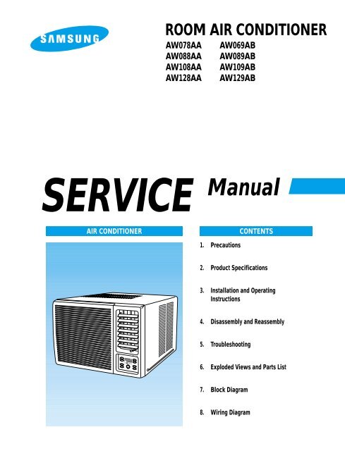
<strong>ROOM</strong> <strong>AIR</strong> <strong>CONDITIONER</strong>AW078AAAW088AAAW108AAAW128AAAW069ABAW089ABAW109ABAW129ABSERVICE Manual<strong>AIR</strong> <strong>CONDITIONER</strong>CONTENTS1. Precautions2. Product Specifications3. Installation and OperatingInstructions4. Disassembly and Reassembly5. Troubleshooting6. Exploded Views and Parts List7. Block Diagram8. Wiring Diagram
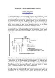
1. Precautions1. Warning: Prior to repair, disconnect thepower cord from the circuit breaker.2. Use proper parts: Use only exactreplacement parts. (Also, we recommendreplacing parts rather than repairing them.)3. Use the proper tools: Use the proper toolsand test equipment, and know how to useequipment may cause problems laterintermittentcontact, for example.4. Power Cord: Prior to repair, check thepower cord and replace it if necessary.Fig. 1-1 Avoid Dangerous Contact5. Avoid using an extension cord, and avoidtapping into a power cord. This practicemay result in malfunction or fire.6. After completing repairs and reassembly,check the insulation resistance.Procedure: Prior to applying power, measurethe resistance between the power cord and theground terminal. The resistance must begreater than 30 megaohms.Fig. 1-2 No Tapping and No Extension Cords7. Make sure that the grounds are adequate.8. Make sure that the installation conditionsare satisfactory.Relocate the unit if necessary.9. Keep children away from the unit while it isbeing repaired.10. Be sure to clean the unit and its surroundingarea.Fig. 1-3 No Kids Nearby!Fig. 1-4 Clean the UnitSamsung Electronics 1-1
Notice: The symbol of model nameTypeModel NameAAW078AAAW088AAAW069ABAW089ABBAW109ABAW128AAAW129ABCAW108AA1-2 Samsung Electronics
2. Product Specifications2-1 TableItem Unit of Measure AW069AB AW078AA AW088AA AW089ABType -Dimensions:(Width×Height×Depth)Packing size:(Width×Height×Depth)VoltageVoltPhase -FrequencyOperating CurrentPower ConsumptionRefrigerant TypeRefrigerant ChargeCapacityEERNet WeightHzAWFREONgBTU/hBTU/h.WkgCondenser Row 3×15 2×15 2×15 3×15Condenser FanTypeEvaporator Row 2×14 2×14 2×14 3×14Evaporator FanTypeFan Motor Model YGN55-6F YGN55-6E YGN55-6B YGN55-6BCompressor(Rotary) Model 44C062HU1EA 44A072HW1EB 44A080HU1EB 44A076HU1EBOverload Protect - MRA12040-12008 MRA98706-12008 MRA12083-12008 MRA12083-12008Compressor Capacitor F/VAC 35/370 25/370 35/370 35/370Fan Motor Capacitor F/VAC 5/250 6/450 6/250 6/250Fan speed RPM 780/750/670 780/720/650 880/780/710 880/780/710Thermo Control -Air SwingmmmmModelWINDOW520×345×485571×454×546SingleR22Propeller FanBlowerTHERMISTORM2CK59ZT79-HSamsung Electronics 2-1
2-2 Dimensions2-2-1 Main Unit(Unit : mm)DType W H DA 520 345 485B 600 394 595C 550 345 485Front viewSide viewHHW2-2-2 Remote ControlTimer setting buttonSleep timer setting buttonOperating modeselection buttonsTemperature adjustmentbuttonsFan speedadjustment buttonsEnergy Saver buttonAir flow blade swing buttonON/OFF buttonSamsung Electronics 2-3
MEMO2-4 Samsung Electronics
3. Installation and Operating Instructions3-1 Installation3-1-1 Selecting Area for Installation1. Make sure that you install the unit in an areaproviding good ventilation. The air conditionermust not be blocked by any obstacle affecting theair flow near the air inlet and air outlet.2. Make sure that you install the unit in an area thatallow good air handling. The installation area mustbe able to endure vibration from the unit.3. Make sure that you install the unit away from heator vapor.4. Make sure that you install the unit in an areawhich is cool and has adequate space.6. Make sure that you install the unit in an area whichprovides easy drainage for condensed water.7. Make sure that you install the unit in an area notexposed to rain or direct sunlight.(Install a separate sunblind if exposed to directsunlight.)8. Make sure that you install the unit in an areaallowing good air movement. Do not install it ina space that would cause noise amplification ofnoise.9. Fix the unit firmly if mounted in a high place.5. Make sure that you install the unit in an area awayfrom TVs, audio units, cordless phones,fluorescent lighting fixtures and other electricalappliances (obtain a clearance of at least one meter).Caution:Do not use the air conditioner in the following environments : greasy areas (including areas nearmachines), or marine areas. Contact your local dealer for advice.Samsung Electronics 3-1
3-2 Function DescriptionFan speed indicator(LOW, MED, HIGH)Temperature/Timer settingsTemperatureadjustment buttonsOperating mode indicators(COOL, FAN)Remote control sensorAir flow blade swing buttonFan Speed adjustment buttonAir flow blade swing indicatorEnergy saver indicatorON/OFF Timer adjustment buttonSleep adjustment buttonTimer indicatorEnergy saver buttonOperating mode selection buttonOperating on/off3-2-1 Cooling operation modeThe compressor is turned on and off according to the ambient temperature and set temperature.1) Compressor on and off control• Compressor on and off control according to the ambient temperature* The compressor is turned off when "ambient temperature = set temperature* The compressor is turned on when "ambient temperature = set temperature +1˚C"2) Default value after power reset ➔ set temperature = 24˚CFan speed = High3) Set temperature indicating (setting) range : 1˚C interval from 18˚C to 30˚C.3-2-2 Fan operation mode1) If "Fan operation mode" signal is received from remocon or panel.➔ the compressor is immediately turned off and only fan motor is operated at set blowing speed.➔ it changes such as "High ➔ Med ➔ Low ➔ High"( if Fan speed is selected).2) The initial Fan motor speed is set to "High".3) The set temperature can not be indicated and set.3-2-3 Energy saver operation mode***If the compressor turn off at the cooling operation, the fan motor turn off after operation during the fixation time only,and operation that energy saver by turn off the fixation time only, and operation that energy saver by turn off the motorcontinuously before the condition of the compressor on.The fan motor is not operated at flow wind operation.Energy saver operation specification at the cooling operation.1) Fan motor control in compressor on : operate with setting wind speed2) Fan motor control in compressor off : After compressor off, the fan motor is operated breeze for 2 minutes and then itturn off.3) After the fan motor off, the compressor and fan motor is operated normally when the compressor on.3-2 Samsung Electronics
Installation and Operating Instructions3-2-4 Sleep operation mode1) Enable to sleep operation only when cooling operation.2) First, 7-SEG LED DISPLAY "SLEEP" while 15 second, Second, 7-SEG LED DISPLAY "8Hr"And, automatically SET OFF after operated while 8 Hour3) If sleep operation, setting Temperature rise 1˚C after 1 Hour4) ON TIMER operation, not operation, ENERGY SAVER operation, not sleep operation.3-2-5 Air flow blade swing motor operation1) The Air flow blade swing motor is turned on and off according to Air flow blade swing operation in remocon or panel,if SET is cooling or Fan operation mode.2) If the operation mode is "ENERGY SAVER", in case of fan motor being turned off Air flow blade swing motor isimmediately turned off.3-2-6 LED display indication in case of error detectionERROR OPERATION<strong>ROOM</strong> THERMISTOR(OPEN or SHORT)7-SEGLED DISPLAYE1 displayed1) Set operation in case of error occurrence.• Malfunction of each temperature sensor (open, short)- Error mode display, warning sound.- The operation status is off.Samsung Electronics 3-3
Installation and Operating Instructions3-2-7 Panel key operationKey discriptionKey nameKey operational functionPOWERModeFan speedOperation start and stop* First ON = operation start, second ON = operation stop- Selected as "OFF –> COOL or FAN". (DEFAULT=OFF)* Continuous operation is not available.Operation mode change* at every ON- Selected as "COOL –> FAN". (Default=COOL)* If operation is OFF, it is considered as an invalid key.* Continuous operation is not available.Fan motor speed setting* at every ON- Selected as “HIGH → MED → LOW → HIGH”. (DEFAULT=HIGH)Temperature Currently displayed set temperature increase/decrease(▲ ▼) * At every pressing, the set temperature is changed by 1˚C(increase(▲) : 18˚C → 19˚C → ... → 29˚C → 30˚C)(decrease(▼) : 24˚C → 23˚C → ... → 17˚C → 18˚C)* In case of the set temperature of 30˚C, when the “increase” key is pressedtemperature does not increase any more.* In case of the set temperature of 18˚C, when the “decrease” key is pressedtemperature does not decrease any more.* In case of above situation, when “increase/decrease“ key is pressed by remocon,warning sound is generated.* If operation is OFF, it is considered as an invalid key.* In case of “FAN” mode operation, it is considered as an invalid key.* Continuous operation is available.Circulaire Circulaire motor operation and stop* Once ON=Circulaire motor operation. Another ON-Circulaire motor stop.* Continuous operation is not available.* In case of operation stop, when the fan motor is turned off it is considered as an invalid key.TimerSetting the on/off timer(ON/OFF) * Can set “OFF TIMER HOUR“ if set is operation* Can set “ON TIMER HOUR“ if set is not operation* Once ON = standby setting TIMER : “– –“ displayed* In case of key pressing in status of standby setting ON/OFF TIMER(––Hr → 1Hr → 2Hr → ... –> 23Hr → 24Hr)* If press TIMER key countinuosly operate such the lower part(––Hr → 1Hr → 2Hr → ... → 24Hr → --Hr)* Continuous operation is available.SleepSLEEP mode on and off* Once ON=SLEEP mode on, Another ON=SLEEP mode off• Continuous operation is not abailable• Operation off, on timer Operation, save operation , not key operation* Not SLEEP operation is FAN modeEnergy Saver Power save mode on and off* Once ON=Power save mode on, Another ON=Power save mode off* Continuous operation is not available.* If operation is OFF, it is considered as an invalid key.3-4 Samsung Electronics
Installation and Operating Instructions3-2-8 LED lamp operation specificationsLAMP nameCOOLINGFANHIGHMEDLOWTIMERENER SAVERCIRCUL<strong>AIR</strong>E(1) (2)The mode is set to "COOL" → ONOthers → OFFThe mode is set to "FAN" → ONOthers → OFFThe mode is set to "HIGH" → ONOthers → OFFThe mode is set to "MED" → ONOthers → OFFThe fan speed is set to "LOW" → ONOthers → OFFThe mode is set to "TIMER" → ONOthers → OFFThe mode is set to "ENERGY SAVER" → ONOthers → OFFThe mode is set to "CIRCUL<strong>AIR</strong>E" → ONOthers → OFFOperations specificationsIn case of set temperature display→ NO. (1) 7–SEG LED DISPLAY indicates temperature of the tens digit→ NO. (2) 7-SEG LED DISPLAY indicates temperature of the units digitIn case of time display→ NO. (1) 7–SEG LED DISPLAY indicates time of the tens digit→ NO. (2) 7–SEG LED DISPLAY indicates time of the units digit(3)(4)In case of set temperature display→ NO. (3) 7–SEG LED DISPLAY indicates temperature unit(˚)→ NO. (4) 7-SEG LED DISPLAY indicates temperature unit(C)In case of time display→ NO. (3) 7–SEG LED DISPLAY indicates time unit(H) of the tens digit→ NO. (4) 7–SEG LED DISPLAY indicates time unit(r) of the units digitFirst, 7–SEG LED DISPLAY "SLEEP" while 15 second,Second, 7-SEG LED DISPLAY "8Hr"(1) (2) (3) (4)Samsung Electronics 3-5
3-3 Remocon ControlTimer setting buttonSleep timer setting buttonOperating modeselection buttonsTemperature adjustmentbuttonsFan speedadjustment buttonsEnergy Saver buttonAir flow blade swing buttonON/OFF button3-3-1 Remocon key operation11) In case of pressing ”POWER” key, operation start and stop.12) In case of pressing ”COOL” key, cool mode operation start.13) In case of pressing ”FAN” key, fan mode operation start.14) In case of pressing ”HIGH” key, fan motor operates high speed.15) In case of pressing ”MED” key, fan motor operates mid speed.16) In case of pressing ”LOW” key, fan motor operates low speed.17) In case of pressing ”ENERGY SAVER” on/off key, set operates as power saving mode.18) In case of pressing ”▲” key, set temperature increase by 1˚C(18˚C ~ 30˚C).19) In case of pressing ”▼” key, set temperature decrease by 1˚C(30˚C ~ 18˚C).10) In case of pressing ”TIMER” key, the convenient reserve TIMER time increase by 1 Hr (1Hr ~ 24Hr).11) In case of pressing ”SLEEP” key, SLEEP operates.12) In case of power off, all keys except POWER key are considered as an invalid key.3-6 Samsung Electronics
Installation and Operating Instructions3-3-2 Resistor values table of “<strong>ROOM</strong> THERMISTOR” for each temperatureTemperature[˚C]THERMISTOR RESISTOR[Kohm] ±1%Temperature[˚C]THERMISTOR RESISTOR[Kohm] ±1%70696867666564636261605958575655545352515049484746454443424140393837363534333231302.2292.2962.3652.4372.5122.5892.6692.7522.8382.9283.0213.1163.2163.3193.4263.5373.6523.7723.8974.0264.1614.3004.4444.5944.7494.9125.0805.2565.4395.6305.8286.0336.2466.4686.6996.9417.1927.4557.7298.0158.31329282726252423222120191817161514131211109876543210-1-2-3-4-5-6-7-8-98.6228.9449.2819.63210.00010.38010.78011.20011.63012.09012.56013.06013.57014.12014.68015.28015.90016.55017.24017.96018.70019.48020.29021.15022.05022.99023.90025.03026.13027.28028.47029.72031.04032.43033.89035.43037.05038.76040.560Samsung Electronics 3-7
MEMO3-8 Samsung Electronics
4. Disassembly and Reassembly4-1 Compressor Replacement Flow ChartLocate cause of defectRelease refrigerantDisconnect electrical wiringfrom compressorCut refrigerant linesfrom compressorPlug disconnected linesReplace compressorInspect electricalwiring for defects,and terminals forcorrect and secureconnectionsSolder discharge lineSolder suction lineUse nitrogen gasPerform soldering functionYProblem?Fill system with nitrogen gasNCheck for leakageCorrective actionCheck refrigerant oil levelLeakage?YNYLow oil level?NRelease nitrogen gas?Evacuate systemAdd oil as necessaryRecharge systemPinch and braze filling tubeSamsung Electronics 4-1
4-2 Checking the oilFill the transparent container with 10cc of oil, and then conduct the test.4-2-1 Oil qualityConidition ofRefrigerant CycleNormalOver-heatedCompressor DamageColorStraw YellowBrown ColorDark BrownOil ConditionOdorNo Odor-Pungent oilRemarksReturn with the systemChange the oilChange the oil4-2-2 Replacing and refilling the refrigerant oil1. Change the compressor - DO NOT recharge the oil as the compressor itself isalready charged.2. Change the condenser .... add 50cc3. Change the evaporator .... add 50cc4. When the refrigerant is replaced .... add 30cc oil.5. After vacuum is completed, the oil is filled through the high pressure side.6. In the event of a refrigerant leak, generally it is not necessary to add oil.(Unless the oil has leaked significantly.)4-2 Samsung Electronics
POWER / MODE4-3 Disassembly and Reassembly Procedure (Type “A”)Stop operating the air conditioner, and pull out the power cord before repair.No. Part name Procedures Remarks!Ass'y Grill1. Pull the panel front and remove the screwon the grille.*The type of front-paneldepends on models.2. Hold the lower part of grill with two handswhile pressing down on both sides of thelower part of the cabi<strong>net</strong>, pull it forward byabout 30, and the then lift it up for removal.@Ass'y Cabi<strong>net</strong>1. Remove the two screws both side cabi<strong>net</strong>.2. Pull the front both side, and remove the unitfrom the cabi<strong>net</strong>.#Ass'y COVER EVAP1. Remove 6 screws on the COVER EVAP.2. Remove the COVER EVAP.Samsung Electronics 4-3
Disassembly and ReassemblyNo. Part name Procedures Remarks$Ass'y Control1. Remove the blade V(and arm blade).2. Remove 4 screws on the FRAME BLADE.3. Remove the FRAME BLADE.4. Remove 2 screws under the BASE PAN, andearth wire screw.5. Remove two lead wire assemblies.6. Take out the control box forward.%PLATE EVAP CASING&TRAY DRAIN1. Remove 2 srews on the front side.2. Remove 3 screws on the left side.3. Remove 1 screw from the Base pan.4. Pull up the PLATE EVAP CASING and TRAYDRAIN.^Case Cond&Propeller Fan1. Remove 2 screws on the rear side (Basepan), and 7 screws on the case cond.2. Pull up the CONDENSER from the Base pan.3. Remove the Nut, and remove the propellerfan.4. Remove the Nut, and remove the BLOWER.Samsung Electronics 4-7
Disassembly and ReassemblyNo. Part name Procedures Remarks&CASE COND1. Remove the CASE COND.*MOTOR&the others parts1. Remove 4 screws on the MOTOR,and remove the motor.2. Remove 4 bolts on the mounter motor,and remove the mounter motor.3. Remove the CASE EVAP.4. Remove 4 screws on the partition.4-8 Samsung Electronics
5. TroubleshootingCheck the basic checkpoints first to determine whether it is machine trouble or a problem in theoperation method. When it is not related to the basic checkpoints, perform checking in accordancewith the procedures of troubleshooting by symptom.5-1 Basic Checkpoints for Troubleshooting1) Is the voltage of the power source appropriate ?(1) It should be within the rating voltage ±10% range.(2) The air conditioner may not operate properly when the voltage is out of this range.2) Is the connection with the fan motor, compressor wire, and starting condenserappropriately made ?3) The symptoms listed in the table below are not indicative of machine trouble.SymptomNo operationAir flows, butno coolingThe remocon doesnot operateNo temperaturesettingCause and check• Check whether there is power failure or the power plug is pulled out.• Check whether the unit is stopped as a result of completionof the sleep time.• Pull out the power plug for ten seconds, and then insert it again.• Check whether the Air filter is clogged with dust or is dirty.• Check whether the desired temperature is too high. Set the desiredtemperature to a lower level than the current temperature.• Check whether it is in "FAN" mode.• Check whether battery is completely depleted.• Check whether the battery is properly inserted.• Check whether the receiving window of the remocon for the assemblymain PCB is blinded.• Check whether the remocon is affected by jamming due to a neon sign.• Check whether the unit is in "FAN" mode.(In "FAN" mode, only the current temperature is displayed, and thedesired temperature is not set.)❈ Checking and Display of Fault AreaERROR OPERATION<strong>ROOM</strong> THERMISTOR (OPEN OR SHORT)ERROR OPERATIONE1 displayedSamsung Electronics 5-1
5-2 Troubleshooting by Symptom5-2-1 No power1) Check points(1) Is the voltage of the power source normal ? (the rating voltage ±10% range.)(2) Is the electric wire in good contact ?(CN 71, RY 71)(3) Is the output voltage of the IC01(KA 7812) normal ?(DC 11.5V ~ DC 12.5V)(4) Is the output voltage of the IC02(KA 7805) normal ?(DC 4.5V ~ DC 5.5V)Turn off the power, and then turn it on again fiveseconds later.Dose the buzzer sound, when the power on?Check whether the "COOLING ICON" LED lamp is on,and the operation starts when pressing the ON/OFFbutton of the remocon.Is the F701(3.15A) fuse blown?Is the primary voltage of the transformer normal?(the rating voltage ±10% range.)Is the secondary voltage of the transformer normal?(AC 13V ~ AC 17V)Is the rectifier diode(D101~D104) normal?- Is the voltage of DC 17V ~ DC 23V applied at bothends of the C101 electrolytic condenser?- Is the voltage of DC 12V applied at both ends ofthe C102 electrolytic condenser?- Is the voltage of DC 5V applied at both ends ofthe C103 electrolytic condenser?NNNAre the IC01(KA7812) and IC02(KA7805) normal?YYYYYReplace the assembly main PCB.YYYNNNNNNormal operation.Normal operation.Replace the fuse.Check the power cord and electric wire.Check and replace the trans.• Check the D101 ~ D104 for cold soldering.• Replace the rectifier diode• Check both ends of the C101 for shortand cold soldering.• Check the +12V for a short.• Check the +5V for a short.• Check and replace the C101~104.• Check the IC01, and IC02 for coldsoldering and a short.• Replace the IC01, and IC02.5-2 Samsung Electronics
Troubleshooting5-2-2 When the Membrane Key pad and Led Display1) Check points(1) Is the voltage of the power source normal ? (the rating voltage ±10% range.)(2) Is the electric wire in good contact ?(CN71, RY71)(3) Is the connection of the assembly main PCB, and MEMBRANE KEY PAD in good contact?(CN91)Turn off the power, and then turn it on againfive seconds later.Normal operationNWhen the LED DISPLAY isnot operated.When the MEMBRANE KEYis not operated.NNormal operationYYCheck the micom(IC04) for a short,and replace it.NIs the voltage of the micom(IC04) No.1, 2, 38~43 port asquare wave?Is the voltage of themicom (IC04) No.13, 14 porta square wave?NCheck the micom(IC04) for a short,and replace it.YYCheck the micom(IC04) for a short,and replace it.NIs the voltage of the micom(IC04) No.3, 4, 10, 11, 44 port asquare wave?Is the voltage of the micom(IC04) No.3, 4, 10, 11, 44 port asquare wave?NCheck the micom(IC04) for a short,and replace it.YYCheck the Q901~Q905 for a short,and replace it.NIs the voltage of theQ901 ~ Q905 square wave?Replace the MEMBRANEKEY PAD.Check the IC07for a short, andreplace it.NYIs the voltage of theIC07 No. 10~16 a square value?YReplace the MEMBRANE KEY PADSamsung Electronics 5-3
Troubleshooting5-2-3 When the remocon is not operated1) Check points(1) Is the voltage of the power source normal ? (the rating voltage ±10% range. )(2) Is the electric wire in good contact ? (CN71, RY71)(3) Is the assembly main PCB in good contact with the MEMBRANE KEY PAD(CN91)(4) Is the battery voltage of the remocon above DC 2.7V?Turn off the power, and then turn it onagain five seconds later.Dose the Buzzer sound, when the power on?NGo to the clause "No power".Check whether the "COOLING ICON" LED lamp is onand th operation starts when pressing theon/off button of the remocon.YNIs the battery voltage of the remocon aboveDC 2.7V?YNThe remocon is normally operated.Replace the battery.Does the X-TAL(RJ 455JB) oscillate normally?Is the collector voltage of the remocon QT1, QT2a square wave?Is the input voltage of the micom(IC04) No. 15pin of the assembly main PCB a aquare wave?YYYYReplace the assembly main PCB.NNN• Check the X-TAL for cold soldering and ashort.• Replace relevant components.• Check the micom(ICT1) QT1, and QT2 forcold soldering and a short.• Replace relevant components.• Check the R415 components.• Check the assembly main PCB micom(IC04).5-4 Samsung Electronics
Troubleshooting5-2-4 When the compressor is not operated1) Check points(1) Is the voltage of the power source normal ? (the rating voltage ±10% range. )(2) Is the desired temperature lower than the indoor temperature in the “COOL” mode?(Compressor stopped)(3) Is the starting condenser in good contact?(4) Is the electric wire in good contact ? (CN71, RY71)(5) Is the output voltage of the IC01(KA7812) and IC02(KA7805) normal ?Turn off the power, and then turn it on again fiveseconds later.Dose the Buzzer sound, when the power on?Check whether the "COOLING ICON" LED lamp is onand the operation starts when pressing the on/offbutton of the remocon.Check whether the compressor is activated in threeminutes after turning on the power with the "COOLINGICON" LED lamp being switched on when selecting thecool mode of the remocon.Is the IC03 output normal?- When the compressor is ON, IC03No. 15 pin –> Low.Does the relay(RY71) operate normally?- When the compressor is ON, the RY71 should operate.YYNYYIs the compressor normal?YReplace the compressor.NNYNNNGo to the clause "No power".• Go to the clause "when he remocondoes not operate".Normal operation.• Check the IC03 for short and cold soldering.• Replace the IC03.• Check the relay coil resistance.(resistance : About 150Ω±20Ω)• Replace the relay.• Check the operation of the O.L.P,and replace it if necessary.• Check the compressorresistance.(0Ω : short, ∞Ω : open)Samsung Electronics 5-5
Troubleshooting5-2-5 When the air swing motor is not operated1) Check points(1) Is the voltage of the power source normal ? (the rating voltage ±10% range. )(2) Is the electric wire in good contact ?(CN71, RY71)(3) Is the swing motor connector in good contact?(CN71)(4) Is the terminal connected to the swing motor in good contact?(5) Is the output voltage of the IC01(KA7812) and IC02(KA7805) normal?Turn off the power, and then turn it on again fiveseconds later.Dose the buzzer sound, when the power on?Check whether the “COOLING ICON” LED lamp is on,and the operation starts when pressing the ON/OFFbutton of the remocon?Does the air-swing motor operate whenpressing the air-swing button of the remote control?YYNIs the IC03 output normal?- When the air-swing motor is on, IC03No. 11 pin ➝ LowYDoes the relay(RY 75) operate normally?- When the air-swing motor is operated, theRY75 should be operated.YIs the air-swing motor normal?YReplace the air-swing motor.NNYNNNGo to the clause "No power".Go to the clause of “when the remocondose not operated”Normal operation.• Check the IC03 for a short and coldsoldering.• Replace the IC03.• Check the relay coil resistance.(Normal: About 400Ω)• Replace the relay.• Check the air-swing motor resistance.(0Ω : short, ∞Ω : open)5-6 Samsung Electronics
Troubleshooting5-2-6 When the fan motor does not operated1) Check points(1) Is the voltage of the power source normal ? (the rating voltage ±10% range. )(2) Is the electric wire in good contact ?(CN71, RY71)(3) Is the starting condenser(FAN MOTOR) in good contact?(4) Is the fan motor connector in good contact?(CN73)(5) Is the output voltage of the IC01(KA7812) and IC02(KA7805) normal ?Turn off the power, and then turn it on again fiveseconds later.Dose the buzzer sound, when the power on?Check whether the "COOLING ICON" LED lamp is on andthe operation starts when pressing the on/off buttonof the remocon.Is the IC03 output normal?- When the fan motor is High, IC03 No. 13 pin –> LOW.- When the fan motor is Med, IC03 NO. 14 pin –> LOW.- When the fan motor is Low, IC03 No. 16 pin –> LOW.YYNNNGo to the clause "No power".• Go to the clause of "when the remocondoes not operated".• Check the IC03 for a short and coldsoldering.• Replace the IC03.Does the relay(RY 72, 73) operate normally?- When the fan motor is High, RY72 should operate.- When the fan motor is Med, RY73 should operate.- When the fan motor is Low, RY76 should operate.YYIs the fan motor normal?YReplace the fan motor.NN• Check the relay coil resistance.(Normal: About 400Ω)• Replace the relay.• Check the fan motor resistance.(0Ω : short, ∞Ω : open)• Check the fan motor thermal fuse?(130˚C)Samsung Electronics 5-7
MEMO5-8 Samsung Electronics
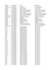
Exploded View and Parts List■ Part List ( Type “A” And "C")Q'TYNO DESCRIPTION CODE NO SPECIFICATIONAW069AB AW078AA AW088AA AW089AB AW108AA1 GRILLE <strong>AIR</strong>-INLET DB64-10158A HIPS 1 1 1 1 12 ASSY PANEL FRONT DB92-00042E SC94445R 1 1 1 1 12-1 GUARD <strong>AIR</strong>-FILTER DB63-30158A HIPS 1 1 1 1 12-2 PANEL FRONT DB64-70093A HIPS 1 1 1 1 12-3 BLADE-H DB66-30191A HIPS 1 1 1 1 13 ASSY EVAP DB96-00994A OD7.0*2*14 1 1 1 - -DB96-01574A OD7.0*3*14 - - - 1 -DB96-01514A OD9.52*2*12 - - - - 14 ARM BLADE DB66-70031A PS 1 1 1 1 15 BLADE-V DB66-30211B PP,SC-97525R 1 1 1 1 16 FRAME BLADE DB90-00508A ASSY 1 1 1 1 -DB90-00508B ASSY - - - - 16-1 LEVER DAMPER DB66-00278A ABS,T2.0 - - - - 1DB66-00126A ABS,T2.0 1 1 1 1 -7 PLATE EVAP CASING DB61-00644A SGCC-M 1 1 1 1 -DB61-00689A SGCC-M - - - - 18 PLATE PARTITION DB71-00068B SGCC-M,T0.8 1 1 1 1 19 CASE EVAP DB61-00645A 30FO-PS,T10 1 1 1 1 110 NUT WASHER DB60-30004A M6 SM20C NTR 1 1 1 1 111 BLOWER DB67-00013A ABS,OK-PJT 1 - - - -DB67-50078A ABS,180 - 1 1 1 112 MOUNT MOTOR DB61-00651A SGCC-M 1 1 1 1 -DB61-00690A SGCC-M - - - - 113 MOTOR FAN DB31-00123C YGN55-6F 1 - - - -DB31-00123B YGN55-6E - 1 - - -DB31-00123A YGN55-6B - - 1 1 -DB31-00140A YGN61-6A - - - - 114 ASSY COVER EVAP DB90-00539A ASSY 1 1 1 1 -DB90-00539B ASSY - - - - 115 FAN PROPELLER DB67-50077A ABS,290 1 1 1 1 116 NUT FLANGE DB60-30020A M6,FEFZY,LF 1 1 1 1 117 CASE COND DB61-00423A PP 1 1 1 1 118 ASSY BASE DB90-20212F SGCC-M 1 1 1 1 -DB90-00544B SGCC-M - - - - 119 ASSY COND DB96-01027A OD7*3*15 1 - - 1 -DB96-01515A OD7*3*15 - - - - 1DB96-00995A OD7*2*15 - 1 1 - -20 COMPRESSOR 44C062HU1EA 115V/60Hz 1 - - - -44A072HW1EB 115V/60Hz - 1 - - -44A080HU1EB 115V/60Hz - - 1 - -44A076HU1EB 115V/60Hz - - - 1 -44B098HU2EF 115V/60Hz - - - - 121 TUBE SUCTION DB96-00966A OD9.52 1 1 1 1 -DB62-00871A OD9.52 - - - - 122 TUBE DISCHARGE DB62-00483A 8K TOP 1 - - 1 -DB62-00675A OD7.93 - 1 1 - -DB62-00826A T-PJT - - - - 16-2 Samsung Electronics
Exploded View and Parts List■ Part List ( Type “A” And "C" )NO DESCRIPTION CODE NO SPECIFICATIONQ'TYAW069AB AW078AA AW088AA AW089AB AW108AA23 TUBE CAPILARY DB96-01018A ID1.3*1100 1 - - - -DB96-00992A ID1.3*900 - 1 - - -DB96-00993A ID1.42*1200 - - 1 1 -DB62-00872A 2-ID1.2*1200 - - - - 124 NUT WASHER DB60-30018A M5 SM20C 1 1 1 1 125 COVER TERMINAL DB63-10026A NORYL,SEI-701 1 1 1 1 126 OLP DB47-20002F MRA12040-12008 1 - - - -DB47-20001V MRA98706-12008 - 1 - - -- MRA12083-12008 - - 1 1 -- MRA12132-12007 - - - - 127 GASKET DB63-20002A EPDM T0.8 1 1 1 1 128 NUT WASHER DB60-30028A HEX 2C M8 ZPC 3 3 3 3 329 GROMMET ISOLATER DB73-00070A NR 3 3 3 3 3 330 ASSY CABINET DB90-00133P N-PJT 1 1 1 1 -DB90-00701A T-PJT - - - - 131 ASSY CONTROL DB93-00465B 6K 1 - - - -DB93-00465F 7K - 1 - - -DB93-00465A 8K - - 1 1 -DB93-00465E 10K - - - - 132 TRAY DRAIN DB63-00274A HIPS,T1.5 1 1 1 1 -DB63-00296A HIPS,T2.0 - - - - 133 ASSY REMOCON DB93-00284K ARC-709 1 1 1 1 1Samsung Electronics 6-3
6-2 Main unit (Type “B”)11122-12-2323372-31489355-16-13131-12 31-1131-331-531-1031-231-1 31-1331-810631-431-9431-731-6121817131523162120242526272829223019You can search for the updated part codenumber through the ITSELF.URL : http://itself.sec.samsung.co.kr6-4 Samsung Electronics
Exploded View and Parts List■ Part List (Type “B”)Q'TYNO DESCRIPTION CODE NO SPECIFICATIONAW109AB AW128AA AW129AB1 GRILLE <strong>AIR</strong>-INLET DB64-10145A HIPS,T2.5 1 1 12 ASSY PANEL FRONT DB92-10319C ASSY 1 1 12-1 GUARD <strong>AIR</strong>-FILTER DB63-30142A HIPS,T2 1 1 12-2 PANEL FRONT DB64-70080A HIPS,T2.5,W600 1 1 12-3 BLADE-H DB66-30169A PP,T2.5 1 1 13 ASSY EVAP DB96-00983A 7-2*16*273 1 - -DB96-00978A 9.52-2*14*355 - - 1DB96-01002A 9.52-2*14*355 - 1 -4 ARM BLADE DB66-70022D PS,T2,SC-96527R 1 1 15 BLADE-V DB66-30170A PP,SC-97525R 1 1 16 FRAME BLADE DB90-00510B AW129AB/XAA 1 1 16-1 LEVER DAMPER DB66-70024A HIPS,T2.5 1 1 17 PLATE EVAP CASING DB71-00074B SGCC-M,T0.7 1 1 18 PLATE PARTITION DB71-00075B SGCC-M,T0.8,358 1 1 19 CASE EVAP DB61-00649A 30FO-PS,T10 1 1 110 NUT WASHER DB60-30004A M6 SM20C NTR 1 1 111 BLOWER DB67-50078A ABS,180 1 - 1DB67-50073A ABS,200 - 1 -12 MOUNT MOTOR DB61-00650A SGCC-M 1 1 113 MOTOR FAN DB31-00122F YGN60-6A 1 - -DB31-00122A YGN60-6B - 1 -DB31-00122E YGN60-6G - - 114 ASSY COVER EVAP DB90-00511A ASSY 1 1 115 FAN PROPELLER DB67-00139A ABS+G.F20% 1 1 116 NUT FLANGE DB60-30020A M6,FEFZY,LF 1 1 117 CASE COND DB61-00647A PP,T2 1 1 118 ASSY BASE DB90-00514A D-PJT 1 1 119 ASSY COND DB96-00979A 7-3*17*510.4 1 1 120 COMPRESSOR 44B098HU2EF 115V,60Hz 1 - -44B124HX1EL 115V,60Hz - 1 121 TUBE SUCTION DB62-00684A OD12.7 1 1 122 TUBE DISCHARGE DB62-00327A OD9.52,T0.7 1 1 123 TUBE CAPILARY DB62-00687A ID1.7*900 - 1 -DB62-00687B ID1.5*900 1 - -DB62-01026A 2-ID1.3*1000 - - 124 NUT FLANGE DB60-30018A M5 SM20C 1 1 125 COVER TERMINAL DB63-10026A NORYL,SEI-701 1 1 126 OLP - MRA12132-12007 1 - -DB47-20001U MRA98693-12007 - 1 127 GASKET DB63-20002A EPDM T0.8 1 1 128 NUT WASHER DB60-30028A HEX 2C M8 ZPC 3 3 329 GROMMET ISOLATER DB73-00070A NR 3 3 3 330 ASSY CABINET DB90-00364B D-PJT 1 1 131 ASSY CONTROL DB93-00674B 10K 1 - -DB93-00674A 12K - 1 132 TRAY DRAIN DB63-00276A 30FO-PS,T10 1 1 133 ASSY REMOCON DB93-00284K ARC-709 1 1 1Samsung Electronics 6-5
Exploded View and Parts List■ Part List (Type “B”)6-6 Samsung Electronics
6-3 Ass’y Control45121173610911328■ Part List ( Type “A” And "C" )Q'TYNO DESCRIPTION CODE NO SPECIFICATIONAW088AAAW069AB AW078AAAW089ABAW108AA0 ASSY CONTROL DB93-00465B 6K 1 - - -DB93-00465F 7K - 1 - -DB93-00465A 8K - - 1 -DB93-00465E 10K - - - 11 SWITCH MEMBRANE DB34-00013B 99*134.5,PC 1 1 1 12 PANEL CONTROL DB64-00259B HIPS,T2.0,V5 1 1 1 13 ASSY PCB MAIN DB93-00407A COOLING 1 1 1 14 CASE CONTROL UP DB61-00419A SGCC-M T0.7 1 1 1 15 SWING MOTOR DB31-00084A M2CK59ZT79-H 1 1 1 16 C-OIL 2501-001228 35 F 370VAC 1 - 1 -2501-001226 25 F 370VAC - 1 - -2501-001230 45 F 370VAC - - - 17 CLIP CAPACITOR DB65-10008B SGCC-M T0.8 1 1 1 18 POWER CORD ASSY DB39-00343A 125V,13A 1 1 1 19 C-FILM 2301-001451 5 F 250VAC 1 - - -2301-001449 6 F 450VAC- 1 1 -2301-001452 15 F 250VAC- - - 110 TRANSFORMER DB26-00006B AC115V,50Hz/60Hz 1 1 1 111 CASE CONTROL LOW DB61-00417A SGCC-M T0.7 1 1 1 112 THERMISTOR DB32-10051B 10K/25 103AT 1 1 1 113 WINDOW REMOCON DB64-00321A MTN-G2 1 1 1 1Samsung Electronics 6-7
Exploded View and Parts List45121173610911328■ Part List (Type “B”)Q'TYNO DESCRIPTION CODE NO SPECIFICATION AW 128AAAW 109ABAW 129AB0 ASSY CONTROL DB93-00674B 10K 1 -DB93-00674A 12K - 11 SWITCH MEMBRANE DB34-00013B 99*134.5,PC 1 12 PANEL CONTROL DB64-00259B H IPS ,T2 .0,V 5 1 13 ASSY PC B M AIN DB93-00407A COOLING 1 14 CASE CONTROL UP DB61-00421A SGCC-M T0.7 1 15 SWING MOTOR DB31-00084A M2C K59ZT 79-H 1 16 C-O IL 2501-001230 45 F 370VA C 1 -2501-001231 50 F 370VA C - 17 CLIP CAPACITOR DB65-10008B SGCC-M T0.8 1 18 POWER CORD ASSY DB39-00343B 125V,15A 1 19 C-F ILM 2301-001448 8 F 250VA C 1 -C-F ILM 2301-001452 15 F 250VA C - 110 TRANSFORMER DB26-00006B AC115V ,50Hz/60Hz 1 111 CASE CONTROL LOW DB61-00417A SGCC-M T0.7 1 112 THERM ISTOR DB32-10051B 10K/25 103AT 1 113 WINDOW REMOCON DB64-00321A MTN-G2 1 16-8 Samsung Electronics
7. Block Diagram7-1 Refrigerating Cycle Block DiagramPINCH PIPE(SERVICE VALVE)SUCTION LINEDISCHARGE LINEACCUMULATOR/COMPRESSOREVAPORATORCONDENSERCAPILLARY TUBEPINCH PIPE(SERVICE VALVE)7-2 Basic Structure7-2-1 Micom Control DiagramRoom Temperature sensorReceiving Unit of Remocon(Remote Control)OperationSwingTimerSleepFan speed (high)Fan speed (med)Fan speed (low)FanCoolEnergy saverTemp.setting(↑)Temp.setting(↓)MAIN MICOMA/D converterLed display control• Swing motor control• Compressor control• Buzzer control• Temperature control• Fan motor controlReset CircuitRemocon SingleReceivingOscillation CircuitMembrane Pad control(Key operation)• Energe saver• Temp.set(↑, ↓)• Operation, Mode• Swing, Sleep• Fan select, Timer(Remocon control)• Remocon single controlCompressorFan motorSwing motorPower circuit (DC 5V)Powercircuit (DC 12V)Down Trans (AC15V)Power input (AC230V)Samsung Electronics 7-1
Block Diagram7-2-2 Micom pin assignmentSEG-DATA(c)SEG-DATA(b)GRID4GRID3VccVss10MHz RESONATOR10MHz RESONATORTESTGRID2GRDI1RESET IC OUTPUTKEY-IN1KEY-IN2REMOCONEEPROM CSLOW FANCOMPERSSORMIDDLE FANHIGH FAN4-WAY VALVEVccKS88C47161 P0.1 P4.4 442 P0.0 P0.2 433 P4.3 P0.3 424 P4.2 P0.4 415 VDD P0.5 406 VSS P0.6 397 Xout P0.7 388 Xin P1.0 379 TEST P1.1 3610 P4.1 P1.2 3511 P4.0 P1.3 3412 RESET P1.4 3313 P2.0 P1.5 3214 P2.1 P3.7 3115 P2.2 P3.6 3016 P2.3 P3.5 2917 P2.4 P3.4 2818 P2.5 P3.3 2719 P2.6 P3.2 2620 P2.7 P3.1 2521 P4.5 P3.0 2422 AVref AVss 23GRID5SEG-DATA(d)SEG-DATA(e)SEG-DATA(f)SEG-DATA(g)SEG-DATA(h)SEG-DATA(a)EEPROM CLKEEPROM INEEPROM OUTBUZZEROPTIONJIG OUTPUTOPTIONSENSOR THERMISTOR(103AT)OPTIONOPTIONOPTIONOPTIONSAVE OPTIONSWING MOTORGND7-2 Samsung Electronics
MEMOSamsung Electronics 7-3
8. PCB Diagram8-1 ASS’Y Main PCB• DB93-00407B8-1 Samsung Electronics
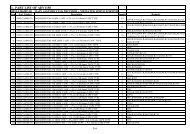
PCB Diagram■ Part ListNO. CODE-NO DESCRIPTION SPECIFICATION Q’TY REMAKRS12345678910111213141516171819202122232425262728293132333435363738394041424344454647-1405-000147DE13-20017ADE13-20009ADE13-20016ADE13-20008ADE60-10100ADE62-30031A------3711-003407--DE32-10037A-DE30-20016A2001-001172-----DB93-00407B---2004-0011372004-000218---------DB09-00091A3501-0010582802-000103DB07-00010A3501-000399DIODE-RECTIFIERVARISTORIC-DRIVEICIC-VOLT REGUIC-VOLT REGUSCREW TAPPINGHEAT SINKC-ALC-ALC-ALC-ALCONNECTOR WAFERCONNECTOR WAFERCONNECTOR WAFERCONNECTOR WAFERCONNECTOR WAFERFUSEFUSE HOLDERBUZZERR-CARBONREMOCON MODULECONNECTOR WAFERJUMPER WIREJUMPER WIREJUMPER WIREPCB-MAINR-CARBONR-CARBON(2012)R-CARBON(2012)R-CARBONR-CARBONR-CARBON(2012)R-CARBON(2012)C-CERAMIC(2012)C-CERAMIC(2012)C-CERAMIC(2012)C-CERAMIC(2012)TRANSISTORTRANSISTORDIODE-SWITCHING(SMALL)IC-MCURELAY-POWERCERAMIC RESONATORLED DISPLAYRELAY1T4470V 4500AKID65003APKA7533ZKA7805AKA7812APH-3 L6A6063 L23.5 W302200µF 25V1000µF 35V100µF 10V22µF 16VYW396-03AV YELYW396-03AV WHTYW396-05AV WHTJSW250-02 REDJSW250-03 RED250V 3.15AFB 58 20MMCSB2220BA620 OHM 1/2WKSM713TE5FCZ254-08SPI0.6 52MMPI0.6 52MM3216 TYPEFR-1 81.5*134.5RD 1/4W 180-JMCR10 330-JMCR10 10K-JRD 1/8W 6.8K-FRD 1/8W 10K-FMCR10 1K-JMCR 100K-JMCR21 2F 104ZMCR21 2F 223ZMCR21 2F 101ZMCR21 2F 102ZKRA226SKRC246S1N4148KS88C4716ID 1U10MHzELF-316GWBJQ1A 12V412111111111111111111112417185101221941351511114D101~D104VA71IC03, IC07IC05IC02IC01C102C101C103C104CN11CN71CN73CN41CN12F701F701BZ61R601RM41CN91J1~J13, J15~J24, J32OP01J25~J31R903~R910R404~R406, R415, R902R301, R407, R408, R410~R414, R501, R901R403R401, R402R201, R202R409C105, C106, C401~C406, C410C501, C502, C601, C901C407C408, C409, C902Q901~Q905Q906D901~D905IC04RY71X501RY72, 73, 75, 76Samsung Electronics 8-2
MEMO8-3 Samsung Electronics
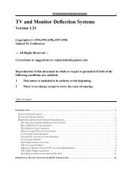
9. Wiring DiagramCN73DIAGRAM - ELECTRICDB68-02015ASamsung Electronics 9-1
10. Schematic Diagrams10-1 Main PCBOPTIONNo. Resistor Temp. UnitR41110K-J4.7K-J˚C˚F10-1 Samsung ElectronicsSamsung Electronics 10-2
10-2 Remote Control(KEY NAME)K29 : SAVEK37 : TIMERK39 : SLEEPK41 : <strong>AIR</strong> SWINGK49 : TEMP. (↓)K50 : TEMP. (↑)K53 : LOW FANK54 : MID FANK55 : HIGH FANK57 : FANK60 : COOLK63 : ON/OFF10-3 Samsung Electronics
UPDATE LOG SHEETApplication date Page Part# Note(Cause & Solution) S/Bulletin#Use this page to keep any special servicing information. (Service Bulletin, etc.)If only parts number changes, Just change parts number directly on parts list.And if you need more information, please see the service website.Itself SolutionIntegrated technology supporting electronic libraryhttp://itself.sec.samsung.co.krCopyright © 2002By Samsung Electronics Co., Ltd.All rights reserved.This manual may not, in whole or in part, becopied, photocopied, reproduced, translated, orconverted to any electronic or machine readablefrom without prior written permission ofSamsung Electronics Co., Ltd.Printed in Korea.