
You also want an ePaper? Increase the reach of your titles
YUMPU automatically turns print PDFs into web optimized ePapers that Google loves.
<strong>NAVTEX</strong> <strong>RECEIVER</strong><br />
NX-700A/B
Your Local Agent/Dealer<br />
9-52 Ashihara-cho,<br />
Nishinomiya 662-8580, JAPAN<br />
Telephone : 0798-65-2111<br />
Fax :<br />
0798-65-4200<br />
( HIMA<br />
All rights reserved.<br />
Pub. No. OME-56490<br />
) NX-700<br />
Printed in Japan<br />
FIRST EDITION :MAY.<br />
2005<br />
B<br />
: JUN. 24, 2005<br />
*00015280401*<br />
*00015280401*<br />
* 0 0 0 1 5 2 8 0 4 0 1 *<br />
*OME56490B00*<br />
*OME56490B00*<br />
* O M E 5 6 4 9 0 B 0 0 *
IMPORTANT NOTICE<br />
• No part of this manual may be copied or reproduced without written permission.<br />
• If this manual is lost or worn, contact your dealer about replacement.<br />
• The contents of this manual and equipment specifications are subject to change without<br />
notice.<br />
• The example screens (or illustrations) shown in this manual may not match the screens<br />
you see on your display. The screen you see depends on your system configuration and<br />
equipment settings.<br />
• This manual is intended for use by native speakers of English.<br />
• FURUNO will assume no responsibility for the damage caused by improper use or<br />
modification of the equipment or claims of loss of profit by a third party.<br />
• Please carefully read and follow the operation and maintenance procedures set forth in<br />
this manual.<br />
• Store this manual in a convenient place for further reference.<br />
i
SAFETY INSTRUCTIONS<br />
Safety information for the Operator<br />
WARNING<br />
ELECTRICAL SHOCK HAZARD<br />
Do not open the equipment.<br />
Only qualified personnel<br />
should work inside the<br />
equipment.<br />
Do not disassemble or modify the<br />
equipment.<br />
CAUTION<br />
A warning label is attached to the equipment.<br />
Do not remove the label. If the<br />
label is missing or damaged, contact<br />
a FURUNO agent or dealer about<br />
replacement.<br />
WARNING<br />
To avoid electrical shock, do not<br />
remove cover. No user-serviceable<br />
parts inside.<br />
Name: Warning Label (1)<br />
Type: 86-003-1011-1<br />
Code No.: 100-236-231<br />
Fire, electrical shock or serious injury can<br />
result.<br />
Immediately turn off the power at the<br />
switchboard if the equipment is emitting<br />
smoke or fire.<br />
Continued use of the equipment can cause<br />
fire or electrical shock. Contact a FURUNO<br />
agent for service.<br />
Keep heater away from equipment.<br />
A heater can melt the equipment's power<br />
cord, which can cause fire or electrical<br />
shock.<br />
Use the proper fuse.<br />
Fuse rating is shown on the equipment.<br />
Use of a wrong fuse can result in damage<br />
to the equipment.<br />
ii
Safety information for the Installer<br />
ELECTRICAL<br />
SHOCK<br />
HAZARD<br />
WARNING<br />
Do not open the equipment<br />
unless totally familiar with<br />
electrical circuits and<br />
service manual.<br />
Only qualified personnel<br />
should work inside the<br />
equipment.<br />
Turn off the power at the mains switchboard<br />
before beginning the installation.<br />
Fire, electrical shock or serious injury can<br />
result if the power is left on or is applied<br />
while the equipment is being installed.<br />
Observe the following compass safe<br />
distances to prevent deviation of a<br />
magnetic compass.<br />
Display unit<br />
CAUTION<br />
NX-700A<br />
NX-700B<br />
Receiver unit NX-7001<br />
Standard Steering<br />
1.45 m 0.95 m<br />
0.30 m 0.30 m<br />
1.15 m 0.75 m<br />
Attach securely protective<br />
earth to the ship's body.<br />
The protective earth is required<br />
to the power supply to prevent<br />
electrical shock.<br />
iii
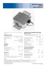
FORWORD<br />
Congratulations on your choice of the FURUNO NX-700A/B <strong>NAVTEX</strong> Receiver.<br />
We are confident that you will enjoy many years of operation with this fine piece<br />
of equipment.<br />
For over 50 years, <strong>Furuno</strong> Electric Company has enjoyed an enviable reputation<br />
for quality and reliability throughout the world. Our extensive global network of<br />
agents and dealers furthers this dedication to excellence.<br />
The NX-700A/B is just one of the many <strong>Furuno</strong> developments in the field of<br />
marine radio communication.<br />
NX-700A: Display unit w/printer<br />
NX-700B: Display unit w/o printer<br />
This NX-700A/B provides cost-effective price, high sensitivity and simple<br />
operation in one compact and light-weight unit. In addition to its fundamental<br />
function of receiving <strong>NAVTEX</strong> broadcasts, this unit can also function as nav data<br />
display when connected to navigation equipment.<br />
This unit is designed and constructed to ensure the user many years of<br />
trouble-free operation. To obtain full performance from the equipment, however,<br />
you should carefully read and follow the recommended procedures for<br />
installation, operation and maintenance. No machine can perform its intended<br />
functions unless it is installed and maintained properly.<br />
Thank you for considering and purchasing FURUNO equipment.<br />
iv
Features<br />
<strong>NAVTEX</strong> (Navigational Telex) is a world wide coastal telex broadcasting system.<br />
Coastal <strong>NAVTEX</strong> broadcasting stations with specific ID’s transmit Navigational<br />
warnings. Meteorological warnings, Search and Rescue (SAR) information and<br />
other navigational information for <strong>NAVTEX</strong> receiver-equipped vessels sailing in<br />
coastal waters.<br />
The FURUNO NX-700 <strong>NAVTEX</strong> receiver receives <strong>NAVTEX</strong> messages and<br />
automatically displays them together with station ID and message category<br />
information.<br />
If ship’s position data is fed from navigation equipment, the NX-700<br />
automatically decides in which NAVAREA the vessel is navigating, and selects<br />
stations. (NAVAREAs are geographical zones defined by the international<br />
Maritime Organization.)<br />
-Meets the following standards and regulations<br />
MSC.148 (77) IMO A.694 (17)<br />
IEC 61097-6 Ed.2 CDV (2005-02)<br />
IEC 60945 Ed. 3 and 4<br />
IEC 61162-1 and 2<br />
EN 300 065V 1.1.3<br />
EN 301 011V 1.1.1 (1998-09)<br />
ITU-R M 540-2<br />
ITU-R M 625-3<br />
-Receives 518 kHz and another (490 or 4209.5 kHz) at the same time<br />
-5” LCD display<br />
-Prints out the message selected<br />
-Bright 76 x 100 mm, monochrome LCD, 240 x 320 dots with adjustable contrast<br />
and brilliance<br />
-Low power consumption<br />
-Displays the NAV data (date, own ship’s position, speed and course) or distance<br />
(distance between own ship’s position and information mentioned in the<br />
message) at the bottom of screen<br />
v
TABLE OF CONTENTS<br />
EQUIPMENT LISTS ........................................................................................... viii<br />
SYSTEM CONFIGURATIONS .............................................................................. x<br />
1. PRINCIPLE OF <strong>NAVTEX</strong> SYSTEM ............................................................... 1-1<br />
1.1 How <strong>NAVTEX</strong> Works................................................................................................. 1-1<br />
1.2 <strong>NAVTEX</strong> System Operation....................................................................................... 1-1<br />
1.3 Message Format ....................................................................................................... 1-2<br />
1.4 <strong>NAVTEX</strong> Station Map ................................................................................................ 1-3<br />
1.5 <strong>NAVTEX</strong> Station List.................................................................................................. 1-4<br />
2. OPERATION................................................................................................... 2-1<br />
2.1 Operating Controls .................................................................................................... 2-1<br />
2.2 Turn the Unit On/Off .................................................................................................. 2-1<br />
2.3 Adjusting LCD Dimmer.............................................................................................. 2-2<br />
2.4 Confirming the New Message.................................................................................... 2-3<br />
2.5 Sample Messages..................................................................................................... 2-4<br />
2.6 Choosing the Receive Mode ..................................................................................... 2-5<br />
2.7 Choosing the Local Frequency.................................................................................. 2-6<br />
2.8 Editing the Setting for Station and Message .............................................................. 2-6<br />
2.9 Switchings the Frequency to Display......................................................................... 2-8<br />
2.10 Alarm Messages........................................................................................................ 2-8<br />
2.11 Processing Messages ............................................................................................... 2-9<br />
2.12 Printing Messages................................................................................................... 2-10<br />
2.13 Editing the <strong>NAVTEX</strong> Station List .............................................................................. 2-12<br />
2.14 Icons ....................................................................................................................... 2-15<br />
2.15 Messages List ......................................................................................................... 2-16<br />
2.16 Other Functions....................................................................................................... 2-17<br />
3. MAINTENANCE & TROUBLESHOOTING ................................................... 3-1<br />
3.1 Maintenance.............................................................................................................. 3-1<br />
3.2 Replacement of Fuse, Battery, LCD and Thermal Paper ........................................... 3-2<br />
3.3 Troubleshooting......................................................................................................... 3-4<br />
3.4 Diagnostics................................................................................................................ 3-5<br />
3.5 Restoring All Default Settings .................................................................................... 3-6<br />
4. INSTALLATION.............................................................................................. 4-1<br />
4.1 Display Unit............................................................................................................... 4-1<br />
4.2 Receiver Unit............................................................................................................. 4-3<br />
4.3 Antenna Unit ............................................................................................................. 4-4<br />
4.4 Printer (NX-700B only) .............................................................................................. 4-5<br />
4.5 Wiring........................................................................................................................ 4-5<br />
4.6 Setting of Printer...................................................................................................... 4-10<br />
4.7 Digital Interfacing......................................................................................................4-11<br />
vi
MENU TREE.................................................................................................... AP-1<br />
SPECIFICATIONS........................................................................................... SP-1<br />
PACKING LISTS ............................................................................................... A-1<br />
OUTLINE DRAWINGS ...................................................................................... D-1<br />
INTERCONNECTION DIAGRAM.......................................................................S-1<br />
vii
EQUIPMENT LISTS<br />
Standard Supply<br />
Name Type Code No. Qty Remarks<br />
Display Unit<br />
NX-700A - w/printer<br />
1<br />
NX-700B -<br />
w/o printer<br />
Receiver Unit NX-7001 - 1<br />
Antenna Unit NX-7H - 1<br />
CP08-01810 000-040-180 10 m cable, CP08-01811*<br />
CP08-01820 000-040-210 20 m cable, CP08-01811*<br />
CP08-01870 000-040-350 1 30 m cable, CP08-01811*<br />
CP08-01880 000-040-362 40 m cable, CP08-01811*<br />
CP08-01890 000-040-363<br />
50 m cable, CP08-01811*<br />
Installation<br />
DSUB25P cable, between<br />
CP08-01860 000-040-349 1<br />
Materials<br />
Display and Receiver Units<br />
CP08-01863* 004-514-530 1<br />
For Antenna Unit w/o antenna<br />
cable<br />
CP08-01864* 004-514-540<br />
For Antenna Unit w/ antenna<br />
cable.<br />
CP08-01861* 004-514-350 1 For Display Unit<br />
Spare Parts SP08-02101* 004-514-370 1 Fuse for Receiver Unit*<br />
Accessories FP08-00800* 000-040-396 1 For NX-700A<br />
*: See the back of this manual.<br />
viii
Optional Supply<br />
Name Type Code No. Qty Remarks<br />
Thermal Paper TP058-30CL 000-154-047 1 set For NX-700A<br />
Flush Mount Kit<br />
OP08-19 004-514-810 1 For NX-700A<br />
OP08-20 004-514-820 1 For NX-700B<br />
AC-DC Power PR-240-CE 000-053-373 1<br />
000-041-174 1 10 m, w/connector<br />
000-041-175 1 20 m, w/connector<br />
OP04-2<br />
000-041-176 1 30 m, w/connector<br />
000-041-177 1 40 m, w/connector<br />
Extension Cable<br />
000-041-178 1 50 m, w/connector<br />
005-948-250 1 10 m<br />
005-948-260 1 20 m<br />
OP08-12<br />
005-948-270 1 30 m<br />
005-948-280 1 40 m<br />
005-948-290 1 50 m<br />
000-563-048 1 30 m<br />
Coaxial Cable RG-10/U-Y<br />
000-126-000 1 40 m<br />
000-126-001 1 50 m<br />
000-152-698 1 3 m<br />
Cable Assy<br />
DSUB25P-DSUB25P<br />
000-152-699 1 5 m<br />
000-152-700 1 10 m<br />
000-152-701 1 15 m<br />
Right Angle Mounting<br />
For antenna unit NX-7H<br />
No.13-QA330 000-803-239 1<br />
Base<br />
L-Angle Mounting No.13-QA310 000-803-240<br />
Base<br />
1<br />
Handrail Mounting No.13-RC5160 000-806-114<br />
Base<br />
1<br />
Mast Mounting Kit CP20-01111 004-365-780 1<br />
Display Unit<br />
NX-700A -<br />
NX-700B -<br />
1<br />
ix
SYSTEM CONFIGURATIONS<br />
DISPLAY UNIT<br />
NX-700B<br />
DISPLAY UNIT<br />
NX-700A<br />
ANTENNA UNIT<br />
NX-7H<br />
or<br />
Max. 15 m<br />
<strong>RECEIVER</strong> UNIT<br />
NX-7001<br />
Max. 100 m<br />
External Alarm<br />
Rectifier<br />
PR-240-CE<br />
Power supply<br />
100-115/<br />
200-230 VAC.<br />
1 , 50/60 Hz<br />
Power supply<br />
12-24 VDC<br />
Printer (NX-700B only)<br />
INS<br />
(Integrated Navigation System)<br />
or<br />
Navigator<br />
: Standard<br />
: Option<br />
: User supply<br />
Environmental Category<br />
Antenna unit<br />
Display unit<br />
Receiver unit<br />
To be installed in an exposed area<br />
To be installed in a protected area<br />
x
1. PRINCIPLE OF <strong>NAVTEX</strong> SYSTEM<br />
1.1 How <strong>NAVTEX</strong> Works<br />
<strong>NAVTEX</strong> is an acronym meaning Navigational Telex, and as its name shows, it is<br />
a kind of narrow band radio teletype system for sending (by frequency shift<br />
keying) text messages expressed in a 7-unit code. The difference is that a<br />
<strong>NAVTEX</strong> transmitter transmits nine control characters (header code) ahead of<br />
the main message, so that the receiver can identify the station, message type<br />
and serial number automatically.<br />
1.2 <strong>NAVTEX</strong> System Operation<br />
For navigation purposes, the world is divided into 16 areas as shown in the<br />
figure below. Each Navtex station has an identification code, from “A” to “Z”. The<br />
frequency assigned to Navtex are 518 kHz and another (490 or 4209.5 kHz),<br />
and many stations exist in the same service coverage.<br />
If the stations were to transmit without any rule, the system would collapse due<br />
to mutual interference. To avoid this problem, the following rules apply.<br />
• The transmission schedule is determined so that two or more stations having<br />
a common service area may not overlap in time.<br />
• Each station transmits with minimum required power to cover its service area<br />
(200 to 400 nautical miles nominal).<br />
1-1
1. PRINCIPLE OF <strong>NAVTEX</strong> SYSTEM<br />
1.3 Message Format<br />
For automatic identification of messages, each message starts with nine control<br />
characters, called “Header codes”.<br />
The first five characters are always “ZCZC_“ and common to all messages. This<br />
part is used for message synchronization. The latter four characters are<br />
designed as B1, B2, B3 and B4 indicate origin, category and serial number of<br />
the message.<br />
Character B1 is the identification letter of the Navtex station “A” thru “Z”.<br />
Character B2 indicates the type of message. “A” thru “Z”, as listed below.<br />
Character B3 and B4 indicate the serial number of the message. The serial<br />
numbers are counted up from “01” to “99”, and starts from “01” again. Number<br />
“00” is specially reserved for important emergency messages.<br />
The end of each message is indicated by “NNNN” (four successive N’s).<br />
General message format is summarized below.<br />
Header code<br />
ZCZC B1 B2 B3 B4 main message NNNN<br />
Start code<br />
(sync)<br />
Main message<br />
Serial number<br />
"00": Emergency message<br />
"01" - "99": Normal message<br />
Termination code<br />
Type of message<br />
"A" - "Z"<br />
(See the list below.)<br />
Station ID<br />
"A" - "Z"<br />
[Type of message (category)]<br />
A: Navigational warning I: Spare<br />
B: Meteorological warning J: SATNAV message<br />
C: Ice report K: Other electronic navigational aid<br />
system message<br />
D: Search and rescue information/pirate<br />
attack warnings<br />
E: Meteorological forecast<br />
F: Pilot message<br />
L: Navigational warning (addition to<br />
“A”)<br />
V to Y Special services allocation by the<br />
<strong>NAVTEX</strong> Co-ordinating Panel<br />
G: AIS<br />
H: LORAN message Z: QRU (no message on hand)<br />
1-2
1. PRINCIPLE OF <strong>NAVTEX</strong> SYSTEM<br />
1.4 <strong>NAVTEX</strong> Station Map<br />
1-3
1. PRINCIPLE OF <strong>NAVTEX</strong> SYSTEM<br />
1.5 <strong>NAVTEX</strong> Station List<br />
NAV<br />
area<br />
Country Station Latitude Longitude<br />
Freq.<br />
(kHz)<br />
Area<br />
(nm)<br />
Station<br />
ID<br />
Broadcast schedule (UTC)<br />
I Belgium Oostende 51 11 N 02 48 E 518 55 T 0310, 0710, 1110, 1510, 1910, 2310<br />
Estonia Tallinn 59 30 N 24 30 E 518 250 U 0320, 0720, 1120, 1520, 1920, 2320<br />
Iceland Reykjavik Radio 64 05 N 21 51 W<br />
518 550 R 0250, 0650, 1050, 1450, 1850, 2250<br />
490 550 R 0318, 0718, 1118, 1518, 1918, 2318<br />
Ireland Valentia 51 27 N 09 49 W 518 400 W 0340, 0740, 1140, 1540, 1940, 2340<br />
Malin Head 55 22 N 07 21 W 518 400 Q 0240, 0640, 1040, 1440, 1840, 2240<br />
France Niton 50 35 N 01 18 W 518 270 K 0140, 0540, 0940, 1340, 1740, 2140<br />
Netherlands Den Helder 52 06 N 04 15 E 518 110 P 0230, 0630, 1030, 1430, 1830, 2230<br />
Norway Bodo Radio 67 16 N 14 23 E 518 450 B 0010, 0410, 0810, 1210, 1610, 2010<br />
Rogaland Radio 58 48 N 05 34 E 518 450 L 0150, 0550, 0950, 1350, 1750, 2150<br />
Vardoe Radio 70 22 N 31 06 E 518 450 V 0330, 0730, 1130, 1530, 1930, 2330<br />
Svalbard 78 04 N 13 38 E 518 450 A 0000, 0400, 0800, 1200, 1600, 2000<br />
Orlandet 63 40 N 09 33 E 518 450 N 0210, 0610, 1010, 1410, 1810, 2210<br />
Sweden Bjuroklubb 64 28 N 21 36 E 518 300 H 0110, 0510, 0910, 1310, 1710, 2110<br />
Gislovshammar 55 29 N 14 19 E 518 300 J 0130, 0530, 0930, 1330, 1730, 2130<br />
Grimeton 57 06 N 12 23 E 518 300 D 0030, 0430, 0830, 1230, 1630, 2030<br />
United<br />
Kingdom<br />
Cullercoats 55 02 N 01 26 W<br />
Portpatrick 54 51 N 05 07 W<br />
Niton 50 35 N 01 18 W<br />
518 270 G 0100, 0500, 0900, 1300, 1700, 2100<br />
490 270 U 0320, 0720, 1120, 1520, 1920, 2320<br />
518 270 O 0220, 0620, 1020, 1420, 1820, 2220<br />
490 270 C 0020, 0420, 0820, 1220, 1620, 2020<br />
518 270 E 0040, 0440, 0840, 1240, 1640, 2040<br />
490 270 I 0120, 0520, 0920, 1320, 1720, 2120<br />
Oostende 51 11 N 02 48 E 518 150 M 0200, 0600, 1000, 1400, 1800, 2200<br />
II France Cross Corsen 48 28 N 05 03 W<br />
518 300 A 0000, 0400, 0800, 1200, 1600, 2000<br />
490 300 E 0040, 0440, 0840, 1240, 1640, 2040<br />
Niton 50 35 N 01 18 W 490 270 T 0310, 0710, 1110, 1510, 1910, 2310<br />
Portugal Horta 38 32 N 28 38 W 518 640 F 0050, 0450, 0850, 1250, 1650, 2050<br />
Monsanto 38 44 N 09 11 W<br />
518 530 R 0250, 0650, 1050, 1450, 1850, 2250<br />
490 530 G 0100, 0500, 0900, 1300, 1700, 2100<br />
Spain Coruna 43 21 N 08 27 W 518 400 D 0030, 0430, 0830, 1230, 1630, 2030<br />
Tarifa 36 01 N 05 34 W 518 400 G 0100, 0500, 0900, 1300, 1700, 2100<br />
Las Palmas 28 10 N 15 25 W 518 400 I 0120, 0520, 0920, 1320, 1720, 2120<br />
(Continued on next page)<br />
1-4
1. PRINCIPLE OF <strong>NAVTEX</strong> SYSTEM<br />
<br />
NAV<br />
area<br />
Country Station Latitude Longitude<br />
Freq.<br />
(kHz)<br />
Area<br />
(nm)<br />
Station<br />
ID<br />
Broadcast schedule (UTC)<br />
III Bulgaria Varna 43 04 N 27 46 E 518 350 J 0130, 0530, 0930, 1330, 1730, 2130<br />
Croatia Split radio 43 30 N 16 29 E 518 85 Q 0240, 0640, 1040, 1440, 1840, 2240<br />
Cyprus Cypradio 35 03 N 33 17 E 518 200 M 0200, 0600, 1000, 1400, 1800, 2200<br />
Egypt Alexandria 31 12 N 29 52 E 518 350 N 0210, 0610, 1010, 1410, 1810, 2210<br />
Serapeum 30 28 N 32 22 E 4209.5 400 X 0750, 1150<br />
France Toulon 43 06 N 05 59 E<br />
518 250 W 0340, 0740, 1340, 1540, 1940, 2340<br />
490 250 S 0300, 0700, 1100, 1500, 1900, 2300<br />
Greece Iraklion 35 20 N 25 07 E 518 280 H 0110, 0510, 0910, 1310, 1710, 2110<br />
Kerkyra 39 37 N 19 55 E 518 280 K 0140, 0540, 0940, 1340, 1740, 2140<br />
Limnos 39 52 N 25 04 E 518 280 L 0150, 0550, 0950, 1350, 1750, 2150<br />
Israel Haifa 32 49 N 35 00 E 518 200 P 0020, 0420, 0820, 1220, 1620, 2020<br />
Italy Roma 41 48 N 12 31 E 518 320 R 0250, 0650, 1050, 1450, 1850, 2250<br />
Augusta 37 14 N 15 14 E 518 320 V 0330, 0730, 1130, 1530, 1930, 2330<br />
Cagliari 39 14 N 09 14 E 518 320 T 0310, 0710, 1110, 1510, 1910, 2310<br />
Trieste 45 41 N 13 46 E 518 320 U 0320, 0720, 1120, 1520, 1920, 2320<br />
Malta Malta 35 49 N 14 32 E 518 400 O 0220, 0620, 1020, 1420, 1820, 2220<br />
Russian<br />
Federation<br />
Novorossiysk 44 42 N 37 44 E 518 300 A 0300, 0700, 1100, 1500, 1900, 2300<br />
Spain Cabo de la Nao 38 43 N 00 09 E 518 300 X 0350, 0750, 1150, 1550, 1950, 2350<br />
Turkey Istanbul 41 04 N 28 57 E 518 300 D 0030, 0430, 0830, 1230, 1630, 2030<br />
Samsun 41 17 N 36 20 E 518 300 E 0040, 0440, 0840, 1240, 1640, 2040<br />
Antalya 36 53 N 30 42 E 518 300 F 0050, 0450, 0850, 1250, 1650, 2050<br />
Izmir 38 22 N 26 36 E 518 300 I 0120, 0520, 0920, 1320, 1720, 2120<br />
Ukraine Mariupol 47 06 N 37 33 E 518 280 B 0100, 0500, 0900, 1300, 1700, 2100<br />
Odessa 46 29 N 30 44 E 518 280 C 0230, 0630, 1030, 1430, 1830, 2230<br />
IV<br />
Bermuda<br />
(UK)<br />
Bermuda 32 23 N 64 41 W 518 280 B 0010, 0410, 0810, 1210, 1610, 2010<br />
Canada Riviere-au-Renard 50 11 N 66 07 W 518 300<br />
C<br />
D<br />
0020, 0420, 0820, 1220, 1620, 2020<br />
0035, 0435, 0835, 1235, 1635, 2035<br />
Wiarton 44 20 N 81 10 W 518 300 H 0110, 0510, 0910, 1310, 1710, 2110<br />
St. Johns 47 30 N 52 40 W 518 300 O 0220, 0620, 1020, 1420, 1820, 2220<br />
Thunder Bay 48 25 N 89 20 W 518 300 P 0230, 0630, 1030, 1430, 1830, 2230<br />
Sydney, NS 46 10 N 60 00 W 518 300<br />
Yarmouth 43 45 N 66 10 W 518 300<br />
<br />
Q<br />
J<br />
U<br />
V<br />
0240, 0640, 1040, 1440, 1840, 2240<br />
0255, 0655, 1055, 1455, 1855, 2255<br />
0320, 0720, 1120, 1520, 1920, 2320<br />
0335, 0735, 1135, 1535, 1935, 2335<br />
(Continued on next page)<br />
1-5
1. PRINCIPLE OF <strong>NAVTEX</strong> SYSTEM<br />
<br />
NAV<br />
area<br />
Country Station Latitude Longitude<br />
Freq.<br />
(kHz)<br />
Area<br />
(nm)<br />
Station<br />
ID<br />
Broadcast schedule (UTC)<br />
IV Canada Labrador 53 42 N 57 01 W 518 300 X 0350, 0750, 1150, 1550, 1950, 2350<br />
Iqaluit, NU 63 43 N 68 33 W<br />
518 300 T 0310, 0710, 1110, 1510, 1910, 2310<br />
490 300 S 0300, 0700, 1100, 1500, 1900, 2300<br />
United States Miami 25 37 N 80 23 W 518 240 A 0000, 0400, 0800, 1200, 1600, 2000<br />
Boston 41 43 N 70 30 W 518 200 F 0445, 0845, 1245, 1645, 2045, 0045<br />
New Orleans 29 53 N 89 57 W 518 200 G 0300, 0700, 1100, 1500, 1900, 2300<br />
Portsmouth 36 43 N 76 00 W 518 280 N 0130, 0530, 0930, 1330, 1730, 2130<br />
Isabella 18 28 N 67 04 W 518 200 R 0200, 0600, 1000, 1400, 1800, 2200<br />
Savannah, GA 32 08 N 81 42 W 518 200 E 0040, 0440, 0840, 1240, 1640, 2040<br />
Netherlands<br />
Antilles<br />
Curacao 12 10 N 68 52 W 518 400 H 0110, 0510, 0910, 1310, 1710, 2110<br />
V<br />
NIL<br />
VI Argentina Ushaia 54 48 S 68 18 W 518 280 M 0200, 0600, 1000, 1400, 1800, 2200<br />
Rio Gallegos 51 37 S 65 03 W 518 280 N 0210, 0610, 1010, 1410, 1810, 2210<br />
Comodoro<br />
Rivadavia<br />
45 51 S 67 25 W 518 280 O 0220, 0620, 1020, 1420, 1820, 2220<br />
Bahia Blanca 38 43 S 62 06 W 518 280 P 0230, 0630, 1030, 1430, 1830, 2230<br />
Mar del Plata 38 03 S 57 32 W 518 280 Q 0240, 0640, 1040, 1440, 1840, 2240<br />
Buenos Aires 34 36 S 58 22 W 518 560 R 0250, 0650, 1050, 1450, 1850, 2250<br />
Uruguay La Paloma 34 40 S 54 09 W<br />
518 280 F 0050, 0450, 0850, 1250, 1650, 2050<br />
490 280 A 0000, 0400, 0800, 1200, 1600, 2000<br />
VII Namibia Walvis Bay 23 03 S 14 37 E 518 378 B 0010, 0410, 0810, 1210, 1610, 2010<br />
South Africa Cape Town 33 40 S 18 43 E 518 500 C 0020, 0420, 0820, 1220, 1620, 2020<br />
Port Elizabeth 34 02 S 25 33 E 518 500 I 0120, 0520, 0920, 1320, 1720, 2120<br />
Durban 30 00 S 31 30 E 518 500 O 0220, 0620, 1020, 1420, 1820, 2220<br />
VIII India Mumbay 19 05 N 72 50 E 518 250 G 0100, 0500, 0900, 1300, 1700, 2100<br />
Madras 13 08 N 80 10 E 518 400 P 0230, 0630, 1030, 1430, 1830, 2230<br />
Mauritius Mauritius Radio 20 10 S 57 28 E 518 400 C 0020, 0420, 0820, 1220, 1620, 2020<br />
IX Bahrain Hamala 26 09 N 50 28 E 518 300 B 0010, 0410, 0810, 1210, 1610, 2010<br />
Egypt Serapeum 30 28 N 32 22 E<br />
518 200 X 0350, 0750, 1150, 1550, 1950, 2350<br />
4209.5 200 X 0750, 1150<br />
Kosseir 26 06 N 34 17 E 518 400 V 0330, 0730, 1130, 1530, 1930, 2330<br />
Iran Bushehr 28 59 N 50 50 E 518 300 A 0000, 0400, 0800, 1200, 1600, 2000<br />
Bandar Abbas 27 07 N 56 04 E 518 300 F 0050, 0450, 0850, 1250, 1650, 2050<br />
(Continued on next page)<br />
1-6
1. PRINCIPLE OF <strong>NAVTEX</strong> SYSTEM<br />
NAV<br />
area<br />
Country Station Latitude Longitude<br />
Freq.<br />
(kHz)<br />
Area<br />
(nm)<br />
Station<br />
ID<br />
Broadcast schedule (UTC)<br />
IX Saudi Arabia Jeddah 21 23 N 39 10 E 518 390 H 0705, 1305, 1905<br />
Oman Muscat 23 36 N 58 30 E 518 270 M 0200, 0600, 1000, 1400, 1800, 2200<br />
Pakistan Karachi 24 51 N 67 03 E 518 400 P 0230, 0630, 1030, 1430, 1830, 2230<br />
X<br />
NIL<br />
XI China Sanya 18 14 N 109 30 E 518 250 M 0200, 0600, 1000, 1400, 2200<br />
Guangzhou 23 08 N 113 32 E 518 250 N 0210, 0610, 1010, 1410, 2210<br />
Fuzhou 26 01 N 119 18 E 518 250 O 0220, 0620, 1020, 1420, 2220<br />
Shanghai 31 08 N 121 33 E 518 250 Q 0240, 0640, 1040, 1440, 2240<br />
Dalian 38 52 N 121 31 E 518 250 R 0250, 0650, 1050, 1450, 2250<br />
Indonesia Jayapura 02 31 S 140 43 E 518 300 A 0000, 0400, 0800, 1200, 1600, 2000<br />
Ambon 03 42 S 128 12 E 518 300 B 0010, 0410, 0810, 1210, 1610, 2010<br />
Makassar 05 06 S 119 26 E 518 300 D 0030, 0430, 0830, 1230, 1830, 2030<br />
Jakarta 06 06 S 106 54 E 518 300 E 0040, 0440, 0840, 1240, 1640, 2040<br />
Japan Otaru 43 19 N 140 27 E 518 400 J 0130, 0530, 0930, 1330, 1730, 2130<br />
Kushiro 42 57 N 144 36 E 518 400 K 0140, 0540, 0940, 1340, 1740, 2140<br />
Yokohama 35 14 N 139 55 E 518 400 I 0120, 0520, 0920, 1320, 1720, 2120<br />
Moji 34 01 N 130 56 E 518 400 H 0110, 0510, 0910, 1310, 1710, 2110<br />
Naha 26 05 N 127 40 E 518 400 G 0100, 0500, 0900, 1300, 1700, 2100<br />
Korea,<br />
Republic of<br />
Chukpyong 37 03 N 129 26 E<br />
Pyongsan 35 36 N 126 29 E<br />
518 200 V 0330, 0730, 1130, 1530, 1930, 2330<br />
490 200 J 0130, 0530, 0930, 1330, 1730, 2130<br />
518 200 W 0340, 0740, 1340, 1540, 1940, 2340<br />
490 200 K 0140, 0540, 0940, 1340, 1740, 2140<br />
Malaysia Penang 05 26 N 100 24 E 518 350 U 0320, 0720, 1120, 1520, 1920, 2320<br />
Miri 04 28 N 114 01 E 518 350 T 0310, 0710, 1110, 1510, 1910, 2310<br />
Sandakan 05 54 N 118 00 E 518 350 S 0300, 0700, 1100, 1500, 1900, 2300<br />
Singapore Singapore 01 25 N 103 52 E 518 400 C<br />
0020-0030, 0420-0430, 0820-0830,<br />
1220-1230, 1620-1630, 2020-2030<br />
Thailand Bangkok Radio 13 43 N 100 34 E 518 200 F 0050, 0450, 0850, 1250<br />
United States Guam 13 29 N 144 50 E 518 100 V 0100, 0500, 0900, 1300, 1700, 2100<br />
(Continued on next page)<br />
1-7
1. PRINCIPLE OF <strong>NAVTEX</strong> SYSTEM<br />
<br />
NAV<br />
area<br />
Country Station Latitude Longitude<br />
Freq.<br />
(kHz)<br />
Area<br />
(nm)<br />
Station<br />
ID<br />
Broadcast schedule (UTC)<br />
XI Vietnam Ho Chi Minh City 10 47 N 106 40 E 518 400 X 0350, 0750, 1150, 1550, 1950, 2350<br />
Haiphong 20 44 N 106 44 E<br />
490 400 W 0340, 1540<br />
4209.5 400 W 0230, 0630, 1030, 1430, 1830, 2230<br />
Danang 16 05 N 108 13 E 518 400 K 0140, 0540, 0940, 1340, 1740, 2140<br />
Taiwan Kaohsiung 22 29 N 120 25 E 518 216 P 0230, 0630, 1030, 1430, 1830, 2230<br />
Associate<br />
Member of IMO<br />
Hong Kong 22 13 N 114 15 E 518 400 L 0150, 0550, 0950, 1350, 1750, 2150<br />
XII Canada Prince Rupert 54 20 N 130 20 W 518 300 D 0030, 0430, 0830, 1230, 1630, 2030<br />
Tofino 48 55 N 125 35 W 518 300 H 0110, 0510, 0910, 1310, 1710, 2110<br />
United States San Francisco 37 55 N 122 44 W 518 350 C 0400, 0800, 1200, 1600, 2000, 2400<br />
Kodiak 57 46 N 152 34 W 518 200 J 0300, 0700, 1100, 1500, 1900, 2300<br />
Honolulu 21 22 N 158 09 W 518 350 O 0040, 0440, 0840, 1240, 1640, 2040<br />
Cambria 35 31 N 121 03 W 518 350 Q 0445, 0845, 1245, 1645, 2045, 0045<br />
Astoria 46 10 N 123 49 W 518 216 W 0130, 0530, 0930, 1330, 1730, 2130<br />
XIII<br />
Russian<br />
Federation<br />
Kholmsk 47 02 N 142 03 E 518 300 B 0010, 0410, 0810, 1210, 1610, 2010<br />
Murmansk 68 46 N 32 58 E 518 300 C 0020, 0420, 0820, 1220, 1620, 2020<br />
Arkhangelsk 64 51 N 40 17 E 518 300 F 0050, 0450, 0850, 1250, 1650, 2050<br />
Astrakhan 45 47 N 47 33 E 518 250 W 0340, 0740, 1140, 1540, 1940, 2340<br />
XIV<br />
NIL<br />
XV Chile Antofagasta 23 40 S 70 25 W 518 300<br />
A<br />
H<br />
0400, 1200, 2000<br />
0000, 0800, 1600<br />
Valparaiso 32 48 S 71 29 W 518 300<br />
B<br />
I<br />
0410, 1210, 2010<br />
0010, 0810, 1610<br />
Talcahuano 36 42 S 73 06 W 518 300<br />
C<br />
J<br />
0420, 1220, 2020<br />
0020, 0820, 1620<br />
Puerto Montt 41 30 S 72 58 W 518 300<br />
D<br />
K<br />
0430, 1230, 2030<br />
0030, 0830, 1630<br />
Punta Arenas 53 09 S 70 58 W 518 300<br />
E<br />
L<br />
0440, 1240, 2040<br />
0040, 0840, 1640<br />
Isla de Pascua 27 09 S 109 25 W 518 300<br />
F<br />
G<br />
0450, 1250, 2050<br />
0050, 0850, 1650<br />
XVI Peru Paita 05 05 S 81 07 W 518 200 S 0300, 0700, 1100, 1500, 1900, 2300<br />
Callao 12 03 S 77 09 W 518 200 U 0320, 0720, 1120, 1520, 1920, 2320<br />
Mollendo 17 01 S 72 01 W 518 200 W 0340, 0740, 1140, 1540, 1940, 2340<br />
Note: The list shows the stations listed at Longwave Navtex Broadcasts (Oct. 2004).<br />
1-8
2. OPERATION<br />
2.1 Operating Controls<br />
Registers items on menus.<br />
Cursor pad<br />
-Shifts the cursor and display.<br />
-Selects items on menus.<br />
ENT<br />
MENU<br />
ESC<br />
Opens menu/Returns to the previous display.<br />
DIM<br />
LIST<br />
PRINT<br />
Opens the LIST options.<br />
Opens the PRINT options.<br />
Turns the power on/off.<br />
Adjusts the panel and LCD dimmer.<br />
+: Raises the setting.<br />
- : Decreases the setting.<br />
2.2 Turning the Unit On/Off<br />
Display unit, front view<br />
Press the key to turn the unit on. A beep sounds and the equipment shows<br />
the start up display, where the ROM and RAM are checked for proper operation<br />
and the program no. is displayed. The results of the check are shown as OK or<br />
NG (No Good).<br />
When the results are OK, the list display is shown after five seconds after<br />
completion of the check, with frequency last used before turning the power off.<br />
DUAL CHANNEL <strong>NAVTEX</strong><br />
NX-700<br />
FURUNO ELECTRIC CO., LTD.<br />
ROM : OK RAM : OK<br />
Program No. 0850193-XX<br />
XX: Program version No.<br />
2-1
2. OPERATION<br />
At the default setting, the equipment functions as below;<br />
When the results of the check are OK, ALL MESSAGE display for 518 kHz<br />
appears. This screen shows all messages received in 518 kHz.<br />
You can switch 518 kHz (International message) and 490 kHz (local message) to<br />
display. The NX-700A is preset to print all received message out.<br />
All message display (518 kHz)<br />
Note 1: To display all received messages in 490 kHz, press ◄ or ►.<br />
Note 2: To cancel the printing all received messages out, see page 2-11.<br />
To turn the power off, press the<br />
key again.<br />
Note: If NG appears for any test, try to press any key to go to the next stage.<br />
The equipment, however, may not be operated properly. Contact your<br />
dealer if the problem persists.<br />
2.3 Adjusting LCD Dimmer<br />
You can adjust LCD and panel dimmer with the + DIM – key. The adjustment<br />
range is 0 (dark) to 9 (bright).<br />
+: Raises the dimmer.<br />
-: Decreases the dimmer.<br />
2-2
2. OPERATION<br />
2.4 Confirming the New Message<br />
When you receive a new message, do one of the following depending on<br />
message received.<br />
SAR (Search and Rescue) message<br />
1. When an SAR message is received, the audible alert sounds and details for<br />
the SAR message appear.<br />
Icon for SAR message<br />
2. Press any key other than key to silence the alarm.<br />
Other messages<br />
1. When a message other than an SAR message is received, the display shows<br />
one of the following windows.<br />
Received new int'l msg.<br />
Received new local msg.<br />
Display new msg ?<br />
Yes No<br />
International message<br />
Display new msg ?<br />
Yes No<br />
Local message<br />
2. If you want to read the message immediately, press ◄ to choose “Yes” and<br />
then press the ENT key to display the message<br />
To read the message later, choose “No”, and then press the ENT key to<br />
close the window.<br />
2-3
2. OPERATION<br />
2.5 Sample Messages<br />
Press ▲ or ▼ on the cursor pad to choose a message, and then press the ENT<br />
key to show the detailed information for that message. The message list and<br />
detailed message displays can be switched by pressing the ENT key.<br />
Category of messages<br />
(paragraph 2.11)<br />
New<br />
Frequency (paragraph 2.9)<br />
Status icon (paragraph 2.14)<br />
No. of saved messages<br />
Receiving<br />
date<br />
Station ID, type of message,<br />
serial No. (two digits, paragraph 1.3)<br />
Error rate<br />
ENT key<br />
Old<br />
Operation guide<br />
Message icon (paragraph 2.14)<br />
Message list<br />
Detailed message<br />
Note 1: The operation guide at the bottom of screen shows the functions of the<br />
keys available for use with the current screen.<br />
Note 2: The character size can be changed. For detail, see page 2-18.<br />
Key Display mode Function<br />
▲▼<br />
List<br />
Scrolls the list.<br />
Detailed Scrolls the message.<br />
◄►<br />
List<br />
Switches the international and local lists.<br />
Detailed Shows the newer (◄) or older (►) message.<br />
MENU<br />
List<br />
Detailed<br />
Shows the main menu.<br />
ENT<br />
List<br />
Shows the detailed message selected.<br />
Detailed Shows the message list.<br />
LIST<br />
List<br />
Detailed<br />
Shows the list options.<br />
PRINT<br />
List<br />
Detailed<br />
Shows the print options.<br />
2-4
2.6 Choosing the Receive Mode<br />
2. OPERATION<br />
The <strong>NAVTEX</strong> menu allows you to select what station to receive, automatically,<br />
manually. The Auto mode requires navigation data, and stations are<br />
automatically selected according to the distance between own ship and <strong>NAVTEX</strong><br />
stations. If navigation data is not input, all stations are selected. The manual<br />
mode lets you freely stations to receive. The INS mode allows you to set the<br />
station, message and local channel from the external equipment (ex. Integrated<br />
Navigation System, using NMK sentence) connected.<br />
1. Press the MENU/ESC key to show the main menu.<br />
Menu<br />
<strong>NAVTEX</strong><br />
System<br />
Display<br />
Service<br />
Main menu<br />
2. Press ▲ or ▼ to choose <strong>NAVTEX</strong>.<br />
3. Press the ENT key or ► to open the <strong>NAVTEX</strong> menu.<br />
<strong>NAVTEX</strong><br />
Receive Mode Manual<br />
Local Channel 490kHz<br />
Auto Print All<br />
Rcv Station & Msg<br />
User Select Station & Msg<br />
<strong>NAVTEX</strong> menu<br />
4. Press ▲ or ▼ to choose Receive Mode, and then press the ENT key or ► to<br />
show the receive mode options.<br />
INS<br />
Auto<br />
Manual<br />
Receive mode options<br />
5. Press ▲ or ▼ to choose INS, Auto or Manual as appropriate, and then press<br />
the ENT key.<br />
6. Press the MENU/ESC key several times to close the menu.<br />
2-5
2. OPERATION<br />
2.7 Choosing the Local Frequency<br />
You can choose 490 kHz or 4209.5 kHz as the local frequency. This function is<br />
only available for the Auto and Manual modes. (See paragraph 2.6.)<br />
1. Press the MENU/ESC key to show the main menu.<br />
2. Press ▲ or ▼ to choose <strong>NAVTEX</strong>, and then press the ENT key or ►.<br />
3. Press ▲ or ▼ to choose Local Channel, and then press the ENT key or ► to<br />
show the local channel options.<br />
490kHz<br />
4209.5kHz<br />
Local channel options<br />
4. Press ▲ or ▼ to choose the frequency 490 kHz or 4209.5 kHz, and then<br />
press the ENT key.<br />
5. Press the MENU/ESC key several times to close the menu.<br />
2.8 Editing the Settings for Station and Message<br />
Stations and messages for receiving/displaying on each station (message) can<br />
be edited as below.<br />
Rcv Station & Msg<br />
Station<br />
You can receive messages by station when Manual is chosen as the Receive<br />
Mode on the <strong>NAVTEX</strong> menu.<br />
Message<br />
You can choose the messages to receive when Manual or Auto is chosen as the<br />
Receive Mode on the <strong>NAVTEX</strong> menu. Note that A/B/D/L cannot be rejected.<br />
User Select Station & Msg<br />
Station<br />
Choose the station to display on User Selected Messages, which is shown when<br />
the LIST key is pressed.<br />
Message<br />
Choose the type of message to display on User Selected Messages, which is<br />
shown when the LIST key is pressed.<br />
Note 1: For messages, the alarm message is displayed always.<br />
Note 2: When User Select is chosen as the Auto Print on <strong>NAVTEX</strong> menu, only<br />
the messages chosen here are printed. (See paragraph 2-11.)<br />
1. Press the MENU/ESC key to show the main menu.<br />
2. Press ▲ or ▼ to choose <strong>NAVTEX</strong>, and then press the ENT key.<br />
2-6
2. OPERATION<br />
3. Press ▲ or ▼ to choose “Rcv Station & Msg” or “User Select Station & Msg”.<br />
4. Press the ENT key to open the appropriate editing window. (Below is the Rcv<br />
Station & Msg editing window.)<br />
Recieve mode<br />
Internaitional frequency<br />
Station<br />
Message<br />
Local frequency*<br />
Changeable item<br />
Rcv Station & Msg [Auto]<br />
[518]<br />
Station<br />
ABCDEFGHIJKLMNOPQRSTUVWXYZ<br />
Message<br />
ABCDEFGHIJKLMNOPQRSTUVWXYZ<br />
[490]<br />
Station<br />
ABCDEFGHIJKLMNOPQRSTUVWXYZ<br />
Message<br />
ABCDEFGHIJKLMNOPQRSTUVWXYZ<br />
[ ][ ] MOVE<br />
[ENT] EDIT<br />
[MENU] RETURN TO MENU<br />
*: Local channel selected at Paragraph 2.7.<br />
Edit window (ex. Rcv Station & Msg)<br />
5. Press ▲ or ▼ to choose the item to edit, and then press the ENT key to<br />
show the alphabet selection window.<br />
ABCDEFGHIJKLMNOPQRSTUVWXYZ<br />
Cursor<br />
6. Press ◄ or ► to choose the alphabet desired, and then press ▲ or ▼ to<br />
choose to receive or not.<br />
The alphabet you have chosen not to receive is marked with “-“ (hyphen).<br />
7. Press the ENT key<br />
8. Repeat steps 5 through 7 to complete.<br />
9. Press the MENU/ESC key to close the window.<br />
2-7
2. OPERATION<br />
2.9 Switching the Frequency to Display<br />
With showing the message list, you can switch the frequency to 518 kHz or 490<br />
(or 4209.5) kHz by pressing ◄ or ► key.<br />
Press<br />
518 490 (4209)<br />
2.10 Alarm Messages<br />
Switching the frequency to display<br />
The sequence of events when an alarm message is received is as shown below.<br />
When receiving SAR (Search and Rescue) message:<br />
The audible alarm beep sounds, and the SAR message is shown. Note that All<br />
Messages list appears if other list option is chosen when the ENT key is pressed.<br />
(See paragraph 2.11.)<br />
When receiving WARNING message (A/B/L):<br />
When the Warn Msg Alm on System menu is set to On, the audible alarm<br />
sounds and the message for receiving appears.<br />
Silencing audible alarm<br />
Press any key (except<br />
key).<br />
2-8
2. OPERATION<br />
2.11 Processing Messages<br />
Choosing messages to display<br />
You can choose which category of messages to display: All, Alarm, User<br />
Selected and Good messages.<br />
1. With the message list or detailed message shown, press the LIST key to<br />
show the list options.<br />
All Messages<br />
Alarm Messages<br />
User Messages<br />
Good Messages<br />
Lock Message<br />
List options<br />
2. Press ▲ or ▼ to choose the item.<br />
All Messages: Shows all messages received.<br />
Alarm Messages: Shows only SAR/WARNING messages.<br />
User Selected Messages: Shows messages arranged at User Select Station &<br />
Msg on <strong>NAVTEX</strong> menu.<br />
Good Messages: Shows messages whose error rate is less than 4%.<br />
3. Press the ENT key to close the window.<br />
The list chosen at step 2 appears.<br />
Note: When the following messages appear, set the List window to All Messages<br />
to show.<br />
Urgent message:<br />
“Message not chosen for display received; it is a int’l (or local) 00 message.<br />
Choose “All Message” (LIST menu) to display.”<br />
Normal message:<br />
Int’l (or local) message not chosen for display received. Choose “All<br />
Message” (LIST menu) to display.”<br />
2-9
2. OPERATION<br />
Protecting message from deleting<br />
Messages are automatically deleted from the memory under the following<br />
conditions.<br />
-66 hours passed from the moment when received.<br />
-Older than No. 200<br />
To prevent a message from being deleted, do the follows;<br />
1. Choose the message at the list display.<br />
2. Press the LIST key to show the list options.<br />
All Messages<br />
Alarm Messages<br />
User Messages<br />
Good Messages<br />
Lock Message<br />
List options<br />
3. Choose Lock Message from the list window.<br />
The protect icon ( ) appears next to the message selected.<br />
Note 1: To unlock a message, choose it and then select Unlock Message in the<br />
list window. (The protect icon disappears.)<br />
Note 2: When you unlock a message which was received 66 hours ago or a<br />
message that is older than No. 200, it will be deleted promptly when<br />
unlocked.<br />
Note 3: Maximum each 50 messages for International and local (or 25% of each<br />
memory) can be protected.<br />
2.12 Printing Messages<br />
Received messages can be printed automatically or manually, from the built-in<br />
printer (NX-700A) or external printer (NX-700B).<br />
Printing all messages displayed<br />
All messages chosen on paragraph 2.11 can be printed out.<br />
1. Press the PRINT key with showing all messages.<br />
Print<br />
Cancel Print<br />
Print options<br />
2. Press ▲ or ▼ to choose “Print”.<br />
3. Press the ENT key to print.<br />
2-10<br />
Note: When a message is received while printing some messages, the new one<br />
cannot be printed.
2. OPERATION<br />
Printing each message<br />
1. Press ▲ or ▼ to choose the desired message from the list.<br />
2. Press the ENT key to show the detailed information.<br />
3. Press the PRINT key.<br />
4. Press ▲or ▼ to choose “Print” from the window.<br />
5. Press the ENT key to print.<br />
Printing messages automatically<br />
When receiving a message, it can be printed out immediately.<br />
1. Press the MENU/ESC key to open the main menu.<br />
2. Press ▲ or ▼ to choose <strong>NAVTEX</strong>, and then press the ENT key to show the<br />
<strong>NAVTEX</strong> menu.<br />
3. Press ▲ or ▼ to choose Auto Print, and then press the ENT key to open the<br />
auto print options.<br />
Off<br />
All<br />
User Select<br />
Auto print options<br />
4. Press ▲ or ▼ to choose All, User Select or Off as appropriate.<br />
All: Prints all messages when receiving.<br />
User Select: Prints only the specified messages at User Select Station & Msg<br />
on the <strong>NAVTEX</strong> menu when receving.<br />
Off: All messages are not printed automatically.<br />
5. Press the ENT key.<br />
6. Pres the MENU/ESC key several times to close the menu.<br />
Canceling printing<br />
When a menu is displayed, you cannot cancel the printing.<br />
1. Press the PRINT key while showing the messages to open the print window.<br />
2. Press ▼ to choose “Cancel Print” and then press the ENT key.<br />
2-11
2. OPERATION<br />
2.13 Editing the <strong>NAVTEX</strong> Station List<br />
Maximum 300 <strong>NAVTEX</strong> stations can be registered into the memory.<br />
Note: To cancel editing of a <strong>NAVTEX</strong> station, press the MENU/ESC key. The<br />
message “Exit without saving?” appears. Choose “Yes”, and then press<br />
ENT key.<br />
Adding <strong>NAVTEX</strong> station<br />
You may add a <strong>NAVTEX</strong> station to the <strong>NAVTEX</strong> station list as follows:<br />
1. Press the MENU/ESC key to show the main menu.<br />
2. Press ▲ or ▼ to choose Service, and then press the ENT key.<br />
Service<br />
INS Input Speed<br />
INS Output Speed<br />
Print Header<br />
Edit Station List<br />
Default Setting<br />
Test<br />
Rcv Monitor<br />
4800bps<br />
4800bps<br />
On<br />
Service menu<br />
3. Press ▲ or ▼ to choose Edit Station List, and then press the ENT key.<br />
Frequency<br />
NAV Area<br />
Station name<br />
518kHz<br />
NavArea 01<br />
[ New ]<br />
Oostende T, - , -<br />
Tallinn U, - , -<br />
Reykjavik Radio R, - , -<br />
Valentia W,- , -<br />
Malin Head Q, - , -<br />
Niton K, - , -<br />
Den Helder P, - , -<br />
Bodo Radio B, - , -<br />
Rogaland Radio L, - , -<br />
Vardoe Radio V, - , -<br />
Svalbard A, - , -<br />
[ ][ ] CHANGE NAVAREA<br />
[LIST] CHANGE FREQ<br />
[ENT] EDIT [MENU] RETURN TO MENU<br />
Edit station list display<br />
4. Confirm that New is chosen, and then press the ENT key to show the<br />
addition window appears.<br />
2-12
2. OPERATION<br />
NAV Area<br />
Station Name<br />
Latitude<br />
Longitude<br />
Station ID<br />
Sertvice Area<br />
NavArea 1<br />
Station<br />
Latitude 0 00'N<br />
Longitude 0 00'E<br />
518kHz ID1: - ID2: - ID3: -<br />
490kHz ID1: - ID2: - ID3: -<br />
4209.5kHz ID1: - ID2: - ID3: -<br />
Range 400nm<br />
Save data ?<br />
New addition window<br />
5. Confirm that NavArea is chosen, and then press the ENT key to show the<br />
area No. window.<br />
6. Press ▲ or ▼ to choose a Nav area No. (1 to 16, and EXT), and then press<br />
the ENT key.<br />
For NAV area No., see paragraph 1.4. EXT is reserved for future use.<br />
7. Confirm that Station is chosen, and then press ENT key.<br />
8. Enter a station name (Max. 18 characters), and then press the ENT key.<br />
a) Press ▲ or ▼ to choose a character. Each press of ▲ shows A -> … -> Z -><br />
a -> … -> z -> 0 -> … -> 9 -> _ -> - -> space in that sequence.<br />
b) Press ► to move the cursor to next digit.<br />
c) Repeat steps a) and b) to complete the station name.<br />
9. Confirm that Latitude is chosen, and then press the ENT key.<br />
10. Enter the latitude for station, and then press the ENT key.<br />
Use ▲ or ▼ to switch to North and South.<br />
11. Confirm that Longitude is chosen, and then press the ENT key.<br />
12. Enter the longitude for station, and then pres the ENT key.<br />
Use ▲ or ▼ to switch to East and West.<br />
13. Choose 518kHz, 490kHz or 4209.5kHz, and then press the ENT key.<br />
14. Enter the station ID (A to Z), and then press the ENT key.<br />
For multiple stations, fill in ID2 and ID3.<br />
15. Confirm that Range is chosen, and then press the ENT key.<br />
16. Enter the service area (1 to 999 nm), and then press the ENT key.<br />
17. Confirm that Save data? is chosen, and then press the ENT key.<br />
The message “Save new station?” appears.<br />
18. Press ◄ to choose “Yes”, and then press ENT key to close the new addition<br />
window disappears.<br />
Note: If the station ID was not entered at step 14, the message “Enter ID<br />
data.” appears. Press any key, and then enter the station ID.<br />
19. To enter another <strong>NAVTEX</strong> station, repeat steps 4 through 18.<br />
20. Press the MENU/ESC key several times to close the menu.<br />
2-13
2. OPERATION<br />
Editing <strong>NAVTEX</strong> station<br />
Existing <strong>NAVTEX</strong> station may be edited as follows:<br />
1. Press the MENU/ESC key to show the main menu.<br />
2. Press ▲ or ▼ to choose Service, and then press the ENT key.<br />
3. Press ▲ or ▼ to choose Edit Station List, and then press the ENT key.<br />
4. Press ◄ or ► to choose the NAV area to be changed (01 to 16, EXT).<br />
5. Press the LIST key to choose the frequency to be changed (518kHz, 490kHz<br />
or 4209.5kHz).<br />
6. Press ▲ or ▼ to choose the station, and then press the ENT key.<br />
Edit<br />
Delete<br />
7. Press ▲ to choose “Edit”, and then press ENT key to show the edit window<br />
appears.<br />
NAV Area<br />
Station Name<br />
Latitude<br />
Longitude<br />
Station ID<br />
Service Area<br />
Oostende<br />
NavArea 1<br />
Station Oostende<br />
Latitude 51 11'N<br />
Longitude 2 48'E<br />
518kHz ID1: T ID2: - ID3: -<br />
490kHz ID1: - ID2: - ID3: -<br />
4209.5kHz ID1: A ID2: - ID3: -<br />
Range 55nm<br />
Save data ?<br />
Edit window (Ex. <strong>NAVTEX</strong> station Oostende)<br />
8. Edit data as appropriate.<br />
9. Confirm that Save station? is chosen, and then press the ENT key.<br />
10. Press ◄ to choose “YES”, and then press the ENT key to erase the edit<br />
window.<br />
11. Press the MENU/ESC key several times to close the menu.<br />
Deleting <strong>NAVTEX</strong> stations<br />
You may delete unnecessary <strong>NAVTEX</strong> stations as follows:<br />
1. Press the MENU/ESC key to show the main menu.<br />
2. Press ▲ or ▼ to choose Service, and then press the ENT key.<br />
3. Press ▲ or ▼ to choose Edit Station List, and then press the ENT key.<br />
4. Press ◄ or ► to choose the NAV area to be deleted. (01 to 16, EXT).<br />
5. Press the LIST key to choose the frequency to be deleted (518kHz, 490kHz<br />
or 4209.5kHz).<br />
6. Press ▲ or ▼ to choose the station name to be deleted, and then press ENT<br />
key.<br />
The item window appears.<br />
2-14
2. OPERATION<br />
2.14 Icons<br />
Edit<br />
Delete<br />
7. Press ▲ or ▼ to choose Delete, and then press the ENT key.<br />
The message “Delete station?” appears.<br />
8. Press ◄ to choose “Yes”, and then press the ENT key to close the edit<br />
window.<br />
9. Press the MENU/ESC key several times to close the menu.<br />
The NX-700 shows various icons to denote equipment status, and these are as<br />
shown in the table below.<br />
Icon Status Meaning<br />
Status icon (shown at the tip of display)<br />
L1<br />
L2<br />
I<br />
L1<br />
L2<br />
X<br />
Blinking<br />
Blinking<br />
Blinking<br />
Blinking<br />
Blinking<br />
Blinking<br />
Lighting<br />
Lighting<br />
Shows that an International frequency (518 kHz)<br />
message has not been read.<br />
Shows that a Local frequency message has not<br />
been read.<br />
L1: 490 kHz, L2: 4209.5 kHz<br />
Appears while receiving a message.<br />
I: International frequency (518 kHz)<br />
L1: 490 kHz<br />
L2: 4209.5 kHz<br />
Displayed when the voltage of the internal battery is<br />
low. The message “Battery error” also appears on<br />
the display.<br />
Print error (no paper, not connected to the printer,<br />
etc.). The message “Printer error” also appears on<br />
the display.<br />
P<br />
R Lighting While printing.<br />
Message icon (shown next to messages)<br />
NEW<br />
Lighting<br />
Displayed when message is displayed for the first<br />
time.<br />
(This icon disappeared after showing the detail or 24<br />
hours has passed.)<br />
SAR Lighting Displayed when message type D (SAR) is displayed.<br />
!!<br />
Lighting<br />
Lighting<br />
Appears when message type A, B or L (Warning) is<br />
displayed.<br />
Protected message<br />
2-15
2. OPERATION<br />
2.15 Messages List<br />
In addition to the message “Received new local (int’l) msg.” the following<br />
message-related messages may appear on the display.<br />
Message Meaning Remedy<br />
New message received. Appears when the oldest<br />
Oldest message deleted to message is deleted to<br />
free up memory.<br />
make space for the latest<br />
Press any key.<br />
one.<br />
Same message with lower<br />
error rate received.<br />
Currently displayed<br />
message will be deleted.<br />
Term of validity expired.<br />
Currently displayed<br />
message will be deleted.<br />
Message not chosen for<br />
display received; it is a int’l<br />
00 message. Choose “All<br />
Message”(LIST menu) to<br />
display.<br />
Message not chosen for<br />
display received; it is a<br />
local 00 message. Choose<br />
“All Message”(LIST menu)<br />
to display.<br />
Int’l message not chosen<br />
for display received.<br />
Choose “All<br />
Message”(LIST menu) to<br />
display.<br />
Local message not chosen<br />
for display received.<br />
Choose “All<br />
Message”(LIST menu) to<br />
display.<br />
Appears when two<br />
messages have the<br />
same ID are received<br />
and the latter’s error rate<br />
is lower than the former.<br />
Appears when 66 hours<br />
has passed after<br />
receiving the currently<br />
displayed message.<br />
Appears when receiving<br />
an international message<br />
not specified for display<br />
(00) at the SELECT<br />
MESSAGES display.<br />
Appears when receiving<br />
a local message not<br />
specified for display (00)<br />
at the SELECT<br />
MESSAGES display.<br />
Appears when receiving<br />
an international message<br />
not specified for display<br />
(Normal) at the SELECT<br />
MESSAGES display.<br />
Appears when receiving<br />
a local message not<br />
specified for display<br />
(Normal) at the SELECT<br />
MESSAGES display.<br />
Press any key.<br />
Press any key.<br />
Press any key, and then<br />
choose All Message in<br />
the List window.<br />
2-16
2.16 Other Functions<br />
2. OPERATION<br />
This paragraph describes the various options which allow you to set up your unit<br />
to suit your needs.<br />
<strong>NAVTEX</strong> menu<br />
Item Description Setting<br />
Receive Chooses the receiving mode. (See INS, Auto, Manual<br />
Mode paragraph 2.6.)<br />
Local Chooses the local channel.<br />
490kHz, 4209.5kHz<br />
Channel<br />
Auto Print Chooses the message to print<br />
Off, All, User Select<br />
automatically. (See paragraph 2.12.)<br />
Rcv Station & Receives messages in the category.<br />
Msg<br />
-<br />
User Select<br />
Station &<br />
Msg<br />
Sets the station and type of message to<br />
be shown on the SELECT MESSAGES<br />
display.<br />
-<br />
System menu<br />
Item Description Setting<br />
Warn Msg Alm<br />
Turns the audible alarm on/off when receiving a On, Off<br />
Warning message (A, B, and L).<br />
Signal Monitor<br />
Turns the audible alarm for monitoring of Rx<br />
signal on/off.<br />
Off: Disables monitoring.<br />
Off, Int’l, Local<br />
Int’l: Monitors international frequency.<br />
Local: Monitors local frequency.<br />
Key Beep Turns key beep on/off. On, Off<br />
If a GPS receiver feeds nav data to the <strong>NAVTEX</strong>,<br />
Time Offset<br />
you may use local time instead of UTC time. -13:30 to<br />
Enter the time difference between local time and +13:30<br />
UTC time.<br />
Units<br />
Chooses units of measurement (distance and<br />
ship speed) to be shown on the User Display.<br />
Printer Sets the printer type. (See paragraph 4.6.)<br />
nm, kt,<br />
km, km/h,<br />
mi, mi/h<br />
None,<br />
NX-700A,<br />
Upright,<br />
Inverted<br />
2-17
2. OPERATION<br />
Display menu<br />
Item Description Setting<br />
Selects the speed of scrolling by pressing ▲ or ▼.<br />
Slow: Scrolls by one line.<br />
Scrolling<br />
Fast: Scrolls by half of screen.<br />
Slow, Fast,<br />
Skips to $$:<br />
Skip to $$<br />
Scrolls line by line in list display; Skips to $$ position in detailed<br />
display.<br />
Font Size Selects the size of characters.<br />
Small,<br />
Medium,<br />
Large<br />
Time Display Selects the time format. 24 hour,<br />
12 hour<br />
Selects the date format.<br />
MMM DD YYY,<br />
Date Display<br />
Selects the type of data as user display to be shown at the<br />
bottom of the display.<br />
Nav Data<br />
DD MMM YYYY,<br />
YYYY MMM DD<br />
User Display<br />
Date<br />
Own ship's<br />
position<br />
Ship's speed<br />
MAY 07 2005 00:00:18<br />
12 34. 001 ' N<br />
123 45. 001 ' E<br />
SOG 1. 6 kt COG 56. 9<br />
[ ][ ] SCROLL [ ][ ] CHANGE FREQ<br />
[MENU] MENU [ENT] SHOW MESSAGE<br />
[LIST] LIST MENU [PRINT] PRINT MENU<br />
Course<br />
Off,<br />
Nav Data,<br />
Distance<br />
Distance<br />
Distance between the positions shown in the message and<br />
own ship's when receiving.<br />
Speed<br />
Display<br />
DISTANCE 23.4nm<br />
[ ][ ] SCROLL [ ][ ] CHANGE FREQ<br />
[MENU] MENU [ENT] SHOW MESSAGE<br />
[LIST] LIST MENU [PRINT] PRINT MENU<br />
Selects the speed format to be displayed.<br />
SOG: Speed Over Ground<br />
STW: Speed Through Water<br />
SOG, STW<br />
Contrast Sets the display contrast. 0 to 9<br />
2-18
2. OPERATION<br />
Service menu<br />
Item Description Setting<br />
4800,<br />
INS<br />
9600,<br />
Selects the data transmission speed at which to input data<br />
Input<br />
19200,<br />
from INS.<br />
Speed<br />
38400<br />
bps<br />
INS<br />
Output<br />
Speed<br />
Print<br />
Header<br />
Edit<br />
Station<br />
List<br />
Default<br />
Settings<br />
Selects the data transmission speed to output data to the INS.<br />
Turns the header (Own ship’s position, date, frequency, error<br />
rate and distance information when receiving a message) for<br />
printing on/off.<br />
Receiving date<br />
Own ship's poisition<br />
when receiving<br />
518kHz Error Rate: 0.0%<br />
Received MAY 07 2005 01:12:53<br />
Position 34 28'N 134 03'E<br />
Distance 23.4nm<br />
ZCZC AA10<br />
Header<br />
4800,<br />
9600,<br />
19200,<br />
38400<br />
bps<br />
On, Off<br />
Distance between the positions shown in the messasge<br />
and own ship's when receiving.<br />
Edits/deletes stations. (See paragraph 2.13.) -<br />
Restores all default settings. (See paragraph 3.5.)<br />
Test Starts the diagnostic test. (See paragraph 3.4.) -<br />
Shows the status for International and Local receiving.<br />
International<br />
message<br />
-<br />
Rcv<br />
Monitor<br />
Local message -<br />
2-19
2. OPERATION<br />
This page is intentionally left be blank.<br />
2-20
3. MAINTENANCE &<br />
TROUBLESHOOTING<br />
This chapter provides information necessary for keeping your unit in good<br />
working order and remedying simple problems.<br />
3.1 Maintenance<br />
WARNING<br />
Do not open the equipment.<br />
Hazardous voltage which can<br />
cause electrical shock exists<br />
inside the equipment. Only<br />
qualified personnel should<br />
work inside the equipment.<br />
Regular maintenance is important for optimum performance. A maintenance<br />
program should be established and should at least include the items shown in<br />
the table below.<br />
Maintenance program<br />
Item Check point Remedy<br />
Display unit connectors Check for tight connection. Tighten loosened connectors.<br />
LCD<br />
Ground terminal<br />
The LCD will, in time,<br />
accumulate a coating of dust<br />
which tends to dim the picture.<br />
Wipe LCD lightly with soft<br />
cloth to remove dust.<br />
Check for tight connection and<br />
corrosion.<br />
Wipe the LCD carefully to<br />
prevent scratching, using<br />
tissue paper and an LCD<br />
cleaner. To remove dirt or salt<br />
deposits, use an LCD cleaner,<br />
wiping slowly with tissue<br />
paper so as to dissolve the dirt<br />
or salt. Change paper<br />
frequently so the salt or dirt<br />
will not scratch the LCD. Do<br />
not use solvents such as<br />
thinner, acetone or benzene<br />
for cleaning.<br />
Clean or replace ground wire<br />
as necessary.<br />
3-1
3. MAINTENANCE & TROUBLESHOOTING<br />
3.2 Replacement of Fuse, Battery and Thermal<br />
Paper<br />
Fuse<br />
The fuse inside the receiver unit protects the equipment from overcurrent or<br />
reverse polarity. If the fuse blows, contact your dealer about replacement.<br />
Name Type Code No.<br />
Fuse FGMB 2A 125V 000-103-165<br />
Use the proper fuse.<br />
WARNING<br />
Use of a wrong fuse can result in damage<br />
to the equipment or cause fire.<br />
Battery<br />
A battery is installed inside the display unit, and it preserves data when the<br />
power is turned off. The life of the battery is about 5-10 years, and its voltage is<br />
checked when the power is turned on. When its voltage is low, the BATTERY<br />
( ) icon appears on the display to alert you. When this happens, contact your<br />
dealer to request replacement of the battery.<br />
Note: When the battery is dead, all default settings are restored.<br />
Name Type Code No.<br />
BATT CR2450-F2ST2L 000-144-941<br />
LCD Display<br />
WARNING<br />
Ensure battery polarity is correct.<br />
Wrong polarity may cause the batteries to<br />
explode.<br />
The life of the LCD is approx. 20,000 hour. When the LCD has expired, the<br />
brilliance cannot be raised.<br />
3-2
3. MAINTENANCE & TROUBLESHOOTING<br />
Thermal paper (NX-700A only)<br />
When the thermal paper runs out completely, the message “Printer error” (center<br />
of screen) and the X icon (at the right-hand top corner) appear. Replace the<br />
paper as follows.<br />
Name Type Code No.<br />
Thermal paper TP058-30CL 000-154-047<br />
1. Turn off the power.<br />
2. Press the button shown below to open the paper holder cover.<br />
Eject button<br />
3. Peel the tape from the end of new paper.<br />
Tape<br />
4. Set the new paper in the paper container in the direction shown below.<br />
Paper holder<br />
New paper<br />
Paper holder cover<br />
5. Pull the end of the paper by 2 to 3 cm (as shown above), and then close the<br />
cover.<br />
3-3
3. MAINTENANCE & TROUBLESHOOTING<br />
3.3 Troubleshooting<br />
This section provides simple troubleshooting procedures which the user can<br />
follow to restore normal operation. If you cannot restore normal operation do not<br />
attempt to check inside the unit. Any trouble should be referred to a qualified<br />
technician.<br />
If . . . then . . .<br />
-ask serviceman to replace the blown<br />
fuse.<br />
you cannot turn on the power<br />
-check battery for proper voltage<br />
output.<br />
the equipment receives unwanted confirm that “Manual” is chosen at<br />
messages.<br />
Receive Mode on the <strong>NAVTEX</strong> menu.<br />
check equipment by the diagnostic<br />
test.<br />
check the broadcasting schedule.<br />
<strong>NAVTEX</strong> signal cannot be received. check that the D-sub connector is<br />
firmly fastened.<br />
check that the antenna cable is firmly<br />
fastened.<br />
paper does not advance. (NX-700A only) load paper correctly.<br />
paper feeds but no recording. (NX-700A check if correct thermal paper is being<br />
only)<br />
used.<br />
paper has darkened. (NX-700A only)<br />
the recording is not proper for the external<br />
printer. (NX-700B only)<br />
keep the paper in a well-ventilated and<br />
cool place.<br />
check the setting of Printer on the<br />
System menu.<br />
check the printer cable.<br />
check that the power of printer is<br />
turned on and status is<br />
“SELET/READY”.<br />
check that the printer is available.<br />
check that paper is set properly.<br />
3-4
3.4 Diagnostics<br />
3. MAINTENANCE & TROUBLESHOOTING<br />
The memory test checks ROM, RAM, data port, battery, keyboard and LCD for<br />
proper operation and displays program version numbers.<br />
1. Press the MENU/ESC key to open the main menu.<br />
2. Press ▼ to choose Service, and then press the ENT key.<br />
3. Press ▲ or ▼ to choose Test, and then press the ENT key.<br />
The message “Start test?” appears.<br />
4. Press ◄ to choose “Yes”, and then press the ENT key.<br />
Memory Test<br />
Program No : 0850193-01.*<br />
Boot : 0850192-01.*<br />
ROM : OK<br />
SRAM : OK<br />
DRAM : OK<br />
CPU RAM : OK<br />
EEPROM : OK<br />
Battery : OK (3.2V)<br />
Hit any key.<br />
*: Program version no.<br />
Memory test<br />
For any NG (No Good), contact your dealer.<br />
5. When the message “Hit any key.” appears at the bottom of screen, press any<br />
key (except key) to show the key test screen.<br />
Key Test<br />
If there is no operation for<br />
10 s, the screen changes.<br />
Key test<br />
6. Press each key (except key) one by one.<br />
A key is functioning properly if its on-screen location fills in black when the key is<br />
pressed.<br />
7. After all keys have been tested or no key is pressed after 10 seconds, the<br />
equipment starts the LCD test by showing the white and black display (level<br />
0 to 9).<br />
3-5
3. MAINTENANCE & TROUBLESHOOTING<br />
8. When the message “Hit any key” appears on the screen, press any key<br />
(except key) to show the Rx test screen.<br />
The alarm for receiving monitor sounds while the Rx test is being conducted.<br />
Also the test message is printed when the item other than “None” at Printer on<br />
System menu.<br />
Rx test<br />
9. When the message “Hit any key.” appears on the screen, press any key<br />
(except key) or wait for one minute with no operation to finish.<br />
10. Press the MENU/ESC key several times to close the menu.<br />
3.5 Restoring all Default Settings<br />
This operation restores all default settings. The following two settings, however,<br />
are not disturbed.<br />
-Received messages<br />
-<strong>NAVTEX</strong> stations list (See paragraph 2.13.)<br />
1. Press the MENU/ESC key to show the main menu.<br />
2. Press ▼ to choose Service, and then press the ENT key.<br />
3. Press ▲ or ▼ to choose Default Setting, and then press ENT key.<br />
The message “Restore default settings?” appears.<br />
4. Press ◄ to choose “Yes”, and then press the ENT key.<br />
The Service menu appears.<br />
5. Press the MENU/ESC key several times to close the menu.<br />
3-6
4. INSTALLATION<br />
4.1 Display Unit<br />
The display unit can be installed on a tabletop, on the overhead, or in a panel.<br />
Refer to the outline drawings at the back of this manual for installation<br />
instructions. When selecting a mounting location, keep in mind the following<br />
points.<br />
• Locate the unit away from exhaust pipes and vents.<br />
• Locate it of direct sunlight, (or in a suitable, ventilated enclosure) to prevent<br />
heat which can build up inside the cabinet.<br />
• The mounting location should be well ventilated.<br />
• Mount the unit where shock and vibration are minimal.<br />
• Allow sufficient maintenance space at the sides and rear of the unit and leave<br />
sufficient slack in cables, to facilitate maintenance and servicing.<br />
• Compass safe distances are:<br />
NX-700A (Standard: 1.45 m, Steering: 0.95 m)<br />
NX-700B (Standard: 0.30 m, Steering: 0.30 m)<br />
Tabletop, overhead mounting<br />
1. Fix the hanger by using four self-tapping screws (5x20).<br />
2. Screw knob bolts in display unit, set it to the hanger, and tighten the knob<br />
bolts.<br />
Note: For the overhead mounting, reinforce the mounting location for the weight<br />
of the display unit (NX-700A: 3.3 kg, NX-700B: 0.7 kg) and secure the<br />
hanger, with bolts, nuts and washers (local supply).<br />
NX-700A<br />
NX-700B<br />
4-1
4. INSTALLATION<br />
Flush mounting<br />
The display unit can be installed flush mounted in a console or panel by using<br />
the optional flush mount kit.<br />
.<br />
(For NX-700A)<br />
Type: OP08-19 Code No.: 004-514-810<br />
Name Type Code No. Qty Remarks<br />
Mounting metal 08-023-1019 100-326-960 1<br />
Self-tapping screw 5X20 000-802-081 6<br />
Hex. bolt M8x15 000-862-144 2<br />
Spring washer M8 000-864-262 2<br />
1. Cut out a hole with dimensions as shown below in the mounting location.<br />
284+0.5<br />
168+0.5<br />
30+1<br />
7<br />
156+1<br />
275+1<br />
7<br />
4<br />
Fixing hole<br />
2. Attach the fixing metal to the display unit with two hex. bolts (M8x15,<br />
supplied with optional kit) and spring washers (supplied with optional kit).<br />
3. Fasten six self-tapping screws to fix the display unit to the mounting location.<br />
(For NX-700B)<br />
Type: OP08-20 Code No.: 004-514-820<br />
Name Type Code No. Qty Remarks<br />
Mounting metal 08-023-2011 100-327-010 1<br />
Self-tapping screw 5x20 000-802-081 4<br />
Pan head screw M4x12 000-802-130 4<br />
1. Cut out a hole with dimensions as shown below in the mounting location.<br />
155+0.5<br />
156+1<br />
144+1<br />
155+0.5<br />
4<br />
Fixing hole<br />
2. Attach the fixing metal to the display unit with four pan head screws (M4X12,<br />
supplied with the optional kit).<br />
3. Fasten four self-tapping screws (supplied with the optional kit) to fix the<br />
display unit to the mounting location.<br />
4-2
4. INSTALLATION<br />
4.2 Receiver Unit<br />
General mounting considerations<br />
• The mounting location should be well ventilated and dry.<br />
• The unit can be mounted on bulkhead or the desk.<br />
• Secure the maintenance space shown in drawing at the back of this manual<br />
for ease of maintenance and service.<br />
• Compass safe distances are:<br />
Standard: 1.15 m, Steering: 0.75 m<br />
Mounting Method<br />
Fasten the receiver unit with four self-tapping screws (5x20, supplied as<br />
installation material). For bulkhead mounting, do the follows.<br />
1. Tighten lower self-tapping screws so there is 5 mm clearance between<br />
bottom of screw head and bulkhead.<br />
2. Hook the receiver unit on the lower screws.<br />
3. Tighten upper screws followed by the lower screws.<br />
Fixing hole 2- 6<br />
210+1<br />
205+1<br />
8<br />
6<br />
210+1<br />
Notch<br />
4-3
4. INSTALLATION<br />
4.3 Antenna Unit<br />
Mounting considerations<br />
Install the antenna unit referring to the antenna installation diagram at the back<br />
of this manual. When selecting a mounting location for the antenna unit, keep in<br />
mind the following points:<br />
• Do not shorten the antenna cable.<br />
• The NX-700 contains a very sensitive receiver. To avoid mutual interface with<br />
other radio equipment, do not install this unit near an SSB/VHF/CB<br />
radiotelephone.<br />
Coat here with silicone sealant to<br />
prevent breakage of the cable by<br />
vibration.<br />
Wrap the vinyl sheet to prevent<br />
the breakage of the cable, and<br />
then fix the hose clamp.<br />
4-4
4. INSTALLATION<br />
4.4 Printer (NX-700B only)<br />
Prepare the printer by locally as shown below for the NX-700B.<br />
-8 bit parallel Centronics interface, or serial RS-232C<br />
-Serial printer<br />
-Baud Rate: 9600 bps<br />
-Character length: 8 bit<br />
-Parity: No<br />
-Flow control: Xon/Xoff<br />
-32 characters/line or more<br />
4.5 Wiring<br />
Display unit<br />
NX-700A or B<br />
Antenna ubit<br />
NX-7H<br />
Ground wire<br />
IV-1.25sq (Local supply)<br />
Antenna cable<br />
04S4168 10/20/30/40/50m<br />
DSUB25P-DSUB25P cable<br />
(3m)<br />
Ground wire<br />
IV-1.25sq (Local supply)<br />
Power cable<br />
DPYC-2.5<br />
(Local supply)<br />
12-24VDC<br />
Receiver unit<br />
NX-7001<br />
-INS or Navigator<br />
-Printer (for NX-700B only)<br />
-Alarm<br />
4-5
4. INSTALLATION<br />
Receiver unit<br />
All cables are gathered to the receiver unit. Connect cables at inside of the<br />
receiver unit as shown below.<br />
RCV Board<br />
08P3227<br />
TB401 TB402<br />
(+) (-)<br />
J401<br />
J402<br />
1 2 3 4 5 6<br />
J403<br />
1 2 3 4 5 6 7 8<br />
DPYC-2.5<br />
(to ship's battery)<br />
TTYCS-1Q<br />
(to Navigator<br />
or INS)<br />
DPYC-1.5<br />
(to External alarm)<br />
Antenna cable<br />
(to Antenna unit)<br />
Printer cable<br />
(to Printer, NX-700B only)<br />
DSUB25P-DSUB25P-3M cable<br />
(to Display unit)<br />
Receiver unit, inside view<br />
Use the following JIS cable (Japan Industrial Standard) or equivalent to connect<br />
power source, INS and external alarm appropriately.<br />
DPYC-2.5<br />
Armor<br />
DPYC-1.5<br />
Armor<br />
TTYCS-1Q (Four core twisted)<br />
Sheath<br />
Sheath<br />
Armor<br />
Sheath<br />
φ = 12.5 mm<br />
Conductor<br />
2<br />
S = 2.5 mm<br />
φ = 2.01 mm<br />
φ = 11.7 mm<br />
Conductor<br />
2<br />
S = 1.5 mm<br />
φ = 1.56 mm<br />
Shield<br />
φ = 11.3 mm<br />
Conductor<br />
2<br />
S = 0.75 mm<br />
φ = 1.11 mm<br />
For printer, use the cable supplied with the printer.<br />
4-6
4. INSTALLATION<br />
Fabricate these cables as below to connect to the receiver unit.<br />
DPYC-1.5 (For external alarm)<br />
Vinyl sheath<br />
5 mm<br />
25 mm<br />
100 mm<br />
Soldering<br />
Vinyl wire<br />
Scrape the paint off the cable<br />
where the cable contacts the cable clamp.<br />
TTYCS-1Q (For Navigator or INS)<br />
Shield<br />
25 mm<br />
100 mm<br />
5 mm<br />
Soldering<br />
Vinyl sheath<br />
Scrape the paint off the cable<br />
where the cable contacts the cable clamp.<br />
DPYC-2.5 (For ship’s battery)<br />
Vinyl wire<br />
5 mm<br />
25 mm<br />
100 mm<br />
Crimp-on lug<br />
(M4, local supply)<br />
Vinyl sheath<br />
Scrape the paint off the cable<br />
where the cable contacts the cable clamp.<br />
How to use J402 and 403 connector<br />
1. Insert the terminal opener (attached in the receiver unit) into the connector.<br />
2. Insert a wire in terminal while pressing and holding the terminal opener.<br />
3. Release the terminal opener. Pull wire to confirm that it is connected firmly.<br />
Terminal opener<br />
Wire<br />
4-7
4. INSTALLATION<br />
Antenna cable<br />
Be sure to leave some slack in the cable for future service and maintenance.<br />
For RG-10/UY cable<br />
When using the coaxial cable, type RG-10/UY (or equivalent), attach the<br />
FM-MP-7 connector (supplied as installation material) as below.<br />
1. Remove the sheath by 30 mm.<br />
2. Bare 23 mm of the center conductor. Trim braided shield by 5 mm and tin.<br />
3. Slide coupling ring onto cable.<br />
4. Screw the plug assembly on the cable.<br />
5. Solder plug assembly to braided shield through solder holes. Solder contact<br />
sleeve to conductor.<br />
6. Screw coupling ring into plug assembly.<br />
Sheath<br />
30 mm<br />
5 mm 2 mm<br />
Plug assembly<br />
Contact sleeve<br />
Solder here.<br />
Braided shield<br />
Conductor<br />
Insulator<br />
Coupling ring<br />
Solder both<br />
sides of hole.<br />
Cut conductor here.<br />
4-8
4. INSTALLATION<br />
Extending antenna cable length<br />
When connecting two cables for extension, use optional extension cable kit<br />
OP-04-2.<br />
Code No.: 000-041-174 (10 m), 000-041-175 (20 m), 000-041-176 (30 m),<br />
000-041-177 (40 m), 000-041-178 (50 m)<br />
Name Type Code No. Qty Remarks<br />
005-948-320 10 m w/connectors<br />
005-948-330 20 m w/connectors<br />
Cable assy 04S4168<br />
005-948-340 1 30 m w/connectors<br />
005-948-350 40 m w/connectors<br />
005-948-360<br />
50 m w/connectors<br />
Connector FMA-1 000-152-964-10 1<br />
Insulating tape U tape 0.5x19x5M 000-800-985 1<br />
OP04-2<br />
To Receiver unit<br />
Grounding<br />
FMA-1 connector<br />
The ground wire (local supply) should be 1.25 sq or larger. The ground wire<br />
should be as short as possible.<br />
4-9
4. INSTALLATION<br />
4.6 Setting of Printer<br />
After the connection completely, the setting of printer should be done for<br />
NX-700B as shown below. (For NX-700A, use the default setting as is.)<br />
1. Press the key to turn the power on.<br />
2. Press the MENU key to show the main menu.<br />
Menu<br />
<strong>NAVTEX</strong><br />
System<br />
Display<br />
Service<br />
3. Press ▼ to choose System, and then press the ENT key or ► to activate the<br />
System menu.<br />
System<br />
Warn Msg Alm Off<br />
Signal Monitor Off<br />
Key Beep Off<br />
Time Offset +00:00<br />
Units<br />
nm, kt<br />
Printer NX-700A<br />
4. Press ▼ to choose Printer, and then press the ENT key or ► to show the<br />
item window.<br />
None<br />
NX-700A<br />
Upright<br />
Inverted<br />
5. Press ▲ or ▼ to choose the appropriate setting, and then press the ENT<br />
key.<br />
None: When no printer is connected.<br />
NX-700A: For NX-700A only.<br />
Upright: When NX-700B is connected to an upright-type printer which ejects<br />
paper in bottom to top direction.<br />
Inverted: When NX-700B is connected to a bulkhead mount printer which ejects<br />
paper in top to bottom direction.<br />
6. Press the MENU key several times to close the menu.<br />
4-10
4.7 Digital Interfacing<br />
4. INSTALLATION<br />
This equipment can receive navigation data in IEC 61162-1 Ed2/2 format.<br />
Priority<br />
TIMEDATE<br />
L/L<br />
SOG<br />
STW<br />
COG<br />
ZDA<br />
GNS > GGA > RMC > GLL<br />
VTG > VBW > RMC<br />
VHW > VBW<br />
VTG > RMC<br />
Input data sentence description<br />
GGA: GPS position fixing condition<br />
$--GGA,hhmmss.ss,llll.lll,a,yyyyy.yyy,a,x,xx,x.x,x.x,M,x.x,M,x.x,xxxx*hh<br />
| | | | | | | | | | | | | | |<br />
| | | | | | | | | | | | | | +-- 11<br />
| | | | | | | | | | | | | +---- 10<br />
| | | | | | | | | | | | +--------- 9<br />
| | | | | | | | | | +---+------------ 8<br />
| | | | | | | | +---+------------------ 7<br />
| | | | | | | +------------------------- 6<br />
| | | | | | +---------------------------- 5<br />
| | | | | +------------------------------- 4<br />
| | | +----+--------------------------------- 3<br />
| +---+--------------------------------------------- 2<br />
+------------------------------------------------------------- 1<br />
1. UTC of position<br />
2. Latitude, N/S<br />
3. Longitude, E/W<br />
4. GPS quality indicator (see note)<br />
5. Number of satellite in use,00-12, may be different from the number in view<br />
6. Horizontal dilution of precision<br />
7. Antenna altitude above/below mean sealevel, m<br />
8. Geoidal separation, m<br />
9. Age of differential GPS data<br />
10. Differential reference station ID, 0000-1023<br />
11. Checksum<br />
NOTE<br />
0 = fix not available or invalid<br />
1 = GPS SPS mode, fix valid<br />
2 = differential GPS, SPS mode, fix valid<br />
3 = GPS PPS mode, fix valid<br />
4 = Real Time Kinetic. Satellite system used in RTK mode with fixed integers<br />
5 = Float RTK. Satellite system used in RTK mode with floating fingers<br />
6 = Estimated (dead reckoning) mode<br />
7 = Manual input mode<br />
8 = Simulator mode<br />
The GPS quality indicator shall not be a null field.<br />
4-11
4. INSTALLATION<br />
GLL: Latitude and longitude<br />
$--GLL,llll.lll,a,yyyyy.yyy,a,hhmmss.ss,A,a*hh<br />
| | | | | | | |<br />
| | | | | | | +------- 6<br />
| | | | | | +--------- 5<br />
| | | | | +----------- 4<br />
| | | | +---------------- 3<br />
| | +------+----------------------- 2<br />
+---+----------------------------------- 1<br />
1. Latitude, N/S<br />
2. Longitude, E/W<br />
3. UTC of position<br />
4. Status: A=data valid, V=data invalid<br />
5. Mode indicator (see note)<br />
6. Checksum<br />
NOTE Positioning system Mode indicator:<br />
A = Autonomous<br />
D = Differential<br />
E = Estimated (dead reckoning)<br />
M = Manual input<br />
S = Simulator<br />
N = Data not valid<br />
The Mode indicator field supplements the Status field. The Status field shall be<br />
set to V=invalid for all values of Operating Mode except for A=Autonomous and<br />
D=Differential. The positioning system Mode indicator and Status field shall not<br />
be null fields.<br />
4-12
4. INSTALLATION<br />
RMC: Recommend Minimum Specific GNSS Data<br />
$--RMC,hhmmss.ss,A,llll.lll,a,yyyyy.yyy,a,x.x,x.x,xxxxxx,x.x,a,a*hh<br />
| | | | | | | | | | | | |<br />
| | | | | | | | | | | | +--- 10<br />
| | | | | | | | | | | +----- 9<br />
| | | | | | | | | +--+------- 8<br />
| | | | | | | | +--------------- 7<br />
| | | | | | | +--------------------- 6<br />
| | | | | | +------------------------- 5<br />
| | | | +---+---------------------------- 4<br />
| | +---+---------------------------------------- 3<br />
| +--------------------------------------------------- 2<br />
+---------------------------------------------------------- 1<br />
1. UTC of position fix<br />
2. Status: A=data valid, V=navigation receiver warning<br />
3. Latitude, N/S<br />
4. Longitude, E/W<br />
5. Speed over ground, knots<br />
6. Course over ground, degrees true<br />
7. Date: dd/mm/yy<br />
8. Magnetic variation, degrees E/W<br />
9. Mode indicator (see note)<br />
10. Checksum<br />
NOTE Positioning system Mode indicator:<br />
A = Autonomous<br />
D = Differential<br />
E = Estimated (dead reckoning)<br />
M = Manual input<br />
S = Simulator<br />
N = Data not valid<br />
The Mode indicator field supplements the Status field. The Status field<br />
shall be set to V=invalid for all values of Operating Mode except for<br />
A=Autonomous and D=Differential. The positioning system Mode indicator<br />
and Status field shall not be null fields.<br />
4-13
4. INSTALLATION<br />
ZDA: Time and date<br />
$--ZDA,hhmmss.ss,xx,xx,xxxx,xx,xx*hh<br />
| | | | | | |<br />
| | | | | | +--------- 7<br />
| | | | | +----------- 6<br />
| | | | +-------------- 5<br />
| | | +------------------ 4<br />
| | +---------------------- 3<br />
| +------------------------- 2<br />
+--------------------------------- 1<br />
1. UTC<br />
2. Day, 01 to 31(UTC)<br />
3. Month, 01 to 12(UTC)<br />
4. Year(UTC)<br />
5. Local zone hours, 00h to +-13h<br />
6. Local zone minutes, 00 to +59<br />
as local hours<br />
7. Checksum<br />
4-14
4. INSTALLATION<br />
NRQ: Request <strong>NAVTEX</strong> messages<br />
Command to request specific <strong>NAVTEX</strong> message(s) to be sent to IBS port. Messages may be<br />
sent in any order. Each message sent from the IBS port shall be preceded by the NRX sentence.<br />
$-NRQ,x,h,h*hh<br />
Note 1: the transmitter coverage area mask is defined as a 32 bit mask 0xFF.FF.FF.FF where<br />
the least significant bit represents transmitter coverage area ’A’, the next bit is ’B’ and so on up<br />
to bit 25 which is ’Z’. Bits 31-26 shall be set to ’0’. To select a transmitter coverage area its<br />
corresponding bit shall be set to ’1’; to deselect a transmitter coverage area its corresponding<br />
bit shall be set to ’0’.<br />
Note 2: the message type mask is defined as a 32 bit mask 0xFF.FF.FF.FF where the least<br />
significant bit represents message type ’A’, the next bit is ’B’ and so on up to bit 25 which is ’Z’.<br />
Bits 31-26 shall be set to ’0’. To select a message type its corresponding bit shall be set to ’1’;<br />
to deselect a message type its corresponding bit shall be set to ’0’.<br />
NMK: Set <strong>NAVTEX</strong> mask<br />
Command to set B1.B2 mask for specific <strong>NAVTEX</strong> message(s) to be stored in internal message<br />
memory & echoed to the IBS port.<br />
$-NMK,x,h,h*hh<br />
Note 1: the transmitter coverage area mask is defined as a 32 bit mask 0xFF.FF.FF.FF where<br />
the least significant bit represents transmitter coverage area ’A’, the next bit is ’B’ and so on up<br />
to bit 25 which is ’Z’. Bits 31-26 shall be set to ’0’. To select a transmitter coverage area its<br />
corresponding bit shall be set to ’1’; to deselect a transmitter coverage area its corresponding<br />
bit shall be set to ’0’.<br />
Note 2: the message type mask is defined as a 32 bit mask 0xFF.FF.FF.FF where the least<br />
significant bit represents message type ’A’, the next bit is ’B’ and so on up to bit 25 which is ’Z’.<br />
Bits 31-26 shall be set to ’0’. To select a message type its corresponding bit shall be set to ’1’;<br />
to deselect a message type its corresponding bit shall be set to ’0’.<br />
Example usage:<br />
&NVNMK,518,00001E1F,00000023*42<br />
4-15
4. INSTALLATION<br />
ACK: Acknowledge<br />
$--ACK,xxx*hh<br />
| |<br />
| + ------------------------2<br />
+-----------------------------1<br />
1. Local alarm number(identifier)<br />
2. Checksum<br />
GNS:<br />
$--GNS,hhmmss.ss,llll.lll,a,yyyyy.yyy,a,c--c,xx,x.x,x.x,x.x,x.x,x.x*hh<br />
| | | | | | | | | | | | |<br />
| | | | | | | | | | | | +--- 11<br />
| | | | | | | | | | | +------ 10<br />
| | | | | | | | | | +---------- 9<br />
| | | | | | | | | +-------------- 8<br />
| | | | | | | | +------------------ 7<br />
| | | | | | | +---------------------- 6<br />
| | | | | | +------------------------- 5<br />
| | | | | +------------------------------ 4<br />
| | | +-----+--------------------------------- 3<br />
| +-----+--------------------------------------------- 2<br />
+------------------------------------------------------------- 1<br />
1. UTC of position<br />
2. Latitude, N/S<br />
3. Longitude, E/W<br />
4. Mode indicator<br />
5. Total number of satllite in use,00-99<br />
6. HDOP<br />
7. Antenna altitude, metres, re:mean-sea-level (geoid)<br />
8. Geoidal separation<br />
9. Age of differential data<br />
10. Differential reference station ID<br />
11. Checksum<br />
4-16
4. INSTALLATION<br />
VHW: Water speed and heading<br />
$--VHW,x.x,T,x.x,M,x.x,N,x.x,K*hh<br />
| | | | | | | | |<br />
| | | | | | | | +--------- 5<br />
| | | | | | +--+----------- 4<br />
| | | | +--+----------------- 3<br />
| | +---+----------------------- 2<br />
+---+----------------------------- 1<br />
1. Heading, degrees true<br />
2. Heading, degrees magnetic<br />
3. Speed, knots<br />
4. Speed, km/h<br />
5. Checksum<br />
VTG: Course over ground and ground speed<br />
$--VTG,x.x,T,x.x,M,x.x,N,x.x,K,a*hh<br />
| | | | | | | | | |<br />
| | | | | | | | | +------- 6<br />
| | | | | | | | +--------- 5<br />
| | | | | | +--+----------- 4<br />
| | | | +--+----------------- 3<br />
| | +--+----------------------- 2<br />
+--+----------------------------- 1<br />
1. Course over ground, degrees true<br />
2. Course over ground, degrees magnetic<br />
3. Speed over ground, knots<br />
4. Speed over ground, km/h<br />
5. Mode indicator (see note)<br />
6. Checksum<br />
NOTE Positioning system Mode indicator:<br />
A = Autonomous<br />
D = Differential<br />
E = Estimated (dead reckoning)<br />
M = Manual input<br />
S = Simulator<br />
N = Data not valid<br />
The positioning system Mode indicator field shall not be a null field.<br />
4-17
4. INSTALLATION<br />
VBW: Dual ground/water speed<br />
$--VBW,x.x,x.x,A,x.x,x.x,A,x.x,A,x.x,A*hh<br />
| | | | | | | | | | |<br />
| | | | | | | | | | +--- 11<br />
| | | | | | | | | +----- 10<br />
| | | | | | | | +-------- 9<br />
| | | | | | | +----------- 8<br />
| | | | | | +-------------- 7<br />
| | | | | +----------------- 6<br />
| | | | +-------------------- 5<br />
| | | +------------------------ 4<br />
| | +--------------------------- 3<br />
| +------------------------------ 2<br />
+---------------------------------- 1<br />
1. Longitudial water speed, knots<br />
2. Transverse water speed, knots<br />
3. Status: water speed, A=data valid V=data invalid<br />
4. Longitudial ground speed, knots<br />
5. Transverse ground speed, knots<br />
6. Status: ground speed, A=data valid V=data invalid<br />
7. Stern transverse water speed, knots<br />
8. Status: stern water speed, A=data valid V=data invalid<br />
9. Stern transverse ground speed, knots<br />
10. Status: stern ground speed, A=data valid V=data invalid<br />
11. Checksum<br />
4-18
4. INSTALLATION<br />
Output data description<br />
NRX: New <strong>NAVTEX</strong> received message<br />
New <strong>NAVTEX</strong> message to follow in ASCII format<br />
$NXNRX,xxxx,x,x,x,xx,xx,xxxx,hhmmss,x.x,n--n*hh<br />
encapsulated message<br />
error rate % (xx.x)<br />
UTC of receipt of message<br />
year<br />
month (1-12)<br />
day (0-31)<br />
freq ('490', '518' or '4209')<br />
number of lines in message (1 to 999)<br />
line number (1 to 999)<br />
message identifier (B1B2B3B4)<br />
The first NRX sentence transmitted for a particular <strong>NAVTEX</strong> message shall contain valid data<br />
for all fields. For subsequent NRX sentences encapsulating a <strong>NAVTEX</strong> message, all fields apart<br />
from 'message identifier', 'line number' and 'encapsulated message' are optional. If UTC time or<br />
date are not known then the fields are NULL.<br />
Example usage:<br />
$NXNRX,TA21,1,4,518,10,01,2005,102000,2.2,291600 UTC JAN =*hh<br />
$NXNRX,TA21,2,4,,,,,,,OOSTENDERADIO - INFO 37/04 =*hh<br />
$NXNRX,TA21,3,4,,,,,,,WESTHINDER ANCHORAGE, ANCHOR LOST IN*hh<br />
$NXNRX,TA21,4,4,,,,,,,POSITION 51-24.94N 002-40.02E.+*hh<br />
Example usage when no UTC is available to the equipment:<br />
$NXNRX,TA21,1,4,518,,,,,2.2, TEST MESSAGE*hh<br />
Where the <strong>NAVTEX</strong> message contains reserved characters as defined in IEC 61162-1, then<br />
these shall be handled by using ASCII 'escape code' :<br />
c) Reserved character ASCII escape code<br />
d) ^0D<br />
e) ^0A<br />
f) $ ^24<br />
g) * ^2A<br />
h) , ^2C<br />
i) ! ^21<br />
j) \ ^5C<br />
k) ^ ^5E<br />
l) ~ ^7E<br />
4-19
4. INSTALLATION<br />
ALR: Set alarms<br />
$NXALR,hhmmss.ss,xxx,A,A,c--c*hh<br />
| | | | | |<br />
| | | | | +----------------- 6<br />
| | | | +----------------- 5<br />
| | | +-------------------- 4<br />
| | +---------------------- 3<br />
| +------------------------- 2<br />
+--------------------------------- 1<br />
1. Time of alarm condition change, UTC<br />
2. Local alarm number(identifier)<br />
3. Alarm condition(A=threshold exceeded, V=not exceeded)<br />
4. Alarm's acknowledge state, A=acknowledged V=unacknowledged<br />
5. Alarm's description text<br />
6. Checksum<br />
Serial Interface<br />
4-20
MENU TREE<br />
MENU/ESC Key<br />
<strong>NAVTEX</strong><br />
Receive Mode (INS, Auto, Manual)<br />
Local Channel (490kHz, 4209.5kHz)<br />
Auto Print (Off, All, User Select)<br />
Rcv Station & Msg<br />
User Select Station & Msg<br />
System<br />
Display<br />
Warn Msg Alm (Off, On)<br />
Signal Monitor (Off, Int’l, Local)<br />
Key Beep (Off, On)<br />
Time Offset (-13:30 to +13:30, 0:00)<br />
Units (nm, kt, km, km/h, mi, mi/h)<br />
Printer (None*, NX-700A, Upright, Inverted) *: Default seting for NX-700B.<br />
Scrolling (Slow, Fast, Skip To $$)<br />
Font Size (Small, Medium, Large)<br />
Time Display (24hour, 12hour)<br />
Date Display (MMM DD YYYY, DD MMM YYYY, YYYY MMM DD)<br />
User Display (Off, Nav Data, Distance)<br />
Speed Display (SOG, STW)<br />
Contrast (0 to 9, 5)<br />
Service<br />
INS Input Speed (4800, 9600, 19200, 38400bps)<br />
INS Output Speed (4800, 9600, 19200, 38400bps)<br />
Print Header (Off, On)<br />
Edit Station List<br />
Default Setting<br />
Test<br />
Rcv Monitor<br />
LIST key<br />
All Messages<br />
Alarm Messages<br />
User Selected Messages<br />
Good Messages<br />
Lock Message<br />
PRINT key<br />
Print<br />
Cancel Print<br />
AP-1
FURUNO<br />
SPECIFICATIONS OF <strong>NAVTEX</strong> <strong>RECEIVER</strong><br />
NX-700A/B<br />
NX-700A/B<br />
1 <strong>NAVTEX</strong> <strong>RECEIVER</strong><br />
1.1 Receiving frequency 518 kHz and 490 kHz (or 4209.5 kHz), receive both frequencies<br />
simultaneously<br />
1.2 Mode of reception F1B<br />
1.3 Sensitivity 2 µV e.m.f. (50 ohms), 4% error rate or less<br />
1.4 Input protection Withstands 30 Vrms for 15 minutes or more (w/ pre-amp unit)<br />
1.5 Spurious emission 1nW or less<br />
1.6 Message category A: Navigation warning<br />
B: Meteorological warning<br />
C: Ice report<br />
D: Search and rescue information/ pirate attack warnings<br />
E: Meteorological forecast<br />
F: Pilot message<br />
G: AIS<br />
H: Loran message<br />
I: Spare<br />
J: SATNAV messages<br />
K: Other electronic navigational aid and system message<br />
L: Navigational warning (addition to “A”)<br />
V to Y: Special services allocation by the <strong>NAVTEX</strong> Co-ordinating<br />
Panel<br />
Z: QRU (no message on hand)<br />
2 DISPLAY UNIT<br />
2.1 Display system 5-inch, 76 (W) x 100 (H) mm, monochrome LCD, 240 x 320 dots<br />
2.2 Display modes Message selection mode<br />
Message display mode<br />
2.3 Message storage 200 messages x 2 channels<br />
(100,000 characters x 2 channels)<br />
3 PRINTER SECTION (FOR NX-700A ONLY)<br />
3.1 Printing system Line thermal head printing system<br />
3.2 Printing paper Thermal paper (58 mm x 30 m)<br />
3.3 Printing width 48 mm<br />
3.4 Character format 24 x 12 dot<br />
3.5 Dot pitch 8 dots/ mm<br />
3.6 Number of characters 32 characters/line<br />
3.7 Print speed Approx. 20 mm/sec.<br />
SP - 1<br />
E5649S01B-M
FURUNO<br />
NX-700A/B<br />
4 ANTENNA UNIT<br />
4.1 Antenna type NX-7H: H-field antenna<br />
4.2 Output impedance 50 ohms<br />
4.3 Power supply +7 V to +9 V (thru co-ax cable)<br />
5 INTERFACE<br />
5.1 Input data IEC61162-1, -2<br />
GGA, GLL, RMC, ZDA, NRQ, NMK, ACK, GNS, VHW, VTG, VBW<br />
Output data<br />
NRX, ALR<br />
5.2 Alarm PHOTO MOS Contact closure signal (max. 0.5 A, 50 V) for SAR<br />
alert<br />
6 POWER SUPPLY<br />
6.1 NX-700A 12-24VDC: 1.5-0.8A<br />
6.1 NX-700B 12-24VDC: 0.7-0.4A<br />
7 ENVIRONMENTAL CONDITION<br />
7.1 Ambient temperature<br />
Antenna unit<br />
-25°C to +70°C<br />
Receiver / Display unit -15°C to +55°C<br />
7.2 Relative humidity 95% at 40°C (without dew condensation)<br />
7.3 Waterproofing<br />
Antenna unit<br />
IP66<br />
Receiver / Display unit IP20 (NX-700B: IP25 for front panel)<br />
7.4 Vibration - 2Hz to 5 Hz and up to 13.2 Hz with a deviation of ±1 mm ±10%<br />
(7 m/s2 maximum acceleration at 13.2 Hz);<br />
- above 13.2 Hz and up to 100 Hz with a constant maximum<br />
acceleration of 7 m/s 2 .<br />
8 COATING COLOR<br />
8.1 Display unit N3.0<br />
8.2 Receiver unit N3.0<br />
8.3 Antenna unit N9.5<br />
SP - 2<br />
E5649S01B-M
INDEX<br />
A<br />
Alarm message.............................................2-9<br />
C<br />
Contrast...................................................... 2-18<br />
D<br />
Date............................................................ 2-21<br />
Default Settings ............................................3-6<br />
Diagnostics ...................................................3-5<br />
F<br />
Font Size .................................................... 2-18<br />
Frequency.....................................................2-8<br />
I<br />
Icons........................................................... 2-15<br />
Input Speed ................................................ 2-19<br />
Editing.....................................................2-14<br />
O<br />
Output Speed..............................................2-19<br />
P<br />
Power ...........................................................2-1<br />
Printer Setting.............................................4-10<br />
Printing .......................................................2-10<br />
all messages...........................................2-10<br />
canceling ................................................ 2-11<br />
each messages....................................... 2-11<br />
Print header ................................................2-19<br />
Protecting ...................................................2-10<br />
R<br />
Rcv Monitor.................................................2-19<br />
Receive Mode...............................................2-5<br />
Replacement.................................................3-2<br />
K<br />
Keys .............................................................2-1<br />
Key Beep.................................................... 2-17<br />
S<br />
Scrolling......................................................2-18<br />
Speed Display.............................................2-18<br />
L<br />
LCD dimmer .................................................2-2<br />
M<br />
Maintenance .................................................3-1<br />
Menu Tree ................................................. AP-1<br />
Message<br />
Sample .....................................................2-4<br />
Format......................................................1-2<br />
List.......................................................... 2-16<br />
New ..........................................................2-3<br />
Processing................................................2-9<br />
T<br />
Time Display ...............................................2-18<br />
Time Offset .................................................2-17<br />
Troubleshooting ............................................3-4<br />
U<br />
Units ...........................................................2-17<br />
N<br />
<strong>NAVTEX</strong> .......................................................1-1<br />
<strong>NAVTEX</strong> Station Map....................................1-3<br />
<strong>NAVTEX</strong> Station List .....................................1-4<br />
Adding .................................................... 2-12<br />
Deleting .................................................. 2-14<br />
IN-1