
You also want an ePaper? Increase the reach of your titles
YUMPU automatically turns print PDFs into web optimized ePapers that Google loves.
CBS-1.00GBD0108<br />
Series BS<br />
(Compact Worm Gear)<br />
Technical<br />
Up to - 4 kW / 315 Nm<br />
WORM GEARBOX<br />
www.davidbrown.com
SERIES BS<br />
PRODUCTS IN THE RANGE<br />
Serving an entire spectrum of mechanical drive applications from food, energy, mining and metal; to automotive,<br />
aerospace and marine propulsion, we are here to make a positive difference to the supply of drive solutions.<br />
Series A<br />
Worm Gear units<br />
and geared motors<br />
in single & double<br />
reduction types<br />
Series B<br />
Conex helicoidal<br />
gear geometry right<br />
angle gearmotors<br />
and reducers<br />
Series BD<br />
Screwjack worm<br />
gear unit<br />
HTP<br />
High torque<br />
planetary gear units<br />
Series BS<br />
Worm gear unit<br />
Series C<br />
Right angle drive<br />
helical worm geared<br />
motors & reducers<br />
DuoDrive<br />
Dual gears on<br />
parallel output<br />
shafts<br />
Series E<br />
Economical<br />
planetary servo<br />
gearboxes<br />
Extruder Drive<br />
Rugged duty<br />
reducer takes high<br />
screw pressure<br />
Series F<br />
Parallel angle<br />
helical bevel helical<br />
geared motors &<br />
reducers<br />
Series G<br />
Helical parallel shaft<br />
& bevel helical right<br />
angle drive gear<br />
units<br />
Series H<br />
Large helical<br />
parallel shaft &<br />
bevel helical right<br />
angle drive units<br />
Series J<br />
Shaft mounted<br />
helical speed<br />
reducers<br />
Series K<br />
Right angle helical<br />
bevel helical geared<br />
motors & reducers<br />
Series M<br />
In-line helical<br />
geared motors &<br />
reducers<br />
Series P<br />
Precision planetary<br />
servo gearboxes<br />
Roloid Gear Pump<br />
Lubrication and fluid<br />
transportation pump<br />
Series W<br />
Precision right angle<br />
servo gearboxes<br />
Series X<br />
Cone Ring<br />
Pin and bush<br />
elastomer coupling<br />
Series X<br />
Gear<br />
Torsionally rigid,<br />
high torque coupling<br />
Series X<br />
Grid<br />
Double flexing steel<br />
grid coupling<br />
Series X<br />
Nylicon<br />
Gear coupling with<br />
nylon sleeve<br />
Series X<br />
Torque Limiter<br />
Overload protection<br />
device<br />
We offer a wide range<br />
of repair services and<br />
many years experience of<br />
repairing demanding and<br />
highly critical transmissions<br />
in numerous industries.<br />
We can create custom engineered transmission solutions of any size and configuration.
SERIES BS<br />
Contacts<br />
AUSTRALIA<br />
EUROPE<br />
ITALY<br />
THAILAND<br />
David Brown Gear<br />
Industries Ltd<br />
13-19 Franklin Avenue<br />
Bulli, NSW 2516<br />
Australia<br />
Tel: +61 2 4283 0300<br />
Fax: +61 2 4283 0333<br />
CHINA<br />
Benzler TBA BV<br />
Jachthavenweg 2<br />
NL-5928 NT Venlo<br />
Netherlands & the rest of Europe<br />
Tel: +31 77 324 59 00<br />
Fax: +31 77 324 59 01<br />
Austria<br />
Tel: +43 7 229 618 91<br />
Fax: +43 7 229 618 84<br />
David Brown<br />
Hydraulics Italia S.R.L.<br />
Via Del Costruttore, 64<br />
41058 – Vignola (MO)<br />
Italy<br />
Tel: +39 059 770 0411<br />
Fax: +39 059 770 0425<br />
SOUTH AFRICA<br />
David Brown (Thailand) Ltd<br />
700/43 Moo 6<br />
Amata Nakorn Industrial Estate<br />
Tumbol Klongtumru<br />
Muang,<br />
Chonburi<br />
20000<br />
Thailand<br />
Tel: +66 3845 9044<br />
Fax: +66 3821 3655<br />
David Brown Gear Systems<br />
Trading (Shanghai) Co. Ltd<br />
No. 218 Xi Zhang South Road,<br />
Silver Tower, Suite 1204B<br />
Shanghai 200021 P.R.China<br />
Tel: +86 21 53966 555<br />
Fax: +86 21 53966 913<br />
DENMARK<br />
Benzler Transmission A/S<br />
Fuglebævej 3D<br />
DK-2770 Kastrup,<br />
Danmark<br />
Tel: +45 36 34 03 00<br />
Fax: +45 36 77 02 42<br />
Germany<br />
Tel: 0800 350 40 00<br />
Fax: 0800 350 40 01<br />
FINLAND<br />
Oy Benzler AB<br />
Vanha Talvitie 3C<br />
FI-00580 Helsingfors,<br />
Finland<br />
Tel: +358 9 340 1716<br />
Fax: +358 9 340 1761<br />
FRANCE<br />
WECO Transmissions SA<br />
Tel: +333 8937 0113<br />
Fax: +333 8937 3936<br />
David Brown<br />
Gear Industries Ltd<br />
12 Birmingham Street,<br />
Benoni Industrial<br />
1500<br />
South Africa<br />
Tel: +27 11 748 0000<br />
Fax: +27 11 421 2553<br />
SWEDEN & NORWAY<br />
AB <strong>Benzlers</strong><br />
Box 922 (Landskronavägen 1)<br />
251 09 Helsingborg<br />
Sweden<br />
Tel: +46 42 18 68 00<br />
Fax: +46 42 21 88 03<br />
UNITED KINGDOM<br />
David Brown<br />
Gear Systems Ltd<br />
Park Road<br />
Lockwood, Huddersfield<br />
West Yorkshire, HD4 5DD<br />
Tel: +44 (0) 1484 465 610<br />
Fax: +44 (0) 1484 465 586<br />
USA<br />
Cone Drive<br />
240 East 12th Street<br />
Traverse City<br />
Michigan<br />
49684<br />
USA<br />
Tel: +1 888 994 2663<br />
Fax: +1 888 907 2663<br />
www.davidbrown.com<br />
www.benzlers.com
www.davidbrown.com
Contents<br />
Technical information ................................ 5<br />
Selection of worm gears and<br />
worm geared motors.................................. 6<br />
Order procedure .......................................10<br />
Mounting positions..................................... 11<br />
WORM GEARED MOTORS<br />
Power ratings - Output speeds......................12<br />
Applications........ ..................................... 25<br />
Dimensions .............................................. 26<br />
WORM GEARS<br />
Power ratings - Output speeds..................... 40<br />
Dimensions............................................... 48<br />
Maximum input speed .............................. 57<br />
Gear with Environmental classification ....... 58<br />
Combinationexamples .............................. 60<br />
CAD ...................................................... 61<br />
Mounting and maintenance instructions ...... 62<br />
Questionnaire........................................... 63<br />
3
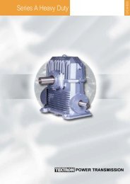
The programme<br />
BS 40-71 BS 40-71 BS 88-112<br />
BENZLERS<br />
Single input shaft Hollow shaft Single input shaft<br />
BS 40-71 BS 40-71 BS 88-112<br />
BENZLERS<br />
Output shaft Motorflange Hollow shaft<br />
BS 40-71 BS 88-112 BS 88-112<br />
BENZLERS<br />
Feet Feet Horizontal<br />
BS 40-71 BS 40-71 BS 88-112<br />
Bolt the gear to a<br />
wall or foundation<br />
without feet or flange<br />
Output flange<br />
Output flange<br />
BS 40-71 BS 40-71 BS 88-112<br />
BENZLERS<br />
BENZLERS<br />
Double input shaft Double worm gears Double worm gears<br />
4
Technical information<br />
Benzler worm gears BS 35-71 have a symmetrical gearhousing<br />
manufactured in aluminium. BS 88 and 112 have<br />
a gearhousing of cast-iron.<br />
The worm wheel is made of centrifugal cast tinbronze and<br />
the worm screw is case-hardened and ground.<br />
All motor connections are according to IEC-standard and<br />
for BS 40-112 with elastic coupling. This means the<br />
following advantages:<br />
• The worm screw is mounted with two separate bearings<br />
and are not connected with the motor bearings. This<br />
means longer lifetime and a smoother drive..<br />
• Soft start and stop with elastic coupling for size 40-112.<br />
• No oil leakage in to the motor.<br />
• Possibility to change motor without dismounting the<br />
gear..<br />
• Any type of motor with IEC-flange can be used..<br />
The worm geared motor is available for mounting on a<br />
base, flange or torque arm and can be installed in any<br />
position.<br />
The gear can be combined with <strong>Benzlers</strong>’ remaining<br />
range of helical and worm gears to provide very low<br />
output speeds. All data given in this catalogue applies to<br />
ABB standard motors and <strong>Benzlers</strong> brake motors.<br />
Motorflanges<br />
The motorflanges up to IEC-size 112 are made of<br />
aluminium and are available in B5 and B14, larger<br />
motorflanges are made of cast-iron and available in B5.<br />
A finished bore shaft coupling is always delivered<br />
together with the motorflange.<br />
Feet<br />
The feet can be mounted without modification.<br />
Output shaft<br />
Single or double output shaft can be mounted into the<br />
hollow shaft. The output shafts are locked into position<br />
with keys and retaining rings. BS 88-112 has as standard<br />
execution, a single output shaft or a hollow shaft.<br />
Output flange<br />
An output flange can easily be mounted on to the gear.<br />
The BS 40-71 gear casing can also be mounted onto a<br />
wall or foundation and bolted through the 4 bolt holes in<br />
the gear casing.<br />
Torque arm bracket<br />
The hollow shaft gearboxes can be supplied with torque<br />
arm bracket and torque arm.<br />
Fan<br />
BS 88/112 have fan as an option.<br />
Painting<br />
BS35-71 is normally delivered without painting. BS 40-71<br />
can be delivered according to environmental<br />
classification M2-M3, see page 58-59.<br />
BS88-112 is normally delivered with standardpaint,<br />
which is an alkyd paint in Benzler blue colour (RAL<br />
5015).<br />
5
Selection of gears and gearmotors<br />
Power and torque ratings for gears on page 40-47 apply<br />
to service factor 1.0. Service factor for geared motors can<br />
be found after the output speeds. Service factor 1.0 is<br />
valid for continous operation 8 hours/day without shocks<br />
and with 10-200 starts per hour. The inertia of the driven<br />
machine is less than 20% of the electric motor.<br />
Occasional shock loads may not exceed 1.8 times the<br />
gear rating at service factor 1.0.<br />
Determination of sizes<br />
1. Determine the demand power or torque, P e or T 2b<br />
ratio (i) or output speed (n 2 ).<br />
2. Based on type of load/driven machine, operating<br />
hours/day and number of starts/hour, select service<br />
factor fb (page 6-7).<br />
3. Calculate T 2 ≥ T 2b x f b .<br />
4. Choose gear on page 40-47 according to following:<br />
T 2 ≥ T 2b x f b at required ratio (i) or speed (n 2 ).<br />
Note the efficiency.<br />
For example BS40 ratio 6,67:1, code A<br />
η = 86% at n 1 = 1430 rpm.<br />
5. Calculate P 1 =P e x f b x 1 η<br />
Choose a size larger motor P m ≥ P 1<br />
For example P 1 ≥ 0,42 kW choose 0,55 kW.<br />
6. Choose a worm gear motor on pages 12-24.<br />
For example BS40A with a motor size 80A4.<br />
7. Check that occasional shock loads do not exceed 1.8<br />
times the gear rating at service factor 1.0.<br />
T 2max ≥ T 2 x 1,8<br />
8. Check that the thrust and overhung loads are not<br />
exceeded.<br />
9. Check that maximum input speeds and thermal ratings<br />
are not exceeded.<br />
10. For conditions other than above described, for<br />
instance extreme environments, high inertia<br />
systems or other, please contact your nearest<br />
Benzler office.<br />
Formulas:<br />
T 2b = P e x 9550<br />
n 2<br />
T 2 ≥ T 2b x fb<br />
P 1 = P e x f b x 1<br />
η<br />
P m ≥ P 1<br />
T 2max ≥ T 2 x 1,8<br />
J e, red = J e x<br />
(Nm)<br />
(Nm)<br />
(kW)<br />
(kW)<br />
(Nm)<br />
n<br />
2 2<br />
( n1 ) (kgm2 )<br />
T 2 = Output torque rating, Nm page 12-24,<br />
40-47)<br />
T 2b = Demand torque, Nm<br />
T 2max = Occasional maximum torque, Nm<br />
P 1 = Demand input power, kW<br />
P e = Demand power driven machine, kW<br />
P m = Motor power<br />
n 1 = Input speed, rpm<br />
n 2 = Output speed, rpm<br />
f b = Service factor<br />
η = Efficiency of the gear<br />
J e, red = Reduced inertia, kgm 2<br />
J e = Inertia driven machine, kgm 2<br />
J m = Inertia motor, kgm 2<br />
Load classification Description Moment of inertia Example<br />
I<br />
I a<br />
II<br />
Je, red ≤ 0.2 x Jm<br />
Machines with uniform load and no shocks<br />
Je, red ≤ Jm<br />
Machines with small shocks and<br />
small variations in load<br />
Je, red ≤ 3 x Jm<br />
Machines with moderate shocks and variable load<br />
Uniform loaded conveyors and elevators.<br />
Centrifugal pumps and fans.<br />
Agitators and mixers for liquids and<br />
semiliquids without solid particles.<br />
Larger conveyors.<br />
Reciprocating pumps with 3 or more cylinders.<br />
Agitators and mixers for media with<br />
high viscosity and/or solid particles.<br />
Larger conveyors.<br />
Reciprocating pumps with 3 or more cylinders.<br />
Agitators and mixers for media with<br />
high viscosity and/or solid particles<br />
Je, red ≤ 10 x Jm<br />
Heavy agitators and mixers.<br />
Reciprocating pumps with 1 or 2 cylinders.<br />
III Machines with very heavy shocks and large masses Crushers, mills and presses.<br />
to be accelerated<br />
Vibrators and shakers<br />
6
Service factor f b<br />
Daily operations in hours 4 hours 8 hours 16 hours 24 hours<br />
Starts per hour 200 200 200 200<br />
Load classification<br />
I 0.8 0.9 1.0 0.9 1.0 1.1 1.1 1.2 1.3 1.3 1.4 1.5<br />
I a 1.1 1.2 1.3 1.1 1.3 1.5 1.3 1.5 1.6 1.4 1.6 1.8<br />
II 1.3 1.4 1.6 1.3 1.6 1.8 1.4 1.7 1.9 1.5 1.8 2.0<br />
III 1.5 1.6 1.8 1.6 1.8 2.0 1.7 1.9 2.1 1.8 2.0 2.2<br />
Ambient temperature factor f t<br />
For other ambient temperatures then 20° C, always multiply the thermal rating with the following factors.<br />
°C Celsius - 40 - 30 - 20 - 10 +/- 0 10 20 30 40 50<br />
ft 1.80 1.67 1.53 1.40 1.27 1.13 1.00 0.87 0.73 0.60<br />
Fan factor f f<br />
If the gearbox has no fan and the motor is not directly flanged to the gearbox, multiply the thermal rating with the<br />
following factors.<br />
Input speed n1 (rpm) 10 100 300 750 1 000 1 500 3 000<br />
f f<br />
1 0.95 0.74 0.63 0.65 0.69 0.77<br />
Control points<br />
The forces allowed on the gear shafts are determined by<br />
bearing life and strength on gear shafts and housing.<br />
Radial forces at no thrust loads.In the power ratings page<br />
12-24 max. allowed radial force on output shaft is given<br />
for each output speed. The value is only valid if the force<br />
is applied at the centre of the output shaft.If the force is<br />
applied at another position the allowed radial force is<br />
given by the following:<br />
Radial forces<br />
Bearing life: F r,x =<br />
a<br />
(f + x)<br />
F r2<br />
Strength on shaft F r,x = c F r2<br />
x<br />
Strength on d<br />
F r,x =<br />
gear housing: (g + x)<br />
F r2max<br />
F r<br />
F r,x<br />
c<br />
x<br />
F r,x<br />
F r2<br />
F r2max<br />
= Max. radial force (N)<br />
= Radial force acc to power ratings (N).<br />
= Upper limit, for radial force. Can not<br />
be exceeded (N)<br />
a, d, f, g = Internal measures (mm)<br />
x = Distance to radial force (mm)<br />
c = Half shaft length (mm)<br />
Type/Size a c d f g F r2max (N)<br />
BS 35 77.5 18 88.0 59.5 70.0 2 000<br />
40 90.5 18 101.5 72.5 83.5 2 000<br />
50 96.5 21 110.0 75.5 89.0 2 700<br />
63 107.0 29 122.0 78.0 93.0 4 000<br />
71 127.5 29 142.5 98.5 113.5 5 000<br />
88 152.5 41 181.0 111.5 140.0 10 000<br />
112 175.0 41 210.5 134.0 169.5 15 000<br />
7
Overhung load<br />
If a sprocket, gear wheel or pulley is mounted on a shaft,<br />
a load check must be made. The overhung load in middle<br />
of the shaft may not exceed values shown in tables<br />
below. For calculation of minimum permissible diameter<br />
the following formula should be used.<br />
D min = 2000 x T 2b x f e x f b<br />
Fr2<br />
T 2b = Torque required (Nm)<br />
T 2b = P e x 9 550<br />
n 2<br />
Nm<br />
mm<br />
P e = Power kW<br />
n 2 = Output speed (rpm)<br />
F r2 = Permissible overhung load (N)<br />
f b = Service factor (tables page 7)<br />
f e<br />
= 1.10 for sprockets<br />
= 1.30 for gearwheels<br />
= 1.50 for pulleys<br />
D min = Minimum permissible diameter (mm)<br />
Max overhung load in the middle of input shaft (N)<br />
Gear<br />
Ratio<br />
Fr1 A B C D E F Fx G H I J K L M<br />
BS 40 180 135 100 95 80 70 - 50 45 45 40 30 - -<br />
50 215 190 155 115 100 80 70 65 55 55 40 - - -<br />
63 385 305 255 210 165 155 125 115 100 100 75 45 - -<br />
71 400 350 285 240 180 150 - 115 100 100 60 45 - -<br />
88 925 635 470 405 335 305 - 235 200 200 190 145 100 65<br />
112 1375 930 740 580 505 425 - 340 295 295 255 160 125 105<br />
Max thrust load on output shaft (N)<br />
Size<br />
Ratio<br />
A B C D E F Fx G H I J K L M<br />
BS 35 1500 1500 1500 1500 1500 1500 1500<br />
40 2000 2000 2000 2000 2000 2000 - 2000 2000 2000 2000 2000 - -<br />
50 2500 2500 2500 2500 2500 2500 2500 2500 2500 2500 2500 - - -<br />
63 3500 3500 3500 3500 3500 3500 3500 3500 3500 3500 3500 3500 - -<br />
71 4500 4500 4500 4500 4500 4500 - 4500 4500 4500 4500 4500 - -<br />
88 7800 10000 10000 10000 10000 10000 - 10000 10000 - 10000 10000 10000 10000<br />
112 10400 14700 15000 15000 15000 15000 - 15000 15000 - 15000 15000 15000 15000<br />
Reversing<br />
Dynamic self locking means that a force applied on the<br />
output shaft of the gear can not continue to drive the gear<br />
when the motor has been stopped.<br />
Dynamic self locking is only possible at very high ratios<br />
and low output speeds. None of the worm gears<br />
produced by BENZLERS is dynamic totally self locking.<br />
Static self locking means that a force applied on the<br />
output shaft of the gear can not start a movement.<br />
When driving loads with high inertia care must be taken<br />
to achieve a braking time long enough to prevent<br />
overload on the gear.<br />
When a worm gear is used in an application with short<br />
braking time a worm gear that is "dynamically reversible"<br />
is normally the best selection.<br />
Information regarding lead angle for BENZLERS worm<br />
gears are given on the following page.<br />
Reversing as a function of the lead<br />
angle<br />
γ<br />
≥25° Total reversing<br />
12° - 25° Statically reversible<br />
Variable static self locking<br />
8° - 12° Quick return in case of vibrations<br />
Dynamically reversible<br />
Statically self locking<br />
5° - 8° Return in case of vibrations<br />
Scant dynamic reversing<br />
Statically self locking<br />
3°- 5° Slow movement return in case of<br />
vibrations. Low dynamic reversing<br />
Statically self locking<br />
1°- 3° No return<br />
Low dynamic reversing<br />
8
<strong>Benzlers</strong> Worm gear BS, Wormwheel and Wormscrew data<br />
i = Ratio z = Starts of worm shaft η s = Starting efficiency<br />
γ = Lead angle m = Module η = Running efficiency n1=1430 rpm<br />
i γ z m η s η<br />
i γ z m η s η<br />
10 A 15.45 3 1.75 60 79<br />
15 B 10.45 2 1.75 51 74<br />
B S 20 C 7.13 2 1.25 43 64<br />
3 5 25 D 5.71 1 2.0 37 60<br />
30 E 5.26 1 1.75 36 60<br />
40 F 3.58 1 1.25 27 48<br />
50 G 2.86 1 1.0 23 42<br />
6.67 A 15.52 3 2.5 60 86<br />
10 B 16.70 3 2 62 85<br />
15 C 11.31 2 2 53 79<br />
20 D 8.53 1 3 47 75<br />
B S 24 E 7.13 1 2.5 43 71<br />
4 0 30 F 5.71 1 2 37 67<br />
40 G 4.02 1 1.45 30 59<br />
48 H 3.58 1 1.25 27 56<br />
60 I 2.86 1 1 23 49<br />
70 J 3.03 1 0.9 24 44<br />
84 K 2.53 1 0.75 21 36<br />
8 A 17.82 3 3 63 88<br />
10.5 B 15.07 2 3.5 60 87<br />
14 C 12.19 2 2.7 55 84<br />
21 D 7.67 1 3.5 44 77<br />
BS 24 E 7.07 1 3 39 74<br />
5 0 32 F 5.71 1 2.4 37 71<br />
37 FX 4.40 1 2 32 66<br />
42 G 4.29 1 1.8 31 65<br />
54 H 3 34 1 1.4 26 59<br />
64 I 2.99 1 1.2 24 55<br />
80 J 2.86 1 1 23 49<br />
7.75 A 18.43 4 3 64 90<br />
11 B 17.82 3 3 63 88<br />
14 C 15.07 2 3.5 60 87<br />
18 D 10.20 2 2.7 51 83<br />
24.5 E 9 93 2 2.1 50 81<br />
B S 29 F 7.67 1 3 5 44 77<br />
6 3 37 FX 4 47 1 2.5 32 70<br />
43 G 5 71 1 2.4 37 71<br />
51 H 4.76 1 2 33 67<br />
57 I 4.29 1 1.8 31 65<br />
73 J 3.34 1 1.4 26 59<br />
104 K 2.60 1 1 22 46<br />
Efficiency<br />
The efficiency of the gear has to be considered when a<br />
worm gear or a worm geared motor is chosen. For<br />
intermittent duties it is necessary to increase the motor<br />
power to be able to compensate for the low efficiency<br />
during start.<br />
Also consider that the highest efficiency is reached after<br />
Maximum input speed<br />
7.5 A 18.29 4 3.5 64 92<br />
9.33 B 19.98 3 4 65 91<br />
12 C 14.04 3 3 58 88<br />
16 D 12.34 2 3.5 55 87<br />
B S 21 E 10.20 2 2.7 51 84<br />
71 28 F 6.91 1 4 42 79<br />
37 G 6.12 1 3 39 76<br />
48 H 4.73 1 2.4 33 71<br />
63 1 3.55 1 1.8 27 65<br />
82 J 2.86 1 1.4 23 58<br />
100 K 2.99 1 1.2 24 54<br />
7.25 A 21.80 4 4.5 67 94<br />
11.75 B 18.43 4 3 64 91<br />
15.67 C 14.04 3 3 58 89<br />
19.50 D 9.93 2 3.5 50 87<br />
23.50 E 9.46 2 3 49 85<br />
B S 29 F 5.71 1 4.5 38 80<br />
8 8 39 G 5.00 1 3.5 34 77<br />
47 H 4.76 1 3 33 75<br />
58 J 4.47 1 2.5 32 72<br />
71 K 3.37 1 2 26 67<br />
82 L 3.55 1 1.8 27 66<br />
106 M 2.86 1 1.4 23 57<br />
7 A 22.48 4 6 68 94<br />
11.5 B 20.85 4 4 66 93<br />
15.3 C 15.95 3 4 61 91<br />
19.5 D 11.31 2 4.5 54 88<br />
23 E 10.78 2 4 52 88<br />
B S 28 F 5.91 1 6 39 83<br />
112 39 G 5.71 1 4.5 38 80<br />
46 H 5.44 1 4 36 79<br />
63 J 4.76 1 3 33 75<br />
76 K 4.21 1 2.5 31 71<br />
95 L 3.37 1 2 26 66<br />
108 M 2 95 1 1.75 24 61<br />
run-in period and under continuous duty.<br />
All values given in the catalogue are only valid for a gear<br />
after running-in period under continuous duty with service<br />
factor 1.<br />
If the gear is driven from the output shaft the back driving<br />
efficiency is calculated as follows:<br />
η - = 2 - 1 η<br />
n1, max 35 40 50 63 71 88 112i60:1<br />
rpm 4500 6000 5500 5000 4500 4000 3000 3500<br />
Size<br />
9
Questionaire<br />
To specify a drive precisely certain data are essential. The most important questions are listed in the table below. If you<br />
do not have the required data available in this form, we advice you to use a technical handbook or other suitable<br />
documentation. Should you have any question, please do not hesitate to contact us, <strong>Benzlers</strong> specialists will be pleased<br />
to assist you.<br />
Load designation<br />
Output power (kW): P e at n max at n min Motor<br />
Enclosure IP<br />
Output speed (RPM): n emax n emin<br />
Operating voltage motor (V) brake (V) frequency (Hz)<br />
Output torque (Nm): T e at n max at n min<br />
Brake torque (Nm)<br />
Overhung load (N): F r2e at output shaft at input shaft<br />
Axial thrust load (N): F a2e at output shaft at input shaft<br />
Ambient factors<br />
Ambient temperature (°C)<br />
(away + / towards -) Load cycle / Duty cycle S / % ED<br />
Moment of inertia (kgm 2 ): at output shaft at input shaft<br />
Starting frequency (1/h)<br />
Unit type and mounting position (see page 11)<br />
Gears and geared motors are described by a code consisting of 10 positions. Positions that aren’t used are left empty.<br />
Additional information is written clearly.<br />
Example of such information is:<br />
Output speed, Motor power<br />
Connecting voltage for motor and brake (if used)<br />
Type of motor at specific request<br />
All nonstandard executions that are not described in this catalogue.<br />
Example on ordering text: (explanations, see page 11):<br />
Gear<br />
Motor<br />
1 2 3 4 5 6 7 8 9 10<br />
BS 40 A 2,0H, M=115 - 4 80A4 - 180 B5<br />
214 rpm 0,37 kW 220-240/380-420V, 50 Hz<br />
Additional information:<br />
10
BENZLERS<br />
BENZLERS<br />
BENZLERS<br />
BENZLERS<br />
1 Gear type<br />
BS (Worm gear and worm geared motor)<br />
2 Gear size<br />
Standard sizes 35,40, 50, 63, 71, 88, 112,<br />
50/40, 63/40, 71/40, 88/50, 112/63<br />
Other combinations and sizes can be achieved.<br />
Check with <strong>Benzlers</strong>.<br />
3 Ratio code<br />
A, B, C....FA, FB, FC (2 letters for double<br />
wormgears).<br />
4 Mounting position<br />
See picture *For execution - code 2 and 3 state flange<br />
size, for example M=115, see page 55.<br />
5 Gear Accessories<br />
VM = distance ring for different position of terminal box<br />
EB = brake on gear<br />
KEB = coupling/brake unit (specify type and voltage)<br />
F = fan on gear (only BS88 and BS112)<br />
DP = double input shaft<br />
6 Input design<br />
2 = free high speed shaft (no motor or flange for<br />
motor)<br />
3 = prepared for motor (specify flange and shaft<br />
diametres or IEC-standard size)<br />
4 = with motor<br />
7 Motor<br />
Acc. to IEC (71A, 71B)<br />
8 Accessories for the motor<br />
B = Brake<br />
TB = Thermostat protection<br />
Th = Thermistor protection<br />
FS = Fitted with forced cooling<br />
TG = Tachogenerator<br />
PG = Encoder<br />
9 Terminal box position<br />
Positions acc picture<br />
10 Motorflange<br />
B14 = Small flange<br />
B5 = Large flange<br />
Motor flange B5<br />
Position of terminal box<br />
Motor sizes<br />
63 71 80 90 100 112 132 160 180<br />
Gear<br />
BS 40 45* 45* 45* 45*<br />
50 0 0 0<br />
63 0 0 0<br />
71 45+ 45+ 45+ 45+<br />
88 45 45 45 45 90<br />
112(i60) 45 45 45 90<br />
BS35 is not available with B5-flange.<br />
Mounting positions<br />
Hollow shaft U O H-A H-B<br />
gear<br />
BENZLERS<br />
Execution - code 0<br />
Feet and output OV OH OD<br />
shaft<br />
Execution - code 1<br />
Only output UV UH UD<br />
shaft<br />
Execution - code 8<br />
Only feet VV VH VD<br />
Execution - code 9 Endast Endast Endast<br />
BS 40-71 BS 40-71 BS 40-71<br />
Code 9 only<br />
for BS40-71<br />
BENZLERS<br />
BENZLERS<br />
Position of terminal box<br />
Standard position 0 Standard position 45<br />
<br />
90° <br />
135° 45°<br />
180°<br />
<br />
270°<br />
<br />
0°<br />
Motor flange B14<br />
Position of terminal box<br />
HU-A HN-A HD-A<br />
HU-B HN-B HD-B<br />
Output flange<br />
BS 35-71 BS 35-71 BS 88-112<br />
and shaft<br />
OH OV OH<br />
Execution - code 2*<br />
State M<br />
Output flange BS 35-71 BS 35-71 BS 88-112<br />
and hollow shaft OH OV OH<br />
Execution - code 3*<br />
State M<br />
Double gears P 1<br />
P 2<br />
P 3<br />
(prestep gear is<br />
shown on picture)<br />
Execution - code 4<br />
BENZLERS<br />
P 4<br />
P 5<br />
P 6<br />
P 7<br />
P 8<br />
BENZLERS<br />
Gear with hollow O V<br />
shaft, torque arm<br />
and connection<br />
Execution - code 5<br />
BENZLERS<br />
Motor sizes<br />
63 71 80 90 100 112 132 160 180<br />
Gear<br />
BS 35 45 45<br />
40 45* 45* 45* 45*<br />
50 45* 45* 45*<br />
63 45* 45* 45* 45<br />
71 0+ 0+ 0+ 0+<br />
88 0 0 0 0<br />
112 0 0 0<br />
* = Can be changed to 0 with distance ring, VM<br />
+ = Distance ring to be mounted on gear<br />
BENZLERS<br />
BENZLERS<br />
225°<br />
<br />
315°<br />
<br />
BENZLERS<br />
11
Worm geared motors<br />
0.12 kW<br />
Output Ratio Service Output Permissible Size Weight Dim.<br />
speed factor torque overhung load page<br />
n 2 i f bp T2 Fr2<br />
rpm Nm kN kg<br />
0.69 1960.00 FJ 0.76 524 5.0 BS 71/40 63A-4 19 36-39<br />
0.81 1680.00 Fl 0.86 463 5.0<br />
1.01 1344.00 FH 0.99 403 5.0<br />
1.21 1120.00 FG 1.13 354 5.0<br />
1.62 840.00 FF 1.34 299 5.0<br />
2.02 672.00 FE 1.57 255 5.0<br />
2.43 560.00 FD 1.77 226 5.0<br />
3.24 420.00 FC 2.20 182 5.0<br />
4.86 280.00 FB 3.00 133 5.0<br />
2.34 580.00 FD 0.76 234 4.0 BS 63/40 63A-4 16 36-39<br />
3.13 435.00 FC 0.96 189 4.0<br />
4.69 290.00 FB 1.33 138 4.0<br />
7.03 193.43 FA 1.96 95 4.0<br />
2.83 480.00 ED 1.30 113 2.7 BS 50/40 63A-4 14 36-39<br />
3.78 360.00 EC 0.99 146 2.7<br />
5.67 240.00 EB 1.33 108 2.7<br />
8.50 160.00 EA 1.93 75 2.7<br />
6.44 104.00 K 1.47 73 4.0 BS 63 71B-8 15 28-35<br />
9.18 73.00 J 3.10 58 4.0<br />
11.75 57.00 I 3.91 49 4.0<br />
8.94 104.00 K 2.09 50 4.0 BS 63 71-6 13 28-35<br />
8.38 80.00 J 1.24 62 2.7 BS 50 71B-8 13 28-35<br />
10.47 64.00 I 1.99 51 2.7<br />
11.63 80.00 J 1.94 39 2.7 BS 50 71-6 11 28-35<br />
14.53 64.00 I 3.03 33 2.7<br />
17.22 54.00 H 3.73 29 2.7<br />
7.98 84.00 K 0.75 48 2.0 BS 40 71B-8 11 28-35<br />
9.57 70.00 J 0.87 54 2.0<br />
11.17 60.00 I 1.20 46 2.0<br />
11.07 84.00 K 0.83 42 2.0 BS 40 71-6 9 28-35<br />
13.29 70.00 J 1.22 38 2.0<br />
15.50 60.00 I 1.66 32 2.0<br />
16.19 84.00 K 1.60 21 2.0 BS 40 63A-4 9 28-35<br />
19.43 70.00 J 2.36 19 2.0<br />
22.67 60.00 I 3.21 16 2.0<br />
28.33 48.00 H 4.15 14 2.0<br />
34.00 40.00 G 4.84 12 2.0<br />
45.33 30.00 F 5.97 10 2.0<br />
56.67 24.00 E 7.07 8 2.0<br />
68.00 20.00 D 8.18 7 2.0<br />
90.67 15.00 C 10.53 6 2.0<br />
136.00 10.00 B 14.84 4 2.0<br />
203.90 6.67 A 19.52 3 1.7<br />
13.00 50.00 G .90 39 2.0 BS 35 71B-8 8.5 26-27<br />
16.00 40.00 F 1.04 34 2.0<br />
22.00 30.00 E 1.26 29 2.0<br />
26.00 25.00 D 1.43 25 2.0<br />
33.00 20.00 C 1.62 21 2.0<br />
44.00 15.00 B 2.06 17 2.0<br />
67.00 10.00 A 2.94 12 2.0<br />
18.00 50.00 G 1.13 28 2.0 BS 35 71-6 7.0 26-27<br />
23.00 40.00 F 1.3 24 2.0<br />
31.00 30.00 E 1.54 20 2.0<br />
37.00 25.00 D 1.8 17 2.0<br />
46.00 20.00 C 2.13 15 2.0<br />
62.00 15.00 B 2.67 12 2.0<br />
93.00 10.00 A 3.78 8 1.9<br />
27.00 50.00 G 1.93 14 2.0 BS 35 63A-4 6.0 26-27<br />
34.00 40.00 F 2.23 12 2.0<br />
12
Worm geared motors<br />
0.12 kW<br />
Output Ratio Service Output Permissible Size Weight Dim.<br />
speed factor torque overhung load page<br />
n 2 i f bp T2 Fr2<br />
rpm Nm kN kg<br />
45.00 30.00 E 2.70 10 2.0 BS 35 63A-4 6.0 26-27<br />
54.00 25.00 D 3.16 8 2.0<br />
68.00 20.00 C 3.8 7 2.0<br />
90.00 15.00 B 4.78 5 2.0<br />
136.00 10.00 A 6.84 4 1.7<br />
Worm geared motors<br />
0.18 kW<br />
Output Ratio Service Output Permissible Size Weight Dim.<br />
speed factor torque overhung load page<br />
n 2 i f bp T2 Fr2<br />
rpm Nm kN kg<br />
1.22 1120.00 FG 0.76 529 5.0 BS 71/40 63B-4 19 36-39<br />
1.63 840.00 FF 0.89 448 5.0<br />
2.04 672.00 FE 1.04 383 5.0<br />
2.45 560.00 FD 1.18 339 5.0<br />
3.26 420.00 FC 1.46 274 5.0<br />
4.89 280.00 FB 1.98 202 5.0<br />
7.34 186.76 FA 2.91 137 5.0<br />
4.72 290.00 FB 0.88 209 4.0 BS 63/40 63B-4 16 36-39<br />
7.08 193.43 FA 1.29 144 4.0<br />
5.71 240.00 EB 0.89 163 2.7 BS 50/40 63B-4 14 36-39<br />
8.56 160.00 EA 1.27 114 2.7<br />
6.60 106.00 M 2.35 123 10.0 BS 88 80A-8 51 28-35<br />
7.00 100.00 K 1.40 118 5.0 BS 71 80A-8 21 28-35<br />
8.54 82.00 J 2.15 100 5.0<br />
11.11 63.00 I 3.71 83 5.0<br />
6.73 104.00 K 0.92 117 4.0 BS 63 80A-8 18 28-35<br />
9.59 73.00 J 1.94 92 4.0<br />
8.85 104.00 K 1.19 88 4.0 BS 63 71A-6 14 28-35<br />
12.60 73.00 J 2.50 69 4.0<br />
16.14 57.00 I 3.30 58 4.0<br />
8.75 80.00 J 0.80 96 2.7 BS 50 80A-8 16 28-35<br />
10.94 64.00 I 1.28 80 2.7<br />
12.96 54.00 H 1.67 72 2.7<br />
11.50 80.00 J 1.10 68 2.7 BS 50 71A-6 12 28-35<br />
14.38 64.00 I 1.72 58 2.7<br />
17.04 54.00 H 2.12 51 2.7<br />
21.90 42.00 G 2.53 43 2.7<br />
24.86 37.00 Fx 2.76 38 2.7<br />
11.67 60.00 I 0.78 72 2.0 BS 40 80A- 8 14 28-35<br />
15.33 60.00 I 0.99 54 2.0 BS 40 71A-6 10 28-35<br />
19.17 48.00 H 1.37 48 2.0<br />
16.31 84.00 K 0.81 41 2.0 BS 40 63B-4 9 28-35<br />
19.57 70.00 J 1.19 37 2.0<br />
22.83 60.00 I 1.62 32 2.0<br />
28.54 48.00 H 2.09 28 2.0<br />
34.25 40.00 G 2.44 24 2.0<br />
45.67 30.00 F 3.01 20 2.0<br />
57.08 24.00 E 3.56 16 2.0<br />
68.50 20.00 D 4.12 14 2.0<br />
91.33 15.00 C 5.31 11 2.0<br />
137.00 10.00 B 7.48 8 2.0<br />
13
Worm geared motors<br />
0.18 kW<br />
Output Ratio Service Output Permissible Size Weight Dim.<br />
speed factor torque overhung load page<br />
n 2 i f bp T2 Fr2<br />
rpm Nm kN kg<br />
205.40 6.67 A 9.84 5 1.7 BS 40 63B-4 9 28-35<br />
184.00 15.00 C 31.13 1 1.9 BS 40 63K-2 9 28-35<br />
276.00 10.00 B 44.16 1 1.6<br />
413.79 6.67 A 56.96 1 1.3<br />
26 25 D .87 40 2.0 BS 35 71C-8 9.5 26-27<br />
33 20 C .98 35 2.0<br />
44 15 B 1.25 28 2.0<br />
66 10 A 1.79 20 2.0<br />
30 30 E .92 34 2.0 BS 35 71A-6 7.5 26-27<br />
37 25 D 1.07 29 2.0<br />
46 20 C 1.27 24 2.0<br />
61 15 B 1.59 19 2.0<br />
92 10 A 2.25 14 1.9<br />
27 50 G .97 27 2.0 BS 35 63B-4 6.5 26-27<br />
34 40 F 1.13 23 2.0<br />
45 30 E 1.36 19 2.0<br />
54 25 D 1.59 16 2.0<br />
68 20 C 1.92 14 2.0<br />
91 15 B 2.41 11 2.0<br />
137 10 A 3.45 8 1.7<br />
Worm geared motors<br />
0.25 kW<br />
Output Ratio Service Output Permissible Size Weight Dim.<br />
speed factor torque overhung load page<br />
n 2 i f bp T2 Fr2<br />
rpm Nm kN kg<br />
0.48 2912.00 FK 0.93 1433 15.0 BS 112/63 71 A-4 71 36-39<br />
0.68 2044.00 FJ 1.19 1178 15.0<br />
0.88 1596.00 Fl 1.40 1000 15.0<br />
0.98 1428.00 FH 1.49 942 15.0<br />
1.16 1204.00 FG 1.64 853 15.0<br />
1.35 1036.00 FFx 1.91 733 15.0<br />
1.72 812.00 FF 2.18 641 15.0<br />
2.04 686.00 FE 2.43 575 15.0<br />
2.78 504.00 FD 3.14 445 15.0<br />
3.57 392.00 FC 3.72 377 15.0<br />
0.75 1856.00 Fl 0.82 976 10.0 BS 88/50 71A-4 52 36-39<br />
0.89 1566.00 FH 0.91 876 10.0<br />
1.15 1218.00 FG 1.05 763 10.0<br />
1.30 1073.00 FFx 1.13 707 10.0<br />
1.51 928.00 FF 1.24 643 10.0<br />
2.01 696.00 FE 1.55 516 10.0<br />
2.30 609.00 FD 1.66 481 10.0<br />
3.45 406.00 FC 2.22 360 10.0<br />
4.60 304.50 FB 2.77 289 10.0<br />
6.03 232.00 FA 3.48 230 10.0<br />
2.08 672.00 FE 0.77 522 5.0 BS 71/40 71A-4 20 36-39<br />
2.50 560.00 FD 0.86 463 5.0<br />
3.33 420.00 FC 1.07 374 5.0<br />
5.00 280.00 FB 1.45 276 5.0<br />
7.50 186.76 FA 2.11 190 5.0<br />
7.24 193.43 FA 0.94 198 4.0 BS 63/40 71A-4 17 36-39<br />
8.75 160.08 EA 0.92 156 2.7 BS 50/40 71 A-4 15 36-39<br />
8.85 104.00 K 0.79 132 4.0 BS 63 71 B-6 15 28-35<br />
14
Worm geared motors<br />
0.25 kW<br />
Output Ratio Service Output Permissible Size Weight Dim.<br />
speed factor torque overhung load page<br />
n 2 i f bp T2 Fr2<br />
rpm Nm kN kg<br />
12.60 73.00 J 1.67 104 4.0 BS 63 71 B-6 15 28-35<br />
16.14 57.00 I 2.21 87 4.0<br />
18.04 51.00 H 2.29 80 4.0<br />
21.40 43.00 G 2.32 72 4.0<br />
13.46 104.00 K 1.30 77 4 0 BS 63 71A-4 14 28-35<br />
19.18 73.00 J 2.69 60 4.0<br />
24.56 57.00 I 3.18 50 4.0<br />
27.45 51.00 H 3.46 46 4.0<br />
14.38 64.00 I 1.15 87 2.7 BS 50 71B 6 13 28-35<br />
17.04 54.00 H 1.42 77 2.7<br />
17.50 80.00 J 1.07 66 2.7 BS 50 71A-4 12 28-35<br />
21.88 64.00 I 1.70 55 2.7<br />
25.93 54.00 H 1.86 48 2.7<br />
33.33 42.00 G 2.23 40 2.7<br />
37.84 37.00 Fx 2.45 36 2.7<br />
43.75 32.00 F 2.75 33 2.7<br />
19.17 48.00 H 0.94 70 2.0 BS 40 71B 6 11 28-35<br />
23.00 40.00 G 1.12 61 2.0<br />
20.00 70.00 J 0.77 57 2.0 BS 40 71A-4 10 28-35<br />
23.33 60.00 I 1.04 50 2.0<br />
29.17 48.00 H 1.35 43 2.0<br />
35.00 40.00 G 1.57 37 2.0<br />
46.67 30.00 F 1.94 30 2.0<br />
58.33 24.00 E 2.30 25 2.0<br />
70.00 20.00 D 2.66 22 2.0<br />
93.33 15.00 C 3.43 17 2.0<br />
140.00 10.00 B 4.83 12 2.0<br />
209.90 6.67 A 6.35 8 1.7<br />
183.33 15.00 C 9.36 5 1.9 BS 40 63B-2 9 28-35<br />
275.00 10.00 B 13.28 3 1.6<br />
412.29 6.67 A 17.13 2 1.3<br />
46.00 20.00 C .87 35 2.0 BS 35 71B-6 8.5 26-27<br />
61.00 15.00 B 1.09 29 2.0<br />
92.00 10.00 A 1.54 20 1.9<br />
46.00 30.00 E .88 30 2.0 BS 35 71A-4 7.5 26-27<br />
56.00 25.00 D 1.03 25 2.0<br />
70.00 20.00 C 1.24 21 2.0<br />
93.00 15.00 B 1.55 17 2.0<br />
140.00 10.00 A 2.23 12 1.7<br />
275.00 10.00 A 5.93 3 1.3 BS 35 63-B2 6.5 26-27<br />
Worm geared motors<br />
0.37 kW<br />
Output Ratio Service Output Permissible Size Weight Dim.<br />
speed factor torque overhung load page<br />
n 2 i f bp T2 Fr2<br />
rpm Nm kN kg<br />
0.68 2044.00 FJ 0.80 1747 15.0 BS 112/63 71B-4 72 36-39<br />
0.88 1596.00 Fl 0.94 1483 15.0<br />
0.98 1428.00 FH 1.00 1398 15.0<br />
1.16 1204.00 FG 1.10 1267 15.0<br />
1.35 1036.00 FFx 1.29 1089 15.0<br />
1.72 812.00 FF 1.47 954 15.0<br />
2.04 686.00 FE 1.64 856 15.0<br />
2.78 504.00 FD 2.11 664 15.0<br />
15
Worm geared motors<br />
0.37 kW<br />
Output Ratio Service Output Permissible Size Weight Dim.<br />
speed factor torque overhung load page<br />
n 2 i f bp T2 Fr2<br />
rpm Nm kN kg<br />
2.78 504.00 FD 2.11 664 15.0 BS 112/63 71B-4 72 36-39<br />
3.57 392.00 FC 2.49 563 15.0<br />
4.55 308.00 FB 3.08 455 15.0<br />
1.30 1073.00 FFx 0.76 1050 10.0 BS 88/50 71B-4 53 36-39<br />
1.51 928.00 FF 0.84 954 10.0<br />
2.01 696.00 FE 1.04 766 10.0<br />
2.30 609.00 FD 1.12 716 10.0<br />
3.45 406.00 FC 1.49 536 10.0<br />
4.60 304.50 FB 1.86 431 10.0<br />
6.03 232.00 FA 2.33 344 10.0<br />
5.00 280.00 FB 0.97 411 5.0 BS 71/40 71B-4 21 36-39<br />
7.50 186.76 FA 1.41 284 5.0<br />
6.48 108.00 M 1.92 294 15.0 BS 112 90S-8 71 28-35<br />
7.37 95.00 L 2.53 271 15.0<br />
6.60 106.00 M 1.00 288 10.0 BS 88 90S 8 54 28-35<br />
8.54 82.00 L 1.74 241 10.0<br />
9.86 71.00 K 2.38 212 10.0<br />
8.68 106.00 M 1.30 216 10.0 BS 88 80A-6 50 28-35<br />
11.22 82.00 L 2.27 180 10.0<br />
12.96 71.00 K 3.15 156 10.0<br />
8.54 82.00 J 0.95 228 5.0 BS 71 90S-8 24 28-35<br />
9.20 100.00 K 0.78 207 5.0 BS 71 80A-6 20 28-35<br />
11.22 82.00 J 1.22 172 5.0<br />
14.60 63.00 I 1.97 143 5.0<br />
19.17 48.00 H 2.37 118 5.0<br />
9.59 73.00 J 0.85 210 4.0 BS 63 90S-8 21 28-35<br />
12.60 73.00 J 1.07 163 4.0 BS 63 80A-6 17 28-35<br />
16.14 57.00 I 1.41 137 4.0<br />
18.04 51.00 H 1.46 126 4.0<br />
13.46 104.00 K 0.77 130 4.0 BS 63 71B-4 15 28-35<br />
19.18 73.00 J 1.60 101 4.0<br />
24.56 57.00 I 1.88 85 4.0<br />
27.45 51.00 H 2.05 78 4.0<br />
32.56 43.00 G 2.34 68 4.0<br />
37.84 37.00 Fx 2.56 57 4.0<br />
48.28 29.00 F 3.18 49 4.0<br />
12.96 54.00 H 0.76 159 2.7 BS 50 90S-8 19 28-35<br />
17.04 54.00 H 0.90 121 2.7 BS 50 80A 6 15 28-35<br />
21.88 64.00 I 1.04 89 2.7 BS 50 71B-4 13 28-35<br />
25.93 54.00 H 1.14 79 2.7<br />
33.33 42.00 G 1.37 66 2.7<br />
37.84 37.00 Fx 1.50 59 2.7<br />
43.75 32.00 F 1.68 53 2.7<br />
58.33 24.00 E 2.07 41 2.7<br />
66.67 21.00 D 2.33 37 2.7<br />
100.00 14.00 C 3.34 26 2.7<br />
29.17 48.00 H 0.83 70 2.0 BS 40 71B-4 11 28-35<br />
35.00 40.00 G 0.97 60 2.0<br />
46.67 30.00 F 1.19 50 2.0<br />
58.33 24.00 E 1.41 41 2.0<br />
89.00 10.00 A .96 32 1.9 BS 35 71C-6 9.5 26-27<br />
93.00 15.00 B .95 27 2.0 BS 35 71B-4 8.5 26-27<br />
140.00 10.00 A 1.37 19 1.7<br />
282.00 10.00 A 2.77 7 1.3 BS 35 71A-2 7.5 26-27<br />
16
Worm geared motors<br />
0.55 kW<br />
Output Ratio Service Output Permissible Size Weight Dim.<br />
speed factor torque overhung load page<br />
n 2 i f bp T2 Fr2<br />
rpm Nm kN kg<br />
1.36 1036.00 FFx 0.87 1612 15.0 BS 112/63 80A-4 74 36-39<br />
1.74 812.00 FF 0.99 1412 15.0<br />
2.06 686.00 FE 1.10 1268 15.0<br />
2.80 504.00 FD 1.42 985 15.0<br />
3.60 392.00 FC 1.67 836 15.0<br />
4.58 308.00 FB 2.07 677 15.0<br />
6.50 217.00 FA 2.73 514 15.0<br />
2.32 609.00 FD 0.75 1060 10.0 BS 88/50 80A-4 55 36-39<br />
3.47 406.00 FC 1.01 795 10.0<br />
4.63 304.50 FB 1.25 639 10.0<br />
6.08 232.00 FA 1.57 511 10.0<br />
7.55 186.76 FA 0.94 424 5.0 BS 71/40 80A-4 23 36-39<br />
6.48 108.00 M 1.22 461 15.0 BS 112 90L-8 74 28-35<br />
7.37 95.00 L 1.61 425 15.0<br />
9.21 76.00 K 2.35 366 15.0<br />
8.54 82.00 L 1.13 372 10.0 BS 88 90L-8 57 28-35<br />
9.86 71.00 K 1.54 327 10.0<br />
8.68 106.00 M 0.82 341 10.0 BS 88 80B-6 51 28-35<br />
11.22 82.00 L 1.44 285 10.0<br />
12.96 71.00 K 2.00 246 10.0<br />
15.86 58.00 J 2.59 216 10.0<br />
13.30 106.00 M 1.22 221 10.0 BS 88 80A-4 50 28-35<br />
17.20 82.00 L 2.12 184 10.0<br />
19.86 71.00 K 2.74 159 10.0<br />
24.31 58.00 J 3.51 139 10.0<br />
11.11 63.00 I 1.07 290 5.0 BS 71 90L-8 27 28-35<br />
11.22 82.00 J 0.78 269 5.0 BS 71 80B-6 21 28-35<br />
14.60 63.00 I 1.26 223 5.0<br />
19.17 48.00 H 1.52 185 5.0<br />
17.20 82.00 J 1.14 177 5.0 BS 71 80A 4 20 28-35<br />
22.38 63.00 I 1.60 146 5.0<br />
29.38 48.00 H 1.97 119 5.0<br />
38.11 37.00 G 2.47 96 5.0<br />
50.36 28.00 F 2.97 76 5.0<br />
67.14 21.00 E 3.87 59 4.6<br />
16.14 57.00 I 0.91 212 4.0 BS 63 80B-6 18 28-35<br />
18.04 51.00 H 0.94 195 4.0<br />
21.40 43.00 G 0.96 173 4.0<br />
19.32 73.00 J 1.00 162 4.0 BS 63 80A-4 17 28-35<br />
24.74 57.00 I 1.18 136 4.0<br />
27.65 51.00 H 1.28 125 4.0<br />
32.79 43.00 G 1.46 109 4.0<br />
38.11 37.00 Fx 1.60 92 4.0<br />
48.62 29.00 F 1.99 78 4.0<br />
57.55 24.50 E 2.33 69 4.0<br />
78.33 18.00 D 2.92 51 3.9<br />
33.57 42.00 G 0.87 103 2.7 BS 50 80A-4 15 28-35<br />
38.11 37.00 Fx 0.96 92 2.7<br />
44.06 32.00 F 1.07 84 2.7<br />
58.75 24.00 E 1.32 65 2.7<br />
67.14 21.00 D 1.49 59 2.7<br />
100.71 14.00 C 2.13 41 2.7<br />
134.29 10.50 B 2.74 32 2.7<br />
176.25 8.00 A 3.40 24 2.4<br />
201.43 14.00 C 3.82 17 2.5 BS 50 71B-2 13 28-35<br />
58.75 24.00 E 0.90 65 2.0 BS 40 80A-4 13 28-35<br />
17
Worm geared motors<br />
0.55 kW<br />
Output Ratio Service Output Permissible Size Weight Dim.<br />
speed factor torque overhung load page<br />
n 2 i f bp T2 Fr2<br />
rpm Nm kN kg<br />
70.50 20.00 D 1.04 56 2.0 BS 40 80A-4 13 28-35<br />
94.00 15.00 C 1.34 43 2.0<br />
141.00 10.00 B 1.89 30 2.0<br />
211.39 6.67 A 2.48 20 1.7<br />
188.00 15.00 C 2.40 18 1.9 BS 40 71B-2 11 28-35<br />
282.00 10.00 B 3.41 13 1.6<br />
422.79 6.67 A 4.40 8 1.3<br />
138.00 10.00 A 0.85 31 1.7 BS 35 71C-4 9.5 26-27<br />
282.00 10.00 A 1.52 12 1.3 BS 35 71B-2 8.5 26-27<br />
Worm geared motors<br />
0.75 kW<br />
Output Ratio Service Output Permissible Size Weight Dim.<br />
speed factor torque overhung load page<br />
n 2 i f bp T2 Fr2<br />
rpm Nm kN kg<br />
2.06 686.00 FE 0.81 1733 15.0 BS 112/63 80B-4 75 36-39<br />
2.80 504.00 FD 1.04 1347 15.0<br />
3.60 392.00 FC 1.22 1144 15.0<br />
4.58 308.00 FB 1.51 928 15 0<br />
6.50 217.00 FA 1.99 705 15.0<br />
4.63 304.50 FB 0.92 874 10.0 BS 88/50 80B-4 56 36-39<br />
6.08 232.00 FA 1.14 699 10.0<br />
6.48 108.00 M 0.87 647 15.0 BS 112 100LA 8 80 28-35<br />
7.37 95.00 L 1.15 596 15.0<br />
9.21 76.00 K 1.67 513 15.0<br />
8.52 108.00 M 1.10 497 15.0 BS 112 90S-6 71 28-35<br />
9.68 95.00 L 1.46 457 15.0<br />
12.11 76.00 K 2.19 393 15.0<br />
14.60 63.00 J 2.96 339 15.0<br />
8.54 82.00 L 0.81 518 10.0 BS 88 100LA-8 62 28-35<br />
9.86 71.00 K 1.11 455 10.0<br />
11.22 82.00 L 1.02 400 10.0 BS 88 90S-6 54 28-35<br />
12.96 71.00 K 1.42 347 10.0<br />
15.66 58.00 J 1.84 304 10.0<br />
13.30 106.00 M 0.85 318 10.0 BS 88 80B-4 51 28-35<br />
17.20 82.00 L 1.48 264 10.0<br />
19.86 71.00 K 1.91 229 10.0<br />
24.31 58.00 J 2.44 200 10.0<br />
30.00 47.00 H 3.06 166 10.0<br />
36.15 39.00 G 3.76 140 10.0<br />
14.58 48.00 H 0.91 339 5.0 BS 71 100LA-8 31 28-35<br />
19.17 48.00 H 1.09 259 5.0 BS 71 90S-6 24 28-35<br />
17.20 82.00 J 0.80 251 5.0 BS 71 80B-4 21 28-35<br />
22.38 63.00 I 1.13 207 5.0<br />
29.38 48.00 H 1.38 169 5.0<br />
38.11 37.00 G 1.74 137 5.0<br />
50.36 28.00 F 2.09 108 5.0<br />
67.14 21.00 E 2.72 85 4.6<br />
88.13 16.00 D 3.40 66 4.0<br />
18
Worm geared motors<br />
0.75 kW<br />
Output Ratio Service Output Permissible Size Weight Dim.<br />
speed factor torque overhung load page<br />
n 2 i f bp T2 Fr2<br />
rpm Nm kN kg<br />
24.74 57.00 I 0.83 193 4.0 BS 63 80B-4 18 28-35<br />
27.65 51.00 H 0.90 177 4.0<br />
32.79 43.00 G 1.03 155 4 0<br />
38.11 37.00 Fx 1.13 130 4 0<br />
48.62 29.00 F 1.40 111 4.0<br />
57.55 24.50 E 1.64 97 4.0<br />
78.33 18.00 D 2.06 72 3.9<br />
100.71 14.00 C 2.64 58 3.4<br />
128.18 11.00 B 3.22 46 3.0<br />
158.33 18.00 D 3.59 31 3.1 BS 63 80A-2 17 28-35<br />
44.06 32.00 F 0.76 118 2.7 BS 50 80B-4 16 28-35<br />
58.75 24.00 E 0.94 91 2.7<br />
67.14 21.00 D 1.06 82 2.7<br />
100.71 14.00 C 1.51 58 2.7<br />
134.29 10.50 B 1.95 45 2.7<br />
176.25 8.00 A 2.41 34 2.4<br />
203.57 14.00 C 2.58 26 2.5 BS 50 80A-2 15 28-35<br />
271.43 10.50 B 3.31 20 2.2<br />
94.00 15.00 C 0.95 61 2.0 BS 40 80B-4 14 28-35<br />
141.00 10.00 B 1.34 43 2.0<br />
211.39 6.67 A 1.76 28 1.7<br />
190.00 15.00 C 1.62 27 1.9 BS 40 80A-2 13 28-35<br />
285.00 10.00 B 2.30 19 1.6<br />
427.29 6.67 A 2.97 12 1.3<br />
282.00 10.00 A 1.02 19 1.3 BS 35 71C-2 9.5 26-27<br />
19
Worm geared motors<br />
1.1 kW<br />
Output Ratio Service Output Permissible Size Weight Dim.<br />
speed factor torque overhung load page<br />
n 2 i f bp T2 Fr2<br />
rpm Nm kN kg<br />
3.60 392.00 FC 0.83 1683 15.0 BS 112/63 90S-4 78 36-39<br />
4.58 308.00 FB 1.03 1366 15.0<br />
6.50 217.00 FA 1.35 1039 15.0<br />
7.37 95.00 L 0.76 895 15.0 BS 112 100LB-8 83 28-35<br />
9.21 76.00 K 1.11 770 15.0<br />
9.68 95.00 L 0.96 692 15.0 BS 112 90L-6 74 28-35<br />
12.11 76.00 K 1.45 594 15.0<br />
14.60 63.00 J 1.96 513 15.0 BS 112 90L-6 74 28-35<br />
13.06 108.00 M 1.06 495 15.0 BS 112 90S-4 71 28-35<br />
14.84 95.00 L 1.40 454 15.0<br />
18.55 76.00 K 2.17 383 15.0<br />
22.38 63.00 J 2.65 330 15.0<br />
12.96 71.00 K 0.94 522 10.0 BS 88 90L-6 57 28-35<br />
15.86 58.00 J 1.22 458 10.0<br />
17.20 82.00 L 0.97 404 10.0 BS 88 90S-4 54 28-35<br />
19.86 71.00 K 1.25 350 10.0<br />
24.31 58.00 J 1.60 306 10.0<br />
30.00 47.00 H 2.00 254 10.0<br />
36.15 39.00 G 2.46 213 10.0<br />
48.62 29.00 F 3.18 165 9.7<br />
60.00 23.50 E 3.39 141 9.0<br />
29.38 48.00 H 0.91 257 5.0 BS 71 90S 4 24 28-35<br />
38.11 37.00 G 1.14 208 5.0<br />
50.36 28.00 F 1.38 163 5.0<br />
67.14 21.00 E 1.79 128 4.6<br />
88.13 16.00 D 2.24 100 4.0<br />
117.50 12.00 C 2.84 76 3.5<br />
151.13 9.33 B 3.62 60 3.0<br />
48.62 29.00 F 0.92 169 4.0 BS 63 90S-4 21 28-35<br />
57.55 24.50 E 1.08 148 4.0<br />
78.33 18.00 D 1.35 110 3.9<br />
100.71 14.00 C 1.74 88 3.4<br />
128.18 11.00 B 2.12 70 3.0<br />
181.94 7.75 A 2.68 50 2.6<br />
158.33 18.00 D 2.22 50 3.1 BS 63 80B-2 18 28-35<br />
203.57 14.00 C 2.86 40 2.7<br />
259.09 11.00 B 3.51 32 2.4<br />
100.71 14.00 C 1.00 88 2.7 BS 50 90S-4 19 28-35<br />
134.29 10.50 B 1.29 67 2.7<br />
176.25 8.00 A 1.60 52 2.4<br />
203.57 14.00 C 1.63 41 2.5 BS 50 80B-2 16 28-35<br />
271.43 10.50 B 2.09 31 2.2<br />
356.25 8.00 A 2.59 24 1.9<br />
285.00 10.00 B 1.45 30 1.6 BS 40 80B-2 14 28-35<br />
427.29 6.67 A 1.87 20 1.3<br />
20
Worm geared motors<br />
1.5 kW<br />
Output Ratio Service Output Permissible Size Weight Dim.<br />
speed factor torque overhung load page<br />
n 2 i f bp T2 Fr2<br />
rpm Nm kN kg<br />
4.61 308.00 FB 0.76 1853 15.0 BS 112/63 90L 4 81 36-39<br />
6.54 217.00 FA 0.99 1411 15.0<br />
9.08 76.00 K 0.79 1080 15.0 BS 112 112M-8 91 28-35<br />
12.37 76.00 K 1.07 807 15.0 BS 112 100L-6 83 28-35<br />
14.92 63.00 J 1.44 697 15.0<br />
13.15 108.00 M 0.76 692 15.0 BS 112 90L-4 74 28-35<br />
14.95 95.00 L 1.00 635 15.0<br />
18.68 76.00 K 1.55 536 15.0<br />
22.54 63.00 J 1.89 462 15.0<br />
30.87 46.00 H 2.78 350 15.0<br />
36.41 39.00 G 3.19 300 15.0<br />
16.21 58.00 J 0.90 620 10.0 BS 88 100L-6 65 28-35<br />
20.00 71.00 K 0.90 485 10.0 BS 88 90L-4 57 28-35<br />
24.48 58.00 J 1.15 424 10.0<br />
30.21 47.00 H 1.44 352 10.0<br />
36.41 39.00 G 1.77 296 10.0<br />
48.97 29.00 F 2.30 228 9.7<br />
60.43 23.50 E 2.44 196 9.0<br />
72.82 19.50 D 3.01 165 8.2<br />
90.62 15.67 C 3.56 135 7.4<br />
50.71 28.00 F 1.00 225 5.0 BS 71 90L-4 27 28-35<br />
67.62 21.00 E 1.30 177 4.6<br />
88.75 16.00 D 1.62 138 4.0<br />
118.33 12.00 C 2.05 105 3.5<br />
152.20 9.33 B 2.62 83 3.0<br />
189.33 7.50 A 2.97 68 2.7<br />
238.33 12.00 C 3.25 49 2.9 BS 71 90S-2 24 28-35<br />
57.96 24.50 E 0.78 204 4.0 BS 63 90L-4 24 28-35<br />
78.89 18.00 D 0.98 152 3.9<br />
101.43 14.00 C 1.26 122 3.4<br />
129.09 11.00 B 1.54 97 3.0<br />
183.23 7.75 A 1.94 69 2.6<br />
158.89 18.00 D 1.55 71 3.1 BS 63 90S-2 21 28-35<br />
204.29 14.00 C 2.00 57 2.7<br />
260.00 11.00 B 2.46 46 2.4<br />
369.03 7.75 A 3.11 32 2.1<br />
135.24 10.50 B 0.94 93 2.7 BS 50 90L-4 22 28-35<br />
177.50 8.00 A 1.16 71 2.4<br />
204.29 14.00 C 1.15 57 2.5 BS 50 90S-2 19 28-35<br />
272.38 10.50 B 1.48 44 2.2<br />
357.50 8.00 A 1.83 34 1.9<br />
21
Worm geared motors<br />
2.2 kW<br />
Output Ratio Service Output Permissible Size Weight Dim.<br />
speed factor torque overhung load page<br />
n 2 i f bp T2 Fr2<br />
rpm Nm kN kg<br />
14.76 63.00 J 0.96 1048 15.0 BS 112 112M-6 91 28-35<br />
18.82 76.00 K 1.04 802 15.0 BS 112 100LA-4 81 28-35<br />
22.70 63.00 J 1.26 691 15.0<br />
31.09 46.00 H 1.86 524 15.0<br />
36.67 39.00 G 2.13 450 15.0<br />
51.07 28.00 F 2.70 331 15.0<br />
62.17 23.00 E 3.23 288 13.6<br />
30.43 47.00 H 0.97 523 10.0 BS 88 100LA-4 63 28-35<br />
36.67 39.00 G 1.19 440 10.0<br />
49.31 29.00 F 1.54 339 9.7<br />
60.85 23.50 E 1.64 291 9.0<br />
73.33 19.50 D 2.03 245 8.2<br />
91.26 15.67 C 2.39 201 7.4<br />
121.70 11.75 B 3.18 154 6.3<br />
89.38 16.00 D 1.10 204 4.0 BS 71 100LA-4 32 28-35<br />
119.17 12.00 C 1.39 155 3.5<br />
153.27 9.33 B 1.77 123 3.0<br />
190.67 7.50 A 2.01 100 2.7<br />
239.17 12.00 C 2.13 75 2.9 BS 71 90L-2 27 28-35<br />
307.61 9.33 B 2.74 60 2.4<br />
382.67 7.50 A 3.15 48 2.2<br />
102.14 14.00 C 0.85 181 3.4 BS 63 100LA-4 29 28-35<br />
130.00 11.00 B 1.04 144 3.0<br />
184.52 7.75 A 1.31 102 2.6<br />
205.00 14.00 C 1.31 88 2.7 BS 63 90L-2 24 28-35<br />
260.91 11.00 B 1.61 70 2.4<br />
370.32 7.75 A 2.04 50 2.1<br />
358.75 8.00 A 1.21 51 1.9 BS 50 90L-2 22 28-35<br />
Worm geared motors<br />
3 kW<br />
22.70 63.00 J 0.91 957 15.0 BS 112 100LB-4 84 28-35<br />
31.09 46.00 H 1.34 726 15.0<br />
36.67 39.00 G 1.54 623 15.0<br />
51.07 28.00 F 1.95 458 15.0<br />
62.17 23.00 E 2.33 398 13.6<br />
73.33 19.50 D 2.70 338 12.8<br />
93.46 15.30 C 3.42 274 11.0<br />
60.85 23.50 E 1.19 402 9.0 BS 88 100LB-4 66 28-35<br />
73.33 19.50 D 1.47 337 8.2<br />
91.26 15.67 C 1.74 277 7.4<br />
121.70 11.75 B 2.31 212 6.3<br />
197.24 7.25 A 3.35 134 5.0<br />
245.96 11.75 B 3.58 103 5.1 BS 88 100L-2 63 28-35<br />
153.27 9.33 B 1.29 170 3.0 BS 71 100LB-4 35 28-35<br />
190.67 7.50 A 1.46 138 2.7<br />
240.83 12.00 C 1.54 104 2.9 BS 71 100L-2 32 28-35<br />
309.75 9.33 B 1.97 83 2.4<br />
385.33 7.50 A 2.27 66 2.2<br />
184.52 7.75 A 0.95 141 2.6 BS 63 100LB-4 32 28-35<br />
262.73 11.00 B 1.16 96 2.4 BS 63 100L-2 29 28-35<br />
372.90 7.75 A 1.47 69 2.1<br />
22
Worm geared motors<br />
4 kW<br />
Output Ratio Service Output Permissible Size Weight Dim.<br />
speed factor torque overhung load page<br />
n 2 i f bp T2 Fr2<br />
rpm Nm kN kg<br />
30.98 46.00 H 0.99 981 15.0 BS 112 112M-4 91 28-35<br />
36.54 39.00 G 1.14 842 15.0<br />
50.89 28.00 F 1.44 619 15.0<br />
61.96 23.00 E 1.72 538 13.6<br />
73.08 19.50 D 2.00 456 12.8<br />
93.14 15.30 C 2.53 370 11.0<br />
123.91 11.50 B 3.17 281 9.5<br />
73.08 19.50 D 1.09 455 8.2 BS 88 112M-4 73 28-35<br />
90.94 15.67 C 1.29 374 7.4<br />
121.28 11.75 B 1.71 286 6.3<br />
196.55 7.25 A 2.49 180 5.0<br />
241.70 11.75 B 2.59 142 5.1 BS 88 112M-2 72 28-35<br />
304.39 9.33 B 1.43 114 2.4 BS 71 112M-2 41 28-35<br />
378.67 7.50 A 1.65 92 2.2<br />
Worm geared motors<br />
5.5 kW<br />
Output Ratio Service Output Permissible Size Weight Dim.<br />
speed factor torque overhung load page<br />
n 2 i f bp T2 Fr2<br />
rpm Nm kN kg<br />
50.89 28.00 F 1.04 858 15.0 BS 112 132S-4 107 28-35<br />
61.96 23.00 E 1.24 746 13.6<br />
73.08 19.50 D 1.44 633 12.8<br />
93.14 15.30 C 1.82 513 11.0<br />
123.91 11.50 B 2.29 390 9.5<br />
203.57 7.00 A 3.36 240 7.6<br />
249.13 11.50 B 3.72 190 7.5 BS 112 132SA-2 109 28-35<br />
121.28 11.75 B 1.24 396 6.3 BS 88 132S-4 90 28-35<br />
196.55 7.25 A 1.80 250 5.0<br />
243.83 11.75 B 1.87 197 5.1 BS 88 132SA-2 92 28-35<br />
395.17 7.25 A 2.92 123 4.0<br />
23
Worm geared motors<br />
7.5 kW<br />
Output Ratio Service Output Permissible Size Weight Dim.<br />
speed factor torque overhung load page<br />
n 2 i f bp T2 Fr2<br />
rpm Nm kN kg<br />
62.17 23.00 E 0.91 1020 13.6 BS 112 132M-4 117 28-35<br />
73.33 19.50 D 1.05 865 12.8<br />
93.46 15.30 C 1.33 701 11.0<br />
124.35 11.50 B 1.67 533 9.5<br />
204.29 7.00 A 2.46 328 7.6<br />
249.57 11.50 B 2.70 263 7.5 BS 112 132SB-2 109 28-35<br />
410.00 7.00 A 3.75 162 6.2<br />
197.24 7.25 A 1.32 341 5.0 BS 88 132M-4 100 28-35<br />
244.26 11.75 B 1.36 271 5.1 BS 88 132SB-2 92 28-35<br />
395.86 7.25 A 2.12 169 4.0<br />
Worm geared motors<br />
9 kW<br />
Output Ratio Service Output Permissible Size Weight Dim.<br />
speed factor torque overhung load page<br />
n 2 i f bp T2 Fr2<br />
rpm Nm kN kg<br />
73.33 19.50 D 0.88 1041 12.8 BS 112 132MD-4 129 28-35<br />
93.46 15.30 C 1.11 844 11.0<br />
124.35 11.50 B 1.39 641 9.5<br />
204.29 7.00 A 2.04 394 7.6<br />
256.96 11.50 B 2.30 308 7.5 BS 112 132ME-2 132 28-35<br />
422.14 7.00 A 3.20 190 6.2<br />
251.49 11.75 B 1.16 317 5.1 BS 88 132ME-2 115 28-35<br />
407.59 7.25 A 1.81 198 4.0<br />
24
Worm geared motors BS35 Shaftmounted<br />
øDMB<br />
L<br />
øDM<br />
LMB<br />
LM<br />
LB<br />
HA<br />
HH<br />
ø PA<br />
VA<br />
HB<br />
F2<br />
øV<br />
HF A<br />
HE<br />
BA<br />
BB<br />
BC<br />
LE<br />
øD2<br />
øDy2<br />
G2<br />
K<br />
øTA<br />
F<br />
E<br />
Gear Motor size BA BB BC LE HA HB HH L LM LB ø PA HF A HE ø V<br />
BS 35 63 7.5 56 74 82 15.5 87 167 297.5 183 72 90 45 35 118 70<br />
BS 35 71 7.5 56 74 82 15.5 87 181 334.5 210 82 90 45 35 118 70<br />
Gear Motor size VA ø TA K F E øD2 H7 G2 F2 JS9 øDY2 øDM øDMB LMB<br />
BS 35 63 M6x9 (4x) 7.5 (12x) 14.5 56 85 20 22.8 6 30 120 120 49<br />
BS 35 71 M6x9 (4x) 7.5 (12x) 14.5 56 85 20 22.8 6 30 140 150 102<br />
Worm geared motors BS35 Footmounted<br />
ø DMB<br />
L<br />
ø DM<br />
LMB<br />
LM<br />
LB<br />
HA<br />
ø PA<br />
VA<br />
HB<br />
HH<br />
F2<br />
øV<br />
HF A<br />
HE<br />
L2<br />
LA<br />
BA<br />
BB<br />
øD2<br />
G2<br />
K<br />
ø TA<br />
F<br />
E<br />
BC<br />
LE<br />
Gear Motor size LA L2 BA BB BC LE HA HB HH L LM LB ø PA HF A<br />
BS 35 63 42 36 7.5 56 74 82 15.5 87 167 297.5 183 72 90 45 35<br />
BS 35 71 42 36 7.5 56 74 82 15.5 87 181 334.5 210 82 90 45 35<br />
Gear Motor size HE ø V VA ø TA K F E øD2 j6 G2 F2 h9 øDM øDMB LMB<br />
BS 35 63 118 70 M6x9 (4x) 7.5 (12x) 14.5 56 85 20 22.5 6 120 120 49<br />
BS 35 71 118 70 M6x9 (4x) 7.5 (12x) 14.5 56 85 20 22.5 6 140 150 102<br />
26
Worm geared motors BS35 Flangemounted<br />
ø DMB<br />
L<br />
ø DM<br />
LMB<br />
LM<br />
LB<br />
HH<br />
ø PA<br />
VA<br />
HE<br />
A<br />
F2<br />
L2<br />
T<br />
BH<br />
BC<br />
øD2<br />
G2<br />
ø N<br />
ø M<br />
ø P<br />
Gear Motor size BC BH T L2 HE HH L LM LB ø PA A<br />
BS 35 63 74 75 8 36 118 167 297.5 183 72 90 35<br />
BS 35 71 74 75 8 36 118 181 334.5 210 82 90 35<br />
Gear Motor size ø VA ø M ø P ø N h7 ø D2 j6 F2 h9 G2 øDM øDMB LMB<br />
BS 35 63 7.5 100 120 80 20 6 22.5 120 120 49<br />
BS 35 71 7.5 100 120 80 20 6 22.5 140 150 102<br />
B47264-3<br />
Worm geared motors BS35 Foot/flangemounted<br />
ø DMB<br />
L2<br />
LA<br />
ø DM<br />
LE<br />
LA<br />
L2<br />
LMB<br />
LM<br />
L<br />
LB<br />
VA<br />
ø V<br />
F2<br />
G2<br />
AC<br />
HH<br />
ø PA<br />
A<br />
HE<br />
HF<br />
E<br />
BE<br />
AA<br />
BC<br />
ø TB<br />
BD<br />
AB<br />
B<br />
BF<br />
C<br />
øD2<br />
Gear Motor size LA L2 BD BE BC LE BF AA H, L LM LB øPA HF A HE<br />
BS 35 63 42 36 100 7 74 82 98 16 150 297.5 183 72 90 45 35 118<br />
BS 35 71 42 36 112 9 74 82 112 20 172 334.5 210 82 90 45 35 118<br />
Gear Motor size øV VA ø TB AB B C øD2j6 G2 F2h9 AC øDM øDMB LMB<br />
BS 35 63 70 M6x9 (4x) 7 (4x) 120 80 40 20 22.5 6 63 120 120 49<br />
BS 35 71 70 M6x9 (4x) 7 (4x) 136 90 45 20 22.5 6 71 140 150 102<br />
B47264-5<br />
27
Worm geared motors BS40-112 Shaftmounted<br />
LMB LM LB<br />
L<br />
øDMB<br />
øDM<br />
LU<br />
R(4)<br />
A<br />
HD<br />
HC<br />
øDA<br />
øD2<br />
HB<br />
HM<br />
øPA<br />
HA<br />
LD<br />
LC LC<br />
LA<br />
BC<br />
LE<br />
Mounting position O, hollow shaft<br />
Position of terminal box, see page 11<br />
Shaft tolerance, see page 57<br />
BS 40-71<br />
Motor- Motor dimensions Gear unit dimensions<br />
size B14 B5<br />
BS L LB L LB A BC øDA HA HB HC HD HE HH HJ LA LC øR<br />
40 63 355 112 355 112<br />
71 388 118 388 118<br />
80 420 128 420 128 40 73 58 10 36 140 130 100 40 8.3<br />
90 S 443 138 443 138<br />
90 L 468 138 468 138<br />
50 71 421 140 421 140<br />
80 453 150 463 160<br />
90 S 476 160 476 160<br />
90 L 501 160 501 160<br />
50 78 68 10 38 155 145 124 52 8.3<br />
63 71 443 151 443 151<br />
80 475 161 485 171<br />
90 S 498 171 498 171 63 82 80 10 43 183 173 146 63 10.3<br />
90 L 523 171 523 171<br />
100 561.5 181.5 561.5 181.5<br />
71 80 495 177 505 187<br />
90 S 518 187 518 187<br />
90L 543 187 543 187 71 101.4 92 14 49 209 195 165 68.5 12.3<br />
100 581.5 197.5 581.5 197.5<br />
112 595.5 197.5 595.5 197.5<br />
88 80 (i>55) 577 213 587 223<br />
90 S 600 223 600 223<br />
90 L 625 223 625 223 88 275 203 115<br />
100 664 233.5 664 233.5<br />
112 678 233.5 678 233.5<br />
132 (i60) 642 244 642 244<br />
90 L (i>60) 667 244 667 244<br />
100 (i>60) 705 254.5 705 254.5<br />
100 718 267 718 267 112 340 252 140<br />
112 (i>60) 720 254.5 720 254.5<br />
112 732 267 732 267<br />
132 821 287<br />
160 956 317<br />
28
L<br />
LMB LM LB<br />
øDM<br />
øDMB<br />
FL<br />
LU<br />
HH<br />
HE<br />
A<br />
HJ<br />
T<br />
øD2<br />
øFD<br />
øPA<br />
BG<br />
Mounting position O, hollow shaft<br />
F<br />
E<br />
G<br />
K<br />
øTA<br />
BS 88-112<br />
DL<br />
BB<br />
LE<br />
BA<br />
DL<br />
Position of terminal box, see page 11<br />
Shaft tolerance, see page 57<br />
Shaft- Fan Motor dimensions With<br />
dimensions<br />
brake motor<br />
BA BB BG E F G K T øTA øD2 LE DL FD FL DM HM LM LU PA-B14 PA-B5 DMB LMB<br />
120 125 183 92 90 140<br />
140 140 210 102 105 160 185 73<br />
20 92 158 152 232 113 120 200 201 72<br />
178 161 245 122 140 200 220 75<br />
178 161 270 122 140 200 220 75<br />
140 150 210 102 105 160 185 73<br />
25 98 158 162 232 113 120 200 201 72<br />
178 172 245 122 140 200 220 75<br />
178 172 270 122 140 200 220 75<br />
140 163 210 102 105 160 185 73<br />
158 175 232 113 120 200 201 72<br />
30 101 178 184 245 122 140 200 220 75<br />
178 184 270 122 140 200 220 75<br />
198 204 298 136 160 250 255 106<br />
158 183 232 113 120 200 201 72<br />
178 192 245 122 140 200 220 75<br />
35 122 178 192 270 122 140 200 220 75<br />
198 212 298 136 160 250 255 106<br />
221 231 312 155 160 250 278 109<br />
158 200 232 113 120 200 201 72<br />
178 209 245 122 140 200 220 75<br />
170 140 8 200 140 70 30 20 14 45 154 45 140 55 178 209 270 122 140 200 220 75<br />
198 229 298 136 160 250 255 106<br />
221 248 312 155 160 250 278 109<br />
248 255 381 165 300 317 135<br />
178 233 245 122 140 200 220 75<br />
178 233 270 122 140 200 220 75<br />
198 253 298 136 160 250 255 106<br />
210 175 18 250 175 87.5 37.5 23 18 55 174 50 140 55 198 253 298 136 160 250 255 106<br />
221 272 312 155 160 250 278 109<br />
221 272 312 155 160 250 278 109<br />
248 279 381 165 300 317 135<br />
310 332 486 210 350 375 170<br />
29
Worm geared motors BS40-112<br />
Footmounted<br />
LMB<br />
LM<br />
L<br />
LB<br />
L2<br />
B<br />
øDMB<br />
øDM<br />
LU<br />
HJ<br />
T<br />
HH<br />
HE<br />
øD2<br />
HM<br />
øPA<br />
øTA<br />
G<br />
F<br />
E<br />
K<br />
BB<br />
BA<br />
Mounting position OV, OH, OD<br />
Position of terminal box, see page 11<br />
Shaft tolerance, see page 57<br />
BS 40-71<br />
Motor- B14 B5 Gear unit dimensions<br />
size Motor dimensions<br />
BS L LB L LB B HE HH HJ BA BB E F G K T TA<br />
40 63 355 112 355 112<br />
71 388 118 388 118<br />
80 420 128 420 128 47 152 106 66 133 108 140 80 20 30 5 8.5<br />
90 S 443 138 443 138<br />
90 L 468 138 468 138<br />
50 71 421 140 421 140<br />
80 453 150 463 160<br />
90 S 476 160 476 160<br />
90 L 501 160 501 160<br />
50 167 119 69 138 113 155 104 36.5 25.5 5 8.5<br />
63 71 443 151 443 151<br />
80 475 161 485 171<br />
90 S 498 171 498 171 52 195 142 79 146 121 183 126 44.5 28.5 7 10.5<br />
90 L 523 171 523 171<br />
100 561.5 181.5 561.5 181.5<br />
71 80 495 177 505 187<br />
90 S 518 187 518 187<br />
90L 543 187 543 187 62.5 216.5 153.5 82.5 170 144 209 137 46.5 36 8 12.5<br />
100 581.5 197.5 581.5 197.5<br />
112 595.5 197.5 595.5 197.5<br />
88 80 (i>55) 577 213 587 223<br />
90 S 600 223 600 223<br />
90 L 625 223 625 223 70 275 203 115 170 140 140 200 70 30 20 14<br />
100 664 233.5 664 233.5<br />
112 678 233.5 678 233.5<br />
132 (i60) 642 244 642 244<br />
90 L (i>60) 667 244 667 244<br />
100 (i>60) 705 254.5 705 254.5<br />
100 718 267 718 267 82 340 252 140 210 175 175 250 87.5 37.5 23 18<br />
112 (i>60) 720 254.5 720 254.5<br />
112 732 267 732 267<br />
132 821 287<br />
160 956 317<br />
30
Series BS Eng2.:Series BS Eng. 29/8/07 13:15 Page 33<br />
LMB LM LB<br />
L<br />
FL<br />
øDM<br />
L2 B LU<br />
øDMB<br />
T<br />
HJ<br />
HH<br />
HE<br />
øD2<br />
øFD<br />
øPA<br />
Mounting position OV, OH, OD<br />
Position of terminal box, see page 11<br />
Shaft tolerance, see page 57<br />
F<br />
E<br />
G<br />
K<br />
øTA<br />
BS 88-112<br />
BB<br />
BA<br />
Shaft- Fan Motor With<br />
dimensions dimensions brake motor<br />
D2 L2 FD FL DM HM LM LU PA-B14 PA-B5 DMB LMB<br />
120 125 183 85 90 140<br />
140 140 210 100 105 160 185 73<br />
20 36 158 152 232 112 120 200 201 72<br />
178 161 245 121 140 200 220 75<br />
178 161 270 121 140 200 220 75<br />
140 135 210 100 105 160 185 73<br />
25 42 158 150 232 112 120 200 201 72<br />
178 171 245 121 140 200 220 75<br />
178 171 270 121 140 200 220 75<br />
140 163 210 100 105 160 185 73<br />
158 175 232 112 120 200 201 72<br />
30 58 178 184 245 121 140 200 220 75<br />
178 184 270 121 140 200 220 75<br />
198 204 298 141 160 250 255 106<br />
158 183 232 112 120 200 201 72<br />
178 192 245 121 140 200 220 75<br />
35 58 178 192 270 121 140 200 220 75<br />
198 212 298 141 160 250 255 106<br />
221 231 312 160 160 250 278 109<br />
158 232 112 120 200 201 72<br />
178 245 121 140 200 220 75<br />
45 82 140 55 178 270 121 140 200 220 75<br />
198 298 136 160 250 255 106<br />
221 312 156 160 250 278 109<br />
248 381 167 300 317 135<br />
178 245 121 140 200 220 75<br />
178 270 121 140 200 220 75<br />
198 298 136 160 250 255 106<br />
55 82 140 55 198 298 136 160 250 255 106<br />
221 312 156 160 250 278 109<br />
221 312 156 160 250 278 109<br />
248 381 167 300 317 135<br />
310 486 210 350 375 170<br />
31
Worm geared motors BS40-112<br />
Footmounted<br />
L<br />
LMB<br />
LM<br />
LB<br />
L2 B LU<br />
HG<br />
T<br />
HF<br />
HE<br />
øPA<br />
øD2<br />
HM<br />
øTA<br />
K<br />
G<br />
BB<br />
F<br />
E<br />
øDM<br />
BA<br />
øDMB<br />
Mounting position UV, UH, UD<br />
Position of terminal box, see page 11<br />
Shaft tolerance, see page 57<br />
BS 40-71<br />
Motor- Motor dimensions Gear unit dimensions<br />
size B14 B5<br />
BS L LB L LB B HE HF HG BA BB E F G K T TA<br />
40 63 355 112 355 112<br />
71 388 117 388 118<br />
80 420 128 420 128 47 152 98 58 133 108 140 80 20 30 5 8.5<br />
90 S 443 138 443 138<br />
90 L 468 138 468 138<br />
50 71 421 140 421 140<br />
80 453 150 463 160<br />
90 S 476 160 476 160<br />
90 L 501 160 501 160<br />
50 167 110 60 138 113 155 104 36.5 25.5 5 8.5<br />
63 71 443 151 443 151<br />
80 475 161 485 171<br />
90 S 498 171 498 171 52 195 128 65 146 121 183 126 44.5 28.5 7 10.5<br />
90 L 523 171 523 171<br />
100 561.5 181.5 561.5 181.5<br />
71 80 495 177 505 187<br />
90 S 518 187 518 187<br />
90L 543 187 543 187 62.5 216.5 141.5 70.5 169.4 143.4 209 137 46.5 36 8 12.5<br />
100 581.5 197.5 581.5 197.5<br />
112 595.5 197.5 595.5 197.5<br />
88 80 (i>55) 577 213 587 223<br />
90 S 600 223 600 223<br />
90 L 625 223 625 223 70 275 160 72 170 140 140 200 70 30 20 14<br />
100 664 233.5 664 233.5<br />
112 678 233.5 678 233.5<br />
132 (i60) 642 244 642 244<br />
90 L (i>60) 667 244 667 244<br />
100 (i>60) 705 254.5 705 254.5<br />
100 718 267 718 267 82 340 200 88 210 175 175 250 87.5 37.5 23 18<br />
112 (i>60) 720 254.5 720 254.5<br />
112 732 267 732 267<br />
132 821 287<br />
160 956 317<br />
32
Series BS Eng2.:Series BS Eng. 29/8/07 13:18 Page 35<br />
LMB LM LB<br />
L2<br />
B<br />
øFD<br />
HG<br />
T<br />
HF<br />
HE<br />
øPA<br />
øD2<br />
L<br />
E<br />
F<br />
G<br />
øTA<br />
K<br />
FL<br />
BB<br />
BA<br />
øDM<br />
LU<br />
øDMB<br />
Mounting position UV, UH, UD<br />
Position of terminal box, see page 11<br />
Shaft tolerance, see page 57<br />
BS 88-112<br />
Shaft- Fan Motor With<br />
dimensions dimensions brake motor<br />
D2 L2 FD FL DM HM LM LU PA-B14 PA-B5 DMB LMB<br />
120 45 183 85 90 140<br />
140 60 210 100 105 160 185 73<br />
20 36 158 72 232 112 120 200 201 72<br />
178 81 245 121 140 200 220 75<br />
178 81 270 121 140 200 220 75<br />
140 50 210 100 105 160 185 73<br />
25 42 158 62 232 112 120 200 201 72<br />
178 71 245 121 140 200 220 75<br />
178 71 270 121 140 200 220 75<br />
140 37 210 100 105 160 185 73<br />
158 49 232 112 120 200 201 72<br />
30 58 178 58 245 121 140 200 220 75<br />
178 58 270 121 140 200 220 75<br />
198 78 298 141 160 250 255 106<br />
158 41 232 112 120 200 201 72<br />
178 50 245 121 140 200 220 75<br />
35 58 178 50 270 121 140 200 220 75<br />
198 70 298 141 160 250 255 106<br />
221 89 312 160 160 250 278 109<br />
158 232 112 120 200 201 72<br />
178 245 121 140 200 220 75<br />
45 82 140 55 178 270 121 140 200 220 75<br />
198 298 136 160 250 255 106<br />
221 312 156 160 250 278 109<br />
248 381 167 300 317 135<br />
178 245 121 140 200 220 75<br />
178 270 121 140 200 220 75<br />
198 298 136 160 250 255 106<br />
55 82 140 55 198 298 136 160 250 255 106<br />
221 312 156 160 250 278 109<br />
221 312 156 160 250 278 109<br />
248 381 167 300 317 135<br />
310 486 210 350 375 170<br />
33
Worm geared motors BS40-112<br />
Flangemounted<br />
Mounting position OH<br />
Position of terminal box, see page 11<br />
Shaft tolerance, see page 57<br />
BS 40-71<br />
34<br />
Motor- Motor dimensions Gear unit dimensions<br />
size B14 B5<br />
BS L LB L LB A HS BJ M N P øSA TE TD BH<br />
40 63 355 112 355 112<br />
71 388 117 388 118 100 80 118<br />
80 420 128 420 128 40 46 28 115 1) 95 1) 140 1) 9 10 3 91.5<br />
90 S 443 138 443 138 130 110 160<br />
90 L 463 138 468 138 165 130 200<br />
50 71 421 140 421 140 100 80 118<br />
80 453 150 463 160 115 95 140<br />
50 48 28<br />
90 S 476 160 476 160<br />
130 1) 110 1) 160 1) 9 10 3.5 99<br />
90 L 501 160 501 160 165 130 200<br />
63 71 443 151 443 151<br />
80 475 161 485 171 130 110 160<br />
90 S 498 171 498 171 63 53 35 165 1) 130 1) 200 1) 11 12 3.5 106<br />
90 L 523 171 523 171<br />
100 561.5 181.5 561.5 181.5<br />
71 80 495 177 505 187<br />
90 S 518 187 518 187<br />
90L 543 187 543 187 71 63 32 165 130 200 11 12 3.5 122.4<br />
100 581.5 197.5 581.5 197.5<br />
112 595.5 197.5 595.5 197.5<br />
88 80 (i>55) 577 213 587 223<br />
90 S 600 223 600 223<br />
90 L 625 223 625 223 88 72 24 215 180 250 14 15 4 105<br />
100 664 233.5 664 233.5<br />
112 678 233.5 678 233.5<br />
132 (i60) 642 244 642 244<br />
90 L (i>60) 667 244 667 244<br />
100 (i>60) 705 254.5 705 254.5<br />
100 718 267 718 267 112 88 32 265 230 300 14 15 4 125<br />
112 (i>60) 720 254.5 720 254.5<br />
112 732 267 732 267<br />
132 821 287<br />
160 956 317<br />
Standard execution, others on request.
Series BS Eng2.:Series BS Eng. 29/8/07 13:19 Page 37<br />
L<br />
øDM<br />
LU<br />
øDMB<br />
LMB LM LB<br />
FL<br />
BK<br />
BH<br />
L2<br />
øN<br />
øP<br />
øFD<br />
A<br />
øD2<br />
HS<br />
øPA<br />
øSA<br />
øM<br />
BJ<br />
TE<br />
TD<br />
Mounting position OH<br />
Position of terminal box, see page 11<br />
Shaft tolerance, see page 57<br />
BS 88-112<br />
Shaft- Fan Motor With<br />
dimensions dimensions brake motor<br />
D2 L2 FD FL DM HM LM LU PA-B14 PA-B5 DMB LMB<br />
120 125 183 85 90 140<br />
140 140 210 100 105 160 185 73<br />
20 36 158 152 232 112 120 200 201 72<br />
178 161 245 121 140 200 220 75<br />
178 161 270 121 140 200 220 75<br />
140 150 210 100 105 160 185 73<br />
25 42 158 162 232 112 120 200 201 72<br />
178 171 245 121 140 200 220 75<br />
178 171 270 121 140 200 220 75<br />
140 163 210 100 105 160 185 73<br />
158 175 232 112 120 200 201 72<br />
30 58 178 184 245 121 140 200 220 75<br />
178 184 270 121 140 200 220 75<br />
198 204 298 141 160 250 255 106<br />
158 183 232 112 120 200 201 72<br />
178 192 245 121 140 200 220 75<br />
35 58 178 192 270 121 140 200 220 75<br />
198 212 298 141 160 250 255 106<br />
221 231 312 160 160 250 278 109<br />
158 232 112 120 200 201 72<br />
178 245 121 140 200 220 75<br />
45 82 140 55 178 270 121 140 200 220 75<br />
198 298 136 160 250 255 106<br />
221 312 156 160 250 278 109<br />
248 381 167 300 317 135<br />
178 245 121 140 200 220 75<br />
178 270 121 140 200 220 75<br />
198 298 136 160 250 255 106<br />
55 82 140 55 198 298 136 160 250 255 106<br />
221 312 156 160 250 278 109<br />
221 312 156 160 250 278 109<br />
248 381 167 300 317 135<br />
310 486 210 300 375 170<br />
35
Worm geared motors BS 50/40 - BS112/63<br />
Shaftmounted<br />
LU<br />
LK<br />
LN<br />
HB HA<br />
LB<br />
øPA<br />
L<br />
LM<br />
HM<br />
A<br />
HD<br />
HC<br />
øDA<br />
øD2<br />
R(4)<br />
øDM<br />
LD<br />
LC<br />
LA<br />
LC<br />
BC<br />
LE<br />
BS 50/40 - 71/40<br />
Mounting position O, U -P7 Mountingsposition O -P7<br />
Position of terminal box, see page 11<br />
Shaft tolerance, see page 57<br />
Motor- Motor dimensions Gear unit dimensions<br />
size B14 B5<br />
BS L LK LB L LK LB A BC DA HA HB HC HD HE HH HJ LA LC LN R<br />
50/40 63 355 280 112 355 280 112<br />
71 387 295 118 388 295 118 50 78 68 10 38 155 145 124 52 124 8.3<br />
80 420 307 128 420 307 128<br />
63/40 63 355 302 112 355 302 112<br />
71 387 317 118 388 317 118 63 82 80 10 43 183 173 146 63 135 8.3<br />
80 420 329 128 420 329 128<br />
71/40 63 355 310 112 355 310 112<br />
71 387 325 118 388 325 118 71 101.4 92 14 49 209 195 165 68.5 139 10.3<br />
80 420 337 128 420 337 128<br />
88/50 71 435 412 140 435 412 140<br />
80 467 424 150 477 424 160<br />
90 S 490 433 160 490 433 160<br />
90 L 515 433 160 515 433 160<br />
88 275 203 115 180 12.3<br />
112/63 71 466 453 151 466 453 151<br />
80 498 465 161 508 465 171<br />
90 S 521 474 171 521 474 171<br />
112 340 252 140 200<br />
90 L 546 474 171 546 474 171<br />
100 585 494 181.5 585 494 181.5<br />
36
Series BS Eng2.:Series BS Eng. 29/8/07 13:19 Page 39<br />
LK<br />
L<br />
LU<br />
LN<br />
L2 B LB<br />
LM<br />
T<br />
HJ<br />
HH<br />
HM<br />
A<br />
HE<br />
øD2<br />
øDM<br />
øTA<br />
BB<br />
G<br />
K<br />
BA<br />
F<br />
E<br />
BS 88/50 - 112/63<br />
Position of terminal box, see page 11<br />
Shaft tolerance, see page 57<br />
Shaft-<br />
Motordimensions<br />
dimensions<br />
BA BB E F G K T TA D2 L2 DM HM LM LU PA<br />
120 95 183 85 90<br />
138 113 155 104 36.5 25.5 4 8.5 25 42 140 110 210 100 105<br />
158 122 232 112 120<br />
120 108 183 85 90<br />
146 121 183 126 44.5 28.5 5 11 30 58 140 123 210 100 105<br />
158 135 232 112 120<br />
120 116 183 85 90<br />
170 144 209 137 46.5 36 6 12.5 35 58 140 131 210 100 105<br />
158 143 232 112 120<br />
170 140 200 140 70 30 20 14 45 82<br />
140 138 210 100 105<br />
158 150 232 112 120<br />
178 159 245 121 140<br />
178 159 270 121 140<br />
140 149 210 100 105<br />
158 161 232 112 120<br />
210 175 250 175 87.5 37.5 23 18 55 82 178 170 245 121 140<br />
178 170 270 121 140<br />
198 190 298 141 160<br />
37
Worm geared motors BS50/40 - BS 112/63<br />
Footmounted<br />
LU<br />
LK<br />
LN<br />
L2 B LB<br />
L<br />
LM<br />
HJ<br />
T<br />
HH<br />
HM<br />
A<br />
HE<br />
øD2<br />
øDM<br />
øPA<br />
øTA<br />
BB<br />
F<br />
E<br />
G<br />
K<br />
OV<br />
BA<br />
OH<br />
Mounting position OV, OH, OO - P7<br />
Position of terminal box, see page 11<br />
Shaft tolerance, see page 57<br />
BS 50/40 - 71/40<br />
Mounting position OV - P7<br />
Motor- Motor dimensions Gear unit dimensions<br />
size B14 B5<br />
BS L LK LB L LK LB A B HE HH HJ LN<br />
50/40 63 387 280 112 387 280 112<br />
71 420 295 118 420 295 118 50 50 167 119 69 124<br />
80 452 307 128 452 307 128<br />
63/40 63 405 302 112 405 302 112<br />
71 438 317 118 438 317 118 63 52 195 142 79 135<br />
80 470 329 128 470 329 128<br />
71/40 63 415.5 310 112 415.5 310 112<br />
71 448.5 325 118 448.5 325 118 71 62.5 216.5 153.5 82.5 139<br />
80 480.5 337 128 480.5 337 128<br />
88/50 71 502 412 140 502 412 140<br />
80 536 424 150 536 424 160<br />
90 S 557 433 160 557 433 160<br />
90 L 582 433 160 582 433 160<br />
112/63 71 525 453 151 525 453 151<br />
80 557 465 161 557 465 171<br />
90 S 580 474 171 580 474 171<br />
90 L 605 474 171 605 474 171<br />
100 643.5 494 181.5 643.5 494 181.5<br />
88 70 275 203 115 180<br />
112 82 340 252 140 200<br />
38
Series BS Eng2.:Series BS Eng. 29/8/07 13:20 Page 41<br />
LK<br />
L<br />
LU<br />
LN<br />
LB<br />
LM<br />
HH<br />
HM<br />
HJ<br />
HE<br />
øD2<br />
øDM<br />
BG<br />
G<br />
øTA<br />
K<br />
DL<br />
BB<br />
DL<br />
F<br />
LE<br />
E<br />
BS 88/50 - 112/63<br />
BA<br />
Mounting position 0,O - P7<br />
Position of terminal box, see page 11<br />
Shaft tolerance, see page 57<br />
Shaft-<br />
Motordimensions<br />
dimensions<br />
BA BB BG E F G K T TA D2 LE DL DM HM LM LU PA<br />
120 95 183 85 90<br />
25 98 140 110 210 100 105<br />
158 122 232 112 120<br />
120 108 183 85 90<br />
30 101 140 123 210 100 105<br />
158 135 232 112 120<br />
120 116 183 85 90<br />
35 122 140 131 210 100 105<br />
158 143 232 112 120<br />
170 140 8 200 140 70 30 20 14 45 154 45<br />
140 138 210 100 105<br />
158 150 232 112 120<br />
178 159 245 121 140<br />
178 159 270 121 140<br />
140 149 210 100 105<br />
158 161 232 112 120<br />
210 175 18 250 175 87.5 37.5 23 18 55 174 50 178 170 245 121 140<br />
178 170 270 121 140<br />
198 190 298 141 160<br />
39
BS 35 Power ratings<br />
Ratio Input Output Input Output Efficiency Thermal rating 1) Overhung<br />
and code speed speed power torque load<br />
Shaft- Footn<br />
1 n 2 P1 T2 η mount mount F r2<br />
i rpm rpm kW Nm % kW kW N<br />
10 A 2860 286 .80 19 71 .47 .63 1300<br />
1430 143 .49 26 79 .47 .60 1700<br />
930 93 .37 31 81 .37 .50 1900<br />
700 70 .31 35 81 .33 .42 2000<br />
15 B 2860 191 .58 19 65 .36 .47 1600<br />
1430 95 .35 26 74 .34 .44 2000<br />
930 62 .27 31 74 .28 .36 2000<br />
700 47 .22 35 76 .24 .31 2000<br />
20 C 2860 143 .51 19 55 .25 .34 1800<br />
1430 72 .30 26 64 .26 .33 2000<br />
930 46 .22 31 67 .21 .27 2000<br />
700 35 .18 34 69 .18 .24 2000<br />
25 D 2860 114 .46 19 49 .22 .29 1900<br />
1430 57 .26 26 60 .22 .28 2000<br />
930 37 .19 31 62 .18 .24 2000<br />
700 28 .16 35 64 .16 .20 2000<br />
30 E 2860 95 .38 19 49 .21 .29 2000<br />
1430 48 .22 26 60 .21 .26 2000<br />
930 31 .17 31 59 .17 .22 2000<br />
700 23 .14 36 61 .15 .19 2000<br />
40 F 2860 72 .37 19 38 .16 .23 2000<br />
1430 36 .20 26 48 .16 .20 2000<br />
930 23 .15 31 51 .13 .17 2000<br />
700 18 .12 35 53 .12 .15 2000<br />
50 G 2860 57 .34 19 33 .15 .20 2000<br />
1430 29 .18 26 42 .14 .18 2000<br />
930 19 .13 31 45 .12 .15 2000<br />
700 14 .11 35 48 .10 .13 2000<br />
1) Gearbox with fan or motor motor with fan,<br />
flange mounted on the gearbox.<br />
40
BS 40 Power ratings<br />
Ratio Input Output Input Output Efficiency Thermal rating 1) Overhung<br />
and code speed speed power torque load<br />
Shaft- Footn<br />
1 n 2 P1 T2 η mount mount F r2<br />
i rpm rpm kW Nm % kW kW N<br />
2860 429 1.9 37 85 .89 1.2 1300<br />
6.67 1430 214 1.3 50 86 1.1 1.3 1700<br />
(20/3) 930 139 .99 59 87 .84 1.0 1900<br />
A 730 109 .87 66 86 .73 .92 2000<br />
2860 286 1.5 43 83 .86 1.1 1600<br />
10 1430 143 1.0 57 85 1.0 1.2 2000<br />
(20/2) 930 93 .78 69 85 .79 .99 2000<br />
B 730 73 .68 76 85 .69 .86 2000<br />
2860 191 1.1 44 78 .65 .87 1900<br />
15 1430 95 .73 58 79 .75 .92 2000<br />
(30/2) 930 62 .56 70 80 .58 .73 2000<br />
C 730 49 .50 77 79 .51 .64 2000<br />
2860 143 .91 44 72 .53 .70 2000<br />
20 1430 72 .58 58 75 .60 .73 2000<br />
(20/1) 930 46 .45 70 75 .47 .58 2000<br />
D 730 36 .40 78 74 .41 .52 2000<br />
2860 119 .80 44 69 .47 .62 2000<br />
24 1430 60 .51 58 71 .53 .65 2000<br />
(24/1) 930 39 .39 70 72 .41 .51 2000<br />
730 30 .35 78 71 .36 .45 2000<br />
2860 95 .69 44 64 .41 .53 2000<br />
30 1430 48 .44 59 67 .45 .54 2000<br />
(30/1) 930 31 .34 70 67 .35 .44 2000<br />
F 730 24 .30 78 66 .31 .39 2000<br />
2860 72 .57 43 56 .34 .44 2000<br />
40 1430 36 .37 58 59 .36 .44 2000<br />
(40/1) 930 23 .28 69 60 .28 .35 2000<br />
G 730 18 .25 76 58 .25 .31 2000<br />
2860 60 .52 44 52 .32 .41 2000<br />
48 1430 30 .32 58 56 .33 .40 2000<br />
(48/1) 930 19 .24 66 56 .26 .33 2000<br />
H 730 15 .21 71 55 .23 .29 2000<br />
2860 48 .45 42 46 .29 .37 2000<br />
60 1430 24 .26 52 49 .29 .35 2000<br />
(60/1) 930 16 .18 54 49 .23 .29 2000<br />
I 730 12 .15 56 47 .21 .26 2000<br />
2860 41 .39 40 43 .29 .36 2000<br />
70 1430 20 .21 44 44 .29 .35 2000<br />
(70/1) 930 13 .14 46 46 .23 .28 2000<br />
J 730 10 .11 47 44 .20 .25 2000<br />
2860 34 .32 31 34 .27 .33 2000<br />
84 1430 17 .16 33 36 .27 .32 2000<br />
(84/1) 930 11 .10 35 38 .21 .26 2000<br />
K 730 8.7 .09 36 37 .19 .23 2000<br />
1) Gearbox with fan or motor motor with fan,<br />
flange mounted on the gearbox.<br />
41
BS 50 Power ratings<br />
Ratio Input Output Input Output Efficiency Thermal rating 1) Overhung<br />
and code speed speed power torque load<br />
Shaft- Footn<br />
1 n 2 P1 T2 η mount mount F r2<br />
i rpm rpm kW Nm % kW kW N<br />
8 2860 358 2.6 62 88 1.7 2.2 1900<br />
(24/3) 1430 179 1.7 83 88 1.7 2.1 2400<br />
A 930 116 1.4 99 88 1.3 1.6 2700<br />
730 91 1.2 110 88 1.1 1.4 2700<br />
10.5 2860 272 2.1 65 86 1.4 1.8 2200<br />
(21/2) 1430 136 1.4 87 87 1.4 1.7 2700<br />
B 930 89 1.1 103 85 1.1 1.4 2700<br />
730 70 .97 114 85 .94 1 .2 2700<br />
14 2860 204 1.7 66 82 1.2 1.5 2500<br />
(28/2) 1430 102 1.1 88 84 1.2 1.5 2700<br />
C 930 66 .88 105 83 .91 1.1 2700<br />
730 52 .77 117 83 .78 .97 2700<br />
21 2860 136 1.2 66 76 .86 1.1 2700<br />
(21/1) 1430 68 .80 87 77 .84 1.0 2700<br />
D 930 44 .63 104 76 .64 .80 2700<br />
730 35 .56 116 75 .56 .69 2700<br />
24 2860 119 1.1 63 73 .74 .93 2700<br />
(24/1) 1430 60 .71 85 74 .72 .87 2700<br />
E 930 39 .57 102 72 .55 .69 2700<br />
730 30 .49 112 72 .48 .60 2700<br />
32 2860 89 .92 68 69 .69 .86 2700<br />
(32/1) 1430 45 .59 90 71 .65 .79 2700<br />
F 930 29 .47 108 69 .50 .62 2700<br />
730 23 .41 120 69 .43 .54 2700<br />
37 2860 77 .82 66 65 .59 .73 2700<br />
(37/1) 1430 39 .53 88 66 .56 .67 2700<br />
Fx 930 25 .43 106 64 .43 .53 2700<br />
730 20 .37 116 64 .37 .47 2700<br />
42 2860 68 .76 68 63 .57 .70 2700<br />
(42/1) 1430 34 .49 90 65 .54 .65 2700<br />
G 930 22 .40 109 63 .42 .51 2700<br />
730 17 .34 120 63 .36 .45 2700<br />
54 2860 53 .66 68 57 .49 .61 2700<br />
(54/1) 1430 26 .42 90 59 .46 .55 2700<br />
H 930 17 .34 109 57 .35 .43 2700<br />
730 14 .30 120 57 .31 .38 2700<br />
64 2860 45 .60 69 53 .46 .56 2700<br />
(64/1) 1430 22 .39 93 55 .42 .51 2700<br />
I 930 15 .28 100 53 .33 .40 2700<br />
730 11 .23 102 53 .29 .36 2700<br />
80 2860 36 .50 66 49 .44 .53 2700<br />
(80/1) 1430 18 .27 71 49 .40 .47 2700<br />
J 930 12 .19 75 47 .31 .38 2700<br />
730 9.1 .15 77 47 .27 .34 2700<br />
1) Gearbox with fan or motor motor with fan,<br />
flange mounted on the gearbox.<br />
42
BS 63 Power ratings<br />
Ratio Input Output Input Output Efficiency Thermal rating 1) Overhung<br />
and code speed speed power torque load<br />
Shaft- Footn<br />
1 n 2 P1 T2 η mount mount F r2<br />
i rpm rpm kW Nm % kW kW N<br />
7.75 2860 369 4.3 101 91 2.8 3.5 2100<br />
(31/4) 1430 185 2.9 134 90 2.6 3.2 2600<br />
A 930 120 2.3 162 90 2.0 2.4 2900<br />
730 94 2.0 178 89 1.7 2.1 3200<br />
11 2860 260 3.4 112 89 2.6 3.2 2400<br />
(33/3) 1430 130 2.3 149 88 2.3 2.8 3000<br />
B 930 85 1.8 178 88 1.7 2.1 3400<br />
730 66 1.6 197 88 1.5 1.8 3700<br />
14 2860 204 2.8 115 87 2.2 2.7 2700<br />
(28/2) 1430 102 1.9 154 87 2.0 2.4 3400<br />
C 930 66 1.3 160 86 1.5 1.8 4000<br />
730 52 1.0 160 85 1.2 1.6 4000<br />
18 2860 159 2.2 111 82 1.7 2.1 3100<br />
(36/2) 1430 79 1.5 149 83 1.5 1.8 3900<br />
D 930 52 1.2 178 83 1.1 1.4 4000<br />
730 41 1.0 196 81 .97 1.2 4000<br />
24.5 2860 117 1.8 119 80 1.5 1.9 3500<br />
(49/2) 1430 58 1.2 160 81 1.4 1.6 4000<br />
E 930 38 .81 162 79 1.0 1.3 4000<br />
730 30 .64 162 79 .87 1.1 4000<br />
29 2860 99 1.6 117 77 1.3 1.6 3800<br />
(29/1) 1430 49 1.0 156 77 1.1 1.4 4000<br />
F 930 32 .82 188 77 .86 1.1 4000<br />
730 25 .67 192 75 .74 .92 4000<br />
37 2860 77 1.3 109 69 .92 1.1 4000<br />
(37/1) 1430 39 .85 147 70 .81 .97 4000<br />
Fx 930 25 .67 175 68 .62 .77 4000<br />
730 20 .60 194 67 .54 .67 4000<br />
43 2860 67 1.2 121 70 1.0 1.2 4000<br />
(43/1) 1430 33 .78 160 71 .89 1.1 4000<br />
G 930 22 .53 166 70 .67 .82 4000<br />
730 17 .43 165 68 .57 .71 4000<br />
51 2860 56 1.1 121 67 .89 1.1 4000<br />
(51/1) 1430 28 .69 160 67 .78 .93 4000<br />
H 930 18 .53 184 66 .59 .73 4000<br />
730 14 .42 183 65 .51 .63 4000<br />
57 2860 50 .98 121 64 .83 1.0 4000<br />
(57/1) 1430 25 .64 160 65 .73 .87 4000<br />
I 930 16 .51 193 64 .55 .68 4000<br />
730 13 .41 193 62 .47 .59 4000<br />
73 2860 39 .85 121 58 .72 .87 4000<br />
(73/1) 1430 20 .56 162 59 .61 .74 4000<br />
J 930 13 .40 174 58 .47 .57 4000<br />
730 10 .33 179 56 .41 .51 4000<br />
104 2860 28 .56 92 47 .61 .73 4000<br />
(104/1) 1430 14 .31 100 46 .52 .62 4000<br />
K 930 8.9 .21 105 47 .40 .49 4000<br />
730 7 .17 107 45 .35 .43 4000<br />
1) Gearbox with fan or motor motor with fan,<br />
flange mounted on the gearbox.<br />
43
BS 71 Power ratings<br />
Ratio Input Output Input Output Efficiency Thermal rating 1) Overhung<br />
and code speed speed power torque load<br />
Shaft- Footn<br />
1 n 2 P1 T2 η mount mount F r2<br />
i rpm rpm kW Nm % kW kW N<br />
7.5 2860 381 6.5 151 92 3.2 4.4 2200<br />
(30/4) 1430 191 4.3 201 92 3.6 3.8 2700<br />
A 930 124 3.4 242 91 2.4 2.9 3100<br />
730 97 3.0 267 91 2.0 2.5 3300<br />
9.33 2860 307 5.7 163 91 3.4 4.2 2400<br />
(28/3) 1430 153 3.8 218 91 3.1 3.7 3000<br />
B 930 100 3.0 260 90 2.3 2.8 3400<br />
730 78 2.6 288 89 1.9 2.4 3600<br />
12 2860 238 4.5 160 89 2.7 3.3 2900<br />
(36/3) 1430 119 3.0 215 88 2.4 2.9 3500<br />
C 930 78 2.3 255 88 1.8 2.2 4000<br />
730 61 2.0 282 87 1.5 1.9 4300<br />
16 2860 179 3.6 169 87 2.3 2.8 3300<br />
(32/2) 1430 89 2.4 224 87 2.0 2.5 4000<br />
D 930 58 1.9 269 85 1.5 1.9 4600<br />
730 46 1.7 297 85 1.3 1.6 5000<br />
21 2860 136 2.9 173 84 2.0 2.4 3700<br />
(42/2) 1430 68 1.9 230 84 1.7 2.0 4600<br />
E 930 44 1.5 276 83 1.3 1.6 5000<br />
730 35 1.4 305 82 1.1 1.4 5000<br />
28 2860 102 2.2 168 80 1.5 1 .8 4200<br />
(28/1) 1430 51 1.5 225 79 1.3 1.5 5000<br />
F 930 33 1.2 267 77 .97 1.2 5000<br />
730 26 1.0 298 77 .83 1.0 5000<br />
37 2860 77 1.9 178 76 1.3 1.6 4700<br />
(37/1) 1430 39 1.3 238 76 1.1 1.3 5000<br />
G 930 25 1.0 283 74 .84 1.0 5000<br />
730 20 .89 315 73 .72 .89 5000<br />
48 2860 60 1.5 175 71 1.1 1.3 5000<br />
(48/1) 1430 30 1.0 234 71 .93 1.1 5000<br />
H 930 19 .82 281 69 .70 .86 5000<br />
730 15 .72 310 68 .60 .75 5000<br />
63 2860 45 1.3 175 66 .89 1.1 5000<br />
(63/1) 1430 23 .85 234 65 .76 .91 5000<br />
I 930 15 .69 281 63 .58 .71 5000<br />
730 12 .61 310 61 .51 .63 5000<br />
82 2860 35 1.1 178 60 .77 .92 5000<br />
(82/1) 1430 17 .62 201 58 .66 .79 5000<br />
J 930 11 .45 211 56 .50 .61 5000<br />
730 8.9 .37 216 54 .44 .54 5000<br />
100 2860 29 .77 143 56 .76 .91 5000<br />
(100/1) 1430 14 .42 154 54 .64 .77 5000<br />
K 930 9.3 .30 162 49 .49 .60 5000<br />
730 7.3 .25 166 43 .43 .53 5000<br />
1) Gearbox with fan or motor motor with fan,<br />
flange mounted on the gearbox.<br />
44
BS 88 Power ratings<br />
Ratio Input Output Input Output Efficiency Thermal rating 1) Overhung<br />
and code speed speed power torque load<br />
Shaft- Footn<br />
1 n 2 P1 T2 η mount mount F r2<br />
i rpm rpm kW Nm % kW kW N<br />
2860 394 15.6 358 94 9.3 11 .3 4000<br />
7.25 1430 197 9.9 449 94 6.7 8.4 5000<br />
(29/4) 930 128 7.5 518 93 4.5 5.9 5800<br />
A 730 101 6.4 560 92 3.6 4.9 6300<br />
2860 243 10.1 368 93 7.6 9.3 5100<br />
11.75 1430 122 6.8 490 91 5.4 6.8 6300<br />
(47/4) 930 79 5.1 564 90 3.6 4.8 7300<br />
B 730 62 4.4 611 90 2.9 4.0 7900<br />
2860 183 7.7 364 90 6.1 7.4 6000<br />
15.67 1430 91 5.1 481 89 4.3 5.4 7400<br />
(47/3) 930 59 3.9 562 88 2.9 3.8 8500<br />
C 730 47 3.4 610 87 2.3 3.2 9200<br />
2860 147 6.6 377 88 4.7 5.7 6600<br />
19.5 1430 73 4.4 496 87 3.3 4.2 8200<br />
(39/2) 930 48 3.4 578 85 2.3 3.0 9400<br />
D 730 37 2.9 627 84 1.8 2.5 10000<br />
2860 122 5.4 367 86 4.4 5.3 7200<br />
23.5 1430 61 3.6 479 85 3.1 3.9 9000<br />
(47/2) 930 40 2.7 556 84 2.1 2.7 10000<br />
E 730 31 2.3 602 83 1.7 2.3 10000<br />
2860 99 5.2 413 82 3.0 3.7 8800<br />
29 1430 49 3.3 524 80 2.2 2.7 10000<br />
(29/1) 930 32 2.6 604 78 1.5 2.0 10000<br />
F 730 25 2.2 654 77 1.2 1.7 10000<br />
2860 73 3.9 406 79 2.7 3.2 9600<br />
39 1430 37 2.6 525 77 1.9 2.4 10000<br />
(39/1) 930 24 2.0 606 74 1.3 1.7 10000<br />
G 730 19 1.7 654 73 1.1 1.5 10000<br />
2860 61 3.2 396 77 2.5 3.0 10000<br />
47 1430 30 2 1 508 75 1.8 2.2 10000<br />
(47/1) 930 20 1.7 585 73 1.2 1.6 10000<br />
H 730 16 1.4 630 72 .99 1.3 10000<br />
2860 49 2.7 383 74 2.3 2.8 10000<br />
58 1430 25 1.7 488 72 1.7 2.1 10000<br />
(58/1) 930 16 1.3 560 69 1.1 1.5 10000<br />
J 730 13 1.2 602 68 .92 1.2 10000<br />
2860 40 2.1 343 69 1.9 2.3 10000<br />
71 1430 20 1.4 437 67 1.4 1.7 10000<br />
(71/1) 930 13 1.1 492 64 .95 1.2 10000<br />
K 730 10 .86 505 63 .78 1.0 10000<br />
2860 35 1.8 341 68 1.9 2.3 10000<br />
82 1430 17 1.1 390 66 1.4 1.7 10000<br />
(82/1) 930 11 .77 409 62 .94 1.2 10000<br />
L 730 8.9 .64 420 61 .77 1.0 10000<br />
2860 27 1.2 248 59 1.6 2.0 10000<br />
106 1430 13 .66 269 57 1.2 1.5 10000<br />
(106/1) 930 8.8 .47 281 55 .81 1.1 10000<br />
M 730 6.9 .39 289 54 .67 .90 10000<br />
1) Gearbox with fan or motor motor with fan,<br />
flange mounted on the gearbox.<br />
45
BS 112 Power ratings<br />
Ratio Input Output Input Output Efficiency Thermal rating 1) Overhung<br />
and code speed speed power torque load<br />
Shaft- Footn<br />
1 n 2 P1 T2 η mount mount F r2<br />
i rpm rpm kW Nm % kW kW N<br />
7 2860 409 27.3 607 95 20.0 24.1 6200<br />
(28/4) 1430 204 18.3 806 94 13.9 17.2 7600<br />
A 930 133 13.8 929 93 9.3 12.2 8900<br />
730 104 11.7 1006 93 7.4 10.0 9500<br />
11.5 2860 249 19.7 709 93 17.5 21.0 7500<br />
(46/4) 1430 124 12.5 891 93 11.8 14.6 9500<br />
B 930 81 9.4 1026 92 7.8 10.2 10900<br />
730 63 8.1 1111 91 6.2 8.4 11800<br />
15.3 2860 187 14.9 705 92 14.0 16.8 8900<br />
(46/3) 1430 93 10.0 936 91 9.4 11.6 11000<br />
C 930 61 7.6 1078 90 6.3 8.2 12700<br />
730 48 6.5 1167 90 5.0 6.7 13800<br />
19.5 2860 147 11.8 691 89 10.6 12.7 10300<br />
(39/2) 1430 73 7.9 912 88 7.2 9.0 12800<br />
D 930 48 6.0 1064 87 4.8 6.3 14800<br />
730 37 5.2 1155 87 3.8 5.2 15000<br />
23 2860 124 10.3 708 89 10.0 11.9 10900<br />
(46/2) 1430 62 6.8 928 88 6.7 8.3 13600<br />
E 930 40 5.3 1080 86 4.5 5.9 15000<br />
730 32 4.5 1171 85 3.6 4.8 15000<br />
28 2860 102 8.6 679 84 6.5 7.7 12100<br />
(28/1) 1430 51 5.7 893 83 4.5 5.5 15000<br />
F 930 33 4.5 1041 80 3.1 4.0 15000<br />
730 26 3.9 1129 79 2.5 3.3 15000<br />
39 2860 73 6.9 741 82 5.9 7.1 13700<br />
(39/1 ) 1430 37 4.6 960 80 4.1 5.0 15000<br />
G 930 24 3.5 1111 78 2.8 3.6 15000<br />
730 19 3.0 1200 77 2.2 3.0 15000<br />
46 2860 62 6.1 755 81 5.6 6.7 14600<br />
(46/1) 1430 31 4.0 974 79 3.8 4.7 15000<br />
H 930 20 2.1 1124 77 2.6 3.4 15000<br />
730 16 1.8 1212 75 2.1 2.8 15000<br />
63 2860 45 4.2 684 77 4.8 5.8 15000<br />
(63/1) 1430 23 2.7 874 75 3.3 4.1 15000<br />
J 930 15 3.1 1003 73 2.2 2.9 15000<br />
730 12 2.7 1065 71 1.8 2.4 15000<br />
76 2860 38 3.5 654 73 4.4 5.2 15000<br />
(76/1) 1430 19 2.3 831 71 3.0 3.7 15000<br />
K 930 12 1.6 861 69 2.0 2.6 15000<br />
730 9.6 1.3 858 68 1.6 2.2 15000<br />
95 2860 30 2.7 587 69 3.7 4.4 15000<br />
(95/1) 1430 15 1.5 636 66 2.5 3.1 15000<br />
L 930 9.8 1.1 667 63 1.7 2.2 15000<br />
730 7.7 .89 684 62 1.4 1.9 15000<br />
108 2860 26 2.1 484 64 3.4 4.0 15000<br />
(108/1) 1430 13 1.2 524 61 2.3 2.9 15000<br />
M 930 8.6 .83 549 59 1.6 1.7 15000<br />
730 6.8 .69 563 58 1.3 1.7 15000<br />
1) Gearbox with fan or motor motor with fan,<br />
flange mounted on the gearbox.<br />
46
Double worm gears<br />
Power ratings<br />
Ratio Input Output Input Output Efficiency Thermal rating 1) Overhung<br />
and code speed speed power torque load<br />
Shaft- Footn<br />
1 n 2 P1 T2 η mount mount F r2<br />
Code i rpm rpm kW Nm % kW kW N<br />
BS 50/40<br />
EA 160 1430 8.9 .31 150 45 .30 .38 2700<br />
EB 240 1430 6 .24 150 39 .27 .34 2700<br />
EC 360 1430 4 .20 150 32 .25 .31 2700<br />
ED 480 1430 3 .17 150 28 .23 .30 2700<br />
EE 576 1430 2.5 .16 150 25 .23 .29 2700<br />
EF 720 1430 2 .14 150 22 .22 .28 2700<br />
EG 960 1430 1.5 .13 150 18 .21 .27 2700<br />
EH 1152 1430 1.2 .12 150 16 .21 .27 2700<br />
El 1440 1430 1 .12 150 13 .20 .26 2700<br />
EJ 1680 1430 0.9 .12 150 12 .20 .26 2700<br />
EK 2016 1430 0.7 .11 150 10 .20 .26 2700<br />
BS 63/4 0<br />
FA 193 1430 7.4 .40 250 48 .44 .56 4000<br />
FB 290 1430 4.9 .31 250 42 .40 .51 4000<br />
FC 435 1430 3.3 .25 250 34 .36 .46 4000<br />
FD 580 1430 2.5 .23 250 29 .35 .44 4000<br />
FE 696 1430 2.1 .21 250 26 .33 .42 4000<br />
FF 870 1430 1.6 .18 250 23 .32 .41 4000<br />
FG 1160 1430 1.2 .17 250 19 .31 .39 4000<br />
FH 1392 1430 1 .16 250 16 .30 .39 4000<br />
Fl 1740 1430 0.8 .15 250 14 .29 .35 4000<br />
FJ 2030 1430 0.7 .15 250 12 .29 .35 4000<br />
FK 2436 1430 0.6 .14 250 11 .27 .32 4000<br />
BS 71/4 0<br />
FA 187 1430 7.7 .58 400 55 .50 .63 5000<br />
FB 280 1430 5.1 .43 400 50 .44 .56 5000<br />
FC 420 1430 3.4 .33 400 42 .40 .51 5000<br />
FD 560 1430 2.6 .28 400 38 .38 .48 5000<br />
FE 672 1430 2.1 .26 400 34 .37 .47 5000<br />
FF 840 1430 1.7 .23 400 31 .35 .45 5000<br />
FG 1120 1430 1.3 .20 400 26 .34 .43 5000<br />
FH 1344 1430 1.1 .18 400 24 .33 .40 5000<br />
Fl 1680 1430 0.9 .17 400 21 .29 .35 5000<br />
FJ 1960 1430 0.7 .16 400 19 .29 .35 5000<br />
FK 2352 1430 0.6 .15 400 17 .27 .32 5000<br />
BS 88/5 0<br />
FA 232 1430 6.2 .92 800 56 .61 .89 10000<br />
FB 304 1430 4.7 .75 800 52 .57 .82 10000<br />
FC 406 1430 3.5 .62 800 47 .53 .77 10000<br />
FD 609 1430 2.3 .47 800 41 .48 .69 10000<br />
FE 696 1430 2.1 .45 800 38 .47 .68 10000<br />
FF 928 1430 1.5 .37 800 34 .44 .64 10000<br />
FFX 1073 1430 1.3 .35 800 32 .43 .63 10000<br />
FG 1218 1430 1.2 .32 800 30 .43 .62 10000<br />
FH 1566 1430 0.9 .29 800 26 .42 .55 10000<br />
Fl 1856 1430 0.8 .27 800 24 .41 .51 10000<br />
FJ 2320 1430 0.6 .23 800 22 .40 .47 10000<br />
BS 112/63<br />
FA 217 1430 6.6 1.6 1400 61 1.2 1.7 15000<br />
FB 308 1430 4.6 1.2 1400 56 1.1 1.6 15000<br />
FC 392 1430 3.6 1.0 1400 53 1.0 1.5 15000<br />
FD 504 1430 2.8 .86 1400 48 .95 1.4 15000<br />
FE 686 1430 2.1 .68 1400 44 .89 1.3 15000<br />
FF 812 1430 1.8 .62 1400 41 .85 1.2 15000<br />
FFX 1036 1430 1.4 .56 1400 36 .81 .97 15000<br />
FG 1204 1430 1.2 .49 1400 35 .79 1.1 15000<br />
FH 1428 1430 1.0 .45 1400 32 .77 .93 15000<br />
Fl 1596 1430 0.9 .42 1400 30 .73 .87 15000<br />
FJ 2044 1430 0.7 .37 1400 27 .61 .74 15000<br />
FK 2912 1430 0.5 .31 1400 22 .52 .62 15000<br />
1) Gearbox with fan or motor motor with fan,<br />
flange mounted on the gearbox.<br />
47
Standard execution BS40-71<br />
L<br />
LB<br />
L1<br />
HA<br />
ME<br />
SE<br />
R(4)<br />
øDA<br />
øD1<br />
A HB<br />
HD<br />
HC<br />
MF<br />
øD2<br />
LD<br />
<br />
LC<br />
LA<br />
LC<br />
BC<br />
LX<br />
LE<br />
Mounting position O, hollow shaft<br />
BS A BC D1 D2 DA HA HB HC HD L L1 LA LB LC LD LE LX ME MF øR SE Kgs<br />
40 40 73 14 20 58 10 36 140 130 146 25 100 86 40 10 92 8.5 46 46 8.1 M8x12 3.0<br />
50 50 78 19 25 68 10 38 155 145 179 35 124 108 52 10 98 8 56.6 56.6 8.3 M8x12 4.8<br />
63 63 82 19 30 80 10 43 183 173 200.5 35 146 118.5 63 10 101 7 56.6 56.6 10.3 M8x12 6.5<br />
71 71 101.4 24 35 92 14 49 209 195 214 40 165 128 68.5 14 122 7.3 76.4 76.4 12.5 M8x14 9.6<br />
Underdriven worm gear with feet and output shaft<br />
LB<br />
L<br />
L1<br />
L2<br />
B<br />
HG<br />
T<br />
øD1<br />
HF<br />
HE<br />
øD2<br />
øTA<br />
BB<br />
K<br />
G<br />
BA<br />
F<br />
E<br />
Mounting position UV, UH, UD<br />
Mounting position UV<br />
BS B BA BB D1 D2 E F G HE HF HG K L L1 L2 LB T TA Kgs<br />
40 47 133 108 14 20 140 80 20 152 98 58 30 146 25 36 86 5 8.5 3.0<br />
50 50 138 113 19 25 155 104 36.5 167 110 60 25.5 179 35 42 108 5 8.5 4.8<br />
63 52 146 121 19 30 183 126 44.5 195 128 65 28.5 200.5 35 58 118.5 7 10.5 6.5<br />
71 62.5 169.4 143.4 24 35 209 137 46.5 216.5 141.5 70.5 36 214 40 58 128 8 12.5 9.6<br />
Shaft tolerance, see page 57<br />
48
Overdriven worm gear with feet and output shaft<br />
LB<br />
L<br />
L1<br />
L2<br />
B<br />
HG<br />
T<br />
HH<br />
HE<br />
øD2<br />
øD1<br />
øTA<br />
BB<br />
G<br />
K<br />
BA<br />
F<br />
E<br />
Mounting position OV, OH, OD<br />
Mounting position OV<br />
BS B BA BB D1 D2 E F G HE HH HG K L L1 L2 LB T TA Kgs<br />
40 47 133 108 14 20 140 80 20 152 106 66 30 146 25 36 86 5 8.5 3.0<br />
50 50 138 113 19 25 155 104 36.5 167 119 69 25.5 179 35 42 108 5 8.5 4.8<br />
63 52 146 121 19 30 183 126 44.5 195 142 79 28.5 200.5 35 58 118.5 7 10.5 6.5<br />
71 62.5 169.4 143.4 24 35 209 137 46.5 216.5 153.5 82.5 36 214 40 58 128 8 12.5 9.6<br />
Worm gear with vertical worm screw, feet and output shaft<br />
øD1<br />
B<br />
L2<br />
HE LB<br />
HK<br />
T<br />
øD2<br />
L1<br />
F<br />
GA<br />
øTA<br />
K<br />
BB<br />
BA<br />
E<br />
Mounting position VV, VH, VD<br />
Mounting position VV<br />
BS B BA BB D1 D2 E F GA HE HK K L1 L2 LB T TA Kgs<br />
40 47 133 108 14 20 140 80 24 62 148 30 25 36 86 5 8.5 3.9<br />
50 50 138 113 19 25 155 104 31.5 74 182 25.5 35 42 108 5 8.5 6.1<br />
63 52 146 121 19 30 183 126 38.5 85 203.5 28.5 35 58 118.5 7 10.5 8.3<br />
71 62.5 169.4 143.4 24 35 209 137 39 90 218 36 40 58 128 8 12.5 12.0<br />
Shaft tolerance, see page 57<br />
49
Series BS Eng2.:Series BS Eng. 29/8/07 14:41 Page 52<br />
Worm gear with horizontal input shaft and feet<br />
LB<br />
L<br />
L1<br />
<br />
øD2<br />
A<br />
TC<br />
HN<br />
X<br />
øD1<br />
B<br />
HI<br />
L2<br />
øTB<br />
LF<br />
LE<br />
KA<br />
BD<br />
<br />
GB<br />
BF<br />
BE<br />
Mounting position HU, HN, HD. Also state position of input shaft A or B. Mounting position HU-B<br />
BS A B BD BE BF D1 D2 GB HI HN KA L L1 L2 LB LE LF TB TC X Kgs<br />
40 40 47 40 181 162 14 20 57 131.5 48.5 9.5 146 25 36 86 100 80 9 12 49 4.1<br />
50 50 50 40 196 177 19 25 59 143 51 9.5 179 35 42 108 124 104 9 12 52 6.4<br />
63 63 52 45 233 213 19 30 68 163 53 10 200.5 35 58 118.5 146 126 11 12 54 8.7<br />
71 71 62.5 55 266 241 24 35 79 186.5 66 12.5 214 40 58 128 165 137 12.5 15 64.5 12.7<br />
Standard execution with motorflange<br />
L<br />
LB<br />
øMA<br />
TM<br />
HA<br />
øNA<br />
BS40 M90 45<br />
BS71 45<br />
øS<br />
R(4)<br />
DA<br />
A<br />
HC<br />
øD2<br />
øPA<br />
HD<br />
HB<br />
Mounting position O- or<br />
U-hollow shaft<br />
LD<br />
LC<br />
LA<br />
LC<br />
BC<br />
LE<br />
Size Motor- Flange<br />
size type A BC D2 DA HAHB HC HD L LA LB LC LD LE MA NA PA øR S TM Kgs<br />
63 B14 172 112 75 60 92 6 8 3.6<br />
40 71 B14 40 73 20 58 10 36 140 130 178 100 118 40 10 92 85 70 102 8.3 7 9 3.6<br />
80 B14 188 128 100 80 118 7 10 3.6<br />
90 B14 198 138 115 95 140 9 12 3.6<br />
71 B14 211 140 85 70 108 7 10 5.5<br />
50 80 B14 50 78 25 68 10 38 155 145 221 124 150 52 10 98 100 80 118 8.3 7 10 5.7<br />
90 B14 231 160 115 95 140 9 12 5.9<br />
71 B14 233 151 85 70 108 7 10 7.2<br />
63 80 B14 63 82 30 80 10 43 183 173 243 146 161 63 10 101 100 80 118 10.3 7 10 7.4<br />
90 B14 253 171 115 95 140 9 12 7.6<br />
100 B14 263.5 181.5 130 110 160 9 12 7.8<br />
80 B14 263 177 100 80 118 7 10 10.6<br />
71 90 B14 71 104.5 35 92 14 49 209 195 273 165 187 68.5 14 122 115 95 140 12.3 9 12 10.8<br />
100/112 B14 283.5 197.5 130 110 160 9 12 11.0<br />
Shaft tolerance, see page 57<br />
50
Series BS Eng2.:Series BS Eng. 29/8/07 14:30 Page 53<br />
Underdriven worm gear with feet, output shaft and motorflange<br />
L<br />
TM<br />
LB<br />
øD2<br />
L2<br />
<br />
B<br />
BS40 M90 45°<br />
BS71 45°<br />
HE<br />
øPA<br />
HG<br />
HF<br />
øS<br />
T<br />
øNA<br />
øMA<br />
Mounting position UV, UH, UD<br />
øTA<br />
K<br />
G<br />
<br />
F<br />
E<br />
BB<br />
BA<br />
Mounting position UV<br />
Size Motor- Flange<br />
size typee B BA BB D2 E F G HE HF HG K L L2 LB MA NA PA TA TM S T<br />
63 B14 172 112 75 60 92 8 6<br />
40 71 B14 47 133 108 20 140 80 20 152 98 58 30 178 36 118 85 70 102 8.5 9 7 5<br />
80 B14 188 128 100 80 118 10 7<br />
90 B14 198 138 115 95 140 10 9<br />
71 B14 211 140 85 70 108 10 7<br />
50 80 B14 50 138 113 25 155 104 36.5 167 110 60 25.5 221 42 150 100 80 118 8.5 10 7 5<br />
90 B14 231 160 115 95 140 12 9<br />
71 B14 233 151 85 70 108 10 7<br />
63 80 B14 52 146 121 30 183 126 44.5 195 128 65 28.5 243 58 161 100 80 118 10.5 10 7 7<br />
90 B14 253 171 115 95 140 12 9<br />
100 B14 263.5 181.5 130 110 160 12 9<br />
80 B14 263 177 100 80 118 10 7<br />
71 90 B14 62.5 169.4 143.4 35 209 137 46.5 217 142 71 36 273 58 187 115 95 140 12.5 12 9 8<br />
100/112 B14 283.5 197.5 130 110 160 12 9<br />
Overdriven worm gear with feet, output shaft and motorflange<br />
L<br />
TM<br />
LB<br />
L2<br />
B<br />
BS40 M90 45°<br />
BS71 45°<br />
øS<br />
T<br />
HJ<br />
HH<br />
HE<br />
øD2<br />
øPA<br />
øNA<br />
øMA<br />
øTA<br />
BB<br />
G<br />
K<br />
BA<br />
F<br />
E<br />
Mounting position OV<br />
Size Motor- Flange<br />
size typee B BA BB D2 E F G HE HH HJ K L L2 LB MA NA PA S T TA TM<br />
63 B14 172 112 75 60 92 6 8<br />
40 71 B14 47 133 108 20 140 80 20 152 106 66 30 178 36 118 85 70 102 7 5 8.5 9<br />
80 B14 188 128 100 80 118 7 10<br />
90 B14 198 138 115 95 140 9 10<br />
71 B14 211 140 85 70 108 7 10<br />
50 80 B14 50 138 113 25 155 104 36.5 167 110 60 25.5 221 42 150 100 80 118 7 5 8.5 10<br />
90 B14 231 160 115 95 140 9 12<br />
71 B14 233 151 85 70 108 7 10<br />
63 80 B14 52 146 121 30 183 126 44.5 195 142 79 28.5 243 58 161 100 80 118 7 5 10.5 12<br />
90 B14 253 171 115 95 140 9 12<br />
100 B14 263.5 181.5 130 110 160 9 12<br />
80 B14 263 177 100 80 118 7 10<br />
71 90 B14 62.5 169.4 143.4 35 209 137 46.5216.5153.5 82.5 36 273 58 187 115 95 140 9 8 12.5 12<br />
100/112 B14 283.5 197.5 130 110 160 9 12<br />
Shaft tolerance, see page 57<br />
51
Worm gear with vertical worm screw, feet, output shaft and motorflange<br />
L2<br />
B<br />
øMA<br />
øPA<br />
TM<br />
øNA<br />
øS(4x)<br />
BS71 45°<br />
HL<br />
T<br />
HR<br />
øD2<br />
LB<br />
Mounting position VV, VH, VD<br />
F<br />
E<br />
GA<br />
øTA<br />
K<br />
BB<br />
BA<br />
Mounting position VV<br />
Size Motor- Flange<br />
size type B BA BB D2 E F GA HR HL K L2 LB MA NA PA S T TA TM Vikt<br />
40 63 B14 174 112 75 60 92 6 8 4.5<br />
71 B14 47 133 108 20 140 80 24 180 62 30 36 118 85 70 102 7 5 8.5 9 4.5<br />
80 B14 190 128 100 80 118 7 10 4.5<br />
90 B14 200 138 115 95 140 9 10 4.5<br />
71 B14 214 140 85 70 108 7 10 6.8<br />
50 80 B14 50 138 113 25 155 104 31.5 224 74 25.542 150 100 80 118 7 5 8.5 10 7.0<br />
90 B14 234 160 115 95 140 9 12 7.2<br />
71 B14 236 151 85 70 108 10 9.0<br />
63 80 B14 52 146 121 30 183 126 38.5 246 85 28.558 161 100 80 118 7 10.5 10 9.2<br />
90 B14 256 171 115 95 140 9 7 12 9.4<br />
100 B14 266.5 181.5 130 110 160 9 12 9.6<br />
71 80 B14 267 177 100 80 118 7 10 13.0<br />
90 B14 62.5 169.4 143.4 35 209 137 39 277 90 36 58 187 115 95 140 9 8 12.5 12 13.2<br />
100/112 B14 287.5 197.5 130 110 160 9 12 13.4<br />
Motorflange type B5<br />
BS 40 M71-M80 0°<br />
øS BS 50-63 0°<br />
Size Motorsize LB MA NA PA S TM<br />
63 112 115 95 140 9 9<br />
BS 40 71 118 130 110 160 9 9<br />
80 128 165 130 200 11.5 10<br />
90 138 165 130 200 11.5 10<br />
øNA<br />
øMA<br />
71 140 130 110 160 9 10<br />
BS 50 80 160 165 130 200 11.5 12<br />
90 160 165 130 200 11.5 12<br />
71 151 130 110 160 9 10<br />
BS 63 80 171 165 130 200 11.5 12<br />
90 171 165 130 200 11.5 12<br />
100 181.5 215 180 250 14 12<br />
øPA<br />
BENZLERS<br />
80 187 165 130 200 11.5 12<br />
BS 71 90 187 165 130 200 11.5 12<br />
100/112 197.5 215 180 250 14 12<br />
TM<br />
LB<br />
52
BS 88-112 Worm gear with feet and output shaft<br />
L<br />
L1<br />
LB<br />
FL<br />
L2<br />
B<br />
ME<br />
SE<br />
HJ<br />
T<br />
HH<br />
HE<br />
ØFD<br />
øD2<br />
MF<br />
<br />
øD1<br />
Size FD FL<br />
BS 88 140 55<br />
BS 112 140 55<br />
øTA<br />
G K<br />
E<br />
F<br />
Mounting position OV, OH, OD<br />
BB<br />
BA<br />
Mounting position OV<br />
Size Ratio BB BA B E K F G D2 D1 L2 L1 HH T HJ HE L LB TA SE ME MF Kgs<br />
BS 55 140 170 70 140 30 200 70 45 24 82 42 203 20 115 275 300 168 14 M10x18 95 120 40<br />
BS 60 175 210 82 175 37.5 250 87.5 55 28 82 42 252 23 140 340 339 186 18 M10x20 95 120 57<br />
BS 88-112 Worm gear with hollow shaft<br />
L<br />
LB<br />
L1<br />
FL<br />
ME<br />
SE<br />
HH<br />
HE<br />
HJ<br />
øD2<br />
ØFD<br />
MF<br />
øD1<br />
BG<br />
T<br />
øTA<br />
G K<br />
E<br />
F<br />
Mounting position O-hollow shaft<br />
BB<br />
DL<br />
DL<br />
LE<br />
BA<br />
Mounting position O-hollow shaft<br />
Size Ratio BB BA BG D2 D1 DL E F G HH HJ HE K L L1 LB LE T TA SE ME MF Kgs<br />
BS 55 140 170 8 45 24 45 140 200 70 203 115 275 30 300 42 168 154 20 14 M10x18 95 120 39<br />
BS 60 175 210 18 55 28 50 175 250 87.5 252 140 34037.5 339 42 186 174 23 18 M10x20 95 120 56<br />
Shaft tolerance, see page 57<br />
53
Worm gear BS88-112 with horizontal input shaft and feet<br />
LB<br />
L<br />
L1<br />
øD2<br />
A<br />
FL<br />
HN<br />
TC<br />
øD1<br />
øFD<br />
B L2<br />
HM<br />
øTB<br />
BD<br />
LF<br />
LE<br />
BF<br />
GB<br />
KA<br />
BE<br />
Mounting position HU, HN, HD. Also state position of input shaft A or B. Mounting position HU-A<br />
Size Ratio A B BD BF BE D1 D2 L2 L1 FD FL GB HM HN L LB LF LE KA TB TC Kgs Oil (lit)<br />
BS 55 88 70 45 335 365 24 45 82 42 140 55 102 252 100 300 168 120 200 15 14 7 40 1.5<br />
BS 60 112 82 60 420 460 28 55 82 42 140 55 128 289 125 339 186 135 250 20 18 10 57 1.6<br />
BS 88-112<br />
Motorflange<br />
L<br />
LB<br />
TM<br />
øMA<br />
øPA<br />
øS<br />
<br />
øNA<br />
HH<br />
Mounting position OH, OV, OD<br />
Mounting position OV<br />
Size Motor B14 Flange B5 Flange<br />
size HH L LB MA NA PA S TM L LB MA NA PA S TM Vikt<br />
i>55 80 203 345 213 100 80H7 118 7 10 355 223 165 130H7 200 11.5 12 41<br />
BS 90 203 355 233 115 95H7 140 9 12 355 223 165 130H7 200 11.5 12 41<br />
88 100/112 203 365 233.5 130 110H7 160 9 12 365 233.5 215 180H7 250 14 12 42<br />
i60 90 252 397 244 115 95H7 140 9 12 397 244 165 130H7 200 11.5 12 58<br />
BS i>60 252 408 254.5 130 110H7 160 9 12 408 254.5 215 180H7 250 14 12 59<br />
100/112<br />
112<br />
252 420 267 130 110H7 160 9 12 420 267 215 180H7 250 14 12 61<br />
132 252 440 287 265 230H7 300 14 13 67<br />
Shaft tolerance, see page 57<br />
54
Execution with output flange and shaft<br />
BS40-112<br />
BH<br />
TE<br />
L2<br />
TD<br />
ØM<br />
ØSA<br />
BJ<br />
BH<br />
L2<br />
øD2<br />
øN<br />
øP<br />
ØN<br />
ØP<br />
ØD2<br />
øSA<br />
øM<br />
BJ<br />
TE TD<br />
1) Standard execution,<br />
others on request<br />
Size BH D2 L2 BJ M N P SA TE TD Vikt<br />
BS 40 91.5 20 36 28 100 80h7 118 7 10 3 4.1<br />
115 1 95h7 1 140 1 9<br />
130 110h7 160 9<br />
165 130h7 200 11<br />
BS 50 99 25 42 28 100 80h7 118 7 10 3.5 6.6<br />
115 95h7 140 9<br />
130 1 110h7 1 160 1 9<br />
165 130h7 200 11<br />
BS 63 106 30 58 35 130 110h7 160 9 12 3.5 9.3<br />
165 1 130h7 1 200 1 11<br />
BS 71 122.4 35 58 32 165 130h7 200 11 12 3.5 13.9<br />
BS 88 105 45 82 24 215 180j6 250 14 15 4 47<br />
BS 112 125 55 82 32 265 230j6 300 14 15 4 69<br />
Shaft tolerance, see page 57<br />
55
Execution with torque arm<br />
Size ø B ø BY ø H SA ø SH ø SV RL RS TS TB<br />
BS 35 9 20 7 (8x) 100 70 55 15 42.5 4 12<br />
LN<br />
LS<br />
BO<br />
20°<br />
BL<br />
TF<br />
øSB<br />
HT<br />
20°<br />
Torque arm shall be mounted<br />
for tension (see arrows).<br />
LS<br />
AK<br />
AS<br />
20°<br />
AT<br />
ØS<br />
HT<br />
LS<br />
Size AK AS AT BO HT BL LN min/max S SB TF Kgs<br />
BS 40 - - - 9 76 36.5 70 165/245 - 8 4 4.0<br />
BS 50 - - - 9 88 39 85 165/245 . 8 5 5.8<br />
BS 63 - - - 11 106 41 103 190/290 - 3/8" 5 7.5<br />
BS 71 - - - 11 120 50.7 107.5 190/290 - 3/8" 5 10.7<br />
BS 88 47 18 - - 190 - 460/600 16 - - 40.0<br />
BS 112 60 18 5 - 240 - 480/600 16 - - 57<br />
56
Execution with electromagnetic brake<br />
LK<br />
LH<br />
øPB<br />
Size Brake Brake<br />
size torque<br />
Nm øPB LH LK Vikt<br />
02 3 85 115 55 4.6<br />
BS 40 03 5.7 100 120 60 5.2<br />
04 12.6 116 126 66 6.3<br />
03 6.4 100 131 60 7<br />
BS 50 04 14.4 116 137 66 8.1<br />
05 24 137 146 75 10.4<br />
03 6.4 100 142 60 8.7<br />
BS 63 04 14.4 116 148 66 9.8<br />
05 24 137 157 75 12.1<br />
04 16 116 160 74 12.3<br />
BS 71 05 26 137 161 75 14.3<br />
Shaft bushings<br />
Hollow shaft mm<br />
Size Standard Bushing<br />
BS 88 45 40 35 -<br />
BS 112 55 50 45 40<br />
Key and locking screws are supplied with each set of<br />
bushes.<br />
Shaftdimensions and tolerances<br />
F1<br />
F2<br />
F2<br />
G1<br />
Input shaft Hollow shaft Output shaft<br />
øDY2<br />
G2<br />
<br />
<br />
G2<br />
øD1<br />
øD2<br />
øD2<br />
Size Input shaft Hollow shaft Output shaft<br />
D1 F1 G1 DY2 D2 F2 G2 D2 F2 G2<br />
BS 35 30d9 20H7 6JS9 22.8 20j6 6h9 22.5<br />
BS 40 14j6 5h9 16 37d9 20H7 6JS9 22.8 20j6 6h9 22.5<br />
BS 50 19j6 6h9 21.5 40d9 25H7 8JS9 28.3 25j6 8h9 28.0<br />
BS 63 19j6 6h9 21.5 45d9 30H7 8JS9 33.3 30j6 8h9 33 0<br />
BS 71 24j6 8h9 27 50d9 35H7 10JS9 38.3 35j6 10h9 38.0<br />
BS 88 i60 24j6 8h9 27<br />
BS 112 i60 28j6 8h9 31<br />
Keyway acc. to SMS 2305<br />
Maximum input speed n1<br />
Size<br />
35 40 50 63 71 88 112i60:1<br />
n 1 , max rpm 4500 6000 5500 5000 4500 4000 3000 3500<br />
57
Worm Gear<br />
with environmental<br />
With BS (size 40-71) classified acc to<br />
environmental class we are able to<br />
recommend the gears for installation in<br />
ambient conditions where normally<br />
classification<br />
only materials in stainless steel are<br />
accepted. The gears are classified acc<br />
to environ-mental class M2-M3, Swedish<br />
standard stBK-N4.<br />
58
Advantages:<br />
• No corrosion<br />
• Low weight (aluminium)<br />
• High rating<br />
• IEC-standard<br />
• High surface finish • Modern design<br />
• No maintenance • Easy handling<br />
• Large number of motor alternatives<br />
Product specification<br />
• coated gear case, flanges and feet<br />
• stainless steel bolts in gear housing<br />
• stainless steel hollow shaft ( SS 2346 alt. 2382)<br />
• stainless steel output shaft<br />
• surface for seal ring protected by stainless steel sleeve<br />
(SS 2333)<br />
• Seal rings of viton<br />
• ratings acc to catalogue<br />
Type of coating<br />
The coating is a recently developed surface coating<br />
method for aluminium.<br />
The coating means that the material surface is, by a<br />
chemical process, converted into an aluminium oxide,<br />
which gives a very hard, ceramic, surface finish.<br />
The oxide layer is then impregnated and coated with<br />
plastic. With heat treatment a very strong and resistant<br />
connection between oxide and plastic is created.<br />
Unique coating qualities:<br />
• high resistance against corrosion<br />
• very hard and resistant against wear<br />
• Iow tendency to be sticky<br />
• hygienic<br />
Application examples<br />
• food industry<br />
• paper and cellulose industry<br />
• pharmaceutical industry<br />
• chemical industry<br />
• defence industry<br />
• marine and mobile installations<br />
• all outdoor installations<br />
Gear BS 40 BS 50 BS 63 BS 71<br />
Catalogue rating, Nm max 78 120 197 315<br />
min 31 62 92 143<br />
Output speed, rpm max 429 358 369 381<br />
min 9 9 7 7<br />
Max static load, Nm 93 150 250 400<br />
Radial force on output shaft, N 2000 2700 4000 5000<br />
Thrust load on output shaft, N 2000 2500 3500 4500<br />
59
Applications<br />
Worm gear with shrink fit<br />
BENZLERS<br />
Size Shrink disc A B øC øD Nm<br />
BS 40 HSD 30-22 119 46 60 20 155<br />
BS 50 HSD 36-22 128 49 72 25 350<br />
BS 63 HSD 44-22 133 50.5 80 30 440<br />
BS 71 HSD 44-22 154 61 80 35 770<br />
øD<br />
øC<br />
BENZLERS<br />
BS 88<br />
B<br />
A<br />
BENZLERS<br />
BS 88<br />
Wormed geared motor with<br />
v-belt variator<br />
BENZLERS<br />
63<br />
Wormed geared motor with<br />
planetary variator<br />
Wormed geared motor with encoder flange (PGF)<br />
60
<strong>Benzlers</strong> "electronic" catalogue<br />
We at <strong>Benzlers</strong> has as one of our goals to continuously help our customers to increase their<br />
profitability and efficiency. As a step on this road we have made programs for CAD and PC with<br />
drawings and calculation programs for our whole range of gears, which will simplify your selection<br />
of gears.<br />
This electronic catalogue will help you with;<br />
Selection of gear and geared motor.<br />
Documentation of selection and related power demands etc.<br />
Detail drawing and Layout drawing.<br />
With these programs you will win considerable amount of time in the design stadium and will gain<br />
higher development speed in your own business. Except gaining time the selection will secure that<br />
the optimal gear combination is selected in each and every case. Thereby the risk for expensive<br />
breakdown will decrease to a minimum and also unnecessary high cost if too big gears are selected .<br />
61
Mounting<br />
General<br />
1. The gear should be placed on a flat and solid<br />
foundation.<br />
2. Sprocket, pulley or coupling on shaft can not be<br />
mounted with force. This will damage the gear.<br />
3. To avoid increasing load on shafts and bearings, the<br />
gear and the driven machine should be carefully<br />
aligned, even if an elastic coupling is used.<br />
Hollow shaft gears<br />
1. The gear is normally mounted on a shaft with tolerance<br />
js6. The hollow shaft have tolerance H7.<br />
Grease the shaft with Molykote BR2 or equivalent<br />
before the gear is mounted. The gear shall not be<br />
mounted with force.<br />
The gear shall be locked against axiel movement. Set<br />
screws in hollow shaft can be used for BS88 and 112.<br />
4. If sprockets are used on the output shaft the preferable<br />
direction of pull should be such that the gear housing<br />
willbe pressed towards the foundation.<br />
5. When situated outdoors or working under adverse<br />
conditions as heat, dust or damp, the gear must be<br />
provided with sufficient protection, but the cooling air<br />
circulation must not be unduly restricted.<br />
Lubrication<br />
Before delivery BS40-112 are filled with synthetic oil -<br />
Mobil SHC 634 and BS35 with synthetic grease - Mobil<br />
SHC 007. This type of lubrication is extra suitable for<br />
worm gears.<br />
At normal condition the oil/grease never needs to be<br />
changed.<br />
Ambient temperature -30°C - +30°C.<br />
Maintenance<br />
1. Benzler worm gears are lubricated for life with synthetic<br />
oil/grease and are therefore maintenance free.<br />
3. The worm gears shall under no circumstances be<br />
entirely filled with oil or grease.<br />
2. Check that there are no leakage.<br />
Running in<br />
1.The gear should be run under low load conditions<br />
during the first 10-30 hours. Then the load should<br />
gradually be increased to full load.<br />
2.The length of the running-in period depends on the size<br />
of the gear and the actual working conditions.<br />
3. When increasing the load the temperature of the gear<br />
can exceed the ambient temperature by 60-70° C. Oiland<br />
geartemperatures of 95-100° C are harmless and<br />
have no influence on the function af the gear. When<br />
the temperature exceeds 100° C special sealrings must<br />
be used.<br />
4. Gears which are not used for a long period should be<br />
run for short periods, approximately every third month.<br />
62
Questionaire<br />
To specify a drive precisely, certain data are essential. The most important questions are listed in the table below. If you<br />
do not have the required data available in this form, we advice you to use a technical handbook or other suitable<br />
documentation. Should you have any question, please do not hesitate to contact us, <strong>Benzlers</strong> specialists will be pleased<br />
to assist you.<br />
Load designation<br />
Output power (kW): P e at n max at n min Motor<br />
Enclosure IP<br />
Output speed (RPM): n emax n emin<br />
Operating voltage motor (V) brake (V) frequency (Hz)<br />
Output torque (Nm): T e at n max at n min<br />
Brake torque (Nm)<br />
Overhung load (N): F r2e at output shaft at input shaft<br />
Axial thrust load (N): F a2e at output shaft at input shaft<br />
Ambient factors<br />
Ambient temperature (°C)<br />
(away + / towards -) Load cycle / Duty cycle S / % ED<br />
Moment of inertia (kgm 2 ): at output shaft at input shaft<br />
Starting frequency (1/h)<br />
Unit type and mounting position (see page 11)<br />
Additional information:<br />
63
DB Series BS CBS-1.01GBD0808:English Cover (Series F) 06.07 15/8/08 12:28 Page 5<br />
SERIES BS