MAWS HydroMet™ Systems for Meteorological and Hydrological ...
MAWS HydroMet™ Systems for Meteorological and Hydrological ...
MAWS HydroMet™ Systems for Meteorological and Hydrological ...

Create successful ePaper yourself
Turn your PDF publications into a flip-book with our unique Google optimized e-Paper software.
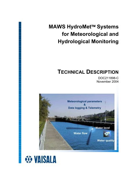
<strong>MAWS</strong> HydroMet <strong>Systems</strong><br />
<strong>for</strong> <strong>Meteorological</strong> <strong>and</strong><br />
<strong>Hydrological</strong> Monitoring<br />
TECHNICAL DESCRIPTION<br />
DOC211898-C<br />
November 2004<br />
<strong>Meteorological</strong> parameters<br />
&<br />
Data logging & Telemetry<br />
Water flow<br />
Water level<br />
Water quality
PUBLISHED BY<br />
Vaisala Oyj Phone (int.): +358 9 8949 1<br />
P.O. Box 26 Fax: +358 9 8949 2227<br />
FIN-00421 Helsinki<br />
Finl<strong>and</strong><br />
Visit our Internet pages at http://www.vaisala.com/<br />
© Vaisala 2004<br />
The contents are subject to change without prior notice.
_________________________________________________________________________________<br />
Table of Contents<br />
GENERAL INFORMATION ............................................................................3<br />
Technology................................................................................3<br />
St<strong>and</strong>ardization – Economies of Scale <strong>and</strong> Scope ...............5<br />
Life Cycle Cost..........................................................................6<br />
Reliability <strong>and</strong> Flexibility..........................................................7<br />
Exp<strong>and</strong>ability ............................................................................8<br />
Quality Assurance ....................................................................9<br />
MAIN COMPONENTS ..................................................................................11<br />
QML201 Logger.......................................................................12<br />
Compact Flash Memory Card Option ...................................13<br />
QMI108 Digital I/O Module .....................................................14<br />
Display <strong>and</strong> Keyboard Units..................................................15<br />
QMD201 ..............................................................................16<br />
QMD202 ..............................................................................16<br />
QMD170 ..............................................................................17<br />
<strong>MAWS</strong> Enclosure ....................................................................17<br />
ENC542PLM........................................................................17<br />
QBR101B Battery Regulator..................................................20<br />
Transient Protection Devices ................................................20<br />
Options ....................................................................................21<br />
SOFTWARE..................................................................................................23<br />
General Characteristics .........................................................23<br />
Sensor Library ........................................................................24<br />
Generic Sensor Interfaces .....................................................25<br />
Digital Input/Output..............................................................26<br />
Data Quality Control...............................................................28<br />
Auto-calibration....................................................................28<br />
Climatological/Measurement Limits Check .........................28<br />
Sensor Status In<strong>for</strong>mation...................................................29<br />
Checking Statistical Calculations ........................................30<br />
Calculations ............................................................................31<br />
Data Messages <strong>and</strong> Reports..................................................34<br />
Alarms..................................................................................35<br />
Data Acquisition...................................................................36<br />
Remote Maintenance ..........................................................37<br />
Logged Data in Reports.......................................................37<br />
Data Compression...............................................................38<br />
Communication.......................................................................39<br />
Power Management................................................................40<br />
Power monitoring of telemetry devices ...............................41<br />
Dynamically Controlled Timer Function...............................41<br />
DATA LOGGING ..........................................................................................43<br />
VAISALA _________________________________________________________________________ 1
Technical Description ________________________________________________________________<br />
Internal Flash Memory........................................................... 43<br />
External Compact Flash Card............................................... 44<br />
TELEMETRY AND COMMUNICATION ...................................................... 47<br />
Serial I/O Lines ....................................................................... 47<br />
Hardwire Telemetry................................................................ 49<br />
Wireless Telemetry ................................................................ 51<br />
POWERING.................................................................................................. 55<br />
Solar Power ............................................................................ 55<br />
SOLAR12-75....................................................................... 56<br />
SOLAR24............................................................................ 57<br />
Backup Batteries.................................................................... 58<br />
Optional Mains (AC) Power Supply MGP15V-M3................ 58<br />
OPERATING ENVIRONMENT .................................................................... 61<br />
Operating temperature .......................................................... 61<br />
ESD/EMI .................................................................................. 62<br />
MASTS ......................................................................................................... 63<br />
DKP206W & DKP210W - Pole Masts .................................... 63<br />
DKP102 - 2 m Pole Mast ........................................................ 65<br />
AFTER SALES SERVICE............................................................................ 67<br />
Commitment to Long Term Service ..................................... 67<br />
TECHNICAL DATA...................................................................................... 69<br />
QML201 Logger...................................................................... 69<br />
ENC542PLM Enclosure ......................................................... 70<br />
Mains Power Supply Unit MGP15V (Optional) .................... 71<br />
Battery Regulator QBR101B ................................................. 72<br />
Solar Panels............................................................................ 73<br />
Backup Batteries.................................................................... 74<br />
2 ________________________________________________________________________________
Chapter 1 _________________________________________________________ General In<strong>for</strong>mation<br />
CHAPTER 1<br />
GENERAL INFORMATION<br />
This document give you detailed in<strong>for</strong>mation on the <strong>MAWS</strong><br />
HydroMet systems, which offer advanced environmental monitoring<br />
features integrated into a compact <strong>and</strong> economical system package.<br />
For more details on available sensors <strong>and</strong> telemetry solutions, please<br />
refer to the following technical description documents:<br />
• <strong>MAWS</strong> <strong>Systems</strong>- <strong>Meteorological</strong> Sensors (DOC211899)<br />
• <strong>MAWS</strong> <strong>Systems</strong> - <strong>Hydrological</strong> Sensor (DOC211895)<br />
• <strong>MAWS</strong> <strong>Systems</strong> - Sensors <strong>for</strong> Soil Measurements (DOC211896)<br />
• <strong>MAWS</strong> System - Telemetry (DOC211897)<br />
Technology<br />
The <strong>MAWS</strong> HydroMet systems integrated around the QML201<br />
Logger are new generation, fully integrated systems especially<br />
designed <strong>for</strong> applications where no commercial power or<br />
communication networks are present or are too expensive to be<br />
installed. Due to their flexibility <strong>and</strong> economical design, the <strong>MAWS</strong><br />
systems are the ideal choice <strong>for</strong> both meteorological <strong>and</strong> hydrological<br />
applications. The possibility of using the same <strong>and</strong> st<strong>and</strong>ard<br />
equipment <strong>for</strong> various applications lowers the cost of training, spare<br />
parts <strong>and</strong> logistics support – the Total Life Cycle Cost of the network<br />
investment. QML201 based systems offer the most economical<br />
solution when the total life cycle cost of operating the entire network<br />
is fully considered.<br />
VAISALA _________________________________________________________________________ 3
Technical Description ________________________________________________________________<br />
The <strong>MAWS</strong> HydroMet <strong>Systems</strong> are integrated in a compact, readyto-install<br />
package:<br />
• <strong>MAWS</strong>301 <strong>for</strong> applications requiring larger back-up batteries<br />
<strong>and</strong>/or multiple telemetry solutions.<br />
The <strong>MAWS</strong> systems are compact, environmentally robust <strong>and</strong> low<br />
power systems to provide reliable <strong>and</strong> continuous data on a multitude<br />
of meteorological <strong>and</strong> hydrological parameters. Based on the latest<br />
technology both in measurements <strong>and</strong> communication, <strong>MAWS</strong>301<br />
can be interfaced with a large choice of telecommunication equipment<br />
such as st<strong>and</strong>ard PSTN <strong>and</strong> GSM modems (incl. GPRS packetswitched),<br />
CDMA (incl. 1xRTT packet-switched), radio modems <strong>and</strong><br />
satellite transmitters. The direct connection to the LAN network (via<br />
tcp/ip) can easily be made using an economical COM Server module.<br />
The <strong>MAWS</strong> systems have been designed <strong>for</strong> applications where only a<br />
few sensors are required. However, these systems can easily be<br />
upgraded, even in the field, to include a larger set of sensors,<br />
including smart sensors such ceilometer, visibility <strong>and</strong> present weather<br />
sensors <strong>and</strong> multi-parameter water quality sondes <strong>and</strong> ADCP flow<br />
sensors. The same basic system with its options <strong>and</strong> accessories can<br />
cater <strong>for</strong> all the needs of meteorological <strong>and</strong> hydrological networks.<br />
<strong>MAWS</strong>301 Automatic Weather Station Installation<br />
4 ________________________________________________________________________________
Chapter 1 _________________________________________________________ General In<strong>for</strong>mation<br />
The new Digital I/O module option exp<strong>and</strong>s the use of the<br />
<strong>MAWS</strong> system into supervisory <strong>and</strong> control systems. This<br />
allows users to add controlling features such as<br />
burglary/v<strong>and</strong>alism alarms, flood gate controls <strong>and</strong><br />
optimization of telemetry device power, to name but a few.<br />
St<strong>and</strong>ardization – Economies of Scale <strong>and</strong><br />
Scope<br />
In<strong>for</strong>mation technology, sensor technology, electronics <strong>and</strong> data<br />
communication have developed rapidly in recent years. This has made<br />
the automation of meteorological <strong>and</strong> hydrological networks very<br />
economical <strong>and</strong> attractive to meteorological <strong>and</strong> hydrological<br />
institutes, power corporations <strong>and</strong> other authorities that need to<br />
monitor weather <strong>and</strong>/or manage water systems such as rivers, lakes,<br />
reservoirs <strong>and</strong> ground water. Hydrometeorological networks, which<br />
typically consist of hundreds of automatic monitoring stations,<br />
telecommunication systems, databases <strong>and</strong> application software <strong>for</strong><br />
users, are installed over wide geographical areas that often include<br />
remote areas. The equipment must be able to survive harsh weather<br />
conditions while providing in<strong>for</strong>mation on the prevailing weather,<br />
precipitation, water quality <strong>and</strong> existing water reserves that the<br />
authority needs to manage - whether scarce or overabundant - or give<br />
timely <strong>and</strong> accurate <strong>for</strong>ecasts, whether short or long-term.<br />
Meanwhile, dem<strong>and</strong> <strong>for</strong> meteorological <strong>and</strong> hydrological data is<br />
growing constantly due to new requirements arising from legislation,<br />
environmental awareness <strong>and</strong> the push <strong>for</strong> efficiency in many of the<br />
industries that drive our modern society. Nowcasting, including the<br />
<strong>for</strong>ecasting of floods <strong>and</strong> severe weather events, is creating new<br />
requirements <strong>for</strong> real-time monitoring.<br />
A hydrometeorological network is rarely used on its own <strong>and</strong> in many<br />
cases the same infrastructure is used <strong>for</strong> other applications as well.<br />
Complementary meteorological <strong>and</strong> climatological observations, or<br />
vise versa, are frequently required in order to be able to produce<br />
timely <strong>and</strong> accurate <strong>for</strong>ecasts, warnings, reports <strong>and</strong> other end<br />
products. New <strong>for</strong>ecasting models require more data <strong>and</strong> more<br />
parameters to be monitored - both in meteorology <strong>and</strong> in hydrology.<br />
If the network is located in a populated area, the hydrometeorological<br />
stations can provide accurate real-time weather in<strong>for</strong>mation to the<br />
local community, environmentally hazardous industry, fire brigades,<br />
holiday resorts etc, who would not otherwise have accurate<br />
meteorological in<strong>for</strong>mation available. By using the same sensor, data<br />
VAISALA _________________________________________________________________________ 5
Technical Description ________________________________________________________________<br />
logger <strong>and</strong> telecommunication technology the network operator can<br />
enjoy the benefits of economies of scale <strong>and</strong> scope by reducing the<br />
cost of network design <strong>and</strong> maintenance servicing, including spare<br />
parts <strong>and</strong> training. The archived savings in network operation can then<br />
be used to further automate the conventional network or otherwise<br />
improve hydrometeorological services.<br />
Life Cycle Cost<br />
Although some administrative procedures still favor a “lowest bidder<br />
is the winner” policy, the Total Life Cycle Cost (TLCC) is becoming a<br />
subject of greater importance. The TLCC is the total cost during the<br />
expected lifetime of the meteorological <strong>and</strong> hydrological equipment.<br />
A basic concept of the TLCC contains the following four elements;<br />
T = P + R + O + C<br />
Product Cost<br />
Resource Cost<br />
Operating Cost<br />
Contingency Cost<br />
P<br />
R<br />
O<br />
C<br />
An optimum selection would be a combination of a low T <strong>and</strong> a good<br />
overall per<strong>for</strong>mance of the equipment to be purchased. We have aimed<br />
at a low Life Cycle Cost when designing the <strong>MAWS</strong> system <strong>and</strong> when<br />
selecting its system components <strong>and</strong> accessories.<br />
The Product Cost contains, in addition to the basic price quoted,<br />
installation, testing <strong>and</strong> documentation, packaging <strong>and</strong> transportation,<br />
taxis <strong>and</strong> duties etc.<br />
The Resource Cost includes site preparation works such as site<br />
purchasing, access to the site, possible building(s), electricity etc. The<br />
<strong>MAWS</strong> systems are compact, lightweight <strong>and</strong> easy to install.<br />
Frequently they are powered by solar panel <strong>and</strong> communicate via<br />
wireless telemetry, thus minimizing site preparation costs.<br />
When talking about unmanned, automated equipment the major part<br />
of the Operating Cost comes from the telecommunication <strong>and</strong><br />
maintenance costs. In addition, modification <strong>and</strong> upgrade costs will<br />
play a more significant role in future systems. The <strong>MAWS</strong> systems<br />
already have field proven extended Mean Time Between Failure<br />
(MTBF) rates. In addition, maintenance is made easy with modular,<br />
easy to replace modules <strong>and</strong> sensors with connectors. A wide range of<br />
telemetry options always offer the most economical <strong>and</strong> reliable<br />
alternative <strong>for</strong> data transmission.<br />
6 ________________________________________________________________________________
Chapter 1 _________________________________________________________ General In<strong>for</strong>mation<br />
The Contingency Cost primarily contains possible risks in the planned<br />
purchase such as a defective product, late delivery, inability to deliver<br />
at all, or inability to support the investment with spare parts <strong>and</strong><br />
upgrades during the life time of the equipment, frequently calculated<br />
as 10- 15 years. Vaisala, as the largest manufacturer of meteorological<br />
systems, can guarantee timely delivery. In addition, it is Vaisala’s<br />
policy to support its equipment <strong>for</strong> its whole lifetime with spare parts,<br />
training, upgrades <strong>and</strong> technical support, incl. HelpDesk functions.<br />
Reliability <strong>and</strong> Flexibility<br />
Vaisala's HydroMet Station <strong>MAWS</strong>301 combines Vaisala's <strong>and</strong><br />
H<strong>and</strong>ar's long term expertise with a new, compact data logger design.<br />
The design has been derived from field experience with the<br />
MILOS200, MILOS500, QLC50, QLI50 <strong>and</strong> H<strong>and</strong>ar's 555 systems in<br />
synoptic, climatological, hydrological <strong>and</strong> research applications <strong>and</strong> in<br />
the most dem<strong>and</strong>ing industrial use. There are over 25,000 of these<br />
pieces of equipment installed in over 70 countries.<br />
<strong>MAWS</strong> HydroMet systems are an excellent choice <strong>for</strong> applications<br />
requiring ease of installation, low power consumption, automatic<br />
operation <strong>and</strong> interfacing with modern telecommunication options<br />
such as satellite transmitters <strong>and</strong> packed-switched data networks.<br />
The <strong>MAWS</strong> systems are easy to install <strong>and</strong> maintain. All connections<br />
are pre-wired. The sensors are equipped with ready-made cables <strong>and</strong><br />
connectors/gl<strong>and</strong>s <strong>for</strong> quick installation. All optional modules such as<br />
modems, mains power supplies <strong>and</strong> surge arrestors are easily mounted<br />
on DIN-rails without any special tools.<br />
VAISALA _________________________________________________________________________ 7
Technical Description ________________________________________________________________<br />
The <strong>MAWS</strong> is the most modern HydroMet system including all<br />
necessary functions designed on a single printed board logger. Using<br />
the latest Surface Mounted Technology the board is very compact <strong>and</strong><br />
uses little current. It has a very high Mean-Time-Between-Failure<br />
(MTBF) value (over 20,000 hours strictly according to MIL-HNDB-<br />
217F).<br />
The <strong>MAWS</strong> HydroMet systems are field proven in various<br />
installations around the world. The <strong>MAWS</strong> stations are already in use<br />
in over 65 countries around the world.<br />
For example, the <strong>MAWS</strong>301 stations are used in the Surface Weather<br />
<strong>and</strong> Airport systems in the SIVAM (Sistema de Vigilancia da<br />
Amazonia) in Brazil. Climatological networks in Pol<strong>and</strong>, Romania<br />
<strong>and</strong> Brazil are equipped with the <strong>MAWS</strong> systems. The Swedish<br />
<strong>Hydrological</strong> <strong>and</strong> <strong>Meteorological</strong> Institute (SMHI) automated their<br />
whole hydrological network using the <strong>MAWS</strong>301. In addition, the US<br />
Air <strong>for</strong>ce’s new generation Tactical <strong>Meteorological</strong> (TACMET)<br />
Observation System is based on the same <strong>MAWS</strong> technology with<br />
300 systems already in field operations. For further details of <strong>MAWS</strong><br />
references, please see the <strong>MAWS</strong> Reference List.<br />
Based on Vaisala’s continuous product development, the <strong>MAWS</strong><br />
HydroMet system offers a versatile system concept with a planned<br />
upgrade path to meet future customer requirements.<br />
Exp<strong>and</strong>ability<br />
<strong>MAWS</strong> HydroMet systems are already economical in applications,<br />
requiring only few sensors. However, they are easily <strong>and</strong><br />
economically exp<strong>and</strong>able to incorporate a large number of sensors,<br />
including intelligent sensors with different types of serial interface.<br />
The total number of inputs in the basic data logger is 20 analog inputs<br />
(single ended) with the possibility to use them as digital inputs (state),<br />
2 counters <strong>and</strong> a dedicated input <strong>for</strong> a Vaisala atmospheric pressure<br />
sensor (frequency). Intelligent sensors can be interfaced using the RS-<br />
232, RS-485 <strong>and</strong> SDI-12 serial interfaces, up to 7 ports.<br />
The new optional expansion modules include:<br />
• QMI108 Digital I/O Module with 8 digital inputs <strong>and</strong> 8 digital<br />
outputs <strong>for</strong> digital measurements <strong>and</strong> control purposes.<br />
• QMU101 Sensor Multiplexer with additional 20 single ended (10<br />
diff.) analog inputs<br />
8 ________________________________________________________________________________
Chapter 1 _________________________________________________________ General In<strong>for</strong>mation<br />
Quality Assurance<br />
Vaisala's quality management system meets the requirements of the<br />
ISO 9001 quality system st<strong>and</strong>ard. Vaisala's quality management<br />
system has been granted the ISO 9001 Quality System Certificate No.<br />
1413-02 (First issue 1993-03-18) by the Finnish St<strong>and</strong>ardization<br />
Organization <strong>and</strong> the IQNet -The International Certification Network.<br />
The Finnish Defense Forces have granted Vaisala a Certificate No.8<br />
<strong>for</strong> meeting the requirements of AQAP 110 <strong>and</strong> ISO 9001 since<br />
1.12.1990. More in<strong>for</strong>mation on Vaisala's Quality Assurance system is<br />
available in a separate document.<br />
WAA151 Anemometer <strong>and</strong><br />
WAV151 Wind vane with<br />
WT521 transmitter, cross<br />
arm <strong>and</strong> 10 m cable<br />
QMW110<br />
Combined Wind Sensor<br />
with 10 m cable <strong>and</strong> mast<br />
mounting accessories<br />
Pyranometer<br />
SOLAR24<br />
Solar panel, 24 W<br />
with cable <strong>and</strong> mast<br />
mounting accessories<br />
QMH102<br />
Temperature <strong>and</strong><br />
Relative Humidity<br />
Probe inside<br />
DTR502<br />
Radiation Shield<br />
Satellite antenna<br />
Mast<br />
Sensor support arm<br />
QMR102 Rain<br />
gauge <strong>and</strong> st<strong>and</strong><br />
<strong>MAWS</strong>301<br />
Automatic Weather<br />
Station with PMT16A<br />
Pressure sensor,<br />
incl. rad. shield <strong>and</strong><br />
mast mounting<br />
accessories<br />
Soil temperature sensor(s)<br />
An Example of a Typical Met. Station Layout<br />
VAISALA _________________________________________________________________________ 9
Technical Description ________________________________________________________________<br />
GSM antenna<br />
QMW110<br />
Combined Wind<br />
Sensor with 10 m<br />
cable <strong>and</strong> mast<br />
mounting<br />
accessories<br />
FD12P<br />
PW & Visibility Sensor<br />
Pyranometer<br />
QMH102<br />
Temperature <strong>and</strong><br />
Relative Humidity Probe<br />
in DTR502 Radiation Shield<br />
QMR102<br />
Rain Gauge<br />
<strong>and</strong> st<strong>and</strong><br />
DKP12SUP1<br />
DKP12<br />
10 m pole mast<br />
<strong>MAWS</strong>301<br />
Automatic Weather<br />
Station with PMT16A<br />
Pressure sensor ,<br />
BWT15SX Mains power<br />
sypply, comms modules,<br />
incl.. rad. shield <strong>and</strong> mast<br />
mounting accessories<br />
2-wire RS-485<br />
cable not included<br />
CT25K<br />
Ceilometer with cloud<br />
coverage algorithm<br />
Mains (AC) power<br />
2-wire RS-485 Mains (AC) power<br />
cable not included<br />
+5 cm<br />
+-0<br />
-5 cm<br />
-10 QMT107<br />
-20 Multi -level Soil<br />
-50 Temperature probe<br />
Mains (AC) power<br />
-100<br />
An Example of a Met. Station with an Extended Set of Sensors<br />
QMR102<br />
Rain gauge<br />
GSM antenna<br />
Solar panel<br />
<strong>MAWS</strong>110<br />
incl. back-up battery,<br />
GSM data terminal<br />
<strong>and</strong> accessories<br />
Pole mast<br />
Water level<br />
sensor<br />
An Example of a Typical Pluviometric / Water Level Station<br />
10 _______________________________________________________________________________
Chapter 2 __________________________________________________________ Main Components<br />
CHAPTER 2<br />
MAIN COMPONENTS<br />
<strong>MAWS</strong> HydroMet systems are integrated into the versatile<br />
<strong>MAWS</strong>301. The basic <strong>MAWS</strong> HydroMet system comprises the<br />
following main components.<br />
Back-up batteries of<br />
7, 12, 24 or 48 Ah<br />
Telemetry options, incl:<br />
PSTN & cellular modems,<br />
UHF modems, LAN<br />
satellites: readiness <strong>for</strong><br />
multiple telemetry<br />
solutions<br />
QML201 Logger with<br />
options (Digital I/O,<br />
Sensor Mux. etc)<br />
Power supply options,<br />
battery regulator, surge<br />
arrestors etc<br />
Main Components (photo of <strong>MAWS</strong>301 system)<br />
VAISALA ________________________________________________________________________ 11
Technical Description ________________________________________________________________<br />
QML201 Logger<br />
The QML201 is a complete data logger with a highly specialized<br />
single board computer (CPU) which makes the measurements <strong>and</strong><br />
calculations, controls all system functions <strong>and</strong> telemetry devices <strong>and</strong><br />
logs data. The simplicity of the single board approach reduces the<br />
need <strong>for</strong> excess interconnecting wires <strong>and</strong> cables. It also greatly<br />
enhances reliability <strong>and</strong> reduces the cost of maintaining a spare part<br />
stock. This board contains the 32-bit Motorola CPU <strong>for</strong> data<br />
processing <strong>and</strong> 10 differential (20 single ended) analog sensor inputs.<br />
There are also three (3) frequency sensor interfaces, the 16 bit A/D<br />
converter, 1.7 Mbytes of secure Flash memory <strong>for</strong> data logging, RS-<br />
232 <strong>and</strong> RS-485 serial ports, a real-time-clock <strong>and</strong> a power supply<br />
also providing sensor excitations.<br />
The QML201 has an internal Real-Time-Clock with a resolution of 1<br />
second (internally in milliseconds) <strong>and</strong> stability better than 20<br />
seconds/month. The RTC is backed up with a lithium battery. There is<br />
also the possibility of reading <strong>and</strong> adjusting the RTC using comm<strong>and</strong>s<br />
issued via serial ports, both locally <strong>and</strong> remotely, e.g. from the central<br />
data collection software. In addition, the RTC can be synchronized by<br />
GPS clock, as an independent device or built-in, e.g. in satellite<br />
transmitters.<br />
Optional modules include, <strong>for</strong> example, a Compact Flash (CF)<br />
memory card, various communication modules <strong>and</strong> a built-in pressure<br />
transducer.<br />
QML201 Logger<br />
12 _______________________________________________________________________________
Chapter 2 __________________________________________________________ Main Components<br />
The printed board uses the latest SMT <strong>and</strong> CPLD (Complex<br />
Programmable Logic Device) technologies <strong>and</strong> is uni<strong>for</strong>mly coated <strong>for</strong><br />
better protection <strong>and</strong> reliability in high humidity environments.<br />
Each sensor input has a varistor (VDR) protection against induced<br />
transients. The maintenance terminal connection (RS-232, COM0)<br />
also has transzorb diodes in its inputs.<br />
When long signal cables are needed, these will be equipped with<br />
optional devices <strong>for</strong> surge voltage protection. These surge arrestors<br />
consist of a combination of VDR, gas-filled discharge tube, transzorb<br />
diodes <strong>and</strong> coils, thus providing excellent protection. These DIN-rail<br />
mountable devices are easy to change without any special tools.<br />
Compact Flash Memory Card Option<br />
The QML201 Logger has a place <strong>for</strong> a st<strong>and</strong>ard Compact Flash<br />
memory card, the same as is used <strong>for</strong> example in a digital camera, <strong>for</strong><br />
logging a large amount of data. CF cards offer logging capacity from<br />
32 Mbytes to hundreds of Mbytes at a very economical cost. CF cards<br />
do not need any back-up battery <strong>for</strong> preserving contents practically<br />
indefinitely.<br />
The data is logged into the daily files making it easy to locate any<br />
particular data set e.g. <strong>for</strong> further analysis.<br />
Compact Flash Memory Card Option<br />
These cards can be read directly to the PC. Several different types of<br />
readers are commercially available at any PC or camera store; internal<br />
PCMCIA (PC-card) readers <strong>and</strong> external readers connected to the<br />
USB or parallel port of a PC.<br />
VAISALA ________________________________________________________________________ 13
Technical Description ________________________________________________________________<br />
Compact Flash Memory Card Readers<br />
QMI108 Digital I/O Module<br />
The new QML201 Logger provides the possibility to extend the<br />
digital I/O capacity of <strong>MAWS</strong> with the optional Digital I/O Module<br />
QMI108 equipped with eight digital inputs <strong>and</strong> eight digital outputs.<br />
Digital I/O Module QMI108<br />
0312-025<br />
14 _______________________________________________________________________________
Chapter 2 __________________________________________________________ Main Components<br />
The main characteristics of the QMI108 module are:<br />
• The module interfaces to the logger via the SPI connector, there<strong>for</strong>e<br />
it does not use any RS- channels.<br />
• The module has eight (8) open collector outputs with 30 VDC / 1 A<br />
continuous drive capability <strong>and</strong> LED indicators.<br />
• The eight (8) inputs of the module tolerate voltages from 0 to 25<br />
VDC (the absolute maximum 30 VDC), <strong>and</strong> they have 40 ms<br />
(typical) contact debouncing circuitry.<br />
• The module con<strong>for</strong>ms to the same environmental immunity <strong>and</strong><br />
emission st<strong>and</strong>ards than the logger.<br />
• The module also allows connection of slow pulse inputs, e.g. tipping<br />
bucket rain gauges.<br />
• The module is located inside the enclosure beside the logger.<br />
Display <strong>and</strong> Keyboard Units<br />
The <strong>MAWS</strong>301 HydroMet systems can be equipped with optional<br />
display <strong>and</strong> keyboard units at installation sites where an operator<br />
needs to see data locally <strong>and</strong>/or insert some own observations or<br />
reference data into the system. There are three different models of<br />
QMD - display <strong>and</strong> keyboard units utilizing the same hardware <strong>and</strong><br />
software technology.<br />
The QMD displays are programmable LCD displays with back light..<br />
They can show several lines of alphanumeric data. The full display<br />
size expressed in characters is 20*6 (width * height). The QMD<br />
displays include keypad with user-friendly menu, whose content is<br />
also configurable by the user. The displayed data is sent as reports to<br />
the display. The contents, <strong>for</strong>mat <strong>and</strong> updating intervals of these<br />
reports are user configurable. The update interval can be anything<br />
between 1 second <strong>and</strong> 24 hours. The QMD displays are <strong>for</strong>:<br />
• Viewing data messages whose contents are freely configurable by<br />
the user using the <strong>MAWS</strong> Lizard Setup software.<br />
• Setting up of an extended set of system parameters<br />
• Per<strong>for</strong>ming one-point calibration in the field (gain & offset)<br />
• Entering data <strong>and</strong>/or text messages via the keyboard.<br />
VAISALA ________________________________________________________________________ 15
Technical Description ________________________________________________________________<br />
QMD201<br />
The QMD201 unit is mounted on the door of the enclosure. The units<br />
can be accessed without opening the enclosure. This unit is mainly <strong>for</strong><br />
sites, where the enclosure will be installed indoors, e.g. in a "hut" built<br />
<strong>for</strong> a stilling well.<br />
QMD202<br />
The QMD202 unit is mounded on a DIN-rail inside the enclosure.<br />
Access is only by opening the enclosure door, which can be firmly<br />
locked.<br />
16 _______________________________________________________________________________
Chapter 2 __________________________________________________________ Main Components<br />
QMD170<br />
The QMD170 h<strong>and</strong>held unit is attached to the RS-232 port connector<br />
at the bottom flange of the enclosure. There is no need to open the<br />
door of the enclosure. The QMD170 unit is powered by its own<br />
rechargeable battery. Due to its light weight <strong>and</strong> small size, the<br />
QMD170 is easily carried to the installation site in the pocket. The<br />
length of the cable is 3 meters.<br />
<strong>MAWS</strong> Enclosure<br />
ENC542PLM<br />
The ENC542PLM is a polyester enclosure rein<strong>for</strong>ced with fiberglass<br />
<strong>for</strong> the <strong>MAWS</strong>301 HydroMet system. This robust enclosure has space<br />
<strong>for</strong> the QML201 Logger, multiple communication equipment, battery<br />
charger <strong>and</strong> maintenance free Lead-acid batteries of different sizes<br />
with a capacity of up to 48 Ah. Optional devices such as a mains<br />
power supply <strong>and</strong> protective devices <strong>for</strong> communication lines can also<br />
be installed inside the enclosure. All of these devices are installed on<br />
easy-to-remove DIN-rails except the back up battery which is installed<br />
by means of a screw fixed mounting clamp.<br />
VAISALA ________________________________________________________________________ 17
Technical Description ________________________________________________________________<br />
The modular design allows optional devices to be installed on two<br />
levels. These installation modules can easily be removed <strong>for</strong><br />
maintenance or replacement. The installation frame <strong>for</strong> equipment is<br />
made of stainless steel, which also provides excellent protective<br />
grounding.<br />
The enclosure material is highly resistant to corrosion, ultra-violet<br />
radiation, principal chemicals <strong>and</strong> atmospheric agents. The door<br />
sealing is ensured by using an extruded polyurethane foam gasket.<br />
The door has two keyed locks.<br />
The protection rating is min. IP 65 (equiv. NEMA 4X) i.e. dust tight<br />
<strong>and</strong> sealed against water jets. The enclosure material is selfextinguishing.<br />
The ENC542PLM enclosure can be equipped with an optional metal<br />
radiation shield, which is painted white. This shield gives additional<br />
protection against excessive sun radiation or falling material such as<br />
ice, tree branches etc. In addition, as st<strong>and</strong>ard there is a white back<br />
plate, this gives additional protection against excessive sun radiation.<br />
The enclosure has an optional pressure compensation element<br />
installed on the bottom plate. This element compensates <strong>for</strong> varying<br />
degrees of pressure caused by the temperature differences. The<br />
element has a GoreTex membrane filter, which prevents moisture<br />
sucking in while the enclosure is cooling off, because the element can<br />
"breathe". This membrane filter element together with plastic material<br />
of high quality <strong>and</strong> white painted shields significantly reduces water<br />
condensation inside the enclosure. There<strong>for</strong>e no drying agent, such as<br />
silicacel bags, is required inside the enclosure.<br />
18 _______________________________________________________________________________
Chapter 2 __________________________________________________________ Main Components<br />
In hydrological application where the equipment is frequently<br />
installed in small huts built e.g. over the stilling well, the radiation<br />
shield is not necessary.<br />
For future needs, the ENC542PLM enclosure has spare space reserved<br />
<strong>for</strong> optional devices.<br />
Bottom View of the ENC542PLM enclosure with extended<br />
meteorological configuration, all connectors are labeled<br />
All sensors, power supplies <strong>and</strong> communication devices are connected<br />
to the equipment inside the enclosure via environmentally sealed<br />
connectors.<br />
The protection class of all connectors is IP66 as a minimum. Each<br />
connector is identified individually with a label. The enclosure used in<br />
hydrological systems is normally economized <strong>for</strong> these applications.<br />
The atmospheric pressure sensor is located on the CPU board of the<br />
QML201 Logger. There is a static pressure head <strong>for</strong> venting out the<br />
pressure sensor, thus minimizing the wind effect on the pressure<br />
measurement.<br />
There is space <strong>for</strong> future expansion by installing new sensors <strong>and</strong>/or<br />
communication devices both in the CPU’s sensor inputs <strong>and</strong> in the<br />
enclosure.<br />
VAISALA ________________________________________________________________________ 19
Technical Description ________________________________________________________________<br />
QBR101B Battery Regulator<br />
The QBR101B Battery Regulator maintains the charging of the<br />
integral 12 V battery. The charge/recharge control includes a<br />
temperature compensation function as well as deep discharge<br />
protection of the battery. QBR101B also allows simultaneous inputs<br />
from both a solar panel <strong>and</strong> mains (AC) power.<br />
QBR101B Battery Regulator<br />
Also included are LED lamps <strong>for</strong> indicating Battery OK/Low <strong>and</strong><br />
Charge/Recharge conditions. In order to maximize autonomy time, the<br />
lamps are activated only while pressing the ON button.<br />
QBR101B is a rail-mountable unit allowing easy maintenance.<br />
Transient Protection Devices<br />
Each sensor input in the QML201 has varistor (VDR) protection<br />
against induced transients. The maintenance terminal I/O port has<br />
transzorb diodes in their inputs. A coaxial surge arrestor is used <strong>for</strong><br />
the RF signal input when radio or satellite equipment is being used.<br />
In case of long signal cables, additional transient protectors can be<br />
installed on the DIN-rail. These surge arrestors consist of a<br />
combination of VDR, gas discharge, transzorb diodes <strong>and</strong> coils, thus<br />
providing excellent protection.<br />
These are easy to change in the field without tools. In addition, these<br />
devices are industry st<strong>and</strong>ard <strong>and</strong> readily available locally, too.<br />
20 _______________________________________________________________________________
Chapter 2 __________________________________________________________ Main Components<br />
Surge Arrestor <strong>for</strong> the 230 <strong>and</strong> 115 VAC Mains Power<br />
Surge Arrestors <strong>for</strong> RS - serial lines <strong>and</strong> PT100 sensor<br />
Optional coaxial surge arrestors will be used <strong>for</strong> UHF / VHF antennas.<br />
Options<br />
In the <strong>MAWS</strong> enclosures there is space <strong>for</strong> various types of optional<br />
devices, such as:<br />
- Communication equipment (modems, satellite terminals, radio<br />
modem).<br />
- Mains power supplies, e.g. <strong>for</strong> the heating of a rain gauge or wind<br />
sensor<br />
- Additional protective devices against over-voltage <strong>and</strong> electric<br />
discharge, e.g. <strong>for</strong> communication lines or long signal cables.<br />
VAISALA ________________________________________________________________________ 21
Technical Description ________________________________________________________________<br />
This page intentionally left blank<br />
22 _______________________________________________________________________________
Chapter 3 __________________________________________________________________ Software<br />
CHAPTER 3<br />
SOFTWARE<br />
General Characteristics<br />
The <strong>MAWS</strong> HydroMet systems utilize Vaisala’s field-proven <strong>and</strong><br />
accurate sensors, which are in extensive use in over 100 countries all<br />
over the world from Antarctica to tropical isl<strong>and</strong>s. The offered suite of<br />
meteorological sensors measures wind direction <strong>and</strong> speed, pressure,<br />
air <strong>and</strong> surface temperature, relative humidity, precipitation <strong>and</strong> global<br />
solar radiation. There is space <strong>for</strong> exp<strong>and</strong>ing the station with optional<br />
sensors such as soil temperature, net radiation, leaf wetness, water<br />
level etc. when necessary.<br />
The library of sensors also includes intelligent sensors such as a cloud<br />
height ceilometer with cloud cover algorithm, visibility <strong>and</strong> present<br />
weather.<br />
The suite of hydrological sensors includes various types of sensor <strong>for</strong><br />
measuring water level, water temperature, precipitation <strong>and</strong><br />
intelligent, multi-parameter water quality sondes <strong>and</strong> acoustic Doppler<br />
profilers <strong>for</strong> flow <strong>and</strong> discharge measurements.<br />
The operation of the <strong>MAWS</strong> systems can be easily set-up <strong>and</strong><br />
modified with the help of the user-friendly <strong>MAWS</strong> Lizard Setup<br />
program. Using the ready-made templates, this setup software guides<br />
the user through the simple set-up routines. Modifications to the<br />
system configuration <strong>and</strong> operation can easily be carried out by the<br />
user.<br />
All the configuration settings can be stored in the <strong>MAWS</strong> Lizard’s<br />
configuration library where they are easily available <strong>for</strong> modifications<br />
or <strong>for</strong> creating a new setup based on the old one. In addition, there is<br />
an Import/Export function <strong>for</strong> adding new setup files, or, <strong>for</strong> example,<br />
VAISALA ________________________________________________________________________ 23
Technical Description ________________________________________________________________<br />
<strong>for</strong> sending an old file to the Vaisala Helpdesk in case troubleshooting<br />
or other assistance is needed.<br />
Lizard Configuration Software<br />
Sensor Library<br />
The <strong>MAWS</strong> HydroMet systems have a large <strong>and</strong> continuously<br />
updated sensor library. The sensor library includes the default setting<br />
<strong>for</strong> the most common meteorological <strong>and</strong> hydrological sensors,<br />
including Vaisala’s optical sensors <strong>for</strong> cloud height, visibility <strong>and</strong><br />
present weather.<br />
Example of Sensor Setup Template<br />
24 _______________________________________________________________________________
Chapter 3 __________________________________________________________________ Software<br />
Generic Sensor Interfaces<br />
In addition to the sensors with default settings, the <strong>MAWS</strong> Lizard<br />
software has options <strong>for</strong> configuring generic voltage, PT100, counter,<br />
frequency, mA <strong>and</strong> potentiometric inputs as well as numeric string<br />
received via serial interface(s).<br />
Each sensor can have user specified validation <strong>and</strong> conversion/<br />
linearization parameters (up to the 3rd degree factor). This feature<br />
enables the interfacing <strong>and</strong> conditioning of customer’s own sensors.<br />
Generic Sensor Interface Setup Template<br />
In the generic numeric receiver, the user can define receiving<br />
parameters <strong>for</strong> a data string via serial port(s). In addition, the SDI-12<br />
interface can be used <strong>for</strong> interfacing sensors supporting this st<strong>and</strong>ard<br />
protocol, which is frequently used especially with hydrological<br />
sensors.<br />
VAISALA ________________________________________________________________________ 25
Technical Description ________________________________________________________________<br />
Digital Input/Output<br />
Basic QML201 Logger<br />
In addition to digital frequency/counter inputs (2 + 1 pcs), analog<br />
inputs can be used <strong>for</strong> monitoring digital state. Furthermore, the state<br />
status in<strong>for</strong>mation can be used <strong>for</strong> controlling one of the excitation<br />
voltages, e.g. as a contact enclosure that can be activated by an event.<br />
Optional QMI108 Digital I/O Module<br />
The digital inputs <strong>and</strong> outputs of QMD108 are freely <strong>and</strong> individually<br />
configurable by the user.<br />
Hardware Setup View: Digital I/O Configuration<br />
The Hardware Setup view also provides the possibility to select<br />
which outputs are controlled by Timers. The on/off cycle <strong>for</strong> the<br />
selected outputs can then be configured in the Timers view. The other<br />
possibility to control the outputs is to use alarms, <strong>for</strong> example, to<br />
activate the output signal when the alarm condition is met. The alarm<br />
condition is configured in the Alarms view.<br />
The following template shows an example of the Timers view. In the<br />
example the configuration is as follows:<br />
- Output 0 toggles between on <strong>and</strong> off in a one minute cycle.<br />
- Output 5 is on <strong>for</strong> one minute be<strong>for</strong>e each full hour.<br />
26 _______________________________________________________________________________
Chapter 3 __________________________________________________________________ Software<br />
Timers View: Timer Configuration <strong>for</strong> Digital Outputs<br />
The following example shows the Alarms view. In the example, the<br />
configuration activates output 3 when the air temperature measured by<br />
the QMH101 sensor rises above +15 °C.<br />
Alarms View: Controlling Digital Output Using Alarm<br />
The inputs of the QMI108 module can be used as any other<br />
application variables, that is <strong>for</strong> reporting, logging <strong>and</strong> as alarm<br />
inputs.<br />
In the Reports view, the input statuses are available as individual<br />
variables IN0 through IN7 <strong>and</strong> combined as bits into a single status<br />
word ALL. The input module status is also available as <strong>for</strong> the<br />
sensors.<br />
VAISALA ________________________________________________________________________ 27
Technical Description ________________________________________________________________<br />
Reports View: Digital Inputs in the Report<br />
Data Quality Control<br />
The QML201 Logger has a 32-bit CPU, a 16-bit A/D conversion, <strong>and</strong><br />
advanced software with data quality control features in order to ensure<br />
the continuous accuracy of the measured <strong>and</strong> calculated data.<br />
Auto-calibration<br />
The <strong>MAWS</strong> software automatically per<strong>for</strong>ms the offset recalibration<br />
of the A/D converter <strong>and</strong> electronics every 15 minutes. In addition, the<br />
self-calibration will be initiated automatically whenever there is a<br />
temperature change of more than 1° C measured onboard the CPU.<br />
The full ADC calibration will be made every 10th calibration time, i.e.<br />
at least every 150-min.<br />
Climatological/Measurement Limits<br />
Check<br />
The built-in quality control software checks the measured sensor data<br />
against the user-set minimum <strong>and</strong> maximum limit values <strong>and</strong> step<br />
changes between two successive measurements. The user can set these<br />
data validation parameters independently <strong>for</strong> each measured parameter<br />
<strong>and</strong> each site. There is also built-in test software to ensure the<br />
reliability of the sensors’ measurements.<br />
28 _______________________________________________________________________________
Chapter 3 __________________________________________________________________ Software<br />
Data Validation<br />
Sensor Status In<strong>for</strong>mation<br />
The <strong>MAWS</strong> logger provides status values indicating detailed<br />
in<strong>for</strong>mation about the state of the connected sensors. Depending on<br />
the sensor, this indication may vary, <strong>for</strong> example between ok <strong>and</strong> out<br />
of range, or may provide more accurate diagnostic in<strong>for</strong>mation. For<br />
all sensors, the value is contained in the variable status, which can be<br />
included in the report(s) <strong>and</strong>/or monitored in order to produce an<br />
alarm, e.g. <strong>for</strong> maintenance purposes. The following table provides the<br />
list of currently available status indications:<br />
VAISALA ________________________________________________________________________ 29
Technical Description ________________________________________________________________<br />
Possible Values <strong>for</strong> the Status Variable<br />
Value Meaning Note<br />
0 The sensor is working properly (OK).<br />
1 Not measured yet<br />
2 Interface is not initialized. 1)<br />
3 Communication timeout has occurred. 1)<br />
4 Unknown data is received. 1)<br />
5 Communication is functioning, but sensor reports errors. 1)<br />
Use sensor's own service interface to determine cause.<br />
6 Sensor communication is paused because service 1)<br />
connection is opened through <strong>MAWS</strong>.<br />
7 Message sequence numbers are overlapping in the 1)<br />
Autotrac satellite transceiver interface.<br />
8..19 Not available<br />
20 Excitation failure is caused by an overload in the 2)<br />
excitation output.<br />
21 The input voltage is out of range or A/D conversion has 2)<br />
failed due to an internal error.<br />
22 Sensor is disconnected or connection cables are 2)<br />
broken.<br />
23 Sensor output exceeds the min/max limits defined in the 2)<br />
Measurement configuration view.<br />
24 Change in sensor output has exceeded the maximum 2)<br />
step defined in the Measurement configuration view.<br />
25 An internal configuration error has occurred. 2)<br />
26 Error in reference measurement, usually caused by 2)<br />
damaged sensor/logger or electrical interference.<br />
27 Internal voltage error occurred or the logger is<br />
2)<br />
damaged.<br />
28 PMT16 calibration data error. 2)<br />
29 Data invalidated <strong>for</strong> unspecified reason. 2)<br />
99 Sensor status is not supported. 2)<br />
1) Value is available only <strong>for</strong> sensors with serial interface.<br />
2) Value is available only <strong>for</strong> sensors with a conventional, that is analogue or counter/frequency, interface.<br />
Checking Statistical Calculations<br />
The statistical calculations are made only when the minimum number<br />
of valid measurements are available. This number (%) is also a user<br />
configurable parameter which can be set individually <strong>for</strong> each<br />
calculation.<br />
Data Quality Control in Statistical Calculations<br />
30 _______________________________________________________________________________
Chapter 3 __________________________________________________________________ Software<br />
Calculations<br />
Statistical calculations such as minimum, maximum, averages,<br />
st<strong>and</strong>ard deviation, <strong>and</strong> cumulative values, are calculated over user set<br />
periods at user set intervals independently <strong>for</strong> each measured <strong>and</strong><br />
calculated parameter.<br />
An Example of the Calculations Setup Window<br />
The extreme values can have time stamps accurate to seconds<br />
(selectable <strong>for</strong>mat hh:mm:ss).<br />
A library of ready made calculations is available in the <strong>MAWS</strong><br />
software, including, <strong>for</strong> example, unit conversions, dew point, QNH,<br />
QFF, QFE, evapotranspiration, wind chill, heat stress <strong>and</strong> frost point,<br />
MacArthur fire index, rain duration (requires DRD11A sensor) etc. In<br />
addition, the sunshine duration can be calculated using the data from<br />
the global solar radiation sensor. The CM6B or CM11 global solar<br />
radiation sensor is recommended <strong>for</strong> this purpose.<br />
VAISALA ________________________________________________________________________ 31
Technical Description ________________________________________________________________<br />
The List of Unit Conversions<br />
The calculation module also offers the possibility to make various<br />
arithmetic operation one or two oper<strong>and</strong>s, which can be any measured,<br />
calculated or manually entered parameters. The operations include:<br />
• Add<br />
• Subtract<br />
• Multiply<br />
• Divide<br />
• Square root<br />
• Power<br />
• Logarithm, lg(A)<br />
• Logarithm10, log(A)<br />
• Exponent<br />
• Absolute<br />
• Sine<br />
• Cosine<br />
• Tangent<br />
32 _______________________________________________________________________________
Chapter 3 __________________________________________________________________ Software<br />
An Example of Arithmetic Operation<br />
The special Wind Task is <strong>for</strong> calculating statistical values <strong>for</strong> wind<br />
speed <strong>and</strong> <strong>for</strong> wind direction in the vector <strong>for</strong>mat. The list of<br />
calculations also includes the Sigma-Theta calculation <strong>for</strong> wind<br />
turbulence.<br />
An Example of the Wind Calculation Setup Options (Partial List)<br />
VAISALA ________________________________________________________________________ 33
Technical Description ________________________________________________________________<br />
Data Messages <strong>and</strong> Reports<br />
The <strong>for</strong>mats <strong>and</strong> contents of the output message are freely<br />
configurable by the user(s). <strong>MAWS</strong> HydroMet systems can be<br />
configured to produce several different kinds of fully automated<br />
messages to serve various users of the data. The data messages can<br />
include measured <strong>and</strong> calculated data items, complete reports, user<br />
inserted data <strong>and</strong>/or ASCII text. In addition, the data messages can<br />
include diagnostics data such as battery voltage, internal temperature,<br />
status of the mains power, enclosure door open/close etc.<br />
The <strong>for</strong>matting of the messages is done using the <strong>MAWS</strong> Lizard<br />
Setup software. The software is fully configurable <strong>and</strong> there<strong>for</strong>e there<br />
is no need to write new software code <strong>and</strong> no prior knowledge of<br />
programming is needed.<br />
Several Data Messages Can Be Configured to Be Sent to Different<br />
Output Ports<br />
In addition, the reports can be easily configured to simulate already<br />
existing data <strong>for</strong>mats.<br />
34 _______________________________________________________________________________
Chapter 3 __________________________________________________________________ Software<br />
An Example of a Configuration Template <strong>for</strong> a Tabular Message<br />
Alarms<br />
The alarms function is also a completely user configurable feature.<br />
Any measured or calculated parameter can be used <strong>for</strong> testing the user<br />
set alarm criteria.<br />
Example: It is possible to combine several alarm criteria (AND or OR<br />
- type functions) e.g. to create an alarm when the wind direction is<br />
more than 275 degrees <strong>and</strong> wind speed exceeds 20 m/s.<br />
Whenever an alarm condition has been detected, a user configured<br />
alarm message will be automatically sent to the specified<br />
communication port(s). Alternatively, triggering an alarm can cause<br />
logging of a user defined data group or set an excitation voltage e.g.<br />
<strong>for</strong> controlling a relay. The system supports multiple alarm functions.<br />
There are several alternative triggering functions <strong>for</strong> alarms such as<br />
below minimum, above maximum or a combination of these limits.<br />
In addition, the Alarm module can be used to dynamically adjust the<br />
timer functions, such as the report transmission interval or measuring<br />
intervals. For a more detailed description, see the Dynamically<br />
Controlled Timer Functions section.<br />
VAISALA ________________________________________________________________________ 35
Technical Description ________________________________________________________________<br />
An Example of the Alarms Setup Window<br />
Data Acquisition<br />
The transmission of the reports can be:<br />
• Self-timed: <strong>MAWS</strong> sends data at user set interval(s). The<br />
interval(s) can be changed remotely on comm<strong>and</strong>. The interval is<br />
freely configurable between 1 second <strong>and</strong> 24 hours at 1 second<br />
intervals. In addition, these intervals can be changed automatically<br />
when a user set parameter exceeds its threshold values. In this way<br />
the data can be transmitted more frequently, e.g. when the water<br />
level is rising <strong>and</strong> the development of a potential flood situation<br />
requires more real-time data. This feature also allows<br />
telecommunication costs to be optimized.<br />
• Polled: data acquisition system polls <strong>MAWS</strong> stations whenever<br />
data is needed. Polling can retrieve data message(s) or data logged<br />
into the station's memory (see Logged Data in Reports below)<br />
• ALARM: based on a measured or calculated parameter exceeding<br />
preset threshold value(s).<br />
• FTP: data transfer via FTP (File Transfer Protocol) in GSM,<br />
GPRS <strong>and</strong> PSTN networks. AWS acts as an FTP client placing a<br />
file on the FTP Server's hard disk using the central data collection<br />
software at a user configurable interval <strong>and</strong>/or at an ALARM.<br />
36 _______________________________________________________________________________
Chapter 3 __________________________________________________________________ Software<br />
Data transmission can include any combination of the above<br />
mentioned methods.<br />
Remote Maintenance<br />
Reporting functions can also be efficiently used <strong>for</strong> remote<br />
maintenance by:<br />
- the system monitoring itself with real-time self-diagnostics tasks<br />
<strong>and</strong> providing system alarms in case of system failure,<br />
- providing system maintenance in<strong>for</strong>mation to the system operators<br />
remotely, so that the system status can be analyzed <strong>and</strong> required<br />
maintenance procedures planned in advance prior to maintenance<br />
on site, <strong>and</strong><br />
- providing a maintenance interface to maintenance technicians on<br />
remote sites.<br />
A system status message can include in<strong>for</strong>mation on internal<br />
temperature, available battery capacity <strong>and</strong> the status of charging,<br />
amongst other things. In addition, hardware <strong>and</strong> software version<br />
numbers can be included in these messages. This message can be<br />
transmitted e.g. once a day at a set time, typically at midnight.<br />
Logged Data in Reports<br />
In the <strong>MAWS</strong> systems, it is possible to <strong>for</strong>mat output reports using the<br />
data items in logged data files. The user can select the number of<br />
records from the logged file to be included in the report. There are two<br />
automatically made report <strong>for</strong>mats. When using the SCAN <strong>for</strong>mat, the<br />
logged data items are organized in columns, in such a way that one<br />
column consists of the measurements of one item over a user-set<br />
period of records. In the CHANNEL ordered report <strong>for</strong>mat, the logged<br />
data are organized in rows, with one row consisting of the<br />
measurements of one item over a period of records. The data items are<br />
by default separated by a space, but the user can also change this<br />
parameter.<br />
This option is most convenient when the data is not needed in nearreal-time<br />
but will be sent e.g. every 3 or 6 hours only.<br />
VAISALA ________________________________________________________________________ 37
Technical Description ________________________________________________________________<br />
Data Compression<br />
The cost of telecommunications is often the most significant annual<br />
cost in operating the network. In order to lower this cost the <strong>MAWS</strong><br />
system offers two automatic data compression methods which are user<br />
configurable. This function is particularly useful when the data is<br />
transferred using methods which are costly or otherwise limit the<br />
amount of data to be transferred. Such methods include, <strong>for</strong> example,<br />
satellite systems <strong>and</strong> SMS (Short Message Service) messages in<br />
cellular data transfer.<br />
There are two methods <strong>for</strong> automatic report <strong>for</strong>matting: BASE32 <strong>and</strong><br />
BCD. Depending on the parameters <strong>and</strong> the length of the message, the<br />
data reduction can even be over 50 %.<br />
An Example of the Compression Setup Window<br />
Base32 Compression<br />
The BASE32 report <strong>for</strong>matting method produces ASCII data <strong>and</strong> thus<br />
printable characters. With this method every measured value is scaled<br />
<strong>and</strong> converted using a radix of 32 instead of 1. The compression ratio<br />
is approximately from 30 to 60 %.<br />
38 _______________________________________________________________________________
Chapter 3 __________________________________________________________________ Software<br />
Example: temperature value, string presentation:<br />
Original: -18.7<br />
(5bytes)<br />
Offset: -18.7+50=31.3 (if -50 is minimum of measured value)<br />
Scale: 31.3*10=313 (if 0.1 is resolution of measurement)<br />
313 -> BASE32 -> 9P (2bytes)<br />
BCD Compression<br />
The BCD (Binary Coded Decimal) method is a Positional Number<br />
System, with a radix of 10 <strong>and</strong> coefficients expressed in 4-bit binary<br />
words. The BCD <strong>for</strong>matting method produces non-printable binary<br />
reports.<br />
Example2:<br />
3 | 1 | 3<br />
8421|8421|8421<br />
0011|0001|0011<br />
313 -> BCD -> 001100010011 (1,5bytes)<br />
Communication<br />
The available telemetry devices are selectable from the list. All<br />
equipment has its own default setting which can be modified by the<br />
user whenever necessary.<br />
List of Communication Equipment<br />
VAISALA ________________________________________________________________________ 39
Technical Description ________________________________________________________________<br />
The <strong>MAWS</strong> system can have up to 7 serial ports <strong>for</strong> connecting to<br />
telemetry equipment as well as to sensors with serial interface. The<br />
communication ports are easily managed using their own setup<br />
template:<br />
Communication Ports Setup Template<br />
Multiple telemetry devices can be connected at the same time thus<br />
increasing reliability at critical monitoring site(s).<br />
Power Management<br />
The <strong>MAWS</strong> HydroMet system includes several advanced power<br />
management features, which guarantee long term operation during<br />
main power failures. In addition to the very low power consumption<br />
of the QML201 Logger itself, the following features are included:<br />
• Monitoring of presence of the main power voltage<br />
• Monitoring the voltage level of the back-up battery<br />
• Monitoring the presence of charging <strong>for</strong> back-up batteries.<br />
• Switching off heater circuits whenever the main power is OFF.<br />
• Controlling powering of the telemetry devices according to the user<br />
configured schedule whenever the mains power is OFF<br />
40 _______________________________________________________________________________
Chapter 3 __________________________________________________________________ Software<br />
• Controlling powering of the telemetry devices according to the user<br />
configured schedule whenever the charging of the back-up batteries<br />
from the solar panel is OFF.<br />
• Reducing the telecommunication rate whenever the system works<br />
on back-up batteries.<br />
• Reducing the sampling rate whenever the system works on back-up<br />
batteries.<br />
The low power monitoring is an intelligent algorithm taking into<br />
account the charging state of the back-up batteries <strong>and</strong> repeated mains<br />
power failures.<br />
Power monitoring of telemetry<br />
devices<br />
The <strong>MAWS</strong> station offers intelligent power monitoring features <strong>for</strong><br />
guaranteeing extended operation. When there is a failure in supplying<br />
primary power to a remote station, the <strong>MAWS</strong> system can be<br />
configured to switch off the power from the telemetry device <strong>for</strong> most<br />
of that time. In order to conserve the back-up battery capacity, the<br />
power can be switched on at user-defined times <strong>for</strong> a short period to<br />
transmit an alarm or other critical data. Whenever the primary power<br />
is recovered, the telemetry device will again be powered normally.<br />
Dynamically Controlled Timer Function<br />
<strong>MAWS</strong> application execution is mostly controlled by timers, which<br />
are configured to fixed intervals using the <strong>MAWS</strong> Lizard Setup<br />
Software.<br />
Timer intervals controlled by thresholds provide the means to change<br />
these intervals dynamically according to limit values (thresholds)<br />
while the system is running. Each measured <strong>and</strong>/or calculated data<br />
item can be configured to be monitored by thresholds.<br />
For example, the following topics can be h<strong>and</strong>led using this control<br />
method:<br />
- Power consumption control when operating on backup batteries.<br />
<strong>MAWS</strong> can keep the communication equipment permanently on<br />
when external AC-power/solar charging is available, <strong>and</strong> switch to<br />
VAISALA ________________________________________________________________________ 41
Technical Description ________________________________________________________________<br />
cyclic powered mode (low power mode) when the system is<br />
running on back-up batteries.<br />
- Communication cost reduction. When the measured conditions are<br />
normal, data messages can be transmitted less frequently, but<br />
when preset limits are exceeded by user set parameter(s), the faster<br />
transmission cycle can automatically be taken into use.<br />
Interval threshold configuration view<br />
The Interval thresholds are configured in the <strong>MAWS</strong> Lizard's alarm<br />
configuration view. The above picture shows a typical setup <strong>for</strong><br />
managing transmission intervals <strong>for</strong> reports. For each timer there can<br />
be up to five (5) thresholds configured.<br />
Example of thresholds definition<br />
42 _______________________________________________________________________________
Chapter 4 ______________________________________________________________ Data Logging<br />
CHAPTER 4<br />
DATA LOGGING<br />
Internal Flash Memory<br />
The QML201 Logger has 1.7 Megabytes of secure flash memory<br />
available <strong>for</strong> the logging of measured <strong>and</strong> calculated data. The flash<br />
memory does not need any external or internal back-up batteries, <strong>and</strong><br />
preserves its contents <strong>for</strong> many years.<br />
There can be several logging schedules where the parameters <strong>and</strong><br />
logging intervals are user definable. The intervals are configurable<br />
from 1 second to 24 hours at 1-second intervals. Data are logged into<br />
the daily files, which can be retrieved through the communication<br />
channel(s) locally using a laptop PC, or remotely via a modem.<br />
The user can also specify how many days of back-up data is held in<br />
the memory. When the memory is full the system will automatically<br />
free space by deleting old files, but will always preserve the user<br />
specified amount of most recent files in the memory.<br />
The logged files can easily be retrieved e.g. onto a PC’s hard disk<br />
using the <strong>MAWS</strong> Terminal software, which is included in the <strong>MAWS</strong><br />
delivery. The <strong>MAWS</strong> Terminal automatically converts the binary files<br />
into Comma Separated Value (CSV) <strong>for</strong>mat used e.g. by Microsoft’s<br />
Excel software.<br />
In addition, the logged data can be used in data reports that are sent<br />
via communication port(s).<br />
VAISALA ________________________________________________________________________ 43
Technical Description ________________________________________________________________<br />
External Compact Flash Card<br />
The <strong>MAWS</strong> system can also log data <strong>and</strong> reports on a Compact Flash<br />
memory card, exp<strong>and</strong>ing the memory capacity to hundreds of<br />
megabytes.<br />
The external memory card is used <strong>for</strong> storing data files which have<br />
been copied/moved from the internal log directory. The internal log<br />
system, file <strong>for</strong>mat <strong>and</strong> operation is not changed, <strong>and</strong> is operated<br />
parallel to the external card. The copy/move is carried out once a day,<br />
typically just after midnight. In case the internal memory becomes full<br />
earlier, the oldest files are moved to the external log module.<br />
QML201 Logger with a Compact Flash Memory Card<br />
The external log memory card can be hot-swapped with a new card<br />
without any comm<strong>and</strong> or stopping the logging operation.<br />
The data can be retrieved from the memory card via a terminal<br />
connection using Zmodem protocol or by swapping the memory card<br />
with empty one. Due to the large amount of data on the card, the<br />
contents of the card are most conveniently read directly to a PC.<br />
However, it is also possible to retrieve data records or complete files<br />
remotely from the CF card.<br />
44 _______________________________________________________________________________
Chapter 4 ______________________________________________________________ Data Logging<br />
Memory Card Readers<br />
The file system is compatible with the PC file system, i.e. by inserting<br />
the log module into a PC slot or external reader the files can be copied<br />
onto the PC. The files are stored in internal log-<strong>for</strong>mat, so the <strong>MAWS</strong><br />
Terminal program can be used to convert the files to CSV <strong>for</strong>mat. The<br />
files can then be used in various st<strong>and</strong>ard software packages, such as<br />
MS-Excel, <strong>for</strong> further analysis.<br />
An Example of the Logging Setup Window<br />
VAISALA ________________________________________________________________________ 45
Technical Description ________________________________________________________________<br />
This page intentionally left blank.<br />
46 _______________________________________________________________________________
Chapter 5 ________________________________________________ Telemetry <strong>and</strong> Communication<br />
CHAPTER 5<br />
TELEMETRY AND COMMUNICATION<br />
Telecommunication costs are frequently the major annual cost of<br />
operating an observation network. There<strong>for</strong>e, it is essential that there<br />
are several alternative telecommunication options available to best<br />
optimize this function. In addition, the availability of<br />
telecommunications is frequently a restrictive factor.<br />
In addition, the availability of data sets requirements <strong>for</strong> the<br />
telecommunication equipment used in the network. When e.g. flood<br />
warning is a critical requirement, then near real-time data transmission<br />
must be guaranteed. In the <strong>MAWS</strong> systems there can be two or more<br />
redundant communication devices connected at most critical sites,<br />
where data availability is of the highest concern.<br />
On the other h<strong>and</strong>, when data is used <strong>for</strong> statistical purposes or<br />
processes which do not require real-time data, other, often less costly<br />
methods, can be used. The <strong>MAWS</strong> system offers solutions <strong>for</strong> all<br />
these requirements.<br />
Serial I/O Lines<br />
The <strong>MAWS</strong> system has one (1) RS-232 <strong>and</strong> one (1) RS-485 port as<br />
st<strong>and</strong>ard. Two (2) optional plug-in communication modules can be<br />
used <strong>for</strong> enhancing the number of serial I/O channels up to seven (7),<br />
including SDI-12 serial sensor interface(s). The high number of serial<br />
channels allows the interfacing of intelligent sensors. Redundant<br />
communication channels can easily be used <strong>for</strong> applications <strong>and</strong> sites<br />
where data accessibility is highly important.<br />
The st<strong>and</strong>ard RS-232 interface is normally reserved <strong>for</strong> local use <strong>and</strong><br />
maintenance tasks such as comm<strong>and</strong> interface, updating software,<br />
uploading new configurations or downloading logged data files. For<br />
VAISALA ________________________________________________________________________ 47
Technical Description ________________________________________________________________<br />
all these tasks the <strong>MAWS</strong> Terminal Software is included with each<br />
system. This terminal software automates many of these tasks using<br />
easy to use user interfaces.<br />
<strong>MAWS</strong> Terminal Software can be set to automate many tasks<br />
The QML201 Logger with 2 Communication Modules<br />
The optional plug-in communication modules include:<br />
- DSI485 Isolated RS-485 modules <strong>for</strong> connecting intelligent<br />
sensors, terminals <strong>and</strong> displays up to 1,500 meters away from<br />
<strong>MAWS</strong>.<br />
- DSI486 Dual isolated RS-485 module, also including the SDI-12<br />
interface. The module can be also used as 1 x RS485 <strong>and</strong> 1 x<br />
RS232.<br />
- DSU232 Dual RS-232 module providing an additional two RS-232<br />
channels.<br />
48 _______________________________________________________________________________
Chapter 5 ________________________________________________ Telemetry <strong>and</strong> Communication<br />
- DMX501 Fixed line modem <strong>for</strong> connecting other Vaisala devices<br />
with a similar interface, max. distance up to 10 km.<br />
Communication Modules<br />
The communication interfaces are freely user configurable in regards<br />
to baud rate, stop <strong>and</strong> start bits, h<strong>and</strong>shaking <strong>and</strong> ASCII protocol with<br />
headers, footers, delimiters, message contents etc.<br />
Hardwire Telemetry<br />
The <strong>MAWS</strong> system has several options <strong>for</strong> hardwire telemetry. For<br />
more details, see the <strong>MAWS</strong> <strong>Systems</strong> - Telemetry - Technical<br />
Description document:<br />
• DXE421 ComServer module <strong>for</strong> connecting the <strong>MAWS</strong> directly to<br />
a 10- or 100Base-T Ethernet network, making <strong>MAWS</strong> systems<br />
Internet-Enabled devices.<br />
DXE421 ComServer <strong>for</strong> TCP/IP Network<br />
VAISALA ________________________________________________________________________ 49
Technical Description ________________________________________________________________<br />
• DXM421 modem <strong>for</strong> Public Switched Telephone Networks<br />
(PSTN). DMX421 includes both data compression <strong>and</strong> data<br />
correction functions <strong>and</strong> has a data rate of up to 57.6 Kbits/second.<br />
DXM421 PSTN Modem<br />
• DXL421 is a compact modem <strong>for</strong> leased line connections of up to<br />
10 kms.<br />
DXL421 Leased Line Modem<br />
50 _______________________________________________________________________________
Chapter 5 ________________________________________________ Telemetry <strong>and</strong> Communication<br />
Wireless Telemetry<br />
The <strong>MAWS</strong> system has a large variety of wireless telemetry options.<br />
In addition, several of these options can be installed simultaneously as<br />
a back up <strong>for</strong> each other at sites where data availability is of the<br />
utmost importance. For more details, see the <strong>MAWS</strong> <strong>Systems</strong> -<br />
Telemetry - Technical Description document:<br />
• GSMTC35T-M3 is a dual b<strong>and</strong> (900 <strong>and</strong> 1800 MHz) GSM<br />
Terminal especially designed <strong>for</strong> dem<strong>and</strong>ing professional use.<br />
• GSMMC45-M3 is a GSM terminal <strong>for</strong> the 1900 MHz network in<br />
use e.g. in USA.<br />
• GPRS-M3 is a GSM terminal including a GPRS option, offering a<br />
permanent online connection plus fast <strong>and</strong> cost efficient data<br />
transmission.<br />
• CDMA-M3 is a cellular data modem operating both in circuit<br />
switched <strong>and</strong> packed-switched CDMA networks.<br />
GSMTC35T-M3 GSM Data Terminal<br />
• QST101-GOES-M3; GOES Transmitter - transmits at 100 or 300<br />
baud, no internal GPS<br />
• QST102 -GOES-M3; GOES HDR Transmitter - transmits at 100,<br />
300 or 1200 baud, with internal GPS.<br />
VAISALA ________________________________________________________________________ 51
Technical Description ________________________________________________________________<br />
GOES transmitters<br />
• QST102-METEOSAT-M3; Meteosat transmitter<br />
• OmniSAT Satellite Communication (AutoTrac); The OmniSat<br />
telemetry offers 2-way communication, enabling the sending of<br />
polling <strong>and</strong> other comm<strong>and</strong>s to remote <strong>MAWS</strong> systems.<br />
AutoTrac Satellite Transmitter <strong>and</strong> Antenna Installed on a St<strong>and</strong><br />
at INMET, Brazil<br />
• ORBCOMM Satellite Transmitter; the ORBCOMM system<br />
utilizes a Low-Earth-Orbiting (LEO) satellite enabling the use of<br />
low power <strong>and</strong> small antenna in transmitter terminals. The<br />
ORBCOMM telemetry offers 2-way communication, enabling the<br />
sending of polling <strong>and</strong> other comm<strong>and</strong>s to remote <strong>MAWS</strong><br />
systems.<br />
52 _______________________________________________________________________________
Chapter 5 ________________________________________________ Telemetry <strong>and</strong> Communication<br />
ORBCOMM Satellite Transmitter<br />
• QSI101-M3; Inmarsat-C Satellite Transmitter; TT-3026LM is a<br />
mini-C system comprising transceiver, antenna <strong>and</strong> 12 channel<br />
GPS receiver in one single <strong>and</strong> compact unit, making installation<br />
very easy <strong>and</strong> simple. The INMARSAT-C telemetry offers 2-way<br />
communication, enabling the sending of polling <strong>and</strong> other<br />
comm<strong>and</strong>s to remote <strong>MAWS</strong> systems.<br />
INMARSAT-C Transceiver with Mast Mounting Kit<br />
• SATEL3ASET-M3; high speed UHF radio modem with data<br />
transmission of up to 40 kms Line-Of-Sight (LOS). The Epic<br />
model with its 10 W transmitter power <strong>and</strong> dual receivers with<br />
Diversity Reception operation can have a distance of up to 60+<br />
kms LOS.<br />
VAISALA ________________________________________________________________________ 53
Technical Description ________________________________________________________________<br />
Satelline 3AS & Epic Radio modems, with optional display<br />
Message Routing is a built-in feature in SATELLINE-3AS modems,<br />
which makes it easier to build up a large radio modem network.<br />
Message Routing features a versatile radio protocol, which takes care<br />
of routing messages across a radio modem network. Only one radio<br />
channel is required even in large networks. Any radio modem in the<br />
network can act as a repeater.<br />
QMR102<br />
Rain gauge<br />
Substation No:1<br />
with radio modem<br />
Substation No:2<br />
with radio modem<br />
Communication antenna:<br />
• GSM<br />
• Radio modem<br />
• Satellite<br />
Pole mast<br />
Radio modem antenna<br />
Solar panel<br />
<strong>MAWS</strong>301 incl.;<br />
• Back-up battery,battery<br />
• Charger<br />
• Comms equipment<br />
• Mains power supply (option)<br />
• Accessories<br />
Signal cable<br />
Vented cable<br />
Water level<br />
sensor<br />
54 _______________________________________________________________________________
Chapter 6 _________________________________________________________________ Powering<br />
CHAPTER 6<br />
POWERING<br />
The <strong>MAWS</strong> HydroMet systems are low power systems. The basic<br />
QML201 Logger consumes less than 5 mA from a 12 V battery with<br />
five basic sensors. It can be powered using a small-sized solar panel or<br />
optionally using a 110/230 Mains (AC) power supply. The power<br />
consumption of the complete <strong>MAWS</strong> system depends on the<br />
connected sensors, telemetry equipment <strong>and</strong> other options included in<br />
the delivery.<br />
Solar Power<br />
The <strong>MAWS</strong> system is typically powered by SOLAR12, a 12 W solar<br />
panel. When e.g. communication equipment with a higher power<br />
consumption is used, the system uses SOLAR24, a 24 W solar panel,<br />
to guarantee trouble-free <strong>and</strong> continuous operation. For systems with<br />
multiple telemetry options installed <strong>and</strong> operating simultaneously,<br />
there is a 50 W solar panel, SOLAR50.<br />
Solar Panel Mounted to a Pole<br />
VAISALA ________________________________________________________________________ 55
Technical Description ________________________________________________________________<br />
The solar power package also includes mast-mounting accessories <strong>for</strong><br />
a pole mast <strong>and</strong> a 6-meter cable with connector. The angle of the panel<br />
is adjustable.<br />
Using a solar panel significantly reduces the risk of electric shocks<br />
caused by lightning <strong>and</strong> induced via long cables when mains (AC)<br />
power is used.<br />
SOLAR12-75<br />
SOLAR12-75 solar panels are custom-designed modules<br />
incorporating high power efficiency, quality <strong>and</strong> ruggedness. The 12-<br />
Watt panel contains 36 polycrystalline silicon cells in series. The cells<br />
are protected from dirt, moisture <strong>and</strong> mechanical impact by a tough<br />
fluoropolymer front film. The solar circuit is laminated using EVA<br />
between this film <strong>and</strong> the durable glass fiberboard back sheet <strong>for</strong><br />
superior moisture resistance. The SOLAR12-75 modules have<br />
lightweight, high power <strong>and</strong> robust construction.<br />
Solar Panel SOLAR12-75<br />
56 _______________________________________________________________________________
Chapter 6 _________________________________________________________________ Powering<br />
SOLAR24<br />
Solar Panel SOLAR24<br />
SOLAR24 solar panels are custom-designed modules incorporating<br />
high power efficiency <strong>and</strong> quality. The 24-Watt panel contains 36<br />
polycrystalline silicon cells in series. The cells are protected from dirt,<br />
moisture <strong>and</strong> mechanical impact using a tempered, low iron glass<br />
front. The solar circuit is laminated using EVA between tempered<br />
glass <strong>and</strong> a durable, multi-layered polymer back sheet <strong>for</strong> superior<br />
moisture resistance.<br />
Anodiset aluminium frame<br />
Tempered high transmission glass<br />
EVA (Ethylene vinyl acetate)<br />
Cell string<br />
Silicone sealant<br />
Junction box, including By-pass diodes<br />
Fibre-glass<br />
EVA<br />
Tedlar<br />
Figure 53<br />
Solar Panel Layers<br />
The mounting frame of the SOLAR24 panel also has space <strong>for</strong> a 50 W<br />
panel (SOLAR50) <strong>for</strong> applications with higher power consumption or<br />
<strong>for</strong> installation sites where less sunshine will be available e.g. during<br />
the winter months.<br />
VAISALA ________________________________________________________________________ 57
Technical Description ________________________________________________________________<br />
Backup Batteries<br />
There are four alternative back-up battery sets available with<br />
capacities:<br />
QMBATT7; 7 Ah<br />
QMBATT12; 12 Ah<br />
QMBATT26; 26 Ah<br />
QMBATT52: 52 Ah (2x 26 Ah)<br />
The size of the back-up battery depends on the system configuration<br />
(options) <strong>and</strong> the required back-up time. The batteries are charged by<br />
solar panel using the QBR101B Battery Regulator. Optionally, the<br />
back-up battery can also be charged through the Mains power supply<br />
when included in the system.<br />
<strong>MAWS</strong> can also have its own optional internal backup battery of 1.3<br />
Ah/ 6V, keeping the basic AWS Logger operational <strong>for</strong> an additional<br />
week.<br />
The batteries are sealed lead-acid <strong>and</strong> maintenance free.<br />
Optional Mains (AC) Power Supply MGP15V-M3<br />
MGP15V Mains<br />
58 _______________________________________________________________________________
Chapter 6 _________________________________________________________________ Powering<br />
The Mains power supply unit MGP15V is a switching power supply,<br />
which operates from the universal mains (AC) input of 85 to 264 VAC<br />
<strong>and</strong> 50/60 Hz. The output voltage is 15 VDC, which is used to power<br />
the <strong>MAWS</strong> system, <strong>and</strong> as an input to the Battery Regulator<br />
QBR101B to charge the back-up battery.<br />
MGP15V is installed inside the <strong>MAWS</strong> enclosure on a st<strong>and</strong>ard DINrail<br />
enabling easy maintenance of the unit.<br />
Some sensors, such as the heated ultrasonic wind sensor<br />
WS425STDH, require higher DC voltage. In these installations, an<br />
additional mains power supply MGP36V-M3, a 36 VDC power<br />
supply module will be installed.<br />
Power Supply<br />
The mains power supply modules are delivered as packages that also<br />
include surge aerators <strong>and</strong> all internal wiring in the <strong>MAWS</strong> enclosure:<br />
• MGP15V-230-M3: <strong>for</strong> 230 VAC mains power<br />
• MGP15V-115-M3: <strong>for</strong> 115 VAC mains power<br />
VAISALA ________________________________________________________________________ 59
Technical Description ________________________________________________________________<br />
This page intentionally left blank<br />
60 _______________________________________________________________________________
Chapter 7 _______________________________________________________Operating environment<br />
CHAPTER 7<br />
OPERATING ENVIRONMENT<br />
The <strong>MAWS</strong> HydroMet systems have been especially designed <strong>for</strong><br />
unattended operation at remote locations. Only minimum maintenance<br />
is required annually.<br />
Operating temperature<br />
The <strong>MAWS</strong> systems have a wide operating temperature of -35° to +<br />
55° C (extended range at request). When installed outside, it is<br />
recommended that the enclosure is equipped with a white radiation<br />
shield, efficiently protecting the enclosure against excessive sun<br />
radiation, falling ice in tower installations etc. The shield also<br />
minimizes the temperature differences between day <strong>and</strong> night, thus<br />
preventing condensation inside the enclosure. This, together with the<br />
GoreTex membrane filter, guarantees that no extra drying agent bags<br />
are required inside the enclose to keep it dry.<br />
Bottom of the Enclosure<br />
VAISALA ________________________________________________________________________ 61
Technical Description ________________________________________________________________<br />
ESD/EMI<br />
The ESD/EMI (Electrostatic Discharge/Electromagnetic Impulse)<br />
design of the <strong>MAWS</strong> system is based on Vaisala's over 25 years<br />
experience of delivering highly reliable data collection systems <strong>for</strong> the<br />
most dem<strong>and</strong>ing environments <strong>and</strong> industrial conditions, to over 70<br />
countries around the world.<br />
The high reliability is achieved with professional electronic design,<br />
protecting the I/O lines <strong>and</strong> proper grounding of the equipment. All<br />
the I/O lines are protected against lightning induced overvoltage<br />
surges. When sensors are installed using short, shielded cables, the<br />
proper protection is achieved using VDR circuits at inputs. Whenever<br />
longer cables are required, additional protective devices - surge<br />
arrestors - are installed on those lines.<br />
62 _______________________________________________________________________________
Chapter 8 ____________________________________________________________________ Masts<br />
CHAPTER 8<br />
MASTS<br />
DKP206W & DKP210W - Pole Masts<br />
The Vaisala Tiltable Masts DKP206W (6 m high) <strong>and</strong> DKP210W (10<br />
m high) are suitable <strong>for</strong> a wide range of surface weather <strong>and</strong><br />
climatological applications. The mast tubes are made of anodized<br />
aluminum. The remaining parts of the main assembly are made of<br />
stainless steel to resist weathering. The mast is painted white. One<br />
maintenance person can ef<strong>for</strong>tlessly tilt the mast with the optional,<br />
easily detached winch to maintain the sensors <strong>and</strong> other equipment<br />
installed on the upper mast assembly. This significantly reduces the<br />
costs associated with maintaining the automatic weather station. The<br />
basic mast delivery includes the lightning rod with grounding cable,<br />
one set of guy wires, the lifting rod <strong>and</strong> the foundation set. All the<br />
components are packed in durable cardboard boxes suitable <strong>for</strong><br />
airfreight.<br />
The lightning rod protects the sensors <strong>and</strong> other equipment by means<br />
of non-conductive holders <strong>and</strong> grounding via one of three guy wires<br />
totally isolated from the mast. The equipment is always grounded to a<br />
separate grounding point. With one st<strong>and</strong>ard set of guy wires, the mast<br />
can easily withst<strong>and</strong> winds of up to 50 m/s when the weather station<br />
enclosure, solar panel <strong>and</strong> sensors are installed on it. The optional<br />
second guy wire set enables the DKP210W to withst<strong>and</strong> winds of up<br />
to 75 m/s. The foundation set includes all parts needed to construct a<br />
steady <strong>and</strong> correctly oriented base <strong>for</strong> the mast. The only additional<br />
item needed at the installation site is concrete or an existing concrete<br />
block.<br />
VAISALA ________________________________________________________________________ 63
Technical Description ________________________________________________________________<br />
The air temperature, humidity, <strong>and</strong> solar radiation sensors will be<br />
installed on a sensor cross arm (DKP12SUP1 or DKP12SUP2)<br />
typically at a height of 1.5 to 2.0 meters from the ground.<br />
An Example of the 10-m Installation Mast with Accessories<br />
DKP210 Specifications<br />
Property<br />
Height<br />
Diameter<br />
Lowest section<br />
Highest section<br />
Maximum wind speed<br />
With one set of guy wires<br />
With two sets of guy wires<br />
Weight (DKP210W with winch)<br />
Pedestal tube <strong>and</strong> hinge<br />
Mast tubes <strong>and</strong> lifting rod<br />
Guy wires<br />
Material<br />
Breaking strength<br />
Marking<br />
Threaded anchor bolts<br />
Other parts, e.g. bolts<br />
Description/Value<br />
10 m (32.8 feet)<br />
100 mm (3.94 in)<br />
60 mm (2.36 in)<br />
50 m/s (100 knots)<br />
75 m/s (145 knots)<br />
125 kg<br />
Stainless steel<br />
Aluminum alloy<br />
Stainless steel<br />
28 kN (6 295 lbf)<br />
Black <strong>and</strong> yellow colored cable shrouds<br />
to a height of 2 meters from the ground<br />
Galvanized steel, thread M20, length<br />
300 mm (11.8 in), with M20 wedge bolts<br />
(cast or drilled into concrete using the<br />
provided orientation plate)<br />
Stainless steel<br />
64 _______________________________________________________________________________
Chapter 8 ____________________________________________________________________ Masts<br />
Property<br />
Coating/Painting<br />
Pedestal tube<br />
Aluminum parts<br />
Steel parts<br />
Stainless steel parts<br />
Temperature<br />
Description/Value<br />
Corrosion-resistant powder coating<br />
Anodized <strong>and</strong> painted<br />
Galvanized<br />
Uncoated<br />
-50 … +60 °C (-50 ... 140 °F)<br />
DKP102 - 2 m Pole Mast<br />
DKP102 is a 2-m high pole mast designed <strong>for</strong> installations where<br />
normally no wind sensor is required. The diameter of the mast is 60<br />
mm. It is shipped with all necessary installation accessories on a<br />
concrete pad.<br />
VAISALA ________________________________________________________________________ 65
Technical Description ________________________________________________________________<br />
This page intentionally left blank<br />
66 _______________________________________________________________________________
Chapter 9 __________________________________________________________After Sales Service<br />
CHAPTER 9<br />
AFTER SALES SERVICE<br />
Commitment to Long Term Service<br />
A hydrometeorological network is a long-term investment, which is<br />
intended to operate <strong>for</strong> over a decade. With such a system, special<br />
interest should be paid to the manufacturers' capability of providing<br />
after sales support to network components. A practical demonstration<br />
of a company's commitment to providing long lasting value to its<br />
customers is a certified quality system. In the case of Vaisala, the ISO<br />
9001 quality system ensures that the customer can rely on receiving<br />
after sales support <strong>for</strong> Vaisala-made components up to 10 years after<br />
the initial delivery.<br />
An important factor in operating a network is its capability to adjust to<br />
new requirements <strong>and</strong> to be exp<strong>and</strong>ed economically during its whole<br />
operational life. At the time the first system is installed, the operator<br />
of the system may decide not to extend the system to cover a certain<br />
area or certain variables due to some practical restraining reason.<br />
However, it is often found that the system needs be extended after a<br />
while <strong>and</strong> new stations, sensors <strong>and</strong>/or telemetry must be added to the<br />
system. The rapid development of electronics brings new solutions,<br />
which must also be easily adapted to existing systems. The system<br />
components should be modular so that it is straight<strong>for</strong>ward to exp<strong>and</strong><br />
the system’s features. In the <strong>MAWS</strong> system all of these factors are<br />
already taken care of in the system’s design.<br />
VAISALA ________________________________________________________________________ 67
Technical Description ________________________________________________________________<br />
This page intentionally left blank<br />
68 _______________________________________________________________________________
Chapter 10 ____________________________________________________________ Technical Data<br />
CHAPTER 10<br />
TECHNICAL DATA<br />
QML201 Logger<br />
QML201 Logger Specifications<br />
Property<br />
Processor<br />
A/D conversion<br />
Data logging memory<br />
Sensor inputs<br />
Typical accuracy across<br />
measured temperature<br />
range –50 °C ... +80 °C<br />
Maximum error across<br />
measured temperature<br />
range –35 °C ... +50 °C<br />
Description / Value<br />
32 bit Motorola<br />
16 bit<br />
1.7 Mbytes internal Flash memory<br />
Several hundreds Mbytes on optional<br />
Compact Flash memory card<br />
10 Analog inputs (20 single ended inputs)<br />
2 counter / frequency inputs<br />
Internal channel <strong>for</strong> PMT16A pressure<br />
transducer<br />
Better than ± 0.06 °C<br />
Less than ± 0.12 °C<br />
Maximum error at 0 °C Less than ± 0.06 °C<br />
Voltage measurement With factory calibration:<br />
±2.5V range<br />
Better than 0.04 % reading ± 150 µV<br />
±250mV range<br />
Better than 0.04 % reading ± 20 µV<br />
±25mV range<br />
Better than 0.04 % reading ± 6 µV<br />
±6.5mV range<br />
Better than 0.12 % reading ± 6 µV<br />
Frequency measurements 0.003 % + resolution 241 nsec (up to 10 kHz)<br />
Common mode range<br />
Real-time clock<br />
St<strong>and</strong>ard<br />
With GPS option<br />
Serial communication<br />
St<strong>and</strong>ard<br />
Optional<br />
+5 V / -4 V<br />
Better than 20 sec/month<br />
Configurable, default 5 sec/month<br />
One RS-232, one RS-485<br />
Two (2) optional plug-in slots <strong>for</strong><br />
communication modules to increase the<br />
number of serial I/O channels up to 7 pcs<br />
VAISALA ________________________________________________________________________ 69
Technical Description ________________________________________________________________<br />
Property<br />
Description / Value<br />
Speed<br />
Parameters<br />
300 ... 19200 bit/s<br />
Configurable speed, start bits, data bits, stop<br />
bits, parity, XON/XOFF, <strong>and</strong> check sum<br />
Voltage (external<br />
8 ... 14 VDC recommended (30 V max.)<br />
powering)<br />
Optional internal battery 1.3 Ah/6 V<br />
Power consumption < 10 mA/6 V (typically with basic 5 sensors)<br />
Solar panel options 12 W/12 V <strong>and</strong> 24 W/12 V<br />
Back-up battery options 7, 12, 26 or 52 Ah rechargeable sealed lead<br />
acid, maintenance free<br />
Mains power<br />
Optional module MGP15V<br />
85 … 264 VAC<br />
Temperature (operating) -35 ... +55 °C (extended range at request)<br />
Temperature (storage) -50 ... +70 °C<br />
Humidity<br />
0 ... 100 % RH<br />
Emissions<br />
CISPR 22 class B (EN55022)<br />
ESD immunity IEC 61000-4-2<br />
RF field immunity IEC 61000-4-3<br />
EFT immunity IEC 61000-4-4<br />
Surge (lightning pulse) IEC 61000-4-5<br />
Conducted RF immunity IEC 61000-4-6<br />
ENC542PLM Enclosure<br />
ENC542PLM Equipment Enclosure Specifications<br />
Property<br />
Description / Value<br />
Material<br />
Glass fiber rein<strong>for</strong>ced polyester<br />
Protection rating<br />
IP 66, equivalent with NEMA 4X<br />
Dimensions<br />
530 (h) × 430 (w) × 200 (d) mm<br />
Weight<br />
7 kg (without equipment)<br />
Wall mounting<br />
By four M8 × 15-mm screws from rear side<br />
Temperature range -50 … + 100 ºC<br />
Approved by<br />
UL50<br />
Optional 2 locks with key PLMLOCKSET<br />
70 _______________________________________________________________________________
Chapter 10 ____________________________________________________________ Technical Data<br />
Mains Power Supply Unit MGP15V (Optional)<br />
MGP15V is a switching mains power supply unit, which operates<br />
from universal mains (AC) input.<br />
MGP15V Mains Power Supply Specifications<br />
Property<br />
Description / Value<br />
Output power<br />
30 W<br />
Operating principle SMPS<br />
Input voltage range 85 … 264 VAC<br />
Frequency range<br />
50/60 Hz<br />
Input current on full load:<br />
110 VAC<br />
220 VAC<br />
0.6 A<br />
0.4 A<br />
Output voltage +15 V, adjustable ± 10%<br />
Output current<br />
2 A<br />
Efficiency 80 %<br />
Operating temperature -40 ... +60 °C<br />
range<br />
Installation<br />
DIN rail<br />
It is recommended that over voltage protection is used <strong>for</strong> the main<br />
input lines. The following mains power supply packages also include<br />
surge arrestors <strong>for</strong> input lines as well as the necessary wiring inside<br />
the <strong>MAWS</strong> enclosures:<br />
• MGP15V-230-M3 <strong>for</strong> 230 VAC lines<br />
• MGP15V-115-M3 <strong>for</strong> 115 VAC lines<br />
VAISALA ________________________________________________________________________ 71
Technical Description ________________________________________________________________<br />
Battery Regulator QBR101B<br />
QBR101B Battery Regulator Specifications<br />
Property<br />
Description / Value<br />
Maximum input voltage 30 VDC<br />
(SMPS <strong>and</strong> Solar Panel<br />
inputs)<br />
Maximum input current 6 A<br />
(SMPS)<br />
Solar panel input<br />
55 W max.<br />
Recommended input 16 VDC<br />
voltage from SMPS input<br />
Max. load current (backup 3.5 A<br />
output)<br />
Recommended battery 4 … 72 Ah<br />
capacity range<br />
Battery charge current <strong>for</strong> 0.5 A<br />
4 Ah battery (selections<br />
0.5 / 1.0 / 2.0 / 2.5 A by<br />
jumper)<br />
Max. battery discharge 3.5 A<br />
current<br />
Battery charge voltage 13.7 V <strong>for</strong> st<strong>and</strong>-by use (mains back-up)<br />
selection (with external 14.4 V <strong>for</strong> cycling use (solar panels)<br />
resistor)<br />
Battery charge temp. -20 mV/°C typ.<br />
comp. Coefficient<br />
Load disconnection 10.0 V typ.<br />
threshold voltage (with Lo<br />
Btry Switch)<br />
Load reconnection 12.0 V typ.<br />
threshold voltage<br />
Btry Low signal threshold 11.5 V typ.<br />
voltage<br />
Self consumption from 0.2 mA max. @ + 25 °C<br />
battery (with LEDs<br />
disconnected)<br />
Ground connection Negative<br />
Reverse voltage protection Btry, solar panel<br />
Dimensions (in mm) 90 × 80 × 25 (w × d × h)<br />
Weight<br />
0.1 kg<br />
Housing<br />
Anodized aluminum, gray<br />
Wire terminals<br />
screw terminals, removable<br />
battery <strong>and</strong> load wires 2.5 mm 2<br />
solar panel, DC input <strong>and</strong> 1.5 mm 2<br />
controls<br />
MTBF (parts stress > 150 000 hours<br />
method, MIL.HDBK 271F<br />
ground benign Ta +25 °C)<br />
72 _______________________________________________________________________________
Chapter 10 ____________________________________________________________ Technical Data<br />
Solar Panels<br />
SOLAR12 Solar Panel Specifications<br />
Property<br />
Description / Value<br />
Peak power (Pp)<br />
12 W<br />
@ 1 kW/m 2 @ +25 °C<br />
Guaranteed min. peak 10.8 W<br />
power<br />
Voltage @ peak power 16.7 V<br />
(Vpp), typical<br />
Current @ peak power 0.72 A<br />
(Ipp), typical<br />
Short-circuit current (Isc), 0.8 A<br />
typical<br />
Temperature coefficient of 0.25 mA/°C<br />
current<br />
Operating temperature -40 °C ... +85 °C<br />
Dimensions (in mm) 268 × 540 × 15<br />
Weight<br />
1.5 kg<br />
Output cable<br />
6 m, 2 × 1.55 mm 2 , incl.<br />
SOLAR24 Solar Panel Specifications<br />
Property<br />
Description / Value<br />
Peak power (Pp)<br />
24 W<br />
@ 1 kW/m 2 @ +25 °C<br />
Guaranteed min. peak 21.6 W<br />
power<br />
Voltage @ peak power 16.7 V<br />
(Vpp), typical<br />
Current @ peak power 1.44 A<br />
(Ipp), typical<br />
Short-circuit current (Isc), 1.6 A<br />
typical<br />
Temperature coefficient of 0.5 mA/°C<br />
current<br />
Operating temperature -40 °C ... +85 °C<br />
Dimensions (in mm) 327 × 674 × 34<br />
Weight<br />
3.2 kg<br />
Output cable<br />
6 m, 2 × 1.55 mm 2 , incl.<br />
VAISALA ________________________________________________________________________ 73
Technical Description ________________________________________________________________<br />
Backup Batteries<br />
QMBATT7 7 Ah Backup Battery Specifications<br />
Property<br />
Description / Value<br />
Type<br />
Sealed. Lead-acid<br />
Nominal voltage<br />
12 V<br />
Nominal capacity<br />
7Ah<br />
Self discharge<br />
3% / month<br />
Expected lifetime<br />
4 … 5 years, temp. dependant<br />
Dimensions<br />
151 (w) × 65 (d) × 97.5 (h) mm<br />
Weight<br />
2.8 kg<br />
QMBATT12 12 Ah Backup Battery Specifications<br />
Property<br />
Description / Value<br />
Type<br />
Sealed. Lead-acid<br />
Nominal voltage<br />
12 V<br />
Nominal capacity<br />
12 Ah<br />
Self discharge<br />
3% / month<br />
Expected lifetime<br />
4 … 5 years, temp. dependant<br />
Dimensions<br />
151 (w) × 98 (d) × 94 (h) mm<br />
Weight<br />
4 kg<br />
QMBATT26 26 Ah Backup Battery Specifications<br />
Property<br />
Type<br />
Nominal voltage<br />
Nominal capacity<br />
Self discharge<br />
Expected lifetime<br />
Dimensions<br />
Weight<br />
Description / Value<br />
Sealed. Lead-acid<br />
12 V<br />
26 Ah<br />
3% / month<br />
4 … 5 years, temp. dependant<br />
8 kg<br />
The QMBATT52 battery set includes two pcs of 26 Ah back-up<br />
batteries.<br />
74 _______________________________________________________________________________