CARB® toroidal roller bearings â a revolutionary ... - Acorn Bearings
CARB® toroidal roller bearings â a revolutionary ... - Acorn Bearings
CARB® toroidal roller bearings â a revolutionary ... - Acorn Bearings

Create successful ePaper yourself
Turn your PDF publications into a flip-book with our unique Google optimized e-Paper software.
CARB ® <strong>toroidal</strong> <strong>roller</strong> <strong>bearings</strong><br />
– a <strong>revolutionary</strong> concept
Contents<br />
The SKF brand now stands for more than ever before,<br />
and means more to you as a valued customer.<br />
While SKF maintains its leadership as the hallmark of<br />
quality <strong>bearings</strong> throughout the world, new dimensions<br />
in technical advances, product support and services<br />
have evolved SKF into a truly solutions-oriented supplier,<br />
creating greater value for customers.<br />
These solutions encompass ways to bring greater<br />
productivity to customers, not only with breakthrough<br />
application-specific products, but also through leadingedge<br />
design simulation tools and consultancy services,<br />
plant asset efficiency maintenance programs, and the<br />
industry’s most advanced supply management<br />
techniques.<br />
The SKF brand still stands for the very best in rolling<br />
<strong>bearings</strong>, but it now stands for much more.<br />
SKF – The knowledge engineering company<br />
1 Product information.................................................. 3<br />
The winning combination............................................. 3<br />
SKF <strong>toroidal</strong> <strong>roller</strong> <strong>bearings</strong> with <strong>revolutionary</strong><br />
design characteristics.................................................. 4<br />
SKF Explorer class <strong>bearings</strong> ....................................... 5<br />
The range for all requirements .................................... 6<br />
Availability.................................................................... 7<br />
Bearing features and benefits ..................................... 7<br />
The CARB <strong>toroidal</strong> <strong>roller</strong> bearing –<br />
the cornerstone of the new self-aligning system...... 8<br />
Successful in service ................................................... 10<br />
2 Recommendations....................................................12<br />
Selection of bearing size ............................................ 12<br />
Longer life or downsizing ............................................ 12<br />
Design of bearing arrangements ............................... 14<br />
Radial location ............................................................ 14<br />
Axial location .............................................................. 16<br />
Design of adjacent components ................................ 18<br />
Sealing the bearing arrangement ................................ 20<br />
Lubrication ................................................................... 22<br />
Grease lubrication ...................................................... 22<br />
Deviating conditions ................................................... 24<br />
Oil lubrication .............................................................. 25<br />
Mounting ...................................................................... 26<br />
Mounting on cylindrical seatings................................. 26<br />
Mounting on tapered seatings..................................... 27<br />
Dismounting ................................................................. 34<br />
Dismounting from a cylindrical seating ....................... 34<br />
Dismounting from a tapered seating ........................... 35<br />
SKF concept for cost saving ....................................... 36<br />
3 Product data ..............................................................37<br />
Bearing data – general ................................................ 37<br />
Product tables .............................................................. 44<br />
CARB <strong>toroidal</strong> <strong>roller</strong> <strong>bearings</strong> ..................................... 44<br />
Sealed CARB <strong>toroidal</strong> <strong>roller</strong> <strong>bearings</strong>.......................... 56<br />
CARB <strong>toroidal</strong> <strong>roller</strong> <strong>bearings</strong> on adapter sleeve ........ 58<br />
CARB <strong>toroidal</strong> <strong>roller</strong> <strong>bearings</strong> on withdrawal sleeve ... 68<br />
Other associated SKF products ................................. 78<br />
SKF – The knowledge engineering company ............ 82<br />
2
1 Product information 2 Recommendations 3 Product data<br />
The winning combination Page ............. 12 Page ............. 37<br />
The winning combination<br />
1<br />
Self-alignment ...<br />
Self-aligning <strong>bearings</strong> are the hallmark<br />
of SKF – not surprising since SKF was<br />
founded in 1907, based on the invention<br />
of the self-aligning ball bearing by Sven<br />
Wingquist. But the development did<br />
not stop there, other SKF inventions<br />
followed: the spherical <strong>roller</strong> bearing in<br />
1919 and the spherical <strong>roller</strong> thrust<br />
bearing in 1939.<br />
Self-alignment is called for<br />
• when misalignment exists as a<br />
result of manufacturing or mounting<br />
errors<br />
• when shaft deflections occur under<br />
load<br />
and these have to be compensated for<br />
in the bearing arrangement without<br />
negative effects on performance or<br />
any reduction in bearing service life.<br />
... and axial<br />
displacement ...<br />
SKF was also heavily involved in the<br />
development of <strong>bearings</strong> having rings<br />
that can be axially displaced with<br />
respect to each other. In 1908, for<br />
example, the cylindrical <strong>roller</strong> bearing<br />
in its modern version was largely<br />
developed by Dr.-Ing. Josef Kirner of<br />
the Norma Compagnie in Stuttgart-Bad<br />
Cannstatt, which became a subsidiary<br />
of AB SKF.<br />
Cylindrical <strong>roller</strong> <strong>bearings</strong> are applied<br />
when<br />
• heavy radial loads and relatively<br />
high speeds prevail and<br />
• thermal changes in shaft length<br />
must be accommodated in the bearing<br />
with as little friction as possible –<br />
provided, of course, that there is no<br />
significant misalignment.<br />
... combined for success<br />
Previously, it was always necessary to<br />
compromise. Because misalignment or<br />
shaft bending makes the use of selfaligning<br />
<strong>bearings</strong> essential – and,<br />
depending on load and speed, the<br />
choice lay between self-aligning ball<br />
<strong>bearings</strong> and spherical <strong>roller</strong> <strong>bearings</strong>.<br />
However, in contrast to cylindrical<br />
<strong>roller</strong> <strong>bearings</strong>, those <strong>bearings</strong> cannot<br />
accommodate important axial displacements<br />
within the bearing.<br />
Therefore, it was necessary for one<br />
of the <strong>bearings</strong> to move axially on its<br />
seating in the housing. Such movement<br />
is always accompanied by considerable<br />
friction, which produces internal axial<br />
forces in the bearing arrangement.<br />
The result is a shortened bearing service<br />
life and relatively high costs for maintenance<br />
and repairs.<br />
Today, this is a thing of the past.<br />
Because Magnus Kellström, a product<br />
designer at SKF, had a brilliant idea;<br />
he invented the <strong>toroidal</strong> <strong>roller</strong> bearing.<br />
This bearing not only can compensate<br />
for misalignment without friction, but<br />
also for changes in shaft length within<br />
the bearing. Thus a completely new<br />
type of bearing for non-locating<br />
arrangements has become available<br />
to the engineering world.<br />
It is no longer necessary to compromise,<br />
and there are added benefits<br />
too – much longer service life for the<br />
complete bearing arrangement and<br />
minimized maintenance and repair<br />
costs.<br />
Self-alignment …<br />
… and axial<br />
displacement …<br />
… combined in<br />
a <strong>toroidal</strong> <strong>roller</strong><br />
bearing<br />
3
1 Product information 2 Recommendations 3 Product data<br />
Customer benefits Page ............. 12 Page ............. 37<br />
SKF <strong>toroidal</strong> <strong>roller</strong> <strong>bearings</strong><br />
with <strong>revolutionary</strong> design<br />
characteristics<br />
The SKF <strong>toroidal</strong> <strong>roller</strong> bearing represents<br />
one of the most important<br />
breakthroughs in rolling bearing technology<br />
over the past sixty years. The<br />
bearing was introduced to the market<br />
the market in 1995 under the SKF<br />
trademark CARB ® .<br />
The CARB <strong>toroidal</strong> <strong>roller</strong> bearing is<br />
a completely new type of <strong>roller</strong> bearing,<br />
which offers benefits that were previously<br />
unthinkable. Irrespective of<br />
whether a new machine is to be designed<br />
or an older machine maintained<br />
there are benefits to be gained by using<br />
a <strong>toroidal</strong> <strong>roller</strong> bearing. Which of these<br />
benefits is realized depends on the<br />
machine design and its operating parameters.<br />
The CARB bearing is a single row<br />
<strong>roller</strong> bearing with relatively long, slightly<br />
crowned <strong>roller</strong>s. The inner and outer<br />
ring raceways are correspondingly<br />
concave and symmetrical (➔ fig 1 ).<br />
The outer ring raceway geometry is<br />
based on a torus (➔ fig 2 ), hence<br />
the term <strong>toroidal</strong> <strong>roller</strong> bearing.<br />
The SKF <strong>toroidal</strong> <strong>roller</strong> bearing is<br />
designed as a non-locating bearing<br />
that combines the self-aligning ability<br />
of a spherical <strong>roller</strong> bearing with the<br />
ability to accommodate axial displacement<br />
like a cylindrical or needle <strong>roller</strong><br />
bearing. Additionally, if required, the<br />
<strong>toroidal</strong> <strong>roller</strong> bearing can be made as<br />
compact as a needle <strong>roller</strong> bearing.<br />
An application incorporating an SKF<br />
<strong>toroidal</strong> <strong>roller</strong> bearing provides benefits<br />
outlined in the following.<br />
Self-aligning capability<br />
The self-aligning capability of the<br />
CARB bearing is particularly important<br />
in applications where there is misalignment<br />
as a result of manufacturing or<br />
mounting errors or shaft deflections.<br />
To compensate for these conditions,<br />
a CARB bearing can accommodate<br />
misalignment up to 0,5 degrees between<br />
the bearing rings without any<br />
detrimental effects on the bearing or<br />
bearing service life (➔ fig 3 ).<br />
Axial displacement<br />
Previously, only cylindrical and needle<br />
<strong>roller</strong> <strong>bearings</strong> could accommodate<br />
thermal expansion of the shaft within<br />
the bearing. Today, however, the CARB<br />
bearing can be added to that list (➔<br />
fig 4 ). The inner and outer rings of<br />
a CARB bearing can be displaced,<br />
with respect to each other, up to 10 %<br />
of the bearing width. By installing the<br />
bearing so that one ring is initially displaced<br />
with respect to the other one,<br />
it is possible to extend the permissible<br />
axial displacement in one direction. In<br />
contrast to cylindrical and needle <strong>roller</strong><br />
<strong>bearings</strong> that require accurate shaft<br />
alignment, this is not needed for <strong>toroidal</strong><br />
<strong>roller</strong> <strong>bearings</strong>, which can also cope<br />
with shaft deflection under load. This<br />
provides a solution to many problem<br />
cases.<br />
Long system life<br />
The ability to accommodate misalignment<br />
plus the ability to accommodate<br />
axial displacement with virtually no<br />
friction enables a CARB bearing to<br />
provide benefits to the bearing arrangement<br />
and its associated components<br />
(➔ fig 5 ).<br />
The CARB <strong>toroidal</strong><br />
<strong>roller</strong> bearing<br />
The torus<br />
Angular<br />
misalignment<br />
The most frequently<br />
occurring misalignments<br />
in operation<br />
are not a problem<br />
for a CARB <strong>toroidal</strong><br />
<strong>roller</strong> bearing<br />
Axial displacement<br />
Changes in shaft<br />
length are accommodated<br />
within the<br />
bearing virtually<br />
without friction<br />
Freedom<br />
Permissible angular<br />
misalignment + axial<br />
displacement within<br />
the bearing<br />
Fig<br />
Fig<br />
Fig<br />
Fig<br />
Fig<br />
1<br />
2<br />
3<br />
4<br />
5<br />
4
1 Product information 2 Recommendations 3 Product data<br />
Customer benefits Page ............. 12 Page ............. 37<br />
axial vibration<br />
Fig<br />
6<br />
Deviations from<br />
cylindrical form are<br />
less problematic<br />
Demands on accuracy<br />
of form of the<br />
bearing seatings<br />
are less stringent,<br />
making simpler and<br />
less costly arrangements<br />
possible<br />
Fig<br />
– conventional arrangement<br />
– with CARB as non-locating bearing<br />
time<br />
Axial vibration<br />
With a CARB bearing axial vibrations are<br />
considerably reduced, meaning longer<br />
service life and quieter operation<br />
Full dimensional interchangeability<br />
CARB advantages can be fully exploited<br />
when refurbishing non-locating bearing<br />
arrangements designed for self-aligning as<br />
well as rigid <strong>bearings</strong><br />
7<br />
• Internal axial displacement is virtually<br />
without friction; there are no internally<br />
induced axial forces, thus operating<br />
conditions are considerably improved.<br />
• The non-locating bearing as well as<br />
the locating bearing only need to<br />
support external loads.<br />
• The <strong>bearings</strong> run cooler, the lubricant<br />
lasts longer and maintenance<br />
intervals can be appreciably<br />
extended.<br />
Taken together, these benefits contribute<br />
to a longer system life.<br />
High load carrying capacity<br />
CARB <strong>toroidal</strong> <strong>roller</strong> <strong>bearings</strong> can<br />
accommodate very high radial loads.<br />
This is due to the optimized design of<br />
the rings combined with the design<br />
and number of <strong>roller</strong>s. The large number<br />
of long <strong>roller</strong>s make CARB <strong>bearings</strong><br />
the strongest of all aligning <strong>roller</strong><br />
<strong>bearings</strong>. Due to their robust design,<br />
CARB <strong>bearings</strong> can cope with small<br />
deformations and machining errors of<br />
the bearing seating (➔ fig 6 ). The rings<br />
accommodate these small imperfections<br />
without the danger of edge<br />
stresses. The high load carrying<br />
capacity plus the ability to compensate<br />
for small manufacturing or installation<br />
errors provide opportunities to<br />
increase machine productivity and<br />
uptime.<br />
Increased performance<br />
or downsizing<br />
For bearing arrangements incorporating<br />
a CARB <strong>toroidal</strong> <strong>roller</strong> bearing as nonlocating<br />
bearing, internally induced axial<br />
forces are prevented. Together with high<br />
load carrying capacity this means that<br />
• for the same bearing size in the<br />
arrangement, performance can be<br />
increased or the service life extended,<br />
or<br />
• new machine designs can be made<br />
more compact to provide the same,<br />
or even higher performance.<br />
Reduced vibration<br />
Self-aligning ball or spherical <strong>roller</strong><br />
<strong>bearings</strong> in the non-locating position<br />
need to be able to slide within the<br />
housing seating. This sliding, however,<br />
causes axial vibrations which can reduce<br />
bearing service life considerably.<br />
Bearing arrangements that use<br />
CARB <strong>toroidal</strong> <strong>roller</strong> <strong>bearings</strong> as the<br />
non-locating bearing are stiff because<br />
the CARB bearing can be radially and<br />
axially located in the housing and on<br />
the shaft. This is possible because<br />
thermal expansion of the shaft is<br />
accommodated within the bearing.<br />
The stiffness of the bearing arrangement,<br />
combined with the ability of the<br />
CARB bearing to accommodate axial<br />
movement, substantially reduces<br />
vibrations within the application to<br />
increase service life of the bearing<br />
arrangement and related components<br />
(➔ fig 7 ).<br />
1<br />
Fig<br />
8<br />
Full dimensional interchangeability<br />
The boundary dimensions of SKF<br />
CARB <strong>toroidal</strong> <strong>roller</strong> <strong>bearings</strong> are in<br />
accordance with ISO 15:1998. This provides<br />
full dimensional interchangeability<br />
with self-aligning ball <strong>bearings</strong>, cylindrical<br />
<strong>roller</strong> and spherical <strong>roller</strong> <strong>bearings</strong><br />
in the same Dimension Series. The<br />
CARB bearing range also covers wide<br />
<strong>bearings</strong> with low cross sections normally<br />
associated with needle <strong>roller</strong><br />
<strong>bearings</strong> (➔ fig 8 ).<br />
SKF Explorer class<br />
<strong>bearings</strong><br />
All CARB <strong>bearings</strong> are manufactured to<br />
the SKF Explorer performance class.<br />
5
1 Product information 2 Recommendations 3 Product data<br />
Assortment Page ............. 12 Page ............. 37<br />
The range for all requirements<br />
Fig<br />
1<br />
C 39 C 49 C 59 C 69 C 30 C 40 C 50 C 60 C 31 C 41 C 22 C 32 C 23<br />
Overview of product range<br />
The SKF standard range of CARB <strong>toroidal</strong><br />
<strong>roller</strong> <strong>bearings</strong> comprises <strong>bearings</strong> in<br />
13 ISO Dimension Series (➔ fig 1 ). The<br />
smallest bearing has a bore diameter of<br />
25 mm and the largest one a bore diameter<br />
of 1250 mm. <strong>Bearings</strong> with a bore<br />
diameter up to 1800 mm can be produced.<br />
Whether a new bearing arrangement<br />
is to be designed or an existing<br />
arrangement upgraded most often there<br />
is an appropriate CARB <strong>toroidal</strong> <strong>roller</strong><br />
bearing available or such a bearing could<br />
be manufactured.<br />
SKF <strong>toroidal</strong> <strong>roller</strong> <strong>bearings</strong> are produced<br />
in<br />
• a caged version (➔ fig 2 ) as well as<br />
• a full complement version (➔ fig 3 )<br />
SKF also produces special executions<br />
to suit particular applications, e.g.<br />
• <strong>bearings</strong> with case hardened inner<br />
rings to allow a heavy interference<br />
fit on the shaft/journal of dryer or<br />
Yankee cylinders, for example;<br />
• <strong>bearings</strong> with a surface hardened<br />
cage for vibrating screens;<br />
• sealed <strong>bearings</strong>, for example, for<br />
continuous casting plants (➔ fig 4 ).<br />
The permissible misalignment and<br />
axial displacement as well as the<br />
load carrying capacity are lower<br />
than for the corresponding bearing<br />
without seals.<br />
with<br />
• a cylindrical bore, or<br />
• a tapered bore.<br />
The tapered bore has a taper of 1:12<br />
or 1:30, depending on the Dimension<br />
Series.<br />
In addition to the standard <strong>bearings</strong>,<br />
6
1 Product information 2 Recommendations 3 Product data<br />
Assortment Page ............. 12 Page ............. 37<br />
Fig<br />
2<br />
Fig 3<br />
Fig 4<br />
1<br />
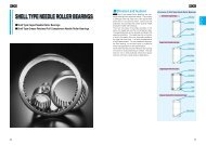
Caged bearing<br />
For heavy loads and relatively high speeds<br />
Full complement bearing<br />
For very heavy loads and low speeds<br />
Sealed bearing<br />
Lubricated for life and protected against<br />
contamination<br />
Availability<br />
The product range is shown in the<br />
product tables starting on page 44.<br />
SKF recommends checking availability<br />
of those <strong>bearings</strong> marked with a triangle.<br />
To do that, contact your local SKF<br />
representative or SKF distributor. The<br />
standard range is being continuously<br />
extended and the intention is to manufacture<br />
all the products shown in the<br />
product tables in a few years time.<br />
Bearing benefits<br />
Already well proven in service, <strong>toroidal</strong><br />
<strong>roller</strong> <strong>bearings</strong> enable all types of<br />
machines and equipment to be<br />
• smaller,<br />
• lighter,<br />
• more cost-effective, and<br />
• more operationally reliable.<br />
Replacing other non-locating <strong>bearings</strong><br />
with an equivalent CARB bearing can,<br />
depending on the application, improve<br />
perform-ance and uptime while decreasing<br />
maintenance. Why not put<br />
CARB <strong>bearings</strong> to the test and reap<br />
the benefits they can provide?<br />
7
1 Product information 2 Recommendations 3 Product data<br />
Self-aligning bearing system Page ............. 12 Page ............. 37<br />
The CARB <strong>toroidal</strong> <strong>roller</strong> bearing<br />
– the cornerstone of the new<br />
self-aligning bearing system<br />
The conventional solution<br />
Until recently a self-aligning bearing<br />
system consisted of two self-aligning<br />
ball <strong>bearings</strong> if there were high speeds<br />
and light loads, or two spherical <strong>roller</strong><br />
<strong>bearings</strong> when there were heavy loads<br />
and moderate speeds. These bearing<br />
systems are simple, have good load<br />
carrying capacity and can compensate<br />
for misalignment resulting from manufacturing<br />
or mounting errors as well as<br />
shaft deflections (➔ fig 1 ). So far, so<br />
good – but what happens if the shaft<br />
were to expand axially?<br />
In a traditional bearing arrangement,<br />
axial expansion of the shaft is accommodated<br />
by the non-locating bearing.<br />
The fits for this bearing are selected so<br />
that one of the bearing rings will be<br />
able to move axially on its seating as<br />
the shaft expands. Generally this<br />
movement is between the outer ring<br />
and the housing seating. This movement<br />
is always accompanied by friction,<br />
which gives rise to induced axial<br />
forces in both the <strong>bearings</strong> (➔ fig 2 ).<br />
In addition, the movement of the loose<br />
bearing on its seating can create damaging<br />
vibrations because the movement<br />
is ”stick-slip” and not smooth (➔fig 3 ).<br />
The loose fit has a negative effect<br />
on the stiffness of the bearing arrangement.<br />
The bearing ring with the loose<br />
fit can also begin to “wander”, which<br />
can wear the seating and lead to fretting<br />
corrosion and possibly “weld”<br />
the ring to its seating (➔ fig 4 ).<br />
The new solution<br />
Today, the CARB <strong>toroidal</strong> <strong>roller</strong> bearing<br />
is available for the non-locating position<br />
in a self-aligning bearing system.<br />
It is no longer necessary to compromise.<br />
8<br />
Conventional<br />
solution<br />
Two spherical <strong>roller</strong><br />
<strong>bearings</strong> (or selfaligning<br />
ball <strong>bearings</strong>)<br />
compensate<br />
easily for angular<br />
misalignment of<br />
the inner ring with<br />
respect to the<br />
outer ring<br />
Axial expansion<br />
of the shaft can<br />
influence the load<br />
distribution in the<br />
<strong>bearings</strong><br />
Load conditions<br />
in a conventional<br />
solution<br />
Changes in axial<br />
force in a non-locating<br />
bearing during<br />
the machine start-up<br />
phase; internal axial<br />
forces of corresponding<br />
magnitude<br />
are produced in the<br />
locating bearing<br />
In a non-locating<br />
bearing which has<br />
been clamped in its<br />
housing bore seating,<br />
heavy axial<br />
forces prevail in the<br />
bearing arrangement<br />
after the startup<br />
phase and dramatically<br />
shorten<br />
bearing service life<br />
F a /F r<br />
0,2<br />
0,1<br />
0<br />
F a /F r<br />
1,5<br />
1<br />
0,5<br />
0<br />
Fig<br />
Fig 2<br />
F r<br />
t<br />
t<br />
Fig<br />
Fig<br />
1<br />
3<br />
4
1 Product information 2 Recommendations 3 Product data<br />
Self-aligning bearing system Page ............. 12 Page ............. 37<br />
1<br />
°C<br />
Fig<br />
Fig<br />
Fig<br />
5<br />
6<br />
7<br />
The new solution<br />
A spherical <strong>roller</strong> bearing<br />
or a self-aligning<br />
ball bearing as the<br />
locating bearing and<br />
a CARB <strong>toroidal</strong> <strong>roller</strong><br />
bearing as the nonlocating<br />
bearing compensate<br />
for angular<br />
misalignment of the<br />
rings resulting from<br />
errors of alignment or<br />
deflection under load<br />
as well as thermal<br />
changes in shaft<br />
length, virtually without<br />
friction<br />
There are no internally<br />
induced axial<br />
forces. The rings<br />
of the non-locating<br />
bearing should be<br />
axially and radially<br />
located<br />
CARB <strong>toroidal</strong> <strong>roller</strong> <strong>bearings</strong> are<br />
able to compensate for misalignment<br />
and accommodate axial displacements<br />
within the bearing (➔ fig 5 ).<br />
This means that both rings of the nonlocating<br />
bearing can be axially located<br />
in the housing and on the shaft (➔ fig<br />
6 ). If it is necessary to secure the<br />
rings so that they cannot “creep”, they<br />
can be mounted with an interference<br />
fit, thus enhancing the radial stiffness<br />
of the bearing arrangement.<br />
This is an optimal solution for applications<br />
with undetermined load direction,<br />
e.g. vibrating applications, because<br />
internal preload and wear to the bearing<br />
seating in the housing are eliminated.<br />
No longer is there a compromise<br />
between a tight fit and axial freedom.<br />
A CARB <strong>toroidal</strong> <strong>roller</strong> bearing is<br />
designed to accommodate axial displacement<br />
without inducing additional<br />
axial internal forces or friction (➔ fig 6 ).<br />
This means that the loads acting on the<br />
bearing are determined exclusively<br />
by external radial and axial forces.<br />
Because of this, a bearing system<br />
incorporating a CARB bearing will<br />
have lower loads and better load distribution<br />
than a conventional bearing<br />
system. This translates into lower operating<br />
temperatures, higher operating<br />
viscosities, extended relubrication<br />
intervals, and a significantly longer<br />
service life for both the <strong>bearings</strong> and<br />
the lubricant (➔ fig 7 ).<br />
With a CARB <strong>toroidal</strong> <strong>roller</strong> bearing<br />
F r<br />
9<br />
Lower operating<br />
temperatures extend<br />
relubrication intervals<br />
and bearing<br />
service life<br />
in the non-locating position, the many<br />
excellent design characteristics and<br />
properties of SKF spherical <strong>roller</strong> <strong>bearings</strong><br />
and self-aligning ball <strong>bearings</strong> can<br />
be fully exploited. This provides new<br />
opportunities to further optimize<br />
machine design.
1 Product information 2 Recommendations 3 Product data<br />
Application areas Page ............. 12 Page ............. 37<br />
Successful in service<br />
Although a recent invention, the CARB<br />
<strong>toroidal</strong> <strong>roller</strong> bearing can be found in<br />
a variety of applications spanning<br />
almost every industry. This bearing<br />
has already proven itself and in many<br />
cases has outperformed expectations<br />
by<br />
• extending service life,<br />
• increasing reliability,<br />
• reducing maintenance, and<br />
• providing more compact designs.<br />
One of the major application areas<br />
for CARB <strong>toroidal</strong> <strong>roller</strong> <strong>bearings</strong> is in<br />
steelmaking and particularly in continuous<br />
casters where the multitude of<br />
guide <strong>roller</strong>s are subjected to the most<br />
difficult operating conditions. Paper<br />
machines are another important application<br />
where shaft deflections and thermal<br />
changes in roll length of up to 10 mm<br />
have to be accommodated.<br />
These are not the only fields where<br />
CARB <strong>toroidal</strong> <strong>roller</strong> <strong>bearings</strong> perform<br />
successfully. They are also in service<br />
in gearboxes, large electric motors,<br />
wind power plants, water turbines, bow<br />
thrusters, crane wheels, separators,<br />
centrifuges, presses, staking machines<br />
for tanneries, rotary cultivators and<br />
mulchers.<br />
Main application areas<br />
• Steelmaking and rolling mills<br />
• Conveyors and <strong>roller</strong> beds<br />
• Paper machines<br />
• Fluid machinery<br />
• Crushers<br />
• Gearboxes of all types<br />
• Textile machines<br />
• Food and beverage<br />
processing machines<br />
• Agricultural machinery<br />
• Vibrating screens<br />
Major demands<br />
• Freedom<br />
• High load carrying capacity<br />
• High operational reliability<br />
• Long service life<br />
• Reduced maintenance<br />
• Low operational costs<br />
• Compact design<br />
• Enhanced performance<br />
• High power density<br />
Solution
1 Product information 2 Recommendations 3 Product data<br />
Application areas Page ............. 12 Page ............. 37<br />
To facilitate the incorporation of<br />
CARB <strong>toroidal</strong> <strong>roller</strong> <strong>bearings</strong> in new<br />
as well as existing machines, please<br />
consult the SKF application engineering<br />
service.
1 Product information 2 Recommendations 3 Product data<br />
Page ............. 3 System life Page ............. 37<br />
Selection of bearing size<br />
To calculate bearing size or the basic<br />
rating life for a <strong>toroidal</strong> <strong>roller</strong> bearing<br />
it is possible to use all the known and<br />
standardized (ISO 281) calculation<br />
methods. However, it is recommended<br />
that the SKF Life Method be applied<br />
so that the enhanced performance of<br />
SKF <strong>bearings</strong> can be fully exploited.<br />
Detailed information can be found in the<br />
SKF General Catalogue in the section<br />
“Selection of bearing size” or in the<br />
“SKF Interactive Engineering Catalogue”<br />
available on CD-ROM or online<br />
at www.skf.com.<br />
For a self-aligning bearing system<br />
that uses an SKF Explorer spherical<br />
<strong>roller</strong> bearing and a CARB bearing,<br />
system life can be calculated using the<br />
SKF rating life equation:<br />
L nm,Sys =<br />
9/8<br />
where<br />
L nm,Sys<br />
L nm,SRB<br />
L nm,CARB =<br />
1<br />
L nm,SRB<br />
9/8<br />
= SKF rating life for the bearing<br />
system (at 100 – n %<br />
reliability), millions of revolutions<br />
= SKF rating life for the locating<br />
spherical <strong>roller</strong> bearing<br />
(at 100 – n % reliability),<br />
millions of revolutions<br />
SKF rating life for the nonlocating<br />
CARB <strong>toroidal</strong><br />
<strong>roller</strong> bearing (at 100 – n %<br />
reliability), millions of revolutions<br />
1<br />
+<br />
1<br />
L nm,CARB<br />
9/8<br />
Longer life or downsizing<br />
When used in a self-aligning bearing<br />
system, the CARB bearing prevents<br />
internally induced axial forces from<br />
occuring. This is in contrast to conventional<br />
self-aligning bearing systems<br />
with two spherical <strong>roller</strong> <strong>bearings</strong> or<br />
self-aligning ball <strong>bearings</strong> where the<br />
induced internal axial forces can be<br />
20 % or more of the radial load acting<br />
on the non-locating bearing. These<br />
additional forces represent a sizeable<br />
proportion of the total load that cannot<br />
be neglected and can result in<br />
• the bearing system not achieving the<br />
requisite life, or<br />
• larger <strong>bearings</strong> being used to compensate<br />
for the additional forces.<br />
Because a CARB <strong>toroidal</strong> <strong>roller</strong> bearing<br />
prevents internally induced axial<br />
forces from occuring, the load conditions<br />
in the bearing arrangement can<br />
be predicted accurately since the<br />
locating bearing is only subjected to its<br />
portion of the external radial and axial<br />
loads, while the non-locating bearing<br />
is only subjected to its portion of the<br />
radial load.<br />
Whether a spherical <strong>roller</strong> bearing<br />
(➔ diagram 1 ) or a self-aligning ball<br />
bearing (➔ diagram 2 ) is used in the<br />
locating position, the new self-aligning<br />
bearing system can substantially<br />
increase the service life of a bearing<br />
arrangement. It is also worth noting<br />
that, even if smaller <strong>bearings</strong> are used,<br />
it is often possible to achieve system<br />
lives that are longer compared to the<br />
traditional systems. This can be<br />
exploited by downsizing adjacent<br />
components and reducing costs.<br />
To take full advantage of the benefits<br />
offered by the new self-aligning<br />
system it is necessary to carefully<br />
select the bearing size – at the nonlocating<br />
as well as the locating side.<br />
For assistance, contact the SKF application<br />
engineering service.<br />
12
1 Product information 2 Recommendations 3 Product data<br />
Page ............. 3 System life Page ............. 37<br />
Compare the life of a conventional selfaligning<br />
bearing system with spherical<br />
<strong>roller</strong> <strong>bearings</strong> with a bearing system<br />
containing a CARB <strong>toroidal</strong> <strong>roller</strong> bearing<br />
and a spherical <strong>roller</strong> bearing<br />
Diagram<br />
1<br />
1<br />
C 3148 23148<br />
2<br />
C 3144 23144<br />
0,5<br />
Relative life of the system<br />
23148 23148<br />
0<br />
0 0,05 0,1 0,15* 0,2 0,25 0,3 0,35 0,4<br />
Coefficient of friction µ<br />
* Typical value for steel on cast iron<br />
Compare the life of a conventional selfaligning<br />
bearing system with self-aligning<br />
ball <strong>bearings</strong> with a bearing system<br />
containing a CARB <strong>toroidal</strong> <strong>roller</strong> bearing<br />
and a self-aligning ball bearing<br />
6<br />
Diagram<br />
2<br />
5<br />
C 2222 2222<br />
4<br />
3<br />
Relative life of the system<br />
2<br />
C 2220 2220<br />
1<br />
2222 2222<br />
0<br />
0 0,05 0,1 0,15* 0,2 0,25 0,3 0,35 0,4<br />
Coefficient of friction µ<br />
* Typical value for steel on cast iron<br />
13
1 Product information 2 Recommendations 3 Product data<br />
Page ............. 3 Radial location Page ............. 37<br />
Design of bearing arrangements<br />
Two <strong>bearings</strong> are generally required to<br />
support, guide and locate a shaft in<br />
the radial and axial directions. To do<br />
this, one bearing is designated the<br />
locating bearing and the other is the<br />
non-locating bearing.<br />
In traditional self-aligning bearing<br />
systems, the locating bearing locates<br />
the shaft axially in its housing while<br />
the non-locating bearing typically<br />
moves in its housing to accommodate<br />
axial expansion of the shaft.<br />
With the new SKF self-aligning<br />
bearing system, a CARB <strong>toroidal</strong> <strong>roller</strong><br />
bearing is used in the non-locating<br />
position and either a spherical <strong>roller</strong><br />
bearing (➔ fig 1 ) or a self-aligning<br />
ball bearing (➔ fig 2 ) is used in the<br />
locating position. Because a CARB<br />
bearing can accommodate axial<br />
expansion internally like a cylindrical<br />
<strong>roller</strong> bearing, it prevents internally<br />
induced axial forces from occuring that<br />
would otherwise that would otherwise<br />
be present if the bearing had to slide<br />
on its seating in the housing. This ability<br />
to accommodate internal axial forces<br />
allows the bearing rings to be axially<br />
located on the shaft and in the housing.<br />
Radial location<br />
To take advantage of the very high load<br />
carrying capacity and full life potential of<br />
a <strong>toroidal</strong> <strong>roller</strong> bearing, the bearing<br />
rings must be fully supported around<br />
their whole circumference and across<br />
the full width of the outer ring.<br />
Selecting the proper fit<br />
To locate a shaft radially, most applications<br />
require an interference fit between<br />
the bearing rings and their seatings.<br />
However, if easy mounting and dismounting<br />
are required, the outer ring<br />
will have a looser fit.<br />
Recommendations for suitable shaft<br />
diameter and housing bore tolerances<br />
for CARB <strong>toroidal</strong> <strong>roller</strong> <strong>bearings</strong> are<br />
given in tables 1 , 2 and 3 . These<br />
recommendations apply to solid steel<br />
shafts and housings made from cast<br />
iron or steel.<br />
Generally, CARB <strong>toroidal</strong> <strong>roller</strong> <strong>bearings</strong><br />
follow the fit recommendations<br />
for spherical <strong>roller</strong> <strong>bearings</strong> on shafts<br />
and in housings. However, a spherical<br />
<strong>roller</strong> bearing on the non-locating side<br />
must be axially free, which requires a<br />
loose housing fit – this is not necessary<br />
for bearing arrangements using a CARB<br />
<strong>toroidal</strong> <strong>roller</strong> bearing. CARB <strong>bearings</strong><br />
(and locating spherical <strong>roller</strong> <strong>bearings</strong>)<br />
can therefore utilise the advantages of<br />
tight outer ring fits if mounting and<br />
dismounting allow this, but for normal,<br />
stationary outer ring load it is not necessary.<br />
For example a K7 fit is applied to<br />
<strong>bearings</strong> in the split housing for a fan<br />
with an unbalanced fan rotor and a P7<br />
fit applied to a non-split housing.<br />
<strong>Bearings</strong> with a tapered bore are<br />
mounted either directly on a tapered<br />
journal or on an adapter or a withdrawal<br />
sleeve on cylindrical shaft seatings.<br />
The fit of the inner ring in these<br />
cases depends on how far the ring is<br />
driven up the tapered seating.<br />
Accuracy of associated components<br />
The accuracy of the cylindrical seatings<br />
on the shaft and in the housing bore<br />
should correspond to that of the bearing.<br />
For CARB <strong>toroidal</strong> <strong>roller</strong> <strong>bearings</strong><br />
the shaft seating should be tolerance<br />
grade 6 and the housing seating grade<br />
7. For an adapter or withdrawal sleeve,<br />
wider diameter tolerances can be<br />
SKF self-aligning bearing system with a spherical <strong>roller</strong><br />
bearing at the locating side and a CARB <strong>toroidal</strong> <strong>roller</strong> bearing<br />
at the non-locating side<br />
SKF self-aligning bearing system with a self-aligning ball<br />
bearing at the locating side and a CARB <strong>toroidal</strong> <strong>roller</strong> bearing<br />
at the non-locating side<br />
Fig 1<br />
Fig 2<br />
14
1 Product information 2 Recommendations 3 Product data<br />
Page ............. 3 Radial location Page ............. 37<br />
adopted for the cylindrical seating on<br />
the shaft, e.g. grade 9 or 10.<br />
The cylindricity as defined in<br />
ISO 1101-1996 for the bearing seating<br />
should be 1 or 2 grades better than<br />
the recommended dimensional tolerance<br />
depending on the requirements.<br />
For example, a shaft seating machined<br />
to tolerance m6 should have a cylindricity<br />
grade 5 or 4.<br />
Conditions Examples Shaft diameter (mm) Tolerance<br />
over incl.<br />
<strong>Bearings</strong> with cylindrical bore<br />
Rotating inner ring load or direction of load indeterminate<br />
Normal and General 40 k5<br />
heavy loads engineering, 40 65 m5<br />
(P > 0,06 C) electric motors, 65 100 m6<br />
pumps, 100 140 n6<br />
gearboxes 140 280 p6<br />
280 500 r6 1)<br />
500 r7 1)<br />
Table<br />
1<br />
2<br />
Very heavy loads and shock loads 50 100 n6 1)<br />
with difficult working conditions 100 140 p6 1)<br />
(P > 0,12 C) 140 r6 1)<br />
<strong>Bearings</strong> with tapered bore on adapter or withdrawal sleeves<br />
Normal loads and/or normal speeds<br />
Heavy loads and/or high speeds<br />
h10/IT7/2<br />
h9/IT5/2<br />
Stationary inner ring load<br />
Easy dismounting unnecessary<br />
h6<br />
Easy dismounting desirable g6 2)<br />
Fits for solid steel<br />
shafts<br />
1)<br />
<strong>Bearings</strong> with radial internal clearance greater than Normal may be necessary<br />
2)<br />
Tolerance f6 can be selected for large <strong>bearings</strong> to provide easy displacement<br />
Table<br />
2<br />
Conditions Examples Tolerance Remarks<br />
Rotating outer ring load<br />
Heavy loads and Crushers, N6 Bearing outside diameter < 160 mm<br />
shock loads vibrating P6 Bearing outside diameter ≥ 160 mm<br />
screens, fans<br />
Stationary outer ring load<br />
Loads of all kinds General H7<br />
engineering<br />
Direction of load indeterminate<br />
Heavy shock loads<br />
M7<br />
Normal and General K7<br />
heavy loads engineering,<br />
(P > 0,06 C) electric motors, H7 Easy mounting of bearing required<br />
pumps<br />
Fits for non-split<br />
cast iron and steel<br />
housings<br />
Table<br />
3<br />
Conditions Examples Tolerance<br />
Stationary outer ring load<br />
Loads of all kinds General H7<br />
engineering<br />
Direction of load indeterminate<br />
Loads of all kinds General J7<br />
engineering,<br />
electric motors,<br />
pumps<br />
Fits for split cast<br />
iron and steel<br />
housings<br />
15
1 Product information 2 Recommendations 3 Product data<br />
Page ............. 3 Axial location Page ............. 37<br />
Axial location<br />
The rings of CARB <strong>toroidal</strong> <strong>roller</strong> <strong>bearings</strong><br />
should be axially located on both<br />
sides on the shaft as well as in the<br />
housing. SKF recommends arranging<br />
the bearing rings so that they abut a<br />
shoulder on the shaft or in the housing.<br />
Inner rings can be locked in position<br />
using<br />
• a shaft (lock) nut (➔ fig 3 ),<br />
• a retaining ring (➔ fig 4 ) or<br />
• an end plate screwed to the shaft<br />
end (➔ fig 5 ).<br />
Abutment and fillet dimensions<br />
The abutment and fillet dimensions,<br />
which include the diameters of shaft<br />
and housing shoulders, spacer sleeves<br />
etc. have been determined so that<br />
adequate abutment surfaces are provided<br />
for the side faces of the bearing<br />
rings without any danger of the rotating<br />
parts being fouled. The recommended<br />
abutment and fillet dimensions for each<br />
individual bearing can be found in the<br />
product tables.<br />
Outer rings are usually secured in<br />
position in the housing by the end<br />
cover (➔ fig 6 ).<br />
Instead of integral shaft and housing<br />
shoulders CARB <strong>toroidal</strong> <strong>roller</strong> <strong>bearings</strong><br />
can be mounted against<br />
• spacer sleeves (➔ fig 7 )or<br />
• retaining rings (➔ fig 8 ).<br />
<strong>Bearings</strong> with a tapered bore that are<br />
mounted<br />
• directly onto a tapered journal are<br />
usually secured to the shaft with a<br />
nut on the threaded section (➔ fig 9 ),<br />
or<br />
• on an adapter sleeve and a stepped<br />
shaft are secured against a spacer<br />
ring (➔ fig 10), or<br />
• on a withdrawal sleeve against<br />
a shaft shoulder are secured by<br />
a shaft nut (➔ fig 11 ) or an end<br />
plate (➔ fig 12).<br />
Inner ring located<br />
axially with a<br />
shaft nut<br />
Fig<br />
3<br />
Inner ring located<br />
axially with a<br />
retaining ring<br />
Fig<br />
4<br />
16
1 Product information 2 Recommendations 3 Product data<br />
Page ............. 3 Axial location Page ............. 37<br />
Fig<br />
5<br />
Inner ring located<br />
axially with an end<br />
plate<br />
Fig<br />
9<br />
Inner ring on a<br />
tapered shaft held<br />
in place by a shaft<br />
nut<br />
2<br />
Fig<br />
6<br />
Outer ring located<br />
axially with an end<br />
cover<br />
Fig<br />
10<br />
Inner ring on an<br />
adapter sleeve<br />
and a stepped<br />
shaft, axially<br />
located against<br />
a spacer ring<br />
Fig<br />
7<br />
Spacer sleeves<br />
used to axially<br />
locate the inner<br />
and outer rings<br />
Fig<br />
11<br />
Inner ring on a withdrawal<br />
sleeve and<br />
a stepped shaft,<br />
axially located by<br />
a shaft nut<br />
Fig<br />
8<br />
Retaining rings<br />
used to axially<br />
locate the bearing<br />
rings<br />
Fig<br />
12<br />
Inner ring on a withdrawal<br />
sleeve and<br />
a stepped shaft,<br />
axially located by<br />
an end plate<br />
17
1 Product information 2 Recommendations 3 Product data<br />
Page ............. 3 Associated components Page ............. 37<br />
Design of adjacent<br />
components<br />
Space on the sides of the bearing<br />
To enable axial displacement of the<br />
shaft relative to the housing, space<br />
must be provided on both sides of<br />
the bearing as indicated in fig 13 .<br />
The actual value for the width of this<br />
space can be estimated based on<br />
It is particularly important when<br />
designing large bearing arrangements<br />
to take steps so that the mounting and<br />
dismounting of the <strong>bearings</strong> are facilitated<br />
or actually made possible.<br />
C a<br />
Fig<br />
13<br />
• the value C a (from the product<br />
tables),<br />
• the axial displacement of the bearing<br />
rings from the central position<br />
expected in operation, and<br />
• the displacement of the rings caused<br />
by misalignment<br />
Free space on<br />
both sides of the<br />
bearing<br />
Fig<br />
14<br />
C areq = C a + 0,5 (s + s mis )<br />
or<br />
C areq = C a + 0,5 (s + k 1 B α)<br />
where<br />
C areq = width of space required on each<br />
side of the bearing, mm<br />
C a = minimum width of space required<br />
on each side of the bearing, mm<br />
(➔ product tables)<br />
s = thermal change in shaft length,<br />
mm<br />
s mis = axial displacement of <strong>roller</strong><br />
complement caused by misalignment,<br />
mm<br />
k 1 = misalignment factor<br />
(➔ product tables)<br />
B = bearing width, mm<br />
(➔ product tables)<br />
α = angular misalignment, degrees<br />
See also under “Axial displacement” on<br />
page 40.<br />
Normally, the bearing rings are<br />
mounted so that they are not displaced<br />
with respect to each other. However,<br />
if considerable thermal changes<br />
in shaft length can be expected, the<br />
inner ring can be mounted offset relative<br />
to the outer ring up to the permissible<br />
axial displacement s 1 or s 2 in the<br />
direction opposite to the expected<br />
thermal elongation (➔ fig 14 ). In this<br />
way, the permissible axial displacement<br />
can be appreciably extended, an<br />
advantage which is made use of in the<br />
bearing arrangement of drying cylinders<br />
in papermaking machines.<br />
By mounting the<br />
outer ring purposely<br />
displaced<br />
with regard to the<br />
inner ring the<br />
permissible axial<br />
displacement can<br />
be extended<br />
CARB <strong>toroidal</strong><br />
<strong>roller</strong> bearing on<br />
a tapered journal<br />
with oil duct and<br />
distributor groove<br />
CARB <strong>toroidal</strong><br />
<strong>roller</strong> bearing<br />
arrangement with<br />
oil ducts and distributor<br />
grooves in<br />
the shaft and<br />
housing<br />
s 1<br />
s 2<br />
Fig<br />
Fig<br />
15<br />
16<br />
18
1 Product information 2 Recommendations 3 Product data<br />
Page ............. 3 Associated components Page ............. 37<br />
Threaded holes for the oil injection<br />
method<br />
If the oil injection method is to be used<br />
• for mounting and dismounting<br />
<strong>bearings</strong> on tapered journals<br />
(➔ fig 15 ) or<br />
• for dismounting <strong>bearings</strong> on or in<br />
cylindrical seatings on the shaft or<br />
in the housing<br />
it is necessary to provide oil ducts and<br />
distributor grooves in the seating on<br />
the shaft or in the housing (➔ fig 16 ).<br />
The distance of the distributor groove<br />
from the side at which the bearing is to<br />
be mounted and/or dismounted should<br />
correspond to approximately a third of<br />
the bearing width. Recommended<br />
dimensions for the distributor grooves,<br />
the oil ducts and the appropriate<br />
threads for the connections are given<br />
in tables 4 and 5 .<br />
2<br />
Recommended dimensions for oil ducts<br />
and distributor grooves<br />
Threaded connection holes<br />
Table<br />
4<br />
Table<br />
5<br />
L<br />
L<br />
3<br />
Gc<br />
G a<br />
N<br />
60°<br />
Gb<br />
c<br />
h a<br />
r a<br />
b a<br />
N a<br />
N a<br />
G a<br />
G Gb<br />
Design A<br />
Design B<br />
Bearing seating Dimensions<br />
diameter b a h a r a N<br />
over incl.<br />
Thread<br />
G a<br />
Design<br />
G b<br />
Dimensions<br />
1)<br />
G c N a<br />
max<br />
mm<br />
mm<br />
– – mm<br />
100 3 0,5 2,5 2,5<br />
100 150 4 0,8 3 3<br />
150 200 4 0,8 3 3<br />
200 250 5 1 4 4<br />
250 300 5 1 4 4<br />
300 400 6 1,25 4,5 5<br />
400 500 7 1,5 5 5<br />
500 650 8 1,5 6 6<br />
650 800 10 2 7 7<br />
M 6 A 10 8 3<br />
G 1/8 A 12 10 3<br />
G 1/4 A 15 12 5<br />
G 3/8 B 15 12 8<br />
G 1/2 B 18 14 8<br />
G 3/4 B 20 16 8<br />
800 1 000 12 2,5 8 8<br />
1) Effective threaded length<br />
19
1 Product information 2 Recommendations 3 Product data<br />
Page ............. 3 Seals Page ............. 37<br />
Sealing the bearing<br />
arrangement<br />
When selecting the most suitable<br />
sealing arrangement for a self-aligning<br />
bearing arrangement it is necessary to<br />
pay particular attention to<br />
• the angular misalignment of the<br />
shaft and<br />
• the magnitude of the axial<br />
displacement.<br />
Otherwise the general selection criteria<br />
presented in the SKF General Catalogue<br />
(and the “SKF Interactive Engineering<br />
Catalogue”) apply and all types<br />
of seals can be used.<br />
Non-contact seals are to be preferred<br />
when the operating conditions<br />
involve<br />
Some seal types are supplied as<br />
standard with SKF bearing housings<br />
and include a double-lip contact seal,<br />
a labyrinth seal as well as a Taconite<br />
seal (➔ fig 21 ). Additional information<br />
can be found in the brochure 4403<br />
“SNL plummer block housings solve<br />
the housing problems”.<br />
Reference<br />
Additional information about radial<br />
shaft seals, V-ring seals or mechanical<br />
seals can be found in the<br />
SKF catalogue 4006 “CR seals” or<br />
in the “SKF Interactive Engineering<br />
Catalogue” on CD-ROM or online<br />
at www.skf.com.<br />
• high speeds,<br />
• large axial displacements,<br />
• high temperatures,<br />
CR seals<br />
and the sealing position is not directly<br />
exposed to contamination. The shaft<br />
should be horizontal.<br />
The simple gap-type seal (➔ fig 17 )<br />
is very suitable for sealing the nonlocating<br />
arrangement of self-aligning<br />
bearing systems. The size of the gap<br />
can be adapted to the misalignment of<br />
the shaft and is not limited in any way.<br />
Single or multi-stage labyrinth seals<br />
are obviously more efficient than the<br />
simple gap-type seal, but are more<br />
expensive. With CARB <strong>toroidal</strong> <strong>roller</strong><br />
<strong>bearings</strong>, the labyrinth passages should<br />
be arranged axially in order to provide<br />
freedom of axial movement for the<br />
shaft in operation. If considerable<br />
misalignment is expected in operation,<br />
the passages should be angled (➔ fig<br />
18 ). When split housings are used,<br />
labyrinth seals with radially arranged<br />
passages can be used, provided axial<br />
movement of the shaft relative to the<br />
housing is not limited (➔ fig 19 ).<br />
Radial shaft seals are contact seals<br />
that are suitable for sealing greased or<br />
oil lubricated CARB <strong>toroidal</strong> <strong>roller</strong> <strong>bearings</strong>,<br />
provided misalignment is slight<br />
and the seal lip counterface is sufficiently<br />
wide (➔ fig 20 ).<br />
20
1 Product information 2 Recommendations 3 Product data<br />
Page ............. 3 Seals Page ............. 37<br />
Labyrinth seal<br />
with radially<br />
arranged<br />
passages<br />
Fig<br />
19<br />
2<br />
Fig<br />
17<br />
Gap-type seal<br />
Radial shaft seal<br />
Fig<br />
20<br />
Fig<br />
18<br />
Labyrinth seal<br />
with angled<br />
passages<br />
Taconite seal<br />
Fig<br />
21<br />
21
1 Product information 2 Recommendations 3 Product data<br />
Page ............. 3 Grease lubrication Page ............. 37<br />
Lubrication<br />
CARB <strong>toroidal</strong> <strong>roller</strong> <strong>bearings</strong> can be<br />
lubricated with grease as well as oil.<br />
There is no strict rule for when grease<br />
or oil should be used.<br />
Grease has the advantage over oil<br />
that it is more easily retained in the<br />
bearing than oil and grease is better if<br />
the shaft is at an angle or arranged<br />
vertically.<br />
On the other hand, oil lubrication<br />
allows higher operating speeds and<br />
temperatures and can contribute to<br />
heat removal from the bearing position,<br />
which is particularly important where<br />
external heating is involved. Very small<br />
quantities of lubricant are required to<br />
lubricate the bearing surfaces.<br />
Since CARB <strong>toroidal</strong> <strong>roller</strong> <strong>bearings</strong><br />
cannot be relubricated via the outer<br />
ring, lubricant has to be supplied from<br />
the side of the bearing. This is best<br />
done via a duct that opens immediately<br />
adjacent to the side face of the bearing<br />
outer ring. To force the lubricant to<br />
pass through the bearing, a drainage<br />
opening should be provided on the<br />
opposite side of the bearing (➔ fig 1 ).<br />
Grease lubrication<br />
For the lubrication of CARB <strong>toroidal</strong><br />
<strong>roller</strong> <strong>bearings</strong> good quality rust<br />
inhibiting greases that are resistant<br />
to ageing and have a consistency of<br />
2 or 3 are suitable. Many factors influence<br />
the choice of grease. To assist in<br />
this process, SKF greases that are<br />
suitable for CARB bearing lubrication<br />
are listed in table 1 .<br />
Lubricant supply to the bearing<br />
Operating conditions<br />
Fig<br />
1<br />
The correct quantity of grease<br />
For the majority of applications the<br />
following guidelines apply:<br />
• Caged CARB <strong>toroidal</strong> <strong>roller</strong> <strong>bearings</strong><br />
should be filled with grease to<br />
approximately 50 %. In <strong>bearings</strong><br />
that are to be greased before<br />
mounting it is recommended just to<br />
fill the space between the inner ring<br />
and the cage (➔ fig 2 ).<br />
• The free space in the bearing housing<br />
should be filled with grease to<br />
between 30 and 50 %.<br />
• Full complement CARB <strong>toroidal</strong><br />
<strong>roller</strong> <strong>bearings</strong> should be completely<br />
filled with grease.<br />
For bearing arrangements that turn<br />
slowly but where good protection<br />
against corrosion is required, all the<br />
free space in the housing can be filled<br />
with grease as there is little risk of the<br />
operating temperature increasing.<br />
SKF grease<br />
Designation Temperature Viscosity at<br />
range<br />
40/100 ˚C<br />
– – ˚C mm 2 /s<br />
Standard bearing LGMT 2 –30/+120 110/11<br />
arrangements<br />
Standard bearing arrange- LGMT 3 –30/+120 125/12<br />
ments but with relatively<br />
high ambient temperatures<br />
Operating temperatures LGHB 2 –20/+150 420/26,5<br />
always over 100 ˚C<br />
High operating temperatures, LGHP 2 –40/+150 96/10,5<br />
smooth operation<br />
Table<br />
1<br />
Shock loads, heavy loads, LGEP 2 –20/+110 200/16<br />
vibration<br />
High demands on LGGB 2 –40/+120 110/13<br />
environmental friendliness<br />
Recommended SKF greases<br />
Full details on the mentioned SKF greases as well as the complete range of SKF greases will be found in<br />
– SKF catalogue MP3000 “SKF Maintenance and Lubrication Products” or online at www.mapro.skf.com<br />
– “SKF Interactive Engineering Catalogue” on CD-ROM or online at www.skf.com<br />
22
1 Product information 2 Recommendations 3 Product data<br />
Page ............. 3 Grease lubrication Page ............. 37<br />
Table<br />
2<br />
Fig<br />
2<br />
Bearing design Bearing Maximum n × d m<br />
factor C/P ≥ 15 C/P ≈ 8 C/P ≈ 4<br />
CARB <strong>bearings</strong> with cage 2 350 000 200 000 100 000<br />
CARB <strong>bearings</strong> – full complement 1) 4 N.A 3) N.A 3) 20 000 2)<br />
1)<br />
The t f value obtained from diagram 1 needs to be divided by a factor 10<br />
2)<br />
For higher speeds oil lubrication is recommended<br />
3)<br />
For these C/P values a caged bearing is recommended instead<br />
2<br />
Bearing factors and recommended maximum speed limits<br />
Relubrication<br />
CARB <strong>toroidal</strong> <strong>roller</strong> <strong>bearings</strong> have to<br />
be relubricated if the service life of the<br />
grease is shorter than the expected service<br />
life of the bearing. Relubrication<br />
should always be undertaken at a time<br />
when the existing lubricant is still satisfactory.<br />
The time at which relubrication should<br />
be undertaken depends on many related<br />
factors. These include bearing type and<br />
size, speed, operating temperature,<br />
grease type, space around the bearing<br />
and the bearing environment.<br />
It is only possible to base recommendations<br />
on statistical rules; the SKF<br />
relubrication intervals are defined as the<br />
time period, at the end of which 99 % of<br />
the <strong>bearings</strong> are still reliably lubricated.<br />
This represents L 1 for grease life.<br />
SKF recommends using experience<br />
data from running applications and<br />
tests, together with the estimated relubrication<br />
intervals provided in the next<br />
section.<br />
Relubrication intervals (t f )<br />
The relubrication intervals t f for normal<br />
operating conditions are provided in<br />
diagram 1 . The diagram is valid for<br />
<strong>bearings</strong> on horizontal shafts under<br />
clean conditions.<br />
The value on the horizontal axis is<br />
obtained from “n × d m ” (rotational<br />
speed × bearing mean diameter)<br />
(unit: mm/min) multiplied by the relevant<br />
CARB <strong>toroidal</strong> <strong>roller</strong> bearing factor,<br />
which depends on the applied CARB<br />
<strong>toroidal</strong> <strong>roller</strong> bearing execution and<br />
loading situation. The bearing factor<br />
and recommended maximum “n × d m ”<br />
values for CARB <strong>toroidal</strong> <strong>roller</strong> <strong>bearings</strong><br />
are given in table 2 .<br />
The t f value is then derived considering<br />
the load magnitude, given by the<br />
value of C/P. The relubrication interval<br />
(t f ) is an estimated value, valid for an<br />
operating temperature of 70 °C, using<br />
good quality lithium base greases.<br />
Different conditions are covered in<br />
detail in “Deviating conditions”.<br />
If the value of “n × d m ” approaches<br />
the limit value (> 70 %) or if ambient<br />
temperatures are high, then the use of<br />
Relubrication intervals for CARB <strong>toroidal</strong> <strong>roller</strong> <strong>bearings</strong> at 70 °C<br />
tf, operating hours<br />
100 000<br />
50 000<br />
10 000<br />
5 000<br />
1 000<br />
500<br />
100<br />
0<br />
Bearing grease fill<br />
Caged CARB <strong>toroidal</strong> <strong>roller</strong> <strong>bearings</strong> should<br />
not be completely filled with grease; for<br />
high speed operation fill only the space<br />
between the inner ring and the cage<br />
the calculations presented in the SKF<br />
General Catalogue, section “Speeds<br />
and vibration”, is recommended to<br />
check the operating temperature and<br />
the proper lubrication method.<br />
Diagram<br />
100 000 200 000 300 000 400 000 500 000 600 000 700 000 800 000<br />
Bearing factor n × d m<br />
C/P ≥ 15<br />
C/P ≈ 8<br />
C/P ≈ 4<br />
Example: CARB <strong>toroidal</strong> <strong>roller</strong> bearing C 2220 K<br />
The bearing has a bore diameter d = 100 mm, an outside diameter D = 180 mm and rotates at a speed<br />
n = 1 000 r/min. The load ratio C/P is 4 and the operating temperature lies between 60 and 70 °C. What is the<br />
relubrication interval?<br />
The bearing factor n × d m is obtained as follows: n × d m = 1 000 × 0,5 (d + D) = 1 000 × 0,5 (100 + 180) =<br />
140 000. Follow a vertical line from the x-axis from the point n × d m = 140 000 until it intersects the line<br />
of the load ratio C/P = 4. The relubrication interval can then be read off on the y-axis by drawing a horizontal<br />
line from the point of intersection with 3 000 operating hours.<br />
1<br />
23
1 Product information 2 Recommendations 3 Product data<br />
Page ............. 3 Grease lubrication Page ............. 37<br />
Deviating conditions<br />
Operating temperature<br />
To account for the accelerated ageing<br />
of grease in hot running applications,<br />
SKF recommends halving the intervals<br />
obtained from the diagram for every<br />
15 °C increase in bearing temperature<br />
above 70 °C.<br />
The relubrication interval t f may be<br />
extended at temperatures below 70 °C.<br />
In many cases the interval may also be<br />
prolonged if the load is low (C/P = 30 to<br />
50). Extending the relubrication interval<br />
t f by more than a factor of two is not<br />
recommended.<br />
For full complement <strong>bearings</strong>, t f<br />
values obtained from the diagram<br />
should not be prolonged.<br />
Moreover, it is not advisable to use<br />
relubrication intervals in excess of<br />
30 000 hours.<br />
For many applications, there are<br />
practical grease lubrication limits,<br />
when the bearing ring with the highest<br />
temperature reaches an operating temperature<br />
of 100 °C. Above this temperature<br />
special greases should be used.<br />
In addition,temperature stability of the<br />
bearing and premature seal failure<br />
should be taken into consideration.<br />
For high temperature applications,<br />
contact the SKF application engineering<br />
service.<br />
Vertical shafts<br />
For <strong>bearings</strong> on vertical shafts, the<br />
intervals obtained from the diagram<br />
should be halved.<br />
The use of a good seal or retaining<br />
shield is a prerequisite or grease will<br />
leak from the bearing arrangement.<br />
Vibrations<br />
Mild vibrations will not have a negative<br />
effect on grease life, but high vibration<br />
and shock levels, such as those in<br />
vibrating screen applications, will cause<br />
the grease to churn. In these cases the<br />
relubrication interval should be reduced.<br />
If the grease becomes too soft, a<br />
grease with a better mechanical stability<br />
(e.g. LGHB 2) and/or a stiffer grease<br />
(NLGI 3) should be used.<br />
Outer ring rotation<br />
In applications where there is outer ring<br />
rotation, the value of the bearing factor<br />
n × d m is calculated by applying the<br />
value of the bearing outside diameter D<br />
instead of d m . The use of a good sealing<br />
mechanism is a prerequisite in order<br />
to avoid grease loss.<br />
Under conditions of high outer ring<br />
speeds (i.e. > 50 % of the speed rating<br />
in the bearing tables), greases with<br />
a reduced bleeding tendency should<br />
be selected (e.g. lithium complex and<br />
polyurea).<br />
Contamination<br />
In case of ingress of contamination, a<br />
more frequent relubrication interval will<br />
reduce the negative effects of foreign<br />
particles on the bleeding characteristics<br />
of grease while reducing the damaging<br />
effects caused by overrolling of particles.<br />
Fluid contaminants (water, process<br />
fluids) also call for a reduced interval.<br />
In case of severe contamination,<br />
continuous relubrication should be<br />
considered.<br />
Requisite grease quantities<br />
for relubrication<br />
The used grease in a CARB <strong>toroidal</strong><br />
<strong>roller</strong> bearing should be replaced by<br />
fresh grease. The quantity of grease<br />
required for this depends on the bearing<br />
size; this can be determined using<br />
G p = 0,005 D B<br />
where<br />
G p = grease quantity required for<br />
periodic lubrication, g<br />
D = bearing outside diameter, mm<br />
B = bearing width, mm<br />
Grease valve<br />
Excess grease is caused to enter<br />
a circular channel in the housing cover<br />
Supplying grease to a CARB bearing<br />
When using a hand-operated grease gun, excess pressure should<br />
be avoided or the seals may be damaged<br />
Fig 3<br />
Fig 4<br />
24
1 Product information 2 Recommendations 3 Product data<br />
Page ............. 3 Oil lubrication Page ............. 37<br />
Grease valve<br />
If CARB <strong>toroidal</strong> <strong>roller</strong> <strong>bearings</strong> are to<br />
be relubricated frequently, there is a<br />
risk that too much grease will collect in<br />
the housing. This risk can be avoided<br />
by using a grease valve that allows<br />
excess grease to leave the housing<br />
(➔ fig 3 ).<br />
The so-called grease valve consists<br />
of a washer that rotates with the shaft<br />
and forms a narrow gap to the housing<br />
cover. Excess grease is carried by the<br />
washer into this gap and leaves the<br />
housing by a grease escape hole in<br />
the base.<br />
The grease should always be<br />
supplied from the side of the bearing<br />
opposite to the grease valve so that it<br />
is forced to pass through the bearing.<br />
When the bearing is mounted on an<br />
adapter sleeve, the lock nut with locking<br />
washer acts as a grease valve,<br />
so that grease should be supplied at<br />
the side opposite to the lock nut<br />
(➔ fig 4 ).<br />
Oil lubrication<br />
Oil lubrication is recommended or<br />
must be used if<br />
• the relubrication intervals for grease<br />
are too short,<br />
• speeds and/or operating temperatures<br />
are too high for grease,<br />
• heat must be removed from the<br />
bearing position, or<br />
• adjacent components are lubricated<br />
with oil.<br />
For CARB <strong>toroidal</strong> <strong>roller</strong> <strong>bearings</strong><br />
the following methods are normally<br />
employed:<br />
• Oil bath lubrication where the oil is<br />
distributed by rotating machine<br />
components to the bearing arrangement<br />
and runs back to the sump.<br />
• Circulating oil lubrication where the<br />
circulation is achieved by a pump<br />
and where the oil is filtered and<br />
cooled before being returned to<br />
the sump. The use of this method<br />
requires efficient sealing to prevent<br />
oil leakage.<br />
The oil level should be checked regularly.<br />
The appropriate level should not<br />
be higher than the middle of the lowest<br />
<strong>roller</strong> when the bearing is stationary.<br />
The lower limit should be 2 to 3 mm<br />
above the lowest point of the outer<br />
ring smallest diameter, D 1 in the product<br />
tables (➔ fig 5 ).<br />
The same oils can be used for CARB<br />
<strong>toroidal</strong> <strong>roller</strong> <strong>bearings</strong> as for spherical<br />
and cylindrical <strong>roller</strong> <strong>bearings</strong>. They<br />
should<br />
• have good thermal and chemical<br />
stability,<br />
• contain anti-wear additives and<br />
• provide good protection against<br />
corrosion.<br />
Oils of viscosity class<br />
• ISO VG 150 and ISO VG 220 can be<br />
used under normal conditions and<br />
• ISO VG 320 and VG 460 may be<br />
more appropriate at high temperatures,<br />
under heavy loads and slow<br />
speeds.<br />
2<br />
Fig<br />
5<br />
Oil level in CARB<br />
<strong>toroidal</strong> <strong>roller</strong><br />
bearing arrangements<br />
Max.: middle of the<br />
lowest <strong>roller</strong><br />
Min.: 2 to 3 mm<br />
above the lowest<br />
point of the outer<br />
ring smallest diameter,<br />
D 1 in the<br />
product tables<br />
25
1 Product information 2 Recommendations 3 Product data<br />
Page ............. 3 Cylindrical seating Page ............. 37<br />
Mounting<br />
A variety of mechanical and hydraulic<br />
tools and heaters can be used to mount<br />
a CARB bearing. The procedures you<br />
choose will depend on the size of the<br />
bearing and the application. The one<br />
basic rule in any installation procedure<br />
is to avoid hitting the bearing rings,<br />
the <strong>roller</strong>s or cage.<br />
Detailed information on mounting<br />
rolling <strong>bearings</strong> will be found in the<br />
publication 4100 “SKF Bearing<br />
Maintenance Handbook”, as well as<br />
online at www.skf.com/mount.<br />
Mounting on cylindrical<br />
seatings<br />
With CARB <strong>bearings</strong>, the ring that is to<br />
have the tighter fit should be mounted<br />
first. If the bearing is to be cold mounted<br />
on the shaft and in the housing at<br />
the same time a tool of the type shown<br />
in fig 1 should be used. This tool<br />
abuts both bearing rings to apply even<br />
pressure without damaging the rolling<br />
elements.<br />
As a rule, larger <strong>bearings</strong> cannot be<br />
cold mounted, as the force required to<br />
press a bearing into position increases<br />
considerably with size. Therefore it is<br />
recommended<br />
• to heat the bearing before it is<br />
mounted on the shaft, and<br />
• to heat non-split housings before<br />
inserting the bearing.<br />
To mount a bearing on the shaft,<br />
a temperature differential of 80 °C (between<br />
ambient temperature and heated<br />
inner ring) is usually sufficient. For<br />
housings, the appropriate differential<br />
depends on the degree of interference<br />
and the seating diameter. However,<br />
a moderate increase in temperature will<br />
usually suffice. An even and risk-free<br />
heating of CARB <strong>bearings</strong> can be<br />
achieved using an induction heater<br />
(➔ fig 2 ).<br />
Mounting dolly with abutment faces<br />
for both bearing rings in the same plane<br />
A CARB <strong>toroidal</strong> <strong>roller</strong> bearing<br />
on an induction heater<br />
Fig 1<br />
Fig 2<br />
26
1 Product information 2 Recommendations 3 Product data<br />
Page ............. 3 Tapered seating Page ............. 37<br />
Mounting on tapered<br />
seatings<br />
A CARB <strong>toroidal</strong> <strong>roller</strong> bearing with<br />
a tapered bore is always mounted on<br />
the shaft with an interference fit. To<br />
determine the degree of interference<br />
either the reduction in radial internal<br />
clearance or the amount by which the<br />
inner ring is driven up on its seating<br />
can be used.<br />
Suitable methods for mounting a<br />
CARB bearing with a tapered bore are:<br />
• measuring the clearance reduction,<br />
• measuring the lock nut tightening<br />
angle,<br />
• measuring the axial drive-up and<br />
• measuring the inner ring expansion.<br />
For CARB <strong>toroidal</strong> <strong>roller</strong> <strong>bearings</strong> with<br />
bore diameters greater than or equal<br />
to 50 mm, SKF recommends the SKF<br />
Drive-up method. This method is more<br />
accurate and takes less time than the<br />
procedure based on clearance reduction.<br />
Measuring clearance reduction<br />
Prior to mounting, the internal radial<br />
clearance must be measured with a<br />
feeler gauge between the outer ring<br />
and an unloaded <strong>roller</strong>. Before measuring,<br />
the bearing should be rotated a<br />
few times to make sure that the <strong>roller</strong>s<br />
have assumed their correct position.<br />
For the first measurement a blade<br />
should be selected that is slightly thinner<br />
than the minimum value for the<br />
clearance. During the measurement,<br />
the blade should be pushed backwards<br />
and forwards (➔ fig 3 ) until it<br />
can be inserted to the middle of the<br />
<strong>roller</strong>. The procedure should be repeated<br />
using slightly thicker blades each<br />
time until a certain resistance is felt.<br />
During mounting, the reduction in<br />
clearance should be measured between<br />
the outer ring raceway and<br />
the lowest <strong>roller</strong> (➔ fig 4 ). Again the<br />
bearing should be rotated a few times<br />
between each measurement.<br />
Guideline values for the clearance<br />
reduction and axial drive-up are given in<br />
table 2 on page 28. They are valid for<br />
solid steel shafts and normal operating<br />
conditions (C/P > 10). Where loads are<br />
heavy (C/P < 5), speeds high or there is<br />
a considerable temperature gradient<br />
across the bearing, greater clearance<br />
reductions or axial drive-up are required<br />
and thus <strong>bearings</strong> with greater initial<br />
radial internal clearance might be<br />
needed.<br />
The minimum values given in table<br />
2 on page 28 for the clearance reduction<br />
apply mainly to <strong>bearings</strong> having<br />
initial clearances close to the lower<br />
limits for clearance given in table 2<br />
on page 39. This will provide that the<br />
final clearance will not be less than the<br />
permissible minimum. For <strong>bearings</strong> with<br />
C3 or C4 clearance to have a sufficient<br />
degree of interference on their seating,<br />
it is recommended that the maximum<br />
clearance reductions be applied.<br />
Measuring the lock nut tightening<br />
angle<br />
Smaller <strong>bearings</strong> can easily be mounted<br />
using the tightening angle α through<br />
which the nut has to be turned to drive<br />
up the bearing properly on to its tapered<br />
seating. Where applicable, the tightening<br />
angle α is listed in table 1 . Before<br />
mounting, the thread and side face of<br />
the nut should be coated with a molybdenum<br />
disulphide paste or similar<br />
lubricant and the seating should be<br />
lightly oiled with thin oil. The bearing is<br />
then pushed on to the tapered seating<br />
Angular drive-up for CARB <strong>bearings</strong><br />
180°<br />
Table<br />
Bearing Clear- Axial Turning<br />
desig- ance drive-up angle<br />
nation reduc- α<br />
tion<br />
– mm mm degrees<br />
C 2205 0,011 0,42 100<br />
C 2206 0,013 0,45 105<br />
C 2207 0,016 0,48 115<br />
C 2208 0,018 0,52 125<br />
C 2209 0,020 0,54 130<br />
α<br />
1<br />
2<br />
Move the blade backwards and forwards<br />
between <strong>roller</strong> and outer ring<br />
Fig<br />
3<br />
Measuring clearance reduction<br />
Fig<br />
4<br />
C 2210 0,023 0,58 140<br />
C 2211 0,025 0,60 110<br />
C 2212 0,027 0,65 115<br />
C 2213 0,029 0,67 120<br />
C 2214 0,032 0,69 125<br />
C 2215 0,034 0,72 130<br />
C 2216 0,036 0,77 140<br />
C 2217 0,038 0,80 145<br />
C 2218 0,041 0,84 150<br />
C 2219 0,043 0,84 150<br />
C 2220 0,045 0,87 155<br />
C 2222 0,050 0,95 170<br />
C 2314 0,032 0,72 130<br />
C 2315 0,034 0,75 135<br />
C 2316 0,036 0,78 140<br />
C 2317 0,038 0,81 145<br />
C 2318 0,041 0,86 155<br />
C 2319 0,043 0,87 155<br />
C 2320 0,045 0,90 160<br />
27
1 Product information 2 Recommendations 3 Product data<br />
Page ............. 3 Tapered seating Page ............. 37<br />
and the nut screwed on. By turning the<br />
nut through the recommended angle α<br />
the bearing will be pressed up on the<br />
tapered seating. As the bearing has a<br />
tendency to skew when being pressed<br />
into place it is advisable to reposition<br />
the hook spanner in a slot at 180° to<br />
that used for tightening and then applying<br />
a light hammer blow to the hook<br />
spanner. The bearing will straighten<br />
up on its seating. Finally the residual<br />
clearance of the bearing should be<br />
checked.<br />
In all cases, before mounting, the<br />
rust inhibiting oil should be wiped from<br />
the bore and outside diameter of new<br />
<strong>bearings</strong> and sleeves. The shaft seating<br />
and outside diameter of the sleeve<br />
should then be lightly oiled with thin oil.<br />
The SKF Drive-up Method<br />
The SKF Drive-up Method is based on<br />
measuring axial displacement of the<br />
bearing inner ring on its tapered seating<br />
from a reliably determined starting<br />
position.<br />
The SKF Drive-up Method (➔ fig 5 )<br />
requires the use of an HMV .. E hydraulic<br />
nut, that can accommodate a dial gauge.<br />
A pressure gauge, appropriate to the<br />
mounting conditions, mounted on a<br />
suitably sized hand pump, allows<br />
accurate pressure measurement to<br />
determine the starting position. The<br />
tools required are shown in fig 6 .<br />
Guideline values for<br />
• the requisite oil pressure and<br />
• the axial displacement<br />
for the individual <strong>bearings</strong> are provided<br />
in table 3 on page 30.<br />
Bearing bore Reduction of Axial drive-up s 1) Permissible residual<br />
diameter radial internal Taper Taper radial clearance 2)<br />
d clearance 1:12 1:30 after mounting<br />
<strong>bearings</strong> with initial<br />
clearance<br />
over incl. min max min max min max Normal C3 C4<br />
mm mm mm mm<br />
Table<br />
24 30 0,012 0,018 0,25 0,34 0,64 0,85 0,025 0,033 0,047<br />
30 40 0,015 0,024 0,30 0,42 0,74 1,06 0,031 0,038 0,056<br />
40 50 0,020 0,030 0,37 0,51 0,92 1,27 0,033 0,043 0,063<br />
50 65 0,025 0,039 0,44 0,64 1,09 1,59 0,038 0,049 0,074<br />
65 80 0,033 0,048 0,54 0,76 1,36 1,91 0,041 0,055 0,088<br />
80 100 0,040 0,060 0,65 0,93 1,62 2,33 0,056 0,072 0,112<br />
100 120 0,050 0,072 0,79 1,10 1,98 2,75 0,065 0,083 0,129<br />
120 140 0,060 0,084 0,93 1,27 2,33 3,18 0,075 0,106 0,147<br />
140 160 0,070 0,096 1,07 1,44 2,68 3,60 0,085 0,126 0,173<br />
160 180 0,080 0,108 1,21 1,61 3,04 4,02 0,093 0,140 0,193<br />
180 200 0,090 0,120 1,36 1,78 3,39 4,45 0,103 0,150 0,209<br />
200 225 0,100 0,135 1,50 1,99 3,74 4,98 0,113 0,163 0,228<br />
225 250 0,113 0,150 1,67 2,20 4,18 5,51 0,123 0,175 0,251<br />
250 280 0,125 0,168 1,85 2,46 4,62 6,14 0,133 0,186 0,276<br />
280 315 0,140 0,189 2,06 2,75 5,15 6,88 0,143 0,198 0,292<br />
315 355 0,158 0,213 2,31 3,09 5,77 7,73 0,161 0,226 0,329<br />
355 400 0,178 0,240 2,59 3,47 6,48 8,68 0,173 0,251 0,358<br />
400 450 0,200 0,270 2,91 3,90 7,27 9,74 0,183 0,275 0,383<br />
450 500 0,225 0,300 3,26 4,32 8,15 10,80 0,210 0,295 0,433<br />
500 560 0,250 0,336 3,61 4,83 9,04 12,07 0,225 0,327 0,467<br />
560 630 0,280 0,378 4,04 5,42 10,09 13,55 0,250 0,364 0,508<br />
s<br />
2<br />
630 710 0,315 0,426 4,53 6,10 11,33 15,25 0,275 0,386 0,560<br />
710 800 0,355 0,480 5,10 6,86 12,74 17,15 0,319 0,430 0,620<br />
800 900 0,400 0,540 5,73 7,71 14,33 19,27 0,335 0,465 0,675<br />
900 1 000 0,450 0,600 6,44 8,56 16,09 21,39 0,364 0,490 0,740<br />
1 000 1 120 0,500 0,672 7,14 9,57 17,86 23,93 0,395 0,543 0,823<br />
1 120 1 250 0,560 0,750 7,99 10,67 19,98 26,68 0,414 0,595 0,885<br />
Guideline values for clearance reduction<br />
and axial drive-up<br />
1)<br />
Only valid for solid steel shafts<br />
2)<br />
The residual clearance must be measured when the initial radial internal clearance (before mounting) lies in the lower<br />
half of the clearance range and if large temperature differences between inner and outer rings are to be expected in<br />
operation; the residual clearance should not be less than the minimum values quoted here. When measuring clearance<br />
care must be taken to see that both bearing rings and the <strong>roller</strong> complement are centrically arranged with respect to<br />
each other<br />
28
1 Product information 2 Recommendations 3 Product data<br />
Page ............. 3 Tapered seating Page ............. 37<br />
Fig<br />
5<br />
Zero<br />
position<br />
Starting<br />
position<br />
Final<br />
position<br />
s<br />
ss<br />
One sliding interface<br />
Case 1<br />
One sliding interface<br />
Case 2<br />
2<br />
Two sliding interfaces<br />
Case 3<br />
Two sliding interfaces<br />
Case 4<br />
1. Check whether the bearing size and the HMV .. E hydraulic nut coincide. Otherwise<br />
the values for the pressure given in table 2 must be adjusted (➔ note on page 32).<br />
2. Check the number of sliding interfaces (➔ above).<br />
3. Lightly coat the sliding surfaces with a thin oil, e.g. SKF LHMF 300, and place the<br />
bearing on the tapered journal or sleeve. Screw the hydraulic nut on to the thread of<br />
the journal or sleeve so that it abuts the bearing and connect the appropriate oil<br />
pump (➔ fig 6 ).<br />
4. Bring the bearing to its starting position. Pump oil into the hydraulic nut until the<br />
pressure quoted in table 3 on page 30 is reached.<br />
5. Set the dial gauge to “zero” (➔ fig 6 ) and pump more oil into the hydraulic nut until<br />
the bearing has been driven up the distance prescribed in table 3 on page 30 and is<br />
in its final position.<br />
6. After mounting has been completed, release the return valve of the oil pump,<br />
so that oil under high pressure in the nut can flow back out of the nut.<br />
7. To completely empty the oil, bring the piston of the hydraulic nut to its original<br />
position. This is most simply done by screwing the nut further up the threaded<br />
portion of the journal or sleeve.<br />
8. Remove the nut from the shaft by unscrewing and replace with a lock nut and<br />
a locking device.<br />
The SKF<br />
Drive-up Method<br />
Fig<br />
6<br />
Dial gauge<br />
SKF hydraulic<br />
nut HMV .. E<br />
Suitable<br />
tools for the SKF<br />
Drive-up Method<br />
SKF pump 729124 SRB (for nuts up to and including HMV 54 E)<br />
SKF pump TML 50 SRB (for nuts up to and including HMV 170 E)<br />
29
1 Product information 2 Recommendations 3 Product data<br />
Page ............. 3 Tapered seating Page ............. 37<br />
Table<br />
3<br />
Basic bearing Starting position Final position Hydraulic nut<br />
designation Requisite oil pressure for Axial displacement from Radial clearance Desig- Piston<br />
one sliding two sliding starting position reduction from nation area<br />
interface* interfaces* one sliding two sliding zero position<br />
interface* interfaces<br />
s s s s ∆ r<br />
– MPa mm mm – mm 2<br />
Series C 22<br />
C 2210 K 0,67 1,15 0,34 0,41 0,023 HMV 10 E 2 900<br />
C 2211 K 0,57 0,98 0,35 0,42 0,025 HMV 11 E 3 150<br />
C 2212 K 1,09 1,86 0,39 0,47 0,027 HMV 12 E 3 300<br />
C 2213 K 0,82 1,40 0,40 0,47 0,029 HMV 13 E 3 600<br />
C 2214 K 0,76 1,29 0,43 0,50 0,032 HMV 14 E 3 800<br />
C 2215 K 0,70 1,20 0,45 0,52 0,034 HMV 15 E 4 000<br />
C 2216 K 1,03 1,76 0,48 0,55 0,036 HMV 16 E 4 200<br />
C 2217 K 1,12 1,91 0,50 0,57 0,038 HMV 17 E 4 400<br />
C 2218 K 1,36 2,32 0,55 0,62 0,041 HMV 18 E 4 700<br />
C 2219 K 1,02 1,74 0,54 0,62 0,043 HMV 19 E 4 900<br />
C 2220 K 1,12 1,90 0,57 0,64 0,045 HMV 20 E 5 100<br />
C 2222 K 1,49 2,54 0,63 0,71 0,050 HMV 22 E 5 600<br />
C 2224 K 1,58 2,69 0,67 0,74 0,054 HMV 24 E 6 000<br />
C 2226 K 1,44 2,46 0,71 0,79 0,059 HMV 26 E 6 400<br />
C 2228 K 2,36 4,03 0,79 0,86 0,063 HMV 28 E 6 800<br />
C 2230 K 1,79 3,05 0,82 0,89 0,068 HMV 30 E 7 500<br />
C 2234 K 2,58 4,40 0,94 1,01 0,076 HMV 34 E 9 400<br />
C 2238 K 1,77 3,01 1,01 1,08 0,086 HMV 38 E 11 500<br />
C 2244 K 1,95 3,34 1,15 1,22 0,100 HMV 44 E 14 400<br />
Series C 23<br />
C 2314 K 2,01 3,43 0,46 0,53 0,032 HMV 14 E 3 800<br />
C 2315 K 2,25 3,84 0,48 0,55 0,034 HMV 15 E 4 000<br />
C 2316 K 2,11 3,61 0,49 0,56 0,036 HMV 16 E 4 200<br />
C 2317 K 2,40 4,10 0,52 0,59 0,038 HMV 17 E 4 400<br />
C 2318 K 2,88 4,91 0,57 0,64 0,041 HMV 18 E 4 700<br />
C 2319 K 2,22 3,79 0,57 0,64 0,043 HMV 19 E 4 900<br />
C 2320 K 2,56 4,36 0,59 0,66 0,045 HMV 20 E 5 100<br />
C 2326 K 2,71 4,62 0,73 0,81 0,059 HMV 26 E 6 400<br />
Series C 30<br />
C 3022 K 0,97 1,66 0,62 0,69 0,050 HMV 22 E 5 600<br />
C 3024 K 0,92 1,58 0,65 0,72 0,054 HMV 24 E 6 000<br />
C 3026 K 1,23 2,10 0,72 0,79 0,056 HMV 26 E 6 400<br />
C 3028 K 1,25 2,13 0,76 0,83 0,063 HMV 28 E 6 800<br />
C 3030 K 1,02 1,73 0,80 0,87 0,068 HMV 30 E 7 500<br />
C 3032 K 1,33 2,26 0,86 0,93 0,072 HMV 32 E 8 600<br />
C 3034 K 1,52 2,60 0,90 0,98 0,076 HMV 34 E 9 400<br />
C 3036 K 1,43 2,44 0,95 1,02 0,081 HMV 36 E 10 300<br />
C 3038 K 1,60 2,73 1,02 1,09 0,086 HMV 38 E 11 500<br />
C 3040 K 1,62 2,76 1,06 1,13 0,090 HMV 40 E 12 500<br />
C 3044 K 1,58 2,69 1,15 1,22 0,099 HMV 44 E 14 400<br />
C 3048 K 1,34 2,29 1,23 1,30 0,108 HMV 48 E 16 500<br />
C 3052 K 1,77 3,02 1,35 1,43 0,117 HMV 52 E 18 800<br />
C 3056 K 1,69 2,89 1,52 1,45 0,126 HMV 56 E 21 100<br />
C 3060 K 1,85 3,16 1,55 1,62 0,135 HMV 60 E 23 600<br />
C 3064 K 1,80 3,08 1,65 1,72 0,144 HMV 64 E 26 300<br />
C 3068 K 2,04 3,48 1,76 1,83 0,153 HMV 68 E 28 400<br />
C 3072 K 1,65 2,82 1,82 1,89 0,162 HMV 72 E 31 300<br />
* The quoted values are for hydraulic nuts, the thread diameter of which corresponds to the bore diameter of the bearing to be mounted and for applications with lightly oiled sliding<br />
surfaces<br />
30
1 Product information 2 Recommendations 3 Product data<br />
Page ............. 3 Tapered seating Page ............. 37<br />
Continuation table<br />
3<br />
Basic bearing Starting position Final position Hydraulic nut<br />
designation Requisite oil pressure for Axial displacement from Radial clearance Desig- Piston<br />
one sliding two sliding starting position reduction from nation area<br />
interface* interfaces* one sliding two sliding zero position<br />
interface* interfaces<br />
s s s s ∆ r<br />
– MPa mm mm – mm 2<br />
2<br />
Series C 30<br />
C 3076 K 1,36 2,32 1,88 1,95 0,171 HMV 76 E 33 500<br />
C 3080 K 1,54 2,63 1,99 2,06 0,180 HMV 80 E 36 700<br />
C 3084 K 1,34 2,29 2,07 2,14 0,189 HMV 84 E 40 000<br />
C 3088 K 1,22 2,08 2,14 2,21 0,198 HMV 88 E 42 500<br />
C 3092 K 2,00 3,42 2,33 2,41 0,207 HMV 92 E 45 100<br />
C 3096 K 1,75 2,99 2,40 2,47 0,216 HMV 96 E 48 600<br />
C 30/500 K 1,56 2,66 2,47 2,54 0,225 HMV 100 E 51 500<br />
C 30/530 K 1,54 2,63 2,60 2,68 0,239 HMV 106 E 56 200<br />
C 30/560 K 2,26 3,85 2,84 2,91 0,252 HMV 112 E 61 200<br />
C 30/600 K 1,92 3,28 2,98 3,06 0,270 HMV 120 E 67 300<br />
C 30/630 K 1,68 2,87 3,09 3,16 0,284 HMV 126 E 72 900<br />
C 30/670 K 2,12 3,61 3,34 3,41 0,302 HMV 134 E 79 500<br />
C 30/710 K 1,73 2,96 3,47 3,54 0,320 HMV 142 E 87 700<br />
C 30/750 K 1,89 3,22 3,68 3,75 0,338 HMV 150 E 95 200<br />
C 30/800 K 1,88 3,22 3,91 3,98 0,360 HMV 160 E 103 900<br />
C 30/850 K 1,90 3,24 4,15 4,22 0,383 HMV 170 E 114 600<br />
C 30/900 K 1,60 2,73 4,32 4,39 0,405 HMV 180 E 124 100<br />
C 30/950 K 1,94 3,30 4,62 4,69 0,428 HMV 190 E 135 700<br />
C 30/1000 K 1,93 3,30 4,85 4,92 0,450 HMV 200 E 145 800<br />
Series C 31<br />
C 3120 K 1,27 2,16 0,57 0,64 0,045 HMV 20 E 5 100<br />
C 3130 K 2,41 4,12 0,84 0,91 0,068 HMV 30 E 7 500<br />
C 3132 K 2,07 3,54 0,87 0,94 0,072 HMV 32 E 8 600<br />
C 3134 K 1,84 3,13 0,90 0,97 0,076 HMV 34 E 9 400<br />
C 3136 K 1,71 2,92 0,94 1,01 0,081 HMV 36 E 10 300<br />
C 3138 K 2,27 3,87 1,02 1,10 0,086 HMV 38 E 11 500<br />
C 3140 K 2,71 4,63 1,08 1,16 0,090 HMV 40 E 12 500<br />
C 3144 K 2,76 4,71 1,18 1,26 0,099 HMV 44 E 14 400<br />
C 3148 K 2,01 3,44 1,24 1,31 0,108 HMV 48 E 16 500<br />
C 3152 K 2,76 4,70 1,37 1,44 0,117 HMV 52 E 18 800<br />
C 3156 K 2,63 4,49 1,47 1,54 0,126 HMV 56 E 21 100<br />
C 3160 K 2,81 4,79 1,57 1,64 0,135 HMV 60 E 23 600<br />
C 3164 K 2,09 3,56 1,61 1,68 0,144 HMV 64 E 26 300<br />
C 3168 K 2,84 4,85 1,75 1,82 0,153 HMV 68 E 28 400<br />
C 3172 K 2,46 4,20 1,83 1,90 0,162 HMV 72 E 31 300<br />
C 3176 K 2,57 4,39 1,93 2,01 0,171 HMV 76 E 33 500<br />
C 3180 K 3,32 5,66 2,10 2,17 0,180 HMV 80 E 36 700<br />
C 3188 K 2,38 4,06 2,20 2,27 0,198 HMV 88 E 42 500<br />
C 3184 K 3,29 5,62 2,17 2,25 0,189 HMV 84 E 40 000<br />
C 3192 K 3,57 6,09 2,39 2,46 0,207 HMV 92 E 45 100<br />
C 3196 K 3,51 6,00 2,48 2,56 0,216 HMV 96 E 48 600<br />
Series C 31<br />
C 31/500 K 3,54 6,04 2,57 2,64 0,225 HMV 100 E 51 500<br />
C 31/530 K 3,40 5,81 2,71 2,79 0,239 HMV 106 E 56 200<br />
C 31/560 K 3,11 5,30 2,83 2,90 0,252 HMV 112 E 61 200<br />
C 31/600 K 3,15 5,38 3,01 3,09 0,270 HMV 120 E 67 300<br />
C 31/630 K 3,36 5,74 3,18 3,26 0,284 HMV 126 E 72 900<br />
C 31/670 K 3,48 5,95 3,38 3,45 0,302 HMV 134 E 79 500<br />
* The quoted values are for hydraulic nuts, the thread diameter of which corresponds to the bore diameter of the bearing to be mounted and for applications with lightly oiled sliding<br />
surfaces<br />
31
1 Product information 2 Recommendations 3 Product data<br />
Page ............. 3 Tapered seating Page ............. 37<br />
Continuation table<br />
3<br />
Basic bearing Starting position Final position Hydraulic nut<br />
designation Requisite oil pressure for Axial displacement from Radial clearance Desig- Piston<br />
one sliding two sliding starting position reduction from nation area<br />
interface* interfaces* one sliding two sliding zero position<br />
interface* interfaces<br />
s s s s ∆ r<br />
– MPa mm mm – mm 2<br />
Series C 31<br />
C 31/710 K 3,58 6,10 3,59 3,67 0,320 HMV 142 E 87 700<br />
C 31/750 K 3,52 6,00 3,77 3,84 0,338 HMV 150 E 95 200<br />
C 31/800 K 3,55 6,06 4,01 4,09 0,360 HMV 160 E 103 900<br />
C 31/850 K 4,02 6,86 4,32 4,39 0,383 HMV 170 E 114 600<br />
C 31/1000 K 3,69 6,30 4,97 5,04 0,450 HMV 200 E 145 800<br />
Series C 32<br />
C 3224 K 2,46 4,20 0,69 0,76 0,054 HMV 24 E 6 000<br />
C 3232 K 2,68 4,58 0,87 0,94 0,072 HMV 32 E 8 600<br />
C 3234 K 3,87 6,60 0,96 1,03 0,076 HMV 34 E 9 400<br />
C 3236 K 3,69 6,30 1,01 1,09 0,081 HMV 36 E 10 300<br />
Series C 39<br />
C 3972 K 0,63 1,08 1,74 1,81 0,162 HMV 72 E 31 300<br />
C 3976 K 1,06 1,81 1,88 1,95 0,171 HMV 76 E 33 500<br />
C 3980K 0,74 1,27 1,93 2,00 0,180 HMV 80 E 36 700<br />
C 3984 K 0,73 1,25 2,03 2,10 0,189 HMV 84 E 40 000<br />
C 3988 K 1,05 1,79 2,16 2,23 0,198 HMV 88 E 42 500<br />
C 3992 K 0,82 1,41 2,22 2,29 0,207 HMV 92 E 45 100<br />
C 3996 K 1,18 2,01 2,37 2,44 0,216 HMV 96 E 48 600<br />
C 39/500 K 0,95 1,63 2,43 2,50 0,225 HMV 100 E 51 500<br />
C 39/530 K 0,73 1,25 2,52 2,59 0,239 HMV 106 E 56 200<br />
C 39/560 K 0,96 1,64 2,70 2,78 0,252 HMV 112 E 61 200<br />
C 39/600 K 1,00 1,71 2,89 2,96 0,270 HMV 120 E 67 300<br />
C 39/630 K 1,05 1,80 3,03 3,11 0,284 HMV 126 E 72 900<br />
C 39/670 K 1,44 2,46 3,31 3,38 0,302 HMV 134 E 79 500<br />
C 39/710 K 0,81 1,39 3,35 3,42 0,320 HMV 142 E 87 700<br />
C 39/750 K 1,06 1,80 3,59 3,66 0,338 HMV 150 E 95 200<br />
C 39/800 K 1,13 1,93 3,83 3,90 0,360 HMV 160 E 103 900<br />
C 39/850 K 1,09 1,85 4,06 4,14 0,383 HMV 170 E 114 600<br />
C 39/900 K 1,00 1,70 4,26 4,34 0,405 HMV 180 E 124 100<br />
C 39/950 K 1,04 1,77 4,50 4,57 0,428 HMV 190 E 135 700<br />
* The quoted values are for hydraulic nuts, the thread diameter of which corresponds to the bore diameter of the bearing to be mounted and for applications with lightly oiled sliding<br />
surfaces<br />
Note<br />
The values given in table 3 for the bearing in table 3 . The requisite oil P ref = oil pressure specified for the<br />
requisite oil pressure and the axial pressure can be calculated from<br />
standard hydraulic nut<br />
displacement s s apply to <strong>bearings</strong><br />
(➔ table 3 ), MPa<br />
mounted on solid steel shafts for the<br />
A<br />
A req = piston area of hydraulic nut<br />
first time. For the case 4 shown in<br />
req<br />
P req = · P ref<br />
used (➔ table 3 ), mm 2<br />
fig 5 on page 29, “Two sliding<br />
A ref<br />
A ref = piston area of the specified<br />
interfaces” (bearing on a withdrawal<br />
standard hydraulic nut<br />
sleeve), the guideline values given in where<br />
(➔ table 3 ), mm 2<br />
table 3 do not apply as a smaller P req = requisite oil pressure for<br />
nut is used than that shown for the<br />
hydraulic nut used, MPa<br />
32
1 Product information 2 Recommendations 3 Product data<br />
Page ............. 3 SKF Drive-up Method Page ............. 37<br />
Measuring inner ring expansion<br />
Measuring inner ring expansion allows<br />
large size CARB <strong>bearings</strong> with a<br />
tapered bore to be mounted simply,<br />
quickly and accurately without measuring<br />
the radial internal clearance<br />
before and after mounting. The SKF<br />
SensorMount ® Method uses a sensor,<br />
integrated into the CARB <strong>toroidal</strong> <strong>roller</strong><br />
bearing inner ring, and a dedicated<br />
hand-held indicator (➔ fig 7 ).<br />
The bearing is driven up the tapered<br />
seating using common SKF mounting<br />
tools. Information from the sensor is<br />
processed by the indicator. Inner ring<br />
expansion is displayed as the relationship<br />
between the clearance reduction<br />
(mm) and the bearing bore diameter (m).<br />
Aspects like bearing size, smoothness,<br />
shaft material or design – solid or<br />
hollow do not need to be considered.<br />
For detailed information about SKF<br />
SensorMount please contact SKF.<br />
Additional mounting information<br />
Additional information on mounting<br />
CARB <strong>toroidal</strong> <strong>roller</strong> <strong>bearings</strong> can be<br />
found<br />
• in the handbook “SKF Drive-up<br />
Method” on CD-ROM,<br />
• in the “SKF Interactive Engineering<br />
Catalogue” on CD-ROM or online at<br />
www.skf.com, or<br />
• online at www.skf.com/mount.<br />
2<br />
Fig<br />
7<br />
0,450<br />
ON<br />
0FF<br />
CLR<br />
MAX<br />
TMEM 1500<br />
SensoMount Indicator<br />
33
1 Product information 2 Recommendations 3 Product data<br />
Page ............. 3 Cylindrical seating Page ............. 37<br />
Dismounting<br />
If CARB <strong>toroidal</strong> <strong>roller</strong> <strong>bearings</strong> are to<br />
be re-used after dismounting, the<br />
force used for dismounting should<br />
never pass through the <strong>roller</strong>s. The<br />
ring with the looser fit should be withdrawn<br />
from its seating first. There are<br />
three methods available to dismount<br />
the bearing ring that has been mounted<br />
with an interference fit: mechanical,<br />
hydraulic or the oil injection method.<br />
Detailed information on the dismounting<br />
of <strong>bearings</strong> is contained in<br />
publication 4100 “SKF Bearing Maintenance<br />
Handbook”.<br />
The puller is<br />
applied to the side<br />
face of the inner<br />
ring<br />
Fig<br />
1<br />
Dismounting from<br />
a cylindrical seating<br />
SKF puller<br />
with hydraulic<br />
assistance<br />
Fig<br />
2<br />
CARB <strong>toroidal</strong> <strong>roller</strong> <strong>bearings</strong> having<br />
a bore diameter up to approximately<br />
120 mm that have been mounted with<br />
an interference fit on the shaft can be<br />
removed using a conventional puller.<br />
The puller should be applied to the<br />
face of the ring to be dismounted (➔<br />
fig 1 ). By turning the puller spindle<br />
the bearing is easily removed from the<br />
cylindrical seating.<br />
For larger <strong>bearings</strong>, the withdrawal<br />
forces are considerable. In these cases,<br />
the use of pullers with hydraulic assistance<br />
(➔ fig 2 ) or the SKF oil injection<br />
method should be used.<br />
CARB <strong>toroidal</strong> <strong>roller</strong> <strong>bearings</strong> that<br />
have an interference fit for both rings<br />
should be pressed out of the housing<br />
together with the shaft. On the other<br />
hand it is also possible to withdraw the<br />
bearing with the housing from the shaft,<br />
particularly if the oil injection method is<br />
applied (➔ fig 3 ).<br />
Small CARB <strong>toroidal</strong> <strong>roller</strong> <strong>bearings</strong><br />
mounted with an interference fit in a<br />
housing bore without shoulders can<br />
be removed using a dolly applied to<br />
the outer ring. Larger <strong>bearings</strong> require<br />
more force to remove them and a<br />
press is required.<br />
CARB <strong>toroidal</strong><br />
<strong>roller</strong> bearing on a<br />
cylindrical seating<br />
being removed<br />
using the oil<br />
injection method<br />
Fig<br />
3<br />
34
1 Product information 2 Recommendations 3 Product data<br />
Page ............. 3 Tapered seating Page ............. 37<br />
Various larger CARB <strong>toroidal</strong> <strong>roller</strong><br />
<strong>bearings</strong> that have a loose or a transition<br />
fit in the housing can be removed<br />
using a tool with hooks that pass<br />
between the <strong>roller</strong>s and grip the outer<br />
ring from behind (➔ fig 4 ), so that the<br />
withdrawal forces are applied directly<br />
to the outer ring and the <strong>roller</strong>s do not<br />
become jammed between the rings.<br />
Fig<br />
4<br />
2<br />
Dismounting from<br />
a tapered seating<br />
As <strong>bearings</strong> with a tapered bore come<br />
free from their seating very suddenly it<br />
is necessary to provide a stop of some<br />
sort to limit their axial movement. An<br />
end plate screwed to a shaft end or a<br />
lock nut (➔ fig 5 ) serve this purpose.<br />
The lock nut should be unscrewed a<br />
few turns.<br />
Small CARB <strong>toroidal</strong> <strong>roller</strong> <strong>bearings</strong><br />
can be removed with the aid of a dolly<br />
or a drift of special design (➔ fig 6 ).<br />
A few blows directed at the dolly are<br />
sufficient to drive the inner ring from<br />
its tapered seating.<br />
Medium-sized CARB <strong>toroidal</strong> <strong>roller</strong><br />
<strong>bearings</strong> can be withdrawn using a<br />
mechanical puller or a puller with a<br />
hydraulic assistance. To avoid damaging<br />
the bearing, the puller should be<br />
applied centrically.<br />
The removal of large <strong>bearings</strong> is<br />
greatly facilitated if the oil injection<br />
method is employed.<br />
.<br />
Schematic sketch of tool for removal of CARB <strong>bearings</strong><br />
from a non-split housing<br />
The lock nut is left on the shaft thread to provide a stop<br />
Fig<br />
5<br />
Fig<br />
6<br />
Removal of a small CARB <strong>toroidal</strong> <strong>roller</strong> bearing using a drift<br />
of special design<br />
35
1 Product information 2 Recommendations 3 Product data<br />
Page ............. 3 Integrated maintenance Page ............. 37<br />
SKF concept for cost saving<br />
A daily occurrence<br />
Whatever the branch of industry – unplanned<br />
stoppages are still not a thing<br />
of the past. They are not only annoying,<br />
but costly too. And with the heightened<br />
demands for prompt and just-in-time<br />
deliveries they may be even more<br />
expensive.<br />
The SKF answer<br />
The <strong>bearings</strong> in a machine can be<br />
likened to the heart of a living being.<br />
When the bearing comes to a standstill,<br />
the machine does too.<br />
And just as a doctor will listen to the<br />
heart of a patient, so it is possible to<br />
listen to the <strong>bearings</strong> in order to judge<br />
the condition of the machine. It is possible<br />
to determine whether the bearing<br />
is in danger of failing prematurely<br />
because of faulty mounting, poor<br />
lubrication or other causes.<br />
If the importance of the <strong>bearings</strong> is<br />
neglected this will inevitably lead to<br />
high costs, unnecessary stoppages<br />
and, in the worst case, damage to<br />
other components of the machine.<br />
Instead, SKF recommends to make<br />
use of one of its services: an IMS<br />
(Integrated Maintenance Solutions)<br />
contract, which consists of linking<br />
customers with SKF resources.<br />
This involves a multi-stage programme<br />
that includes the following<br />
points:<br />
• common problem definition and<br />
target setting,<br />
• optimization of spares stocked,<br />
• reduction of purchasing costs,<br />
• choosing the right <strong>bearings</strong>,<br />
• caring for the <strong>bearings</strong>,<br />
• monitoring the machine condition,<br />
• having the correct tools and<br />
lubricants on hand,<br />
• customer-specific training, and<br />
• a repair service.<br />
Obviously it is possible to accept the<br />
whole programme or to select only<br />
parts of it. Whatever the choice, it will<br />
be a win-win situation. More information<br />
can be obtained from the nearest<br />
SKF office or authorised distributor.<br />
Monitoring temperature<br />
Monitoring noise<br />
SKF experts bring their experience<br />
to lubricant analysis<br />
36
1 Product information 2 Recommendations 3 Product data<br />
Page ............. 3 Page ............. 12 Bearing data<br />
Bearing data – general<br />
Designs<br />
CARB <strong>toroidal</strong> <strong>roller</strong> <strong>bearings</strong> are<br />
available<br />
• with a caged <strong>roller</strong> assembly<br />
(➔ fig 1 ) and<br />
• in a full complement version<br />
(➔ fig 2 ).<br />
They are both produced with a cylindrical<br />
bore, but the caged <strong>bearings</strong> are<br />
also produced with a tapered bore.<br />
Depending on the bearing series, the<br />
taper is either 1:12 or 1:30.<br />
Fig<br />
Fig<br />
Fig<br />
1<br />
2<br />
3<br />
Caged CARB<br />
<strong>toroidal</strong> <strong>roller</strong><br />
bearing<br />
Full complement<br />
CARB <strong>toroidal</strong><br />
<strong>roller</strong> bearing<br />
Sealed CARB<br />
<strong>toroidal</strong> <strong>roller</strong><br />
bearing<br />
Sealed <strong>bearings</strong><br />
Today, the range of sealed <strong>bearings</strong><br />
(➔ fig 3 ) consists of small and medium<br />
size full complement <strong>bearings</strong> for low<br />
speeds. These <strong>bearings</strong> with seals on<br />
both sides are filled with a high temperature<br />
long life grease and are maintenance-free.<br />
The double lip seal suitable for high<br />
temperature operations is sheet steel<br />
reinforced and made of hydrogenated<br />
acrylonitrile butadiene rubber (HNBR).<br />
It seals against the inner ring raceway.<br />
The outside diameter of the seal is<br />
retained in an outer ring recess and<br />
provides proper sealing also in applications<br />
with outer ring rotation. The seals<br />
can withstand operating temperatures<br />
in the range of –40 and +150 °C.<br />
The sealed <strong>bearings</strong> are filled with<br />
a premium quality, synthetic ester oil<br />
based grease using polyurea as a<br />
thickener. This grease has good corrosion<br />
inhibiting properties and can be<br />
used at temperatures between –25<br />
and +180 °C. The base oil viscosity is<br />
440 mm 2 /s at 40 °C and 38 mm 2 /s at<br />
100 °C. The grease fill is 70 to 100 %<br />
of the free space in the bearing.<br />
Sealed <strong>bearings</strong> with other lubricating<br />
greases or degrees of greasefill<br />
can be supplied on request.<br />
Dimensions<br />
The boundary dimensions of CARB<br />
<strong>toroidal</strong> <strong>roller</strong> <strong>bearings</strong> are in accordance<br />
with ISO 15:1998. The dimensions<br />
of the adapter and withdrawal<br />
sleeves correspond to ISO 2982-1:1995.<br />
Tolerances<br />
SKF CARB <strong>bearings</strong> are manufactured<br />
as standard to Normal tolerances.<br />
<strong>Bearings</strong> up to and including 300 mm<br />
bore diameter are produced to higher<br />
precision than the ISO Normal tolerances.<br />
For example<br />
• the width tolerance is considerably<br />
tighter than the ISO Normal tolerance,<br />
• the running accuracy is to tolerance<br />
class P5 as standard.<br />
For larger bearing arrangements<br />
where running accuracy is a key operational<br />
parameter, SKF CARB <strong>bearings</strong><br />
with P5 running accuracy are also available.<br />
These <strong>bearings</strong> are identified by<br />
the suffix C08. Their availability should<br />
be checked.<br />
The values of the tolerances are in<br />
accordance with ISO 492:2002.<br />
Internal clearance<br />
CARB <strong>toroidal</strong> <strong>roller</strong> <strong>bearings</strong> are<br />
produced as standard with Normal<br />
radial internal clearance. Many of the<br />
<strong>bearings</strong> are also available with C3<br />
clearance and some with the smaller<br />
C2 or the much larger C4 clearance.<br />
The radial internal clearance limits<br />
for<br />
• <strong>bearings</strong> with cylindrical bore are<br />
given in table 1 on page 38 and for<br />
• <strong>bearings</strong> with tapered bore in<br />
table 2 on page 39.<br />
They are valid for <strong>bearings</strong> before<br />
mounting and under zero measuring<br />
load.<br />
Axial displacement of one ring in<br />
relation to the other will gradually<br />
reduce the radial internal clearance in<br />
a CARB <strong>toroidal</strong> <strong>roller</strong> bearing. However,<br />
for the amount of axial displacement<br />
found in standard applications,<br />
this is not an issue.<br />
CARB <strong>toroidal</strong> <strong>roller</strong> <strong>bearings</strong> are<br />
often used together with spherical<br />
<strong>roller</strong> <strong>bearings</strong>. In these cases the<br />
operational internal clearance of both<br />
the <strong>bearings</strong> should be the same.<br />
3<br />
37
1 Product information 2 Recommendations 3 Product data<br />
Page ............. 3 Page ............. 12 Bearing data<br />
Bore<br />
Radial internal clearance<br />
diameter C2 Normal C3 C4 C5<br />
d<br />
over incl. min max min max min max min max min max<br />
mm µm<br />
Table<br />
1<br />
Radial internal<br />
clearance of<br />
CARB <strong>toroidal</strong><br />
<strong>roller</strong> <strong>bearings</strong><br />
with cylindrical<br />
bore<br />
18 24 15 27 27 39 39 51 51 65 65 81<br />
24 30 18 32 32 46 46 60 60 76 76 94<br />
30 40 21 39 39 55 55 73 73 93 93 117<br />
40 50 25 45 45 65 65 85 85 109 109 137<br />
50 65 33 54 54 79 79 104 104 139 139 174<br />
65 80 40 66 66 96 96 124 124 164 164 208<br />
80 100 52 82 82 120 120 158 158 206 206 258<br />
100 120 64 100 100 144 144 186 186 244 244 306<br />
120 140 76 119 119 166 166 215 215 280 280 349<br />
140 160 87 138 138 195 195 252 252 321 321 398<br />
160 180 97 152 152 217 217 280 280 361 361 448<br />
180 200 108 171 171 238 238 307 307 394 394 495<br />
200 225 118 187 187 262 262 337 337 434 434 545<br />
225 250 128 202 202 282 282 368 368 478 478 602<br />
250 280 137 221 221 307 307 407 407 519 519 655<br />
280 315 152 236 236 330 330 434 434 570 570 714<br />
315 355 164 259 259 360 360 483 483 620 620 789<br />
355 400 175 280 280 395 395 528 528 675 675 850<br />
400 450 191 307 307 435 435 577 577 745 745 929<br />
450 500 205 335 335 475 475 633 633 811 811 1 015<br />
500 560 220 360 360 518 518 688 688 890 890 1 110<br />
560 630 245 395 395 567 567 751 751 975 975 1 215<br />
630 710 267 435 435 617 617 831 831 1 075 1 075 1 335<br />
710 800 300 494 494 680 680 920 920 1 200 1 200 1 480<br />
800 900 329 535 535 755 755 1 015 1 015 1 325 1 325 1 655<br />
900 1 000 370 594 594 830 830 1 120 1 120 1 460 1 460 1 830<br />
1 000 1 120 410 660 660 930 930 1 260 1 260 1 640 1 640 2 040<br />
1 120 1 250 450 720 720 1 020 1 020 1 380 1 380 1 800 1 800 2 240<br />
To obtain equal values for both <strong>bearings</strong>,<br />
the reduction of radial internal<br />
clearance in the CARB bearing,<br />
caused by axial displacement, must<br />
be taken into account. Therefore, the<br />
initial clearance of a CARB bearing will<br />
be greater than for a comparably sized<br />
spherical <strong>roller</strong> bearing in the same<br />
clearance class. The difference amounts<br />
to approximately half the value of the<br />
clearance zone of the spherical <strong>roller</strong><br />
bearing. Axial displacement of the<br />
CARB inner ring relative to the outer<br />
ring by 6 to 8 % of the bearing width<br />
will reduce the operational clearance<br />
by approximately the same value.<br />
38<br />
Misalignment<br />
An angular misalignment of 0,5° between<br />
the inner and outer rings can<br />
be accommodated by CARB <strong>toroidal</strong><br />
<strong>roller</strong> <strong>bearings</strong> without any negative<br />
consequences for the bearing. This<br />
guideline value presupposes that<br />
• the positions of the shaft and housing<br />
axes remain constant and<br />
• the actual permissible axial displacement<br />
of the bearing rings is<br />
not exceeded.<br />
Greater misalignments cause additional<br />
sliding movements to take place<br />
between the <strong>roller</strong>s and raceways.<br />
This will increase friction and shorten<br />
bearing service life. Therefore, the<br />
angular misalignment should preferably<br />
not exceed 1°. Also, the ability to<br />
compensate for misalignment when<br />
the bearing is stationary is limited and<br />
misalignment when the bearing is<br />
stationary under load should therefore<br />
be avoided.<br />
Both misalignment and axial displacement<br />
cause the <strong>roller</strong>s to move<br />
towards the side faces of the bearing<br />
rings. Rollers should not protrude;<br />
hence there is a limit to the axial displacement.<br />
The influence of misalignment<br />
on permissible axial displacement<br />
can be determined (➔ “Axial displacement”<br />
on page 40). Misalignment<br />
in <strong>bearings</strong> with MB type cage should<br />
never exceed 0,5°.
1 Product information 2 Recommendations 3 Product data<br />
Page ............. 3 Page ............. 12 Bearing data<br />
Radial internal<br />
clearance of<br />
CARB <strong>toroidal</strong><br />
<strong>roller</strong> <strong>bearings</strong><br />
with tapered bore<br />
Bore<br />
Radial internal clearance<br />
diameter C2 Normal C3 C4 C5<br />
d<br />
over incl. min max min max min max min max min max<br />
mm µm<br />
Table<br />
2<br />
18 24 19 31 31 43 43 55 55 69 69 85<br />
24 30 23 37 37 51 51 65 65 81 81 99<br />
30 40 28 46 46 62 62 80 80 100 100 124<br />
40 50 33 53 53 73 73 93 93 117 117 145<br />
50 65 42 63 63 88 88 113 113 148 148 183<br />
65 80 52 78 78 108 108 136 136 176 176 220<br />
3<br />
80 100 64 96 96 132 132 172 172 218 218 272<br />
100 120 75 115 115 155 155 201 201 255 255 321<br />
120 140 90 135 135 180 180 231 231 294 294 365<br />
140 160 104 155 155 212 212 269 269 338 338 415<br />
160 180 118 173 173 238 238 301 301 382 382 469<br />
180 200 130 193 193 260 260 329 329 416 416 517<br />
200 225 144 213 213 288 288 363 363 460 460 571<br />
225 250 161 235 235 315 315 401 401 511 511 635<br />
250 280 174 258 258 344 344 444 444 556 556 692<br />
280 315 199 283 283 377 377 481 481 617 617 761<br />
315 355 223 318 318 419 419 542 542 679 679 848<br />
355 400 251 350 350 471 471 598 598 751 751 920<br />
400 450 281 383 383 525 525 653 653 835 835 1 005<br />
450 500 305 435 435 575 575 733 733 911 911 1 115<br />
500 560 335 475 475 633 633 803 803 1 005 1 005 1 225<br />
560 630 380 530 530 702 702 886 886 1 110 1 110 1 350<br />
630 710 422 590 590 772 772 986 986 1 230 1 230 1 490<br />
710 800 480 674 674 860 860 1 100 1 100 1 380 1 380 1 660<br />
800 900 529 735 735 955 955 1 215 1 215 1 525 1 525 1 855<br />
900 1 000 580 814 814 1 040 1 040 1 340 1 340 1 670 1 670 2 050<br />
1 000 1 120 645 895 895 1 165 1 165 1 495 1 495 1 875 1 875 2 275<br />
1 120 1 250 705 975 975 1 275 1 275 1 635 1 635 2 055 2 055 2 495<br />
39
1 Product information 2 Recommendations 3 Product data<br />
Page ............. 3 Page ............. 12 Bearing data<br />
Axial displacement<br />
CARB <strong>toroidal</strong> <strong>roller</strong> <strong>bearings</strong> can<br />
accomodate changes in shaft length<br />
within certain limits. The guideline values<br />
for axial displacement given in the<br />
product tables are valid provided there is<br />
• a sufficiently large operational radial<br />
clearance in the bearing, and that<br />
• the rings are not misaligned.<br />
This means that the <strong>roller</strong>s (➔ fig 4 )<br />
will not protrude from the bearing rings<br />
(a) or interfere with the retaining ring<br />
(b) or with the seal, if any.<br />
If the axial movement exceeds 50 %<br />
of the permissible axial displacement<br />
capability s 1 , it should be checked,<br />
whether the residual radial internal<br />
clearance is sufficiently large. The reduction<br />
of radial clearance C red as a<br />
result of an axial displacement can be<br />
calculated using the equation shown in<br />
the section “Influence of radial operating<br />
clearance on the axial displacement<br />
capability”.<br />
If the axial movement exceeds 50 %<br />
of the axial displacement capability s 1<br />
or s 2 , and the misalignment attains<br />
approximately 0,5°, the actual axial<br />
displacement of the <strong>roller</strong>s should be<br />
checked additionally. The axial displacement<br />
of the <strong>roller</strong>s s mis caused<br />
by misalignment of the bearing rings<br />
can be calculated using the equation<br />
Axial displacement<br />
limits s 1 and s 2<br />
a<br />
b<br />
s 1<br />
s 2<br />
Fig<br />
4<br />
shown in the following section “Influence<br />
of <strong>roller</strong> displacement on the<br />
axial displacement capability”. For<br />
additional information please contact<br />
the SKF application engineering service.<br />
The maximum permissible axial displacement<br />
is obtained from the smaller<br />
of the minimum values of the<br />
• permissible axial displacement s lim<br />
depending on <strong>roller</strong> complement displacement,<br />
and the<br />
• permissible axial displacement s cle<br />
depending on the clearance reduction,<br />
calculated as explained in the following<br />
part.<br />
Influence of <strong>roller</strong> displacement<br />
on axial displacement capability<br />
The axial displacement, as well as the<br />
misalignment of one ring with respect<br />
to the other, changes the position of<br />
the <strong>roller</strong> complement in CARB bearing.<br />
The reduction in the permissible<br />
axial displacement caused by the misalignment<br />
can be estimated using<br />
s mis = k 1 B α<br />
where<br />
s mis = reduction in permissible axial<br />
displacement caused by<br />
misalignment, mm<br />
k 1 = misalignment factor<br />
(➔ product tables)<br />
B = bearing width, mm<br />
(➔ product tables)<br />
α = misalignment, degrees<br />
Assuming a sufficiently large operational<br />
clearance, the maximum permissible<br />
axial displacement is<br />
obtained from<br />
s lim = s 1 – s mis<br />
or<br />
s lim = s 2 – s mis<br />
where<br />
s lim = permissible axial displacement<br />
with respect to the <strong>roller</strong> complement<br />
caused by misalignment,<br />
mm<br />
s 1<br />
s 2<br />
= guideline value for the axial displacement<br />
capability in <strong>bearings</strong><br />
with cage, sealed <strong>bearings</strong><br />
or full complement <strong>bearings</strong><br />
when displacing away from the<br />
snap ring, mm (➔ product<br />
tables)<br />
= guideline value for the axial<br />
displacement capability in full<br />
complement <strong>bearings</strong> when<br />
displacing towards the snap<br />
ring, mm (➔ product tables)<br />
s mis = reduction in permissible axial<br />
displacement caused by misalignment,<br />
mm<br />
Influence of radial operating clearance<br />
on axial displacement capability<br />
Axial displacement from a centred<br />
position of one bearing ring in relation<br />
to the other reduces the radial clearance.<br />
The radial clearance reduction<br />
corresponding to a certain axial displacement<br />
from a centred position can<br />
be calculated using<br />
2<br />
k 2 s cle<br />
C red =<br />
B<br />
The clearance reduction cannot be<br />
larger than the bearing operating radial<br />
clearance.<br />
If instead a certain permissible radial<br />
clearance reduction is known, the corresponding<br />
permissible axial displacement<br />
from a centred position can be calculated<br />
using<br />
B C red<br />
s cle =<br />
k2<br />
where<br />
s cle = axial displacement from a centred<br />
position giving a certain<br />
radial clearance reduction C red ,<br />
mm<br />
C red = reduction of radial clearance as<br />
a result of an axial displacement<br />
from a centred position, mm<br />
k 2 = operating clearance factor<br />
(➔ product tables)<br />
B = bearing width, mm<br />
The axial displacement capability can<br />
also be obtained using diagram 1 ,<br />
40
1 Product information 2 Recommendations 3 Product data<br />
Page ............. 3 Page ............. 12 Bearing data<br />
which is valid for all CARB <strong>bearings</strong>.<br />
The axial displacement and operational<br />
clearance are shown as functions<br />
of the bearing width.<br />
From diagram 1 it can be seen<br />
(dotted line) that for a bearing C 3052<br />
K/HA3C4, with an operational clearance<br />
of 0,15 mm which corresponds to approximately<br />
0,15 % of the bearing width,<br />
an axial displacement of approximately<br />
12,5 % of the bearing width is possible.<br />
Thus, when an axial displacement of<br />
approximately 0,125 × 104 = 13 mm<br />
has taken place, the operational clearance<br />
will be zero.<br />
It should be remembered that the<br />
distance between the dotted line and<br />
the curve represents the residual radial<br />
operating clearance in the bearing<br />
arrangement.<br />
Diagram 1 also illustrates how it is<br />
possible, simply by axially displacing<br />
the bearing rings relative to each other,<br />
to achieve a given radial internal clearance<br />
in a CARB bearing.<br />
Radial clearance, % of bearing width<br />
0,5<br />
0,4<br />
0,3<br />
0,2<br />
0,1<br />
0<br />
–0,1<br />
–20 –10 0 10 20<br />
Axial displacement, % of the bearing width<br />
I Range of operation with operational clearance<br />
II Possible range of operation where the bearing will have preload and the friction<br />
can increase by up to 50 % but where the L 10 bearing life will still be achieved<br />
Diagram<br />
Axial displacement in % of the bearing width as a function of radial operational<br />
clearance<br />
1<br />
3<br />
Calculation example 1<br />
For bearing C 3052 with a width<br />
B = 104 mm, a misalignment<br />
factor k 1 = 0,122 and a guideline<br />
value for the axial displacement<br />
capability s 1 = 19,3 mm for an<br />
angular misalignment α = 0,3°,<br />
the permis-sible axial displacement<br />
with respect to the <strong>roller</strong><br />
complement movement caused<br />
by misalignment s lim can be<br />
obtained from<br />
s lim =s 1 – k 1 B α<br />
s lim = 19,3 – 0,122 × 104 × 0,3<br />
= 19,3 – 3,8<br />
s lim = 15,5 mm<br />
Calculation example 2<br />
Bearing C 3052/HA3C4 has a<br />
width B = 104 mm, an operating<br />
clearance factor k 2 = 0,096 and an<br />
operational clearance of 0,15 mm.<br />
The possible axial displacement<br />
from the central position of one<br />
ring to the other until the operational<br />
clearance becomes zero is<br />
BC red<br />
s cle =<br />
k2<br />
s cle =<br />
104 × 0,15<br />
0,096<br />
= 12,7 mm<br />
The axial displacement of 12,7 mm<br />
lies within the guideline value of<br />
s 1 = 19,3 mm (from the product<br />
tables) and is still permissible even<br />
if the rings should be misaligned<br />
at 0,3° to each other<br />
(➔ Calculation example 1).<br />
Calculation example 3<br />
For bearing C 3052 that has a<br />
width of B = 104 mm and an operating<br />
clearance factor k 2 = 0,096<br />
the reduction in operational clearance<br />
C red caused by an axial<br />
displacement s cle = 6,5 mm from<br />
the central position is calculated<br />
using<br />
2<br />
k 2 s cle<br />
C red =<br />
B<br />
C red =<br />
0,096 × 6,5 2<br />
104<br />
C red = 0,039 mm<br />
41
1 Product information 2 Recommendations 3 Product data<br />
Page ............. 3 Page ............. 12 Bearing data<br />
Cages<br />
Depending on their size, CARB <strong>toroidal</strong><br />
<strong>bearings</strong> are fitted with one of the<br />
following as standard (➔ fig 5 ):<br />
• injection moulded cage of glass<br />
fibre reinforced polyamide 4,6,<br />
<strong>roller</strong> centred, designation suffix<br />
TN9 (a),<br />
• window-type steel cage, <strong>roller</strong><br />
centred, no designation suffix (b),<br />
• window-type brass cage, <strong>roller</strong><br />
centred, designation suffix M (c), or<br />
• machined brass cage, inner ring<br />
centred, designation suffix MB (d).<br />
CARB <strong>bearings</strong> with polyamide<br />
4,6 cages can be operated at temperatures<br />
up to +120 °C. With the exception<br />
of a few synthetic oils and greases<br />
with a synthetic oil base, and lubricants<br />
containing a high proportion of EP<br />
additives when used at high temperatures,<br />
the lubricants generally used<br />
for rolling <strong>bearings</strong> do not have a<br />
detrimental effect on cage properties.<br />
For bearing arrangements that are<br />
to be operated at continuously high temperatures<br />
or under arduous conditions,<br />
SKF recommends using steel or brass<br />
cages.<br />
Influence of operating temperature<br />
on bearing material<br />
All CARB bearing rings undergo a special<br />
heat treatment so that they can operate<br />
at higher temperatures for extended<br />
periods without causing detrimental<br />
dimensional changes. Of course, the<br />
maximum temperature is dependant on<br />
the cage, lubricant and seals, However,<br />
the rings are heat treated to withstand<br />
200 °C for 2 500 h, or for short periods,<br />
even higher temperatures.<br />
Minimum load<br />
In order to provide satisfactory operation,<br />
CARB <strong>toroidal</strong> <strong>roller</strong> <strong>bearings</strong>,<br />
like all ball and <strong>roller</strong> <strong>bearings</strong>, must<br />
always be subjected to a given minimum<br />
load, particularly if they are to<br />
operate at high speeds or are subjected<br />
to high accelerations or rapid<br />
changes in the direction of load. Under<br />
such conditions the inertia forces of<br />
<strong>roller</strong>s and cage, and the friction in the<br />
lubricant, can have a detrimental<br />
effect on the rolling conditions in the<br />
bearing arrangement and may cause<br />
damaging sliding movements to occur<br />
between the <strong>roller</strong>s and the raceways.<br />
The requisite minimum load to be<br />
applied to a CARB <strong>toroidal</strong> <strong>roller</strong> bearing<br />
with cage can be estimated using<br />
P 0m = 0,007 C 0<br />
and for a full complement bearing<br />
using<br />
P 0m = 0,01 C 0<br />
where<br />
P 0m = minimum equivalent static load,<br />
kN<br />
C 0 = basic static load rating, kN<br />
(➔ product tables)<br />
In some applications it is not possible to<br />
obtain the requisite minimum load. However,<br />
for caged <strong>bearings</strong> that are oil<br />
lubricated, lower minimum loads are<br />
permissible. These loads can be calculated<br />
when n/n r ≤ 0,3 from<br />
P 0m = 0,002 C 0<br />
and when 0,3 < n/n r ≤ 2 from<br />
Fig<br />
5<br />
P<br />
n<br />
0m = 0,002 C 0 ( 1 + 2 n – 0,3 r<br />
)<br />
where<br />
P 0m = minimum equivalent static bearing<br />
load, kN<br />
C 0 = basic static load rating, kN<br />
(➔ product tables)<br />
n = rotational speed, r/min<br />
n r = reference speed, r/min<br />
(➔ product tables)<br />
When starting up at low temperatures<br />
or when the lubricant is highly viscous,<br />
even greater minimum loads than P 0m<br />
= 0,007 C 0 and 0,01 C 0 respectively<br />
may be required. The weight of the<br />
components supported by the bearing,<br />
together with external forces, generally<br />
exceeds the requisite minimum<br />
load. If this is not the case, the CARB<br />
bearing must be subjected to an additional<br />
radial load.<br />
Equivalent dynamic bearing load<br />
For CARB <strong>toroidal</strong> <strong>roller</strong> <strong>bearings</strong><br />
P = F r<br />
Equivalent static bearing load<br />
For CARB <strong>toroidal</strong> <strong>roller</strong> <strong>bearings</strong><br />
P 0 = F r<br />
CARB <strong>bearings</strong> on adapter sleeves<br />
For CARB <strong>bearings</strong> with a tapered<br />
bore, SKF also supplies adapter sleeves<br />
(➔ fig 6 ) and withdrawal sleeves.<br />
These enable the <strong>bearings</strong> to be quickly<br />
and easily secured on smooth or<br />
stepped shafts. Detailed information on<br />
CARB <strong>bearings</strong> on adapter sleeves can<br />
be found in the product table starting on<br />
page 58.<br />
Where appropriate, modified<br />
adapter sleeves of the E, L and TL<br />
designs, e.g. H 310 E, are available for<br />
CARB <strong>toroidal</strong> <strong>roller</strong> <strong>bearings</strong>, to prevent<br />
the locking device from fouling<br />
the cage. With adapter sleeves of<br />
• series H … E, the standard lock nut<br />
with locking washer (KM + MB) is replaced<br />
by a KMFE lock nut (➔ fig 7 ),<br />
a b c d<br />
Cages for CARB <strong>bearings</strong><br />
42
1 Product information 2 Recommendations 3 Product data<br />
Page ............. 3 Page ............. 12 Designation scheme<br />
• series OH … HE the standard lock<br />
nut HM is replaced by a HME nut<br />
with a changed front face (➔ fig 8 ),<br />
• L-design differs from the standard<br />
design in that the standard lock nut<br />
KM and locking washer MB have<br />
been replaced by a KML nut with<br />
MBL locking washer; these have<br />
a lower sectional height (➔ fig 9 ),<br />
• TL-design, the standard HM 31 lock<br />
nut with MS 31 locking clip have<br />
been replaced with the corresponding<br />
HM 30 nut and MS 30 locking<br />
clip; these have a lower sectional<br />
height.<br />
CARB bearing on adapter sleeve<br />
Examples C 2215 TN9/C3 C 22 15 TN9/C3<br />
C 3160 K/HA3C4 C 31 60 K HA3C4<br />
Prefix<br />
C<br />
BSC-<br />
Bearing with standardised<br />
dimensions<br />
Special bearing<br />
ISO-Dimension Series<br />
39, 49, 59, 69 ISO Diameter Series 9<br />
30, 40, 50, 60 ISO Diameter Series 0<br />
31, 41 ISO Diameter Series 1<br />
22, 32 ISO Diameter Series 2<br />
23 ISO Diameter Series 3<br />
Size identification<br />
05 × 5 25 mm bore diameter<br />
to<br />
96 × 5 480 mm bore diameter<br />
from<br />
/500 Bore diameter uncoded in millimetres<br />
Diagram<br />
2<br />
3<br />
Fig<br />
6<br />
Bore<br />
– Cylindrical bore<br />
K Tapered bore, taper 1:12<br />
K30 Tapered bore, taper 1:30<br />
Other features<br />
Fig<br />
Fig<br />
7<br />
8<br />
Sleeve of series<br />
H … E with a<br />
KMFE lock nut<br />
– Steel window-type cage<br />
– Normal radial internal clearance<br />
C1 Radial internal clearance smaller than C2<br />
C2 Radial internal clearance smaller than Normal<br />
C3 Radial internal clearance greater than Normal<br />
C4 Radial internal clearance greater than C3<br />
C5 Radial internal clearance greater than C4<br />
2CS Sheet steel reinforced nitrile rubber seals<br />
(NBR) on both sides of the bearing 1)<br />
2CS5 Sheet steel reinforced hydrogenated nitirile rubber<br />
seals (HNBR) on both sides of the bearing 2)<br />
HA3 Case hardened inner ring<br />
M Machined brass window-type cage<br />
MB Machined inner ring centred brass cage<br />
2NS Highly efficient nitrile rubber seals on<br />
both sides of the bearing 2)<br />
TN9 Injection moulded cage of glass fibre reinforced<br />
polyamide 4,6<br />
V Full complement of <strong>roller</strong>s (no cage)<br />
VG114 Surface hardened pressed steel cage<br />
VE240 Bearing modified for greater axial displacement<br />
1)<br />
<strong>Bearings</strong> with CS seals are filled to 40 % of the free space in the bearing<br />
2)<br />
<strong>Bearings</strong> with CS5 seals as well as with NS seals are filled to between 70 and 100 % of the free space in<br />
the bearing<br />
Sleeve of series<br />
OH … HE with<br />
a modified HME<br />
lock nut<br />
Designation scheme for CARB <strong>toroidal</strong> <strong>roller</strong> <strong>bearings</strong><br />
Fig<br />
9<br />
Designation<br />
The complete designation of a CARB<br />
<strong>toroidal</strong> <strong>roller</strong> bearing is made up of<br />
• any supplementary designations<br />
used to identify certain features of<br />
the bearing.<br />
Sleeve of series<br />
H … L with a KML<br />
lock nut plus an<br />
MBL locking<br />
washer<br />
• the prefix C,<br />
• the ISO Dimension Series<br />
identification,<br />
• the size identification, and<br />
Diagram 2 shows the designation<br />
scheme and the meaning of the various<br />
letters and figures in the order in which<br />
they appear.<br />
43
1 Product information 2 Recommendations 3 Product data<br />
Page ............. 3 Page ............. 12 CARB <strong>toroidal</strong> <strong>roller</strong> <strong>bearings</strong><br />
d 25 – 60 mm<br />
B<br />
r2<br />
r1<br />
r1 r2<br />
s 1<br />
s2<br />
D<br />
D1 d d2 d<br />
Cylindrical bore Tapered bore Full complement<br />
Principal Basic load ratings Fatigue Speed ratings Mass Designations<br />
dimensions dynamic static load Refer- Limiting Bearing with<br />
limit ence speed cylindrical tapered<br />
d D B C C 0 P u speed bore bore<br />
mm kN kN r/min kg –<br />
25 52 18 44 40 4,55 13 000 18 000 0,17 C 2205 TN9 C 2205 KTN9<br />
52 18 58,5 50 5,5 – 7 000 0,18 C 2205 V C 2205 KV<br />
30 55 45 134 180 19,6 – 3 000 0,50 C 6006 V –<br />
62 20 69,5 62 7,2 11 000 15 000 0,27 C 2206 TN9 C 2206 KTN9<br />
62 20 76,5 71 8,3 – 6 000 0,29 C 2206 V C 2206 KV<br />
35 72 23 83 80 9, 3 9 500 13 000 0,43 C 2207 TN9 C 2207 KTN9<br />
72 23 95 96,5 11,2 – 5 000 0,45 C 2207 V C 2207 KV<br />
40 62 22 76,5 100 11 – 4 300 0,25 C 4908 V C 4908 K30V<br />
62 30 104 143 16 – 3 400 0,35 C 5908 V –<br />
62 40 122 180 19,3 – 2 800 0,47 C 6908 V –<br />
80 23 90 86,5 10,2 8 000 11 000 0,50 C 2208 TN9 C 2208 KTN9<br />
80 23 102 104 12 – 4 500 0,53 C 2208 V C 2208 KV<br />
45 68 22 81,5 112 12,9 – 3 800 0,30 C 4909 V C 4909 K30V<br />
68 30 110 163 18,3 – 3 200 0,41 C 5909 V –<br />
68 40 132 200 22 – 2 600 0,55 C 6909 V –<br />
85 23 93 93 10,8 8 000 11 000 0,55 C 2209 TN9 C 2209 KTN9<br />
85 23 106 110 12,9 – 4 300 0,58 C 2209 V C 2209 KV<br />
50 72 22 86,5 125 13,7 – 3 600 0,29 C 4910 V C 4910 K30V<br />
72 30 118 180 20,4 – 2 800 0,42 C 5910 V –<br />
72 40 140 224 24,5 – 2 200 0,54 C 6910 V –<br />
80 30 116 140 16 5 000 7 500 0,55 C 4010 TN9 C 4010 K30TN9<br />
80 30 137 176 20 – 3 000 0,59 C 4010 V C 4010 K30V<br />
90 23 98 100 11,8 7 000 9 500 0,59 C 2210 TN9 C 2210 KTN9<br />
90 23 114 122 14,3 – 3 800 0,62 C 2210 V C 2210 KV<br />
55 80 25 106 153 18 – 3 200 0,43 C 4911 V C 4911 K30V<br />
80 34 143 224 25 – 2 600 0,60 C 5911 V –<br />
80 45 180 300 32,5 – 2 000 0,81 C 6911 V –<br />
100 25 116 114 13,4 6 700 9 000 0,79 C 2211 TN9 C 2211 KTN9<br />
100 25 132 134 16 – 3 400 0,81 C 2211 V C 2211 KV<br />
60 85 25 112 170 19,6 – 3 000 0,46 C 4912 V C 4912 K30V<br />
85 34 150 240 26,5 – 2 400 0,64 C 5912 V –<br />
85 45 190 335 36 – 1 900 0,84 C 6912 V –<br />
110 28 143 156 18,3 5 600 7 500 1,10 C 2212 TN9 C 2212 KTN9<br />
110 28 166 190 22,4 – 2 800 1,15 C 2212 V C 2212 KV<br />
Please check availability of the bearing before incorporating it in a bearing arrangement design<br />
44
1 Product information 2 Recommendations 3 Product data<br />
Page ............. 3 Page ............. 12<br />
C a<br />
r a<br />
r a<br />
C a<br />
r a<br />
Da<br />
d<br />
a<br />
d a D a<br />
3<br />
Dimensions Abutment and fillet dimensions Calculation<br />
factors<br />
d d 2 D 1 r 1,2<br />
1)<br />
s 1<br />
1)<br />
s 2 d a<br />
2)<br />
d a<br />
3)<br />
D a D a<br />
4)<br />
C a r a k 1 k 2<br />
≈ ≈ min ≈ ≈ min max min max min max<br />
mm min –<br />
25 32,1 43,3 1 5,8 – 30,6 32 42 46,4 0,3 1 0,09 0,126<br />
32,1 43,3 1 5,8 2,8 30,6 39 – 46,4 – 1 0,09 0,126<br />
30 38,5 47,3 1 7,9 4,9 35,6 43 – 49,4 – 1 0,102 0,096<br />
37,4 53,1 1 4,5 – 35,6 37 51 56,4 0,3 1 0,101 0,111<br />
37,4 53,1 1 4,5 1,5 35,6 49 – 56,4 – 1 0,101 0,111<br />
35 44,8 60,7 1,1 5,7 – 42 44 59 65 0,1 1 0,094 0,121<br />
44,8 60,7 1,1 5,7 2,7 42 57 – 65 – 1 0,094 0,121<br />
40 46,1 55,3 0,6 4,7 1,7 43,2 52 – 58,8 – 0,6 0,099 0,114<br />
45,8 54,6 0,6 5 2 43,2 45 – 58,8 0,6 0,096 0,106<br />
46,6 53,8 0,6 9,4 6,4 43,2 46 – 58,8 0,6 0,113 0,088<br />
52,4 69,9 1,1 7,1 – 47 52 68 73 0,3 1 0,093 0,128<br />
52,4 69,9 1,1 7,1 4,1 47 66 – 73 – 1 0,093 0,128<br />
45 51,6 60,5 0,6 4,7 1,7 48,2 51 – 64,8 – 0,6 0,114 0,1<br />
51,3 60,1 0,6 5 2 48,2 51 – 64,8 – 0,6 0,096 0,108<br />
52,1 59,3 0,6 9,4 6,4 48,2 52 – 64,8 – 0,6 0,113 0,09<br />
55,6 73,1 1,1 7,1 – 52 55 71 78 0,3 1 0,095 0,128<br />
55,6 73,1 1,1 7,1 4,1 52 69 – 78 – 1 0,095 0,128<br />
50 56,9 66,1 0,6 4,7 1,7 53,2 62 – 68,8 – 0,6 0,103 0,114<br />
56,8 65,7 0,6 5 2 53,2 56 – 68,8 – 0,6 0,096 0,11<br />
57,5 65 0,6 9,4 6,4 53,2 61 – 68,8 – 0,6 0,093 0,113<br />
57,6 70,8 1 6 – 54,6 57 69 75,4 0,1 1 0,103 0,107<br />
57,6 70,8 1 6 3 54,6 67 – 75,4 – 1 0,103 0,107<br />
61,9 79,4 1,1 7,1 – 57 61 77 83 0,8 1 0,097 0,128<br />
61,9 79,4 1,1 7,1 3,9 57 73 – 83 – 1 0,097 0,128<br />
55 62 72,1 1 5,5 2,5 59,6 62 – 80,4 – 1 0,107 0,105<br />
62,8 72,4 1 6 3 59,6 62 – 80,4 – 1 0,097 0,109<br />
62,8 71,3 1 7,9 4,9 59,6 62 – 80,4 – 1 0,096 0,105<br />
65,8 86,7 1,5 8,6 – 64 65 84 91 0,3 1,5 0,094 0,133<br />
65,8 86,7 1,5 8,6 5,4 64 80 – 91 – 1,5 0,094 0,133<br />
60 68 78,2 1 5,5 2,3 64,6 68 – 80,4 – 1 0,107 0,108<br />
66,8 76,5 1 6 2,8 64,6 66 – 80,4 – 1 0,097 0,11<br />
68,7 77,5 1 7.9 4,7 64,6 72 – 80,4 – 1 0,108 0,096<br />
77,1 97,9 1,5 8,5 – 69 77 95 101 0,3 1,5 0,1 0,123<br />
77,1 97,9 1,5 8,5 5,3 69 91 – 101 – 1,5 0,1 0,123<br />
1)<br />
Permissible axial displacement from normal position of one bearing ring in relation to the other (➔ page 40)<br />
2)<br />
To clear the cage for caged <strong>bearings</strong> or to clear the snap ring for full complement <strong>bearings</strong><br />
3)<br />
To clear the cage for caged <strong>bearings</strong><br />
4)<br />
Minimum width of free space for <strong>bearings</strong> with cage in normal position (➔ page 18)<br />
45
1 Product information 2 Recommendations 3 Product data<br />
Page ............. 3 Page ............. 12 CARB <strong>toroidal</strong> <strong>roller</strong> <strong>bearings</strong><br />
d 65 – 95 mm<br />
B<br />
r2<br />
r1<br />
r1 r2<br />
s 1<br />
s2<br />
D<br />
D1 d d2 d<br />
Cylindrical bore Tapered bore Full complement<br />
Principal Basic load ratings Fatigue Speed ratings Mass Designations<br />
dimensions dynamic static load Refer- Limiting Bearing with<br />
limit ence speed cylindrical tapered<br />
d D B C C 0 P u bore bore<br />
mm kN kN r/min kg –<br />
65 90 25 116 180 20,8 – 2 800 0,50 C 4913 V C 4913 K30V<br />
90 34 156 260 30 – 2 200 0,70 C 5913 V –<br />
90 45 196 355 38 – 1 800 0,93 C 6913 V –<br />
100 35 196 275 32 – 2 400 1,00 C 4013 V C 4013 K30V<br />
120 31 180 180 21,2 5 300 7 500 1,40 C 2213 TN9 C 2213 KTN9<br />
120 31 204 216 25,5 – 2 400 1,47 C 2213 V C 2213 KV<br />
70 100 30 163 240 28 – 2 600 0,78 C 4914 V C 4914 K30V<br />
100 40 196 310 34,5 – 2 000 1,00 C 5914 V –<br />
100 54 265 455 49 – 1 700 1,40 C 6914 V –<br />
125 31 186 196 23,2 5 000 7 000 1,45 C 2214 TN9 C 2214 KTN9<br />
125 31 212 228 27 – 2 400 1,50 C 2214 V C 2214 KV<br />
150 51 405 430 49 3 800 5 000 4,25 C 2314 C 2314 K<br />
75 105 30 166 255 30 – 2 400 0,82 C 4915 V C 4915 K30V<br />
105 40 204 325 37,5 – 1 900 1,10 C 5915 V –<br />
105 54 204 325 37,5 – 1 600 1,40 C 6915 V/VE240 –<br />
115 40 236 345 40 – 2 000 1,50 C 4015 V C 4015 K30V<br />
130 31 196 208 25,5 4 800 6 700 1,60 C 2215 C 2215 K<br />
130 31 220 240 29 – 2 200 1,65 C 2215 V C 2215 KV<br />
160 55 425 465 52 3 600 4 800 5,20 C 2315 C 2315 K<br />
80 110 30 173 275 31,5 – 2 200 0,87 C 4916 V C 4916 K30V<br />
110 40 208 345 40 – 1 800 1,20 C 5916 V –<br />
140 33 220 250 28,5 4 500 6 000 2,00 C 2216 C 2216 K<br />
140 33 255 305 34,5 – 2 000 2,10 C 2216 V C 2216 KV<br />
170 58 510 550 61 3 400 4 500 6,20 C 2316 C 2316 K<br />
85 120 35 224 355 40,5 – 2 000 1,30 C 4917 V C 4917 K30V<br />
120 46 275 465 52 – 1 700 1,70 C 5917 V –<br />
150 36 275 320 36,5 4 300 5 600 2,60 C 2217 C 2217 K<br />
150 36 315 390 44 – 1 800 2,80 C 2217 V C 2217 KV<br />
180 60 540 600 65,5 3 200 4 300 7,30 C 2317 C 2317 K<br />
90 125 35 186 315 35,5 – 2 000 1,30 C 4918 V C 4918 K30V<br />
125 46 224 400 44 – 1 600 1,75 C 5918 V –<br />
150 72 455 670 73,5 – 1 500 5,10 BSC-2039 V –<br />
160 40 325 380 42,5 3 800 5 300 3,30 C 2218 C 2218 K<br />
160 40 365 440 49 – 1 500 3,40 C 2218 V C 2218 KV<br />
190 64 610 695 73,5 2 800 4 000 8,50 C 2318 C 2318 K<br />
95 170 43 360 400 44 3 800 5 000 4,00 C 2219 C 2219 K<br />
200 67 610 695 73,5 2 800 4 000 10,0 C 2319 C 2319 K<br />
Please check availability of the bearing before incorporating it in a bearing arrangement design<br />
46
1 Product information 2 Recommendations 3 Product data<br />
Page ............. 3 Page ............. 12<br />
C a<br />
r a<br />
r a<br />
C a<br />
r a<br />
Da<br />
d<br />
a<br />
d a D a<br />
3<br />
Dimensions Abutment and fillet dimensions Calculation<br />
factors<br />
d d 2 D 1 r 1,2<br />
1)<br />
s 1<br />
1)<br />
s 2 d a<br />
2)<br />
d a<br />
3)<br />
D a D a<br />
4)<br />
C a r a k 1 k 2<br />
≈ ≈ min ≈ ≈ min max min max min max<br />
mm mm –<br />
65 72,1 82,2 1 5,5 2,3 69,6 72 – 85,4 – 1 0,107 0,109<br />
72,9 82,6 1 6 2,8 69,6 72 – 85,4 – 1 0,097 0,111<br />
72,9 81,4 1 7,9 4,7 69,6 72 – 85,4 – 1 0,096 0,107<br />
74,2 89,1 1,1 6 2,8 71 74 – 94 – 1 0,1 0,108<br />
79 106 1,5 9,6 – 74 79 102 111 0,2 1,5 0,097 0,127<br />
79 106 1,5 9,6 5,3 74 97 – 111 – 1,5 0,097 0,127<br />
70 78 91 1 6 2,8 74,6 78 – 95,4 – 1 0,107 0,107<br />
78,7 90,3 1 9,4 6,2 74,6 78 – 95,4 – 1 0,114 0,095<br />
79,1 89,8 1 9 5,8 74,6 79 – 95,4 – 1 0,102 0,1<br />
83,7 111 1,5 9,6 – 79 83 107 116 0,4 1,5 0.098 0,127<br />
83,7 111 1,5 9,6 5,3 79 102 – 116 – 1,5 0,098 0,127<br />
91,4 130 2,1 9,1 – 82 105 120 138 2,2 2 0,11 0,099<br />
75 83,1 96,1 1 6 2,8 79,6 83 – 100 – 1 0,107 0,108<br />
83,6 95,5 1 9,4 6,2 79,6 89 – 100 – 1 0,098 0,114<br />
83,6 95,5 1 9,2 9,2 79,6 88 – 100 – 1 0,073 0,154<br />
87,6 104 1,1 9,4 5,1 81 87 – 109 – 1 0,115 0,097<br />
88,5 115 1,5 9,6 – 84 98 110 121 1,2 1,5 0,099 0,127<br />
88,5 115 1,5 9,6 5,3 84 105 – 121 – 1,5 0,099 0,127<br />
98,5 135 2,1 13,1 – 87 110 130 148 2,2 2 0,103 0,107<br />
80 88,2 101 1 6 1,7 84,6 88 – 105 – 1 0,107 0,11<br />
88,8 101 1 9,4 5,1 84,6 88 – 105 – 1 0,114 0,098<br />
98,1 125 2 9,1 – 91 105 120 129 1,2 2 0,104 0,121<br />
98,1 125 2 9,1 4,8 91 115 – 129 – 2 0,104 0,121<br />
102 145 2,1 10,1 – 92 115 135 158 2,4 2 0,107 0,101<br />
85 94,5 109 1,1 6 1,7 91 94 – 114 – 1 0,1 0,114<br />
95 109 1,1 8,9 4,6 91 95 – 114 – 1 0,098 0,109<br />
104 133 2 7,1 – 96 110 125 139 1,3 2 0,114 0,105<br />
104 133 2 7,1 1,7 96 115 – 139 – 2 0,114 0,105<br />
110 153 3 12,1 – 99 125 145 166 2,4 2,5 0,105 0,105<br />
90 102 113 1,1 11 6,7 96 100 – 119 – 1 0,125 0,098<br />
102 113 1,1 15,4 11,1 96 105 – 119 – 1 0,089 0,131<br />
109 131 2 19,7 19,7 101 115 – 139 – 2 0,087 0,123<br />
112 144 2 9,5 – 101 120 130 149 1,4 2 0,104 0,117<br />
112 144 2 9,5 5,4 101 125 – 149 – 2 0,104 0,117<br />
119 166 3 9,6 – 104 135 155 176 2 2,5 0,108 0,101<br />
95 113 149 2,1 10,5 – 107 112 149 158 4,2 2 0,114 0,104<br />
120 166 3 12,6 – 109 135 155 186 2,1 2,5 0,103 0,106<br />
1)<br />
Permissible axial displacement from normal position of one bearing ring in relation to the other (➔ page 40)<br />
2)<br />
To clear the cage for caged <strong>bearings</strong> or to clear the snap ring for full complement <strong>bearings</strong><br />
3)<br />
To clear the cage for caged <strong>bearings</strong><br />
4)<br />
Minimum width of free space for <strong>bearings</strong> with cage in normal position (➔ page 18)<br />
47
1 Product information 2 Recommendations 3 Product data<br />
Page ............. 3 Page ............. 12 CARB <strong>toroidal</strong> <strong>roller</strong> <strong>bearings</strong><br />
d 100 – 160 mm<br />
B<br />
r2<br />
r1<br />
r1 r2<br />
s 1<br />
D<br />
D1 d d2 d<br />
Cylindrical bore Tapered bore Full complement<br />
Principal Basic load ratings Fatigue Speed ratings Mass Designations<br />
dimensions dynamic static load Refer- Limiting Bearing with<br />
limit ence speed cylindrical tapered<br />
d D B C C 0 P u speed bore bore<br />
mm kN kN r/min kg –<br />
100 140 40 275 450 49 – 1 700 1,90 C 4920 V C 4920 K30V<br />
140 54 375 640 68 – 1 400 2,70 C 5920 V –<br />
150 50 355 530 57 – 1 400 3,05 C 4020 V C 4020 K30V<br />
150 67 510 865 90 – 1 100 4,30 C 5020 V –<br />
165 52 415 540 58,5 3 200 4 300 4,40 C 3120 C 3120 K<br />
165 52 475 655 69,5 – 1 300 4,40 C 3120 V –<br />
165 65 475 655 69,5 – 1 300 5,25 C 4120 V/VE240 C 4120 K30V/VE240<br />
170 65 475 655 69,5 – 1 300 5,95 BSC-2034 V –<br />
180 46 415 465 47,5 3 600 4 800 4,85 C 2220 C 2220 K<br />
215 73 800 880 91,5 2 600 3 600 12,5 C 2320 C 2320 K<br />
110 170 45 355 480 51 3 200 4 500 3,50 C 3022 C 3022 K<br />
170 60 500 800 83 – 1 200 5,15 C 4022 V C 4022 K30V<br />
180 69 670 1 000 102 – 900 7,05 C 4122 V C 4122 K30V<br />
200 53 530 620 64 3 200 4 300 6,90 C 2222 C 2222 K<br />
120 180 46 375 530 55 3 000 4 000 3,90 C 3024 C 3024 K<br />
180 46 430 640 67 – 1 400 4,05 C 3024 V C 3024 KV<br />
180 60 530 880 90 – 1 100 5,50 C 4024 V C 4024 K30V<br />
200 80 780 1 120 114 – 750 10,5 C 4124 V C 4124 K30V<br />
215 58 610 710 72 3 000 4 000 8,60 C 2224 C 2224 K<br />
215 76 750 980 98 2 400 3 200 11,5 C 3224 C 3224 K<br />
130 200 52 390 585 58,5 2 800 3 800 5,90 C 3026 C 3026 K<br />
200 69 620 930 91,5 1 900 2 800 7,84 C 4026 C 4026 K30<br />
200 69 720 1 120 112 – 850 8,05 C 4026 V C 4026 K30V<br />
210 80 750 1 100 108 – 670 10,5 C 4126 V/VE240 C 4126 K30V/VE240<br />
230 64 735 930 93 2 800 3 800 11,0 C 2226 C 2226 K<br />
140 210 53 490 735 72 2 600 3 400 6,30 C 3028 C 3028 K<br />
210 69 750 1 220 118 – 800 8,55 C 4028 V C 4028 K30V<br />
225 85 1 000 1 600 153 – 630 14,2 C 4128 V C 4128 K30V<br />
250 68 830 1 060 102 2 400 3 400 13,8 C 2228 C 2228 K<br />
150 225 56 540 850 83 2 400 3 200 8,30 C 3030 MB C 3030 KMB<br />
225 75 780 1 320 125 – 750 10,5 C 4030 V C 4030 K30V<br />
250 80 880 1 290 122 2 000 2 800 15,0 C 3130 C 3130 K<br />
250 100 1 220 1 860 173 – 450 20,5 C 4130 V C 4130 K30V<br />
270 73 980 1 220 116 2 400 3 200 17,5 C 2230 C 2230 K<br />
160 240 60 600 980 93 2 200 3 000 9,60 C 3032 C 3032 K<br />
240 80 795 1 160 110 1 600 2 400 12,3 C 4032 C 4032 K30<br />
240 80 915 1 460 140 – 600 12,6 C 4032 V C 4032 K30V<br />
270 86 1 000 1 400 132 2 000 2 600 20,0 C 3132 C 3132 K<br />
270 109 1 460 2 160 200 – 300 26,0 C 4132 V C 4132 K30V<br />
290 104 1 370 1 830 170 1 700 2 400 28,5 C 3232 C 3232 K<br />
Please check availability of the bearing before incorporating it in a bearing arrangement design<br />
1)<br />
Also available in design K/HA3C4<br />
48
1 Product information 2 Recommendations 3 Product data<br />
Page ............. 3 Page ............. 12<br />
C a<br />
r a<br />
r a<br />
C a<br />
r a<br />
Da<br />
d<br />
a<br />
d a D a<br />
3<br />
Dimensions Abutment and fillet dimensions Calculation<br />
factors<br />
d d 2 D 1 r 1,2<br />
1)<br />
s 1<br />
1)<br />
s 2 d a<br />
2)<br />
d a<br />
3)<br />
D a D a<br />
4)<br />
C a r a k 1 k 2<br />
≈ ≈ min ≈ ≈ min max min max min max<br />
mm mm –<br />
100 113 130 1,1 9,4 5,1 106 110 – 134 – 1 0,115 0,103<br />
110 127 1,1 9 4,7 106 105 – 134 – 1 0,103 0,105<br />
113 135 1,5 14 9,7 109 120 – 141 – 1,5 0,098 0,118<br />
114 136 1,5 9,3 5 109 125 – 141 – 1,5 0,112 0,094<br />
119 150 2 10 – 111 119 150 154 4,5 2 0,1 0,112<br />
119 150 2 10 4,7 111 130 – 154 – 2 0,1 0,112<br />
120 148 2 17,7 17,7 111 130 – 154 – 2 0,09 0,125<br />
120 148 2 17,7 17,7 111 130 – 159 – 2 0,09 0,125<br />
118 157 2,1 10,1 – 112 130 150 168 0.9 2 0,108 0,11<br />
126 185 3 11.2 – 114 150 170 201 3,2 2,5 0,113 0,096<br />
110 128 156 2 9,5 – 119 127 157 161 4 2 0,107 0,11<br />
126 150 2 12 6,6 119 130 – 161 – 2 0,107 0,103<br />
132 163 2 11,4 4,6 120 145 – 170 – 2 0,111 0,097<br />
132 176 2,1 11,1 – 122 150 165 188 1,9 2 0,113 0,103<br />
120 138 166 2 10,6 – 129 145 160 171 0,9 2 0,111 0,109<br />
138 166 2 10,6 3,8 129 150 – 171 – 2 0,111 0,109<br />
140 164 2 12 5,2 129 150 – 171 – 2 0,109 0,103<br />
140 176 2 18 11,2 131 140 – 189 – 2 0,103 0,103<br />
144 191 2,1 13 – 132 143 192 203 5,4 2 0,113 0,103<br />
149 190 2,1 17,1 – 132 160 180 203 2,4 2 0,103 0,108<br />
130 154 180 2 16,5 – 139 152 182 191 4,4 2 0,123 0,1<br />
149 181 2 11,4 – 139 155 175 191 1,9 2 0,113 0,097<br />
149 181 2 11,4 4,6 139 165 – 191 – 2 0,113 0,097<br />
153 190 2 9,7 9,7 141 170 – 199 – 2 0,09 0,126<br />
152 199 3 9,6 – 144 170 185 216 1,1 2,5 0,113 0,101<br />
140 163 194 2 11 – 149 161 195 201 4,7 2 0,102 0,116<br />
161 193 2 11,4 5,9 149 175 – 201 – 2 0,115 0,097<br />
167 203 2,1 12 5,2 151 185 – 214 – 2 0,111 0,097<br />
173 223 3 13,7 – 154 190 210 236 2,3 2,5 0,109 0,108<br />
150 173 204 2,1 2,8 – 161 172 200 214 1,3 2 – 0,108<br />
173 204 2,1 17,4 10,6 161 185 – 214 – 2 0,107 0,106<br />
182 226 2,1 13,9 – 162 195 215 238 2,3 2 0,12 0,092<br />
179 222 2,1 20 10,1 162 175 – 228 – 2 0,103 0,103<br />
177 236 3 11,2 – 164 200 215 256 2,5 2,5 0,119 0,096<br />
160 187 218 2,1 15 – 171 186 220 229 5,1 2 0,115 0,106<br />
181 217 2,1 18,1 – 171 190 210 229 2,2 2 0,109 0,103<br />
181 217 2,1 18,1 8,2 171 195 – 229 – 2 0,109 0,103<br />
191 240 2,1 19 – 172 190 242 258 7,5 2 0,099 0,111<br />
190 241 2,1 21 11,1 172 190 – 258 – 2 0,101 0,105<br />
194 256 3 19,3 – 174 215 245 276 2,6 2,5 0,112 0,096<br />
1)<br />
Permissible axial displacement from normal position of one bearing ring in relation to the other (➔ page 40)<br />
2)<br />
To clear the cage for caged <strong>bearings</strong> or to clear the snap ring for full complement <strong>bearings</strong><br />
3)<br />
To clear the cage for caged <strong>bearings</strong><br />
4)<br />
Minimum width of free space for <strong>bearings</strong> with cage in normal position (➔ page 18)<br />
49
1 Product information 2 Recommendations 3 Product data<br />
Page ............. 3 Page ............. 12 CARB <strong>toroidal</strong> <strong>roller</strong> <strong>bearings</strong><br />
d 170 – 340 mm<br />
B<br />
r2<br />
r1<br />
r1 r2<br />
s 1<br />
s2<br />
D<br />
D1 d d2 d<br />
Cylindrical bore Tapered bore Full complement<br />
Principal Basic load ratings Fatigue Speed ratings Mass Designations<br />
dimensions dynamic static load Refer- Limiting Bearing with<br />
limit ence speed cylindrical tapered<br />
d D B C C 0 P u speed bore bore<br />
mm kN kN r/min kg –<br />
170 260 67 750 1 160 108 2 000 2 800 12,5 C 3034 C 3034 K<br />
260 90 1 140 1 860 170 – 480 17,5 C 4034 V C 4034 K30V<br />
280 88 1 040 1 460 137 1 900 2 600 21,0 C 3134 C 3134 K<br />
280 109 1 530 2 280 208 – 280 27,0 C 4134 V C 4134 K30V<br />
310 86 1 270 1 630 150 2 000 2 600 28,0 C 2234 C 2234 K<br />
180 280 74 880 1 340 125 1 900 2 600 16,5 C 3036 C 3036 K 1)<br />
280 100 1 320 2 120 193 – 430 23,0 C 4036 V C 4036 K30V<br />
300 96 1 250 1 730 156 1 800 2 400 26,0 C 3136 C 3136 K 1)<br />
300 118 1 760 2 700 240 – 220 34,5 C 4136 V C 4136 K30V<br />
320 112 1 530 2 200 196 1 500 2 000 37,0 C 3236 C 3236 K<br />
190 290 75 930 1 460 132 1 800 2 400 17,5 C 3038 C 3038 K 1)<br />
290 100 1 370 2 320 204 – 380 24,5 C 4038 V C 4038 K30V<br />
320 104 1 530 2 200 196 1 600 2 200 33,5 C 3138 C 3138 K<br />
320 128 2 040 3 150 275 – 130 43,0 C 4138 V C 4138 K30V<br />
340 92 1 370 1 730 156 1 800 2 400 34,0 C 2238 C 2238 K 1)<br />
200 310 82 1 120 1 730 153 1 700 2 400 22,0 C 3040 C 3040 K 1)<br />
310 109 1 630 2 650 232 – 260 30.5 C 4040 V C 4040 K30V<br />
340 112 1 600 2 320 204 1 500 2 000 40,0 C 3140 C 3140 K 1)<br />
340 140 2 360 3 650 315 – 80 54,0 C 4140 V C 4140 K30V<br />
220 340 90 1 320 2 040 176 1 600 2 200 29,0 C 3044 C 3044 K 1)<br />
340 118 1 930 3 250 275 – 200 40,0 C 4044 V C 4044 K30V<br />
370 120 1 900 2 900 245 1 400 1 900 51,0 C 3144 C 3144 K 1)<br />
400 108 2 000 2 500 216 1 500 2 000 56,5 C 2244 C 2244 K 1)<br />
240 360 92 1 340 2 160 180 1 400 2 000 31,5 C 3048 C 3048 K 1)<br />
400 128 2 320 3 450 285 1 300 1 700 63,0 C 3148 C 3148 K 1)<br />
260 400 104 1 760 2 850 232 1 300 1 800 46,0 C 3052 C 3052 K 1)<br />
440 144 2 650 4 050 325 1 100 1 500 87,0 C 3152 C 3152 K 1)<br />
280 420 106 1 860 3 100 250 1 200 1 600 50,0 C 3056 C 3056 K 1)<br />
460 146 2 850 4 500 355 1 100 1 400 93,0 C 3156 C 3156 K 1)<br />
300 460 118 2 160 3 750 290 1 100 1 500 71,0 C 3060 M C 3060 KM<br />
460 160 2 900 4 900 380 850 1 200 95,0 C 4060 M C 4060 K30M<br />
500 160 3 250 5 200 400 1 000 1 300 120 C 3160 C 3160 K 1)<br />
320 480 121 2 280 4 000 310 1 000 1 400 76,5 C 3064 M C 3064 KM<br />
540 176 4 150 6 300 480 950 1 300 160 C 3164 M C 3164 KM<br />
340 520 133 2 900 5 000 375 950 1 300 100 C 3068 M C 3068 KM<br />
580 190 4 900 7 500 560 850 1 200 205 C 3168 M C 3168 KM 1)<br />
Please check availability of the bearing before incorporating it in a bearing arrangement design<br />
1)<br />
Also aavailable in design K/HA3C4 or KM/HA3C4<br />
50
1 Product information 2 Recommendations 3 Product data<br />
Page ............. 3 Page ............. 12<br />
C a<br />
r a<br />
r a<br />
C a<br />
r a<br />
Da<br />
d<br />
a<br />
d a D a<br />
3<br />
Dimensions Abutment and fillet dimensions Calculation<br />
factors<br />
d d 2 D 1 r 1,2<br />
1)<br />
s 1<br />
1)<br />
s 2 d a<br />
2)<br />
d a<br />
3)<br />
D a D a<br />
4)<br />
C a r a k 1 k 2<br />
≈ ≈ min ≈ ≈ min max min max min max<br />
mm mm –<br />
170 200 237 2,1 12,5 – 181 200 238 249 5,8 2 0,105 0,112<br />
195 235 2,1 17,1 7,2 181 215 – 249 – 2 0,108 0,103<br />
200 249 2,1 21 – 182 200 250 268 7,6 2 0,101 0,109<br />
200 251 2,1 21 11,1 182 200 – 268 – 2 0,101 0,106<br />
209 274 4 16,4 – 187 230 255 293 3 3 0,114 0,1<br />
180 209 251 2,1 15,1 – 191 220 240 269 2 2 0,112 0,105<br />
203 247 2,1 20,1 10,2 191 225 – 269 – 2 0,107 0,103<br />
210 266 3 23,2 – 194 230 255 286 2,2 2,5 0,102 0,111<br />
211 265 3 20 10,1 194 210 – 286 – 2,5 0,095 0,11<br />
228 289 4 27,3 – 197 245 275 303 3,2 3 0,107 0,104<br />
190 225 266 2,1 16,1 – 201 235 255 279 1,9 2 0,113 0,107<br />
220 263 2,1 20 10,1 201 220 – 279 – 2 0,103 0,106<br />
228 289 3 19 – 204 227 290 306 9,1 2,5 0,096 0,113<br />
222 284 3 20 10,1 204 220 – 306 – 2,5 0,094 0,111<br />
224 296 4 22,5 – 207 250 275 323 1,6 3 0,108 0,108<br />
200 235 285 2,1 15,2 – 211 250 275 299 2,9 2 0,123 0,095<br />
229 280 2,1 21 11,1 211 225 – 299 – 2 0,101 0,108<br />
245 305 3 27,3 – 214 260 307 326 – 2,5 0,108 0,104<br />
237 302 3 22 12,1 214 235 – 326 – 2,5 0,092 0,112<br />
220 257 310 3 17,2 – 233 270 295 327 3,1 2,5 0,114 0,104<br />
251 306 3 20 10,1 233 250 – 327 – 2,5 0,095 0,113<br />
268 333 4 22,3 – 237 290 315 353 3,5 3 0,114 0,097<br />
259 350 4 20,5 – 237 295 320 383 1,7 3 0,113 0,101<br />
240 276 329 3 19,2 – 253 290 315 347 1,3 2,5 0,113 0,106<br />
281 357 4 20,4 – 257 305 335 383 3,7 3 0,116 0,095<br />
260 305 367 4 19,3 – 275 325 350 385 3,4 3 0,122 0,096<br />
314 394 4 26,4 – 277 340 375 423 4,1 3 0,115 0,096<br />
280 328 389 4 21,3 – 295 350 375 405 1,8 3 0,121 0,098<br />
336 416 5 28,4 – 300 360 395 440 4,1 4 0,115 0,097<br />
300 352 417 4 20 – 315 375 405 445 1,7 3 0,123 0,095<br />
338 409 4 30,4 – 315 360 400 445 2,8 3 0,105 0,106<br />
362 448 5 30,5 – 320 390 425 480 4,9 4 0,106 0,106<br />
320 376 440 4 23,3 – 335 395 430 465 1,8 3 0,121 0,098<br />
372 476 5 26,7 – 340 410 455 520 3,9 4 0,114 0,096<br />
340 402 482 5 25,4 – 358 430 465 502 1,9 4 0,12 0,099<br />
405 517 5 25,9 – 360 445 490 560 4,2 4 0,118 0,093<br />
1)<br />
Permissible axial displacement from normal position of one bearing ring in relation to the other (➔ page 40)<br />
2)<br />
To clear the cage for caged <strong>bearings</strong> or to clear the snap ring for full complement <strong>bearings</strong><br />
3)<br />
To clear the cage for caged <strong>bearings</strong><br />
4)<br />
Minimum width of free space for <strong>bearings</strong> with cage in normal position (➔ page 18)<br />
51
1 Product information 2 Recommendations 3 Product data<br />
Page ............. 3 Page ............. 12 CARB <strong>toroidal</strong> <strong>roller</strong> <strong>bearings</strong><br />
d 360 – 600 mm<br />
B<br />
r2<br />
r1<br />
r1 r2<br />
s 1<br />
D<br />
D1 d d2 d<br />
Cylindrical bore<br />
Tapered bore<br />
Principal Basic load ratings Fatigue Speed ratings Mass Designations<br />
dimensions dynamic static load Refer- Limiting Bearing with<br />
limit ence speed cylindrical tapered<br />
d D B C C 0 P u speed bore bore<br />
mm kN kN r/min kg –<br />
360 480 90 1 760 3 250 250 1 000 1 400 44,0 C 3972 M C 3972 KM<br />
540 134 2 900 5 000 375 900 1 200 105 C 3072 M C 3072 KM 1)<br />
600 192 5 000 8 000 585 800 1 100 215 C 3172 M C 3172 KM 1)<br />
380 520 106 2 120 4 000 300 950 1 300 65,5 C 3976 MB C 3976 KMB<br />
560 135 3 000 5 200 390 900 1 200 110 C 3076 M C 3076 KM<br />
620 194 4 550 7 500 540 750 1 000 230 C 3176 MB C 3176 KMB<br />
400 540 106 2 160 4 150 305 900 1 300 69,0 C 3980 MB C 3980 KMB<br />
600 148 3 650 6 200 450 800 1 100 140 C 3080 M C 3080 KM<br />
650 200 5 000 8 650 610 700 950 275 C 3180 MB C 3180 KMB<br />
420 560 106 2 160 4 250 310 850 1 200 71,0 C 3984 M C 3984 KM<br />
620 150 3 800 6 400 465 800 1 100 150 C 3084 M C 3084 KM<br />
700 224 6 000 10 400 710 670 900 340 C 3184 M C 3184 KM 1)<br />
440 600 118 2 750 5 300 375 800 1 100 98,0 C 3988 MB C 3988 KMB<br />
650 157 3 750 6 400 465 750 1 000 185 C 3088 MB C 3088 KMB<br />
720 226 5 700 9 300 655 670 900 360 C 3188 MB C 3188 KMB<br />
460 620 118 2 700 5 300 375 800 1 100 100 C 3992 MB C 3992 KMB<br />
680 163 4 000 7 500 510 700 950 200 C 3092 M C 3092 KM 1)<br />
760 240 6 800 12 000 800 600 800 430 C 3192 M C 3192 KM<br />
760 300 8 300 14 300 950 480 630 535 C 4192 M C 4192 K30M<br />
480 650 128 3 100 6 100 430 750 1 000 120 C 3996 M C 3996 KM<br />
700 165 4 050 7 800 530 670 900 210 C 3096 M C 3096 KM<br />
790 248 6 950 12 500 830 560 750 490 C 3196 MB C 3196 KMB<br />
500 670 128 3 150 6 300 440 700 950 125 C 39/500 M C 39/500 KM<br />
720 167 4 250 8 300 560 630 900 225 C 30/500 M C 30/500 KM 1)<br />
830 264 7 500 12 700 850 530 750 550 C 31/500 M C 31/500 KM 1)<br />
830 325 9 800 17 600 1 140 400 560 720 C 41/500 MB C 41/500 K30MB<br />
530 710 136 3 550 7 100 490 670 900 150 C 39/530 M C 39/530 KM<br />
780 185 5 100 9 500 640 600 800 295 C 30/530 M C 30/530 KM 1)<br />
870 272 8 800 15 600 1 000 500 670 630 C 31/530 M C 31/530 KM 1)<br />
560 750 140 3 600 7 350 490 600 850 170 C 39/560 M C 39/560 KM<br />
820 195 5 600 11 000 720 530 750 345 C 30/560 M C 30/560 KM 1)<br />
920 280 9 500 17 000 1 100 480 670 750 C 31/560 MB C 31/560 KMB<br />
600 800 150 4 000 8 800 570 560 750 210 C 39/600 M C 39/600 KM<br />
870 200 6 300 12 200 780 500 700 390 C 30/600 M C 30/600 KM 1)<br />
980 300 10 200 18 000 1120 430 600 870 C 31/600 MB C 31/600 KMB<br />
Please check availability of the bearing before incorporating it in a bearing arrangement design<br />
1)<br />
Also available in design K/HA3C4 or KM/HA3C4<br />
52
1 Product information 2 Recommendations 3 Product data<br />
Page ............. 3 Page ............. 12<br />
C a<br />
r a<br />
r a<br />
C a<br />
r a<br />
Da<br />
d<br />
a<br />
d a D a<br />
3<br />
Dimensions Abutment and fillet dimensions Calculation<br />
factors<br />
d d 2 D 1 r 1,2<br />
1)<br />
s 1 d a<br />
2)<br />
d a<br />
2)<br />
D a D a<br />
3)<br />
C a r a k 1 k 2<br />
≈ ≈ min ≈ min max min max min max<br />
mm mm –<br />
360 394 450 3 17,2 373 405 440 467 1,6 2,5 0,127 0,104<br />
417 497 5 26,4 378 445 480 522 2 4 0,12 0,099<br />
423 537 5 27,9 380 460 510 522 3,9 4 0,117 0,094<br />
380 429 489 4 10 395 425 490 505 9,7 3 – 0,128<br />
431 511 5 27 398 460 495 542 2 4 0,12 0,1<br />
450 550 5 19 400 445 555 600 16,4 4 – 0,106<br />
400 440 500 4 10 415 435 505 525 9,7 3 – 0,128<br />
458 553 5 30,6 418 480 525 582 2,1 4 0,121 0,099<br />
485 589 6 10,1 426 480 565 624 4,4 5 – 0,109<br />
420 462 522 4 21,3 435 480 515 545 1,8 3 0,132 0,098<br />
475 570 5 32,6 438 510 550 602 2,2 4 0,12 0,1<br />
508 618 6 34,8 446 540 595 674 3,8 5 0,113 0,098<br />
440 495 564 4 11 455 490 565 585 10,5 3 – 0,119<br />
491 587 6 19,7 463 490 565 627 1,7 5 – 0,105<br />
514 633 6 22 466 510 635 694 19,1 5 – 0,102<br />
460 508 577 4 11 475 505 580 605 10,4 3 – 0,12<br />
539 624 6 33,5 486 565 605 654 2,3 5 0,114 0,108<br />
559 679 7,5 51 492 570 655 728 4,2 6 0,108 0,105<br />
540 670 7,5 46,2 492 570 655 728 5,6 6 0,111 0,097<br />
480 529 604 5 20,4 498 550 590 632 2 4 0,133 0,095<br />
555 640 6 35,5 503 580 625 677 2,3 5 0,113 0,11<br />
583 700 7,5 24 512 580 705 758 20,6 6 – 0,104<br />
500 556 631 5 20,4 518 580 615 652 2 4 0,135 0,095<br />
572 656 6 37,5 523 600 640 697 2,3 5 0,113 0,111<br />
605 738 7,5 75,3 532 655 705 798 – 6 0,099 0,116<br />
598 740 7,5 16,3 532 595 705 798 5,9 6 – 0,093<br />
530 578 657 5 28,4 548 600 640 692 2,2 4 0,129 0,101<br />
601 704 6 35,7 553 635 685 757 2,5 5 0,12 0,101<br />
635 781 7,5 44,4 562 680 745 838 4,8 6 0,115 0,097<br />
560 622 701 5 32,4 578 645 685 732 2,3 4 0,128 0,104<br />
660 761 6 45,7 583 695 740 793 2,7 5 0,116 0,106<br />
664 808 7,5 28 592 660 810 888 23,8 6 – 0,111<br />
600 666 744 5 32,4 618 685 725 782 2,4 4 0,131 0,1<br />
692 805 6 35,9 623 725 775 847 2,7 5 0,125 0,098<br />
710 870 7,5 30 632 705 875 948 25,4 6 – 0,105<br />
1)<br />
Permissible axial displacement from normal position of one bearing ring in relation to the other (➔ page 40)<br />
2)<br />
To clear the cage<br />
3)<br />
Minimum width of free space for <strong>bearings</strong> with cage in normal position (➔ page 18)<br />
53
1 Product information 2 Recommendations 3 Product data<br />
Page ............. 3 Page ............. 12 CARB <strong>toroidal</strong> <strong>roller</strong> <strong>bearings</strong><br />
d 630 – 1 250 mm<br />
B<br />
r2<br />
r1<br />
r1 r2<br />
s 1<br />
D<br />
D1 d d2 d<br />
Cylindrical bore<br />
Tapered bore<br />
Principal Basic load ratings Fatigue Speed ratings Mass Designations<br />
dimensions dynamic static load Refer- Limiting Bearing with<br />
limit ence speed cylindrical tapered<br />
d D B C C 0 P u speed bore bore<br />
mm kN kN r/min kg –<br />
630 850 165 4 650 10 000 640 530 700 270 C 39/630 M C 39/630 KM<br />
920 212 6 800 12 900 830 480 670 465 C 30/630 M C 30/630 KM 1)<br />
1 030 315 12 200 22 000 1 370 400 560 1 040 C 31/630 MB C 31/630 KMB<br />
670 900 170 4 900 11 200 695 480 630 310 C 39/670 M C 39/670 KM<br />
980 230 8 150 16 300 1 000 430 600 580 C 30/670 M C 30/670 KM 1)<br />
1 090 336 12 000 22 000 1 320 380 530 1 230 C 31/670 MB C 31/670 KMB<br />
710 950 180 6 000 12 500 780 450 630 355 C 39/710 M C 39/710 KM<br />
1 030 236 8 800 17 300 1 060 400 560 645 C 30/710 M C 30/710 KM<br />
1 030 315 10 600 21 600 1 290 320 430 860 C 40/710 M C 40/710 K30M<br />
1 150 345 12 700 24 000 1 430 360 480 1 410 C 31/710 MB C 31/710 KMB<br />
750 1 000 185 6 100 13 400 815 430 560 405 C 39/750 M C 39/750 KM<br />
1 090 250 9 000 18 000 1 100 380 530 770 C 30/750 MB C 30/750 KMB<br />
1 220 365 16 000 30 500 1 800 320 450 1 700 C 31/750 MB C 31/750 KMB<br />
800 1 060 195 6 400 14 600 865 380 530 470 C 39/800 M C 39/800 KM<br />
1 150 258 9 150 18 600 1 120 360 480 860 C 30/800 MB C 30/800 KMB<br />
1 280 375 15 600 30 500 1 760 300 400 1 870 C 31/800 MB C 31/800 KMB<br />
850 1 120 200 7 350 16 300 965 360 480 530 C 39/850 M C 39/850 KM<br />
1 220 272 11 200 24 000 1 370 320 430 1 050 C 30/850 MB C 30/850 KMB<br />
1 360 400 16 000 32 000 1 830 280 380 2 260 C 31/850 MB C 31/850 KMB<br />
900 1 180 206 8 150 18 000 1 060 340 450 580 C 39/900 MB C 39/900 KMB<br />
1 280 280 12 700 26 500 1 530 300 400 1 150 C 30/900 M C 30/900 KM<br />
950 1 250 224 9 300 22 000 1 250 300 430 745 C 39/950 M C 39/950 KM<br />
1 360 300 12 900 27 500 1 560 280 380 1 410 C 30/950 MB C 30/950 KMB<br />
1 000 1 420 308 13 400 29 000 1 630 260 340 1 570 C 30/1000 MB C 30/1000 KMB<br />
1 580 462 22 800 45 500 2 500 220 300 3 470 C 31/1000 MB C 31/1000 KMB<br />
1 060 1 400 250 12 500 29 000 1 600 260 340 1 040 C 39/1060 MB C 39/1060 KMB<br />
1 180 1 540 272 12 900 31 500 1 660 220 300 1 340 C 39/1180 M C 39/1180 KM<br />
1 250 1 750 375 20 400 45 000 2 320 180 240 2 740 C 30/1250 MB C 30/1250 KMB<br />
Please check availability of the bearing before incorporating it in a bearing arrangement design<br />
1)<br />
Also available in design K/HA3C4 or KM/HA3C4<br />
54
1 Product information 2 Recommendations 3 Product data<br />
Page ............. 3 Page ............. 12<br />
C a<br />
r a<br />
r a<br />
C a<br />
r a<br />
Da<br />
d<br />
a<br />
d a D a<br />
3<br />
Dimensions Abutment and fillet dimensions Calculation<br />
factors<br />
d d 2 D 1 r 1,2<br />
1)<br />
s 1 d a<br />
2)<br />
d a<br />
2)<br />
D a D a<br />
3)<br />
C a r a k 1 k 2<br />
≈ ≈ min ≈ min max min max min max<br />
mm mm –<br />
630 700 784 6 35,5 653 720 770 827 2,4 5 0,121 0,11<br />
717 840 7,5 48,1 658 755 810 892 2,9 6 0,118 0,104<br />
749 919 7,5 31 662 745 920 998 26,8 6 – 0,109<br />
670 764 848 6 40,5 693 765 830 877 2,5 5 0,121 0,113<br />
775 904 7,5 41,1 698 820 875 952 2,9 6 0,121 0,101<br />
797 963 7,5 33 702 795 965 1 058 28 6 – 0,104<br />
710 773 877 6 30,7 733 795 850 927 2,7 5 0,131 0,098<br />
807 945 7,5 47,3 738 850 910 1 002 3,2 6 0,119 0,104<br />
803 935 7,5 51,2 738 840 915 1 002 4,4 6 0,113 0,101<br />
848 1 012 9,5 34 750 845 1 015 1 100 28,6 8 – 0,102<br />
750 830 933 6 35,7 773 855 910 977 2,7 5 0,131 0,101<br />
858 993 7,5 25 778 855 995 1 062 21,8 6 – 0,112<br />
888 1 076 9,5 36 790 885 1 080 1 180 31,5 8 – 0,117<br />
800 889 990 6 45,7 823 915 970 1 037 2,9 5 0,126 0,106<br />
913 1 047 7,5 25 828 910 1 050 1 122 22,3 6 – 0,111<br />
947 1 133 9,5 37 840 945 1 135 1 240 32,1 8 – 0,115<br />
850 940 1 053 6 35,9 873 960 1 025 1 097 2,9 5 0,135 0,098<br />
968 1 113 7,5 27 878 965 1 115 1 192 24,1 6 – 0,124<br />
1 020 1 200 12 40 898 1 015 1 205 1 312 33,5 10 – 0,11<br />
900 989 1 113 6 20 923 985 1 115 1 157 18,4 5 – 0,132<br />
1 008 1 172 7,5 45,8 928 1 050 1 130 1 252 3,4 6 0,124 0,1<br />
950 1 044 1 167 7,5 35 978 1 080 1 145 1 222 3,1 6 0,134 0,098<br />
1 080 1 240 7,5 30 978 1 075 1 245 1 322 26,2 6 – 0,116<br />
1 000 1 136 1 294 7,5 30 1 028 1 135 1 295 1 392 26,7 6 – 0,114<br />
1 179 1 401 12 46 1 048 1 175 1 405 1 532 38,6 10 – 0,105<br />
1 060 1 175 1 323 7,5 25 1 088 1 170 1 325 1 372 23,4 6 – 0,142<br />
1 180 1311 1457 7,5 44,4 1 208 1 335 1 425 1 512 4,1 6 0,137 0,097<br />
1 250 1 397 1 613 9,5 37 1 284 1 395 1 615 1 716 33,9 8 – 0,126<br />
1)<br />
Permissible axial displacement from normal position of one bearing ring in relation to the other (➔ page 40)<br />
2)<br />
To clear the cage<br />
3)<br />
Minimum width of free space for <strong>bearings</strong> with cage in normal position (➔ page 18)<br />
55
1 Product information 2 Recommendations 3 Product data<br />
Page ............. 3 Page ............. 12 SealedCARB <strong>toroidal</strong><br />
<strong>roller</strong> <strong>bearings</strong><br />
d 50 – 200 mm<br />
B<br />
r2<br />
r1<br />
r1 r2<br />
s 2<br />
D<br />
D1 d d2<br />
Principal Basic load ratings Fatigue Speed rating Mass Designation<br />
dimensions dynamic static load Limiting<br />
limit<br />
speed<br />
d D B C C 0 P u<br />
mm kN kN r/min kg –<br />
50 72 40 140 224 24,5 200 0,56 C 6910-2CS5V<br />
60 85 45 150 240 26,5 170 0,83 C 6912-2CS5V<br />
85 45 190 335 36 – 0,85 C 6912-2NSV<br />
65 100 35 102 173 19 150 1,10 C 4013-2CS5V<br />
75 105 54 204 325 37,5 140 1,40 C 6915-2CS5V<br />
115 40 143 193 23,2 130 1,40 C 4015-2CS5V<br />
90 125 46 224 400 44 110 1,75 C 5918-2CS5V<br />
100 150 50 310 450 50 95 2,90 C 4020-2CS5V<br />
165 65 475 655 69,5 90 5,20 C 4120-2CS5V<br />
110 170 60 415 585 63 85 4,60 C 4022-2CS5V<br />
180 69 500 710 75 85 6,60 C 4122-2CS5V<br />
120 180 60 430 640 67 80 5,10 C 4024-2CS5V<br />
200 80 710 1 000 100 75 9,70 C 4124-2CS5V<br />
130 200 69 550 830 85 70 7,50 C 4026-2CS5V<br />
210 80 750 1 100 108 70 10,5 C 4126-2CS5V<br />
140 210 69 570 900 88 67 7,90 C 4028-2CS5V<br />
225 85 780 1 200 116 63 12,5 C 4128-2CS5V<br />
150 225 75 585 965 93 63 10,0 C 4030-2CS5V<br />
250 100 1 220 1 860 173 60 20,5 C 4130-2CS5V<br />
160 240 80 655 1 100 104 60 12,0 C 4032-2CS5V<br />
270 109 1 460 2 160 200 53 26,0 C 4132-2CS5V<br />
170 260 90 965 1 630 150 53 17,0 C 4034-2CS5V<br />
280 109 1 530 2 280 208 53 27,0 C 4134-2CS5V<br />
180 280 100 1 320 2 120 193 53 23,5 C 4036-2CS5V<br />
300 118 1 760 2 700 240 48 35,0 C 4136-2CS5V<br />
190 290 100 1 370 2 320 204 48 24,5 C 4038-2CS5V<br />
320 128 2 040 3 150 275 45 43,5 C 4138-2CS5V<br />
200 310 109 1 630 2 650 232 45 31,0 C 4040-2CS5V<br />
340 140 2 360 3 650 315 43 54,5 C 4140-2CS5V<br />
Please check availability of the bearing before incorporating it in a bearing arrangement design<br />
56
1 Product information 2 Recommendations 3 Product data<br />
Page ............. 3 Page ............. 12<br />
r a<br />
r a<br />
Da<br />
d<br />
a<br />
3<br />
Dimensions Abutment and fillet dimensions Calculation factors<br />
d d 2 D 1 r 1,2<br />
1)<br />
s 2 d a<br />
2)<br />
d a D a r a k 1 k 2<br />
≈ ≈ min ≈ min max max max<br />
mm mm –<br />
50 57,6 64,9 0,6 2,8 53,2 57 68,8 0,6 0,113 0,091<br />
60 68 75,3 1 5,4 64,6 67 80,4 1 0,128 0,083<br />
68 77,5 1 0,5 64,6 67 80,4 1 0,108 0,096<br />
65 78,6 87,5 1,1 5,9 71 78 94 1 0,071 0,181<br />
75 83,6 95,5 1 7,1 79,6 83 100 1 0,073 0,154<br />
88,5 104 1,1 7,3 81 88 111 1 0,210 0,063<br />
90 102 113 1,1 4,5 96 101 119 1 0,089 0,131<br />
100 114 136 1,5 6,2 107 113 143 1,5 0,145 0,083<br />
120 148 2 7,3 111 119 154 2 0,09 0,125<br />
110 128 155 2 7,9 119 127 161 2 0,142 0,083<br />
130 160 2 8,2 121 129 169 2 0,086 0,133<br />
120 140 164 2 7,5 129 139 171 2 0,085 0,142<br />
140 176 2 8,2 131 139 189 2 0,126 0,087<br />
130 152 182 2 8,2 139 151 191 2 0,089 0,133<br />
153 190 2 7,5 141 152 199 2 0,09 0,126<br />
140 163 193 2 8,7 149 162 201 2 0,133 0,089<br />
167 204 2,1 8,9 152 166 213 2 0,086 0,134<br />
150 175 204 2,1 10,8 161 174 214 2 0,084 0,144<br />
179 221 2,1 6,4 162 178 238 2 0,103 0,103<br />
160 188 218 2,1 11,4 170 187 230 2 0,154 0,079<br />
190 241 2,1 6,7 172 189 258 2 0,101 0,105<br />
170 201 237 2,1 9 180 199 250 2 0,116 0.097<br />
200 251 2,1 6,7 182 198 268 2 0,101 0,106<br />
180 204 246 2,1 6,4 190 202 270 2 0,103 0,105<br />
211 265 3 6,4 194 209 286 2,5 0,095 0,11<br />
190 221 263 2,1 6,4 200 219 280 2 0,103 0,106<br />
222 283 3 6,4 204 220 306 2,5 0,094 0,111<br />
200 229 280 2,1 6,7 210 227 300 2 0,101 0,108<br />
237 301 3 7 214 235 326 2,5 0,092 0,112<br />
1)<br />
Permissible axial displacement from normal position of one bearing ring in relation to the other (➔ page 40)<br />
2)<br />
To clear the seal<br />
57
1 Product information 2 Recommendations 3 Product data<br />
Page ............. 3 Page ............. 12 CARB <strong>toroidal</strong> <strong>roller</strong> <strong>bearings</strong><br />
on adapter sleeve<br />
d 1 20 – 80 mm<br />
D<br />
s1<br />
B B2<br />
s 2<br />
r2<br />
r1<br />
B 1<br />
D1 d 2 d 1 d 3<br />
CARB on sleeve H .. E<br />
CARB on sleeve H<br />
Principal Basic load ratings Fatigue Speed ratings Mass Designations<br />
dimensions dynamic static load Refer- Limiting Bearing Bearing Adapter sleeve<br />
limit ence speed +<br />
d 1 D B C C 0 P u speed sleeve<br />
mm kN kN r/min kg –<br />
20 52 18 44 40 4,55 13 000 18 000 0,24 C 2205 KTN9 H 305 E<br />
52 18 50 48 5,5 – 7 000 0,25 C 2205 KV H 305 E<br />
25 62 20 69,5 62 7,2 11 000 15 000 0,37 C 2206 KTN9 H 306 E<br />
62 20 76,5 71 8,3 – 6 000 0,39 C 2206 KV H 306 E<br />
30 72 23 83 80 9, 3 9 500 13 000 0,59 C 2207 KTN9 H 307 E<br />
72 23 95 96,5 11,2 – 5 000 0,59 C 2207 KV H 307 E<br />
35 80 23 90 86,5 10,2 8 000 11 000 0,69 C 2208 KTN9 H 308 E<br />
80 23 102 104 12 – 4 500 0,70 C 2208 KV H 308<br />
40 85 23 93 93 10,8 8 000 11 000 0,76 C 2209 KTN9 H 309 E<br />
85 23 106 110 12,9 – 4 300 0,79 C 2209 KV H 309 E<br />
45 90 23 98 100 11,8 7 000 9 500 0,85 C 2210 KTN9 H 310 E<br />
90 23 114 122 14,3 – 3 800 0,89 C 2210 KV H 310 E<br />
50 100 25 116 114 13,4 6 700 9 000 1,10 C 2211 KTN9 H 311 E<br />
100 25 132 134 16 – 3 400 1,15 C 2211 KV H 311 E<br />
55 110 28 143 156 18,3 5 600 7 500 1,45 C 2212 KTN9 H 312 E<br />
110 28 166 190 22,4 – 2 800 1,50 C 2212 KV H 312<br />
60 120 31 180 180 21,2 5 300 7 500 1,80 C 2213 KTN9 H 313 E<br />
120 31 204 216 25,5 – 2 400 1,90 C 2213 KV H 313<br />
125 31 186 196 23,2 5 000 7 000 2,10 C 2214 KTN9 H 314 E<br />
125 31 212 228 27 – 2 400 2,20 C 2214 KV H 314<br />
150 51 405 430 49 3 800 5 000 5,10 C 2314 K H 2314<br />
65 130 31 196 208 25,5 4 800 6 700 2,30 C 2215 K H 315 E<br />
130 31 220 240 29 – 2 200 2,40 C 2215 KV H 315<br />
160 55 425 465 52 3 600 4 800 6,20 C 2315 K H 2315<br />
70 140 33 220 250 28,5 4 500 6 000 2,90 C 2216 K H 316 E<br />
140 33 255 305 34,5 – 2 000 3,00 C 2216 KV H 316<br />
170 58 510 550 61 3 400 4 500 7,40 C 2316 K H 2316<br />
75 150 36 275 320 36,5 4 300 5 600 3,70 C 2217 K H 317 E<br />
150 36 315 390 44 – 1 800 3,85 C 2217 KV H 317<br />
180 60 540 600 65,5 3 200 4 300 8,50 C 2317 K H 2317<br />
80 160 40 325 380 42,5 3 800 5 300 4,50 C 2218 K H 318 E<br />
160 40 365 440 49 – 1 500 4,60 C 2218 KV H 318<br />
190 64 610 695 73,5 2 800 4 000 10,0 C 2318 K H 2318<br />
Please check availability of the bearing before incorporating it in a bearing arrangement design<br />
58
1 Product information 2 Recommendations 3 Product data<br />
Page ............. 3 Page ............. 12<br />
r a<br />
r a<br />
B a<br />
D a d a d b<br />
C a<br />
B a d a d b<br />
D a<br />
3<br />
Dimensions Abutment and fillet dimensions Calculation<br />
factors<br />
d 1 d 2 d 3 D 1 B 1 B 2 r 1,2<br />
1)<br />
s 1<br />
1)<br />
s 2<br />
2)<br />
d a d b D a D a B a<br />
3)<br />
C a r a k 1 k 2<br />
≈ ≈ min ≈ ≈ max min min max min min max<br />
mm mm –<br />
20 32,1 38 43,3 29 10,5 1 5,8 – 32 28 42 46,4 5 0,3 1 0,09 0,126<br />
32,1 38 43,3 29 10,5 1 5,8 2,8 39 28 – 46,4 5 – 1 0,09 0,126<br />
25 37,4 45 53,1 31 10,5 1 4,5 – 37 33 51 56,4 5 0,3 1 0,101 0,111<br />
37,4 45 53,1 31 10,5 1 4,5 1,5 49 33 – 56,4 5 – 1 0,101 0,111<br />
30 44,8 52 60,7 35 11,5 1,1 5,7 – 44 39 59 65 5 0,1 1 0,094 0,121<br />
44,8 52 60,7 35 11,5 1,1 5,7 2,7 57 39 – 65 5 – 1 0,094 0,121<br />
35 52,4 58 69,9 36 13 1,1 7,1 – 52 44 68 73 5 0,3 1 0,093 0,128<br />
52,4 58 69,9 36 10 1,1 7,1 4,1 66 44 – 73 5 – 1 0,093 0,128<br />
40 55,6 65 73,1 39 13 1,1 7,1 – 55 50 71 78 7 0,3 1 0,095 0,128<br />
55,6 65 73,1 39 13 1,1 7,1 4,1 69 50 – 78 7 – 1 0,095 0,128<br />
45 61,9 70 79,4 42 14 1,1 7,1 – 61 55 77 83 9 0,8 1 0,097 0,128<br />
61,9 70 79,4 42 14 1,1 7,1 3,9 73 55 – 83 9 – 1 0,097 0,128<br />
50 65,8 75 86,7 45 14 1,5 8,6 – 65 60 84 91 10 0,3 1,5 0,094 0,133<br />
65,8 75 86,7 45 14 1,5 8,6 5,4 80 60 – 91 10 – 1,5 0,094 0,133<br />
55 77,1 80 97,9 47 14 1,5 8,5 – 77 65 95 101 9 0,3 1,5 0,1 0,123<br />
77,1 80 97,9 47 13 1,5 8,5 5,3 91 65 – 101 9 – 1,5 0,1 0,123<br />
60 79 85 106 50 15 1,5 9,6 – 79 70 102 111 8 0,2 1,5 0,097 0,127<br />
79 85 106 50 14 1,5 9,6 5,3 97 70 – 111 8 – 1,5 0,097 0,127<br />
83,7 92 111 52 15 1,5 9,6 – 83 75 107 116 9 0,4 1,5 0.098 0,127<br />
83,7 92 111 52 14 1,5 9,6 5,3 102 75 – 116 9 – 1,5 0,098 0,127<br />
91,4 92 130 68 14 2,1 9,1 – 105 76 120 138 6 2,2 2 0,11 0,099<br />
65 88,5 98 115 55 16 1,5 9,6 – 98 80 110 121 12 1,2 1,5 0,099 0,127<br />
88,5 98 115 55 15 1,5 9,6 5,3 105 80 – 121 12 – 1,5 0,099 0,127<br />
98,5 98 135 73 15 2,1 13,1 – 110 82 130 148 5 2,2 2 0,103 0,107<br />
70 98,1 105 125 59 18 2 9,1 – 105 85 120 129 12 1,2 2 0,104 0,121<br />
98,1 105 125 59 17 2 9,1 4,8 115 85 – 129 12 – 2 0,104 0,121<br />
102 105 145 78 17 2,1 10,1 – 115 88 135 158 6 2,4 2 0,107 0,101<br />
75 104 110 133 63 19 2 7,1 – 110 91 125 139 12 1,3 2 0,114 0,105<br />
104 110 133 63 18 2 7,1 1,7 115 91 – 139 12 – 2 0,114 0,105<br />
110 110 153 82 18 3 12,1 – 125 94 145 166 7 2,4 2,5 0,105 0,105<br />
80 112 120 144 65 19 2 9,5 – 120 96 130 149 10 1,4 2 0,104 0,117<br />
112 120 144 65 18 2 9,5 5,4 125 96 – 149 10 – 2 0,104 0,117<br />
119 120 166 86 18 3 9,6 – 135 100 155 176 7 2 2,5 0,108 0,101<br />
1)<br />
Permissible axial displacement from normal position of one bearing ring in relation to the other (➔ page 40)<br />
2)<br />
To clear the cage for caged <strong>bearings</strong> or to clear the snap ring for full complement <strong>bearings</strong><br />
3)<br />
Minimum width of free space for <strong>bearings</strong> with cage in normal position (➔ page 18)<br />
59
1 Product information 2 Recommendations 3 Product data<br />
Page ............. 3 Page ............. 12 CARB <strong>toroidal</strong> <strong>roller</strong> <strong>bearings</strong><br />
on adapter sleeve<br />
d 1 85 – 180 mm<br />
D<br />
s 1<br />
s<br />
B B2<br />
s 1<br />
r<br />
2<br />
2<br />
B 3<br />
r1<br />
B 1<br />
D1 d 2 d 1 d 3<br />
CARB on sleeve H .. (E)<br />
CARB on sleeve H .. (L)<br />
CARB on sleeve OH .. H(TL)<br />
Principal Basic load ratings Fatigue Speed ratings Mass Designations<br />
dimensions dynamic static load Refer- Limiting Bearing Bearing Adapter sleeve<br />
limit ence speed +<br />
d 1 D B C C 0 P u speed sleeve<br />
mm kN kN r/min kg –<br />
85 170 43 360 400 44 3 800 5 000 5,30 C 2219 K H 319 E<br />
200 67 610 695 73,5 2 800 4 000 11,5 C 2319 K H 2319<br />
90 165 52 415 540 58,5 3 200 4 300 6,10 C 3120 K H 3120 E<br />
165 52 475 655 69,5 – 1 300 6,10 C 3120 KV H 3120 E<br />
180 46 415 465 47,5 3 600 4 800 6,30 C 2220 K H 320 E<br />
215 73 800 880 91,5 2 600 3 600 14,5 C 2320 K H 2320<br />
100 170 45 355 480 51 3 200 4 500 5,50 C 3022 K H 322 E<br />
200 53 530 620 64 3 200 4 300 8,80 C 2222 K H 322 E<br />
110 180 46 375 530 55 3 000 4 000 5,70 C 3024 K H 3024 E<br />
180 46 430 640 67 – 1 400 5,85 C 3024 KV H 3024<br />
215 58 610 710 72 3 000 4 000 8,60 C 2224 K H 3124 L<br />
215 76 750 980 98 2 400 3 200 14,2 C 3224 K H 2324 L<br />
115 200 52 390 585 58,5 2 800 3 800 8,70 C 3026 K H 3026<br />
230 64 735 930 93 2 800 3 800 14,0 C 2226 K H 3126 L<br />
125 210 53 490 735 72 2 600 3 400 9,30 C 3028 K H 3028<br />
250 68 830 1 060 102 2 400 3 400 17,5 C 2228 K H 3128 L<br />
135 225 56 600 980 93 2 400 3 200 12,0 C 3030 KMB H 3030 E<br />
250 80 880 1 290 122 2 000 2 800 20,0 C 3130 K H 3130 L<br />
270 73 980 1 220 116 2 400 3 200 23,0 C 2230 K H 3130 L<br />
140 240 60 600 980 93 2 200 3 000 14,5 C 3032 K H 3032<br />
270 86 1 000 1 400 132 2 000 2 600 27,0 C 3132 K H 3132 L<br />
290 104 1 370 1 830 170 1 700 2 400 36,5 C 3232 K H 2332 L<br />
150 260 67 750 1 160 108 2 000 2 800 18,0 C 3034 K H 3034<br />
280 88 1 040 1 460 137 1 900 2 600 29,0 C 3134 K H 3134 L<br />
310 86 1 270 1 630 150 2 000 2 600 35,0 C 2234 K H 3134 L<br />
160 280 74 880 1 340 125 1 900 2 600 23,0 C 3036 K H 3036<br />
300 96 1 250 1 730 156 1 800 2 400 34,0 C 3136 K H 3136 L<br />
320 112 1 530 2 200 196 1 500 2 000 47,0 C 3236 K H 2336<br />
170 290 75 930 1 460 132 1 800 2 400 24,0 C 3038 K H 3038<br />
320 104 1 530 2 200 196 1 600 2 200 44,0 C 3138 K H 3138 L<br />
340 92 1 370 1 730 156 1 800 2 400 43,0 C 2238 K H 3138<br />
180 310 82 1 120 1 730 153 1 700 2 400 30,0 C 3040 K H 3040<br />
340 112 1 600 2 320 204 1 500 2 000 50,5 C 3140 K H 3140<br />
Please check availability of the bearing before incorporating it in a bearing arrangement design<br />
60
1 Product information 2 Recommendations 3 Product data<br />
Page ............. 3 Page ............. 12<br />
r a<br />
r a<br />
B a<br />
D a d a d b<br />
C a<br />
B a d a d b<br />
D a<br />
3<br />
Dimensions Abutment and fillet dimensions Calculation<br />
factors<br />
d 1 d 2 d 3 D 1 B 1 B 2 r 1,2<br />
1)<br />
s 1<br />
1)<br />
s 2<br />
2)<br />
d a d b D a D a B a<br />
3)<br />
C a r a k 1 k 2<br />
≈ ≈ min ≈ ≈ max min min max min min max<br />
mm mm –<br />
85 113 125 149 68 20 2,1 10,5 – 112 102 149 158 9 4,2 2 0,114 0,104<br />
120 125 166 90 19 3 12,6 – 135 105 155 186 7 2,1 2,5 0,103 0,106<br />
90 119 130 150 76 21 2 10 – 119 106 150 154 6 4,5 2 0,1 0,112<br />
119 130 150 76 20 2 10 4,7 130 106 – 154 6 – 2 0,1 0,112<br />
118 130 157 71 21 2,1 10,1 – 130 108 150 168 8 0.9 2 0,108 0,11<br />
126 130 185 97 20 3 11.2 – 150 110 170 201 7 3,2 2,5 0,113 0,096<br />
100 128 145 156 77 21,5 2 9,5 – 127 118 157 160 14 4 2 0,107 0,11<br />
132 145 176 77 21,5 2,1 11,1 – 150 118 165 188 6 1,9 2 0,113 0,103<br />
110 138 155 166 72 26 2 10,6 – 145 127 160 170 7 0,9 2 0,111 0,109<br />
138 145 166 72 22 2 10,6 3,8 150 127 – 170 7 – 2 0,111 0,109<br />
144 145 191 88 22 2,1 13 – 143 128 192 203 11 5,4 2 0,113 0,103<br />
149 145 190 112 22 2,1 17,1 – 160 131 180 203 17 2,4 2 0,103 0,108<br />
115 154 155 180 80 23 2 16,5 – 152 137 182 190 8 4,4 2 0,123 0,1<br />
152 155 199 92 23 3 9,6 – 170 138 185 216 8 1,1 2,5 0,113 0,101<br />
125 163 165 194 82 24 2 11 – 161 147 195 200 8 4,7 2 0,102 0,116<br />
173 165 223 97 24 3 13,7 – 190 149 210 236 8 2,3 2,5 0,109 0,108<br />
135 173 180 204 87 26 2,1 2,8 – 172 158 200 214 8 1,3 2 – 0,108<br />
182 180 226 111 26 2,1 13,9 – 195 160 215 238 8 2,3 2 0,12 0,092<br />
177 180 236 111 26 3 11,2 – 200 160 215 256 15 2,5 2,5 0,119 0,096<br />
140 187 190 218 93 27,5 2,1 15 – 186 168 220 229 8 5,1 2 0,115 0,106<br />
191 190 240 119 27,5 2,1 19 – 190 170 242 258 8 7,5 2 0,099 0,111<br />
194 190 256 147 27,5 3 19,3 – 215 174 245 276 18 2,6 2,5 0,112 0,096<br />
150 200 200 237 101 28,5 – 2,1 12,5 200 179 238 249 8 5,8 2 0,105 0,112<br />
200 200 249 122 28,5 – 2,1 21 200 180 250 268 8 7,6 2 0,101 0,109<br />
209 200 274 122 28,5 – 4 16,4 230 180 255 293 10 3 3 0,114 0,1<br />
160 209 210 251 109 29,5 – 2,1 15,1 220 189 240 269 8 2 2 0,112 0,105<br />
210 210 266 131 29,5 – 3 23,2 230 191 255 286 8 2,2 2,5 0,102 0,111<br />
228 230 289 161 30 – 4 27,3 245 195 275 303 22 3,2 3 0,107 0,104<br />
170 225 220 266 112 30,5 – 2,1 16,1 235 199 255 279 9 1,9 2 0,113 0,107<br />
228 220 289 141 30,5 – 3 19 227 202 290 306 9 9,1 2,5 0,096 0,113<br />
224 240 296 141 31 – 4 22,5 250 202 275 323 21 1,6 3 0,108 0,108<br />
180 235 240 285 120 31,5 – 2,1 15,2 250 210 275 299 9 2,9 2 0,123 0,095<br />
245 250 305 150 32 – 3 27,3 260 212 307 326 9 – 2,5 0,108 0,104<br />
1)<br />
Permissible axial displacement from normal position of one bearing ring in relation to the other (➔ page 40)<br />
2)<br />
To clear the cage for caged <strong>bearings</strong> or to clear the snap ring for full complement <strong>bearings</strong><br />
3)<br />
Minimum width of free space for <strong>bearings</strong> with cage in normal position (➔ page 18)<br />
61
1 Product information 2 Recommendations 3 Product data<br />
Page ............. 3 Page ............. 12 CARB <strong>toroidal</strong> <strong>roller</strong> <strong>bearings</strong><br />
on adapter sleeve<br />
d 1 200 – 430 mm<br />
D<br />
B B3<br />
s 1<br />
B<br />
r 2<br />
2<br />
r1<br />
B 1<br />
D1 d 2 d 1 d3<br />
CARB on sleeve OH .. H(TL)<br />
CARB on sleeve OH .. HE<br />
Principal Basic load ratings Fatigue Speed ratings Mass Designations<br />
dimensions dynamic static load Refer- Limiting Bearing Bearing Adapter sleeve<br />
limit ence speed +<br />
d 1 D B C C 0 P u speed sleeve<br />
mm kN kN r/min kg –<br />
200 340 90 1 320 2 040 176 1 600 2 200 37,0 C 3044 K OH 3044 H<br />
370 120 1 900 2 900 245 1 400 1 900 64,0 C 3144 K OH 3144 HTL<br />
400 108 2 000 2 500 216 1 500 2 000 69,0 C 2244 K OH 3144 H<br />
220 360 92 1 340 2 160 180 1 400 2 000 42,5 C 3048 K OH 3048 H<br />
400 128 2 320 3 450 285 1 300 1 700 77,0 C 3148 K OH 3148 HTL<br />
240 400 104 1 760 2 850 232 1 300 1 800 59,0 C 3052 K OH 3052 H<br />
440 144 2 650 4 050 325 1 100 1 500 105 C 3152 K OH 3152 HTL<br />
260 420 106 1 860 3 100 250 1 200 1 600 65,0 C 3056 K OH 3056 H<br />
460 146 2 850 4 500 355 1 100 1 400 115 C 3156 K OH 3156 HTL<br />
280 460 118 2 160 3 750 290 1 100 1 500 91,0 C 3060 KM OH 3060 H<br />
500 160 3 250 5 200 400 1 000 1 300 150 C 3160 K OH 3160 H<br />
300 480 121 2 280 4 000 310 1 000 1 400 95,0 C 3064 KM OH 3064 H<br />
540 176 4 150 6 300 480 950 1 300 190 C 3164 KM OH 3164 H<br />
320 520 133 2 900 5 000 375 950 1 300 125 C 3068 KM OH 3068 H<br />
580 190 4 900 7 500 560 850 1 200 235 C 3168 KM OH 3168 H<br />
340 480 90 1 760 3 250 250 1 000 1 400 73,0 C 3972 KM OH 3972 HE<br />
540 134 2 900 5 000 375 900 1 200 135 C 3072 KM OH 3072 H<br />
600 192 5 000 8 000 585 800 1 100 250 C 3172 KM OH 3172 H<br />
360 520 106 2 120 4 000 300 950 1 300 96,0 C 3976 KMB OH 3976 HE<br />
560 135 3 000 5 200 390 900 1 200 145 C 3076 KM OH 3076 H<br />
620 194 4 550 7 500 540 750 1 000 290 C 3176 KMB OH 3176 HE<br />
380 540 106 2 160 4 150 305 900 1 300 105 C 3980 KMB OH 3980 HE<br />
600 148 3 650 6 200 450 800 1 100 175 C 3080 KM OH 3080 H<br />
650 200 5 000 8 650 610 700 950 345 C 3180 KMB OH 3180 HE<br />
400 560 106 2 160 4 250 310 850 1 200 105 C 3984 KM OH 3984 HE<br />
620 150 3 800 6 400 465 800 1 100 180 C 3084 KM OH 3084 H<br />
700 224 6 000 10 400 710 670 900 395 C 3184 KM OH 3184 H<br />
410 600 118 2 750 5 300 375 800 1 100 155 C 3988 KMB OH 3988 HE<br />
650 157 3 750 6 400 465 750 1 000 250 C 3088 KMB OH 3088 HE<br />
720 226 5 700 9 300 655 670 900 475 C 3188 KMB OH 3188 HE<br />
430 620 118 2 700 5 300 375 800 1 100 160 C 3992 KMB OH 3992 HE<br />
680 163 4 000 7 500 510 700 950 270 C 3092 KM OH 3092 H<br />
760 240 6 800 12 000 800 600 800 540 C 3192 KM OH 3192 H<br />
Please check availability of the bearing before incorporating it in a bearing arrangement design<br />
62
1 Product information 2 Recommendations 3 Product data<br />
Page ............. 3 Page ............. 12<br />
C a<br />
r a<br />
B a<br />
D a d a d b<br />
3<br />
Dimensions Abutment and fillet dimensions Calculation<br />
factors<br />
d 1 d 2 d 3 D 1 B 1 B 2 r 1,2<br />
1)<br />
s 1<br />
1)<br />
s 2<br />
2)<br />
d a d b D a D a B a<br />
3)<br />
C a r a k 1 k 2<br />
≈ ≈ min ≈ ≈ max min min max min min max<br />
mm mm –<br />
200 257 260 310 126 30 41 3 17,2 270 231 295 327 9 3,1 2,5 0,114 0,104<br />
268 260 333 161 30 41 4 22,3 290 233 315 353 9 3,5 3 0,114 0,097<br />
259 280 350 161 35 – 4 20,5 295 233 320 383 21 1,7 3 0,113 0,101<br />
220 276 290 329 133 34 46 3 19,2 290 251 315 347 11 1,3 2,5 0,113 0,106<br />
281 290 357 172 34 46 4 20,4 305 254 335 383 11 3,7 3 0,116 0,095<br />
240 305 310 367 145 34 46 4 19,3 325 272 350 385 11 3,4 3 0,122 0,096<br />
314 310 394 190 34 46 4 26,4 340 276 375 423 11 4,1 3 0,115 0,096<br />
260 328 330 389 152 38 50 4 21,3 350 292 375 405 12 1,8 3 0,121 0,098<br />
336 330 416 195 38 50 5 28,4 360 296 395 440 12 4,1 4 0,115 0,097<br />
280 352 360 417 168 42 54 4 20 375 313 405 445 12 1,7 3 0,123 0,095<br />
362 380 448 208 40 53 5 30,5 390 318 425 480 12 4,9 4 0,106 0,106<br />
300 376 380 440 171 42 55 4 23,3 395 334 430 465 13 1,8 3 0,121 0,098<br />
372 400 476 226 42 56 5 26,7 410 338 455 520 13 3,9 4 0,114 0,096<br />
320 402 400 482 187 45 58 5 25,4 430 355 465 502 14 1,9 4 0,12 0,099<br />
405 440 517 254 55 72 5 25,9 445 360 490 560 14 4,2 4 0,118 0,093<br />
340 394 420 450 144 45 58 3 17,2 405 372 440 467 14 1,6 2,5 0,127 0,104<br />
417 420 497 188 45 58 5 26,4 445 375 480 522 14 2 4 0,12 0,099<br />
423 460 537 259 58 75 5 27,9 460 380 510 580 14 3,9 4 0,117 0,094<br />
360 429 450 489 164 48 62 4 10 425 393 490 505 15 9,7 3 – 0,128<br />
431 450 511 193 48 62 5 27 460 396 495 542 15 2 4 0,12 0,1<br />
450 490 550 264 60 77 5 19 445 401 555 600 15 16,4 4 – 0,106<br />
380 440 470 500 168 52 66 4 10 435 413 505 525 15 9,7 3 – 0,128<br />
458 470 553 210 52 66 5 30,6 480 417 525 582 15 2,1 4 0,121 0,099<br />
485 520 589 272 62 82 6 10,1 480 421 565 624 15 4,4 5 – 0,109<br />
400 462 490 522 168 52 66 4 21,3 480 433 515 545 15 1,8 3 0,132 0,098<br />
475 490 570 212 52 66 5 32,6 510 437 550 602 16 2,2 4 0,12 0,1<br />
508 540 618 304 70 90 6 34,8 540 443 595 674 16 3,8 5 0,113 0,098<br />
410 495 520 564 189 60 77 4 11 490 454 565 585 17 10,5 3 – 0,119<br />
491 520 587 228 60 77 6 19,7 490 458 565 627 17 1,7 5 – 0,105<br />
514 560 633 307 70 90 6 22 510 463 635 694 17 19,1 5 – 0,102<br />
430 508 540 577 189 60 77 4 11 505 474 580 605 17 10,4 3 – 0,12<br />
539 540 624 234 60 77 6 33,5 565 478 605 657 17 2,3 5 0,114 0,108<br />
559 580 679 326 75 95 7,5 51 570 484 655 728 17 4,2 6 0,108 0,105<br />
1)<br />
Permissible axial displacement from normal position of one bearing ring in relation to the other (➔ page 40)<br />
2)<br />
To clear the cage<br />
3)<br />
Minimum width of free space for <strong>bearings</strong> with cage in normal position (➔ page 18)<br />
63
1 Product information 2 Recommendations 3 Product data<br />
Page ............. 3 Page ............. 12 CARB <strong>toroidal</strong> <strong>roller</strong> <strong>bearings</strong><br />
on adapter sleeve<br />
d 1 450 – 800 mm<br />
D<br />
B B3<br />
s 1<br />
B<br />
r 2<br />
2<br />
r1<br />
B 1<br />
D1 d 2 d 1 d3<br />
CARB on sleeve OH .. H<br />
CARB on sleeve OH .. HE<br />
Principal Basic load ratings Fatigue Speed ratings Mass Designations<br />
dimensions dynamic static load Refer- Limiting Bearing Bearing Adapter sleeve<br />
limit ence speed +<br />
d 1 D B C C 0 P u speed sleeve<br />
mm kN kN r/min kg –<br />
450 650 128 3 100 6 100 430 750 1 000 185 C 3996 KM OH 3996 H<br />
700 165 4 050 7 800 530 670 900 275 C 3096 KM OH 3096 H<br />
790 248 6 950 12 500 830 560 750 620 C 3196 KMB OH 3196 HE<br />
470 670 128 3 150 6 300 440 700 950 195 C 39/500 KM OH 39/500 HE<br />
720 167 4 250 8 300 560 630 900 305 C 30/500 KM OH 30/500 H<br />
830 264 7 500 12 700 850 530 750 690 C 31/500 KM OH 31/500 H<br />
500 710 136 3 550 7 100 490 670 900 230 C 39/530 KM OH 39/530 HE<br />
780 185 5 100 9 500 640 600 800 390 C 30/530 KM OH 30/530 H<br />
870 272 8 800 15 600 1 000 500 670 770 C 31/530 KM OH 31/530 H<br />
530 750 140 3 600 7 350 490 600 850 260 C 39/560 KM OH 39/560 HE<br />
820 195 5 600 11 000 720 530 750 440 C 30/560 KM OH 30/560 H<br />
920 280 9 500 17 000 1 100 480 670 930 C 31/560 KMB OH 31/560 HE<br />
560 800 150 4 000 8 800 570 560 750 325 C 39/600 KM OH 39/600 HE<br />
870 200 6 300 12 200 780 500 700 520 C 30/600 KM OH 30/600 H<br />
980 300 10 200 18 000 1 120 430 600 1 100 C 31/600 KMB OH 31/600 HE<br />
600 850 165 4 650 10 000 640 530 700 420 C 39/630 KM OH 39/630 HE<br />
920 212 6 800 12 900 830 480 670 635 C 30/630 KM OH 30/630 H<br />
1 030 315 12 200 22 000 1 370 400 560 1 280 C 31/630 KMB OH 31/630 HE<br />
630 900 170 4 900 11 200 695 480 630 455 C 39/670 KM OH 39/670 H<br />
980 230 8 150 16 300 1 000 430 600 750 C 30/670 KM OH 30/670 H<br />
1 090 336 12 000 22 000 1 320 380 530 1 550 C 31/670 KMB OH 31/670 HE<br />
670 950 180 6 000 12 500 780 450 630 520 C 39/710 KM OH 39/710 HE<br />
1 030 236 8 800 17 300 1 060 400 560 865 C 30/710 KM OH 30/710 H<br />
1 150 345 12 700 24 000 1 430 360 480 1 800 C 31/710 KMB OH 31/710 HE<br />
710 1 000 185 6 100 13 400 815 430 560 590 C 39/750 KM OH 39/750 HE<br />
1 090 250 9 000 18 000 1 100 380 530 1 000 C 30/750 KMB OH 30/750 HE<br />
1 220 365 16 000 30 500 1 800 320 450 2 150 C 31/750 KMB OH 31/750 HE<br />
750 1 060 195 6 400 14 600 865 380 530 715 C 39/800 KM OH 39/800 HE<br />
1 150 258 9 150 18 600 1 120 360 480 1 150 C 30/800 KMB OH 30/800 HE<br />
1 280 375 15 600 30 500 1 760 300 400 2 400 C 31/800 KMB OH 31/800 HE<br />
800 1 120 200 7 350 16 300 965 360 480 785 C 39/850 KM OH 39/850 HE<br />
1 220 272 11 200 24 000 1 370 320 430 1 050 C 30/850 KMB OH 30/850 HE<br />
1 360 400 16 000 32 000 1 830 280 380 2 260 C 31/850 KMB OH 31/850 HE<br />
Please check availability of the bearing before incorporating it in a bearing arrangement design<br />
64
1 Product information 2 Recommendations 3 Product data<br />
Page ............. 3 Page ............. 12<br />
C a<br />
r a<br />
B a<br />
D a d a d b<br />
3<br />
Dimensions Abutment and fillet dimensions Calculation<br />
factors<br />
d 1 d 2 d 3 D 1 B 1 B 2 r 1,2<br />
1)<br />
s 1<br />
1)<br />
s 2<br />
2)<br />
d a d b D a D a B a<br />
3)<br />
C a r a k 1 k 2<br />
≈ ≈ min ≈ ≈ max min min max min min max<br />
mm mm –<br />
450 529 560 604 200 60 77 5 20,4 550 496 590 632 18 2 4 0,133 0,095<br />
555 560 640 237 60 77 6 35,5 580 499 625 677 18 2,3 5 0,113 0,11<br />
583 620 700 335 75 95 7,5 24 580 505 705 758 18 20,6 6 – 0,104<br />
470 556 580 631 208 68 85 5 20,4 580 516 615 652 18 2 4 0,135 0,095<br />
572 580 656 247 68 85 6 37,5 600 519 640 697 18 2,3 5 0,113 0,111<br />
605 630 738 356 80 100 7,5 75,3 655 527 705 798 18 – 6 0,099 0,116<br />
500 578 630 657 216 68 90 5 28,4 600 547 640 692 20 2,2 4 0,129 0,101<br />
601 630 704 265 68 90 6 35,7 635 551 685 757 20 2,5 5 0,12 0,101<br />
635 670 781 364 80 105 7,5 44,4 680 558 745 838 20 4,8 6 0,115 0,097<br />
530 622 650 701 227 75 97 5 32,4 645 577 685 732 20 2,3 4 0,128 0,104<br />
660 650 761 282 75 97 6 45,7 695 582 740 797 20 2,7 5 0,116 0,106<br />
664 710 808 377 85 110 7,5 28 660 589 810 888 20 23,8 6 – 0,111<br />
560 666 700 744 239 75 97 5 32,4 685 619 725 782 22 2,4 4 0,131 0,1<br />
692 700 805 289 75 97 6 35,9 725 623 775 847 22 2,7 5 0,125 0,098<br />
710 750 870 399 85 110 7,5 30 705 632 875 948 22 25,4 6 – 0,105<br />
600 700 730 784 254 75 97 6 35,5 720 650 770 827 22 2,4 5 0,121 0,11<br />
717 730 840 301 75 97 7,5 48,1 755 654 810 892 22 2,9 6 0,118 0,104<br />
749 800 919 424 95 120 7,5 31 745 663 920 998 22 26,8 6 – 0,109<br />
630 764 780 848 264 80 102 6 40,5 765 691 830 877 22 2,5 5 0,121 0,113<br />
775 780 904 324 80 102 7,5 41,1 820 696 875 952 22 2,9 6 0,121 0,101<br />
797 850 963 456 106 131 7,5 33 795 705 965 1 058 22 28 6 – 0,104<br />
670 773 830 877 286 90 112 6 30,7 795 732 850 927 26 2,7 5 0,131 0,098<br />
807 830 945 342 90 112 7,5 47,3 850 736 910 1 002 26 3,2 6 0,119 0,104<br />
848 900 1 012 467 106 135 9,5 34 845 745 1 015 1 110 26 28,6 8 – 0,102<br />
710 830 870 933 291 90 112 6 35,7 855 772 910 977 26 2,7 5 0,131 0,101<br />
858 870 993 356 90 112 7,5 25 855 778 995 1 062 26 21,8 6 – 0,112<br />
888 950 1 076 493 112 141 9,5 36 885 787 1 080 1 180 26 31,5 8 – 0,117<br />
750 889 920 990 303 90 112 6 45,7 915 825 970 1 037 28 2,9 5 0,126 0,106<br />
913 920 1 047 366 90 112 7,5 25 910 829 1 050 1 122 28 22,3 6 – 0,111<br />
947 1 000 1 133 505 112 141 9,5 37 945 838 1 135 1 240 28 32,1 8 – 0,115<br />
800 940 980 1 053 308 90 115 6 35,9 960 876 1 025 1 097 28 2,9 5 0,135 0,098<br />
968 980 1 113 380 90 115 7,5 27 965 880 1 115 1 192 28 24,1 6 – 0,124<br />
1 020 1 060 1 200 536 118 147 12 40 1 015 890 1 205 1 312 28 33,5 10 – 0,11<br />
1)<br />
Permissible axial displacement from normal position of one bearing ring in relation to the other (➔ page 40)<br />
2)<br />
To clear the cage<br />
3)<br />
Minimum width of free space for <strong>bearings</strong> with cage in normal position (➔ page 18)<br />
65
1 Product information 2 Recommendations 3 Product data<br />
Page ............. 3 Page ............. 12 CARB <strong>toroidal</strong> <strong>roller</strong> <strong>bearings</strong><br />
on adapter sleeve<br />
d 1 850 – 1 000 mm<br />
D<br />
B B3<br />
s 1<br />
B<br />
r 2<br />
2<br />
r1<br />
B 1<br />
D1 d 2 d 1 d3<br />
CARB on sleeve OH .. H<br />
CARB on sleeve OH .. HE<br />
Principal Basic load ratings Fatigue Speed ratings Mass Designations<br />
dimensions dynamic static load Refer- Limiting Bearing Bearing Adapter sleeve<br />
limit ence speed +<br />
d 1 D B C C 0 P u speed sleeve<br />
mm kN kN r/min kg –<br />
850 1 180 206 8 150 18 000 1 060 340 450 900 C 39/900 KMB OH 39/900 HE<br />
1 280 280 12 700 26 500 1 530 300 400 1 520 C 30/900 KM OH 30/900 H<br />
900 1 250 224 9 300 22 000 1 250 300 430 1 100 C 39/950 KM OH 39/950 HE<br />
1 360 300 12 900 27 500 1 560 280 380 1 800 C 30/950 KMB OH 30/950 HE<br />
950 1 420 308 13 400 29 000 1 630 260 340 2 000 C 30/1000 KMB OH 30/1000 HE<br />
1 580 462 22 800 45 500 2 500 220 300 4 300 C 31/1000 KMB OH 31/1000 HE<br />
1 000 1 400 250 12 500 29 000 1 600 260 340 1 500 C 39/1060 KMB OH 39/1060 HE<br />
Please check availability of the bearing before incorporating it in a bearing arrangement design<br />
66
1 Product information 2 Recommendations 3 Product data<br />
Page ............. 3 Page ............. 12<br />
C a<br />
r a<br />
B a<br />
D a d a d b<br />
3<br />
Dimensions Abutment and fillet dimensions Calculation<br />
factors<br />
d 1 d 2 d 3 D 1 B 1 B 2 r 1,2<br />
1)<br />
s 1<br />
1)<br />
s 2<br />
2)<br />
d a d b D a D a B a<br />
3)<br />
C a r a k 1 k 2<br />
≈ ≈ min ≈ ≈ max min min max min min max<br />
mm mm –<br />
850 989 1 030 1 113 326 100 125 6 20 985 924 1 115 1 157 30 18,4 5 – 0,132<br />
1 008 1 030 1 172 400 100 125 7,5 45,8 1 050 931 1 130 1 252 30 3,4 6 0,124 0,1<br />
900 1 044 1 080 1 167 344 100 125 7,5 35 1 080 976 1 145 1 222 30 3,1 6 0,134 0,098<br />
1 080 1 080 1 240 420 100 125 7,5 30 1 075 983 1 245 1 332 30 26,2 6 – 0,116<br />
950 1 136 1 140 1 294 430 100 125 7,5 30 1 135 1 034 1 295 1 392 33 26,7 6 – 0,114<br />
1 179 1 240 1 401 609 125 154 12 46 1 175 1 047 1 405 1 532 33 38,6 10 – 0,105<br />
1 000 1 175 1 200 1 323 372 100 125 7,5 25 1 170 1 090 1 325 1 392 33 23,4 6 – 0,142<br />
1)<br />
Permissible axial displacement from normal position of one bearing ring in relation to the other (➔ page 40)<br />
2)<br />
To clear the cage<br />
3)<br />
Minimum width of free space for <strong>bearings</strong> with cage in normal position (➔ page 18)<br />
67
1 Product information 2 Recommendations 3 Product data<br />
Page ............. 3 Page ............. 12 CARB <strong>toroidal</strong> <strong>roller</strong> <strong>bearings</strong><br />
on withdrawal sleeve<br />
d 1 35 – 95 mm<br />
B<br />
r2<br />
r1<br />
B 1<br />
D D 1 G<br />
B 2<br />
G1<br />
d1 d2<br />
s 1<br />
s2<br />
Principal Basic load ratings Fatigue Speed ratings Mass Designations<br />
dimensions dynamic static load Refer- Limiting Bearing Bearing Withdrawal sleeve<br />
limit ence speed +<br />
d 1 D B C C 0 P u speed sleeve<br />
mm kN kN r/min kg –<br />
35 80 23 90 86,5 10,2 8 000 11 000 0,59 C 2208 KTN9 AH 308<br />
80 23 102 104 12 – 4 500 0,62 C 2208 KV AH 308<br />
40 85 23 93 93 10,8 8 000 11 000 0,67 C 2209 KTN9 AH 309<br />
85 23 106 110 12,9 – 4 300 0,70 C 2209 KV AH 309<br />
45 90 23 98 100 11,8 7 000 9 500 0,72 C 2210 KTN9 AHX 310<br />
90 23 114 122 14,3 – 3 800 0,75 C 2210 KV AHX 310<br />
50 100 25 116 114 13,4 6 700 9 000 0,95 C 2211 KTN9 AHX 311<br />
100 25 132 134 16 – 3 400 0,97 C 2211 KV AHX 311<br />
55 110 28 143 156 18,3 5 600 7 500 1,30 C 2212 KTN9 AHX 312<br />
110 28 166 190 22,4 – 2 800 1,35 C 2212 KV AHX 312<br />
60 120 31 180 180 21,2 5 300 7 500 1,60 C 2213 KTN9 AH 313 G<br />
120 31 204 216 25,5 – 2 400 1,70 C 2213 KV AH 313 G<br />
65 125 31 186 196 23,2 5 000 7 000 1,70 C 2214 KTN9 AH 314 G<br />
125 31 212 228 27 – 2 400 1,75 C 2214 KV AH 314 G<br />
150 51 405 430 49 3 800 5 000 4,65 C 2314 K AHX 2314 G<br />
70 130 31 196 208 25,5 4 800 6 700 1,90 C 2215 K AH 315 G<br />
130 31 220 240 29 – 2 200 1,95 C 2215 KV AH 315 G<br />
160 55 425 465 52 3 600 4 800 5,65 C 2315 K AHX 2315 G<br />
75 140 33 220 250 28,5 4 500 6 000 2,35 C 2216 K AH 316<br />
140 33 255 305 34,5 – 2 000 2,45 C 2216 KV AH 316<br />
170 58 510 550 61 3 400 4 500 6,75 C 2316 K AHX 2316<br />
80 150 36 275 320 36,5 4 300 5 600 3,00 C 2217 K AHX 317<br />
150 36 315 390 44 – 1 800 3,20 C 2217 KV AHX 317<br />
180 60 540 600 65,5 3 200 4 300 7,90 C 2317 K AHX 2317<br />
85 160 40 325 380 42,5 3 800 5 300 3,75 C 2218 K AHX 318<br />
160 40 365 440 49 – 1 500 3,85 C 2218 KV AHX 318<br />
190 64 610 695 73,5 2 800 4 000 9,00 C 2318 K AHX 2318<br />
90 170 43 360 400 44 3 800 5 000 4,50 C 2219 K AHX 319<br />
200 67 610 695 73,5 2 800 4 000 11,0 C 2319 K AHX 2319<br />
95 165 52 415 540 58,5 3 200 4 300 5,00 C 3120 K AHX 3120<br />
165 52 475 655 69,5 – 1 300 5,00 C 3120 KV AHX 3120<br />
180 46 415 465 47,5 3 600 4 800 5,30 C 2220 K AHX 320<br />
215 73 800 880 91,5 2 600 3 600 13,5 C 2320 K AHX 2320<br />
Please check availability of the bearing before incorporating it in a bearing arrangement design<br />
68
1 Product information 2 Recommendations 3 Product data<br />
Page ............. 3 Page ............. 12<br />
C a<br />
Da<br />
da<br />
r a<br />
3<br />
Dimensions Abutment and fillet dimensions Calculation<br />
factors<br />
d 1 d 2 D 1 B 1<br />
1)<br />
B 2 G G 1 r 1,2<br />
2)<br />
s 1<br />
2)<br />
s 2<br />
3)<br />
d a d a<br />
4)<br />
D a D a<br />
5)<br />
C a r a k 1 k 2<br />
≈ ≈ min ≈ ≈ min max min max min max<br />
mm mm –<br />
35 52,4 69,9 29 32 M 45×1,5 6 1,1 7,1 – 47 52 68 73 0,3 1 0,093 0,128<br />
52,4 69,9 29 32 M 45×1,5 6 1,1 7,1 4,1 47 66 – 73 – 1 0,093 0,128<br />
40 55,6 73,1 31 34 M 50×1,5 6 1,1 7,1 – 52 55 71 78 0,3 1 0,095 0,128<br />
55,6 73,1 31 34 M 50×1,5 6 1,1 7,1 4,1 52 69 – 78 – 1 0,095 0,128<br />
45 61,9 79,4 35 38 M 55×2 7 1,1 7,1 – 57 61 77 83 0,8 1 0,097 0,128<br />
61,9 79,4 35 38 M 55×2 7 1,1 7,1 3,9 57 73 – 83 – 1 0,097 0,128<br />
50 65,8 86,7 37 40 M 60×2 7 1,5 8,6 – 64 65 84 91 0,3 1,5 0,094 0,133<br />
65,8 86,7 37 40 M 60×2 7 1,5 8,6 5,4 64 80 – 91 – 1,5 0,094 0,133<br />
55 77,1 97,9 40 43 M 65×2 8 1,5 8,5 – 69 77 95 101 0,3 1,5 0,1 0,123<br />
77,1 97,9 40 43 M 65×2 8 1,5 8,5 5,3 69 91 – 101 – 1,5 0,1 0,123<br />
60 79 106 42 45 M 70×2 8 1,5 9,6 – 74 79 102 111 0,2 1,5 0,097 0,127<br />
79 106 42 45 M 70×2 8 1,5 9,6 5,3 74 97 – 111 – 1,5 0,097 0,127<br />
65 83,7 111 43 47 M 75×2 8 1,5 9,6 – 79 83 107 116 0,4 1,5 0.098 0,127<br />
83,7 111 43 47 M 75×2 8 1,5 9,6 5,3 79 102 – 116 – 1,5 0,098 0,127<br />
91,4 130 64 68 M 75×2 12 2,1 9,1 – 82 105 120 138 2,2 2 0,11 0,099<br />
70 88,5 115 45 49 M 80×2 8 1,5 9,6 – 84 98 110 121 1,2 1,5 0,099 0,127<br />
88,5 115 45 49 M 80×2 8 1,5 9,6 5,3 84 105 – 121 – 1,5 0,099 0,127<br />
98,5 135 68 72 M 80×2 12 2,1 13,1 – 87 110 130 148 2,2 2 0,103 0,107<br />
75 98,1 125 48 52 M 90×2 8 2 9,1 – 91 105 120 129 1,2 2 0,104 0,121<br />
98,1 125 48 52 M 90×2 8 2 9,1 4,8 91 115 – 129 – 2 0,104 0,121<br />
102 145 71 75 M 90×2 12 2,1 10,1 – 92 115 135 158 2,4 2 0,107 0,101<br />
80 104 133 52 56 M 95×2 9 2 7,1 – 96 110 125 139 1,3 2 0,114 0,105<br />
104 133 52 56 M 95×2 9 2 7,1 1,7 96 115 – 139 – 2 0,114 0,105<br />
110 153 74 78 M 95×2 13 3 12,1 – 99 125 145 166 2,4 2,5 0,105 0,105<br />
85 112 144 53 57 M 100×2 9 2 9,5 – 101 120 130 149 1,4 2 0,104 0,117<br />
112 144 53 57 M 100×2 9 2 9,5 5,4 101 125 – 149 – 2 0,104 0,117<br />
119 166 79 83 M 100×2 14 3 9,6 – 104 135 155 176 2 2,5 0,108 0,101<br />
90 113 149 57 61 M 105×2 10 2,1 10,5 – 107 112 149 158 4,2 2 0,114 0,104<br />
120 166 85 89 M 105×2 16 3 12,6 – 109 135 155 186 2,1 2,5 0,103 0,106<br />
95 119 150 64 68 M 110×2 11 2 10 – 111 119 150 154 4,5 2 0,1 0,112<br />
119 150 64 68 M 110×2 11 2 10 4,7 111 130 – 154 – 2 0,1 0,112<br />
118 157 59 63 M 110×2 10 2,1 10,1 – 112 130 150 168 0.9 2 0,108 0,11<br />
126 185 90 94 M 110×2 16 3 11.2 – 114 150 170 201 3,2 2,5 0,113 0,096<br />
1)<br />
Width before sleeve is driven into bearing bore<br />
2)<br />
Permissible axial displacement from normal position of one bearing ring in relation to the other (➔ page 40)<br />
3)<br />
To clear the cage for caged <strong>bearings</strong> or to clear the snap ring for full complement <strong>bearings</strong><br />
4)<br />
To clear the cage for caged <strong>bearings</strong><br />
5)<br />
Minimum width of free space for <strong>bearings</strong> with cage in normal position (➔ page 18)<br />
69
1 Product information 2 Recommendations 3 Product data<br />
Page ............. 3 Page ............. 12 CARB <strong>toroidal</strong> <strong>roller</strong> <strong>bearings</strong><br />
on withdrawal sleeve<br />
d 1 105 – 160 mm<br />
B<br />
r2<br />
r1<br />
B 1<br />
D D 1 G<br />
B 2<br />
G1<br />
d1 d2<br />
s 1<br />
s2<br />
Principal Basic load ratings Fatigue Speed ratings Mass Designations<br />
dimensions dynamic static load Refer- Limiting Bearing Bearing Withdrawal sleeve<br />
limit ence speed +<br />
d 1 D B C C 0 P u speed sleeve<br />
mm kN kN r/min kg –<br />
105 170 45 355 480 51 3 200 4 500 4,25 C 3022 K AHX 3122<br />
180 69 670 1 000 102 – 900 7,75 C 4122 K30V AH 24122<br />
200 53 530 620 64 3 200 4 300 7,65 C 2222 K AHX 3122<br />
115 180 46 375 530 55 3 000 4 000 4,60 C 3024 K AHX 3024<br />
180 46 430 640 67 – 1 400 4,75 C 3024 KV AHX 3024<br />
180 60 530 880 90 – 1 100 6,20 C 4024 K30V AH 24024<br />
200 80 780 1 120 114 – 750 11,5 C 4124 K30V AH 24124<br />
215 58 610 710 72 3 000 4 000 9,50 C 2224 K AHX 3124<br />
215 76 750 980 98 2 400 3 200 13,0 C 3224 K AHX 3224 G<br />
125 200 52 390 585 58,5 2 800 3 800 6,80 C 3026 K AHX 3026<br />
200 69 620 930 91,5 1 900 2 800 8,70 C 4026 K30 AH 24026<br />
200 69 720 1 120 112 – 850 8,90 C 4026 K30V AH 24026<br />
210 80 750 1 100 108 – 670 11,5 C 4126 K30V/VE240 AH 24126<br />
230 64 735 930 93 2 800 3 800 12,0 C 2226 K AHX 3126<br />
135 210 53 490 735 72 2 600 3 400 7,30 C 3028 K AHX 3028<br />
210 69 750 1 220 118 – 800 9,50 C 4028 K30V AH 24028<br />
225 85 1 000 1 600 153 – 630 15,5 C 4128 K30V AH 24128<br />
250 68 830 1 060 102 2 400 3 400 15,5 C 2228 K AHX 3128<br />
145 225 56 540 850 83 2 400 3 200 9,40 C 3030 KMB AHX 3030<br />
225 75 780 1 320 125 – 750 11,5 C 4030 K30V AH 24030<br />
250 80 880 1 290 122 2 000 2 800 16,5 C 3130 K AHX 3130 G<br />
250 100 1 220 1 860 173 – 450 22,0 C 4130 K30V AH 24130<br />
270 73 980 1 220 116 2 400 3 200 19,0 C 2230 K AHX 3130 G<br />
150 240 60 600 980 93 2 200 3 000 11,5 C 3032 K AH 3032<br />
240 80 795 1 160 110 1 600 2 400 14,7 C 4032 K30 AH 24032<br />
240 80 915 1 460 140 – 600 15,0 C 4032 K30V AH 24032<br />
270 86 1 000 1 400 132 2 000 2 600 23,0 C 3132 K AH 3132 G<br />
270 109 1 460 2 160 200 – 300 29,0 C 4132 K30V AH 24132<br />
290 104 1 370 1 830 170 1 700 2 400 31,0 C 3232 K AH 3232 G<br />
160 260 67 750 1 160 108 2 000 2 800 15,0 C 3034 K AH 3034<br />
260 90 1 140 1 860 170 – 480 20,0 C 4034 K30V AH 24034<br />
280 88 1 040 1 460 137 1 900 2 600 24,0 C 3134 K AH 3134 G<br />
280 109 1 530 2 280 208 – 280 30,0 C 4134 K30V AH 24134<br />
310 86 1 270 1 630 150 2 000 2 600 31,0 C 2234 K AH 3134 G<br />
Please check availability of the bearing before incorporating it in a bearing arrangement design<br />
70
1 Product information 2 Recommendations 3 Product data<br />
Page ............. 3 Page ............. 12<br />
C a<br />
Da<br />
da<br />
r a<br />
3<br />
Dimensions Abutment and fillet dimensions Calculation<br />
factors<br />
d 1 d 2 D 1 B 1<br />
1)<br />
B 2 G G 1 r 1,2<br />
2)<br />
s 1<br />
2)<br />
s 2<br />
3)<br />
d a d a<br />
4)<br />
D a D a<br />
5)<br />
C a r a k 1 k 2<br />
≈ ≈ min ≈ ≈ min max min max min max<br />
mm mm –<br />
105 128 156 68 72 M 120×2 11 2 9,5 – 119 127 157 161 4 2 0,107 0,11<br />
132 163 82 91 M 115×2 13 2 11,4 4,6 120 145 – 170 – 2 0,111 0,097<br />
132 176 68 72 M 120×2 11 2,1 11,1 – 122 150 165 188 1,9 2 0,113 0,103<br />
115 138 166 60 64 M 130×2 13 2 10,6 – 129 145 160 171 0,9 2 0,111 0,109<br />
138 166 60 64 M 130×2 13 2 10,6 3,8 129 150 – 171 – 2 0,111 0,109<br />
140 164 73 82 M 125×2 13 2 12 5,2 129 150 – 171 – 2 0,109 0,103<br />
140 176 2 18 11,2 131 140 – 189 – 2 0,103 0,103<br />
144 191 75 79 M 130×2 12 2,1 13 – 132 143 192 203 5,4 2 0,113 0,103<br />
149 190 90 94 M 130×2 13 2,1 17,1 – 132 160 180 203 2,4 2 0,103 0,108<br />
125 154 180 67 71 M 140×2 14 2 16,5 – 139 152 182 191 4,4 2 0,123 0,1<br />
149 181 83 93 M 140×2 14 2 11,4 – 139 155 175 191 1,9 2 0,113 0,097<br />
149 181 83 93 M 135×2 14 2 11,4 4,6 139 165 – 191 – 2 0,113 0,097<br />
153 190 94 104 M 140×2 14 2 9,7 9,7 141 170 – 199 – 2 0,09 0,126<br />
152 199 78 82 M 140×2 12 3 9,6 – 144 170 185 216 1,1 2,5 0,113 0,101<br />
135 163 194 68 73 M 150×2 14 2 11 – 149 161 195 201 4,7 2 0,102 0,116<br />
161 193 83 93 M 145×2 14 2 11,4 5,9 149 175 – 201 – 2 0,115 0,097<br />
167 203 99 109 M 150×2 14 2,1 12 5,2 151 185 – 214 – 2 0,111 0,097<br />
173 223 83 88 M 150×2 14 3 13,7 – 154 190 210 236 2,3 2,5 0,109 0,108<br />
145 173 204 72 77 M 160×3 15 2,1 2,8 – 161 172 200 214 1,3 2 – 0,108<br />
173 204 90 101 M 155×3 15 2,1 17,4 10,6 161 185 – 214 – 2 0,107 0,106<br />
182 226 96 101 M 160×3 15 2,1 13,9 – 162 195 215 238 2,3 2 0,12 0,092<br />
179 222 115 126 M 160×3 15 2,1 20 10,1 162 175 – 228 – 2 0,103 0,103<br />
177 236 96 101 M 160×3 15 3 11,2 – 164 200 215 256 2,5 2,5 0,119 0,096<br />
150 187 218 77 82 M 170×3 16 2,1 15 – 171 186 220 229 5,1 2 0,115 0,106<br />
181 217 95 106 M 170×3 15 2,1 18,1 – 171 190 210 229 2,2 2 0,109 0,103<br />
181 217 95 106 M 170×3 15 2,1 18,1 8,2 171 195 – 229 – 2 0,109 0,103<br />
191 240 103 108 M 170×3 16 2,1 19 – 172 190 242 258 7,5 2 0,099 0,111<br />
190 241 124 135 M 170×3 15 2,1 21 11,1 172 190 – 258 – 2 0,101 0,105<br />
194 256 124 130 M 170×3 20 3 19,3 – 174 215 245 276 2,6 2,5 0,112 0,096<br />
160 200 237 85 90 M 180×3 17 2,1 12,5 – 181 200 238 249 5,8 2 0,105 0,112<br />
195 235 106 117 M 180×3 16 2,1 17,1 7,2 181 215 – 249 – 2 0,108 0,103<br />
200 249 104 109 M 180×3 16 2,1 21 – 182 200 250 268 7,6 2 0,101 0,109<br />
200 251 125 136 M 180×3 16 2,1 21 11,1 182 200 – 268 – 2 0,101 0,106<br />
209 274 104 109 M 180×3 16 4 16,4 – 187 230 255 293 3 3 0,114 0,1<br />
1)<br />
Width before sleeve is driven into bearing bore<br />
2)<br />
Permissible axial displacement from normal position of one bearing ring in relation to the other (➔ page 40)<br />
3)<br />
To clear the cage for caged <strong>bearings</strong> or to clear the snap ring for full complement <strong>bearings</strong><br />
4)<br />
To clear the cage for caged <strong>bearings</strong><br />
5)<br />
Minimum width of free space for <strong>bearings</strong> with cage in normal position (➔ page 18)<br />
71
1 Product information 2 Recommendations 3 Product data<br />
Page ............. 3 Page ............. 12 CARB <strong>toroidal</strong> <strong>roller</strong> <strong>bearings</strong><br />
on withdrawal sleeve<br />
d 1 170 – 340 mm<br />
B<br />
r2<br />
r1<br />
B 1<br />
D D 1 G<br />
B 2<br />
G1<br />
d1 d2<br />
s 1<br />
s2<br />
Principal Basic load ratings Fatigue Speed ratings Mass Designations<br />
dimensions dynamic static load Refer- Limiting Bearing Bearing Withdrawal sleeve<br />
limit ence speed +<br />
d 1 D B C C 0 P u speed sleeve<br />
mm kN kN r/min kg –<br />
170 280 74 880 1 340 125 1 900 2 600 19,0 C 3036 K AH 3036<br />
280 100 1 320 2 120 193 – 430 26,0 C 4036 K30V AH 24036<br />
300 96 1 250 1 730 156 1 800 2 400 30,0 C 3136 K AH 3136 G<br />
300 118 1 760 2 700 240 – 220 38,0 C 4136 K30V AH 24136<br />
320 112 1 530 2 200 196 1 500 2 000 41,5 C 3236 K AH 3236 G<br />
180 290 75 930 1 460 132 1 800 2 400 20,5 C 3038 K AH 3038 G<br />
290 100 1 370 2 320 204 – 380 28,0 C 4038 K30V AH 24038<br />
320 104 1 530 2 200 196 1 600 2 200 38,0 C 3138 K AH 3138 G<br />
320 128 2 040 3 150 275 – 130 47,5 C 4138 K30V AH 24138<br />
340 92 1 370 1 730 156 1 800 2 400 38,0 C 2238 K AH 2238 G<br />
190 310 82 1 120 1 730 153 1 700 2 400 25,5 C 3040 K AH 3040 G<br />
310 109 1 630 2 650 232 – 260 34,5 C 4040 K30V AH 24040<br />
340 112 1 600 2 320 204 1 500 2 000 45,5 C 3140 K AH 3140<br />
340 140 2 360 3 650 315 – 80 59,0 C 4140 K30V AH 24140<br />
200 340 90 1 320 2 040 176 1 600 2 200 36,0 C 3044 K AOH 3044 G<br />
340 118 1 930 3 250 275 – 200 48,0 C 4044 K30V AOH 24044<br />
370 120 1 900 2 900 245 1 400 1 900 60,0 C 3144 K AOH 3144<br />
400 108 2 000 2 500 216 1 500 2 000 65,5 C 2244 K AOH 2244<br />
220 360 92 1 340 2 160 180 1 400 2 000 39,5 C 3048 K AOH 3048<br />
400 128 2 320 3 450 285 1 300 1 700 75,0 C 3148 K AOH 3148<br />
240 400 104 1 760 2 850 232 1 300 1 800 55,5 C 3052 K AOH 3052<br />
440 144 2 650 4 050 325 1 100 1 500 102 C 3152 K AOH 3152 G<br />
260 420 106 1 860 3 100 250 1 200 1 600 61,0 C 3056 K AOH 3056<br />
460 146 2 850 4 500 355 1 100 1 400 110 C 3156 K AOH 3156 G<br />
280 460 118 2 160 3 750 290 1 100 1 500 84,0 C 3060 KM AOH 3060<br />
460 160 2 900 4 900 380 850 1 200 110 C 4060 K30M AOH 24060 G<br />
500 160 3 250 5 200 400 1 000 1 300 140 C 3160 K AOH 3160 G<br />
300 480 121 2 280 4 000 310 1 000 1 400 93,0 C 3064 KM AOH 3064 G<br />
540 176 4 150 6 300 480 950 1 300 185 C 3164 KM AOH 3164 G<br />
320 520 133 2 900 5 000 375 950 1 300 120 C 3068 KM AOH 3068 G<br />
580 190 4 900 7 500 560 850 1 200 230 C 3168 KM AOH 3168 G<br />
340 540 134 2 900 5 000 375 900 1 200 125 C 3072 KM AOH 3072 G<br />
600 192 5 000 8 000 585 800 1 100 245 C 3172 KM AOH 3172 G<br />
Please check availability of the bearing before incorporating it in a bearing arrangement design<br />
72
1 Product information 2 Recommendations 3 Product data<br />
Page ............. 3 Page ............. 12<br />
C a<br />
Da<br />
da<br />
r a<br />
3<br />
Dimensions Abutment and fillet dimensions Calculation<br />
factors<br />
d 1 d 2 D 1 B 1<br />
1)<br />
B 2 G G 1 r 1,2<br />
2)<br />
s 1<br />
2)<br />
s 2<br />
3)<br />
d a d a<br />
4)<br />
D a D a<br />
5)<br />
C a r a k 1 k 2<br />
≈ ≈ min ≈ ≈ min max min max min max<br />
mm mm –<br />
170 209 251 92 98 M 190×3 17 2,1 15,1 – 191 220 240 269 2 2 0,112 0,105<br />
203 247 116 127 M 190×3 16 2,1 20,1 10,2 191 225 – 269 – 2 0,107 0,103<br />
210 266 116 122 M 190×3 19 3 23,2 – 194 230 255 286 2,2 2,5 0,102 0,111<br />
211 265 134 145 M 190×3 16 3 20 10,1 194 210 – 286 – 2,5 0,095 0,11<br />
228 289 140 146 M 190×3 24 4 27,3 – 197 245 275 303 3,2 3 0,107 0,104<br />
180 225 266 96 102 M 200×3 18 2,1 16,1 – 201 235 255 279 1,9 2 0,113 0,107<br />
220 263 118 131 M 200×3 18 2,1 20 10,1 201 220 – 279 – 2 0,103 0,106<br />
228 289 125 131 M 200×3 20 3 19 – 204 227 290 306 9,1 2,5 0,096 0,113<br />
222 284 146 159 M 200×3 18 3 20 10,1 204 220 – 306 – 2,5 0,094 0,111<br />
224 296 112 117 M 200×3 18 4 22,5 – 207 250 275 323 1,6 3 0,108 0,108<br />
190 235 285 102 108 Tr 210×4 19 2,1 15,2 – 211 250 275 299 2,9 2 0,123 0,095<br />
229 280 127 140 Tr 210×4 18 2,1 21 11,1 211 225 – 299 – 2 0,101 0,108<br />
245 305 134 140 Tr 220×4 21 3 27,3 – 214 260 307 326 – 2,5 0,108 0,104<br />
237 302 158 171 Tr 210×4 18 3 22 12,1 214 235 – 326 – 2,5 0,092 0,112<br />
200 257 310 111 117 Tr 230×4 20 3 17,2 – 233 270 295 327 3,1 2,5 0,114 0,104<br />
251 306 138 152 Tr 230×4 20 3 20 10,1 233 250 – 327 – 2,5 0,095 0,113<br />
268 333 145 151 Tr 240×4 23 4 22,3 – 237 290 315 353 3,5 3 0,114 0,097<br />
259 350 145 151 Tr 240×4 23 4 20,5 – 237 295 320 383 1,7 3 0,113 0,101<br />
220 276 329 116 123 Tr 260×4 21 3 19,2 – 253 290 315 347 1,3 2,5 0,113 0,106<br />
281 357 154 161 Tr 260×4 25 4 20,4 – 257 305 335 383 3,7 3 0,116 0,095<br />
240 305 367 128 135 Tr 280×4 23 4 19,3 – 275 325 350 385 3,4 3 0,122 0,096<br />
314 394 172 179 Tr 280×4 26 4 26,4 – 277 340 375 423 4,1 3 0,115 0,096<br />
260 328 389 131 139 Tr 300×4 24 4 21,3 – 295 350 375 405 1,8 3 0,121 0,098<br />
336 416 175 183 Tr 300×5 28 5 28,4 – 300 360 395 440 4,1 4 0,115 0,097<br />
280 352 417 145 153 Tr 320×5 26 4 20 – 315 375 405 445 1,7 3 0,123 0,095<br />
338 409 184 202 Tr 320×5 24 4 30,4 – 315 360 400 445 2,8 3 0,105 0,106<br />
362 448 192 200 Tr 320×5 30 5 30,5 – 320 390 425 480 4,9 4 0,106 0,106<br />
300 376 440 149 157 Tr 340×5 27 4 23,3 – 335 395 430 465 1,8 3 0,121 0,098<br />
372 476 209 217 Tr 340×5 31 5 26,7 – 340 410 455 520 3,9 4 0,114 0,096<br />
320 402 482 162 171 Tr 360×5 28 5 25,4 – 358 430 465 502 1,9 4 0,12 0,099<br />
405 517 225 234 Tr 360×5 33 5 25,9 – 360 445 490 560 4,2 4 0,118 0,093<br />
340 417 497 167 176 Tr 380×5 30 5 26,4 – 378 445 480 522 2 4 0,12 0,099<br />
423 537 229 238 Tr 380×5 35 5 27,9 – 380 460 510 522 3,9 4 0,117 0,094<br />
1)<br />
Width before sleeve is driven into bearing bore<br />
2)<br />
Permissible axial displacement from normal position of one bearing ring in relation to the other (➔ page 40)<br />
3)<br />
To clear the cage for caged <strong>bearings</strong> or to clear the snap ring for full complement <strong>bearings</strong><br />
4)<br />
To clear the cage for caged <strong>bearings</strong><br />
5)<br />
Minimum width of free space for <strong>bearings</strong> with cage in normal position (➔ page 18)<br />
73
1 Product information 2 Recommendations 3 Product data<br />
Page ............. 3 Page ............. 12 CARB <strong>toroidal</strong> <strong>roller</strong> <strong>bearings</strong><br />
on withdrawal sleeve<br />
d 1 360 – 670 mm<br />
B<br />
r2<br />
r1<br />
s 1<br />
B 1<br />
D D 1 G<br />
d1 d2<br />
B 2<br />
G1<br />
Principal Basic load ratings Fatigue Speed ratings Mass Designations<br />
dimensions dynamic static load Refer- Limiting Bearing Bearing Withdrawal sleeve<br />
limit ence speed +<br />
d 1 D B C C 0 P u speed sleeve<br />
mm kN kN r/min kg –<br />
360 560 135 3 000 5 200 390 900 1 200 130 C 3076 KM AOH 3076 G<br />
620 194 4 550 7 500 540 750 1 000 260 C 3176 KMB AOH 3176 G<br />
380 600 148 3 650 6 200 450 800 1 100 165 C 3080 KM AOH 3080 G<br />
650 200 5 000 8 650 610 700 950 310 C 3180 KMB AOH 3180 G<br />
400 620 150 3 800 6 400 465 850 1 200 175 C 3084 KM AOH 3084 G<br />
700 224 6 000 10 400 710 800 1 100 380 C 3184 KM AOH 3184 G<br />
420 650 157 3 750 6 400 465 800 1 100 215 C 3088 KMB AOHX 3088 G<br />
720 226 5 700 9 300 655 670 900 405 C 3188 KMB AOHX 3188 G<br />
440 680 163 4 000 7 500 510 700 950 230 C 3092 KM AOHX 3092 G<br />
760 240 6 800 12 000 800 600 800 480 C 3192 KM AOHX 3192 G<br />
760 300 8 300 14 300 950 480 630 585 C 4192 K30M AOH 24192<br />
460 700 165 4 050 7 800 530 670 900 245 C 3096 KM AOHX 3096 G<br />
790 248 6 950 12 500 830 560 750 545 C 3196 KMB AOHX 3196 G<br />
480 720 167 4 250 8 300 560 630 900 265 C 30/500 KM AOHX 30/500 G<br />
830 264 7 500 12 700 850 530 750 615 C 31/500 KM AOHX 31/500 G<br />
830 325 9 800 17 600 1 140 400 560 775 C 41/500 K30MB AOH 241/500<br />
500 780 185 5 100 9 500 640 600 800 355 C 30/530 KM AOH 30/530<br />
870 272 8 800 15 600 1 000 500 670 720 C 31/530 KM AOH 31/530<br />
530 820 195 5 600 11 000 720 600 850 415 C 30/560 KM AOHX 30/560<br />
920 280 9 500 17 000 1 100 530 750 855 C 31/560 KMB AOH 31/560<br />
570 870 200 6 300 12 200 780 500 700 460 C 30/600 KM AOHX 30/600<br />
980 300 10 200 18 000 1 120 430 600 990 C 31/600 KMB AOHX 31/600<br />
600 920 212 6 800 12 900 830 480 670 555 C 30/630 KM AOH 30/630<br />
1 030 315 12 200 22 000 1 370 400 560 1 180 C 31/630 KMB AOH 31/630<br />
630 980 230 8 150 16 300 1 000 430 600 705 C 30/670 KM AOH 30/670<br />
1 090 336 12 000 22 000 1 320 380 530 1 410 C 31/670 KMB AOHX 31/670<br />
670 1 030 236 8 800 17 300 1 060 450 630 780 C 30/710 KM AOHX 30/710<br />
1 030 315 10 600 21 600 1 290 400 560 1 010 C 40/710 K30M AOH 240/710 G<br />
1 150 345 12 700 24 000 1 430 360 480 1 600 C 31/710 KMB AOHX 31/710<br />
Please check availability of the bearing before incorporating it in a bearing arrangement design<br />
74
1 Product information 2 Recommendations 3 Product data<br />
Page ............. 3 Page ............. 12<br />
C a<br />
da Da<br />
r a<br />
3<br />
Dimensions Abutment and fillet dimensions Calculation<br />
factors<br />
d 1 d 2 D 1 B 1<br />
1)<br />
B 2 G G 1 r 1,2<br />
2)<br />
s 1<br />
3)<br />
d a d a<br />
3)<br />
D a D a<br />
4)<br />
C a r a k 1 k 2<br />
≈ ≈ min ≈ min max min max min max<br />
mm mm –<br />
360 431 511 170 180 Tr 400×5 31 5 27 398 460 495 542 2 4 0,12 0,1<br />
450 550 232 242 Tr 400×5 36 5 19 400 445 555 600 16,4 4 – 0,106<br />
380 458 553 183 193 Tr 420×5 33 5 30,6 418 480 525 582 2,1 4 0,121 0,099<br />
485 589 240 250 Tr 420×5 38 6 10,1 426 480 565 624 4,4 5 – 0,109<br />
400 475 570 186 196 Tr 440×5 34 5 32,6 438 510 550 602 2,2 4 0,12 0,1<br />
508 618 266 276 Tr 440×5 40 6 34,8 446 540 595 674 3,8 5 0,113 0,098<br />
420 491 587 194 205 Tr 460×5 35 6 19,7 463 490 565 627 1,7 5 – 0,105<br />
514 633 270 281 Tr 460×5 48 6 22 466 510 635 694 19,1 5 – 0,102<br />
440 539 624 202 213 Tr 480×5 37 6 33,5 486 565 605 654 2,3 5 0,114 0,108<br />
559 679 285 296 Tr 480×6 43 7,5 51 492 570 655 728 4,2 6 0,108 0,105<br />
540 670 332 355 Tr 480×5 32 7,5 46,2 492 570 655 728 5,6 6 0,111 0,097<br />
460 555 640 205 217 Tr 500×6 38 6 35,5 503 580 625 677 2,3 5 0,113 0,11<br />
583 700 295 307 Tr 500×6 45 7,5 24 512 580 705 758 20,6 6 – 0,104<br />
480 572 656 209 221 Tr 530×6 40 6 37,5 523 600 640 697 2,3 5 0,113 0,111<br />
605 738 313 325 Tr 530×6 47 7,5 75,3 532 655 705 798 – 6 0,099 0,116<br />
598 740 360 383 Tr 530×6 35 7,5 16,3 532 595 705 798 5,9 6 – 0,093<br />
500 601 704 230 242 Tr 560×6 45 6 35,7 553 635 685 757 2,5 5 0,12 0,101<br />
635 781 325 337 Tr 560×6 53 7,5 44,4 562 680 745 838 4,8 6 0,115 0,097<br />
530 660 761 240 252 Tr 600×6 45 6 45,7 583 695 740 793 2,7 5 0,116 0,106<br />
664 808 335 347 Tr 600×6 55 7,5 28 592 660 810 888 23,8 6 – 0,111<br />
570 692 805 245 259 Tr 630×6 45 6 35,9 623 725 775 847 2,7 5 0,125 0,098<br />
710 870 355 369 Tr 630×6 55 7,5 30 632 705 875 948 25,4 6 – 0,105<br />
600 717 840 258 272 Tr 670×6 46 7,5 48,1 658 755 810 892 2,9 6 0,118 0,104<br />
749 919 375 389 Tr 670×6 60 7,5 31 662 745 920 998 26,8 6 – 0,109<br />
630 775 904 280 294 Tr 710×7 50 7,5 41,1 698 820 875 952 2,9 6 0,121 0,101<br />
797 963 395 409 Tr 710×7 59 7,5 33 702 795 965 1 058 28 6 – 0,104<br />
670 807 945 286 302 Tr 750×7 50 7,5 47,3 738 850 910 1 002 3,2 6 0,119 0,104<br />
803 935 360 389 Tr 750×7 45 7,5 51,2 738 840 915 1 002 4,4 6 0,113 0,101<br />
848 1 012 405 421 Tr 750×7 60 9,5 34 750 845 1 015 1 100 28,6 8 – 0,102<br />
1)<br />
Width before sleeve is driven into bearing bore<br />
2)<br />
Permissible axial displacement from normal position of one bearing ring in relation to the other (➔ page 40)<br />
3)<br />
To clear the cage<br />
4)<br />
Minimum width of free space for <strong>bearings</strong> with cage in normal position (➔ page 18)<br />
75
1 Product information 2 Recommendations 3 Product data<br />
Page ............. 3 Page ............. 12 CARB <strong>toroidal</strong> <strong>roller</strong> <strong>bearings</strong><br />
on withdrawal sleeve<br />
d 1 710 – 950 mm<br />
B<br />
r2<br />
r1<br />
s 1<br />
B 1<br />
D D 1 G<br />
d1 d2<br />
B 2<br />
G1<br />
Principal Basic load ratings Fatigue Speed ratings Mass Designations<br />
dimensions dynamic static load Refer- Limiting Bearing Bearing Withdrawal sleeve<br />
limit ence speed +<br />
d 1 D B C C 0 P u speed sleeve<br />
mm kN kN r/min kg –<br />
710 1 090 250 9 000 18 000 1 100 380 530 920 C 30/750 KMB AOH 30/750<br />
1 220 365 16 000 30 500 1 800 320 450 1 930 C 31/750 KMB AOH 31/750<br />
750 1 150 258 9 150 18 600 1 120 360 480 1 060 C 30/800 KMB AOH 30/800<br />
1 280 375 15 600 30 500 1 760 300 400 2 170 C 31/800 KMB AOH 31/800<br />
800 1 220 272 11 200 24 000 1 370 320 430 1 280 C 30/850 KMB AOH 30/850<br />
1 360 400 16 000 32 000 1 830 280 380 2 600 C 31/850 KMB AOH 31/850<br />
850 1 280 280 12 700 26 500 1 530 300 400 1 400 C 30/900 KM AOH 30/900<br />
900 1 360 300 12 900 27 500 1 560 280 380 1 700 C 30/950 KMB AOH 30/950<br />
950 1 420 308 13 400 29 000 1 630 260 340 1 880 C 30/1000 KMB AOH 30/1000<br />
1 580 462 22 800 45 500 2 500 220 300 3 950 C 31/1000 KMB AOH 31/1000<br />
Please check availability of the bearing before incorporating it in a bearing arrangement design<br />
76
1 Product information 2 Recommendations 3 Product data<br />
Page ............. 3 Page ............. 12<br />
C a<br />
da Da<br />
r a<br />
3<br />
Dimensions Abutment and fillet dimensions Calculation<br />
factors<br />
d 1 d 2 D 1 B 1<br />
1)<br />
B 2 G G 1 r 1,2<br />
2)<br />
s 1<br />
3)<br />
d a d a<br />
3)<br />
D a D a<br />
4)<br />
C a r a k 1 k 2<br />
≈ ≈ min ≈ min max min max min max<br />
mm mm –<br />
710 858 993 300 316 Tr 800×7 50 7,5 25 778 855 995 1 062 21,8 6 – 0,112<br />
888 1 076 425 441 Tr 800×7 60 9,5 36 790 885 1 080 1 180 31,5 8 – 0,117<br />
750 913 1 047 308 326 Tr 850×7 50 7,5 25 828 910 1 050 1 122 22,3 6 – 0,111<br />
947 1 133 438 456 Tr 850×7 63 9,5 37 840 945 1 135 1 240 32,1 8 – 0,115<br />
800 968 1 113 325 343 Tr 900×7 53 7,5 27 878 965 1 115 1 192 24,1 6 – 0,124<br />
1 020 1 200 462 480 Tr 900×7 62 12 40 898 1 015 1 205 1 312 33,5 10 – 0,11<br />
850 1 008 1 172 335 355 Tr 950×8 55 7,5 45,8 928 1 050 1 130 1 252 3,4 6 0,124 0,1<br />
900 1 080 1 240 355 375 Tr 1000×8 55 7,5 30 978 1 075 1 245 1 322 26,2 6 – 0,116<br />
950 1 136 1 294 365 387 Tr 1060×8 57 7,5 30 1 028 1 135 1 295 1 392 26,7 6 – 0,114<br />
1 179 1 401 525 547 Tr 1060×8 63 12 46 1 048 1 175 1 405 1 532 38,6 10 – 0,105<br />
1)<br />
Width before sleeve is driven into bearing bore<br />
2)<br />
Permissible axial displacement from normal position of one bearing ring in relation to the other (➔ page 40)<br />
3)<br />
To clear the cage<br />
4)<br />
Minimum width of free space for <strong>bearings</strong> with cage in normal position (➔ page 18)<br />
77
Other associated SKF products<br />
Self-aligning ball<br />
<strong>bearings</strong><br />
Self-aligning ball <strong>bearings</strong> as locating<br />
<strong>bearings</strong> are excellent partners for nonlocating<br />
CARB <strong>toroidal</strong> <strong>roller</strong> <strong>bearings</strong><br />
in self-aligning bearing systems if loads<br />
are light and speeds relatively high.<br />
Self-aligning ball <strong>bearings</strong> were<br />
invented in 1907 by Sven Wingquist<br />
and SKF was founded to manufacture<br />
them. They are the low-friction <strong>bearings</strong><br />
among rolling <strong>bearings</strong> and are still the<br />
optimum choice for many applications,<br />
even today. The SKF range covers all<br />
the usual dimension series and sizes<br />
for shafts from 5 to 120 mm in diameter.<br />
Most sizes are available with<br />
a tapered bore as well as a cylindrical<br />
bore and can therefore be mounted on<br />
the shaft in a variety of ways.<br />
Spherical <strong>roller</strong> <strong>bearings</strong><br />
Spherical <strong>roller</strong> <strong>bearings</strong> are used in<br />
widely differing branches of industry<br />
as the locating bearing in self-aligning<br />
arrangements when loads are heavy<br />
and speeds moderate. They are used<br />
successfully, e.g. in paper machines,<br />
for the <strong>roller</strong> beds of continuous casting<br />
plant as well as in ventilators and<br />
fans.<br />
Spherical <strong>roller</strong> <strong>bearings</strong> are core<br />
products for SKF, as are self-aligning<br />
ball <strong>bearings</strong>, and were invented in<br />
1919 by Arvid Palmgren and further<br />
developed in three stages by SKF.<br />
Today, the range produced by SKF<br />
comprises <strong>bearings</strong> in twelve series in<br />
the bore diameter range 20 to 2 300<br />
mm. All are available with cylindrical<br />
and tapered bores and some sizes are<br />
available in a sealed version.<br />
78<br />
Accessories<br />
Lock nuts<br />
Lock nuts (also referred to as shaft<br />
nuts) are mostly used to axially locate<br />
<strong>bearings</strong> at shaft ends and are produced<br />
by SKF in several designs. The<br />
KM, KML and HM nuts have four or<br />
eight slots equally spaced around the<br />
circumference and they are secured<br />
by locking washers or locking clips,<br />
which engage a groove in the shaft.<br />
KMFE lock nuts with locking screw<br />
were specially developed for use with<br />
CARB <strong>bearings</strong> and sealed spherical<br />
<strong>roller</strong> <strong>bearings</strong> and have dimensions<br />
appropriate to these <strong>bearings</strong>. They<br />
can therefore be mounted immediately<br />
adjacent to the <strong>bearings</strong> without<br />
impeding axial displacement within the<br />
bearing. A holding groove in the shaft<br />
is not needed.<br />
KMT precision lock nuts and KMK<br />
nuts with locking pin that do not<br />
require a groove in the shaft are also<br />
available.<br />
Adapter and withdrawal sleeves<br />
Adapter and withdrawal sleeves are<br />
used above all for bearing arrangements<br />
which have to be repeatedly<br />
mounted and dismounted. <strong>Bearings</strong><br />
with tapered bore can be mounted on<br />
smooth shafts as well as stepped<br />
shafts. They facilitate bearing mounting<br />
and dismounting and often simplify<br />
bearing arrangement design.<br />
Adapter sleeves<br />
Adapter sleeves are the more popular<br />
as they enable <strong>bearings</strong> to be mounted<br />
on smooth shafts as well as stepped<br />
shafts. When using adapter sleeves on<br />
smooth shafts it is possible to locate<br />
the bearing at any position on the<br />
shaft. When used on stepped shafts<br />
together with a spacer ring, exact axial<br />
positioning of the bearing can be<br />
achieved and bearing dismounting is<br />
facilitated.<br />
SKF adapter sleeves are slotted and<br />
are supplied complete with lock nut<br />
and locking device.<br />
Withdrawal sleeves<br />
Withdrawal sleeves can be used to<br />
mount <strong>bearings</strong> with tapered bore on<br />
cylindrical seatings of stepped shafts.<br />
The sleeve is pressed into the bore<br />
of the bearing, which abuts a shaft<br />
shoulder or similar fixed component.<br />
SKF withdrawal and adapter sleeves<br />
SKF lock nuts
The sleeve is located on the shaft by<br />
a nut or an end plate. SKF withdrawal<br />
sleeves are slotted and have an external<br />
taper of 1:12 or 1:30.The nuts<br />
required for mounting and dismounting<br />
the withdrawal sleeve are not supplied<br />
with the sleeve and must be ordered<br />
separately<br />
Bearing housings<br />
Standard bearing housings together<br />
with rolling <strong>bearings</strong> provide economic<br />
bearing arrangements that require little<br />
maintenance. This is also true of<br />
CARB <strong>toroidal</strong> <strong>roller</strong> <strong>bearings</strong>. Mounted<br />
in standard housings the <strong>bearings</strong> are<br />
supported firmly and evenly around<br />
their circumference and across the<br />
whole raceway width. They are also<br />
protected against damp and solid<br />
contaminants.<br />
SKF produces a wide variety of<br />
bearing housings to meet different<br />
application demands. Most are of grey<br />
cast iron, but housings of spheroidal<br />
graphite cast iron or cast steel can<br />
also be produced.<br />
To meet the needs of bearing<br />
applications, for example in paper<br />
machines, housings to fit the CARB<br />
<strong>bearings</strong> used at the non-drive side<br />
are available. These housings can be<br />
bolted to the bed as the thermal<br />
changes in cylinder length can be<br />
accommodated in the CARB <strong>toroidal</strong><br />
<strong>roller</strong> bearing itself.<br />
See also SKF catalogues<br />
– “Bearing accessories”<br />
– “Bearing housings”<br />
and SKF brochures<br />
– 4403 “SNL plummer block<br />
housings solve the housing<br />
problems”<br />
– 4410 “The CARB bearing –<br />
a better solution for the front<br />
side of drying cylinders”<br />
– 5100 “SKF spherical <strong>roller</strong><br />
<strong>bearings</strong> – setting a new<br />
standard for performance<br />
and reliability”<br />
– 5101 “SNL 30 and SNL 31<br />
plummer block housings solve<br />
the housing problems”<br />
or the<br />
– “SKF Interactive Engineering<br />
Catalogue” on CD-ROM or<br />
online at www.skf.com<br />
79
Lubricants and<br />
lubrication equipment<br />
CARB <strong>toroidal</strong> <strong>roller</strong> <strong>bearings</strong> operate<br />
under the most varying loads, speeds,<br />
temperature and environmental conditions.<br />
They require the type of highquality<br />
lubricating greases, which SKF<br />
provides.<br />
SKF greases have been specially<br />
developed for rolling <strong>bearings</strong> in their<br />
typical applications. The SKF range<br />
includes fifteen environmentally friendly<br />
greases and covers practically all<br />
application requirements.<br />
The range is complemented by a<br />
selection of lubrication accessories<br />
including<br />
Products for mounting<br />
and dismounting<br />
Like all rolling <strong>bearings</strong>, CARB <strong>toroidal</strong><br />
<strong>roller</strong> <strong>bearings</strong> require a high degree of<br />
skill when mounting or dismounting, as<br />
well as the correct tools and methods.<br />
The comprehensive SKF range of<br />
tools and equipment includes everything<br />
that is required:<br />
• mechanical tools,<br />
• heaters,<br />
• hydraulic tools and equipment,<br />
• pullers and withdrawal tools for all<br />
sizes of <strong>bearings</strong>.<br />
• automatic lubricators,<br />
• grease guns,<br />
• lubricant metering devices and<br />
• a wide range of manually and pneumatically<br />
operated grease pumps.<br />
Induction heater, hydraulic pumps,<br />
hydraulic nut, mounting fluid and<br />
anti-fretting paste from SKF<br />
See also catalogue MP3000<br />
“SKF Maintenance and Lubrication<br />
Products” or online at<br />
www.mapro.skf.com<br />
80<br />
SKF lubricants:<br />
always the best choice<br />
for any kind of bearing<br />
application
Condition monitoring<br />
equipment<br />
The goal of condition monitoring is to<br />
maximise the time that the machine is<br />
functioning well and minimize the<br />
number of breakdowns, thereby significantly<br />
reducing operating downtime<br />
and maintenance costs.<br />
To achieve this, it is recommended<br />
that the bearing and machine condition<br />
be monitored either periodically or continuously.<br />
Condition monitoring enables<br />
incipient bearing damage to be detected<br />
and evaluated, so that bearing<br />
replacement can be scheduled for a<br />
time when the machine is not in operation,<br />
to avoid unplanned stoppages.<br />
Applied to all machinery (not just sensitive<br />
or problematic machines), condition<br />
monitoring improves machinery<br />
operation to an optimum level, often<br />
exceeding the original equipment<br />
specifications.<br />
SKF provides a comprehensive<br />
range of condition monitoring equipment<br />
to measure all important parameters.<br />
These include<br />
• temperature,<br />
• speed,<br />
• noise,<br />
• oil condition,<br />
• shaft alignment,<br />
• vibration and<br />
• bearing condition.<br />
The range includes lightweight, handheld<br />
devices for manual use as well as<br />
complex continuous monitoring systems<br />
for fixed installations in connection<br />
with preventive maintenance.<br />
One example is the Machine<br />
Reliability Inspection System MARLIN,<br />
which is at the leading edge of technology<br />
and allows storage of up to 2 000<br />
measuring points. It can be used to<br />
diagnose machines and individual<br />
<strong>bearings</strong> and is backed by tailored<br />
software for the evaluation of the readings<br />
including enveloping vibration<br />
acceleration curves.<br />
Recording vibration values using an<br />
SKF Microlog data collection unit<br />
Taking the temperature<br />
Noise testing<br />
The MARLIN machine reliability<br />
inspection system<br />
81
SKF – The knowledge<br />
engineering company<br />
The business of the SKF Group consists<br />
of the design, manufacture and<br />
marketing of the world’s leading brand<br />
of rolling <strong>bearings</strong>, with a global leadership<br />
position in complementary products<br />
such as radial seals. SKF also<br />
holds an increasingly important position<br />
in the market for linear motion<br />
products, high precision aerospace<br />
<strong>bearings</strong>, machine tool spindles, as<br />
well as plant maintenance services<br />
and is an established producer of<br />
high-quality bearing steel.<br />
The SKF Group maintains specialized<br />
businesses to meet the needs of<br />
the global marketplace. SKF supports<br />
specific market segments with ongoing<br />
research and development efforts that<br />
have led to a growing number of innovations,<br />
new standards and new<br />
products.<br />
SKF Group has global ISO 14001<br />
environmental certification. Individual<br />
divisions have been approved for<br />
quality certification in accordance<br />
with either ISO 9000 or appropriate<br />
industry specific standards.<br />
Some 80 manufacturing sites worldwide<br />
and sales companies in 70 countries<br />
make SKF a truly international<br />
corporation. In addition, our 7 000<br />
distributor and dealer partners around<br />
the world, e-business marketplace and<br />
global distribution system put SKF<br />
close to customers for the supply of<br />
both products and services. In essence,<br />
SKF solutions are available wherever<br />
and whenever our customers need<br />
them.<br />
Overall, the SKF brand now stands<br />
for more than ever before. It stands for<br />
the knowledge engineering company<br />
ready to serve you with world-class<br />
product competences, intellectual<br />
resources and the vision to help you<br />
succeed.<br />
Harnessing wind power<br />
The growing industry of wind-generated<br />
electric power provides an environmentally<br />
compatible source of electricity. SKF is<br />
working closely with global industry leaders<br />
to develop efficient and trouble-free<br />
turbines, using SKF knowledge to provide<br />
highly specialized <strong>bearings</strong> and condition<br />
monitoring systems to extend equipment<br />
life in the extreme and often remote environments<br />
of wind farms.<br />
Delivering asset efficiency<br />
optimization<br />
To optimize efficiency and boost productivity,<br />
many industrial facilities outsource<br />
some or all of their maintenance services<br />
to SKF, often with guaranteed performance<br />
contracts. Through the specialized<br />
capabilities and knowledge available from<br />
Developing a cleaner cleaner<br />
The electric motor and its <strong>bearings</strong> are the<br />
heart of many household appliances. SKF<br />
works closely with appliance manufacturers<br />
to improve their product performance,<br />
cut costs and reduce weight. A recent<br />
example produced a new generation of<br />
vacuum cleaners with substantially more<br />
suction. SKF’s knowledge in small bearing<br />
technology is also applied to manufacturers<br />
of power tools and office equipment.<br />
SKF Reliability Systems, SKF provides<br />
a comprehensive range of asset efficiency<br />
services, from maintenance strategies and<br />
engineering assistance, to operator-driven<br />
reliability and machine maintenance<br />
programs.<br />
82
Creating a new “cold remedy”<br />
In the frigid winters of northern China,<br />
sub-zero temperatures can cause rail car<br />
wheel assemblies and their <strong>bearings</strong> to<br />
seize due to lubrication starvation. SKF<br />
created a new family of synthetic lubricants<br />
formulated to retain their lubrication<br />
viscosity even at these extreme bearing<br />
temperatures. SKF’s knowledge of lubricants<br />
and friction are unmatched<br />
throughout the world.<br />
Evolving by-wire technology<br />
SKF has unique expertise and knowledge<br />
in fast growing by-wire technology, from<br />
fly-by-wire, to drive-by-wire, to work-bywire.<br />
SKF pioneered practical fly-by-wire<br />
technology and is a close working partner<br />
with all aerospace industry leaders.<br />
As an example, virtually all aircraft of the<br />
Airbus design use SKF by-wire systems<br />
for cockpit flight control. SKF is also<br />
a leader in automotive drive-by-wire,<br />
having jointly developed the <strong>revolutionary</strong><br />
Filo and Novanta concept cars which<br />
employ SKF mechatronics for steering<br />
and braking. Further by-wire development<br />
has led SKF to produce an allelectric<br />
forklift truck which uses mechatronics<br />
rather than hydraulics for all<br />
controls.<br />
Planning for sustainable growth<br />
By their very nature, <strong>bearings</strong> make a positive<br />
contribution to the natural environment.<br />
Reduced friction enables machinery to<br />
operate more efficiently, consume less<br />
power and require less lubrication. SKF is<br />
continually raising the performance bar,<br />
enabling new generations of high-efficiency<br />
products and equipment. With an eye to<br />
the future, SKF’s global policies and manufacturing<br />
techniques are planned and<br />
implemented to help protect and preserve<br />
the earth’s limited natural resources. We<br />
remain committed to sustainable, environmentally<br />
responsible growth.<br />
Maintaining a 320 km/h R&D lab<br />
In addition to SKF’s renowned research<br />
and development facilities in Europe and<br />
the United States, Formula One car racing<br />
provides a unique environment for SKF to<br />
push the limits of bearing technology. For<br />
over 50 years, SKF products, engineering<br />
and knowledge have helped make<br />
Scuderia Ferrari a formidable force in F1<br />
racing. (The average racing Ferrari utilizes<br />
more than 150 SKF components.) Lessons<br />
learned here are applied to the products<br />
we provide to automakers and the aftermarket<br />
worldwide.<br />
83
R<br />
® SKF, CARB and SensorMount are<br />
registered trademarks of the SKF Group.<br />
MARLIN is a trademark of the<br />
SKF Group.<br />
© Copyright SKF 2004<br />
The contents of this publication are the<br />
copyright of the publisher and may not<br />
be reproduced (even extracts) unless<br />
permission is granted. Every care has<br />
been taken to ensure the accuracy of<br />
the information contained in this publication<br />
but no liability can be accepted<br />
for any loss or damage whether direct,<br />
indirect or consequential arising out of<br />
the use of the information contained<br />
herein.<br />
Publication 5102 E · January 2004<br />
Printed in Denmark on environmentally<br />
friendly, chlorine-free paper (Multiart<br />
Silk) by Scanprint as.<br />
www.skf.com