Carter WCFB 4 - Pontiac Custom Safari 55 56 & 57
Carter WCFB 4 - Pontiac Custom Safari 55 56 & 57
Carter WCFB 4 - Pontiac Custom Safari 55 56 & 57

Create successful ePaper yourself
Turn your PDF publications into a flip-book with our unique Google optimized e-Paper software.
ENGINE FUEL-CARTER FOUR BARREL 6B-21<br />
INLET<br />
Fig. 68-40<br />
Float Circuit<br />
Fig. 68-39<br />
<strong>Carter</strong> WCF8 Four-Barrel Climatic (R)<br />
Control Carburetor<br />
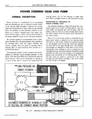
DESCRIPTION<br />
CARTER <strong>WCFB</strong> FOUR-BARREL<br />
CLIMATIC (R) CONTROL<br />
CARBURETOR<br />
NOTE: The following illustrations are used by<br />
permission of the copyright owner, <strong>Carter</strong> Carburetor<br />
Corporation, St. Louis, Missouri: Figs. 6B-<br />
39 through 6B-47 and Figs. 6B-64 through 6B-70.<br />
The <strong>Carter</strong> Model <strong>WCFB</strong> carburetor (Fig. 6B-39)<br />
is basically two dual carburetors contained in one<br />
assembly. The section containing the metering rods,<br />
accelerating pump and choke is termed the primary<br />
side of the carburetor; the other section, the secondary<br />
side. It has five (5) conventional circuits, as have<br />
been used in previous carburetors. They are:<br />
2-Float Circuits<br />
I-Low Speed Circuit<br />
2-High Speed Circuits<br />
I-Pump Circuit<br />
I-Climatic (R) Control (choke) Circuit<br />
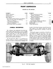
flOAT CIRCUITS (FIG. 68-40J<br />
The purpose of the float circuits is to maintain an<br />
adequate supply of fuel at the proper level in the<br />
bowls for use by the low speed, high speed, pump and<br />
choke circuits. Primary and secondary bowls are<br />
separated by a partition. A connecting passage along<br />
the outside of the body effects a balance of the fuel<br />
levels and pressures between the two bowls. The fuel<br />
line connection is on the primary side. Fuel is supplied<br />
to the primary and secondary intake needles<br />
and seats through a passage in the bowl cover. There<br />
are three strainer screens in the bowl cover. They are<br />
located at the fuel inlet and at both primary and secondary<br />
needle seats.<br />
Setting the floats to specifications assures an adequate<br />
supply of fuel in the bowls for all operating conditions.<br />
Float adjustments must be made with the<br />
bowl cover gasket removed and should be checked<br />
vertically (specified distance between bowl cover and<br />
bottom of floats) and laterally (sides of floats should<br />
just clear the arms of gauge) (see adjustment-page<br />
6B-33). Correct lateral adjustment is important. If the<br />
floats are misaligned, they may bind or drag against<br />
the walls of the bowl.<br />
Intake needles and seats are carefully matched<br />
during manufacture. Do not use the primary needle<br />
in the secondary seat or vice versa. To avoid unnecessary<br />
bending, floats should be reinstalled in their<br />
original positions and then adjusted.<br />
The bowls are vented to the inside of the air<br />
cleaner and also to atmosphere. The bowl vents are<br />
calibrated to provide proper pressure above the fuel<br />
at all times. The bowl cover gasket seals the fuel<br />
bowl, idle and vacuum passages. To assure a positive<br />
seal, always use a new bOWl cover gasket when reassembling.<br />
An air leak at this point can result in a<br />
performance or economy complaint.<br />
www.<strong>Pontiac</strong><strong>Safari</strong>.com
6B-22 19<strong>55</strong> PONTIAC SHOP MANUAL<br />
SECONDARY SIDE PRIMARY SIDE JET<br />
Fig. 68-41<br />
Low Speed Circuit<br />
Fig. 68-42<br />
High Speed Circuits<br />
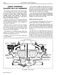
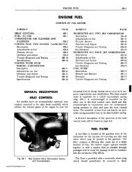
LOW SPEED CIRCUIT (fIG. 6B-4JJ<br />
Fuel for idle and early part throttle operation is<br />
metered through the low speed circuit.<br />
Fuel enters the idle wells through the metering rod<br />
jets on the primary side of the carburetor. No idle<br />
system is used in the secondary side of the carburetor.<br />
The low speed jets measure the amount of fuel for<br />
idle and early part throttle operation. The air by-pass,<br />
economizer, and idle air bleed are carefully calibrated<br />
and serve to break up the liquid fuel and mix it with<br />
air as it moves thrpugh the passages to the idle ports<br />
and idle adjustment screw ports. Turning the idle<br />
adjustment screws toward their seats reduces the<br />
quantity of fuel mixture supplied by the idle circuit.<br />
The idle ports are slot shaped. As the throttle<br />
valves are opened, more of the idle ports are uncovered<br />
allowing a greater quantity of fuel and air<br />
mixture to enter the carburetor bores. The secondary<br />
throttle valves remain seated at idle.<br />
Air leakage at the gasketed surface surrounding<br />
the low speed mixture passages or between the flange<br />
and manifold may cause poor idle and low speed<br />
operation. Always use new gaskets.<br />
All by-passes, bleeds, economizers, idle ports, idle<br />
mixture adjustment screw ports, as well as the bores<br />
of the flange must be clean and free of carbon. Obstructions<br />
will cause poor low speed engine operation.<br />
Worn or damaged idle adjustment screws or low<br />
speed jets should be replaced.<br />
To combat engine stalling during warm-up on cool,<br />
humid days, caused by "carburetor icing", exhaust<br />
gas is circulated through a passage in the base of the<br />
carburetor flange. The heat transferred is sufficient<br />
to eliminate ice formation at the throttle valve edges<br />
and idle ports.<br />
HIGH SPEED CIRCUITS (fIG. 6B-421<br />
Fuel for part throttle and full throttle operation<br />
is supplied through the high speed circuits. Main discharge<br />
nozzles are permanently installed and must<br />
not be removed in service.<br />
PRIMARY SIDE<br />
The position of the metering rods in the metering<br />
rod jets controls the amount of fuel flowing in the<br />
high speed circuit of the primary side of the carburetor.<br />
The position of the metering rods is dual controlled;<br />
mechanically by movement of the throttle,<br />
and by manifold vacuum applied to the vacuum<br />
piston on the vacumeter link.<br />
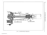
MECHANICAL METERING ROD ACTION<br />
During part throttle operation, manifold vacuum<br />
pulls the vacumeter piston, link and metering rod assembly<br />
down holding the vacumeter link against the<br />
metering rod countershaft arm (Fig. 6B-43). Movement<br />
of the metering rods will then be controlled by<br />
the metering rod countershaft arm which is connected<br />
to the throttle shaft. This is true at all times that the<br />
vacuum under the piston is strong enough to overcome<br />
the tension of the vacumeter spring.<br />
VACUUM METERING ROD ACTION<br />
Under any operating condition (acceleration, hill<br />
climbing, etc.) when the tension of the vacumeter<br />
www.<strong>Pontiac</strong><strong>Safari</strong>.com
ENGINE FUEL-CARTER FOUR BARREL 6B-23<br />
METERING ROD<br />
COUNTERSHAFT AR~'\7";'m~;::::,".w<br />
METERING<br />
PUMP<br />
JET<br />
NOZZLE<br />
-====~ DISCHARGE<br />
..::::=~I-t-- CHECK<br />
NEEDLE<br />
Fig. 68-43<br />
Metering Rods and Vacumeter Piston<br />
spring overcomes the pull of vacuum under the<br />
piston, the metering rods will move toward their wide<br />
open throttle or power position.<br />
Fig. 68-44<br />
Pump Circuit<br />
SECONDARY SIDE<br />
Fuel for the high speed circuit of the secondary<br />
side is metered at the secondary main metering jets<br />
(no metering rods used).<br />
Throttle valves in the secondary side remain closed<br />
until the primary throttle valves have been opened<br />
a predetermined amount. They arrive at wide open<br />
throttle position at the same time as the primary<br />
valves. This is accomplished by linkage between the<br />
throttle levers.<br />
Secondary throttle valves are locked closed during<br />
choke operation to assure proper cold engine starting<br />
and warm-up.<br />
ANTI-PERCOLATOR<br />
To prevent vapor bubbles in the nozzle passages<br />
and low speed wells from forcing fuel out of the<br />
nozzles, anti-percolator passages with calibrated vents<br />
are used. Their purpose is to vent the vapors and relieve<br />
the pressure before it is sufficient to push the<br />
fuel out of the nozzles and into the intake manifold.<br />
Anti-percolator vent plugs and bushings are permanently<br />
installed and must not be removed in service.<br />
PUMP CIRCUIT (FIG. 68-44J<br />
The pump circuit is located only in the primary<br />
side of the carburetor.<br />
The accelerating pump circuit provides the measured<br />
amount of fuel necessary to ensure smooth engine<br />
operation during acceleration at speeds below<br />
approximately 30 MPH.<br />
When the throttle is closed the pump plunger<br />
moves upward in its cylinder and fuel is drawn into<br />
the pump cylinder through the inlet passage. The<br />
discharge needle is seated at this time to prevent air<br />
being drawn into the cylinder. When the throttle is<br />
opened the pump plunger moves downward forcing<br />
fuel out through the discharge passage, past the discharge<br />
needle, and out of the pump jets. When the<br />
plunger moves downward the inlet valve is closed preventing<br />
fuel from being forced back into the bowl.<br />
If the throttle is opened suddenly, the plunger<br />
shaft will telescope compressing the pump spring.<br />
The spring will then push the plunger down resulting<br />
in a smoother pump discharge of longer duration.<br />
At speeds above approximately 30 MPH pump discharge<br />
is no longer necessary to ensure smooth acceleration.<br />
When the throttle valves are opened a predetermined<br />
amount, the pump plunger bottoms in the<br />
pump cylinder eliminating pump discharge.<br />
www.<strong>Pontiac</strong><strong>Safari</strong>.com
6B-24 19<strong>55</strong> PONTIAC SHOP MANUAL<br />
REVOLVING TYPE<br />
BAFFLE<br />
CHOKE OPERATING<br />
TH<br />
SLOTS IN CHOKE<br />
PISTON CYLINDER<br />
Fig. 68-46<br />
Choke Housing Detail<br />
Fig. 68-45<br />
CHOKE CIRCUIT (FIG. 68-45)<br />
Choke Circuit<br />
The Climatic (R) control circuit provides a correct<br />
mixture necessary for quick cold engine starting<br />
and warm-up.<br />
When the engine is cold, tension of the thermostatic<br />
coil holds the choke valve closed. When the engine<br />
is started, air velocity against the offset choke<br />
valve causes the valve to open slightly against the<br />
thermostatic coil tension. Intake manifold vacuum<br />
applied to the choke piston also tends to pull the<br />
choke valve open. The choke valve assumes a position<br />
where tension of the thermostatic coil is balanced<br />
by the pull of vacuum on the piston and air velocity<br />
on the offset choke valve.<br />
entering the housing from striking the thermostatic<br />
coil until the choke valve opens a predetermined<br />
amount. This serves to delay the opening of the choke.<br />
When the engine is accelerated dUring the warmup<br />
period, the corresponding drop in manifold vacuum<br />
applied to the choke piston allows the thermostatic<br />
coil to momentarily close the choke, providing<br />
a richer mixture.<br />
'I.",'I: ...... ~ ,-;,;;J/j/'--CHOKE LEVER<br />
When the engine starts, slots located in the sides<br />
of the choke piston cylinder (Fig. 6B-46) are uncovered<br />
allowing intake manifold vacuum to draw<br />
warm air from the hot air tube, located in the exhaust<br />
crossover passage of the intake manifold, through<br />
the Climatic (R) control housing. The flow of warm<br />
air in turn heats the thermostatic coil and causes it<br />
to lose some of its tension. The thermostatic coil loses<br />
its tension gradually until the choke valve reaches<br />
wide open position.<br />
A secondary baffle plate revolves with the choke<br />
valve. The revolving baffle prevents the warm air<br />
Fig. 68-47<br />
Choke Linkage<br />
www.<strong>Pontiac</strong><strong>Safari</strong>.com
ENGINE FUEL-CARTER FOUR BARREL 6B-25<br />
During the warm-up period it is necessary to provide<br />
a fast idle speed to prevent engine stalling. This<br />
is accomplished by a fast idle cam which is rotated<br />
by a connector rod attached to the choke shaft (Fig.<br />
6B-47). The fast idle cam prevents the primary throttle<br />
valves from returning to a normal warm engine<br />
idle position while the Climatic (R) control is in operation.<br />
During the starting period if the engine becomes<br />
flooded the choke valve can be partially opened manually.<br />
This can be accomplished by depressing the<br />
accelerator pedal to the floor. The unloader projection<br />
on the throttle lever will rotate the fast idle cam<br />
and in turn partially open the choke valve.<br />
ADJUSTMENTS ON CAR<br />
All adjustments with the exception of Fast Idle<br />
Adjustment, are included in the "OVERHAUL AND<br />
ADJUSTMENTS" procedure and can be done with<br />
the carburetor on the car. The fast idle can be adjusted<br />
on the car as follows:<br />
1. Start engine and run until engine reaches normal<br />
temperature.<br />
2. Move fast idle cam so that highest step is under<br />
end of fast idle screw.<br />
3. Observing tachometer, adjust fast idle screw to<br />
give an engine speed of 1900 RPM.<br />
OVERHAUL AND ADJUSTMENTS<br />
Flooding, stumble on acceleration and other performance<br />
complaints are, in many instances, caused<br />
by the presence of dirt, water or other foreign matter<br />
in the carburetor. To aid in diagnosing the cause of<br />
the complaint, the carburetor should be carefully removed<br />
from the engine without draining the fuel from<br />
the bowl. The contents of the fuel bowl may then be<br />
examined for contamination as the carburetor is disassembled.<br />
CAUTION: Whenever the carburetor is<br />
removed from the engine, care must be exercised to<br />
avoid damaging the throttle valves, as the lower edge<br />
of the valves project below the throttle flange when<br />
the valves are in the open position.<br />
The following is a step-by-step sequence by which<br />
the <strong>Carter</strong> model <strong>WCFB</strong> Carburetor may be completely<br />
disassembled and reassembled. Adjustments<br />
may be made and the various parts of the carburetor<br />
may be serviced without completely disassembling<br />
the entire unit.<br />
Fig. 68-48<br />
DISASSEMBL Y OF AIR HORN<br />
Metering Rod and Pump Linkage<br />
1. Remove gasoline strainer nut and gasket assemblies<br />
from primary and secondary sides and screen<br />
from primary side.<br />
2. Remove throttle connector rod.<br />
3. Remove choke connector rod.<br />
4. Remove 2 metering rod housing dust cover attaching<br />
screws, dust cover and gasket.<br />
S. Unhook countershaft return spring (Fig. 6B-48).<br />
6. Loosen. but do not remove screw holding the<br />
pump operating lever to pump countershaft.<br />
7. Loosen. but do not remove metering rod arm<br />
screw.<br />
8. Slide pump countershaft and lever assembly from<br />
air horn assembly.<br />
9. Remove pump arm and link assembly. spacer<br />
bushing and metering rod arm from metering rod<br />
housing.<br />
10. Remove both metering rods.<br />
11. Remove choke lever from choke shaft.<br />
12. Remove 3 choke coil housing screws and retainers.<br />
www.<strong>Pontiac</strong><strong>Safari</strong>.com
6B-26 19<strong>55</strong> PONTIAC SHOP MANUAL<br />
L -LONG M. -MEDIUM 5 -SHORT<br />
Fig. 68-49<br />
Location of Air Horn Attaching Screws<br />
Fig. 68-50<br />
Removing Air Horn Assembly<br />
13. Remove choke coil housing, gasket and then<br />
baffle plate.<br />
NOTE: Under normal service the carburetor air<br />
horn may be cleaned without further disassembly.<br />
If complete disassembly is necessary, perform operations<br />
a, b, and c.<br />
a. File off staked end of choke valve screws. Remove<br />
screws and valve.<br />
18. Remove primary needle seat with strainer<br />
screen and gasket.<br />
19. Remove secondary needle seat, strainer screen,<br />
and gasket.<br />
20. Remove vacumeter piston and vacumeter piston<br />
link.<br />
21. Remove gasket from air horn.<br />
b. Rotate choke shaft counter-clockwise, and remove<br />
shaft and piston assembly.<br />
c. Remove 3 self-tapping screws, choke piston<br />
housing and gasket.<br />
14. Remove 16 air horn attaching screws (Fig.<br />
6B-49).<br />
15. Carefully remove air horn assembly with gasket<br />
and attached parts by lifting straight up from<br />
carburetor body assembly (Fig. 6B-sO).<br />
NOTE: To avoid bending floats, be sure bowl cover<br />
gasket is not sticking to body casting.<br />
16. Remove primary float hinge pin, float assembly,<br />
and intake needle. IMPORTANT: Mark and group<br />
float assemblies with needle and needle seat together<br />
as units. Extreme care should be used to avoid mixing<br />
needles and seats.<br />
17. Remove secondary float hinge pin, float assembly<br />
and intake needle in the same manner.<br />
Fig. 68-51<br />
Carburetor 8ody-Top View<br />
www.<strong>Pontiac</strong><strong>Safari</strong>.com
ENGINE FUEL-CARTER FOUR BARREL 6B-27<br />
DISASSEMBLY Of CARBURETOR BODY<br />
1. Remove pump plunger assembly and lower pump<br />
spring.<br />
2. Remove vacumeter spring (Fig. 6B-Sl).<br />
3. Check the fuel in the bowl for contamination by<br />
dirt, water, gum or other foreign matter, then drain<br />
fuel from bowl.<br />
NOTE: Magnet swept around bottom of bowl<br />
while fuel is still present will pick up iron oxide dust<br />
which may have contributed to float needle leaks.<br />
4. Remove pump jet cluster attaching screw, then<br />
remove cluster and gasket.<br />
S. Invert carburetor and remove small brass pump<br />
discharge needle.<br />
6. Remove pump inlet ball retainer and check ball<br />
from bottom of pump cylinder.<br />
NOTE: Use o/!r," six point socket to pry sideways<br />
on dome of retainer to loosen it.<br />
Fig. 68-52<br />
Location of Throttle Flange Attaching Screws<br />
7. Remove pump passage screw plug and gasket.<br />
8. Remove 2 primary metering rod jets (located on<br />
pump cylinder side of carburetor).<br />
9. Remove 2 secondary main jets. NOTE: Primary<br />
metering rod jets have larger openings than the- secondary<br />
main jets. Never mix these jets.<br />
10. Remove two low speed jets (primary side).<br />
NOTE: The anti-percolator vent plugs and bushings,<br />
and main discharge nozzles are pressed in place<br />
and should not be removed.<br />
11. Remove the 6 throttle flange to carburetor body<br />
attaching screws (Fig. 6B-S2).<br />
12. Remove throttle flange.<br />
13. Remove body flange gasket.<br />
DISASSEMBL Y OF THROTTLE FLANGE<br />
1. Remove idle mixture adjusting screws with<br />
springs. NOTE: Under normal service the carburetor<br />
flange may be cleaned without further disassembly.<br />
If complete disassembly is necessary, perform the<br />
remaining operations.<br />
2. Remove fast idle cam screw, fast idle cam assembly,<br />
lockout arm and lockout arm spring.<br />
3. Remove primary to secondary connector rod<br />
pin springs and washers, then remove rod.<br />
4. Remove primary throttle shaft screw and washer.<br />
S. Remove primary throttle levers and spring as an<br />
assembly.<br />
6. Remove primary throttle shaft spring thrust<br />
washer.<br />
7. Remove secondary throttle shaft screw and<br />
washer.<br />
8. Remove secondary throttle lever, and secondary<br />
throttle return spring.<br />
9. File off staked ends of throttle valve attaching<br />
screws and remove screws and throttle valves from<br />
the four bores.<br />
10. Remove primary and secondary throttle shafts.<br />
11. Remove idle speed screw and spring.<br />
CLEANING AND INSPECTION<br />
OF PARTS<br />
Dirt, gum, water or carbon contamination in the<br />
carburetor or on the exterior moving parts of a carburetor<br />
are often responsible for unsatisfactory performance.<br />
For this reason, efficient carburetion depends<br />
upon careful cleaning and inspection while<br />
servicing.<br />
1. Thoroughly clean carburetor castings and all<br />
metal parts in clean carburetor cleaning solution.<br />
CAUTION: Composition and plastic parts such as<br />
thermostatic coil housing and pump plunger should<br />
not be immersed in cleaner.<br />
www.<strong>Pontiac</strong><strong>Safari</strong>.com
6B-28 19<strong>55</strong> PONTIAC SHOP MANUAL<br />
VACUUM PASSAGE TO<br />
CHOKE VACUUM PISTON<br />
Fig. 6B-53<br />
Passage Identification-Body to Air Horn<br />
www.<strong>Pontiac</strong><strong>Safari</strong>.com
ENGINE FUEL-CARTER FOUR BARREL 68-29<br />
VACUUM PASSAGE TO<br />
VACUMETER PISTON<br />
Fig. 6B-54<br />
Passage Identification-Body to Throttle Flange<br />
2. Blowout all passages (Figs. 6B-53-6B-<strong>55</strong>) in<br />
casting with compressed air and blow off all parts so<br />
they are free of cleaner (be sure to follow instructions<br />
furnished with cleaning solution). CAUTION: Do<br />
not use drills or wire to clean out jets or ports as this<br />
may enlarge the opening and affect carburetor operation.<br />
3. Carefully inspect parts for wear and replace<br />
those which are worn. Check the following specific<br />
points:<br />
a. If choke housing was disassembled in ste~ 13<br />
a, b, and c for complete overhaul, remove Welch plug<br />
in the bottom of the choke piston housing. Plug can<br />
be removed by piercing center with a small pointed<br />
www.<strong>Pontiac</strong><strong>Safari</strong>.com
6B-30 19<strong>55</strong> PONTIAC SHOP MANUAL<br />
Fig. 68-<strong>55</strong><br />
Passage at Manifold Side of Throttle Flange<br />
instrument and prying outward. Care should be exercised<br />
so that damage will not result to the casting<br />
when I:(moving this plug. Before installing new plug,<br />
carbon,,:present in piston cylinder slots should be removed-<br />
and the Welch plug seat should be carefully<br />
cleaned.<br />
b. Remove carbon from bores of throttle flange<br />
with sandpaper; never use emery cloth.<br />
c. Inspect needle or seat for wear; if worn, both<br />
must be replaced.<br />
d. Inspe,ct float pin for excessive wear.<br />
e. Inspect float for dents and excessive wear on<br />
lip. Check for fluid inside float by shaking. Replace<br />
float if any of above are present.<br />
f. Inspect air horn for wear in countershaft hole<br />
(hole worn egg shaped).<br />
g. In'spect .throttle shafts for excessive wear (looseness<br />
or rattle in body flange casting).<br />
h. Inspect idle mixture adjusting screws for burrs.<br />
Replace if burred.<br />
i. In~ect metering rods and jets for bent rods and<br />
signs of wear, and replace if bent rods or wear are<br />
noted. Always replace both metering rod and jet; do<br />
not install new rod in old jet or vice versa.<br />
j. Inspect pump plunger assembly. If leather is not<br />
in good condition, replace plunger.<br />
k. Inspect gasketed surfaces between body and air<br />
horn, and between body and flange. Small nicks or<br />
burrs should be smoothed down to eliminate air or<br />
fuel leakage. Be especially particular when inspecting<br />
choke vacuum passages and the top surface of the<br />
inner wall of the bowl.<br />
4. Check part numbers of jets, metering rods, etc.<br />
(where stamped with <strong>Carter</strong> part number), against<br />
Master Parts Catalog to make. sure correct parts will<br />
be installed.<br />
ASSEMBL Y OF THROTTLE FLANGE<br />
l. Install idle mixture adjusting $crews and springs<br />
finger tight, then back out 1 turn. CAUTION: Do not<br />
tighten idle mixture adjusting screws more than finger<br />
tight.<br />
If throttle flange was fully disassembled, reassemble<br />
as follows:<br />
2. Install primary and secondary throttle shafts.<br />
3. Install primary throttle valves from top or body<br />
side, with trade mark (C in circle) toward idle ports<br />
when viewing flange from manifold side. Use NEW<br />
www.<strong>Pontiac</strong><strong>Safari</strong>.com
ENGINE FUEL-CARTER FOUR BARREL 6B-31<br />
Fig. 6B-58<br />
Outer Throttle Lever Installed<br />
Fig. 6B-<strong>56</strong><br />
Proper Assembly of Secondary Throttle Lever<br />
screws. Install secondary throttle valves with trade<br />
mark (C in circle) away from center of carburetor<br />
when viewing flange from manifold side.<br />
4. Install secondary throttle return spring and secondary<br />
throttle lever (Fig. 6B-<strong>56</strong>).<br />
5. Install secondary throttle washer and screw<br />
(Fig. 6B-<strong>56</strong>).<br />
6. Wind spring 1 % turns with tag wire and hook<br />
over secondary throttle lever (Fig. 6B-<strong>56</strong>).<br />
7. Install primary shaft thrust washer and inner<br />
throttle shaft arm (Fig. 6B-<strong>57</strong>).<br />
8. Install outer throttle lever (Fig. 6B-58).<br />
9. Install throttle shaft dog, washer, and screw.<br />
Hook throttle flex spring on outer throttle lever and<br />
throttle shaft dog (Fig. 6B-59).<br />
10. Using a flat washer on each side of the levers,<br />
install connector rod (Fig. 6B-59). Retain with pin<br />
springs.<br />
11. Install fast idle cam assembly, consisting of<br />
secondary lockout lever spring, secondary lockout<br />
lever, lower choke lever, fast idle cam and spring and<br />
attaching screw as follows:<br />
a. Assemble fast idle cam and spring assembly and<br />
lower choke lever and place over attaching screw and<br />
set aside (Fig. 6B-60).<br />
b. Hook secondary lockout lever spring in lockout<br />
lever and place lever against boss with spring hooked<br />
on casting (Fig. 6B-61).<br />
c. Install fast idle cam assembly with screw (assembled<br />
in step a) in position on boss (Fig. 6B-62).<br />
Make sure cam and levers operate freely.<br />
12. Install idle speed screw and spring.<br />
Fig. 68-<strong>57</strong><br />
Inner Throttle Shaft Arm Installed<br />
Fig. 6B-59<br />
Proper Assembly of Primary and Secondary<br />
Throttle Levers<br />
www.<strong>Pontiac</strong><strong>Safari</strong>.com
6B-32 19<strong>55</strong> PONTIAC SHOP MANUAL<br />
FAST IDLE CAM<br />
Fig. 68-60<br />
Fast Idle Cam and lower Choke lever<br />
Fig. 68-62<br />
Fast Idle Cam and Secondary<br />
lockout Assembly<br />
ASSEMBLY OF CARBURETOR BODY<br />
1. Place NEW body to flange gasket on carburetor<br />
body being sure slot in gasket is lined up with vacumeter<br />
passage.<br />
2. Install throttle flange on carburetor body with<br />
6 attaching screws and lock washers (Fig. 6B-52).<br />
3. Install primary metering rod jets. NOTE: The<br />
primary metering rod jets have the large holes and<br />
must be installed in the primary side of the carburetor.<br />
This is the pump cylinder side of the carburet()r<br />
body.<br />
4. Install secondary main jets.<br />
5. Install 2 low speed jets on primary side of body.<br />
NOTE: Low speed jets are mounted at a slight angle.<br />
6. Install steel pump inlet ball check and retainer<br />
(Fig. 6B-51). Press retainer into place with a %6"<br />
six point socket.<br />
7. Install pump passage screw plug and gasket.<br />
8. Install brass pump discharge check needle (Fig.<br />
6B-63). Be sure needle is installed point down.<br />
9. Install pump discharge cluster gasket, cluster<br />
assembly and attaching screw.<br />
10. Install vacumeter spring in vacumeter bore.<br />
NOTE: The vacumeter spring affects both economy<br />
and performance. If vacumeter piston spring appears<br />
to be damaged or distorted, it should be replaced. If<br />
any doubt exists, use a new spring for comparison.<br />
Fig. 68-61<br />
Positioning Secondary lockout lever<br />
Fig. 68-63<br />
Installing Pump Discharge Check Needle<br />
www.<strong>Pontiac</strong><strong>Safari</strong>.com
ENGINE FUEL-CARTER FOUR BARREL 6B-33<br />
Fig. 68-65<br />
Float Drop<br />
5. Remove floats and install new air horn gasket.<br />
Fig. 68-64<br />
Float Gauge in Position for Checking Floats<br />
11. Install lower pump spring in pump cylinder.<br />
ASSfMBL Y OF AIR HORN<br />
1. Install strainer screen in primary intake needle<br />
seat. Then install primary needle and seat with new<br />
gasket. IMPORTANT: Float needles and seats are<br />
factory matched and must never be mixed.<br />
2. Install secondary intake needle and seat with<br />
new gasket.<br />
3. Temporarily install both the primary and secondary<br />
float assemblies. NOTE: Float adjustments<br />
must be measured with air horn gasket removed.<br />
4. Three separate float adjustments must be made<br />
-lateral, vertical, and float drop.<br />
a. Lateral Adjustment: Place float gauge ] -545B<br />
under center of float with notched portion of gauge<br />
fitted over edge of casting (Fig. 6B-64). Sides of float<br />
should just clear the vertical uprights of float gauge.<br />
Adjustment should be made by bending arms of<br />
float.<br />
b. Vertical Adjustment: With float gauge in position,<br />
(Fig. 6B-64) floats should just clear the horizontal<br />
portion of gauge. Vertical distance between top<br />
of float (at center) and machined surface of casting<br />
is ~i6" (gauge]-545B) for both primary and secondary<br />
floats. Adjust by bending at center portion of<br />
float arms. Remove gauge.<br />
c. Float Drop Adjustment: With bowl cover held<br />
in upright position and measuring from center of<br />
float, the distance between top of floats and bowl<br />
cover should be ~i6" for both primary and secondary<br />
floats (Fig. 6B-65). Adjust by bending stop tabs on<br />
float brackets.<br />
6. Install vacumeter link and vacumeter piston<br />
with lip on link toward center of air horn.<br />
7. Insert pump plunger shaft through air horn and<br />
retain in position with link and pump arm assembly.<br />
B. Reinstall the primary and secondary float assemblies.<br />
9. Carefully position the air horn assembly on the<br />
carburetor body being sure the vacumeter piston and<br />
pump plunger are aligned so they enter their respective<br />
bores.<br />
10. Install 16 air horn attaching screws. See Fig<br />
6B-49 for proper location of different length screws.<br />
11. Tighten all screws evenly and securely in alternate<br />
order.<br />
12. Install both metering rods as follows: Catch<br />
metering rod spring loop with lower end of rod before<br />
rod is inserted, then twist "eye" of rod onto<br />
vacumeter piston link assembly.<br />
13. Install countershaft return spring on countershaft.<br />
14. Install pump countershaft by sliding shaft<br />
through pump operating arm, spacer bushing and<br />
metering rod arm (Fig. 6B-4B). CAUTION: Be certain<br />
metering rod operating arm is positioned in slot<br />
in vacumeter piston link.<br />
15. Tighten pump arm screw.<br />
16. Using tag wire wind countershaft spring Yz<br />
turn and hook over pump arm.<br />
17. Place washer on lower end of throttle connector<br />
rod, install rod into throttle lever while holding<br />
lever in wide open position. and retain with spring<br />
and retainer.<br />
lB. Install throttle connector rod in pump countershaft<br />
lever and retain with pin spring.<br />
www.<strong>Pontiac</strong><strong>Safari</strong>.com
68-34 19<strong>55</strong> PONTIAC SHOP MANUAL<br />
19. Install choke piston housing and NEW gasket<br />
using three self-tapping screws.<br />
20. Assemble choke piston on link and install choke<br />
shaft and piston assembly through air horn while<br />
guiding piston into cylinder.<br />
21. Place choke valve in position on choke shaft<br />
with the "C" (in circle) on valve visible from the top<br />
of carburetor. Center choke valve and install screws.<br />
Use new screws. IMPORTANT: Make sure that<br />
neither valve nor shaft binds in any position and that<br />
valve drops free by its own weight.<br />
22. Position baffle plate into choke housing with<br />
choke operating lever extending through slot in stationary<br />
baffle and small hole in rotating baffle.<br />
23. Install choke coil housing and new gasket on<br />
piston housing with index mark on plastic housing at<br />
the bottom. Revolve coil housing in direction opposite<br />
to arrow (counterclockwise) until index mark on coil<br />
housing is aligned with index mark on piston housing,<br />
and retain with 3 screws and retainers.<br />
24. Install choke operating lever on shaft and<br />
tighten screw only enough to permit lever to be<br />
moved.<br />
25. Install choke connector rod in choke operating<br />
lever and choke lower lever, and retain lower end of<br />
rod with pin spring.<br />
26. Install strainer plug, gasket, and strainer in<br />
primary side.<br />
27. Drop secondary strainer into place around<br />
stand pipe. Carefully press down into bore around<br />
standpipe. Install strainer plug and gasket.<br />
Fig. 68-66<br />
Accelerating Pump Arm Adjustment<br />
rod at lower angle (use tool J-5496) until flat on top<br />
of pump arm is parallel with straight edge while<br />
throttle valves are seated (Fig. 6B-66).<br />
METERING ROD ADJUSTMENT<br />
1. Back out idle speed screw and fast idle speed<br />
screw until throttle valves seat.<br />
2. Press down on vacumeter piston link until metering<br />
rods bottom in carburetor body (Fig. 6B-67).<br />
3. Holding rods in this downward position and with<br />
throttle valves seated, revolve metering rod arm until<br />
finger on arm contacts lip of vacumeter link. Hold<br />
in place and carefully tighten clamp screw (Fig.<br />
6B-67).<br />
ADJUSTMENTS<br />
The float adjustments have been described and<br />
made during assembly of the air horn. The remaining<br />
adjustments should be made in the following sequence:<br />
1. Pump Adjustment<br />
2. Metering Rod Adjustment<br />
3. Fast Idle Cam Clearance Adjustment<br />
4. Unloader Adjustment<br />
5. Secondary Throttle Lever Adjustment<br />
6. Secondary Throttle Lockout Adjustment<br />
PUMP ADJUSTMENT<br />
1. Back out idle speed screw and fast idle speed<br />
screw until throttle valves seat in bores of carburetor.<br />
2. Hold straight edge across top of dust cover boss<br />
at pump arm (Fig. 6B-66). Bend throttle connector<br />
Fig. 68-67<br />
Metering Rod Arm Adjustment<br />
www.<strong>Pontiac</strong><strong>Safari</strong>.com
ENGINE FUEL-CARTER FOUR BARREL 6B-35<br />
Fig. 68-68<br />
Fast Idle Cam Clearance Adjustment<br />
Fig. 68-69<br />
Unloader Adjustment<br />
4. Lubricate countershaft by dropping engine oil<br />
in 2 oil holes and install dust cover.<br />
FAST IDLE CAM CLEARANCE ADJUSTMENT<br />
1. Make sure choke lever clamp screw is still loose.<br />
2. Hold choke valve closed.<br />
3. Place .020" wire gauge (J-1388) on boss, rotate<br />
choke lever on shaft until tang on fast idle cam contacts<br />
wire gauge and all slack in linkage is removed<br />
(Fig. 6B-68)~ While holding in this position, tighten<br />
choke lever clamp screw.<br />
UNLOADER ADJUSTMENT<br />
1. Hold throttle lever wide open.<br />
2. There should be %" (gauge J -818-5) between<br />
top edge of choke valve and inner wall of air horn<br />
(Fig. 6B-69). If necessary, adjust by bending unloader<br />
projection on throttle lever.<br />
SECONDARY THROTTLE LEVER ADJUSTMENT<br />
1. Open choke valve to unlock secondary throttle<br />
valves.<br />
2. Open primary throttle lever to wide open position.<br />
3. Secondary throttle valves should reach wide open<br />
position at the same time as primary valves. If necessary,<br />
bend throttle operating rod at upper angle<br />
(Fig. 6B-70) (use bending tool T-I09-2l3).<br />
Fig. 68-70<br />
Primary and Secondary Throttle Levers<br />
4. Check to see that there is .017" to .022" clearance<br />
between primary and secondary throttle positive<br />
closing shoes (Fig. 6B-70).<br />
LOCKOUT ADJUSTMENT<br />
1. Hold choke valve wide open.<br />
2. Hold throttle lever closed.<br />
3. Allow choke valve to close slowly. Lockout step<br />
on secondary lockout lever should freely engage tang<br />
on secondary throttle lever (Fig. 6B-71). If adjustment<br />
is necessary, bend tang (Fig. 6B-7l).<br />
www.<strong>Pontiac</strong><strong>Safari</strong>.com
6B-36 19<strong>55</strong> PONTIAC SHOP MANUAL<br />
TEST BEFORE INSTALLATION<br />
ON ENGINE<br />
It is good shop practice to fill the carburetor bowl<br />
before installing the carburetor. This reduces the<br />
strain on the starting motor and battery and reduces<br />
the possibility of backfiring while attempting to start<br />
the engine. A fuel pump clamped on the bench, a<br />
small supply of fuel and the necessary fittings enable<br />
the carburetor to be filled and the operation of the<br />
float and intake needle and seat to be checked. Operate<br />
the throttle several times and check the discharge<br />
from the pump jets.<br />
Before installing the carburetor, hold choke valve<br />
open and turn the idle speed screw until it just contacts<br />
the throttle lever, then % of a turn more to open<br />
the throttle valves enough to keep the engine running<br />
until the idle mixture and final RPM adjustment<br />
can be made.<br />
TROUBLE DIAGNOSIS AND TESTING<br />
Excessive leanness during cold engine operation<br />
may indicate that the secondary throttle valves are<br />
partially open. Check the secondary lockout and<br />
check for too rapid choke opening.<br />
Fig. 68-71<br />
Lockout Adjustment<br />
In all other respects 4 barrel trouble diagnosis is<br />
the same as on the 2 barrel carburetor. See page<br />
6B-18 for 2 barrel trouble diagnosis.<br />
CARTER CARBURETOR <strong>WCFB</strong>-SPECIFICATIONS<br />
ADJUSTMENT SPECIFICATIONS<br />
Float Adjustment-Vertical distance between center of float and surface of air<br />
horn '%6" (gauge J-5458) for both primary and secondary.<br />
Float Drop-Casting in operating position distance between center of floats and<br />
air horn is %6" (no gauge necessary; use an ordinary scale).<br />
Fast Idle-Cam to machined boss clearance minimum of .020" (gauge J-1388).<br />
Un loader-Distance between upper edges of choke valve and wall of air horn<br />
Ys" (gauge J-818-5).<br />
Clearance Between Positive Closing Shoes-is .017" to .022" with both valves<br />
seated (hold choke valve open to revolve fast idle cam and be sure idle speed<br />
screw is backed out so valves seat in bore).<br />
Fast Idle Speed<br />
Hot Idle Speed<br />
1900 RPM<br />
390-410 HM, 450-470 SM<br />
Choke-<strong>Carter</strong> Climatic (R) Control-Butterfly Type, Set on Index. Offset<br />
choke valve on primary side only.<br />
www.<strong>Pontiac</strong><strong>Safari</strong>.com
ENGINE FUEL-CARTER FOUR BARREL<br />
6B-37<br />
GENERAL SPECifiCATIONS<br />
Flange Size<br />
Primary Venturi (I.D.)<br />
Main Venturi, Primary (I.D.)<br />
Main Venturi, Secondary (I.D.)<br />
Float Level<br />
Vents<br />
Outside<br />
Inside<br />
Gasoline Intake (In Needle Seat)<br />
1:%" (Four Bore-4 Bolt Type)<br />
Iljg2"<br />
1%6"<br />
I" HM, 1%6" SM<br />
See Adjustments<br />
Five in Bowl Cover<br />
Two in Dust Cover<br />
Three on Primary Side<br />
Two on Secondary Side<br />
.......... No. 38 Drill (.1015")<br />
Low Speed Jet Tube (Primary Side Only)<br />
Jet (DO NOT REMOVE) .. No. 68 Drill (.031") HM, No. 67 Drill (.032") SM<br />
By-Pass (In Body) ......... .<br />
Economizer (In Screw Plug)<br />
Idle Bleed (In Body)<br />
Idle Port (Primary-Upper)<br />
(Secondary)<br />
No. 53 Drill (.0595")<br />
.0492"<br />
..... No. 52 Drill (.0635")<br />
Slot Length .195", Width .030"<br />
None<br />
Opening Above Throttle Valve When<br />
Valve Is Tightly Closed (Primary) .139" to .145"<br />
(Secondary)<br />
None<br />
Idle Port (lower for the idle screw-Primary) No. 53 Drill (.0595")<br />
(Secondary) . . . . . . . . . . ......... None<br />
Idle Adjustment Screw Setting<br />
Main Nozzle (DO NOT REMOVE)<br />
Anti-Percolating Jet (Off Nozzle Well)<br />
Metering Rod (Primary)<br />
Economy Step ......... .<br />
Middle Step Tapers To<br />
Power Step<br />
Metering Rod (Secondary)<br />
Metering Rod jet<br />
Primary (for metering rod)<br />
Secondary (no metering rod)<br />
Metering Rod Setting<br />
Accelerating Pump<br />
Discharge jet (Primary)<br />
(Secondary)<br />
Intake Ball Check Seat<br />
Discharge Needle Seat<br />
Pump Adjustment ...<br />
0/4 to 10/4 turns open<br />
. Permanently Installed<br />
.. No. 60 Drill (.040")<br />
.074" HM, .072" SM<br />
.067" HM, .069" SM<br />
.059" All<br />
.......... None<br />
.0935"<br />
.0492" HM, .0512" SM<br />
.... See Adjustments<br />
..... No. 72 Drill (.025")<br />
None<br />
.115" to .120"<br />
.070"<br />
See Adjustment<br />
www.<strong>Pontiac</strong><strong>Safari</strong>.com
6B-38<br />
19<strong>55</strong> PONTIAC SHOP MANUAL<br />
Choke Heat Suction Hole Restriction<br />
In Piston Housing<br />
Vacuum Spark Port<br />
Diameter ......... .<br />
Distance from throttle valve with valve tightly closed<br />
No. 45 Drill (.082")<br />
.062" to .064"<br />
.029" to .039"<br />
(To Top of Port)<br />
I<br />
J-5458<br />
t<br />
CARTER 4-BARREL SPECIAL TOOLS<br />
J-1388<br />
J- 818-5<br />
J-1388<br />
J-5458<br />
J-5496<br />
J-5923<br />
Choke Un loader Gauge<br />
. Fast Idle Cam Clearance Gauge<br />
Float level Gauge<br />
. Bending Tool<br />
Holding Stand<br />
J-5923<br />
J-5496<br />
J-818-5<br />
SER VICE CRAFTSMAN NEWS REFERENCE<br />
News<br />
Year<br />
News<br />
No.<br />
Page<br />
No.<br />
Subject<br />
www.<strong>Pontiac</strong><strong>Safari</strong>.com